Craftsman 917255572 User Manual Lawn, Tractor Manuals And Guides L0805149
CRAFTSMAN Lawn, Tractor Manual L0805149 CRAFTSMAN Lawn, Tractor Owner's Manual, CRAFTSMAN Lawn, Tractor installation guides
User Manual: Craftsman 917255572 917255572 CRAFTSMAN Lawn, Tractor - Manuals and Guides View the owners manual for your CRAFTSMAN Lawn, Tractor #917255572. Home:Lawn & Garden Parts:Craftsman Parts:Craftsman Lawn, Tractor Manual
Open the PDF directly: View PDF ![]() .
.
Page Count: 52
OWNER'S
MANUAL
MODEL NO.
917.255572
Caution:
Read and follow
all Safety Rules
and Instructions
Before Operating
This Equipment
i ,i,,,,ii,iiii,iii,,,,,iiiiii
®
oAssembHy
° Operation
oCustomer AesponsibiHties
oService and Adjustment
oRepair Parts
Sears, Roebuck and Co., Chicago, IL 60684 U.S.A.
H n = =m,= NHnH=HHHnnH= ,I, i= =JH
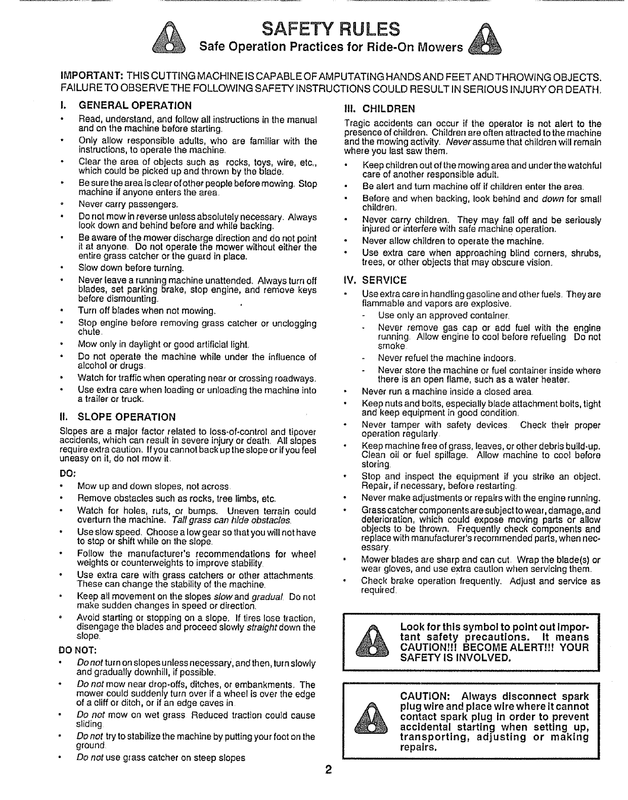
SAFETY RULES
Safe Operation Practices for Ride.On Mowers
IMPORTANT: THIS CUTTING MACHINE IS CAPABLE OF AMPUTATING HANDS AND FEETAND THROWING OBJECTS.
FAILURE TO OBSERVETHE FOLLOWING SAFETY INSTRUCTIONS COULD RESULT IN SERIOUS INJURY OR DEATH,
!. GENERAL OPERATION
•Read, understand, and follow all instructions in the manual
and on the machine before starting
Only allow responsible adults, who are familiar' with the
instructions, to operate the machine,
• Clear the area of objects such as rocks, toys, wire, etc.
which could be picked up and thrown by the b_ade,
Be sure the area is clear of other people before mowing° Stop
machine if anyone enters the area.
Never carry passengers.
Do not mow in reverse unless absolutely necessary, Always
look down and behind before and while backing.
• Be aware of the mower discharge direction and do not point
it at anyone,. Do not operate the mower without either the
entire grass catcher or the guard in placeo
• Slow down before turning.
•Never leave a running machine unattended. Always turn off
blades, set parking brake, stop engine, and remove keys
before dismounting
• Turn off blades when not mowing.
Stop engine before removing grass catcher or unclogging
chute
• Mow onty in daylight or good artificiai light
• Do not operate the machine while under the influence of
alcohol or drugs,
Watch for traffic when operating near or crossing roadways.
Use extra care when loading or unloading the machine into
atrailer'or truck_
I1o SLOPE OPERATION
Slopes are a major factor related to Ioss-oflcontrol and tipover
accidents, which can result in severe injury or death, All slopes
require extra caution_ Ifyou cannot back upthe slope or ifyou feel
uneasy on it, do not mow it,
DO:
• Mow up and down slopes, not across
.Remove obstacles such as rocks, tree limbs, etco
Watch for holes, ruts, or bumps. Uneven terrain could
overturn the machine_ Tall grass can hide obstacles.
• Use slow speed. Choose a low gear so that you will not have
to stop or shift while on the slope.
- Follow the manufacturer's recommendations for wheel
weights or counterweights to improve stability
• Use extra care with grass catchers or other attachments
These can change the stability of the machine.
Keep all movement on the slopes slowand gradual Do not
make sudden changes in speed or direction.
o Avoid starting or stopping on a slope. If tires lose t_action,
disengage the blades arid proceed slowly straight down the
slope.
DO NOT:
•Do not turn on slopes unless necessary, and then, turn slowly
and gradually downhill, ifpossible.
•Do not mow near drop-offs, ditches, or embankments, The
mower could suddenly turn over ifa wheel is over the edge
of a cliff or ditch, or if an edge caves in
•Do not mow on wet grass Reduced traction could cause
sliding
Do not try to stabilize the machine by putting your foot on the
ground
•Do not use grass catcher on steep slopes
IlL CHILDREN
Tragic accidents can occur if the operator is not alert to the
presence of children, Children are often attracted to the machine
and the mowing activity_ Neverassume that children will remain
where you last saw them_
• Keep children out of the mowing area and under the watchful
care of another responsible adulL
Be alert and turn machine off ifchildren enter the area
•Before and when backing, look behind and down for small
children,
Never carry children. They may fail off and be seriously
injured or interfere with safe machine operation.
Never allow children to operate the machine.
• Use extra care when approaching blind corners, shrubs,
trees, or other objects that may obscure vision.
IV. SERVICE
Use extra care inhandfing gasoline and other fuels. They are
flammable and vapors are explosive.
Use only an approved container,
Never remove gas cap or add fuel with the engine
running Allow engine to coo] before refueling Do not
smoke
Never refuel the machine indoors.
Never store the machine or fuel container inside where
there is an open flame, such as a water heater_
Never run a machine inside a closed area
• Keep nuts and bolts, especially blade attachment bolts, tight
and keep equipment in good condition,
Never tamper with safety devices Check their proper
operation regularly
Keep machine free of grass, leaves, or other debris build-up.
Clean oil or fuel spillage_ Allow machine to cool before
storing.
• Stop and inspect the equipment if you strike an object.
Repair, if necessary, before restarting,
•Never make adjustments or repairs with the engine running.
• Grass catcher components are subject to wear, damage, and
deterioration, which could expose moving parts or allow
objects to be thrown. Frequently check components and
replace with manufacturer's recommended parts, when nec-
essary
• Mower blades are sharp and can cut, Wrap the blade(s) or
wear gloves, and use extra caution when servicing them°
• Check brake operation frequently. Adjust and service as
required
Look for this symbol to point out Impor-
tant safety precautions. It means
CAUTION!t! BECOME ALERT!i! YOUR
SAFETY IS INVOLVED.
CAUTION: Always disconnect spark
plug wire and place wire where It cannot
contact spark plug In order to prevent
accidental starting when setting up,
transporting, adjusting or making
repairs,
2

CONGRATULATIONS on your purchase of a Sears
Tractor_ It has been designed, engineered and manu-
factured to give you the best possible dependability and
performance.
Should you experience any problem you cannot easily
remedy, please contact your nearest Sears Service
Center/Department. We have competent, well-trained
technicians and the proper tools to service or repair this
unit,
Please read and retain this manual. The instructions will
enable you to assemble and maintain your untt properly_
Always observe the "SAFETY RULES".
MODEL
NUMBER 917o255572
SERIAL
NUMBER
DATE OF PURCHASE
THE MODELAND SERIALNUMBERSWILLBE FOUND
ON A PLATE UNDER THE SEAT.
YOU SHOULD RECORD BOTH SERIAL NUMBERAND
DATE OF PURCHASE AND KEEP IN A SAFE PLACE
FOR FUTURE REFERENCE_
MAINTENANCE AGREEMENT
A Sears Maintenance Agreement is available on this prod-
UCtoContact your nearest Sears store for details°
CUSTOMER RESPONSIBILITIES
• Read and observe the safety rules.
o Follow a regular schedule in maintaining, caring for and
using your unit.
.Followthe instructions under "Customer Responsibili-
ties" and "Storage" sections of this owner's manual
PRODUCT SPECIFICATIONS
HORSEPOWER; 12,5
GASOLINE CAPACITY: 5 QUARTS
UNLEADED REGULAR
OIL (30 PINTS): SAE 30 (Above 32°F)
5W-30 (Below 32°F)
SPARK PLUG (GAP030 IN.): CHAMPION RJ-19LM
STD361458
VALVE CLEARANCE: INTAKE 005 -007 IN,
EXHAUST 009 - ,011 IN
GROUND SPEED: FORWARD
1st 110 MPH
2nd 1.40 MPH
3rd 2,00 MPH
4th 300 MPH
5th 4.20 MPH
6th 5.00 MPH
REVERSE: 1.50 MPH
TIRE PRESSURE: FRONT: 14 PSI
REAR: 12 PSI
CHARGING SYSTEM: 3 AMPS BATTERY
5 AMPS HEADLIGHTS
BLADE BOLT TORQUE: 30-35 FT, LBS
WARNING', This unit is equipped with an internal combus-
tion engine and should not be used on or near any unim-
proved forest-covered, brush-covered or grass-covered
land unless the engine's exhaust system is equipped with
a spark arrester meeting appFicable local or state laws (if
any), If a spark arrester is used, it should be maintained in
effective working order by the operator.
In the state of California the above is required by law
(_Section 4442 of the California Public Resources Code).
Other states may have similar laws, Federal laws apply on
federal lands° A spark arrester for the muffler is available
through your nearest Sears Authorized Service Center
(See REPAIR PARTS section of this manual),
LIMITED TWO YEAR WARRANTY ON ELECTRIC START RIDING EQUIPMENT
For two (2) years from the date of purchase, if this riding equipment is maintained, lubricated and tuned up according to the
instructionstn the owner's manual, Sears will repair or replace, free of charge, any parts found to be defective in material or
workmanship,
This Warranty does not cover:
•Expendable itemswhich become worn during normal use, such as blades,spark plugs, air cleaners and belts.
• Tire replacement or repaircaused by punctures from outside objects, such as nails, thorns, stumps, or glass,
•Repairs necessary because of operator abuse, negligence, improperstorage or accident or the failure to maintain the
equipment according to the instructionscontained in the owner's manual.
• Riding equipmentused for commercial or rental purposes_
LIMITED 90 DAY WARRANTY ON BATTERY
For 90 days from date of purchase, if any battery includedwith this riding equipment proves defective inmaterial or workmanship
and our testing determines the baltery will not hold a charge, Sears wi{Ireplacethe battery at no charge,
WARRANTY SERVICE IS AVAILABLE BY RETURNING THE RIDING EQUIPMENT TO THE NEAREST SEARS SERVICE
CENTER/DEPARTMENT IN THE UNITED STATES
This Warranty gives you specific legal rights, and you may also have other rights which may vary from state to state,
SEARS, ROEBUCK AND CO,, D/731CR-W, SEARS TOWER, CHICAGO, ILLINOIS 60684
3

TABLE OF CONTENTS
SAFETY RULES ............................................................ 2
PRODUCT SPECIFICATIONS ....................................... 3
CUSTOMER RESPONSIBILITIES ..................... 3_15-18
WARRANTY ................................................................... 3
TABLE OF CONTENTS ................................................. 4
INDEX ............................................................................. 4
TRACTOR ACCESSORIES ........................................... 5
ASSEMBLY .............................................................. 7-10
OPERATION ........................................................... 11-14
MAINTENANCE SCHEDULE ...................................... 15
SERVICE AND ADJUSTMENTS ............................ 19-24
STORAGE .................................................................... 25
TROUBLESHOOTING ............................................ 26-27
REPAIR PARTS -TRACTOR ................................. 28.43
REPAIR PARTS -ENGINE ..................................... 44-48
PARTS ORDERING/SERVICE ................... BACK PAGE
tNDEX
A
Accessories .....................................................5
Adjustments;
Brake ...................................................21
Carburetor. .............................................24
Mower
Front-To-Back .................................20
Side-To-Side ...............................20
Throttle Control Cable .....................24
Air Filter, Engine .........................................18
Air Screen, Engine ...................................18
Assembly ...............................................7-10
B
Battery:
Charging ..................................................... 8
Cleaning .............................................17
Installation ..... ................................... 9
Levels ................................................... 8,17
Preparation ..................................... 8
Starting with Weak Battery .......... 22
Storage ................................................25
Terminals ...................................... 17
Belt:
Motion Drive
Removal/Replacement ................21
Mower Blade Drive
Removal/Replacement ............ 21
Blade:
Sharpening ........................................ 16
Replacement ................................... 1 6
Brake Adjustment ........................................21
C
Carburetor Adjustment ........................ 25
Controls, Tractor ................................... t 1
Customer Responsibilities .............. 15-t 8
Engine:
Air Filter .................................. 18
Air Filter Foam Pro-Cleaner .... 18
Air Screen, Engine ................... 18
Battery .............................................17
Cooling Fins, Engine ............... 18
Engine Oil ................................ 17
Fuel Filter. ................................ 18
Spark Plugs .................................18
Tractor:
Blade ................................................16
Lubrication Chart ....................... 15
Maintenance Schedule ............ 15
Tire Care ............................ 8,16,22
Cutting Height, Mower ....................... 12
E
Electrical:
interlocks and Relays .....................23
Schematic ........................................28
Wiring Diagram ............................. 29
Engine:
Air Filter .............................................18
Air Filter Foam Pro-Cleaner ...........18
Air Screen ..........................................! 8
Cooling Fins, Engine ........................18
Oil Change ..............................................17
Oil Level ................................... 13,17
Oil Type ............................................17
Preparation .......................................13
Repair Parts ................................44-48
Starting ..............................................14
Storage ................................................25
F
Filter:
Air Filter ..............................................18
Air Filter Foam Pro-Cleaner .........18
Fuel .........:...................................... 18
Fuel:
Type ...................................................13
Storage ......................................... 25
Fuse ....................................................... 23
H
Hood Removal/Installation ................. 23
L
Leveling Mower Deck ......................... 20
Lubrication:
Chart ............................................... 15
M
Maintenance Schedule ...........................15
Mower:
Adjustment, Front-to-Back ...............20
Adjustment, Side-to.Side ............ 20
Blade Sharpening ........................ 16
Blade Replacement ........................16
Cutting Height ................................ 12
Installation .........................................19
Operation ..................................... 13
Removal ...............................................19
Mowing Tips ..............................................14
Muffler ................................................. 18
Spark Arrestor .................................3,38
O
Oil:
Cold Weather Conditions ....... 13,17
Engine ............................................ 17
Storage ...............................................25
Operation .............................................1!-14
Operating Mower ....................................13
Options:
Accessories ................................... 5
Spark Arrestor ......................... 3,38
P
Parking Brake ................................ 11-12
Parts Bag .............................................. 6
Parts, ReplacementJRepair ........... 28=43
Product Specifications ........................... 3
R
Repair Parts ..............................................28-43
S
Safety Rules ......................................... 2
Seat .......................................................... 6
Service and Adjustments .................t9-24
Car buretor .................................... 24
Fuse ................................................ 23
Hood Removal/Installation ........... 23
Motion Drive Belt
Removal/Replacement ........... 21
Mower Blade Drive Belt
Removal/Replacement ........... 21
Mower Adjustment
Front- to-Back ...........................20
Side-to-Side ............................ 20
Mower Removal .......................... t 9
Tire Care ............................ 8,16,22
Slope Guide Sheet ............................. 51
Spark Plugs .......................................... 18
Specifications ......................................... 3
Starting the Engine ........................ 13-t4
Steering Wheel ................................. 7,22
Stopping the Tractor .............................. t2
Storage ............................................... 25
T
Throttle Control Cable
Adjustment ................................... 24
Tires.........................................................8,16,22
Trouble Shooting Chart .................. 26-27
Transaxie:
Repair Parts ........................... 42-43
W
Warranty ............................................... 3
Wiring Diagram ....................................... 28
Wiring Schematic ................................ 28
iiiitltl,_i_lt,luiitlll n,_, i ii i nllnnl I i i
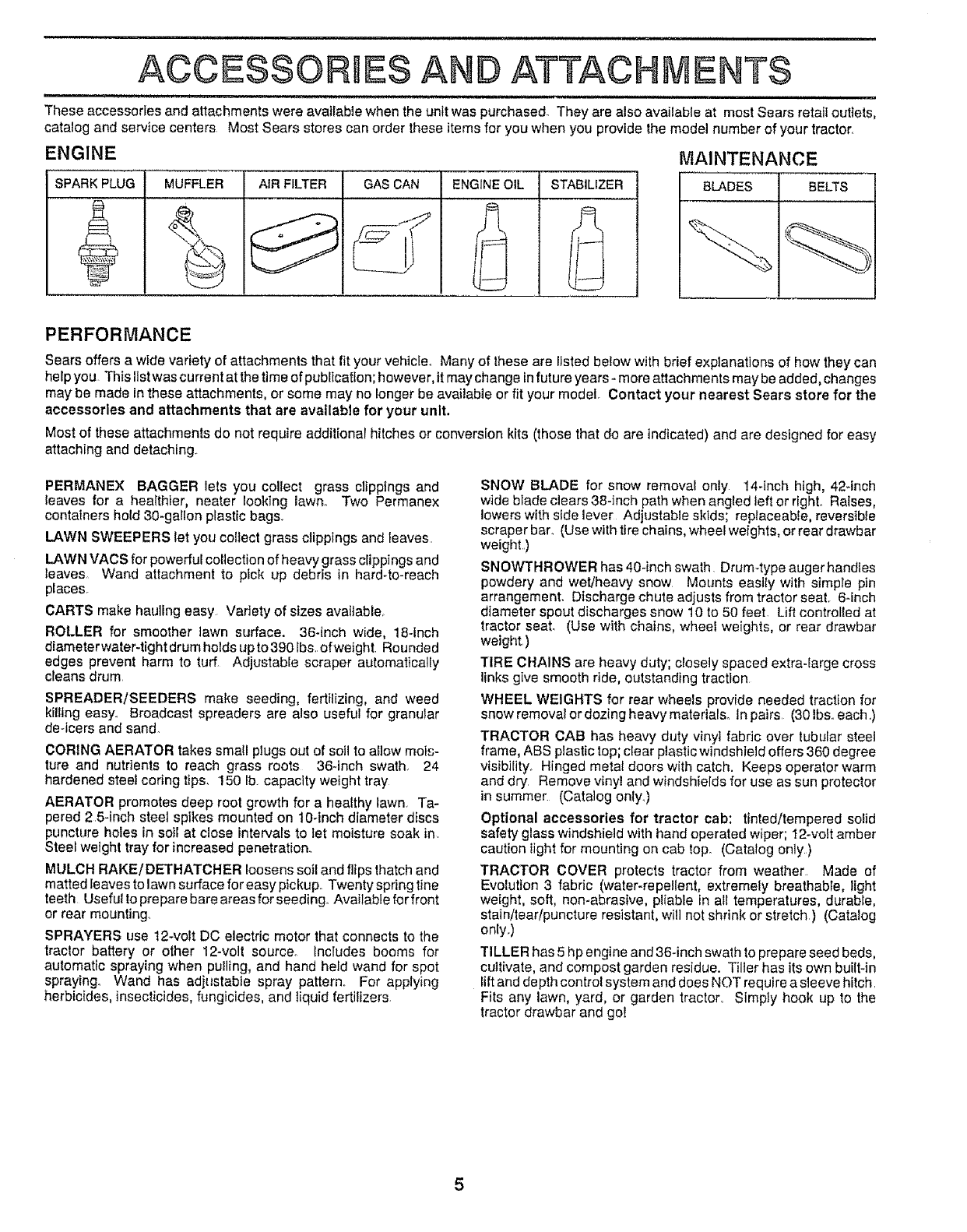
ACCESSORIES AND ATTACHMENTS
These accessories and attachments were available when the unit was purchased. They are also available at most Sears retail outlets,
catalog and service centers Most Sears stores can order these items for you when you provide the model number of your tractor.
ENGINE
SPARK PLUG MUFFLER AIR FILTER GAS CAN ENGINE OIL STABILIZER
MAINTENANCE
BLADES BELTS
PERFORMANCE
Sears offers a wide vartety of attachments that fit your vehicle° Many of these are listed below with brief explanations of how they can
help you This list was current at the time of publication; however, it may change infuture years - more attachments may be added, changes
may"be made in these attachments, or some may no longer be available or fit your model° Contact your nearest Sears store for the
accessories and attachments that are available for your unit.
Most of these attachments do not require addit[onar hitches or conversion kits (those that do are indicated) and are designed for easy
attaching and detaching.
PERMANEX BAGGER lets you collect grass clippings and
leaves for a healthier, neater looking lawno Two Permanex
containers hold 30-gallon plastic bags.
LAWN SWEEPERS let you collect grass clippings and leaves
LAWN VACS for powerfui collection of heavy grass clippings and
leaves Wand attachment to pfck up debris in hard4o-reach
placeso
CARTS make hauling easy Variety of sizes available_
ROLLER for smoother lawn surface. 36-inch wide, 18-inch
diameter water-tight drum holds up to 390 lbs. ofwetght Rounded
edges prevent harm to turf Adjustable scraper automatically
cleans drum
SPREADER/SEEDERS make seeding, fertilizing, and weed
kilfing easy. Broadcast spreaders are also useful for granular
de-icers and sand.
CORING AERATOR takes small plugs out of soil to a!]ow mois-
ture and nutrients to reach grass roots 36-inch swath, 24
hardened steel coring tips, 150 lb. capacity weight tray
AERATOR promotes deep root growth for a healthy lawn, Ta-
pered 2,5-inch steel spikes mounted on 10-inch diameter discs
puncture holes in soil at close intervals to let moisture soak in
Steel weight tray for increased penetration.
MULCH RAKE/DETHATCHER loosens soil and flips thatch and
matted leaves to lawn surface for easy pickup. Twenty spring tine
teeth Useful to prepare bare areas for seeding. Available for front
or rear mounting.
SPRAYERS use 12-volt DC electric motor that connects to the
tractor battery or other 12-volt source° Includes booms for
automatic spraying when pulling, and hand held wand for spot
spraying° Wand has adjustable spray pattern,, For applying
herbicides, insecticides, fungicides, and liquid fertilizers
SNOW BLADE for snow removal only 14-inch high, 42-inch
wide blade clears 38-inch path when angled left or right° Raises,
lowers with side lever Adjustable skids; replaceable, reversible
scraper bar_ (Use with tire chains, wheel weights, or rear drawbar
weight..)
SNOWTHROWER has 40-inch swath Drum4ype augerhandles
powdery and wet/heavy snow Mounts easify with simple pin
arrangement. Discharge chute adjusts from tractor seat. 6-inch
diameter spout discharges snow 10 to 50 feet. Lift contro[fed at
tractor seat. (Use with chains, wheel weights, or rear drawbar
weight)
TIRE CHAINS are heavy duty; c_osely spaced extra4arge cross
links give smooth ride, outstanding traction
WHEEL WEIGHTS for rear wheels provide needed traction for
snow removat or dozing heavy materials.. In pairs (30 Ibs..each .)
TRACTOR CAB has heavy duty vinyl fabric over tubular steel
frame, ABS plastic top; clear plastic windshield offers 360 degree
vlsibilityo Hinged metal doors with catch. Keeps operator warm
and dry. Remove vinyl and windshields for use as sun protector
in summer (Catalog onlyo)
Optional accessories for tractor cab: tinted/tempered solid
safety glass windshield with hand operated wiper; 12-volt amber
caution iight for mounting on cab top. (Catalog only)
TRACTOR COVER protects tractor from weather Made of
Evolution 3 fabric (water-repellent, extremely breathable, light
weight, soft, non-abrasive, pliable in all temperatures, durabEe,
stain/tear/puncture resistant, will not shrink or stretch) (Catatog
only..)
TILLER has 5 hp engine and 36-inch swath to prepare seed beds,
cultivate, and compost garden residue. Tiller has its own built-in
lift and depth control system and does NOT require a sleeve hitch.
Fits any lawn, yard, or garden tractor. SimpIy hook up to the
tractor drawbar and go!
5
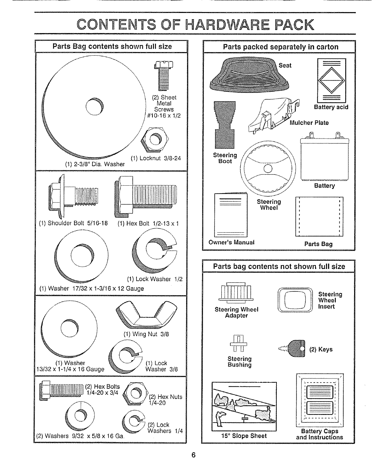
CONTENTS OF HARDWARE PACK
Parts Bag contents shown full size
O I (2) Sheet
Metal
Screws
#10-16 x 1/2
(1) Locknut 3/8-24
(I) 2-3/8" Die, Washer
(1) Shoulder Bolt 5/16-18
@(1) Hex Bolt 1/2-13 x 1
(!) LockWasher I/2
(1) Washer' 17/32 x 1-3/16 x t2 Gauge
_1, in,ln,,lll,i i i, i,
(t) Washer
13/32 x 1-1/4 x 16 Gauge
(1) Wing Nut 3/8
(1) Lock
Washer 3/8
(2) Hex Bolts
1/4-20 x 3/4 _/_(2) Hex Nuts
_1/4-20
_ (2) Lock
Washers 1/4
(2) Washers 9/32 x 5/8 x 16 Ga,
Parts packed separately in carton
Steering
Boot
Seat ÷
_ulcher Plate
Battery
:
.....• ....... t
Owner's Manual Parts Bag
Parts bag contents not shown full size
I_l Steering
Wheel
Steering Wheel Insert
Adapter
Steering
Bushing
150 Slope Sheet
(2) Keys
t
k4
Battery Caps
and Instructions
i,i iii, i,i iii illlll,,ll,i illll,ii ii ,i ill,i
ASSEMBLY
i,,,11 I,,INHI I,I .......................... I' Illl, I ,'I,,,,U
Your new tractor has been assembled at the factory with exception of those parts left unassembled for shipping purposes°
To ensure safe and proper operation of your tractor, all parts and hardware you assemble must be tightened securely. Use
the correct tools as necessary to insure their proper tightness,
TOOLS REQUIRED FOR ASSEMBLY
A socket wrench set will make assembly easier. Standard
wrench sizes are listed.
(1) 5/16" wrench
(2) 7/16" wrenches
(t) 1/2" wrench
(1) 3/4" wrench
5/16" wrench
Screwdriver
Utility knife
Tire pressure gauge
When right and left hand is mentioned in this manual, it
means when you are in the operating position (seated
behind the steering wheel).
TO REMOVE UNIT FROM CARTON
UNPACK CARTON
• Remove all accessible loose parts and parts cartons
from carton (See page 6),
• Cut along lines on carton, from top to bottom, all four
corners of carton and lay panels flat.
.Check for any additional loose parts or cartons and
remove.
BEFORE ROLLING UNIT OFF SKID
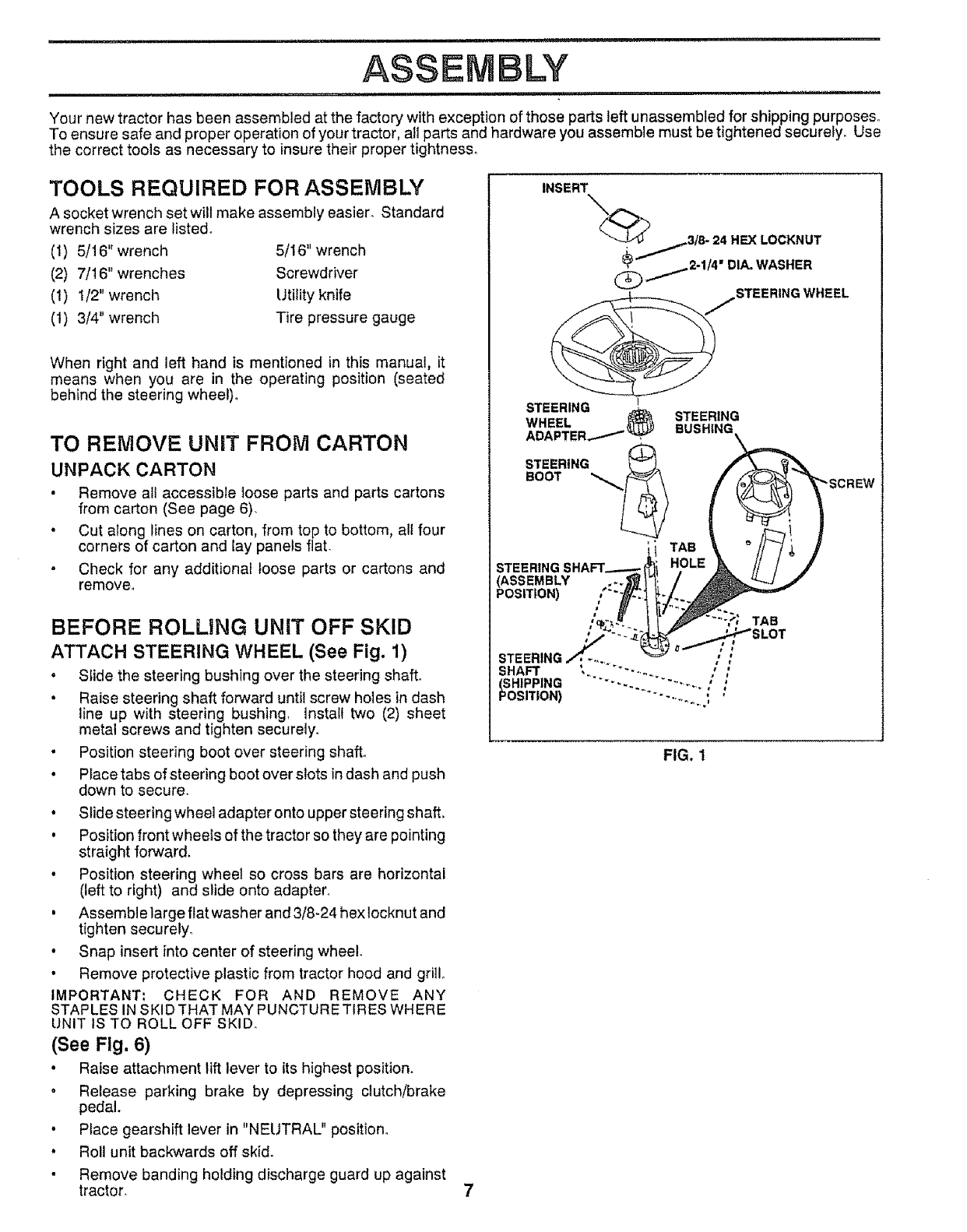
ATTACH STEERING WHEEL (See Fig. 1)
° SIide the steering bushing over the steering shaft_
•Raise steering shaft forward until screw holes in dash
line up with steering bushing, install two (2) sheet
metal screws and tighten securely_
• Position steering boot over steering shaft°
•Place tabs of steering boot over slots in dash and push
down to securer
• Slide steering wheel adapter onto upper steering shaft,
, Position front wheels of the tractor so they are pointing
straight forward,
• Position steering wheel so cross bars are horizontal
(left to right) and slide onto adapter,
, Assemble large flat washer and 3/8-24 hex tocknut and
tighten securely°
• Snap insert into center of steering wheel.
• Remove protective plastic from tractor hood and grill.
IMPORTANT= CHECK FOR AND REMOVE ANY
STAPLES IN SKID THAT MAY PUNCTURE TIRES WHERE
UNIT IS TO ROLL OFF SKID.
(See Fig, 6)
• Raise attachment lift lever to its highest position.
• Release parking brake by depressing clutch/brake
pedal.
• Place gearshift lever in "NEUTRAL" position.
, Roll unit backwards off skid.
• Remove banding holding discharge guard up against
tractor.
INSERT
_'__3/8- 24 HEX LOCKNUT
(_/2-1/4" DIA. WASHER
_jSTEERING WHEEL
!
STEERING _:_ STEERING
WHEEL I_) BUSH|_
ADAPTER_..._._
SOREW
ii TAe
POSITION) ,' -. -...
STEERING_ ..... ::
SHAFT ,. ......... /:
(SHIPPING .... -... "..........
POSITION) "'" .......... , '
FIG, 1
==l=l ==ill i ill=l=l= i =
ASSEMBLY
HOW TO SET UP YOUR TRACTOR
PREPARE BATTERY (See Fig. 2)
CAUTION: wear eye and face shield.
Wash hands or clothing immediately tf
accidentally In contact wtth battery acld,
Do not smoke° Fumes from charged
battery acid are explosive.
Read the Instructions Included with the
battery vent cap s. Always wear gloves,
clothing and goggles to protect your
hands, skin and eyes.
Your unit has a battery charging system which is sufficient
for normal use_ However, periodic charging of the battery
witt_ an automotive charger will extend its life,
•See instructions packed with vent caps in parts bag
• Fill battery with acid. Fitl each cell until it reaches the
bottom of the vent wells. Do not overfill.
. Allow battery to stand and settle for at least thirty
minutes° After standing, check the level of acid. If
below the vent wells, add more acid until the correct
level is reached.
While battery isstanding (after adding acid) and later, while
battery is being charged, continue with assembly of unit
IMPORTANT: TO MAXIMIZE THE LIFE OF YOUR
BATTERY, IT IS NECESSARY THAT THE BATTERY BE
CHARGED BEFORE USE FAILURE TO CHARGE
BATTERY CAN RESULT IN A SHORTENED BATTERY
LIFE.
•Charge battery at a rate of 6 amperes for 1 hour° Use
a 12 volt battery charger, Observe all safety precautions
required for battery charging.
• Check the acid level after the battery is charged. If the
acid has fallen below the correct level, add distilled or
iron free water'.
• Install the vent caps to cover the vent wells. Wash the
top of the battery with water to remove any acid, then
wipe dry.
•Check battery case for leakage to make sure that no
damage has occurred in handling
• Dispose of excess battery acid, Neutralize acid for
disposal by adding it to four inches of water in a five
gallon plastic container. Stir with a wooden or plastic
paddle while adding baking soda until the addition of
more soda causes no more foaming.
• Follow instructions on how to install battery
CUT AWAY VIEW CAP
VENT WELL
BATTERY
CELLACID
LEVEL
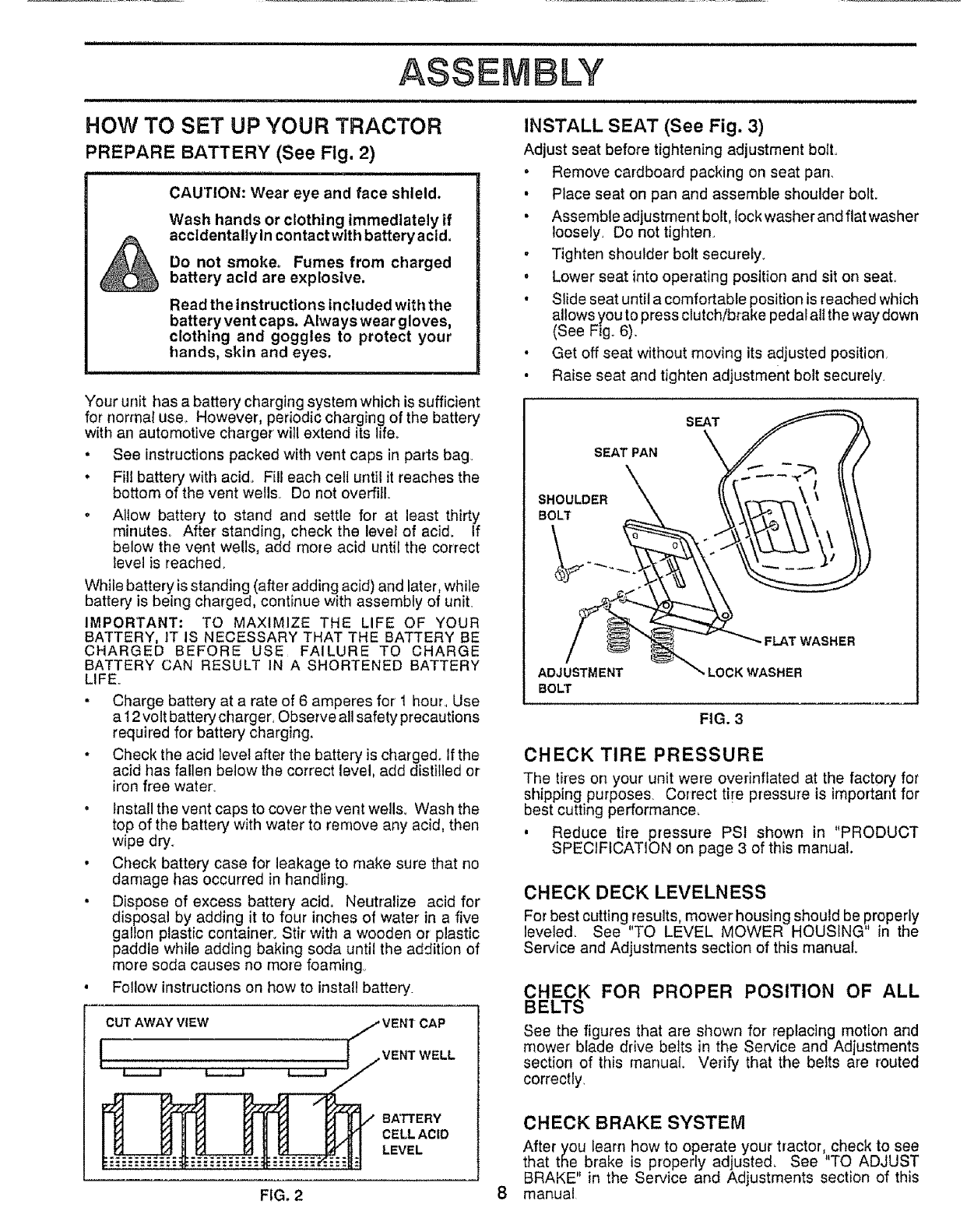
INSTALL SEAT (See Fig. 3)
Adjust seat before tightening adjustment boll
l
• Remove cardboard packing on seat pan.
• Place seat on pan and assemble shoulder bolt.
• Assemble adjustment bolt, lock washer and flat washer
loosely. Do not tighten.
•Tighten shoulder bolt securely.
• Lower seat into operating position and sit on seat.
• Slide seat until a comfortable position is reached which
allows you to press clutch/brake pedal all the way down
(See Fig. 6).
Get off seat without moving its adjusted position.
Raise seat and tighten adjustment bolt securely
SEAT
SEAT PAN
SHOULDER
BOLT
ADJUSTMENT
BOLT
-FLAT WASHER
LOCK WASHER
FIG. 3
CHECK TIRE PRESSURE
The tires on your unit were overinffated at the factory for
shipping purposes. Correct ti!e pressure is important for
best cutting performance,
, Reduce tire pressure PSt shown in "PRODUCT
SPECIFICATION on page 3 of this manual.
CHECK DECK LEVELNESS
For best cutting results, mower housing should be properly
leveled, See "TO LEVEL MOWER HOUSING in the
Service and Adjustments section of this manual.
CHECK FOR PROPER POSITION OF ALL
BELTS
See the figures that are shown for replacing motion and
mower blade drive belts in the Service and Adjustments
section of this manual Verify that the belts are routed
correctly
CHECK BRAKE SYSTEM
After you Ieam how to operate your tractor,,check to see
that tSe brake is properly adjusted, See 'TO ADJUST
BRAKE" in the Service and Adjustments section of this
manual
FIG. 2 8
'HHHH = = L == H ¸ ' H
ASSE LY
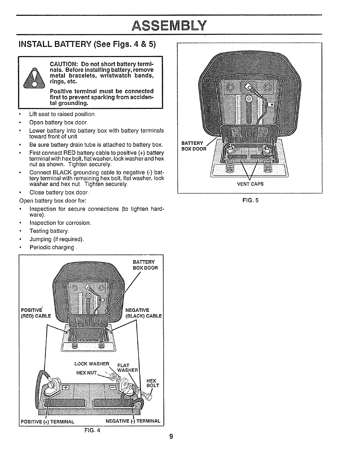
INSTALL BATTERY (See Figs. 4 & 5)
CAUTION: Do not short battery termi-
nals. Before Installing battery, remove
metal bracelets, wristwatch bands,
rings, etc.
Positive terminal must be connected
first to prevent sparldng from acciden-
tal grounding.
* Lift seat to raised positiOnr
* Open battery box door.
,Lower battery into battery box with battery terminals
toward front of unit.
, Be sure battery drain tube is attached to battery box.
, First connect RED battery cable to positive (4-)battery
terminal with hex bolt, fiat washer, lock washer and hex
nut as shown° Tighten securelyo
* Connect BLACK grounding cable to negative (-) bat-
tery terminal with remaining hex bolt, flat washer, lock
washer and hex nut. Tighten securely.
, Close battery box door.
Open battery box door for:
° Inspection for secure connections (to tighten hard-
ware).
, Inspection for corrosion_
,Testing battery.
, Jumping (if required).
, Periodic charging •
BATTERY
BOX DOOR
VENT CAPS
FIG, 5
BATTERY
BOX DOOR
POSITIVE NEGATIVE
(RED) CABLE (BLAC_ CABLE
HEX
BO LT
POSITIVE (+) TERMINAL NEGATIVE TERMINAL
FiG. 4 9
ASSEMBLY
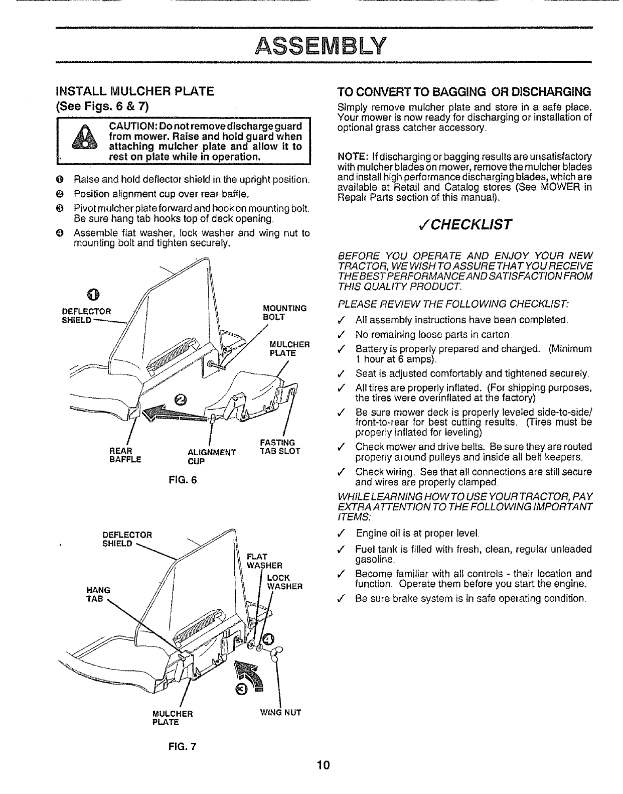
INSTALL MULCHER PLATE
(See Figs. 6 & 7)
& CAUTION:Donotremovedischargeguard I
from mower. Raise and hold guard when
attaching mulcher plate and allow it to
• rest on plate while in operation.
@ Raise and hold deflectorshield in the upright position
Position alignment cup over rear baffle.
_) Pivotmulcherplateforward and hookon mounting bolt,
Be sure hang tab hooks top of deck opening.
Q Assemble fiat washer, lock washer and wing nut to
mounting bolt and tighten securely.
@
DEFLECTOR MOUNTING
BOLT
MULCHER
PLATE
@
/
REAR
BAFFLE AL|GNMENT
CUP
FIG. 6
FASTING
3tAB SLOT
DEFLECTOR
SHIELD
HANG
TAB_
FLAT
WASHER
LOCK
WASHER
TO CONVERT TO BAGGING OR DISCHARGING
Simply remove mulcher plate and store in a safe place,
Your mower is now ready for discharging or installation of
optional grass catcher accessory.
NOTE: If discharging or' bagging results are unsatisfactory
with mulcher blades on mower, remove the mulcher blades
and install high performance discharging blades, which are
available at Retail and Catalog stores (See MOWER in
Repair Parts section of this manual),
,/CHECKLIST
BEFORE YOU OPERATE AND ENJOY YOUR NEW
TRACTOR, WE WISH TO ASSURETHA T YOU RECEIVE
THE BEST PERFORMANCE AND SA TISFACTION FROM
THIS QUALITY PRODUCT°
PLEASE REVIEW THE FOLLOWING CHECKLIST:
7" All assembly instructions have been completed.
J" No remaining loose parts in carton
v" Batteryis properly prepared and charged. (Minimum
1 hour at 6 amps).
€' Seat is adjusted comfortably and tightened securely,
v" Alltires are properly inflated, (For shipping purposes,
the tires were over'inflated at the factory)
,/ Be sure mower deck is properly leveled side-to-side/
front-to-rear for best cutting results, (Tires must be
properly inflated for leveling)
,/ Check mower and drive belts, Be sure they are routed
properly around pulleys and inside all belt keepers.
,/ Check wiring, See that all connections are still secure
and wires are properly clamped.
WHILELEARNING HOWTO USE YOUR TRACTOR, PAY
EXTRA ATTENTION TO THE FOLLOWING IMPORTANT
ITEMS:
€" Engine oil is at proper level.
•/Fuel tank is filled with fresh, clean, regular unleaded
gasoline.
€" Become familiar with all controls - their location and
function. Operate them before you start the engine.
V' Be sure brake system is in safe operating condition.
MULCHER
PLATE
FIG. 7
WING NUT
10
H,,, ,,,,,I,H=,I, ,,
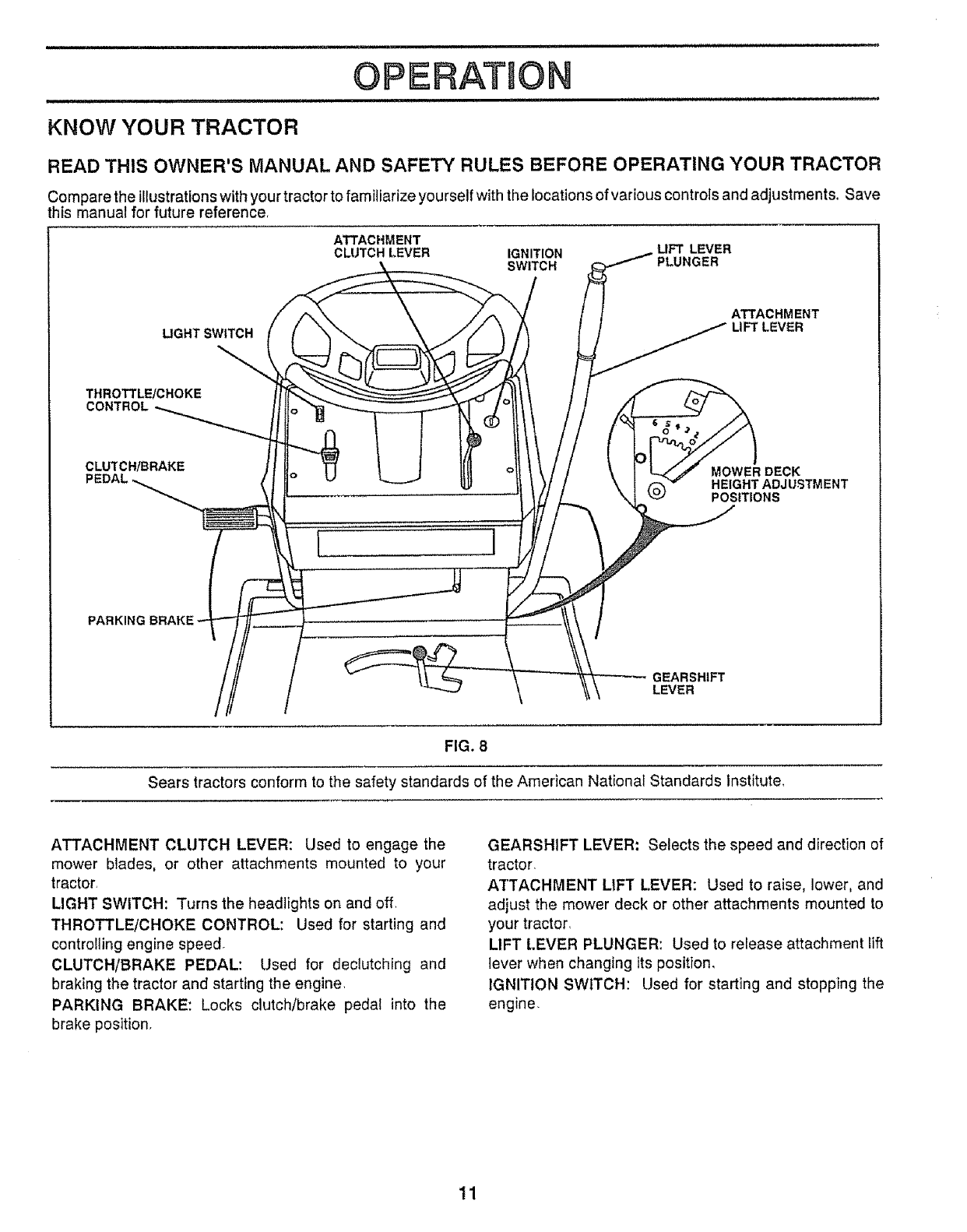
KNOW YOUR TRACTOR
READ THIS OWNER'S MANUAL AND SAFE_ RULES BEFORE OPERATING YOUR TRACTOR
Compare the illustrations with your tractor to familiarize yourself with the locations of various controls and adjustments. Save
this manual for future reference,
ATTACHMENT
CLUTCHLEVER IGNITION LIFT LEVER
SWITCH PLUNGER
LIGHT SWITCH
ATTACHMENT
LIFT LEVER
THROTTL_CHOKE
CONTROL
CLUTCH/BRAKE
I ]
MOWER DECK
HEIGHT ADJUSTMENT
POSITIONS
PARKING
GEARSHIFT
LEVER
FIG. 8
Sears tractors conform to the safety standards of the American National Standards Institute,
ATTACHMENT CLUTCH LEVER: Used to engage the
mower blades, or other attachments mounted to your
tractor.
LIGHT SWITCH: Turns the headlights on and off.
THROTTLE/CHOKE CONTROL: Used for starting and
controlling engine speed.
CLUTCH/BRAKE PEDAL: Used for declutching and
braking the tractor and starting the engine.
PARKING BRAKE: Locks clutch/brake pedal into the
brake position,
GEARSHIFT LEVER; Selects the speed and direction of
tractor.
ATTACHMENT LIFT LEVER: Used to raise, lower, and
adjust the mower deck or other attachments mounted to
your tractor_
LIFT LEVER PLUNGER: Used to release attachment Nft
lever when changing its position,
IGNITION SWITCH: Used for starting and stopping the
engine.
11
OPEF ATIO
iiiiiii HIIIIHII III I IIIIIIlUl III I
The operation of any tractor can result in foreign objects thrown into the eyes, which can
result in severe eye damage. Always wear safety glasses or eye shields while operating
your tractor or performing any adjustments or repairs. We recommend wide vision safety
mask for over the spectacles or standard safety glasses, available at Sears Retail or
Catalog stores.
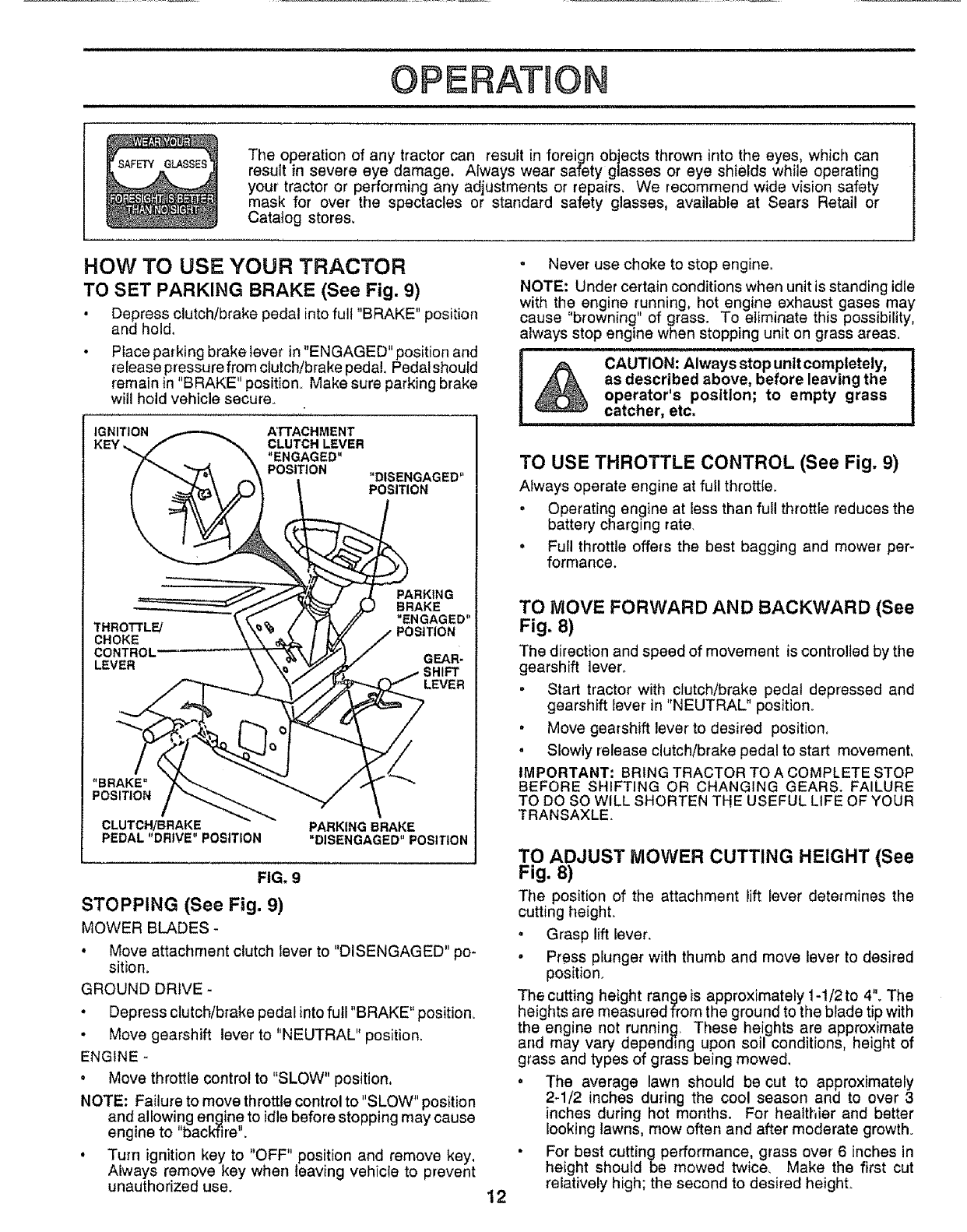
HOW TO USE YOUR TRACTOR
TO SET PARKING BRAKE (See Fig. 9)
• Depress clutch/brake pedal into full "BRAKE" position
and hold.
• Place parking brake lever in "ENGAGED" position and
release pressure from clutch/brake pedal Pedal should
remain in "BRAKE" position. Make sure parking brake
will hold vehicle secure..
IGNITION A'rrACHMENT
KEY ,, CLUTCH LEVER
"ENGAGED"
POSITION "DISENGAGED"
POSITION
THROTTL_
CHOKE
CONTROL'
LEVER
PARKING
BRAKE
"ENGAGED"
POSITION
GEAR-
SHIFT
LEVER
"BRAKE"
POSITION
CLUTCH/BRAKE
PEDAL "DRIVE" POSITION PARKING BRAKE
"DISENGAGED"POSITION
FIG, 9
STOPPING (See Fig. 9)
MOWER BLADES-
° Move attachment clutch lever to "DISENGAGED" po-
sition.
GROUND DRIVE -
°Depress clutch/brake pedal into full "BRAKE" position_
•Move gearshift lever to "NEUTRAL" position.
ENGINE -
oMove throttle control to "SLOW" position,
NOTE: Failure to move throttle control to "SLOW" position
and allowing engine to idle before stopping may cause
engine to "backfire".
• Turn ignition key to '*OFF" position and remove key.
Always remove key when leaving vehicle to prevent
unauthorized use.
.Never use choke to stop engine.
NOTE: Under certain conditions when unit is standing idle
with the engine running, hot engine exhaust gases may
cause "browning" of grass. To eliminate this possibility,
always stop engine when stopping unit on grass areas.
TO USE THROTTLE CONTROL (See Fig. 9)
Aiways operate engine at full throttle.
,Operating engine at less than full throttle reduces the
battery charging rate.
,Full throttle offers the best bagging and mower per-
formance.
12
TO MOVE FORWARD AND BACKWARD (See
Fig. 8)
The direction and speed of movement is controlled by the
gearshift lever.
oStart tractor with clutch/brake pedal depressed and
gearshift lever in "NEUTRAL" position_
,Move gearshift lever to desired position,
, Slowly release clutch/brake pedal to start movement,
IMPORTANT; BRING TRACTOR TO A COMPLETE STOP
BEFORE SHIFTING OR CHANGING GEARS. FAILURE
TO DO SO WILL SHORTEN THE USEFUL LIFE OF YOUR
TRANSAXLE.
TO ADJUST MOWER CUTTING HEIGHT (See
Fig. 8)
The position of the attachment lift lever determines the
cutting heighL
• Grasp lift lever.
oPress plunger with thumb and move lever to desired
position.
The cutting height range is approximately 1-1/2to 4". The
heights are n'leasured from the ground to the blade tip with
the engine not running. These heights are approximate
arid may vary depending upon soi! conditions, height of
grass and types of grass being mowed.
o The average lawn should be cut to approximately
2-1/2 inches during the cool season and to over 3
inches during hot months. For healthier and better
Iooking lawns, mow often and after moderate growth.
•For best cutting performance, grass over6 inches in
height should be mowed twice, Make the first cut
relatively high; the second to desired height.
TO OPERATE MOWER (See Fig. 10)
Your unit is equipped with an operator presence sensing
switch. Any attempt by the operator to leave the seat with
the engine running and the attachment clutch engaged will
shut off the engine.
• Select desired height of cut°
• Engage mower by slowly moving attachment dutch
lever to "ENGAGED" position..
• TO STOP MOWER o Move attachment clutch lever to
"DISENGAGED" position.
i i i i n i,Uiil_
CAUTION: Do not operate the mower
without either the entire grass catcher,
on mowers so equipped, or the dis-
charge guard In place.
ATTACHMENT CLUTCH LEVER
"DISENGAGED" POSITION
"ENGAGED"
POSITION
ATTACHMENT
LIFT LEVER
HIGH POSITION
LOW
POSITION
R_H,
RUNNER
DISCHARGE GUARD
FIGo 10
TO OPERATE ON HILLS
CAUTION: Do not drive up or down
hills with slopes greater than 15° and
do not drive across any slope.
•Choose the slowest speed before starting up or down
hills.
• Avoid stopping or changing speed on hills
•If slowing is necessary, move throttle control lever to
s}ower position
o
o
If stopping is absolutely necessary, push c_utch/brake
_oedalquickly to brake position and engage parking
rake.
Move gearshift lever to 1st gear and be sure you have
allowed room for tractor to roll slightly as you restart
movement.
To restart movement, slowly release parking brake and
clutch/brake pedal
Make all turns slowly°
TO TRANSPORT
• Raise attachment lift control to highest position.
• When pushing or towing your unit, be sure gearshift
lever is in "NEUTRAL" position.
• Do not push or tow unit at more than five (5) MPH
BEFORE STARTING THE ENGINE
CHECK ENGINE OIL LEVEL (See Fig, 16)
• The engine in your unit has been shipped, from the
factory, already filled with summer weight oil
•Check engine oil with unit on level ground.
• Remove oil fill dipstick and wipe clean, replace and
screw cap tight, wait for a few seconds, remove and
read oil level. If necessary, add oil until "FULL" mark
on dipstick is reached_ Do not overfill
• For cold weather operation you should change oil for
easier starting (see "OIL VISCOSITY CHART" in the
Customer Responsibilities section of this manual)
. To change engine oil, see the Customer ResponsibilF
ties section in this manual
ADD GASOLINE
• Fill fuel tank, Use fresh, clean, regular unleaded
gasoline. (Use of leaded gasolinewillincrease carbon
and lead oxide deposits and reduce valve life).
IMPORTANT: WHEN OPERATING IN TEMPERATURES
BELOW 32°F(0°C), USE FRESH, CLEAN WINTER GRADE
GASOLINE TO HELP INSURE GOOD COLD WEATHER
STARTING
WARNING: Experience indicates that alcohol blended
fuels (called gasohol or using ethanol or methanol) can
attract moisture which leads to separation and formation of
acids during storage. Acidic gas can damage the fuel
system of an engine while in storage° To avoid engine
problems, the fuel system should be emptied before stor-
age of 30 days or longer. Drain the gas tank, start the
engine and Jet it run until the fuel lines and carburetor are
empty. Use fresh fuel next season, See Storage Instruc-
tions for additional information° Never use engine or
carburetor cleaner products in the fuet tank or permanent
damage may occur
CAUTION: Fill to bottom of gas tank
filler neck. Do not overfill. Wipe off any
spilled oil or fuel. Do not store, spill or
use gasoline near an open flame.
13
OPERATNON
TO START ENGINE (See Fig. 9)
When starting engine for the first time or if engine has
run out of fuel, it will take extra cranking time to move
fuel from the tank to the engine
• Depress the clutch/brake pedal and set the parking
brake
• Place gearshift lever in "NEUTRAL" position
•Move attachment clutch to "DISENGAGED" position
.Move throttle control lever to "CHOKE' position for
cold engine start For warm engine start, move
throttle control to "FAST' position
.Turn ignition key clockwise to 'START" position and
release key as soon as engine starts Do not run
starter continuously for more than fifteen seconds per
minute If engine does not start after several at-
tempts, move throttle control to 'FAST" position, wait
a few minutes and try again
- When engine starts, move throttle control to desired
position
•Allow engine to warm up for a few minutes before
engaging drive or attachment clutch
NOTE: If at a high altitude (above 3000 feet) or in cold
temperatures (below 32 ° F), the carburetor fuel mixture
may need to be adjusted for best engine performance
See TO ADJUST CARBURETOR" in the Service and
Adjustments section of this manual
" When mowing large areas, start by turning to the right
so that clippings will discharge away from shrubs,
fences, driveways, etc After one or two rounds, mow
in the opposite direction making left hand turns until
finished (See Fig 11)
• if grass is extremely tall, it should be mowed twice to
reduce load and possible fire hazard from dried clip-
pings Make first cut relatively high; the second to the
desired height
.Do not mow grass when it is wet Wet grass will plug
mower and leave undesirable clumps Allow grass to
dry before mowing
. Always operate engine at full throttle when mowing to
assure better mowing performance and proper dis-
charge of material Regulate ground speed by select-
ing alow enough gear to give the mower cutting
performance as well as the quality of cut desired
• When operating attachments, select a ground speed
that will suit the terrain and give best performance of
the attachment being used
MOWING TIPS
. Tire chains cannot be used when the mower housing
is attached to unit
o Mower should be properly leveled for best mowin_
performance See TO LEVEL MOWER HOUSING
in the Service and Adjustments section of this manual
• Use the runner on the right hand side of mower as a
guide The blade cuts approximately an inch outside
the runner (See Fig 10)
• The left hand side of mower should be used for trim
ming
•Drive so that clippings are discharged onto the area
that has been cut Have the cut area to the right of
the machine This will result in a more even distribu-
tion of clippings and more uniform cutting
ii ii i lll illl
f -,
• i p'#
FIG. 11
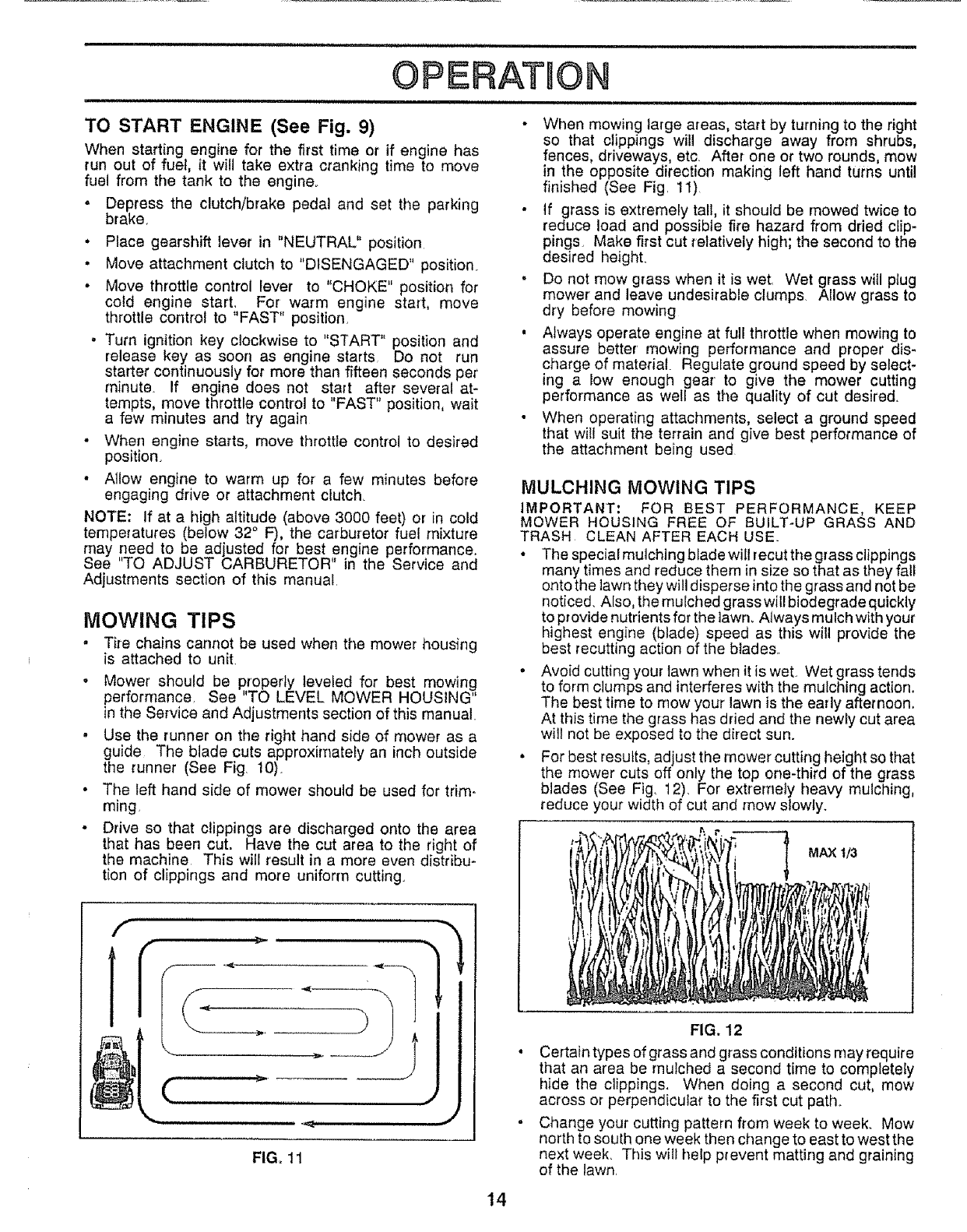
MULCHING MOWING TIPS
IMPORTANT: FOR BEST PERFORMANCE, KEEP
MOWER HOUSING FREE OF BUILT-UP GRASS AND
TRASH CLEAN AFTER EACH USE
• The special mulching blade will recut the grass clippings
many times and reduce them in size so that as they fall
onto the lawn they will disperse into the grass and not be
noticed Also, the mulched grass will biodegrade quickly
to provide nutrients for the lawn Atways mulch with your
highest engine (blade) speed as this will provide the
best recutting action of the blades
.Avoid cutting your lawn when it is wet Wet grass tends
to form clumps and interferes with the mulching action
The best time to mow your lawn is the early afternoon
At this time the grass has dried and the newly cut area
will not be exposed to the direct sun
•For best results, adjust the mower cutting height so that
the mower cuts off only the top one-third of the grass
blades (See Fig. 12) For extremely heavy mulching,
reduce your width of cut and mow slowly
MAX t/3
FIG. 12
Certain types of grass and grass conditions may require
that an area be mulched a second time to completely
hide the clippings When doing a second cut, mow
across or perpendicular to the first cut path
Change your cutting pattern from week to week Mow
north to south one week then change to east to west the
next week This will heb prevent matting and graining
of the lawn
14

CUSTOME ESPONSIBIL ES
i [,LIIU,JU,,JU,,, , ,111" I I ',, ,11111,11
MAINTENANCE SCHEDULE
FILL IN DATES
REGULAR SERVICE _ _./i_,_ySERVtCE DATES
Check Brake Operation
Check Tire Pressure
T Check for Loose Fasteners
a Sharpen/Replace Mower Blades.
C Lubrication Chart
TCheck Battery Level/Recharge .......
0 Clean Battery and Terminals
a CheckTransmisslon Cooling
Adjust Blade Belt(s) Tension
Adjust Motion Drive Belt(s) Tension
Check Engine Oil Level
Change Engine Oil
,V" .....V" ........................
v" v'
V" v" . . _
_4 ....
.... V'. V" __
V"
..... _ .................. V"
V"
.... y ........... _ _5
Clean Air Filter
E ........ , .......................................................
N .Clean .&irScreen
G Inspect Muffler/SparkArrester ,, , , ....... , ........
t Replace Oil FHter(If equipped)
N CIean Englne'codling F;ns...... ...........
Replace Spark Plug
Replace Air Filter Paper Cartridge
Replace Fuel Filter
=
V'2]
V'2i V"
1-Change more often when operating under a heavy load or in high ambient temperatures
2 - Service more often when operating in dldy or dusty conditions,
Iv' ............
3-If equipped wl|h el! filter, change oil every 50 hours
4-Replace blades more often when mowing In sandy soil
5-If equipped with ad{uslable system
GENERAL RECOMMENDATIONS
The warranty on this vehicle does not cover items that have
been subjected to operator abuse or negligence. To
receive full value from the warranty, operator must main-
tain unit as instructed in this manual.
Some adjustments wilt need to be made periodically to
properly maintain your unit.
All adjustments in the Service and Adjustments section of
this manual should be checked at least once each season.
Once a year you should replace the spark plug, clean
or replace air filter, and check blades and belts for
wear. A new spark p_ug and clean air filter assure
proper air-fuel mixture and help your engine run better
andlast Ionger_
LUBRICATION CHART
(_ _FRONT WHEEL (_)
BEARING ZERK BEARING ZERK
C
NE®
CLUTCH
P,VOT(S)
BEFORE EACH USE
•Check engine oil level.
oCheck brake operation.
• Check tire pressure.
• Check for loose fasteners.
15
(_) SAE 30 OR 10W30 MOTOR OIL API -SG
(_) GENERAL PURPOSE GREASE
_) REFER TO CUSTOMER RESPONSIBILITIES "ENGINE" SECTION
IMPORTANT: DO NOT OIL OR GREASE THE PIVOT POINTS
WHICH HAVE SPECIAL NYLON BEARINGS. VISCOUS LUBRI-
CANTS WILL ATTRACT DUST AND DIRT THAT WILL SHORTEN
THE LIFE OF THE SELF-LUBRICATING BEARINGS. IF YOU
FEEL THEY MUST BE LUBRICATED, USE ONLY A DRY, POW-
DERED GRAPHITE TYPE LUBRICANT SPARINGLY
TRACTOR
Always observe safety rules when performing any mainte-
nance.
BRAKE OPERATION
If unit requires more than six (6) feet stopping distance at
high speed in highest gear, than brake must be adjusted.
(See "TO ADJUST BRAKE" in Service and Adjustments
section of this manual).
TIRES
• Maintain proper air pressure in all tires (See "PROD-
UCT SPECIFICATIONS" on page 3 of this manual)_
"Keep tires free of gasoline, oil, or insect control chemi-
cals which can harm rubber.
. Avoid stumps, stones, deep ruts, sharp objects and
other hazards that may cause tire damage.
BLADE CARE
For best results mower blades must be kept sharp. The
blades can be sharpened with a file or on agrinding wheel,
We suggest they be sharpened or replacedafter every 25
hours of mowing. Check blades more often if mowing in
sandy conditions,
.Do not attempt to sharpen blades while they are on the
mower.
.Replace bent or damaged blades.
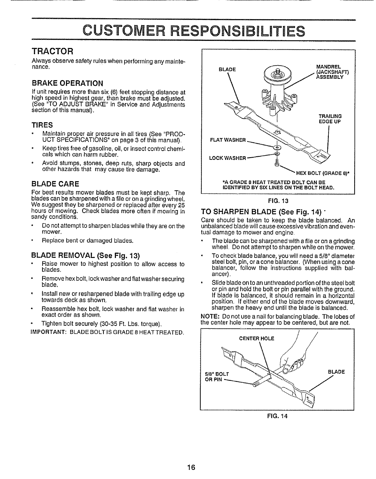
BLADE REMOVAL (See Fig. 13)
-Raise mower to highest position to a_low access to
blades.
• Rernove hex bolt, lock washer and flatwasher securing
blade,
, Install new or resharpened blade with trailing edge up
towards deck as shown.
•Reassemble hex bolt, lock washer and fiat washer in
exact order as shown.
•Tighten bolt securely (30-35 Fto Lbso torque).
IMPORTANT: BLADE BOLT IS GRADE 8 HEATTREATED.
BLADE MANDREL
TRAILING
EDGE UP
FLAT WASHER
LOCKWASHER
:_LT (GRADE 8)*
_'A GRADE 8 HEAT TREATED BOLT CAN BE
IDENTIFIED BY SIX LINES ON THE BOLT HEAD.
FIG. 13
TO SHARPEN BLADE (See Fig. 14)"
Care should be taken to keep the blade balanced= An
unbalanced blade will cause excessive vibration and even-
tual damage to mower and engine
•The blade can be sharpened with a file or on a grinding
wheel Do not attempt to sharpen while on the mower,
• To check blade balance, you will need a 5/8" diameter
steel bolt, pin, or a cone balancero (When using a cone
balancer, follow the instructions supplied with bal-
anGer)
• Slide blade on to an unthreaded portion of the steel bolt
or pin and hold the bolt or pin parallel with the ground.
If blade is balanced, it should remain in a horizontal
position. If either end of the blade moves downward,
sharpen the heavy end until the blade is balanced.
NO'f'E: Do not use a nail for balancing blade. The lobes of
the center hole may appear to be centered, but are noL
S_/CENTER HOLE
S/B"BB!.ADE
FIG. 14
16
CUSTOM ESPONSI
,..... , ,,,, HH,,U,,,,H, ,nil
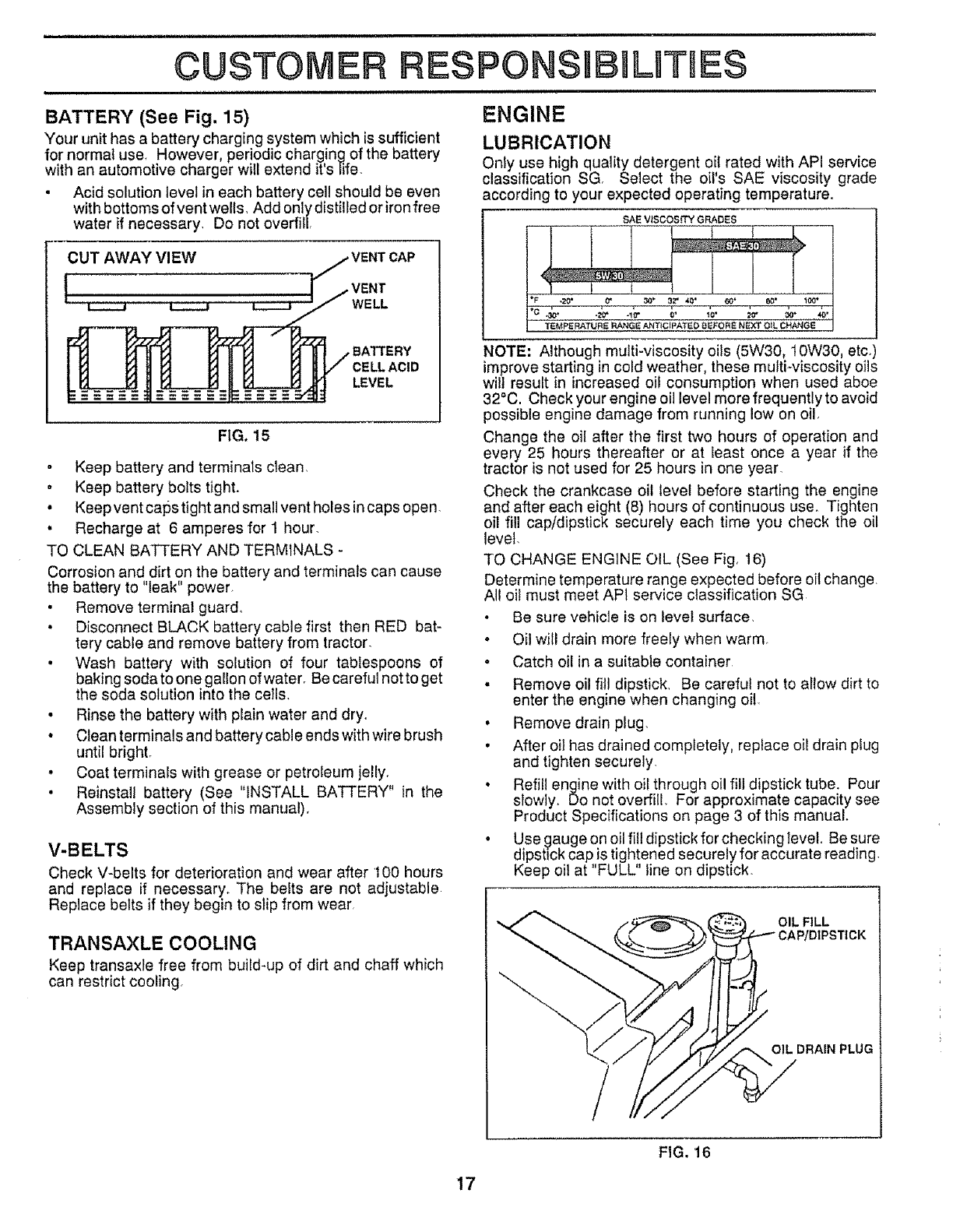
BATTERY (See Fig. 15) ENGINE
Your unit has a battery charging system which is sufficient
for normal use, However, periodic charging of the battery
with an automotive charger will extend it's life,
• Acid solution level in each battery cell should be even
with bottoms of vent wells_ Add only distilled or iron free
water if necessary, Do not overfill,
CUT AWAY VIEW
WELL
.BATTERY
CELLACID
LEVEL
FIG, 15
. Keep battery and terminals clean,
• Keep battery bolts tight.
• Keep vent caps tight and small vent holes in caps open,
• Recharge at 6 amperes for 1 hour,
TO CLEAN BATTERY AND TERMINALS -
Corrosion and dirt on the battery and terminals can cause
the battery to "leak" power,
•Remove terminal guard,
• Disconnect BLACK battery cable first then RED bat-
tery cable and remove battery from tractor,
• Wash battery with solution of four tablespoons of
baking soda to one gallon of water, Be careful not to get
the soda solution into the cells,
• Rinse the battery with plain water and dry,
• Clean terminals and battery cable ends with wire brush
until bright,
• Coat terminals with grease or petroleum jelly,
• Reinstall battery (See "INSTALL BATTERY" in the
Assembly section of this manual),
V-BELTS
Check V-belts for deterioration and wear after t00 hours
and replace if necessary, The belts are not adjustable
Replace belts if they begin to slip from wear,
TRANSAXLE COOLING
Keep transaxle free from build-up of dirt and chaff which
can restrict cooling,
LES
LUBRICATION
Only use high quality detergent oii rated with API service
classification SG Select the oil's SAE viscosity grade
according to your expected operating temperature°
SAE VISCOSITY GRADES
NOTE: Although multi-viscosity oils (5W30, t0W30, etc,
improve starting in cold weather, these multFviscosity oils
wilt result in increased oil consumption when used aboe
32°C. Check your engine oil level more frequently to avoid
possible engtne damage from running low on oil,
Change the oil after the first two hours of operation and
every 25 hours thereafter or at Ieast once a year if the
tractor is not used for 25 hours in one year,
Check the crankcase oil level before starting the engine
and after each eight (8) hours of continuous use. Tighten
oil fill cap/dipstick securely each time you check the oil
level,
TO CHANGE ENGINE OIL (See Fig 16)
Determine temperature range expected before oil change
All oi_must meet API service classification SG
• Be sure vehicle is on level surface.
•Oil will drain more freely when warm.
o Catch oil in a suitable container
• Remove oil fill dipstick. Be careful not to aIIow dirt to
enter the engine when changing oil.
• Remove drain plug.
• After oil has drained completely, replace oil drain plug
and tighten securely
• Refill engine with oil through oil fill dipstick tube. Pour
slowly. Do not overfill. For approximate capacity see
Product Specifications on page 3 of this manual.
• Use 9auge on oil fill dipstick for checking tevet, Be sure
dipstick cap is tightened securely for accurate reading
Keep oil at "FULL" line on dipstick,
OIL FILL
OIL DRAIN PLUG
FIG. 16
17
CUSTO E ESPO JLmES
,11111,ii, i mnn i.,n um in JUJlH,,[_,JUL[JHW
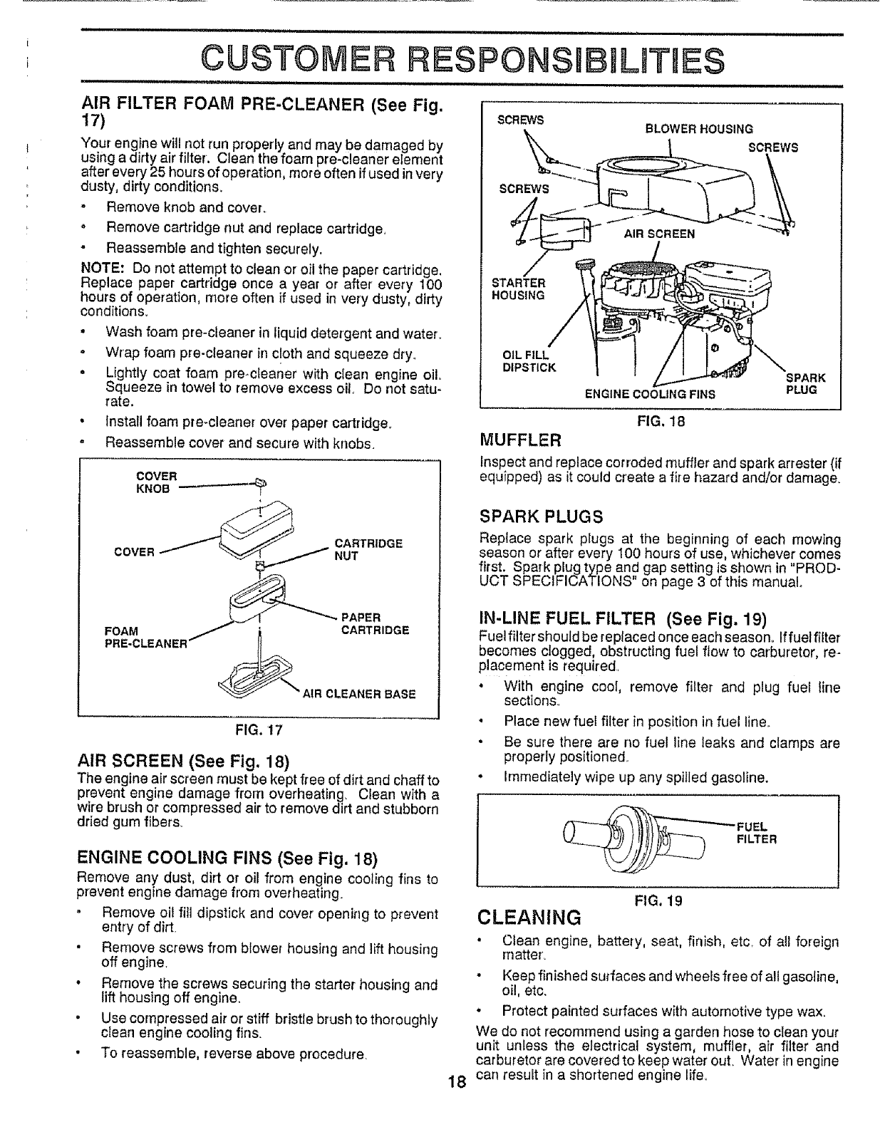
SCREWS
AIR FILTER FOAM PRE-CLEANER (See Fig.
17)
Your engine will not run properly and may be damaged by
using a dirty air filter. Clean the foam pre-€leaner element
after every 25 hours of operation, more often if used in very
dusty, dirty conditions.
-Remove knob and cover.
°Remove cartridge nut and replace cartridge,
-Reassemble and tighten securely.
NOTE: Do not attempt to clean or oil the paper cartridge,
Replace paper cartridge once a year or after every 100
hours of operation, more often ff used in very dusty, dirty
conditions,
•Wash foam pre-cleaner in liquid detergent and water.
- Wrap foam pre-cleaner in cloth and squeeze dry°
•Lightly coat foam pre-cleaner with clean engine oil,
Squeeze in towel to remove excess oil Do not satu-
rate.
BLOWER HOUSING
SCREWS
AIR SCREEN
STARTER
HOUSING
OIL FILL
DIPSTICK
ENGINE COOLING FINS
• Install foam pre-cleaner over paper cartridge.
o Reassemble cover and secure with knobs.
COVER
KNOB _"_
COVER CARTRIDGE
NUT
PAPER
FOAM _CARTRIDGE
AIR CLEANER BASE
FIG, 17
AIR SCREEN (See Fig. 18)
SCREWS
SPARK
PLUG
IN-LINE FUEL FILTER (See Fig. 19)
Fuelfilter should be replaced once each season° Iffuelfllter
becomes clogged, obstructing fuel flow to carburetor, re-
placement is required,
•With engine cool, remove filter and plug fuel line
sections.
• Place new fuel filter in Position in fuel line.
•Be sure there are no fuel line leaks and clamps are
properly positioned_
The engine air screen must be kept free of dirt and chaff to
prevent engine damage from overheating, Clean with a
wire brush or compressed air to remove dirt and stubborn
dried gum fibers.
ENGINE COOLING FINS (See Fig. 18)
Remove any dust, dirt or oil from engine cooling fins to
prevent engine damage from overheating.
.Remove oil fill dipstick and cover opening to prevent
entry of dirt.
• Remove screws from bfower housing and lift housing
off engine,
• Remove the screws securing the starter housing and
lift housing off engine.
•Use compressed air or stiff bristle brush to thoroughly
clean engine cooling fins.
• To reassemble, reverse above procedure
. Immediately wipe up any spilled gasoline.
(__---_ FUEL
__ FILTER
18
FIG. 19
CLEANING
• Clean engine, battely, seat, finish, etc, of all foreign
rnatter_
Keep finished surfaces and wheels free of all gasoline,
oil, etc,
° Protect painted surfaces with automotive type wax.
We do not recommend using a garden hose to ctean your
unit unless the electrical system, muffler, air filter and
carburetor are covered to keep water out. Water in engine
can result in a shortened engine life,
SPARK PLUGS
Replace spark plugs at the beginning of each mowing
season or after every 100 hours of use, whichever comes
first. Spark plug type and gap setting is shown in "PROD-
UCT SPECIFICATIONS on page 3 of this manual
FIG. 18
MUFFLER
Inspect and replace corroded muffler and spark arrester (if
equfpped) as it could create a fire hazard and/or damage,
SERVICE AN
= = unuun ,,1
== =,H, == =,H, = =,,==,,=,,n
CAUTION: BEFORE PERFORMING ANY SERVICE OR ADJUSTMENTS:
• Depress clutch/brake pedal fully and set parking brake
• Place gearshift lever In 'NEUTRAL" positlon_
•Place attachment clutch in "DISENGAGED' position.
• Turn Ignition key "OFF" and remove key.
• Make sure the blades and all moving parts have completely stopped
• Disconnect spark plug wire from spark plug and place wire where it cannot come in contact with
plug, = Hi 1,,u,, ,,,,H,,,,,m n,,,, =
TRACTOR
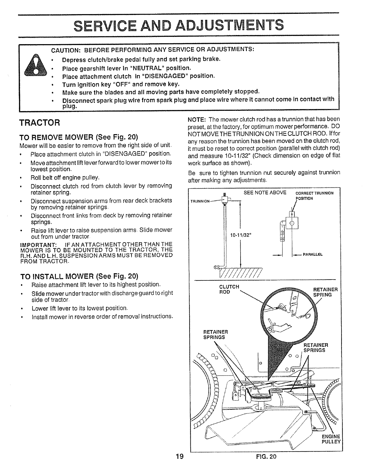
TO REMOVE MOWER (See Fig. 20)
Mower will be easier to remove from the right side of unit.
, Place attachment clutch in "DISENGAGED" position°
, Move attachment lift lever forward to lower mower to its
NOTE: The mower clutch rod has a trunnion that has been
preset, at the factory, for optimum mower performance. DO
NOT MOVE THETRUNNION ON THE CLUTCH ROD, lffor
any reason the trunnion has been moved on the clutch rod,
it must be reset to correct position (parallel with clutch rod)
and measure 10-11/32" (Check dimension on edge of flat
work surface as shown),
lowest position.
.Roll belt off engine pulley.
• Disconnect clutch rod from clutch lever by removing
retainer spring.
• Disconnect suspension arms from rear deck brackets
by removing retainer springs.
• Disconnect front links from deck by removing retainer
springs.
• Raise lift lever to raise suspension arms Slide mower
out from under tractor.
IMPORTANT: tF AN ATTACHMENT OTHER THAN THE
MOWER IS TO BE MOUNTED TO THE TRACTOR. THE
R.H. AND L.H. SUSPENSION ARMS MUST BE REMOVED
FROM TRACTOR.
TO INSTALL MOWER (See Fig. 20)
° Raise attachment lift lever to its highest position.
• Slide mower under tractor with discharge guard to right
side of tractor.
• Lower lift lever to its lowest position.
• Install mower in reverse order of removal instructions.
Be sure to tighten trunnion nut securely against trunnion
after making any adjustments.
TRlJ NNION_--- -'-"-
SEE NOTE ABOVE COR_EC'rTRUNN_OX
POSmON
i
10-11/32"
CLUTCH
ROD RETAINER
SPRING
RETAINER
SPRINGS
/ENGINE
PULLEY
19 FIG. 20
SERVICE AND
III,I,,,,,,,NI I,N,II ,i ,,i i ill I
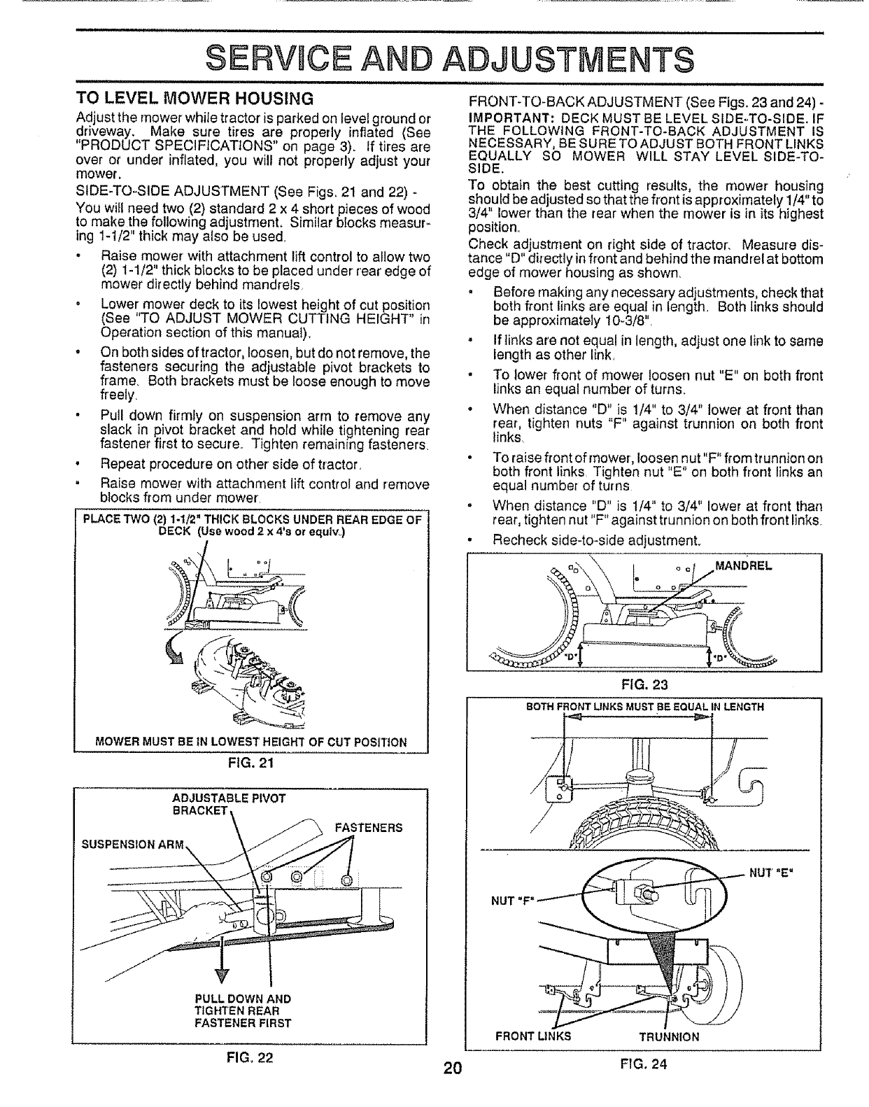
TO LEVEL MOWER HOUSING
Adjust the mower while tractor is parked on level ground or
driveway. Make sure tires are properly inflated (See
"PRODUCT SPECIFICATIONS on page 3). If t'res are
over or under inflated, you will not properly adjust your
mower,
SIDE-TO-SIDE ADJUSTMENT (See Figs, 21 and 22) -
You will need two (2) standard 2 x 4 short pieces of wood
to make the following adjustment. Similar blocks measur*
ing 1-1/2" thick may also be used.
. Raise mower with attachment lift control to allow two
(2) 1-1/2" thick blocks to be placed under rear edge of
mower directly behind mandrels,
ADJUSTMENTS
,IHHI lUHHHI I
FRONT-TO-BACK ADJUSTMENT (See Figs. 23 and 24) -
IMPORTANT: DECK MUST BE LEVEL SIDE-TO-SIDE. IF
THE FOLLOWING FRONT-TO-BACK ADJUSTMENT IS
NECESSARY, BE SURE TO ADJUST BOTH FRONT LINKS
EQUALLY SO MOWER WILL STAY LEVEL SIDE-TO-
SIDE.
To obtain the best cutting results, the mower housing
should be adjusted so that the front is approximately 1/4"to
3/4" lower than the rear when the mower is in its highest
position
Check adjustment on right side of tractor. Measure dis-
tance "D" directly in front and behind the mandrel at bottom
edge of mower housing as shown,
• Lower mower deck to its lowest height of cut position
(See "TO ADJUST MOWER CUTTING HEIGHT" in
Operation section of this manual).
. On both sides of tractor, loosen, but do not remove, the
fasteners securing the adjustable pivot brackets to
frame. Both brackets must be loose enough to move
freely.
• Pull down firmly on suspension arm to remove any
slack in pivot bracket and hold while tightening rear
fastener first to secure. Tighten remaining fasteners,
° Repeat procedure on other side of tractor,
• Raise mower with attachment lift control and remove
blocks from under mower
PLACE TWO (2) %1/2" THICK BLOCKS UNDER REAR EDGE OF
DECK (Usewood2x 4's orequlvo)
MOWERMUSTBEIN LOWESTHEIGH'[OF CUTPOSITION
FIG, 21
ADJUSTABLEPIVOT
BRACKET\\
PULLDOWNAND
TIGHTENREAR
FASTENER FIRST
FIG_ 22 2O
• Before making any necessary adjustrnents, check that
both front links are equal in length, Both links should
be approximately 10-3/8'L
. If links are not equal in length, adjust one link to same
length as other link,
. To lower front of mower loosen nut "E" on beth front
links an equal number of turns.
*When distance "D" is 1/4" to 3/4" lower at front than
rear, tighten nuts "F" against trunnion on both front
links
.To raise front of mower, loosen nut"F" from trunnion on
both front links Tighten nut "E" on both front links an
equal number of turns
•When distance "D" is 1/4" to 3/4" lower at front than
rear, tighten nut"F" against trunnion on both front links
. Recheck side-to-side adjustmenL
o o MANDREL
FIG, 23
BOTH FRONT LIFJKS MUST BE EQUAL IN LENGTH
•___ii _r_.,_ ll_Tl _ NUT"E"
NUT "F"
FRONT LINKS TRUNNION
FIG. 24
$E
i iiii
CE AN i iiiii
ADJUSTMENTS
I,,,,,lllll,ll,IM I III '_1'11
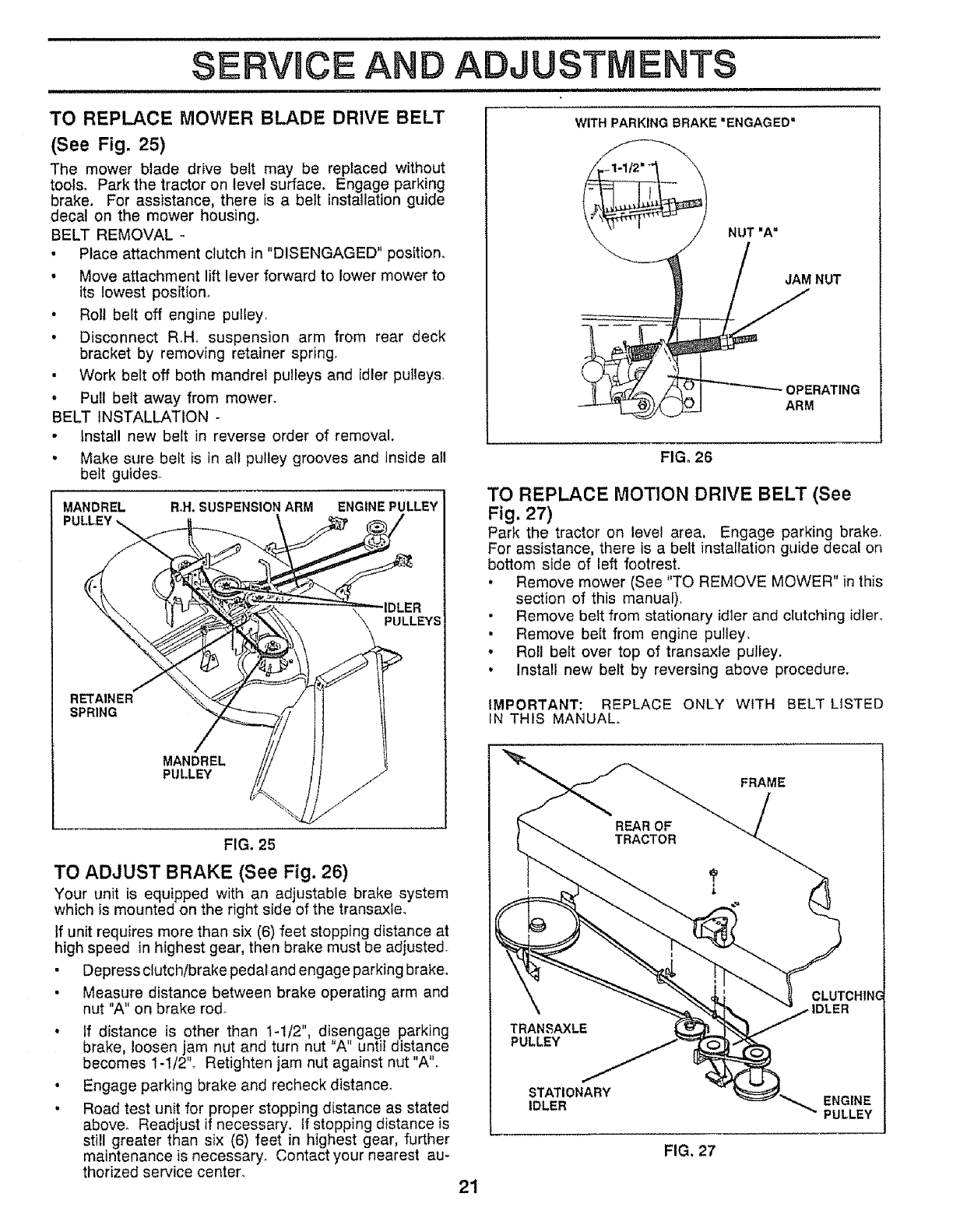
TO REPLACE MOWER BLADE DRIVE BELT
(See Fig. 25)
The mower blade drive belt may be replaced without
tools. Park the tractor on level surface. Engage parking
brake. For assistance, there is a belt installation guide
decal on the mower housing.
BELT REMOVAL -
• Place attachment clutch in "DISENGAGED" position°
- Move attachment lift lever forward to lower mower to
its lowest position°
• Roll belt off engine pulley,
• Disconnect RoHo suspension arm from rear deck
bracket by removing retainer spring.
• Work belt off both mandrel pulleys and idler pulleys,
•Pull belt away from mower.
BELT INSTALLATION -
• install new belt in reverse order of removal.
• Make sure belt is in all pulley grooves and inside all
belt guides.
MANDREL Roll.SUSPENSION ARM ENGINE PULLEY
PULLEYS
RETAINER
SPRING
MANDREL
PLILLEY
WITH PARKING BRAKE =ENGAGED"
NUT =A"
NUT
OPERATING
ARM
FIGo 26
TO REPLACE MOTION DRIVE BELT (See
Fig. 27)
Park the tractor on level area, Engage parking brake_
For assistance, there is a belt installation guide decal on
bottom side of left footrest.
,Remove mower (See "TO REMOVE MOWER" in this
section of this manual),
• Remove belt from stationary idler and clutching idler°
• Remove belt from engine pulley,
• Roll belt over top of transaxle pulley.
• Install new belt by reversing above procedure.
IMPORTANT: REPLACE ONLY WITH BELT LISTED
IN THIS MANUAL.
FRAME
FIG. 25
TO ADJUST BRAKE (See Fig. 26)
Your unit is equipped with an adjustable brake system
which is mounted on the right side of the transaxle.
If unit requires more than six (6) feet stopping distance at
high speed in highest gear, then brake must be adjusted°
• Depress clutch/brake pedal and engage parking brake,
• Measure distance between brake operating arm and
nut "A" on brake rod_
• if distance is other than 1-1/2", disengage parking
brake, loosen jam nut and turn nut A until distance
becomes 1-1/2". Retighten jam nut against nut "A".
• Engage parking brake and recheck distance,
• Road test unit for proper stopping distance as stated
above. Readjust if necessary, if stopping distance is
still greater than six (6) feet in highest gear, further
maintenance is necessary. Contact your nearest au-
thorized service center. 21
FIG. 27
CLUTCHIN(
ENGINE
PULLEY
SERVHCE AND ADJUSTMENTS
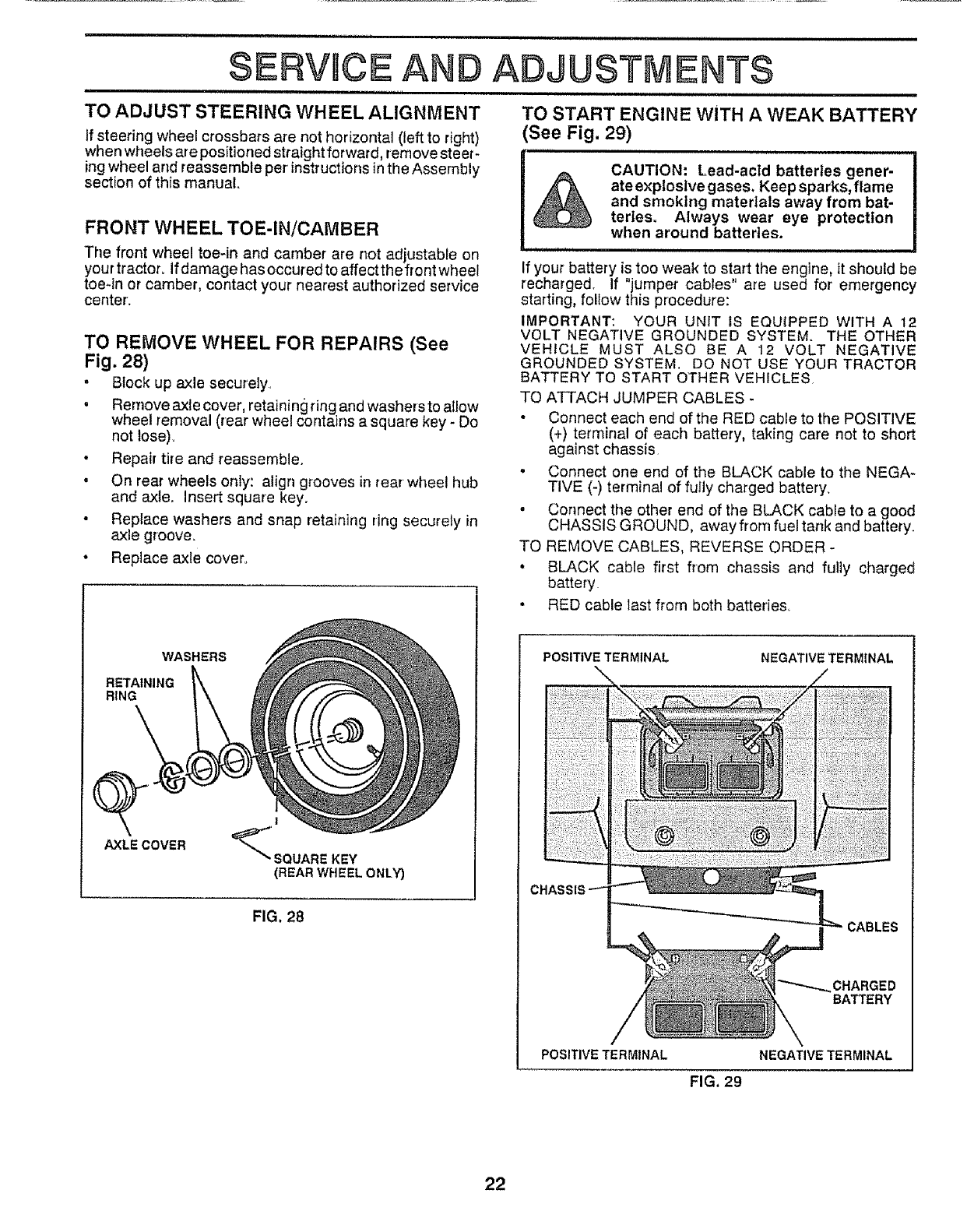
TO ADJUST STEERING WHEEL ALIGNMENT
If steering wheel crossbars are not horizontal (left to right)
when wheels are positioned straightforward, remove steer-
ing wheel and reassemble per instructions in the Assembly
section of this manual.
FRONT WHEEL TOE-IN/CAMBER
The front wheel toe-in and camber are not adjustable on
your tractor° If damage has occured to affect the front wheel
toe-in or camber, contact your nearest authorized service
center.
TO REMOVE WHEEL FOR REPAIRS (See
Fig. 28)
- Block up axle securely,
• Remove axle cover, retaining ring and washers to allow
wheel removal (rear wheel contains a square key - Do
not Iose)_
• Repair tire and reassemble.
•On rear wheels only: align grooves in rear wheel hub
and axle, insert square key.
• Replace washers and snap retaining ring securely in
axle groove.
• Replace axle cover.
WASHERS
RETAINING
RING
AXLECOVER
(REAR WHEEL ONLY)
FIG. 28
TO START ENGINE WiTH A WEAK BATTERY
(See Fig. 29)
CAUTION: Lead-acld batteries gener-
ate explosive gases. Keep sparks, flame
and smoking materials away from bat-
terles. Always wear eye protection
when around batteries.
111 i ill =
If your battery is too weak to start the engine, it should be
recharged. If "jumper cables" are used for emergency
starting, follow this procedure:
IMPORTANT: YOUR UNIT IS EQUIPPED WITH A t2
VOLT NEGATIVE GROUNDED SYSTEM. THE OTHER
VEHICLE MUST ALSO BE A 12 VOLT NEGATIVE
GROUNDED SYSTEM, DO NOT USE YOUR TRACTOR
BATTERY TO START OTHER VEHICLES.
TO ATTACH JUMPER CABLES -
• Connect each end of the RED cable to the POSITIVE
(+) terminal of each battery, taking care not to short
against chassis.
• Connect one end of the BLACK cable to the NEGA-
TIVE (-) terminal of fully charged battery.
*Connect the other end of the BLACK cable to a good
CHASSIS GROUND, away from fuel tank and battery.
TO REMOVE CABLES, REVERSE ORDER -
, BLACK cable first from chassis and fully charged
battery
. RED cable last from both batteries.
POSITIVE TERMINAL NEGATIVE TERMINAL
CABLES
CHARGED
BATTERY
POSITIVE TERMINAL NEGATIVE TERMINAL
FIG. 29
22
SERVIC5 AN ADJUSTMENTS
ii ,, ii i,,Ul i, b
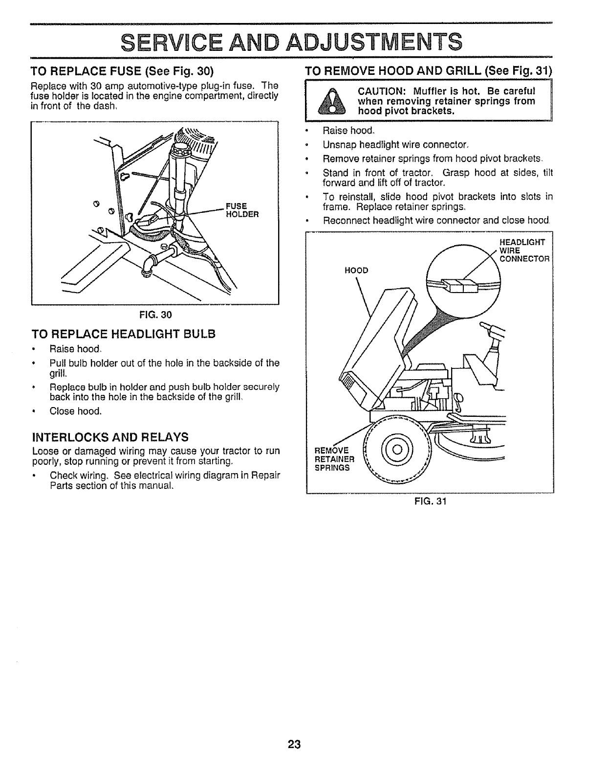
TO REPLACE FUSE (See Fig. 30)
Replace with 30 amp automotive-type ptug-in fuse. "[he
fuse holder is located in the engine compartment, directiy
in front of the dash,
FUSE
HOLDER
FIG. 30
TO REPLACE HEADLIGHT BULB
•Raise hood.
° Pull bulb holder out of the hole in the backside of the
grill,
° Replace bulb in holder and push bulb holder securely
back into the hole in the backside of the grill,
• Close hood,
INTERLOCKS AND RELAYS
Loose or damaged wiring may cause your tractor to run
poorly, stop running or prevent it from starting°
•Check wiring. See electrical wiring diagram in Repair
Parts section of this manual.
TO REMOVE HOOD AND GRILL (See Fig. 31)
i,11 u N,,IHII U,I IH'HI,UU,
_CAUTION: Muffler is hot. Be careful
when removing retainer springs from
hood pivot brackets.
•Raise hood.
.Unsnap headlight wire connector.
°Remove retainer springs from hood pivot brackets.
.Stand in front of tractor, Grasp hood at sides, tilt
forward and lift off of tractor.
• To reinstall, slide hood pivot brackets into slots in
frame. Replace retainer springs.
• Reconnect headlight wire connector and close hood
HEADLIGHT
HOOD
CONNECTOR
REMOVE
RETAINER
SPRINGS
FIG, 31
23
ILIIIIII,,IIII,, , illllU ii
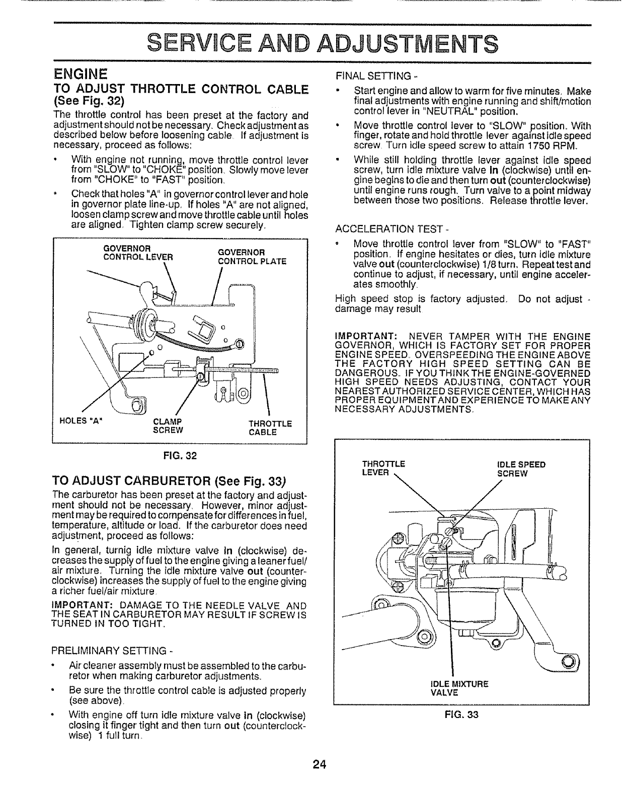
ENGINE
TO ADJUST THROTTLE CONTROL CABLE
(See Fig, 32)
The throttle control has been preset at the factory and
adjustment should not be necessary Check adjustment as
described below before loosening cable If adjustment is
necessary, proceed as follows:
• With engine.no!, running_, move throttle control lever
from SLOW to CHOKE position. Slowly move lever
from "CHOKE" to "FAST" position.
•Check that holes "A" in governor control lever and hole
in governor' plate line-up_ If holes "A" are not aligned
loosen clam p screw and move throttle cable until holes
are aligned, Tighten clamp screw securely.
GOVERNOR
CONTROL LEVER
SERVICE AN ADJUSTMENTS
HOLES =A" CLAMP
SCREW
GOVERNOR
CONTROL PLATE
THROTTLE
CABLE
FINAL SETTt NG
* Start engine and allow to warm for five minutes. Make
final adjustments with engine running and shift/motion
control lever in "NEUTRAL" position,
• Move throttle control lever to "SLOW" position° With
finger, rotate and hold throttle lever' against idle speed
screw Turn idle speed screw to attain 1750 RPM
•While still holding throttle lever against idle speed
screw, turn idle mixture valve In (clockwise) until en*
gine begins to die and then turn out (counterclockwise)
until engine runs rough. Turn valve to a point midway
between those two positions. Release throttle lever.
ACCELERATION TEST-
.Move throttle control lever from "SLOW" to "FAST"
position. If engine hesitates or dies, turn idle mixture
valveout (counterclockwise) 1/8turn. Repeattestand
continue to adjust, if necessary, until engine acceler.
ales smoothly
High speed stop is factory adjusted. Do not adjust -
damage may result
IMPORTANT: NEVER TAMPER WITH THE ENGINE
GOVERNOR, WHICH IS FACTORY SET FOR PROPER
ENGINE SPEED OVERSPEEDING THE ENGINEABOVE
THE FACTORY HIGH SPEED SETTING CAN BE
DANGEROUS. IF YOU THINK THE ENGINE-GOVERNED
HIGH SPEED NEEDS ADJUSTING, CONTACT YOUR
NEAREST AUTHORIZED SERVICE CENTER, WHICH HAS
PROPER EQUIPMENTAND EXPERIENCE TO MAKE ANY
NECESSARY ADJUSTMENTS
FIG. 32
TO ADJUST CARBURETOR (See Fig. 33)
The carburetor has been preset at the factory and adjust-
rnent should not be necessary. However, minor adjust-
ment may be required to compensate for differences infuel,
temperature, altitude or load. If the carburetor does need
adjus!ment, proceed as follows:
In general, turnig idle mixture valve tn (clockwise) de-
creases the supply of fuet to the engine giving a leaner fuel/
air mixture, Turning the idle mixture valve out (counter-
clockwise) increases the supply of fuel to the engine giving
a richer fuet/air mixture_
IMPORTANT: DAMAGE TO THE NEEDLE VALVE AND
THE SEAT IN CARBURETOR MAY RESULT IF SCREW IS
TURNED IN TOO TIGHT.
PRELIMINARY SETTING -
• Air cleaner assembly must be assembled to the carbu-
retor when making carburetor adjustments.
• Be sure the throttle control cable is adjusted properly
(see above)_
• With engine off turn idle mixture valve tn (clockwise)
dosing it finger tight and then turn out (counterclock-
wise) 1 fullturn
THROTTLE IDLE SPEED
SCREW
IDLE MIXTURE
VALVE
FIG. 33
24
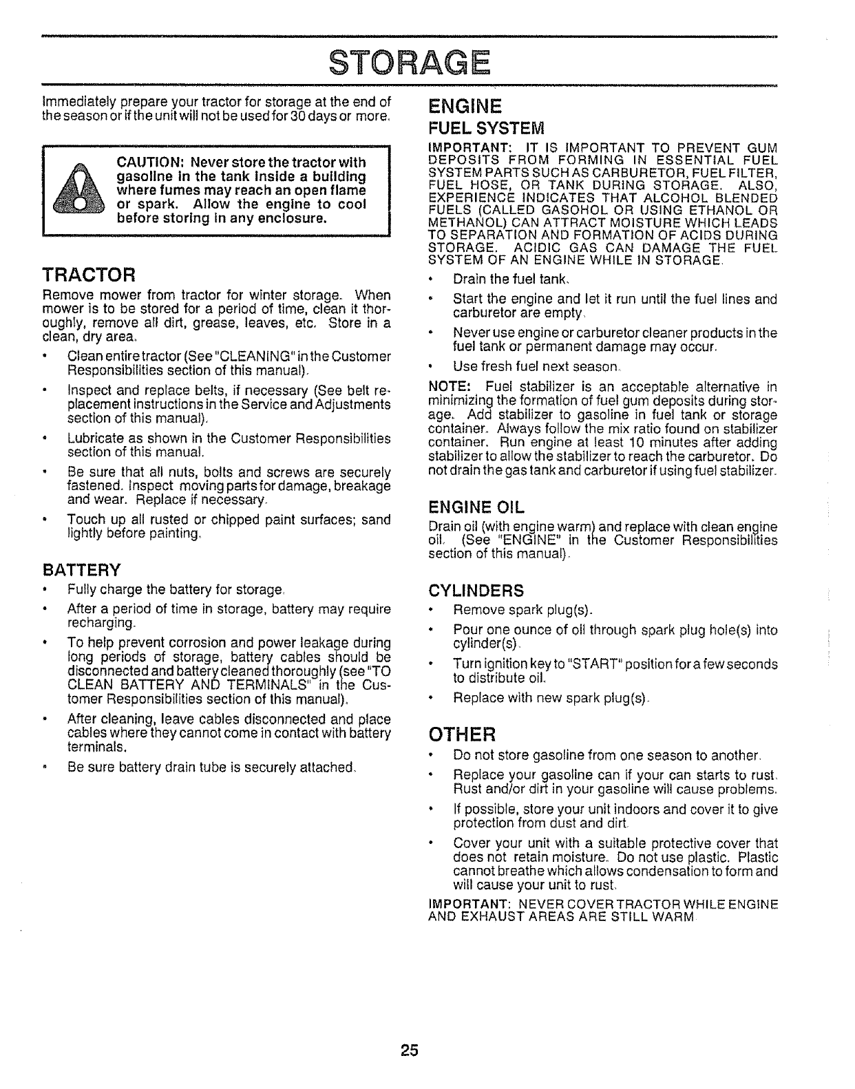
Immediately prepare your tractor for storage at the end of
the season or if the unit will not be used for 30 days or more°
CAUTION: Never store the tractor with
gasoline In the tank inside a building
where fumes may reach an open flame
or spark. AItow the engine to cool
before storing In any enclosure.
TRACTOR
Remove mower from tractor for winter storage° When
mower is to be stored for a period of time, clean it thor-
oughty, remove all dirt, grease, leaves, etc. Store in a
clean, dry area_
• Clean entire tractor (See "CLEANING" in the Customer
Responsibilities section of this manual).
•Inspect and replace belts, if necessary (See belt re-
pIacement instructions in the Service and Adjustments
section of this manual).
• Lubricate as shown in the Customer Responsibilities
section of this manual,
° Be sure that all nuts, bolts and screws are securely
fastened. Inspect moving partsfordamage, breakage
and wear. Replace if necessary.
° Touch up all rusted or chipped paint surfaces; sand
lightly before painting,
BATTERY
• Fully charge the battery for storage,
•After a period of time in storage, battery may require
recharging.
° To help prevent corrosion and power leakage during
long periods of storage, battery cables should be
disconnected and battery cleaned thoroughly (see "TO
CLEAN BATTERY AND TERMINALS in the Cus-
tomer Responsibilities section of this manual)°
• After cleaning, leave cables disconnected and place
cables where they cannot come in contact with battery
terminals.
o Be sure battery drain tube is securely attached°
ENGINE
FUEL SYSTEM
IMPORTANT: IT IS IMPORTANT TO PREVENT GUM
DEPOSITS FROM FORMING IN ESSENTIAL FUEL
SYSTEM PARTS SUCH AS CARBURETOR, FUEL FILTER,
FUEL HOSE, OR TANK DURING STORAGE. ALSO,
EXPERIENCE INDICATES THAT ALCOHOL BLENDED
FUELS (CALLED GASOHOL OR USING ETHANOL OR
METHANOL) CAN ATTRACT MOISTURE WHICH LEADS
TO SEPARATION AND FORMATION OF ACIDS DURING
STORAGE. ACIDIC GAS CAN DAMAGE THE FUEL
SYSTEM OF AN ENGINE WHILE IN STORAGE
•Drain the fuel tank.
• Start the engine and let it run until the fuel lines and
carburetor are empty.
. Never use engine or carburetor cleaner products in the
fuel tank or permanent damage may occur_
,Use fresh fuel next season
NOTE: Fuel stabilizer is an acceptable alternative in
minimizing the formation of fuel gum deposits during storo
age, Add stabilizer to gasoline in fuel tank or storage
container. Always follow the mix ratio found on stabilizer
container. Run engine at least 10 minutes after adding
stabilizer to allow the stabilizer to reach the carburetor, Do
not drain the gas tank and carburetor if using fuel stabilizer.
ENGINE OIL
Drain oil (with engine warm)and replace with clean engine
oil (See "ENGINE" in the Customer Responsibihties
section of this manual).
CYLINDERS
•Remove spark plug(s).
•Pour one ounce of oil through spark plug hole(s) into
cylinder(s).
• Turn ignition key to "START" position for a few seconds
to distribute oil
• Replace with new spark plug(s).
OTHER
• Do not store gasoline from one season to another.
• Replace your gasoline can if your can starts to rusL
Rust and/or dirt in your gasoline will cause probfems.
• If possible, store your unit indoors and cover it to give
protection from dust and dirt,
• Cover your unit with a suitable protective cover that
does not retain moisture. Do not use plastic. Plastic
cannot breathe which allows condensation to form and
will cause your unit to rust.
IMPORTANT: NEVER COVER TRACTOR WHILE ENGINE
AND EXHAUST AREAS ARE STILL WARM
25

[LLIJUU'IU',U III I III IIII,I,T,,II
TROUBLESHOOTmNG POINTS
,i,i i, i i, i,i, HUHIHIIII,I
CAU S E CO RRECTIO NPROBLEM
illll i ii i illllll i ill i
Will not start
Hard to start
Engine wil! not turn over
Engine clicks but will not
start
Loss of power
Excessive vibration
i. Out of fuel.
2_ Engine not"CHOKED" propedy,
3. Engine flooded
4Bad spark plug.
5Dirty air fitter
6 Dirty fuel filter
7_ Water In fuel
8Loose or damaged wiring.
9Carburetor out of adjustment
10. Engine valves out of adjustment
1, Dirty air fitter
2 Bad spark plug
3. Weak or dead battery.
4. Dirty fuel filter.
5, Stale or dirty fuel,
6 Loose or damaged wiring,
7. Carburetor out of adjustment
8 Engine valves out of adjustment
4,
1 Clutch/brake peda! not depressed
2. Attachment clutchis engaged°
3 Weak or dead battery.
4. Blown fuse.
5Corroded battery terminals.
6. Loose or damaged wiring
7 Faulty ignttton switch
8 Faulty solenoid or starter
9, Faulty operator presence swltc_(es).
1. Weak or dead battery.
2. Corroded battery terminals
3.. Loose or damaged wiring.
Faulty solenoid or starter_
1. Cutting too much grass/too fast
2 Throttle in "CHOKE" posfflon.
3 But{d.up of grass, leaves and trash under mower.
4. Dirty air filter,
5 Low oil laveVdirty oil.
6. Faulty spark plug
7. Dirty fuel filter.
8. Stale or dirty fuel
9. Water in fuel.
10, Spark plugwire loose
11, Dirty engine air screen/fins
12 Dirty/cloggedmuffler.
13, Looseor damagedwiring
!4, Carburetoroutof adjustment
15 Enginevalyesout of adjustment,
1. Worn, bent or loose blade
2 Bent blade mandrel.
3. Loose/damaged part(s)
I, Fili fuel tank
2, See "TO START ENGINE" In Operation section,
3. Wait several minutes before attempting to start.
4. Repface spark plug.
5. Clean/replace afr filter,.
6. Replace fuel filter
7. Drain fuel tank and carburetor, refill tank with fresh
gasoilne and replace fuel filter.
8. Check all wldng.
9.. Contact Sears Service Center/Department.
!0. Contact Sears Service Center/Department
1 Clean/replace air fitter.
2_ Replace spark plug
3, Recharge or replace battery.
4.. Replace fuel filter'
5 Drain fuel tank and refill with fresh gasoline.
6Check eli wiring,
7, Contact Sears Service Center/Department.
8 Contact Sears Service Center/Department,
1_ Depress clutch/brake pedal
2Disengage attachment clutch.
3 Recharge or replace battery.
4_ Replace fuse.
5_ Clean battery terminals.
6 Check all wiring
7, Check/replace ignition switch.
8Check/replace so[eno{d or starter.
9 Contact Sears Service Center/Department.
1. Recharge or replace battery.
2Clean battery term{nals
3_ Check all wiring
4 Check/replace solenoid or starter,
1. Set _n "Higher Cut" postttonlreduce speed.
2, Adjust throttle control.
3. Clean underside of mower housing
4Cleantreplace air filter
5. Check oHlevel/change oil
6. Clean and regep or change spark plug.
7. Replace fuel filter
8. Drain fuel tank and refill with fresh gasoline.
9. Drain fuel tank and carburetor, reflU tank with fresh
gaso{Ine and replace fuel filter.
10 Connect and tighten spark plug wire
t 1_. Clean engine air screen/fins.
12.. Clean/replace muffler_
t3 Check el! widng.
14. Contact Sears Service Center/Department.
I5. Contact Sears Service Center/Department.
!. Replace blade Tighten blade bolt.
2. Replace blade mandrel,
3Tighten loose part(s). Replace damaged parts.
26

= = = H,=,,,H,H
TRO LESHOOTING POHNT$
11 =HiHiliH , 1'1 m,.,,,=,.,=,,
PROBLEM CAUSE CORRECTION
1 Faulty operator-safety presence control systemEngine continuesto run
when operator leaves seat
with attachment clutch
engaged
Poor cut -uneven
Mower blades will not
rotate
Poor grass discharge
Headlight(s) not working
(if so equipped)
Battery wilt not charge
Engine "backfires"
when turning engine
"OFF"
1. Worn, bent or loose blade
2. Mower deck not lever.
3Buildup ofgrass, leaves, and trashundermower.
4. Bentblade mandrel..
5. Cloggedmower deck vent holes from buildupof
grass, leaves, and trash around mandrels
1, Obstruction in ciutch mechanism.
2, Worn/damaged mower drive belt
1, Check wiring, switches and connections, if not
corrected, contact Sears Service Center/Department
1, Replace blade. Tighten blade boit
2r Level mower deck.,
3 Clean underside of mower houstng
4 Replace blade mandrel,
5 Clean around mandrels to open vent holes
1, Remove obstruction
2- Replace mower drive belt
3 Frozen Idler pulley
4. Frozen blade mandrel
I
2
3
4,
5.
6_
7,
8.
9.
!0,
11
Engine speed too slow.
Travel speed too fast,
Wet grass.
Mower deck not level,
Low/uneven tire air pressure.
Worn, bent or loose blade,
Buildup of grass, leaves and trash under mower.
Mower drive belt worn
Blades Improperly installed,
Improper blades used,
Clogged mower deck vent holes from buildup of
grass, leaves, and trash around mandrels
3 Replace _dler pulley
4Replace blade mandrel
1Place throttle control in "FAST" position
2 Shift to slower speed,
3. Allow grass to dry before mowing.
4. Levei mower deck
5o Check tires for proper air pressure
6. Repface/sh_pen blade Tighten blade boiL.
7, Clean underside of mower housing.
B. Replace mower drive belt,
9, Reinstall blades sharp edge down.
10 Replace with blades listed In this manual
11, Clean around mandrers to open vent holes.
t Switch is =OFF"
2. Bulb(s) burned out.
3. Faulty light switch
4. Loose or damaged wiring
5. Blown fuse,
1, Bad battery cell(s)
2_ Poor cable connections
3, Faulty regulator (if so equipped)
4 Faulty altematar_
== ===,== , = ,_j_=_j = == ,,,==,,,=
Engine throttle control not set at "SLOW"
position for 30 seconds before stopping engine
I, Turn switch "ON"
2Replace bulb(s)
3 Check!repface light switch,
4, Check wiring and connectEons.
5 Replace fuse
1. Replace battery
2, Check/clean all connections.
3- Replace regulator
4. Replace alternator.
Move throttle control to "SLOW" posttlon and a;low
to tdle for 30 seconds before slopping englne
27
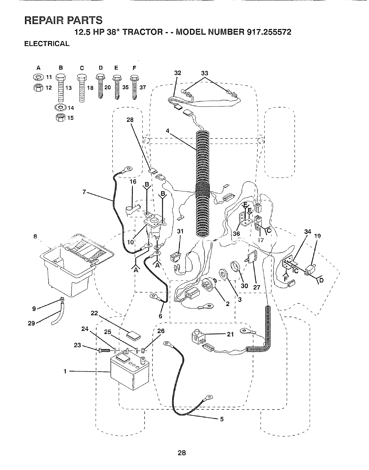
REPAgR PARTS
12.5 HP 38" TRACTOR - - MODEL NUMBER 917.255572
ELECTRICAL
A B
@11
12 13
C_b.14
_115
29
\
\
\
22
32 33
\
31 t9
28
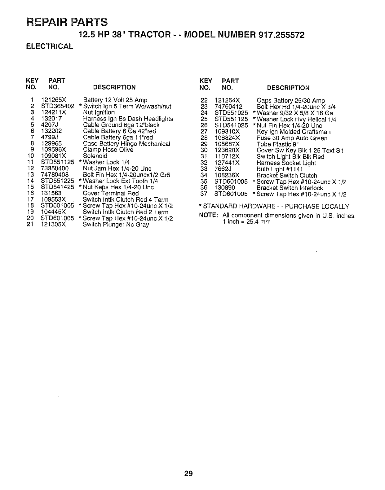
REPAIR PARTS
12.5 HP 38" TRACTOR - - MODEL NUMBER 917.255572
ELECTRICAL
KEY PART KEY PART
NO. NO. DESCRIPTION NO. NO. DESCRIPTION
I 121265X
2 STD365402
3 124211X
4 132017
5 4207J
6 132202
7 4799J
8 129965
9 109596X
10 109081X
11 STD551125
12 73350400
13 74780408
14 STD551225
15 STD541425
16 131563
17 109553X
18 STD60t005
19 104445X
20 STD601005
21 121305X
Battery 12 Volt 25 Amp 22
*Switch tgn 5 Term Wo/wash/nut 23
Nut Ignition 24
Harness Ign Bs Dash Headlights 25
Cable Ground 6¢t_a12"black 26
Cable Battery 6 _a 42"red 27
Cable Battery 6ga 11"red 28
Case Battery Hinge Mechanical 29
Clamp Hose Olive 30
Solenoid 31
*Washer Lock 1/4 32
Nut ,Jam Hex 1/4-20 Unc 33
Bolt Fin Hex 1/4-20uncx1/2 Gr5 34
* Washer Lock Ext Tooth 1/4 35
*Nut Keps Hex 1/4-20 Uric 36
Cover Terminal Red 37
Switch Intlk Clutch Red 4 Term
* Screw Tap He)( #10-24unc X 1/2
Switch Intlk Clutch Red 2 Term
*Screw Tap Hex #t0-24unc X 1/2
Switch Plunger Nc Gray
121264X Caps Battery 25/30 Amp
74760412 Bolt Hex Hd 1/4-20unc X 3/4
STD551025 *Washer 9/32 X 5/8 X 16 Ga
STD551125 *Washer Lock Hvy Helical 1/4
STD541025 *Nut Fin Rex 1/4-20 Unc
109310X
108824X
105687X
123620X
110712X
127441X
7662J
108236X
STD601005
130890
STD601005
Key Ign Molded Craftsman
Fuse 30 Amp Auto Green
Tube Plastic 9"
Cover Sw Key BIk 1 25 Text Sit
Switch Light Bik BIk Red
Harness Socket Light
Bulb Light #t 141
Bracket Switch Clutch
* Screw Tap Hex #10-24unc X I/2
Bracket Switch Interlock
* Screw Tap Hex #10-24unc X 1/2
*STANDARD HARDWARE - - PURCHASE LOCALLY
NOTE: All component dimensions given in USo inches,
1 inch = 25,4 mm
29
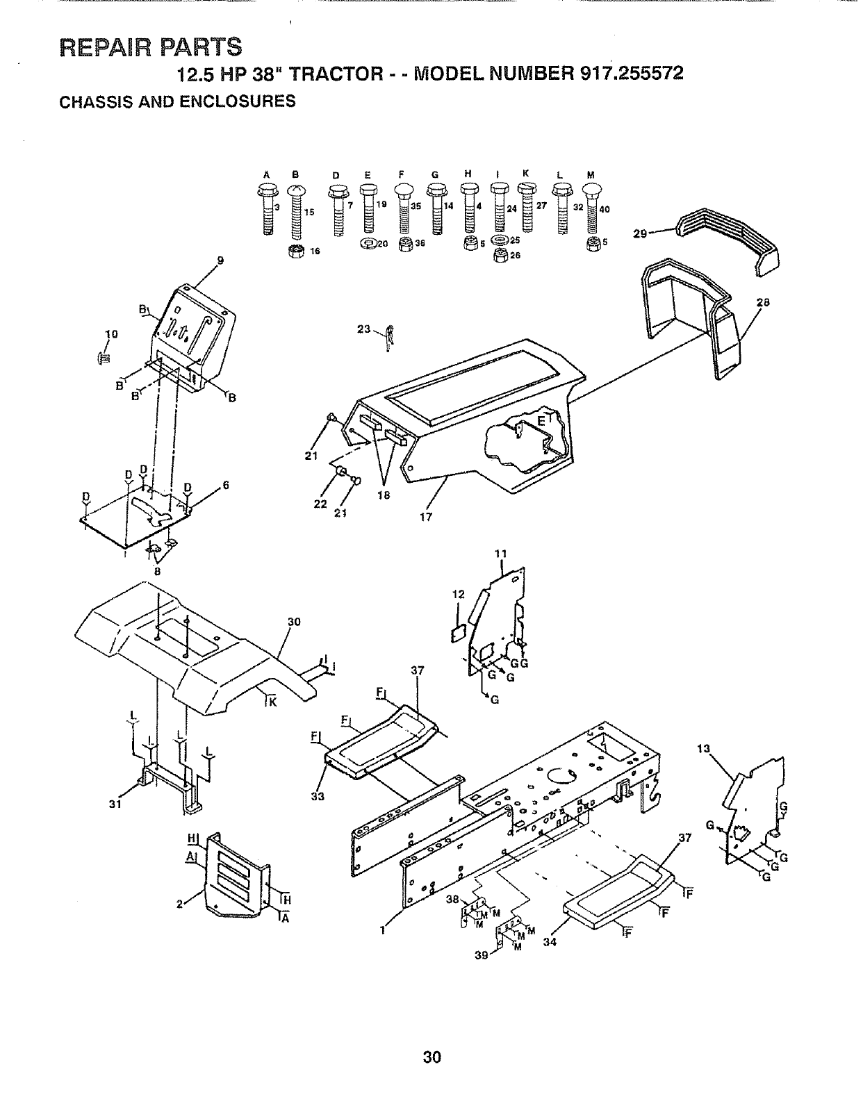
REPAUR PARTS
"12.5 HP 38" TRACTOR - - MODEL NUMBER 917.255572
CHASSIS AND ENCLOSURES
9
6
31
A
2
A B D E F G H ! K L M
3O
21 "" O
21 17
33
11
39
29
13
37
," -IF
34
G_
30
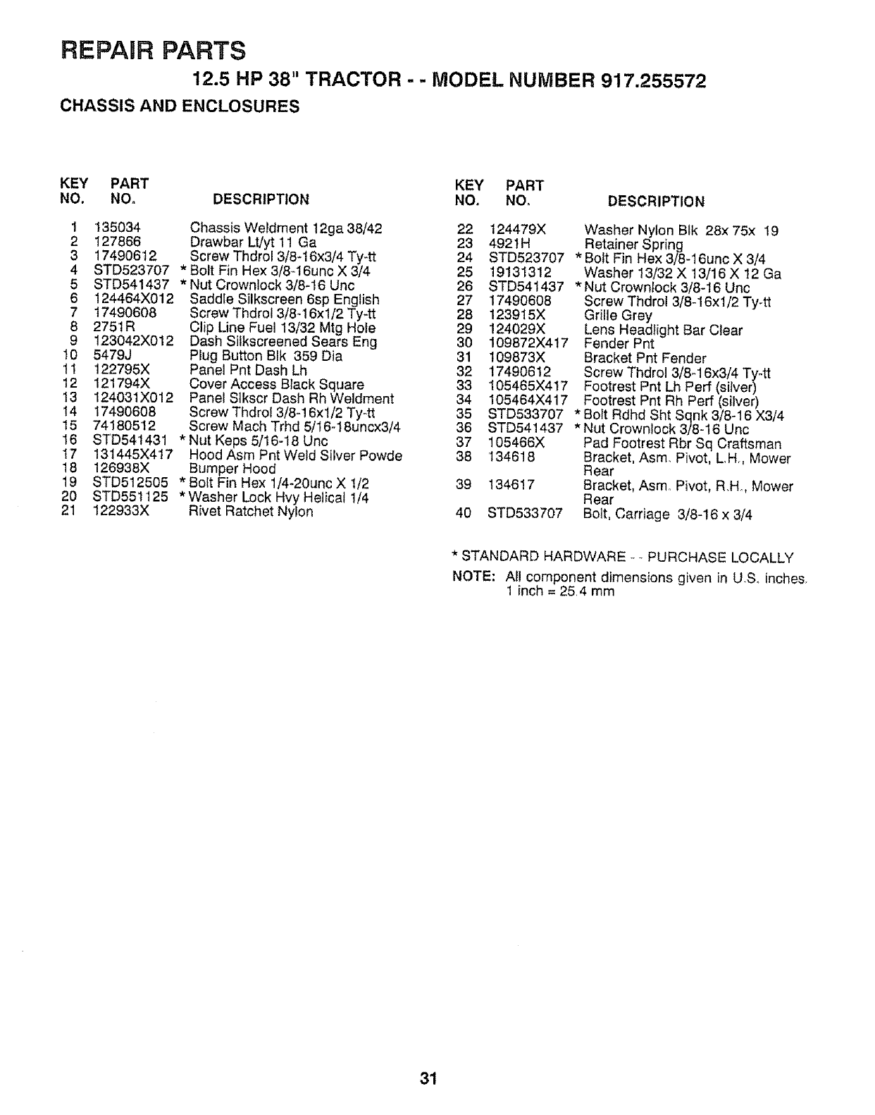
REPAIR PARTS
12.5 HP 38" TRACTOR -- MODEL NUMBER 917.255572
CHASSIS AND ENCLOSURES
KEY PART KEY PART
NO. NO. DESCRIPTION NO, NOo DESCRIPTION
STD541437
124464X012
17490608
2751R
123042X012
5479J
122795X
121794X
124031X012
17490608
74180512
STD541431
131445)(417
126938X
1 135034 Chassis Weldment 12ga 38/42 22 124479X
2 127866 Drawbar Lt/yt 11 Ga 23 4921H
3 17490612 Screw Thdrol 3/8-16x3/4 Ty-tt 24 STD523707
4STD523707 *Bolt Fin Hex 3/8-16unc X 3/4 25 19131312
5*Nut Crownlock 3/8-16 Unc 26 STD541437
6 Saddle Silkscreen 6sp English 27 17490608
7 ScrewThdrol 3/8_16xl/2 Ty-tt 28 123915X
8 Clip Line Fuel 13/32 Mtg Hote 29 124029X
9 Dash Siikscreened Sears Eng 30 109872X417
10 Plug Button Blk 359 Dia 31 109873X
1t Panel Pnt Dash Lh 32 17490612
12 Cover Access Black Square 33 105465X417
13 Panel Slkscr Dash Rh Weldment 34 105464X417
14 Screw Thdrol 3/8-16xt/2 Ty-tt 35 STD533707
15 Screw Mach Trhd 5/16-18uncx3/4 36 STD541437
16 *Nut Keps 5/16-18 Unc 37 105466X
I7 Hood Asm Pnt Weld Silver Powde 38 134618
18 Bumper Hood
19 STD512505 *Bolt Fin Hex 1/4-20unc X 1/2 39 134617
20 STD551125 *Washer Lock Hvy Helicat 1/4
21 122933X Rivet Ratchet Nylon 40 STD533707
Washer Nylon Btk 28x 75x 19
Retainer Spring
*Bolt Fin Hex 3/8-16unc X 3/4
Washer 13/32 X 13/16 X 12 Ga
*Nut Crownlock 3/8-16 Unc
Screw Thdrol 3/8_16xl/2 Ty-tt
Grille Grey
Lens Headlight Bar Clear
Fender Pnt
Bracket Pnt Fender
Screw Thdrol 3/8_16x3/4 Ty-tt
Footrest Pnt Lh Perf (silver)
Footrest Pnt Rh Perf (silver)
*Bolt Rdhd Sht Sqnk 3/8-16 X3/4
*Nut Crownlock 3/8-16 Unc
Pad Footrest Rbr Sq Craftsman
Bracket, Asm, Pivot, L,H,, Mower
Rear
Bracket, Asmo Pivot, R,H, Mower
Rear
Bolt, Carriage 3/8-16 x 3/4
*STANDARD HARDWARE _- PURCHASE LOCALLY
NOTE: AI! component dimensions given in U,S,, inches,
1 inch = 25,4 mm
31
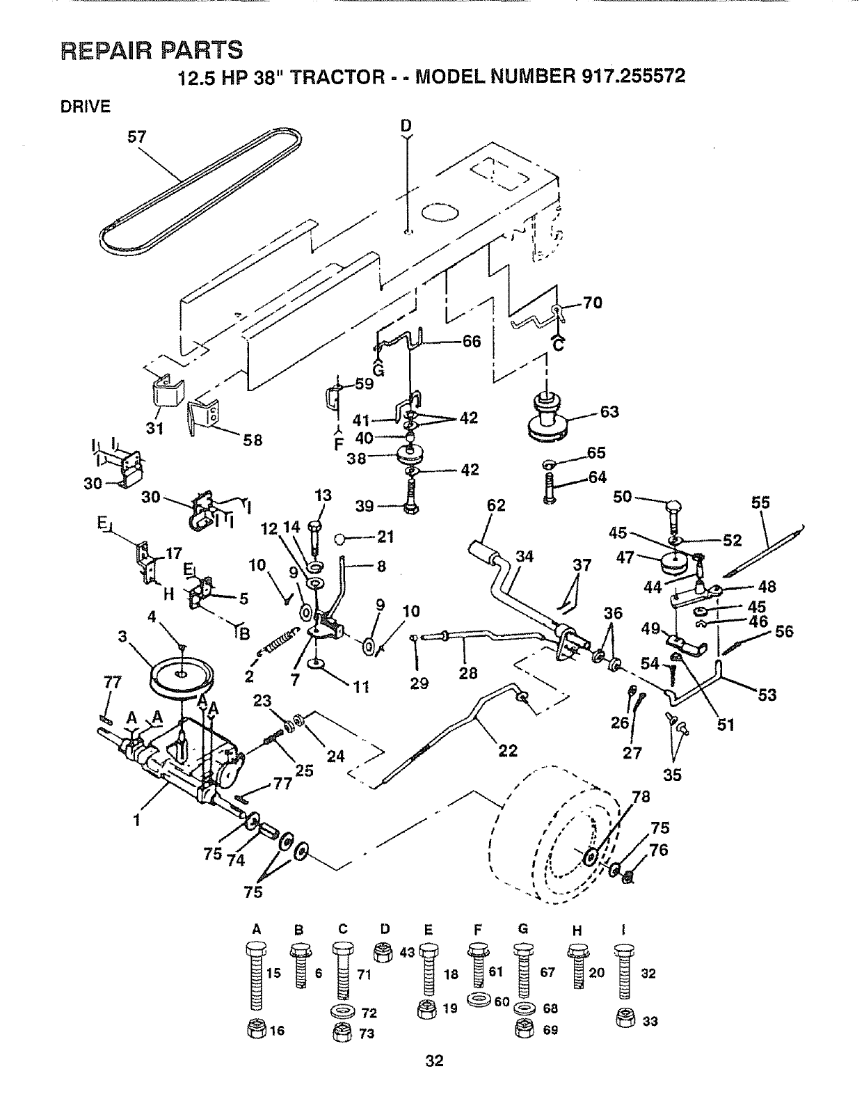
REPAIR PARTS
12.5 HP 38" TRACTOR - - MODEL NUMBER 917.255572
DRIVE
77 2
A 23
11
10
29
75 74
75
A
_)16
BC D E F G H I
71 18 1 67 0 32
(_ 72 _19 _60 (_ 68 _33
32

REPARR PARTS
12.5 HP 38" TRACTOR-- MODEL NUMBER 917.255572
DRIVE
KEY PART
NO_ NO. 3
1 t20898X
2110422X
3123686×
412000028
5121520X
6 17490512
7 t06919X
8!24461X
919151216
10 STD5612t0
11 105701X
12 19091210
13 71040412
14 STD551125
15 STD523727
16 STD541437
17 121520X
18 STD523707
19 STD541437
20 1749O512
21 106933X
22 131867
23 STD54t437
24 STD541237
25 106888X
26 STD551037
27 STD561210
28 128904
29 124236X
30 109187X
31 127275X
32 8TD523707
33 STD541437
34 122424X
35 120183X
36 STD551062
37 STD571810
38 123674X
39 STD523727
40 4470J
4! 109070X
42 19131312
43 STD541437
KEY PART
DESCRIPTION NO. NO. DESCRIPTION
Transaxte 6sp Std Dana
Spring Return Brake T/a Zinc
Pulley Transaxle Alum
Ring Retainer # 5100-62
Strap Pnt Torque 30 Deg Blk
Screw Thdrol 5/t 6-18 X 3/4 Tyt
Plate Pnt Rod Shift T/a (btk)
Rod Shifter BIk (dana)
Washer 15/32 X 3/4 X 16ga
* Pin Cotter 1/8 X 1 Cad
Washer Plate Shf 388 Sq Hole
Washer 9/32 X 3/4 X 10 Ga
Bolt Fin Hex 1/4-28unfx3!4 Gr8
*Washer Lock Hvy Helical 1/4
*Bolt Fin Hex 3/8-16unc X 2-3/4
*Nut Crownlock 3/8-t6 Unc
Strap Pnt Torque 30 Deg Blk
*Bolt Fin Hex 3/8-16unc X 3/4
*Nut Crownlock 3/8-t6 Unc
Screw Thdrol 5/16-18 X 3/4 Tyt
Knob Rd 1/2-13 Plstc Thds Blk
Rod Brake Lt
*Nut Lock Hex W/wsh 3/8-16unc
*Nut Hex Jam 3/8-,16 Unc
Spring Rod Brake 2 00 Zinc
*Washer 13/32 X 13/t6 X 16 Ga
*Pin Cotter 1/8 X 3/4 Cad
Rod Brake Parking Lt
Cap Parking Brake Red
Bracket Transmission
Keeper Belt Lh Lt 14 Ga
* Bolt Fin Hex 3/8-16unc X 3/4
* Nut Crownlook 3/8-16 Unc
Shaft Asm Pedal Foot I 930
Bearing Nylon BIk 629 Id
* Washer 21/32 X 1 X 16 Ga
*Pin Roll 3/16 X 1"
Pulley Idler Flat
*Bolt Fin Hex 3/8-16unc X 2-3/4
Spacer Split 395 X 59 Bzp
Keeper Belt Retainer
Washer 13/32 X 13/16 X 12 Ga
* Nut Crownlock 3/8-16 Unc
105709X
STD56t210
125907X
127274X
136715
19131312
17490612
8883R
134825
71170764
STD551143
129921
STD523710
19131312
STD541437
134683
STD523710
19132012
STD541437
109502X
121749X
STD581075
123583X
121748X
44 105706X Bearing Nyl 503 X 628 X 1 25
45 110812X Washer Hardened
46 12000039 Ring Klip #t5304-50
47 127783 Pulley Idler V Groove Plastic
48 123789X BellcrankAsm
49 123205X Retainer Belt Style Spring
50 STD523715 * Bolt Hex Hd 3/8-16unc X !-1/2
51 STD541437 *Nut Crownlock 3/8-16 Unc
52 STD551037 *Washer 13/32 X 13/16 X 16 Ga
53 1057!0X Link Clutch 7 66
54 STD561210 *Pin Cotter l/8 X 3/4 Cad
55 Spring Return Clutch 6 75
56 *Pin Cotter 1/8 X 3/4 Cad
57 V-belt Ground Drive 90 00
58 Keeper Belt Rh Lt Pnt]zinc 16g
59 Retainer Belt Chassis Lh Zinc
60 Washer 13/32 X 13/16 X 12 Ga
61 Screw Thdrol 3/8-16x3/4 Tyott
62 Cover Pedal Blk Std
63 Pulley Engine
64 Bolt Finhex 7/16-20 x 4 g5
65 * Washer Lock Hvy Hlcl Spr 7/t6
66 Keeper Belt Engine Lh Lt
67 * Bolt Fin Hex 3/8-16unc X 1
68 Washer 13/32 X t3/16 X 12 Ga
69 * Nut Crownlock 3/8-16 Unc
70 Guide Belt Dr Mower Rh
71 * Bolt Fin Hex 3/8-16unc X 1
72 Washer 13/32 X 1-1/4 X 12 Ga
73 *Nut Crownlock 3/8-16 l)nc
74 Spacer Split .80xl.94
75 Washer 25/32 X 1 1/4 X 16 Ga
76 *Ring E #5133-75
77 Key Square 2 0 X 1845/1865
78 Washer 25/32 X1 5/8 X 16ga
*STANDARD HARDWARE - - PURCHASE LOCALLY
NOTE; All component dimensions given in U.S inches
1 inch = 25,4 mm
33
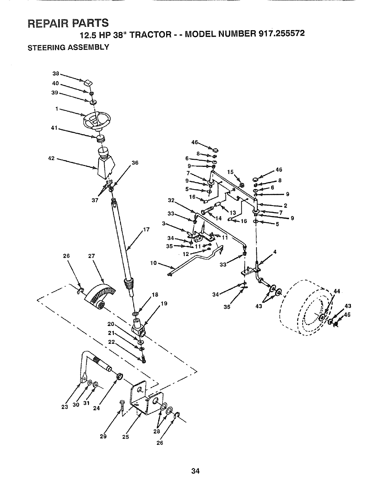
REPAURPARTS
12.5 HP 38" TRACTOR - - MODEL NUMBER 917.255572
STEERING ASSEMBLY
46
9
2
-9
26 27
18
19 43
44
43
,45
23 24
28
29 25 J
26
34
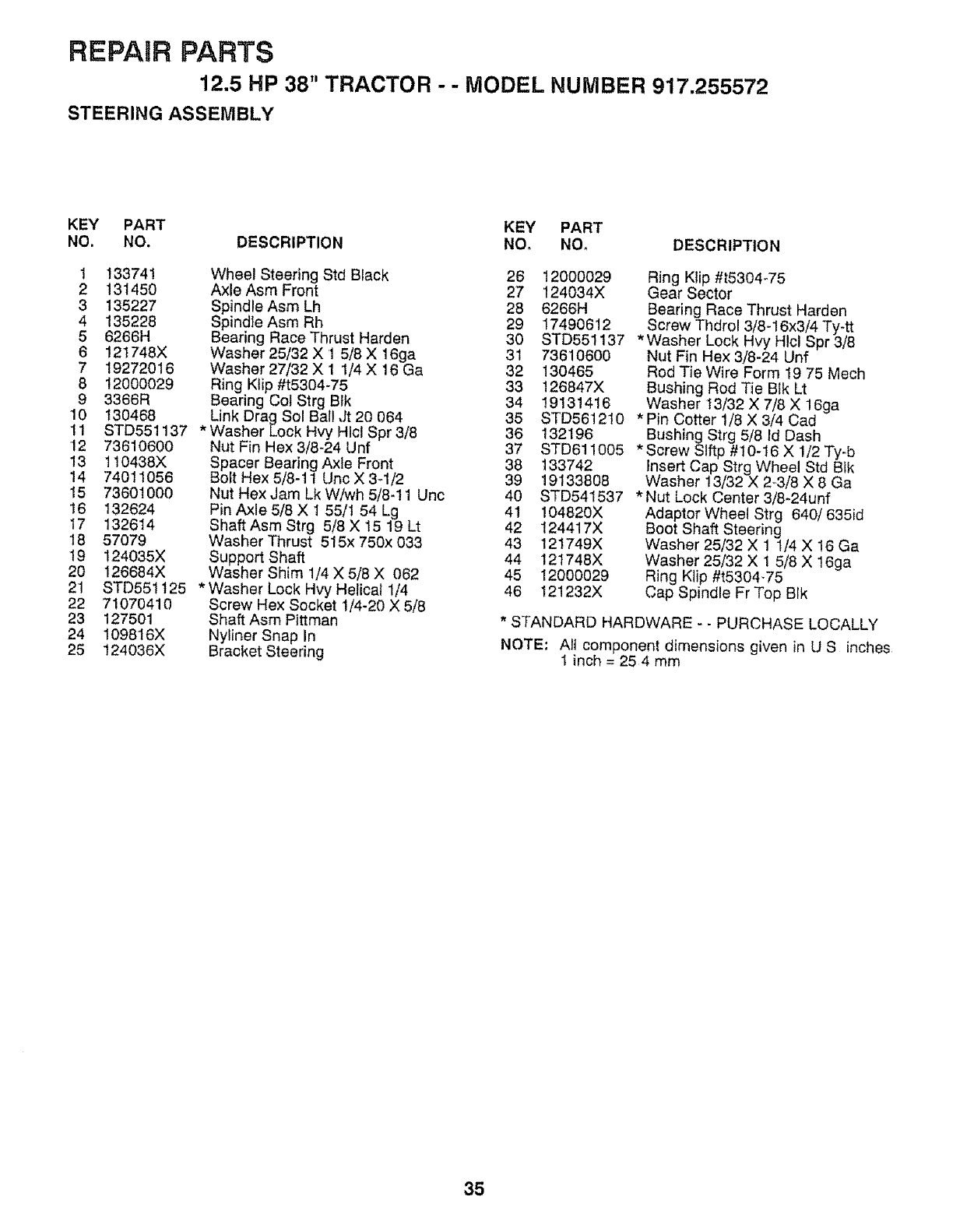
REPAIR PARTS
12.5 HP 38" TRACTOR - - MODEL NUMBER 917.255572
STEERING ASSEMBLY
KEY PART KEY PART
NO. NO. DESCRIPTION NO, Nee DESCRIPTION
1 !33741 Wheel Steering Std Black 26 12000029
2 131450 Axle Asm Front 27 124034X
3 135227 Spindle Asm Lh 28 6266H
4 135228 Spind]eAsm Rh 29 17490612
5 6266H Bearing Race Thrust Harden 30 STD561137
6 !21748X Washer 25132 X 1 5t8 X 16ga 31 73610600
7 19272016 Washer 27/32 X 1 1/4 X 16 Ga 32 !30465
B 12000029 Ring Klip #t5304-75 33 126847X
9 3366R Bearing Col Strg Btk 34 19131416
10 130468 Link Drag Sol Ball Jt 20 064 35 STD561210
11 STD551137 *WasherLockHvyHIclSpr3/8 36 132196
12 73610600 Nut Fin Hex 3/8-24 Unf 37 STD611005
13 110438X Spacer Bearing Axle Front 38 133742
14 74011056 Bolt Hex 5/8-11 UncX3-1/2 39 19133808
15 7360t000 Nut Hex Jam Lk W/wh 5/8-11 Unc 40 STD541537
16 132624 Pin Axle 5/8 X1 55/1 54 Lg 41 !04820X
17 132614 Shaft Asm Strg 5/8 X 15 19 Lt 42 124417X
18 57079 Washer Thrust 515x 750x 033 43 121749X
t9 124035X Support Shaft 44 121748X
20 126684X Washer Shim 1/4 X 5/8 X 062 45 12000029
21 STD551125 *Washer Lock Hvy Helical 1/4 46 121232X
22 71070410 Screw Hex Socket 1/4-20 X 5/8
23 127501 Shaft Asm Pittman
24 109816X Nyliner Snap In
25 124036X Bracket Steering
Ring Klip #t5304-75
Gear Sector
Bearing Race Thrust Harden
Screw Thdrol 3/8-16x3/4 Ty-tt
* Washer Lock Hvy Hlcl Spr 3/8
Nut Fin Hex 3/8-24 Unf
Rod Tie Wire Form 19 75 Mech
Bushing Red Tie Blk Lt
Washer 13/32 X 7/8 X 16ga
*Pin Cotter 1/8 X 3/4 Cad
Bushing Strg 5/8 Id Dash
* Screw Slftp #10-16 X 1/2 Ty-b
insert Cap Strg Wheel Std Blk
Washer 13/32 X 2-3/8 X 8 Ga
* Nut Lock Center 3/8-24unf
Adaptor Wheel Strg 640/635id
Boot Shaft Steering
Washer 25/32 X 1 1/4 X 16 Ga
Washer 25/32 X 1 5/8 X 16ga
Ring Ktip #t5304-75
Cap Spindle Fr Top Blk
* STANDARD HARDWARE - -PURCHASE LOCALLY
NOTE: All component dimensions given in U S inches
1 inch = 254 mm
35
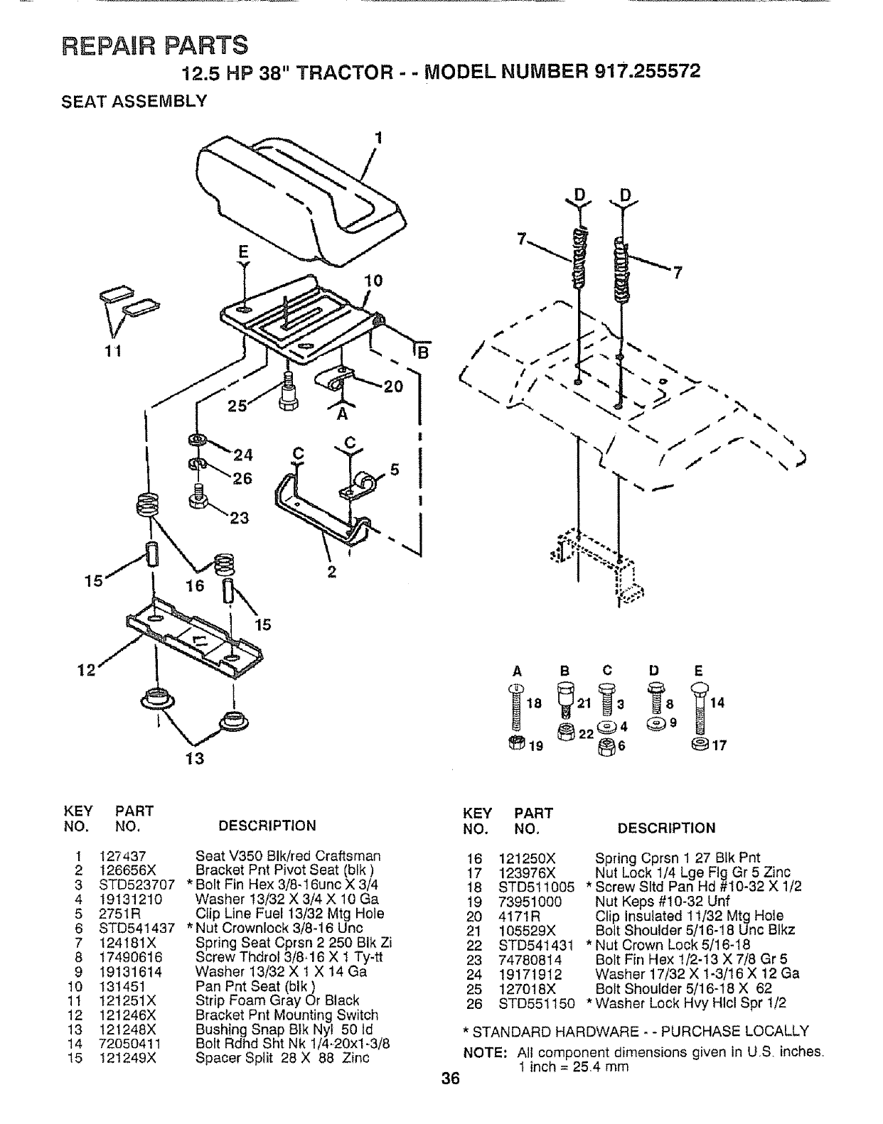
REPAtR PARTS
12.5 HP 38" TRACTOR - - MODEL NUMBER 917.255572
SEAT ASSEMBLY
11
2
15
\
12
13
A B CD E
KEY
NO.
1
2
3
4
5
6
7
8
9
10
11
12
13
14
15
PART
NO,
127437
126656X
STD523707
19131210
275IR
STD541437
124181X
17490616
19131614
131451
121251X
121246X
121248X
72050411
121249X
DESCRIPTION
Seat V350 BIk/red Craftsman
Bracket Pnt Pivot Seat (blk)
*Bolt Fin Hex 3/8-16unc X 3/4
Washer 13/32 X 3/4 X 10 Ga
Clip Line Fuel 13/32 Mtg Hole
* Nut Crownlock 3/8-16 Unc
Spring Seat Cprsn 2 250 BIk Zi
Screw Thdrol 3/8-16 X 1 Ty-tt
Washer 13/32 X 1 X 14 Ga
Pan Pnt Seat (blk)
Strip Foam Gray Or Black
Bracket Pnt Mounting Switch
Bushing Snap Btk Nyl 50 ld
Bolt Rdhd Sht Nk 1/4=20xl-3/8
Spacer Split 28 X 88 Zinc
KEY PART
NO. NO. DESCRIPTION
16 121250X
17 123976X
18 STD511005
19 73951000
20 4171R
21 105529X
22 STD541431
23 74780814
24 19171912
25 127018X
26 STD551150
Spring Cprsn 1 27 BIk Pnt
Nut Lock 1/4 Lge Fig Gr 5 Zinc
* Screw Sltd Pan Hd #10-32 X 1/2
Nut Keps #10-32 Unf
Clip Insulated 11/32 Mtg Hole
Bott Shoulder 5/16-18 Unc Blkz
* Nut Crown Lock 5/16-18
Bolt Fin Hex 1/2-t3 X 7/8 Gr 5
Washer 17/32 X t-3/16 X !2 Ga
Bolt Shoulder 5/16-18 X 62
*Washer Lock Hvy Hlcl Spr 1/2
*STANDARD HARDWARE - - PURCHASE LOCALLY
NOTE: All component dimensions given in US inches,
t inch = 25,4 mm
36
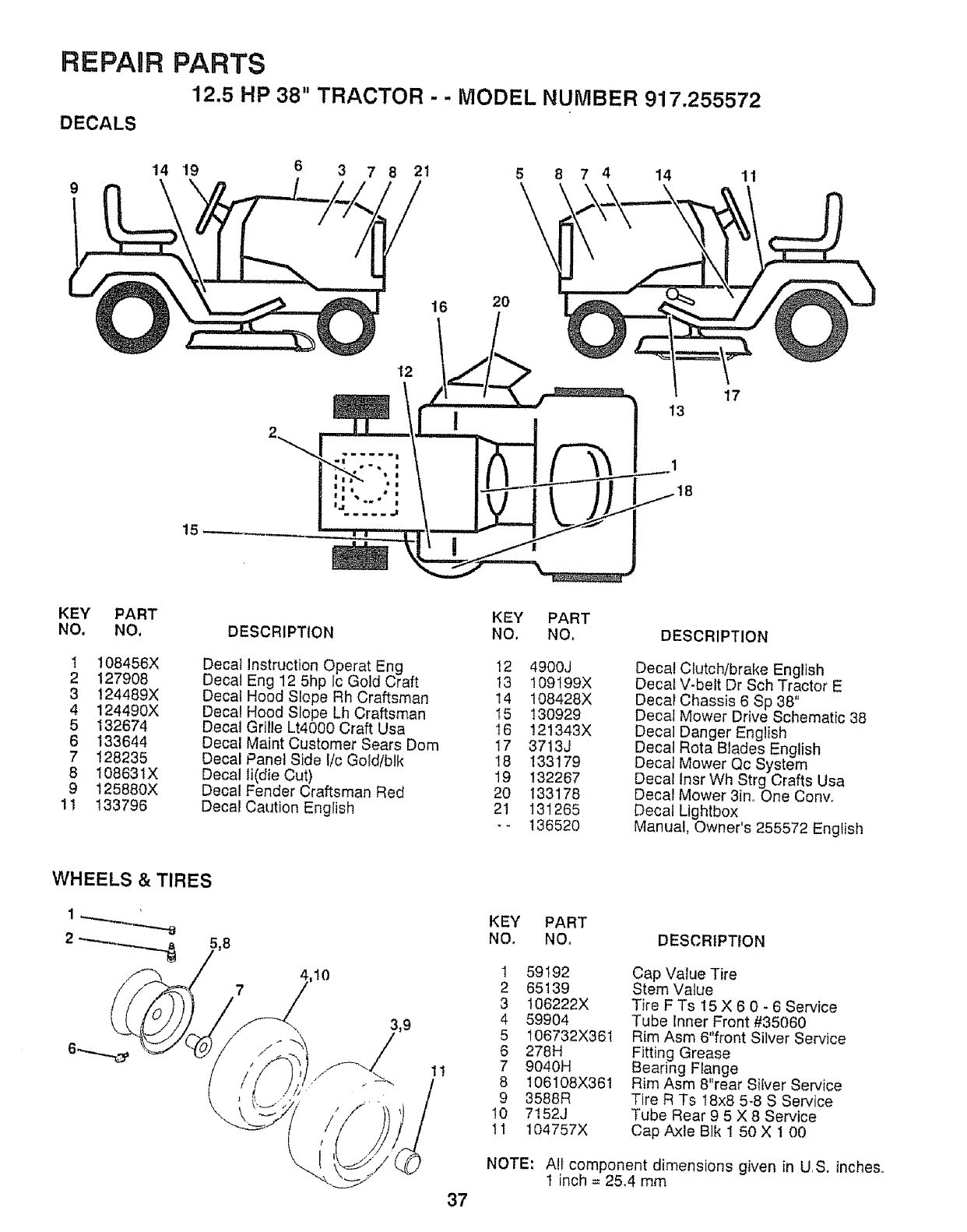
REPAOR PARTS
12.5 HP 38" TRACTOR - - MODEL NUMBER 917.255572
DECALS
14 19 6 3 7 82t 5 8 74 14 11
16
12
20
17
13
KEY PART KEY PART
NO. NO, DESCRIPTION NO, NO, DESCRIPTION
1 108456X Decal Instruction Operat Eng 12 4900J Decal Clutch/brake English
2 127908 Decal Eng 12 5hp lc Gold Craft 13 109199X Decal V-belt Dr Sch Tractor E
3 124489X Decal Hood Slope Rh Craftsman 14 108428X Decal Chassis 6 Sp 38"
4 124490X Decal Hood Slope Lh Craftsman I5 130929 Decal Mower Drive Schematic 38
5 132674 Decal Gritle Lt4000 Craft Usa 16 121343X Decal Danger English
6 133644 Decal Maint Customer Sears Dora 17 3713J Decal Rota Blades English
7 128235 Decal Panel Side I/c Gold/blk 18 133179 Decal Mower Qc System
8 108631X Decal li(die Cut) 19 132267 Decal tnsr Wh Strg Crafts Usa
9 125880X Decal Fender Craftsman Red 20 I33178 Decal Mower 3in., One Conv.
11 133796 Decal Caution English 21 131265 Decal Lightbox
-- 136520 Manual, Owner's 255572 English
/
KEY PART
NO. NOo DESCRIPTION
1t
1 59192
2 65139
3 106222X
4 59904
5 106732X361
6 278H
79040H
8 106108X361
9 3588R
10 7152J
11 104757X
Cap Value Tire
Stem Value
Tire FTs 15 X 6 0 - 6 Service
Tube Inner Front #35060
Rim Asm 6"front Silver Service
Fitting Grease
Bearing Flange
Rim Asm 8"rear Silver Service
Tire R Ts 18x8 5-8 S Service
Tube Rear 9 5 X 8 Service
Cap Axle Blk 1 50 X ! 00
NOTE: All component dimensions given in US. inches,
1 inch = 25,4 mm
37
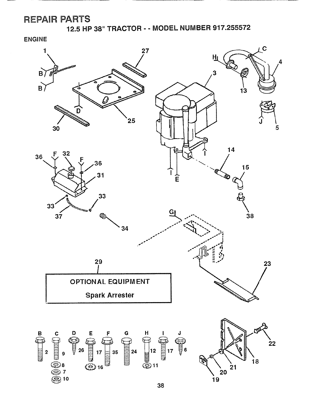
REPAIR PARTS
12.5 HP 38" TRACTOR - - MODEL NUMBER 917.255572
ENGINE
27
3O
25
F 32
37 _34
!OPTIONAL EQUIPM ENT
Spark Arrester
38
23
B C D E F G
Qlo
I-,i I J
_12 _17 _ 6
38
2
lg
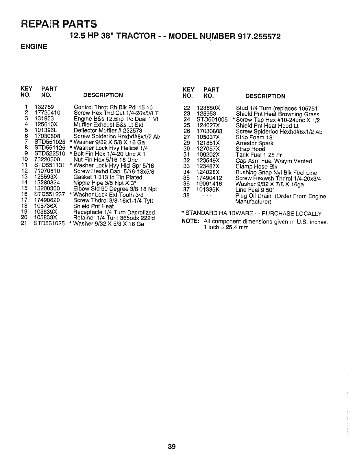
REPAUR PARTS
12.5 HP 38" TRACTOR - - MODEL NUMBER 917.255572
ENGINE
KEY PART KEY PART
NO. NO. DESCRIPTION NO. NO. DESCRIPTION
1 132759 Control rhrot Rh BIk Pdl 15 10 22 123650X
2 17720410 Screw H ex Thd Cut 1/4-20x5/8 T 23 128953
3 131953 Engine B&s 12.5hp t/c Dual 1 Vt 24 STD601005
4 125610X Muffler Exhaust B&s Lt Std 25 124027X
5 101326L Deflector Muffler # 222573 26 17030808
6 17030808 ScrewSpidedoc Hexhd#8xl!2 Ab 27 105037X
7 STD551025 *Washer9/32X5/8X16Ga 29 121851X
8 STD551125 *Washer Lock Hvy Helical !/4 30 127057X
9 STD522510 * Bolt Fin Hex 1/4-20 Unc X 1 31 109202X
10 73220500 Nut Fin Hex 5/16-18 Unc 32 123549X
11 STD551131 *Washer Lock Hvy Hlcl Spr 5/16 33 !23487X
12 71070510 Screw Hexhd Cap 5/! 6-18x5/8 34 !24028X
13 125593X Gasket 1 313 Id Tin Plated 35 17490412
14 13280324 Nipple Pipe 3/8 NptX3" 36 19091416
15 13200300 Elbow Std 90 Degree 3/8-18 Npt 37 101335K
I6 STD551237 * Washer Lock Ext Tooth 3/8 38 - -
17 17490620 Screw Thdrol 3/8_16x1-1/4 Tytt
18 105736X Shield Pnt Heat
19 105839X Receptacle 1/4 Turn Dacrotized
20 105838X Retainer t/4 Turn 365odx 222id
21 STD55t025 *Washer 9/32 X 5/8 X 16 Ga
Stud 1/4 Turn (replaces 105751
Shield Pnt Heat Browning Grass
*Screw Tap Hex #10-24unc X 1/2
Shield Pnt Heat Hood Lt
Screw Spidedoc Hexhd#8xl!2 Ab
Strip Foam 18"
Arrestor Spark
Strap Hood
Tank Fuel 1 25 Fr
Cap Asm Fuel W/sym Vented
Clamp Hose BIk
Bushing Snap Nyl Blk Fuel Line
Screw Hexwsh Thdrol 1/4-20x3/4
Washer 9/32 X 7/8 X t6ga
Line Fuel 9 50"
Plug Oil Drain (Order From Engine
Manufacturer)
*STANDARD HARDWARE _-PURCHASE LOCALLY
NOTE_ All component dimensions given in U_Soinches_
1 inch = 25,4 mm
39
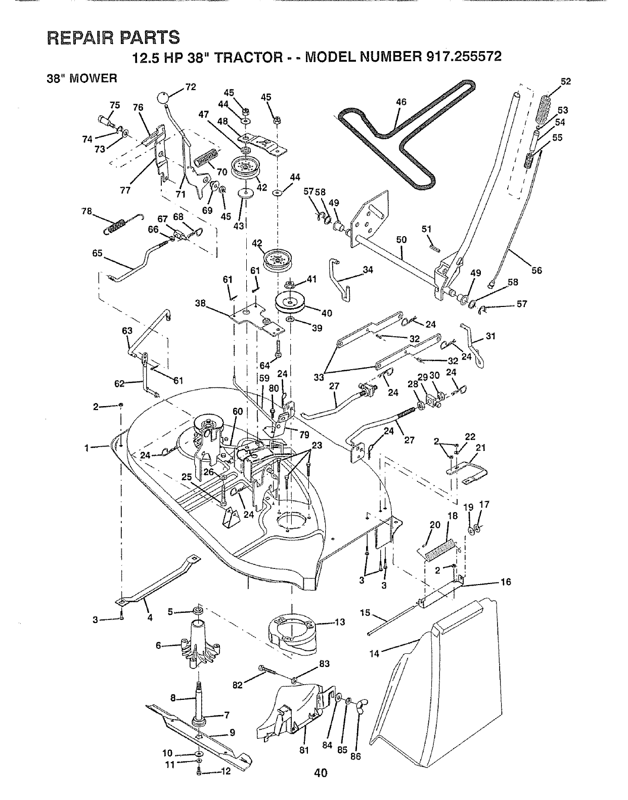
REPAIR PARTS
12.5 HP 38" TRACTOR - ,. MODEL NUMBER 917.255572
81 86
4O
52
53
,55
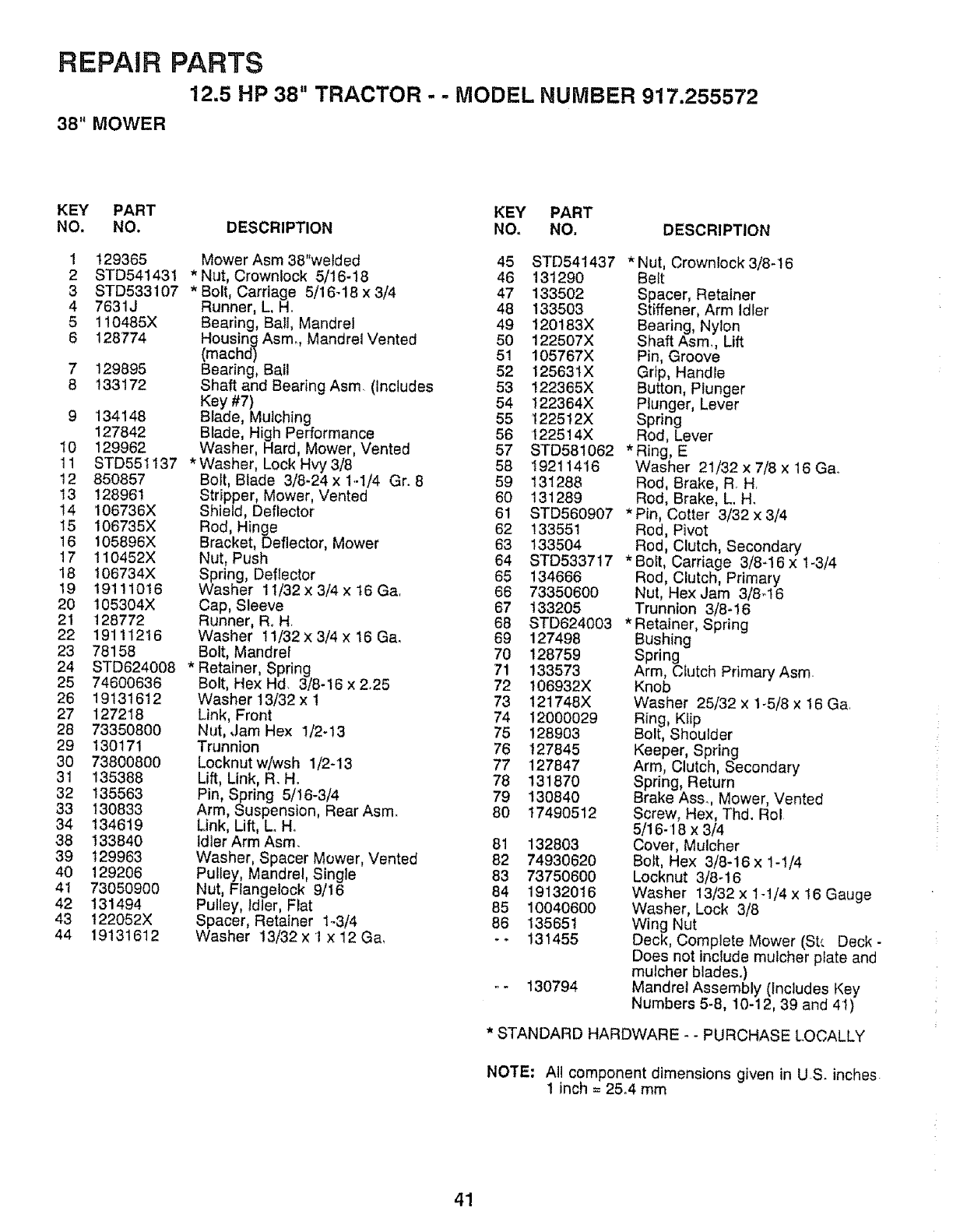
REPAIR PARTS
12.5 HP 38" TRACTOR - - MODEL NUMBER 917.255572
38" MOWER
KEY PART KEY PART
NO, NO. DESCRIPTION NO. NO. DESCRIPTION
!
2
3
4
5
6
7
8
10
11
12
13
14
15
16
17
18
19
20
21
22
23
24
25
26
27
28
29
3O
31
32
33
34
38
39
4O
4I
42
43
44
129365
STD54!431
STD533107
7631J
110485X
128774
129895
133172
134148
127842
129962
STD551137
850857
128961
106736X
106735X
105896X
110452X
106734X
19111016
105304X
128772
19111216
78158
STD624008
74600636
19131612
127218
73350800
130171
73800800
135388
135563
130833
134619
133840
129963
129206
73050900
131494
t22052X
19131612
Mower Asm 38"welded 45
*Nut, Crowntock 5/16-18 46
* Bolt, Carriage 5/16-18 x 3/4 47
Runner, L, H. 48
Bearing, Ball, Mandrel 49
Housing Asm., Mandrel Vented 50
(machd) 51
Bearing, Ball 52
Shaft and Bearing Asrn (includes 53
Key #7) 54
Blade, Mulching 55
Blade, High Performance 56
Washer, Hard, Mower, Vented 57
*Washer, Lock Hvy 3/8 58
Bolt, Blade 3/8-24 x 1-1/4 Gr. 8 59
Stripper, Mower, Vented 60
Shield, Deflector 61
Rod, Hinge 62
Bracket, Deflector, Mower 63
Nut, Push 64
Spring, Deflector 65
Washer 11/32 x 3/4 x 16 Ga, 66
Cap, Sleeve 67
Runner, R. H, 68
Washer 11/32 x 3/4 x 16 Ga_ 69
Bolt, Mandrel 70
*Retainer, Spring 71
Bolt, Hex Hd. 3/8-I6 x 2.25 72
Washer 13/32 x 1 73
Link, Front 74
Nut,,Jam Hex 1/2-t3 75
Trunnion 76
Locknut w/wsh 1/2-13 77
Lift, Link, R.H. 78
Pin, Spring 5/16-3/4 79
Arm, Suspension, Rear Asm. 80
Link, Lift, L. H.
idler Arm Asm. 81
Washer, Spacer Mower, Vented 82
Pulley, Mandrel, Single 83
Nut, Ftangelock 9/16 84
Pulley, idler, Flat 85
Spacer, Retainer 1_3/4 86
Washer 13/32 x 1 x 12 Ga, - -
STD541437 *Nut, Crownlock 3/8-16
131290 Belt
133502 Spacer, Retainer
!33503 Stiffener, Arm Idler
120183X Bearing, Nylon
122507X Shaft Asm., Lift
105767X Pin, Groove
125631X Grip, Handle
122365X Button, Plunger
122364X Plunger, Lever
1225!2X Spring
1225!4X Rod, Lever
STD581062 *Ring, E
I92114t6 Washer 21/32 x 7/8 x 16 Ga.
131288
131289
STD560907
133551
133504
STD533717
134666
73350600
133205
STD624003
127498
128759
133573
106932X
121748X
12000O29
128903
127845
127847
131870
130840
17490512
132803
74930620
73750600
19132016
10040600
135651
131455
130794
Rod, Brake, R. H,
Rod, Brake, L. H.
* Pin, Cotter 3/32 x 3/4
Rod, Pivot
Rod, Clutch, Secondary
*Bo_t, Carriage 3/8-16 x t-3/4
Rod, Clutch, Primary
Nut, Hex Jam 3/8_16
Trunnion 3/8-16
* Retainer, Spring
Bushing
Spring
Arm, Clutch Primary Asm
Knob
Washer 25/32 x 1-5/8 x !6 Ga.
Ring, Klip
Bolt, Shoulder
Keeper, Spring
Arm, Clutch, Secondary
Spring, Return
Brake Ass. Mower, Vented
Screw, Hex, Thd, Rol
5/16-18 x 3/4
Cover, Mulcher
Bolt, Hex 3/8-16 x 1-1/4
Locknut 3/8-16
Washer 13/32 x t-1/4 x 16 Gauge
Washer, Lock 3/8
Wing Nut
Deck, Complete Mower (St_ Deck -
Does not include mulcher plate and
mulcher blades.)
Mandrel Assembly (includes Key
Numbers 5-8, 10-12, 39 and 41)
* STANDARD HARDWARE - - PURCHASE LOCALLY
NOTE: All component dimensions given in US. inches
1 inch = 25.4 mm
41
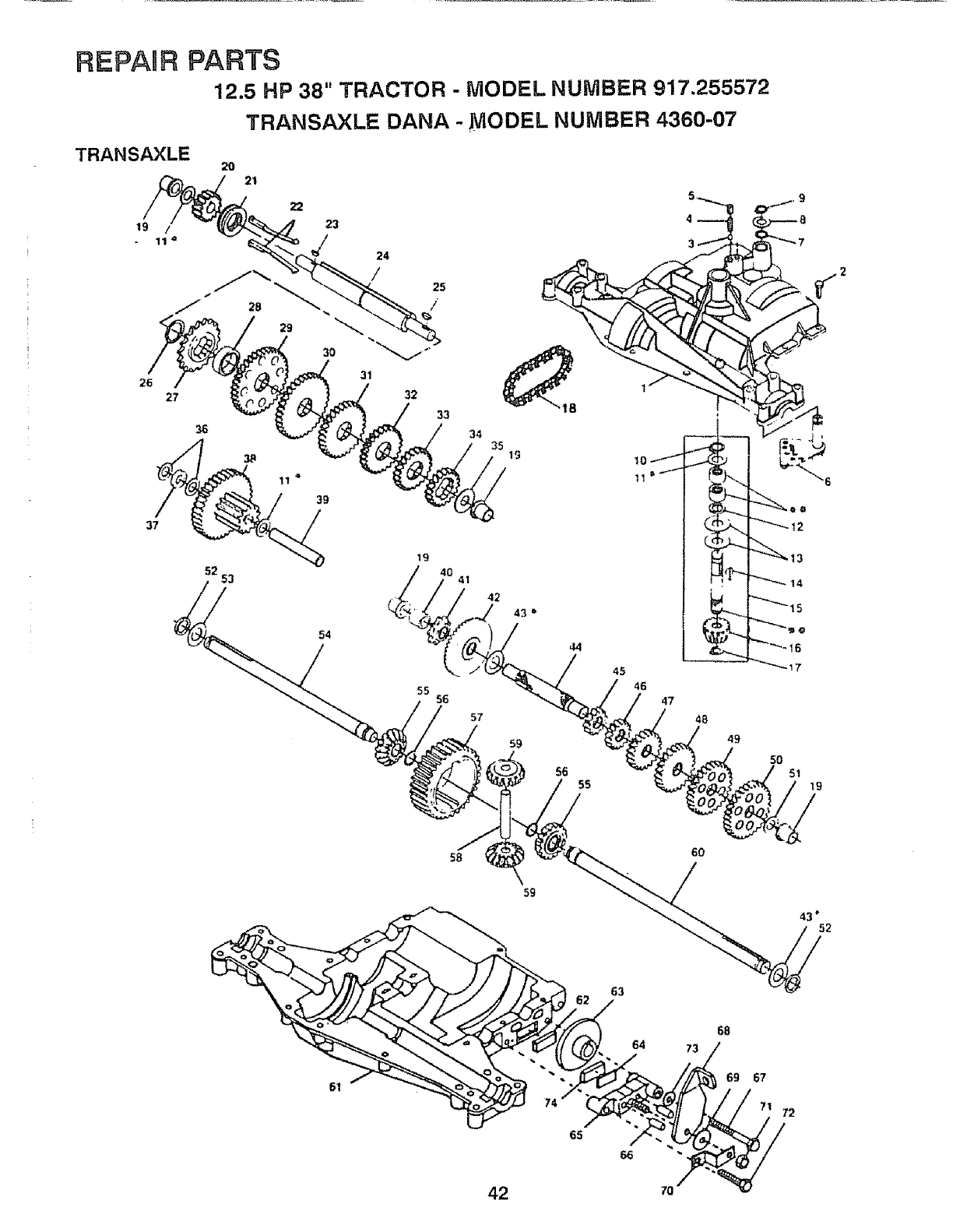
REPAaR PARTS
12.5 HP 38" TRACTOR - MODEL NUMBER 917.255572
TRANSAXLE DANA - MODEL NUMBER 4360-07
TRANSAXLE 2O 21
22
19 /23
11 '= J24
/
30 "_"
31
26
27 32
36
_11 _
52 53
54
33
55 56
34 35 17
42
57
59
44
45
56 55
45 47
48
49
50
51 19
58
59
6O
43" 52
63
65
64
66
73
68
69 67
72
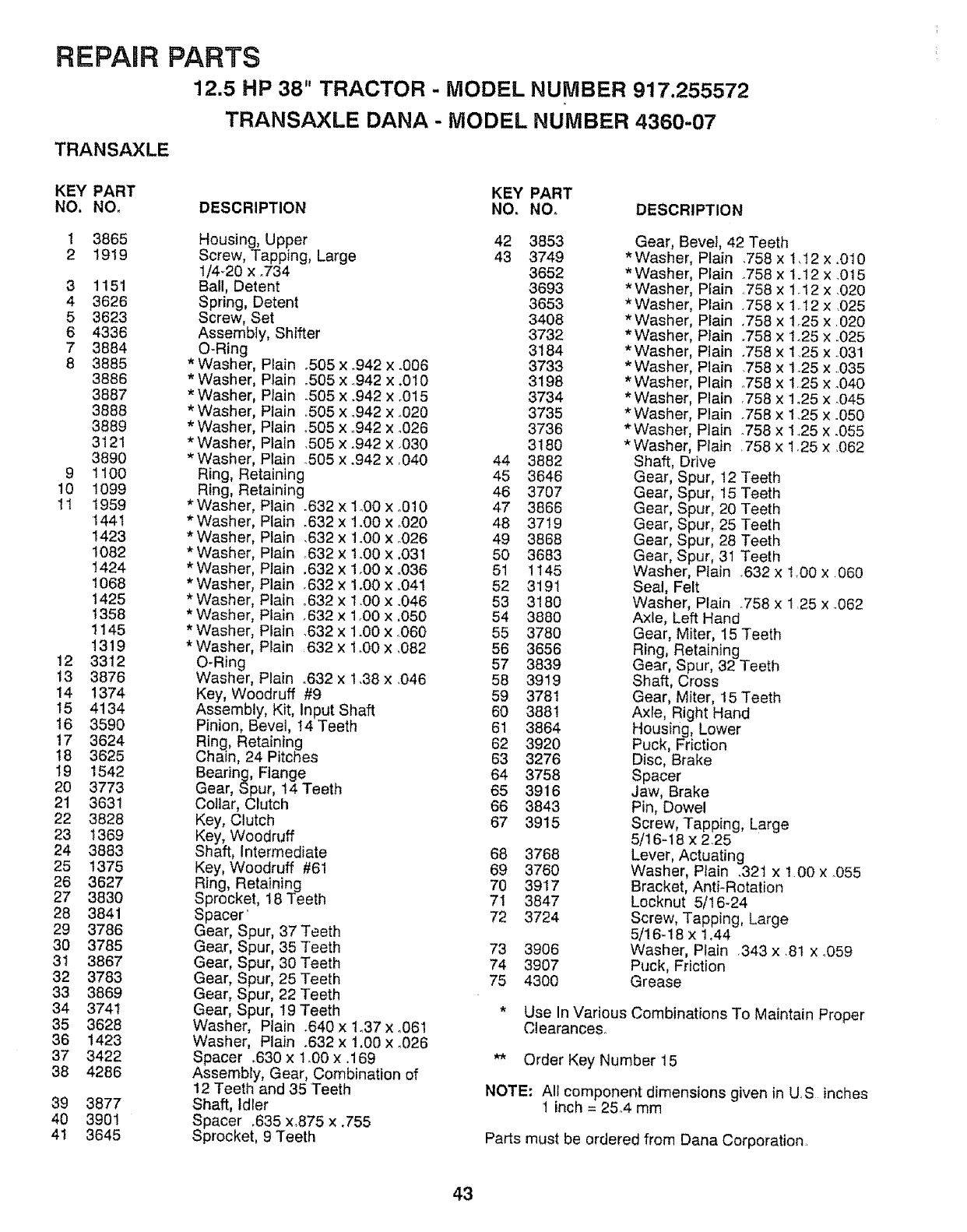
REPAIR PARTS
12.5 HP 38" TRACTOR - MODEL NUMBER 917.255572
TRANSAXLE DANA - MODEL NUMBER 4360-07
TRANSAXLE
KEY PART KEY PART
NO. NO. DESCRIPTION NO, NO, DESCRIPTION
3865
1919
3 1151
4 3626
5 3623
6 4336
7 3884
83885
3886
3887
3888
3889
3121
3890
9 1100
10 1099
11 1959
1441
1423
1082
1424
t068
t425
t358
1145
1319
12 3312
13 3876
14 1374
15 4134
16 3590
t7 3624
18 3625
t9 1542
20 3773
21 3631
22 3828
23 1369
24 3883
25 t375
26 3627
27 3830
28 3841
29 3786
30 3785
31 3867
32 3783
33 3869
34 3741
35 3628
36 1423
37 3422
38 4286
39
4O
41
3877
3901
3645
Housing, Upper 42 3853
Screw, Tapping, Large 43 3749
1/4_20 x _734 3652
Ball, Detent 3693
Spring, Detent 3653
Screw, Set 3408
Assembly, Shifter 3732
O-Ring 3184
*Washer, Plain °505 x .942 x °006 3733
*Washer, Plain .505 x ..942 x .010 3198
* Washer, Plain .505 x .942 x _015 3734
*Washer, P{ain .505 x _942x ,.020 3735
*Washer, Plain °505 x °942 x .026 3736
*Washer, Plain .505 x .942 x .030 3180
*Washer, Plain .505 x .942 x ,040 44 3882
Ring, Retaining 45 3646
Ring, Retaining 46 3707
* Washer, Plain .632 x 1.00 x .010 47 3865
*Washer, Plain .632 x 1.00 x ,020 48 3719
* Washer, Plain .632 x 1.00 x °026 49 3868
*Washer, Plain .632 x !o00 x .031 50 3683
*Washer, Plain .632 x 1.00 x °036 51 ! 145
* Washer, Plain .832 x 1.00 x .041 52 3191
* Washer, Plain °632 x 1.00 x .046 53 3180
* Washer, Plain .632 x 1.00 x .050 54 3880
* Washer, Plain .632 x 1.00 x.060 55 3780
*Washer, Plain 632 x 1.00 x ,082 56 3656
O-Ring 57 3839
Washer, Plain °632 x 1.38 x .046 58 3919
Key, Woodruff #9 59 3781
Assembly, Kit, Input Shaft 60 3881
Pinion, Bevel, t4 Teeth 61 3864
Ring, Retaining 62 3920
Chain, 24 Pitches 63 3276
Bearing, Flange 64 3758
Gear, Spur, 14 Teeth 65 3916
Collar, Clutch 66 3843
Key, Clutch 67 3915
Key, Woodruff
Shaft, Intermediate 68 3768
Key, Woodruff #61 69 3760
Ring, Retaining 70 3917
Sprocket, 18Teeth 71 3847
Spacer' 72 3724
Gear, Spur, 37 Teeth
Gear, Spur, 35 Teeth 73 3906
Gear, Spur, 30 Teeth 74 3907
Gear, Spur, 26 Teeth 75 4300
Gear, Spur, 22 Teeth
Gear, Spur, t9 Teeth
Washer, Plain .640 x t_37 x o061
Washer, Plain .632 x 1,00 x °026
Spacer .630 x 1o00 x ,169
Assembly, Gear, Combination of
12 Teeth and 35 Teeth
Shaft, Idler
Spacer ,635 x,875 x .755
Sprocket, 9 Teeth
Gear, Bevel, 42 Teeth
*Washer, Plain .758 x 1.12 x o010
*Washer, Plain
* Washer, Plain
* Washer, Plain
* Washer, Plain
*Washer, Plain
*Washer Plain
*Washer P_ain
*Washer Plain
*Washer Plain
*Washer Plain
*Washer Plain
*Washer Plain
Shaft, Drive
.758 x 1.t2 x .015
.758 x 1.t2 x .020
.758 X 1.12 x .025
.758 x t.25 x 020
°758 xl.25 X.025
°758 x t,25 X.031
758 x 1.25 x .035
.758 x 1.25 x .040
758 x 1o25 x _045
.758 x 1.25 x .050
.758 x 125 X.055
758 x 1.25 x,062
Gear, Spur, 12 Teeth
Gear, Spur, 15 Teeth
Gear, Spur, 20 Teeth
Gear, Spur, 25 Teeth
Gear, Spur, 28 Teeth
Gear, Spur, 31 Teeth
Washer, Ptain _632 x 1.00 x .060
Seal, Felt
Washer, Plain _758 x 1,25 x .062
Axle, Left Hand
Gear, Miter, 15 Teeth
Ring, Retaining
Gear, Spur, 32 Teeth
Shaft, Cross
Gear, Miter, 15 Teeth
Axle, Right Hand
Housing, Lower
Puck, Friction
Disc, Brake
Spacer
Jaw, Brake
Pin, Dowel
Screw, Tapping, Large
5/16-t 8 x 2.25
Lever, Actuating
Washer, Plain .32t x 100 x .055
Bracket, Anti-Rotation
Locknut 5/16-24
Screw, Tapping, Large
5/16_18 x 1,44
Washer, Plain 343 x .81 x .059
Puck, Friction
Grease
* Use In Various Combinations To Maintain Proper
Clearances,.
** Order Key Number 15
NOTE: All component dimensions given in US inches
1 inch = 25.4 mm
Parts must be ordered from Dana Corporation.
43
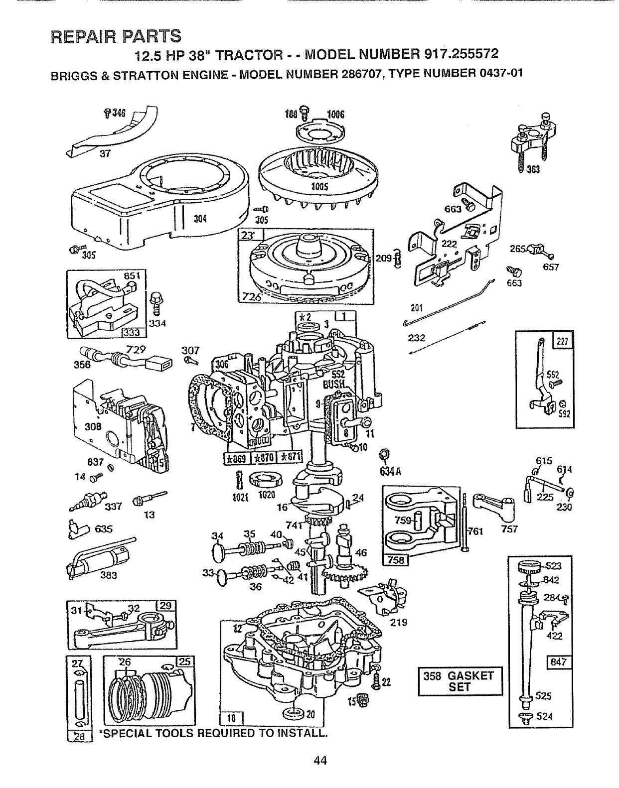
REPAIR PARTS
12.5 HP 38" TRACTOR - - MODEL NUMBER 917.255572
BRIGGS & STRATTON ENGINE - MODEL NUMBER 286707, TYPE NUMBER 0437-01
.363
307
837
t4(_
13
26
*SPECIAL TOOLS REQUIRED TO INSTALL.
657
663
757
_15 6 4
358 ASKET
SET
524
44
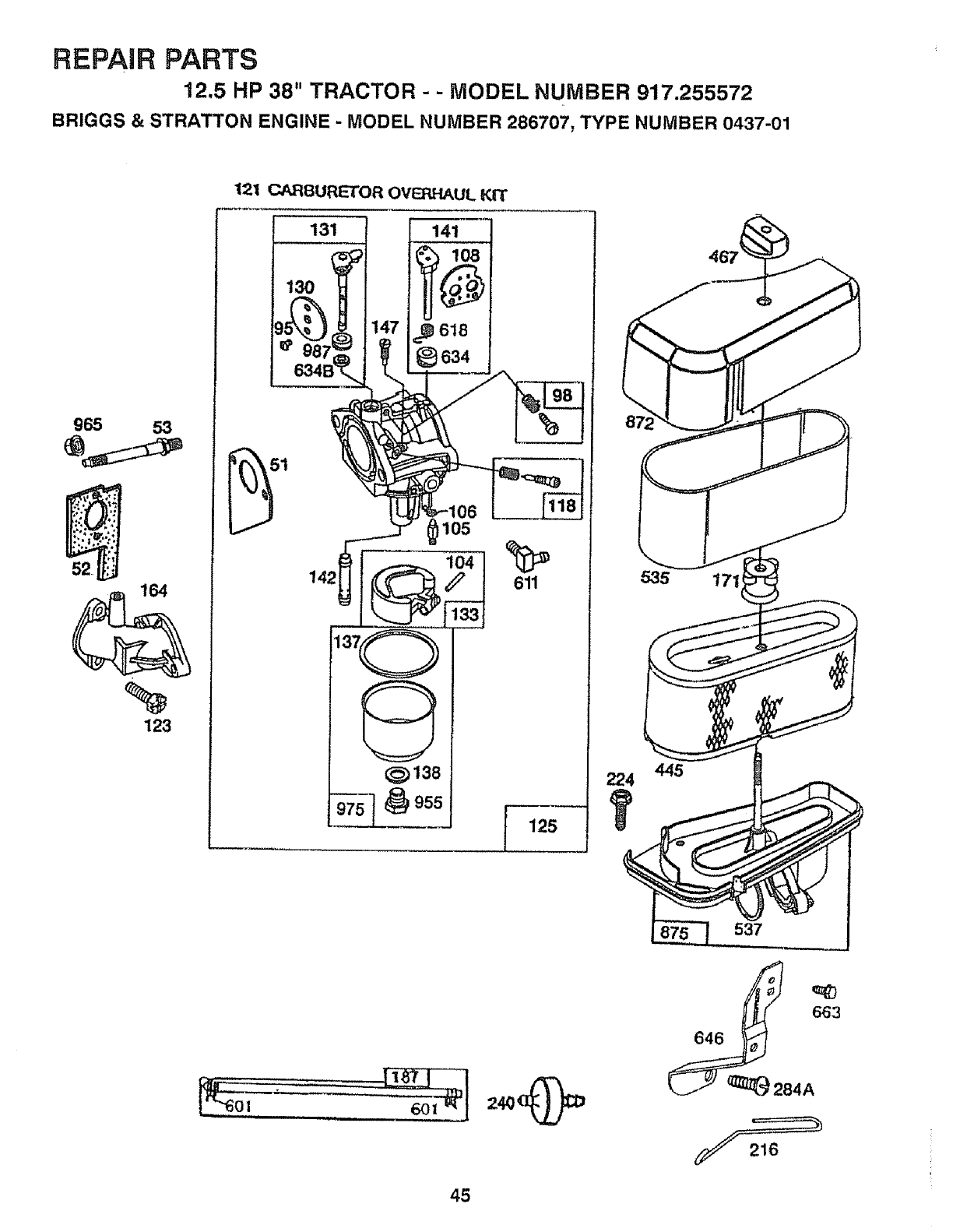
REPAIR PARTS
12.5 HP 38" TRACTOR - - MODEL NUMBER 917.255572
BRIGGS & STRATTON ENGINE - MODEL NUMBER 286707, TYPE NUMBER 0437-01
965 53
52.
164
%
123
121 CARBUP_TOR OVERHAUL KIT
131
130
141
,_ 618
634
105
611
I125
224
535
537
45
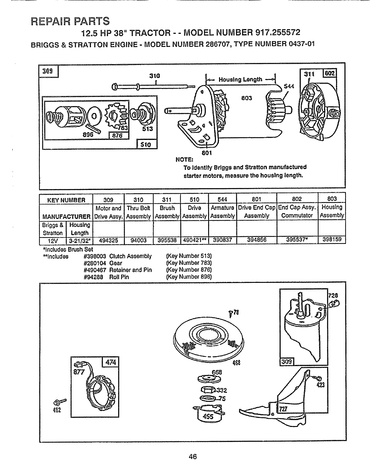
REPAaR PARTS
12.5 HP 38" TRACTOR - -MODEL NUMBER 917,255572
BRIGGS & STRATTON ENGINE -MODEL NUMBER 286707, TYPE NUMBER 0437-01
:_0 = __'- Housing Length
, o
NOTE:
To Identlfy Brlggs and Stratton manufactured
starter motors, measure the housing length.
i i,iiii iiiii iiiii i J, i1,,,,,
KEY NUMBER 309 310 311 510 544 801 802 803
Motorand Thru Bolt Brush Drive Armature Drive End Cap End Cap Assy. Housing
MANUFACTURER Drive Assy. Assembly Assembly Assembly Assembly Assembly Commutator Assembly
Briggs & I Housing
$tratton J_Length
t2V [_ 494325 94003 395538 490421_j 390837 394856 o395537* 398159
*Includes BrushSet
**includes #398003 Clutch Assembly
#280104 Gear
#490467 Retainer and Pin
#94288 Roll Pin
i IN illl illllll ii ,lllll,llll,, i , iH, i i
(Key Number 513)
(Key Number 783)
(Key Number 876)
(Key Number 896)
,i, ,,,,,,,111,,
4_2
66_
46
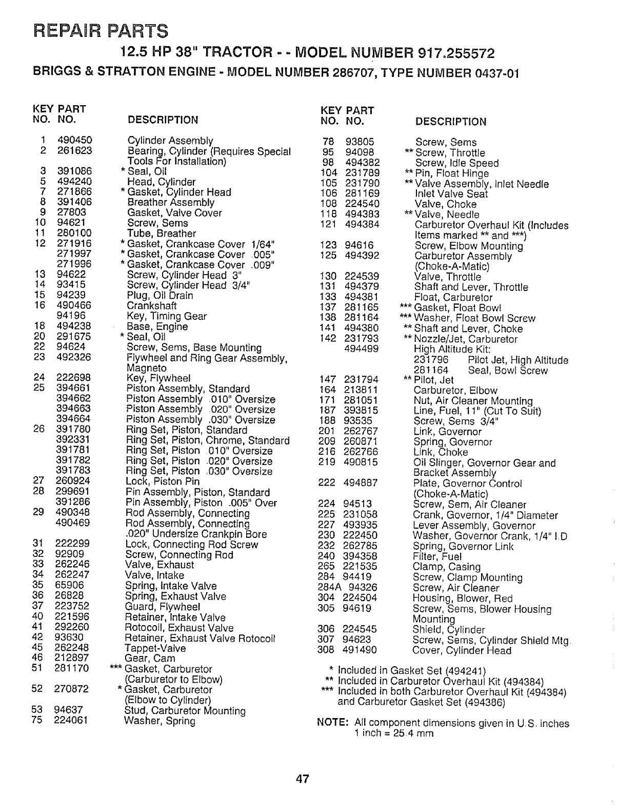
REPAIR PARTS
12.5 HP 38" TRACTOR - - MODEL NUMBER 917.255572
BRIGGS & STRATTON ENGINE - MODEL NUMBER 286707, TYPE NUMBER 0437-01
KEY PART KEY PART
NO. NO. DESCRIPTION NO. NO. DESCRIPTION
1 490450
2 261623
3 391086
5 494240
7 271866
8 391406
9 27803
10 94621
11 280100
12 271916
271997
271996
13 94622
14 93415
15 94239
16 490466
94196
18 494238
20 291675
22 94624
23 492326
24 222698
25 394661
394662
394663
394664
26 391780
392331
391781
391782
391783
27 260924
28 299691
391286
29 490348
490469
31 222299
32 92909
33 262246
34 262247
35 65906
36 26828
37 223752
40 221596
41 292260
42 93630
45 262248
46 212897
51 281170
52 270872
53 94637
75 224061
Cylinder Assembly 78 93805
Bearing, Cylinder (Requires Special 95 94098
Tools For Installation) 98 494382
Seal, Oil 104 231789
Head, Cylinder 105 231790
* Gasket, Cylinder Head 106 281169
Breather Assembly t08 224540
Gasket, Valve Cover 118 494383
Screw, Seres 121 494384
Tube, Breather
* Gasket, Crankcase Cover 1/64" 123 94616
* Gasket, Crankcase Cover ,005" 125 494392
* Gasket, Crankcase Cover _009"
Screw, Cytinder Head 3" 130 224539
Screw, Cylinder Head 3/4" 131 494379
Plug, OilDrain 133 494381
Crankshaft 137 281165
Key, Timing Gear 138 281164
Base, Engine 141 494380
*Seal, Oil 142 231793
Screw, Seres, Base Mounting 494499
Flywheel and Ring Gear Assembly,
Magneto
Key, Flywheel 147 231794
Piston Assembly, Standard 164 213811
Piston Assembly 010" Oversize 171 281051
Piston Assembly ,020" Oversize 187 393815
Piston Assembly .030" Oversize IBB 93535
Ring Set, Piston, Standard 201 262767
Ring Set, Piston, Chrome, Standard 209 260871
Ring Set, Piston 010" Oversize 216 262766
Ring Set, Piston .020" Oversize 219 490815
Ring Set, Piston .030" Oversize
Lock, Piston Pin 222 494887
Pin Assembly, Piston, Standard
Pin Assembly, Piston .005" Over 224 94513
Rod Assembly, Connecting 225 231058
Rod,Assembly, Connecting 227 493935
.020 Undersize Crankpin Bore 230 222450
Lock, Connecting Rod Screw 232 262785
Screw, Connecting Rod 240 394358
Valve, Exhaust 265 221535
Valve, Intake 284 94419
Spring, Intake VaIve 284A 94326
Spring, Exhaust Valve 304 224504
Guard, Flywheel 305 94619
Retainer, Intake Valve
Rotocoil, Exhaust Valve 306 224545
Retainer, Exhaust Valve Rotocoll 307 94623
Tappet-Valve 308 491490
Gear, Cam
*'_ Gasket, Carburetor
(Carburetor to Elbow)
* Gasket, Carburetor
(Elbow to Cylinder)
Stud, Carburetor Mounting
Washer, Spring
Screw, Sems
** Screw, Throttle
Screw, Idle Speed
** Pin, Float Hinge
**Valve Assembly, Inlet Needle
Inlet Valve Seat
Valve, Choke
** Valve, Needle
Carburetor Overhaul Kit (Includes
Items marked ** and ***)
Screw, Elbow Mounting
Carburetor Assembly
(Choke-A-Matic)
Valve, Throttle
Shaft and Lever, Throttle
F_oat, Carburetor
*** Gasket, Float Bowl
*** Washer, Float Bowl Screw
** Shaft and Lever, Choke
** Nozzle/Jet, Carburetor
High Altitude Kit:
231796 Pilot Jet, High Altitude
281164 Seal, Bowl Screw
** Pilot, Jet
Carburetor, Elbow
Nut, Air Cleaner Mounting
Line, Fuel, 11" (Cut To Suit)
Screw, Seres 3/4"
Link, Governor
Spring, Governor
Link, Choke
Oii Slinger, Governor Gear and
Bracket Assembly
Plate, Governor Control
(Choke-A-Matic)
Screw, Sere, Air Cleaner
Crank, Governor, 1/4" Diameter
Lever Assembly, Governor
Washer, Governor Crank, 1/4" ID
Spring, Governor Link
Filter, Fuel
Clamp, Casing
Screw, Clamp Mounting
Screw, Air Cleaner
Housing, Blower, Red
Screw, Seres, Blower Housing
Mounting
Shield, Cylinder
Screw, Sems, Cylinder Shield Mtg,
Cover, Cylinder Head
Included in Gasket Set (494241)
** Included in Carburetor Overhaul Kit (494384}
*** Included in both Carburetor Overhaul Kit (494384)
and Carburetor Gasket Set (494386)
NOTE: All component dimensions given in US inches
1 inch = 25.4 mm
47
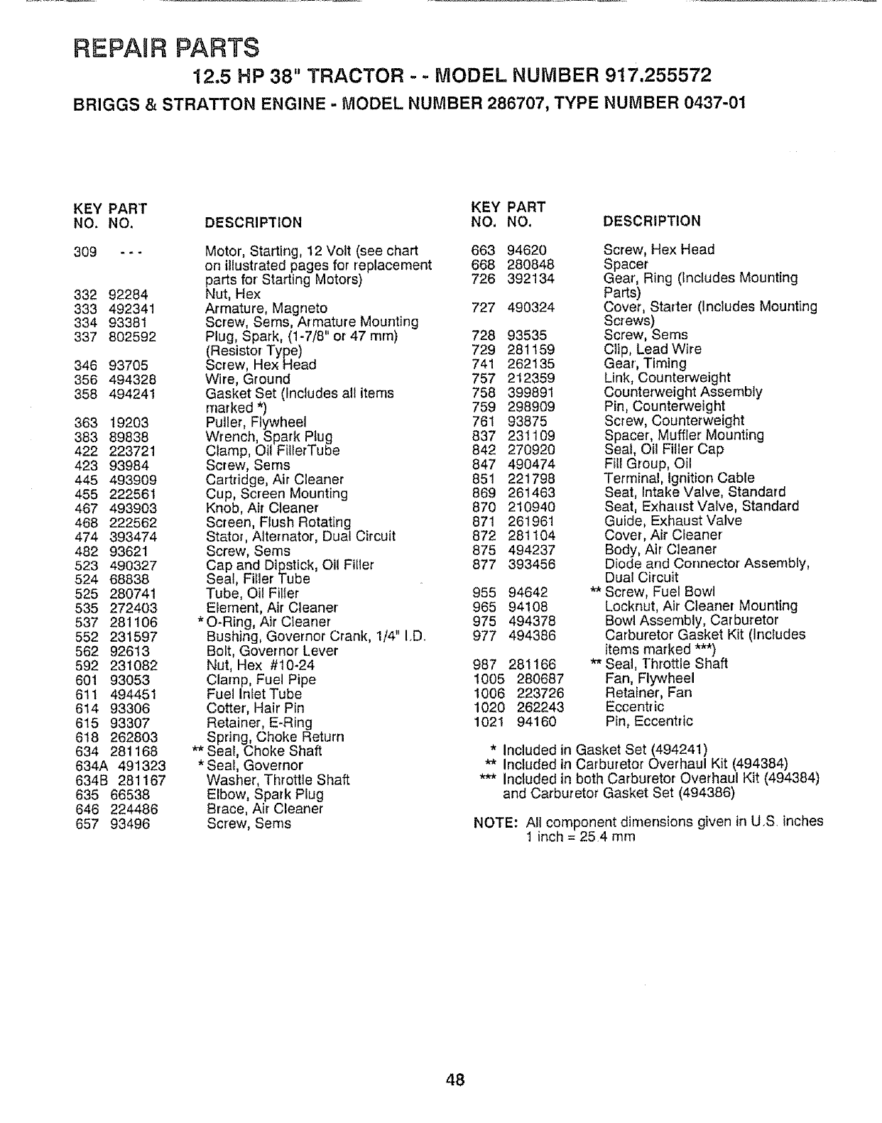
REPARR PARTS
12.5 HP 38" TRACTOR - - MODEL NUMBER 917.255572
BRIGGS & STRATTON ENGINE - MODEL NUMBER 286707, TYPE NUMBER 0437-01
KEY PART KEY PART
NO. NO. DESCRIPTION NO. NO. DESCRIPTION
309
332 92284
333 492341
334 93381
337 802592
346 93705
356 494328
358 494241
363 19203
383 89838
422 223721
423 93984
445 493909
455 222561
467 493903
468 222562
474 393474
482 93621
523 490327
524 68838
525 280741
535 272403
537 281106
552 231597
562 92613
592 231082
601 93053
611 494451
614 93306
615 93307
618 262803
634 281168
634A 491323
634B 281167
635 66538
646 224486
657 93496
Motor, Starting, 12 Volt (see chart 663 94620
on illustrated pages for replacement 668 280848
parts for Starting Motors) 726 392134
Nut, Hex 727 490324
Armature, Magneto
Screw, Sems, Armature Mounting
Plug, Spark, (1-7/8" or 47 ram) 728 93535
(Resistor Type) 729 281159
Screw, Hex Head 741 262135
Wire, Ground 757 212359
Gasket Set (Includes all items 758 399891
marked *) 759 298909
Puller, Flywheel 761 93875
Wrench, Spark Plug 837 231109
Clamp, Oil FillerTube 842 270920
Screw, Seres 847 490474
Cartridge, Air Cleaner 851 221798
Cup, Screen Mounting 869 261463
Knob, Air Cleaner 870 210940
Screen, Flush Rotating 871 261961
Stator, Alternator, Dual Circuit 872 28tt04
Screw, Seres 875 494237
Cap and D_pstick, Oil Filler 877 393456
Seal, Filler Tube
Tube, Oil Filier 955 94642
Element, Air Cleaner 965 94108
*O-Ring, Air C{eaner 975 494378
Bushing, Governer Crank, 1/4" I.D. 977 494386
Bolt, Governor Lever
Nut, Hex #t0-24 987 281166
Clamp, Fuel Pipe 1005 280687
Fuel Inlet Tube 1006 223726
Cotter, Hair Pin 1020 262243
Retainer, E-Ring 1021 94160
Spring, Choke Return
** Seal, Choke Shaft
* Seal, Governor
Washer, Throttle Shaft
Elbow, Spark Plug
Brace, Air Cleaner
Screw, Seres
Screw, Hex Head
Spacer
Gear, Ring (tnc{udes Mounting
Parts)
Cover, Starter (Includes Mounting
Screws)
Screw, Sems
Clip, Lead Wire
Gear, Timing
Link Counterweight
Counterweight Assembly
Pin Counterweight
Screw, Counterwe ght
Spacer, Muffler Mounting
Seal, Oil Filler Cap
Fill Group, Oil
Terminal, ignition Cable
Seat, Intake Valve, Standard
Seat, Exhaust Valve, Standard
Guide, Exhaust Valve
Cover, Air CIeaner
Body, Air Cleaner
Diode and Connector Assembly,
Dual Circuit
** Screw, Fuel Bowl
Locknut, Air Cleaner Mounting
Bowl Assembly, Car buretor
Carburetor Gasket Kit (Includes
Items marked ***)
** Seal, Throttle Shaft
Fan, Flywheel
Retainer, Fan
Eccent[ic
Pin, Eccentric
*Included in Gasket Set (494241)
** Included in Carburetor Overhaul Kit (494384)
*** Included in both Carburetor Overhaul Kit (494384)
and Carburetor Gasket Set (494386)
NOTE: Allcomponent dimensions given inU,S inches
1 inch = 254 mm
48
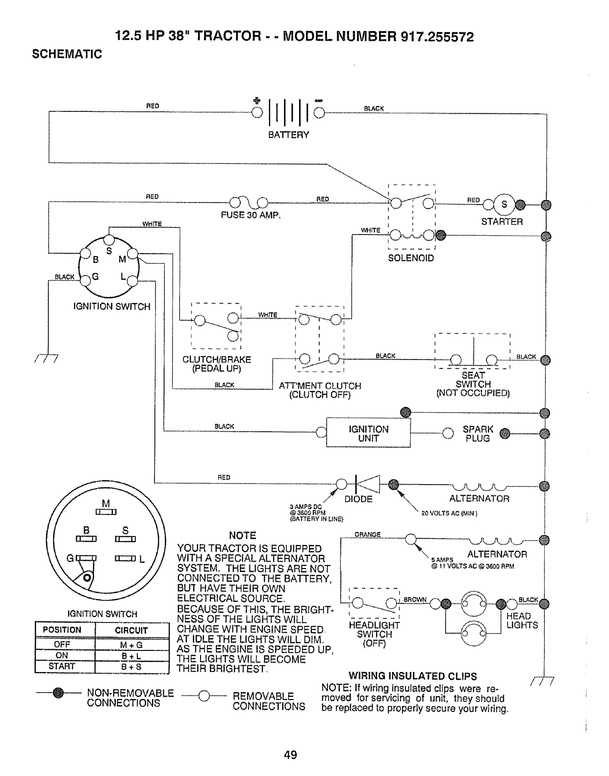
12.5 HP 38" TRACTOR - -MODEL NUMBER 917.255572
SCHEMATIC
RED ollllllo
BATTERY
BLACK
RED
8LACK
/-77
WHrfE
IGNITION SWITCH
IGNiTiON SWITCH
.os,T,o.i
OFF M + G__
ON L+c_ J
START B + S j
FUSE 30 AMP,
RED t
t I I
J
SOLENOID
I ...... tI
tII
CLUTCH/BRAKE ....I
(PEDAL UP) _
BLACK
8LACK
ATT'MENT CLUTCH
(CLUTCH OFF)
SLACK
STARTER
RED
I ......... I
I I
SEAT
SWITCH
(NOT OCCUPIED)
IGNITION SPARKUNIT PLUG
aAMPSOCf DIODE "_ ALTERNATOR
@ 3600 RPM _20 VOLTS AC (MIN }
(BATTERY IN UNE}
ORANGE
_JL_JL_..7---i
5AMPS ALTERNATOR
@1t VOLTS AC @ 3600 RPM
1 t BROWN 8LACK
HEADLIGHT I /S'-"_'_ I LIGHTS
SWITCH
(OFF)
NOTE
YOUR TRACTOR IS EQUIPPED
WITH A SPECIAL ALTERNATOR
SYSTEM. THE LIGHTS ARE NOT
CONNECTED TO THE BATTERY,
Bu'r HAVE THEIR OWN
ELECTRICAL SOURCE,
BECAUSE OF THIS, THE BRIGHT-
NESS OF THE LIGHTS WILL
CHANGE WITH ENGINE SPEED.
AT IDLE THE LIGHTS WILL DIM,
AS THE ENGINE IS SPEEDED UP,
THE LIGHTS WILL BECOME
THEIR BRIGHTEST. WIRING INSULATED CLIPS
NOTE: If wiring insulated clips were re-
moved for servicing of unit, theyshoutd
be replaced to properly secure your wiring.
NON-REMOVABLE _ REMOVABLE
CONNECTIONS CONNECTIONS
49

SERVICE NOTES
HI HIH HH HI
5O

SUGGESTED GUfDE FOR SUGHTING SLOPES FOR SAFE OPERATION
O1
.-&
SIGHTING
GUIDE
ONLY RIDE UP AND DOWN HILL,
NOT ACROSS HILL
SIGHT AND HOLD THIS LEVEL WiTH
SKY LINE OR TREE.
'="== .... i....... i,' '
Operate your Tractor up and down the face of slopes (not I
greater than 15°), never across the face. Make turns gradu- I
ally to prevent tipping or loss of control. Exercise extreme !
caution when changing directio? on _o_pes, ......... j
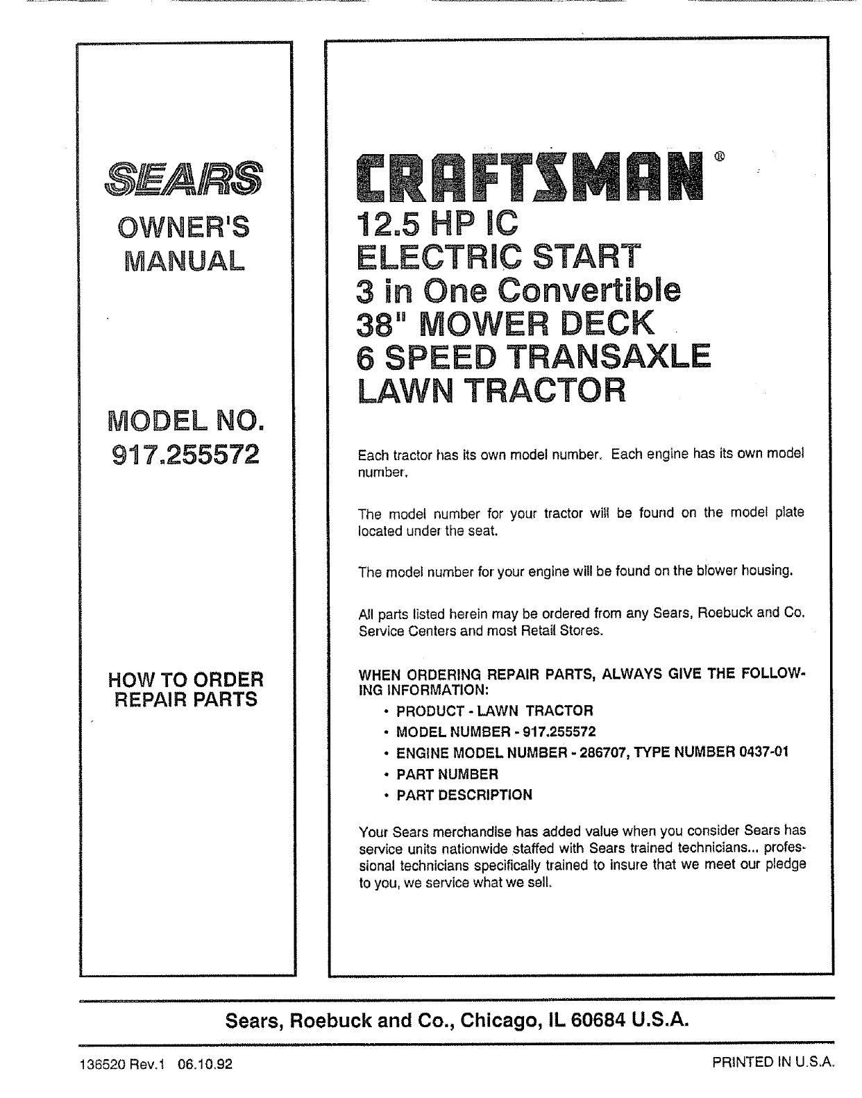
MODEL NO.
917o255572
HOW TO ORDER
REPAIR PARTS
®
Each tractor has its own model number. Each engine has its own model
number.
The model number for your tractor will be found on the model plate
located under the seat.
The model number for' your engine will be found on the blower housing.
All parts listed herein may be ordered from any Sears, Roebuck and Co.
Service Centers and most Retail Stores.
WHEN ORDERING REPAIR PARTS, ALWAYS GIVE THE FOLLOW-
ING INFORMATION:
•PRODUCT-LAWN TRACTOR
• MODEL NUMBER - 917.255572
•ENGINE MODEL NUMBER - 286707, TYPE NUMBER 0437-01
•PART NUMBER
•PART DESCRIPTION
Your Sears merchandise has added value when you consider Sears has
service units nationwide staffed with Sears trained technicians.., profes-
sicnal technicians specifically trained to insure that we meet our pledge
to you, we service what we sell.
u. ii,i I,=I,=,,=H=IIH,,I, =' HHHHH= H ==HHHI=HH=IH
Sears, Roebuck and Co., Chicago, IL 60684 U.S.A.
136520 Revol 06.10_92 PRINTED IN U.S,A,
