Craftsman 917255732 User Manual 11 H.P. 38 INCH RIDING LAWN TRACTOR Manuals And Guides L0807660
CRAFTSMAN Lawn, Tractor Manual L0807660 CRAFTSMAN Lawn, Tractor Owner's Manual, CRAFTSMAN Lawn, Tractor installation guides
User Manual: Craftsman 917255732 917255732 CRAFTSMAN CRAFTSMAN 11 H.P. 38 INCH RIDING LAWN TRACTOR - Manuals and Guides View the owners manual for your CRAFTSMAN CRAFTSMAN 11 H.P. 38 INCH RIDING LAWN TRACTOR #917255732. Home:Lawn & Garden Parts:Craftsman Parts:Craftsman CRAFTSMAN 11 H.P. 38 INCH RIDING LAWN TRACTOR Manual
Open the PDF directly: View PDF ![]() .
.
Page Count: 132 [warning: Documents this large are best viewed by clicking the View PDF Link!]
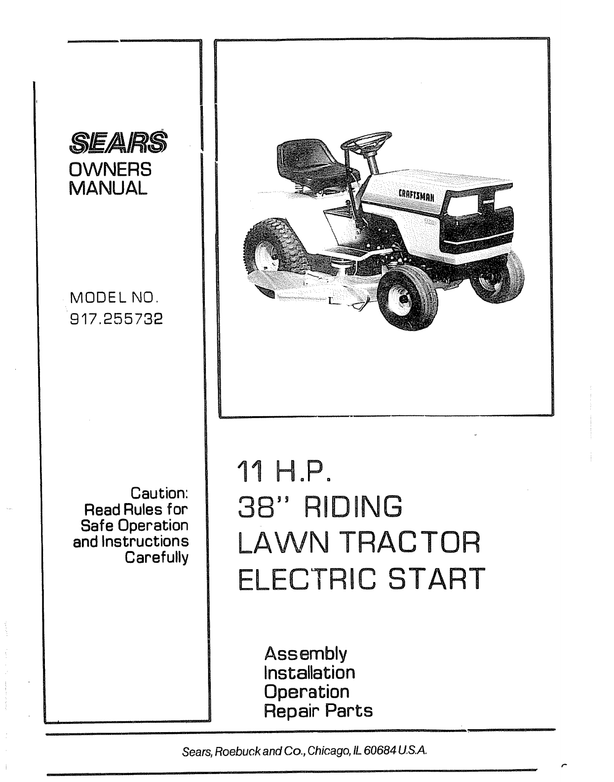
SEA/ S
OWNERS
MANUAL
MODE L NO.
917.255732
Caution:
Read Rules for
Safe Operation
and Instructions
Carefully
| i/ ........
11 H,P,
38" RIDJNG
LAWN TRAC TOR
ELECTRIC START
Assembly
Installation
Operation
Repair Parts
ii u l
Sears, Roebuck and Co., Chicago, IL 60684 US.Ao
t"
CONGRATULATIONS on your purchase of a Sears Lawn
Tractor, It has been designed, engineered and manufactured
to give you the best possib{e dependability and performance
Should you experience any problem you cannot easily reme-
dy, please contact your nearest Sears Service Department,
They have competent, well-trained technicians and the proper
tools to service or repair this unit.
Please read and retain this manual. The instructions will enable
you to assemble, operate and maintain your Tractor properly
Always observe the "RULES FOR SAFE OPERATION"_
MODEL
NUMBER ....... ;_ ..... :;,_. _..... ,-._ ....._.
SERIAL
NUMBER
THE DRAWBARo
YOU SHOULD PECORD BOTH MODEL AND
SERIAL NUMBF'._ AND KEEP IN A SAFE PLACE
FOR FUTURE rtEFERENCE,
LIMITED ONE YEAR WARRANTY
ON ELECTRIC START RIDING EQUIPMENT
For one year from date of purchase, when this riding equipment is maintained, lubricated, and
tuned up according to the operating and maintenance instructions in the owner's manual, Sears
will repair' free of charge any defect in material or workmanship in this electric start riding equip-
mento
This warranty excludes blade(s), blade adapter(s), spark plug(s), air cleaner and belt(s), which are
expendable and become worn during normal use.
This warranty does not cover:
tire replacement or repair caused by punctures from outside objects (such as nails, thorns,
stumps, or glass); and
repairs necessary because of operator abuse or negligence, including the failure to main-
tain the equipment according to instructions contained in the owner's manual; and
riding equipment used for commercial or rental purposes.
FULL 90-DAY WARRANTY ON BATTERY
For 90 days from the date of purchase, if any battery included with this riding equipment proves
defective in material or workmanship and our testing determines the battery will not hold a charge,
Sears will replace the battery at no charge.
WARRANTY SERVICE IS AVAILABLE BY CONTACTING THE NEAREST SEARS SERVICE
CENTER/DEPARTMENT IN THE UNITED STATES° This warranty applies only while this
product is in use in the United States.
This warranty gives you specific legal rights, and you may also have other rights which vary from
state to state.
Sears, Roebuck and Co., D/698-731A, Sears Tower, Chicago, IL 60684
TABLE OF CONTENTS
RULES FOR SAFE OPERATION .............. 3
ASSEMBLY INSTRUCTIONS ................. 4
OPERATION INSrRUCTIONS - TRACTOR ...... 8
qPERATION INSTRUCTIONS - MOWER ....... 1!
MAINTENANCE INSTRUCTIONS-MOWER ..... 12
MAINTENANCE INSTRUCTIONS _TRACTOR . .14
TROUBLE SHOOTING ..................... 21
-2- REPAIR PARTS ........................... 24
RULES FOR SAFE OPERATDON
WARNING: This unit is equipped with an internal combustion engine and should not be used on or near any unimproved forest-
covered, brush-covered or grass-covered land unless the engine's exhaust system is equipped with a spark arrester meeting applicable
local or state laws (if any) If a spark arrester is used, it should be maintained in effective ,.,corking order by the operator.
fil the State of California the above is required by law (Section 4442 of the California Public Resources Code). Other states may
have similar taws. Federal laws apply on federal lands, S_e your Sears Authorized Service Center for spark arrester muffler part
number 677Vt,
1., Know the controls and how to stop quickly,, READ THE
OWNER'S MANUAL..
2, Do not allow children to operate the vehicle, Do not allow
adults to operate it without proper instruction or with-
out having read the owner's manual,
3, Do not carry passengers, Keep children and pets a safe dis-
tance away,
4, Always wear substantial footwear° Do not wear loose fitting
clothing that could get caught in moving parts,
5 Keep your eyes and mind on your tractor, mower and the
•|
area being cut Don t let other interests distract you,
6, Do not attempt to operate your tractor or mower when
not in drivers seat,
7., Always get on or off your tractor from the operators left
hand side
8, Clear the work area of objects which might be picked up
and thrown,
9, Disengage all attachment clutches and shift into neutral be-
fore attempting to start the engine,
t0, Disengage power to attachments and stop the engine be-
fore leaving the operator's position_
11, Disengage power to mower, stop the engine and disconnect
spark plug wire(s) from spark plug(s) before cleaning, mak-
ing an adjustment or repairs_
|2_ Disengage power to attachments when transporting or not
in use,
13. Take all possible precautions when leaving the vehicle un-
attended° Disengage the power-take-off, lower the attach-
ments, shift into neutral, set the parking brake, stop the en-
gine and remove the key.
14.. Do not stop or start suddenly when going uphill or down-
hill. Mow up and down the face of slopes (not greater than
15o}; never across the face, Refer to page 43..
15 Reduce speed on slopes and make turns gradually to pre-
vent tipping or loss of control° Exercise extreme caution
when changing direction on slopes.
16. Do not shift gears while going up or down slopes.. Choose
a gear low enough to negotiate the slope without stopping
and shifting gears To reduce speed, move throttle lever
to slow.
17. Never mow in wet or slippery grass, when traction is un-
sure or at a speed which could cause a skid
18. Stay alert for holes in the terrain and other hidden hazards
19,, Do not drive too close to creeks, ditches and public high°
ways.
20, Exercise special care when mowing around fixed objects
in order to prevent the blades from striking them, Never
deliberately run tractor or mower into or over any foreign
object
21 rNever shift gears until tractor comes to a stop.
22. Never place hands or feet under the mower, in the deflector
(discharge chute) or near any moving parts while tractor or
mower are running. Always keep clear of discharge chute°
23 Use care when pulling loads or using heavy equipment,.
a. Use only approved drawbar hitch points.
b, Limit loads to those you can safely controi_
c. Do not turn sharply. Use care when backing,
d. Use counterweight or wheel weights when suggested in
this owner s manual_
24. Watch out for traffic when crossing or near roadways.
25 When using any attachments, never direct discharge of
material toward bystanders nor allow anyone near the ve-
hicle while in operatiom
26° Handle gasoline with care - it is highly flammable.
a_ Use approved gasoline containers.
b.. Never remove the cap of the fuel tank or add gasoline to
a running or hot engine, or fill the fuel tank indoors°
Wipe up spilled gasoline.
c. Open doors if the engine is run in the garage - exhaust
fumes are dangerous° Do not run the engine indoors..
27, Keep the vehicle and attachments in good operating con-
dition, and keep safety devices in place,
28° Keep all nuts, bolts and screws tight to be sure the equip-
ment is in safe working condition,.
29. Never store the equipment with gasoline in the tank inside
a building where fumes may reach an open flame or spark.
Allow the engine to cool before storing in any enclosure..
30_ To reduce fire hazard, keep the engine free of grass, leaves
or excessive greaser Do not clean product while engine is
running.
31 Except for adjustment; DO NOT operate Engine if air
cleaner or cover directly over carburetor air intake is re-
moved. Removal of such part could create a fire hazard,
32. Do not operate without a muffler or tamper with the
exhaust system,. Damaged mufflers or spark arresters
could create a fire hazard. Inspect periodically and replace
if necessary,
33., The vehicle and attachments should be stopped and inspect-
ed for damage after striking a foreign object, and the dam-
age should be repaired before restarting and operating the
equipment.
34, Do not change the engine governor settings or overspeed
the engine; severe damage or injury may result.
35. When using the vehicle with mower, proceed as follows:
a_ Mow only in daylight or in good artificial light
b, Never make a cutting height adjustment while the engine
is running if the operator must dismount to do soo
c, Shut the engine off when removing the grass catcher or
unclogging chute.
d, Check the blade mounting bolts for proper tightness at
frequent intervals,
36_ Do not operate the Mower without the deflector shield in
place.
37. Disengage power to mower before backing up, Do not mow
in reverse unless absolutely necessary and then only after
careful observation of the entire area behind the mower,
LOOK FOR THIS SYMBOL TO POINT OUT IMPORTANT SAFETY
PRECAUTIONS, IT MEANS - ATTENTION! BECOME ALERT!
YOUR SAFETY IS INVOLVED,
-3-

To assemble your Tractor you will need:
two 7/16" wrenches, two 9/16" wrenches, and a 3/4"
wrench
NOTE: RIGHT HAND (R.H.) AND LEFT HAND (LH°) ARE
DETERMINED FROM OPERATOR'S POSITION WHILE
SEATED ON THE TRACTOR°
112" NUT _---_.__._
LARGE WASHER _
STEERING
SHAFT \
BOLTS
ASSEMBLY
1v Remove Shipping Strap Banding, Battery, Steering Wheel
and Bag of Parts (under Hood).
2. Slide Upper Steering Shaft over Lower Steering Shaft so
bolt holes line up with slots in Lower Steering Shaft (Fig.
1L
3. Use two Bolts and two Locknuts to retain Upper- Steering
Shaft to Lower Steering Shaft_ Tighten securely,
4._ Slide Tube over Steering Shaft Assembly and over Steering
Sleeve Bracket.
5. Place Steering Wheel Adapte_ on Upper Steering Shaft
6. With front wheels pointed straight ahead, place Steering
Wheel on Steering Wheel Adapter, B'ars of Steering Wheel
should point straight across tractor.
7. Place Large Washer on Upper Steering Shaft and install a
1/2" Nut, Tighten securely_
8. Snap Insert into Steering Wheel°
9. Remove plastic on Tractor Hood,
NUTS
_RING
SHAFT
SLEEVE
BRACKET
BATTERY IINSTALLATg ON
1 Before installation in Tractor, foltow the Battery prepara-
tion steps below,
WEAR EYE AND FACE SHIELD.
FIGURE 1
CUT AWAY VIEW
_' .......
l----d
e,.,_VENTCAP
J
BATTERY
TUBE
BATTERY
CELL
a, Battery Electrolyte: SEE DETAILED INSTRUCTIONS
PACKAGED WITH BATTERY
b, Fill Battery with electrolyte to bottoms of tubes in cells
(Fig,. 2), NOTE: DO NOT OVERFILL. (OVERFILLING
CAN RESULT IN DAMAGE TO TRACTOR)
WASH HANDS OR CLOTHING IMMEDI-
ATELY IF ACCIDENTALLY IN CONTACT
WITH ELECTROLYTE
c= Check level of electrolyte after 30 minutes= Add addi-
tional electrolyte if necessary. NOTE: PUSH VENT
CAPS SECURELY INTO PLACE,
d, Charge Battery at a rate not exceeding three amperes
for about two and one half houls.
FIGURE 2
DO NOT SMOKE. FUMES FROM CHARG-
ED ELECTROLYTE ARE EXPLOSIVE
_4-
e, Neutralize excess electrolyte for disposal by adding it to
four inches of water in a five gallon plastic container_
Stir with awooden or plastic paddle white adding bak-
ing soda until the addition of more soda causes no more
foaming
DO NOT SHORT BATTERY TERMINALS.
BEFORE INSTALLING BATTERY, RE-
MOVE METAL BRACELETS, WRIST-
WATCH BANDS, RINGS, ETC. FROM
YOUR PERSON_

2. Position Battery in tractor as follows:
a. Lift Seat Pan so it rests on Steering Wheel (Fig° 3)o
b, Lower Battery into Fender Wel! with Battery Terminals
toward front of tractor° Make sure Battery rests in Bat-
tery Tray (Fig. 4).
NOTE: BE SURE BATTERY DRAIN TUBE IS SECURE-
LY ATTACHED TO BATTERY TRAY DRAIN,
3o Connect Battery Cables using: two Hex Bolts, two Flat
Washers, two Lockwashers and two Hex Nuts (shown full
size below) found in Bag of Parts.
@@
POSITIVE TERMINAL MUST BE CON-
NECTED FIRST TO PREVENT SPARKS
FROM ACCIDENTAL GROUNDING°
a, Connect RED Battery Cable to Positive (+) Battery Ter _
minal with Hex Bolt, Flat Washer, Lockwasher and Hex
Nut (Fig, 4), Tighten securely,
b Connect BLACK Ground Cable to Negative (-) Battery
Terminal with remaining Hex Bolt, Flat Washer, Lock-
washer and Hex Nut (Fig 4), Tighten securely,
4,, Install Battery using: two tnt,/Ey, t Lockwashers, two Wing
Nuts (shown full size below) and
_t_,j_##,_ ,, ©
TIT: ,
two Battery Bolts and one Terminal Guard found in Bag of
Parts,
a, Using the slot on one side of the Battery Support (Fig 5)
slide Battery Bolt into Frame Slot (head of Bolt down),
Fasten the Battery Bolt to the Terminal Guard using
Int,/Ext, Lockwasher and Wing Nut as shown in Fig, 5.
b Assemble the remaining Battery Bolt to other side of
Battery Support and fasten Terminal Guard to it with re-
maining lnt/Ext, Lockwasher and Wing Nut Tighten
Wing Nuts securely by hand (Fig, 5),
NOTE: USE TERMINAL ACCESS DOORS (FIG, 5) FOR:
1. Inspection for secure connections (tighten hardware),
2, Inspection for corrosion,
3. Testing battery
4 Jumping (if required).
5. Charging (if required),
WHEN NOT IN USE, KEEP TERMINAL
ACCESS DOORS CLOSED_
NOTE: DO NOT START ENGINE UNTIL INITIAL SER-
VICE HAS BEEN PERFORMED
/
SEAT PAN --_
POSITIVE /
BATTERY
TERMINAL BATTERY
' ¸
BATTERY
TERMINAL
FIGURE 3
FENDER
WASHER
POSITIVE
TERMINAL
POSITIVE
CABLE (RED)
WASHER
HEX BOLTS
NEGATIVE
TERMINAL
NEGATIVE
CABLE (BLACK)
NUT
LOCKWASHE R
BATTERY TRAY
! t
BATTERY
TUBE
WINW
INTERNAL/
LOCI{WASHER
WING
NUT _
INTERNAL/EXTERNAL
LOCI(WASHER
TERMINAL
GUARD
FIGURE 4
S
BATTERY
BOLT
SLOT
-5- FIGURE 5

CLUTCHIBRAKE
PEDAL
/
FIGURE 6
SCREW
FIGURE 7
'MENT
BOLT
INITIIAL ADJUSTMENTS
1. SEAT INSTALLATION
a,. Place Seat on Seat Pan.. Screw Adjustment Bolt, Lock_
washer and Fiat Washer into Seat° Adjustment Bolt,
Lockwasher and Flat Washer"found in Bag of Parts=
Tighten finger tight.
bo Place Seat in operating position. Sit on the Seat and
press Crutch-Brake Pedal all the way down. if operating
position is not comfortable, adjust Seat,,
Co Raise Seat. Use 3/4 _wrench to loosen Adjustment Bolt
(Fig° 6),. When adjusted for comfortable operation,
tighten Adjustment Bolt securely.
/
2_
3_
TIRE PRESSURE
Reduce Tire pressure to 14 PSI in front tires; 12 PSi in
rear tires. (Tires were overinflated for shipping).
HOOD
a,. To raise Hood, !ift at rear of Hood,
be To remove Hood, Grill and Side Panels, raise Hood and
loosen one screw on each Side Panel (The screw remains
in the Side Panel) (Fig, 7),
c Unsnap Headlight Connection (Fig, 8),
do Stand in front of Tractor Grasp Hood and tilt forward
and lift off (Fig. 8},
e_ To reinstall, reverse above procedure°
HEADLIGHT
CONNECTION
\
FIGURE 8 - 6-

INITIAL SERVRCE
NOTE: BE CAREFUL NOT TO ALLOW DIRT TO ENTER
THE ENGINE WHEN CHECKING OR ADDING OIL OR
FUEL
Io Pull up at rear of Hood to open,
2 Check Engine Oil Level with Tractor on level ground, Re-
move and wipe Dipstick (Fig. 9) cteano screw it in tight for
a few seconds, remove and read Oil Level° If necessary, add
Oil until "FULL" mark is reached
RECOMMENDED SAE VISCOSITY GRADES
1oI!1 .I...I1,,
"_/I '"5;'20 iR iW'3i - OR 10W-30
-20 ° 0° 32° 60° 80 ° 100 °
TEMPERATURE RANGE EXPECTED BEFORE NEXT OIL
CHANGE,, ALL OILS MUST MEET A.P,I, SERVICE CLAS-
SIFICATION SD, SE, OR SF,
Capacity is 3 pints, NOTE: DO NOT OVERFILL, Dipstick
assembly must be securely tightened into tube at all times
when engine is operating.
3, Fill Fuel Tank (Fig, 9), Use fresh, clean, unleaded auto-
motive gasoline. (Leaded "" " "Regular grade gasohne Is not an
acceptable substitute° Use of leaded gasoline will increase
carbon and lead oxide deposits and reduce valve life)o
Capacity is 5 quarts,,
WARNING: DO NOT USE GASOHOL OR METHANOL,
These type fuels react with water content in the fuel
and tend to form strong acids which can corrode metal
parts and harm rubber and ptastics
FUEL
CAP
FUEL
TANK
FIGURE 9
FILL TO BOTTOM OF GAS TANK FILL-
ER NECK° DO NOT OVERFILL. WIPE
OFF ANY SPILLED OIL OR FUEL. DO
NOT STORE, SPILL OR USE GASOLINE
NEAR AN OPEN FLAME°
-7_

KEY
MOWERBLADE
CLUTCH"ENGAGED"
POSITION
HEADLIGHT
THROTTLE
_CONTROL
LEVER
"DISENGAGED"
POSITION
PARKING
BRAKE
"ENGAGED"
POSITION
='DISENGAGED"
CLUTCH/BRAKE
"CLUTCH" POSITION;
"CLUTCH/BRAKE"
POS|TI ON
FIGURE 10 .... _.
/
G EARSHIFT
LEVER
LIFT LEVER
PLUNGER LIFT
R
FIGURE 11
OPERATION
NOTE: MOWER OPERATION IS LISTED ON PAGE 11.
THIS TRACTOR IS EQUIPPED WITH
INTERLOCK SWITCHES TO PREVENT
STARTING OF THE TRACTOR ENGINE
WHILE THE MOWER BLADE CLUTCH
LEVER IS IN THE "ENGAGED" POSI-
TION AND/OR THE GEAR SHIFT LEVER
IS NOT IN "NEUTRAL" POSITION (FIG.
10). IMMEDIATELY REPLACE SWITCHES
THA, T ARE NOT IN PROPER WORKING
ORDER. DO NOT ATTEMPT TO DEFEAT
THE PURPOSE OF THESE SWITCHES,,
LEARN TO START, STOP AND REVERSE
YOUR TRACTOR tN A LARGE, OPEN
AREA,,
-8-
t,
2.
,
4,.
CAUTION
Keep all shields in place_
Before leaving operator'Jsposition:
a., Shift lever to neutral (Fig,, 10),.
b. Depress Clutch/Brake Pedal and set Parking Brake (Fig.
10)_
c_ Disengage attachment clutch (Mower Blade Clutch
Lever) (Fig. 10),_
d. Shut off engine,
eo Remove ignition key=
Wait for all movement to stop before servicing machine°
Keep people and pets asafe distance away from machine.
STARTliNG THE ENGINE
1. Disengage Mower Blade Clutch Lever (Fig. 10).
2,_Depress Clutch-Brake Pedal fully., Raise Parking Brake
Lever and hold in "ENGAGED" position. Release Clutch-
Brake Pedal,
CLUTCH-BRAKE PEDAL SHOULD RE-
MAIN COMPLETELY DEPRESSED WHEN
FOOT PRESSURE tS RELEASED=
3_
4.
,
Place Gear Shift Lever in "NEUTRAL" position (Fig t0),
Move Throttle Control Lever (Fig_ 10) to "FAST" detent,
then to the right and upward for "CHOKE '_ position, At
"FAST"
the position the Lever has a stop., The stop is pro-
vided so that you will know when you are at ful! throttle
"FAST" position and prevent over travel into choke posi-
tion,
Turn Ignition Key clockwise ((_) to "START" position
and release Key as soon as engine starts (Fig. 10)_ Immedi;
ately move Throttle Control Lever mid-way between
"FAST" and "SLOW" positions.
NOTE: DO NOT RUN STARTER CONTINUOUSLY FOR
MORE THAN FIFTEEN SECONDS PER MINUTE. if
Engine does not start after several attempts, move Throttle
Control Lever mid,way between "FAST" and "SLOW"
positions, wait a few minutes and try again°
ALWAYS WEAR SUBSTANTIAL FOOT-
WEAR AND AVOID LOOSE FITTING
CLOTHING THAT COULD GET CAUGHT
IN MOVING PARTS.
WARMING UP THE ENGINE
Move Throttle Control Lever mid-way between "FAST" and
,, ir 0
SLOW positions (Fi_, 10)o As engine warms up, move Thr t-
tie Control Lever to 'FAST" position. NOTE: ALLOW EN-
GINE TO WARM UP FOR A FEW MINUTES BEFORE
OPERATING,.
When restarting a warm engine, move Throttle Control Lever
It _1 •,I' II
to FAST posltmn, CHOKE may not have to be used.

MOWER nNSTALLATION
Your 38" Mower installs without the use of toots,, Raise Lift
Lever (Fig° 1t) to its highest position. Turn Depth Adjust-
ment Knob to towest positign (Fig, 14L
1. Install Front Hinge Pin through Axle and Parallel Link
(Fig. 12L Secure with Retainer Spring°
2. Install Rear Hinge Pin through Mower Lift Brackets and
Parallel Link (Fig, 12)o Secure with Retainer Spring,
3_ Install Clutch Rod in Clutch Lever (Fig° 13- tnsetL
4,, Move Lift Lever (Fig° 11) forward to lower Suspension
Arms. Slide Trunnions through Lift Bracket holes and
secure with Retainer Springs (Fig., 13).
5, Roll Belt over Mower Drive Putiey_ Make stJre Belt is inside
Belt Guides (Fig. 14)_ See Belt Drive Schematic Decal on
Mower Housing,
6, Use Lift Lever (Fig° 11) to raise mower,
NOTE: SEE MOWER ADJUSTMENT, BELOW.,
7. Turn Depth Adjustment Knob clockwise (r-_} to the mid-
die of it's travel.
MOWER ADJUSTMENT
CLUTCH
ROD PARAI. LE L
RETAINER LINK
SPRING
CLUTCH
REAR
HINGE
PIN
CLUTCH
LEVER
CLUTCH
ROD
SUSPENSION
ARM
RETAINER
FRONT SPRINGS
AXLE
FRONT
HINGE
PIN
FIGURE 12
RETAINER
SPRING
FOR ANY ADJUSTMENTS, INSPECTION
OR MAINTENANCE:
PUSH TRACTOR CLUTCH-BRAKE PED-
AL COMPLETELY INTO BRAKE POSI-
TIONo MOVE GEAR SHIFT LEVER TO
"N" NEUTRAL POSITION. PLACE PARK-
tNG BRAKE IN "ENGAGED" POSITION.
PLACE MOWER BLADE CLUTCH LEVER
tN "ENGAGED" POSITION° SHUT
OFF THE ENGINE. MAKE ABSOLUTELY
SURE THE BLADES AND ALL MOVING
PARTS HAVE COMPLETELY STOPPED,
REMOVE THE IGNITION KEY, DiSCON-
NECT THE SPARK PLUG WIRE FROM
THE SPARK PLUG AND KEEP WIRE
AWAY FROM THE PLUG TO PREVENT
INJURY FROM ACCIDENTAL START-
ING,
NOTE: BEFORE CHECKING THE SIDE TO SIDE AND
FRONT TO REAR ADJUSTMENTS, PAGE 10, BE SURE
PRESSURE IN FRONT TIRES 1S 14 PSi AND PRESSURE
IN REAR TIRES IS t2 PSL tF TIRES ARE OVER OR
UNDER INFLATED YOU WlLL NOT PROPERLY ADJUST
YOUR MOWER,
DEPTH ADJUSTMENT
Adjustment for mower height is made with the Depth Adjust-
ment Knob, Raise Mower cutting height by turning Depth
Adjustment Knob clockwise ( f_ )_ Lower Mower cutting
height by turning Depth Adjustment Knob counterclockwise
((-,)o
_9-
RETAINER LIFT
SPRING BRACKET
f
TRUNNION
\MOWER
DRIVE
PULLEY
FIGURE 13
\
FIGURE 14

LIFT
PLUNGER
L I FT
LEVER
SIDE-TO*SiDE
/IENT
TOP OF
FLANGE TOP OF
,_ FLANGE
A
FIGURE 15
A
NUT "C"
SIDE-TO, SIDE _N
ADJUSTMENT
TRUNNION UT "B"
___e__._._j
FIGURE 16
REAR
SUSPENSION
ARM
REAR
SUSPENSION
TRUNNION
LIFT
BRACKET
D
FRONT
FLANGE
FIGURE 17
_%TJ_R EAR
NUT "E ".-_...._ l,._J-,=_ SUSPE NSI ON
REAR _ARM
SUSPENSION ,-_. (_--/_!
..o..,o.
NUT "F" -_ _t_
LEVEL MOWER FROM SIDE TO SiDE
SEE MOWER ADJUSTMENT, PAGE 9_
1, Park tractor on level sur_face.,Depress Lift Lever Plunger
and use Lift Lever to raise mower to maximum cutting
height,
2_
3_
4e
m
6_
Measure height of Top of Flange to tevel surface at front of
mower° Distance "A" should be the same (Fig. 15)o
if distance "A" needs to be changed, snap out Access Hole
Cover on L,H, side above Footrest, Use 9/16" wrench on
Nuts "B" and "C" at Side-To-Side Adjustment Trunnion
(Fig, 16),
To raise left side of mower, loosen Nut "B" and tighten
Nut "C_°
TO lower left side of mower, loosen Nut "C '_ and tighten
Nut "B".
NOTE: ONE ROTATION OF ADJUSTMENT NUTS IS
EQUIVALENT TO APPROXIMATELY 3/16" HEIGHT
CHANGE_
Be sure at!nuts are securely tightened.
NOTE: SEE MOWER ADJUSTMENT, FRONT-TO-REAR,
BELOW,
ADJUST MOWER FROM FRONT
TO REAR
1, To obtain the best cutting results, your Mower Housing
should be adjusted so the Front and Rear Flange distance
"D" (Fig_ 17) is 5/16" lower in front when the mower is
positioned in the hiclhest cutting position. NOTE: MEAS-
URE DISTANCE _TD" FROM SURFACE TO RIGHT
REAR FLANGE AND COMPARE TO DISTANCE "D" AT
RIGHT FRONT FLANGE,
2 To raise rear of mower, loosen Nut "E" on both Rear Sus-
pension Arms. Screw both Nuts "F" up EQUAL NUMBER
OF TURNS (Fig, 18),
3o When distance "D" is 5/16" lower at front than rear, tight-
en Nut "E"_
4, To lower rear of mower, loosen Nut "F" on both Rear
Suspension Arms an EQUAL NUMBER OF TURNS (Fig,
18),
5= When distance "D" is 5/16" lower at front than rear, re_
tighten Nuts "E'_
NOTE: WHEN ADJUSTING REAR SUSPENSION TRUN-
NIONS, ALWAYS ADJUST BOTH EQUALLY SO MOWER
WILL STAY LEVEL
FIGURE 18 .10 -

OPERATRON = MOWER
READ THE "RULES FOR SAFE OPERA-
TION" CAREFULLY BEFORE OPERAT-
ING YOUR MOWER, 1
I
THE MOWER MUST BE ADJUSTED PROPERLY FROM
FRONT TO REAR AND LEVELED FROM SIDE TO SIDE
"BEFORE OPERATING. THIS IS NECESSARY FOR LEVEL
AND EFFICIENT MOWING REFER TO PAGE 10.
1. Place Mower Blade Clutch Lever in I'DISENGAGED"
position (Fig_ 19),
2o Push tractor Clutch-Brake Pedal fully into brake position.
3. Place Gear Shift Lever in "NEUTRAL" position.
NOTE: TRACTOR MUST BE IN NEUTRAL AND MOWER
BLADE CLUTCH LEVER IN "DISENGAGED" POSITION
BEFORE TRACTOR WILL START
4o Start tractor and set engine speed to about 1/3 to t/2 throt-
tle before engaging mower. After mower is "ENGAGED"
and you have started forward travel, set to FULL THROT-
TLE,
NOTE: "ENGAGE" OR "DISENGAGE" MOWER BLADE
CLUTCH LEVER SLOWLY,,
ANEVER "ENGAGE" MOWER EXCEPT
WHEN SITTING ON TRACTOR SEAT°
DEPTH
ADJUSTMENT
KNOB
MOWER CLUTCH LEVER
'*DISENGAGED" POSITION
MOWER CLUTCH LEVER
"ENGAGED" POSITION
LIFT LEVER
LIFT
LEVER
GUARD
FIGURE 19
NOTE: ALWAYS MOW WITH THROTTLE CONTROL IN
"FAST" POSITION. THIS RESULTS IN BETTER GRASS
CUT, BETTER ENGINE COOLING, AND BETTER FUEL
ECONOMY.
5, Use Lift Lever to lower mower into cutting position, Start
mowing in the first gear and increase ground speed as
conditions wilt permit. Average cutting height is approxi-
mately 2 - 1/2 to 2 -3/4 inches, Height of cut can be adjust.
ed by means of the Depth Adjustment Knob (Fig. 19),
Moving the Knob clockwise { _ ) raises the mower (Fig.
t4 - Inset). Moving the Knob counterclockwise ( !(_ )
lowers the mower.
6, Drive so that clippings are discharged onto the area that has
been cut. Have the cut area to the right of the machine.
This wilt result in a more even distribution of clippings and
more uniform cutting When mowing large areas (Fig,. 201
start by turning to the right so that the clippings wlt be
discharged away from shrubs, fences, driveways, etc, After
two or three rounds, mow in the opposite direction making
left hand turns until finished, if grass is extremely tall, it
should be mowed twice,, The first time cut relatively high,
The second time to the desired height The left hand side
of mower should be used for trimming.
FLBP-UP DtSCNARGE GUAI D
Your mower has a flip-up Discharge Guard (Fig. 19) for door
or gate clearance when held in raised position
(
T
" ...........ii •i
FIGURE 20
MAKE SURE MOWER BLADE CLUTCH
LEVER IS IN "DISENGAGED" POSITION
AND BLADES HAVE STOPPED BEFORE
RAISING DISCHARGE GUARD (DEFLEC-
TOR),, NEVER OPERATE MOWER WITH-
OUT DISCHARGE GUARD iN OPERAT-
ING POSITION. 11-

MANDREL _
ASSEMBLY
WASH|
LOCKWASHER _
HEX BOLT GR_ 5_
FIGURE 21
.......................II1....
FIGURE 22
MAINTENANCE = MOWER
FOR ANY ADJUSTMENTS, INSPECTION
OR MAINTENANCE:
PUSH TRACTOR CLUTCH-BRAKE PED-
AL COMPLETELY INTO BRAKE POSI-
TION. PLACE PARKING BRAKE IN
"ENGAGED" POSITION. MOVE GEAR
SHIFT LEVER TO "NEUTRAL" POSF
TIONo PLACE MOWER BLADE CLUTCH
LEVER IN "DISENGAGED" POSITION.
TURN IGNITION KEY TO "OFF" POSI-
TION. MAKE ABSOLUTELY SURE THE
BLADES AND ALL MOVING PARTS
HAVE COMPLETELY STOPPED_ RE-
MOVE THE IGNITION KEY, DISCON-
NECT THE SPARK PLUG WIRE FROM
THE SPARK PLUG AND KEEP WIRE
AWAY FROM THE PLUG TO PREVENT
INJURY FROM ACCIDENTAL STARTING°
1,,
2_
When grinding, care should be taken to maintain blade bal-
ance and the blade should be checked for proper balance
before reinstallation on mower,. Unbalanced or bent blade
will cause excessive vibration when running, and eventual
damage to mower or engine. Replace bent, damaged or un-
balanced blades.
To check Blade balance, drive a nail into a beam or wall,
Leave about one inch of the straight nail exposed. Place
Center Hole of clean Blade over the head of the nail (Fig,
22). NOTE: CENTER HOLE OF BLADE ON NAIL. IF
BLADE IS PROPERLY BALANCED, BLADE SHOULD
REMAIN IN POSITION SHOWN IN FIG._22. IF EITHER
END OF THE BLADE MOVES DOWNWARD, BLADE IS
NOT BALANCED AND MUST BE REPLACED_
To ensure satisfactory operation, it is recommended that
before the star_ of each mowing season, the old blades be
discarded and replaced with new blades. Mower blades can
be purchased at any Sears Service Center/Departments and
most Sears Retail Stores°
DASLY MA0 NTENANCE
Make sure all nuts on baits are tight and cotter pins and retain,,
er springs are secure_ Keep blades sharp. Observe all safety pre-
cautions,, Keep mower wel! lubricated (refer to page 22),
CLEANONG MOWER
DISCONNECT SPARK PLUG WIRE TO
PREVENT ACCIDENTAL STARTING BE-
FORE CLEANING.
Water pressure from agarden hose will remove fresh clippings
from underside of mower,. Clean mower' after each mowing°
BLADE REPLACEMENT
Raise Mower to highest position to permit access to Blades°
1. Remove Bait, Lockwasher and Washer (Fig. 21) (turn
counterclockwise (_/"_).
2. Place new Blade between Flanges, (the word "TOP" is
stamped on all Blades to assure proper installation), and
secure with Washer, Lockwasher and Bolt previously re-
moved, TIGHTEN SECURELY°
ALWAYS USE GRADE 5 HEAT TREATED
BOLTS TO ATTACH BLADES. CHECK
BOLTS IN BLADES OCCASIONALLY TO
MAKE SURE BOLTS ARE TIGHT° TaR-
QUE BOLTS 30 - 35 FT_ LBSo
BLADE CAR E
For best results mower blades must be kept sharp,, The blades
can be sharpened with afew strokes of a file or on a grinding
wheel° We suggest they be sharpened after every 15 hours of
mowing. Do not attempt to sharpen while on mower.,
A GRADE 5 HEAT TREATED BOLT
CAN BE IDENTIFIED BY THREE
LINES ON THE BOLT HEAD AS
SHOWN AT LEFT.
12_
TRACTOR OPERATmON
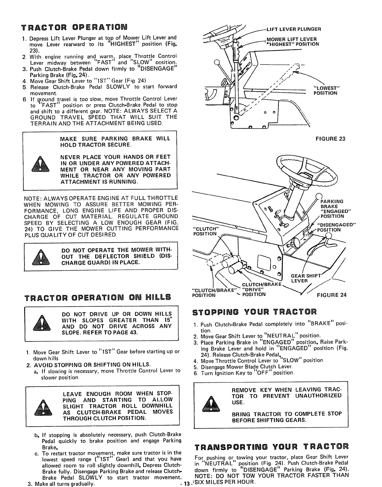
1. Depress Lift Lever Plunger at top of Mower Lift Lever and
move Lever rearward to its _HIGHEST" position (Fig.
23).
2, With engine running and warm, place Throttle Control
÷I' ,,
Lever mfdway between FAST and "SLOW" position.
3o Push Clutch-Brake Pedal down firmly to "DISENGAGE"
Parking Brake (Fig. 24).
4, Move Gear Shift Lever to "1ST" Gear (Fig 24}
'5. Release Clutch-Brake Pedal SLOWLY to start forward
movement,
6If qround travel is too stow, move Throttle Control Lever
to 1'FAST" position or press Clutch-Brake Pedal to stop
and shift to adifferent gear. NOTE: ALWAYS SELECT A
GROUND TRAVEL SPEED THAT WILL SUIT THE
TERRAIN AND THE ATTACHMENT BEING USED.
LEVER PLUNGER
_...,_,....,__ MOWER LIFT LEVER
_'°HIGHEST" POSITION
"LOWEST"
POSITION
MAKE SURE PARKING BRAKE WILL
HOLD TRACTOR SECURE,
NEVER PLACE YOUR HANDS OR FEET
1N OR UNDER ANY POWERED ATTACH_
MENT OR NEAR ANY MOVING PART
WHILE TRACTOR OR ANY POWERED
ATTACHMENT IS RUNNING_
FIGURE 23
NOTE: ALWAYS OPERATE ENGINE AT FULL THROTTLE
WHEN MOWING TO ASSURE BETTER MOWING PER-
FORMANCE, LONG ENGINE LIFE AND PROPER DIS-
CHARGE OF CUT MATERIAL, REGULATE GROUND
SPEED BY SELECTING A LOW ENOUGH GEAR (FIG,
24) TO GIVE THE MOWER CUTTING PERFORMANCE
PLUS QUALITY OF CUT DESIRED,
DO NOT OPERATE THE MOWER WITH-
OUT THE DEFLECTOR SHIELD (DIS-
CHARGE GUARD) tN PLACE°
TRACTOR OPERAT"ON ON HULLS
DO NOT DRIVE UP OR DOWN HILLS
WITH SLOPES GREATER THAN 15°
AND DO NOT DRIVE ACROSS ANY
SLOPE° REFER TO PAGE 43.
1, Move Gear Shift Lever to "1ST" Gear before starting up or
down hills
2o AVOID STOPPING OR SHIFTING ON HILLS,
a. If slowing is necessary, move Throttle Control Lever to
slower position
LEAVE ENOUGH ROOM WHEN STOP-
PING AND STARTING TO At.LOW
SLIGHT TRACTOR ROLL DOWNHILL
AS CLUTCH-BRAKE PEDAL MOVES
THROUGH CLUTCH POSITION°
BRAKE
"ENGAGED"
POSITION
"DISENGAGED"
"CLUTCH" T1oN
POSITION
°'CLUTCH/BRAK E.... DRIVE" "_,_,// .....
POSITION ",,, POSITION _" "FIGURE 24
STOPPING YOUR TRACTOR
1. Push Clutch=Brake Pedal completely into _'BRAKE" posi-
lion.
2. Move Gear Shift Lever to hNEUTRAL" position.,
•.Ii I, ••-*
3, Pace Parking Brake m ENGAGED position. Rinse Park-
.,It '1 *
mg Brake Lever and hold m ENGAGED position (Fig,,
24) Release Clutch-Brake Pedal=
""'SLOW"
4. Move Throttle Contro Lever to position
5,, Disengage Mower Blade Clutch Lever.
6. Turn Ignition Key to "OFF" position,
REMOVE KEY WHEN LEAVING TRAC-
TOR TO PREVENT UNAUTHORIZED
USE_
BRING TRACTOR TO COMPLETE STOP
BEFORE SHIFTING GEARS°
b. If stopping is absolutely necessary, push Clutch-Brake
Pedal quickly to brake position and engage Parking
Brake.
co To restart tractor movement, make sure tractor is in the
lowest speed range ('_lST" Gear) and that you have
allowed room to roll slightly downhill. Depress Clutch-
Brake fully° Disengage Parking Brake and release Clutch-
Brake Pedal SLOWLY to start tractor movement°
3. Make al! turns gradually.
TRANSPORTONG YOUR TRACTOR
For pushing or towing your tractor, place Gear Shift Lever
in "NEUTRAL" position (Fig. 24). Push Clutch-Brake Pedal
down firmly to "DISENGAGE '_ Parking Brake (Fig. 24).
NOTE: DO NOT TOW YOUR TRACTOR FASTER THAN
- 13 iStX MILES PER HOUR,,

ST,ART NG YOUR TRACTOR WaTH
A LOW 6ATTERY
If your Battery is too low to start the engine, it should be
•tt tJ
recharged. If Jumper Cables are used for emergency starting
foflow this procedure NOTE: YOUR TRACTOR iS EQUIP-
PED WITH A 12 VOLT NEGATIVE GROUNDED SYSTEM.
THE OTHER VEHICLE MUST ALSO BE A 12 VOLT NEGA-
TIVE GROUNDED SYSTEM
LEAD-ACID BATTERIES GENERATE EX-
PLOSIVE GASES= KEEP SPARKS, FLAME,
AND SMOKING MATERIALS AWAY
FROM BATTERIES. ALWAYS WEAR EYE
PROTECTION AROUND BATTER IESo
1 Connect each end of the RED Cable to the POSITIVE (+)
terminals of each battery (taking care not to short against
chassis)
2, Connect one end of the BLACK. Cable to the NEGATIVE
(-) terminal of fully charged battery
3 Connect the other end of the cable to ENGINE BLOCK
or good CHASSIS GROUND on tractor' (away from Gas
Tank or Battery)
4. Disconnect cables in reverse order:
a Engine Block or chassis of tractor
b. Negative terminal of fully charged battery,
c. Positive terminals
DO NOT USE YOUR TRACTOR BAT-
TERY TO START OTHER VEHICLES,,
MAtNTENANC E-=YRAC YOR
MOWER MAINTENANCE IS LISTED ON PAGE 12_
To keep your tractor running better, longer; perform neces-
sary service using the following Maintenance Schedule,
PEFER TO "STOPPING YOUR TRAC-
TOR" PAGE 13 AND DISCONNECT
SPARK PLUG WIRE TO PREVENT AC-
CIDENTAL STARTING BEFORE MAKING
ANY INSPECTION, ADJUSTMENT OR
REPAIR (EXCEPT CARBURETOR)°
DAILY MAINTENANCE
Make sure all nuts on bolts are tight and cotter pins and
retainer springs are secure° Observe all safety precautions.
Keep tractor wetl lubricated (refer to page 22)_
FIIRST _HOURS
1_ CHANGE ENGINE OIL
Changing Oil after the first two hours will help eliminate
break-in residue which might be damaging to your' Engine_
NOTE: BE CAREFUL NOT TO /_LLOW DIRT TO ENTER
THE ENGINE WHEN CHANGING OIL.
a. Drain Oil with Engine warm. Loosen Oil Drain Wing Nut
(Fig 25} and remove Dipstick, Catch Oil in asuitable
container. Tighten Oil Drain Wing Nut,
bo Refill Engine Oil, See oil chart, page 7oRefill capacity is
1 quart, NOTE: DO NOT OVERFILL, Replace Dipstick,
J
AIR
FUEL FILLER
CAP
INTAKE_
AIR DUCT
FREQUENTLY
1,, CHECK BATTERY
a Electrolyte solution level in each Battery Cell should be
even with bottoms of tubes in cells (Fig. 26), Add dis=
tilled water if necessary, NOTE: DO NOT OVERFILL
b Keep Battery and Terminals clean,
co Keep Battery Bolts tight°
dKeep Vent Cap_ tight and small Vent holes in Caps
open,
e. Recharge SLOWLY at 3 amperes if necessary,
2, CHECK TIRE PRESSURE
Tire pressure in front Tires should be 14 PS!; rear Tires
12 PSI_
3, CLEAN AIR SCREEN
Air Screen and Intake Air Duct (Fig. 25) must be kept free
of dirt and chaff to prevent Engine damage from overheat-
ing,
FIGURE 25
DRAIN
WING NUT'
CUT AWAY VIEW
.BATTERY
CELL
FIGURE 26 -14-

4,, CHECK BRAKE OPERATION
This tractor is equipped with an adjustable disc brake
mounted on the right side of the transaxle (Fig, 27). DISC BRAKE
IF TRACTOR REQUIRES MORE THAN
SIX FEET STOPPING DISTANCE IN
HIGHEST GEAR, THEN BRAKE MUST
BE ADJUSTED.
NOTE: WHEN ADJUSTING BRAKES DO NOT MOVE
12-POINT BOLT°
NOTE: A 5/6-4 INCH ALLEN SET SCREW WRENCH IS
REQUIRED TO ADJUST THE BRAKE.
a, To adjust, tighten Set Screw (Fig. 27) clockwise ((-_)
until Disc Brake can not be moved by hand. Now loosen
Set Screw by turning counterclockwise (_) I/2 turn.
NOTE: PARKING BRAKE MUST BE DISENGAGED
WHI LE MAK ING ADJUSTMENT.
b. Depress Clutch-Brake Pedal and engage Parking Brake.
co Measure distance between Brake Operating Arm and
Nut "A" on Brake Rod
d. If distance is other than 1 - 1/2", turn Nut "A" until
distance becomes i °1/2"
Road test tractor for proper stopping distance as stated
above Readjust if necessary°
EVERY _ HOURS
CHECK ENGINE OIL LEVEL
DO NOT CHECK ENGINE OIL LEVEL
WITH ENGINE RUNNING.
Several minutes after stopping Engine, check Engine Oil
Level with Tractor on level ground Remove and wipe Dip*
stick clean (Fig,, 29), screw it in tight for a few seconds, re-
move slowly and read Oil levet° If necessary, add Oil until
"FULL" mark is reached.
EVE.V25 .OU.S
(EVERY 15 HOURS IF OPERATING
IN VERY DUSTY CONDITIONS)
1. CLEAN AIR CLEANER ELEMENT (FIG, 28).
a, Open Hood. Pull intake Air Duct up off engine,
b Remove two screws from Air Cleaner Cover Lift off Air
Cleanero
c= Remove Screen and Spacers from Foam Element.
d. Remove Foam Element from Air Cleaner Body,,
e Wash Foam Element in liquid detergent and water to
remove dirt.
f Wrap foam in cloth and squeeze dry.
g= Saturate foam in engine Oilo Squeeze to remove excess
oil,
h, Assemble parts - securely fasten to carburetor with
screws,
When assembling make certain the lip of the Foam Element
extends over edge of the Air Cleaner Body° The Foam Ele-
ment lip will form a protective seal.
NOTE: NEVER RUN ENGINE WITH AIR CLEANER OR
INTAKE AIR DUCT REMOVED.
2o CHANGE ENGINE OIL
The best time to change Engine Oil is at the end of a day's
operation when all dirt and foreign materials are suspended
in the hot Oil. See oil chart, page 7o -15-
12-POINT BOLT
AIR CLEANER
COVER
SPACER
SCREEN
FOAM ELEMENT
AIR
CLEANER
BODY
BRAKE
ROD
NUT
1 - 1/2"
BRAKE
OPERATING ARM
FIGURE 27
FIGURE 28
INTAKE
AIR Ev .vB@.ouns
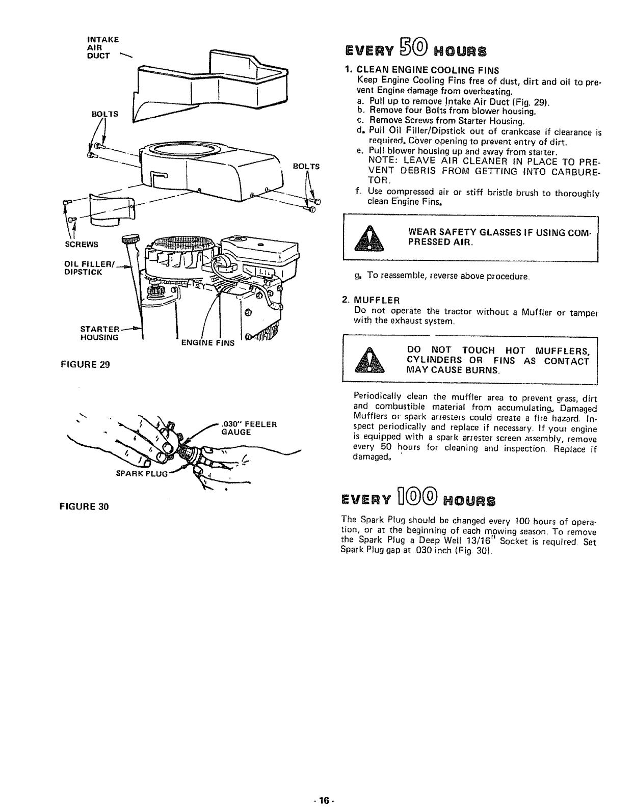
1, CLEAN ENGINE COOLING FINS
Keep Engine Cooling Fins free of dust, dirt and oil to pre-
vent Engine damage from overheating.
a. Pull up to remove !ntake Air Duct (Fig, 29).
b_ Remove four Bolts from blower housing,,
c. Remove Screws from Starter Housing,
d, Puft Oil Filler!Dipstick out of crankcase if clearance is
required, Cover opening to prevent entry of dirt.
eo Pull blower housing up and away from starter.
NOTE: LEAVE AIR CLEANER IN PLACE TO PRE-
VENT DEBRIS FROM GETTING iNTO CARBURE-
TORo
f. Use compressed air or stiff bristle brush to thoroughly
clean Engine Fins.
SCREWS
OIL FILLER
DIPSTICK
STA
HOUSING
FIGURE 29
ENGINE FINS
WEAR SAFETY GLASSES IF USING COM-
PRESSED AIR.
g. To reassemble, reverse above procedure..
2o MUFFLER
Do not operate the tractor without a Muffler or tamper
with the exhaust system,
DO NOT TOUCH HOT MUFFLERS,
CYLINDERS OR FINS AS CONTACT
MAY CAUSE BURNS,
FIGURE 30
SPARK PLUI
FEELER
GAUGE
Periodically clean the muffler area to prevent grass, dirt
and combustible material from accumulating= Damaged
Mufflers or spark arreste[s could create a fire hazard. In-
spect periodically and replace if necessary. If your engine
is equipped with a spark arrester screen assembly, remove
every 50 hours for cleaning and inspection. Replace if
damaged° '
The Spark Plug should be changed every !00 hours of opera-
tion, or at the beginning of each mowing season. To remove
the Spark Ptug a Deep Well 13/16" Socket is required Set
Spark Plug gap at 030 inch (Fig. 30),
16-

Ew.v
REPLACE AIR CLEANER ELEMENT
CARBURETOR ADJUSTMENT (FIGo 31)
Never attempt to change maximum engine speed, This is
preset at the factory and should only be changed by a quali-
fied service technician who has the necessary equipment. CAU-
TION: BEFORE ANY ENGINE ADJUSTMENT, MAKE
SURE AIR CLEANER tS CLEAN., SEE PAGE 16, Remove
Air Cleaner Assembly.,
1,, HIGH SPEED SETTING
a. With engine off, place Throttle Control in "FAST" posi-
tiono
b_ Loosen Clamp Screw., Adjust Throttle Cable untitl holes
"A" are aligned in Governor Control Plate and Slide
Plate.
co Tighten Clamp Screw.
2o HIGH SPEED MIXTURE
a, Turn High Speed Mixture Screw clockwise (f_) closing
finger tight ONLY, and then turn counterclockwise (I,"_)
1 - 1/2 turns (Fig. 31)o
NOTE: VALVES MAY BE DAMAGED BY TURNING
THEM TOO FAR°
b. Start Engine and altow to warm for five minutes_ Make
final adjustments with Engine running and Gear Shift
Lever in "NEUTRAL" position°
c, With Throttle Control Lever in "FAST" position, turn
Higt_ Speed Mixture Screw counterclockwise (t'_) un-
til engine runs "rough" then turn clockwise (t_)until
engine begins to miss. Turn Screw to a point midway
between these positions°
3, IDLE MIXTURE
ao With Throttle Control Lever in "SLOW" position, hold
Throttle Lever so that Idle Stop Screw is against Carbur-
etor, turn Idle Mixture Screw counterclockwise (_) un-
til engine runs "rough" and then turn clockwise (iql) un-
til engine begins to die_, Turn idle Mixture Screw to a
point midway between these positions,
4o IDLE SPEED SETTING
a,. With Throttle Control Lever in "SLOW" position, engine
should idle at 1750 RPM, If engine idles too slow, push
Throttle Control Lever above idle and turn Idle Speed
Screw one turn clockwise ((-_)_ Set Throttle Control
Lever at "SLOW" Repeat until satisfactory idle is at-
tained.
b. If engine idles too fast with Throttle Control Lever in
"SLOW" position, push Throttle Control Lever above
idle and turn Idle Speed Screw one turn counterclock-
wise (f"_), Set Throttle Control Lever at I'SLOW",, Re-
peat until satisfactory idle is attained,
IDLE
MIXTURE
IDLE SCREW
STOP
DO NOT
ADJUST
IDLE
MIXTURE
ADJUSTMENT
HIGH SPEED
MIXTURE SCREW
HOLES "A"
THROTTLE
CABLE,
IOLESPEED
SCREW
PLATE,
GOVERNOR
CONTROL
SLIDE
PLATE
FIGURE 31

RETAINER
SPRING
FIGURE 32
FIGURE 33
TRANSAXLE
PULLEY
BELT GUIDE
BRACKET
BELT
GUIDE
RETAINER
SPRING
SHIFT GATE
5 ,, REPLACE TRACTOR MOTION DRIVE BELT
The tractor Drive Belt may be reptaced without tools.. Park
the tractor on level area. Engage Parking Brake, NOTE:
BELT INSTALLATION DECAL UNDER LEFT FOOT-
REST.
a. Remove mower. (See Mower Section, page 20).
b. Remove two Retainer Springs from Belt Guide Bracket
below Transaxte Pulley. Remove Bracket (Fig. 32),
c. Swing Belt Guides away from Belt, toward rear of trac-
tor' (Fig, 32)_
d. Roll Belt over top of Transaxle Pulley
e, Roll Belt over Engine Pulley and off Idler (Fig 34)
f Release Parking Brake, Pull Belt as far as possible over'
top of Ctutch Puitey,
g Reset Parking Brake. Put! Belt over top of Clutch Pulley
(Fig, 34}.
h Pull Belt out through Shift Gate to remove from trac_
tot (Fig, 33)r
Install Belt by reversing above procedure, NOTE: RE-
PLACE ONLY WITH BELT LISTED iN MANUAL,
6. CLEAN BATTERY AND TERMINALS
Corrosion and dirt on the Battery and Terminals cause
the Battery to ='leak" power
LEAD-ACID BATTERIES GENERATE EX-
PLOSIVE GASES_ KEEP SPARKS, FLAME,
AND SMOKING MATERIALS AWAY
FROM BATTERIES ALWAYS SHIELD
YOUR EYES AROUND BATTERIES,
a Disconnect BLACK Battery Cable then RED Battery
Cable and remove Battery from Tractor. Wash Battery
with four tablespoons of baking soda to one gallon of
water. NOTE: BE CAREFUL NOT TO GET THE SODA
SOLUTION INTO THE CELLS. Rinse the Battery with
plain water, dry and reinstall on Tractor.
b. Clean Terminals and Battery Cable ends with awire
brush until bright,. Replace Battery Cables, connecting
RED Battery Cable to Positive Terminal first, then
BLACK Battery Cable to Negative Terminal. Coat ter-
minal connections with Vasoline_
CLUTCH
PULLEY
ENGINE
PULLEY /
DRIVE BELT
SCHEMATIC
LH. SIDE
BELT GUIDE
REAR
VIEWED FROM BOTTOM OF TRACTOR
FIGURE 34 - 18-
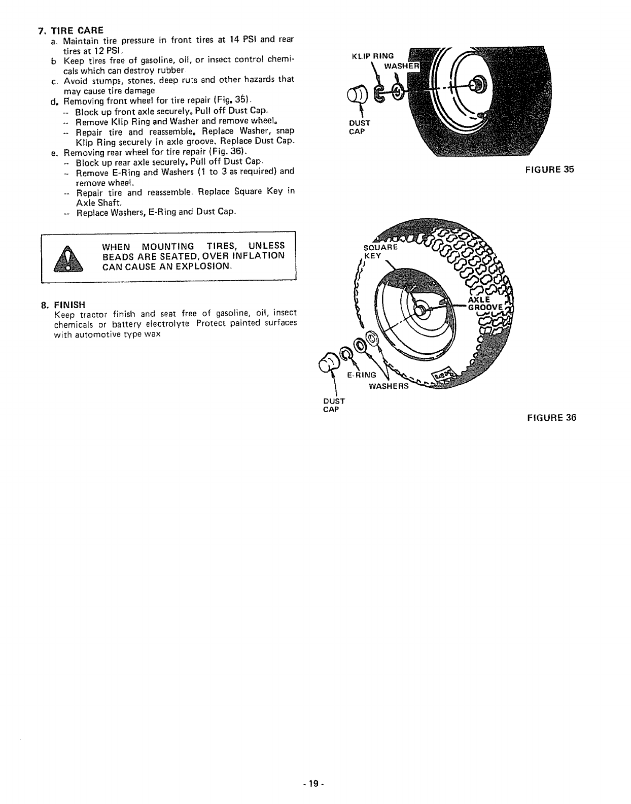
7, TIRE CARE
a, Maintain tire pressure in front tires at 14 PS! and rear
tires at 12 PSI,
b Keep tires free of gasoline, oil, or insect control chemi-
cals which can destroy rubber
c, Avoid stumps, stones, deep ruts and other hazards that
may cause tire damage,
d. Removing front wheet for tire repair (Fig. 35),
-- Block up front axle securely, Pull off Dust Cap,
-- Remove Klip Ring and Washer and remove wheelo
-- Repair tire and reassembJe. Replace Washer, snap
KtIp Ring securely in axle groove, Replace Dust Cap°
e., Removing rear wheel for tire repair (Fig, 36)°
-- Block up rear axle securely. Pull off Dust Cap_
-- Remove E-Ring and Washers (I to 3 as required) and
remove wheel
-- Repair tire and reassemble° Replace Square Key in
Axle Shaft.
-- Replace Washers, E-Ring and Dust Cap,
KLIP RING
DUST
CAP
FIGURE 35
WHEN MOUNTING TIRES, UNLESS
BEADS ARE SEATED, OVER INFLATION
CAN CAUSE AN EXPLOSION,
8. FINISH
Keep tractor finish and seat free of gasoline, oit, insect
chemicals or battery electrolyte Protect painted surfaces
with automotive type wax
DUST
CAP
SQUARE
KEY
E.RING
WA S H E F
FIGURE 36
-19-

DEPTH
ADJUSTME NT
KNOB \
MOWER CLUTCH
LEVER "'DISENGAGED"
POSITION
"'HIGHEST"
ITION
LIFT LEVER
"LOWEST"
POSI T tON
TO REMOVE MOWER BELT
NOTE: MOWER BELT INSTALLATION DECAL LOCATED
ON MOWER HOUSING.
REPLACE ONLY WITH THE BELTS SPECIFIED IN THIS
MANUAL,
,
3,
4
Place Mower Blade Clutch Lever in _DISENGAGED _t
position (Fig 37)
Turn Depth Adjustment Knob to Lowest position,. Move
Mower Lift Lever (Fig. 37) forward to lower' Mower to its
lowest position,,
Rotl Belt off Engine Pulley (Fig. 38)
Pull Belt off both Mandrels,
5 Spring Belt Guide away from Idler Pulley and pull Belt
off Idler Pulley°
6. Slide Belt from under Idler Spring
FIGURE 37
ENGINE
PULLEY IDLER
IDLER
BELT GUlDE
TO REPLACE MOWER BELT
1Slide Belt under Idler Spring (Fig_ 38)_
2, Place Belt on rear side of both Mandrels.
3. Spring Idler Belt Guide down and place Bett around rear
side of Idler Pulley.
4. Roll Belt over Engine Pulley,
FIGURE 38
L,H, MANDREL IDLER
SPRING
RETAINER
SPRINGS
RH,, MANDREL
RETAINER
SPRINGS
TO REMOVE MOWER
1. Remove mower Belt per' instruct{ons under "To Remove
Mower Belt j', through step 3=
2. Turn Depth Adjustment Knob to lowest position, Use Lift
Lever to lower' mower to its lowest position°
3, Remove Retainer Spring from Clutch Rod; putt Clutch Rod
out of Clutch Bracket.
4 Pull Retainer Springs out of Rear Suspension Trunnionso
Remove Rear Suspension Trunnions from Lift Brackets
(Fig. 39),
5. Putl Retainer Spring out of Rear Hinge Pin. Remove Rear
Hinge Pin°
6. Pull Retainer Spring out of Front Hinge Pin, Remove Front
Hinge Pin (Fig,'39L
7. Use Lift Lever to raise Suspension Arms_ Slide mower out
from under tractor.
/
REAR
SUSPENSION
TRUNNtONS LIFT
BRACKET
HINGE
PINS
STORAGE
When mower is to be stored for a period of time. cfean it
thoroughly, remove all dirt, grease, leaves, etc, Give blades
and underside of housing a good coat of grease or rust pre-
ventat{veo S_ore in a clean dry area.
FIGURE 39 - 20 -

TROU,LESNOOT,NG
POSSIBLE CAUSE POSSIBLE REMEDY
WILL NOT START
Shift Lever in gear
Mower Blade CIutch Lever engaged
No gasoline in Fuel Tank, clogged Fuel
Line, or Fuel Filter
Blown Fuse
Dead Battery
HARD TO START
Choked improperly, flooded Engine
Clogged Fuel System
Dirty Air Cleaner
Spark Plug dirty or improper gap
Defective Battery
Defective Ignition or loose wiring
Water in gasoline or old fuel
Improper Carburetor adjustment
ENGINE MISSES OR LACKS POWER
Engine overload
Clogged Fuel Tank or Fuel Filter
Partially plugged Air Cleaner
improper Carburetor adjustment
Dirty Engine Air Screen
Low oil level or dirty oil
Spark Plug dirty, improper gap or wrong type
Faulty ignition
Poor compression
Oil in gasoline
ENGINE OVERHEATS
Dirty Air Screen
Low oit level or dirty oil
Dirty Engine
Partially plugged Muffler
Partially plugged Air Cleaner
Stale fuel or improper Carburetor adjustment
NO LIGHTS
No Headlights with Light Switch on and
Place in neutrai
Disengage Lever (Fig. 10). Be sure Lever is in bottom of slot
Fi{I Tank with Gasoline Check Fuel Line and Car-
buretor (clean if necessary) Replace Fuel Fitter.
Check for fault and replace Fuse
Recharge or replace Battery
Place Throttle Control in "FAST" position (Fig., 10)
and run starter several times to clear out gas
Remove and clean Tank and lines° Replace Fuel Filter
Remove and clean (Fig.. 28)
Clean, adjust gap or replace (Fig 30)
Recharge or replace
Check the wiring and Spark Plug
Drain Fuel Tank and Carburetor, use fresh fuel and
replace Spark Pfug
Make necessary adjustments (F ig. 31 )
Shift to a lower gear (Fig 24) or reduce toad
Remove and clean Tan{<; replace Fuel Filter
Remove and clean (Fig. 28)
Make necessary adjustments (Fig 31)
Clean Air Screen (Fig 25)
Add or change oil (page 14)
Replace Spark Plug (Fig. 30)
Check Spark Plug and for loose wires
Major Engine overhaul
Drain Gas Tank and Carburetor and refitl
Engine running
WON'T CHARGE
Blown Fuse
Defective Battery
Defective Diode Assembly
Defective Alternator
Clean Air Screen (Fig. 25)
Add or change oil (page t4)
Ctean Engine Cooling Fins (page 16)
Remove and clean Muffler or replace
Remove and clean (Fig. 28)
Use fresh fuel and adjust Carburetor (Fig 31)
Check Fuse, Switch and wire connections Replace
Headlight Bulbs
UNSATISFACTORY MOWER PERFORMANCE
Tires not inflated properly
Mower improperly adjusted
Check for fault and replace
Replace
Replace
Replace
Check air pressure in tires (page 6)
Check front to rear and side to side mower adjust-
merit (page 10)
Grass high or wet
Incorrect engine RPM's
Excessive wear to outer cutting tip of mower blade
improper mower blade installation
Incorrect mower blade
Use a slower ground speed (refer to Mower Operating
Instructions, pacje 1 I}
Check engine RPM's (refer to Carburetor Adiustment, page 17)
Replace mower blade
Reinstall with top of blade up
Replace with proper mower blade
STORAGE
1. FUEL SYSTEM
a, Drain fuel tank and carburetor by allowing the engine to
run out of gasoline. NOTE: GASOLINE LEFT IN
YOUR ENGINE WILL LEAVE GUM DEPOSITS CLOG-
GING FUEL SYSTEM.
b Dispose of gasofine if not to be used. NOTE: GASO-
LINE STORED FOR SEVERAL MONTHS LOSES ITS
VOLATILITY (ABILITY TO BURN EFFECTIVELY)..
2o ENGINE OIL
Drain (with engine warm) and replace with clean engine oil.
(See chart, page 7).
3o CYLINDER
a. Remove Spark Plug..
b. Pour one ounce of engine oit through spark plug hole
into cyiindero
c.. Turn ignition key to "START" position for a few
seconds to distribute oil.
d_ Replace with new Spark Plug.
4. BATTERY
a.. Remove battery if tractor is not used regularly during
winter months_ Store in cool, dry place (above 50OF.).
Re-charge each month if necessary. NOTE: BATTERIES
NOT IN USE FOR SEVERAL MONTHS AND NOT
KEPT FULLY CHARGED, PRODUCE SULPHATE
DEPOSITS ON PLATES WHICH CANNOT BE RE-
MOVED BY RECHARGING
5o GENERAL CLEANING
Clean engine, battery, finish, seat, etc of all foreign matter,
-21 -
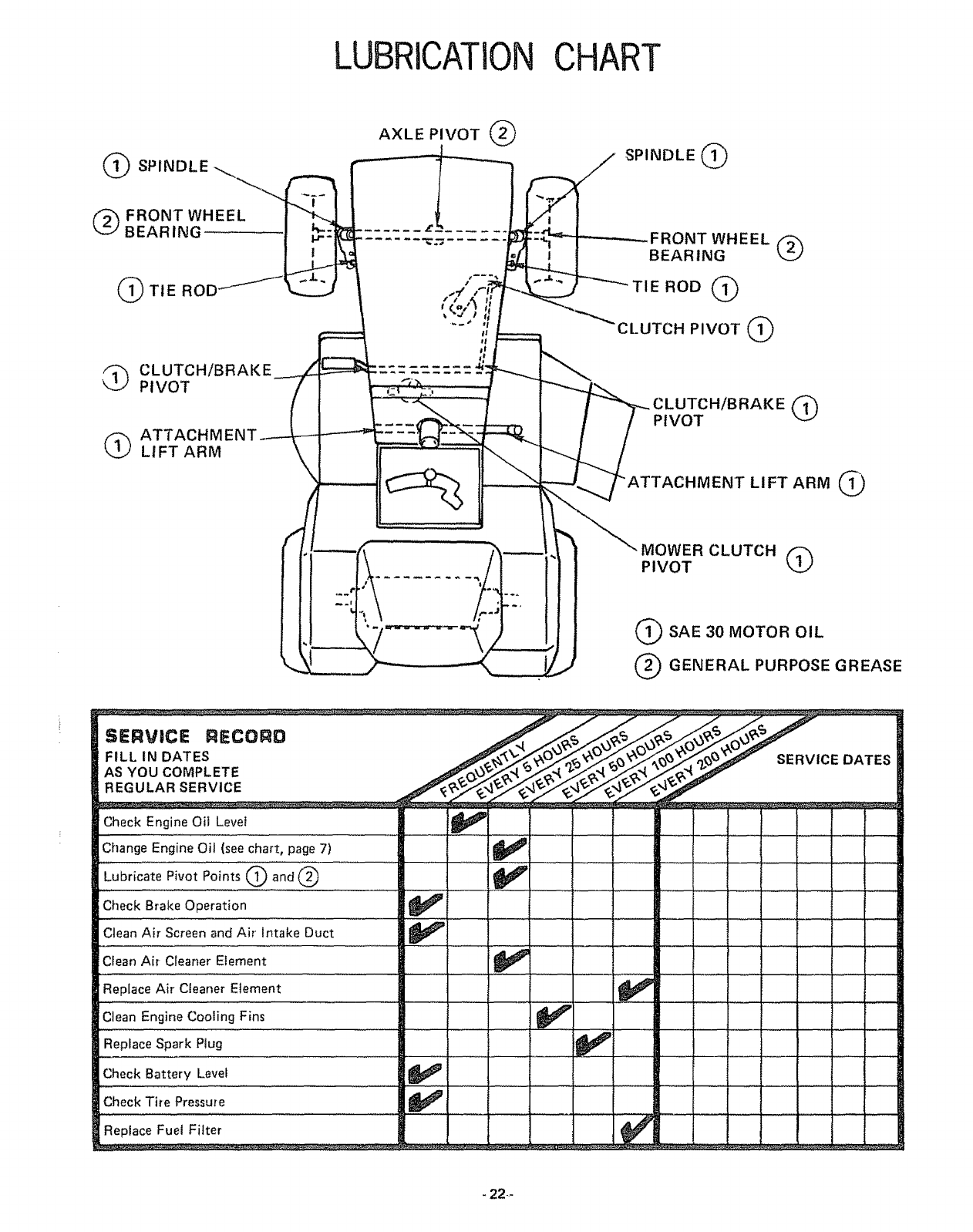
LUBRICATIONCHART
(9
AXLE PIVOT (_
SPINDLE (_
(_) FRONT WHEEL
BEARING
(_TIE ROD
_ LUTCH/BRAKE
PIVOT
(_ ATTACHM E
LIFT ARM
#
FRONT WHEEL
BEARING (_
ROD (_)
CLUTCH PIVOT (_
/BRAKE (_
PIVOT
HMENT LIFT ARM 1_)
MOWER CLUTCH
PIVOT (_
(_SAE 30 MOTOR OIL
(_ GENERAL PURPOSE GREASE
SERVICE RIECOgB
FILL IN DATES
AS YOU COMPLETE
REGULAR SERVICE
SERVICE DATES
Check Engine Oil ,L,evel .... _ I
Change Engine Oil (see chart, page 7) _1_
Lubricate Pivot Points Q and @ .... _ .........
Check Brake Operation
..... '.... ;,,_ : ....... :...... : i m i i _ ....... :
Clean Air Screen and Air' Intake Duct
Clean Air Cleaner Element _ : " _....
Replace Air Cleaner......Element _ I
.Clean Engine Cooling Fins ......... ........
Replace Spark Plug
Check Batte.[y..Levet ................. _!
Check Tire Pressure
Replace Fuel Filter .....
-22--
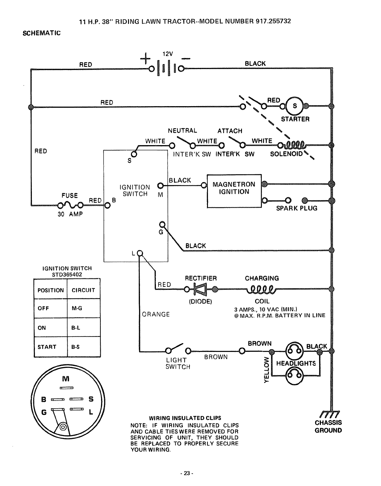
SCHEMATIC
11 H°P, 38" RIDING LAWN TRACTOR--MODEL NUMBER 917,255732
RED
12V
+ -
oltllo BLACK
RED
RED
30 AMP
IGNITION SWITCH
STD365402
POSITION CIRCUIT
OFF M-G
ON B-L
START B-S
O
%STARTER
%
NEUTRAL ATTACH
WHITE--_C_ _ WHITE
Of---'---_tNTER'K SW ,NTER'K SW SOLENOID%
S%
IGNITION C'
SWITCH M
B
BLACK
'" MAGNETRON
IGNITION
SPAR K PLUG
_[_/ RECTIFIER CHARGING
IRED.......
(DIODE) COIL
3AMP&, 10 VAC (MIN.)
ORANGE
_\ BLACK .....
@MAX, R,P.Mo BATTERY IN LINE
LIGHT
SWITCH
BROWN
BROWN BLA'
WIRING INSULATED CLIPS
NOTE: IF WIRING INSULATED CLIPS
AND CABLE TIESWERE REMOVED FOR
SERVICING OF UNIT, THEY SHOULD
BE REPLACED TO PROPERLY SECURE
YOURWIRING
CHASSIS
GROUND
-23-

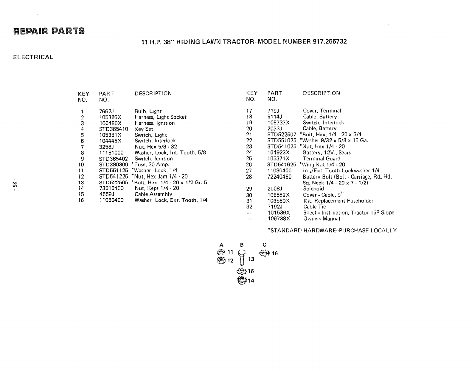
REPAIR PARTS
11 H.P. 38" RIDING LAWN TRACTOR--MODEL NUMBER 917.255732
ELECTR ICAL
910
17
3O
29
2O
11
18
REPAIIR PARTS
ELECTRICAL
11 H.P. 38" RIDING LAWN TRACTOR--MODEL NUMBER 917.255732
KEY
NO.
1
2
3
4
5
6
7
8
9
t0
1t
12
13
14
15
16
PART DESCRIPTION KEY PART DESCRIPTION
NO. NO. NO.
7662J Bulb, LIght ! 7
105386X Harness, Light Socket !8
!06480X Harness, tgmtIon 19
STD365410 Key Set 20
105381X Switch, Light 21
104445X Sw_tch, ]nterlock 22
3258J Nut, Hex 5/8- 32 23
11151000 Washer, Lock, Int. Tooth, 5/8 24
STD365402 Switch, Igmtlon 25
STD380300 *Fuse, 30 Amp. 26
STD551125 *Washer, Lock, !/4 27
STD541225 *Nut, Hex Jam 1/4- 20 28
STD522505 *Bolt, Hex, 1/4 - 20 x 1/2 Gr. 5
73510400 Nut, Keps 1/4 - 20 29
4559J Cable Assembly 30
11050400 Washer Lock, Ext. Tooth, t/4 31
32
719J Cover, Terminal
5114J Cable, Battery
105737X Switch, Interlock
2033J Cable, Battery
STD522507 *Bolt, Hex, 1/4- 20 x 3/4
STD551025 *Washer 9/32 x 5/8 x 16 Ga.
STD541025 *Nut. Hex 1/4 - 20
t04923X Battery, 12V., Sears
105371X Terminal Guard
STD541625 *Wing Nut 1/4 -20
11030400
72240460
2008J
106552X
I06580X
7!92J
101539X
106738X
Int./Ext, Tooth Lockwasher 1/4
Battery 8oit (Bolt -Carriage, Rd° Hd.
Sq. Neck 1/4 - 20 x 7 - 1/2)
Solenoid
Cover - Cable, 9"
Kit, Replacement Fuseholder
Cable Tie
Sheet - Instruction, Tractor 15° Slope
Owners Manual
*STANDARD HARDWARE--PURCHASE LOCALLY
A B
@11_) 12 13
@16

REPA|R PARTS
ENCLOSURE
1! H.P. 38"' RIDING LAWN TRACTOR--MODEL NUMBER 917.255732
39
48 53
16
55
4O
36
26
2O
38

REPAaR PARTS
ENCLOSURE
11 H.P. 38" RIDING LAWN TRACTOR--MODEL NUMBER 917.255732
1
",4
i
KEY
NO.
t
2
4
5
6
7
8
9
10
11
12
t3
t4
16
17
18
19
20
21
22
23
24
25
26
27
28
29
30
31
32
PART
NO. DESCRIPTION KEY PART DESCRIPTION
NO. NO.
105873X
17490612
17490616
105513X
105529X
73680500
105512X
105514X
105274X
19132012
STD523707
73680600
17490608
105753x
105465X
105464X
Seat
Screw, Hex Washer Thdo R01t 3/8 -
16 x 3/4 Type TT
Screw, Hex Washer Thd. Rolling
5/8 • 16 x !
Bracket. Pivot, Seat
Bolt, Shoulder, 5/16 - 18
Nut, Lock. 5/16 * 18
Spring - Compression
Clamp, Spring
Fender
Washer_ 13/32 x 1 -1/4 x I2 Ga.
• Bolt, Hex, 3/8- 16 x 3/4
Nut, Lock 3/8 - 16
Screw, Hex Washer Thd. Roll 3/8
t6 x 1/2
Bracket, Fender
Footrest, L.H.
Footrest, R.H,
STD533707 *Bolt. Cart. 3/8 - 16 x 3/4
105466X Pad, Footrest
105600X Bracket, Pivot, GriII, R.H.
105602X Bracket, Pivot, Grill L.H.
STD551125 *Washer. Lock, 1/4
STD541025 *Nut, Hex, I/4,20
1056t5X
105614X
105776X
105777X
11030400
105268X
!05685X
STD551025
t05797X
Lens, L.H.
Lens, R.H.
Spacer, .28 x .75 x.20
Spacer, °28 x .75 x .46
Washer, Lock, int. Ext. Tooth, I/4
Bezel
Strap Assembly, Grill
*Washer, 9/32 x 5/8 x t6 Ga.
Hinge, Hood, L.H.
A B C D F
"_ 2 _ 5 _) tl _13 (_ 18
Q 6 G 12 @ 12
33 105792X Hinge, Hood, R,H.
34 105682X Hood Assembly
35 105678X Grill Assembtv
36 !05604X Bracket, Frame, Pivot, R,H,
37 105606X Bracket, Frame, Pivot. L.H,
38 t05683X Side Panel. R.H.
39 105684X Side Panet, L.H.
40 105666X Chassis Assembly
41 102481X Drawbar
42 105516X Pan - Seat
45 105372X Tray, Battery
46 105687X Tube oPlastic
47 6999R Clamp Hose
48 105801X Decal - Reflective, Rear
49 t05802X Decal, Stripe, L.H.
50 105803X Decal. Stripe, R.H..
5t t05806X Decal, Grill Craftsman
52 t05807X Decal, Grill, Strtpe
53 4900J Decal, Clutch/Brake
54 105805X Decal. 11 H.Po
55 105809X Decal, 5 Speed 38"
56 105813X Decal.. V-Belt Schematic
57 105774X Clip, Hold Down bL.A
58 74780812 Bolt, Hex 1/2 - 13 x 3/4
59 t0110800 Washer- Lock -Light t/2
60 19171912 Washer !7/32 x 1 -3/16 x 12 Ga,
61 STD523710 *Bolt, Hex 3/8 - t6 x !
63 106301X Guide - Belt, Lower, Eng. Pulley, L.H.
64 t06300X Guide -Belt, Lower, Eng. Putley, R.H.
*STANDARD HARDWARE--PURCHASE LOCALLY
G H J K L M
@22 '_," 28 @ 31 _[_ _ _
O23 _ 23 (5) 22 58 61 3
_) 23 @ 59 @t0
Q 60 @ 12

REPAIR
DRIVE
P, TS
1t H.P. 38" RIDING LAWN TRACTOR--MODEL NUMBER 917.255732
12
P !
F
98
3
19
D3O
D
32
43
45
68
7O
69 74
64
65
62
61 93
49 21
63
81
82
8O
82
83
OPTIONAL EQUIPMENT
Spark Arrester Screen Assembly 677Vl
- 28-
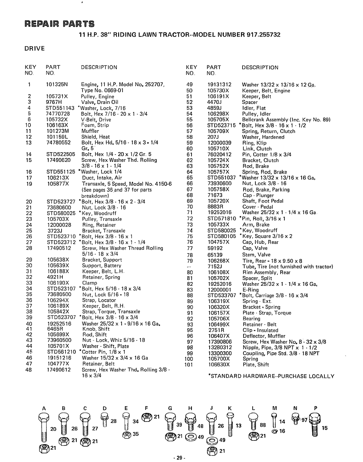
REPAaR
DRIVE
PARTS
11 H.P. 38" RIDING LAWN TRACTOR--MODEL NUMBER 917.255732
KEY PART
NO NO
1 I01325N
2 105731X
3 9767H
4 STD551143
5 74770728
6 105732X
10 t06163X
11 101273M
t2 101t59L
13 74780552
14 STD522505
15 17490620
16
17 1062!3X
19 10587_X
20 STD523727
21 73680600
22 STD580025
23 105703X
24 12000028
25 3723J
26 STD523710
27 STD523712
28 17490512
29 105638X
30 I05639X
31 t06188X
32 4921H
33 I06190X
34 STD523107
35 73680500
36 !06294X
37 106189X
38 t05842X
39 STD523707
40 19252516
41 6465R
42 105699X
43 73960500
44 105701X
45 STD5612!0
46 19151216
47 t04777X
48 17490612
DESCRIPTION KEY PART DESCRIPTION
NO. NO
Engine, 11 H.P. Model No. 252707,
Type Noo 0669-01
Putley, Engine
Valve, Drain Oil
*Washer, Lock, 7/16
Bolt, Hex 7/16- 20 x 1 - 3/4
V-Belt, Drive
Foam, Strip
Muffler
Shield, Heat
Bolt, Hex Hd. 5/16- 18 x 3- 1/4
Gr. 5
Bolt, Hex I/4- 20 x I/2 Gr, 5
Screw, Hex Washer Thd° Rolling
3/8- 16 x 1 -1/4
STD551125 *Washer, Lock I/4
Duct, lntake_ Air
Transaxle, 5 Speed, Model No. 4150-6
(See pages 36and 37 for parts
breakdown)
*Bolt, Hex 3/8- !6 x 2- 3/4
Nut, Lock 3/8- t6
* Key, Woodruff
Pulley, Transaxle
Ring, Retainer
Bracket, Transaxle
*Bolt, Hex 3/8 - 16 x 1
*Bolt, Hex 3/8- 16 x 1- 1/4
Screw, Hex Washer Thread Roiling
5/16- 18 x 3/4
Bracket, Support
Support, Battery
Keeper, Belt, L.H.
Retainer, Spring
Clamp
*Bolt, Hex 5/16- 18 x 3/4
Nut, Lock 5/t6- 18
Strap, Locator
Keeper, Belt, R.H,
Strap, Torque, Transaxte
*Bolt, Hex 3/8 16 x 3/4
Washer 25/32 x 1 o.9/16 x 16Ga.
Knob, Shift
Rod, Shift
Nut Lock, Whiz 5/16 -18
Washer- Shift, Plate
*Cotter Pin, 1/8 x 1
Washer 15/32 x 3/4 x 16 Ga
Retainer, Belt
Screw, Hex Washer Thdo Rolling 3/8 -
!6 x 3/4
49
50
51
52
53
54
55
56
57
58
59
6O
6t
62
63
64
65
66
67
68
69
70
71
72
73
74
75
76
77
78
79
8O
8t
82
83
88
89
90
91
92
93
95
96
97
98
99
100
101
19131312 Washer 13/32 x 13)'16 x 12 Ga,
105730X Keeper, Belt, Engine
106191X Keeper, Belt
4470J Spacer
4859J Idler, Flat
106298X Pulley, Idler
t05705X BeHcrank Assembly (lnc. Key Noo 89)
STD523715 *Bolt, Hex 3/8- 16 x 1 _ 1/2
t05709X Spring, Return, Clutch
207J Washer, Hardened
12000039 Ring, Klip
I057t0X Link, Clutch
760204 t2 Pin, Cotter 1/8 x 3/4
105724X Bracket, Clutch
105752X Rod, Brake
105757X Spring, Rod, Brake
STD551037 "Washer 13/32 x t3/16 x 16 Gao
73930600 Nut, Lock 3/8- 16
105758X Rod, Brake, Parking
71673 Cap- Ptunger
105720X Shaft, Foot Pedal
8883R Cover -Pedal
19252016 Washer 25/32 x 1 - 1/4 x 16 Ga
STD571810 *Pin, Roll, 3/16 x 1
105733X Arm, Brake
STD580025 * Key, Woodruff
STD580105 *Key, Square 3/16 x 2
104767X Cap, Hub, Rear
59192 Cap, Valve
65139 Stem, Valve
106268X Tire, Rear o18 x 950 x 8
7152J Tube, Tire (not furnished with tractor)
I06108X Rim Assembly, Rear
105702X Spacer, Split
19252016 Washer 25/32 x 1 -1/4 x t6 Gao
12000001 E-Ring
STD533707 *Bolt, Carriage 3/8 - 16 x 3/4
106319X Spring- Ext
106320X Bracket o Spring
106157X Plate _Strap, Torque
105706X Bearing
106499X Retainer- Belt
2751R Clip -Insulated
t06407X Deflector, Muffler
17390806 Screw, Hex Washer No. 8: 32 x 3/8
13280312 Nipple, Pipe, 3/8 NPT x I - 1/2
13300300 Coupling, Pipe Stdo 3/8- 18 NPT
105700X Spring
I06630X P_ate, Shift
*STANDARD HARDWARE-PURCHASE LOCALLY
AB C D EF G H J KL M
- 29-
NP
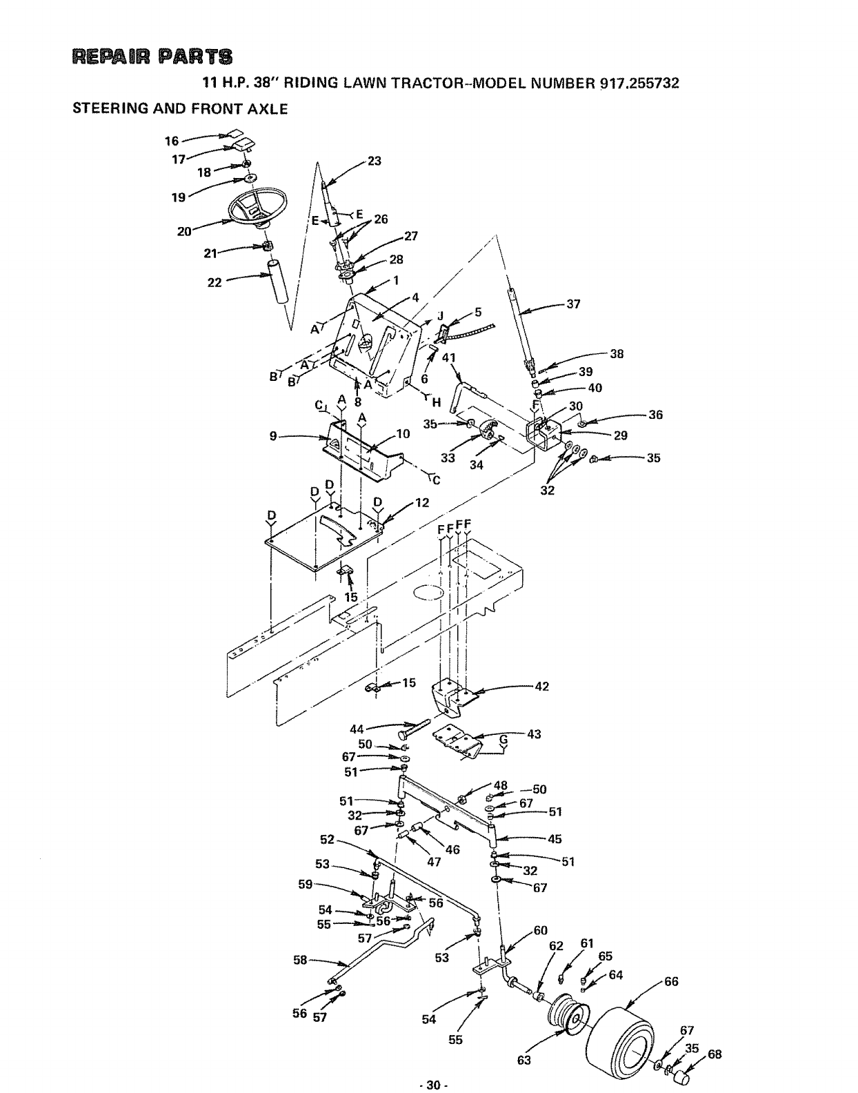
RE_IR PARTS
11 H.P. 38" RIDING LAWN TRACTOR-MODEL NUMBER 917.255732
STEERING AND FRONT AXLE
22
55
56 57
53
55
63
62 61 65
67
,68
- 30 -
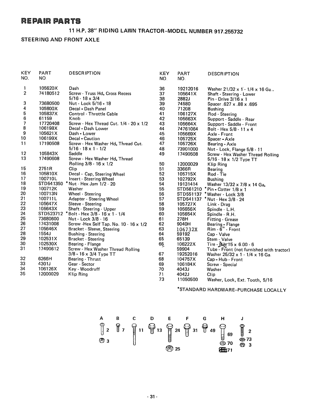
REPAnR PARTS
11 H.P. 38" RIDING LAWN TRACTOR--MODEL NUMBER 917.255732
STEERING AND FRONT AXLE
KEY PART DESCRIPTION KEY PART DESCRIPTION
NO NO NO NQ
1 105620X Dash 36
2 74180512 Screw- Truss Hd. Cross Recess 37
5/16 - 18 x 3/4 38
3 73680500 Nut- Lock 5/16- 18 39
4 105800X Decal - Dash Panel 40
5 105837X Control - Throttle Cable 41
6 61159 Knob 42
7 17720408 Screw -Hex Thread Cut. 1/4 -20 x 1/2 43
8 106198X Deca! -Dash Lower 44
9 105621X Dash - Lower 45
10 106199X Decal-Caution 46
11 17!90508 Screw- Hex Washer Hd. Thread Cut. 47
5/16- 18 x 1 -I/2 48
12 105843X Saddle 49
13 17490608 Screw- Hex Washer Hd, Thread
Rolling 3/8- 16 x 1/2 50
15 2751R Clip 5!
16 105810X Decal - Cap, Steering Wheel 52
17 1007 IOL Insert- Steering Wheel 53
18 STD54t350 * Nut- Hex Jam 1/2- 20 54
t9 100712K Washer 55
20 100713N Wheel - Steering 56
21 !00711 L Adapter- Steering Wheel 57
22 t05647X Sleeve - Steering 58
23 105643X Shaft- Steering -Upper 59
24 STD523712 * Bolt - Hex 3/8- 16 x t - 1/4 60
25 73680600 Nut- Lock 3/8 - 16 61
26 17431008 Screw-Hex Self Tap° Noo 10. 16x 1/2 62
27 105646X Bracket- Sleeve, Steering 63
28 1554J Bushing -Steering 64
29 102531X Bracket- Steering 65
30 102530X Bearing- Flange 66
31 17490612 Screw- Hex Washer Thread Rolling
3/8 o 16 x 3/4 Type TT 67
32 6266H Bearing- Thrust 68
33 4301J Gear - Sector 69
34 106126X Key- Woodruff 70
35 12000029 Klip Ring 71
73
19212016 Washer 21/32 x 1- 1/4 x 16 Ga,
105641X Shaft - Steering _ Lower
2882J Pin -Drive 3/16 x 1
74580 Spacer .627 x .88 x _695
7t 208 Bushing
106127X Rod -Steering
t05663X Support - Saddle - Rear
105664X Support- Saddle -Front
74761064 Bolt - Hex 5/8- 1t x 4
105669X Axle- Front
105725X Spacer -Axle
105726X Bearing. Axle
73901000 Nut- Lock, Flange 5/8 - 11
17490508 Screw- Hex Washer Thread Rolling
5/16.18 x 1/2 Type TT
12000029 Klip Ring
3366R Bearing
105715X Rod - Tie
102792X Bushing
19131414 Washer 13/32 x 7/8 x 14 Gao
STD561210 * Pin * Cotter 1/8 x 1
STD55t137 *Washer- Lock 3t8
STD54I 137 *Nut- Hex 3/8.24
105727X Link - Drag
105656X Spindle -LH
105654X Spindle- R,H.
278H Fitting* Grease
9040H Bearing- Flange
106732X Rim. 6"- Front
59192 Cap- Valve
65139 Stem - Valve
106222X Tire -j_15 x 600 -6
59904 Tube -Front (not furnished with tractor)
19252016 Washer 25/32 x t -1/4 x t6 Ga
104757X Cap oHub -Front
106184X Screw -Special
4043J Washer
4042J Clip
11050500 Washer, Lock, Exto Tooth, 5/16
*STANDARD HARDWARE--PURCHASE LOCALLY
A B C D
O3
E
25
F G H
_69 _ 2
._73
(_70 e 3
t_Z71
-31_
REPAmR PARTS
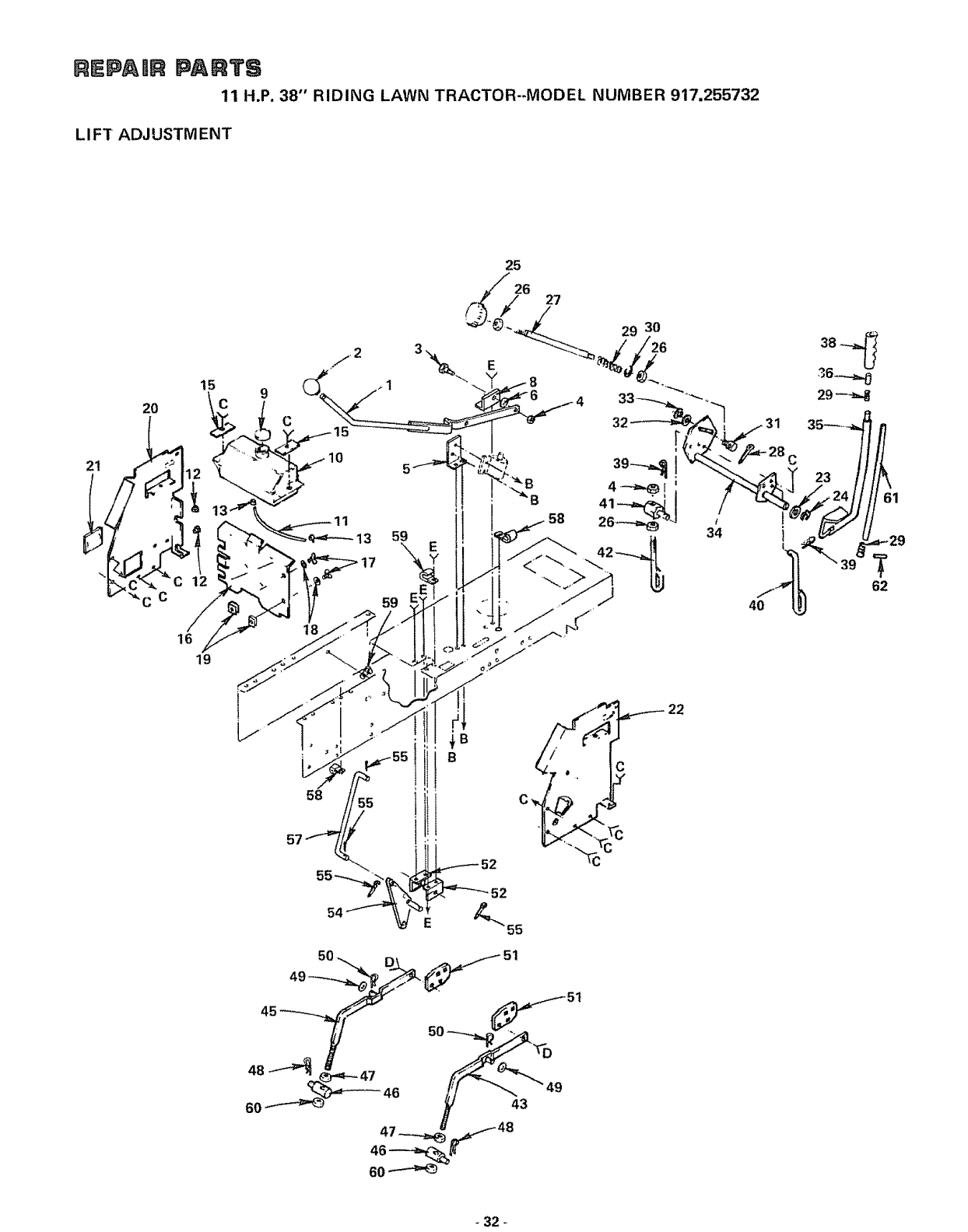
11 H.P. 38" RIDING LAWN TRACTOR-MODEL NUMBER 917.255732
LI FT ADJUSTM ENT
20
15 9
16
19
C
13 59
17
59
18
25
26 27
/29 30
E8
22
40
61
T
62
-32 -
REPA ilR PARTS
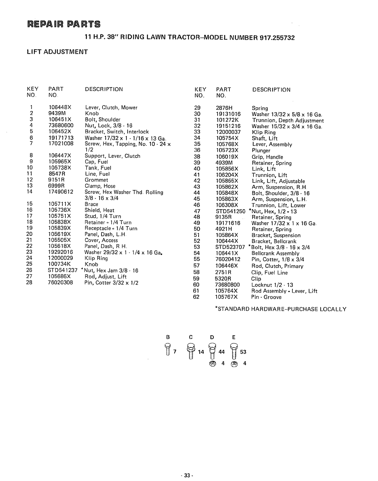
11 H.P. 38" RIDING LAWN TRACTOR--MODEL NUMBER 917.255732
LI FT ADJUSTM ENT
KEY PART DESCRIPTION KEY PART DESCRIPTION
NO NO NO. NO.
I
2
3
4
5
6
7
8
9
10
11
12
13
14
t5
t6
17
18
19
20
2t
22
23
24
25
26
27
28
106448X Lever, Clutch, Mower 29 2876H Spring
9439M Knob 30 19131016 Washer 13/32 x 5/8 x 16 Ga.
I06451X Bolt, Shoulder 31 10!272K Trunnion, Depth Adjustment
73680600 Nut, Lock, 3/8 - 16 32 19151216 Washer 15/32 x 3/4 x 16 Ga.
106452X Bracket, Switch, interlock 33 12000037 Klip Ring
19171713 Washer 17/32 x 1 - 1/16 x 13 Ga. 34 105754X Shaft, Lift
17021008 Screw, Hex, Tapping, No.. 10 - 24 x 35 105768X Lever, Assembly
1/2 36 105723X Plunger
106447X Support, Lever, Clutch 38 t06019X Grip, Handle
I05965X Cap, Fuel 39 4939M Retainer, Spring
I05738X Tank, Fuel 40 105856X Link, Lift
8547R Line, Fuel 41 106204X Trunnion, Lift
9151R Grommet 42 105855X Link, Lift, Adjustable
6999R Clamp, Hose 43 105862X Arm, Suspension, R..H
17490612 Screw, Hex Washer Thd Rolling 44 105848X Bolt, Shoulder, 3/8 -16
3/8- 16 x 3/4 45 105863X Arm, Suspension, LoHo
105711X Brace 46 106308X Trunnion, Lift, Lower
I05736X Shield, Heat 47 STD541250 *Nut, Hex, 1/2 - 13
105751X Stud, 1/4 Turn 48 9135R Retainer, Spring
t05838X Retainer _ 1/4 Turn 49 19171616 " Washer 17/32 x t x 16 Ga.
t05839X Receptacle _ 1/4 Turn 50 4921H Retainer, Spring
!05619X Panel, Dash, L,H. 51 105864X Bracket, Suspension
105505X Cover, Access 52 106444X Bracket, Bellcrank
1056t8X Panel, Dash, RH. 53 STD523707 *Bolt, Hex 3/8 - 16 x 3/4
19292016 Washer 29/32 x 1 -1/4 x 16 Ga, 54 t06441X Belfcrank Assembly
12000029 Ktip Ring 55 76020412 Pin, Cotter, 1/8 x 3/4
100734K Knob 57 t06446X Rod, Clutch, Primary
STD541237 *Nut, Hex Jam 3/8- 16 58 2751R Clip, Fuel Line
t05686X Rod, Adjust, Lift 59 532OR Clip
76020308 Pin, Cotter 3/32 x 1/2 60 73680800 Locknut I/2- 13
61 105764X Rod Assembly - Lever, Lift
62 105767X Pin - Groove
*STANDARD HARDWARE--PURCHASE LOCALLY
BC D E
®4
33-
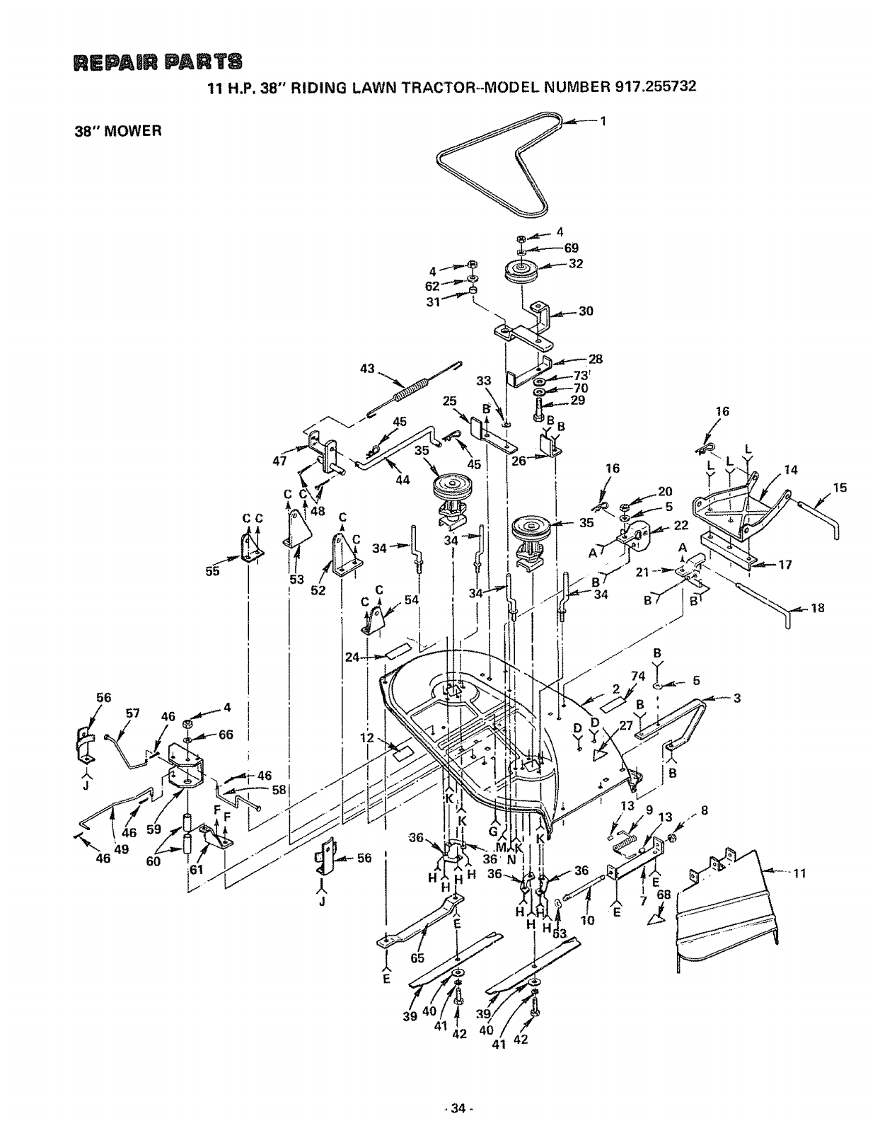
REPAtR PARTS
11 H.P, 38" RIDING LAWN TRACTOR--MODEL NUMBER 917.255732
38" MOWER
30
46
CC
60
33
16
L
±
J
56
14
11
15
_34 -
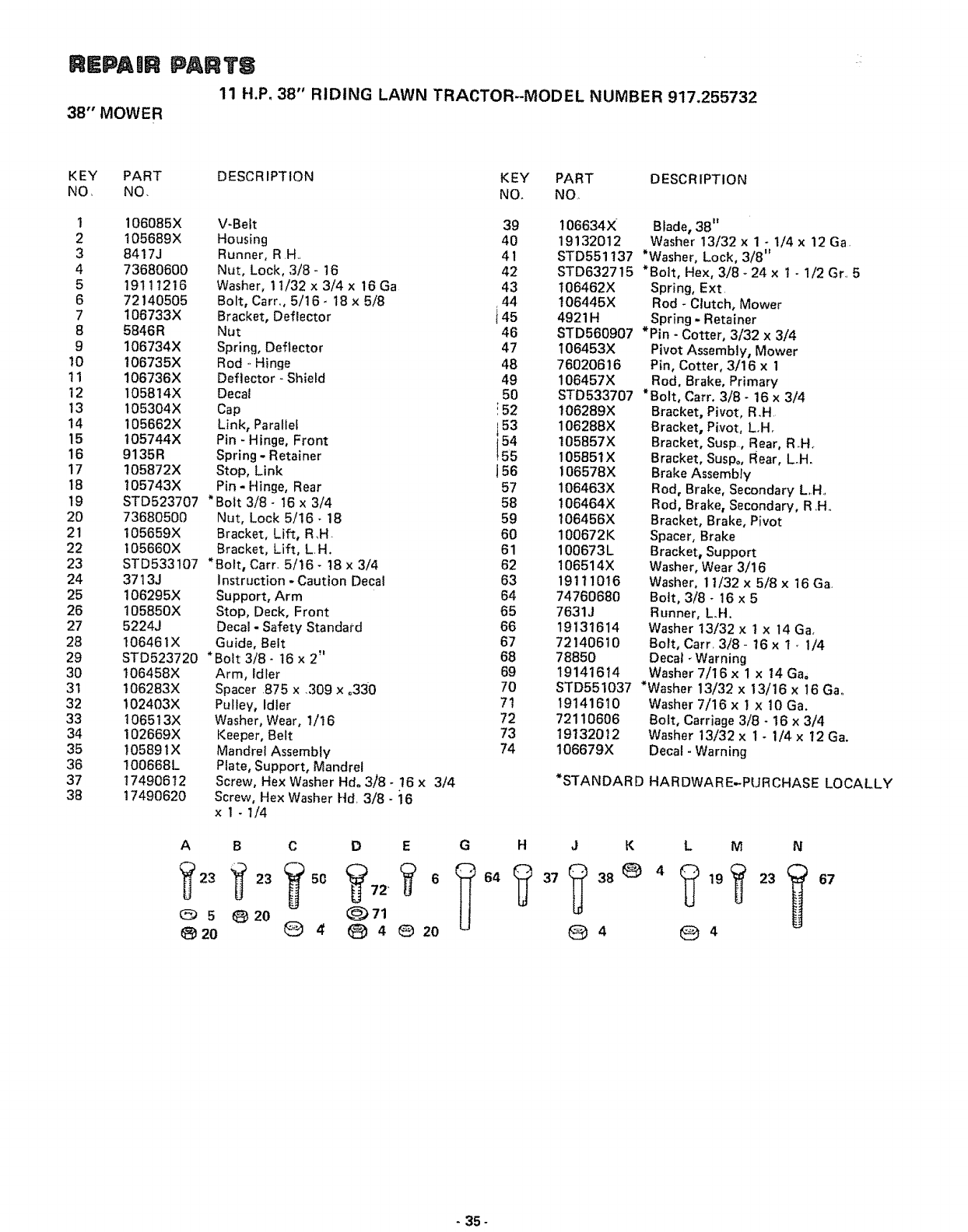
KPAUR
38" MOWER
PARTS
11 H.P. 38" RIDING LAWN TRACTOR--MODEL NUMBER 917.255732
KEY PART
NO, NO.
I 106085X
2 105689X
38417J
47368060O
5 19111216
6 72140505
7 106733X
B 5846R
9 106734X
10 I06735X
11 106736X
12 105814X
13 I05304X
14 105662X
15 105744X
16 9135R
17 105872X
18 I05743X
19 STD523707
20 73680500
21 105659X
22 I05660X
23 STD533!07
24 3713J
25 106295X
26 105850X
27 5224J
28 106461X
29 STD523720
30 I06458X
31 I06283X
32 102403X
33 106513X
34 102669X
35 105891X
36 I00668L
37 17490612
38 17490620
DESCRIPTION KEY PART DESCRIPTION
NO. NO,
V-Belt 39
Housing 40
Runner, R .H.. 41
Nut, Lock, 3/8- 16 42
Washer, 1t/32 x 3/4 x 16 Ga 43
Bolt, Car,., 5/16- 18 x 5/8 r44
Bracket, Deflector t 45
Nut 46
Spring, Deftector 47
Rod ° Hinge 48
Deflector- Shield 49
Decal 50
Cap !52
,53
Link, Parallel i54
Pin - Hinge, Front _155
Spring - Retainer
Stop, Link j56
Pin -Hinge, Rear 57
*Bolt 3/8- 16 x 3/4 58
Nut, Lock 5/16 -18 59
Bracket, Lift, R,H- 60
Bracket, Lift, LH. 61
*Bolt, Carr. 5/!6- t8 x 3/4 62
Instruction - Caution Decal 63
Support, Arm 64
Stop, Deck, Front 65
Decal -Safety Standa_'d 66
Guide, Belt 67
*Bolt 3/8- 16 x 2" 68
Arm, Idler 69
Spacer .875 x309 x.330 70
Pulley, Idler 71
Washer, Wear, 1/!6 72
Keeper, Belt 73
Mandrel Assembly 74
Plate, Support, Mandrel
Screw, Hex Washer Hdo 3/'8- !6 x 3/4
Screw, Hex Washer Hd. 3/8- ;16
x I-1/4
A
(5) 5
20
BCD E G H
(_)20 _ 4(_ 4@20
106453X
76020616
106457X
STD533707
106289X
106288X
105857X
10585tX
106578X
106463X
t06464X
106456X
100672K
100673L
106514X
19111016
74760680
7631J
19131614
72140610
78850
19141614
106634X Blade, 38"
19132012 Washer 13/32 x 1 - 1/4 x 12 Ga.
STD551137 *Washer, Lock, 3/8"
STD632715 *Boit, Hex, 3/8 -24 x 1-1/2 Gr_,5
t06462X Spring, Ext
106445X Rod -Ciutch, Mower
4921H Spring - Retainer
STD560907 *Pin - Cotter, 3/32 x 3/4
Pivot Assembly, Mower
Pin, Cotter, 3/16 x 1
Rod, Brake, Primary
*Bolt, Carr, 3/8- 16 x 3/4
Bracket, Pivot, R.H
Bracket, Pivot, L.H.
Bracket, Susp,, Rear, R.Ho
Bracket, Suspo, Rear, Loll.
Brake Assembly
Rod, Brake, Secondary LH.
Rod, Brake, Secondary, R,H..
Bracket, Brake, Pivot
Spacer, Brake
Bracket, Support
Washer, Wear 3/16
Washer, 11/32 x 5/8 x 16 Ga
Bo_t, 3/8- 16 x 5
Runner, L.H,
Washer 13/32 x 1 x 14 Ga,
Bolt, Car,. 3/8- 16 x t * 1/4
Decal _Warning
Washer 7/16 x ! x 14Ga=
STD551037 *Washer 13/32 x 13/16 x 16 Gao
19141610 Washer 7/16 x I x 10 Ga.
72110606 Bolt, Carriage 3/8 - 16 x 3/4
19132012 Washer 13/32 x 1 - 1/4 x 12 Ga.
106679X Decal - Warning
*STANDARD HARDWARE-PURCHASE LOCALLY
JK L M N
_ 4 _ 4
67
-35-

REPAIR PARTS
11 H.P. 38"' RIDING LAWN TRACTOR_MODEL NUMBER 917.255732
16
19
20 21 _2
/
18 22
24 25
26
27
28
23 27
29
10 27
33 27 15
31
8* 32 16
38* 46
/
57
58
59
6O 62
61
63
65
66
37
64
-36 -
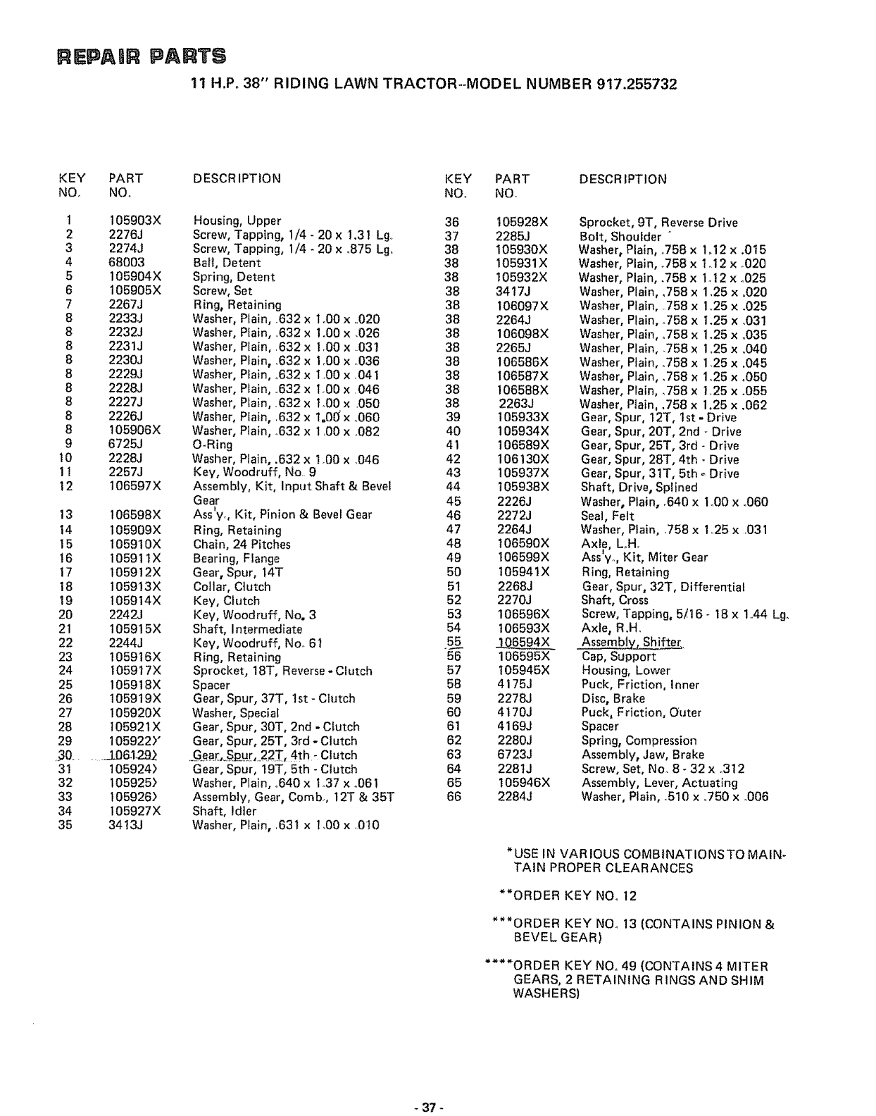
REPAUR PARTS
11 H.P° 38" RIDING LAWN TRACTOR--MODEL NUMBER 917.25,5732
KEY PART DESCRIPTION KEY PART DESCRIPTION
NOr NOo NOo NO.
1 105903X
2 2276J
3 2274J
4 68003
5 105904X
6 105905X
7 2267J
8 2233J
8 2232J
8 2231J
8 2230J
8 2229J
8 2228J
8 2227J
8 2226J
8 t05906X
9 6725J
10 2228J
11 2257J
12 106597X
13 106598X
14 105909X
15 105910X
16 10591IX
17 105912X
18 105913X
19 105914X
20 2242J
21 105915X
22 2244J
23 105916X
24 105917X
25 105918X
26 105919X
27 105920X
28 t05921X
29 105922)"
50 ........._:L06_29_
31 105924)
32 105925)
33 105926)
34 I05927X
35 3413J
Housing, Upper
Screw, Tapping, !/4 -20 x 1.31 Lg
Screw, Tapping, 1/4 -20 x °875 Lg.
Ball, Detent
Spring, Detent
Screw, Set
Ring, Retaining
Washer Plain, .632 x Io00 x ..020
Washer Plain, 632 x 1.00 x ,026
Washer Plain, .632 x 1.00 x ..031
Washer Plain, .632 x 1,00 x .036
Washer Plain, .632 x 1.00 x .041
Washer Plain, ..632 x 1.00 x .046
Washer, Plain, .632 x ! .00 x.050
Washer, Plain, 632 x l°00x _060
Washer, Plain, .632 x 1,00 x ..082
O-Ring
Washer, Plain, .632 x 1,00 x ,046
Key, Woodruff, No. 9
Assembly, Kit, Input Shaft & Bevel
Gear
i
Ass yo, Kit, Pinion & Bevel Gear
Ring, Retaining
Chain, 24 Pitches
Bearing, Flange
Gear, Spur, t4T
Collar, Clutch
Key, Clutch
Key, Woodruff, No. 3
Shaft, Intermediate
Key, Woodruff, No. 6t
Ring, Retaining
Sprocket, 18T, Reverse - Clutch
Spacer
Gear, Spur, 37T, 1st - Clutch
Washer, Special
Gear, Spur, 30T, 2nd - Clutch
Gear, Spur, 25T, 3rd - Clutch
._a[,.Sp__.[,_22T, 4th - Clutch
Gear, Spur, 19T, 5th - Clutch
Washer, Plain, .640 x 1.37 x °061
Assembly, Gear, Comb., 12T & 35T
Shaft, Idler
Washer, Plain, 631 x 1,00 x ,010
36 105928X
37 2285J
38 105930X
38 105931X
38 105932X
38 34t7J
38 106097X
38 2264J
38 106098X
38 2265J
38 !06586X
38 106587X
38 106588X
38 2263J
39 105933X
40 105934X
41 106589X
42 106130X
43 105937X
44 105938X
45 2226J
46 2272J
47 2264J
48 t06590X
49 106599X
50 105941X
51 2268J
52 2270J
53 106596X
54 106593X
55 _J_0_594X
56 106595X
57 105945X
58 4175J
59 2278J
60 4170J
61 4169J
62 2280J
63 6723J
64 2281J
65 105946X
66 2284J
Sprocket, 9T, Reverse Drive
Bolt, Shoulder "
Washer, Plain, °758 x 1_12 x .0t5
Washer, Plain, °758 x t.12 x .020
Washer, Plain, .758 x i_ 12 x °025
Washer, Plain, _758 x 1.25 x °020
Washer, Plain, ..758 x 1.25 x .025
Washer, Plain, .758 x 1.25 x .031
Washer, Plain, °758 x 1.25 x °035
Washer, Plain, _758 x 1.25 x ..040
Washer, Plain, .758 x 1.25 x .045
Washer, Plain, .758 x 1.25 x .050
Washer, Plain, .758 x 1,25 x .055
Washer, Plain, .758 x 1,25 x .062
Gear, Spur, 12T, 1st - Drive
Gear, Spur, 20T, 2nd - Drive
Gear, Spur, 25T, 3rd - Drive
Gear, Spur, 28T, 4th - Drive
Gear, Spur, 31T, 5th _ Drive
Shaft, Drive, Splined
Washer, Plain, °640 x I_00 x _060
Seal, Felt
Washer, Plain, .758 x 1.25 x ,031
Axle, LoH_
Ass %, Kit, Miter Gear
Ring, Retaining
Gear, Spur, 32T, Differential
Shaft, Cross
Screw, Tapping, 5/16 - 18 x 1o44 Lg.
Axle, R.H.
Cap, Support
Housing, Lower
Puck, Friction, Inner
Disc, Brake
Puck, Friction, Outer
Spacer
Spring, Compression
Assembly, Jaw, Brake
Screw, Set, No. 8 - 32 x 312
Assembly, Lever, Actuating
Washer, Plain, o510 x ..750 x °006
*USE IN VARIOUS COMBtNATIONSTO MAIN-
TAIN PROPER CLEARANCES
**ORDER KEY NOo 12
***ORDER KEY NOo 13 (CONTAINS PINION &
BEVEL GEAR)
****ORDER KEY NO, 49 (CONTAINS 4 MITER
GEARS, 2 RETAINING RINGS AND SHIM
WASHERS)
37 -
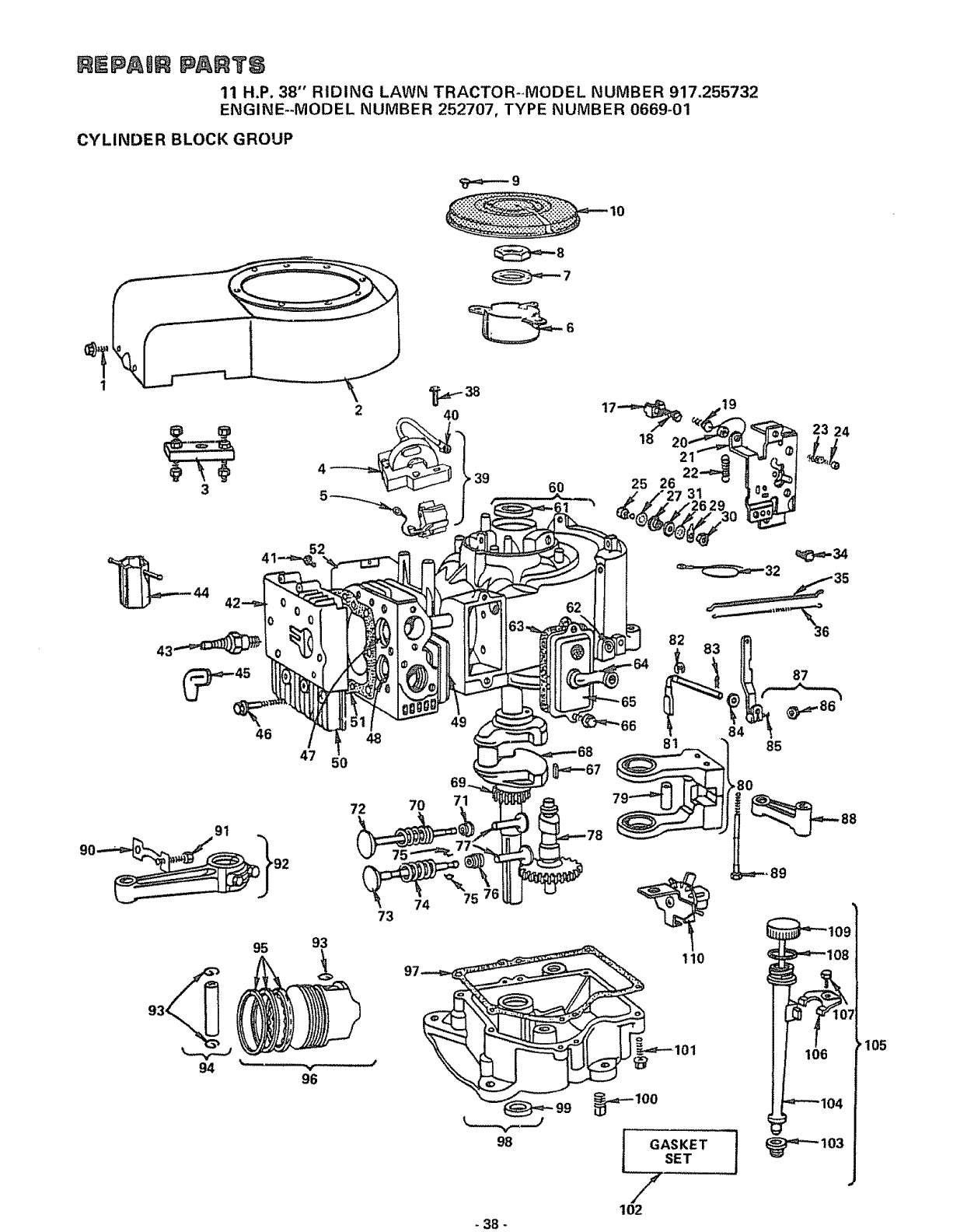
mEpAem PAINTS
11 H.P. 38" RIDING LAWN TRACTOR-_MODEL NUMBER 917.255732
ENGINE+-MODEL NUMBER 252707, TYPE NUMBER 0669+01
CYLINDER BLOCK GROUP
3
46
94
2
52
48
47 50
72
73
95 93
40
39 6O
7O
74
49
69-
71
75
62
98
GASKET
SET
' 105
102
- 38 -
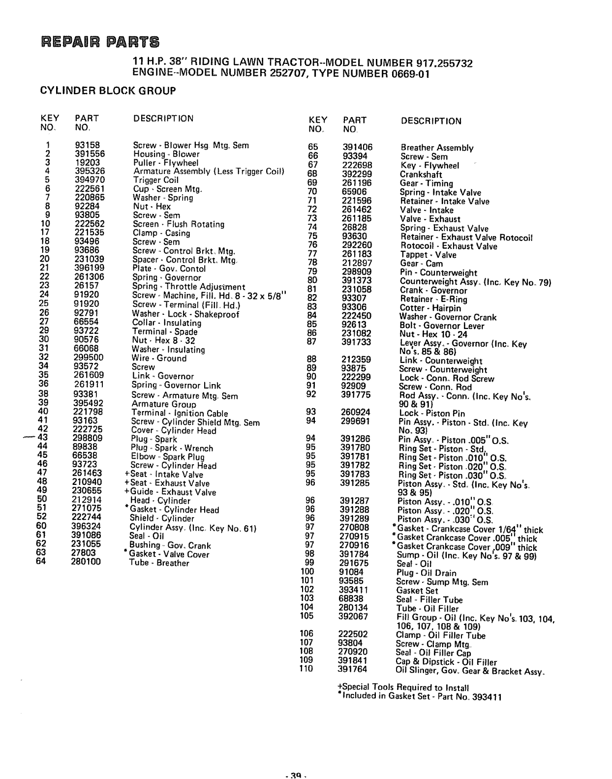
REPAmR PARTS
11 H.P. 38" RIDING LAWN TRACTOR--MODEL NUMBER 917.255732
ENGINE--MODEL NUMBER 252707, TYPE NUMBER 0669_01
CYLINDER BLOCK GROUP
KEY PART DESCRIPTION KEY PART DESCRIPTION
NO. NO, NOo NO.
! 93158 Screw _Blower Hsg Mtg., Sem 65 391406
2 391556 Housing- Btower 66 93394
3 19203 Puller- Flywheel 67 222698
4 395326 Armature Assembly (Less Trigger Coit) 68 392299
5 394970 Trigger Coil 69 261196
6 222561 Cup _Screen Mtgo 70 65906
7220865 Washer- Spring 71 221596
8 92284 Nut- Hex 72 261462
9 93805 Screw* Sam 73 261185
10 222562 Screen- Flush Rotating 74 26828
17 221535 Clamp- Casing 75 93630
!8 93496 Screw - Sam 76 292260
19 93686 Screw ,.Control Brkt_ Mtg. 77 261 t83
20 231039 Spacer- Control 8rkto Mtg 78 212897
21 396199 Plate- Gov. Contol 79 298909
22 261306 Spring- Governor 80 391373
23 26157 Spring. Throttle Adjustment 81 231058
24 91920 Screw., Machine, Fill. Hd_ 8- 32 x 5/8 It 82 93307
25 91920 Screw - Terminal (Fill,, Hd.) 83 93306
26 92791 Washer- Lock- Shakeproof 84 222450
27 66554 Collar- Insulating 85 92613
29 93722 Terminal -Spade 86 231082
30 90576 Nut- Hex 8- 32 87 391733
3! 66068 Washer ,, Insulating
32 299500 Wire* Ground 88 212359
34 93572 Screw 89 93875
35 261609 Link- Governor 90 222299
36 261911 Spring ,.Governor Link 91 92909
38 93381 Screw- Armature Mtg. Sam 92 391775
39 395492 Armature Group
40 221798 Terminal -ignition Cable 93
41 93163 Screw ,.Cylinder Shield Mtg., Sem 94
42 222725 Cover., Cylinder Head
---- 43 298809 Plug- Spark 94
44 89838 Plug ..Spark -Wrench 95
45 66538 Elbow -Spark Plug 95
46 93723 Screw - Cylinder Head 95
47 261463 +Seat- intake Valve 95
48 210940 +Seat- Exhaust Valve 96
49 230655 +Guide - Exhaust Valve
50 212914 Head- Cylinder 96
51 271075 *Gasket - Cylinder Head 96
52 222744 Shield _Cylinder 96
60 396324 Cylinder Assy. (lnc. Key No. 6t) 97
61 391086 Seal - Oil 97
62 231055 Bushing., Gow Crank 97
63 27803 *Gasket- Valve Cover 98
64 280100 Tube - Breather 99
100
101
102
!03
104
105
106
107
t08
109
110
Breather Assembly
Screw- Sere
Key - Flywheel
Crankshaft
Gear- Timing
Spring- intake Valve
Retainer _Intake Valve
Valve- intake
Valve - Exhaust
Spring- Exhaust Valve
Retainer- Exhaust Valve Rotocoil
Rotocoit -Exhaust Valve
Tappet- Valve
Gear - Cam
Pin - Counterweight
Counterweight Assyo(tnc. Key NOR79)
Crank -Governor
Retainer -E-Ring
Cotter oHairpin
Washer -Governor Crank
Bolt - Governor Lever
Nut -Hex 10- 24
Lev,er Assy, -Governor (Inc. Key
No's, 85 & 86}
Link -Counterweight
Screw -Counterweight
Lock - Conno Rod Screw
Screw- Conn oRod
Rod Assy. -Conn. (Inco Key No's,
90& 91)
260924 Lock - Piston Pin
299691 Pin Assy. -Piston -Stdo(Inc. Key
No. 93)
391286 Pin Assy. - Piston °005" O.S,
391780 Ring Set - Piston - Std.
391781 Ring Set Piston _010" OoS.
391782 Ring Set Piston .020:'_ OoSo
391783 Ring Set Piston .030 OoSo
391285 Piston Assyo. Stdo (Inco Key No's.
93 & 95)
391287 Piston Assv _ 010 O.S
391288 Piston Assy.- 020 OoSo
• .*t
391289 Piston Assy.- .030 OoS,
270808 *Gasket- Crankcase Cover 1/64" thick
270915 *Gasket Crankcase Cover .005' _thick
270916 *Gasket Crankcase Covero009 th=ck
391784 Sump- Oil (Inco Key No's. 97 & 99)
291675 Seal - Oil
91084 Plug- Oil Drain
93585 Screw _Sump Mtg. Sere
39341 tGasKetSet
68838 Seal -Filler Tube
280134 Tube - Oil Filler
392067 Fill Group - Oil (inc. Key Nots. 103, 104,
106, !07,108 &109)
222502 Clamp- Oil Filler Tube
93804 Screw - Clamp Mtg
270920 Sea! - Oil Filler Cap
391841 Cap & Dipstick - Oil Filler
391764 Oil Slinger, Gov,, Gear & Bracket Assy.
+Special Tools Required to tnsta}t
* included in Gasket Set - Part No,,393411

REPAmR PART6
11 H.P. 38" RIDING LAWN TRACTOR_-MODEL NUMBER 917.255732
ENGINE-MODEL NUMBER 252707, TYPE NUMBER 0669-01
CARBURETOR
9
20
16
31
15
40
41
47
48
49
40 -
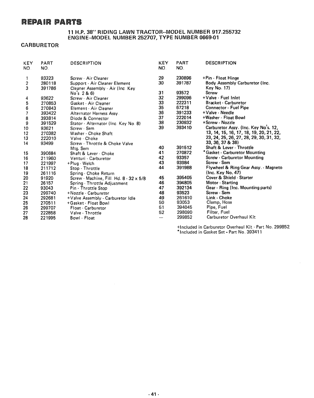
REPAnR PARTS
11 H.P. 38" RIDING LAWN TRACTOR--MODEL NUMBER 917_255732
ENGINE--MODEL NUMBER 252707, TYPE NUMBER 0669-01
CARBURETOR
KEY PART DESCRIPTION KEY PART DESCRIPTION
NO. NO NO, NQ,
!93323 Screw- Air Cleaner 29 230896
2 280118 Support- Air Cleaner Element 30 391787
3 391786 Cleaner Assembly .-Air (Inc Key
No's- 2 & 6) 3t 93572
4 93622 Screw ,,Air Cleaner 32 299096
5 270853 Gasket ,,Air Cleaner 33 222311
6 270843 Element ,,Air Cleaner 35 67218
7 393422 Alternator Harness Assy, 36 391233
8 393814 Diode & Connector 37 222014
9 391529 Stator _Alternator (lnc Key No 8} 38 230932
10 93621 Screw-. Sem 39 393410
12 270382 Washer- Choke Shaft
13 222010 Valve ,,Choke
14 93499 Screw ,,Throttle & Choke Valve
Mtg. Sem 40 391512
15 390684 Shaft & Lever., Choke 41 270872
t6 2! !960 Venturi _Carburetor 42 93357
17 221997 +Plug, Welch 43 93984
18 211712 Stop- Throttle 44 391988
19 261116 Spring ,,Choke Return
20 91920 Screw., Machine, Fill. Hd, 8- 32 x 5/8 45 395405
21 26157 Spring _Throttle Adjustment 46 394805
22 93043 Pin- Throttle Stop 47 392134
23 299740 +Nozzle ,,Carburetor 48 93523
24 292681 +Valve Assembly -Carburetor Idle 49 261610
25 270511 +Gasket- Float Bowl 50 93053
26 299707 Float° Carburetor 51 394045
27 222858 Valve, Throttie 52 298090
28 221995 Bowl., Float -.- 299852
+Pin - Float Hinge
Body Assembly Carburetor (Inc.
Key No. 17)
Screw
+Valve- Fuel Inlet
Bracket- Carburetor
Connector* Fuel Pipe
+Valve - Needle
+Washer- Float Bowl
+Screw- Nozzle
Carburetor Assy_(Inc. Key No's. 12,
13, 14, 15, 16, 17, 18, 19, 20, 21, 22,
23, 24, 25, 26, 27, 28, 29, 30, 31, 32,
33, 36, 37 & 38)
Shaft & Lever -Throttle
*Gasket -Carburetor Mounting
Screw -Carburetor Mounting
Screw - Sere
Flywheel & Ring Gear Assyo- Magneto
(Inc. Key No. 47)
Cover & Shield- Starter
Motor- Starting
Gear- Ring (IncoMounting parts)
Screw- Sem
Link -Choke
Clamp, Hose
Pipe, Fuel
Filter, Fuel
Carburetor Overhaul Kit
+Included in Carburetor Overhaul Kit - Part No, 299852
* included in Gasket Set - Part No1,393411
-41

REPAIR PA TS
11 H.P. 38" RIDING LAWN TRACTOR--MODEL NUMBER 917.255732
ENGINE--MODEL NUMBER 252707, TYPE NUMBER 0669-01
STARTER-MOTOR
1
3
5
12
11
KEY
NO.
2
3
4
5
PART
NO.
394805
94003
93754
391462
391461
280104
DESCRIPTION
Motor- Starting (Inc. Key No'so 2, 3,
4, 5,6,7, 8,9, 10, 11 &t2)
Thru Bolt Assembly
Roll Pin
Retainer & Pin (inc. Key No. 3)
Drive Assembly (lnc° Key No's 3,
4,6& 7)
Gear
KEY PART DESCRIPTION
NO, NO.
7391135
8 393825
9 392747
10 395538
11 395537
12 394856
Clutch Assembly
Housing Assembly
Armature Assembly
Brush Assembly
End Cap Assy Commutator (Inc Key
No, 10)
End Cap Assy Drive
- 42 -

SUGGESTED GUIDE FOR SmGHTING SLOPES FOR SAFE OPERATION
I
SIGHTING GUIDE
t
ONLY RIDE UP AND DOWN HILL
NOT ACROSS HiLL
SIGHT AND HOLD THIS LEVEL WiTH
SKY LINE OR TREE
@
Operate your Tractor up and down the face of slopes (not
greater than !5°); never across the face. Make turns gradu-
ally to prevent tipping or loss of control. Exercise extreme
caution when changing direction on slopes.

SEA/RS
OWNERS
MANUAL
MODEL NO.
917.255732
HOW TO ORDER
REPAIR PARTS
11 HoPo
38" RIDING
LAWN TRAC
ELECTRIC
TOR
START
The Model Number will be found on the Model Plate attached
to the Drawbar. Always mention the Model Number when
requesting service or parts for' your Lawn Tractor.
All parts listed herein may be ordered from any Sears Service
Center/Departments and most Sears Retail Stores,
WHEN ORDERING REPAIR PARTS, ALWAYS GIVE THE
FOLLOWING INFORMATION:
@ THE PART NUMBER
• THE PART DESCRIPTION
@ THE MODEL NUMBER
O THE NAME OF MERCHANDISE
If the parts you need are not stocked locally, your order will
be electronically transmitted to a Sears Repair Parts Distribu-
tion Center for "expedited handling",
k,,, ,,,.i
.......... ,, ,, ,i III r,]l ,_;

SEA/ S
OWNERS
MANUAL
MODE L NO.
917.255732
Caution:
Read Rules for
Safe Operation
and Instructions
Carefully
| i/ ........
11 H,P,
38" RIDJNG
LAWN TRAC TOR
ELECTRIC START
Assembly
Installation
Operation
Repair Parts
ii u l
Sears, Roebuck and Co., Chicago, IL 60684 US.Ao
t"

CONGRATULATIONS on your purchase of a Sears Lawn
Tractor, It has been designed, engineered and manufactured
to give you the best possib{e dependability and performance
Should you experience any problem you cannot easily reme-
dy, please contact your nearest Sears Service Department,
They have competent, well-trained technicians and the proper
tools to service or repair this unit.
Please read and retain this manual. The instructions will enable
you to assemble, operate and maintain your Tractor properly
Always observe the "RULES FOR SAFE OPERATION"_
MODEL
NUMBER ....... ;_ ..... :;,_. _..... ,-._ ....._.
SERIAL
NUMBER
THE DRAWBARo
YOU SHOULD PECORD BOTH MODEL AND
SERIAL NUMBF'._ AND KEEP IN A SAFE PLACE
FOR FUTURE rtEFERENCE,
LIMITED ONE YEAR WARRANTY
ON ELECTRIC START RIDING EQUIPMENT
For one year from date of purchase, when this riding equipment is maintained, lubricated, and
tuned up according to the operating and maintenance instructions in the owner's manual, Sears
will repair' free of charge any defect in material or workmanship in this electric start riding equip-
mento
This warranty excludes blade(s), blade adapter(s), spark plug(s), air cleaner and belt(s), which are
expendable and become worn during normal use.
This warranty does not cover:
tire replacement or repair caused by punctures from outside objects (such as nails, thorns,
stumps, or glass); and
repairs necessary because of operator abuse or negligence, including the failure to main-
tain the equipment according to instructions contained in the owner's manual; and
riding equipment used for commercial or rental purposes.
FULL 90-DAY WARRANTY ON BATTERY
For 90 days from the date of purchase, if any battery included with this riding equipment proves
defective in material or workmanship and our testing determines the battery will not hold a charge,
Sears will replace the battery at no charge.
WARRANTY SERVICE IS AVAILABLE BY CONTACTING THE NEAREST SEARS SERVICE
CENTER/DEPARTMENT IN THE UNITED STATES° This warranty applies only while this
product is in use in the United States.
This warranty gives you specific legal rights, and you may also have other rights which vary from
state to state.
Sears, Roebuck and Co., D/698-731A, Sears Tower, Chicago, IL 60684
TABLE OF CONTENTS
RULES FOR SAFE OPERATION .............. 3
ASSEMBLY INSTRUCTIONS ................. 4
OPERATION INSrRUCTIONS - TRACTOR ...... 8
qPERATION INSTRUCTIONS - MOWER ....... 1!
MAINTENANCE INSTRUCTIONS-MOWER ..... 12
MAINTENANCE INSTRUCTIONS _TRACTOR . .14
TROUBLE SHOOTING ..................... 21
-2- REPAIR PARTS ........................... 24

RULES FOR SAFE OPERATDON
WARNING: This unit is equipped with an internal combustion engine and should not be used on or near any unimproved forest-
covered, brush-covered or grass-covered land unless the engine's exhaust system is equipped with a spark arrester meeting applicable
local or state laws (if any) If a spark arrester is used, it should be maintained in effective ,.,corking order by the operator.
fil the State of California the above is required by law (Section 4442 of the California Public Resources Code). Other states may
have similar taws. Federal laws apply on federal lands, S_e your Sears Authorized Service Center for spark arrester muffler part
number 677Vt,
1., Know the controls and how to stop quickly,, READ THE
OWNER'S MANUAL..
2, Do not allow children to operate the vehicle, Do not allow
adults to operate it without proper instruction or with-
out having read the owner's manual,
3, Do not carry passengers, Keep children and pets a safe dis-
tance away,
4, Always wear substantial footwear° Do not wear loose fitting
clothing that could get caught in moving parts,
5 Keep your eyes and mind on your tractor, mower and the
•|
area being cut Don t let other interests distract you,
6, Do not attempt to operate your tractor or mower when
not in drivers seat,
7., Always get on or off your tractor from the operators left
hand side
8, Clear the work area of objects which might be picked up
and thrown,
9, Disengage all attachment clutches and shift into neutral be-
fore attempting to start the engine,
t0, Disengage power to attachments and stop the engine be-
fore leaving the operator's position_
11, Disengage power to mower, stop the engine and disconnect
spark plug wire(s) from spark plug(s) before cleaning, mak-
ing an adjustment or repairs_
|2_ Disengage power to attachments when transporting or not
in use,
13. Take all possible precautions when leaving the vehicle un-
attended° Disengage the power-take-off, lower the attach-
ments, shift into neutral, set the parking brake, stop the en-
gine and remove the key.
14.. Do not stop or start suddenly when going uphill or down-
hill. Mow up and down the face of slopes (not greater than
15o}; never across the face, Refer to page 43..
15 Reduce speed on slopes and make turns gradually to pre-
vent tipping or loss of control° Exercise extreme caution
when changing direction on slopes.
16. Do not shift gears while going up or down slopes.. Choose
a gear low enough to negotiate the slope without stopping
and shifting gears To reduce speed, move throttle lever
to slow.
17. Never mow in wet or slippery grass, when traction is un-
sure or at a speed which could cause a skid
18. Stay alert for holes in the terrain and other hidden hazards
19,, Do not drive too close to creeks, ditches and public high°
ways.
20, Exercise special care when mowing around fixed objects
in order to prevent the blades from striking them, Never
deliberately run tractor or mower into or over any foreign
object
21 rNever shift gears until tractor comes to a stop.
22. Never place hands or feet under the mower, in the deflector
(discharge chute) or near any moving parts while tractor or
mower are running. Always keep clear of discharge chute°
23 Use care when pulling loads or using heavy equipment,.
a. Use only approved drawbar hitch points.
b, Limit loads to those you can safely controi_
c. Do not turn sharply. Use care when backing,
d. Use counterweight or wheel weights when suggested in
this owner s manual_
24. Watch out for traffic when crossing or near roadways.
25 When using any attachments, never direct discharge of
material toward bystanders nor allow anyone near the ve-
hicle while in operatiom
26° Handle gasoline with care - it is highly flammable.
a_ Use approved gasoline containers.
b.. Never remove the cap of the fuel tank or add gasoline to
a running or hot engine, or fill the fuel tank indoors°
Wipe up spilled gasoline.
c. Open doors if the engine is run in the garage - exhaust
fumes are dangerous° Do not run the engine indoors..
27, Keep the vehicle and attachments in good operating con-
dition, and keep safety devices in place,
28° Keep all nuts, bolts and screws tight to be sure the equip-
ment is in safe working condition,.
29. Never store the equipment with gasoline in the tank inside
a building where fumes may reach an open flame or spark.
Allow the engine to cool before storing in any enclosure..
30_ To reduce fire hazard, keep the engine free of grass, leaves
or excessive greaser Do not clean product while engine is
running.
31 Except for adjustment; DO NOT operate Engine if air
cleaner or cover directly over carburetor air intake is re-
moved. Removal of such part could create a fire hazard,
32. Do not operate without a muffler or tamper with the
exhaust system,. Damaged mufflers or spark arresters
could create a fire hazard. Inspect periodically and replace
if necessary,
33., The vehicle and attachments should be stopped and inspect-
ed for damage after striking a foreign object, and the dam-
age should be repaired before restarting and operating the
equipment.
34, Do not change the engine governor settings or overspeed
the engine; severe damage or injury may result.
35. When using the vehicle with mower, proceed as follows:
a_ Mow only in daylight or in good artificial light
b, Never make a cutting height adjustment while the engine
is running if the operator must dismount to do soo
c, Shut the engine off when removing the grass catcher or
unclogging chute.
d, Check the blade mounting bolts for proper tightness at
frequent intervals,
36_ Do not operate the Mower without the deflector shield in
place.
37. Disengage power to mower before backing up, Do not mow
in reverse unless absolutely necessary and then only after
careful observation of the entire area behind the mower,
LOOK FOR THIS SYMBOL TO POINT OUT IMPORTANT SAFETY
PRECAUTIONS, IT MEANS - ATTENTION! BECOME ALERT!
YOUR SAFETY IS INVOLVED,
-3-
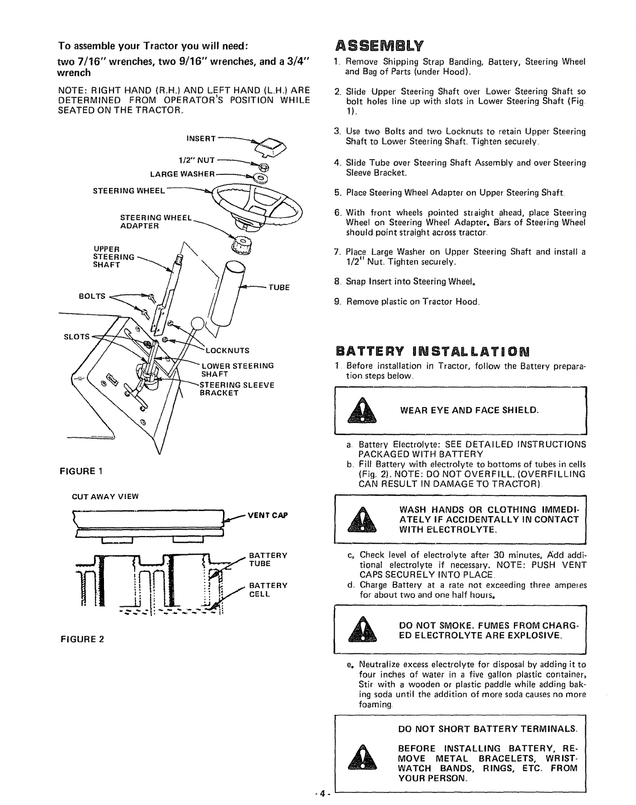
To assemble your Tractor you will need:
two 7/16" wrenches, two 9/16" wrenches, and a 3/4"
wrench
NOTE: RIGHT HAND (R.H.) AND LEFT HAND (LH°) ARE
DETERMINED FROM OPERATOR'S POSITION WHILE
SEATED ON THE TRACTOR°
112" NUT _---_.__._
LARGE WASHER _
STEERING
SHAFT \
BOLTS
ASSEMBLY
1v Remove Shipping Strap Banding, Battery, Steering Wheel
and Bag of Parts (under Hood).
2. Slide Upper Steering Shaft over Lower Steering Shaft so
bolt holes line up with slots in Lower Steering Shaft (Fig.
1L
3. Use two Bolts and two Locknuts to retain Upper- Steering
Shaft to Lower Steering Shaft_ Tighten securely,
4._ Slide Tube over Steering Shaft Assembly and over Steering
Sleeve Bracket.
5. Place Steering Wheel Adapte_ on Upper Steering Shaft
6. With front wheels pointed straight ahead, place Steering
Wheel on Steering Wheel Adapter, B'ars of Steering Wheel
should point straight across tractor.
7. Place Large Washer on Upper Steering Shaft and install a
1/2" Nut, Tighten securely_
8. Snap Insert into Steering Wheel°
9. Remove plastic on Tractor Hood,
NUTS
_RING
SHAFT
SLEEVE
BRACKET
BATTERY IINSTALLATg ON
1 Before installation in Tractor, foltow the Battery prepara-
tion steps below,
WEAR EYE AND FACE SHIELD.
FIGURE 1
CUT AWAY VIEW
_' .......
l----d
e,.,_VENTCAP
J
BATTERY
TUBE
BATTERY
CELL
a, Battery Electrolyte: SEE DETAILED INSTRUCTIONS
PACKAGED WITH BATTERY
b, Fill Battery with electrolyte to bottoms of tubes in cells
(Fig,. 2), NOTE: DO NOT OVERFILL. (OVERFILLING
CAN RESULT IN DAMAGE TO TRACTOR)
WASH HANDS OR CLOTHING IMMEDI-
ATELY IF ACCIDENTALLY IN CONTACT
WITH ELECTROLYTE
c= Check level of electrolyte after 30 minutes= Add addi-
tional electrolyte if necessary. NOTE: PUSH VENT
CAPS SECURELY INTO PLACE,
d, Charge Battery at a rate not exceeding three amperes
for about two and one half houls.
FIGURE 2
DO NOT SMOKE. FUMES FROM CHARG-
ED ELECTROLYTE ARE EXPLOSIVE
_4-
e, Neutralize excess electrolyte for disposal by adding it to
four inches of water in a five gallon plastic container_
Stir with awooden or plastic paddle white adding bak-
ing soda until the addition of more soda causes no more
foaming
DO NOT SHORT BATTERY TERMINALS.
BEFORE INSTALLING BATTERY, RE-
MOVE METAL BRACELETS, WRIST-
WATCH BANDS, RINGS, ETC. FROM
YOUR PERSON_
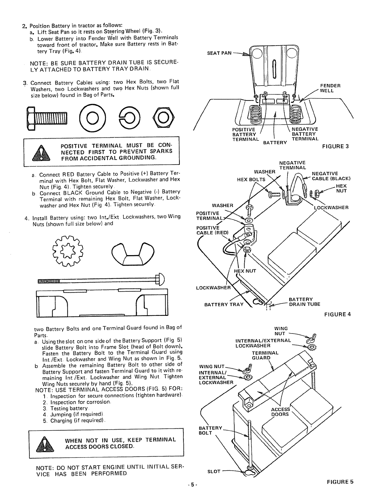
2. Position Battery in tractor as follows:
a. Lift Seat Pan so it rests on Steering Wheel (Fig° 3)o
b, Lower Battery into Fender Wel! with Battery Terminals
toward front of tractor° Make sure Battery rests in Bat-
tery Tray (Fig. 4).
NOTE: BE SURE BATTERY DRAIN TUBE IS SECURE-
LY ATTACHED TO BATTERY TRAY DRAIN,
3o Connect Battery Cables using: two Hex Bolts, two Flat
Washers, two Lockwashers and two Hex Nuts (shown full
size below) found in Bag of Parts.
@@
POSITIVE TERMINAL MUST BE CON-
NECTED FIRST TO PREVENT SPARKS
FROM ACCIDENTAL GROUNDING°
a, Connect RED Battery Cable to Positive (+) Battery Ter _
minal with Hex Bolt, Flat Washer, Lockwasher and Hex
Nut (Fig, 4), Tighten securely,
b Connect BLACK Ground Cable to Negative (-) Battery
Terminal with remaining Hex Bolt, Flat Washer, Lock-
washer and Hex Nut (Fig 4), Tighten securely,
4,, Install Battery using: two tnt,/Ey, t Lockwashers, two Wing
Nuts (shown full size below) and
_t_,j_##,_ ,, ©
TIT: ,
two Battery Bolts and one Terminal Guard found in Bag of
Parts,
a, Using the slot on one side of the Battery Support (Fig 5)
slide Battery Bolt into Frame Slot (head of Bolt down),
Fasten the Battery Bolt to the Terminal Guard using
Int,/Ext, Lockwasher and Wing Nut as shown in Fig, 5.
b Assemble the remaining Battery Bolt to other side of
Battery Support and fasten Terminal Guard to it with re-
maining lnt/Ext, Lockwasher and Wing Nut Tighten
Wing Nuts securely by hand (Fig, 5),
NOTE: USE TERMINAL ACCESS DOORS (FIG, 5) FOR:
1. Inspection for secure connections (tighten hardware),
2, Inspection for corrosion,
3. Testing battery
4 Jumping (if required).
5. Charging (if required),
WHEN NOT IN USE, KEEP TERMINAL
ACCESS DOORS CLOSED_
NOTE: DO NOT START ENGINE UNTIL INITIAL SER-
VICE HAS BEEN PERFORMED
/
SEAT PAN --_
POSITIVE /
BATTERY
TERMINAL BATTERY
' ¸
BATTERY
TERMINAL
FIGURE 3
FENDER
WASHER
POSITIVE
TERMINAL
POSITIVE
CABLE (RED)
WASHER
HEX BOLTS
NEGATIVE
TERMINAL
NEGATIVE
CABLE (BLACK)
NUT
LOCKWASHE R
BATTERY TRAY
! t
BATTERY
TUBE
WINW
INTERNAL/
LOCI{WASHER
WING
NUT _
INTERNAL/EXTERNAL
LOCI(WASHER
TERMINAL
GUARD
FIGURE 4
S
BATTERY
BOLT
SLOT
-5- FIGURE 5

CLUTCHIBRAKE
PEDAL
/
FIGURE 6
SCREW
FIGURE 7
'MENT
BOLT
INITIIAL ADJUSTMENTS
1. SEAT INSTALLATION
a,. Place Seat on Seat Pan.. Screw Adjustment Bolt, Lock_
washer and Fiat Washer into Seat° Adjustment Bolt,
Lockwasher and Flat Washer"found in Bag of Parts=
Tighten finger tight.
bo Place Seat in operating position. Sit on the Seat and
press Crutch-Brake Pedal all the way down. if operating
position is not comfortable, adjust Seat,,
Co Raise Seat. Use 3/4 _wrench to loosen Adjustment Bolt
(Fig° 6),. When adjusted for comfortable operation,
tighten Adjustment Bolt securely.
/
2_
3_
TIRE PRESSURE
Reduce Tire pressure to 14 PSI in front tires; 12 PSi in
rear tires. (Tires were overinflated for shipping).
HOOD
a,. To raise Hood, !ift at rear of Hood,
be To remove Hood, Grill and Side Panels, raise Hood and
loosen one screw on each Side Panel (The screw remains
in the Side Panel) (Fig, 7),
c Unsnap Headlight Connection (Fig, 8),
do Stand in front of Tractor Grasp Hood and tilt forward
and lift off (Fig. 8},
e_ To reinstall, reverse above procedure°
HEADLIGHT
CONNECTION
\
FIGURE 8 - 6-

INITIAL SERVRCE
NOTE: BE CAREFUL NOT TO ALLOW DIRT TO ENTER
THE ENGINE WHEN CHECKING OR ADDING OIL OR
FUEL
Io Pull up at rear of Hood to open,
2 Check Engine Oil Level with Tractor on level ground, Re-
move and wipe Dipstick (Fig. 9) cteano screw it in tight for
a few seconds, remove and read Oil Level° If necessary, add
Oil until "FULL" mark is reached
RECOMMENDED SAE VISCOSITY GRADES
1oI!1 .I...I1,,
"_/I '"5;'20 iR iW'3i - OR 10W-30
-20 ° 0° 32° 60° 80 ° 100 °
TEMPERATURE RANGE EXPECTED BEFORE NEXT OIL
CHANGE,, ALL OILS MUST MEET A.P,I, SERVICE CLAS-
SIFICATION SD, SE, OR SF,
Capacity is 3 pints, NOTE: DO NOT OVERFILL, Dipstick
assembly must be securely tightened into tube at all times
when engine is operating.
3, Fill Fuel Tank (Fig, 9), Use fresh, clean, unleaded auto-
motive gasoline. (Leaded "" " "Regular grade gasohne Is not an
acceptable substitute° Use of leaded gasoline will increase
carbon and lead oxide deposits and reduce valve life)o
Capacity is 5 quarts,,
WARNING: DO NOT USE GASOHOL OR METHANOL,
These type fuels react with water content in the fuel
and tend to form strong acids which can corrode metal
parts and harm rubber and ptastics
FUEL
CAP
FUEL
TANK
FIGURE 9
FILL TO BOTTOM OF GAS TANK FILL-
ER NECK° DO NOT OVERFILL. WIPE
OFF ANY SPILLED OIL OR FUEL. DO
NOT STORE, SPILL OR USE GASOLINE
NEAR AN OPEN FLAME°
-7_

KEY
MOWERBLADE
CLUTCH"ENGAGED"
POSITION
HEADLIGHT
THROTTLE
_CONTROL
LEVER
"DISENGAGED"
POSITION
PARKING
BRAKE
"ENGAGED"
POSITION
='DISENGAGED"
CLUTCH/BRAKE
"CLUTCH" POSITION;
"CLUTCH/BRAKE"
POS|TI ON
FIGURE 10 .... _.
/
G EARSHIFT
LEVER
LIFT LEVER
PLUNGER LIFT
R
FIGURE 11
OPERATION
NOTE: MOWER OPERATION IS LISTED ON PAGE 11.
THIS TRACTOR IS EQUIPPED WITH
INTERLOCK SWITCHES TO PREVENT
STARTING OF THE TRACTOR ENGINE
WHILE THE MOWER BLADE CLUTCH
LEVER IS IN THE "ENGAGED" POSI-
TION AND/OR THE GEAR SHIFT LEVER
IS NOT IN "NEUTRAL" POSITION (FIG.
10). IMMEDIATELY REPLACE SWITCHES
THA, T ARE NOT IN PROPER WORKING
ORDER. DO NOT ATTEMPT TO DEFEAT
THE PURPOSE OF THESE SWITCHES,,
LEARN TO START, STOP AND REVERSE
YOUR TRACTOR tN A LARGE, OPEN
AREA,,
-8-
t,
2.
,
4,.
CAUTION
Keep all shields in place_
Before leaving operator'Jsposition:
a., Shift lever to neutral (Fig,, 10),.
b. Depress Clutch/Brake Pedal and set Parking Brake (Fig.
10)_
c_ Disengage attachment clutch (Mower Blade Clutch
Lever) (Fig. 10),_
d. Shut off engine,
eo Remove ignition key=
Wait for all movement to stop before servicing machine°
Keep people and pets asafe distance away from machine.
STARTliNG THE ENGINE
1. Disengage Mower Blade Clutch Lever (Fig. 10).
2,_Depress Clutch-Brake Pedal fully., Raise Parking Brake
Lever and hold in "ENGAGED" position. Release Clutch-
Brake Pedal,
CLUTCH-BRAKE PEDAL SHOULD RE-
MAIN COMPLETELY DEPRESSED WHEN
FOOT PRESSURE tS RELEASED=
3_
4.
,
Place Gear Shift Lever in "NEUTRAL" position (Fig t0),
Move Throttle Control Lever (Fig_ 10) to "FAST" detent,
then to the right and upward for "CHOKE '_ position, At
"FAST"
the position the Lever has a stop., The stop is pro-
vided so that you will know when you are at ful! throttle
"FAST" position and prevent over travel into choke posi-
tion,
Turn Ignition Key clockwise ((_) to "START" position
and release Key as soon as engine starts (Fig. 10)_ Immedi;
ately move Throttle Control Lever mid-way between
"FAST" and "SLOW" positions.
NOTE: DO NOT RUN STARTER CONTINUOUSLY FOR
MORE THAN FIFTEEN SECONDS PER MINUTE. if
Engine does not start after several attempts, move Throttle
Control Lever mid,way between "FAST" and "SLOW"
positions, wait a few minutes and try again°
ALWAYS WEAR SUBSTANTIAL FOOT-
WEAR AND AVOID LOOSE FITTING
CLOTHING THAT COULD GET CAUGHT
IN MOVING PARTS.
WARMING UP THE ENGINE
Move Throttle Control Lever mid-way between "FAST" and
,, ir 0
SLOW positions (Fi_, 10)o As engine warms up, move Thr t-
tie Control Lever to 'FAST" position. NOTE: ALLOW EN-
GINE TO WARM UP FOR A FEW MINUTES BEFORE
OPERATING,.
When restarting a warm engine, move Throttle Control Lever
It _1 •,I' II
to FAST posltmn, CHOKE may not have to be used.
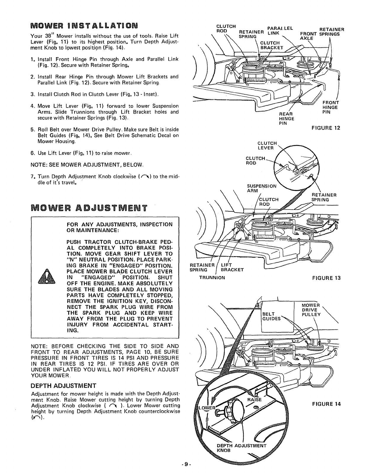
MOWER nNSTALLATION
Your 38" Mower installs without the use of toots,, Raise Lift
Lever (Fig° 1t) to its highest position. Turn Depth Adjust-
ment Knob to towest positign (Fig, 14L
1. Install Front Hinge Pin through Axle and Parallel Link
(Fig. 12L Secure with Retainer Spring°
2. Install Rear Hinge Pin through Mower Lift Brackets and
Parallel Link (Fig, 12)o Secure with Retainer Spring,
3_ Install Clutch Rod in Clutch Lever (Fig° 13- tnsetL
4,, Move Lift Lever (Fig° 11) forward to lower Suspension
Arms. Slide Trunnions through Lift Bracket holes and
secure with Retainer Springs (Fig., 13).
5, Roll Belt over Mower Drive Putiey_ Make stJre Belt is inside
Belt Guides (Fig. 14)_ See Belt Drive Schematic Decal on
Mower Housing,
6, Use Lift Lever (Fig° 11) to raise mower,
NOTE: SEE MOWER ADJUSTMENT, BELOW.,
7. Turn Depth Adjustment Knob clockwise (r-_} to the mid-
die of it's travel.
MOWER ADJUSTMENT
CLUTCH
ROD PARAI. LE L
RETAINER LINK
SPRING
CLUTCH
REAR
HINGE
PIN
CLUTCH
LEVER
CLUTCH
ROD
SUSPENSION
ARM
RETAINER
FRONT SPRINGS
AXLE
FRONT
HINGE
PIN
FIGURE 12
RETAINER
SPRING
FOR ANY ADJUSTMENTS, INSPECTION
OR MAINTENANCE:
PUSH TRACTOR CLUTCH-BRAKE PED-
AL COMPLETELY INTO BRAKE POSI-
TIONo MOVE GEAR SHIFT LEVER TO
"N" NEUTRAL POSITION. PLACE PARK-
tNG BRAKE IN "ENGAGED" POSITION.
PLACE MOWER BLADE CLUTCH LEVER
tN "ENGAGED" POSITION° SHUT
OFF THE ENGINE. MAKE ABSOLUTELY
SURE THE BLADES AND ALL MOVING
PARTS HAVE COMPLETELY STOPPED,
REMOVE THE IGNITION KEY, DiSCON-
NECT THE SPARK PLUG WIRE FROM
THE SPARK PLUG AND KEEP WIRE
AWAY FROM THE PLUG TO PREVENT
INJURY FROM ACCIDENTAL START-
ING,
NOTE: BEFORE CHECKING THE SIDE TO SIDE AND
FRONT TO REAR ADJUSTMENTS, PAGE 10, BE SURE
PRESSURE IN FRONT TIRES 1S 14 PSi AND PRESSURE
IN REAR TIRES IS t2 PSL tF TIRES ARE OVER OR
UNDER INFLATED YOU WlLL NOT PROPERLY ADJUST
YOUR MOWER,
DEPTH ADJUSTMENT
Adjustment for mower height is made with the Depth Adjust-
ment Knob, Raise Mower cutting height by turning Depth
Adjustment Knob clockwise ( f_ )_ Lower Mower cutting
height by turning Depth Adjustment Knob counterclockwise
((-,)o
_9-
RETAINER LIFT
SPRING BRACKET
f
TRUNNION
\MOWER
DRIVE
PULLEY
FIGURE 13
\
FIGURE 14
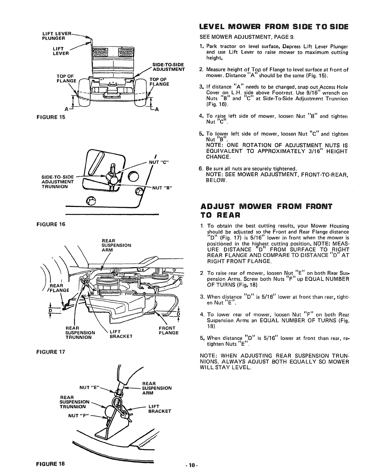
LIFT
PLUNGER
L I FT
LEVER
SIDE-TO*SiDE
/IENT
TOP OF
FLANGE TOP OF
,_ FLANGE
A
FIGURE 15
A
NUT "C"
SIDE-TO, SIDE _N
ADJUSTMENT
TRUNNION UT "B"
___e__._._j
FIGURE 16
REAR
SUSPENSION
ARM
REAR
SUSPENSION
TRUNNION
LIFT
BRACKET
D
FRONT
FLANGE
FIGURE 17
_%TJ_R EAR
NUT "E ".-_...._ l,._J-,=_ SUSPE NSI ON
REAR _ARM
SUSPENSION ,-_. (_--/_!
..o..,o.
NUT "F" -_ _t_
LEVEL MOWER FROM SIDE TO SiDE
SEE MOWER ADJUSTMENT, PAGE 9_
1, Park tractor on level sur_face.,Depress Lift Lever Plunger
and use Lift Lever to raise mower to maximum cutting
height,
2_
3_
4e
m
6_
Measure height of Top of Flange to tevel surface at front of
mower° Distance "A" should be the same (Fig. 15)o
if distance "A" needs to be changed, snap out Access Hole
Cover on L,H, side above Footrest, Use 9/16" wrench on
Nuts "B" and "C" at Side-To-Side Adjustment Trunnion
(Fig, 16),
To raise left side of mower, loosen Nut "B" and tighten
Nut "C_°
TO lower left side of mower, loosen Nut "C '_ and tighten
Nut "B".
NOTE: ONE ROTATION OF ADJUSTMENT NUTS IS
EQUIVALENT TO APPROXIMATELY 3/16" HEIGHT
CHANGE_
Be sure at!nuts are securely tightened.
NOTE: SEE MOWER ADJUSTMENT, FRONT-TO-REAR,
BELOW,
ADJUST MOWER FROM FRONT
TO REAR
1, To obtain the best cutting results, your Mower Housing
should be adjusted so the Front and Rear Flange distance
"D" (Fig_ 17) is 5/16" lower in front when the mower is
positioned in the hiclhest cutting position. NOTE: MEAS-
URE DISTANCE _TD" FROM SURFACE TO RIGHT
REAR FLANGE AND COMPARE TO DISTANCE "D" AT
RIGHT FRONT FLANGE,
2 To raise rear of mower, loosen Nut "E" on both Rear Sus-
pension Arms. Screw both Nuts "F" up EQUAL NUMBER
OF TURNS (Fig, 18),
3o When distance "D" is 5/16" lower at front than rear, tight-
en Nut "E"_
4, To lower rear of mower, loosen Nut "F" on both Rear
Suspension Arms an EQUAL NUMBER OF TURNS (Fig,
18),
5= When distance "D" is 5/16" lower at front than rear, re_
tighten Nuts "E'_
NOTE: WHEN ADJUSTING REAR SUSPENSION TRUN-
NIONS, ALWAYS ADJUST BOTH EQUALLY SO MOWER
WILL STAY LEVEL
FIGURE 18 .10 -

OPERATRON = MOWER
READ THE "RULES FOR SAFE OPERA-
TION" CAREFULLY BEFORE OPERAT-
ING YOUR MOWER, 1
I
THE MOWER MUST BE ADJUSTED PROPERLY FROM
FRONT TO REAR AND LEVELED FROM SIDE TO SIDE
"BEFORE OPERATING. THIS IS NECESSARY FOR LEVEL
AND EFFICIENT MOWING REFER TO PAGE 10.
1. Place Mower Blade Clutch Lever in I'DISENGAGED"
position (Fig_ 19),
2o Push tractor Clutch-Brake Pedal fully into brake position.
3. Place Gear Shift Lever in "NEUTRAL" position.
NOTE: TRACTOR MUST BE IN NEUTRAL AND MOWER
BLADE CLUTCH LEVER IN "DISENGAGED" POSITION
BEFORE TRACTOR WILL START
4o Start tractor and set engine speed to about 1/3 to t/2 throt-
tle before engaging mower. After mower is "ENGAGED"
and you have started forward travel, set to FULL THROT-
TLE,
NOTE: "ENGAGE" OR "DISENGAGE" MOWER BLADE
CLUTCH LEVER SLOWLY,,
ANEVER "ENGAGE" MOWER EXCEPT
WHEN SITTING ON TRACTOR SEAT°
DEPTH
ADJUSTMENT
KNOB
MOWER CLUTCH LEVER
'*DISENGAGED" POSITION
MOWER CLUTCH LEVER
"ENGAGED" POSITION
LIFT LEVER
LIFT
LEVER
GUARD
FIGURE 19
NOTE: ALWAYS MOW WITH THROTTLE CONTROL IN
"FAST" POSITION. THIS RESULTS IN BETTER GRASS
CUT, BETTER ENGINE COOLING, AND BETTER FUEL
ECONOMY.
5, Use Lift Lever to lower mower into cutting position, Start
mowing in the first gear and increase ground speed as
conditions wilt permit. Average cutting height is approxi-
mately 2 - 1/2 to 2 -3/4 inches, Height of cut can be adjust.
ed by means of the Depth Adjustment Knob (Fig. 19),
Moving the Knob clockwise { _ ) raises the mower (Fig.
t4 - Inset). Moving the Knob counterclockwise ( !(_ )
lowers the mower.
6, Drive so that clippings are discharged onto the area that has
been cut. Have the cut area to the right of the machine.
This wilt result in a more even distribution of clippings and
more uniform cutting When mowing large areas (Fig,. 201
start by turning to the right so that the clippings wlt be
discharged away from shrubs, fences, driveways, etc, After
two or three rounds, mow in the opposite direction making
left hand turns until finished, if grass is extremely tall, it
should be mowed twice,, The first time cut relatively high,
The second time to the desired height The left hand side
of mower should be used for trimming.
FLBP-UP DtSCNARGE GUAI D
Your mower has a flip-up Discharge Guard (Fig. 19) for door
or gate clearance when held in raised position
(
T
" ...........ii •i
FIGURE 20
MAKE SURE MOWER BLADE CLUTCH
LEVER IS IN "DISENGAGED" POSITION
AND BLADES HAVE STOPPED BEFORE
RAISING DISCHARGE GUARD (DEFLEC-
TOR),, NEVER OPERATE MOWER WITH-
OUT DISCHARGE GUARD iN OPERAT-
ING POSITION. 11-
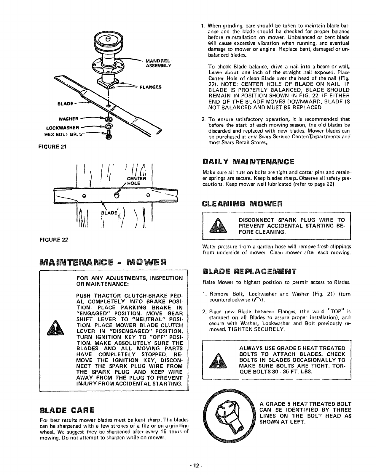
MANDREL _
ASSEMBLY
WASH|
LOCKWASHER _
HEX BOLT GR_ 5_
FIGURE 21
.......................II1....
FIGURE 22
MAINTENANCE = MOWER
FOR ANY ADJUSTMENTS, INSPECTION
OR MAINTENANCE:
PUSH TRACTOR CLUTCH-BRAKE PED-
AL COMPLETELY INTO BRAKE POSI-
TION. PLACE PARKING BRAKE IN
"ENGAGED" POSITION. MOVE GEAR
SHIFT LEVER TO "NEUTRAL" POSF
TIONo PLACE MOWER BLADE CLUTCH
LEVER IN "DISENGAGED" POSITION.
TURN IGNITION KEY TO "OFF" POSI-
TION. MAKE ABSOLUTELY SURE THE
BLADES AND ALL MOVING PARTS
HAVE COMPLETELY STOPPED_ RE-
MOVE THE IGNITION KEY, DISCON-
NECT THE SPARK PLUG WIRE FROM
THE SPARK PLUG AND KEEP WIRE
AWAY FROM THE PLUG TO PREVENT
INJURY FROM ACCIDENTAL STARTING°
1,,
2_
When grinding, care should be taken to maintain blade bal-
ance and the blade should be checked for proper balance
before reinstallation on mower,. Unbalanced or bent blade
will cause excessive vibration when running, and eventual
damage to mower or engine. Replace bent, damaged or un-
balanced blades.
To check Blade balance, drive a nail into a beam or wall,
Leave about one inch of the straight nail exposed. Place
Center Hole of clean Blade over the head of the nail (Fig,
22). NOTE: CENTER HOLE OF BLADE ON NAIL. IF
BLADE IS PROPERLY BALANCED, BLADE SHOULD
REMAIN IN POSITION SHOWN IN FIG._22. IF EITHER
END OF THE BLADE MOVES DOWNWARD, BLADE IS
NOT BALANCED AND MUST BE REPLACED_
To ensure satisfactory operation, it is recommended that
before the star_ of each mowing season, the old blades be
discarded and replaced with new blades. Mower blades can
be purchased at any Sears Service Center/Departments and
most Sears Retail Stores°
DASLY MA0 NTENANCE
Make sure all nuts on baits are tight and cotter pins and retain,,
er springs are secure_ Keep blades sharp. Observe all safety pre-
cautions,, Keep mower wel! lubricated (refer to page 22),
CLEANONG MOWER
DISCONNECT SPARK PLUG WIRE TO
PREVENT ACCIDENTAL STARTING BE-
FORE CLEANING.
Water pressure from agarden hose will remove fresh clippings
from underside of mower,. Clean mower' after each mowing°
BLADE REPLACEMENT
Raise Mower to highest position to permit access to Blades°
1. Remove Bait, Lockwasher and Washer (Fig. 21) (turn
counterclockwise (_/"_).
2. Place new Blade between Flanges, (the word "TOP" is
stamped on all Blades to assure proper installation), and
secure with Washer, Lockwasher and Bolt previously re-
moved, TIGHTEN SECURELY°
ALWAYS USE GRADE 5 HEAT TREATED
BOLTS TO ATTACH BLADES. CHECK
BOLTS IN BLADES OCCASIONALLY TO
MAKE SURE BOLTS ARE TIGHT° TaR-
QUE BOLTS 30 - 35 FT_ LBSo
BLADE CAR E
For best results mower blades must be kept sharp,, The blades
can be sharpened with afew strokes of a file or on a grinding
wheel° We suggest they be sharpened after every 15 hours of
mowing. Do not attempt to sharpen while on mower.,
A GRADE 5 HEAT TREATED BOLT
CAN BE IDENTIFIED BY THREE
LINES ON THE BOLT HEAD AS
SHOWN AT LEFT.
12_

TRACTOR OPERATmON
1. Depress Lift Lever Plunger at top of Mower Lift Lever and
move Lever rearward to its _HIGHEST" position (Fig.
23).
2, With engine running and warm, place Throttle Control
÷I' ,,
Lever mfdway between FAST and "SLOW" position.
3o Push Clutch-Brake Pedal down firmly to "DISENGAGE"
Parking Brake (Fig. 24).
4, Move Gear Shift Lever to "1ST" Gear (Fig 24}
'5. Release Clutch-Brake Pedal SLOWLY to start forward
movement,
6If qround travel is too stow, move Throttle Control Lever
to 1'FAST" position or press Clutch-Brake Pedal to stop
and shift to adifferent gear. NOTE: ALWAYS SELECT A
GROUND TRAVEL SPEED THAT WILL SUIT THE
TERRAIN AND THE ATTACHMENT BEING USED.
LEVER PLUNGER
_...,_,....,__ MOWER LIFT LEVER
_'°HIGHEST" POSITION
"LOWEST"
POSITION
MAKE SURE PARKING BRAKE WILL
HOLD TRACTOR SECURE,
NEVER PLACE YOUR HANDS OR FEET
1N OR UNDER ANY POWERED ATTACH_
MENT OR NEAR ANY MOVING PART
WHILE TRACTOR OR ANY POWERED
ATTACHMENT IS RUNNING_
FIGURE 23
NOTE: ALWAYS OPERATE ENGINE AT FULL THROTTLE
WHEN MOWING TO ASSURE BETTER MOWING PER-
FORMANCE, LONG ENGINE LIFE AND PROPER DIS-
CHARGE OF CUT MATERIAL, REGULATE GROUND
SPEED BY SELECTING A LOW ENOUGH GEAR (FIG,
24) TO GIVE THE MOWER CUTTING PERFORMANCE
PLUS QUALITY OF CUT DESIRED,
DO NOT OPERATE THE MOWER WITH-
OUT THE DEFLECTOR SHIELD (DIS-
CHARGE GUARD) tN PLACE°
TRACTOR OPERAT"ON ON HULLS
DO NOT DRIVE UP OR DOWN HILLS
WITH SLOPES GREATER THAN 15°
AND DO NOT DRIVE ACROSS ANY
SLOPE° REFER TO PAGE 43.
1, Move Gear Shift Lever to "1ST" Gear before starting up or
down hills
2o AVOID STOPPING OR SHIFTING ON HILLS,
a. If slowing is necessary, move Throttle Control Lever to
slower position
LEAVE ENOUGH ROOM WHEN STOP-
PING AND STARTING TO At.LOW
SLIGHT TRACTOR ROLL DOWNHILL
AS CLUTCH-BRAKE PEDAL MOVES
THROUGH CLUTCH POSITION°
BRAKE
"ENGAGED"
POSITION
"DISENGAGED"
"CLUTCH" T1oN
POSITION
°'CLUTCH/BRAK E.... DRIVE" "_,_,// .....
POSITION ",,, POSITION _" "FIGURE 24
STOPPING YOUR TRACTOR
1. Push Clutch=Brake Pedal completely into _'BRAKE" posi-
lion.
2. Move Gear Shift Lever to hNEUTRAL" position.,
•.Ii I, ••-*
3, Pace Parking Brake m ENGAGED position. Rinse Park-
.,It '1 *
mg Brake Lever and hold m ENGAGED position (Fig,,
24) Release Clutch-Brake Pedal=
""'SLOW"
4. Move Throttle Contro Lever to position
5,, Disengage Mower Blade Clutch Lever.
6. Turn Ignition Key to "OFF" position,
REMOVE KEY WHEN LEAVING TRAC-
TOR TO PREVENT UNAUTHORIZED
USE_
BRING TRACTOR TO COMPLETE STOP
BEFORE SHIFTING GEARS°
b. If stopping is absolutely necessary, push Clutch-Brake
Pedal quickly to brake position and engage Parking
Brake.
co To restart tractor movement, make sure tractor is in the
lowest speed range ('_lST" Gear) and that you have
allowed room to roll slightly downhill. Depress Clutch-
Brake fully° Disengage Parking Brake and release Clutch-
Brake Pedal SLOWLY to start tractor movement°
3. Make al! turns gradually.
TRANSPORTONG YOUR TRACTOR
For pushing or towing your tractor, place Gear Shift Lever
in "NEUTRAL" position (Fig. 24). Push Clutch-Brake Pedal
down firmly to "DISENGAGE '_ Parking Brake (Fig. 24).
NOTE: DO NOT TOW YOUR TRACTOR FASTER THAN
- 13 iStX MILES PER HOUR,,
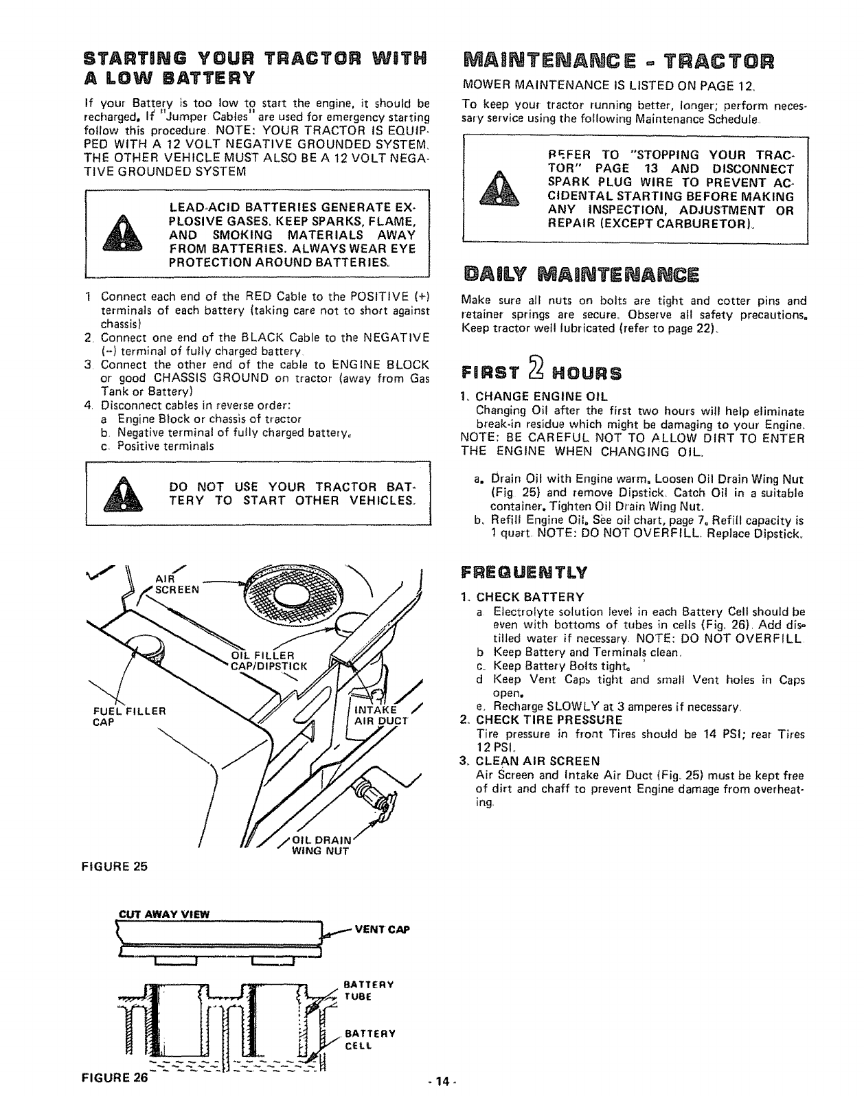
ST,ART NG YOUR TRACTOR WaTH
A LOW 6ATTERY
If your Battery is too low to start the engine, it should be
•tt tJ
recharged. If Jumper Cables are used for emergency starting
foflow this procedure NOTE: YOUR TRACTOR iS EQUIP-
PED WITH A 12 VOLT NEGATIVE GROUNDED SYSTEM.
THE OTHER VEHICLE MUST ALSO BE A 12 VOLT NEGA-
TIVE GROUNDED SYSTEM
LEAD-ACID BATTERIES GENERATE EX-
PLOSIVE GASES= KEEP SPARKS, FLAME,
AND SMOKING MATERIALS AWAY
FROM BATTERIES. ALWAYS WEAR EYE
PROTECTION AROUND BATTER IESo
1 Connect each end of the RED Cable to the POSITIVE (+)
terminals of each battery (taking care not to short against
chassis)
2, Connect one end of the BLACK. Cable to the NEGATIVE
(-) terminal of fully charged battery
3 Connect the other end of the cable to ENGINE BLOCK
or good CHASSIS GROUND on tractor' (away from Gas
Tank or Battery)
4. Disconnect cables in reverse order:
a Engine Block or chassis of tractor
b. Negative terminal of fully charged battery,
c. Positive terminals
DO NOT USE YOUR TRACTOR BAT-
TERY TO START OTHER VEHICLES,,
MAtNTENANC E-=YRAC YOR
MOWER MAINTENANCE IS LISTED ON PAGE 12_
To keep your tractor running better, longer; perform neces-
sary service using the following Maintenance Schedule,
PEFER TO "STOPPING YOUR TRAC-
TOR" PAGE 13 AND DISCONNECT
SPARK PLUG WIRE TO PREVENT AC-
CIDENTAL STARTING BEFORE MAKING
ANY INSPECTION, ADJUSTMENT OR
REPAIR (EXCEPT CARBURETOR)°
DAILY MAINTENANCE
Make sure all nuts on bolts are tight and cotter pins and
retainer springs are secure° Observe all safety precautions.
Keep tractor wetl lubricated (refer to page 22)_
FIIRST _HOURS
1_ CHANGE ENGINE OIL
Changing Oil after the first two hours will help eliminate
break-in residue which might be damaging to your' Engine_
NOTE: BE CAREFUL NOT TO /_LLOW DIRT TO ENTER
THE ENGINE WHEN CHANGING OIL.
a. Drain Oil with Engine warm. Loosen Oil Drain Wing Nut
(Fig 25} and remove Dipstick, Catch Oil in asuitable
container. Tighten Oil Drain Wing Nut,
bo Refill Engine Oil, See oil chart, page 7oRefill capacity is
1 quart, NOTE: DO NOT OVERFILL, Replace Dipstick,
J
AIR
FUEL FILLER
CAP
INTAKE_
AIR DUCT
FREQUENTLY
1,, CHECK BATTERY
a Electrolyte solution level in each Battery Cell should be
even with bottoms of tubes in cells (Fig. 26), Add dis=
tilled water if necessary, NOTE: DO NOT OVERFILL
b Keep Battery and Terminals clean,
co Keep Battery Bolts tight°
dKeep Vent Cap_ tight and small Vent holes in Caps
open,
e. Recharge SLOWLY at 3 amperes if necessary,
2, CHECK TIRE PRESSURE
Tire pressure in front Tires should be 14 PS!; rear Tires
12 PSI_
3, CLEAN AIR SCREEN
Air Screen and Intake Air Duct (Fig. 25) must be kept free
of dirt and chaff to prevent Engine damage from overheat-
ing,
FIGURE 25
DRAIN
WING NUT'
CUT AWAY VIEW
.BATTERY
CELL
FIGURE 26 -14-

4,, CHECK BRAKE OPERATION
This tractor is equipped with an adjustable disc brake
mounted on the right side of the transaxle (Fig, 27). DISC BRAKE
IF TRACTOR REQUIRES MORE THAN
SIX FEET STOPPING DISTANCE IN
HIGHEST GEAR, THEN BRAKE MUST
BE ADJUSTED.
NOTE: WHEN ADJUSTING BRAKES DO NOT MOVE
12-POINT BOLT°
NOTE: A 5/6-4 INCH ALLEN SET SCREW WRENCH IS
REQUIRED TO ADJUST THE BRAKE.
a, To adjust, tighten Set Screw (Fig. 27) clockwise ((-_)
until Disc Brake can not be moved by hand. Now loosen
Set Screw by turning counterclockwise (_) I/2 turn.
NOTE: PARKING BRAKE MUST BE DISENGAGED
WHI LE MAK ING ADJUSTMENT.
b. Depress Clutch-Brake Pedal and engage Parking Brake.
co Measure distance between Brake Operating Arm and
Nut "A" on Brake Rod
d. If distance is other than 1 - 1/2", turn Nut "A" until
distance becomes i °1/2"
Road test tractor for proper stopping distance as stated
above Readjust if necessary°
EVERY _ HOURS
CHECK ENGINE OIL LEVEL
DO NOT CHECK ENGINE OIL LEVEL
WITH ENGINE RUNNING.
Several minutes after stopping Engine, check Engine Oil
Level with Tractor on level ground Remove and wipe Dip*
stick clean (Fig,, 29), screw it in tight for a few seconds, re-
move slowly and read Oil levet° If necessary, add Oil until
"FULL" mark is reached.
EVE.V25 .OU.S
(EVERY 15 HOURS IF OPERATING
IN VERY DUSTY CONDITIONS)
1. CLEAN AIR CLEANER ELEMENT (FIG, 28).
a, Open Hood. Pull intake Air Duct up off engine,
b Remove two screws from Air Cleaner Cover Lift off Air
Cleanero
c= Remove Screen and Spacers from Foam Element.
d. Remove Foam Element from Air Cleaner Body,,
e Wash Foam Element in liquid detergent and water to
remove dirt.
f Wrap foam in cloth and squeeze dry.
g= Saturate foam in engine Oilo Squeeze to remove excess
oil,
h, Assemble parts - securely fasten to carburetor with
screws,
When assembling make certain the lip of the Foam Element
extends over edge of the Air Cleaner Body° The Foam Ele-
ment lip will form a protective seal.
NOTE: NEVER RUN ENGINE WITH AIR CLEANER OR
INTAKE AIR DUCT REMOVED.
2o CHANGE ENGINE OIL
The best time to change Engine Oil is at the end of a day's
operation when all dirt and foreign materials are suspended
in the hot Oil. See oil chart, page 7o -15-
12-POINT BOLT
AIR CLEANER
COVER
SPACER
SCREEN
FOAM ELEMENT
AIR
CLEANER
BODY
BRAKE
ROD
NUT
1 - 1/2"
BRAKE
OPERATING ARM
FIGURE 27
FIGURE 28

INTAKE
AIR Ev .vB@.ouns
1, CLEAN ENGINE COOLING FINS
Keep Engine Cooling Fins free of dust, dirt and oil to pre-
vent Engine damage from overheating.
a. Pull up to remove !ntake Air Duct (Fig, 29).
b_ Remove four Bolts from blower housing,,
c. Remove Screws from Starter Housing,
d, Puft Oil Filler!Dipstick out of crankcase if clearance is
required, Cover opening to prevent entry of dirt.
eo Pull blower housing up and away from starter.
NOTE: LEAVE AIR CLEANER IN PLACE TO PRE-
VENT DEBRIS FROM GETTING iNTO CARBURE-
TORo
f. Use compressed air or stiff bristle brush to thoroughly
clean Engine Fins.
SCREWS
OIL FILLER
DIPSTICK
STA
HOUSING
FIGURE 29
ENGINE FINS
WEAR SAFETY GLASSES IF USING COM-
PRESSED AIR.
g. To reassemble, reverse above procedure..
2o MUFFLER
Do not operate the tractor without a Muffler or tamper
with the exhaust system,
DO NOT TOUCH HOT MUFFLERS,
CYLINDERS OR FINS AS CONTACT
MAY CAUSE BURNS,
FIGURE 30
SPARK PLUI
FEELER
GAUGE
Periodically clean the muffler area to prevent grass, dirt
and combustible material from accumulating= Damaged
Mufflers or spark arreste[s could create a fire hazard. In-
spect periodically and replace if necessary. If your engine
is equipped with a spark arrester screen assembly, remove
every 50 hours for cleaning and inspection. Replace if
damaged° '
The Spark Plug should be changed every !00 hours of opera-
tion, or at the beginning of each mowing season. To remove
the Spark Ptug a Deep Well 13/16" Socket is required Set
Spark Plug gap at 030 inch (Fig. 30),
16-
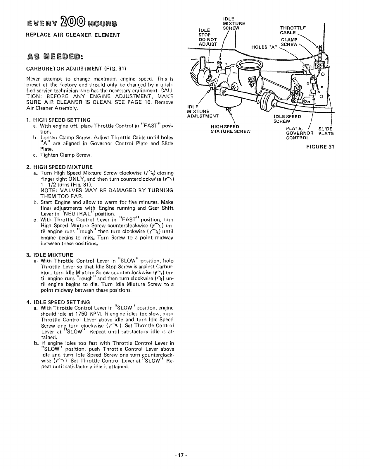
Ew.v
REPLACE AIR CLEANER ELEMENT
CARBURETOR ADJUSTMENT (FIGo 31)
Never attempt to change maximum engine speed, This is
preset at the factory and should only be changed by a quali-
fied service technician who has the necessary equipment. CAU-
TION: BEFORE ANY ENGINE ADJUSTMENT, MAKE
SURE AIR CLEANER tS CLEAN., SEE PAGE 16, Remove
Air Cleaner Assembly.,
1,, HIGH SPEED SETTING
a. With engine off, place Throttle Control in "FAST" posi-
tiono
b_ Loosen Clamp Screw., Adjust Throttle Cable untitl holes
"A" are aligned in Governor Control Plate and Slide
Plate.
co Tighten Clamp Screw.
2o HIGH SPEED MIXTURE
a, Turn High Speed Mixture Screw clockwise (f_) closing
finger tight ONLY, and then turn counterclockwise (I,"_)
1 - 1/2 turns (Fig. 31)o
NOTE: VALVES MAY BE DAMAGED BY TURNING
THEM TOO FAR°
b. Start Engine and altow to warm for five minutes_ Make
final adjustments with Engine running and Gear Shift
Lever in "NEUTRAL" position°
c, With Throttle Control Lever in "FAST" position, turn
Higt_ Speed Mixture Screw counterclockwise (t'_) un-
til engine runs "rough" then turn clockwise (t_)until
engine begins to miss. Turn Screw to a point midway
between these positions°
3, IDLE MIXTURE
ao With Throttle Control Lever in "SLOW" position, hold
Throttle Lever so that Idle Stop Screw is against Carbur-
etor, turn Idle Mixture Screw counterclockwise (_) un-
til engine runs "rough" and then turn clockwise (iql) un-
til engine begins to die_, Turn idle Mixture Screw to a
point midway between these positions,
4o IDLE SPEED SETTING
a,. With Throttle Control Lever in "SLOW" position, engine
should idle at 1750 RPM, If engine idles too slow, push
Throttle Control Lever above idle and turn Idle Speed
Screw one turn clockwise ((-_)_ Set Throttle Control
Lever at "SLOW" Repeat until satisfactory idle is at-
tained.
b. If engine idles too fast with Throttle Control Lever in
"SLOW" position, push Throttle Control Lever above
idle and turn Idle Speed Screw one turn counterclock-
wise (f"_), Set Throttle Control Lever at I'SLOW",, Re-
peat until satisfactory idle is attained,
IDLE
MIXTURE
IDLE SCREW
STOP
DO NOT
ADJUST
IDLE
MIXTURE
ADJUSTMENT
HIGH SPEED
MIXTURE SCREW
HOLES "A"
THROTTLE
CABLE,
IOLESPEED
SCREW
PLATE,
GOVERNOR
CONTROL
SLIDE
PLATE
FIGURE 31

RETAINER
SPRING
FIGURE 32
FIGURE 33
TRANSAXLE
PULLEY
BELT GUIDE
BRACKET
BELT
GUIDE
RETAINER
SPRING
SHIFT GATE
5 ,, REPLACE TRACTOR MOTION DRIVE BELT
The tractor Drive Belt may be reptaced without tools.. Park
the tractor on level area. Engage Parking Brake, NOTE:
BELT INSTALLATION DECAL UNDER LEFT FOOT-
REST.
a. Remove mower. (See Mower Section, page 20).
b. Remove two Retainer Springs from Belt Guide Bracket
below Transaxte Pulley. Remove Bracket (Fig. 32),
c. Swing Belt Guides away from Belt, toward rear of trac-
tor' (Fig, 32)_
d. Roll Belt over top of Transaxle Pulley
e, Roll Belt over Engine Pulley and off Idler (Fig 34)
f Release Parking Brake, Pull Belt as far as possible over'
top of Ctutch Puitey,
g Reset Parking Brake. Put! Belt over top of Clutch Pulley
(Fig, 34}.
h Pull Belt out through Shift Gate to remove from trac_
tot (Fig, 33)r
Install Belt by reversing above procedure, NOTE: RE-
PLACE ONLY WITH BELT LISTED iN MANUAL,
6. CLEAN BATTERY AND TERMINALS
Corrosion and dirt on the Battery and Terminals cause
the Battery to ='leak" power
LEAD-ACID BATTERIES GENERATE EX-
PLOSIVE GASES_ KEEP SPARKS, FLAME,
AND SMOKING MATERIALS AWAY
FROM BATTERIES ALWAYS SHIELD
YOUR EYES AROUND BATTERIES,
a Disconnect BLACK Battery Cable then RED Battery
Cable and remove Battery from Tractor. Wash Battery
with four tablespoons of baking soda to one gallon of
water. NOTE: BE CAREFUL NOT TO GET THE SODA
SOLUTION INTO THE CELLS. Rinse the Battery with
plain water, dry and reinstall on Tractor.
b. Clean Terminals and Battery Cable ends with awire
brush until bright,. Replace Battery Cables, connecting
RED Battery Cable to Positive Terminal first, then
BLACK Battery Cable to Negative Terminal. Coat ter-
minal connections with Vasoline_
CLUTCH
PULLEY
ENGINE
PULLEY /
DRIVE BELT
SCHEMATIC
LH. SIDE
BELT GUIDE
REAR
VIEWED FROM BOTTOM OF TRACTOR
FIGURE 34 - 18-

7, TIRE CARE
a, Maintain tire pressure in front tires at 14 PS! and rear
tires at 12 PSI,
b Keep tires free of gasoline, oil, or insect control chemi-
cals which can destroy rubber
c, Avoid stumps, stones, deep ruts and other hazards that
may cause tire damage,
d. Removing front wheet for tire repair (Fig. 35),
-- Block up front axle securely, Pull off Dust Cap,
-- Remove Klip Ring and Washer and remove wheelo
-- Repair tire and reassembJe. Replace Washer, snap
KtIp Ring securely in axle groove, Replace Dust Cap°
e., Removing rear wheel for tire repair (Fig, 36)°
-- Block up rear axle securely. Pull off Dust Cap_
-- Remove E-Ring and Washers (I to 3 as required) and
remove wheel
-- Repair tire and reassemble° Replace Square Key in
Axle Shaft.
-- Replace Washers, E-Ring and Dust Cap,
KLIP RING
DUST
CAP
FIGURE 35
WHEN MOUNTING TIRES, UNLESS
BEADS ARE SEATED, OVER INFLATION
CAN CAUSE AN EXPLOSION,
8. FINISH
Keep tractor finish and seat free of gasoline, oit, insect
chemicals or battery electrolyte Protect painted surfaces
with automotive type wax
DUST
CAP
SQUARE
KEY
E.RING
WA S H E F
FIGURE 36
-19-

DEPTH
ADJUSTME NT
KNOB \
MOWER CLUTCH
LEVER "'DISENGAGED"
POSITION
"'HIGHEST"
ITION
LIFT LEVER
"LOWEST"
POSI T tON
TO REMOVE MOWER BELT
NOTE: MOWER BELT INSTALLATION DECAL LOCATED
ON MOWER HOUSING.
REPLACE ONLY WITH THE BELTS SPECIFIED IN THIS
MANUAL,
,
3,
4
Place Mower Blade Clutch Lever in _DISENGAGED _t
position (Fig 37)
Turn Depth Adjustment Knob to Lowest position,. Move
Mower Lift Lever (Fig. 37) forward to lower' Mower to its
lowest position,,
Rotl Belt off Engine Pulley (Fig. 38)
Pull Belt off both Mandrels,
5 Spring Belt Guide away from Idler Pulley and pull Belt
off Idler Pulley°
6. Slide Belt from under Idler Spring
FIGURE 37
ENGINE
PULLEY IDLER
IDLER
BELT GUlDE
TO REPLACE MOWER BELT
1Slide Belt under Idler Spring (Fig_ 38)_
2, Place Belt on rear side of both Mandrels.
3. Spring Idler Belt Guide down and place Bett around rear
side of Idler Pulley.
4. Roll Belt over Engine Pulley,
FIGURE 38
L,H, MANDREL IDLER
SPRING
RETAINER
SPRINGS
RH,, MANDREL
RETAINER
SPRINGS
TO REMOVE MOWER
1. Remove mower Belt per' instruct{ons under "To Remove
Mower Belt j', through step 3=
2. Turn Depth Adjustment Knob to lowest position, Use Lift
Lever to lower' mower to its lowest position°
3, Remove Retainer Spring from Clutch Rod; putt Clutch Rod
out of Clutch Bracket.
4 Pull Retainer Springs out of Rear Suspension Trunnionso
Remove Rear Suspension Trunnions from Lift Brackets
(Fig. 39),
5. Putl Retainer Spring out of Rear Hinge Pin. Remove Rear
Hinge Pin°
6. Pull Retainer Spring out of Front Hinge Pin, Remove Front
Hinge Pin (Fig,'39L
7. Use Lift Lever to raise Suspension Arms_ Slide mower out
from under tractor.
/
REAR
SUSPENSION
TRUNNtONS LIFT
BRACKET
HINGE
PINS
STORAGE
When mower is to be stored for a period of time. cfean it
thoroughly, remove all dirt, grease, leaves, etc, Give blades
and underside of housing a good coat of grease or rust pre-
ventat{veo S_ore in a clean dry area.
FIGURE 39 - 20 -

TROU,LESNOOT,NG
POSSIBLE CAUSE POSSIBLE REMEDY
WILL NOT START
Shift Lever in gear
Mower Blade CIutch Lever engaged
No gasoline in Fuel Tank, clogged Fuel
Line, or Fuel Filter
Blown Fuse
Dead Battery
HARD TO START
Choked improperly, flooded Engine
Clogged Fuel System
Dirty Air Cleaner
Spark Plug dirty or improper gap
Defective Battery
Defective Ignition or loose wiring
Water in gasoline or old fuel
Improper Carburetor adjustment
ENGINE MISSES OR LACKS POWER
Engine overload
Clogged Fuel Tank or Fuel Filter
Partially plugged Air Cleaner
improper Carburetor adjustment
Dirty Engine Air Screen
Low oil level or dirty oil
Spark Plug dirty, improper gap or wrong type
Faulty ignition
Poor compression
Oil in gasoline
ENGINE OVERHEATS
Dirty Air Screen
Low oit level or dirty oil
Dirty Engine
Partially plugged Muffler
Partially plugged Air Cleaner
Stale fuel or improper Carburetor adjustment
NO LIGHTS
No Headlights with Light Switch on and
Place in neutrai
Disengage Lever (Fig. 10). Be sure Lever is in bottom of slot
Fi{I Tank with Gasoline Check Fuel Line and Car-
buretor (clean if necessary) Replace Fuel Fitter.
Check for fault and replace Fuse
Recharge or replace Battery
Place Throttle Control in "FAST" position (Fig., 10)
and run starter several times to clear out gas
Remove and clean Tank and lines° Replace Fuel Filter
Remove and clean (Fig.. 28)
Clean, adjust gap or replace (Fig 30)
Recharge or replace
Check the wiring and Spark Plug
Drain Fuel Tank and Carburetor, use fresh fuel and
replace Spark Pfug
Make necessary adjustments (F ig. 31 )
Shift to a lower gear (Fig 24) or reduce toad
Remove and clean Tan{<; replace Fuel Filter
Remove and clean (Fig. 28)
Make necessary adjustments (Fig 31)
Clean Air Screen (Fig 25)
Add or change oil (page 14)
Replace Spark Plug (Fig. 30)
Check Spark Plug and for loose wires
Major Engine overhaul
Drain Gas Tank and Carburetor and refitl
Engine running
WON'T CHARGE
Blown Fuse
Defective Battery
Defective Diode Assembly
Defective Alternator
Clean Air Screen (Fig. 25)
Add or change oil (page t4)
Ctean Engine Cooling Fins (page 16)
Remove and clean Muffler or replace
Remove and clean (Fig. 28)
Use fresh fuel and adjust Carburetor (Fig 31)
Check Fuse, Switch and wire connections Replace
Headlight Bulbs
UNSATISFACTORY MOWER PERFORMANCE
Tires not inflated properly
Mower improperly adjusted
Check for fault and replace
Replace
Replace
Replace
Check air pressure in tires (page 6)
Check front to rear and side to side mower adjust-
merit (page 10)
Grass high or wet
Incorrect engine RPM's
Excessive wear to outer cutting tip of mower blade
improper mower blade installation
Incorrect mower blade
Use a slower ground speed (refer to Mower Operating
Instructions, pacje 1 I}
Check engine RPM's (refer to Carburetor Adiustment, page 17)
Replace mower blade
Reinstall with top of blade up
Replace with proper mower blade
STORAGE
1. FUEL SYSTEM
a, Drain fuel tank and carburetor by allowing the engine to
run out of gasoline. NOTE: GASOLINE LEFT IN
YOUR ENGINE WILL LEAVE GUM DEPOSITS CLOG-
GING FUEL SYSTEM.
b Dispose of gasofine if not to be used. NOTE: GASO-
LINE STORED FOR SEVERAL MONTHS LOSES ITS
VOLATILITY (ABILITY TO BURN EFFECTIVELY)..
2o ENGINE OIL
Drain (with engine warm) and replace with clean engine oil.
(See chart, page 7).
3o CYLINDER
a. Remove Spark Plug..
b. Pour one ounce of engine oit through spark plug hole
into cyiindero
c.. Turn ignition key to "START" position for a few
seconds to distribute oil.
d_ Replace with new Spark Plug.
4. BATTERY
a.. Remove battery if tractor is not used regularly during
winter months_ Store in cool, dry place (above 50OF.).
Re-charge each month if necessary. NOTE: BATTERIES
NOT IN USE FOR SEVERAL MONTHS AND NOT
KEPT FULLY CHARGED, PRODUCE SULPHATE
DEPOSITS ON PLATES WHICH CANNOT BE RE-
MOVED BY RECHARGING
5o GENERAL CLEANING
Clean engine, battery, finish, seat, etc of all foreign matter,
-21 -

LUBRICATIONCHART
(9
AXLE PIVOT (_
SPINDLE (_
(_) FRONT WHEEL
BEARING
(_TIE ROD
_ LUTCH/BRAKE
PIVOT
(_ ATTACHM E
LIFT ARM
#
FRONT WHEEL
BEARING (_
ROD (_)
CLUTCH PIVOT (_
/BRAKE (_
PIVOT
HMENT LIFT ARM 1_)
MOWER CLUTCH
PIVOT (_
(_SAE 30 MOTOR OIL
(_ GENERAL PURPOSE GREASE
SERVICE RIECOgB
FILL IN DATES
AS YOU COMPLETE
REGULAR SERVICE
SERVICE DATES
Check Engine Oil ,L,evel .... _ I
Change Engine Oil (see chart, page 7) _1_
Lubricate Pivot Points Q and @ .... _ .........
Check Brake Operation
..... '.... ;,,_ : ....... :...... : i m i i _ ....... :
Clean Air Screen and Air' Intake Duct
Clean Air Cleaner Element _ : " _....
Replace Air Cleaner......Element _ I
.Clean Engine Cooling Fins ......... ........
Replace Spark Plug
Check Batte.[y..Levet ................. _!
Check Tire Pressure
Replace Fuel Filter .....
-22--

SCHEMATIC
11 H°P, 38" RIDING LAWN TRACTOR--MODEL NUMBER 917,255732
RED
12V
+ -
oltllo BLACK
RED
RED
30 AMP
IGNITION SWITCH
STD365402
POSITION CIRCUIT
OFF M-G
ON B-L
START B-S
O
%STARTER
%
NEUTRAL ATTACH
WHITE--_C_ _ WHITE
Of---'---_tNTER'K SW ,NTER'K SW SOLENOID%
S%
IGNITION C'
SWITCH M
B
BLACK
'" MAGNETRON
IGNITION
SPAR K PLUG
_[_/ RECTIFIER CHARGING
IRED.......
(DIODE) COIL
3AMP&, 10 VAC (MIN.)
ORANGE
_\ BLACK .....
@MAX, R,P.Mo BATTERY IN LINE
LIGHT
SWITCH
BROWN
BROWN BLA'
WIRING INSULATED CLIPS
NOTE: IF WIRING INSULATED CLIPS
AND CABLE TIESWERE REMOVED FOR
SERVICING OF UNIT, THEY SHOULD
BE REPLACED TO PROPERLY SECURE
YOURWIRING
CHASSIS
GROUND
-23-
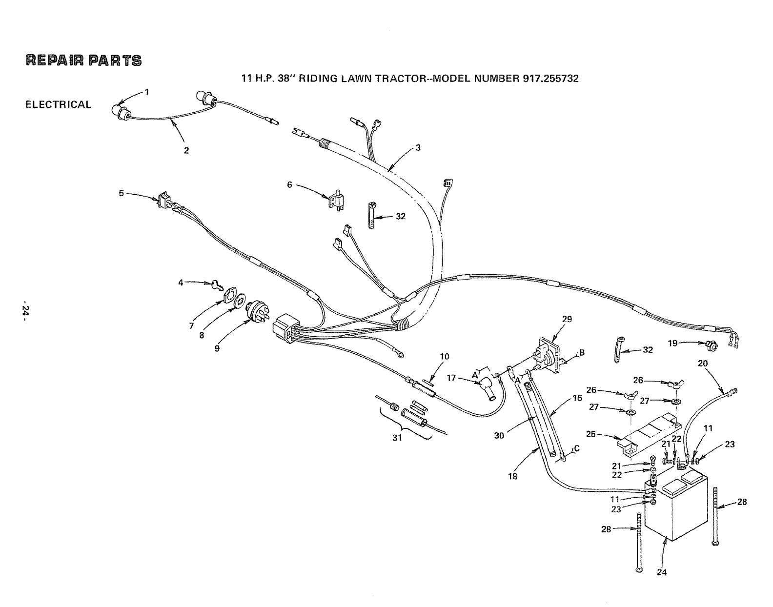
REPAIR PARTS
11 H.P. 38" RIDING LAWN TRACTOR--MODEL NUMBER 917.255732
ELECTR ICAL
910
17
3O
29
2O
11
18

REPAIIR PARTS
ELECTRICAL
11 H.P. 38" RIDING LAWN TRACTOR--MODEL NUMBER 917.255732
KEY
NO.
1
2
3
4
5
6
7
8
9
t0
1t
12
13
14
15
16
PART DESCRIPTION KEY PART DESCRIPTION
NO. NO. NO.
7662J Bulb, LIght ! 7
105386X Harness, Light Socket !8
!06480X Harness, tgmtIon 19
STD365410 Key Set 20
105381X Switch, Light 21
104445X Sw_tch, ]nterlock 22
3258J Nut, Hex 5/8- 32 23
11151000 Washer, Lock, Int. Tooth, 5/8 24
STD365402 Switch, Igmtlon 25
STD380300 *Fuse, 30 Amp. 26
STD551125 *Washer, Lock, !/4 27
STD541225 *Nut, Hex Jam 1/4- 20 28
STD522505 *Bolt, Hex, 1/4 - 20 x 1/2 Gr. 5
73510400 Nut, Keps 1/4 - 20 29
4559J Cable Assembly 30
11050400 Washer Lock, Ext. Tooth, t/4 31
32
719J Cover, Terminal
5114J Cable, Battery
105737X Switch, Interlock
2033J Cable, Battery
STD522507 *Bolt, Hex, 1/4- 20 x 3/4
STD551025 *Washer 9/32 x 5/8 x 16 Ga.
STD541025 *Nut. Hex 1/4 - 20
t04923X Battery, 12V., Sears
105371X Terminal Guard
STD541625 *Wing Nut 1/4 -20
11030400
72240460
2008J
106552X
I06580X
7!92J
101539X
106738X
Int./Ext, Tooth Lockwasher 1/4
Battery 8oit (Bolt -Carriage, Rd° Hd.
Sq. Neck 1/4 - 20 x 7 - 1/2)
Solenoid
Cover - Cable, 9"
Kit, Replacement Fuseholder
Cable Tie
Sheet - Instruction, Tractor 15° Slope
Owners Manual
*STANDARD HARDWARE--PURCHASE LOCALLY
A B
@11_) 12 13
@16
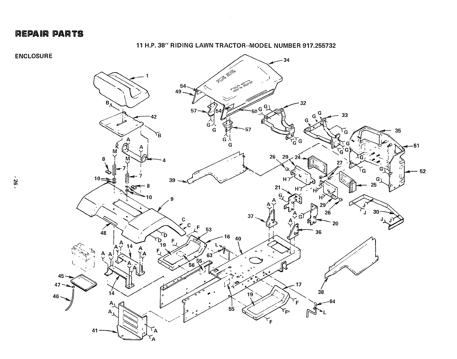
REPA|R PARTS
ENCLOSURE
1! H.P. 38"' RIDING LAWN TRACTOR--MODEL NUMBER 917.255732
39
48 53
16
55
4O
36
26
2O
38
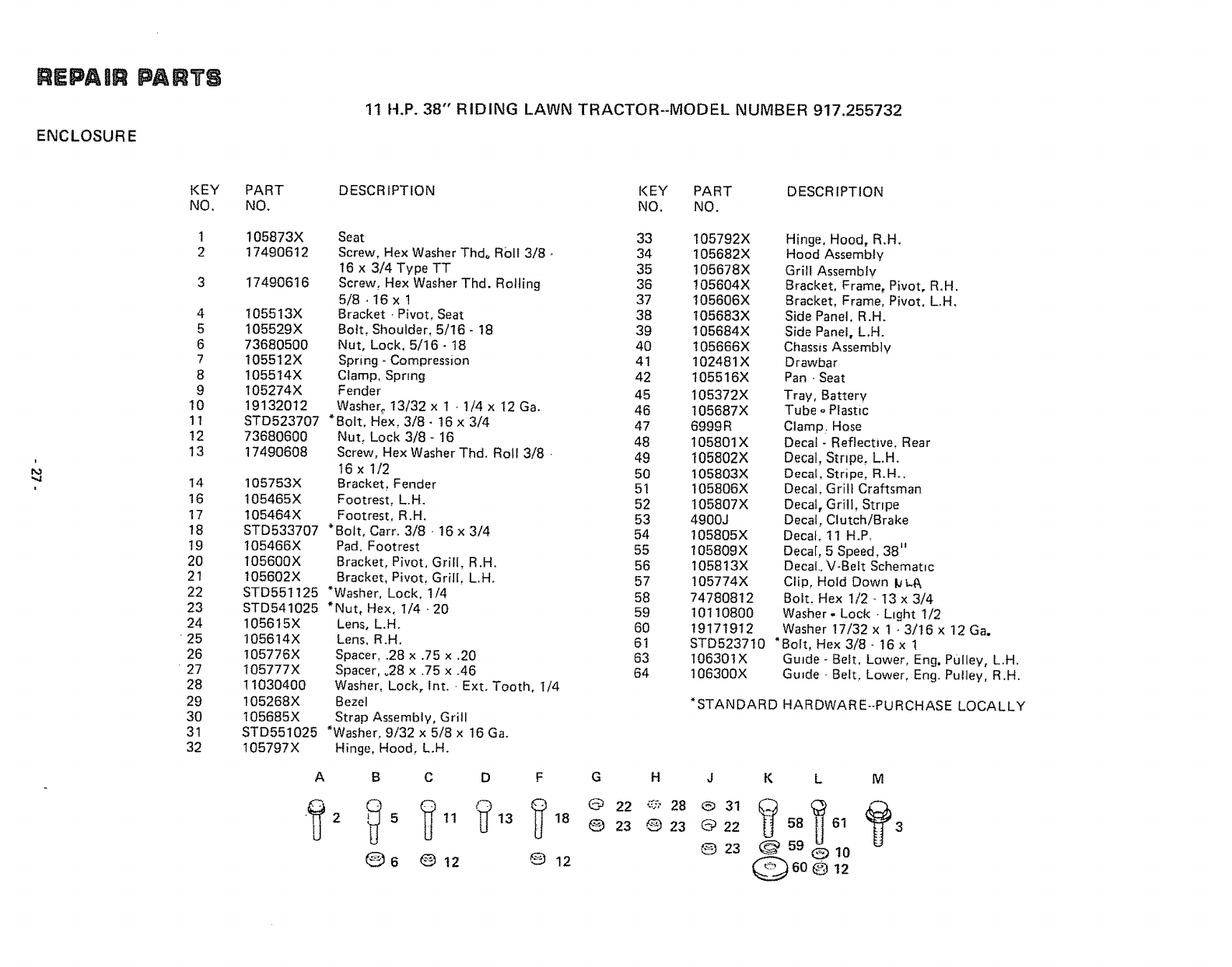
REPAaR PARTS
ENCLOSURE
11 H.P. 38" RIDING LAWN TRACTOR--MODEL NUMBER 917.255732
1
",4
i
KEY
NO.
t
2
4
5
6
7
8
9
10
11
12
t3
t4
16
17
18
19
20
21
22
23
24
25
26
27
28
29
30
31
32
PART
NO. DESCRIPTION KEY PART DESCRIPTION
NO. NO.
105873X
17490612
17490616
105513X
105529X
73680500
105512X
105514X
105274X
19132012
STD523707
73680600
17490608
105753x
105465X
105464X
Seat
Screw, Hex Washer Thdo R01t 3/8 -
16 x 3/4 Type TT
Screw, Hex Washer Thd. Rolling
5/8 • 16 x !
Bracket. Pivot, Seat
Bolt, Shoulder, 5/16 - 18
Nut, Lock. 5/16 * 18
Spring - Compression
Clamp, Spring
Fender
Washer_ 13/32 x 1 -1/4 x I2 Ga.
• Bolt, Hex, 3/8- 16 x 3/4
Nut, Lock 3/8 - 16
Screw, Hex Washer Thd. Roll 3/8
t6 x 1/2
Bracket, Fender
Footrest, L.H.
Footrest, R.H,
STD533707 *Bolt. Cart. 3/8 - 16 x 3/4
105466X Pad, Footrest
105600X Bracket, Pivot, GriII, R.H.
105602X Bracket, Pivot, Grill L.H.
STD551125 *Washer. Lock, 1/4
STD541025 *Nut, Hex, I/4,20
1056t5X
105614X
105776X
105777X
11030400
105268X
!05685X
STD551025
t05797X
Lens, L.H.
Lens, R.H.
Spacer, .28 x .75 x.20
Spacer, °28 x .75 x .46
Washer, Lock, int. Ext. Tooth, I/4
Bezel
Strap Assembly, Grill
*Washer, 9/32 x 5/8 x t6 Ga.
Hinge, Hood, L.H.
A B C D F
"_ 2 _ 5 _) tl _13 (_ 18
Q 6 G 12 @ 12
33 105792X Hinge, Hood, R,H.
34 105682X Hood Assembly
35 105678X Grill Assembtv
36 !05604X Bracket, Frame, Pivot, R,H,
37 105606X Bracket, Frame, Pivot. L.H,
38 t05683X Side Panel. R.H.
39 105684X Side Panet, L.H.
40 105666X Chassis Assembly
41 102481X Drawbar
42 105516X Pan - Seat
45 105372X Tray, Battery
46 105687X Tube oPlastic
47 6999R Clamp Hose
48 105801X Decal - Reflective, Rear
49 t05802X Decal, Stripe, L.H.
50 105803X Decal. Stripe, R.H..
5t t05806X Decal, Grill Craftsman
52 t05807X Decal, Grill, Strtpe
53 4900J Decal, Clutch/Brake
54 105805X Decal. 11 H.Po
55 105809X Decal, 5 Speed 38"
56 105813X Decal.. V-Belt Schematic
57 105774X Clip, Hold Down bL.A
58 74780812 Bolt, Hex 1/2 - 13 x 3/4
59 t0110800 Washer- Lock -Light t/2
60 19171912 Washer !7/32 x 1 -3/16 x 12 Ga,
61 STD523710 *Bolt, Hex 3/8 - t6 x !
63 106301X Guide - Belt, Lower, Eng. Pulley, L.H.
64 t06300X Guide -Belt, Lower, Eng. Putley, R.H.
*STANDARD HARDWARE--PURCHASE LOCALLY
G H J K L M
@22 '_," 28 @ 31 _[_ _ _
O23 _ 23 (5) 22 58 61 3
_) 23 @ 59 @t0
Q 60 @ 12

REPAIR
DRIVE
P, TS
1t H.P. 38" RIDING LAWN TRACTOR--MODEL NUMBER 917.255732
12
P !
F
98
3
19
D3O
D
32
43
45
68
7O
69 74
64
65
62
61 93
49 21
63
81
82
8O
82
83
OPTIONAL EQUIPMENT
Spark Arrester Screen Assembly 677Vl
- 28-

REPAaR
DRIVE
PARTS
11 H.P. 38" RIDING LAWN TRACTOR--MODEL NUMBER 917.255732
KEY PART
NO NO
1 I01325N
2 105731X
3 9767H
4 STD551143
5 74770728
6 105732X
10 t06163X
11 101273M
t2 101t59L
13 74780552
14 STD522505
15 17490620
16
17 1062!3X
19 10587_X
20 STD523727
21 73680600
22 STD580025
23 105703X
24 12000028
25 3723J
26 STD523710
27 STD523712
28 17490512
29 105638X
30 I05639X
31 t06188X
32 4921H
33 I06190X
34 STD523107
35 73680500
36 !06294X
37 106189X
38 t05842X
39 STD523707
40 19252516
41 6465R
42 105699X
43 73960500
44 105701X
45 STD5612!0
46 19151216
47 t04777X
48 17490612
DESCRIPTION KEY PART DESCRIPTION
NO. NO
Engine, 11 H.P. Model No. 252707,
Type Noo 0669-01
Putley, Engine
Valve, Drain Oil
*Washer, Lock, 7/16
Bolt, Hex 7/16- 20 x 1 - 3/4
V-Belt, Drive
Foam, Strip
Muffler
Shield, Heat
Bolt, Hex Hd. 5/16- 18 x 3- 1/4
Gr. 5
Bolt, Hex I/4- 20 x I/2 Gr, 5
Screw, Hex Washer Thd° Rolling
3/8- 16 x 1 -1/4
STD551125 *Washer, Lock I/4
Duct, lntake_ Air
Transaxle, 5 Speed, Model No. 4150-6
(See pages 36and 37 for parts
breakdown)
*Bolt, Hex 3/8- !6 x 2- 3/4
Nut, Lock 3/8- t6
* Key, Woodruff
Pulley, Transaxle
Ring, Retainer
Bracket, Transaxle
*Bolt, Hex 3/8 - 16 x 1
*Bolt, Hex 3/8- 16 x 1- 1/4
Screw, Hex Washer Thread Roiling
5/16- 18 x 3/4
Bracket, Support
Support, Battery
Keeper, Belt, L.H.
Retainer, Spring
Clamp
*Bolt, Hex 5/16- 18 x 3/4
Nut, Lock 5/t6- 18
Strap, Locator
Keeper, Belt, R.H,
Strap, Torque, Transaxte
*Bolt, Hex 3/8 16 x 3/4
Washer 25/32 x 1 o.9/16 x 16Ga.
Knob, Shift
Rod, Shift
Nut Lock, Whiz 5/16 -18
Washer- Shift, Plate
*Cotter Pin, 1/8 x 1
Washer 15/32 x 3/4 x 16 Ga
Retainer, Belt
Screw, Hex Washer Thdo Rolling 3/8 -
!6 x 3/4
49
50
51
52
53
54
55
56
57
58
59
6O
6t
62
63
64
65
66
67
68
69
70
71
72
73
74
75
76
77
78
79
8O
8t
82
83
88
89
90
91
92
93
95
96
97
98
99
100
101
19131312 Washer 13/32 x 13)'16 x 12 Ga,
105730X Keeper, Belt, Engine
106191X Keeper, Belt
4470J Spacer
4859J Idler, Flat
106298X Pulley, Idler
t05705X BeHcrank Assembly (lnc. Key Noo 89)
STD523715 *Bolt, Hex 3/8- 16 x 1 _ 1/2
t05709X Spring, Return, Clutch
207J Washer, Hardened
12000039 Ring, Klip
I057t0X Link, Clutch
760204 t2 Pin, Cotter 1/8 x 3/4
105724X Bracket, Clutch
105752X Rod, Brake
105757X Spring, Rod, Brake
STD551037 "Washer 13/32 x t3/16 x 16 Gao
73930600 Nut, Lock 3/8- 16
105758X Rod, Brake, Parking
71673 Cap- Ptunger
105720X Shaft, Foot Pedal
8883R Cover -Pedal
19252016 Washer 25/32 x 1 - 1/4 x 16 Ga
STD571810 *Pin, Roll, 3/16 x 1
105733X Arm, Brake
STD580025 * Key, Woodruff
STD580105 *Key, Square 3/16 x 2
104767X Cap, Hub, Rear
59192 Cap, Valve
65139 Stem, Valve
106268X Tire, Rear o18 x 950 x 8
7152J Tube, Tire (not furnished with tractor)
I06108X Rim Assembly, Rear
105702X Spacer, Split
19252016 Washer 25/32 x 1 -1/4 x t6 Gao
12000001 E-Ring
STD533707 *Bolt, Carriage 3/8 - 16 x 3/4
106319X Spring- Ext
106320X Bracket o Spring
106157X Plate _Strap, Torque
105706X Bearing
106499X Retainer- Belt
2751R Clip -Insulated
t06407X Deflector, Muffler
17390806 Screw, Hex Washer No. 8: 32 x 3/8
13280312 Nipple, Pipe, 3/8 NPT x I - 1/2
13300300 Coupling, Pipe Stdo 3/8- 18 NPT
105700X Spring
I06630X P_ate, Shift
*STANDARD HARDWARE-PURCHASE LOCALLY
AB C D EF G H J KL M
- 29-
NP

RE_IR PARTS
11 H.P. 38" RIDING LAWN TRACTOR-MODEL NUMBER 917.255732
STEERING AND FRONT AXLE
22
55
56 57
53
55
63
62 61 65
67
,68
- 30 -

REPAnR PARTS
11 H.P. 38" RIDING LAWN TRACTOR--MODEL NUMBER 917.255732
STEERING AND FRONT AXLE
KEY PART DESCRIPTION KEY PART DESCRIPTION
NO NO NO NQ
1 105620X Dash 36
2 74180512 Screw- Truss Hd. Cross Recess 37
5/16 - 18 x 3/4 38
3 73680500 Nut- Lock 5/16- 18 39
4 105800X Decal - Dash Panel 40
5 105837X Control - Throttle Cable 41
6 61159 Knob 42
7 17720408 Screw -Hex Thread Cut. 1/4 -20 x 1/2 43
8 106198X Deca! -Dash Lower 44
9 105621X Dash - Lower 45
10 106199X Decal-Caution 46
11 17!90508 Screw- Hex Washer Hd. Thread Cut. 47
5/16- 18 x 1 -I/2 48
12 105843X Saddle 49
13 17490608 Screw- Hex Washer Hd, Thread
Rolling 3/8- 16 x 1/2 50
15 2751R Clip 5!
16 105810X Decal - Cap, Steering Wheel 52
17 1007 IOL Insert- Steering Wheel 53
18 STD54t350 * Nut- Hex Jam 1/2- 20 54
t9 100712K Washer 55
20 100713N Wheel - Steering 56
21 !00711 L Adapter- Steering Wheel 57
22 t05647X Sleeve - Steering 58
23 105643X Shaft- Steering -Upper 59
24 STD523712 * Bolt - Hex 3/8- 16 x t - 1/4 60
25 73680600 Nut- Lock 3/8 - 16 61
26 17431008 Screw-Hex Self Tap° Noo 10. 16x 1/2 62
27 105646X Bracket- Sleeve, Steering 63
28 1554J Bushing -Steering 64
29 102531X Bracket- Steering 65
30 102530X Bearing- Flange 66
31 17490612 Screw- Hex Washer Thread Rolling
3/8 o 16 x 3/4 Type TT 67
32 6266H Bearing- Thrust 68
33 4301J Gear - Sector 69
34 106126X Key- Woodruff 70
35 12000029 Klip Ring 71
73
19212016 Washer 21/32 x 1- 1/4 x 16 Ga,
105641X Shaft - Steering _ Lower
2882J Pin -Drive 3/16 x 1
74580 Spacer .627 x .88 x _695
7t 208 Bushing
106127X Rod -Steering
t05663X Support - Saddle - Rear
105664X Support- Saddle -Front
74761064 Bolt - Hex 5/8- 1t x 4
105669X Axle- Front
105725X Spacer -Axle
105726X Bearing. Axle
73901000 Nut- Lock, Flange 5/8 - 11
17490508 Screw- Hex Washer Thread Rolling
5/16.18 x 1/2 Type TT
12000029 Klip Ring
3366R Bearing
105715X Rod - Tie
102792X Bushing
19131414 Washer 13/32 x 7/8 x 14 Gao
STD561210 * Pin * Cotter 1/8 x 1
STD55t137 *Washer- Lock 3t8
STD54I 137 *Nut- Hex 3/8.24
105727X Link - Drag
105656X Spindle -LH
105654X Spindle- R,H.
278H Fitting* Grease
9040H Bearing- Flange
106732X Rim. 6"- Front
59192 Cap- Valve
65139 Stem - Valve
106222X Tire -j_15 x 600 -6
59904 Tube -Front (not furnished with tractor)
19252016 Washer 25/32 x t -1/4 x t6 Ga
104757X Cap oHub -Front
106184X Screw -Special
4043J Washer
4042J Clip
11050500 Washer, Lock, Exto Tooth, 5/16
*STANDARD HARDWARE--PURCHASE LOCALLY
A B C D
O3
E
25
F G H
_69 _ 2
._73
(_70 e 3
t_Z71
-31_

REPAmR PARTS
11 H.P. 38" RIDING LAWN TRACTOR-MODEL NUMBER 917.255732
LI FT ADJUSTM ENT
20
15 9
16
19
C
13 59
17
59
18
25
26 27
/29 30
E8
22
40
61
T
62
-32 -

REPA ilR PARTS
11 H.P. 38" RIDING LAWN TRACTOR--MODEL NUMBER 917.255732
LI FT ADJUSTM ENT
KEY PART DESCRIPTION KEY PART DESCRIPTION
NO NO NO. NO.
I
2
3
4
5
6
7
8
9
10
11
12
13
14
t5
t6
17
18
19
20
2t
22
23
24
25
26
27
28
106448X Lever, Clutch, Mower 29 2876H Spring
9439M Knob 30 19131016 Washer 13/32 x 5/8 x 16 Ga.
I06451X Bolt, Shoulder 31 10!272K Trunnion, Depth Adjustment
73680600 Nut, Lock, 3/8 - 16 32 19151216 Washer 15/32 x 3/4 x 16 Ga.
106452X Bracket, Switch, interlock 33 12000037 Klip Ring
19171713 Washer 17/32 x 1 - 1/16 x 13 Ga. 34 105754X Shaft, Lift
17021008 Screw, Hex, Tapping, No.. 10 - 24 x 35 105768X Lever, Assembly
1/2 36 105723X Plunger
106447X Support, Lever, Clutch 38 t06019X Grip, Handle
I05965X Cap, Fuel 39 4939M Retainer, Spring
I05738X Tank, Fuel 40 105856X Link, Lift
8547R Line, Fuel 41 106204X Trunnion, Lift
9151R Grommet 42 105855X Link, Lift, Adjustable
6999R Clamp, Hose 43 105862X Arm, Suspension, R..H
17490612 Screw, Hex Washer Thd Rolling 44 105848X Bolt, Shoulder, 3/8 -16
3/8- 16 x 3/4 45 105863X Arm, Suspension, LoHo
105711X Brace 46 106308X Trunnion, Lift, Lower
I05736X Shield, Heat 47 STD541250 *Nut, Hex, 1/2 - 13
105751X Stud, 1/4 Turn 48 9135R Retainer, Spring
t05838X Retainer _ 1/4 Turn 49 19171616 " Washer 17/32 x t x 16 Ga.
t05839X Receptacle _ 1/4 Turn 50 4921H Retainer, Spring
!05619X Panel, Dash, L,H. 51 105864X Bracket, Suspension
105505X Cover, Access 52 106444X Bracket, Bellcrank
1056t8X Panel, Dash, RH. 53 STD523707 *Bolt, Hex 3/8 - 16 x 3/4
19292016 Washer 29/32 x 1 -1/4 x 16 Ga, 54 t06441X Belfcrank Assembly
12000029 Ktip Ring 55 76020412 Pin, Cotter, 1/8 x 3/4
100734K Knob 57 t06446X Rod, Clutch, Primary
STD541237 *Nut, Hex Jam 3/8- 16 58 2751R Clip, Fuel Line
t05686X Rod, Adjust, Lift 59 532OR Clip
76020308 Pin, Cotter 3/32 x 1/2 60 73680800 Locknut I/2- 13
61 105764X Rod Assembly - Lever, Lift
62 105767X Pin - Groove
*STANDARD HARDWARE--PURCHASE LOCALLY
BC D E
®4
33-

REPAtR PARTS
11 H.P, 38" RIDING LAWN TRACTOR--MODEL NUMBER 917.255732
38" MOWER
30
46
CC
60
33
16
L
±
J
56
14
11
15
_34 -

KPAUR
38" MOWER
PARTS
11 H.P. 38" RIDING LAWN TRACTOR--MODEL NUMBER 917.255732
KEY PART
NO, NO.
I 106085X
2 105689X
38417J
47368060O
5 19111216
6 72140505
7 106733X
B 5846R
9 106734X
10 I06735X
11 106736X
12 105814X
13 I05304X
14 105662X
15 105744X
16 9135R
17 105872X
18 I05743X
19 STD523707
20 73680500
21 105659X
22 I05660X
23 STD533!07
24 3713J
25 106295X
26 105850X
27 5224J
28 106461X
29 STD523720
30 I06458X
31 I06283X
32 102403X
33 106513X
34 102669X
35 105891X
36 I00668L
37 17490612
38 17490620
DESCRIPTION KEY PART DESCRIPTION
NO. NO,
V-Belt 39
Housing 40
Runner, R .H.. 41
Nut, Lock, 3/8- 16 42
Washer, 1t/32 x 3/4 x 16 Ga 43
Bolt, Car,., 5/16- 18 x 5/8 r44
Bracket, Deflector t 45
Nut 46
Spring, Deftector 47
Rod ° Hinge 48
Deflector- Shield 49
Decal 50
Cap !52
,53
Link, Parallel i54
Pin - Hinge, Front _155
Spring - Retainer
Stop, Link j56
Pin -Hinge, Rear 57
*Bolt 3/8- 16 x 3/4 58
Nut, Lock 5/16 -18 59
Bracket, Lift, R,H- 60
Bracket, Lift, LH. 61
*Bolt, Carr. 5/!6- t8 x 3/4 62
Instruction - Caution Decal 63
Support, Arm 64
Stop, Deck, Front 65
Decal -Safety Standa_'d 66
Guide, Belt 67
*Bolt 3/8- 16 x 2" 68
Arm, Idler 69
Spacer .875 x309 x.330 70
Pulley, Idler 71
Washer, Wear, 1/!6 72
Keeper, Belt 73
Mandrel Assembly 74
Plate, Support, Mandrel
Screw, Hex Washer Hdo 3/'8- !6 x 3/4
Screw, Hex Washer Hd. 3/8- ;16
x I-1/4
A
(5) 5
20
BCD E G H
(_)20 _ 4(_ 4@20
106453X
76020616
106457X
STD533707
106289X
106288X
105857X
10585tX
106578X
106463X
t06464X
106456X
100672K
100673L
106514X
19111016
74760680
7631J
19131614
72140610
78850
19141614
106634X Blade, 38"
19132012 Washer 13/32 x 1 - 1/4 x 12 Ga.
STD551137 *Washer, Lock, 3/8"
STD632715 *Boit, Hex, 3/8 -24 x 1-1/2 Gr_,5
t06462X Spring, Ext
106445X Rod -Ciutch, Mower
4921H Spring - Retainer
STD560907 *Pin - Cotter, 3/32 x 3/4
Pivot Assembly, Mower
Pin, Cotter, 3/16 x 1
Rod, Brake, Primary
*Bolt, Carr, 3/8- 16 x 3/4
Bracket, Pivot, R.H
Bracket, Pivot, L.H.
Bracket, Susp,, Rear, R.Ho
Bracket, Suspo, Rear, Loll.
Brake Assembly
Rod, Brake, Secondary LH.
Rod, Brake, Secondary, R,H..
Bracket, Brake, Pivot
Spacer, Brake
Bracket, Support
Washer, Wear 3/16
Washer, 11/32 x 5/8 x 16 Ga
Bo_t, 3/8- 16 x 5
Runner, L.H,
Washer 13/32 x 1 x 14 Ga,
Bolt, Car,. 3/8- 16 x t * 1/4
Decal _Warning
Washer 7/16 x ! x 14Ga=
STD551037 *Washer 13/32 x 13/16 x 16 Gao
19141610 Washer 7/16 x I x 10 Ga.
72110606 Bolt, Carriage 3/8 - 16 x 3/4
19132012 Washer 13/32 x 1 - 1/4 x 12 Ga.
106679X Decal - Warning
*STANDARD HARDWARE-PURCHASE LOCALLY
JK L M N
_ 4 _ 4
67
-35-

REPAIR PARTS
11 H.P. 38"' RIDING LAWN TRACTOR_MODEL NUMBER 917.255732
16
19
20 21 _2
/
18 22
24 25
26
27
28
23 27
29
10 27
33 27 15
31
8* 32 16
38* 46
/
57
58
59
6O 62
61
63
65
66
37
64
-36 -

REPAUR PARTS
11 H.P° 38" RIDING LAWN TRACTOR--MODEL NUMBER 917.25,5732
KEY PART DESCRIPTION KEY PART DESCRIPTION
NOr NOo NOo NO.
1 105903X
2 2276J
3 2274J
4 68003
5 105904X
6 105905X
7 2267J
8 2233J
8 2232J
8 2231J
8 2230J
8 2229J
8 2228J
8 2227J
8 2226J
8 t05906X
9 6725J
10 2228J
11 2257J
12 106597X
13 106598X
14 105909X
15 105910X
16 10591IX
17 105912X
18 105913X
19 105914X
20 2242J
21 105915X
22 2244J
23 105916X
24 105917X
25 105918X
26 105919X
27 105920X
28 t05921X
29 105922)"
50 ........._:L06_29_
31 105924)
32 105925)
33 105926)
34 I05927X
35 3413J
Housing, Upper
Screw, Tapping, !/4 -20 x 1.31 Lg
Screw, Tapping, 1/4 -20 x °875 Lg.
Ball, Detent
Spring, Detent
Screw, Set
Ring, Retaining
Washer Plain, .632 x Io00 x ..020
Washer Plain, 632 x 1.00 x ,026
Washer Plain, .632 x 1.00 x ..031
Washer Plain, .632 x 1,00 x .036
Washer Plain, .632 x 1.00 x .041
Washer Plain, ..632 x 1.00 x .046
Washer, Plain, .632 x ! .00 x.050
Washer, Plain, 632 x l°00x _060
Washer, Plain, .632 x 1,00 x ..082
O-Ring
Washer, Plain, .632 x 1,00 x ,046
Key, Woodruff, No. 9
Assembly, Kit, Input Shaft & Bevel
Gear
i
Ass yo, Kit, Pinion & Bevel Gear
Ring, Retaining
Chain, 24 Pitches
Bearing, Flange
Gear, Spur, t4T
Collar, Clutch
Key, Clutch
Key, Woodruff, No. 3
Shaft, Intermediate
Key, Woodruff, No. 6t
Ring, Retaining
Sprocket, 18T, Reverse - Clutch
Spacer
Gear, Spur, 37T, 1st - Clutch
Washer, Special
Gear, Spur, 30T, 2nd - Clutch
Gear, Spur, 25T, 3rd - Clutch
._a[,.Sp__.[,_22T, 4th - Clutch
Gear, Spur, 19T, 5th - Clutch
Washer, Plain, .640 x 1.37 x °061
Assembly, Gear, Comb., 12T & 35T
Shaft, Idler
Washer, Plain, 631 x 1,00 x ,010
36 105928X
37 2285J
38 105930X
38 105931X
38 105932X
38 34t7J
38 106097X
38 2264J
38 106098X
38 2265J
38 !06586X
38 106587X
38 106588X
38 2263J
39 105933X
40 105934X
41 106589X
42 106130X
43 105937X
44 105938X
45 2226J
46 2272J
47 2264J
48 t06590X
49 106599X
50 105941X
51 2268J
52 2270J
53 106596X
54 106593X
55 _J_0_594X
56 106595X
57 105945X
58 4175J
59 2278J
60 4170J
61 4169J
62 2280J
63 6723J
64 2281J
65 105946X
66 2284J
Sprocket, 9T, Reverse Drive
Bolt, Shoulder "
Washer, Plain, °758 x 1_12 x .0t5
Washer, Plain, °758 x t.12 x .020
Washer, Plain, .758 x i_ 12 x °025
Washer, Plain, _758 x 1.25 x °020
Washer, Plain, ..758 x 1.25 x .025
Washer, Plain, .758 x 1.25 x .031
Washer, Plain, °758 x 1.25 x °035
Washer, Plain, _758 x 1.25 x ..040
Washer, Plain, .758 x 1.25 x .045
Washer, Plain, .758 x 1.25 x .050
Washer, Plain, .758 x 1,25 x .055
Washer, Plain, .758 x 1,25 x .062
Gear, Spur, 12T, 1st - Drive
Gear, Spur, 20T, 2nd - Drive
Gear, Spur, 25T, 3rd - Drive
Gear, Spur, 28T, 4th - Drive
Gear, Spur, 31T, 5th _ Drive
Shaft, Drive, Splined
Washer, Plain, °640 x I_00 x _060
Seal, Felt
Washer, Plain, .758 x 1.25 x ,031
Axle, LoH_
Ass %, Kit, Miter Gear
Ring, Retaining
Gear, Spur, 32T, Differential
Shaft, Cross
Screw, Tapping, 5/16 - 18 x 1o44 Lg.
Axle, R.H.
Cap, Support
Housing, Lower
Puck, Friction, Inner
Disc, Brake
Puck, Friction, Outer
Spacer
Spring, Compression
Assembly, Jaw, Brake
Screw, Set, No. 8 - 32 x 312
Assembly, Lever, Actuating
Washer, Plain, o510 x ..750 x °006
*USE IN VARIOUS COMBtNATIONSTO MAIN-
TAIN PROPER CLEARANCES
**ORDER KEY NOo 12
***ORDER KEY NOo 13 (CONTAINS PINION &
BEVEL GEAR)
****ORDER KEY NO, 49 (CONTAINS 4 MITER
GEARS, 2 RETAINING RINGS AND SHIM
WASHERS)
37 -

mEpAem PAINTS
11 H.P. 38" RIDING LAWN TRACTOR-_MODEL NUMBER 917.255732
ENGINE+-MODEL NUMBER 252707, TYPE NUMBER 0669+01
CYLINDER BLOCK GROUP
3
46
94
2
52
48
47 50
72
73
95 93
40
39 6O
7O
74
49
69-
71
75
62
98
GASKET
SET
' 105
102
- 38 -

REPAmR PARTS
11 H.P. 38" RIDING LAWN TRACTOR--MODEL NUMBER 917.255732
ENGINE--MODEL NUMBER 252707, TYPE NUMBER 0669_01
CYLINDER BLOCK GROUP
KEY PART DESCRIPTION KEY PART DESCRIPTION
NO. NO, NOo NO.
! 93158 Screw _Blower Hsg Mtg., Sem 65 391406
2 391556 Housing- Btower 66 93394
3 19203 Puller- Flywheel 67 222698
4 395326 Armature Assembly (Less Trigger Coit) 68 392299
5 394970 Trigger Coil 69 261196
6 222561 Cup _Screen Mtgo 70 65906
7220865 Washer- Spring 71 221596
8 92284 Nut- Hex 72 261462
9 93805 Screw* Sam 73 261185
10 222562 Screen- Flush Rotating 74 26828
17 221535 Clamp- Casing 75 93630
!8 93496 Screw - Sam 76 292260
19 93686 Screw ,.Control Brkt_ Mtg. 77 261 t83
20 231039 Spacer- Control 8rkto Mtg 78 212897
21 396199 Plate- Gov. Contol 79 298909
22 261306 Spring- Governor 80 391373
23 26157 Spring. Throttle Adjustment 81 231058
24 91920 Screw., Machine, Fill. Hd_ 8- 32 x 5/8 It 82 93307
25 91920 Screw - Terminal (Fill,, Hd.) 83 93306
26 92791 Washer- Lock- Shakeproof 84 222450
27 66554 Collar- Insulating 85 92613
29 93722 Terminal -Spade 86 231082
30 90576 Nut- Hex 8- 32 87 391733
3! 66068 Washer ,, Insulating
32 299500 Wire* Ground 88 212359
34 93572 Screw 89 93875
35 261609 Link- Governor 90 222299
36 261911 Spring ,.Governor Link 91 92909
38 93381 Screw- Armature Mtg. Sam 92 391775
39 395492 Armature Group
40 221798 Terminal -ignition Cable 93
41 93163 Screw ,.Cylinder Shield Mtg., Sem 94
42 222725 Cover., Cylinder Head
---- 43 298809 Plug- Spark 94
44 89838 Plug ..Spark -Wrench 95
45 66538 Elbow -Spark Plug 95
46 93723 Screw - Cylinder Head 95
47 261463 +Seat- intake Valve 95
48 210940 +Seat- Exhaust Valve 96
49 230655 +Guide - Exhaust Valve
50 212914 Head- Cylinder 96
51 271075 *Gasket - Cylinder Head 96
52 222744 Shield _Cylinder 96
60 396324 Cylinder Assy. (lnc. Key No. 6t) 97
61 391086 Seal - Oil 97
62 231055 Bushing., Gow Crank 97
63 27803 *Gasket- Valve Cover 98
64 280100 Tube - Breather 99
100
101
102
!03
104
105
106
107
t08
109
110
Breather Assembly
Screw- Sere
Key - Flywheel
Crankshaft
Gear- Timing
Spring- intake Valve
Retainer _Intake Valve
Valve- intake
Valve - Exhaust
Spring- Exhaust Valve
Retainer- Exhaust Valve Rotocoil
Rotocoit -Exhaust Valve
Tappet- Valve
Gear - Cam
Pin - Counterweight
Counterweight Assyo(tnc. Key NOR79)
Crank -Governor
Retainer -E-Ring
Cotter oHairpin
Washer -Governor Crank
Bolt - Governor Lever
Nut -Hex 10- 24
Lev,er Assy, -Governor (Inc. Key
No's, 85 & 86}
Link -Counterweight
Screw -Counterweight
Lock - Conno Rod Screw
Screw- Conn oRod
Rod Assy. -Conn. (Inco Key No's,
90& 91)
260924 Lock - Piston Pin
299691 Pin Assy. -Piston -Stdo(Inc. Key
No. 93)
391286 Pin Assy. - Piston °005" O.S,
391780 Ring Set - Piston - Std.
391781 Ring Set Piston _010" OoS.
391782 Ring Set Piston .020:'_ OoSo
391783 Ring Set Piston .030 OoSo
391285 Piston Assyo. Stdo (Inco Key No's.
93 & 95)
391287 Piston Assv _ 010 O.S
391288 Piston Assy.- 020 OoSo
• .*t
391289 Piston Assy.- .030 OoS,
270808 *Gasket- Crankcase Cover 1/64" thick
270915 *Gasket Crankcase Cover .005' _thick
270916 *Gasket Crankcase Covero009 th=ck
391784 Sump- Oil (Inco Key No's. 97 & 99)
291675 Seal - Oil
91084 Plug- Oil Drain
93585 Screw _Sump Mtg. Sere
39341 tGasKetSet
68838 Seal -Filler Tube
280134 Tube - Oil Filler
392067 Fill Group - Oil (inc. Key Nots. 103, 104,
106, !07,108 &109)
222502 Clamp- Oil Filler Tube
93804 Screw - Clamp Mtg
270920 Sea! - Oil Filler Cap
391841 Cap & Dipstick - Oil Filler
391764 Oil Slinger, Gov,, Gear & Bracket Assy.
+Special Tools Required to tnsta}t
* included in Gasket Set - Part No,,393411

REPAmR PART6
11 H.P. 38" RIDING LAWN TRACTOR_-MODEL NUMBER 917.255732
ENGINE-MODEL NUMBER 252707, TYPE NUMBER 0669-01
CARBURETOR
9
20
16
31
15
40
41
47
48
49
40 -

REPAnR PARTS
11 H.P. 38" RIDING LAWN TRACTOR--MODEL NUMBER 917_255732
ENGINE--MODEL NUMBER 252707, TYPE NUMBER 0669-01
CARBURETOR
KEY PART DESCRIPTION KEY PART DESCRIPTION
NO. NO NO, NQ,
!93323 Screw- Air Cleaner 29 230896
2 280118 Support- Air Cleaner Element 30 391787
3 391786 Cleaner Assembly .-Air (Inc Key
No's- 2 & 6) 3t 93572
4 93622 Screw ,,Air Cleaner 32 299096
5 270853 Gasket ,,Air Cleaner 33 222311
6 270843 Element ,,Air Cleaner 35 67218
7 393422 Alternator Harness Assy, 36 391233
8 393814 Diode & Connector 37 222014
9 391529 Stator _Alternator (lnc Key No 8} 38 230932
10 93621 Screw-. Sem 39 393410
12 270382 Washer- Choke Shaft
13 222010 Valve ,,Choke
14 93499 Screw ,,Throttle & Choke Valve
Mtg. Sem 40 391512
15 390684 Shaft & Lever., Choke 41 270872
t6 2! !960 Venturi _Carburetor 42 93357
17 221997 +Plug, Welch 43 93984
18 211712 Stop- Throttle 44 391988
19 261116 Spring ,,Choke Return
20 91920 Screw., Machine, Fill. Hd, 8- 32 x 5/8 45 395405
21 26157 Spring _Throttle Adjustment 46 394805
22 93043 Pin- Throttle Stop 47 392134
23 299740 +Nozzle ,,Carburetor 48 93523
24 292681 +Valve Assembly -Carburetor Idle 49 261610
25 270511 +Gasket- Float Bowl 50 93053
26 299707 Float° Carburetor 51 394045
27 222858 Valve, Throttie 52 298090
28 221995 Bowl., Float -.- 299852
+Pin - Float Hinge
Body Assembly Carburetor (Inc.
Key No. 17)
Screw
+Valve- Fuel Inlet
Bracket- Carburetor
Connector* Fuel Pipe
+Valve - Needle
+Washer- Float Bowl
+Screw- Nozzle
Carburetor Assy_(Inc. Key No's. 12,
13, 14, 15, 16, 17, 18, 19, 20, 21, 22,
23, 24, 25, 26, 27, 28, 29, 30, 31, 32,
33, 36, 37 & 38)
Shaft & Lever -Throttle
*Gasket -Carburetor Mounting
Screw -Carburetor Mounting
Screw - Sere
Flywheel & Ring Gear Assyo- Magneto
(Inc. Key No. 47)
Cover & Shield- Starter
Motor- Starting
Gear- Ring (IncoMounting parts)
Screw- Sem
Link -Choke
Clamp, Hose
Pipe, Fuel
Filter, Fuel
Carburetor Overhaul Kit
+Included in Carburetor Overhaul Kit - Part No, 299852
* included in Gasket Set - Part No1,393411
-41
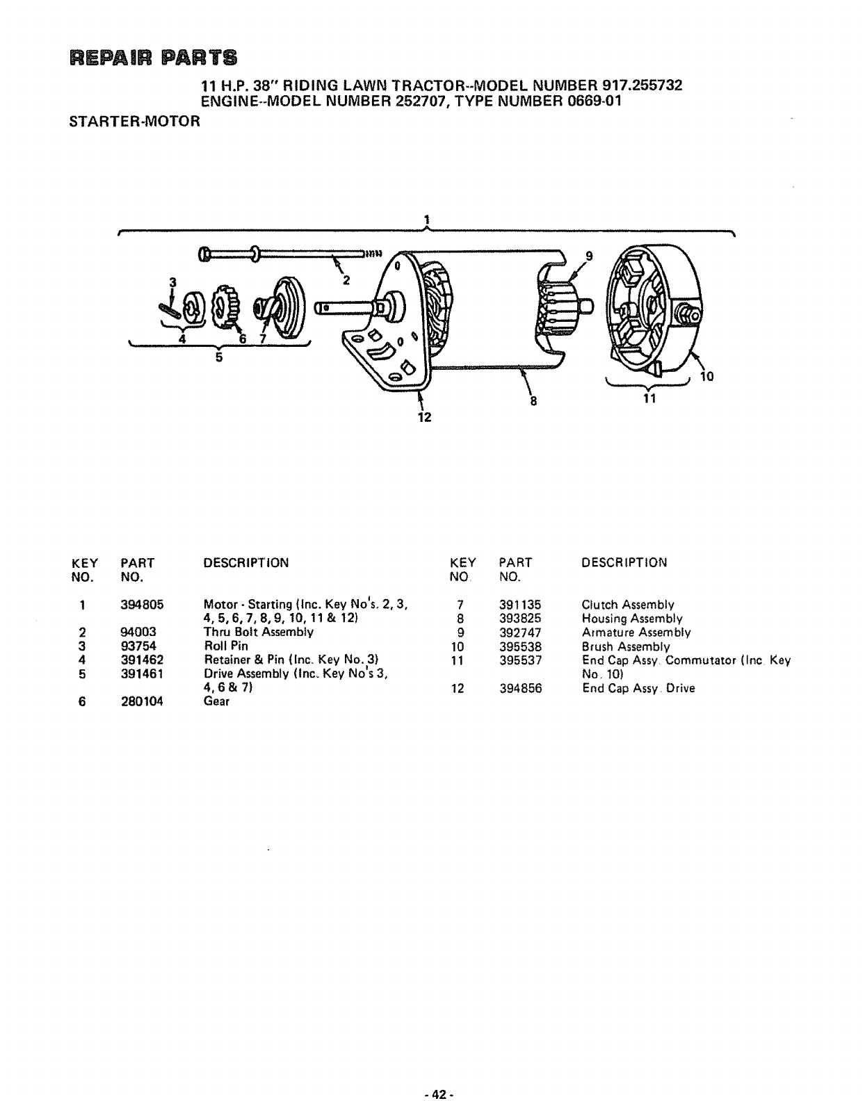
REPAIR PA TS
11 H.P. 38" RIDING LAWN TRACTOR--MODEL NUMBER 917.255732
ENGINE--MODEL NUMBER 252707, TYPE NUMBER 0669-01
STARTER-MOTOR
1
3
5
12
11
KEY
NO.
2
3
4
5
PART
NO.
394805
94003
93754
391462
391461
280104
DESCRIPTION
Motor- Starting (Inc. Key No'so 2, 3,
4, 5,6,7, 8,9, 10, 11 &t2)
Thru Bolt Assembly
Roll Pin
Retainer & Pin (inc. Key No. 3)
Drive Assembly (lnc° Key No's 3,
4,6& 7)
Gear
KEY PART DESCRIPTION
NO, NO.
7391135
8 393825
9 392747
10 395538
11 395537
12 394856
Clutch Assembly
Housing Assembly
Armature Assembly
Brush Assembly
End Cap Assy Commutator (Inc Key
No, 10)
End Cap Assy Drive
- 42 -

SUGGESTED GUIDE FOR SmGHTING SLOPES FOR SAFE OPERATION
I
SIGHTING GUIDE
t
ONLY RIDE UP AND DOWN HILL
NOT ACROSS HiLL
SIGHT AND HOLD THIS LEVEL WiTH
SKY LINE OR TREE
@
Operate your Tractor up and down the face of slopes (not
greater than !5°); never across the face. Make turns gradu-
ally to prevent tipping or loss of control. Exercise extreme
caution when changing direction on slopes.

SEA/RS
OWNERS
MANUAL
MODEL NO.
917.255732
HOW TO ORDER
REPAIR PARTS
11 HoPo
38" RIDING
LAWN TRAC
ELECTRIC
TOR
START
The Model Number will be found on the Model Plate attached
to the Drawbar. Always mention the Model Number when
requesting service or parts for' your Lawn Tractor.
All parts listed herein may be ordered from any Sears Service
Center/Departments and most Sears Retail Stores,
WHEN ORDERING REPAIR PARTS, ALWAYS GIVE THE
FOLLOWING INFORMATION:
@ THE PART NUMBER
• THE PART DESCRIPTION
@ THE MODEL NUMBER
O THE NAME OF MERCHANDISE
If the parts you need are not stocked locally, your order will
be electronically transmitted to a Sears Repair Parts Distribu-
tion Center for "expedited handling",
k,,, ,,,.i
.......... ,, ,, ,i III r,]l ,_;

SEA/ S
OWNERS
MANUAL
MODE L NO.
917.255732
Caution:
Read Rules for
Safe Operation
and Instructions
Carefully
| i/ ........
11 H,P,
38" RIDJNG
LAWN TRAC TOR
ELECTRIC START
Assembly
Installation
Operation
Repair Parts
ii u l
Sears, Roebuck and Co., Chicago, IL 60684 US.Ao
t"

CONGRATULATIONS on your purchase of a Sears Lawn
Tractor, It has been designed, engineered and manufactured
to give you the best possib{e dependability and performance
Should you experience any problem you cannot easily reme-
dy, please contact your nearest Sears Service Department,
They have competent, well-trained technicians and the proper
tools to service or repair this unit.
Please read and retain this manual. The instructions will enable
you to assemble, operate and maintain your Tractor properly
Always observe the "RULES FOR SAFE OPERATION"_
MODEL
NUMBER ....... ;_ ..... :;,_. _..... ,-._ ....._.
SERIAL
NUMBER
THE DRAWBARo
YOU SHOULD PECORD BOTH MODEL AND
SERIAL NUMBF'._ AND KEEP IN A SAFE PLACE
FOR FUTURE rtEFERENCE,
LIMITED ONE YEAR WARRANTY
ON ELECTRIC START RIDING EQUIPMENT
For one year from date of purchase, when this riding equipment is maintained, lubricated, and
tuned up according to the operating and maintenance instructions in the owner's manual, Sears
will repair' free of charge any defect in material or workmanship in this electric start riding equip-
mento
This warranty excludes blade(s), blade adapter(s), spark plug(s), air cleaner and belt(s), which are
expendable and become worn during normal use.
This warranty does not cover:
tire replacement or repair caused by punctures from outside objects (such as nails, thorns,
stumps, or glass); and
repairs necessary because of operator abuse or negligence, including the failure to main-
tain the equipment according to instructions contained in the owner's manual; and
riding equipment used for commercial or rental purposes.
FULL 90-DAY WARRANTY ON BATTERY
For 90 days from the date of purchase, if any battery included with this riding equipment proves
defective in material or workmanship and our testing determines the battery will not hold a charge,
Sears will replace the battery at no charge.
WARRANTY SERVICE IS AVAILABLE BY CONTACTING THE NEAREST SEARS SERVICE
CENTER/DEPARTMENT IN THE UNITED STATES° This warranty applies only while this
product is in use in the United States.
This warranty gives you specific legal rights, and you may also have other rights which vary from
state to state.
Sears, Roebuck and Co., D/698-731A, Sears Tower, Chicago, IL 60684
TABLE OF CONTENTS
RULES FOR SAFE OPERATION .............. 3
ASSEMBLY INSTRUCTIONS ................. 4
OPERATION INSrRUCTIONS - TRACTOR ...... 8
qPERATION INSTRUCTIONS - MOWER ....... 1!
MAINTENANCE INSTRUCTIONS-MOWER ..... 12
MAINTENANCE INSTRUCTIONS _TRACTOR . .14
TROUBLE SHOOTING ..................... 21
-2- REPAIR PARTS ........................... 24

RULES FOR SAFE OPERATDON
WARNING: This unit is equipped with an internal combustion engine and should not be used on or near any unimproved forest-
covered, brush-covered or grass-covered land unless the engine's exhaust system is equipped with a spark arrester meeting applicable
local or state laws (if any) If a spark arrester is used, it should be maintained in effective ,.,corking order by the operator.
fil the State of California the above is required by law (Section 4442 of the California Public Resources Code). Other states may
have similar taws. Federal laws apply on federal lands, S_e your Sears Authorized Service Center for spark arrester muffler part
number 677Vt,
1., Know the controls and how to stop quickly,, READ THE
OWNER'S MANUAL..
2, Do not allow children to operate the vehicle, Do not allow
adults to operate it without proper instruction or with-
out having read the owner's manual,
3, Do not carry passengers, Keep children and pets a safe dis-
tance away,
4, Always wear substantial footwear° Do not wear loose fitting
clothing that could get caught in moving parts,
5 Keep your eyes and mind on your tractor, mower and the
•|
area being cut Don t let other interests distract you,
6, Do not attempt to operate your tractor or mower when
not in drivers seat,
7., Always get on or off your tractor from the operators left
hand side
8, Clear the work area of objects which might be picked up
and thrown,
9, Disengage all attachment clutches and shift into neutral be-
fore attempting to start the engine,
t0, Disengage power to attachments and stop the engine be-
fore leaving the operator's position_
11, Disengage power to mower, stop the engine and disconnect
spark plug wire(s) from spark plug(s) before cleaning, mak-
ing an adjustment or repairs_
|2_ Disengage power to attachments when transporting or not
in use,
13. Take all possible precautions when leaving the vehicle un-
attended° Disengage the power-take-off, lower the attach-
ments, shift into neutral, set the parking brake, stop the en-
gine and remove the key.
14.. Do not stop or start suddenly when going uphill or down-
hill. Mow up and down the face of slopes (not greater than
15o}; never across the face, Refer to page 43..
15 Reduce speed on slopes and make turns gradually to pre-
vent tipping or loss of control° Exercise extreme caution
when changing direction on slopes.
16. Do not shift gears while going up or down slopes.. Choose
a gear low enough to negotiate the slope without stopping
and shifting gears To reduce speed, move throttle lever
to slow.
17. Never mow in wet or slippery grass, when traction is un-
sure or at a speed which could cause a skid
18. Stay alert for holes in the terrain and other hidden hazards
19,, Do not drive too close to creeks, ditches and public high°
ways.
20, Exercise special care when mowing around fixed objects
in order to prevent the blades from striking them, Never
deliberately run tractor or mower into or over any foreign
object
21 rNever shift gears until tractor comes to a stop.
22. Never place hands or feet under the mower, in the deflector
(discharge chute) or near any moving parts while tractor or
mower are running. Always keep clear of discharge chute°
23 Use care when pulling loads or using heavy equipment,.
a. Use only approved drawbar hitch points.
b, Limit loads to those you can safely controi_
c. Do not turn sharply. Use care when backing,
d. Use counterweight or wheel weights when suggested in
this owner s manual_
24. Watch out for traffic when crossing or near roadways.
25 When using any attachments, never direct discharge of
material toward bystanders nor allow anyone near the ve-
hicle while in operatiom
26° Handle gasoline with care - it is highly flammable.
a_ Use approved gasoline containers.
b.. Never remove the cap of the fuel tank or add gasoline to
a running or hot engine, or fill the fuel tank indoors°
Wipe up spilled gasoline.
c. Open doors if the engine is run in the garage - exhaust
fumes are dangerous° Do not run the engine indoors..
27, Keep the vehicle and attachments in good operating con-
dition, and keep safety devices in place,
28° Keep all nuts, bolts and screws tight to be sure the equip-
ment is in safe working condition,.
29. Never store the equipment with gasoline in the tank inside
a building where fumes may reach an open flame or spark.
Allow the engine to cool before storing in any enclosure..
30_ To reduce fire hazard, keep the engine free of grass, leaves
or excessive greaser Do not clean product while engine is
running.
31 Except for adjustment; DO NOT operate Engine if air
cleaner or cover directly over carburetor air intake is re-
moved. Removal of such part could create a fire hazard,
32. Do not operate without a muffler or tamper with the
exhaust system,. Damaged mufflers or spark arresters
could create a fire hazard. Inspect periodically and replace
if necessary,
33., The vehicle and attachments should be stopped and inspect-
ed for damage after striking a foreign object, and the dam-
age should be repaired before restarting and operating the
equipment.
34, Do not change the engine governor settings or overspeed
the engine; severe damage or injury may result.
35. When using the vehicle with mower, proceed as follows:
a_ Mow only in daylight or in good artificial light
b, Never make a cutting height adjustment while the engine
is running if the operator must dismount to do soo
c, Shut the engine off when removing the grass catcher or
unclogging chute.
d, Check the blade mounting bolts for proper tightness at
frequent intervals,
36_ Do not operate the Mower without the deflector shield in
place.
37. Disengage power to mower before backing up, Do not mow
in reverse unless absolutely necessary and then only after
careful observation of the entire area behind the mower,
LOOK FOR THIS SYMBOL TO POINT OUT IMPORTANT SAFETY
PRECAUTIONS, IT MEANS - ATTENTION! BECOME ALERT!
YOUR SAFETY IS INVOLVED,
-3-

To assemble your Tractor you will need:
two 7/16" wrenches, two 9/16" wrenches, and a 3/4"
wrench
NOTE: RIGHT HAND (R.H.) AND LEFT HAND (LH°) ARE
DETERMINED FROM OPERATOR'S POSITION WHILE
SEATED ON THE TRACTOR°
112" NUT _---_.__._
LARGE WASHER _
STEERING
SHAFT \
BOLTS
ASSEMBLY
1v Remove Shipping Strap Banding, Battery, Steering Wheel
and Bag of Parts (under Hood).
2. Slide Upper Steering Shaft over Lower Steering Shaft so
bolt holes line up with slots in Lower Steering Shaft (Fig.
1L
3. Use two Bolts and two Locknuts to retain Upper- Steering
Shaft to Lower Steering Shaft_ Tighten securely,
4._ Slide Tube over Steering Shaft Assembly and over Steering
Sleeve Bracket.
5. Place Steering Wheel Adapte_ on Upper Steering Shaft
6. With front wheels pointed straight ahead, place Steering
Wheel on Steering Wheel Adapter, B'ars of Steering Wheel
should point straight across tractor.
7. Place Large Washer on Upper Steering Shaft and install a
1/2" Nut, Tighten securely_
8. Snap Insert into Steering Wheel°
9. Remove plastic on Tractor Hood,
NUTS
_RING
SHAFT
SLEEVE
BRACKET
BATTERY IINSTALLATg ON
1 Before installation in Tractor, foltow the Battery prepara-
tion steps below,
WEAR EYE AND FACE SHIELD.
FIGURE 1
CUT AWAY VIEW
_' .......
l----d
e,.,_VENTCAP
J
BATTERY
TUBE
BATTERY
CELL
a, Battery Electrolyte: SEE DETAILED INSTRUCTIONS
PACKAGED WITH BATTERY
b, Fill Battery with electrolyte to bottoms of tubes in cells
(Fig,. 2), NOTE: DO NOT OVERFILL. (OVERFILLING
CAN RESULT IN DAMAGE TO TRACTOR)
WASH HANDS OR CLOTHING IMMEDI-
ATELY IF ACCIDENTALLY IN CONTACT
WITH ELECTROLYTE
c= Check level of electrolyte after 30 minutes= Add addi-
tional electrolyte if necessary. NOTE: PUSH VENT
CAPS SECURELY INTO PLACE,
d, Charge Battery at a rate not exceeding three amperes
for about two and one half houls.
FIGURE 2
DO NOT SMOKE. FUMES FROM CHARG-
ED ELECTROLYTE ARE EXPLOSIVE
_4-
e, Neutralize excess electrolyte for disposal by adding it to
four inches of water in a five gallon plastic container_
Stir with awooden or plastic paddle white adding bak-
ing soda until the addition of more soda causes no more
foaming
DO NOT SHORT BATTERY TERMINALS.
BEFORE INSTALLING BATTERY, RE-
MOVE METAL BRACELETS, WRIST-
WATCH BANDS, RINGS, ETC. FROM
YOUR PERSON_

2. Position Battery in tractor as follows:
a. Lift Seat Pan so it rests on Steering Wheel (Fig° 3)o
b, Lower Battery into Fender Wel! with Battery Terminals
toward front of tractor° Make sure Battery rests in Bat-
tery Tray (Fig. 4).
NOTE: BE SURE BATTERY DRAIN TUBE IS SECURE-
LY ATTACHED TO BATTERY TRAY DRAIN,
3o Connect Battery Cables using: two Hex Bolts, two Flat
Washers, two Lockwashers and two Hex Nuts (shown full
size below) found in Bag of Parts.
@@
POSITIVE TERMINAL MUST BE CON-
NECTED FIRST TO PREVENT SPARKS
FROM ACCIDENTAL GROUNDING°
a, Connect RED Battery Cable to Positive (+) Battery Ter _
minal with Hex Bolt, Flat Washer, Lockwasher and Hex
Nut (Fig, 4), Tighten securely,
b Connect BLACK Ground Cable to Negative (-) Battery
Terminal with remaining Hex Bolt, Flat Washer, Lock-
washer and Hex Nut (Fig 4), Tighten securely,
4,, Install Battery using: two tnt,/Ey, t Lockwashers, two Wing
Nuts (shown full size below) and
_t_,j_##,_ ,, ©
TIT: ,
two Battery Bolts and one Terminal Guard found in Bag of
Parts,
a, Using the slot on one side of the Battery Support (Fig 5)
slide Battery Bolt into Frame Slot (head of Bolt down),
Fasten the Battery Bolt to the Terminal Guard using
Int,/Ext, Lockwasher and Wing Nut as shown in Fig, 5.
b Assemble the remaining Battery Bolt to other side of
Battery Support and fasten Terminal Guard to it with re-
maining lnt/Ext, Lockwasher and Wing Nut Tighten
Wing Nuts securely by hand (Fig, 5),
NOTE: USE TERMINAL ACCESS DOORS (FIG, 5) FOR:
1. Inspection for secure connections (tighten hardware),
2, Inspection for corrosion,
3. Testing battery
4 Jumping (if required).
5. Charging (if required),
WHEN NOT IN USE, KEEP TERMINAL
ACCESS DOORS CLOSED_
NOTE: DO NOT START ENGINE UNTIL INITIAL SER-
VICE HAS BEEN PERFORMED
/
SEAT PAN --_
POSITIVE /
BATTERY
TERMINAL BATTERY
' ¸
BATTERY
TERMINAL
FIGURE 3
FENDER
WASHER
POSITIVE
TERMINAL
POSITIVE
CABLE (RED)
WASHER
HEX BOLTS
NEGATIVE
TERMINAL
NEGATIVE
CABLE (BLACK)
NUT
LOCKWASHE R
BATTERY TRAY
! t
BATTERY
TUBE
WINW
INTERNAL/
LOCI{WASHER
WING
NUT _
INTERNAL/EXTERNAL
LOCI(WASHER
TERMINAL
GUARD
FIGURE 4
S
BATTERY
BOLT
SLOT
-5- FIGURE 5
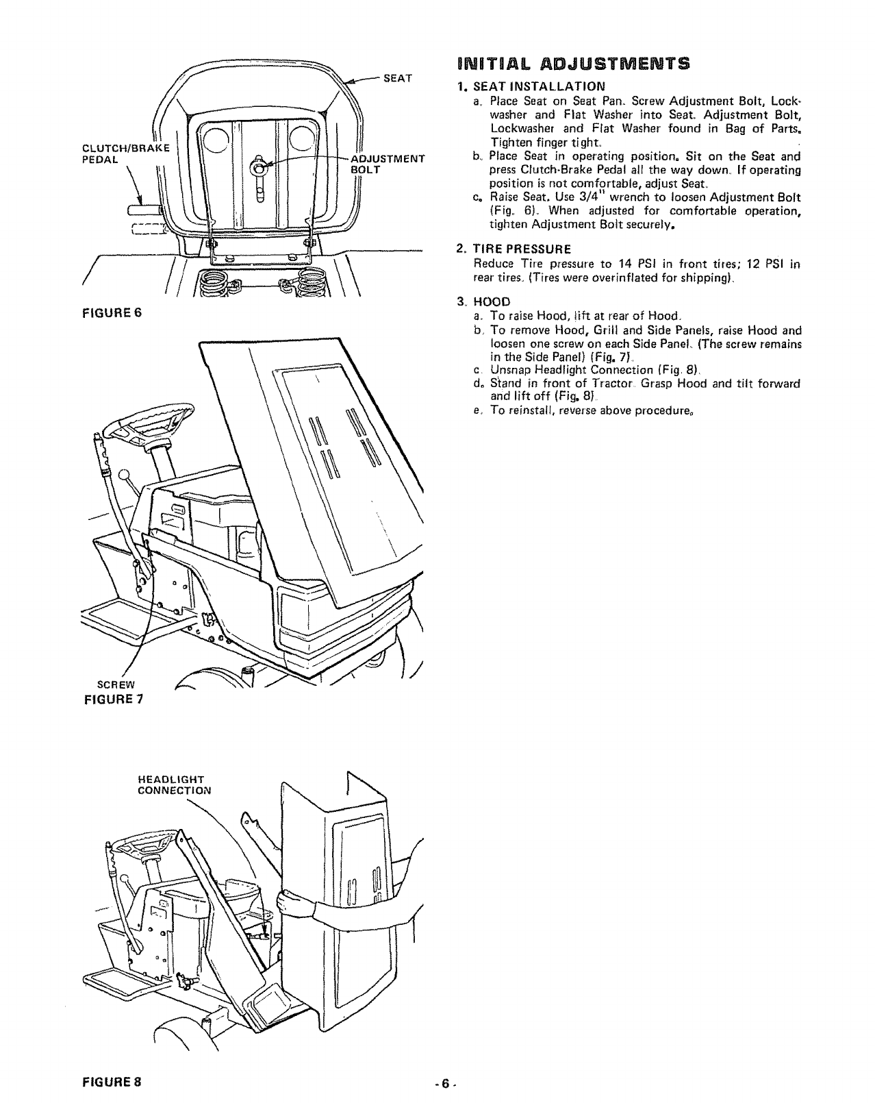
CLUTCHIBRAKE
PEDAL
/
FIGURE 6
SCREW
FIGURE 7
'MENT
BOLT
INITIIAL ADJUSTMENTS
1. SEAT INSTALLATION
a,. Place Seat on Seat Pan.. Screw Adjustment Bolt, Lock_
washer and Fiat Washer into Seat° Adjustment Bolt,
Lockwasher and Flat Washer"found in Bag of Parts=
Tighten finger tight.
bo Place Seat in operating position. Sit on the Seat and
press Crutch-Brake Pedal all the way down. if operating
position is not comfortable, adjust Seat,,
Co Raise Seat. Use 3/4 _wrench to loosen Adjustment Bolt
(Fig° 6),. When adjusted for comfortable operation,
tighten Adjustment Bolt securely.
/
2_
3_
TIRE PRESSURE
Reduce Tire pressure to 14 PSI in front tires; 12 PSi in
rear tires. (Tires were overinflated for shipping).
HOOD
a,. To raise Hood, !ift at rear of Hood,
be To remove Hood, Grill and Side Panels, raise Hood and
loosen one screw on each Side Panel (The screw remains
in the Side Panel) (Fig, 7),
c Unsnap Headlight Connection (Fig, 8),
do Stand in front of Tractor Grasp Hood and tilt forward
and lift off (Fig. 8},
e_ To reinstall, reverse above procedure°
HEADLIGHT
CONNECTION
\
FIGURE 8 - 6-
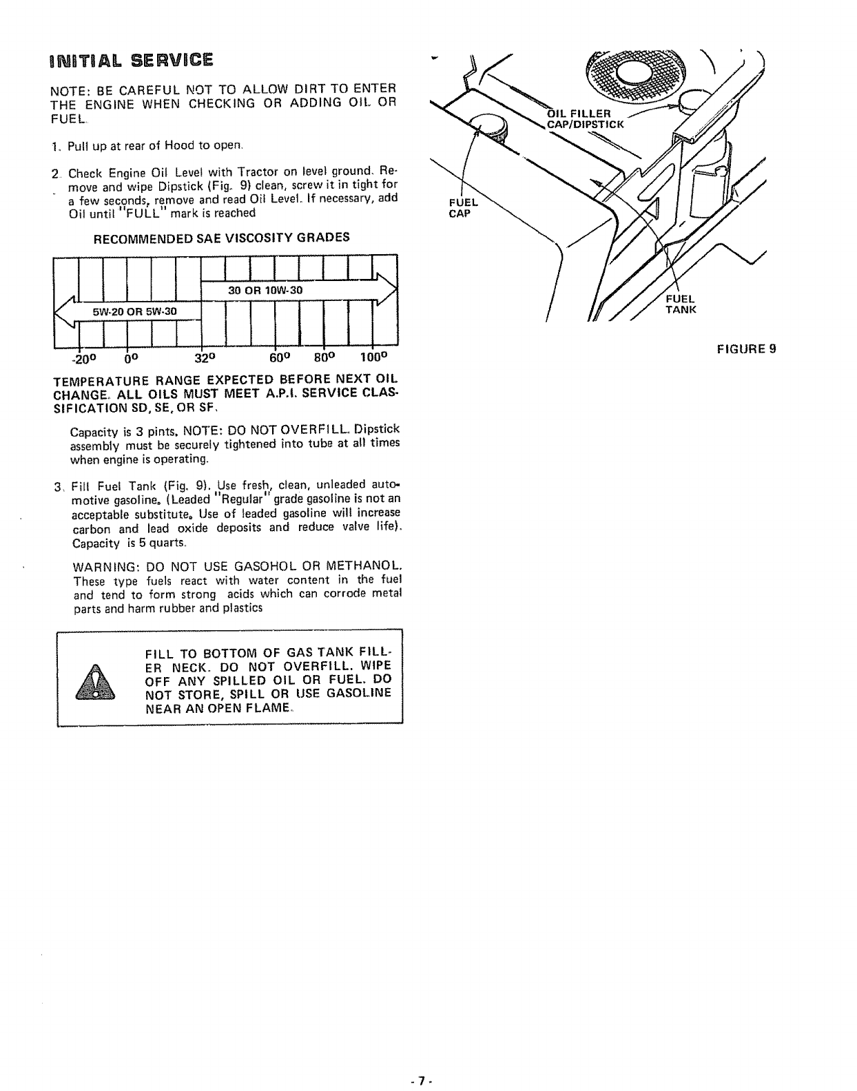
INITIAL SERVRCE
NOTE: BE CAREFUL NOT TO ALLOW DIRT TO ENTER
THE ENGINE WHEN CHECKING OR ADDING OIL OR
FUEL
Io Pull up at rear of Hood to open,
2 Check Engine Oil Level with Tractor on level ground, Re-
move and wipe Dipstick (Fig. 9) cteano screw it in tight for
a few seconds, remove and read Oil Level° If necessary, add
Oil until "FULL" mark is reached
RECOMMENDED SAE VISCOSITY GRADES
1oI!1 .I...I1,,
"_/I '"5;'20 iR iW'3i - OR 10W-30
-20 ° 0° 32° 60° 80 ° 100 °
TEMPERATURE RANGE EXPECTED BEFORE NEXT OIL
CHANGE,, ALL OILS MUST MEET A.P,I, SERVICE CLAS-
SIFICATION SD, SE, OR SF,
Capacity is 3 pints, NOTE: DO NOT OVERFILL, Dipstick
assembly must be securely tightened into tube at all times
when engine is operating.
3, Fill Fuel Tank (Fig, 9), Use fresh, clean, unleaded auto-
motive gasoline. (Leaded "" " "Regular grade gasohne Is not an
acceptable substitute° Use of leaded gasoline will increase
carbon and lead oxide deposits and reduce valve life)o
Capacity is 5 quarts,,
WARNING: DO NOT USE GASOHOL OR METHANOL,
These type fuels react with water content in the fuel
and tend to form strong acids which can corrode metal
parts and harm rubber and ptastics
FUEL
CAP
FUEL
TANK
FIGURE 9
FILL TO BOTTOM OF GAS TANK FILL-
ER NECK° DO NOT OVERFILL. WIPE
OFF ANY SPILLED OIL OR FUEL. DO
NOT STORE, SPILL OR USE GASOLINE
NEAR AN OPEN FLAME°
-7_
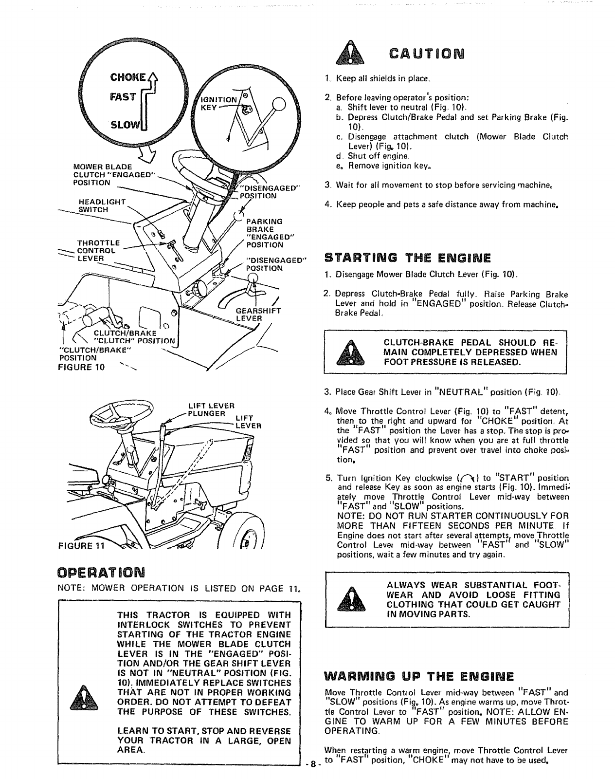
KEY
MOWERBLADE
CLUTCH"ENGAGED"
POSITION
HEADLIGHT
THROTTLE
_CONTROL
LEVER
"DISENGAGED"
POSITION
PARKING
BRAKE
"ENGAGED"
POSITION
='DISENGAGED"
CLUTCH/BRAKE
"CLUTCH" POSITION;
"CLUTCH/BRAKE"
POS|TI ON
FIGURE 10 .... _.
/
G EARSHIFT
LEVER
LIFT LEVER
PLUNGER LIFT
R
FIGURE 11
OPERATION
NOTE: MOWER OPERATION IS LISTED ON PAGE 11.
THIS TRACTOR IS EQUIPPED WITH
INTERLOCK SWITCHES TO PREVENT
STARTING OF THE TRACTOR ENGINE
WHILE THE MOWER BLADE CLUTCH
LEVER IS IN THE "ENGAGED" POSI-
TION AND/OR THE GEAR SHIFT LEVER
IS NOT IN "NEUTRAL" POSITION (FIG.
10). IMMEDIATELY REPLACE SWITCHES
THA, T ARE NOT IN PROPER WORKING
ORDER. DO NOT ATTEMPT TO DEFEAT
THE PURPOSE OF THESE SWITCHES,,
LEARN TO START, STOP AND REVERSE
YOUR TRACTOR tN A LARGE, OPEN
AREA,,
-8-
t,
2.
,
4,.
CAUTION
Keep all shields in place_
Before leaving operator'Jsposition:
a., Shift lever to neutral (Fig,, 10),.
b. Depress Clutch/Brake Pedal and set Parking Brake (Fig.
10)_
c_ Disengage attachment clutch (Mower Blade Clutch
Lever) (Fig. 10),_
d. Shut off engine,
eo Remove ignition key=
Wait for all movement to stop before servicing machine°
Keep people and pets asafe distance away from machine.
STARTliNG THE ENGINE
1. Disengage Mower Blade Clutch Lever (Fig. 10).
2,_Depress Clutch-Brake Pedal fully., Raise Parking Brake
Lever and hold in "ENGAGED" position. Release Clutch-
Brake Pedal,
CLUTCH-BRAKE PEDAL SHOULD RE-
MAIN COMPLETELY DEPRESSED WHEN
FOOT PRESSURE tS RELEASED=
3_
4.
,
Place Gear Shift Lever in "NEUTRAL" position (Fig t0),
Move Throttle Control Lever (Fig_ 10) to "FAST" detent,
then to the right and upward for "CHOKE '_ position, At
"FAST"
the position the Lever has a stop., The stop is pro-
vided so that you will know when you are at ful! throttle
"FAST" position and prevent over travel into choke posi-
tion,
Turn Ignition Key clockwise ((_) to "START" position
and release Key as soon as engine starts (Fig. 10)_ Immedi;
ately move Throttle Control Lever mid-way between
"FAST" and "SLOW" positions.
NOTE: DO NOT RUN STARTER CONTINUOUSLY FOR
MORE THAN FIFTEEN SECONDS PER MINUTE. if
Engine does not start after several attempts, move Throttle
Control Lever mid,way between "FAST" and "SLOW"
positions, wait a few minutes and try again°
ALWAYS WEAR SUBSTANTIAL FOOT-
WEAR AND AVOID LOOSE FITTING
CLOTHING THAT COULD GET CAUGHT
IN MOVING PARTS.
WARMING UP THE ENGINE
Move Throttle Control Lever mid-way between "FAST" and
,, ir 0
SLOW positions (Fi_, 10)o As engine warms up, move Thr t-
tie Control Lever to 'FAST" position. NOTE: ALLOW EN-
GINE TO WARM UP FOR A FEW MINUTES BEFORE
OPERATING,.
When restarting a warm engine, move Throttle Control Lever
It _1 •,I' II
to FAST posltmn, CHOKE may not have to be used.

MOWER nNSTALLATION
Your 38" Mower installs without the use of toots,, Raise Lift
Lever (Fig° 1t) to its highest position. Turn Depth Adjust-
ment Knob to towest positign (Fig, 14L
1. Install Front Hinge Pin through Axle and Parallel Link
(Fig. 12L Secure with Retainer Spring°
2. Install Rear Hinge Pin through Mower Lift Brackets and
Parallel Link (Fig, 12)o Secure with Retainer Spring,
3_ Install Clutch Rod in Clutch Lever (Fig° 13- tnsetL
4,, Move Lift Lever (Fig° 11) forward to lower Suspension
Arms. Slide Trunnions through Lift Bracket holes and
secure with Retainer Springs (Fig., 13).
5, Roll Belt over Mower Drive Putiey_ Make stJre Belt is inside
Belt Guides (Fig. 14)_ See Belt Drive Schematic Decal on
Mower Housing,
6, Use Lift Lever (Fig° 11) to raise mower,
NOTE: SEE MOWER ADJUSTMENT, BELOW.,
7. Turn Depth Adjustment Knob clockwise (r-_} to the mid-
die of it's travel.
MOWER ADJUSTMENT
CLUTCH
ROD PARAI. LE L
RETAINER LINK
SPRING
CLUTCH
REAR
HINGE
PIN
CLUTCH
LEVER
CLUTCH
ROD
SUSPENSION
ARM
RETAINER
FRONT SPRINGS
AXLE
FRONT
HINGE
PIN
FIGURE 12
RETAINER
SPRING
FOR ANY ADJUSTMENTS, INSPECTION
OR MAINTENANCE:
PUSH TRACTOR CLUTCH-BRAKE PED-
AL COMPLETELY INTO BRAKE POSI-
TIONo MOVE GEAR SHIFT LEVER TO
"N" NEUTRAL POSITION. PLACE PARK-
tNG BRAKE IN "ENGAGED" POSITION.
PLACE MOWER BLADE CLUTCH LEVER
tN "ENGAGED" POSITION° SHUT
OFF THE ENGINE. MAKE ABSOLUTELY
SURE THE BLADES AND ALL MOVING
PARTS HAVE COMPLETELY STOPPED,
REMOVE THE IGNITION KEY, DiSCON-
NECT THE SPARK PLUG WIRE FROM
THE SPARK PLUG AND KEEP WIRE
AWAY FROM THE PLUG TO PREVENT
INJURY FROM ACCIDENTAL START-
ING,
NOTE: BEFORE CHECKING THE SIDE TO SIDE AND
FRONT TO REAR ADJUSTMENTS, PAGE 10, BE SURE
PRESSURE IN FRONT TIRES 1S 14 PSi AND PRESSURE
IN REAR TIRES IS t2 PSL tF TIRES ARE OVER OR
UNDER INFLATED YOU WlLL NOT PROPERLY ADJUST
YOUR MOWER,
DEPTH ADJUSTMENT
Adjustment for mower height is made with the Depth Adjust-
ment Knob, Raise Mower cutting height by turning Depth
Adjustment Knob clockwise ( f_ )_ Lower Mower cutting
height by turning Depth Adjustment Knob counterclockwise
((-,)o
_9-
RETAINER LIFT
SPRING BRACKET
f
TRUNNION
\MOWER
DRIVE
PULLEY
FIGURE 13
\
FIGURE 14

LIFT
PLUNGER
L I FT
LEVER
SIDE-TO*SiDE
/IENT
TOP OF
FLANGE TOP OF
,_ FLANGE
A
FIGURE 15
A
NUT "C"
SIDE-TO, SIDE _N
ADJUSTMENT
TRUNNION UT "B"
___e__._._j
FIGURE 16
REAR
SUSPENSION
ARM
REAR
SUSPENSION
TRUNNION
LIFT
BRACKET
D
FRONT
FLANGE
FIGURE 17
_%TJ_R EAR
NUT "E ".-_...._ l,._J-,=_ SUSPE NSI ON
REAR _ARM
SUSPENSION ,-_. (_--/_!
..o..,o.
NUT "F" -_ _t_
LEVEL MOWER FROM SIDE TO SiDE
SEE MOWER ADJUSTMENT, PAGE 9_
1, Park tractor on level sur_face.,Depress Lift Lever Plunger
and use Lift Lever to raise mower to maximum cutting
height,
2_
3_
4e
m
6_
Measure height of Top of Flange to tevel surface at front of
mower° Distance "A" should be the same (Fig. 15)o
if distance "A" needs to be changed, snap out Access Hole
Cover on L,H, side above Footrest, Use 9/16" wrench on
Nuts "B" and "C" at Side-To-Side Adjustment Trunnion
(Fig, 16),
To raise left side of mower, loosen Nut "B" and tighten
Nut "C_°
TO lower left side of mower, loosen Nut "C '_ and tighten
Nut "B".
NOTE: ONE ROTATION OF ADJUSTMENT NUTS IS
EQUIVALENT TO APPROXIMATELY 3/16" HEIGHT
CHANGE_
Be sure at!nuts are securely tightened.
NOTE: SEE MOWER ADJUSTMENT, FRONT-TO-REAR,
BELOW,
ADJUST MOWER FROM FRONT
TO REAR
1, To obtain the best cutting results, your Mower Housing
should be adjusted so the Front and Rear Flange distance
"D" (Fig_ 17) is 5/16" lower in front when the mower is
positioned in the hiclhest cutting position. NOTE: MEAS-
URE DISTANCE _TD" FROM SURFACE TO RIGHT
REAR FLANGE AND COMPARE TO DISTANCE "D" AT
RIGHT FRONT FLANGE,
2 To raise rear of mower, loosen Nut "E" on both Rear Sus-
pension Arms. Screw both Nuts "F" up EQUAL NUMBER
OF TURNS (Fig, 18),
3o When distance "D" is 5/16" lower at front than rear, tight-
en Nut "E"_
4, To lower rear of mower, loosen Nut "F" on both Rear
Suspension Arms an EQUAL NUMBER OF TURNS (Fig,
18),
5= When distance "D" is 5/16" lower at front than rear, re_
tighten Nuts "E'_
NOTE: WHEN ADJUSTING REAR SUSPENSION TRUN-
NIONS, ALWAYS ADJUST BOTH EQUALLY SO MOWER
WILL STAY LEVEL
FIGURE 18 .10 -
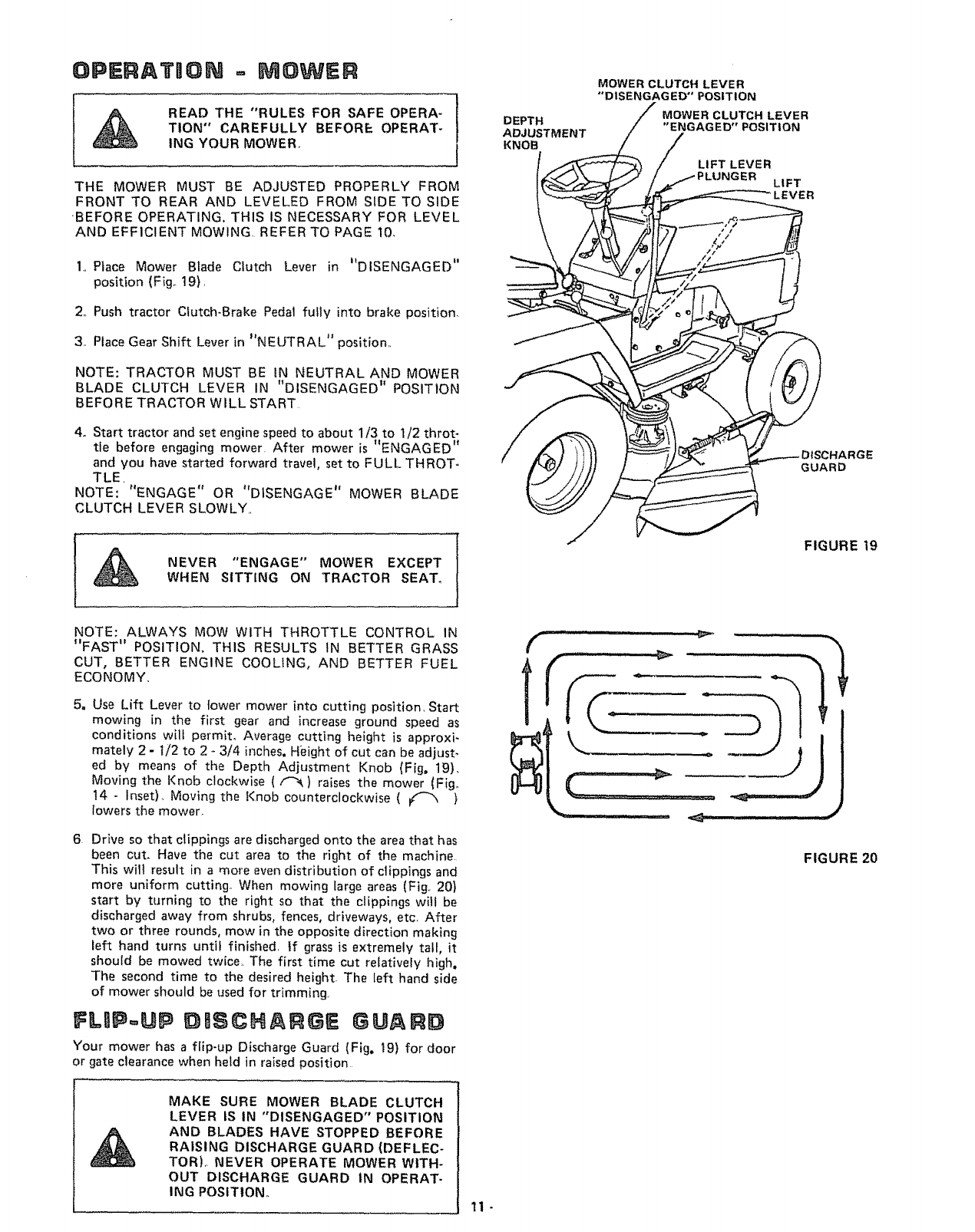
OPERATRON = MOWER
READ THE "RULES FOR SAFE OPERA-
TION" CAREFULLY BEFORE OPERAT-
ING YOUR MOWER, 1
I
THE MOWER MUST BE ADJUSTED PROPERLY FROM
FRONT TO REAR AND LEVELED FROM SIDE TO SIDE
"BEFORE OPERATING. THIS IS NECESSARY FOR LEVEL
AND EFFICIENT MOWING REFER TO PAGE 10.
1. Place Mower Blade Clutch Lever in I'DISENGAGED"
position (Fig_ 19),
2o Push tractor Clutch-Brake Pedal fully into brake position.
3. Place Gear Shift Lever in "NEUTRAL" position.
NOTE: TRACTOR MUST BE IN NEUTRAL AND MOWER
BLADE CLUTCH LEVER IN "DISENGAGED" POSITION
BEFORE TRACTOR WILL START
4o Start tractor and set engine speed to about 1/3 to t/2 throt-
tle before engaging mower. After mower is "ENGAGED"
and you have started forward travel, set to FULL THROT-
TLE,
NOTE: "ENGAGE" OR "DISENGAGE" MOWER BLADE
CLUTCH LEVER SLOWLY,,
ANEVER "ENGAGE" MOWER EXCEPT
WHEN SITTING ON TRACTOR SEAT°
DEPTH
ADJUSTMENT
KNOB
MOWER CLUTCH LEVER
'*DISENGAGED" POSITION
MOWER CLUTCH LEVER
"ENGAGED" POSITION
LIFT LEVER
LIFT
LEVER
GUARD
FIGURE 19
NOTE: ALWAYS MOW WITH THROTTLE CONTROL IN
"FAST" POSITION. THIS RESULTS IN BETTER GRASS
CUT, BETTER ENGINE COOLING, AND BETTER FUEL
ECONOMY.
5, Use Lift Lever to lower mower into cutting position, Start
mowing in the first gear and increase ground speed as
conditions wilt permit. Average cutting height is approxi-
mately 2 - 1/2 to 2 -3/4 inches, Height of cut can be adjust.
ed by means of the Depth Adjustment Knob (Fig. 19),
Moving the Knob clockwise { _ ) raises the mower (Fig.
t4 - Inset). Moving the Knob counterclockwise ( !(_ )
lowers the mower.
6, Drive so that clippings are discharged onto the area that has
been cut. Have the cut area to the right of the machine.
This wilt result in a more even distribution of clippings and
more uniform cutting When mowing large areas (Fig,. 201
start by turning to the right so that the clippings wlt be
discharged away from shrubs, fences, driveways, etc, After
two or three rounds, mow in the opposite direction making
left hand turns until finished, if grass is extremely tall, it
should be mowed twice,, The first time cut relatively high,
The second time to the desired height The left hand side
of mower should be used for trimming.
FLBP-UP DtSCNARGE GUAI D
Your mower has a flip-up Discharge Guard (Fig. 19) for door
or gate clearance when held in raised position
(
T
" ...........ii •i
FIGURE 20
MAKE SURE MOWER BLADE CLUTCH
LEVER IS IN "DISENGAGED" POSITION
AND BLADES HAVE STOPPED BEFORE
RAISING DISCHARGE GUARD (DEFLEC-
TOR),, NEVER OPERATE MOWER WITH-
OUT DISCHARGE GUARD iN OPERAT-
ING POSITION. 11-

MANDREL _
ASSEMBLY
WASH|
LOCKWASHER _
HEX BOLT GR_ 5_
FIGURE 21
.......................II1....
FIGURE 22
MAINTENANCE = MOWER
FOR ANY ADJUSTMENTS, INSPECTION
OR MAINTENANCE:
PUSH TRACTOR CLUTCH-BRAKE PED-
AL COMPLETELY INTO BRAKE POSI-
TION. PLACE PARKING BRAKE IN
"ENGAGED" POSITION. MOVE GEAR
SHIFT LEVER TO "NEUTRAL" POSF
TIONo PLACE MOWER BLADE CLUTCH
LEVER IN "DISENGAGED" POSITION.
TURN IGNITION KEY TO "OFF" POSI-
TION. MAKE ABSOLUTELY SURE THE
BLADES AND ALL MOVING PARTS
HAVE COMPLETELY STOPPED_ RE-
MOVE THE IGNITION KEY, DISCON-
NECT THE SPARK PLUG WIRE FROM
THE SPARK PLUG AND KEEP WIRE
AWAY FROM THE PLUG TO PREVENT
INJURY FROM ACCIDENTAL STARTING°
1,,
2_
When grinding, care should be taken to maintain blade bal-
ance and the blade should be checked for proper balance
before reinstallation on mower,. Unbalanced or bent blade
will cause excessive vibration when running, and eventual
damage to mower or engine. Replace bent, damaged or un-
balanced blades.
To check Blade balance, drive a nail into a beam or wall,
Leave about one inch of the straight nail exposed. Place
Center Hole of clean Blade over the head of the nail (Fig,
22). NOTE: CENTER HOLE OF BLADE ON NAIL. IF
BLADE IS PROPERLY BALANCED, BLADE SHOULD
REMAIN IN POSITION SHOWN IN FIG._22. IF EITHER
END OF THE BLADE MOVES DOWNWARD, BLADE IS
NOT BALANCED AND MUST BE REPLACED_
To ensure satisfactory operation, it is recommended that
before the star_ of each mowing season, the old blades be
discarded and replaced with new blades. Mower blades can
be purchased at any Sears Service Center/Departments and
most Sears Retail Stores°
DASLY MA0 NTENANCE
Make sure all nuts on baits are tight and cotter pins and retain,,
er springs are secure_ Keep blades sharp. Observe all safety pre-
cautions,, Keep mower wel! lubricated (refer to page 22),
CLEANONG MOWER
DISCONNECT SPARK PLUG WIRE TO
PREVENT ACCIDENTAL STARTING BE-
FORE CLEANING.
Water pressure from agarden hose will remove fresh clippings
from underside of mower,. Clean mower' after each mowing°
BLADE REPLACEMENT
Raise Mower to highest position to permit access to Blades°
1. Remove Bait, Lockwasher and Washer (Fig. 21) (turn
counterclockwise (_/"_).
2. Place new Blade between Flanges, (the word "TOP" is
stamped on all Blades to assure proper installation), and
secure with Washer, Lockwasher and Bolt previously re-
moved, TIGHTEN SECURELY°
ALWAYS USE GRADE 5 HEAT TREATED
BOLTS TO ATTACH BLADES. CHECK
BOLTS IN BLADES OCCASIONALLY TO
MAKE SURE BOLTS ARE TIGHT° TaR-
QUE BOLTS 30 - 35 FT_ LBSo
BLADE CAR E
For best results mower blades must be kept sharp,, The blades
can be sharpened with afew strokes of a file or on a grinding
wheel° We suggest they be sharpened after every 15 hours of
mowing. Do not attempt to sharpen while on mower.,
A GRADE 5 HEAT TREATED BOLT
CAN BE IDENTIFIED BY THREE
LINES ON THE BOLT HEAD AS
SHOWN AT LEFT.
12_

TRACTOR OPERATmON
1. Depress Lift Lever Plunger at top of Mower Lift Lever and
move Lever rearward to its _HIGHEST" position (Fig.
23).
2, With engine running and warm, place Throttle Control
÷I' ,,
Lever mfdway between FAST and "SLOW" position.
3o Push Clutch-Brake Pedal down firmly to "DISENGAGE"
Parking Brake (Fig. 24).
4, Move Gear Shift Lever to "1ST" Gear (Fig 24}
'5. Release Clutch-Brake Pedal SLOWLY to start forward
movement,
6If qround travel is too stow, move Throttle Control Lever
to 1'FAST" position or press Clutch-Brake Pedal to stop
and shift to adifferent gear. NOTE: ALWAYS SELECT A
GROUND TRAVEL SPEED THAT WILL SUIT THE
TERRAIN AND THE ATTACHMENT BEING USED.
LEVER PLUNGER
_...,_,....,__ MOWER LIFT LEVER
_'°HIGHEST" POSITION
"LOWEST"
POSITION
MAKE SURE PARKING BRAKE WILL
HOLD TRACTOR SECURE,
NEVER PLACE YOUR HANDS OR FEET
1N OR UNDER ANY POWERED ATTACH_
MENT OR NEAR ANY MOVING PART
WHILE TRACTOR OR ANY POWERED
ATTACHMENT IS RUNNING_
FIGURE 23
NOTE: ALWAYS OPERATE ENGINE AT FULL THROTTLE
WHEN MOWING TO ASSURE BETTER MOWING PER-
FORMANCE, LONG ENGINE LIFE AND PROPER DIS-
CHARGE OF CUT MATERIAL, REGULATE GROUND
SPEED BY SELECTING A LOW ENOUGH GEAR (FIG,
24) TO GIVE THE MOWER CUTTING PERFORMANCE
PLUS QUALITY OF CUT DESIRED,
DO NOT OPERATE THE MOWER WITH-
OUT THE DEFLECTOR SHIELD (DIS-
CHARGE GUARD) tN PLACE°
TRACTOR OPERAT"ON ON HULLS
DO NOT DRIVE UP OR DOWN HILLS
WITH SLOPES GREATER THAN 15°
AND DO NOT DRIVE ACROSS ANY
SLOPE° REFER TO PAGE 43.
1, Move Gear Shift Lever to "1ST" Gear before starting up or
down hills
2o AVOID STOPPING OR SHIFTING ON HILLS,
a. If slowing is necessary, move Throttle Control Lever to
slower position
LEAVE ENOUGH ROOM WHEN STOP-
PING AND STARTING TO At.LOW
SLIGHT TRACTOR ROLL DOWNHILL
AS CLUTCH-BRAKE PEDAL MOVES
THROUGH CLUTCH POSITION°
BRAKE
"ENGAGED"
POSITION
"DISENGAGED"
"CLUTCH" T1oN
POSITION
°'CLUTCH/BRAK E.... DRIVE" "_,_,// .....
POSITION ",,, POSITION _" "FIGURE 24
STOPPING YOUR TRACTOR
1. Push Clutch=Brake Pedal completely into _'BRAKE" posi-
lion.
2. Move Gear Shift Lever to hNEUTRAL" position.,
•.Ii I, ••-*
3, Pace Parking Brake m ENGAGED position. Rinse Park-
.,It '1 *
mg Brake Lever and hold m ENGAGED position (Fig,,
24) Release Clutch-Brake Pedal=
""'SLOW"
4. Move Throttle Contro Lever to position
5,, Disengage Mower Blade Clutch Lever.
6. Turn Ignition Key to "OFF" position,
REMOVE KEY WHEN LEAVING TRAC-
TOR TO PREVENT UNAUTHORIZED
USE_
BRING TRACTOR TO COMPLETE STOP
BEFORE SHIFTING GEARS°
b. If stopping is absolutely necessary, push Clutch-Brake
Pedal quickly to brake position and engage Parking
Brake.
co To restart tractor movement, make sure tractor is in the
lowest speed range ('_lST" Gear) and that you have
allowed room to roll slightly downhill. Depress Clutch-
Brake fully° Disengage Parking Brake and release Clutch-
Brake Pedal SLOWLY to start tractor movement°
3. Make al! turns gradually.
TRANSPORTONG YOUR TRACTOR
For pushing or towing your tractor, place Gear Shift Lever
in "NEUTRAL" position (Fig. 24). Push Clutch-Brake Pedal
down firmly to "DISENGAGE '_ Parking Brake (Fig. 24).
NOTE: DO NOT TOW YOUR TRACTOR FASTER THAN
- 13 iStX MILES PER HOUR,,

ST,ART NG YOUR TRACTOR WaTH
A LOW 6ATTERY
If your Battery is too low to start the engine, it should be
•tt tJ
recharged. If Jumper Cables are used for emergency starting
foflow this procedure NOTE: YOUR TRACTOR iS EQUIP-
PED WITH A 12 VOLT NEGATIVE GROUNDED SYSTEM.
THE OTHER VEHICLE MUST ALSO BE A 12 VOLT NEGA-
TIVE GROUNDED SYSTEM
LEAD-ACID BATTERIES GENERATE EX-
PLOSIVE GASES= KEEP SPARKS, FLAME,
AND SMOKING MATERIALS AWAY
FROM BATTERIES. ALWAYS WEAR EYE
PROTECTION AROUND BATTER IESo
1 Connect each end of the RED Cable to the POSITIVE (+)
terminals of each battery (taking care not to short against
chassis)
2, Connect one end of the BLACK. Cable to the NEGATIVE
(-) terminal of fully charged battery
3 Connect the other end of the cable to ENGINE BLOCK
or good CHASSIS GROUND on tractor' (away from Gas
Tank or Battery)
4. Disconnect cables in reverse order:
a Engine Block or chassis of tractor
b. Negative terminal of fully charged battery,
c. Positive terminals
DO NOT USE YOUR TRACTOR BAT-
TERY TO START OTHER VEHICLES,,
MAtNTENANC E-=YRAC YOR
MOWER MAINTENANCE IS LISTED ON PAGE 12_
To keep your tractor running better, longer; perform neces-
sary service using the following Maintenance Schedule,
PEFER TO "STOPPING YOUR TRAC-
TOR" PAGE 13 AND DISCONNECT
SPARK PLUG WIRE TO PREVENT AC-
CIDENTAL STARTING BEFORE MAKING
ANY INSPECTION, ADJUSTMENT OR
REPAIR (EXCEPT CARBURETOR)°
DAILY MAINTENANCE
Make sure all nuts on bolts are tight and cotter pins and
retainer springs are secure° Observe all safety precautions.
Keep tractor wetl lubricated (refer to page 22)_
FIIRST _HOURS
1_ CHANGE ENGINE OIL
Changing Oil after the first two hours will help eliminate
break-in residue which might be damaging to your' Engine_
NOTE: BE CAREFUL NOT TO /_LLOW DIRT TO ENTER
THE ENGINE WHEN CHANGING OIL.
a. Drain Oil with Engine warm. Loosen Oil Drain Wing Nut
(Fig 25} and remove Dipstick, Catch Oil in asuitable
container. Tighten Oil Drain Wing Nut,
bo Refill Engine Oil, See oil chart, page 7oRefill capacity is
1 quart, NOTE: DO NOT OVERFILL, Replace Dipstick,
J
AIR
FUEL FILLER
CAP
INTAKE_
AIR DUCT
FREQUENTLY
1,, CHECK BATTERY
a Electrolyte solution level in each Battery Cell should be
even with bottoms of tubes in cells (Fig. 26), Add dis=
tilled water if necessary, NOTE: DO NOT OVERFILL
b Keep Battery and Terminals clean,
co Keep Battery Bolts tight°
dKeep Vent Cap_ tight and small Vent holes in Caps
open,
e. Recharge SLOWLY at 3 amperes if necessary,
2, CHECK TIRE PRESSURE
Tire pressure in front Tires should be 14 PS!; rear Tires
12 PSI_
3, CLEAN AIR SCREEN
Air Screen and Intake Air Duct (Fig. 25) must be kept free
of dirt and chaff to prevent Engine damage from overheat-
ing,
FIGURE 25
DRAIN
WING NUT'
CUT AWAY VIEW
.BATTERY
CELL
FIGURE 26 -14-
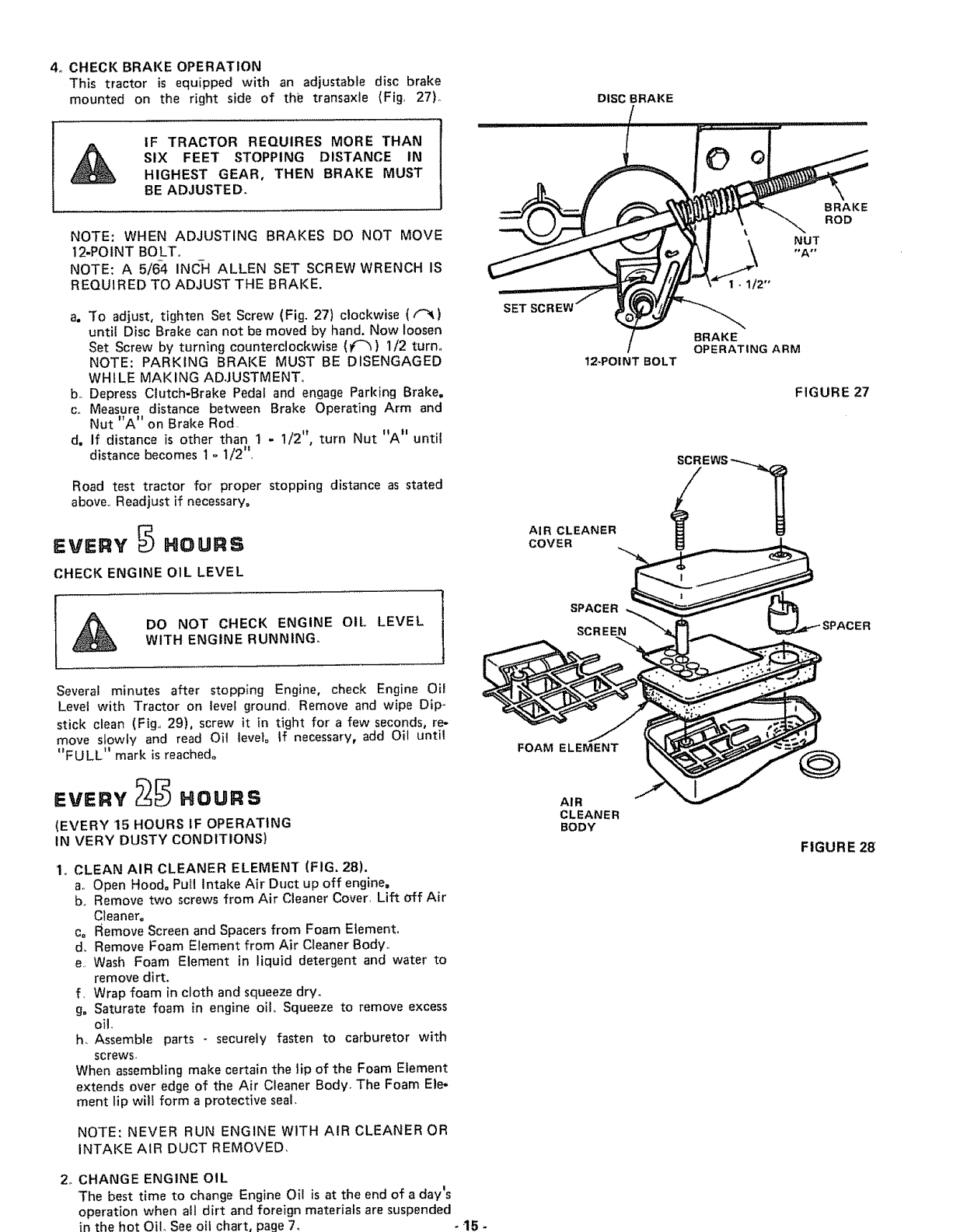
4,, CHECK BRAKE OPERATION
This tractor is equipped with an adjustable disc brake
mounted on the right side of the transaxle (Fig, 27). DISC BRAKE
IF TRACTOR REQUIRES MORE THAN
SIX FEET STOPPING DISTANCE IN
HIGHEST GEAR, THEN BRAKE MUST
BE ADJUSTED.
NOTE: WHEN ADJUSTING BRAKES DO NOT MOVE
12-POINT BOLT°
NOTE: A 5/6-4 INCH ALLEN SET SCREW WRENCH IS
REQUIRED TO ADJUST THE BRAKE.
a, To adjust, tighten Set Screw (Fig. 27) clockwise ((-_)
until Disc Brake can not be moved by hand. Now loosen
Set Screw by turning counterclockwise (_) I/2 turn.
NOTE: PARKING BRAKE MUST BE DISENGAGED
WHI LE MAK ING ADJUSTMENT.
b. Depress Clutch-Brake Pedal and engage Parking Brake.
co Measure distance between Brake Operating Arm and
Nut "A" on Brake Rod
d. If distance is other than 1 - 1/2", turn Nut "A" until
distance becomes i °1/2"
Road test tractor for proper stopping distance as stated
above Readjust if necessary°
EVERY _ HOURS
CHECK ENGINE OIL LEVEL
DO NOT CHECK ENGINE OIL LEVEL
WITH ENGINE RUNNING.
Several minutes after stopping Engine, check Engine Oil
Level with Tractor on level ground Remove and wipe Dip*
stick clean (Fig,, 29), screw it in tight for a few seconds, re-
move slowly and read Oil levet° If necessary, add Oil until
"FULL" mark is reached.
EVE.V25 .OU.S
(EVERY 15 HOURS IF OPERATING
IN VERY DUSTY CONDITIONS)
1. CLEAN AIR CLEANER ELEMENT (FIG, 28).
a, Open Hood. Pull intake Air Duct up off engine,
b Remove two screws from Air Cleaner Cover Lift off Air
Cleanero
c= Remove Screen and Spacers from Foam Element.
d. Remove Foam Element from Air Cleaner Body,,
e Wash Foam Element in liquid detergent and water to
remove dirt.
f Wrap foam in cloth and squeeze dry.
g= Saturate foam in engine Oilo Squeeze to remove excess
oil,
h, Assemble parts - securely fasten to carburetor with
screws,
When assembling make certain the lip of the Foam Element
extends over edge of the Air Cleaner Body° The Foam Ele-
ment lip will form a protective seal.
NOTE: NEVER RUN ENGINE WITH AIR CLEANER OR
INTAKE AIR DUCT REMOVED.
2o CHANGE ENGINE OIL
The best time to change Engine Oil is at the end of a day's
operation when all dirt and foreign materials are suspended
in the hot Oil. See oil chart, page 7o -15-
12-POINT BOLT
AIR CLEANER
COVER
SPACER
SCREEN
FOAM ELEMENT
AIR
CLEANER
BODY
BRAKE
ROD
NUT
1 - 1/2"
BRAKE
OPERATING ARM
FIGURE 27
FIGURE 28

INTAKE
AIR Ev .vB@.ouns
1, CLEAN ENGINE COOLING FINS
Keep Engine Cooling Fins free of dust, dirt and oil to pre-
vent Engine damage from overheating.
a. Pull up to remove !ntake Air Duct (Fig, 29).
b_ Remove four Bolts from blower housing,,
c. Remove Screws from Starter Housing,
d, Puft Oil Filler!Dipstick out of crankcase if clearance is
required, Cover opening to prevent entry of dirt.
eo Pull blower housing up and away from starter.
NOTE: LEAVE AIR CLEANER IN PLACE TO PRE-
VENT DEBRIS FROM GETTING iNTO CARBURE-
TORo
f. Use compressed air or stiff bristle brush to thoroughly
clean Engine Fins.
SCREWS
OIL FILLER
DIPSTICK
STA
HOUSING
FIGURE 29
ENGINE FINS
WEAR SAFETY GLASSES IF USING COM-
PRESSED AIR.
g. To reassemble, reverse above procedure..
2o MUFFLER
Do not operate the tractor without a Muffler or tamper
with the exhaust system,
DO NOT TOUCH HOT MUFFLERS,
CYLINDERS OR FINS AS CONTACT
MAY CAUSE BURNS,
FIGURE 30
SPARK PLUI
FEELER
GAUGE
Periodically clean the muffler area to prevent grass, dirt
and combustible material from accumulating= Damaged
Mufflers or spark arreste[s could create a fire hazard. In-
spect periodically and replace if necessary. If your engine
is equipped with a spark arrester screen assembly, remove
every 50 hours for cleaning and inspection. Replace if
damaged° '
The Spark Plug should be changed every !00 hours of opera-
tion, or at the beginning of each mowing season. To remove
the Spark Ptug a Deep Well 13/16" Socket is required Set
Spark Plug gap at 030 inch (Fig. 30),
16-

Ew.v
REPLACE AIR CLEANER ELEMENT
CARBURETOR ADJUSTMENT (FIGo 31)
Never attempt to change maximum engine speed, This is
preset at the factory and should only be changed by a quali-
fied service technician who has the necessary equipment. CAU-
TION: BEFORE ANY ENGINE ADJUSTMENT, MAKE
SURE AIR CLEANER tS CLEAN., SEE PAGE 16, Remove
Air Cleaner Assembly.,
1,, HIGH SPEED SETTING
a. With engine off, place Throttle Control in "FAST" posi-
tiono
b_ Loosen Clamp Screw., Adjust Throttle Cable untitl holes
"A" are aligned in Governor Control Plate and Slide
Plate.
co Tighten Clamp Screw.
2o HIGH SPEED MIXTURE
a, Turn High Speed Mixture Screw clockwise (f_) closing
finger tight ONLY, and then turn counterclockwise (I,"_)
1 - 1/2 turns (Fig. 31)o
NOTE: VALVES MAY BE DAMAGED BY TURNING
THEM TOO FAR°
b. Start Engine and altow to warm for five minutes_ Make
final adjustments with Engine running and Gear Shift
Lever in "NEUTRAL" position°
c, With Throttle Control Lever in "FAST" position, turn
Higt_ Speed Mixture Screw counterclockwise (t'_) un-
til engine runs "rough" then turn clockwise (t_)until
engine begins to miss. Turn Screw to a point midway
between these positions°
3, IDLE MIXTURE
ao With Throttle Control Lever in "SLOW" position, hold
Throttle Lever so that Idle Stop Screw is against Carbur-
etor, turn Idle Mixture Screw counterclockwise (_) un-
til engine runs "rough" and then turn clockwise (iql) un-
til engine begins to die_, Turn idle Mixture Screw to a
point midway between these positions,
4o IDLE SPEED SETTING
a,. With Throttle Control Lever in "SLOW" position, engine
should idle at 1750 RPM, If engine idles too slow, push
Throttle Control Lever above idle and turn Idle Speed
Screw one turn clockwise ((-_)_ Set Throttle Control
Lever at "SLOW" Repeat until satisfactory idle is at-
tained.
b. If engine idles too fast with Throttle Control Lever in
"SLOW" position, push Throttle Control Lever above
idle and turn Idle Speed Screw one turn counterclock-
wise (f"_), Set Throttle Control Lever at I'SLOW",, Re-
peat until satisfactory idle is attained,
IDLE
MIXTURE
IDLE SCREW
STOP
DO NOT
ADJUST
IDLE
MIXTURE
ADJUSTMENT
HIGH SPEED
MIXTURE SCREW
HOLES "A"
THROTTLE
CABLE,
IOLESPEED
SCREW
PLATE,
GOVERNOR
CONTROL
SLIDE
PLATE
FIGURE 31
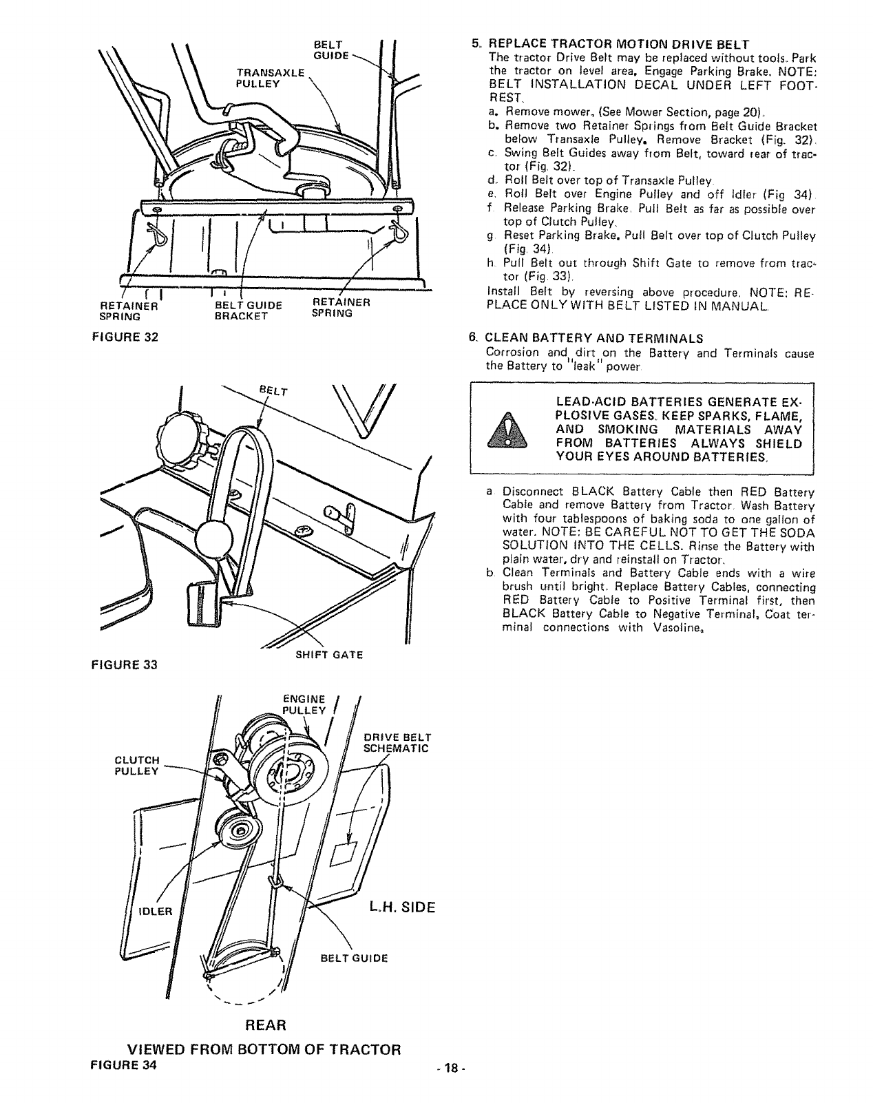
RETAINER
SPRING
FIGURE 32
FIGURE 33
TRANSAXLE
PULLEY
BELT GUIDE
BRACKET
BELT
GUIDE
RETAINER
SPRING
SHIFT GATE
5 ,, REPLACE TRACTOR MOTION DRIVE BELT
The tractor Drive Belt may be reptaced without tools.. Park
the tractor on level area. Engage Parking Brake, NOTE:
BELT INSTALLATION DECAL UNDER LEFT FOOT-
REST.
a. Remove mower. (See Mower Section, page 20).
b. Remove two Retainer Springs from Belt Guide Bracket
below Transaxte Pulley. Remove Bracket (Fig. 32),
c. Swing Belt Guides away from Belt, toward rear of trac-
tor' (Fig, 32)_
d. Roll Belt over top of Transaxle Pulley
e, Roll Belt over Engine Pulley and off Idler (Fig 34)
f Release Parking Brake, Pull Belt as far as possible over'
top of Ctutch Puitey,
g Reset Parking Brake. Put! Belt over top of Clutch Pulley
(Fig, 34}.
h Pull Belt out through Shift Gate to remove from trac_
tot (Fig, 33)r
Install Belt by reversing above procedure, NOTE: RE-
PLACE ONLY WITH BELT LISTED iN MANUAL,
6. CLEAN BATTERY AND TERMINALS
Corrosion and dirt on the Battery and Terminals cause
the Battery to ='leak" power
LEAD-ACID BATTERIES GENERATE EX-
PLOSIVE GASES_ KEEP SPARKS, FLAME,
AND SMOKING MATERIALS AWAY
FROM BATTERIES ALWAYS SHIELD
YOUR EYES AROUND BATTERIES,
a Disconnect BLACK Battery Cable then RED Battery
Cable and remove Battery from Tractor. Wash Battery
with four tablespoons of baking soda to one gallon of
water. NOTE: BE CAREFUL NOT TO GET THE SODA
SOLUTION INTO THE CELLS. Rinse the Battery with
plain water, dry and reinstall on Tractor.
b. Clean Terminals and Battery Cable ends with awire
brush until bright,. Replace Battery Cables, connecting
RED Battery Cable to Positive Terminal first, then
BLACK Battery Cable to Negative Terminal. Coat ter-
minal connections with Vasoline_
CLUTCH
PULLEY
ENGINE
PULLEY /
DRIVE BELT
SCHEMATIC
LH. SIDE
BELT GUIDE
REAR
VIEWED FROM BOTTOM OF TRACTOR
FIGURE 34 - 18-

7, TIRE CARE
a, Maintain tire pressure in front tires at 14 PS! and rear
tires at 12 PSI,
b Keep tires free of gasoline, oil, or insect control chemi-
cals which can destroy rubber
c, Avoid stumps, stones, deep ruts and other hazards that
may cause tire damage,
d. Removing front wheet for tire repair (Fig. 35),
-- Block up front axle securely, Pull off Dust Cap,
-- Remove Klip Ring and Washer and remove wheelo
-- Repair tire and reassembJe. Replace Washer, snap
KtIp Ring securely in axle groove, Replace Dust Cap°
e., Removing rear wheel for tire repair (Fig, 36)°
-- Block up rear axle securely. Pull off Dust Cap_
-- Remove E-Ring and Washers (I to 3 as required) and
remove wheel
-- Repair tire and reassemble° Replace Square Key in
Axle Shaft.
-- Replace Washers, E-Ring and Dust Cap,
KLIP RING
DUST
CAP
FIGURE 35
WHEN MOUNTING TIRES, UNLESS
BEADS ARE SEATED, OVER INFLATION
CAN CAUSE AN EXPLOSION,
8. FINISH
Keep tractor finish and seat free of gasoline, oit, insect
chemicals or battery electrolyte Protect painted surfaces
with automotive type wax
DUST
CAP
SQUARE
KEY
E.RING
WA S H E F
FIGURE 36
-19-
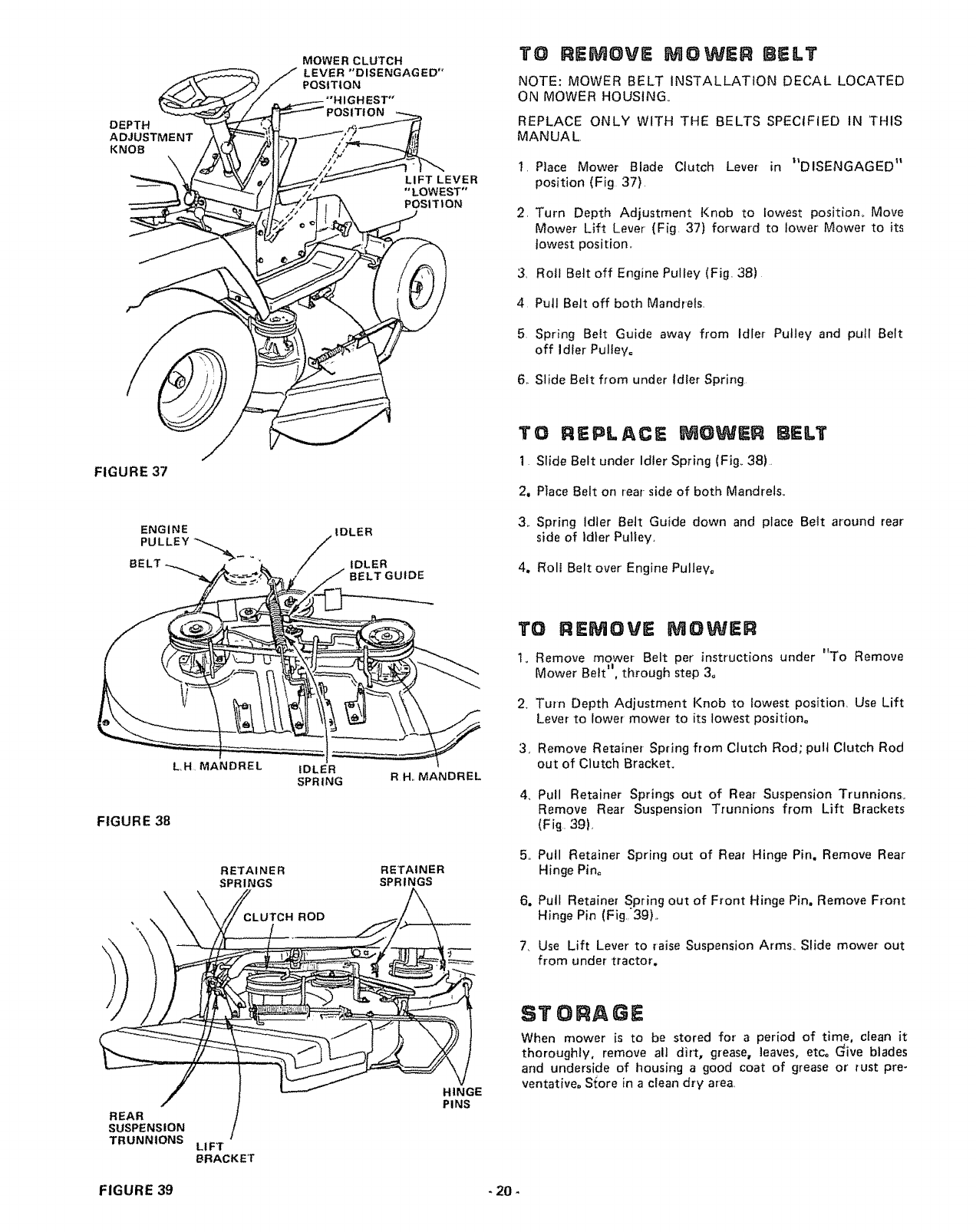
DEPTH
ADJUSTME NT
KNOB \
MOWER CLUTCH
LEVER "'DISENGAGED"
POSITION
"'HIGHEST"
ITION
LIFT LEVER
"LOWEST"
POSI T tON
TO REMOVE MOWER BELT
NOTE: MOWER BELT INSTALLATION DECAL LOCATED
ON MOWER HOUSING.
REPLACE ONLY WITH THE BELTS SPECIFIED IN THIS
MANUAL,
,
3,
4
Place Mower Blade Clutch Lever in _DISENGAGED _t
position (Fig 37)
Turn Depth Adjustment Knob to Lowest position,. Move
Mower Lift Lever (Fig. 37) forward to lower' Mower to its
lowest position,,
Rotl Belt off Engine Pulley (Fig. 38)
Pull Belt off both Mandrels,
5 Spring Belt Guide away from Idler Pulley and pull Belt
off Idler Pulley°
6. Slide Belt from under Idler Spring
FIGURE 37
ENGINE
PULLEY IDLER
IDLER
BELT GUlDE
TO REPLACE MOWER BELT
1Slide Belt under Idler Spring (Fig_ 38)_
2, Place Belt on rear side of both Mandrels.
3. Spring Idler Belt Guide down and place Bett around rear
side of Idler Pulley.
4. Roll Belt over Engine Pulley,
FIGURE 38
L,H, MANDREL IDLER
SPRING
RETAINER
SPRINGS
RH,, MANDREL
RETAINER
SPRINGS
TO REMOVE MOWER
1. Remove mower Belt per' instruct{ons under "To Remove
Mower Belt j', through step 3=
2. Turn Depth Adjustment Knob to lowest position, Use Lift
Lever to lower' mower to its lowest position°
3, Remove Retainer Spring from Clutch Rod; putt Clutch Rod
out of Clutch Bracket.
4 Pull Retainer Springs out of Rear Suspension Trunnionso
Remove Rear Suspension Trunnions from Lift Brackets
(Fig. 39),
5. Putl Retainer Spring out of Rear Hinge Pin. Remove Rear
Hinge Pin°
6. Pull Retainer Spring out of Front Hinge Pin, Remove Front
Hinge Pin (Fig,'39L
7. Use Lift Lever to raise Suspension Arms_ Slide mower out
from under tractor.
/
REAR
SUSPENSION
TRUNNtONS LIFT
BRACKET
HINGE
PINS
STORAGE
When mower is to be stored for a period of time. cfean it
thoroughly, remove all dirt, grease, leaves, etc, Give blades
and underside of housing a good coat of grease or rust pre-
ventat{veo S_ore in a clean dry area.
FIGURE 39 - 20 -
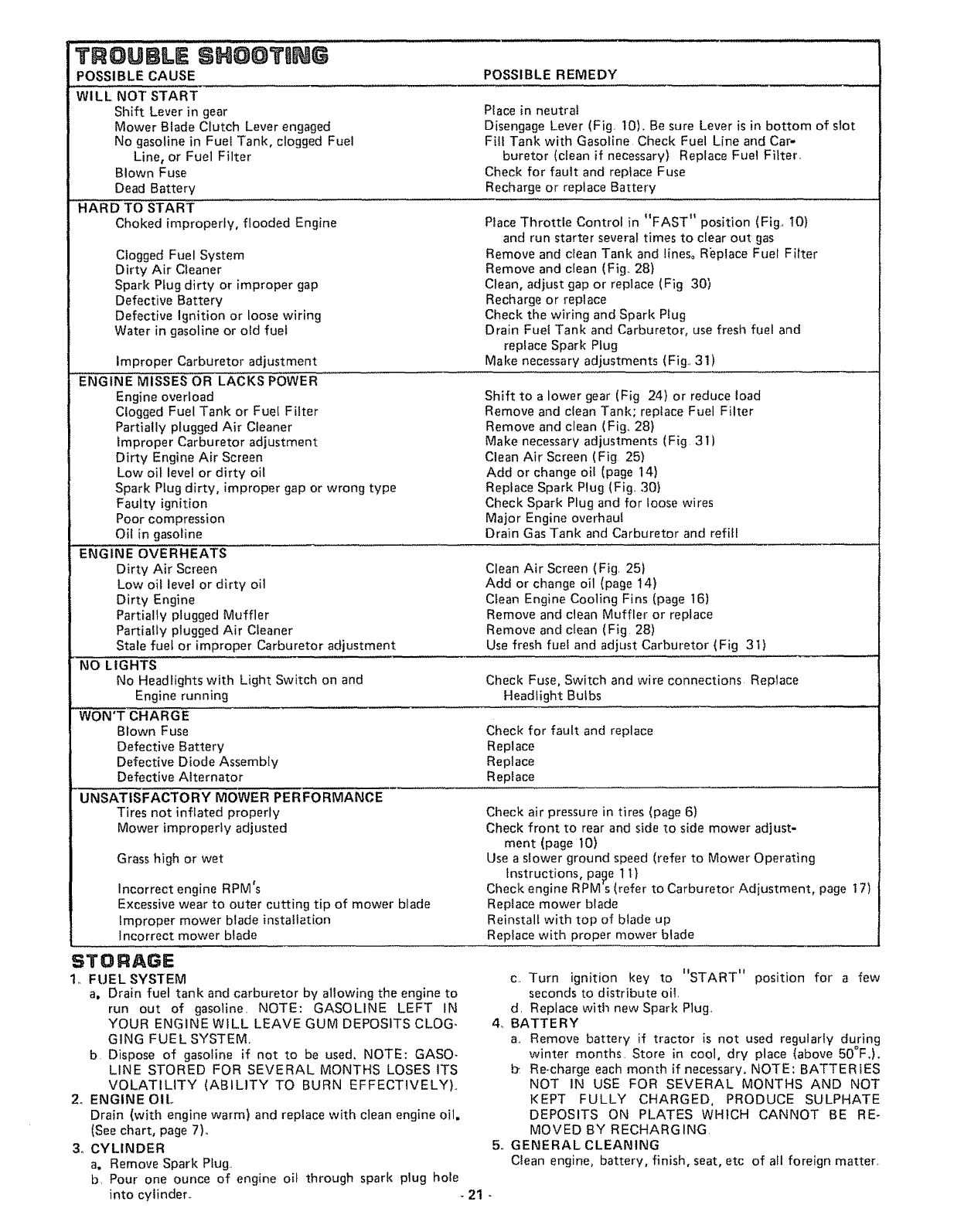
TROU,LESNOOT,NG
POSSIBLE CAUSE POSSIBLE REMEDY
WILL NOT START
Shift Lever in gear
Mower Blade CIutch Lever engaged
No gasoline in Fuel Tank, clogged Fuel
Line, or Fuel Filter
Blown Fuse
Dead Battery
HARD TO START
Choked improperly, flooded Engine
Clogged Fuel System
Dirty Air Cleaner
Spark Plug dirty or improper gap
Defective Battery
Defective Ignition or loose wiring
Water in gasoline or old fuel
Improper Carburetor adjustment
ENGINE MISSES OR LACKS POWER
Engine overload
Clogged Fuel Tank or Fuel Filter
Partially plugged Air Cleaner
improper Carburetor adjustment
Dirty Engine Air Screen
Low oil level or dirty oil
Spark Plug dirty, improper gap or wrong type
Faulty ignition
Poor compression
Oil in gasoline
ENGINE OVERHEATS
Dirty Air Screen
Low oit level or dirty oil
Dirty Engine
Partially plugged Muffler
Partially plugged Air Cleaner
Stale fuel or improper Carburetor adjustment
NO LIGHTS
No Headlights with Light Switch on and
Place in neutrai
Disengage Lever (Fig. 10). Be sure Lever is in bottom of slot
Fi{I Tank with Gasoline Check Fuel Line and Car-
buretor (clean if necessary) Replace Fuel Fitter.
Check for fault and replace Fuse
Recharge or replace Battery
Place Throttle Control in "FAST" position (Fig., 10)
and run starter several times to clear out gas
Remove and clean Tank and lines° Replace Fuel Filter
Remove and clean (Fig.. 28)
Clean, adjust gap or replace (Fig 30)
Recharge or replace
Check the wiring and Spark Plug
Drain Fuel Tank and Carburetor, use fresh fuel and
replace Spark Pfug
Make necessary adjustments (F ig. 31 )
Shift to a lower gear (Fig 24) or reduce toad
Remove and clean Tan{<; replace Fuel Filter
Remove and clean (Fig. 28)
Make necessary adjustments (Fig 31)
Clean Air Screen (Fig 25)
Add or change oil (page 14)
Replace Spark Plug (Fig. 30)
Check Spark Plug and for loose wires
Major Engine overhaul
Drain Gas Tank and Carburetor and refitl
Engine running
WON'T CHARGE
Blown Fuse
Defective Battery
Defective Diode Assembly
Defective Alternator
Clean Air Screen (Fig. 25)
Add or change oil (page t4)
Ctean Engine Cooling Fins (page 16)
Remove and clean Muffler or replace
Remove and clean (Fig. 28)
Use fresh fuel and adjust Carburetor (Fig 31)
Check Fuse, Switch and wire connections Replace
Headlight Bulbs
UNSATISFACTORY MOWER PERFORMANCE
Tires not inflated properly
Mower improperly adjusted
Check for fault and replace
Replace
Replace
Replace
Check air pressure in tires (page 6)
Check front to rear and side to side mower adjust-
merit (page 10)
Grass high or wet
Incorrect engine RPM's
Excessive wear to outer cutting tip of mower blade
improper mower blade installation
Incorrect mower blade
Use a slower ground speed (refer to Mower Operating
Instructions, pacje 1 I}
Check engine RPM's (refer to Carburetor Adiustment, page 17)
Replace mower blade
Reinstall with top of blade up
Replace with proper mower blade
STORAGE
1. FUEL SYSTEM
a, Drain fuel tank and carburetor by allowing the engine to
run out of gasoline. NOTE: GASOLINE LEFT IN
YOUR ENGINE WILL LEAVE GUM DEPOSITS CLOG-
GING FUEL SYSTEM.
b Dispose of gasofine if not to be used. NOTE: GASO-
LINE STORED FOR SEVERAL MONTHS LOSES ITS
VOLATILITY (ABILITY TO BURN EFFECTIVELY)..
2o ENGINE OIL
Drain (with engine warm) and replace with clean engine oil.
(See chart, page 7).
3o CYLINDER
a. Remove Spark Plug..
b. Pour one ounce of engine oit through spark plug hole
into cyiindero
c.. Turn ignition key to "START" position for a few
seconds to distribute oil.
d_ Replace with new Spark Plug.
4. BATTERY
a.. Remove battery if tractor is not used regularly during
winter months_ Store in cool, dry place (above 50OF.).
Re-charge each month if necessary. NOTE: BATTERIES
NOT IN USE FOR SEVERAL MONTHS AND NOT
KEPT FULLY CHARGED, PRODUCE SULPHATE
DEPOSITS ON PLATES WHICH CANNOT BE RE-
MOVED BY RECHARGING
5o GENERAL CLEANING
Clean engine, battery, finish, seat, etc of all foreign matter,
-21 -

LUBRICATIONCHART
(9
AXLE PIVOT (_
SPINDLE (_
(_) FRONT WHEEL
BEARING
(_TIE ROD
_ LUTCH/BRAKE
PIVOT
(_ ATTACHM E
LIFT ARM
#
FRONT WHEEL
BEARING (_
ROD (_)
CLUTCH PIVOT (_
/BRAKE (_
PIVOT
HMENT LIFT ARM 1_)
MOWER CLUTCH
PIVOT (_
(_SAE 30 MOTOR OIL
(_ GENERAL PURPOSE GREASE
SERVICE RIECOgB
FILL IN DATES
AS YOU COMPLETE
REGULAR SERVICE
SERVICE DATES
Check Engine Oil ,L,evel .... _ I
Change Engine Oil (see chart, page 7) _1_
Lubricate Pivot Points Q and @ .... _ .........
Check Brake Operation
..... '.... ;,,_ : ....... :...... : i m i i _ ....... :
Clean Air Screen and Air' Intake Duct
Clean Air Cleaner Element _ : " _....
Replace Air Cleaner......Element _ I
.Clean Engine Cooling Fins ......... ........
Replace Spark Plug
Check Batte.[y..Levet ................. _!
Check Tire Pressure
Replace Fuel Filter .....
-22--

SCHEMATIC
11 H°P, 38" RIDING LAWN TRACTOR--MODEL NUMBER 917,255732
RED
12V
+ -
oltllo BLACK
RED
RED
30 AMP
IGNITION SWITCH
STD365402
POSITION CIRCUIT
OFF M-G
ON B-L
START B-S
O
%STARTER
%
NEUTRAL ATTACH
WHITE--_C_ _ WHITE
Of---'---_tNTER'K SW ,NTER'K SW SOLENOID%
S%
IGNITION C'
SWITCH M
B
BLACK
'" MAGNETRON
IGNITION
SPAR K PLUG
_[_/ RECTIFIER CHARGING
IRED.......
(DIODE) COIL
3AMP&, 10 VAC (MIN.)
ORANGE
_\ BLACK .....
@MAX, R,P.Mo BATTERY IN LINE
LIGHT
SWITCH
BROWN
BROWN BLA'
WIRING INSULATED CLIPS
NOTE: IF WIRING INSULATED CLIPS
AND CABLE TIESWERE REMOVED FOR
SERVICING OF UNIT, THEY SHOULD
BE REPLACED TO PROPERLY SECURE
YOURWIRING
CHASSIS
GROUND
-23-

REPAIR PARTS
11 H.P. 38" RIDING LAWN TRACTOR--MODEL NUMBER 917.255732
ELECTR ICAL
910
17
3O
29
2O
11
18

REPAIIR PARTS
ELECTRICAL
11 H.P. 38" RIDING LAWN TRACTOR--MODEL NUMBER 917.255732
KEY
NO.
1
2
3
4
5
6
7
8
9
t0
1t
12
13
14
15
16
PART DESCRIPTION KEY PART DESCRIPTION
NO. NO. NO.
7662J Bulb, LIght ! 7
105386X Harness, Light Socket !8
!06480X Harness, tgmtIon 19
STD365410 Key Set 20
105381X Switch, Light 21
104445X Sw_tch, ]nterlock 22
3258J Nut, Hex 5/8- 32 23
11151000 Washer, Lock, Int. Tooth, 5/8 24
STD365402 Switch, Igmtlon 25
STD380300 *Fuse, 30 Amp. 26
STD551125 *Washer, Lock, !/4 27
STD541225 *Nut, Hex Jam 1/4- 20 28
STD522505 *Bolt, Hex, 1/4 - 20 x 1/2 Gr. 5
73510400 Nut, Keps 1/4 - 20 29
4559J Cable Assembly 30
11050400 Washer Lock, Ext. Tooth, t/4 31
32
719J Cover, Terminal
5114J Cable, Battery
105737X Switch, Interlock
2033J Cable, Battery
STD522507 *Bolt, Hex, 1/4- 20 x 3/4
STD551025 *Washer 9/32 x 5/8 x 16 Ga.
STD541025 *Nut. Hex 1/4 - 20
t04923X Battery, 12V., Sears
105371X Terminal Guard
STD541625 *Wing Nut 1/4 -20
11030400
72240460
2008J
106552X
I06580X
7!92J
101539X
106738X
Int./Ext, Tooth Lockwasher 1/4
Battery 8oit (Bolt -Carriage, Rd° Hd.
Sq. Neck 1/4 - 20 x 7 - 1/2)
Solenoid
Cover - Cable, 9"
Kit, Replacement Fuseholder
Cable Tie
Sheet - Instruction, Tractor 15° Slope
Owners Manual
*STANDARD HARDWARE--PURCHASE LOCALLY
A B
@11_) 12 13
@16

REPA|R PARTS
ENCLOSURE
1! H.P. 38"' RIDING LAWN TRACTOR--MODEL NUMBER 917.255732
39
48 53
16
55
4O
36
26
2O
38

REPAaR PARTS
ENCLOSURE
11 H.P. 38" RIDING LAWN TRACTOR--MODEL NUMBER 917.255732
1
",4
i
KEY
NO.
t
2
4
5
6
7
8
9
10
11
12
t3
t4
16
17
18
19
20
21
22
23
24
25
26
27
28
29
30
31
32
PART
NO. DESCRIPTION KEY PART DESCRIPTION
NO. NO.
105873X
17490612
17490616
105513X
105529X
73680500
105512X
105514X
105274X
19132012
STD523707
73680600
17490608
105753x
105465X
105464X
Seat
Screw, Hex Washer Thdo R01t 3/8 -
16 x 3/4 Type TT
Screw, Hex Washer Thd. Rolling
5/8 • 16 x !
Bracket. Pivot, Seat
Bolt, Shoulder, 5/16 - 18
Nut, Lock. 5/16 * 18
Spring - Compression
Clamp, Spring
Fender
Washer_ 13/32 x 1 -1/4 x I2 Ga.
• Bolt, Hex, 3/8- 16 x 3/4
Nut, Lock 3/8 - 16
Screw, Hex Washer Thd. Roll 3/8
t6 x 1/2
Bracket, Fender
Footrest, L.H.
Footrest, R.H,
STD533707 *Bolt. Cart. 3/8 - 16 x 3/4
105466X Pad, Footrest
105600X Bracket, Pivot, GriII, R.H.
105602X Bracket, Pivot, Grill L.H.
STD551125 *Washer. Lock, 1/4
STD541025 *Nut, Hex, I/4,20
1056t5X
105614X
105776X
105777X
11030400
105268X
!05685X
STD551025
t05797X
Lens, L.H.
Lens, R.H.
Spacer, .28 x .75 x.20
Spacer, °28 x .75 x .46
Washer, Lock, int. Ext. Tooth, I/4
Bezel
Strap Assembly, Grill
*Washer, 9/32 x 5/8 x t6 Ga.
Hinge, Hood, L.H.
A B C D F
"_ 2 _ 5 _) tl _13 (_ 18
Q 6 G 12 @ 12
33 105792X Hinge, Hood, R,H.
34 105682X Hood Assembly
35 105678X Grill Assembtv
36 !05604X Bracket, Frame, Pivot, R,H,
37 105606X Bracket, Frame, Pivot. L.H,
38 t05683X Side Panel. R.H.
39 105684X Side Panet, L.H.
40 105666X Chassis Assembly
41 102481X Drawbar
42 105516X Pan - Seat
45 105372X Tray, Battery
46 105687X Tube oPlastic
47 6999R Clamp Hose
48 105801X Decal - Reflective, Rear
49 t05802X Decal, Stripe, L.H.
50 105803X Decal. Stripe, R.H..
5t t05806X Decal, Grill Craftsman
52 t05807X Decal, Grill, Strtpe
53 4900J Decal, Clutch/Brake
54 105805X Decal. 11 H.Po
55 105809X Decal, 5 Speed 38"
56 105813X Decal.. V-Belt Schematic
57 105774X Clip, Hold Down bL.A
58 74780812 Bolt, Hex 1/2 - 13 x 3/4
59 t0110800 Washer- Lock -Light t/2
60 19171912 Washer !7/32 x 1 -3/16 x 12 Ga,
61 STD523710 *Bolt, Hex 3/8 - t6 x !
63 106301X Guide - Belt, Lower, Eng. Pulley, L.H.
64 t06300X Guide -Belt, Lower, Eng. Putley, R.H.
*STANDARD HARDWARE--PURCHASE LOCALLY
G H J K L M
@22 '_," 28 @ 31 _[_ _ _
O23 _ 23 (5) 22 58 61 3
_) 23 @ 59 @t0
Q 60 @ 12
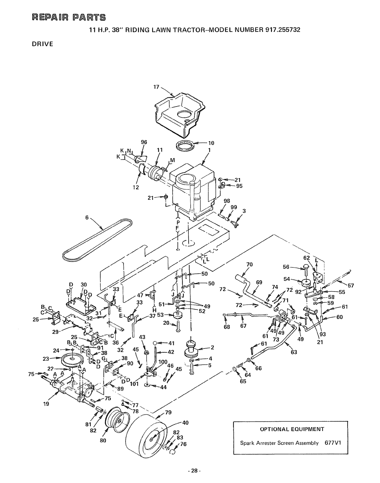
REPAIR
DRIVE
P, TS
1t H.P. 38" RIDING LAWN TRACTOR--MODEL NUMBER 917.255732
12
P !
F
98
3
19
D3O
D
32
43
45
68
7O
69 74
64
65
62
61 93
49 21
63
81
82
8O
82
83
OPTIONAL EQUIPMENT
Spark Arrester Screen Assembly 677Vl
- 28-

REPAaR
DRIVE
PARTS
11 H.P. 38" RIDING LAWN TRACTOR--MODEL NUMBER 917.255732
KEY PART
NO NO
1 I01325N
2 105731X
3 9767H
4 STD551143
5 74770728
6 105732X
10 t06163X
11 101273M
t2 101t59L
13 74780552
14 STD522505
15 17490620
16
17 1062!3X
19 10587_X
20 STD523727
21 73680600
22 STD580025
23 105703X
24 12000028
25 3723J
26 STD523710
27 STD523712
28 17490512
29 105638X
30 I05639X
31 t06188X
32 4921H
33 I06190X
34 STD523107
35 73680500
36 !06294X
37 106189X
38 t05842X
39 STD523707
40 19252516
41 6465R
42 105699X
43 73960500
44 105701X
45 STD5612!0
46 19151216
47 t04777X
48 17490612
DESCRIPTION KEY PART DESCRIPTION
NO. NO
Engine, 11 H.P. Model No. 252707,
Type Noo 0669-01
Putley, Engine
Valve, Drain Oil
*Washer, Lock, 7/16
Bolt, Hex 7/16- 20 x 1 - 3/4
V-Belt, Drive
Foam, Strip
Muffler
Shield, Heat
Bolt, Hex Hd. 5/16- 18 x 3- 1/4
Gr. 5
Bolt, Hex I/4- 20 x I/2 Gr, 5
Screw, Hex Washer Thd° Rolling
3/8- 16 x 1 -1/4
STD551125 *Washer, Lock I/4
Duct, lntake_ Air
Transaxle, 5 Speed, Model No. 4150-6
(See pages 36and 37 for parts
breakdown)
*Bolt, Hex 3/8- !6 x 2- 3/4
Nut, Lock 3/8- t6
* Key, Woodruff
Pulley, Transaxle
Ring, Retainer
Bracket, Transaxle
*Bolt, Hex 3/8 - 16 x 1
*Bolt, Hex 3/8- 16 x 1- 1/4
Screw, Hex Washer Thread Roiling
5/16- 18 x 3/4
Bracket, Support
Support, Battery
Keeper, Belt, L.H.
Retainer, Spring
Clamp
*Bolt, Hex 5/16- 18 x 3/4
Nut, Lock 5/t6- 18
Strap, Locator
Keeper, Belt, R.H,
Strap, Torque, Transaxte
*Bolt, Hex 3/8 16 x 3/4
Washer 25/32 x 1 o.9/16 x 16Ga.
Knob, Shift
Rod, Shift
Nut Lock, Whiz 5/16 -18
Washer- Shift, Plate
*Cotter Pin, 1/8 x 1
Washer 15/32 x 3/4 x 16 Ga
Retainer, Belt
Screw, Hex Washer Thdo Rolling 3/8 -
!6 x 3/4
49
50
51
52
53
54
55
56
57
58
59
6O
6t
62
63
64
65
66
67
68
69
70
71
72
73
74
75
76
77
78
79
8O
8t
82
83
88
89
90
91
92
93
95
96
97
98
99
100
101
19131312 Washer 13/32 x 13)'16 x 12 Ga,
105730X Keeper, Belt, Engine
106191X Keeper, Belt
4470J Spacer
4859J Idler, Flat
106298X Pulley, Idler
t05705X BeHcrank Assembly (lnc. Key Noo 89)
STD523715 *Bolt, Hex 3/8- 16 x 1 _ 1/2
t05709X Spring, Return, Clutch
207J Washer, Hardened
12000039 Ring, Klip
I057t0X Link, Clutch
760204 t2 Pin, Cotter 1/8 x 3/4
105724X Bracket, Clutch
105752X Rod, Brake
105757X Spring, Rod, Brake
STD551037 "Washer 13/32 x t3/16 x 16 Gao
73930600 Nut, Lock 3/8- 16
105758X Rod, Brake, Parking
71673 Cap- Ptunger
105720X Shaft, Foot Pedal
8883R Cover -Pedal
19252016 Washer 25/32 x 1 - 1/4 x 16 Ga
STD571810 *Pin, Roll, 3/16 x 1
105733X Arm, Brake
STD580025 * Key, Woodruff
STD580105 *Key, Square 3/16 x 2
104767X Cap, Hub, Rear
59192 Cap, Valve
65139 Stem, Valve
106268X Tire, Rear o18 x 950 x 8
7152J Tube, Tire (not furnished with tractor)
I06108X Rim Assembly, Rear
105702X Spacer, Split
19252016 Washer 25/32 x 1 -1/4 x t6 Gao
12000001 E-Ring
STD533707 *Bolt, Carriage 3/8 - 16 x 3/4
106319X Spring- Ext
106320X Bracket o Spring
106157X Plate _Strap, Torque
105706X Bearing
106499X Retainer- Belt
2751R Clip -Insulated
t06407X Deflector, Muffler
17390806 Screw, Hex Washer No. 8: 32 x 3/8
13280312 Nipple, Pipe, 3/8 NPT x I - 1/2
13300300 Coupling, Pipe Stdo 3/8- 18 NPT
105700X Spring
I06630X P_ate, Shift
*STANDARD HARDWARE-PURCHASE LOCALLY
AB C D EF G H J KL M
- 29-
NP

RE_IR PARTS
11 H.P. 38" RIDING LAWN TRACTOR-MODEL NUMBER 917.255732
STEERING AND FRONT AXLE
22
55
56 57
53
55
63
62 61 65
67
,68
- 30 -

REPAnR PARTS
11 H.P. 38" RIDING LAWN TRACTOR--MODEL NUMBER 917.255732
STEERING AND FRONT AXLE
KEY PART DESCRIPTION KEY PART DESCRIPTION
NO NO NO NQ
1 105620X Dash 36
2 74180512 Screw- Truss Hd. Cross Recess 37
5/16 - 18 x 3/4 38
3 73680500 Nut- Lock 5/16- 18 39
4 105800X Decal - Dash Panel 40
5 105837X Control - Throttle Cable 41
6 61159 Knob 42
7 17720408 Screw -Hex Thread Cut. 1/4 -20 x 1/2 43
8 106198X Deca! -Dash Lower 44
9 105621X Dash - Lower 45
10 106199X Decal-Caution 46
11 17!90508 Screw- Hex Washer Hd. Thread Cut. 47
5/16- 18 x 1 -I/2 48
12 105843X Saddle 49
13 17490608 Screw- Hex Washer Hd, Thread
Rolling 3/8- 16 x 1/2 50
15 2751R Clip 5!
16 105810X Decal - Cap, Steering Wheel 52
17 1007 IOL Insert- Steering Wheel 53
18 STD54t350 * Nut- Hex Jam 1/2- 20 54
t9 100712K Washer 55
20 100713N Wheel - Steering 56
21 !00711 L Adapter- Steering Wheel 57
22 t05647X Sleeve - Steering 58
23 105643X Shaft- Steering -Upper 59
24 STD523712 * Bolt - Hex 3/8- 16 x t - 1/4 60
25 73680600 Nut- Lock 3/8 - 16 61
26 17431008 Screw-Hex Self Tap° Noo 10. 16x 1/2 62
27 105646X Bracket- Sleeve, Steering 63
28 1554J Bushing -Steering 64
29 102531X Bracket- Steering 65
30 102530X Bearing- Flange 66
31 17490612 Screw- Hex Washer Thread Rolling
3/8 o 16 x 3/4 Type TT 67
32 6266H Bearing- Thrust 68
33 4301J Gear - Sector 69
34 106126X Key- Woodruff 70
35 12000029 Klip Ring 71
73
19212016 Washer 21/32 x 1- 1/4 x 16 Ga,
105641X Shaft - Steering _ Lower
2882J Pin -Drive 3/16 x 1
74580 Spacer .627 x .88 x _695
7t 208 Bushing
106127X Rod -Steering
t05663X Support - Saddle - Rear
105664X Support- Saddle -Front
74761064 Bolt - Hex 5/8- 1t x 4
105669X Axle- Front
105725X Spacer -Axle
105726X Bearing. Axle
73901000 Nut- Lock, Flange 5/8 - 11
17490508 Screw- Hex Washer Thread Rolling
5/16.18 x 1/2 Type TT
12000029 Klip Ring
3366R Bearing
105715X Rod - Tie
102792X Bushing
19131414 Washer 13/32 x 7/8 x 14 Gao
STD561210 * Pin * Cotter 1/8 x 1
STD55t137 *Washer- Lock 3t8
STD54I 137 *Nut- Hex 3/8.24
105727X Link - Drag
105656X Spindle -LH
105654X Spindle- R,H.
278H Fitting* Grease
9040H Bearing- Flange
106732X Rim. 6"- Front
59192 Cap- Valve
65139 Stem - Valve
106222X Tire -j_15 x 600 -6
59904 Tube -Front (not furnished with tractor)
19252016 Washer 25/32 x t -1/4 x t6 Ga
104757X Cap oHub -Front
106184X Screw -Special
4043J Washer
4042J Clip
11050500 Washer, Lock, Exto Tooth, 5/16
*STANDARD HARDWARE--PURCHASE LOCALLY
A B C D
O3
E
25
F G H
_69 _ 2
._73
(_70 e 3
t_Z71
-31_

REPAmR PARTS
11 H.P. 38" RIDING LAWN TRACTOR-MODEL NUMBER 917.255732
LI FT ADJUSTM ENT
20
15 9
16
19
C
13 59
17
59
18
25
26 27
/29 30
E8
22
40
61
T
62
-32 -

REPA ilR PARTS
11 H.P. 38" RIDING LAWN TRACTOR--MODEL NUMBER 917.255732
LI FT ADJUSTM ENT
KEY PART DESCRIPTION KEY PART DESCRIPTION
NO NO NO. NO.
I
2
3
4
5
6
7
8
9
10
11
12
13
14
t5
t6
17
18
19
20
2t
22
23
24
25
26
27
28
106448X Lever, Clutch, Mower 29 2876H Spring
9439M Knob 30 19131016 Washer 13/32 x 5/8 x 16 Ga.
I06451X Bolt, Shoulder 31 10!272K Trunnion, Depth Adjustment
73680600 Nut, Lock, 3/8 - 16 32 19151216 Washer 15/32 x 3/4 x 16 Ga.
106452X Bracket, Switch, interlock 33 12000037 Klip Ring
19171713 Washer 17/32 x 1 - 1/16 x 13 Ga. 34 105754X Shaft, Lift
17021008 Screw, Hex, Tapping, No.. 10 - 24 x 35 105768X Lever, Assembly
1/2 36 105723X Plunger
106447X Support, Lever, Clutch 38 t06019X Grip, Handle
I05965X Cap, Fuel 39 4939M Retainer, Spring
I05738X Tank, Fuel 40 105856X Link, Lift
8547R Line, Fuel 41 106204X Trunnion, Lift
9151R Grommet 42 105855X Link, Lift, Adjustable
6999R Clamp, Hose 43 105862X Arm, Suspension, R..H
17490612 Screw, Hex Washer Thd Rolling 44 105848X Bolt, Shoulder, 3/8 -16
3/8- 16 x 3/4 45 105863X Arm, Suspension, LoHo
105711X Brace 46 106308X Trunnion, Lift, Lower
I05736X Shield, Heat 47 STD541250 *Nut, Hex, 1/2 - 13
105751X Stud, 1/4 Turn 48 9135R Retainer, Spring
t05838X Retainer _ 1/4 Turn 49 19171616 " Washer 17/32 x t x 16 Ga.
t05839X Receptacle _ 1/4 Turn 50 4921H Retainer, Spring
!05619X Panel, Dash, L,H. 51 105864X Bracket, Suspension
105505X Cover, Access 52 106444X Bracket, Bellcrank
1056t8X Panel, Dash, RH. 53 STD523707 *Bolt, Hex 3/8 - 16 x 3/4
19292016 Washer 29/32 x 1 -1/4 x 16 Ga, 54 t06441X Belfcrank Assembly
12000029 Ktip Ring 55 76020412 Pin, Cotter, 1/8 x 3/4
100734K Knob 57 t06446X Rod, Clutch, Primary
STD541237 *Nut, Hex Jam 3/8- 16 58 2751R Clip, Fuel Line
t05686X Rod, Adjust, Lift 59 532OR Clip
76020308 Pin, Cotter 3/32 x 1/2 60 73680800 Locknut I/2- 13
61 105764X Rod Assembly - Lever, Lift
62 105767X Pin - Groove
*STANDARD HARDWARE--PURCHASE LOCALLY
BC D E
®4
33-

REPAtR PARTS
11 H.P, 38" RIDING LAWN TRACTOR--MODEL NUMBER 917.255732
38" MOWER
30
46
CC
60
33
16
L
±
J
56
14
11
15
_34 -

KPAUR
38" MOWER
PARTS
11 H.P. 38" RIDING LAWN TRACTOR--MODEL NUMBER 917.255732
KEY PART
NO, NO.
I 106085X
2 105689X
38417J
47368060O
5 19111216
6 72140505
7 106733X
B 5846R
9 106734X
10 I06735X
11 106736X
12 105814X
13 I05304X
14 105662X
15 105744X
16 9135R
17 105872X
18 I05743X
19 STD523707
20 73680500
21 105659X
22 I05660X
23 STD533!07
24 3713J
25 106295X
26 105850X
27 5224J
28 106461X
29 STD523720
30 I06458X
31 I06283X
32 102403X
33 106513X
34 102669X
35 105891X
36 I00668L
37 17490612
38 17490620
DESCRIPTION KEY PART DESCRIPTION
NO. NO,
V-Belt 39
Housing 40
Runner, R .H.. 41
Nut, Lock, 3/8- 16 42
Washer, 1t/32 x 3/4 x 16 Ga 43
Bolt, Car,., 5/16- 18 x 5/8 r44
Bracket, Deflector t 45
Nut 46
Spring, Deftector 47
Rod ° Hinge 48
Deflector- Shield 49
Decal 50
Cap !52
,53
Link, Parallel i54
Pin - Hinge, Front _155
Spring - Retainer
Stop, Link j56
Pin -Hinge, Rear 57
*Bolt 3/8- 16 x 3/4 58
Nut, Lock 5/16 -18 59
Bracket, Lift, R,H- 60
Bracket, Lift, LH. 61
*Bolt, Carr. 5/!6- t8 x 3/4 62
Instruction - Caution Decal 63
Support, Arm 64
Stop, Deck, Front 65
Decal -Safety Standa_'d 66
Guide, Belt 67
*Bolt 3/8- 16 x 2" 68
Arm, Idler 69
Spacer .875 x309 x.330 70
Pulley, Idler 71
Washer, Wear, 1/!6 72
Keeper, Belt 73
Mandrel Assembly 74
Plate, Support, Mandrel
Screw, Hex Washer Hdo 3/'8- !6 x 3/4
Screw, Hex Washer Hd. 3/8- ;16
x I-1/4
A
(5) 5
20
BCD E G H
(_)20 _ 4(_ 4@20
106453X
76020616
106457X
STD533707
106289X
106288X
105857X
10585tX
106578X
106463X
t06464X
106456X
100672K
100673L
106514X
19111016
74760680
7631J
19131614
72140610
78850
19141614
106634X Blade, 38"
19132012 Washer 13/32 x 1 - 1/4 x 12 Ga.
STD551137 *Washer, Lock, 3/8"
STD632715 *Boit, Hex, 3/8 -24 x 1-1/2 Gr_,5
t06462X Spring, Ext
106445X Rod -Ciutch, Mower
4921H Spring - Retainer
STD560907 *Pin - Cotter, 3/32 x 3/4
Pivot Assembly, Mower
Pin, Cotter, 3/16 x 1
Rod, Brake, Primary
*Bolt, Carr, 3/8- 16 x 3/4
Bracket, Pivot, R.H
Bracket, Pivot, L.H.
Bracket, Susp,, Rear, R.Ho
Bracket, Suspo, Rear, Loll.
Brake Assembly
Rod, Brake, Secondary LH.
Rod, Brake, Secondary, R,H..
Bracket, Brake, Pivot
Spacer, Brake
Bracket, Support
Washer, Wear 3/16
Washer, 11/32 x 5/8 x 16 Ga
Bo_t, 3/8- 16 x 5
Runner, L.H,
Washer 13/32 x 1 x 14 Ga,
Bolt, Car,. 3/8- 16 x t * 1/4
Decal _Warning
Washer 7/16 x ! x 14Ga=
STD551037 *Washer 13/32 x 13/16 x 16 Gao
19141610 Washer 7/16 x I x 10 Ga.
72110606 Bolt, Carriage 3/8 - 16 x 3/4
19132012 Washer 13/32 x 1 - 1/4 x 12 Ga.
106679X Decal - Warning
*STANDARD HARDWARE-PURCHASE LOCALLY
JK L M N
_ 4 _ 4
67
-35-
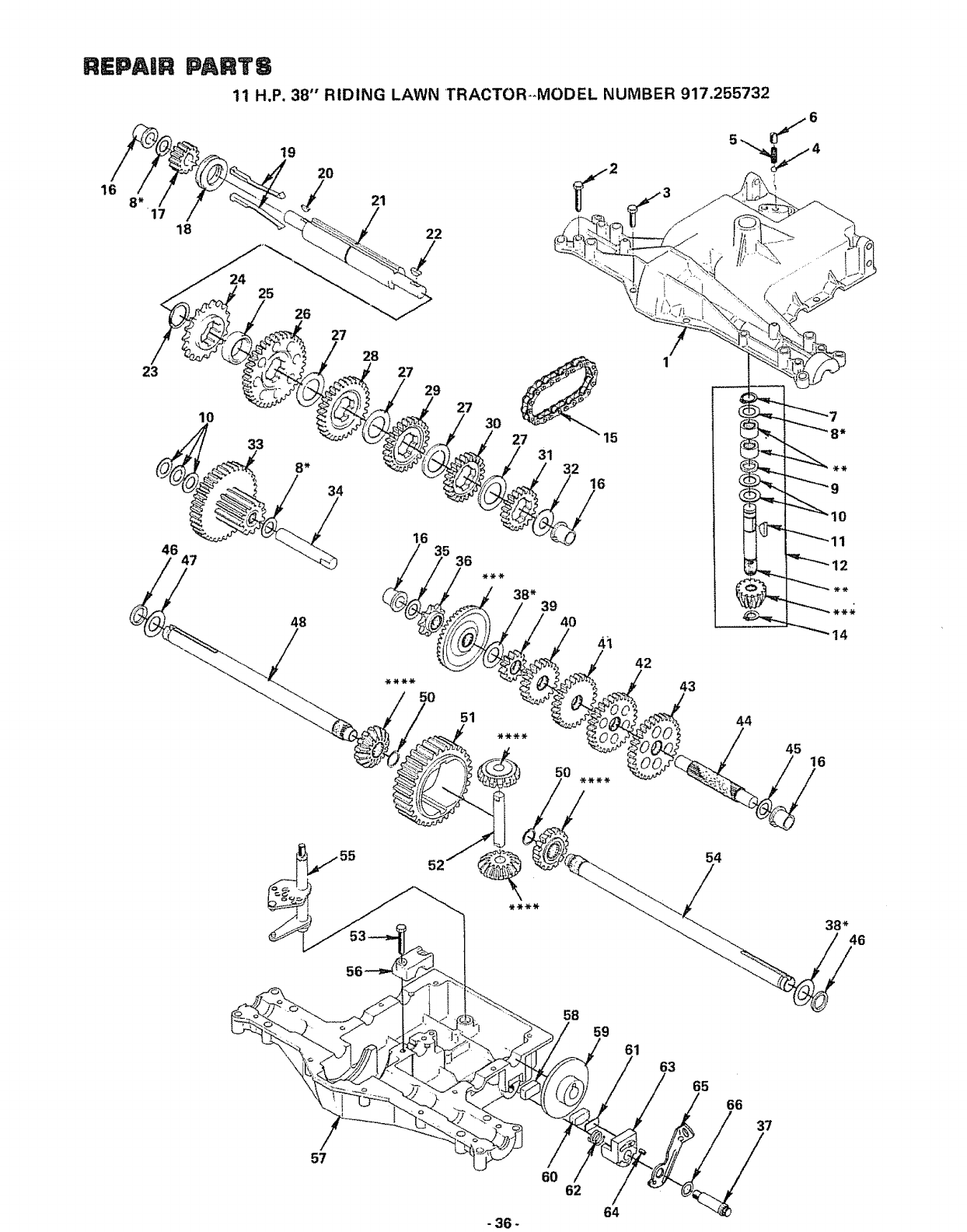
REPAIR PARTS
11 H.P. 38"' RIDING LAWN TRACTOR_MODEL NUMBER 917.255732
16
19
20 21 _2
/
18 22
24 25
26
27
28
23 27
29
10 27
33 27 15
31
8* 32 16
38* 46
/
57
58
59
6O 62
61
63
65
66
37
64
-36 -

REPAUR PARTS
11 H.P° 38" RIDING LAWN TRACTOR--MODEL NUMBER 917.25,5732
KEY PART DESCRIPTION KEY PART DESCRIPTION
NOr NOo NOo NO.
1 105903X
2 2276J
3 2274J
4 68003
5 105904X
6 105905X
7 2267J
8 2233J
8 2232J
8 2231J
8 2230J
8 2229J
8 2228J
8 2227J
8 2226J
8 t05906X
9 6725J
10 2228J
11 2257J
12 106597X
13 106598X
14 105909X
15 105910X
16 10591IX
17 105912X
18 105913X
19 105914X
20 2242J
21 105915X
22 2244J
23 105916X
24 105917X
25 105918X
26 105919X
27 105920X
28 t05921X
29 105922)"
50 ........._:L06_29_
31 105924)
32 105925)
33 105926)
34 I05927X
35 3413J
Housing, Upper
Screw, Tapping, !/4 -20 x 1.31 Lg
Screw, Tapping, 1/4 -20 x °875 Lg.
Ball, Detent
Spring, Detent
Screw, Set
Ring, Retaining
Washer Plain, .632 x Io00 x ..020
Washer Plain, 632 x 1.00 x ,026
Washer Plain, .632 x 1.00 x ..031
Washer Plain, .632 x 1,00 x .036
Washer Plain, .632 x 1.00 x .041
Washer Plain, ..632 x 1.00 x .046
Washer, Plain, .632 x ! .00 x.050
Washer, Plain, 632 x l°00x _060
Washer, Plain, .632 x 1,00 x ..082
O-Ring
Washer, Plain, .632 x 1,00 x ,046
Key, Woodruff, No. 9
Assembly, Kit, Input Shaft & Bevel
Gear
i
Ass yo, Kit, Pinion & Bevel Gear
Ring, Retaining
Chain, 24 Pitches
Bearing, Flange
Gear, Spur, t4T
Collar, Clutch
Key, Clutch
Key, Woodruff, No. 3
Shaft, Intermediate
Key, Woodruff, No. 6t
Ring, Retaining
Sprocket, 18T, Reverse - Clutch
Spacer
Gear, Spur, 37T, 1st - Clutch
Washer, Special
Gear, Spur, 30T, 2nd - Clutch
Gear, Spur, 25T, 3rd - Clutch
._a[,.Sp__.[,_22T, 4th - Clutch
Gear, Spur, 19T, 5th - Clutch
Washer, Plain, .640 x 1.37 x °061
Assembly, Gear, Comb., 12T & 35T
Shaft, Idler
Washer, Plain, 631 x 1,00 x ,010
36 105928X
37 2285J
38 105930X
38 105931X
38 105932X
38 34t7J
38 106097X
38 2264J
38 106098X
38 2265J
38 !06586X
38 106587X
38 106588X
38 2263J
39 105933X
40 105934X
41 106589X
42 106130X
43 105937X
44 105938X
45 2226J
46 2272J
47 2264J
48 t06590X
49 106599X
50 105941X
51 2268J
52 2270J
53 106596X
54 106593X
55 _J_0_594X
56 106595X
57 105945X
58 4175J
59 2278J
60 4170J
61 4169J
62 2280J
63 6723J
64 2281J
65 105946X
66 2284J
Sprocket, 9T, Reverse Drive
Bolt, Shoulder "
Washer, Plain, °758 x 1_12 x .0t5
Washer, Plain, °758 x t.12 x .020
Washer, Plain, .758 x i_ 12 x °025
Washer, Plain, _758 x 1.25 x °020
Washer, Plain, ..758 x 1.25 x .025
Washer, Plain, .758 x 1.25 x .031
Washer, Plain, °758 x 1.25 x °035
Washer, Plain, _758 x 1.25 x ..040
Washer, Plain, .758 x 1.25 x .045
Washer, Plain, .758 x 1.25 x .050
Washer, Plain, .758 x 1,25 x .055
Washer, Plain, .758 x 1,25 x .062
Gear, Spur, 12T, 1st - Drive
Gear, Spur, 20T, 2nd - Drive
Gear, Spur, 25T, 3rd - Drive
Gear, Spur, 28T, 4th - Drive
Gear, Spur, 31T, 5th _ Drive
Shaft, Drive, Splined
Washer, Plain, °640 x I_00 x _060
Seal, Felt
Washer, Plain, .758 x 1.25 x ,031
Axle, LoH_
Ass %, Kit, Miter Gear
Ring, Retaining
Gear, Spur, 32T, Differential
Shaft, Cross
Screw, Tapping, 5/16 - 18 x 1o44 Lg.
Axle, R.H.
Cap, Support
Housing, Lower
Puck, Friction, Inner
Disc, Brake
Puck, Friction, Outer
Spacer
Spring, Compression
Assembly, Jaw, Brake
Screw, Set, No. 8 - 32 x 312
Assembly, Lever, Actuating
Washer, Plain, o510 x ..750 x °006
*USE IN VARIOUS COMBtNATIONSTO MAIN-
TAIN PROPER CLEARANCES
**ORDER KEY NOo 12
***ORDER KEY NOo 13 (CONTAINS PINION &
BEVEL GEAR)
****ORDER KEY NO, 49 (CONTAINS 4 MITER
GEARS, 2 RETAINING RINGS AND SHIM
WASHERS)
37 -

mEpAem PAINTS
11 H.P. 38" RIDING LAWN TRACTOR-_MODEL NUMBER 917.255732
ENGINE+-MODEL NUMBER 252707, TYPE NUMBER 0669+01
CYLINDER BLOCK GROUP
3
46
94
2
52
48
47 50
72
73
95 93
40
39 6O
7O
74
49
69-
71
75
62
98
GASKET
SET
' 105
102
- 38 -

REPAmR PARTS
11 H.P. 38" RIDING LAWN TRACTOR--MODEL NUMBER 917.255732
ENGINE--MODEL NUMBER 252707, TYPE NUMBER 0669_01
CYLINDER BLOCK GROUP
KEY PART DESCRIPTION KEY PART DESCRIPTION
NO. NO, NOo NO.
! 93158 Screw _Blower Hsg Mtg., Sem 65 391406
2 391556 Housing- Btower 66 93394
3 19203 Puller- Flywheel 67 222698
4 395326 Armature Assembly (Less Trigger Coit) 68 392299
5 394970 Trigger Coil 69 261196
6 222561 Cup _Screen Mtgo 70 65906
7220865 Washer- Spring 71 221596
8 92284 Nut- Hex 72 261462
9 93805 Screw* Sam 73 261185
10 222562 Screen- Flush Rotating 74 26828
17 221535 Clamp- Casing 75 93630
!8 93496 Screw - Sam 76 292260
19 93686 Screw ,.Control Brkt_ Mtg. 77 261 t83
20 231039 Spacer- Control 8rkto Mtg 78 212897
21 396199 Plate- Gov. Contol 79 298909
22 261306 Spring- Governor 80 391373
23 26157 Spring. Throttle Adjustment 81 231058
24 91920 Screw., Machine, Fill. Hd_ 8- 32 x 5/8 It 82 93307
25 91920 Screw - Terminal (Fill,, Hd.) 83 93306
26 92791 Washer- Lock- Shakeproof 84 222450
27 66554 Collar- Insulating 85 92613
29 93722 Terminal -Spade 86 231082
30 90576 Nut- Hex 8- 32 87 391733
3! 66068 Washer ,, Insulating
32 299500 Wire* Ground 88 212359
34 93572 Screw 89 93875
35 261609 Link- Governor 90 222299
36 261911 Spring ,.Governor Link 91 92909
38 93381 Screw- Armature Mtg. Sam 92 391775
39 395492 Armature Group
40 221798 Terminal -ignition Cable 93
41 93163 Screw ,.Cylinder Shield Mtg., Sem 94
42 222725 Cover., Cylinder Head
---- 43 298809 Plug- Spark 94
44 89838 Plug ..Spark -Wrench 95
45 66538 Elbow -Spark Plug 95
46 93723 Screw - Cylinder Head 95
47 261463 +Seat- intake Valve 95
48 210940 +Seat- Exhaust Valve 96
49 230655 +Guide - Exhaust Valve
50 212914 Head- Cylinder 96
51 271075 *Gasket - Cylinder Head 96
52 222744 Shield _Cylinder 96
60 396324 Cylinder Assy. (lnc. Key No. 6t) 97
61 391086 Seal - Oil 97
62 231055 Bushing., Gow Crank 97
63 27803 *Gasket- Valve Cover 98
64 280100 Tube - Breather 99
100
101
102
!03
104
105
106
107
t08
109
110
Breather Assembly
Screw- Sere
Key - Flywheel
Crankshaft
Gear- Timing
Spring- intake Valve
Retainer _Intake Valve
Valve- intake
Valve - Exhaust
Spring- Exhaust Valve
Retainer- Exhaust Valve Rotocoil
Rotocoit -Exhaust Valve
Tappet- Valve
Gear - Cam
Pin - Counterweight
Counterweight Assyo(tnc. Key NOR79)
Crank -Governor
Retainer -E-Ring
Cotter oHairpin
Washer -Governor Crank
Bolt - Governor Lever
Nut -Hex 10- 24
Lev,er Assy, -Governor (Inc. Key
No's, 85 & 86}
Link -Counterweight
Screw -Counterweight
Lock - Conno Rod Screw
Screw- Conn oRod
Rod Assy. -Conn. (Inco Key No's,
90& 91)
260924 Lock - Piston Pin
299691 Pin Assy. -Piston -Stdo(Inc. Key
No. 93)
391286 Pin Assy. - Piston °005" O.S,
391780 Ring Set - Piston - Std.
391781 Ring Set Piston _010" OoS.
391782 Ring Set Piston .020:'_ OoSo
391783 Ring Set Piston .030 OoSo
391285 Piston Assyo. Stdo (Inco Key No's.
93 & 95)
391287 Piston Assv _ 010 O.S
391288 Piston Assy.- 020 OoSo
• .*t
391289 Piston Assy.- .030 OoS,
270808 *Gasket- Crankcase Cover 1/64" thick
270915 *Gasket Crankcase Cover .005' _thick
270916 *Gasket Crankcase Covero009 th=ck
391784 Sump- Oil (Inco Key No's. 97 & 99)
291675 Seal - Oil
91084 Plug- Oil Drain
93585 Screw _Sump Mtg. Sere
39341 tGasKetSet
68838 Seal -Filler Tube
280134 Tube - Oil Filler
392067 Fill Group - Oil (inc. Key Nots. 103, 104,
106, !07,108 &109)
222502 Clamp- Oil Filler Tube
93804 Screw - Clamp Mtg
270920 Sea! - Oil Filler Cap
391841 Cap & Dipstick - Oil Filler
391764 Oil Slinger, Gov,, Gear & Bracket Assy.
+Special Tools Required to tnsta}t
* included in Gasket Set - Part No,,393411
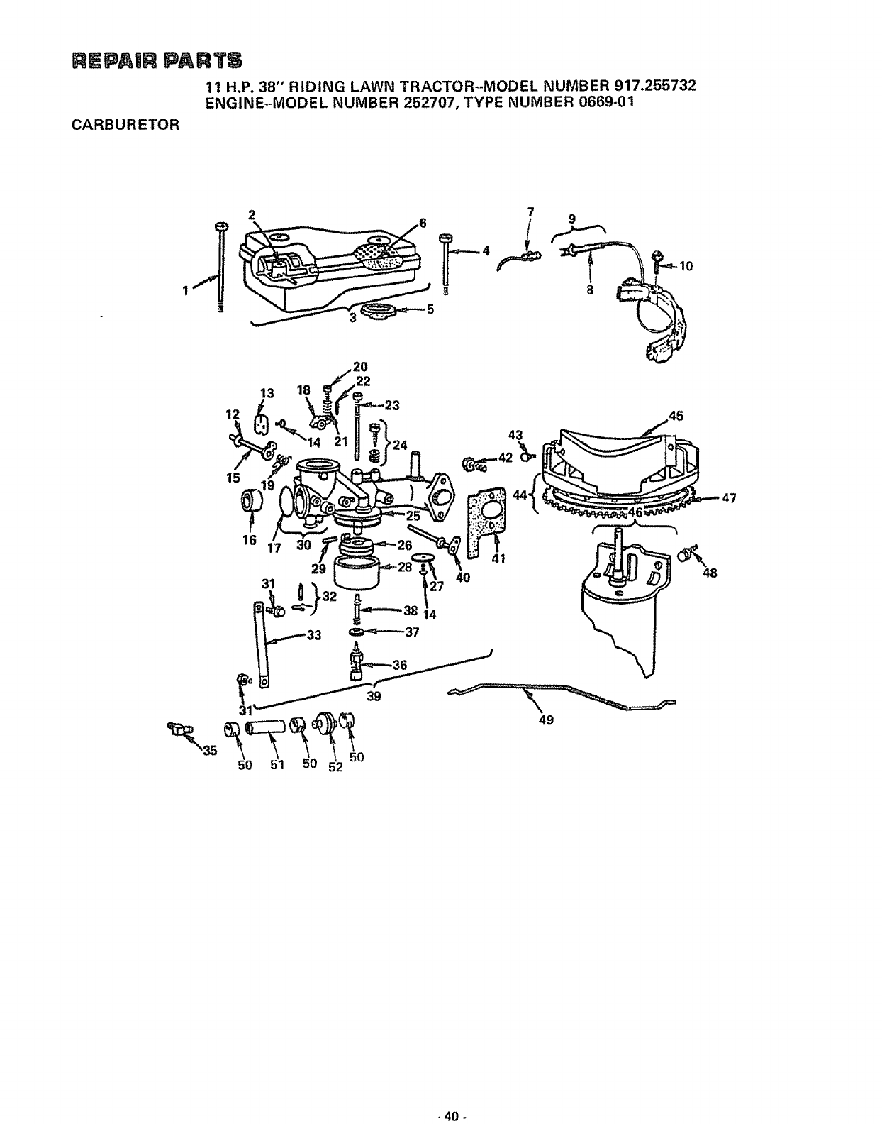
REPAmR PART6
11 H.P. 38" RIDING LAWN TRACTOR_-MODEL NUMBER 917.255732
ENGINE-MODEL NUMBER 252707, TYPE NUMBER 0669-01
CARBURETOR
9
20
16
31
15
40
41
47
48
49
40 -

REPAnR PARTS
11 H.P. 38" RIDING LAWN TRACTOR--MODEL NUMBER 917_255732
ENGINE--MODEL NUMBER 252707, TYPE NUMBER 0669-01
CARBURETOR
KEY PART DESCRIPTION KEY PART DESCRIPTION
NO. NO NO, NQ,
!93323 Screw- Air Cleaner 29 230896
2 280118 Support- Air Cleaner Element 30 391787
3 391786 Cleaner Assembly .-Air (Inc Key
No's- 2 & 6) 3t 93572
4 93622 Screw ,,Air Cleaner 32 299096
5 270853 Gasket ,,Air Cleaner 33 222311
6 270843 Element ,,Air Cleaner 35 67218
7 393422 Alternator Harness Assy, 36 391233
8 393814 Diode & Connector 37 222014
9 391529 Stator _Alternator (lnc Key No 8} 38 230932
10 93621 Screw-. Sem 39 393410
12 270382 Washer- Choke Shaft
13 222010 Valve ,,Choke
14 93499 Screw ,,Throttle & Choke Valve
Mtg. Sem 40 391512
15 390684 Shaft & Lever., Choke 41 270872
t6 2! !960 Venturi _Carburetor 42 93357
17 221997 +Plug, Welch 43 93984
18 211712 Stop- Throttle 44 391988
19 261116 Spring ,,Choke Return
20 91920 Screw., Machine, Fill. Hd, 8- 32 x 5/8 45 395405
21 26157 Spring _Throttle Adjustment 46 394805
22 93043 Pin- Throttle Stop 47 392134
23 299740 +Nozzle ,,Carburetor 48 93523
24 292681 +Valve Assembly -Carburetor Idle 49 261610
25 270511 +Gasket- Float Bowl 50 93053
26 299707 Float° Carburetor 51 394045
27 222858 Valve, Throttie 52 298090
28 221995 Bowl., Float -.- 299852
+Pin - Float Hinge
Body Assembly Carburetor (Inc.
Key No. 17)
Screw
+Valve- Fuel Inlet
Bracket- Carburetor
Connector* Fuel Pipe
+Valve - Needle
+Washer- Float Bowl
+Screw- Nozzle
Carburetor Assy_(Inc. Key No's. 12,
13, 14, 15, 16, 17, 18, 19, 20, 21, 22,
23, 24, 25, 26, 27, 28, 29, 30, 31, 32,
33, 36, 37 & 38)
Shaft & Lever -Throttle
*Gasket -Carburetor Mounting
Screw -Carburetor Mounting
Screw - Sere
Flywheel & Ring Gear Assyo- Magneto
(Inc. Key No. 47)
Cover & Shield- Starter
Motor- Starting
Gear- Ring (IncoMounting parts)
Screw- Sem
Link -Choke
Clamp, Hose
Pipe, Fuel
Filter, Fuel
Carburetor Overhaul Kit
+Included in Carburetor Overhaul Kit - Part No, 299852
* included in Gasket Set - Part No1,393411
-41

REPAIR PA TS
11 H.P. 38" RIDING LAWN TRACTOR--MODEL NUMBER 917.255732
ENGINE--MODEL NUMBER 252707, TYPE NUMBER 0669-01
STARTER-MOTOR
1
3
5
12
11
KEY
NO.
2
3
4
5
PART
NO.
394805
94003
93754
391462
391461
280104
DESCRIPTION
Motor- Starting (Inc. Key No'so 2, 3,
4, 5,6,7, 8,9, 10, 11 &t2)
Thru Bolt Assembly
Roll Pin
Retainer & Pin (inc. Key No. 3)
Drive Assembly (lnc° Key No's 3,
4,6& 7)
Gear
KEY PART DESCRIPTION
NO, NO.
7391135
8 393825
9 392747
10 395538
11 395537
12 394856
Clutch Assembly
Housing Assembly
Armature Assembly
Brush Assembly
End Cap Assy Commutator (Inc Key
No, 10)
End Cap Assy Drive
- 42 -

SUGGESTED GUIDE FOR SmGHTING SLOPES FOR SAFE OPERATION
I
SIGHTING GUIDE
t
ONLY RIDE UP AND DOWN HILL
NOT ACROSS HiLL
SIGHT AND HOLD THIS LEVEL WiTH
SKY LINE OR TREE
@
Operate your Tractor up and down the face of slopes (not
greater than !5°); never across the face. Make turns gradu-
ally to prevent tipping or loss of control. Exercise extreme
caution when changing direction on slopes.
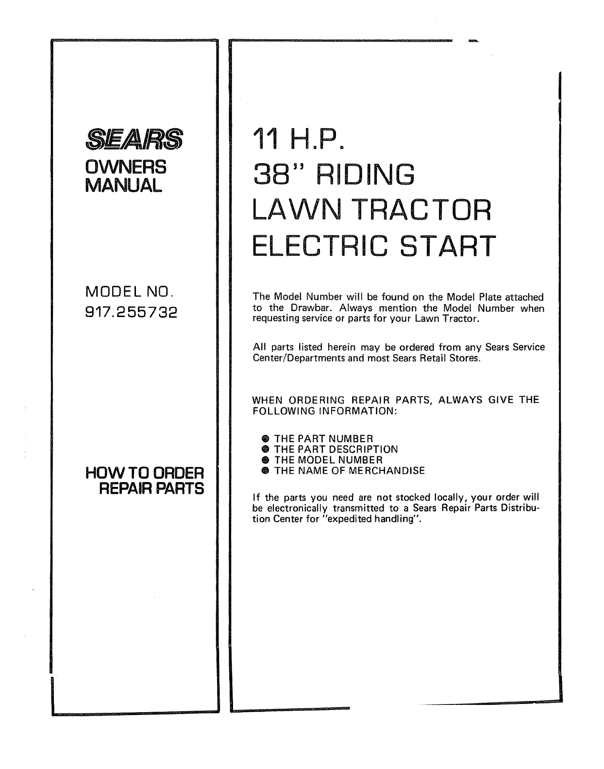
SEA/RS
OWNERS
MANUAL
MODEL NO.
917.255732
HOW TO ORDER
REPAIR PARTS
11 HoPo
38" RIDING
LAWN TRAC
ELECTRIC
TOR
START
The Model Number will be found on the Model Plate attached
to the Drawbar. Always mention the Model Number when
requesting service or parts for' your Lawn Tractor.
All parts listed herein may be ordered from any Sears Service
Center/Departments and most Sears Retail Stores,
WHEN ORDERING REPAIR PARTS, ALWAYS GIVE THE
FOLLOWING INFORMATION:
@ THE PART NUMBER
• THE PART DESCRIPTION
@ THE MODEL NUMBER
O THE NAME OF MERCHANDISE
If the parts you need are not stocked locally, your order will
be electronically transmitted to a Sears Repair Parts Distribu-
tion Center for "expedited handling",
k,,, ,,,.i
.......... ,, ,, ,i III r,]l ,_;
