Craftsman 917255820 User Manual SEARS 44 INCH 16 H.P. YARD TRACTOR Manuals And Guides L0806845
CRAFTSMAN Lawn, Tractor Manual L0806845 CRAFTSMAN Lawn, Tractor Owner's Manual, CRAFTSMAN Lawn, Tractor installation guides
User Manual: Craftsman 917255820 917255820 CRAFTSMAN SEARS 44 INCH 16 H.P. YARD TRACTOR - Manuals and Guides View the owners manual for your CRAFTSMAN SEARS 44 INCH 16 H.P. YARD TRACTOR #917255820. Home:Lawn & Garden Parts:Craftsman Parts:Craftsman SEARS 44 INCH 16 H.P. YARD TRACTOR Manual
Open the PDF directly: View PDF ![]() .
.
Page Count: 22
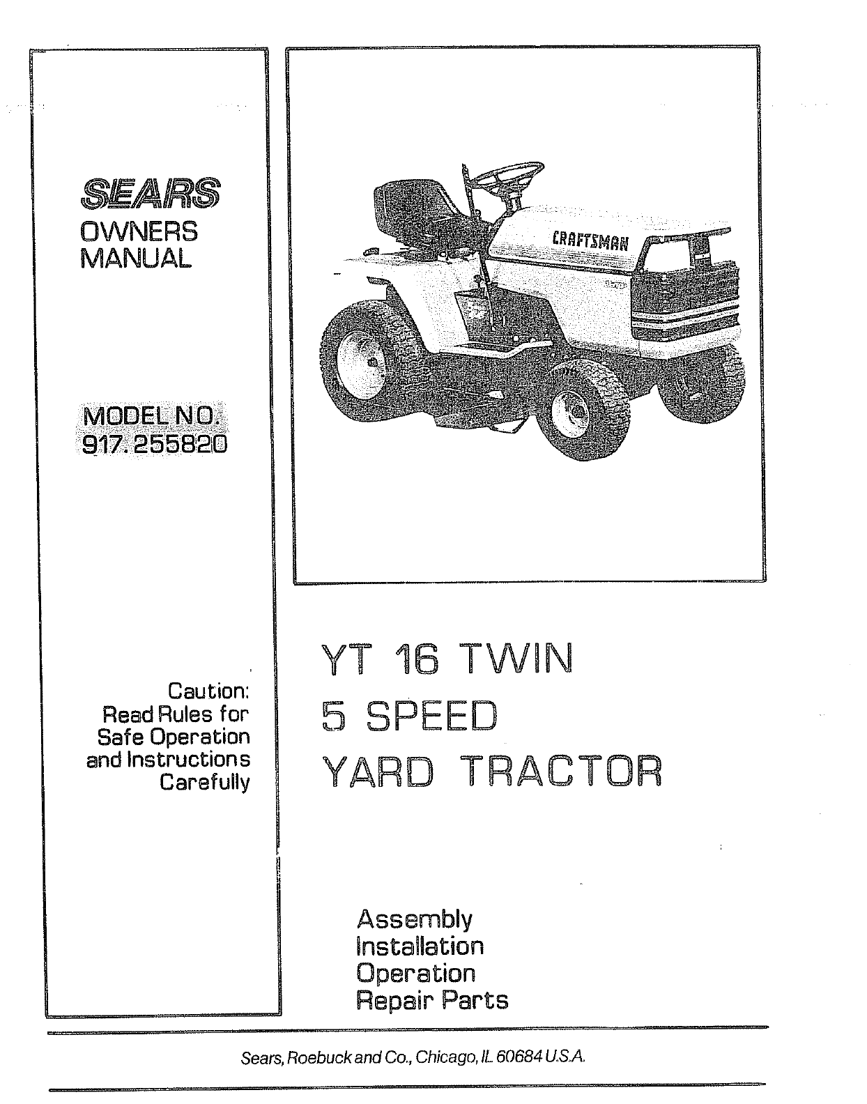
OWNERS
MANUAL
Caution:
Read Rules for
Safe Operation
and Instructions
Carefully
YT 16 TWIN
5 SPEED
YARD TRAC TOR
Assembly
Installation
Operation
Repair Parts
Sears, Roebuck and Co., Chicago, IL 60684 US.A.

CONGRATULATIONS on your purchase of a Sears Yard
Tractor, It has been designed, engineered and manufactured
to give you the best possible dependability and performance_
Should you experience any problem you cannot easily reme-
dy, please contact your nearest Sears, Roebuck and Co. Store°
They have competent, well-trained technicians and the proper
tools to service or repair this unit.
Please read and retain this manual, The instructions will enable
you to assemble operate and maintain your Tractor properly_
Always observe the RULES FOR SAFE OPERATION".
MODEL
NUMBER __
SERIAL
NUMBER
THE MODEL AND SERIAL NUMBERS WILL BE
FOUND ON THE MODEL PLATE ATTACHED TO
THE DRAWBARo
YOU SHOULD RECORD BOTH MODEL AND
SERIAL NUMBERS AND KEEPIN A SAFEPLACE
FOR FUTURE REFERENCE,
L6M_TED ONE YEAR WARRANTY
ON ELECTRUC START RIIDQNG EQUIPMENT
For one year" from date of purchase, when this riding equipment is maintained, lubricated, and
tuned up according to the operating and maintenance instructions in the owner's manual, Sears
will repair"free of charge any defect in material or workmanship in this electric start riding equip-
ment.
This warranty excludes blade(s), blade adapter(s), spark plug(s), air cleaner' and belt(s), which are
expendable and become worn during normal use.
This warranty does not cover:
tire replacement or' repair caused by punctures from outside objects (such as nails, thorns,
stumps, or glass); and
repairs necessary because of operator abuse or' negligence, including the failure to main-
tain the equipment according to instructions contained in the owner's manual; and
riding equipment used for" commercial or' rental purposes.
FULL SO-_)AY WARRAN3"Y O_J BATTERY
For 90 days from the date of purchase, if any battery included with this riding equipment proves
defective in material or workmanship and our testing determines the battery will not hold a charge,
Sears will replace the battery at no charge.
WARRANTY SERVICE IS AVAILABLE BY CONTACTING THE NEAREST SEARS SERVICE
CENTER/DEPARTMENT IN THE UNITED STATES. This warranty applies only while this
product is in use in the United States.
This warranty gives you specific legal rights, and you may also have other rights which vary from
state to state.
Sears, Roebuck and Co,, D/698-731A, Sears Tower, Chicago, IL 60684
TABLE OIF C@ T NTS
RULES FOR SAFE OPERATION .............. 3
ASSEMBLY INSTRUCTIONS ................. 4
OPERATION INSTRUCTIONS - TRACTOR ...... 7
OPERATION INSTRUCTIONS =MOWER ....... 11
=2"
MAINTENANCE INSTRUCTIONS -MOWER .... 12
MAINTENANCE INSTRUCTIONS -TRACTOR . ,15
TROUBLE SHOOTING ..................... 21
REPAIR PARTS ............................ 24
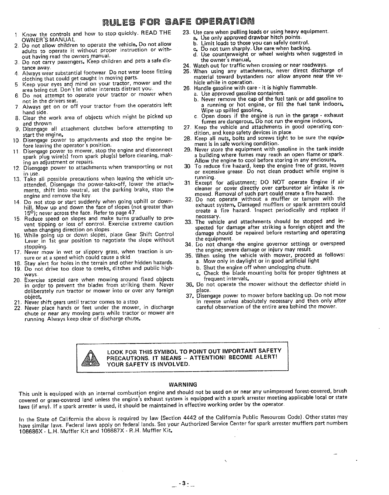
ULES FOR SAFE
1 Know the controls and how to stop qulckly. READ THE
OWNER'S MANUAL
2, Do not allow children to operate the vehicle. Do not allow
adults to operate it without proper instruction or with°
out having read the owners manual.
3 Do not carry passengers. K_eepchildren and pets a safe dis-
tance away
4 Always wear substantial footwear Do not wear loose fitting
clothing that could get caught in moving parts-
5 Keep your eyes and mind on your tractor, mower and the
area being cut Don't let other interests distract you,
6 Do not attempt to operate your tractor or mower when
not in the drivers seat.
7 Always get on or off your tractor from the operators left
hand side
8. Clear the work area of objects which might be picked up
and thrown
9 Disengage all attachment clutches before attempting to
start the engine.
10 Disengage power to attachments and stop the engine be-
fore leaving the operator s position,
11 Disengage power to mower stop the engine and disconnect
spark plug wire(s) from spark plug s before c ean ng, mak-
ing an adjustment or repairs,
12 Disengage power to attachments when transporting or not
in use,
13 Take all possible precautions when leaving the vebicle un-
attended. Disengage the power-take-off, lower the attach-
ments, shift into neutral, set the parking brake, stop the
engine and remove the key
14 Do not stop or start suddenly when going uphill or down-
hill. Mow up and down the face of slopes (not greater than
15°); never across the face_ Refer to page 47_
15 Reduce speed on slopes and make turns gradually to pre-
vent tipping or loss of control, Exercise extreme caution
when changing direction on slopes
]6. While going up or down slopes, place Gear Shift Control
Lever in 1st gear position to negotiate the slope without
stopping.
17 Never mow in wet or slippery grass, when traction is un-
sure or at a speed which could cause a skid
18 Stay aler_ for holes in the terrain and other hidden hazards
19 Do not drive too close to creeks, ditches and public high-
ways,
20 Exercise special care when mowing around fixed objects
in order to prevent the blades from striking them Never
deliberately run tractor or mower into or over any foreign
object°
21, Never shift gears until tractor comes to a stop
22 Never place hands or feet under the mower, in discharge
chute or near any moving parts while tractor or mower are
running Always keep clear of discharge chute.
OPERAT6@N
23_ Use care when pulling loads or using heavy equipment
a. [Jseonly approved drawbar hitch points,
b. Limit loads to those you can safely control.
c. lid not turn sharply. Use care when backing,
d Use count_erweight or wheel weights when suggested in
the owner s manual°
24, Watch out for traffic when crossing or near roadways.
25, When using any attachments, never direct discharge of
material toward bystanders nor allow anyone near the ve-
hicle while in operatiom
26, Handle gasoline with care - it is highly flammable.
a. Use approved gasoline contalners_
b. Never remove the cap of the fuel tank or add gasoline to
a running or hot engine, or fill the fuel tank indoors.
Wipe up spilled gasoline.
c Open doors if the eng ne is run in the garage - exhaust
fumes are dangerous. Db not run the engine indoors,
27 Keep the vehicle and attachments in good operating con-
dition, and keep safety devices in place.
28 Keep all nuts, bolts and screws tight to be sure the equip-
ment is in safe working condition.
29. Never store the equipment with gasoline in the tank inside
a building where fumes may reach an open flame or spark,
Allow the engine to cool before storing in any enclosure°
30 To reduce fire hazard, keep the engine free of grass, leaves
or excessive grease Do not clean product while engine is
running
31 Except for adjustment; DO NOT operate Engine if air
cleaner or cover directly over carburetor air intake is re=
moved Removal of such part could create a fire hazard,
32 Do not operate without a muffler or tamper with the
exhaust system. Damaged mufflers or spark arresters could
create a fire hazard. Inspect periodically and replace if
necessary.
33 The vehicle and attachments should be stopped and in-
spected for damage after strikiog a foreign object and the
damage should be repaired before restarting and operating
the equipment,
,34. rOD not change,the engine governor settings or overspeed
the engine; severe damage or injury may result
35. When using the vehicle with mower, proceed as follows:
a, Mow only in daylight or in good artificial light
b. Shut the engine off when unclogging chute.
c. Check the blade mounting bolts for proper tightness at
frequent intervals.
36. Do not operate the mower without the deflector shield in
p!ace.
37. Disengage power to mower before baeldng up. Do not mow
in reverse unless absolutely necessary and then only after
careful observation of the entire area behind the mower,
LOOK FOR THIS SYMBOL TO POINT OUT IMPORTANT SAFETY
PRECAUTIONS. IT MEANS -- ATTENTION! BECOME ALERT!
YOUR SAFETY IS INVOLVED.
WARNING
This unit is equipped with an internal combustion engine and should not be used on or near any unimproved forest-covered, brush
• I
covered or grass-covered land unless the engine sexhaust system is equipped with a spark arrester meeting applicable local or state
laws (if any). If a spark arrester is used, it should be maintained in effective working order by the operator
In the State of California the above is required by law (Section 4442 of the California Public Resources Code) Other states may
have similar [aws_ Federal laws apply on federal lands, See your Authorized Service Center for spark arrester mufflers part numbers
106686X - LH Muffler Kit and 106687X -R.H Muffler Kit.
._. -3-
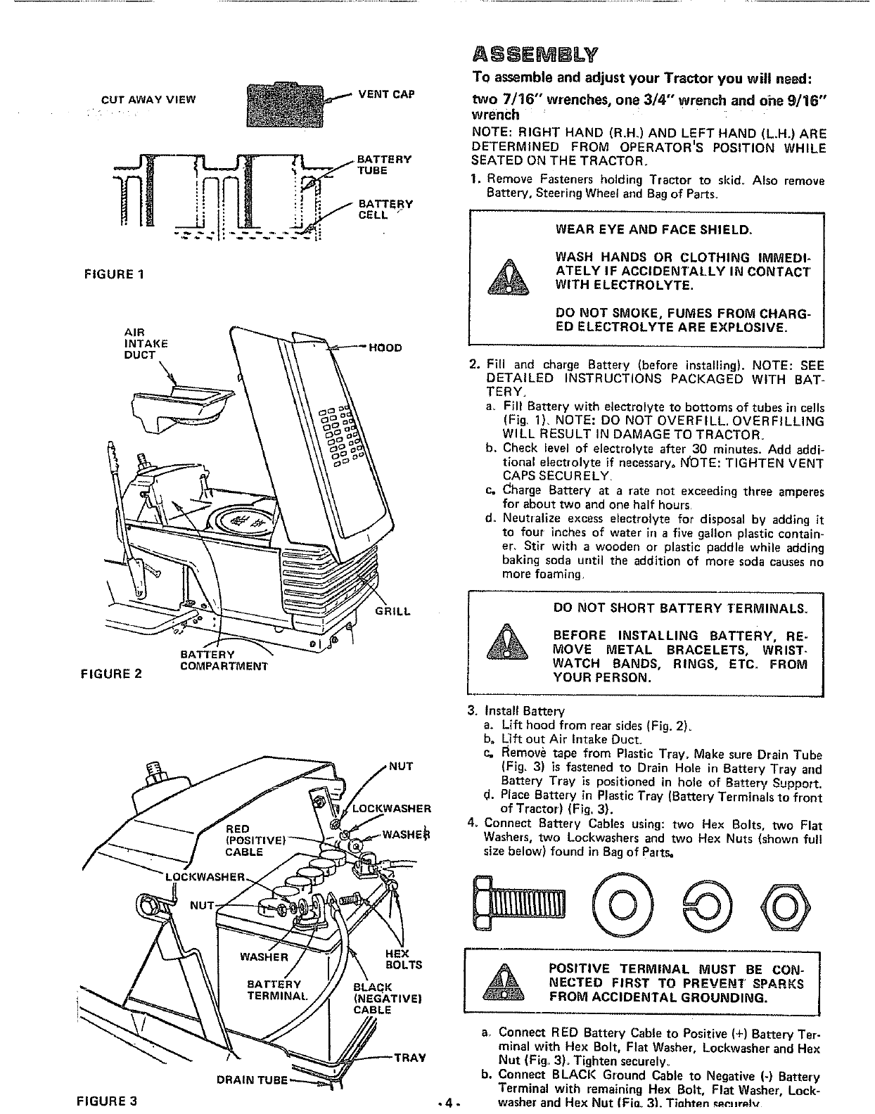
CUTAWAYVIEW
FIGURE1
AIR
INTAKE
DUCT
BATTERY
COMPARTMENT
FIGURE 2
FIGURE 3
DRAIN TUB
VENT CAP
BATTERY
TUBE
BATTERY
CELL '
GRILL
,NUT
ER
HEX
BOLTS
BLAqK
(NEGATIVE)
CABLE
.4-
ASSEMBLY
To assemble and adjust your Tractor you will need:
two 7/16" w;enches, one 3/4" wrench and ohe 9/16"
wrench
NOTE: RIGHT HAND (R.H_)AND LEFT HAND (L.H.) ARE
DETERMINED FROM OPERATORIS POSITION WHILE
SEATED ON THE TRACTOR.
1. Remove Fastenersholding Tractor to skid_Also remove
Batter,/, SteeringWheetand Bagof Parts_
WEAR EYE AND FACE SHIELD=
WASH HANDS OR CLOTHING IMMEDI-
ATELY IF ACCIDENTALLY IN CONTACT
WITH ELECTROLYTE.
DO NOT SMOKE, FUMES FROM CHARG-
EDELECTROLVTE ARE EXPLOSlVE.
2. Fill and charge Battery (before installing). NOTE: SEE
DETAILED INSTRUCTIONS PACKAGED WITH BAT-
TERY,
a, Fill Battery with electrolyte to bottoms of tubes in cells
(Fig, 1), NOTE= DO NOT OVERFILL. OVERFILLING
WILL RESULT IN DAMAGE TO TRACTOR.
b. Check level of electrolyte after 30 minutes. Add addi-
tional electrolyte if necessary° I_OTE: TIGHTEN VENT
CAPS SECU R ELY,
Co Charge Battery at arate not exceeding three amperes
for about two and one half hours
d. Neutralize excess electrolyte for disposal by adding it
to four inches of water in a five gallon plastic contain-
er, Stir with a wooden or plastic paddle while adding
baking soda until the addition of more soda causes no
more foaming.
DO NOT SHORT BATTERY TERMINALS.
BEFORE INSTALLING BATTERY, RE-
MOVE METAL BRACELETS, WRIST-
WATCH BANDS, RINGS, ETC. FROM
VOURPERSON.
3. Install Battery
a. Lift hood from rear sides (Fig. 2).
b, L_ft out Air Intake Duct.
c, Remove tape from Plastic Tray= Make sure Drain Tube
(Fig. 3) is fastened to Drain Hole in Battery Tray and
Battery Tray is positioned in hole of Battery Support.
d. Place Battery in Plastic Tray (Battery Terminals to front
of Tractor) (Fig. 3).
4_ Connect Battery Cables using: two Hex Bolts, two Flat
Washers, two Lockwashers and two Hex Nuts (shown full
size below) found in Bagof Parts,
POSITIVE TERMINAL MUST BE CON- I
NECTED FIRST TO PREVENT SPARKS
FROM ACCIDENTAL GROUNDING.
a. Connect RED Battery Cable to Positive (+) Battery Ter-
minal with Hex Bolt, Flat Washer, Lockwasher and Hex
Nut (Fig, 3)_ Tighten securely°
b. Connect BLACK Ground Cable to Negative (-) Battery
Terminal with remaining Hex Bolt, Flat Washer, Lock-
washer and Hex Nut (Fioo 3). TJnhten _n_Hr_lv
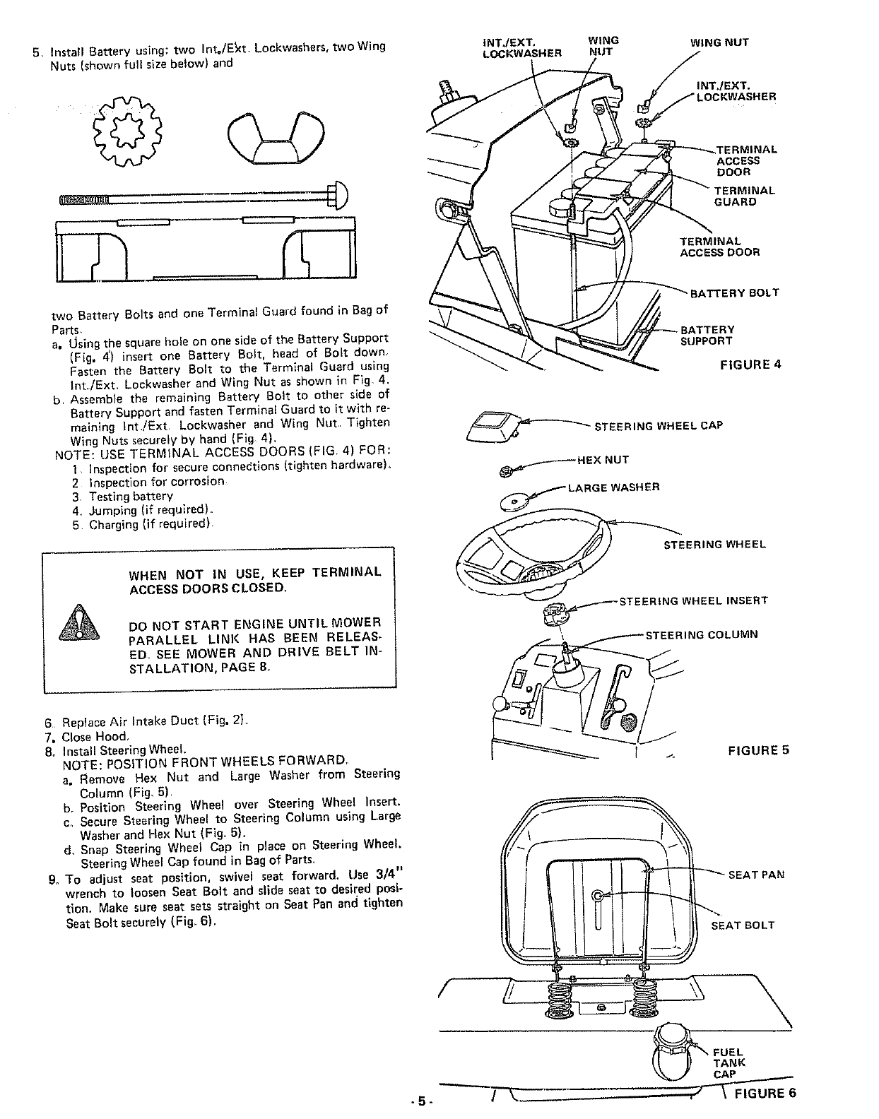
5, InstallBatteryusing:twoInt=/E_xt,Lockwashers,two Wing
Nuts (shown full size below) and
INT./EXT, WING WING NUT
LOCKWASHER NUT
©INT./EXT.
ACCESS
DOOR
_INAL
GUARD
TERMINAL
ACCESS DGOR
two Battery Bolts and one Terminal Guard found in Bag of
Parts,
a. LJsingthe square hole on one side of the Battery Support
(Fig. 4) insert one Battery Bolt, head of Bolt down,
Fasten the Battery Bolt to the Terminal Guard using
Int,/Ext Lockwasher and Wing Nut as shown in Fig, 4.
b Assemble the remaining Battery Bolt to other side of
Battery Support and fasten Terminal Guard to it with re-
maining }nt/Ext Lockwasher and Wing Nut, Tighten
Wing Nuts securely by hand (Fig 4).
NOTE: USE TERMINAL ACCESS DOORS (FIG. 4) FOR:
! Inspection for secure connedtions (tighten hardware),
2 Inspection for corrosion
3 Testing battery
4 Jumping (if required).
5 Charging (if required)
BOLT
SUPPORT
FIGURE 4
_ STEERING WHEEL CAP
_HEX NUT
_ER
WHEN NOT IN USE, KEEP TERMINAL
ACCESS DOORS CLOSED.
DO NOT START ENGINE UNTIL MOWER
PARALLEl LiNK HAS BEEN RELEAS-
ED, SEE MOWER AND DRIVE BELT IN-
STALLATION, PAGE B_
6 Replace Air Intake Duct (Fig, 2},
7. Close Hood,
8_ Install Steering Wheel.
NOTE: POSITION FRONT WHEELS FORWARD°
a° Remove Hex Nut and Large Washer from Steering
Column (Fig, 5),
b, Position Steering Wheel over Steering Wheel Insert.
c, Secure Steering Wheel to Steering Column using Large
Washer and Hex Nut (Fig. 5),
d, Snap Steering Wheel Cap in place on Steering Wheel.
Steering Wheel Cap found in Bag of Parts,
9. To adjust seat position, swivel seat forward. Use 3/4"
wrench to loosen Seat Bolt and slide seat to desired posi-
tion. Make sure seat sets straight on Seat Pan and tighten
Seat Bolt securely (Fig, 6).
.5-
/
STEERING WHEEL
SEAT PAN
SEAT BOLT
\
FUEL
TANK
CAP
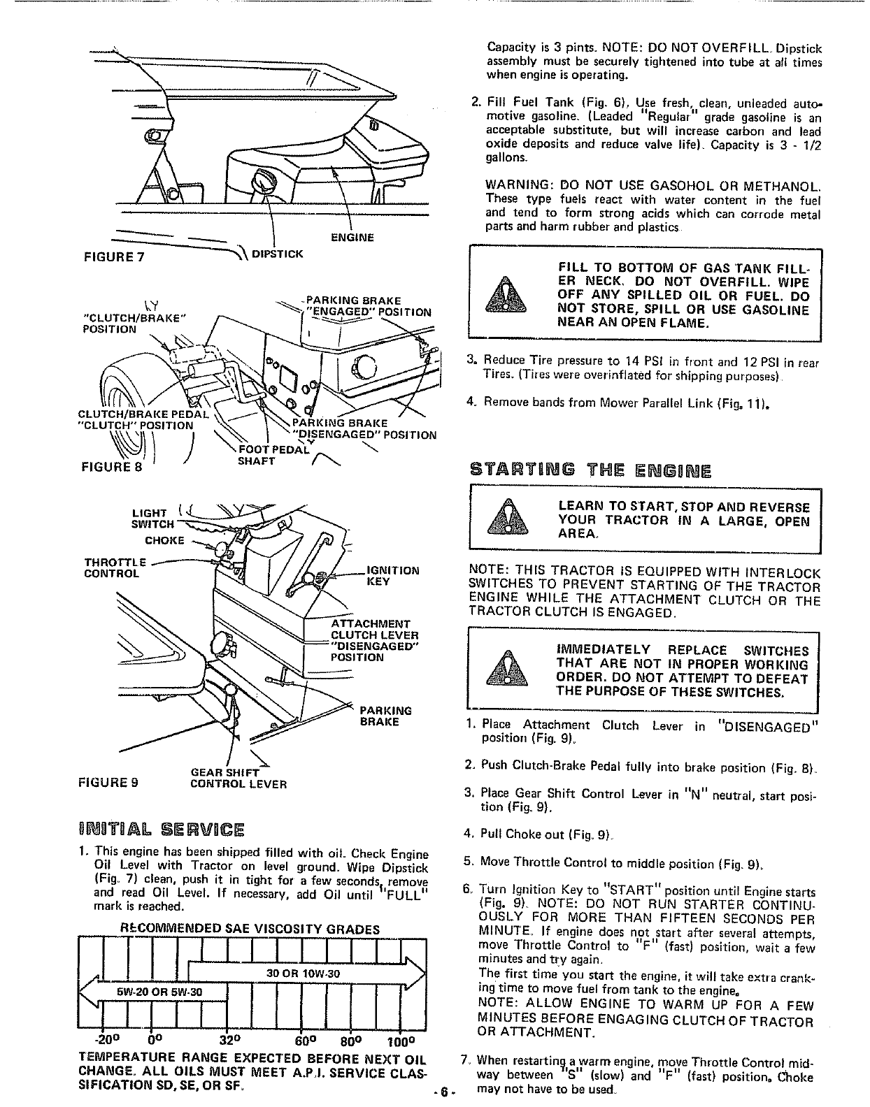
ENGINE
FIGURE 7
UGHT
CHOKE
THROTTLE
CONTROL IGNITION
KEY
ATTACHMENT
CLUTCH LEVER
DISENGAGED"
pOSITION
PARKING
BRAKE
FIGURE gGEAR SHIFT
CONTROLLEVER
I]NSTltAL SI RVDCE
I. This engine has been shipped filled with oil. Check Engine
Oil Level with Tractor on level ground. Wipe Dipstick
(Fig_ 7clean, push it in tight for a few seconds, remove
It tt
and read Oil Level. If necessary, add Oil until FULL
mark is reached.
RECOMMENDED SAE VISCOSITY GRADES
l/lllllllllll-
_0 o 0o 32°60° 80° 100 °
TEMPERATURE RANGE EXPECTED BEFORE NEXT OIL
CHANGE. ALL OILS MU_ MEET A.PJ. SERVICE CLA_
SIFICATION SD, SE, OR SF. -6-
Capacity is 3 p_nts. NOTE: DO NOT OVERFILL. Dipstick
assembly must be securely tightened into tube at all times
when engine is operating.
2. Fill Fuel Tank (Fig. 6), Use fresh clean, unleaded auto-
motive gasoline, (Leaded " ""is anRegular grade gasoline
acceptable substitute, but will increase carbon and lead
oxide deposits and reduce valve _ife). Capacity is 3 - 1/2
gallons,
WARNING: DO NOT USE GASOHOL OR METHANOL.
These type fuels react with water content in the fuel
and tend to form strong acids which can corrode metal
parts and harm rubber and plastics
FILL TO BOTTOM OF GAS TANK FILL-
ER NECK, OO NOT OVERFILL. WIPE
OFF ANY SPILLED OIL OR FUEL. DO
NOT STORE, SPILL OR USE GASOLINE
NEAR AN OPEN FLAME.
3. Reduce Tire pressure to 14 PSi in front and 12 PSI in rear
Tires. (Tires were overinflated for shipping purposes)
4. Remove bands from Mower Parallel Link (Fig. 1J).
TARTBNG THE
/
LEARN TO START, STOP AND REVERSE |
YOUR TRACTOR IN ALARGE, OPEN J
AREA,
NOTE: THIS TRACTOR IS EQUIPPED WITH INTERLOCK
SWITCHES TO PREVENT STARTING OF THE TRACTOR
ENGINE WHILE THE ATTACHMENT CLUTCH OR THE
TRACTOR CLUTCH IS ENGAGED.
IMMEDIATELY REPLACE SWITCHES
THAT ARE NOT IN PROPER WORKING
ORDER. DO NOT ATTEMPT TO DEFEAT
THE PURPOSE OF THESE SWITCHES.
2_
3.
4_
5_
6_
Place Attachment Clutch Lever in "DISENGAGED"
position (Fig. 9)_
Push Clutch-Brake Pedal fully into brake position (Fig_ 8)_
Place Gear Shift Control " " "
Lever m N neutral, start posi-
tion (Fig. 9).
Pull Choke out (Fig. 9),
Move Throttle Control to middle position (Fig. 9).
Turn Ignition Key to "START Hposition until Engine starts
(Fig. g). NOTE: DO NOT RUN STARTER CONTINU-
OUSLY FOR MORE THAN FIFTEEN SECONDS PER
MINUTE If engine does not start after several attempts,
move Throttle Control to "F" (fast) position, wait a few
minutes and try again.
The first time you start the engine, it will take extra crank-
ing time to move fuet from tank to the engine=
NOTE: ALLOW ENGINE TO WARM UP FOR A FEW
MINUTES BEFORE ENGAGING CLUTCH OF TRACTOR
OR ATTACHMENT.
7_ When restarting a warm engine, move Throttle Control mid-
way between ]'S" (slow) and "F" (fast) position= Choke
may not have to be used.
PERATDO
BEFORE DRIVING THE TRACTOR, IN-
STALL MOWER OR REMOVE MOWER
PARALLEL LINK (FIG. 11),
C UTDO
f. Keep aH shields in place
2. Before leaving operatorts position:
aShift transmission to neutral
b Depress Clutch/Brake Peda{ and set Parking Brake°
c Disengage Attachment Lever
d Shut off engine
e Remove {gn{t_on Key.
3 Wait for all movement to stop before servicing machine,
4 Keep people and pets a safe distance away from machine.
5Always wear substantia_ footwear and avoid loose fitting
clothing that could get caught in moving parts
TRACTOR GPE ATIO
IWith engine running and warm, place Throttle Control mid-
Ii If ii II . .
way between S (_low) and F (fast) position
2 Push Clutch-Brake Pedal down firmly (Fig, 8), Move Gear
Shift Control Lever to desired gear {Fig, 9),
3 Release Clutch-Brake Pedal SLOWLY to start movement.
4 If ground travel _s too slow, move Throttle Control to
"F" (fast) position or press Clutch-Brake Pedal and shift
to a different gear
NOTE: BRING TRACTOR TO COMPLETE STOP BE-
FORE SHIFTING GEARS. ALWAYS SELECT A
GROUND TRAVEL SPEED THAT WILL SUIT THE TER-
RAIN AND THE ATTACHMENT BEING USED
NEVER PLACE YOUR HANDS OR FEET
IN OR UNDER ANY POWERED ATTACH-
MENT OR NEAR ANY MOVING PART
WHILE TRACTOR OR ANY POWERED
ATTACHMENT IS RUNNING.
DO NOT OPERATE THE MOWER WITH-
OUT THE DISCHARGE GUARD IN
PLACE,
NOTE: A SPARK ARRESTER MUFFLER (PAGE 28) IS
AVAILABLE AS AN ACCESSORY PART FOR YOUR
TRACTOR, CHECK LEGAL REQUIREMENTS IN YOUR
AREA
STOPPBNG YOUR TI ACTOn
1Push Clutch-Brake Pedal into futl "BRAKE" position,
2 Place Parking Brake Lever in "ENGAGED" position and re-
lease pressure from Clutch-Brake. Pedal should remain in ........
brake position. NOTE: MAKE SURE PARKING BRAKE
WILL HOLD TRACTOR SECURE,
3Move Shift Control Lever to "NEUTRAL" position,
4. P}ace Attachment Clutch Lever in "DISENGAGED" posi-
tion,
B= Move Throttle Control to "S" (slow) position°
6 Turn Ignition Key to "OFF" position,
REMOVE KEY WHEN LEAVING TRAC-
TOR TO PREVENT UNAUTHORIZED
USE,
For pushing or towing your tractor, place Gear Sh ft Contro
II II , *.
Lever to N neutral posit=on (Fig. 9). NOTE: DO NOT TOW
YOUR TRACTOR FASTER THAN SIX MILES PER HOUR.
TRACTOR Hi]ILL
1Choose the Lowest gear BEFORE starting up or down
hills+
DO NOT DRIVE UP OR DOWN HILLS
WITH SLOPES GREATER THAN 15°,
AND DO NOT DRIVE ACROSS ANY
SLOPE. REFER TO PAGE 47,
2, AVOID STOPPING OR SHIFTING ON HILLS,,
a_ If slowing is necessary, move" Thrott]e Control Lever
to middle position_
LEAVE ENOUGH ROOM WHEN STOP-
PING AND STARTING TO ALLOW
SLIGHT TRACTOR ROLL DDWNHILL AS
CLUTCH-BRAKE PEDAL MOVES
THROUGH CLUTCH POSITION,
b_ If stopping is absolutely necessary, push Clutch-Brake
Pedal quickly to brake position and engage Parking
Brake,
c, To restart your tractor, make sure tractor is in 1st gear
and that you have allowed room to roll slightly down-
hillo Disengage Parking Brake and release Clutch-Brake
Pedal SLOWLY to start tractor forward movement
3 Make all turns slowly=
-7-
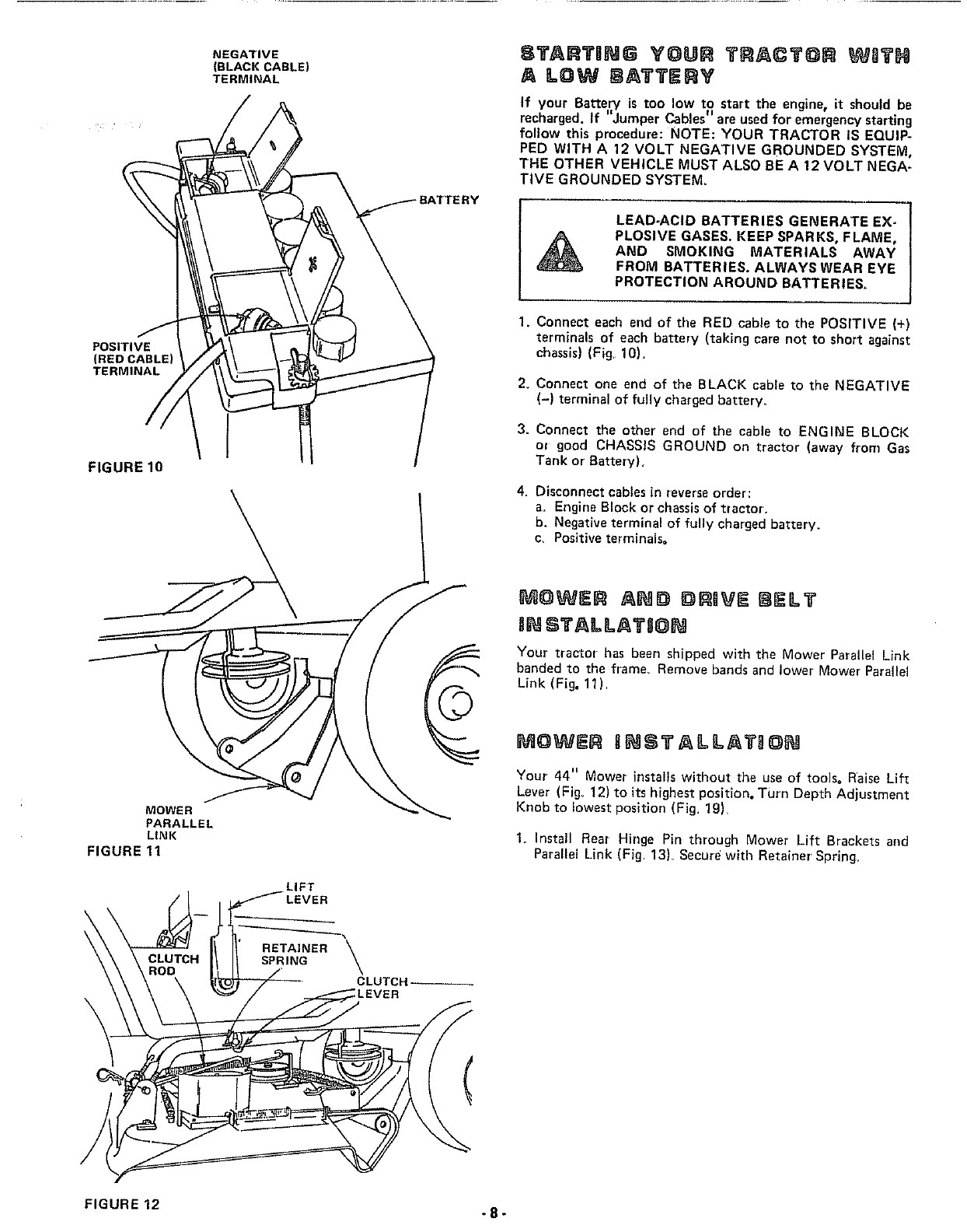
POSITIVE
(RED CABLE)
TERMINAL
FIGURE 10
NEGATIVE
(BLACK CABLE)
TERMINAL
STARTBNG YOUR TRACTOR WSTH
A LGW BATTERY
If your Battery is too low to start the engine, it should be
recharged If "Jumper Cables" a rti• re used for emergency sta ng
follow this procedure: NOTE: YOUR TRACTOR IS EQUIP-
PED WITH A 12 VOLT NEGATIVE GROUNDED SYSTEM,
THE OTHER VEHICLE MUST ALSO BE A 12 VOLT NEGA-
TIVE GROUNDED SYSTEM.
LEAD-ACID8ATTER,ESGENERATEE×--!
PLOSIVE GASES. KEEP SPARKS. FLAME. |
AND SMOKING MATERIALS AWAY |
FROMBATTERIES.ALWAYSWEAREYE!
PROTECTION AROUND BATTERIES° /
J
1. Connect each end of the RED cable to the POSITIVE (+)
terminals of each battery (taking care not to short against
chassis) (Fig. 10).
2. Connect one end of the BLACK cable to the NEGATIVE
(-) terminal of fully charged battery_
3. Connect the other end of the cable to ENGINE BLOCK
ol good CHASS)S GROUND on tractor (away from Gas
Tank or Battery).
4. Disconnect cables in reverse order:
a_ Engine B)ock or chassisof tractor.
b. Negative terminal of fully charged battery.
c. Positive terminals°
MOWER
PARALLEL
LINK
FIGURE 11
LIFT
LEVER
RETAINER
SPRING
CLUTCH
_OWER AND I_$_aVE {_IELT
gNSTALLAT_@N
Your tractor has been shipped with the Mower Parallel Link
banded to the frame_ Remove bands and lower Mower Parallel
Link (Fig. 11).
_OWER INSTALLATB O{_
Your 44" Mower installs without the use of tools, Raise Lif_
Lever (Fig_ 12) to its highest position, Turn Depth Adjustment
Knob to lowest position (Fig. 19).
1. Install Rear Hinge Pin through Mower Lift Brackets and
Parallel Link (Fig 13L Secure with Retainer' Spring.
FIGURE 12 -8-
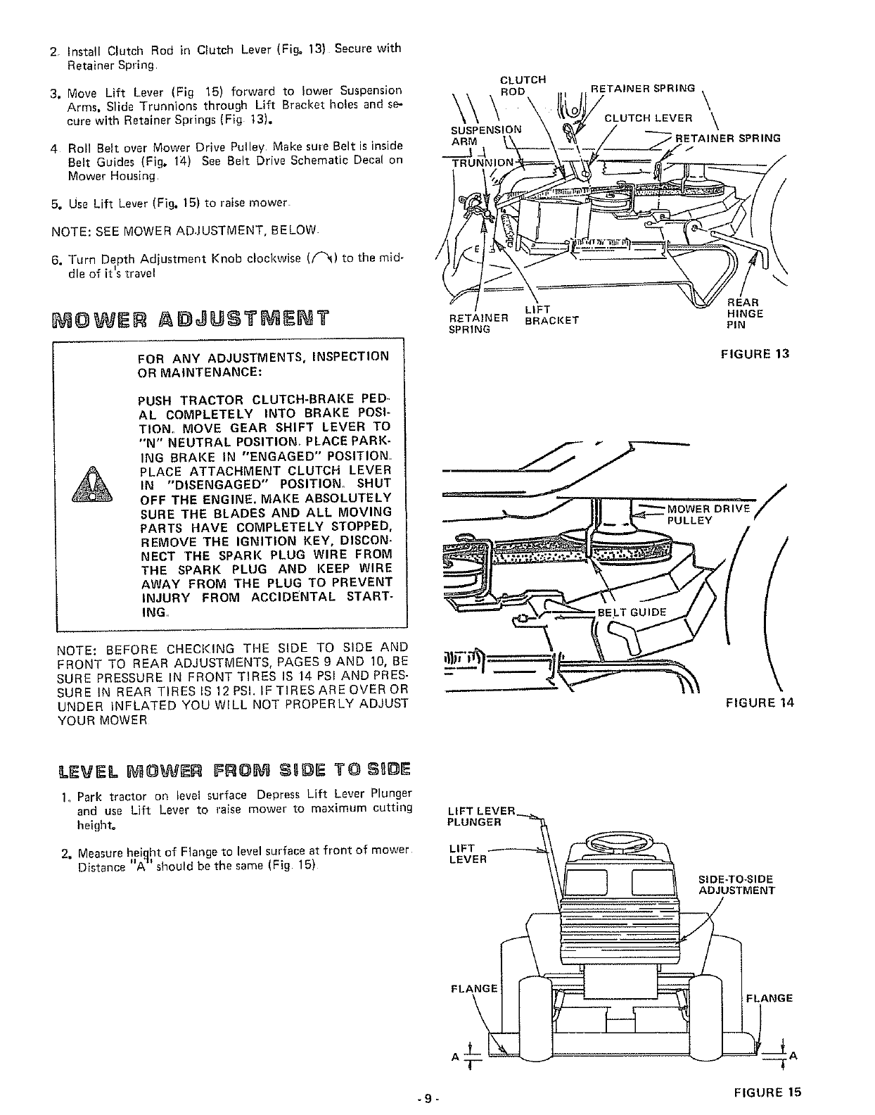
2r Install Clutch Rod in Clutch Lever (Fig° I3} Secure with
Retainer Spring
3. Move Lift Lever /Fig 15) forward to }ower Suspension
Arms. Slide Trunnions through Lift Bracket holes and se-
cure with Retainer Springs (Fig t3).
4 Roll Belt over Mower Drive Pulley Make sule Belt is inside
Belt Guides (Fig. 1;4) See Belt Drive Schematic Decal on
Mower Housing
5. Use Lift Lever (Fig. 15) to raise mower
NOTE: SEE MOWER ADJUSTMENT, BELOW
6, Turn Depth Adjustment Knob clockwise (/_) to the mid-
dle of it's travel
At J]U $TMI I T
FOR ANY ADJUSTMENTS, INSPECTION
OR MAINTENANCE:
PUSH TRACTOR CLUTCH-BRAKE PED-
AL COMPLETELY INTO BRAKE POSI-
TION. MOVE GEAR SHIFT LEVER TO
"N" NEUTRAL POSITION_ PLACE PARK-
ING BRAKE IN "ENGAGED" POSITION.
PLACE ATTACHMENT CLUTCH LEVER
IN "DISENGAGED" POSITION. SHUT
OFF THE ENGINE. MAKE ABSOLUTELY
SURE THE BLADES AND ALL MOVING
PARTS HAVE COMPLETELY STOPPED,
REMOVE THE IGNITION KEY, DISCON-
NECT THE SPARK PLUG WIRE FROM
THE SPARK PLUG AND KEEP WIRE
AWAY FROM THE PLUG TO PREVENT
INJURY FROM ACCIDENTAL START-
ING.,
NOTE: BEFORE CHECKING THE SIDE TO SIDE AND
FRONT TO REAR ADJUSTMENTS, PAGES gAND 10, BE
SURE PRESSURE IN FRONT TIRES IS 14 PSI AND PRES-
SURE IN REAR TIRES IS 12 PSI. IF TIRES ARE OVER OR
UNDER INFLATED YOUWILL NOT PROPERLY ADJUST
YOUR MOWER
CLUTCH
\ROD ,., .. RETA,NER SPRING \
\/f /OLUTCRLEVER
ARM t\ \ _ /_/" RETAINER SPRING
J _ -\--\--./-- "-S /
RETAINER BRACKET HINGE
SPRING PIN
FIGURE 13
l
FIGURE 14
LEVEL FRO SUDIE $1 31E
1_ Park tractor on level surface Depress Lift Lever Plunger
and use Lift Lever to raise mower to maximum cutting
height=
2, Measure height of Flange to revel surface at front of mower
Distance "A ='should be the same (Fig 15)
LIFT LEVER
PLUNGE_L_FvTER
FLANGE
A
SIDE-TO-SIDE
ADJUSTMENT
__AFLANGE
- 9- FIGURE 15
SIDE-TO=SIDE NUT"B"
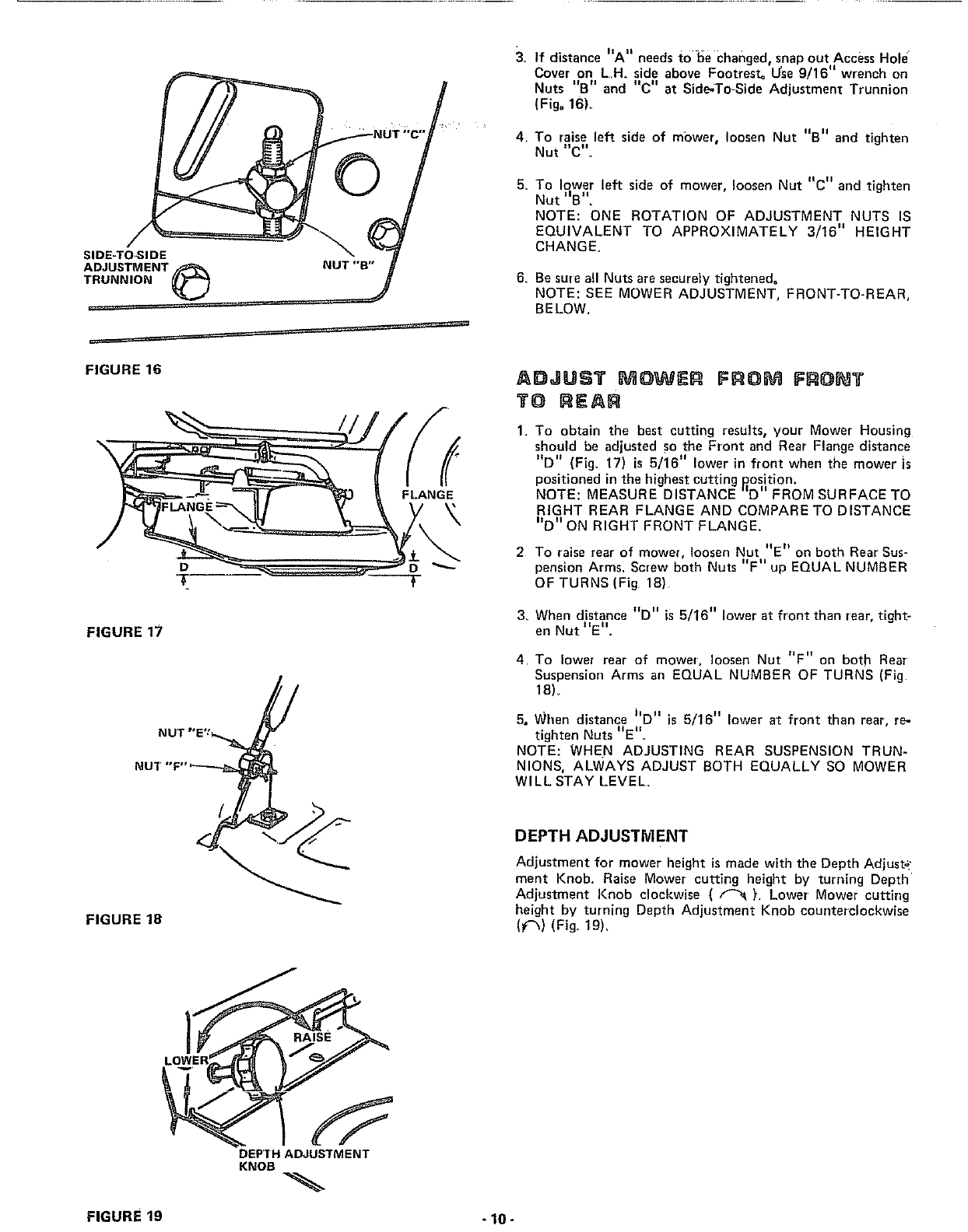
3_ •ii ii ..... . ,
If distance Aneeds to be changed, snap out Access Hole
II
Cover on L.H. side above Footrest= Use 9/16 wrench on
Nuts "B" and "C" at Side-To-Side Adjustment Trunnion
(Fig. 16L
4. To raise left side of mower, loosen Nut "B" and tighten
Nut "C'.
5_ To lower left side of mower, loosen Nut "C" and tighten
Nut _=B"_
NOTE: ONE ROTATION OF ADJUSTMENT NUTS IS
EQUIVALENT TO APPROXIMATELY 3/16" HEIGHT
CHANGE.
6. BesureallNutsaresecurelytightened.
NOTE:SEE MOWER ADJUSTMENT, FRONT-TO-REAR,
BELOW,
FIGURE 16
FIGURE 17
NUT "E'_
NUT "F"
/
FIGURE 18
f
FLANGE
ADJUST MOWER FROM FRO JT
TO REAR
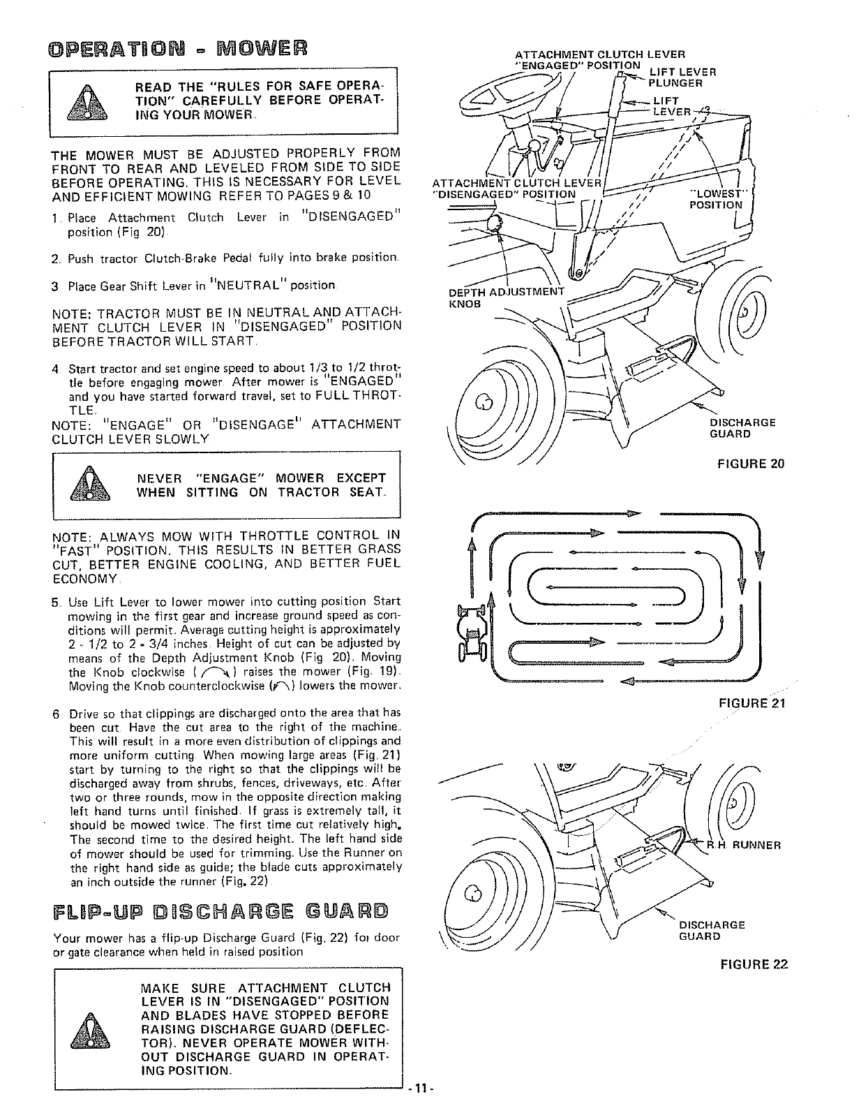
1.
2
To obtain the best cutting results, your Mower Housing
should be adjusted so the Front and Rear Flange distance
"D" (Fig, 17) is 5/16" lower in front when the mower is
positioned in the highest cutting position.
NOTE: MEASURE DISTANCE lID" FROM SURFACE TO
RIGHT REAR FLANGE AND COMPARE TO DISTANCE
"D'ON RIGHT FRONT FLANGE,
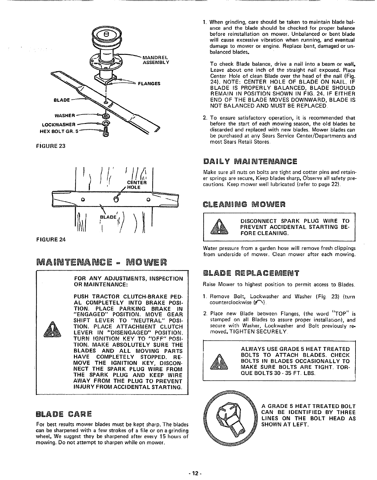
To raise rear of mower, loosen Nut "E _ on both Rear Sus-
pension Arms. Sclew both Nuts "F" up EQUAL NUMBER
OF TURNS (Fig 18)
3_ When distance "D" is 5/16" lower at front than rear, tight-
II II
en Not E .
4 To lower rear of mower, loosen Nut "F" on both Rear'
Suspension Arms an EQUAL NUMBER OF TURNS (Fig
16)
5, When distance hD" is 5/16" lower at front than rear, re-
tighten Nuts "E',
NOTE: WHEN ADJUSTING REAR SUSPENSION TRUN-
NIONS, ALWAYS ADJUST BOTH EQUALLY SO MOWER
WILL STAY LEVEL
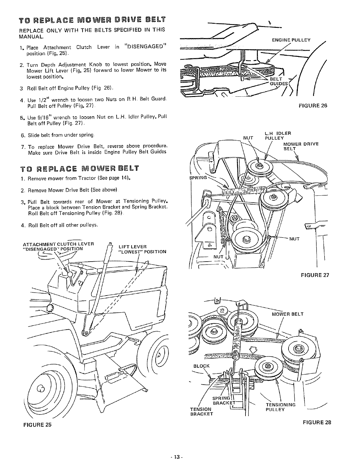
DEPTH ADJUSTMENT
Adjustment for mower height is made with the Depth Adjusta:
ment Knob• Raise Mower cutting height by turning Depth
Adjustment Knob clockwise ( _ }, Lower Mower cutting
height by turning Depth Adjustment Knob counterclockwise
(f_) (Fig, 19),
DEPTH ADJUSTMENT
KNOB
FIGURE 19 -10 -
OPERATION - I OWER
I _ READ THE "RULES FOR SAFEOPERA"
TION" CAREFULLY BEFORE OPERAT-
ING YOUR MOWER
THE MOWER MUST BE ADJUSTED PROPERLY FROM
FRONT TO REAR AND LEVELED FROM SIDETOSIDE
BEFORE OPERATING. THIS IS NECESSARY FOR LEVEL
AND EFFICIENT MOWING REFER TO PAGES9& 10
1 Place Attachment Clutch Lever in "DISENGAGED"
position (Fig 20)
2, Push tractor Clutch-Brake Pedal fully into brake position
3 Place Gear Shift Lever in "NEUTRAL" posltlon
NOTE: TRACTOR MUST BE IN NEUTRAL AND ATTACH-
MENT CLUTCH LEVER IN "DISENGAGED" POSITION
BEFORE TRACTOR WILL START
4 Start tractor and set engine speed to about 1/3 to I/2 throt-
tle before engaging mower After mower _s "ENGAGED"
and you have started forward travel, set to FULLTHROT-
TLE
NOTE: "ENGAGE" OR "DISENGAGE I' ATTACHMENT
CLUTCH LEVER SLOWLY
NEVER "ENGAGE" MOWER EXCEPT
WHEN SITTING ON TRACTOR SEAT
NOTE: ALWAYS MOW WITH THROTTLE CONTROL IN
"FAST" POSITION. THIS RESULTS IN BETTER GRASS
CUT, BETTER ENGINE COOLING, AND BETTER FUEL
ECONOMY
5 Use Lift Lever" to lower mower into cutting position Start
mowing in the first gear and increase ground speed as con-
ditions will permit Average cutting height is approximately
2 .. 1/2 to 2 -3/4 inches Height of cut can be adjusted by
means of the Depth Adjustment Knob (Fig 20), Moving
the Knob clockwise (/'_&) raises the mower (Fig 19)
Moving the Knob counterclockwise (_) lowers the mower,
6 Drive so that cllppings are discharged onto the area that has
been cut Have the cut area to the right of the machine
This will result in a more even distribution of clippings and
more uniform cutting When mowing large areas (Fig 21)
start by turning to the right so that the clippings wtl be
discharged away from shrubs, fences, driveways, etc After
two or three rounds, mow in the opposite direction making
left hand turns until finished If grass is extremely tall, it
should be mowed twice The first time cut re[atively high,
The second time to the desired height, The left hand side
of mower should be used for trimming, Use the Runner on
the right hand side as guide; the blade cuts approximately
an inch outside the runnel" (Fig, 22)
I I_II =IIII IIIIIIIIH I IIIII GUAIR#
Your mower has a flip-up Discharge Guard (Fig, 22) fo! door
or gate clearance when held in raised position
MAKE SURE ATTACHMENT CLUTCH
LEVER IS IN "DISENGAGED" POSITION
AND BLADES HAVE STOPPED BEFORE
RAISING DISCHARGE GUARD (DEFLEC-
TOR), NEVER OPERATE MOWER WITH-
OUT DISCHARGE GUARD IN OPERAT-
ING POSITION
ATTACHMENT CLUTCH LEVER
"ENGAGED" POSITION LIFT LEVER
ATTACHMENT CLUTCH LEVER
"DISENGAGED" POSITION
DEPTH ADJUSTMENT
KNOB
POSITION
DISCHARGE
GUARD
FIGURE 20
f
1
FIGURE 2i
_/_ DISCHARGE
GUARD
FIGURE 22
-11-
WASHE
LOCKWASHER _
HEN BOLT GR_ S'_*'-"_
FIGURE 23
ASSEMBLY
FLAPJGES
1When grinding, care should be taken to maintain blade bal-
ance and the blade should be checked for proper balance
before reinstallation on mower_ Unbalanced or bent blade
will cause excessive vibration when running, and eventual
damage to mower or engine, Replace bent, damaged or un-
balanced blades=
To cbeck Blade balance, drive a nail into a beam or wall.
Leave about one inch of the straight nail exposed. Place
Center Hole of clean Blade over the head of the nail (Fig.
24). NOTE: CENTER HOLE OF BLADE ON NAIL IF
BLADE IS PROPERLY BALANCED, BLADE SHOULD
REMAIN IN POSITION SHOWN IN FIG, 24. IF EITHER
END OF THE BLADE MOVES DOWNWARD, BLADE IS
NOT BALANCED AND MUST BE REPLACED
2_ To ensure satisfactory operation, it is recommended that
before the start of each mowing season, the old blades be
discarded and replaced with new blades. Mower blades can
be purchased at any Sears Service Center/Departments and
most Sears Retail Stores
tCENTER
HOLE
FIGURE 24
I
BLADE
!
MABNTENANCE = MOWER
FOR ANY ADJUSTMENTS, INSPECTION
OR MAINTENANCE:
PUSH TRACTOR CLUTCH-BRAKE PED-
AL COMPLETELY INTO BRAKE POSI-
TION_ PLACE PARKING BRAKE IN
"ENGAGED" POSITION. MOVE GEAR
SHIFT LEVER TO "NEUTRAL" POSI-
TION. PLACE ATTACHMENT CLUTCH
LEVER IN "DISENGAGED" POSITION,
TURN IGNITION KEY TO "OFF" POSI-
TION, MAKE ABSOLUTELY SURE THE
BLADES AND ALL MOVING PARTS
HAVE COMPLETELY STOPPED. RE-
MOVE THE IGNITION KEY, DISCON-
NECT THE SPARK PLUG WIRE FROM
THE SPARK PLUG AND KEEP WIRE
AWAY FROM THE PLUG TO PREVENT
INJURY FROM ACCIDENTAL STARTING_
8LADE CARE
DAnLY MAgNTENANCE
Make sure all nuts on bolts are tight and cotter pins and retain-
er springs are secure. K_ep blades sharp. Observe al! safety pre-
cautions Keep mower well lubricated (refer to page 22).
For best results mower blades must be kept sharp. The blades
can be sharpened with a few strokes of a file or on a grinding
wbeelo We suggest they be sharpened after every 15 hours of
mowing_ Do not attempt to sharpen while on mower.
Cn-EAI SNG MOWER
DISCONNECT SPARK PLUG WIRE TO
PREVENT ACCIDENTAL STARTING BE-
FORE CLEANING.
Water pressure from a garden hose will remove fresh clippings
from underside of mower_ Clean mower after each mowing_
BLADE REPLACEMENT
Raise Mower to highest position to permit access to Blades_
1 Remove Bolt, Loci<washer and Washer (Fig 23) (turn
counterclockwise (f'_)
2 Place new Blade between Flanges, (the word "TOP" is
stamped on all Blades to assure proper installa[ion), and
secure with Washer', Lockwasher and Bolt previously re-
moved. TIGHTEN SECURELY
ALWAYS USE GRADE 5 HEAT TREATED
BOLTS TO ATTACH BLADES. CHECK
BOLTS IN BLADES OCCASIONALLY TO
MAKE SURE BOLTS ARE TIGHT° TOR-
QDE BOLTS 30 •35 FT_ LBS
A GRADE 5 HEAT TREATED BOLT
CAN BE IDENTIFIED BY THREE
LINES ON THE BOLT HEAD AS
SHOWN AT LEFT_
-12-
TO REPLACE MOWE$1 O$ QVE BELT
REPLACE ONLY WITH THE BELTS SPECIFIED IN THIS
MANUAL
1_ Place Attachment Clutch Lever in "DISENGAGED" ..................
position (Fig, 25).
2. Turn Depth Adjustment Knob to lowest position, Move
Mower Lift Lever (Fig, 25) forward to lower Mower to its
lowest position,
3 Roll Belt off Engine PuIley (Fig 26).
4 Use 1/2" wrench to loosen two Nuts on R H Belt Guard.
Pull Belt off Pulley (Fig, 27)
5, Use 9/16" wrench to loosen Nut on L.H Idler Pulley, PuII
Belt off Pulley(Fig 27).
6. Slide belt from under spring
7. To replace Mower Drive Belt, reverse above procedure.
Make sure Drive Belt is ins{de Engine Pulley Belt Guides
TO REPLACE mOWER BELT
1. Remove mower from Tractor (See page 14)_
2. Remove Mower Drive Belt (See above)
3, Pull Belt towards rear of Mower at Tensioning Pulley,
Place a block between Tension Bracket and Spring Bracket.
Roll Belt off Tensioning Pulley (Fig. 28)
4. Roll Belt off all other pulleys_
ATTACHMENT CLUTCH LEVER
"DISENGAGED" POSITION LIFT LEVER
"LOWEST" POSITION
SPRING
_j"
FIGURE 26
L.H IDLER
NUT PULLEY
MOWER DRIVE
BELT
FIGURE 27
MOWER BELT
BLOCK
FIGURE 25
TENSION
BRACKET
TENSIONING
PULLEY J
FIGURE 28
-t3-
//
BRAKE SPRING
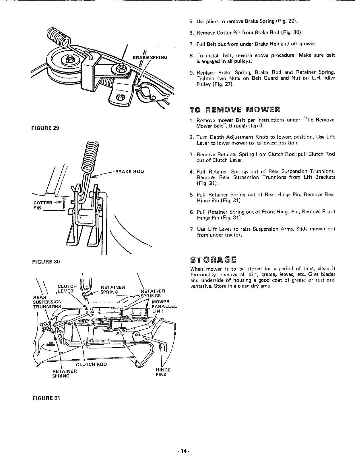
5_ Use pliers to remove Brake Spring (Fig, 29),
6. Remove Cotter Pin from Brake Rod (Fig, 39)
7. Pull Belt out from under Brake Rod and off mower
9. To install belt, reverse above procedure Make sure belt
is engaged in all pulleys,
9,. Replace Brake Spring, Brake Rod and Retainer Spring,
Tighten two Nuts on Belt Guard and Nut on L.H_ Idler
Pulley (Fig. 27)
FIGURE 29
PIN
E ROD
\
TO REMOVE MOWER
1 Remove mower Belt per instructions under "To Remove
Mower Bert", through step 3,
2. Turn Depth Adjustment Knob to lowest position= Use Lift
Lever to lower mower to its ],west position
3. Remove Retainer Spring from Clutch Rod; pull Clutch Rod
out of Clutch Lever'
4
50
6.
7,
Pull Retainer Springs out of Rear Suspension Trunnions_
Remove Rear Suspension Trunnions from Lift Brackets
(Fig, 31).
Pull Retainer Spring out of Rear Hinge Pin= Remove Rear
Hinge Pin (Fig, 31L
Pull Retainer Spring out of Front Hinge Pin, Remove Front
Hinge Pin (Fig, 31).
Use Lift Lever to raise Suspension Arms, Slide mower out
from under tractor=
FIGURE 30 STOR .GE
When mower is to be stored for a period of time, clean it
thoroughly, remove all dirt, grease, leaves, etc. Give blades
and underside of housing a good coat of grease or rust pre-
ventative, S(ore in a clean dry area
FIGURE 31
-14-
JJ BC 3"B
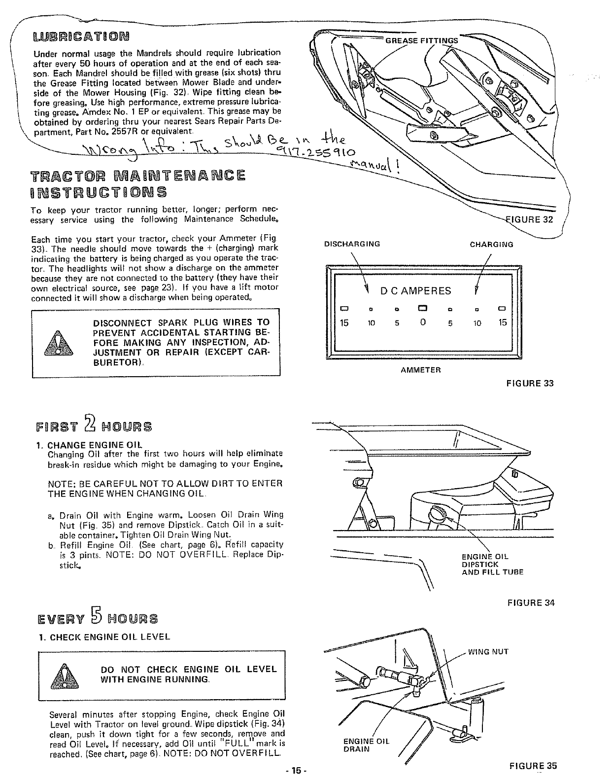
Under normal usage the Mandrels should require lubrication
after every 50 hours of operation and at the end of each sea-
t son. Each Mandrel should be filled with grease (six shots) thru
the Grease Fitting located between Mower Blade and under-
side of the Mower Housing (Fig. 32), Wipe fitting clean be-
fore greasing, Use high performance, extreme pressure lubrica-
ting grease. Amdex No. 1 EP or equivalent, This grease may be
obtained by ordering thru your nearest Sears Repair Parts De-
\ partment, Part No. 2557R or equivalent,
To keep your tractor running better, longer; perform nec-
essary service using the following Maintenance Schedule.
Each time you start your tractor, check your Ammeter (Fig
33). The needle should move towards the + (charging) mark
indicating the battery is being charged asyou operate the trac-
tor The headlights will not show a discharge on the ammeter
because they are not connected to the battery (they have their
own electrical source, see page 23). If you have a lift motor
connected it will show a discharge when being operated°
ADISCONNECT SPARK PLUG WIRES TO
PREVENT ACCIDENTAL STARTING BE-
FORE MAKING ANY INSPECTION, AD-
JUSTMENT OR REPAIR (EXCEPT CAR-
BURETOR),
DISCHARGING
\
\
'_' DCAMPERES
i:_ D Q r"l o
15 10 5 0 5
CHARGING
/
/.
/
oD
lo 15
AMMETER
FIGURE 33
FORS? N@#R8
1. CHANGE ENGINE OIL
Changing Oil after the first two hours will help eliminate
break-in residue which might be damaging to your Engine.
NOTE: BE CAREFUL NOT TO ALLOW DIRT TO ENTER
THE ENGINE WHEN CHANGING OIL
a. Drain Oil with Engine warm. Loosen Oil Drain Wing
Nut (Fig 35) and remove Dipstick Catch Oil in a su{t-
able container. Tighten Oil Drain Wing Nut.
b Refill Engine Oil (See chart, page 6)° Refill capacity
is 3 pints NOTE: DO NOT OVERFILL. Replace Dip-
stick= ENGINE OIL
DIPSTICK
AND FILL TUBE
IEVERV N@NR
1o CHECK ENGINE OIL LEVEL
ADO NOT CHECK ENGINE OIL LEVEL
WITH ENGINE RUNNING
Several minutes after stopping Engine, check Engine Oil
Level with Tractor on level ground Wipe dipstick (Fig. 34)
clean, push it down tight for a few seconds remove and
read Oil Level. It_necessary, add Oil until FULL" mark is
reached, (Seechart, page 6). NOTE: DO NOT OVERFILL.
-15-
ENGINE OIL
DRAIN
FIGURE 34
FIGURE 35

PAPER
CARTRIDGE
A,RSC.EEN
FIGURE 36
FIGURE 37
CUT.AWAY VIEW
FIGURE 38
_.._. KNOB
PLATE
FOAM
PRE-CLEANER
BODY
GREASE BOTH /
OIL SPINDLES
I
I
I
I
I
t
I
4T CAP
BATTERY
BATTERY
EVE.V25 .O..S
(EVERY 15 HOURS IF OPERATING
IN VERY DUSTY CONDITIONS)
1o CLEAN AIR CLEANER FOAM PRE-CLEANER (FIG, 36).
a. Remove Knob and Cover,
b, Remove Foam Pre-Cleaner element by sliding it off of
the Paper Cartridge.
c, Wash Foam Pre-Cleaner in liquid detergent and water,
d. Wrap Foam Pre-Cleaner in cloth and squeeze dry=
e. Saturate Foam Pre-Cleaoer in engine oil. Squeeze to re-
move excess Oil,
f, Install Foam Pre-Cieanet over Paper Cartridge, Reassem-
ble Cover and Screw down tight.
Yearly or every 100 hours, whichever occurs first, remove
Paper Cartridge (Service more often if necessary)° Clean by
tapping gently on fiat surface. If very dirty, replace Cart-
ridge_
CAUTION: PETROLEUM SOLVENTS ARE NOT TO BE
USED TO CLEAN PAPER CARTRIDGE. THEY MAY
CAUSE DETERIORATION OF THE CARTRIDGE. DO NOT
OIL PAPER CARTRIDGE. DO NOT USE PRESSURIZED
AIR
NOTE: NEVER RUN ENGINE WITH AIR CLEANER RE-
MOVED_
2, CLEAN AIR SCREEN
Air Screen (Fig. 36) must allow free-flow of air to prevent
Engine damage from overheating Clean with a wire brush,
compressed air or water pressure to remove dirt, chaff,
stubborn dried gum and fibers.
3_
4,,
CHANGE ENGINE OIL
The best time to drain Engine Oil is at the end of a day's
operation when all dirt and foreign materials are suspended
in the hot Oil. See oil chart, page 6.
CLEAN FRONT GRILL
The front GrilJ (Fig. 2) must allow free flow of air to pre=
vent engine damage from overheating
a, Brush off debris
5_ LUBRICATE STEERING AND FRONTWHEELS
There is a grease fitting on each front wheel. Use a grease
gun; give each grease fitting two shots of Extreme Pressure
Lubricating Grease Amdex No. 1 or equivalent (available
through your Sears Service Center). Use 30 weight oil to
lubricate Front Spindles (Fig. 37). Use Amdex No. 1 to
grease Front Axle Pivot (Fig_ 37)_ Sears Part No. 2557R.
6. OIL PIVOT POINTS
Place several drops of SA.E. 30 Oil at points where parts
move against each other, especially:
a. Front Axle Pivot=
b. Hood Hinges.
e. Foot Pedal Shaft (both ends).
d Lift Shaft (both ends).
SEE LUBRICATION CHART, PAGE 22
7, CHECK BATTERY
a. Electrolyte solution level in each Battery Cell should be
even with bottoms of tubes in cells (Fig. 38). Add dis-
tilled water if oecessary_ NOTE: DO NOT OVERFILL,
b, Keep Battery and Terminals clean Refer to step 8,
c. Keep Battery Bolts tight.
d. Keep Vent Caps tight and small vent holes in Caps
open.
e, Recharge SLOWLY at 3 amperes if necessary.
-16-
8 CLEAN BATTERY AND TERMINALS
Corrosion and dirt on the Battery and Terminals cause
the Battery to "leak" power and hinders the operation of
the charger
a. Remove the Battery from the Tractor and wash with
four tablespoons of baking soda to one gallop of water,
NOTE: BE CAREFUL NOT TO GET THE SODA
SOLUTION INTO THE CELLS. Rinse the Battery with
plain water, dry and reinstall on Tractor°
b Clean terminals and cable ends w_th a wire brush until
bright, Replace Battery Cables Coat terminal connec-
tions with Vasoline
Ev= v5@ H=u =
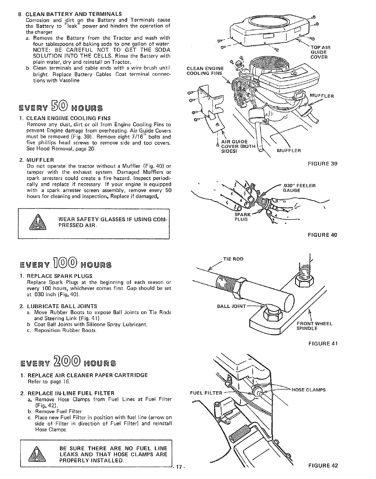
1. CLEAN ENGINE COOLING FINS
Remove any dust, dirt or oil from Engine Cooling Fins to
prevent Engine damage from overheating. Air" Guide Covers
must be removed (Fig. 39) Remove eight 7/16" bolts and
five phillips head screws to remove side end top covers_
See Hood Removal, page 20
2. MUFFLER
Do not operate the tractor without aMuffler (Fig, 40) or
tamper with the exhaust system Damaged Mufflers or
spark arresters could create a fire hazard. Inspect periodi-
cally and replace if necessary If your engine is equipped
with a spark arrester screen assembly, remove every B0
hours for cleaning and inspection. Replace if damaged°
WEAR SAFETY GLASSES IF USING COM- t
PRESSED AIR_
CLEAN ENGINE
COOLING FINS
"a.
I AIR GUIDE
$ COVER (BOTI*
SIDES) MUFFLER
GUIDE
COVER
MUFFLER
FIGURE 39
• " .ozo" FEELER
-_ _ GAUGE
,
FIGURE 40
1o REPLACE SPARK PLUGS
Replace Spark Plugs at the beginning of each season or
every 100 hours, whichever comes first Gap should be set
at 030 inch (Fig. 40)
2. LUBRICATE BALL JOINTS
aMove Rubber Boots to expose Ball Joints on Tie Rods
and Steering Link (Fig, 41)
b Coat Ball .Joints with Silicone Spray Lubricant
c Reposition Rubber Boots
1. REPLACE AIR CLEANER PAPER CARTRIDGE
Refer to page 16
2REPLACE IN-LINE FUEL FILTER
a. Remove Hose Clamps from Fuel Lines at Fuel Filter
(Fig. 42),
b. Remove Fuel Filter
c Place new Fuel Filter in position with fuel line (arrow on
side of Filter in direction of Fue! Filter) and reinsta!!
Hose Clemps_
]
BE SURE THERE ARE NO FUEL LINE |
LEAKS AND THAT HOSE CLAMPS ARE
PROPERLY INSTALLED.
17-
TIE ROD
FRONT WHEEL
SPINDLE
FIGURE 41
FIGURE 42
HOLES "A"
FIGURE 43
FIGURE 44
r l
RETAINER
SPRING
THROTTLE
CABLE "_
TRANSAXLE
PULLEY
BELT GUIDE
BRACKET
THROTTLE CABLE
THROTTLESTOP
SCREW
GOVERNOR
CONTROL
BELT
GUIOI
2,
RETAINER
SPRING
AS N EDED
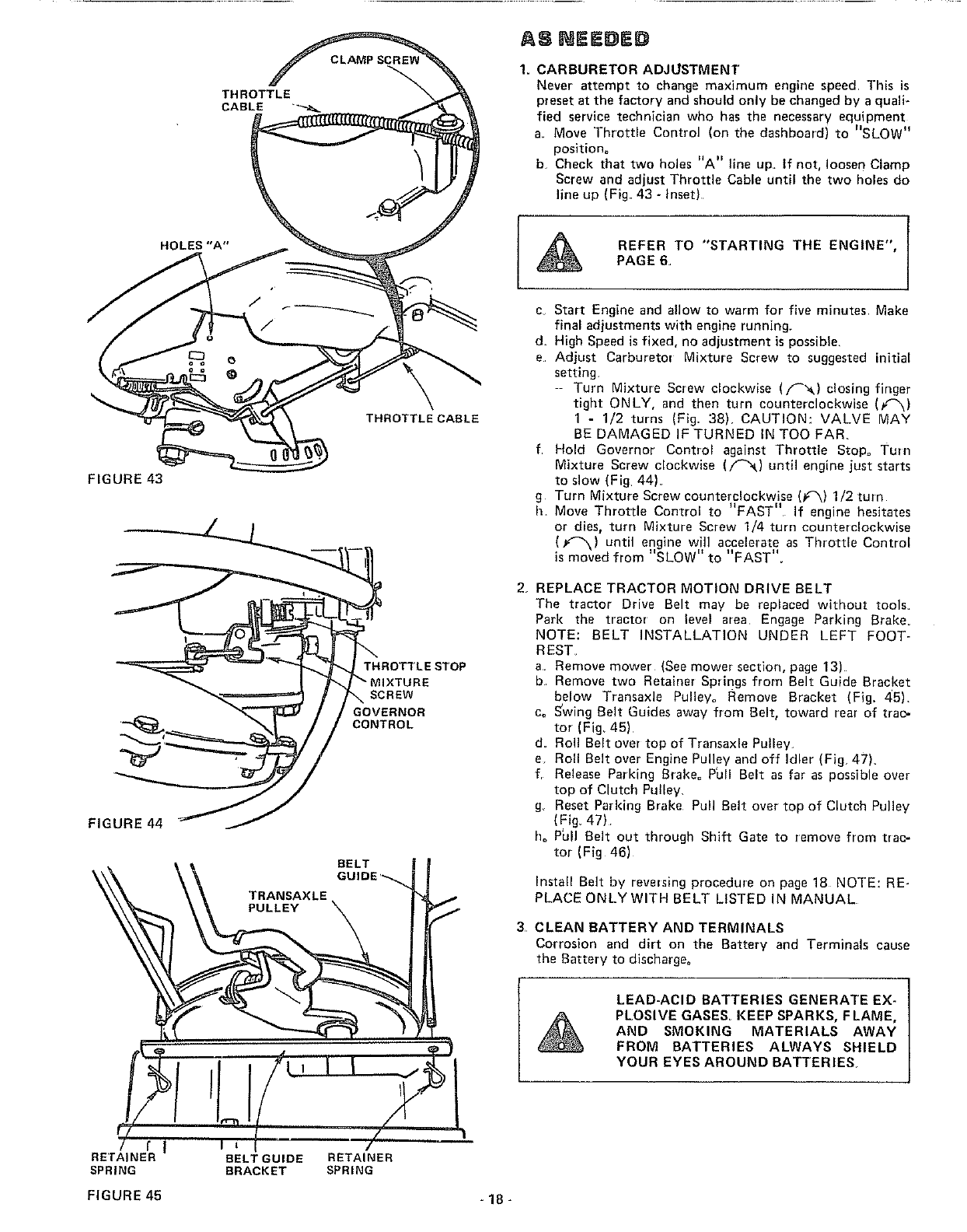
1. CARBURETOR ADJUSTMENT
Never attempt to change maximum engine speed This is
preset at the factory and should only be changed by a quali-
fied service technician who has the necessary equipment
a. Move Throttle Control (on the dashboard) to "SLOW"
position°
b. Check that two holes "A" line up. If not, loosen Clamp
Screw and adjust Throttle Cable until the two holes do
line up (Fig. 43 -inset)
REFER TO "STARTING THE ENGINE",PAGE6.
3
c. Start Engine and allow to warm for five minutes Make
final adjustments with engine running_
d= High Speed is fixed, no adjustment is possible.
e. Adjust Carburetor Mixture Screw to suggested initial
setting.
-- Turn Mixture Screw clockwise (p_) closing finger
tight ONLY, and then turn counterclockwise (f_)
1 - 1/2 turns (Fig. 38). CAUTION: VALVE MAY
BE DAMAGED iF TURNED IN TOO FAR_
f Hold Governor Control against Throttle Stop= Tuln
Mixture Screw clockwise (f_) until engine just starts
to slow (Fig 44)_
g Turn Mixture Screw counterclockwise (f_'_) 1/2 turn
h Move Throttle Control to "FAST" If engine hesitates
or dies, turn Mixture Screw 1/4 turn counterc!ockwise
(f-"k) until engine will accelerate as Throttle Control
•-- ii H It I_
_smoved from SLOW to FAST
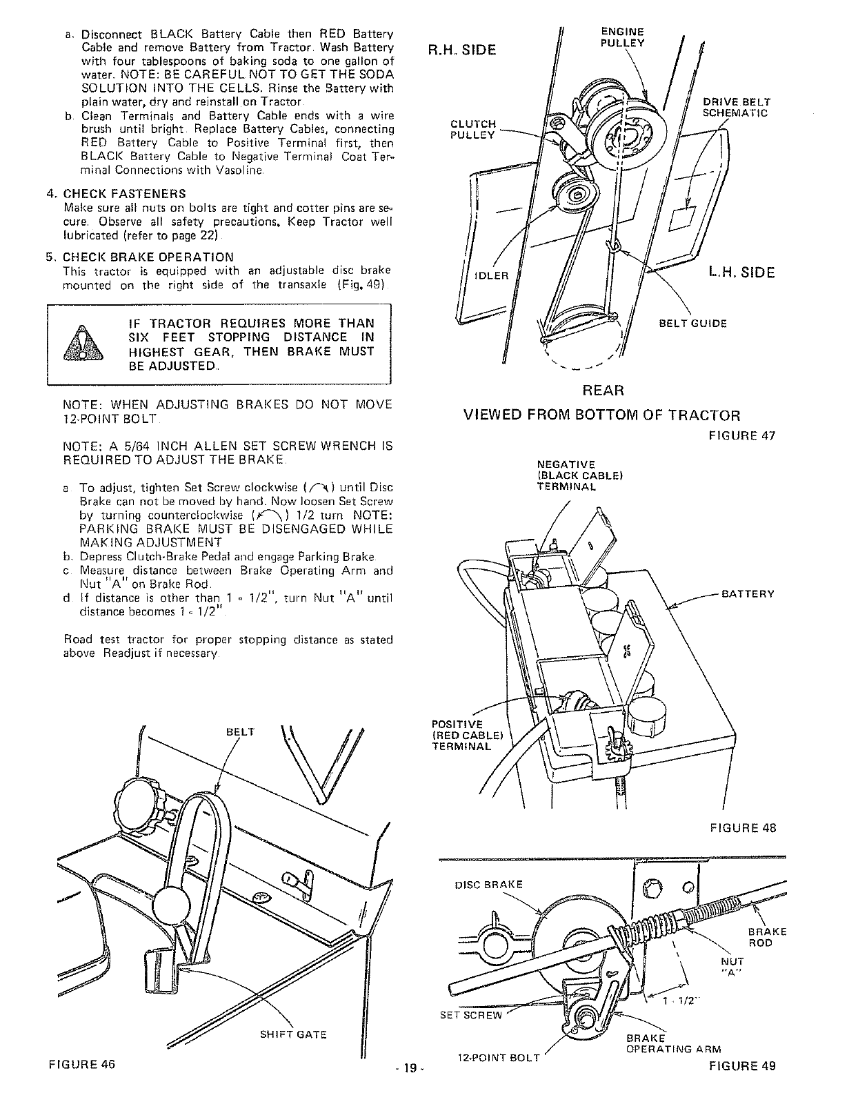
REPLACE TRACTOR MOTION DRIVE BELT
The tractor Drive Belt may be replaced without tools_
Park the tractor on level area Engage Parking Brake.
NOTE: BELT INSTALLATION UNDER LEFT FOOT-
REST
a. Remove mower (See mower section, page 13)
b Remove two Retainer Springs from Belt Guide Bracket
below Transaxle Pulley° Remove Bracket (Fig. 45).
co S'wing Belt Guides away from Belt t toward rear of traC-
tor (Fig_ 45)
d_ Rol! Belt over top of Trensaxle Pulley.
e. Roll Belt over Engine Pulley and off Idler (Fig 47).
f, Release Parking Brake° Phil Belt as far as possible over
top of Clutch Pulley.
g. Reset Parking Brake Pull Belt over top of Clutch Pulley
(Fig_ 47).
ho P_I] Belt out through Shift Gate to remove from trac-
tor (Fig 46)
Install Belt by reversing procedure on page 18 NOTE: RE-
PLACE ONLY WITH BELT LISTED IN MANUAL
CLEAN BATTERY AND TERMINALS
Corrosion and dirt on the Battery and Terminals cause
the Battery to discharge°
LEAD-ACID BATTERIES GENERATE EX-
PLOSIVE GASES. KEEP SPARKS, FLAME,
AND SMOKING MATERIALS AWAY
FROM BATTERIES ALWAYS SHIELD
YOUR EYES AROUND BATTERIES,
FIGURE 45 -18-
a. Disconnect BLACK Battery Cable then RED Battery
Cable and remove Battery from Tractor Wash Battery
with four tablespoons of baking soda to one gallon of
water NOTE: BE CAREFUL NOT TO GET THE SODA
SOLUTION INTO THE CELLS. Rinse the ,Battery with
plain water, dry and reinstall on Tractor
b Clean Terminals and Battery Cable ends with a wire
brush until bright Replace Battery Cables, connecting
RED Battery Cable to Positive Terminal first, then
BLACK Battery Cable to Negative Terminal Coat Ter,,
minal Connections with Vasoline
4. CHECK FASTENERS
Make sure all nuts on bolts are tight and cotter pins are se-
cure Observe all safety precautions, Keep Tractor well
lubricated (refer to page 22)
5_ CHECK BRAKE OPERATION
This tractor is equipped with an adjustable disc brake
mounted on the right side of the transaxfe (Fig, 49)
IF TRACTOR REQUIRES MORE THAN
SIX FEET STOPPING DISTANCE IN
HIGHEST GEAR, THEN BRAKE MUST
BE ADJUSTED
NOTE: WHEN ADJUSTING BRAKES DO NOT MOVE
12-POINT BOLT
NOTE; A 5/64 INCH ALLEN SET SCREW WRENCH IS
REQUIRED TO ADJUST THE BRAKE
a To adjust, tighten Set Screw clockwise (/-'_) until Disc
Brake can not be moved by hand. Now loosen Set Screw
by turning counterclockwise (k'_k) 1/2 turn NOTE:
PARKING BRAKE MUST BE DISENGAGED WHILE
MAKING ADJUSTMENT
b, Depress Clutch-Brake Pedal and engage Parking Brake
c Measure distance between Brake Operating Arm and
Nut "A" on Brake Rod
d If distance is other than 1 o 1/2", turn Nut "A" until
distance becomes 1 _ 1/2"
Road test tractor for proper stopping distance as stated
above Readjust if necessary
R.Ho SIDE
ENGINE
PULLEY
CLUTCH
PUL
DRIVE BELT
SCHEMAT(C
L,H, SIDE
BELT GUIDE
REAR
VIEWED FROM BOTTOM OF TRACTOR
FIGURE 47
NEGATIVE
(BLACK CABLE)
TERMINAL
BELT
SHIFT GATE
POSITIVE
(RED CABLEI
TERMINAL
DISC BRAKE
SET SCREW
FIGURE 48
BRAKE
ROD
NUT
,*A._
1 I/2-
BRAKE
OPERATING ARM
12-POINT BOLT
FIGURE 46 " 19 - FIGURE 49
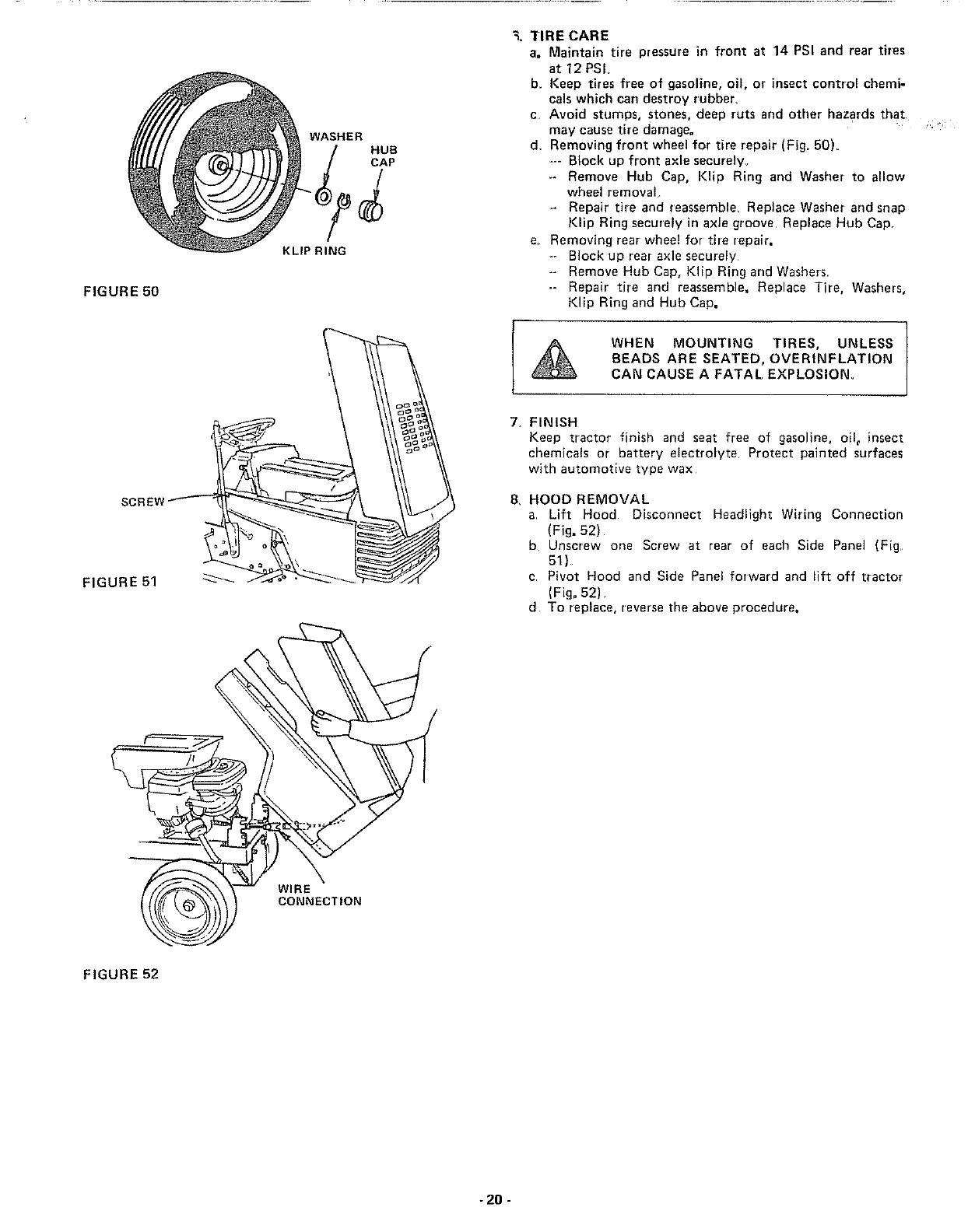
FIGURE 50
SCRE
FIGURE 51
WASHER
HUB
CAP
KLIP RING
"_=TIRE CARE
a. Maintain tire pressure in front at 14 PSI and rear tires
at 12 PSI
b. Keep tires free of gasoline, oil, or insect control chemi-
cals which can destroy rubber,
cAvoid stumps, stones, deep ruts and other hazards that
may cause tire damage.
d, Removing front wheel for tire repair (Fig. 50)_
--- Block up front axle securely,
-- Remove Hub Cap, Klip Ring and Washer to allow
wheel removal
*- Repair tire and reassemble, Replace Washer and snap
Kllp Ring securely in axle groove Replace Hub Cap
e, Removing rear wheel for tire repair.
-- Block up rear axle securely
-- Remove Hub Cap, Klip Ring and Washers
-- Repair tire and reassemble. Replace Tire, Washers,
Klip Ring and Hub Cap.
7_
S,
WHEN MOUNTING TIRES, UNLESS I
BEADS ARE SEATED, OVERINFLATION
CAN CAUSE A FATAL EXPLOSION.
FINISH
Keep tractor finish and seat free of gasoline, oil_ insect
chemicals or battery electrolyte Protect painted surfaces
with automotive type wax
HOOD REMOVAL
aLift Hood Disconnect Headlight Wiring Connection
(Fig. 52)
b Unscrew one Screw at rear of each Side Panel (Fig,
51)
c Pivot Hood and Side Panel forward and lift off tractor
(Fig. 52)
d To replace, reverse the above procedure.
WIRE
CONNECTION
FIGURE 52
-20 -
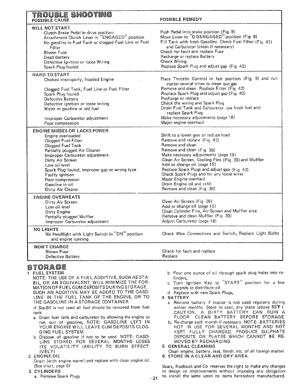
3" OUI LE SHO@T G
POSSIBLE CAUSE POSSIBLE REMEDY
WILL NOT START
C utch-Brake Pedal in drive position
• II t_ .•
Attachment Clutch Lever in ENGAGED poslt_on
No gasoline in Fuel Tank or clogged Fuel Line or Fuel
Filter
Clown Fuse
Dead Battery
Defective ignition or loose Wiring
Spark Plug fouled
HARD TO START
Choked improperly, flooded Engine
Clogged Fuel Tank, Fuel Line or Fuel Filter
Spark Plug fouled
Defective Battery
Defective Ignition or loose wiring
Water in gasoline or old fuel
Improper Carburetor adjustment
Poor compression
ENGINE MISSES OR LACKS POWER
Engine overloaded
Clogged Fuel Filter
Clogged Fuel Tank
Partially plugged Air Cleaner
Improper Carburetor adjustment
Dirty Air Screen
Low oil level
Spark Plug fouled, improper gap or wrong type
Faulty ignition
Poor compression
Gasoline in oil
Dirty Air Cleaner
Push Pedal into brake position (Fig, 8)
Move Lever to "DISENGAGED" position (Fig 9)
Fill Tank with fresh Gasoline Check Fuel Filter (Fig 42)
and Carburetor (clean if necessary)
Check for fault and replace Fuse
Recharge or replace Battery
Check Widng
Replace Spark Plug and adjust gap (Fig 40)
Place Throttle Control in fast position (Fig 9) and run
starter several times to clean out gas
Remove and clean Replace Filter (Fig 42)
Replace Spark Plug and adjust gap (Fig 40)
Recharge or replace
Check the wiring and Spark Plug
Dra_n Fuel Tank and Carburetor. use fresh fuel and
replace Spark Plug
Make necessary adjustments (page 18)
Major engine overhaul
Shift to a lower gear or reduce load
Remove and replace (Fig 42)
Remove and clean
Remove and clean (Fig 36)
Make necessary adjustments (page 18)
Clean Air Screen, Cooling Fins (Fig 39) and Muffler
Add or change oil (page 15)
Replace Spark Plugs and adjust gap (Fig 40)
Check Spark Plugs and for any loose wires
Major Engine overhaul
Drain Engine oil and refill
Remove and clean (Fig 36)
ENGINE OVERHEATS
Dirty Air Screen Clean Air Screen (Fig 36)
Low oil level Add or change oil (page 15)
Dirty Engine Clean Cylinder Fins, Air Screen and Muffler area
Partially plugged Muffler Remove and clean Muffler (Fig 39)
Improper Carburetor adjustment Adjust Carburetor (page 18)
NO LIGHTS
No Headlight with Light Swttch m ON position Check Wire Connections and Switch. Replace Light Bulbs
and engine running
WON'T CHARGE
Blown Fuse Check for fault and replace
Defective Battery Replace
t. FUEL SYSTEM
NOTE: THE USE OF A FUEL ADDITIVE, SUCH AS STA-
BIL, OR AN EQUIVALENT, WILL MINIMIZE THE FOR-
MATION OF FUEL GUM DEPOSITS DURING STORAGE.
SUCH AN ADDITIVE MAY BE ADDED TO THE GASO-
LINE IN THE FUEL TANK OF THE ENGINE, OR TO
THE GASOLINE IN A STORAGE CONTAINER
If Sta-Cil is not used alt fueI should be removed from fuel
tank
a Drain fuel tank and carburetor by allowing the engine to
run out of gasoline. NOTE: GASOLINE LEFT IN
YOUR ENGINE WILL LEAVE GUM DEPOSITS CLOG-
GING FUEL SYSTEM.
b Dispose of gasoline if not to be used NOTE: GASO-
LINE STORED FOR SEVERAL MONTHS LOSES
ITS VOLATILITY (ABILITY TO BURN EFFECT
IVELY)
2 ENGINE OIL
Drain (with engine warm) and replace with clean engine od
(Seechart, page 6)
3. CYLINDERS
a. Remove Spark Plugs - 21
bPour one ounce of oil through spark plug holes into cy-
linders.
c Turn Ignition Key to "START" position for a few
seconds to distribute oil
d Replace with new Spark Plugs°
4 BATTERY
a Remove battery if tractor is not used regularly during
winter months Store in cool, dry place (above 50°F)
CAUTION: A DIRTY BATTERY CAN RUIN A
FLOOR CLEAN BATTERY BEFORE STORAGE.
bo Re-charge each month if necessary. NOTE: BATTERIES
NOT IN USE FOR SEVERAL MONTHS AND NOT
KEPT FULLY CHARGED, PRODUCE SULPHATE
DEPOSITS ON PLATES WHICH CANNOT BE RE..
MOVED BY RECHARGING
5 GENERAL CLEANING
Clean engine, battery, seat, finish, etc of all foreign matter
B, STORE IN A CLEAN AND DRY AREA.
Sears, Roebuck and Co reserves the right to make any changes
in design or improvements without imposing any obligation
to install the same upon its items heretofore manufactured,
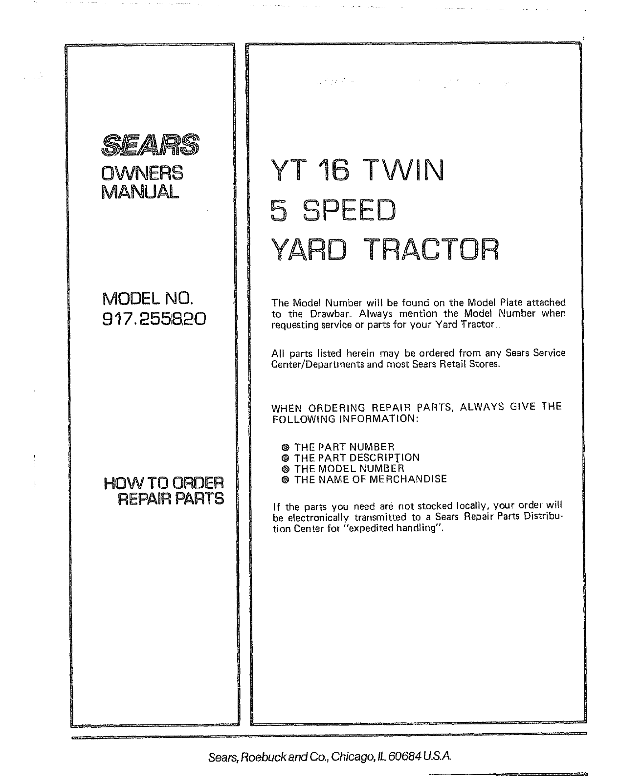
OWNERS
MANUAL
MODEL NO.
917.2551820
HOW TO ORDER
REPAaRPARTS
YT 16 TWIN
5 SPEED
YARD TRACTOR
The Model Number will be found on the Model Plate attached
to the Drawbaro Always mention the Model Number when
requesting service or parts for' your Yard Tractor°
All parts listed herein may be ordered from any Sears Service
Center/Departments and most Sears Retail Stores.
WHEN ORDERING REPAIR PARTS, ALWAYS GIVE THE
FOLLOWING INFORMATION:
@ THE PART NUMBER
@ THE PART DESCRIP!_ION
@ THE MODEL NUMBER
@ THE NAME OF MERCHANDISE
If the parts you need are not stocked locally, your order will
be electronically transmitted to a Sears Repair Parts Distribu-
tion Center' for "expedited handling".
Sears, Roebuck and Co., Chicago, IL 60684 UoS.A
...... .............. ,,_,p
