Craftsman 917256410 User Manual TRACTOR Manuals And Guides 1104008L
User Manual: Craftsman 917256410 917256410 CRAFTSMAN TRACTOR - Manuals and Guides View the owners manual for your CRAFTSMAN TRACTOR #917256410. Home:Lawn & Garden Parts:Craftsman Parts:Craftsman TRACTOR Manual
Open the PDF directly: View PDF ![]() .
.
Page Count: 56
)•_•i: H • .... H • • •• ••• •••• • ••
MODEL NUMBER 917.256410 OWNER'S MANUAL
•Assembly
•Operation
°Customer Responsibilities
•Service and Adjustments
•Repair Parts
CAUTION: Read and follow all safety rules and instructions before operating this equipment.
FOR CONSUMER ASSISTANCE HOT LINE, CALL THIS TOLL FREE NUMBER: 1-800-659-5917
IIIII II II II II
SAFETY RULES
Safe Operation Practices for Ride-On Mowers
IMPORTANT: THIS CUTTING MACHINE IS CAPABLE OF AMPUTATING HANDS AND FEET AND THROWI NG OBJECTS.
FA LURE TO OBSERVE THE FOLLOWING SAFETY INSTRUCTIONS COULD RESULT IN SERIOUS INJURY OR DEATH.
GENERAL OPERATION :I11, CHILDREN ..... :
aRnec_d,nt_deerSatac_dr_ea_edffoO_O;a__nstructi0ns in the manua! : Tragic accidents can occur if the operator is not alert to the:
................. ..... presence of ch dren. Chitdren are often attracted to the
Only:allow responsible adults, who are familiar with the mach ne and the mowin_ activity Never assume that
nstruct ons, to operate the roach no. :...... :: .... _: • . . = ou ia_t" ....... :
...... _ ....... : _ children will remain-where y t saw them.:
Clear the area of objects such as rocks, toys, wire, etc.,
L
0
which could be picked up and thrown by the blade.
Be sure the area isclear Ofother peoplebefore mowing. Stop
machine if anyone enters the area.
Never carry passengers.
Do not mow in reverse unless absolutely necessary, Always
took down and behind before and while backing.
Be aware of the mower discharge direction and do not point
it at anyone. Do not operate the mower without either the
entire grass catcher or the guard in place.
•Slow down before turning.
•Never leave a running machine unattended. Always turn off
blades, set parking brake, stop engine, and remove keys
before dismounting.
•Turn off blades when not mowing.
•Stop engine before removing grass catcher or unclogging
chute.
•Mow only in daylight or good artificial light.
• Do not operate the machine while under the influence of
alcohol or drugs.
•Watch for traffic when operating near or crossing roadways.
• Use extra care when loading or unloading the machine into
a trailer or truck.
e
Keep children out of the mowing area and under the watchful
care of another responsible adult.
Be alert and turn machine off if children enter the area.
• Before and when backing, look behind and down for small
children,
*Never carry children. They may fall off and be seriously
injuredor interfere with safe machine operation.
• Never aitow children to operate the machine, .
• Use extra care when approaching blind corners, shrubs,
trees or other objects that may obscure vision.
IV. SERVICE ....
.Use extra care in handling gasoline and other fuels. They are
flammable and vapors are explosive.
Use only an approved container.
Never remove gas cap or add fuel with the engine
running. AIlow engine to coo! before refueling. Do not
smoke.
Never refuel the machine indoors.
- Never store the machine or fuel container inside where
there is an open flame, such as a water heater.
• :Never run a machine inside a closed area.
oKeep nuts and bolts, especially blade attachment bolts, tight
II. SLOPE OPERATION ..... : : i ::i : : :i i ! and keep equipment in good condition.
...... .............. Never tamper with safety devices. Check their proper
Slopes are a major factor reiatedtol]oss_of-c0ntrol and :::: :: operation regularly: ....
tipover accidents, which can result in severe injuryor death. _...... ....
..... =4, Keep machine free of grass, leaves or other debris build-up.
AI! slopes require extra caution. If you cannot back up:the i: Clean olor fuel:spillage. Allow machine to cool before
siope or if you feel uneasy on it do not mow it. = ::':il :storing. : :: :i:i_:
DO" :: : ::i i ::ii i::: : i;: ::i Stop and :inspect::the equipment if you strike an object.
". . . :_ .... : : :: : : : : : : Repar, ifnecessary, before:restarting.
*Mow up an(] (]own s opes, not across. : .... ........ ...........
..... : ,_ .:: : : .... i Nevermake adjustments or repairs with the engine running.
°Hemove obstacles sucn as rOCKS_ree i mos etc : _ .... : ,.
........ .". . : _rasscatcnercomponen[saresuDjecttowear, uamage, ana
° vvmcn Tor noles, .furs, or Dumps. uneven terra!n:cou_ :deterioration, which could expose moving parts or allow
overturn the machine Tatl grass can hide oostac/es
. - : _objects _to:bethrown. Frequently check components and
Use slow speed. Choose a ow gears Qthat you will not have _ rep ace w th manufacturer's recommended parts, when nec-
Avoid starting or stopping on as ope. If _tireslose traction,
disengage the blades and proceed s owiystraight down the
slope.
to stop or shift white on the slope.::
•Follow the manufacturer's recommendations for wheel
weights or counterweights to improve stability.
•Use extra care with grass catchers or other attachments.
These can change the stability of the machine.
•Keep a movement on the slopes stowand gradual. Do not
make sudden changes in speed oFd r_ct on ::_ii
o
essary.
•Mower blades are sharp and can cut. Wrap the blade(s) or
wear gloves, and use extra caution when servicing them.
° Check brake operation frequently. Adjust and service as
required.
:Look for this symbol to point out !m-
i:portant safety precautions. It means
:i CAUTION!!! BECOME ALERT!!! YOUR
..... SAFETY IS INVOLVED.
=
DO NOT:
•Do not turn on slopes unless necessary, and then turn slowly ] CAUTION: Always d!scon.nect spark plug I
and gradually downhill ifpossible. ..... I wireana pracewirewnerekcanno[comac_ !
°Do not mow near drop_offs, ditches, or embankments. The | spark plug in order to prevent accidental I
:mower cou d suddenJyturn over if a wheel s over the edge : ! starting wnen setting up, transpor[mg ....
........ of a cliff or ditch, or if an edge caves in.......... _ .... ::| .......:adjusting 0r making repairs. _I
• • •
'' Do notmowon wet grass.: Reduced traction could cause ..... ........_: : ' : ............ ............ '
:Sliding.: ....... : ........ ........ :' : ....
:Donottrytostabiiizethemaohinebyputtingyourfootonthe _ IWARNING i_::i ii
: : ground. ....... : ::::..... :: :The :::: ::' ::(haust: Con::::::| :
:1
:ancer, :birth defects,:: or :Other: !

CONGRATULATIONS on your purchase of a Sears
Tractor. It has been designed, engineered and manufac- :
tured to give you the best possible dependability and _ .....
performance. .......
Should you experience any problem you cannot easily
remedy, please contact your nearest Sears Authorized
Service Center/Department. We have competent, well-
trained technicians and the proper tools to service or repair
this tractor. : :
Please read and retain this manual. The instructions wi!l
enable you to assemble and maintain your tractor properly.
Always observe the "SAFETY RULES".
MODEL
NUMBER 917.256410
SERIAL
NUMBER
DATEOF PURCHASE
THE MODELAND SERIALNUMBERSWlLL BE FOUND
iON A PLATE UNDER THE SEAT,
!YOU SHOU[_D RECORD BOTH SERIAL NUMBERAND
: DATE OF PURCHASE AND KEEP IN A SAFE PLACE
FOR FUTURE REFERENCE.
MAINTENANCE AGREEMENT
A Sears Maintenance Agreement is available on this prod-
uct, Contact your nearest Sears store for details.
CUSTOMER RESPONSIBILITIES
° Read and observe the safety rules.
•Follow a regular schedule in maintaining, caring for and
using your tractor. .....
•Followthe instructions under"Customer Responsibili-
ties" and ,Storage" sections of this owner's manual.
WARNING: This tractor is equipped with an internal
combustion engine and should not be used on or near any
unimproved forest-covered, brush-covered or grass-cov-
eredland unless the engine's exhaust system is equipped
PRODUCT SPECIFICATIONS
...._ :i : 13.5
GASOLINE CAPACITY 5 QUARTS
AND TYPE: UNLEADED REGULAR
OtL TYPE (API-SF/SG): SAE 30 (above 32°F)
SAE 5W-30 (below 32°F)
OIL CAPACITY: 3 PINTS
SPARK PLUG: CHAMPION RJ19LM
(GAP: .030") STD361458
VALVE CLEARANCE: INTAKE: .005" - ;007 '!
EXHAUST: .009" - .011"
GROUND SPEED (MPH): FORWARD:
I st 1,0
2nd 1.3
3rd 2.1
4th 3.1
5th 4.0
6th 5. t
REVERSE: 1_6
TIRE PRESSURE: FRONT: 14 PSI
REAR: 12 PSI
CHARGING SYSTEM: 3 AMPS BA-I-FERY
5 AMPS HEADLIGHTS
BATTERY: AMP/HR: 25
MIN. CCA: 190
CASE SIZE: U1R
BLADE BOLT TORQUE: 30-35 FT. LBS.
with a spark arrester meeting applicable local or state laws
(if any). Ifa spark arrester is used, it should be maintained
in effective working order by the operator, .... :
In the state of California the above is required by law
(Section 4442 of the California Public Resources Code).
Other states may have similar laws. Federal laws apply on
federal lands. A spark arrester for the muffler is available
through your nearest Sears Authorized Service Center!
Department (See REPAIR PARTS section of this manual).
LIMITED TWO YEAR WARRANTY ON CRAFTSMAN RIDING EQUIPMENT
For two (2) years from the date of purchase, if this Craftsman Riding Equipment is maintained, lubricated and tuned up according
to the instructions in the owner's manual, Sears will repair or replace, free of charge, any parts found to be defective in material or
workmanship,
This Warranty does not cover:
• Expendable items which become worn during normal use, such as blades, spark plugs, air cleaners, belts, etc.
• Tire replacement or repai r caused bY punctures from outside objects, such as nails, thorns, stumps, or glass.
• Repairs necessary because of operator abuse, negligence, improper storage or accident or the failure to maintain the
equipment according to the instructions contained in the owner's manual.
• Riding equipment used for commercial or rental purposes.
LIMITED 90 DAY WARRANTY ON BATTERY
For ninety (90) days from date of purchase, if any battery included with this riding equipment proves defective in material or
workmanship and our testing determines the battery will not hold a charge, Sears wilt replace the battery at no charge.
IN-HOME WARRANTY SERVICE ON YOUR CRAFTSMAN RIDING EQUIPMENT IS AVAILABLE AT NO-CHARGE FOR 30
DAYS FROM THE DATE OF PURCHASE. PLEASE CONTACT YOUR NEAREST SERV[CE CENTER. AFTER 30 DAYS FROM
THE DATE OF PURCHASE, WARRANTY SERVICE IS AVAILABLE BY TAKING YOUR CRAFTSMAN RIDING EQUIPMENT TO
YOUR NEAREST SEARS SERVICE CENTER. (IN-HOME WARRANTY SERVICE WILL STILL BE AVAILABLE AFTER 30 DAYS
FROM THE DATE OF PURCHASE BUT A STANDARD TRIP CHARGE WILL APPLY.) THIS WARRANTY APPLIES ONLY
WHILE THIS PRODUCT IS IN THE UNITED STATES.
This Warranty gives you specific legal dghts, and you may also have other rights which may vary from state to state.
SEARS, ROEBUCK AND CO., D/817 WA, HOFFMAN ESTATES, IL 60179
,H,,nrrrMii
3
,,,,,! ii i i i i lllll i, •,! iiii Ill,l,l,,,,,ll
SAFETY RULES .................................................. .......... 2
PRODUCT SPECIFICATIONS ...................................... 3
CUSTOMER RESPONSIBILITIES ..................... 3, 15-18
WARRANTY .................................................................. 3
TRACTOR ACCESSORIES .......................................... 5
ASSEMBLY ............................................................... 7-9
OPERATION ............... ..................................... ,..... 10-14
INDEX
MAINTENANCE SCHEDULE ..................................... 15
SERVICE AND ADJUSTMENTS ........................... 19-24
STORAGE ................................................................... 25
TROUBLESHOOTING ........................................... 26-27
REPAIR PARTS - TRACTOR ................................ 30-47
REPAIR PARTS -ENGINE .................................... 48-52
PARTS ORDERING/SERVICE ............... BACK COVER
Schematic .................................... 29
Wiring Diagram ............................ 30
Engine:
Air Filter ................................... 17-18
Air Screen .................................... 18
Cooling Fins ................................. t8
Oil Change ................................... 17
Oil Level ............. .......................... t3
Oil Type ................................... 13,17
Preparation .................................. 13
Repair Parts ............................ 48-52
Starting ......................................... 14
Storage _....................................... 25
F
Filter:
Air Filter ........................................ 17
Fuel .............................................. 18
Fuel:
:_ Type ............................................. I4
Storage ........................................ 25
Fuse .................................................... 23
A
Accessories ........................................... 5
Adjustments:
Brake ............................................ 2t
Carburetor .................................... 24
Mower
Front-To-Back ......................... 20
Side-To-Side ........................... 20
Throttle Control Cable .................. 24
Air Filter, Engine ............................. 17-18
Air Screen, Engine .............................. 18
Assembly ............................. :.............. 7-9
B
Battery:
Charging ........................................ 8
Cleaning ....................................... 17
Starting with Weak Battery .......... 22
Storage ............. :.......................... 25
Terminals 17
Belt: .....
Motion Drive
Removal/Replacement ........... 21
Mower Belt(s)
Removal/Replacement ........... 21
Blade:
Sharpening .................................. 16
Replacement ................................ 16
Brake Adjustment ...................... .......... 21
H
Hood Removal/lnstaflation .................. 23
L
Leveling Mower Deck .......................... 20
:Lubrication:
Chart ............................................ 15
.... Engine ........................................... 17
M
Maintenance Schedule ....................... 15
Mower:
Adjustment, Front-to-Back ........... 20
Adjustment, Side-to-Side ............. 20
Blade Rep}acement ..................... 16
Blade Sharpening ........................ 16
Cutting Height .............................. 12
Installation .................................... 19
Operation. .................................... 13
Removal ...._............................ L.... 19
Mowing Tips ........................................ 14
Muffler ................................................. 18
Spark Arrestor ........................... 3,40
O
:C
:Carburetor Adjustment ........................ 24
Controls, Tractor ................................. 1!
Customer Responsibilities ............. I5- t8
Engine:
Air Filter .................................... 17
Air Screen ................................ 18
Cooling Fins ............................. 18
Engine Oil ........................... 13,17
Fuel Filter ................................. 18
Spark Plug(s) ........................... I8
Tractor:
Battery ................................. 16-17
Blade ........................................ 16
Lubrication Chart ..................... 15
Maintenance Schedule ............ 15
:Tire Care .......................... 8,16,22
Transaxle ................................. 17
.Cutting Height, Mower ........................ 12 Oil:
E
:Electrical:
• Interlocks and Relays ......._.......... 23
Cold Weather Conditions ........ 13,17
Engine .......................................... 17
Storage ........................................ 25
Operation ....................................... 10-14
Operating Mower ................................ 13
Options:
Accessories .................................... 5
Spark Arrester ........................... 3,40
P
Parking Brake ................................ 11,12
Parts Bag .............................................. 6
Parts, Replacement!Repair ............ 30-47
Product Specifications .......................... 3
R
Repair Parts ................................... 30-47
Safety Rules .......................................... 2
Seat ....................................................... 8
Service and Adjustments ............... 19-24
Carburetor .................................... 24
Fuse ....... _.............. ....................... 23
Hood Removal!installation ........... 23
Motion Drive Belt
Removal/Replacement ........... 21
Mower Bett(s)
Removal/Replacement ........... 21
Mower Adjustment
Front-to-Back .......................... 20
Side-to-Side ............................ 20
Mower Removal/Installation ......... 19
Tire Care .............................. 8,16,22
Slope Guide Sheet .............................. 55
Spark Plug(s) ...................................... 18
Specifications ........................................ 3
Starting the Engine ........................ 13-!4
Steering Wheel ................................ 7,22
Stopping the Tractor ........................... I2
Storage ................................................ 25
T
Throttle Control Cable Adjustment ...... 24
Tires ............................................ 8,16,22
Trouble Shooting Chart .................. 26-27
Transaxle. ........., 17
W
Warranty ................................................ 3
_:_ :_::: : : :::_:::::; ...... wiring Diagram......................:............3O ....
............... Wiring Schematic ............................... 229 ......
4"
AND ATTACHMENTS
IIH II I nl iiiiiiiiiiiiiiiiiiiiii .,,,,,,.,,,,, ill ii I..H
These accessories and attachments were available through most Sears retail outlets and service centers when the tractor was purchased,
Most Sears stores can order these items for,Y0U when you provide the model number of your tractor.
>
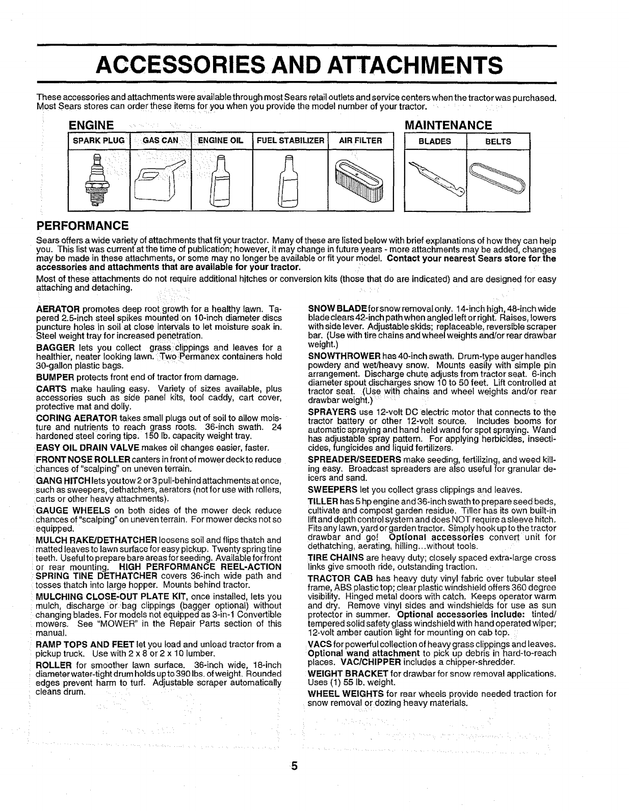
ENGINE .......
FUELSTABILIZER AIR FILTER
,,,,,,,
%
MAINTENANCE
BLADES BELTS
PERFORMANCE
Sears offers a wide variety of attachments that fit your tractor. Many of these are listed below withbrief explanations of how they can help
you. This list was current at the time of publication; however, it may change in future years - more attachments may be added, changes
may be made in these attachments, or some may no longer be available or fit your model. Contact your nearest Sears store for the
accessories and attachments that are available for your tractor. :....
Most of these attachments donot require additional hitches or conversion kits (those that do are indicated) and are designed for easy
attaching and detaching ....... .... , :
AERATOR promotes deep root growth for a healthy lawn. Ta-
pered 2.5-inch steel spikes mounted :on 10-inch diameter discs
puncture holes in soil at close intervals to let moisture soak in.
Steel weight tray for increased penetration.
BAGGER lets you collect grass:clippings and leaves for a
healthier, heater looking lawn. Two Permanex containers hold
30-gallon plastic bags.
BUMPER protects front end of tractor from damage.
CARTS make hauling easy. Variety of sizes available, plus
accessories such as side panel kits, tool caddy, cart cover,
protective mat and doily.
CORING AERATOR takes small plugs out of soil to allow mois-
ture and nutrients to reach grass roots. 36-inch swath. 24
hardened steel coring tips. t50 lb. capacity weight tray.
EASY OIL DRAIN VALVE makes oil changes easier, faster.
FRONT NOSE ROLLER canters in front of mower deck to reduce
chances of "scalping" on uneven terrain.
GANG HITCH lets you tow 2 or3 pull-behind attachments at once,
such as sweepers, dethatchers, aerators (not for use with rollers,
carts or other heavy attachments).
:GAUGE WHEELS on both sides of the mower deck reduce
chances of "scalping" on uneven terrain. For mower decks not so
equipped.
MULCH RAKE/DETHATCHER loosens soil and flips thatch and
matted leaves to lawn surface for easy pickup. Twenty spring tine
teeth. Useful to prepare bare areas for seeding. Available for front
or rear mounting. HIGH PERFORMANCE REEL-ACTION
SPRING TtNE DETHATCHER covers 36-inch wide path and
tosses thatch into large hopper. Mounts behind tractor.
MULCHING CLOSE-OUT PLATE KIT, once installed, lets you
mulch, discharge 0rbag clippings (bagger optional) without
changing blades. For models not equipped as 3-in-! Convertible
mowers. See "MOWER" in the Repair Parts section of this
manual.
RAMP TOPS AND FEET let you load and unload tractor from a
pickup truck. Use with 2 x 8 or 2 x 10 lumber.
ROLLER for smoother Eawnsurface. 36-inch wide, 18-inch
diameter water-tight drum holds upto 390 Ibs.of weight. Rounded
edges prevent harm to turf. Adjustable scraper automatically
cleans drum.
SNOW BLADEforsnowremovalonly. 14-inch high,48-inch wide
blade clears 42-inch path when angled left or right, Raises, lowers
with side lever. Adjustable skids; replaceable, reversible scraper
bar, (Use with tire chains and wheel weights and/or rear drawbar
weight.)
SNOWTHROWER has 40-inch swath, Drum-type auger handles
powdery and wet/heavy snow. Mounts easily with simple pin
arrangement, Discharge chute adjusts from tractor seat. 6-inch
diameter spout discharges snow 10 to 50 feet. Lift controlled at
tractor seat. (Use with chains and wheel weights and/or rear
drawbar weight.) ....
SPRAYERS use 12-volt DC electric motor that connects to the
tractor battery or other 12-vott source. Includes booms for
automatic spraying and hand held wand for spot spraying. Wand
has adjustable spray pattern. For applying herbicides, insecti-
cides, fungicides and liquid fertilizers.
SPREADER/SEEDERS make seeding, fertilizing, and weed kill-
ing easy. Broadcast spreaders are also useful for granular de-
icers and sand.
SWEEPERS let you collect grass clippings and leaves.
TILLER has 5 hp engine and 36-inch swath to prepare seed beds,
cultivate and compost garden residue. Tiller has its own built-in
lift and depth control system and does NOT require a sleeve hitch.
Fits any lawn, yard orgarden tractor. Simply hook up to the tractor
drawbar and go! Optional accessories convert unit for
dethatching, aerating, hitling...without tools.
TIRE CHAINS are heavy duty; closely spaced extra-large cross
linksgive smooth ride, outstanding traction.
TRACTOR CAB has heavy duty vinyl fabric over tubular steel
frame, ABS plastic top; clea r plastic windshield offers 360 degree
visibility. Hinged meta] doors with catch. Keeps operator warm
and dry. Remove vinyl sides and windshields for use as sun
protector in summer. Optional accessories include: tinted/
tempered solid safety glass windshield with hand operated wiper;
12-volt amber caution Iight for mounting on cab top.
VAOS for powerful collection of heavy grass clippings and leaves.
Optional wand attachment to pick up debris in hard-to-reach
places. VAClCHIPPER includes a chipper-shredder.
WEIGHT BRACKET for drawbar for snow removal applications.
Uses (1) 55 lb. weight.
WHEEL WEIGHTS for rear wheels provide needed traction for
snow removal or dozing heavy materials.
5
ill i i illll illl ,,, ,,,,,,,,,,,,,,,,
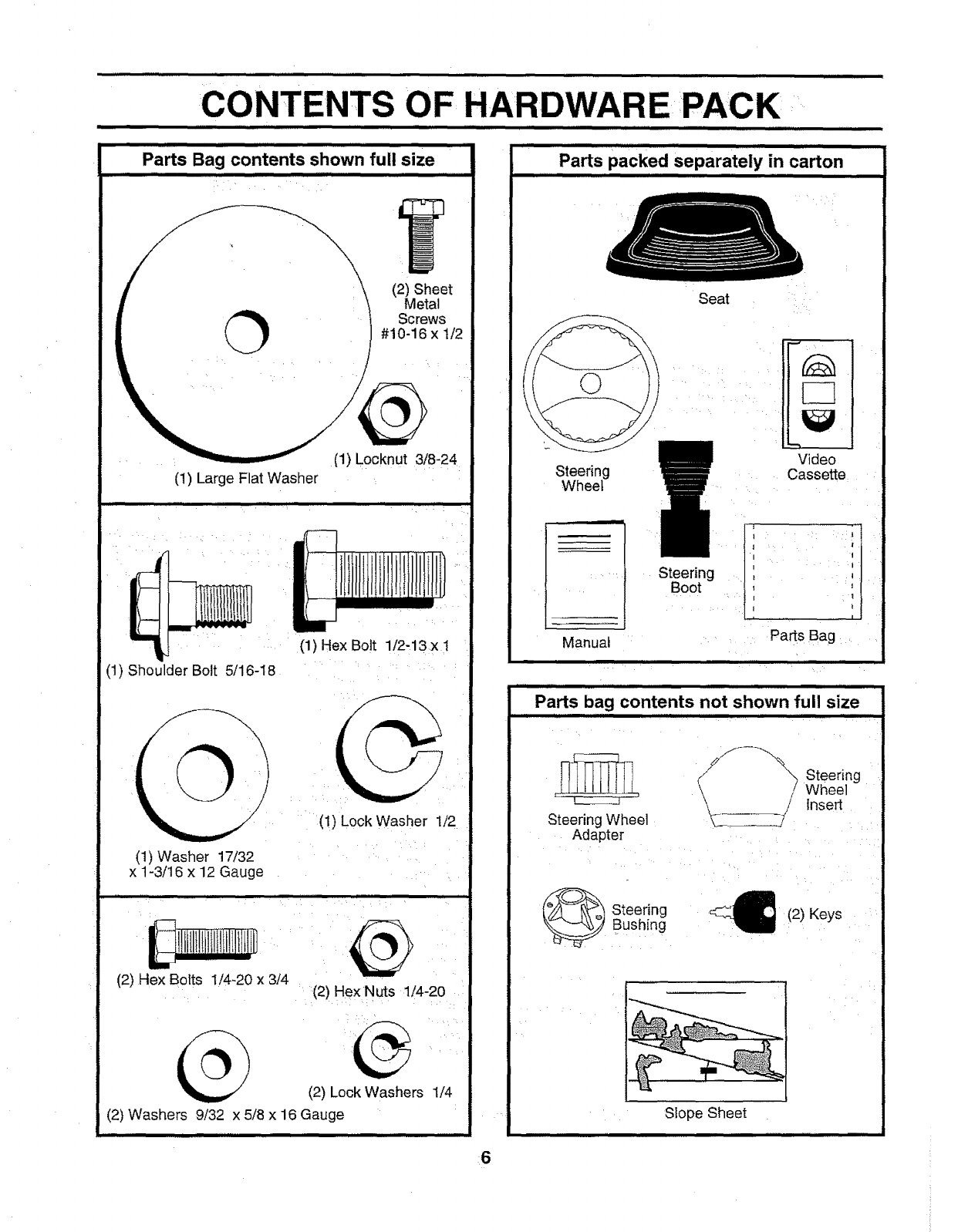
CONTENTS OF HARDWARE PACK
lil l I u i= ,,,,,,,,,,
Ill[ Jill ill ii I,
Parts Bag contents shown full size
IIIIII iii .......... i IIIII iiii
(2) Sheet
Metal
Screws
#10-16 x 1/2
O
(1) Locknut 3/8-24
(1) Large Flat Washer
(1) Hex Bolt 1/2-13 x 1
: i
(1) Shoulder Bolt 5/16-18
(!) Lock Washer 1/2
(!) Washer 17/32 ....
x 1-3/16 x 12 Gauge
i_1t11lI1_t_fl1litIU
(2) Hex Bolts 1/4-20 x 3/4
r,,i,,i ]llrlll : • I
(2) Hex Nuts 1/4-20
(2) Lock Washers 1/4
(2) Washers 9/32 x 5/8 x 16 Gauge
i IHIIIIIIIIIIIIIIIIIIII II IIl, I I,II, I Illlllll ,,ll
Parts packed separately in carton
ill i,,,,,,,,,,,,,,,,,,,,,,,,,,,,,
Seat
Steering
Wheel
Manual
Steering
Boot
Video
Cassette
il
Parts Bag
iii i
i ,,, ,i,,, ii r l
Parts bag contents not shown full size
i
_'%_X Steering
Wheel
_'\ /insert
Steering Wheel _ _/
Adapter
_ teering
Bushing 4:_ (2) Keys
Slope Sheet
6
LY
iiii , ,,,,,,,,,,,,,,,,,, i iii i iii i ,,, ,,,,,,,,,,,,,,,,,,,,, .... , ....................................
Your new tractor has been assembled at the factory with exception of those parts left unassembted for shipping purposes.
To ensure safe and proper operation of your tractor all parts and hardware you assemble must be tightened securely, Use
the correct tools as necessary to insure proper tightness.
• :•i •/¸ "•,.I•'••::::. ' : ':i ¸,
TOOLS REQUIRED FOR ASSEMBLY
A socket wrench set will make assemb y easier. Standard
wrench sizes are listed. :,_
(1) 5/16" wrench :i (1) :3/'4"wrench
(2) 7/16" wrenches: Tire pressure gauge
(1) 1/2 wrench UtJltyknufe
(1) 9/16" wrench: ::
When right or !eft hand is mentioned in this manual, it
means when you are in :::the:operating :position (seated
behind the steering wheel).: :,::,:> :,_
TO REMOVE TRACTOR FROM CARTON
•Remove all accessible loose parts and-parts cartons
from carton (See page 6).
•Cut, from top to bottom, along lines on all four corners
of carton, and lay panels flat. ....
•Check for any additional loose: parts or cartons and
remove ....
BEFORE ROLLING TRACTOR OFF SKID
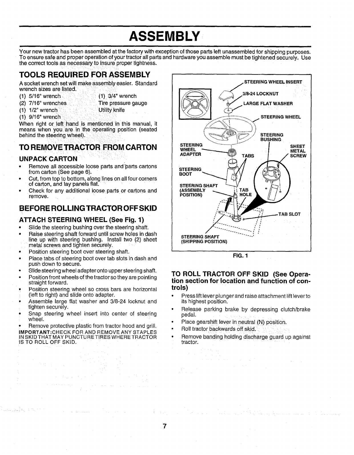
ATTACH STEERING WHEEL (See Fig. 1)
• Slide the steering bushing over the steering shaft.
• Raise steering shaft forward until screw holes in dash
line up with steering bushing. Install two (2) sheet
metal screws and tighten securely.
•Position steering boot over steering shaft.
• Place tabs of steering boot over tab slots in dash and
push down to secure.
• Slide steering wheel adapter onto upper steering shaft.
• Position front wheels of the tractor so they are pointing
straight forward.
, Position steering wheel so cross bars are horizontal
(left to right) and slide onto adapter.
• Assemble large flat washer and 3/8-24 locknut and
tighten securely.
• Snap steering wheel insert into center of steering
wheel.
• Remove protective plastic from tractor hood and grill.
IMPORTANT:CHECK FOR AND REMOVE ANY STAPLES
IN SKiD THAT MAY PUNCTURE TIRES WHERE TRACTOR
IS TO ROLL OFF SKID.
STEERING
BOOT
STEERING SHAFT
(ASSEMBLY
POSITION)
TABS
STEERING WHEELINSERT
3/8_4LOCKNUT
LARGE FLAT WASHER
SHEET
METAL
SCREW
STEERING SHAFT ......... " '
(SHIPPING POSITION)
FIG. 1
TO ROLL TRACTOR OFF SKID (See Opera-
tion section for location and function of con-
trols)
•Press lift lever plunger and raise attachment lift lever to
its highest position.
• Release parking brake by depressing clutch!brake
pedal.
• Place gearshift lever in neutral (N) position.
• Rol! tractor backwards off skid.
•Remove banding holding discharge guard up against
tractor.
7
BLY
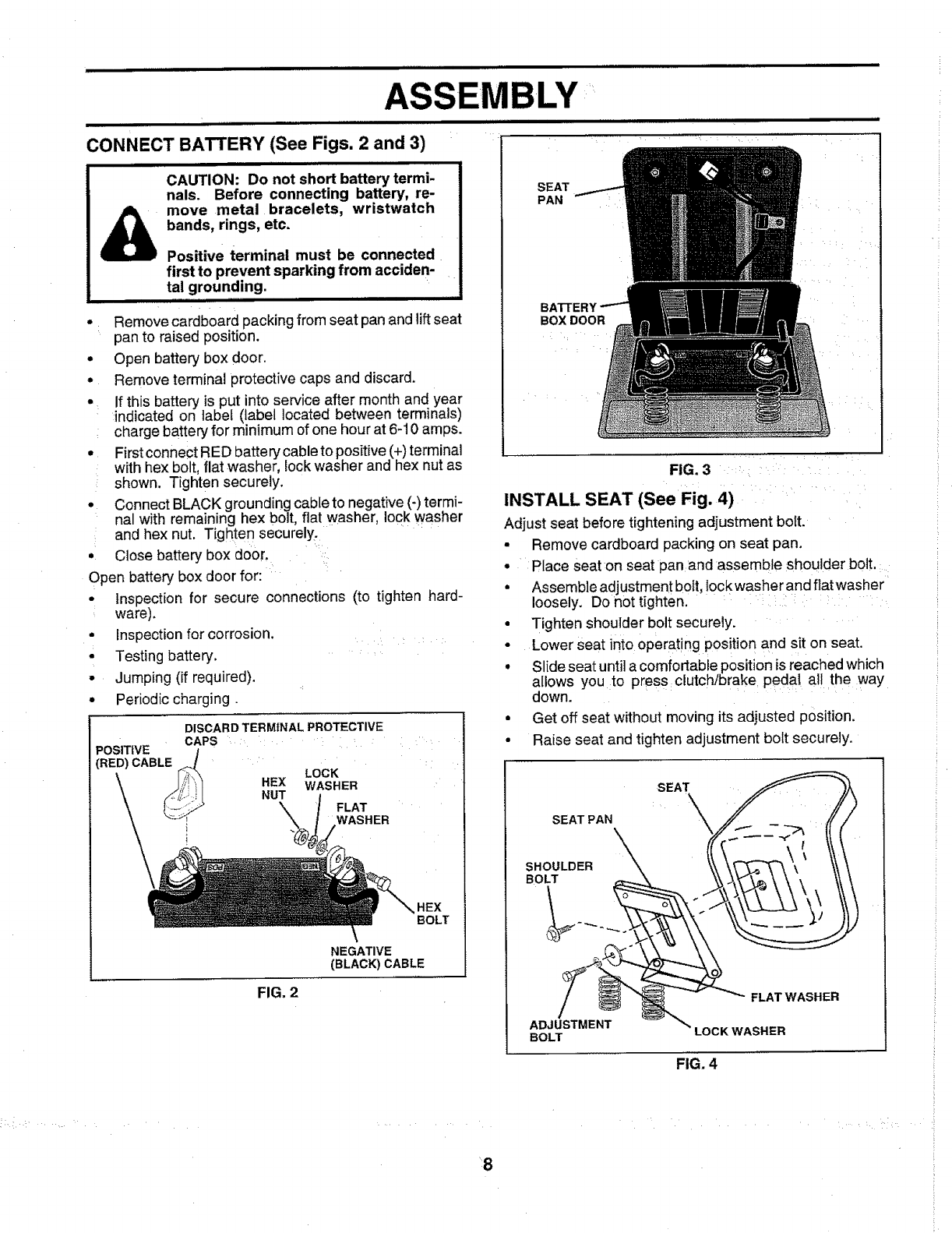
CONNECT BATTERY (See Figs. 2 and 3)
i
CAUTION: Do not short battery termi-
nals. Before connecting battery, re-
move metal bracelets, wristwatch
_bands, rings, etc.
Positive terminal must be connected
first to prevent sparking from acciden-
tal grounding.
• : Remove cardboard packing from seat pan and lift seat
pan to raised position.
• Open battery box door.
• Remove terminal protective caps and discard.
• If this battery is put into service after month and year
indicated on label (label located between terminals)
charge battery for minimum of one hour at 6-10 amps.
• First connect RED battery cable to positive (+) terminal
with hex bolt, flat washer, lock washer and hex nut as
: shown. Tighten securely.
• Connect BLACK grounding cable to negative (-) termi-
na wth remain ng hex bolt, flat washer lock washer
: and hex nut. Tighten securely.
•Close battery box door.
Open battery box door for:
• Inspection for secure connections (to tighten hard-
ware),
• Inspection for corrosion .... :
• Testing battery.
• Jumping (if required).
•Periodic charging.
DISCARDTERMINALPROTECTIVE
CAPS
POSITIVE /
(RED)CABLE_ LOCK
HEX WASHER
NUT FLAT
_t WASHER
FIG, 2
BOLT
NEGATIVE
(BLACK) CABLE
SEAT
PAN
BOX DOOR
FIG. 3
INSTALL SEAT (See Fig. 4)
Adjust seat before tightening adjustment bolt.
•Remove cardboard packing on seat pan.
• Place seat on seat pan and assemble shoulder bolt.
• Assemble adjustment bolt, lockwasher and flatwasher
loosely. Do not tighten.
•Tighten shoulder bolt securely.
• Lower seat into operating position and sit on seat.
•Slide seat until a comfortable position is reached which
allows you to press clutch/brake pedal all the way
down.
• Get off seat without moving its adjusted position.
• Raise seat and tighten adjustment bolt securely.
SEAT PAN
SHOULDER _
BOLT g
ADJUSTMENT
BOLT
,,,_ FLAT WASHER
LOCK WASHER
FIG. 4
•:8
ASSEMBLY
CHECK TIRE PRESSURE
The tires on yourtractor were overinflated at the factory for
shipping purposes. Correct tire pressure is important for
best cutting performance ....
• ,Reduce tire pressure to PSI shown in "PRODUCT
SPECIFICATIONS" on page 3 of th s manual. :'
CHECK DECK LEVELNESS
For best cutting results, mower housing should be properly
leveled. See "TO LEVEL MOWER HOUSING" in the
Service and Adjustments section of this manual.
CHECK FOR PROPER POSITION OF ALL
"See the figures that are shown for replacing motion and
mower blade drive belts in the Service and Adjustments
section of this manual. Verify that the betts are routed
correctly.
CHECK BRAKE SYSTEM
After you learn how to operate your tractor, check to see
that the brake is properly adjusted. See "TO ADJUST
BRAKE" in the Service and Adjustments section of this
manual.
,/CHECKLIST
BEFORE YOU OPERATE AND ENJOY YOUR NEW
TRACTOR, WE WISH TO ASSURE THAT YOU RECEIVE
THIS QUALITY PRODUCT.
PLEASE REVIEW THE FOLLOWING CHECKLIST:
,/ All assembly instructions have been completed.
,/ No remaining loose parts in carton.
,/ Batteryis properly prepared and charged. (Minimum
1 hour at 6 amps).
,/ Seat is adjusted comfortably and tightened securely.
/All tires :are properly inflated. (For shipping purposes,
the tires were overinflated at the factory).
/Be sure mower deck is properly leveled side-to-side/
front-to-rear for best cutting results. (Tires must be
properly inflated for leveling).
,/ Check mower and drive belts. Be sure they are routed
properly around putleys and inside all belt keepers.
v" Check wiring. See that all connections are still secure
and wires are properly clamped.
WHILE LEARNING HOWTO USE YOUR TRACTOR, PAY
EXTRA ATTENTION TO THE FOLLOWING IMPORTANT
ITEMS:
,/ Engine oil is at proper level,
/Fuel tank is filled with fresh, clean, regular unleaded
gasoline.
,/ Become familiar with all controls - their location and
function. Operate them before you start the engine.
/Be sure brake system is in safe operating condition.
.......... OPERATI..........
i i iii ,,,,,,,,,,,,, ii
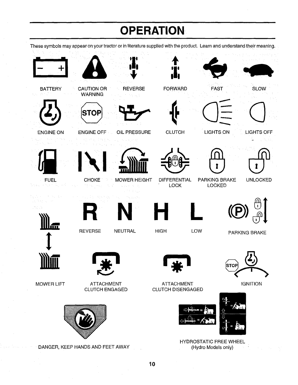
These symbols may appear on your tractor or inliterature supplied withthe product. Learn and understand their meaning.
t
BATTERY CAUTION OR REVERSE
WARNING FORWARD FAST SLOW
ENGINE ON ENGINE OFF OIL PRESSURE CLUTCH LIGHTS ON LIGHTS OFF
FUEL
!
MOWER LIFT
CHOKE : MOWER HEIGHT DIFFERENTIAL PARKING BRAKE
LOCK LOCKED
R N H L
REVERSE NEUTRAL
ATTACHMENT
CLUTCH ENGAGED
HIGH LOW
ATTACHMENT
CLUTCH DISENGAGED
UNLOCKED
PARKING BRAKE
IGNITION
DANGER, KEEP HANDS AND FEET AWAY
HYDROSTATIC FREE WHEEL
(Hydro Models only)
10
i iiUlllll ihill iii I,,, ,,,,,,,,,,,,,,,,,,,, i n iUlll
OPERATION
HInIIIIIIIIIIIIII II II Inlllllllln IIIIIII Ilnl I III I II nIIIIIIIIIIII m .,Hin II III1!1
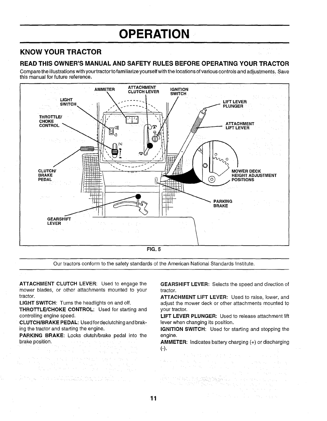
KNOW YOUR TRACTOR
READ THIS OWNER'S MANUAL AND SAFETY RULES BEFORE OPERATING YOUR TRACTOR
Compare the illustrations with your tractor to familiarize yourself withthe locations of variouscontrols and adjustments. :Save
this manual for future reference.
LIGHT
...... SWITCH
THROTTL_
CHOKE
CONTROL
CLUTCH/
BRAKE
PEDAL
AMMETER ATTACHMENT
CLUTCH LEVER
\
IGNITION
SWITCH
i
LIFT LEVER
PLUNGER
ATTACHMENT
LIFT LEVER
MOWER DECK
HEIGHT ADJUSTMENT
POSITIONS
PARKING
BRAKE
GEARSHIFT
LEVER
FIG. 5
Our tractors conform to the safety standards of the American National Standards Institute,
ATTACHMENT CLUTCH LEVER: Used to engage the
mower blades, or other attachments mounted to your
tractor.
LIGHT SWITCH: Turns the headlights on and off.
THROTTLE/CHOKE CONTROL: Used for starting and
controlling engine speed.
CLUTCH/BRAKE PEDAL: Used for declutching and brak-
ing the tractor and starting the engine.
PARKING BRAKE: Locks clutch/brake pedal into the
:brake position,
GEARSHIFT LEVER: Selects the speed and direction of
tractor.
ATTACHMENT LIFT LEVER: Used to raise, lower, and
adjust the mower deck or other attachments mounted to
your tractor.
LIFT LEVER PLUNGER: Used to release attachment lift
lever when changing its position.
IGNITION SWITCH: Used for starting and stopping the
eng ine.
AMMETER: Indicates battery charging (+) or discharging
(4.
11
......................... ,,,,,,,,,,,,,, illl i,iiiiiHI iiiiiiiiiiiiiiiiiiiiiiii inll, i iilll ii i i
OPERATION
i nil n,,m , IH i i i,i i Hi ,i i i i m
,_ ..................... ,, ,,,,, ill ill in,m, i i llllll,lllll i,lll i i I_1 i, ,,,,, ,.
|
hro oth ye !
The operation of any tractor can result in foreign objects t wn int e e s, which
,can result in severe eye damage. Always wear safety glasses or eye shields while i
operating your tractor orperforming any adjustments or repairs. We recommend awide I
vision safety mask over the spectacles or standard safety glasses. I
I
iiiiii III II I IIIIII IIIIIIIIIIIIIIIIII III
NOTE: Under certain conditions when tractor is standing
idle with the engine running, hot engine exhaust gases may
cause "browning" of grass. To eliminate this possibility,
always stop engine when stopping tractor on grass areas.
i
HOW TO USE YOUR TRACTOR
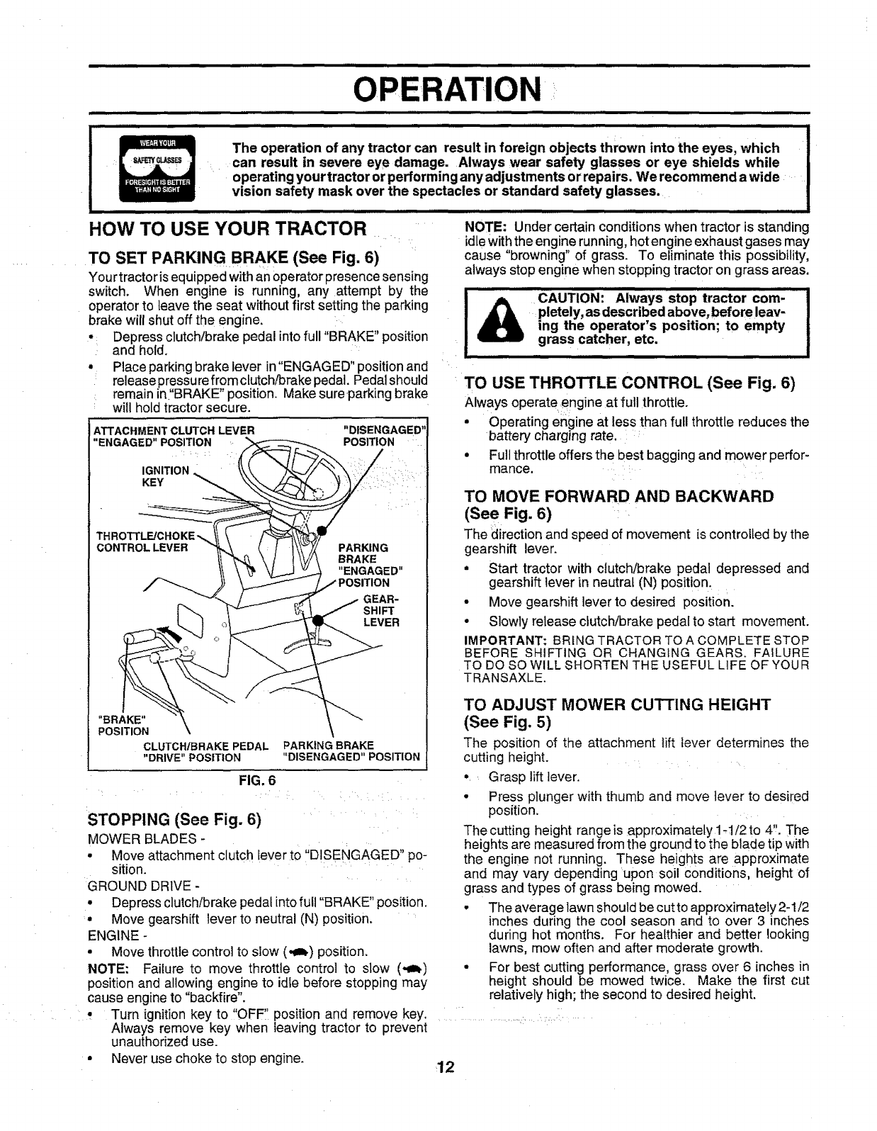
TO SET PARKING BRAKE (See Fig. 6)
You rtractor is equipped withan operator presence sensing
switch. When engine is running, any attempt by the
operator to leave the seat without first setting the parking
brake will shut off the engine.
•Depress clutch/brake pedal into full "BRAKE" position
and hold,
•Place parking brake lever in"ENGAGED" position and
release pressure fromctutch/brake pedal. Pedal should
:: remain in"BRAKE" position. Make sureparking brake
will hold tractor secure.
ATTACHMENT CLUTCH LEVER
"ENGAGED" POSITION
IGNITION
KEY
"DISENGAGED'
POSITION
THROTTL_CHOKE_
CONTROLLEVER PARKING
BRAKE
"ENGAGED"
GEAR-
SHIFT
LEVER
"BRAKE"
POSITION
CLUTCHtBRAKE PEDAL
"DRIVE" POSITION PARKING BRAKE
li
"DISENGAGED POSITION
FIG. 6
STOPPING (See Fig. 6)
MOWER BLADES-
. Move attachment clutch lever to ';DISENGAGED" po-
sition.
GROUND DRIVE -
• Depress clutch/brake pedal into full "BRAKE" position.
• Move gearshift lever to neutral (N) position.
ENGINE -
•Move throttlecontrol to slow (,_=_)position.
NOTE: Failure to move throttle control to slow (_)
position and allowing engine to idfe before stopping may
cause engine to "backfire".
................IICAUTION: Always stop tractor corn- I
_pletely, as described above, before leav- Jing the operator s position; to empty
grass catcher, etc. I
I
I
TO USE THROTTLE CONTROL (See Fig. 6)
Always operateengine at full throttle.
•Operating engine at less than full throttle reduces the
battery charging rate. :
° Full throttle offers the best bagging and mower perfor-
mance. :::
TOMowFoRwARoA.DBACKWA.D
(See Fig. 6)
The direction and speed of movement is controlled by the
gearshift lever.
•Start tractor with clutch/brake pedal depressed and
gearshift lever in neutral (N) position.
•Move gearshift lever to desired position.
•Slowly release clutch/brake pedaf to start movement.
IMPORTANT: BRING TRACTOR TO A COMPLETE STOP
BEFORE SHIFTING OR CHANGING GEARS. FAILURE
TO DO SO WILL SHORTEN THE USEFUL LIFE OF YOUR
TRANSAXLE.
TO ADJUST MOWER CUTTING HEIGHT
(See Fig. 5)
The position of the attachment tift _ever determines the
cutting height.
•,Grasp lift lever.
• Press plunger with thumb and move lever to desired
position.
The cutting height range is approximately lq/2 to 4'. The
heights are measured from the ground to the blade tip with
the engine not running. These heights are approximate
and may vary depending upon soil conditions, height of
grass and types of grass being mowed.
• The average lawn should be cutto approximately2-1/2
inches during the cool season and to over 3 inches
during hot months. For healthier and better looking
lawns, mow often and after moderate growth.
• For best cutting performance, grass over 6 inches in
height should be mowed twice. Make the first cut
relatively high; the second to desired height.
Turn ignition key to "OFF" position and remove key.
Always remove key when leaving tractor to prevent
unauthorized use.
Never use choke to stop engine. 12
i,,,,,i i ill i i ii i iii i ,,, ,,, ,,, .......................
rATION
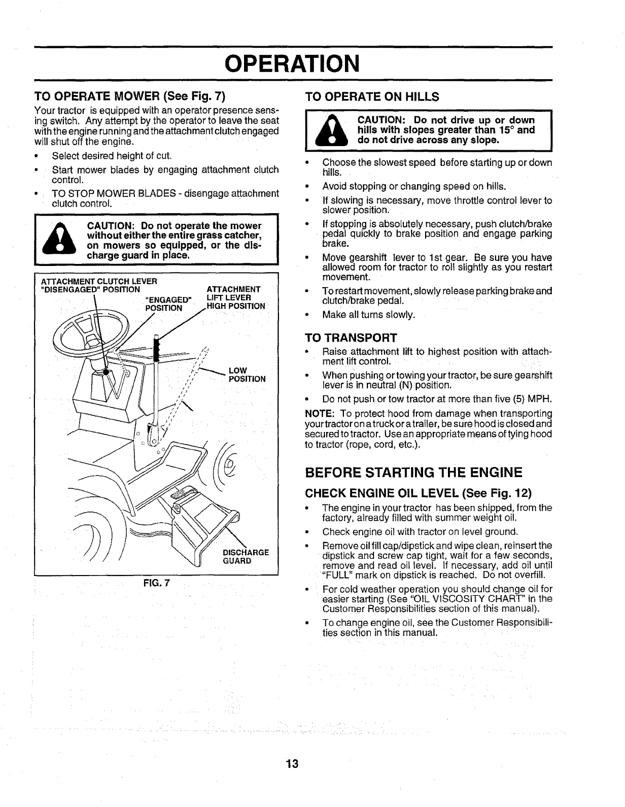
TO OPERATE MOWER (See Fig. 7) TO OPERATE ON HILLS
Your tractor is equipped with an operator presence sens-
ing switch. Any attempt by the operator to leave the seat
with the engine running and the attachment clutch engaged
will shut off the engine.
• Select desired height of cut.
• Start mower blades by engaging attachment clutch
control.
• TO STOP MOWER BLADES - disengage attachment
clutch control.
&illlll ii ii,iHIIIIIIIIIIIIIIIIIIII IIll III
CAUTION: Do not operate the mower !
without either the entire grass catcher, !
on mowers so equipped, or the dis-
charge guard in place.
ATTACHMENT CLUTCH LEVER
"DISENGAGED"POSITION
"ENGAGED"
_POS_ION
ATTACHMENT
LIFT LEVER
HIGH POSITION
DISCHARGE
GUARD
FIG. 7
i iHi, iui ,H=l
!,&cA,.,r,o,,,;oonot°r'veuPor0owoI
hills with slopes greater than 15° and
do not drive across any slope, ,
iiiiiitt]l ] ttLiUiiiiiiii t tltlt
Choose the slowest speed before starting up or down
hills.
Q
OAvoid stopping or changing speed on hills.
If slowing is necessary, move throttle control lever to
slower position.
if stopping is absolutely necessary, push clutch/brake
pedal quickly to brake position and engage parking
brake.
Move gearshift lever to 1st gear. Be sure you have
allowed room for tractor to roll slightly as you restart
movement.
•To restart movement, slowly release parking brake and
clutch/brake pedal.
• Make all turns slowly.
TO TRANSPORT
•Raise attachment liftto highest position with attach-
ment lift control.
• When pushing or towing your tractor, be sure gearshift
lever is in neutral (N) position.
• Do not push or tow tractor at more than five (5) MPH.
NOTE: To protect hood from damage when transporting
your tractor on a truck ora trailer, besure hood is closed and
secured to tractor. Use an appropriate means of tying hood
to tractor (rope, cord, etc.).
BEFORE STARTING THE ENGINE
CHECK ENGINE OIL LEVEL (See Fig. 12)
•The engine inyour tractor has been shipped, from the
factory, already filled with summer weight oil.
• Check engine oil with tractor on level ground.
• Remove oil fill cap/dipstick and wipe clean, reinsert the
dipstick and screw cap tLght, wait for a few seconds,
remove and read oil IeveL If necessary, add oil until
'!FULL" mark on dipst{ck is reached. Do not overfill.
• For cold weather operation you should change oil for
easier starting (See "OIL VISCOSITY CHART" in the
Customer Responsibilities section of this manual).
• To change engine oil, see the Custome r Responsibili-
ties section in this manual.
13
iii IIH II II II Illlll I
OPERATION
ADD GASOLINE I_
•Fill fuel tank. Use fresh, clean, regular unleaded
::gasoline with a minimum of 87 octane. (Useof leaded
gasoline wilt increase carbon and lead oxide deposits
and reduce Valve life). Do not mix oil with gasoline.
Purchase fuel in quantities that can be used within 30
days to assure fuel freshness.
IMPORTANT: WHEN OPERATING IN TEMPERATURES
BELOW 32°F(0°C) USE FRESH, CLEAN WINTER GRADE
GASOLINE T'O HELP INSURE GOOD COLD WEATHER
STARTING.
WARNING: Experience indicates that alcohol blended
fuels (called gasohol or using ethanol or methanol) can
attract moisture which leads to separation and formation of
acids during storage. Acidic gas can damage the fuel
system of an engine while in storage. To avoid engine
problems, the fuel system should be emptied before stor-
age of 30 days or longer. Drain the gas tank, start the
engine and let it run until the fuel lines and carburetor are
empty. Use fresh fuel next season. See Storage Instruc-
tions for additional information. Never use engine or
carburetor cleaner products in the fuel tank or permanent
damage may occur.
llll i i ii ii llllllii
CAUTION: Fill to bottom of gas tank
filler neck. Do not overfill. Wipe offany
spilled oil or fuel. Donot store, spill or
use gasoline near an open flame.
lll,lll,i
TO START ENGINE (See Fig. 6)
When starting the engine for the first time or ifthe engine
has run out of fuel, it will take extra crankingtime to move
fuel from the tank to the engine.
•Depress clutch/brake pedal and set parking brake.
• Place gear shift lever in neutral (N) position.
•Move attachment clutch to "DISENGAGED" position.
•Move throttle control to choke (N) position.
Note: Before starting, read the warm and cold starting
procedures below.
•Insert keyinto ignition andturn key clockwiseto"START"
position and release key as soon as engine starts. Do
not run starter continuously for more than fifteen :sec-
onds per minute. If the engine does not start after
several attempts, move throttle control to fast (.t_)
position, wait afew minutes and try again. If engine still
does not start, move the throttle control back to the
choke ( X ) position and retry.
WARM WEATHER STARTING (50° F and above)
•When engine starts, move the throttle control to the fast
(,top)position.
•The attachments and ground drive can now be used. If
the engine does not accept the load, restart the engine
and allow it to warm up for one minute using the choke
as described above.
COLD WEATHER STARTING ( 50° F and below)
• When engine starts0allow engineto run with the throttle
control in the choke ( X ) position until the engine runs
roughly, then move thrott e control to fast (,_) position.
This may require an engine warm-up period from
several seconds to several minutes, depending on the
temperature.
• The attachments can also be used during the engine
warm-up period.
NOTE: If at a high altitude (above 3000 feet) or in cold
temperatures (below 32 F) the carburetor fuel mixture may
need to be adjusted for best engine performance. See'q'O
ADJUST CARBURETOR" in the Service and Adjustments
section of this manual. : : :: ..... _ :: ..... :i
MOWING TIPS ........
• Tire chains cannotbe used when the mower housingis
attachedto tractor,
•Mower should be propedy leveled for best mowing
performance. See'q'O LEVEL MOWER HOUSING" in
the Service and Adjustments section of this manual.
•The left hand side of mower should be used for trim-
ming.
•Drive so that clippings are discharged onto the area
that has been cut. Have the cut area to the right of the
machine. This will result in a more even distribution of
clippings and more uniform cutting.
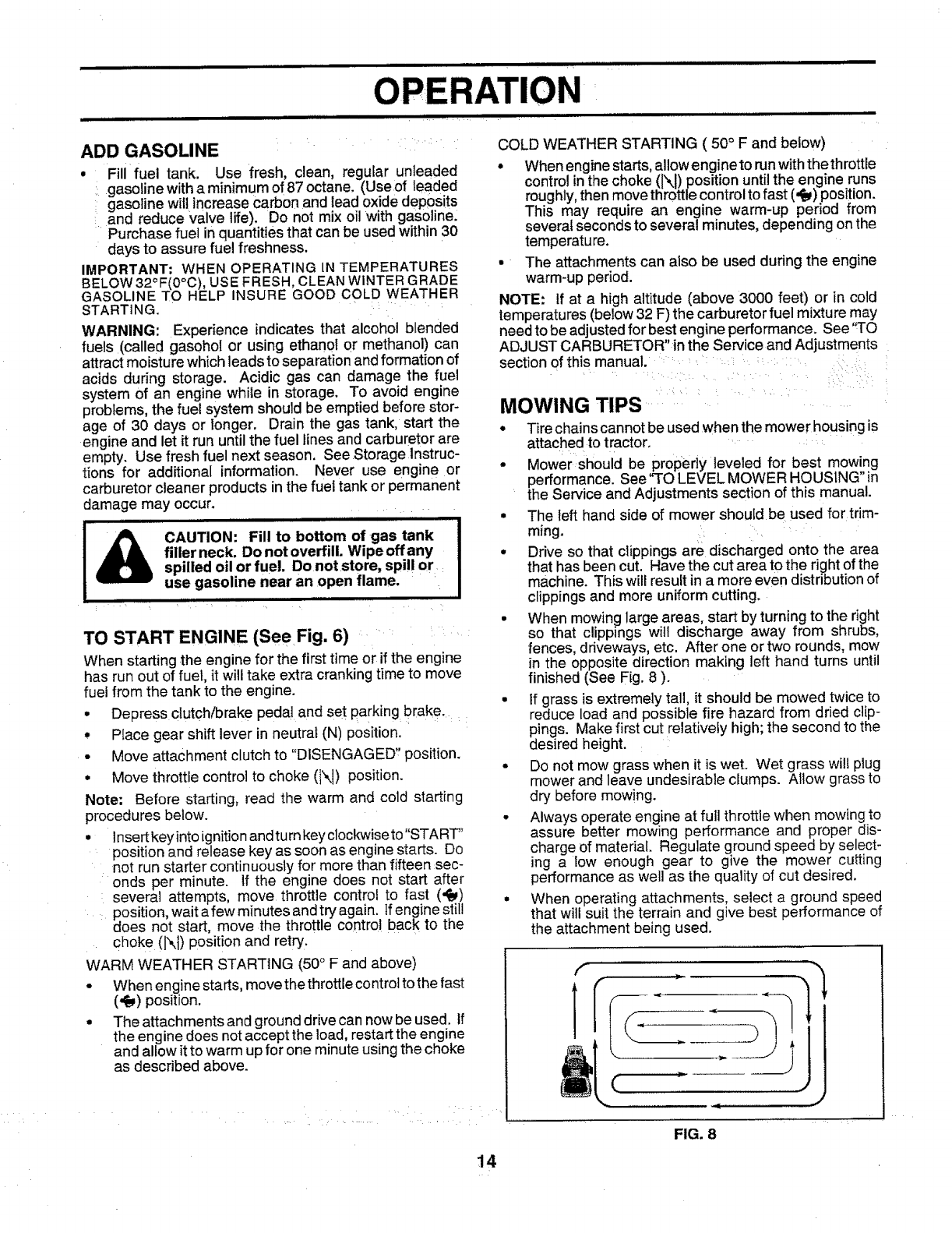
• When mowing large areas, start by turning to the right
so that clippings wilt discharge away from shrubs,
fences, driveways, etc. After one or two rounds, mow
in the opposite direction making left hand turns until
finished (See Fig. 8 ).
•if grass is extremely tall, it should be mowed twice to
reduce load and possible fire hazard from dried clip-
pings. Make first cut relatively high; the second to the
desired height.
• Do not mow grass when it is wet. Wet grass will plug
mower and leave undesirable clumps. Allow grass to
dry before mowing.
• Always operate engine at full throttle when mowing to
assure better mowing performance and proper dis-
charge of material. Regulate ground speed by select-
ing a low enough gear to give the mower cutting
performance as well as the quality of cut desired.
• When operating attachments, select a ground speed
that will suit the terrain and give best performance of
the attachment being used.
FIG. 8
14
ii • ilnlllllll II
CUSTOMER RESPONSIBILITIES
I II I II
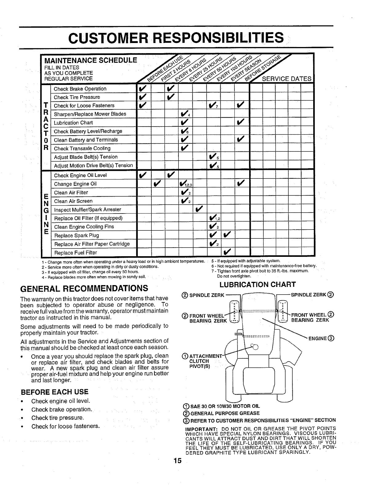
MAINTENANCE SCHEDULE :/___J
AS YOU COMPLETE _O_,,r,r. '
REGULAR..SERVICE ........ f_F_'_v SERVICE DATES
1-Change more often when operating under a heavy load or in high ambient temperatures. :5-If equipped with adjustable system.
2- Service more often when operating in dirty or dusty conditions.
3 - tf equipped with oi! fitter, change oil every 50 hours.
4 - Replace blades more often when mowing in sandy soil,
GENERAL RECOMMENDATIONS
The warranty on this tractor does not cover items that have
been subjected to operator abuse or negligence. To
receive full value from the warranty, operator must maintain
tractor as instructed in this manual.
Some adjustments will need to be made periodically to
properly maintain your tractor.
All adjustments in the Service and Adjustments section of
this manual should be checked at least once each season.
• Once a year you should replace the spark plug, clean
or replace air filter, and check blades and belts for
wear. A new spark plug and clean air filter assure
proper air-fuel mixture and help your engine run better
and last longer.
(_) SPI _IDLE ZERK(_)
6 - Not requiredif equippedwtthmaintenance4reebattery.
7 - Tightenfrontaxle pivot boltto 35 ft.-lbs, maximum,
Donotovertighten.
LUBRICATION CHART
(_ FRONT (_)
BEARING ZERK BEARING ZERK
®CLUTCH :
PIVOT(S)
BEFORE EACH USE
•Check engine oil level.
° Check brake operation.
:, Checktire pressure.
° Check for loose fasteners.
(_) SAE 30OR 10W30 MOTOR OIL
(_ GENERAL PURPOSE GREASE
(_) REFER TO CUSTOMER RESPONSIBILITIES "ENGINE" SECTION
IMPORTANT: DO NOT OIL OR GREASE THE PIVOT POINTS
WHICH HAVE SPECIAL NYLON BEARINGS, VISCOUS LUBRI-
CANTS WILL ATTRACT DUST AND DIRT THAT WILL SHORTEN
THE LIFE OF THE SELF-LUBRICATING BEARINGS. IF YOU
FEEL THEY MUST BE LUBRICATED, USE ONLY A DRY, POW-
DERED GRAPHITE TYPE LUBRICANT SPARINGLY.
15
Check Brake Operation If if
Check Tire Pressure ! _
T"C'heck for Loose Fasten'ers ..... If _4'7 if
R _sharpen/Replace 'Mower Blades " t_4
AC Lubrication Cha.rt . .. if V_ .....
TCheck Battery Level/Recharge ......... 1_6 ....
0Clean Battery and Terminals V_Vf
RCheck Transaxle Cooling
Adjust Biade Belt(s) Tension Ks ........
Adjust Motion Drive Belt(s) Tension t_s
III III I I II III IIIIIIIIIIIIIIIIIIIIIII
Check Engine Oil Level Vp
Change Engine Oil _ _1.2,3 ....... _#t
Clean Air Filter Ill2
E .................. ..........................
N Clean Air Screen ...... 1_2
G Inspect Muffl'er!Spark Arrester ...........!_ .....',,',"'
! Replace Oil Filter (If equipped) V_1,2
N €,ean Engine Cooling Fins ...... ...................... ,. t#42 i .....
Replace Spark Plug tf If ...............
Replace Air Filter Paper Cartridge VP2
Replace Fuel.Filter ._ ........
, i i
CUSTOMER R NSIBILITIES
ii /_ll L i
TRACTOR TO SHARPEN BLADE (See Fig. 10)
Always observe safety rules when performing any mainte- Care should be taken to keep the blade balanced. An
nance, unbalanced blade will cause excessive vibration and even-
tual damage to mower and engine.
BRAKE OPERATION • The blade can be sharpened with a file or on a gdnding
If tractor requires more than six (6) feet stopping distance wheel. Do not attempt to sharpen while on the mower.
at high speed in highestgear, thenbrake must be adjusted. • To check blade balance, you will need a 5/8" diameter
(See "TO ADJUST BRAKE" in the Service and Adjust- steel bolt, pin, or a cone balancer. (When using a cone
ments section of this manual), balancer, follow the instructions supplied with bal-
ancer).
TIRES •Slide blade on to an unthreaded portion of the steel bolt
• Maintain proper air pressure in all tires (See "PROD- or pin and hold the bolt or pin parallel with the ground.
UCT SPECIFICATIONS" on page 3 of this manual), If blade is balanced, it should remain in a horizontal
position. If either end of the blade moves downward,
• Keep tires free of gasoline, oil, or insect control chemi- sharpen the heavy end until the blade is balanced.
cals which can harm rubber. NOTE: Do not use a nail for balancing blade. The lobes of
• Avoid stumps, stones, deep ruts, sharp objects and the center hole may appear to be centered, but are not.
other hazards that may cause tire damage. L
BLADE CARE /
For best results mower blades must be kept sharp. Re- CENTERHOLE /
place bent or damaged blades. /
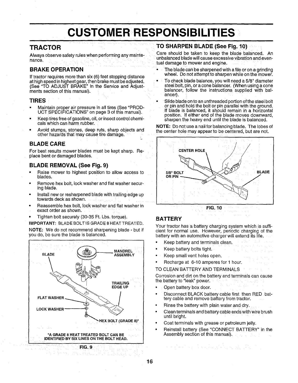
BLADE REMOVAL (See Fig. 9)
• Raise mower to highest position to allow access to 5/8"BOLT BLADE
blades. ORPIN
• Remove hex bolt, lock washer and flat washer secur-
ing blade.
• Install new or resharpened blade with trailing edge up
towards deck as shown.
• Reassemble hex bolt, lock washer and flat washer in FIG. 10
exact order as shown.
•Tighten bolt securely (30-35 Ft. Lbs. torque). BATTERY
IMPORTANT: BLADE BOLT IS GRADE 8 HEATTREATED. Your tractor has a battery charging system which is suffi-
NOTE: We do not recommend sharpening blade - but if cient for normal use. However, periodic charging of the
_oudo, be sure the blade is balanced, battery with an automotive charger wilf extend its life.
BLADE
\
FLAT WASH
•Keep battery and terminals clean.
• Keep battery bolts tight.
MANDREL
ASSEMBLY •Keep small vent holes open.
• Recharge at 6-10 amperes for 1 hour.
TO CLEAN BATTERY AND TERMINALS
Corrosion and dirt on the battery and terminals can cause
the battery to "leak" power.
TRAILING
LOCK WASHER
EDGE UP •
•
*A GRADE 8 HEAT TREATED BOLT CAN BE
IDENTIFIED BY SIX LINES ON THE BOLT HEAD.
Open battery box door.
Disconnect BLACK battery cable first then RED bat-
tery cable and remove battery from tractor.
Rinse the battery with plain water and dry.
Clean terminals and battery cable ends with wire brush
until bright.
Coat terminals with grease or petroleum jelly.
Reinstall battery (See "CONNECT BA']-rERY" in the
Assembly section of this manual).
FIG. 9
16
i i iii ii ii t tUllllllllllUiii nllllllllllllllllllllllllllllllllll nlll i iiiiiiiiiiii n i i iii II nil i I
CUSTOMER R
iii
V-BELTS ii,,,,,,¸ : • i ,i,w,i,,
Check V-belts for deterioration and wear after 100 hours of
operation and replace if necessary. The belts are not
adjustable. Replace belts if they begin to slip from wear.
TRANSAXLE COOLING
Keep transaxle free from build:.up of dirt and chaff which
can restrict cooling, .......
ENGINE ......
LUBRICATION
Only use high quality detergent oil rated with API service
classification SF orSG. Select the oil's SAE viscosity grade
according to your expected operating temperature,
NOTE: Although multi-viscosity oils (5W30, 10W30 etc.)
improve starting in.cold weather, these multi-viscosity oils
will result in increased oil consumption when used above
32°F. Check your engine oil level more frequently to avoid
possible engine damage from running tow on oil,
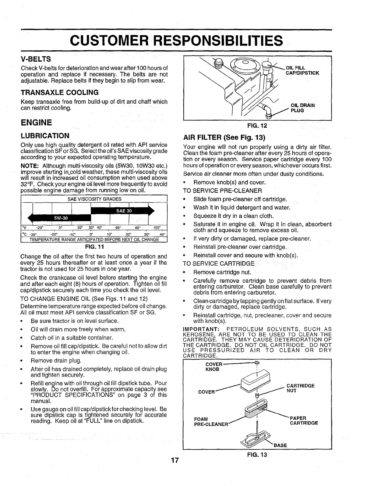
SAE VISCOSITY GRADES
4
oF,.20° 0 •
i,,
30" 320 40_ 60 ° 80 _ ' 100 _
TEMPERATURE RANGE ANTICIPATED BEFORE NEXT OIL CHANGE
FIG. 11
Change the oil after the first two hours of operation and
every 25 hours thereafter or at ]east once a year if the
tractor is not used for 25 hours inone year.
Check the crankcase oil level before starting the engine
and after each eight (8) hours of operation. Tighten oil flit
cap/dipstick securely each time you check the oil level.
TO CHANGE ENGINE OIL (See Figs. 11 and 12)
Determine temperature range expected before oil change.
Afl oil must meet API service classification SF or SG.
• Be sure tractor is on level surface.
• Oil will drain more freely when warm.
•Catch oil in a suitable container.
• Remove oil fill cap/dipstick. Becareful not to allow dirt
to enter the engine when changing oil.
•Remove drain plug.
•After oil has drained completely, replace oil drain plug
and tighten securely.
•Refill engine with oil through oil fill dipstick tube. Pour
slowly. Do not overfill. For approximate capacity see
"PRODUCT SPECIFICATIONS" on page 3 of this
manual.
• Use gauge on oil ill] cap/dipstick for checking level. Be
sure dipstick cap is tightened securely for accurate
reading. Keep oil at "FULL" line on dipstick.
FIG. 12
AIR FILTER (See Fig. 13)
Your engine will not run properly using a dirty air filter.
Clean the foam pre-cleaner after every 25 hoursof opera-
tion or every season, Service paper cartridge ever:/100
hours of operationorevery season, whichever occurs first.
Service air cleaner more often under dusty conditions.
•Remove knob(s) and cover.
TO SERVICE PRE-CLEANER
• Slide foam pre-cteaner off cartridge.
° Wash it in liquiddetergent and water.
°Squeeze it dry inaclean cloth.
•Saturate it in engine oil. Wrap it in clean, absorbent
cloth and squeeze to remove excess oil.
•If very dirty or damaged, replace pre-cieaner.
• Reinstall pre-cleaner over Cartridge.
• Reinstall cover and secure with knob(s).
TO SERVICE CARTRIDGE:: ::
° Remove cartridge nut.
• Carefully remove cartridge to prevent debris from
entering carburetor. Clean base carefully to prevent
debris from entering carburetor.
• Clean cartridge by tapping gently on flat su dace. Ifvery
dirty or damaged, replace cartridge.
° Reinstall cartridge, nut, precleaner, cover and secure
with knob(s).
IMPORTANT: PETROLEUM SOLVENTS, SUCH AS
KEROSENE, ARE NOT TO BE USED TQ CLEAN THE
CARTRIDGE. THEY MAY CAUSE DETERIORATION OF
THE CARTRIDGE. DO NOT OIL CARTRIDGE. DO NOT
USE PRESSURIZED AIR TO CLEAN OR DRY
CARTRIDGE.
COVER
KNOB
COVER
CARTRIDGE
NUT
FOAM , PAPER
PRE-CLEANER _BASE CARTRIDGE
FIG. 13
17
........ illll i
CUSTOMERIIRESPONSIBILITIES
lU n.i ill
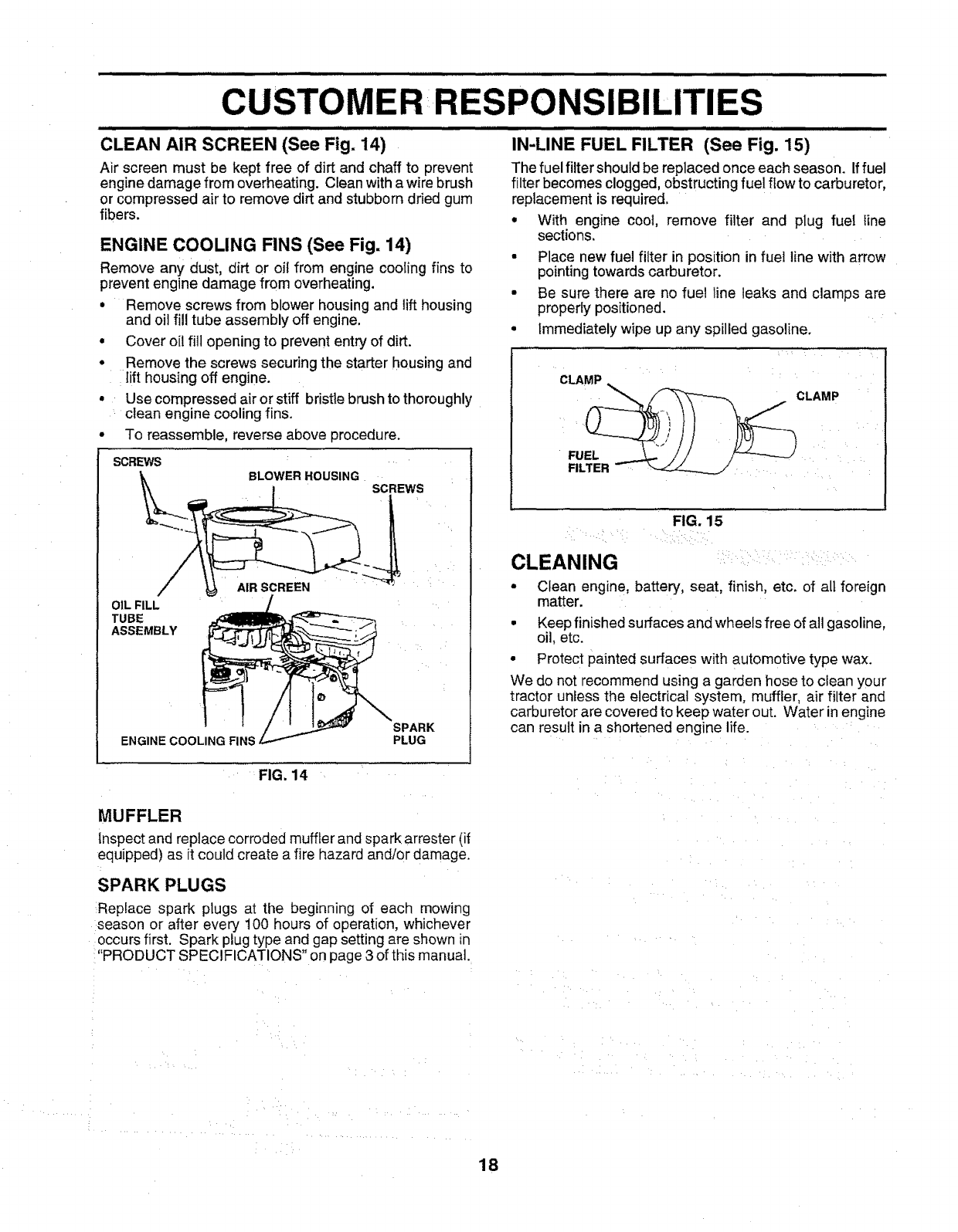
CLEAN AIR SCREEN (See Fig. 14)
Air screen must be kept free of dirt and chaff to prevent
engine damage from overheating. Clean with a wire brush
or compressed air to remove dirt and stubborn dried gum
fibers.
ENGINE COOLING FINS (See Fig. 14)
Remove any dust, dirt or oi_from engine cooling fins to
prevent engine damage from overheating.
° Remove screws from blower housing and lift housing
and oil fill tube assembly off engine.
° Cover oil fill opening to prevent entry of dirt.
• Remove the screws securing the starter housing and
[ift housing off engine.
• Use compressed air or stiff bristle brush to thoroughly
clean engine cooling fins.
•To reassemble, reverse above procedure.
SCREWS
BLOWER HOUSING SCREWS
OIL FILL
TUBE
ASSEMBLY
AIR SCREEN
ENGINE COOLING FINS SPARK
PLUG
u,,=,=l,=,,,,,,,, ==,,,,,,m ii ,, H,,,,,,,,m lliHll L i
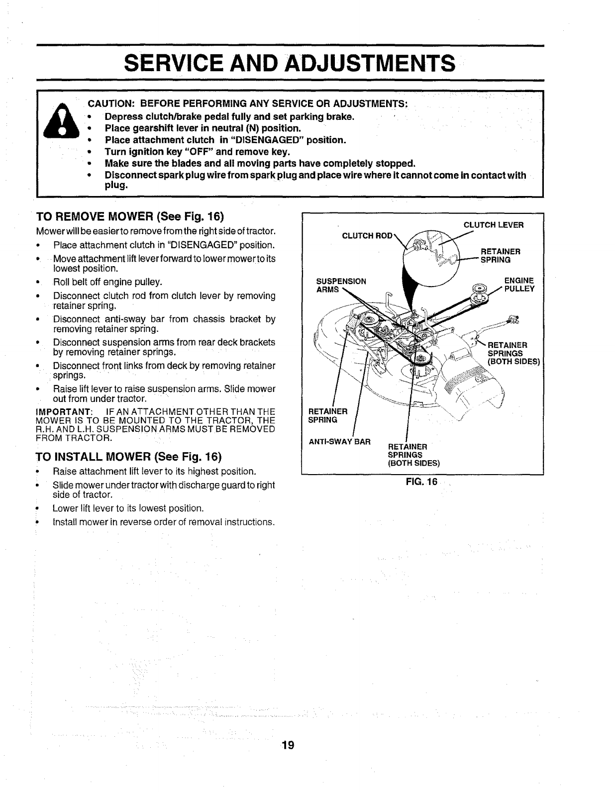
IN-LINE FUEL FILTER (See Fig. 15)
The fuel filter should be replaced once each season. Iffuel
filter becomes clogged, obstructing fuel flow to carburetor,
replacement is required.
° With engine coot, remove filter and plug fuel line
sections.
•Place new fuel filter in position in fuel line with arrow
pointing towards carburetor.
• Be sure there are no fuel line leaks and clamps are
properly positioned.
•Immediately wipe up any spilled gasoline.
CLAMP
FIG. 15
CLEANING
• Clean engine, battery, seat, finish, etc. of all foreign
matter.
• Keep finished surfaces and wheels free of all gasoline,
oil, etc.
• Protect painted surfaces with automotive type wax.
We do not recommend using a garden hose to clean your
tractor unless the electrical system, muffler, air filter and
carburetor are covered to keep water out. Water in engine
can result in a shortened engine life.
FIG. 14
MUFFLER
Inspect and replace corroded muffler and spark arrester (if
equipped) as it could create a fire hazard and/or damage.
SPARK PLUGS
Replace spark plugs at the beginning of each mowing
season or after every 100 hours of operation, whichever
occurs first. Spark plug type and gap setting are shown in
"PRODUCT SPECIFICATIONS" on page 3 of this manual.
18
IIHll I,IIIIWI,I IIIIll Illll I IIIIIIIH ,I III IIIll 111111
CE AND ADJUSTMENTS
Disconnect spark plug wire from spark plug and place wire where it cannot come in contact with
plug.
CAUTION: BEFORE PERFORMING ANY SERVICE OR ADJUSTMENTS:
•Depress clutch/brake pedal fully and set parking brake.
Place gearshift lever in neutral (N) position.
• Place attachment clutch in "DISENGAGED" position.
•Turn ignition key "OFF" and remove key.
•Make sure the blades and all moving parts have completely stopped.
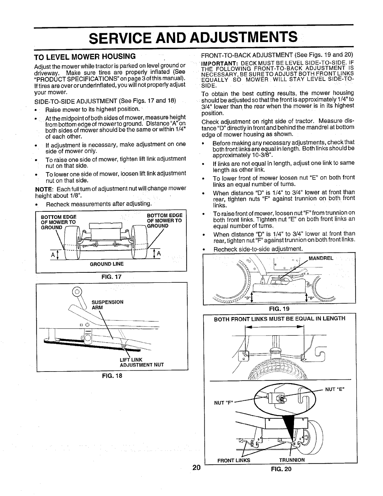
TO REMOVE MOWER (See Fig. 16)
Mower willbe easier to remove from the right side of tractor.
• Place attachment clutch in "DISENGAGED" position,
• Move attachment liftlever forward to lower mower to its
lowest position,
• Roll belt off engine pulley.
• Disconnect clutch rod from clutch lever by removing
retainer spring.
• Disconnect anti-sway bar from chassis bracket by
removing retainer spdng,
• Disconnect suspension arms from rear deck brackets
by removing retainer springs.
° Disconnect front links from deck by removing retainer
: springs.
• Raise fft teverto raise suspension arms. Slide mower
out from under tractor.
IMPORTANT: IF AN ATTACHMENT OTHER THAN THE
MOWER IS TO BE MOUNTED TO THE TRACTOR, THE
R.H. AND L.H, SUSPENSION ARMS MUST BE REMOVED
FROM TRACTOR,
TO INSTALL MOWER (See Fig. 16)
'Raise attachment lift lever to its highest position,
• Slide mower under tractor with discharge guard to right
side of tractor,
° Lower lift lever to its lowest position.
• Install mower in reverse order of removal instructions.
CLUT(
CLUTCH LEVER
RETAINER
SUSPENSION ENGINE
ARMS PULLEY
RETAINER
SPRING
ANTI-SWAY BAR
RETAINER
SPRINGS
"'--,. (BOTH SIDES)
RETAINER
SPRINGS
(BOTH SIDES)
FIG. 16
19
iiiii ill ii iii illlll illl illi i ill ii ii i ii illlllll ii,,,,,,lllll
AND ADJUSTMENTS
iii ill Ul iiiii, ii iii,ii,lll i ii i i IL II
TO LEVEL MOWER HOUSING
Adjust the mower while tractor is parked on level ground or
driveway. Make sure tires are properly inflated (See
"PRODUCT SPECIFICATIONS" on page 3 of this manual).
Iftires are over or underinflated, you will not properly adjust
your mower.
SIDE-TO-SIDE ADJUSTMENT (See Figs. 17 and 18)
• Raise mower to its highest position.
...... At the midpoint of both sides of mower, measure height
from bottom edge of mowerto ground. Distance"A" on
both sides of mower should be the same or within 1/4"
of each other.
°If adjustment is necessary, make adjustment on one
side of mower only.
° To raise one side of mower, tighten liftlink adjustment
nut on that side.
• To lower one side of mower, loosenliftlink adjustment
nut on that side.
NOTE: Each fullturn of adjustment nut willchange mower
height about 1/8".
Recheck measurements after adjusting.
BOTTOM EDGE
OF MOWER TO
GROUND
GROUND LINE
FIG. 17
SUSPENSION
ARM
LIFT LINK
ADJUSTMENT NUT
FIG. 18
i, ,.,... i i,,i ill illl illll i ii
FRONT-TO-BACK ADJUSTMENT (See Figs. 19 and 20)
......'IMPORTANT: DECKMUST BE LEVEL SIDE-TO-SIDE. IF
THE FOLLOWING FRONT-TO-BACK ADJUSTMENT IS
NECESSARY, BE SURETO ADJUST BOTH FRONT LINKS
EQUALLY SO MOWER : WILL STAY LEVEL SIDE-TO-
SIDE.
BOWOMEDGe
OF MOWER TO
GROUND
20
To obtain the best cutting results, the mower housing
should be adjusted so that the front isapproximately 1/4"to
3/4" lower than the rear when the mower is in its highest
position.
Check adjustment on right side of tractor. Measure dis-
tance "D" directly in front and behind the mandrel at bottom
edge of mower housing as shown.
• Before making any necessary adjustments, checkthat
both front links are equal in length. Both linksshould be
approximately 10-3/8".
• If iinks are not equal in length, adjust one link to same
length as other link.
• To lower front of mower loosen nut "E" on both front
links an equal number of turns.
• When distance "D" is 1/4" to 3/4" lower at front than
rear, tighten nuts "F" against trunnion on both. front
links.
To raise front of mower, loosennut"F" from trunnion on
both front links. Tighten nut "E" on both front _inksan
equal number of turns.
When distance "D" is 1/4" to 3/4" lower at front than
rear, tighten nut"F" against trunnion on both front tinks.
Recheck side-to-side adjustment.
\,
:._ %\ "\ _ .... _ _ MANDREL :
FIG. 19
BOTH FRONT LINKSMUST BE EQUAL IN LENGTH
/
NUT "E"
NUT "F"
FRONT LINKS TRUNNION
FIG. 20
SERVICE AND ADJUSTMENTS
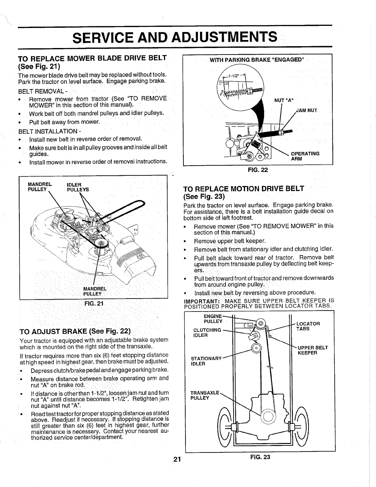
TO REPLACE MOWER BLADE DRIVE BELT
(See Fig. 21)
The mower blade drive belt may be rep aced without tools.
Park the tractor on level surface. Engage parking brake.
BELT REMOVAL -
• Remove mower from tractor (See 'q-o REMOVE
MOWER" in this section of this manual).
•Work bett off both mandrel pulleys and idler pulleys.
• Pull belt away from mower.
BELT INSTALLATION -
• Install new belt in reverse order of removal.
• Make sure belt is in all pulley grooves and inside all belt
guides.
• Install mower in reverse order of removal instructions.
MANDREL IDLER
PULLEY PULLEYS
MANDREL
PULLEY
FIG. 21
TO ADJUST BRAKE (See Fig. 22)
Your tractor is equipped with an adjustable brake system
which is mounted on the right side of the transaxte.
If tractor requires more than six (6) feet stopping distance
at high speed in highest gear, then brake must be adjusted.
• Depress clutch/brake pedal and engage parking brake.
• Measure distance between brake operating arm and
nut "A" on brake rod.
• If distance is otherthan 1-1/2", loosen jam nut and turn
nut "A" until distance becomes 1-1/2". Retighten jam
nut against nut "A".
• Road test tractor for proper stopping distance as stated
above. Readjust if necessary. If stopping distance is
still greater than six (6) feet in highest gear, further
maintenance is necessary. Contact your nearest au-
thorized service center/department.
WITH PARKING BRAKE "ENGAGED"
OPERATING
ARM
FIG. 22
TO REPLACE MOTION DRIVE BELT
(See Fig. 23)
Park the tractor on level surface. Engage parking brake.
For assistance, there is a belt installation guide decal on
bottom side of left footrest.
° Remove mower (See %0 REMOVE MOWER" in this
section of this manual.)
• Remove upperbelt keeper.
• Remove :be tfrom stationary idler and clutching idler.
• Puilbelt slack toward::rearof tractor. Remove belt
upwards from transaxle pulley by deflecting belt keep-
ers. :,
• Pul belt toward front of tractor and remove downwards
from around engine pulleY,::
• instal newbelt by reversing above procedure.
': :[
IMPORTANT::: MAKESURE UPPER BELT KEEPER IS
POSITIONED PROPERLY BETWEEN LOCATOR TABS.
PULLEY
CLUTCHING
IDLER
TABS
ST/
IDLER
UPPER BELT
KEEPER
PULLEY
21 FIG. 23
SERVICE AND ADJU
TO ADJUST STEERING WHEEL ALIGNMENT
If steering wheel crossbars are not horizontal (left to right)
when wheels are positioned straightforward, remove steer-
ing wheel and reassemble per instructions inthe Assembly
section of this manual. _
FRONT WHEEL TOE-IN/CAMBER
The front wheel toe-in and camber are not adjustable on
your tractor. If damage has occurred to affect the front
wheel toe-in or camber, contact your nearest authorized
service center/department.
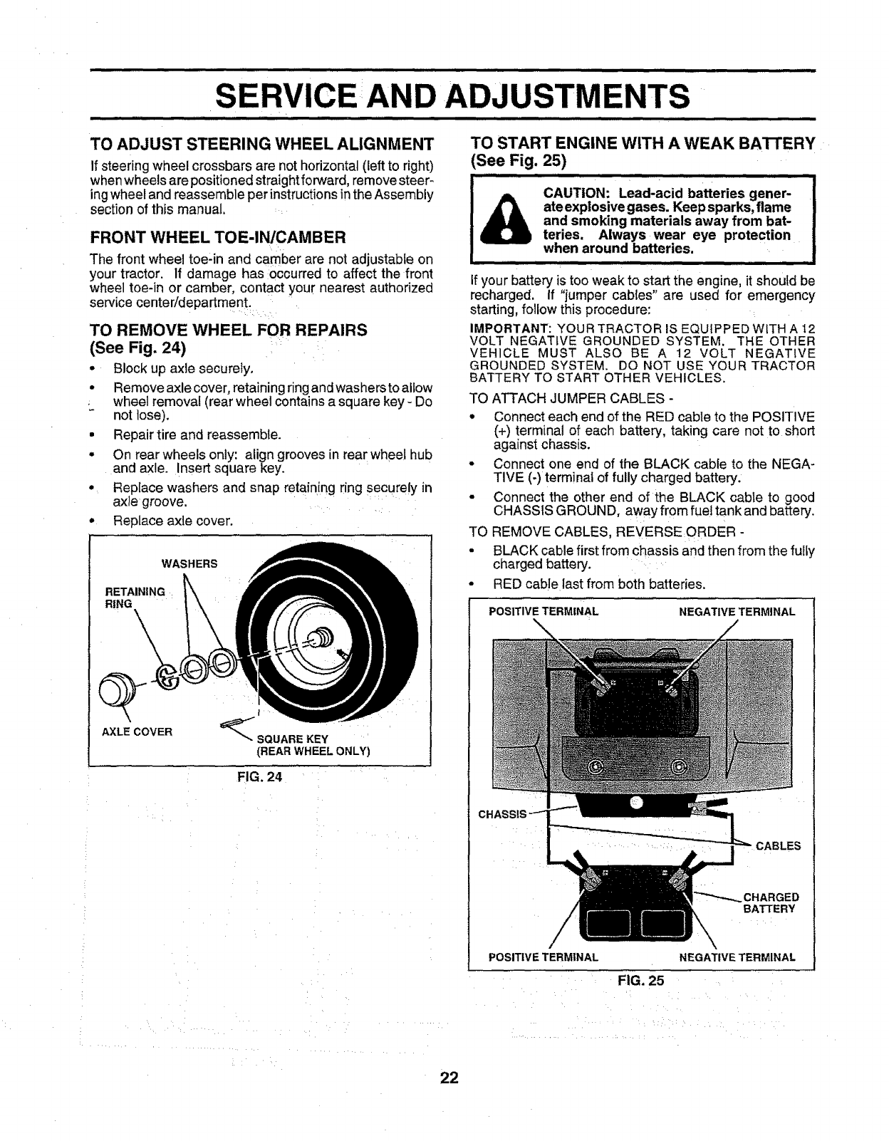
TO REMOVE WHEEL FOR REPAIRS
(See Fig. 24) i....
•Block up axle securely.
° Remove axle cover, retaining ring and washers to aliow
.wheel removal (rear wheel contains a square key - Do
not lose).
• Repair tire and reassemble.
° On rear wheels only: align grooves in rear whee hub
and axle. Insert square key.
° Replace washers and snap retaining ring securely in
axle groove ..........
° Replace axle cover.
WASHERS
RETAINING
RING
AXLE COVER SQUARE KEY
(REAR WHEEL ONLY)
FIG. 24
TO START ENGINE WITH A WEAK BATTERY
(See Fig. 25)
teries.
if your battery is too weak to start the engine, it should be
recharged. If "jumper cables" are used for emergency
starting, follow this procedure:
IMPORTANT: YOUR TRACTOR IS EQUIPPED WITH A 12
VOLT NEGATIVE GROUNDED SYSTEM. THE OTHER
VEHICLE MUST ALSO BE A 12 VOLT NEGATIVE
GROUNDED SYSTEM. DO NOT USE YOUR TRACTOR
BATTERY TO START OTHER VEHICLES.
TO ATTACH JUMPER CABLES -
° Connect each end of the RED cable to the POSITIVE
(+) terminal of each battery, taking care not to short
against chassis.
• Connect one end of the BLACK cable to the NEGA-
TIVE (-)terminal of fully charged battery.
• Connect the other end of the BLACK cable to good
CHASSIS GROUND, away from fuel tankand battery.
TO REMOVE CABLES, REVERSEORDER -
• BLACK cable first from chassis and then from the fuliy
charged battery.
• RED cable last from both batteries.
POSITIVE TERMINAL NEGATIVE TERMINAL
POSITIVE TERMINAL \
NEGATIVETERMINAL
FIG. 25
22
AND ADJUSTM
TO REPLACE HEADLIGHT BULB
•Raise hood.
• Pull bulb holder out of the hole in the backside of the
grill.
• Replace bulb in holder and push bulb holder securely
back into the hole in the backside of the gdll.
• CIosehood.
INTERLOCKS AND RELAYS
Loose or damaged wiring may cause your tractor to run
poorly, stop running, or prevent it from starting.
• Check wiring. See electrical wiring diagram in the
Repair Parts section of this manual.
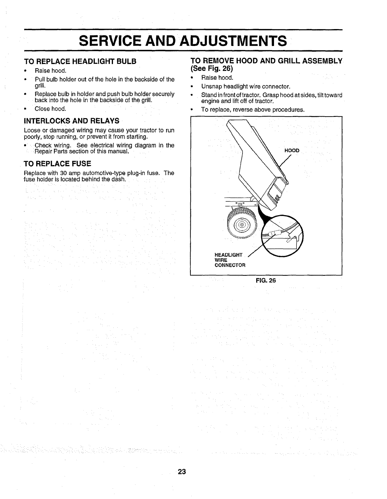
TO REMOVE HOOD AND GRILL ASSEMBLY
(See Fig. 26)
• Raise hood.
• Unsnap headlight wire connector.
• Stand infront oftractor. Grasp hood at sides, tilt toward
engine and lift off of tractor.
• To replace, reverse above procedures.
TO REPLACE FUSE
Replace with 30 amp automotive-type plug-in fuse. The
fuse holder is located behind the dash.
HOOD
HEADLIGHT
WIRE
CONNECTOR
FIG. 26
23
ICE AND ADJUSTMENTS
ENGINE :: :
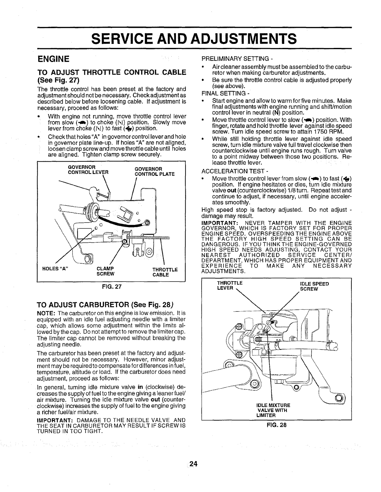
TO ADJUST THROTTLE CONTROL CABLE
(See Fig. 27)
The throttle control has been preset at the factory and
adjustmentshouldnot be necessary. Checkadjustmentas
described below before loosening cable. If adjustment is
necessary, proceed as follows:
• With engine not running, move throttle control lever
from slow (,_i) to choke (N) position. Slowly move
lever from choke (l'_i) to fast (,{y) position.
• Checkthatholes"A" in governorcontrolleverand hole
in governor plate iine-up. If holes "A" are not aligned,
, loosen clamp screw and move throttle cable until holes
are aligned, Tighten clamp screw securely.
GOVERNOR GOVERNOR
CONTROL LEVER CONTROL PLATE
HOLES"A" CLAMP THROTTLE
SCREW CABLE
FIG. 27
TO ADJUST CARBURETOR (See Fig. 28)
NOTE: The carburetor on this engine is tow emission, it is
equipped with an idle fuel adjusting needle with a limiter
cap, which allows some adjustment within the limits al-
lowed by the cap. Do not attempt to remove the limiter cap.
The limiter cap cannot be removed without breaking the
adjusting needle.
The carburetor has been preset at the factory and adjust-
ment should not be necessary. However, minor adjust-
ment may be required to compensate for differences infue!,
temperature, altitude or load. If the carburetor does need
adjustment, proceed as follows:
In general, turning idle mixture valve in (clockwise) de-
creases the supply of fuel to the engine giving a leaner fuel/
air mixture. Turning the idle mixture valve out (counter-
clockwise) increasesthe supply of fuel to the engine giving
a richer fuel/air mixture.
IMPORTANT; DAMAGE TO THE NEEDLE VALVE AND
THE SEAT tN CARBURETOR MAY RESULT IF SCREW IS
TURNED IN TOO TtGHT.
PRELIMINARY SETTING -
• Air cleaner assembly must be assembled to the carbu-
retor when making carburetor adjustments.
° Be sure the throttle control cable is adjusted properly
(see above).
FINAL SETTING -
• Start engine and allow to warm for five minutes. Make
final adjustments with engine running and shift/motion
control lever in neutral (N) position,
• Move throttle control lever to slow (,I_) position. With
finger, rotate and hold throttle lever against idle speed
screw. Turn idle speed screw to attain 1750 RPM.
• While still holding throttle lever against idle speed
screw, turn idle mixture valve full travel clockwise then
counterclockwise until engine runs rough. Turn valve
to a point midway between those two positions. Re-
lease throttle lever. : :
ACCELERATION TEST -
° Move throttle control lever from slow (,ab) to fast (,_)
position. If engine hesitates or dies, turn idle mixture
valveout (counterclockwise) I!8turn. Repeattest and
continue to adjust, if necessary, until engine acceler-
ates smoothly.
High speed stop is factory adjusted. Do not adjust -
damage may result.
IMPORTANT: NEVER TAMPER WITH THE ENGtNE
GOVERNOR, WHICH IS FACTORY SET FOR PROPER
ENGINE SPEED. OVERSPEEDING THE ENGINE ABOVE
THE FACTORY HIGH SPEED SETTING CAN BE
DANGEROUS. IF YOU THINK THE ENGINE-GOVERNED
HIGH SPEED NEEDS ADJUSTING, CONTACT YOUR
NEAREST AUTHORIZED SERVICE CENTER/
DEPARTMENT, WHICH HAS PROPER EQUIPMENT AND
EXPERIENCE TO MAKE ANY NECESSARY
ADJUSTMENTS.
THROTTLE IDLE SPEED
LEVER SCREW
IDLE MIXTURE
VALVE WITH
LtMITER
FIG. 28
24
STORAGE
Immediately prepare your tractor for storage at the end of
the season or if the tractor will not be used for 30 days or
more,
,,,,,,,,,,,,,,,,,,,,,,,,, ,,,,,,,,,,,,,,,,
CAUTION:, Never store the tractor with
gasoline in the tank inside a building
where fumes may reach an open flame
or spark. Allow the engine to cool
before storing in any enclosure.
...................................,, : : .... : ,, ................
i,i ill i j i,,,lll,llllll,i i,i ill ll,l,l,,,ll
TRACTOR
Remove mower from tractor for winter storage. When
mower is to be stored for a period of time, clean it thor-
oughly, remove all dirt, greas e, leaves, etc. Store in a
clean, dry area.
•Clean entire tractor (See "CLEANING" inthe Customer
Responsibilities section of this manual).
• Inspect and replace belts, if necessary (See belt re-
placement instructions in the Service and Adjustments
section of this manual).
Lubricate as shown in the Customer Responsibilities
section of this manual.
Be sure that all nuts, bolts and screws are securely
fastened. Inspect moving parts fordamage, breakage
and wear. Replace if necessary.
• Touch up all rusted or chipped paint surface,_ sand
lightly before painting.
BATTERY
Fully charge the battery for storage.
After a period of time in storage, battery may require
recharging.
To help prevent corrosion and power leakage during
long periods of storage, battery cables should be
disconnected and battery cleaned thoroughly (see "TO
CLEAN BATTERY AND TERMINALS" in the Cus-
tomer Responsibilities section of this manual).
After cleaning, leave cables disconnected and place
cables where they cannot come in contact with battery
terminals.
•Be sure battery drain tube is securely attached.
• If battery is removed from tractor for storage, do not
store battery directly on concrete or damp surfaces.
ENGINE
FUEL SYSTEM
IMPORTANT: IT 1S IMPORTANT TO PREVENT GUM
DEPOStTS FROM FORMING IN ESSENTIAL FUEL
SYSTEM PARTS SUCH AS CARBURETOR, FUEL FILTER,
FUEL HOSE, OR TANK DURING STORAGE. ALSO,
EXPERIENCE INDICATES THAT ALCOHOL BLENDED
FUELS (CALLED GASOHOL OR USING ETHANOL OR
METHANOL) CAN ATTRACT MOISTURE WHICH LEADS
TO SEPARATION AND FORMATION OF ACIDS DURING
STORAGE. ACIDIC GAS CAN DAMAGE THE FUEL
SYSTEM OF AN ENGINE WHILE IN STORAGE.
• Drain the fuel tank.
• Start the engine and iet it run until the fuel lines and
carburetor are empty.
• Never use engine or carburetor cleaner products in the
fuel tank or permanent damage may occur.
• Use fresh fuel next season.
NOTE: Fuel stabilizer is an acceptable alternative in
minimizing the formation of fuel gum deposits during stor-
age. Add stabi!izer to gasoline in fuel tank or storage
container. Always follow the mix ratio found on stabilizer
container. Run engine at least 10 minutes after adding
stabilizer to allowthe stabilizer to reach the carburetor. Do
not drain the gas tank and carburetor if using fue! stabilizer.
ENGINE OIL '
Drain oil (with engine warm) and replace with clean engine
oil. (See "ENGINE" in the Customer Responsibilities
section of this manual).
CYLINDERS
• Remove spark plug(s).
• Pour one ounce of oil through spark plug hole(s) into
cylinder(s).
• Turn ignition key to"START" position for afew seconds
to distribute oil.
•Replace with new spark plug(s).
OTHER
• Do not store gasoline from one season to another.
• Replace your gasoline can if your can starts to rust.
Rust and/or dirt in your gasoline will cause problems.
•If possible, store your tractor indoors and cover it to
give protection from dust and dirt.
• Cover your tractor with a suitable protective cover that
does not retain moisture. Do not use plastic. Plastic
cannot breathe which allows condensation to form and
will cause your tractor to rust.
IMPORTANT: NEVER COVER TRACTOR WHILE ENGINE
AND EXHAUST AREAS ARE STILL WARM.
25

/ i Hi,llnl TROUBLESHOOTING POINTS
. /l/l/_ i i ii
PROBLEM
Will not start
i i Ill,
Hard to start
4
Engine will not turn over
: i
Engine clicks but will not
start
Loss of power
Excessive vibration
ii
CAUSE ....
1, Out of fuel.
2. Engine not"CHOKED" properly,
3. Engine flooded, ....
4. Bad spark plug,
5. D rty air filter,
6. Dirtyfuel filter.
7. Water in fuel. : : _
8, Loose or damaged wiring,
9, Carburetor out of adjustment.
10, Engine valves out of adjustment,
1. Dirtyair fitter,
2. Bad spark plug.
3. Weak or dead battery,
4. Dirty fuel filter.
5. Stale or dirty fuel.
6. Loose or damaged wiring .....
7. Carburetor out of adjustment.
8, Engine valves out of adjustment
1. Clutch/brake pedal not depressed.
2, Attachment clutch is engaged,
3, Weak or dead battery,
4, Blown fuse,
5. Corroded battery terminab,
6. Loose or damaged wiring.
7. Faulty ignition switch.
8. Faulty solenoid or starter.
9. Faulty operator presence switch(es).
.IIHIIIIlll I
1. Weak or dead battery.
2. Corroded battery terminab.
3. Loose or damaged wiring.
4. Faulty soIenoid or starter.
t, Cutting too much grass/too fast.
2, Throttle in "CHOKE" position.
3. Build-up of grass, leaves and trash under mower,
CORRECTION
1.
2,
3.
4,
5.
6.
7.
8,
9.
10,
Fill fuel tank.
See "TO START ENGINE" in Operation section,
Wat severa minutes before attempting to start,;
Replace spark plug. :..... ::
Clean/repiac e air filter,
Replace fuel filter. :........
Drain fuel tank and Carburetor, refill tank with fresh
gasoline and replace fue! filter.
Check all widng.
Contact an authorized service center/department.
Contact an authorized service center/department.
1. Clean/replace air filter.
2, Replace spark plug.
3, Recharge or replace battery.
4. Replace fuel filter.
5, Drain fue! tank and refill with fresh gasoline,
6. :Check all wiring,
7. Contact an authorized service center/department,
8, Contact an authorized service centeddepartment
1.
2,
3,
4.
5,
6.
7.
8.
9.
Depress clutch/brake pedal,
Disengage attachment clutch.
Recharge or replace battery,
Replace fuse, :
Ciean battery terminals.
Check al! widng,
CheckJreptace ignition switch,
CheckJrepiace sobnoid or starlet,
Contact an authorized service center/department
1. Recharge or replace battery,
2, Clean battery terminals,
3. Check all wiring,
4, Check!replace solenoid orstarter.
r
t. Set in "Higher Cut _ position/reduce speed,
2, Adjust throttle control.
3. Clean underside of mower housing .....
4,
5.
6,
7.
8.
9.
Dirty air fiiter,
Low oil level/dirty oil, :
Faulty spark plug,
Dirty fueI filter.
Stale or dirty fuel .........
Water in fuel.
10. Spark plug wire loose.
11. Dirty engine air screen/fins.
12. Dirty/clogged muffler.
13. Loose or damaged wiring.
I4. Carburetor out of adjustment,
!5. Engine valves out of adjustment
1. Worn, bent or loose blade.
2. Bent blade mandrel.
3. Loose/damaged part(s).
4, Clean/replace air filter.
5. Check oilleve!ichange oil.
6, Clean and regap or change spark plug.
7. Replace fuel filter.
8, Drain rue! tank and refill w!th fresh gasoline,
9. Drain fuet tank and carburetor, refill tank with fresh
gasoline and replace fuel _ter.
10. Connect and tighten spark plug wire.
11. Ciean engine air screen/fins,
12. Clean/replace muffler,
13. Check all wiring,
14, Contact an authorized service center/department,
15. Contact an authorized service center/department.
1. Replace blade. Tighten blade bolt.
2. Replace biade mandrel.
3. Tighten loose part(s). Replace damaged parts.
L I • • -•i • ......
26

i i illl ill , iiii
TROU HOOTING POINTS
PROBLEM
Engine continues to run
when operator leaves seat
with attachment clutch
engaged
Poor cut-uneven
Mower blades will not
rotate
nlnllH
Poor grass discharge
Headlight(s) not working
(if so equipped)
Battery will not charge
Engine "backfires"
when turning engine
"OFF"
CAUSE
1. Faulty operator-safety presence control system.
1. Wom, bent or _ooseblade.
2. Mower deck not level
3, Buildup of grass, leaves, and trash under mower.
4, Bent blade mandrel.
5, Clogged mower deck vent holes from buildup of
grass, leaves, and trash around mandrels.
1. Obstruction in clutch mechanism.
2. Worn/damaged mower drive belt.
3. Frozen idler pulley.
4. Frozen blade mandrel.
1, Engine speed too slow.
2. Travel speed too fast.
3. Wet grass,
4. Mower deck not level.
5. Low/uneven tire air pressure.
6. Worn, bent or loose blade.
7. Buildup of grass, leaves and trash under mower.
8. Mower drive belt worn.
9. Blades improperly installe&
10. ImproperbIades used.
11. Clogged mower deck vent holes from buildup of
grass, leaves, and trash around mandrels.
1. Switch is "OFF".
2, Bulb(s) burnedout.
3. Faulty light switch.
4. Loose or damaged wiring.
5. Blown fuse.
1. Bad battery cell(s).
2. Poor cable connections.
3. Faulty regulator (if so equipped).
4. Faulty alternator.
1, Engine throttle controt not set at "SLOW"
positionfor 30 seconds before stopping engine.
CORRECTION
1, Check wiring, switches and connections. If not
corrected, contact an authorized service center/
department.
1. Replace blade. Tighten blade boIt.
2. Level mower deck.
3, Clean underside of mower housing.
4. Replace blade mandrel.
5. Clean around mandrels to open vent holes..
I. Remove obstruction.
2. Replace mower drive belt.
3. Replace idler pulley.
4. Replace blade mandrel.
t. Place throttle control in "FAST" position.
2. Shift to slower speed.
3. Allow grass to dry before mowing.
4. Level mower deck.
5. Check tires for proper air pressure.
6. Replacelsharpen blade. Tighten blade bolt.
7. Clean underside of mower housing.
8. Replace mower drive belt.
9. Reinstall blades sharp edge down.
t0. Replace with blades listed in this manual.
11. Clean around mandrels to open vent holes.
1. Turn switch "ON".
2. Replace bulb(s),
3. Check/replace light switch.
4. Check wiring and connections.
5. Replace fuse.
1. Replace battery.
2. Check/clean all connections.
3. Replace regulator,
4. Replace alternator.
Move throttle control to "SLOW" position and allow
to idle for 30 seconds before stopping engine.
27

SE
28
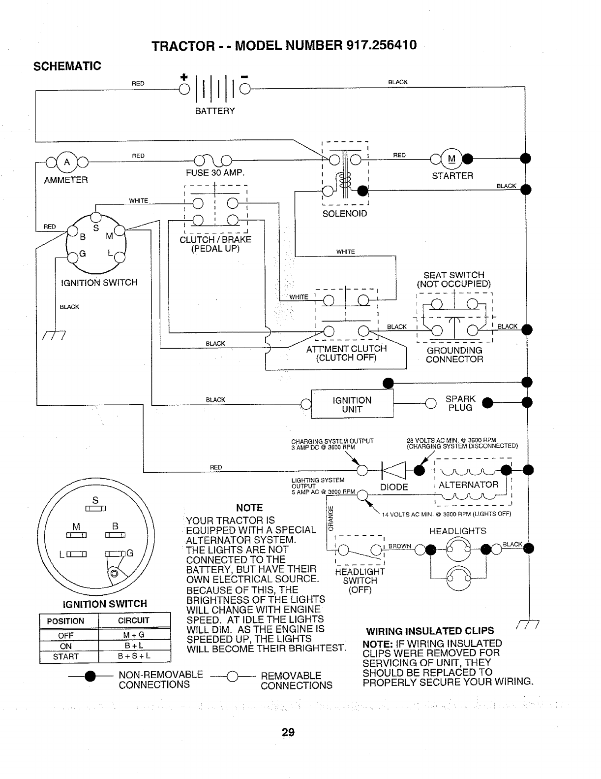
SCHEMATIC
RED
TRACTOR -- MODEL NUMBER 917.256410
BATTERY
BLACK
J
CLUTCH/BRAKE
(PEDAL UP)
FUSE30 AMP. i _llh i
r----_ ___: _I I
'O'O'
1 t 1 _" ..... }
SOLENOID
AMMETER
RED
BLACK f
WHITE I
,0
: :::' I
WHITE
IGNITION SWITCH
BLACK
RED Q _je
STARTER
BLACK
SEAT SWITCH
(NOT OCCUPIED)
.... 1-
,UST;-::
_1
WHITE
1 1
'{Of_ IBLACK
(CLUTCHOFF) I
GROUNDING
CONNECTOR
,GN,T,O. SPARKe----ll: UNIT PLUG
IGNITION SWITCH
POSITION
OFF
......ON
START
A
W
CHARGING SYSTEM OUTF_UT 28 VOLTS AC MIN. @ 3600 RPM
3AMP DC @ 3600 RPM (CHARGING SYSTEM DISCONNECTED)
RED
_u2_;u_: :_ .... DIODE ........ i'-" ' A'._ATO-_ _
:NOTE 1_ _x '......... J
YOUR TRACTOR IS ]_ " 14 VOLTS AC MIN, @ 3600 RPM {LIGHTS OFF)
EQUIPPED WITH A SPECIAL l_ HEADLIGHTS
:ALTERNATOR SYSTEM. ! _...... i /_
t I BROWN BLACK
THE LIGHTS ARE NOT ____
CONNECTED TO THE ;_2 __ ; - T \_/ T -
BATFERY, BUT HAVE THEIR I_EAT3LI_T i _\ I
OWN ELECTRICAL SOURCE. SWITCH L_O
BECAUSE OF THIS, THE (OFF)
CIRCUIT
M+G"
B+L
B+S+L
NON-REMOVABLE _ REMOVABLE
CONNECTIONS CONNECTIONS
BRIGHTNESS OF THE LIGHTS
WILL CHANGE WITH ENGINE
SPEED. AT IDLE THE LIGHTS
WILL DIM. AS THE ENGINE IS
SPEEDED UP, THE LIGHTS
WILL BECOME THEIR BRIGHTEST.
WIRING INSULATED CLIPS
NOTE: IF WIRING INSULATED
CLIPS WERE REMOVED FOR
SERVICING OF UNIT, THEY
SHOULD BE REPLACED TO
F 7
PROPERLY SECURE YOUR WIRING.
29
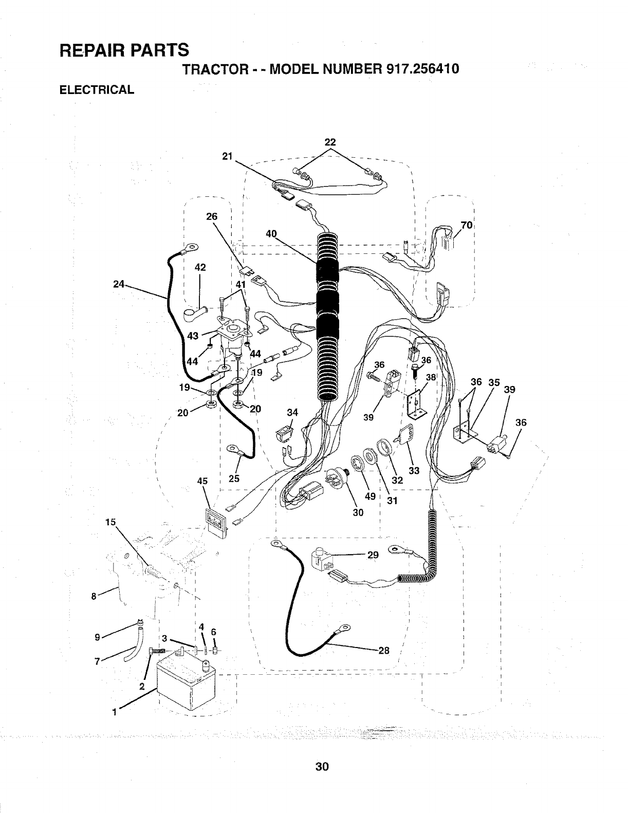
REPAIR PARTS
TRACTOR -- MODEL NUMBER 917.256410
ELECTRICAL
22
42
41
36
20
15\
8/ -__
/
45 25
6
34 39
32
]
]
]
= - T- =
J
I
35 39
36
/
/
30
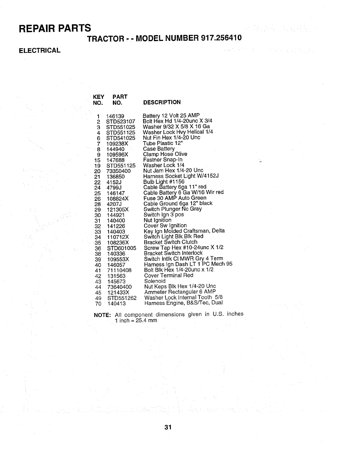
REPAIR PARTS
TRACTOR -- MODEL NUMBER 917,256410
ELECTRICAL .....
• KEY PART
NO, NO. DESCRIPTION
1 146139
2 STD523107
3 STD551025
4 STD551125
6 STD541025
7 109238X
8 144940
9 !09596X
15 147688
19 STD551125
20 73350400
21 136850
22 4152J
24 4799J
25 146147
26 108824X
28 4207J
29 121305X
3O 144921
31 140400
32 141226
33 1404o3
34 110712X
35 108236X
36 STD601005
38 140336
39 109553X
40 146057
41 71110408
42 131563
43 145673
44 73640400
45 121433X
49 STD551262
70 140413
Battery 12 Volt 25 AMP
Bolt Hex Hd 1/4-20unc X 3/4
Washer 9/32 X 5/8 X 16 Ga
Washer Lock Hvy Helical 1/4
Nut Fin Hex 1/4-20 Unc
Tube Plastic 12"
Case Battery
Clamp Hose Olive
Fastner Snap-ln
Washer Lock 1/4
Nut Jam Hex 1/4-20 Unc
Harness Socket Light W/4152J
Bulb Light #1156
Cable Battery 6ga 11" red
Cable Battery 6 Ga W/16 Wir red
Fuse 30 AMP Auto Green
Cable Ground 6ga 12" black
Switch Plunger Nc Gray
Switch Ign 3 pos
Nut Ignition
Cover Sw Ignition
Key Ign Motded Craftsman, Delta
Switch Light BIk Blk Red
Bracket Switch Clutch
Screw Tap Hex #10-24unc X 1t2
Bracket Switch interlock
Switch Intlk CI MWR Gry 4 Term
Harness Ign Dash LT 1 PC Mech 95
Bolt BIk Hex I/4-20unc x 1/2
Cover Terminal Red
Solenoid
Nut Keps Blk Hex 114-20Uric
Ammeter Rectangular 6 AMP
Washer Lock Internal Tooth 5/8
Harness Engine, B&SFFec, Dual
NOTE: All component dimensions given in U.S. inches
1 inch = 25.4 mm
31
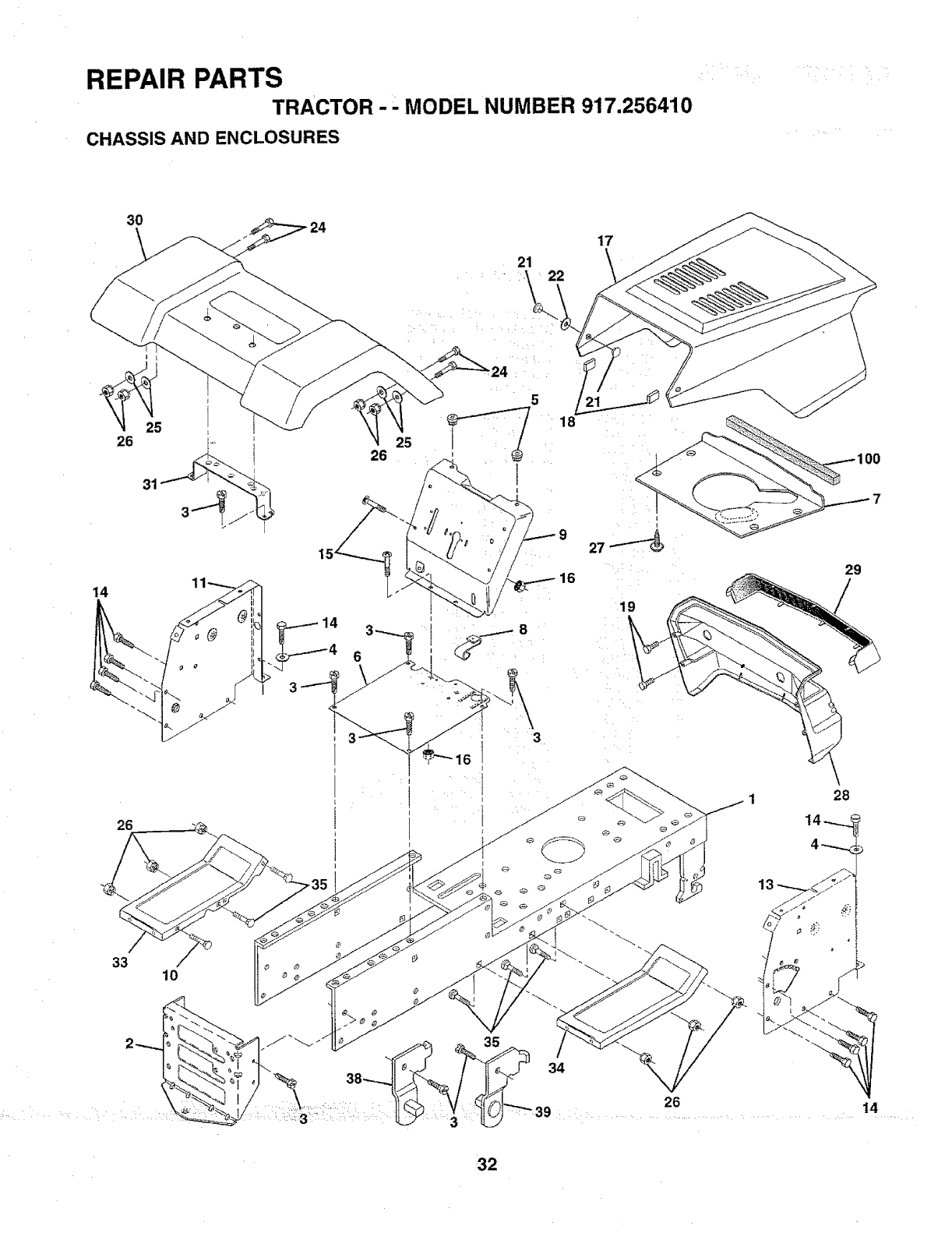
REPAIR PARTS
TRACTOR- MODEL NUMBER 917.256410
CHASSIS AND ENCLOSURES
30
21 22
17
26
14
26
33 10
25
26
5
18
O0
29
1
\
1 28
•32
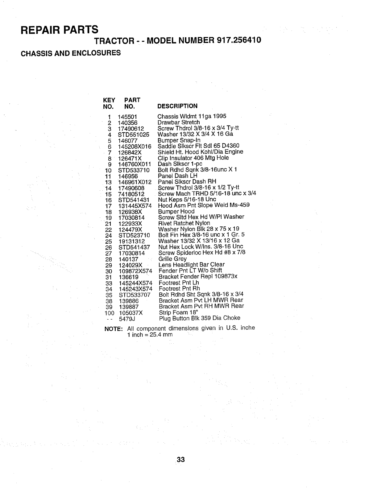
REPAIR PARTS
TRACTOR - -MODEL NUMBER 917.256410
CHASSIS AND ENCLOSURES
KEY PART
NO. NO, DESCRIPTION
1 145501
2 140356
3 17490612
4 STD55t025
5 146O77
6 145208X016
7 126842X
8 126471X
9 146760X011
10 STD533710
11 146956
13 146961X012
14 17490608
15 74180512
16 STD541431
t7 131445X574
18 126938X
19 17030814
21 122933X
22 124479X
24 STD523710
25 19131312
26 STD541437
27 1703O814
28 14O137
29 !24029X
30 109872X574
31 136619
33 145244X574
34 145243X574
35 STD533707
38 139886
39 139887
100 !05037X
-- 5479J
NOTE:
Chassis Wldmt 11ga 1995
Drawbar Stretch
Screw Thdrol 3/8-16 x 3/4 Ty-tt
Washer 13/32 X 3/4 X 16 Ga
Bumper Snap-in
Saddle Slkscr Fit Sdl 65 D4360
Shield Hr. Hood Kohl/Dia Engine
Clip Insulator 406 Mtg Hole
Dash Slkscr 1-pc
Bolt Rdhd Sqnk 3/8-16unc X 1
Panel Dash LH
Panel Slkscr Dash RH
Screw Thdrol 3/8-16 x 1/2 Ty-tt
Screw Mach TRHD 5/16-18 unc x 3/4
Nut Keps 5/16-t8 Unc
Hood Asm Pnt Slope Weld Ms-459
Bumper Hood
Screw Sltd Hex Hd W/PI Washer
Rivet Ratchet Nylon
Washer Nylon BIk 28 x 75 x 19
Bolt Fin Hex 3/8-16 unc x 1 Gr. 5
Washer 13/32 X 13/16 x 12 Ga
Nut Hex Lock W/Ins. 3/8-16 Unc
Screw Spiderloc Hex Hd #8 x 7/8
GriIte Grey
Lens Headlight Bar Clear
Fender Pnt LT W/o Shift
Bracket Fender Repl 109873x
Footrest Pnt Lh
Footrest Pnt Rh
Bolt Rdhd Sht Sqnk 3/8-16 × 3/4
Bracket Asm Pvt LH MWR Rear
Bracket Asm Pvt RH MWR Rear
Strip Foam 18"
Plug Button Bik 359 Dia Choke
All component dimensions given in U.S. inche
1 inch = 25.4 mm
33
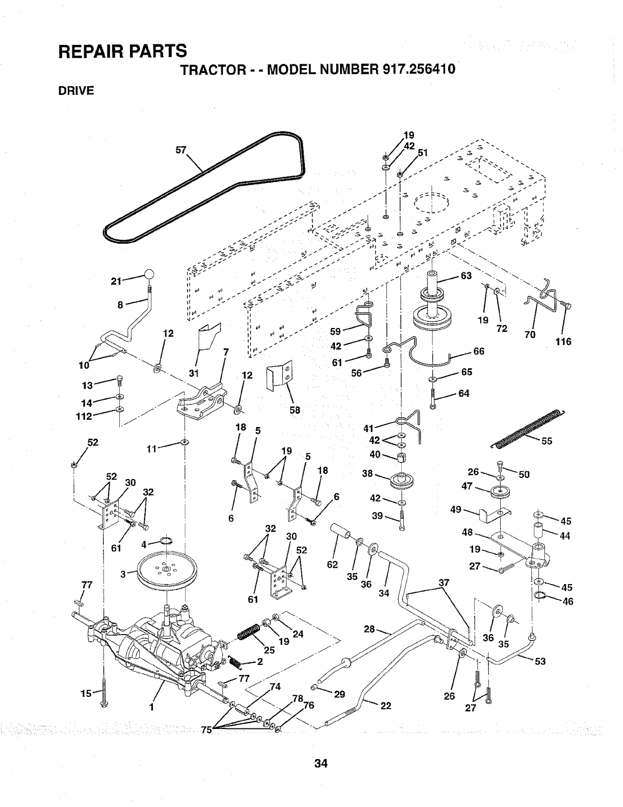
REPAIR PARTS
TRACTOR - - MODEL NUMBER 917.256410
DRIVE
r19
61
34
26
27
53
34

REPAIR PARTS
TRACTOR-- MODELNUMBER 917.256410
DRIVE
KEY PART KEY PART
NO. NO. DESCRIPTION NO. NO. DESCRIPTION
1 142603 Transaxle 6sp Std D4360-79 4! 109070X
2 146682 Spring Return Brake T/a Zinc 42 19131312
3 123666X Pulley Transaxle 18/20" tires 44 105706X
4 12000028 Ring Retainer # 5100-62 45 110812X
5 121520X Strap Torque 30 Degrees 46 12000039
6 17490512 Screw Thdrol 5/16-18 X 3/4 TYT 47 127783
7 130802 Bracket Saddle Shift T!8, 48 123789X
8 t31679 Rod Shf Sdf LY/YT Str Bik Zinc 49 123205X
10 STD561210 Pin Cotter t/8 X 1 Cad 50 STD523715
11 105701X Washer Plate Shf 388 Sq Hole 51 _STD541437
12 19151216 Washer 15/32 X3/4X 16ga 52 STD541431
13 74550412 Bolt 1/4-28unf Gr8 W/Patch 53 105710X
t4 STD551125 Washer Lock Hvy Helical 1/4 55 105709X
15 74490544 Bolt Hex FLGHD5/16-18Gr.5 56 STD523712
t8 STD523710 Bolt Fin Hex3/8-16unc X 1 Gr, 5 57 130801
19 STD541437 Nut Lock Hex W!Ins. 3/8-16 Unc 58 127274X
21 106933X Knob Rd 1/2-13 Ptstc Thds BIk 59 1403t2
22 130804 Rod Brake BIk Zinc 26 840 61 17490612
24 STD541237 Nut Hex Jam 3/8-16 Unc 62 8883R
25 106888X Spring Rod Brake 2 00 Zinc 63 140186
26 STD551037 Washer 13/32 X 13/16 X 16 Ga 64 71170764
27 STD561210 Pin Cotter 1/8 X 3/4 Cad 65 STD551143
28 145204 Rod Brake Parking Lt/Yt 66 129921
29 124236X Cap Brake Parking Red 70 134683
30 130807 Bracket Mtg Transaxle 72 19132012
31 127275X Keeper Belt LH LT 14 Ga 74 109502X
32 STD523107 Bolt Hex Hd 5/16-18unc X 3/4 75 121749X
34 149001 Shaft Asm Pedal Foot 76 STD581075
35 120183X Bearing Nylon BIk 629 ld 77 123583X
36 STD551062 Washer21/32 X 1 X 16 Ga 78 121748X
37 1572H Pin Rolf 3/16 X1" 1t2 19091210
38 123674X Pulley Idler Flat
39 STD523727 Bolt Fin Hex 3/8-16unc X 2-3/4
40 4470J Spacer Split 395 X 59 Bzp
Keeper Belt Retainer
Washer 13/32 X 13/16 X 12 Ga
Bearing Nyl 503 X 628 X 1 25
Washer Hardened
Ring Klip #t5304-50
Pulley Idler V Groove Plastic
Bellcrank Asm Clutch
Retainer Belt Style Spring
Bolt Hex Hd 3/8-16unc X 1-!/2
Nut Crownlock 3/8-16 UNC
Nut Crown Lock 5/16-18
Link Clutch 7 66
Spring Return Clutch 6 75
Bolt Fin Hex 3/8-16 unc x 1-1/4
V-Belt Gd Drive 95 25
Keeper Belt RH LT Pnt/zinc 16g
Keeper Belt Centerspan
Screw Thdrol 3/8-16x3/4 Ty-tt
Cover Pedal BIk Round
Pulley Eng Ct Mech 38deg LTiYT
Bolt Hex 7/16-20x4 Gr 5
Washer Lock Hvy HIcl Spr 7/16
Keeper Belt Engine LH LT
Guide Belt Mower Drive RH
Washer 13/32 X 1-1/4 X 12 Ga
Spacer Split 80xl 94 Cad/zinc
Washer 25/32 X 1 1/4 X 16 Ga
E-ring #5133-75
Key Square 2 0 X 1845/1865
Washer 25/32 X 1-5/8 X 16ga
Washer 9/32 X 3/4 X 10 Ga
NOTE: All component dimensions given in U.S. inches.
1 inch = 25.4 mm
35
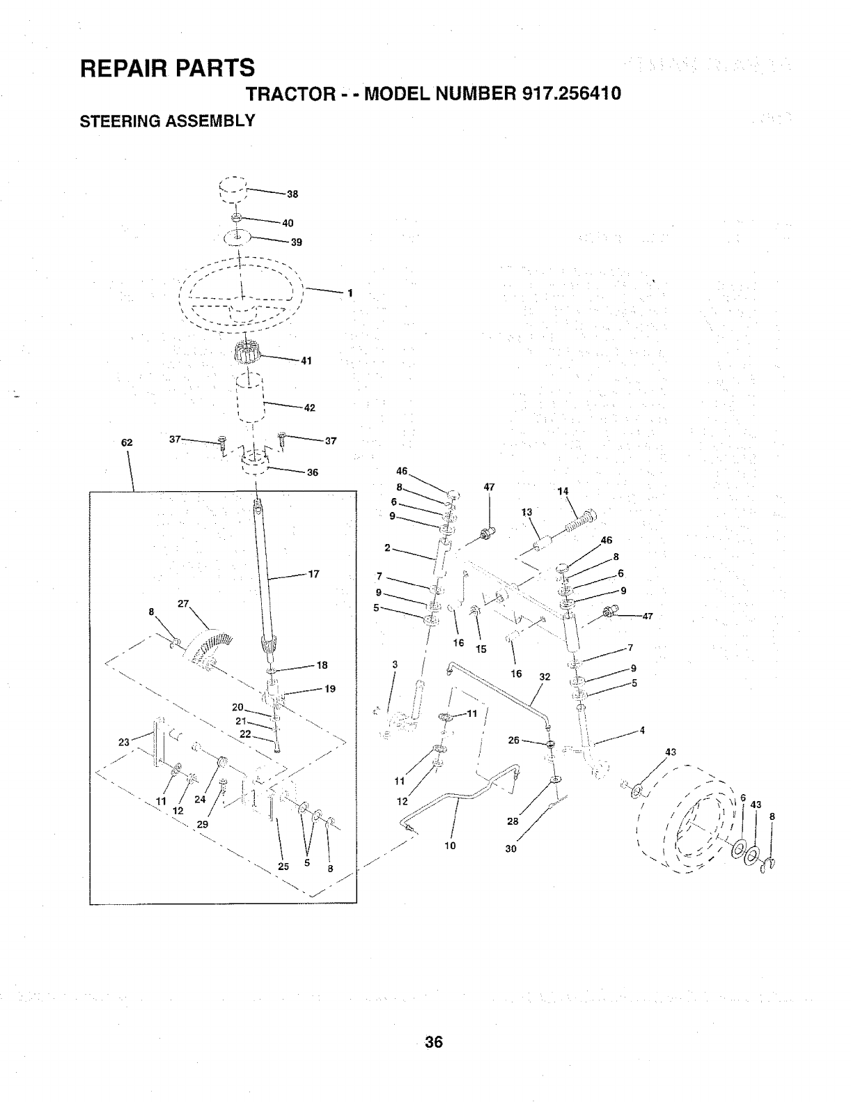
REPAIR PARTS
TRACTOR - MODEL NUMBER 917.256410
STEERING ASSEMBLY
62
11 /
/
12
_/ 10
46
.....8
36
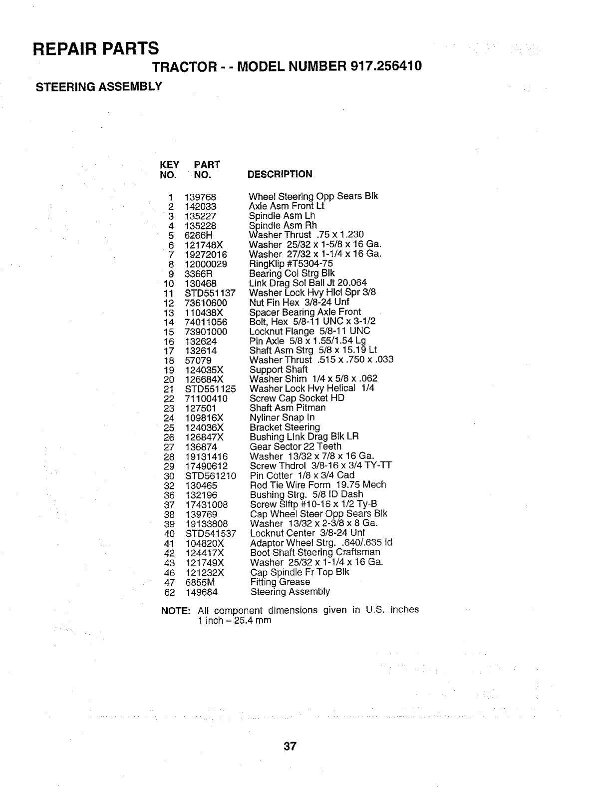
REPAIR PARTS
TRACTOR -- MODEL NUMBER 917.256410
STEERING ASSEMBLY
KEY PART
NO. NO. DESCRIPTION
1 139768
2 142033
3135227
4 135228
5 6266H
6 121748X
7 19272016
8 12000029
9 3366R
10 13O468
11 STD551137
12 73610600
13 110438X
14 74011056
15 73901000
16 132624
t7 132614
18 57079
19 124035X
20 126684X
2t STD551125
22 71100410
23 127501
24 109816X
25 124036X
26 126847X
27 136874
28 19131416
29 17490612
3O STD561210
32 130465
36 132196
37 17431OO8
38 139769
39 19133808
40 STD541537
41 104820X
42 124417X
43 121749X
46 121232X
47 6855M
62 149684
Wheel Steering Opp Sears BIk
Axle Asm Front Lt
Spindle Asm Lh
Spindle Asm Rh
Washer Thrust .75 x 1,230
Washer 25/32 x 1-5/8 x 16 Ga.
Washer 27/32 x 1-1/4 x 16 Ga,
RingKlip #T5304-75
Bearing Col Strg BIk
Link Drag Sol Ball Jt 20.064
Washer Lock Hvy Hlcl Spr 3/8
Nut Fin Hex 3/8_24 Unf
Spacer Bearing Axle Front
Bolt, Hex 5/8-11 UNC x 3-1/2
Locknut Flange 5/8-11 UNC
Pin Axle 5/8 x 1o55/1,54 Lg
Shaft Asm Strg 5/8 x 15,19 Lt
Washer Thrust ,515 x,750 x.033
Support Shaft
Washer Shim 1/4 x 5/8 x .062
Washer Lock Hvy Helical 1/4
Screw Cap Socket HD
Shaft Asm Pitman
Nyliner Snap In
Bracket Steering
Bushing Link Drag Blk LR
Gear Sector 22 Teeth
Washer 13/32 x 7/8 x t6 Ga.
Screw Thdro! 3/8-16 x 3/4 TY-TT
Pin Cotter 1/8 x 3/4 Cad
Rod Tie Wire Form 19.75 Mech
Bushing Strg. 5/8 ID Dash
Screw Stftp #10-16 x 1/2 Ty-B
Cap Wheel Steer Opp Sears B}k
Washer 13/32 x 2-3/8 x 8 Ga,
Locknut Center 3/8-24 Unf
Adaptor Wheel Strg..640/.635 ld
Boot Shaft Steering Craftsman
Washer 25/32 x 1-1/4 x 16 Ga.
Cap Spindle Fr Top Blk
Fitting Grease
Steering Assembly
NOTE: All component dimensions given in U.S. inches
1 inch = 25.4 mm
37
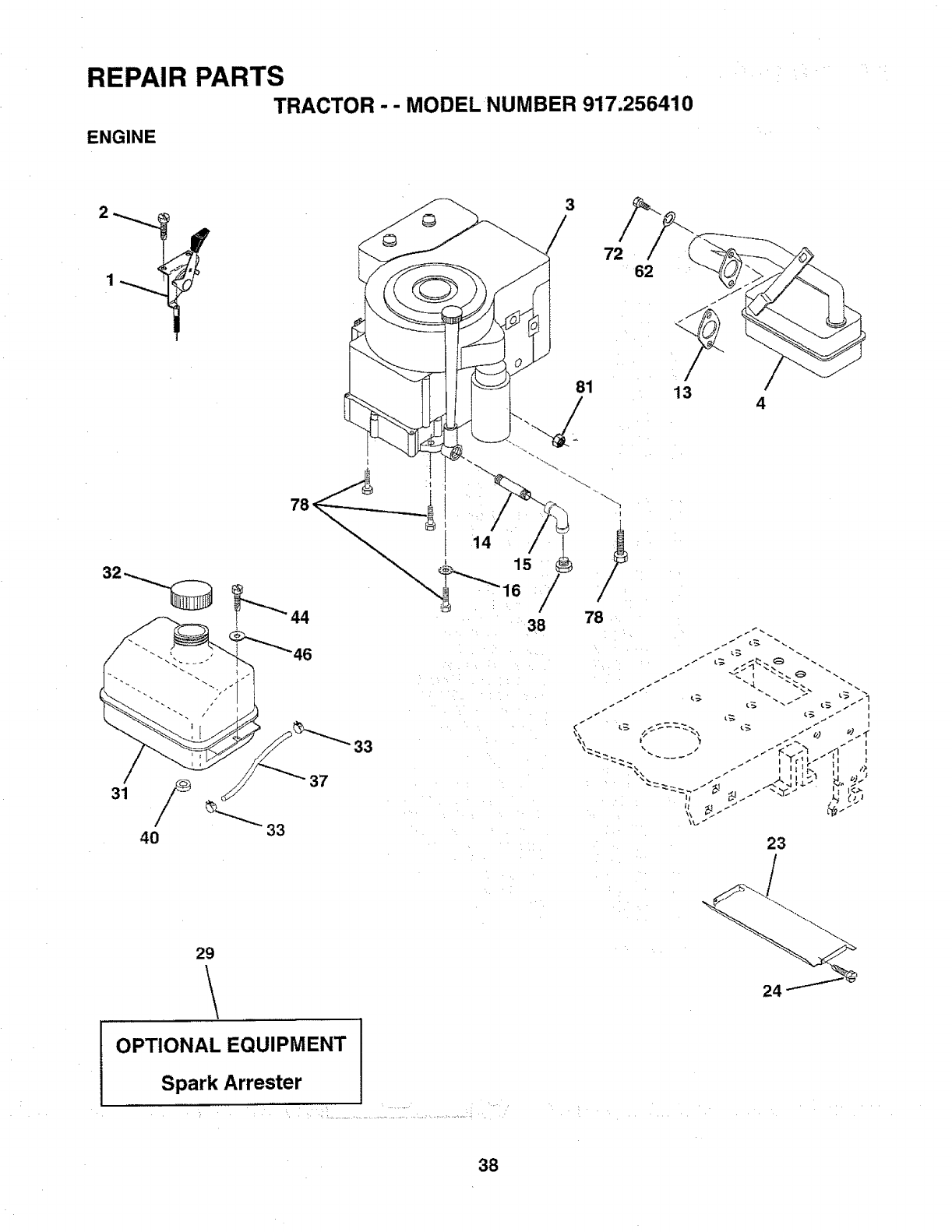
REPAIR PARTS
TRACTOR -- MODEL NUMBER 917,256410
ENGINE
81
7
4
31
4O
33
37
29
\
23
OPTIONAL EQUIPMENT
Spark Arrester
!i
38
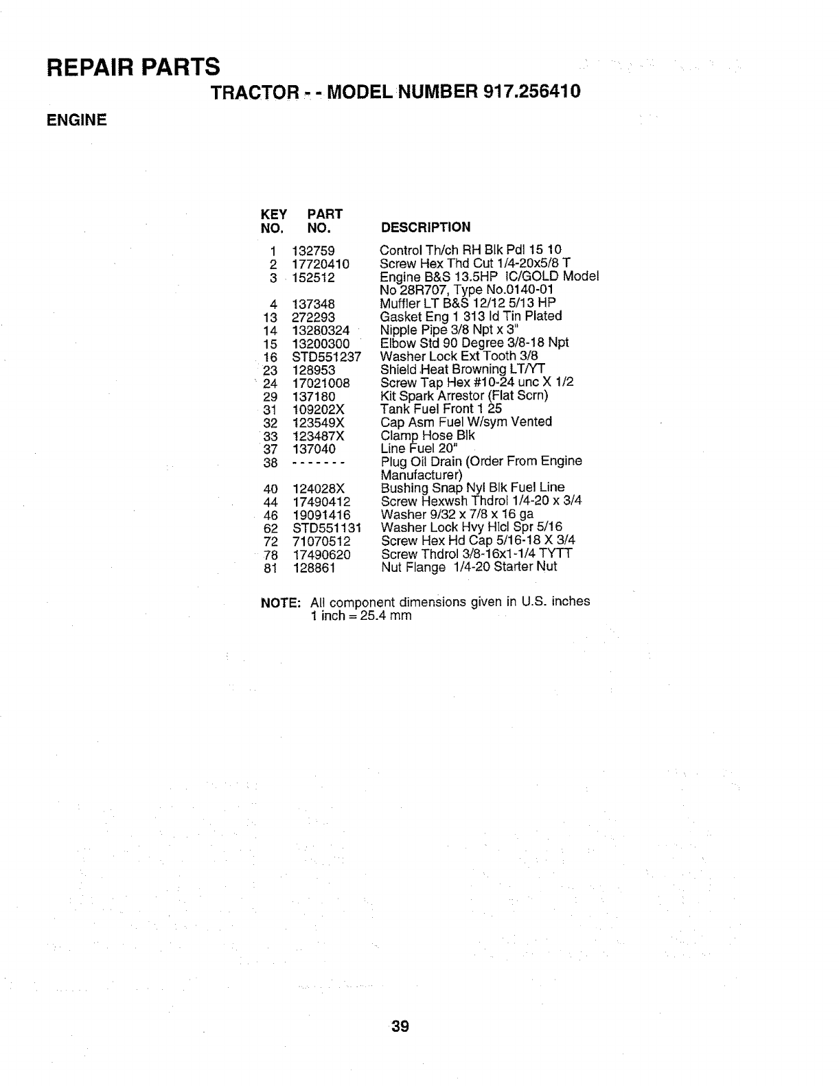
REPAIR PARTS
TRACTOR , - MODEL NUMBER 917.256410
ENGINE
KEY PART
NO. NO, DESCRIPTION
1
2
3
132759
17720410
152512
4 137348
13 272293
14 13280324
15 13200300
16 STD551237
23 128953
24 17021008
29 137180
31 109202X
32 t23549X
33 t23487X
37 137040
38 .......
40 124028X
44 17490412
46 19091416
62 STD551131
72 71070512
78 1749062O
81 128861
Control Th/ch RH Blk Pdl 15 10
Screw Hex Thd Cut 1/4-20x5/8 T
Engine B&S 13,5HP IC/GOLD Model
No 28R707, Type No.0140-01
Muffler LT B&S 12/12 5/13 HP
Gasket Eng 1 313 Id Tin Plated
Nipple Pipe 3/8 Npt x 3"
Elbow Std 90 Degree 3/8-18 Npt
Washer Lock Ext Tooth 3/8
Shield ,Heat Browning LTiYT
Screw Tap Hex #10-24 unc X 1/2
Kit Spark Arrestor (Flat Scrn)
Tank Fuel Front 1 25
Cap Asm Fuel W/sym Vented
Clamp Hose Blk
Line Fuel 20"
Plug Oit Drain (Order From Engine
Manufacturer)
Bushing Snap Nyl BIk Fuel Line
Screw Hexwsh Thdrof 1/4-20 x 3/4
Washer 9/32 x 7/8 x 16 ga
Washer Lock Hvy Hict Spr 5/16
Screw Hex Hd Cap 5/16-18 X 3/4
Screw Thdrol 3/8-16xl-1/4 TYTT
Nut Flange 1/4-20 Starter Nut
NOTE: All component dimensions given in U.S. inches
i inch = 25.4 mm
39
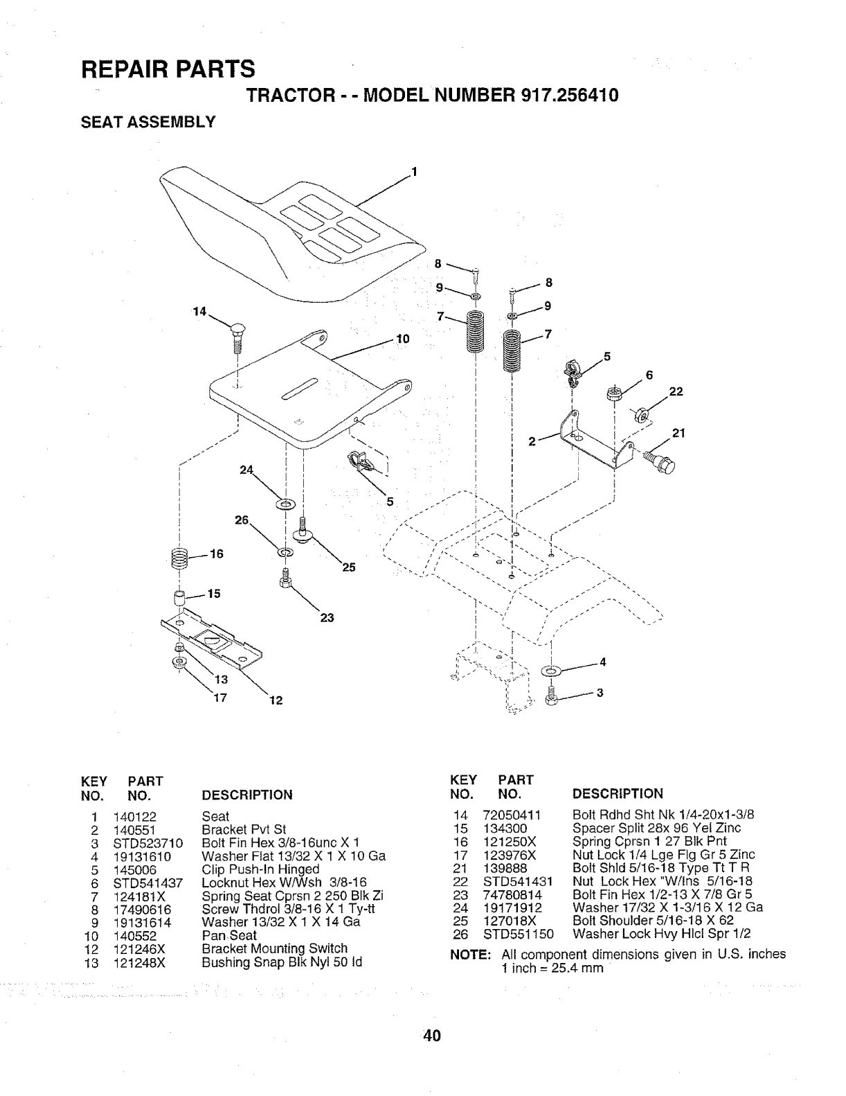
REPAIR PARTS
.... TRACTOR -- MODEL NUMBER 917.256410
SEAT ASSEMBLY
23
25
_9
5
21
KEY
NO.
1
2
3
4
5
6
7
8
9
10
12
13
PART
NO.
140122
140551
STD523710
19131610
145006
STD541437
124181X
17490616
19131614
140552
121246X
t21248X
DESCRIPTION
Seat
Bracket Pvt St
Bolt Fin Hex 3/8-16unc X 1
Washer Fiat 13/32 X I X 10 Ga
Clip Push-In Hinged
Locknut Hex W/Wsh 3/8-16
Spring Seat Cprsn 2 250 Blk Zi
Screw Thdrot 3/8-16 X 1 Ty-tt
Washer 13/32 X 1 X 14 Ga
Pan ,Seat
Bracket Mounting Switch
Bushing Snap BIk Nyl 50 ld
KEY PART
NO. NO. DESCRIPTION
14 72050411
15 134300
16 121250X
17 123976X
2t 139888
22 STD541431
23 74780814
24 19171912
25 127018X
26 STD551150
NOTE:
Bott Rdhd Sht Nk 1/4-20xl-3/8
Spacer Split 28x 96 Yel Zinc
Spring Cprsn 1 27 Btk Pnt
Nut Lock 1/4 Lge Fig Gr 5 Zinc
Bolt Shld 5/16-18 Type Tt T R
Nut Lock Hex"Wilns 5/16-18
Bolt Fin Hex 1/2-t3 X 7/8 Gr 5
Washer 17/32 X 1-3/16 X 12 Ga
Bolt Shoulder 5/16-18 X 62
Washer Lock Hvy Hlcl Spr 1/2
All component dimensions given in U.S. inches
1 inch = 25,4 mm
40
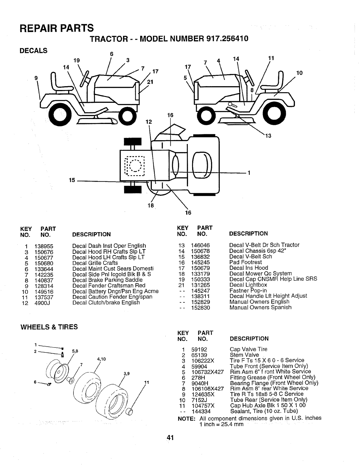
REPAIR PARTS
TRACTOR -- MODEL NUMBER 917,256410
DECALS
9
6
19 3 7 4
14 17 17
14 11
10
15
18
16
16
13
KEY
NO. PART
NO.
1 138955
3 150676
4 150677
5 150680
6 133644
7 142235
8 140837
9 128314
10 149516
1I 137537
12 4900J
KEY PART
DESCRIPTION NO. NO.
Decal Dash Inst Oper English
Decal Hood RH Crafts Sip LT
Decal Hood LH Crafts Stp LT
Decal Grille Crafts
Decal Maint Cust Sears Domesti
Decal Side Pnf Icgold BIk B & S
Decal Brake Parking Saddle
Decal Fender Craftsman Red
Decal Battery DngdPsn Eng Acme
Decal Caution Fender Engispan
Decal Clutch/brake English
13 146O46
14 150678
15 136832
16 145245
17 15O679
I8 133179
19 150333
21 131265
-- 145247
-- 138311
-- 152829
-- 152830
DESCRIPTION
Decal V-Belt Dr Sch Tractor
Decal Chassis 6sp 42"
Decal V-Belt Sch
Pad Footrest
Decal Ins Hood
Decal Mower Qc System
Decal Cap CNSMR Help Line SRS
Decal Lightbox
Fastner Pop-in
Decal Handle L|t Height Adjust
Manual Owners English
Manual Owners Spanish
WHEELS & TIRES
ii" _:T ..... /
4,10
11
KEY PART
NO. NO. DESCRIPTION
Cap Valve Tire
Stem Valve
Tire F Ts 15 X 6 0 - 6 Service
Tube Front (Service Item Only)
Rim Asm 6" f ront White Service
Fitting Grease (Front Wheel Only)
Beadng Flange (Front Wheel Only)
Rim Asm 8" rear White Service
Tire R Ts 18x8 5-8 C Service
Tube Rear (Service Item Only)
Cap Hub Axle BIk I 50 X 1 00
Sealant, Tire (10 oz. Tube)
1 59192
2 65139
3 106222X
4 59904
5 106732X427
6 278H
7 9040H
8 106108X427
9 124635X
10 7152J
1t !04757X
- - 144334
NOTE: All component dimensions given in U.S. inches
1 inch = 25.4 mm .......
41
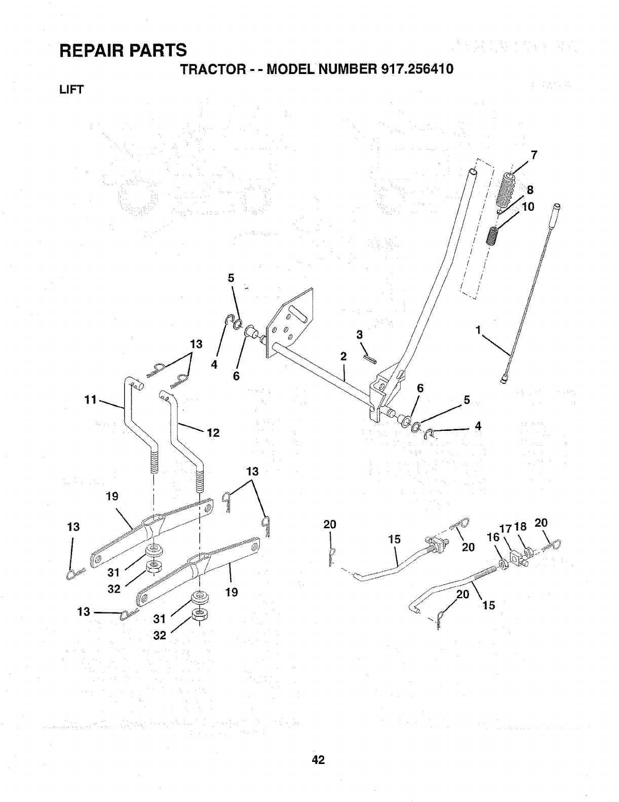
REPAIR PARTS
TRACTOR - - MODEL NUMBER 917.256410
LIFT
H
13
32
13__
32
19
6
H
/ /
/i
161718 20
15
42
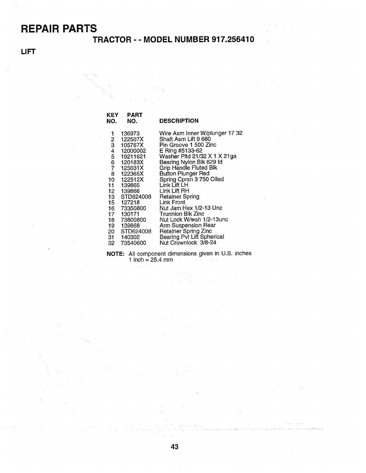
REPAIR PARTS
TRACTOR -- MODEL NUMBER 917.256410
LIFT
KEY_ PART
NO. NO. DESCRIPTION
1 136973
2 122507X
3 105767X
4 12000002
5 19211621
6 120183X
7 125631X
8 122365X
10 122512X
tl 139865
12 139866
13 STD624008
15 127218
16 73350800
17 130171
18 73800800
19 139868
20 STD624008
31 140302
32 73540600
Wire Asm Inner W/plunger 17 32
Shaft Asm Lift 9680
Pin Groove I 500 Zinc
E Ring #5133-62
Washer PItd 21/32 X 1 X 21ga
Bearing Nylon Blk 629 Id
Grip Handle Fluted BIk
Button Plunger Red
Spring Cprsn 3 750 Oiled
Link Lift LH
Link Lift RH
Retainer Spring
Link Front
Nut Jam Hex t/2-13 Unc
Trunnion Blk Zinc
Nut Lock W/wsh 1/2-13unc
Arm Suspension Rear
Retainer Spring Zinc
Bearing Pvt Lift Spherical
Nut Crownlock 3/8-24
NOTE: All component dimensions given in U.S. inches
1 inch = 25.4 mm
43
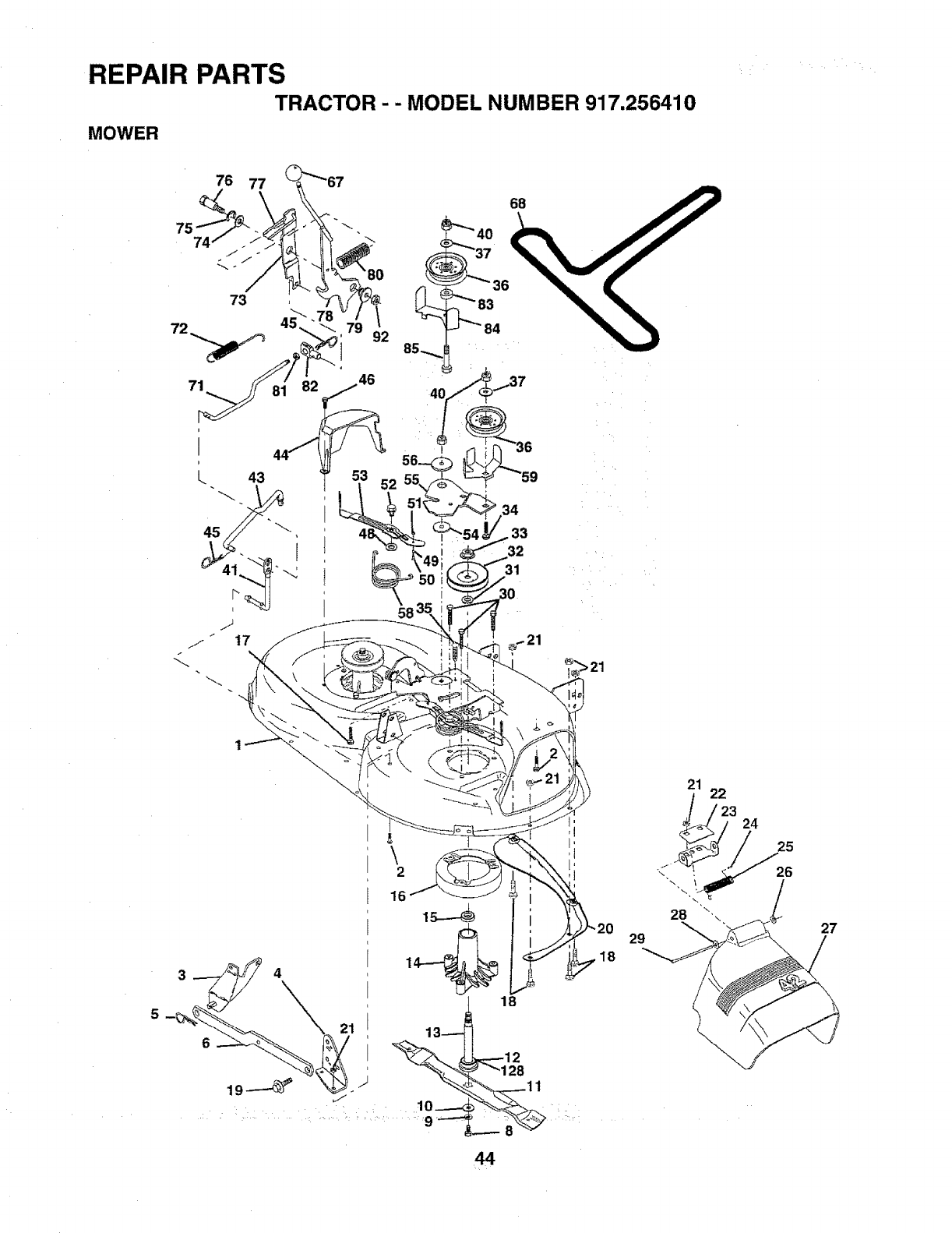
REPAIR PARTS
TRACTOR - -MODEL NUMBER 917,256410
MOWER
76 77
73
68
\2
21 13_
44
18
29
21 22
23 24
25
26
27
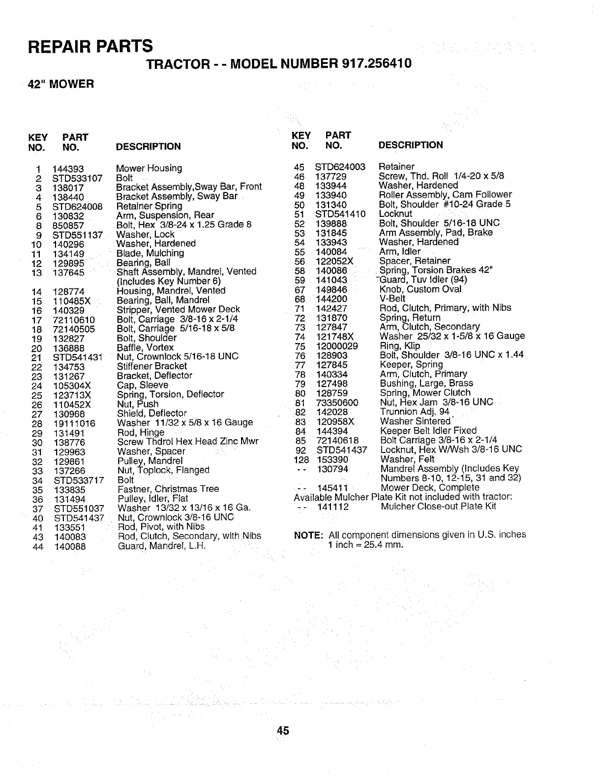
REPAIR PARTS
TRACTOR -- MODEL NUMBER 917.256410
42" MOWER
KEY PART KEY PART
NO. NO. DESCRIPTION NO. NO.
Mower Housing
Bolt
Bracket Assembly, Sway Bar, Front
Bracket Assembly, Sway Bar
Retainer Spring
Arm, Suspension, Rear
Bolt, Hex 3/8-24 x 1,25 Grade 8
Washer, Lock
Washer, Hardened
134149 , Blade, Mulching
129895 Bearing, Ball
137645 Shaft Assembly, Mandrel, Vented
1 144393
2 STD533107
3 138017
4 138440
5 STD624008
6 130832
8 850857
9 STD551137
10 140296
11
12
13 (Includes Key Number 6)
Housing, Mandrel, Vented
Bearing, Ball, Mandrel
Stripper, Vented Mower Deck
Bolt, Carriage 3/8-16 x 2-1/4
Bolt, Carriage 5/t6-18 x 5/8
Bolt, Shoulder
Baffle, Vortex
Nut, Crownlock 5/16-18 UNC
Stiffener Bracket
Bracket, Deflector
Cap, Sleeve
Spring, Torsion, Deflector
Nut, Push
Shield, Deflector
Washer 11/32 x 5/8 x t6 Gauge
Rod, Hinge
Screw Thdrot Hex Head Zinc Mwr
Washer, Spacer
Pulley, Mandrel
Nut Toplock, Flanged
Bolt
Fastner, :Christmas Tree
Pulley, Idler, Flat
Washer 13/32 x 13/16 x !6 Ga.
Nut, Crownlock 3/8-16 UNC
Rod, Pivot, with Nibs
Rod, Clutch, Secondary, with Nibs
Guard, Mandrel, L.H.
14 128774
15 110485X
16 140329
17 72110610
18 72140505
19 132827
20 136888
21 STD541431
22 134753
23 131267
24 105304X
25 123713X
26 110452X
27 130968
28 19111016
29 131491
30 138776
31 129963
32 129861
33 137266
34 STD533717
35 133835
36 131494
37 STD551037
40 STD541437
41 133551
43 140O83
44 140088
DESCRIPTION
67
68
7t
72
73
74
75
76
77
78
79
8O
81
82
83
84
45 STD624003 Retainer
46 137729 Screw, Thd. Roll 1/4-20 x 5/8
48 133944 Washer, Hardened
49 133940 Roller Assembly, Cam Follower
50 131340 Bolt, Shoulder #10-24 Grade 5
51 STD541410 Locknut ....
52 139888 Bolt, Shoulder 5/16-18 UNC
53 13t845 Arm Assembly, Pad, Brake
54 133943 Washer, Hardened
55 140084 Arm, Idler
56 122052X Spacer; Retainer ,,
58 140086 . Spring, Torsion Brakes 42
59 141043 :Guard, Tuv Idler (94)
149846 Knob, Custom Oval
144200 V-Belt
142427 Rod, Clutch, Primary, with Nibs
131870 Spring, Return
127847 Arm, Clutch, Secondary
121748X Washer 25/32 x 1-5/8 x 16 Gauge
12000029 Ring, Klip
128903 Bolt, Shoulder 3/8-16 UNC x 1.44
127845 Keeper, Spring
140334 Arm, Crutch, Primary
127498 Bushing, Large, Brass
128759 Spring, Mower Clutch
73350600 Nut, Hex Jam 3/8-t6 UNC
142028 Trunnion Adj. 94
120958X Washer Sintered"
144394 Keeper Belt Idler Fixed
85 72140618 Bolt Carriage 3/8-16 x 2-1/4
92 STD541437 Locknut, Hex W/Wsh 3/8-16 UNC
128 153390 Washer, Felt
- - 130794 Mandrel Assembly (Includes Key
Numbers 8-10, 12-15, 31 and 32)
- - 145411 Mower Deck, Complete
Available Mulcher Plate Kit not included with tractor:
- - 141112 Mulcher Close-out Plate Kit
NOTE: All component dimensions given _nU.S. inches
1 inch = 25.4 turn.
45
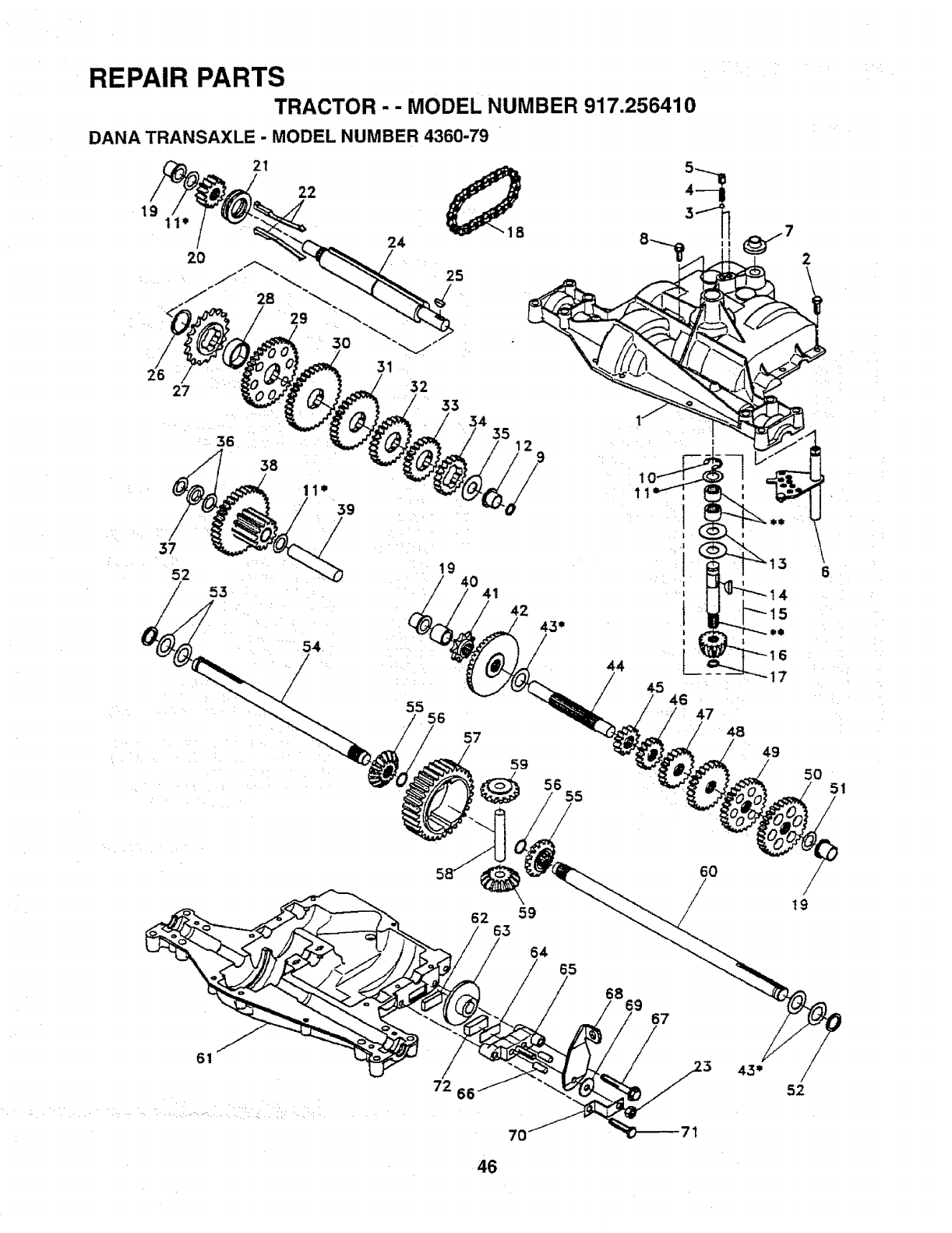
REPAIR PARTS
TRACTOR- -MODEL NUMBER 917.256410
DANA TRANSAXLE -MODEL NUMBER 4360-79
19 11"
2O
21
22
26 27
37
53
24
25
#
31
32
33 34
19
55 56
35
40 41 42
57
44
45
47 48
59
56 55
6
17
49
50
6
51
62 59
63
64 65
6869 67
6O /
t9
61
52
46
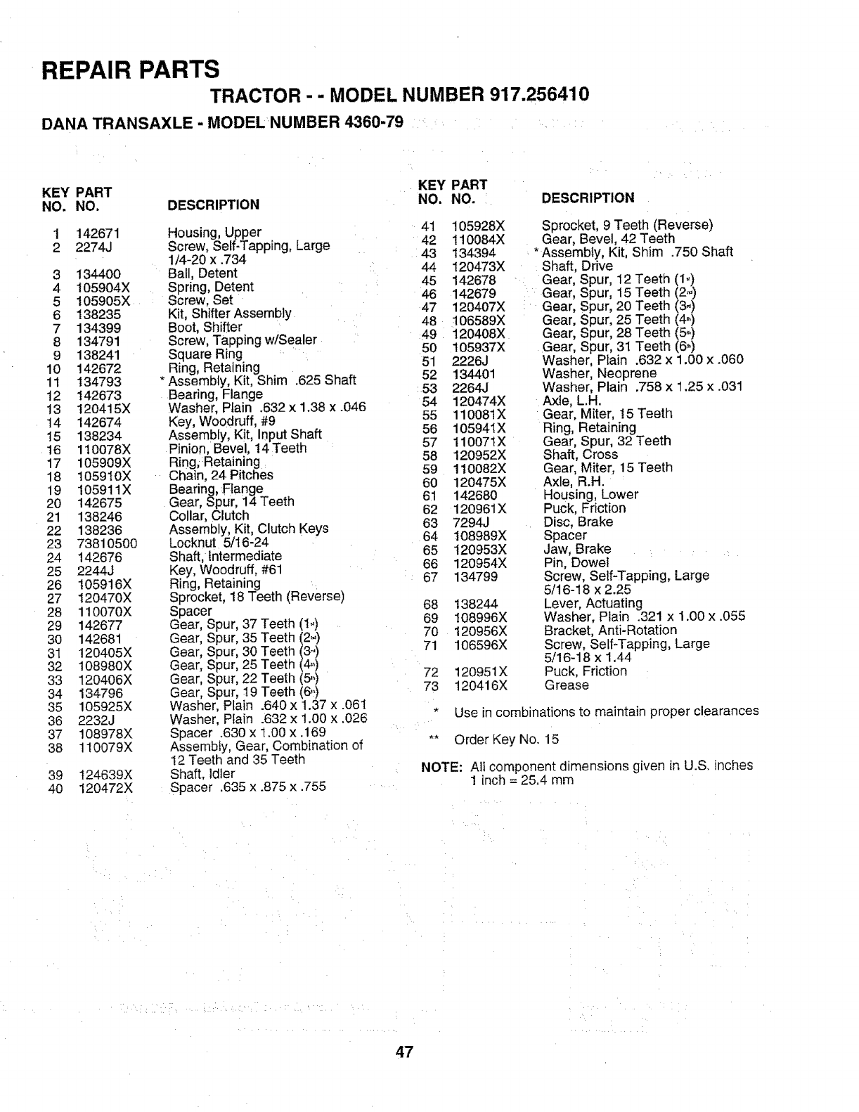
REPAIR PARTS
TRACTOR - - MODEL NUMBER 917.256410
DANA TRANSAXLE -MODEL NUMBER 4360-79 ....
KEY PART KEY PART
NO. NO. DESCRIPTION NO. NO.
1
2142671
2274J
3134400
4 105904X
5105905X
6 138235
7 134399
8 134791
9 138241
10 142672
11 134793
12 142673
13 t20415X
14 142674
15 138234
t6 110078X
17 105909X
18 105910X
19 105911X
20 142675
21 138246
22 138236
23 73810500
24 142676
25 2244J
26 I05916X
27 120470X
28 110070X
29 142677
30 142681
31 120405X
32 108980×
33 120406X
34 134796
35 105925X
36 2232J
37 108978X
38 110079X
39 124639X
4O 120472X
Housing, Upper
Screw, Self-Tapping, Large
1/4-20 x .734
Ball, Detent
Spring, Detent
Screw, Set
Kit, Shifter Assembly
Boot, Shifter
Screw, Tapping w/Sealer
Square Ring
Ring, Retaining
*Assembly, Kit, Shim .625 Shaft
Bearing, Flange
Washer, Piain .632 x 1.38 x .046
Key, Woodruff, #9
Assembly, Kit, Input Shaft
Pinion, Bevel, !4 Teeth
Ring;Retaining
Chain, 24 Pitches
Bearing, Flange
Gear, Spur, 14 Teeth
Collar, Clutch
Assembly, Kit, Clutch Keys
Locknut 5/16-24
Shaft, Intermediate
Key, Woodruff, #61
Ring, Retaining
Sprocket, 18 Teeth (Reverse)
Spacer
Gear, Spur, 37 Teeth (1,,)
Gear, Spur, 35 Teeth (2_)
Gear, Spur, 30 Teeth (3-)
Gear, Spur, 25 Teeth (4_)
Gear, Spur, 22 Teeth (5,,)
Gear, Spur, 19 Teeth (6,o)
Washer, Plain .640 x 1.37 x .061
Washer, Plain .632 x 1.00 x .026
Spacer .630 x 1.00 x .169
Assembly, Gear, Combination of
12 Teeth and 35 Teeth
Shaft, Idler
Spacer .635 x .875 x .755
DESCRIPTION
41
42
43
44
45
46
47
48
49
50
51
52
:53
54
55
56
57
58
59
60
61
62
63
64
65
66
67
68
69
70
71
72
73
105928X
110084X
134394
120473X
142678
142679
120407X
106589X
120408X
105937X
2226J
134401
2264J
120474X
110081X
105941X
110071X
120952X
110082X
120475X
142680
120961X
7294J
t08989X
120953X
120954X
134799
138244
108996X
120956X
106596X
120951X
120416X
Sprocket, 9 Teeth (Reverse)
Gear, Bevel, 42 Teeth
* Assembly, Kit, Shim .750 Shaft
Shaft, Drive
Gear, Spur, I2 Teeth (1,,)
Gear, Spur, 15 Teeth (2,,)
Gear, Spur, 20 Teeth (3-)
Gear, Spur, 25 Teeth (4_)
Gear, Spur, 28 Teeth (5,,)
Gear, Spur, 31 Teeth (6,)
Washer, Plain .632 x 1.00 x .060
Washer, Neoprene
Washer, Plain .758 x 1.25 x .031
Axle, L.H.
Gear, Miter, 15 Teeth
Ring, Retaining
Gear, Spur, 32 Teeth
Shaft, Cross
Gear, Miter, 15 Teeth
Axle, R.H.
Housing, Lower
Puck, Friction
Disc, Brake
Spacer
Jaw, Brake
Pin, Dowel
Screw, Self-Tapping, Large
5/16-18 x 2.25
Lever, Actuating
Washer, Plain .321 x 1.00 x .055
Bracket, Anti-Rotation
Screw, Self-Tapping, Large
5/16-18 x 1.44
Puck, Friction
Grease
*Use in combinations to maintain proper clearances
** Order Key No. 15
NOTE: All component dimensions given in U.S. inches
1 inch = 25.4 mm
47
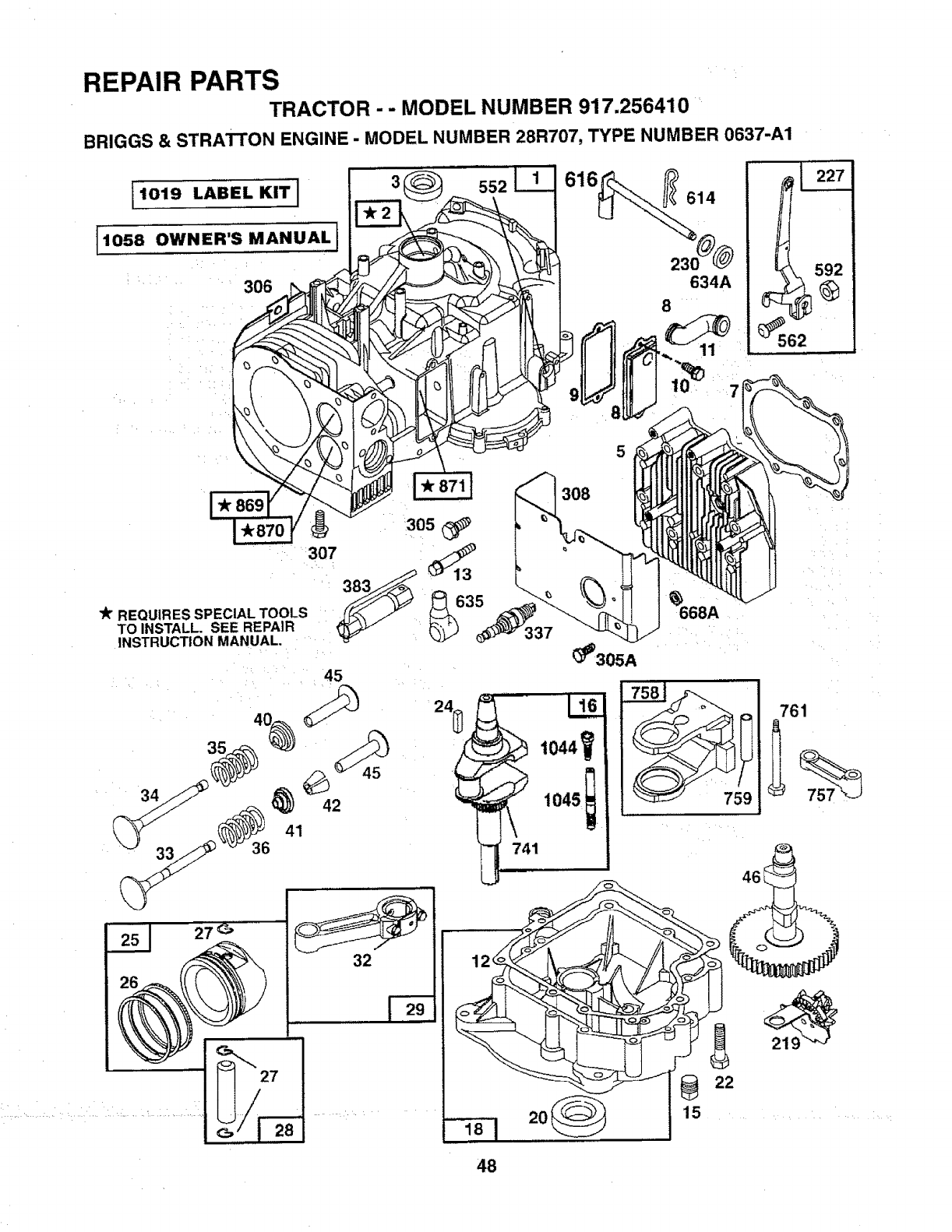
REPAIR PARTS
TRACTOR -- MODEL NUMBER 917.256410
BRIGGS & STRATTON ENGINE - MODEL NUMBER 28R707, TYPE NUMBER 0637-A1
1019 LABEL KIT I
I1058 OWNER'S MANUALI
306
552
305_i_
307
lk REQUIR ES SPECIAL TOOLS 35
TO INSTALL. SEE REPAIR
INSTRUCTION MANUAL.
45
616 _614
230
634A
8
337
_'305A
368A
20 15
48
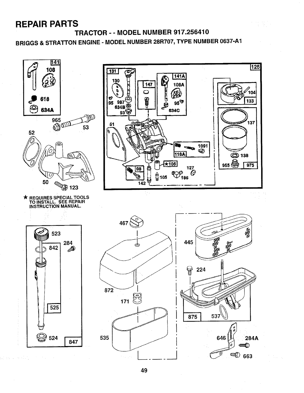
REPAIR PARTS
TRACTOR - - MODEL NUMBER 917.256410
BRIGGS & STRATTON ENGINE -MODEL NUMBER 28R707, TYPE NUMBER 0637-A1
108
618
_634A
965 +.+_+++++_
52 '
50 <_ 123
lk" REQUIRES SPECIAL TOOLS
TO INSTALL. SEE REPAIR
INSTRUCTION MANUAL,
523
284
524
130 _,J
s34e_
93_
51
!
108A
95_
634C
'_ _108
142
II I IIIII1[I
872 1
171 _
224
138
49
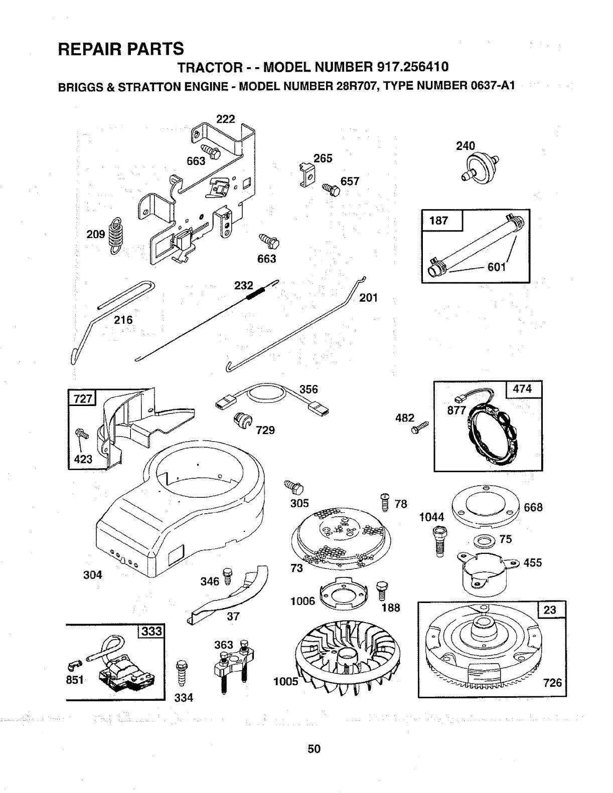
REPAIR PARTS
TRACTOR - - MODEL NUMBER 917,256410
BRIGGS & STRATTON ENGINE -MODEL NUMBER 28R707, TYPE NUMBER 0637-A1
209
663
240
j65 657 '_
187 I
601
877
_., ,:i ¸ •H
304
334
100!
305 _78
73
1044 668
._75
455
F726
H
5O
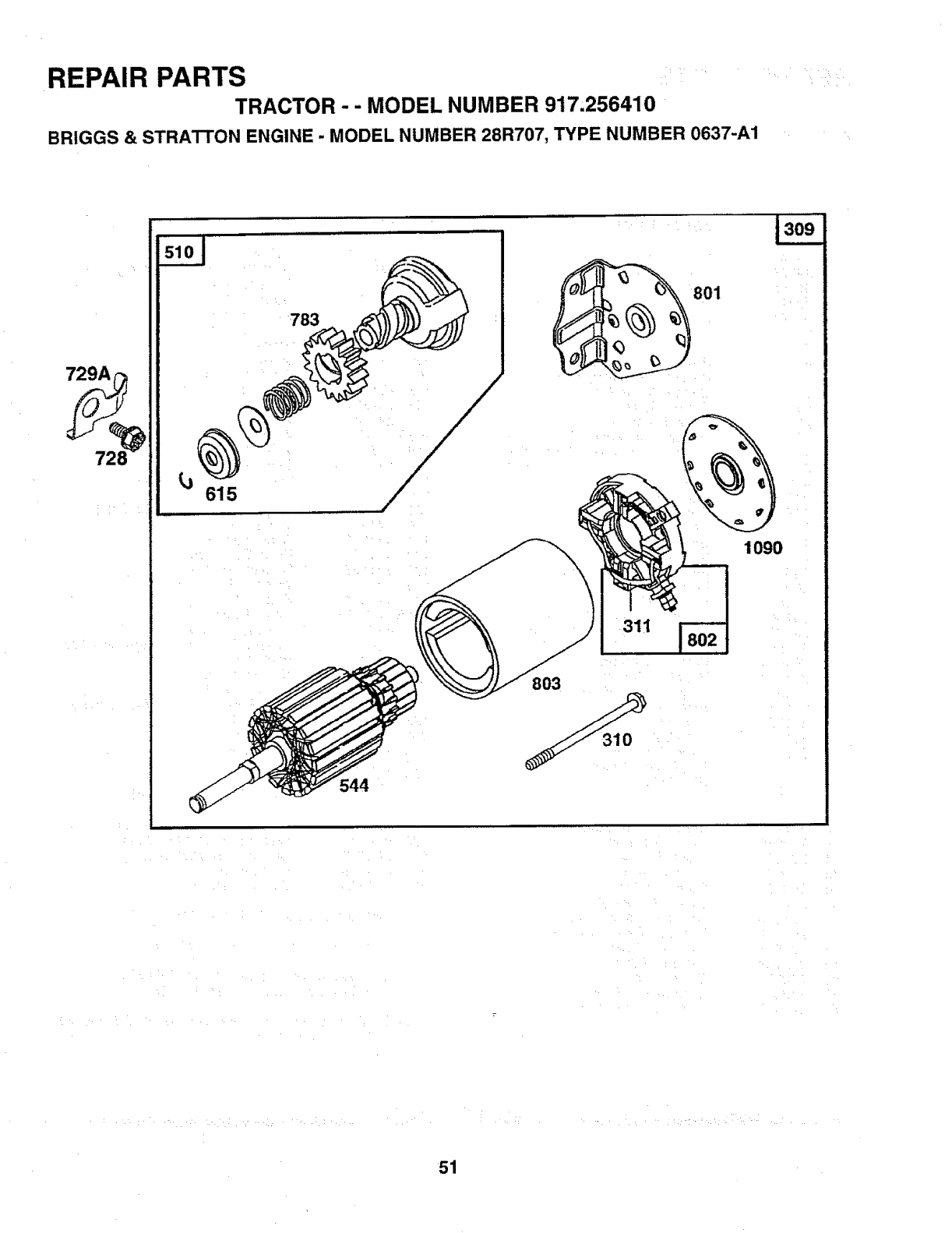
REPAIR PARTS
TRACTOR - - MODEL NUMBER 917,256410
BRtGGS & STRATI"ON ENGINE -MODEL NUMBER 28R707, TYPE NUMBER 0637-A1
615
544
801
1090
311
803
H • H H¸
51
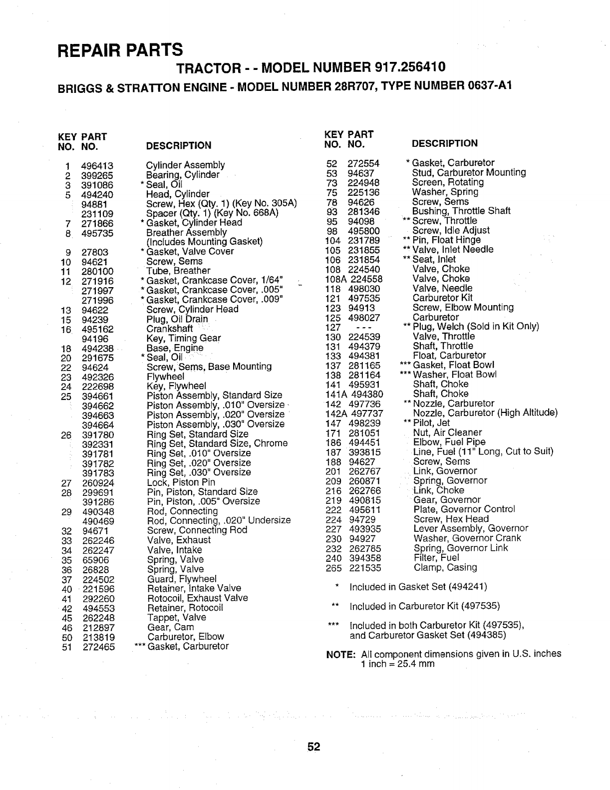
REPAIR PARTS
TRACTOR - - MODEL NUMBER 917.256410
BRIGGS & STRATTON ENGINE -MODEL NUMBER 28R707, TYPE NUMBER 0637-A1
KEY PART KEY PART
NO. NO. DESCRIPTION NO. NO. DESCRIPTION
t
2
3
5
7
8
9
10
11
12
13
15
16
t8
2O
22
23
24
25
26
27
28
29
32
33
34
35
36
37
4O
41
42
45
46
5O
51
496413
399265
391086
494240
94881
231109
271866
495735
27803
94621
280100
271916
271997
271996
94622
94239
495162
94196
494238
291675
94624
492326
222698
394661
394662
394663
394664
391780
392331
391781
391782
391783
260924
299691
391286
490348
490469
94671
262246
262247
65906
26828
224502
221596
292260
494553
262248
212897
213819
272465
Cylinder Assembly
Bearing, Cylinder
Seal, Oil
Head, Cylinder
Screw, Hex (Qty. 1) (Key No. 305A)
Spacer (Qty. 1) (Key No. 668A)
* Gasket, Cylinder Head
Breather Assembly
(Includes Mounting Gasket)
* Gasket, Valve Cover
Screw, Seres
Tube, Breather
* Gasket, Crankcase Cover, 1/64"
* Gasket, Crankcase Cover, .005"
, Gasket, Crankcase Cover, .009"
Screw, Cylinder Head
Plug, Oil Drain
Crankshaft :
Key, Timing Gear
Base, Engine
* Seal, Oil
Screw, Sems, Base Mounting
Flywheel
Key, Flywheel
Piston Assembly, Standard Size
Piston Assembly, .010" Oversize*
Piston Assembly, .020" Oversize
Piston Assembly, .030" Oversize
Ring Set, Standard Size
Ring Set, Standard Size, Chrome
Ring Set, .010" Oversize
Ring Set, .020" Oversize
Ring Set, .030" Oversize
Lock, Piston Pin
Pin, Piston, Standard Size
Pin, Piston, .005" Oversize
Rod, Connecting
Rod, Connecting, .020" Undersize
Screw, Connecting Rod
Valve, Exhaust
Valve, Intake
Spring, Valve
Spring, Valve
Guard, Flywheel
Retainer, Intake Valve
Rotocoil, Exhaust Valve
Retainer, Rotocoit
Tappet, Valve
Gear, Cam
Carburetor, Elbow
*** Gasket, Carburetor
52 272554
53 94637
73 224948
75 225136
78 94626
93 281346
95 94098
98 495800
104 231789
105 231855
106 231854
108 224540
108A 224558
118 498030
121 497535
123 94913
125 498027
127 ---
130 224539
131 494379
133 494381
137 281165
138 281164
141 495931
141A 494380
142 497736
142A 497737
147 498239
171 281051
186 494451
187 393815
188 94627
20t 262767
209 260871
216 262766
219 490815
222 495611
224 94729
227 493935
23O 94927
232 262785
240 394358
265 221535
*Gasket, Carburetor
Stud, Carburetor Mounting
Screen, Rotating
Washer, Spring
Screw, Sems
Bushing, Throttle Shaft
** Screw, Throttle
Screw, Idle Adjust
** Pin, Float Hinge
** Valve, Inlet Needle
**Seat, Inlet
Valve Choke
Valve, Choke
Valve, Needle
Carburetor Kit
Screw, Elbow Mounting
Carburetor
** Plug, Welch (Sold in Kit Only)
Valve, Throttle
Shaft, Throttle
Float, Carburetor
*** Gasket, Float Bowl
*** Washer, Float Bowl
Shaft, Choke
Shaft, Choke
** Nozzle, Carburetor
Nozzle, Carburetor (High Altitude)
** Pilot, Jet
Nut, Air Cleaner
Elbow, Fuel Pipe
Line, Fuel (11" Long, Cut to Suit)
Screw, Sems
Link, Governor
Spring, Governor
Link, Choke
Gear, Governor
Plate, Governor Control
Screw, Hex Head
Lever Assembly, Governor
Washer, Governor Crank
Spring, Governor Link
Filter, Fuel
Clamp, Casing
* Included in Gasket Set (494241)
** tncluded in Carburetor Kit (497535)
*** included in both Carburetor Kit (497535),
and Carburetor Gasket Set (494385)
NOTE: All component dimensions given in U.S. inches
1 inch = 25.4 mm
52
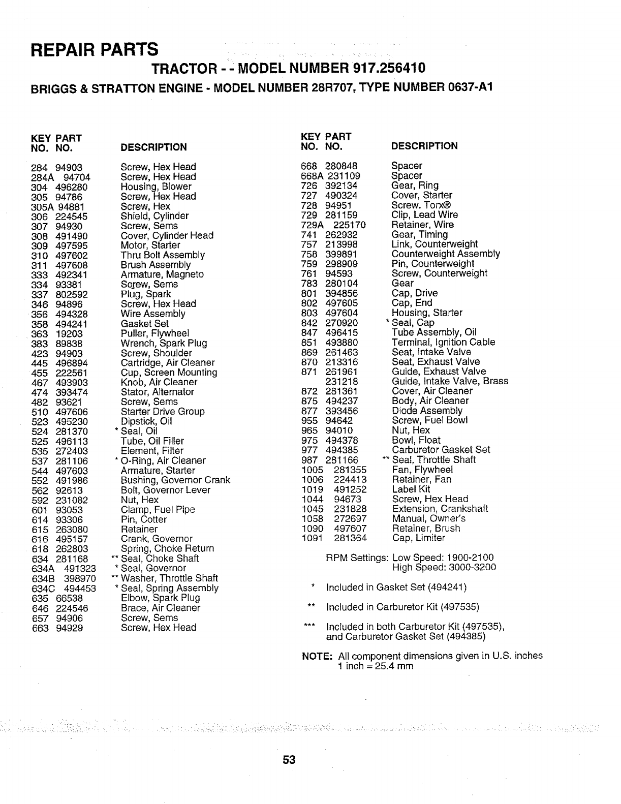
REPAIR PARTS i
TRACTOR MODEL NUMBER 917.256410
BRIGGS & STRATrON ENGINE - MODEL NUMBER 28R707, TYPE NUMBER 0637-A1
KEY PART KEY PART
NO. NO. DESCRIPTION NO. NO. DESCRIPTION
284 94903 Screw, HexHead 668 280848 Spacer
284A 94704 Screw, Hex Head 668A 231109 Spacer
304 496280 Housing, Blower 726 392134 Gear, Ring
305 94786 Screw, Hex Head 727 490324 Cover, Starter
305A 94881 Screw, Hex 728 94951 Screw. Torx_
306 224545 Shield, Cylinder 729 281159 Cfip, LeadWire
307 94930 Screw, Sems 729A 225170 Retainer, Wire
308 491490 Cover, Cylinder Head 741 262932 Gear, Timing
309 497595 Motor, Starter 757 213998 Link, Counterweight
310 497602 Thru Bolt Assembly 758 399891 Counterweight Assembly
311 497608 Brush Assembly 759 298909 Pin, Counterweight
333 492341 Armature, Magneto 761 94593 Screw, Counterweight
334 93381 Sc_rew,Sems 783 280104 Gear
337 802592 Plug, Spark 801 394856 Cap, Drive
346 94896 Screw, Hex Head 802 497605 Cap, End
356 494328 Wire Assembfy 803 497604 Housing, Starter
358 494241 Gasket Set 842 270920 * Seal, Cap
363 19203 Puller, Flywheel 847 496415 Tube Assembly, Oil
383 89838 Wrench, Spark Plug 851 493880 Terminal, Ignition Cable
423 94903 Screw, Shoulder 869 261463 Seat, Intake Valve
445 496894 Cartridge, Air Cleaner 870 213316 Seat, Exhaust Valve
455 222561 Cup, Screen Mounting 871 261961 Guide, Exhaust Valve
467 493903 Knob, Air Cleaner 231218 Guide, Intake Valve, Brass
474 393474 Stator, Alternator 872 281361 Cover, Air Cleaner
482 93621 Screw, Sems 875 494237 Body, Air Cleaner
510 497606 Starter Drive Group 877 393456 Diode Assembly
523 495230 Dipstick, Oil 955 94642 Screw, Fuel Bowl
524 281370 * Seal, Oil 965 94010 Nut, Hex
525 496113 Tube, Oil Filler 975 494378 Bowl, Float
535 272403 Element, Filter 977 494385 Carburetor Gasket Set
537 281106 * O-Ring, Air Cleaner 987 281166 ** Seal, Throttle Shaft
544 497603 Armature, Starter 1005 281355 Fan, Flywheel
552 491986 Bushing, Governor Crank 1006 224413 Retainer, Fan
562 92613 Bolt, Governor Lever 1019 491252 Label Kit
592 231082 Nut, Hex 1044 94673 Screw, Hex Head
601 93053 Clamp, Fuel Pipe 1045 231828 Extension, Crankshaft
614 93306 Pin, Cotter 1058 272697 Manual, Owner's
615 263080 Retainer 1090 497607 Retainer, Brush
616 495157 Crank, Governor 1091 281364 Cap, Limiter
618 262803 Spring, Choke Return
634 281168 ** Seal, Choke Shaft RPM Settings: Low Speed: 1900-2100
634A 491323 * Seal, Governor High Speed: 3000-3200
634B 398970 **Washer, Throttle Shaft
634C 494453 * Seal, Spring Assembly * Included in Gasket Set (494241)
635 66538 Elbow, Spark Plug
646 224546 Brace, Air Cleaner ** Included in Carburetor Kit (497535)
657 94906 Screw, Seres
663 94929 Screw, Hex Head *** Included in both Carburetor Kit (497535),
and Carburetor Gasket Set (494385)
NOTE: All component dimensions given in U.S. inches
1 inch = 25.4 mm
..... :!i ..... i ! :: i _
53

........ iilll
.........................SERVICE NOTES
i iiiiiii i II III _I III III IIII III III IIII
i i i ::
54

iSUGGESTED GUIDE FOR SIGHTING SLOPES FOR SAFE OPERATION
!
i _ : :: :
ONLY RIDE UP AND DOWN HILL;
NOT ACROSS HILL
SIGHT AND HOLD THIS LEVEL WITH
SKY LINE OR TREE.
15 ° MAX.
::,
Jiiiili
_r/_; Operate your Tractor up and down the face of s;opes (not
_ _ greater than 15 ), never across the {ace. Make turnsgradu-
_ally to prevent tipping or loss of control. Exercise extreme
caution when changing direction on slopes.
L_ ii i iill ii lllll i llll ill ....... i_: iHlll ii _:_:.

OWNER'S
MANt AL
MODEL NO
917,256410
L
IF YOU NEED
REPAIR SERVICE
OR PARTS:
!
• FOR REPAIR SERVICE, CALL
THIS TOLL FREE NUMBER:
• 1-800-4-REPAIR
(1-800-473-7247)
FOR REPLACEMENT PARTS
INFORMATION AND
ORDERING, CALL THIS
TOLL FREE NUMBER:
1,800-FON-PART
(1-800 366-7278)
FOR CONSUMER ASSISTANCE
:HOT LINE, CALL THIS
TOLL FREE NUMBER:
1-800-659-5917
152829 Rev. 2 04.02.96 JH/RH
£RI:IFTIMRN®
13.5 HP IC
ELECTRIC START
42. MOWER
6 SPEED TRANSAXLE
LAWN TRACTOR
Each tractor has its own model number. Each engine has
its own model number,
The model number for your tractor will be found on the
model plate located under the seat.
The model number for your engine will be found on the
blower housing of the engine.
AI! parts listed herein may be ordered from any Sears,
Roebuck and Co. Service Center/Department and most Re-
tail Stores,
WHEN ORDERING REPAIR PARTS, ALWAYS GIVE THE
FOLLOWING INFORMATION:
• PRODUCT- TRACTOR
•MODEL NUMBER-917.256410
•ENGINE MODEL NO. -28R707, TYPE NO. 0637-A1
°PART NUMBER
•PART DESCRIPTION
Your Sears merchandise has added value when you
consider Sears has service units nationwide staffed with
Sears trained technicians.,, professional technicians
specifically trained to insure that we meet our pledge to
you, we service what we sell.
Printed in U.S.A.
