Craftsman 917257561 User Manual Lawn, Tractor Manuals And Guides L0708440
CRAFTSMAN Lawn, Tractor Manual L0708440 CRAFTSMAN Lawn, Tractor Owner's Manual, CRAFTSMAN Lawn, Tractor installation guides
User Manual: Craftsman 917257561 917257561 CRAFTSMAN Lawn, Tractor - Manuals and Guides View the owners manual for your CRAFTSMAN Lawn, Tractor #917257561. Home:Lawn & Garden Parts:Craftsman Parts:Craftsman Lawn, Tractor Manual
Open the PDF directly: View PDF ![]() .
.
Page Count: 56

CRRFTSMON°
MODEL NUMBER 917.257561 OWNER'SMANUAL
•Assembly
•Operation
oCustomer Responsibilities
°Service and Adjustments
oRepair Parts
Convertible
CAUTION: Read and follow all safety rules and instructions before operating this equipment.
lillllllllllllllllllliiiiiiiiiiii iiiiiii i i iiiiiiiiiiiiiiiiiiiiiiiiiiiIiiiiiii
Safe Operation Practices for Ride-On Mowers
IMPORTANT: THIS CUTTING MACHINE IS CAPABLE OF AMPUTATING HANDS AND FEET AND THROWING OBJECTS.
FAILURE TO OBSERVE THE FOLLOWING SAFETY INSTRUCTIONS COULD RESULT IN SERIOUS INJURY OR DEATH
I. GENERAL OPERATION
•Read, understand, and follow all instructions in the manual
and on the machine before starting.
• Only allow responsible adults, who are familiar with the
instructions, to operate the machine
• Clear the area of ob ects such as rocks, toys, wire, etc,
wh ch cou d be picked up and thrown by the blade..
° Be sure the area is clear of otherpeople before mowing. Stop
machine if anyone enters the area,
° Never carry passengers
,, Do not mow in reverse unless absolutely necessary.. Always
look down and behind before and while backing.
• Be aware of the mower discharge direction and do not point
it at anyone. Do not operate the mower without either the
entire grass catcher or the guard in place.
• Slow down before turning
• Never leave a running machine unattended. Atways turn off
blades, set parking brake, stop engine, and remove keys
before dismounting.
• Turn off blades when not mowing
• Stop engine before removing grass catcher or unclogging
chute.
• Mow only in daylight or good artificial light.
• Do not operate the machine while under the influence of
alcohol or drugs.
• Watch for traffic when operating near or crossing roadways
= Use extra care when loading or unloading the machine into
a trailer or truck.
II, SLOPE OPERATION
Slopes are a major factor related to loss-of-control and tipover
accidents, which can result in severe injury or death, AH slopes
require extra caution If you cannot back up the slope or if you feel
uneasy on it, do not mow it.
DO:
•Mow up and down slopes, not across.
•Remove obstacles such as recks, tree limbs, etc
• Watch for holes, ruts, or bumps Uneven terrain could
overturn the machine Taft grass can hide obstacles..
•Use slow speed. Choose a tow gear so that you will not have
to stop or shift while on the slope.r
• FO[IOW the manufacturer's recommendations for wheel
weights or counterweights to improve stability
° Use extra care with grass catchers or other attachments
These can change the stability of the machine.
• Keep atl movement on the slopes slow and gradual Do not
make sudden changes in speed or direction
• Avoid starting or stopping on a slope. If tires lose traction,
disengage the blades and proceed slowly straight down the
slope,
DO NOT:
•Donot turn on slopes unless necessary, and then, turn slowly
and gradually downhill, if possible°
•Do not mow near drop-offs, ditches, or embankments The
mower could suddenly turn over if a wheel is over the edge
of a cliff or ditch, or if an edge caves in.
•Do not mow on wet grass Reduced traction could cause
s!iding.
•Do not try to stabilize the machine by putting your foot on the
ground.
°Do not use grass catcher on steep slopes
IlL CHILDREN
Tragic accidents can occur if the operator is not alert to the
presence of children Children are often attracted to the machine
and the mowing activity, Neverassume that children wiif remain
where you last saw them.
• Keep children out of the mowing area and under the watchful
care of another responsible adult.
• Be alert and turn machine off if children enter the area,.
° Before and when backing, look behind and down for small
children..
• Never carry children They may fall off and be seriously
injured or interfere with safe machine operation.
• Never allow children to operate the machine,
• Use extra care when approaching blind corners, shrubs,
trees, or other objects that may obscure vision.
IV. SERVICE
• Use extra care in handling gasoline and other fuels. They are
flammable and vapors are expioslveo
Use only an approved container
Never remove gas cap or add fuel with the engine
running. Allow engine to cool before refueling Do not
smoke
Never refuel the machine indoorso
Never store the machine or fuel container inside where
there is an open flame, such as a water heater.
•Never run a machine inside a closed area.
• Keep nuts and bolts, especially blade attachment bolts, tight
and keep equipment in good condition
•Never tamper with safety devices. Check their proper
operation regularly
• Keep machine free of grass, leaves, or other debris build-up
Clean oil or fuei spillage. Allow machine to cool before
storing
• Stop and inspect the equipment if you strike an object.
Repair, if necessary, before restarting
•Never make adjustments or repairs with the engine running
• Grass catcher components are subject to wear, damage, and
deterioration, which could expose moving parts or al/ow
objects to be thrown. Frequently check components and
replace with manufacturer's recommended parts, when nec-
essary
• Mower blades are sharp and can cut. Wrap the blade(s) or
wear gloves, and use extra caution when servicing them.
• Check brake operation frequently Adjust and service as
required.
Look for this symbol to point out impor-
tant safety precautions, it means
CAUTION!!! BECOME ALERT!!! YOUR
SAFETY IS INVOLVED.
CAUTION: Always disconnect spark
plug wire and place wire where it cannot
contact spark plug in order to prevent
accidental starting when setting up,
transporting, adjusting or making
repairs.
2

CONGRATULATIONS on your purchase of a Sears
Tractor.. It has been designed, engineered and manufac-
tured to give you the best possible dependability and
performance
Should you experience any problem you cannot easily
remedy, please contact your nearest Sears Authorized
Service Center/Department.. We have competent, well-
trained technicians and the proper tools to service or repair
this unit.
Please read and retain this manual. The instructions will
enabfe you to assemble and maintain your unit properly.
Always observe the "SAFETY RULES".
MODEL
NUMBER
SERIAL
NUMBER
917,257561
DATE OF PURCHASE
THE MODELAND SERIAL NUMBERS WtLL BE FOUND
ON A PLATE UNDER THE SEAT.
YOU SHOULD RECORD BOTH SERIAL NUMBER AND
DATE OF PURCHASE AND KEEP IN A SAFE PLACE
FOR FUTURE REFERENCE_
i , , ,,,,, ....... , ............
MAINTENANCE AGREEMENT
A Sears Maintenance Agreement is available on this prod-
uct., Contact your nearest Sears store for details.
CUSTOMER RESPONSIBILITIES
• Read and observe the safety ruIes
• Follow a regular schedule in maintaining, caring for and using
your unit,
• Follow the instructions under "Customer Responsibilities"
and "Storage' sections of this owner's manual.
PRODUCT SPECIFICATIONS
HORSEPOWER: 180
GASOLINE CAPACITY 3 5 GALLONS
AND TYPE: UNLEADED REGULAR
OIL TYPE (API-SG): SAE 30 (above 32°F)
SAE 5W-30 (below 32°F)
OIL CAPACITY: &0 PINTS
SPARK PLUG: CHAMPION RJ-19LM
(GAP: ,030") STD361458
VALVE CLEARANCE: INTAKE: .004" - °006"
EXHAUST: °007" - .009"
GROUND SPEED (MPH): FORWARD:
1st &77
2rid 1.46
3rd 341
4th &34
5th 5.57
REVERSE: 1.07
TIRE PRESSURE: FRONT: 14 PSI
REAR: 10 PSI
CHARGING SYSTEM: 3 AMPS BATTERY
5 AMPS HEADLIGHTS
BLADE BOLT TORQUE: 30-35 F'T. LBS
WARNING: This unit is equipped with an internal combus-
tion engine and should not be used on or near any unim-
proved forest-covered, brush-covered or grass-covered
land unless the engine's exhaust system is equipped with
a spark arrestor meeting applicable local or state laws (if
any). tf a spark arrester is used, it should be maintained in
effective working order by the operator.
In the state of California the above is required by taw
(Section 4442 of the California Public Resources Code).
Other states may have similar law&. Federal laws apply on
federal lands. A spark arrester for the muffler is available
through your nearest Sears Authorized Service Center/
Department (See REPAIR PARTS section of this manual).
ii,lnl nnnlllH, I,IIII ii Inl, I IItJ,UL_ IllUI,II i .............. i'
LIMITED TWO YEAR WARRANTY ON ELECTRIC START RIDING EQUIPMENT
For two (2) years from the date of purchase, if this riding equipment is maintained, lubricated and tuned up according to the
instructions in the owner's manual, Sears will repair or replace, free of charge, any parts found to be defective in material or
workmanship.
This Warranty does not cover:
° Expendable items which become worn during normal use, such as blades, spark plugs, air cleaners and beltso
• Tire replacement or repair caused by punctures from outside objects, such as nails, thorns, stumps, or glass,
• Repairs necessary because of operator abuse, negligence, improper storage or accident or the failure to maintain the
equipment according to the instructions contained in the owner's manual
•Riding equipment used for commercial or rental purposes,.
LIMITED 90 DAY WARRANTY ON BATTERY
For ninety (90) days from date of purchase, if any battery included with this riding equipment proves defective in material or
workmanship and our testing determines the battery will not hold a charge, Sears will replace the battery at no charge..
WARRANTY SERVICE IS AVAILABLE BY RETURNING THE RIDING EQLItPMENT TO THE NEAREST SEARS SERVICE
CENTER/DEPARTMENT IN THE UNITED STATES
This Warranty gives you specific legal rights, and you may also have other rights which may vary from state to state
SEARS, ROEBUCK AND CO., [3/817 WA, HOFFMAN ESTATES, ILLINOIS 60179
uiun,l,l,n illU,i inn Ul ,,,,,, ,,,,,,,,,,,,it Hi, ,u i i,,i, =,1_L_L ....

TABLE OF CONTENTS
SAFETY RULES ............................................................ 2
PRODUCT SPECIFICATIONS ...................................... 3
CUSTOMER RESPONSIBILITIES ..................... 3, 15-18
WARRANTY .................................................................. 3
TRACTOR ACCESSORIES .......................................... 5
ASSEMBLY ............................................................. 7-10
OPERATION .......................................................... 11-14
MAINTENANCE SCHEDULE ..................................... 15
SERVICE AND ADJUSTMENTS ........................... 19-24
STORAG E ................................................................... 25
TROUBLESHOOTING ........................................... 26-27
REPAIR PARTS -TRACTOR ................................ 30-47
REPAIR PARTS -ENGINE .................................... 48-53
PARTS ORDERING/SERVICE ............... BACK COVER
INDEX
A
Accessories ........................................... 5
Adjustments:
Brake .................................. 21
Carburetor ................................ 24
Mower
Front-To-Back .................... 20
Side-To-Side ...................... 20
Throttle Control Cable .................. 23
Air Filter, Engine .......................... 17-18
Air Screen, Engine ................................. 18
Assembly ............................... 7- t 0
B
Battery:
Charging ............................. 8
Cleaning ..................................... 17
Installation ............................. 9
Levels ......................................... 8,16
Preparation ................................... 8
Starting with Weak Battery ........... 22
Storage .............................. 28
Terminals 17
Belt:
Motion Drive
Removal/Replacement ....... 21
Mower Blade(s)
RemovaVReplacement ....... 21
Blade:
Sharpening ........................ 16
Replacement ................................. 16
Brake Adjustment ................. 21
C
Carburetor Adjustment ................... 24
Controls, Tractor ................................. 11
Customer Responsibilities .............. 15-18
Engine:
Air Filter ............................ 17-18
Air Screen, Engine ...................... 18
Cooling Fins, Engine ............... 18
Engine Oil ............................... 17
Fuel Filter ................................ 18
Spark Plug(s) ............................. 18
Tractor:
Battery ..................................... 17
Blade .............................................. 16
Lubrication Chart ..................... 15
Maintenance Schedule ............ 15
Tire Care ............................ 8,16,22
Transaxle ................................... 17
Cutting Height, Mower ........................... 12
E
Electrical:
Interlocks and Relays .............. 23
Schematic ............................ 29
Wiring Diagram ............... 30
Engine:
Air Filter .................................. 18
Air Screen ................................ 18
Cooling Fins, Engine ............... 18
Oil Change ............................... 17
Oil Level ............................ 13,17
Oil Type ............................. 17
Preparation ............................... 13
Repair Parts ....................... 30-47
Starting ................................... 14
Storage ............................... 25
F
Filter:
Air Filter ................... 17-18
Fuel .......................... !7-18
Fuel:
Type ............................. 13
Storage ........................... 25
Fuse ..................................... 23
H
Hood Removal/Installation ......... 23
L
Leveling Mower Deck .................... 20
Lubrication:
Chart ............................. 15
M
Maintenance Schedule .................... 15
Mower:
Adjustment, Front4o-Back .......... 20
Adjustment, Side4o-Side ........... 20
Blade Sharpening .......................... 16
Blade Replacement .................. 16
Cutting Height ........................... 12
Installation ....................................... 19
Operation ...................................... 13
Removal .................................... 19
Mowing Tips ..................................... 14
Muffler ............................................... I8
Spark Arrester ........................... 3,40
Oil:
O
Cold Weather Conditions ....... 13,17
Engine .................................... 13,17
Storage ..................................... 25
Operation ...................................... 11-14
Operating Mower ..................................... 13
Options:
Accessories ................................... 5
Spark Arrester ............................ 3,40
P
Parking Brake ...................................... 12
Parts Bag ..................................................... 6
Parts, Replacement!Repair ........... 30-47
Product Specifications .......................... 3
R
Repair Parts ..................................... 30-47
$
Safety Rules ......................................... 2
Seat ........................................................ 8
Service and Adjustments ....................1g-24
Carburetor ..................................... 24
Fuse ................................................ 23
Hood Removal/Installation ........... 23
Motion Drive Belt
Removal/Replacement ................21
Mower Belt(s)
Remova!/Replacement .............21
Mower Adjustment
Front4o-Back .............................. 20
Side-to-Side ............................. 20
Mower Removal .............................. 19
Tire Care ............................... 8,16,22
Slope Guide Sheet ................................. 55
Spark Plug(s) .......................................... 18
Specifications ............................................ 3
Starting the Engine ........................... 13-14
Steering Wheel .....................................7,22
Stopping the Tractor ............................... 12
Storage ...................................................... 25
T
Throttle Control Cable Adjustment ........23
Tires .................................................. 8,16,22
Trouble Shooting Chart .................. 26-27
Transaxle ......................................................17
W
Warranty ....................................................... 3
Wiling Diagram ..................................... 29
Wiring Schematic ............................... 30
4

ACCESSORIES AND ATTACH ENTS
iii ,i iiiil,lllNi iiiiiiiii , i iii,Hl,l,i, iii ii II,IINNIN II I I I1,1
These accessories and attachments were available through most Sears retail outlets and service centers when the tractor was purchased.
Most Sears stores can order these items for you when you provide the model number of your tractor..
ENGINE
SPARK PLUG GAS CAN ENGINE OIL FUEL STABILIZER
MAINTENANCE
BLADES BELTS
PERFORMANCE
Sears offers a wide variety of attachments that fit your tractor Many of these are Iisted below with brief explanations of how they can help
you This list was current at the time of publication; however, it may change in future years °more attachments may be added, changes
may be made in these attachments, or some may no longer be available or fit your model Contact your nearest Sears store for the
accessories and attachments that are available for your tractor.
Most of these attachments do not require additional hitches or conversion kits (those that do are indicated) and are designed for easy
attaching and detaching.
AERATOR promotes deep root growth for a healthy lawn Ta-
pered 2.,5-inch steel spikes mounted on 10-inch diameter discs
puncture holes in soil at close intervals to let moisture soak in.
Steel weight tray for increased penetration.
BAGGER lets you collect grass clippings and leaves for a
healthier, heater looking lawn.. Two Permanex containers hold
30-ga{Ion plastic bags
BUMPER protects front end of tractor from damage.
CARTS make hauling easy Variety of sizes available, plus
accessories such as side panel kits, tool caddy, cart cover,
protective mat and dolly
CORING AERATOR takes small plugs out of soil to allow mois-
ture and nutrients to reach grass roots. 36-inch swath. 24
hardened steel coring tips 150 lb capacity weight tray
EASY OIL DRAIN VALVE makes oil changes easier, faster
FRONT NOSE ROLLER canters infront of mower deck to reduce
chances of "sca{ping" on uneven terrain.
GANG HITCH _etsyou tow 2 or 3 pull-behind attachments at once,
such as sweepers, dethatchers, aerators (not for use with rollers,
carts or other heavy attachments)..
GAUGE WHEELS on both sides of the mower deck reduce
chances of "scalping" on uneven terrain. For mower decks not so
equipped.
MULCH RAKIFJDETHATCHER loosens soil and flips thatch and
matted leaves to lawn surface for easy pickup. Twenty spring tine
teeth. Useful to prepa re bare areas for seeding. Available for front
or rear mounting. HIGH PERFORMANCE REEL-ACTION
SPRING TINE DETHATCHER covers 36_inch wide path and
tosses thatch into large hopper. Mounts behind tractor
MULCHING KIT, once installed, lets you mu_ch, discharge orbag
clippings (bagger optional) without changing bEades. For models
not equipped as 3-in-1 Convertible mowers°
RAMP TOPS AND FEET let you lead and unload tractor from a
pickup truck. Use with 2 x 8 or2 x 10 lumber.
ROLLER for smoother lawn surface_ 36-inch wide, 18-inch
diameter water-tight drum holds up to390 Ibs of weight. Rounded
edges prevent harm to turf° Adjustable scraper automatically
cleans drum..
SNOWBLADEforsnowremovalonly. 14-inchhigh 42-inchwide
blade clears 38-inch path when angled left or righL Raises Iowers
with side lever AdjustabLe skids; replaceable, reversible scraper
bar. (Use with tire chains and wheel weights and/or rear drawbar
weighL)
SNOWTHROWER has 40-inch swath Drum-type auger handles
powdery and wet/heavy snow Mounts easily with simple pin
arrangement. Discharge chute adjusts from tractor seal 6-inch
diameter spout discharges snow 10 to 50 feet. Uff controlled at
tractor seat. (Use with chains and wheel weights and/or rear
drawbar weight .)
SPRAYERS use 12-volt DC electric motor that connects to the
tractor battery or other 12-volt source.. Includes booms for
automat{c spraying and hand held wand for spot spraying. Wand
has adjustable spray pattern For applying herbicides, insecti-
cides, fungicides and liquid fertilizers..
SPREADERISEEDERS make seeding, fertilizing, and weed kill-
ing easy, Broadcast spreaders are also useful for granular de-
icers and sand.
SWEEPERS fet you co({ect grass c{ippings and leaves
TILLER has 5 hp engine and 36-inch swath to prepare seed beds,
cultivate and compost garden residue. Tiller has its own built-in
lift and depth control system and does NOT require a sleeve hitch°
Fits any lawn, yard or garden tractor. Simply hook up to the tractor
drawbar and go! Optional accessories convert unit for
dethatching, aerating, hilling...without tooIs,
TIRE CHAINS are heavy duty; closely spaced extra-large cross
links give smooth ride, outstanding traction.
TRACTOR CAB has heavy duty vinyl fabric over tubular steel
frame, ABS plastic top; clear plastic windshield offers 360 degree
visibility Hinged metal doors with catch. Keeps operator warm
and dry Remove vinyl sides and windshields for use as sun
protector in summer. Optional accessories include: tinted/
tempered solid safety glass windshield with hand operated wiper;
12-vott amber caution light for mounting on cab top.
VACS for powerfut collection of heavy grass clippings and leaves.
Optional wand attachment to pick up debris in hard-to-reach
places. VAC/CHIPPER includes a chipper-shredder
WEIGHT BRACKET for drawbar for snow removal applications
Uses (1) 55 Ib weight
WHEEL WEIGHTS for rear wheels provide needed traction for
snow removal or dozing heavy materials.
5
i, ii ,rl,,,i iiiiii i n ..................................
CONTENTS OF HARDWARE PACK
'11"11 i ii i ii ii1,1,1111ii i i iiii1,111I iii
i i .llrlnl i iiiiii i
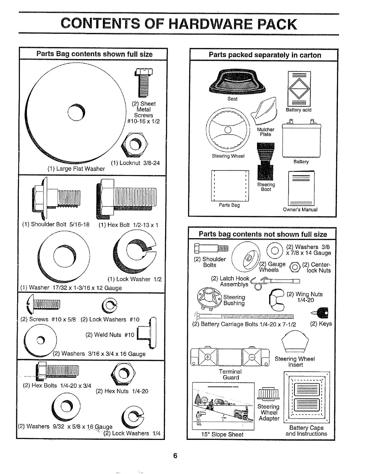
Parts Bag contents shown full size
iiii1,11111111i ,111111111iiiii i
O (2) Sheet
Metal
Screws
#10-16 x 1/2
(1) Shoulder Bolt 5/16-18 (1)HexBolt t/2-13xl
(1) Lock Washer 1/2
(1) Washer 17/32 x 1-3/16,,x,,12Gauge
.... o
(2) Screws #10 x 5/8 (2) Lock Washers #10/-')
I21We dNuts
c- .l
_.,./'(2) Washers 3/16 x 3/4 x 16 Gauge
i i_n,i iii ,u,nu n ii
(2) Hex Bolts 1/4-20 x 3/4 (2) Hex Nuts 1/4-20
(2) Washers 9/32 x 5/8 x 16Gauge
_; _ (2) Lock Washers 1/4
Parts packed separately in carton
,Hn, nn i
Seat
Mulcher
Plate
Steedng Wheel
;
I Steering
Boot
I
Parts Bag
Battery acid
Battery
Owner's Manuat
Parts bag contents not shown full size
,i,,,i n
/f'--_'_\ (2) Washers 3/8
(2) Shoulder (i_f_")) x 7/8x t4 Gauge
Bolts \\ [</_j/!2) Gauge _ (2) Center-
\--_ Wheels _ lock Nuts
(2) Latch Hookup' 4_r-------_7
Assemblys _r'_ ' _-_
_ _ _ (2) Wing Nuts
[_ _Ce)Steering I T-- 1/4 20
_ Bushing !_ "
(2) Battery Carriage Bolts 1/4-20 x 7-1/2 (2) Keys
Steering Wheel
Insert
Terminal o
Guard
Steering
Wheel
Adapter
15° Slope Sheet
1 •
Battery Caps
and Instructions
6

nnnu,i i rl , ,,,,,,,,,,,,,,,,,i..11 ilnll innl,,.ll,l,ll
ASSEMBLY
iiii n,lllll i iinn,Hi nn ii i nnlll i,,,,,,,,,,,,,,,,,,,,,,,, nil
Your new tractor has been assembled at the factory with exception of those parts left unassembled for shipping purposes°
To ensure safe and proper operation of your tractor, all parts and hardware you assemble must be tightened securely. Use
the correct tools as necessary to insure proper tightness.
TOOLS REQUIRED FOR ASSEMBLY
A socket wrench set wilt make assembly easier,. Standard
wrench sizes are listed.,
(1) 5/16" wrench
(2) 7/16" wrenches
(1) 1/2" wrench
('1) 3/4" wrench
(1) 9/'I6" wrench
(1) Phillips screwdriver
Utility knife
Tire pressure gauge
(1) 3/4" socket with drive ratchet
When right and left hand is mentioned in this manual, it
means when you are in the operating position (seated
behind the steering wheel),
TO REMOVE TRACTOR FROM CAR-
TON
UNPACK CARTON
• Remove all accessible loose parts and parts cartons
from carton (See page 6)r
• Cut, from top to bottom, along lines on alI four corners
of carton, and Iay panels flat,
.Check for any additionat loose parts or cartons and
remove.
STEERING SHAFT
(ASSEMBLY
POSITION) _ ,,
STEERING SHAFT
(SHIPPING
POSITION)
FIG. 1
TAB SLOT
BEFORE ROLLING TRACTOR OFF SKID
ATTACH STEERING WHEEL (See Fig. 1)
•Slide the steering bushing over the steering shaft°
•Raise steering shaft forward until screw holes in dash
line up with steering bushing. Install two (2) sheet
metal screws and tighten securely_
• Position steering boot over steering shaft.
• Place tabs of steering boot over tab slots in dash and
push down to secure.
,Slide steering wheel adapteronto uppersteering shaft,
• Position front wheels of the tractor so they are pointing
straight forward.
• Position steering wheel so cross bars are horizontal
(left to right) and slide onto adapter.
• Assemble large flat washer and 3/8-24 Iocknut and
tighten securelyo
• Snap steering wheel insert into center of steering
wheel.
• Remove protective plastic from tractor hood and grill.
IMPORTANT:CHECK FOR AND REMOVE ANY STAPLES
IN SKIDTHAT MAY PUNCTURE TIRES WHERE TRACTOR
IS TO ROLL OFF SKID
TO ROLL TRACTOR OFF SKID (See Fig. 7)
• Raise attachment lift lever to its highest position.
• Release parking brake by depressing clutch/brake
pedal
•Place gearshift lever in neutral (N) position.
• Roll tractor backwards off skid,1
•Remove banding holding discharge guard up against
tractor.
7
L II,,ll
ASSEMBLY
i iii i nu, nul :::::::::::::::::::::::::
HOW TO SET UP YOUR TRACTOR
PREPARE BATTERY (See Fig. 2)
Your tractor has a battery charging system which is suffi-
cient for normal use. However, periodic charging of the
battery with an automotive charger will extend its life.
• See instructions packed with vent caps in parts bag_
o Fill batten./with acid. Fill each cell until it reaches the
bottom of the vent wells. Do not overfill
• Allow battery to stand and settle for at least thirty
minutes. After standing, check the battery cell acid
level. If below the vent wells, add more acid until the
correct level is reached.
While battery is standing (after adding acid) and later, while
battery is being charged, continue with assembly of tractor,
IMPORTANT: TO MAXIMIZE THE LIFE OF YOUR
BATTERY, IT IS NECESSARY THAT THE BATTERY BE
CHARGED BEFORE USE. FAILURE TO CHARGE
BATTERY CAN RESULT IN A SHORTENED BATTERY
LIFE
• Charge battery at a rate of 6 amperes for I hour. Use
a 12 volt battery charger, Observe all safety precau-
tions required for battery charging,
. Check the acid level after the battery is charged, If the
acid has fallen below the correct level, add distilled or
iron free water.
° fnstall the vent caps to cover the vent well&, Wash the
top of the battery with water to remove any acid, then
wipe dry
oCheck battery case for leakage to make sure that no
damage has occurred in handling_
• Dispose of excess battery acid., Neutralize acid for
disposal by adding it to two gallons of water in a five
gallon plastic container,, Stir with a wooden or plastic
paddle while adding baking soda until the addition of
more soda causes no more foaming.
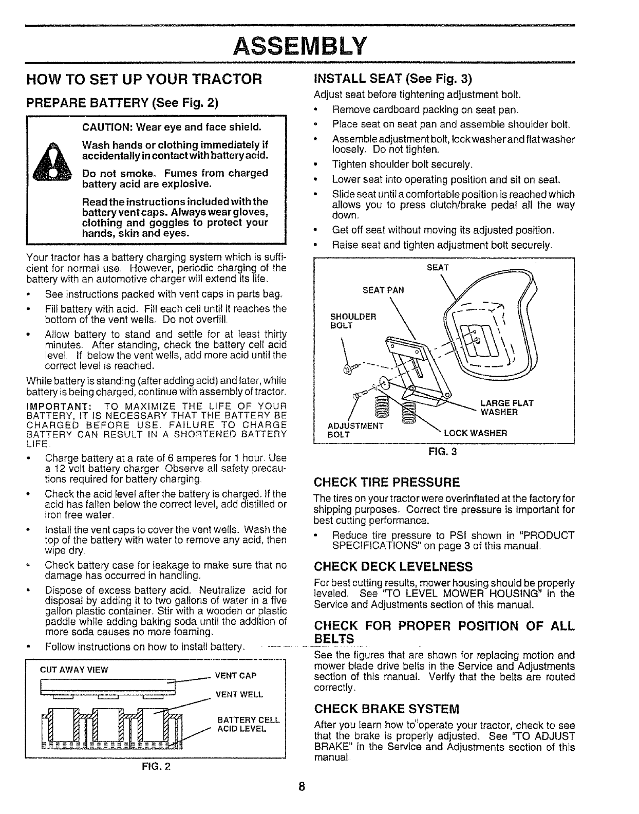
INSTALL SEAT (See Fig. 3)
Adjust seat before tightening adjustment bolt.
• Remove cardboard packing on seat pan,
° Place seat on seat pan and assemble shoulder bolt.
° Assemble adjustment bolt, lockwasherandflatwasher
loosely, Do not tighten.
• Tighten shoulder bolt securely.
• Lower seat into operating position and sit on seat,
• Slide seat until a comfortable position is reached which
allows you to press clutch/brake pedal all the way
down°
• Get off seat without moving its adjusted position.
• Raise seat and tighten adjustment bolt securely.
SEAT
SEAT PAN
BOLTSHOULDER
ADJUSTMENT
BOLT
LARGE FLAT
WASHER
LOCK WASHER
FIG. 3
CHECK TIRE PRESSURE
The tires on your tractor were overinflated at the factory for
shipping purposes. Correct tire pressure is important for
best cutting performance,
• Reduce tire pressure to PSI shown in "PRODUCT
SPECIFICATIONS" on page 3 of this manual
CHECK DECK LEVELNESS
For best cutting results, mower housing should be properly
leveled, See '%0 LEVEL MOWER HOUSING" in the
Service and Adjustments section of this manual.
CHECK FOR PROPER POSITION OF ALL
BELTS
Follow instructions on how to install battery. -.............................
See the figures that are shown for replacing motion and
CUT AWAY VIEW
[ _ VENT CAP
VENT WELL
_ATTERY CELL
ACID LEVEL
FIG. 2
mower blade drive belts in the Service and Adjustments
section of this manual. Verify that the belts are routed
correctly,
CHECK BRAKE SYSTEM
After you learn how to"operate your tractor, check to see
that the brake is properly adjusted. See "TO ADJUST
BRAKE" in the Service and Adjustments section of this
manual
ii, iiirll,i ii i ii iiiiiiiiii I IIIHIII,II II I,II1',,I, I I1'111111 ,I ....................
ASSEMBLY
H= Hm.m.. H. Hm.,.,, Hm=,m= =.,
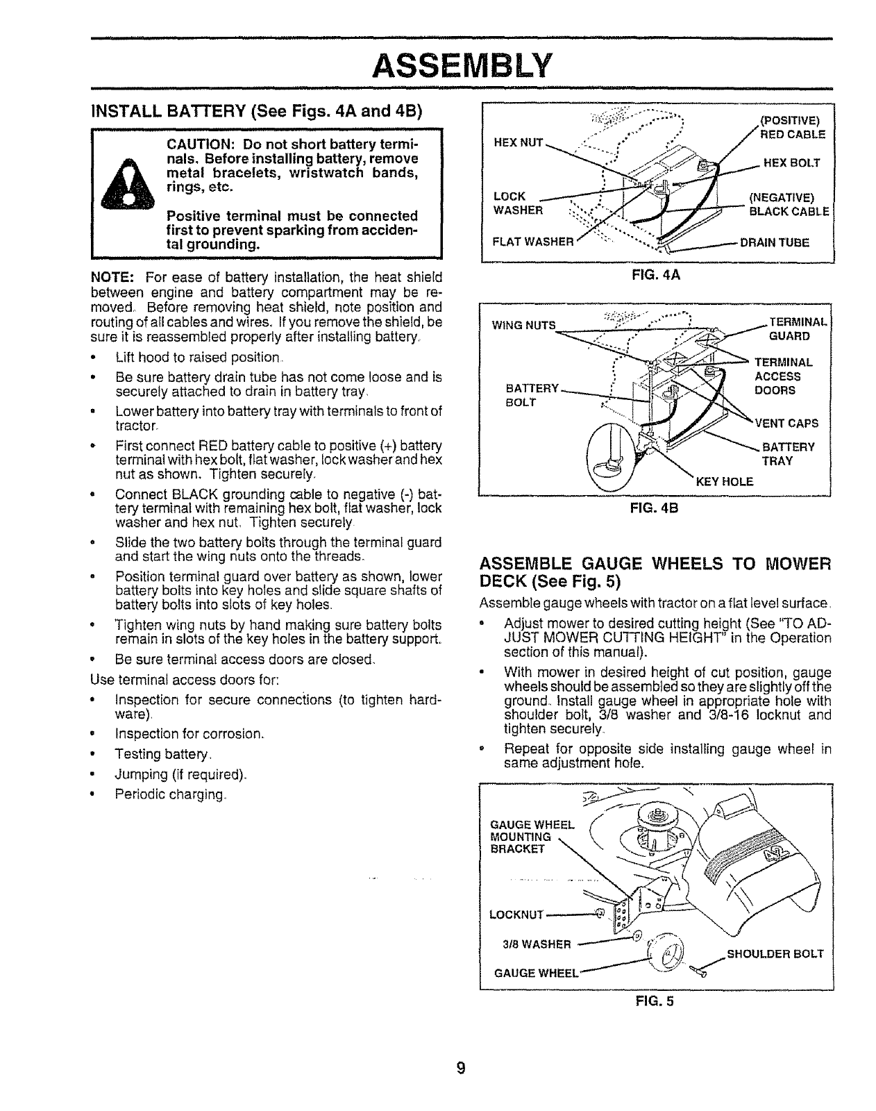
INSTALL
..,=.1
BATrERY (See Figs. 4A and 4B)
. HH.=.,,,... H H,,,, H.
CAUTION: Do not short battery termi-
nals. Before installing battery, remove
metal bracelets, wristwatch bands,
rings, etc.
APositive terminal must be connected
first to prevent sparking from acciden-
tal grounding.
NOTE: For ease of battery installation, the heat shield
between engine and battery compartment may be re-
moved° Before removing heat shield, note position and
routing of atl cables and wires, Ifyou remove the shield, be
sure it is reassembled properly after installing battery
•Lift hood to raised position.
•Be sure battery drain tube has not come loose and is
securely attached to drain in battery tray,
, Lower battery intobattery tray with terminals to front of
tractor.
•First connect RED battery cable to positive (+) battery
terminal with hex bolt, fiat washer, lock washer and hex
nut as shown° Tighten securely.
• Connect BLACK grounding cable to negative (-) bat-
tery terminal with remaining hex bolt, flat washer, lock
washer and hex nut. Tighten securely
o Slide the two battery bolts through the terminal guard
and start the wing nuts onto the threads.
o Position terminal guard over battery as shown, lower
battery bolts into key holes and slide square shafts of
battery bolts into slots of key holes.
• Tighten wing nuts by hand making sure battery bolts
remain in slots of the key holes in the battery support..
•Be sure terminal access doors are closed.
Use terminal access doors for:
° Inspection for secure connections (to tighten hard-
ware),
• Inspection for corrosion.
•Testing batteE/.
• Jumping (if required).
•Periodic charging..
(POSITIVE)
HEX NUT '_ "';;" "* "/° .'°': !RED CABLE
LOCK ,,...---.-_'_'_:" L,_ __,/) _(NEGATIVE)
WASHERou_:_ _.:_:. _ BLACKCABLE
FLAT WASHER "'""*.;__ DRAIN TUBE
FIG. 4A
BOLT
TERMINAL
ACCESS
DOORS
APS
_BATTERY
TRAY
KEY HOLE
FIG. 4B
ASSEMBLE GAUGE WHEELS TO MOWER
DECK (See Fig. 5)
Assemble gauge wheels with tractor on a fiat tevel surface.
°Adjust mower to desired cutting height (See "TO AD-
JUST MOWER CUTTING HEIGHT" in the Operation
section of this manuat).
• With mower in desired height of cut position, gauge
wheels should be assembled so they are slightly off the
ground.. Install gauge wheel in appropriate hole with
shoulder bolt, 3/8 washer and 3/8-16 locknut and
tighten securely.
,Repeat for opposite side installing gauge wheel in
same adjustment hole.
GAUGEWHEEL
MOUNTING
BRACKET
BOLT
FIG. 5
9
BLY
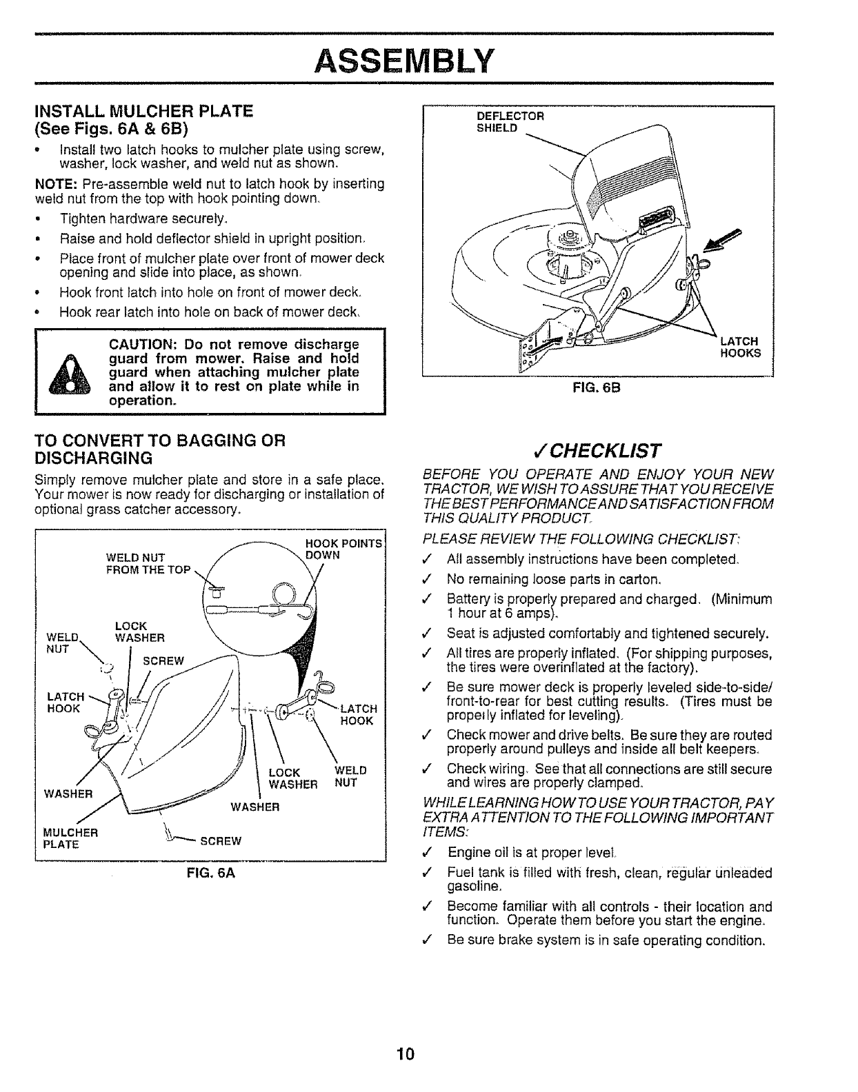
INSTALL MULCHER PLATE
(See Figs. 6A & 6B)
oInstall two latch hooks to mulcher plate using screw,
washer, lock washer, and weld nut as shown,
NOTE: Pre-assemble weld nut to latch hook by inserting
weld nut from the top with hook pointing down,,
• Tighten hardware securely°
• Raise and hold deflector shietd in upright position,
• Place front of mulcher plate over front of mower deck
opening and slide into place, as shown_
• Hook front latch into hole on front of mower deck,
, Hook rear latch into hole on back of mower deck,
CAUTION: Do not remove discharge
guard from mower. Raise and hold
guard when attaching mulcher plate
and allow it to rest on plate while in
operation.
TO CONVERT TO BAGGING OR
DISCHARGING
Simply remove mulcher plate and store in a safe place,
Your mower is now ready for discharging or installation of
optional grass catcher accessory,.
WELD NUT
FROM THE TOP \
HOOK POINTS
DOWN
LOCK
WELD.
NUT _ WASHER
_. SCREW
:j
LATCH
HOOK
HOOK
WASHER
MULCHER
PLATE
LOCK
WASHER
WELD
NUT
FIG. 6A
DEFLECTOR
SHIELD
FIG, 6B
HOOKS
4"CHECKLIST
BEFORE YOU OPERATE AND ENJOY YOUR NEW
TRACTOR, WE WISH TO ASSURE THAT YOU RECEIVE
THE BEST PERFORMANCE AND SA TISFA CTION FROM
THIS QUALITY PRODUCT
PLEASE REVIEW THE FOLLOWING CHECKLIST:
4" A!I assembly instructions have been completed°
4 No remaining loose parts in carton,
J Batteryis properly prepared and charged. (Minimum
1 hour at 6 amps),
,/ Seat is adjusted comfortably and tightened securely.
,/ All tires are properly inflated. (For shipping purposes,
the tires were overinflated at the factory).
,/ Be sure mower deck is properly leveled side-to-side/
front-to-rear for best cutting results. (Tires must be
proper ly inflated for leveling),
J" Check mower and drive belts. Be sure they are routed
properly around pulleys and inside all belt keepers,,
J" Check wiring, See that all connections are still secure
and wires are properly clamped°
WHILE LEARNING HOW TO USE YOUR TRACTOR, PAY
EXTRA A TTENTION TO THE FOLLOWING IMPORTANT
ITEMS:
4' Engine oit is at proper level,
,/ Fuel tank is filled with fresh, clean, regular unleaded
gasoline°
,/ Become familiar with all controls - their location and
function_ Operate them before you start the engine_
,/ Be sure brake system is in safe operating condition.
10
i i n l ii iiiii ii ,inl i i in,,,,,n,,i, i i,nl,,,
OPERATION
m i
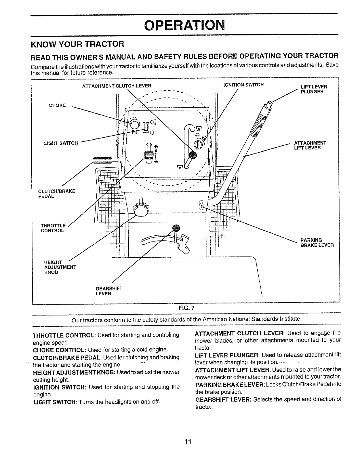
KNOW YOUR TRACTOR
READ THIS OWNER'S MANUAL AND SAFETY RULES BEFORE OPERATING YOUR TRACTOR
Compare the illustrations with your tractor to familiarize yourself with the locations of various controls and adjustments° Save
this manual for future reference,
CHOKE
LIGHT SWITCH
CLUTCHIBRAKE
PEDAL
ATTACHMENTCLUTCHLEVER IGNITION SWITCH LIFT LEVER
_------ PLUNGER
,_ _r
ATTACHMENT
LIFT LEVER
THROTTLE
CONTROL
HEIGHT
ADJUSTMENT
KNOB
GEARSHIFT
LEVER
PARKING
BRAKE LEVER
FIG, 7
Our tractors conform to the safety standards of the American National Standards fnstitute_
THROTTLE CONTROL: Used for starting and controlling
engine spee&
CHOKE CONTROL: Used for starting a cold engine
CLUTCH/BRAKE PEDAL: Used for clutching and braking
the tractor and starting the engine, --
HEIGHT ADJUSTMENT KNOB: Used to adjust the mower
cutting height.
IGNITION SWITCH: Used for starting and stopping the
engine.
LIGHT SWITCH: Turns the headlights on and off,
ATTACHMENT CLUTCH LEVER: Used to engage the
mower blades, or other attachments mounted to your
tractor.
LIFT LEVER PLUNGER: Used to release attachment lift
lever when changing its position,.--
ATTACHMENT LIFT LEVER: Used to raise and tower the
mower deck or other attachments mounted to your tractor.,
PARKING BRAKE LEVER: Locks Clutch/Brake Pedal into
the brake position,
GEARSHIFT LEVER: Selects the speed and direction of
tractor.
11
OPERATION
,,,Jl nl,,nulun i un, II n UU,ulnlun,n, i i
The operation of any tractor can result in foreign objects thrown into the eyes, which
can result in severe eye damage. Always wear safety glasses or eye shields while
operating your tractor or performing any adjustments or repairs. We recommend a
wide vision safety mask for over the spectacles or standard safety glasses.
HOW TO USE YOUR TRACTOR
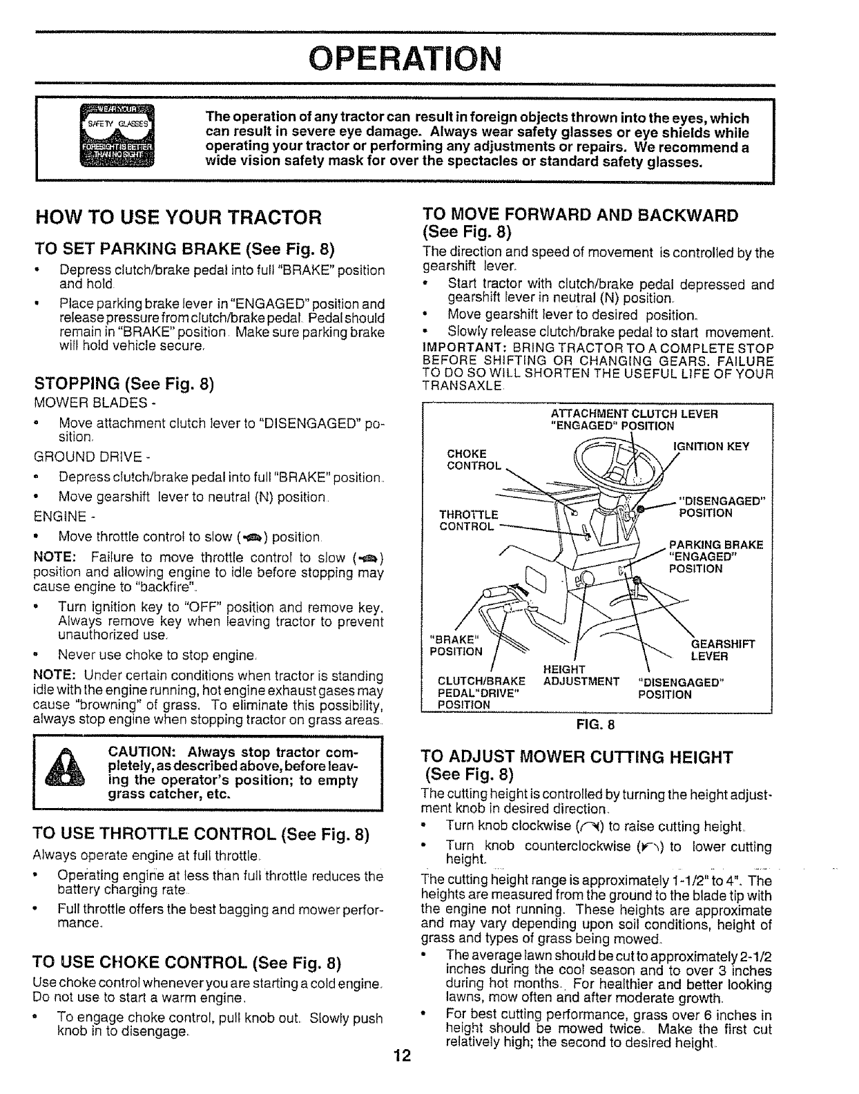
TO SET PARKING BRAKE (See Fig. 8)
•Depress clutch/brake pedal into full "BRAKE" position
and hold
• Place parking brake lever in "ENGAGED" position and
release pressure from clutch/brake pedal Pedalshould
remain in "BRAKE" position Make sure parking brake
will hold vehicle secure,
STOPPING (See Fig. 8)
MOWER BLADES -
•Move attachment dutch lever to "DISENGAGED" po-
sition,
GROUND DRIVE-
• Depress clutch/brake pedal into full "BRAKE" position..
• Move gearshift lever to neutral (N) position
ENGINE -
• Move throttle control to slow (,_) position
NOTE: Failure to move throttle control to slow (,_)
position and allowing engine to idle before stopping may
cause engine to "backfire"..
• Turn ignition key to "OFF" position and remove key.
Always remove key when leaving tractor to prevent
unauthorized use.
• Never use choke to stop engine,
NOTE: Under certain conditions when tractor is standing
idle with the engine running, hot engine exhaust gases may
cause "browning" of grass. To eliminate this possibility,
always stop engine when stopping tractor on grass areas.
CAUTION: Always stop tractor com-
pletely, as described above, before leav-
ing the operator's position; to empty
grass catcher, etc.
TO USE THROTTLE CONTROL (See Fig. 8)
Always operate engine at full throttle.
* Operating engine at tess than full throttle reduces the
battery charging rate
• Full throttle offers the best bagging and mower perfor-
mance..
TO USE CHOKE CONTROL (See Fig, 8)
Use choke control whenever you are starting a cold engine.
Do not use to start a warm engine.
, To engage choke control, pull knob out. Slowly push
knob in to disengage
TO MOVE FORWARD AND BACKWARD
(See Fig. 8)
The direction and speed of movement is controlled by the
gearshift lever_
•Start tractor with clutch/brake pedal depressed and
gearshift lever in neutral (N) position.
° Move gearshift lever to desired position°
• Slowly release clutch/brake pedal to start movement.
IMPORTANT: BRING TRACTOR TO A COMPLETE STOP
BEFORE SHIFTING OR CHANGING GEARS. FAILURE
TO DO SO WILL SHORTEN THE USEFUL LIFE OF YOUR
TRANSAXLE
CHOKE
CONTROL
ATTACHMENT CLUTCH LEVER
"ENGAGED"POSITION
IGNITION KEY
THROTTLE POSITION
CONTRt
PARKING BRAKE
"ENGAGED"
POSITION
12
"BRAKE" GEARSHIFT
POSITION LEVER
HEIGHT
CLUTCH/BRAKE ADJUSTMENT "DISENGAGED"
PEDAL"DRIVE" POSITION
POSITION
FIG, 8
TO ADJUST MOWER CUTTING HEIGHT
(See Fig. 8)
The cutting height is controlled by turning the height adjust-
ment knob in desired direction.
•Turn knob clockwise (f'-_) to raise cutting height..
• Turn knob counterclockwise (_',)to lower cutting
height.
The cutting height range is approximately 1-1/2"to 4". The
heights are measured from the ground to the blade tip with
the engine not running. These heights are approximate
and may vary depending upon soil conditions, height of
grass and types of grass being mowed.
• The average lawn should be cut to approximately 2-1/2
inches during the coot season and to over 3 inches
during hot months. For healthier and better looking
lawns, mow often and after moderate growth.
• For best cutting performance, grass over 6 inches in
height should be mowed twice. Make the first cut
relatively high; the second to desired height.
,HH=,H ,,, ==,==1,=,1 = ,== = " ='H,NH,,................................. ,,,,H,"=-"r, , ==,_,,=,
OPERATION
= ==H,=, =H,= , ,,==,=_,lr
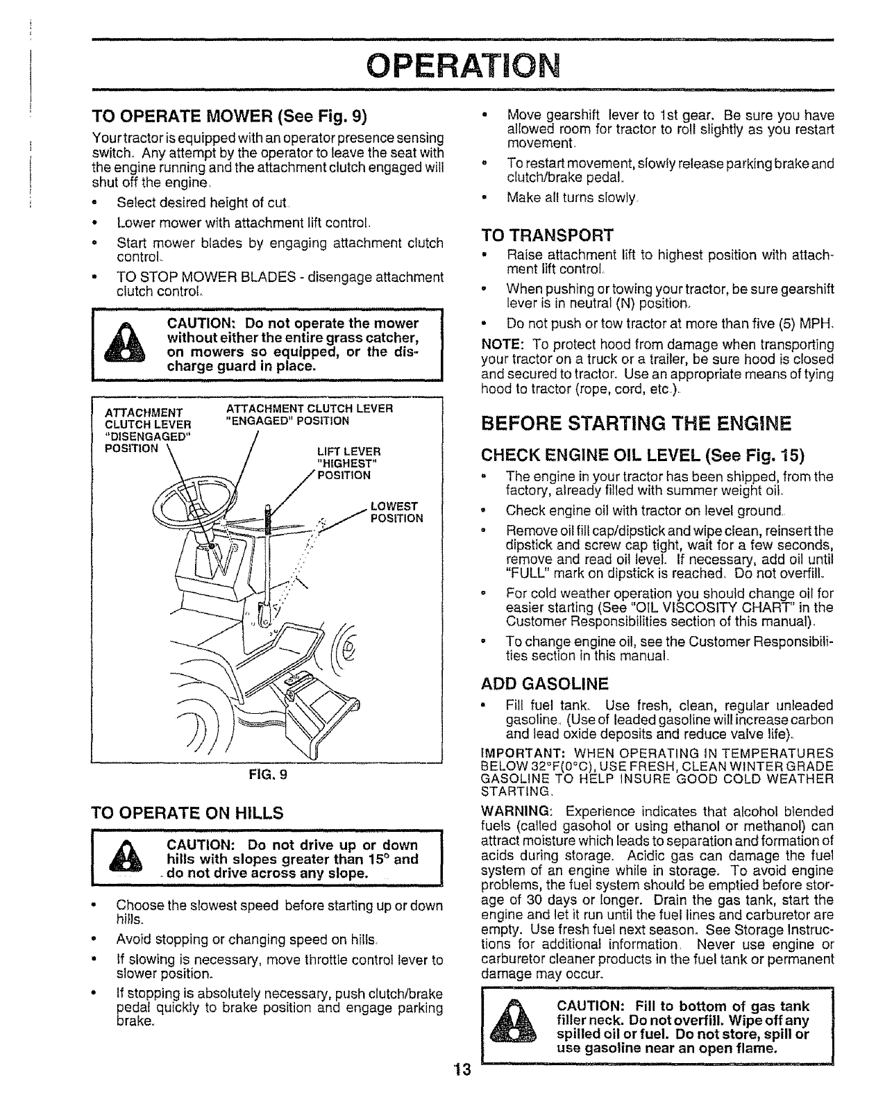
TO OPERATE MOWER (See Fig, 9) • Move gearshift lever to 1st gear. Be sure you have
allowed room for tractor to roll slightly as you restart
Your tractor is equipped with an operator presence sensing movement.
switch° Any attempt by the operator to leave the seat with
the engine running and the attachment clutch engaged will °
shut off the engine,
. Select desired height of cut
* Lower mower with attachment lift control
. Start mower blades by engaging attachment clutch
control.
.TO STOP MOWER BLADES - disengage attachment
clutch control.
=HH =HH= H=H H HH=
!_ CAUTION: Do not operate the mower
without either the entire grass catcher,
on mowers so equipped, or the dis,-
charge guard in place.
,., H= =H H =
ATTACHMENT
CLUTCHLEVER
ATTACHMENT CLUTCH LEVER
"ENGAGED"POSITION
FIG. 9
LIFT LEVER
"HIGHEST"
LOWEST
POSITION
TO OPERATE ON HILLS
I i iiiiiiiiii iii i ii iiii ii iiiii iiii
CAUTION: Do not drive up or down
hills with slopes greater than 15° and
.do not drive across any slope.
iii iiiii iiii ii II ,_ ............. I
•Choose the s!owest speed before starting up or down
hi}Is.
, Avoid stopping or changing speed on hills_
• If slowing is necessary, move throttle control lever to
slower position.
.If stopping is absolutely necessary, push clutch/brake
pedal quickly to brake position and engage parking
brake,
To restart movement, slowly release parking brake and
clutch/brake pedal
Make all turns slowly.
TO TRANSPORT
• Raise attachment lift to highest position with attach-
ment lift control
• When pushing ortowing your tractor, be sure gearshift
Iever is in neutral (N) position.
• Do not push or tow tractor at more than five (5) MPH,
NOTE: To protect hood from damage when transporting
your tractor on a truck or a trailer, be sure hood is closed
and secured to tractor. Use an appropriate means of tying
hood to tractor (rope, cord, etc)
13
BEFORE STARTING THE ENGINE
CHECK ENGINE OIL LEVEL (See Fig. 15)
•The engine in your tractor has been shipped, from the
factory, already filled with summer weight oil.
o Check engine oil with tractor on level ground.
•Remove oil fill cap/dipstick and wipe clean, reinsert the
dipstick and screw cap tight, wait for a few seconds,
remove and read oil level If necessary, add oil until
"FULL" mark on dipstick is reached. Do not overfill,
- For cold weather operation you should change oil for
easier starting (See "OIL VISCOSITY CHART" in the
Customer Responsibilities section of this manual).
• To change engine oil, see the Customer Responsibili-
ties section in this manual.
ADD GASOLINE
• Fill fuel tank. Use fresh, clean, regular unleaded
gasoline_ (Use of leaded gasoline will increase carbon
and lead oxide deposits and reduce valve life)o
IMPORTANT: WHEN OPERATING IN TEMPERATURES
BELOW 32OF(0=C),USE FRESH, CLEAN WINTER GRADE
GASOLINE TO HELP INSURE GOOD COLD WEATHER
STARTING,
WARNING: Experience indicates that alcohol b_ended
fuels (called gasohot or using ethanol or methanol) can
attract moisture which leads to separation and formation of
acids during storage,, Acidic gas can damage the fuel
system of an engine while in storage. To avoid engine
problems, the fuel system should be emptied before stor-
age of 30 days or longer. Drain the gas tank, start the
engine and let it run until the fuel lines and carburetor are
empty. Use fresh fuel next season° See Storage Instruc-
tions for additional information Never use engine or
carburetor cleaner products in the fuel tank or permanent
damage may occur,
CAUTION: Fill to bottom of gas tank
filler neck. Do not overfill. Wipe off any
spilled oil or fuel. Do not store, spill or
use gasoline near an open flame.
................................... i,,i,ii
OPERATION
TO START ENGINE (See Fig. 8)
When starting engine for the first time or if engine has run
out of fuel, it will take extra cranking time to move fuel from
the tank to the engine.
, Depress clutch/brake pedal and set parking brake.
o Place gearshift lever in neutral (N) position.
° Move attachment clutch to "DISENGAGED" position,
° Pull choke control out to choke (IX}) position for cold
engine start For warm engine start do not use choke
control
• Move throttle control to midway between fast (,t_) and
slow (._.) positions°
• tnsertkeyintoignitionandturnkeyc!ockwiseto"START"
position and release key as soon as engine starts. Do
not run starter continuously for more than fifteen
seconds per minute. If engine does not start after
several attempts, move throttle control to fast (,_,)
position, wait a few minutes and try again.
°When engine starts, slowly push choke control in.
•Move throttle control to fast (,_) position..
°Allow engine to warm up for a few minutes before
engaging drive or attachments.
NOTE: If at a high altitude (above 3000 feet) or in cold
temperatures (below 32°F), the carburetor fuel mixture
may need to be adjusted for best engine performance. See
"TO ADJUST CARBURETOR" in the Service and Adjust-
ments section of this manual.
MOWING TIPS
• Tire chains cannot be used when the mower housing
is attached to tractor.
•Mower should be properly leveled for best mowing
performance. See"TO LEVEL MOWER HOUSING" in
the Service and Adjustments section of this manual.
° The left hand side of mower should be used for trim-
ming.
•Drive so that clippings are discharged onto the area
that has been cut. Have the cut area to the right of the
machine This will result in a more even distribution of
clippings and more uniform cutting
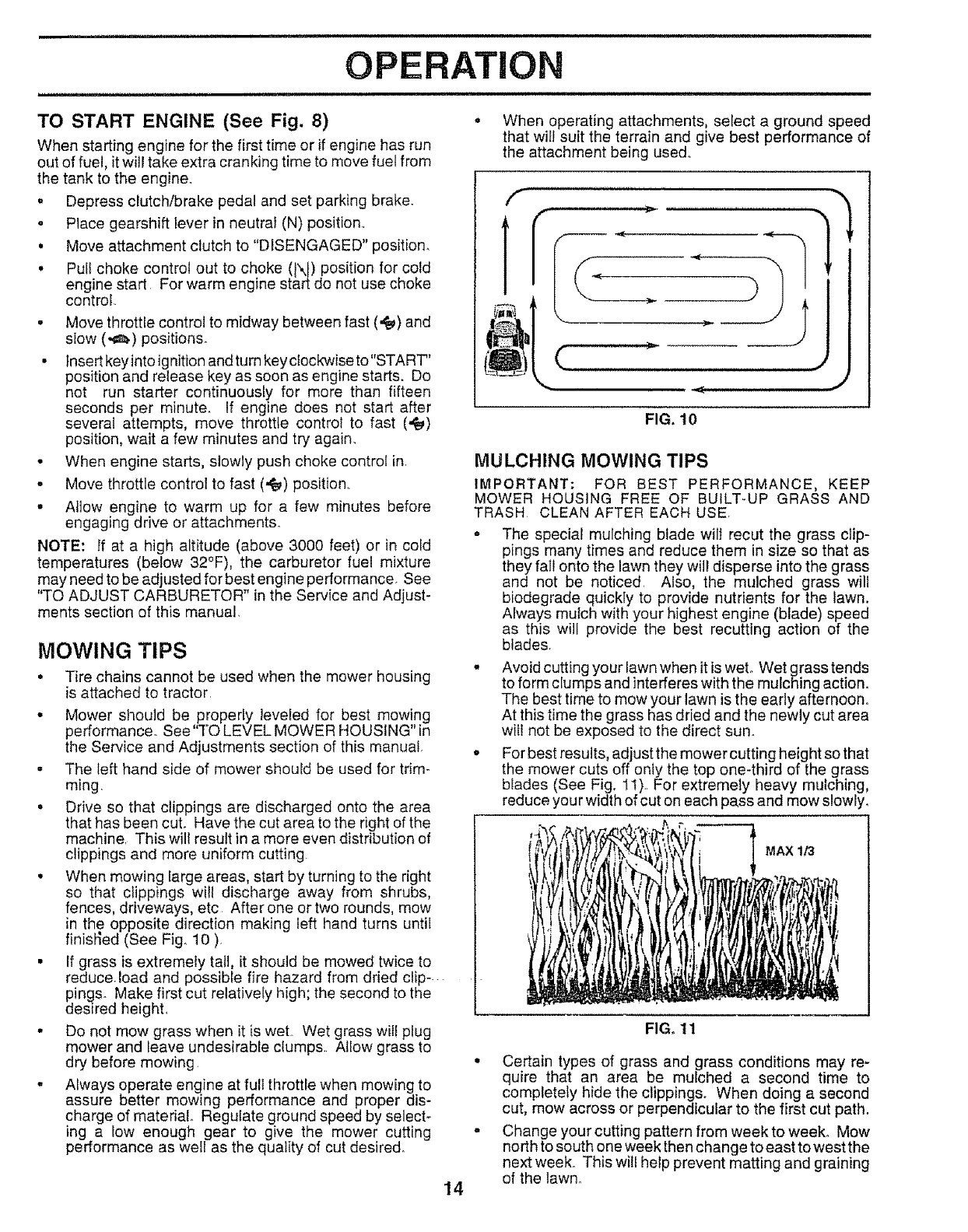
• When mowing large areas, start by turning to the right
so that clippings will discharge away from shrubs,
fences, driveways, etc After one or two rounds, mow
in the opposite direction making left hand turns until
finisi_ed (See Fig, 10 ),
• If grass is extremely tall, it should be mowed twice to
reduce load and possible fire hazard from dried clip ....
ping& Make first cut relatively high; the second to the
desired heighL
• Do not mow grass when it is wet. Wet grass will plug
mower and leave undesirable clump&. Allow grass to
dry before mowing. °
°Always operate engine at full throttle when mowing to
assure better mowing performance and proper dis-
charge of material. Regulate ground speed by select-
ing a low enough gear to give the mower cutting =
performance as well as the quality of cut desired.
14
. When operating attachments, select a ground speed
that will suit the terrain and give best performance of
the attachment being used..
FIG. 10
MULCHING MOWING TIPS
IMPORTANT: FOR BEST PERFORMANCE, KEEP
MOWER HOUSING FREE OF BUILT-UP GRASS AND
TRASH CLEAN AFTER EACH USE.
° The special mulching blade will recut the grass clip-
pings many times and reduce them in size so that as
they fail onto the lawn they will disperse into the grass
and not be noticed Also, the mulched grass will
biodegrade quickly to provide nutrients for the lawn.
Always mulch with your highest engine (blade) speed
as this will provide the best recutting action of the
blades.
° Avoid cutting your lawn when it is wet. Wet grass tends
to form clumps and interferes with the mulching action.
The best time to mow your lawn is the early afternoon°
At this time the grass has dried and the newly cut area
will not be exposed to the direct sun.
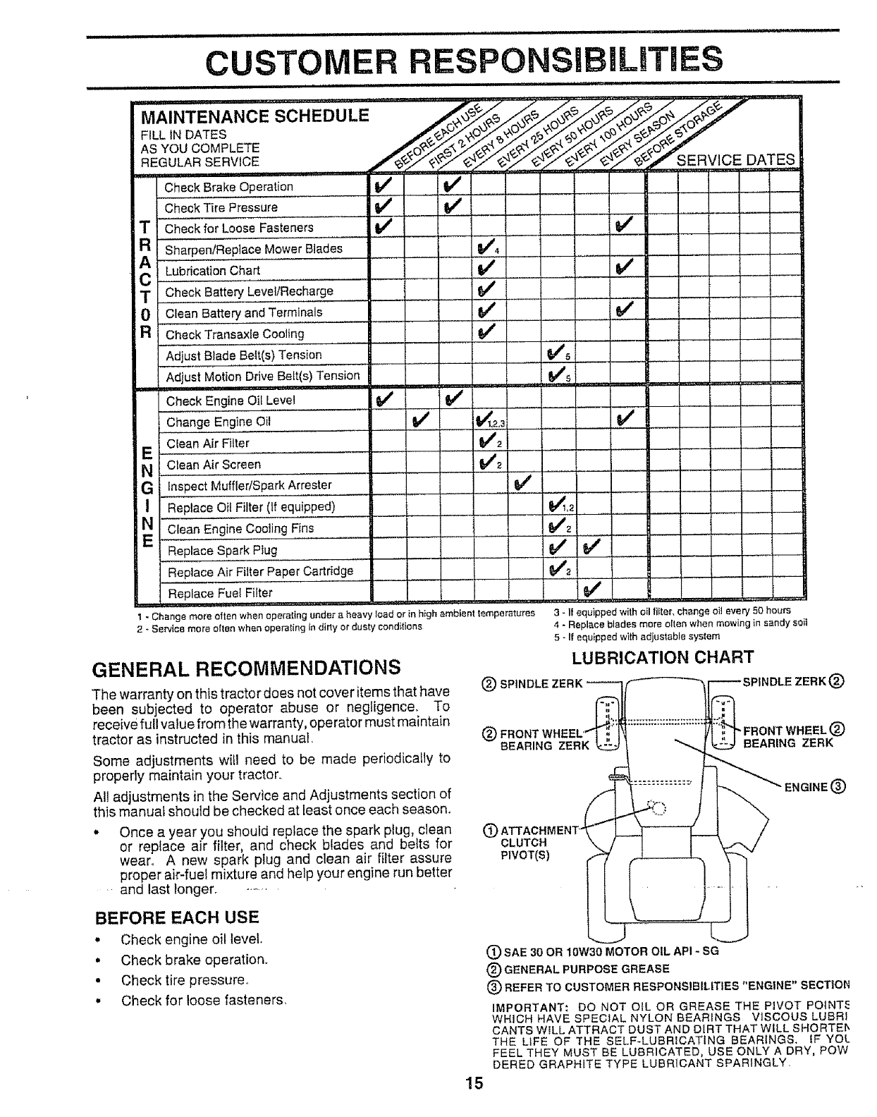
,, For best results, adjust the mower cutting height so that
the mower cuts off only the top one-third of the grass
blades (See Fig. 1t).. For extremely heavy mulching,
reduce you r width of cut on each pa.ss and mow slowly_
MAX1/3
f
FIG. 11
Certain types of grass and grass conditions may re-
quire that an area be mulched a second time to
completely hide the clippings. When doing a second
cut, mow across or perpendicular to the first cut path.
Change your cutting pattern from week to week. Mow
north to south one week then change to east to west the
next week. This wil! help prevent matting and graining
of the lawno
CUSTO RESPONSIBILmTIES
,= , =, = ==
MAINTENANCE SCHEDU"LE ......... _! __ j_o_ ..,_/"_ .....
FILL IN DATES __ _//_u _L_ 7
ASYOUCOMPLETE _,. ¢ _._,Z._o_,_"
,, ,,
Check Brake.O.p.e[.a!ion if I_
Check Tire Pressure if 6#'..
Check for Loose Fasteners
RSharpen/Replace Mower Blades 1_4
.....
LubricationChart if
i ............
'T ,C,heckBa!!eryLevee/Recharge, ...........
0Clean Batteryand Terminals I_
RCheck Transaxie Cooling
Adjust Blade Belt(s) Tension
Adjust Motion Drive Belt(s) Tension
Check Engine Oil Level I_ !_
Change Engine Oil ............... _ ....... 1_1,2.3
Clean Air Filter V'2
NClean Air Screen _2
GInspectMuffler/SparkArrester if/
IReplace Oil Filter (if equipped) .... I
EN Clean Engine Cooling Fins i
ReplaceSpark Piug
ReplaceAir Filte;"Paper Cartridge
Replace Fuel Filter
6/'5¸
.....
t-Change more often when operating under a heavy load or in h}gh ambient temperatures
2-Service more often when operating in dirty or dusty conditions
GENERAL RECOMMENDATIONS
The warranty on this tractor does not cover items that have
been subjected to operator abuse or negligence. To
receive full value from the warranty, operator must maintain
tractor as instructed in this manual.
Some adjustments will need to be made periodicafly to
properly maintain your tractor.,
All adjustments in the Service and Adjustments section of
this manual should be checked at least once each season,,
*Once a year you should replace the spark plug, clean
or replace air filter, and check blades and belts for
wear. A new spark plug and clean air filter assure
proper air-fuel mixture and help your engine run better
. and last longer_ -.......
v'
v'
v'
,,, _--
(_) SPINDLE
....... Vq
t
v' v'
v' U
3-If equipped with oil filter, change oi! every 50 hours
4. Replace blades more often when mowing in sandy soil
5-If equipped with adjustable system
LUBRICATION CHART
®BEARING ZERK
OCLUTCH
PIVOT(S)
®
-FRONT WHEEL ®
BEARING ZERK
ENGINE (_
BEFORE EACH USE
• Check engine oil level
•Check brake operation.
•Check tire pressure.
• Check for loose fasteners,
15
(_SAE 30 OR 10W30 MOTOR OIL API -SG
®GENERAL PURPOSE GREASE
®REFER TO CUSTOMER RESPONSIBILITIES "ENGINE" SECTIOR
IMPORTANT; DO NOT OIL OR GREASE THE PIVOT POINT_
WHICH HAVE SPECIAL NYLON BEARINGS VISCOUSLUBRI
CANTS WILL ATTRACT DUST AND DLRT THAT WILL SHORTE[',
THE UFE OF THE SELF-LUBRICATING BEARINGS, IF YOL
FEEL THEY MUST BE LUBRICATED, USE ONLY A DRY, Paw
DERED GRAPHITE TYPE LUBRICANT SPARINGLY,

iiiiiilU, llU ,ii, i
CUSTOMER RESPONSIBILITIES
TRACTOR
Always observe safety rules when performing any mainte-
nance
BRAKE OPERATION
if tractor requires more than six (6) feet stopping distance
at high speed in highest gear, then brake must be adjusted_
(See "TO ADJUST BRAKE" in the Service and Adjust-
ments section of this manual)_
TIRES
o Maintain proper air pressure in al[ tires (See "PROD-
UCT SPECIFICATIONS" on page 3 of this manual),
•Keep tires free of gasoline, oil, or insect control chemi-
cals which can harm rubber.
* Avoid stumps, stones, deep ruts, sharp objects and
other hazards that may cause tire damage.
TO SHARPEN BLADE (See Fig. 13)
Care should be taken to keep the blade balanced, An
unbalanced blade will cause excessive vibration and even-
tual damage to mower and engine.,
•The blade can be sharpened with a file or on a grinding
wheel. Do not attempt to sharpen while on the mower.
•To check blade balance, you will need a 5/8" diameter
steel bolt, pin, or a cone balancer. (When using a cone
batancer, follow the instructions supplied with baI-
ancer).
•Slide blade on to an unthreaded portion of the steel bolt
or pin and hold the bolt or pin parallel with the ground.
If blade is balanced, it should remain in a horizontal
position, tf either end of the blade moves downward,
sharpen the heavy end until the blade is balanced.
NOTE: Do not use a nail for balancing blade, The lobes of
the center hole may appear to be centered, but are not.
BLADE CARE
For best results mower blades must be kept sharp_ Re-
place bent or damaged blades,,
BLADE REMOVAL (See Fig. 12)
.Raise mower to highest position to allow access to
blades
°Remove hex bolt, [ock washer and fiat washer securing
blade,
.Install new or resharpened blade with trailing edge up
towards deck as shown.
Reassemble hex bolt, lock washer and flat washer in
exact order as shown.
• Tighten bolt securely (30-35 Ft, Lbs,. torque).
IMPORTANT: BLADE BOLT IS GRADE 8 HEAT TREATED,
NOTE: We do not recommend sharpening blade- but ifyou
do, be sure the blade is balanced,
--_ MANDREL
__ ASSEMBLY
FIATWASHER _t_
•BLADE
LOCKW B.ER .'-%..... /TRAtL,NGEDGE
"A GRADE 8 HEAT TREATED BOLT CAN BE IDENTIFIED
BY SIX LINES ON THE BOLT HEAD.
FIG. 12
// ,
/' /
.OL
5/8" BOLT ,-_'_ "_.._/,_"_
OR PiN
FIG. 13
BATTERY (See Fig. 14)
Your tractor has a battery charging system which is suffi-
cient for normal use. However, periodic charging of the
battery with an automotive charger will extend its fife,
• Acid solution level in each battery cell should be even
with bottoms of vent wells, Add only distilled or iron free
water if necessary,r Do not overfill,
•Keep battery and terminals clean.
•Keep battery bolts tight.
• Keep vent caps tight and small vent holes in caps open.
• Recharge at 6 amperes for I hour.
CUT AWAY VIEW VENT CAP
_ _ _--_ VENT
WELL
BATTERY
CELL ACID
LEVEL
FIG. 14
16
TO CLEAN BATTERY AND TERMINALS
Corrosion and dirt on the battery and terminals can cause
the battery to "leak" power.
- Remove terminal guard_
• Disconnect BLACK battery cable first then RED
battery cable and remove battery from tractor,
• Wash battery with solution of four tablespoons of
baking soda to one gallon of water, Be careful not to
get the soda solution into the ceils.
• Rinse the battery with plain water and dry.
• Clean terminals and battery cable ends with wire
brush until bright°
. Coat terminals with grease or petroleum jelly
• Reinsta!l battery (See "INSTALL BATTERY" in the
Assembly section of this manual)°
V-BELTS
Check V-belts for deterioration and wear after 100 hours of
operation and replace if necessary. The belts are not
adjustable,. RepIace belts if they begin to slip from wear
TRANSAXLE COOLING
Keep transaxle free from build-up of dirt and chaff which
can restrict cooling
ENGINE
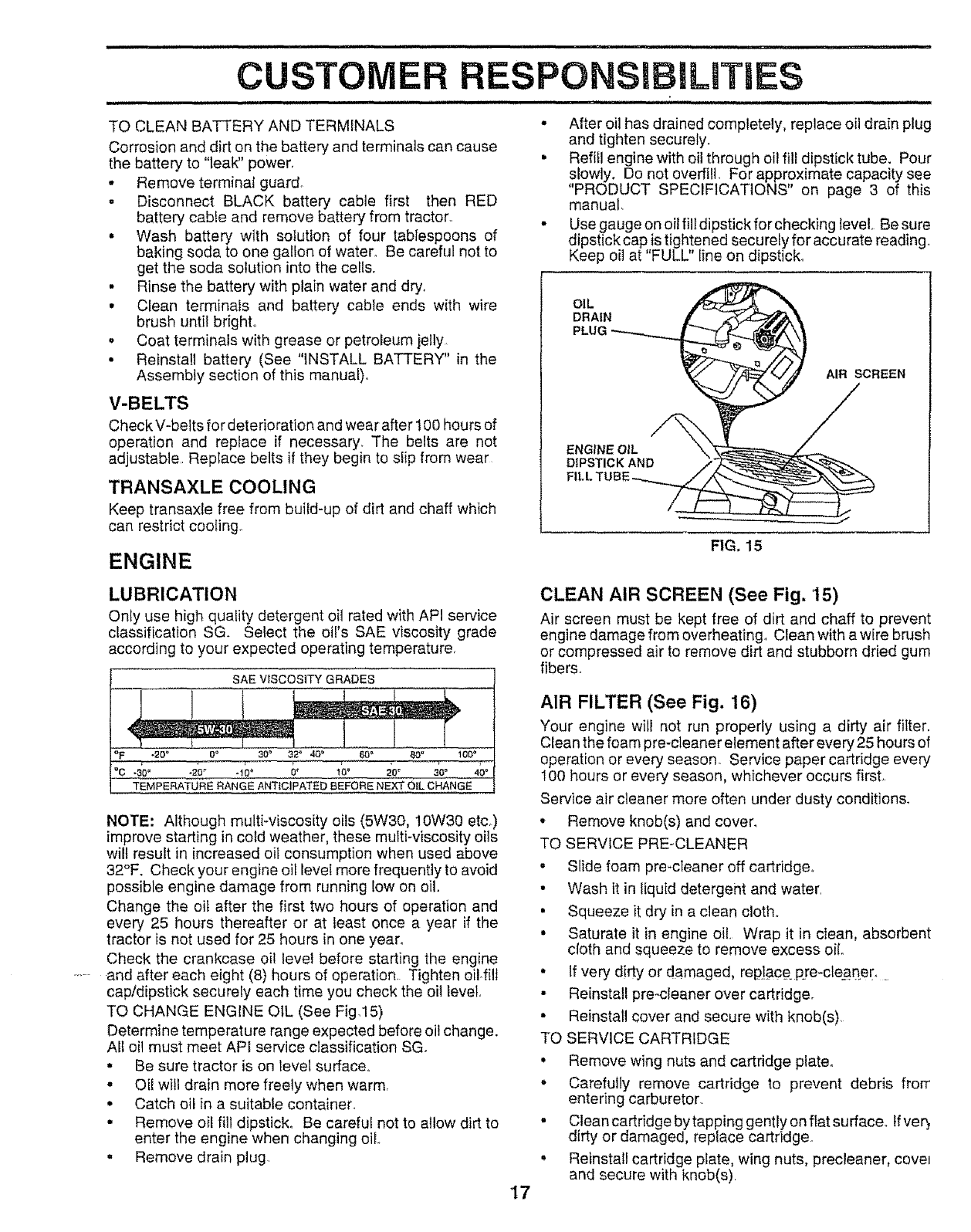
• After oil has drained completely, replace oil drain plug
and tighten securely.
. Refill engine with oil through oil fill dipstick tube. Pour
slowly. Do not overfill, For approximate capacity see
PRODUCT SPECIFICATIONS on page 3 of this
manual.
• Use gauge on oil flit dipstick for checking level, Be sure
dipstickcap is tightened securely foraccurate reading.
Keep oil at "FULL" line on dipstick°
O,L
DRAIN _ _J'A_
FIG. 15
LUBRICATION
Only use high quality detergent oil rated with API service
classification SG. Select the oil's SAE viscosity grade
according to your expected operating temperature.
SAE VISCOSITY GRADES
J]I
°F -_0_ 0° 30°32°40_ 60= 80° 100"
°C -30" -20 _-t0 _ O' 10' 8° 30=........ 40 °
TEMPERATURE RANGE ANTICIPATED BEFORE NEXT OIL CHANGE
NOTE: Although multi-viscosity oils (5W30, 10W30 eta)
improve starting in cold weather, these multi-viscosity oils
will result in increased oil consumption when used above
32°F. Check your engine oit leve! more frequently to avoid
possible engine damage from running low on oil.
Change the oit after the first two hours of operation and
every 25 hours thereafter or at least once a year if the
tractor is not used for 25 hours in one year.
Check the crankcase oil level before starting the engine
.... and after each eight (8) hours of operation, Tighten oiHill
cap/dipstick securely each time you check the oil level.
TO CHANGE ENGINE OIL (See Fig.15)
Determine temperature range expected before oil change.
All oil must meet APt service classification SG.
• Be sure tractor is on level surface.
• Oil wilt drain more freely when warmr
• Catch oil in a suitable container.
• Remove oil fill dipstick° Be careful not to allow dirt to
enter the engine when changing oil.,
• Remove drain plug.
17
CLEAN AIR SCREEN (See Fig, '15)
Air screen must be kept free of dirt and chaff to prevent
engine damage from overheating,, Clean with a wire brush
or compressed air to remove dirt and stubborn dried gum
fibers.
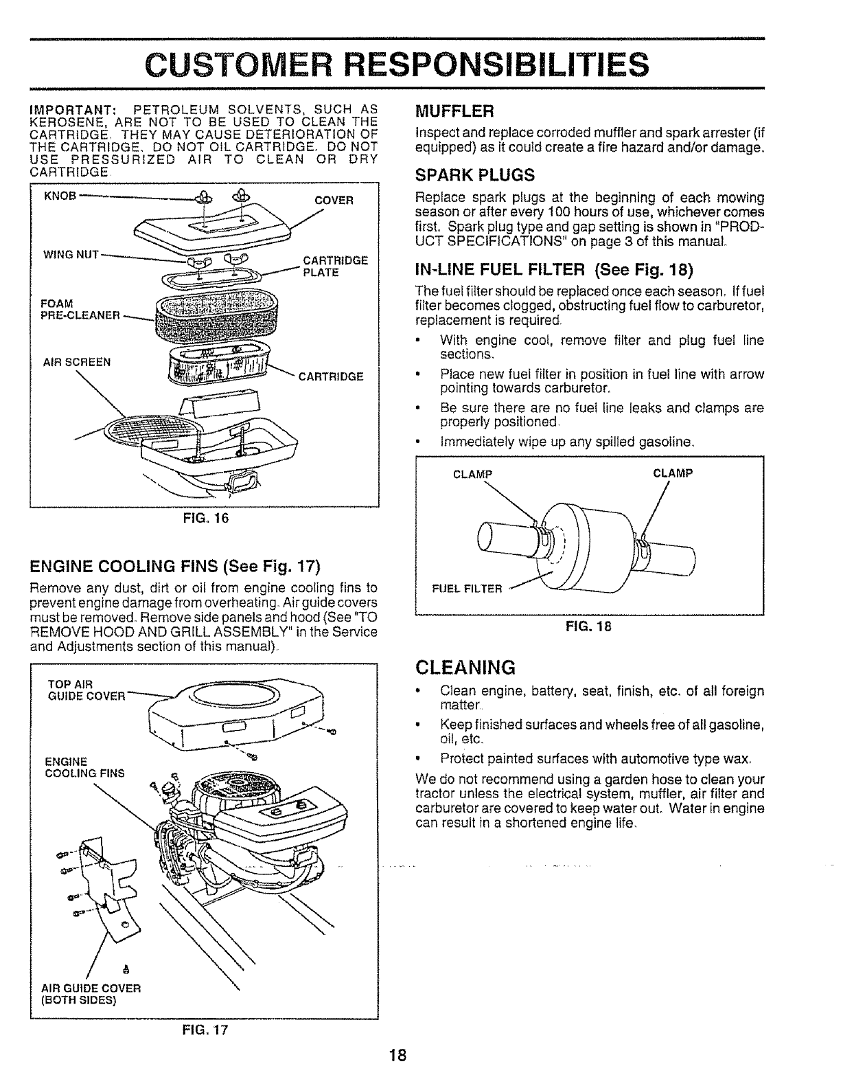
AIR FILTER (See Fig. 16)
Your engine will not run properly using a dirty air filter.
Clean the foam pre-cleaner element after every 25 hours of
operation or every season. Service paper cartridge every
100 hours or every season, whichever occurs first,,
Service air cleaner more often under dusty conditions_
. Remove knob(s) and cover.
TO SERVICE PRE-CLEANER
•Slide foam pre*cleaner off cartridge.
•Wash it in liquid detergent and water,
• Squeeze it dry in a clean cloth.
•Saturate it in engine oil, Wrap it in clean, absorbent
cloth and squeeze to remove excess oil
•If very dirty or damaged, repJace p!e-cleaner. •
•Reinstall pre-cleaner over cartridge.
• Reinstall cover and secure with knob(s),
TO SERVICE CARTRIDGE
° Remove wing nuts and cartridge plate°
.Carefully remove cartridge to prevent debris frorr
entering carburetor
.Ctean cartridge by tapping gently on flat surface,, tfver')
dirty or damaged, replace cartridge.
.Reinstall cartridge plate, wing nuts, precleaner, covel
and secure with knob(s),
i i iiii i i,iii iiiiii i
CUSTOMER RESPONSIBILITIES
i
IMPORTANT; PETROLEUM SOLVENTS, SUCH AS
KEROSENE, ARE NOT TO BE USED TO CLEAN THE
CARTRIDGE THEY MAY CAUSE DETERIORATION OF
THE CARTRIDGE° DO NOT OILCARTRtDGE DO NOT
USE PRESSUR!ZED AIR TO CLEAN OR DRY
CARTRIDGE
FOAM
PRE-CLEANER -_.
AIR SCREEN
CARTRIDGE
FIG. 16
ENGINE COOLING FINS (See Fig. 17)
Remove any dust, dirt or oil from engine cooling fins to
prevent engine damage from overheating_ Air guide covers
must be removed. Remove side panels and hood (See "TO
REMOVE HOOD AND GRILL ASSEMBLY" in the Service
and Adjustments section of this manual)
ENGINE
COOLING FINS
/,
AIR GUIDE COVER
(BOTH SIDES)
\
MUFFLER
Inspect and replace corroded muffler and spark arrestor (if
equipped) as it could create a fire hazard and/or damage°
SPARK PLUGS
Rep!ace spark plugs at the beginning of each mowing
season or after every 100 hours of use, whichever comes
first. Spark plug type and gap setting is shown in "PROD-
UCT SPECIFICATIONS" on page 3 of this manual.
IN-LINE FUEL FILTER (See Fig. 18)
The fuel filter should be replaced once each season_ If fuel
filter becomes clogged, obstructing fuel flow to carburetor,
rep!acement is required
•With engine coo!, remove filter and plug fuel line
sections.
•Place new fuel filter in position in fuel line with arrow
pointing towards carburetor_
• Be sure there are no fuel tine leaks and clamps are
properly positioned
• Immediately wipe up any spilled gasoline.
CLAMP CLAMP
FIG. 18
CLEANING
• Clean engine, battery, seat, finish, etc. of all foreign
matter
• Keep finished surfaces and wheels free of all gasoline,
oil, etc.
• Protect painted surfaces with automotive type wax°
We do not recommend using a garden hose to clean your
tractor unless the electrical system, muffler, air filter and
carburetor are covered to keep water ouL Water in engine
can result in a shortened engine life.
FIG. 17
18
n ...................... IIIIJlH n II IIIIIII I II1'11'
SERVICE AND ADJUSTMENTS
i ii iii1,1 iii i ii iii1,1,1 , IIHII iii i iiii1,11111111,1,1 ii iiiiiiiii i i
CAUTION: BEFORE PERFORM|NG ANY SERVICE OR ADJUSTMENTS:
&:t
Depress clutch/brake pedal fully and set parking brake.
Place gearshift lever in neutral (N) position.
Place attachment clutch in "DISENGAGED" position,
Turn ignition key "OFF" and remove key.
Make sure the blades and all moving parts have completely stopped.
Disconnect spark plug wire from spark plug and place wire where it cannot come in contact with
plugo
TRACTOR
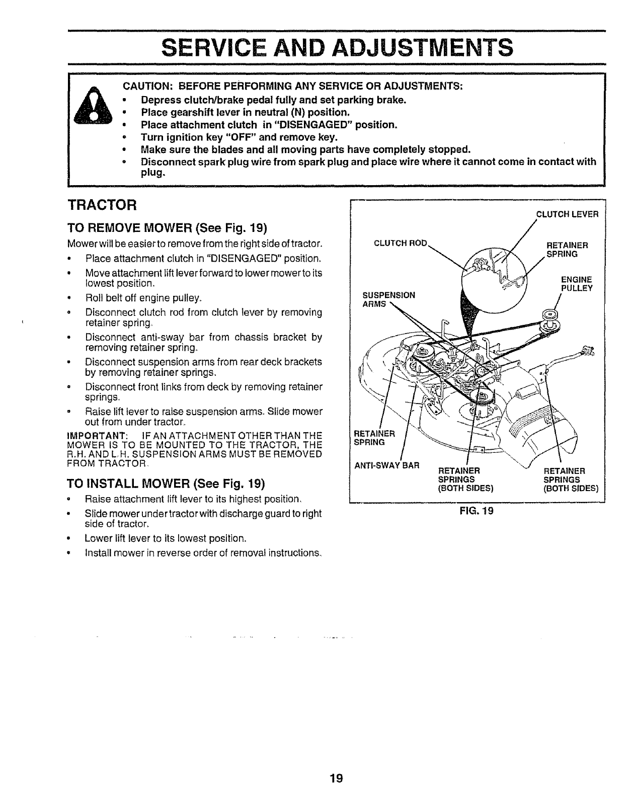
TO REMOVE MOWER (See Fig. 19)
Mower will be easier to remove from the right side of tractor,
• Place attachment clutch in "DISENGAGED" position,
•Move attachment lift lever forward to lower mower to its
lowest position_
• Roll belt off engine pulley..
• Disconnect clutch rod from clutch lever by removing
retainer spring
• Disconnect anti-sway, bar from chassis bracket by
removing retainer spnng_
•Disconnect suspension arms from rear deck brackets
by removing retainer springs,
• Disconnect front links from deck by removing retainer
springs.
• Raise lift lever to raise suspension arms,. Slide mower
out from under tractor,
IMPORTANT: IF AN ATTACHMENT OTHER THAN THE
MOWER IS TO BE MOUNTED TO THE TRACTOR, THE
R.H. AND L,H, SUSPENSION ARMS MUST BE REMOVED
FROM TRACTOR,
TO INSTALL MOWER (See Fig. 19)
•Raise attachment lift lever to its highest position,
• Slide mower under tractor with discharge guard to right
side of tractor,
• Lower lift lever to its lowest position.
° Install mower in reverse order of removal instructions_
CLUTCH LEVER
CLUTCH ROD RETAINER
SPRING
SUSPENSION
ARMS
ENGINE
PULLEY
RETAINER
SPRING
ANTI-SWAY BAR RETAINER
SPRINGS
(BOTH SIDES)
RETAINER
SPRINGS
(BOTH SIDES)
FIG, 't9
19
===11,,,=111,1
SERVICE AND ADJUSTMENTS
j,_ .............. iiii iiii ,i, i i i , i,i iii i
TO LEVEL MOWER HOUSING
Adjust the mower while tractor is parked on level ground or
driveway. Make sure tires are properly inflated (See
"PRODUCT SPECIFICATIONS" on page 3 of this manua0o
Iftires are over or underinfiated, you will not properly adjust
your mower.
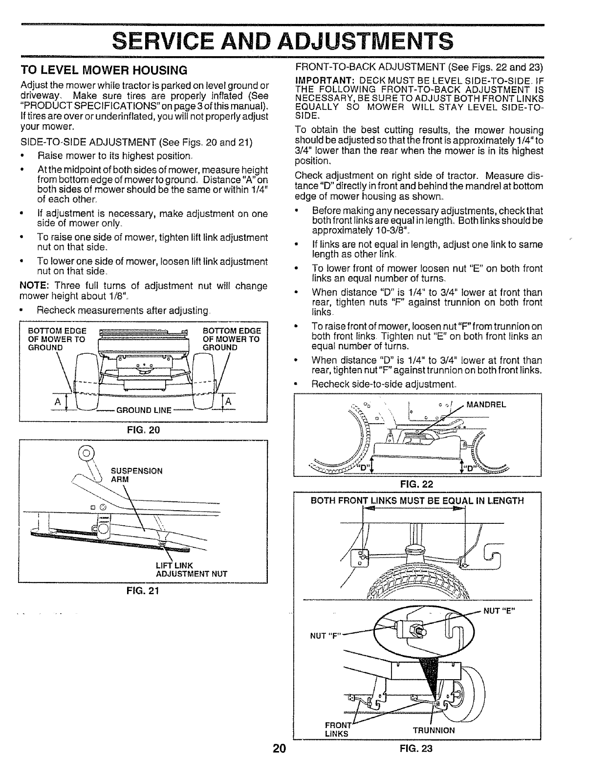
SIDE-TO_SIDE ADJUSTMENT (See Figs. 20 and 21)
,, Raise mower to its highest position_
• Atthe midpoint of both sides of mower, measure height
from bottom edge of mower to ground. Distance"A" on
both sides of mower should be the same or within 1/4"
of each other,
• if adjustment is necessary, make adjustment on one
side of mower only..
• To raise one side of mower, tighten lift link adjustment
nut on that side_
• To lower one side of mower, loosen lift link adjustment
nut on that side
NOTE: Three fun turns of adjustment nut wilI change
mower height about 1/8'L
° Recheck measurements after adjusting.
BOTTOM EDGE _ _, _ BOTTOM EDGE
O MOWERTO,- OFMOWE.TO
GROUN D
FIG, 20
@
SUSPENSION
ARM
LIFT LINK
ADJUSTMENT NUT
FIG. 21
FRONT-TO-BACK ADJUSTMENT (See Figs. 22 and 23)
IMPORTANT. DECK MUST BE LEVEL SIDE-TO-SIDEo IF
THE FOLLOWING FRONT-TO-BACK ADJUSTMENT IS
NECESSARY, BE SURE TO ADJUST BOTH FRONT LINKS
EQUALLY SO MOWER WILL STAY LEVEL SIDE-TO-
SIDE.
To obtain the best cutting results, the mower housing
should be adjusted so that the front is approximately 1/4" to
3/4" lower than the rear when the mower is in its highest
position.
Check adjustment on right side of tractor. Measure dis-
tance "D" directly infront and behind the mandrel at bottom
edge of mower housing as shown..
•Before making any necessary adjustments, checkthat
both front links are equal in length° Both links should be
approximately 10-3/8"o
• If links are not equal in length, adjust one link to same
length as other link.
•To lower front of mower loosen nut "E" on both front
links an equal number of turns.
• When distance "D" is 1/4" to 3/4" lower at front than
rear, tighten nuts "F" against trunnion on both front
links
• To raise front of mower, Ioosen nut"F"from trunnion on
both front links Tighten nut "E" on both front links an
equal number of turns°
. When distance "D" is !/4" to 3/4" lower at front than
rear, tighten nut"F" against trunnion on both front links.
. Recheck side4o-side adjustment.
":'.% I _ o/I. MANDREL
•
FIG. 22
BOTH FRONT LINKS MUST BE EQUAL IN LENGTH
'/_"'-'_ __ I _'_ IIfQq _ NUT"E"
1 °
FRO
LINKS TRUNNION
20 FIG. 23
u...............................
SERVICE AN
ii ii ii ii ,n ii, i ii iii ii
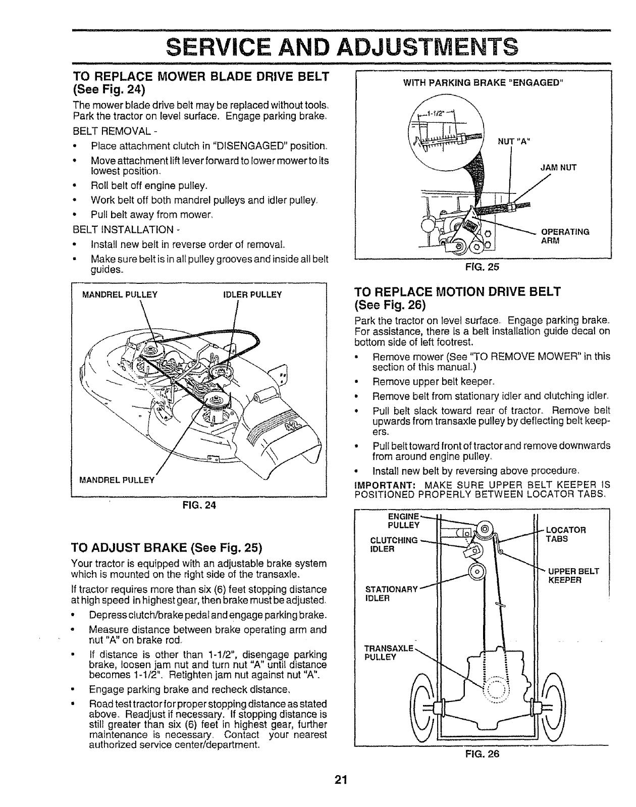
TO REPLACE MOWER BLADE DRIVE BELT
(See Fig. 24)
The mower blade drive belt may be replaced withouttoot&
Park the tractor on level surface. Engage parking brake.
BELT REMOVAL-
• Place attachment clutch in "DISENGAGED" position..
• Move attachment lift lever forward to lower mowerto its
lowest position.
• Roll belt off engine pulley.
• Work belt off both mandrel pulleys and idler pulley,
• Pull belt away from mowerr.
BELT {NSTALLATION
, Install new bett in reverse order of removal
• Make sure belt is inall pulley grooves and insideatl belt
guides,,
ADJUSTMENTS
nil ...................... inl i
WITH PARKING BRAKE "ENGAGED"
NUT "A"
MNUT
FIG. 25
MANDREL PULLEY IDLER PULLEY
MANDREL PULLEY
FIG. 24
TO REPLACE MOTION DRIVE BELT
(See Fig. 26)
Park the tractor on level surface_ Engage parking brake,.
For assistance, there is a belt installation guide decal on
bottom side of left footrest,
• Remove mower (See 'q'O REMOVE MOWER" in this
section of this manual,,)
-Remove upper belt keeper.
.Remove belt from stationary idler and clutching id_er.
oPull belt slack toward rear of tractor. Remove belt
upwards from transaxle pulley by deflecting belt keep-
ers.
•Pull belt toward front of tractor and remove downwards
from around engine pulley,,
-Install new bett by reversing above procedure.
IMPORTANT: MAKE SURE UPPER BELT KEEPER IS
POSITIONED PROPERLY BETWEEN LOCATOR TABS.
TO ADJUST BRAKE (See Fig. 25)
Your tractor is equipped with an adjustable brake system
which is mounted on the right side of the transaxle.
If tractor requires more than six (6) feet stopping distance
at high speed in highest gear, then brake must be adjusted,
•Dep ress clutch/brake pedal and engage parking brake_
-Measure distance between brake operating arm and
nut "A" on brake rod.
r " "
• If distance is othe than t-1/2, disengage parking
brake, loosen jam nut and turn nut "A" until distance
becomes 1-1/2"_ Retighten jam nut against nut "A".
• Engage parking brake and recheck distance.
• Road test tractor fo rproper stopping distance as stated
above, Readjust if necessary. If stopping distance is
stil_ greater than six (6) feet in highest gear, further
maintenance is necessary. Contact your nearest
authorized service center/departmento
PULLEY
IDLER
IDLER
PULLEY
FIG. 26
LOCATOR
_ER BELT
KEEPER
21
TO ADJUST STEERING WHEEL ALIGNMENT
If steering wheel crossbars are not horizontal (left to right)
when wheels are positioned straight forward, remove steer-
ing wheel and reassemble per instructions in the Assembly
section of this manual°
FRONT WHEEL TOE-IN/CAMBER
The front whee_ toe-in and camber are not adjustable on
your tractor. If damage has occurred to affect the front
wheel toe-in or camber, contact your nearest authorized
service center.
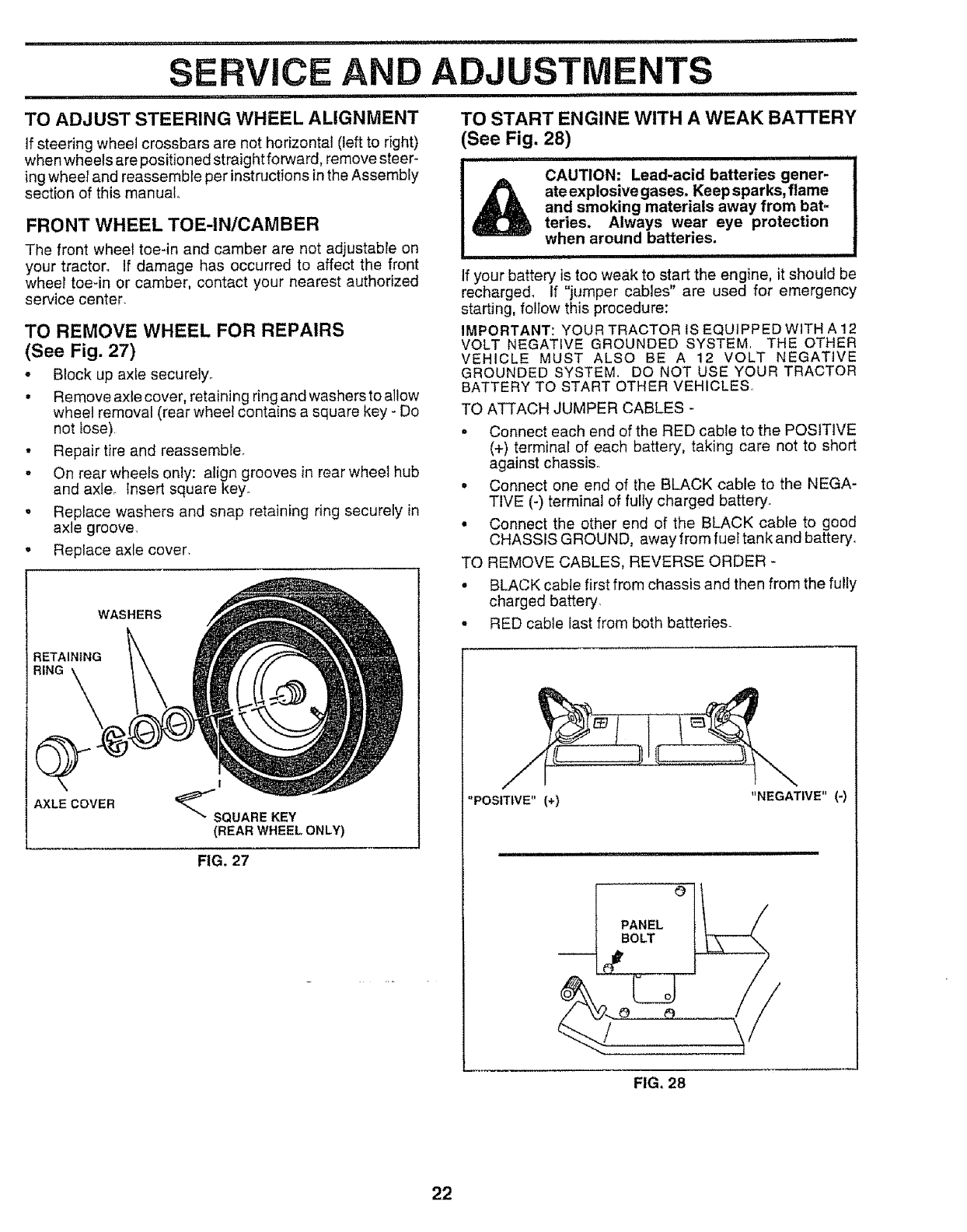
TO REMOVE WHEEL FOR REPAIRS
(See Fig. 27)
•B_ock up axle securelyo
• Remove axle cover, retaining ring and washers to allow
wheel removal (rear wheel contains a square key - Do
not lose)
• Repair tire and reassemble.
o On rear wheels only: align grooves in rear wheel hub
and axle, insert square key°
° Replace washers and snap retaining ring securely in
axle groove.
• Replace axle cover.
WASHERS
RETAINING
RING
AXLE COVER
!
(REAR WHEEL ONLY)
FIG. 27
TO START ENGINE WITH A WEAK BATTERY
See Fig. 28)
..................... i H H
CAUTION: Lead-acid batteries gener-
_ateexplosivegases. Keep sparks, flame
and smoking materials away from bat_
teries. Always wear eye protection
when around batteries.
iii ii iii iiiiiiiii1,111 i i iiiiiiii1,111111
If your battery is too weak to start the engine, it should be
recharged_ If "jumper cables" are used for emergency
starting, follow this procedure:
IMPORTANT: YOUR TRACTOR IS EQUIPPED WITH A 12
VOLT NEGATIVE GROUNDED SYSTEM. THE OTHER
VEHICLE MUST ALSO BE A 12 VOLT NEGATIVE
GROUNDED SYSTEM. DO NOT USE YOUR TRACTOR
BATTERY TO START OTHER VEHICLES.
TO ATTACH JUMPER CABLES -
• Connect each end of the RED cable to the POSITIVE
(+) terminal of each battery, taking care not to short
against chassis.
°Connect one end of the BLACK cable to the NEGA-
TIVE (-) terminal of fully charged battery.
• Connect the other end of the BLACK cable to good
CHASSIS GROUND, away from fuel tank and battery_
TO REMOVE CABLES, REVERSE ORDER -
°BLACK cable first from chassis and then from the fully
charged battery
°RED cable last from both batteries_
"POSITIVE" (+) "NEGATIVE"(-)
O
PANEL
BOLT
FIG, 28
22
iii iiiii i 1,1,11 ill, iiii, i ii1,1 ...................................... ...................
SERVICE AND ADJUSTMENTS
iqIIIIIHI III ....................................... I'1.................... I' I
TO REPLACE HEADLIGHT BULB ENGINE
•Raise hood TO ADJUST THROTTLE CONTROL CABLE
• Pull bulb holder out of the hole in the backside of the (See Fig. 30)
grill° The throttle control has been preset at the factory and
° Replace bulb in holder and push bulb holder securely adjustment should not be necessary Check adjustment as
back into the hole in the backside of the grill described below before loosening cable tf adjustment is
•Close hood necessary, proceed as follows:
• With engine not running, move throttle control lever to
fast (,_) position
• Check that swivel is against side of quarter circle If it
is not, loosen cable clamp screw and pull cable back
until swivel is against quarter circle° Tighten cabIe
clamp screw securely
INTERLOCKS AND RELAYS
Loose or damaged wiring may cause your tractor to run
poorly stop running or prevent it from starting
• Check wiring. See electrical wiring diagram in Repair
Parts section of this manual
TO REPLACE FUSE
Replace with 30 amp automotive-type plug-in fuse° The
fuse holder is located behind the dash
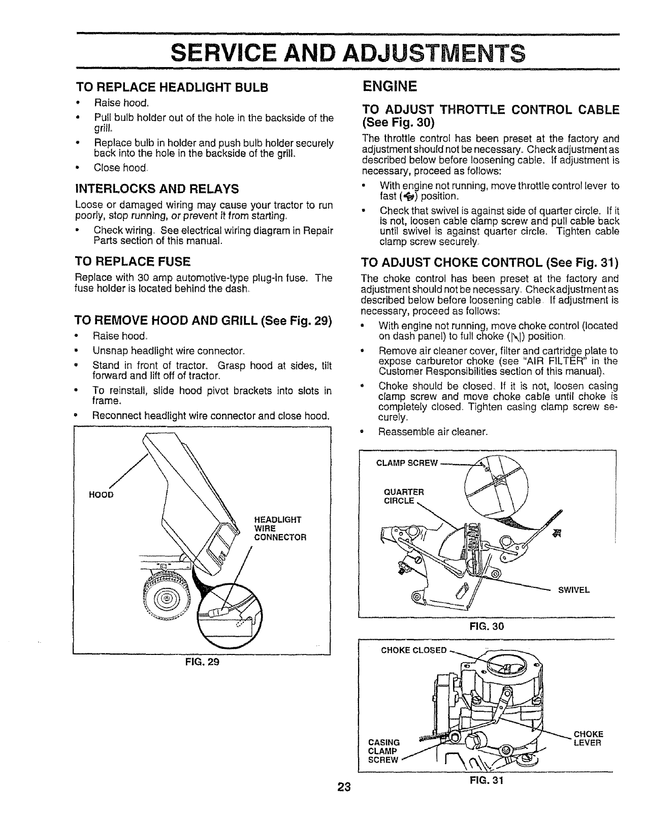
TO REMOVE HOOD AND GRILL (See Fig. 29)
• Raise hood
• Unsnap headlight wire connector
= Stand in front of tractor Grasp hood at sides, titt
forward and lift off of tractor
•To reinstall, slide hood pivot brackets into slots in
frame°
o Reconnect headlight wire connector and close hood
HOOD
HEADLIGHT
WIRE
CONNECTOR
FIG. 29
TO ADJUST CHOKE CONTROL (See Fig. 31)
The choke control has been preset at the factory and
adjustment should not be necessary Check adjustment as
described below before loosening cable If adjustment is
necessary, proceed as follows:
• With engine not running, move choke control (located
on dash panel) to full choke (1\1) position
,Remove air cleaner cover, filter and cartridge plate to
expose carburetor choke (see "AIR FILTER" in the
Customer Responsibilities section of this manual)
,Choke should be closed If it is not, loosen casing
clamp screw and move choke cable until choke is
completely closed Tighten casing clamp screw se
curelyo
,Reassemble air cleaner
CLAMP
QUARTER
CIRCLE
SWIVEL
FIG. 30
CHOKE CLOSED
CAS{NG
CLAMP
SCREW
CHOKE
FIG. 31
23
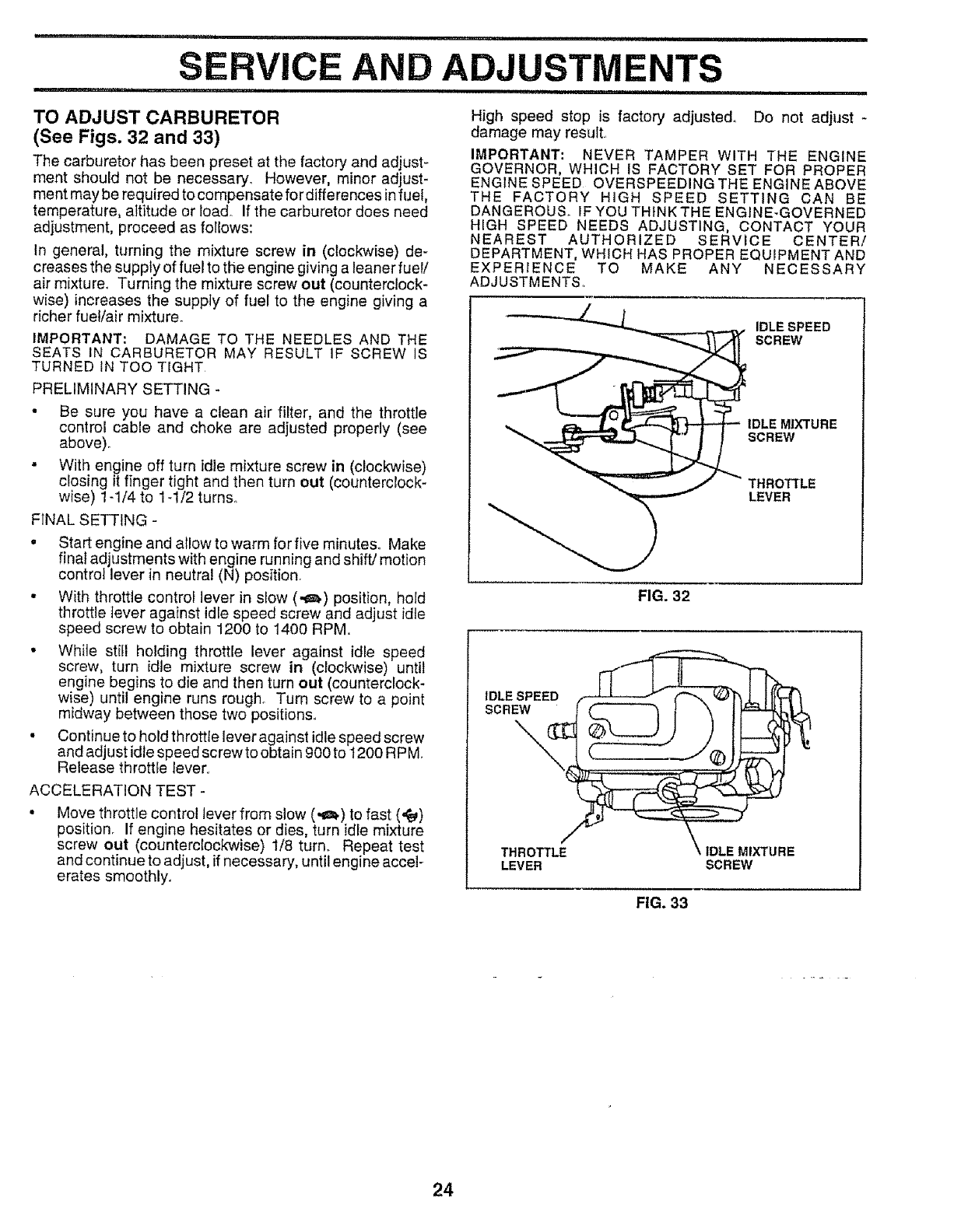
,11,111111,1,,11ii, i i,,111i iii i ,i,iiiiiiiii1,11 iiii
AND ADJUSTMENTS
,1111 ,11,111,,, i, iiiii ........................... i,i1,111 iI i i
TO ADJUST CARBURETOR
(See Figs. 32 and 33)
The carburetor has been preset at the factory and adjust-
ment should not be necessary_ However, minor adjust-
ment may be required to compensate for differences infuel,
temperature, altitude or load. If the carburetor does need
adjustment, proceed as follows:
In general, turning the mixture screw in (clockwise) de-
creases the supply of fuel to the engine giving a leaner fuel/
air mixture. Turning the mixture screw out (counterclock-
wise) increases the supply of fuel to the engine giving a
richer fuel/air mixture.
IMPORTANT: DAMAGE TO THE NEEDLES AND THE
SEATS IN CARBURETOR MAY RESULT iF SCREW IS
TURNED IN TOO TIGHT
PRELIMINARY SETTING -
• Be sure you have a clean air filter, and the throttle
control cable and choke are adjusted properly (see
above)_
• With engine off turn idle mixture screw in (clockwise)
closing it finger tight and then turn out (counterclock-
wise) 1-1/4 to 1-1/2 turns.
FINAL SETTING -
,Start engine and allow to warm for five minutes.. Make
fina_adjustments with engine running and shift/motion
control lever in neutral (N) position.
• With throttle control lever in slow (,_) position, hold
throttle tever against idle speed screw and adjust idle
speed screw to obtain 1200 to 1400 RPM..
• While still holding throttle lever against idle speed
screw, turn idle mixture screw in (clockwise) until
engine begins to die and then turn out (counterclock-
wise) until engine runs rough. Turn screw to a point
midway between those two positions..
• Continue to hold throttle lever against idle speed screw
and adjust idle speed screw to obtain 900 to 1200 R PM
Release throttfe lever°
ACCELERATION TEST -
Move throttle control lever from slow (,_=_)to fast (,_)
position° If engine hesitates or dies, turn idle mixture
screw out (counterclockwise) 1/8 turn. Repeat test
and continue to adjust, if necessary, until engine accel-
erates smoothly.
High speed stop is factory adjusted° Do not adjust -
damage may resutt.
IMPORTANT" NEVER TAMPER WITH THE ENGINE
GOVERNOR, WHICH IS FACTORY SET FOR PROPER
ENGINE SPEED OVERSPEEDING THE ENGINE ABOVE
THE FACTORY HiGH SPEED SETTING CAN BE
DANGEROUS. IF YOU THINK THE ENGINE-GOVERNED
HiGH SPEED NEEDS ADJUSTING, CONTACT YOUR
NEAREST AUTHORIZED SERVICE CENTER/
DEPARTMENT, WHICH HAS PROPER EQUIPMENT AND
EXPERIENCE TO MAKE ANY NECESSARY
ADJUSTMENTS,
THROTTLE
LEVER
FIG. 32
IDLE SPEED
SCREW
/
THROTTLE
LEVER
_E MIXTURE
SCREW
FIG. 33
24
lmmediatety prepare your tractor for storage at the end of
the season or if the tractor will not be used for 30 days or
mo re.
CAUTION: Never store the tractor with
gasoline in the tank inside a building
where fumes may reach an open flame
or spark. Allow the engine to cool
before storing in any enclosure.
=,u,,n'r
TRACTOR
Remove mower from tractor for winter storage. When
mower is to be stored for a period of time, clean it thor-
oughly, remove al! dirt, grease, leaves, etc_ Store in a
clean, dry area
= Clean entire tractor (See"CLEANING" inthe Customer
Responsibilities section of this manual).
=Inspect and replace belts, if necessary (See belt re-
placement instructions inthe Service and Adjustments
section of this manual).
- Lubricate as shown in the Customer Responsibilities
section of this manual
• Be sure that all nuts, bolts and screws are securely
fastened, Inspect moving parts fordamage, breakage
and wear. Replace if necessary.
• Touch up all rusted or chipped paint surfaces; sand
Iightly before painting.
BATTERY
.Fully charge the battery for storage_
-After a period of time in storage, battery may require
recharging
• To help prevent corrosion and power leakage during
long periods of storage, battery cables should, ` be
disconnected and battery cleaned thorou,ghly (see TO
CLEAN BATTERY AND TERMINALS in the Cus-
tomer Responsibilities section of this manual).
• After cleaning, leave cables disconnected and place
cables where they cannot come in contact with battery
terminals.
,, Be sure battery drain tube is securely attached
•If battery is removed from tractor for storage, do not
store battery directly on concrete or damp surfaces.
ENGINE
FUEL SYSTEM
IMPORTANT: IT IS IMPORTANT TO PREVENT GUM
DEPOSITS FROM FORMING IN ESSENTIAL FUEL
SYSTEM PARTS SUCH AS CARBURETOR, FUEL FILTER,
FUEL HOSE, OR TANK DURING STORAGE. ALSO,
EXPERIENCE INDICATES THAT ALCOHOL BLENDED
FUELS (CALLED GASOHOL OR USING ETHANOL OR
METHANOL) CAN ATTRACT MOISTURE WHICH LEADS
TO SEPARATION AND FORMATION OF ACIDS DURING
STORAGE, ACIDIC GAS CAN DAMAGE THE FUEL
SYSTEM OF AN ENGINE WHILE IN STORAGE.
- Drain the fuel tank,
• Start the engine and let it run until the fuel lines and
carburetor are empty.
, Never use engine or carburetor cleaner products in the
fuel tank or permanent damage may occur
• Use fresh fuel next season
NOTE: Fuel stabilizer is an acceptable alternative in
minimizing the formation of fuel gum deposits during stor-
age Add stabilizer to gasoline in fuef tank or storage
container,. Always follow the mix ratio found on stabilizer
container, Run engine at least 10 minutes after adding
stabilizer to alfow the stabilizer to reach the carburetor. Do
not drain the gas tank and carburetor if using fuel stabilizer
ENGINE OIL
Drain oil (with engine warm) and reptace with clean engine
oil (See "ENGINE" in the Customer Responsibilities
section of this manual)
CYLINDERS
° Remove spark ptug(s)
-Pour one ounce of oit through spark plug hole(s) into
cylinder(s).
•Turn ignition key to"START" position for a few seconds
to distribute oiL
,, Replace with new spark plug(s).
OTHER
° Do not store gasoline from one season to another.
• Replace your gasoline can if your can starts to rust
Rust and/or dirt in your gasoline will cause problems
• If possible, store your tractor indoors and cover it tc
give protection from dust and dirt.
. Cover your tractor with a suitable protective cover tha
does not retain moisture_ Do not use plastic. Piasti(
cannot breathe which allows condensation to form ant
will cause your tractor to rust
IMPORTANT: NEVER COVER TRACTOR WHILE ENGINE
AND EXHAUST AREAS ARE STILL WARM
25

TRO
i i ,i,iii1,11,,,11,1111,1,i nUll
CAUSE CORRECTION
i,inll
LESHOOTING POINTS
ii ........................................................................
PROBLEM
Will not start
ii i i,lUln,,,
Hard to start
Engine will not turn over
Engine ct_cks but will not
start
m
Loss of power
Excessive vibration
1 Out of fuel
2 Engine not "CHOKED" properly
3 Engine flooded
4 Bad sparkplug
5 Dirty air filter
6 Dirty fuel fitter,
7 Water in fue_
8 Looseor damaged wiring
9 Carburetor out of adjustment,
10 Engine valves out of adjustment
1 Dirty air filter
2Bad spark plug
3 Weak or dead battery
4 Didy fuel filter
5 Stale ordirty fuel
6, Loose or damaged wiring
7 Carburetor out of adjustment
8 Engine valves out of adiustment.
1 Clutch/brake pedal not depressed
2 Attachment clutch is engaged
3 Weak or dead battery
4 Blown fuse
5 Corroded batteryterminats
6 Loose or damaged wiring
7Faulty ignition switch
8 Faulty solenoid or starter
9 Faulty operator presence switch(as)
1 Weak or dead battery
2 Corroded battery terminals
3 Loose or damaged wiring
4 Faulty solenoid or starter
t Cutting too much grass!too last
2 Throttle in "CHOKE" position
3 Build-up of grass, leaves and trash under mower
4 Dirty air filter
5Low oil level/dlrty oil
6 Faulty spark plug
7Dirty fuel filter
8 Stale or dirty fuel
9 Water in fuel
10 Spark plug wire loose
11 Dirty engine air screen/fins
12 Dirty!clogged muffler
13 Loose or damaged wiring,
t4 Carburetor out of adjustment
t5 Engine valves cut of adjustment
1 Worn, bent or loose blade
2 Bent blade mandrel
3 Loose/damaged part(s)
1 Fi$lfuel tank
2, See "TO START ENGINE" in Operation section.
3 Wait several minutes before attempting to start,
4 Replace spark plug
5 Clean/replace air filter,
6 Replace fuel filter
7 Drain fuel tank and carburetor, refill tank with fresh
gasoline and replace fuel filter
8 Check all widng
9 Contact an authorized servicecenter/department
10 Contact an authorized service center/department,
1 Clean/replace air filter
2 Reptace spark plug
3 Recharge or replace battery
4 Replace fuef filter
5 Drain fuel tank and refill with fresh gasoline
6 Check all wiring
7 Contact an authorized service center/department,
8 Contact an authorized service center!department
t Depress clutch/brake pedal_
2 Disengage attachment cJutch
3 Recharge or replace battery
4 Replace fuse
5 Clean battery terminals
6 Check all wiring
7 Check/replace ignition switch
8 Check/replace solenoid or starter
9 Contact an authorized service center!department
! Recharge or replace battery
2 Clean battery terminals
3 Check all wiring
4 Check/replace solenoid or starter
1 Set in "Higher Cut" positfonlreduce speed
2 Adjust throttle control
3Clean underside of mower housing
4 Clean!replace air filter
5 Check oil leveIfchange oil
6 Clean and regap or change spark plug
7 Replace fuel tilter
8 Drain fuel tank and refill with fresh gasoline
9 Drain fuel iank and carburetor, refill tank with fresh
gasoline and replace fuel filter
10 Connect and tighten spark plug wire
lt, Clean engine air screen/fins
12 Clean/replace muffler
13 Check all wiring
14, Contact an authorized service center/department,
15 Contact ah authorized service center/department
1 Replace blade, Tighten blade bolt
2 Replace blade mandrel
3 Tighten loose part(s) Replace damaged parts,
26

= ................... i ul,= ..........................................
TROUBLESHOOTING POINTS
PROBLEM
Engine continues to run
when operator leaves seat
with attachment clutch
engaged
Poor cut* uneven
i mn,
Mower blades wit1 not
rotate
Poor grass discharge
u =,= ==
Headlight(s) not working
(ff so equipped)
Battery will not charge
Engine "backfires"
when turning engine
"OFF"
CAUSE
1Faulty operator-safety presence controi system
1 Worn, bent orloose blade
2 Mower deck not levei
3 Buildup of grass, leaves, and trash under mower
4 Bent blade mandrel
5 Clogged mower deck vent holes from buildup of
grass, leaves, and trash around mandrels.
II = n,U,H= 1' n= = ,1
1 Obstruction in clutch mechanism
2, Worn/damaged mower dflve heft
3 Frozen ld[er pu_ey
4 Frozen blade mandrel
1 Engine speed too slow
2. Travel speed too fast
3 Wet grass
4 Mower deck not fevel
5 Low/uneven tire air pressure
6 Wom, bent or loose blade
7 Buildup of grass, leaves and trash under mower_
8 Mower drive bett worn
9 Blades improperly installed
10 improper blades used.
11 Clogged mower deck vent holes from buildup of
grass, leaves, and trash around mandrels
1 Switch is "OFF"
2 Bulb(s) burned out
3 Faulty light switch
4 Loose or damaged wiring.
5. Blown fuse
1 Bad battery cetE(s)_
2 Poor cable connections
3Faulty regulator (if so equipped)
4Faulty alternator
Engine throttle control not set at "SLOW"
position for 30 seconds before stopping engine
CORRECTION
,,,, = i ,,.,
l Check wiring, switches and connections If not
corrected, contact an authorized service center/
department
1, Replace blade Tighten b{ade bolt
2 Level mower deck
3, C_ean underside of mower housing
4_ Replace blade mandrel,
5 Clean around mandrels to open vent holes
1 Remove obstruction
2 Reptace mower drive belt
3 Replace idler pulley.
4 Replace blade mandrel
1 Place throttle control in "FAST" position
2 Shift to slower speed.
3 Allow grass to dry before mowing
4. Level mower deck
5 Checktires for proper air pressure
6 Replace/sharpen blade Tighten blade bolt
7 Clean underside of mower housing.
8. Replace mower drive belt
9 Reinstall blades sharp edge down
10 Reptace with blades listed in this manual
11 Clean around mandrels to open vent holes
1 Turn switch "ON"
2 Replace bulb(s).
3 Check!replace tight switch.
4 Check widng and connections
5 Replace fuse
1 Repface battery
2 CheckJciean all connections
3, Replace regulator
4 Replace alternator
1 Move throttle control to "SLOW" position and aITow
to idle for 30 seconds before stopping engine.
27

RVICE
28
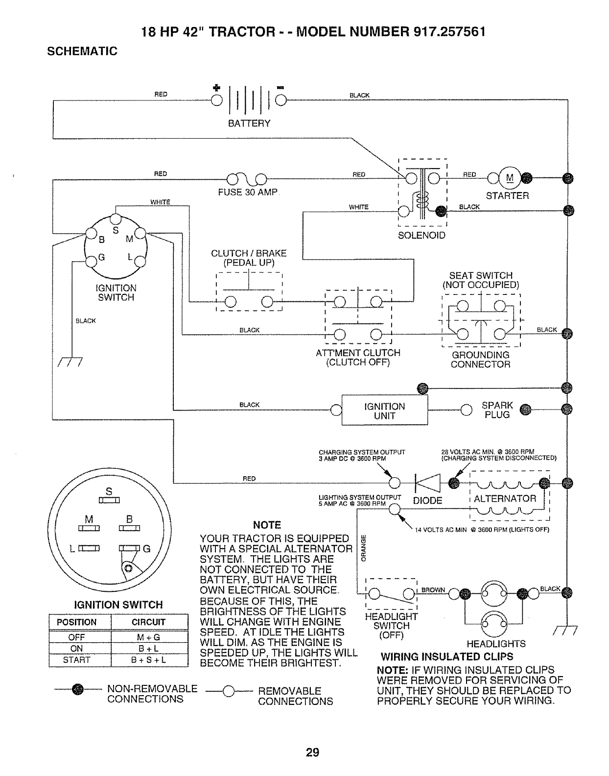
SCHEMATIC
18 HP 42" TRACTOR - - MODEL NUMBER 917.257561
J
F
RED
RED
WHITE
IGNiTiON
SWITCH
BLACK
-7
M
oltto
BATTERY
FUSE 30 AMP
CLUTCH /BRAKE
(PEDAL UP)
II........ 1I
---@ O'
I J
BLACK
BLACK
RED I
_'--" IH v_
SOLENOID
SEAT SWITCH
(NOT OCCUPIED)
I i I I I
I f I"1 t-
I
,"0 0 j _,
ATT'MENT CLUTCH GROUNDING
(CLUTCH OFF) CONNECTOR
STARTER
8LACK _
8LACK_ )
l
}
BLACK
@
(_ IGNITION _) SPARK _UNIT PLUG
CHARGING SYSTEM OUTPUT
3AMP DC @ 3600 RPM
28 VOLTS AC MIN, @ 3600 RPM
(CHARGING SYSTEM DISCONNECTED)
RED
IGNITION SWITCH
POSITION CIRCUIT
OFF M + G
ON B+L
START B + S + L
NOTE
YOUR TRACTOR IS EQUIPPED
WITH A SPECIAL ALTERNATOR
SYSTEM. THE LIGHTS ARE
NOT CONNECTED TO THE
BATTERY, BUT HAVE THEIR
OWN ELECTRICAL SOURCE..
BECAUSE OF THIS, THE
BRIGHTNESS OF THE LIGHTS
WILL CHANGE WiTH ENGINE
SPEED. AT IDLE THE LIGHTS
WILL DIM. AS THE ENGINE IS
SPEEDED UP, THE LIGHTS WILL
BECOME THEIR BRIGHTEST°
NON-REMOVABLE
CONNECTIONS 0 REMOVABLE
CONNECTIONS
I
LIGHTING SYSTEM OUTPUT
5AMPAC DIODE _ALTERNATOR
_j
14 VOLTS AC MIN @ 3600 RPM (LIGHTS OFF)
I11
o
z
<
O
___.___li_]_l I BROWN BLACK
F......
HEADL,a 4I
SWITCH _-_u _ ri
(OFF) _ / /
HEADLIGHTS
WIRING INSULATED CLIPS
NOTE." IF WIRING INSULATED CLIPS
WERE REMOVED FOR SERVICING OF
UNIT, THEY SHOULD BE REPLACED TO
PROPERLY SECURE YOUR WIRING.
29
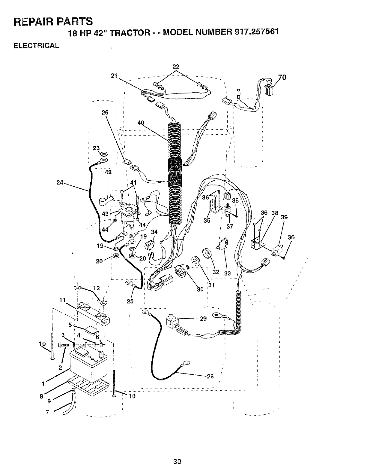
REPAIR PARTS
18 HP 42" TRACTOR -- MODEL NUMBER 917,257561
ELECTRICAL
22
20
25
35
36 38
30
32 33
39
36
30
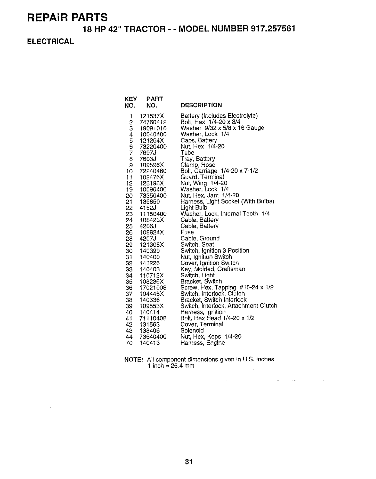
REPAIR PARTS
18 HP 42" TRACTOR -- MODEL NUMBER 917.257561
ELECTRICAL
KEY PART
NO. NO. DESCRIPTION
1 121537X
2 74760412
3 19091016
4 10040400
5 121264X
6 73220400
7 7697J
8 7603J
9 109596X
10 72240460
11 102476X
12 123198X
19 10090400
20 73350400
21 136850
22 4152J
23 11150400
24 108423X
25 4206J
26 108824X
28 4207J
29 121305X
30 140399
31 140400
32 141226
33 140403
34 t10712X
35 I08236X
36 17021008
37 104445X
38 140336
39 I09553X
4O 140414
41 71110408
42 131563
43 138406
44 73640400
70 140413
Battery (Includes Electrolyte)
Bolt, Hex 1/4-20 x 3/4
Washer 9/32 x 5/8 x !6 Gauge
Washer, Lock 1/4
Caps, Battery
Nut, Hex 1/4-20
Tube
Tray, Battery
Clamp, Hose
Bolt, Carriage 1/4-20 x 7-1/2
Guard, Terminal
Nut, Wing 1/4-20
Washer, Lock 1/4
Nut, Hex, Jam 1/4-20
Harness, Light Socket (With Bulbs)
Light Bulb
Washer, Lock, Internal Tooth 1/4
Cable, Battery
Cable, Battery
Fuse
Cable, Ground
Switch, Seat
Switch, Ignition 3 Position
Nut, Ignition Switch
Cover, Ignition Switch
Key, Molded, Craftsman
Switch, Light
Bracket, Switch
Screw, Hex, Tapping #10-24 x 1/2
Switch, Interlock, Clutch
Bracket, Switch Interlock
Switch, Interlock, Attachment Clutch
Harness, Ignition
Boit, Hex Head 1/4-20 x 1/2
Cover, Terminal
Solenoid
Nut, Hex, Keps 1/4-20
Harness, Engine
NOTE: All component dimensions given in US. inches
1 inch = 25.4 mm
31
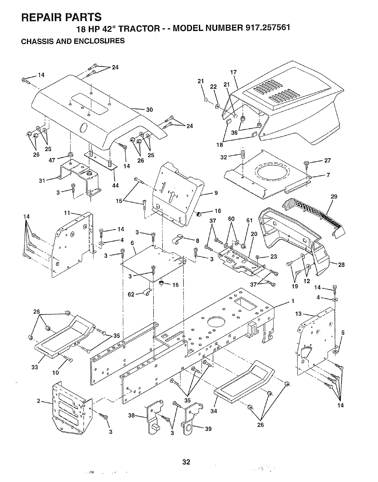
REPAIR PARTS
18 HP 42" TRACTOR - -MODEL NUMBER 917.257561
CHASSIS AND ENCLOSURES
24 17
31
14
26
25
26
44
16
60 6t
12
19
t3
29
33 10
38 34
26
14
32
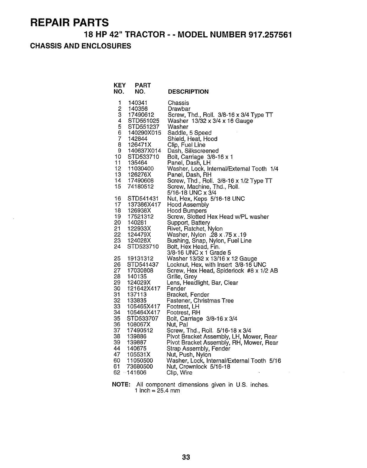
REPAIR PARTS
18 HP 42" TRACTOR --MODEL NUMBER 917.257561
CHASSIS AND ENCLOSURES
KEY PART
NO. NO. DESCRIPTION
1 140341
2 140356
3 17490612
4 STD551025
5 STD551237
6 140290X015
7 142844
8 126471X
9 140637X014
10 STD533710
11 135464
12 11030400
13 126276X
14 17490608
15 74180512
16 STD541431
17 137386X417
t8 126938X
19 17521312
20 140281
21 122933X
22 124479X
23 124028X
24 STD523710
25 19131312
26 STD541437
27 17030808
28 140135
29 124029X
30 121642X417
31 137113
32 133835
33 105465X417
34 105464X417
35 STD533707
36 108067X
37 17490512
38 139886
39 139887
44 140675
47 105531X
60 11050500
6! 73680500
62 141606
Chassis
Drawbar
Screw, Thd., Roll. 3/8-16 x 3/4 Type -IT
Washer 13/32 x 3/4 x 16 Gauge
Washer
Saddle, 5 Speed
Shield, Heat, Hood
Clip, Fuel Line
Dash, Silkscreened
Bolt, Carriage 3/8-16 x 1
Panel, Dash, LH
Washer, Lock, Internal/External Tooth 1/4
Panel, Dash, RH
Screw, Thd., Roll. 3/8-16 x t/2 Type TT
Screw, Machine, Thd. Rollo
5/16-18 UNC x 3/4
Nut, Hex, Keps 5/16-18 UNC
Hood Assembly
Hood Bumpers
Screw, Slotted Hex Head w/PL washer
Support, Battery
Rivet, Ratchet, Nylon
Washer, Nylon .28 x .75 x .19
Bushing, Snap, Nylon, Fuel Line
Bolt, Hex Head, Fin..
3/8-16 UNC x 1 Grade 5
Washer 13/32 x 13/16 x 12 Gauge
Locknut, Hex, with Insert 3/8-16 UNC
Screw, Hex Head, Spidedock #8 x 1/2 AB
Grille, Grey
Lens, Headlight, Bar, CIear
Fender
Bracket, Fender
Fastener, Christmas Tree
Footrest, LH
Footrest, RH
Bolt, Carriage 3/8-16 x 3/4
Nut, Pal
Screw, Thdo, Rollo 5/16-18 x 3/4
Pivot Bracket Assembly, LH, Mower, Rear
Pivot Bracket Assembly, RH, Mower, Rear
Strap Assembly, Fender
Nut, Push, Nylon
Washer, Lock, Internal/External Tooth 5/16
Nut, Crownlock 5/16-18
Clip, Wire
NOTE: Atl component dimensions given in U.S. inches.
1inch = 25°4 mm
33
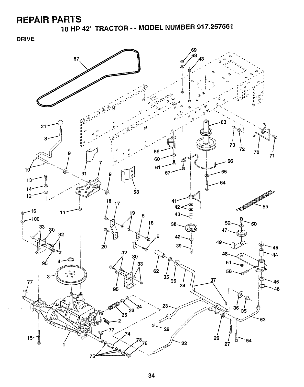
REPAIR PARTS
18 HP 42" TRACTOR - - MODEL NUMBER 917.257561
DRIVE
57
It
II
18
62
35 36 34
72
7'1
37
29
53
75
34
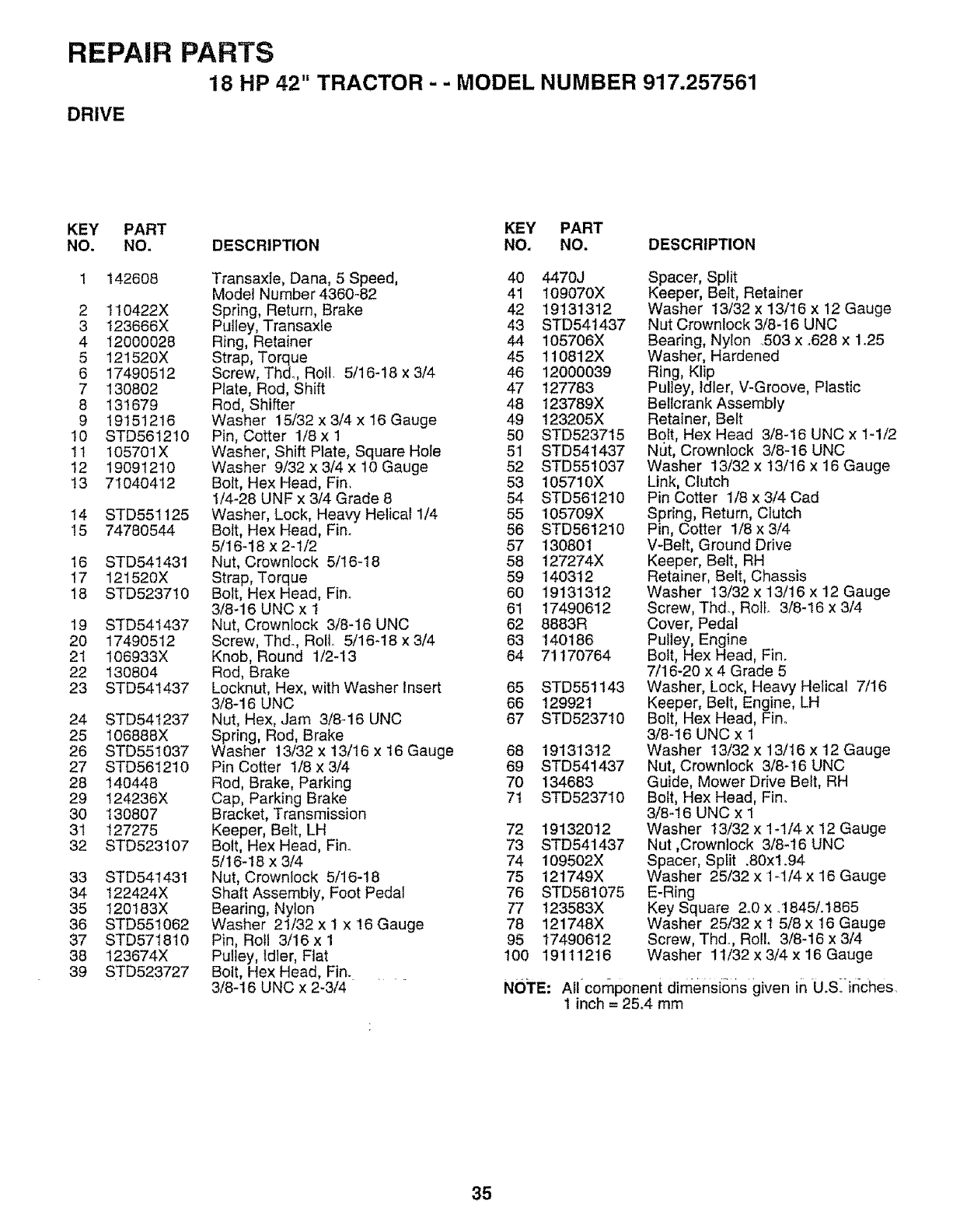
REPAIR PARTS
18 HP 42" TRACTOR - -MODEL NUMBER 917.257561
DRIVE
KEY PART KEY PART
NO. NO. DESCRIPTION NO, NO. DESCRIPTION
142608
2 110422X
3 123666X
4 12000028
5 12t520X
6 17490512
7 130802
8 13'1679
9 19151216
10 STD561210
11 105701X
12 19091210
!3 71040412
14 STD551125
15 74780544
16 STD541431
17 121520X
18 STD523710
19 STD541437
20 17490512
21 106933X
22 130804
23 STD541437
24 STD54t237
25 I06888X
26 STD551037
27 STD561210
28 140448
29 124236X
30 130807
31 127275
32 STD523107
33 STD541431
34 I22424X
35 120183X
36 STD551062
37 STD571810
38 123674X
39 STD523727
Transaxle, Dana, 5 Speed, 40
Model Number 4360-82 41
Spring, Return, Brake 42
Pulley, Transaxle 43
Ring, Retainer 44
Strap, Torque 45
Screw, Thd. Roll. 5/16-18 x 3/4 46
Plate, Rod, Shift 47
Rod, Shifter 48
Washer 15/32 x 3/4 x 16 Gauge 49
Pin, Cotter 1/8 x 1 50
Washer, Shift Plate, Square HoIe 51
Washer 9/32 x 3/4 x 10 Gauge 52
Bolt, Hex Head, Fin, 53
1/4-28 UNF x 3/4 Grade 8 54
Washer, Lock, Heaw Helical 1/4 55
Bolt, Hex Head, Finn 56
5/16-18 x 2-1/2 57
Nut, Crowniock 5/!6-18 58
Strap, Torque 59
Bolt, Hex Head, Fin° 60
3/8-16 UNC x I 61
Nut, Crownlock 3/8-16 UNC 62
Screw, Thd., Roll,. 5/16_18 x 3/4 63
Knob, Round 1/2-13 64
Rod, Brake
Locknut, Hex, with Washer Insert 65
3/8-16 UNC 66
Nut, Hex, .Jam 3/8-16 UNC 67
Spring, Rod, Brake
Washer 13/32 x 13/16 x 16 Gauge 68
Pin Cotter 1/8 x 3/4 69
Rod, Brake, Parking 70
Cap, Parking Brake 7t
Bracket, Transmission
Keeper, Belt, LH 72
Bolt, Hex Head, Fin_ 73
5/16-18 x 3/4 74
Nut, Crownlock 5/16-18 75
Shaft Assembly, Foot Pedal 76
Bearing, Nylon 77
Washer 21/32 x I x 16 Gauge 78
Pin, Roll 3/16 x 1 95
Pultey, Idler, Fiat 100
Bolt, Flex Head, Fin. ....
3/8-16 UNC x 2-3/4
4470J
109070X
'19131312
STD541437
105706X
110812X
12000039
127783
123789X
123205X
STD523715
STD54t437
STD551037
105710X
STD561210
105709X
STD561210
130801
127274X
140312
19131312
17490612
8883R
140186
71170764
STD551143
129921
STD523710
19131312
STD541437
134683
STD523710
19132012
STD541437
109502X
121749X
STD581075
123583X
121748X
17490612
191112t6
Spacer, Split
Keeper, Belt, Retainer
Washer 13/32 x 13/16 x 12 Gauge
Nut Crownlock 3/8-16 UNC
Bearing, Nylon 503 x °628 x 1.25
Washer, Hardened
Ring, Klip
Pulley, Idler, V-Groove, Plastic
Bellcrank Assembly
Retainer, Belt
Bolt, Hex Head 3/8-16 UNC x 1-1/2
Nut, Crownlock 3/8-16 UNC
Washer 13/32 x 13/16 x 16 Gauge
Link, Clutch
Pin Cotter 1/8 x 3/4 Cad
Spring, Return, Clutch
Pin, Cotter 1/8 x 3/4
V-Belt, Ground Drive
Keeper, Belt, RH
Retainer, Belt, Chassis
Washer 13/32 x 13/16 x 12 Gauge
Screw, Thd_, Roll 3/8-16 x 3/4
Cover, Pedal
Pulley, Engine
Bolt, Hex Head, Fin.
7/16-20 x 4 Grade 5
Washer, Lock, Heavy Helical 7/16
Keeper, Belt, Engine, LH
Bolt, Hex Head, Fin°
3/8-16 UNC x 1
Washer 13/32 x 13/16 x 12 Gauge
Nut, Crownlock 3/8-16 UNC
Guide, Mower Drive Belt, RH
Bolt, Hex Head, Fin.
3/8-t6 UNC x 1
Washer 13/32 x 1-1/4 x 12 Gauge
Nut ,Crownlock 3/8-16 UNC
Spacer, Split .80xl.94
Washer 25/32 x 1-1/4 x 16 Gauge
E-Ring
Key Square 2.0 x °1845/.t865
Washer 25/32 x 1 5/8 x 16 Gauge
Screw, Thd. Roll. 3/8-16 x 3/4
Washer 11/32 x 3/4 x 16 Gauge
NOTE: Allcornponent dimensions given in U.S._in'ches.
1 inch = 25.4 mm
35
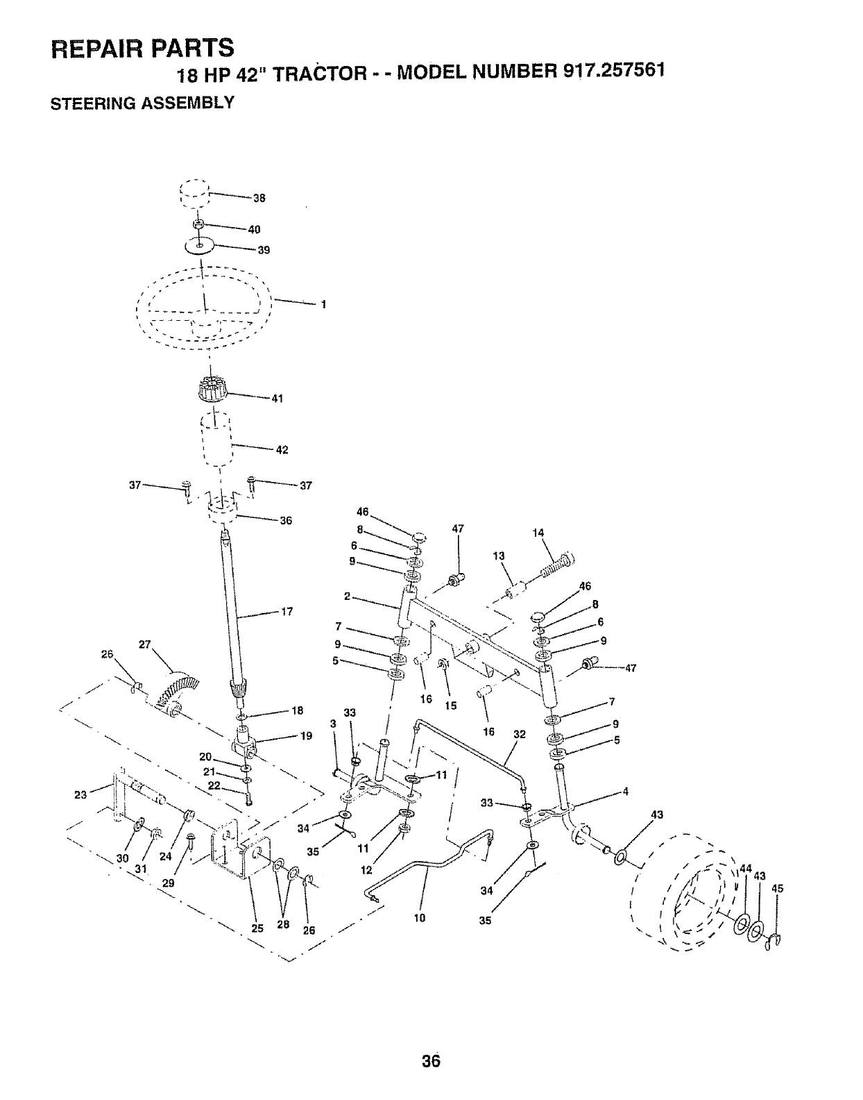
REPAIR PARTS
18 HP 42" TRACTOR - - MODEL NUMBER 917.257561
STEERING ASSEMBLY
--_5_- "5 .
t
29
25
35
7
33
3i
11
12
47
!6
10
16 32
34
35
43
i_l
/!
\!
/
45
S6

REPAIR PARTS
18 HP 42" TRACTOR -- MODEL NUMBER 917.257561
STEERING ASSEMBLY
KEY PART
NO, NO. DESCRIPTION
1 '139768
2 142033
3 135227
4 135228
5 6266H
6 121748X
7 19272016
8 12000029
9 3366R
10 130468
11 STD551137
12 73610600
13 110438X
14 74011056
t5 73901000
t6 132624
17 132614
18 57079
19 124035X
20 126684X
21 STD55t125
22 71070410
23 127501
24 t09816X
25 124036X
26 12000029
27 136874
28 6266H
29 17490612
30 STD551137
31 73610600
32 130465
33 126847X
34 19131416
35 STD561210
36 132196
37 STD611005
38 139769
39 19133808
40 STD541537
41 104820X
42 I24417X
43 12t749X
44 121748X
45 12000029
46 12t232X
47 6855M
Wheel Steering Std Black
Axre Asm Front
Spindle Asm Lh
Spindle Asm Rh
Bearing Race Thrust Harden
Washer 25/32 X 1 5/8 X 16ga
Washer 27/32 X 1 1/4 X 16 Ga
Ring Klip #t5304-75
Bearing Co} Strg BIk
Link Drag Sol Ball Jt 20 064
Washer Lock Hvy Hlcl Spr 3/8
Nut Fin Hex 3/8-24 Unf
Spacer Bearing Axle Front
Bolt Hex 5/8-11 Unc X 3-1/2
Locknut Flange 5/8-11 Unc
Pin Axle 5/8 X 1 55/1 54 Lg
Shaft Asm Strg 5/8 X I5 19 Lt
Washer Thrust 515x 750x 033
Support Shaft
Washer Shim 1/4 X 5/8 X 062
Washer Lock Hvy Helical 1/4
Screw Hex Socket 1/4-20 X 5/8
Shaft Asm Pittman
Nyliner Snap In
Bracket Steering
Ring Klip #t5304-75
Gear Sector
Bearing Race Thrust Harden
Screw Thdrol 3/8-16x3/4 Ty-tt
Washer Lock Hvy Hlcl Spr 3/8
Nut Fin Hex 3/8-24 Unf
Rod Tie Wire Form 19 75 Mech
Bushing Rod Tie BIk Lt
Washer 13/32 X 7/8 X '16ga
Pin Cotter 1/8 X 3/4 Cad
Bushing Strg 5/8 Id Dash
Screw Slftp #10-16 X 1/2 Ty-b
Insert Cap Strg Wheel Std Btk
Washer 13/32 X 2-3/8 X 8 Ga
Nut Lock Center 3/8-24unf
Adaptor Wheel Strg 640/635id
Boot Shaft Steering
Washer 25/32 X 1 1/4X t6 Ga
Washer 25/32 X 1 5/8 X 16ga
Ring Klip #t5304-75
Cap Spindle Fr Top BIk
Fitting Grease
NOTE: All component dimensions given in US_ inches.
1inch = 25.4 mm
37

REPAIR PARTS
18 HP 42" TRACTOR -= MODEL NUMBER 917.257561
SEAT ASSEMBLY
KEY
NO.
1
2
5
6
7
8
9
10
t2
13
14
15
28
PART KEY PART
NO. DESCRIPTION NO. NO. DESCRIPTION
127437 Seat 16 121250X
140551 Bracket Pnt Pivot Seat (btk) 17 123976X
140407 Clip Push-in 21 139888
STD541437 Nut Crownlock 3/8-18 Unc 22 STD54143t
124181X Spring Seat Cprsn 2 250 Blk Zi 23 74780814
17490508 Screw Thdrol 3/8-16 X 1 Ty-tt 24 19171912
19131614 Washer 13/32 X 1 X 14 Ga 25 t27018X
140552 Pan Pnt Seat (blk) 26 STD551150
121246X Bracket Pnt Mounting Switch 28 17490608
121248X Bushing Snap BIk Nyi 50 Id
72050411 Bolt Rdhd Sht Nk 1/4-20xl-3/8
134300 Spacer Split 28 X 96 Zinc 38
Spring Cprsn 1 27 BIk Pnt
Nut Lock 1/4 Lge Fig Gr 5 Zinc
Bolt Shoulder 5/16-18 Unc Blkz
Nut Crown Lock 5/16-18
Bott Fin Hex 1/2-13 X 7/8 Gr 5
Washer 17/32 X 1-3/16 X 12 Ga
BoEtShoulder 5/16-18 X 62
Washer Lock Hvy Hlcl Spr 1/2
Screw Thdrol, 3/8-16 x 1/2
NOTE: ALlcomponent dimensions given in US. inches
1 inch = 25.4 mm
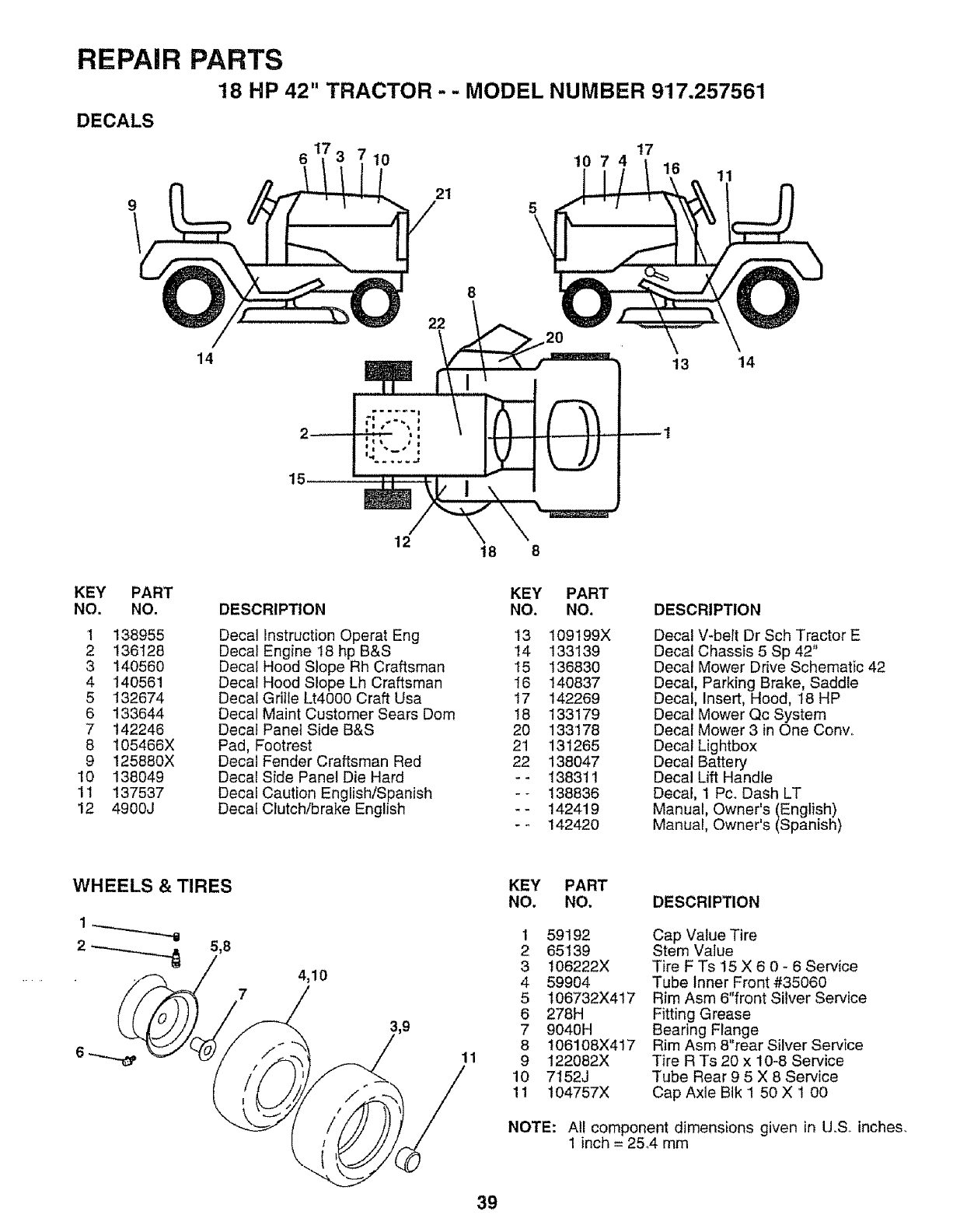
REPAIR PARTS
18 HP 42" TRACTOR - -MODEL NUMBER 917.257561
t7
10 10 7 4 16 11
DECALS
21
14
15
22
12 t8
13 \14
KEY PART KEY PART
NO. NO, DESCRIPTION NO. NO. DESCRIPTION
1 138955 Decal instruction Operat Eng 13 109t99X
2 136128 Decal Engine 18 hp B&S 14 133139
3 140560 Decal Hood Slope Rh Craftsman 15 136830
4 140561 Decal Hood Slope Lh Craftsman 16 140837
5 132674 Decal Grille Lt4000 Craft Usa t7 142269
6 133644 Decal Maint Customer Sears Dom 18 133179
7 142246 Decal Panel Side B&S 20 133'178
8 105466X Pad, Footrest 21 131265
9 125880X Decal Fender Craftsman Red 22 138047
10 138049 Decal Side Panel Die Hard -- 138311
11 137537 Decal Caution English/Spanish -- 138836
12 4900J Decal Clutch/brake English -- 142419
- - 142420
Decal V-beit Dr Sch Tractor E
Decal Chassis 5 Sp 42"
Decal Mower Drive Schematic 42
Decal, Parking Brake, Saddle
Decal, Insert, Hood, 18 HP
Decal Mower Qc System
Decal Mower 3 in One Cony,.
Decal Lightbox
Decal Battery
Decal Lift Handle
Decal, 1 Pc. Dash LT
Manual, Owner's (English)
Manual, Owner's (Spanish)
WHEELS &TIRES
4,10
11
KEY PART
NO. NO, DESCRIPTION
1 59192
2 65139
3 t06222X
4 59904
5 106732X417
6 278H
7 9040H
8 106108X417
9 122082X
10 7t52J
11 104757X
Cap Value Tire
Stem Value
Tire F Ts 15 X 6 0 - 6 Service
Tube Inner Front #35060
Rim Asm 6"front Silver Service
Fitting Grease
Bearing Flange
Rim Asm 8"rear Silver Service
Tire R Ts 20 x 10-8 Service
Tube Rear 9 5 X 8 Service
Cap Axle Blk 1 50 X 1 00
NOTE: All component dimensions given in U.S. inches.
1inch = 25.4 mm
39
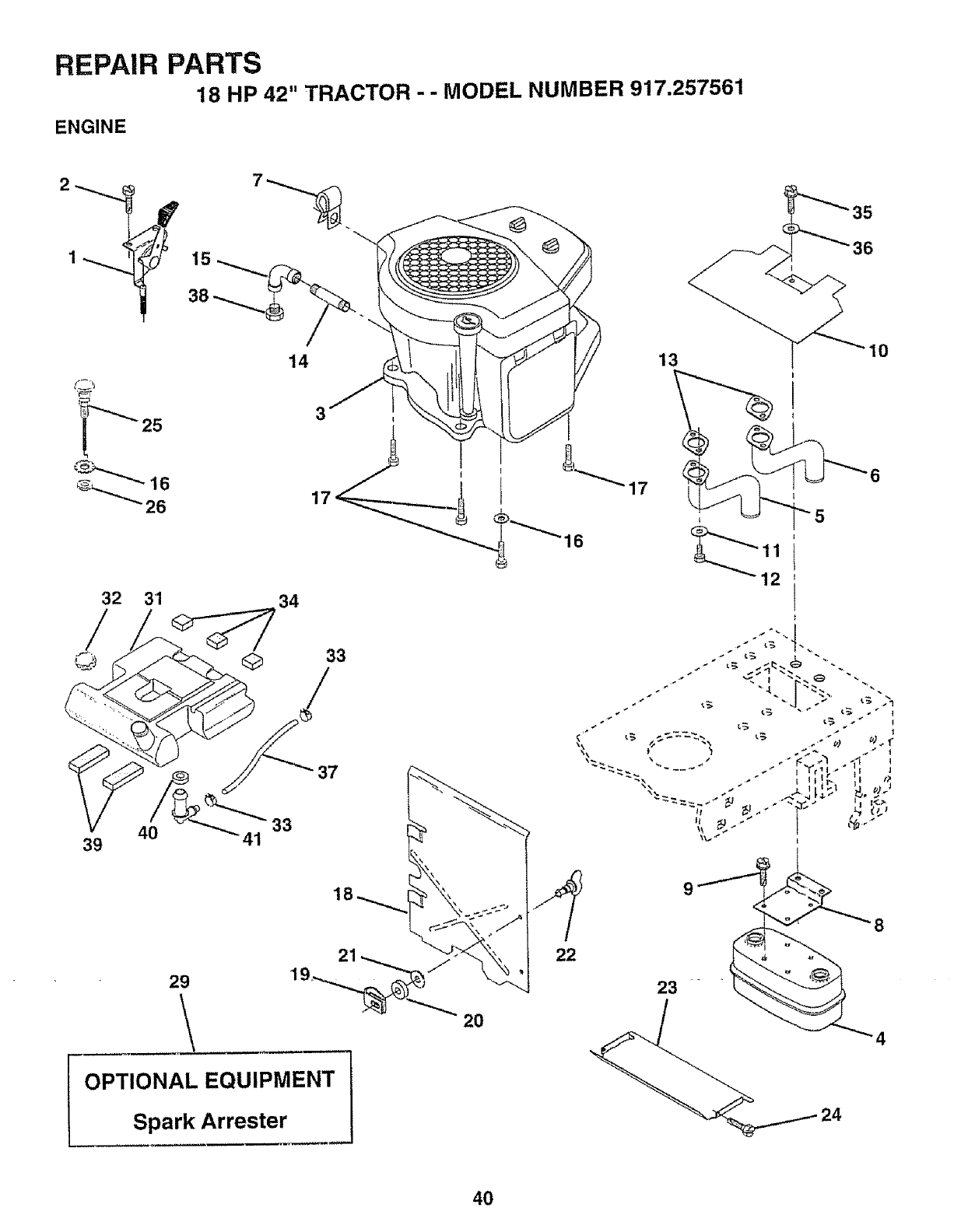
REPAIR
ENGINE
PARTS
18 HP 42" TRACTOR -- MODEL NUMBER 917.257561
25
32 31
40
39
14 13
35
41
34
37
33
29
\
OPTIONAL EQUIPMENT
Spark Arrester
22
23
9
24
8
4
40
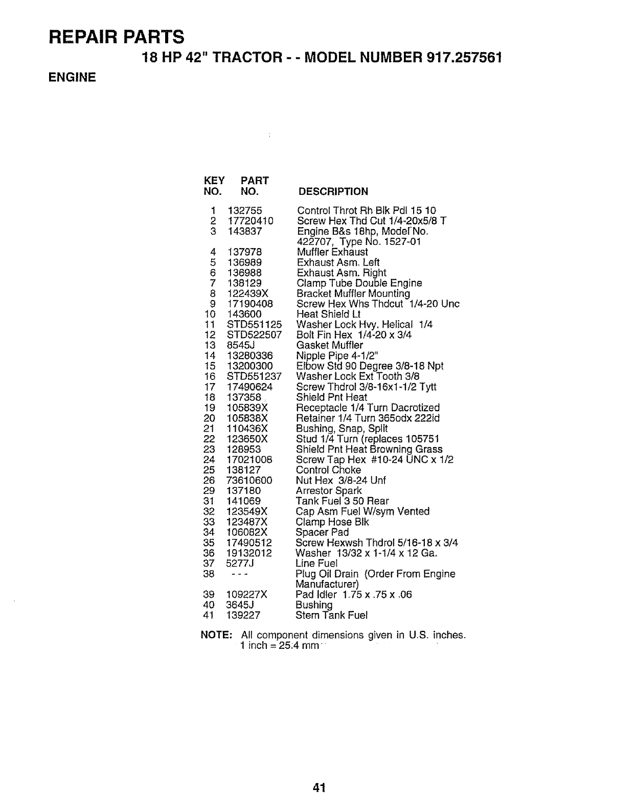
REPAIR PARTS
18 HP 42" TRACTOR -- MODEL NUMBER 917.257561
ENGINE
KEY PART
NO. NO. DESCRIPTION
I 132755
2 17720410
3 143837
4 137978
5 136989
6 136988
7 138129
8 122439X
9 17190408
10 143600
11 STD551125
12 STD522507
13 8545J
14 13280336
15 132003O0
16 STD551237
17 17490624
18 137358,
19 105839×
20 105838X
21 !10436X
22 123650X
23 128953
24 17021008
25 138127
26 73610600
29 137180
31 141069
32 !23549X
33 123487X
34 106082X
35 17490512
36 19132012
37 527_J
38 ---
39 109227X
40 3645J
41 139227
Control Throt Rh Btk Pd115 10
Screw Hex Thd Cut 1/4-20x5/8 T
Engine B&s 18hp, Modef'No.
422707, Type Noo 1527-01
Muffler Exhaust
Exhaust Asm. Left
Exhaust Asm, Right
Clamp Tube Doubte Engine
Bracket Muffler Mounting
Screw Hex Whs Thdcut !/4-20 Unc
Heat Shield Lt
Washer Lock Hvy, Helical 1/4
Bolt Fin Hex 1/4-20 x 3/4
Gasket Muffler
Nipple Pipe 4-1/2"
Elbow Std 90 Degree 3/8.18 Npt
Washer Lock Ext Too[n _ltJ
Screw Thdrot 3/8-!6x1-1/2 Tytt
Shield Pnt Heat
Receptacle 1/4 Turn Dacrotized
Retainer t/4 Turn 365odx 222id
Bushing, Snap, Split
Stud 1/4 Turn (replaces 105751
Shield Pnt Heat Browning Grass
Screw Tap Hex #10-24 UNC x 1/2
Control Choke
Nut Hex 3/8-24 Unf
Arrestor Spark
Tank Fuel 3 50 Rear
Cap Asm Fuel W/sym Vented
Clamp Hose Blk
Spacer Pad
Screw Hexwsh Thdrol 5/16-18 x 3/4
Washer 13/32 x 1-1/4 x 12 Ga,
Line Fuel
Piug Oil Drain (Order From Engine
Manufacturer)
Pad Idler 1.75 x _75x ,06
Bushing
Stem Tank Fuel
NOTE: All component dimensions given in U.S. inches.
1inch =25:4 ram
41
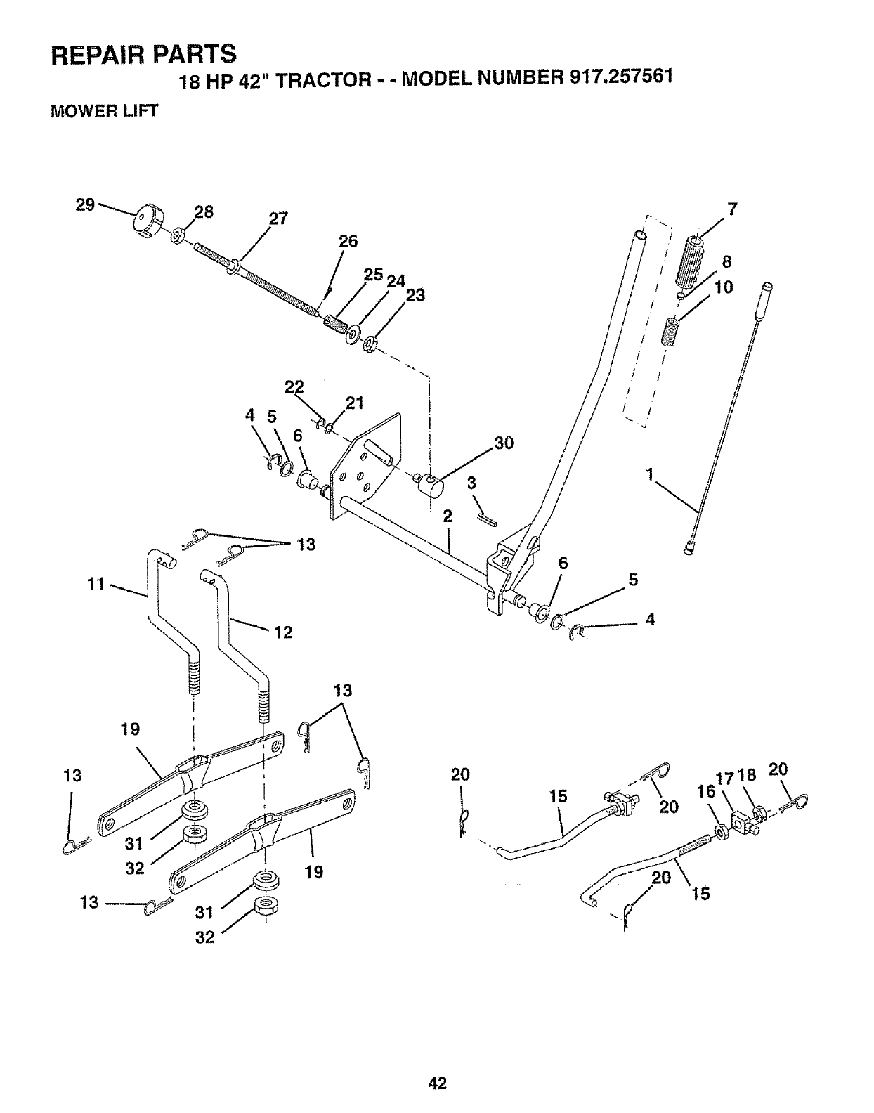
REPAIR PARTS
18 HP 42" TRACTOR -- MODEL NUMBER 917.257561
MOWER LIFT
11
28 27
22
45 6
26
25 24 23
21
2_23 3°
6
8
10
/ /'
/ /
r/ /
5
13
19
13
3_m
32
l
32
19
20
15
42
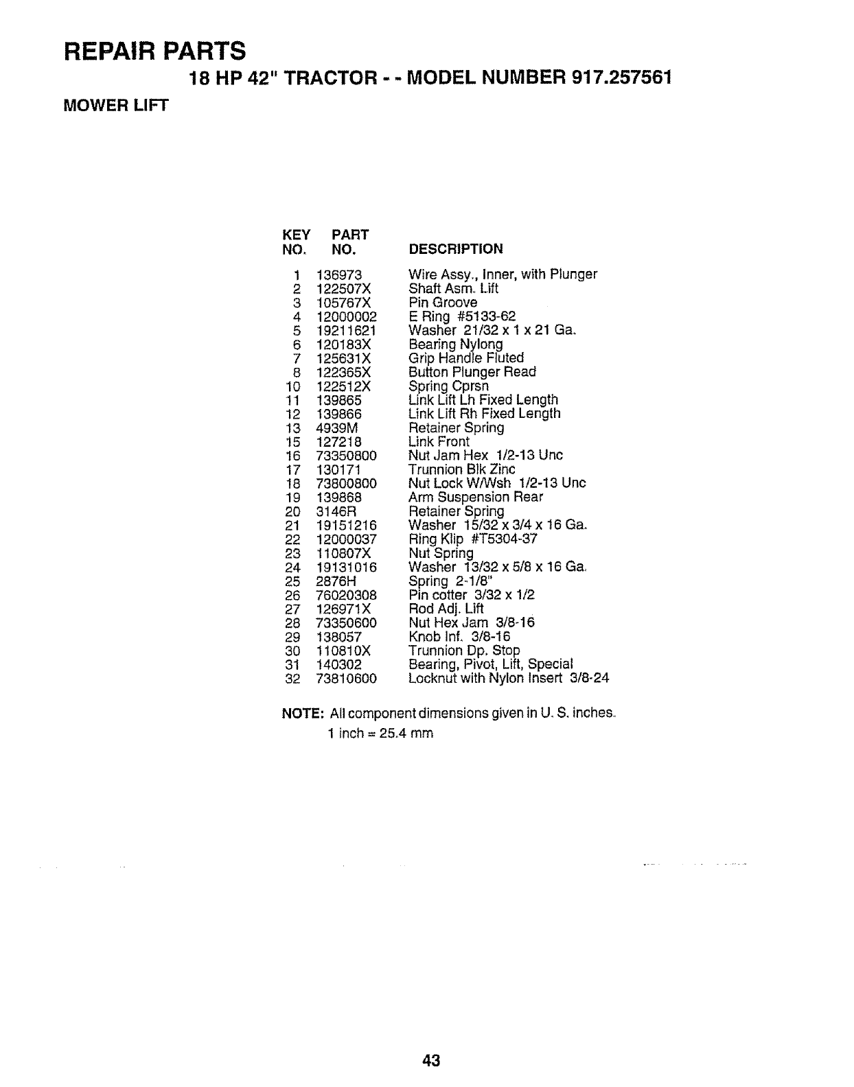
REPAIR PARTS
18 HP 42" TRACTOR --MODEL NUMBER 917.257561
MOWER LIFT
KEY PART
NO. NO. DESCRIPTION
1 136973
2 122507X
3 105767X
4 12000002
5 '19211621
6 120183X
7 125631X
8 122365X
10 122512X
1t 139865
12 139866
13 4939M
15 127218
16 73350800
17 130171
18 73800800
19 139868
20 3146R
21 19151216
22 12000037
23 110807X
24 19131016
25 2876H
26 76020308
27 126971X
28 733506O0
29 138057
30 110810X
31 140302
32 73810600
Wire Assy., Inner, with Plunger
Shaft Asm, Lift
Pin Groove
E Ring #5133_62
Washer 21/32 x I x 21 Gao
Bearing Nylong
Grip Handle Fluted
Button Plunger Read
Spring Cprsn
Link Lift Lh Fixed Length
Link Lift Rh Fixed Length
Retainer Spring
Link Front
Nut Jam Hex 1/2-13 Unc
Trunnion Blk Zinc
Nut Lock W/Wsh 1/2-13 Unc
Arm Suspension Rear
Retainer Spring
Washer 15/32 x 3/4 x 16 Ga.
Ring Ktip #T5304-37
Nut Spring
Washer 13/32 x 5/8 x 16 Ga.
Spring 2_1/8"
Pin cotter 3/32 x 1/2
Rod Adj. Lift
Nut Hex Jam 3/8-16
Knob Inf. 3/8-16
Trunnion Dp. Stop
Bearing, Pivot, Lift, Special
Locknut with Nylon Insert 3/8-24
NOTE: All component dimensions given in U_S. inches_
1 inch = 25°4 mm
43
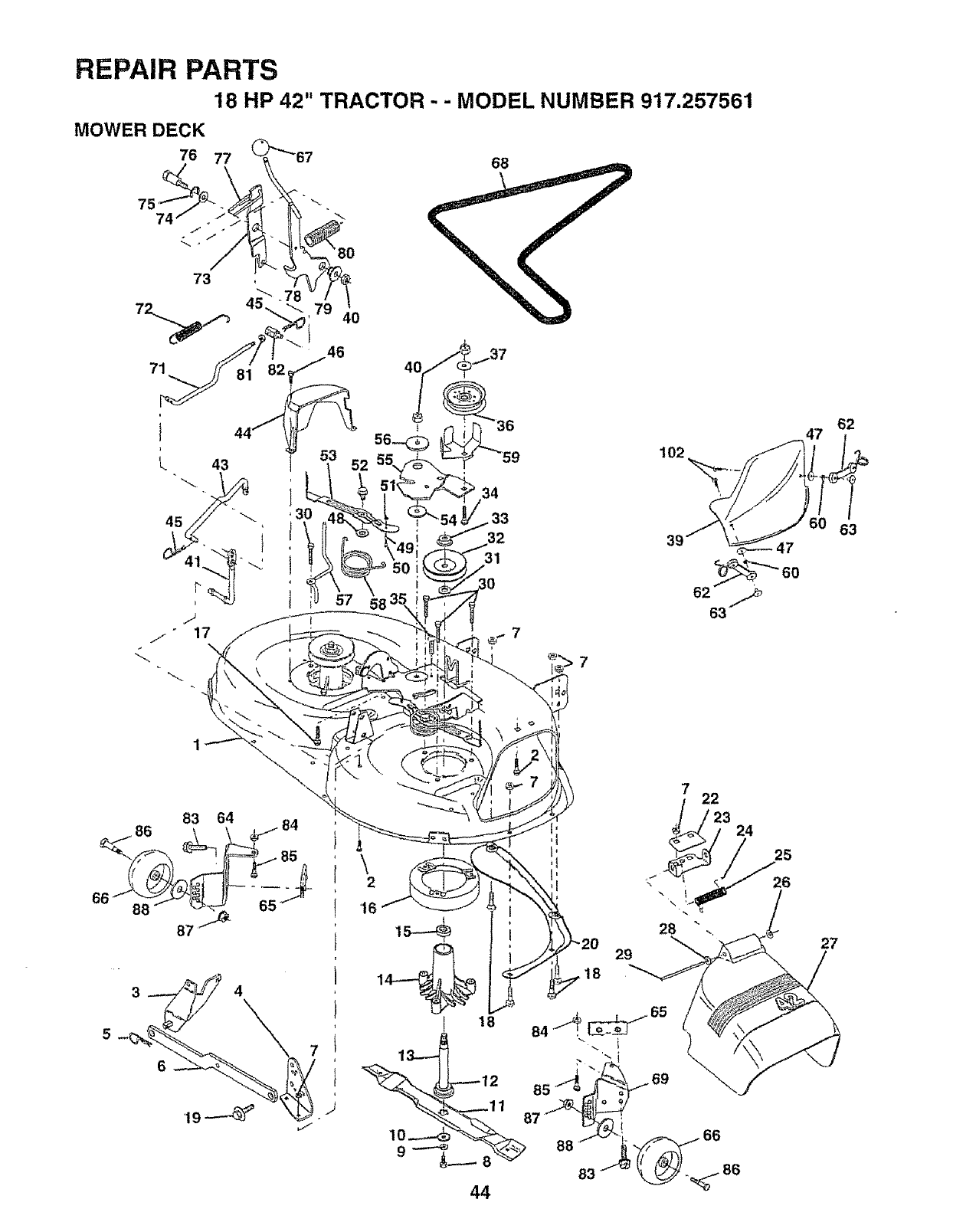
REPAIR PARTS
18 HP 42" TRACTOR -- MODEL NUMBER 917.257561
MOWER DECK
76 77 68
45 i
79 40
46
34
33
32
31
102
62
63
62
63
86 83 64 84
27
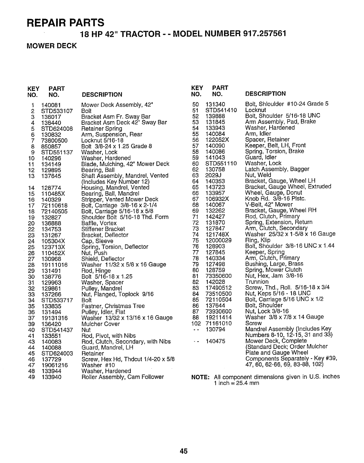
REPAIR PARTS
18 HP 42" TRACTOR - - MODEL NUMBER 917.257561
MOWER DECK
KEY PART KEY PART
NO. NO. DESCRIPTION NO. NO. DESCRIPTION
1 140081
2 STD533107
3 138017
4 138440
5 STD624008
6 130832
7 73800500
8 850857
9 STD551137
10 I40296
1t 134149
12 129895
13 137645
14 128774
15 t10485X
16 140329
17 72110618
18 72140505
19 132827
20 136888
22 134753
23 131267
24 105304X
25 123713X
26 110452X
27 130968
28 19111016
29 131491
30 138776
3'1 129963
32 129861
33 137266
34 STD533717
35 133835
36 131494
37 19131316
39 136420
40 STD541437
41 133551
43 140083
44 140088
45 STD624003
46 137729
47 19061216
48 133944
49 133940
Mower Deck Assembly, 42" 50
Bolt 51
Bracket Asm FroSway Bar 52
Bracket Asm Deck 42" Sway Bar 53
Retainer Spring 54
Arm, Suspension, Rear 55
Locknut 5/16-18 56
Bolt 3/8-24 x 1.25 Grade 8 57
Washer, Lock 58
Washer, Hardened 59
Blade, Mulching, 42" Mower Deck 60
Bearing, Ball 62
Shaft Assembly, Mandrel, Vented 63
(Includes Key Number 12) 64
Housing, Mandrel, Vented 65
Bearing, Ball, Mandrel 66
Stripper, Vented Mower Deck 67
Bolt, Carriage 3/8-16 x 2-1/4 68
Bolt, Carriage 5/16-18 x 5/8 69
Shoulder Bolt 5/16-18 Thd. Form 71
Baffle, Vortex 72
Stiffener Bracket 73
Bracket, Deflector 74
Cap, Sleeve 75
Spring, Torsion, Deflector 76
Nut, Push 77
Shield, Deflector 78
Washer 11/32 x 5/8 x 16 Gauge 79
Rod, Hinge 80
Bolt 5/16-18 x 1.25 81
Washer, Spacer 82
Pulley, Mandrel 83
Nut, Flanged, Toptock 9/16 84
Bolt 85
Fastner, Christmas Tree 86
Pulley, Idler, Flat 87
Washer 13/32 x 13/16 x t6 Gauge 88
Mulcher Cover 102
Nut - -
Rod, Pivot, with Nibs
Rod, Clutch, Secondary, with Nibs _-
Guard, Mandrel, LH
Retainer
Screw, Hex Hd, Thdcut 1/4-20 x 5/8
Washer #10
Washer, Hardened
Roller Assembly, Cam Follower NOTE:
131340
STD541410
139888
131845
133943
140084
122052X
140090
140086
141O43
STD55tit0
130758
2029J
140353
143723
133957
106932X
140067
132262
142427
13'1870
127847
121748X
12O00029
128903
127845
140334
127498
128759
73350600
142028
17490512
73510500
72110504
137644
73930600
19211414
71161010
130794
140475
Bolt, Shloulder #10-24 Grade 5
Locknut
Bolt, Shoulder 5/16-18 UNC
Arm Assembly, Pad, Brake
Washer, Hardened
Arm, Idler
Spacer, Retainer
Keeper, Belt, LH, Front
Spring, Torsion, Brake
Guard, Idler
Washer, Lock
Latch Assembly, Bagger
Nut, Weld
Bracket, Gauge, Wheel LH
Bracket, Gauge Wheel, Extruded
Wheel, Gauge, Donut
Knob Rd. 3/8-16 PIstc_
V-Belt, 42" Mower
Bracket, Gauge, Wheel RH
Rod, CIutch, Primary
Spring, Extension, Return
Arm, Clutch, Secondary
Washer 25/32 x 1-5/8 x 18 Gauge
Ring, Klip
Bo_t, Shoulder 3/8_16 UNC x 1.44
Keeper, Spring
Arm, C_utch, Primary
Bushing, Large, Brass
Spring, Mower Clutch
Nut, Hex, Jam 3/8-16
Trunnion
Screw, Thdr, Roll. 5/16-t8 x 3/4
Nut, Keps 5/16 - 18 UNC
Bolt, Carriage 5/16 UNC x 1/2
Bolt, Shoulder
Nut, Lock 3/8-16
Washer 3/8 x 7/8 x 14 Gauge
Screw
Mandrel Assembly (Includes Key
Numbers 8-10, 12-15, 31 and 33)
Mower Deck, Complete
(Standard Deck; Order Mulcher
Plate and Gauge Wheel
Components Separately - Key #39,
47, 60, 62-66, 69, 83-88, 102)
All component dimensions given in U.S. inches
1inch = 25.4 mm
45
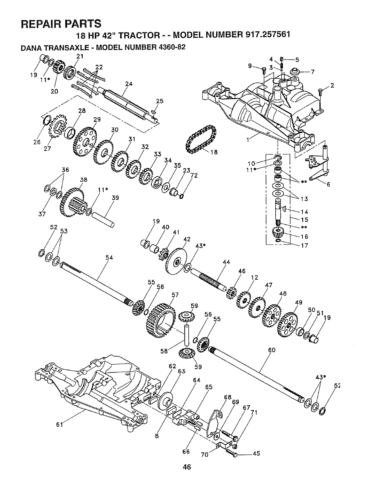
REPAIR PARTS
18 HP 42" TRACTOR - - MODEL NUMBER 917.257561
DANA TRANSAXLE - MODEL NUMBER 4360-82
21
19 11"
20
22
24
25
26 27
36
3t
32
33 34 35 23 72
37
52 53
54
19 40 41 42
59
13
44
46 12
47
48
49
6O
62
66 7O
46
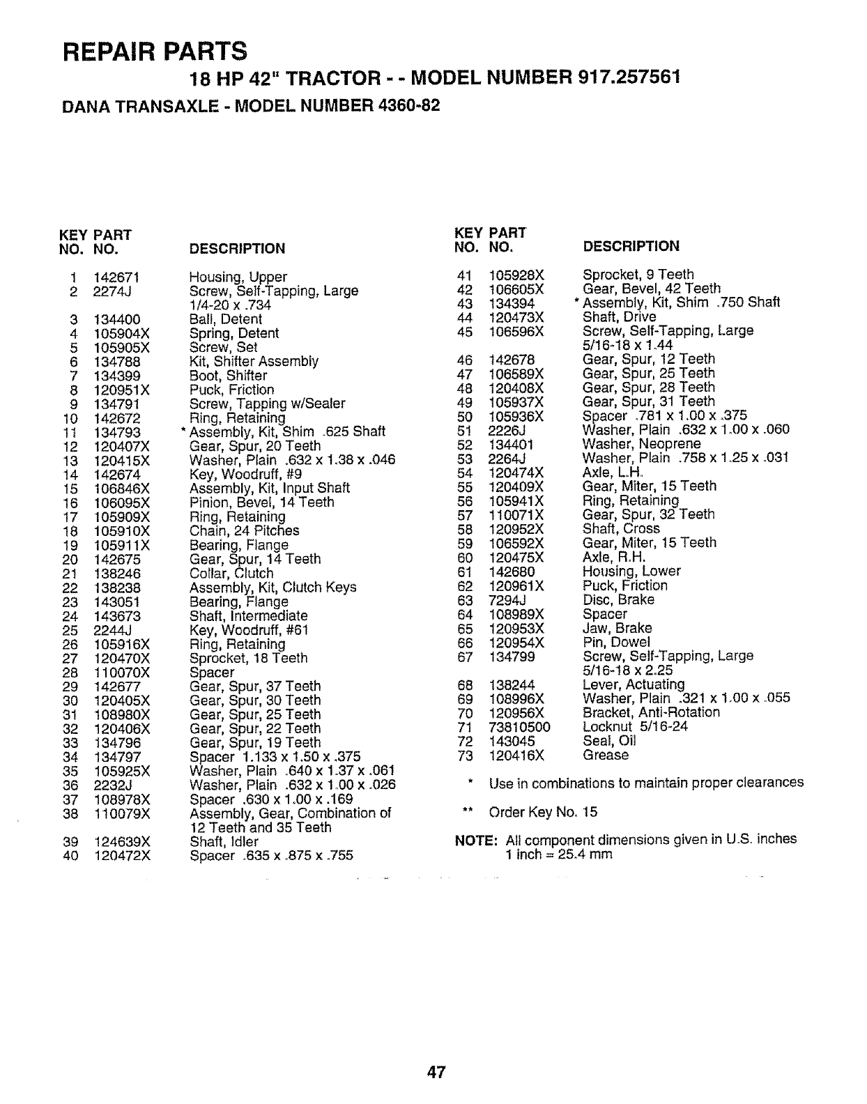
REPAIR PARTS
18 HP 42" TRACTOR - - MODEL NUMBER 917.257561
DANA TRANSAXLE - MODEL NUMBER 4360-82
KEY PART KEY PART
NO, NO. DESCRIPTION NO. NO. DESCRIPTION
39 124639X
40 120472X
1 142671 Housing, Upper 41 105928X Sprocket, 9Teeth
2 2274J Screw, Self-Tapping, Large 42 't06605X Gear, Bevel, 42 Teeth
1/4-20 x .734 43 134394 * Assembly, Kit, Shim °750 Shaft
3 134400 Ball, Detent 44 120473X Shaft, Drive
4 105904X Spring, Detent 45 106596X Screw, Self-Tapping, Large
5 105905X Screw, Sat 5/16-18x 1o44
6 134788 Kit, Shifter Assembly 46 t42678 Gear, Spur, 12 Teeth
7 134399 Boot, Shifter 47 I06589X Gear, Spur, 25 Teeth
8 120951X Puck, Friction 48 120408X Gear, Spur, 28 Teeth
9 134791 Screw, Tapping w/Sealer 49 I05937X Gear, Spur, 31 Teeth
10 142672 Ring, Retaining 50 105936X Spacer .781 x 1.00 x °375
1t 134793 * Assembly, Kit, Shim .625 Shaft 5! 2226J Washer, Plain .632 x1o00x .060
12 120407X Gear, Spur, 20Teeth 52 134401 Washer, Neoprene
13 120415X Washer, Plain .632 x t.38 x .046 53 2264J Washer, Plain .758 x 1..25 x o031
14 142674 Key, Woodruff, #9 54 120474X Axle, L.H.
15 106846X Assembly, Kit, Input Shaft 55 120409X Gear, Miter, 15 Teeth
16 106095X Pinion, Bevel, 14 Teeth 56 105941X Ring, Retaining
17 105909X Ring, Retaining 57 110071X Gear, Spur, 32 Teeth
18 105910X Chain, 24 Pitches 58 120952X Shaft, Cross
19 105911X Bearing, Flange 59 106592X Gear, Miter, 15 Teeth
20 142675 Gear, Spur, 14Teeth 60 120475X Axle, Roll.
2t 138246 Cotlar, Clutch 61 142680 Housing, Lower
22 138238 Assembly, Kit, Clutch Keys 62 120961X Puck, Friction
23 143051 Bearing, Flange 63 7294J Disc, Brake
24 143673 Shaft, Intermediate 64 108989X Spacer
25 2244J Key, Woodruff, #61 65 120953X Jaw, Brake
26 105916X Ring, Retaining 66 120954X Pin, Dowel
27 120470X Sprocket, !8 Teeth 67 134799 Screw, Self-Tapping, Large
28 110070X Spacer 5/16-18 x 2.25
29 142677 Gear, Spur, 37 Teeth 68 138244 Lever, Actuating
30 120405X Gear, Spur, 30 Teeth 69 108996X Washer, Plain .321 x 1°00 x.055
31 108980X Gear, Spur, 25 Teeth 70 120956X Bracket, Anti-Rotation
32 120406X Gear, Spur, 22 Teeth 71 73810500 Locknut 5/16-24
33 134796 Gear, Spur, 19 Teeth 72 143045 Seal, Oil
34 134797 Spacer 1.133 x 1.50 x _375 73 120416X Grease
35 105925X Washer, Plain °640 x 1o37x .061
36 2232J Washer, Plain .632 x 1°00 x .026 * Use in combinations to maintain proper clearances
37 108978X Spacer ,630 x 1o00 x.169
38 110079X Assembly, Gear, Combination of ** Order Key Noo 15
12 Teeth and 35 Teeth
Shaft, Idler
Spacer .635 x °875 x .755 NOTE: All component dimensions given in U,S. inches
1 inch = 25,4 mm
47
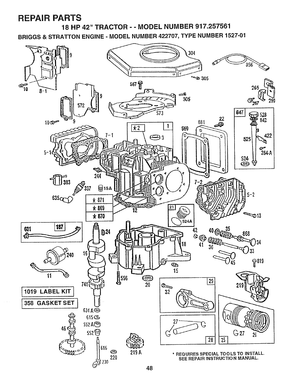
REPAIR PARTS
18 HP 42" TRACTOR - - MODEL NUMBER 917.257561
BRIGGS & STRATTON ENGINE - MODEL NUMBER 422707, TYPE NUMBER 1527-01
572 305
"'*e_ 305
2O
2t9 k
48
*REQUIRES SPECIAL TOOLS TO INSTALL,
SEE REPAIR INSTRUCT10 N MANUAL.
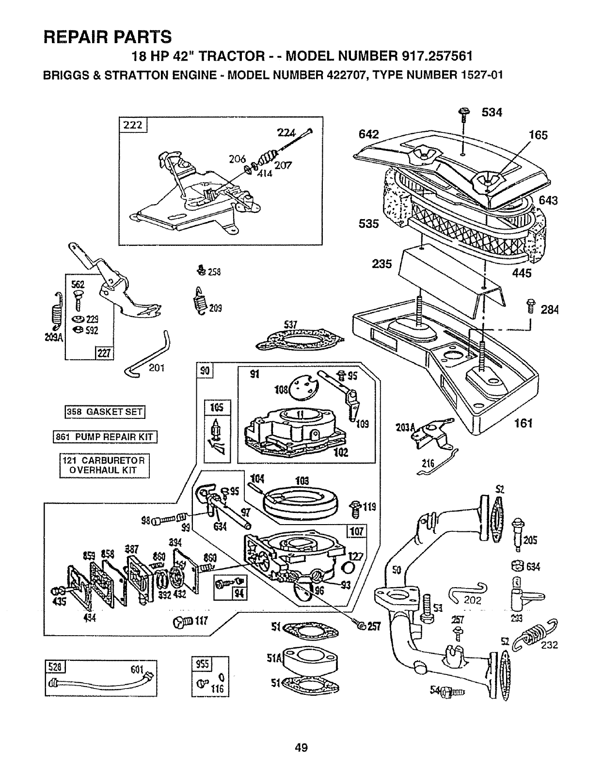
REPAIR PARTS
18 HP 42" TRACTOR - - MODEL NUMBER 917.257561
BRIGGS & STRATTON ENGINE - MODEL NUMBER 422707, TYPE NUMBER 1527-01
e$92
[3seaASKETSETI
1861 PUMP REPAIR KIT I
121 CARBURETOROVERHAUL KIT
t0S i
642
535
235
534
165
643
161
49
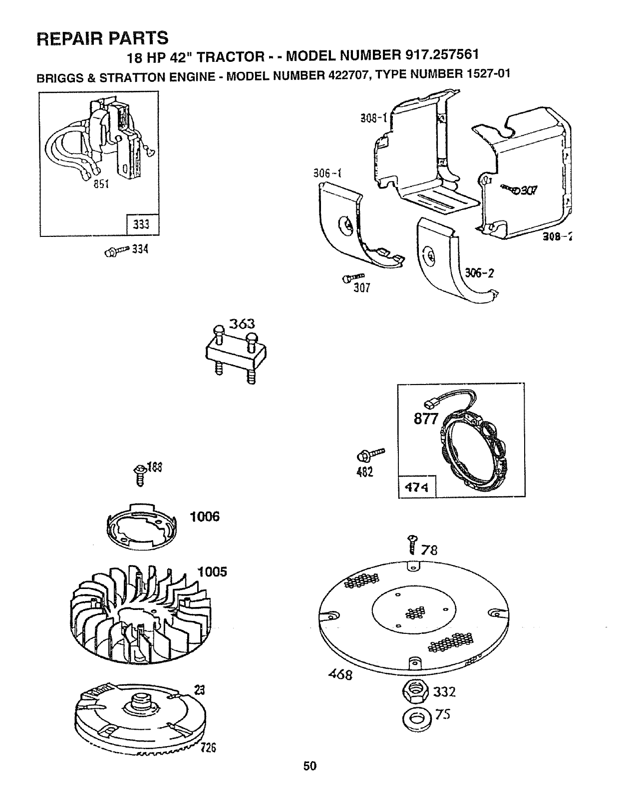
REPAIR PARTS
18 HP 42" TRACTOR . . MODEL NUMBER 917.257561
BRIGGS & STRATTON ENGINE .MODEL NUMBER 422707, TYPE NUMBER 1527-01
1006
1005
877
78
"4_86 .--.-_.
_332
50
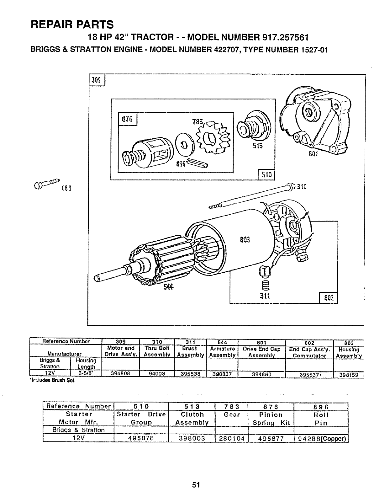
REPAIR PARTS
18 HP 42" TRACTOR - - MODEL NUMBER 917.257561
BRIGGS & STRATTON ENGINE -MODEL NUMBER 422707, TYPE NUMBER 1527-01
78_
___ Reference Number 309
Motor and
Manufacturer .... Drive Ass'y.
.......Briggs & Housing
S_retmn Lenqth
2v 3,:s_8"...... 394808
"lr_iudesBrash S_t
310 311 544 801 802
Thru Bolt Brush ....Armature Drive End Cap End Cap Ass'yo
Assembly Assembly Assembly Assembly Commutator
94003 395538 390837 394860 395537.
8O3
Housing
Assembly!
398159
Reference Number
Starter
Motor Mfr,
Briq.qs &S_ratton
12V
510
iStarter Drive
Group
513
Clutch
Assembly
783
Gear
876
Pinion
_!t
896
Roll
Pin
495878 398003 280104 495877 94288(Cop_0
51
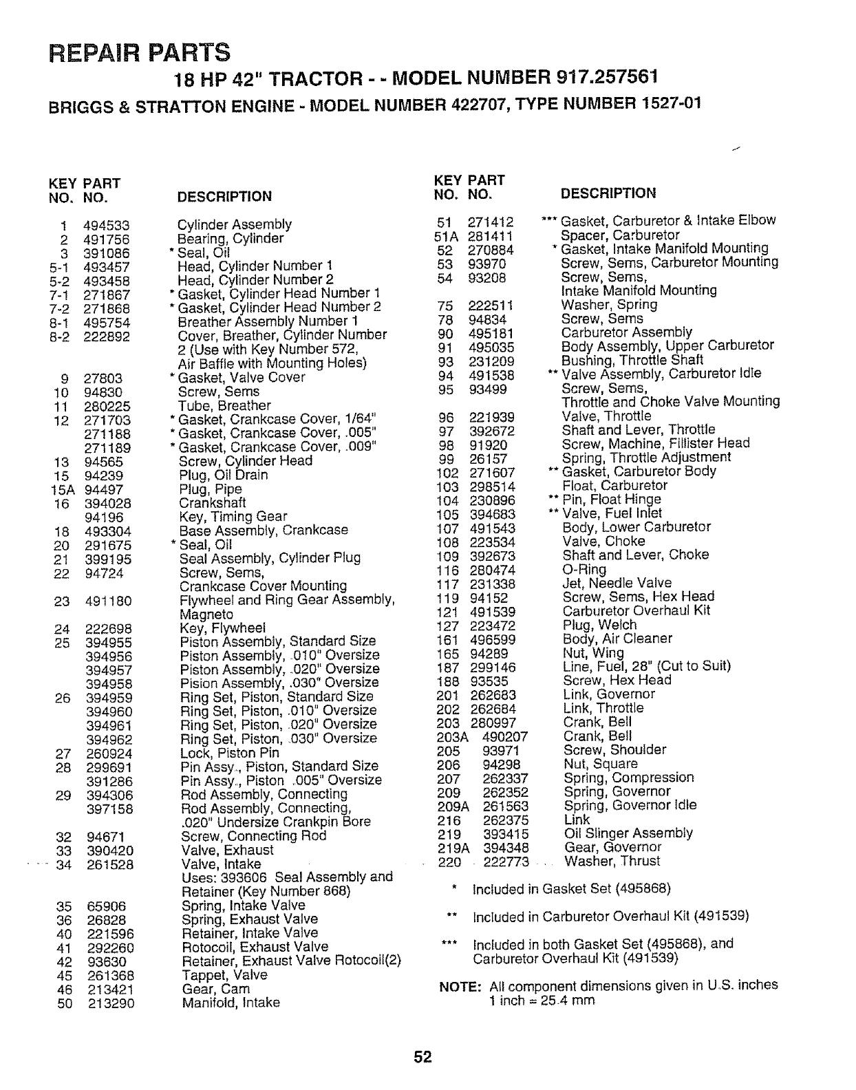
REPAIR PARTS
18 HP 42" TRACTOR - - MODEL NUMBER 917.257561
BRIGGS & STRATTON ENGINE - MODEL NUMBER 422707, TYPE NUMBER 1527-01
KEY PART KEY PART
NO. NO. DESCRIPTION NO. NO_ DESCRIPTION
1 494533
2 491756
3 391O86
5-1 493457
5-2 493458
7-1 271867
7-2 271868
8-1 495754
8-2 222892
9 27803
10 94830
11 280225
12 271703
271188
271189
13 94565
15 94239
15A 94497
16 394028
94196
18 493304
20 291675
21 399195
22 94724
23 491180
24 222698
25 394955
394956
394957
394958
26 394959
394960
394961
394962
27 260924
28 299691
391286
29 394306
397158
32
33
- 34
35
36
40
41
42
45
46
5O
94671
390420
261528
65906
26828
221596
292260
93630
261368
213421
213290
Cylinder Assembly 51 271412
Bearing, Cylinder 51A 281411
* Seal, Oil 52 270884
Head, Cylinder Number 1 53 93970
Head, Cylinder Number2 54 93208
* Gasket, Cylinder Head Number 1
* Gasket, Cylinder Head Number 2 75 222511
Breather Assembly Number 1 78 94834
Cover, Breather, Cylinder Number 90 495181
2 (Use with Key Number 572, 91 495035
Air Baffle with Mounting Holes) 93 231209
*Gasket, Valve Cover 94 491538
Screw, Seres 95 93499
Tube, Breather
* Gasket, Crankcase Cover, 1/64" 96 221939
* Gasket, Crankcase Cover, °005" 97 392672
* Gasket, Crankcase Cover, .009" 98 91920
Screw, Cylinder Head 99 26157
Plug, Oil Drain 102 271607
Plug, Pipe 103 298514
Crankshaft 104 230896
Key, Timing Gear 105 394683
Base Assembly, Crankcase 107 491543
* Seal, Oil 108 223534
Seal Assembly, Cylinder Plug 109 392673
Screw, Sems, 116 280474
Crankcase Cover Mounting 117 231338
Flywheel and Ring Gear Assembly, 119 94152
Magneto '121 491539
Key, Flywheel 127 223472
Piston Assembly, Standard Size 161 496599
Piston Assembly, O10" Oversize 165 94289
Piston Assembly, 020" Oversize 187 299146
Pision Assembly, .030" Oversize 188 93535
Ring Set, Piston, Standard Size 201 262683
Ring Set, Piston, .010" Oversize 202 262684
Ring Set, Piston, °020" Oversize 203 280997
Ring Set, Piston, .030" Oversize 203A 490207
Lock, Piston Pin 205 93971
Pin Assy., Piston, Standard Size 206 94298
Pin Assy.., Piston ..005" Oversize 207 262337
Rod Assembly, Connecting 209 262352
Rod Assembly, Connecting, 209A 261563
.020" Undersize Crankpin Bore 216 262375
Screw, Connecting Rod 219 393415
Valve, Exhaust 219A 394348
Valve, Intake 220 _ 222773 ....
Uses: 393606 Seal Assembly and
Retainer (Key Number 868) *
Spring, Intake Valve
Spring, Exhaust Valve **
Retainer, Intake Valve
Rotocoil, Exhaust Valve ***
Retainer, Exhaust Valve Rotocoil(2)
Tappet, Valve
Gear, Cam
Manifold, Intake
*** Gasket, Carburetor & Intake Elbow
Spacer, Carburetor
* Gasket, Intake Manifold Mounting
Screw, Seres, Carburetor Mounting
Screw, Seres,
Intake Manifold Mounting
Washer, Spring
Screw, Sems
Carburetor Assembly
Body Assembly, Upper Carburetor
Bushing Throttle Shaft
** Valve Assembly, Carburetor dte
Screw, Seres,
ThrottIe and Choke Valve Mounting
Valve, Throttle
Shaft and Lever, Throttle
Screw, Machine, Fitlister Head
Spring, Throttle Adjustment
** Gasket, Carburetor Body
Float, Carburetor
** Pin, Float Hinge
** Valve, Fuel Inlet
Body, Lower Carburetor
Valve, Choke
Shaft and Lever, Choke
O-Ring
Jet, Needle Valve
Screw, Sems, Hex Head
Carburetor Overhaul Kit
Plug, Welch
Body, Air Cleaner
Nut, Wing
Line, Fuel, 28" (Cut to Suit)
Screw, Hex Head
Link, Governor
Link, Throttle
Crank, Bell
Crank, Bell
Screw, Shoulder
Nut, Square
Spring, Compression
Spring, Governor
Spring, Governor Idle
Link
Oil Slinger Assembly
Gear, Governor
Washer, Thrust
Included in Gasket Set (495868)
Included in Carburetor Overhaul Kit (491539)
Included in both Gasket Set (495868), and
Carburetor Overhaul Kit (491539)
NOTE: Afl component dimensions given in U.S. inches
1 inch = 25.4 mm
52
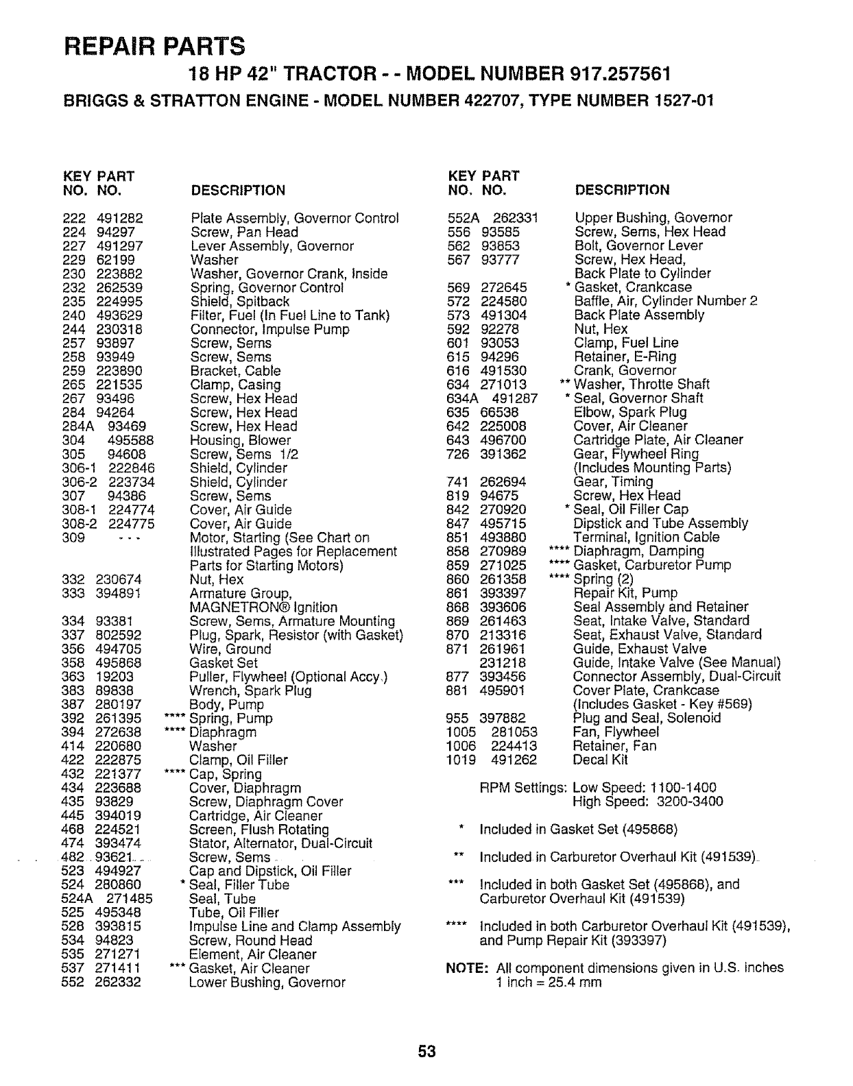
REPAIR PARTS
18 HP 42" TRACTOR -- MODEL NUMBER 917.257561
BRIGGS & STRATTON ENGINE - MODEL NUMBER 422707, TYPE NUMBER 1527-01
KEY PART KEY PART
NO. NO, DESCRIPTION NO. NO. DESCRIPTION
222 491282
224 94297
227 491297
229 62199
230 223882
232 262539
235 224995
240 493629
244 230318
257 93897
258 93949
259 223890
265 221535
267 93496
284 94264
284A 93469
304 495588
305 94608
306-1 222846
306-2 223734
307 94386
308q 224774
308-2 224775
309 ---
332 230674
333 394891
334 93381
337 802592
356 494705
358 495868
363 19203
383 89838
387 280197
392 261395
394 272638
414 220680
422 222875
432 221377
434 223688
435 93829
445 394019
468 224521
474 393474
48293621 .....
523 494927
524 280860
524A 271485
525 495348
528 393815
534 94823
535 271271
537 271411
552 262332
Plate Assembly, Governor Control 552A 262331
Screw, Pan Head 556 93585
Lever Assembly, Governor 562 93853
Washer 567 93777
Washer, Governor Crank, inside
Spring, Governor Control 569 272645
Shield, Spitback 572 224580
Filter, Fuel (in Fuel Line to Tank) 573 491304
Connector, Impulse Pump 592 92278
Screw, Seres 601 93053
Screw, Seres 615 94296
Bracket, Cable 616 491530
Clamp, Casing 834 2710!3
Screw, Hex Head 634A 491287
Screw, Hex Head 635 66538
Screw, Hex Head 642 225008
Housing, Blower 643 496700
Screw, Sems 1/2 726 391362
Shield, Cylinder
Shield, Cylinder 741 262694
Screw, Sems 819 94675
Cover, Air Guide 842 270920
Cover, Air Guide 847 495715
Motor, Starting (See Chart on 851 493880
Illustrated Pages for Replacement 858 270989
Parts for Starting Motors) 859 271025
Nut, Hex 860 261358
Armature Group, 861 393397
MAGNETRON® Ignition 868 393606
Screw, Sems, Armature Mounting 869 261463
Plug, Spark, Resistor (with Gasket) 870 213316
Wire, Ground 871 261961
Gasket Set 231218
Puller, Flywheel (Optional Accy,) 877 393456
Wrench, Spark Plug 881 495901
Body, Pump
.... Spring, Pump 955 397882
.... Diaphragm 1005 281053
Washer 1006 2244t3
Clamp, Oil Filler 1019 491262
.... Cap, Spring
Cover, Diaphragm
Screw, Diaphragm Cover
Cartridge, Air Cleaner
Screen, Flush Rotating
Stator, Alternator, Dual-Circuit
Screw, Sems.
Cap and Dipstick, Oil Filler
* Seal, Filler Tube
Seal, Tube
Tube, Oil Filler
Impulse Line and Clamp Assembly
Screw, Round Head
Element, Air Cleaner
*** Gasket, Air Cleaner
Lower Bushing, Governor
Upper Bushing, Governor
Screw, Sems, Hex Head
Bolt, Governor Lever
Screw, Hex Head,
Back Plate to Cylinder
* Gasket, Crankcase
Baffle, Air, Cylinder Number 2
Back Plate Assembly
Nut, Hex
Clamp, Fuel Line
Retainer, E-Ring
Crank, Governor
** Washer, Throtte Shaft
* Seal, Governor Shaft
Elbow, Spark Plug
Cover, Air Cleaner
Cartridge Plate, Air Cleaner
Gear, Flywheel Ring
(Includes Mounting Parts)
Gear, Timing
Screw, Hex Head
* Seat, Oil Filler Cap
Dipstick and Tube Assembly
Terminal, Ignition Cable
.... Diaphragm, Damping
.... Gasket, Carburetor Pump
.... Spring (2)
Repair Kit, Pump
Sea! Assembly and Retainer
Seat, Intake Valve, Standard
Seat, Exhaust Valve, Standard
Guide, Exhaust Valve
Guide, Intake Valve (See Manual)
Connector Assembly, Dual-Circuit
Cover Plate, Crankcase
(Includes Gasket - Key #669)
Plug and Sea!, Solenoid
Fan, Flywheel
Retainer, Fan
Decal Kit
RPM Settings: Low Speed: 1t00-1400
High Speed: 3200-3400
* Included in Gasket Set (495868)
** Included in Carburetor Overhaul Kit (491539)
*** Included in both Gasket Set (495868), and
Carburetor Overhaul Kit (491539)
.... Included in both Carburetor Overhaul Kit (491539),
and Pump Repair Kit (393397)
NOTE: All component dimensions given in U..S. inches
1 inch = 25.4 mm
53

iJ i == ,,,=H,= .............................. ==,ll
SERVICE NOTES
...................... = H'HH'H
54

SUGGESTED GUIDE FOR SIGHTING SLOPES FOR SAFE OPERATION
O1
O1
SIGHTING
JlDE _CUT o.
ONLY RIDE UP AND DOWN HILL,
NOT ACROSS HILL
SIGHT AND HOLD THIS LEVEL WITH
SKY LINE OR TREE.
!
15 ° MAX.
&
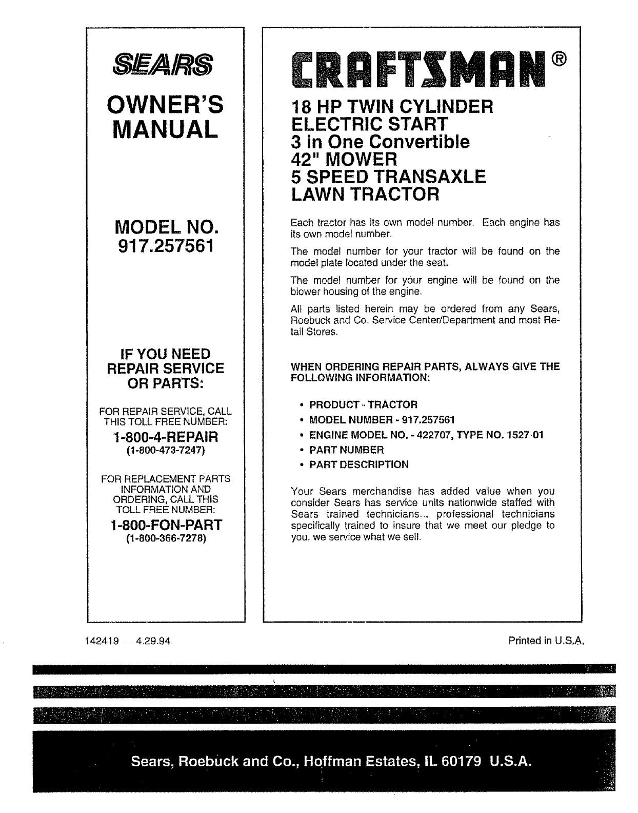
OWNE
MANUAL
MODEL NO.
917.257561
IF YOU NEED
REPAIR SERVICE
OR PARTS:
FOR REPAIR SERVICE, CALL
THIS TOLL FREE NUMBER:
1-800-4-REPAIR
(1-800-473-7247)
FOR REPLACEMENT PARTS
INFORMATION AND
ORDERING, CALL THIS
TOLL FREE NUMBER:
1-800-FON-PART
(1-800-366-7278)
£RilFT MRN
18 HP TWIN CYLINDER
ELECTRIC START
3 in One Convertible
42" MOWER
5 SPEED TRANSAXLE
LAWN TRACTOR
Each tractor has its own model number_ Each engine has
its own model number,
The model number for your tractor will be found on the
model plate located under the seat.
The model number for your engine will be found on the
blower housing of the engine.
Alf parts listed herein may be ordered from any Sears,
Roebuck and Co. Service Center/Department and most Re-
tail Stores_
WHEN ORDERING REPAIR PARTS, ALWAYS GIVE THE
FOLLOWING INFORMATION:
=PRODUCT- TRACTOR
• MODEL NUMBER- 917.257561
• ENGINE MODEL NO. - 422707, TYPE NO. 1527-01
° PART NUMBER
• PART DESCRIPTION
Your Sears merchandise has added value when you
consider Sears has service units nationwide staffed with
Sears trained technicians°.° professional technicians
specifically trained to insure that we meet our pledge to
you, we service what we sell
142419 4,29,94 Printed in U.S,A,
I i i
iiiiiiiiiiiiiiii i i ii illllllllllllllllllllllilillllllllllili
ithr-:';;1
rIIIIIIIII
