Craftsman 917257620 User Manual Lawn, Tractor Manuals And Guides LR707473
CRAFTSMAN Lawn, Tractor Manual LR707473 CRAFTSMAN Lawn, Tractor Owner's Manual, CRAFTSMAN Lawn, Tractor installation guides
User Manual: Craftsman 917257620 917257620 CRAFTSMAN Lawn, Tractor - Manuals and Guides View the owners manual for your CRAFTSMAN Lawn, Tractor #917257620. Home:Lawn & Garden Parts:Craftsman Parts:Craftsman Lawn, Tractor Manual
Open the PDF directly: View PDF ![]() .
.
Page Count: 52

®
MODEL NUIVIBER 9t7.257620 OWNER'SMANUAL
Assembly
Operation
Customer
ResponsibiiBties
Service
Adjustments
Repair Parts
,aution.
_ead and Follow
_11Safety Rules
_nd Instructions
_efore Operating
"his Equipment
_. I Ill'-- LJ_ !_IJJL []J_....... _-----_ "---m/!
_- -- "1 I'r/
[_-- iiw_i,p,p .L _ ....._,, __ _.
fl
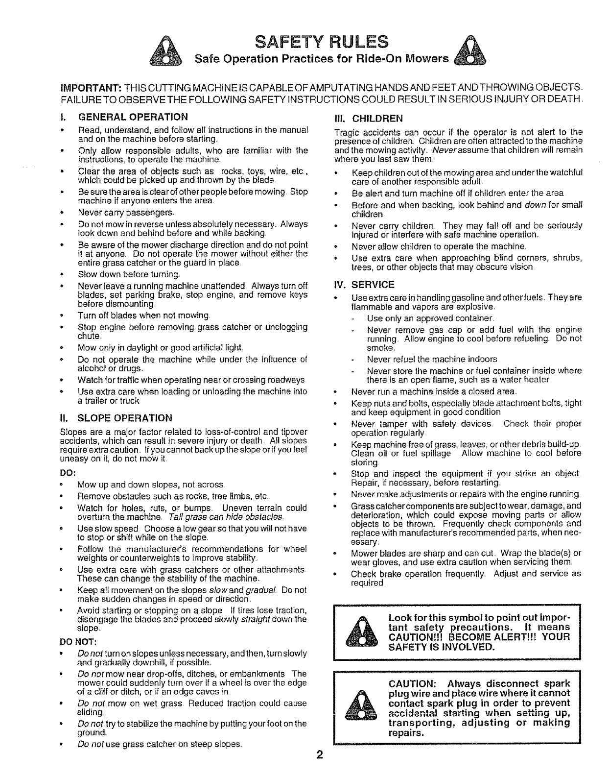
SAFETY RULES
Safe Operation Practices for Ride-On Mowers
IMPORTANT: THIS CUTTING MACHINE IS CAPABLE OF AMPUTATING HANDS AND FEETAND THROWING OBJECTS,
FAILURE TO OBSERVE THE FOLLOWING SAFETY INSTRUCTIONS COULD RESULT 1NSERIOUS INJURY OR DEATH,
I. GENERAL OPERATION
o Read, understand, and follow all instructions in the manual
and on the machine before starting,
• Only allow responsible adults, who are familiar with the
instructions, to operate the machine
• blear the area of objects such as rocks, toys, wire, etc.
which coutd be picked up and thrown by the blade
° Be sure the area isclear of other people before mowing Stop
machine if anyone enters the area
o Never carry passengers.
° Do not mow in reverse unless absolutely necessary,, Always
look down and behind before and while backing
• Be aware of the mower discharge direction and do not point
it at anyone. Do not operate the mower without either the
entire grass catcher or the guard in place,
° Stow down before turning.
• Never leave a running machine unattended Always turn off
blades, set parking brake, stop engine, and remove keys
before dismounting.
.Turn off blades when not mowing.
• Stop engine before removing grass catcher or unclogging
chute.
° Mow only in daylight or good artificial light.
o Do not operate the machine while under the influence of
alcohol or drugs.
-Watch for traffic when operating near or crossing roadways
o Use extra care when loading or unloading the machine into
a trailer or truck
IL SLOPE OPERATION
Slopes are a major factor related to toss-of-control and tipover
accidents, which can result in severe injury or death AII slopes
require extra caution. If you cannot back up the slope or if you feel
uneasy on it, do not mow it
DO:
oMow up and down slopes, not across
° Remove obstacles such as rocks, tree limbs, etc.
•Watch for hobs, ruts, or bumps Uneven terrain could
overtum the machine, Tall grass can hide obstacles.
o Use slow speed Choose a low gear so that you will not have
to stop or shift while on the slope,
o Follow the manufacturer's recommendations for wheel
weights or counterweights to improve stability.,
•Use extra care with grass catchers or other attachments.
These can change the stability of the machine.
• Keep all movement on the slopes stow and gradual. Do not
make sudden changes in speed or direction.
• Avoid starting or stopping on a slope tf tires lose traction,
disengage the blades and proceed slowly straight down the
slope.
DO NOT:
•Donotturnonslopesunlessnecessary,andthen,turnstowty
and gradually downhilI, if possible..
•Do not mew near drop-offs, ditches, or embankments The
mower coutd suddeniy turn over if a wheel is over the edge
of a cliff or ditch, or if an edge caves in,
°Do not mow on wet grass Reduced traction could cause
sliding.
•Do not try to stabilize the machine by putting your foot on the
ground,
•Do not use grass catcher on steep slopes.,
IlL CHILDREN
Tragic accidents can occur if the operator is not aled to the
presence of children, Children are often attracted to the machine
and the mowing activity. Neverassume that children wil! remain
where you last saw them
° Keep children out of the mowing area and under the watchful
care of another responsiMe adult
• Be alert and turn machine off if children enter the area
° Before and when bacMng, Iook behind and down for small
children
° Never carry children., They may fall off and be seriously
injured or interfere with safe machine operation,
o Never allow children to operate the machine.
° Use extra care when approaching blind corners, shrubs,
trees, or other objects that may obscure vision
IV. SERVICE
* Use extra care inhandting gasoline and other fuels They are
flammable and vapors are explosive,
Use only an approved container,
Never remove gas cap or add fuel with the engine
running. Allow engine to cool before refueling Do not
smoke.
Never refuel the machine indoors
Never store the machine or fuel container inside where
there is an open flame, such as a water heater
. Never run a machine inside a closed area.
- Keep nuts and bolts, especially blade attachment bolts, tight
and keep equipment in good condition
. Never tamper with safety devices. Check their proper
operation regularly
. Keep machine free of grass, leaves, or other debris build-up.
Clean oi! or fuel spillage Mow machine to cool before
storing
• Stop and inspect the equipment if you strike an object
Repair, if necessary, before restarting,,
° Never make adjustments or repairs with the engine running
- Grass catcher components are subject to wear, damage, and
deterioration, which could expose moving parts or allow
objects to be thrown. Frequently check components and
replace with manufacturer's recommended parts, when nec-
essary,
• Mower blades are sharp and can cut. Wrap the blade(s) or
wear gloves, and use extra caution when servicing them
o Check brake operation frequently° Adiust end service as
required,
Look for this symbol to point out impor-
tant safety precautions, tt means
CAUTION!!! BECOME ALERT!!! YOUR
SAFETY IS INVOLVED.
CAUTION: Always disconnect spark
plug wire and place wire where it cannot
contact spark plug in order to prevent
accidental starting when setting up,
transporting, adjusting or making
repairs.
ii

CONGRATULATIONS on your purchase of a Sears
Tractor, It has been designed, engineered and manufac-
tured to give you the best possible dependability and
performance°
Should you experience any problem you cannot easily
remedy, please contact your nearest Sears Authorized
Service Center/Department. We have competent, well-
trained technicians and the proper tools to service or repair
this unit.
Please read and retain this manual.. The instructions will
enable you to assemble and maintain your unit properly.
Always observe the "SAFETY RULES"
MODEL
NUMBER 917..257620
SERIAL
NUMBER
:)ATE OF PURCHASE
THE MODELAND SERIAL NUMBERS WILL BE FOUND
ON A PLATE UNDER THE SEAT,
YOU SHOULD RECORD BOTH SERIAL NUMBER AND
DATE OF PURCHASE AND KEEP 1NA SAFE PLACE
FOR FUTURE REFERENCE.
MAINTENANCE AGREEMENT
A Sears Maintenance Agreement is available on this prod-
uct Contact your nearest Sears store for details.
CUSTOMER RESPONS BBLITIES
o Read and observe the safety rules
o Follow a regular scheduie in maintaining, caring for and
using your unit
o Fellow the instructions under "Customer Responsibili-
ties" and "Storage" sections of this owner's manual.
PRODUCT SPEClFlCAT!ONS
HORSEPOWER: 12 5
GASOUNE CAPACITY 5 QUARTS
AND TYPE: UNLEADED REGULAR
OIL TYPE (APt-SG): SAE 30 (above 32°F)
SAE 5W-30 (below 32°F)
OiL CAPACITY: 3 0 PINTS
SPARK PLUG: CHAMPION RJ19LM
(GAP: 030") STD361458
VALVE CLEARANCE: INTAKE: 005" - 007"
EXHAUST: 00g*' - 011"
GROUND SPEED (MPH): FORWARD:
1st 1 02
2nd 2t0
3rd 3 14
4th 4 00
5th 5 12
REVERSE: 1.58
TIRE PRESSURE: FRONT: 14 PSl
REAR: 12 PSI
CHARGING SYSTEM: 3 AMPS BATTERY
5 AMPS HEADLIGHTS
BLADE BOLT TORQUE: 30-35 FT. LBS
WARNING: This unit is equipped with an internal combus-
tion engine and should not be used on or near any unim-
proved forest-covered, brush-covered or grass-covered
land unless the engine's exhaust system is equipped with
a spark arrester meeting applicable local or state laws (if
any), If a spark arrester is used, it should be maintained in
effective working order by the operator.
In the state of California the above is required by law
(Section 4442 of the California Public Resources Code)
Other states may have similar laws. Federal taws appiy on
federal lands° A spark arrester for the muffler is available
through your nearest Sears Authorized Service Center/
Department (See REPAIR PARTS section of this manual)..
,if . u .u nl i i.i nl i i,,,,i.i ii i i."," 1.1.1
LIMITED TWO YEAR WARRANTY ON ELECTRIC START RIDING EQUIPMENT
For two (2) years from the date of purchase, if this riding equipment is maintained, lubricated and tuned up according to the
instructions in the owner's manual, Sears will repair or replace, free of charge, any paris found to be defective in material or
workmanship,
This Warranty does net cover:
• Expendable items which become worn during normal use, such as blades, spark plugs, air cleaners and belts
o Tire replacementor repair caused by punctures from outside objects, such as nails, thorns, stumps, or glass
o Repairs necessary because of operator abuse, negligence,improper storage or accident or the failure to maintain the
equ!oment according to the instructions contained in the owner s manual
- Ridin_ equioment used for commerciat or rental purposes
MMITED 90 DAY WARRANTY ON BATTERY
For ninety (90) days from date of purchase, if any battery included with this riding equipment proves defective in material or
wofl_manshipand our testing determines the battery will not hold a charge, Sears will replacethe battery at no charge
WARRANTY SERVICE tS AVAILABLE BY RETURNING THE RIDING EQUIPMENT TO THE NEAREST SEARS SERVICE
CENTER!DEPARTL,IENT1NTHE UNlqE ,mS'_ATES
This Warranty gives you specific legal fights, and you may also have other rightswhich may vary from state to state
SEARS, ROEBUCK AND CO,, D/8t7 WA, HOFFMAN ESTATE:_. ILL]NOtS 60179
,i ..... i, i ..................... iH HI n ..............
3
TABLE OF CONTENTS
SAFETY t_ULES ............................................................. 2
PRODUCT SPECIFICATIONS ....................................... 3
CUSTOMER RESPONSIBILITIES ..................... 3, 14-17
WARRANTY ................................................................... 3
TRACTOR ACCESSORIES ........................................... 5
ASSEMBLY ................................................................. 7-9
OPERATION ........................................................... 10-13
MAINTENANCE SCHEDULE ...................................... 14
SERVICE AND ADJUSTMENTS ............................ 18-23
STORAGE .................................................................... 24
TROUBLESHOOTING ............................................ 25-26
REPAIR PARTS - TRACTOR ................................. 28-45
REPAIR PARTS - ENGINE ........................ ............. 46-50
PARTS ORDERING/SERVICE ................ BACK COVER
NDEX
A
Accessories .......................................... 5
Adjustments:
Brake ................ _............................20
Carburetor ................................. 23
Mower
Front-To-Back ........................... 19
Side-To-Side .................................19
Throttle Control Cable ..........;......... 23
Air Filter, Engine ................................... 17
Air Screen, Engine ............................. 17
Assembly ................................................. 7-9
B
Battery:
Charging ......................................... 8
Cieaning ................................... 16
Installation ........... :....................................9
Levels .......................................... 8,16
Preparation ...................................... 8
Starting with Weak Battery ........... 21
Storage .......................................... 24
Terminals ..................................... 16
Belt:
Motion Drive
RemovaVReplacement ........... 20
Mower Blade(s)
Removal/Replacement ............ 20
Blade:
Sharpening ............................... 15
Replacement .................................. 15
Brake Adjustment .....................................20
C
Carburetor Adjustment ......................... 24
Controls, Tractor ...................................... 10
Customer Responsibilities ............... 15-17
Engine:
Air Filter ..................................... 17
Air Screen ........................................17
Cooling Fins ................................ 17
Engine Oil .......................................16
Fuel Filter ...................................... 17
Spark Plug(s) ............................. 17
Tractor:
Battery ..............................................16
Blade ............................................ 15
Lubrication Chart ....................... 14
Maintenance Schedule ............. 14
Tire Care ..............................8,15,21
Transaxle ................................... 16
Cutting Height, Mower ................... 11
E
Electrical:
Interlocks and Relays ................... 22
Schematic ...........................................27
Wiring Diagram .............................. 28
Engine:
Air Filter ............................................ t7
Air Screen ........................................ 17
Cooling Fins, Engine ................... 17
Oil Change ..................................... 16
Oil Level .................................. 12,16
Oil Type ..................................................16
Preparation ................................... 12
Repair Parts ............................... 44-48
Starling ....................................... 13
Sto rage ...............................................24
F
Filter:
Air Fitter ......................................... 17
Fuel ............................................... 17
Fuel:
Type ......................................... 12
Storage ..................................... 24
Fuse ..................................................... 22
H
Hood Removal/Installation ................... 22
L
Leveling Mower Deck ..............................I9
Lubrication:
Chart .....................................................14
M
Maintenance Schedule ............................14
Mower:
Adjustment, Front4o-Back .......... 19
Adjustment, Side-to_Side ..................19
Blade Sharpening ........................ 15
Blade Replacement ....................... 15
Cutting Height .................................. t 1
Installation ...................................... 18
Operation ........................................ t 2
Removal .............................................18
Mowing Tips ...............................................13
Muffler ..........................................................17
Spark Arrester ...............................3,38
Oil: O
Cold Weather Conditions ...... 12, !6
Engine ............................................. 16
Storage .................................. 24
Operation ........................................ 10-13
Operating Mower ................................. 12
Options:
Accessories ...................................... 5
Spark Arrester ...................... 3,38
P
Parking Brake ................................ 10-11
Parts Bag .......................................................6
Parts, Replacement/Repair .......... 28-45
Product Specifications .................... 3
R
Repair Pads ................................... 28-45
S
Safety Rules ..................................................2
Seat ................................................................. 8
Service and Adjustments .................. 18-23
Carburetor ..................................... 23
Fuse .............................................. 22
Hood Removal/Installation ................22
Motion Drive Belt
Removal!Replacement ...............20
Mower Belt(s)
Remova[fReptacement ............ 20
Mower Adjustment
Front4o-Back .............................. 1g
Side-to-Side .....................................19
Mower Removal ............................ 18
Tire Care ............................... 8,15,21
Slope Guide Sheet ............................... 51
Spark Plug(s) ...................................................17
Specifications .......................................... 3
Starting the Engine .............................12-!3
Steering Wheel .................................. 7,21
Stopping the Tractor ............................ 11
Storage ..........................................................24
T
Throttle Control Cable Adjustment .......23
Tires ............................................. 8,15,21
Trouble Shooting Chart ......................25-26
Transaxle .................................................. 16
W
Warranty ..........................................................3
Wiring Diagram ................................. 28
Wiring Schematic ............................ 27
4
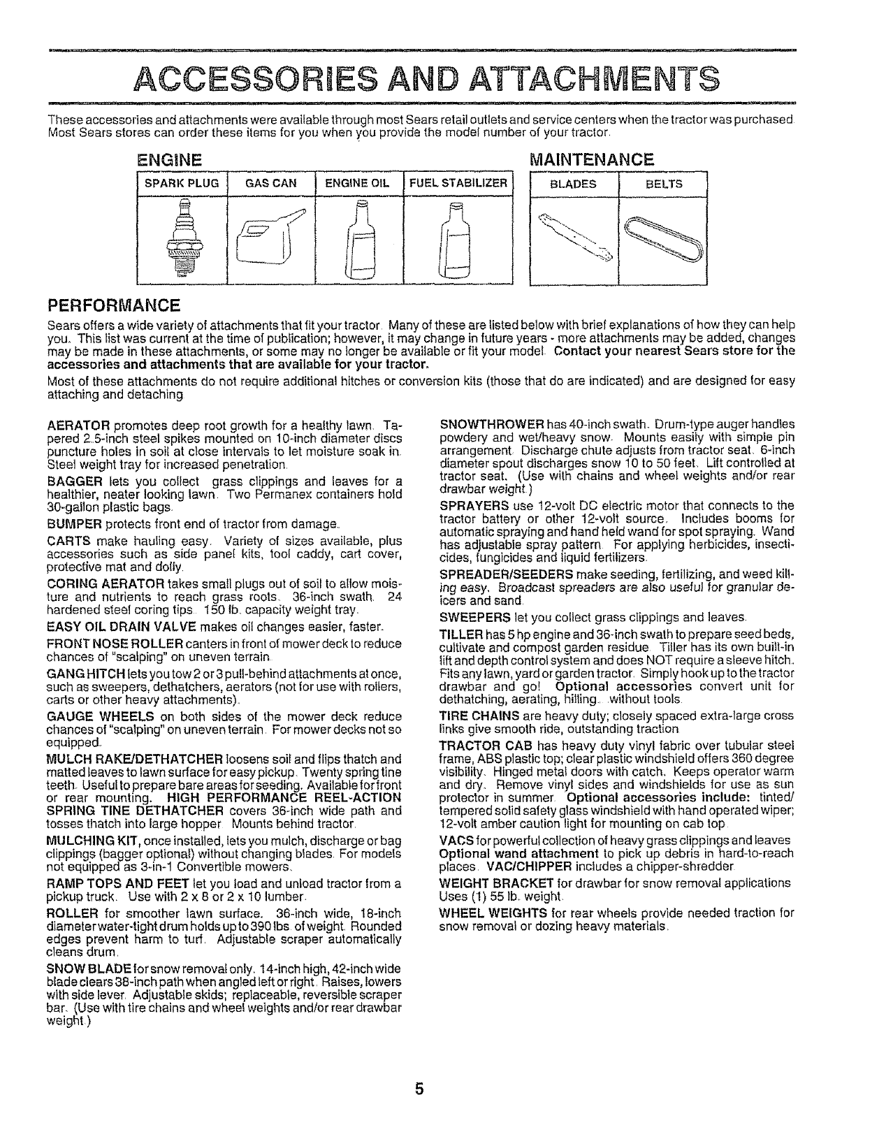
ACCESSOR ES AND ATTACH ENTS
These accessories and attachments were avaifabfe through most Sears retail outlets and service centers when the tractor was purchased
Most Sears stores can order these items for you when you provide the model number of your tractor.
ENGtNE
SPARK PLUG GAS CAN ENGINE OIL FUEL STABILIZER
MAINTENANCE
r
i BLADES BELTS
I
t
I
PERFORMANCE
Sears offers a wide variety of attachments that fit your tractor Many of these are listed below with brief explanations of how they can help
you° This list was current at the time of publication; however, it may change in future years - more attachments may be added, changes
may be made in these attachments, or some may no longer be available or fit your model Contact your nearest Sears store for the
accessories and attachments that are available for your tractor.
Most of these attachments do not require additional hitches or conversion ki|s (those that do are indicated) and are designed lor easy
attaching and detaching
AERATOR promotes deep root growth for a healthy lawn. Ta-
pered 25-inch steel spikes mounted on 10qnch diameter discs
puncture holes in soil at close intervals to let moisture soak in
Steel weight tray for increased penetration
BAGGER lets you collect grass clippings and leaves for a
healthier, nearer looking lawn Two Permene^ containers hold
30-gallon plastic bags.
BUMPER protects front end of tractor from damage..
CARTS make hauling easy. Variety of sizes available, plus
accessories such as side panel kits, tool caddy, cart cover,
protective mat and doily.
CORING AERATOR takes small plugs out of soil to allow mois-
ture and nutrients to reach grass roots. 36-inch swath. 24
hardened steel coring tips 150 Ib. capacity weight tray.
EASY OIL DRAIN VALVE makes oil changes easier, faster.
FRONT NOSE ROLLER canters in front of mower deck to reduce
chances of "scafping" on uneven terrain
CAN G HITCH lets you tow 2 or 3 pull-behind attachments at once,
such as sweepers, dethatchers, aerators (not for use with rollers,
carts or other heavy attachments).
GAUGE WHEELS on both sides of the mower deck reduce
chances of "scalping" on uneven terrain For mower decks not so
equipped..
MULCH RAKE/DETHATCHER loosens soil and ffips thatch and
matted leaves to lawn surface for easy pickup Twenty spring tine
teeth. Usefultopreparebare areasforseeding. Available for front
or rear mounting. HIGH PERFORMANCE REEL-ACTION
SPRING TINE DETHATCHER covers 36-inch wide path and
tosses thatch into large hopper Mounts behind tractor.
MtJLCHING KIT, once installed, lets you mulch, discharge or bag
clippings (bagger optional) without changing blades. For models
not equipped as 3-in-1 Convertible mowers.
RAMP TOPS AND FEET let you toad and unfoad tractor lrom a
pickup truck Use with 2 x 8 or 2 x t0 lumber
ROLLER for smoother lawn surface. 36-inch wide, 18-inch
diameterwater-tightdrumholdsupto3901bs ofweight. Rounded
edges prevent harm to turf. Adjustable scraper automatically
cleans drum
SNOW BLADE tor snow removal only. 14-inch high, 42-inch wide
blade clears38-inch path when angled left or right. Raises, lowers
with side lever. Adjustable skids; replaceable, reversible scraper
bar. (Use with tire chains and wheel weights and/or rear drawbar
weight)
SNOWTHROWER has 40-inch swath. Drum-type auger handtes
powdery and wet!heavy snow Mounts easiiy with simple pin
arrangemenL Discharge chute adjusts from tractor seat. 6-inch
diameter spout discharges snow 10 to 50 feet. Lift controlled at
tractor seat. (Use wilh chains and wheel weights and/or rear
drawbar weight )
SPRAYERS use 12-volt DC electric motor that connects to the
tractor battery or other 12-volt source. Includes booms for
automatic spraying and hand held wand for spot spraying Wand
has adjustable spray pattern For applying herbicides, insecti-
cides, fungicides and liquid fertilizers.
SPREADERISEEDERS make seeding, fertilizing, and weed kill-
ing easy. Broadcast spreaders are also useful for granular de-
icers and sand
SWEEPERS let you collect grass clippings and leaves
TILLER has 5 hp engine and 36-inch swath to prepare seed beds,
cultivate and compost garden residue Tiller has its own built-in
lift and depth control system and does NOT require a sleeve hitch..
Fits any tawn, yard or garden tractor. Simply hook up to the tractor
drawbar and go! Optional accessories convert unit lor
dethatching, aerating, hiiling, without tools
TIRE CHAINS are heavy duty; closely spaced extra-large cross
links give smooth ride, outstanding traction
TRACTOR CAB has heavy duty vinyl fabric over tubular steel
frame, ABS plastic top; clear plastic windshield offers 360 degree
visibility. Hinged metal doors with catch, Keeps operator warm
and dry. Remove vinyl sides and windshields for use as sun
protector in summer Optional accessories include: tinted!
tempered solid safety glass windshield with hand operated wiper;
12-volt amber caution light for mounting on cab top
VACS for powerful collection of heavy grass clippings and leaves
Optional wand attachment to pick up debris in hard-to-reach
places. VAC/CHtPPER includes a chipper-shredder
WEIGHT BRACKET for drawbar for snow removal applications
Uses (1) 55 Ibmweight.
WHEEL WEIGHTS for rear wheels provide needed traction for
snow removal or dozing heavy materials.
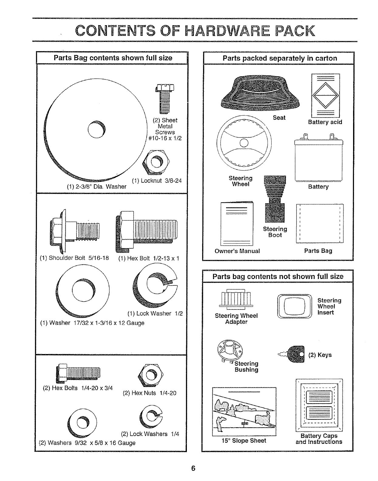
Parts Bag contents shown full size
©(2) Sheet
Metal
Screws
#10-16 x 1/2
(t) Locknut 3/8-24
(1)2-3/8" Die Washer
UUll i i =
(1) Shoulder Bolt 5/16-18
@(I) Hex Bolt 1/2-13 x 1
(1) Lock Washer 1/2
(1) Washer 17/32 x 1-3/!6 x t2 Gauge
(2) Hex Bolts 1/4-20 x 3/4 @
(2) Hex Nuts 1/4-20
(2) Lock Washers t/4
(2) Washers 9/32 x 5/8 x 16 Gauge
Parts packed separately in carton
i......
Seat
÷
Battery acid
Steering
Wheel
Owner's Manual
Steering
Boot
Batte_
I t
I I
I I
I t
Parts Bag
m
Parts bag contents not shown full size
Wheel
Steering Wheel Insert
Adapter
Steering
Bushing
15°Slope Sheet
C.'_ (2) Keys
:: ]::
I
::1 ]::
Battery Caps
and Instructions
6
ASSEMBLY
Your new tractor has been assembled at the factory with exception of those parts left unassembfed for shipping purposes,,
To ensure safe and proper operation of your tractor all parts and hardware you assemble must be tightened securely,, Use
the correct tools as necessary to insure proper tightness,
TOOLS REQUIRED FOR ASSEMBLY
A socket wrench set witl make assembly easier, Standard
wrench sizes are listed,
(1) 5/16" wrench
(2) 7/16" wrenches
(1) 1/2" wrench
(1) 9/16" wrench
(1) 3/4" wrench
Tire pressure gauge
Screwdriver
Utility knife
When right or left hand is mentioned in this manual, it
means when you are in the operating position (seated
behind the steering wheel).
TO REMOVE TRACTOR FROM CARTON
UNPACK CARTON
• Remove all accessible loose parts and parts cartons
from carton (See page 6)
o Cut, from top to bottom, along lines on all four corners
of carton, and lay panels flat,
o Check for any additional loose parts or cartons and
remove
BEFORE ROLUNG TRACTOR OFF SKID
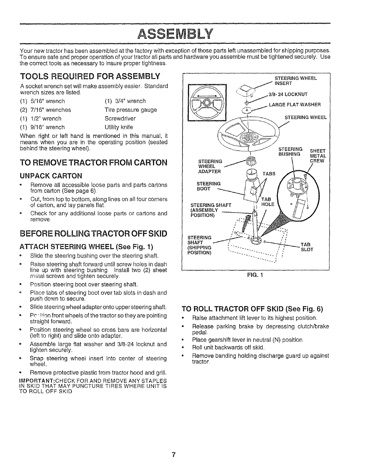
ATTACH STEERING WHEEL (See Fig. 1)
o Slide the steering bushing over the steering shaft.,
• Raise steering shaft forward until screw holes in dash
line up with steering bushing Install two (2) sheet
metal screws and tighten securely,
. Position steering boot over steering shaft,,
Place tabs of steering boot over tab slots in dash and
push down to secure.
Slide steering wheel adapter onto upper steering shaft,
o Pc °ffion front wheels of the tractor so they are pointing
straight forward.
. Position steering wheel so cross bars are horizontal
(left to right) and slide onto adapter,,
o Assemble large flat washer and 3/8-24 Iocknut and
tighten securely,
• Snap steering wheel insert into center of steering
wheel,
. Remove protective plastic from tractor hood and grill
IMPORTANT:CHECK FOR AND REMOVE ANY STAPLES
IN SKID THAT MAY PUNCTURE TIRES WHERE UNIT IS
TO ROLL OFF SKID
STEERING WHEEL
/ INSERT
{ °_'"2,
LARGEFLATWAS"ER
STEERING SHEET
BUSHING
,_.'_, METAL
STEERING j;_, CREW
WHEEL
ADAPTER _ABS
STEERING [
STEERING SHAFT E
(ASSEMBLY
POSITION)
SLOT
FIG. 1
TO ROLL TRACTOR OFF SKID (See Fig. 6)
•Raise attachment lift lever to its highest position_
•Release parking brake by depressing clutch/brake
pedal
•Place gearshift lever in neutral (N) position,
•Roll unit backwards off skid.
•Remove banding holding discharge guard up against
tractor.
ASSEMBLY
HOW TO SET UP YOUR TRACTOR
PREPARE BATTERY (See Fig. 2)
-- i11 11 11.11
ICAUTION: Wear eye and face shield.
i Wash hands or clothing immediately if
! _€_ accidentally in contact with battery acid.
Do not smoke. Fumes from charged
battery acid are explosive.
Read the instructions included with the
batteryvent caps. Atways wear gloves,
clothing and goggles to protect your
hands, skin and eyes.
Your unit has a battery charging system which is sufficient
for normal use. However, periodic charging of the battery
with an automotive charger will extend its life
• See instructions packed with vent caps in parts bag.
• Fill battery with acid.. Fill each cell until it reaches the
bottom of the vent wells Do not overfill
• Allow battery to stand and settle for at least thirty
minutes. After standing, check the battery cell acid
level.. If below the vent wells, add more acid until the
correct level is reached..
While battery is standing (after adding acid) and later, while
battery is being charged, continue with assembly of unit.
IMPORTANT: TO MAXIMIZE THE LIFE OF YOUR
BATTERY, tT IS NECESSARY THAT THE BATTERY BE
CHARGED BEFORE USE FAILURE TO CHARGE
BATTERY CAN RESULT IN A SHORTENED BATTERY
LIFE
• Charge battery at a rate of 6 amperes for I hour. Use
a 12 volt battery charger' Observe all safety precau-
tions required for battery charging.
• Check the acid level after the battery is charged. Ifthe
acid has fallen below the correct level, add distilled or
iron free water..
, install the vent caps to cover the vent wells Wash the
top of the battery with water to remove any acid, then
wipe dry.
• Check battery case for leakage to make sure that no
damage has occurred in handling,
, Dispose of excess battery acid. Neutralize acid for'
disposal by adding it to two gallons of water in a five
gallon plastic container. Stir with a wooden or plastic
paddle while adding baking soda until the addition of
more soda causes no more foaming
• Follow instructions on how to install battery.
CUT AWAY VIEW VENT CAP
fVENT WELL
BATTERY
CELL ACID
LEVEL
FIG. 2
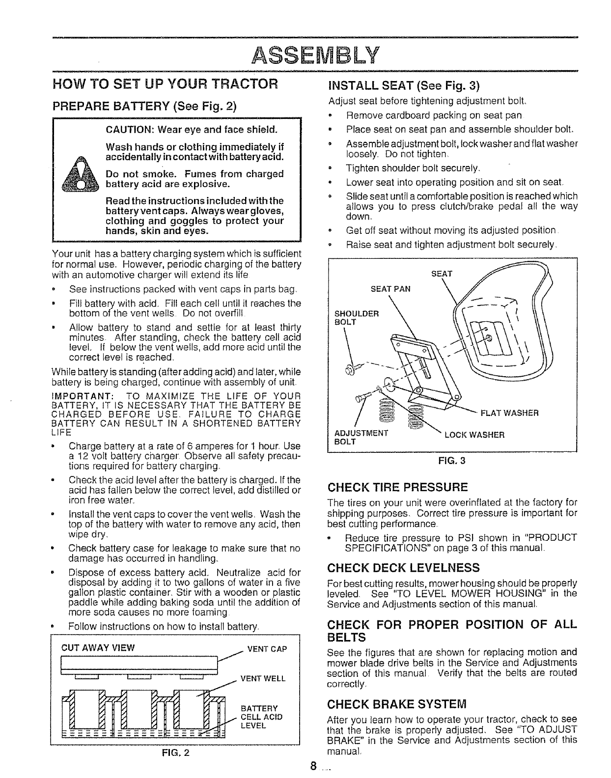
INSTALL SEAT (See Fig. 3)
Adjust seat before tightening adjustment bolt.
•Remove cardboard packing on seat pan
o Place seat on seat pan and assemble shoulder bolt.
. Assemble adjustment bolt, lock washer and flat washer
loosely Do not tighten,
o Tighten shoulder bolt securely
. Lower seat into operating position and sit on seat
. Slide seat until acomfortable position is reached which
allows you to press clutch/brake pedal all the way
down
o Get off seat without moving its adjusted position
. Raise seat and tighten adjustment bolt securely,
SEAT
SEAT PAN
SHOULDER
BOLT
ADJUSTMENT
BOLT
FLAT WASHER
LOC!( WASHER
FIG. 3
CHECK TIRE PRESSURE
The tires on your unit were overinffated at the factory for
shipping purposes, Correct tire pressure is important for
best cutting performance
oReduce tire pressure to PSI shown in "PRODUCT
SPECIFICATIONS" on page 3 of this manual
CHECK DECK LEVELNESS
For best cutting results, mower housing should be properly
leveled See 'q_O LEVEL MOWER HOUSING" in the
Service and Adjustments section of this manual
CHECK FOR PROPER POSITION OF ALL
BELTS
See the figures that are shown for replacing motion and
mower blade drive belts in the Service and Adjustments
section of this manual Verify that the belts are routed
correctly.
CHECK BRAKE SYSTEM
After you learn how to operate your tractor, check to see
that the brake is properly adjusted. See "TO ADJUST
BRAKE" in the Service and Adjustments section of this
manual.
ASSEMBLY
= __.
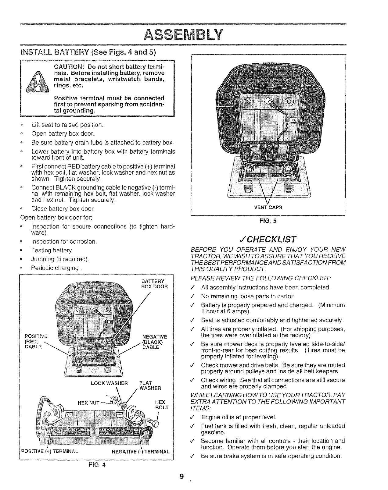
INSTALL BATTERY (See Figs. 4 and 5)
CAUT_,ON: Do not short battery termi-
nals. Before installing battery, remove
metal bracelets, wristwatch bands,
rings, etc.
Positive terminal must be connected
fil'st to prevent sparking from acciden-
tal grounding.
•Lift seat to raised position.
oOpen battery box door
• Be sure battery drain tube is attached to battery box.
o Lower battery into battery box with battery terminals
toward front of unit.
o First connect RED battery cable to positive (+) terminal
witiq hex bolt, fiat washer, lock washer and hex nut as
shown Tighten securely.
o Connect BLACK grounding cable to negative (-) termi_
hal with remaining hex bolt, flat washer, lock washer
and hex nut Tighten securely.
o Close battery box door
Open battery box door for:
Inspection for secure connections (to tighten hard-
ware)
o Inspection for corrosion.
= Testing battery.
Jumping (if requiled)
o Periodic charging
BATTERY
BOX DOOR
POSITIVE NEGATIVE
(RED) ..,..,,.. (BLACK)
CABLE CABLE
POSITIVE (+) TERMINAL
LOCKWASRER FLAT
_./- _L /WASHER
,._ .... 'Y((._,,_'_] BOLT
_/
NEGATIVE (-) TERMINAL
FIG, 4
VENT CAPS
FIG. 5
v'CHECKLIST
BEFORE YOU OPERATE AND ENJOY YOUR NEW
TRACTOR, WE WISH TO ASSURE THAT YOU RECEIVE
THE BEST PERFORMANCE AND SA TISFA CTION FROM
THIS QUALITY PRODUCT
PLEASE REWEW THE FOLLOWING CHECKLIST:
v" All assembly instructions have been completed
v" No remaining loose parts in carton
¢" Battery is properly prepared and charged, (Minimum
1 hour at 6 amps)..
,/ Seat is adjusted comfortably and tightened securely
,/ All tires are properly inflated. (For shipping purposes,
the tires were overinftated at the factory)
,/ Be sure mower deck is properly leveled side-to-sidet
front-to-rear for best cutting results (Tires must be
properly inflated for leveling).
,/ Check mower and drive belts. Be sure they are routed
properly around pulleys and inside all belt keepers.
,/ Check wiring See that all connections are still secure
and wires are properly clamped.
WHILE LEARNING HOW TO USE YOUR TRA CTOR, PAY
EXTRA ATTENTION TO THE FOLLOWING IMPORTANT
ITEMS:'
,/ Engine oil is at proper level.
,/ Fuel tank is filled with fresh, clean, regular unleaded
gasoline.
v' Become familiar with all controls - their location and
function. Operate them before you start the engine
¢" Be sure brake system is in safe operating condition.
9
OPERATION
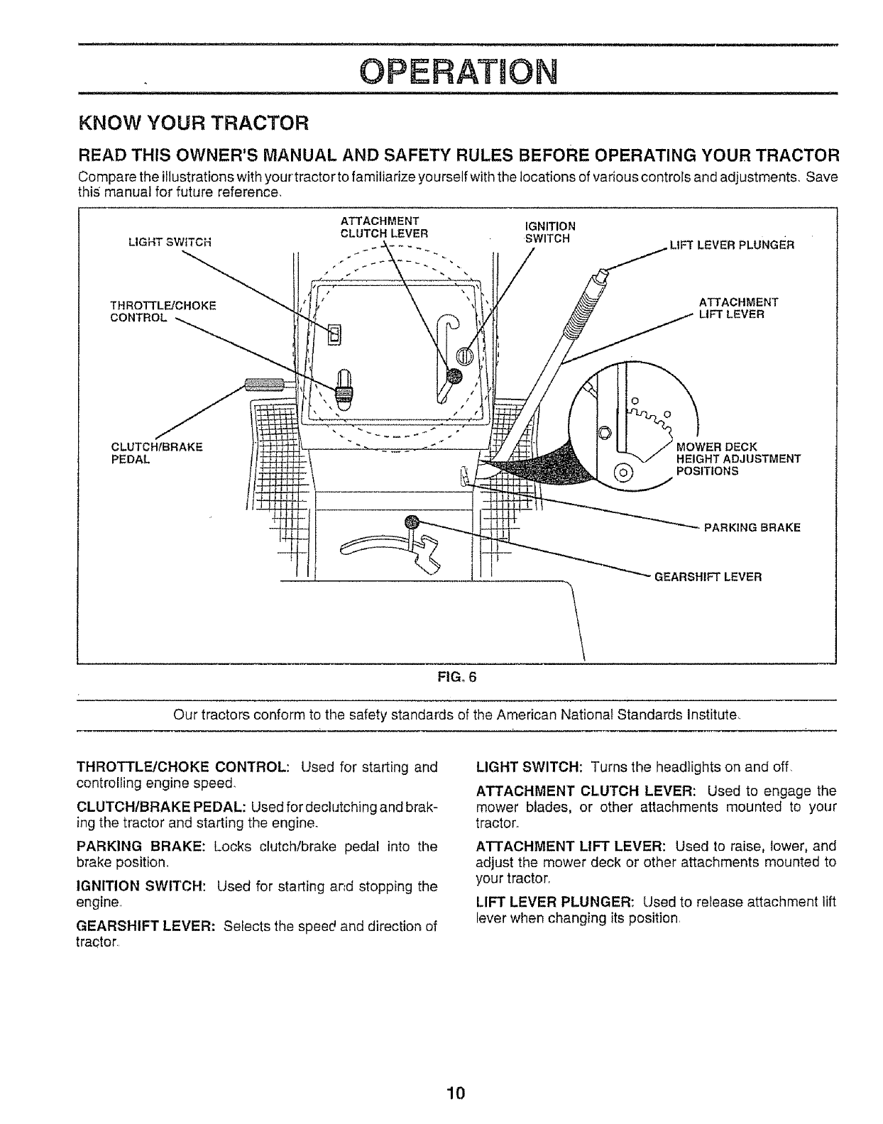
KNOW YOUR TRACTOR
READ THIS OWNER'S MANUAL AND SAFETY RULES BEFORE OPERATING YOUR TRACTOR
Compare the i!lustrations with your tractor to familiarize yourself with the locations of various controls and adjustments,, Save
this manual for future reference
LIGHT SWITCH
THROTTL_CHOKE
CONTROL
ATTACHMENT IGNITION
CLUTCH LEVER SWITCH LIFT LEVER PLUNGER
ATTACHMENT
LIFT LEVER
CLUTCHfBRAKE
PEDAL HEIGHT ADJUSTMENT
POSITIONS
PARKING BRAKE
GEARSHIFT LEVER
FIGo 6
Our tractors conform to the safety standards of the American National Standards Institute,
THROTTLE/CHOKE CONTROL: Used for starting and
controlling engine speed.
CLUTCH/BRAKE PEDAL: Used for dechJtching and brak-
ing the tractor and starting the engine.
PARKING BRAKE: Locks clutch/brake pedal into the
brake position_
IGNITION SWITCH: Used for starting and stopping the
engine
GEARSHIFT LEVER: Selects the speed and direction of
tractor
LIGHT SWITCH: Turns the headlights on and off.
ATTACHMENT CLUTCH LEVER: Used to engage the
mower blades, or other attachments mounted to your
tractor.
ATTACHMENT LIFT LEVER: Used to raise, lower, and
adjust the mower deck or other attachments mounted to
your tractorr
LIFT LEVER PLUNGER: Used to release attachment lift
lever when changing its position.
10
OPERATUON
'----_ Th_ operation of any tractor can result in foreign objects thrown into the eyes, wh_
[_ssE_ result in severe eye damage. Always wear safety glasses or eye shields while operating i
__ your tractor or performing any adjustments or repairs. We recommend a wide vision safety J
mask for over the spectacles or standard safety glasses.
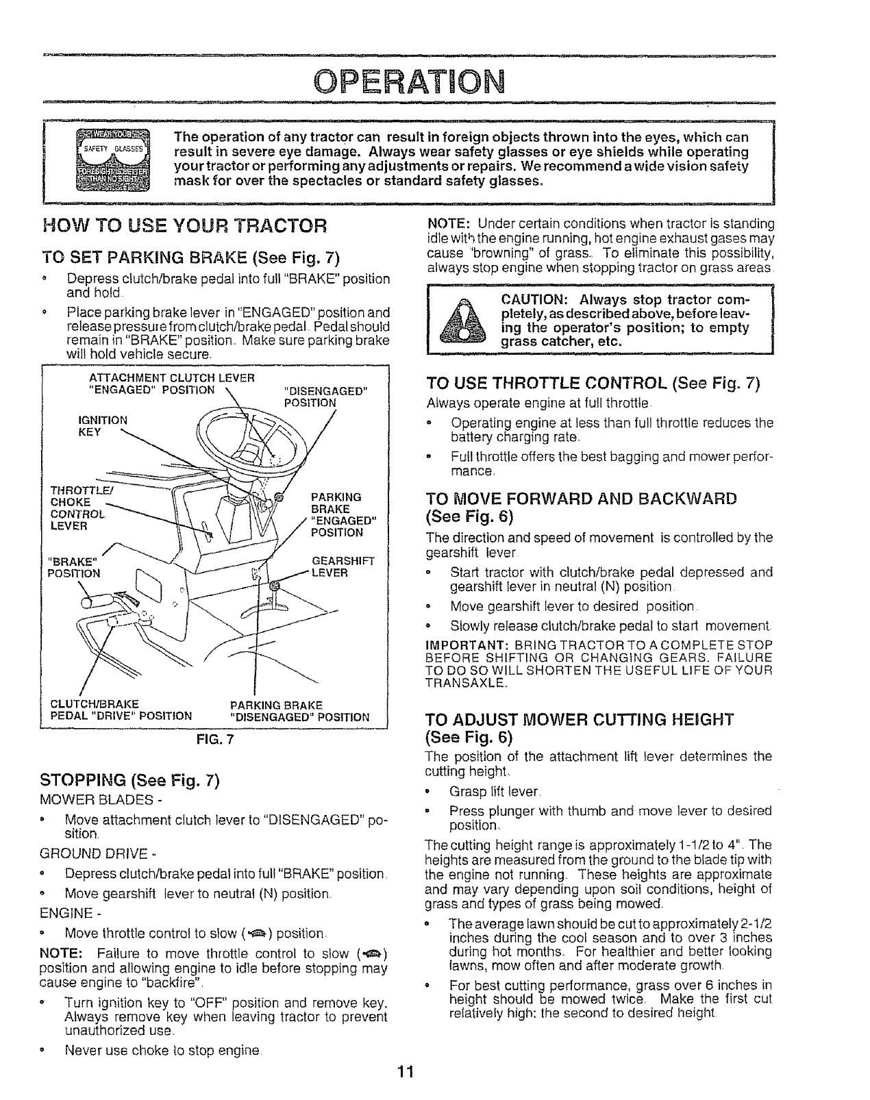
HOW TO USE YOUR TRACTOR
TO SET PARKING BRAKE (See Fig. 7)
o Depress clutch/brake pedal into fuli "BRAKE" position
and hold
o Place parking brake lever in "ENGAGED" position and
release pressure from clutch!brake pedal Pedal should
remain in "BRAKE" position. Make sure parking brake
will hold vehicle secure,
NOTE: Under certain conditions when tractor is standing
idle with the engine running, hot engine exhaust gases may
cause "browning" of grass.. To eliminate this possibility,
always stop engine when stopping tractor on grass areas
CAUTION: Always stop tractor com-
pletely, as described above, before leav-
ing the operator's position; to empty
grass catcher, etc.
ATTACHMENT CLUTCH LEVER
"ENGAGED" POSITION
IGNITION
KEY
"DISENGAGED"
POSITION
THROTTL_ PARKING
CHOKE BRAKE
LEVER POSITION
"BRAKE" GEARSHIFT
POSITION
CLUTCH/BRAKE
PEDAL "DRIVE" POSITION PARKING BRAKE
"DISENGAGED" POSITION
FIG. 7
STOPPING (See Fig. 7)
MOWER BLADES -
• Move attachment clutch lever to "DISENGAGED" po-
sit{on.
GROUND DRIVE -
•Depress clutch/brake pedal into full "BRAKE" position.
, Move gearshift lever to neutral (N) position.
ENGINE -
• Move throttle control to slow (',_,) position.
NOTE: Failure to move throttle control to stow (,_)
position and allowing engine to idle before stopping may
cause engine to "backfire".
o Turn ignition key to "OFF" position and remove key.
Always remove key when leaving tractor to prevent
unauthorized use.
•Never use choke to stop engine
TO USE THROTTLE CONTROL (See Fig. 7)
Always operate engine at full throttle.
oOperating engine at less than full throttle reduces the
battery charging rate.
,Full throttle offers the best bagging and mower perfor-
mance.
TO MOVE FORWARD AND BACKWARD
(See Fig. 6)
The direction and speed of movement is controlled by the
gearshift lever
-Start tractor with clutch/brake pedal depressed and
gearshift lever in neutral (N) position
- Move gearshift lever to desired position.
= Slowly release clutch/brake pedal to start movement
IMPORTANT: BRING TRACTOR TO A COMPLETE STOP
BEFORE SHIFTING OR CHANGING GEARS. FAILURE
TO DO SO WILL SHORTEN THE USEFUL LIFE OF YOUR
TRANSAXLE..
TO ADJUST MOWER CUTTING HEIGHT
(See Fig. 6)
The position of the attachment lift lever' determines the
cutting height,
o Grasp lift lever.
• Press plunger with thumb and move lever to desired
position,
The cutting height range is approximately 1-1/2 to 4", The
heights are measured from the ground to the blade tip with
the engine not running These heights are approximate
and may vary depending upon soil conditions, height of
grass and types of grass being mowed.
• The average lawn should be cut to approximately 2-1/2
inches during the cool season and to over 3 inches
during hot months.. For healthier and better _ooking
lawns, mow often and after moderate growth
o For best cutting performance, grass over 6 inclqes in
height should be mowed twice. Make the first cut
relatively high: the second to desired height
11
OPERATIO
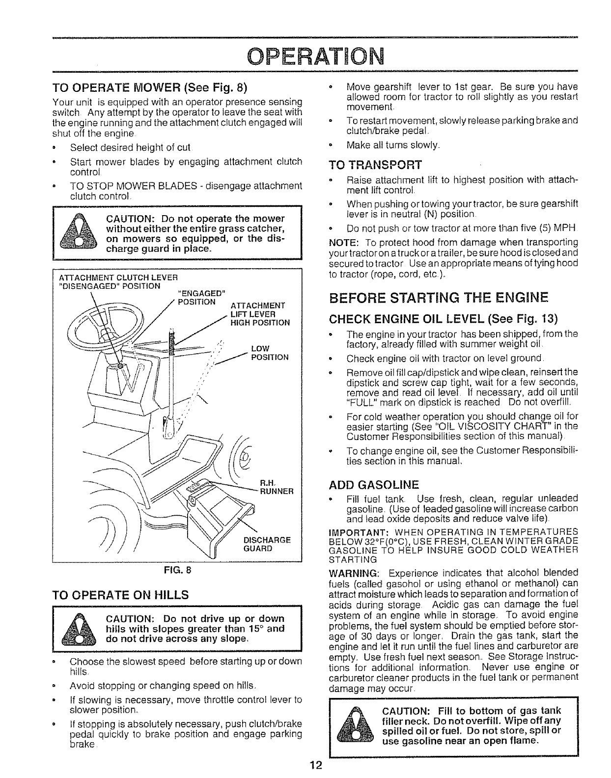
TO OPERATE MOWER (See Fig. 8)
Your unit is equipped with an operator presence sensing
switch Any attempt by the operator to leave the seat with
the engine running and the attachment clutch engaged will
shut off the engine
• Select desired height of cut
• Start mower biades by engaging attachment clutch
contr'ol
. TO STOP MOWER BLADES - disengage attachment
clutch control.
CAUTION: Do not operate the mower
without either the entire grass catcher,
on mowers so equipped, or the dis-
charge guard in place.
i l i, i llll lul,, H,HI
ATTACHMENT CLUTCH LEVER
"DISENGAGED" POSITION "ENGAGED"
POSITION A]-[ACHMENT
LIFT LEVER
HIGH POSITION
FIG. B
TO OPERATE ON HILLS
CAUTION: Do not drive up or down i
hills with slopes greater than 15° and
do not drive ac!0s s any S!0Pe. I
-Choose the slowest speed before starting up or down
hilfs
- Avoid stopping or changing speed on hills
•If slowing is necessary, move throttle control lever to
slower position_
° tf stopping is absofutefy necessary, push clutch!brake
pedal quickly to brake position and engage parking
brake
o Move gearshift lever to 1st gear. Be sure you have
allowed room for tractor to roll slightly as you restart
movement.
- To restart movement, slowly release parking brake and
clutch/brake pedal
o Make all turns slowly.
TO TRANSPORT
oRaise attachment lift to highest position with attach-
ment lift control
o When pushing or towing your tractor, be sure gearshift
lever is in neutral (N) position
o Do not push or tow tractor at more than five (5) MPH
NOTE: To protect hood from damage when transporting
your tractor on atruck or a trailer, be sure hood is closed and
secured to tractor Use an appropriate means of tying hood
to tractor (rope, cord, etc)_
BEFORE STARTING THE ENGINE
CHECK ENGINE OIL LEVEL (See Fig. 13)
oThe engine in your tractor has been shipped, from the
factory, already filled witi_ summer weight oil.
. Check engine oil with tractor on level ground.
° Remove oil fill cap/dipstick and wipe clean, reinsert the
dipstick and screw cap tight, wait for a few seconds,
remove and read oil level. If necessary, add oil until
"FULL" mark on dipstick is reached Do not overfill..
- For cold weather operation you should change oil for
easier starting (See "OIL VISCOSITY CHART" in the
Customer Responsibilities section of this manual)
o To change engine oil, see the Customer Responsibili-
ties section in this manual,
ADD GASOLINE
° Fill fuel tank. Use fresh, clean, regular unleaded
gasoline. (Use of leaded gasoline will increase carbon
and lead oxide deposits and reduce valve life)
IMPORTANT: WHEN OPERATING IN TEMPERATURES
BELOW 32°F(0°C), USE FRESH, CLEAN WINTER GRADE
GASOLINE TO HELP INSURE GOOD COLD WEATHER
STARTING
WARNING: Experience indicates that alcohol blended
fuels (called gasohol or using ethanol or methanol) can
attract moisture which leads to separation and formation of
acids during storage Acidic gas can damage the fuel
system of an engine while in storage.. To avoid engine
problems, the fuel system should be emptied before stor-
age of 30 days or longer, Drain the gas tank, start the
engine and let it Fun until the fuel lines and carburetor are
empty, Use fresh fuel next season.. See Storage Instruc-
tions for additional information. Never use engine or
carburetor cleaner products in the fuel tank or permanent
damage may occur.
CAUTION: Fill to bottom of gas tank
filler neck. Do not overfill. Wipe off any
spilled oil or fuel. Do not store, spill or
use gasoline near an open flame.
12
OPERATmON
TO START ENGINE (See Fig, 7)
When starting engine for the first time or if engine has run
out of fuel, it will take extra cranking time to move fuel from
the tank to the engine
o Depress clutch/brake pedal and set parking brake.
• Place gearshift lever in neutral (N) position
Move attachment clutch to "DISENGAGED" position
• Move throttle control lever to choke (t',,l) position for
cold engine start.. For warm engine start, move throttle
control to fast (,9) position.
• lnsert key into ignition and turn key clockwise to"START"
position and release key as soon as engine starts. Do
not run starter continuously for more than fifteen
seconds per minute_ If engine does not start after
several attempts, move throttle control to fast (,9)
position, wait a few minutes and try again.
• When engine starts, move throttle control to desired
position.
• Allow engine to warm up for a few minutes before
engaging drive or attachments
NOTE: If at a high altitude (above 3000 feet) or in cold
temperatures (below 32°F), the carburetor fuel mixture
may need to be adjusted for best engine performance See
"TO ADJUST CARBURETOR" in the Service and Adjust-
ments section of this manual
MOWING TRPS
• Tire chains cannot be used when the mower housing
is attached to unit.
o Mower should be properly leveled for best mowing
performance. See'%Q LEVEL MOWER HOUSING" in
the Service and Adjustments section of this manual
• Use the runner on the right hand side of mower as a
guide The blade cuts approximately an inch outside
the runner (See Fig. 8).
• The left hand side of mower should be used for trim-
ming
, Drive so that clippings are discharged onto the area
that has been cuL Have the cut area to the right of the
machine. This will result in a more even distribution of
clippings and more uniform cutting.
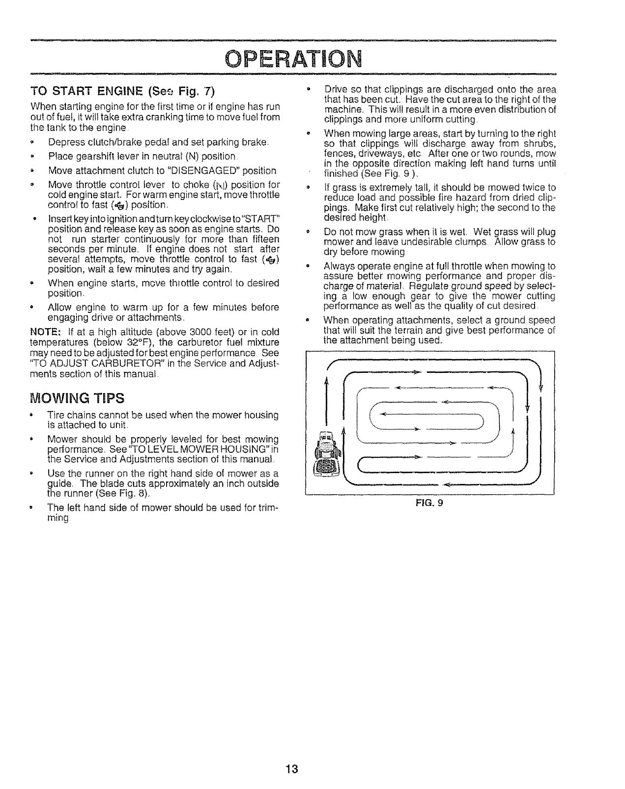
oWhen mowing large areas, start by turning to the right
so that clippings wilt discharge away from shrubs,
fences, driveways, etc After' one or two rounds, mow
in the opposite direction making left hand turns until
finished (See Fig. 9 ).
If grass is extremely tall, it should be mowed twice to
reduce load and possible fire hazard from dried clip-
pings. Make first cut relatively high; the second to the
desired height
o Do not mow grass when it is wet. Wet grass will plug
mower and leave undesirable clumps Allow grass to
dry before mowing
oAlways operate engine at full throttle when mowing to
assure better mowing performance and proper dis-
charge of material. Regulate ground speed by select-
ing a low enough gear to give the mower cutting
performance as well as the quality of cut desired
• When operating attachments, select a ground speed
that will suit the terrain and give best performance of
the attachment being used..
f
c
,_J
FIG. 9
13
MAINTENANCE SCHEDULE ............... / ._
FILL,NOATES
AS YOU COMPLETE __,._O_"_v _.. -., _ _ -, -,, ,'c'-.
o _ _ _ ÷_._ _o 0AT S
Check Brake Operalion V #
Check Tire Pressure
T Check for Loose Fasteners
R ShaipeniRePiace Mower Blades
_ Lubrication Chart
T Check BatteryLevetlRecharge
0 Clean Battery and Terminals
R CheckTransaxle Cooling
Adjust Blade Belt(s) Tension
Adjust Motion Drive Belt(s) Tension
Check Engine Oil Level
Change Engine Oil 6#4
Clean Air Filter
E ..................
NClean Air Screen...................................
G Inspect Muffler/Spark Arrestor
Replace Oil Filter (If equipped)
N=CleaoEngineCoo_ngFi'nS....
Replace Spark Plug
Replace Air Filter Paper Cartridge
Replace Fuel Filfer
v'
e,' v' ......
e,' e,,'
e,'
Iiv'0 .......
l
V' d2.3 ei ....
• , . =,,_ 1_2
v'2 I
I .......v' .........I
1 - Change more ellen when operaling under a heavy load or in high ambient tempm'atures
2 - Service more otlen when operating in dirty or dusly cendilions
3 - It equipped with oil _'iller. change oil every 50 hours
4 - Replace blades more often when mowing in sandy soil
5 - It equipped with adjustable system
GENERAL RECOMMENDATIONS
The warranty on this tractor does not cover items that have
been subjected to operator abuse or negligence To
receive full value from the warranty, operator must maintain
tractor as instructed in this manual,
Some adjustments will need to be made periodically to
properly maintain your tractor.
All adjustments in the Service and Adjustments section of
this manual should be checked at least once each season
o Once a year you should replace the spark plug, clean
or replace air filter, and check blades and belts for
wear. A new spark plug and clean air filter assure
proper air-fuel mixture and help your engine run better
and last longer
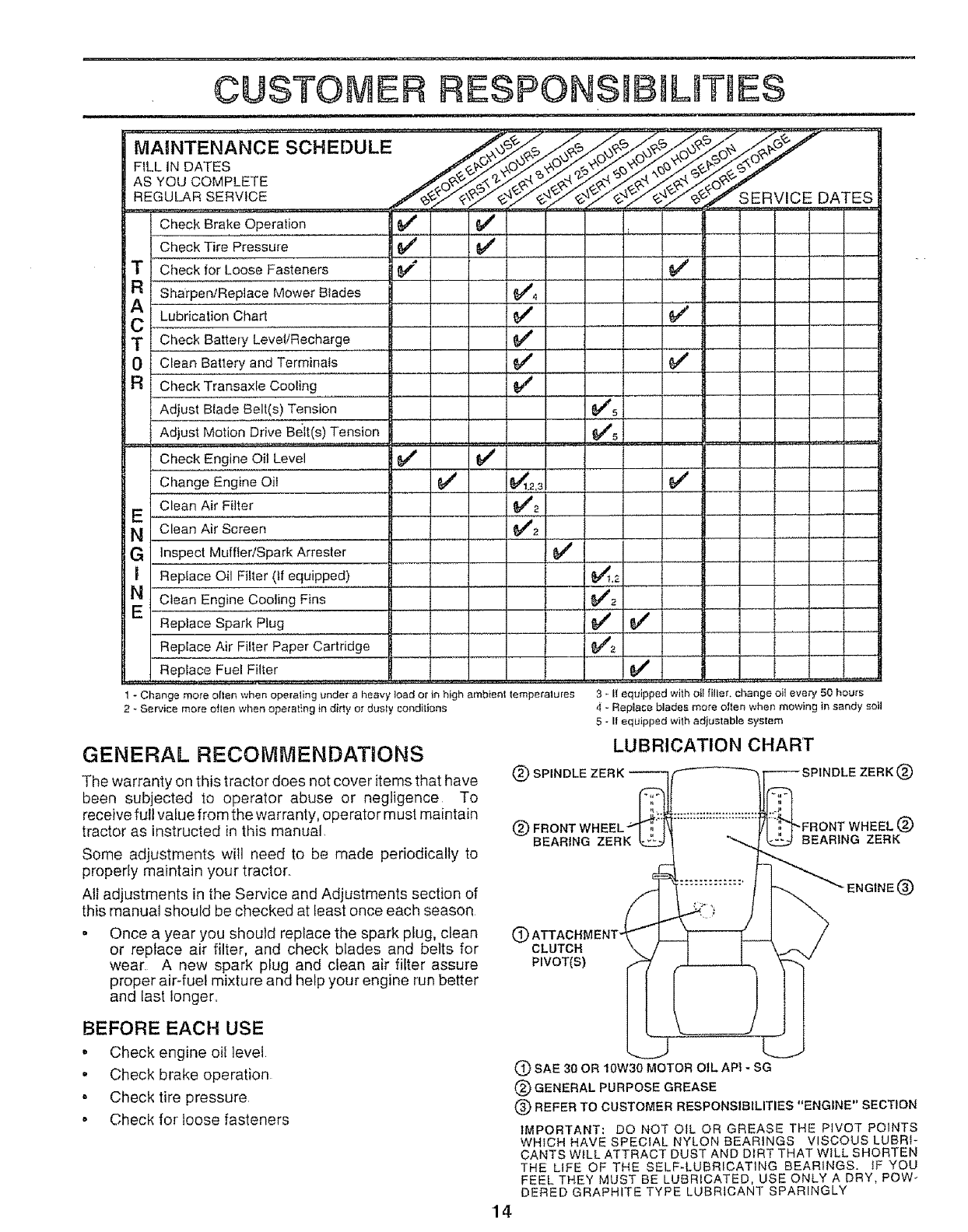
LUBRICATION CHART
(_ SPINDLE ZERK ------__ _F_- SPINDLE ZERK (_)
@ FRONTWBEEL_F_i_ !/I !q"FBONTWHEELQ
BEARING ZERK _! "--.._ _ BEARING ZERK
(_) ATTACHMENT-
CLUTCH
PIVOT(S)
BEFORE EACH USE
,' Check engine oil level
" Check brake operation
, Check tire pressure
o Check for loose fasteners
14
ENGINE (_)
(_) SAE 30 OR 10W30 MOTOR OIL APf - SG
(_) GENERAL PURPOSE GREASE
(_ REFER TO CUSTOMER RESPONSIBILITIES "ENGINE" SECTION
IMPORTANT: DO NOT OIL OR GREASE THE PIVOT POINTS
WHICH HAVE SPECIAL NYLON BEARINGS VISCOUS LUBRI-
CANTS WiLL ATTRACT DUST AND DIRT THAT WILL SHORTEN
THE LiFE OF THE SELF-LUBRICATING BEARINGS. IF YOU
FEEL THEY MUST BE LUBRICATED, USE ONLY A DRY, POW-
DERED GRAPHITE TYPE LUBRICANT SPARINGLY
TRACTOR
Always observe safety rules when performing any mainte-
nance.
BRAKE OPERATION
If tractor requires more than six (6) feet stopping distance
at high speed in highest gear; then brake must be adjusted
(See "TO ADJUST BRAKE" in the Service and Adjust-
ments section of this manual).
TIRES
Maintain proper air pressure in all tires (See "PROD-
UCT SPECIFICATIONS" on page 3 of this manual)
. Keep tires free of gasoline, oil, or insect control chemi-
cals which can harm rubber..
• Avoid stumps, stones, deep ruts, sharp objects and
other hazards that may cause tire damage.
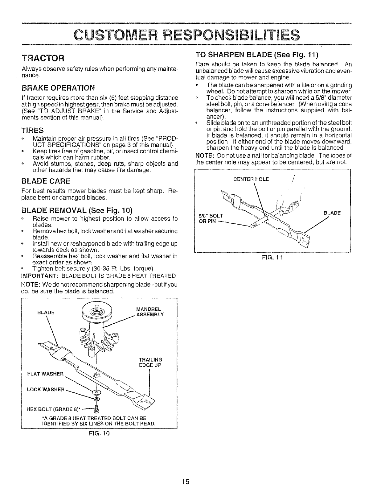
BLADE CARE
For best results mower blades must be kept sharp.. Re-
place bent or damaged blades.
BLADE REMOVAL (See Fig. 10)
,, Raise mower to highest position to allow access to
blades,
Remove hex bott, lock washer and flat washer securing
blade.
o Install new or resharpened blade with trailing edge up
towards deck as shown.
o Reassemble hex bolt, lock washer and flat washer in
exact order as shown
. Tighten bolt securely (30-35 Ft Lbs torque)
IMPORTANT: BLADE BOLT iS GRADE 8 HEAT TREATED
NOTE: We do not recommend sharpening blade- but if you
do, be sure the blade is balanced
TO SHARPEN BLADE (See Fig. 11)
Care should be taken to keep the blade balanced An
unbalanced blade will cause excessive vibration and even-
tual damage to mower and engine..
• The blade can be sharpened with a file or on a grinding
wheel,. Do not attempt to sharpen while on the mower.
• To check blade balance, you will need a 5/8" diameter
steel bolt, pin, or a cone balancer (When using a cone
balancer, follow the instructions supplied with bal-
ancer).
• Slide blade on to an unthreaded portion of the steel bolt
or pin and hold the bolt or pin parallel with the ground.
if blade is balanced, it should remain in a horizontal
position. If either end of the blade moves downward,
sharpen the heavy end until the blade is balanced
NOTE: Do not use a nail for balancing blade The lobes of
the center hole may appear to be centered, but are not
518" BOLT
OR PIN
CENTER HOLE
\
FIG. 11
_MANDREL
BLADE ASSEMBLY
1 TRAILING
EDGEUP
FLAT WASHER
HEX BOLT (GRADE
'A GRADE 8 HEAT TREATED BOLT CAN BE
IDENTIFIED BY SIX LINES ON THE BOLT HEAD°
FIG. 10
15
CUSTOME RESPONSmB LmT ES
ii, nl ,i
SAE VISCOSITY GRADES
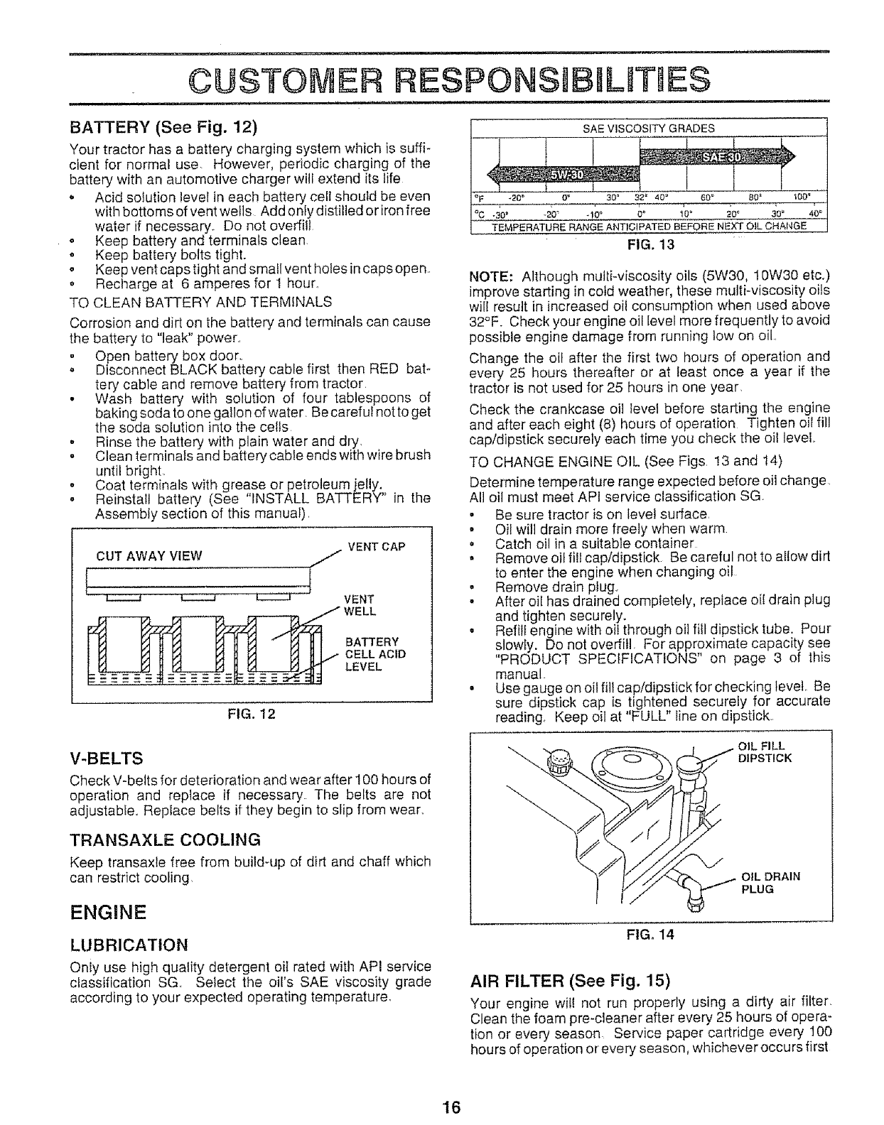
BATTERY (See Fig. 12)
Your tractor has a battery charging system which is suffi-
cient for normal use However, periodic charging of the
battery with an automotive charger will extend its life
.Acid solution level in each battery celi should be even
with bottoms of vent wells Add only distilled oriron free
water if necessary., Do not overfill
o Keep battery and terminals clean
. Keep battery bolts tight.
o Keep vent caps tight and smaflvent holesin caps open,.
o Recharge at 6 amperes for 1 hour
TO CLEAN BATTERY AND TERMINALS
Corrosion and dirt on the battery and terminals can cause
the battery to "leak" power,
o Open battery box door,
o Disconnect BLACK battery cable first then RED bat-
tery cable and remove battery from tractor,
• Wash battery with solution of four tablespoons of
baking soda to one gallon of water Be careful not to get
the soda solution into the cells
• Rinse the battery with plain water and dry,
• Clean terminals and battery cable ends with wire brush
until bright,
• Coat terminals with grease or petroleum jelly.
• Reinstall battery (See "INSTALL BATTERY" in the
Assembly section of this manual),
VENT CAP
CUT AWAY VIEW /
L VENT
WELL
BATTERY
CELL ACID
LEVEL
FIG. 12
-20 ° 0°30" 60 ° 80'
TEMPERATURE RANGE ANT}CIPATEO BEFORE NEXT O}L CHANGE
FIG. 13
NOTE: Although mulli-viscosity oils (5W30, 10W30 etc.)
improve starting in cold weather, these multi-viscosity oils
will resuit in increased oil consumption when used above
32°F. Check your engine oil level more frequently to avoid
possible engine damage from running low on oil,,
Change the oil after the first two hours of operation and
every 25 hours thereafter or at least once a year if the
tractor is not used for 25 hours in one year.
Check the crankcase oil tevel before starting the engine
and after each eight (8) hours of operation Tighten oil fill
cap!dipstick securely each time you check the oil level,,
TO CHANGE ENGINE OIL (See Figs, 13 and 14)
Determine temperature range expected before oil change,
All oil must meet API service classification SG
. Be sure tractor is on level surface,
• Oit will drain more freely when warm
o Catch oil in a suitable container
° Remove oil fill cap/dipstick Be careful not to allow dirt
to enter the engine when changing oil
• Remove drain plug.,
° After oil has drained completely, replace oi{ drain plug
and tighten securely.
• Refilf engine with oii through oil fill dipstick tube. Pour
slowly. Do not overfill. For approximate capacity see
"PRODUCT SPECIFICATIONS" on page 3 of this
manual
° Use gauge on oil fill cap!dipstick for checking level, Be
sure dipstick cap is tightened securely for accurate
reading Keep oil at "FULL" line on dipstick.,
V-BELTS
Check V-belts for deterioration and wear after 100 hours of
operation and replace if necessary The belts are not
adjustable., Replace belts if they begin to slip from wear,,
TRANSAXLE COOLING
Keep transaxle free from build-up of dirt and chaff which
can restrict cooling
ENGINE
LUBRICATION
Only use high quality detergent oil rated with API service
classification SG,, Select the oil's SAE viscosity grade
according to your expected operating temperature,
OIL FILL
DIPSTICK
OIL DRAIN
PLUG
FtGo 14
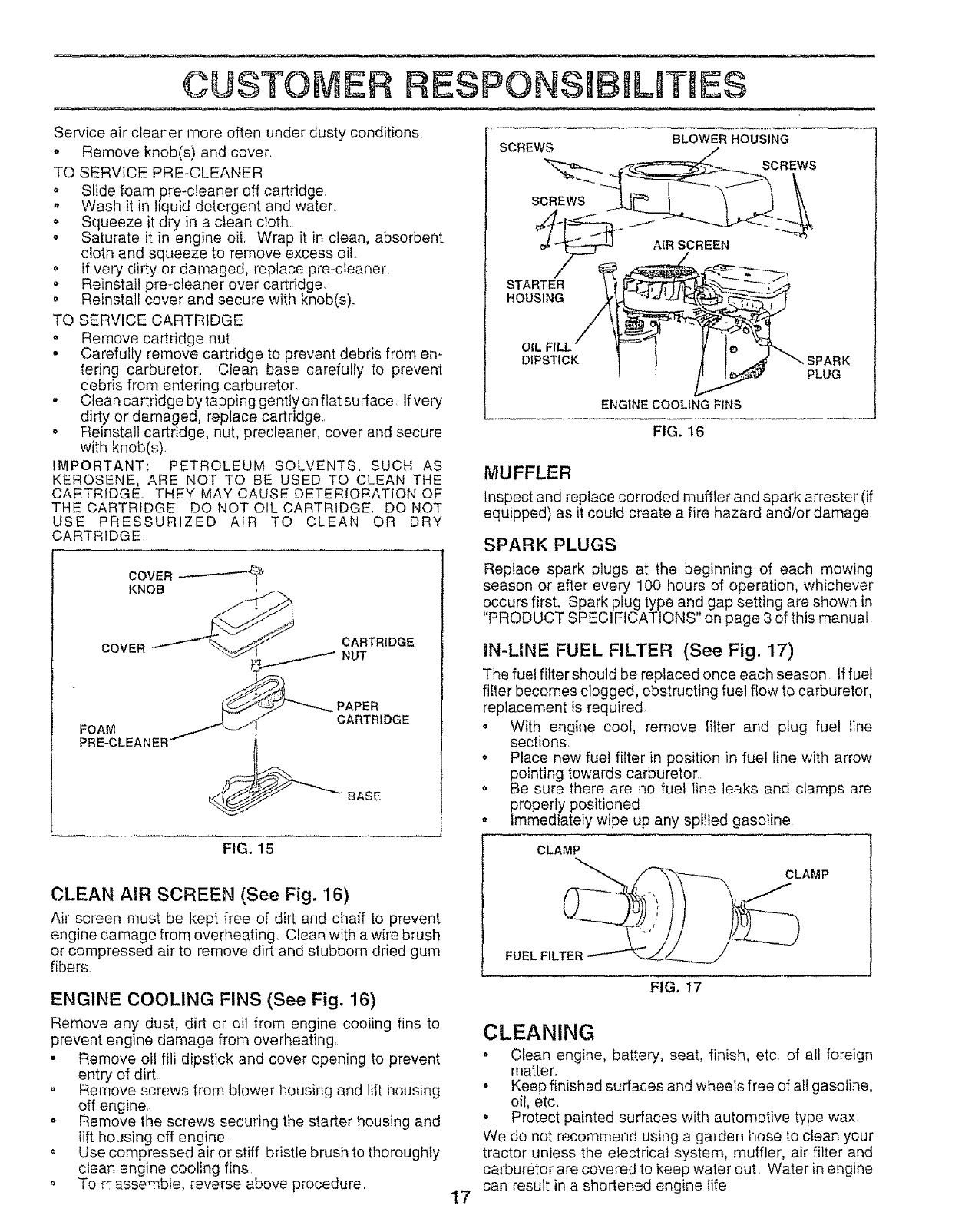
AIR FILTER (See Fig. 15)
Your engine wil! not run properly using a dirty air filter,
Clean the foam pre-cleaner after every 25 hours of opera-
tion or every season, Service paper cartridge every 100
hours of operation or every season, whichever occurs first
'16
CUSTOMER RESPONS BWLIT tES
Service air cleaner rnore often under dusty conditions
° Remove knob(s) and cover
TO SERVICE PRE-CLEANER
o Slide foam pre-cleaner off cartridge
.Wash it in liquid detergent and water,
oSqueeze it dry in a clean cloth
o Saturate it in engine oil, Wrap it in clean, absorbent
cloth and squeeze to remove excess oil,
o If very dirty or damaged, replace pre-cleaner
- Reinstall pre-cleaner over cartridge.
• Reinstall cover and secure with knob(s).,
TO SERVICE CARTRIDGE
o Remove cartridge nut,
• Carefully remove cartridge to prevent debris from en-
tering carburetor. Clean base carefully to prevent
debris from entering carburetor
o Clean cartridge by tapping gently on flat surface. Ifvery
dirty or damaged, replace cartridge.,
o Reinstall cartridge, nut, precleaner, cover and secure
with knob(s).
liVlPORTANT: PETROLEUM SOLVENTS, SUCH AS
KEROSENE, ARE NOT TO BE USED TO CLEAN THE
CARTRIDGE. THEY MAY CAUSE DETERIORATION OF
THE CARTRIDGE DO NOT OIL CARTRIDGE, DO NOT
USE PRESSURIZED AIR TO CLEAN OR DRY
CARTRIDGE
SCREWS BLOWER HOUSING
SCREWS
SCREWS
ENGINE COOLING FINS
FIG. 16
MUFFLER
inspect and replace corroded muffler and spark arrester (if
equipped) as it coutd create a fire hazard and/or damage
SPARK PLUGS
COVER
FOAM
PRE-CLEANER
CARTRIDGE
NUT
PAPER
CARTRIDGE
BASE
Replace spark plugs at the beginning of each mewing
season or after every 100 hours of operation, whichever
occurs first. Spark plug type and gap setting are shown in
"PRODUCT SPECIFICATIONS" on page 3 of this manual
IN-LINE FUEL FILTER (See Fig. 17)
The fuel filter should be replaced once each season If fuel
filter becomes clogged, obstructing fuel flow to carburetor,
replacement is required
o With engine cool, remove fitter and plug fuel !ine
sections.
o Place new fuel filter in position in fuel line with arrow
pointing towards carburetor.
oBe sure there are no fue! line leaks and clamps are
properly positioned.
• Immediately wipe up any spilled gasoline
FIG. 15
CLEAN AIR SCREEN (See Fig. 16)
Air screen must be kept free of dirt and cllaff to prevent
engine damage from overheating. Clean with a wire brush
or compressed air to remove dirt and stubborn dried gum
fibers
ENGINE COOLING FINS (See Fig. 16)
Remove any dust, dirt or oil from engine cooling fins to
prevent engine damage from overheating
" Remove oil fill dipstick and cover opening to prevent
entry of dirt
• Remove screws from blower housing and lift housing
off engine.
Remove the screws securing the starter housing and
lift housing off engine
o Use compressed air or stiff bristle brush to thoroughly
clean engine cooling fins
To r,- assemble, reverse above procedure,
CLAMP
FUEL FI_ LAMP
FIG. I7
17
CLEANING
° Clean engine, battery, seat, finish, etc. of alt foreign
matter,
oKeep finished surfaces and wheels free of all gasoline.
oil, etc.
-Protect painted surfaces with automotive type wax.
We de not recommend using a garden hose to clean your
tractor unless the electrical system, muffler, air filter and
carburetor are covered to keep water out Water in engine
can result in a shortened engine life
.................. i
SERWCE AND ADJUSTMENTS
ii i mllll i i ,, ,,,ll, :
i
CAUTION: BEFORE PERFORMING ANY SERVICE OR ADJUSTMENTS:
- Depress clutch!brake pedal fully and set parking brake.
o Place gearshift lever in neutral (N) position,
° Place attachment clutch in "DISENGAGED" position.
• Turn ignition key "OFF" and remove key.
oMake sure the blades and all moving parts have completely stopped.
oDisconnect spark plug wire from spark pug and place wire where it cannot come in contact with
plug.
............. ImINH
TRACTOR
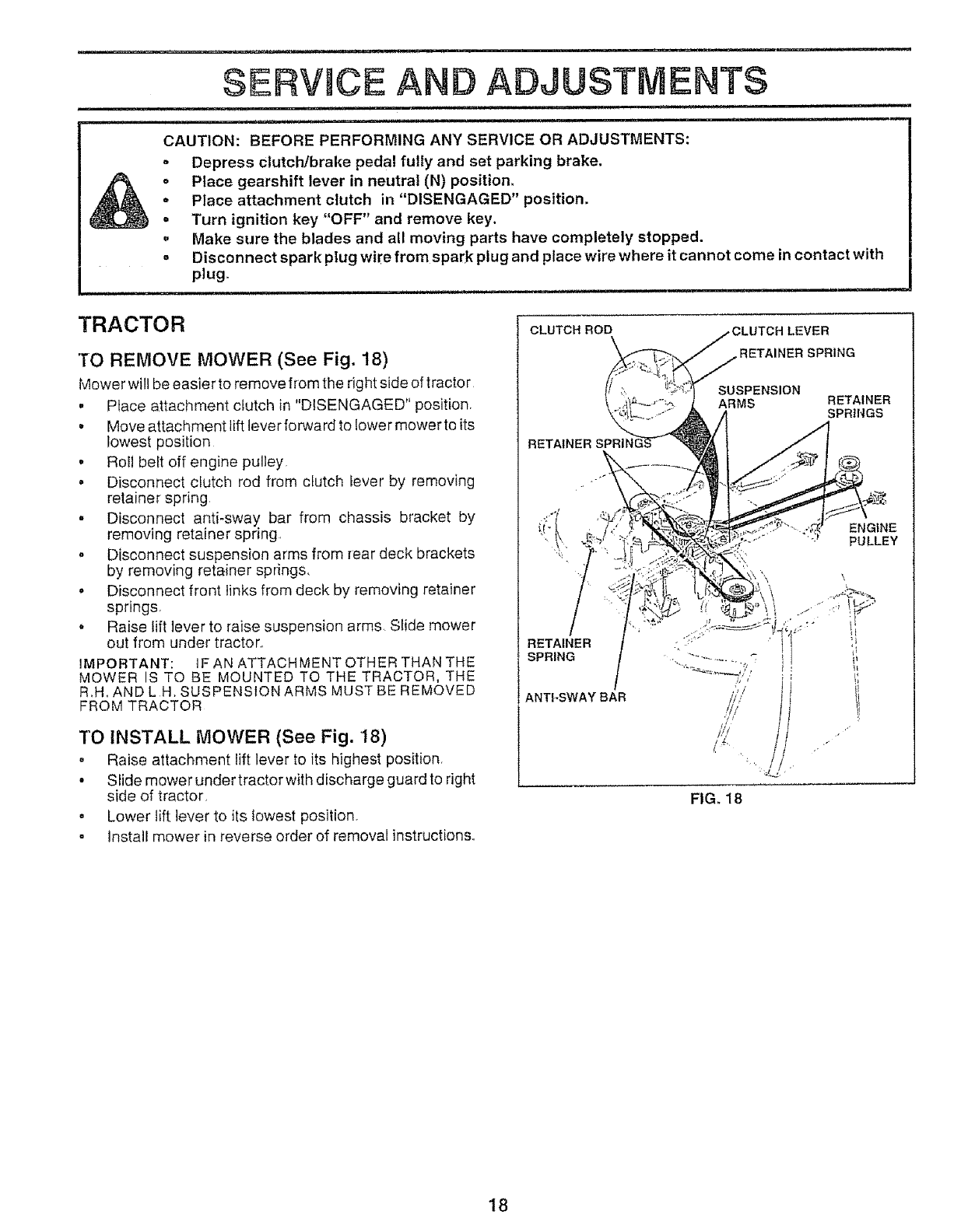
TO REMOVE MOWER (See Fig. 18)
Mower will be easier to remove from the right side of tractor
, Place attachment clutch in "DISENGAGED" position.
Move attachment lift lever forward to lower mower to its
lowest position
• Roll belt off engine pulley.
• Disconnect clutch rod from clutch lever by removing
retainer spring
° Disconnect anti-sway bar from chassis bracket by
removing retainer spring.
• Disconnect suspension arms from rear deck brackets
by removing retainer springs.
• Disconnect front links from deck by removing retainer
springs.
• Raise lift lever to raise suspension arms. Slide mower
out from under tractor..
IMPORTANT: tF AN ATTACHMENT OTHER THAN THE
MOWER IS TO BE MOUNTED TO THE TRACTOR, THE
R.H. AND L H. SUSPENSION ARMS MUST BE REMOVED
FROM TRACTOR
TO INSTALL MOWER (See Fig. 18)
, Raise attachment lift lever to its highest position.
• Slide mower under tractor with discharge guard to right
side of tractor.
• Lower lift lever to its lowest position.
• Install mower in reverse order of removal instructions..
CLUTCH ROD _LEVER
ETAINER SPRING
SUSPENSION
ARMS RETAINER
SPRINGS
RETAINER
ANTFSWAY BAR
ENGINE
PULLEY
FIG, 18
18
SERVICE AND ADJILIS:i:I ENTS
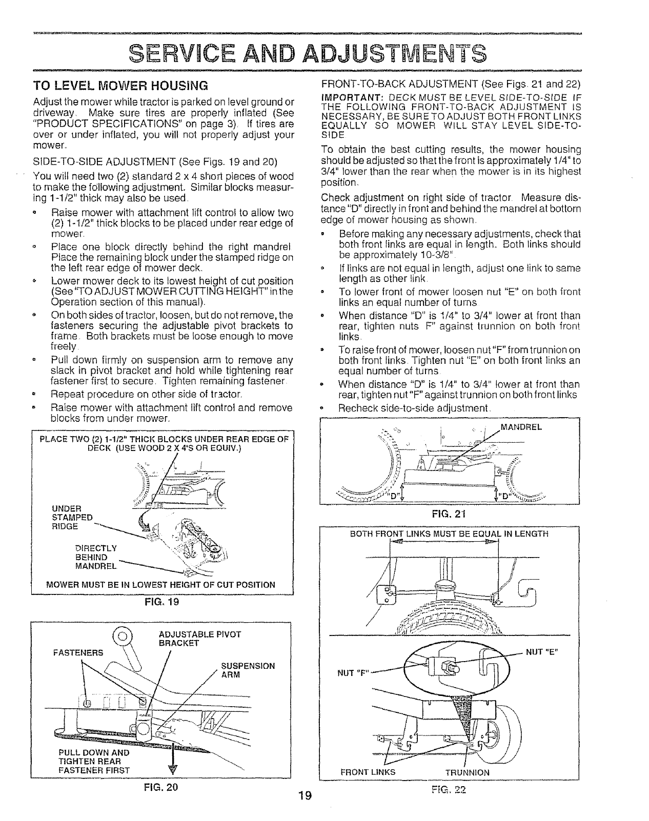
TO LEVEL MOWER HOUSING FRONT-TO-BACK ADJUSTMENT (See Figs, 2! and 22)
Adjust the mower while tractor is parked on level ground or
driveway, Make sure tires are properly inflated (See
"PRODUCT SPECIFICATIONS" on page 3), If tires are
over or under inflated, you wilt not properly adjust your
mower.,
SIDE-TO-SIDE ADJUSTMENT (See Figs. 19 and 20)
You will need two (2) standard 2 x 4 short pieces of wood
to make the following adjustment• Similar blocks measur-
ing 1-1/2" thick may also be used,
o Raise mower with attachment lift control to allow two
(2) 1-!/2" thick blocks to be placed under rear edge of
mower
o Place one block directly behind the right mandrel
Place the remaining block under the stamped ridge on
the left rear edge of mower deck.,
o Lower' mower deck to its lowest height of cut position
(See "TO ADJUST MOWER CUTTING HEIGHT" in the
Operation section of this manual).
On both sides of tractor, loosen, but do not remove, the
fasteners securing the adjustable pivot birackets to
frame Both brackets must be loose enough to move
freely
• Pull down firmly on suspension arm to remove any
slack in pivot bracket and hold while tightening rear
fastener first to secure Tighten remaining fastener
o Repeat procedure on other side of tractor,
. Raise mower with attachment lift control and remove
blocks from under mower,
PLACE TWO (2) 1-112" THICK BLOCKS UNDER REAR EDGE OF
DECK (USE WOOD 2 X 4'S OR EQUIVo)
FIG, 19
FASTENERS
ADJUSTABLEPIVOT
BRACKET
SUSPENSION
ARM
PULL DOWN AND
TIGHTEN REAR
FASTENER FIRST
FIG, 20
IMPORTANT: DECK MUST BE LEVEL SfDE-TO-SIDE IF
THE FOLLOWING FRONT-TO-BACK ADJUSTMENT IS
NECESSARY, BE SURE TO ADJUST BOTH FRONT LINKS
EQUALLY SO MOWER WILL STAY LEVEL SIDE-TO-
SIDE
To obtain the best cutting results, the mower housing
sl_ould be adjusted so that the front is approximately 1/4" to
3/4" lower than the rear when the mower is in its highest
position
Check adjustment on right side of tractor Measure dis-
tance"D" directly in front and behind the mandrel at bottom
edge of mower housing as shown,
. Before making any necessary adjustments, check that
both front links are equal in length., Both links should
be approximately 10-3/8"
o If links are not equal in tength, adjust one link to same
length as other link
. To lower front of mower loosen nut "E" on both front
links an equal number of turns
° When distance "D" is I/4" to 3/4" lower at front than
rear, tighten nuts F" against trunnion on both front
links.
o To raise front of mower, loosen nut"F" from trunnion on
both front links Tighten nut "E" on both front links an
equal number of turns
,, When distance "D" is 1/4" to 3/4" lower at front than
rear, tighten nut"F" against trunnion on both front links
o Recheck side-to-side adjustment,
• ,:._ :,_. , MANDREL
FIG. 2t
BOTH FRONT LINKS MUST BE EQUAL IN LENGTH
19
,, ,_ NUT
FRONT LINKS TRUNNION
F_G, 22
u,-i
SERVICE AND ADJUSTMENTS
i,i ,,, ,i, ill
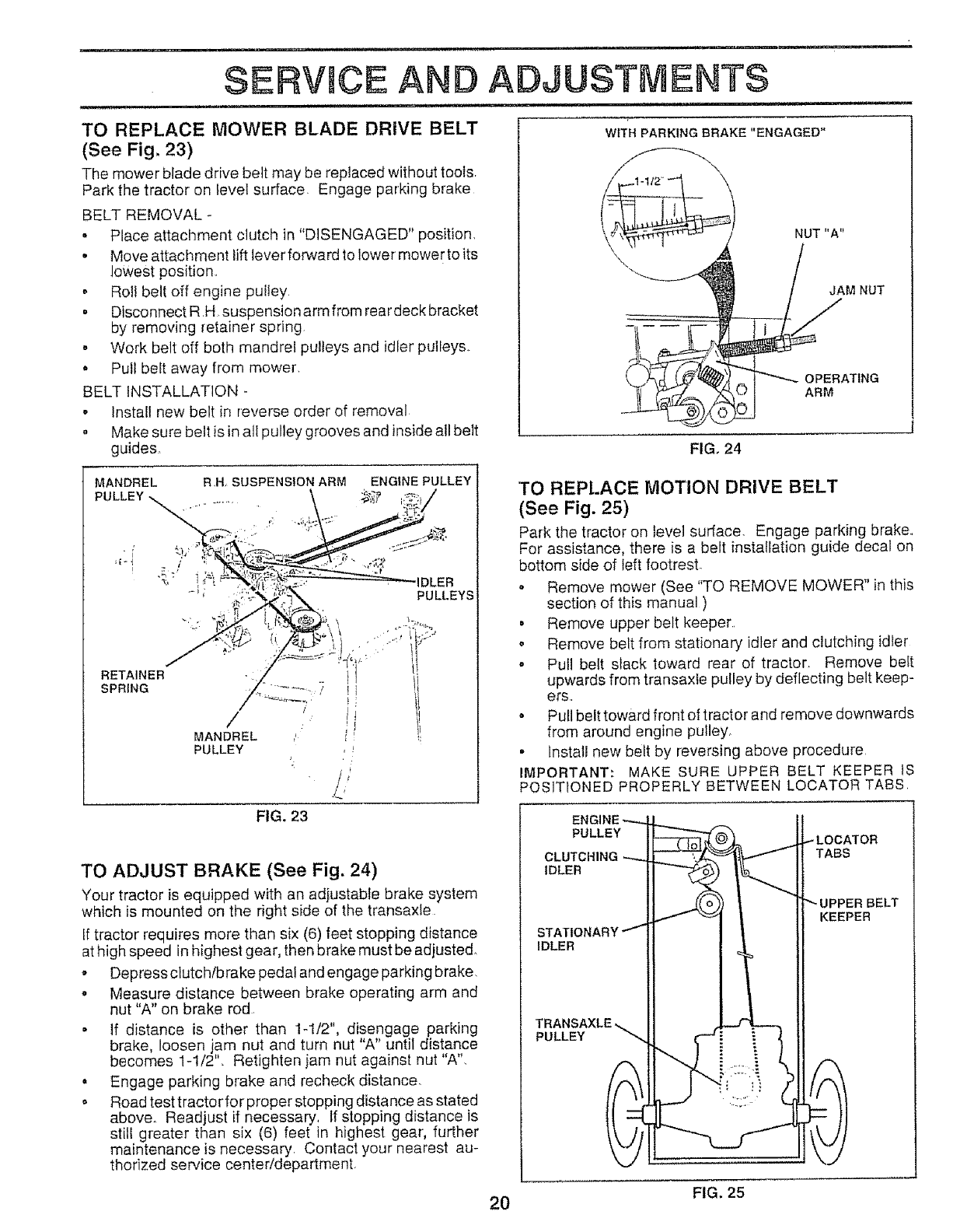
TO REPLACE MOWER BLADE DRIVE BELT
(See Fig. 23)
The mower blade drive belt may be replaced without toots
Park the tractor on level surface. Engage parking brake
BELT REMOVAL -
•Place attachment clutch in "DISENGAGED" position
• Move attachment lift lever forward to lower mower to its
lowest position,,
o Rol! belt off engine pultey,
•Disconnect R H, suspension arm from rear deck bracket
by removing retainer spring
° Work belt off both mandrel pulleys and idler pulleys,
•Pull belt away from mower,
BELT INSTALLATION -
.Install new belt in reverse order of removal
• Make sure belt is in all pulley grooves and inside all belt
guides.
WITH PARKING BRAKE "ENGAGED"
__ NUT "A"
J_f_M NUT
t _ OPERATING
(_ I ARM
FIG. 24
MANDREL R,H, SUSPENSION ARM ENGINE PULLEY
PULLEY :_';_
RETAINER
SPRING
/
MANDREL
PULLEY
PULLEYS
TO REPLACE MOTION DRIVE BELT
(See Fig. 25)
Park the tractor on fevei surface, Engage parking brake.,
For assistance, there is a belt installation guide decal on
bottom side of left footrest.
o Remove mower (See "TO REMOVE MOWER" in this
section of this manual )
• Remove upper belt keeper,,
o Remove belt from stationary idler and clutching idler
-Put] belt slack toward rear of tractor. Remove belt
upwards from transaxte pulley by deflecting belt keep-
ere,,
-Pull belt toward front of tractor and remove downwards
from around engine pulley
° Install new belt by reversing above procedure
IMPORTANT: MAKE SURE UPPER BELT KEEPER iS
POSITIONED PROPERLY BETWEEN LOCATOR TABS,
FIG. 23
TO ADJUST BRAKE (See Fig. 24)
Your tractor is equipped with an adjustable brake system
which is mounted on the right side of the transaxle
[f tractor requires more than six (6) feet stopping distance
at high speed in highest gear, then brake must be adjusted.
o Depress clutch/brake pedal and engage parking brake.
o Measure distance between brake operating arm and
nut "A" on brake rod
• If distance is other than 1-1/2", disengage parking
brake, loosen jam nut and turn nut "A" until distance
becomes 1-1/2L Reflghten jam nut against nut "A".
•Engage parking brake and recheck distance.
o Road test tractor for proper stopping distance as stated
above_ Readjust if necessary, If stopping distance is
still greater than six (6) feet in highest gear, further
maintenance is necessary, Contact your nearest au-
thorized service center/department
PULLEY
CLUTC
IDLER
IDLER
PULLEY
TABS
KEEPER
FIG. 25
20
SERVICE AND ADJUSTMENTS
TO ADJUST STEERING WHEEL ALIGNMENT
If steering wheel crossbars are not horizontal (left io right)
when wheels are positioned straightforward, remove steer-
ing wheel and reassemble per instructions in the Assembly
section of this manual
FRONT WHEEL TOE-IN/CAMBER
The front wheet toe-in and camber are not adjustable on
your tractor, if damage has occurred to affect the front
wheel toeqn or camber, contact your nearest authorized
service center/department.
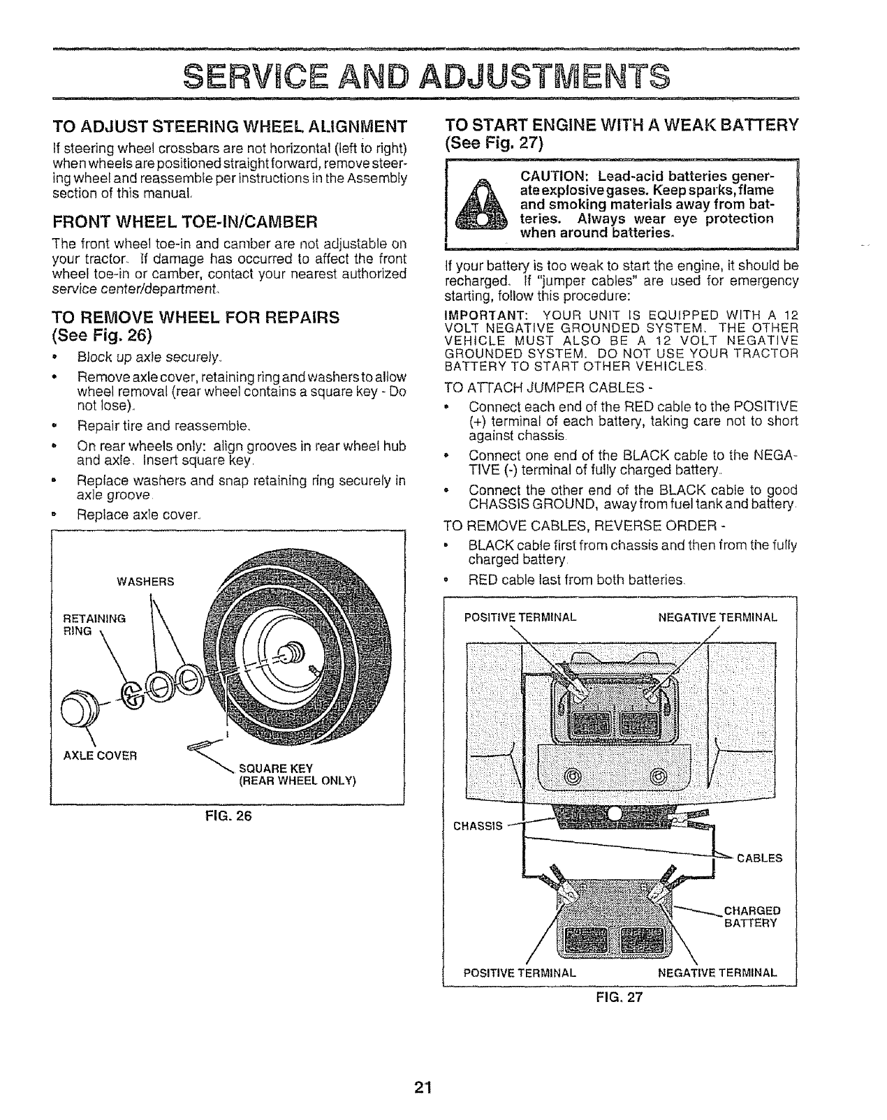
TO REMOVE WHEEL FOR REPAIRS
(See Fig. 26)
• Block up axie securely..
• Remove axle cover, retaining ring and washersto a!tow
wheel removal (rear wheel contains a square key- Do
not lose)..
,Repair tire and reassemble..
• On rear wheels only: align grooves in rear wheel hub
and axle. Insert square key.
• Replace washers and snap retaining ring securely in
axle groove
o Replace axle cover..
WASHERS
RETAINING
RING
AXLE COVER
t
_SQUAREKEY
(REAR WHEELONLY)
FIG. 26
TO START ENGINE WITH A WEAK BATTERY
See Fig. 27)
CAUTION: Lead-acid batteries gener-
ateexplosivegases. Keepsparks,flame
and smoking materials away from bat-
teries. Always wear eye protection
when around batteries.
If your battery is too weak to start the engine, it should be
recharged_ If "jumper cables" are used for emergency
starting, follow this procedure:
IMPORTANT: YOUR UNIT tS EQUIPPED WITH A 12
VOLT NEGATIVE GROUNDED SYSTEM, THE OTHER
VEHICLE MUST ALSO BE A 12 VOLT NEGATIVE
GROUNDED SYSTEM, DO NOT USE YOUR TRACTOR
BATTERY TO START OTHER VEHICLES.
TO ATTACH JUMPER CABLES -
o Connect each end of the RED cable to the POSITIVE
(+) terminal of each battery, taking care not to short
against chassis
, Connect one end of the BLACK cable to the NEGA-
TIVE (-) terminal of fully charged battery..
,Connect the other end of the BLACK cabte to good
CHASSIS GROUND, away from fuel tank and battery
TO REMOVE CABLES, REVERSE ORDER -
° BLACK cable first from chassis and then from the fully
charged battery
, RED cable last from both batteries.
POSITIVE TERMINAL
:: : : ::_ ::_ :
NEGATIVE TERMINAL
CABLES
CHARGED
BA"I-FERY
POSITIVE TERMINAL NEGATIVE TERMINAL
FIG, 27
2'1
SERVICE A ADJUSTMENTS
,iii ii
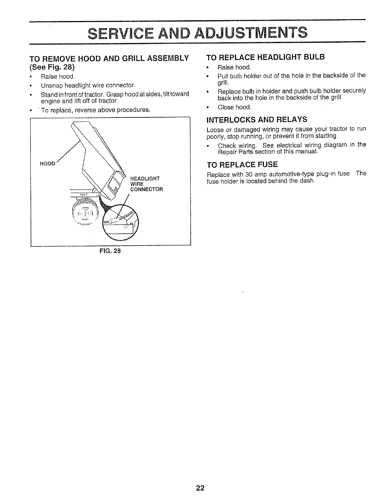
TO REMOVE HOOD AND GRILL ASSEMBLY
(See Fig. 28)
. Raise hood.,
• Unsnap headlight wire connector.
• Stand in front of tracton, Grasp hood at sides, tilt toward
engine and lift off of tractor.
. To replace, reverse above procedures.
HOOD
HEADLIGHT
WIRE
CONNECTOR
TO REPLACE HEADLIGHT BULB
• Raise hood_
•Pull bulb holder out of the hole in the backside of the
grill
• Replace bulb in hotder and push bulb holder securely
back into the hole in the backside of the grill
•Ctose hood.
INTERLOCKS AND RELAYS
Loose or damaged wiring may cause your tractor to run
poorly, stop running, or prevent it from starting
°Check wiring See electrical wiring diagram in the
Repair Parts section of this manual.
TO REPLACE FUSE
Replace with 30 amp automotive-type plug-in fuse. The
fuse holder is located behind the dash,
FIG. 2B
22
SEIRV OE AND ADJUSTMENTS
ENGINE
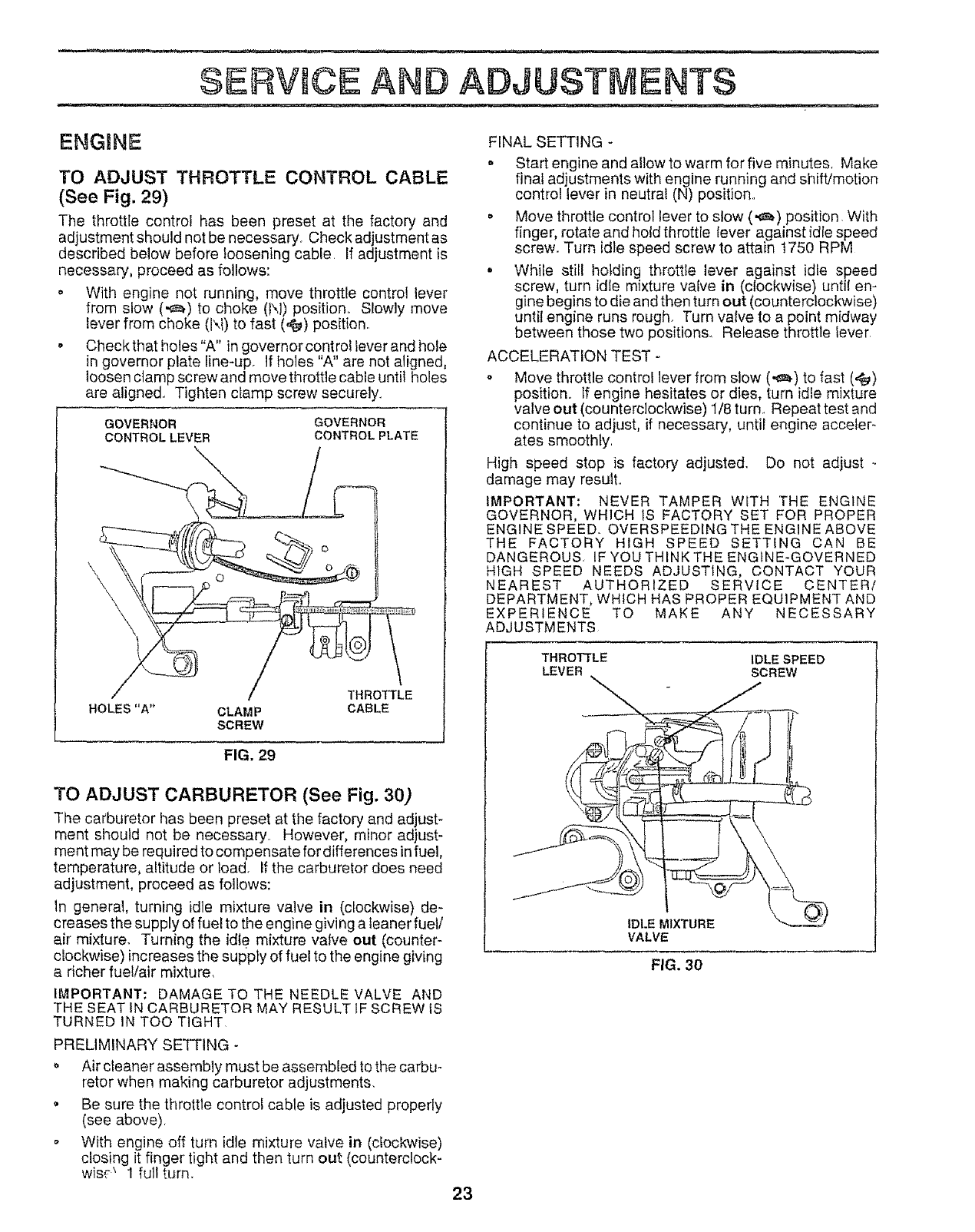
TO ADJUST THROTTLE CONTROL CABLE
(See Fig. 29)
The throttle control has been preset at the factory and
adjustment should not be necessary_ Checkadjustment as
described below before loosening cable, If adjustment is
necessary, proceed as follows:
o With engine not running, move throttle control lever
from slow (,e_) to choke (N) position, SIowly move
lever from choke (l".i) to fast (,_) position,,
-Check that holes "A" in governor control lever and hole
in governor plate line*up. If holes "A" are not aligned,
loosen clamp screw and move throttle cable until holes
are aligned., Tighten clamp screw securely.,
GOVERNOR
CONTROL LEVER
GOVERNOR
CONTROL PLATE
\
THROTTLE
HOLES"A" CLAMP CABLE
SCREW
FIG. 29
TO ADJUST CARBURETOR (See Fig. 30)
The carburetor has been preset at the factory and adjust-
ment should not be necessary, However, minor adjust-
ment may be required to compensate for differences in fuel,
temperature, altitude or load. If the carburetor does need
adjustment, proceed as follows:
In general, turning idle mixture valve in (clockwise) de-
creases the supply of fuel to the engine giving a leaner fuel/
air mixture. Turning the idle mixture valve out (counter-
clockwise) increases the supply of fuel to the engine giving
a richer fuel/air mixture,
IMPORTANT: DAMAGE TO THE NEEDLE VALVE AND
THE SEAT tN CARBURETOR MAY RESULT IF SCREW IS
TURNED IN TOO TIGHT.
PRELIMINARY SETTING -
o Air cleaner assembly must be assembled to the carbu-
retor when making carburetor adjustments.
• Be sure the throttle control cable is adjusted properly
(see above).
°With engine off turn idle mixture valve in (clockwise)
closing it finger tight and then turn out (counterclock-
wis,,'_ 1 full turn,,
FINAL SETTING -
- Start engine and allow to warm for five minutes. Make
final adjustments with engine running and shift/motion
control lever in neutral (N) position.,
• Move throttle control lever to slow (,._) position, With
finger, rotate and hold throttle lever against idle speed
screw. Turn idle speed screw to attain t750 RPM
- While still holding throttle lever against idle speed
screw, turn idle mixture valve in (clockwise) until en-
gine begins to die and then turn out (counterclockwise)
until engine runs rough. Turn valve to a point midway
between those two positions. Release throttle lever
ACCELERATION TEST -
,, Move throttle control lever from slow (,,_) to fast (4_)
position.. If engine hesitates or dies, turn idle mixture
valve out (counterclockwise) 1/8 turn. Repeat test and
continue to adjust, if necessary, until engine acceler-
ates smoothly.
High speed stop is factory adjusted. Do not adjust -.
damage may result..
IMPORTANT: NEVER TAMPER WITH THE ENGINE
GOVERNOR, WHICH 1S FACTORY SET FOR PROPER
ENGINE SPEED. OVERSPEEDtNG THE ENGINE ABOVE
THE FACTORY HIGH SPEED SETTING CAN BE
DANGEROUS. IF YOU THINK THE ENGINE-GOVERNED
HIGH SPEED NEEDS ADJUSTING, CONTACT YOUR
NEAREST AUTHORIZED SERVICE CENTER/
DEPARTMENT, WHICH HAS PROPER EQUIPMENT AND
EXPERIENCE TO MAKE ANY NECESSARY
ADJUSTMENTS
THROTTLE IDLE SPEED
LEVER SCREW
p/
IDLE MIXTURE
VALVE
FIG. 30
23
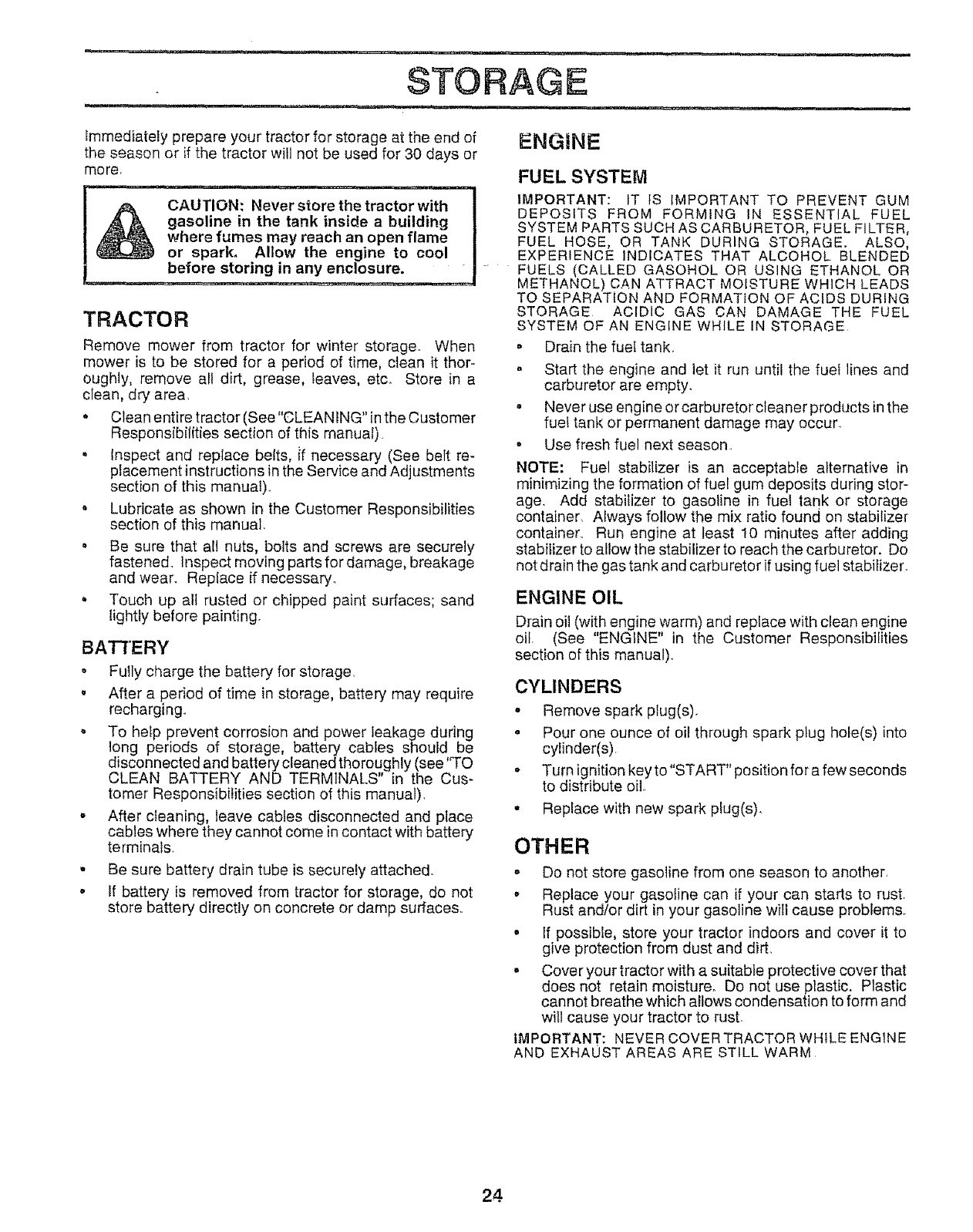
STORAGE
, ,,,i,111 , u .................. i lU,,i ....................
immediately prepare your tractor for storage at the end of ENGINE
the season or if the tractor will not be used for 30 days or
mo re.
" OAuTioN: Never store the tractorw'ith '1
gasoline in the tank inside a building !
where fumes may reach an open flame I
or spark. Allow the engine to cool I
before storing in any enclosure. I "
TRACTOR
Remove mower from tractor for winter storage° When
mower is to be stored for a period of time, clean it thor-
oughly, remove all dirt, grease, leaves, etco Store in a
clean, dry area,
•Clean entire tractor (See "CLEAN ING" inthe Customer
Responsibilities section of this manual),
°Inspect and replace beits, if necessary (See belt re-
placement instructions in the Service and Adjustments
section of this manual),,
° Lubricate as shown in the Customer Responsibilities
section of this manual,
• Be sure that all nuts, bolts and screws are securely
fastened. Inspect moving parts for damage, breakage
and wear. Replace if necessary_
. Touch up all rusted or chipped paint surfaces; sand
fightly before painting.
u
BATTERY
Fully charge the battery for storage,
After a period of time in storage, battery may require
recharging.
To help prevent corrosion and power leakage during
tong periods of storage, battery cables shouid be
disconnected and battery cleaned thoroughly (see 'q'O
CLEAN BATTERY AND TERMINALS" in the Cus-
tomer Responsibilities section of this manual).
After cleaning, leave cables disconnected and place
cables where they cannot come in contact with battery
terminals.
Be sure battery drain tube is securely attached.
If battery is removed from tractor for storage, do not
store battery directly on concrete or damp surface&,
FUEL SYSTEM
IMPORTANT: IT tS IMPORTANT TO PREVENT GUM
DEPOSITS FROM FORMING IN ESSENTIAL FUEL
SYSTEM PARTS SUCH AS CARBURETOR, FUEL FILTER,
FUEL HOSE, OR TANK DURING STORAGE. ALSO,
EXPERIENCE INDICATES THAT ALCOHOL BLENDED
FUELS (CALLED GASOHOL OR USING ETHANOL OR
METHANOL) CAN ATTRACT MOISTURE WHICH LEADS
TO SEPARATION AND FORMATION OF ACIDS DURING
STORAGE ACIDIC GAS CAN DAMAGE THE FUEL
SYSTEM OF AN ENGINE WHILE tN STORAGE
• Drain the fuel tank.
• Start the engine and let it run until the fueI lines and
carburetor are empty.
• Never use engine or carburetor cleaner products in the
fuet tank or permanent damage may occur,,
° Use fresh fuel next season,
NOTE: Fuel stabilizer is an acceptable alternative in
minimizing the formation of fuel gum deposits during stor-
age. Add stabilizer to gasoline in fuet tank or storage
container, Always follow the mix ratio found on stabilizer
container. Run engine at least 10 minutes after adding
stabilizer to allow the stabilizer to reach the carburetor. Do
not drain the gas tank and carburetor if using fuel stabilizer
ENGINE OIL
Drain oil (with engine warm) and replace with clean engine
oil, (See "ENGINE" in the Customer Responsibifities
section of this manual),,
CYLINDERS
• Remove spark plug(s).
• Pour one ounce of oil through spark plug hole(s) into
cylinder(s)
• Turn ignition keyto"START"position for a few seconds
to distribute oil..
• Replace with new spark plug(s).
OTHER
o Do not store gasoline from one season to another,
oReplace your gasoline can if your can starts to rust,
Rust and/or dirt in your gasoline will cause problems
o If possible, store your tractor indoors and cover it to
give protection from dust and dirt,
-Cover your tractor with a suitable protective cover that
does not retain moisture° Do not use plastic. Plastic
cannot breathe which allows condensation to form and
will cause your tractor to rust
IMPORTANT: NEVER COVER TRACTOR WHILE ENG1NE
AND EXHAUST AREAS ARE STILL WARM
24

i.
PROBLEM
Will not start
m iii
Hard to start
Engine wil! not turn over
Engine clicks but will not
start
Loss of power
Excessive vibration
1 Out of fuel
2 Engine not "CHOKED" properly
3 Engine flooded
4 Bad spark plug
5 Dirty air filler
6 Dirty fuel fifter
7 Water in fuel
8 Loose or damaged wiring
9 Carburetor out of adjustment
t0 Engine valves out of adjustment
1 Dirty air fitter
2 Bad spark plug
3 Weak or dead battery
4 Dirty fuel filter
5 Stale or dirty fuel
6 Loose or damaged wiring
7 Carburetor out of adjustment
8 Engine valves out of adjustment
1 Clutch!brake pedal not depressed
2 Attachment clutch is engaged
3 Weak or dead battery
4 Blown fuse
5 Corroded batteryterminats
6 Loose or damaged wiring
7 Faulty ignition switch
8 Faulty solenoid or starter
9 Faulty operator presence switch(es)
1 Weak or dead battery
2 Corroded battery terminals
3 Loose or damaged wiring
4 Faulty solenoid or starter
1 Cutting too much grass/too fast
2 Throttle in "CHOKE" position
3 Build-up of grass, leaves and trash under mower
4 Dirty air filter
5 Low oil level/dirty oil
6 Faulty spark plug
7 Dirty fuel filter
8 Stale or dirty fuel
9 Wate_- in fuel
10 Spark plug wire loose
1 t Dirty engine air screen!fins,
12 Dirty/clogged muffler
13 Loose or damaged wiring
14 Carburetor out of adjustment
t5 Engine valves cut of adjustment
1 Worn. bent or loose blade
2 Bent blade mandrel
3 Loose!damaged part(s}
1 Fill fuel tank
2 See "TO START ENGINE" in Operation section
3 Wait several minutes before attempting to start
4 Replace spark plug
5 Clean!replace air filter
6 Replace fuel filler
7 Drain fuel tank and carburetor, refill tank with fresh
gasoline and replace fuel filter
8 Check all wiring
g Contact an authorized service center/depadment
10 Contact an authorized service center/department
1 Clean/replace air filter
2 Replace spark plug
3 Recharge or replace battery
4 Replace fuet fil_er
5 Drain fuel tank and refill with fresh gasoline
6 Check all wiring
7 Contact an authorized service center/department
8 Contact an authorized service center/department
1 Depress clutch/brake pedal
2 Disengage attachment clutch
3 Recharge or replace battery
4 Replace fuse
5 Clean battery terminals
6 Check all wiring
7 ChecWreptace ignition switch
8 Check/replace solenoid or starter
9 Contact an aulherized service center/department
1 Recharge or replace battery
2 Clean battery terminals
3 Check all wiring
4 ChecWreplace solenoid or starter
1 Set in "Higher Cut" position/reduce speed
2 Adjust throttle control
3 Clean underside el mower housing
4 Clean/replace air filter
5 Check oil level/change oil
6 Clean and regap or change spark plug
7 Replace fuel filter
8 Drain fuel tank and refill with fresh gasoline
9 Drain fuel tank and carburetor, refill tank with fresh
gasoline and replace fuel filter
10 Connect and tighten spark plug wire
11 Clean engine air screen/fins
12 Clean/replace muffler
t3 Check all wiring
t4 Contact an authorized service center/department
15 Contact an authorized service center/department
1 Replace blade Tighten blade bolt
2 Replace blade mandrel
3 Tighten loose part(s) Replace damaged paris
25

TROUBLESHOOTING POINTS
PROBLEM
Engine continues to run
when operator teaves seat
with attachment ctuteh
engaged
Poor cut-uneven
Mower blades will not
rotate
uu i,i
Poor grass discharge
iJ ii ,,,lli,ilu,J,i ,,,
Headlight(s) not working
(if so equipped)
Battery will not charge
Engine '_backfires"
when turning engine
"OFF"
t
2
3
4
5
6
7
8
9
10
11
CAUSE
.................... !J,Jll,i
Faulty operator-safety presence contro$ system
1 Worn. bent or loose blade
2 Mower deck noI level
3 Buildup of grass, leaves, and trash under mower
4 Bent blade mandrel
5 Clogged mower deck vent holes from buildup of
grass, leaves, and trash around mandrels
1 Obstruction in clutch mechanism
2 Worn/damaged mower drive belt
3 Frozen idler pulley
4 Frozen blade mandrel
Engine speed too slow
Travel speed too fast
Wet grass
Mower deck not level
Low/uneven tire air pressure
Worn, bent or loose blade
Buildup ot grass, leaves and trash under mower
Mower drive belt worn
Blades improperly installed
Improper blades used
Clogged mower deck vent holes from buildup of
grass, leaves, and lrash around mandrels
CORRECTION
Check wiring, switches and connections tf not
corrected, contact an authorized service center/
department
t Replace blade Tighten blade bott
2 Level mower deck
3 Clean underside ol mower housing
4 Replace blade mandrel
5 Clean around mandrels to open vent holes
1 Switch is "OFF"
2 Bulb(s) burned out
3 Faulty light switch
4 Loose or damaged wiring
5 Blown ruse
1 Bad baitery ceil(s)
2 Poor cable connections
3 Faulty regulator (if so equipped)
4 Faulty alternator
1 Remove obstruction
2 Replace mower drive belt
3 Replace idler pulley
4 Replace blade mandrel
1 Place throttle control in "FAST" position
2 Shift to slower speed
3 Allow grass to dry before mowing
4 Level mower deck
5 Check tires for proper air pressure
6 Replace/sharpen blade Tighten blade bolt
1 Engine throttle control not set at "SLOW"
position for 30 seconds before stopping engine
7 Clean underside of mower housing
8 Reptace mower drive bell
9 Reinstall blades sharp edge down
10 Replace with blades listed in this manual
t Clean around mandrels to open vent holes
1 Turn switch "ON"
2 Replace bulb(s)
3 Cheek/replace light switch
4 Check wiring and connections
5 Replace fuse
1 Replace battery
2 Check!clean all connections
3 Replace regulator
4 Replace alternator
lUl iuulu i uit,,ll i ,i,l,l,,i,, ii
Move thfotlle control to "SLOW" position and allow
to idle for 30 seconds before stopping engine
26
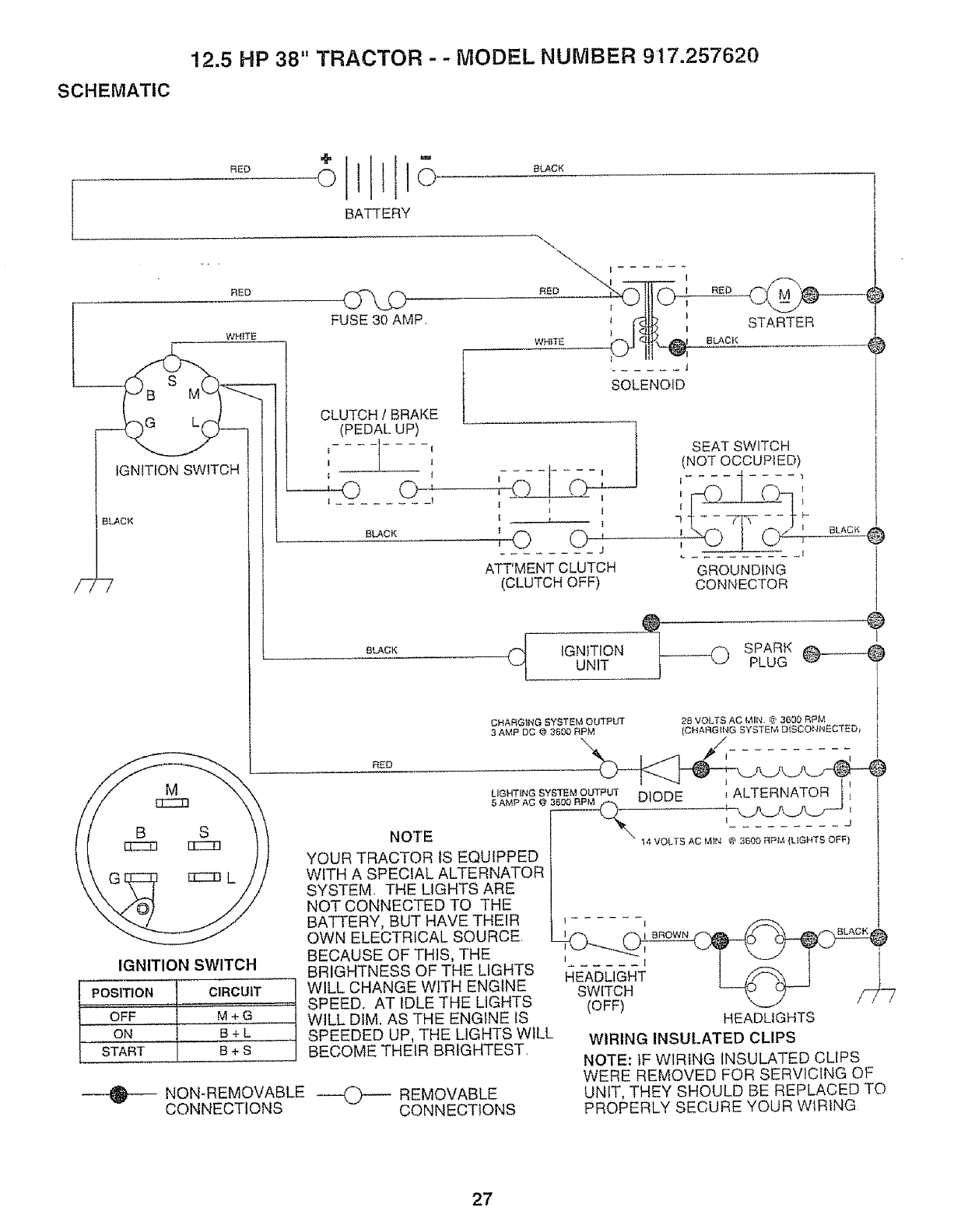
12.5 HP 38" TRACTOR - - MODEL NUMBER 9'17.257620
SCHEMATIC
lll
BATTERY
FUSE 30 AMP
WHITE
L( CLUTCH /BRAKE
(PEDAL UP)
1
SOLENOID
REI3
BLACK
STARTER
SEAT SWITCH
(NOT OCCUPIED)
7 F*
ATT'MENT CLUTCH GROUNDING
(CLUTCH OFF) CONNECTOR
t
SLACK
('_ IGNITION
UNIT
CHARGING SYSTEM OUTPUT
3 AMP DC @ 3600 RPM
RED
IGNITION SWITCH
POSITION CIRCUIT
OFF M + G
ON B+L
START B + S
NOTE
YOUR TRACTOR IS EQUIPPED
WITH A SPECIAL ALTERNATOR
SYSTEM THE LIGHTS ARE
NOT CONNECTED TO THE
BATTERY, BUT HAVE THEIR
OWN ELECTRICAL SOURCE.
BECAUSE OF THIS, THE
BRIGHTNESS OF THE LIGHTS
WILL CHANGE WITH ENGINE
SPEED. AT IDLE THE LIGHTS
WILL DIM. AS THE ENGINE IS
SPEEDED UP, THE LIGHTS WILL
BECOME THEIR BRIGHTEST.
LIGHTING SYSTEM OUTPUT
5 AMP AO @ 3_
NON-REMOVABLE ----,.,_--- REMOVABLE
CONNECTIONS CONNECTIONS
BLACK O
DIODE _ALTERNATOR _
I......... g
14 VOLTS AC MtN @ 3B00 RPM (LIGHTS OFF)
1
I...... I 1
HEADLIGHT
SWITCH
(OFF) 7
HEADLIGHTS
WIRING INSULATED CLIPS
NOTE: IF WIRING INSULATED CLIPS
WERE REMOVED FOR SERVICING OF
UNIT, THEY SHOULD BE REPLACED TO
PROPERLY SECURE YOUR WIRING
27
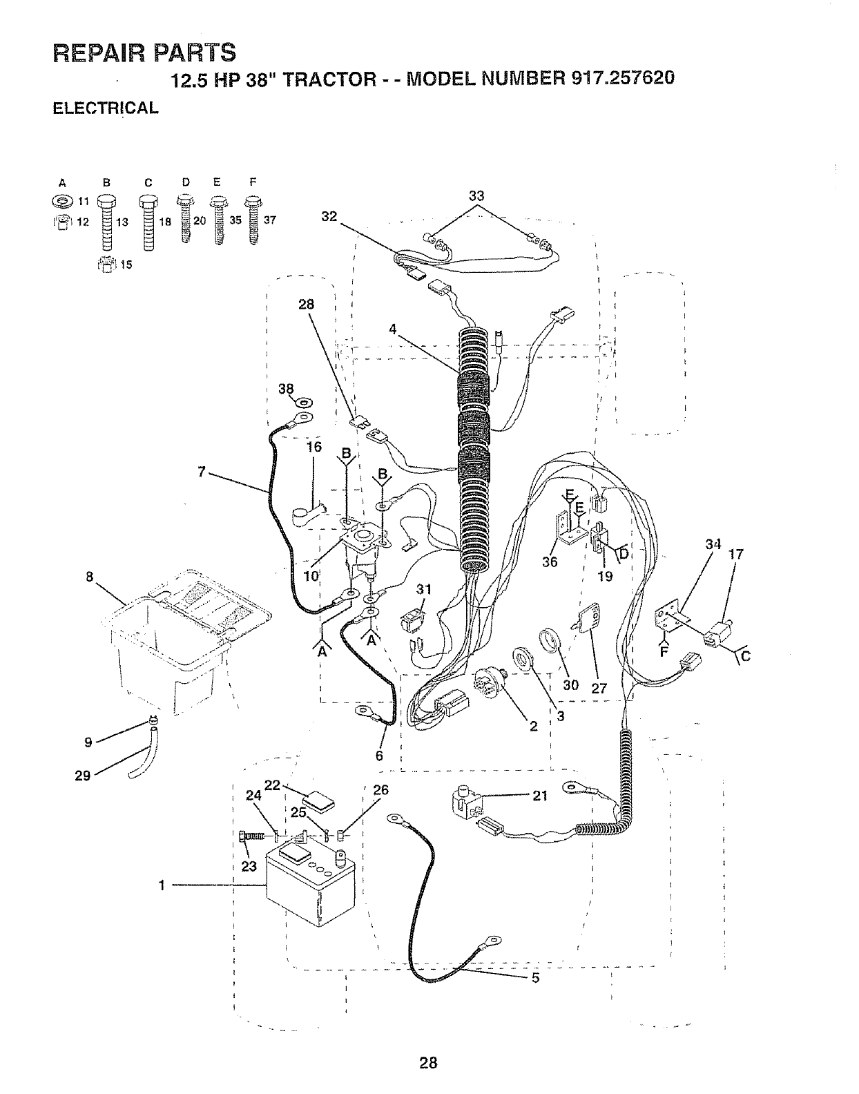
REPAUR PARTS
12.5 HP 38" TRACTOR - - MODEL NUMBER 917.257620
ELECTRICAL
A B C D EF
@I_ @,
29
_:t 15
24
23
'1
33
28
38
16
4
36
f
34
\
\
30 27
2
26 21
\
t7
28
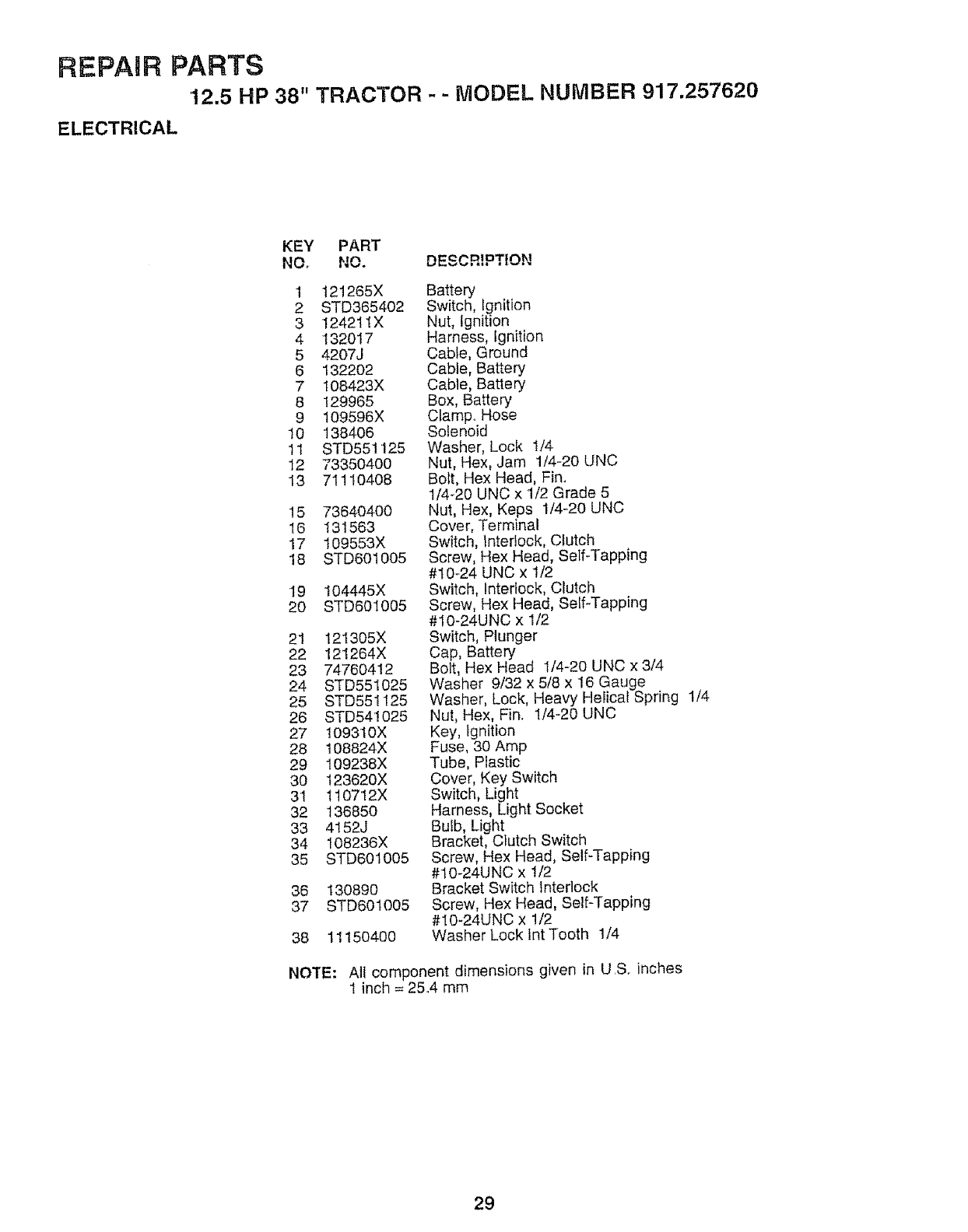
REPAIR PARTS
12.5 HP 38" TRACTOR - -MODEL NUMBER 917.257620
ELECTRICAL
KEY PART
NO, NO. DESCRIPTION
1 121265X
2 STD365402
3 124211X
4 132017
5 4207J
6 1322O2
7 108423X
8 129965
9 109596X
10 138406
11 STD551125
12 73350400
13 71110408
15 736404OO
16 131563
17 109553X
18 STD601005
19 104445X
2O STD601005
21 121305X
22 12!264X
23 74760412
24 STD551025
25 STD551125
26 STD54!025
27 109310X
28 108824X
29 I09238X
30 123620X
3I 110712X
32 136850
33 4152J
34 108236X
35 STD601005
36 130890
37 STD601005
38 1115O400
Battery
Switch, Ignition
Nut, Ignition
Harness, Ignition
Cable, Ground
Cable, Battery
Cable, Battery
Box, Battery
Clamp,, Hose
Solenoid
Washer, Lock 1/4
Nut, Hex, Jam 1/4-20 UNC
Bolt, Hex Head, Fin,
1/4_20 UNC x 1/2 Grade 5
Nut, Hex, Keps 1/4-20 UNC
Cover, Terminal
Switch, interlock, Clutch
Screw, Hex Head, Self-Tapping
#t0-24 UNC x 1/2
Switch, Interlock, Clutch
Screw, Hex Head, Self-Tapping
#10-24UNC x 1/2
Switch, Plunger
Cap, Battery
Bolt, Hex Head I/4-20 UNC x 3/4
Washer 9/32 x 518x 16 Gauge
Washer, Lock, Heavy Helical Spring 1/4
Nut, Hex, Fin, 1/4-20 UNC
Key, Ignition
Fuse, 30 Amp
Tube, Plastic
Cover, Key Switch
Switch, Light
Harness, Light Socket
Bulb, Light
Bracket, Clutch Switch
Screw, Hex Head, Self-Tapping
#10-24UNC x 1/2
Bracket Switch Interlock
Screw, Hex Head, Self-Tapping
#10-24UNC x 1/2
Washer Lock lnt Tooth 1/4
NOTE: All component dimensions given in U,S,. inches
1 inch = 254 mm
29
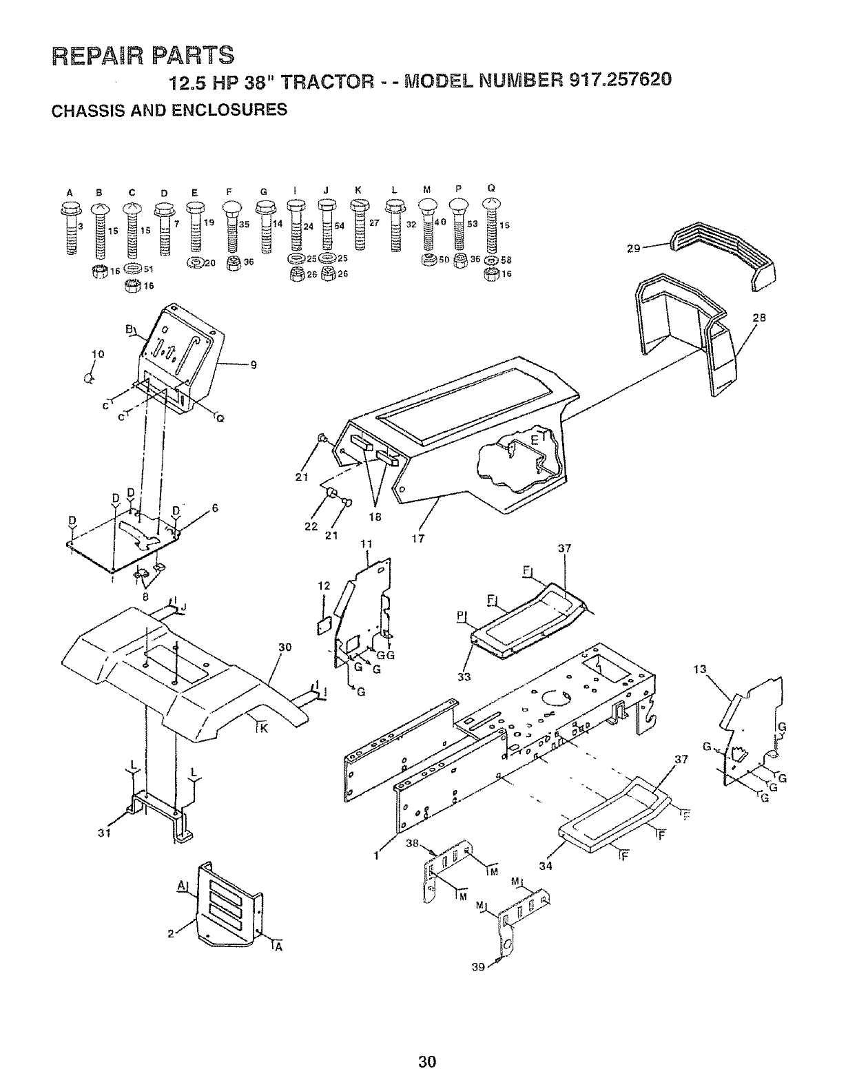
REPA_F_PARTS
12.5 HP 38" TRACTOR --MODEL NUMBER 917.257620
CHASSIS AND ENCLOSURES
A B C D
I0
(
31
3O
L
T
22_ 18
21 11 17 37
33 13
2B
3O
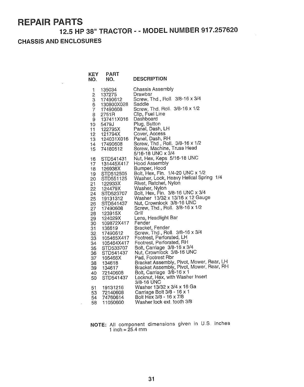
REPAIR PARTS
12.5 HP 38" TRACTOR - - MODEL NUMBER 917.257620
CHASSIS AND ENCLOSURES
KEY PART
NO. NO. DESCRIPTION
1 135034
2 137275
3 17490612
6 130800X028
7 17490608
82751R
9 137411X016
10 5479J
11 122795X
12 121794X
13 !24031X016
14 17490608
15 74180512
16 STD541431
17 131445X417
18 126938X
19 STD512505
20 STD551t25
2't 122933X
22 t24479X
24 STD523707
25 19131312
26 STD541437
27 17490608
28 123915X
29 124029X
30 109872X417
31 136619
32 17490612
33 105465X417
34 105464X417
35 STD533707
36 STD54!437
37 105466X
38 134618
39 134617
40 72140608
60 STD541437
51 19131216
53 72140608
54 74760614
58 11050600
Chassis Assembly
Drawbar
Screw, Thd., Roll. 3/8-16 x 3/4
Saddle
Screw, Thd. RoIt. 3/8-t6 x 1/2
Clip, Fuel Line
Dashboard
Plug, Button
Panel, Dash, LH
Cover, Access
Panel, Dash, RH
Screw, Thd, Roll. 3/8-16 × 1/2
Screw, Machine, Truss Head
5/16-t8 UNC x 3/4
Nut, Hex, Keps 5/16-18 UNC
Hood Assembly
Bumper, Hood
Bolt, Hex, Fin 1/4-20 UNC x 1/2
Washer, Lock, Heavy Helical Spring 1/4
Rivet, Ratchet, Nylon
Washer, Nylon
Bolt, Hex, Fin. 3/8-16 UNC x 3/4
Washer 13/32 x 13/16 x 12 Gauge
Nut, Crownlock 3/8-16 UNC
Screw, Thd, Roll, 3/8-16 x 1/2
Grill
Lens, Headlight Bar
Fender
Bracket, Fender
Screw, Thd,, Roll, 3/8-16 x 3/4
Footrest, Perforated, LH
Footrest, Perforated, RH
Bolt, Carriage 3/8-16 x 3/4
Nut, Crownlock 3/8-16 UNC
Pad, Footrest Rbr
Bracket Assembly, Pivot, Mower, Rear, LH
Bracket Assembly, Pivot, Mower, Rear, RH
Bolt, Carriage 3/8-I6 x 1
Locknut, Hex, with Washer Insert
3/8-16 UNC
Washer 13/32 x 3/4 x 16 Ga
Carriage Bolt 3t8 - 16 x 1
Bolt Hex 3/8 - 16 x 7/8
Washer lock ext. tooth 3/8
NOTE: All component dimensions given in U.S. inches
I inch = 25.4 mm
31
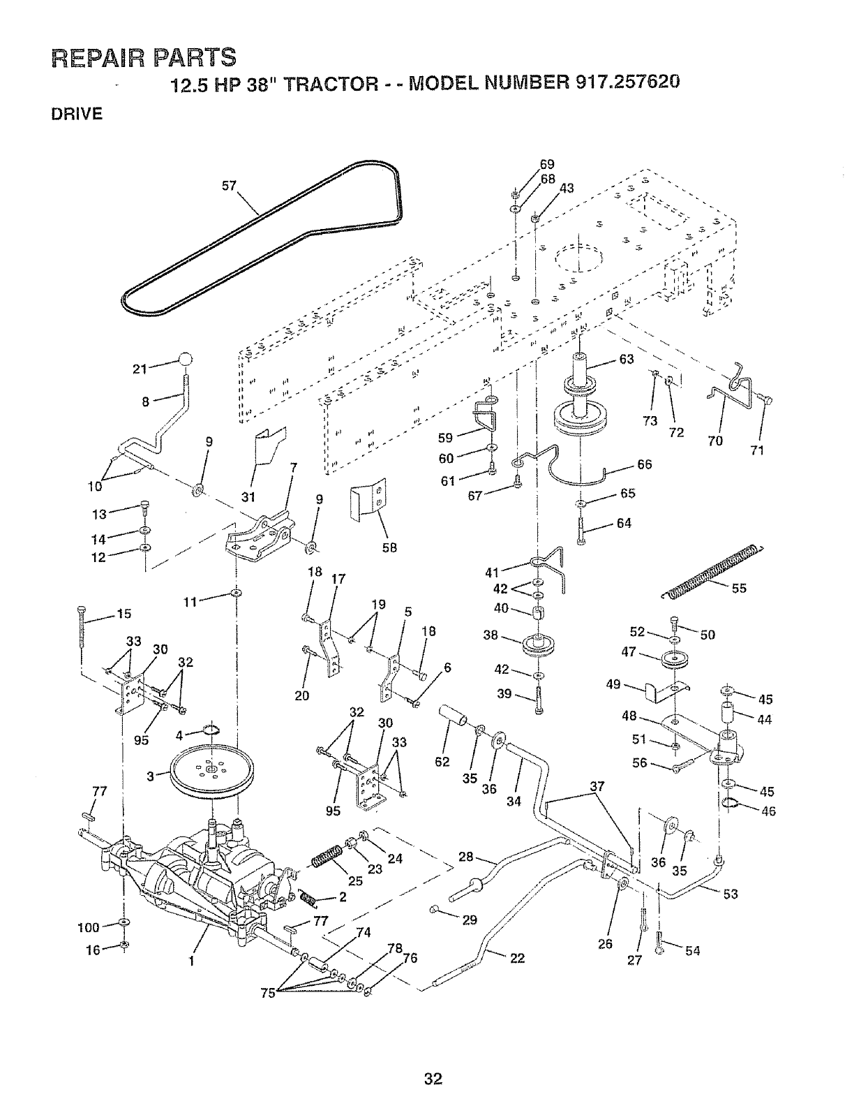
REPABR
DRIVE
PARTS
12.5 HP 38" TRACTOR --MODEL. NUMBER 917.257620
15
33 30
77
2O
32 30
33
18
,6
62
35 36 34
37
46
1
75'
23
25
26
27
53
32
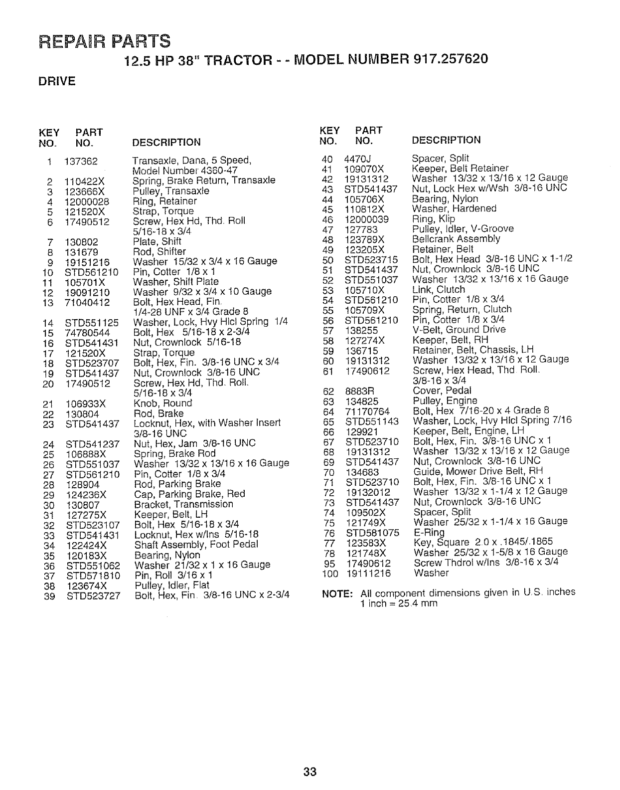
REPABR
DRIVE
PARTS
12.5 HP 38" TRACTOR - - MODEL NUMBER 917.257620
KEY
NO.
2
3
4
5
6
7
8
9
I0
11
12
13
14
15
16
17
18
19
20
21
22
23
24
25
26
27
28
29
30
31
32
33
34
35
36
37
38
39
PART
NO.
137362
11O422X
123666X
12000028
12152ox
1749o512
130802
131679
19151216
STD56t2t0
105701X
1909121O
71O40412
STD551125
74780544
STD541431
121520X
STD523707
STD541437
17490512
106933X
130804
STD541437
STD541237
t06888X
STD551037
STD581210
128904
124236X
130807
127275X
STD523107
STD541431
122424X
120183X
STD551062
STD571810
123674X
STD523727
KEY PART
DESCRIPTION NO, NO. DESCRIPTION
Transaxfe, Dana, 5 Speed, 40
Model Nurnber 4360-47 41
Spring, Brake Return, Transaxte 42
Pulley, Transaxte 43
Ring, Retainer 44
Strap, Torque 45
Screw, Hex Hd, Thd Roll 46
5/16-18 x 3/4 47
Plate, Shift 48
Rod, Shifter 49
Washer 15/32 x3/4 x 16 Gauge 50
Pin, Cotter 1/8 x 1 51
Washer, Shift Plate 52
Washer 9/32 x 3/4 x 10 Gauge 53
Bolt, Hex Head, Fin. 54
1/4-28 UNF x 3/4 Grade 8 55
Washer, Look, Hvy Htcl Spring 1/4 56
Bolt, Hex 5/16-18 x 2-3/4 57
Nut, Crownlock 5/16-!8 58
Strap, Torque 59
Bolt, Hex, Fin. 3/8-16 UNC x 3/4 80
Nut, Crownlock 3/8-16 UNC 61
Screw, Rex Hd, Thd. RotL
5/16-18 x 3/4 62
Knob, Round 63
Rod, Brake 64
Locknut, Hex, with Washer insert 65
3/8-16 UNC 66
Nut, Hex, Jam 3/8-16 UNC 67
Spring, Brake Rod 68
Washer 13/32 x 13/16 x 16 Gauge 69
Pin, Cotter 1/8 x 3/4 70
Rod, Parking Brake 71
Cap, Parking Brake, Red 72
Bracket, Transmission 73
Keeper, Belt, LH 74
Bolt, Hex 5/16q8 x 3/4 75
Locknut, Hex w/Ins 5/16-18 76
Shaft Assembly, Foot Pedal 77
Bearing, Nylon 78
Washer 21132 x 1 x 16 Gauge 95
Pin, Roll 3/16 x 1 100
Pulley, Idler, Flat
Bolt, Hex, Fin. 3/8-16 UNC x 2-314
4470J
109070X
19131312
STD541437
105706X
110812X
12000039
127783
123789X
123205X
STD523715
STD541437
STD551037
I05710X
STD561210
!05709X
STD561210
138255
127274X
136715
19131312
17490612
8883R
134825
71170764
STD551143
129921
STD523710
19131312
STD541437
134683
STD523710
19132012
STD541437
109502X
121749X
STD581075
123583X
I21748X
1749O612
19111216
Spacer, Split
Keeper, Belt Retainer
Washer 13/32 x t3/16 x t2 Gauge
Nut, Lock Hex wiWsh 3/8q6 UNC
Bearing, Nylon
Washer, Hardened
Ring, Klip
Pulley, Idler, V-Groove
Bellcrank Assembly
Retainer, Belt
Bolt, Hex Head 3/8-16 UNC x lq/2
Nut, Crowniock 3/8-16 UNC
Washer 13/32 x 13/16 x 16 Gauge
Link, Clutch
Pin, Cotter 1/8 x 3/4
Spring, Return, Clutch
Pin, Cotter 1/8 x 3/4
V-Belt, Ground Drive
Keeper, Belt, RH
Retainer, Belt, Chassis, LH
Washer 13/32 x 13/16 x 12 Gauge
Screw, Hex Head, Thd Roll.
3/8-16 x 3/4
Cover, Pedal
Pulley, Engine
Bolt, Hex 7/I6-20 x 4 Grade 8
Washer, Lock, Hvy Htcl Spring 7/16
Keeper, Belt, Engine, LH
Bolt, Hex, Fin. 3/8-16 UNC x 1
Washer 13/32 x I3/16 x !2 Gauge
Nut, Crownlock 3/8-16 UNC
Guide, Mower Drive Belt, RH
Bolt, Hex, Fin. 3/8-16 UNC x 1
Washer 13/32 x 1-1/4 x 12 Gauge
Nut, Crownlock 3/8-16 UNC
Spacer, Split
Washer 25/32 x 1-1/4 x 16 Gauge
E-Ring
Key, Square 20 x .t845/.1865
Washer 25/32 x 1-5/8 x 16 Gauge
Screw Thdrot wllns 3/8-16 x 3/4
Washer
NOTE: All component dimensions given in US. inches
1 inch = 25.4 mm
33
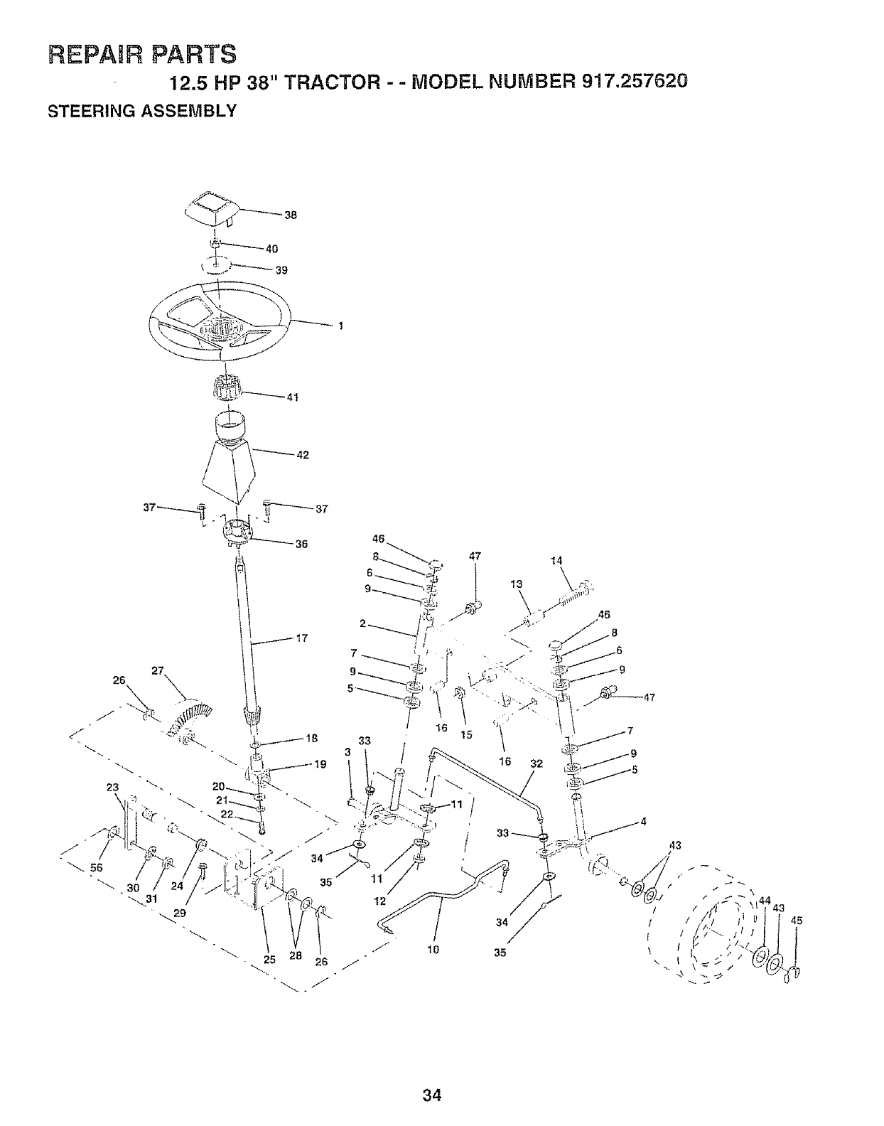
REPABR PARTS
12.5 HP 38" TRACTOR - - MODEL NUMBER 917.257620
STEERING ASSEMBLY
26
_37
d
36
/17
35
46
33
3/
12
47 14
35
45
34
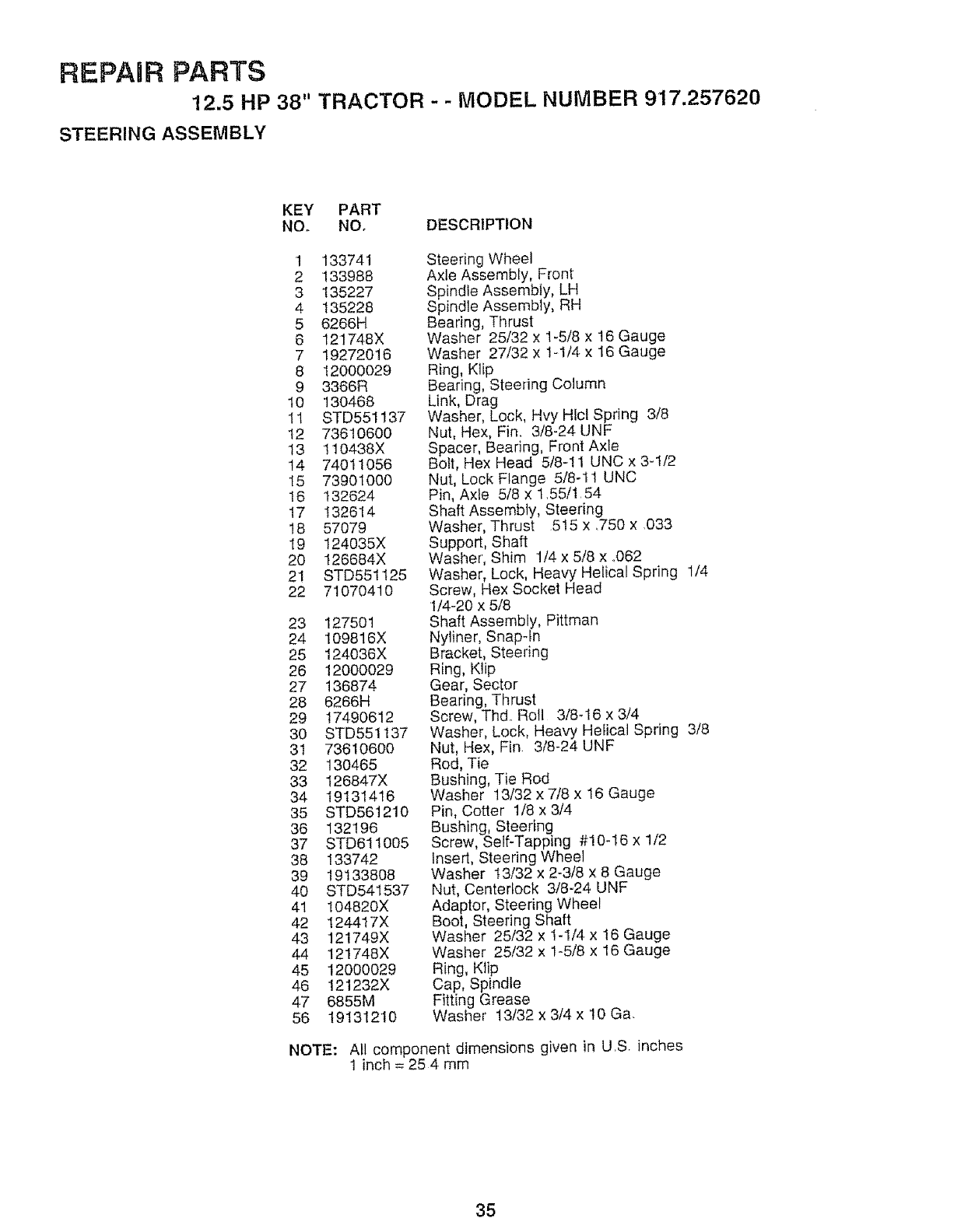
REPAIR PARTS
12.5 HP 38" TRACTOR - - MODEL NUMBER 917.257620
STEERING ASSEMBLY
KEY PART
NO. NOo DESCRIPTION
1 133741
2 133988
3 135227
4 135228
5 6266H
6 121748X
7 19272016
8 12000029
9 3366R
10 13O468
11 STD551137
12 73610600
13 110438X
t4 74011056
I5 73901O00
I6 132624
17 132614
18 57079
19 124035X
20 126684X
21 STD551t25
22 71070410
23 127501
24 109816X
25 124036X
26 12000029
27 136874
28 6266H
29 17490612
30 STD551137
31 73610600
32 13O465
33 t26847X
34 19131416
35 STD561210
36 132196
37 STD611005
38 133742
39 19133808
40 STD541537
41 104820X
42 124417X
43 121749X
44 121748X
45 12000029
46 121232X
47 6855M
56 19131210
Steering Wheel
Axle Assembly, Front
Spindle Assembly, LH
Spindle Assembly, RH
Bearing, Thrust
Washer 25/32 x 1-5/8 x 16 Gauge
Washer 27/32 x 1-I/4 x 16 Gauge
Ring, Klip
Bearing, Steering Column
Link, Drag
Washer, Lock, Hvy Hlcl Spring 3/8
Nut, Hex, Fin, 3/8-24 UNF
Spacer, Bearing, Front Axle
Bolt, Hex Head 5/8-11 UNC x 3-1/2
Nut, Lock Flange 5/8-11 UNC
Pin, Axle 5/8 x t,55/1,54
Shaft Assembly, Steering
Washer, Thrust 515 x ,750 x 033
Support, Shaft
Washer', Shim 1/4 x 5/8 x 1062
Washer, Lock, Heavy Helical Spring 1/4
Screw, Hex Socket Head
1/4-20 x 5/8
Shaft Assembly, Pittman
Nyliner, Snapqn
Bracket, Steering
Ring, Klip
Gear, Sector
Bearing, Thrust
Screw, Thd,, Roll 3/8-16 x 3/4
Washer, Lock, Heavy Helical Spring 3/8
Nut, Hex, Fin 3t8-24 UNF
Rod, Tie
Bushing, Tie Rod
Washer 13/32 x 7/8 x 16 Gauge
Pin, Cotter 1/8 x 3/4
Bushing, Steering
Screw, Self-Tapping #10-16 x 1/2
Insert, Steering Wheel
Washer !3/32 x 2-3/8 x 8 Gauge
Nut, Centertock 3!8-24 UNF
Adaptor, Steering Wheel
Boot, Steering Shaft
Washer 25/32 x 1-I/4 x 16 Gauge
Washer 25/32 x 1-5/8 x 16 Gauge
Ring, Klip
Cap, Spindle
Fitting Grease
Washer 13132 x 3/4 x '10Ga,
NOTE: All component dimensions given in US inches
1 inch = 25 4 mm
35
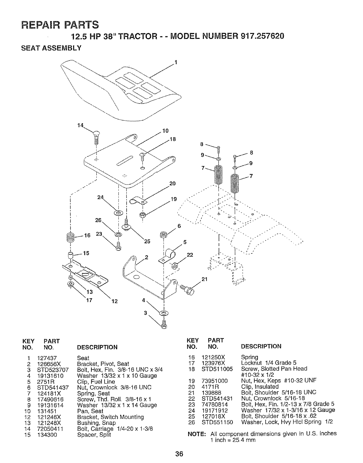
REPAIR PARTS
12.5 HP 38" TRACTOR --MODEL NUMBER 917.257620
SEAT ASSEMBLY
KEY PART
NO. NOr
1 127437
2 126656X
3 STD523707
4 19131610
5 2751 R
6 STD541437
7 124181X
8 17490616
9 19131614
10 131451
12 121246X
13 121248X
14 72050411
15 134300
DESCRIPTION
Seat
Bracket, Pivot, Seat
Bolt, Hex, Fin. 3/8-16 UNC x 3/4
Washer I3/32 x I x 10 Gauge
Clip, Fue! Line
Nut, Crownlock 318-16 UNC
Spring, Seat
Screw, Thd, Rotl, 3/8-16 x 1
Washer 13/32 x 1 x 14 Gauge
Pan, Seat
Bracket, Switch Mounting
Bushing, Snap
Bolt, Carriage 1/4-20 x 1-3/8
Spacer, Split
KEY PART
NO. NO. DESCRIPTION
16 121250X
17 123976X
18 STD511005
19 73951000
20 4171R
2t 139888
22 STD541431
23 74780814
24 19171912
25 t27018X
26 STD551150
Spring
Locknut 1/4 Grade 5
Screw, Slotted Pan Head
#10-32 x 1/2
Nut, Hex, Keps #10-32 UNF
Clip, Insulated
Bolt, Shoulder 5/16-18 UNC
Nut, Crownlock 5/16-18
Bolt, Hex, Fin. 1/2-13 x 7/8 Grade 5
Washer 17/32 x 1-3/16 x 12 Gauge
Bolt, Shoulder 5/16-18 x ..62
Washer, Lock, Hvy Hlcl Spring I/2
NOTE: All component dimensions given in U.S.. inches
1 inch = 25.4 mm
36
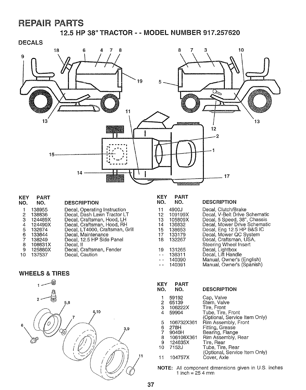
REPABR
DECALS
9
13
PARTS
12.5 HP 38" TRACTOR - - MODEL NUMBER 917.257520
18 6 4 7 8 8 7 3 10
19
11
12
13
t5-
14 17
KEY PART
NO. NO.
1 138955
2 138836
3 124489X
4 t24490X
5 132674
6 133644
7 138249
8 108631X
9 125880X
10 137537
DESCRIPTION
Decal, Operating Instruction
Decal, Dash Lawn Tractor LT
Decal, Craftsman, Hood, LH
Decal, Craftsman, Hood, RH
Decal, LT4000, Craftsman, Grill
Decal, Maintenance
Decal, 125 HP Side Panel
Decal, 1I
Decal, Craftsman, Fender
Decal, Caution
WHEELS & TIRES
2_'_ ;,8
,t0
tl
KEY
NO.
11
t2
13
14
15
17
18
19
KEY
NO.
37
PART
NO.
4900J
t09199X
105809X
136832
138653
133179
132267
131265
138311
140390
140391
DESCRIPTION
Decal, Clutch/Brake
Decal, V-Belt Drive Schematic
Decal, 5 Speed, 38", Chassis
Decal, Mower Drive Schematic
Decal, Eng 12,5 HP B&S IC
Decal, Mower QC System
Decal, Craftsman, USA,
Steering Wheel Insert
Decal, Lightbox
Decal, Lift Handle
Manual, Owner's (English)
Manual, Owner's (Spanish)
PART
NO. DESCRIPTION
1
2
3
4
5
6
7
8
9
10
11
59192
65139
106222X
59904
106732X361
278H
9040H
106108X361
124635X
7152J
104757X
Cap, Valve
Stem, Valve
Tire, Front
Tube, Tire, Front
(Optional, Service Item Only)
Rim Assembly, Front
Fitting, Grease
Bearing, Flange
Rim Assembly, Rear
Tire, Rear
Tube, Tire, Rear
(Optional, Service Item Only)
Cover, Axle
NOTE: All component dimensions given in US inches
1 inch = 25 4 mm
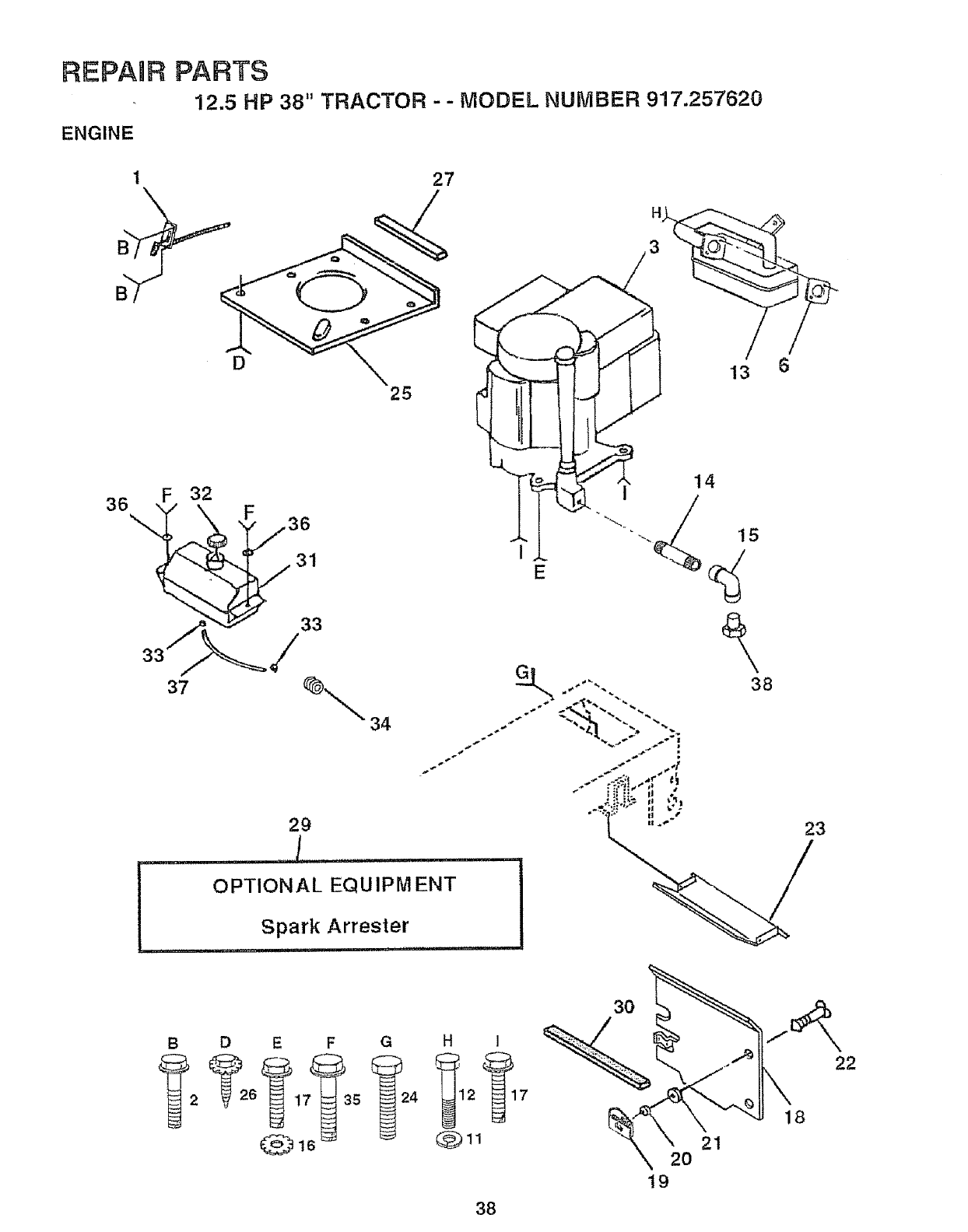
REPAnR
ENGINE
PARTS
12.5 HP 38" TRACTOR - - MODEL NUMBER 917.257620
36 \
D
25
32 F
31
2g
27
, 3
38
_ _ €._
i_: .., t,_l
•% " II l
DEFGHI
38
30
2O
19
21
18
22
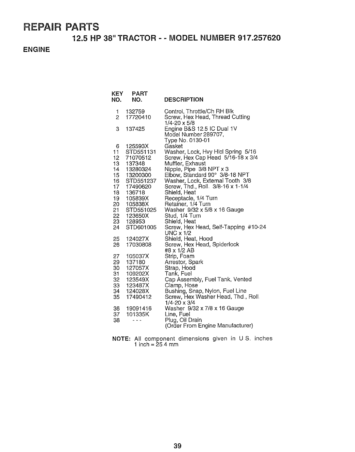
REPAmR
ENGINE
PARTS
'12.5 HP 38" TRACTOR - -MODEL NUMBER 917,257620
KEY PART
NO. NO. DESCRIPTION
1 132759
2 17720410
3 137425
6 125593X
11 STD551131
12 71O70512
13 137348
14 13280324
15 13200300
16 STD551237
17 17490620
18 136718
19 105839X
20 105838X
21 STD551025
22 123650X
23 128953
24 STD601005
25 124027X
26 17O308O8
27 105037X
29 137180
30 127057X
31 109202X
32 123549X
33 123487X
34 124028X
35 17490412
36 19091416
37 101335K
38 ---
Control, Throttle/Ch RH Blk
Screw, Hex Head, Thread Cutting
1/4-20 x 5/8
Engine B&S 12,,5 IC Dual 1V
Model Number 289707,
Type No, 0130-01
Gasket
Washer, Lock, Hvy Hlcl Spring 5/16
Screw, Hex Cap Head 5/16-18 x 3/4
Muffler, Exhaust
Nipple, Pipe 3/8 NPT x 3
Elbow, Standard 90° 3/8-18 NPT
Washer, Lock, External Tooth 3/8
Screw, Thd. Roll. 3/8-16 x 1-1/4
Shield, Heat
Receptacle, 1/4 Turn
Retainer, 1/4 Turn
Washer 9/32 x 5/8 x 16 Gauge
Stud, 1/4 Turn
Shield, Heat
Screw, Hex Head, Self-Tapping #10-24
UNC x 1/2
Shield, Heat, Hood
Screw, Hex Head, Spideriock
#8 x 1/2 AB
Strip, Foam
Arrestor, Spark
Strap, Hood
Tank, Fuel
Cap Assembly, Fuel Tank, Vented
Clamp, Hose
Bushing, Snap, Nylon, Fuel Line
Screw, Hex Washer Head, Thd,, Roll,
1/4-20 x 3/4
Washer 9/32 x 7/8 x 16 Gauge
Line, Fuel
Plug, Oil Drain
(Order From Engine Manufacturer)
NOTE: All component dimensions given in U S,, inches
I inch = 254 mm
39
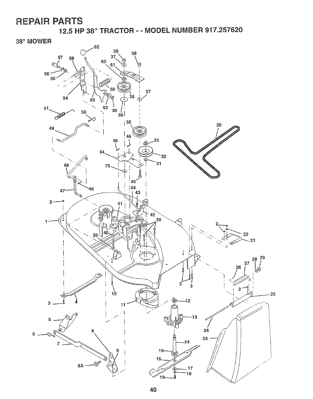
REPAIR PARTS
12.5 HP 38" TRACTOR -- MODEL NUMBER 917,257620
38" MOWER
57 58
55
2O
3O
33
24
23
_,j
26
4O
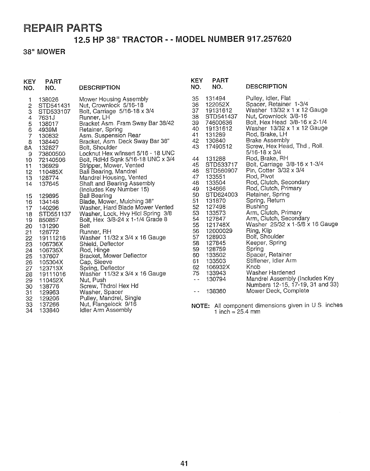
REPABR PARTS
12.5 HP 38" TRACTOR - - MODEL NUMBER 9'17.257620
38" MOWER
KEY PART KEY PART
NO. NO. DESCRIPTION NO. NO. DESCRIPTION
1 138026
2 STD541431
3 STD533107
4 7631J
5 138017
6 4939M
7 130832
8 138440
8A 132827
9 73800500
10 72140506
11 136929
12 110485X
!3 128774
14 137645
15 129895
16 134148
17 140296
18 STD551137
19 850857
20 131290
21 128772
22 '19111216
23 106736X
24 106735X
25 137607
26 195304X
27 123713X
28 19111016
29 110452X
30 138776
31 129963
32 129206
33 137266
34 133840
Mower Housing Assembly 35
Nut, Crowntock 5/16-18 36
Bolt, Carriage 5/16-18 x 3/4 37
Runner, LH 38
Bracket Asm Fram Sway Bar 38/42 39
Retainer, Spring 40
Asm, Suspension Rear 41
Bracket, Asm Deck Sway Bar 38" 42
Bolt, Shoulder 43
Locknut Hex w/insert 5/16 - 18 UNC
Bolt, RdHd Sqnk 5/16-18 UNC x 3/4 44
Stripper, Mower, Vented 45
Ball Bearing, Mandrel 46
Mandrel Housing, Vented 47
Shaft and Bearing Assembly 48
(Includes Key Number 15) 49
Ball Bearing 50
Blade, Mower, Mulching 38" 51
Washer, Hard Blade Mower Vented 52
Washer, Lock, Hvy Hfcl Spring 3/8 53
Bolt, Hex 3/8-24 x 1-1/4 Grade 8 54
Belt 55
Runner, RH 56
Washer 11/32 x 3/4 x 16 Gauge 57
Shield, Deflector 58
Rod, Hinge 59
Bracket, Mower Deflector 60
Cap, Sleeve 61
Spring, Deflector 62
Washer 11/32 x 3/4 x 16 Gauge 75
Nut, Push --
Screw, Thdrol Hex Hd
Washer, Spacer - -
Pulley, Mandrel, Single
Nut, Flangelock 9/16
Idler Arm Assembly
131494
122052X
19131612
STD541437
74600636
19131612
13'1289
13084O
17490512
131288
STD533717
STD560907
133551
133504
134666
STD624003
131870
127498
133573
127847
t21748X
12000029
128903
127845
128759
133502
133503
106932X
133943
130794
138360
Pulley, Idler, Flat
Spacer, Retainer' 1-3/4
Washer 13/32 x 1 x 12 Gauge
Nut, Crowntock 3/8-16
Bolt, Hex Head 3/8-16 x 2-1/4
Washer 13/32 x 1 x 12 Gauge
Rod, Brake, LH
Brake Assembly
Screw, Hex Head, Thd, Rol!
5/16-I8 x 3/4
Rod, Brake, RH
Bolt, Carriage 3/8-16 x 1-3/4
Pin, Cotter 3/32 x 3/4
Rod, Pivot
Rod, Clutch, Secondary
Rod, Clutch, Primary
Retainer, Spring
Spring, Return
Bushing
Arm, Clutch, Primary
Arm, Clutch, Secondary
Washer 25/32 x 1-5/8 x 16 Gauge
Ring, Klip
Bolt, Shoulder
Keeper, Spring
Spring
Spacer, Retainer
Stiffener, Idler Arm
Knob
Washer Hardened
Mandrel Assembly (Includes Key
Numbers t2-I5, 17-19, 31 and 33)
Mower Deck, Complete
NOTE: All component dimensions given in US. inches
1 inch = 25,4 mm
41
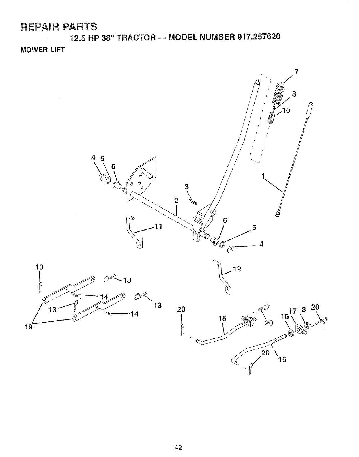
REPABF_PARTS
12.5 HP 38" TRACTOR -- MODEL NUMBER 917.257620
MOWER LIFT
7
13
45
6
8
12
\'15
42

REPAIR PARTS
12.5 HP 38" TRACTOR - - MODEL NUMBER 917.257620
MOWER LIFT
KEY PART
NO. NO. DESCRIPTION
1 136973
2 122507X
3 105767X
4 12000002
5 19211621
6 120183X
7 125631X
8 I22365X
10 122512X
11 134619
12 135388
13 4939M
'14 135563
15 127218
16 73350800
17 130171
18 73800800
19 130832
20 3146R
Rod, Asm, Lever
Shaft Asm Lift
Pin Groove
E Ring #5133-62
Washer Pltd 21/32 x t x 2! Ga
Bearing Nylon
Grip Handle Fluted
Button Plunger Red
Spring Cprsn
Link Lift Lh Fixed Length
Link Lift Rh Fixed Length
Retainer Spring
Pin Roll Stt 5/16 x 1,25
Link Front
Nut Jam Hex 1/2 - 13 Uric
TrLJnnion Blk Zinc
Nut Lock w/wsh 1/2 - 13 Unc
Arm Suspension Rear
Spring Retainer
NOTE: Atl component dimensions given in U,S, inches
1inch = 25.4 mm
A_
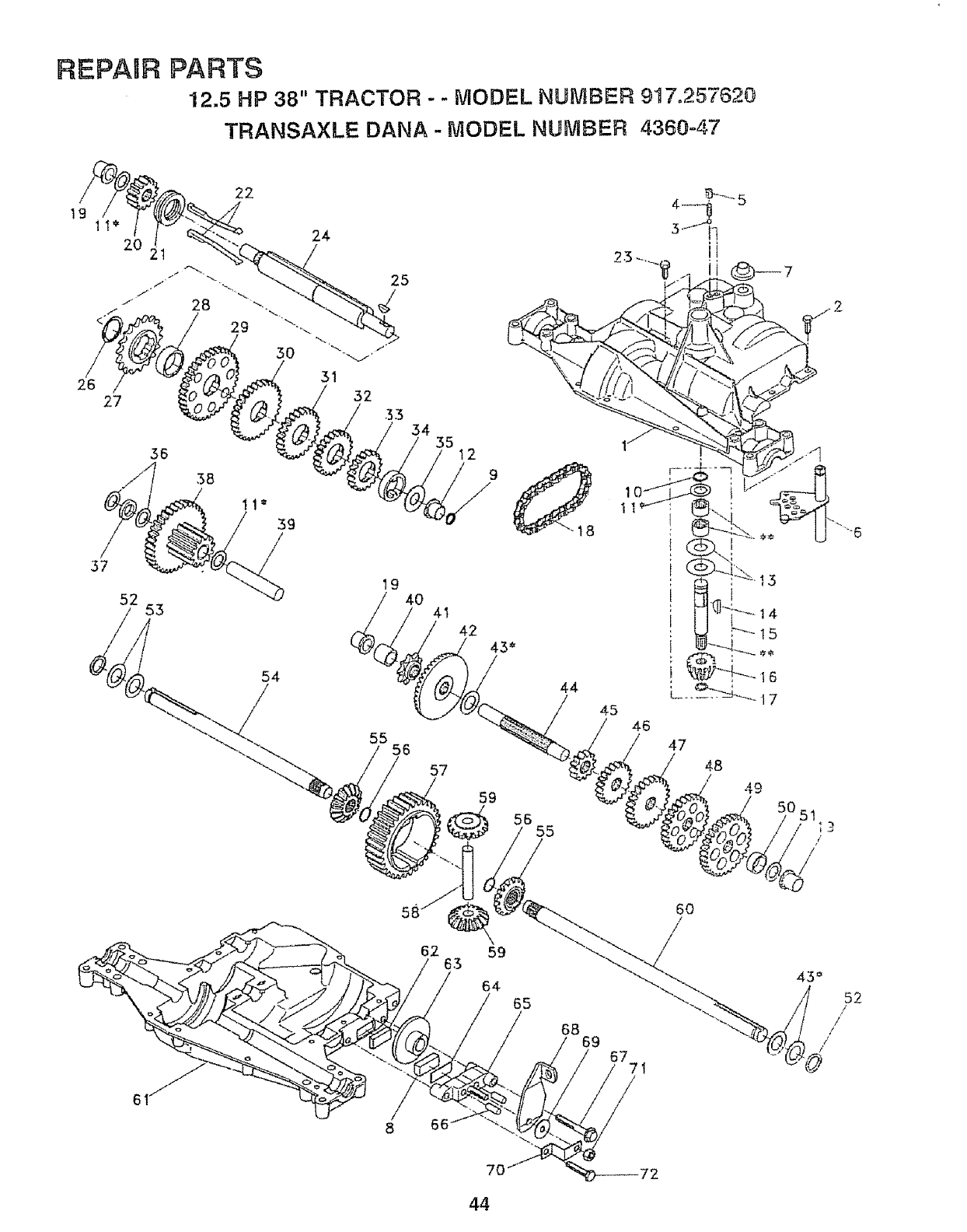
REPAIR PARTS
12.5 HP 38" TRACTOR - - MODEL NUMBER 917.257620
TRANSAXLE DANA - MODEL NUMBER 4360°47
t9
36 12
38 9
11 = 11
39
/
57
52 53
54
t9 40 41
55 56
57
59
@
44
1555
45 46
: I5
i
14
15
47
48
/49
51 ;3
/
62 59
63
64 65
66 ._
70
68 69 67 7!
/
/
52
,/
/
/
/
!
44

REPAIR PARTS
12.5 HP 38" TRACTOR - - MODEL NUMBER 917.257620
TRANSAXLE DANA - MODEL NUMBER 4360-47
KEY PART KEY PART
NO. NO. DESCRIPTION NO. NO. DESCRIPTION
1 138248 Housing, Upper 40 120472X
2 2274J Screw, Self-Tapping, Large 41 105928X
1/4-20 x _734 42 1t0084X
3 134400 Ball, Detent 43 134394
4 105904X Spring, Detent 44 120473X
5 '105905X Screw, Set 45 105933X
6 138235 Kit, ShifterAssembty 46 120407X
7 134399 Boot, Shifter 47 106589X
8 120951X Puck, Friction 48 120408X
9 138241 Square Ring 49 105937X
'10 2267J Ring, Retaining 50 120523X
lt 134793 * Assembly, Kit, Shim ..625 Shaft 51 2226J
'12 138240 Bearing, Flange 52 134401
13 t20415X Washer, Plain .632 x 1.38 x 046 53 2264J
14 2257J Key, Woodruff, #9 54 120474X
15 138234 Assembly, Kit, Input Shaft 55 11008IX
16 It0078X Pinion, Bevel, 14Teeth 56 10594tX
17 105909X Ring, Retaining 57 110071X
18 105910X Chain, 24 Pitches 58 120952X
19 105911X Bearing, Flange 59 110082X
20 138242 Gear, Spur, 14 Teeth 60 120475X
21 138246 Collar, Clutch 81 138247
22 138236 Assembly, Kit, Clutch Keys 62 120961X
23 134791 Screw, Self-Tapping, with Sealer 63 7294J
24 138243 Shaft, Intermediate 64 I08989X
25 2244J Key, Woodruff, #61 65 't20953X
26 105916X Ring, Retaining 66 120954X
27 120470X Sprocket, 18 Teeth 67 134799
28 110070X Spacer 68 I38244
29 108977X Gear, Spur, 37Teeth 69 108996X
30 120405X Gear, Spur, 30 Teeth 70 120956X
31 108980X Gear, Spur, 25 Teeth 71 73810500
32 120406X Gear, Spur, 22Teeth 72 106596X
33 134796 Gear, Spur, 19 Teeth 73 120416X
34 134797 Spacer 1.133 x 1.50 x .375
35 105925X Washer, Plain .640 x 1.37 x .061
36 2232J Washer, Plain ..632 x 1..00 x .026
37 108978X Spacer .630 x 1.00 x .16g *" Order Key Number 15
3B 110079X Assembly, Gear, Combination of
12 Teeth and 35 Teeth
Shaft, Idler
39 I24639X
Spacer .635 x 875 x 755
Sprocket 9 Teeth
Gear, Bevel, 42 Teeth
* Assembly, Kit, Shim, 750 Shaft
Shaft, Drive
Gear, Spur, 12 Teeth
Gear, Spur, 20 Teeth
Gear, Spur, 25 Teeth
Gear, Spur, 28 Teeth
Gear, Spur, 31 Teeth
Spacer 781 x 1.00 x 375
Washer, Plain .632 x 1 00 x 060
Washer, Neoprene
Washer, Plain .758 x 1.25 x 031
Axle, L H.
Gear, Miter, 15 Teeth
Ring, Retaining
Gear, Spur, 32 Teeth
Shaft, Cross
Gear, Miter, 15 Teeth
Axle, RH.
Housing, Lower
Puck, Friction
Disc, Brake
Spacer
Jaw, Brake
Pin, Dowel
Screw, Self-Tapping 5/16-18 x 225
Lever, Actuating
Washer, Plain .321 x 1.00 x 055
Bracket, Anti-Rotation
Locknut 5/16-24
Screw, Self-Tapping 5/16-18 x !.44
Grease
* Use in combinations to maintain proper clearances
NOTE: All component dimensions given in U.S inches
1 inch = 25.4 mm
45
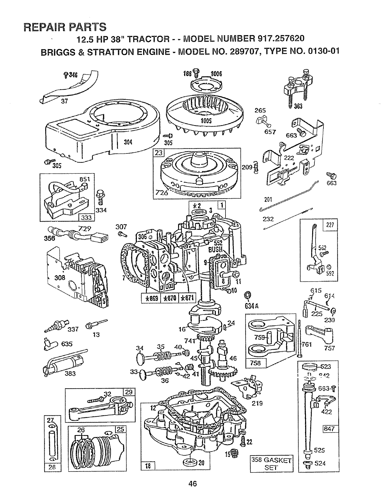
REPAaR PARTS
12.5 HP 38" TRACTOR - - MODEL NUMBER 917.257620
BRiGGS & STRATTON ENGINE - MODEL NO. 289707, TYPE NO. 0130-01
$34
Y337 t3
i 26
305 .................
66.3
46
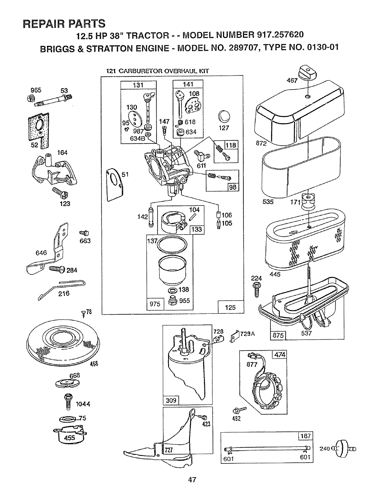
REPAIR PARTS
12.5 HP 38" TRACTOR --MODEL NUMBER 917.257620
BRIGGS & STRATTON ENGINE - MODEL NO. 289707, TYPE NO. 0130-01
965 53
%
123
84
_,78
_1044
121 CARBURE'{'OR OVERHAUL KIT
13t 141
,_ _% lo8
_9_z_ Ve6a4 127
@)138
535 171
445
224
537
47
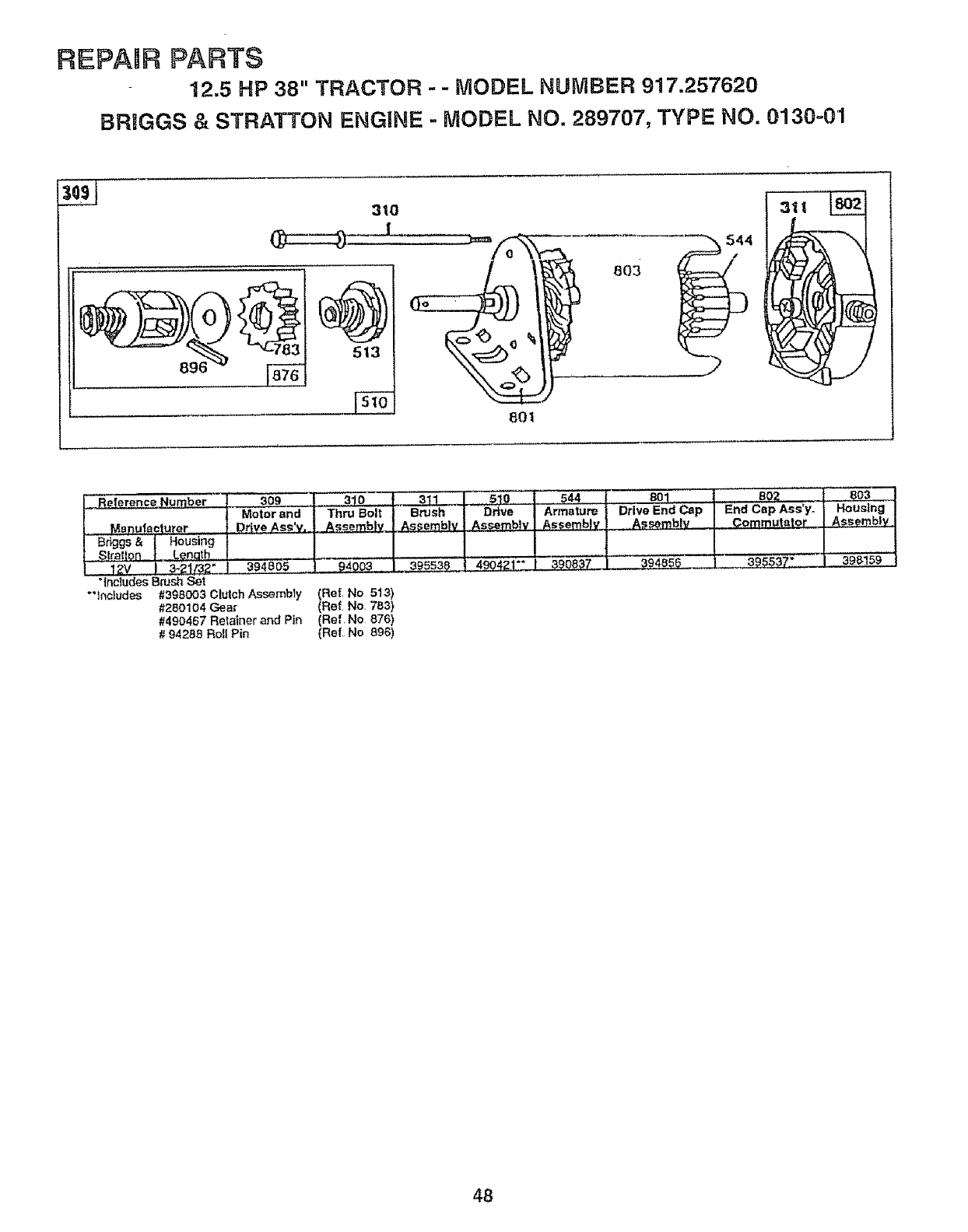
REPANR PARTS
12.5 HP 38" TRACTOR - - MODEL NUMBER 917.257820
BRIGGS & STRATTON ENGINE -MODEL NO. 289707, TYPE NO. 0130-01
3tO
1
__ber I 3o9 31o t331 .
]Motor and Thru Bolt j Brush
- BdggsManufeetuter&l Housing _1Drive Ass'v, _ _Fembl v
_tralton |,,.Lenath I
12v 1 3.21f32".i3948D_ "_4do:_ I 3_838
"IncludesBrush Set
"'Includes #398003 Clutch Assembty (Ref, No 513)
#260104 Gear (Ref No, 783)
#490467 Retainer and Pin (Ref No 876)
# 94288 Roll Pin (Ref, No 896)
5!0
Drive
Assembly
._.4,90421"" I
544 I 801 I...............80Z
Armature _Drive End Cap IEnd Cap Ass*yo IHousing
AssemblyLAssemb!v I Commutator I Assembly
48
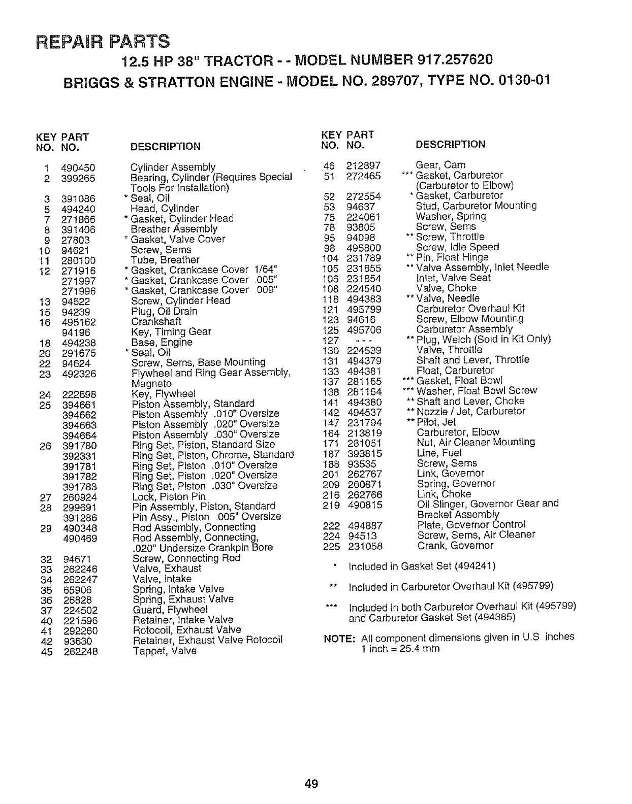
REPAIR PARTS
12.5 HP 38" TRACTOR -- MODEL NUMBER 917=257620
BR1GGS & STRATTON ENGINE -MODEL NO. 289707, TYPE NO. 0130-0'1
KEY PART KEY PART
NO. NO. DESCRIPTION NO. NO. DESCRIPTION
1 490450
2 399265
3 391086
5 494240
7 271866
8 391406
9 27803
10 94621
11 280100
t2 27'I916
271997
271996
13 94622
15 94239
16 495162
94196
18 494238
20 291675
22 94624
23 492326
24 222698
25 394661
394662
394663
394664
26 39'1780
392331
391781
391782
391783
27 260924
28 299691
391286
29 490348
490469
32 94671
33 262246
34 262247
35 65906
36 26828
37 224502
40 221596
41 292260
42 93630
45 262248
Cylinder Assembly 46 212897
Bearing, Cylinder (Requires Special 51 272465
Tools For Installation)
*Seal, Oil 52 272554
Head, Cylinder 53 94637
* Gasket, Cylinder Head 75 224061
Breather Assembly 78 93805
* Gasket, Valve Cover 95 94098
Screw, Sems 98 495800
Tube, Breather 104 231789
* Gasket, Crankcase Cover 1/64" 105 231855
* Gasket, Crankcase Cover ,005" 106 231854
* Gasket, Crankcase Cover 009" 108 224540
Screw, Cyfinder Head 118 494383
Plug, Oil Drain 121 495799
Crankshaft 123 94616
Key, Timing Gear 125 495706
Base, Engine 127 ---
* Seal, Oil 130 224.539
Screw, Sems, Base Mounting 131 494379
Flywheel and Ring Gear Assembly, !33 494381
Magneto !37 281165
Key, Flywheel 138 281164
Piston Assembly, Standard 141 494380
Piston Assembly o010" Oversize 142 494537
Piston Assembly .020" Oversize 147 231794
Piston Assembly .030" Oversize 164 2138t9
Ring Set, Piston, Standard Size 171 281051
Ring Set, Piston, Chrome, Standard 187 393815
Ring Set, Piston .010" Oversize 188 93535
Ring Set, Piston .020" Oversize 201 262767
Ring Set, Piston .030" Oversize 209 260871
Lock, Piston Pin 216 262766
Pin Assembly, Piston, Standard 219 490815
Pin Assy., Piston .005" Oversize
Rod Assembly, Connecting 222 494887
Rod Assembly, Connecting, 224 94513
.020" Undersize Crankpin Bore 225 231058
Screw, Connecting Rod
Valve, Exhaust *
Valve, Intake
Spring, Intake Valve
Spring, Exhaust Valve
Guard, Flywheel
Retainer, Intake Valve
Rotocoil, Exhaust Valve
Retainer, Exhaust Valve Rotocoil
Tappet, Valve
Gear, Cam
*** Gasket, Carburetor
(Carburetor to Elbow)
* Gasket, Carburetor
Stud, Carburetor Mounting
Washer, Spring
Screw, Seres
** Screw, Throttle
Screw, fdie Speed
** Pin, Float Hinge
** Valve Assembly, Inlet Needle
Inlet, Valve Seat
Valve, Choke
** Valve, Needle
Carburetor Overhaul Kit
Screw, Elbow Mounting
Carburetor Assembly
** Plug, Welch (Sold in Kit Only)
Valve, Throttle
Shaft and Lever, Throttle
Float, Carburetor
*** Gasket, Float Bowl
*** Washer, Float Bowl Screw
** Shaft and Lever, Choke
** Nozzle /Jet, Carburetor
** Pilot, Jet
Carburetor, Elbow
Nut, Air Cleaner Mounting
Line, Fuel
Screw, Sems
Link, Governor
Spring, Governor
Link, Choke
Oil Slinger, Governor Gear and
Bracket Assembly
Plate, Governor Control
Screw, Seres, Air Cleaner
Crank, Governer
Included in Gasket Set (494241)
** Included in Carburetor Overhaul Kit (495799)
*** Included in both Carburetor Overhaul Kit (495799)
and Carburetor Gasket Set (494385)
NOTE: All component dimensions given in U.S inches
1 inch = 25..4 mm
49
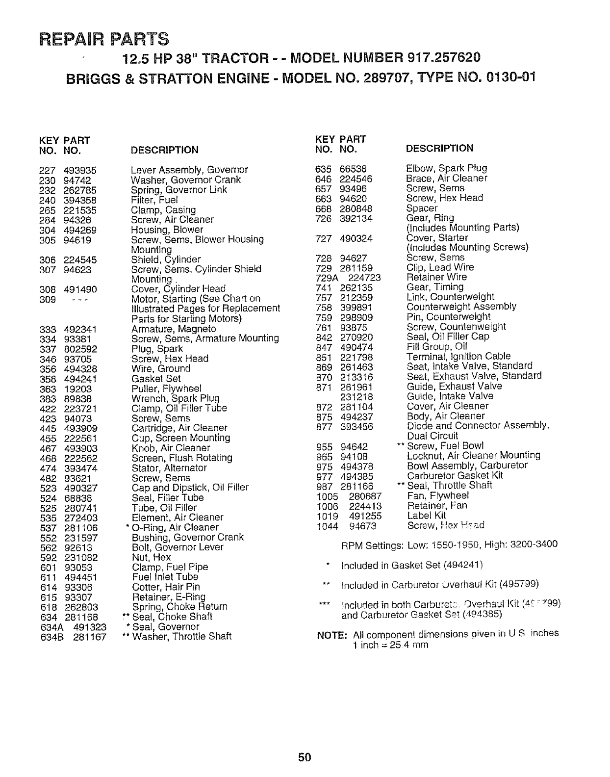
REPAIR PARTS
12.5 HP 38" TRACTOR - - MODEL NUMBER 9'17.257620
BRIGGS & STRATTON ENGINE - MODEL NO. 289707, TYPE NO. 0130-01
KEY PART KEY PART
NO. NO. DESCRIPTION NO. NO. DESCRIPTION
227 493935
230 94742
232 262785
240 394358
265 221535
284 94326
304 494269
305 94619
306 224545
307 94623
308 491490
309 -_*
333 492341
334 93381
337 802592
346 93705
356 494328
358 494241
363 19203
383 89838
422 223721
423 94073
445 493909
455 222561
467 493903
468 222562
474 393474
482 93621
523 490327
524 68838
525 28074'I
535 272403
537 281106
552 231597
562 92613
592 231082
601 93053
611 494451
614 93306
615 93307
618 262803
634 281168
634A 491323
634B 281167
Lever Assembly, Governor 635 66538
Washer, Governor Crank 646 224546
Spring, Governor Link 657 93496
Filter, Fuel 663 94620
Clamp, Casing 668 280848
Screw, Air Cleaner 726 392134
Housing, Blower
Screw, Sems, Blower Housing 727 490324
Mounting
Shield, Cylinder 728 94627
Screw, Sems, Cylinder Shield 729 281159
Mounting, 729A 224723
Cover, Cylinder Head 741 262135
Motor, Starting (See Chart on 757 212359
Illustrated Pages for Replacement 758 399891
Parts for Starting Motors) 759 298909
Armature, Magneto 761 93875
Screw, Sems, Armature Mounting 842 270920
Plug, Spark 847 490474
-Screw, Hex Head 851 221798
Wire, Ground 869 261463
Gasket Set 870 213316
Puller, Flywheel 871 261961
Wrench, Spark Plug 231218
Clamp, Oil Filler Tube 872 281104
Screw, Sems 875 494237
Cartridge, Air Cleaner 877 393456
Cup, Screen Mounting
Knob, Air Cleaner 955 94642
Screen, Flush Rotating 965 94108
Stator, Alternator 975 494378
Screw, Seres 977 494385
Cap and Dipstick, Oil Filler 987 281166
Seal, FillerTube I005 280687
Tube, Oil Filler 1006 224413
Element, Air Cleaner 1019 491255
* O-Ring, Air Cleaner 1044 9.4673
Bushing, Governor Crank
Bolt, Governor Lever
Nut, Hex
Clamp, Fuel Pipe
Fuel Inlet Tube
Cotter, Hair Pin
Retainer, E-Ring
Spring, Choke Return
** Seal, Choke Shaft
* Seal, Governor
** Washer, Throttle Shaft
Elbow, Spark Plug
Brace, Air Cleaner
Screw, Sems
Screw, Hex Head
Spacer
Gear, Ring
(Includes Mounting Parts)
Cover, Starter
(Includes Mounting Screws)
Screw, Sems
Clip, Lead Wire
Retainer Wire
Gear, Timing
Link, Counterweight
Counterweight Assembly
Pin, Counterweight
Screw, Countenweight
Seal, Oil Filler Cap
Flit Group, Oi!
Terminal, Ignition Cable
Seat, Intake Valve, Standard
Seat, Exhaust Valve, Standard
Guide, Exhaust Valve
Guide, Intake Valve
Cover, Air Cleaner
Body, Air Cleaner
Diode and Connector Assembly,
Dual Circuit
Screw, Fuel Bowl
Locknut, Air Cleaner Mounting
Bowl Assembly, Carburetor
Carburetor Gasket Kit
Seal, Throttle Sllaft
Fan, Flywheel
Retainer, Fan
Label Kit
Screw, ,qex H_d
RPM Settings: Low: 1550-1950, High: 3200-3400
* Included in Gasket Set (494241)
** Included in Carburetor Uverhaut Kit (495799)
*** _ncluded in both Carburet:;. Overhaul Kit (4_ :-799)
and Carburetor Gasket Set (494385)
NOTE: All component dimensions given in U S inches
1 inch = 25 4 nTm
50
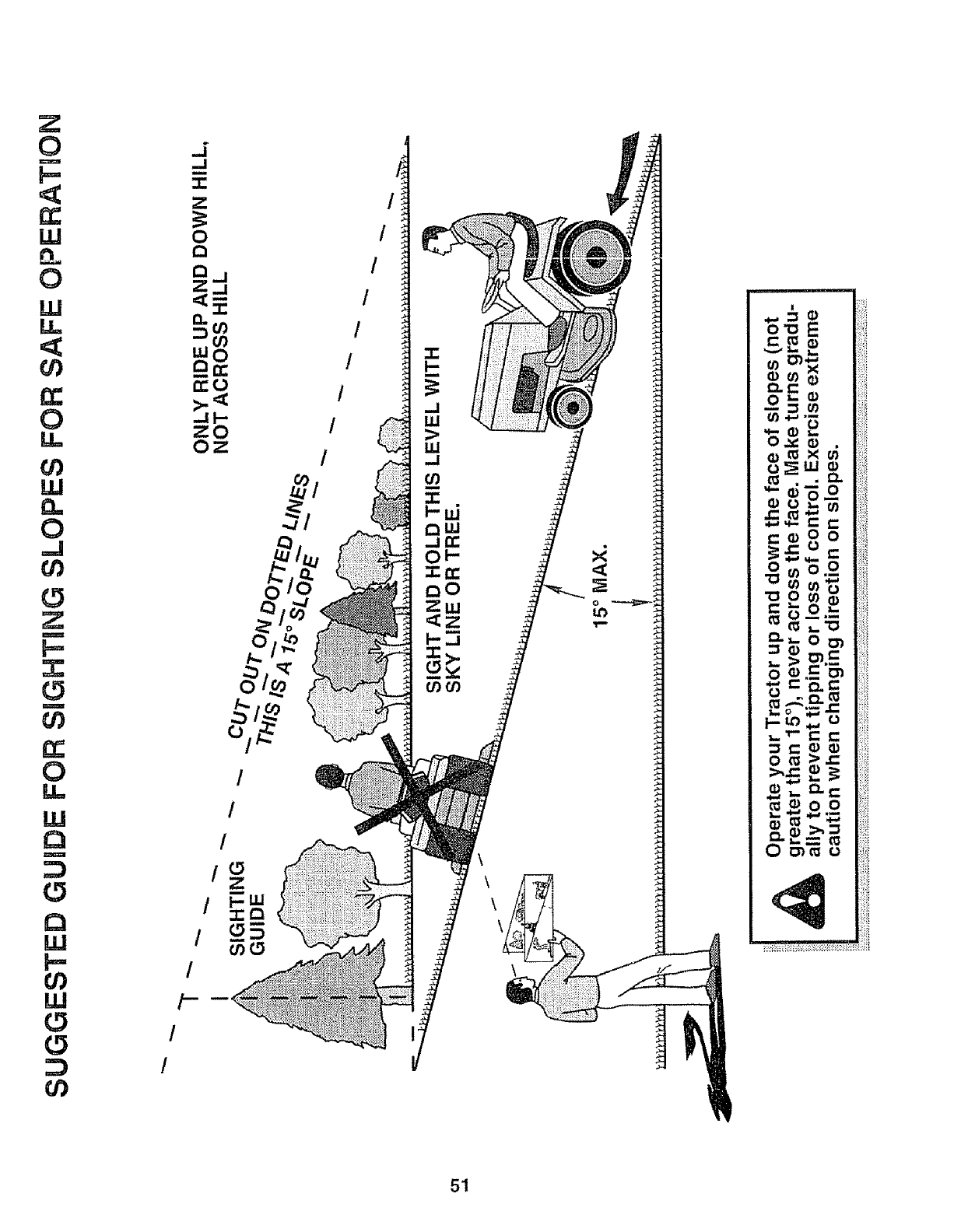
Z
0
m
C_
LLJ
0
LLI
I!
n.-
0
U)
LLi
0
=J
U)
U)
C_
0
LU
r_
m
LLi
p_
U)
LI.J
U)
o
/
/
/
/c_
Z
1.0
51
OWN R'S
ANUAL
MODEL NO.
917,257620
HOW TO ORDER
REPAIR PARTS
®
12.5 HP IC
ELECTRIC START
38" MOWER
5 SPEED TRANSAXLE
LAWN TRACTOR
Each tractor has its own model number_ Each engine has
its own model number,
The model number for your tractor will be found on the
model plate located under the seat,,
The model number for your engine will be found on the
blower housing of the engine,,
All parts listed herein may be ordered from any Sears,
Roebuck and Co,, Service Center/Department and most
Retail Stores_
WHEN ORDERING REPAIR PARTS, ALWAYS GIVE THE
FOLLOWING INFORMATION:
• PRODUCT - LAWN TRACTOR
oMODEL NUMBER - 9t7.257620
•ENGINE MODEL NO. - 289707,
TYPE NUMBER - 0130-01
,, PART NUMBER
oPART DESCRIPTION
Your Sears merchandise has added value when you
consider Sears has service units nationwide staffed with
Sears trained technicians professional technicians
specifically trained to insure that we meet our pledge to
you, we service what we see
140390 8°3,93 Printed in U.S,A,
...... ,.......... ,, =_
, , ........... ,, , ,,,,
