Craftsman 917258492 User Manual Lawn, Tractor Manuals And Guides L0807630
CRAFTSMAN Lawn, Tractor Manual L0807630 CRAFTSMAN Lawn, Tractor Owner's Manual, CRAFTSMAN Lawn, Tractor installation guides
User Manual: Craftsman 917258492 917258492 CRAFTSMAN Lawn, Tractor - Manuals and Guides View the owners manual for your CRAFTSMAN Lawn, Tractor #917258492. Home:Lawn & Garden Parts:Craftsman Parts:Craftsman Lawn, Tractor Manual
Open the PDF directly: View PDF ![]() .
.
Page Count: 48
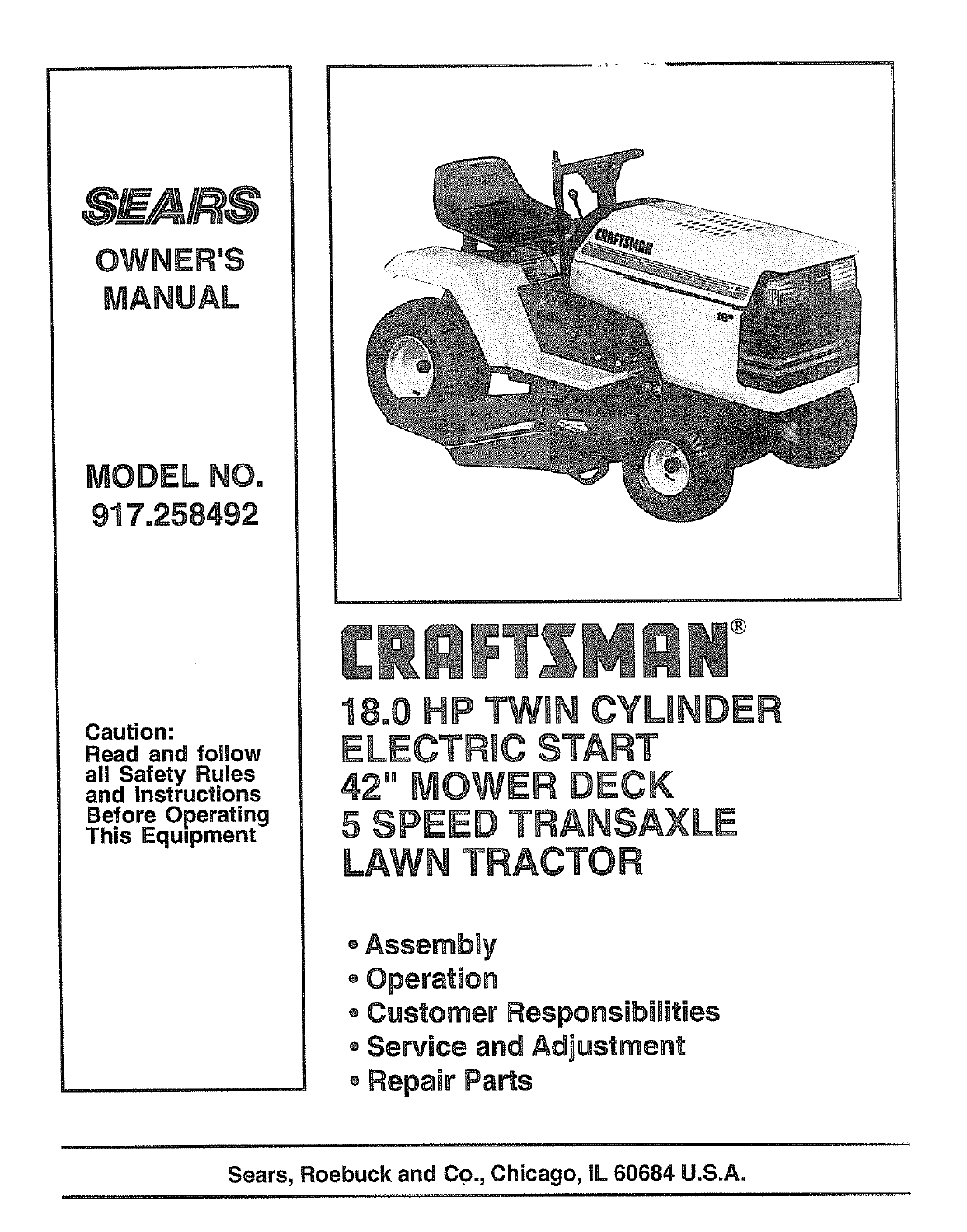
S A/k S
Caution:
Read and follow
all Safety Rules
and instructions
Before Operating
This Equipment
®
18,0 HP TWUNCYLmNDER
ELECTRIC START
42" MOWER DECK
5 SPEED TRANSA×LE
LAWN TRACTOR
,AssembUy
oOperation
Customer Responsibilities
oServBceand Adjustment
,Repair Parts
Sears, Roebuck and Co., Chicago, IL 60684 U.S.A.
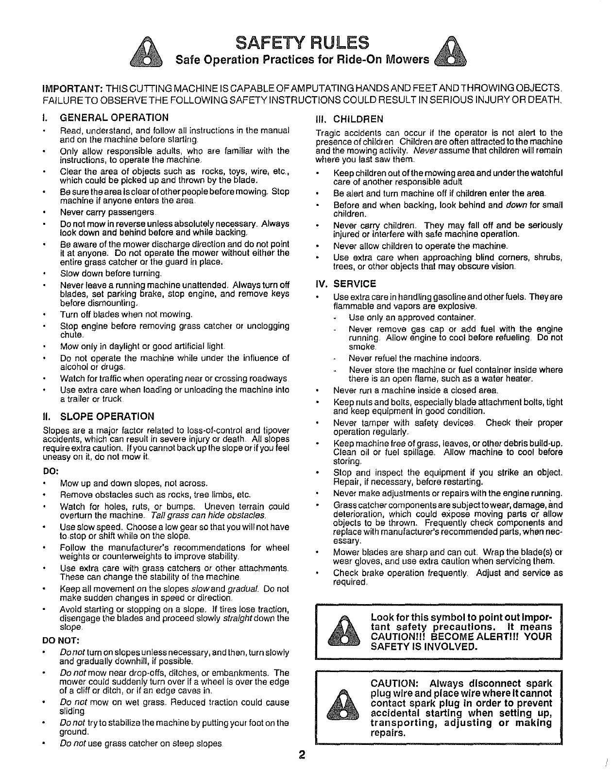
SAFETY RULES
Safe Operation Practices for Ride-On Mowers
IMPORTANT: THIS CUTTING MACHINE IS CAPABLE OFAM PUTATING HANDS AND FEETAND THROWING OBJECTS,
FAILURE TO OBSERVE THE FOLLOWING SAFETY INSTRUCTIONS COULD RESULT IN SERIOUS INJURY OR DEATH,
GENERAL OPERATION
Road, understand, and follow all instructions in the manual
and on the machine before starting.
Only allow respeesible adults, who are familiar with the
instructions, to operate the machine.
Clear the area of eb ects such as rocks, toys, wire, etc,
which could be picked up and thrown by the bade.
Be sure the area is etear of other people before mowing Stop
machine if anyone enters the area.
Never carry passengers
Do not mow in reverse unless absolutely necassary_ Always
look down and behind before and while backing.
Be aware of the mower discharge direction and do not point
it at anyone. Do not operate the mower without either the
entire grass catcher or the guard in place.
Slow down before turning
Never leave a running machine unattended. Always turn off
blades, set parking brake, stop engine, and remove keys
before dismounting.
Turn off blades when not mowing_
Stop engine before removing grass catcher or unclogging
chute
Mow only in daylight or good artificial light
Do not operate the machine while under the influence of
alcohol or drugs
Watch for traffic when operating near or crossing roadways
Use extra care when loading or unloading the machine into
a trailer or truck
II. SLOPE OPERATION
Slopes are a major factor related to Ioss-of-control and tipover
accidents, which can result in severe injury or death. Atl slopes
require extra caution. If you cannot back up the slope or if you feel
uneasy ee it, do not mow it.
DO:
Mow up and down slopes, not across_
Remove obstacles such as rocks, tree limbs, etc.
Watch for holes, ruts, or bumps. Uneven terrain could
overturn the machine Tall grass can hide obstacles.
Use slow speed_ Choose a low gear so that you will not have
to stop or shift white on the slope.
Follow the manufacturer's recommendations for wheel
weights or counterweights to improve stability.
Use extra care with grass catchers or other attachments
These can change the stability of the machine
Keep all movement on the slopes slowand gradual Do not
make sudden changes in speed or direction
Avoid starting or stopping ee a slope. If tires lose traction,
disengage the blades arrd proceed slowly straight down the
slope
DO NOT:
Do not turn on slopes unless necessary, and then, turn slowly
and gradually downhill, if possib{e_
Do not mow near drop-errs, ditches, or embankments. The
mower could suddenly turn over if a wheel is over the edge
of a cliff or ditch, or if an edge caves in_
Do not mow on wet grass. Reduced traction could cause
sliding
Do not tryto stabilize the machine by putting your foot on the
ground_
Do not use grass catcher on steep slopes
III, CHILDREN
Tragic accidents can occur if the operator is not alert to the
presence of chitdren Children are often attracted to the machine
and the mowing activity. Neverassume that children will remain
where you last saw them
Keep children out of the mowing area and under the watchful
care of another responsible adult
Be alert and turn machine off if children enter the area
Before and when backing, look behind and down for small
children_
Never carry children. They may fall off and be seriously
njured or nterfere with safe mach ne operation.
Never allow children to operate the machiae_
Use extra care when approaching blind corners, shrubs,
trees, or other objects that may obscure vision.
IV. SERVICE
Use extra care in handling gasoline and other fuels. They are
flammable and vapors are explosive
Use only an approved container
Never remove gas cap or add fuel with the engine
running Allow engine to cool before refueling. Do not
smoke
Never refuel the machine indoors.
Never store the machine or fuel container inside where
there is an open flame, such as a water heater.
Never run a machine inside a closed area.
Keep nuts and bolts, especially blade attachment bolts, tight
and keep equipment in good condition.
Never tamper with safety devices. Check their proper
operation regularly.
Keep machine free of grass, leaves, or other debris build-up.
Clean oil or fuel spillage. Allow machine to cool before
storing_
Stop and inspect the equipment if you strike an object.
Repair, if necessary, before restarting,
Never make adjustments or repairs with the engine running.
Grass catcher components are subject to wear, damage, and
deterioration, which could expcae moving parts or allow
objects to be thrown. Frequently check components and
replace with manufacturer's recommended parts, when nec-
essary
Mower blades are sharp and can cuL Wrap the blade(s) or'
wear gloves, and use extra caution when servicing them.
Check brake operation frequently. Adjust and service as
required.
Look for this symbol to point out Impor-
tant safety precautions. It means
CAUTION!!f BECOME ALERT!!! YOUR
SAFETY IS INVOLVED.
CAUTION: Always disconnect spark
plug wire and place wire where It cannot
contact spark plug In order to prevent
accidental starting when setting up,
transporting, adjusting or making
repairs.
2

CONGRATULATIONS onyour purchase of a Sears
tractor, It has been designed, engineered and manufac-
tured to give you the best possible dependability and
performance,
Should you experience any problem you cannot easily
remedy please contact your nearest Sears Service
Center/Department We have competent, we -tra ned
technicians and the proper tools to service or repair this
unit.
Please read and retain this manual The instructions will
enable you to assemble and maintain your unit properly_
Always observe the "SAFETY RULES"
MODEL
NUMBER 917_258492
SERIAL
_IUMBER
DATE OF PURCHASE
THE MODEL AND SERIAL NUMBERS WILL BE FOUND
ON A PLATE UNDER THE SEAT,
YOU SHOULD RECORD BOTH SERIAL NUMBER AND
DATE OF PURCHASE AND KEEP IN A SAFE PLACE
FOR FUTURE REFERENCE
MAINTENANCE AGREEMENT
A Sears maintenance agreement is available on this prod-
uct. Contact your nearest Sears store for details.
CUSTOMER RESPONSiBiLiTIES
o Read and observe the safety rule&
o Followa regular schedule in maintaining, caring for and
using your unit.
o Follow the instructions under "Customer Responsibili-
ties" and "Storage" sections of this owner's manual,
PRODUCT SPEClFlCATBONS
HORSEPOWER: l&0
GASOLINE CAPACITY: &5 GALLONS
UNLEADED REGULAR
OIL (3..0PINTS): SAE 30 (above 32° F)
SAE 5W-30 (below32°F)
SPARK PLUG (GAP.030 IN.): CHAMPION RJ-19LM
STD361458
VALVE CLEARANCE: INTAKE _004- 006 IN.
EXHAUST 007- .009 IN_
GROUND SPEED: FORWARD
1st .77 MPH
2nd 1.46 MPH
3rd &41 MPH
4th 4,34 MPH
5th 557 MPH
REVERSE: 1.07 MPH
TIRE PRESSURE: FRONT: 14 PSI
REAR: 10 PSI
5 AMPS HEADLIGHT
CHARGING SYSTEM: 3 AMPS BATTERY
BLADE BOLT TORQUE: 30-35 FT. LBS,
WARNING; This unit is equipped with an internal combus-
tion engine and should not be used on or near any unim-
proved forest-covered brush-covered or grass-covered
land unless the engineZs exhaust system is equipped with
a spark arrester meeting applicable local or state laws (if
any), If a spark arrester Is used it should be maintainea In
effective work ng order by the operator,
in the state of California the above is required bv law
(.Section 4442 of the California Public Resources (_ode),
Other states may have similar laws, Federal laws apply on
federal lands,, A spark arrester for the muffler is available
through your nearest Sears Authorized Service Center
(See REPAIR PARTS section of this manual)
LIMITED TWO YEAR WARRANTY ON ELECTRIC START RiDiNG EQUIPMENT
For two (2) years from the date of purchase, if this riding equipment is maintained, lubricated and tuned up according to the
instructionsin the owner's manual, Sears will repair or replace,free of charge, any parts found to be defective in material or
workmanship.
This Warranty does not cover:
•Expendable items which become worn during normal use, such as blades, spark plugs, air cleaners and belts.
•Tire replacement or repair caused by punctures from outsideobjects, such as nails,thorns, stumps, or glass.
Repairs necessary because of operator abuse, negligence, improper storage or accident or the failure to maintain the
equipment according to the instructionscontained in the owner's manual.
•Riding equipment used for commercial or rental purposes..
UMiTED 90 DAY WARRANTY ON BATTERY
For 90 days from date of purchase, if any battery included with this riding equipmentproves defective in material or workmanship
and our testing determines the battery will not hold a charge, Sears will replace the battery at no charge.
WARRANTY SERVICE IS AVAILABLE BY RETURNING THE RIDING EQUIPMENT TO THE NEAREST SEARS SERVICE
CENTER/DEPARTMENT IN THE UNITED STATES.
This Warranty gives you specific legal rights, and you may also have other rights which may vary from state to state
SEARS, ROEBUCK AND CO., D/731CR-W, SEARS TOWER, CHICAGO, ILLINOIS 60684
3
TABLE OF CONTENTS
SAFETY RULES ............................................................ 2
PRODUCT SPECIFICATIONS ....................................... 3
CUSTOMER RESPONSIBILITIES ..................... 3, 14-17
WARRANTY ................................................................... 3
TABLE OF CONTENTS ................................................. 4
INDEX ............................................................................. 4
TRACTOR ACCESSORIES ........................................... 5
ASSEMBLY ................................................................ 7-9
OPERATION ........................................................... 10-13
MAINTENANCE SCHEDULE ...................................... 14
SERVICE AND ADJUSTMENTS ............................ 18-23
STORAGE .................................................................... 24
TROUBLESHOOTING ............................................ 25-26
REPAIR PARTS - TRACTOR ................................. 28-40
REPAIR PARTS - ENGINE ..................................... 41-46
PARTS ORDERING/SERVICE ................... BACK PAGE
MNDEX
A
Accessories ................................................ 5
Adjustments:
Brake ......................................................20
Carburetor. ..........................................23
Gauge Wheels ........................................9
Mower
Front-To-Back ........................_. 19
Side-To-Side ..................................18
Throttle Control Cable .....................22
Air Filter, Engine ..................................... 16
Air Screen, Engine .......................................16
Assembly ...................................................7-9
B
Battery:
Charging ..............................................8
Cleaning ........................................ 16
installation ................................................9
Levels .............................................8,16
Preparation ...........................................8
StaRing with Weal( Battery ............21
Storage ...................................................24
Terminals .........................................16
Bolt:
Motion Drive
Remova!/Replacement ........... 20
Mower Blade Drive
RemovaVReplacement ................20
Blade:
Sharpening ........................................15
Replacement ................................... 15
Brake Adjustment ................................. 20
C
Carburetor Adjustment ......................... 23
Controls, Tractor ......................................10
Customer Responsibilities ............. 15-17
Engine:
Ail Filter ....................................... 16
Air Filter Foam Pre-Cleaner ._..16
Air Screen, Engine .................... 16
Battery .......................................... 15
Cooling Fins, Engine ............... 17
Engine Oil ............................................16
Fuel Filter ................................. 17
Spark Plugs ....................................17
Tractor:
Blade ....................................... 15
Lubrication Chad ........................ 14
Maintenance Schedule ..............14
Tire Care ........................... 8,15,21
Cutting Height, Mower ............................11
E
Electrical:
Interlocks and Relays .......................22
Schematic ..........................................27
Wiring Diagram ................................28
Engine:
Air Filter. ...............................................16
Air Filter Foam Pre-Cleaner .........16
Air Screen .........................................16
Cooling Fins, Engiae ........................17
Oil Change .................................... 16
Oil Level .................................... 12,16
Oil Type ................................................16
Preparation .................................... 12
Repair Pads ............................ 41-46
Starling ............................................ 13
Storage ...............................................24
F
Filter:
Air Filter .............................................16
Air Filter Foam Pre-Cleaner ........ 16
Fuel ...................................................17
Fuel:
Type ...................................................12
Storage ........................................... 24
Fuse ......................................................... 22
G
Gauge Wheel Installation ....................... 9
H
Hood Removal/installation ................... 22
L
Leveling Mower Deck .................... 18-19
Lubrication:
Char ............................................ 14
M
Maintenance Schedule ......................... 14
Mower:
Adjustment, Front-to-Back .............19
Adjustment, Side-to-Side .............. 18
Adjustment, Gauge Wheel ..............9
Blade Sharpening .......................... 15
Blade Replacement ..................... 15
Cutting Height ...................................11
Installation ..................................... 18
Operation ........................................ 12
Removal ....................................... 18
Mowing Tips ......................................... 13
Muffler ...........................................................17
Spark Arrester .......................... 3,32
4
o
Oil:
Cold Weather Conditions ....... 12,16
Engine ........................................... 16
Storage ......................................... 24
Operation ..............;............................ 10-13
Operating Mower ................................ 12
Options:
Accessories ................................... 5
Spark Arrester ........................... 3,32
P
Parking Brake ................................. 10-11
Parts Bag .............................................. 6
Parts, Raplacement/Repair ........... 28-46
Product Specifications ............................ 3
R
Repair Parts ......................................28-46
S
Safety Rules .............................................2
Seat .........................................................8
Service and Adjustmerrts..................18-23
Carburetor, ...................................23
Fuse .............................................22
Hood Removal/Installation .......... 22
Motion Drive Belt
RemovaVReplacement ........... 20
Mower Blade Drive Belt
RemovaVReplacement ........... 20
Mower Adjustment
Front- to-Back ......................... 19
Side-to-Side ............................ 18
Mower Removal .......................... 18
Tire Care ............................ 8,15,21
Slope Guide Sheet ............................. 47
Spark Plugs ........................................ 17
Specifications ........................................3
Stading the Engine........................ 12-13
Steering Wheel ................................ 7,21
Stopping the Tractor, .......................... 11
Storage ............................................... 24
T
Throttle Control Cable
Adjustment .....................................22
Tires....................................................8,15,21
Trouble Shooting Chart ..................25-26
Transaxle:
Repair Pads........................... 38-39
W
Warranty ............................................... 3
Wiring Diagram .....................................28
Wiring Schematic.................................29
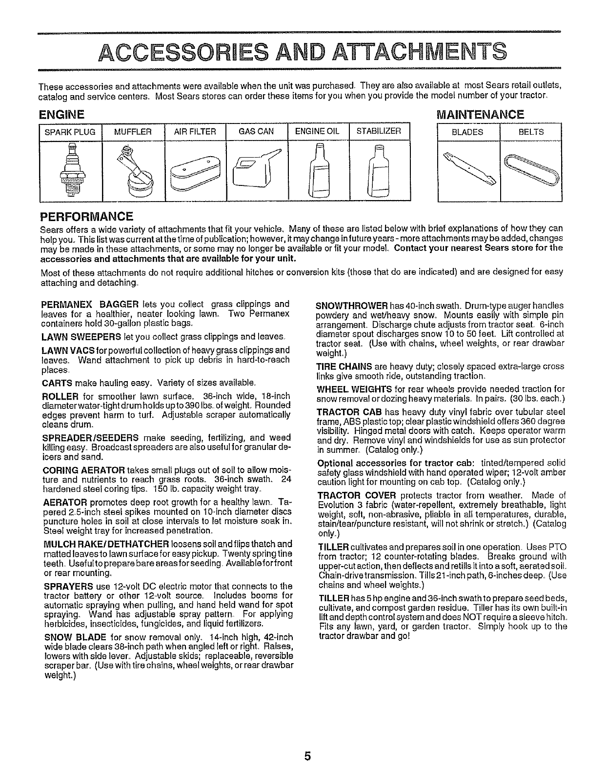
ACCESSORRES ATTACHMENTS
These accessories and attachments were available when the unit was purchased. They are also available at most Sears retail outlets,
catalog and service centers. Most Sears stores can order these items for you when you provide the model number of your tractor_
ENGINE
SPARKPLUG MUFFLER AIRFILTER GASCAN ENGINEOIL STABILIZER
MAINTENANCE
BLADES BELTS
PERFORMANCE
Sears offers a wide variety of attachmentsthat fit yourvehicle_ Many of these are listed below with brief explanations of how they can
helpyou,.This listwas current atthe time of publication;however, it maychange infutureyears- more attachments maybe added, changes
may be made in these attachments, or some may no longer be available or fit your model. Contact your nearest Sears store for the
accessories and attachments that are available for your unit.
Most of these attachments do not require additional hitches or conversion kits (those that do are indicated) and are designed for easy
attaching and detaching
PERMANEX BAGGER lets you collect grass clippings and
leaves for a healthier, neater looking lawn. Two Permanex
containers hold 3B-gallon plastic bags.
LAWN SWEEPERS let you coltect grass clippings and leaves.
LAWN VAOS for powerful collection of heavygrassclippings and
leaves. Wand attachment to pick up debris in hard-to-reach
places.
CARTS make hauling easy. Variety of sizes available.
ROLLER for smoother lawn surface. 36-inch wide, 18-inch
diameterwater.tight drum holds upto 39Bibs. ofweighL Rounded
edges prevent harm to tuff. Adjustable scraper automatically
cleans drum.
SPREADER/SEEDERS make seeding, fertilizing, and weed
killing easy. Broadcast spreaders are also useful for granular de-
icers and sand.
CORING AERATOR takes small plugs out of soil to allow mois-
ture and nutrients to reach grass roots. 36-inch swath. 24
hardened steel coring tips. 150 lb. capacity weight tray_
AERATOR promotes deep root growth for a healthy lawn. Ta-
pered 2_5-inchsteel spikes mounted on 10_inchdiameter discs
puncture holes in soil at close intervalsto let moisture soak ino
Steel weight tray for increased penetration,
MULCH RAKE/DETHATCHER loosens soil andflips thatch and
matted leavesto lawn surface for easypickup. Twenty spring tine
teeth_Usefultopreparebaraareasforseeding Availableforfront
or rear mounting.
SPRAYERS use 12-volt DC electric motor that connects to the
tractor battery or other 12-volt source. Includes booms for
automatic spraying when pulling, and hand held wand for spot
spraying_ Wand has adjustable spray pattern_ For applying
herbicides, insecticides, fungicides, and liquid fertilizers.
SNOW BLADE for snow removal only_ 14-inch high, 42-inch
wide blade clears 38-inch path when angled leftor righL Raises,
lowers with side lever Adjustable skids; replaceable, reversible
scraper bar. (Usewith tire chains, wheel weights, or reardrawbar
weighL)
SNOWTHROWER has 4B-inchswath. Drum-type auger handles
powdery and wetJheavy snow° Mounts easily with simple pin
arrangement. Discharge chute adjusts from tractor seat 6-inch
diameter spout discharges snow 10 to 50feel Lift controlled at
tractor seat. (Use with chains, wheel weights, or rear drawbar
weighL)
TIRE CHAINS are heavy duty; closely spaced extra-large cross
links give smooth ride, outstanding traction.
WHEEL WEIGHTS for rear wheels provide needed traction for
snow removalor dozing heavy materials. In pairs. (30 Ibs each)
TRACTOR CAB has heavy duty vinyl fabric over tubular steel
frame, ABS plastic top; clear plastic windshield offers 360 degree
visibility. Hinged metal doors with catch. Keeps operator warm
and dry. Remove vinyl and windshields for use as sun protector
in summer. (Catalog only.)
Optional accessories for tractor cab: tinted/tempered solid
safety glass windshield with hand operated wiper; 12-volt amber
caution light for mounting on cab top. (Catalog only.)
TRACTOR COVER protects tractor from weather. Made of
Evolution 3 fabric (water-repellent, extremely breathable, light
weight, soft, non-abrasive, pliable in all temperatures, durable,
stain/tear/punctura resistant, will not shrink or stretch.) (Catalog
only.)
TILLER cultivates and prepares soil in one operation Uses PTO
from tractor; 12 counter-rotating blades. Breaks ground with
upper-cutaction, then deflectsand ratillsit into a soft, aerated soil
Chain-drivetransmission_Tills21-inch path, 6-inches deep_(Use
chains and wheel weights.)
TILLER has 5hp engineand 36-inch swath to prepare seed beds,
cultivate, and compost garden residue. Tiller has its own built-in
lift anddepth control systemand does NOT requirea sleeve hitch
Fits any lawn, yard, or garden tractor. Simply hook up to the
tractor drawbar and go!
5
ill
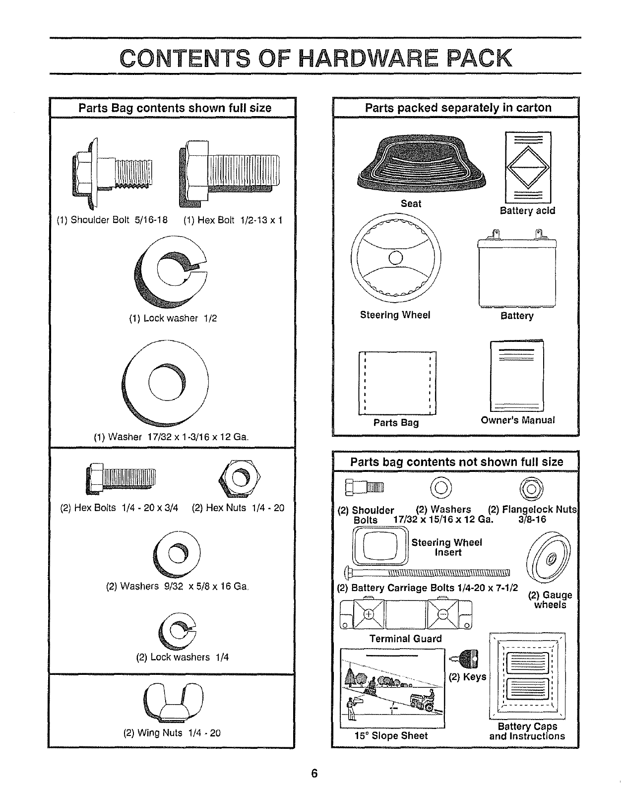
CONTENTS OF HARDWARE PACK
Parts Bag contents shown full size
(1) Shoulder Bolt 5/16-18 (1) Hex Bolt 1/2-13 x t
(1) Lockwasher 1/2
(1) Washer 17/32 x 1-3/16 x 12 Ga.
(2) HexBolts 1/4-20x3/4 (2) HexNuts 1/4-20
(2) Washers 9/32 x 5/8 x 16 Ga,
©
(2) Lock washers 1/4
(2) Wing Nuts 1/4 -20
Parts packed separately in carton
Seat
Steering Wheel
Battery acid
Battery
Parts Bag Owner's Manual
i
Parts bag contents not shown full size
© ©
(2) Shoulder (2) Washers (2) Flangelock Nut.,
Bolts 17/32 ×15/16 x 12 Ga, 3/8-16
L_ Steering Wheel
Insert
(2) Battery Carriage Bolts 1/4-20 x 7-1/2
Terminal Guard
(2) Keys
15° Slope Sheet
(2) Gauge
wheels
......... J_
Battery Caps
and Instructions
6
ASSEMBLY
TOOLS REQUURED FOR ASSEMBLY
A socket wrench set will make assembly easier. Standard
wrench sizes are listed.
(2) 7/16" wrench
(1) 9/16" wrenches
(1) 1/2" wrench
(1) 3/4" wrench
When right and left hand is mentioned in this
manual, it means when you are in the operating position
(seated behind the steenng wheel)
(1) Tire pressure gauge
(1) Screwdriver
(1) Utility knife
TO REMOVE UNUT FROM CARTON
UNPACK CARTON
o Remove all accessible loose parts and parts cartons
from carton (See page 6),
• Cut along dotted lines on the carton, fromtopto bottom,
all four corners of carton and lay panels flaL
• Check for any additional loose parts or cartons and
remove°
BEFORE ROLLING UNUT OFF SKiD
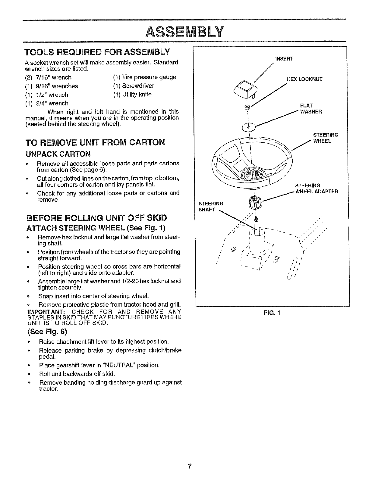
ATTACH STEERING WHEEL (See Fig. 1)
o Remove hex Iocknut and large flat washer from steer-
ing shaft.
° Position front wheels of the tractor so they are pointing
straight forward.
• Position steering wheel so cross bars are horizontal
(left to right) and slide onto adapter.
o Assemble large flat washerand 1/2-20 hex Iocknut and
tighten securely_
• Snap insert into center of steering wheel.
o Remove protective plastic from tractor hood and grill°
IMPORTANT: CHECK FOR AND REMOVE ANY
STAPLES IN SKID THAT MAY PUNCTURE TIRES WHERE
UNIT IS TO ROLL OFF SKID.
(See Fig. 6)
• Raise attachment lift lever to its highest position.
o Release parking brake by depressing clutch/brake
pedal
° Place gearshift lever in "NEUTRAL" position.
o Roll unit backwards off skid
o Remove banding holding discharge guard up against
tractor.
INSERT
HEXLOCKNUT
FLAT
i AS.ER
STEERING
WHEEL
STEERING
_/HEEL ADAPTER
+'
¢
/i /
/11
FIG. 1
7
HOW TO SET UP YOUR TRACTOR
PREPARE BATTERY (See Fig. 2)
CAUTION: Wear eye and face shield.
Wash hands or clothing immediately if
accidentally incontactwith battery acid.
Do not smoke. Fumes from charged
battery acid are explosive.
Read theinstructionsincluded with the
battery vent caps. Always wear gloves,
clothing and goggles to protect your
hands, skin and eyes.
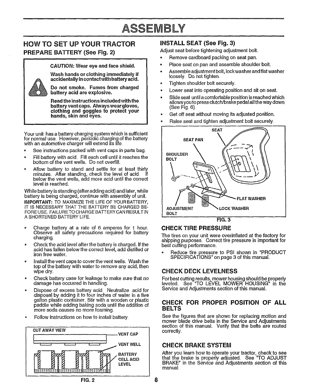
iNSTALL SEAT (See Fig. 3)
Adjust seat before tightening adjustment boll
o Remove cardboard packing on seat pan.
o Place seat on pan and assemble shoulder boll
o Assemble adjustment bolt, lock washer and flat washer
_oose_y_Do not tighten.
o Tighten shoulder bolt securely.
• Lower seat into operating position and sit on seat.
o Slideseat untilacomfortablepositionisreachedwhich
allows you to press clutch/brake pedal all tire way down
(See Fig 6)
°Get off seat without moving its adjusted position.
o Raise seat and tighten adjustment bolt securely..
Your unit has a battery charging system which is sufficient
for normal use. However, periodic charging ofthe battery
with an automotive charger will extend its life
° See instructions packed with vent caps in parts bag
Fill battery with acid_ Fill each cell until it reaches the
bottom of the vent wells. Do not overfill.
o Allow battery to stand and settle for at least thirty
minutes After standing, check the level of acid If
below the vent wells, add more acid until the correct
level is reached_
While battery is standing (after adding acid) and later, while
battery is being charged, continue with assembly of uniL
IMPORTANT: TO MAXIMIZE THE LiFE OF YOURBATTERY,
IT IS NECESSARY THAT THE BATTERY BE CHARGED BE-
FORE USE° FAILURE TO CHARGE BATTERY CAN RESULTIN
A SHORTENED BA'Iq'ERY LIFE.
o Charge battery at a rate of 6 amperes for' 1 hour.
Observe all safety precautions required for battery
charging.
oCheck the acid level after the battery is charged. If the
acid has fallen below the correct level, add distilled or
iron free water.
°Install the vent caps to coverthe vent wells_ Wash the
top of the battery with water to remove any acid, then
wfpe dry_
oCheck battery case for leakage to make sure that no
damage has occurred in handling.
oDispose of excess battery acid Neutralize acid for'
disposal by adding it to four inches of water in a five
gallon plastic container_ Stir' with a wooden or plastic
paddle while adding baking soda until the addition of
more soda causes no more foaming.
° Follow instructions on how to install battery
CUT AWAY VIEW
I "-F -_VENT CAP
CELL ACID
LEVEL
SEAT
SEAT PAN
SHOULDER
BOLT
FLATWASHER
ADJUSTMENT LOCK WASHER
BOLT
FIG. 3
CHECK TIRE PRESSURE
The tires on your unit were overinflated at the factory for
shipping purposes. Correct tire pressure is important for
best cutting performance_
oReduce tire pressure to PSI shown in "PRODUCT
SPECIFICATIONS" on page 3 of this manual°
CHECK DECK LEVELNESS
For best cuttingresults, mower housingshould be ,properly
leveled_ See TO LEVEL MOWER HOUSING in the
Service and Adjustments section of this manual.
CHECK FOR PROPER POSITION OF ALL
BELTS
See the figures that are shown for replacing motion and
mower blade drive belts in the Service and Adjustments
section of this manual. Verify that the belts are routed
correctly_
CHECK BRAKE SYSTEM
After you learn how to operate your tractor, check to see
that the brake is properly adjusted. See "TO ADJUST
BRAKE" in the Service and Adjustments section of this
manual.
FIG. 2 8
ASSEMBLY
iNSTALL BATTERY (See Figs. 4 & 5)
CAUTION: Do not short battery termi-
nals. Before installing battery, remove
metal bracelets, wristwatch bands,
rings, etc.
Positive terminal must be connected
first to prevent sparking from acciden-
tal grounding.
o Make sure draintube isfastened to drain hole in battery
tray and battery tray is positioned in hole of battery
supporL
o Place battery in plastic tray, battery terminals to front of
tractor.
o First connect RED battery cable to positive (+) battery
terminal with hex bolt, flat washer, lock washer and hex
nut as shown Tighten securely
o Connect BLACK grounding cable to negative (-) bat-
tery terminal with remaining hex bolt, flat washer, lock
washer and hex nut. Tighten securely.
• Slide the two battery bolts through the terminal guard
and start the wing nuts onto the threads
•Position terminal guard over the battery as shown,
lower bolts into key holes and slide square shafts of
bolts into slots of key hole&
oTighten wing nuts by hand making sure battery bolts
remain in slots of the key holes in the battery support.
= Be sure terminal access doors are closed.
Use terminal access doors for:
o Inspection for secure connections (to tighten hard-
ware).
, Inspection for corrosion.
o Testing battery.
o Jumping (if required).
Periodic charging.
LOCK _::,_.:.::;;..y- .,...... . HEX LOCI{ WASHER
"=-_;'-" --' :NUT /
WASHER . ,.., ,., dj_ (POSITIVE)
;"
FLAT
(NEGATIVE) '_ WASHER
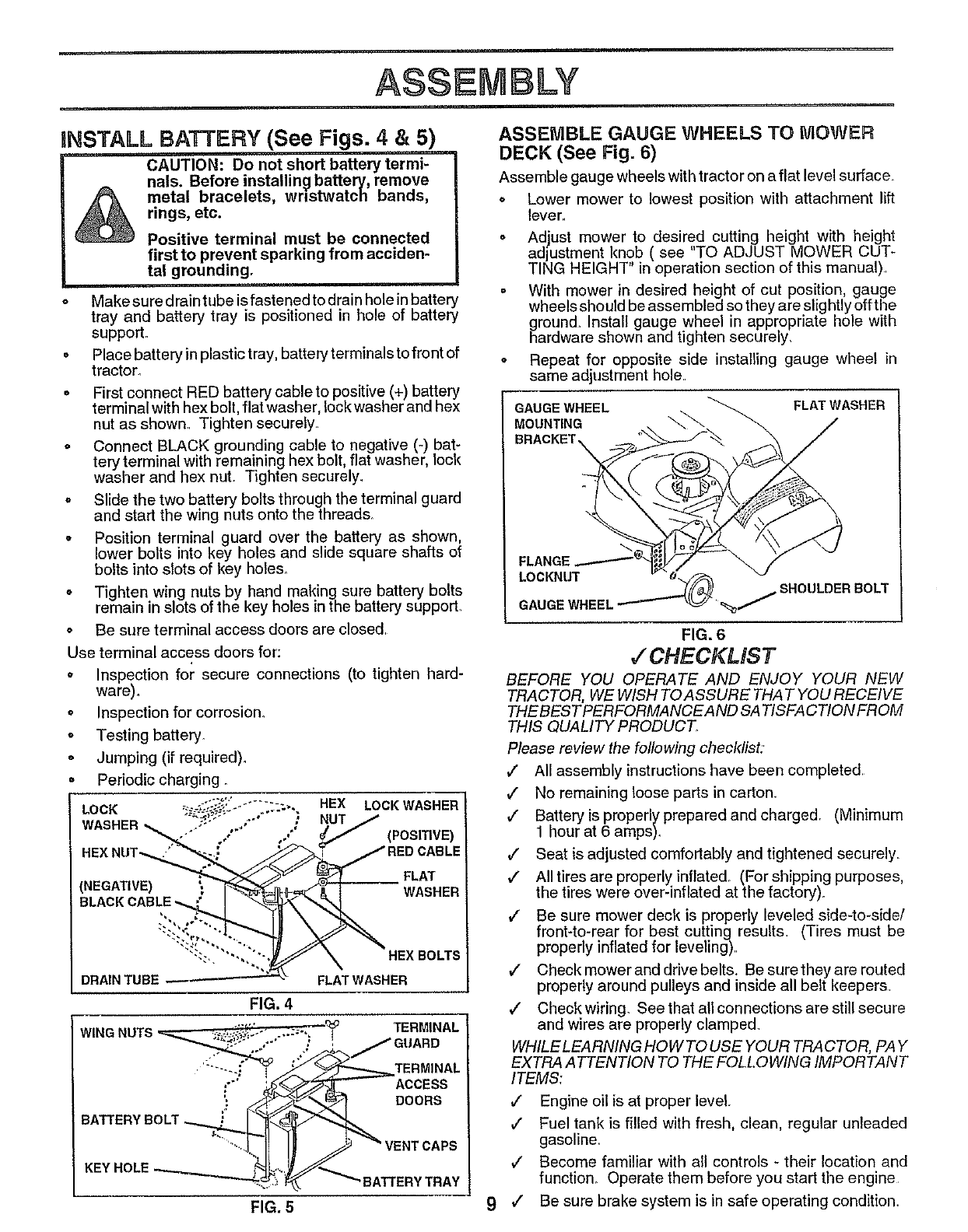
ASSEMBLE GAUGE WHEELS TO NIOWER
DECK (See Fig. 6)
Assemble gauge wheels with tractor on a flat level surface.
o Lower mower to lowest position with attachment lift
lever..
• Adjust mower to desired cutting height with height
adjustment knob ( see "TO ADJUST MOWER CUT-
TING HEIGHT in operation section of this manual)
• With mower in desired height of cut position, gauge
wheels should be assembled so they are slightly off the
ground. Install gauge wheel in appropriate hole with
hardware shown and tighten securely.
oRepeat for opposite side installing gauge wheel in
same adjustment hole.
'GAUGE WHEEL FLAT WASHER
MOUNTING \
BRACKET
9
FLANGE
LOCKNUT
GAUGE WHEEL _/SHOULDER BOLT
FIG. 6
•/ CHECKLIST
BEFORE YOU OPERATE AND ENJOY YOUR NEW
TRACTOR, WE WISH TO ASSURE THAT YOU RECEIVE
THEBESTPERFORMANCEAND SA TISFA CTIONFROM
THIS QUALITY PRODUCT.
Please review the following checldist:
,/ All assembly instructions have been completed.
,/ No remaining loose parts in carton
v" Battery is properly prepared and charged. (Minimum
1 hour at 6 amps).
,/ Seat is adjusted comfortably and tightened securely.
,/ All tires are properly inflated. (For shipping purposes,
the tires were over-inflated at the factory).
,/ Be sure mower deck is properly leveled side-to-side/
front-to-rear for best cutting results (Tires must be
properly inflated for leveling)
,/ Checkmoweranddrivebelts. Besuretheyarerouted
properly around pulleys and inside all belt keepers
,/ Check wiring. See that all connections are still secure
and wires are properly clamped
WHILELEARNING HO W TO USE YOUR TRA CTOR, PAY
EXTRA ATTENTION TO THE FOLLOWING IMPORTANT
ITEMS:
,/ Engine oil is at proper level
#" Fuel tank is filled with fresh, clean, regular unleaded
gasoline.
,/ Become familiar with all controls - their location and
function. Operate them before you start the engine
,f Be sure brake system is in safe operating condition.
OPERATION
ill.... ii I
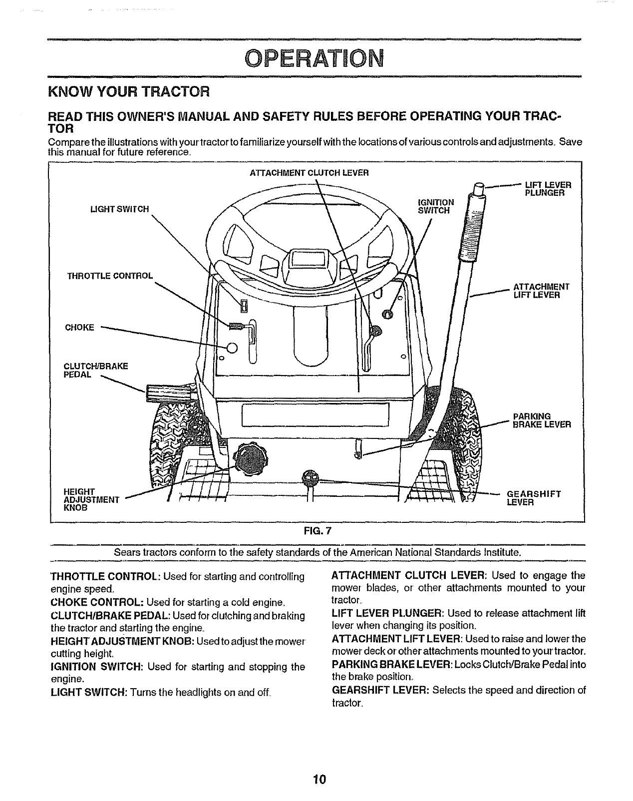
KNOW YOUR TRACTOR
READ THIS OWNER'S MANUAL AND SAFETY RULES BEFORE OPERATING YOUR TRAC-
TOR
Compare the illustrationswith your tractor to familiarize yourself with the locations of variouscontrols and adjustments_ Save
this manual for future reference
ATTACHMENT CLUTCH LEVER
PLUNGER
IGNITION
LIGHT SWITCH SWITCH
THROTTLE CONTROL
ATTACHMENT'
LIFT LEVER
CHOKE
CLUTCH/BRAKE
PEDAL
PARKING
HEIGHT GEARSHIFT
ADJUSTMENT LEVER
KNOB
FIG. 7
Sears tractors conform to the safety standards of the American National Standards Institute,
THROTTLE CONTROL: Used for starting and corrtrolling
engine speed.,
CHOKE CONTROL: Used for starting a cold engine_
CLUTCH/BRAKE PEDAL: Used for clutching and braking
the tractor and starting the engine.
HEIGHT ADJUSTMENT KNO B: Used to adjust the mower
cutting height,
IGNITION SWITCH: Used for starting and stopping the
engine.
LIGHT SWITCH: Turns the headlights on and off_
ATrACHMENT CLUTCH LEVER: Used to engage the
mower blades, or other attachments mounted to your
tractor.
LIFT LEVER PL,UNGER: Used to release attachment lift
lever when changing its position,
ATTACHMENT LIFT LEVER: Used to raise and lower the
nrowerdeck or other attachments mounted to your' tractor.
PARKING BRAKE LEVER: Locks ClutcfVBrake Pedal into
the brake position_
GEARSHIFT LEVER: Selects the speed and direction of
tractor.
10
OPERATION
The operation of any tractor can result in foreign objects thrown into the eyes, which
can result in severe eye damage_ Always wear safety glasses or eye shields while
operating your tractor or performing any adjustments or repairs, We recommend wide
vision safety mask for over the spectacles or standard safety glasses, available at Sears
Retail or Catalog stores_
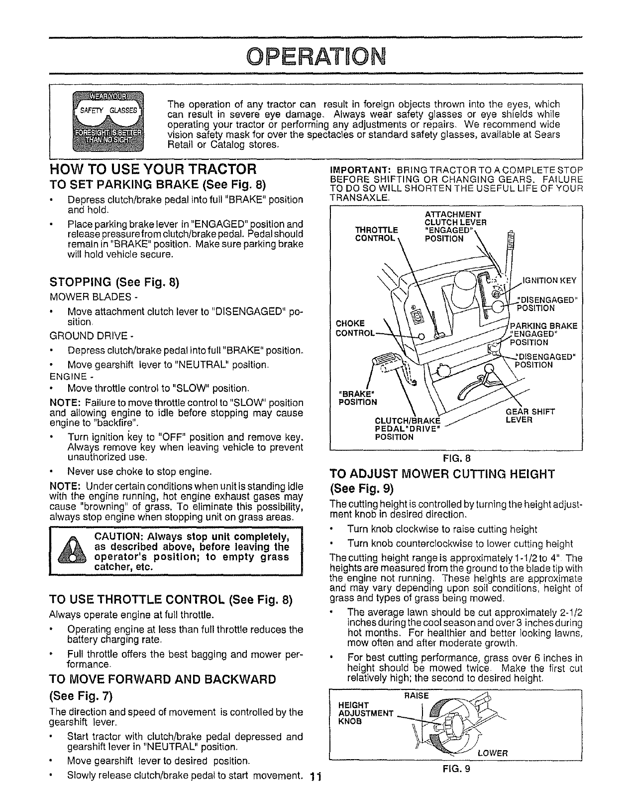
HOW TO USE YOUR TRACTOR
TO SET PARKING BRAKE (See Fig. 8)
Depress clutch/brake pedal into full "BRAKE" position
and hold.
Place parking brake lever in "ENGAGED"position and
release pressurefrom clutch/brake pedal Pedal should
remain in "BRAKE" positiom Make sure parking brake
will hold vehicle secure.
STOPPING (See Fig. 8)
MOWER BLADES -
Move attachment clutch lever to "DISENGAGED" po-
sition.
GROUND DRIVE-
Depress clutch/brake pedal into full "BRAKE" positiom
Move gearshift lever to "NEUTRAL" position.
ENGINE -
Move throttle control to "SLOW" position,
NOTE: Failure to move throttle control to "SLOW" position
and allowing engine to idle before stopping may cause
engine to "backfire".
Turn ignition Key to "OFF" position and remove key.
Always remove key when leaving vehicle to prevent
unauthorized use.
Never use choke to stop engine.
NOTE: Under certain conditions when unit is standing idle
with the engine running, hot engine exhaust gases may
cause "browning" of grass, To eliminate this possibility,
always stop engine when stopping unit on grass areas.
CAUTION: Always stop unit completely, i
as described above, before leaving the
operator's poeltlon; to empty grass
catcher, etc.
TO USE THROTTLE CONTROL (See Fig. 8)
Always operate engine at full throttle.
Operating engine at less than full throttle reduces the
battery charging rate.
Full throttle offers the best bagging and mower per-
formance.
TO MOVE FORWARD AND BACKWARD
(See Fig. 7)
The direction and speed of movement is controlled by the
gearshift lever,
Start tractor with clutch/brake pedal depressed and
gearshift lever in "NEUTRAL" position.
Move gearshift lever to desired position.
Slowly release clutch/brake pedal to start movement. 1 1
IMPORTANT: BRING TRACTOR TO A COMPLETE STOP
BEFORE SHIFTING OR CHANGING GEARS. FAILURE
TO DO SO WILL SHORTEN THE USEFUL LIFE OF YOUR
TRANSAXLE,
ATTACHMENT
CLUTCH LEVER
THROTTLE "ENGAGED"
POSITION
IGNITION KEY
CHOKE
"BRAKE"
POSITION
CLUTCH/BRAKE
PEDAL"DRIVE
POSITION
GEAR SHIFT
LEVER
FIG. 8
TO ADJUST MOWER CUTTING HEIGHT
(See Fig. 9)
The cutting height is controlled byturningthe height adjust-
ment knob in desired direction.
Turn knob clockwise to raise cutting height
Turn knob counterclockwise to lower cutting height
Thecutting height rangeis approximately 1-1/2to 4" The
heights are measured from the ground to the blade tip with
the engine not running, These heights ere approximate
and may vary depending upon soil conditions, height of
grass and types of grass being mowed.
The average lawn should be cut approximately 2-1/2
inches during the cool season and over 3 inches during
hot months_ For healthier and better looking lawns,
mow often and after moderate growth,
For best cutting performance, grass over 6 inches in
height should be mowed twice. Make the first cut
relatively high; the second to desired height,
RAISE
HEIGHT
ADJUSTMENT
KNOB
)-
_, LOWER
FIG, 9
OPERATION
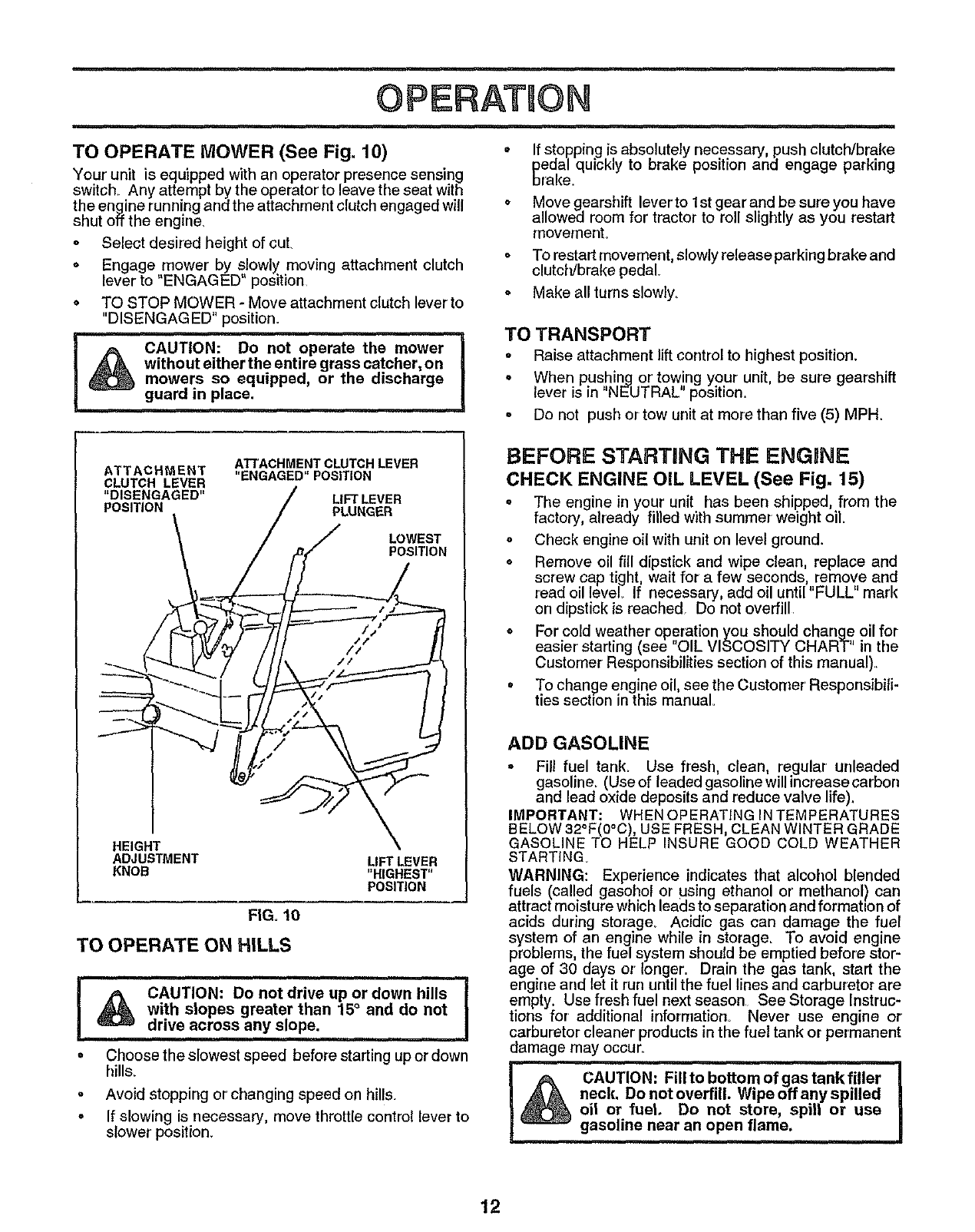
TO OPERATE MOWER (See Fig. 10)
Your unit is equipped with an operator presence sensing
switch Any attempt by the operator to leave the seat with
the engine running and the attachment clutch engaged will
shut olf the engine.
o Select desired height of cuL
,Engage mower by slowly moving attachment clutch
lever to "ENGAGED' position
• TO STOP MOWER - Move attachment clutch lever to
"DISENGAGED" position.
i
!_ CAUTION: DO not operate the mower
without either the entire grass catcher, on
mowers so equipped, or the discharge
guard in place.
oIf stopping is absolutely necessary push clutch/brake
pedal quickly to brake position and engage parking
brake.
o Move gearshift lever' to 1st gear and be sure you have
allowed room for tractor to roll slightly as you restart
movement.
oTo restart movement, slowly release parking brake and
clutch/brake pedal
oMake all turns slowly.
TO TRANSPORT
° Raise attachment lift control to highest position.
°When pushing or' towing your unit, be sure gearshift
lever is in "NEUTRAL" position.
°Do not push or tow unit at more than five (5) MPH.
ATTACHMENT CLUTCH LEVER
ATTACHMENT "ENGAGED" POSITION
CLUTCH LEVER
"DISENGAGED" LIFT LEVER
POSITION PLUNGER
LOWEST
POSITION
HEIGHT
ADJUSTMENT
KNOB LIFT LEVER
"HIGHEST"
POSITION
FIGo10
TO OPERATE ON HILLS
i,i H, ,,, ,I
I,#_ CAUTION: Do not drive up or down hills
with slopes greater than 15° and do not
drive across any slope.
H,,,ll
oChoose theslowest speed before starting upor down
hills.
• Avoid stopping or changing speed on hills.
° If slowing is necessary, move throttle control lever to
slower position.
BEFORE STARTaNG THE ENGINE
CHECK ENGINE OIL LEVEL (See Fig. 15)
•The engine in your'unit has been shipped, from the
factory, already filled with summer weight oil.
° Check engine oil with unit on level ground.
oRemove oil fill dipstick and wipe clean, replace and
screw cap tight, wait for a few seconds, remove and
read oil level If necessary, add oil until "FULL" mark
on dipstick is reached. Do not overfill.
oFor cold weather operation you should change oil for
easier starting (see "OIL VISCOSITY CHART" in the
Customer Responsibilities section of this manual)..
°To change engine oil, see the Customer Respensibili-
ties section in this manual
ADD GASOLINE
°Fill fuel tank_ Use fresh, clean, regular unleaded
gasoline_ (Use of leaded gasoline will increase carbon
and lead oxide deposits and reduce valve life).
IMPORTANT; WHENOPERATING INTEMPERATURES
BELOW 32°F(0°C), USE FRESH, CLEAN WINTER GRADE
GASOLINE TO HELP INSURE GOOD COLD WEATHER
STARTING
WARNING: Experience indicates that alcohol blended
fuels (called gasohol or using ethanol or methanol) carl
attract moisture which leads to separation and formatton of
acids during storage_ Acidic gas can damage the fuel
system of an engine while in storage. To avoid engine
problems, the fuel system should be emptied before stor-
age of 30 days or longer. Drain the gas tank, start the
engine and let it run until the fuel lines and carburetor are
empty. Use fresh fuel next season See Storage Instruc-
tions for additional inforrnation_ Never use engine or
carburetor cleaner products in the fuel tank or permanent
damage may occur.
.#% CAUT'iON:' Filli0 bottom of gas tank filler-]
A A neck. Do not overfill. Wipe off any spilled|
oil or fuel Do not store, spill or use/
gasoline near an open flame. |
12
TO START ENGINE (See Fig. 8)
When starting engine for the first time or if engine has
run out of fuel, it will take extra cranking time to move
fuel from the tank to the engine
•Depress the clutch/brake pedal and set the parking
brake.
oPlace gearshift lever in "NEUTRAL" position.
o Move attachment clutch to "DISENGAGED" position,
•Pull choke control out to "CHOKE"position for cold
engine start. For warm engine start do not use choke
control
°Move throttle control to midway between "FAST" and
"SLOW" positions_
per minute. If engine does not start after several
attempts, move throttle control to "FAST" position,
wait a few minutes and try again_
oWhen engine starts, slowly push choke control in.
oMove throttle control to "FAST" position.
oAllow engine to warm up for a few minutes before
engaging drive or attachment clutch.
NOTE; If at a high altitude (above 3000 feet) or in cold
temperatures (below 32° F), the carburetor fuel mixture
may need to be ad usted for best engine performance.
See "TO ADJUST CARBURETOR" in the Service and
Adjustments section of this manual.
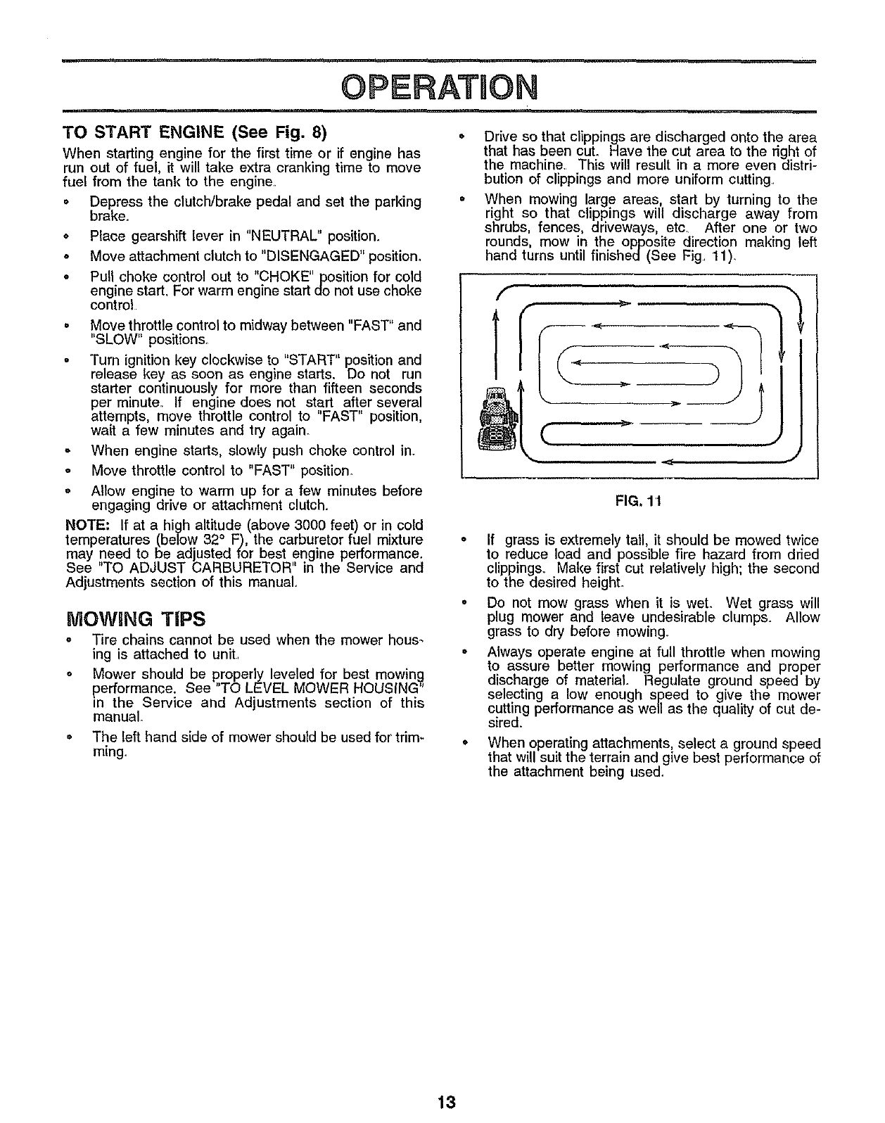
NiOWgNG TiPS
=Tire chains cannot be used when the mower hous_
ing is attached to unit,
oMower should be properly leveled for best mowin_
performance. See TO LEVEL MOWER HOUSING
m the Service and Adjustments section of this
manual.
•The left hand side of mower should be used for trim-
ruing.
Drive so that clippings are discharged onto the area
that has been cuL Have the cut area to the right of
the machine. This will result in a more even distri-
bution of clippings and more uniform cutting
When mowing large areas, start by turning to the
right so that clippings will discharge away from
shrubs, fences, driveways, etc. After one or two
rounds, mow in the opposite direction making left
hand turns until finished(See Fig. 11)_
f
C
FIG, l't
If grass is extremely tall, it should be mowed twice
to reduce load and possible fire hazard from dried
clippings° Make first cut relatively high; the second
to the desired heighL
Do not mow grass when it is wet. Wet grass will
plug mower and leave undesirable clumps. Allow
grass to dry before mowing_
Always operate engine at full throttle when mowing
to assure better mowing performance and proper
discharge of material. Regulate ground speed by
selecting a low enough speed to give the mower
cutting performance as well as the quality of cut de-
sired.
When operating attachments, select a ground speed
that will suit the terrain and give best performance of
the attachment being used,
13
CUSTOM ESPONSNBJLUTHES
sc.,ou,_,
v'
v'
MAINTENANCE
FILL IN DATES
AS YOU COMPLETE
REGULAR SERVICE
Check Brake Operation _#'
Check Tire Pressure
T Check for Loose Fasteners 6#4
a Sharpen/Replace Mower Blades
_ Lubrication Chad
TCheck Battery Level/Recharge
0 Clean Battery and Terminals
R Check Transmission Cooling
Adjust Blade Belt(s) Tension
Adjust Motion Drive Belt(s) Tension
Check Engine Oil Level I_
i
Change Engine OII
Clean Air Filter
E
NClean Air Screen
GInspect Muffler/SparkArrester
IReplace Oil Filter (if equipped)
N Clean Engine Cooling Fins
Replace Spark Plug
Replace Air Filter Paper Cartridge
Replace Fuel Filter
v'
_4
v' v'
e,' e,'
V's
, r ,'.,
_1,2,3
V'2
e,,'
v'
I - Change mote oftenwhen operating under aheavy loador In high ambient temperatures
2- Service mole often when operating inditty or dusty conditions
v'
e,"
v', v'
3-Ifequlppedwithollf_lter,changeollevery50hours
4 • ReplacebladesmoreoftenwhenmowingIn sandysoil
5• If equippedwithadjustablesystem
GENERAL RECOMMENDATIONS
The warranty on this vehicle does not cover' items that have
been subjected to operator abuse or negligence. To
receive full value from the warranty, operator must main-
rain unit as instructed in this manual
Some adjustments will need to be made periodically to
properly maintain your unit.
All adjustments in the Service and Adjustments section of
this manual should be checked at least once each season.
LUBRICATION CHART
@"FRONT WHEEL (_)
BEARING ZERK _BEARING ZERK
Once a year you should replace the spark plug, clean
or replace air filter, and check blades and belts for Q
wear. A new spark plug and clean air filter assure CLUTCH
proper air-fuel mixture and help your engine run better PIVOT(S)
andlast longer.
BEFORE EACH USE
Check engine oi! level.
Check brake operation.
Check tire pressure,
Check for loose fasteners
(_ SAE 30 OR 10W30 MOTOR OIL APt - SG
(_) GENERAL PURPOSE GREASE
(_ REFER TO CUSTOMER RESPONSIBILITIES "ENGINE" SECTION
IMPORTANT: DO NOT OIL OR GREASE THE PIVOT POINTS
WHICH HAVE SPECIAL NYLON BEARINGS VISCOUSLUBRI•
CANTS WILL ATTRACT DUST AND DIRT THAT WILL SHORTEN
THE LIFE OF THE SELF-LUBRICATING BEARINGS, IF YOU
FEEL THEY MUST BE LUBRICATED USE ONLYADRY, POW-
14 DERED GRAPHITE TYPE LUBR CANT SPAR NGLY.
CUSTOMER RESPONSUBILITUES
iIMI
TRACTOR TO SHARPEN BLADE (See Fig. 13)
Always observe safety rules when performing any mainte- Care should be taken to keep the blade balanced. An
nance, unbalanced blade will cause excessive vibration and even-
tual damage to mower and engine.
BRAKE OPERATION
If unit requires more than six (6) feet stoppingdistance at
high speed in highest gear, then brake mustbe adjusted.
(See "TO ADJUST BRAKE in Service and Adjustments
section of this manual).
TIRES
o Maintainproper air pressure in all tires (See "PROD-
UCT SPECIFICATIONS" on page 3 of this manual),
•Keep tires free of gasoline, oil, or insect control chemi-
cals which can harm rubber,,
• Avoid stumps, stones, deep ruts, sharp ob ects and
other hazards that may cause t re damage
.The blade can be sharpened with a file or on a grinding
wheel. Do not attempt to sharpen while on the mower
o To check blade balance you will need a 5/8" diameter
steel bolt,pin, or cone balancer, (When using a cone
balancer, follow the instructions supplied with the bal-
ancer).
o Slide b[ade on to an unthreaded portion of the steel bolt
or pin parallel with ground. If blade is balanced, it
should remain in a horizontal position. If either end of
the blade moves downward, sharpen the heavy end
until the blade is balanced
NOTE: Do not use a nail for balancing blade. The lobes of
the center hole may appear to be centered, but are not,
BLADE CARE
For best results mower blades must be kept sharp, The
blades can be sharpened with a file or on a grinding wheel.
We suggest they be sharpened or replaced after every 25
hours of mowing Check blades more often if mowing in
sandy condition&
oDo not attempt to sharpen blades while they are on the
mower,
• Replace bent or damaged blades.
BLADE REMOVAL (See Fig. 12)
° Raise mower to highest position to allow access to
blades
o Remove hex bolt, lockwasher and flat washer securing
blade.
oinstall new or resharpened blade withtrailing edge up
towards deck as shown.
• Reassemble hex bolt, lock washer and flat washer in
exact order as shown.
° Tighten bolt securely (30-35 FL Lbs. torque).
IMPORTANT: BLADE BOLT IS GRADE 8 HEAT
TREATED.
FIG. 13
BATTERY (See Fig. 14)
Your unit has a battery charging system which is sufficient
for normal use. However, periodic charging of the battery
with an automotive charger will extend it's lifeo
°Acid solution level in each battery cell should be even
with bottoms ofvent wells. Add only distilledor ironfree
water if necessary. Do not overfill.
-Keep battery and terminals clean.
• Keep battery bolts tighL
° Keep vent capstight and smallvent holesin caps open,
oRechargeat 6amperesforl hour.
MANDREL
FLATWASHER
LOCK WASHER
BLADE
TRAILING EDGE
HEXBOLT
(GRADE8
*A GRADE 8HEAT TREATED BOLT CAN BE IDENTIFIED
BY SIX LINES ON THE BOLT HEAD.
CUT AWAY VIEW .-VENT CAP
{L----i"_-L__.._j -_/VENT
WELL
I[_ N _ N N }} N N # bBATTERY
I_ _ _ [_ riJ _ _] _,,_ CELLACID
VEL
FIG. 14
FIG. 12
15
.1 Ill ,
CUSTOMER RIESPONS BIL TIES
TO CLEAN BATTERY AND TERMINALS -
Corrosion and dirt on the battery and terminals can cause
the battery to "leak" power,
o Remove terminal guard,
o Disconnect BLACK battery cable first then RED
battery cable and remove battery from tractor.
oWash battery with solution of four' tablespoons of
baking soda to one gallon of water, Be careful not to
get the soda solution into the cells,
o Rinse the battery with plain water and dry.
* Cleanterminals and battery cable ends with wire brush
until bright
°Coat terminals with grease or petroleum jelly,
o Reinstall battery (See "INSTALL BATTERY" in As-
sembly section of this manual)
V-BELTS
Check V-belts for deterioration and wear after 100 hours
and replace if necessary. The belts are not adjustable,
Replace belts if they begin to slip from wear
TRANSAXLE COOLING
Keep transaxle free from build-up of dirt and chaff which
can restrict cooling
ENGINE
LUBRiCATiON
Only use high quality detergent o!1rated with API service
classification SG Select the oil s SAE viscosity grade
according to your expected operating temperature_
TO CHANGE ENGINE OIL (See Fig. 15)
o Be sure vehicle is on level surface
o Oil will drain more freely when warm.
o Catch oil in a suitable corrtainer.
o Remove oil flit dipstick. Be careful not to allow dirt to
enter the engine when changing oilo
,, Remove drain plug.
• After oil has drained completely, replace oil drain plug
and tighten securely
o Refill engine with oil through oil fill dipstick tube. Pour'
slowly. Do not overfill For approximate capacity see
Product Specifications on page 3 of this manual
oUse gauge on oil fill dipstick for checking level Be sure
dipstick cap is tightened securely for' accurate reading.
Keep oil at "FULL" line on dipstick.
PLUG
yAIR SCREEN
FIG. 15
RECOMMENDED SAE VISCOSITY GRADES
oF -20 o0o 32 °60°80°100°
oC-29 ° .18 °0o16°27°38°
NOTE: Although multi-viscosity oils (5W30, 10W30 etc_)
improve starting in cold weather, these multi-viscosityoils
will result in increased oil consumption when used above
32°F, Check your engine oil level more frequently to avoid
possible engine damage from running low on oil
Change the oil after the first two hours of operation and
every 25 hours thereafter or at least once a year if the
tractor is not used for 25 hours in one year_
Check the crankcase oil level before starting the engine
and after' each eight (8) hours of continuous use_ Tighten
oil fill cap/dipstick securely each time you check the oil
level,
AiR SCREEN (See Fig. 15)
The engine air screen must be kept free of dirt and chaff to
prevent engine damage from overheating. Clean with a wire
brush or compressed airto removed dirt and stubborn dried
gum fibers
AiR FILTER FOAM PRE-CLEANER
(See Fig. 16)
Your engine will not run properly and may be damaged by
using a dirty air filteL Clean the foam pre-cleaner element
after every 25 hours of operation, more often if tractor is
used in very dusty, dirty corrditions,
• Remove knobs and cover,
,, Remove foam pre-cleaner by sliding it off the paper
cartridge
NOTE: Do not attempt to clean or oil the paper cartridge,
Replace paper cartridge once a year or after every 100
hours of operation, more often if used in very dusty, dirty
conditions
° Wash foam pre-cleaner in liquid detergent and water.
• Wrap foam pre-cleaner in cloth and squeeze dry.
• Lightly coat foam pre-cteaner with clean engine oil.
Squeeze in towel to remove excess oiL Do not saturate.
o Install foam pre-cleaner over paper cartridge.
o Reassemble cover and secure with knob&
16
CUSTOMER
KNOB
FOAM
OVER
CARTRIDGE
PLATE
AIR SCREEN
CARTRIDGE
FIG. 16
ENGINE COOLING FINS (See Fig. 17)
Remove any dust, dirt or oil from engine cooling fins to
prevent engine damage from overheating Air guide covers
must be removed. Remove side panels and hood (See "TO
REMOVE HOOD AND GRILL ASSEMBLY" in the Service
and Adjustments section of this manual).
TOP AIR
GUIDE COVER,
ENGINE _.
COOLING FINS
AIR GUIDE COVER (BOTH SIDES) \
MUFFLER
FIG. 17
MUFFLER
Inspect and replace corroded muffler and spark arrester (if
equipped) as it could create a fire hazard and/or damage,
SPARK PLUGS
Replace spark plugs at the beginning of each mowing
season or after every 100 hours of use, whichever comes
first. Spark plugtype and gap setting is shown in "PROD-
UCT SPECIFICATIONS" on page 3 of this manual,
IN-LINE FUEL FILTER (See Fig. 18)
Fuel filter should be replaced once each season. Iffuel filter
becomes clogged, obstructing fuel flow to carburetor, re-
placement is required.
=With engine cool, remove filter and plug fuel line
sections_
oPlace new fuel filter in position in fuel line_
•Be sure there are no fuel line leaks and clamps are
properly positioned.
o Immediately wipe up any spilled gasoline.
RJEL FILTER
CLAMP
CLAMF
FIG. 18
CLEANING
•Clean engine, battery, seat, finish, etc+ of all foreign
matter.
oKeep finished surfaces and wheels free of all gasoline,
oil, etc.
oProtect painted surfaces with automotive type wax.
We do not recommend using a garden hose to clean your
unit unless the electrical system, muffler, air filter and
carburetor are covered to keep water ouL Water in engine
can result in a shortened engine life
17
SERVmCE ADJUSTMENTS
CAUTION: BEFORE PERFORMING ANY SERVICE OR ADJUSTMENTS:
oDepress clutch/brake pedal fully and set parking brake.
=Place gearshift lever in "NEUTRAL" position.
°Place attachment clutch in "DISENGAGED" position.
°Turn ignition key "OFF" and remove key.
oMake sure the blades and all moving parts have completely stopped.
oDisconnect spark plug wire from spark plug and place wire where it cannot come in contact with
plug.
TRACTOR
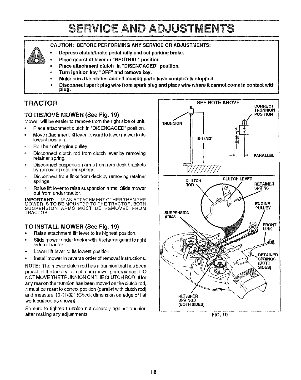
TO REMOVE MOWER (See Fig. 19)
Mower will be easier' to remove from the right side of uniL
o Place attachment clutch in "DISENGAGED" position_
o Move attachment liftleverforward to lower mower to its
lowest position_
oRoll belt off engine pulley,
= Disconnect clutch rod from clutch lever by removing
retainer' spring.
Disconnect suspension arms from rear deck brackets
by removing retainer spring&
°Disconnect front links from deck by removing retainer
springs
. Raise lift lever to raise suspension arms. Slide mower
out from under' tractor_
IMPORTANT: IF AN ATTACHMENT OTHER THAN THE
MOWER IS TO BE MQUNTED TO THE TRACTOR, BOTH
SUSPENSION ARMS MUST BE REMOVED FROM
TRACTOR.
TO mNSTALL MOWER (See Fig. 19)
o Raise attachment lift lever to its highest position
= Slide mower under tractor with discharge guard to right
side of tractor_
,Lower lift lever to its lowest position.
oInstall mower in reverse order' of removal instruction&
NOTE: The mower clutch rod has a trunnion that has been
preset, at the factory, for optimum mower performance. DO
NOT MOVETHETRUNNION ON THE CLUTCH ROD Iffor
any reason the trunnion has been moved on the clutch rod,
it must be reset to correct position (parallel with clutch rod)
and measure 10-11/32" (Check dimension on edge of flat
work surface as shown).
Be sure to tighten trunnion nut securely against trunnion
after making any adjustments
TRUNNION
SUSPENSION
ARMS
SEENOTEABOVE CORRECT
TRUNNION
POSITION
"-- PARALLEL
CLUTCH
ROD
CLUTCH LEVER RETAINER
SPRING
ENGINE
PULLEY
RONT
UNK
RETAINER
(BOTH
SIDES)
RETAINER
SPRINGS
(BOTH SIDES)
FIG. 19
18
SERVICE AND ADJUSTMENTS
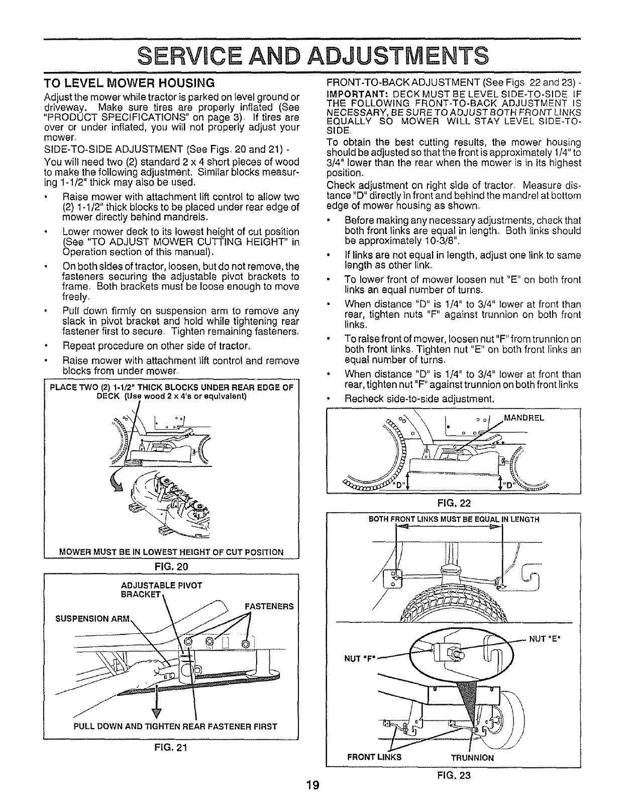
TO LEVEL MOWER HOUSING
Adjust the mower while tractor is parked on level ground or
,driveway. Make sure tires are properly inflated (See
PRODUCT SPECIFICATIONS on page 3), If tires are
over or under inflated, you will not properly adjust your
mower.
SIDE-TO-SIDE ADJUSTMENT (See Figs, 20 and 21).
You will need two (2) standard 2 x 4 short pieces of wood
to make the following ad ustment. Similar blocks measur-
ing 1-1/2 th ck may also be used.
Raise mower with attachment lift control to allow two
(2) 1-1/2" thick blocks to be placed under rear edge of
mower directly behind mandrels.
Lower mower deck to its lowest height of cut position
(See "TO ADJUST MOWER CUTTING HEIGHT" in
Operation section of this manual),
On both sides of tractor, loosen, but do not remove, the
fasteners securing the adjustable pivot brackets to
frame. Both brackets must be loose enough to move
freely,
Pull down firmly on suspension arm to remove any
slack in pivot bracket and hold while tightening rear
fastener first to secure, Tighten remaining fasteners.
Repeat procedure on other side of tractor.
Raise mower with attachment lift control and remove
blocks from under mower,
PLACE TWO (2) 1-1/2" THICK BLOCKS UNDER REAR EDGE OF
DECK (LIse wood 2 x 4's or equivalent)
_%_ I. °°/
MOWER MUST BE IN LOWEST HEIGHT OF CUT POSITION
FIG, 20
ADJUSTABLE PIVOT
BRACKET\ _ FASTENERS
PULL DOWN AND TIGHTEN REAR FASTENER FIRST
FIG. 21
FRONT-TO-BACK ADJUSTMENT (See Figs 22 and 23) -
IMPORTANT: DECK MUST BE LEVEL SIDE-TO-SIDE IF
THE FOLLOWING FRONT-TO-BACK ADJUSTMENT IS
NECESSARY, BE SUR E TO ADJUST BOTH FRONT LINKS
EQUALLY SO MOWER WILL STAY LEVEL SIDE*TO-
SIDE
To obtain the best cutting results, the mower housing
should be adjusted so that the front is approximately 1/4" to
3/4" lower than the rear when the mower is in its highest
position.
Check adjustment on right side of tractor, Measure dis-
tance "D" directly in front and behind the mandrel at bottom
edge of mower housing as shown.
Before making any necessary adjustments, check that
both front links are equal in length. Both links should
be approximately 10-3/8".
If links are not equal in length, ad ust one link to same
length as other link,
To lower front of mower loosen nut "E" on both front
links an equal number of turns.
When distance "D" is 1/4" to 3/4" lower at front than
rear, tighten nuts "F" against trunnion on both front
links.
To raise front of mower, loosen nut"F" from trunnion on
both front links, Tighten nut "E" on both front links an
equal number of turns.
When distance "D" is 1/4" to 3/4" lower at front than
rear, tighten nut"F" against trunnion on both front links
Recheck side-to-side adjustment.
MANDREL
FIG, 22
BOTH FRONT LINKS MUST BE EQUAL IN LENGTH
NUT =F"'__ NUT "E"
FRONT LINKS TRUNNION
FIG. 23
19
SERVICE ADJUSTMENTS
WITHPARKINGBRAKE"ENGAGED"
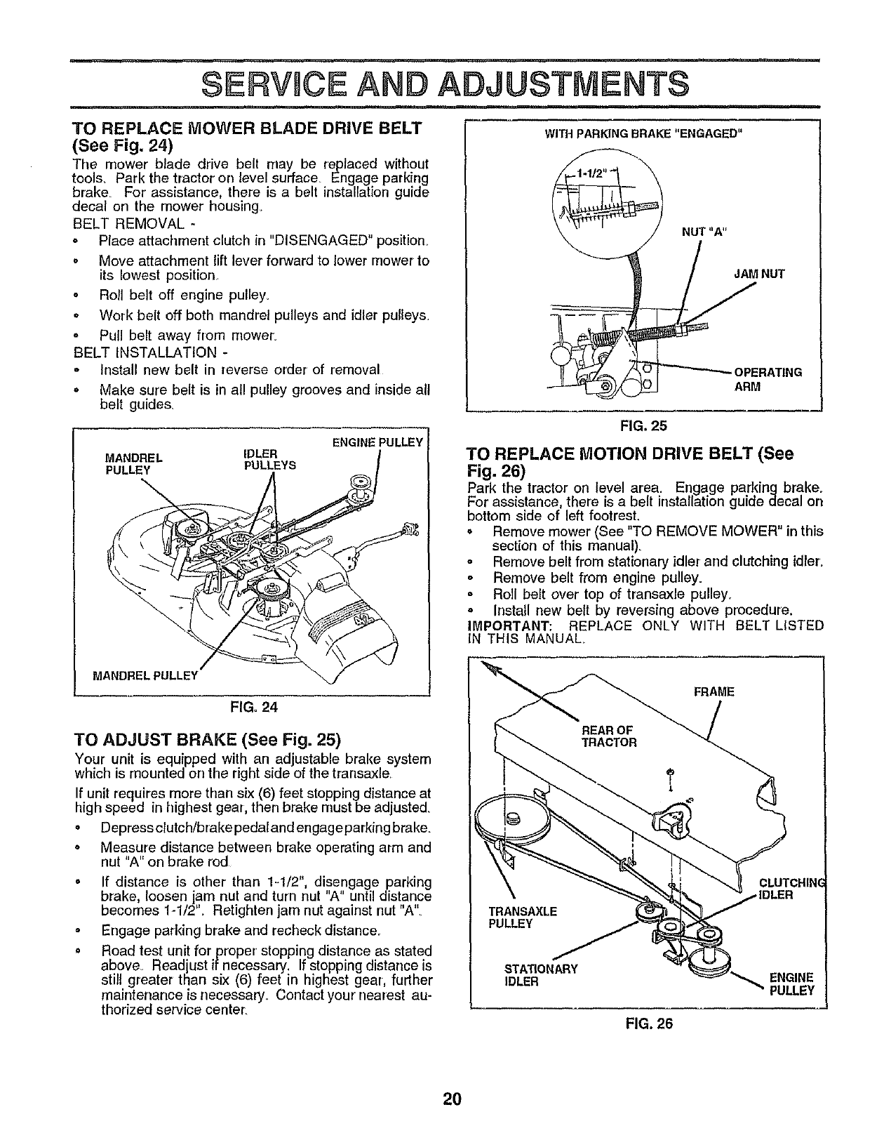
TO REPLACE MOWER BLADE DRIVE BELT
(See Fig. 24)
The mower blade drive belt may be replaced without
tools_ Park the tractor on level surface Engage parking
brake For assistance, there is a belt installation guide
decal on the mower housing.
BELT REMOVAL -
o Place attachment clutch in "DISENGAGED" position.
o Move attachment lift lever forward to lower mower to
its lowest position
o Roll belt off engine pulley_
* Work belt off both mandrel pulleys and idler pulleys,
o Pull belt away from moweL
BELT INSTALLATION -
Install new belt in reverse order of removal
° Make sure belt is in all pulley grooves and inside all
belt guides,
MANDREL IDLER
PULLEY PULLEYS
ENGINE PULLEY
MANDRELPULLEY
FIG. 24
TO ADJUST BRAKE (See Fig. 25)
Your unit is equipped with an adjustable brake system
which is mounted on the right side of the transaxle
If unit requires more than six (6) feet stopping distance at
high speed in trighest gear, then brake must be adjusted
., Depress clutch/brake pedat and engage parking brake_
o Measure distance between brake operating arm and
nut "A" on brake rod
° If distance is other than 1_1/2', disengage parking
brake, loosen jam nut and turn nut "A" until distance
becomes 1-1/2'L Retighten jam nut against nut "A"
oEngage parking brake and recheck distance.
= Road test unit for proper stopping distance as stated
above_ Read ust if necessary. If stopping distance is
still greater than six (6) feet n highest gear, further
maintenance is necessary. Contact your nearest au-
thorized service center.
NUT"A"
\
JAM NUT
OPERATING
ARM
FIG. 25
TO REPLACE MOTION DRIVE BELT (See
Fig. 26)
Park the tractor on level area. Engage parldng brake.
For assistance, there is a belt installation guide decal on
bottom side of left footrest.
oRemove mower (See "TO REMOVE MOWER" in this
section of this manual)
oRemove belt from stationary idler and clutching idler.
oRemove belt from engine pulley.
oRoll belt over top of transaxle pulley.
oInstall new belt by reversing above procedure,
IMPORTANT: REPLACE ONLY WITH BELT LISTED
IN THIS MANUAL
PULLEY
FRAME
CLUTCHIN(
STATIONARY
IDLER ENGINE
PULLEY
FIG. 26
20
SERVICE AND ADJUSTMENTS
TO ADJUST STEERING WHEEL AUGNMENT
If steering wheel crossbars are not horizontal (left to right)
when wheels arepositioned straight forward, remove
steering wheel and reassemble per instructions in the
Assembly section of this manual
FRONT WHEEL TOE-IN/CAMBER
The front wheel toeqn and camber are not adjustable on
your unit If damage has occurred to affect the front wheel
toe-in or camber, contact your nearest Sears Service
Center,
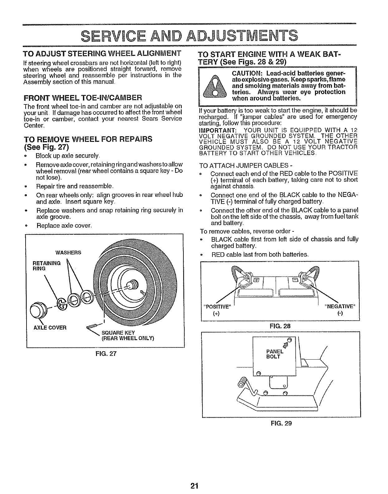
TO REMOVE WHEEL FOR
(See Fig. 27)
o
u
o
o
REPAIRS
Block up axle securely.
Remove axle cover, retaining ring and washers to allow
wheel removal (rear wheel contains a square key - Do
not lose).
Repair tire and reassemble
On rear wheels only: align grooves in rear wheel hub
and axle. Insert square key
Replace washers and snap retaining ring securely in
axle groove.
Replace axle cover.
WASHERS
RETAINING
RING
AXLE COVER
I
(REAR WHEEL ONLY)
FIG, 27
TO START ENGRNE WiTH A WEAK BAT-
TERY (See Figs. 28 & 29)
I& CAUTION: Lead-acid batteries gener-
ate explosive gases. Keepsparks,flame
and smoking materials away from bat-
teries. Always wear eye protection
when around batteries.
If your battery is too weak to start the engine, it should be
recharge& If "jumper cables" are used for emergency
starling, follow this procedure:
IMPORTANT: YOUR UNIT IS EQUIPPED WITH A 12
VOLT NEGATIVE GROUNDED SYSTEM. THE OTHER
VEHICLE MUST ALSO BE A 12 VOLT NEGATIVE
GROUNDED SYSTEM. DO NOT USE YOUR TRACTOR
BATTERY TO START OTHER VEHICLES.
TO ATTACH ,JUMPER CABLES -
oConnect each end of the RED cable to the POSITIVE
(+) terminal of each battery, taking care not to short
against chassis
o Connect one end of the BLACK cable to the NEGA-
TIVE (-) terminal of fully charged battery
o Connect the other end of the BLACK cable to a panel
bolt on the left side of the chassis, away from fuel tank
and battery
To remove cables, reverse order -
o BLACK cable first from left side of chassis and fully
charged battery_
o RED cable last from both batteries.
"POSITIVE.... NEGATIVE"
(+) (°)
FIG. 28
PANEL
BOLT
FIG. 29
21
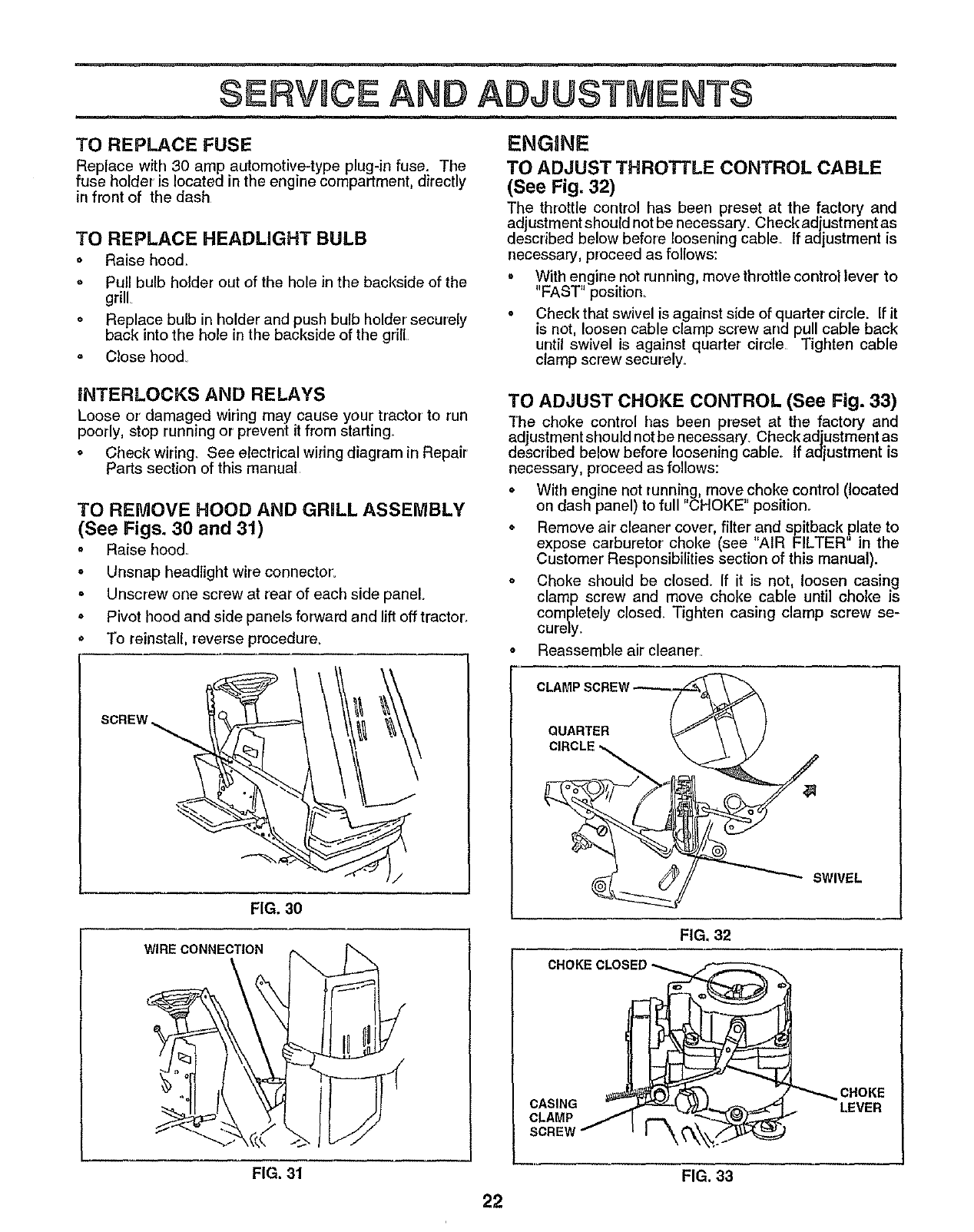
TO REPLACE FUSE
Replace with 30 amp automotive-type plug-in fuse. The
fuse holder is located in the engine compartment, directly
in front of the dash
TO REPLACE HEADLIGHT BULB
o Raise hood.
o Pull bulb holder out of the hole in the backside of the
grill
o Replace bulb in holder and push bulb holder securely
back into the hole in the backside of the grill
= Close hood_
ENGINE
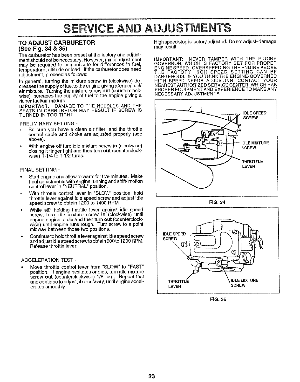
TO ADJUST THROTTLE CONTROL CABLE
(See Fig. 32)
The throttle control has been preset at the factory and
adjustment should not be necessary. Check adjustment as
described below before loosening cable. If adjustment is
necessary, proceed as follows:
• With engine not running, movethrottle controllever to
"FAST" position_
oCheck that swivel is against side of quarter circle. If it
is not, loosen cable clamp screw arrd pull cable back
until swivel is against quarter circle Tighten cable
clamp screw secur'ely_
INTERLOCKS AND RELAYS
Loose or'damaged wiring may cause your' tractor to run
poorly, stop running or prevent it from starting.
oCheck wiring. See electrical wiring diagram in Repair
Parts section of this manual
TO REMOVE HOOD AND GRILL ASSEMBLY
(See Figs. 30 and 31)
o Raise hood.
o Unsnap headlight wire connector.
= Unscrew one screw at rear of each side panel.
° Pivot hood and side panels forward and lift off tractor.
• To reinstall, reverse procedure_
TO ADJUST CHOKE CONTROL (See Fig. 33)
The choke control has been preset at the factory and
adjustment should not be necessary. Check adjustment as
described below before loosening cable.. If adjustment is
necessary, proceed as follows:
•With engine not running, move,choke control (located
on dash panel) to full 'CHOKE position.
oRemove air cleaner cover, filter and spitback plate to
expose carburetor choke (see "AIR FILTER" in the
Customer' Responsibilities section of this manual).
o Choke should be c{osed_ If it is not, loosen casing
clamp screw and move choke cable until choke is
completely closed. Tighten casing clamp screw se-
cureJy.
o Reassemble air cleaner
SCREW_
FIG. 30
WIRECONNECTION
CLAMP
QUARTER
SWIVEL
FIG. 32
CHOKECLOSI
CASING
CLAMP
SCREW _'_
CHOKE
LEVER
FIG. 31
22
FIG. 33
SERVICE ADJUSTMENTS
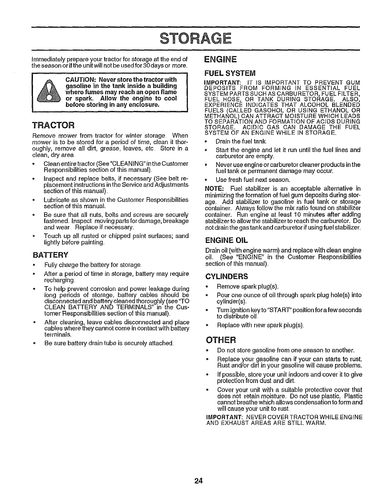
TO ADJUST CARBURETOR
(See Fig. 34 & 35)
The carburetor has been preset at the factory and adjust-
ment shouldnot benecessary, However minoradjustment
may be required to compensate for differences in fuel,
temperature, altitude or load If the carburetor does need
adjustment, proceed as follows:
In general turning the mixture screw in (clockwise) de-
creases the supply offuel to the engine giving a leaner fuel/
air mixture, Turning the mixture screw out (counterclock-
wise) increases the supply of fuel to the engine giving a
richer fuel/air mixture
IMPORTANT: DAMAGE TO THE NEEDLES AND THE
SEATS IN CARBURETOR MAY RESULT IF SCREW IS
TURNED IN TOO TIGHT
PRELIMINARY SETTING
• Be sure you have a clean air filter, and the throttle
control cable and choke are adjusted properly (see
above).
° With engine off turn idle mixture screw in (clockwise)
closing it finger tight and then turn out (counterclock-
wise) 1-1/4 to 1-1/2 turns.
FINAL SETTING -
o Start engine and allow to warm forfive minutes. Make
final ad ustments with engine running and shift! motion
contro ever in "NEUTRAL" position_
- With throttle control lever in "SLOW" position, hold
throttle lever against idle speed screw and adjust idle
speed screw to obtain 1200 to 1400 RPM
= While still holding throttle lever against idle speed
screw, turn idle mixture screw in (clockwise) until
engine begins to die and then turn out (counterclock-
wise) until engine runs rough Turn screw to a point
midway between those two positions,
• Continueto holdthrottle leveragainst idle speed screw
and adjust idle speed screw to obtain 900 to 1200 RPM.
Release throttle lever_
ACCELERATION TEST -
•Move throttle control lever from "SLOW" to "FAST"
position. If engine hesitates or dies. turn idle mixture
screw out (counterclockwise) 1/8 turn. Repeat test
and continue to adjust, if necessary, until engine accel-
erates smoothly_
High speed stop isfactory adjusted, Do not adjust- damage
may resulL
IMPORTANT: NEVER TAMPER WITH THE ENGINE
GOVERNOR, WHICH IS FACTORY SET FOR PROPER
ENGINE SPEED. OVERSPEEDING THE ENGINE ABOVE
THE FACTORY HIGH SPEED SETTING CAN BE
DANGEROUS. IF YOU THINK THE ENGINE-GOVERNED
HIGH SPEED NEEDS ADJUSTING, CONTACT YOUR
NEAREST AUTHORIZED SERVICE CENTER, WHICH HAS
PROPER EQUIPMENT AND EXPERIENCE TO MAKE ANY
NECESSARY ADJUSTMENTS.
IDLESPEED
SCREW
MIXTURE
SCREW
THROTTLE
LEVER
FIG. 34
THROTTLe= \ IDLEMIXTURE
LEVER SCREW
FIG. 35
23
STORAGE
ENGINE
Immediately prepare your tractor' for storage at the end of
the season or if the unit will not be used for 30 days or more.
CAUTION: Never store the tractor with
gasoline in the tank inside a building
where fumes may reach an open flame
or spark. Allow the engine to cool
before storing in any enclosure.
TRACTOR
Remove mower from tractor' for winter storage When
mower' is to be stored for a period of time, clean it thor-
oughly, remove all dirt, grease, leaves, etc. Store in a
clean, dry area.
o Cleanentiretractor(See"CLEANING"intheCustomer
Responsibilities section of this manual).
Inspect and replace belts, if necessary (See belt re-
placement instructions in the Service and Ad ustments
sect on of th s manua ).
o Lubricate as shown in the Customer Responsibilities
section of this manual.
°Be sure that all nuts, bolts and screws are securely
fastened. Inspect movingpartsfordamage, breakage
and wear Replace if necessary
Touch up all rusted or chipped paint surfaces; sand
lightly before painting.
BA'N'ERY
oFully charge the battery for storage
oAfter a period of time in storage, battery may require
recharging
•To help prevent corrosion and power' leakage during
long periods of storage, battery cables should be
disconnected and battery cleaned thoroughly (see"TO
CLEAN BATTERY AND TERMINALS in the Cus-
tomer Responsibilities section of this manual).
oAfter cleaning, leave cables disconnected and place
cables where they cannot come in contact with battery
terminals.
° Be sure battery drain tube is securely attached
FUEL SYSTEM
IMPORTANT: IT IS IMPORTANT TO PREVENT GUM
DEPOSITS FROM FORMING IN ESSENTIAL FUEL
SYSTEM PARTS SUCH AS CARBURETOR, FUEL FILTER,
FUEL HOSE, OR TANK DURING STORAGE, ALSO,
EXPERIENCE INDICATES THAT ALCOHOL BLENDED
FUELS (CALLED GASOHOL OR USING ETHANOL OR
METHANOL) CAN ATTRACT MOISTURE WHICH LEADS
TO SEPARATION AND FORMATION OF ACIDS DURING
STORAGE. ACIDIC GAS CAN DAMAGE THE FUEL
SYSTEM OF AN ENGINE WHILE IN STORAGE.
o Drain the fuel tank.
o Start the engine and let it run until the fuel lines and
carburetor' are empty.
o Never use engine or carburetor cleaner products in the
fuel tank or permanent damage may occur.
o Use fresh fuel next season.
NOTE: Fuel stabilizer is an acceptable alternative in
minimizing the formation of fuel gum deposits during stor-
age. Add stabilizer to gasoline in fuel tank or storage
container'. Always follow the mix ratio found on stabilizer
container. Run engine at least 10 minutes after' adding
stabilizer to allow the stabilizer to reach the carburetor. Do
not drain the gas tan k and carburetor if using fuel stabilizer.
ENGINE OIL
Drain oil (with engine warm) and replace with clean engine
oil. (See "ENGINE" in the Customer Responsibilities
section of this manual),.
CYLINDERS
•Remove sparkplug(s).
oPour one ounce of oil through spark plug hole(s) into
cylinder(s).
oTurn ignition keyto"START"position forafewseconds
to distribute oil
oReplace with new spark plug(s).
OTHER
o Do not store gasoline from one season to another.
oReplace your gasoline can if your can starts to rust.
Rust and/or dirt in your gasoline will cause problems.
o If possible, store your unit indoors and cover it to give
protection from dust and dirt_
o Cover your unit with a suitable protective cover that
does not retain moisture_ Do not use plastic. Plastic
cannot breathe which allows condensation to form and
will cause your unit to rust
IMPORTANT: NEVER COVER TRACTOR WHILE ENGINE
AND EXHAUST AREAS ARE STILL WARM_
24

TF OUBLESHOOTmNG POHNTS
CAUSE CORRECTION
PROBLEM
Wtll not start
Hard to start
Engine will not turn over
Engine clicks but will not
start
Loss of power
Excessive vibration
1 Out of fuel
2Enginenot"CHOKED"propedy_
3Engine flooded
4, Bad spark plug,
5. Dirty air filter
6. Dirty fuel filter,
7 Water In fuel
8 Loose or damaged wiring,
9Carburetor out of adjustment
10 Engine valves out of adjustment
lrDirty airfilter,
2. Bad spark plug
3 Weak or dead batter,/,
4 Dirty fuel filter,
5 Stale or dirty fuel
6, Loose or damaged wiring
7, Carburetor out of adjustment
8 Engine valves out of adjustment
1, Clutch/brake pedal not depressed
2, Attachment clutch Is engaged
3. Weak or dead battery
4_ Blown fuse.
5, Corroded battery terminals
6 Loose or damaged widng
7- Faulty Ignition switch
8 Faulty sotenotd or starter
9 Faulty operator presence switch(es)
1_ Weak or dead battery
2, Corroded battery terminals
3. Loose or damaged wiring
4 Faulty solenoid or starter
1, Cutting too much grass/too fast
2, Throttle In "CHOKE" position.
3_ Bultd.up of grass, leaves end trash under mower
4_ Dirty air filter
5_ Low el! level/dirty oll
6 Faulty spark plug
7_ Dldy fuel filter
8Staleor dirty fue!
9, Water Infuel
10, Sparkplug wireloose
11. Dldy engine airscreen/fins
12, Dldy/clogged muffler_
13 Loose or damaged wiring
14 Carburetor out of adjustment
15 Engine valves out of adjustment,
1 Worn. bent or loose blade
2 Sent blade mandrel
3 Loose/damaged pert(s)
1 FII! fuel tank
2 See "TO START ENGINE" In Operation section
3 Wait several minutes before attempting to start
4 Replace spark plug
5. Clean/replace air filter
6 Replace fuel filter,
7 Drain fuel tank and carburetor, refill tank with fresh
gasoline and replace fuel filter
8, Check all wiring.
9 Contact Sears Service Center/Department
10_ Contact Sears Service Center/Department,
1 Clean/replace air filter
2 Replace spark ptug
3, Recharge or replace battery
4 Replace fuet filter
5, Drain fuel tank and refill with fresh gasoline
6 Check nil wiring
7 Contact Sears Service Center/Department
8 Contact Sears Service Center/Department
1, Depress clutch/brake pedal
2, Disengage attachment clutch
3, Recharge or replace battery
4 Replace fuse,
5 Clean battery terminals
6 Check atl wiring
7 Check/replace Ignition switch
8 Check/replace solenoid or starter
9 Contact Sears Service Center/Department
1, Recharge or replace battery
2 Clean battery terminals
3 Check all wiring
4 Check/replace solenoid or starter
1 Set In"Htgher Cut" position/reduce speed
2. Adjust throttle control
3, Clean underside of mower housing
4 Clean/replace air filter
5, Check oitlevel/change oit
6 Clean and regap or change spark plug
7, Replace fuel filter
8 Drain fuel tank and refill with fresh gasoline
9 Drain fuel tank and carburetor, refill tank with fresh
gasoline and replace fuel filter
10 Connect and tighten spark plug wire
11. Clean engine air screen/fins
12 Clean/replace muffler
13 Check all wiring
14 Contact Sears Service Center/Department
15 Contact Sears Service Center/Department,
f Replace blade, Tighten blade bolt
2 Replace blade mandrel
3 Tighten loose part(s) Replace damaged parts
25

TF OUBLESHOOTJNG POINTS
PROBLEM CAUSE CORRECTION
Engine continues to run
when operator leaves seat
with attachment clutch
engaged
Poorcut-uneven
Mower blades wlll not
rotate
Poor grass discharge
Headlight(s) not working
(If so equipped)
Battery will not charge
Engine "backfires"
when turning engine
"OFF"
1Faulty operator-safety presence control system
1. Worn, bent or loose blade
2Mower deck not level
3. Buildup of grass, leaves, and trash under mower
4 Bent blade mandrel
5 Clogged mower deck vent holes from buildup of
grass, leaves, and trash around mandrels
1 Obstruction in clutch mechanism
2Worn/damaged mower drive belt
3. Fro:_en tdler pulley.
4. Frozen blade mandrel
1 Engtne speed tee slow
2Travel speed too fast
3Wet grass
4. Mower deck not level
5 Low/uneventIrealr pressure
6. Worn, bent or loose blade
7Buildup of grass, leaves and trash under mower
8 Mower drive belt worn,
9Blades Improperly Installed
10 Improper bladesused
t I Clogged mower deck vent holes from bulIdup of
grass, leaves, and trash around mandrels
1 Switch Is "OFF"
2 Bulb(s) burned cut
3 Faulty light switch
4 Loose or damaged wiring
5 Blown fuse
1 Bad battery cell(s).
2Poor cable connections
3. Faulty regulator (If so equlpped)
4. Faulty aftemator
1_ Engine throttle control not set at "SLOW"
position for 30 seconds before stopping engine
1 Check wiring, switches and connections. If not
corrected, contact Sears Service Center/Department
1 Replace blade Tighten blade bolt
2Level mower deck.
3 Clean underside of mower housing
4Replace blade mandrel
5 Clean around mandrels to open vent holes
1 Remove obstruction
2Replace mower ddve belt
3 Replace idler pulley
4 Replace blade mandrel
Place throttle control tn "FAST" position
2Shlftto slower speed.
3 Allow grass to dry before mowtng
4Level mower deck
5 Check tires for proper air pressure.
6 Replace/sharpen blade Tighten blade bolt
7Clean underside of mower housing.
8 Replace mower drive belt,
9Reinstall blades sharp edge down_
10 Replace with blades listed In this manual
11 Clean around mandrels to open vent holes,
1 Turn switch "ON"
2 Replace bulb(s)
3 Check/replace light switch
4 Check wtring and connections
5 Replace fuse
1_ Replace battery
2Check/clean all connections
3 Replace regulator
4 Replace alternator,
1 Move throttle control to "SLOW" position and allow
to Idle for 30 seconds before stopping engine
26
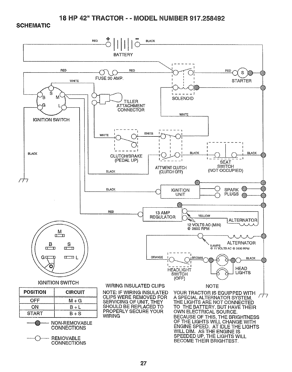
18 HP 42" TRACTOR = =MODEL NUMBER 917.258492
SCHEMATIC
BATTERY
E,
SLACK
-7
f I
I
FUSE30 AMP. _ i I
WHITE I i I
_ ..... J
TILLER OLENOID
__ ATTACHMENT
CONNECTOR
/WHITE
IGNITION SWITCH
t ...... i 1
w.,TE w.,TE
I I I
I I I
I_j I t I
I t I
(PEDAL UP)
I ATPMENTCLUTCH
aLACK J (CLUTCHOFF)
BLACK
BLACK
IGNITION SWITCH
POSITION CIRCUIT
OFF M + G
ON B +L
START B + S
NON-REMOVABLE
CONNECTIONS
REMOVABLE
CONNECTIONS
R_D_ )
STARTER
I-- I
I I
tSEAT
SWITCH
(NOT OCCUPIED)
(_ IGNITIONUNIT
SPARK _--_ )
PLUGS @------4 )
BED (_ 13 AMPREGULATOR YELLOW
12VOLTS AC (MIN)
@3600 RPM
4)
5AMPS ALTERNATOR
@ 11 VOLTS AO @ 3600 RPM
t- I
I...... I
HEADUGHT I IH AD
SWITG'H- L--(d _ LIGHTS
(OFF) _-J
WIRING INSULATED CLIPS
NOTE: IF WIRING INSULATED
CLIPS WERE REMOVED FOR
SERVICING OF UNIT, THEY
SHOULD BE REPLACED TO
PROPERLY SECURE YOUR
WIRING
NOTE
YOUR TRACTOR IS EQUIPPED WITH
A SPECIAL ALTERNATOR SYSTEM.
THE LIGHTS ARE NOT CONNECTED
TO THE BATTERY, BUT HAVE THEIR
OWN ELECTRICAL SOURCE
BECAUSE OF THIS, THE BRIGHTNESS
OF THE LIGHTS WILL CHANGE WITH
ENGINE SPEED. AT IDLE THE LIGHTS
WILL DIM. AS THE ENGINE IS
SPEEDED UP, THE LIGHTS WILL
BECOME THEIR BRIGHTEST.
27
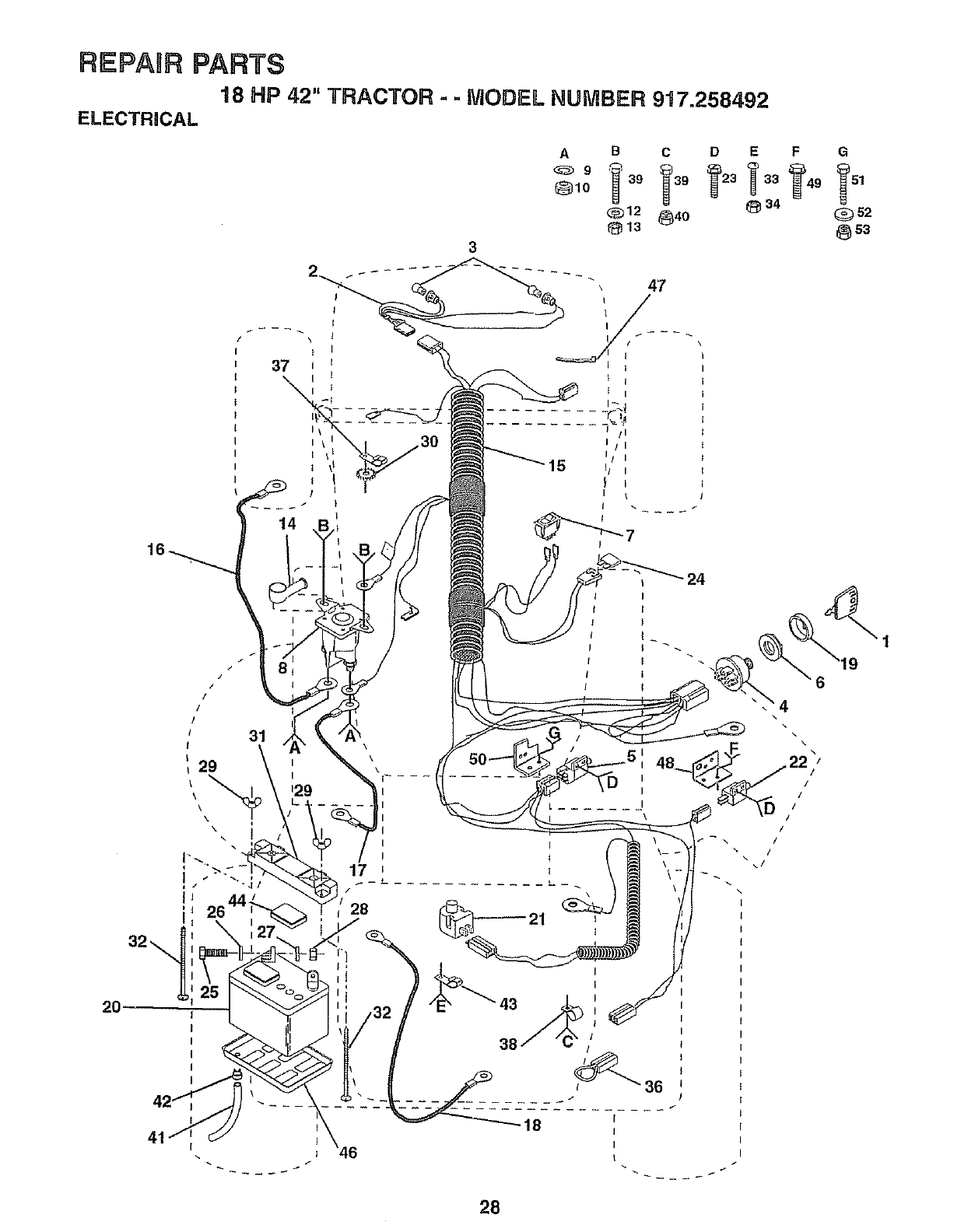
REPAnR PARTS
18 HP 42" TRACTOR =- MODEL NUMBER 917.258492
ELECTRICAL
2O
31
3
A B C D E F G
_10 39 39 23 51
<:_12 _40 _34 _52
813 @s3
41 _46
\
\J I
, 48_.
I
I
L ...... I\
28
38
I
I
I
I
+
36 +
J
I
I
I
t
6
.4
\
]
/
/
/
/
/
/
/
28
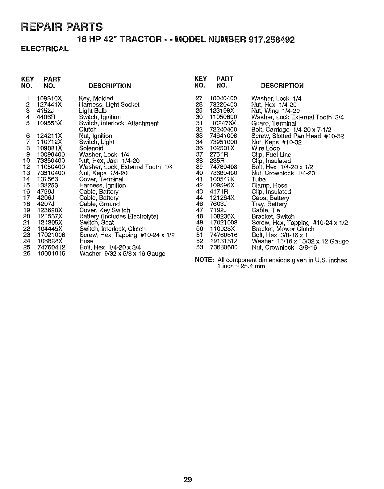
REPAURPARTS
18 HP 42" TRACTOR - -MODEL NUMBER 917.258492
ELECTRICAL
KEY PART KEY PART
NO. NO. DESCRIPTION NO. NO. DESCRIPTION
1
2
3
4
5
6
7
8
9
10
12
13
14
15
'16
17
18
19
20
21
22
23
24
25
26
109310X
127441X
4152J
4406R
109553X
124211X
1107'12X
109081X
10090400
73350400
11050400
73510400
131563
133253
4799J
4206J
4207J
123620X
121537X
121305X
104445X
17021008
108824X
74760412
19091016
Key, Molded 27 !0040400
Harness, Light Socket 28 73220400
Light Bulb 29 123198X
Switch, Ignition 30 11050600
Switch, Interlock, Attachment 31 102476X
Clutch 32 72240460
Nut, Ignition 33 74641008
Switch, Light 34 73951000
Solenoid 36 102501X
Washer, Lock 1/4 37 2751R
Nut, Hex, Jam 1/4-20 38 235R
Washer, Lock, External Tooth '1/4 39 74780408
Nut, Keps 1/4-20 40 73680400
Cover, Terminal 41 10054'1K
Harness, Ignition 42 109596X
Cable, Battery 43 4171R
Cable, Battery 44 121264X
Cable, Ground 46 7603,,I
Cover, Key Switch 47 7192J
Battery (Includes Electrolyte) 46 108236X
Switch, Seat 49 17021008
Switch, Interlock, Clutch 50 110923X
Screw, Hex, Tapping #10-24 x 1/2 51 74760616
Fuse 52 19131312
Bott, Hex 1/4-20 x 3/4 53 73680600
Washer 9/32 x 5/8 x 16 Gauge
Washer, Lock 1/4
Nut, Hex 1/4-20
Nut, Wing 1/4-20
Washer, Lock External Tooth 3/4
Guard, Terminal
Bolt, Carriage 1/4-20 x 7-1/2
Screw, Slotted Pan Head #10-32
Nut, Keps #10-32
Wire Loop
Clip, Fue/Line
Clip, Insulated
Bolt, Hex 1/4-20 x 1/2
Nut, Crownlock 1/4-20
Tube
Clamp, Hose
Clip, Insulated
Caps, Battery
Tray, Battery
Cable, Tie
Bracket, Switch
Screw, Hex, Tapping #10-24 x 1/2
Bracket, Mower Clutch
Bolt, Hex 3/8-16x 1
Washer 13/16 x 13/32 x 12 Gauge
Nut, Crownlock 3/8-'16
NOTE: All component dimensions given in U.& inches
1 inch = 2&4 mm
29
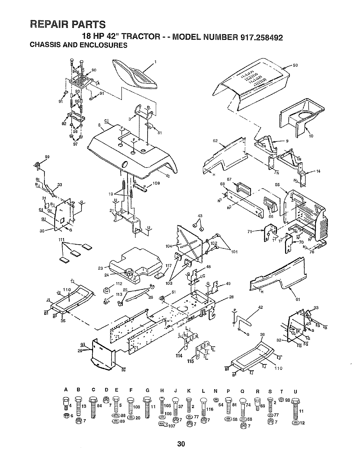
REPAIR PARTS
18 HP 42" TRACTOR --MODEL NUMBER 917.258492
CHASSIS AND ENCLOSURES
1
90
o?
97
51
/
/
ij 109
43
67
68
lol 76
j112
61
42
1 115 J
A B
_6_7
C D E F
84 7 5 108
_88 ®2o
___389
G H J K L N P Q R S T U
30
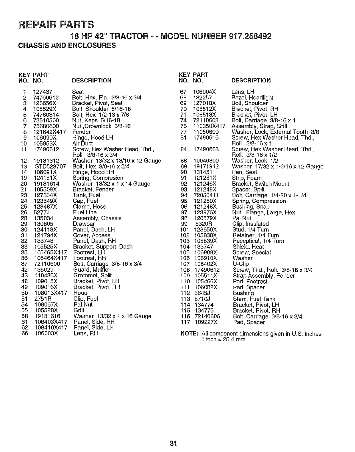
REPABRPARTS
18 HP 42" TRACTOR =-MODEL NUMBER 917.258492
CHASSIS AND ENCLOSURES
KEY PART KEY PART
NO. NO. DESCRIPTION NO. NO. DESCRIPTION
1 127437 Seat 67 106004X
2 74760612 Bolt, Hex, Fin. 3/8m16x 3/4 68 132257
3 126656X Bracket, Pivot, Seat 69 127018X
4 105529X Bolt, Shoulder 5/16-18 70 108512X
5 74780814 Bolt, Hex 1/2-13 x 7/8 7'1 108513X
6 73510500 Nut, Keps 5/16-18 74 72110608
7 73680600 Nut ,Crownlock 3/8-16 76 110350X417
8 12'1642X417 Fender 77 11050600
9 106090X Hinge, Hood LH 81 174906'16
10 105953X Air Duct
11 17490612 Screw, Hex Washer Head, Thd, 84 17490608
Roll. 3/8-16 x 3/4
12 19131312 Washer 13/32x 13/16x 12 Gauge 88 10040800
13 STD523707 Bolt, Hex 3/8q6x3/4 89 19171912
14 106091X Hinge, Hood RH 90 13'1451
19 124181X Spring, Compresion 91 121251X
20 19131614 Washer 13/32x 1 x 14 Gauge 92 121246X
21 105509X Bracket, Fender 93 t21249X
23 127334X Tank, Fuel 94 72050411
24 123549X Cap, Fuel 95 12t250X
25 123487X Clamp, Hose 96 121248X
26 5277J Fuel Line 97 123976X
28 135034 Assembly, Chassis 98 120579X
29 130805 Drawbar 99 5320R
30 124118X Panel, Dash, LH 101 123650X
31 121794X Cover, Access 102 105838X
32 133748 Panel, Dash, RH 103 105839X
33 105525X Bracket, Support, Dash 104 133747
35 105465X417 Footrest, LH 105 106909X
36 105464X417 Footrest, RH 106 106910X
37 72'110606 Bolt, Carriage 3/8-16x3/4 107 108402X
42 135029 Guard, Muffler 108 17490612
43 110436X Grommet, Split 109 105511X
48 109015X Bracket, Pivot, LH 110 105466X
49 109016X Bracket, Pivot, RH 111 106082X
50 106013X417 Hood 112 3645J
51 2751R Clip, Fuel 113 8710J
54 108067X Pal Nut 114 134774
55 105528X Grill 115 134775
58 19131616 Washer 13/32x 1 x 16 Gauge 116 72140606
61 108403X417 Panel, Side, RH 117 109227X
62 108410X417 Panel, Side, LH
66 106003X Lens, RH
Lens, LH
Bezel, Headlight
Bolt, Shoulder
Bracket, Pivot, RH
Bracket, Pivot, LH
Bolt, Carriage 3/8-16 x 1
Assembly, Strap, Grill
Washer, Lock, External Tooth 3/8
Screw, Hex Washer Head, Thd.
Roll 3/8q6 x 1
Screw, Hex Washer Head, Thd,
Roll. 3/8-16 x 1/2
Washer, Lock 1/2
Washer 17/32 x 1-3/16 x 12 Gauge
Pan, Seat
Strip, Foam
Bracket, Switch Mount
Spacer, Split
Bolt, Carriage 1/4-20 x '1-'1/4
Spring, Compression
Bushing, Snap
Nut, Flange, Large, Hex
Pal Nut
Clip, Insulated
Stud, 1/4 Turn
Retainer, 1/4 Turn
Receptical, 1/4 Turn
Shield, Heat
Screw,
Washer Speclal
U-Clip
Screw, Thd. Roll. 3/8-16 x 3/4
Strap Assembly, Fender
Pad, Footrest
Pad, Spacer
Bushing
Stem, Fuel Tank
Bracket, Pivot, LH
Bracket, Pivot, RH
Bolt, Carriage 3/8-16 x 3/4
Pad, Spacer
NOTE: All component dimensions given in U.S. inches
1 inch = 25.4 mm
31
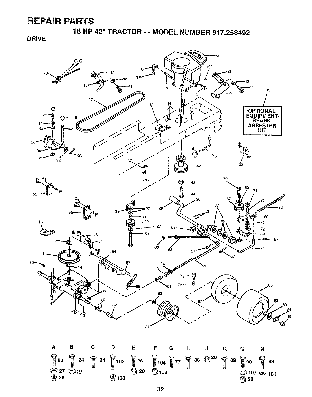
REPAIR PARTS
18 HP 42" TRACTOR --MODEL NUMBER 917.258492
DRIVE
7
f
J
39
40
53
60 58
7O
38
9"9
I -OPTIONAL i
EQUIPMENT.
SPARK
ARRESTER
KIT
25
62 71
83
87 64 59
3_
8O
•83
6
A B
_90 _ 24
(_27 _27
28
CD E F G H J
@28 @1o3
_103
32
KM N
107 _101
28
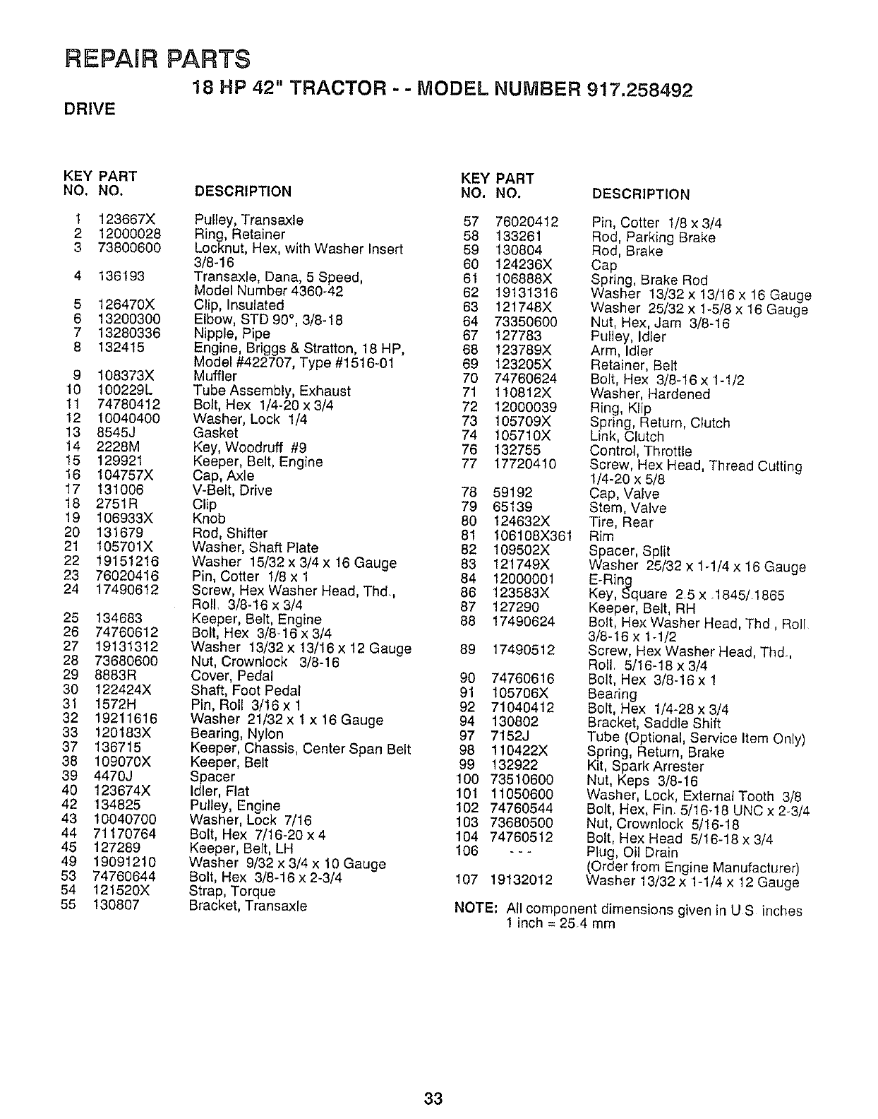
REPAIR PARTS
18 HP 42" TRACTOR - - MODEL NUMBER 917.258492
DRIVE
KEY PART KEY PART
NO. NO. DESCRIPTION NO. NO. DESCRIPTION
1 123667X Pulley, Transaxle 57 76020412
2 12000028 Ring, Retainer 58 133261
3 73800600 Locknut, Hex, with Washer Insert 59 130804
3/8-16 60 124236X
4 136193 Transaxle, Dana, 5 Speed, 61 106888X
Model Number 4360-42 62 19131318
5 126470X Clip, Insulated 63 121746X
6 13200300 Elbow, STD 90 °, 3/8-18 64 73350600
713280336 Nipple, Pipe 67 127783
8 132415 Engine, Briggs & Stratton, 18 HP, 68 123789X
Model #422707, Type #1516-01 69 123205X
9 108373X Muffler 70 74760624
10 100229L Tube Assembly, Exhaust 71 110812X
11 74780412 Bolt, Hex 1/4-20 x 3/4 72 12000039
12 10040400 Washer, Lock 1/4 73 105709X
13 8545J Gasket 74 105710X
14 2228M Key, Woodruff #9 76 132755
15 129921 Keeper, Belt, Engine 77 17720410
16 104757X Cap, Axle
17 131006 V-Belt, Drive 78 59192
18 2751R Clip 79 65139
19 I06933X Knob 80 124632X
20 131679 Rod, Shifter 81 106106X361
21 105701X Washer, Shaft Plate 82 109502X
22 19151216 Washer 15/32 x 3/4 x16 Gauge 83 121749X
23 76020416 Pin, Cotter 1/8 x 1 84 12000001
24 17490612 Screw, Hex Washer Head, Thd., 86 123583X
Roll. 3/8-16 x 3/4 87 127290
25 134683 Keeper, Belt, Engine 88 17490624
26 74760612 Bolt, Hex 3/8-16x3/4
27 19131312 Washer 13/32 x13/16 x12 Gauge 89 17490512
28 73880600 Nut, Crewniock 3/8-16
29 8883R Cover, Pedal 90 74760616
30 122424X Shaft, Foot Pedal 91 105706X
31 1572H Pin, Roll 3/16x 1 92 71040412
32 19211616 Washer 21/32x 1 x 16 Gauge 94 130802
33 120183X Bearing, Nylon 97 7152J
37 136715 Keeper, Chassis, Center Span Belt 98 110422X
38 109070X Keeper, Be_t 99 132922
39 4470J Spacer 100 73510600
40 123674X Idler, Flat 101 11050600
42 134825 Pulley, Engine 102 74760544
43 10040700 Washer, Lock 7/16 103 73680500
44 71170764 Bolt, Hex 7/16-20x4 104 74760512
45 127289 Keeper, Belt, LH 106 - - -
49 19091210 Washer 9/32 x 3/4 x10 Gauge
53 74760644 Bolt, Hex 3/8-16 x 2-3/4 107 19132012
54 121520X Strap, Torque
55 130807 Bracket, Transaxle
Pin, Cotter 1/8 x 3/4
Rod, Parking Brake
Rod, Brake
Cap
Spring, Brake Red
Washer 13/32 x 13/16 x 16 Gauge
Washer 25/32 x 1-5/8 x 16 Gauge
Nut, Hex, Jam 3/8-16
Pulley, Idler
Arm, Idler
Retainer, Belt
Bolt, Hex 3/8-16 x 1-1/2
Washer, Hardened
Ring, Klip
Spring, Return, Clutch
Link, Clutch
Control, Throttle
Screw, Hex Head, Thread Cutting
1/4-20 x 5/8
Cap, Valve
Stem, Valve
Tire, Rear
Rim
Spacer, Split
Washer 25/32 x 1-!/4 x 16 Gauge
E-Ring
Key, Square 25x 1845/1865
Keeper, Belt, RH
Bolt, Hex Washer Head, Thd, Roll
3/8-16 x 1-1/2
Screw, Hex Washer Head, Thd.,
Roll, 5/16-18 x 3/4
Bolt, Hex 3/8-16 x 1
Bearing
Bolt, Hex 1/4-28 x 3/4
Bracket, Saddle Shift
Tube (Optional, Service Item Only)
Spring, Return, Brake
Kit, Spark Arrester
Nut, Keps 3/8-16
Washer, Lock, External Tooth 3/8
Bolt, Hex, Fin. 5/16-16 UNC x 2.3/4
Nut, Crownlock 5/16-18
Bolt, Hex Head 5/16-16 x 3/4
Plug, Oil Drain
(Order from Engine Manufacturer)
Washer 13/32 x 1-1/4 x 12 Gauge
NOTE; All component dimensions given in U S inches
1 inch = 25,4 mm
33
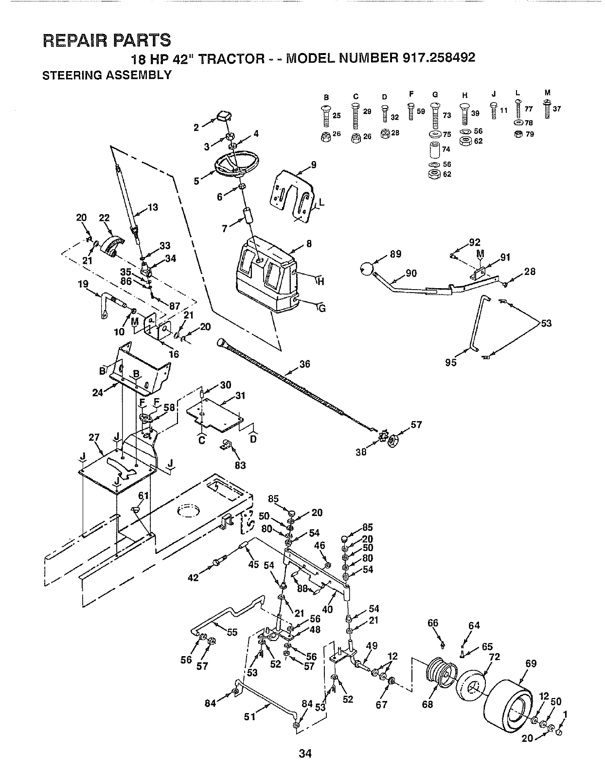
REPAIR PARTS
18 HP 42" TRACTOR - - MODEL NUMBER 917.258492
STEERING ASSEMBLY
20 22
27
10
9
\\\
16
M
85
42
57
45 54
\
53
51
46
40
.56 66 64
12 72
52 67 68
69
34
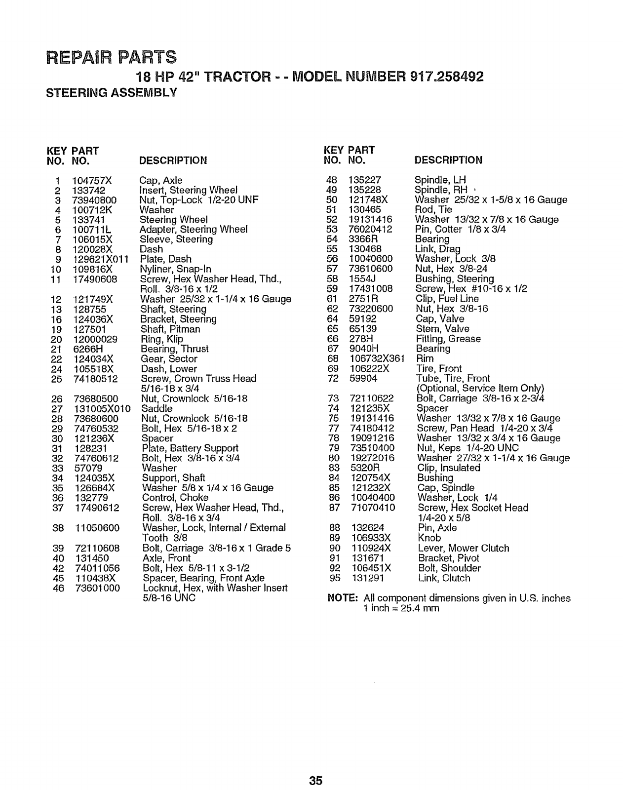
REPAURPARTS
18 HP 42" TRACTOR .. = MODEL NUMBER 917.258492
STEERING ASSEMBLY
KEY PART KEY PART
NO. NO. DESCRIPTION NO. NO. DESCRIPTION
1 104757X
2 133742
3 73940800
4 100712K
5 133741
6 100711L
7 1060'15X
8 120028X
9 129621X01 t
'10 109816X
11 t7490608
12 121749X
13 128755
16 124036X
19 127501
20 12000029
2I 6266H
22 124034X
24 105518X
25 74180512
26 73680500
27 13t005X010
28 73680600
29 7476O532
30 121236X
31 '128231
32 74760612
33 57079
34 124035X
35 126684X
36 132779
37 17490612
38 '11050600
39 72110608
40 131450
42 74011056
45 110438X
46 736O1000
Cap, Axle 48
Insert, Steering Wheel 49
Nut, Top-Lock 1/2-20 UNF 50
Washer 51
Steering Wheel 52
Adapter, Steering Wheel 53
Sleeve, Steering 54
Dash 55
Plate, Dash 56
Nyliner, Snap-In 57
Screw, Hex Washer Head, Thd., 58
Roll.. 3/8-16 x 1/2 59
Washer 25/32 x 1-I/4 x 16 Gauge 61
Shaft, Steering 62
Bracket, Steering 64
Shaft, Pitman 65
Ring, Klip 66
Bearing, Thrust 67
Gear, Sector 68
Dash, Lower 69
Screw, Crown Truss Head 72
5/16-18 x 3/4
Nut, Crownlock 5/16-18 73
Saddle 74
Nut, Crownlock 5/1648 75
Bolt, Hex 5/16-t 8 x 2 77
Spacer 78
Plate, Battery Support 79
Bolt, Hex 3/8-16 x 3/4 80
Washer 83
Support, Shaft 84
Washer 5/8 x 1/4 x 16 Gauge 85
Control, Choke 86
Screw, Hex Washer Head, Thd. 87
Rol!., 3/8-16 x 3/4
Washer, Lock, Internal /External 88
Tooth 3/8 89
Bolt, Carriage 3/8-16 x t Grade 5 90
Axle, Front 91
Bolt, Hex 5/8-11 x 3-1/2 92
Spacer, Bearing, Front Axle 95
Locknut, Hex, with Washer Insert
5/8-16 UNC
135227
135228
121748X
130465
19131416
76020412
3366R
130468
10040600
73610600
1554J
17431008
2751R
73220600
59192
65139
278H
9040H
106732X361
106222X
59904
7211O622
121235X
19131416
7418O412
t9091216
7351O4O0
19272016
5320R
t20754X
121232X
10040400
71070410
132624
106933X
110924X
131671
106451X
131291
Spindle, LH
Spindle, RH '
Washer 25/32 x 1-5/8 x 16 Gauge
Rod, Tie
Washer 13/32 x 7/8 x 16 Gauge
Pin, Cotter 1/8 x 3/4
Bearing
Link, Drag
Washer, Lock 3/8
Nut, Hex 3/8-24
Bushing, Steering
Screw, Hex #10_16 x 1/2
Clip, Fuel Line
Nut, Hex 3/8-16
Cap, Valve
Stem, Valve
Fitting, Grease
Bearing
Rim
Tire, Front
Tube, Tire, Front
(Optional, Service Item Only)
Bolt, Carriage 3/8-16 x 2-3/4
Spacer
Washer 13/32 x 7/8 x 16 Gauge
Screw, Pan Head I/4-20 x 3/4
Washer 13/32 x 3/4 x 16 Gauge
Nut, Keps 1/4-20 UNC
Washer 27/32 x 1-1/4 x 16 Gauge
Clip, Insulated
Bushing
Cap, Spindle
Washer, Lock 1/4
Screw, Hex Socket Head
1/4-20 x 5/8
Pin, Axle
Knob
Lever, Mower Clutch
Bracket, Pivot
Bolt, Shoulder
Link, Clutch
NOTE: All component dimensions given in U...£oinches
t inch = 2&4 mm
35
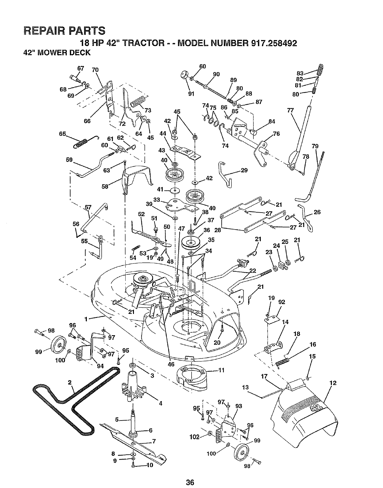
REPAIR PARTS
18 HP 42" TRACTOR - - MODEL NUMBER 917.258492
42" MOWER DECK
67 7O
52
45
42
43
6O
91
90 89
80 88
21 19 92
82
81
80
77
21
96
4
13
93
14
18
16
15
12
36
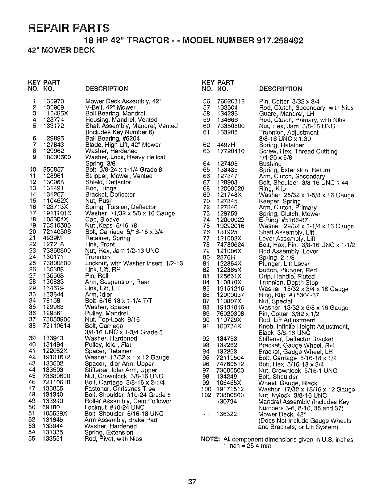
REPAUR PARYS
18 HP 42" TRACTOR - - MODEL NUMBER 917.258492
42" MOWER DECK
KEY PART KEY PART
NO. NO. DESCRIPTION NO. NO. DESCRIPTION
1 130970
2 130969
3 110485X
4 128774
5 133172
6 129895
7 127843
8 129962
9 10030600
10 850857
11 128961
12 130968
13 131491
14 131267
15 110452X
16 123713X
17 19111016
18 105304X
19 73510500
20 72140506
21 4939M
22 127218
23 73350800
24 130171
25 73800800
26 135388
27 135563
28 130833
29 134619
33 133844
34 78158
35 129963
36 129861
37 73050900
38 72110614
39 133943
40 131494
41 122052X
42 19131612
43 133502
44 133503
45 73680600
46 72110618
47 133835
48 131340
49 133940
50 69180
51 105529X
52 131845
53 133944
54 131335
55 133551
Mower Deck Assembly, 42" 56 76020312
V-Belt, 42" Mower 57 133504
Bail Bearing, Mandrel 58 134236
Housing, Mandrel, Vented 59 134666
Shaft Assembly, Mandrel, Vented 60 73350600
(Includes Key Number 6) 61 133205
Ball Bearing, #6204
Blade, High Lift, 42 Mower 62 4497H
Washer, Hardened 63 17720410
Washer, Lock, Heavy Helical
Spring 3/8 64 127498
Bolt 3/8-24 x 1-1/4 Grade 8 65 133435
Stripper, Mower, Vented 66 127847
Shield, Deflector 67 128903
Rod, Hinge 68 12000029
Bracket, Deflector 69 121748X
Nut, Push 70 127845
Spring, Torsion, Deflector 72 127846
Washer 11/32 x 5/8 x 16 Gauge 73 128759
Cap, Sleeve 74 12000022
Nut,Kaps 5/16_18 75 19292016
Bolt, Carriage 5/16-18x3/4 76 131925
Retainer, Spring 77 121002X
Link, Front 78 74780624
Nut, Hex, Jam 1/2-13 UNC 79 121006X
Trunnion 80 2876H
Locknut, with Washer Insert 1/2-13 81 122364X
Link, Lift, RH 82 122365X
Pin, Roll 83 125631X
Arm, Suspension, Rear 84 110810X
Link, Lift, LH 85 19151216
Arm, Idler 86 12000037
Bolt 5/16-18x1-1/4T/T 87 110807X
Washer, Spacer 88 19131016
Pulley, Mandrel 89 76020308
Nut, Top-Lock 9/16 90 110729X
Bolt, Carriage 91 100734K
3/8-16 UNC x 1_3/4 Grade 5
Washer, Hardened 92 134753
Pulley, Idler, Flat 93 132262
Spacer, Retainer 94 132263
Washer 13/32x 1 x 12 Gauge 95 72110504
Spacer, Idler Arm, Upper 96 74760512
Stiffener, Idler Arm, Upper 97 73680500
Nut, Crownlock 3/8-16 UNC 98 134249
Bolt, Carriage 3/8-16 x 2-1/4 99 105455X
Fastener, Christmas Tree 100 19171512
Bolt, Shoulder #10-24 Grade 5 102 73800600
Roller Assembly, Cam Follower - - 130794
Locknut #10-24 UNC
Bolt, Shoulder 5/16_18 UNC - - 136322
Arm Assembly, Brake Pad
Washer, Hardened
Spring, Extension
Rod, Pivot, with Nibs
Pin, Cotter 3/32 x 3/4
Rod, Clutch, Secondary, with Nibs
Guard, Mandrel, LH
Rod, Clutch, Primary, with Nibs
Nut, Hex, Jam 3/8-16 UNC
Trunnion, Adjustment
3/8-16 UNC x 1.30
Spring, Retainer
Screw, Hex, Thread Cuttting
1/4-20 x 5/8
Bushing
Spring, Extension, Return
Arm, Clutch, Secondary
Bolt, Shoulder 3/8-16 UNC 1.44
Ring, Klip
Washer 25/32 x 1-5/8 x 16 Gauge
Keeper, Spring
Arm, Clutch, Primary
Spring, Clutch, Mower
E-Ring #5166-87
Washer 29/32 x 1-1/4 x 16 Gauge
Shaft Assembly, Lift
Lever Assembly, Lift
Bolt, Hex, Fin. 3/8-16 UNCx 1-1/2
Rod Assembly, Lever
Spring 2-1/8
Plunger, Lift Lever
Button, Plunger, Red
Grip, Handle, Fluted
Trunnion, Depth Stop
Washer 15/32 x 3/4 x 16 Gauge
Ring, Klip #T5304-37
Nut, Special
Washer 13/32 x 5/8 x !6 Gauge
Pin, Cotter 3/32 x 1/2
Rod, Lift Adjustment
Knob, Infinite Height Adjustment,
Black 3/8-16 UNC
Stiffener, Deflector Bracket
Bracket, Gauge Wheel, RH
Bracket, Gauge Wheel, LH
Bolt, Carriage 5/16-18 x 1/2
Bolt, Hex 5/16-18 x 3/4
Nut, Crownlock 5/16-1 UNC
Bolt, Shoulder
Wheel, Gauge, Black
Washer 17/32 x 15/16 x 12 Gauge
Nut, Nylock 3/8-16 UNC
Mandrel Assembly (Includes Key
Numbers 3-6, 8-10, 35 and 37)
Mower Deck, 42"
(Does Not Include Gauge Wheels
and Brackets, or Lift System)
NOTE: All component dimensions given in U_S. inches
1 inch = 25.4 mm
37
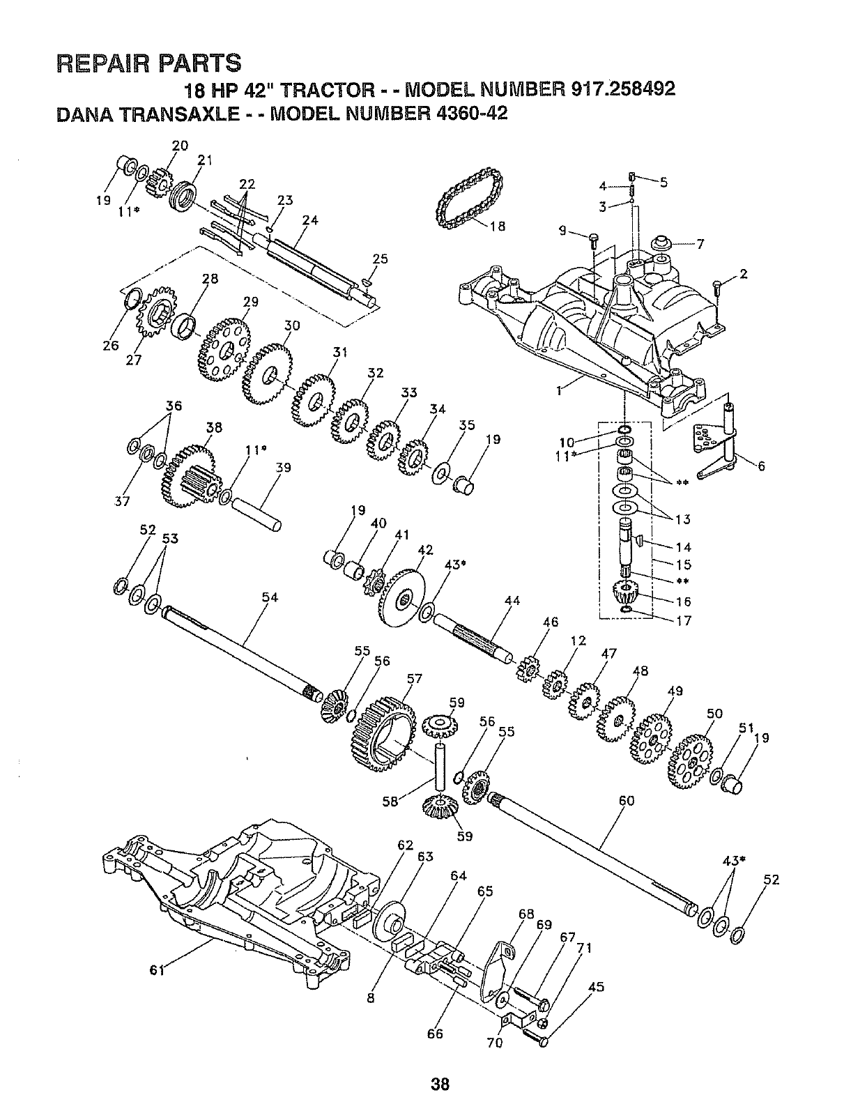
REPAIR PARTS
18 HP 42" TRACTOR - -MODEL NUMBER 917.258492
DANA TRANSAXLE --MODEL NUMBER 4360-42
20 21
25
54 44
55 56
57
59
12 47
49
50
8
62
66
59
64 65
6869 _771
6O
52
38
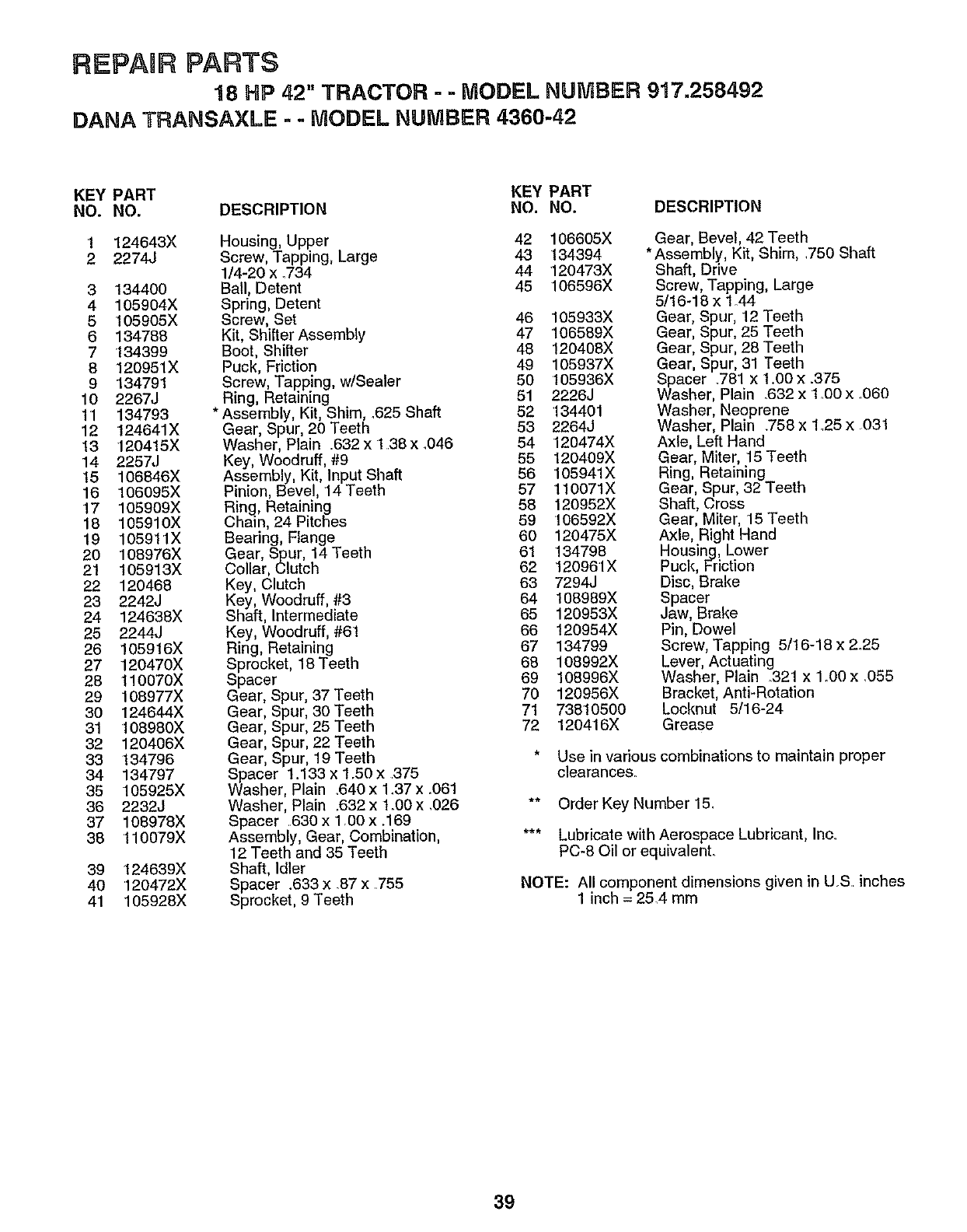
REPAIR PARTS
18 HP 42" TRACTOR --MODEL NUMBER 917o258492
DANA TRANSAXLE - - MODEL NUMBER 4360-42
KEY PART KEY PART
NO. NO. DESCRIPTION NO. NO. DESCRIPTION
1 124643X
2 2274J
3 134400
4 105904X
5 105905X
6 134788
7 '134399
8 120951X
9134791
10 2267J
11 134793
12 124641X
13 120415X
14 225_J
15 106846X
16 106095X
17 105909X
18 105910X
19 105911X
20 108976X
21 1O5913)(
22 120468
23 2242J
24 124638X
25 2244J
26 105916X
27 120470X
28 110070X
29 108977X
30 124644X
31 108980X
32 120406X
33 134796
34 134797
35 105925X
36 2232J
37 108978X
38 110079X
39 124639X
40 120472X
41 105928X
Housing, Upper 42 106605X
Screw, Tapping, Large 43 134394
1/4-20 x .734 44 120473X
Bail, Detent 45 106596X
Spring, Detent
Screw, Set 46 105933X
Kit, Shifter Assembly 47 106589X
Boot, Shifter 48 120408X
Puck, Friction 49 105937X
Screw, Tapping, w/Sealer 50 105936X
Ring, Retaining 51 2226J
* Assembly, Kit, Shim, .625 Shaft 52 134401
Gear, Spur, 20 Teeth 53 2264J
Washer, Plain .632 x 138 x .046 54 120474X
Key, Woodruff, #9 55 120409X
Assembly, Kit, Input Shaft 56 105941X
Pinion, Bevel, 14 Teeth 57 110071X
Ring, Retaining 58 120952X
Chain, 24 Pitches 59 106592X
Bearing, Flange 60 120475X
Gear, Spur, 14 Teeth 61 134798
Collar, Clutch 62 120961X
Key, Clutch 63 7294J
Key, Woodruff, #3 64 108989X
Shaft, Intermediate 65 120953X
Key, Woodruff, #61 66 120954X
Ring, Retaining 67 134799
Sprocket, 18 Teeth 68 108992X
Spacer 69 108996X
Gear, Spur, 37 Teeth 70 120956X
Gear, Spur, 30 Teeth 71 738'10500
Gear, Spur, 25 Teeth 72 120416X
Gear, Spur, 22 Teeth
Gear, Spur, 19 Teeth
Spacer 1.133 x 1.50 x 375
Washer, Plain .640 x 1.37 x .061
Washer, Plain °632 x 1_00x ,026
Spacer .630 x 1.00 x .169
Assembly, Gear, Combination,
12 Teeth and 35 Teeth
Shaft, Idler
Spacer .633 x .87 x .755
Sprocket, 9 Teeth
Gear, Bevel, 42 Teeth
* Assembly, Kit, Shim, .750 Shaft
Shaft, Drive
Screw, Tapping, Large
5/16-18 x 1A4
Gear, Spur, 12 Teeth
Gear, Spur, 25 Teeth
Gear, Spur, 28 Teeth
Gear, Spur, 31 Teeth
Spacer .781 x 1.00 x .375
Washer, Plain .632 x 1.00 x .060
Washer, Neoprene
Washer, Plain .758 x 1o25 x 031
Axle, Left Hand
Gear, Miter, 15 Teeth
Ring, Retaining
Gear, Spur, 32 Teeth
Shaft, Cross
Gear, Miter, 15 Teeth
Axle, Right Hand
Housing, Lower
Puck, Friction
Disc, Brake
Spacer
Jaw, Brake
Pin, Dowel
Screw, Tapping 5/16-18 x 2.25
Lever, Actuating
Washer, Plain 321 x 1.00 x .055
Bracket, Anti-Rotation
Locknut 5/16-24
Grease
* Use in various combinations to maintain proper
clearances.
** OrderKey Number 15.
*** Lubricate with Aerospace Lubricant Inc,
PC-80 or equ vaent.
NOTE: All component dimensions given in U,S. inches
1 inch = 25,4 mm
39
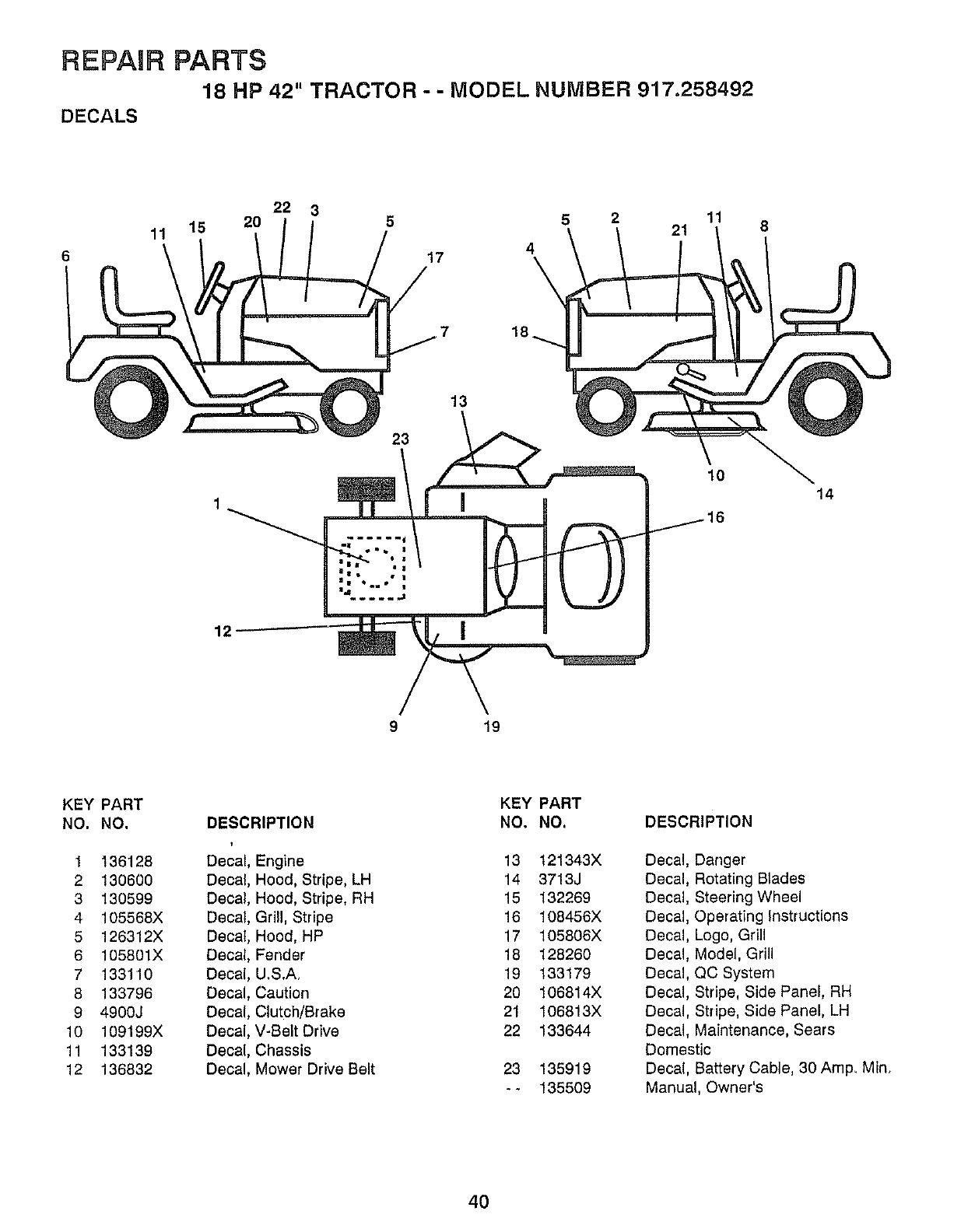
REPAIR PARTS
18 HP 42" TRACTOR - - MODEL NUMBER 917.258492
DECALS
6
22 3 11
11 15 20 5 5 2 21
4
17
8
12
23
13
10 14
9 19
KEY PART KEY PART
NO. NO. DESCRIPTION NO. NO. DESCRIPTION
1 136128
2 130600
3 130599
4 105568X
5 126312X
6 105801X
7 133110
8 133796
9 4900J
10 109199X
11 133139
12 136832
Decal Engine
Decal Hood, Stripe, LH
Decal Hood, Stripe, RH
Decal Grill, Stripe
Decal Hood, HP
Decal Fender
Decal U_S.A,
Decal Caution
Decal Clutch/Brake
Decal V-Belt Drive
Decal Chassis
Decal Mower Drive Belt
13 121343X
14 3713J
15 132269
16 108456X
17 105806X
18 128260
19 133179
20 106814X
21 106813X
22 133644
23 135919
-- 135509
Decal, Danger
Decal, Rotating Blades
Decal, Steering Wheel
Decal, Operating Instructions
Decal, Logo, Grill
Decal, Model, Grill
Decal, QC System
Decal, Stripe, Side Panel, RH
Decal, Stripe, Side Panel, LH
Decal, Maintenance, Sears
Domestic
Decal, Battery Cable, 30 Amp, Min,
Manual, Owner's
4O
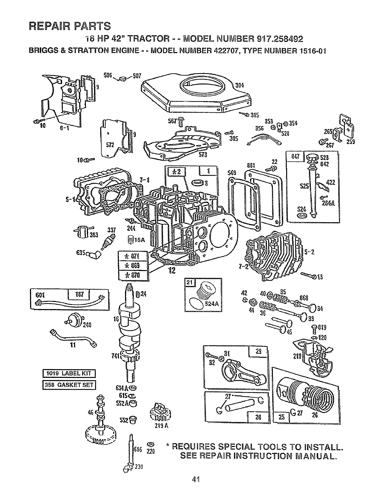
REPAIR PARTS
"i8 NP 42" TRACTOR - - MODEL NUMBER 917.258492
BRIGGS & STRATTON ENGINE - - MODEL NUMBER 422707, TYPE NUMBER 1516-01
61S(_,
_A_5
616 _0
_230
219&
*REQUIRES SPECIAL TOOLS TO INSTALL.
SEE REPABR INSTRUCTION mANUAL°
41
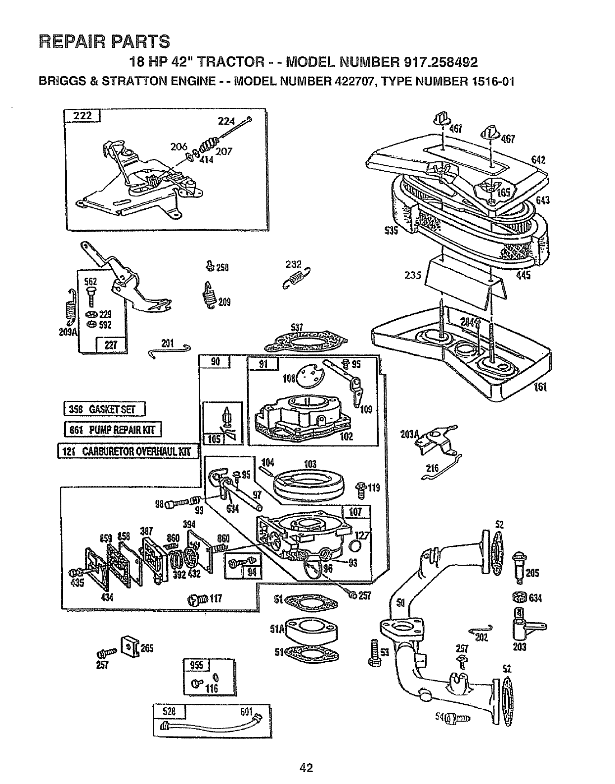
REPABR PARTS
18 HP 42" TRACTOR - ° MODEL NUMBER 917.258492
BRIGGS & STRA3-rON ENGINE - - MODEL NUMBER 422707, TYPE NUMBER 1516-01
434
_119
235
42
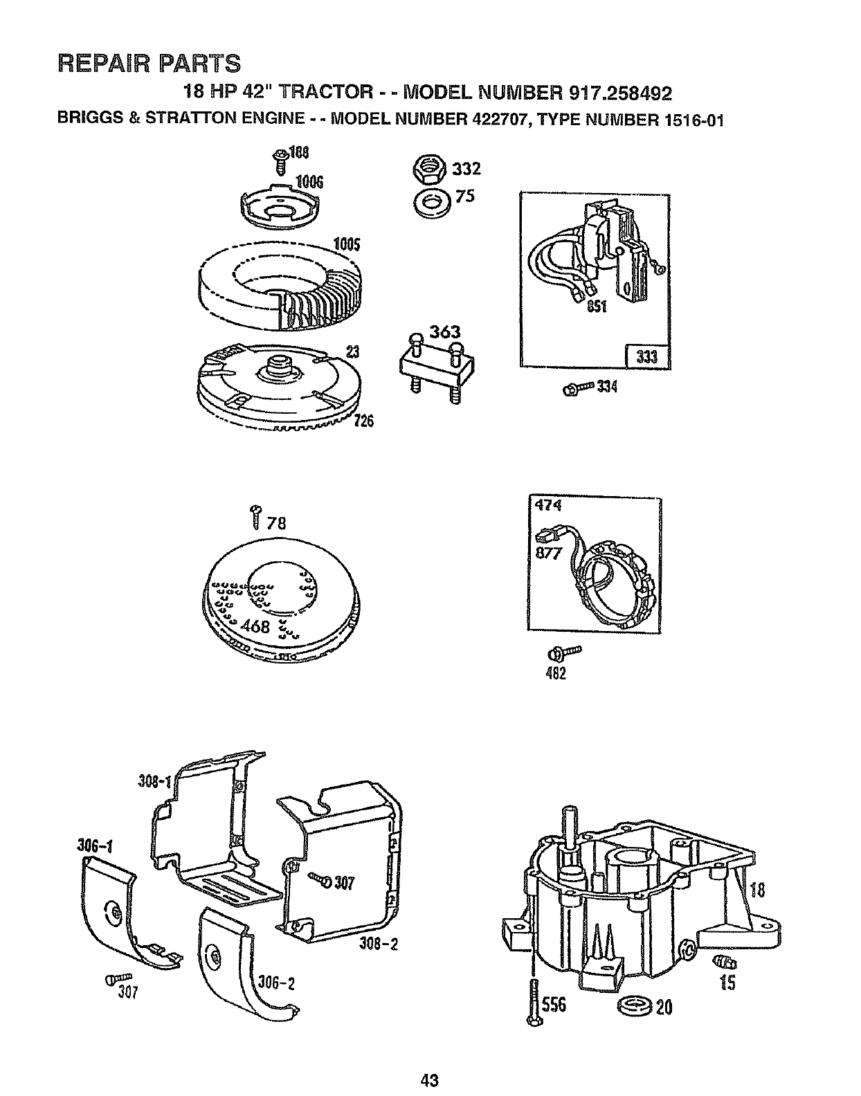
REPASR PARTS
18 HP 42" TRACTOR --MODEL NUMBER 917.258492
BRIGGS & STRA'I-FON ENGINE --MODEL NUMBER 422707, TYPE NUMBER 1516-01
332
@75
,,,,,
78
i
474
%
482
_Z)307 J
1S
43
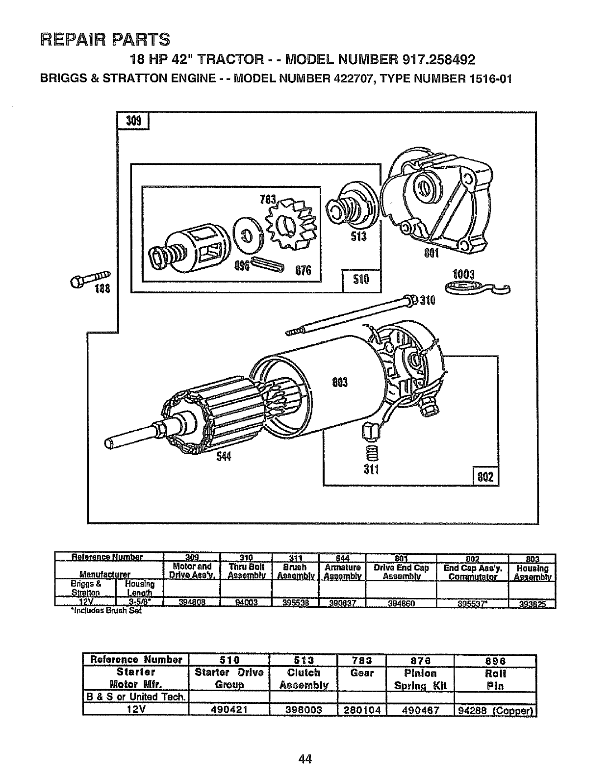
REPAIR PARTS
18 HP 42" TRACTOR --MODEL NUMBER 917.258492
BRIGGS & STRATrON ENGINE - -MODEL NUMBER 422707, TYPE NUMBER 1516-01
1003
Reference Number
Manufacturer
Bdggs& Housfng
Stmtton Lenetf1
!2V 3-5/8"
*IncludesBrush,Set
309 310 311 544 801
Motor and Thru Bolt Brash Altnaturo Drive End Ca
Ddv® Am_'v. Assembly Assembly i Asssmblv Asssmbly
394808 94003 395539 390837 394860
802 _
EndCapAss'y. Housing
Commutator Assembly
39'ss37' _93s2s
i
Reference Number 510
Starter Starter Drive
Motor Mfr. Group
B&Sor United Tech.
12V 490421
513 783 876 896
,i H i
Clutch Gear Pinion Rol!
Assembly Sprlnq Kit Pin
398003 280104 490467 94288 (Copper)
44
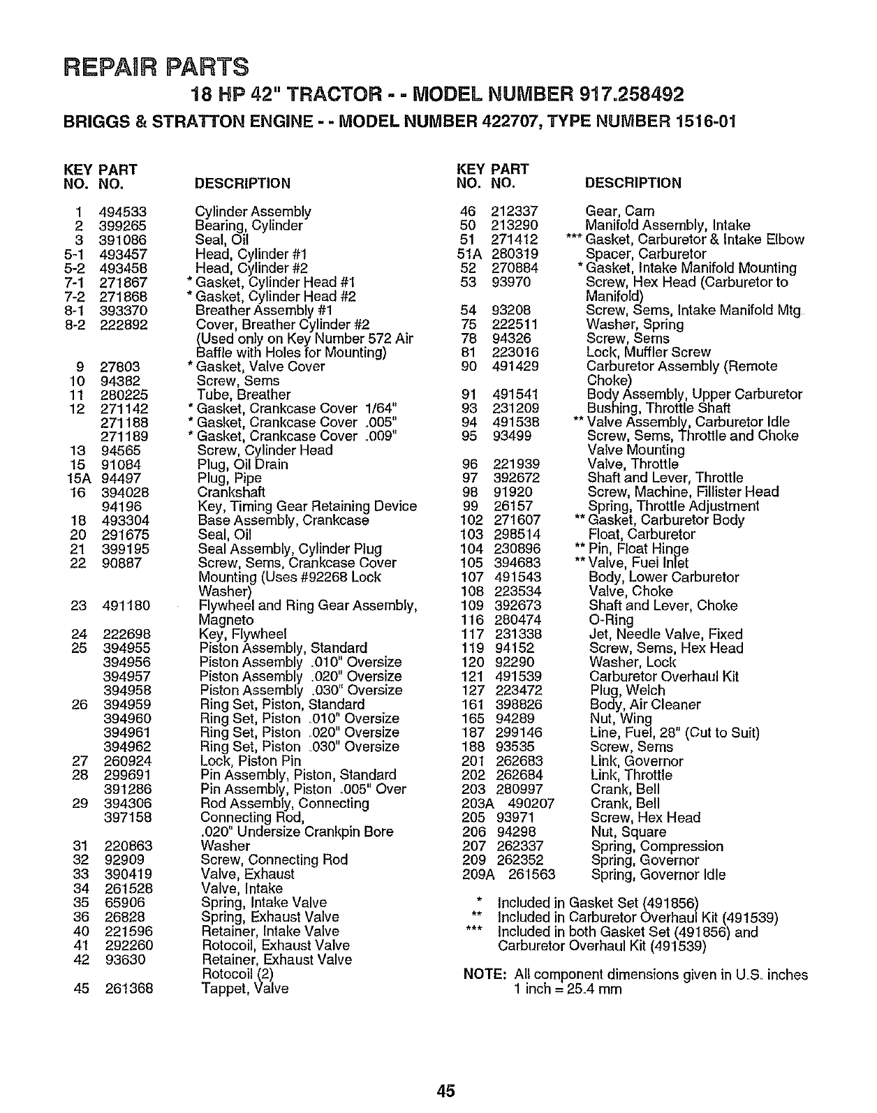
REPAnR PARTS
18 HP 42" TRACTOR - = MODEL NUMBER 917.258492
BRIGGS & STRATTON ENGINE -- MODEL NUMBER 422707, TYPE NUMBER 1516-01
KEY PART KEY PART
NO. NO. DESCRIPTION NO. NO. DESCRIPTION
1 494533
2 399265
3 391086
5-1 493457
5-2 493458
7-1 271867
7-2 271868
8-1 393370
8-2 222892
927803
10 94382
11 280225
12 271142
271188
271189
13 94565
15 91084
15A 94497
'16 394028
94196
18 493304
20 291675
21 399195
22 90887
23 491180
24 222698
25 394955
394956
394957
394958
26 394959
394960
394961
394962
27 260924
28 299691
391286
29 394306
397158
31 220863
32 92909
33 390419
34 261528
35 65906
36 26828
40 221596
4'1 292260
42 93630
45 261368
Cylinder Assembly 46 212337
Bearing, Cylinder 50 213290
Seal, Oil 51 271412
Head, Cylinder #1 51A 280319
Head, Cylinder #2 52 270884
Gasket, Cylinder Head #1 53 93970
Gasket, Cylinder Head #2
Breather Assembly #1 54 93208
Cover, Breather Cylinder #2 75 222511
(Used only on Key Number 572 Air 78 94326
Baffle with Holes for Mounting) 81 223016
* Gasket, Valve Cover 90 491429
Screw, Seres
Tube, Breather 91 491541
*Gasket, Crankcase Cover 1/64" 93 231209
* Gasket, Crankcase Cover ,,005" 94 491538
*Gasket, Crankcase Cover .009" 95 93499
Screw, Cylinder Head
Plug, Oil Drain 96 221939
Plug, Pipe 97 392672
Crankshaft 98 91920
Key, Timing Gear Retaining Device 99 26157
Base Assembly, Crankcase 102 271607
Seal, Oil 103 298514
Seal Assembly, Cylinder Plug 104 230896
Screw, Seres, Crankcase Cover 105 394683
Mounting (Uses#92268 Lock 107 491543
Washer) 108 223534
Flywheel and Ring Gear Assembly, 109 392673
Magneto 116 280474
Key, Flywheel 117 231338
Piston Assembly, Standard 119 94152
Piston Assembly .010" Oversize 120 92290
Piston Assembly .020" Oversize 121 491539
Piston Assembly .030"Oversize 127 223472
Ring Set, Piston, Standard 161 398826
Ring Set, Piston .010" Oversize 165 94289
RingSet, Piston .020"Oversize 187 299146
Ring Set, Piston _030" Oversize 188 93535
Lock, Piston Pin 201 262683
Pin Assembly, Piston, Standard 202 262684
Pin Assembly, Piston .005" Over 203 280997
Rod Assembly, Connecting 203A 490207
Connecting Rod, 205 93971
.020" Undersize Crankpin Bore 206 94298
Washer 207 262337
Screw, Connecting Rod 209 262352
Valve, Exhaust 209A 261563
Valve, Intake
Spring, Intake Valve
Spring, Exhaust Valve
Retainer, Intake Valve
Rotocoil, Exhaust Valve
Retainer, Exhaust Valve
Rotocoil (2)
Tappet, Valve
Gear, Cam
Manifold Assembly, Intake
*** Gasket, Carburetor & Intake Elbow
Spacer, Carburetor
* Gasket, Intake Manifold Mounting
Screw, Hex Head (Carburetor to
Manifold)
Screw, Sems, Intake Manifold Mtg
Washer, Spring
Screw, Seres
Lock, Muffler Screw
Carburetor Assembly (Remote
Choke)
Body Assembly, Upper Carburetor
Bushing, Throttle Shaft
** Valve Assembly, Carburetor Idle
Screw, Sems, Throttle and Choke
Valve Mounting
Valve, Throttle
Shaft and Lever, Throttle
Screw, Machine, Fillister Head
Spring, Throttle Adjustment
** Gasket, Carburetor Body
Float, Carburetor
** Pin, Float Hinge
** Valve, Fuei Inlet
Body, Lower Carburetor
Valve, Choke
Shaft and Lever, Choke
O-Ring
Jet, Needle Valve, Fixed
Screw, Seres, Hex Head
Washer, Lock
Carburetor Overhaul Kit
Plug, Welch
Body, Air Cleaner
Nut, Wing .
Line, Fuel, 28 (Cut to Suit)
Screw, Seres
Link, Governor
Link, Throttle
Crank, Bell
Crank, Bell
Screw, Hex Head
Nut, Square
Spring, Compression
Spring, Governor
Spring, Governor Idle
* Includedin Gasket Set (491856)
** Included in Carburetor Overhau/Kit (491539)
*** Included in both Gasket Set (491856) and
Carburetor Overhaul Kit (491539)
NOTE: All component dimensions given in U.S, inches
1 inch = 25.4 mm
45
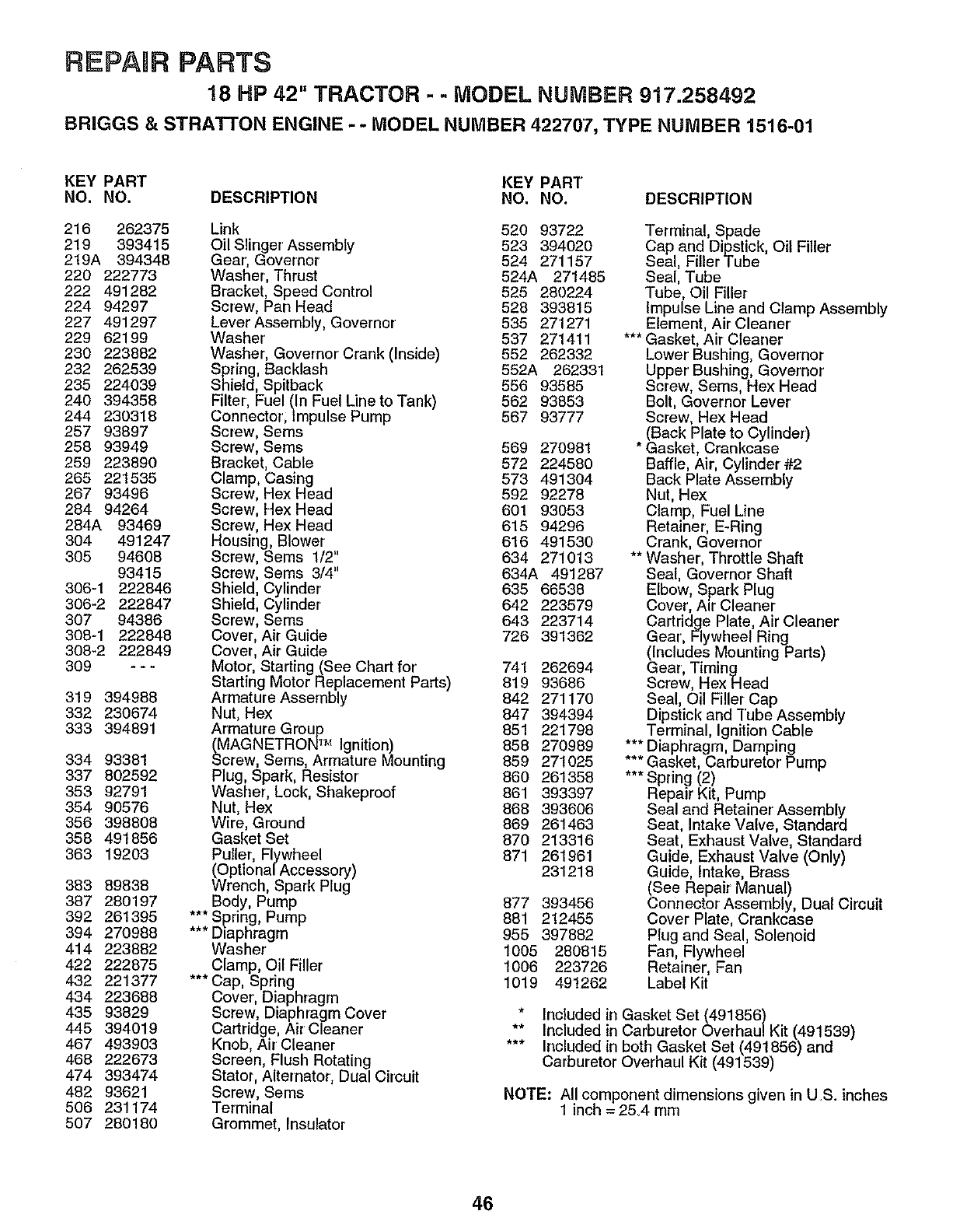
REPAURPARTS
18 HP 42" TRACTOR =- MODEL NUMBER 917.258492
BRNGGS & STRATrON ENGINE --MODEL NUMBER 422707, TYPE NUMBER 1516-01
KEY PART KEY PART
NO. NO. DESCRIPTION NO. NO. DESCRIPTION
216 262375 Link 520 93722
219 393415 Oil Slinger' Assembly 523 394020
219A 394348 Gear', Governor 524 271157
220 222773 Washer, Thrust 524A 271485
222 491282 Bracket, Speed Control 525 280224
224 94297 Screw, Pan Head 528 393815
227 491297 Lever Assembly, Governor 535 271271
229 62199 Washer' 537 271411
230 223882 Washer, Governor' Crank (Inside) 552 262332
232 262539 Spring, Backlash 552A 262331
235 224039 Shield, Spitback 556 93585
240 394358 Filter, Fuel (In Fuel Line to Tank) 562 93853
244 230318 Connector;lmpulsePump 567 93777
257 93897 Screw, Sems
258 93949 Screw, Sems 569 270981
259 223890 Bracket, Cable 572 224580
265 221535 Clamp, Casing 573 491304
267 93496 Screw, Hex Head 592 92278
284 94264 Screw, Hex Head 601 93053
284A 93469 Screw, Hex Head 615 94296
304 491247 Housing, Blower 616 491530
305 94608 Screw, Sems 1/2" 634 271013
93415 Screw, Seres 3/4" 634A 491287
306-1 222846 Shield, Cylinder 635 66538
306-2 222847 Shield, Cylinder 642 223579
307 94386 Screw, Sems 643 223714
308-1 222848 Cover, Air Guide 726 391362
308-2 222849 Cover, Air Guide
309 - - - Motor, Starting (See Chart for' 741 262694
Starting Motor Replacement Parts) 819 93686
319 394988 Armature Assembly 842 271170
332 230674 Nut, Hex 847 394394
333 394891 Armature Group 851 221798
(MAGNETRON TM Ignition) 858 270989
334 93381 Screw, Seres, Armature Mounting 859 271025
337 802592 Plug, Spark, Resistor' 860 261358
353 92791 Washer, Lock, Shakeproof 861 393397
354 90576 Nut, Hex 868 393606
356 398808 Wire, Ground 869 261463
358 491856 Gasket Set 870 213316
363 19203 Puller, Flywheel 871 261961
(Optionat Accessory) 231218
383 89838 Wrench, Spark Plug
387 280197 Body, Pump 877 393456
392 261395 ***Spring, Pump 881 212455
394 270988 ***Diaphragm 955 397882
414 223882 Washer 1005 280815
422 222875 Clamp, Oil Filler 1006 223726
432 221377 ***Cap, Spring 1019 491262
434 223688 Cover, Diaphragm
435 93829 Screw, Diaphragm Cover
445 394019 Cartridge, Air' Cleaner
467 493903 Knob, Air Cleaner
468 222673 Screen, Flush Rotating
474 393474 Stator, Alternator, Dual Circuit
482 93621 Screw, Seres
506 231174 Terminal
507 280180 Grommet, Insulator
Terminal, Spade
Cap and Dipstick, Oil Filler
Seal, Filler Tube
Seal, Tube
Tube, Oil Filler
Impulse Line and Clamp Assembly
Element, Air Cleaner'
*** Gasket, Air Cleaner
Lower Bushing, Governor
Upper' Bustling, Governor
Screw, Seres, Hex Head
Bolt, Governor Lever'
Screw, Hex Head
(Back Plate to Cylinder)
* Gasket, Crankcase
Baffle, Air, Cylinder #2
Back Plate Assembly
Nut, Hex
Clamp, Fuel Line
Retainer, E-Ring
Crank, Governor
** Washer', Throttle Shaft
Seal, Governor Shaft
Elbow, Spark Plug
Cover, Air Cleaner
Cartridge Plate, Air Cleaner
Gear', Flywheel Ring
(Includes Mounting Parts)
Gear, Timing
Screw, Hex Head
Seal, Oil Filler Cap
Dipstick and Tube Assembly
Terminal, Ignition Cable
*** Diaphragm, Damping
*** Gasket, Carburetor Pump
*** Spring (2)
Repair Kit, Pump
Seal and Retainer Assembly
Seat, Intake Valve, Standard
Seat, Exhaust Valve, Standard
Guide, Exhaust Valve (Only)
Guide, Intake, Brass
(See Repair' Manual)
Connector Assembly, Dual Circuit
Cover Plate, Crankcase
Plug and Seal, Solenoid
Fan, Flywheel
Retainer, Fan
Label Kit
* Included in Gasket Set (491856)
** Included in Carburetor Overhaul Kit (491539)
*** Included in both Gasket Set (491856) and
Carburetor Overhaul Kit (491539)
NOTE: All component dimensions given in US. inches
1inch = 25_4 rnm
46
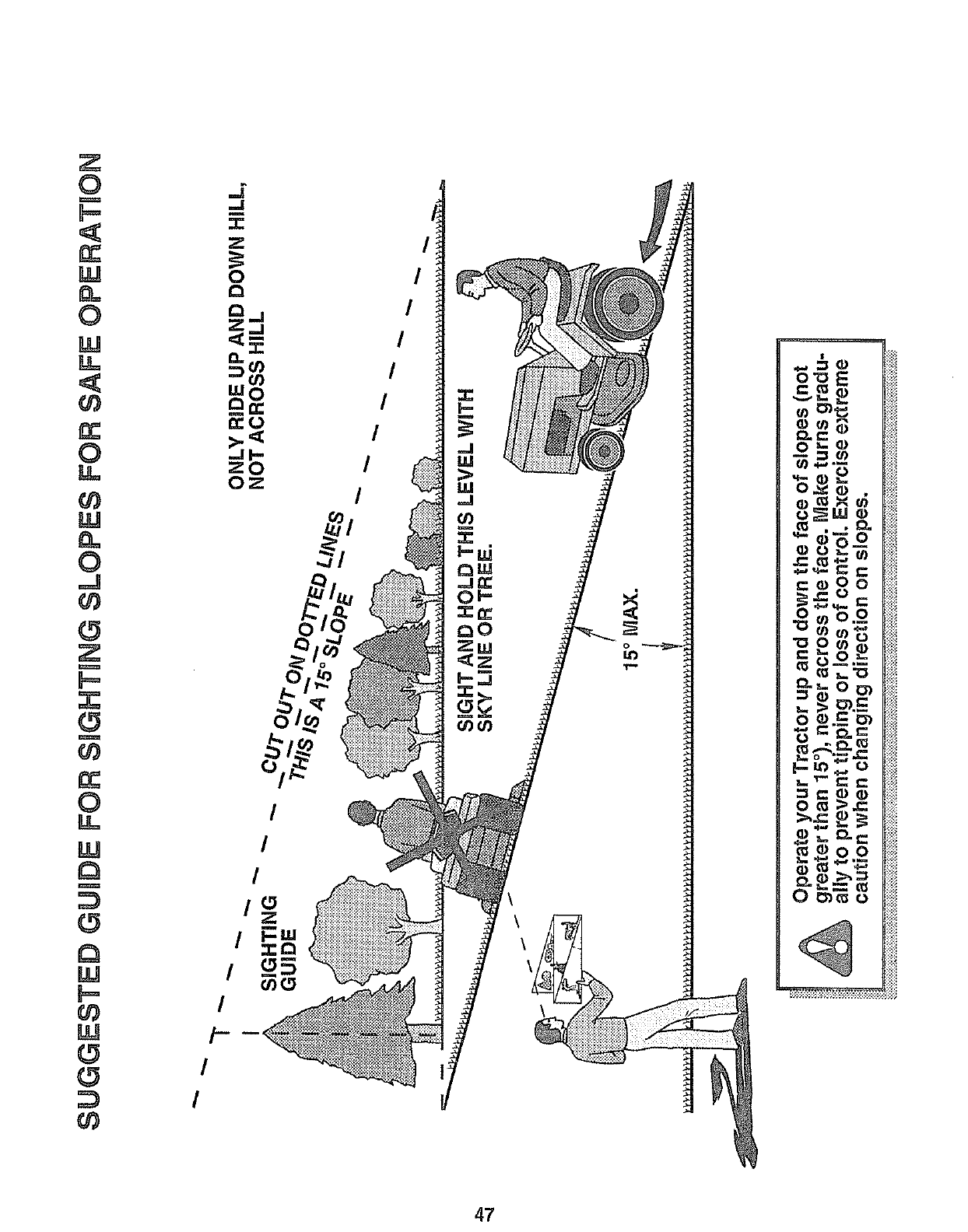
Z
0
b=
W
0
W
Lk
0
LL
U_
0
.J
g_
gO
0
LL
_P
r_
W
U_
...s
"1"
zit
I
I
i-
I
I
o
LO
, !ii!
2 .-_ R_!_
_ _ ..: I_
_ ._ _:_
C: ,_, 0 _- I_:_
o _ .__ _) II_::_
_=_ I_
47
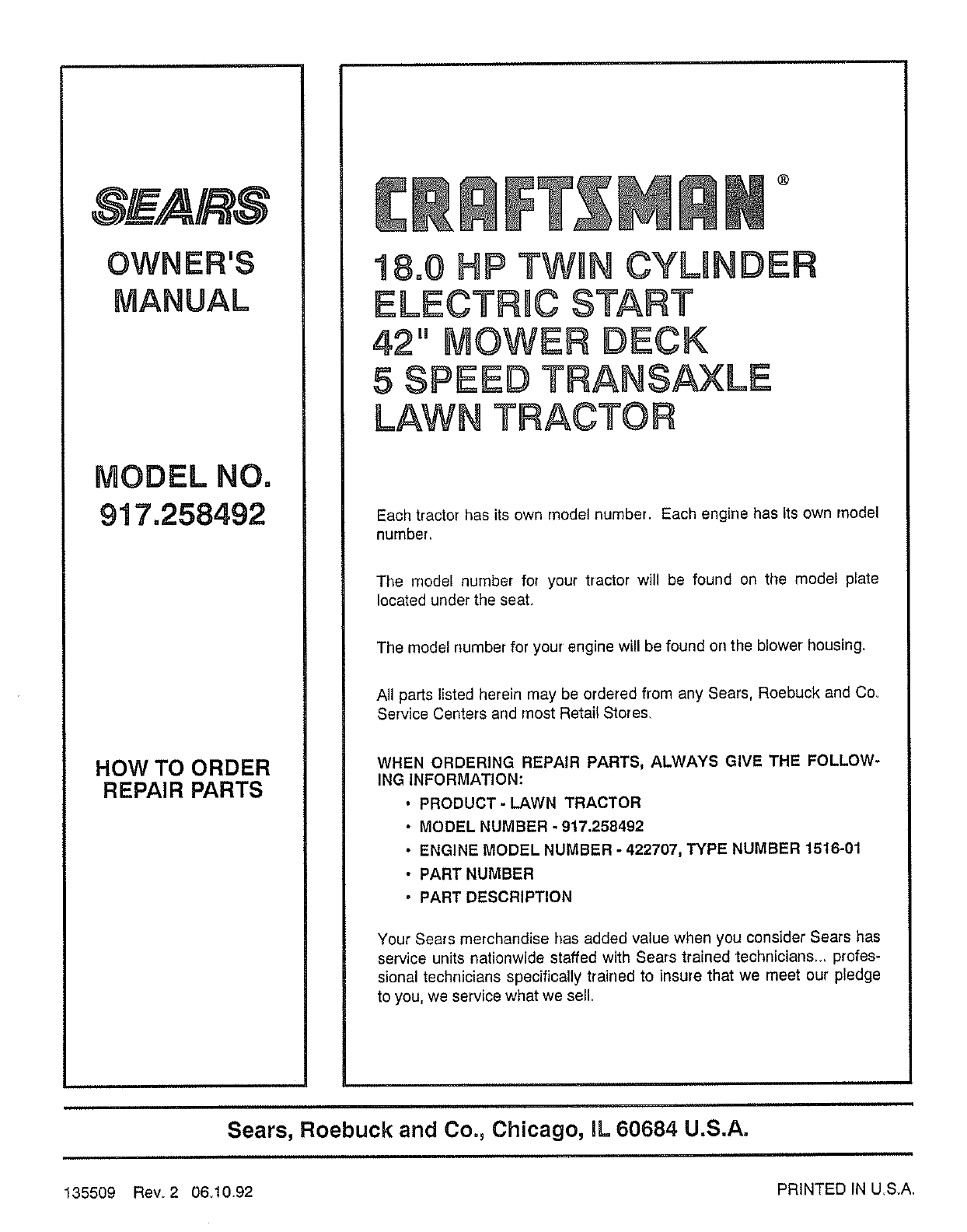
S_ A/k S
OWNER'S
MANUAL
HOW TO ORDER
REPAIR PARTS
®
18=0 P TWHNCYLINDER
ELECTRHC START
42" OWER DECK
5 SPEED TRANS_LE
LAWN TRACTOR
Each tractor has its own model number. Each engine has its own model
number=
The model number for your tractor will be found on the model plate
located under the seat.
The model number for your engine will be found on the blower housing,
All parts listed herein may be ordered from any Sears, Roebuck and Co,
Service Centers and most Retail Stores,
WHEN ORDERING REPAIR PARTS, ALWAYS GIVE THE FOLLOW-
ING INFORMATION:
•PRODUCT- LAWN TRACTOR
• MODEL NUMBER - 917,258492
•ENGINE MODEL NUMBER - 422707, TYPE NUMBER 1516-01
•PART NUMBER
• PART DESCRIPTION
Your Sears merchandise has added value when you consider Sears has
service units nationwide staffed with Sears trained technicians., profes-
sional technicians specifically trained to insure that we meet our pledge
to you, we service what we sell
Sears, Roebuck and Co., Chicago, IL 60684 U.S.A.
PRINTED IN US,A,
135509 Rew 2 06,10.92
