Craftsman 917258580 User Manual Lawn, Tractor Manuals And Guides L0807539
CRAFTSMAN Lawn, Tractor Manual L0807539 CRAFTSMAN Lawn, Tractor Owner's Manual, CRAFTSMAN Lawn, Tractor installation guides
User Manual: Craftsman 917258580 917258580 CRAFTSMAN Lawn, Tractor - Manuals and Guides View the owners manual for your CRAFTSMAN Lawn, Tractor #917258580. Home:Lawn & Garden Parts:Craftsman Parts:Craftsman Lawn, Tractor Manual
Open the PDF directly: View PDF ![]() .
.
Page Count: 60

®
MODEL NUMBER 917.258580 OWNER'SMANUAL
oAssembly
oOperation
oCustomer Responsibilities
oService and Adjustments
oRepair Parts
CAUTION: Read and follow all safety rules and instructions before operating this equipment.
FOR CONSUMER ASSISTANCE HOT LINE, CALL THIS TOLL FREE NUMBER: 1-800-659-5917
SAFETY RULES A
Safe Operation Practices for Ride-On Mowers .,,...,
IMPORTANT: THIS CUTTING MACHINE IS CAPABLE OF AMPUTATING HANDS AND FEET AND THROWING OBJECTS_
FAILURE TO OBSERVE THE FOLLOWING SAFETY INSTRUCTIONS COULD RESULT IN SERIOUS INJURY OR DEATH
LGENERAL OPERATION
Read, understand, and follow all instructions in the manual
and on the machine before starting.
•Only allow responsible adults, who are familiar with the
instructions, to operate the machine.
Clear the area of obects such as rocks, toys, wire, etc.
which could be picked up and thrown by the bade
• Be sure the area is clear of other people before mowing. Stop
machine if anyone enters the area
Never carry passengers.
Do not mow in reverse unless absolutely necessary. Always
look down and behind before and while backing.
• Be aware of the mower discharge direction and do not point
it at anyone Do not operate the mower without either the
entire grass catcher or the guard in place.
• Slow down before turning
• Never leave a running machine unattended. Always turn off
blades, set parking brake, stop engine, and remove keys
before dismounting
• Turn off blades when not mowing
Stop engine before removing grass catcher or unclogging
chute_
• Mow only in daylight or good artificial light
Do not operate the machine while under the influence of
alcohol or drugs.
•Watch for traffic when operating near or crossing roadways.
• Use extra care when loading or unloading the machine into
a trailer or truck
II. SLOPE OPERATION
Slopes are a major factor related to loss-of-control and
tipover accidents, which can result in severe injury or death.
All slopes require extra caution, If you cannot back up the
slope or if you feel uneasy on it, do not mow iL
DO:
Mow up and down slopes, not across.
•Remove obstacles such as rocks, tree limbs, etc.
Watch for holes, ruts, or bumps. Uneven terrain could
overturn the machine. Tall grass can hlde obstacles.
• Use slowspeed Choose a low gear so that you will not have
to stop or shift while on the slope_
• Follow the manufacturer's recommendations for wheel
weights or counterweights to improve stability.
Use extra care with grass catchers or other attachments.
These can change the stability of the machine.
Keep all movement on the slopes slowand gradual Do not
make sudden changes in speed or direction.
• Avoid starting or stopping on a slope. If tires lose traction,
disengage the blades and proceed slowly straight down the
slope.
DO NOT:
•Do not turnon slopes unless necessary, and then, turnslowly
and gradually downhill, if possible
•Do not mow near drop-offs, ditches, or embankments The
mower could suddenly turn over if a wheet is over the edge
of acliff or ditch, or if an edge caves in
Do not mow on wet grass. Reduced traction could cause
sliding
•Do not try to stabilize the machine by putting your foot on the
ground,
•Do not use grass catcher on steep slopes
III. CHILDREN
Tragic accidents can occur ifthe operator is not alert to the
presence of children. Children are often attracted to the
machine and the mowing activity Never assume that
children will remain where you last saw them.
Keep children out of the mowing area and under the watchful
care of another responsible adult
Be alert and turn machine off if children enter the area.
Before and when backing, look behind and down for small
children
Never carry children. They may fall off and be seriously
injured or interfere with safe machine operation.
Never allow children to operate the machine.
• Use extra care when approaching blind corners, shrubs,
trees, or other objects that may obscure vision
IV. SERVICE
Use extra care in handling gasoline and other fuels They are
flammable and vapors are explosive
Use only an approved container
Never remove gas cap or add fuel with the engine
running Al!ow engine to cool before refueling Do not
smoke
Never refuel the machine indoors
Never store the machine or fuel container inside where
there is an open flame, such as a water heater.
Never run a machine inside a closed area
• Keep nuts and bolts, especially blade attachment bolts, tight
and keep equipment in good condition.
Never tamper with safety devices. Check their proper
operation regularly
Keep machine free of grass, leaves, or other debris build-up
Clean oil or fuel spillage. Allow machine to cool before
storing
Stop and inspect the equipment if you strike an object.
Repair, if necessary, before restarting
Never make adjustments or repairs with the engine running.
• Grass catcher components are subject towear, damage, and
deterioration, which could expose moving parts or allow
objects to be thrown. Frequently check components and
replace with manufacturer's recommended pads, when nec-
essary
Mower blades are sharp and can cut Wrap the blade(s) or
wear gloves, and use extra caution when servicing them.
• Check brake operation frequently. Adjust and service as
required.
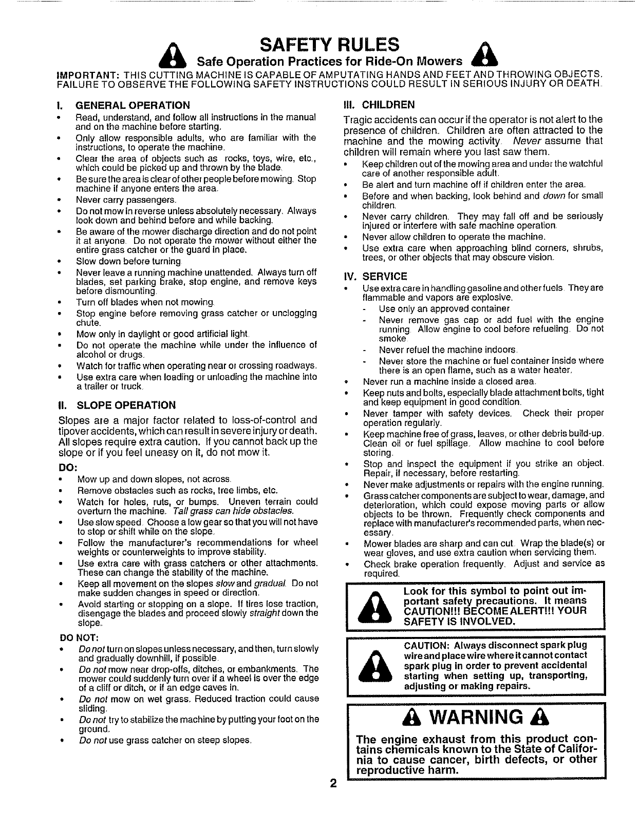
Look for this symbol to point out im-
portant safety precautions. It means I
CAUTION!!! BECOME ALERTt!! YOUR
SAFETY IS INVOLVED. ,,
CAUTION: Always disconnect sparkplug ._
wire and place wire where it cannot contact I
spark plug in order to prevent accidental
starting when setting up, transporting,
adjusting or' making repairs°
2
A WARNING A
The engine exhaust from this product con-
tains chemicals known to the State of Califor-
nia to cause cancer, birth defects, or other
reproductive harm.
CONGRATULA'flONS on your purchase of a Sears
Tractor, It has been designed, engineered and manufac-
tured to give you the best possible dependability and
performance.
Should you experience any problem you cannot easily
remedy, please contact your nearest Sears Authorized
Service CentedDepartment We have competent, weIF
trained technicians and the proper tools to service or repair
this tractor,
Please read and retain this manual The instructions wil!
enable you to assemble and maintain your tractor properly_
Always observe the "SAFETY RULES'L
MODEL
NUMBER 917_258580
SERIAL
NUMBER
DATE OF PURCHASE
THE MODEL AND SERIAL NUMBERS WILL BE FOUND
ON A PLATE UNDER THE SEAT
YOU SHOULD RECORD BOTH SERIAL NUMBER AND
DATE OF PURCHASE AND KEEP IN A SAFE PLACE
FOR FUTURE REFERENCE,
MAINTENANCE AGREEMENT
PRODUCT SPEC|F CATIONS
HORSEPOWER: 16.0
GASOLINE CAPACITY 3.5 GALLONS
AND TYPE: UNLEADED REGULAR
OIL TYPE (API-SF/SG): SAE 10W30 (above 32°F
SAE 5W-30 (be ow 32°F)
OIL CAPACITY: W/FILTER: 4_0 PINTS
W/O FILTER: 3.5 PINTS
SPARK PLUG: CHAMPION RC12YC
(GAP: .040")
VALVE CLEARANCE: NOT ADJUSTABLE
GROUND SPEED (MPH): FORWARD:
1st 11
2nd 1_5
3rd 2.3
4th 3 5
5th 4 4
6th 5.7
REVERSE: 1.7
! TIRE PRESSURE: FRONT: 14 PSI
REAR: 10 PSi
CHARGING SYSTEM: 15 AMPS @ 3600 RPM
BATTERY: AMP/HR: 30
MIN. CCA: 240
CASE SIZE: U1R
BLADE BOLT TORQUE; 30-35 FT LBS
A Sears Maintenance Agreement is available on this prod-
uct. Contact your nearest Sears store for details.
CUSTOMER RESPONSVBBLaTmES
, Read and observe the safety rules.
Followa regularschedulein maintaining, caringforand
using your tractor.
Follow the instructions under "Customer Responsibili-
ties" and "Storage" sections of this owner's manual
WARNING: This tractor is equipped with an internal
combustion engine and should not be used on or near any
unimproved forest-covered, brush-covered or grass-cov-
ered land unless the engine's exhaust system is equipped
with a spark arrester meeting applicable local or state laws
(if any)_ If a spark arrester is used, it should be maintained
in effective working order by the operator
In the state of California the above is required by law
(Section 4442 of the California Public Resources Code)
Other states may have similar laws Federal laws apply on
federal lands, A spark arrester for the muffler is available
through your nearest Sears Authorized Service Center/
Department (See REPAIR PARTS section of this manual)
L MITED TWO YEAR WARRANTY ON CRAFTSMAN RIDING EQUIPS/lENT
For two (2) years from the date of purchase, if this Craftsman Riding Equipment is maintained, lubricated and tuned up according to
the instructions in the owner's manual. Sears will repair or replace, free of charge, any parts found to be defective in material or
workmanship
This Warranty does not cover:
Expendable items which become worn during normal use, such as blades, spark plugs, air cleaners, belts, etc
Tire replacement or repair caused by punctures from outside objects, such as nails, thorns, stumps, or glass
• Repairs necessary because of operator abuse, negligence, improper storage or accident or the failure to maintain the
equipment according to the instructions contained in the owner's manual
Riding equipment used for commercial or renta} purposes
LHMBTED90 DAY WARRANTY ON BATTERY
For ninety (90) days from date of purchase, if any battery included with this riding equipment proves defective in material or
workmanship and our testing determines the battery will not hold a charge, Sears will replace the battery at no charge
IN-HOME WARRANTY SERVICE ON YOUR CRAFTSMAN RIDING EQUIPMENT IS AVAILABLE AT NO-CHARGE FOR 30 DAYS
FROM THE DATE OF PURCHASE PLEASE CONTACT YOUR NEAREST SERVICE CENTER. AFTER 30 DAYS FROM THE
DATE OF PURCHASE, WARRANTY SERVICE IS AVAILABLE BY TAKING YOUR CRAFTSMAN RIDING EQUIPMENT TO YOUR
NEAREST SEARS SERVICE CENTER, (IN-HOME WARRANTY SERVICE WILL STILL BE AVAILABLE AFTER 30 DAYS FROM
THE DATE OF PURCHASE BUT A STANDARD TRIP CHARGE WILL APPLY) THIS WARRANTY APPLIES ONLY WHILE THIS
PRODUCT IS IN THE UNITED STATES
This Warranty gives you specific legal rights, and you may also have other rights which may vary from state to state,
SEARS, ROEBUCK AND CO, D/817 WA, HOFFMAN ESTATES, IL 60179
3
"FABLE OF CONTENTS
SAFETY RULES ............................................................ 2
PRODUCT SPECIFICATIONS ...................................... 3
CUSTOMER RESPONSIBILITIES ..................... 3, 15-19
WARRANTY .................................................................. 3
TRACTOR ACCESSORIES .......................................... 5
ASSEMBLY ................................................................ 7-9
OPERATION ........................................................... 10-14
MAINTENANCE SCHEDULE ...................................... 15
SERVICE AND ADJUSTMENTS ............................ 20-25
STORAGE ................................................................... 26
TROUBLESHOOTING ............................................ 27-28
REPAIR PARTS - TRACTOR ................................. 30-47
REPAIR PARTS- ENGINE .................................... 48-53
iNDEX
A
Accessories .............................................. 5
Adjustments:
Brake .............................................. 22
Carburetor ................................t._.._25
Mower:
Front-To-Back .............................21
Side-To-Side .......................... 21
Throttle Control Cable .....................24
Air Filter, Engine ................................... 18
Air Screen, Engine ..................................18
Assembly ..................................................7-9
B
Battery:
Charging .................................. 8
Cleaning ......................................... 17
StaRing with Weak Battery ......... 23
Storage ...............................................26
Terminals ..........................................17
Belts:
Motion Drive
Removal/Replacement .......... 22
Mower Blade Drive
Removal/Replacement .............22
Blade:
Sharpening ................................... 16
Replacement .................................. 16
Brake Adjustment ..........:........ :...............22
c
Carburetor Adjustment ....................... 25
Controls, Tractor .......................................11
Customer Responsibilities ...............15-19
Engine:
Air Filter .................................... 18
Air Screen, Engine .................. 18
Battery ......................................... 17
Cooling Fins, Engine ................ 18
Engine Oil ................................ 17
Fuel Filter .................................. 19
Spark Plugs ............................. 19
Tractor:
Blades ....................................... 16
Lubrication Chart ..................... 15
Maintenance Schedule ........... 16
Tire Dare .......................... 9,16,23
Cutting Height, Mower ............................12
E
Electrical:
Interlocks and Relays ................. 24
Schematic ...................................... 29
Wiring Diagram .............................. 30
Engine:
Air Filter ................................ 18
Air Screen ................................... 18
Cooling Fins, Engine ................. 18
Oil Change ................................ 17
Oil Level .................................... 13,17
Oil Type ......................................... 17
Preparation ................................ 13
Repair Parts ............................ 48-53
StaRing .......................................... 14
Storage ..................................... 26
F
Filters:
Air .................................................. 18
Fuel ........................................ 19
Fuel:
Type ............................................ 13
Storage ....................................... 26
Fuse ................................................ 24
G
Gauge Wheels ....................................... 9
H
Hood Removal/Installation ................ 24
L
Leveling Mower Deck ................... 21
Lubrication Char ............................... 15
M
Maintenance Schedule ......................... 15
Mower:
Adjustment, Front-to-Back ......... 21
Adjustment, Side-to-Side ............. 21
Blade Sharpening ........................ 16
Blade Replacement ........................ 16
Cutting Height ............................. 12
Installation .........;........................ 20
Operation ........................................ t 3
Removal .......................................... 20
Mowing Tips ......................................... 14
Muffler .................................................. 19
Spark Attester ............................. 3,40
Mulcher Plate ........................................ 9
o
Oil:
Cold Weather Corrditions .........13,17
Engine ........................................... 17
Storage ...................................... 26
Operation .......................... 10-14
Operating Mower ....................... 13
Options:
Accessories ..................................... 5
Spark Arrester ........................... 3,40
P
Parking Brake .................................. 11-12
PaRs Bag .......................................... 6
PaRs, Replacement/Repair ........... 30-47
Product Specifications .......................... 3
R
Repair Parts ............................ 30-47
S
Safety Rules .............................. 2
Seat ................................................... 8
Service and Adjustments ......... 20-25
Brake ...................................... 22
Carburetor .................................... 25
Fuse ....................................................24
Hood Removal/Installation .......... 24
Motion Drive Belt
Remova!/Replacement ...............22
Mower Blade Drive Belt
Removal/Replacement .......... 22
Mower Adjustment:
Front-to-Back ................... 21
Side-to-Side ...................... 21
Mower Installation ........................ 20
Mower Removal ............................ 20
Tire Care ........................... 9,16,23
Slope Guide Sheet ............................... 55
Spark Plugs ............................................ 19
Specifications .......................................... 3
StaRing the Engine ............................13-14
Steering Wheel ............................... 7,23
Stopping the Tractor ......................... 12
Storage ............................................. 26
T
Throttle Control Cable Adjustment ,, 24
Tires ............................ 9,16,23
Trouble Shooting Chart ....................27-28
Transaxle Repair Parts ................... 46-47
W
Warranty .................................................. 3
Wiring Diagram .................................... 30
Wiring Schematic .............................. 29
4
AOOEIIORIII AI Q AWWAOHMIENTS
These accessories and attachments were avalab]e through most Sears retail outlets and service centers when the tractor was purchased
Most Sears stores can order these items for you when you provide the model number of your tractor
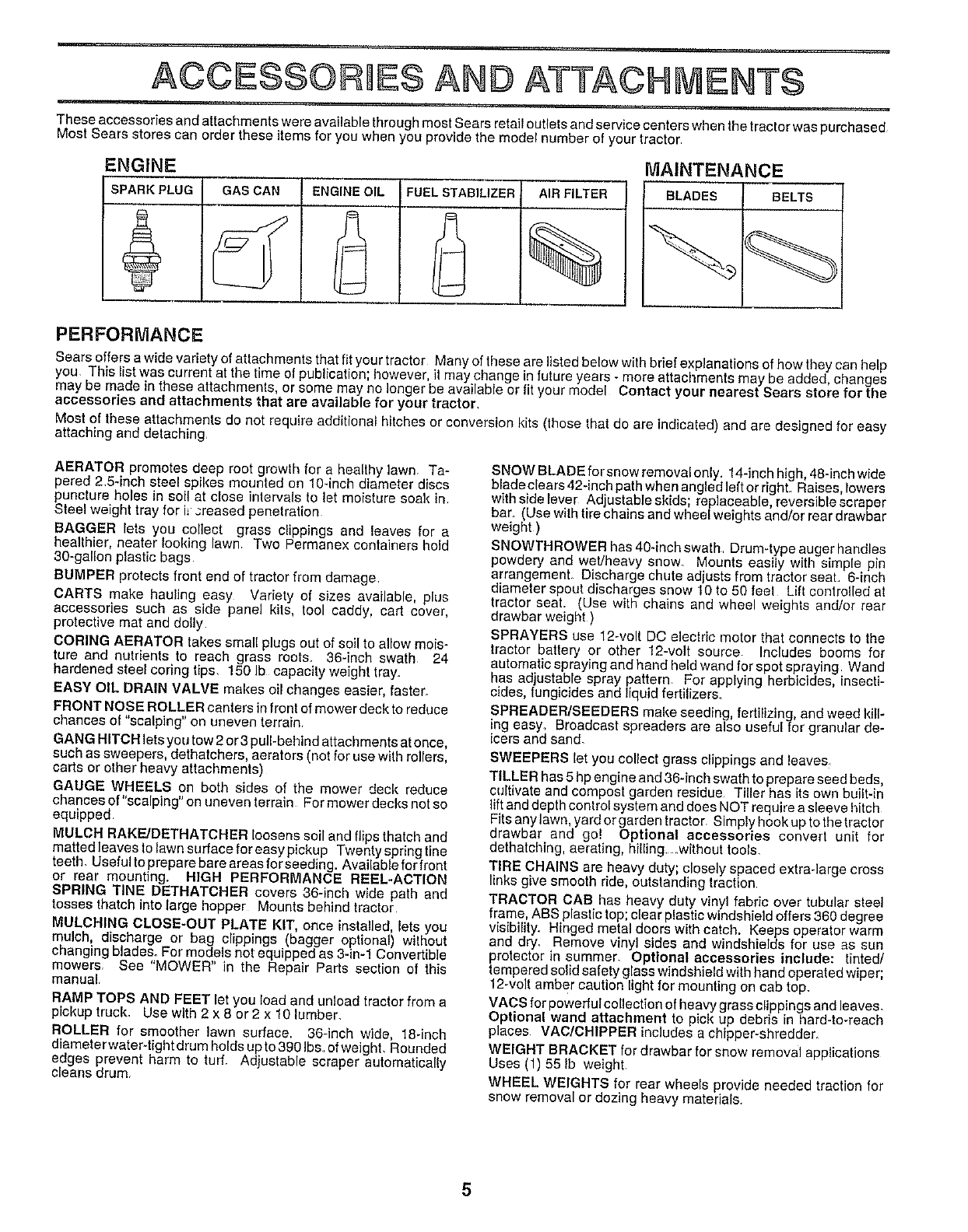
ENGINE MAINTENANCE
SPARK PLUG GAS CAN ENGINE OIL FUEL STABILIZER AIR FILTER BLADES BELTS
PERFORMANCE
Sears offers a wide variety of attachments that fit your tractor Many of these are fsted below with brief explanations of how they can help
you This list was ct,rrent at the time of publication; however, it may change in future years - more attachments may be added, changes
may be made in these attachments, or some may no longer be avatable or fit your model Contact your nearest Sears store for the
accessories and attachments that are available for your tractor,
Most of these attachments do not require additional hitches or conversion kits (those that do are indicated) and are designed for easy
attaching and detaching
AERATOR promotes deep root growth for a healthy ]awn. Ta-
pered 2,5Anch steel spikes mounted on 10Anch diameter discs
puncture holes in soil at close intervals to let moisture soak in
Steel weight tray for i_._reased penetration
BAGGER lets you collect grass clippings and leaves for a
healthier, nearer looking lawn. Two Permanex containers hold
30-galon plastic bags
BUMPER protects front end of tractor from damage
CARTS make haulng easy Variety of sizes available, plus
accessories such as side panel kits, tool caddy, cad cover,
protective mat and doly
CORING AERATOR takes small plugs out of soil to alow mois-
ture and nutrients to reach grass roots. 36-inch swath 24
hardened steel coring tips. 150 Ib capacity weight tray.
EASY OIL DRAIN VALVE makes ol changes easier, faster.
FRONT NOSE ROLLER canters in front of mower deck to reduce
chances of "scalping" on uneven terrain
GANG HITCH lets you tow 2 or 3 pall-behind attachments at once,
such as sweepers, dethatcbers, aerators (not for use with rollers,
carts or other heavy attachments)
GAUGE WHEELS on both sides of the mower deck reduce
chances ot"scalplng" onuneven terrain For mower decks not so
equipped
MULCH RAKE/DETHATCHER loosens soil and flips thatch and
matted leaves to lawn surface for easy pickup Twenty spring line
teeth. Useful to prepare bare areasfor seeding. Available Ior front
or rear mounting. HIGH PERFORMANCE REEL-ACTION
SPRING TINE DETHATCHER covers 36-inch wide path and
tosses thatch into large hopper Mounts behind tractor
MULCHING CLOSE-OUT PLATE KIT, once installed, lets you
mulch, discharge or bag clippings (bagger optional) without
changing blades. For models not equipped as 3An-1 Convedible
mowers, See "MOWER" in the Repair Parts section of this
manual,
RAMP TOPS AND FEET let you load and unload tractor from a
pickup truck. Use with 2 x 8 or 2 x 10 lumber.
ROLLER for smoother _awn surface. 36-inch wide, 18qnch
diameterwater-tight drum holds up to 390 Ibs of weight, Rounded
edges prevent harm to turf. Adjustable scraper automatically
cleans drum.
SNOW BLADE for snow removal only. 14-inch high, 48-inch wide
blade clears 42Anch path when angled left or right Raises, lowers
with side lever Ad ustable skids; replaceable, reversible scraper
bar (Use with t re cha ns and wheel weights and/or rear drawbar
weight)
SNOWTHROWER has 40-inch swath DrumAype auger handles
powdery and wet/heavy snow. Mounts easily with simple pin
arrangemenL Discharge chute adjusts from tractor seal 6-inch
diameter spout discharges snow 10 to 50 feet Lift controled at
tractor seat. (Use with chains and wheel weights and/or rear
drawbar weight )
SPRAYERS use 12-vol DO electric motor that connects to the
tractor battery or other 12-volt source Includes booms for
automatic spraying and hand held wand for spot spraying Wand
has adjustable spray pattern For applying herbicides, insecti-
cides, tung:tides and Iquid fertilizers
SPREADER/SEEDERS make seeding, fedilzing, and weed kill-
ing easy. Broadcast spreaders are also useful for granular de-
icers and sand.
SWEEPERS let you collect grass clippings and leaves
TILLER has 5 hp engine and 36-inch swath to prepare seed beds,
culivate and compost garden residue Tiller has its own built-in
lift and depth control system and does NOT require a sleeve hitch
Fits any lawn, yard or garden tractor Simply hook up to the tractor
drawbar and go! Optional accessories convert unit for
dethatching, aerating, hilling .without tools,
TIRE CHAINS are heavy duty; closely spaced extra-large cross
links give smooth ride, outstanding traction
TRACTOR CAB has heavy duty vinyl fabric over tubular sloe!
frame, ABS plastic top; clear plastic windshield offers 360 degree
visibiity. Hinged metal doors with catch. Keeps operator warm
and dry, Remove vinyl sides and windsMelds for use as sun
protector in summer. Optional accessories include: tinted/
tempered solid safety glass windshield with hand operated wiper;
12-volt amber caution Ight for mounting on cab top.
VACS for powerful collection of heavy grass clippings and leaves.
Optional wand attachment to pick up debris in hard-to-reach
places VAC/CHIPPER includes a chipper-shredder.
WEIGHT BRACKET for drawbar for snow removal applications
Uses (1) 55 Ib weight.
WHEEL WEIGHTS for rear wheels provide needed traction for
snow removal or dozing heavy materials
5
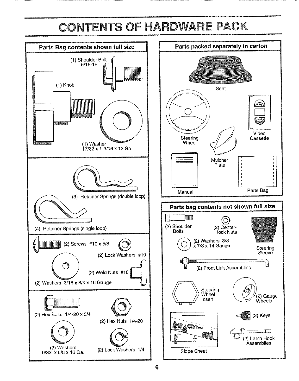
CONTENTS OF HARDWARE PACK
Parts packed separately in carton
Parts Bag contents shown full size
(1) Shoulder Bolt
5/16-18
:
J
(1) Knob
(1) Washer
17/32 x 1-3/16 x 12 Ga,
tailner Springs (double loop)
(4) Retainer Springs (single loop)
_(2)Screws #10x5/8
(2) Lock Washers #10
°@
(2) Weld Nuts #10
(2) Washers 3/16 x 3/4 x 16 Gauge
(2) Hex Bolts 114=20x 3/4
@
(2) Washers
9/32 x 5/8 x 16 Ga.
@
(2) Hex Nuts 1/4-20
(2) Lock Washers 1/4
Steering
Wheel
Seat
Mulcher ,
Plate i
CB
Video
Cassette
Manual Parts Bag
Parts bag contents not shown full size
©
(2) Shoulder' (2) Center-
Bolts lock Nuts
(_(2) Washers 3/6
x 7/8 x 14 Gauge Steering
Sleeve
_(2) Front Link Assemblies
_ teering
Wheel
Insert Gauge
Slope Sheet
(2) Keys
Assemblies
6
ASSEMBLY
Your new tractor has been assembled at the factory with exception of those parts left unassembled for shipping purposes.
To ensure safe and proper operation of your tractor all parts and hardware you assemble must be tightened securely, Use
the correct tools as necessary to insure proper tightness.
TOOLS REQUmRED FOR ASSEMBLY
A socket wrench set will make assembly easier. Standard
wrench sizes are liste&
(2) 7/16" wrenches
(1) 1/2" wrench
(1) 9/16" wrench
(1) 3/4" wrench
Pliers
When right or left hand is mentioned in this manual, it
means when you are in the operating position (seated
behind the steering wheel).
3/4" Socket w/drive ratchet
Tire pressure gauge
Phillips Screwdriver
Utility knife
TO REMOVE TRACTOR FROM CARTON
UNPACK CARTON
°Remove all acce:_sible loose parts and parts cartons
from carton (See page 6).
o Cut, from top to bottom, along lines on all four corners
of carton, and lay panels flat.
Remove mower and packing materia_s_
o Check for any additional loose parts or cartons and
remove,
BEFORE ROLUNG TRACTOR OFF SKUD
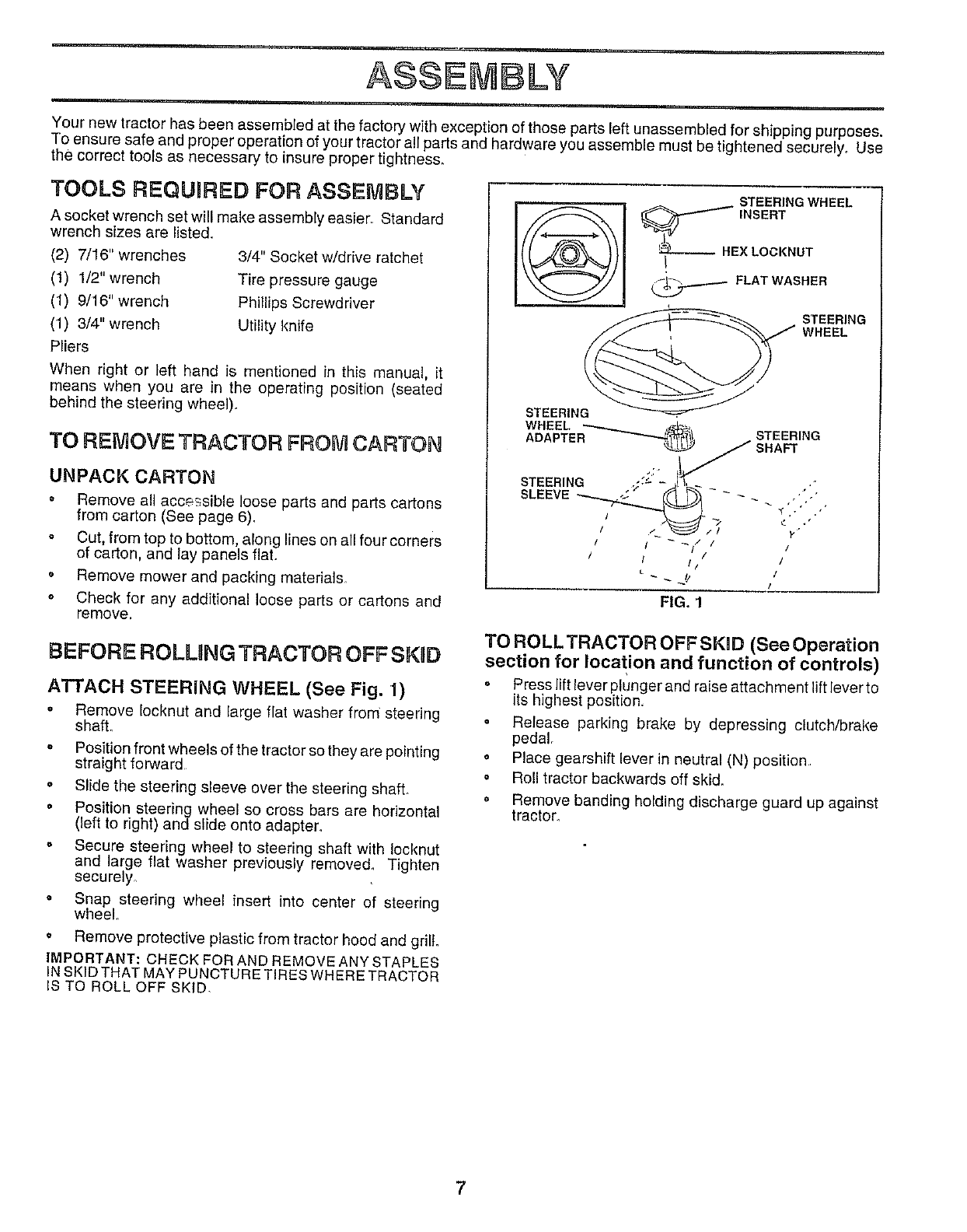
ATTACH STEERING WHEEL (See Fig. 1)
o Remove tocknut and large fiat washer from steering
shafL
° Position front wheels of the tractor so they are pointing
straight forward
o Slide the steering sleeve over the steering shaft.
• Position steering wheel so cross bars are horizontal
(left to right) and slide onto adapter.
° Secure steering wheel to steering shaft with Iocknut
and large flat washer previously remove& Tighten
securely_
• Snap steering wheel insert into center of steering
wheel
oRemove protective plastic from tractor hood and grill.
IMPORTANT: CHECK FOR AND REMOVE ANY STAPLES
_NSKiD THAT MAY PUNCTURE TIRES WHERE TRACTOR
IS TO ROLL OFF SKID.
STEERING WHEEL
_HEX LOONNUT
_FLAT WASHER
STEERING
WHEEL
STEERING
WHEEL
ADAPTER STEERING
;:' 1_3_ SHAFT
STEERING _:- -._ - ,'"
SLEEVE -- .'/,
/ / // /
/ I // /
FIG. 1
TO ROLLTRACTOR OFF SKOD (See Operation
section for location and function of controls)
o Press lift lever plunger and raise attachment lift lever to
its highest position,
o Release parking brake by depressing clutch/brake
pedal,
o Place gearshift lever in neutra_ (N) position
o Roll tractor backwards off skid.
o Remove banding holding discharge guard up against
tractor,
7
ASSEMBLY
ii
CONNECT BATTERY (See Fig. 2)
ACAUTION: Do not short battery termi-
nals. Before connecting battery, re-
move metal bracelets, wristwatch
bands, rings, etc.
Positive terminal must be connected
first to prevent sparking from acciden-
tal grounding.
• Lift hood to raised position.
•Open terminal access doors, remove terminal pretec_
tive caps and discard.
• If this battery is put into service after month and year'
indicated on label ({abe{ located between terminals)
charge battery for minimum of one hour at 6-10 amps.
•First connect RED battery cable to positive (+) battery
terminal with hex bolt, flat washer, lock washer and hex
nut as shown, Tighten securely.
•Connect BLACK grounding cable to negative (-) bat-
tery terminal with remaining flex bolt, flat washer, lock
washer and hex nut. Tighten securely.,
• Close terminal access doors.
Use terminal access doors for:
• Inspection for secure connections (to tighten hard-
ware).
• Inspection for corrosion_
•Testing battery_
• Jumping (if required).
°Periodic charging_
HEX NUT
DISCARD TERMINAL
PROTECTIVE CAPS
LOCK FLAT
WASHER WASHER
HEX
BOLT
POSITIVE
(RED)
CABLE
NEGATIVE
{BLACK)
CABLE
FIG. 2
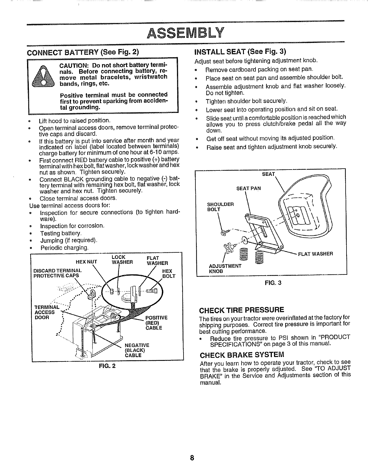
INSTALL SEAT (See Fig. 3)
Adjust seat before tightening adjustment knob°
o Remove cardboard packing on seat pan_
= Place seat on seat pan and assemble shoulder bolt.
• Assemble adjustment knob and flat washer loosely.
Do not tighten_
° Tighten shoulder bolt securely,
.Lower seat into operating position and sit on seat.
• Slide seat until a comfortable position is reached which
allows you to press clutch/brake pedal all the way
down.
= Get off seat without moving its adjusted position.
•Raise seat and tighten adjustment knob securely_
SEAT
ADJUSTMENT
KNOB
FIG, 3
CHECK TIRE PRESSURE
The tires on your tractor were overinflated at the factory for
shipping purposes_ Correct tire pressure is important for
best cutting perforrnanceo
° Reduce tire pressure to PSI shown in "PRODUCT
SPECIFICATIONS" or] page 3 of this manual.
CHECK BRAKE SYSTEM
After you learn how to operate your tractor, check to see
that the brake is properly adjusted. See 'qO ADJUST
BRAKE" in the Service and Adjustments section of this
manual.
8
ASSEMBLY
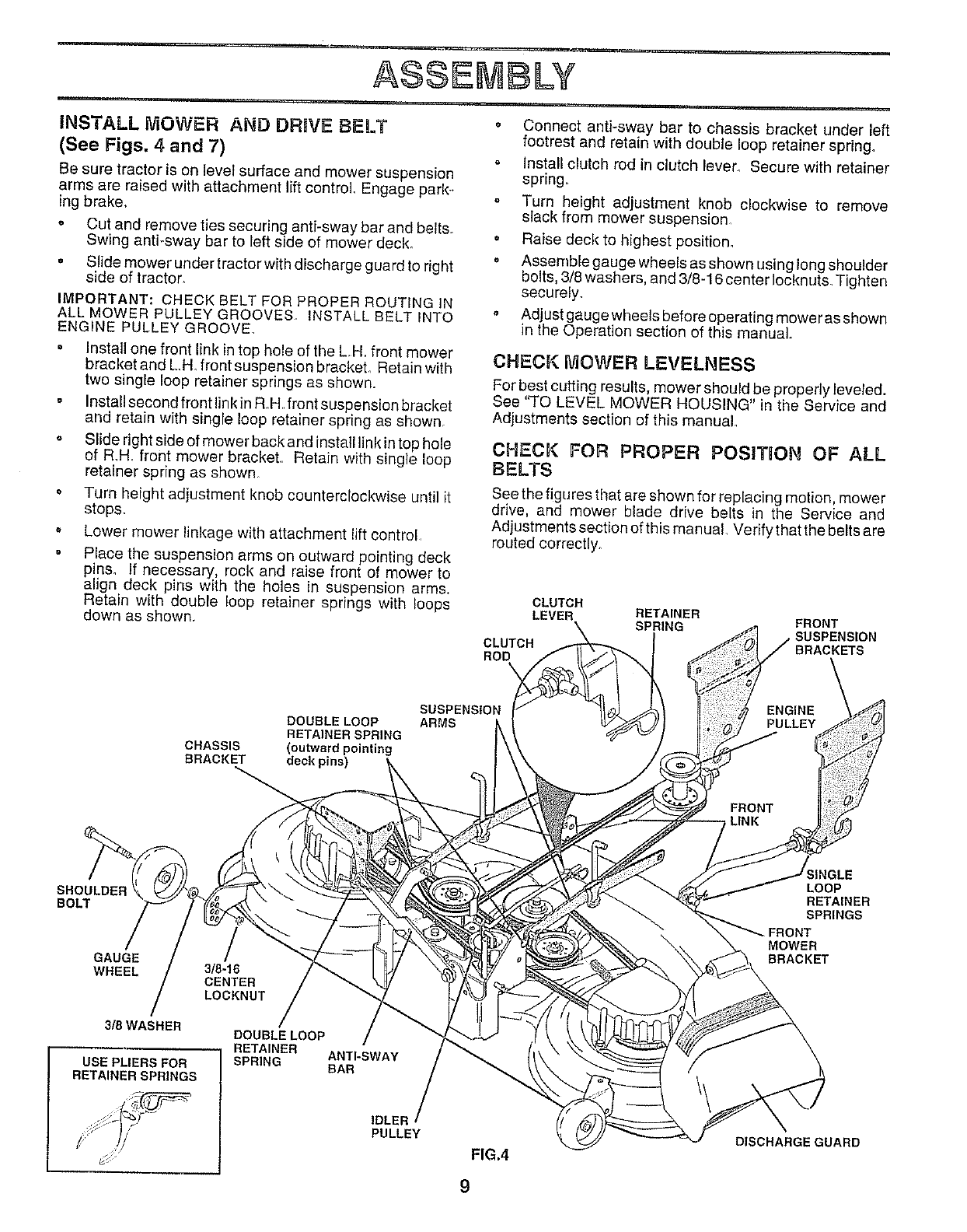
INSTALL MOWER AND DRIVE BELT
(See Figs. 4 and 7)
Be sure tractor is on level surface and mower suspension
arms are raised with attachment lift control Engage park-
ing brake,
o Cut and remove ties securing anti-sway bar and beits.
Swing anti-sway bar to left side of mower deck.
, Slide mower under tractor with discharge guard to right
side of tractor.
IMPORTANT: CHECK BELT FOR PROPER ROUTING IN
ALL MOWER PULLEY GROOVES. INSTALL BELTtNTO
ENGINE PULLEY GROOVE
*Install one front link in top hole of the LH, front mower
bracket and L.H. front suspension brackeL Retain with
two single loop retainer springs as shown.
. Instat1second front linkin R.H front suspension bracket
and retain with single loop retainer spring as shown.
° Slide right side of mower back and install link intop hole
of R_H, front mower bracket, Retain with single loop
retainer spring as shown
° Turn height adjustment knob counterclockwise until it
stops.
.Lower mower linkage with attachment lift control
Place the suspension arms on outward pointing deck
pin& If necessary, rock and raise front of mower to
align deck pins with the holes in suspension arms,
Retain with double loop retainer springs with loops
down as shown,
• Connect anti-sway bar to chassis bracket under left
footrest and retain with double loop retainer spring.
o Install clutch rod in clutch lever. Secure with retainer
spring.
Turn height adjustment knob clockwise to remove
slack from mower suspension.
° Raise deck to highest position.
o Assemble gauge wheels as shown using long shoulder
bolts, 3/8 washers, and 3/8-16 center Iocknuts. Tighten
securely.
Adjust gauge wheels before operating mower as shown
in the Operation section of this manual
CHECK IVIOWER LEVELNESS
For best cutting results, mower should be properly leveled.
See 'q'O LEVEL MOWER HOUSING" in the Service and
Adjustments section of this manual.
CHECK FOR PROPER POSITION OF ALL
BELTS
See the figures that are shown for reptacing motion, mower
drive, and mower blade drive belts in the Service and
Adjustments section of this man uaL Verify that the belts are
routed correctly.
CLUTCH
LEVER
CLUTCH
ROD
RETAINER
SPRING FRONT
SUSPENSION
BRACKETS
DOUBLE LOOP
RETAINER SPRING
CHASSIS (outward pointing
BRACKET deck pins)
SUSPENSION
ARMS
SHOULDER
BOLT
GAUGE
WHEEL
3/8WASHER
USE PL|ERSFOR
RETAINER SPRINGS
3/8-16
CENTER
LOCKNUT
DOUBLE LOOP
RETAINER ANTI-SWAY
SPR_NG BAR
_INGLE
LOOP
RETAINER
SPRINGS
MOWER
BRACKET
IDLER
PULLEY
FIG.4
9
DISCHARGEGUARD
ASSEMBLY
v _..__.__ DEFLECTOR
SHIELD
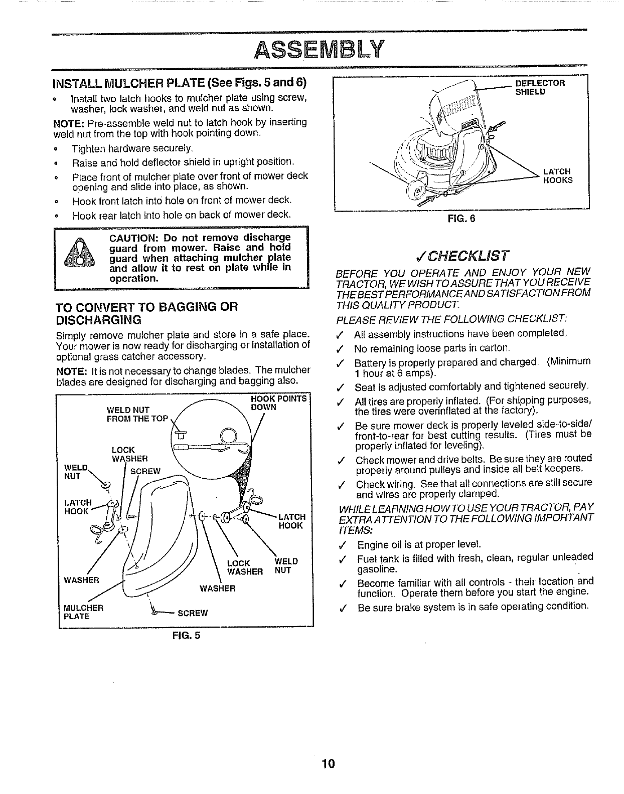
INSTALL IVlULCHER PLATE (See Figs. 5 and 6)
o Install two latch hooks to muicher plate using screw,
washer, lock washer, and weld nut as shown.
NOTE: Pre-assemble weld nut to latch hook by inserting
weld nut from the top with hook pointing down.
oTighten hardware securely.
o Raise and hold deflector shield in upright position.
° Place front of rnulchet plate over front of mower deck
opening and slide into place, as shown
. Hook front latch into hole on front of mower deck_
o Hook rear latch into hole on back of mower deck.
CAUTION: Do not remove discharge
guard from mower. Raise and hold
guard when attaching mulcher plate
and allow it to rest on plate while in
operation.
TO CONVERT TO BAGGING OR
DISCHARGING
Simply remove mulcher plate and store in a safe place,
Your mower is now ready for discharging or installation of
optional grass catcher accessory,,
NOTE: It is not necessary to change blades. The rrlulcher
blades are designed for discharging and bagging also_
WELD NUT
FROM THE TOP
HOOK POINTS
DOWN
LOCI(
WASHER
WELD
NUT _ SCREW
LATCH
HOOK
WASHER
MULCHER
PLATE
LOCK
WASHER
WASHER
_--SCREW
WELD
NUT
FIG. 5
LATCH
HOOKS
FIG. 6
,7 CHECKLIST
BEFORE YOU OPERATE AND ENJOY YOUR NEW
TRACTOR, WE WISH TO ASSURE THA T YOU RECEIVE
THE BEST PERFORMANCE AND SA TISFACTION FROM
THIS QUALITY PRODUCT.
PLEASE REVIEW THE FOLLOWING CHECKLIST:
/All assembly instructions have been completed_
,/ No remaining loose parts in carton.
,/ Battery is properly prepared and charged, (Minimum
1 hour at 6 amps).
,/ Seat is adjusted comfortably and tightened securely_
/All tires are properly inflated. (For shipping purposes,
the tires were ovennflated at the factory).
,/ Be sure mower deck is properly leveled side-to-side/
front-to-rear for best cutting results_ (Tires must be
properly inflated for leveling).
€" Checkmoweranddrivebelts. Besuretheyarerouted
properly around pulleys and inside all belt keepers_
/Check wiring_ See that all connections are still secure
and wires are properly clamped,
WHILE LEARNING HOW TO USE YOUR TRACTOR, PAY
EXTRA A TTENTION TO THE FOLLOWING IMPORTANT
ITEMS:
,/ Engine oil is at proper level.
,/ Fuel tank is filled with fresh, clean, regular unleaded
gasoline.
,/ Become familiar with all controls - their location and
function, Operate them before you start the engine.
,/ Be sure brake system is in safe operating condition.
10
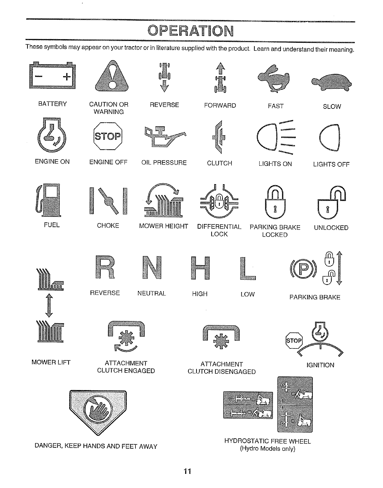
OPSRATION
These symbols may appear on your tractor or in literature supplied with the product. Learn and understand their meaning.
FORWARD
BATTERY CAUTION OR REVERSE FAST SLOW
WARNING
ENGINE ON ENGINE OFF OIL PRESSURE CLUTCH LIGHTS ON LIGHTS OFF
FUEL CHOKE MOWER HEIGHT DIFFERENTIAL PARKING BRAKE UNLOCKED
LOCK LOCKED
MOWER LIFT
REVERSE NEUTRAL HIGH LOW
ATTACHMENT
CLUTCH ENGAGED
ATTACHMENT
CLUTCH DISENGAGED
®SI
PARKING BRAKE
IGNITION
DANGER, KEEP HANDS AND FEET AWAY HYDROSTATIC FREE WHEEL
(Hydro Models only)
11
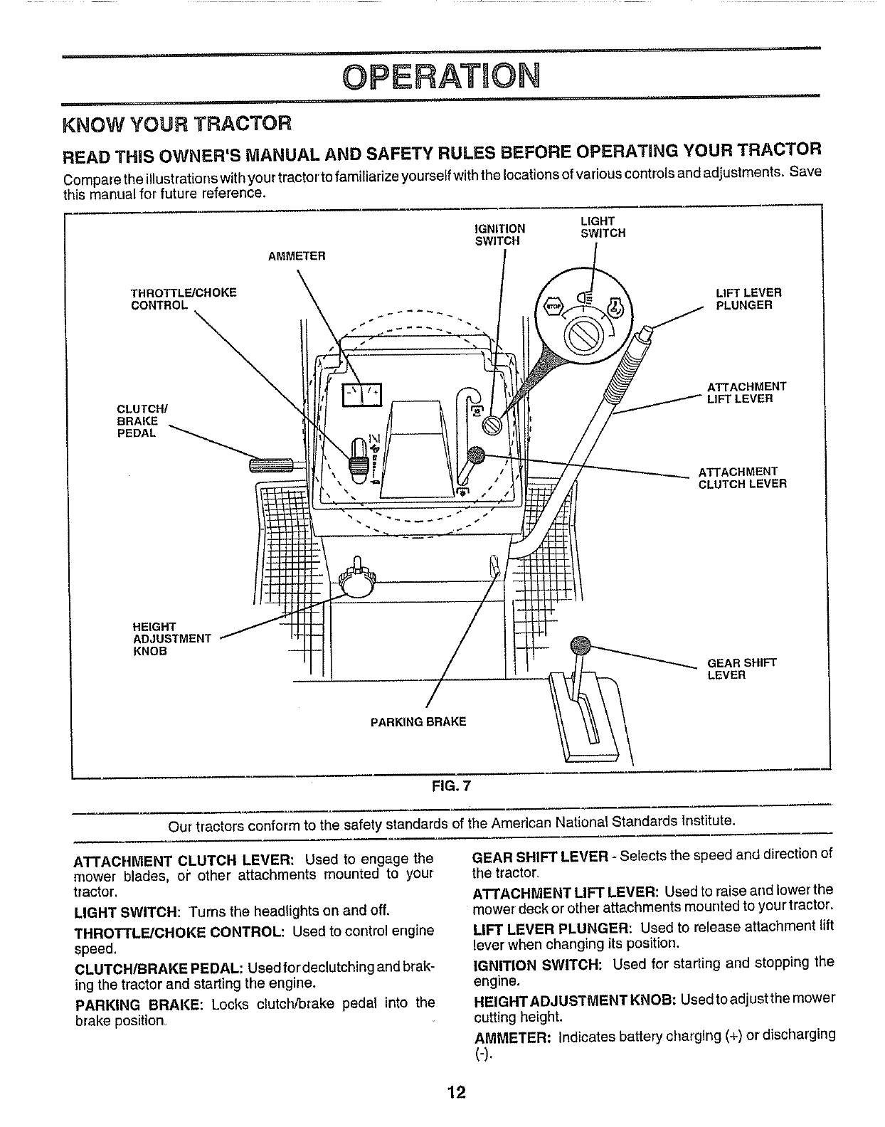
OPERATION
i[
KNOW YOUR TRACTOR
READ THIS OWNER'S MANUAL AND SAFETY RULES BEFORE OPERATING YOUR TRACTOR
Compare the illustrations with your tractorto familiarize yourselfwith the locations of various controlsand adjustments. Save
this manual for future reference.
LIGHT
IGNITION SWITCH
SWITCH
AMMETER
THROTTL_CHOKE
CONTROL
CLUTCW
BRAKE
PEDAL
HEIGHT
ADJUSTMENT
KNOB
LIFT LEVER
PLUNGER
A_'ACHMENT
/LIFTLEVER
ATTACHMENT
CLUTCH LEVER
GEARSHIFT
LEVER
PARKING BRAKE
• =
FIG. 7
Our tractors conform to the safety standards of the American National Standards Institute.
ATTACHMENT CLUTCH LEVER: Used to engage the
mower blades, or other attachments mounted to your
tractor,
LIGHT SWITCH: Turns the headlights on and off,
THROTTLE/CHOKE CONTROL: Used to control engine
speed.
CLUTCH/BRAKE PEDAL: Used fordeelutching and brak-
ing the tractor and starting tile engine.
PARKING BRAKE: Locks clutcl'v'brake pedal into the
brake position_
GEAR SHIFT LEVER - Selects the speed and direction of
the tracton
ATTACHMENT LIFT LEVER: Used to raise and lower the
mower deck or other attachments mounted to yourtractor_
LIFT LEVER PLUNGER: Used to release attachment lift
lever when changing its position.
IGNITION SWITCH: Used for starting and stopping the
engine.
HEIGHTADJUSTMENTKNOB: Usedtoadjustthe mower
cutting height,
AMMETER: Indicates battery charging (+) or discharging
(-).
12
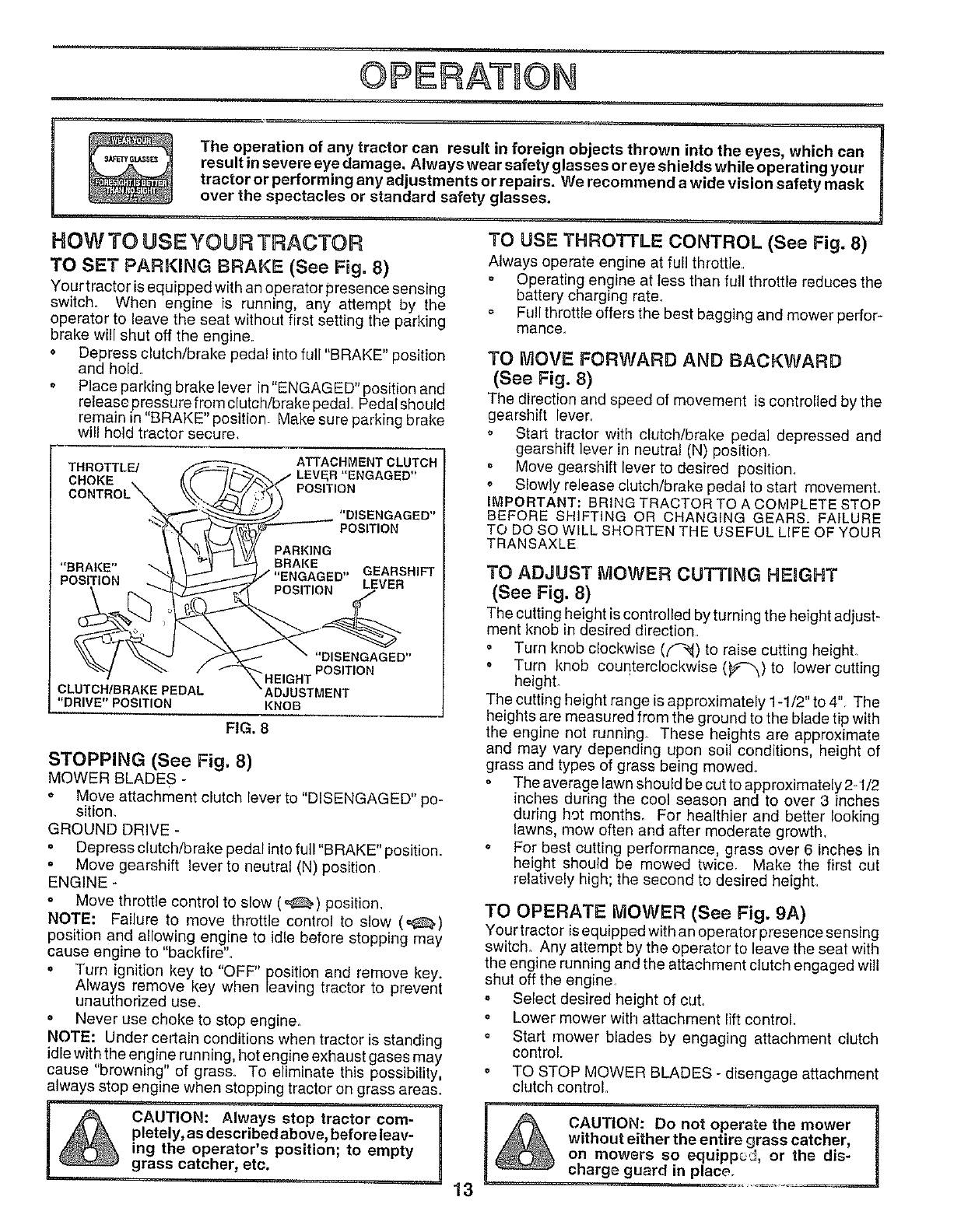
OPERATION
The operation of any tractor can result in foreign objects thrown into the eyes, which can
result in severe eye damage. Always wear safety glasses or eye shields while operating your
tractor or performing any adjustments or repairs. We recommend a wide vision safety mask
over the spectacles or standard safety glasses.
HOW 3"0 USE YOUR 3"RAC3"OR
TO SET PARKING BRAKE (See Fig. 8)
Your tractor isequipped with an operator presence sensing
switch. When engine is running, any attempt by the
operator to leave the seat without first setting the parking
brake will shut off the engine.
• Depress clutch/brake pedal into full "BRAKE" position
and hold.
o Place parking brake lever in "ENGAGED" position and
release pressure from clutch/brake pedal Pedal should
remain in "BRAKE" position. Make sure parking brake
will hold tractor secure,
THROTTLE/ ATTACHMENT CLUTCH
CHOKE LEVER "ENGAGED"
CONTROl POSITION
"DISENGAGED"
POSITION
PARKING
"BRAKE" _ BRAKE GEARSHIFT
POSITION LEVER
CLUTCH/BRAKEPEDAL
"DRIVE"POSITION
"DISENGAGED"
"HEIGHT POSITION
ADJUSTMENT
KNOB
FIG. 8
STOPPING (See Fig. 8)
MOWER BLADES -
• Move attachment clutch lever to "DISENGAGED" po-
sition,
GROUND DRIVE -
, Depress clutch/brake pedal into full "BRAKE" position.
° Move gearshift lever to neutral (N) position
ENGINE -
• Move throttle control to slow (,=_) position,
NOTE: Failure to move throttle control to slow (_)
position and allowing engine to idle before stopping may
cause engine to "backfire'L
• Turn ignition key to "OFF" position and remove key.
Always remove key when leaving tractor to prevent
unauthorized use.
o Never use choke to stop engine.
NOTE: Under certain conditions when tractor is standing
idle with the engine running, hot engine exhaust gases may
cause "browning" of gras& To eliminate this possibility,
always stop engine when stopping tractor on grass areas.
ICAUTION: Always stop tractor cam- I
pletely, as described above, before leav-
ing the operator's position; to empty U
grass catcher, etc.
TO USE THROTTLE CONTROL (See Fig. 8)
Always operate engine at full throttle,
Operating engine at less than full throttle reduces the
battery charging rate.
Full throttle offers the best bagging and mower perfor-
manse,
13
TO MOVE FORWARD AND BACKWARD
(See Fig. 8)
The direction and speed of movement is controlled by the
gearshift lever.
o Start tractor with clutch/brake pedal depressed and
gearshift lever in neutral (N) position.
o Move gearshift lever to desired position.
o Slowly release clutch/brake pedal to start movement.
IMPORTANT: BRING TRACTOR TO A COMPLETE STOP
BEFORE SHIFTING OR CHANGING GEARS. FAILURE
TO DO SOWlLL SHORTEN THE USEFUL LIFE OF YOUR
TRANSAXLE
TO ADJUST MOWER CUTTING HEIGHT
(See Fig. 8)
The cutting height is controlled by turning the height adjust-
ment knob in desired direction,
• Turn knob clockwise (f-'_) to raise cutting height.
o Turn knob counterclockwise (_#_-_)to lower cutting
height.
The cutting height range is approximately 1-1/2" to 4'L The
heights are measured from the ground to the blade tip with
the engine not running. These heights are approximate
and may vary depending upon soil conditions, height of
grass and types of grass being mowed°
The average lawn should be cut to approximately 2-1/2
inches during the cool season and to over 3 inches
during hot month& For healthier and better looking
lawns, mow often and after moderate growth.
° For best cutting performance, grass over 6 inches in
height should be mowed twice. Make the first cut
relatively high; the second to desired height
TO OPERATE MOWER (See Fig. 9A)
Your tractor is equipped with an operater presence sensing
switch, Any attempt by the operator to leave the seat with
the engine running and the attachment clutch engaged will
shut off the engine,
o Select desired height of cuL
o Lower mower with attachment lift control
o Start mower blades by engaging attachment clutch
control.
• TO STOP MOWER BLADES - disengage attachment
clutch control
CAUTION: _==.J
Do not operate the mower
without either the entire grass catcher,
on mowers so the dis-
equipped, or
charge guard in place.
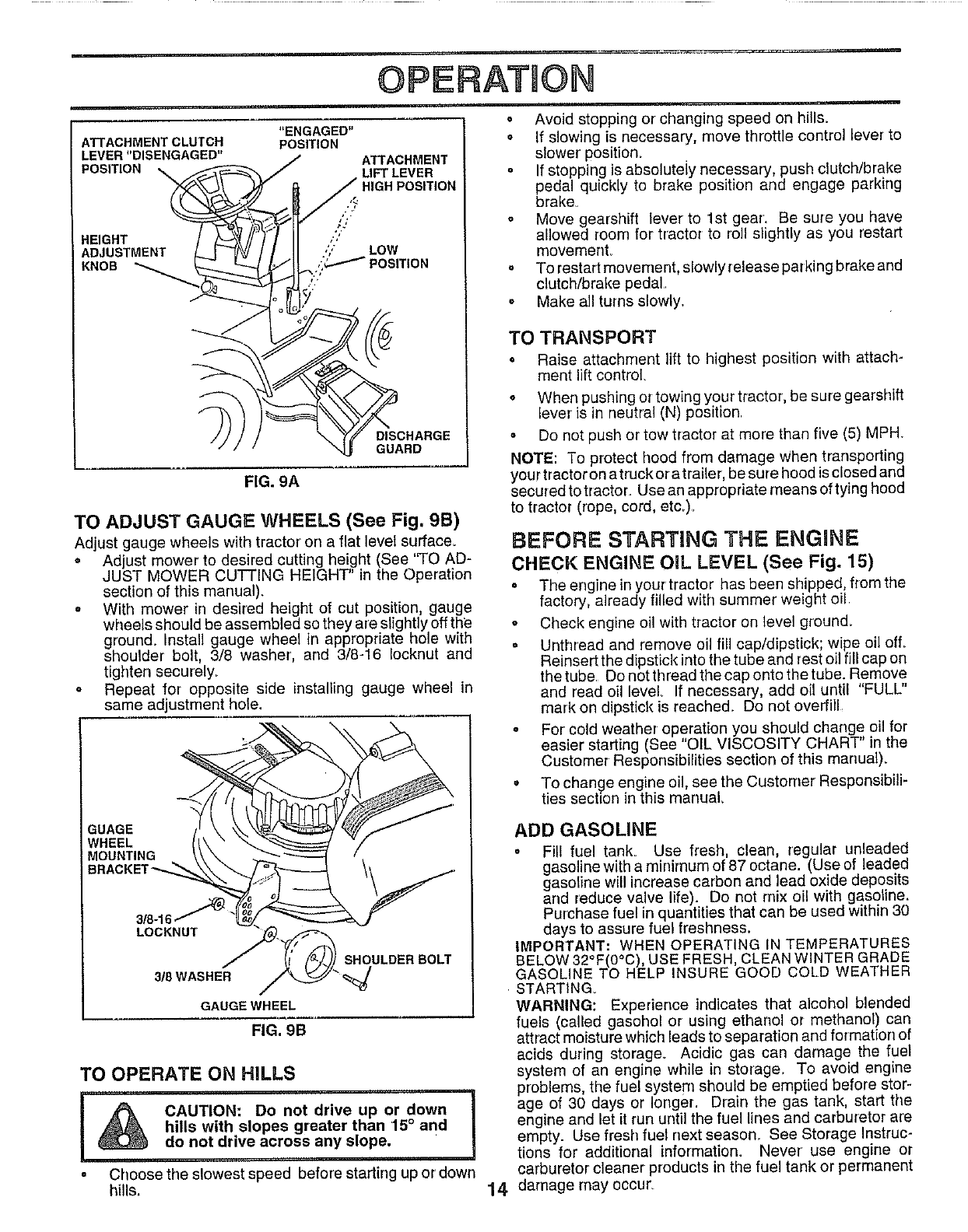
OPERATION
ATTACHMENT CLUTCH
LEVER "DISENGAGED"
POS,TiON
HEIGHT
ADJUSTMENT _ 3_
KNOS
"ENGAGED"
POSITION
/ATTACHMENT
LIFT LEVER
POSITION
I.','
,'; LOW
=OSITION
DISCHARGE
GUARD
FIG. 9A
TO ADJUST GAUGE WHEELS (See Fig. 9B)
Adjust gauge wheels with tractor' on a flat level surface.
• Adjust mower to desired cutting height (See 'q'O AD-
JUST MOWER CUTTING HEIGHT" in the Operation
section of this manual).
oWith mower in desired height of cut position, gauge
wheels should be assembled so they are slightly off the
ground. Install gauge wheel in appropriate hole with
shoulder bolt, 3/8 washer, and 3/8-16 Iocknut and
tighten securely.
oRepeat for opposite side installing gauge wheel in
same adjustment hole.
GUAGE
WHEEL
MOUNTING
3/8-16
LOCKNUT
3/8 WASHER
GAUGE WHEEL
FIG, 9B
SHOULDER BOLT
TO OPERATE ON HILLS
I _ CAUTION: Donotdriveapordown I
hills with slopes greater than 15° and
do not drive across any slope.
• Choose the slowest speed before starting up or down
hills.
o Avoid stopping or changing speed on hills.
o If slowing is necessary, move throttle control lever to
slower position.
° If stopping is absoluteiy necessary, push clutch/brake
pedal quickly to brake position and engage parking
brake_
= Move gearshift lever to 1st gear. Be sure you have
allowed room for tractor to roll slightly as you restart
movement,
• To restart movement, slowlyrelease parking brake and
clutch/brake pedal,
o Make allturns slowly,
TO TRANSPORT
• Raise attachment lift to highest position with attach-
ment lift control,
° When pushing or towing your tractor, be sure gearshift
lever is in neutral (N) position
o Do not push or tow tractor at more than five (5) MPH.
NOTE: To protect hood from damage When transporting
your tractor on a truck or a trailer, be sure hood is closed and
secured to tractor, Use an appropriate means of tying hood
to tractor (rope, cord, etc_).
BEFORE STARTING THE ENGINE
CHECK ENGINE OiL LEVEL (See Fig. 15)
• The engine in your tractor has been shipped, from the
factory, already filled with summer weight oil
o Check engine oil with tractor on level ground.
• Unthread and remove oil fill cap/dipstick; wipe oil ell
Reinsert the dipstick into the tube and rest oil fill cap on
thetube Donotthreadthecapontothetube. Remove
and read oil level If necessary, add oil until "FULL"
mark on dipstick is reached_ Do not overfill,
° For cold weather operation you should change oil for
easier starting (See "OIL VISCOSITY CHART" in the
Customer Responsibilities section of this manual).
oTo change engine oil, see the Customer Responsibili-
ties section in this manual,
14
ADD GASOLINE
• Fil! fuel tank_ Use fresh, Clean, regular unleaded
gasol ne with a minimum of 87 octane. (Use of leaded
gasoline will increase carbon and lead oxide deposits
ard reduce valve life). Do not mix oil with gasoline.
Purchase fuel in quantities that can be used within 30
days to assure fuel freshness.
IMPORTANT: WHEN OPERATING IN TEMPERATURES
BELOW 32°F(0°C), USE FRESH, CLEAN WINTER GRADE
GASOLINE TO HELP INSURE GOOD COLD WEATHER
STARTING_
WARNING: Experience indicates that alcohol blended
fuels (called gasohol or using ethanol or methanol) can
attract moisture which leads to separation and formation of
acids during storage° Acidic gas can damage the fuel
system of an engine while in storage_ To avoid engine
problems, the fuel system should be emptied before stor-
age of 30 days or longer. Drain the gas tank, start the
engine and let it run until the fuel lines and carburetor are
empty. Use fresh fuel next season_ See Storage Instruc-
tions for additional information. Never use engine or
carburetor cleaner products in the fuel tank or permanent
damage may occur.
OPERATION
i
CAUTION: Fill to bottom of gas tank I
filler neck, Do notoverfilL Wipeoffany
spilled oil or fuel. Do not store, spill or H
use gasoline near an open flame.
TO START ENGUNE (See Fig, 9)
When starting the engine for the first time or if the engine
has run out of fuel, it will take extra cranking time to move
fuel from the tank to the engine
o Depress clutch/brake pedal and set parking brake.
o Place gear shift lever in neutral (N) position,
o Move attachment clutch to "DISENGAGED" position
• Move throttle control to choke (l\i) positiOnr
Note: Before starting, read the warm and co_d starting
procedures below.
Insert key into ignition and turn key clockwise to "START"
position and re_ease key as soon as engine starts Do
not run starter continuously for more than fifteen sec-
onds per minute. If the engine does not start after
several attempts, move throttle control to fast (,&,)
position, wait a few minutes and try again Ifengine still
does not slart, move the throttle control back to the
choke (1\I) position and retry.
WARM WEATHER STARTING (50° F and above)
• When engine starts, move the throttle controlto the fast
(,€,) position.
o The attachments and ground drive can now be used. If
the engine does not accept the load, restart the engine
and allow it to warm up for one minute using the choke
as described above.
COLD WEATHER STARTING ( 50 ° F and below)
° When engine starts, allow engine to run with the
throttle co n!rol in the choke (1\1)position untilthe engine
runs roughly, then move throttle control to fast (@)
fposition. This may require an engine warm-up period
rom several seconds to several minutes, depending
on the temperature.
o The attachments can also be used during the engine
warm-up period.
NOTE: If at a high altitude (above 3000 feet) or in cold
temperatures (below 32 F) the carburetor fue! mixture may
need to be adjusted for best engine performance. See "TO
ADJUST CARBURETOR" in the Service and Adjustments
section of this manual.
MOWING TUPS
• Tire chains cannot be used when the mower housing
is attached to tractor.
o Mower should be properly leveled for best mowing
performance. See "TO LEVEL MOWER HOUSING" in
the Service and Adjustments section of this manual.
• The left hand side of mower should be used for trim-
ming.
o Drive so that clippings are discharged onto the area
that has been cut. Have the cut area to the right of the
machine. This will result in a more even distribution of
clippings and more uniform cutting
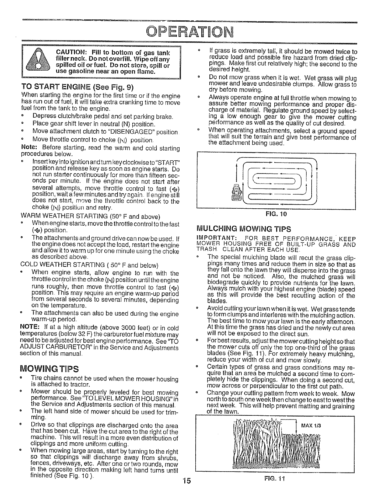
o When mowing large areas, start by turning to the right
so that clippings will discharge away from shrubs,
fences, driveways, etc. After one or two rounds, mow
in the opposite direction making left hand turns until
finished (See Fig. 10 ),
o If grass is extremely tall, it should be mowed twice to
reduce load and possible fire hazard from dried clip-
pings. Make first cut relatively high; the second to the
desired heighL
, Do not mow grass when it is wet. Wet grass will plug
mower and leave undesirable clumps. Allow grass to
dry before mowing.
o Always operate engine at full throttle when mowing to
assure better mowing performance and proper dis-
charge of material° Regulate ground speed by select-
ing a low enough gear to give the mower cutting
performance as well as the quality of cut desired.
o When operating attachments, select a ground speed
that will suit the terrain and give best performance of
the attachment being used.
FIG. 10
fVlULCH_NG MOWING TiPS
IMPORTANT: FOR BEST PERFORMANCE, KEEP
MOWER HOUSING FREE OF BUILT-UP GRASS AND
TRASH CLEAN AFTER EACH USE
The special mulching blade will recut the grass clip-
pings many times and reduce them in size so that as
they fall onto the .lawn they will disperse into the grass
and not be noticed, A_so, the mu_ched grass will
biodegrade quickly to provide nutrients for the lawn,
Always mulch with your highest engine (blade) speed
as this will provide the best recutting action of the
blades.
o Avoid cutting your lawn when it is wet. Wet grass tends
to form clumps and interferes with the mulching action.
The best time to mow your lawn is the early afternoon.
At this time the gross has dried and the newly cut area
will not be exposed to the direct sun.
oFor best results, adjust the mower cutting height so that
the mower cuts off only the top one-third of the grass
blades (See Fig. 11). For extremely heavy mulching,
reduce your width of cut and mow slowly.
o Certain types of grass and grass conditions may re-
quire that an area be mulched a second time to com-
pletely hide the clippings. When doing a second cut,
mow across or perpendicular to the first cut path.
• Change your cutting pattern from week to week. Mow
north to south one week then change to east to west the
next week. This will help prevent matting and graining
of the lawn.
MAX 1/3
15 FIG, 11
CUSTOMER RESPONSiBILiTiES
IVlAINTENANCE SCHEDULE
FILL IN DATES
AS YOU COMPLETE
REGULAR SERVICE
Check Brake Operation 6##
Check Tire Pressure
TCheck for Loose Fasteners
RSharpen/Replace Mower R[ades
_ Lubrication Chart
TCheck Battery Level/Recharge
0 Clean Battery and Terminals
Check Transaxle Cooltng
Adjust Blade Belt(s) Tension
Ad ust Mot on Or ve Belt(s Tension
Check Engine Oil Level _'
Change Engine Oil
Clean Air Filter
Clean Air Screen
Inspect Muffler/Spark ArresterG
I
SERVICE DATES
v' iJ
"° !
V'2
Replace Oil Filter (If equipped)
I.',
Clean Eng ne Cool ng Fins
Replace Spark Plug
Replace Air Filter Paper Cartridge
Replace Fuel Filter
e,'
I - Change more often when operating under a heavy toad or in high ambient temperatures
2 - Service more ogen when opelaling in dirty ot dusty conditions
3-If equipped with oil filter, change oil every 50 hours
4 - Replace blades more often when mowing in sandy soll
5 - If equipped with adjustable system
6 - Not required ir equipped with maintenance4ree baltery
7- Tighten Iront axle pivot bolt to 35 ft4bs maximum
Do not overtighlen
GENERAL RECOMMENDATIONS
The war ranty on this tractor does not cover items that have
been subjected to operator abuse or negligence, To
receive full value from the warranty, operator must maintain
tractor as instructed in this manual,
Some adjustments will need to be made periodically to
properly maintain your tractor,
All adjustments in the Service and Adjustments section of
this manual should be checked at least once each season,
Once a year you should replace the spark plug, clean
or replace air filter, and check blades and belts for
wear. A new spark plug and clean air' filter' assure
proper air-fuel mixture and help your engine run better
and last longer.
BEFORE EACH USE
• Check engine oil level.
o Checkbrake operation,
o Check tire pressure,
, Check for loose fasteners.
®
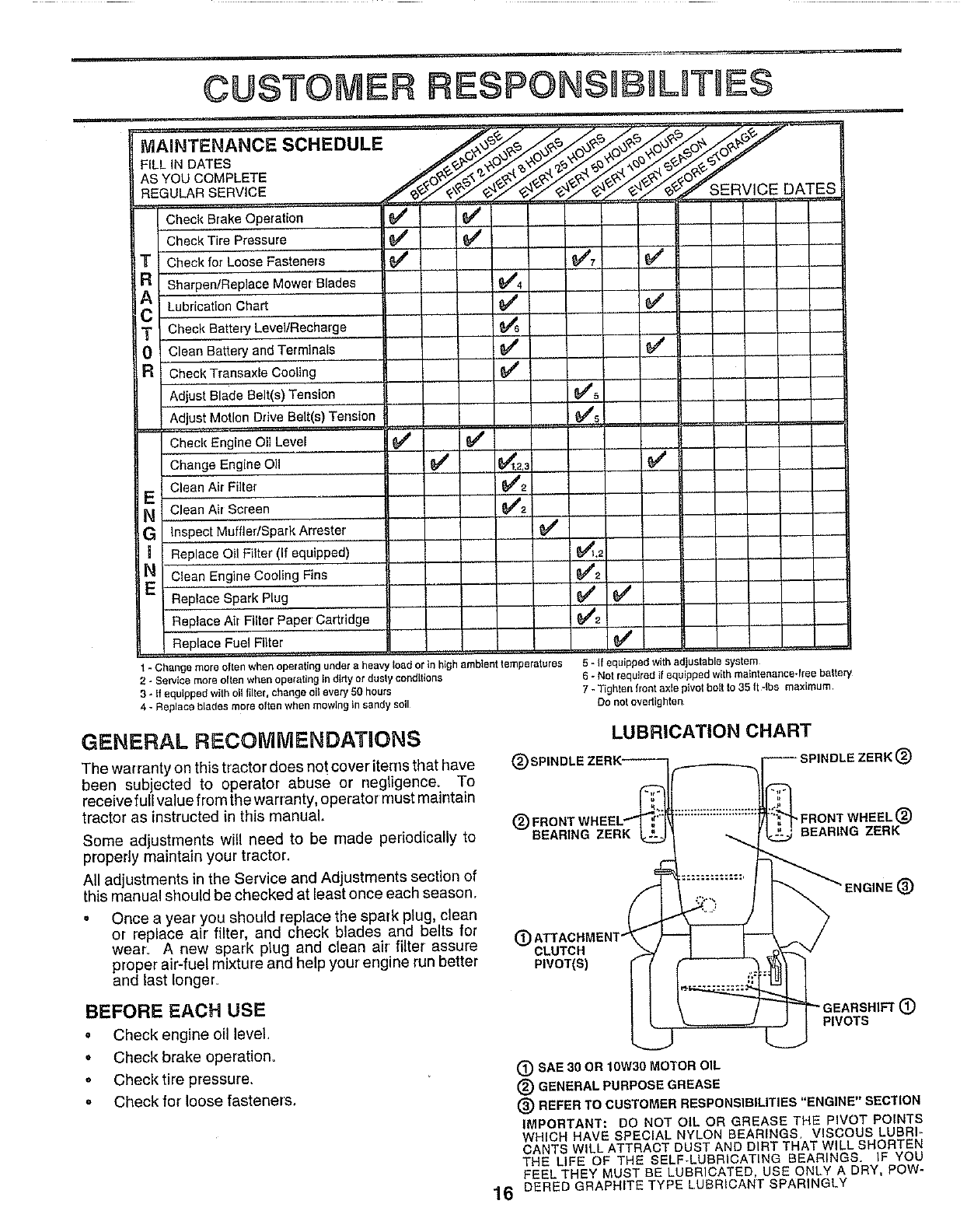
LUBRICATION CHART
DLE ZERK®
®REARING ZERK
PIVOT(S)
"FRONT WHEEL®
REARING ZERK
_ENGINE ®
_" GEARSHIFT (_
PIVOTS
®SAE 30 OR 10W30 MOTOR OIL
®GENERAL PURPOSE GREASE
(_) REFER TO CUSTOMER RESPONSIBILITIES "ENGINE" SECTION
IMPORTANT: DO NOT OIL OR GREASE THE PIVOT POINTS
WHICH HAVE SPECIAL NYLON BEARINGS. VISCOUS LUBRI-
CANTS WILL ATTRACT DUST AND DIRT THAT WILL SHORTEN
THE LIFE OF THE SELF-LUBRICATING BEARINGS. IF YOU
FEEL THEY MUST BE LUBRICATED, USE ONLY A DRY, POW-
16 DERED GRAPHITE TYPE LUBRICANT SPARINGLY
CUSTOMER RESPONSUBIL TnES
TRACTOR
Always observe safety rules when performing any mainte-
nance.
BRAKE OPERATION
If tractor requires more than six (6) feet stopping distance
at high speed in highest gear, then brake must be adjusted.
(See "TO ADJUST BRAKE" in the Service and Adjust-
ments section of this manual).
TIRES
o Maintain proper air pressure in all tires (See "PROD-
UCT SPECIFICATIONS" on page 3 of this manual).
• Keep tires free of gasoline, oil, or insect control chemi-
cals which can harm rubber.
o Avoid stumps_ stones, deep ruts, sharp objects and
other hazards that may cause tire damage_
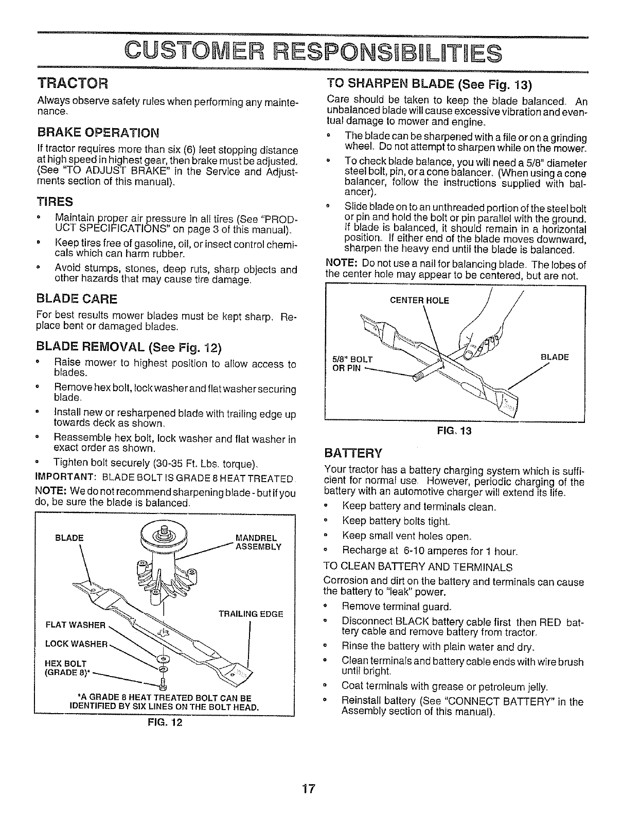
TO SHARPEN BLADE (See Fig. 13)
Care should be taken to keep the blade balanced. An
unbalanced blade will cause excessive vibration and even-
tual damage to mower and engine.
o The blade can be sharpened with a fiie or on a grinding
wheel Do not attempt to sharpen while on the mower.
. To check blade balance, you will need a 5/8" diameter
steel bolt, pin, ora cone balancer_ (When using acone
balancer, follow the instructions supplied with bal-
anGer).
• Slide blade on to an unthreaded portion of the steel bolt
or pin and hold the bolt or pin parallel with the ground.
If blade is balanced, it should remain in a horizontal
position. If either end of the blade moves downward,
sharpen the heavy end until the blade is balanced.
NOTE: Do not use a nail for balancing blade, The lobes of
the center hole may appear to be centered, but are not.
BLADE CARE
For best results mower blades must be kept sharp_ Re-
place bent or damaged blades.
BLADE REMOVAL (See Fig. 12)
° Raise mower to highest position to allow access to
blades.
o Remove hex bolt, lock washer and fiat washer securing
blade.
Install new or resharpened blade with trailing edge up
towards deck as shown,
• Reassemble hex bolt, loci<washer and flat washer in
exact order as shown.
•Tighten bolt securely (30-35 Ft. Lbs, torque),
IMPORTANT: BLADE BOLT IS GRADE 8 HEAT TREATED
NOTE: We do not recommend sharpening blade- but if you
do, be sure the blade is balanced.
BLADE
FLAT W__
LOCK WASHER,_
HEX BOLT
{GRADE 8)* _,,,.._
"_ MANDREL
_"j ASSEMBLY
i _ TRAILING EDGE
*A GRADE 8 HEAT TREATED BOLT CAN BE
IDENTIFIED BY SIX LINES ON THE BOLT HEAD,
FIG. 12
CENTER HOLE
5/8" BOLT
OR
BLADE
FIG. 13
BA'FFERY
Your tractor has a battery charging system which is suffi-
cient for normal use, However, periodic charging of the
battery with an automotive charger will extend its life.
• Keep battery and terminals clean.
o Keep battery bolts tight.
Keep small vent ho_es open.
o Recharge at 6-10 amperes for 1 hour.
TO CLEAN BA'I-FERY AND TERMINALS
Corrosion and dirt on the battery and terminals can cause
the battery to "leak" power.
• Remove terminal guard.
• Disconnect BLACK battery cable first then RED bat-
tery cable and remove battery from tractor.
o Rinse the battery with plain water and dry.
o Clean terminals and battery cable ends with wire brush
until bright.
Coat terminals with grease or petroleum jelly.
o Reinstall battery (See "CONNECT BATTERY" in the
Assembly section of this manual)_
17
CUSTOMER LVTMES
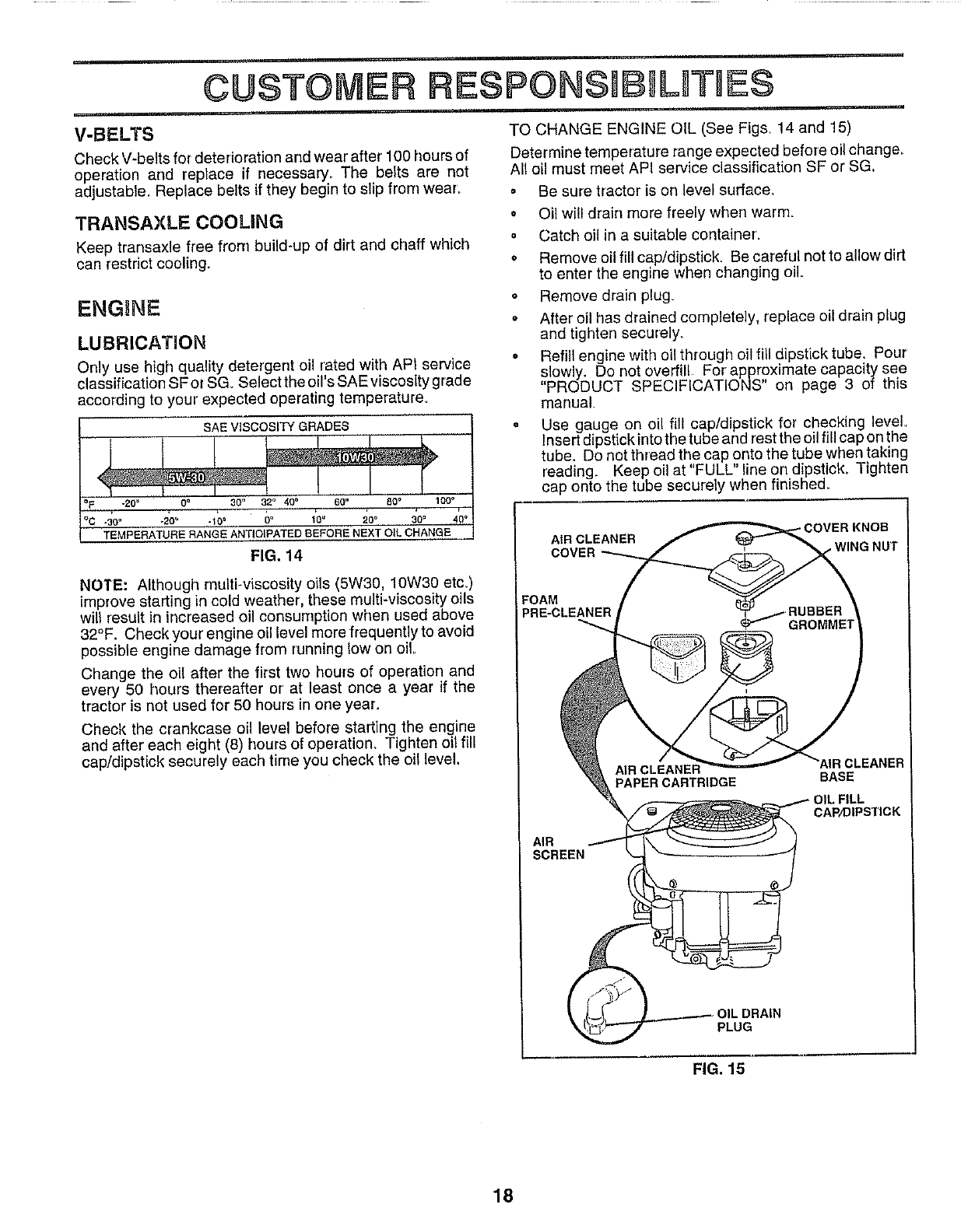
V-BELTS TO CHANGE ENGINE OIL (See Fig& 14 and 15)
Determine temperature range expected before oil change.
All oll must meet API service classification SF or SG.
Check V-belts for deterioration and wear after 100 hours of
operation and replace if necessary_ The belts are not
adjustable. Replace belts if they begin to slip from wear_
TRANSAXLE COOLING
Keep transaxle free from build-up of dirt and chaff which
can restrict cooling_
ENGINE
LUBRICATION
Only use high quality detergent oil rated with API service
classification SF or SG. Select the oil's SAE viscosity grade
according to your expected operating temperature_
SAE VISCOSITY GRADES
*20_ 0° 30" 32° 40o
-_oo -2_° -1_o 5° Io" 20" 30.
TEMPERATURE RANGE ANTIOIPATED BEFORE NEXT OIL CHANGE
FIG. 14
NOTE: Although multFviscosity oils (5W30, 10W30 etc.)
improve starting in cold weather, these multFviscesity oils
wilt result in increased oil consumption when used above
32°F. Check your engine oil leveJ more frequently to avoid
possible engine damage from running low on oil,
Change the oil after the first two hours of operation and
every 50 hours thereafter or' at least once a year if the
tractor is not used for 50 hours in one year.
Check the crankcase oil level before starting the engine
and after' each eight (8) hours of operation. Tighten oil fill
cap/dipstick securely each time you check the oil level.
= Be sure tractor is on level surface,
o Oil will drain more freely when warm.
o Catch oil in a suitable container,
• Remove oil fill cap/dipstick. Be careful not to allow dirt
to enter the engine when changing oil.
o Remove drain plug
= After oil has drained completely, replace oil drain plug
and tighten securely,
o Refill engine with oil through oil fill dipstick tube. Pour
slowly. Do not overfill For approximate capacity see
"PRODUCT SPECIFICATIONS" on page 3 of this
manual.
•Use gauge on oil fill cap/dipstick for checking level
insert dipstick into the tube and _estthe oil fill cap on the
tube. Do not thread the cap onto the tube when taking
reading. Keep oil at "FULL" line on dipstick. Tighten
cap onto the tube securely when finishe&
- COVER KNOB
AIR CLEANER
COVER ,WING NUT
FOAM
PRE-CLEANER
AIR
SCREEN
PAPER CARTRIDGE
AIR CLEANER
BASE
L FILL
CAP/DIPSTICK
OIL DRAIN
PLUG
FIG. 15
18
CUSTOMER RF=SPONSB L TUES
CLEAN AIR SCREEN (See Fig. 15)
Air screen must be kept free of dirt and chaff to prevent
engine damage from overheating, Clean with a wire brush
or compressed air to remove dirt and stubborn dried gum
fiber&
AIR FILTER (See Fig, 15)
Your engine will not run properly using a dirty air filter
Clean the foam pre-cleaner after every 25 hours of opera-
tion or every season. Service paper cartridge every 100
hours of operation or every season, whichever occurs first.
Service air cleaner more often under dusty conditions
Remove knob and cover_
• Remove wing nut and air cleaner from base.
TO SERVICE PRE-CLEANER
•Slide foam pre-cleaner off cartridge
o Wash it in liquid detergent and water.
• Squeeze it dry in a clean cloth_
o Saturate it in engine oil Wrap it in clean, absorbent
cloth and squeeze to remove excess oil
TO SERVICE CARTRIDGE
Gently tap the f_at side of the paper cartridge to dis-
lodge dirt. De net wash the paper cartridge or use
pressurized air, as this will damage the cartridge.
Replace a dirty, bent, or damaged cartridge.
° Reinstall the pre-cleaner (cleaned and oiled) over the
paper cartridge.
. Reassemble air cleaner, wing nut, cover and tighten
knob securety.
CLEAN AiR INTAKE/COOLING AREAS
To insure proper cooling, make sure the grass screen,
cooling fins, and other external surfaces of the engine are
kept clean at all times.
Every 100 hours of operation (more often under extremely
dusty, dirty conditions), remove the blower housing and
other cooling shrouds Clean the cooling fins and external
surfaces as necessary Make sure the cooling shrouds are
reinstalled.
NOTE: Operating the engine with a blocked grass screen,
dirty or plugged cooling fins, and/or cooling shrouds re-
moved will cause engine damage due to overheating
MUFFLER
inspect and replace corroded muffler and spark arrester (if
equipped) as it could create a fire hazard and/or damage,
SPARK PLUGS
Replace spark plugs at the beginning of each mowing
season or after every 100 hours of operation, whichever
occurs first. Spark plug type and gap setting are shown in
"PRODUCT SPECIFICATIONS" on page 3 of this manual.
19
CUSTOMER RESPON$1B LUT E$
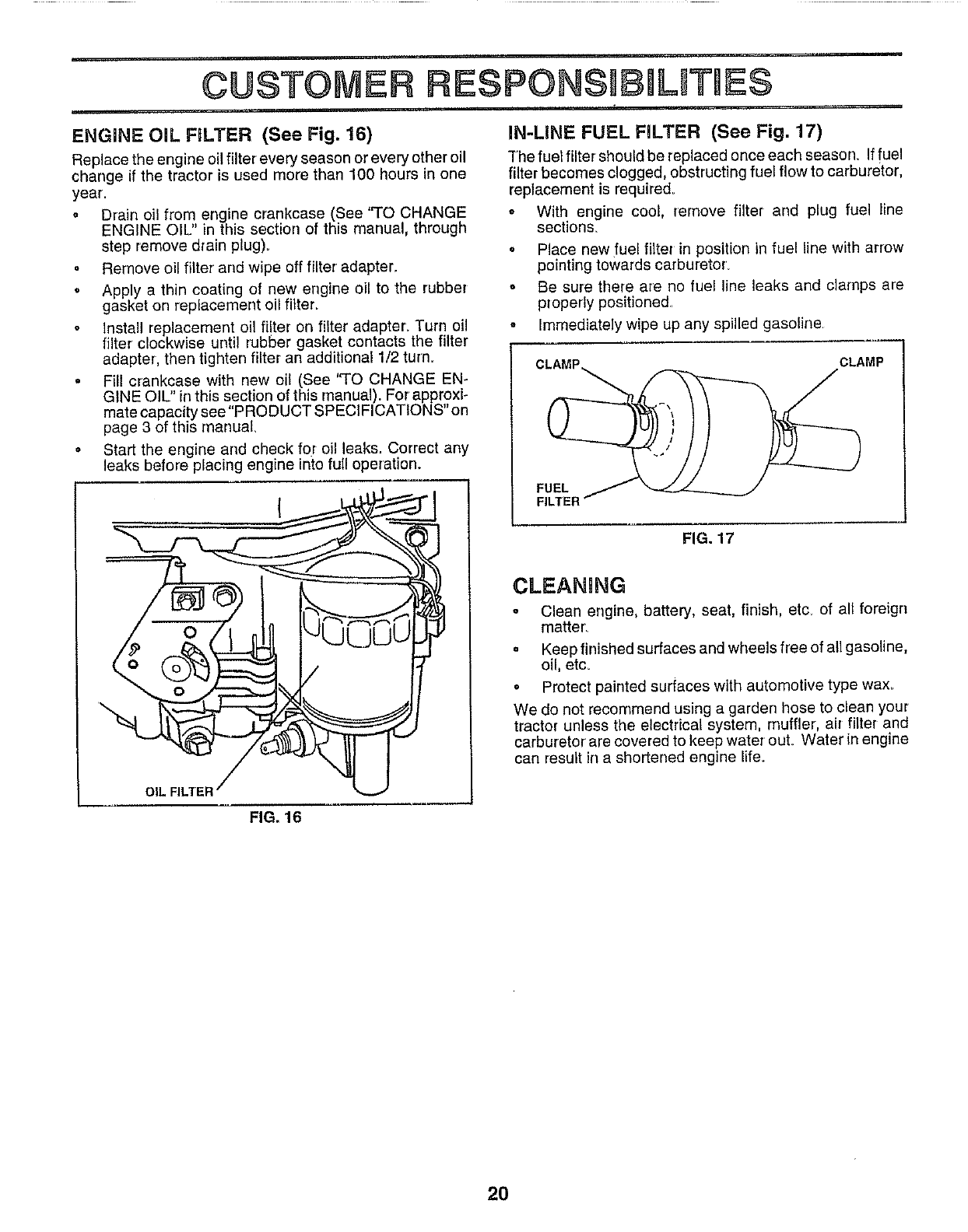
ENGINE OiL FILTER (See Fig. 16)
Replace the engine oil filter every season or every other oil
change if the tractor is used more than 100 hours in one
year
o Drain oil from engine crankcase (See "TO CHANGE
ENGINE OIL" in this section of this manual, through
step remove drain plug).
•Remove oil filter and wipe off filter adapter.
oApply a thin coating of new engine oil to the rubber
gasket on replacement oil filter.
Install replacement oil filter on filter adapter. Turn oil
filter clockwise until rubber gasket contacts the filter
adapter, then tighten filter an additional 1/2 turn.
° Fill crankcase with new oil (See ''TO CHANGE EN-
GINE OIL" in this section of this manual). For approxi-
mate capacity see "PRODUCT SPECIFICATIONS" on
page 3 of this manual.
, Start the engine and check for oil leaks. Correct any
leaks before placing engine into full operation.
OIL
IN-LINE FUEL FILTER (See Fig. 17)
The fuel filter should be replaced once each season If fuel
filter becomes clogged, obstructing fuel flow to carburetor,
replacement is required.
• With engine cool, remove filter and plug fuel line
sections_
, Place new fuel filter in position in fuel line with arrow
pointing towards carburetor'.
o Be sure there are no fuel line leaks and clamps are
properly positioned.
oImmediately wipe up any spilled gasoline
CLAMP
FUEL
FILTER
FIG, 17
CLEANING
° Clean engine, battery, seat, finish, etc of all foreign
matter_
oKeep finished surfaces and wheels free of allgasoline,
oil, etc.
•Protect painted surfaces with automotive type wax.
We do not recommend using a garden hose to clean your
tractor unless the electrical system, muffler, air filter and
carburetor' are covered to keep water ouL Water in engine
can result in a shortened engine life.
FIG. 16
2O
irl_ ..... .......
SErVe@5 AND ADJUSTMENTS
CAUTION: BEFORE PERFORMING ANY"SERVICE OR ADJUSTMENTS:
_i Depress clutch/brake pedal fully and set parking brake.
Place gearshift lever in neutral (N) position.
Place attachment clutch in "DISENGAGED" position.
=Turn ignition key "OFF" and remove key.
oMake sure the blades and all moving parts have completely stopped.
•Disconnect spark plug wire from spark plug and place wire where it cannot come in contact with
plug.
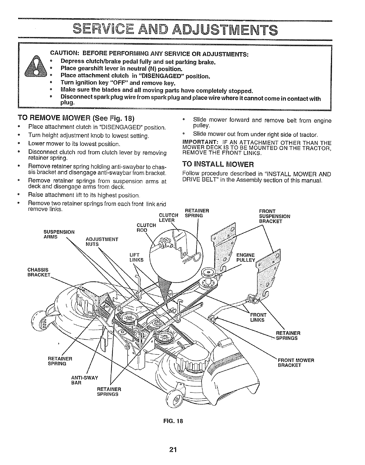
TO REMOVE MOWER (See Fig. 18)
,Place attachment clutch in "DISENGAGED" position.
o Turn height adjustment knob to lowest setting.
oLower mower to its lowest position_
o Disconnect clutch rod from clutch lever by removing
retainer spring.
• Remove retainer spring holding anti-swaybar to chas-
sis bracket and disengage anti-swaybar from bracket.
o Remove retainer springs from suspension arms at
deck and disengage arms from deck,
•Raise attachment lift to its highest position
• Remove two retainer springs from each front link and
remove links. CLUTCH
LEVER
CLUTCH
ROD
SUSPENSION
ARMS ADJUSTMENT
NUTS
o Slide mower forward and remove belt from engine
pulley,
• Slide mower out from under right side of tractor.
IMPORTANT: IF AN ATTACHMENT OTHER THAN THE
MOWER DECK IS TO BE MOUNTED ON THE TRACTOR,
REMOVE THE FRONT LINKS_
TO INSTALL MOWER
Follow procedure described in "INSTALL MOWER AND
DRIVE BELT" in the Assembly section of this manual
RETAINER FRONT
SPRING SUSPENSION
BRACKET
LIFT
LINKS
CHASSIS
BRACKET
RETAINER
•'SPRINGS
RETAINER
SPRING BRACKET
ANTI-SWAY
BAR
RETAINER
SPRINGS
FIG. '18
21
SERVaCE ADJUSTMENTS
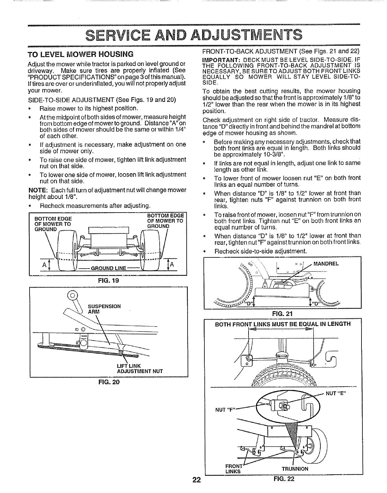
TO LEVEL MOWER HOUSING
Adjust the mower while tractor is parked on level ground or
driveway. Make sure tires are properly inflated (See
"PRODUCT SPECIFICATIONS" on page 3 of this manual).
Iftires are over or underinflated, you will not properly adjust
your mower
SIDE-TO-SIDE ADJUSTMENT (See Figs. 19 and 20)
• Raise mower to its highest position.
o At the midpoint of both sides of mower, measure height
from bottom edge of mower to ground_ Distance"A" on
both sides of mower' should be the same or within 1/4"
of each other_
o If adjustment is necessary, make adjustment on one
side of mower only.
, To raise one side of mower, tighten lift link adjustment
nut on that side.
° To lower one side of mower, loosen lift link adjustment
nut on that side,
NOTE: Each full turn of adjustment nut will change mower
height about 1/8".
o Recheck measurements after adjusting..
BOTTOM EDGE
BOTTOM EDGE OF MOWER TO
OF MOWER TO GROUND
GROUND
--GROUND LINE--
FIG. 19
SUSPENSION
ARM
LIFT LINK
ADJUSTMENT NUT
FIG. 20
FRONT-TO-BACK ADJUSTMENT (See Figs. 21 and 22)
IMPORTANT: DECK MUST BE LEVEL SIDE-TO-SIDE IF
THE FOLLOWING FRONT-TO-BACK ADJUSTMENT IS
NECESSARY, BE SURE TO ADJUST BOTH FRONT LINKS
EQUALLY SO MOWER WILL STAY LEVEL SIDE-TO-
SIDE,
To obtain the best cutting results, the mower housing
should be adjusted so that the front is approximately 1/8" to
1/2" lower than the rear when the mower is in its highest
position..
Check adjustment on right side of tractor_ Measure dis-
tance "D" directly in front and behind the mandrel at bottom
edge of mower housing as shown°
• Before making any necessary adjustments, check that
both front links are equal in length. Both links should
be approximately 10-3/8'L
• If links are not equal in length, adjust one link to same
length as other link_
° To lower' front of mower loosen nut "E" on both front
links an equal number of turns.
° When distance "D" is 1/8" to 1/2" lower' at front than
rear, tighten nuts "F" against trunnion on both front
links.
°To raise front of mower, loosen nut"F" from trunnion on
both front links Tighten nut "E" on both front links an
equal number of turns.
° When distance "D" is 1/8" to 1/2" lower at front than
rear, tighten nut"F" against trunnion on both front links.
o Recheck side-to-side adjustmenL
MANDREL
FIG. 21
BOTH FRONT LINKS MUST BE EQUAL IN LENGTH
NUT"F""_
FRONT_
LINKS
NUT"E"
TRUNNION
22 FIG. 22
SERVICE AND ADJUSTMENTS
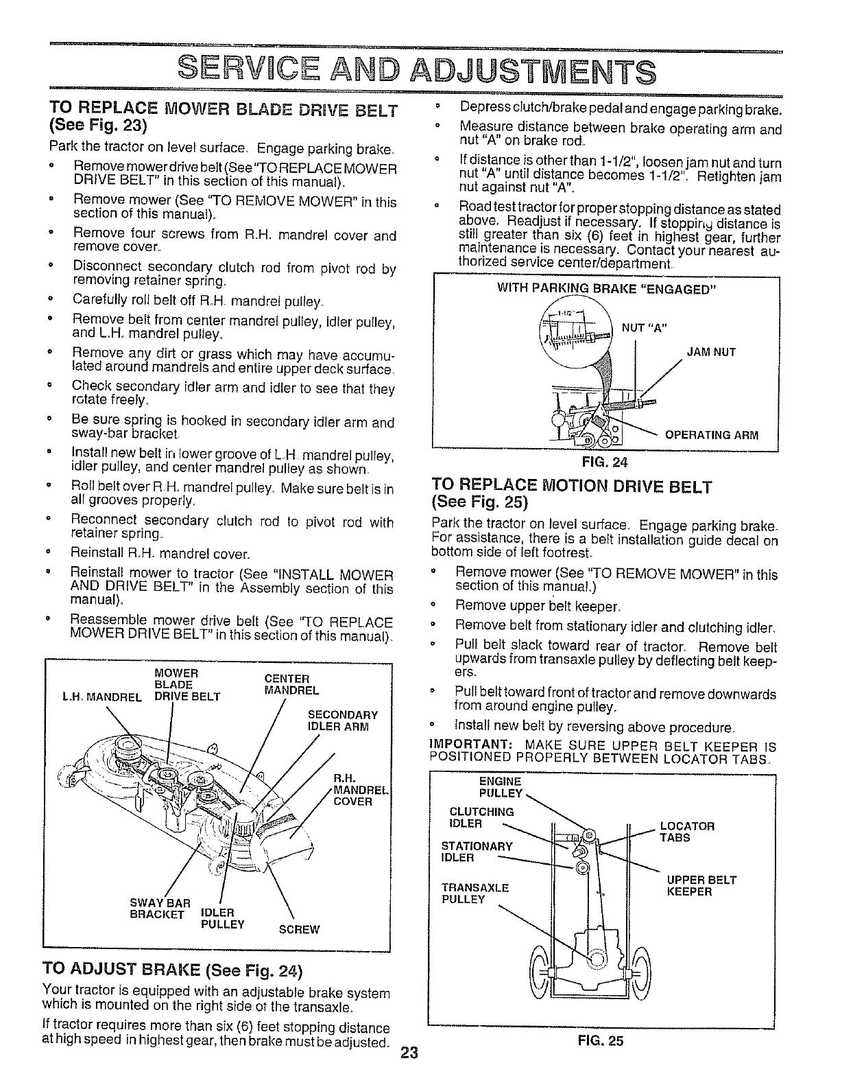
TO REPLACE IVlOWER BLADE DRUVE BELT
(See Fig. 23)
Park the tractor on level surface. Engage parking brake_
o Remove mower drive belt (See"TO REPLACE MOWER
DRIVE BELT in this section of this manual).
• Remove mower (See "TO REMOVE MOWER" in this
section of this manua])_
o Remove four screws from R,.H. mandrel cover and
remove cover.
• Disconnect secondary clutch rod from pivot rod by
removing retainer spring.
o Carefully roll belt off R,H. mandrel pulley.
° Remove belt from center mandrel pulley, idler pulley,
and L.H. mandrel pulley.
oRemove any dirt or grass which may have accumu-
lated around mandrels and entire upper deck surface.
= Check secondary idler arm and idler to see that they
rotate freely_
• Be sure spring is hooked in secondary idler arm and
sway-bar bracket,
° Install new belt in lower groove of L.H mandrel pulley,
idler pulley, and center mandrel pulley as shewn_
• Roll belt over R H, mandrel pulley_ Make sure beltis in
all grooves properly.
° Reconnect secondary clutch rod to pivot rod with
retainer spring,
• Reinstall R_H. mandrel cover
°Reinstall mower to tractor (See "INSTALL MOWER
AND DRIVE BELT" in the Assembly section of this
manual),
o Reassemble mower drive belt (See "TO REPLACE
MOWER DRIVE BELT" in this section of this manual),
L,H. MANDREL
MOWER CENTER
BLADE MANDREL
DRIVE BELT
SECONDARY
IDLER ARM
R,H.
COVER
SWAY BAR
BRACKET IDLER
PULLEY SCREW
TO ADJUST BRAKE (See Fig. 24)
Your tractor is equipped with an adjustable brake system
which is mounted on the right side ot the transaxle,
If tractor requires more than six (6) feet stopping distance
at high speed inhighest gear, then brake must be adjusted.
= Depress clutch/brake pedal and engage parking brake,,
o Measure distance between brake operating arm and
nut "A" on brake rod.
Ifdistance is other than 1-1/2", loosen jam nut and turn
nut "A" until distance becomes 1-1/2'L Retlghten jam
nut against nut "A".
Road test tractor for proper stopping distance as stated
above. Readjust if necessary. If stopping distance is
still greater than six (6) feet in highest gear, further
maintenance is necessary. Contact your nearest au-
thorized service center/department,
WITH PARKING BRAKE"ENGAGED"
NUT'A"
IJAM NUT
OO_ OPERATING ARM
FIG. 24
TO REPLACE MOTION DRIVE BELT
(See Fig. 25)
Park the tractor on level surface. Engage parking brake_
For assistance, there is a belt installation guide decal on
bottom side of left footrest.
o
o
Remove mower (See 'q-O REMOVE MOWER" in this
section of this manuaL)
Remove upper belt keeper,
Remove belt from stationary idler and clutching idler,
Pull belt slack toward rear of tractor. Remove belt
upwards from transaxle pulley by deflecting belt keep-
ers.
Pull belt toward front of tractor and remove downwards
from around engine pulley,,
lnsta}l new belt by reversing above procedure
IMPORTANT: MAKE SURE UPPER BELT KEEPER IS
POSITIONED PROPERLY BETWEEN LOCATOR TABS
ENGINE
PULLEY
CLUTCHING
IDLER _ _
STATIONARY _zz_
LOCATOR
"_"TABS
UPPER BELT
KEEPER
0
FIG, 25
23
SERWCE AND ADJUSTMENTS
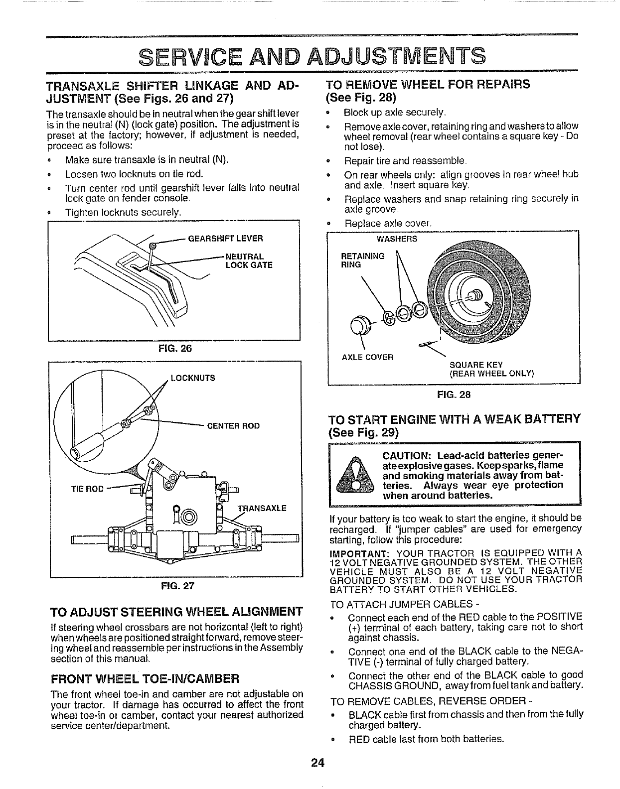
TRANSAXLE SHIFTER LINKAGE AND AD-
JUSTMENT (See Figs. 26 and 27)
The transaxle should be inneutral when the gear shift lever
is in the neutral (N) (lock gate) position. The adjustment is
preset at the factory; however, if adjustment is needed,
proceed as follows:
=Make sure transaxle is in neutral (N).
oLoosen two Iocknuts on tie rod.
• Turn center rod until gearshift lever fails into neutral
lock gate on fender console.
Tighten Iocknuts securely.
:T [.EVER
LOCK GATE
FIG, 26
CENTER ROD
TIE ROD
TRANSAXLE
FIG. 27
TO ADJUST STEERING WHEEL ALIGNMENT
tf steering wheel crossbars are not horizontal (left to right)
when wheels are positioned straight forward, remove steer-
ing wheel and reassemble per instructions in the Assembly
section of this manual
FRONT WHEEL TOE-IN/CAMBER
The front wheel toe-in and camber are not adjustable on
your tractor. If damage has occurred to affect the front
wheel toe-in or camber, contact your nearest authorized
service centeddepartment.
TO REMOVE WHEEL FOR REPAIRS
(See Fig. 28)
o Block up axle securely
= Remove axle cover, retaining ring and washers to allow
wheel removal (rear wheel contains a square key - Do
not lose).
° Repair tire and reassemble
• On rear wheels only: align grooves in rear wheel hub
and axle. Insert square key
oReplace washers and snap retaining ring securely in
axle groove
Replace axle cover_
WASHERS
RETAINING
RING
AXLE COVER
I
SQUARE KEY
(REAR WHEEL ONLY)
FIG. 28
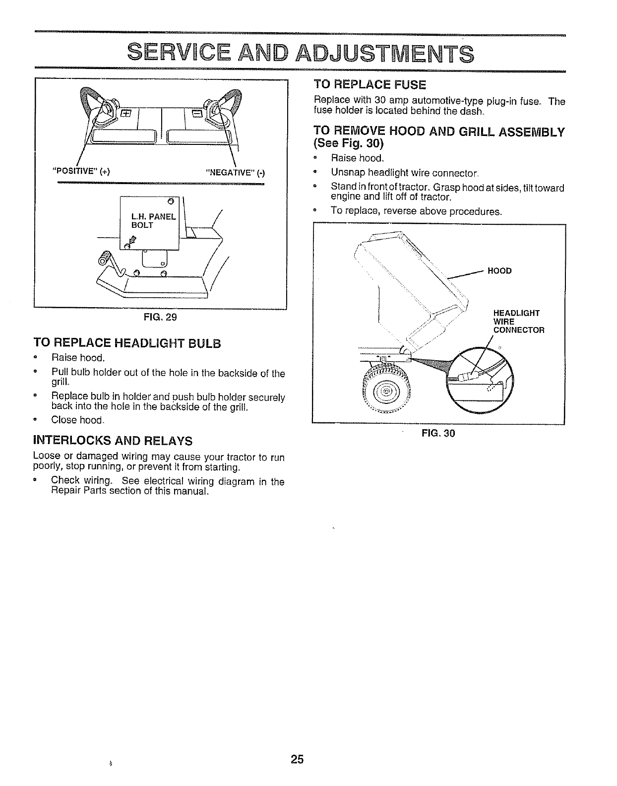
TO START ENGINE WiTH A WEAK BATTERY
See Fig. 29)
CAUTION: Lead-acid batteries gener-
ate explosive gases. Keep sparks, flame
and smoking materials away from bat-
teries. Always wear eye protection
when around batteries.
If your battery is too weak to start the engine, it should be
recharged. If "jumper cables" are used for emergency
starting, follow this procedure:
IMPORTANT: YOUR TRACTOR IS EQUIPPED WITHA
12 VOLT NEGATIVE GROUNDED SYSTEM. THE OTHER
VEHICLE MUST ALSO BE A 12 VOLT NEGATIVE
GROUNDED SYSTEM. DO NOT USE YOUR TRACTOR
BATTERY TO START OTHER VEHICLES.
TO ATTACH JUMPER CABLES -
o Connect each end of the RED cable to the POSITIVE
(+) terminal of each battery, taking care not to short
against chassis.
o Connect one end of the BLACK cable to the NEGA-
TIVE (-) terminal of fully charged battery.
• Connect the other end of the BLACK cable to good
CHASSIS GROUND, away from fuel tank and battery.
TO REMOVE CABLES, REVERSE ORDER -
. BLACK cable first from chassis and then from the fully
charged battery°
o RED cable last from both batteries.
24
SERVICE AND ADJUSTMENTS
"POSITIVE" (+) "NEGATIVE" (-)
L,H. PANEL
BOLT
d'
FIG. 29
TO REPLACE HEADLIGHT BULB
o Raise hood.
• Pull bulb holder out of the hole in the backside of the
grill.
o Replace bulb in holder and push bulb holder securely
back into the hole in the backside of the grill
• Close hood.
INTERLOCKS AND RELAYS
Loose or damaged wiring may cause your tractor to run
poorly, stop running, or prevent it from starting,.
• Check wiring, See electrical wiring diagram in the
Repair Parts section of this manual
TO REPLACE FUSE
Replace with 30 amp automotive-type plug-in fuse. The
fuse holder is located behind the dash,
TO REMOVE HOOD AND GRILL ASSEMBLY
(See Fig. 30)
Raise hood.
• Unsnap headlight wire connector,
o Stand in front of tractor_ Grasp hood at sides, tilt toward
engine and lift off of tractor.
• To replace, reverse above procedures.
"_j HOOD
I'j W,RE"EAOL'GHT
CONNECTOR
FIG, 30
25
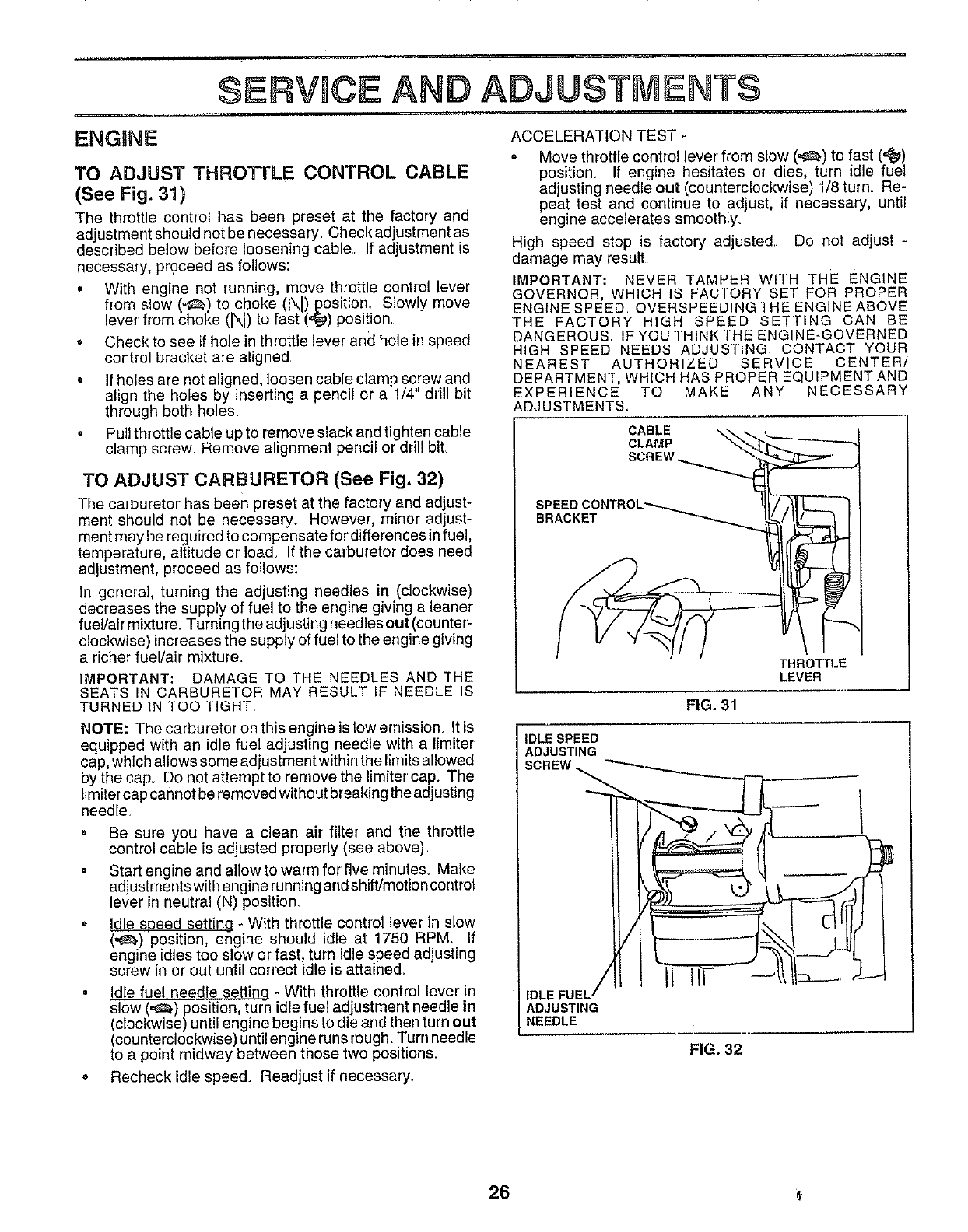
SERVICE AND ADJUSTMENTS
ENGnNE
TO ADJUST THROTTLE CONTROL CABLE
(See Fig. 31)
The throttle control has been preset at the factory and
adjustment should not be necessary_ Check adjustment as
described below before loosening cable_ If adjustment is
necessary, proceed as follows:
° With engine not running, move throttle control lever
from slow (',_) to choke (N) position. Slowly move
lever from choke (N) to fast ('_) position.
o Check to see if hole in throttle lever and hole in speed
control bracket are aligned.
o If holes are not aligned, loosen cable clamp screw and
align _he holes by inserting a pencil or a 1/4" drill bit
through both holes°
• Pull throttle cable up to remove slack and tighten cable
clamp screw. Remove alignment pencil or drill biL
TO ADJUST CARBURETOR (See Fig. 32)
The carburetor has been preset at the factory and adjust-
ment should net be necessary. However, minor adjust-
ment may be reguired to compensate for'differences in fuel,
temperature, altitude or Ioad_ If the carburetor does need
adjustment, proceed as follows:
In general, turning the adjusting needles in (clockwise)
decreases the supply of fuel to the engine giving a leaner
fuel/air mixtu re. Turning the adjusting needles out (counter-
clockwise) increases the supply of fuel to the engine giving
a richer fuel/air mixture.
IMPORTANT: DAMAGE TO THE NEEDLES AND THE
SEATS IN CARBURETOR MAY RESULT IF NEEDLE IS
TURNED IN TOO TIGHT,
NOTE: The carburetor on this engine is tow emission. It is
equipped with an idle fuel adjusting needle with a limiter
cap, which allows some adjustment within the limits allowed
by the cap.. Do not attempt to remove the limiter cap. The
limiter cap cannot be removed without breaking the adjusting
needle.
o Be sure you have a clean air filter' and the throttle
control cable is adjusted properly (see above).
° Start engine and allow to warm for five minutes. Make
adjustments with engine runningand shift/motion control
lever in neutral (N) position_
° Idle speed settinq - With throttle control lever in slow
(,_.) position, engine should idle at 1750 RPM If
engine idles too slow or fast, turn idle speed adjusting
screw in or out until correct idle is attained_
= IdLefuel needle settinq - With throttle corrtrol lever in
slow (,_) position, turn idle fuel adjustment needle in
Iclockwise) until engine begins to die and then turn out
counterclockwise) until engine runs rough_Turn needle
to a point midway between those two positions.
* Recheck idle speed. Readjust if necessary.
ACCELERATION TEST -
= Move throttle control lever from slow (,_) to fast (=_)
position. If engine hesitates or dies, turn idle fuel
adjusting needle out (counterclockwise) 1/8 turn. Re-
peat test and continue to adjust, if necessary, until
engine accelerates smoothly_
High speed stop is factory adjusted Do not adjust
damage may result
IMPORTANT: NEVER TAMPER WITH THE ENGINE
GOVERNOR, WHICH iS FACTORY SET FOR PROPER
ENGINE SPEED OVERSPEEDINGTHEENGINEABOVE
THE FACTORY HIGH SPEED SETTING CAN BE
DANGEROUS IF YOU THINK THE ENGINE-GOVERNED
HIGH SPEED NEEDS ADJUSTING, CONTACT YOUR
NEAREST AUTHORIZED SERVICE CENTER/
DEPARTMENT, WHICH HAS PROPER EQUIPMENT AND
EXPERIENCE TO MAKE ANY NECESSARY
t_DJUSTMENTS.
CABLE
CLAMP
SCREW
BRACKET
THROTTLE
LEVER
FIG. 31
IDLE SPEED
ADJUSTING
SCREW
,DLE UEL//
ADJUSTING
NEEDLE
FIG, 32
26 G.

TROUBLESHOOTI POINTS
lilt ....
CAUSE CORRECTIONPROBLEM
win not start
Hard to start
Engine will not turn over
Engine clicks but will not
start
i,i.
Loss of power
Excessive vibration
1, Out of fuel
2. Engtne not "CHOKED" properly
3 Engine flooded
4, Bad spark plug+
5 Dirty air filter
6. Dirty fuel fi{ter.
7 Watertnfuel
8 Loose or damaged widng
9 Carburetor out of adjustment
10 Engine valves out of adjustment
1 Didy air filter
2 Bad spark plug
3 Weak or dead battery
4 Dirty fuel _ter
5 Staleor dirty fuel
6 Loose or damaged wiring
7 Carburetoroutofadiustment
8Engine valves out of adjustment
...... i
fClutch/brake pedal not depressed
2 Attachment clutch ts engaged
3 Weak or dead battery
4 Blown fuse
5 Corroded battery terminals
6 Loose or damaged wiring
7 Faulty ignition switch.
8 Faulty solenoid or starter
9 Faulty operator presence switch(es)
1 Weak or dead battery
2 Corroded battery terminals,
3 Loose or damaged widng
4 Faulty solenoid or stader
1 Cutting too much grass/leo fast
2 Throttle in "CHOKE" position.
3 Build-up of grass, leaves and trash under mower
4 Dirty air filter
5, Low oil level/dirty oil
6 Faulty spark plug
7 Dirty fuel filter
8 Stale or dirty fuel
9 Water in fuel
10 Spark plug wire loose
11_ Dirty engine air screen/fins
12 Dirty/clogged mufflar_
13 Loose or damaged wiring
14, Carburetor out of adjustment
15 Engine valves out of adjustment
1 Worn, bentorloose blade
2 Bent blade mandrel
3 Loose/damaged part(s)
1FI]!fuel tank
2. See "TO START ENGINE" in Operation sectton,
3 Wait several minutes before attempting to start
4 Replace sparkplug
5. Clean/replace air filter
6 Replace fuel filter
7 Drain fuel tank and carburetor, refill tank with fresh
gasoline and replace fuel filter
8 Check all wiring.
9 See "To Adjust Carburetor" in Service Adjustments
section,
10 Contact an authorized service center/department
1 Clean/replace air filter
2 Replace sparkplug
3 Recharge or replace battery
4 Replace fue! filter
5 Drain fuel tank and refill with fresh gasoline
6 Check all widng.
7 See ''To Adiust Carburetor' in Service Adjustments
section
8 Contacl an authorized service center/department
1 Depress clutch/brake pedal
2 Disengage attachment clutch
3 Recharge or replace battery
4 Replace fuse
5. Clean battery terminals,
6 Check all widng
7 Checldreplace Ignition switcll
8 Checldrap/ace solenoid or starter
9 Contact an authorized service centeddepadment
1 Recharge or replace battery,
2 Clean battery terminals
3 Check all wtdng
4 Check/replace solenoid or starter
1 Set in "Higher Cut" position/reduce speed
2 Adjust throttle control
3 Clean underside of mower houetng
4 Clean/raplace air filter
5 Check oil level/change oil,
6Clean and regap or change spark plug,
7 Replace fuel tilter
8 Drain fuel tank and refill with fresh gasoline
9 Drain fuel tank and carburetor, retill tank with trash
gasoline and replace fuel filter
10. Connect and tighten spark plug wire
It Clean engine air screen/line
12 Clean/replace muffler
!3 Check all wiring
14 See'_To Adjust Carburetor"in Service Adjustments
section
15 Contact an authorized service center/depadment
1 Replace blade Tighten blade boll
2 Replace blade mandrel.
3 Tighten loose part(s) Replace damaged parts
27
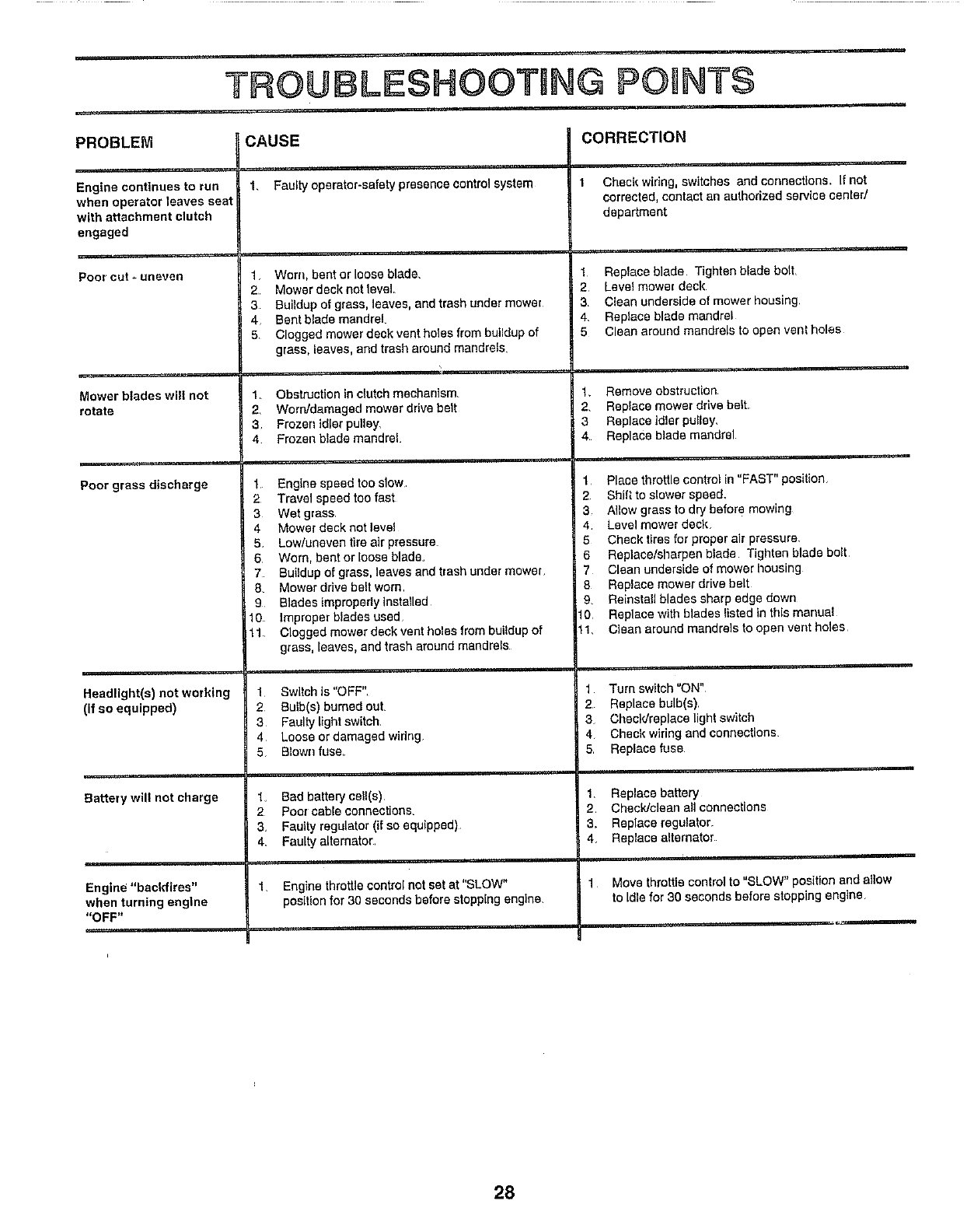
TROUBLESHOOTING POHNTS
.....i1_ , ,
PROBLEM CORRECTION
Engine continues to run
when operator leaves seat
with attachment clutch
engaged
Poorcut*unevan
Mower blades will not
rotate
_,,,,,,,
Poor grass discharge
Headlight(s) not working
(if so equipped)
Battery will not charge
Engin_ "backfires"
when turning engine
"OFF"
iiiiii
CAUSE
1, Faultyoperator-safetypresencecontrolsystem
1Worn, bent or loose blade,
2 Mower deck not level
3 Buildup of grass, leaves, and trash under mower
4 Bent blade mandrel
5 Clogged mower deck vent holes from buildup of
grass, leaves, and trash around mandrels
1 Obstruction In clutch mechanism.
2 Worn/damaged mower drivebelt
3 Frozen idler pulley,
4 Frozen blade mandrel.
1 Engtne speed too slow
2 Travel speedtoofast
3Wet grass
4 Mower deck not level
5. Low/uneven tire air pressure
6 Worn, bent or loose blade.
7 Buitdup of grass, leaves and trashundermower
8. Mower ddve beltworn
9 Blades improperlyInstalled
10 Improperblades used
11 Clogged mowerdeck vent holesfrom buiidup of
grass, leaves, and trash around mandrels
1 Switch Is "OFF"
2 Bulb(s) bumadouL
3Faulty light switch,
4 Loose or damaged widng
5 Blownfuse_
1. Bad battery cel!(s),
2 Poor cable connections.
& Faulty regulator (if so equipped)
4_ Faulty alternator,
1 Engine throttle controlnot sat at "SLOW"
position for 30 seconds before stopping engine.
Check wiring, switches and connections. If not
corrected, contactan authorized service cented
department
1 Replace blade Tighten blade boll
2 Level mower deck
3 Clean underside of mower housing,
4, Replace blade mandrel
5 Clean around mandrels to open vent holes
1_ Remove obstruction
2, Replace mower drive belt
3 Replace idler pollay_
4 Replace blade mandrel
1 Place throttle control in "FAST" position
2 Shift to slower speed,
3 Allow grass to dry before mowing
4, Level mower deck
5 Check tires for proper air pressure
6 Replace/sharpen blade Tighten blade bolt
7 Clean underslde of mower tlouslng
8 Replace mower drive belt
9, Reinstall blades sharp edge down
f0 Replace with blades listed in this manuat
11, Clean around mandrals to open vent holes
Turn switch =ON"
2 Replace bulb(s)
3 Checldreplaca light switch
4 Check wiring and connections
5 Replace fuse
1, Replace battery
2 Chscldclean all connections
& Replace regulator.
4 Replace alternator
1 Move throttle control to "SLOW" position andallow
to Idlefor 30 seconds before stopping engine
28
STORAGE
Immediately prepare your tractor for storage at the end of
the season or if the tractor will not be used for 30 days or
more.
_CAUTION: Neverstorethetractorwith
/l _gasoline in the tank inside a building
where fumes may reach an open flame
or spark. Allow the engine to cool
before storing in any enclosure.
TRACTOR
Remove mower from tractor for winter storage. When
mower is to be stored for a period of time, dean it thor-
oughly, remove all dirt, grease, leaves, etc. Store in a
clean, dry area.
o Clean entire tractor(See"CLEANING"in the Customer
Responsibilities section of this manual)_
•Inspect and replace belts, if necessary (See belt re-
placement instructions in the Service and Adjustments
section of this manual).
° Lubricate as shown in the Customer Responsibilities
section of this manual.
°Be sure that all nuts, bolts and screws are securely
fastened.. Inspect moving parls for damage, breakage
and wear. Replace if necessary.
Touch up all rusted or chipped paint surfaces; sand
lightly before painting.
BATTERY
• Fully charge the battery for storage.
= After a period of time in storage, battery may require
recharging.
° To help prevent corrosion and power leakage during
long periods of storage, battery cables should be
disconnected and battery cleaned thoroughly (see 'q'O
CLEAN BATTERY AND TERMINALS" in the Cus-
tomer Responsibilities section of this manual).
o After cleaning, leave cables disconnected and place
cables where they cannot come in contact with battery
terminals..
• Be sure battery drain tube is securely attached.
if battery is removed from tractor for storage, do not
store battery directly on concrete or damp surfaces
ENGINE
FUEL SYSTEM
IMPORTANT: IT IS IMPORTANT TO PREVENT GUM
DEPOSITS FROM FORMING IN ESSENTIAL FUEL
SYSTEM PARTS SUCH AS CARBURETOR, FUEL FILTER,
FUEL HOSE, OR TANK DURING STORAQE. ALSO,
EXPERIENCE INDICATES THAT ALCOHOL BLENDED
FUELS (CALLED GASOHOL OR USING ETHANOL OR
METHANOL) CAN ATTRACT MOISTURE WHICH LEADS
TO SEPARATION AND FORMATION OF ACIDS DURING
STORAGE. ACIDIC GAS CAN DAMAGE THE FUEL
SYSTEM OF AN ENGINE WHILE IN STORAGE.
oDrain the fuel tank..
° Start the engine and let it run until the fuel lines and
carburetor are empty.
Never use engine or carburetor cleaner products in the
fuel tank or permanent damage may occur.
o Use fresh fuel next season_
NOTE: Fuel stabilizer is an acceptable alternative in
minimizing the formation of fuel gum deposits during stor-
age, Add stabilizer to gasoline in fuel tank or storage
container. Always follow the mix ratio found on stabilizer
container. Run engine at least 10 minutes after adding
stabilizer to allow the stabilizer to reach the carburetor. Do
not drain the gas tank and carburetor4f using fuel stabilizer,
ENGINE OUL
Drain oil (with engine warm) and replace with clean engine
oil. (See "ENGINE" in the Customer Responsibilities
section of this manual)_
CYLINDERS
o Remove spark plug(s).
Pour one ounce of oil through spark plug hole(s) into
cylinder(s)..
o Turn ignition key to"START" position for a few seconds
to distribute oil.
Replace with new spark plug(s).
OTHER
• Do not store gasoline from one season to another.
o Replace your gasoline can if your can starts to rusL
Rust and/or dirt in your gasoline will cause problems
o If possible, store your tractor indoors and cover it to
give protection from dust and dirt,
°Cover your tractor with a suitable protective cover that
does not retain moisture, Do not use plastic. Plastic
cannot breathe which allows condensation to form and
will cause your tractor to rust,
IMPORTANT: NEVER COVER TRACTOR WHILE ENGINE
AND EXHAUST AREAS ARE STILL WARM
29

SERVICE NOTES
3O
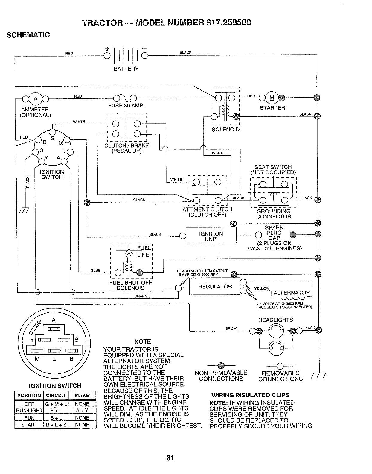
TRACTOR --MODEL NUMBER 917.258580
SCHEMATIC
RBO
BATTERY
BLACK
RED
I
I STARTER
Y A
WHITE
FUSE 30 AMP,
'O_
I
I;i
_ft ....... J
(PEDAL UP) u
BLACK
BLACK
BLUE
..... J
SOLENOID
WHITE
WHITE _
, L I
---f BLACK
"--u,'o__
ATT'MENT CLUTCH
(CLUTCH OFF)
; _U ELIi
II 'z_" LINE i
i
T
IJ
FUEL SHUT-OFF
SOLENOID
ORANGE
IGNITION
UNIT
CHARGING SYSTEM OUTPUT
15 AMP BG @ 3600 RPM
i-_ REGULATOR
BLACK
SEAT SWITCH
(NOT OCCUPIED)
"11[I_I........ 1}--{BLACK
L_ _ _,
GROUNDING
CONNECTOR
_1 SPARK
PLUG
I _ GAP
I (2 PLUGS ON
TWIN CYL, ENGINES)
LLOW
28 VOLTS AG @ 3600 RPM
(REGULATOR DISCONNECTED)
IGNITION SWITCH
POSITION "MAKE"
OFF G + M + L NONE
RUN/LIGHT B + L A + Y
RUN B + L NONE
START B + L + S NONE
NOTE
YOUR TRACTOR IS
EQUIPPED WITH ASPECIAL
ALTERNATOR SYSTEM.
THE LIGHTS ARE NOT
CONNECTED TO THE
BATTERY, BUT HAVE THEIR
OWN ELECTRICAL SOURCE,
BECAUSE OF THIS, THE
BRIGHTNESS OF THE LIGHTS
WILL CHANGE WITH ENGINE
SPEED. AT IDLE THE LIGHTS
WILL DIM. AS THE ENGINE IS
SPEEDED UP, THE LIGHTS
WILL BECOME THEIR BRIGHTEST.
BROWN
HEADLIGHTS
@ 0
NON-REMOVABLE REMOVABLE
CONNECTIONS CONNECTIONS /_'
WIRING INSULATED CLIPS
NOTE: IF WIRING INSULATED
CLIPS WERE REMOVED FOR
SERVICING OF UNIT, THEY
SHOULD BE REPLACED TO
PROPERLY SECURE YOUR WIRING,
31
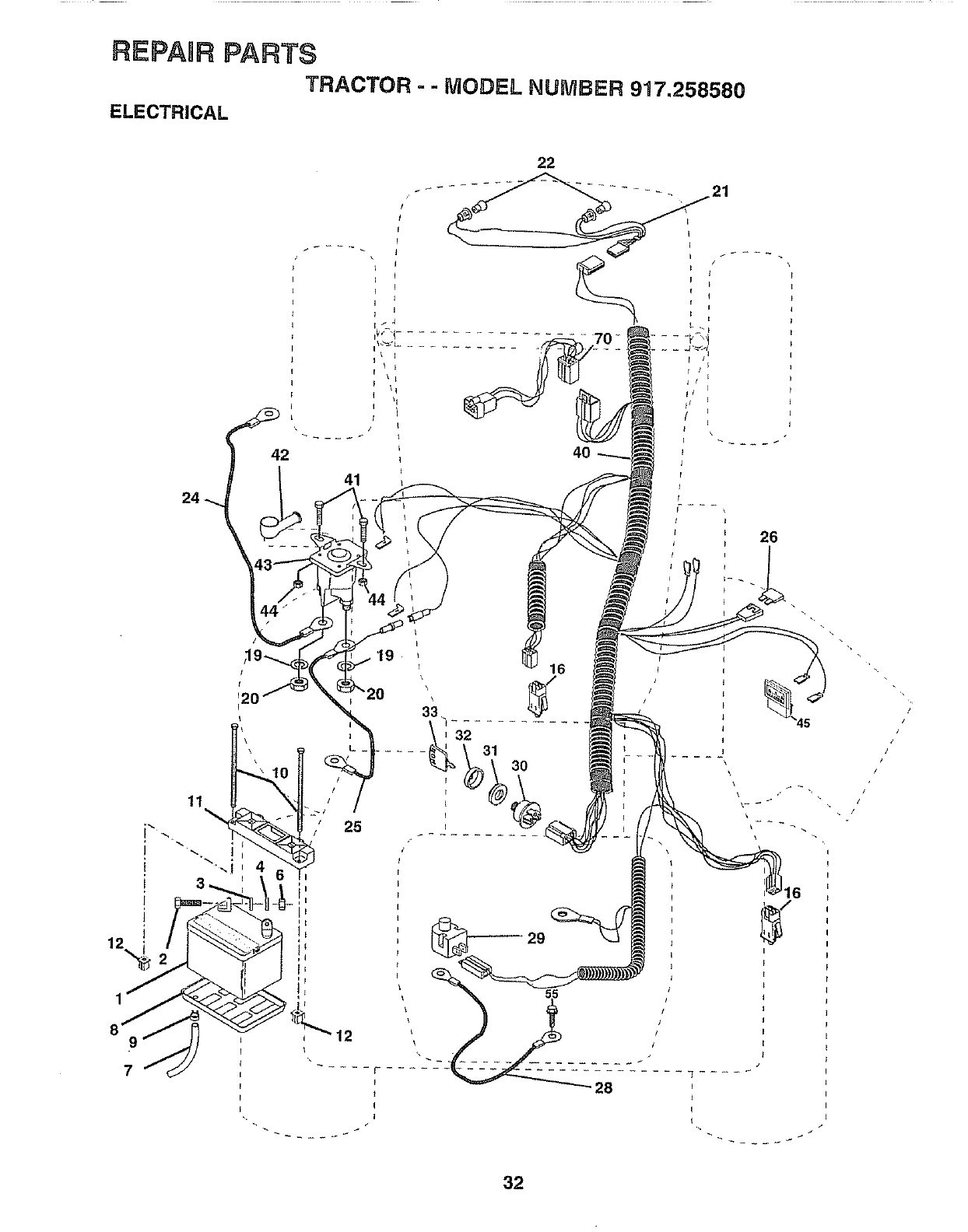
REPAIR PARTS
TRACTOR - - MODEL NUMBER 917.258580
ELECTRICAL
42
11
/ 25
40
26
16
,32
_31 30 !
/
!
32
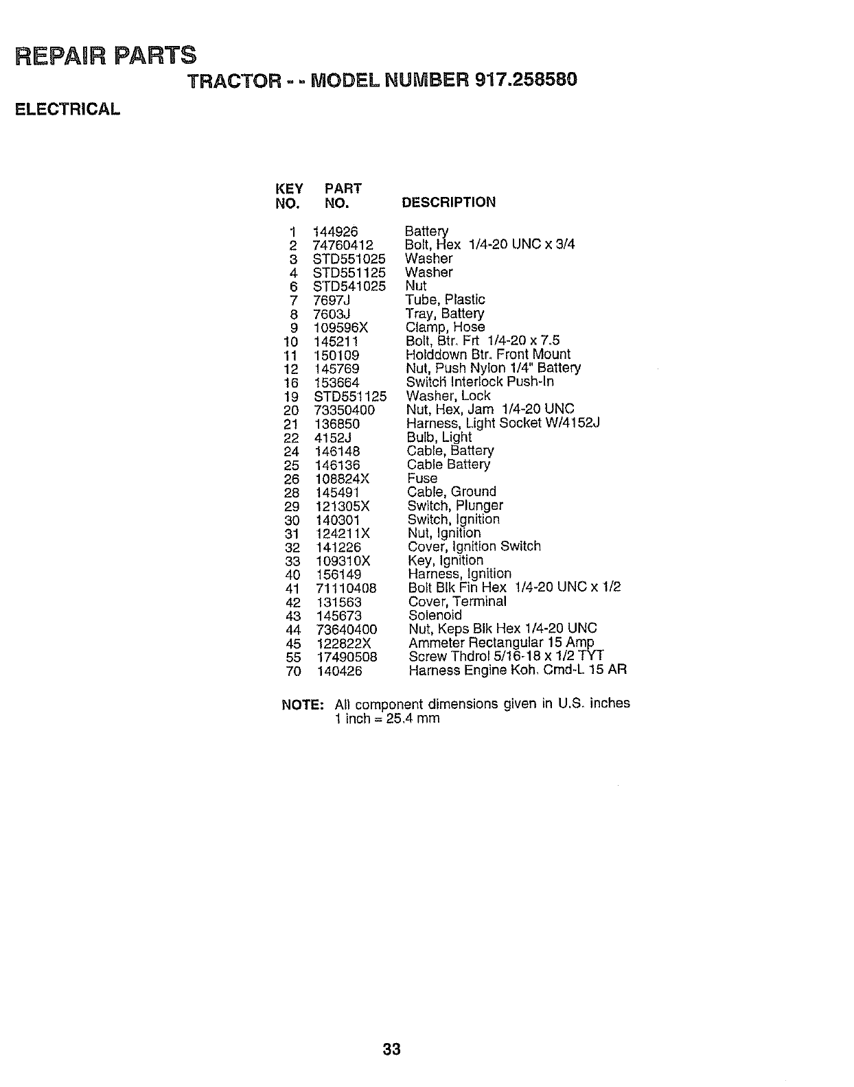
RE PAURPARTS
TRACTOR = - MODEL NUMBER 917,258580
ELECTRICAL
KEY PART
NO. NO. DESCRIPTION
1 144926
2 74760412
3 STD551025
4 STD551125
6 STD541025
7 769_J
8 7603J
9 109596X
10 145211
'11 150109
12 145769
16 153664
19 STD551125
20 73350400
21 136850
22 4152J
24 146148
25 146136
26 108824X
28 145491
29 121305X
30 140301
31 124211X
32 141226
33 109310X
40 156149
41 71110408
42 131563
43 145673
44 73640400
45 122822X
55 17490508
70 140426
Battery
Bolt, Hex 1/4-20 UNC x 3/4
Washer
Washer
Nut
Tube, Plastic
Tray, Battery
Clamp, Hose
Bolt, Btr. Frt 1/4-20 x 7.5
Holddown Btr. Front Mount
Nut, Push Nylon 1/4" Battery
Switcii Interlock Push-In
Washer, Lock
Nut, Hex, Jam 1/4-20 UNC
Harness, Light Socket W/4152J
Bulb, Light
Cable, Battery
Cable Battery
Fuse
Cable, Ground
Switch, Plunger
Switch, Ignition
Nut, Ignition
Cover, Ignition Switch
Key, Ignition
Harness, Ignition
Bolt BIk Fin Hex 1/4-20 UNC x 1/2
Cover, Terminal
Solenoid
Nut, Keps BIk Hex 1/4-20 UNC
Ammeter Rectangular 15 Amp
Screw Thdrol 5/16-18 x 1/2 TYT
Harness Engine Koh, Cmd-L 15 AR
NOTE: All component dimensions given in U.S, inches
1 inch = 25,4 mm
33
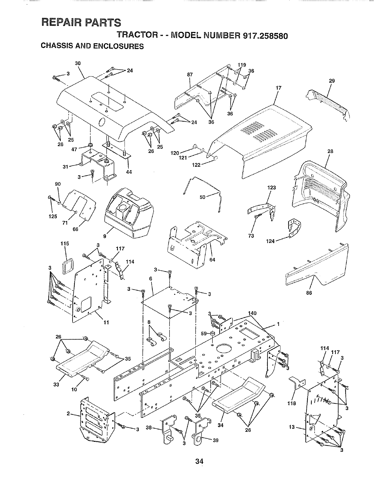
REPAIR PARTS
TRACTOR - -MODEL NUMBER 917.258580
CHASSIS AND ENCLOSURES
30
87
119
36
17
29
9O
26
125
71
3
115
26
44
3117
114
6
25
121
36
64
36
123
28
86
26
33 !0
8
140
26
118
114 117 3
34
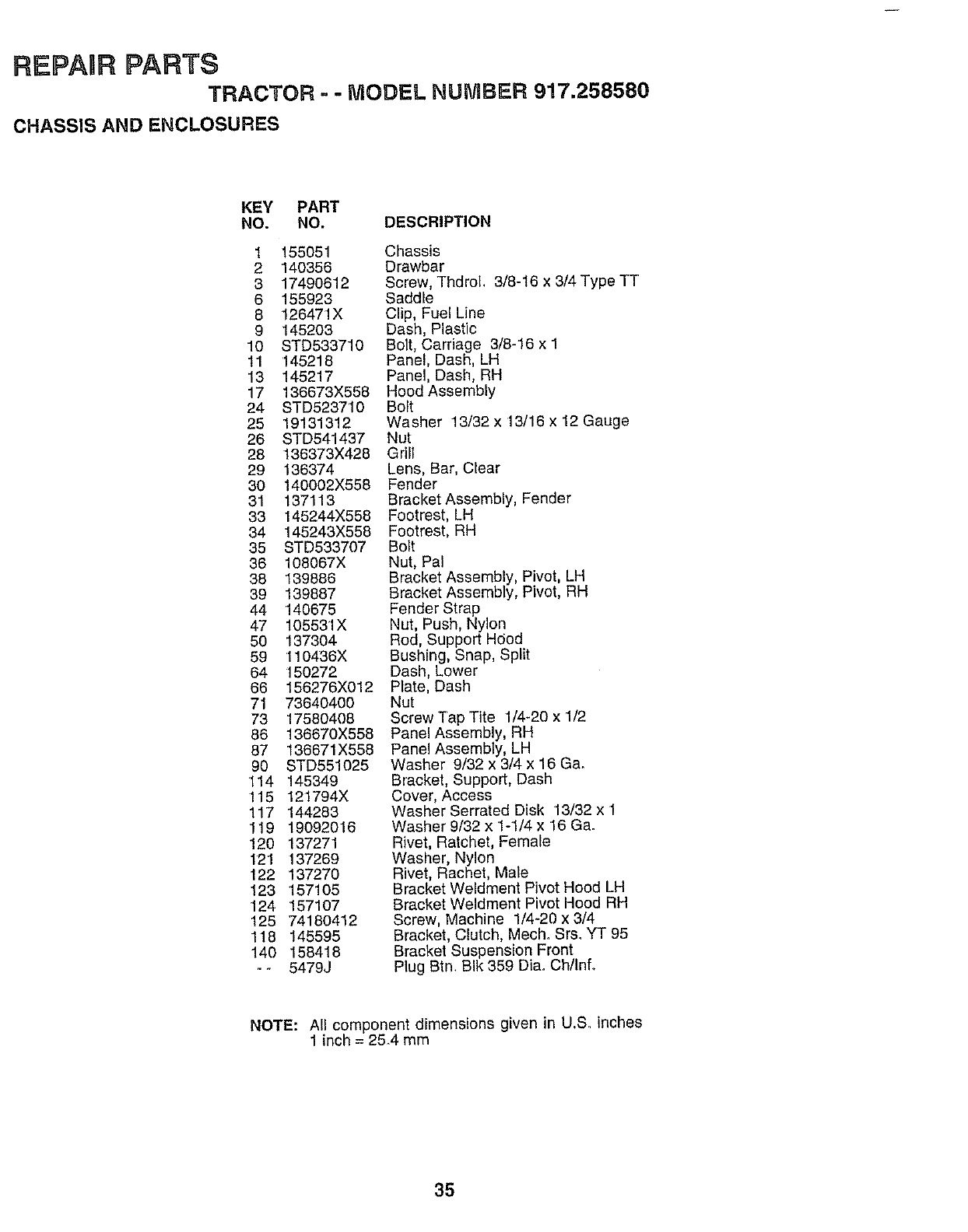
REPAIR PARTS
TRACTOR - -MODEL NUMBER 917.258580
CHASSIS AND ENCLOSURES
KEY PART
NO. NO. DESCRIP_ON
1 155051 Chassis
2 140356 Drawbar
3 17490812 Screw, ThdroL 3/8-16 x3/4 Type TT
6 155923 Saddle
8 126471X Clip, Fuel Line
9 145203 Dash, Plastic
10 STD533710 Bolt, Carriage 3/8-16 x 1
11 145218 Panel, Dash, LH
13 145217 Panel, Dash, RH
17 136673X558 Hood Assembly
24 STD523710 Bolt
25 19131312 Washer 13/32x 13/18 x 12 Gauge
26 STD541437 Nut
28 136373X428 Grill
29 136374 Lens, Bar, Clear
30 140002X556 Fender
31 137113 Bracket Assembly, Fender
33 145244X558 Footrest, LH
34 145243X558 Footrest, RH
35 STD533707 Bolt
36 108067X Nut, Pal
38 139886 Bracket Assembly, Pivot, LH
39 139887 Bracket Assembly, Pivot, RH
44 140675 Fender Strap
47 105531X Nut, Push, Nylon
50 137304 Rod, Support Hood
59 110436X Bushing, Snap, Split
64 150272 Dash, Lower
66 156278X012 Plate, Dash
71 73640400 Nut
73 17580408 Screw Tap Tite 1/4-20 x 1/2
86 136670X558 Panel Assembly, RH
87 136671X558 Panel Assembly, LH
90 STD551025 Washer 9/32 x 3/4 x 16 Ga.
114 145349 Bracket, Support, Dash
115 121794X Cover, Access
117 144283 Washer Serrated Disk 13/32 x 1
119 19092016 Washer 9/32 x 1-1/4 x 16 Ga.
120 137271 Rivet, Ratchet, Female
121 137269 Washer, Nylon
122 137270 Rivet, Rachet, Male
123 157105 Bracket Weldment Pivot Hood LH
124 157107 Bracket Weldment Pivot Hood RH
125 74180412 Screw, Machine 1/4-20 x 3/4
118 145595 Bracket, Clutch, Mech. Srs. YT 95
140 158418 Bracket Suspension Front
- - 5479J Plug Btn. BIk 359 Dia. Ch/Info
NOTE: All component dimensions given in U.S_ inches
1inch = 25.4 mm
35
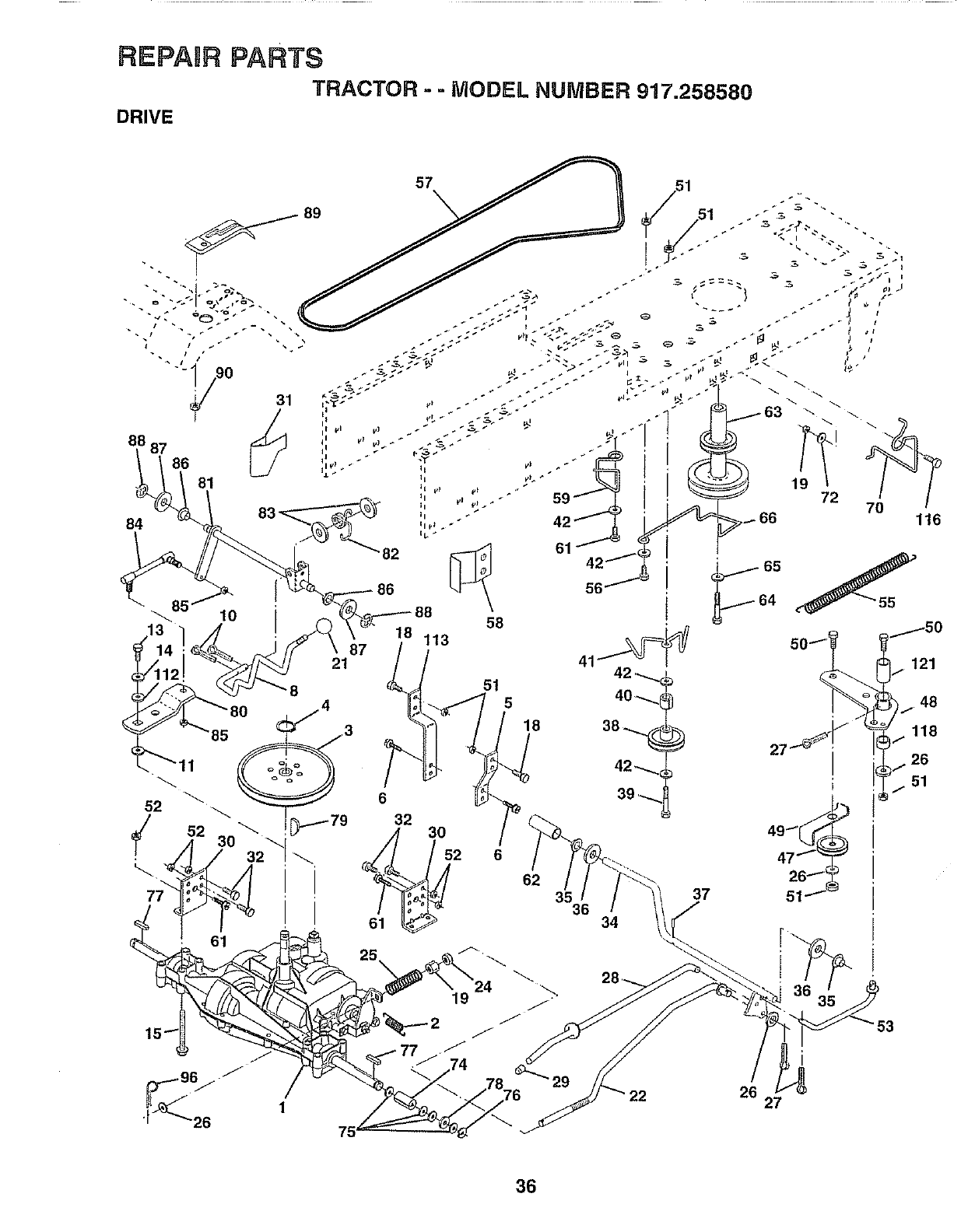
REPAIR PARTSTRACTOR" -MODEL NUMBER 917.258580
DRIVE
/
70 _'_6
18 113 121
87
21
6
32
51 5
18
42 ,--_
39 _._
52 6
19
/
/
62 35
29
34
37
26
22
511
36
27
36
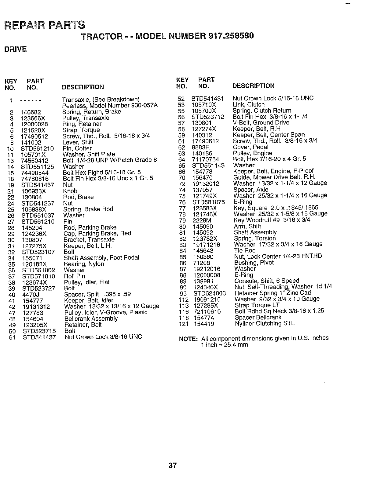
REPAURPARTS
TRACTOR =-MODEL NUMBER 917.258580
DRIVE
KEY PART KEY PART
NO. NO. DESCRIPTION NO, NO. DESCRIPTION
1 ...... Transaxle,(See Breakdown) 52 STD541431
Peerless, Model Number 930-057A 53 105710X
2 146682 Spring, Return, Brake 55 105709X
3 123666X Pulley, Transaxle 56 STD523712
4 12000028 Ring, Retainer 57 130801
5 121520X Strap, Torque 58 127274X
6 17490512 Screw, Thd. ROllo 5/16-18 x 3/4 59 140312
8 141002 Lever, Shift 61 17490612
10 STD561210 Pin, Cotter 62 8883R
11 105701X Washer, Shift Plate 63 140186
13 74550412 Bolt 1/4-28 UNF W/Patch Grade 8 64 71170764
14 STD551125 Washer 65 STD551143
15 74490544 Bolt Hex Flghd 5/16-18 Gr. 5 66 154778
18 74780616 Bolt Fin Hex 3/8_16 Unc x 1 Gr. 5 70 156470
19 STD541437 Nut 72 19132012
21 106933X Knob 74 137057
22 130804 Rod, Brake 75 121749X
24 STD541237 Nut 76 STD581075
25 106888X Spring, Brake Rod 77 123583X
26 STD551037 Washer 78 121748X
27 STD561210 Pin 79 2228M
28 145204 Red, Parking Brake 80 145090
29 124236X Cap, Parking Brake, Red 81 145092
30 130807 Bracket, Transaxle 82 123782X
31 127275X Keeper, Belt, L.H_ 83 19171216
32 STD523107 Bolt 84 145643
34 155071 Shaft Assembly, Foot Pedal 85 150360
35 120183X Bearing, Nylon 86 71208
36 STD551062 Washer 87 19212016
37 STD571810 Roll Pin 88 12000008
38 123674X Pulley, Idler, Flat 89 139991
39 STD523727 Bolt 90 124346X
40 4470J Spacer, Split .395 x.59 96 STD624003
41 154777 Keeper, Belt, Idler 112 19091210
42 19131312 Washer 13/32 x 13/16 x 12 Gauge 113 I27285X
47 127783 Pulley, Idler, V-Groove, Plastic 116 72110610
48 154604 Bellcrank Assembly 118 154774
49 123205X Retainer, Belt 121 154419
50 STD523715 Bolt
51 STD541437 Nut Crown Lock 3/8-16 UNC
Nut Crown Lock 5/16_18 UNC
Link, Clutch
Spring, Clutch Return
Bolt Fin Hex 3/8-16 x 1-1/4
V-Belt, Ground Drive
Keeper, Belt, R.H.
Keeper, Belt, Center Span
Screw, Thd., Roll 3/8-16 x 3/4
Cover, Pedal
Pulley, Engine
Bolt, Hex 7/16-20 x 4 Gr. 5
Washer
Keeper, Belt, Engine, F-Proof
Guide, Mower Drive Belt, R.Ho
Washer 13/32 x 1-1/4 x 12 Gauge
Spacer, Axle
Washer 25/32 x 1-1/4 x 16 Gauge
E-Ring
Key, Square 2.0 x .1845/.1865
Washer 25/32 x 1-5/8 x 16 Gauge
Key Woodruff #9 3/16 x 3/4
Arm, Shift
Shaft Assembly
Spring, Torsion
Washer 17/32 x 3/4 x 16 Gauge
Tie Rod
Nut, Lock Center 1/4-28 FNTHD
Bushing, Pivot
Washer
E-Ring
Console, Shift, 6 Speed
Nut, Self-Threading, Washer Hd 1/4
Retainer Spring 1" Zinc Cad
Washer 9/32 x 3/4 x 10 Gauge
Strap Torque LT
Bolt Rdhd Sq Neck 3/8-16 x 1.25
Spacer Bellcrank
Nyliner Clutching STL
NOTE: All component dimensions given in U.S. inches
1 inch = 25.4 mm
37
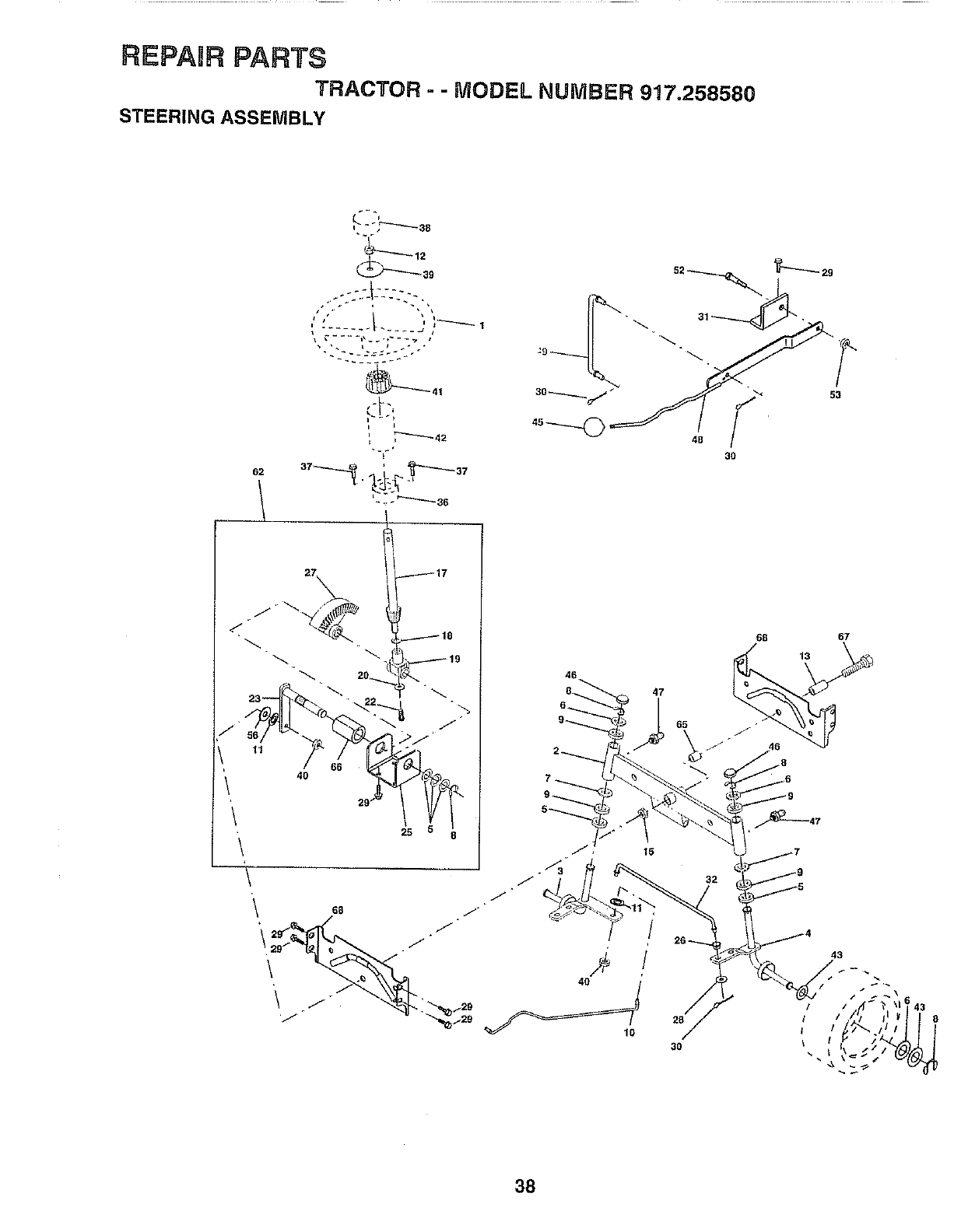
REPAIR PARTS
TRACTOR - - MODEL NUMBER 917,258580
STEERING ASSEMBLY
62
L'
,"÷,_-"-'-'3B
|
i ....... t ._.__J iI_ ]
t
L:- "'"-'_36
53
47
32
3O
38
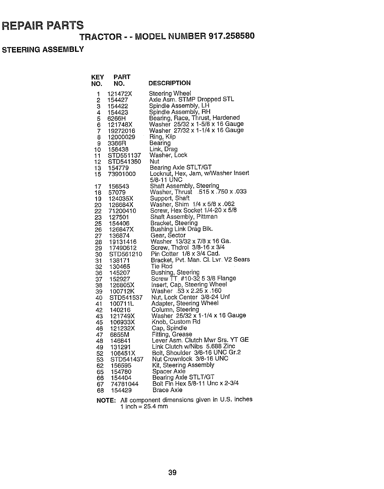
REPAgR PARTS
TRACTOR --MODEL NUMBER 917.258580
STEERING ASSEMBLY
KEY PART
NO. NO. DESCRIPTION
1 121472X
2 154427
3 154422
4 154423
56266H
6 121748X
7 19272016
8 12000029
9 3366R
10 156438
11 STD551137
12 STD541350
13 154779
15 73901000
17 156543
18 57079
19 124035X
20 126684X
22 71200410
23 127501
25 154406
26 126847X
27 136874
28 19131416
29 17490612
30 STD561210
31 138171
32 130465
36 145207
37 152927
38 126805X
39 100712K
40 STD541537
41 100711L
42 '140216
43 121749X
45 106933X
46 121232X
47 6855M
48 146841
49 131291
52 106451X
53 STD541437
62 156595
65 154780
66 154404
67 74781044
68 154429
Steering Wheel
Axle Asm. STMP Dropped STL
Spindle Assembly, LH
Spindle Assembly, RH
Searing, Race, Thrust, Hardened
Washer 25/32 x 1-5/6 x 16 Gauge
Washer 27/32 x 1-1/4 x 16 Gauge
Ring, Klip
Searing
Link, Drag
Washer, Lock
Nut
Bearing Axle STLT/GT
Locknut, Hex, Jam, w/Washer Insert
5/8-11 UNC
Shaft Assembly, Steering
Washer, Thrust .515 x .750 x .033
Support, Shaft
Washer, Shim 1/4 x5/8 x _062
Screw, Hex Socket 1/4-20 x 5/8
Shaft Assembly, Pittman
Bracket, Steering
Bushing Link Drag BIk.
Gear, Sector
Washer 13/32 x 7/8 x 16 Ga.
Screw, Thdrol 3/8-16 x 3/4
Pin Cotter 1/8 x 3/4 Ca&
Bracket, PvL Man.. CL Lvr V2 Sears
Tie Rod
Bushing, Steering
Screw "FT"#10-32 5 3/8 Flange
Insert, Cap, Steering Wheel
Washer 53 x 2.25 x .160
Nut, Lock Center 3/8-24 Unf
Adapter, Steering Wheel
Column, Steering
Washer 25/32 x 1-1/4 x 16 Gauge
Knob, Custom Rd
Cap, Spindle
Fitting, Grease
Lever Asm Clutch Mwr Srs. YT GE
Link Clutch w/Nibs 5.688 Zinc
Bolt, Shoulder 3/8-16 UNC Gr.2
Nut Crownlock 3/8-16 UNC
Kit, Steering Assembly
Spacer Axle
Bearing Axle STLT/GT
Bolt Fin Hex 5/8-11 Uric x 2-3/4
Brace Axle
NOTE: All component dimensions given in U.S. inches
1 inch = 25.4 mm
39
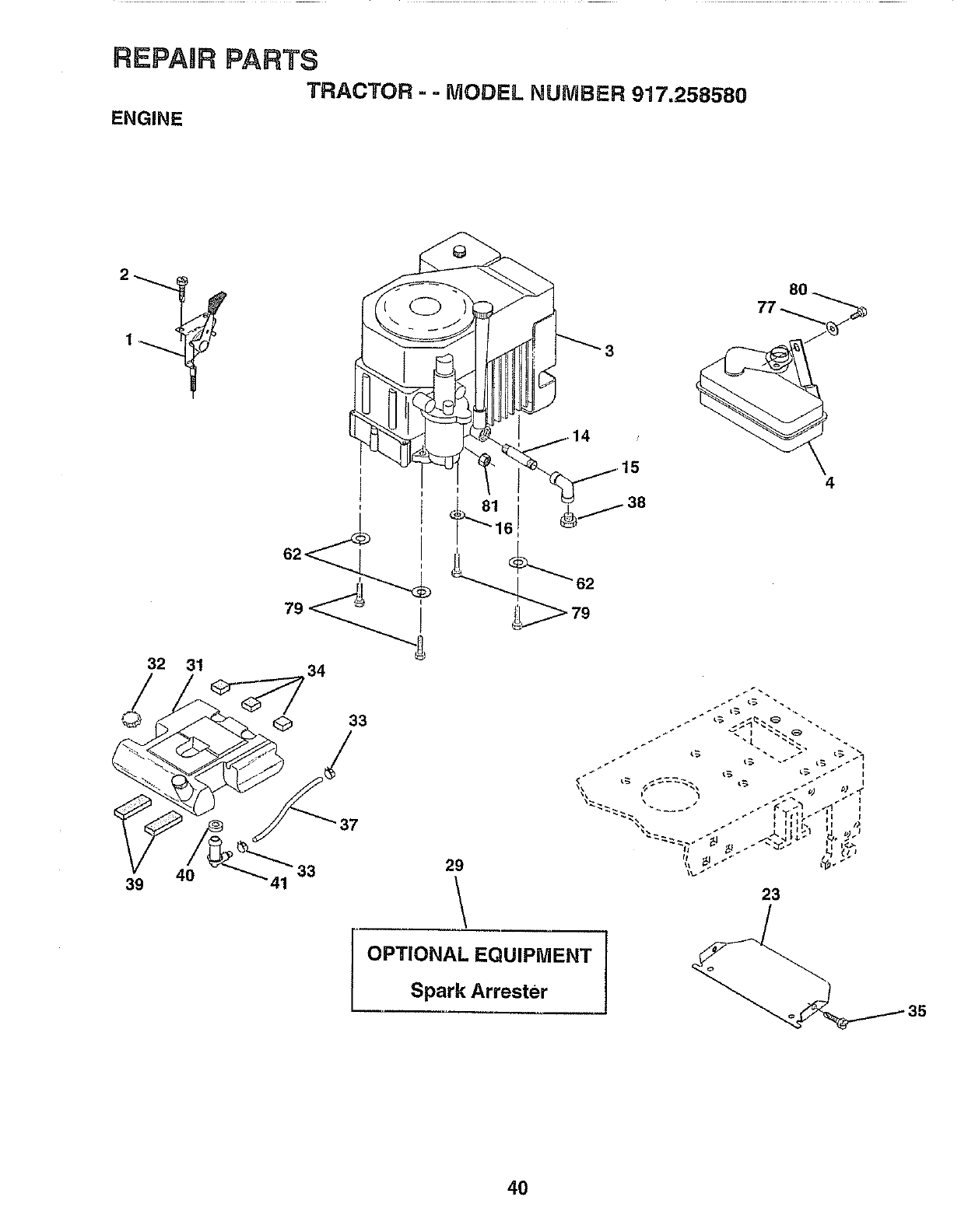
REPAaR PARTS
TRACTOR --MODEL NUMBER 917.258580
ENGINE
32 31
J34
33
/
37
40 _33 29
39 41
OPTIONAL EQUIPMENT
Spark Arrester
23
4O
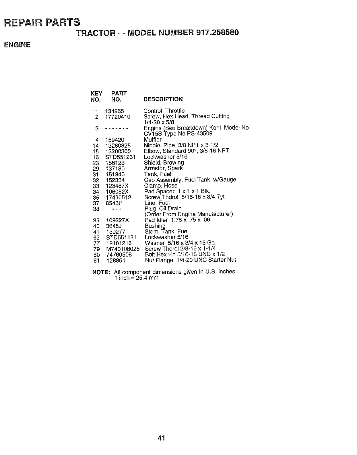
REPAIR PARTS
TRACTOR = = MODEL NUMBER 917.258580
ENGINE
KEY PART
NO. NO. DESCRIPTION
"1 134265
2 17720410
3
4 159420
14 13280328
15 13200300
16 STD551231
23 156123
29 137180
31 151346
32 152334
33 123487X
34 106082X
35 17490512
37 8543R
38 ---
39 109227X
40 3645J
41 139277
62 STD551131
77 19101216
79 M740108025
80 74760508
81 128861
Control, Throttle
Screw, Hex Head, Thread Cutting
1/4-20 x 5/8
Engine (See Breakdown) Kohl Model No.
CV15S Type No PS-43509
Muffler
Nipple, Pipe 3/8 NPT x 3-1/2
Elbow, Standard 90,3/8-18 NPT
Locl_vasher 5/16
Shield, Browing
Arrestor, Spark
Tank, Fuel
Cap Assembly, Fuel Tank, w/Gauge
Clamp, Hose
Pad Spacer 1 x 1 x 1 BIk.
Screw Thdrol 5/16-18 x 3/4 Tyt
Line, Fuel
Plug, Oil Drain
(Order From Engine Manufacturer)
Pad Idler 1.75 x .75 x .06
Bushing
Stem, Tank, Fuel
Lockwasher 5/16
Washer 5/16 x 3/4 x 16 Ga.
Screw Thdrol 3/8-16 x 1-1/4
Bolt Hex Hd 5/16-18 UNC x 1/2
Nut Flange 1/4-20 UNC Starter Nut
NOTE: All component dimensions given in U.S inches
1inch = 25.4 mm
41
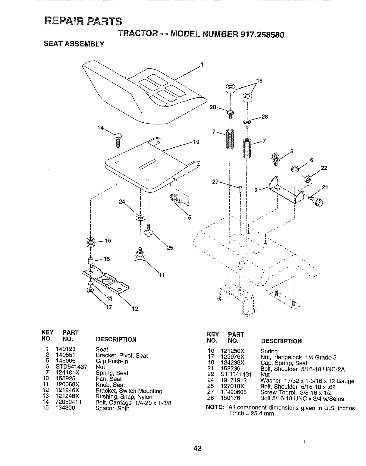
REPAaR PARTS
TRACTOR --MODEL NUMBER 917,258580
SEAT ASSEMBLY
I
116 25
13
KEY PART
NO. NO.
1140123
2 140551
5 145006
6 STD541437
7 124181X
10 155925
11 120068X
12 121246X
13 121248X
14 72050411
15 134300
DESCRIPTION
Seat
Bracket, Pivot, Seat
Clip Push-In
Nut
Spring, Seat
Pan, Seat
Knob, Seat
Bracket, Switch Mounting
Bushing, Snap, Nylon
Bolt, Carriage 1/4-20 x 1-3/8
Spacer, Split
KEY PART
NO. NO, DESCRIPTION
16 121250X
17 123976X
18 124238X
21 153236
22 STD541431
24 19171912
25 127018X
27 1T490608
28 150176
Spring 5
Nut, Flangelock 1/4 Grade
Cap, Spring, Seai
Bolt, Shoulder 5/16-18 UNC-2A
Nut
Washer 17/32 x 1-3/16 x 12 Gauge
Bolt, Shoulder 5/16-18 x .62
Screw ThdroL 3/8-16 x 1/2
Bolt 5/16-18 UNC x 3/4 w/Sems
NOTE: All component dimensions given in U.S. inches
1 inch = 25.4 rnm
42
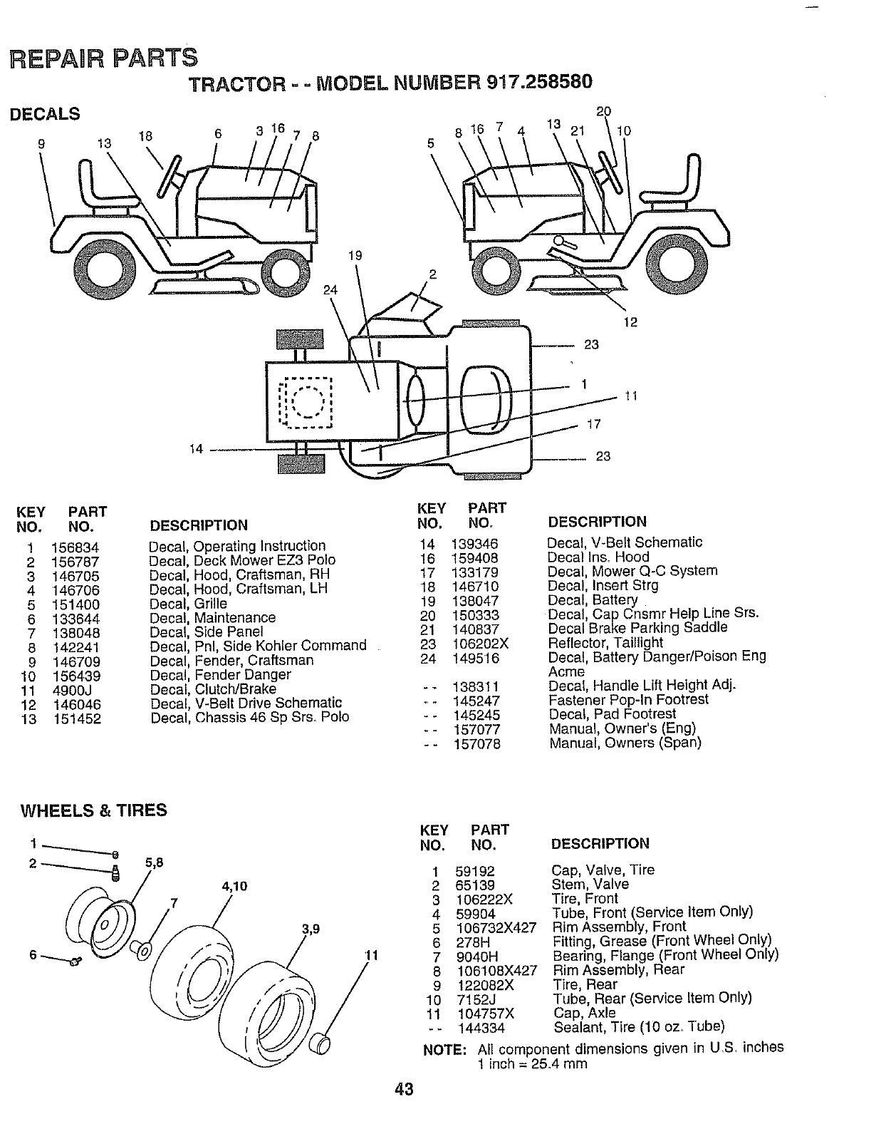
REPAIR PARTS
TRACTOR -= MODEL NUMBER 917.258580
DECALS
9
20
13 18 6 3 7
19
24
816 7
5
\10
12
-- 23
14
1
17
23
11
KEY PART
NO. NO.
1 156834
2 156787
3 146705
4 '146706
5 151400
6 133644
7 138048
8 142241
9 146709
10 156439
11 4900J
12 146046
13 151452
DESCRIPTION
Decal, Operating Instruction
Decal, Deck Mower EZ3 Polo
Decal, Hood, Craftsman, RH
Decal, Hood, Craftsman, LH
Decal, Grille
Decal, Maintenance
Decal, Side Panel
Decal, Pnl, Side Kohler Command
Decal, Fender, Craftsman
Decal, Fender Danger
Decal, Clutch/Brake
Decal, V-Belt Drive Schematic
Decal, Chassis 46 Sp Sr& Polo
KEY
NO.
14
16
17
18
19
20
21
23
24
PART
NO,
139346
159408
133179
146710
138047
15o333
140837
106202X
149516
138311
145247
145245
157077
157078
DESCRIPTION
Decal, V-Belt Schematic
Decal Ins. Hood
Decal, Mower Q-C System
Decal, Insert Strg
Decal, Battery
Decal, Cap Cnsmr Help Line Srs.
Decal Brake Parking Saddle
Reflector, Taillight
Decal, Battery Danger/Poison Eng
Acme
Decal, Handle Lift Height Adj.
Fastener Pop-in Footrest
Decal, Pad Footrest
Manual, Owner's (Eng)
Manual, Owners (Span)
WHEELS &TIRES
2_5,8 4,10
7
11
43
KEY PART
NO. NO. DESCRIPTION
159192
2 65139
3 106222X
4 59904
5 106732X427
6 278H
7 9040H
8 106108X427
9 122082X
10 7152J
11 104757X
-- 144334
Cap, Valve, Tire
Stem, Valve
Tire, Front
Tube, Front (Service Item Only)
Rim Assembly, Front
Fitting, Grease (Front Wheel Only)
Bearing, Flange (Front Wheel Only)
Rim Assembly, Rear
Tire, Rear
Tube, Rear (Service Item Only)
Cap, Axle
Sealant, Tire (10 oz,. Tube)
NOTE: All component dimensions given in U.S, inches
1 inch = 25.4 mm
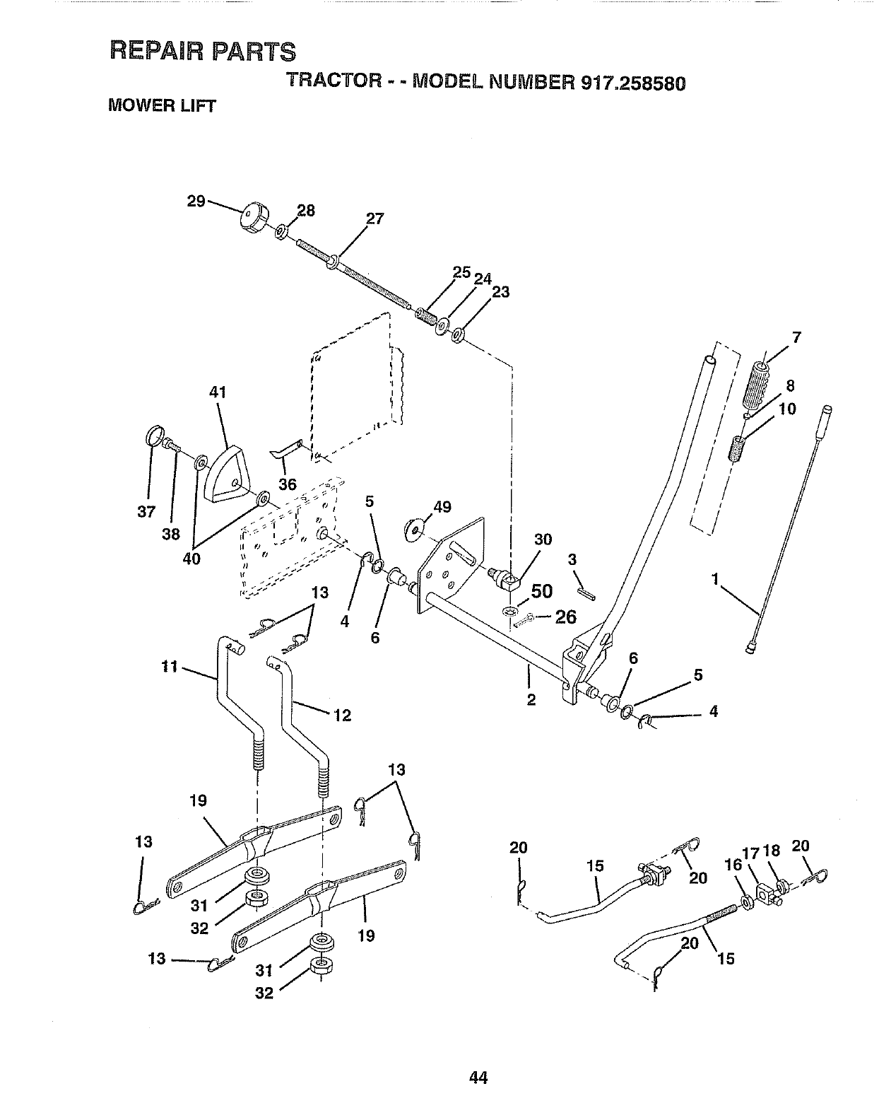
REPAIR PARTS
TRACTOR - - MODEL NUMBER 917.258580
MOWER LIFT
41
36 5
2524 23
49
2
6
7
8
5
4
19
13
13
13---_
32
19
2O 15 2O
1718 20
44
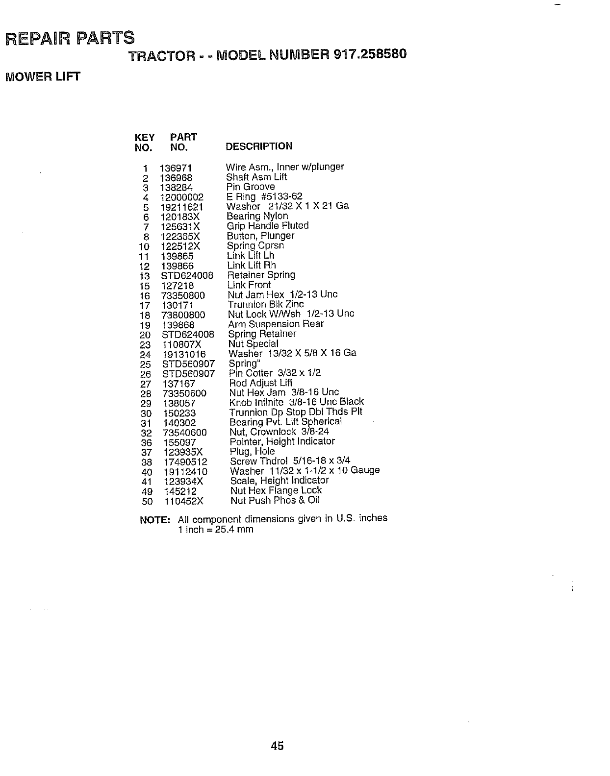
REPAgR PARTS
TRACTOR =-MODEL NUMBER 917.258580
MOWER LIFT
KEY PART
NO. NO. DESCRIPTION
1 136971
2136968
3 138284
4 12000002
5 19211621
6120183X
7 125631X
8 122365X
10 122512X
11 139865
12 139866
13 STD624008
15 127218
16 73350800
17 130171
18 73800800
19 139868
20 STD624008
23 110807X
24 '19131016
25 STD580907
26 STD560907
27 137167
28 73350600
29 138057
30 150233
31 140302
32 73540600
36 155097
37 123935X
38 17490512
40 19112410
41 123934X
49 145212
50 110452X
Wire Asm., Inner w/plunger
Shaft Asm Lift
Pin Groove
E Ring #5133-62
Washer 21/32 X 1 X 21 Ga
Bearing Nyton
Grip Handle Fluted
Button, Plunger
Spring Cprsn
Link Lift Lh
Link Lift Rh
Retainer Spring
Link Front
Nut Jam Hex 1/2-13 Uric
Trunnion BIk Zinc
Nut Lock W/Wsh 1/2-13 Unc
Arm Suspension Rear
Spring Retainer
Nut Special
Washer 13/32 X 5/8 X 16 Ga
Spring"
Pin Cotter 3/32 x 1/2
Rod Adjust Lift
Nut Hex Jam 3/8-16 Uric
Knob Infinite 3/8-16 Unc Black
Trunnion Dp Stop Dbt Thds Pit
Bearing PvL Lift Spherical
Nut, Crownlock 3/8-24
Pointer, Height Indicator
Plug, Hole
Screw Thdrol 5/16-18 x 3/4
Washer 11/32 x 1-1/2 x 10 Gauge
Scale, Height Indicator
Nut Hex Flange Lock
Nut Push Phos & Oil
NOTE: All component dimensions given in U,S. inches
1 inch = 25.4 mm
45
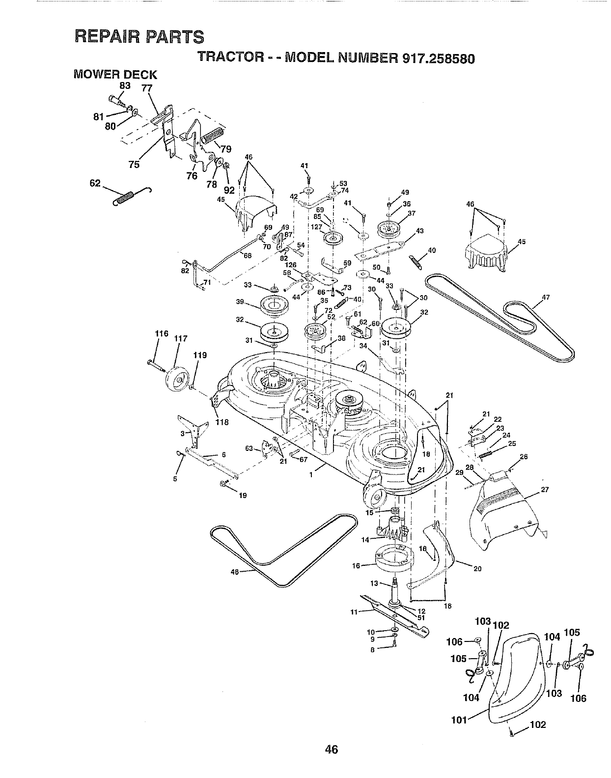
REPAnRPARTS
TRACTOR -- MODEL NUMBER 917.258580
MOWER DECK
83 77
80
75
116
/
76 78
45
117
119
46
21
21 22
26
46
18
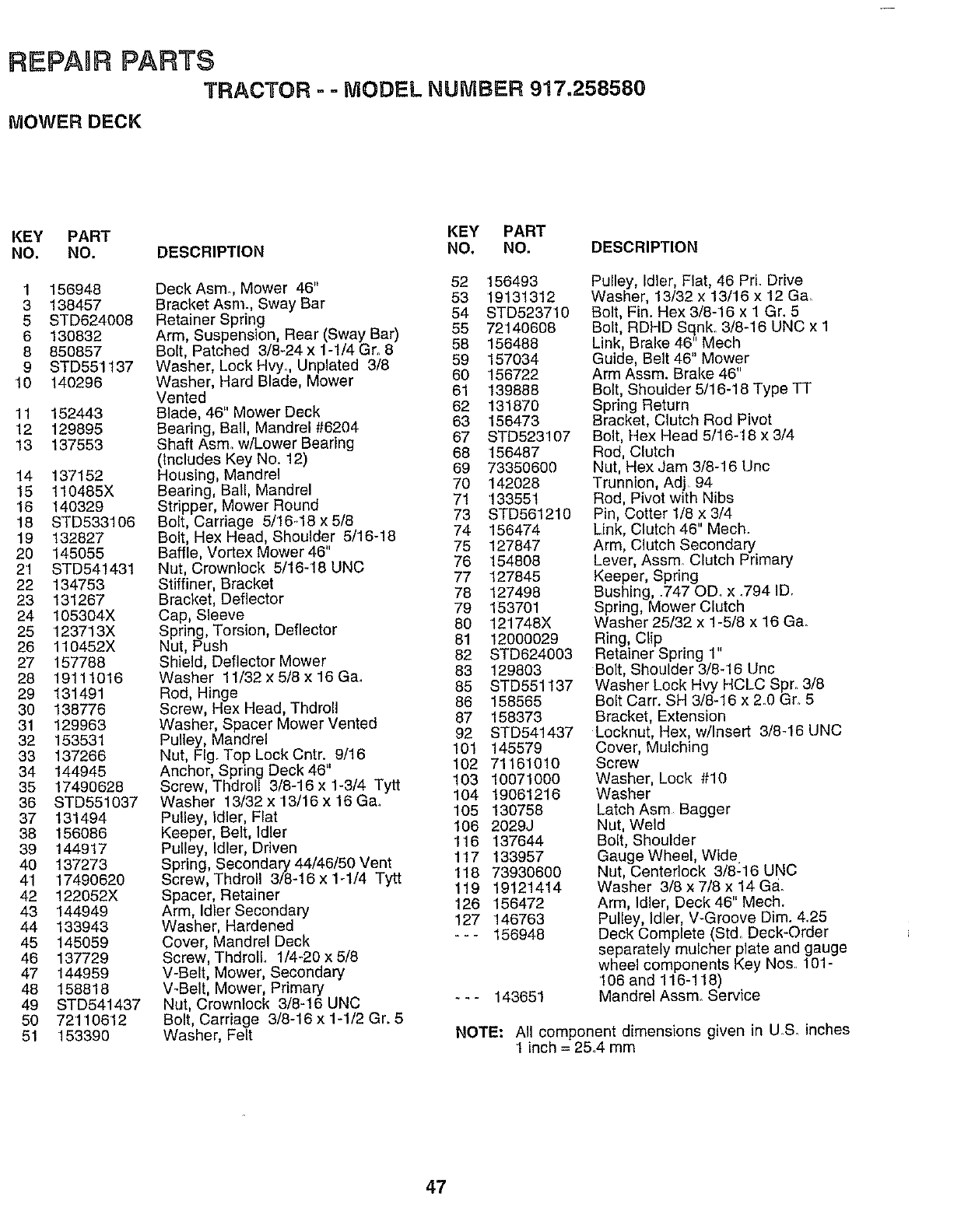
REPAIR PARTS
TRACTOR --MODEL NUMBER 917.258580
MOWER DECK
KEY PART KEY PART
NO. NO. DESCRIPTION NO. NO, DESCRIPTION
1 156948
3 138457
5 STD624008
6 130832
8 850857
9 STD551137
10 140296
11 152443
12 129895
13 137553
14 137152
15 110485X
18 140329
18 STD633106
19 132827
20 145055
21 STD541431
22 134753
23 131267
24 105304X
25 123713X
26 110452X
27 157788
28 19111016
29 131491
30 138776
31 129963
32 153531
33 137266
34 144945
35 17490628
36 STD551037
37 131494
38 156086
39 144917
40 137273
41 17490620
42 122052X
43 144949
44 133943
45 145059
46 137729
47 144959
48 158818
49 STD541437
50 72110612
51 153390
DeckAsm., Mower 46" 52 156493
Bracket Asm. Sway Bar 53 19131312
Retainer Spring 54 STD523710
Arm, Suspension, Rear (Sway Bar) 55 72140608
Bolt, Patched 3/8-24 x 1-1/4 Gro 8 58 156488
Washer, Lock Hvy. Unplated 3/8 59 157034
Washer, Hard Blade, Mower 60 156722
Vented 61 139888
Blade, 46" Mower Deck 62 131870
Bearing, Ball, Mandrel #6204 63 156473
67 STD523107
Shaft Asm. w/Lower Bearing 68 156487
(Includes Key No. 12)
Housing, Mandrel 69 73350600
Bearing, Bail, Mandrel 70 142028
Stripper, Mower Round 71 133551
Bolt, Carriage 5/16-18 x 5/8 73 STD561210
Bolt, Hex Head, Shoulder 5/16-18 74 156474
Baffle, Vortex Mower 46" 75 127847
Nut, Crownlock 5/16-18 UNC 76 154808
Stiffiner, Bracket 77 127845
Bracket, Deflector 78 127498
79 153701
Cap, Sleeve 80 121748X
Spring, Torsion, Deflector
Nut, Push 81 12000029
Shield, Deflector Mower 82 STD624003
Washer 11/32 x 5/8 x 16 Ga. 83 129803
85 STD551t37
Rod, Hinge
Screw, Hex Head, Thdroll 86 158565
Washer, Spacer Mower Vented 87 158373
Pulley, Mandrel 92 STD541437
Nut, Fig. Top Lock Cntr. 9/16 101 145579
102 71161010
Anchor, Spring Deck 46"
Screw, Thdroll 3/8-16x 1-3/4 Tytt 103 10071000
Washer 13/32 x 13/16 x 16 G& 104 19061216
Pulley, Idler, Flat 105 130758
Keeper, Belt, Idler 106 2029J
Pulley, Idler, Driven 116 137644
117 133957
Spring, Secondary 44/46/50 Vent
Screw, Thdroll 3/8-16 x 1-1/4 Tytt 118 73930600
Spacer, Retainer 119 19121414
Arm, Idler Secondary 126 156472
Washer, Hardened 127 146763
Cover, Mandrel Deck - - - 156948
Screw, ThdrolL 1/4-20 x 5/8
V-Belt, Mower, Secondary
V_Beit, Mower, Primary
Nut, Crowniock 3/8-16 UNC - -- 143651
Bolt, Carriage 3/8-16 x 1-1/2 Gr. 5
Washer, Felt
Pulley, Idler, Flat, 46 PrL Drive
Washer, 13/32 x 13/'16 x 12 Ga
Bolt, Fin. Hex 3/8-16 x 1 Gr. 5
Bolt, RDHD Sqnk. 3/8-16 UNC x 1
Link, Brake 46" Mech
Guide, Belt 46" Mower
Arm Assm. Brake 46"
Belt, Shoulder 5/16-18 Type TT
Spring Return
Bracket, Clutch Rod Pivot
Bolt, Hex Head 5/16-18 x 3/4
Rod, Clutch
Nut, Hex Jam 3/8-16 Unc
Trunnion, Adj 94
Rod, Pivot with Nibs
Pin, Cotter 1/8 x 3/4
Link, Clutch 46" Mech.
Arm, Clutch Secondary
Lever, Assm. Clutch Primary
Keeper, Spring
Bushing, .747 OD. x .794 ID.
Spring, Mower Clutch
Washer 25/32 x 1-5/8 x 16 Ga.
Ring, Clip
Retainer Spring 1"
Bolt, Shoulder 3/8-16 Unc
Washer Lock Hvy HCLC Spr. 3/8
Bolt Cam SH 3/8-16 x 2.0 Gr.. 5
Bracket, Extension
Locknut, Hex, w/Insert 3/8-16 UNC
Cover, Mulching
Screw
Washer, Lock #10
Washer
Latch Asm Bagger
Nut, Weld
Bolt, Shoulder
Gauge Wheel, Wide
Nut, CenterIock 3/8-16 UNC
Washer 3/8 x 7/8 x 14 Ga.
Arm, Idler, Deck 46" Mech.
Pulley, Idler, V-Groove Dim. 4.25
Deck Complete (St& Deck-Order
separately mulcher plate and gauge
wheel components Key Nos. 101-
106 and 116-118)
Mandrel Assm. Service
NOTE: All component dimensions given in U& inches
1 inch = 2&4 mm
47
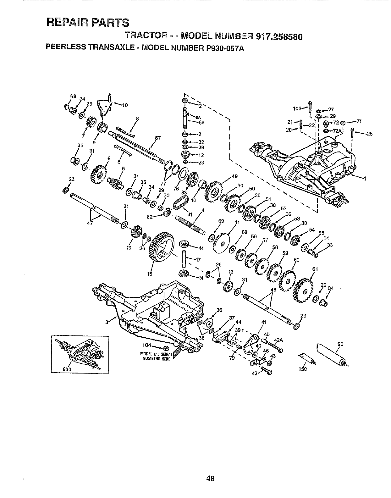
REPAIR PARTS
TRACTOR --MODEL NUMBER 917.258580
PEERLESS TRANSAXLE - MODEL NUMBER P930-057A
150
48
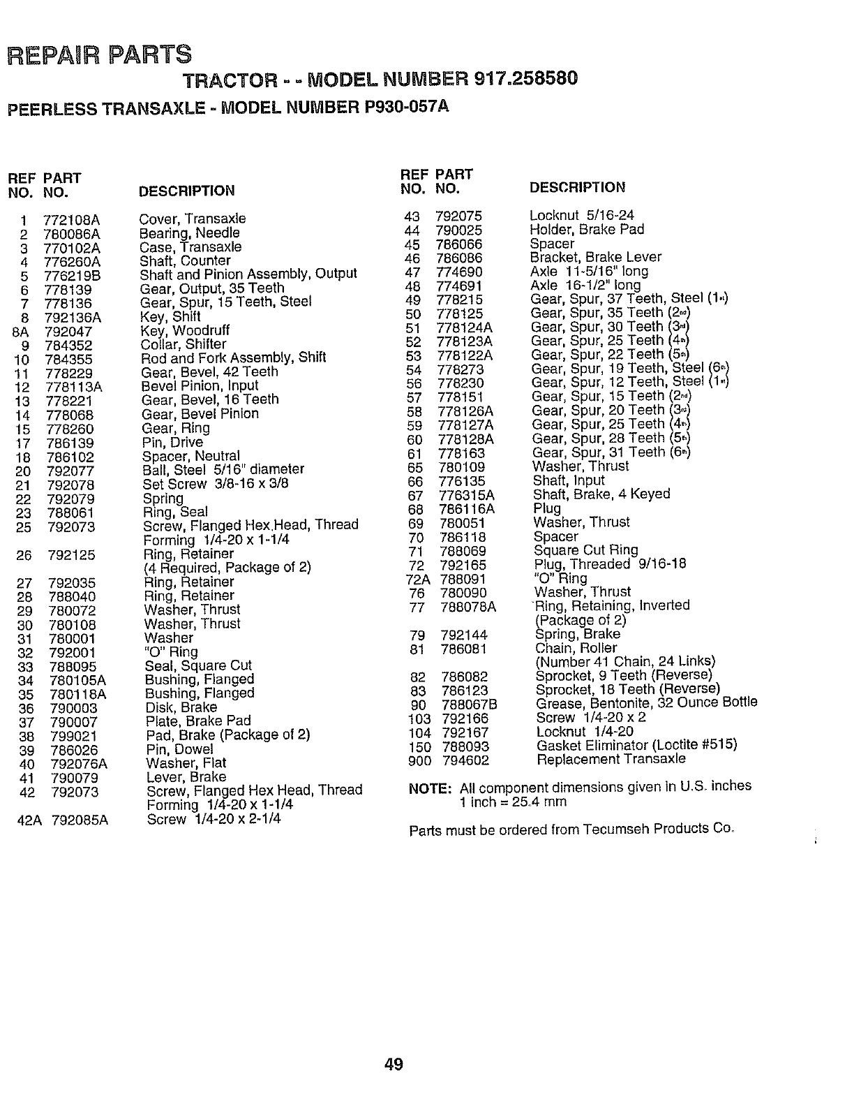
REPAHRPARTS
TRACTOR --MODEL NUMBER 917.258580
PEERLESS TRANSAXLE -MODEL NUMBER P930-057A
REF PART REF PART
NO. NO. DESCRIPTION NO, NO, DESCRIPTION
1 772108A Cover, Transaxle 43 792075
2 780086A Bearing, Needle 44 790025
3 770102A Case, Transaxle 45 786066
4 776260A Shaft, Counter 46 786086
5 776219B Shaft and Pinion Assembly, Output 47 774690
6 778139 Gear, Output, 35 Teeth 48 774691
7 778'136 Gear, Spur, 15 Teeth, Steel 49 778215
8 792136A Key, Shift 50 778125
8A 792047 Key, Woodruff 51 778124A
9 784352 Collar, Shifter 52 778123A
10 784355 Rod and Fork Assembly, Shift 53 778122A
11 778229 Gear, Bevel, 42Teeth 54 778273
12 778113A Bevel Pinion, Input 56 778230
13 778221 Gear, Bevel, 16Teeth 57 778151
14 778068 Gear, Bevel Pinion 58 778126A
15 778260 Gear, Ring 59 778127A
17 786139 Pin, Drive 60 778128A
•18 786102 Spacer, Neutral 61 778163
20 792077 Ball, Steel 5/16" diameter 65 780109
21 792078 Set Screw 3/8-16 x 3/8 66 776135
22 792079 Spring 67 776315A
23 788061 Ring, Seal 68 786116A
25 792073 Screw, Flanged Hex,Head, Thread 69 780051
Forming 1/4-20 x 1-1/4 70 786118
26 792125 Ring, Retainer . 71 788069
(4 Required, Package of 2) 72 792165
27 792035 Ring, Retainer 72A 788091
28 788040 Ring, Retainer 76 780090
29 780072 Washer, Thrust 77 788078A
30 780108 Washer, Thrust
31 780001 Washer 79 792144
32 792001 "O" Ring 81 786081
33 788095 Seal, Square Cut
34 780105A Bushing, Flanged 82 786082
35 780118A Bushing, Flanged 83 786123
36 790003 Disk, Brake 90 788067B
37 790007 Plate, Brake Pad 103 792166
38 799021 Pad, Brake (Package of 2) 104 792167
39 786026 Pin, Dowel 150 788093
40 792076A Washer, Flat 900 794602
41 790079 Lever, Brake
42 792073 Screw, Flanged Hex Head, Thread
Forming 1/4-20 x 1-1/4
42A 792085A Screw 1/4-20 x 2-1J4
Locknut 5/16-24
Holder, Brake Pad
Spacer
Bracket, Brake Lever
Axle 11-5/16" long
Axle 16-1/2" long
Gear, Spur, 37 Teeth, Steel (1.,)
Gear, Spur, 35 Teeth (2_,.'_)
Gear, Spur, 30 Teeth (3.)
Gear, Spur, 25 Teeth (4.)
Gear, Spur, 22 Teeth (5_)
Gear, Spur, 19 Teeth, Steel (6)
Gear, Spur, 12 Teeth, Steel (1.,)
Gear, Spur, t5 Teeth (2°.)
Gear, Spur, 20 Teeth (3_,)
Gear, Spur, 25 Teeth (4-)
Gear, Spur, 28 Teeth (5.)
Gear, Spur, 31 Teeth (6_)
Washer, Thrust
Shaft, Input
Shaft, Brake, 4 Keyed
P_ug
Washer, Thrust
Spacer
Square Cut Ring
Plug, Threaded 9/16-18
"O" Ring
Washer, Thrust
Ring, Retaining, Inverted
(Package of 2)
Spring, Brake
Chain, Roller
(Number 41 Chain, 24 Links)
Sprocket, 9 Teeth (Reverse)
Sprocket, 18 Teeth (Reverse)
Grease, Bentonite, 32 Ounce Bottle
Screw 1/4-20 x 2
Locknut 1/4-20
Gasket Eliminator (Loctite #515)
Replacement Transaxle
NOTE: All component dimensions given in U,S. inches
1 inch = 26,4 mm
Parts must be ordered from Tecumseh Products Co.
49
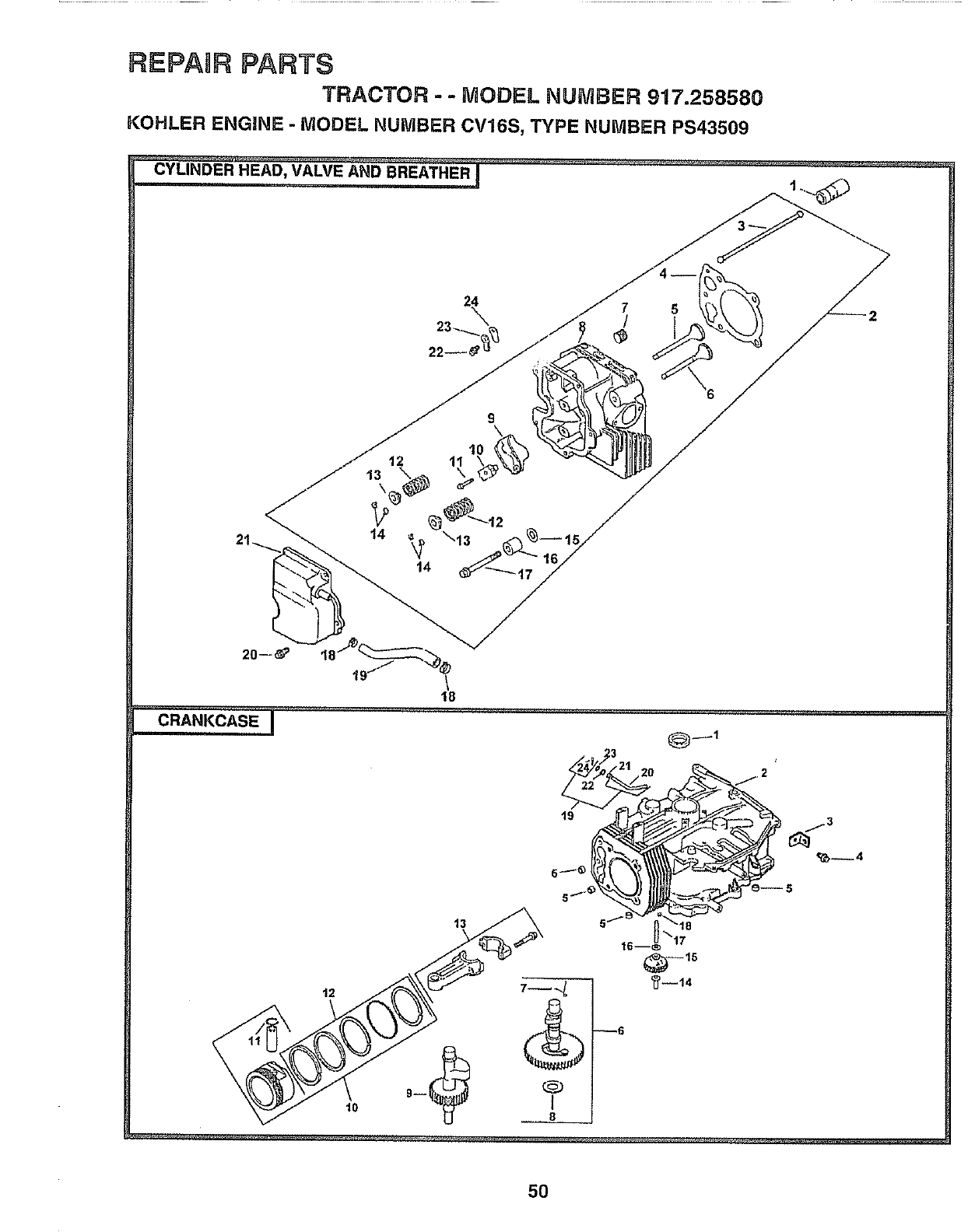
REPAIR PARTS
TRACTOR --MODEL NUMBER 917.25858G
KOHLER ENGINE - MODEL NUMBER CV16S, TYPE NUMBER PS43509
CYLINDER HEAD, VALVE AND BREATHER !
22
18
......... CRA,KC_SEI .............
19
_4
50
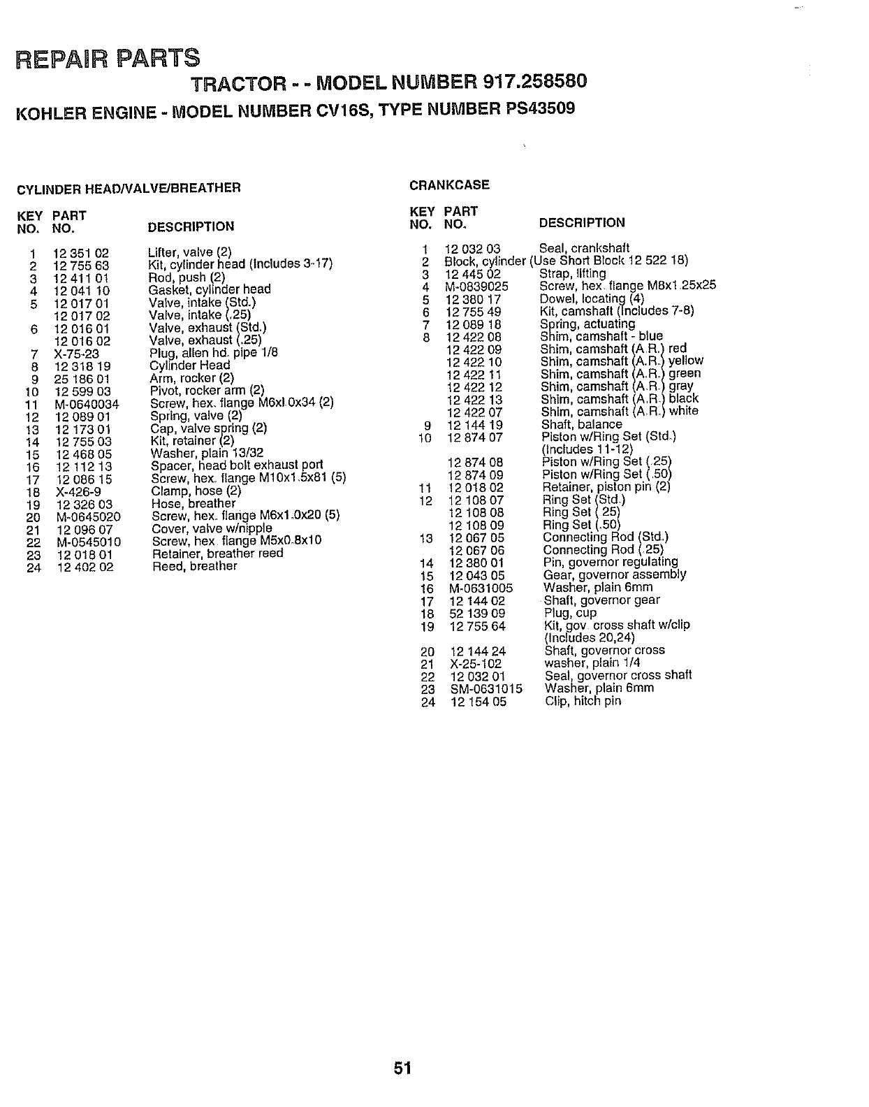
REPAIR PARTS
TRACTOR --MODEL NUMBER 917.258580
KOHLER ENGINE -MODEL NUMBER CV16S, TYPE NUMBER PS43509
CYLINDER HEAD/VALVE/BREATHER CRANKCASE
KEY PART KEY PART
NO, NO. DESCRIPTION NO, NOo DESCRIPTION
Lifter, valve (2)
Kit, cylinder head (Includes 3-17)
Rod, push !2)
Gasket, cylinder head
Valve, intake (Std.)
Valve, intake (.25)
Valve, exhaust (Std.)
Valve, exhaust (.25)
Plug, allen hd_ pipe 1/8
Cylinder Head
Arm, rocker (2)
Pivot, rocker arm (2)
Screw, hex. flange M6xIOx34 (2)
Spring, valve (2)
Cap, valve spring (2)
Kit, retainer (2)
Washer, plain 13/32
Spacer, head bolt exhaust port
Screw, Rex flange M10x1.5x81 (5)
Clamp, hose (2)
Hose, breather
Screw, bex. flange M6xl.Ox20 (5)
Cover, valve w/nipple
Screw, hex flange M5x0.Sxl0
Retainer, breather reed
Reed, breather
1 12 351O2
2 12 755 63
3 12 411 01
4 12 041 10
5 12 017 01
1201702
6 1201601
1201602
7 X-75-23
8 12 318 19
9 25 186 01
10 12 599 03
11 M-0640034
12 12 089 01
t3 12 173 01
14 12 75503
15 12 468 05
16 12 112 13
17 12 086 15
18 X-426-9
19 12 326 03
20 M-0645020
21 12 096 07
22 M-0545010
23 12 018 01
24 12 402 02
9
10
11
12
13
14
15
16
17
18
19
2O
21
22
23
24
1 12 032 03 Seal, crankshaft
2 Block, cylinder (Use Short Block 12 522 18)
3 12 445 02 Strap, lifting
4 M-0839025 Screw, hex. flange MSxl 25x25
5 12 380 17 Dowel, locating (4)
6 12 755 49 Kit, camshaft (includes 7-8)
712 089 18 Spring, actuating
8 12 422 08 Shim, camshaft- blue
12 422 09
12 422 10
12 422 11
12 422 12
12 422 13
12 422 07
12 144 19
12 874 07
12 874 08
12 674 09
12 018 02
12 108 07
12 108 08
12108 09
12 067 05
12 067 06
12 380 01
12 043 05
M-0631005
12 144 02
52139 09
12 755 64
12 144 24
X-25-102
12 032 01
SM-0631015
12 154 05
Shim, camshaft/A R/red
Shim, camshaft ,," yellow
Shim, camshaft/A: RI/green
Shim, camshaft ,, gray
Shim, camshaft/AiRRi/b'ack
Shim, camshaft white
Shaft, balance
Piston w/Ring Set (Std.)
(Includes 11-12)
Piston w/Ring Set (25)
Piston w/Ring Set (50)
Retainer, piston pin (2)
Ring Set (Std)
Ring Set (25)
Ring Set (..50)
Connecting Rod (Std)
Connecting Rod (.25)
Pin, governor regulating
Gear, governor assembly
Washer, plain 6mm
Shaft, governor gear
Plug, cup
Kit, gev cross shaft w/clip
(Includes 20,24)
Shaft, governor cross
washer, plain 1/4
Seal, governor cross shaft
Washer, plain 6mm
Clip, hitch pin
51
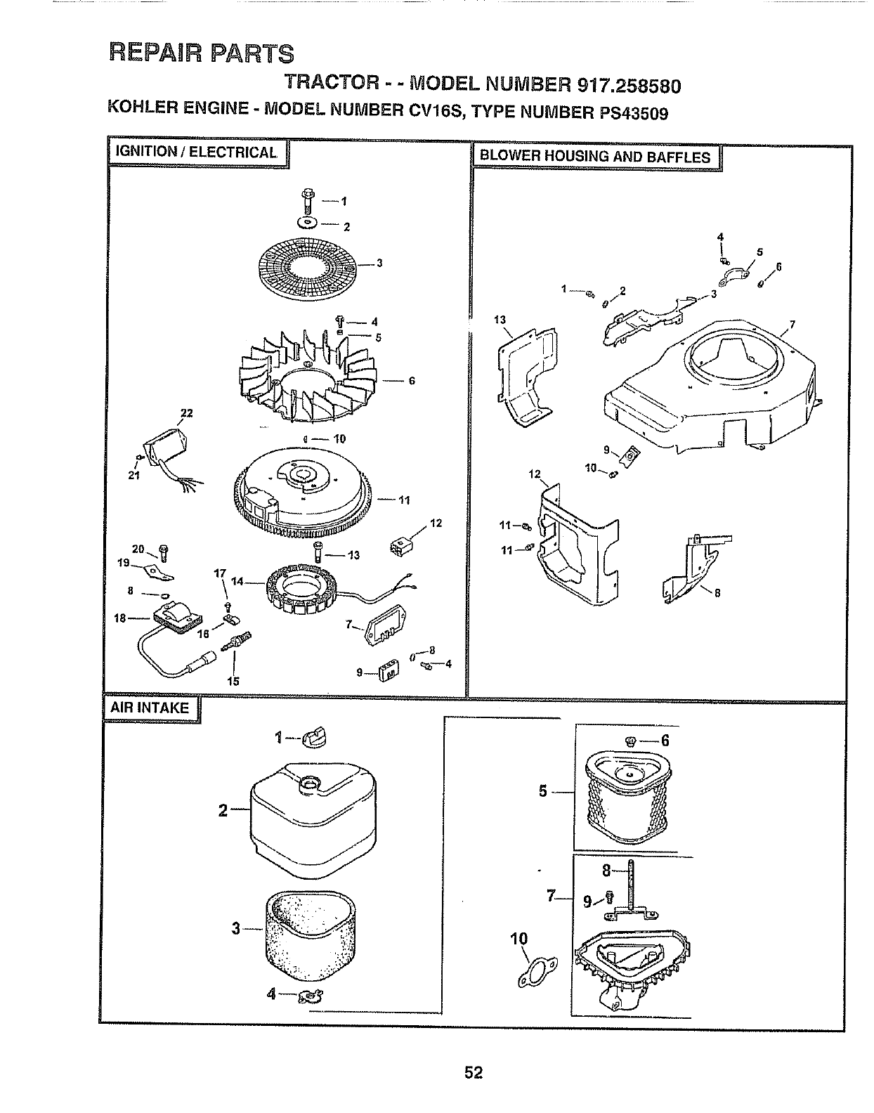
REPAIR PARTS
TRACTOR - - MODEL NUMBER 917,258580
KOHLER ENGINE - MODEL NUMBER CV16S, TYPE NUMBER PS43509
IGNITION/ELECTRICA L
22
/
BLOWER HOUSING. .....'ANDBAFFLES
13
4
6
_
10
52
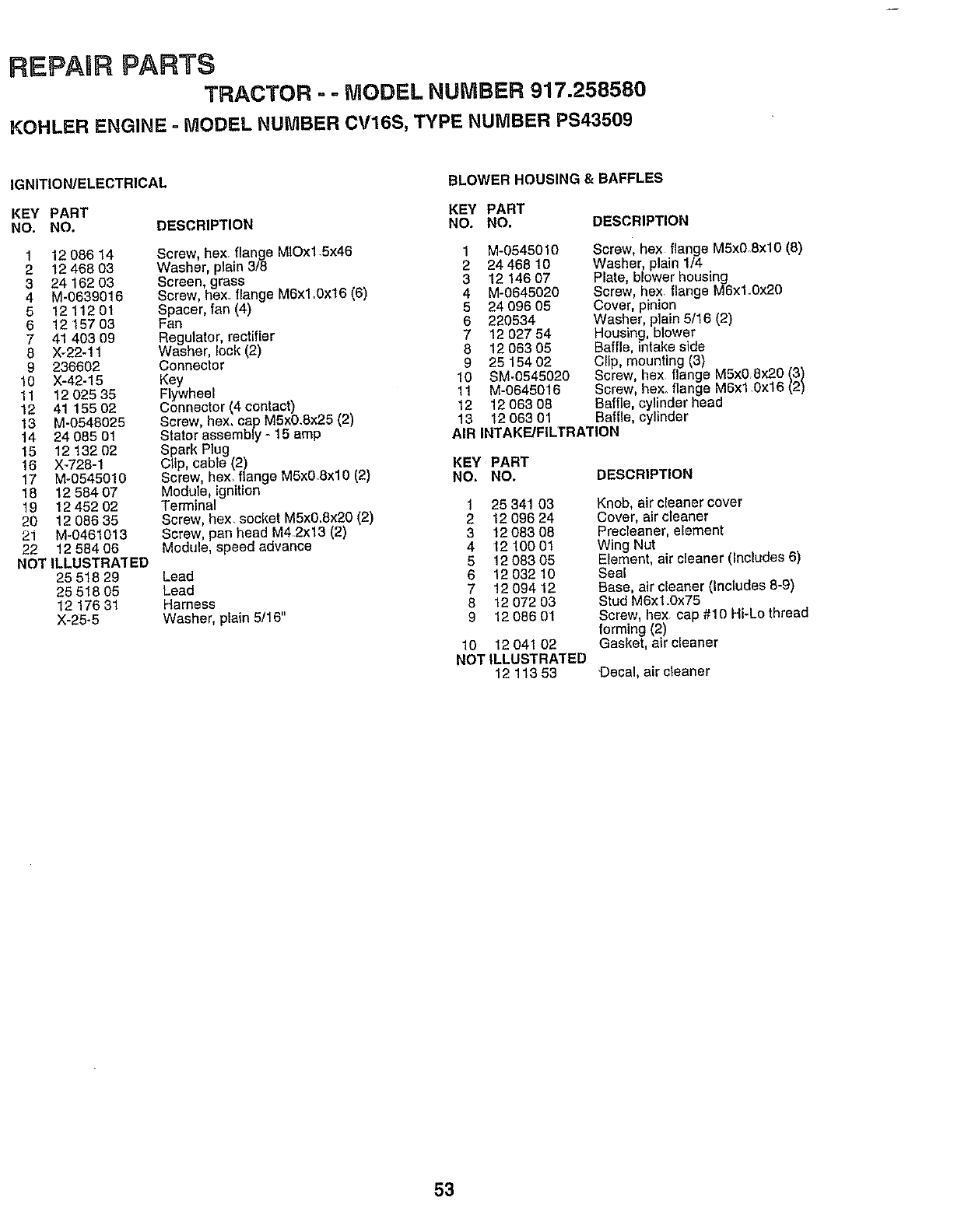
REPABR PARTS
TRACTOR - .. MODEL NUMBER 917.258580
KOHLER ENGINE = MODEL NUMBER CV16S, TYPE NUMBER PS43509
IGNITION/ELECTRICAL BLOWER HOUSING & BAFFLES
KEY PART KEY PART
NO. NO. DESCRIPTION NO. NO. DESCRIPTION
1 12 086 14 Screw, hex. flange MIOx1.5x46
2 12 468 03 Washer, plain 3/8
3 24 162 03 Screen, grass
4 M-0639016 Screw, hex.. flange M6x1_Ox16 (6)
5 12 11201 Spacer, fan (4)
6 1215703 Fan
7 41 403 99 Regulator, rectifier
6 X-22-11 Washer, lock (2)
9 236602 Connector
10 X-42-15 Key
11 12 025 35 Flywheel
12 41 155 02 Connector (4 contact)
13 M-0548025 Screw, hex, cap M5x0.8x25 (2)
14 24 085 01 Staler assembly- 15 amp
15 12 132 02 Spark Plug
16 X-728-1 Clip, cable (2)
17 M-0545010 Screw, hex, flange M5xO_Txl0 (2)
18 12 584 07 Module, ignition
19 12 452 02 Terminal
20 12 086 35 Screw, hex, socket M5x0.8x20 (2)
21 M-9461013 Screw, pan head M42x13 (2)
22 12 584 06 Module, speed advance
NOT ILLUSTRATED
25 518 29 Lead
25 518 05 Lead
12 176 31 Harness
X-25-5 Washer, plain 5/16"
1 M-0545010
2 24468 10
3 1214607
4 M-0645020
5 24 096 05
6 220534
7 12 027 84
812 063 05
9 25 154 02
10 SM-0545020
11 M-0545015
12 1206308
13 1206301
Screw, hex flange M5xO_8xlO (8)
Washer, plain 1/4
Plate, blower housing
Screw, hex. flange M6xl.0x20
Cover, pinion
Washer, plain 5/16 (2)
Houstng, blower
Baffle, intake side
Cllp, mounting (3)
Screw, hex flange MSx0Bx20 (3)
Screw, hex. flange MSx1.0x16 (2)
Baffle, cylinder head
Baffle, cylinder
AIR INTAKE/FILTRATION
KEY PART
NO. NO.
1 25341 03
2 1209624
3 1208308
4 121OO01
5 1208305
6 12 032 10
7 1209412
8 12 072 03
9 1208601
10 12 041 02
NOT ILLUSTRATED
1211353
DESCRIPTION
Knob, air cleaner cover
Cover, air cleaner
Precleaner, element
Wing Nut
Element, air cleaner (Includes 6)
Seal
Base, air cleaner (Includes 8-9)
Stud M6x1.0x75
Screw, hex cap #10 Hi-Lo thread
forming (2)
Gasket, air cleaner
Decal, air cleaner
53
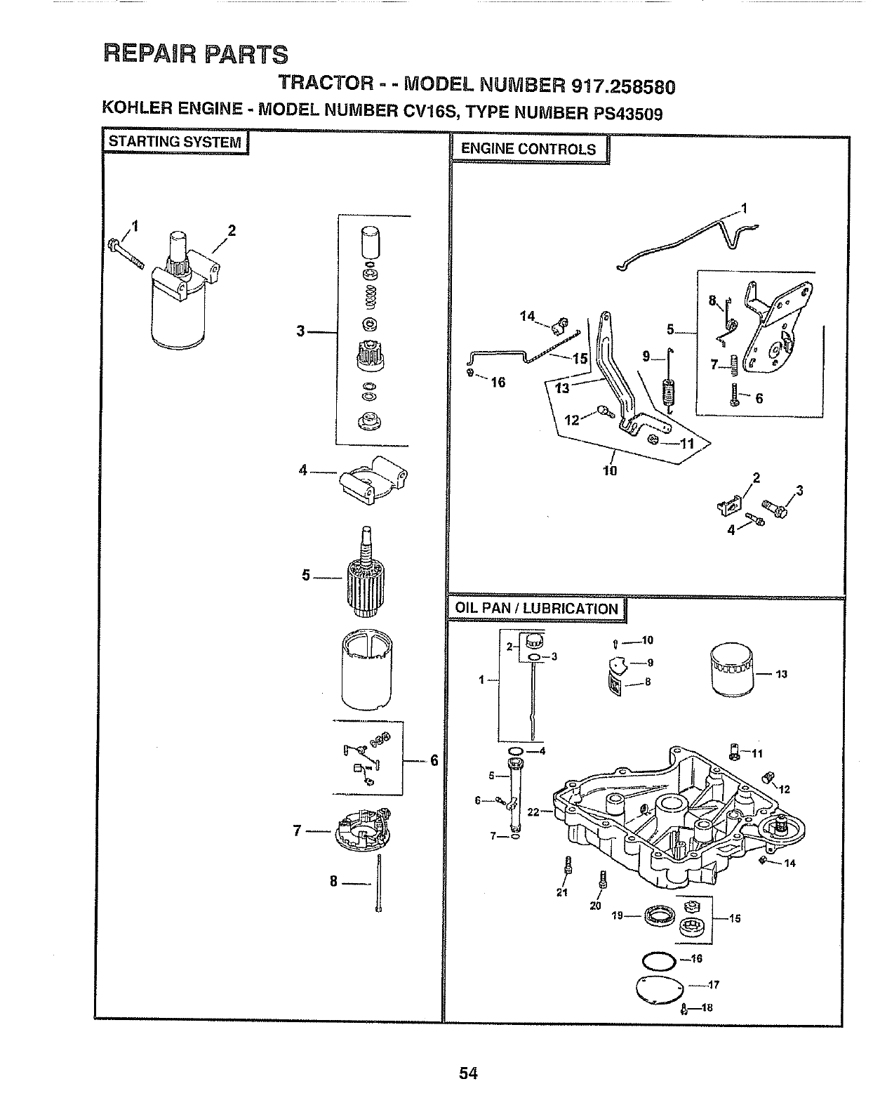
REPAIR PARTS
TRACTOR -- MODEL NUMBER 917.258580
KOHLER ENGINE -MODEL NUMBER CV16S, TYPE NUMBER PS43509
G
(:=
@
!
3-- @
@
@
E=G,,E€O"T"°LSI
I
""° _,-.J
1o 2
t-- _.._8
21 /
20 1,-@__,°
0_16
--,17
54
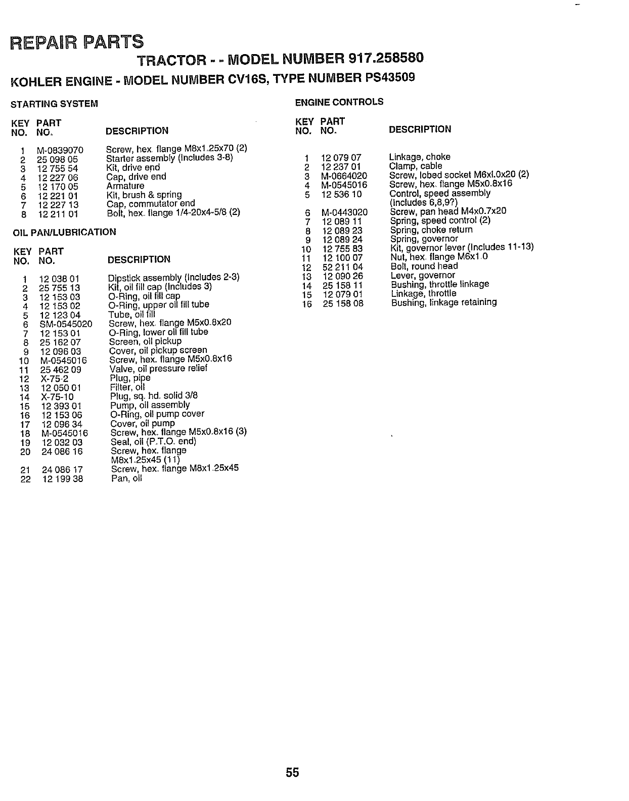
REPAURPARTS
TRACTOR --MODEL NUMBER 917.258580
KOHLER ENGINE - MODEL NUMBER CV16S, TYPE NUMBER PS43509
STARTING SYSTEM ENGINE CONTROLS
KEY PART KEY PART
NO. NOo DESCRIPTION NO. NO. DESCRIPTION
1
2
3
4
5
6
7
8
M-0839070 Screw, hex flange M8x1..25x70 (2)
25 099 05 Starter assembly (Includes 3-8) 1 12 079 07
12 755 54 Kit, drive end 2 12 237 01
12 227 06 Cap, drive end 3 M-0664020
12 t70 05 Armature 4 M-0545016
12 221 01 Kit, brush & spring 5 12 536 10
12 227 13 Cap, commutator and
12 211 01 Bolt, hex. flange 1/4-20x4-5/8 (2) 6 M-0443020
OIL PAN/LUBRICATION
KEY PART
NO. NO.
1 1203801
225 755 13
3 1215303
4 1215302
51212304
6 SM-0545020
7 1215301
8 25 152 07
9 12 096 03
10 M-0548016
11 25 46209
12 X-75-2
13 1205001
14 X-75-10
15 1239301
16 1215306
17 1209634
18 M-0545016
19 12 032 03
20 24 086 16
7 1208911
8 12 089 23
9 1208924
10 1275563
11 121O007
12 52211 04
13 12 090 26
14 25 158 11
15 1207901
15 2515808
21 24 086 17
22 1219938
DESCRIPTION
Dipstick assembly (Includes 2-3)
Kit, oil fllt cap (Includes 3)
O-Rtng, oil fill cap
O-Ring, upper oi/fill tube
Tube, oil fill
Screw, hex. flange M5xO.8x20
O-Ring, lower oil fill tube
Screen, oil pickup
Cover, oil pickup screen
Screw, hex. flange M5x0.Sx16
Valve, oil pressure relief
Plug, pipe
Filter, oil
Plug, sq_hd. solid 3/8
Pump, oil assembly
O-Ring, oil pump cover
Cover, oil pump
Screw, hsxo flange M5x0.8x16 (3)
Seal, oil (P.T.O end)
Screw, hsx. flange
MSxl.25x45 (11)
Screw, hex. flange MSx1.25x45
Pan, oil
Linkage, choke
Clamp, cable
Screw, lobed socket M6xL0x20 (2)
Screw, hex. flange M5x0_Sx16
Control, speed assembly
(includes 6,6,9?)
Screw, pan head M4x0.7x20
Spring, speed control (2)
Spring, choke return
Spring, governor
Kit, governor lever (Includes 11-13)
Nut, hex flange M6xl.0
Bolt, round head
Lever, governor
Bushing, throttle linkage
Linkage, throttle
Bushing, linkage retaining
55
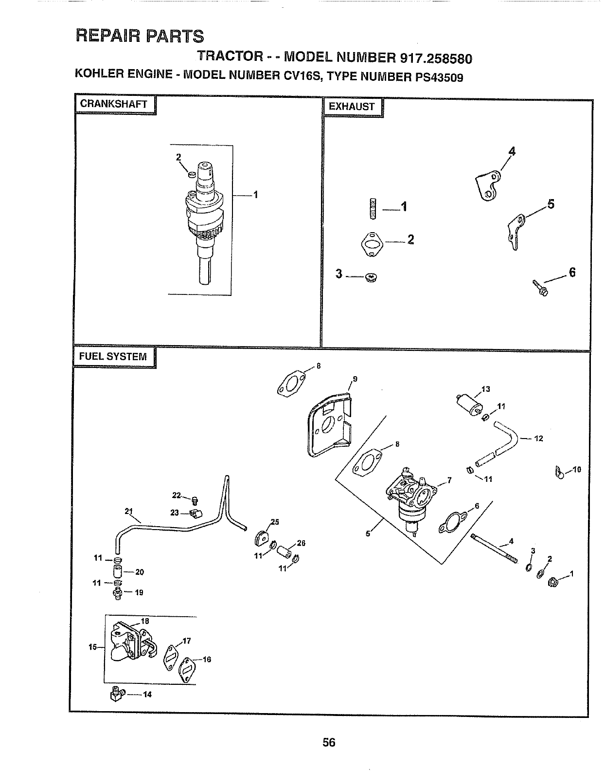
REPAIR PARTS
TRACTOR -- MODEL NUMBER 917.258580
KOHLER ENGINE - MODEL NUMBER CV16S, TYPE NUMBER PS43509
CRANKSHAFT _
2
EX,.US_I
F°E'SYSTE"I _j8
t_ 7t7
,°-
_--14
,H m ,, , ,,,
/9
56
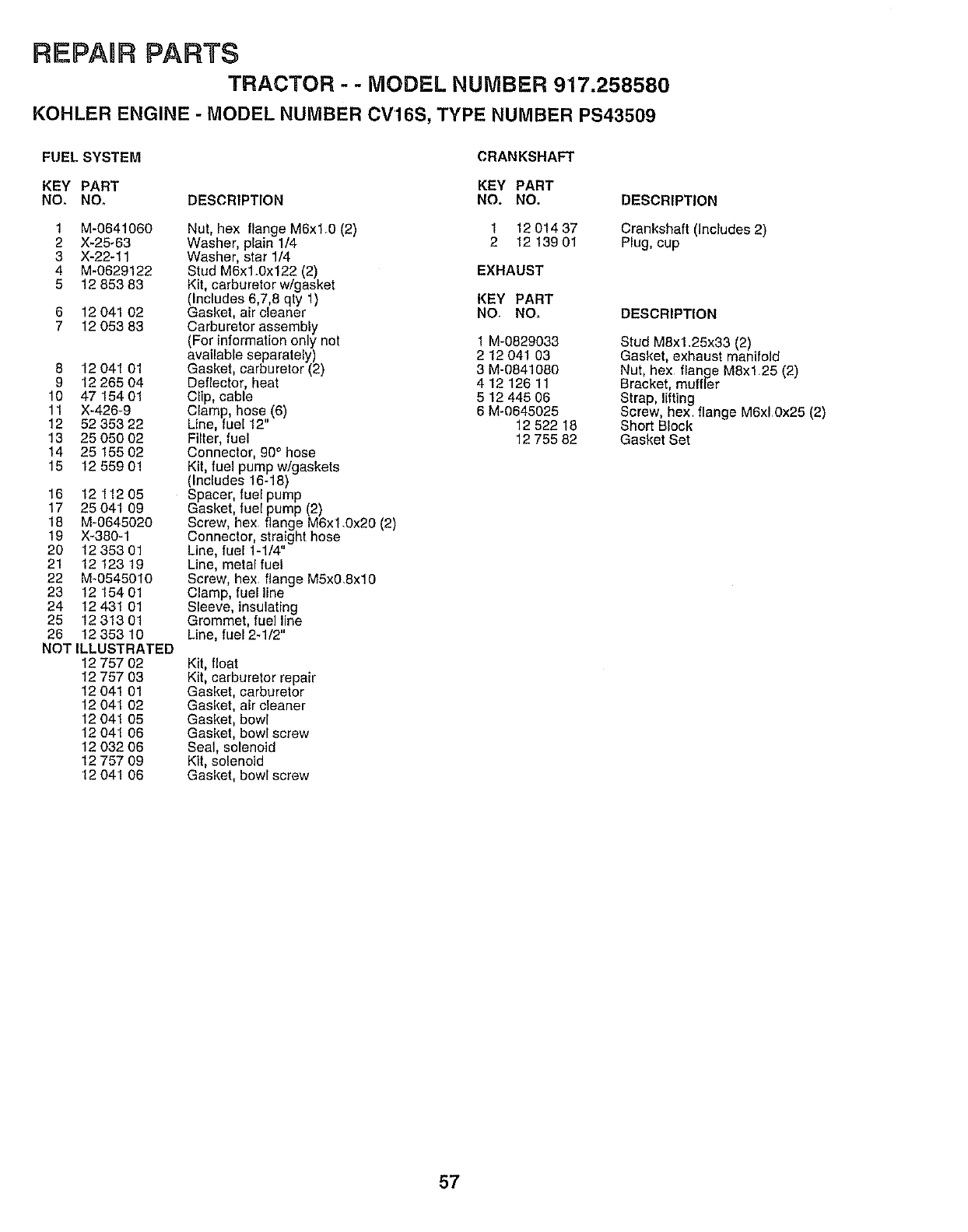
REPABR PARTS
TRACTOR --MODEL NUMBER 917.258580
KOHLER ENGINE - MODEL NUMBER CV16S, TYPE NUMBER PS43509
FUEL SYSTEM CRANKSHAFT
KEY PART KEY PART
NO. NO_ DESCRIPTION NO. NO.
Kit, float
Kit, carburetor repair
Gasket, carburetor
Gasket, air cleaner
Gasket, bowl
Gasket, bowl screw
Seal, solenoid
Kit, solenoid
Gasket, bowl screw
1 M-0641060 Nut, hex flange M6xl.0 (2) 1 12 014 37
2 X-25-63 Washer, plain 1/4 2 12 139 01
3 X-22-11 Washer, star 1/4
4 M-0629122 Stud MSx1.0x122 (2) EXHAUST
5 12 853 83 Kit, carburetor w/gasket
(Includes 6,7,8 qty 1) KEY PART
6 12 041 02 Gasket, air cleaner NO. NO,
7 12 053 83 Carburetor assembly
(For information only not 1 M-0829033
available separately) 2 12 041 03
8 12 041 01 Gasket, carburetor (2) 3 M-0841080
9 12 265 04 Deflector, heat 4 12 126 11
10 47 154 01 Clip, cable 5 12 445 06
11 X-426-9 Clamp, hose (6) 6 M-0645025
12 52 353 22 Line, fuel 12" 12 522 18
13 25 050 02 Filter, fuel 12 755 82
14 25 155 02 Connector, 90° hose
15 12 559 01 Kit, fuel pump w/gaskets
(Includes 16-18)
16 12 11205 Spacer, fuel pump
17 25 041 09 Gasket, fuel pump (2)
18 M-0645020 Screw, hex flange M6xl.0x20 (2)
19 X-380-1 Connector, straight hose
20 12 353 01 Line, fuel 1-1/4"
21 12 123 19 Line, metal fuel
22 M-0545010 Screw, hex flange M5x08xl0
23 12 154 01 Clamp, fuelline
24 12 431 01 Sleeve, insulating
25 12 313 01 Grommet, fuel line
26 12 353 10 Line, fuel2-1/2"
NOT ILLUSTRATED
12 757 02
12 757 03
12 041 01
12 041 02
12 041 05
12 041 06
12 032 06
12 757 09
12 041 06
DESCRIPTION
Crankshaft (includes 2)
Plug, cup
DESCRIPTION
Stud M8x1.25x33 (2)
Gasket, exhaust manifold
Nut, hex flange M8xl 25 (2)
Bracket, muffler
Strap, lifting
Screw, hex flange M6xl 0x25 (2)
Short Block
Gasket Set
57

,ill
SERVmCE NOTES
58

SUGGESTED GUIDE FOR SIGHTING SLOPES FOR SAFE OPERATION
"r
SIGHTING
GUIDE
ONLY RIDE UP AND DOWN HILL,
NOT ACROSS HILL
SIGHT AND HOLD THIS LEVEL WITH
SKY LINE OR TREE.
15° MAX.
!
Operate your Tractor up and down the face of slopes (not I
greater than 15°), never across the face. Make turns gradu- I
ally to prevent tipping or loss of control. Exercise extreme
caution when changing direction on slopes.
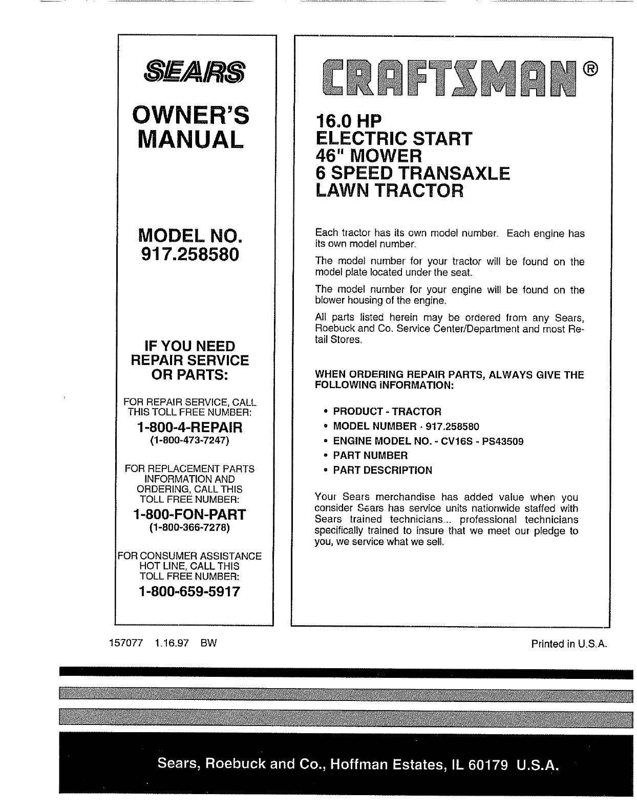
S_E/A/ S
OWNER'S
MANUAL
MODEL NO.
917.258580
IF YOU NEED
REPAIR SERVICE
OR PARTS:
FOR REPAIR SERVICE, CALL
THiS TOLL FREE NUMBER:
1-800-4-REPAIR
(1-800-473-7247)
FOR REPLACEMENT PARTS
INFORMATION AND
ORDERING, CALL THIS
TOLL FREE NUMBER:
1-800-FON-PART
(1-800-366-7278)
:OR CONSUMER ASSISTANCE
HOT LINE, CALL THIS
TOLL FREE NUMBER:
1-800-659-5917
®
16.0 HP
ELECTRIC START
46" MOWER
6 SPEED TRANSAXLE
LAWN TRACTOR
Each tractor has its own model number. Each engine has
its own model number.
The model number for your tractor will be found on the
model plate located under the seal
The model number for' your' engine will be found on the
blower housing of the engine.
All parts listed herein may be ordered from any Sears,
Roebuck and Co. Service Center/Department and most Re-
tail Stores.
WHEN ORDERING REPAIR PARTS, ALWAYS GIVE THE
FOLLOWING iNFORMATION;
• PRODUCT- TRACTOR
°MODEL NUMBER -917.258580
°ENGINE MODEL NO. -CV16S - PS43509
•PART NUMBER
oPART DESCRIPTION
You_ Sears merchandise has added value when you
consider Sears has service units nationwide staffed with
Sears trained technicians°., professional technicians
specifically trained to insure that we meet our pledge to
you, we service what we sell
157077 1_16.97 BW Printed in USA.
