Craftsman 917258692 User Manual TRACTORS Manuals And Guides L0711535
CRAFTSMAN Lawn, Tractor Manual L0711535 CRAFTSMAN Lawn, Tractor Owner's Manual, CRAFTSMAN Lawn, Tractor installation guides
ELT145H33DBV L0711535
User Manual: Craftsman 917258692 917258692 CRAFTSMAN TRACTORS - Manuals and Guides View the owners manual for your CRAFTSMAN TRACTORS #917258692. Home:Lawn & Garden Parts:Craftsman Parts:Craftsman TRACTORS Manual
Open the PDF directly: View PDF ![]() .
.
Page Count: 64

I:RnFTXHaN°
MODEL NUMBER 917.258692 OWNER'SMANUAL
• Assembly
• Operation
• Customer Responsibilities
• Service and Adjustments
• Repair Parts
CAUTION: Read and follow all safety rules and instructions before operating this equipment.
FOR CONSUMER ASSISTANCE HOT LINE, CALL THiS TOLL FREE NUMBER: 1-800-659+5917
l't]IIl'll
II
SAFETY RULES
Safe Operation Practices for Ride-On Mowers
IMPORTANT: THIS CUTTING MACHINE IS CAPABLE OF AMPUTATING HANDS AND FEET AND THROWING OBJECTS
FAILURE TO OBSERVE THE FOLLOWING SAFETY INSTRUCTIONS COULD RESULT IN SERIOUS tNJURY OR DEATH
I. GENERAL OPERATION
,Read, understand, and followall instructionsinthe manual
end on the machine before starling,
, On_y agow responsible adults, who are familiar wIth the
tnstructlons, to op_rala the machine.
= Clear the area of objects such as rocks, toys, wire, eta,
whichcouldbe pickedup and lhrawnby theblade
•Beaura Ihe area tsclear ofother peopfe before mewing Stop
machine if anyone enters the area
•Never carry p=_ssengers
•Do not mow in reverse unless absolutely necessary Always
fook down and behind belore and while backing
• Be aware of the mower discharge direction and do not point
tt at anyone, Do not operate the mower withouteither the
entire grass catcher or the guard in place
•Slow down before turning
• Never leave a running machine unattended. Always tam off
blades, set parking brake, slop engine, and remove keys
before dismounting
•Turn oft blades when not mowing.
•Stop engine belore removinggrass catcher or unclogging
chute.
•Mow onlyIsdaylightorgood artMclalilght
•Do not operate the machine while under the Inlluenca el
etcohot or drugs
• Welch forIrafiio when operating nearor crossing roadways.
• Use exlra care when {ceding or unloading themachine Into
a traitor or truck,
IL SLOPE OPERATION
Slopes are a major factor related to Ices-of-control and
t_poveraccidents, which can resull in severe Injuny or death.
All slopes require extra caulion. I{ you cannot back up the
siope or if you feel uneasy on it, do not mow It.
DO:
•Mow up and down slopes,not across
•Remove obstectessuch as rocks, tree limbs, etc.
Watch for holes, ruts, or bumps. Uneven terrain could
ovedum the machine Tatl grass can hide obetacfas
, Use slow speed, Choose alow gear sothat you wtilnot have
lo slop or shift while on the slope
,Follow the manufacturer's recommendallons Ior wheel
weights orcounterWeightsto Improve stability?
• Usa extra care with grass catchers or other attachments,
These can change the stabilityof the maoMns
• Keep allmovementonthe slopes slow and gradual Do not
make suddenchanges inspeed or d_rectfen
• Avoid starting or slopping on e slope. If tires lose traction,
disengage the blades ano proceed slowly straight down Ihe
slope
DO NOT:
•Donotturnonslopasuniessnecessary, andthen,tumslowly
and graduallydownhill,{tposslble
.Donot mow near drop=oh's,ditches, or embankments. The
mower couldsuddenly turn over tf a wheat Is over the edge
of aclilfor ditch, or if anedge caves in_
•Do not mow on wet grass., Reduced Iractton could cause
sliding
• Dosol try tostabilizethe machine by puttingyour toot on the
ground°
•Do not usa grass catcher on sleep slopes
IlL CHILDREN
Tragic accidents can occur ifthe operator is not alert to the
presence of children Children are often attracted to the
machine and lhe mowing activity, Never assume that
children will remain where you last saw them.
° Keepchtidrenou!of the mowing area and under the watchful
careofanotherresponsibleadult
• Be Bled and Iura mschlne off ifchildren enter the area
• Before and whenbacking, look behind and down for small
children
•Never carFy children. They may fall oil and be seriously
Injuredor intedere with sate machine operation
•Never aItow chltdren to operate the machine,
• Use extra care when approaching bl_ndcomers, shrubs,
trees, or other objectsthat may obscure vision,
IV. SERVICE
•Use extra care in hand)(ng gasottneandotherfusts_ They are
gammable and vapors are expIoslve
Use onlyan approved container,
Never remove gas cap or add fuel with the engine
running Allow engine to cool belore refue!ing. Do not
smoke,
Never refuel the machine indoors
Never storethemachine or fuelcontainer Inside where
thera Is an open game, such as a water heater
•Never runa machine inside a closedarea,
." Keep nuts and boltm especially blade attachmentbolts, tight
and keep equipment ingood condition
• Never tamper wllh safety devices Check Ihek proper
operation regularly
• Keepmachine free o! grass leaves, or other debris build-up
Csan o or luel spillage Allow machine to cool beg'ore
storing,
Slop and inspect the equipmenl ityou strike an obJecl.
Repair, I!necessary, before resladlng_
•Never make adjustmentsor repairs withthe engine running
•Grasscalchercomponenls aresubject towear, damage, and
deterioration, which could expose moving parts or allow
ob acts Io be thrown, Frequenllycheck components and
rapace w lh manufacturer srecommended pads, when nec-
essary
•Mower blades are sharpand can cuL Wrap the blade(s) or
weargloves, and use extra caution when servicing them-
. Check brake operation frequently, Adjust and service as
required.
H= ==H, ,H,= , ,H , , ,
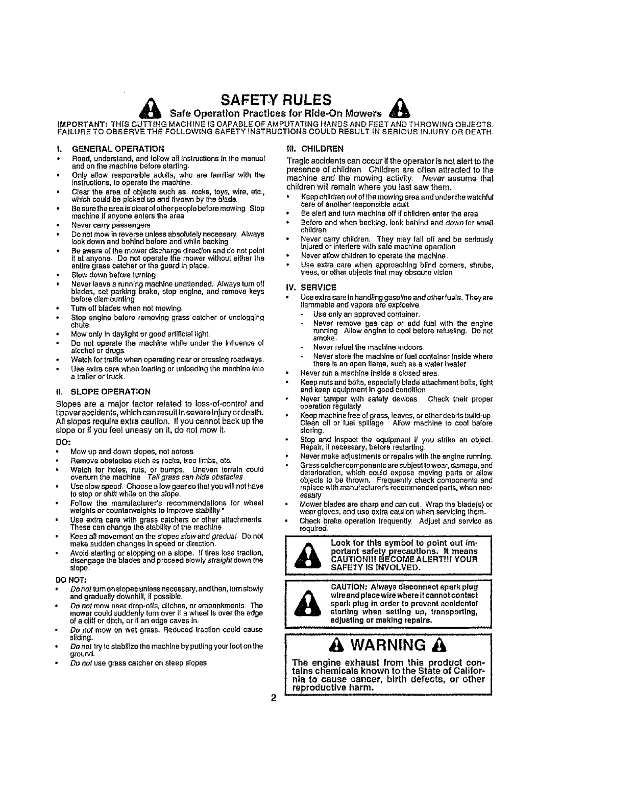
i_ Look for thls symbol to point out im-
portant safety precautions. It means
CAUTIONH| BECOME ALERTIII YOUR
SAFETY IS INVOLVED.
A WARNING
The engine exhaust from this product con-
tams cnemtcats Known to the State of uad!or-
nla to cause cancer, birth defects, or other
reproductive harm.
, H, ,, ,,,
CAUTION: Always disconnect spark plug
_b wire and plaee wire where tt cannot contect
spark plug In order to prevent accidental
starting when setting up, transporting,
adjusting or making repairs.
CONGRATULATIONS on your purchase of a Sears
Tractor It has been designed, engineered and manufac-
tured to give you the best possible dependability and
pedormance,
Shoufd you experience any problem you cannot easily
remedy, please contact your nearest Sears Authorized
Service CentedDepartment, We have competent, well-
trained lechnlctans and the proper toots to service or repair
thts tractor,
Please read and retain th{s manual The instructions wilt
enable you to assemble and maintain your tractor propefly
Always observe the "SAFETY RULES".
MODEL
NUMBER 917258692
SERIAL
NUMBER
DATEOFPURCHASE
THE MODELAND SER1ALNUMBERSW[LL BE FOUND
ON A PLATE UNDER THE SEAT.
i YOU SHOULD RECORD BOTH SERfALNUMBERAND
DATE OF PURCHASE AND KEEP IN A SAFE PLACE
FOR FUTURE REFERENCE
MAINTENANCE AGREEMENT
A Sears Maintenance Agreement Is available on this prod-
uct Contact your nearest Sears store for details.
CUSTOMER RESPONSIBILITIES
• Read and observe the satety rules
. Followa regufarschedulein ma[nlaintng, caring for and
using your tractor.
, Foliow the Instructions under "Customer Responsibili-
{ice" and "Storage" sections of this owner's manual
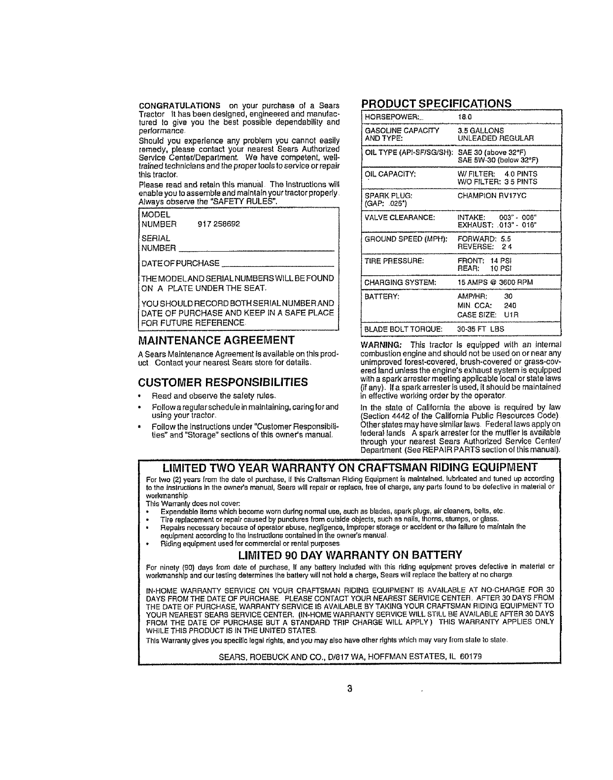
PRODUCT SPECIFICATIONS
HORSEPOWER:.. t8 0
GASOLtNE CAPACITY 3.5 GALLONS
AND TYPE; UNLEADED REGULAR
OIL TYPE (API.,SP/SG/SH): SAE 3.0 (above 32°F)
SAE 5W-30 (below 32°F)
OIL CAPACITY: WI FILTER: 40 PINTS
W/O FILTER: 3 5 PINTS
IPARK PLUG: CHAMPION RV17YC
3AP: ,025")
VALVE CLEARANCE: iNTAKE: 003" - 006"
EXHAUST: .013_'- 0"f6"
GROUND SPEED (MPH): FORWARD; 5,5
REVERSE: 2 4
TIRE PRESSURE; FRONTt 14 PSI
REAR: 10 PSI
CHARGING SYSTEM: 15 AMPS @ 3600 RPM
BATTERY: AMPtHR; 30
MIN CCA: 240
CASE SIZE: U'IR
BLADE BOLT TORQUE: 30-35 FT LBS
WARNING: This traclor is equipped with an Internal
combustion engine and should not be used on or near any
unimproved forest-covered, brush-covered or grass-cov-
ered land unless the engine's exhaust system is equipped
wIIh a spark arrestor meeting applicable local or state taws
(if any). t! a spark arresler is used. it should be maintained
in effective working order by the operator
In the state of California the above is required by taw
(Seclion 4442 of Ihe California Public Resources Code)
Olher states may have simifar Iaws, Federal laws apply on
federal lands A spark arrestor for the muffler Is available
through your nearest Sears Aulhorized Service Center/
Department (See REPAIR PARTS section o¿this manua0,
LIMITED TWO YEAR WARRANTY ONCRAFTSMAN RIDING EQUIPMENT
For two (2) years (rum the date el purchase, if Ibis Craftsman Riding Equipment is matnlalned_lubdeated and tuned up according
to the instructions tn the owner's manua!, Sears wll! repairor replace, tree ol charge, any parts foundto be defeclive in material or
workmanship
Thts Warranly does nol cover:.
• Expendable Itemswhich become warn during normal use, such as blades, spark plugs,air cleaners, belts, elc,
Tire replacement or repaircaused by panclures trsmoutalde objects, such ae nails, Ihoms, stamps, or glass.
• Repairs necessary because of Operatorabuse, negffgence, Improper storage or accident orthe failureto maintain the
equipment according to the Instructions containedin lhe owner'smanuaL
• Riding equipment used for commercial or rentalpurposes
LIMITED 90 DAY WARRANTY ON BATTERY
For ninety (gO) days from dale of purchase, 1I any baltary Included with this ddtng equipment proves defective [n maleflal or
workmanshipand our testing determines the batte_ will not holds cha_ge,Sears will replace the be{tory at no charge
IN-HOME WARRANTY SERVICE ON YOUR CRAFTSMAN RIDING EQUIPMENT IS AVAILABLE AT NO-CHARGE FOR 30
DAYS FROM THE DATE OF PURCHASE. PLEASE CONTACT YOUR NEAREST SERVICE CENTER AFTER 30 DAYS FROM
THE DATE OF PURCHASE, WARRANTY SERVICE IS AVAILABLE BY TAKING YOUR CRAFTSMAN RIDING EQUIPMENT TO
YOUR NEAREST SEARS SERVICE CENTER, {IN-HOME WARRANTY SERVICE WILL STILL BE AVAILABLE AFTER 30 DAYS
FROM THE DATE OF PURCHASE BUT A STANDARD TRIP CHARGE WILL APPLY ) THIS WARRANTY APPLIES ONLY
WHILE THIS PRODUCT IS IN THE UNITED STATES
This Warranty gives you specitic legaf dghts, end you may also have other rights which may vary from s|ale to state,
SEARS, ROEBUCK AND CO., D/817 WA, HOFFMAN ESTATES, IL 60179
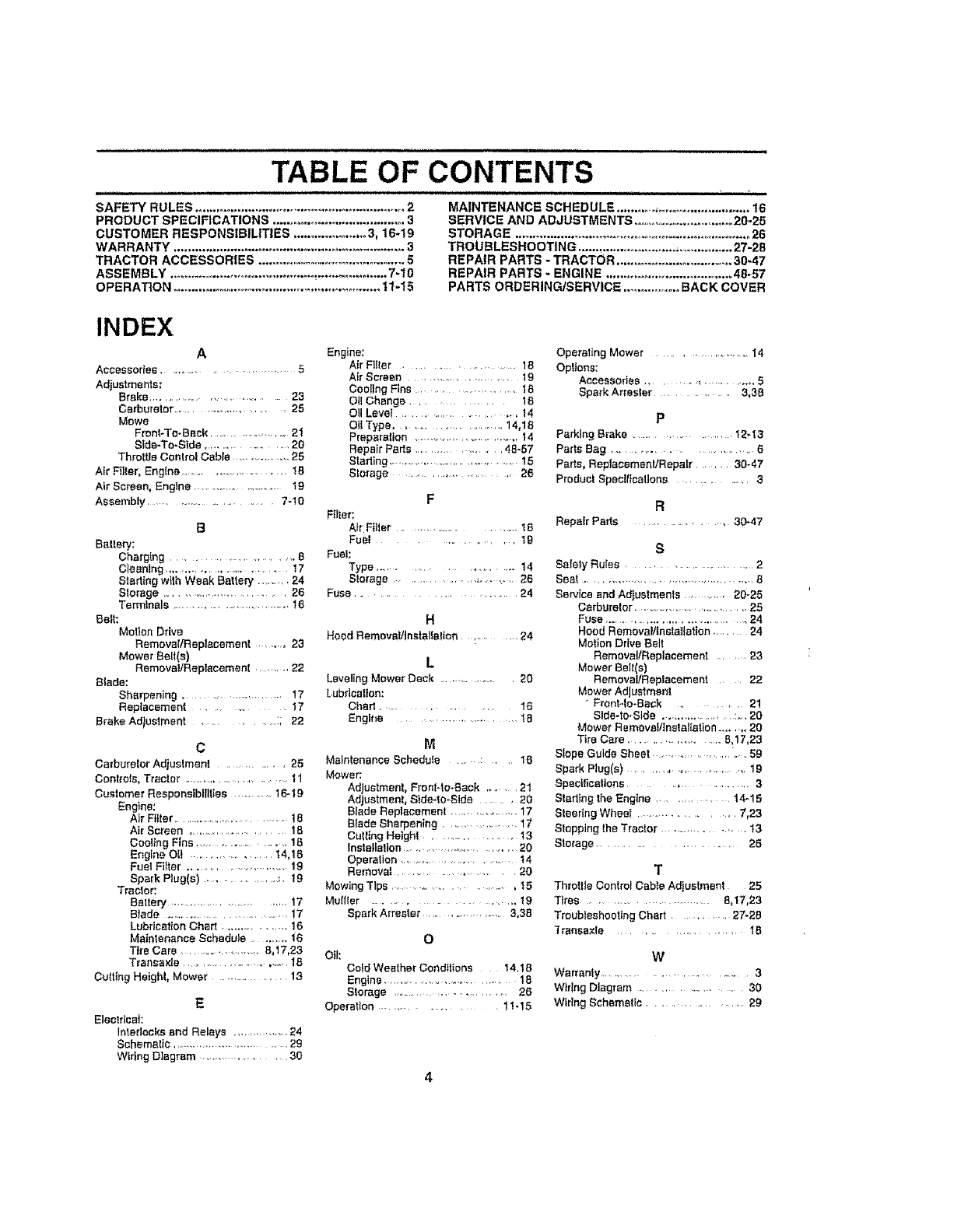
SAFETY RULES ............................................................. 2
PRODUCT SPECIFICATIONS ...................................... 3
CUSTOMER RESPONSIBILITIES ...................... 3, 16-19
WARRANTY .................................................................. 3
TRACTOR ACCESSORIES ............................................ 5
ASSEMBLY .......................................... _.................... 7-I0
OPERATION ............................................................ t1-t5
,lU_l,i ii , i,iin ii I I roll ilu ,i I,
TABLE OF CONTENTS
i,iii,Ul i
MAINTENANCE SCHEDULE ........... , ........................... t6
SERVICE AND ADJUSTMENTS ...............................;20-25
STORAGE ...................................................................... 26
TROUBLESHOOTING ............................... .,............... 27-2B
REPAIR PARTS -TRACTOR ................................. 30-47
REPAIR PARTS- ENGINE .................................... 48-57
PARTS ORDERINGISERVICE ................. BACK COVER
INDEX
A
Accessodes .......................... 5
Adjustments:
Brake ............................. 23
Carburetor .......................... , 25
Mows
Front-To-Back ................... 21
Slde-To-Stde ....................... 20
Throttle Control Cable............... 25
Air Filter, Engine ............................ 1B
Air Screen, Engine ...................... 19
Assembly .................................... 7-10
B
Battery;
Charging ........................... B
Cleaning ......................... 17
Stedlng wtth Weak Battery ......... 24
S{orage ................................. 26
Terminals .............................. !6
Belt:
Motion Drive
Remover/Replacement ..... 23
Mower Belt(s)
RemovaVReptacement .......... 22
Btade:
Sharpening ........................ 17
Replacement ..................... 17
Brake Adtustment .............. :; 22
C
Carburetor Adjustment ................... 25
Controls, Tractor ............................... 11
Customer RespensiblIil{es ........ 16-19
Englne:
A]r Filter ................................ t8
Air Screen ......................... 1B
CostingFins ................ .18
Engine Oi! ................... 14,18
Fuel Filter ............................. 19
Spark Plug(s) .............. _. t9
Tractor:
Battery .............................. 17
Blade ............................ 17
LubricationChart ................. 16
Maintenance Schedule ........ 16
Tire Care ........................ 8,17,23
Transaxle ............................. 18
Cutting Heighl, Mower ................ 13
E
Electrical;
Interlocks and Relays ............... 24
Schematic ........................... 29
Wtdng Diagram ............... 30
Engine:
Air Filter .................... 18
Air Screen ..................... 19
CoolingFins .......................18
OilChange ............ 1B
O11Level ..... ............... ,., 14
Oil Type ......................... 14,18
Preparation .............................. 14
Repair Parts ................... 48-57
Starting ......................................15
Storage ........ _.............. 26
F
F_IIer;
AirFilter ............................18
Fuel .............. 10
Fue!:
Type ................................ !4
Slorage ..................................... 26
Fuse .................... 24
H
Hoed Removab'tnstallalton ............ 24
L
LevelingMower Deck ............... 20
Lubrication:
Chart. ........................ 16
Englt_e ......................... I8
M
Malnlenance Schedule ....... : , ,t0
Mower:
Adjustment, Front4o-Back ...... 21
Adjustment, Side-to-Side ......20
Blade Replacemenl ...................17
Blade Sharpening ...................17
Culling Height .13
Installation.............................20
Operation ...............................14
Remover ............,........20
Mowing Tips ......................... 15
MuIller ......................... ,. t9
Spark Arrestor ....................... 3,38
O
Oil:
Cold Weather Conditions t4,t8
Engine ................................... 18
Storage ............................. 26
Operation ........................ 11,15
Operating Mower ........................ 14
Options:
Accessories .... _., ..............5
Spark Arresler ........... 3,38
P
PerkingBrake ...................... !2-'_3
Parts Bag .............................. 6
Parts, Reptaoemenl/Repafr ....... 30-47
Product Spectlicaflona .............. 3
R
Repair Pads ...................,30-47
S
Safety Rules ......................2
Seat ............................................8
Service andAdjustments......... 20-25
Carburetor...............................25
Fuse ................................... 24
Hood Removal/insIallation ...... 24
MotionDrive Ball
RemovalfReplacement .......23
Mower Bait(s)
RemovallReptacemeet .... 22
Mower Adjustment
"Front-,lo-Back ................ 2!
Side-to-Side .......................:o..20
Mower Remova!/lnstatiatlen ........,. 20
Tire Care ......................8,17,23
Slope Guide Sheet ..................."_.5g
Spark Plug(e) .......................... 1g
Speciticellens ............................. 3
Starting the Engine .............. 14,-15
Steering Wheel ................. 7,23
Stopping the Tractor ....................t3
Storage ................................... 26
T
ThrottleControlCableAdjustment 25
Tires ............................8,17_23
Troubleshooilng Chart ...........27-28
Transaxle ......................... IB
W
Warranly .....................................3
Wiring Diagram ................. 30
Wiring Schematic .................... 29
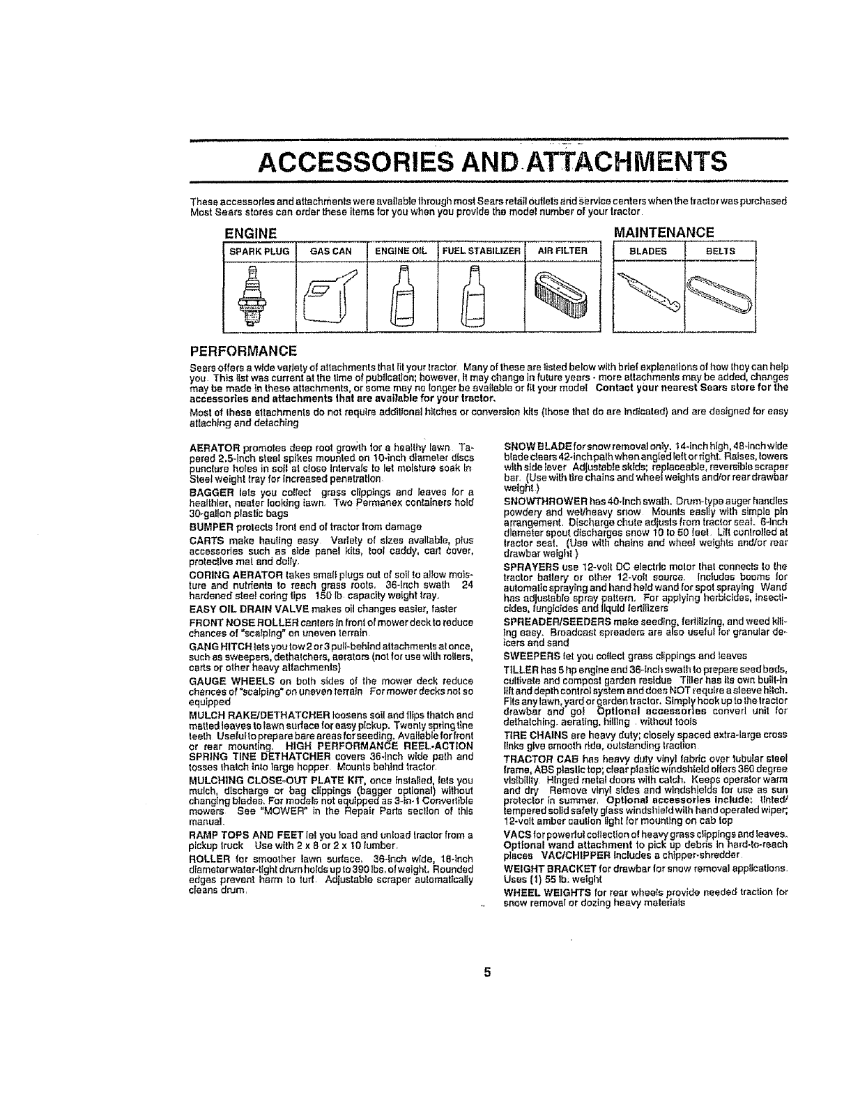
ACCESSORIES AND ATTACHMENTS
Theseaccessories and attachments were available throughmost Soars retail Outletsand s.etrice centers when the tractor was purchased
Most Seers stores can order these items for you whenyou providethe model number of yourtractor
MAINTENANCE
BLADES BELTS
ENGINE
SPARKPLUG GASCAN ENGINEOIL FUELSTABILIZER AIR FILTER
%
PERFORMANCE
Sears offoma widevariety o| attachments that fityourtractor Manyofihesearelistedbelowwtthbdefexplenat_onselhowlhcycanhelp
you This list was current at the lime of publication: however, it may change in future years- more attachments may be added, changes
may be made in these attachments,or somemay no longerbe available or fit your model Contact your nearest Sears store for the
accessories and attachments that are available for your tractor.
Most of these attachmentsdo not raqutre addil_onalhitches or conversionkits (those that do are tndJceled}and are designed tar easy
attaching and detaching
AERATOR promotes deep root gro_;th to_"ahealthy lawn Ta-
pered 2.5-Inch steel spikes mounted on tO-inch diameter d_ses
punclure hates in soil at close tnierva(sto Iet moisture soak In
Steel weight tray for Increased penetration.
BAGGER lets you collect grass olipp_ngs and Ieaves tar a
healthier, nearer looking Iawn, Two permene× containers hold
30-gaUonplasftc begs
BUMPER protects hent end of tractor Item damage
CARTS make hauling easy Variety of sizes available, ptus
eccessodos such as side panel kits, tool caddy, cart Coyote
prolective mat and doily,
CORING AERATOR takessme(}plugs oat of so_lto atIewmois-
ture end nutrients to reach grass roots_ 36-tnoh swa_ 24
hardened stee! coringtips 150 Ib capacity weighttray.,
EASY OIL DRAIN VALVE makes oil changeseasier, fester
FRONT NOSE ROLLER canterstn frontof mower deck to reduce
chancesof "scalping" on uneven terrain
GANG HITCH lets you tow 2 or3 pull-behind attachments el once,
such es sweepers, dethalchere, aerators (not for usawl_hrollers,
carts orother heavy agachments}
GAUGE WHEELS on both sides of the mower deck reduce
chances el "scalping" on uneven terrain For mower decksnct so
equipped
MULCH RAKFJDETHATCHER loosens soiland flips thatchand
matted leaves to Iawn surface foreasy pickup, Twenty springt{ne
teeth UsefuIto prepare bare areas forseeding, Available for {rent
or rear mounting. HIGH PERFORMANCE REEL.ACTION
SPRING TINE IJETHATCHER covers 36-1richwide path and
tosses Ihatch Into largo hopper Mounts behind tractor,
MULCHING CLOSE-OUT PLATE KIT once installed tots you
mulch, discharge or bag clippings (bagger optional) without
changingb!ades. For modelsnotequipped as 3-in. I Convertible
mowers See "MOWER" tn the Repair Parts section of this
manuel.
RAMP TOPS AND FEET let you feed end unload frecter from e
pickup Iruck Use with 2 x 8 or 2x 10 lumber
ROLLER for smoother [awe audace. 36-Inch wide, 18*tnch
dtemetorwator-tight drum holds up to 3901bs,olwaight, Rounded
edges prevent harm to tud Ad ustable scraper automatically
ccans drum,
SNOW BLADEfor snow removal only. 14*inchhigh. ,_B_inchwfde
blade clears42-1nchpath whenangled left or right. Raises, towers
w_thside _ever Adjustable skids; replaceable,reversible scrape r
bar (Use with tirechatns and wheel weights and/or rear drawber
weight)
SNOWTHROWER hes40-fnch swath, Drum-type augerhandles
powdery and weVheavy snow Mounts easily with simple pin
arrangement Discharge chute adjusts tram tractor seat. 6-inch
diameter spout dlschargos snow 10 to 50 feet Uft controlled at
tractor seat. (Use with chafns end wheel weights and/er rea_'
drawbar weight )
SPRAYERS use 12-volt DC etectrlcmotor thai connectsto Ihe
tractor battery or other 12-vei! source. Includes booms far
automaticspraying and hand heid wandtot spotspraying Wand
has ad ustable spray pattern. For applying herbicides, tnsecti-
cdee, fang c des and liquid fertilizers
SPREADERISEEDERS make seeding,fertilizing,end weed kill-
Ing easy. Broadcast spreaders are also uselulfor granular de,-
leers and sand
SWEEPERS let you collect grass clippingsand reaves
TILLER has 5 hp engineand 36-tnclrswath to prepare seed beds,
cultivate end compost garden residue Tiller has itsown built-In
tiltand depthcent rotsystem and does NOT require asleeve hitch.
Fitsany lawn yard orgardentractor, Simply book up to the Irsctor
drawbar end go_ Optional accesser}as convert unit for
dethatching, aerating, hilling withouttools
TIRE CHAINS are heavy duty; closelyspaced extra-large cross
Elnksgive smooth ride. outsl_ndlngt_'action
TRACTOR CA_ hoe heavy duly vinyl fabric over tubularsteel
frame, ASS pta,,Uctop; ctear plastic windshieldoilers 360 degree
vls{billty Hinged metal doomswith catch. Keeps operator warm
and dry Remove v_nytsides end windshields tar use as sun
protector in summer, Optional accessories include: tinted/
temperedsolidsafetyglass windshieldwilh hand opereled wiper;,
12-volt ember cautionIIght for mounting on cab top
VACS forpoweflul collection el heavy grass clippings and leaves.
Optional wand attachment to pick up debris in herd-to-reach
places VACICH1PPER Includes a chtppeFshredder
WEIGHT BRACKET for drawber lorsnow removal apptlcatlons.
Uses (t} 55 Ib: weight
WHEEL WEIGHTS for rear wheeIs provlde neededtraction for
snow removsIordozing heavy materials
I..L_ Ul,U, nil
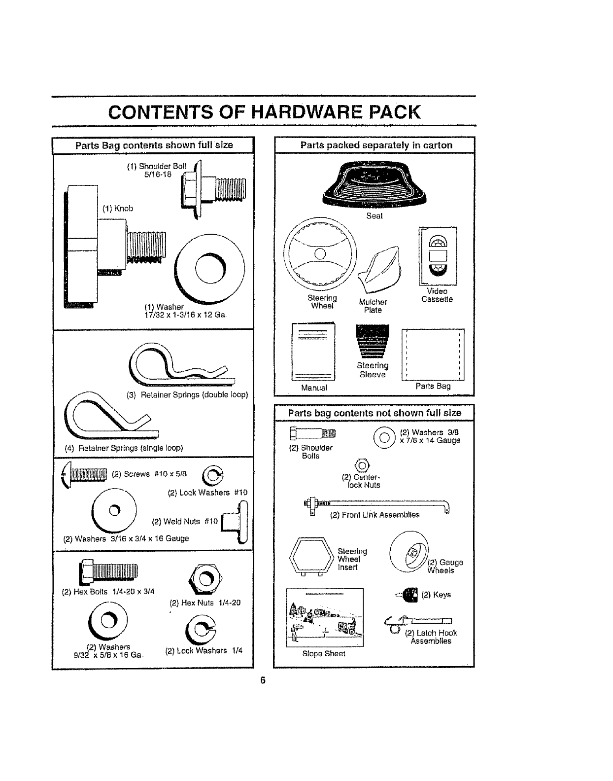
CONTENTS OF HARDWARE PACK
Parts Bag contents shown full size
(1) Shoulder BoTI
5/I6-18
(1) Knob
(I) Washer
17/32 x 1-3/16 x 12 Ga
ner Springs (double loop)
(4) Retainer Springs (single loop)
_ (2) Screws #10 x 518
(2) Lock Washers #1[_
(2) Weld Nuts #10
(2) Washers 3116 x 3/4 x 16 Gauge
, ,,,i,,
(2) Hex Bolts 1/4-20 x 314
G
(2) Washers
9/32 x 5/8 x t6 Ga
®
(2) Hex Nuts !/4-20
®
(2) Lock Washers 1/4
tr
Parts packed separately in carton
Seat
Steering
Wheel
n
Manual
Vldeo
Mulcher Cassette
Plate
Steering
Sleeve
f t
t I
t=
t
ti
t I
Pa_s Bag
(2) Shoulder
Bolls
Parts bag contents not shown full size
(2) Washers 3t8
x 7/8 x t4 Gauge
4#
(2) Center-
lock Nuts
[(_""(2) Front Link Assemblies
_ teering
Wheel
insert
S{ope Sheet
_-<-'_ (2) Keys
Assemblies
_LIJI II '" II I I. .
ASSEMBLY
................... illl, i, L ,iJ,
Your new trac or has been assembled at the factory with exception of those parts teft unassembled for shipping purposes.
To ensure safe and proper operation of your tractor aII parts and hardware you assemble must be ttgittened securely Use
the correct tools as necessary to insure proper tightness
TOOLS REQUIRED FOR ASSEMBLY
A socket wrench set wtil make assembly easier Slandard
wrench sizes are tlsted.
(2) 7/t6" wrenches Ptlers
(1) 9/16" wrench Tire pressure gauge
(1) 3/4" Socket w/drive ratchet Phfflips Screwdriver
Utility knife
When fight or left hand is mentioned in this manual, tt
means when you are in the operating position (seated
behind the steering wheel)
TO REMOVE TRACTOR FROM CARTON
UNPACK CARTON
Remove all accessible loose parts and parts cartons
from carton (See page 6).
•Cut from top to bottom, along lines on at[ four corners
of carton, and lay panels f at.
- Remove mowerand packing materials
• Check for any additional loose parts or cartons and
remove
STEERINGWHEEL
HEX LOCKNUT
FLATWAS.ER
__j.... STEERING
_" WHEEL
STEERING
WHEEL _G
STEERIN
AO,_PTEn_t, SHAFT
STEERING ,;;_ -_'
SLEEVE----....._" ('(i D_, - _ -. _'__'
l t ,t I/
tIi/ I
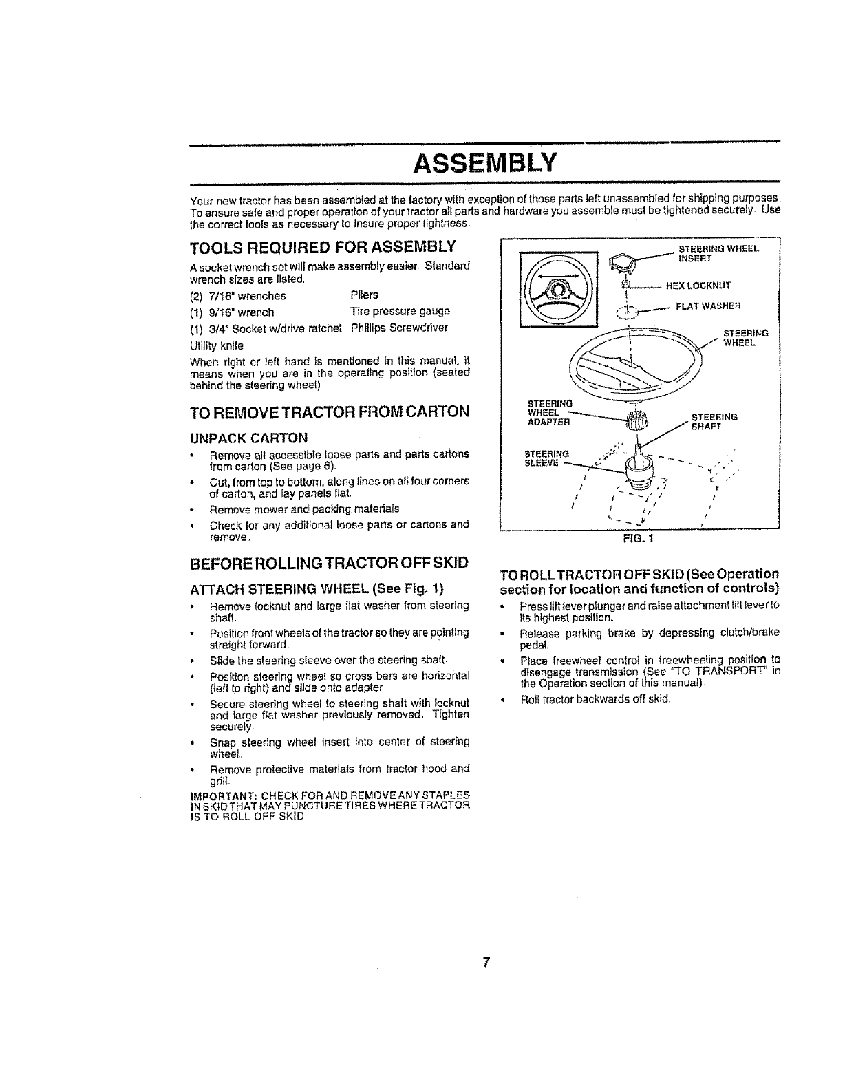
FIG, 1
BEFORE ROLLING TRACTOR OFF SKID
ATTACH STEERING WHEEL (See Fig. 1)
• Remove {ocknut and farge flat washer from steering
shaft-
.Position frontwheels of the tractor So they are Pointing
straight forward
• Slide the steering sleeve over the steering shaft
•Position steering wheel so cross bars are horizontal
(left !o right) and slide onto adapter
•Secure steering wheel to steering shalt wlth Iocknut
and _arge flat washer previously removed. Tighten
securely,
• Snap steering wheel insert into center of steering
wheel,
•Remove protective materials from traclor hood and
gdlL
IMPORTANT; CHECK FOR AND REMOVE ANY STAPLES
iN SK1DTHATMAY PUNCTURETIRES WHERE TRACTOR
IS TO ROLL OFF SKID
TO RO LLTRACTOR OFF SKID (See Operation
section for location and function of controls)
• Press liftlever plunger and raise attachment littlever to
Its highestposition.
•Release parking brake by depressing clutehtbrake
pedal,
,Ptace freewheel controlin freewheeling position to
disengage transmission(See "TO TRANSPORT" In
the Operation section of thismanual)
• Rolltractor backwards off skid
, ,,,,,,, ASSEMBLY
HOW TO SET UP YOUR TRACTOR
CONNECT BATTERY (See Fig, 2)
• Lift hood to raised position
• Open terminal access doors, remove terminal protec-
tive caps and discard.
• tf lhls battery Is put into service after month and year
indicated an label (label located between terminals)
charge battery for minimum of one hour at 6-10 ampso
,, First connect RED baltery cable to positive (+) battery
terrain al wlth hex bolt, tier washer, lock washBr and hex
nut as shown. Tighten securely.
, Connect BLACK grounding cable te negative (-) bat-
tery terminal with remaining hex bolt, flat washer, lock
washer and hex nut. Tighten securely
,, Close lerminat access doors
Use terminal access doors for:
, Inspection for secure conneclions (Io tighten hard-
ware),
• InspectionIor corrosion
•Testing battery.,
• Jumping (if required),
Periodic charging.
LOCK FLAT
HEX NUT WASHER WASHER
DISCARD TERMINAL NEX
PROTECTIVE CAPS BOLT
TERMfNAL -r{1 _
ACCESS
DOOR POSEWE
(REDt
CABLE
NEGATIVE
(BLACK)
CABLE
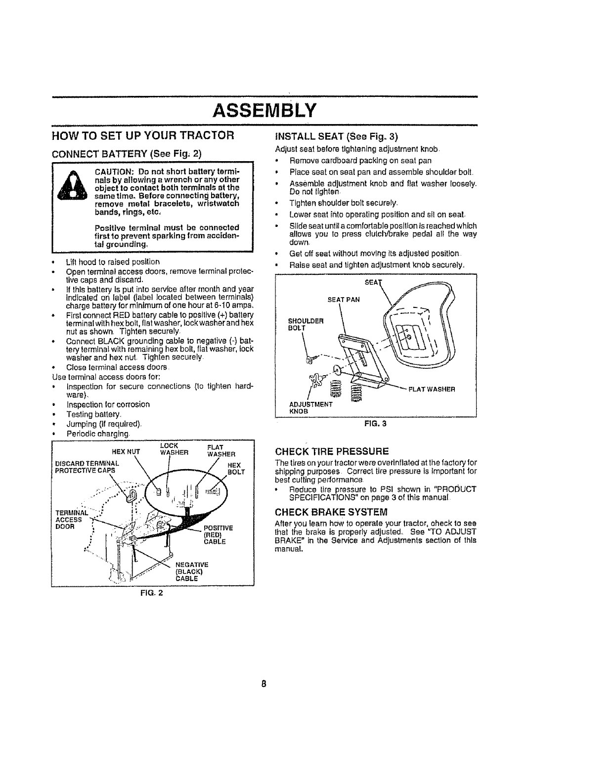
INSTALL SEAT (See Fig. 3)
Adjust seal before tightening adjustment knob.
• Remove cardboard packtng on seat pan
• Place seal on sea! pan and assemble shoulder bolt.
• Assemble adjustment knob and flat washer loosely.
DO notlighten,
.Tighten shoulderbott securely.
• Lower seat into operating position and sil on seat.
• Slide seat unlif a comfortable position is reached which
allows you lo press clutch/brake pedal all the way
down.
•Get off seat without moving its adjusted position
• Raise seat and tighten ad)ustment knob securely..
SEAT PAN
SHOULDER
BOLT
ADJUSTMENT
KNOB
FIG. 3
FLAT WASHER
CHECK TIRE PRESSURE
The tires an your tractor were overlnflated at the factory for
shipping purposes Cprrect tire pressure is important for
best cutting performance
•Reduce tire pressure to PSI shown in "PRODUCT
SPECIFICATIONS" on page 3 of this manual
CHECK BRAKE SYSTEM
After you learn h_w to operate your tractor, check to see
thai the brake is properly adjusted° See "TO ADJUST
BRAKE" in the Service and Adjustments section of this
manual.
FIG. 2
,Li
ASSEMBLY
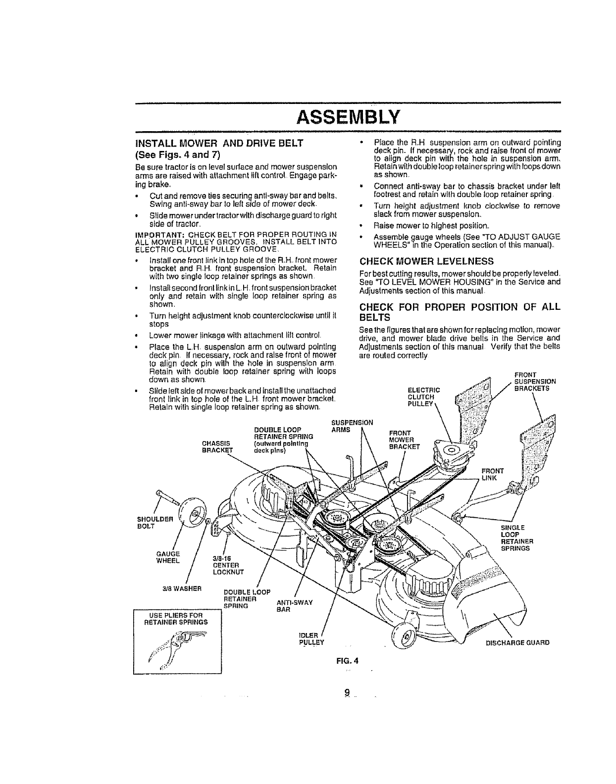
INSTALL MOWER AND DRIVE BELT
(See Figs. 4 and 7)
Be sure tractor is on level sudace and mower suspension
arms are raised with attachment lift control Engage park-
ing brake.
. Cut and remove ties securin_ anti-sway bar and belts,,
Swing anti-sway bar Io left side of mower deck-
.Slide mowerundertractorwtth dlschargeguardto right
side of tractor,
IMPORTANT= CHECK BELT FOR PROPER ROUTING iN
ALL MOWER :PULLEY GROOVES. INSTALL BELT INTO
ELECTRIC CLUTCH PULLEY GROOVE.
•Install one front link in top hole of the Roll., front mower
bracket and R_H. front suspensior_ bracket, Retain
with two single loop relalner springs as shown,
•_nstall second fronl link in L.H. front suspension bracket
only and retain with single loop retainer spdng as
shown,
•Turn height adjustment knob counterclockwise untf! it
stops
•Lower mower Iinkage with altachment lilt control
• Place the L.H. suspension arm on outward pointing
deck pin. tf necessary, rock and raise front of mower
to align deck pin wilh the hole in suspension arm
Retain with double loop retainer spring wilh loops
down as shown,
• Slide left side of mower back and instatt the unattached
front link in top hote of the LH front mower bracket
Retaln wtlh single loop retainer spring as shown
.Place the R.H suspension arm on oulward pointing
deck pin. if necessary, rock and raise front of mower
to atign deck ptn with the hole in suspension arm.
Relain with double loop retainer spring with roops down
as shown
* Connect anti-sway bar to chassis bracket under lett
footrest and retain w[Ih double loop retainer spring
. Turn height adiustment knob clocl_._lse to remove
slack from mower suspension,
. Raise mower to highest position.,
. Assemble gauge wheels (See "TO ADJUST GAUGE
WHEELS" in the Operalion section of this manual)°
CHECK MOWER LEVELNESS
For best cutting results, mower should be propedyleveled,
See "TO LEVEL MOWER HOUSING" in the Service and
Adjustments section of this manual
CHECK FOR PROPER POSITION OF ALL
BELTS
See the figures that are shown for replacing motion, mower
drive, and mower blade drive belts in the Service and
AdJustmenls section of this manual Verify that the belts
are routed correctiy
ELECTRIC
CLUTCH
PULLEY
FRONT
SUSPENSION
BRACKETS
DOUBLELOOP
RETAINER SPRING
CHASSIS (oulwardpoi_lng
BRACKST deckpln_
SUSPENSION
ARMS FRONT
MOWER
BRACKET
SHOULDER
BOLT
GAUGE
WHEEL
3/8 WASHER
USE PLIERS FOR
RETAINER SPRINGS
3f@-'tS
CENTER
LOCKNUT
DOUBLE LOOP
RETAINER
SPRING ANTI*SWAY
BAR
IDLER
PULLEY
FIG. 4
SINGLE
LOOP
DISCHARGEGUARO
•,9.
ASSEMBLY
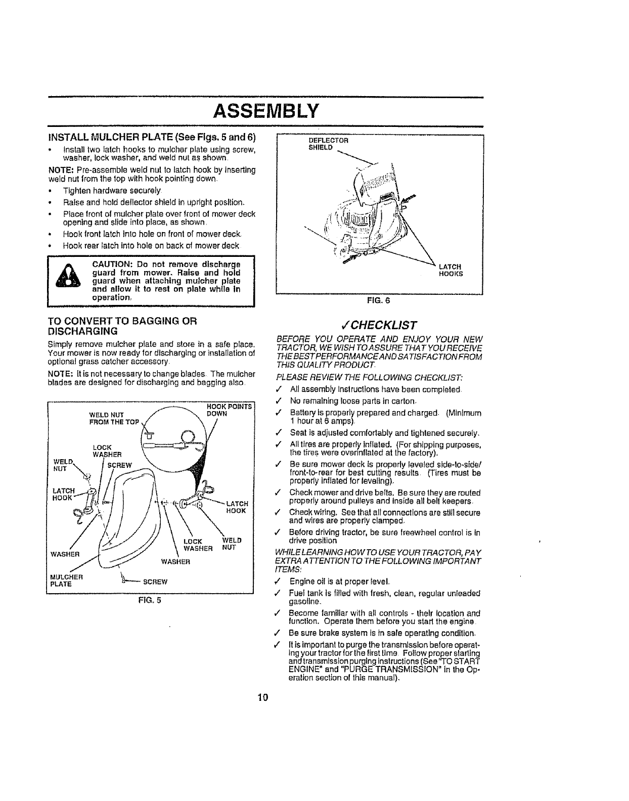
INSTALL MULCHER PLATE (See Figs, 5 and 6)
, Install two latch hooks to mulcher plate using screw,
washer, lock washer, and weld nut as shown.
NOTE: Pro-assemble weld nul to latch hook by inserting
weld nut from the top with hook pointing down.
• Tighten hardware securely
•Raise and hold detteclor shield in upright position.
,, Place front of mulcher plate over front of mower deck
opening and slide into place, as shown.
• Hook front latch into hole on front of mower deck.
,, Hook rear latch into hole on back of mower deck
CAUTION: De not remove discharge
guard from mower, Raise and hold
guard when attaching mutcher plate
and allow it to rest on plate while In
operation,
,w lull i,ll iii
DEFLECTOR
EHrELD
LATCH
HOOKS
FIGo6
TO CONVERT TO BAGGING OR
DISCHARGING
Sfmpiy remove mulcher ptateand store in a safe place,
Your mower is now ready for discharging orinstallationof
optionat grass catcher accessory,
NOTE: It is not necessary to change blades The muleher
blades are designed for discharging and bagging also,
HOOK
LOCK WELD
WASHER NUT
WASHER WASHER
MULCHER _'_""--SCREW
PLATE
FiG. 5
,/CHECKLIST
BEFORE YOU OPERATE AND ENJOY YOUR NEW
TRACTOR, WE WISH TO ASSURE THAT YOU RECEfVE
THE BEST PERFORMANCE AND SATISFACTION FROM
THIS QUA LtTY PRODUCT
PLEASE REVIEW THE FOLLOWING CHECKLIST:
•/Aft assembly Inslructions have been completed
,/ No remaining _oosa parts in carton.
,," Battery is properly prepared and charged. (Minimum
1 hour at 6 amps)
,/ Seat is adiusled comfortably and tightened securely.
,." AII tires are property inflated. (For shipping purposes,
the tires were overfnflaled at the factory),
,/ Be sure mower deck is properly leveled slde-lo.side/
front-to-rear for best culling results (Tires must be
properiy inflated for leve]tng)_
/Check mower and dflve belts. Be sure they are routed
properly around pulleys and inside all belt keepers.
,/ Check wiring, See that alfconnectfons are still secure
and wiles are property clamped.
_" Before driving tractor, be sure freewheel control is in
drNe position
WHILE LEARNING HOW TO USE YOUR TRACTOR, PAY
EXTRA A TTENTfON TO THE FOLLOWING IMPORTANT
ITEMS:
,/ Engine oil is at proper level..
,/ Fuel tank is filled with fresh, clean, regular unleaded
gasoline.
v" Become familiar with afl controls - their location and
function. Operate them before you start the engine
,I Be sure brake system is in sate operating cond{tton.
,f" It is importanl topurge the transmission before operat-
ing your tractor for lSe first time Foltow proper slaritng
and transmission purging instructions (Sea'TO START
ENGINE" and 'PURGE TRANSMISSION" {n the Op-
eralton section of this manual).
10
OPERATION
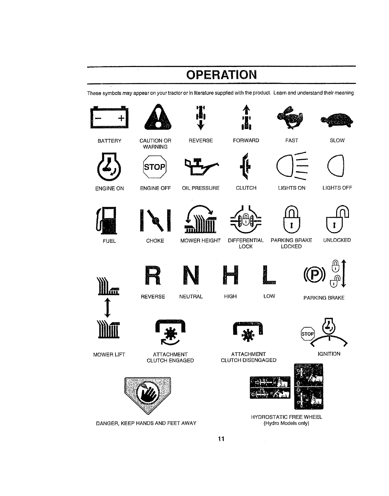
These symbols may appear on your tractor or in ]ttera_ure supplied with the producL Learn end understand their meaning
BATTERY CAUTION OR
WARNING
ENGINE ON ENGINE OFF
41,
REVERSE
OIL PRESSURE CLUTCH
FORWARD FAST SLOW
LIGHTS ON LIGHTS OFF
FUEL CHOKE MOWER HEIGHT DIFFERENTIAL
LOCK
N
REVERSE NEUTRAL HIGH
0
PARKING BRAKE UNLOCKED
LOCKED
MOWER L|FT ATTACHMENT
CLUTCH ENGAGED
ATTACHMENT
CLUTCH DfSENGAGED
L
LOW PARKING BRAKE
IGNITION
DANGER, KEEP HANDS AND FEET AWAY
HYDROSTATIC FREE WHEEL
(Hydro Models only)
11
,1111 i iiiiii i iii
OPERATION
iiii
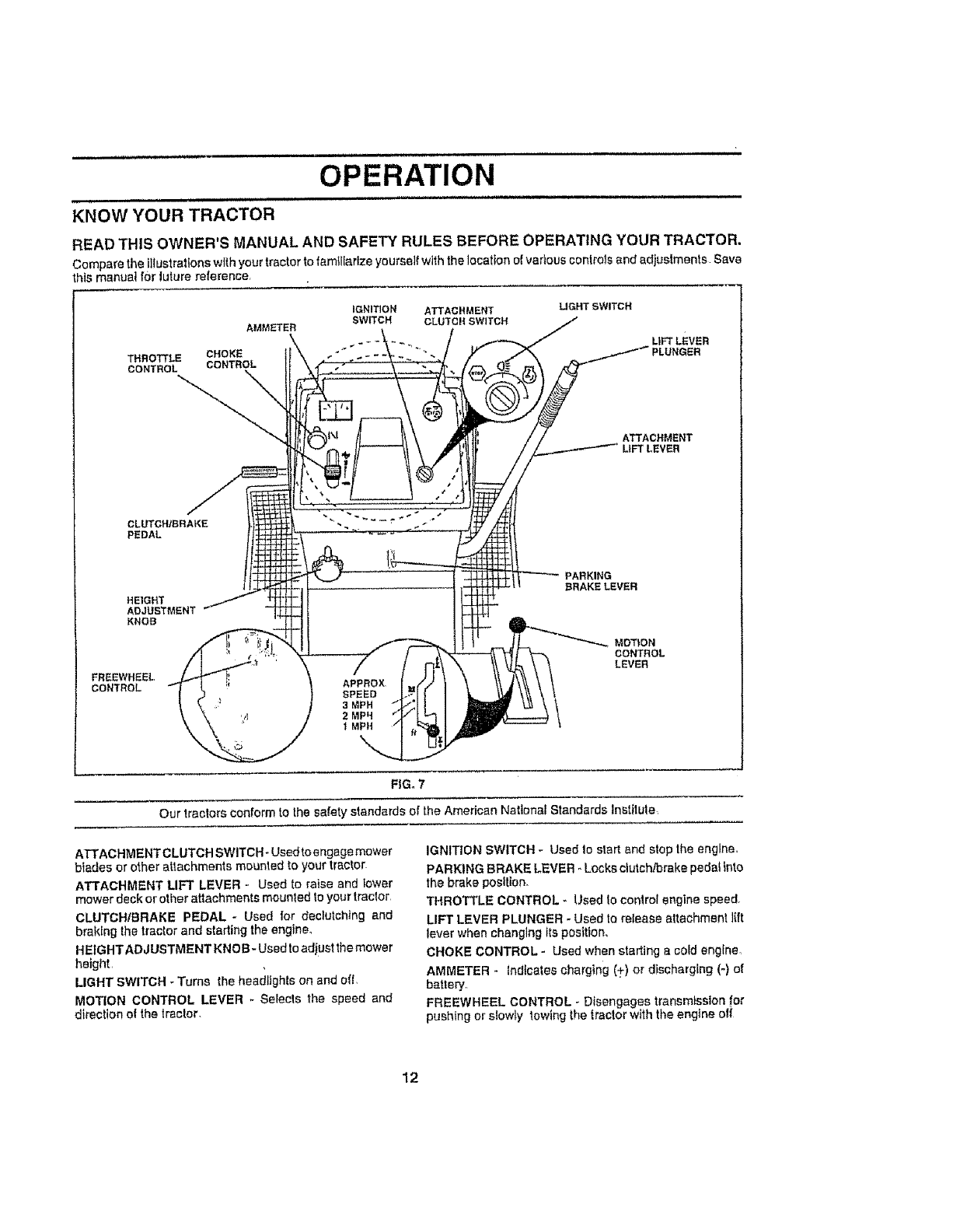
KNOW YOUR TRACTOR
READ THIS OWNER'S MANUAL AND SAFETY RULES BEFORE OPERATING YOUR TRACTOR.
Compare the illustrations with your tractor to familiarize yourself with the location o! various controls and adjustments Save
his manual for luture reference
AMMEI'ER
THRO_LE CHOKE
CONTROL CONTROL
IGNITION ATTACHMENT
SWITCH CLUTCH SW_TCH
UGHT SWITCH
LtFT LEVER
PLUNGER
ATTACHMENT
CLUTCH/BRAKE
PEDAL
HEIGHT
ADJUSTMENT
KNOB
FREEWHEEL,
CONTROL
PARKING
BRAKELEVER
MOTION
CONTROL
LEVER
FIG. 7
Our tractors conform to the safety standards of the American Nettena_ Standards lnstitule_
ATTACHMENTC LUTCH SWITCH _Used to engage mower
biades or other attachments mounted to your tractor
ATTACHMENT LIFT LEVER - Used to raise and lower
mower deck or other attachments mounted to your tractor,
CLUTCHIBRAKE PEDAL - Used for declutching and
bretdng the tractor and starting the engine_
HEIGHT ADJUSTMENT KNOB - Used to adjust the mower
height,
LIGHT SWITCH - Turns the headlights on end off,
MOTION CONTROL LEVER _ Selects the speed and
direction ot the tractor,
IGNITION SWITCH - Used !o slert and stop the engine,
PARKING BRAKE LEVER - Locks clutch!brake pedaf _nto
the brake position,
THROTTLE CONTROL - Used to conlrol engine speed,
LIFT LEVER PLUNGER - Used to reIease attachment lift
lever when changing Its posftfon,
CHOKE CONTROL - Used when starting a cold engine.
AMMETER - indicates charging (+) or discharging (-) of
battery
FREEWHEEL CONTROL - Disengages transmission !or
pushing or slowly towing the tractor with the engine off
12
OPERATION
, , = =,,, ,
The operation of any tractor can result in foreign objects thrown Into the eyes, which can
result in severe eye damage. Always wear safety glasses or eye shields while operating !
your tractor or performing any adjustments or repairs. We recommend awlde v=ston safety
mask over the spectacles or standard safety glasses.
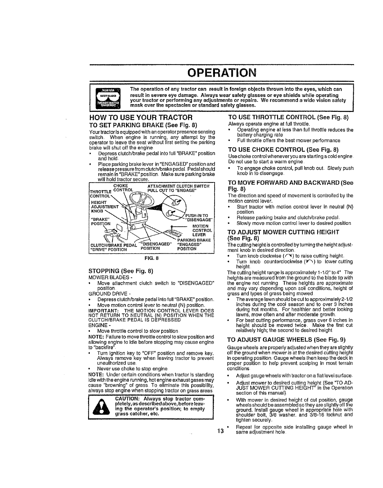
HOW TO USE YOUR TRACTOR TO USE THROTTLE CONTROL (See Fig. 8)
TO SET PARKING BRAKE (See Fig, 8) Always operate engine at (uilthrottle.
Your tractorls equipped with an operatorpresencesensing • OperalJng engine at less than full lhrott[e reduces the
battery charging rate
switch. When engine Is running, any attempt by the
operator to leave the seal without lirst setting the parking •Full throttle offers the best mower performance
brake wtfl shut off the engine TO USE CHOKE CONTROL (See Fig, 8)
•Depress clutch/brake pedal Inlo fu]! "BRAKE" position
and hold. Use choke control whenever you are starting a cold engine
• Place parking brake lever in "ENGAGED" position and Do not use to start a warm engine
reteasepr_ssurefromctutchYorake pedal Pedalshould • To engage choke control, put_ knob out Slowly push
remain [n BRAKE position. Make sure parking brake knob in to disengage
w_tlhold tractor secure. TO MOVE FORWARD AND BACKWARD (See
CHOKE ATTACHMENTBLOTCHSWITCH
THROTTLECONTROL PULLOUTTO *'ENGAGE*' Fig. 8)
CLUTCHIBRAKE PEDAL "_;"DISENGAGED"
"DRIVE" POSmON POSITiON
FIG,. 8
STOPPING (See Fig. 8)
MOWER BLADES =
• Move attachment c_utch switch to "DISENGAGED"
position
GROUND DRIVE -
The direction and speed of movement is controlled by the
motion conlrol lever.
• Start tractor with molten control lever In neulrai (N)
position.
•Release parking brake and cJutchJbrake pedal
DISENGAGE" •Slowly move motion control lever to desired position
MOTION
CONTROL TO ADJUST MOWER CUTTING HEIGHT
LEVER
PAe_NGBRAKE (See Fig. 8)
"ENGAGED'_ The culling heighl is controlled by turning the height adjust-
POSITION meni knob tn desired direction.
• Turn knob clockwise (,"_) to raise cutting height.
•Turn knob counterclockwise {K"_)to lower culling
height
The cutting height range is approximately 1-1/2" to 4" The
heights are measured from the ground to Ihe blade tip wilh
the engine not running These heights are approximate
and may vary depending upon salt conditions, height of
grass and types of grass being mowed
,, Depress clutch/brake pedal inlo full "BRAKE" position.
Move motion control lever to neutral (N) position.
IMPORTANT; THE MOTION CONTROL LEVER DOES
NOT RETURN TO NEUTRAL (N) POSITION WHEN THE
CLUTCH/BRAKE PEDAL IS DEPRESSED
ENGINE -
• Move throttie control to slow position
NOTE: Failure to move throtlle control to slow position and
allowing engine to idle before stopping may cause engine
to "backfire".
• Turn ignition key to "OFF" position and remove key,
Always remove key when leaving tractor to prevent
unauthorized use
• Never use choke to stop engine
• The average fawn should be curto approximately 2d/2
inches during the cool season and to over 3 inches
during hot months, For hea!thler and better looking
lawns, mow olten and after moderate growlh..
• For best cutting performance, grass over 6 inci_es in
height should be mowed twice. Make the first cut
relatively htgh; the second to desired height
TO ADJUST GAUGE WHEELS (See Fig, 9)
Gauge wheels are properly adtusted when they are slightly
off the ground when mower ts at the desired cutting height
in operating position. Gauge wheels then keep the deck in
proper position to help prevent scalping in most terrain
conditions
NOTE: Under certain condiltonswhen traclorls standing
Idle with the engine running, hot e nglne exhaust gases may
cause "browning" of grass To eliminate this possibility,
always stop engine when stopping traelor on grass areas
I_ AUTION: Always stop tractor corn- l
ptetely,as describedabove, before leav-
ing the operator's position; to empty
grass catcher, etc.
• Adjust gauge wheelswilh tractor on a tlattevef surface
• Ad ust mower to desired cutting hei_ht (See "TO AD-
JUST MOWER CUTT NG HE GHT' in the Operation
section of this manuel)
• With mower in desired height of cut position, gauge
wheels should be assembled so they are slighliy off the
ground, Inslall gauge wheel in appropriate hole with
shoufder boll, 318 washer, and 3lB-16 !ocknut and
tighten securely.
•Repeat far opposite side installing gauge wheel in
13 same adjustment hole
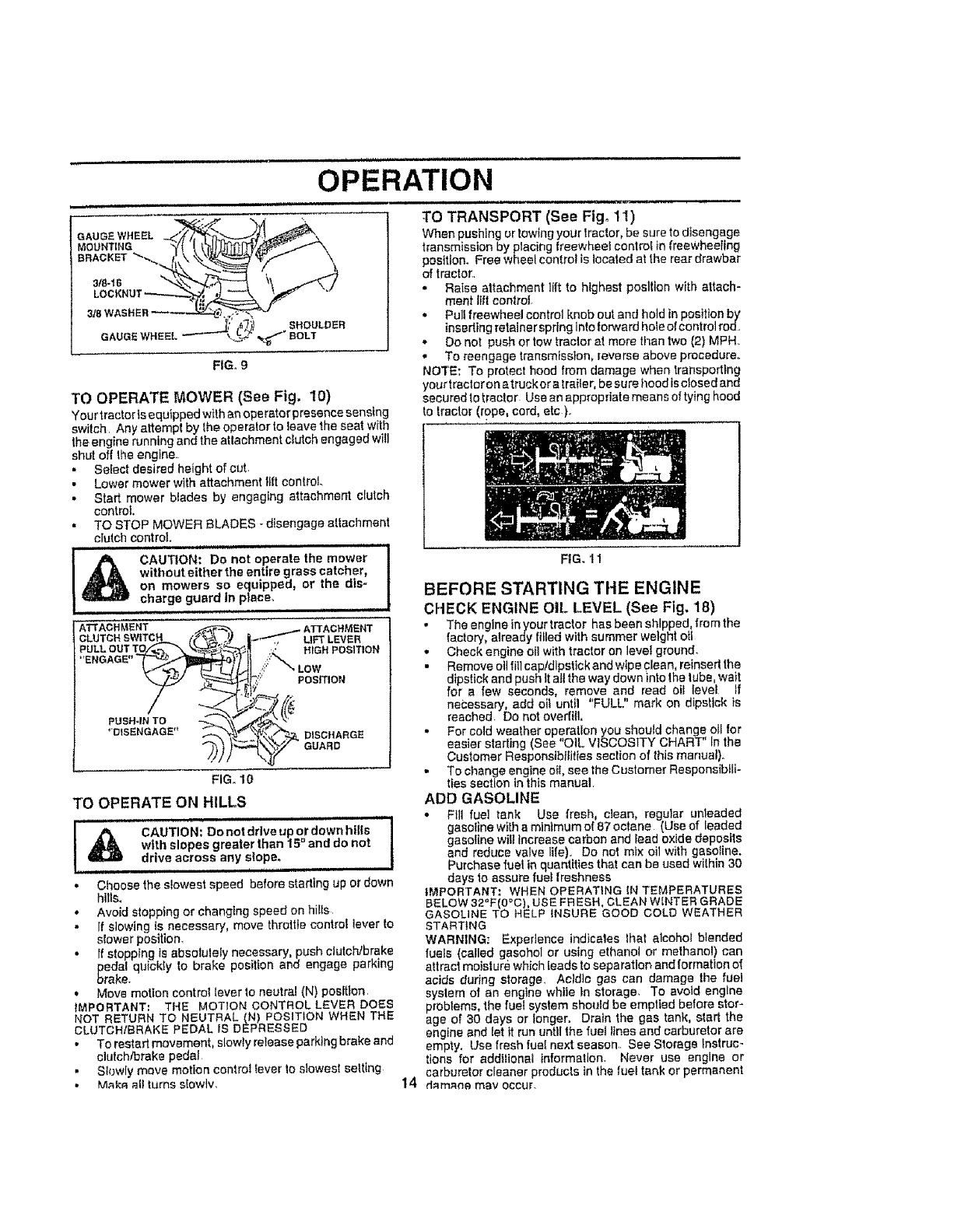
GAUGE WHEEL
MOUNTING
BBACKE'T_
3t8-16
3/8 WASHER
SHOULDER
GAUGEWF _"_'BOLT
FIG, g
TO OPERATE MOWER (See Fig. 10)
',(our tractor is equipped with an operator presence sensing
switch Any attempt by the operator to leave the seat wilh
the engine running and the attachment clutch engaged will
shut off the engine
• Selecl desired height of cut.
• Lower mower with attachment itft control.
• Start mower blades by engaging attachment clutch
control.
• TO STOP MOWER BLADES - disengage atlachment
clutch control.
ii, H,,, IIIIMI
t& AUTION: Do not operate the mower
without either the entire grass catcher,
on mowers so equipped, or the dis-
charge guard in place,
iii
OPERATION
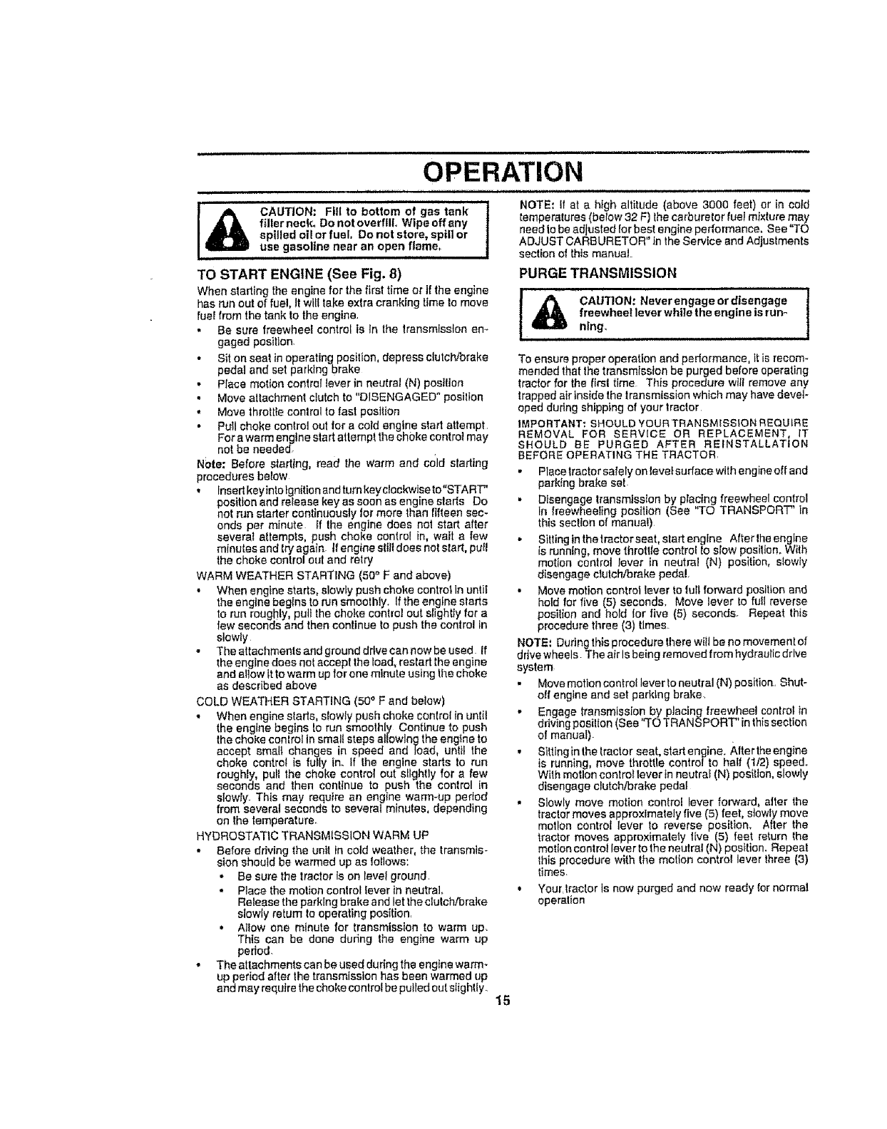
TO TRANSPORT (See Fig. 11)
When pushing or towing your tractor, be sure todisengage
transmission by placing freewheel control _nfreewheeling
position. Free wheel control is located al the rear drawbar
of tractor.
• Raise attachment lift to highest posllion with attach-
ment tilt control-
.Pull freewheel control knob out and hold in position by
inserting retainersprlng into forward hole of control rod
. Do not push or tow tractor at more than two (2) MPH
• To reengage transmission, reverse above procedure.
NOTE: To protect hood from damage when transpodlng
your traclcron a truck or a traiter, be sure hood is closed and
secured totraclor Use an appropriate means of tying hood
to tractor (rope, cord, etc).
FiG. 11
BEFORE STARTING THE ENGINE
CHECK ENGINE OIL LEVEL (See Fig. 18)
FIG. 10
•The englneinyour tractor has been shipped, fromthe
factory, already filled with summer weight oil
• Check engine otl with tractor on level ground.
• Remove oit tilt cap/dipstick and wipe clean reinsed the
dipstick and push II all the way down into the tube, wait
for a few seconds, remove and read oil ievei if
necessary, add oil until "FULL" mark on dipstick is
reached Do notoverfHl.
•For cold weather operation you should change oll for
easier starting (See "OIL VISCOSITY CHART" In the
Customer Responsibilities section of this manuat).
•To change engine oil see the Customer ReeponsibLli-
ties section in this manual
TO OPERATE ON HILLS
i,mHi ,Ul iH•
OA T,O.:Oonotd.vo pe.downhi.s
I
with slopes greater lhan 15 ° and do not
drive across any slope. i
• Choose the slowest speed before starting up or down
hills,
• Avoid stopping or changing speed on hil{s
•If slowing {s necessary', move throttte control lever to
slower position.
•rfstopp ng s absolufeiy necessary push clutch/brake
pedal quickly to brake position and engage parking
brake.
• Move motion control lever lo neutral (N) position,
IMPORTANT: THE MOTION CONTROL LEVER DOES
NOT RETURN TO NEUTRAL (N) POSITION WHEN THE
CLUTOHIBRAKE PEDAL IS DEPRESSED
• To restart movement, slowly release parking brake and
clutch/brake pedal
• Slowly move motion control tever lo slowest setting
•Make all turns sIowlv.
ADD GASOLINE
• Fill fuel tank Use fresh clean regular unleaded
gasoline with a minimum of 87 octane {Use of leaded
gasoline wilt increase carbon and fead oxide deposits
and reduce valve life). Do not mix oil with gasoline.
Purchase fuel in quantities that can be used within 30
days lo assure fuel freshness
IMPORTANT: WHEN OPERATING IN TEMPERATURES
BELOW 32"F(0°C), USE FRESH, CLEAN WINTER GRADE
GASOLINE TO HELP _NSURE GOOD COLD WEATHER
STARTING
WARNING; Experience indicales that alcohol blended
fuels (called gasohol or using ethanol or methanol) can
attract moisture which Ieads to separation and formation o_
acids during storage. Acidic gas can damage the fuel
system of an engine while in storage. To avoid engine
problems, the fuel system should be emptied before stor-
age of 30 days or longer. Drain the gas tank, start the
engine and let it run until the fuet lines and carburetor are
empty, Use fresh fuel next season. See Storage Instruc-
tions for additional Information. Never use engine or
carburetor cleaner products in the fuel tank or permanent
14 damana may occur.
ii OPERATION
=
[_ CAUTION: Fill to bottom of gas tank |
filler neck, Do not overfill Wipe off any I
spilled oi! or fuel. Do not store, spill or
use gasoline near an open flame,
TO START ENGINE (See Fig. 8)
When starting the engine for the first time or if the engine
has run out of fuel, It will take extra cranking lime to move
fuel from the tank to the engine.
•Be sure freewheel control is ]n the lransmlsston an.-
gaged position.
"Sit on seat in operating position, depress clutch/brake
pedal and set parking brake
• Place motion control lever in neutral IN) postlten
°Move altachment clutch to "DISENGAGED" posillon
,Move throttle conlrol to fast position
•Pull choke control out for a cold engine slad attempt
For a warm engine start atlempl lhe choke csntro! may
net be needed_
NOte: Before starting, read the warm and cold starting
procedures below
• Insert keyinlo ignition and turn keydockwise to"START"
position and release key as soon as engine slarts Do
not run starter continuously for more than fifteen sec-
onds per minute If Ihe engine does nat start after
several attempts, push choke control in, wait a few
minutes and lry again tf engine slilldoes notstart, putl
the choke control out and retry
WARM WEATHER STARTING (50° F and above)
• When engine starts, slowly push choke centrotln until
the engine begins to run smoothly. Ifthe engine slarts
to run roughly, pu]t the choke control out slightly for a
few seconds and then continue to push the control in
slowly
•The attachmenls and ground drive can now be used if
the engine does not accept the toad, restart the engine
and allow tt to warm up for one minute using the choke
as described above
COLD WEATHER STARTING (50°F and betow)
•When engine slarts, slowly push choke conlral in unlit
the engine begins le run smoothly Continue to push
the choke conlrol in small steps allowing the engine to
accept small changes in speed and load, until the
choke control is fully In. If Ihe engine starts to run
roughly pull the choke control out stlghlly for a few
seconds and then continue to push the centre n
slowly. This may require an engine warm-up period
from several seconds to several minutes, depending
on the temperature.
HYDROSTATIC TRANSMLSSION WARM UP
•Before driving the unit fn cold weather, the transmis-
sion should be warmed up as lellows;
•Be sure the tractor is on level ground.
• Place the motion control lever in neutral.
Release the parking brake and let Ihe clutch/brake
slowly retum to operating position,
,, Allow one minute for transmission to warm up_
This can be done during the engine warm up
period.
•The attachments can be used during the engine warm-
up period after the transmission has been warmed up
and may require the choke control be pulled out sfigh_ly.
NOTE: If at a high altitude (above 3000 feet) or in cold
temperatures (below 32 F) the carburetor fuel mixture may
need Io be adjusted for best engine performance. Sea"TO
ADJUST CARBURETOR" in _he Service and Adjustments
section of this manual
PURGE TRANSMISSION
_CAUTION: Neverengageordisengage !
freewheel lever while the engine is run_
nlng,
To ensure proper operation and performance, It is recom-
mended thai the lransmlsston be purged before operating
tractor for the firsl time This procedure witl remove any
trapped air Inside the lransmtssion which may have devel-
oped during shipping of your tractor
IMPORTANT: SHOULD YOUR TRANSMISSION REQUIRE
REMOVAL FOR SERVICE OR REPLACEMENT, IT
SHOULD BE PURGED AFTER REINSTALLATION
BEFORE OPERATING THE TRACTOR.
• Plasetractor safely on levetsurface with engine off and
parking brake set
,, D_sengage lransmtsslon by placing freewheel control
in freewheeling position (See TO TRANSPORT" in
this section of manual)
° Sittinginthelractorseat, startenglne Alterlheeng[ne
[s running, move throttle control Eoslow position. With
motion controt lever in neutral IN) position, slowly
disengage clutch/brake pedal.
•Move motion control lever to full forward position and
hold for five (5) seconds. Move lever to furl reverse
posilion and hold tor five (5) seconds_ Repeat this
procedure three (3) times
NOTE: During this procedure lhere witJbe no movement of
d rive wheels. The air Is being removed from hydraulic drive
system
• Move metlon control lever to neutral (N) position.. Shut-
elf engine and set parktng brake
• Engage transmission by placing freewheel control in
driving posilien (See "TO TRANSPORT" in thissection
of manual)
• Sitting in the tractor seat. start engine. After the engine
is running move throttle centre/to half (1/2) speed.
With motion control lever in neutrat IN) position, s owly
disengage c_utchibrake pedal
• Slowly move motion control lever forward, alter the
lractcr moves approximately five (5) feet, slowly move
motion control lever to reverse position_ After the
trB,ctor moves approximately l[ve (5) feet return the
motion control lever to the neutral IN) position. Repeat
this procedure with the motion control lever lhree {3)
times.
, Your_lractor is now purged and now ready for normal
operation
15
OPERATION
i J,
MOWING TIPS
• Tire chains cannot be used when the mower housing is
attached to tractor
° Mower should be properly teveled for best mowing
performance° See "TO LEVEL MOWER HOUSING" in
the Service and Adjustments section of this manual,,
• The left hand side of mower should be used for trLm-
ming,
• Drive so that clippings are discharged onto the area
that has been out. Have the cut area to the right of the
machine, This wit{ resuIt in a more even distribution of
clippings and more uniform cutting
• When mowing large areas, stad by turning to the right
so that clippings will discharge away from shrubs,
fences, driveways, etc, After one or two rounds, mow
in Ihe opposite direction making left hand turns until
ffnished (See Fig, 12),
•if grass _sextremely tall, it should be mowed twice to
reduce toad and posstbfe fire hazard from tided clip-
pings, Make first cut relatively high; the second to the
deslredheight.
• Do not mow grass when It is wet, Wet grass will plug
mower and leave undesirable clumps Allow grass to
dry before mowing
• Atways operate engine at full throttle when mowing to
assure better mowing performance end proper dis-
charge of matedal Regulate ground speed by select-
ing a low enough gear to give the mower cutting
performance as wel! as the quality of cut desired
• When operating attachments, select a ground speed
that witl suit tile terrain and give best performance of
the attachment being used,
MULCHING MOWING TIPS
IMPORTANT: FOR BEST PERFORMANCE, KEEP
MOWER HOUSING FREE OF BUILT-UP GRASS AND
TRASH_ CLEAN AFTER EACH USE
• The special mutching blade will recur the grass clip-
pings many times and reduce them in size so that as
they fall onto the lawn they"will disperse into the grass
and not be noliced Also, the mulched grass will
blodegrade quickly to provide nutrients for lhe lawn.
Always mulch with your h_ghest engine (blade) speed
as this will provide the best recurring action of lhe
blades
= Avoidcultlngyourlawnwhenitiswet Welgrasslends
to term clumps and interferes with the mulching action
The best time to mow your lawn is 1ha early aflemoon.
At this tlme the grass has dried and the newIy cut area
wt!f not be exposed to the direct sun.,
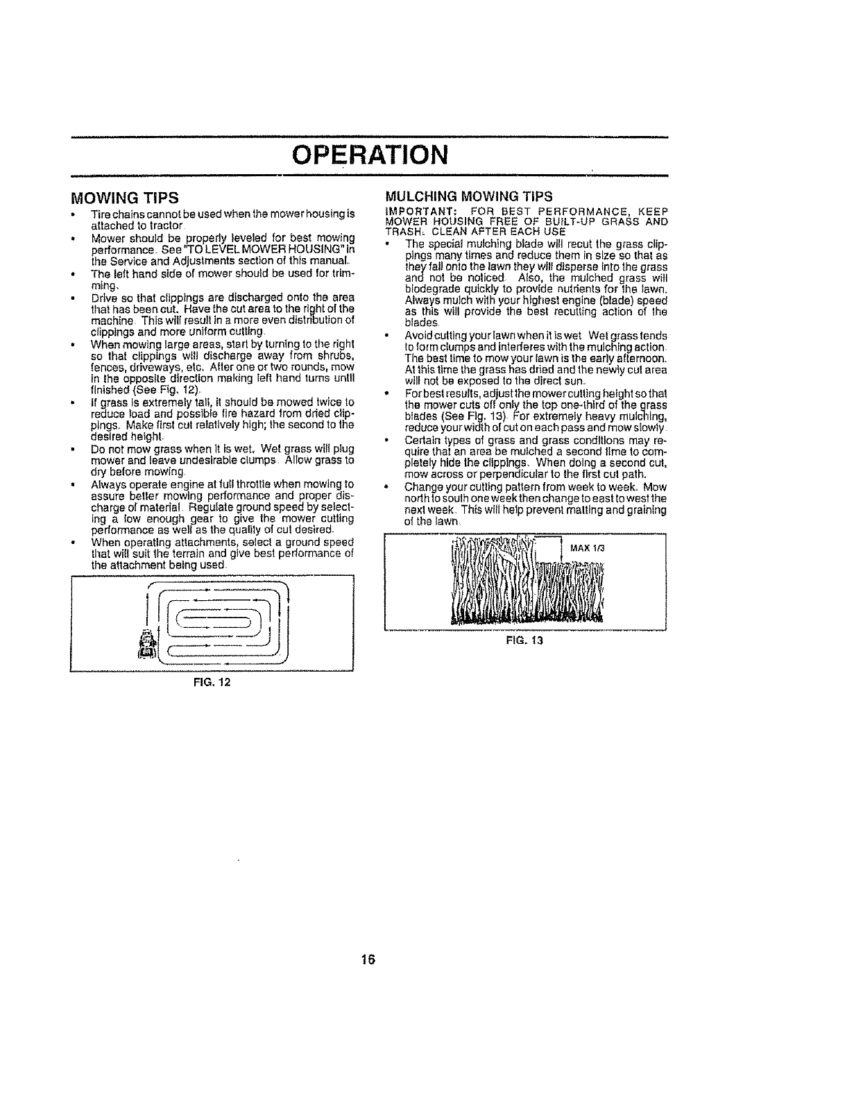
', For best resuIls, adjust the mower cutting height so that
the mower cute off only the top one..thlrd of the grass
bfedes (See Fig. 13) For extremely heavy mutcHng,
reduce your width of cut on each pass and mow slowly
•Certain types of grass and grass conditions may re-
quire thal an area be mutehed a second time to com-
pletely hide the clippings. When doing a second cut,
mow across or perpendicular to the first cul path.
= Changeyourcuttingpatternfromweektoweek. Mew
nedh to soulh one weekthen change to east to west the
next week, This will help prevent malting and graining
ofthelawn,
FIG. 13
FIG, 12
16
CUSTOMER RESPONSIBILITIES
MAINTENANCE SCHEDULE ___oo_n_J
AS YOU COMPLETE f__-_'_9,_._._O?'_ti '"
"Check Brake Operation ..If V' ........
Check T_rePressure I,/V' ....
1"JChec,forLoo,oF.eteners V" V', V'
_Sh_rpen!ReptaceMowerBlades I#"*,_ J
LUb,iCa"oec.e_" V' I," [
T iiChecF!BatteryLeve,_echarge I/_
0 '.CleenBstre_.,RedTerm!._._!e' ' 'V' ........ i --
ai CheckTrensaxle,€ooilng ,, If .............. i
Adjust B{adeBelt{e}Tension V'#_ ..... {
k_lustMotionD,_veee,(s)Te_e_on V'e '
CheckEngineOil Leve_ V_' I_ : ,
Change EngineOil _2.,_ . !if ,
Clean Air Screen ......
i Inspect Multt_dSperkAttester _ .............
_ ReptaceOil Filter (if equipped) I_l,z .....
ReplaceSparkFI,g V' V' :"
RepiacFgeIRepi_eeAirFiilerFitlerPaperCartridge ....., V'_t V _ .........]
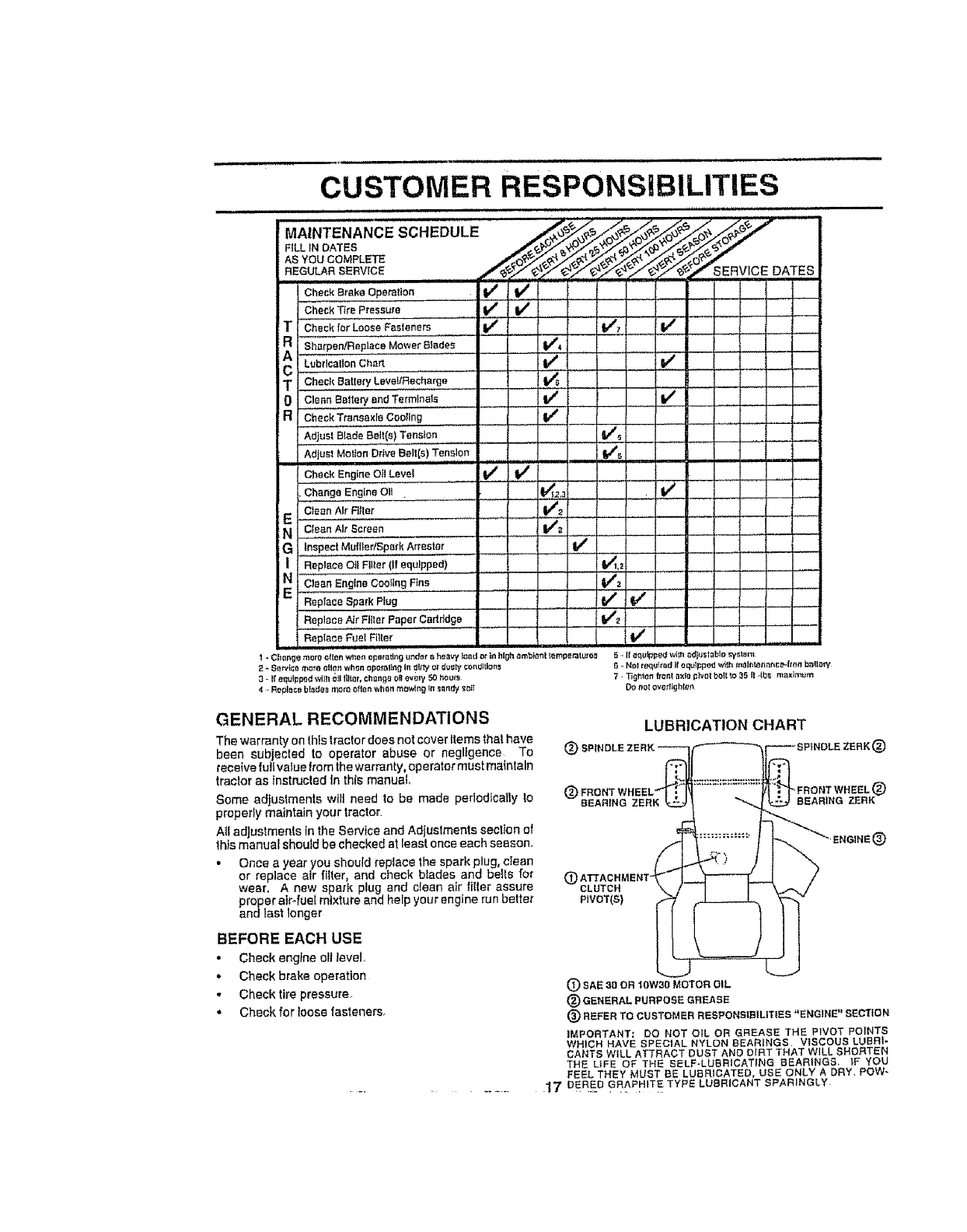
GENERAL RECOMMENDATIONS
The warranty on this _ractor does not cover items that have
been subjected to operator abuse or negligence To (])sPl_
receive lullvalue from the warranty, ope rater must maintain
tractor as instrucled {nth{s manual
Some adjustments wilt need to be made perlodfcatly to
properly maintain your tractor.
AII adjustments in the Service and Adjuslments section of
this manual should be checked at least once each season.
• Once a year you should replace the spark plug, cfean
or replace air filter, and check blades and belts for _("f')CLUTCH
wear. A new spark plug and clean air tilter assure
proper elf-fuel mixture and help your engine run better PWOT(S)
and tast longer
BEFORE EACH USE
• Check engine oil level,
• Checkbrake operation
. Checktire pressure.
• Checkfor teose fasteners,
LUBRICATION CHART
®
FRONT WHEEL (_
BEARING ZERK BEARING ZERK
®
(_) SAE 30 OR '_swe0 MOTOR OIL
(_ GENERAL PURPOSE GREASE
®REFER TO CUSTOMER RESPONSIBILITIES "ENGINE" SECTION
IMPORTANT: DO NOT OIL OR GREASE THE PIVOT POINTS
WHICH HAVE SPECIAL NYLON BEARINGS VISCOUS LUBRi-
CANTS WILL ATTRACT DUST AND DIRT THAT WILL SHORTEN
THE LIFE OF THE SELF-LUBRICATING BEARINGS, IF YOU
FEEL THEY MUST BE LUBRICATED, USE ONLY A DRY, POW-
17 DERED GFLAPHITE TYPE LUBRICANT SPARINGLY
CUSTOMER RESPONSIBILITIES
TRACTOR
Always observe safety rules when performing any mainte-
nance.
BRAKE OPERATION
II tractor requires more than six (6) feet stopping distance
at htgh speed in h_ghest gear, then brake must be adjusted,
(See "TO ADJUST BRAKE" in 1he Service and Adjust-
merits section of this manual)
TIRES
,, Malntatnproper air pressure in all tires (See "PROD-
UCT SPECIFICATIONS on page 3 of this manua!)
• Keep tires free of gasoline, o11,or insect control cheml-
cals which can harm rubber.
• Avoid stumps, stones, deep ruts, sharp objects and
other hazards that may cause tire damage.
NOTE: To seal tire punctures and prevent fiat tires due to
s_ow leaks, tire sealant may be purchased from your tocal
parts dealer Tire sealant atso prevents tire dry rot and
corrosion.
BLADE CARE
For best results mower blades must be kept sharp. Re-
place bent or damaged blades.
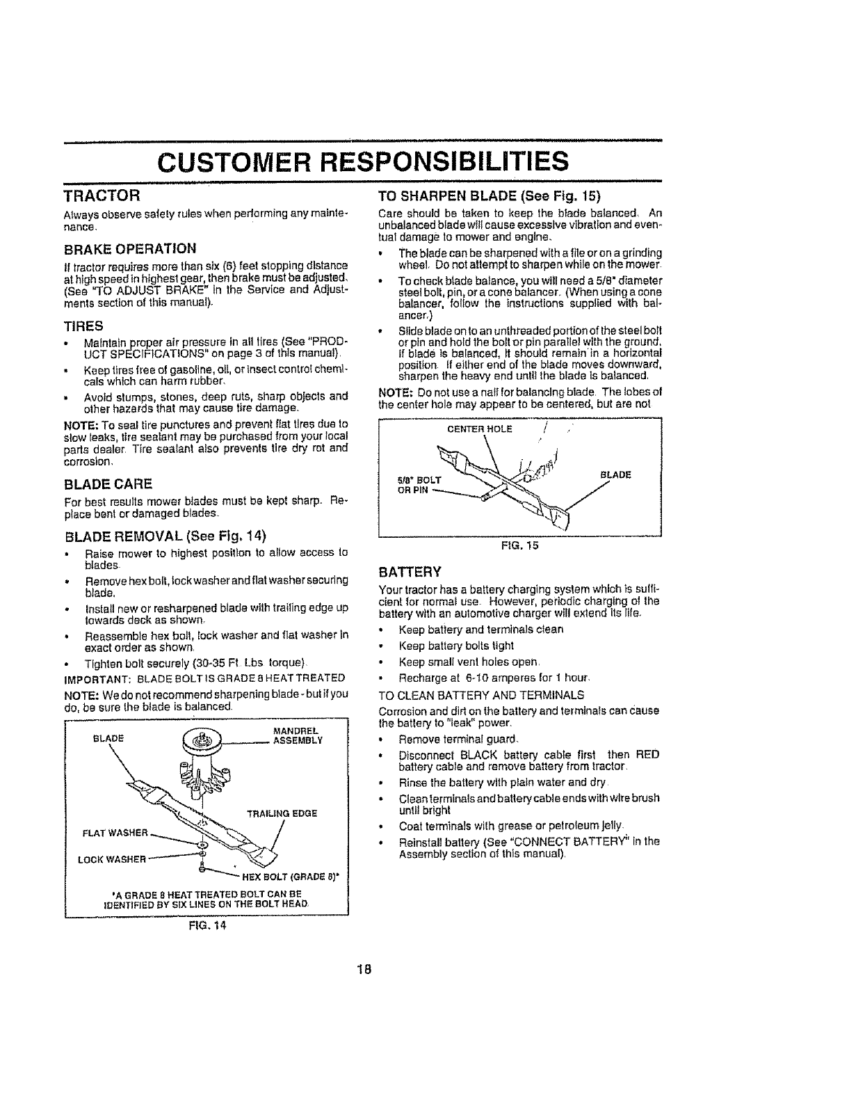
BLADE REMOVAL (See Fig, 14)
•Raise mower to highest posilton to allow access to
bIades
• Remove hex boff, lockwasher and flat washer securing
blade.
•install new or resharpened blade with trailing edge up
towards deck as shown.
• Reassemble hex boll, lock washer and flat washer in
exact order as shown
• Tighten bott securely (30-35 Ft Lbs torque}
IMPORTANT: BLADE BOLT IS GRADE 8 HEAT TREATED
NOTE: We do not recommend sharpening blade- but ifyou
do, be sure the blade is balanced
MANDREL
BLADe
TRAILING EDGE
LOCK WASHER
HeX BOLT (GRADe 8}*
'A GRADe 8HEAT TReATeD BOLT CAN BE
IDENTiFieD BY SIX L|NES ON THE BOLT HEAD.
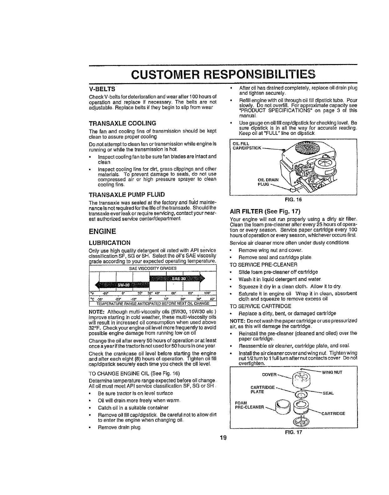
TO SHARPEN BLADE (See Fig. 15)
Care should be taken to keep the blade balanced, An
unbalanced blade wlif cause excessive vibration and even-
tual damage to mower and engine.
• The blade can be sharpen?d with a file or on a grinding
wheel Do not attempt to snarpen while on the mower
. To check blade balance, you will need a 5/B" diameter
steel bolt, pin or a cone balancer (When using a cone
balancer, follow the instructions supplied with ba-
ancer,)
• Slide blade on to an unthreaded portion of lhe steel bolt
or pin and hold the bolt or pin parallel withthe ground,
If blade ts balanced, It should remain tn a ho_:izontel
posilion if ellher end of the btade moves downward,
sharpen the heavy end unlit the blade is balanced
NOTE; Do not use a neff for balancing blade The lobes of
he center hole may appear to be centered, but are not
CENTER HOLE ' / ,"
s,." LADe
FIG. 15
BATTERY
Your tractor has a battery charging system which is sulfi-
cient for normal use However, periodic charging of the
battery with an automotive charger will extend its life,
•Keep battery and terminals ctean
• Keep battery bolts tight
• Keep smallvent holesopen
• Recharge at 6-I0 amperes for 1 hour
TO CLEAN BATTERY AND TERMINALS
Corrosion and dirt on the battery and terminals can c_ause
lhe battery to "leak" power.
• Remove terminal guard.
• Disconnect BLACK battery cable first then RED
battery cable and remove battery from tractor
• Rinse the battery with plain water and dry
• Clean terminals and batterycable endswith wire brush
until bright
• Coat terminals wilh grease or petroleum Jelly
•Reinstall battery (See "CONNECT BATTERY _'in the
Assembly section Of this manual)
FIG. 14
18
CUSTOMER RESPONSIBILITIES
V-BELTS
Check V-be!Is for delerIorat}on and wear after 100 hours of
operation and replace tf necessary. The belts are not
adjustable, Replace belts if they begin to slip from wear
TRANSAXLE COOLING
The fan and cooling fins of transmission should be kept
clean to assure proper cooling
Do not atlempt to clean fan or transmission while engine is
running or while the transmission is hot,
• Inspect coating fan to be sure fan biades are intact and
clean
• Inspect coo_ing tins for dirt, grass clippings and other
materials To prevent damage to seals, do not use
compressed air or high pressure sprayer to clean
cooling fins.
TRANSAXLE PUMP FLUID
The transaxiewas sealed at the factory and fluid mainte-
nancetsnotrequlredfor the lifeofthetransaxle,Shouldthe
trensaxle ever[oakorrequireservicing_contactyour near_
eatauthorized service center/department
ENGINE
LUBRICATION
Only use high quality detergent oi! rated with APt service
classification SF, SG or SH. Select the oil's SAE viscosity
grade according to your expected operating temperature.
SAlE VISCOSITY GRADES
_C,3,,. O" .2'_1" -_C," b* 10_ _1}" 30* 40_
TE,MPERATURE RANGE ANT_C_PA"fEO aEFOR_ NEXT OIL CHANGE
NOTE: Although mu_ti-viscosiiy oils (5W30, 10W30 efc
improve starting In cold weather, these multi-viscosity oils
will result in increased oil consumption when used above
32°F, Check your engine oil level more frequently to avoid
possible engine damage from running low on oil
Change the of! after every 50 hours of operation or at least
once a year tfthe tractoris not used for 50 hours In one yea r
Check the crankcase oil tevel before starting the engine
and after each eight (8) hours of operation, Tighten oil fil_
capldtpstick securely each time you check the oll [eve[
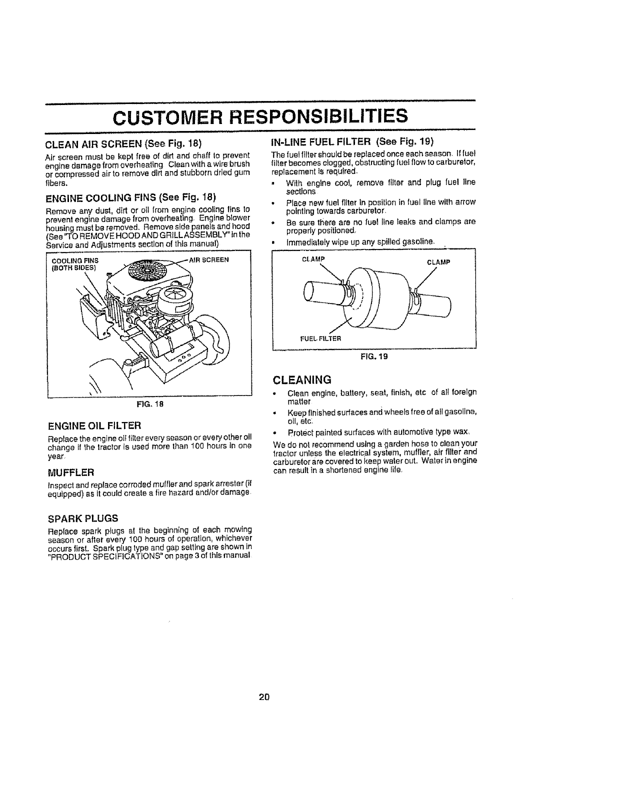
TO CHANGE ENGINE OIL (See Fig. 16)
Determine temperalure range expected before oil change
All ell must meet API service classification SF, SG or SH
• Be sure tractor is on level surface
• Oil will drain more freety when warm,
• Catch oil in a suitabEe container
• Remove eil fill capldipstick. Be careful not to allow dirt
to enter the engine when changing oil
Remove drain plug.
,,,,,, ,,,,,,,,,,,,,,,,,,,,,,,,,,,,,,_
• After oil has drained completely, reptace oil drain plug
and tighten securely.
• Refill engine with oil through eft fill dipstick tube, Pour
slowly. Do not overfill. For approximate capacity see
"PRODUCT SPECIFICATIONS" on page 3 oi this
manual.
• Use gauge on oil fillcep/dlpsllck for checking level, Be
sure dipstick is In all the way for accurate reading,
Keep oil at "FULL" line on dipstick
OIL FILL
OIL DRAIN
19
FIG. 16
AIR FILTER (See Fig. 17)
Your engine wilt not run properly using a dtdy air fitter_
Clean the foam pro-cleaner after every 25 hours of opera-
tion or every season. Service paper cartridge every 100
hours of operation or every season, whichever occurs first
Service air cleaner more often under dusty conditions
•Remove wing nut and cover.
• Remove seal and cartridge plate
TO SERVtCE PRE-CLEANER
• Slide loam pro-cleaner off cartridge
• Wash it in liquid detergent and water,
• Squeeze it dry in a clean clolho Mow it to dry
• Saturate it In engine o11 Wrap it in clean, absorbent
cloth and squeeze to remove excess oil
TO SERVICE CARTRIDGE
•Replace a dirty, bent, or damaged cartrfdge
NOTE: Do not wash the paper cartridge or use pressurized
air, as thts will damage the cartridge,
. Reinstall the pre*cleaner (cleaned and oiled) over the
paper cartridge.
• Reassemble air cleaner, cartridge plate, and seal.
• Installtheaircteanercoverandwingnut Tightenwing
nut 1/2 turn to I full turn after nut contacts cove r Do not
overttghten.
COVER-,_, .,.-_'-'_'_'- WINGNUT
SEAL
PRE-CLEANER".-._ ""CARTRIDGE
0
FIG. 17
.................... , ill ill,i ,,,I,II I I I IIIlllllllllllllllll I Illl,.utl
CUSTOMER RESPONSIBILITIES
CLEAN AIR SCREEN (See Fig. 18)
Air screen must be kept free of did and chaff to prevent
engine damage from overheating Clean with awire brush
or compressed air to remove dirt and stubborn dried gum
fibers.
ENGINE COOLING FINS (See Fig, I8)
Remove any dust, dirt or oil from engine coolingfins to
prevent engine damage from overheating, Engine blower
housing must be removed, Remove side panels andhood
(See"TO REMOVE HOOD ANDGRILLASSEMBLY tnthe
_erviceend Adjustments section of thismanual)
\
FIG,, 18
ENGINE OIL FILTER
Replace the engine ott tilter every season or every otheroil
change if the lractor is used more than 100 hours tn one
year_
MUFFLER
inspectand replacecorroded muffler and spark arrestor (if
equipped) as l( could create a fire hazard andtor damage
i,, .... ,, ............... i i,,,,
IN-LINE FUEL FILTER (See Fig, 19)
The fuel filter should be replaced once each season. If fuel
filter becomes clogged, obstructing fuel flow to carburetor,
replacement ts requlrsd.
• With engine cool, remove filter and plug fuel line
sections
• Place new fuel filter In position in fuel line with arrow
pointing towards carburetor.
• Be sure there are no fuel line leaks and clamps ere
properly positioned.
Immediately wipe up any spilled gasoline.
CLAMP CLAMP
FUELF1LTER
FfG, 19
CLEANING
• Clean engfne, battery, seat, finish, etc of all foreign
metier
. Keep finished surfaces and wheels free of all gasoline,
otl, etc.
- Protect painted surfaces with automotive type wax,
We do not recommend using a garden hose to clea n your
1rector unless the electrical system, muffler, air filter and
carburetor are covered to keep water out. Wafer in engine
can result in a shortened engine life
SPARK PLUGS
Replace spark plugs at the beginning of each mowing
season or after every 100 hours of operation, whichever
occurs first. Spark plug type and gap salting are shown in
"PRODUCT SPECIFICATIONS" on page 3of this manual
2O
i ill,,iu,,i i i .....
SERVICE AND,ADJUSTMENTS
CAUTION: BEFORE PERFORMING ANY SERVICE OR ADJUSTMENTS:
Depress clutch/brake pedal fully and set parking brake°
Place motion control lever in neutral iN) positlono
Place attachment clutch in "DISENGAGED" position,
Turn ignition key "OFF" and remove key.
Make sure the blades and all moving parts have completely stopped°
Disconnect spark plug wire from spark plug and place wire where it cannot come in contact
with piug. i
TRACTOR
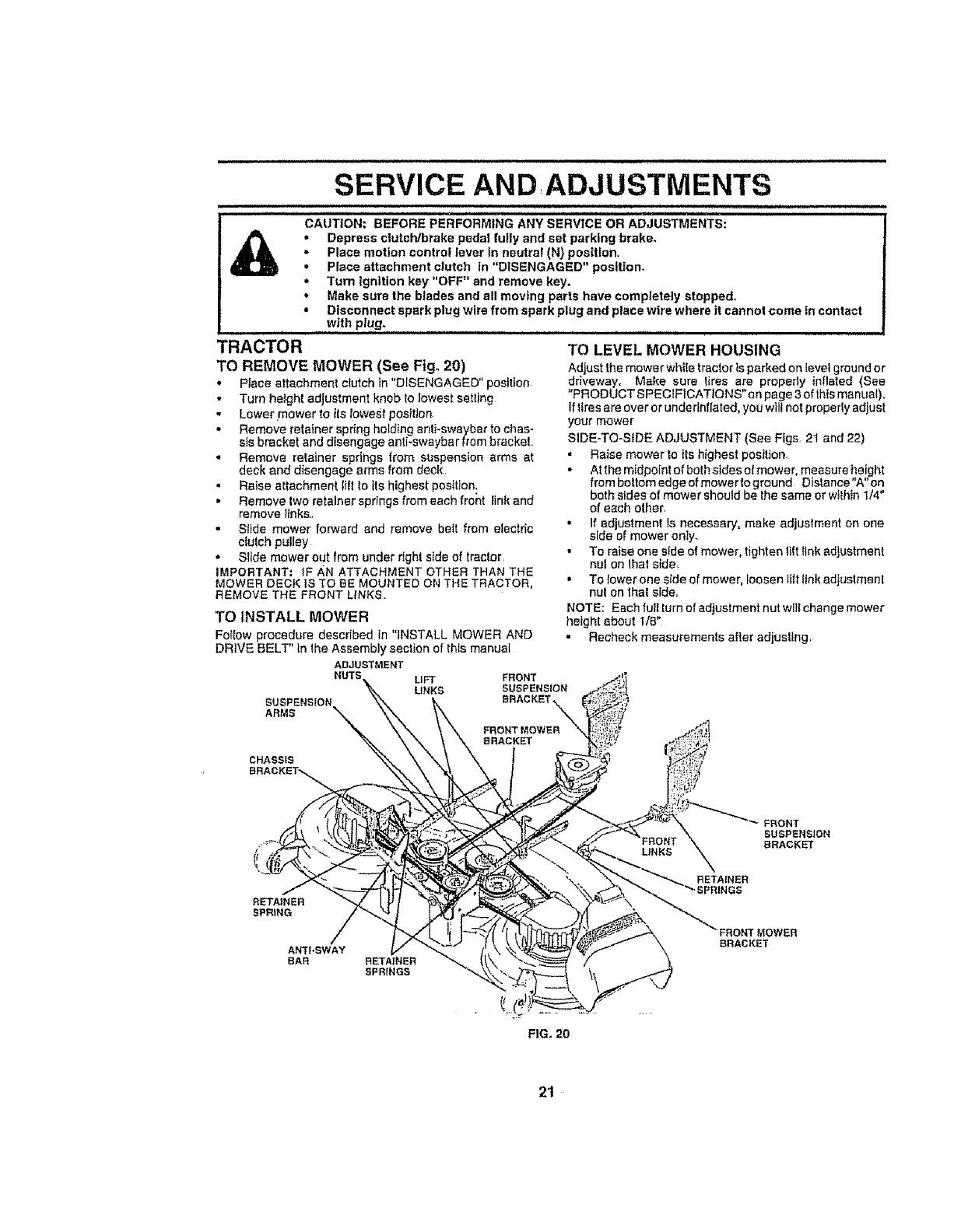
TO REMOVE MOWER (See Fig. 20)
• Place attachment ciutch in "DISENGAGED" position
•Turn height adjustment knob to lowest setting
- Lower mower to its Iowesf position
• Remove retainer spring holding anl}-swaybar to chas-
sis bracket and disengage anti-swaybar from brackeL
•Remove retainer springs from suspension arms at
deck and disengage arms from deck
• Raise attachment lift to Its highest position:
• Remove two retainer springs from each front link and
remove iinks.,
• Sitde mower forward and remove bett from eieclric
clutch pulley
• Slide mower out from under right side of traclor,
iMPORTANT; iF AN ATTACHMENT OTHER THAN THE
MOWER DECK IS TO BE MOUNTED ON THE TRACTOR,
REMOVE THE FRONT LINKS
TO INSTALL MOWER
Farrow procedure described in "iNSTALL MOWER AND
DRIVE BELT' in the Assembly section of this manual
ADJUSTMENT
NUTS UFT FRONT
LINKS SUSPENSION
RRACNET
TO LEVEL MOWER HOUSING
Adjust the mower white tractor is parked on level ground or
driveway. Make sure tires are property inflated (Sea
"PRODUCT S PECIF1CATtONS" o n page 3 of this manual).
If tires are over or undertnflated, you wll! not properly adjust
your mower
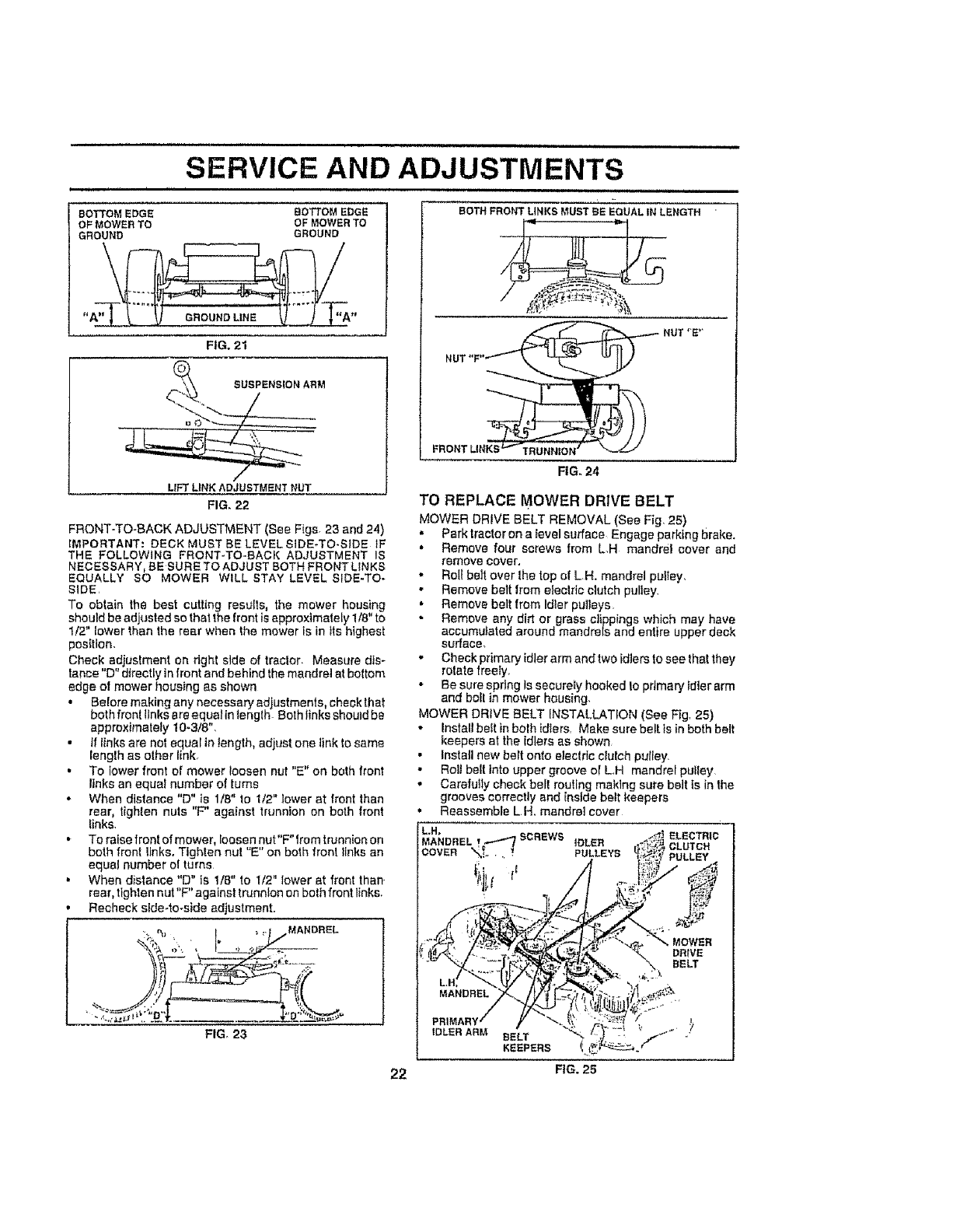
SIDE-TO-SIDE ADJUSTMENT (See Figs, 21 and 22)
• Raise mower to its highest position.
• At the midpoint of both sides ol mower, measure heigltt
from bottom edge of mower to ground Distance"A"on
both sides of mower should be the same or within 1/4"
of each other,
• If adjustment is necessary, make adjustment on one
side of mower only.
• To raise one side of mower, tighten lift link adjustment
nul on 1hal side
• To lower one side of mower, toosen lilt link adjustmenl
nul on lhal side,,
NOTE: Each full turn of adjustment nut wltl change mower
height about 1/8"
•Recheck measurements after adjusting,
CHASSIS
RETAINER
SPRING
ANTi-SWAY
BAR RETAINER
SPRINGS
FIG. 20
FRONT
SUSPENSION
BRACKET
RETAINER
MOWER
BRACKET
iii, i, IIIIHIIlll ii
SERVICE AND ADJUSTMENTS
BOTTOM EDGE
OF MOWER TO
GROUND
BOTTOM EDGE
OF MOWER TO
GROUND
FIG. 21
_(_ SUSPENSIONARM
./
LIFT LiNK ADJUSTMENT NUT
FIG_ 22
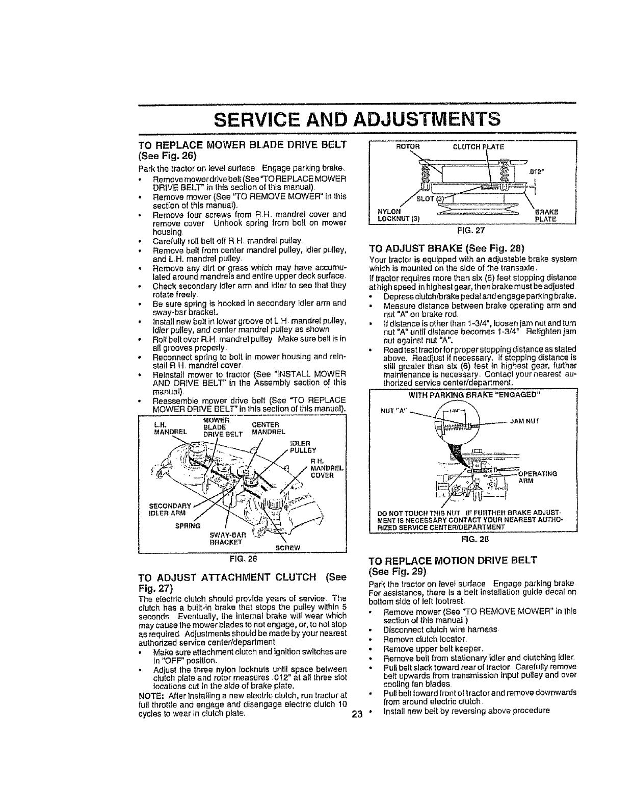
FRONT-TO-SACK ADJUSTMENT (See Figs 23 and 24)
IMPORTANT: DECK MUST BE LEVEL SIDE÷TO-S_DE _F
THE FOLLOWING FRONT-TO-BACK ADJUSTMENT IS
NECESSARY, BE SURE TO ADJUST BOTH FRONTLINK8
EQUALLY SO MOWER WILL STAY LEVEL SIDE-TO-
SIDE,
To obtain the best cutting results, the mower housing
should be adjusted so that the front is approximately 118"to
1/2" lower than the rear when the mower is in its highest
position,
Check adjuslment on right side of tractor Measure dis-
tance "D" directly in front and behind the mandrel at boltom
edge of mower housing as shown
BOTHFRONTLINKSMUSTBE EQUALIN LENGTH
NUT "E"
NUl
FIG. 24
TO REPLACE MOWER DRIVE BELT
MOWER DRIVE BELT REMOVAL (See Fig, 25)
, Park!rector on a level surface Engage parking brake.
• Remove four screws from L,H mandrel cover and
remove cover,
•Roll beIt over the top of LH, mandrel pui_ey,
•Remove belt from electric clutch pulley.
• Remove belt from tdter pulleys,
Remove any dirt or grass clippings which may have
accumulated around mandrels and entire upper deck
surface,
•Check primary idler arm and two idlers to see that they
rotate freely,
• Be sure spdng ts securely hooked to primary idler arm
and bolt in mower housing,
•Before making any necessary adjustments, check that
both fron! links are equalin tenglh Both links should be
approximately 10-3/8",
•tf links are not equal in length, adjust one link to same
Ieng[h as other link,
• To lower front of mower loosen nut "E" on both front
links an equal number of turns
• When distance "D" is 1/8" to 1/2" lower at front than
rear, tighten nuts "F" against trunnion on both front
links.
• To raise front of mower, loosen nut"F" from trunnion on
both front links. Tighten nut "E" on both front links an
equal number ol turns
• When distance "D" is 1/8" to 1/2" lower at front than •
rear, tighten nut"F" against trunnion on both front links.
Recheck side-to-side adjustment.
:,_,,,% t _ =,_ MANDREL
FIG, 23
MOWER DRIVE BELT INSTALLATION (See Fig, 25)
•Install be{t in both idlers, Make sure belt. is in both belt
keepers at the idlers as shown
•Install new belt onto electric cFutch puItey,
• Roll belt into upper groove ol LH mandrel pulley
.Carefully check bell routing making sure belt ls in the
grooves correctly and inside belt keepers
Reassemble LH. mandrel cover
ELECTRIC
CLUTCH
PULLEY
22 FIG. 25
SERVICE AND ADJUSTMENTS
TO REPLACE MOWER BLADE DRIVE BELT
(See Fig. 26)
Park the tractor on level surface Engage parking brake
• Remove mower drive belt (See "TO REPLACE MOWER
DRIVE BELT" in this section of thls manual)
• Remove mower (See "TO REMOVE MOWER" in this
section of this manual)
• Remove four screws from R H mandrel cover and
remove cover Unhook spring from bop on mower
housing
• Carefully roll belt oIf R H mandrel putley
• Remove beft from center mandrel pulley, idler pulley,
and L.Ho mandrel pulley
Remove any dirt or grass which may have accumu-
lated around mandrels and entire upper deck surface
• Check secondary idler arm and Idler to sea that they
rotate freety
• Be sure spring is hooked in secondary idler arm and
sway-bar bracket.
• Install new belt in lower groove of LH mandrel pulley,
fdter pulley, and cenler mandrel pu/tey as shown
• Rollbelt over R H mandrel pulley Make sure belt isln
all grooves properly
• Reconnect spring to bolt in mower housing and rein-
stall R H mandrel cover
•Reinstall mower to lractor (See "iNSTALL MOWER
AND DRWE BELT" in the Assembly section of this
manual)
• Reassemble mower drive belt (See "TO REPLACE
MOWER DRIVE BELT" inthis section o! this manual
MOWER
LH. BLADE CENTER
MANDREL DRIVE9ELT MANDREL
tDLER
RH,
MANDREL
COVER
SFR|NG
SWAY-eAR
BRACKET SCREW
FIG. 26
TO ADJUST ATTACHMENT CLUTCH (See
Fig, 27)
The eiectflc ctutch should provide years of service The
clutch has a built-in brake that stops the pultey within 5
seconds Eventually, the tntemat brake wilt wear which
may cause the mower btades to not engage, or, to not stop
as required Adjustments should be made by your nearest
authorized service center/department
•Make sure attachment clutch andignttton switches are
in "OFF" positron.
• Ad ust the three nylon Iocknuls unlit space between
clutch plate and rotor measures O12" at all three slot
tocalions cut in the side of brake plate.
NOTE; After installing a new electric clutch, run tractor at
full throttle and engage and disengage electric clutch 10
cycles to wear In clutch plate
ROTOR CLUTCHF.LATE
NYLON_SL_ _eRAKE
LOCKNUT(3) PLATE
FIG. 27
TO ADJUST BRAKE (See Fig. 28)
Your tractor is equipped with an adjustable brake system
which is mounted on the side of the transaxle
if _ractor requires more than six (6) feet stopping distance
at high speed in htghesl gear, then brake must be adjusted
• Depress c]ulchibraka pedal and engage parking brake.
• Measure d{stance between brake operating arm and
nut "A" on brake rod
•II distance is other than 1-3/4% loosen jam nut and turn
nut "A" until distance becomes !-3/4" Retlghten iam
nut against nut "A".
• Roadtest tractor forproper stopping distance as stated
above, Rsadjusl if necessary. If stopping distance is
stil! greater than six (6) leel tn highest gear, further
maintenance is necessary Contact your nearest au-
thorized service center/department
WITH PARKING BRAKE "ENGAGED"
HUT "A'"-_._.__, JAM NUT
-77_;__ OPERATING
DONOTTOUCHTHt5 NUT. IF FURTHER;BRAKeADJUST-
MENT|S NECESSARYCONTACTYOURNEARESTAUTHO-
R|ZEDSERVICECENTER!DEPARTMENT
F|Go 28
TO REPLACE MOTION DRIVE BELT
(See Fig. 29)
Park the tractor on leve_ surface Engage parking brake
For assistance, there is a belt installation guide decal on
bottom side of]elt footres_
• Remove mower (See "TO REMOVE MOWER" in this
section of this manual )
• Disconnect clutch wire harness
• Remove clutch locater
• Remove upper belt keeper
• Remove be_t from stationary idler and clutching Idler
•Pull belt slack toward rear of tractor Carefully remove
bait upwards from transmission input pu!ley and over
cooling fan biades
Pull belt toward front of tractor and remove downwards
from around electric clutch
Insta!l new be]t by reversing above procedure
23"
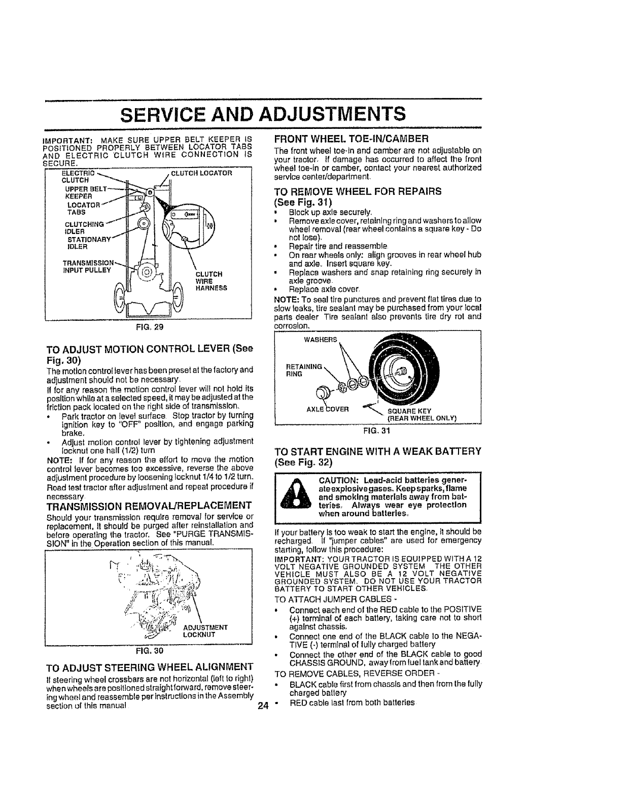
SERVICE AND ADJUSTMENTS
IMPORTANT; MAKE SURE UPPER BELT KEEPER tS
POSITIONED PROPERLY BETWEEN LOCATOR TABS
_ND ELECTRtO "CLUTCH WIRE CONNECTION IS
;ECURE.
ELECTRIC
CLUTCH _"'_.,
UPPER BELT_
KEEPER /
LOCATOR "'"
TABS
CLUTCHING "_''"
IDLER
STATIONARY
IDLER
TRANSMiSSiON*',-.
iNPUT PULLEY
_CLUTCH LOCATOR
1i,,
if,?, HARNESS
FIG, 29
TO ADJUST MOTION CONTROL LEVER (See
Fig, 30)
The motion con=rot lever has been preset at the factory and
adjustmenl should nst be necessary,
If for any reason the motion control tever will no! hotd Its
pesltloe while at a selected speed, it may be adjusted at the
friction pack located on the right side of transmission.
•Park tractor on level surface Stop tractor by turning
ignition key to "OFF" position, and engage parking
brake.
• Adjust motion control lever by tightening adjustment
locknut one hall (1/2) turn
NOTE: If for any reason the eftod Io move the motion
control lever becomes too excessive, reverse the above
adjustment procedure by loosening ]ocknut 1/4 to 1/2 turn.
Road test tractor after adjustment and repeat procedure if
necessary
TRANSMISSION REMOVAL/REPLACEMENT
Should your transmission require removat for service or
replacement, tt should be purged after retnstatlatfon and
before operating the tractor. See "PURGE TRANSMtS*
SION" in the Operation section of this manual
tf %:'
_,.. ADJUSTMENT
LOCKNUT
FIG, 30
TO ADJUST STEERING WHEEL ALIGNMENT
!1steering wheel crossbars are not horizontal (Ieft to dgh0
when wheels are positioned straightforward, remove sleep
ing wheat and reassemble per InstrUctions in the Assembly
section of this manual
FRONT WHEEl. TOE4NICAMBER
The front wheel toe-in and camber are not adiustable on
your tractor, tf damage has occurred to affect the front
wheel tee4n or camber, contact your nearest authorized
service center/department.
TO REMOVE WHEEL FOR REPAIRS
(See Fig. 31)
• Block up axle securely,
• Remove axle cover, retaining ring and washers to allow
wheel removal (rear wheel conlains a square key - Do
no! lose).
• Repair tire and reassemble
• On rear wheels only: align grooves in rear wheel hub
and axle.. Insert square key.
,, Replace washers and snap retaining ring securely in
axle groove.
• Replace axle cover,
NOTE: To seal tire punctures and prevent flat tires due to
slow leaks, tire sealant may be purchased from your local
parts dealer Tire sealanl also prevents tire dry rot and
corrosion.
WASHERS
RiNG
AX2OVER _'"_BGUARE KEY
(REAR WHEEL ONLY)
FIG, 31
TO START ENGINE WITH AWEAK BATTERY
(See Fig° 32)
= i = =l m llll i H,,,,H,,,,,,I
l& CAUTION: Lead-acid batteries gener-
ate explosive gases,, Keep sparks, flame
and smoking materials away from bat-
terios, Always wear eye protection
when around batterles_
tf your battery ls too weak to start the engine, tt should be
recharged, tf "jumper cables" are used for emergency
starting, follow this procedure:
IMPORTANT: YOUR TRACTOR IS EQUIPPED WITH A 12
VOLT NEGATIVE GROUNDED SYSTEM THE OTHER
VEHICLE MUST ALSO BE A 12 VOLT NEGATIVE
GROUNDED SYSTEM, DO NOT USE YOUR TRACTOR
BATTERY TO START OTHER VEHICLES
TO ATTACH JUMPER CABLES -
• Connect each end of the RED cable to the POSITIVE
(+) terminal of each batten/, taking care not to shorl
against chassis,
• Connect one end of the BLACK cable Io the NEGA-
TIVE (-) terminal of lully charged battery
• Connect the other end of the BLACK cable to good
CHASSIS GROUND, awaylrom fuel tankand battery
TO REMOVE CABLES, REVERSE ORDER -
- BLACK cable first from chassis and then from the fully
charged battery
24 "RED cable last from both batteries
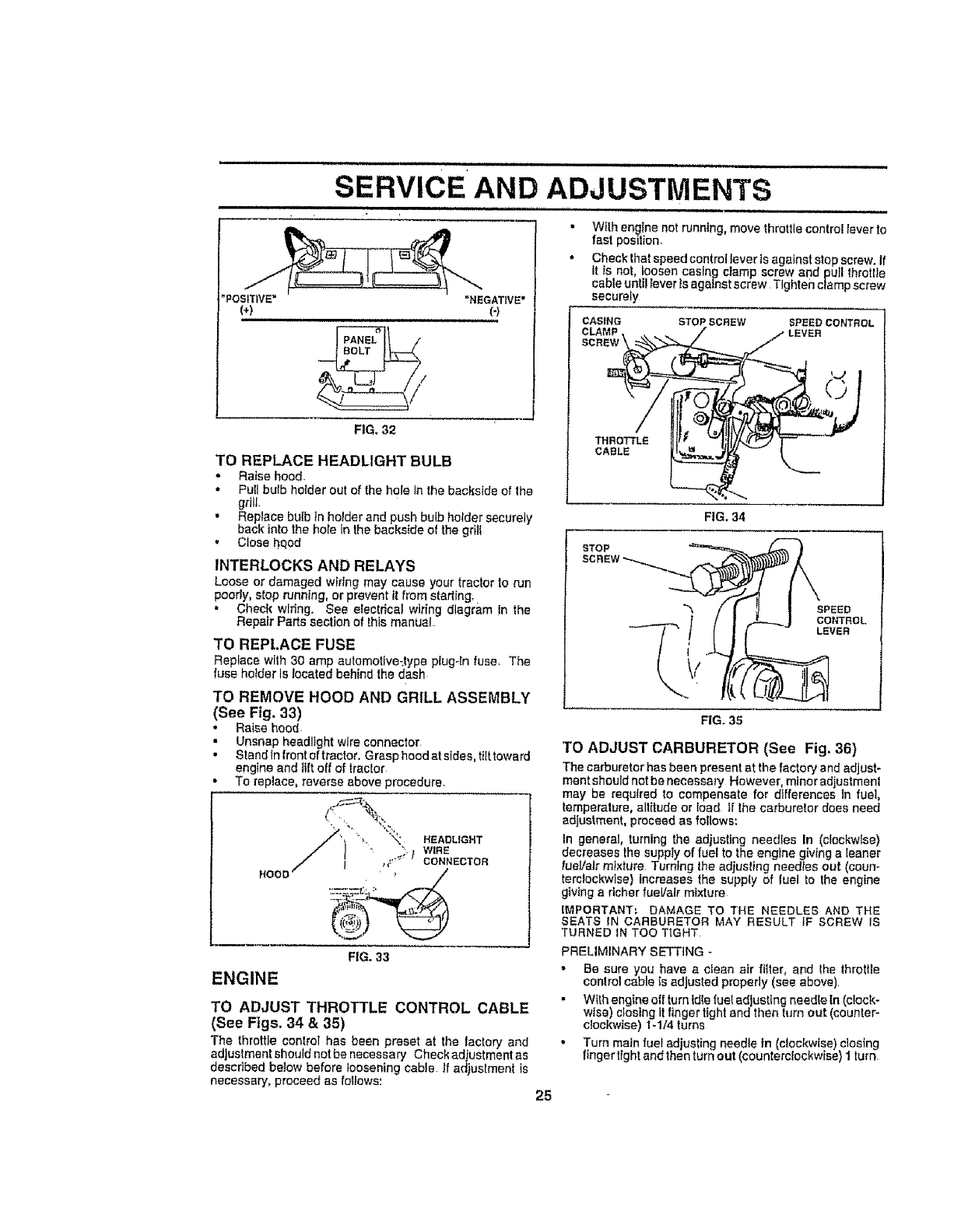
it1 ,i ullul ul ii Ull i i,,uJ u uulu,
• +
SERVICE AND ADJUSTMENTS
'POSITIVE="NEGATIVE"
(+) (-)
,i ,, itt,, ,uv_
FiG. 32
TO REPLACE HEADLIGHT BULB
•Raise hood.
• Pull bulb holder out of thehole In the backside of the
grill
• Replace bulb tn holder and pushbulb holder securely
back into thehole in the backside of the grill
• Close hqod
INTERLOCKS AND RELAYS
Loose or damaged w+rtngmay cause your tractorto run
poorly, stop running, or prevent it from starling+
• Check wiring+ See electrical wir+ng diagram in the
RepairParts section of this manual
TO REPLACE FUSE
Replace with 30 amp automotlve_type plug+Infuse The
fuseholder is located behind thedash
TO REMOVE HOOD AND GRILL ASSEMBLY
(See Fig, 33)
• Raise hood
• Unsnap headlight wire connector
. Stand +nfront of tractor Grasp hood at s+des,tilt toward
engine and liftoff of tractor
To replace,reverse above procedure
HOOE
FIG+ 33
ENGINE
25
TO ADJUST THROTTLE CONTROL CABLE
(See Figs. 34 &35)
The throttle control has been preset at the tactory and
adjustment should notbe necessary Check adiustmentas
described below before loosening cable If adjuslment is
necessary, proceed as follows:
=With engine net running, move throttle control lever to
fast pos+lion
Check that speed controllever ts against step screw _'
it is not, boosen casing clamp screw and pull throttte
cable until lever is against screw Ttghten clamp screw
securely
CASING STOP SCREW SPEEDCONTROL
THROTTLE
CABLE
FIG, 34
STOP
SPEED
CONTROL
LEVER
FIG+ 35
TO ADJUST CARBURETOR (See Fig. 36)
The carburetor has been present at the factory and adjust+
ment should not be necessary However, minor adjustmenl
may be required to compensate for differences In fuel,
temperature, all{rude or load tf the carburetor does need
adjustment, proceed as follows:
In general, turning the adjusting needles In (clockwise)
decreases the supp+y of fuel to the engine giving a leaner
fuel/air mI×h_re Turning lhe adjusling needles out (coun-
terclockwise) increases the supp{y of luel to the engine
giving a richer fueVair mixture
IMPORTANT: DAMAGE TO THE NEEDLES ANO THE
SEATS IN CARBURETOR MAY RESULT tF SCREW IS
TURNED tN TOO TIGHT
PRELIMINARY SETTING
• Be sure you have a c{ean air filter, and lhe throttle
control cable ts adjusted properly (see above)
•With engine oft turn id+elust ad ustlng needle [n (clock-
w ss) cos ng t fnger t ght and then turn out (counter-
clockwise) 1-1/4 turns
• Turn main fuel adjusting needle in (clockwise) ctosing
finger tight end then turrl out (counterclockwise) 1 turn
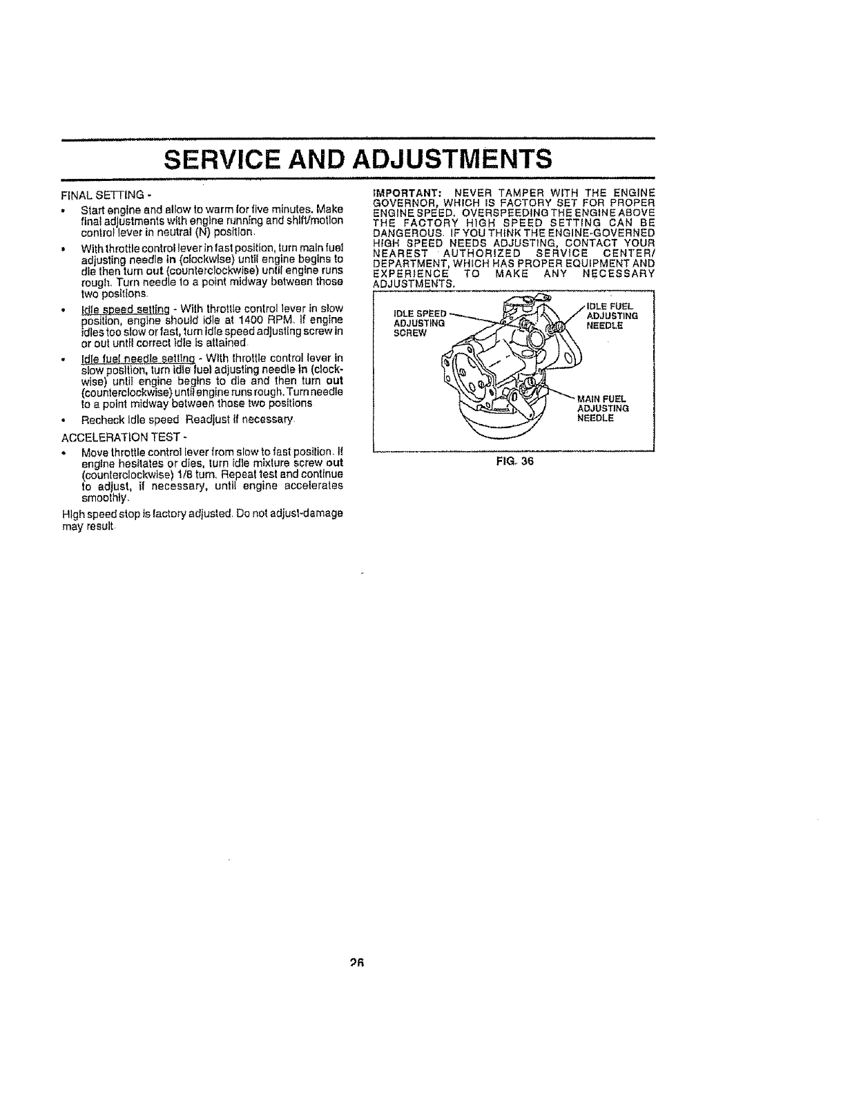
,,,,, i i i ,i
SERVICE AND ADJUSTMENTS
FINAL SE"FFING -
, Start engine end allow to warm for five minutes. Make
final adjustments with engine running and shlf'Jmotlon
control lever in neutral (N) position.
•With throttle control lever in last position, turn main fuel
adjusting needle in (ciockwlse) untll engine begins to
die then turn out (counterclockwise) until engine runs
rough. Turn needle to apoint midway between these
two positions,
•Idle speed setliqq -With throttle control lever in stow
position engine should idle at 1400 RPM If engine
=diestoo stow or fast, turn id e speed adjust ng screw n
or out untti correct idle is attained
!die rue{ need!e t_s_e_U_g-Wtth throttle control lever in
s!ow position, turn idle luet ad usting needle in (clock-
wise) until engine begins to die and then turn out
(counterc!ockwise) unttf engine runs roug h. Turn needle
1oa point midway between those two positions
• Recheckldle speed Readjustif necessary
ACCELERATION TEST -
• Move throttle control lever from slow to fast position, tt
engine hesitates or dies, Iurn idle mixlure screw out
(counterclockwise) 118 turn. Repeat test and continue
to adjust, if necessary, until engine accelerates
smoothty_
High speed stop is factory adjusted Do not adjust=damage
may result
IMPORTANT: NEVER TAMPER WITH THE ENGINE
GOVERNOR, WHICH IS FACTORY SET FOR PROPER
ENGINESPEED, OVERSPEEDINGTHE ENGINEASOVE
THE FACTORY HIGH SPEED SETTING CAN BE
DANGEROUS, IF YOU THINK THE ENGINE-GOVERNED
HIGH SPEED NEEDS ADJUSTING, CONTACT YOUR
NEAREST AUTHORIZED SERVICE CENTER/
DEPARTMENT, WHICH HAS PROPER EQUIPMENT AND
EXPERIENCE TO MAKE ANY NECESSARY
ADJUSTMENTS,
,,*IDLEFUEL
IDLESPEED_--_'_-_" _. // ADJUSTNG
ADJUSTING -'_"_,_ _NEEDLE
' _ _'"_" MAINFUEL
__"_______'_ ADJUSTING
'_ NEEDLE
FIG_ 36
_R
STORAGE
lmmediatefy prepare your tractor for storage si the end of
the season or if the tractor will not be used for 30 days or
more.
CAUTION: Never store the tractor with
gasoline In the tank Inside a building
where fumes may reach an open flame
or spark, Allow the engine to cool
before storing in any enclosure°
TRACTOR
Remove mower from tractor for winter storage When
mower is to be stored for a period of time, clean il thor-
oughly, remove aft dirt, grease, leaves, etc Store in a
clean, dry area-
-Clean entire tractor (See "CLEANING" in the Customer
Responsibilities section of lhis manual).
Inspect and replace bells, if necessary (S_e belt re-
placement tnstrucltons in the Service and Adjustments
section of Ihis manual).
* Lubricate as shown in the Customer Responsibilities
saclion o[ this manual.
. Be sure that all nuts, bolts and screws are securely
fastened. Inspect moving parts for damage, breakage
and wear,, Replace If necessary
. Touch up all r_sted or chipped paint surfaces; sand
lightly before painting
BATTERY
Fully charge Ihe battery for storage.
• After a period of time in storage, battery may require
recharging
.To help prevenl corrosion and power leakage dUdng
tong periods of storage battery cables should be
disconnecte d and battery cleaned thoroughly (see "TO
CLEAN BATTERY AND TERMINALS" in the Cus-
tomer Responsibilities section of this manual)
• After cleaning, leave cables disconnected and place
cables where they cannot come in contact with battery
terminals.
•Be sure battery drain tube Is securely attached,
, tf baltery Ssremoved from tractor for storage, do not
store battery directly on concrete or damp surfaces,
ENGINE
FUEL SYSTEM
IMPORTANT: IT IS IMPORTANT' TO PREVENT GUM
DEPOSITS FROM FORMING IN ESSENTIAL FUEL
SYSTEM PARTS SUCH AS CARBURETOR, FUEL FILTER,
FUEL HOSE, OR TANK DURING STORAGE. ALSO,
EXPERIENCE INDICATES THAT ALCOHOL BLENDED
FUELS (CALLED GASOHOL OR USING ETHANOL OR
METHANOL) CAN ATTRACT MOISTURE WHICH LEADS
TO SEPARATION AND FORMATION OF ACIDS DURING
STORAGE. ACiDiC GAS CAN DAMAGE THE FUEL
SYSTEM OF AN ENGINE WHILE IN STORAGE
•Drain the fuet tank
• Slart the engine and let it run until the fue_ lines and
carburetor ere empty
* Never use engine or carburetor cleaner products tn the
fuel tank or permanent damage may occur.
• Use fresh rue] next season
NOTE: Fuel stabilizer is an acceplab]e alEemative in
minimizing the Iormatlon of fuel gum deposits during stor-
age. Add stabilizer to gasoline in fuel lank or storage
container, Always follow Ihe mix ratio found on stabilizer
conta!ner. Run engine at feasl 10 minutes alter adding
slabtttzer to allow the stabilizer to reach the carburetor. Do
not drain the gas tank and carburetor if using fuel stabilizer.
ENGINE OIL
Drain oil (withengine warm) and replacewithclean engine
etf (See "ENGINE" in the Customer Responsibilities
seclion of thismanual)
CYUNDERS
• Remove spark plug(s)
• Pour one ounce of ofl through spark plug hole(s) into
cylinder(s)
•Turn ignition key to "START" posilion for afew seconds
to distribute oil
• Reptace with new spark plug(s).
OTHER
• Do not store gasoline from one season to anolher
• Replace your gasoline can i! your can starts 1o rust.
Rust and/or d{d In your gasoline wtt_ cause problems
•if possible, store your tractor indoors and cover it to
give protection lrom dust and dirt.
•Cover your tractor with a suitable protective cover that
does not retain moisture. Do not use plastic, Plastic
cannot breathe which allows condensation to Io rm and
will cause your tractor to rest.
IMPORTANT: NEVER COVER TRACTOR WHILE ENGIN E
AND EXHAUST AREAS ARE STILL WARM
27

TROUBLESHOOTING POINTS
PROBLEM
WtlInot alert
Hard to start
Engine wI!t not turn over
Engthe clicks bat wgt not
of art
Loss of power
Excessive vtbrotIoa
CAUSE
1 Out of fuel
2. Engine not "Ct?IOKED"properly
3 Engine flooded
4Bad sparkplug,
5Dirty air fIiter
6Dirty fuel filter
7Water in iuaI
B. Loose or damaged wiring
O Carburetor out el adjustment
10 Engine valves out of adjusimenI.
i =
1Dirty e_r Oiler
2 Bad spark plug
3 Week or dead batten/
4Dirty fuel Iillar
5, Stale or dirty fuei
6Loose ordemagedwiring
'7 Carburetor eul of adjustment
8EnginevaJvasoutofadjustment
I, Clulchibrekapedalnotdepressed
2A_tachmeotcIutchtsengaged,
3Weekordead battery
4 Blown fuse
5 Corroded batten/terminals.
BLoose or damaged whine
7 Faulb/IgnIIien switch
B Foully solenoid or _lsrlar
g Faulty operator presence switch(as)
1Week or dead batten/
;_ Corroded batten! terminals
3 Loose or dsmsgB(:l wldng
4Faulty solenoid or slarter,
1. Cutting too mu_h grassf{eo fast
2. Throttle in"CHOKE" position.
3Bui{d-up of gross, leaves and fresh under mower
4, Oldy air filter,
5LOWell Ievegdirty oil
6, Feuflysparkplug
7 Dirty fuel liltar
8 Stale or dlrty fuel
9 Water In fuel
IO, Spark plug wire loose
t I DIdy aogthaoft screen/fins
12 Dlrtylologged mulIIar.
13. Loose ordamaged wiring
"t4 Carburetor out of adjustment
15 Engknavalves out e!adjustment
iWorn, beetorlooseblade
2Bent blade mandret
3Loosefdamsged part(s)
CORRECTION
iFIll rue{tank
2SoB"TO START ENGINE" In Operal]on section.
3. Walt several minutes before ettempling to start
4 Replace spark plug.
5. Clean/rapists air Iltlar
6 Replace lUBIlitter
7Drainfueltankand cerburetonrefilllankwithfresh
gasolineend replaceluslfiller
8Check ellwldng.
g See "To Adjust Carburetor_In Service Adjuslmanls
seclJon,
1Or Contact an authorized aarv)oa center/departmenl
i iii i
tC!ean/rapists air Illte¢
2Replace spark plug
3Recharge or replace barren/
4. Replace fuellifter,
5Dretn fuel tank end rslilI wtlh fresh gasoItne
6. Check all wiring,
7See "ToAdtust Carburetor" In Service Adfuslmants
section,
8 Genteel an a_hodzad sewios cenlsrldepatlmanI
1Depress ciutohYarakepedal
2, Disengage attachment clutch
3 Recharge or replace battery
4 Replace tusa
5Ctean battery tarmtha_s
6 Check all wiring
7Check/replace ignition switch
8 Check/replacesolsnoldorelader
9 Conteolon authorized sorvfce centsr/daparimant.
1Recharge or" replace batten/
2 Clean bajlen! terminals
g Check eliwiring
4Checldreplece sotenold or slarter
1 Sofia =Higher Cut" position/reduce speed
2. Adjust throttle control
3 ClaSh underside el mower housing
4. Ctean,_eplece air filler
5. Check oUIsvel./chsngs oil
6. Clean and rogap or change spa_k p{ug
7 Replacefuelfiller
B Dralnfuellank and refillwlthIraehgasoline,
gDrainfuelranis,end cerbu_'eler,reIi_ltankwithfrssh
gasolineand replacefuelfilter
10 Connect and tighten sps_k plug wire
11 Clean engths sir screen/floe
12 Cleanlrapteee muffler
13 Check eli wiring,
14 Sea %0 AdjustCarburefof'ln SeIvioa Adtuelmenta
SBOI{On.
15 Contaci an authorized service r:enter/departmant.
1Replace blade Tighten blade bolt
2Ftepta0eblade mandrel
3 Tighten loose part{s) Replace damaged parts
28

TROUBLESHOOTING POINTS
= m,,,,,m,,, , ,,i,,,,,,, , , ,
PROBLEM CAUSE CORRECTION
Engine continues to run
when operator leaves sent
with attachment clutch
engaged
POOr out - unevon
Mower blades wit] not
rotors
Poor grass d_acherge
Headgght(e) not working
(if so equipped}
Battery wifi not charge
• • ,,,,,,,, ,,,,,,,,ui
Lees of drive
,,, ,,,, ,,,, ,,,,, ,,, , ,,
Engtno "backfires"
when turning engine
"OFF"
t Fautty operetor,satety presence centr!! system
1 Worn, bent or loose blade
2Mower deck notlevel
3. Buildup of gross, leaves- end trashunder mower
4Bent blademandret
5 Ctegged mower deck vent holes from buildup of
grass, leaves, end trasharound mandrels,
1 ObstrocIion inclutch mechanism
2Womldemaged mower drive bert
3 Frozen Idler pulley
4 Frozen blade mandral
1Engine speed too stow
2 Travel sp_ed Ice fasL
3 Wet gross.
4 Mower deck oat favef
5. Low/uneven tlre e)rpressure
5; Worn, bent or toose blade
7Buildup of grass, leaves and trash under mower
8 Mower drive betf worn
B Blades Improperly InslaIted
10 Improper blades used
| 1 Clogged mower deck vent holes frombulidup of
grass, leaves, end trash around mendrete
"i Swgch Is "OFF
2Bulb(s) burned out
3 Faulty tightswitch,
4Loose or dm'nagedwtrtng
5Blown fuse.
1 Bad baltery es_t(s)
2Poor ceb(econnections.
3 Feu_ty regulator II! so equipped}
4Faulty alternator
1Check wiving, switches and connections It not
eorrested, sontee! an authadzod service ssnler/
department
t Replace b_ade Tighten blade heft
2, Level mower deck,
3GIean undereldeOfmower housing
4 Reptace blade mandrel
5CIean around mandrate to open vent holes
IRemove obst;uctlon
2 Replace mower ddve bell
3 Reptace Idler pulley
4 Replace blade mandrel
fPlace throttle contratin "FAST" posittan
2- Shift to stower speed.
3Allow gross to drybe|ore mowtng
4Level mower deck
5 Check tires tot proper air pressure,
6 Raptacelsherpen brads Tighten bfade bole
7, Glees undere_deo! mowe_ Ilou_ing
8Replace mower drive bert
9Reinstaltblades sharp edge down,
10 Replace with bledea llsled in this manual
fl Clean around masdra_e to open vent holes
1Turn switch"ON"
2Reptace bulb(e}
3 Check/replace light switch
4Check widng end connestions
5Replace fuse
! Repieee battery
2 Check/croon a!l connections
3, Rep!ace regulator
4Rep!ase agemato_
1Freer;heel controlIn =disengaged" p0slttan
2Malice drive bslt worn, damaged, or broken
3, Air trapped intransmissionduring shipment
or sentleing
1 Engine thrallte control not set at "SLOW"
positionIor 30 seconds before stepping engine
1 Piece freewheel conlret In "engaged" pesttion
2Replace motion drive bett
3Purge trensmisslon
1 Move Lhtotlleconlrel to =BLOW_ positionend elIow
1oIdle for 30 seconds before slopping engine
29

3O
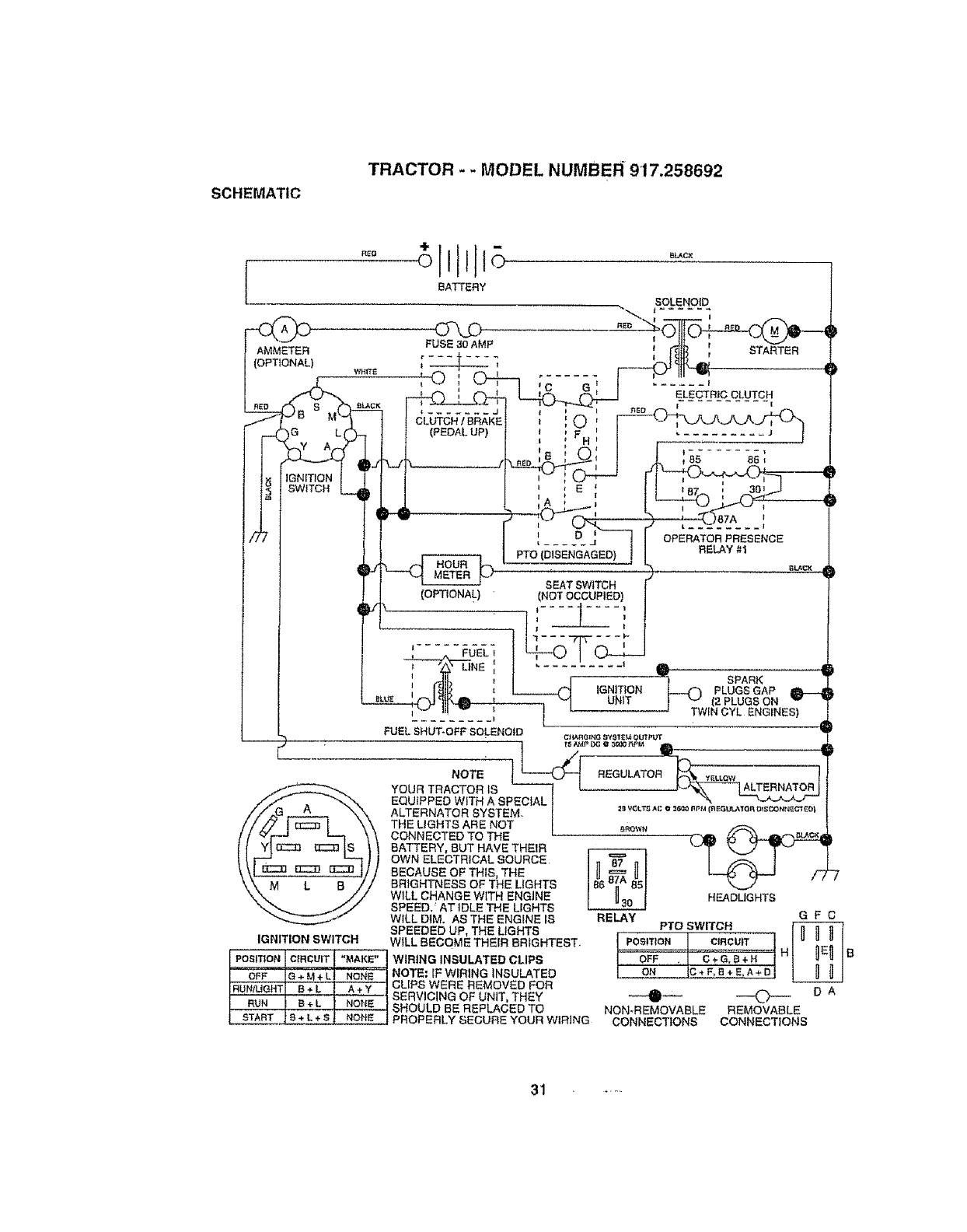
SCHEMATIC
TRACTOR - - MODEL NUMBER 917,258692
BATTERY
SOLENOID
FUsE_0AMP "-dt_-,; ;_
;_ 7 ____ _HLj _ _
WH17_ _ _ ', _ J ,- ..... b" 111',-I
I__ ,o,c>-+-7 , , 1 ...... ,
i __Z"_G Ll" J J (PEDAl. UP) l i 'F _ l .......... J !
II 74_. .1,L ,k.00i i ! ....-,s;
jv t I
! t_I,_N,T,ONI '7_l.... 1_04_ r1_-rO,,,-¢-_,17----
i ' E_87 '301
I l_tSw"°NL'J.I! _ iL, tL-F_,'%_
/PTO (DISEI_dAGED),IGAGED)j BELAY #!
I 1 "i _"1....2._' SEATSW_TCHr'
I I I (OPTIONAl.) (NOT OCCUPIED! l
I I -r--'-"e_TiNE: I ..... =.... '
I 1 _ JIL _ ] _ SPARK
I I l_[_J__ , L -HIGNITION _ PLUGSGAP
I l _'Jll"--,l_ _ , ""'I UNIT _ "_ (2PLUGSON
r FUEL SHUT-OFFSOLENOID
•127 •
,._,._ YOUR TRACTOR IS _ ! _.-..--.-----_-,'_\_TERNA_fOR.R
ALTERNATOR SYSTEM j _ vo_'t__co_n_ {_Gu,_m<o_sco.._m_ol
_o"&g'2g72_?gN°2 i ooo,..
IGNITION SWITCH
POSITION CIRCUIT "MAKE"
OFF G+M + L NONE
RL_NfUGHT B+ L A +Y
RUN B+LNONE
BATTERY, BUT HAVE THEIR
OWN ELECTRICAL SOURCE
BECAUSE OF THIS, THE
BRIGHTNESS OF THE LIGHTS
WILL CHANGE WITH ENGINE
SPEED/AT IDLE THE LIGHTS
WILL DIM. AS THE ENGINE fS
SPEEDED UP, THE LIGHTS
WILL BECQME THEIR BRfGHTEST.
WIRING INSULATED CLIPS
NOTE: IF WIRING INSULATED
CLIPS WERE REMOVED FOR
SERVICING OF UNIT, THEY
SHOULD BE REPLACED TO
PROPERLY SECURE YOUR WIRING
HEADLIGHTS
RELAY G F C
PTO SWITCH
Po_rr,o. c,.cu_TI I" .__._I
oFF:_Hl !_!IE
;C.,F,"+E.A÷_I
_ DA
NON-_EMOVABLEREMOVABLE
CONNECTIONS CONNECTIONS
1 .....
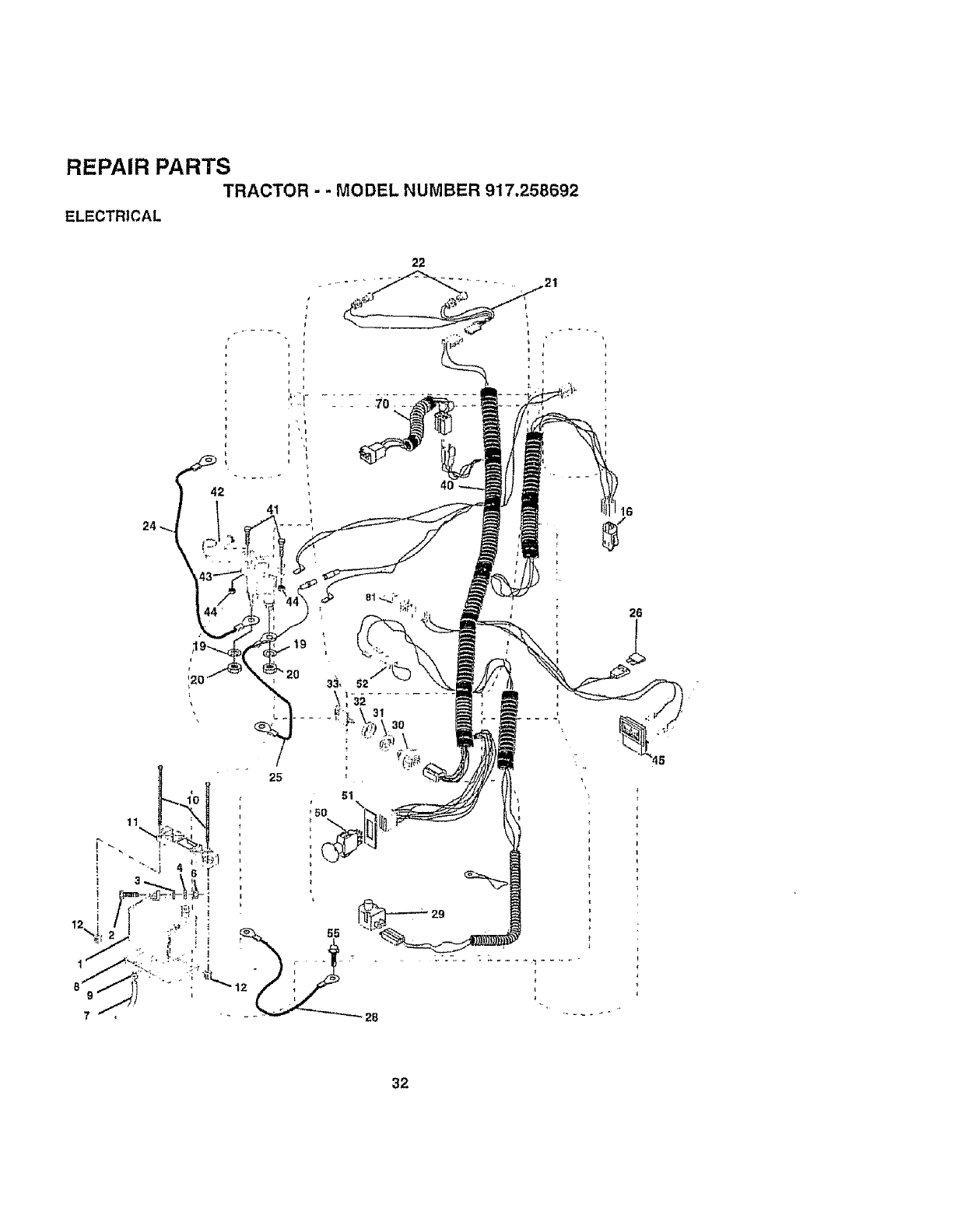
REPAIR PARTS
ELECTRICAL TRACTOR . .MODEL NUMBER 917.258692
t
26
o
32
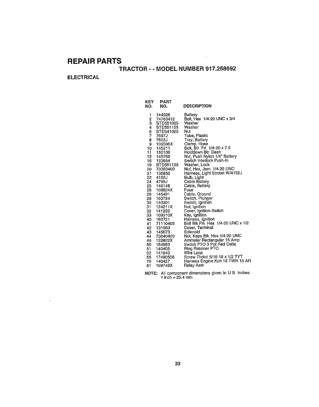
REPAIR PARTS
TRACTOR - - MODEL NUMBER 917.258692
ELECTRICAL
KEY PART
NOr NO. DESCRIPTION
1t44926 Baltery
274750412 Bolt, Hax 1/4-20 UNC x 3/4
3 STD551025 Washer
4 STD551125 Washer
6 STD541026 Nut
7 7697J Tube, Plastic
87603J Tray, Battery
9 t09596X Clamp, Hose
10 145211 Bolt, Btr, Frt 1/4-20 x 7.5
11 150109 Hotddown Btr Dash
12 145769 NUt, Push Nylon 1/4" Battery'
16 153664 Switch Interlock Push-ln
19. STD551125 Washer, Lock
20 73350400 Nut, Hax, Jam 1/4-20 UNC
21 136850 Hamass, Light Socket W/4152J
22 4152J Bulb, Light
24 4799J Cabte Battery
25 146148 Cable, Battery
26 !08824X Fuse
28 145491 Cable, Ground
29 160784 Switch, Plunger
30 140301 Switch, ignition
31 124211X Nui, Ignition
32 141226 Cover, Ignition Switch
33 109310X Key, ignition
40 160721 Harness, Ignition
41 7! 110408 Bo{t B_k Fin Hex 1/4-20 UNC x 1/2
42 131563 Cover, Terminal
43 145673 Solenoid
44 73640400 NUt, Keps Blk, Hex 1/4-20 UNC
45 122922X Ammeter Rectangular 15 Amp
50 154963 Switch PTO 3 Pot Red Delta
5t 140405 Ring Retainer PTO
52 141940 Wire Loop
55 17490508 Screw Thdrof 5/16-18 x1/2 TYT
70 140427 Harness Engine Koh t B TWN 15 AR
81 109748X Relay Asm
NOTE: All component dimensions given In US. inches
Iinch = 25.4 mm
33

REPAIR PARTS
TRACTOR - -MODEL NUMBER 917.258692
CHASSIS AND ENCLOSURES
125
30 119
B7 36
47
14B 66
115 3
26
25
26
44
@
117
1t4
3,---_
6
36
36
t7
29
28
123 19
t24
86
147
114 117
3
33 lo
35 34
34
26
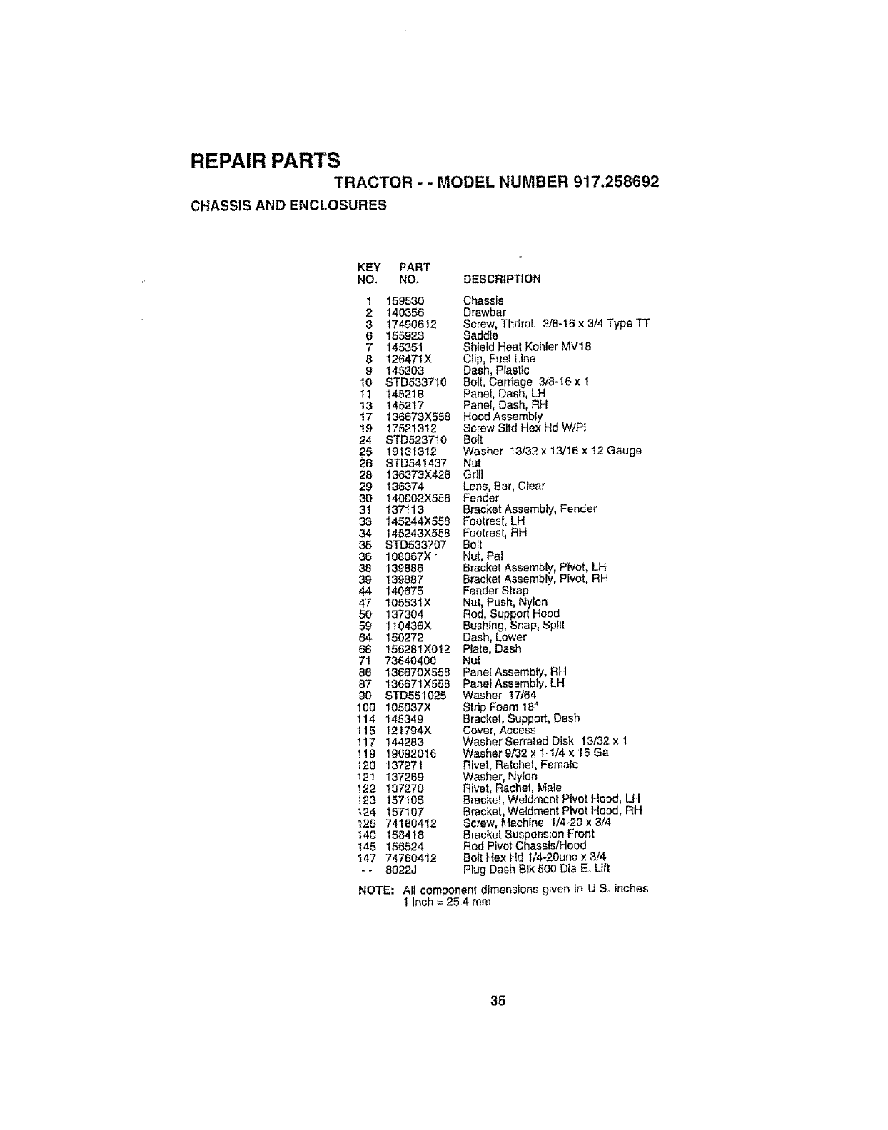
REPAIR PARTS
TRACTOR - - MODEL NUMBER 917.258692
CHASSIS AND ENCt.OSURES
KEY PART
NO_ NO, DESCRIPTION
1 159530 Chassis
2 140356 Drawbar
3 17490612 Screw, ThdroL 3/8+16 x3/4 Type TT
6 155923 Saddle
7 145351 Shield Heat Kohler MV18
8 126471X Clip, Fuel Line
9 145203 Dash, Plastic
I0 STD533710 Bolt, Carriage 3t8-I6x 1
11 145218 Panel, Dash, LH
13 145217 Panel, Dash, RH
17 136673X558 Hood Assembty
19 17521312 Screw Sttd Hex Hd WtPI
24 STD523710 Bolt
25 19131312 Washer 13/32 x 13/16 x 12 Gauge
26 STD641437 Nut
28 138373X428 Grill
29 136374 Lens, Bar, Clear
30 140002X558 Fender
31 t37"H3 Bracket Assembly, Fender
33 145244X558 Footrest, LH
34 145243X558 Footrest, RH
35 STD533707 Bolt
36 108067X +Nut, Pal
38 139886 Bracket Assembly, Pivot, LH
39 139887 Bracket Assembly, Pivot, RH
44 140675 Fender Strap
47 10553tX Nut, Push, Nylon
50 137304 Rod, Support Hood
59 110436X Bush+ng, Snap, Split
54 150272 Dash, Lower
86 156281X012 Plate, Dash
71 73640400 Nut
86 138670X558 Pane/Assembly, RH
87 136671X558 Panel Assembly, LH
90 STD551025 Washer 17/64
100 105037X Strip Foam 18"
114 145349 Bracket+ Support, Dash
115 121794X Cover, Access
117 144283 Washer Serrated Disk 13132 x 1
!19 19092016 Washer 9/32 x1+1/4 x16 Ga
!20 137271 Rivet, Ratchet, Female
121 137269 Washer, Nylon
122 137270 Rivet, Rachel, Male
123 157105 Bracke_, Weldment Plvot Hood, LH
t24 157107 Bracket, Wetdment Pivot Hood, RH
I25 74180412 Screw, Machine 1/4+20 x3/4
140 158418 Bracket Suspension Front
145 156524 Rod Pivot ChasslstHood
147 74760412 Bolt Hex Hd lt4-20une x 3/4
- - 8022J Plug Dash 81k 500 Din E Lift
NOTE: Ail component dimensions given in US, inches
1 Inch = 25 4 mm
35
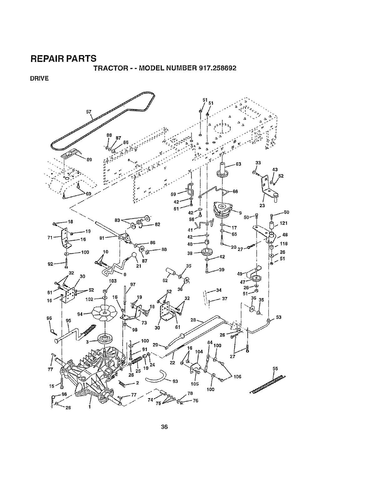
REPAIR PARTS
TRACTOR --MODEL NUMBER 917.258692
DRIVE
26
14100
1oo
55
36
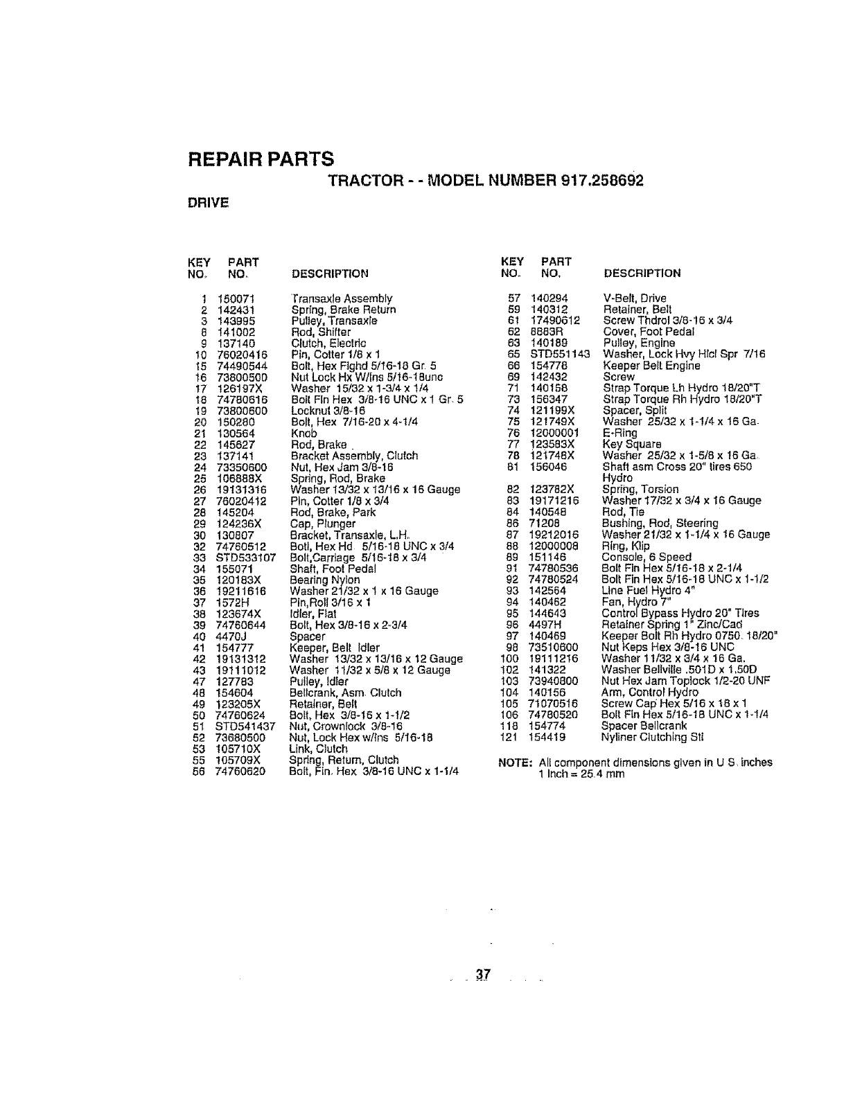
REPAIR PARTS
TRACTOR -- MODEL NUMBER 917,258692
DRIVE
KEY PART KEY PART
NOo NO. DESCRIPTION NOo NO, DESCRIPTION
1 150071 Transaxle Assembly 57
2 142431 Spdng, Brake Return 59
3 143996 Pufley, Transax[e 6!
6 141002 Rod, Shifter 62
g 137140 Clutch, E]ectdc 63
10 76020416 Pin, Cotter 1/6 x 1 65
15 74490544 Bolt, Hex Ftghd 5/16-18 Gr 566
16 73800500 Nut Lock Hx W/ins 5/I6-18unc 69 142432
17 126197X Washer 15/32x1-3/4xlt4 71 140158
16 74780616 Boll Fin Hex 3t8-16 UNC x 1 Gr. 5 73 156347
19 73800600 Locknut3/8_16 74 121199X
20 150280 Boll, Hex 7t16-20 x4-t/4 75 121749X
2t 130564 Knob 76 12000001
22 145627 Rod, Brake. 77 !23563X
23 137141 Bracket Assembly, Clutch 78 121748X
24 73350600 Nut, Hex Jam 3/8-18 81 156046
25 106888X Spdng, Rod, Brake
26 19131316 Washer 13/32 x 13/16 x 16 Gauge 62 123782X
27 76020412 Pln, Cottert/axS/4 83 19171216
28 145204 Rod, Brake, Park 64 140548
29 124236X Cap, Plunger 66 71208
30 130807 Bracket, Transax[e, L.Hr. 87 19212016
32 74760512 Bofl, HexHd 5/16_18UNC×3/4 88 12000006
33 STD533107 Bolt,Carriage 5/16-18 x 3/4 89 151146
34 155071 Shaft, Foot Pedal 91 74780536
35 120183X Bearing Nylon 92 74780524
36 19211616 Washer 2t/32 x 1 x 16 Gauge 93 142564
37 1572H Pin, Roll 3/16 ×1 94 140462
38 123674X Idler, Fiat 95 144643
39 74760644 Bolt, Hex 3/8-16 x 2-3/4 96 4497H
40 4470J Spacer 97 140469
41 154777 Keeper, Belt Idler 96 73510600
42 19131312 Washer 13/32x13/t6xt2Gauge 100 19111216
43 19111012 Washer tt/32 x 518 x 12 Gauge t02 141322
47 127783 Pulley, Idler 103 73940800
48 154604 Bellcrank, Asm. Clutch I04 140156
49 t23205X Retalner, Belt 105 71070516
50 74760624 Boll, Hex 3/8-16 x 1-1/2 106 74780520
51 STD541437 Nut, Crownfock 3/8-16 118 154774
52 73680500 Nut, Lock Hexwlins 5/16-16 121 154419
53 105710)( Link, Clutch
55 t05709X Spdng, Return, Clutch
66 74760620 Bolt, Fin. Hex 318-16 UNC x 1-1/4
140294 V-Belt, Drive
140312 Retainer, Belt
17490612 Screw Thdrol 3t6-!6 x 3/4
8883R Cover, Foot Pedal
140189 Pulley, Engine
STD551143 Washer, Lock Hvy Hrcl Spr 7/16
154778 Keeper Belt Engine
Screw
Strap Torque Lh Hydro 18t20",T
Strap Torque Rh Hydro 18120 T
Spacer, Split
Washer 25/32 x 1-114 x 16 Ga
E-Ring
Key Square
Washer 25/32 x 1-5/8 x 16 Go.
Shaft asm Cross 20" tires 650
Hydro
Spriilg, Torsion
Washer 17/32 x 3/4 x 16 Gauge
Rod, Tie
Bushing, Rod, Steering
Washer 21/32 x 1_1/4 x 16 Gauge
Ring, Kfip
Console, 6 Speed
Bolt Fin Hex 5/16-18 x 2-1/4
Bolt Fin Hex 5t16-18 UNC x 1-t/2
Line Fuel Hydro 4"
Fan, Hydro 7
Centre/Bypass Hydro 20" Tires
Ratatner Spdng 1" ZlnctCac_ ,,
Keeper Boft Rh Hydro 0750.18t20
Nut Keps Hex 3/8-16 UNC
Washer 11/32 x 3/4 x 16 Go.
Washer Bellville .501D x 1,50D
Nut Hex Jam Toplock 112-20 UNF
Arm, Control Hydro
Screw Cap Hex 5/16 x t8 x 1
Bolt Fin Hex 5/16-18 UNC x 1-1/4
Spacer Bellcrank
Nyliner Clutching Stl
NOTE: All componentdimensions given in U S, _nches
I Inch=25.4 mm
37
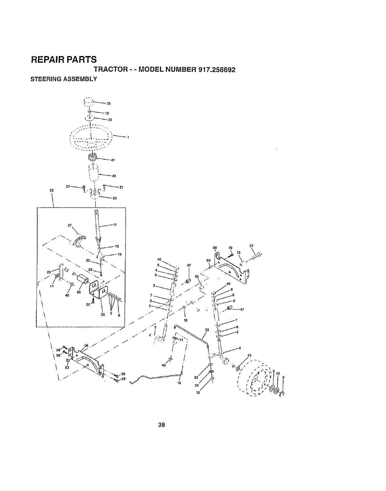
REPAIR PARTS
TRACTOR -- MODEL NUMBER 917.258692
STEERING ASSEMBLY
62
(, ,
I i
38
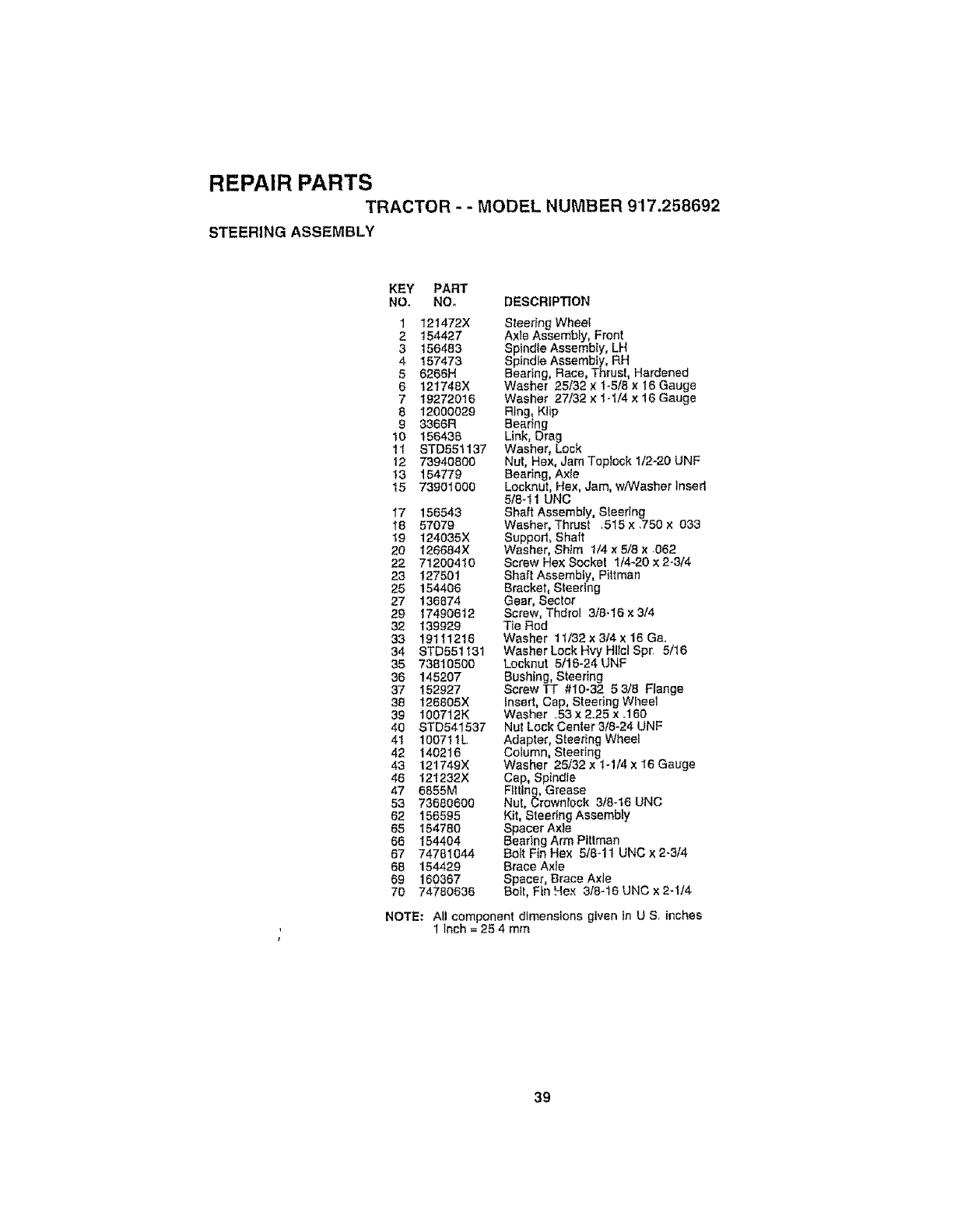
REPAIR PARTS
TRACTOR - - MODEL NUMBER 9'17.258692
STEERING ASSEMBLY
KEY PART
NO, NO. DESCRIPTION
1 121472X
2 154427
3 156483
4 157473
5 6266H
6 121746X
7 19272016
8 12000029
9 3366R
10 156436
11 STD551137
12 73940600
t3 154779
15 73901000
17 156543
18 57079
19 124035X
20 126684X
22 71200410
23 127501
25 154406
27 136874
29 17490612
32 139929
33 19111216
34 STD551131
35 73610500
36 145207
37 152927
38 126805X
39 100712K
40 STD541537
41 100711L
42 140216
43 121749X
46 121232X
47 6855M
53 73680600
62 156595
65 154780
66 154404
67 74781044
68 154429
69 160367
7O 74780636
Steer}ng Wheel
Axle Assembly, Front
Spindle Assembly, LH
Spindle Assembly, RH
Bearing, Race, Thrust, Hardened
Washer 25132 x t-5/8 × 16 Gauge
Washer 27/32 x 1-t/4 x 16 Gauge
Ring, Klip
Bearing
Link, Drag
Washer, Lock
Nut, Hex, Jam Toplock 1/2-20 UNF
Bearing, Axle
Locknut, Hex, Jam, w/Washer insert
5/6-1 t UNC
Shaft Assembly, Sleerlng
Washer, Thrust .515x .750 x 033
Supped, Shaft
Washer, Shim 1/4 x 5/8 x 062
Screw Hex Socket 1/4-20 x 2.3/4
Shaft Assembly, Pittman
Bracket, Steering
Gear, Sector
Screw, Thdrel 3/8-16 x 3/4
Tie Rod
Washer 1t/32x 3/4x 16 Ga.
Washer Lock Hvy Hltci Spr. 5/16
Locknut 5/16-24 UNF
Bushing, Steering
Screw TT #10-32 53/6 Flange
Insed, Cap, Steering Wheel
Washer ..53 x 2.25 × .160
Nut Lock Center 3/8-24 UNF
Adapter, Steering Wheel
Column, Steering
Washer 25/32 x 1-1/4 x I6 Gauge
Cap, Spindle
Fitting, Grease
Nut, Crownlock 3/8-16 UNO
Kit, Steering Assembly
Spacer Axle
Beating Arm Plttman
Bolt Fin Hex 5/8-11 UNC x 2-3/4
Brace Axle
Spacer, Brace Axle
Bett, Fin Hex 318-16 UNC x 2-1/4
NOTE: All component dimensions given in U S inches
1 inch = 25 4 mm
39
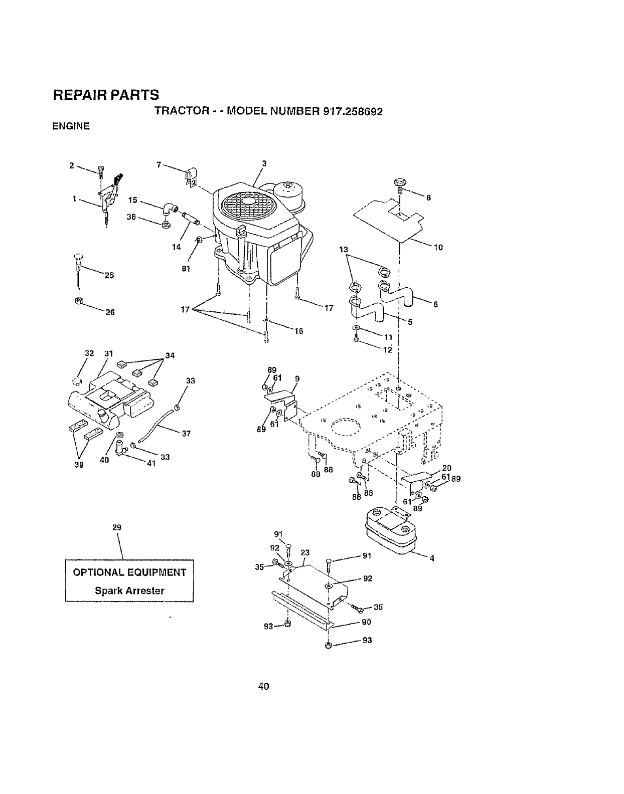
REPAIR PARTS
TRACTOR -- MODEl. NUMBER 917.258692
ENGINE
32 31 34
89 9
39 4O 41
8B
29
OPTIONAL EQUIPMENT
23
Spark Arrester
40
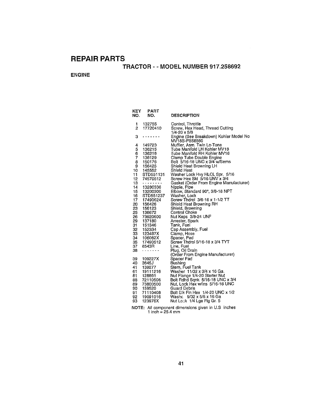
REPAIR PARTS
TRACTOR - -MODEL NUMBER 917,258692
ENGINE
KEY PART
NO_ NO, DESCRIPTION
1 132755
2 17720410
3 .......
4 149723
5 136215
6 136216
7 138129
8 150176
9155425
10 145552
1t STD551131
12 74570512
13 .........
14 13280336
15 13200300
16 STD551237
17 17490624
20 156426
23 156123
25 138672
26 73920600
29 137180
31 151346
32 152334
33 123487X
34 t06082X
35 17490512
37 6543R
38 .......
39 109227X
40 3645J
41 139277
61 19111216
81 128861
88 72110506
89 73800500
90 15952O
91 71110408
92 19091018
93 123976X
Control, Throttle
Screw, He× Head, Thread Cutting
1/4-20 x 5/8
Engine (See Breakdown) Koh(er Model No
MVISS-PS58560
Muffler, Asm, Twin LmTone
Tube Manilotd LH Kohler MV18
Fube Manifold RH Kohler MV18
Clamp Tube Double Engine
Bolt 5/t6-16 UNC × 3/4 w/Sems
Shield Heat Browning LH
Shfeld Heat
Washer Lock Hvy HLCL Spr. 5/16
Screw Hex Ski 5/15 UNV × 3/4
Gasket (Order From Engine Manufacturer)
Nipple, Pipe
Elbow, Standard 90 °, 3/8-18 NPT
Washer, Lock
Screw Thdroi 3/6-16 x 1=1/2 TT
Shield Heal Browning RH
Shield, Browning
Control Choke
NutKeps 3/8-24 UNF
Arrestor, Spark
Tank, Fuel
Cap Assembly, Fuel
Cl,amp, Hose
Spacer, Pad
Screw Thdrol 5/16-!8 x 3/4 TYT
Line, Fuel
Plug, Oil Drain
(Order From Engine Manufacturer)
Spacer Pad
Bushing
Sl`em, Fuel Tank
Washer t 1/32 x 3/4 x 16 Ca,
Nut Flange t/4-20 Starter Nut
Bolt Rdhd Sqnk 5t16-16 UNC x 3/4
Nut, Lock Hex w/Ins 5/15-18 UNC
Guard Debris
Bolt FJlk Fin Hex 1/4-20 UNC x 1/2
Waehc 9/32 x 5/8 x 16 Ga
Nut Lo::k lj4 Lge Fig Gr. 5
NOTE: Al! component dtmens!one given in UoS inches
1 inch = 25,4 mm
41
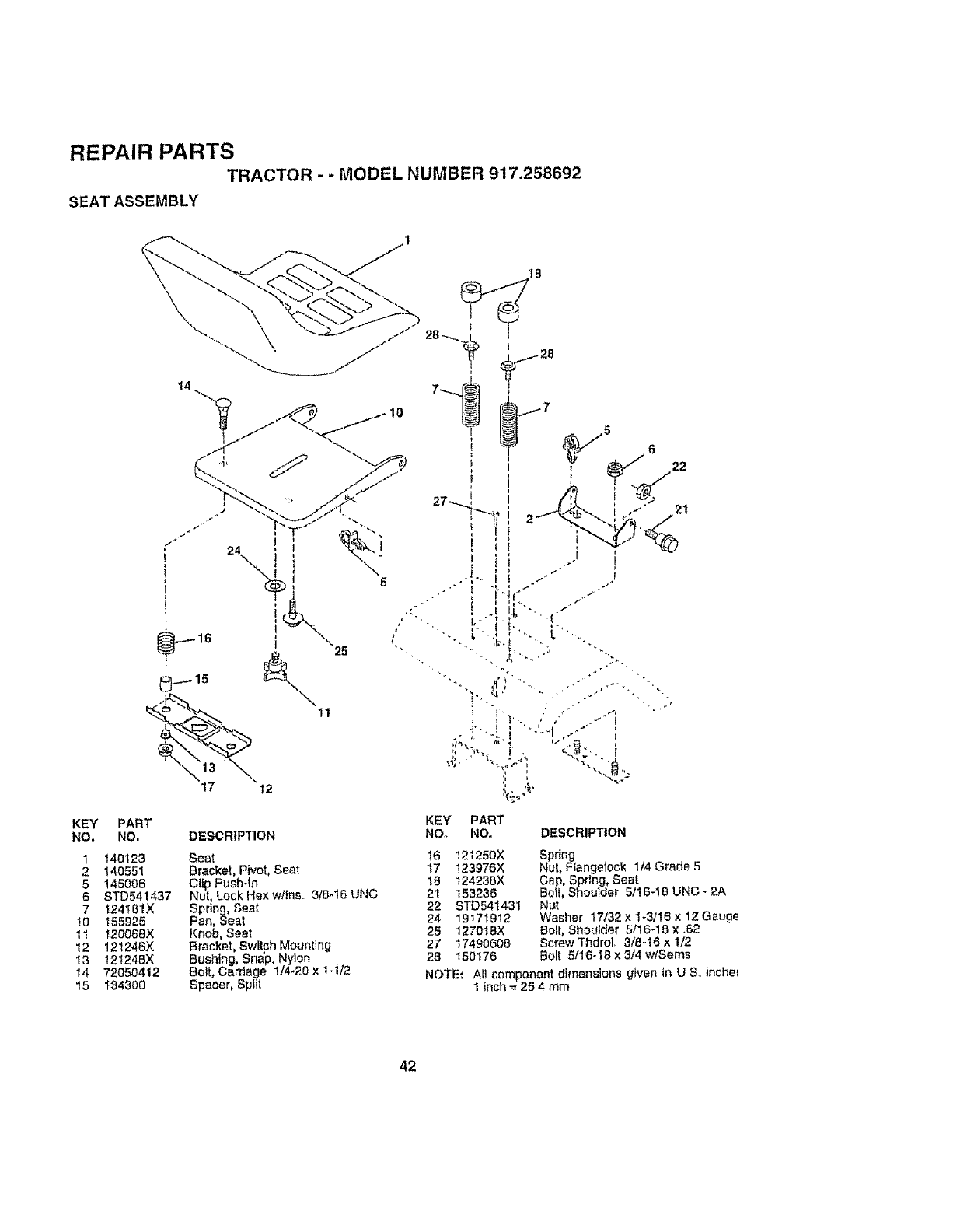
REPAIR PARTS TRACTOR - - MODEL NUMBER 917.258692
SEAT ASSEMBLY
KEY
NO.
1
2
5
6
7
lo
11
12
13
14
15
PART
NO.
140123
140551
145006
STD541437
124!81X
155925
t20068X
121246X
121248X
72050412
1343OO
DESCRIPTION
Seat
Bracket, Pivot, Seat
Clip Push.in
Nut tLock Hex w/tns,, 3/8-15 UNC
Spnng, Seat
Par_, Seat
Knob, Seat
Bracket, Sw_tchMounting
Bushing, Sna'p, Nylon
Bolt, Carriage 1/4-20 x 1-1/2
Spacer, Spiit
5
/22
21
KEY PART
NO_ NO.
t6 121250X
17 123976X
18 12423_X
21 153236
22 STD541431
24 19171912
25 1270t8X
27 17490608
28 150176
DESCRIPTION
Spdng
Nut Flangetock 1/4 Grade 5
Cap, Spring, Seat
Bolt, Shoulder 5/16-18 UNC. 2A
N_t
Washer 17/32 x 1-3/16 x 12 Gauge
Bo_t, Shoulder 5f16-16 x ,62
Screw Thdrol 3/8-16 x 1/2
Bolt 5tl 6-18 x 3/4 wlSems
NO!rE_ All component d(menstons given in U 8 inchm
1 inch = 25 4 mm
42
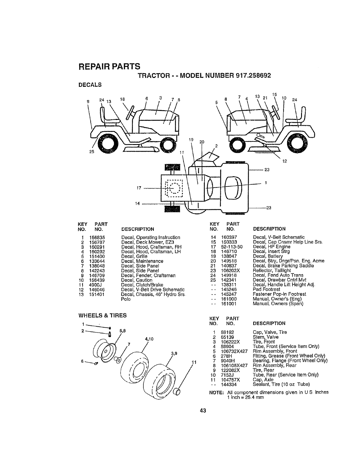
REPAIR PARTS
TRACTOR - - MODEL NUMBER 917.258692
DECALS
t8 6 3 785
\24
25
17_
t9
11
2O 2
!2
23
14
KEY PART
NO, NO.
1 156835
2 156787
3160291
4 160292
5 151408
6 133644
7 138048
8 142243
8146709
10 156439
11 4900J
12 146046
t3 151401
DESCRIPTION
Decal Operating Instruction
Decal Deck Mower, EZ3
Decal Hood, Craftsman, RH
Decal Hood, Craftsman, LH
Decal Grille
Decal Maintenance
Decal Side Panel
Decal Side Pane!
Decal Fender, Craftsman
Decal Caution
Decal ClulchiBrake
Decal V÷BelI Drive Schematic
Decal Chassis, 46" Hydro Srs
Polo
WHEELS & TIRES
2_5,8 4,10
KEY PART
NO,_ NO, DESCRIPTION
14 160397 Decal, V-Belt Schematic
16 150333 DecaI, Cap Cnsmr Help Line Srs_
17 52-113-50 Decal, HP Engine
18 146710 Decal, InsertStrg
19 138047 Decal, Battery
20 149516 Decal, Btry,Dngr/Psn, Eng, Acme
21 140837 Decal, Brake Parking Saddle
23 106202)( ReflecIor, Taillight
24 149918 Decal, Fend Auto Trana
25 142341 Decal, Drawbar Cntd Mvt
-- 138311 Decal, Handle Lilt Height Adj
-- 145246 Pad Footrest
-- 145247 Fastener Pop-In Footrest
--161000 Manual, Owners (Eng)
-- 161001 Manual, Owners (Span)
11
KEY PART
NOo NO, DESCRIPTION
t 59!92 Cap, Valve, Tire
2 65139 Stem, Valve
3 106222X Tire, Front
4 59904 Tube, Front (Service Item Only)
5 106732X427 Rim AssembIy, Front
6278H Fitting, Grease (Front WheeIOnly)
79040H Bearing, Flange (Front Wheel Only)
8 106108X427 Rim Assembly, Rear
9 122082X Tire, Rear
IO 7!52J Tube, Rear (Service item Only)
11 104757X Cap, Axle
-- 144334 Sealant, Tire (10 oz Tube)
NOTE: All component dimensions given in U S inches
1inch = 254 mm
43
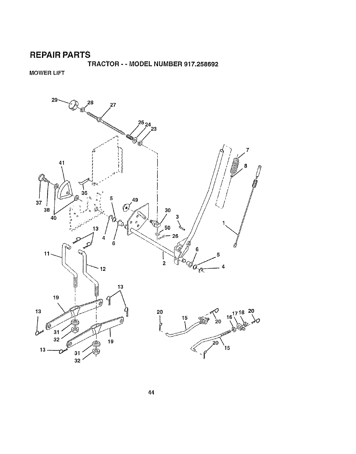
REPAIR PARTS
TRACTOR -- MODEL NUMBER 917.258692
MOWER LIFT
//°f
5
2O
44
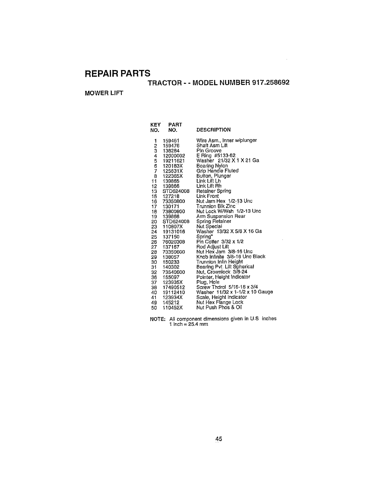
REPAIR PARTS
TRACTOR - - MODEL NUMBER 917.258692
MOWER LIFT
KEY PART
NO. NO. DESCRIPTION
1 159461 Wire Asm. Inner wtplunger
2 159476 Shaft Asm Lilt
3138284 Pin Groove
4 12000002 E R}ng #5133-62
5 19211621 Washer 2!/32X ;I X 21 Ga
6 120183X Bearing Nylon
7 125631X Grip Handle Fluted
8 t22365X Butlon, Plunger
11 I39865 Link Uft Lh
12 139666 Link Lift Rh
13 STD624008 Retainer Spring
15 127218 Link Front
16 73350800 Nut Jam Hex 1/2-13 Unc
17 130171 Trunnion Btk Zinc
18 73800800 Nut Lock WA4tsh 1t2-t3 Uric
19 139868 Arm Suspension Rear
20 STD824008 Spring Retainer
23 !10807X Nut Special
24 19131016 Washer 13/32 X 5/8 X 16 Ga
25 137150 Spring"
28 76020308 Pin Cotter 3132 x 1/2
27 137167 Rod Adjust Lift
28 73350600 Nut Hex Jam 3/8-16 Unc
29 138057 Kneb Infinite 318-16 Unc Black
30 150233 Trunnion lnfin Height
31 140302 Bearing Pvt LiltSpherica!
32 73540600 Nut, Crownlock 3/8-24
36 155097 Pointer, Height Indicator
37 123935X Plug, Hole
38 17490512 Screw Thdrot 5/16_18 x 3/4
40 19112410 Washer 11/32 x 1-1/2 x 10 Gauge
41 t23934X Scale, Height Indicator
49 145212 Nut Hex Flange Lock
50 110452X Nut Push Phee & Oil
NOTE: A$Icomponent dimensions given [n US inches
1 Inch = 25.4 mm
45
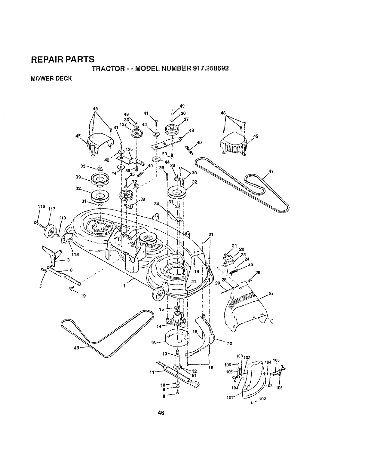
REPAIR PARTS
TRACTOR - - MODEL NUMBER 917.258692
MOWER DECK
46
45\
31
!17
49
49 41 36
32
l i j
15
46
21
21 22
47
26
46
18
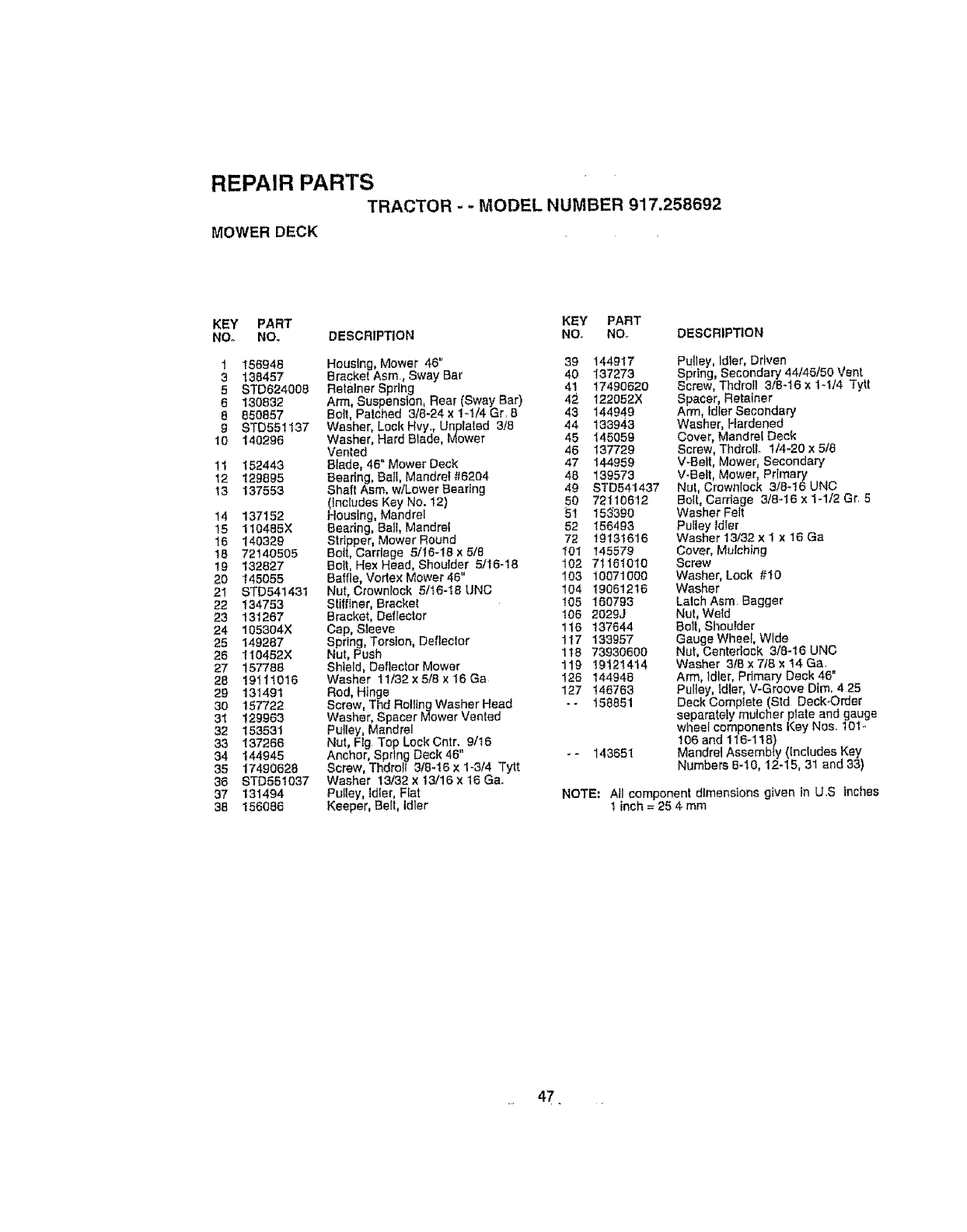
REPAIR PARTS
TRACTOR - -MODEL NUMBER 917.258692
MOWER DECK
KEY PART KEY PART
Nee NO. DESCRIPTION NO, Nee DESCRIPTION
1156946
3138457
5STD624008
6130832
8850857
9 STD551137
10 140296
11 152443
12 129895
13 137553
14 137152
15 110465X
16 140329
16 72140505
!9 132827
20 145055
21 STD541431
22 134753
23 131267
24 105304X
25 149287
26 110452X
27 157788
28 19111016
29 131491
30 157722
31 129963
32 153531
33 137266
34 144945
35 17490628
36 STD551037
37 131494
38 156086
Housing, Mower 46" 39 144917
Bracket Asm,Sway Bar 40 137273
Retainer Spring 41 17490620
Arm, Suspension, Rear (Sway Bar) 42 122052X
Belt, Palched 3/8-24 x 1-.1/4 Gr. B 43 144949
Washer, Lock Hvy,, Unplaled 3/8 44 133943
Washer, Hard Blade, Mower 45 145059
Vented 46 137729
Blade, 46" Mower Deck 47 144959
Beedng, Bail, Mandrel#6204 48 139573
Shaft Asm, wtLewer Bearing 49 STD541437
(Includes Key No. t2) 50 72110612
Housing, Mandrel 51 153390
Beedng, Bail, Mandrel 52 156493
Stripper, Mower Round 72 19131616
Bolt, Carriage 51!6-18 x5/6 101 145579
Bolt, Hex Head, Shoulder 5/16-18 102 71161010
Baffle, Vodex Mower 46" 103 10071000
Nut, Crownlock 5/t6-18 UNC 104 19061216
Stifflner, Bracket 105 160793
Bracket, Deflector 106 2029J
Cap, Sleeve 116 137644
Spring, Torsion, Defleclor 117 133957
Nut, Push 1t8 73930600
Shield, Deflector Mower 119 19121414
Washer tl/32 × 5/8 ×16 Ga 126 144948
Rod, Hinge , 127 146763
Screw, Thd Rolling Washer Heae -- 158851
Washer, Spacer Mower Vented
Pulley, Mandrel
Nut, Flg Top Lock Cntr. 9/!6
Anchor, Spring Deck 46" - - 143651
Screw, Thdroll 3/8-16 x 1-3t4 Tylt
Washer 13/32 x13/16 x 16 Ga,
Pultey, Idler, Flat
Keeper, Belt, Idler
Pulley, Idler, Driven
Spring, Secondary 44/45/50 Vent
Screw, Thdroll 3/8-16 x t-t/4 Tytt
Spacer Retatner
Arm, dter Secondary
Washer, Hardened
Cover, Mandrel Deck
Screw, Thdrollo 1/4-20 x 5/8
V-Belt, Mower, Secondary
V-Bett, Mower, Prlrnary
Nul, Crownlock 3]8-16 UNC
Bolt, Csrdage 3/8-16 x 1-1/2 Gr. 5
Washer Felt
Pulley Idler
Washer 13132 x 1 × 16 Ga
Cover, Mulching
Screw
Washer, Lock #I0
Washer
Latch Asm Bagger
Nut, Weld
Boll, Shoulder
Gauge Wheel, Wide
Nut, Centedock 3/8-16 UNC
Washer 3t6 x 7/8 x 14 Ga.
Arm, Idler, Primary Deck 46"
Pulley, Idler, V-Groove Dim. 4 25
Deck Complete (Std Deck-Order
separately mulcher plate and gauge
wheel components Key Nos. 10!-
106 and 116-1t8)
Mandrel Assembty (Includes Key
Numbers 6-10, 12-15, 3t and 33)
NOTE: All component dimensions given in U.S Inches
t inch =25 4 mm
47
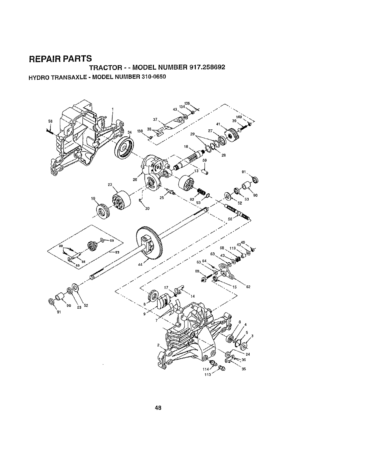
REPAIR PARTS
TRACTOR - -MODEL NUMBER 917.258692
HYDRO TRANSAXLE -MODEL NUMBER 3't0-0650
5B
25 90
53
35
48

REPAIR PARTS
TRACTOR -- MODEL NUMBER 917,258692
HYDRO TRANSAXLE - MODEL NUMBER 310-0650
KEY PART KEY PART
NO. NO. DESCRIPTION NO. NO_ DESCRIPTION
1 142930 Housing, Lower 43 142884 Washer 7116 ×718 x 060
2 142931 Assembly, Upper Housing 44 150829 Differential Assembly
Washer 3/4x 1.5 x .t3
3 142932 Seat, LIp 52 142991
4 142928 Ring, Wlra Retaining 53 142961 Seal 75x 1 25 x 250
5 142933 Ring, Retaining 56 142963 Shaft, Input
5 142934 Bearing, Shaft Bali 58 142964 Bolt t/4-20 x 1.38
7 142935 Bearing, Cradle 59 142965 Pin 50D x 43 ID x 750
8 150771 Bearing, Thrust 30 x52 x 13 62 142966 Arm, Conifer
9142937 Swashplate, Variab{e 63 142967 Puck, Dampener
13 142938 Block, Cylinder Assembly 64 142920 Set Screw
14 142939 Arm, Trunnion 68 142969 Spring
15 142940 Seal, Lip 69 144610 Stud 5/16-24
17 142941 Guide, Slot 83 142971 Jackshaft Assembly
16 150772 Shaft, Motor 85 150806 Jackshaft
19 150773 Bearing, Thrust 42 x 68 x 16 88 142973 Screw, Cap
23 142944 Block, CylinderAssembty 89 142974 Washer 7/15 x 1 x 112
24 142945 Seal, Lip 10x 25 x790 142975 Sleeve Bearing
25 142946 Actuator, Bypass 91 142976 Seal, Wiper
26 150774 Center Section Assembly Kit 92 142977 Spring, Block
27 142948 Seat, Lip 26 x 42 x 8 93 142978 Washer, Block Thrust
28 142949 Ring, Retaining I13 142917 Cap. VeniAssembly
29 142950 Washer 26x35x1 1t4 142918 Fitting, O.RingAssembly
30 150787 Plate, Bypass 119 142980 Spacer
34 142951 Oi! Filter Elemenl 134 144607 Nut, Castle 5/t6-24
35 142952 Arm, Bypass 135 144608 Pin, Cotter
36 142953 Ring, Retaining t39 150775 Spring, Compression
37 142954 Arm, Actuating 140 150776 Nut, Hex 5ti6-24
38 142955 Ptn Actuating
39 150777 Be t 5116-24 x I-3/4 NOTE: A_ component dimensions given in US _nches
40 150778 Locknut, Hex 5/16-24 UNJC 1 inch = 25.4 mm
41 142958 Brake Rotor/Stater Kit
49
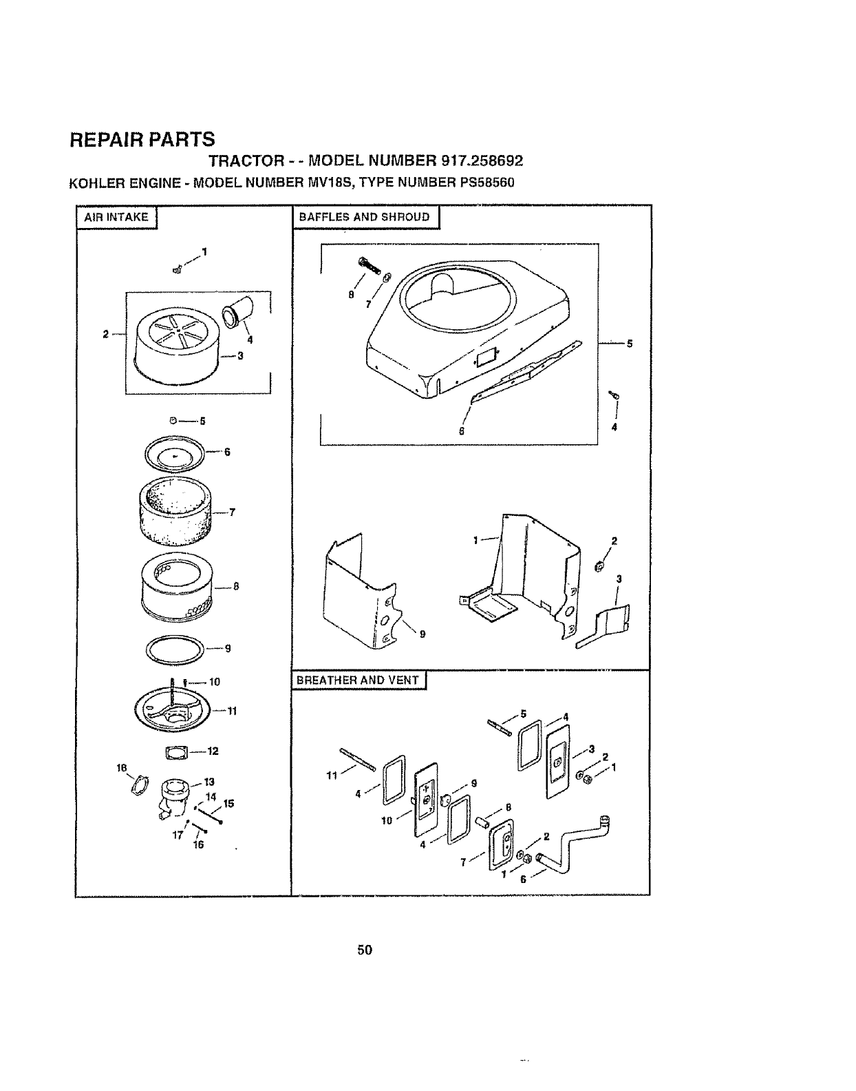
REPAIR PARTS
TRACTOR -- MODEL NUMBER 917.258692
KOHLER ENGINE - MODEL NUMBER MV18S, TYPE NUMBER PS58560
AIR INTAKE j
1
!_--.5
18
t6
/
I 6
%
/
4
7 .I'" i
5O
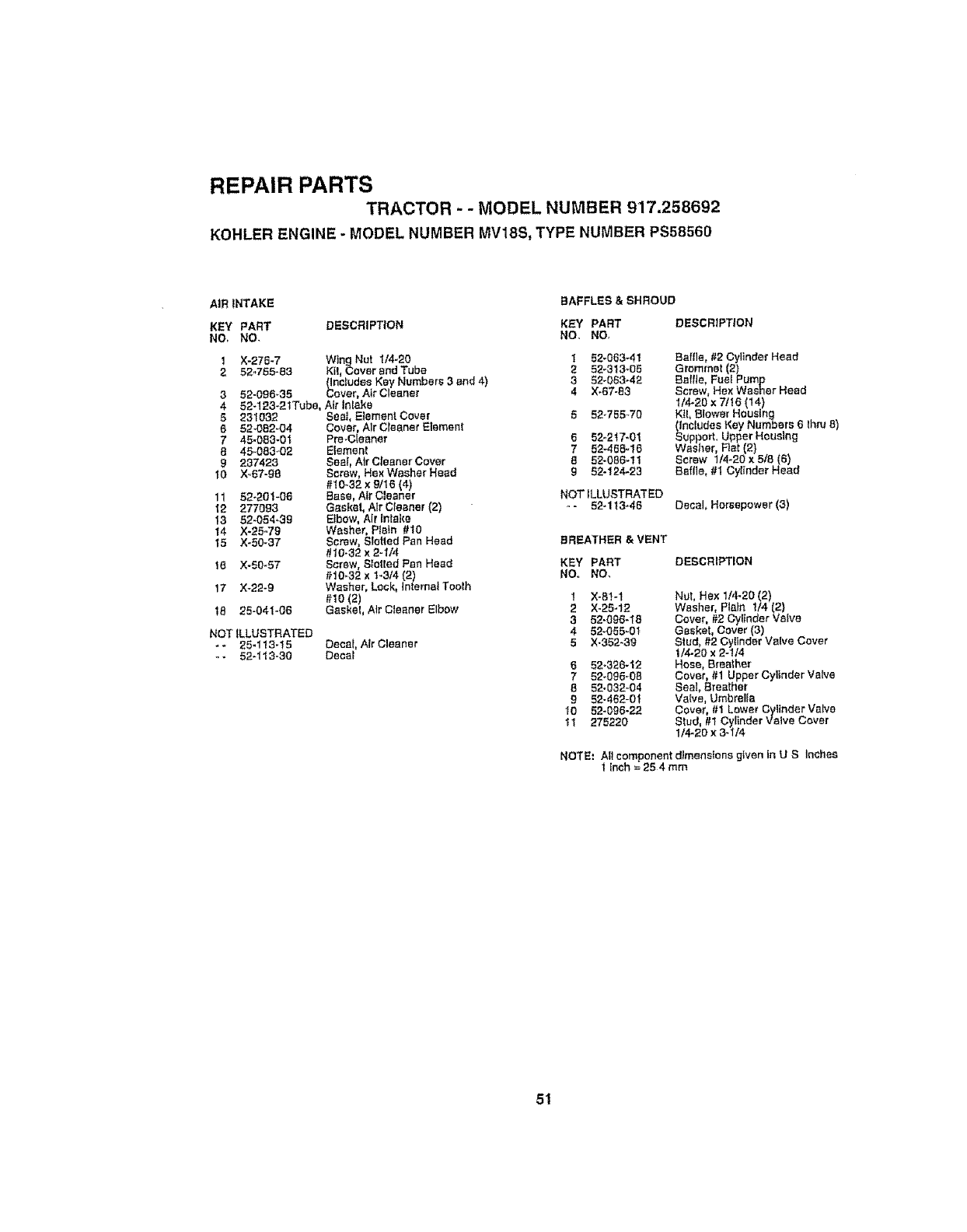
REPAIR PARTS
TRACTOR - - MODEL NUMBER 917.258692
KOHLER ENGINE - MODEL NUMBER MV18S, TYPE NUMBER PS58560
AIR INTAKE BAFFLES& SHROUD
KEY PART DESCRIPTION KEY PART
NO. NO- NO, NO.
NOT ILLUSTRATED
** 25-I13_t5 Decor, Air Cleaner
-- 52-113-30 Decal
1 X_276-7 WingNut 1/4-20 1 52_063_41
252.755-83 Kil, Cover and Tube 252_313-O5
(includes Key Numbers 3and 4) 3 52`063_42
352-098_35 Cover, Air Cleaner 4 X-67-83
4 52-123-21Tube, Ai_"In_ake
5231032 Sea], E_emen! Cover 5 52-755-70
8 52-082`04 Cover, Air Cleaner Element
7 45-083-0t Pro.Cleaner 6 52"r2t7"01
8 45-083-02 Element 7 52-458-16
9 237423 Seal, Atr C|eaner Cover 8 52`086-11
'_0 )(.,67-98 Screw, Ha× Washer Head 952-!24-23
#t0-32 x9/t6 (4)
11 52-201`06 Bass, Air Cleaner
12 277093 Gasket, Air Crooner (2)
13 52-054-39 E_bow, Air Intake
14 X-25.79 Washer, Plain #10
15 X-50--37 Screw, SIotled Pan Head BREATHER & VENT
#10-32 x 2-I/4
15 X-50-57 Screw, Slotted Pan Head
#10_32 x1-3/4 (2)
t7 X-22-g Washer, Lock, Intemat Tooih
#10 (2) 1
t8 22-041-06 Gasket, Air Cieaner Elbow 2
3
4
5
DESCRIPTION
Baffle, #2 Cylinder Head
Grommet (2)
Baffle, Fuel Pump
Screw, Hex Washer Head
t/4-20 x 7/!6 (14)
KtL BIower Housing
(Includes Key Numbers 6 lhna 8)
Support, Upper Housing
Washer, Flat (2}
Screw 1t4-20 x 5/8 (6)
Saflle, #! Cylinder Head
NOT ILLUSTRATED
- 52-1t3-46 Decal, Horsepower(3)
KEY PART DESCRIPTION
NO. NO,
6
7
8
9
I0
tl
X-8t-1 Nut, He× 1/4-20 (2)
X-25-12 Washer, Plain t/4 (2)
52.096-18 Cover, #2 CyI_nder Valve
52-055-01 Gasket, Cover (3)
X-352-3g Stud, #2 Cylinder Valve Cover
1/4-20 x 2-114
52-326-12 Hose, Breather
52-095.0_ Cover, #1 Upper Cylinder Valve
52-032`04 Seal, Breather
52-462-0t Valve, Umbrella
52`096-22 Covet #1 Lower Cylinder Valve
275220 Siud, #t Cylinder Valve Cover
1/4-20 x 3-1/4
NOTE_ Allcomponent dimensions given In U S Inches
1 Inch = 25 4 mm
51
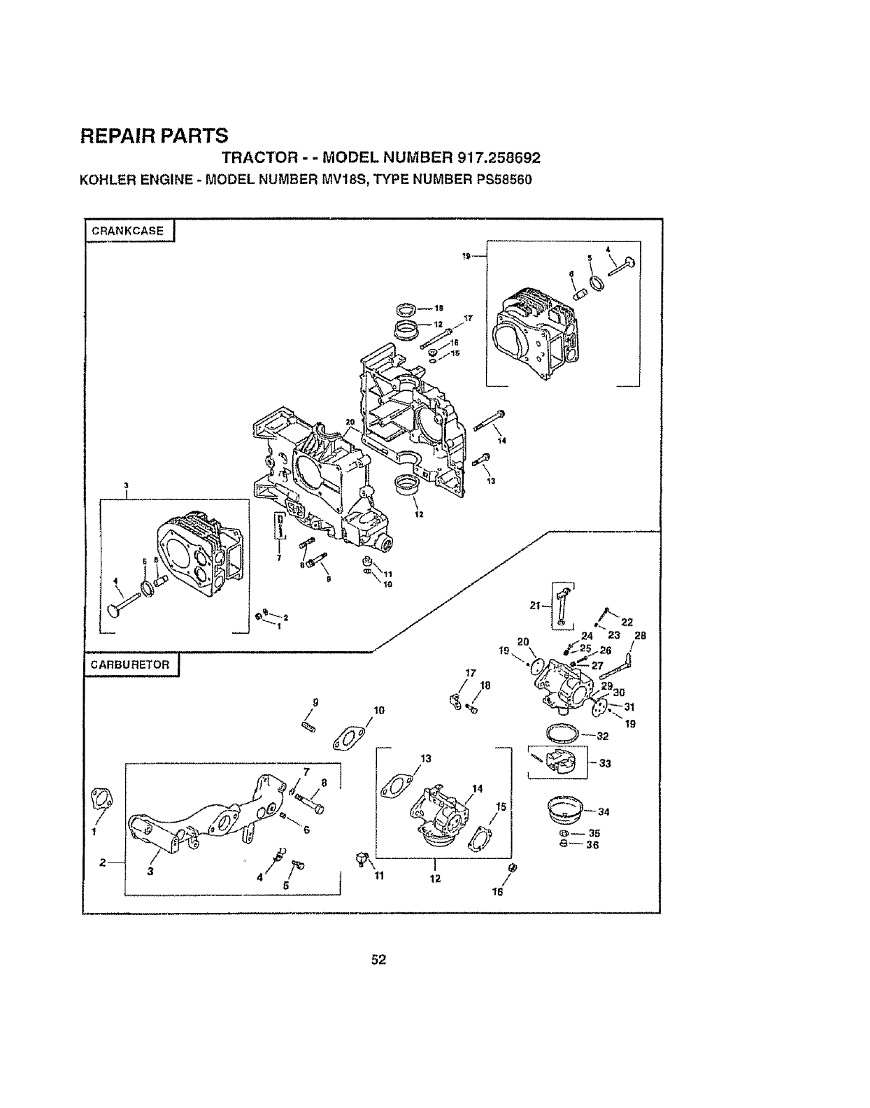
REPAIR PARTS
TRACTOR - - MODEL NUMBER 917.258692
KOHLER ENGINE - MODEL NUMBER MV18S, TYPE NUMBER PS58560
CRANKCASE J
3
CARBURETOR I
13
11
52

REPAIR PARTS
TRACTOR - -MODEL NUMBER 917.258692
KOHLER ENGINE -MODEL NUMBER MVI88, TYPE NUMBER. PS58560
CRANKCASE CARBURETOR
KEY PART DESCRIPTION KEY PART DESCRIPTION
NO. NO. NO. NO.
1X-82-2
2 52,,466,12
382-756,15
4 52-0"t6,,05
5 62-031-01
852-3! 6-66
752-755-50
B 52-072-12
926,g86.12
10 X-26g-43
11 52-078-05
12 52-030.10
52-030_11
52-030.12
13 25-086,10
14 25-066,13
15 52-14!-02
"16 52-13.9-08
17 25-(}66-11
IB 52-032-10
19 82-755q 7
20 .--
Nut, Hex 5/16,1B (12)
asher, Fiat 5/16(12)
Ktt #1 Cylinder Barrel
(Includes Key Numbers 4 thru 6)
Valve, Exhaust
Insert, Valve Seat (2)
Guide,Valve(2)
Kit, Oil Relief
Step Stud 5/16-18 x3/4,
3/8-16 x5iS, 2 Lung(12)
Screw, Hex Flange 5t16,I6 ×2 (2)
Ring, Retaining
Shalt, Govemur
Bearing, Sleeve, Standard (2)
8earing, Sleeve ,010" (2)
Beadng, Sleeve .020" (2)
_crew. rtex FIange
5t!6-18 x 1-112 (3)
Screw, Hex Fiange
318-16 x 3.516 (2)
O.Rlng
Plug
Screw, Hex Ftange
5/16,18 x 3-112 (8}
Seal, Oil, Front
KIt, #2 Cylinder Barrel
(Includes Key Numbers 4thru 6)
Crankcase (Service with Shud Block,
Par',Number 82 522 30)
t 52-04t-09
252.755-gl
3 52-t64,-I5
4 X_21-1
5 X-6-29
6 X-75-23
7 236776
8 X-67-97
g4t_072-'{9
10 52=063-46
1t 25-'155-02
12 62..&,.._3-25
13 271030
14 52-053-54
I5 25-041-06
I6 X-77-2
! 7 232667
I8X-67-62
19 25-086-27
20 25-146-03
21 52-t44,24
22 25-368-01
23 25-089-02
24 25-066-26
25 25-069-04
26 25-368-03
27 25-089*02
28 52-090-13
29 25-08g-03
20 26-194`01
31 25-146-02
82 26,041-04
33 26,757-09
34 25-104-01
35 25.041.,03
36 26,100-05
Gasket, intake (2)
Kit, Manifold
(includes Key Numbers 3 thru 8)
Mantra{d, intake
Washer, Lock 5;/18 (4)
Screw, Hex Cap 5/16,18 x 2 (4)
Plug, He×, Countersunk
ttSN.P,T.F.
Clamp, Cable (2)
Screw, Hex Washer Head
#10-24 ×3/8 (2)
Stud 5/16,18 x I(2)
BaliIe, Carburetor
Connecter, Hose
Kit, Carburelor WtthGasket (]nctudes
Key Numbers 12 {hru14)
Gasket, Carburetor (2)
Carburetor Assembly (Information OnLy
-Net Available Separately) (Includes
Kay Numbers 10 Ihru 35)
Gasket, Air Cleaner
Nut 5/t6 (2)
S#ap, Ltfllng
Screw, Hex Washer Head
1t4-20 x 3]4
Screw, Throttle and Choke Plate (4)
Plate, Choke
Shaft, Throllte with Lever and Seal
Needle, Idle Fuel AdIust
Spdng, _dle,Fuel
Screw, Idle Speed Adjust
Spring,fdta Speed
Needle, Main Fue!
Spring, Main Fuet
Lever, Chuke
Spring.Choke, Friction
Ball, Choke, Friction
Plate, Throttle
Gasket, Bawl
KIt, Float
Bow_,Fuel
GaskeL Bewt Retalner Screw
Screw, 8uwl Retainer
NOT ILLUSTRATED
--25,757q 1 Kit, Carburetor Repair
- - 25-757-23 Ki!, Buwl Baltte
NOTE: At_componentdimensions given {nU S inches
t _nch=25A mm
53
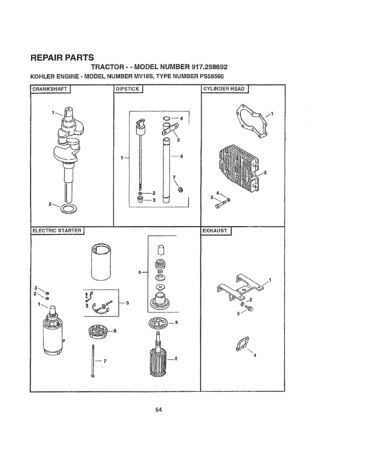
REPAIR PARTS
TRACTOR -- MODEL NUMBER 917.258692
KOHLER ENGINE -MODEL NUMBER MV18S_ TYPE NUMBER PS58560
DIPSTICK ] CYLINDER HEAD J
I
CRANKSHAFTJ
ELECTRIC STARTER J
3,._
4J
0
@
@
,@
6
--6
1
EXHAUST j
4
54
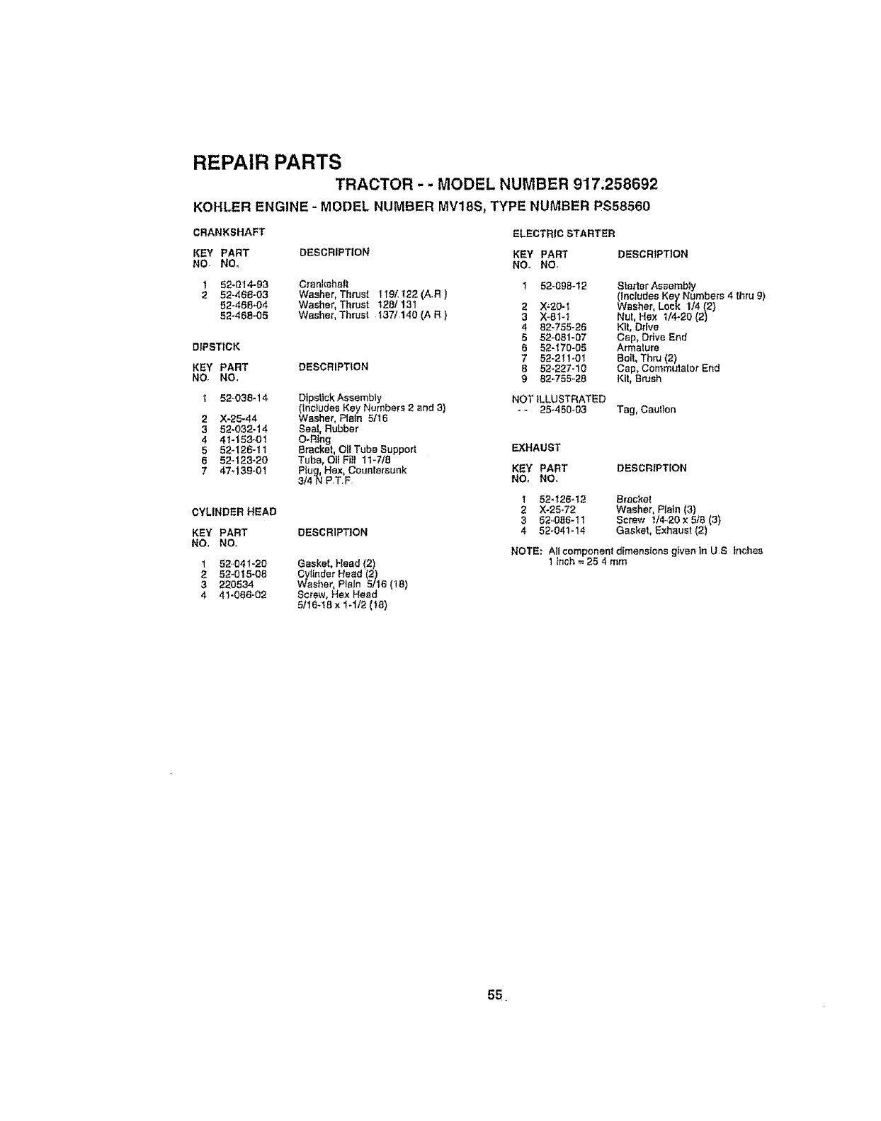
REPAIR PARTS
TRACTOR - - MODEL NUMBER 917.258692
KOHLER ENGINE - MODEL NUMBER MV18S, TYPE NUMBER PS58560
CRANKSHAFT ELECTRIC STARTER
KEY PART DESCRIPTION KEY PART DESCRIPTION
NO. NO. NO. NO,
1 52-014-g3 Crankshaft 1 52-09B-12
252-468-03 Washer, Thrust llg/122(A,R)
52-468-04 Washer, Thrust 128/13t 2X_20-_
52-468-05 Washer, Thruet 137/140 (A R) 3 X-81-1
4 82-755-25
552-081-07
DIPSTICK 6 52-170-05
7 52-211-0t
KEY PART DESCRIPTION 8 52-227-10
NO, NO., 9 82-755..28
1 52.035-14 OipsttckAssembiy
(includes Key Numbers 2 and 3)
2 X-25-44 Washer, Plain 5tt6
3 52-032-14 Seal, Rubber
4 41-153-01 O-Ring
552-126-11 Bracket, OI!Tube Support
652-123-20 Tube, Oil Fitl 11-7t8
747_139-01 PIug, Hex, Countersunk
3/4N PT.F
CYLINDER HEAD
KEY PART DESCRIPTION
NO,, NO.,
1 52.041-20 Gasket, Head 2)
252-0 t5-08 Cylinder Head (2)
3220534 Washer, Plain 5116(18)
441-086-02 Screw, Hex Head
5116-15x 1-112(t8)
Starter Assembly
(Includes Key Numbers 4 thru 9)
Washer, Lock 174(2)
Nut, Hex 1/4-20 (2)
KIt,Drive
Cap, DriveEnd
Armature
Bo_t,Thru(2)
Cap, Commutator End
i_,it,Brush
NOT iLLUSTRATED
- - 25°450-03 Tag, Caution
EXHAUST
KEY PART DESCRIPTION
NO, NO.
1
2
3
4
52,_26-12 Br_cke!
X-25-72 Washer, Plain (3)
52.,056-11 Screw t/4.20 x 5/B (3)
52-041-14 Gasket, Exhaust (2)
NOTE: AJlcomponent dimensions g_ven in US Inches
1 Inch = 25 4mm
55.
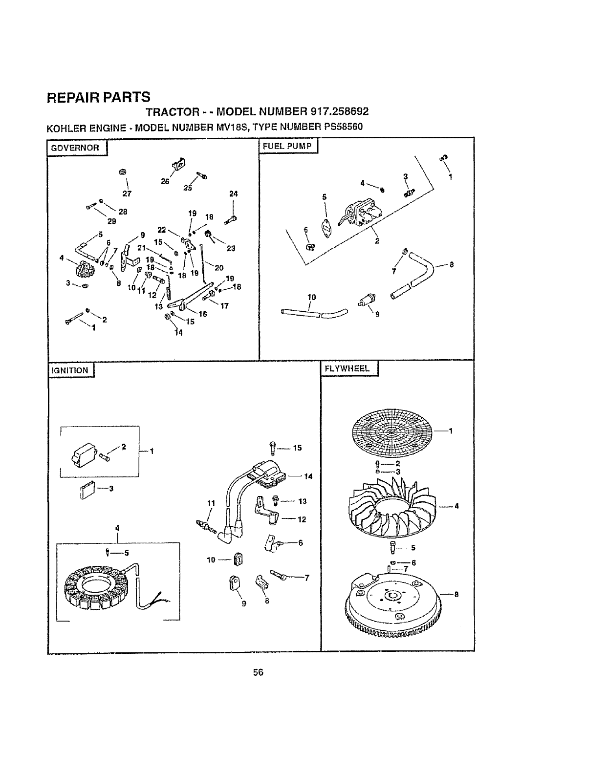
REPAIR PARTS
TRACTOR .-- MODEL NUMBER 917.258692
KOHLER ENGINE -MODEL NUMBER MV18S, TYPE NUMBER PS58560
GOVERNOR I
1 26 2(_
27 24
1
4
I
:UEL PUMP
\
I_--!5
14
FLYWHEEL I
I
18
56
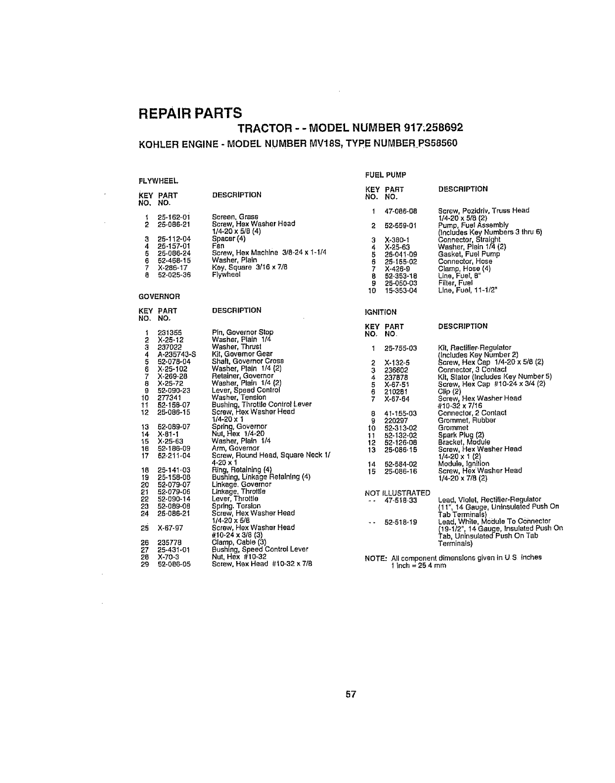
REPAIR PARTS
TRACTOR - -MODEL NUMBER 917.258692
KOHLER ENGINE- MODEL NUMBER MV18S_ TYPE NUMBER PS58560
FLYWHEEL FUEL PUMP
KEY PART DESCRIPTION
KEY' PART DESCRIPTION NO. NO.
NO. NO.
125.152..0"_ Screen, Grass t47-086-08
2 25-086-21 Screw, HexWasher Head 2 52-559-01
1/4-20 x 5/B (4)
3 25_112-04 Spacer (4) 3Xo,380-t
425,.157-01 Fan 4 X-25-63
5 25-086.24 Screw, He×Machine ,3/8-24 x 1-1/4 525-04l.,09
6 52-468-15 Washer, Plain 6 25-t55-02
7X-286-17 Key, Square 3116 x7/'8
B 52-025-36 Flywheel 7 X-426-9
652.,353-18
925-050403
GOVERNOR 10 15_353-04
KEY PART DESCRIPTION IGNITION
NO. NOB
KEY PART
t 231355 Pin, Governor Stop NOt NO,
2X.26.12 Washer, P_a?n1/'4
3237022 Washer, Thrusl 1 25-755-03
4 A-235743-S Kit, Governor Gear
552-078_04 Shaft, GovernorCross 2 X-'{32-5
5 X,.25-102 Washer, Plain 1/4 (2)
7X-269._28 Retainer, Governor 3236602
4 237878
8 X-25-72 Washer, Plain 1/'4(2 5 >(.67.51
g52-090-23 Lever Speed Control 6 210251
10 277341 Washer, Tens on
11 52-158-07 Bushtng, ThfetLte ControlLever 7X-67-64
12 25.086-15 Screw, Hex WasherHead 841-155-03
1/'4-20x 1 9 220297
13 52-089-07 Spring, Governor t0 52-313-02
!4 X-81-I Nul, Hax 1/4-20
15 X.25-63 Washer, Plain 1t4 1! 52-1,32-02
12 52-126-06
18 52*186-09 Arm, Governor 13 25-056-15
17 52-211.04 Screw, Round Head, Square Neck 11
4-20 x 1
18 25-141-03 Ring, Retaining (4) 14 52-584-02
19 25-158-08 Bushing, Linkage Ralalntng(4) 15 25.086.16
20 52-079-07 Linkage, Governor
21 22-079-06 Linkage,Throtlle NOT ILLUSTRATED
22 52-590-14 Lever, Throttle -- 47..518.33
2`3 52-089-08 Spring. Torsion
24 25-086-21 Screw, Hex Washer Head
tt4_20x 2/8 --52.,5t8-19
25 X-67-g7 Screw, HexWasher Head
_10.24 x 3/5 (3)
20 2`35778 Clamp, Cable (3)
27 25-431-01 Bushing, Speed ControtLever
28 X-70-3 ,NUt,Hex #10.32
29 52-056-05 Screw, Hex Head #10-32x7/8
Screw, Poztdrlv, Truss Head
t/4-20 x 5/8 (2)
Pump, Fuel Assembly
0neludes Key Numbers ,3thru 5)
Connector, Straight
Washer, Plain I/4 (2)
Gasket, Fuel Pump
Connector, Hose
Clamp, Hose (4)
Line, Fuel, 8"
Filter, Fuet
Line, Fuel, 11-1/2"
DESCRIPTION
KtL Rec_Jfier-.Reguletor
(Includes Key Number 2)
Screw, Hex Cap 1/'4-20x5/8 (2)
Connector, .3Conlac!
Kff, Starer (IncludesKey Number 5)
Screw, Hex Cap #10-24 x 3/4 _2}
C_rPe(w2!Hex Washer Head
#10-32 x 7/I6
Connector, 2 Contact
Grommet, Rubber
Grommet
Spark P(ug (2}
Bracket, Module
Screw, Hex Washer Head
114-2ox I (2}
Module, Ignition
Screw, Hex Washer Head
t/4-20 x 7/8 (2)
Lead, VtoleL Rectifier-Regulator
(I I", t4 Gauge, UntnauIateo' PushOn
Tab Terminals)
Lead, White, Modute To C,hhnector
_19-I/2", 14 GauF/e,Insulated PushOn
ab, Unlnsulated-Push On Tab
Termlnais)
NOTE: AII component dimensions given fn U.S inches
f inch = 25 4 mm
57
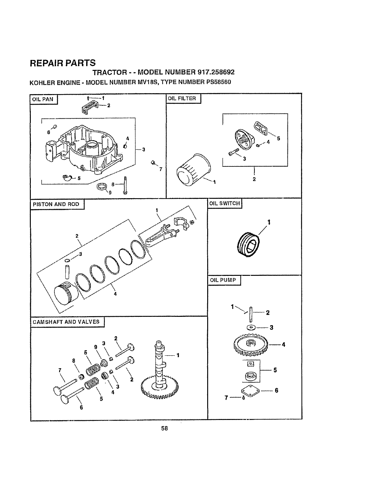
REPAIR PARTS
TRACTOR - -MODEL NUMBER 917.258692
KOHLER ENGINE - MODEL NUMBER MVIBS, TYPE NUMBER PS58560
OIL FILTER j
7
L, ,l,,,I
CAMSHAFT AND VALVES t
9
5
8 \
6
2
4
5
J
J
2
OIL SWITCH i
'1
OIL PUMP J
7_ -6
58
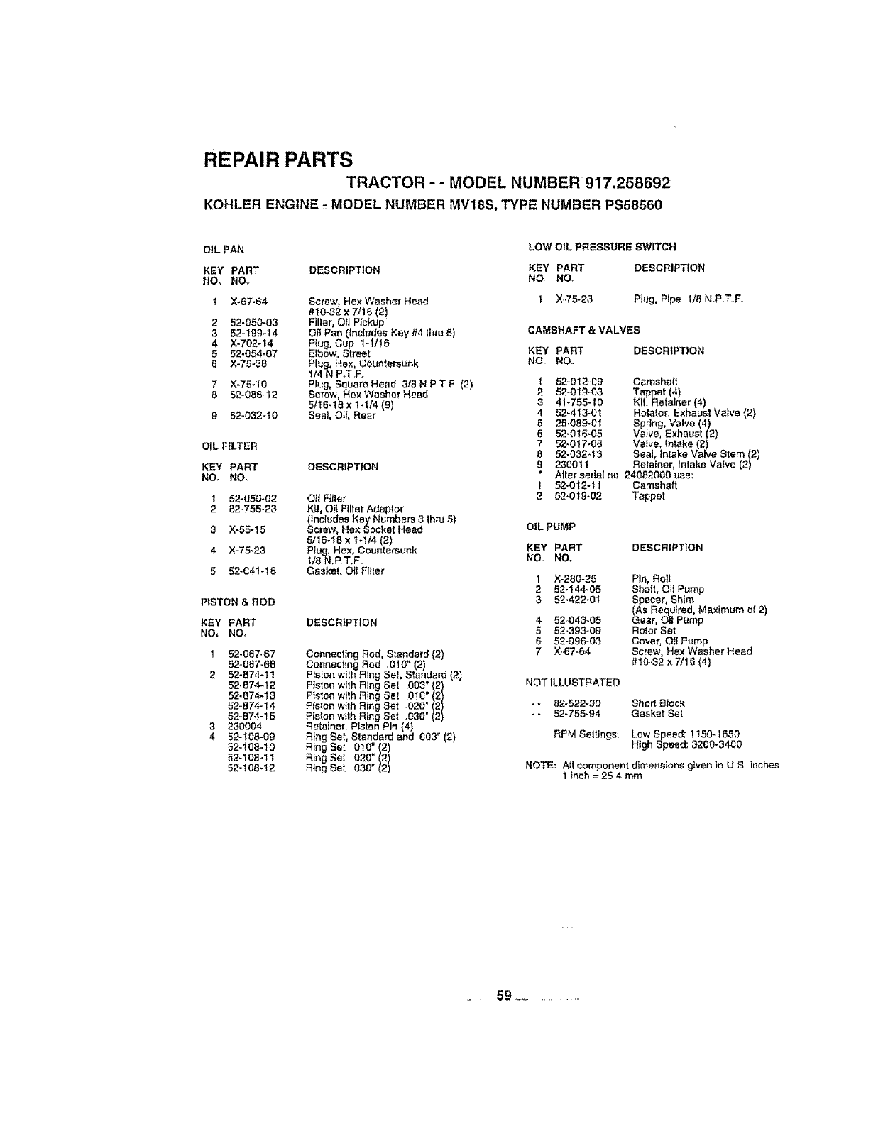
REPAIR PARTS
TRACTOR - - MODEL NUMBER 917.258692
KOHLER ENGINE .- MODEL NUMBER MV18S, TYPE NUMBER PS58560
OiL PAN LOW OIL PRESSURE SWITCH
KEY PART DESCRIPTION KEY PART DESCRIPTION
NO. NO_ NO NO_
! X-67-,54 Screw, Hax Washer Head 1 X.75-23 Plug, Pipe I/8 N_P T..F.
#10=32 x7/16 (2)
252-050-03 Filler O_!Pickup
3 52-199-14 Otf Par, (includes Key #4 thru `5) CAMSHAFT & VALVES
4 X-702-14 PIug, Cup 1-t/!6
552-054_07 Elbow, Street KEY PART DESCRIPTION
6X-75-38 Plug, Hex, Countersunk NO. NO.
t/4N.P.T .F.
7 ×-75-10 Plug, Square Head 318 N P T F(2) i 52-012-09 Camshaft
852-08,5-12 Screw, HexWasher Head 2 52-Ot9-03 Tappet (4)
5/16-18 x 1-t/4 (9) 3 41-755-10 Kit Retainer (4)
9 52-032-10 Seal, Oil, Rear 4 52-413-0"{ RolaIor, Exhaust Va ve (2)
5 25-089-01 Sprlng, Valve (4)
6 52-016-05 Valve, Exhaust(2)
752-0t7-0B Vatve, {nlake (2)
OIL FILTER 8 52-032q3 Seal, Intake Valve Stem (2)
KEY PART DESCRIPTION g 2300tl Retainer, Intake Valve (2)
*After serial no. 240`52000 use:
NO. NO. !524012-11 Camshaft
152-050-02 OilFitter 2,52-019-02 Tappet
2 82-755-23 Ktl, OIt Filter Adaptor
(includes Kay Numbers 3thnJ.5)
3X-55-15 Screw, Hex Socket Head OIL PUMP
5/16-18 x 1ol/4 (2)
4X-75_23 P!ug, Hex, Countersunk KEY PART DESCRIPTION
!/,SN,P T.F.. NO NO.
5 52-04t-16 Gasket, Oil Filter 1 X-280-25 Pin, Roll
252-144-05 Shaft, OltPump
PISTON & ROD 3 52-422-0I Spacer, Shim
(As Required, Maximum el 2)
KEY PART DESCRIPTION 4 52.043-05 Gear, Oil Pump
NO, NO. 5 52..393-09 RotorSet
652-006-03 Cover, Oil Pump
152,067..67 Connecting Rod, Standard (2) 7 X..67-,54 Screw, Hex Washer Head
52-057-65 Conneeling Rod ,010" (2) #10..32 x7/t6 (4}
2 52-,574,11 Piston withRing Set, Standard (2)
52-874-12 Piston with Ring Sat 003" (2) NOT ILLUSTRATED
52,.,574,13 Piston withRing Sat 010" (2)
52-,574,l 4 Piston with Ring Sat 020' (2) - - 82-522-30 Short Block
52-,574-15 P{st0n with Ring Set ,030' (2) - - 52-755-94 Gasket Set
3230004 Re{airier. Pislon Pin (4)
452-108-09 Ring Set, Standard and 003_ 2) RPM Seitings: Low Speed; !150-1650
52-108-10 RUngSet 010" (2) High Speed: 3200-3400
52-108-11 Ring Sat 020" (2)
52-108-12 Ring Set 030" (2) NOTE: A{f component dimensions given in U S inches
1 Inch = 2`54 mm
.59 .............

SERVICE NOTES
i,it _i ,, J,H,HH HI'
6O

,Jii ii
SERVICE NOTES
6t

iii ,lllllll i, ,,i F .......i'
SERVICE NOTES
62
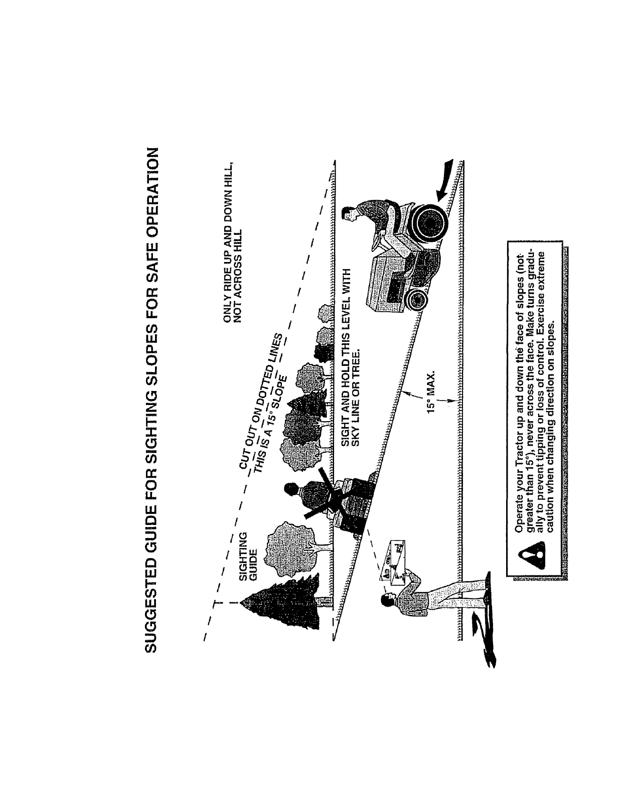
I./J
o _
t_
OWNER'S
MANUAL
MODEL NO.
917.258692
IF YOU NEED
REPAIR SERVICE
OR PARTS:
FOR REPAIR SERVICE, CALL
THIS TOLL FREE NUMBER:
1-800-4-REPAIR
(1-800-473-7247)
FOR REPLACEMENT PARTS
INFORMAT|ON AND
ORDERING," CALL THiS
TOLL FREE NUMBER:
1-800-FON-PART
(1-800-366-7279)
FOR CONSUMER ASSISTANCE
HOT LINE, CALL THtS
TOLL FREE NUMBER:
1-800-659-5917
[RRFTSMRN®
18.0 HP
ELECTRIC START
46" MOWER
AUTOMATIC (HYDROSTATIC)
LAWN TRACTOR
Each tractor has its own model number Each engine has
ils own model number_
The model number for your tractor will be found on the
model plate located under the seat,
The model number for your engine wil! be found on the
blower housing of the engine.,
All parts listed herein may be ordered from any Sears,
Roebuck and Co Service Center/Department and most Re-
tail Stores
WHEN ORDERING REPAIR PARTS, ALWAYS GIVE THE
FOLLOWING INFORMATION:
• PRODUCT- TRACTOR
•MODEL NUMBER - 917.258692
,, ENGINE MODEL NO. - MV18S -PS58560
• PART NUMBER
• PART DESCRIPTION
Your Sears merchandise has added value when you
consider Sears has service units nationwide staffed with
Sears trained technicians,,°, professional technicians
specifically trained to insure that we meet our p{edge to
you, we service whet we sell.
161000 6.2..97 JH Printed in US..A.
iiiiiiiiiiiiiiiiiinni,n ni i ii i, I
IIIIIIIIIIIIIIIIIIIIIIIIIIIIIIIIIIII1'I
I
