Craftsman 917259566 User Manual TRACTOR Manuals And Guides L9080012
CRAFTSMAN Lawn, Tractor Manual L9080012 CRAFTSMAN Lawn, Tractor Owner's Manual, CRAFTSMAN Lawn, Tractor installation guides
User Manual: Craftsman 917259566 917259566 CRAFTSMAN TRACTOR - Manuals and Guides View the owners manual for your CRAFTSMAN TRACTOR #917259566. Home:Lawn & Garden Parts:Craftsman Parts:Craftsman TRACTOR Manual
Open the PDF directly: View PDF ![]() .
.
Page Count: 56
SEARS
I: aFTSHaN°
MODEL NU;_BER 917.259566 OWNER'S MANUAL
• Assembly
• Operation
• Customer Responsibilities
• Service and Adjustments
•Repair Parts
For answers to your questions
about this product, Call:.
1-800-659-5917
SearsCraftsman Help Line
5 am- 5 pm, Mon- Sat
CAUTION: Read and follow all safety rules and instructions before operating this equipment.
FOR CONSUMER ASSISTANCE HOT LINE, CALL THIS TOLL FREE NUMBER: 1-800-659-5917
SAFETY RULES A
Safe Operation Practices for Ride-On Mowers u
IMPORTANT: THIS CUTTING MACHINE IS CAPABLE OF AMPUTATING HANDS AND FEET AND THROWING OBJECTS.
FAILURE TO OBSERVE THE FOLLOWING SAFETY INSTRUCTIONS COULD RESULT iN SERIOUS INJURY OR DEATH.
I. GENERAL OPERATION
•Read, undemtand,and followell instructionsinthe manual
and onthe machinebeforestarting.
•Only allow responsibleadults, who ere familiar with the
instructions,to operatethe machine.
• Clear the area of obects such as rocks,toys,wire, etc.,
wh c_ cou d be pickedup andthrownby the blade.
•Be surethe area isclearofotherpeoplebeforemowing.Stop
machineif anyone entersthe area.
•Nevel"carrypassengers.
•Do notmowinreverseunlessabsolutelynecessary.Always
look downand behind beforeand while backing.
•Be aware of the mowerdischargedirectionanddo notpoint
it at anyone. Do notoperatethe mowerwithouteitherthe
entiregrasscatcherorthe guardin place.
•Slowdown before turning.
•Never leave a runningmachineunattended.Alwaystum off
blades, set parking brake, stop engine, and remove keys
before dismounting.
•Turnoff bladeswhen notmowing.
•Stop engine before removing grasscatcheror unclogging
chute.
•Mow only indaylightor goodartificiallight.
• Do not operate the machine while underthe influenceof
alcoholordrugs.
•Watchfortrafficwhenoperatingnearorcrossingroedways.
•Use extra care when loadingor unloadingthe machineinto
e traileror truck.
II. SLOPE OPERATION
Slopes are amajor factor related to loss-of-control and
tipover accidents, which can result in severe injury or
death. All slopes require extra caution. If you cannot back
up the slope or if you feel uneasy on it, do not mow it.
DO:
•Mow up and downslopes,notacross.
•Removeobstaclessuchas recks,tree limbs,etc.
•Watch for holes, ruts, or bumps. Uneven terrain could
overfumthe machine. Tall grasscan hide obstacles.
•Use slowspeed. Choosea lowgearsothatyouwill nothave
to stopor shiftwhileon the slope.
•Follow the manufacturer's recommendationsfor wheel
weightsorcounterweightsto improvestability.
•Use extra care with grass catchersor other attachments.
These can change the stabilityof the machine.
•Keepallmovementonthe slopesslowandgradual. Do not
make suddenchangesin speed ordirection.
•Avoidstartingor stoppingon a slope. If tireslosetraction,
disengagethe bladesandproceedslowlystraightdownthe
slope.
DO NOT:
• Donottumonslopesunlessnecessary,andthen,tumslowly
and graduallydownhill,if possible.
•Do notmow near drop-offs,ditches,or embankments.The
mowercouldsuddenlyturnover if awheel isoverthe edge
of acliffor ditch,or if an edgecaves in.
• Do not mow on wet grass. Reducedtractioncouldcause
sliding.
• Donottrytostabilizethemachinebyputtingyourfootonthe
ground.
•Do notuse grasscatcher onsteep slopes.
III. CHILDREN
Tragic accidents can occur if the operator is not alertto the
presence of children. Children are often attracted to the
machine and the mowing activity. Never assume that
children will remain where you last saw them.
•Keepchildrenoutofthe mowingarea andunderthewatchful
care of anotherresponsibleadult.
Be alertand turnmachineoft if childrenenterthe area.
•Beforeand when backing,lookbehindand downfor small
children.
•Never carry children. They may fall off and be seriously
injuredor interferewithsafe machineoperation.
•Neverallowchildrento operatethe machine.
•Use extra care when approachingblind comers, shrubs,
trees,orotherobjectsthat may obscurevision.
IV. SERVICE
•Useextracare inhandlinggasolineandotherfuels.Theyare
flammableandvaporsare explosive.
Use onlyan approvedcontainer.
Never remove gas cap or add fuel with the engine
running. Allowengineto cool beforerefueling. Do not
smoke,
Neverrefuelthe machineindoors.
Neverstorethe machineor fuelcontainerinsidewhere
there isan openflame, suchas.a water heater.
•Never run a machineinsidea closedarea.
•Keepnutsand belts,especiallybladeattachmentboltstight
andkeep equipmentin goodcondition.
•Never tamper with safety devices. Check their proper
operationragulady.
•Keepmachinefree ofgrass,leaves,orotherdebrisbuild-up.
Clean oil or fuel spillage. Allow machine to cool before
storing.
•Stop and inspect the equipment if you strike an object.
Repair,if necessary,before restarting.
•Nevermakeadjustmentsor repairswiththeenginerunning.
•Grasscatchercompenantsera subjecttowear,damage,and
deterioration,which could expose movingparts or allow
objectsto be thrown, Frequentlycheck componentsand
replacewithmanufacturer'srecommendedparts,when nec-
essary.
•Mowerbladesare sharpandcan cut. Wrap the blade(s)or
wear gloves,anduse extra cautionwhen servicingthem.
•Check brake operationfrequently. Adjustand serviceas
required.
Look for this symbol to point out important
safety precautions. It means
CAUTION!II BECOME ALERTIn YOUR
SAFETY IS INVOLVED.
CAUTION: Always disconnect spark plug
wire endplace wire where It cannot contact
spark plug In order to prevent accidental
starting when setting up, transporting,
adjusting or making repairs.
AWARNING A
The engine exhaust from this product contains
chemicals known to the State of California to
cause cancer, birth defects, or other reproduc-
tive harm.
2
CONGRATULATIONS on your purchase of a Sears
Tractor. It has been designed, engineeredand manufac-
tured to give you the best possible dependability and
performance.
Should you experience any problem you cannot easily
remedy, please contact your nearest Sears Authorized
Service Center/Department. We have competent, well-
trainedtechniciansandthe propertoolsto serviceor repair
this tractor.
Please read and retain this manual. The instructionswill
enable youto assembleand maintainyourtractorproperly.
Alwaysobserve the "SAFETY RULES".
MODEL
NUMBER 917.259566
SERIAL
NUMBER
DATEOFPURCHASE
THEMODELANOSERIALNUMBERSWILLBEFOUND
ON A PLATE UNDER THE SEAT.
YOU SHOULD RECORD BOTH SERIAL NUMBER AND
!DATE OF PURCHASE AND KEEP IN A SAFE PLACE
I FOR FUTURE REFERENCE.
MAINTENANCE AGREEMENT
A Sears Maintenance Agreement is available on this prod-
uct. Contact your nearest Sears store for details.
CUSTOMER RESPONSIBILITIES
Read and observe the safety rules.
Follow a regular schedule inmaintaining, caring forand
using your tractor.
• Follow the instructions under "Customer Responsibili-
ties" and =Storage" sections of this owner's manual.
WARNING: This tractor is equipped with an internal
combustion engine and should not be used on or near any
unimproved forest-covered, brush-covered or grass-cov-
ered land unless the engine's exhaust system is equipped
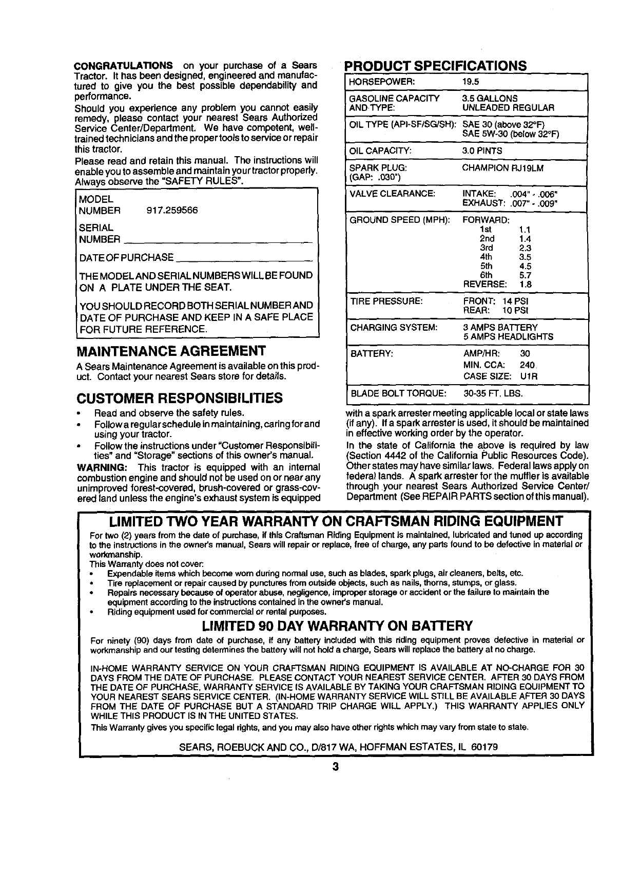
PRODUCT SPECIFICATIONS
HORSEPOWER: 19.5
GASOLINE CAPACITY 3.5 GALLONS
ANDTYPE: UNLEADED REGULAR
OIL TYPE (API-SF/SG/SH): SAE 30 (above32°1=)
SAE 5Wo30 (below 32°F)
OIL CAPACITY: 3.0 PINTS
ISPARK PLUG: CHAMPION RJ19LM
GAP: .030")
VALVE CLEARANCE: INTAKE: .004" ÷.006"
EXHAUST: .007" -.009"
GROUND SPEED (MPH): FORWARD:
1st 1.1
2nd 1.4
3rd 2.3
4th 3.5
5th 4.5
6th 5.7
REVERSE: 1.8
TIRE PRESSURE: FRONT: 14 PSI
REAR: 10 PSI
CHARGING SYSTEM: 3 AMPS BATTERY
5 AMPS HEADLIGHTS
BATTERY: AMPiHR: 30
MIN. CCA: 240
CASE SIZE: UtR
BLADE BOLT TORQUE: 30-35 FT. LBS.
witha sparkarrastermeeting applicablelocalorstate laws
(if any). If a sparkarrester is used, it shouldbe maintained
in effectiveworkingorder by the operator.
In the state of California the above is required by law
(Section 4442 of the California Public ResourcesCode).
Other statesmay have similarlaws. Federal lawsapplyon
federal lands. A sparkattester for the muffler is available
through your nearest Sears Authorized Service Center/
Department (See REPAIR PARTS sectionofthismanual).
LIMITED TWO YEAR WARRANTY ON CRAFTSMAN RIDING EQUIPMENT
For two (2) years fromthe date of purchase, if thisCraftsman Riding Equipmentis maintained,lubricatedand tuned up according
to the instructionsin the owner's manual, Seam willrepairor replace, free of charge, any parts found to be defective in material or
workmanship.
This Warranty does not cover:
Expendable items which become worn duringnormal use, such as blades,spark plugs,air cleaners, belts, etc.
Tire replacementor repaircaused by puncturesfromoutsideobjects,such as nails,thorns,stumps, or glass.
Repairs necessarybecause of operatorabuse, negligence,improperstorage oraccident orthe failure to maintain the
equipment accordingto the instructionscontainedinthe owner'smanual.
Ridingequipment used for commercialor rentalpurposes.
LIMITED 90 DAY WARRANTY ON BATTERY
For ninety (90) days from date of purchase, if any battery includedwith this riding equipment proves defective in material or
workmanshipand our testingdetermines the batterywill not hold a charge, Sears will replace the battery at no charge.
IN-HOME WARRANTY SERVICE ON YOUR CRAFTSMAN RIDING EQUIPMENT IS AVAILABLE AT NO-CHARGE FOR 30
DAYS FROM THE DATE OF PURCHASE. PLEASE CONTACT YOUR NEAREST SERVICE CENTER. AFTER 30 DAYS FROM
THE DATE OF PURCHASE, WARRANTY SERVICE IS AVAILABLEBY TAKING YOUR CRAFTSMAN RIDING EQUIPMENT TO
YOUR NEAREST SEARS SERVICE CENTER. (IN-HOME WARRANTY SERVICE WILL STILL BE AVAILABLEAFTER 30 DAYS
FROM THE DATE OF PURCHASE BUT A STANDARD TRIP CHARGE WILL APPLY.) THIS WARRANTY APPLIES ONLY
WHILE THIS PRODUCT IS IN THE UNITED STATES.
This Warranty gives you specificlegal rights,and you may alsohave otherrightswhich may vary from state to state.
SEARS, ROEBUCK AND CO., D/817 WA, HOFFMAN ESTATES, IL 60179
3
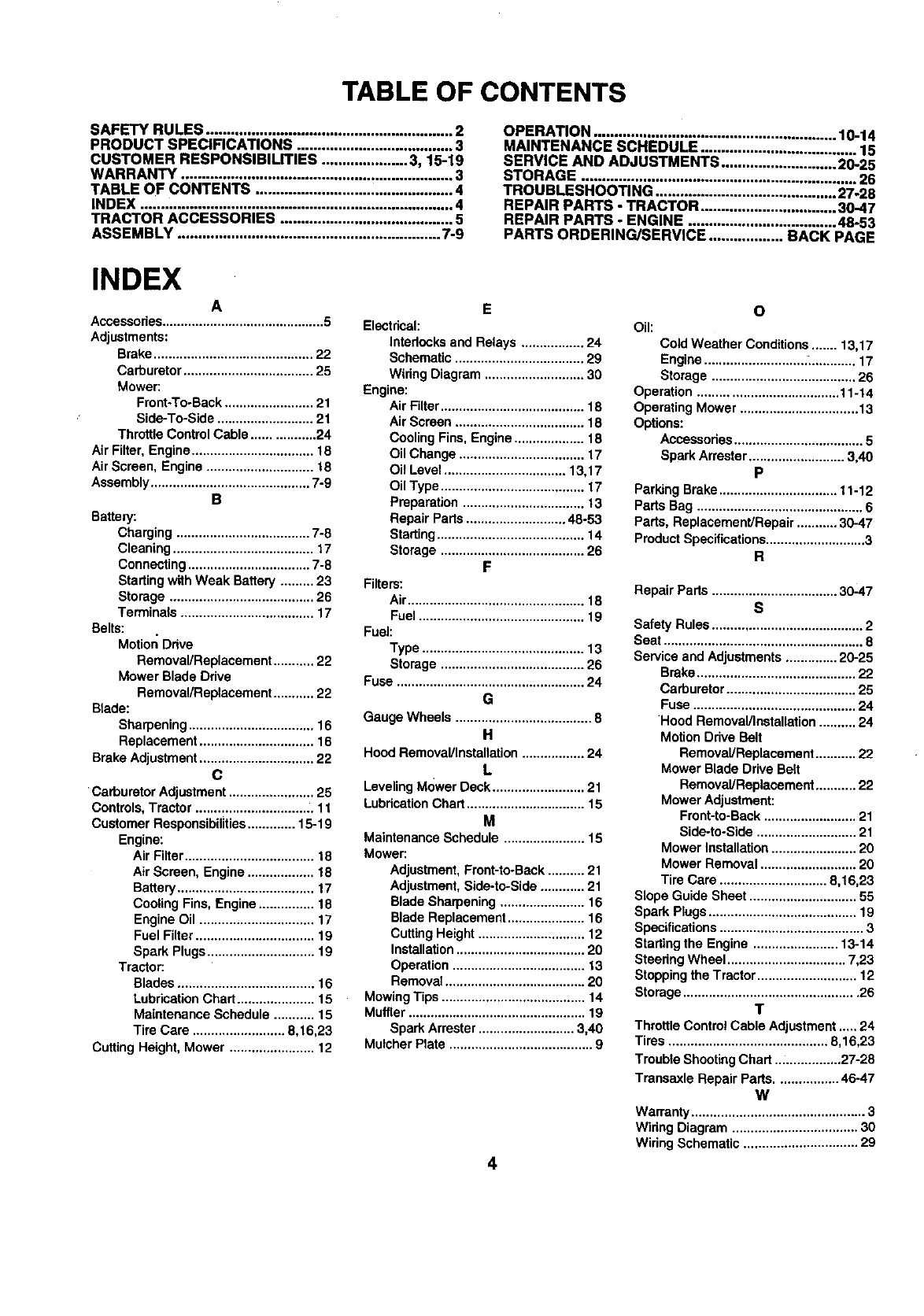
TABLE OF CONTENTS
SAFETY RULES ............................................................ 2
PRODUCT SPECIFICATIONS ...................................... 3
CUSTOMER RESPONSIBILITIES ..................... 3, 15-19
WARRANTY .................................................................. 3
TABLE OF CONTENTS ................................................ 4
INDEX ............................................................................ 4
TRACTOR ACCESSORIES .......................................... 5
ASSEMBLY ................................................................ 7-9
OPERATION ........................................................ 10-14
MAINTENANCE SCHEDULE ...................................... 15
SERVICE AND ADJUSTMENTS ............................ 2025
STORAGE ................................................................... 26
TROUBLESHOOTING ............................................ 27-28
REPAIR PARTS -TRACTOR ................................. 30-47
REPAIR PARTS -ENGINE .................................... 48-53
PARTS ORDERING/SERVICE .................. BACK PAGE
INDEX
A
Accessories............................................ 5
Adjustments:
Brake........................................... 22
Carburetor ................................... 25
Mower:
Front-To-Back........................ 21
Side-To-Side .......................... 21
Throttle ControlCable ................. 24
Air Filter, Engine ................................. 18
AirScreen, Engine ............................. 18
Assembly........................................... 7-9
B
Battery:
Charging .................................... 7-8
Cleaning ...................................... 17
Connecting................................. 7-8
Startingwith Weak Battery ......... 23
Storage ....................................... 26
Terminals .................................... 17
Belts:
Motion Drive
Removal/Replacement ........... 22
Mower Blade Ddve
Removal/Replacement........... 22
Blade:
Sharpening.................................. 16
Replacement ............................... 16
Brake Adjustment............................... 22
C
Carburetor Adjustment....................... 25
Controls,Tractor ................................ 11
Customer Responsibilities............. 15-19
Engine:
Air Filter................................... 18
Air Screen, Engine .................. 18
Battery ..................................... 17
Cooling Fins, Engine ............... 18
Engine Oil ............................... 17
Fuel Filter................................ 19
Spark Plugs............................. 19
Tractor:
Blades ..................................... 16
LubricationChart..................... 15
Maintenance Schedule ........... 15
Tire Care ......................... 8,16,23
Cutting Height, Mower ....................... 12
E
Electrical:
Intedocksand Relays ................. 24
Schematic ................................... 29
WiringDiagram ........................... 30
Engine:
Air Filter....................................... 18
Air Screen ................................... 18
Cooling Fins, Engine ................... 18
Oil Change .................................. 17
Oit Level ................................. 13,17
Oil Type ....................................... 17
Preparation ................................. 13
Repair Parts........................... 48-53
Starting........................................ 14
Storage ....................................... 26
F
Filters:
Air................................................ 18
Fuel ............................................. 19
Fuel:
Type ............................................ 13
Storage ....................................... 26
Fuse ................................................... 24
G
Gauge Wheels ..................................... 8
H
Hood Removal/Installation................. 24
L
LevelingM<)werDeck ......................... 21
LubdcationChart ................................ 15
M
Maintenance Schedule ...................... 15
Mower:
Adjustment,Front-to-Back.......... 21
Adjustment,Side-to-Side ............ 21
Blade Sharpening ....................... 16
Blade Replacement..................... 16
CuttingHeight ............................. 12
Installation................................... 20
Operation .................................... 13
Removal ...................................... 20
MowingTips ....................................... 14
Muffler ................................................ 19
Spark Arrester.......................... 3,40
Mulcher Plate ....................................... 9
4
O
Oil:
Cold Weather Conditions....... 13,17
Engine........................... :_............ 17
Storage ....................................... 26
Operation ...................................... 11-14
Operating Mower ................................ 13
Options:
Accessodes................................... 5
Spark Arrester.......................... 3,40
P
Parking Brake................................ 11-12
Parts Bag ............................................. 6
Pads, Replacement/Repair ........... 30-47
ProductSpecifications........................... 3
R
Repair Parts .................................. 30-47
s
Safety Rules......................................... 2
Seat ...................................................... 8
Service and Adjustments.............. 20-25
Brake........................................... 22
Carburetor................................... 25
Fuse ............................................ 24
Hood Removal/Installation.......... 24
MotionDrive Belt
Removal/Replacement........... 22
Mower BladeDrive Belt
Removal/Replacement........... 22
Mower Adjustment:
Frent-to-Back ......................... 21
Side-to-Side ........................... 21
Mower Installation....................... 20
Mower Removal .......................... 20
Tire Care ............................. 8,16,23
Slope Guide Sheet ............................. 55
Spark Plugs........................................ 19
Specifications....................................... 3
Startingthe Engine ....................... 13-14
Steedng Wheel ................................ 7,23
Stopping theTractor ........................... 12
Storage............................................... 26
T
ThrottleControl Cable Adjustment..... 24
Tires ........................................... 8,16,23
Trouble ShootingChart .................. 27-28
Transaxle Repair Parts................. 46-47
W
Warranty ............................................... 3
Widng Diagram .................................. 30
Wiring Schematic ............................... 29
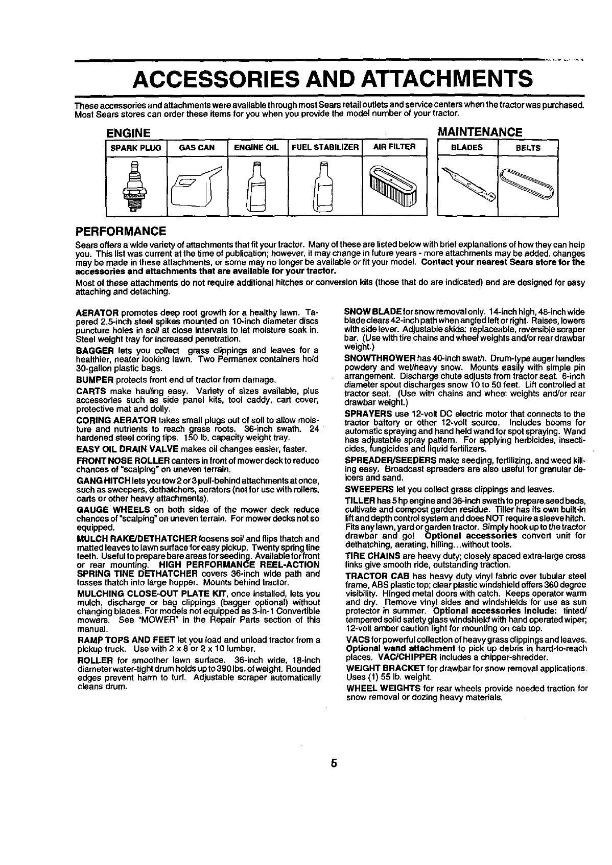
ACCESSORIES AND ATTACHMENTS
These accessories and attachmentswere available throughmostSears retailoutletsandservicecenterswhen thetractorwaspurchased.
Most Sears stores can order these items for you when youprovide the model number of your tractor,
ENGINE
SPARKPLUG GASCAN ENGINEOIL FUELSTABILIZER AIRFILTER
%
MAINTENANCE
BLADES BELTS
PERFORMANCE
Sears offersa wide varietyof attachmentsthatfit yourtractor. Many ofthese are listedbelowwithbriefexplanationsof howthey can help
you. This listwas current st the time of publication;however,itmay change infuture years- more attachments may be added, changes
may be made in these attachments, orsome may no longer be available orfit your model. Contact your nearest Sears store for the
accessories and attachments that are available for your tractor.
Most of these attachments do not requireadditional hitchesorconversion kits(thosethat do are indicated) and are designedfor easy
attaching and detaching.
AERATOR promotes deep root growth for a healthy lawn, Ta-
pered 2.5-inch steel spikes mountedon 10-inch diameter discs
puncture holes in soil at close intervalsto let moisture soak in.
Steel weight trey for increased penetration.
BAGGER lets you collect grass clippings and leaves for a
healthier, nearer looking lawn. Two Permanex containers hold
30-gallon plastic bags.
BUMPER protects front end of tractor from damage.
CARTS make hauling easy. Variety of sizes available, plus
accessories such as side panel kits, tool caddy, cart cover,
protective mat and dolly.
CORING AERATOR takes small plugsout of soil to allowmois-
ture and nutrients to reach grass roots. 36-inch swath. 24
hardened steel coringtips. 150 lb. capacityweight tray.
EASY OIL DRAIN VALVE makes oilchanges easier, faster.
FRONT NOSE ROLLER canters infront of mowerdecktoreduce
chances of =scalping" on uneven terrain.
GANG HITCH letsyoutow2 or3 pull-behindattachmentsatonce,
such as sweepers, dethatchers, aerators (notfor usewithrollers,
carts or other heavy attachments).
GAUGE WHEELS on both sides of the mower deck reduce
chances of =scalping" on uneventerrain. Formowerdecks notso
equipped.
MULCH RAKE/DETHATCHER loosenssoil and flips thatchand
mattedleaves to lawn surfaceforeasy pickup. Twenty springtine
teeth. Usefultoprepare bareareasfor seeding. Availablefor front
or rear mounting. HIGH PERFORMANCE REEL-ACTION
SPRING TINE DETHATCHER covers 36-inch wide path and
tosses thatch into large hopper. Mounts behindtractor.
MULCHING CLOSE-OUT PLATE KIT, once installed, letsyou
mulch, discharge or bag clippings (bagger optional) without
changingblades. For modelsnot equipped as3-in-1 Convertible
mowers. See "MOWER in the Repair Parts section of this
manual.
RAMP TOPS AND FEET let you load and unload tractorfroma
pickuptruck. Use with 2 x 8 or 2 x 10 lumber.
ROLLER for smoother lawn surface. 36-inch wide, 18-inch
diameter water-tightdrumholdsupto 390 Ibs.of weight, Rounded
edges prevent harm to turf. Adjustable scraper automatically
cleans drum.
SNOW BLADE forsnowremovalonly. 14-inchhigh,48-inchwide
bladeclears42-inchpath whenangled leftorfight. Raises,lowers
withsidelever. Ad ustableskids; replaceable, reversiblescraper
bar. (Use witht re cha nsand wbeelwe ghts and/or reardrawbar
weight.)
SNOWTHROWER has40-inchswath. Drum-typeaugerhandles
powdery and wet/heavy snow. Mounts easily with simple pin
arrangement. Discharge chuteadjustsfrom tractorseat. 6-inch
diameter spoutdischargessnow 10 to 50 feet. Liffcontrolledat
tractor seat. (Use with chains and wheel weights and/or rear
drawbar weight.)
SPRAYERS use 12-voltDC electric motorthat connectsto the
tractor battery or other t2-voit source. Includes booms for
automaticsprayingand handheld wandfor spot spraying. Wand
has adjustable spray pattern. For applyingherbicides, insecti-
cides, fungicidesand liquidfertilizers.
SPREADER/SEEDERS make seeding, fertilizing, andweed kill-
ing easy. Broadcast spreaders are also useful for granularde-
icers and sand.
SWEEPERS letyou collectgrass clippingsand leaves.
TILLER has5 hpengineand36-inch swath toprepareseed beds,
cultivateand compostgarden residue. Tiller has its own built-in
liftanddepth controlsystem anddoes NOT require asleeve hitch.
Fitsanylawn, yardorgardentractor. Simplyhookuptothetractor
drawber and go! Optional accessories convert unit for
dethatching,aerating, hilling...withouttools.
TIRE CHAINS are heavy duty;closely Spacedextra-largecross
linksgivesmooth fide, outstandingtraction.
TRACTOR CAB has heavy duty vinylfabric over tubular steel
frame, ABS plastictop;clear plasticwindshieldoffers360 degree
visibility. Hinged metal doors withcatch. Keeps operatorwarm
and dry. Remove vinyl sides and windshieldsfor use as sun
protectorin summer. Optional accessories include: tinted/
temperedsolidsafetyglasswindshieldwithhand operatedwiper;
12-voltamber caution lightfor mounting on cabtop.
VACS for powerfulcollectionof heavygrassclippingsandleaves.
Optional wand attachment to pick up debris in hard-to-reach
places. VAC/CHIPPER includesa chipper-shredder.
WEIGHT BRACKET for drawbar for snow removal applications.
Uses (1) 55 Ib. weight.
WHEEL WEIGHTS for rear wheels provide needed tractionfor
snow removal or dozing heavy materials.
5
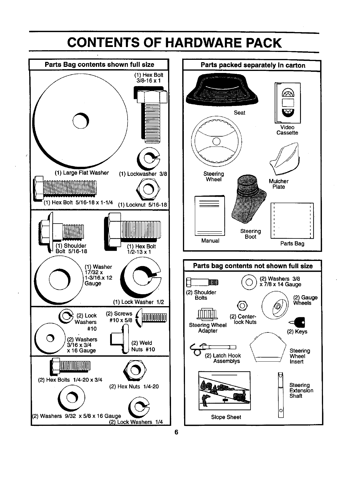
CONTENTS OF HARDWARE PACK
Parts Bag contents shown full size
(1) Hex Bolt
3/8-16 x 1
(1) Large Flat Washer (1) Lockwasher 3/8
1;:He':x:Bo;:t:5:i:16:::;:8x1-I/4(1)Locknut 5/16-18
(1) Shoulder (1) Hex Bolt
Bolt 5/16-18 1/2-13 x I
(1) Washer _.
17/32 x
1-3/16.x 12
Gauge (1) Lock Washer 1/2
__._ (2) (2) Screws
Lock
#10 x 5/8
Was%
|__J }(2) V_/ashers
_i= /3/16 x 3/4
x 16 Gauge
(2) Hex Bolts 1/4-20 x 3/4
@(2) Hex Nuts 1/4-20
(2) Washers 9/32 x 5/8 x16 Gauge
12)LockWashers 1/4
Parts packed separately in carton
Steering
Wheel
Manual
Seat
Steering
Boot
Video
Cassette
Mulcher
Plate
Parts Bag
Parts bag contents not shown full size
(2) Shoulder
Bolts
(_(2) Washers 3/8
x 7/8 x 14 Gauge
(2) Gauge
QWheels
_(2) Center-
Steering Wheel lockNuts
Adapter (2) Keys
k
Assemblys
Steering
Wheel
Insert
Slope Sheet
Steering
Extension
Shaft
6
ASSEMBLY
Your new tractor has been assembledat the factorywithexceptiono4those partsleft unassembledfor shippingpurposes.
To ensure safe and properoperationof yourtractorallpartsand hardwareyou assemble mustbe tightenedsecurely. Use
the correcttools as necessaryto insurepropertightness.
TOOLS REQUIRED FOR ASSEMBLY
A socketwrench set willmake assemblyeasier. Standard
wrench sizes are listed.
(1) 3/4" Socket w/drive rachet
(2) 7/16" wrenches PhillipsScrewdriver
(2) 1/2" wrenches Tire pressuregauge
(1) 9/16" wrench Utilityknife
When right or left hand is mentioned in this manual, it
means when you are in the operating position(seated
behind the steeringwheel).
TO REMOVE TRACTOR FROM CARTON
UNPACK CARTON
• Remove all accessible loose parts and partscartons
from carton (See page 6).
Cut, from topto bottom,along linesonall four corners
of carton,and lay panels flat.
Check for any additional loose parts or cartons and
remove.
BEFORE ROLLING TRACTOR OFF SKID
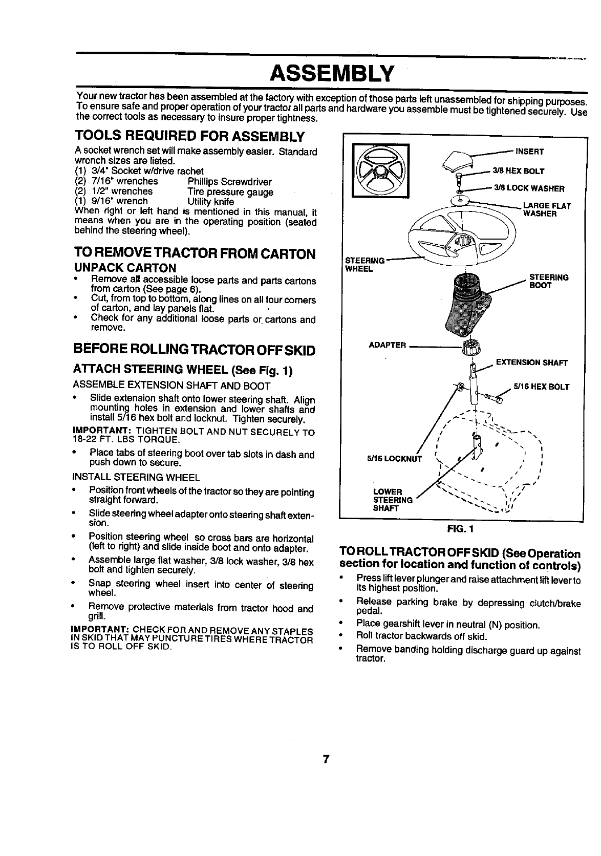
ATFACH STEERING WHEEL (See Fig. 1)
ASSEMBLE EXTENSION SHAFT AND BOOT
•Slide extension shaft onto lower steeringshaft. Align
mounting holes in extension and lower shafts and
install 5/16 hex bolt and Iocknut. Tighten securely,
IMPORTANT: TIGHTEN BOLT AND NUT SECURELY TO
18-22 FT, LBS TORQUE.
• Place tabs of steeringboot over tab slotsindash and
push down to secure.
INSTALL STEERING WHEEL
•Positionfront wheelsof the tractorso they are pointing
straightforward.
Slidesteeringwheeladapterontosteeringshaftexten-
sion.
•Positionsteering wheel so cross bars are horizontal
(left to right)and slide insideboot and onto adapter.
•Assemble large flat washer, 318lookwasher, 318hex
bolt and tightensecurely.
•Snap steering wheel insert into center of steering
wheel.
• Remove protective materials from tractor hood and
grill.
IMPORTANT: CHECK FOR AND REMOVE ANY STAPLES
INSKID THATMAYPUNCTURE TIRES WHERE TRACTOR
IS TO ROLL OFF SKID.
__3/8jE INSERT
X BOLT
LOCK WASHER
LARGE FLAT
WASHER
:STEERING'
WHEEL STEERING
ADAPTER_
EXTENSION SHAFT
5/16 HEX BOLT
5/16LOCKNUT
LOWER
STEERING
SHAFt"
FIG. 1
TO ROLLTRACTOR OFF SKID (See Operation
section for location and function of controls)
•Press liftleverplungerand raiseattachmentliftleverto
its highestposition.
• Release parking brake by depressing clutch/brake
pedal.
• Place gearshift lever in neutral (N) position,
Roll tractor backwards off skid.
• Remove banding holding discharge guard up against
tractor.
7
ASSEMBLY
HOW TO SET UP YOUR TRACTOR
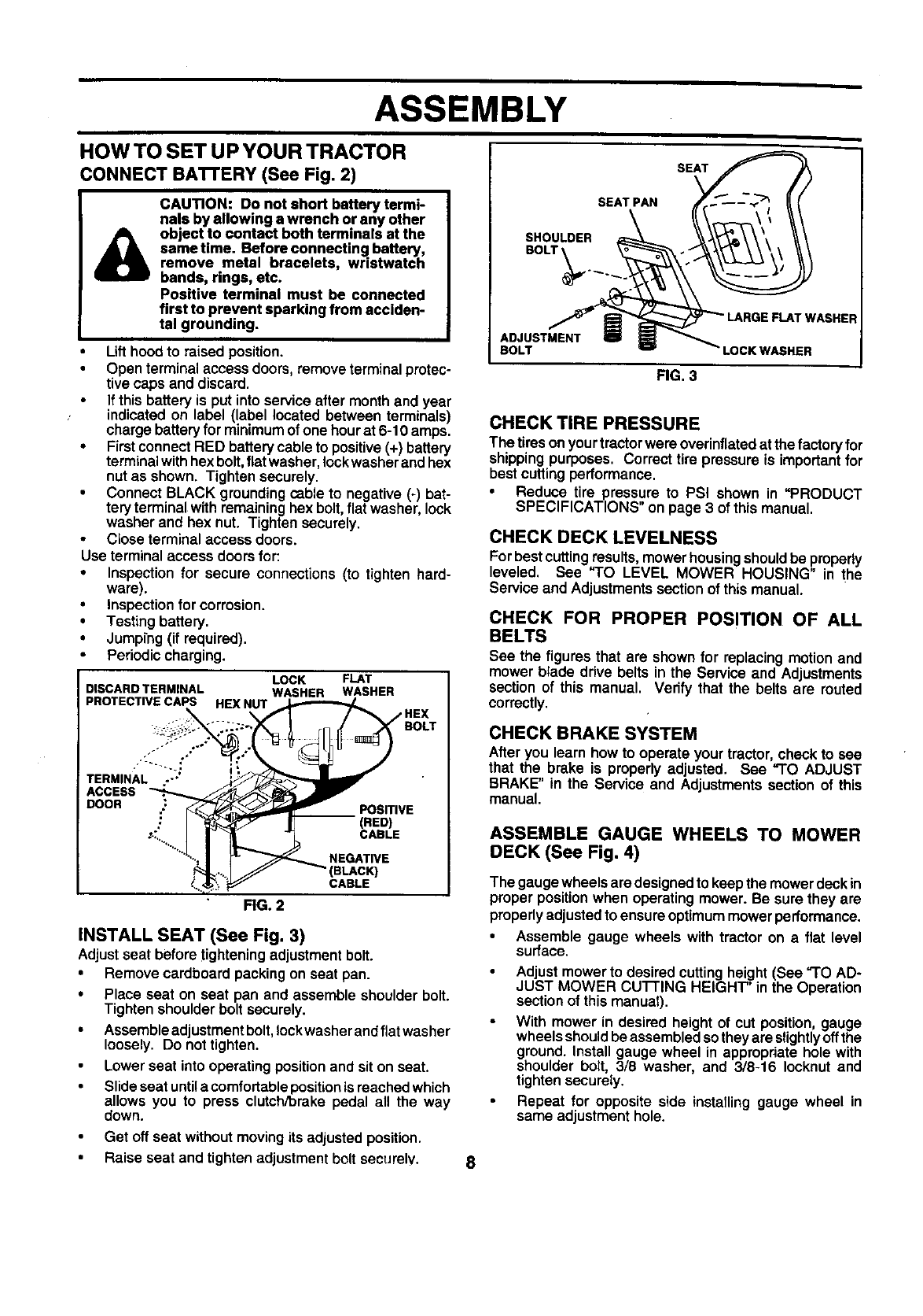
CONNECT BA'rrERY (See Fig. 2)
CAUTION: Do not short battery termi-
nals by allowing a wrench or any other
object to contact both terminals at the
same time. Before connecting battery
remove meta bracelets, wristwatch
bands, rings, etc.
Positive terminal must be connected
first to prevent sparking from acciden-
tal grounding.
Lifthoodto raised position.
Open terminalaccess doors, remove terminal protec-
tive caps and discard.
If this battery is put into service after month and year
indicated on label (label located between terminals)
charge battery for minimum of one hour at 6-10 amps.
•First connect RED battery cable to positive (+) battery
terminal with hex bolt, flat washer, lock washer and hex
nut as shown. Tighten securely.
Connect BLACK grounding cable to negative (-) bat-
tery terminal with remaining hex bolt, flat washer, lock
washer and hex nut. Tighten securely.
Close terminal access doors.
Use terminal access doors for:
• Inspection for secure connections (to tighten hard-
ware).
•Inspection for corrosion.
• Testing battery.
• Jumping (if required).
• Pedodic charging.
DISCARD TERMINAL
PROTECTIVE CAPS HEX NUT
ACCESS
DOOR
LOCK FLAT
WASHER WASHER
PosmvE
(RED)
CABLE
NEGATIVE
(BLAC_
CABLE
FIG. 2
INSTALL SEAT (See Fig. 3)
Adjustseat before tighteningadjustmentbolt.
•Remove cardboard packingon seat pan.
•Place seat on seat pan and assemble shoulderbolt.
Tighten shoulderbolt securely.
•Assembleedjustment bolt, lockwasher and flatwasher
loosely. Do not tighten.
Lower seat into operating position and sit on seat.
Slide seat until acomfortable position is reached which
allows you to press clutch/brake pedal all the way
down.
Get off seat without moving its adjusted position.
• Raise seat and tighten adjustment bolt securely.
SEAT
SEAT PAN
SHOULDER
BOLT
r WASHER
ADJUSTMENT
BOLT LOCK WASNER
FIG. 3
CHECK TIRE PRESSURE
The tiresonyourtractorwere overinflatedat the factoryfor
shippingpurposes. Correcttire pressure is importantfor
best cuttingperformance.
Reduce tire pressure to PSI shown in "PRODUCT
SPECIFICATIONS" on page 3 of this manual.
CHECK DECK LEVELNESS
For best cuttingresults,mowerhousingshouldbe propedy
leveled, See "TO LEVEL MOWER HOUSING" in the
Service and Adjustmentssection of this manual.
CHECK FOR PROPER POSITION OF ALL
BELTS
See the figures that are shown for replacingmotionand
mower blade ddve belts in the Service and Adjustments
section of this manual. Verify that the belts are routed
correctly.
CHECK BRAKE SYSTEM
Afteryou learn how to operate your tractor, check to see
that the brake is properlyadjusted. See "TO ADJUST
BRAKE" in the Service and Adjustmentssection of this
manual,
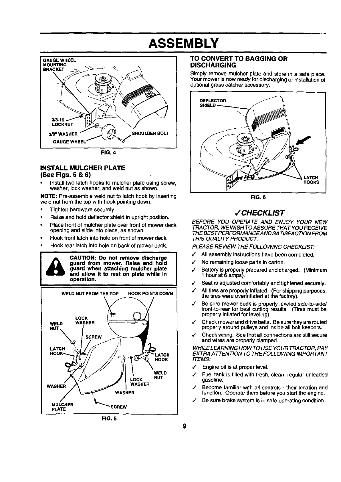
ASSEMBLE GAUGE WHEELS TO MOWER
DECK (See Fig. 4)
The gauge wheelsare designed to keep the mowerdeck in
proper positionwhen operatingmower. Be sure they are
properlyadjustedto ensure optimummowerperformance.
•Assemble gauge wheels with tractor on a flat level
surface.
Adjustmower to desired cuttingheight (See "TO AD-
JUST MOWER CU'I-]'ING HEIGHT" in the Operation
section of this manual).
With mower in desired heightof cut position gauge
whee sshouldbeassembledso theyare slightlyoffthe
ground. Install gauge wheel in appropriate hole with
shoulder bolt, 3/8 washer, and 3/8-16 lecknut and
tighten securely.
Repeat for opposite side installing gauge wheel in
same adjustment hole.
ASSEMBLY
GAUGE WHEEL
MOUN_NG
BRACKET
\
3/8-16
LOCKNUT
_8"WASHER
GAUGE _SHOULDER BOLT
FIG. 4
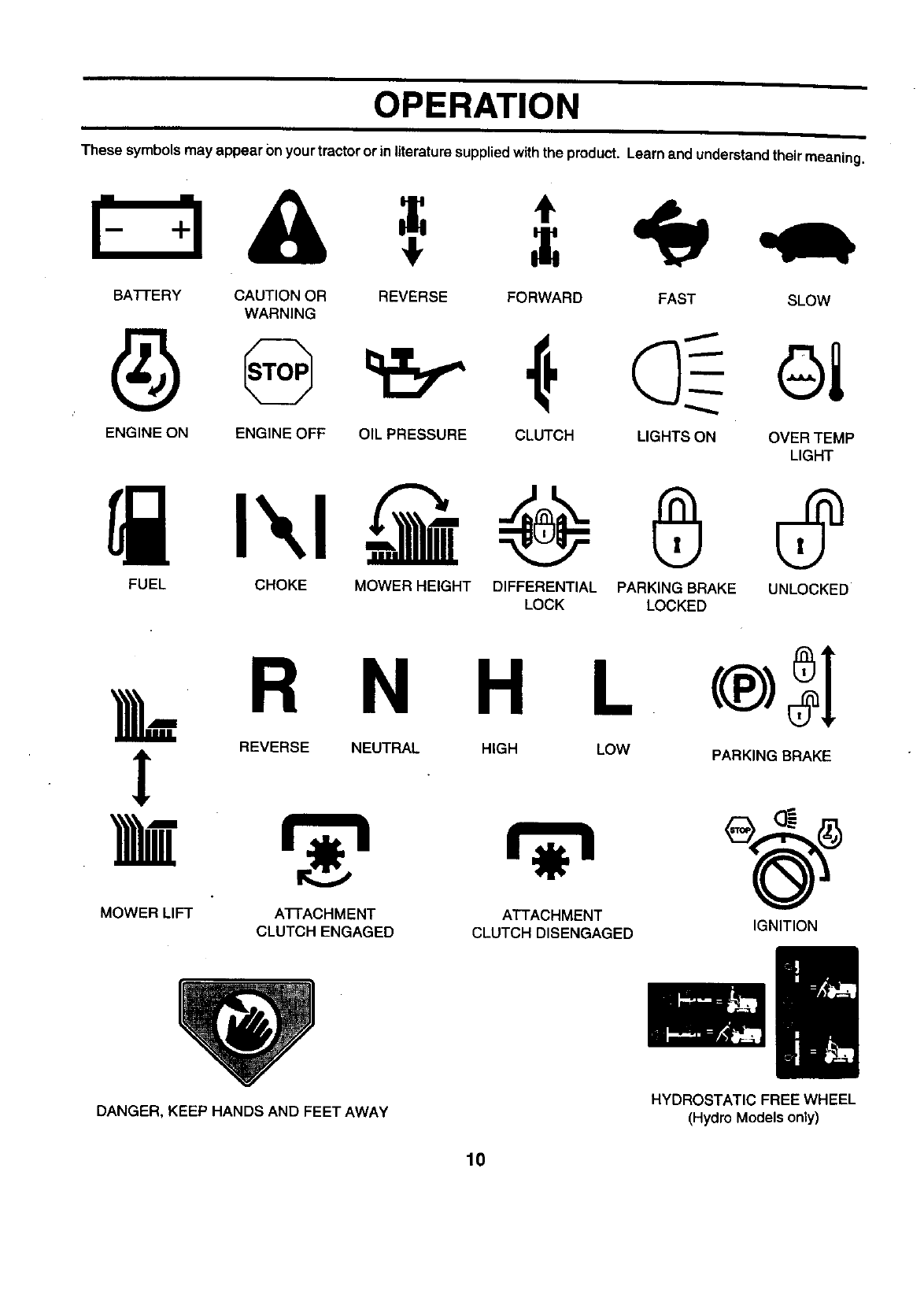
INSTALL MULCHER PLATE
(See Figs. 5 & 6)
Install two latch hooks to mulcher plate using screw,
washer, lockwasher, and weld nutas shown.
NOTE: Pre-assemble weld nut to latch hook by inserting
weld nut fromthe top with hook pointingdown.
•Tighten hardware securely.
•Raise and holddeflectorshield in uprightposition.
•Place front of mulcher plate over frontof mowerdeck
opening and slide intoplace, as shown.
•Hook front latch intohole on frontof mower deck.
•Hook rear latch into hole on back of mower deck.
CAUTION: Do not remove discharge
guard from mower. Raise and ho|d
guard when attaching mulcher plate
and allow it to rest on plate while in
operation.
WELD NUT FROM THE TOP HOOK POINTS DOWN
LOCK
WELD WASHER
NUT_ SCREW
LATCH
HOOK'--..
HOOK
WASHER
MULCHER
PLATE
LOCK
WASHER
WASHER
'_""_SCREW
WELD
NUT
TO CONVERTTO BAGGING OR
DISCHARGING
Simply remove mulcher plate and store in a safe place.
Your moweris now readyfor dischargingorinstallationof
optionalgrasscatcher accessory.
DEFLECTOR
HOOKS
FIG. 6
,/CHECKLIST
BEFORE YOU OPERATE AND ENJOY YOUR NEW
TRACTOR, WE WISH TO ASSURE THAT YOU RECEIVE
THEBEST PERFORMANCE AND SATISFACTION FROM
THIS QUALITY PRODUCT.
PLEASE REVIEW THE FOLLOWING CHECKLIST:
,/ All assemblyinstructionshave been completed.
,/ No remaininglooseparts in carton.
/Batteryis properlyprepared and charged. (Minimum
1 hourat 6 amps).
•/ Seat is adjusted comfortablyand tightened securely.
,/ Alltiresare properlyinflated. (For shippingpurposes,
the tires were overinflatedat the factory).
,/ Be sure mower deck is properlyleveled side-to-side/
front-to-rearfor best cutting results. (Tires must be
properlyinflatedfor leveling).
,/ Check mower anddrive belts. Be suretheyare routed
properlyaround pulleysand insideall belt keepers.
,/ Check wiring. See that allconnectionsare stillsecure
and wires are properlyclamped.
WHILELEARNING HOW TO USE YOUR TRACTOR, PAY
EXTRA ATTENTION TO THE FOLLOWING IMPORTANT
ITEMS:
•/ Engine oil is at proper level
,/ Fuel tank is filledwith fresh, clean, regularunleaded
gasoline.
,/ Become familiar with all controls-their locationand
function. Operate them before you startthe engine.
/Be sure brake system is in safe operatingcondition.
FIG. 5
9
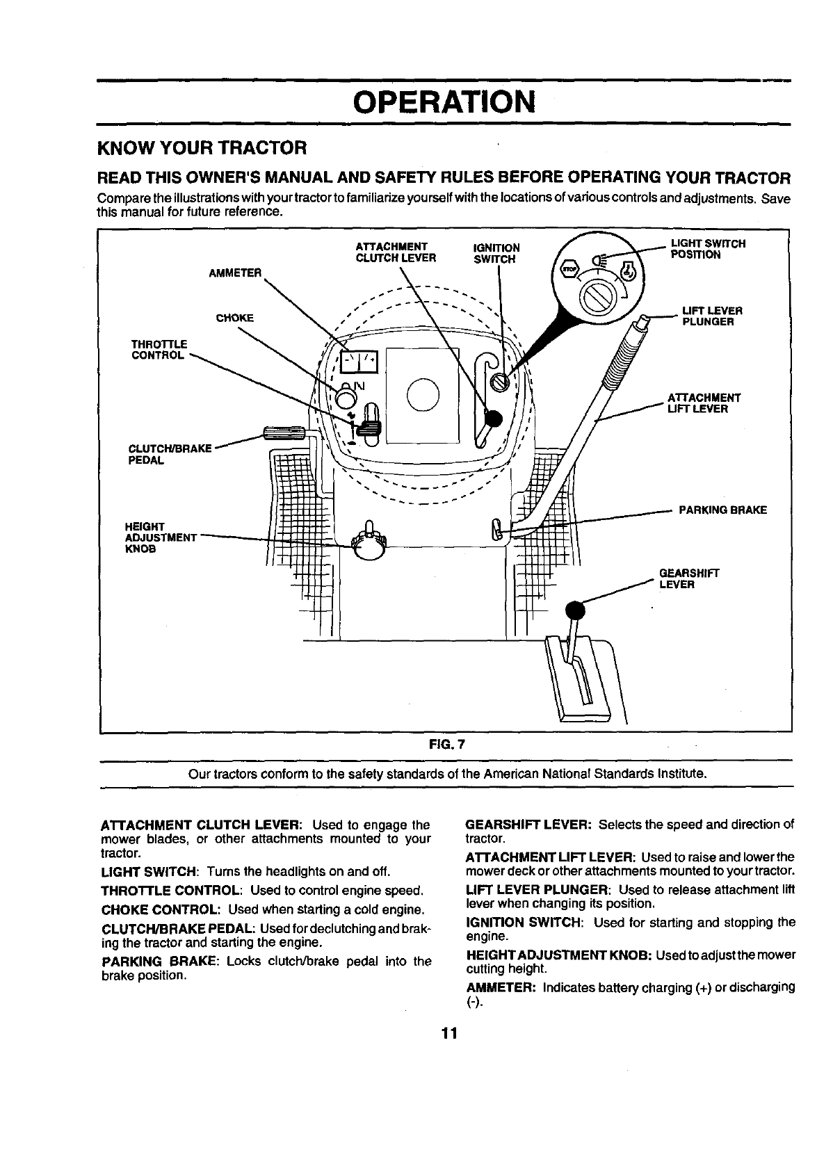
OPERATION
These symbolsmay appear Onyourtractor orinliteraturesuppliedwiththe product. Learn and understandtheirmeaning.
BATFERY CAUTION OR REVERSE FORWARD FAST SLOW
WARNING
ENGINE ON ENGINE OFF OIL PRESSURE CLUTCH LIGHTS ON OVER TEMP
LIGHT
FUEL CHOKE MOWER HEIGHT DIFFERENTIAL PARKING BRAKE UNLOCKED
LOCK LOCKED
LR N H L
i REVERSE NEUTRAL HIGH LOW PARKING BRAKE
MOWER LIFT A'I-I'ACHMENT ATTACHMENT
CLUTCH ENGAGED CLUTCH DISENGAGED IGNITION
DANGER, KEEP HANDS AND FEET AWAY HYDROSTATIC FREEWHEEL
(Hydro Modelsonly)
10
OPERATION
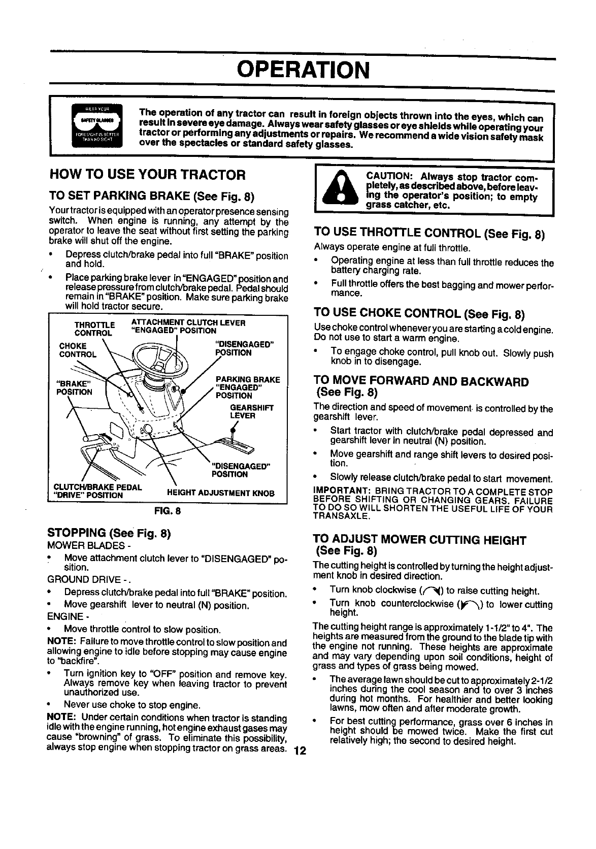
KNOW YOUR TRACTOR
READ THIS OWNER'S MANUAL AND SAFETY RULES BEFORE OPERATING YOUR TRACTOR
Compare the illustrationswithyourtractorto familiarizeyou rselfwiththe locationsofvanouscontrolsandadjustments. Save
this manual for future reference.
ATTACHMENT IGNITION LIGHT SWITCH
CLUTCH LEVER SWITCH POSITION
AMMETER
-
CHOKE tLIFT LEVER
THROTTLE
CONTROL
©ATTACHMENT
CLUTCH/BRAKE
PEDAL
HEIGHT
ADJUSTMENT
KNOB
PARKING BRAKE
GEARSHIFT
FIG. 7
Our tractors conformto the safetystandardsof the American National Standards Institute.
ATFACHMENT CLUTCH LEVER: Used to engage the
mower blades, or other attachments mounted to your
tractor.
LIGHT SWITCH: Tums the headlightson and off.
THROTFLE CONTROL: Used to controlengine speed.
CHOKE CONTROL: Used when startinga coldengine.
CLUTCH/BRAKE PEDAL: Usedfor declutchingand brak-
ingthe tractor and startingthe engine.
PARKING DRAKE: Locks clutch/brake pedal into the
brake position.
GEARSHIFT LEVER: Selects the speed and directionof
tractor.
A'I-rACHMENT LIFT LEVER: Usedto raiseand lowerthe
mowerdeckor otherattachmentsmountedto yourtractor.
LIFT LEVER PLUNGER: Used to release attachmentlift
leverwhen changing itsposition.
IGNITION SWITCH: Used for startingand stoppingthe
engine.
HEIGHTADJUSTMENT KNOB: Usedto adjustthemower
cuttingheight.
AMMETER: Indicatesbatterycharging(+) ordischarging
(-).
11
OPERATION
The operation of any tractor can result in foreign objects thrown into the eyes, which can
reauIt In severe eye damage. Always wear safety glasses or eye shields while operating your
tractor or performing any adjustments or repairs. We recommend s wide vision safety mask
over the spectacles or standard safety glasses.
HOW TO USE YOUR TRACTOR
TO SET PARKING BRAKE (See Fig. 8)
Yourtractorisequippedwithan operatorpresencesensing
switch. When engine is running, any attempt by the
operatorto leave the seat withoutfirst setting the parking
brake willshut off the engine.
•Depressclutch/brakepedal intofull =BRAKE" position
and hold.
Place parkingbrake lever in=ENGAGED"positionand
releasepressurefrom clutch/brakepedal.Pedalshould
remainin=BRAKE"position. Make sureparkingbrake
will holdtractorsecure.
THROTTLE
CONTROL
ATTACHMENT CLUTCH LEVER
"ENGAGED" POSITION
CHOKE "DISENGAGED"
CONTROL POSITION
PAR_NGBRAKE
"BRAKE"
POSITION POSITION
GEARSHIFT
LEVER
"DISENGAGED"
POSmON
CLUTCH/BRAKE PEDAL
"DRIVE"POSDON HEIGHT ADJUSTMENT KNOB
FIG. 8
STOPPING (See Fig. 8)
MOWER BLADES -
,, Move attachmentclutch lever to =DISENGAGED" po-
sition.
GROUND DRIVE -.
• Depress clutch/brakepedal intofuit"BRAKE"position.
Move gearshift leverto neutral (N) position.
ENGINE -
•Move throttleControlto slow position.
NOTE: Failureto move throttlecontrolto slowposition and
allowingengine to idle before stoppingmay cause engine
to "backfire".
Turn ignitionkey to "OFF" positionand remove key.
Always remove key when leaving tractor to prevent
unauthorizeduse.
Never use choke to stopengine.
NOTE: Under certain conditions when tractor is standing
idlewiththeengine running,hotengineexhaustgasesmay
cause "browning" of grass. To eliminate this possibility,
always stopenginewhen stoppingtrector on grassareas. 12
{_ CAUTION: Always stop tractor com-
pletely, as described above, before leav-
ing the operator's position; to empty
grass catcher, etc.
TO USE THROTTLE CONTROL (See Fig. 8)
Alwaysoperate engine at fullthrottle.
Operating engineat less than full throttlereduces the
batterychargingrate.
•Fullthrottleoffersthe best baggingand mowerpedor-
mance.
TO USE CHOKE CONTROL (See Fig, 8)
Usechokecontrolwheneveryouare startinga coldengine.
Do not use to start a warm engine.
•To engage choke control,pullknob out. Slowlypush
knob into disengage.
TO MOVE FORWARD AND BACKWARD
(See Fig. 8)
The directionand speed of movement,is controlledby the
gearshift lever.
Start tractor with clutch/brake pedal depressed and
gearshift lever in neut_l (N) position.
•Move gearshiftand range shiftleversto desiredposi-
tion.
•Slowly release clutchibreke pedal to start movement.
IMPORTANT: BRING TRACTOR TO A COMPLETE STOP
BEFORE SHIFTING OR CHANGING GEARS. FAILURE
TO DO SO WILL SHORTEN THE USEFUL LIFE OF YOUR
TRANSAXLE.
TO ADJUST MOWER CUTTING HEIGHT
(See Fig. 8)
The cuttingheightis controlledbyturningthe heightadjust-
ment knob in desired direction.
•Turn knob clockwise(f_() to raisecuttingheight.
• Turn knob counterclockwise (_)to lower cutting
height.
The cuttingheight range isapproximately 1-1/2" to 4". The
heights are measuredfrom the ground to the blade tip with
the engine not running. These heights are approximate
and may vary depending upon soil conditions, height of
grass and types of grass being mowed.
• The average lawn should be cut to approximately 2-1/2
inches duringthe cool season and to over 3 inches
during hot months. For healthier and better looking
lawns, mow often and after moderate growth.
•For best cuttingpedormance grassover 6 inches in
height shouldbe mowed twice. Make the first cut
relatively high; the second to desired height.
OPERATION
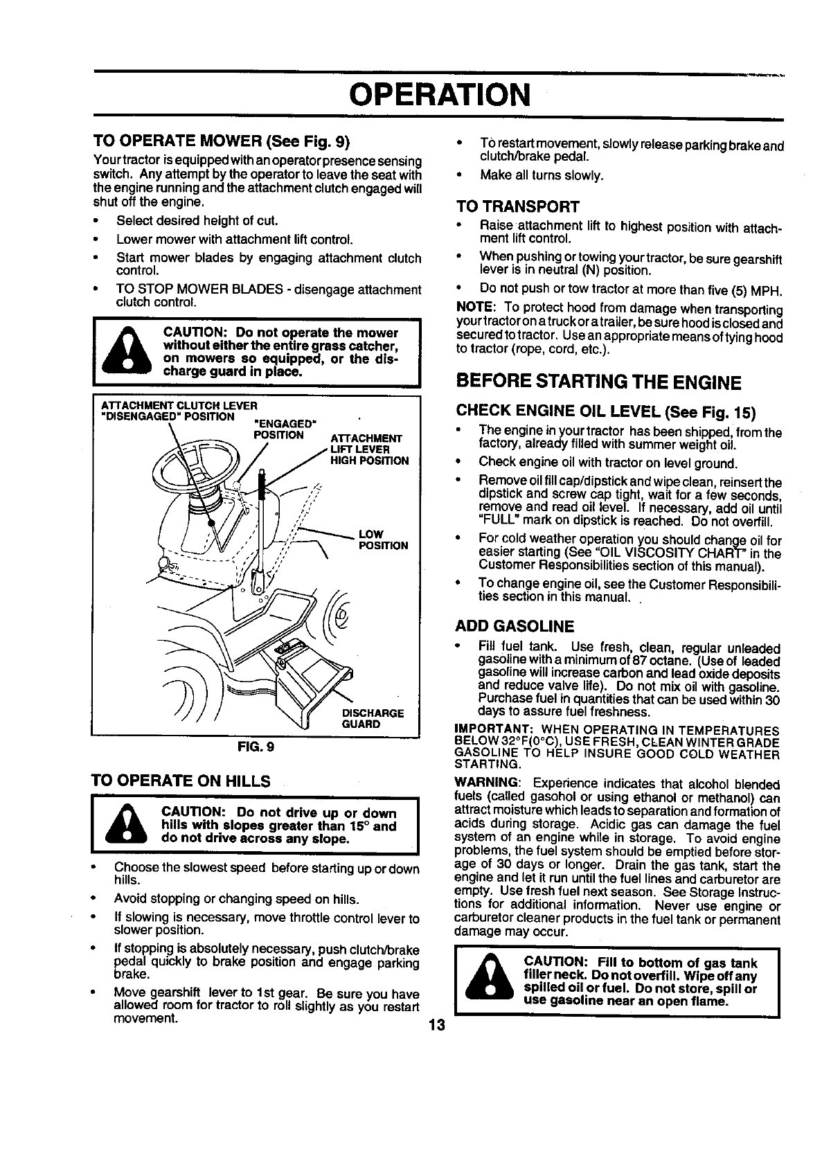
TO OPERATE MOWER (See Fig. 9)
Yourtractor isequippedwithanoperatorpresencesensing
switch. Any attemptby the operatorto leave the seat with
the engine runningand the attachmentclutchengagedwill
shut off the engine.
•Select desired heightof cut.
•Lower mower withattachment liftcontrol.
Start mower blades by engaging attachment clutch
control.
• TO STOP MOWER BLADES - disengageattachment
clutchcontrol
CAUTION: Do not operate the mower
without either the entire grass catcher,
on mowers so equipped, or the dis-
charge guard in place.
AI"rACHMENT CLUTCH LEVER
"DISENGAGED" POSITION "ENGAGED"
POSITION ATrACHMENT
_,_ / / LIFT LEVER
_\ )_ //HIGH POSITION
gwiTI°N
FIG. 9
TO OPERATE ON HILLS
I_CAUTION: Do not drive up or down I
hills with slopes greater than 15° and
do not drive across any slope.
Choose the slowestspeed before startingup ordown
hills.
Avoidstoppingorchangingspeed on hills.
If slowing is necessary, move throttlecontrol leverto
slower position.
If stoppingis absolutelynecessary, pushclutch/brake
pedal quickly to brake position and engage parking
brake.
Move gearshift lever to 1st gear. Be sure you have
allowed room for tractor to roll slightly as you restart
movement.
•TOrestartmovement,slowlyreleaseparkingbrakeand
clutch/brakepedal.
• Make allturns slowly.
TO TRANSPORT
•Raise attachment lift to highestpositionwith attach-
ment liftcontrol.
When pushingortowingyourtractor,be suregearshift
lever is in neutral(N) position.
•Do not push or tow tractor at more than five (5) MPH.
NOTE: To protect hoodfrom damage whentransporting
yourtractoronatruckor atrailer, besurehoodisclosedand
securedtotractor. Usean appropriatemeans oftyinghood
to tractor (rope, cord,etc.).
BEFORE STARTING THE ENGINE
CHECK ENGINE OIL LEVEL (See Fig. 15)
The engineinyourtractor hasbeen shipped,fromthe
factory, already filledwith summerweight oil.
•Check engine oil withtractoron level ground.
•Remove oilfillcap/dipstickandwipeclean, reinsertthe
dipstickand screw cap tight, wait for a few seconds,
remove and read oil level. If necessary, add oil until
"FULL"mark on dipstickis reached. Do notoverfill.
•For cold weather operationyou shouldchange oil for
easier starting(See "OIL VISCOSITY CHART"in the
Customer Responsibilitiessection of thismanual).
•To change engineoil,see the CustomerResponsibili-
ties sectionin thismanual.
ADD GASOLINE
•Fill fuel tank. Use fresh, clean, regular unleaded
gasolinewithaminimumof87octane. (Useof leaded
gasolinewillincrease carbon and lead oxidedeposits
and reduce valve life). Do not mix oil with gasoline.
Purchasefuel in quantitiesthat can be usedwithin30
days to assure fuel freshness.
IMPORTANT: WHEN OPERATING IN TEMPERATURES
BELOW32°F(0°C), USE FRESH, CLEANWINTERGRADE
GASOLINE TO HELP INSURE GOOD COLD WEATHER
STARTING.
WARNING: Experience indicates that alcohol blended
fuels (called gasehol or using ethanol or methanol) cart
attract moisturewhichleadsto separationandformation of
acids during storage. Acidic gas can damage the fuel
system of an engine while in storage. To avoid engine
problems,the fuel system shouldbe emptied beforestor-
age of 30 days or longer. Drain the gas tank, start the
engineand let it run untilthe fuel linesand carburetorare
empty. Use freshfuel next season. See Storage Instruc-
tions for additional information. Never use engine or
carburetorcleaner productsinthe fuel tank or permanent
damage may occur.
I
CAUTION: Fill to bottom of gas tank |
filler neck. Do not overfill. Wipe off any I
spilled oil or fuel. Do not store, spill or
use gasoline near an open flame.
13
OPERATION
TO START ENGINE (See Fig. 8)
When startingthe engine for the firsttime or if the engine
has run outof fuel, it willtake extra crankingtime to move
fuel from the tank to the engine.
•Sit on seat in operating position, depress clutch/brake
pedal and set parking brake.
• Place gear shift lever in neutral (N) position.
Move attachmentclutch to "DISENGAGED" position.
• Move throttle control to fast position
Pull choke control out for a cold engine start attempt.
For a warm engine start attempt the choke control may
not be needed.
Note: Before starting, read the warm and cold starting
procedures below.
Insert keyinto ignition andtum keyclockwise to =START"
position and release key as soon as engine starts. Do
not run starter continuously for more than fifteen sec-
onds per minute. If the engine does not start after
several attempts, push choke control in, wait a few
minutes and try again. If enginestill does not start, pull
the choke control out and retry.
WARM WEATHER STARTING (50° F and above)
•When engine starts, slowlypushchoke controlin until
the engine begins to run smoothly. If the engine starts
to run roughly, pull the choke control out slightly for a
few seconds and then continue to push the control in
slowly.
•Theattachmentsandgrounddrive can nowbe used. If
the enginedoes not accept the load,restart the engine
and allow itto warm up for one minute using the choke
as described above.
COLD WE.ATHER STARTING (50° Fand below)
• When engine starts,slowly push chokecontrolin until
the engine begins to run smoothly. Continue to push
the choke controlin smallsteps allowingthe engineto
accept small changes in speed and load, until the
choke control is fully in, If the engine starts to run
roughly, pull the choke control out slightlyfor a few
seconds and then continue to push the control in
slowly. This may require an engine warm-up period
from several seconds to severa/minutes, depending
on the temperature.
• The attachments can be used dudng the enginewarm-
up period and may require the chokecontrol be pulled
out slightly.
NOTE: If at a high altitude (above 3000 feet) or in cold
temperatures (below 32 F) the carburetorfuel mixture may
need to be adjusted for best engine performance. See "TO
ADJUST CARBURETOR" in the Service and Adjustments
sectionof this manual.
MOWING TIPS
•Tire chainscannot be usedwhenthe mowerhousingis
attachedto tractor.
•Mower should be propedy leveled for best mowing
performance. See "TO LEVEL MOWER HOUSING" in
the Service and Adjustmentssectionof thismanual.
•The left hand sideof mower should be used fortdm-
ming.
Drive so that clippingsare dischargedonto the area
that has been cut. Have the cut area to the rightofthe
tractor. This will result in a moreeven distributionof
clippingsand more uniformcutting.
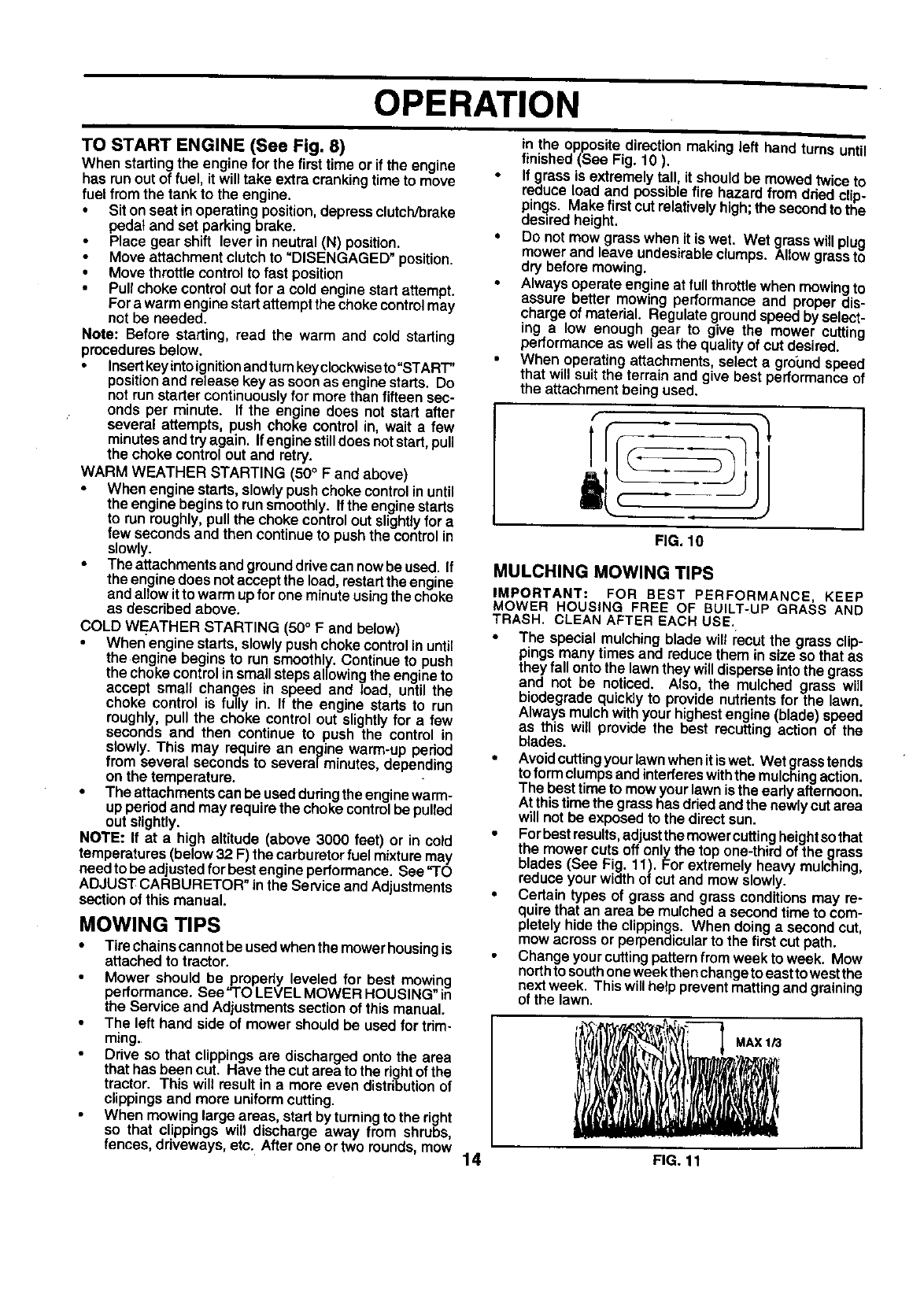
When mowing large areas, start by turning to the right
so that clippings will discharge away from shrubs,
fences, driveways, etc. After one or two rounds, mow
in the opposite directionmaking left hand turns until
finished (See Fig. 10 ).
If grass is extremelytall, it,should be mowed twice to
reduce load and possible Tire hazard from dded clip-
pings. Make first cut relatively high; the second to the
desired height.
Do not mow grass when it is wet. Wet grasswill plug
mower and leave undesirable clumps. Allow grass to
dry before mowing,
Always operate engine at full throttle when mowing to
assure better mowing performance and proper dis-
charge of material. Regulate ground speed by select-
ing a low enough gear to give the mower cutting
performance as well as the quality of cut desired.
When operating attachments, select a greund speed
that will suit the terrain and give best performance of
the attachment being used.
1
FIG. 10
MULCHING MOWING TIPS
IMPORTANT: FOR BEST PERFORMANCE, KEEP
MOWER HOUSING FREE OF BUILT-UP GRASS AND
TRASH. CLEAN AFTER EACH USE.
•The special mulchingblade wilt recutthe grass clip-
pingsmany times and reduce them in size so that as
they fallonto the lawnthey willdisperseintothe grass
and not be noticed. Also, the mulched grass will
biodegrade quicklyto provide nutrientsfor the lawn.
Always mulchwithyour highestengine (blade) speed
as this will provide the best recuttingaction of the
blades.
•Avoidcuttingyourlawn whenit iswet. Wet grasstends
toformclumpsandinterfereswiththe mulchingaction.
The best time to mow your lawnisthe early afternoon.
At thistime the grasshas driedandthe newlycut area
will not be exposedto the direct sun.
•Forbestresults,adjustthemower cuttingheightsothat
the mowercuts off onlythe top one-thirdof the grass
blades (See Fig. 11). For extremely heavy mulching,
reduce your widthof cut and mow slowly.
•Certain types of grass and grassconditionsmay re-
quirethat an area be mulcheda second time to com-
pletely hide the clippings. When doing a secondcut,
mow acrossor perpendicularto the firstcut path.
Change yourcuttingpatternfromweek to week. Mow
northto southoneweekthenchangetoeasttowestthe
next week. This willhelp preventmattingand graining
of the lawn.
.,x,o
14 FIG. 11
CUSTOMER RESPONSIBILITIES
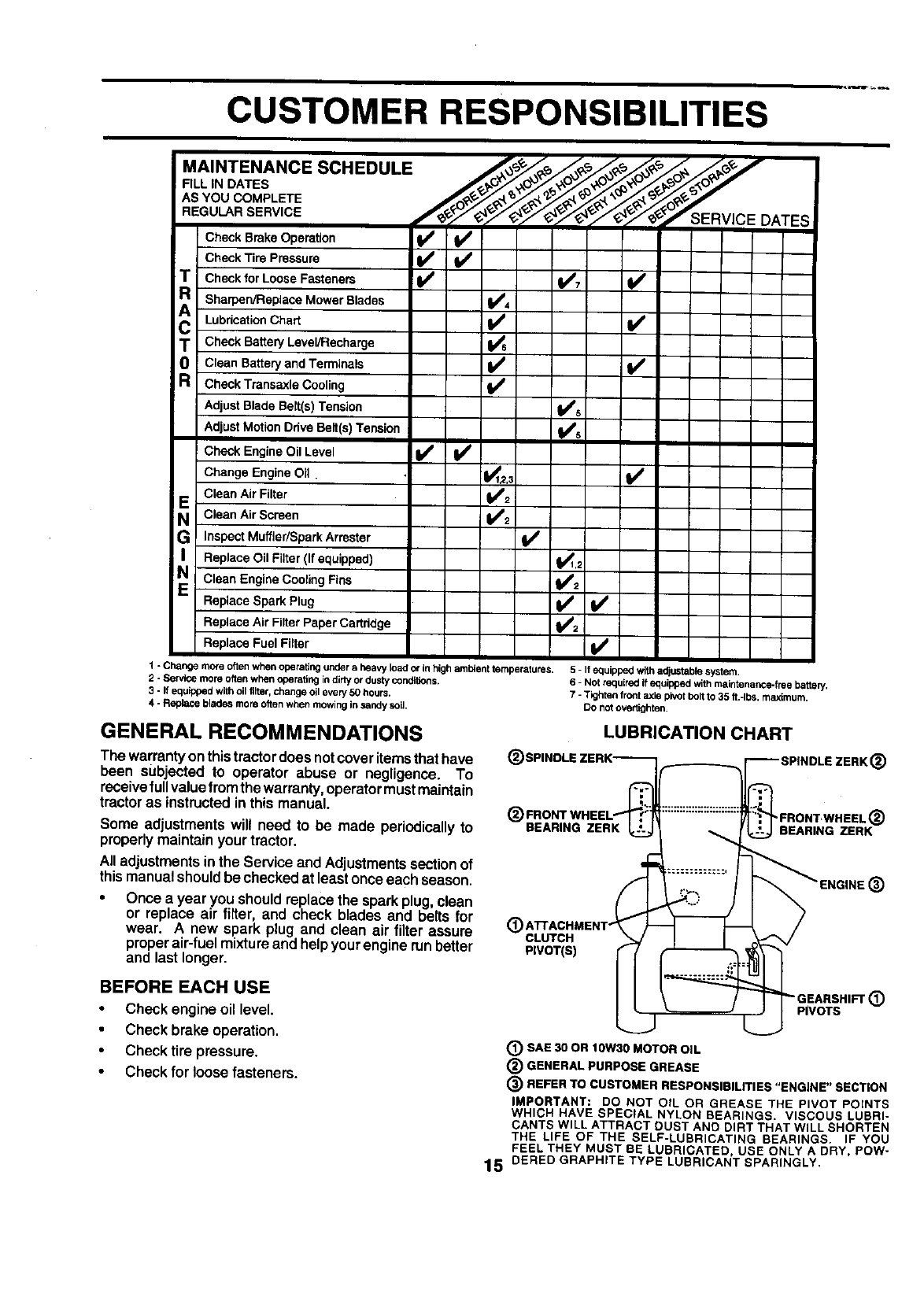
.A,NTENANCESCHEOULE
F,LL'"OATEB
REGULAR SERVICE CEDATES
Check Brake Operation _
Check Tire Pressure
T Cheek for Loose Fasteners 1_7 V'
Sharpen/Replace Mower Blades I_,=
Chart If
Lubrication
TO Check Battery Level/Recharge
Clean Battery and Terminals I_
RCheck Transaxle Cooling k/
Adjust Blade BeLt(s)Tension q_#'s
Adjust Motion Ddve Belt(s) Tension _Jl's
Check Engine Oil Level I1 /Vw
Change Engine Oil ._1,2.3 _1_
Clean Air Filter _2
E Clean Air Screen 1#'2
GInspect Muffler/Spark Arrester I,/
I Replace Oil Filter (If equipped) 1_1,2
N Clean Engine Cooling Fins _i
Replace Spark Plug V'
Replace Air Filter Paper Cartridge
Replace Fuel Fitter I_
1 - Change more oftenwhen operating under aheavy load or in high ambient temperatures.
2 - Service more oftenwhen operating indirly or dustyconditions.
3 - If equipped with oil tilter,change oil every 50 hours.
4 - Replace blades more oftenwhen mowingin sandy soil.
5 - If equipped with adjustable system,
6 - Not raquirad ifequipped with maintenance-free battery.
7-Tighten front axle pivotbolt to 35 ft.-Ibs, maximum,
DO notovedighten,
GENERAL RECOMMENDATIONS
The warrantyonthistractor doesnot coveritems thathave
been subjected to operator abuse or negligence. To
receivefull valuefrom thewarranty,operatormust maintain
tractor as instructedin this manual.
Some adjustments will need to be made periodically to
properlymaintain yourtractor.
All adjustmentsinthe Service and Adjustmentssectionof
thismanualshouldbe checkedatleast onceeach season.
Once a year you should replacethe sparkplug, clean
or replace air filter, and check blades and belts for
wear. A new spark plug and clean air filter assure
proper air-fuel mixture and help your engine run better
and last longer.
BEFORE EACH USE
Check engineoil level.
Check brake operation,
Check tire pressure.
Check for loosefasteners.
LUBRICATION CHART
(_ SPINDLE ZERK-_®FRONTWHEEL 't-- I1:::::::::::::::::::::
BEARING ZERK
(_ ATTACHMENT" !
CLUTCH
PIVOT(S)
(_) SAE 30 OR IOW30 MOTOR OIL
(_ GENERAL PURPOSE GREASE
_SPINDLE ZERK (_)
;.,
(_) REFER TO CUSTOMER RESPONSIBILITIES "ENGINE" SECTION
IMPORTANT: DO NOT OIL OR GREASE THE PIVOT POINTS
WHICH HAVE SPECIAL NYLON BEARINGS. VISCOUS LUBRI-
CANTS WILL ATTRACT DUST AND DIRT THAT WILL SHORTEN
THE LIFE OF THE SELF-LUBRICATING BEARINGS. IF YOU
FEEL THEY MUST BE LUBRICATED, USE ONLY ADRY, POW-
lS OERED GRAPHITE TYPE LUBRICANT SPARINGLY.
CUSTOMER RESPONSIBILITIES
TRACTOR
Alwaysobserve safety ruleswhen performingany mainte-
nance.
BRAKE OPERATION
If tractorrequires morethan six (6) feet stoppingdistance
at highspeed inhigbestgear, thenbrake mustbe adjusted.
(See 'I"O ADJUST BRAKE" in the Service and Adjust-
ments section of this manual).
TIRES
•Maintain proper air pressure in all tires (See "PROD-
UCT SPECIFICATIONS" on page 3of this manual).
Keep tires free ofgasoline, oil, or insect control chemi-
cals which can harm rubber.
,. •Avoid stumps, stones, deep ruts, sharp objects and
other hazards that may cause tire damage.
NOTE: To seal tire punctures and prevent flat tires due to
slow leaks, tire sealant may be purchased from your local
parts dealer. Tire sealant also prevents tire dry rot and
corrosion.
BLADE CARE
For best results mower blades must be kept sharp, Re-
place bent or damaged blades,
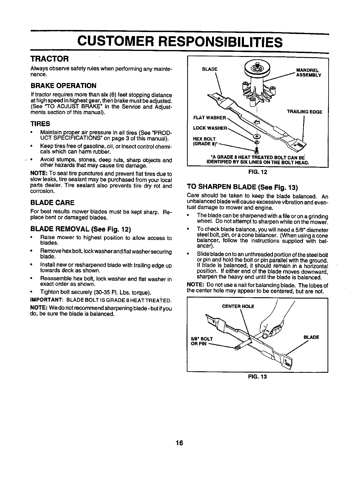
BLADE REMOVAL (See Fig. 12)
Raise mower to highest positionto a_lowaccess to
blades.
•Removehex bolt, leckwasherandflatwashersecuring
blade.
• Install new or resharpenedblade withtrailingedge up
towards deck as shown.
Reassemble hex bolt, lock washer and flat washer in
exact order as shown.
• Tighten bolt securely (30-35 Ft. Lbs. torque).
IMPORTANT: BLADEBOLTIS GRADE 8 HEATTREA]'ED.
NOTE: We do notrecommendsharpeningblade- but ifyou
do, be sure the blade is balanced.
BLADE _MANDREL
IJA°SEMDLV
TRAIUNG EDGE
FLAT WASHER _ _ I
LOCKWASHER !
HEXeOLT.
GRADE,,
*A GRADE 8 HEAT TREATED BOLT CAN BE
IDENTIFIED BY SIX UNES ON THE BOLT HEAO.
FIG. 12
TO SHARPEN BLADE (See Fig. 13)
Care should be taken to keep the blade balanced. An
unbalancedbladewillcause excessivevibrationandeven-
tual damage to mower and engine.
•The blade can be sharpenedwitha fileorona grinding
wheel. Do not attempttosharpenwhileon the mower.
To check blade balance,youwill need a 5/8" diameter
steel bolt,pin,ora conebelancer. (When usinga cone
balancer, follow the instructions-suppliedwith bal-
ancer).
•Slidebladeonto anunthreadedportionofthe steelbolt
orpin and holdthe boltor pin parallelwiththe ground.
If blade is balanced, it should remain in ahorizontal
position. If either end of the blade moves downward,
sharpenthe heavy end untilthe blade is balanced.
NOTE: Do not use a nattforbalancingblade. The lobes of
the center hole may appear to be centered, butare not.
CENTER HOLE / /
,. ADE
OR PIN _
FIG. 13
16
CUSTOMER RESPONSIBILITIES
BATFERY
Your tractor has a batterycharging systemwhich is suffi-
cient for normal use. However, periodicchargingof the
batterywith an automotivechargerwill extend its life.
Keep battery and terminalsclean.
•Keep battery bolts tight.
Keep small vent holes open.
Recharge at 6-10 amperes for 1 hour,
TO CLEAN BATTERY AND TERMINALS
Corrosion and dirt on the battery and terminals can cause
the battery to "leak" power.
Remove terminalguard.
•Disconnect BLACK batterycable first then RED bat-
tery cable and removebattery fromtractor.
•Rinse the batterywith plainwater and dry.
•Clean terminalsandbatterycable endswithwirebrush
untilbright.
• Coat terminalswithgrease or petroleumjelly.
•Reinstall battery (See "CONNECT BATTERY" in the
Assembly section of this manual).
V-BELTS
Check V-belts fordeterioration and wear after 100 hoursof
operation and replace if necessary. The belts are not
adjustable. Replace belts if they begin to slip from wear.
TRANSAXLE COOLING
Keep transaxle free from build-upof dirt and chaff which
can restrictcooling,
ENGINE
LUBRICATION
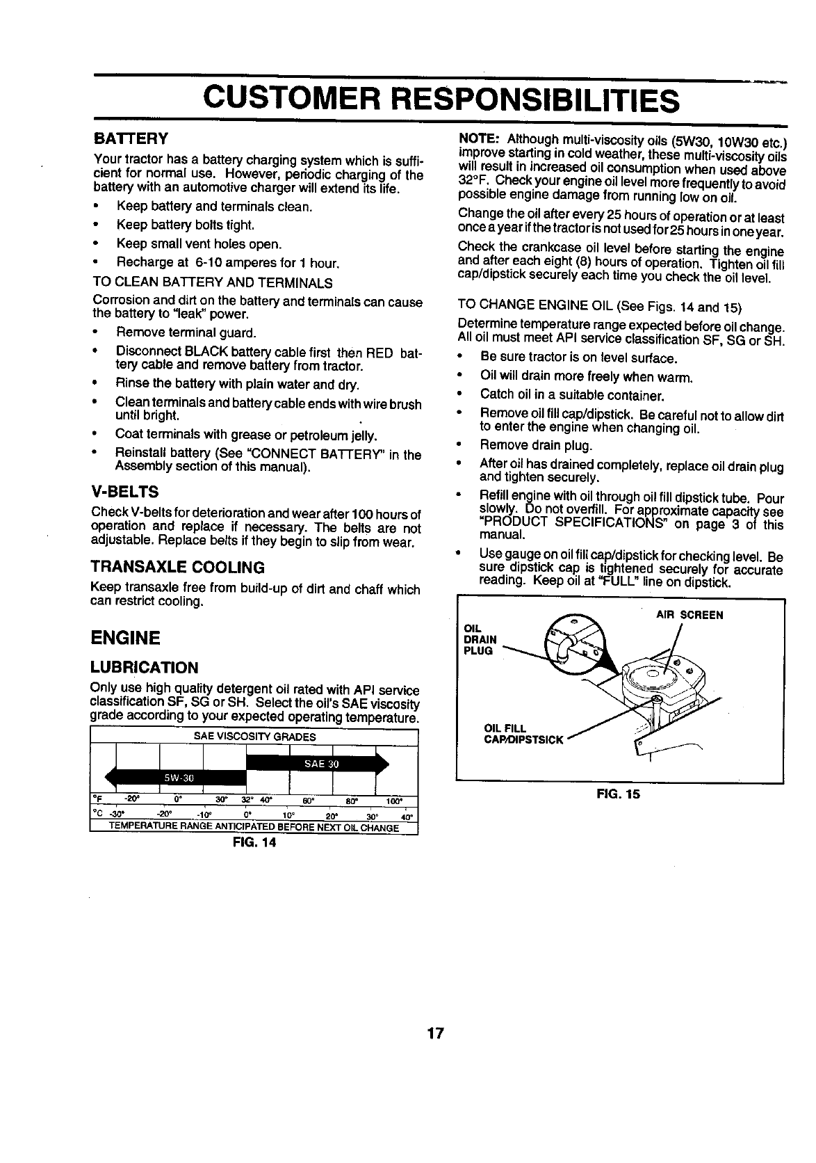
Only use high qualitydetergent oil rated withAPI service
classificationSF, SG or SH. Select the oil's SAE viscosity
grade accordingto your expected operatingtemperature,
SAE VISCOSITY GRADES
_20_0o
.30 • -20 o .10 _0°10 °20 °30°
TEMPERATURE RANGE ANTICIPATED BEFORE NEXT OiL CHANGE
FIG, 14
NOTE: Althoughmulti-viscosity oils (5W30, lOW30 etc.)
improve startingin coldweather, these multi-viscosityoils
will resultin increased oilconsumptionwhen usedabove
32°F. Checkyour engineoillevelmore frequentlytoavoid
possibleengine damage fromrunninglowon oil.
Changethe oilafter every 25 hoursofoperationorat least
oncea year ifthe tractorisnotusedfor25 hoursinoneyear.
Check the crankcase oil level before startingthe engine
and after each eight (6) hoursof operation. Tighten oil fit_
cap/dipsticksecurely each time you check the oil level.
TO CHANGE ENGINE OIL (See Figs. 14 and 15)
Determine temperature range expectedbefore oil change.
All oil must meet API service classificationSF, SG or SH.
Be sure tractor is on level surface.
•Oilwill drain more freely when warm.
•Catch oil inasuitablecontainer.
Remove oil flUcap/dipstick. Be carefulnot to allow dirt
to enter the enginewhen changingoil.
•Remove drain plug.
•Afteroil has drained completely,replaceoil drainplug
and tightensecurely.
Refillenginewithoilthroughoil fill dipsticktube. Pour
slowly. Do notoverfill. For approximatecapacltysee
=PRODUCT SPECIFICATIONS" on page 3 of this
manual.
• Use gauge onoilfill cap/dipstickfor checkinglevel. Be
sure dipstickcap is tightened securely for accurate
reading. Keep oil at "FULL"line on dipstick.
OIL _AIR SCREEN
°I s,s,cK
FIG. 15
17
CUSTOMER RESPONSIBILITIES
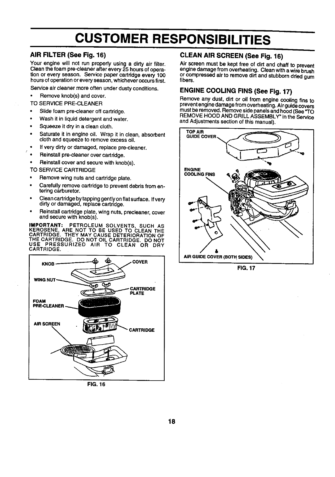
AIR FILTER (See Fig. 16)
Your engine will not run properly using adirty air filter,
Clean the foam pre-cleaner after every 25 hoursof opera-
tion or every season. Service paper cartridge every 100
hoursofoperationorevery season,whicheveroccursfirst.
Serviceair cleaner more often underdustyconditions.
•Remove knob(s) and cover.
TO SERVICE PRE-CLEANER
•Slide foam pre-cleaner off cartridge.
•Wash it inliquiddetergent and water.
•Squeeze it dry in a clean cloth.
•Saturate it in engine oil. Wrap it in clean, absorbent
cloth and squeeze to remove excess oil.
If very dirtyor damaged, replace pre-cleaner.
f•Reinstall pre-cleaner overcartridge.
•Reinstallcover and secure with knob(s).
TO SERVICE CARTRIDGE
•Remove wing nutsand cartridge plate.
•Carefully removecartridge to preventdebrisfromen-
teringcarburetor.
•Cleancartridgebytappinggentlyonflatsurtace. Ifvery
dirty ordamaged, replacecartridge.
•Reinstall cartridgeplate, wing nuts,precteaner, cover
and securewith knob(s).
IMPORTANT; PETROLEUM SOLVENTS, SUCH AS
KEROSENE, ARE NOT TO BE USED TO CLEAN THE
CARTRIDGE. THEY MAY CAUSE DETERIORATION OF
THE CARTRIDGE. DO NOT OIL CARTRIDGE. DO NOT
USE PRESSURIZED AIR TO CLEAN OR DRY
CARTRIDGE.
FOAM
PLATE
AIR SCREEN
:ARTRIDGE
CLEAN AIR SCREEN (See Fig. 16)
Air screen must be kept free of dirt and chaff to prevent
enginedamage from overheating. Clean withe wirebrush
or compressedair to removedirt and stubborndded gum
fibers.
ENGINE COOLING FINS (See Fig. 17)
Remove any dust, dirt or oil from engine coolingfins to
preventenginedamagefrom overheating.Air guidecovers
mustbe removed.Removesidepanels andhood(See "TO
REMOVE HOOD AND GRILL ASSEMBLY" inthe Service
and Adjustmentssectionof this manual).
ENGINE <_
COOLING FINS
&
AIR GUIDE COVER (BOT H SIDES)
FIG. 17
FIG. 16
18
CUSTOMER RESPONSIBILITIES
MUFFLER
Inspectend replace corroded mufflerandsparkattester (if
equipped)as itcould create a fire hazard and/or damage.
SPARK PLUGS
Replace spark plugs at the beginning of each mowing
season or after every 100 hoursof operation, whichever
occurs first. Spark plugtype and gapsettingare shownin
"PRODUCT SPECIFICATIONS" onpage 3 ofthismanual.
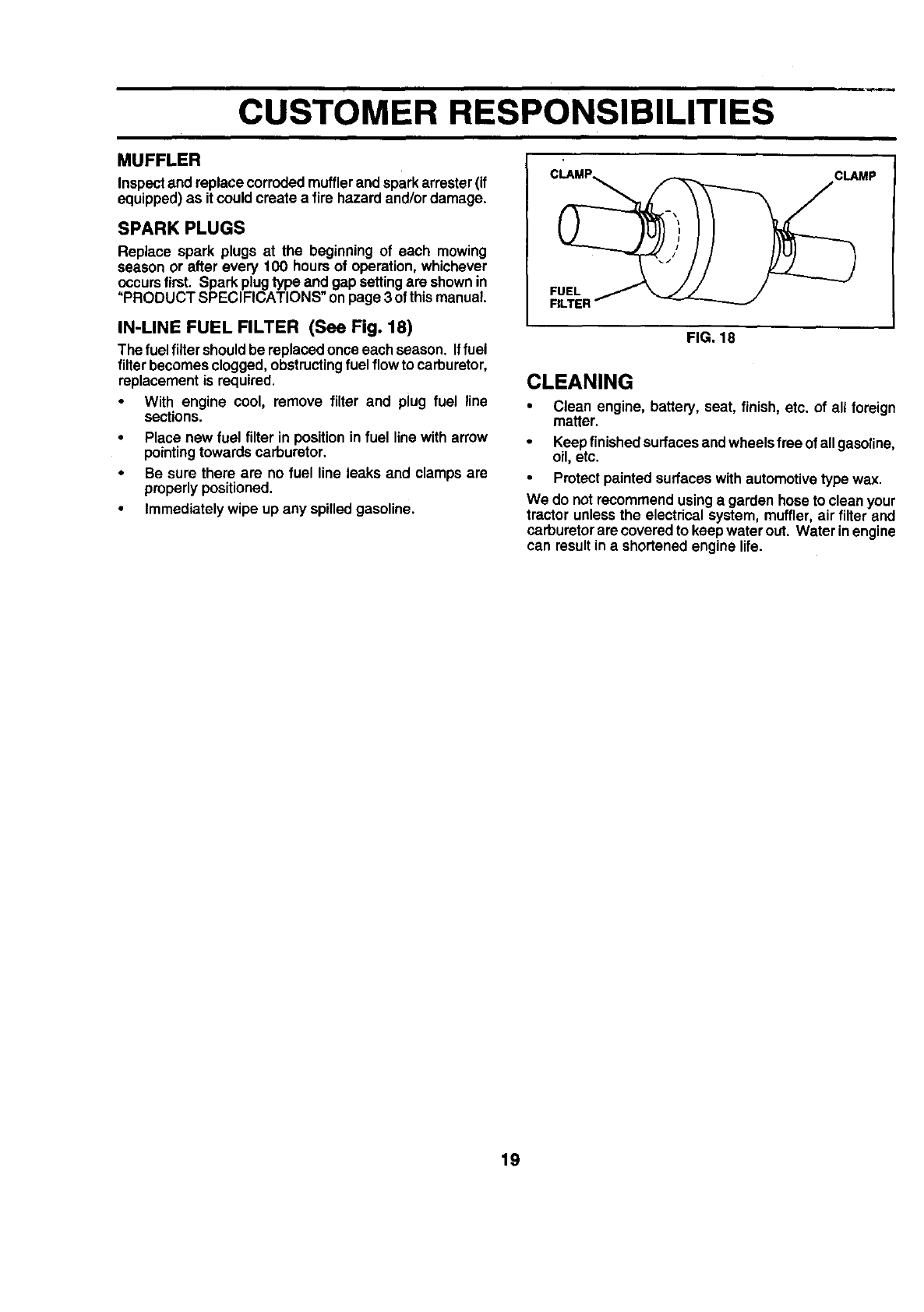
IN-LINE FUEL FILTER (See Fig. 18)
The fuel filtershouldbe replacedonce each season. Iffuel
filterbecomesclogged,obstructingfuel flowto carburetor,
replacementis required.
• With engine cool, remove filter and plug fuel line
sections.
•Place new fuel filter in positionin fuel line witharrow
pointingtowards carburetor.
•Be sure there are no fuel line leaks and clamps are
properlypositioned.
•Immediatelywipe up any spilledgasoline.
CLAMP CLAMP
FUEL
RLTEI
FIG. 18
CLEANING
• Clean engine, battery, seat, finish, etc. of all foreign
matter.
Keepfinished surfacesand wheelsfree of allgasoline,
oil, etc.
Protectpainted surfaceswithautomotivetype wax.
We do not recommendusinga garden hose to cleanyour
tractor unlessthe electrical system, muffler,air filter and
carburetorare covered to keep water out. Water in engine
can resultin a shortenedengine life.
19
SERVICE AND ADJUSTMENTS
CAUTION: BEFORE PERFORMING ANY SERVICE OR ADJUSTMENTS:
Depress clutch/brake pedal fully and set parking brake.
Place gearshift lever in neutral (N) position.
Place attachment clutch in "DISENGAGED" position.
Turn ignition key "OFF" and remove key.
Make sure the blades and all moving parts have completely stopped.
Disconnect spark plug wire from spark plug and place wire where it cannot come in contact with
plug.
TRACTOR
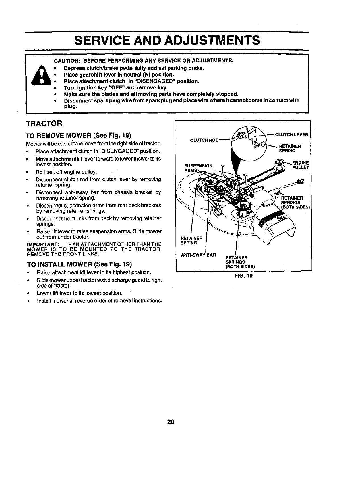
TO REMOVE MOWER (See Fig. 19)
Mowerwillbe easier'toremovefromthe rightsideoftractor,
• Place attachmentclutch in"DISENGAGED" position.
Moveattachmentliftleverforwardtolower mowerto its
lowestposition.
Rollbelt off engine pulley.
•Disconnectclutch rod from clutch lever by removing
retainerspring.
• Disconnect anti-sway bar from chassis bracket by
removingretainerspring.
•Disconnectsuspensionarms from rear deck brackets
by removing retainersprings.
Disconnectfront linksfromdeck by removingretainer
springs,
• Raise liftleverto raise suspensionarms. Slide mower
outfrom undertractor,
IMPORTANT: IF AN ATTACHMENT OTHER THAN THE
MOWER IS TO BE MOUNTED TO THE TRACTOR,
REMOVE THE FRONT LINKS.
TO INSTALL MOWER (See Fig. 19)
Raise attachment liftleverto its highestposition.
•Slide mower undertractorwithdischargeguardto right
side of tractor.
•Lower liftleverto its lowest position.
•Installmowerin reverseorderof removalinstructions.
RETAINER
SPRING
ANTI-SWAY BAR RETAINER
SPRINGS
(BOTH SIDES)
FIG. 19
20
SERVICE AND ADJUSTMENTS
TO LEVEL MOWER HOUSING FRONT-TO-BACK ADJUSTMENT (See Figs. 22 and 23)
Adjustthe mower while tractor is parked onlevel groundor
driveway. Make sure tires are properly inflated (See
"PRODUCT SPECIFICATIONS" on page 3 of this manual).
Iftires are over or underinflated, you will not properly adjust
your mower.
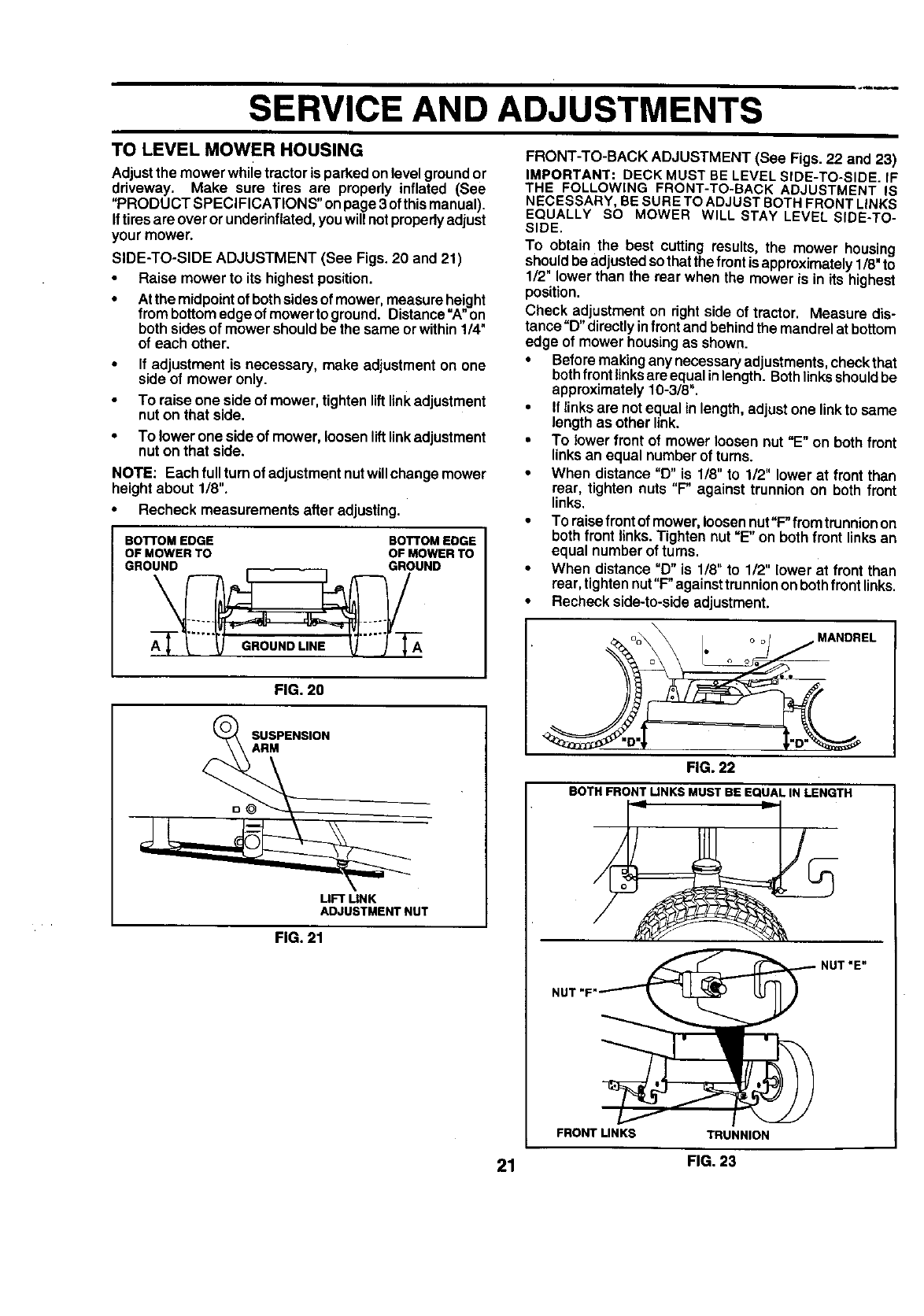
SIDE-TO-SIDE ADJUSTMENT (See Figs. 20 and 21)
• Raise mower to its highest position.
•At the midpointof bothsidesof mower,measureheight
frombottomedgeof mower to greund. Distance=A"on
bothsidesof mowershouldbe the same orwithin1/4"
of each other.
If adjustment is necessary, make adjustmenton one
side of mower only.
To raiseone sideof mower,tightenliftlinkadjustment
nuton that side.
• To lower oneside of mower, loosen lift link adjustment
nut on that side.
NOTE: Each fullturnof adjustmentnutwillchangemower
heightabout 1/8".
•Recheck measurements after adjusting.
BOTTOM EDGE BOTTOM EDGE
OF MOWER TO OF MOWER TO
GROUND GROUND
IMPORTANT: DECK MUST BE LEVELSIDE-TO-SIDE. IF
THE FOLLOWING FRONT-TO-BACK ADJUSTMENT IS
NECESSARY, BE SURETO ADJUSTBOTH FRONTLINKS
EQUALLY SO MOWER WILL STAY LEVEL SIDE-TO-
SIDE.
To obtain the best cutting results, the mower housing
shouldbe adjustedsothat thefront is approximately1/8"to
1/2" lower than the rear when the mower is in its highest
position.
Check adjustmenton rightside of tractor. Measure dis-
tance"D" directlyinfront andbehindthe mandrelat bottom
edge of mowerhousingas shown.
• Beforemakingany necessaryadjustments,checkthat
bothfront linksareequal inlength.Bothlinksshouldbe
approximately10-3/8".
•If linksare notequal in length,adjustone linkto same
lengthas other link.
•To lower front of mower loosen nut "E" on both front
linksan equal numberof turns.
•When distance "D" is 1/8" to 1/2" lower at front than
rear, tighten nuts "P against trunnion on both front
links.
•To raisefront of mower,loosennut"F"from trunnionon
bothfront links.Tighten nut "E" on both front linksan
equal numberof turns.
•When distance "D" is 1/8" to 1/2" lower at front than
rear,tightennut"F"againsttrunniononboth front links.
•Recheckside-to-side adjustment.
FIG. 20
S SM"ENS'ON
UFT MNK
ADJUSTMENT NUT
FIG. 21
MANDREL
FIG. 22
BOTH FRONTLINKSMUSTBE EQUALIN LENGTH
NUT
NUT "E"
FRONT LINKS TRUNNION
21 FIG. 23
SERVICE AND ADJUSTMENTS
WITH PARKING BRAKE "ENGAGED"
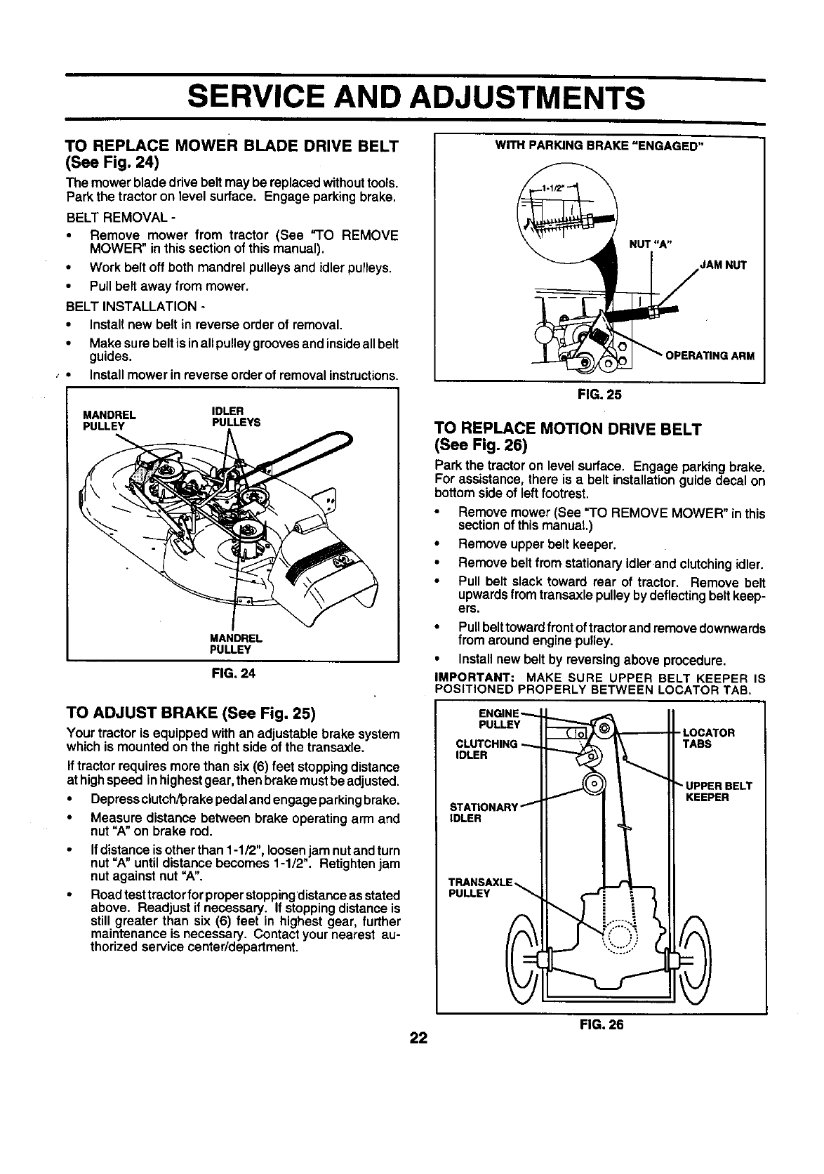
TO REPLACE MOWER BLADE DRIVE BELT
(See Fig. 24)
The mowerblade drivebelt may be replacedwithouttools.
Park the tractor on level surface. Engage parkingbrake.
BELT REMOVAL -
• Remove mower from tractor (See "TO REMOVE
MOWER" in thissection of this manual).
•Work belt off both mandrel pulleysand idler pulleys.
•Pull belt away from mower.
BELT INSTALLATION -
•Installnew belt in reverse order of removal.
•Make surebeltis inall pulleygroovesandinsideallbelt
guides.
Installmowerin reverseorder of removal instructions.
MANDREL IDLER
PULLEY PULLEYS
MANDREL
PULLEY
FIG. 24
TO ADJUST BRAKE (See Fig. 25)
Your tractor is equippedwith an adjustable brake system
which is mounted on the rightsideof the transaxle.
If tractorrequires more than six (6) feet stoppingdistance
at highspeed inhighestgear, then brakemustbe adjusted.
•Depressciutch/'prakepedaland engage parkingbrake.
•Measure distance between brake operatingarm and
nut "A" on brake rod.
Ifdistance isotherthan 1-1/2", loosen jam nutand turn
nut =A"untildistance becomes 1-1/2". Retightenjam
nut against nut "A".
Roadtesttractorfor properstopping'distanceas stated
above, Readjust if necessary. If stoppingdistance is
still greater than six (6) feet in highest gear, further
maintenanceis necessary. Contactyour nearest au-
thorized servicecenter/department.
NUT"A"
JAM NUT
FIG. 25
TO REPLACE MOTION DRIVE BELT
(See Fig. 26)
Park the tractoron level surface. Engage parkingbrake.
For assistance, there is a belt installationguide decal on
bottom sideof left footrest.
•Remove mower(See "TO REMOVE MOWER" in this
sectionof this manual.)
•Remove upperbelt keeper.
Remove beltfrom stationaryidlerand clutchingidler.
•Pull belt slack toward rear of tractor. Remove belt
upwardsfrom transaxlepulleybydeflectingbeltkeep-
ers.
•Pullbelttowardfrontoftractorandremovedownwards
from aroundengine,pulley.
•Installnew belt by reversingabove procedure.
IMPORTANT: MAKE SURE UPPER BELT KEEPER IS
POSITIONED PROPERLY BETWEEN LOCATOR TAB.
ENGINE_
PULLEY
CLUTCHING
IDLER
STATIONARY _
IDLER
TRANSAXLE
PULLEY
-LOCATOR
TABS
UPPER BELT
KEEPER
FIG. 26
22
SERVICE AND ADJUSTMENTS
TRANSAXLE SHIFTER LINKAGE AND AD-
JUSTMENT (See Figs. 27 and 28)
Thetransaxle shouldbe inneutralwhenthe gear shiftlever
isinthe neutral(N) (lockgate) position. The adjustmentis
preset at the factory; however, if adjustment is needed,
proceed as follows:
•Make sure transaxle is in neutral (N).
•Loosentwo Iocknutson tie rod.
Turn center rod untilgearshift lever falls into neutral
lock gate on fender console.
•Tighten Iocknutssecurely.
LOCK GATE
FIG. 27
LOCKNUTS
_CENTER ROD
TIE ROD -'n
FIG. 28
TO ADJUST STEERING WHEEL ALIGNMENT
If steedng wheel crossbarsare not horizontal (left to right)
when wheels are positioned straight forward, remove steer-
ing wheel and reassemble per instructions inthe Assembly
section of this manual.
FRONT WHEEL TOE-IN/CAMBER
The front wheel toe-in and camber are not adjustable on
your tractor. If damage has occurred to affect the front
wheel toe-in or camber, contact your nearest authorized
servicecenter/department.
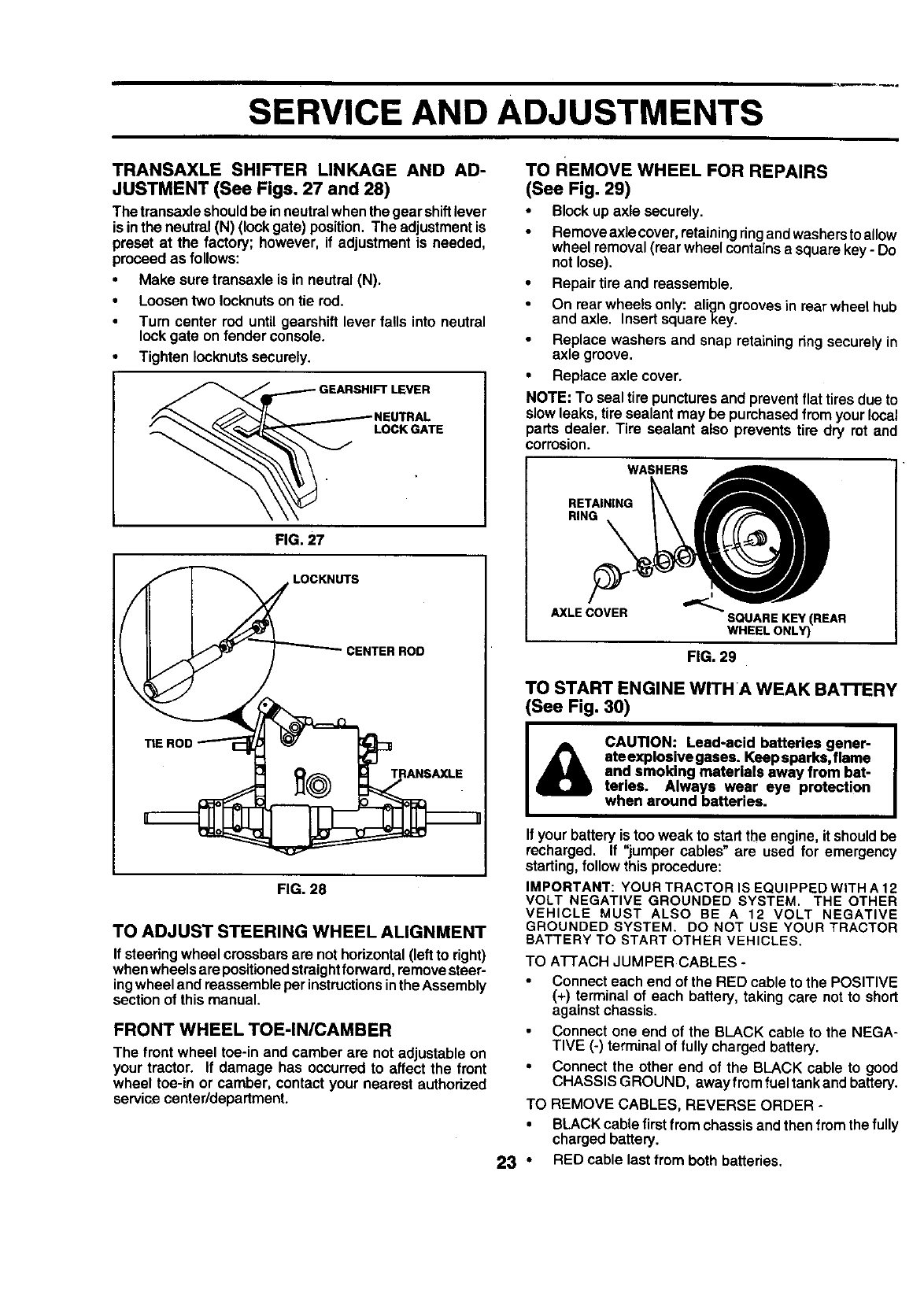
TO REMOVE WHEEL FOR REPAIRS
(See Fig. 29)
•Blockup axle securely.
Removeaxlecover, retainingringand washerstoallow
wheel removal(rearwheel containsa square key-Do
notlose).
•Repairtire and reassemble.
On rearwheels only: aligngroovesin rearwheel hub
and axle. Insert squarekey.
Replace washers and snap retainingringsecurely in
axle groove.
•Replace axle cover.
NOTE: To seal tire puncturesand prevent flattires due to
slowleaks, tiresealant may be purchasedfrom yourlocal
parts dealer. Tire sealant also prevents tire dry rot and
corrosion.
WASHERS
RETAINING
RING __
AXLE COVER SQUARE KEY (REAR
WHEEL ONLY)
FIG. 29
TO START ENGINE WITHA WEAK BA'n'ERY
(See Fig. 30)
CAUTION: Lead-acid batteries gener-
ateexplosive gases. Keepsparks, flame
and smoking materials away from bat-
teries. Always wear eye protection
when around batteries.
If your battery is too weak to start the engine, it should be
recharged. If "jumper cables" are used for emergency
starting, follow this procedure:
IMPORTANT: YOUR TRACTOR IS EQUIPPED WITH A 12
VOLT NEGATIVE GROUNDED SYSTEM. THE OTHER
VEHICLE MUST ALSO BE A 12 VOLT NEGATIVE
GROUNDED SYSTEM. DO NOT USE YOUR TRACTOR
BATTERY TO START OTHER VEHICLES.
TO A'I-FACH JUMPER CABLES -
•Connect each end of the RED cable to the POSITIVE
(+) terminal of each battery, taking care not to short
against chassis.
Connect one end of the BLACK cable to the NEGA-
TIVE (-) terminal of fully charged battery.
• Connect the other end of the BLACK cable to good
CHASSIS GROUND, away from fuel tank and battery.
TO REMOVE CABLES, REVERSE ORDER -
• BLACK cable first from chassis and then from the fully
chargedbattery.
23 "RED cable last from both batteries.
SERVICE AND ADJUSTMENTS
ENGINE
"POSITIVE" (+) "NEGATIVE" (-)
L.H. PANEL
BOLT
FIG. 30
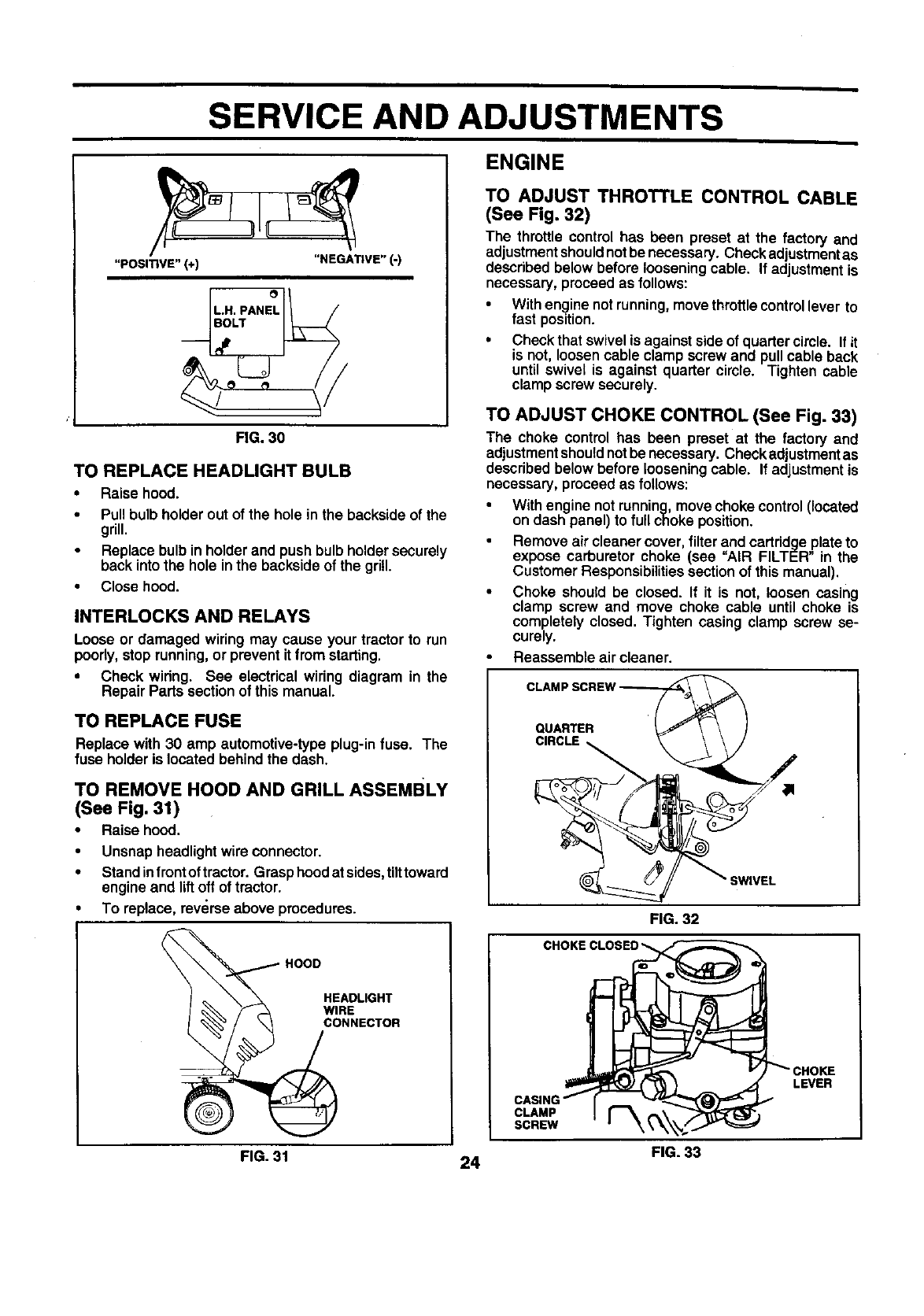
TO REPLACE HEADLIGHT BULB
•Raise hood.
•Pull bulbholder out of the hole inthe backsideof the
grill.
Replace bulbin holderand push bulb holdersecurely
back into the hole in the backsideof the grill.
•Close hood.
INTERLOCKS AND RELAYS
Loose or damaged wiring may cause your tractor to run
poorly,stoprunning,or prevent it from starting.
•Check wiring. See electrical wiring diagram in the
Repair Parts sectionof this manual.
TO REPLACE FUSE
Replace with 30 amp automotive-typeplug-infuse. The
fuse holderis located behindthe dash.
TO REMOVE HOOD AND GRILL ASSEMBLY
(See Fig. 31)
•Raise hood.
Unsnap headlightwire connector.
Standinfrontoftractor. Grasphoodat sides,tilttoward
engine and liftoff of tractor.
To replace, reverse above procedures.
HOODHEADLIGH T
ECTOR
FIG. 31 24
TO ADJUST THROTTLE CONTROL CABLE
(See Fig. 32)
The throttle control has been preset at the factory and
adjustmentshouldnotbe necessary. Checkadjustmentas
described below before looseningcable. If adjustmentis
necessary, proceedas follows:
•With enginenot running,movethrottlecontrollever to
fast position.
•Check that swivelis against sideof quarter circle. If it
is not, loosencable clamp screw and pullcable back
until swivel is against quarter circle. Tighten cable
clamp screw securely.
TO ADJUST CHOKE CONTROL (See Fig. 33)
The choke control has been preset at the factory and
adjustmentshouldnotbe necessary. Checkadjustmentas
describedbelow before loosening cable. If adjustmentis
necessary, proceedas follows:
•With engine notrunning,move choke control(located
on dash panel) to full choke position.
Remove air cleaner cover, filter and cartridgeplateto
expose carburetor choke (see "AIR FILTER" in the
CustomerResponsibilitiessectionof thismanual).
•Choke should be closed. If it is not, loosen casing
clamp screw and move choke cable until choke is
completely closed. Tighten casing clamp screw se-
curely.
Reassemble air cleaner.
QUARTER '(
CIRCLE
SWIVEL
FIG. 32
CLAMP
SCREW
LEVER
FIG. 33
SERVICE AND ADJUSTMENTS
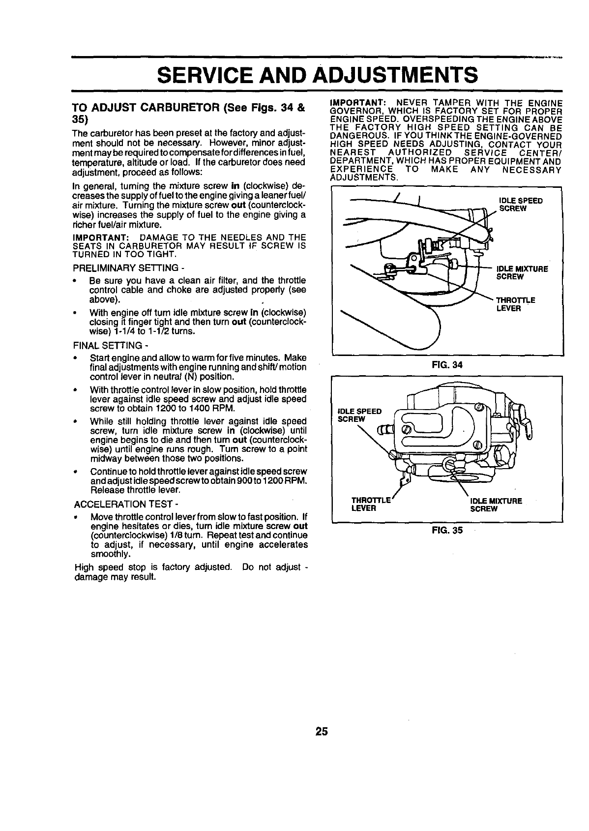
TO ADJUST CARBURETOR (See Figs. 34 &
35)
The carburetorhas been preset at the factory and adjust-
ment should not be necessary. However, minor adjust-
ment may be requiredto compensatefor differencesinfuel,
temperature, altitudeor load. If the carburetordoesneed
adjustment,proceed as follows:
In general, turning the mixture screw in (clockwise) de-
creases the supplyof fuel tothe enginegivinga leanerfuel/
air mixture. Turning the mixturescrew out (counterclock-
wise) increases the supply of fuel to the engine giving a
richerfuel/air mixture.
IMPORTANT: DAMAGE TO THE NEEDLES AND THE
SEATS IN CARBURETOR MAY RESULT IF SCREW IS
TURNED IN TOO TIGHT.
PRELIMINARY SETI'ING -
•Be sure you have a clean air filter, and the throttle
control cable and choke are adjusted properly (see
above).
With engine offturn idle mixture screw in (clockwise)
closingit finger tight and then turn out (counterclock-
wise) 1-1/4 to 1-1/2 turns.
FINAL SETTING -
•Start engine andallowto warmforfive minutes. Make
final ad ustmentswithengine runningandshift/motion
controllever in neutral(N) positon.
•With throttlecontrol lever inslow position,holdthrottle
lever against idle speed screw and adjust idle speed
screw to obtain 1200 to 1400 RPM.
While still holding throttle lever against idle speed
screw, turn idle mixture screw in (clockwise) until
engine begins to die and then turn out (counterclock-
wise) until engine runs rough. Turn screw to a point
midway between those two positions.
Continue to holdthrottle lever against idle speedscrew
and ad ust idlespeed screwto obtain 900to 1200 RPM.
Re ease thrott e ever.
ACCELERATION TEST -
•Move throttlecontrol leverfrom slowto fast position. If
engine hesitatesor dies, turn idle mixturescrew out
(counterclockwise)1/8turn. Repeat testandcontinue
to adjust, if necessary, until engine accelerates
smoothly.
High speed stop is factory adjusted. Do not adjust -
damage may result.
IMPORTANT= NEVER TAMPER WITH THE ENGINE
GOVERNOR, WHICH IS FACTORY SET FOR PROPER
ENGINE SPEED. OVERSPEEDING THE ENGINE ABOVE
THE FACTORY HIGH SPEED SETTING CAN BE
DANGEROUS. IF YOU THINKTHE ENGINE-GOVERNED
HIGH SPEED NEEDS ADJUSTING, CONTACT YOUR
NEAREST AUTHORIZED SERVICE CENTER/
DEPARTMENT, WHICH HAS PROPER EQUIPMENT AND
EXPERIENCE TO MAKE ANY NECESSARY
ADJUSTMENTS,
IDLE SPEED
SCREW
IDLE MIXTURE
SCREW
LEVER
FIG. 34
LEVER SCREW
FIG. 35
25
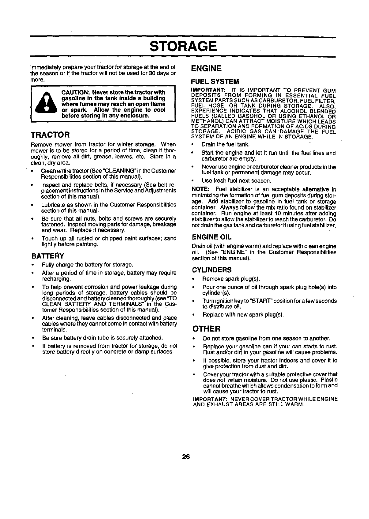
STORAGE
ENGINE
Immediatelyprepare your tractorfor storageat the end of
the season or if the tractorwill not be usedfor 30 days or
more.
CAUTION: Never store the tractor with
gasoline in the tank inside a building
where fumes may reach an open flame
or spark Allow the engine to cool
before storing in any enclosure.
TRACTOR
Remove mower from tractor for winter storage. When
mower is to be stored for a period of time, clean it thor-
oughly, remove an dirt, grease, leaves, etc, Store in a
clean, dry area.
,.. CleanenUretractor(See=CLEANING"intheCustomer
Responsibilities sectionof this manual).
•Inspect and replace belts, if necessary (See belt re-
placement instructionsin the Service and Adjustments
section of this manual).
Lubricate as shown in the Customer Responsibilities
sectionof this manual.
•Be sure that all nuts, bolts and screws are securely
fastened. Inspectmovingpartsfordamage, breakage
and wear. Replace if necessary.
•Touch up all rusted or chipped paint surfaces;sand
lightlybefore painting.
BA'n'ERY
Fully charge the battery for storage.
After a pedod of time in storage, battery may require
recharging.
To help prevent corrosion and power leakage dudng
long periods of storage, battery cables should be
disconnected andbatterycleaned thoroughly (see"TO
CLEAN BATI'ERY AND TERMINALS" in the Cus-
tomer Responsibilities section of this manual). "
After cleaning, leave cables disconnected and place
cableswhere they cannot come in contactwith battery
terminals.
•Be sure batterydrain tube is securely attached.
•If battery is removed from tractor for storage,do not
storebattery directlyon concrete or damp surfaces.
FUEL SYSTEM
IMPORTANT: IT IS IMPORTANT TO PREVENT GUM
DEPOSITS FROM FORMING IN ESSENTIAL FUEL
SYSTEM PARTS SUCH AS CARBURETOR, FUEL FILTER,
FUEL HOSE, OR TANK DURING STORAGE. ALSO,
EXPERIENCE INDICATES THAT ALCOHOL BLENDED
FUELS (CALLED GASOHOL OR USING ETHANOL OR
METHANOL) CAN ATTRACT MOISTURE WHICH LEADS
TO SEPARATION AND FORMATION OF ACIDS DURING
STORAGE. ACIDIC GAS CAN DAMAGE THE FUEL
SYSTEM OF AN ENGINE WHILE IN STORAGE.
•Drainthe fuel tank.
•Start the engine and let it run untilthe fuel lines and
carburetor are empty.
• Never use engine orcarburetorcleaner products inthe
fuel tank or permanent damage may occur.
• Use fresh fuel next season.
NOTE: Fuel stabilizer is an acceptable alternative in
minimizingthe formation of fuel gum depositsduringstor-
age. Add stabilizer to gasoline in fuel tank or storage
container. Always follow the mix ratiofound on stabilizer
container. Run engine at least 10 minutes after adding
stabilizerto aflowthe stabilizerto reachthe carburetor. Do
notdrainthe gastank andcarburetorifusingfuel stabilizer.
ENGINE OIL
Drain oil (with engine warm) and replace withclean engine
oil. (See =ENGINE" in the Customer Responsibilities
sectionof thismanual).
CYLINDERS
•Remove sparkplug(s).
Pour one ounce of oilthroughspark plug hole(s) into
cylinder(s).
•Turnignitionkeyto"START" positionfora few seconds
to distdbuteoIL
• Replace with new spark plug(s).
OTHER
•Do not storegasolinefrom one season to another.
•Replace your gasoline can if your can starts to rust.
Rustand/or dirt in your gasolinewill cause problems.
•If possible,store your tractor indoorsand cover it to
give protectionfrom dust and dirt.
Cover yourtractorwitha suitableprotectivecoverthat
does not retain moisture. Do notuse plastic. Plastic
cannotbreathewhichallowscondensationtoform and
will cause your tractorto rust.
IMPORTANT: NEVER COVER TRACTOR WHILE ENGINE
AND EXHAUST AREAS ARE STILL WARM.
26
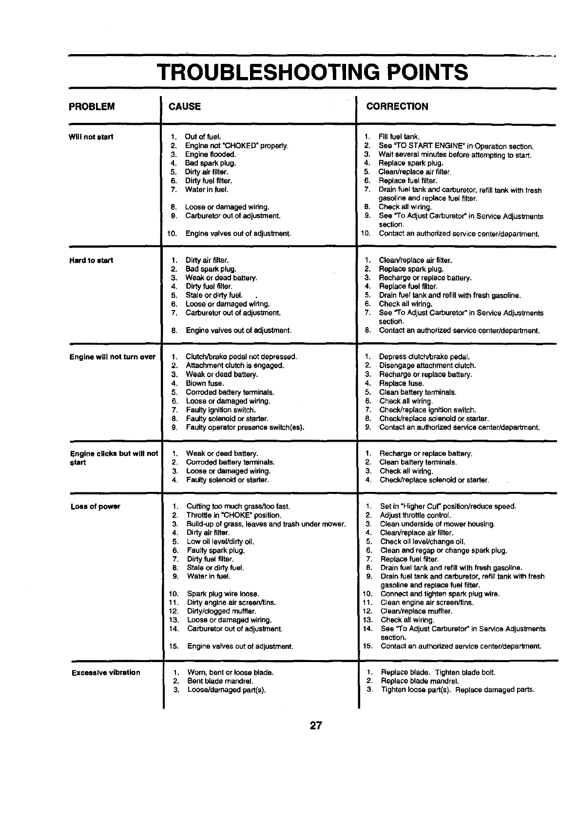
TROUBLESHOOTING POINTS
CAUSE CORRECTIONPROBLEM
Will notstart
Hard to start
Engine wig not turn over
Engine clicks but will not
start
Loss of power
Excessive vibration
1. Out of fuel.
2. Engine not "CHOKED" properly.
3. Engine flooded.
4. Bad spark plug.
5. Dirtya_rfilter.
6. Dirtyfuel fitter.
7. Water in fuel.
8. Loose or damaged wiring.
9. Carburetor out of adjuslment.
10. Engine valves outof adjustment.
1. Dirty air filter.
2. Bad spark plug.
3. Weak or dead battery.
4. Dirtyfuel tilter.
5. Stale or dirty fuel. .
6. Loose or damaged wiring.
7. Carburetor out of adjustment.
8. Engine valves out of adjustment.
1. Clutch/breke pedal not depressed,
2. Attachment clutchis engaged.
3, Weak or dead battery,
4, Blownfuse.
5. Corroded battery terminals.
6. Loose or damaged wiring,
7. Faulty ignitionswitch.
8. Faulty solenoid or stader,
9. Faulty operator presence switch(es),
t. Weak or dead battery.
2. Corroded battery terminals.
3. Loose or damaged wiring.
4. Faulty solenoid or starter.
1. Cuffing too much grass/too fast.
2. Throttle in =CHOKE" position.
3. Build-up of grass, leaves and trash under mower.
4. Dirty air tilter.
5. Low oil level/dirty oil.
6. Faulty spark plug.
7. Dirtyfuel filter.
8. Stale or dirty fuel.
9. Water in fuel.
10. Spark plug wire loose.
11. Dirty engine air screen/fins.
12. Dirty/clogged muffler.
13. Loose or damaged wiring.
14. Carburetor out of adjustment.
15. Engine valves out of adjustment.
1. Worn. bent or loose blade.
2. Bent blade mandrel.
3. Loose/damaged part(s).
1. Fill fuel tank.
2. See =TO START ENGINE" in Operation section.
3. Wait several minutes before attempting to start.
4. Replace spark plug.
5. Clean/replace air fitter.
6. Replace fuel filter.
7. Drain fuel tank and carburetor, refilltank with fresh
gasoline and replace fuel tilter=
8. Check all widng.
9. See *To Adjust Carburetor"in Service Adjustments
section.
10. Contact an authorized service center/department.
1. Clean/replece air filter.
2. ReplaCespark plug.
3. Recharge or replace battery.
4. Replace fuel filter.
5. Drainfuel tank and refill with fresh gasoline.
6. Check all wiring.
7. See "To Adjust Carburetor" in Service Adjustments
section.
8. Contact an authorized service centarldepartment.
1. Depress clutchrbrakepedal.
2. Disengage attachment clutch.
3, Recharge or replace battery,
4, Replace fuse,
5, Clean batteryterminals.
E, Check all wiring.
7, Check/replace ignftionswitch.
8. Check/replace solenoid or starter,
9. Contact an authorized Service center/department,
1. Recharge or replace battery.
2. Clean battery terminals.
3. Check all widng.
4. Check/replace solenoid or starter.
1. Set in =Higher Cut" posttionireducespeed.
2. Adjust throttle control.
3. Clean underside of mowerhousing.
4. Clean/replace air filter.
5. Check oil level/change oil.
6. Clean and regap orchange spark plug.
7. Replace fuel filter.
8. Drain fuel tank and refill with fresh gasoline.
9. Drain fuel tank and carburetor, refill tank with fresh
gasoline and replace fuel filter.
10. Connect and tighten spark plug wire.
11. Clean engine air screen/tins.
12. Clean/replace muffler.
13. Check all wiring.
14. See "To Adjust Carburetor" in Service Adjustments
section.
15. Contact an authorized service centar/department.
1, Replace blade. Tighten blade bolt.
2. Replace blade mandrel,
3. Tighten loose part(s). Replace damaged parts.
27
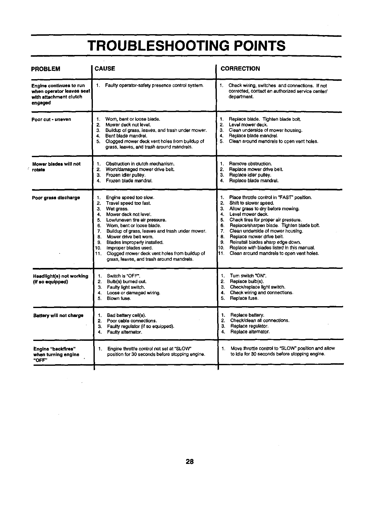
TROUBLESHOOTING POINTS
PROBLEM CAUSE CORRECTION
Engine continues to run
when operator leaves seat
with attachment clutch
engaged
Pooreut-uneven
Mower blades will not
"rotJte
Poor grass discharge
HeedUght(s) not working
(if so equipped)
Battery will not charge
Engine "backfires"
when turning engine .
"OFF"
1. Faulty operator-safety presence control system.
1. Worn, bent or loose blade.
2. Mower deck not level.
3. Buildup of grass, leaves, and trashunder mower.
4. Bent blade mandrel.
5. Clogged mower deck vent holes from buildup of
grass, leaves, and trash around mandrels.
1. Obstruction in clutch mechanism.
2. WorrVdamaged mower drive belt.
3. Frozen idler pulley.
4. Frozen blade mandrel.
1. Engine speed too slow.
2. Travel speed toofast.
3. Wet grass.
4. Mower deck not level.
5. Low/uneven tire air pressure.
6. Worn, bent or loose blade.
7. Buildupof grass, leaves and trash under mower.
8. Mower ddve belt worn.
9. Blades improperly installed.
10. Improper blades used.
11. Clogged mower deck vent holes from buildupof
grass, leaves, and trash around mandrels.
1. Switch is "OFF".
2. Bulb(s) burnedout.
3. Faulty light switch.
4. Loose or damaged widng.
5. Blownfuse.
1. Bad battery cell(s).
2. Pcor cable connections.
3. Faulty regulator (if so equipped).
4. Faulty altemator.
1. Engine throttlecootro_not set at "SLOW"
positionfor 30 seconds before stoppingengine.
t, Check wiring, switches and connections. If not
corrected, contact an authorized service center/
department.
1. Replace blade. Tighten blade bolt.
2. Level mower deck.
3. Clean underside of mower housing.
4. Replace blade mandrel.
5. Clean around mandrels to open vent holes.
1. Remove obstruction.
2. Replace mower drive belt.
3. Replece idler pulley.
4. Replace blade mandrel.
1. Place throttlecontrol in _FAS'F position.
2. Shift to slower speed.
3. Allow grass to dry before mowing.
4. Level mower deck.
5. Check tires for proper air pressure.
6. Replece/sharpen blade. Tighten blade bolt.
7. Clean underside of mower housing.
8. Replace mower drive belt•
9. Reinstallblades sharp edge down.
10. Replace with blades listed in this manual.
11. Clean around mandrels to open vent holes.
t. Tum switch "ON".
2. Replace bulb(s).
3. Check/replace light switch.
4. Check widng and connections.
5. Replece fuse.
1. Replace battery.
2. Check/clean all connections.
!43. Replace regulator.
•Replace alternator.
"l. Move.throttle control to "SLOW" positionand allow
to idle for30 seconds before stopping engine.
28
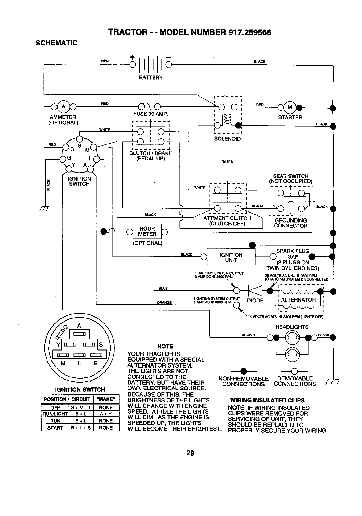
TRACTOR - - MODEL NUMBER 917.259566
SCHEMATIC
RED
BATTERY
BLACK
/7
RED
)WHITE
IG L(
IGNITION
SWITCH
FUSE 30 AMP.
r ------I
II
I
J (_LUTCH /BRAKJE
(PEDAL UP)
N.._K
HOURMETER ]_
(OPTIONAL)
i
[
I RED
STARTER
BLACK
LWHITE
SEAT SWITCH
(NOT OCCUPIED)
WHITE I........ I t .... ----.--1
II
III _ l-
....GROUND,NG
(CLUTCH OFF) ICONNECTOR
BLACK _IGNITIONUNIT
IGNITION SWITCH
PosmoN CIRCUIT "MAKE"
OFF G + M + L NONE
RUN/LIGHT B + LA + Y
RUN B + L NONE
START B + L + S NONE
J__ SPARK PLUG
GAP
(2 PLUGS ON
TWIN CYL, ENGINES)
CHARGJNG SYSTEM OUTPUT
3 AMP DC @ 36_ RPM '28 VOLTS AC MIN. @ 3600 RPM
(CHARGINGSYSTEMDISCONNECllED
BLUE I_
LIGHTING SYSTEM _Il
ORANGE 5 AMP AC, 36_0 _ 'I--_ /
LsRow.
NOTE
YOUR TRACTOR IS
EQUIPPED WITH A SPECIAL
ALTERNATOR SYSTEM.
THE LIGHTS ARE NOT
CONNECTED TO THE
BATFERY, BUT HAVE THEIR
OWN ELECTRICAL SOURCE.
BECAUSE OF THIS, THE
BRIGHTNESS OF THE LIGHTS
WILL CHANGE WITH ENGINE
SPEED. AT IDLE THE LIGHTS
WILL DIM. AS THE ENGINE IS
SPEEDED UP, THE LIGHTS
WILL BECOME THEIR BRIGHTEST.
•©
NON-REMOVABLE REMOVABLE
CONNECTIONS CONNECTIONS
WIRING INSULATED CLIPS
NOTE: IF WIRING INSULATED
CLIPS WERE REMOVED FOR
SERVICING OF UNIT, THEY
SHOULD BE REPLACED TO
PROPERLY SECURE YOUR WIRING.
29
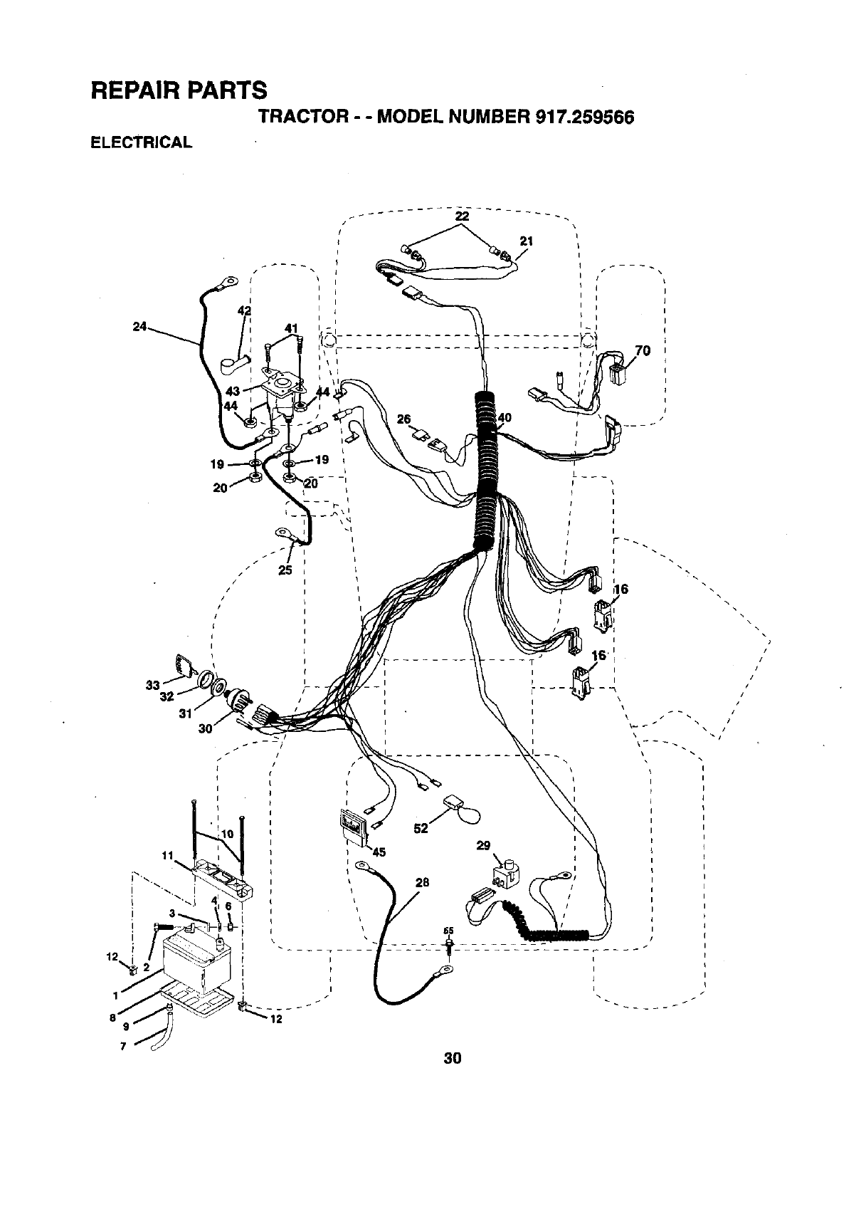
REPAIR PARTS
TRACTOR - - MODEL NUMBER 917.259566
ELECTRICAL
/
I
I
42
41
25
/
p16
I\\
3O
,,,/
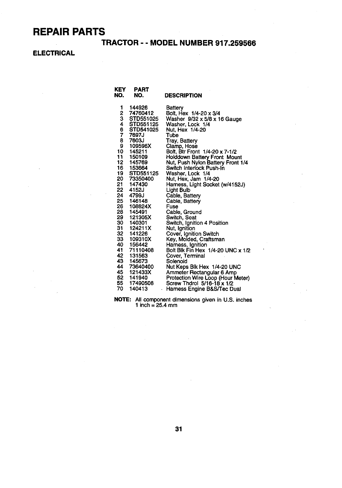
REPAIR PARTS
TRACTOR - - MODEL NUMBER 917.259565
ELECTRICAL
KEY PART
NO. NO. DESCRIPTION
1 144926 Battery
274760412 Bolt, Hex 1/4-20 x 3/4
3 STD551025 Washer 9/32 x 5/8 x 16 Gauge
4 STD551125 Washer, Lock 1/4
6 STD541025 Nut, Hex 1/4-20
7 7697J Tube
8 7603J Tray, Battery
9 109596X Clamp, Hose
10 145211 Bolt, BtrFmnt 1/4-20x7-1/2
11 150109 HolddownBattery Front Mount
12 145769 Nut, Push NylonBattery Front 114
16 153664 Switch InterlockPush-In
19 STD551125 Washer, Lock 1/4
20 73350400 Nut, Hex, Jam 1/4-20
21 147430 Hamess, LightSocket (w/4152J)
22 4152J LightBulb
24 4799J Cable, Battery
25 146148 Cable, Battery
26 108824X Fuse
28 145491 Cable, Ground
29 121305X Switch, Seat
30 140301 Switch, Ignition4 Position
31 124211X Nut, Ignition
32 141226 Cover, IgnitionSwitch
33 109310X Key, Molded,Craftsman
40 156442 Harness, Ignition
41 71110408 Bolt BIk Fin Hex 1/4-20 UNC x 1/2
42 131563 Cover, Terminal
43 145673 Solenoid
44 73640400 Nut Keps BIk Hex 1/4-20 UNC
46 121433X Ammeter Rectangular6 Amp
52 141940 ProtectionWire Loop(Hour Meter)
55 17490508 Screw Thdrel 5/16-18 x 1/2
70 140413 . Harness EngineB&S/Tec Dual
NOTE: All component dimensionsgiven in U.S. inches
1 inch= 25.4 mm
31
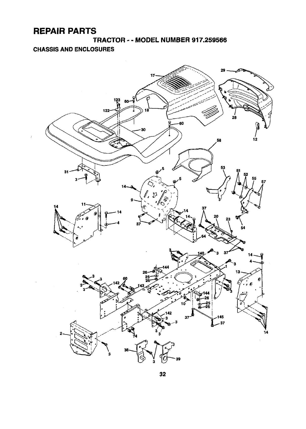
REPAIR PARTS
TRACTOR - - MODEL NUMBER 917,259566
CHASSIS AND ENCLOSURES
28
12
31
37
53
55 7
3
54
32
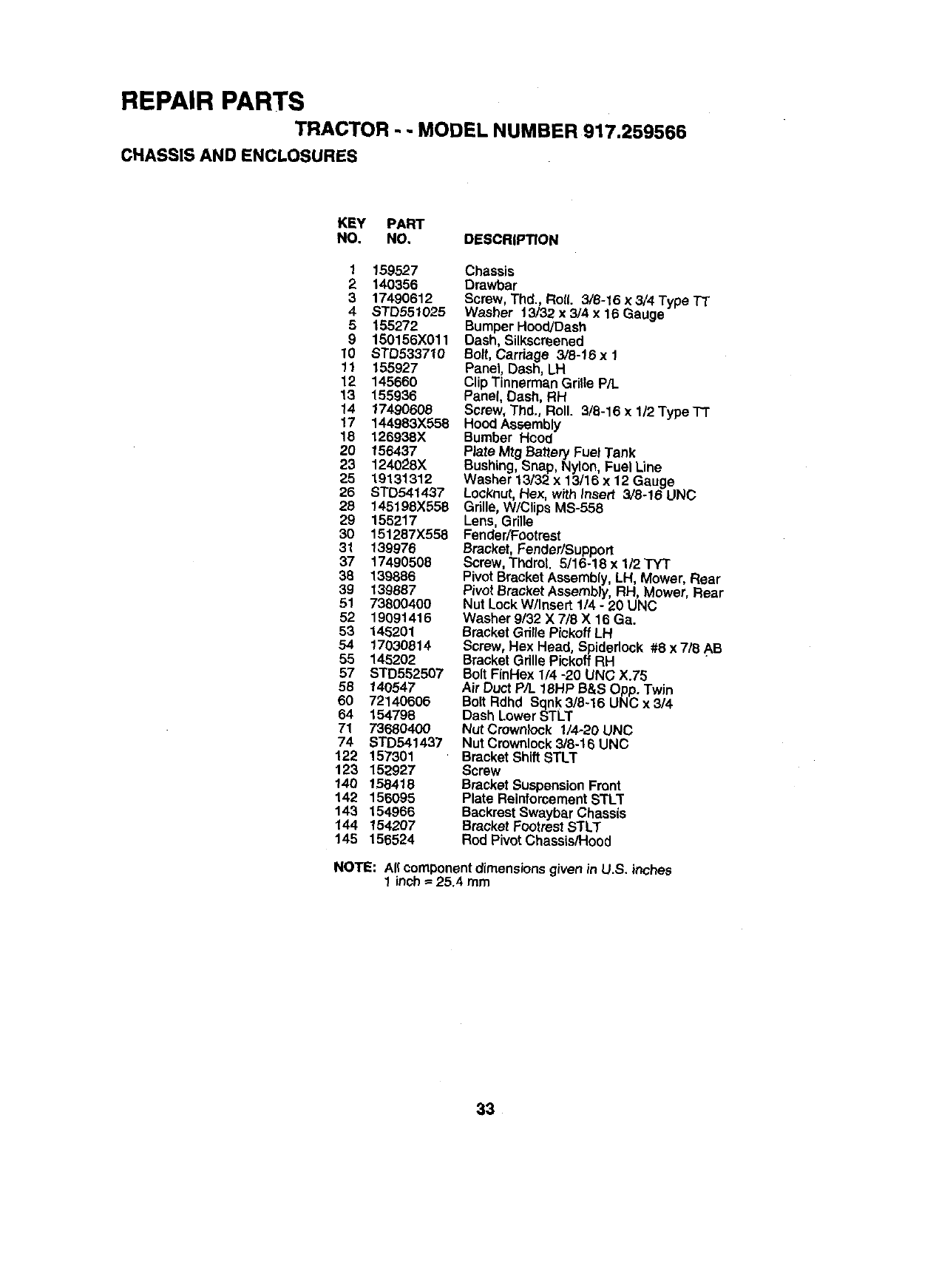
REPAIR PARTS
TRACTOR -- MODEL NUMBER 917.259566
CHASSIS AND ENCLOSURES
KEY PART
NO. NO, DESCRIPTION
1159527
2 140356
3 17490612
4 STD551025
5 155272
9 150156X011
10 STD533710
11 155927
12 145660
13 155936
14 17490608
17 144983X558
18 126938X
20 156437
23 124028X
25 19131312
26 STD541437
28 145198X558
29 155217
30 151287X558
31 139976
37 17490506
38 139886
39 t 39887
51 73800400
52 19091416
53 146201
54 17030814
55 145202
57 STD552507
58 140547
60 72140605
64 154798
71 73680400
74 STD541437
122 157301
123 152927
140 158418
142 156095
143 154966
144 154207
145 156524
Chassis
Drawbar
Screw, Thd., Ro((. 3/8-16 x 3/4 Type TT
Washer 13/32 x 3/4 x16 Gauge
BumperHood/Dash
Dash, Silkscreened
Bolt,Carriage 3/8-16 x 1
Panel, Dash, LH
ClipTinnerman Grille P/L
Panel, Dash, RH
Screw, Thd., Roll. 3/8-16 x 1/2 Type-IT
Hood Assembly
Bumber Hood
Plate Mtg Battery Fuel Tank
Bushing, Snap, Nylon, Fuel Line
Washer 13132x 13/16 x 12 Gauge
Locknut, Hex, with insert 3/6-16 UNC
Gdlle, W/Clips MS-558
Lens, Grille
Fender/Footrest
Bracket, Fender/Support
Screw, ThdroL 5/16-18 x 1/2 "rYT
Pivot Bracket Assembly, LH, Mower, Rear
Pivot BracketAssembly, RH, Mower, Rear
Nut Lock W/Insert 1/4 - 20 UNC
Washer 9/32 X 7/8 X 16 Ga.
Bracket Gdlle Pickoff LH
Screw, Hex Head, Spideriock #8 x7/6 AB
Bracket Grille Piekoff RH
Bolt FinHex 1/4 -20 UNC X.75
Air Duct P/L 16HP B&S Opp. Twin
Bolt Rdhd Sqnk3/8-16 UNC x 3/4
Dash LowerSTLT
Nut Crownk)ck 1/4-20 UNC
Nut Cmwnlock3/8o16UNC
BracketShift STLT
Screw
BracketSuspensionFront
Plate ReinforcementSTLT
BackrestSwaybarChassis
BracketFootrestSTLT
Rod PivotChassis/Hood
NOTE: AI(componentdimensions given in U.S. inches
1 inch_25.4 mm
33
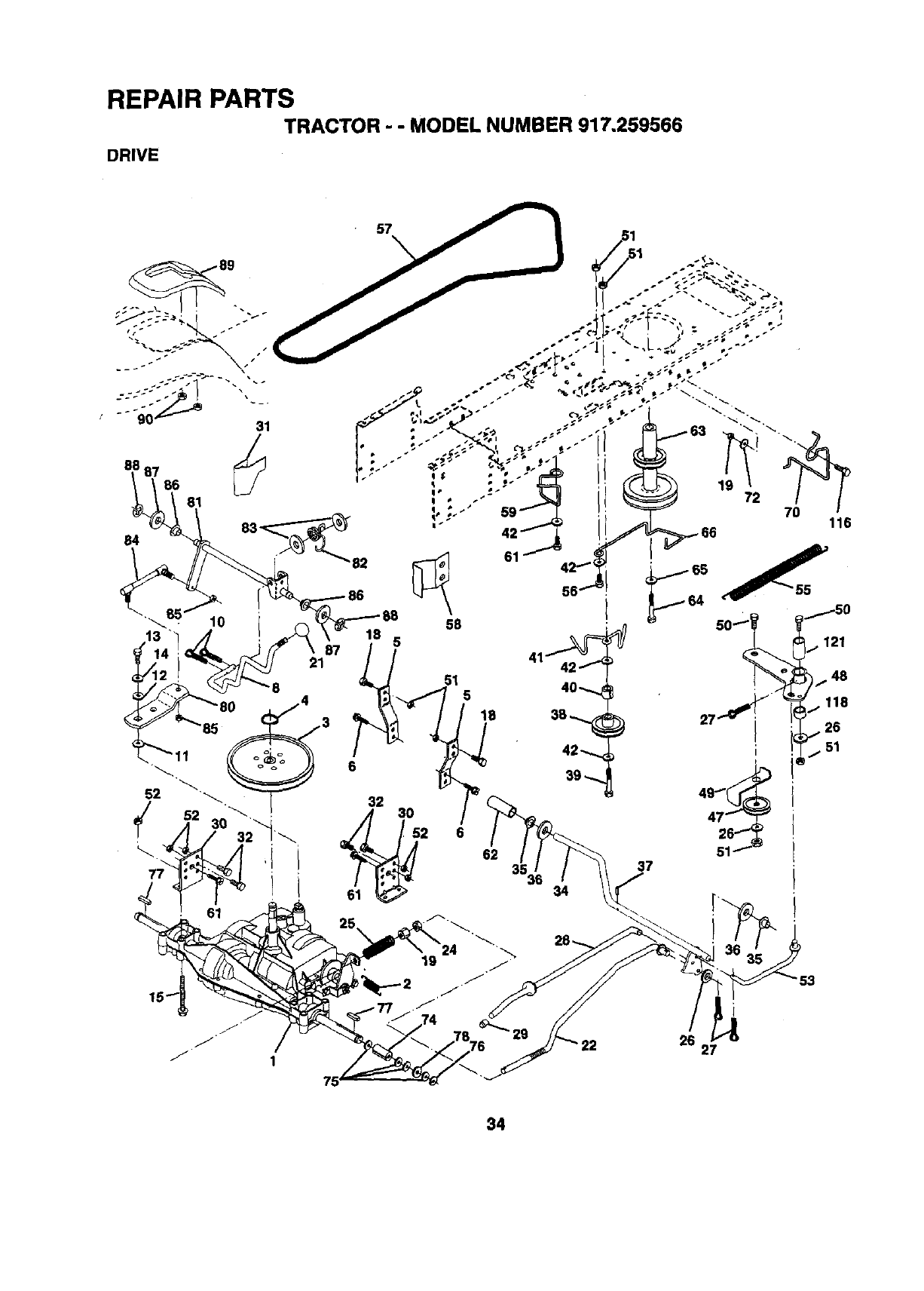
REPAIR PARTS
TRACTOR - - MODEL NUMBER 917.259566
DRIVE
57
84 83_82
10 18
87
21
5
51 5
62 37
26 27
34
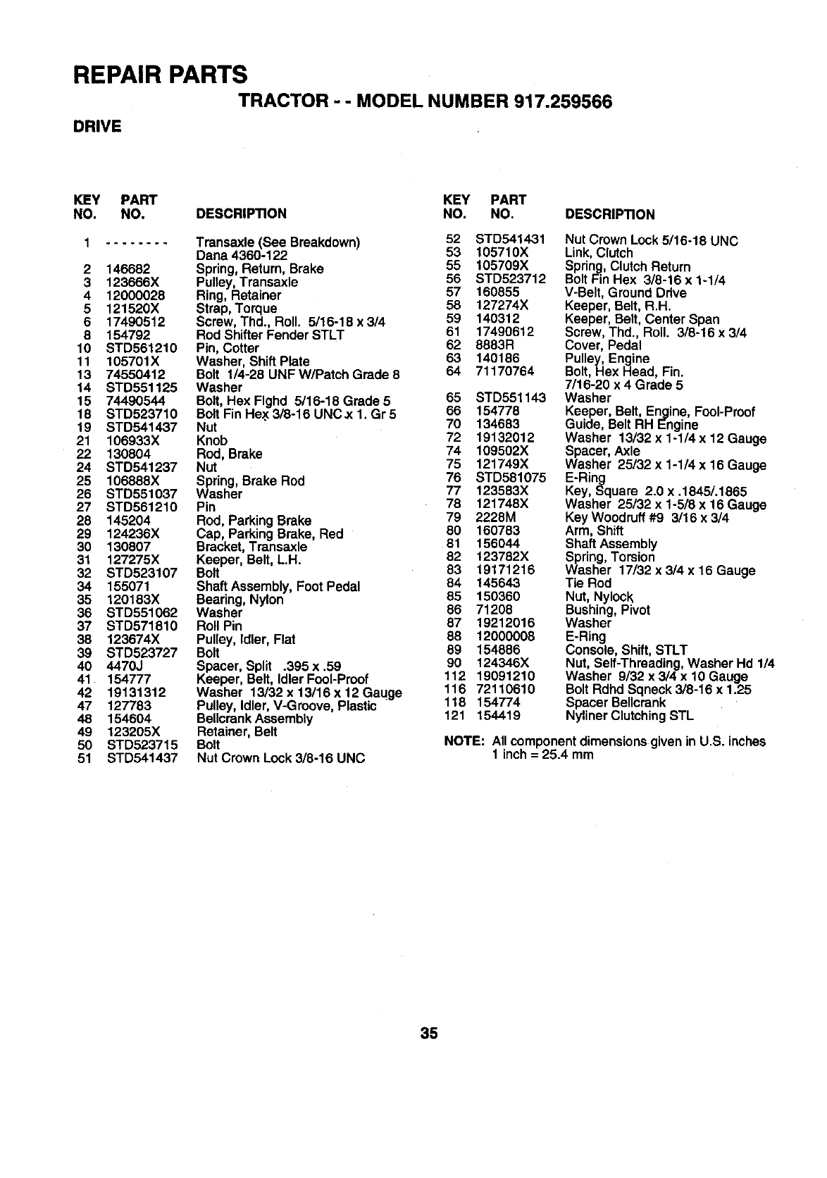
REPAIR PARTS
TRACTOR --MODEL NUMBER 917.259566
DRIVE
KEY PART KEY PART
NO. NO. DESCRIPTION NO. NO. DESCRIPTION
1 ........ Transaxle (See Breakdown) 52 STD541431
Dana 4360-122 53 105710X
2 146682 Spring, Return, Brake 55 105709X
3 123666X Pulley,Transaxle 56 STD523712
4 12000028 Ring, Retainer 57 160855
5 121520X Strap, Torque 58 127274X
6 17490512 Screw, Thd., Roll. 5/16-18x3/4 59 140312
8 154792 Rod Shifter Fender STLT 61 17490612
10 STD561210 Pin, Cotter 62 8883R
11 105701X Washer, Shift Plate 63 140186
13 74550412 Bolt 1/4-26 UNF W/Patch Grade 8 64 71170764
14 STD551125 Washer
15 74490544 Bolt, Hex Flghd 5/16-18 Grade 5 65 STD551143
18 STD523710 Bolt Fin Hex 3/8-16 UNC.x I Gr 5 66 154778
19 STD541437 Nut 70 134683
21 106933X Knob 72 19132012
22 130804 Rod, Brake 74 109502X
24 STD541237 Nut 75 121749X
25 106888X Spring, Brake Rod 76 STD581075
26 STD551037 Washer 77 123583X
27 STD561210 Pin 78 121748X
28 145204 Rod, ParkingBrake 79 2228M
29 124236X Cap, ParkingBrake, Red 80 160783
30 130807 Bracket,Transaxle 81 156044
31 127275X Keeper, Belt, L.H. 82 123782X
32 STD523107 Bolt 83 19171216
34 155071 Shaft Assembly,Foot Pedal 84 145643
35 120183X Bearing, Nylon 85 150360
36 STD551062 Washer 86 71208
37 STD571810 RollPin 87 19212016
38 123674X Pulley, Idler, Flat 88 12000008
39 STD523727 Bolt 89 154886
40 4470J Spacer, Split °395 x .59 90 124346X
41 154777 Keeper, Belt, Idler Fool-Proof 112 19091210
42 19131312 Washer 13/32x13/16x12Gaqge 116 72110610
47 127783 Pulley, Idler, V-Groove, Plastic 118 154774
48 154604 BellcrenkAssembly 121 154419
49 123205X Retainer, Belt
50 STD523715 Bolt
51 STD541437 Nut Crown Look3/8-16 UNC
Nut Crown Look5/16-18 UNC
Link,Clutch
Spring,ClutchReturn
Bolt Fin Hex 3/8-16 x 1-1/4
V-Belt, Ground Drive
Keeper, Belt, R.H.
Keeper, Belt, Center Span
Screw, Thd., Roll. 3/8-16 x 3/4
Cover, Pedal
Pulley, Engine
Bolt, Hex Head, Fin.
7/16-20 x 4 Grade 5
Washer
Keeper, Belt, Engine, Fool-Proof
Guide, Belt RH Engine
Washer 13/32 x 1-1/4 x 12 Gauge
Spacer, Axle
Washer 25/32 x 1-1/4 x 16 Gauge
E-Ring
Key, Square 2.0 x .1845/.1865
Washer 25/32 x 1-5/8 x 16 Gauge
Key Woodruff#9 3/16 x 3/4
Arm, Shift
Shaft Assembly
Spring,Torsion
Washer 17/32 x 3/4 x 16 Gauge
Tie Rod
Nut, Nylock
Bushing,Pivot
Washer
E-Ring
Console, Shift, STLT
Nut, Self-Threading, Washer Hd 1/4
Washer 9/32 x 3/4 x 10 Gauge
Bolt RdhdSqneck 3/8-16 x 1.25
Spacer Be,crank
NylinerClutchingSTL
NOTE: All componentdimensionsgiven in U.S. inches
1 inch= 25.4 mm
35
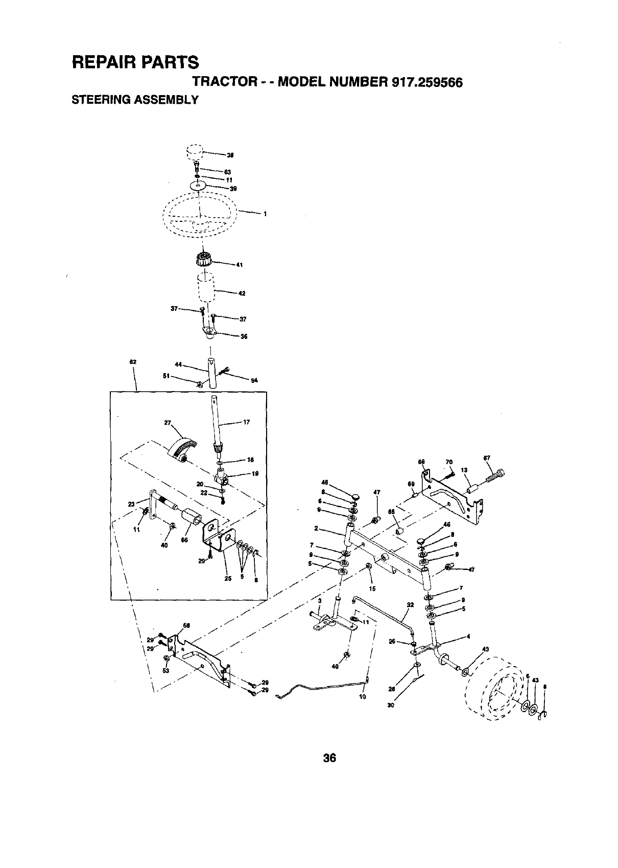
REPAIR PARTS
TRACTOR - - MODEL NUMBER 917.259566
STEERING ASSEMBLY
•p
62 44
27
67
66 70 13
36
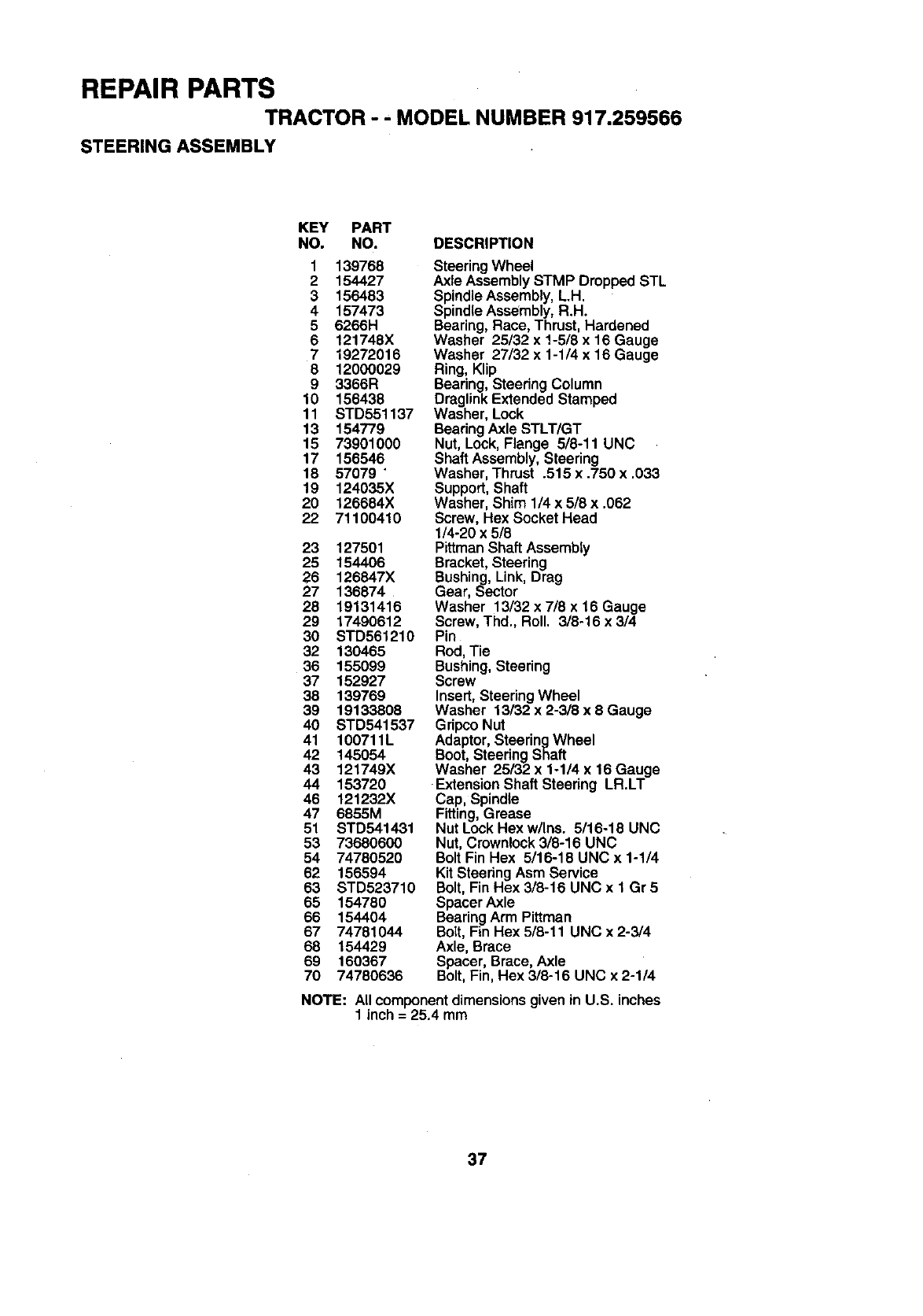
REPAIR PARTS
TRACTOR - - MODEL NUMBER 917.259566
STEERING ASSEMBLY
KEY PART
NO. NO. DESCRIPTION
1 139768
2154427
3156483
4157473
5 6266H
6 121748X
719272016
8 12000029
9 3366R
10 156438
11 STD551137
13 154779
15 73901000
17 156546
18 57079 "
19 124035X
20 125884X
22 71100410
23 127501
25 154406
26 126847X
27 136874
28 19131416
29 17490612
30 STD561210
32 130465
36 155099
37 152927
38 139769
39 19133808
40 STD541537
41 100711L
42 145054
43 121749X
44 153720
46 121232X
47 6855M
51 STD541431
53 73680600
54 74780520
62 156594
63 STD523710
85 154780
66 154404
67 74781044
68 154429
69 160367
70 74780636
SteeringWheel
Axle AssemblySTMP Dropped STL
SpindleAssembly,L.H.
SpindleAssembly,R.H.
Bearing,Race, Thrust, Hardened
Washer 25/32 x !-5/8 x 16 Gauge
Washer 27/32 x 1-1/4 x 16 Gauge
Ring, Klip
Bearing,Steering Column
DraglinkExtended Stamped
Washer, Lock
BearingAxle STLT/GT
Nut, Lock, Flange 5/8-11 UNC
Shaft Assembly,Steering
Washer, Thrust .515 x .750 x .033
Support,Shaft
Washer, Shim 1/4 x 5/8 x .062
Screw, Hex Socket Head
1/4-20 x 5/8
Pittman Shaft Assembly
Bracket, Steering
Bushing, Link, Drag
Gear, Sector
Washer 13/32 x 7/8 x 16 Gauge
Screw, Thd., Roll. 3/8-16 x 3/4
Pin
Rod, Tie
Bushing, Steering
Screw
Insert,SteeringWheel
Washer 13/32 x 2-3/8 x 8 Gauge
GripcoNut
Adaptor,SteeringWheel
Boot,SteeringShaft
Washer 25/32 x 1-1/4 x 16 Gauge
-Extension Shaft Steering LR.LT
Cap, Spindle
Fitting,Grease
Nut LockHexw/Ins. 5/16-18 UNC
Nut, Crownlock3/8-16 UNC
Bolt Fin Hex 5/16-18 UNC x 1-1/4
KitSteeringAsm Service
Bolt, Fin Hex 3/8-16 UNC x 1 Gr 5
Spacer Axle
BearingArm Pittman
Bolt, Fin Hex 5/8-11 UNC x 2-3/4
Axle, Brace
Spacer, Brace, Axle
Bolt,Fin, Hex 3/8-16 UNC x 2-1/4
NOTE: All componentdimensionsgiven in U.S. inches
1 inch = 25.4 mm
37
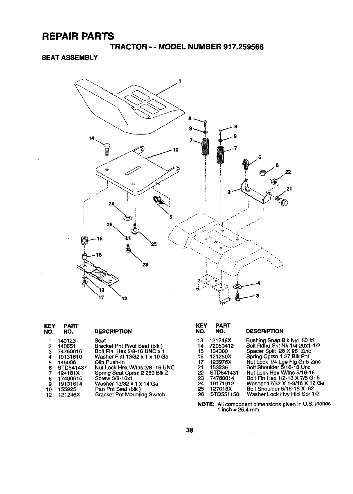
REPAIR PARTS
TRACTOR - - MODEL NUMBER 917.259566
SEAT ASSEMBLY
KEY
NO.
1
2
3
4
5
6
7
8
9
10
12
PART
NO,
140123
140551
74760616
19131610
145006
STD541437
124181X
17490616
19131614
155925
121245X
DESCRIPTION
Seat 13 121248X
Bracket Pnt Pivot Seat (blk) 14 72050412
Bolt Fin Hex 3/8-16 UNC x 1 15 134300
Washer Flat 13/32 x 1 x 10 Ga 16 121250X
Clip Push-In 17 123976X
Nut Lock Hex W/Ins 3/8 -16 UNC 21 153236
Spring Seat Cprsn 2 250 BIk Zi 22 STD541431
Screw 3/8-16xl 23 74780814
Washer 13/32 x 1x 14 Ga 24 19171912
Pan Pnt Seat (blk) 25 127018X
Bracket Pnt Mounting Switch 26 STD551150
KEY PART
NO. NO. DESCRIPTION
BushingSnap BIk Nyl 50 Id
Bolt Rdhd Sht Nk 1/4-20xl-112
Spacer Split 28 X 96 Zinc
SpringCprsn 1 27 BIk Pnt
Nut Lock 1/4 Lge Fig Gr 5 Zinc
Bolt Shoulder5/16-18 Unc
Nut Lock Hex W/Ins 5116-18
Bolt Fin Hex 1/2-13 X 718Gr 5
Washer 17/32 X 1-3/16 X 12 Ga
Bolt Shoulder5/16-18 X 62
Washer LockHvy Hlcl Spr 1/2
NOTE: All componentdimensions given in U.S. inches
1 inch= 25.4 mm
38
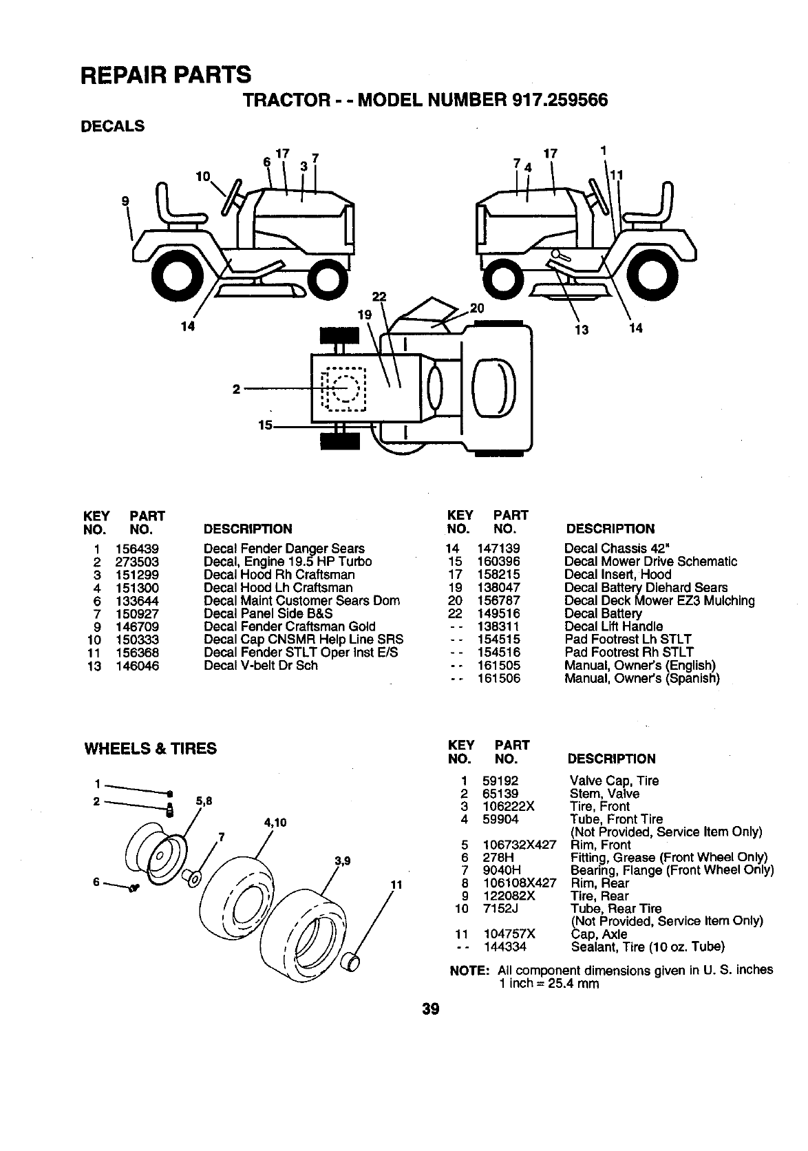
REPAIR PARTS
TRACTOR - - MODEL NUMBER 917.259566
DECALS
9
10\
14
22
19
17
13 14
2
15
KEY PART KEY PART
NO. NO. DESCRIPTION NO. NO.
1 156439 Decal Fender Danger Sears 14 147139
2 273503 Decal, Engine 19.5 HP Turbo 15 150396
3 151299 DecaIHood Rh Craftsman 17 158215
4 151300 Decal Hood Lh Craftsman 19 138047
6 133644 Decal Maint Customer Sears Dom 20 156787
7 150927 Decal Panel Side B&S 22 149516
9 146709 Decal Fender Craftsman Gold - - 138311
10 150333 Decal Cap CNSMR Help Line SRS -- 154515
11 156368 Decal Fender STLT Oper InstE/S - - 154516
13 146046 Decal V-belt Dr Sch - - 161505
-- 161506
DESCRIPTION
Decal Chassis 42"
Decal Mower Drive Schematic
Decal Insert,Hood
Decal Battery Diehard Sears
Decal DeckMower EZ3 Mulching
Decal Battery
Decal Lift Handle
Pad Footrest Lh STLT
Pad Footrest Rh STLT
Manual, Owner's (English)
Manual, Owner's (Spanish)
WHEELS & TIRES
2_5,8 4,10
7
11
39
KEY PART
NO. NO. DESCRIPTION
1
2
3
4
5
6
7
8
9
10
11
°.
59192
65139
106222X
59904
106732X427
278H
9040H
106108X427
122082X
7152J
104757X
144334
Valve Cap, Tire
Stem, Valve
Tire, Front
Tube, Front Tire
(Not Provided,Service Item Only)
Rim, Front
Fitting,Grease (FrontWheel Only)
Bearing, Flange (FrontWheel Only)
Rim, Rear
Tire, Rear
Tube, Rear Tire
(Not Provided, Service Item Only)
Cap, Axle
Sealant, Tire (10 oz. Tube)
NOTE: AIIcomponentdimensions givenin U. S. inches
1 inch = 25.4mm
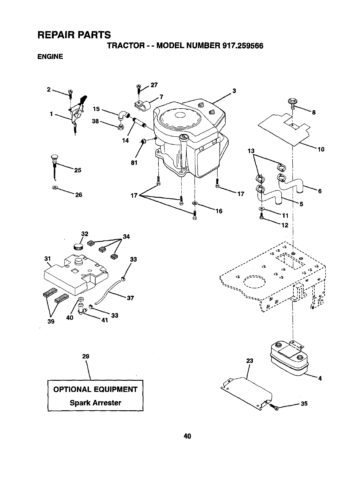
REPAIR PARTS
TRACTOR -- MODEL NUMBER 917.259566
ENGINE
2_
31
40
39
14
33
3
37
13 10
29
.\
IOPTIONAL EQUIPMENT I
Spark Arrester
40
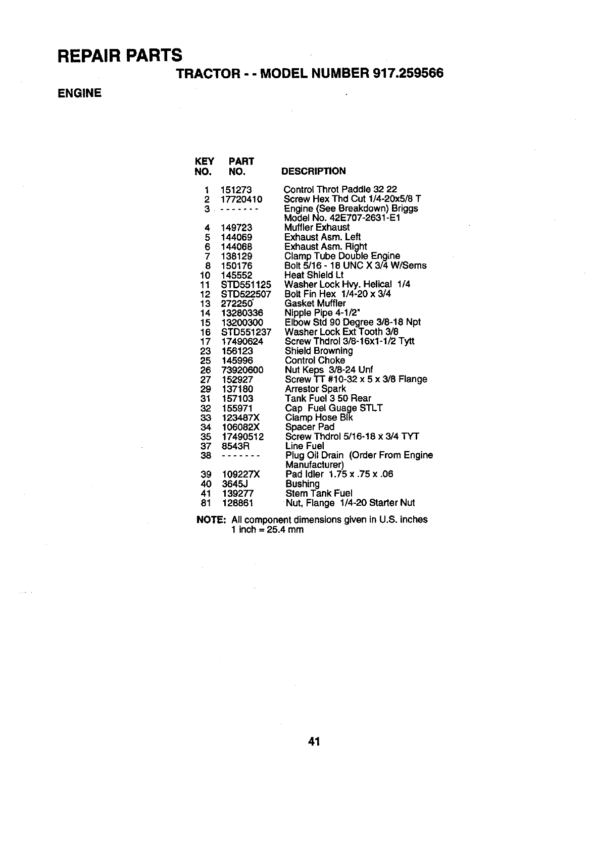
REPAIR PARTS
TRACTOR - - MODEL NUMBER 917.259566
ENGINE
KEY PART
NO. NO. DESCRIPTION
1151273
2 17720410
3 .......
4 149723
5 144069
6 144068
7 138129
8 150176
10 145552
11 STD551125
12 STD522.507
13 27225_
14 13280335
15 13200300
16 STD551237
17 17490624
23 156123
25 145996
26 73920600
27 152927
29 137180
31 157103
32 155971
33 1234.87X
34 106082X
35 17490512
37 8543R
38
39 109227X
40 3645J
41 139277
81 128861
Control Thret Paddle 32 22
Screw Hex Thd Cut 1/4-20x5/8 T
Engine (See Breakdown) Briggs
Model No. 42E707-2631-E1
MufflerExhaust
ExhaustAsm. Left
ExhaustAsm. Right
Clamp Tube Double Engine
Bolt 5/16 - 18 UNC X 3/4 W/Sems
Heat ShieldLt
Washer Lock Hvy. Helical 1/4
BoltFin Hex 1/4-20 x 3/4
Gasket Muffler
Nipple Pipe 4-1/2"
Elbow Std 90 Degree 3/8-18 Npt
Washer LockExtTooth 3/8
Screw Thdrol3/8-16x1-1/2 Tytt
Shield Browning
ControlChoke
Nut Keps 3/8-24 Unf
Screw TT #10-32 x 5 x 3/8 Flange
ArrestorSpark
Tank Fuel 3 50 Rear
Cap Fuel Guage STLT
Clamp Hose BIk
Spacer Pad
Screw Thdrol5/16-18 X3/4 TY'I"
Line Fuel
Plug Oil Drain (Order From Engine
Manufacturer)
Pad Idler 1.75 x .75 x .06
Bushing
Stem Tank Fuel
Nut, Flange 1/4-20 Starter Nut
NOTE: AIIcomponentdimensionsgiven
1 inch = 25.4mm in U.S. inches
41
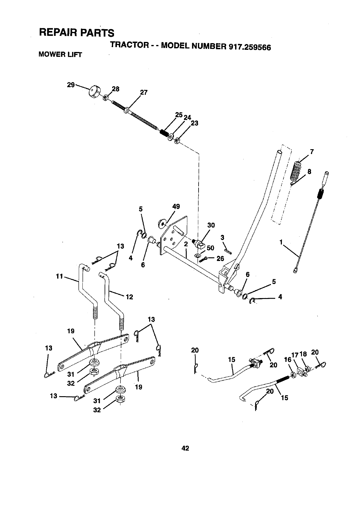
REPAIR PARTS
TRACTOR - - MODEL NUMBER 917.259566
MOWER LIFT
29_27
7
5
13
49
3O
3\
6
8
,I I'
,! !'
.I I"
rI I'
5
4
13
19
2O
15 2O
15
2O
42
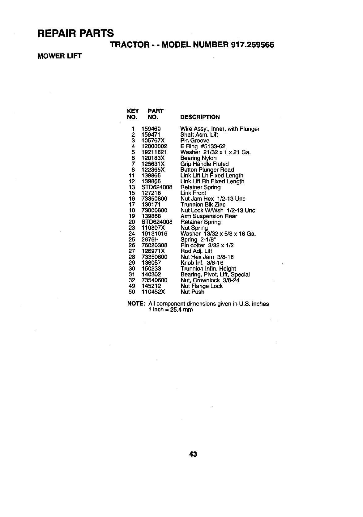
REPAIR PARTS
TRACTOR -- MODEL NUMBER 917.259566
MOWER LIFT
KEY PART
NO. NO. DESCRIP_ON
1 159460 Wire Assy., Inner, with Plunger
2 159471 Shaft Asm. Lift
3 105767X Pin Groove
4 12000002 E Ring #5133-62
5 19211621 Washer 21/32 x 1 x 21 Ga.
6 120183X Bearing Nylon
7125631X Grip Handle Fluted
8 122365X ButtonPlunger Read
11 139865 Link Lift Lh Fixed Length
12 139866 Link Lift Rh Fixed Length
13 STD624008 Retainer Spring
15 127218 Link Front
16 73350800 Nut Jam Hex 1/2-13 Unc
17 130171 Trunnion BlkZinc
18 73800800 Nut Lock WANsh 1/2-13 Unc
19 139868 Arm SuspensionRear
20 STD624008 Retainer Spring
23 110807X Nut Spring
24 19131016 Washer 13/32 x 5/8 x 16 Ga.
25 2876H Spiring 2-1/8"
26 76020308 Pin cotter 3/32 x 1/2
27 126971X Rod Adj. Lift
28 73350600 Nut Hex Jam 3/8-16
29 138057 Knob Inf. 3/8-16
30 150233 Trunnion Infin. Height
31 140302 Bearing, Pivot, Lift, Special
32 73540600 Nut, Crownlock 3/8-24
49 145212 Nut Flange Lock
50 110452X Nut Push
NOTE: All componentdimensions given in U.S. inches
1 inch= 25.4 mm
43
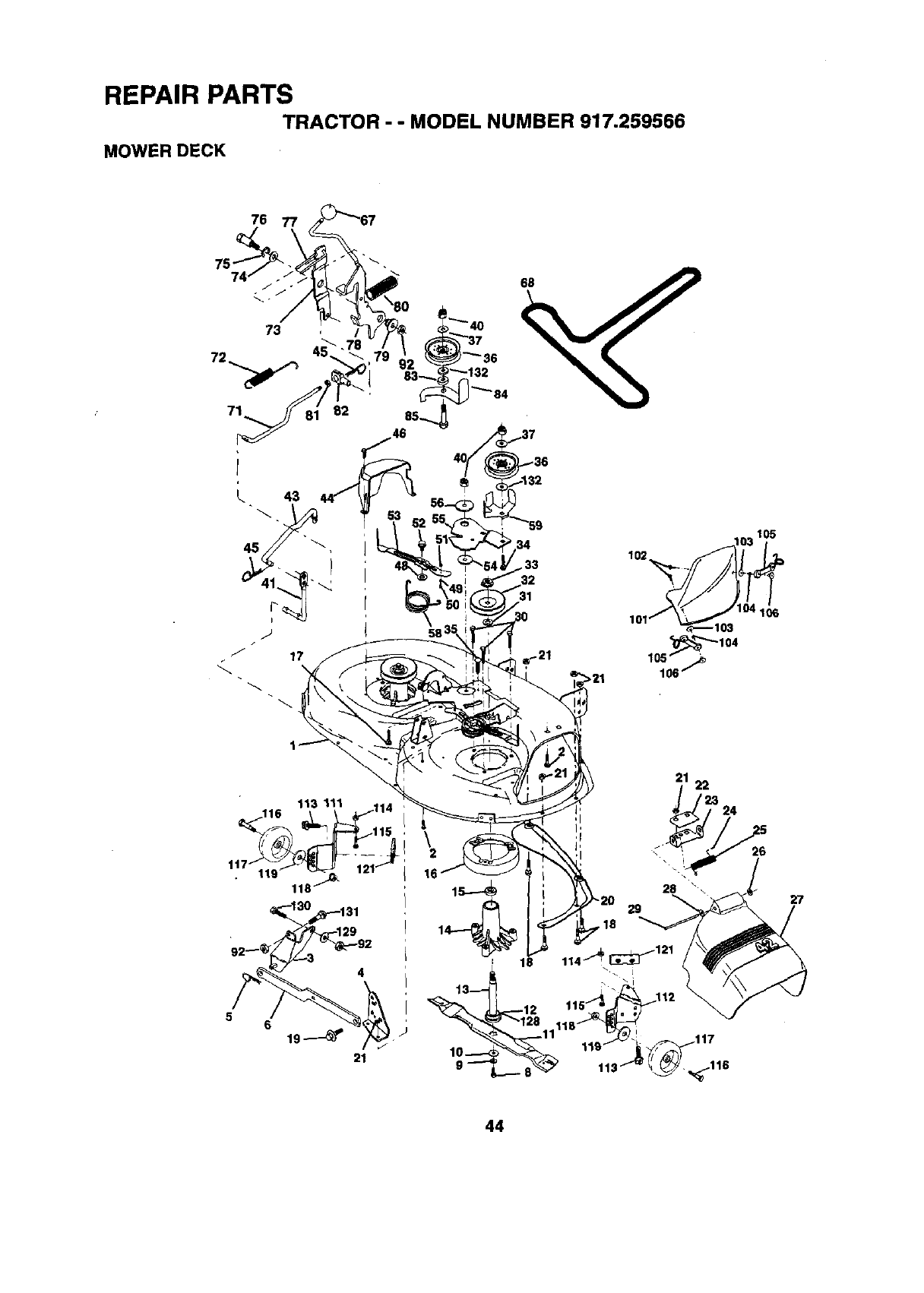
REPAIR PARTS
TRACTOR - -MODEL NUMBER 917.259566
MOWER DECK
76
58
,_'_'_104
105 .,_
106_
56
21
21 22
24
16
18
10----<
9"-_"
28 \
29
,18
26
27
44
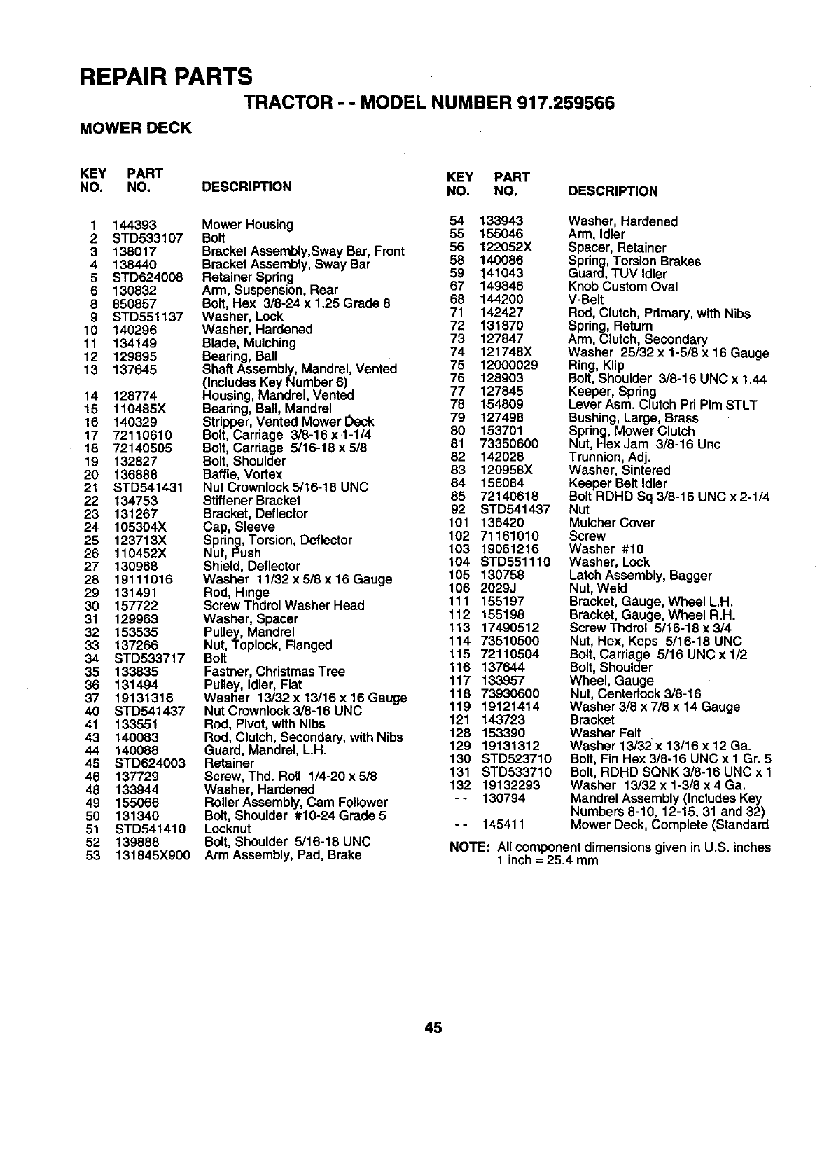
REPAIR PARTS
TRACTOR - - MODEL NUMBER 917.259566
MOWER DECK
KEY PART KEY PART
NO. NO. DESCRIPTION NO. NO. DESCRIPTION
1 144393
2 STD533107
3138017
4138440
5STD624008
6 130832
8 850857
9 STD551137
10 140296
11 134149
12 129895
13 137645
Mower Housing 54 133943
Bolt 55 155046
BracketAssembly,Sway Bar, Front 56 122052X
BracketAssembly, Sway Bar 58 140086
Retainer Spring 59 141043
Arm, Suspension,Rear 67 149846
Bolt, Hex 3/8-24 x 1.25 Grade 8 68 144200
Washer, Lock 71 142427
Washer, Hardened 72 131870
Blade, Mulching 73 127847
74 121748X
Bearing, Ball
Shaft Assembly,Mandrel, Vented 75 12000029
(Includes Key Number 6) 76 128903
14 128774 Housing, Mandrel, Vented 77 127845
15 110485X Bearing,Ball, Mandrel 78 154809
16 140329 Stripper,Vented Mower Oeck 79 127498
17 72110610 Bolt,Carriage 3/8-16 x1-1/4 80 153701
18 72140505 Bolt,Carriage 5/16-18x5/8 81 73350600
19 132827 Bolt,Shoulder 82 142028
20 136888 Baffle,Vortex 83 120958X
21 STD541431 Nut Crownlock 5/16-18 UNC 84 156084
22 134753 StiffenerBracket 85 72140618
23 131267 Bracket,Deflector 92 STD541437
24 105304X Cap, Sleeve 101 136420
25 123713X Spring,Torsion, Deflector 102 71161010
26 110452X Nut, Push 103 19061216
27 130968 Shield, Deflector 104 STD551110
28 19111016 Washer 11/32 x 5/8 x16 Gauge 105 130758
29 131491 Rod, Hinge 106 2029J
30 157722 Screw ThdrolWasher Head 111 155197
31 129963 Washer, Spacer 112 155198
32 153535 Pulley, Mandrel 113 17490512
33 137266 Nut, Toplock, Flanged 114 73510500
34 STD533717 Bolt 115 72110504
35 133835 Fastner,ChristmasTree 116 137644
117 133957
36 131494 Pulley, Idler, Flat
37 19131316 Washer 13/32 x13/16 x16 Gauge 118 73930600
40 STD541437 NutCrownlock3/8-16UNC 119 19121414
41 133551 Rod, Pivot, withNibs 121 143723
43 140083 Rod, Clutch, Secondary,with Nibs 128 153390
44 140088 Guard, Mandrel, L.H. 129 19131312
45 STD624003 Retainer 130 STD523710
46 137729 Screw, Thd. Roll 1/4-20 x 518 131 STD533710
48 133944 Washer, Hardened 132 19132293
49 155066 Roller Assembly,Cam Follower - - 130794
50 131340 Bolt,Shoulder #10-24Grade 5
51 STD541410 Locknut -- 145411
52 139888 Bolt, Shoulder 5/16-18 UNC
53 131845X900 Arm Assembly,Pad, Brake
Washer, Hardened
Arm, Idler
Spacer, Retainer
Spring,TorsionBrakes
Guard, TUV Idler
KnobCustom Oval
V-Belt
Rod, Clutch, Primary,with Nibs
Spring,Return
Arm, Clutch, Secondary
Washer 25/32 x 1-5/8 x 16 Gauge
Ring, Klip
Bolt, Shoulder 3/8-16 UNC x 1.44
Keeper, Spring
Lever Asm. Clutch Pri PIm STLT
Bushing, Large, Brass
Spring, Mower Clutch
Nut, HexJam 3/8-16 Unc
Trunnion, Adj.
Washer, Sintered
Keeper Belt Idler
Bolt RDHD Sq 3/8-16 UNC x 2-1/4
Nut
Mulcher Cover
Screw
Washer #10
Washer, Lock
LatchAssembly, Bagger
Nut, Weld
Bracket, Gauge, Wheel L.H.
Bracket, Gauge, Wheel R.H.
Screw Thdrol 5/16-18 x 314
Nut, Hex, Keps 5/16-18 UNC
Bolt,Carriage 5/16 UNC x 1/2
Bolt,Shoulder
Wheel, Gauge
Nut, Centeriock 3/8-16
Washer 3/8 x 7/8 x 14 Gauge
Bracket
Washer Felt
Washer 13/32 x 13/16 x 12 Ga.
Bolt, Fin Hex 3/8-16 UNC x I Gr. 5
Bolt, RDHD SQNK 3/8-16 UNC x 1
Washer 13/32 x 1-3/8 x 4 Ga.
Mandrel Assembly (Includes Key
Numbers 8-10, 12-15, 31 and 32)
Mower Deck, Complete (Standard
NOTE: All componentdimensions given in U.S. inches
1 inch= 25.4 mm
45
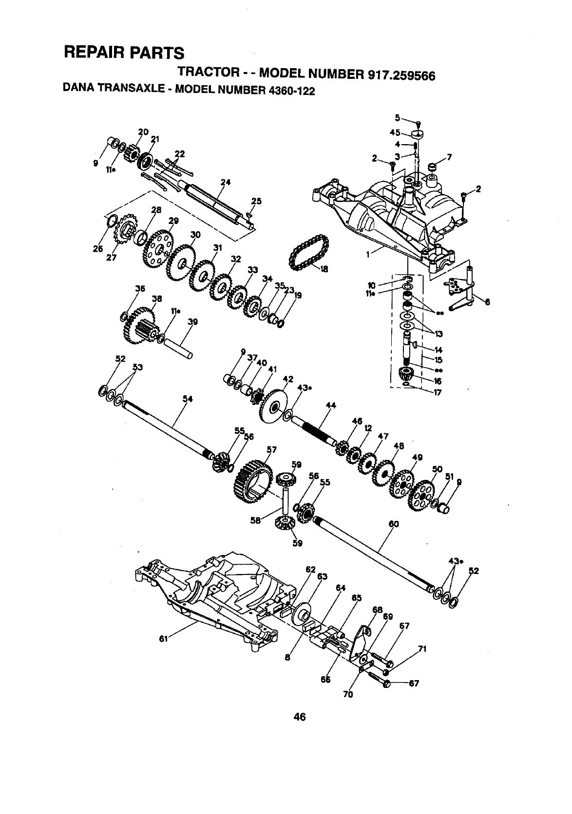
REPAIR PARTS
TRACTOR - - MODEL NUMBER 917.259566
DANA TRANSAXLE o MODEL NUMBER 4360-122
5
20 21 45_
22
24
25
2:
38
31
53
47
49
5O
62
7O
46
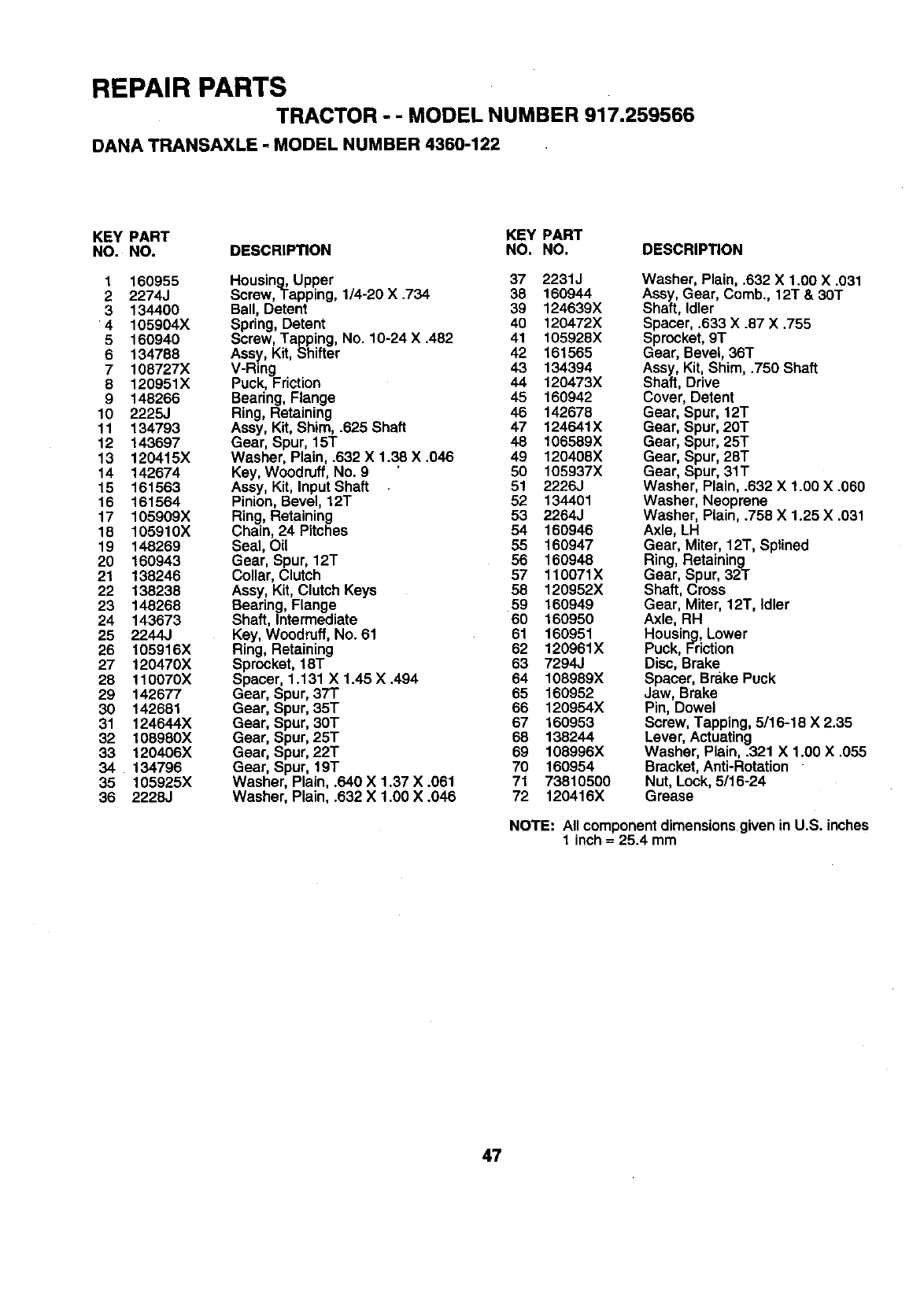
REPAIR PARTS
TRACTOR --MODEL NUMBER 917.259566
DANA TRANSAXLE - MODEL NUMBER 4360-122
KEY PART KEY PART
NO. NO. DESCRIPTION NO. NO. DESCRIPTION
1 160955 Housing, Upper 37 2231J
2 2274J Screw,Tapping, 1/4-20 X .734 38 160944
3 134400 Ball, Detent 39 124639X
4 105904X Spring, Detent 40 120472X
5 160940 Screw, Tapping, No. 10-24 X.482 41 105928X
6 134788 Assy, Kit, Shifter 42 161565
7 108727X V-Ring 43 134394
8 120951X Puck, Friction 44 120473X
9 148266 Bearing, Flange 45 160942
10 2225J Ring, Retaining 46 142678
11 134793 Assy, Kit, Shim, .625 Shaft 47 124641X
12 143697 Gear, Spur, 15T 48 106589X
13 120415X Washer, Plain, .632 X1.38 X .046 49 120408X
14 142674 Key, Woodruff, No. 8 50 105937X
15 161563 Assy, Kit, Input Shaft 5! 2226J
16 161564 Pinion, Bevel, 12T 52 134401
17 105909X Ring, Retaining 53 2264J
18 105910X Chain, 24 Pitches 54 160946
19 148269 Seal, Oil 55 160947
20 160943 Gear, Spur, 12T 56 160948
21 138246 Collar, Clutch 57 110071X
22 138238 Assy, Kit, Clutch Keys 58 120952X
23 148268 Bearing, Flange 59 160949
24 143673 Shaft, Intermediate 60 160950
25 2244J Key, Woodruff, No. 61 61 160951
26 105916X Ring, Retaining 62 120961X
27 120470X Sprocket, 18T 63 7294J
28 110070X Spacer, 1.131 X 1.45 X.494 64 108989X
29 142677 Gear, Spur, 37T 65 160952
30 142681 Gear, Spur, 35T 66 120954X
31 124644X Gear, Spur, 30T 67 160953
32 108980X Gear, Spur, 25T 68 138244
33 120406X Gear, Spur, 22T 69 108996X
34 134796 Gear, Spur, 19T 70 160954
35 105925X Washer, Plain, .640 X 1.37 X .061 71 73810500
36 2228J Washer, Plain, .632 X 1.00 X .046 72 120416X
Washer, Plain, .632 X 1.00 X .031
Assy, Gear, Comb., 12T &30T
Shaft, Idler
Spacer, .633 X .87 X .755
Sprocket, 9T
Gear, Bevel, 36T
Assy, Kit, Shim, .750 Shaft
Shaft, Drive
Cover, Detent
Gear, Spur, 12T
Gear, Spur, 20T
Gear, Spur, 25T
Gear, Spur, 28T
Gear, Spur, 31T
Washer, Plain, .632 X 1.00 X .060
Washer, Neoprene
Washer, Plain, .758 X 1.25 X .031
Axle, LH
Gear, Miter, 12T, Sptined
Ring, Retaining
Gear, Spur, 32T
Shaft, Cross
Gear, Miter, 12T, Idler
Axle, RH
Housing, Lower
Puck, Friction
Disc, Brake
Spacer, Brake Puck
Jaw, Brake
Pin, Dowel
Screw, Tapping, 5116-18 X 2.35
Lever, Actuating
Washer, Plain, .321 X 1.00 X .055
Bracket, Anti-Rotation
Nut, Lock, 5/16-24
Grease
NOTE: All component dimensions given in U.S. inches
1 inch = 25.4 mm
47
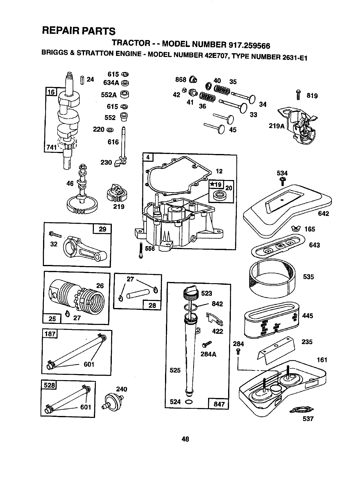
REPAIR PARTS
TRACTOR -- MODEL NUMBER 917.259566
BRIGGS & STRATTON ENGINE -MODEL NUMBER 42E707, TYPE NUMBER 2631-E1
I552A
615
552
220 ¢_
_ 230
868 _ _ 40 35
42 _ _ _)_::::::z_
41 36 "_" Q_:::_.. 34
33
_45 219/
534
819
642
'_ 165
643
27
523
842
422
284A
525
524 o
535
445
2_4 _235
537
41t
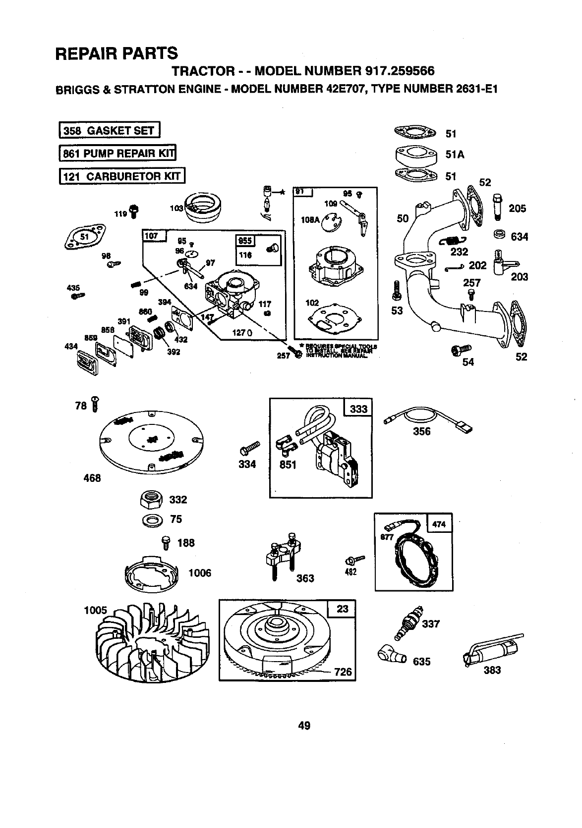
REPAIR PARTS
TRACTOR - - MODEL NUMBER 917.259566
BRIGGS & STRATTON ENGINE -MODEL NUMBER 42E707, TYPE NUMBER 2631-E1
127 0
108A_
51
51A
"" " 51 52
_205
634
_554 52
781
468
_332
75
1006
1005
334 851
63 _2
337
_635
49
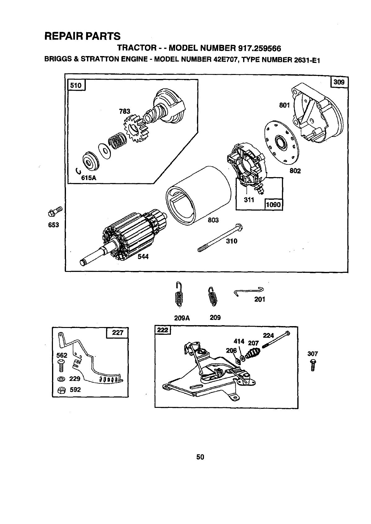
REPAIR PARTS
TRACTOR --MODEL NUMBER 917.259566
BRIGGS & STRATTON ENGINE -MODEL NUMBER 421=707, TYPE NUMBER 2631-1=1
653
783
615A
311
803
801
802
209A 209
414 207_
307
5O
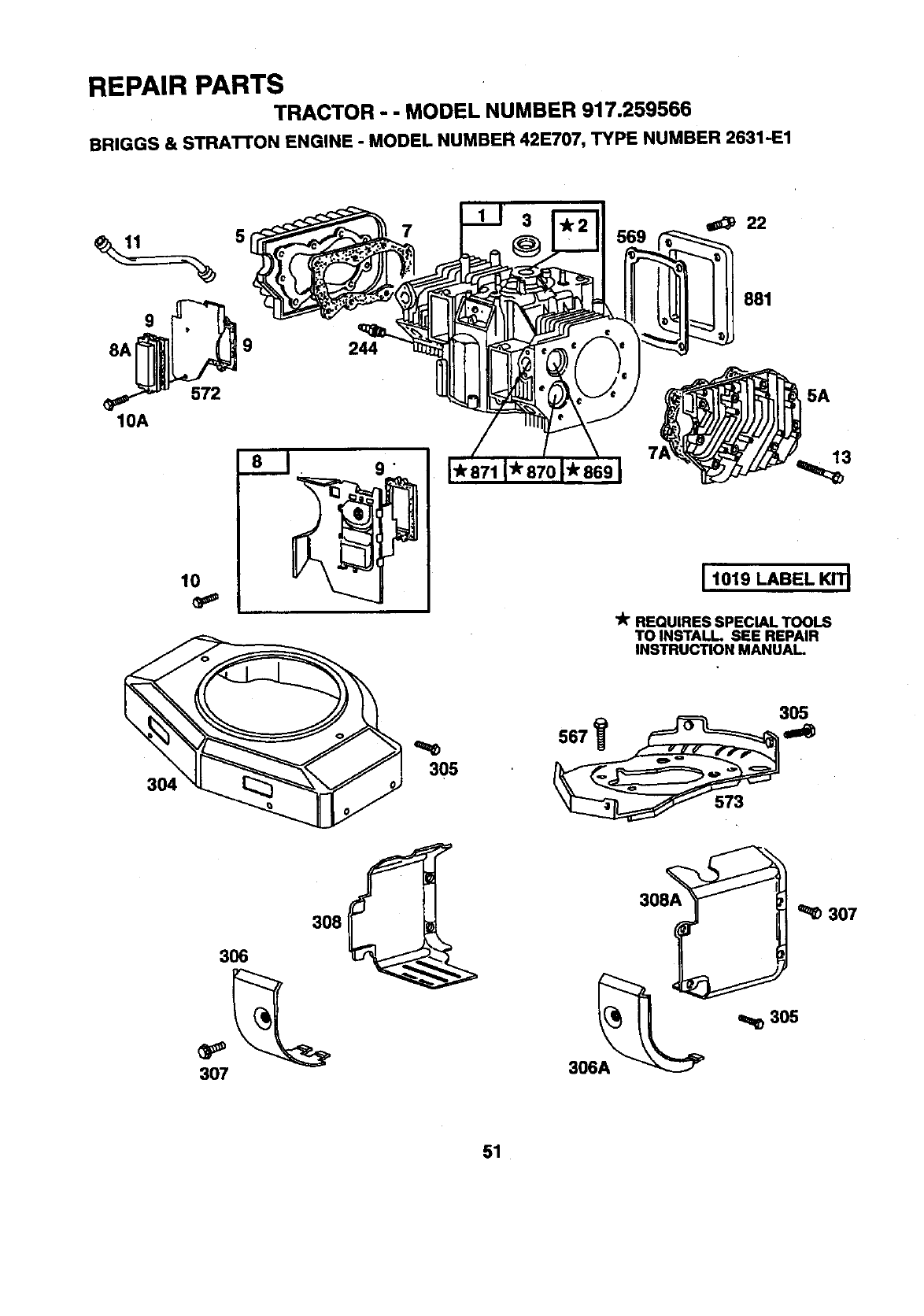
REPAIR PARTS
TRACTOR - - MODEL NUMBER 917.259566
BRIGGS & STRATTON ENGINE -MODEL NUMBER 42E707, TYPE NUMBER 2631'E1
5
9
8A 9
572
10A
lO
304
244
o
305
881
5A
13
I 1019 LABEL KIT_
lit REQUIRES SPECIAL TOOLS
TO INSTALL SEE REPAIR
INSTRUCTION MANUAL
567
305
307
30L_ ''LI_" _ 307
306A
51
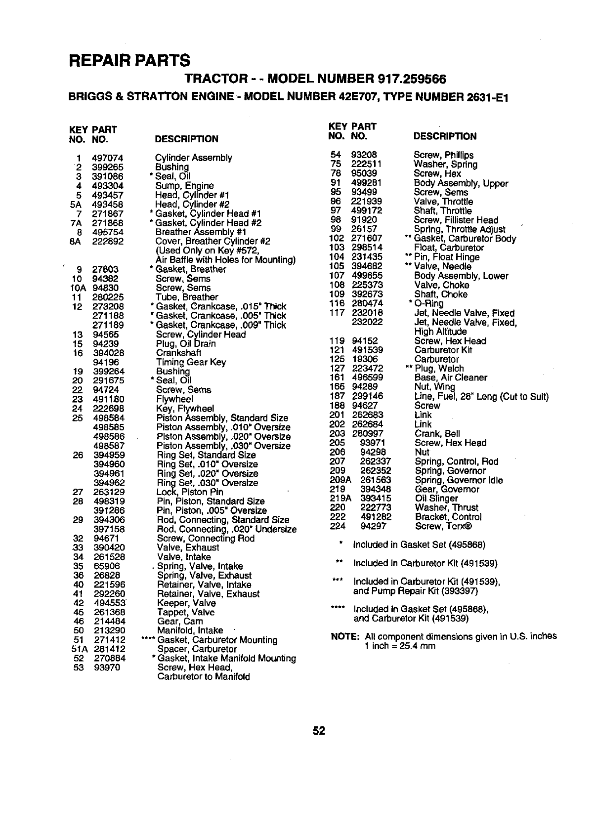
REPAIR PARTS
TRACTOR - - MODEL NUMBER 917.259566
BRIGGS & STRATTON ENGINE - MODEL NUMBER 42E707, TYPE NUMBER 2631-E1
KEY PART KEY PART
NO. NO. DESCRIPTION NO. NO. DESCRIPTION
1 497074
2 399265
3 391086
4 493304
5 493457
5A 493458
7271867
7A 271868
8 495754
8A 222892
9 27603
10 94382
10A 94830
11 280225
12 273208
271188
271189
13 94565
15 94239
16 394028
94196
19 399264
20 291675
22 94724
23 491180
24 222698
25 498584
498585
498586
498587
26 394959
394960
394961
394962
27 263129
28 498319
391286
29 394306
397158
32 94671
33 390420
34 261528
35 65906
36 26828
40 221596
41 292260
42 494553
45 261368
46 214484
50 213290
51 271412
51A 281412
52 270884
53 93970
Cylinder Assembly 54 93208
Bushing 75 222511
* Seal, Oil 78 95039
Sump, Engine 91 499281
95 93499
Head, Cylinder#1 96 221939
Head, Cylinder#2 97 499172
* Gasket, CylinderHead #1
* Gasket, Cylinder Head #2 98 91920
BreatherAssembly #1 99 26157
Cover, Breather Cylinder #2 102 271607
103 298514
(Used Only on Key #572,
Air Baffle withHoles for Mounting) 104 231435
* Gasket, Breather 105 394682
Screw, Sems 107 499655
Screw, Sems 108 225373
Tube, Breather 109 392673
* Gasket, Crankcase, .0t5" Thick 116 280474
* Gasket, Crankcase, .005' Thick 117 232018
* Gasket, Crankcase, .009"Thick 232022
Screw, Cylinder Head
Plug, Oil Drain 119 94152
Crankshaft 121 491539
Timing Gear Key 125 19306
Bushing 127 223472
*Seal, Oil 161 496599
Screw, Seres 165 94289
Flywheel 187 299146
Key, Flywheel 188 94627
PistonAssembly, StandardSize 291 262683
PistonAssembly, .010" Oversize 202 262684
Piston Assembly,.020" Oversize 203 280997
Piston Assembly,.030" Oversize 205 93971
RingSet, StandardSize 206 94298
207 262337
RingSet, .010=Oversize 209 262352
RingSet, .020" Oversize
RingSet, .030" Oversize 209A 261563
Lock, Piston Pin 219 394348
219A 393415
Pin, Piston, StandardSize
Pin, Piston, .005"Oversize 220 222773
222 491282
Rod, Connecting,StandardSize
Rod, Connecting,.020" Undersize 224 94297
Screw, ConnectingRed
Valve, Exhaust
Valve, Intake
• Spring,Valve, Intake
Spring,Valve, Exhaust
Retainer, Valve, Intake
Retainer, Valve, Exhaust
Keeper, Valve
Tappet, Valve
Gear, Cam
Manifold, Intake
.... Gasket, Carburetor Mounting
Spacer, Carburetor
*Gasket, Intake ManifoldMounting
Screw, Hex Head,
Carburetorto Manifold
Screw, Phillips
Washer, Spring
Screw, Hex
Body Assembly,Upper
Screw, Sems
Valve, Throttle
Shaft, Throttle
Screw, FiilisterHead
** Spring,ThrottleAdjust
Gasket, Carburetor Body
Float,Carburetor
** Pin, Float Hinge
** Valve, Needle
BodyAssembly,Lower
Valve, Choke
Shaft, Choke
* O-Ring
Jet, Needle Valve, Fixed
Jet, Needle Valve, Fixed,
High Altitude
Screw, Hex Head
Carburetor Kit
Carburetor
** Plug, Welch
Base, Air Cleaner
Nut, Wing
Line, Fuel, 28" Long (Cut to Suit)
Screw
Link
Link
Crank, Bell
Screw, Hex Head
Nut
Spring, Control,Rod
Spring,Governor
Spring,Governor Idle
Gear, Govamor
Oil Slinger
Washer, Thrust
Bracket, Control
Screw, Torx_
Included in Gasket Set (495866)
** Included in Carburetor Kit (491539)
*** Includedin CarburetorKit (491539),
and Pump Repair Kit(393397)
.... Included in Gasket Set (495868),
and Carburetor Kit (491539)
NOTE: Allcomponentdimensionsgiven in U.S. inches
1 inch = 25.4 mm
52
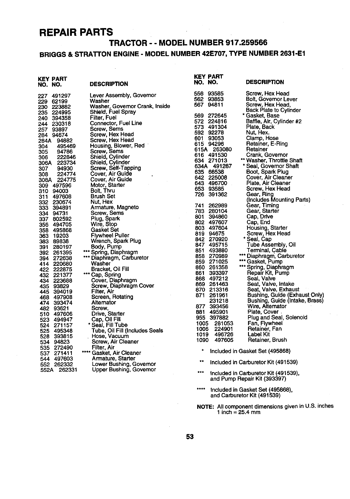
REPAIR PARTS
TRACTOR - - MODEL NUMBER 917.259566
BRIGGS & STRATrON ENGINE - MODEL NUMBER 42E707, TYPE NUMBER 2631-E1
KEY PART KEY PART
NO. NO. DESCRIPTION NO. NO. DESCRIPTION
227 491297 Lever Assembly, Govemor 556 93585
229 62199 Washer 562 93853
230 223882 Washer, GovemorCrank, lnside 567 94811
235 224995 Shield, Fuel Spray
240 394358 Filter,Fuel 569 272645
244 230318 Connector,Fuel Line 572 224816
257 93897 Screw, Sems 573 491304
284 94674 Screw, Hex Head 592 92278
284A 94882 Screw, Hex Head 601 93053
304 495469 Housing, Blower, Red 615 94296
305 94786 Screw, Sems 615A 263080
616 491530
306 222846 Shield, Cylinder 634 271013
306A 223734 Shield, Cylinder
307 94930 Screw, Serf-Tapping 634A 491287
308 224774 Cover, Air Guide 635 66538
308A 224775 Cover, Air Guide 642 225008
309 497596 Motor,Starter 643 496700
310 94003 Bolt,Thru 853 93585
311 497606 BrushSet 726 391362
332 230674 Nut, Hex
333 394891 Armature, Magneto 741 262989
334 94731 Screw, Sems 783 280104
337 802592 Plug, Spark 801 394860
355 494705 Wire, Stop 802 497607
358 495868 Gasket Set 803 497604
363 19203 FlywheeIPuller 819 94675
383 89838 Wrench, Spark Plug 842 270920
847 495715
391 280197 Body, Pump
392 261395 ***Spring, Diaphragm 851 493880
394 272638 *** Diaphragm, Carburetor 858 270989
414 220680 Washer 859 271025
422 222875 Bracket, Oil Fill 860 261358
432 221377 *** Cap, Spring 861 393397
868 497212
434 223688 Cover, Diaphragm
435 93829 Screw, DiaphragmCover 869 261463
445 394019 Filter, Air 870 213316
468 497908 Screen, Rotating 871 261961
474 393474 Altemator 231216
482 93621 Screw, 877 393456
510 497606 Drive, Starter 881 495901
523 494947 Cap, Oil Fill 955 397882
524 271157 *Seal, FilITube 1005 281053
525 495348 Tube, Oil Fill(Includes Seals 1006 224901
526 393815 , Hose, Vacuum 1019 498726
534 94823 Screw, Air Cleaner 1090 497605
535 272490 Filter, Air
537 271411 .... Gasket, Air Cleaner
544 497603 Armature, Starter
552 262332 Lower Bushing, Governor
552A 262331 Upper Bushing,Govemor
Screw, Hex Head
Bolt, GovernorLever
Screw, Hex Head,
Back Plate to Cylinder
* Gasket, Base
Baffle, Air, Cylinder#2
Plate, Back
Nut, Hex.
Clamp, Hose
Retainer, E-Ring
Retainer
Crank, Governor
** Washer, Throttle Shaft
* Seal, Governor Shaft
Boot, Spark Plug
Cover, Air Cleaner
Plate, Air Cleaner
Screw, Hex Head
Gear, Ring
(IncludesMounting Parts)
Gear, Timing
Gear, Starter
Cap, Ddve
Cap, End
Housing,Starter
Screw, Hex Head
* Seal, Cap
Tube Assembly,Oil
Terminal, Cable
*** Diaphragm, Carburetor
*** Gasket, Pump
*** Spring, Diaphragm
Repair Kit, Pump
Seal, Valve
Seat, Valve, intake
Seat, Valve, Exhaust
Bushing,Guide (ExhaustOnly)
Bushing,Guide (Intake, Brass)
Wire, Alternator
Plate, Cover.
Plug and Seal, Solenoid
Fan, Flywheel
Retainer, Fan
Label Kit
Retainer, Brush
Includedin Gasket Set (495868)
** Included in Carburetor Kit (491539)
*** Included in Carburetor Kit (491539),
and Pump Repair Kit (393397)
.... Includedin Gasket Set (495868),
and Carburetor Kit (491539)
NOTE: All componentdimensionsgiven in U.S. inches
1 inch = 25.4 mm
53

ii i
SERVICE NOTES
i i
54

SUGGESTED GUIDE FOR SIGHTING SLOPES FOR SAFE OPERATION
ONLY RIDE UP AND DOWN HILL,
NOT ACROSS HILL
SIGHT AND HOLD THIS LEVEL WITH
SKY LINE OR TREE.
15° MAX.
__ perate your Tractor up and down the face of slopes (not I
greater than 15°), never across the face. Make turns gradu- I
•ally to prevent tipping or !oss of control. Exercise extreme
caution when changing dlrectmn on slopes.
\
i\
SEARS
OWNER'S
MANUAL
MODEL NO.
917.259566
IF YOU NEED
REPAIR SERVICE
OR PARTS:
FOR REPAIR SERVICE, CALL
THIS TOLL FREE NUMBER:
1-800-4-REPAIR
(1-800-473-7247)
FOR REPLACEMENT PARTS
INFORMATION AND
ORDERING, CALL THIS
TOLL FREE NUMBER:
1-800-FON-PART
(1-800-366-7278)
FOR CONSUMER ASSISTANCE
HOT LINE, CALL THIS
TOLL FREE NUMBER:
1-800-659-5917
CRAFTSMAN®
19.5 HP
ELECTRIC START
42" MOWER
6 SPEED TRANSAXLE
LAWN TRACTOR
Each tractor has its own model number. Each engine has
its own model number.
The model number for your tractor will be found on the
model plate located under the seat.
The model number for your engine will be found on the
blower housing of the engine.
All parts listed herein may be ordered from any Seam,
Roebuck and Co. Service Center/Department and most Re-
tail Stores.
WHEN ORDERING REPAIR PARTS, ALWAYS GIVE THE
FOLLOWING INFORMATION:
• PRODUCT - TRACTOR
•MODEL NUMBER-917.259566
•ENGINE MODEL NO. - 42E707-2631-E1
", PART NUMBER
•PART DESCRIPTION
Your Sears merchandise has added value when you
consider Sears has service units nationwide staffed with
Sears trained technicians.., professional technicians
specifically trained to insure that we meet our pledge to
you, we service what we sell.
161505 8.12.97 JH Pdnted in U.S.A.
b
