Craftsman 917259730 User Manual Lawn, Tractor Manuals And Guides 1006758L
User Manual: Craftsman 917259730 917259730 CRAFTSMAN Lawn, Tractor - Manuals and Guides View the owners manual for your CRAFTSMAN Lawn, Tractor #917259730. Home:Lawn & Garden Parts:Craftsman Parts:Craftsman Lawn, Tractor Manual
Open the PDF directly: View PDF ![]() .
.
Page Count: 52
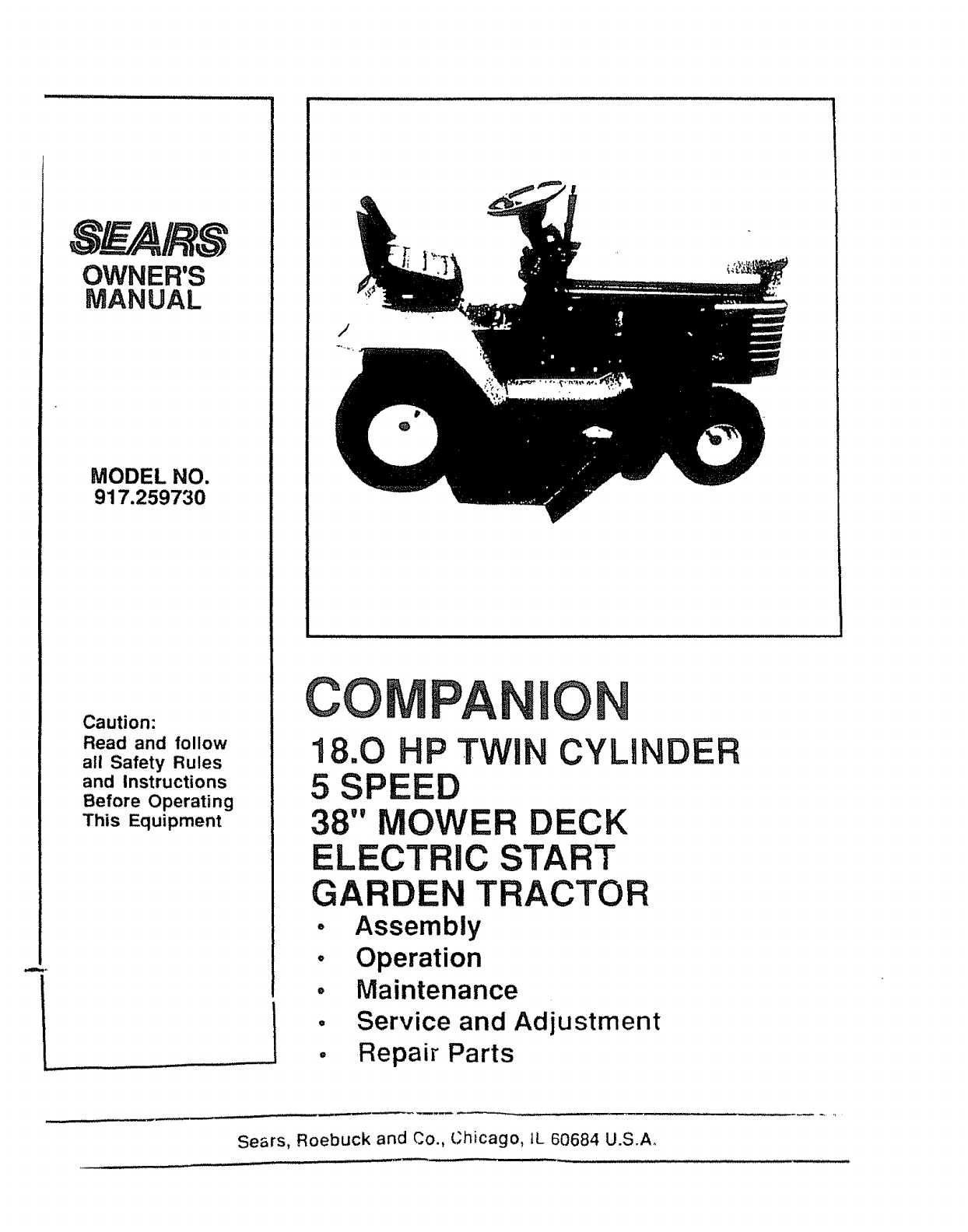
OWNER'S
MANUAL
MODEL NO.
917.259730
Caution:
Read and follow
all Safety Rules
and Instructions
Before Operating
This Equipment
/
CO PAN 0
18.0 HP TWIN CYLINDER
5SPEED
38" MOWER DECK
ELECTRIC START
GARDEN TRACTOR
oAssembly
° Operation
°Maintenance
°Service and Adjustment
° Repair Parts
Sears, Roebuck and Co., Chicago, IL 60684 U.S.A°
LOOK FOR THIS SYMBOL TO POINT'
OUT IMPORTANT SAFETY PRECAU-
TIONS. IT MEANS -ATTENTION! BE-
COME ALERT! YOUR SAFETY IS IN=
VOLVED.
iii ij
CAUTION: LOOK FOR THIS WORD,TO POINT OUT,.
IMPORTANT EQUIPMENT PRECAUTIONS
NOTE: LOOK FOR THIS WORD TO POINT OUT IM-
PORTANT INFORMATION ABOUT THE OPERATION
AND PERFORMANCE OF YOUR TRACTOR
RULES FOR SAFE OPERATION
WARNING: This unit is equipped with an internal combustion engine and should not be used on or near any unimproved forest covered,
brush covered or grass covered land unless the engine's exhaust system is equipped with aspark arresler meetingapplicabte tocal uf area
taws (if any). if aspark attester is used. it should be maintained in effective working order by the operator (See REPAIR PARTS for par1
number identification}.
In the State of California the above is required by law (Section 4442 of the California Public Resources Code) Other States may have similar
taws Federal laws apply on federaldands
t Know the controls and how to stop quickly, READ THIS
OWNER'S MANUAL and instructions furnished with attacli-
ments
2: Do not allow children to operate the machine. Do not allow
adults to operate it without proper instruction.
3 Do not carry passengers Do not mow when children and
others are around.
4 Always wear substantial footwear. Do not wear loose fitting
clothing that could get caught in moving parts.
5 Keep your eyes and mind on your tractor, mower, and the
area being cut Do not le, other interests distract you.
6 Do not attempt to operate your tractor or mower when not in
the driver's seat.
7 Always get on or off your tractor from the operator's left hand
side
8 Clear the work area of obiects (wire, rocks, etc ) which might
be picked up and thrown
9 Disengage all attachment ctutches before attempting to start
the engine
10 Disengage power to attachments and stop the engine before
leaving the operator's position
11 Disengage power to mower, stopthe engine, and disconnect
spark ptug wire(s) from spark plug(s) before cleaning, m aking
an adtustment, or repair Be careful to avoid touching hot
muffler or engine components
12 Disengage power to attachments when t_ansporting or not _n
use
I3 Take all possible precautions when leaving the vehicle
unanended. D_sengage the cower take-oI!, fower the attach..
ments, shift into neutraf set _he park=ng brake stop the
engine, and remove lhe key
14 Do not stop or start suddenly when going uph,ll or downhill
Mow bp and down the face of slopes (not greater 1,han !5 °)
never across the face Refer to page 51
15 Reduce speed or slopes .tnd make turns gradua;ly to prevent
l=ppmg or [oss of cofitrol Exercise extreme caution when
changing d,rec_Mon on slopes
t6 Whde go_ng up or down slopes, ptacegear smftcontroiIever
,n 1st gear #oslhon to negohate the s_ope w_lnout slopp,ng
17 Never mew m wet or shppery grass when traction ts unsure
or at a speec wh,ch could cause a skMd
18 Slay atert lot holes _n the terrain and other h,dden hazards
Keep away _rom atop-otis
19 Do not dnve )c c_ose to creeks d_fches and pubhc h_gh-
ways
20 Exerose "2:. r .'! c.: ." ....... ' mow_r,g aro__._¢_ _ed objects tn
order to prevent me o.ades from stnMng them Neve't deho-
er_{:e.y °,r- ',t&_cr cr r'owe, ,n;o or over any {ore...qr_co ec't.
*_' Nece, S_ ": q-__"S ...., :. :to[or comes to a S_co
22 #,lever D-_:e "_. _ds o: Ieet jr;dot Ine mowe" C 'C" , .je
C;'_:e or "_r.1' "{"€ -_ov,ng #arts wnde tr.'_. O..... '_,_,et 3
. ......rg A ",',,_._,._ -_.O C e3" _ dSCn3rg,." ,.
:_j .... " }',-' ,*, .-," _,, '_ O_,_s o' _s,n_ m_.{,, ec:. _r._e,"t
.t J.,_ .;" _, "lL_D_ove'J d' t',,'_Da r" tc_ ;;,o."4s
C L ..... _15 TD t"o':_e _o.,, C.a z' . !',, y C'On'rO;
c Do not turn sharply Use care when backing.
d Use counterweight or wheel weights when suggested in
owner's manual
24 Watch out for traffic when crossing or near roadways
25.. When using any attachments, never direcf discharge of
material toward bystanders nor allow anyone near the ve-
hicle while in operation.
26 Handle gasoline with care -it is highly flammable
a Use approved gasoline containers
b Never remove the fuel cap of the fuel tank or add
gasoline to a running or hot engine or an engine that has
not been allowed to cool for several minutes after run-
ning Never fill tank indoors Always clean up spilled
gasoline
c Open doors if the engine is run in the garage - exhaust
fumes ate dangerous. Do not run the engine indoors.
27.. Keep the vehicle and attachmenls in good operating condi-
tion and keep satety devices in place and working.
28 Keep all nuts, bolts, and screws tight to be sure the equip-
ment is insafe working condition
29 Never store the equipment with gasoline in the tank inside a
building where tumes may reach an open l_ame or spark
Allow the engine to coo! belore storing _n any enclosure
30 To reduce fire hazard keep the engine bee o{ grass {eaves.
or excessive grease Do not clean product wh_e engine _s
running
31 Except for adius_ments. DO NOT operate engine _ air cteaner
or cover d_rec_ over carburetor air _n(ake is removed
Rem'o£aI ol s.;_" a,._ coJ!d creale a fire h3Za_d
32 Do not operafe w4_'o_I a muir er or tamper wdh exnaus_
system Damage_ mufflers or spark arreslers could cre]:e a
fire hazard Inspect penod_calty and replace if necessaw
33 Th,_vehicle ar:d al_achmer'4s snould be stopped and :,.
spect_-,.d tar dam__ge ait_' striking a toreign GbieCt. and fne
damage shou,a r.,e "eaa red belcre _e;!3rt}ng and operat;ng
;he equ_pmen;
34 Do not change ":e er:g,ne governor se_t:ngs or overspeed _ne
engine: severe c3,"r...'_geOr =nlurY rTr_"l_,' 'esutt
35 When using : ._ ver',,cie wnn mower o_oceed as fo£ows
a Mow on y ;' cayhgn[ or ,n good __rllhoal hghl
bShot tree ,._,:] ne oH oCg.,'g cl_u_e
c Check the Dace ._'.cun; g c.,.3ts _o ,:..'r,r,_r bQh_n,:_S _.t
frequem ._'erva,s " " "
36 Do not ape, 't ,_ : -, '--':,.1' _. w_noL: ::7,: ._,-:,re grass Ca;Chef
on mow ,..,_,.; €_; ec.,_pP,.:d o" ',he oe' eC:3r shield in place
37 P ,engag,'.. ;>;,.,..... to too,,, r befor,_ o !,.- ._g uo Do not mow
n reverse ,_s aoso_u;._ € necessar r, and {her1 Only alto.-
caretul cot,,_ ,_ or. o! '.-';e . '. ,e .i,_ea ::.._. .. ¢!i_e mowe_
Ur_m:-'r,e .... , -.,:4:7,_.] _... _,:nerc_,;:jmaler_a_ssbse,::
1o dell,. D_.l: ::.".]-Tdwt:ar it s:' ; ';.be cr_e_:;,ed_.reque_H _.,_-.
01_ red 1,7e_'"e _" _eo acemer ' :: ,IS S '..';bd 0_. C 7,>c_ec :.:
""_:-. _ 1_1'";. .'7:ew.-- theor ; t:'_t",,,L3C1._re .... .-c,i ....
2
CONGRATULATIONS on your purchase of a Sears
Garden Tractor. It has been designed, engineered and
manufactured to give you the best possible dependability
and performance, Should you experience any problem
you cannot easily remedy, please contact your nearest
Sears Service DepartmenL We have competent, well-
trained technicians and the proper tools to service or
repair this unit,
MAINTENANCE AGREEMENT
A Sears Maintenance Agreement is available on this
product. See the nearest Sears store or service center
for details_
SERIAL
NUMBER
DATE OF PURCHASE
THE SERIAL NUMBER WILL BE FOUND ON THE MODEL
PLATE UNDER THE SEAT°
YOU SHOULD RECORD THESE NUMBERS AND KEEP
FOR FUTURE REFERENCE.
_,,. ,,,, lie i1/11 ll,i
CUSTOMER RESPONSIBILITIES
Read and retain this manual, Study and observe the safety rules. Always use care when using your tractor_ Always
keep your tractor and mower clean° Follow a regular schedule in maintaining, caring for, and using your tractor° A well
#:ared for tractor will run better and last longer.
ATTACHMENTS
This unit can use many attachments now available at your Sears store. It can use a tiller, but cannot use attachments
that engage the ground like a plow, harrow, or cultivator See page 50 for a list of available attachments.
LIMITED ONE YEAR WARRANTY'
ON ELECTRIC START RIDING EQUIPMENT
For one year from date of purchase, when this ridingequipment is maintained, lubricated, and tuned up according to
the operating and maintenance instruction in the owner's manual, Sears will repair free of charge any defect in
material or workmanship inthis electric start riding equipment,,
This warranty excludes blade(s), blade adapter(s), spark plug(s), air cleaner and belt(s), which are expendable and
become worn during normal use
This warranty does not cover:
• Tire replacement or repair caused by punctui'es from outside objects (such as nails, thorns, stumps, or
glass); and
• repairs necessary because of operator abuse or negligence, includingthe failure to maintain the equip-
merit according to instructionscontained in the owner's manual; and
• rk:ling equipment used forcommercial or rental purposes
FULL 90 DAY WARRANTY ON BATTERY
For 90 days from the date of purchase, if any battery included withthis dding equipment proves defective in material
or workmanship and our testing determines the battery will not ho_da charge, Sears will replace the battery at no
charge.
WARRANTY SERVICE tS AVAILABLE BY CONTACTING THE NEAREST SEARS SERVICE CENTER/DEPART-
MENT
This warranty gives you specific legal rights, and you may also have other rights which may vary from state to state
SEARS, ROEBUCK AND CO, D/'731CR-W SEARS TOWER, CHICAGO, IL 60684
DO NOT OVERLOAD TRACTOR BY TOWING WEIGHTS GREATER THAN 150 POUNDS (68 KG),
I
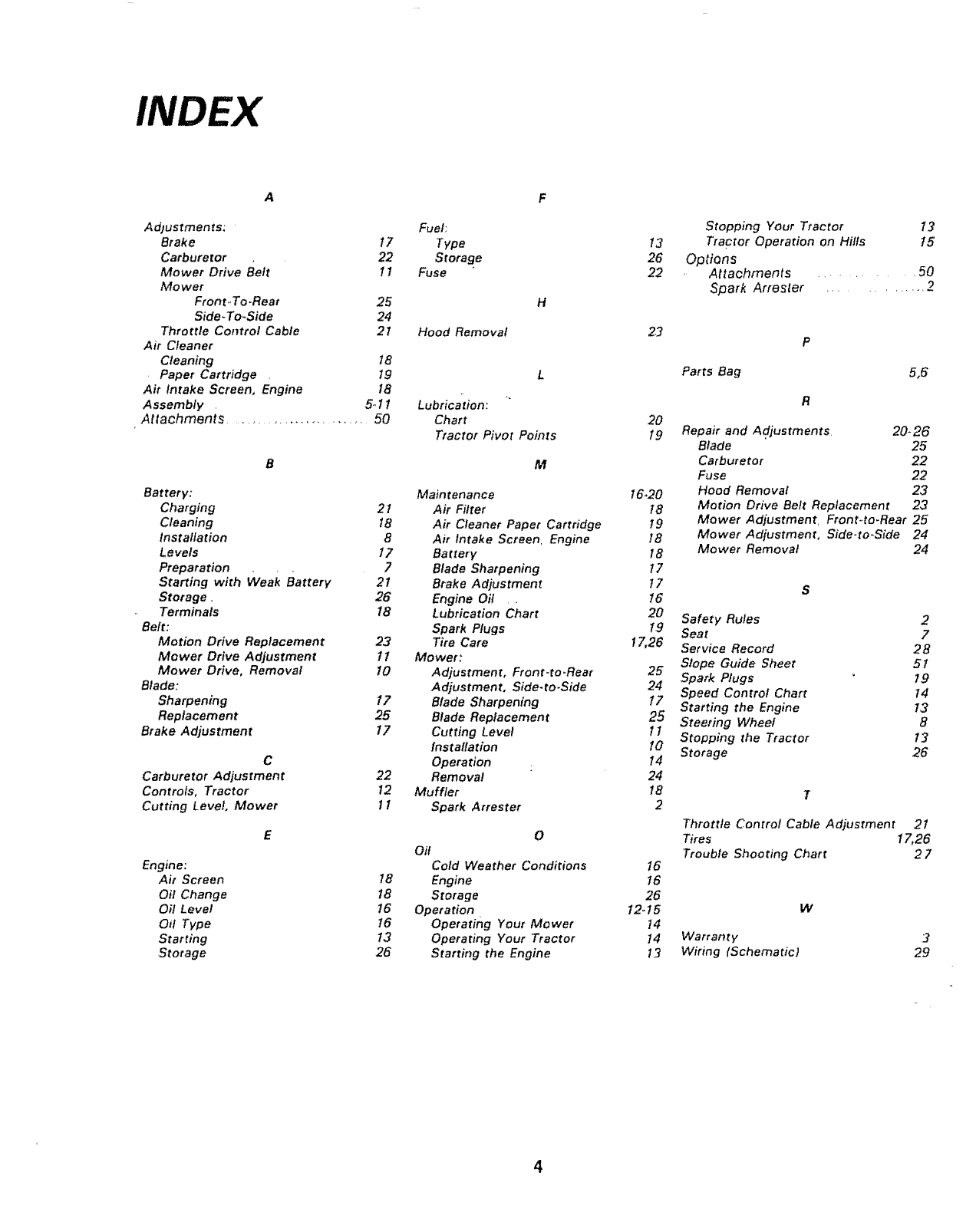
INDEX
AF
Adlustments: Fuel:
Brake 17 Type
Carburetor 22 Storage
Mower Drive Belt 11 Fuse
Mower
Front-To-Rear 25 H
Side-To,Side 24
Throttle Contro! Cable 21 Hood Removal
Air Cleaner
Cleaning 18
Paper Cartridge . 19 L
Air Intake Screen, Engine 18
5-11 Lubrication:
Assembly .
Attachments ........................... 50 Chart
Tractor Pivot Points
Battery:
Charging
Cleaning
Installation
Levels
Prepara lion
Starting with weak Battery
Storage.
Terminals
Belt:
Motion Drive Replacement
Mower Drive Adjustment
Mower Drive, Removal
Blade:
Sharpening
Replacement
Brake Adjustment
C
Carburetor Adjustment
Controls, Tractor
Cutting Level, Mower
Engine:
Air Screen
Oil Change
Oil Level
Oil Type
Starting
Storage
M
Main tenance
21 Air Filter
18 Air Cleaner Paper Cartridge
8 Air Intake Screen. Engine
17 Battery
7Blade Sharpening
21 Brake Adjustment
26 Engine Oil
18 Lubrication Chart
Spark Plugs
23 Tire Care
11 Mower:
!0 Adjustment, Front.to.Rear
Adjustment, Side-to-Side
!7 Blade Sharpening
25 Blade Replacement
17 Cutting Level
Installation
Operation
22 Removal
12 Muffler
11 Spark Arrester
0
Oil
Cold Weather Conditions
18 Engine
18 Storage
16 Operation •
16 Operating Your Mower
13 Operating Your Tractor
26 Starting the Engine
Stopping Your Tractor 13
13 Tractor Operation on Hills 15
26 Options
22 Attachments ............ 50
Spark Attester ............. 2
2_
20
19
16.20
18
79
18
18
17
17
!6
20
1.9
17,26
25
24
17
25
11
10
14
24
18
2
!6
16
26
12.15
14
t4
i3
Parts Bag 5,6
Repair and Adjustments 20-26
Blade 25
Carburetor 22
Fuse 22
Hood Removal 23
Motion Drive Belt Replacement 23
Mower Adjustment. Front-to-Rear 25
Mower Adjustment, Side-to.Side 24
Mower Removal 24
Safety Rules 2
Seat 7
Service Record 28
Slope Guide Sheet 5t
Spark Plugs 19
Speed Control Chart 14
Starting the Engine 13
S_eering Wheel 8
Stopping the Tractor 13
Storage 26
Throttle Control Cable Adjustment 21
Tires 17,26
Trouble Shooting Chart 27
W
Warranty 3
Wiring fSchematic} 29
ASSEMBL Y
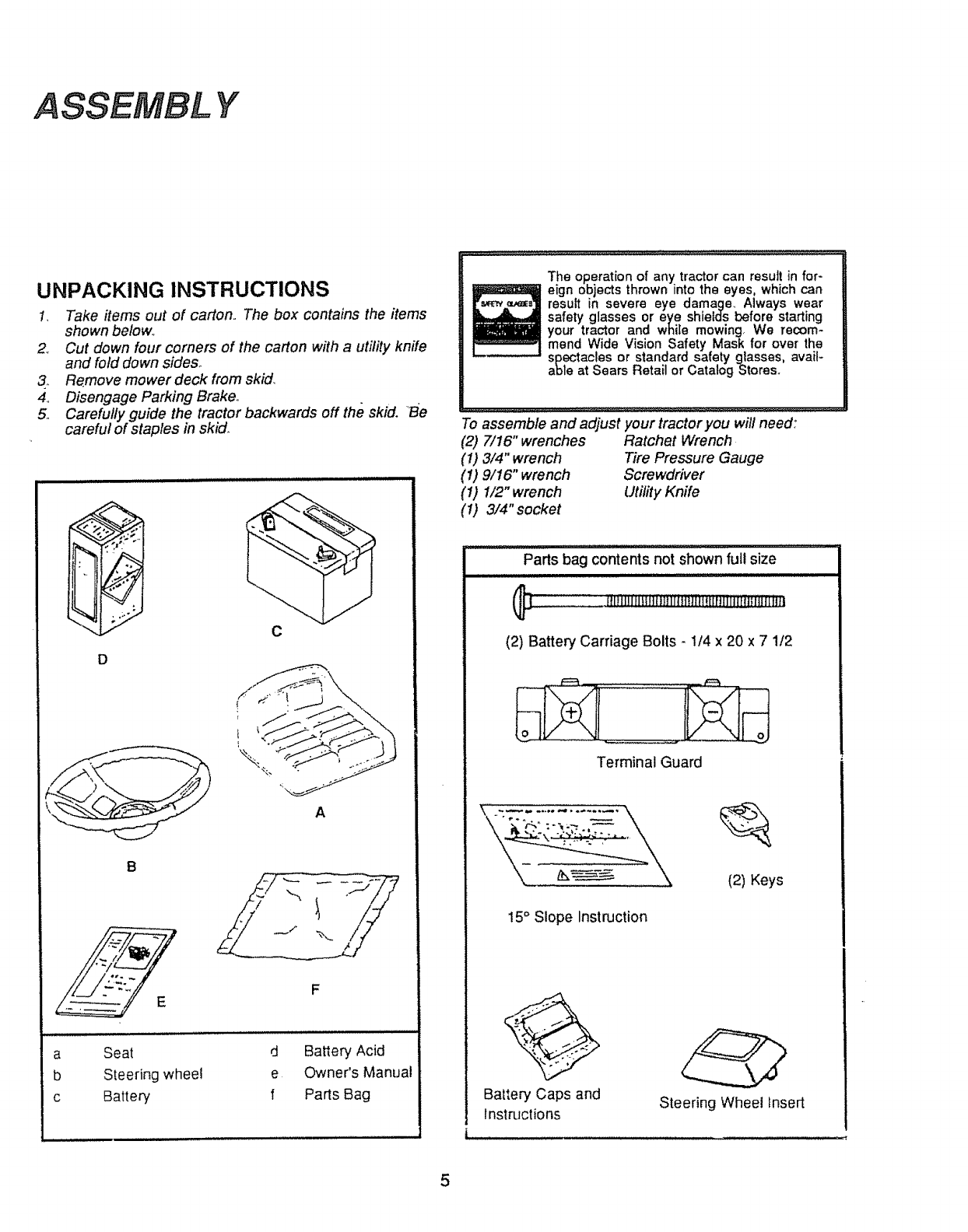
UNPACKING INSTRUCTIONS
!7 Take items out of carton. The box contains the items
shown below..
2.. Cut down four corners of the carton with a utility knife
and fold down sides_
3._ Remove mower deck from skid.
4.. Disengage Parking Brake°
5. Carefully guide the tractor backwards off the skid. "Be
careful of staples in skid_
D
C
A
B
a
b
c
Seat
Steering wheel
Battery
d Battery Acid
e Owner's Manual
f Parts Bag
The operation of any tractorcan resultin for-
eign objectsthrown intothe eyes, whichcan
result in severe eye damage_ Always wear
safety glasses or eye shields before starting
your tractor and while mowing We recom-
mend Wide Vision Safety Mask for over the
spectacles or standard safety glasses, avail-
able at Sears Retail or CatalogStoreso
................ .,,,,,.,.,,_ , L_L L,J ..........................................................................................................................................................
To assemble and adjust your tractor you will need:
(2) 7!16"wrenches Ratchet Wrench
(1) 3/4" wrench Tire Pressure Gauge
(1) 9/16" wrench Screwdriver
(1) 1/2" wrench Utility Knife
(1) 3/4"socket
Parts bag contents not shown full size
fili/ilMilililiii[it]i)lll_LilldiiiJ_iit[li]_l
(2) Battery Carriage Bolts -1/4 x 20 x 7 1/2
Terminal Guard
15" Slope Instruction
(2) Keys
@
Bat_,eryCaps and
Instructions Steering Wheel insert
5
ASSEMBLY
ASSEMBLY
LOCATION
BATTERY
BATTERY
TERMINALS
!SEAT
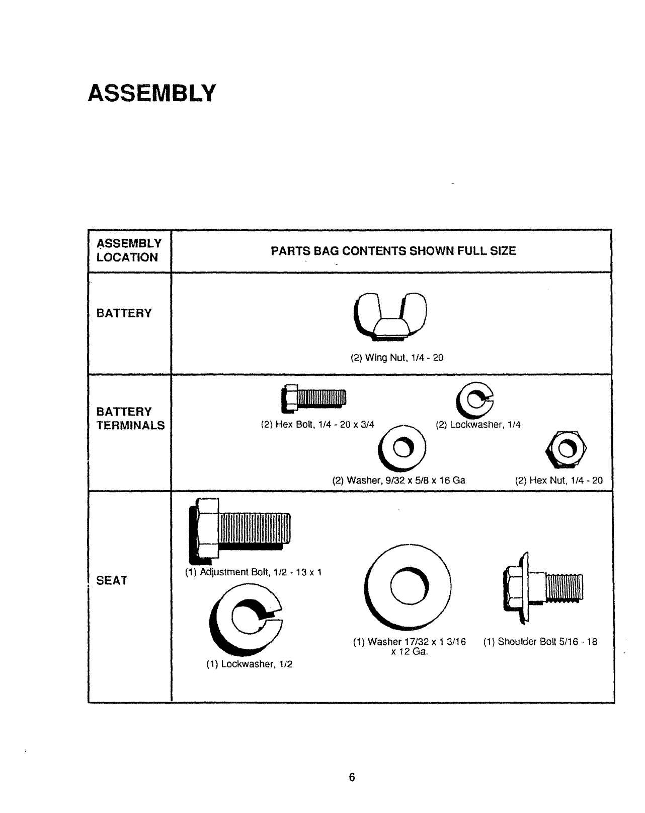
PARTS BAG CONTENTS SHOWN FULL SIZE
(2) Wing Nut, 1/4 - 20
(2) Hex Boit, 114- 20 x 3/4
111iilI
liilI!l lllli
(1) Adjustment Bolt, 1/2 - 13 x1
(1) Lockwasher, 1t2
_,_ (2) Lockwasher, I/4
(2) Washer, 9/32 x 5/8 x 16 Ga, (2) Hex Nut, 1/4 - 20
iiii ]11111 iiiii i ii iiii iii /ii i .....
(I) Washer 17t32 x 1 3/16
x 12Ga (1) Shoulder Bott 5/16 - 18
6
NOTE: RIGHT HAND (R.H.) AND LEFT HAND (L.H.) ARE
DETERMINED FROM OPERATOR'S POSITION
WHILE SEATED ON THE TRACTOR,
WEAR EYE AND FACE SHIELD,
WASH HANDS OR CLOTHING IMMEDI-
ATELY IF ACCIDENTALLY IN CON-
TACT WITH BATTERY ACIDo
DO NOT SMOKE° FUMES FROM
CHARGED BATTERY ACID ARE EX-
PLOSIVE.
NOTE: THIS TRACTOR IS EQUIPPED WITH AN OPERA-
TOR PRESENCE SENSING SWITCH. ANY AT-
TEMPT BY THE OPERATOR TO LEAVE THE
SEAT WITH THE ENGINE RUNNING AND AT-
TACHMENT CLUTCH ENGAGED WILL SHUT
OFF THE ENGINE
1, Prepare Battery
READ INSTRUCTIONS INCL UDED WITH THE BATTERY
VENT CAPS FOUND IN BAG OF PARTS, ALWAYS WEAR
GLOVES, CLOTHING AND GOGGLES TO PROTECT
YOUR HANDS, SKIN AND EYES.
a.. Fill and charge battery (before installing), NOTE:
SEE DETAILED INSTRUCTIONS PACKAGED
WITH BATTERY VENT CAPS IN BAG OF PARTS.,
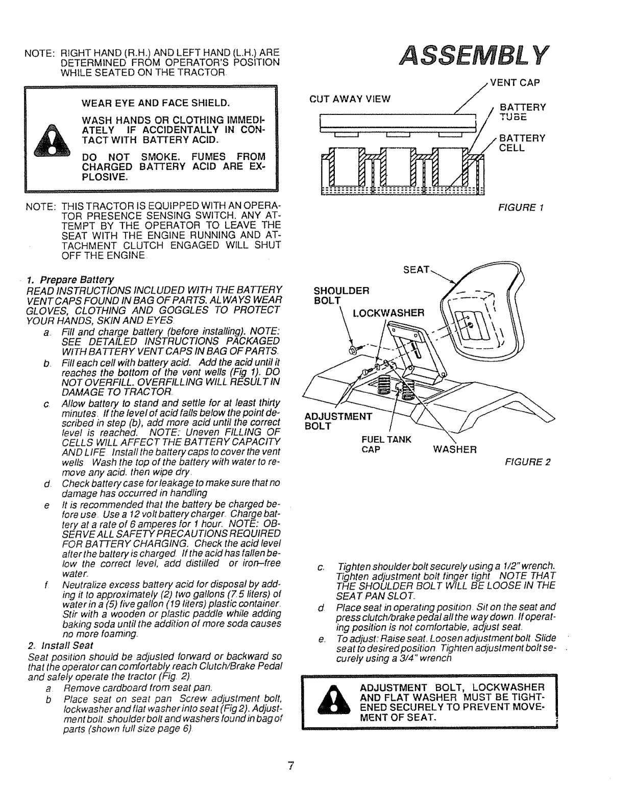
b. Fil! each cell with battery acid,_ Add the acid until it
reaches the bottom of the vent wells (Fig !),. DO
NOT OVERFILL. OVERFILLING WILL RESULT IN
DAMAGE TO TRACTOR
c Allow battery to stand and settle for at least thirty
minutes. If the level of acid falls below the point de-
scribed in step (b)o add more acid until the correct
level is reached. NOTE:' Uneven FILLING OF
CELLS WILL AFFECT THE BATTERY CAPACITY
AND LIFE lnsta/l the battery caps to cover the vent
wells Wash the top of the battery with water to re-
move any acid. then wipe dry.
d. Check battery case for leakage to make sure that no
damage has occurred in handling
e It is recommended that the battery be charged be-
fore use Use a !2 voitbatterycharger. Chargebat-
tery at a rate of 6 amperes for 1 hour. NOTE: OB-
SERVE ALL SAFETY PRECAUTIONS REQUIRED
FOR BATTERY CHARGING. Check the acid level
afler the battery is charged. If the acid has fallen be-
low the correct level, add distilled or iron-free
water.
f Neutralize excess battery acid for disposal by add-
ing it to approximately (2) two gallons (Z 5 fiters) of
water in a (5) five gallon (I9 liters) plastic container.
Stir with a wooden or plastic paddle while adding
baking soda until the addition of more soda causes
no more foaming..
2_ Install Seat
Seat position should be adjusted forward or backward so
that the operator can comfortably reach Clutch/Brake Pedal
and safely operate the tractor (Fig. 2).
a Remove cardboard from seat pan..
b Place seat on seat pan Screw adjustment bolt,
lockwasherand flat washer into seat (Fig2). Adjust_
ment bolt shoulder bolt and washers found inbag of
parts (shown full size page 6)
ASSEMBL Y
/VENT CAP
CUT AWAY VIEW /
FIGURE I
SHOULDER
BOLT
t.OCKWASHER
ADJUSTMENT
BOLT
FUEL TANK
CAP WASHER
FIGURE 2
c° Tighten shoulder bolt securely using a I/2" wrench.
Tighten adjustment bolt finger tight NOTE THAT
THE SHOULDER BOLT WILL BE LOOSE IN THE
SEAT PAN SLOT..
dPlace seat in operating position. Sit on the seat and
press clutch/brake pedal all the way down If operat-
ing position is not comfortable, adjust seat.
e Toadjust.;Raiseseat.. Loosenadjustmentbolt Slide
seat to desired position Tighten adjustment bott se-
cutely using a 3/4" wrench
.......... ..... .o_ ............ == .......
ADJUSTMENT BOLT, LOCI<WASHER
AND FLAT WASHER MUST BE TIGHT-
ENED SECURELY TO PREVENT MOVE-
MENT OF SEAT.
7
A SSEMBL Y
STEERING WHEEL
FIGURE 3
HOOD
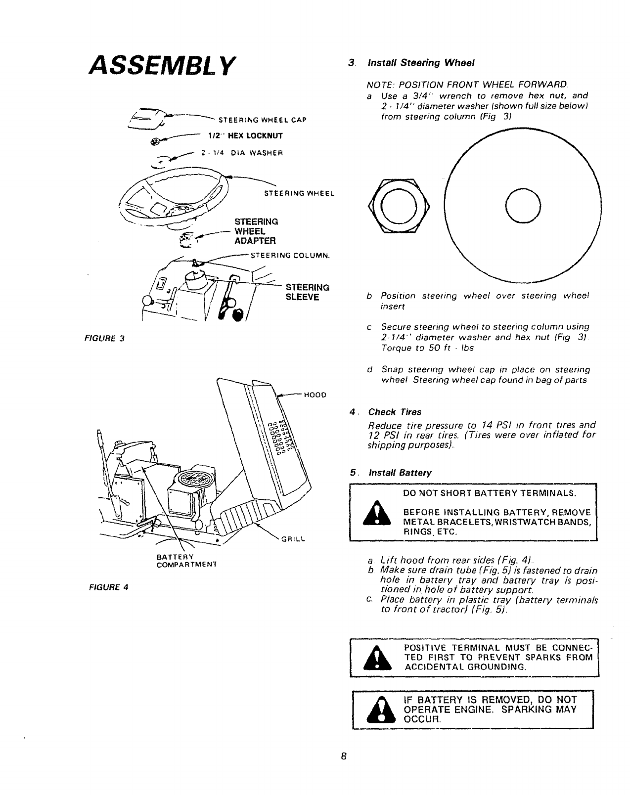
3Instafl Steering Wheel
NOTE: POSITION FRONT WHEEL FORWARD.
a Use a 3/4" wrench to remove hex nut, and
2,1/4" diameter washer (shown futf size below)
from steering column (Fig 3)
G
b Position steering wheel over steering wheel
insert
c Secure steering wheel to steering column using
2.7/4"" diameter washer and hex nut (Fig 3)
Torque to 50 ft ., tbs
dSnap steering wheel cap in place on steering
wheel Steering wheel cap found in bag of parts
4, Check Tires
Reduce tire pressure to 14 PSI in front tires and
12 PSI in rear tires. (Tires were over-inflated for
shipping purposes)..
FIGURE 4
BATTERY
COMPARTMENT
GRILL
5, Install Battery
DO NOT SHORT BATTERY TERMINALS.
BEFORE INSTALLING BATTERY, REMOVE
METAL BRACE LETS,WRISTWATCH BANDS,
RINGS ETC.
a. Lift hood from rear sides (Fig. 4).
bMake sure drain tube (F/g, 5) is fastened to drain
hole in battery tray and battery tray is posi-
tioned in hole of battery support.
c. Place battery in plastic tray (battery terminals
to front of tractoH (Fig 5).
[& LF BATTERY IS REMOVED3 DO NOT !
OPERATE ENGINE., SPARKING MAY
OCCUR_
8
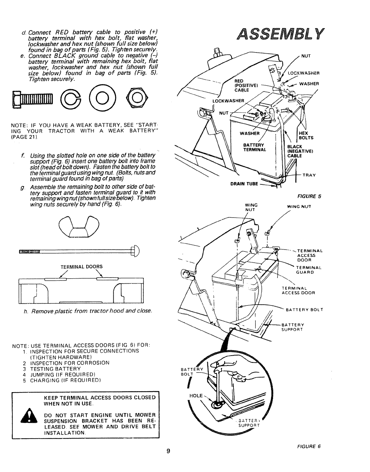
d. Connect RED battery cable to positive (+)
battery terminal with hex bolt, flat washer,
Iockwasher and hex nut (shown full size below)
found in bag of parts (Fig° 5). Tighten securely_
e, Connect BLACK ground cable to negative (-)
battery terminal with remaining hex bolt, flat
washer, Iockwasher and hex nut (shown full
size below) found in bag of parts (Fig, 5)°
Tighten securely.
LOCKWASHER
ASSEMBL Y
NUT
LOCKWASHER
WASHER
NOTE: IF YOU HAVE AWEAK BATTERY, SEE "'START
ING YOUR TRACTOR WITH A WEAK BATTERY"
(PAGE 21 )
f Using the slotted hole on one side of the battery
support (Fig,. 6) insert one battery bolt into frame
slot (head of bolt down). Fasten the battery bolt to
the terminal guard using wing nuL (Bolts, nuts and
termina! guard found in bag of parts)
g. Assemble the remaining bolt to other side of bat-
tery support and fasten terminal guard to it with
remaining wing nut (shown full size below).. Tighten
wing nuts securely by hand (Fig.. 6).
TERMINAL DOORS
HEX
BOLTS
BLACK
(NEGATIVE)
CABLE
FIGURE 5
WING WING NUT
NUT /
I
TERMINAL
ACCESS
DOOR
TERMINAL
GUARD
h.. Remove plastic from tractor hood and close° BATTERY BOLT
ERY
SUPPORT
NOTE: USE TERMINAL ACCESS DOORS (FIG 6) FOR:
1, _NSPECTION FOR SECURE CONNECTIONS
(TIGHTEN HARDWARE)
2INSPECTION FOR CORROSION
3 TESTING BATTERY
4..lUMPING (IF REQUIRED)
5 CHARGING (IF REQUIRED)
KEEP TERMINAL ACCESS DOORS CLOSED
WHEN NOT IN USE,,
DO NOT START ENGINE UNTIL MOWER
SUSPENSION BRACKET HAS BEEN RE-
LEASED. SEE MOWER AND DRIVE BELT
INSTALLATION,
BATTERY
8OLT
/
HOLE
9FIGURE 6
ASSEMBL Y
\
PARALLEL
LINK
FIG,URE 7
CLUTCH
LEVER
CLUTCH
ROD
FRONT
REAR' AXLE
HINGE
PiN
RETAINER
SPRING
FRONT
HINGE
PiN
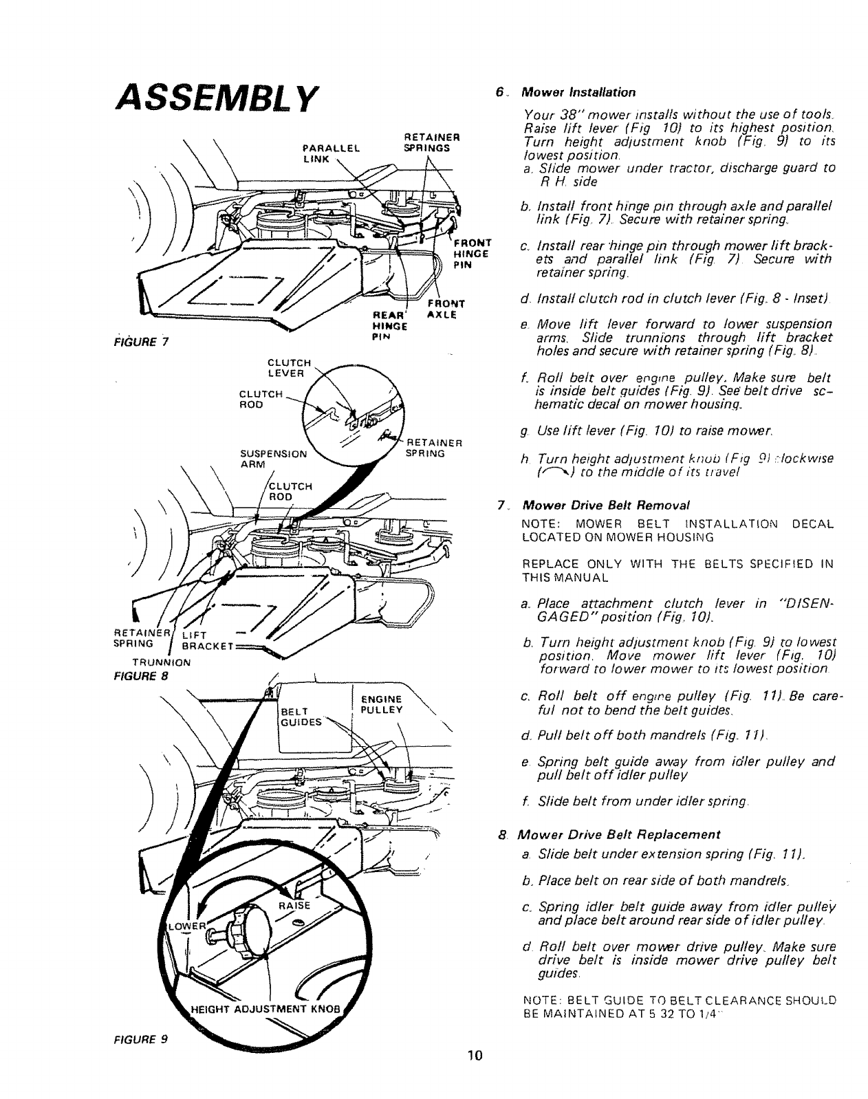
6v Mower Installation
Your 38" mower installs without the use of tools,
Raise lift lever (Fig 10) to its highest position,
Turn height adtustment knob (Fig, 9) to its
fo west position,
a, Slide mower under tractor, discharge guard to
R H, side
b. Install front hinge pm through axle and parallef
link (Fig. 7), Secure with retainer' spring,
c, Install rear "hinge pin through mower lift brack-
ets and parallel link (Fig, 7) Secure with
retainer spring.
d. Install clutch rod in clutch lever (Fig,. 8- Inset)
e, Move lift lever forward to lower suspension
ar'ms, Slide trunnions through lift bracket
holes and secure with retainer spring (Fig,, 8).
f. Roll belt over engine pulley, Make sure bett
is inside belt guides (Fig. 9), See belt drive sc-
hematic decal on mower housing.
g. Use lift lever (Fig,, 10) to raise mower,
h Turn height adjustment knuz) (Fig 9) _:-Iockwise
(/'-",,) to the middle of its tlave!
7_ Mower Drive Belt Removal
NOTE: MOWER BELT fNSTALLAT{ON DECAL
LOCATED ON MOWER HOUSING
REPLACE ONLY WITH THE BELTS SPECIFIED IN
THIS MANUAL
TRUNNION
FIGURE 8
\
\
/
BE LT
\
/
a_
b,
c_
d.
e
Place attachment clutch lever in "'DISEN-
GAGED" position (Fig, 10).
Turn height adiustmenc knob (Fig, 9) to to west
position. Move mower fift lever (Fig. 10)
forward to lower mower to its lowest position
Roll belt off engtne pulley (Fig. 1t),, Be care-
ful not to bend the belt guides.
Pull belt off both mandrels (Fig,. Il),
Spring belt guide away from idler pulley and
pull belt off idler pulley
f Sfide belt from under idler spring.
B. Mower Drive Belt Replacement
a, Slide belt under'extension spring (Fig_ 11).
b. Place bett on rear side of both mandrels,
c, Spring idler belt guide away from idler putte_,
and place belt around rear' side o f idler putle y,
d Roll bett over mower drive pulley, Make sure
drive belt is inside mower drive pulley bett
guides,
NOTE: BELT GUIDE TO BELT CLEARANCE SHOULD
BE MAINTAINED AT 5 32 TO 114'
FIGURE 9
10
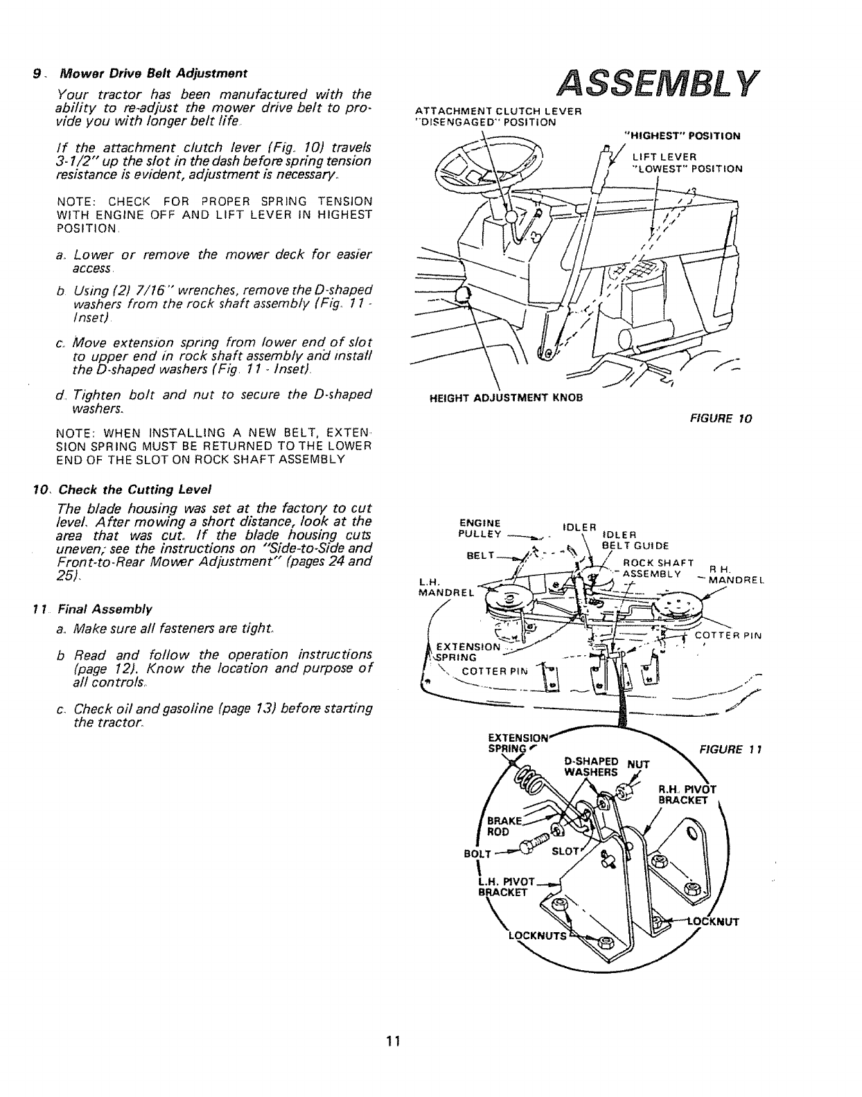
9_ Mower Drive Belt Adjustment
Your tractor has been manufactured with the
ability to re-adjust the mower drive belt to pro-
vide you with longer belt life.
If the attachment clutch lever (Fig.. 10) travels
3-1/2" up the slot in the dash before spring tension
resistance is evident, adjustment is necessary.,
NOTE: CHECK FOR PROPER SPRING TENSION
WITH ENGINE OFF AND LIFT LEVER IN HIGHEST
POSITION,
a.
b
C_
Lower or remove the mower deck for easier
access,
Using (2) 7/16'" wrenches, remove the D-shaped
washers from the rock shaft assembly (Fig, 1 1 -
/nset).
Move extension spring from lower end of slot
to upper end in rock shaft assembly and instafl
the D-shaped washers (Fig. 1 1 -Inset).
Tighten bolt and nut to secure the D.shaped
washers.
NOTE: WHEN INSTALLING A NEW BELT, EXTEN,
SION SPRING MUST BE RETURNED TO THE LOWER
END OF THE SLOT ON ROCK SHAFT ASSEMBLY
10, Check the Cutting Level
The Made housing was set at the factory to cut
level, After mowing a short distance, look at the
area that was cut° tf the blade housing cuts
uneven; see the instructions on "Side-to.Side and
Front-to-Rear Mower Adjustment" (pages 24 and
25).
11 Final Assembly
a° Make sure all fasteners are tight_
b Read and follow the operation instructions
(page 12), Know the location and purpose of
all con trois.
c_ Check oil and gasoline (page l,Y) before starting
the tractor.
ASSEMBL Y
ATTACHMENT CLUTCH LEVER
"DISENGAGED" POSITION
"HIGHEST" POSITION
LIFT LEVER
"LOWEST'* POSITION
\
HEIGHT ADJUSTMENT KNOB
FIGURE 10
ENGINE IDLER
PULLEY _-,_._._. IDLER
BELT GUIDE
BELT-.-_,/_."I /ROCK SHAFT
ASSEMBLY R H.
MANDREL
L,H.
MANDREL
COTTER PiN
EXTENSION
\FIGURE i I
.DO
BOLT
I
L.H, P1VI
LOCKNUTS
R,H,, PIVOT
BRACKET \
/
11
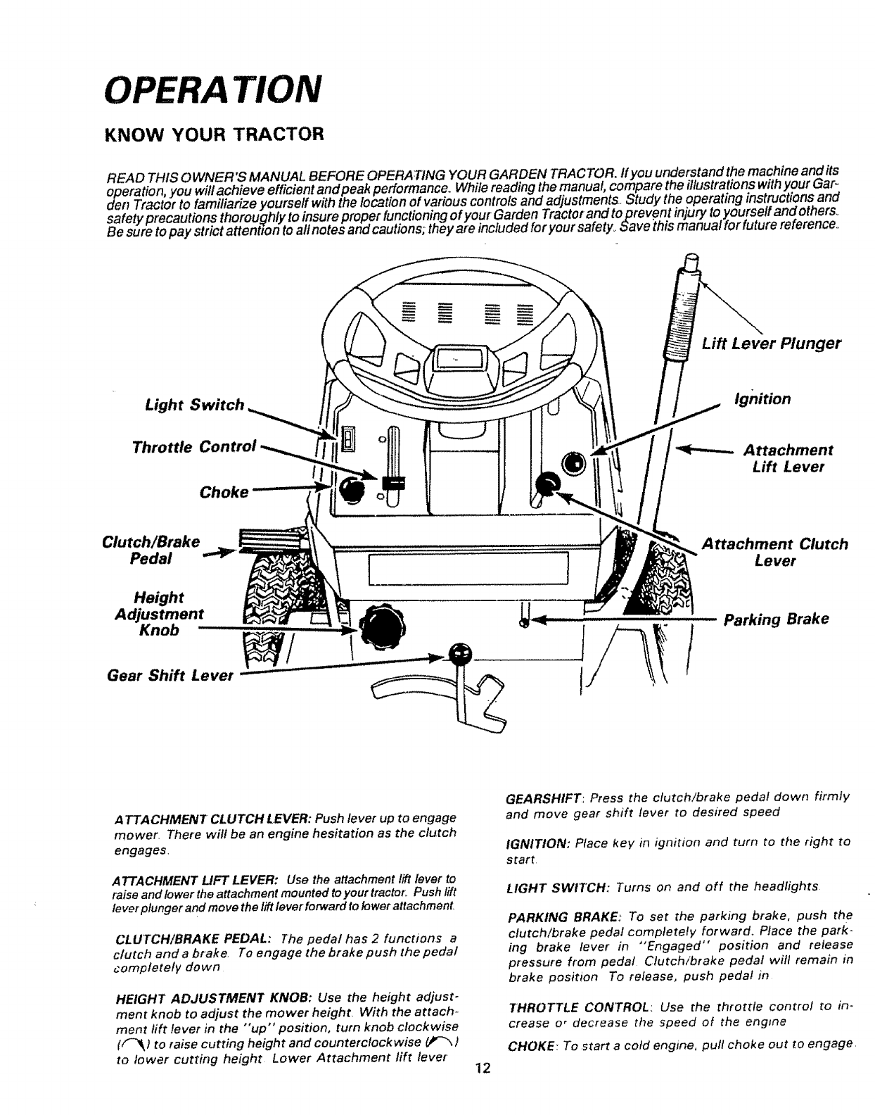
OPERA TION
KNOW YOUR TRACTOR
READ THIS OWNER'S MANUAL BEFORE OPERATING YOUR GARDEN TRACTOR./fyou understand the machine and its
operation, you will achieve efficient and peak pedormance_ While reading the manual, compare the illustrations with your Gar _
den Tractor to familiarize yourself with the location of various controls and adjustments.. Study the operating instructions and
safety precautions thoroughly to insure proper functioning of your Garden Tractor and to prevent injury to yourself and others.
Be sure to pay strict attention to alt notes and cautions; they are included for your safety_ Save _thismanual for future reference.,
Lift Lever Plunger
Light Switch
Throttle Control
Choke
Ignition
-.t.---.-- Attachment
Lift Lever
Clutch/Brake Attachment Clutch
Pedal ""P J Lever
l
Height
Adjustment
Knob
Gear Shift Lever
Parking Brake
ATTACHMENT CLUTCH LEVER: Push lever up to engage
mower. There will be an engine hesitation as the clutch
engages.
ATTACHMENT LIFT LEVER: Use the attachment lift lever to
raise and lower the attachment mounted to your tractor, Push !ift
lever plunger and move the lift lever forward to lower attachment
CLUTCH/BRAKE PEDAL: The pedal has 2 functions a
clutch and a brake. To engage the brake push the pedal
completely down
HEIGHT ADJUSTMENT KNOB: Use the height adjust-
ment knob to adjust the mower height. With the attach-
ment lift lever in the "up" position, turn knob clockwise
(/"_ lto raise cutting height and counterclockwise (JP'_ )
to lower cutting height Lower Attachment lift lever 12
GEARSHIFT: Press the clutch!brake pedal down firmly
and move gear shift lever to desired speed
IGNITION: Place key in ignition and turn to the right to
start
LIGHT SWITCH: Turns on and off the headlights
PARKING BRAKE: To set the parking brake, push the
clutch/brake pedal completely forward. Place the park-
ing brake lever in "Engaged" position and release
pressure from pedal Ctutch/brake pedal will remain in
brake position To release, push pedal in
THROTTLE CONTROL: Use the throttle control to in-
crease o rdecrease the speed of the engine
CHOKE: To .start a cold engine, pult choke out to engage.
1_ Stopping Your Tractor
Id_ DO NOT CHOKE CARBURETOR TO STOP 1THE ENGINE.
LEARN HOW TO STOP YOUR TRAC-
TOR BEFORE ATTEMPTINGTO START
THE ENGINE.
NOTE: REMOVE KEY WHEN LEAVING TRACTOR TO
PREVENT UNAUTHORIZED USE
a.. Push clutch/brake pedal into full "BRAKE"
position,
b Move gear shift lever to "'NEUTRAL'" position
c.Place parking brake in "ENGAGED" position and
release pressure from clutch/brake. Pedal should
remain in "BRAKE" position NOTE: MAKE SURE
PARKING BRAKE WILL HOLD TRACTOR
SECURE
d Place attachment clutch lever in "'DISENGAGE[)'"
position.
e. Move throttle control to "S" (slow) position.
f.Turn ignition key to "OFF" position Never use
choke to stop engine.
2, Starting The Engine
LEARN TO START, STOP AND REVERSE
YOUR TRACTOR IN A LARGE, OPEN AREA.
THIS TRACTOR IS EQUIPPED WITH IN-
TERLOCK SWITCHES TO PREVENT STAR-
TING OF THE TRACTOR ENGINE WHILE
THE MOWER BLADE CLUTCH LEVER IS IN
THE "ENGAGED" POSITION AND/OR THE
FOOT PEDAL IS NOT FULLY DEPRESSED_
IMMEDIATELY REPLACE SWITCHES THAT
ARE NOT IN PROPER WORKING ORDER.
DO NOT ATTEMPT TO DEFEAT THE PUR-
POSE OF THESE SWITCHES.
a, This engine has been shipped filled with sum-
mer weight oiL For cold weather operation,
see chart on page 16, Check engine oil level
with tractor on level ground._ Remove and
wipe dipstick (Fig, I7) clean, screw it in tight
for a few seconds, remove and read oil level.,
If necessary, add oi! until "'FULL" mark is
reached,
b. Fill fuel tank. Use fresh, clean, regular UN-
LEADED automotive gasoline, (Use of leaded
gasoline will increase carbon and lead oxide
deposits and reduce valve fife), Capacity is
2 gallons,
CAUTION EXPERIENCE INDICATES THAT ALCOHOL
BLENDED FUELS (CALLED GASOHOL OR USING
ETHANOL OR METHANOL) CAN ATTRACT MOIS-
TURE WHICH LEADS TO SEPARATION AND FOR-
MATION CF ACIDS DURING STORAGE ACIDIC
GAS CAN D_MAGE THE FUEL SYSTEM OF AN
ENGINE WHIL, E ;N STOPAGE
TD 4bCtD ENG!NE P_:OBLEMS, THE FUEL SYS-
TEM SHOULD BE EMPTIED BEFOPE STOPAGE
FOP 3'3 DAYS C o LDNGEP DRAIN THE GAS
TA._IK STAPT THE ENGINE _ND LET IT RUN UN-
TL THE FUEL JNES AND C/,#BURETOR ARE
E*,f, =TF USE F#ESH FuEL NExT SEASON .SEE
ST_P_DE HS-_L'CT GNS FOP 4DDtT_ONAL tN-
=3PM4 7:C '%_.
•_JE;EF, USE E_,S__IE ;._'_ C4Fg...._ETD p2LEANER
"--RDC'u'_TS b T.-,_ ::.'EL T-:'._d _F. F-__=bfA,_tEt_T
_.4_343E '.,*,4,, _25:., _ 13
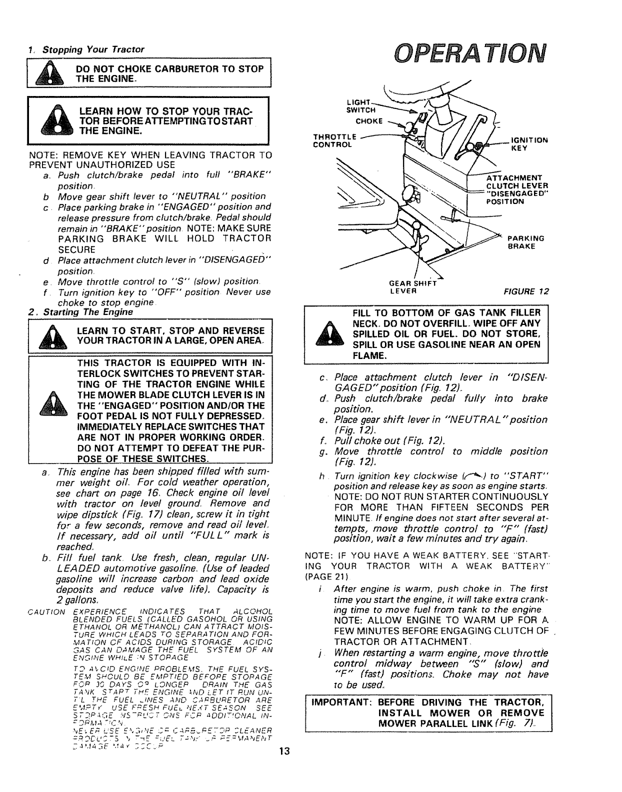
OPERA TION
LIGHT-._,_
SWITCH
CHOKE
THROTTLE
CONTROL IGNITION
KEY
ATTACHMENT
CLUTCH LEVER
'DISENGAGED"
POSITION
PARKING
8RAKE
GEAR SHIFT
LEVER FIGURE 12
FILL TO BOTTOM OF GAS TANK FILLER
NECK_ DO NOT OVERFILL. WIPE OFF ANY
SPILLED OIL OR FUEL. DO NOT STORE,
SPILL OR USE GASOLINE NEAR AN OPEN
FLAME,
c_ Place attachment clutch lever in "'DISEN-
GAGED" position (Fig, 12)_
do Push clutch/brake pedal fully into brake
position.
e. Place gear shift lever in "WEUTRAL "position
(Fig. 12)o
fo Pul! choke out (Fig, 12).
g. Move throttle control to middle position
(Fig, 12)o
h Turn ignition key clockwise ((*-*_,) to "START"
position and release key as soon as engine starts.
NOTE: DO NOT RUN STARTER CONTINUOUSLY
FOR MORE THAN FIFTEEN SECONDS PER
MINLJTE if engine does not start after several at-
tempts, move throttle control to "F" (fast)
position, wait a few minutes and try again,
NOTE: IF YOU HAVE A WEAK BATTERY. SEE "START..
ING YOUR TRACTOR WITH A WEAK BATTERY"
(PAGE 21)
i After engine is warm, push choke in The first
time you start the engine, it wifl take extra crank-
ing time to move fuel from tank to the engine
NOTE: ALLOW ENGINE TO WARM UP FOR A
FEW MINUTES BEFORE ENGAGING CLUTCH OF ..
TRACTOR OR ATTACHMENT,
) When restarting a warm engine, move throttle
control midway between "'S" (slow) and
"F" (fast) positions.. Choke may not have
to be used,,
IMPORTANT: BEFORE DRIVING THE TRACTOR, ]
INSTALL MOWER OR REMOVE
MOWER PARALLEL LINK (Fig. 7),
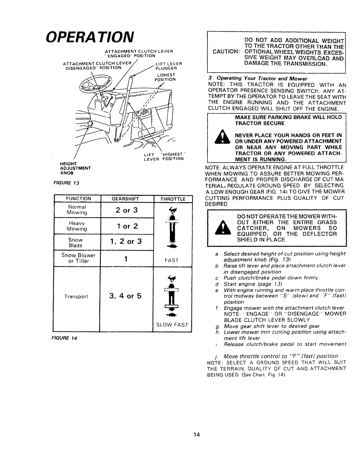
OPERA ]'ION
ATTACHMENT CLU]CH LEVER
'-ENGAGEO" POSiTiON
ATTACHMENT CLUTCH LEVER
•DISENGAGED'* POSITION LIFT LEVER
PLUNGER
LOWEST'
POSITION
//
/
HEIGHT
ADJUSTMENT
KNOB
LLFT "HIGHEST'"
LEVER POSITION
FIGURE 13
...............FUNCTION ...............
Normal
Mowing
Heavv
Mowing
,,,,,,,,,,,,,,,,,,, ]H,,
Snow
Blade
Snow Blower
of Tiller
Transport
GEARSHIFT
2or3
lor2
1,2or3
3,4or 5
,, ,,,,,,,,, i,,, LU
THROTTLE
JJ_
FAST
SLOW FAST
FIGURE 14
CAUTION:
DO NOT ADD ADDITIONAL WEIGHT
TO THE TRACTOR OTHER THAN THE
OPTIONAL WHEEL WEIGHTS° EXCES-
SIVE WEIGHT MAY OVERLOAD AND
DAMAGE THE TRANSMISSION,
3_,Operating Your Tractor and Mower
NOTE: THIS TRACTOR IS EQUIPPED WITH AN
OPERATOR PRESENCE SENSING SWITCH. ANY AT-
TEMPT BY THE OPERATOR TO LEAVE THE SEAT WITH
THE ENGINE RUNNING AND THE ATTACHMENT
CLUTCH ENGAGED WILL SHUT OFF THE ENGINE,
MAKE SURE PARKING BRAKE WILL HOLD
TRACTOR SECURE,
NEVER PLACE YOUR HANDS OR FEET IN
OR UNDER ANY POWERED ATTACHMENT
OR NEAR ANY MOVING PART WHILE
TRACTOR OR ANY POWERED ATTACH-
MENT IS RUNNING.
NOTE: ALWAYS OPERATE ENGINE AT FULL THROTTLE
WHEN MOWING TO ASSURE BETTER MOWING PER-
FORMANCE AND PROPER DISCHARGE OF CUTMA
TERIAL. REGULATE GROUND SPEED BY SELECTING
ALOW ENOUGH GEAR (FIG. 14) TO GIVE THE MQWER
CUTTING PERFORMANCE PLUS QUALITY OF CUT
)ESIRED
!
DO NOT OPERATE THE MOWER WITH- J
OUT EITHER THE ENTIRE GRASS !
CATCHER, ON MOWERS SO t
EQUIPPED, OR THE DEFLECTOR i
SHIELD IN PLACE I
aSelect desired height of cut position using height
adjustment knob (Fig, 13)
b Raise lift lever and place attachment clutch lever
in disengaged position
c Push cfutch/brake pedal down firmly
d Start engine (page I3)
eWith engine running and warm place throttle con-
trol midway between "S' (slow) and "F" (fast)
position
f Engage mower with the attachment clutch lever,
NOTE: "ENGAGE" OR "DISENGAGE" MOWER
BLADE CLUTCH LEVER SLOWLY
g, Move gear shift lever to desired gear
h Lower mower into cutting position using attach-
ment lift level
iRelease clutch!brake pedal to start movement
j, Move throttle control to "'F" (fast) position.
NOTE: SELECT A GROUND SPEED THAT WlLL SUIT
THE TERRAIN, QUALITY OF CUT AND ATTACHMENT
BEINGUSED (See Chart. Fig 14)
14
4. Mowing Tips
NOTE: TIRE CHAINS CANNOT BE USED VVtTH THE
MOWER HOUSING ATTACHED..
OPERA TION
READ THE "SAFETY RULES" CAREFULLY
BEFORE OPERATING YOUR MOWER.
REFER TO PAGE 2,,
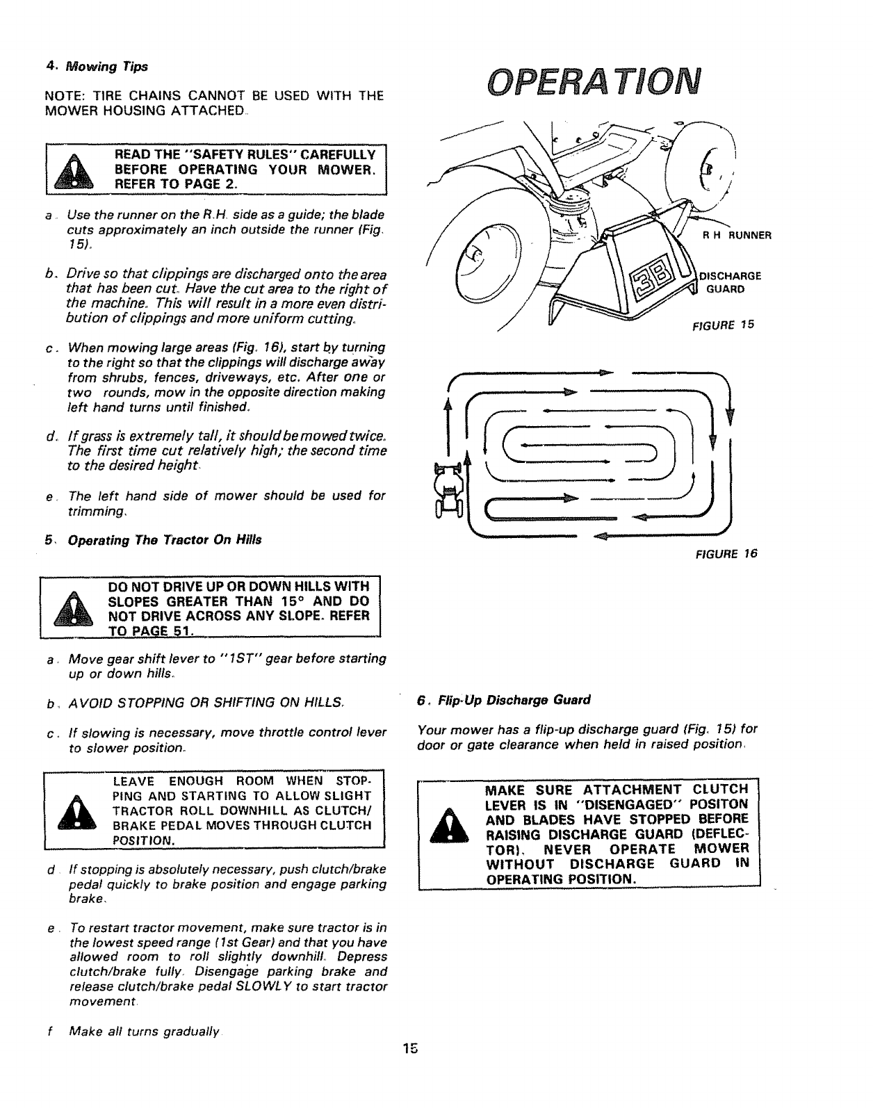
a. Use the runner on the RH side as a guide; the blade
cuts approximately an inch outside the runner (Fig.
15)o
b, Drive so that clippings are discharged onto the area
that has been cut° Have the cut area to the right of
the machine° This will result in a more even distri:
bution of clippings and more uniform cutting,,
C. When mowing large areas (Fig° 16), start by turning
to the right so that the clippings will discharge away
from shrubs, fences, driveways, etc, After one or
two rounds, mow in the opposite direction making
left hand turns until finished°
d., If grass is extremely tall, it should be mowed twiceo
The first time cut relatively high; the second time
to the desired height,
e. The left hand side of mower should be used for
trimming,
5, Operating The Tractor On Hills
DO NOT DRIVE UP OR DOWN HILLS WITH
SLOPES GREATER THAN 15 ° AND DO
NOT DRIVE ACROSS ANY St.OPE_REFER
TO,,_GE 51.
a. Move gear shift lever to ""1ST'" gear before starting
up or down hills..
b_ AVOID STOPPING OR SHIFTING ON HILLS°
co If slowing is necessary, move throttle control lever
to slower position°
ILEAVE ENOUGH ROOM WHEN STOP-
PING AND STARTING TO ALLOW SLIGHT
TRACTOR ROLL DOWNHILL AS CLUTCH/
BRAKE PEDAL MOVES THROUGH CLUTCH
POSITION.
dIf stopping is absolutely necessary, push clutch/brake
peda! quickly to brake position and engage parking
brake.
e , To restart tractor movement, make sure tractor is in
the lowest speed range (Ist Gear) and that you have
allowed room to roll slightly downhill° Depress
clutch/brake fully. Disengage parking brake and
release clutch/brake pedal SLOWL Y to start tractor
movement.
f Make all turns gradually
R H RUNNER
DISCHARGE
GUARD
FIGURE 15
FIGURE 16
6_ Flip:Up Discharge Guard
Your mower has a flip-up discharge guard (Fig° 15) for
door or gate clearance when held in raised position1
MAKE SURE ATTACHMENT CLUTCH
LEVER IS IN "DISENGAGED" POSITON
AND BLADES HAVE STOPPED BEFORE
RAISING DISCHARGE GUARD (DEFLEC-
TORI_ NEVER OPERATE MOWER
WITHOUT DISCHARGE GUARD IN
OPERATING POSITION.
15
MAINTENANCE
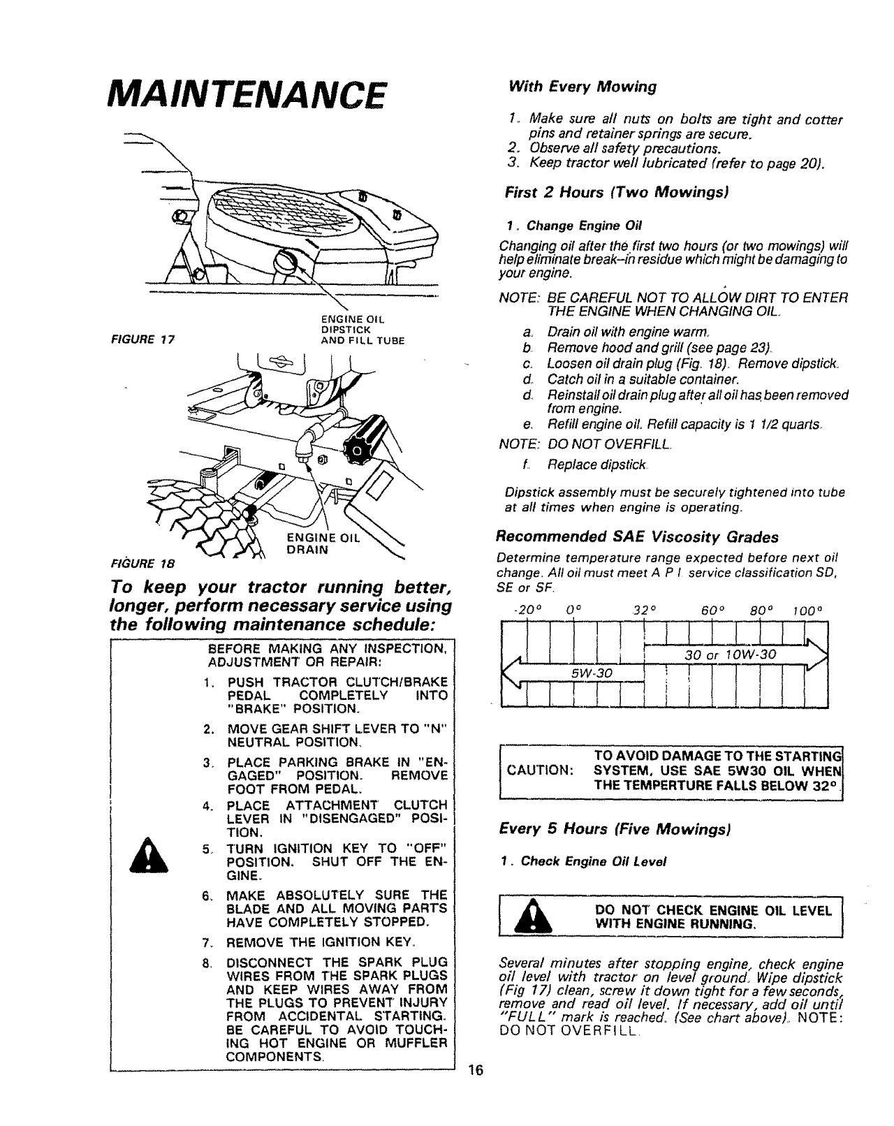
FIGURE 17
ENGINE OIL
DIPSTICK
AND FILL TUBE
ENGINE OIL
DRAIN
FIGURE !8
To keep your tractor running better,
longer, perform necessary service using
the following maintenance schedule:
BEFORE MAKING ANY INSPECTION,
ADJUSTMENT' OR REPAIR:
t, PUSH TRACTOR CLUTCH/BRAKE
PEDAL COMPLETELY INTO
"BRAKE" POSITION.
2, MOVE GEAR SHIFT LEVER TO "N"
NEUTRAL POSITION,
3_ PLACE PARKING BRAKE IN "EN-
GAGED" POSITION. REMOVE
FOOT FROM PEDAL,
4. PLACE ATTACHMENT CLUTCH
LEVER iN "DISENGAGED" POSI-
TION.
5, 3"URN IGNITION KEY TO "OFF"
POSITION, SHUT OFF THE EN-
GINE.
6_ MAKE ABSOLUTELY SURE THE
BLADE AND ALL MOVING PARTS
HAVE COMPLETELY STOPPED.
7. REMOVE THE IGNITION KEY.,
8, DISCONNECT THE SPARK PLUG
WIRES FROM THE SPARK PLUGS
AND KEEP WIRES AWAY FROM
THE PLUGS TO PREVENT INJURY
FROM ACCIDENTAL STARTING_
BE CAREFUL TO AVOID TOUCH-
ING HOT ENGINE OR MUFFLER
COMPONENTS, 16
With Every Mowing
1., Make sure all nuts on bolts are tight and cotter
pins and retainer springs are secure.
2, Observe aft safety precautions,
3, Keep tractor weft lubricated (refer to page 20).
First 2 Hours (Two Mowings)
1o Change Engine Oil
Changing oil after the first two hours (or two mowings) wil!
help eliminate break-in residue which might be damaging to
your engine.
NOTE,: BE CAREFUL NOT TO ALL()W DIRT TO ENTER
THE ENGINE WHEN CHANGING OIL,.
a_ Drain oil with engine warm,
b Remove hoodandgrif/(see page 23),
c, Loosen oil drain plug (Fig_ 18)., Remove dipstick°
d,, Catch oil in a suitable container.
d. Reinstal! oil drain plug after all oil has.been removed
from engine.
e. Refill engine oil. Refill capacity is I 1/2 quarts..
NOTE.: DO NOT OVERFILL.
L. Replace dipstick..
Dipstick assembly must be securely tightened into tube
at all times when engine is operating..
Recommended SAE Viscosity Grades
Determine temperature range expected before next oil
change. All oil must meet A P i service classification SD,
SE or SF.
CAUTION: TO AVOID DAMAGE TO THE STARTING
SYSTEM, USE SAE 5W30 OIL WHEN
THE TEMPERTURE FALLS BELOW 32°. !
Every 5 Hours (Five Mowings)
1. Check Engine Off Level
1
DO NOT CHECK ENGINE OIL LEVEL [
WITH ENGINE RUNNING, J
Several minutes after stopping engine, check engine
oil level with tractor on levelground, Wipe dipstick
(Fig 17) clean, screw it down tight for a few seconds,
remove and read oil level, if necessary, add oil until
"FULL "" mark is reached, (See chart above),, NOTE:
DO NOT OVERFILL.
Every 25 Hours (Twice a Mowing Season)
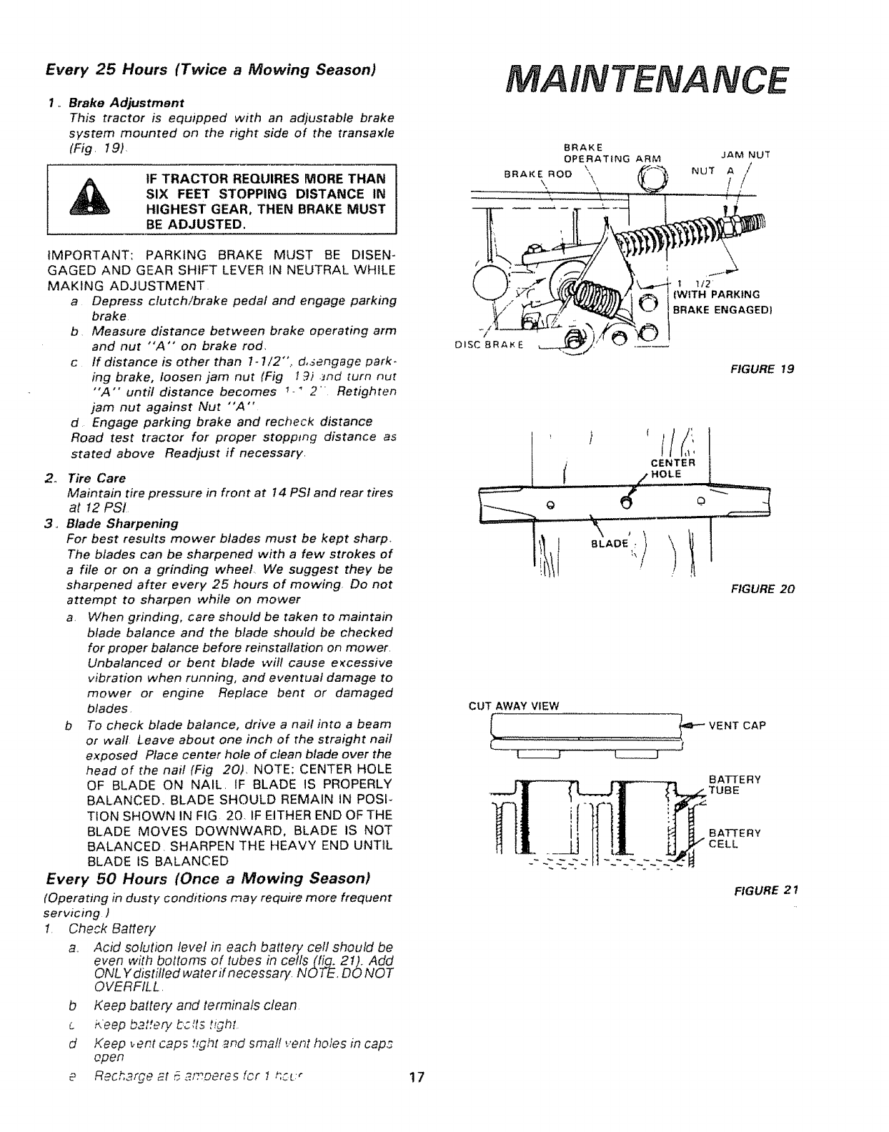
I ,, Brake Adjustment
This tractor is equipped with an adjustable brake
system mounted on the right side of the transaxle
(Fig. 19)
tF TRACTOR REQUIRES MORE THAN
SiX FEET STOPPING DISTANCE IN
HIGHEST GEAR, THEN BRAKE MUST
BE ADJUSTED,
MAINTENANCE
IMPORTANT: PARKING BRAKE MUST BE DISEN-
GAGED AND GEAR SHIFT LEVER IN NEUTRAL WHILE
MAKING ADJUSTMENT
a Depress clutch!brake pedal and engage parking
brake
b Measure distance between brake operating arm
and nut "A'" on brake rod,
c If distance is other than 1-1/2", d,sengage park-
ing brake, loosen jam nut (Fig t._) and turn nut
"A'" until distance becomes 7., 2 Retighten
jam nut against Nut "'A"
d Engage parking brake and recheck distance
Road test tractor for proper stopptng distance as
stated above Readjust if necessary.
2o Tire Care
Maintain tire pressure in front at 14 PSI and rear tires
at 12 PSI
3,, Blade Sharpening
For best results mower blades must be kept sharp,
The blades can be sharpened with a few strokes of
a file or on a grinding wheel We suggest they be
sharpened after every 25 hours of mowing Do not
attempt to sharpen while on mower
a. When grinding, care should be taken to maintain
blade balance and the blade should be checked
for proper balance before reinstatlation on mower.
Unbalanced or bent blade wilt cause excessive
vibration when running, and eventual damage to
mower or engine Replace bent or damaged
blades.
b To check blade balance, drive a nail into a beam
or wall Leave about one inch of the straight nail
exposed Place center hole of clean blade over the
head of the nail (Fig 20), NOTE: CENTER HOLE
OF BLADE ON NAIL. tF BLADE IS PROPERLY
BALANCED, BLADE SHOULD REMAIN IN POSP
TtON SHOWN IN FIG 20, IF EITHER END OF THE
BLADE MOVES DOWNWARD, BLADE IS NOT
BALANCED. SHARPEN THE HEAVY END UNTIL
BLADE IS BALANCED
Every 50 Hours (Once aMowing Season)
(Operating in dusty conditions may require more frequent
servicing )
1. Check Battery
a.. Acid solution level in each battery cell should be
even with bottoms of tubes in cells(fig. 21). Add
ONL Y distifled water if necessary. NOTE. DO NOT
OVERFILL.
bKeep battery and terminals clean
ci4eep battery bc its t,,ghr
d Keep vent caps t_ght .end smafl vent holes in cap,.:
open
eRech3rge _t _ _moeres fcrt t,CL:r 17
CUT AWAY VIEW
t1/2
WITH PARKING
ENGAGED}
FIGURE 19
CENTER
HOLE
,.t. ......
\,
BLADE _,,/
FIGURE 20
=P'-VENT CAP
I
BATTERY
TUBE
BATTERY
CELL
FIGURE 21
MAINTENANCE
PAPER
C'ARTRIDGE
COVER
gNut
CARTRIOGE
PLATE
FOAM
PRE,CLEANER
AtR SCREEN BODY
FIGURE 22
__ GREASE BOTH
o ir
|1
FIGURE 23
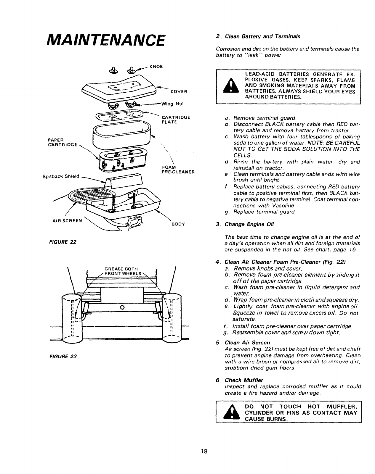
2_ Clean Battery and Terminals
Corrosion and dirt on the battery and terminals cause the
battery to "leak'" power
LEAD-ACID BATTERIES GENERATE EX-
PLOSIVE GASES_ KEEP SPARKS, FLAME
AND SMOKING MATERIALS AWAY FROM
BATTERIES. ALWAYS SHIELD YOUR EYES
AROUND BATTERIES.
a. Remove terminal guard,
b Disconnect BLACK battery cable then RED bat-
tery cable and remove battery from tractor
c Wash battery with four tablespoons of baking
soda to one gallon of water. NOTE: BE CAREFUL
NOT TO GET THE SODA SOLUTION INTO THE
CELLS
d. Rinse the battery with plain water dry and
reinstall on tractor
e Clean terminals and battery cable ends with wire
brush until bright
f Replace battery cables, connecting RED battery
cable to positive terminal first, then BLACK bat-
tery cable to negative terminal Coat terminal con-
nections with Vasoline
g Replace terminal guard
3o Change Engine Off
4_
,
The best time to change engine oil is at the end of
a day's operation when all dirt and foreign materials
are suspended in the hot oil See chart, page 16.
Clean Air Cleaner Foam Pre-Cteaner (Fig, 22)
a. Remove knobs and cover,
b. Remove foam pre_cleaner element by, sliding it
off of the paper cartridge,
c, Wash foam pre-cleaner in liquid detergent and
water,.
d, 'Wrap foam pre-cteaner in cloth and squeeze drv.
e, L/ghtty coat foampre-c/eaner with engineoil
Squeeze m towel to remove excess oil Do not
saturate,
f, Install foam pre-c/eaner over' paper cartridge
g,. Reassemble cover and screw down tight_
Clean Air Screen
Air screen (Fig. 22) must be kept free of dirt and chaff
to prevent engine damage from overheating Clean
with a wire brush or compressed air to remove dirt,
stubborn dried gum fibers
Check Muffler
inspect and replace corroded muffler as it could
create a fire hazard and/or damage
1
DO NOT TOUCH HOT MUFFLER, |
CYLINDER OR FINS AS CONTACT MAY ]
CAUSE BURNS.
18
7,_ Lubricate Steering And Front Wheels
There is a grease fitting on each front wheel Use a
grease gun; give each grease fitting two shots of
extreme pressure lubricating grease (available through
your Sears Service Center).. Use 30 weight oil to
lubricate pivot (Fig.. 23)..
8o Oil Pivot Points
Place severaf drops of SEA 30 oil at points where metal
parts move against each other, especialfy hood hinges.
SEE L UB R ICA T/ON CHA R 7-, PA GE 20,,
INTENANCE
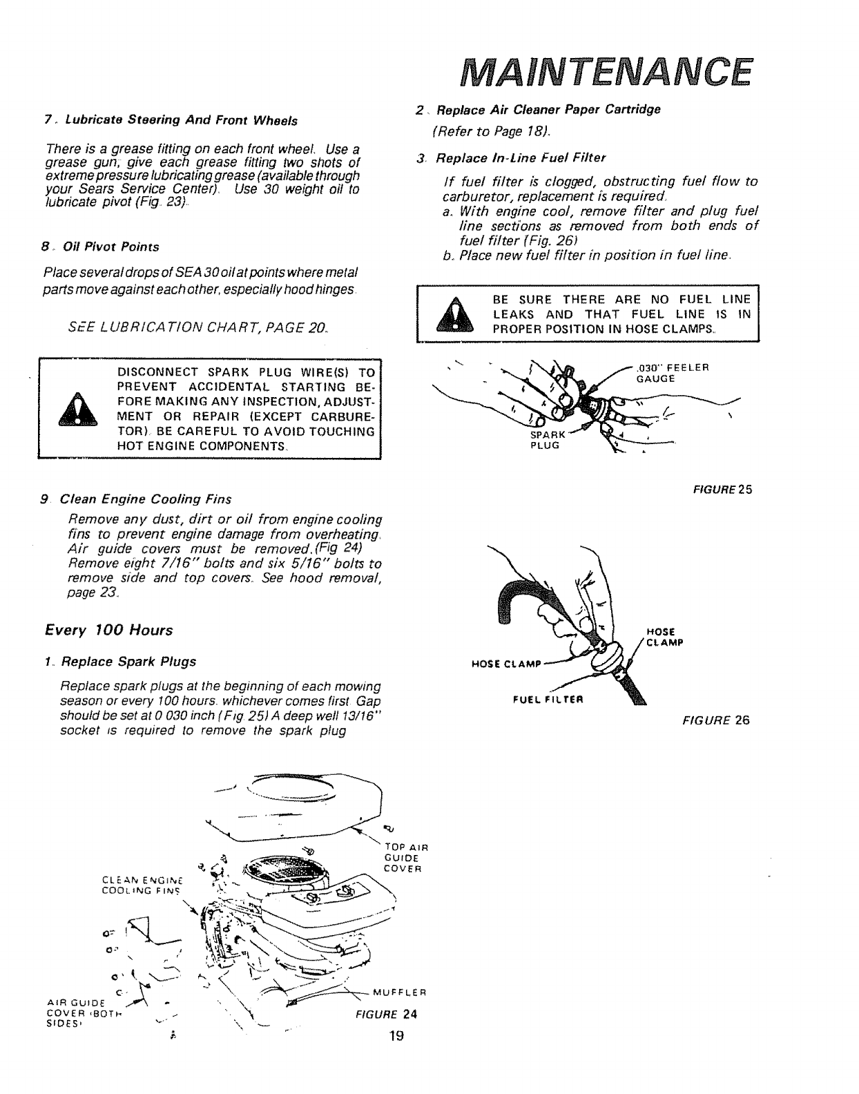
2, Replace Air Cleaner Paper Cartridge
(Refer to Page 18L
3. Replace In-Line Fuel Filter
If fue! filter is clogged, obstructing fuel flow to
carburetor, replacement is required,
a. With engine cool, remove filter and plug fuel
line sections as removed from both ends of
fuel filter {Fig. 26)
bo Place new fuel filter in position in fuel fine.
BE SURE THERE ARE NO FUEL LINE
LEAKS AND THAT FUEL LINE tS IN
PROPER POSITION IN HOSE CLAMPS,,
DISCONNECT SPARK PLUG WIRE(S) TO
PREVENT ACCIDENTAL STARTING BE-
FORE MAKING ANY INSPECTION, ADJUST-
MENT OR REPAIR (EXCEPT CARBURE-
TOR). BE CAREFUL TO AVOID TOUCHING
HOT ENGINE COMPONENTS,, SPARK
PLUG
,03O'FEELER
GAUGE
9. Clean Engine Cooling Fins
Remove any dust, dirt or oil from engine coofing
fins to prevent engine damage from overheating,
Air guide covers must be removed.(Fig 24)
Remove eight 7/16" bolts and six 5/16" bolts to
remove side and top covers.. See hood removal,
page 23..
FIGURE25
Every 700 Hours
1,, Replace Spark Plugs
Replace spark plugs at the beginning of each mowing
season or every 100 hours, whichever comes first Gap
should be set at 0 030 inch (Fig. 25) A deep well t3/t6"
socket ts required to remove the spark plug
HOSE Ct.
FUEL FILTER
FIGURE 26
CLE,_,NE_GiN_.
COOLING FINS
\
\
AIR GUIDE
COVER ,8OT_
SIDES,
__ OP AIR
GUIDE
a. COvEn
"t
J
,, . _MUFFLER
"\"_-- FIGURE 24
_' 19
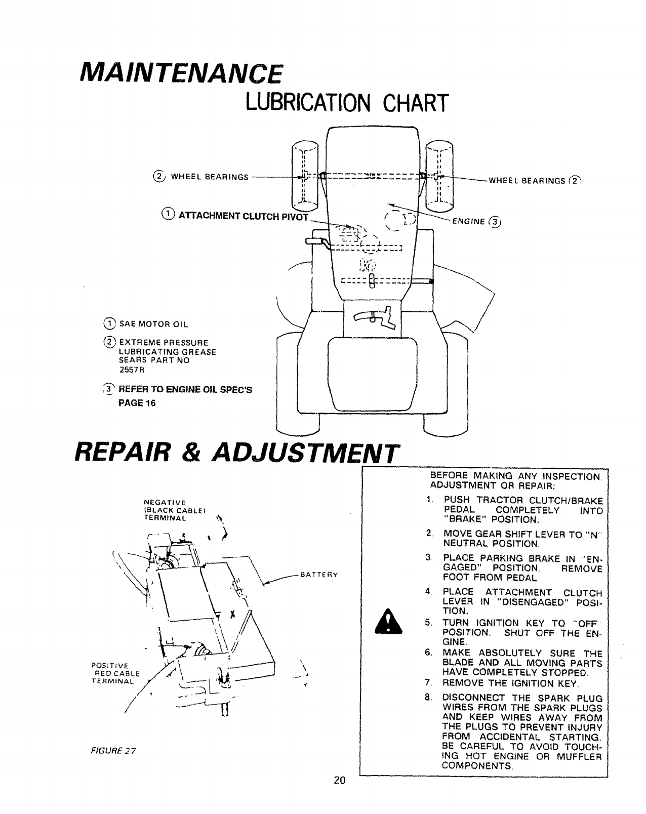
MAINTENANCE
LUBRICATIONCHART
WHEEL BEARINGS
_, SAE MOTOR OIL
_EXTREME PRESSURE
LUBRICATING GREASE
SEARS PAR]" NO
2557 R
•_'_ REFER TO ENGINE OIL SPEC'S
PAGE 16
Q ATTACHMENTCLUTCHP'VOT___ f I-;
& ADJUSTMENT
NEGATIVE
(BLACK CABLE)
TERMINAL _.%
\
Y
FIGURE 2 7
WHEE
)
)
LBEARINGS (2_
BEFORE MAKING ANY INSPECTION
ADJUSTMENT OR REPAIR:
1_ PUSH TRACTOR CLUTCHIBRAKE
PEDAL COMPLETELY INTO
"BRAKE" POSITION
2_ MOVE GEAR SHIFT LEVER TO "N"
NEUTRAL POSITION,
3PLACE PARKING BRAKE IN 'EN-
GAGED" POSITION. REMOVE
FOOT FROM PEDAL
4. PLACE ATTACHMENT CLUTCH
LEVER iN "DISENGAGED" POSI.
TION.
5_ TURN IGNITION KEY TO _OFF
POSITION, SHUT OFF THE EN-
GINE,
6, MAKE ABSOLUTELY SURE THE
BLADE AND ALL MOVING PARTS
HAVE COMPLETELY STOPPED,
7, REMOVE THE IGNITION KEY,
8. DISCONNECT THE SPARK PLUG
WIRES FROM THE SPARK PLUGS
AND KEEP WIRES AWAY FROM
"THE PLUGS TO PREVENT INJURY
FROM ACCIDENTAL START1NG,
BE CAREFUL TO AVOID TOUCH-
ING HOT ENGINE OR MUFFLER
COMPONENTS
2O
REPA &ADJUSTMENT
r
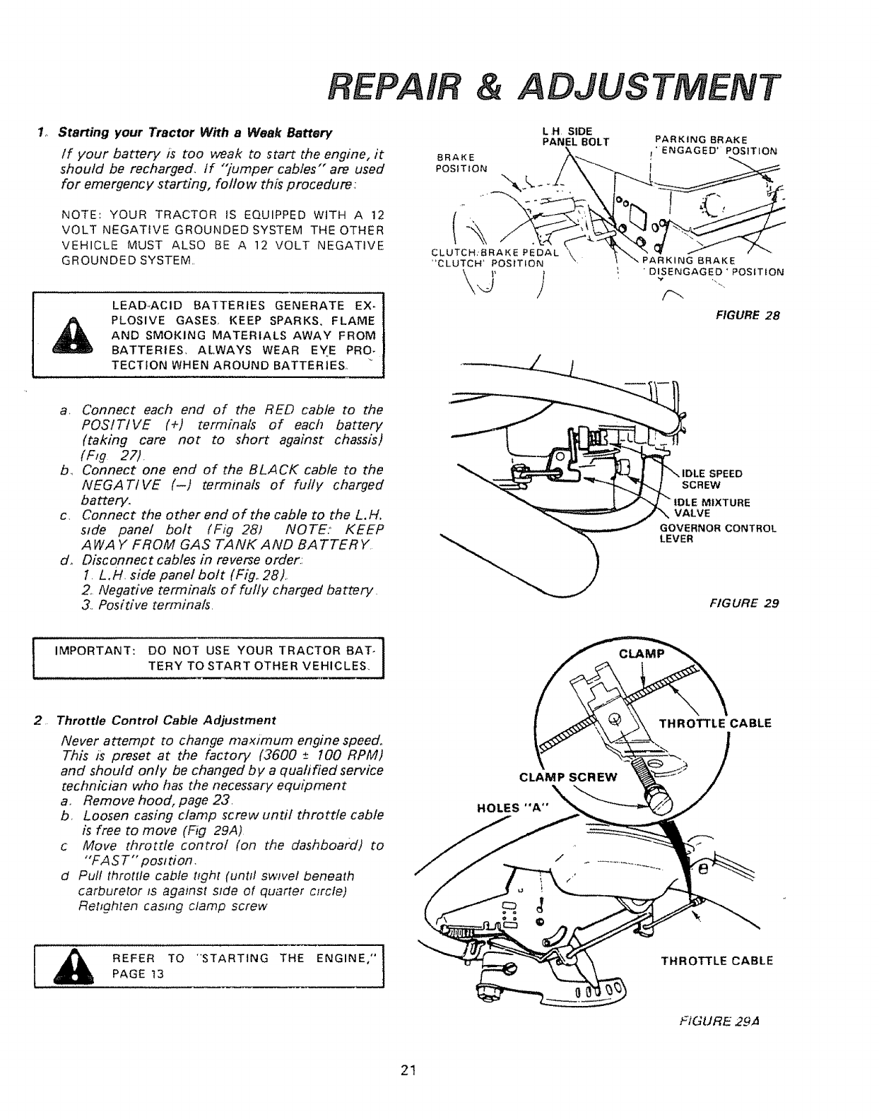
1_ Starting your Tractor With a Weak Battery
if your battery is too weak to start the engine, it
should be recharged, If "_umper cables'" are used
for emergency starting, follow this procedure:
NOTE: YOUR TRACTOR IS EQUIPPED WITH A 12
VOLT NEGATIVE GROUNDED SYSTEM THE OTHER
VEHICLE MUST ALSO BE A 12 VOLT NEGATIVE
GROUNDED SYSTEM,,
LEAD,ACID BATTERIES GENERATE EX-1
PLOSIVE GASES, KEEP SPARKS, FLAME t
AND SMOKING MATERIALS AWAY FROM
BATTERIES, ALWAYS WEAR EYE PRO- _
TECTtON WHEN AROUND BATTERIES,, _ ]
L H SIDE
PANEL BOLT
CLUTCH:BRAKE PEDAL "\
"CLUTCH' POSITION •_RKING BRAKE
• DISENGAGED*POSITiON
F_
FIGURE 28
a, Connect each end of the RED cable to the
POSITIVE (+) terminals of each battery
(taking care not to short against chassis)
(Fig 27).
b_ Connect one end of the BLACK cable to the
NEGATIVE (-) terminals of fully charged
battery.
c. Connect the other end of the cable to the L.H,
side panel bolt (Fig 28) NOTE: KEEP
AWA Y FROM GAS TANKAND BATTERY.
d_ Disconnect cables in reverse order.:
1. L.H. side panel bolt (Fig.. 28),,
2. Negadve terminals of fully charged battery.
3, Pos/dve terminals,
SPEED
SCREW
MIXTURE
VALVE
GOVERNOR CONTROL
LEVER
FIGURE 29
IMPORTANT: DO NOT USE YOUR TRACTOR BATe I
TERY TO START OTHER VEHICLES, J
., Throttle Control Cable Adjustment
Never attempt to change maximum engine speed,
This is preset at the factory (3600 ±100 RPM)
and should only be changed b ya qualified service
technician who has the necessary equipment
a, Remove hood, page 23.
b, Loosen casing clamp screw until throttle cable
is free to move (Fig 29A)
cMove throttle control (on the dashboard) to
"'FA S T'" position.
d Pull throttle cable tight (until swivel beneath
carburetor ts agalnst s_de of quarter c_rcfe)
Rehghten casing clamp screw
CLAMP SCREW
HOLES "A °'
THROTTLE CABLE
i
REFER TO -STARTING THE ENGINE," t
PAGE 13 THROTTLE CABLE
FIGURE 29,4
21
& ADJUSTMENI
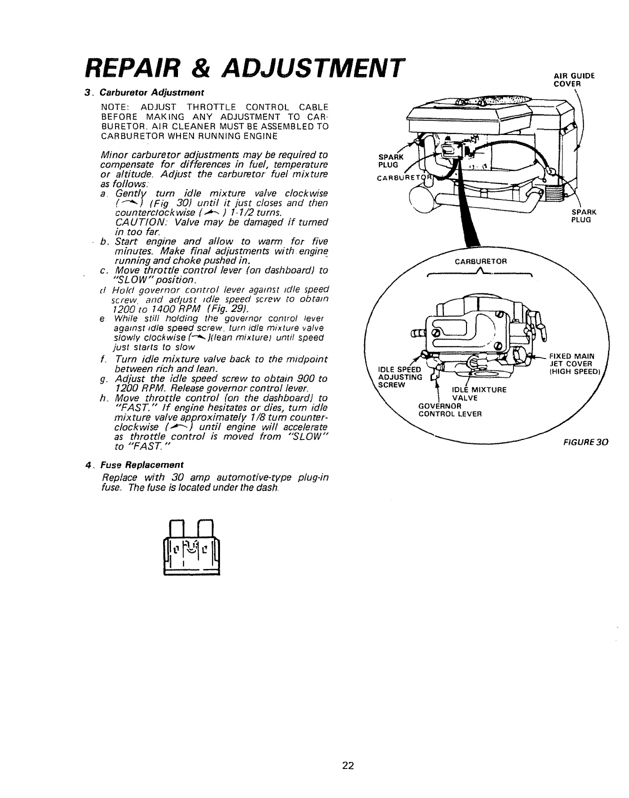
3_ Carburetor Adjustment
NOTE: ADJUST THROTTLE CONTROL CABLE
BEFORE MAKING ANY ADJUSTMENT TO CAR-
BURETOR. AIR CLEANER MUST BE ASSEMBLED TO
CARBURETOR WHEN RUNNING ENGINE
Minor carburetor adjustments may be required to
compensate for differences in fuel. temperature
or altitude. Adjust the carburetor fuel mixture
as follows:
a. Gently turn idle mixture valve clockwise
('-_) (Fig 30) until it just closes and then
counterclockwise (._-. ) 1-1/2 turns.
CAUTION:' Valve may be damaged if turned
in too far,
b° Start engine and allow to warm for five
minutes_ Make final adjustments with engine
running and choke pushed in.
c,, Move throttle control lever (on dashboard) to
"SL0 W'" posidono
(l Hold governor control lever against idle speed
screw and adtust 1die speed screw to obtain
t200 to 1400 RPM (Fig. 29).
eWhile still holding the governor control lever
against _dte speed screw turn _dlemixture valve
slowly clockwise (-'_ )(lean mixture) until speed
just starts to slow
f. Turn idle mixture valve back to the midpoint
between rich and lean.
g_ Adjust the idle speed screw to obtain 900 to
1200 RPM,, Release governor control lever_
h. Move throttle control (on the dashboard) to
"FAST." If engine hesitates or dies, turn idle
mixture valve approximately 1/8 turn counter.
clockwise (.,_-'.) until engine will accelerate
as throttle control is moved from "'SLOW"
to "FAST, "
SPARK
PLUG
CARSURET(
4, Fuse Replacement
Replace with 30 amp automotive-type plug-in
fuse,, The fuse is located under the dash,
GOVERNOR
CONTROL LEVER
AIR GUIDE
COVER
"t
SPARK
PLUG
FIXED MAIN
JET COVER
|HIGH SPEED
FIGURE 30
22
REPAIR
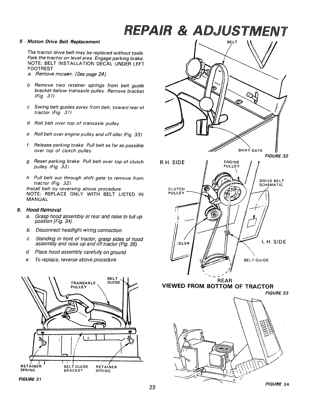
5. Motion Drive Belt Replacement
The tractor drive belt may be replaced without tools°
Park the tractor on level area Engage parking brake,
NOTE: BELT INSTALLATION DECAL UNDER LEFT
FOOTREST-
a. Remove mower,, (See page 24),
b Remove two retainer springs from belt guide
bracket below transaxle pufley. Remove bracket
(Fig 31), j
cSwing belt guides away from belt, toward rear of
tractor lFig, 31)
d Rofl belt over top of transaxle pulley,
e, Roll belt over engine pulley and off idler (Fig 33),
f.Release parking brake Pull belt as far as possible
over top of clutch pulley
g Reset parking brake, Pull belt over top of clutch
pulley (Fig 33)
R.H. SIDE
ADJUSTMENT
BELT
SHIFT GATE
ENGINE
PULLEY
FIGURE 32
h, Pull belt out through shift gate to remove from
tractor (Fig, 32).
Install belt by reversing above procedure.
NOTE: REPLACE ONLY WITH BELT LISTED IN
MANUAL.
CLUTCH
PULLEY
DRIVE BELT
SCHEMATIC
6_ Hood Removal
a, Grasp hood assembly at rear and raise to full up
position (Fig° 34).
b° Disconnect headlight wiring connection,
c., Standing in front of tractor, grasp sides of hood
assembly and raise up and off tractor (Fig, 35),,
d Place hood assembly carefully on ground_,
e, To replace, reverse above procedure,,
BELT
TRANSAXLE
PULLEY
'It,jl
(" If"" f
RETAINER BELT GUIDE RETAINER
SPRING BRACKET SPRING
FIGURE 31
L,H., SIDE
\\,
BELT GUIDE
k/2
REAR
VIEWED FROM BOTTOM OF TRACTOR
FIGURE 33
FIGURE 34
23
IR &ADJUSTMENT
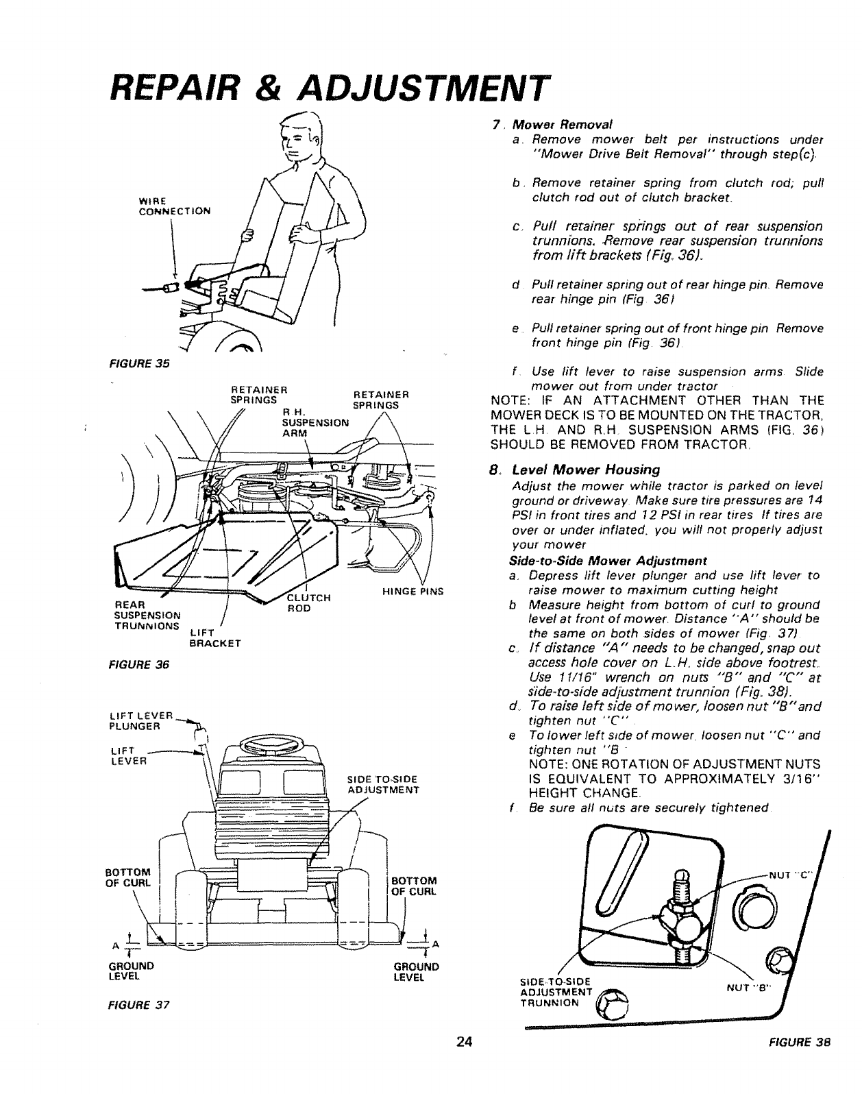
7, Mower Removal
a, Remove mower belt per instructions under
"Mower Drive Belt Removal" through step(c),
WIRE
CONNECTION
b
C,,
Remove retainer spring from clutch rod; pull
clutch rod out of clutch bracket.
Pult retainer springs out of rear suspension
trunnions. Remove rear suspension trunnions
from rift brackets (Fig_ 36).
d Pull retainer spring out of rear hinge pin, Remove
rear hinge pin (Fig 36)
FIGURE 35
RETAINER
SPRINGS
RH.
SUSPENSION
ARM
RETAINER
SPRINGS
REAR
SUSPENSION
TRUNNIONS
FIGURE 36
!
LIFT
BRACKET
ROD
HINGE PINS
LEVER
GROUND
LEVEL
SIDE TOoSIDE
_) ADJUSTMENT
GROUND
LEVEL
_GURE 37
e Pull retainer spring out of front hinge pin Remove
front hinge pin (Fig ,36)
f Use lift lever to raise suspension arms Slide
mower out from under tractor
NOTE: IF AN ATTACHMENT OTHER THAN THE
MOWER DECK IS TO BE MOUNTED ON THE TRACTOR,
THE LH AND R,H SUSPENSION ARMS (FIG, 36)
SHOULD BE REMOVED FROM TRACTOR,
8_ Level Mower Housing
Adjust the mower while tractor is parked on level
ground or driveway Make sure tire pressures are 14
PSI in front tires and 12 PSI in rear tires If tires are
over or under inflated, you will not properly adjust
your mower
Side-to-Side Mower Adjustment
a_ Depress lift lever plunger and use lift lever to
raise mower to maximum cutting height
b Measure height from bottom of curl to ground
level at front of mower. Distance "'A" should be
the same on both sides of mower (Fig, 37)
c,, If distance "A" needs to be changed, snap out
access hole cover on L.H° side above footrest,.
Use 11/16" wrench on nuts "'[3"" and "'C'" at
side-to-side adjustment trunnion (Fig. 38),,
dr To raise left side of mower, Ioosen nut "'B" and
tighten nut "C'"
e To lower left side of mower loosen nut "C" and
tighten nut '°B -
NOTE: ONE ROTATION OF ADJUSTMENT NUTS
IS EQUIVALENT TO APPROXIMATELY 3/16"
HEIGHT CHANGE,
f Be sure all nuts are securely tightened
SIDE,,TO-SIDE
ADJUSTMENT
TRUNNION
24 FIGURE 38
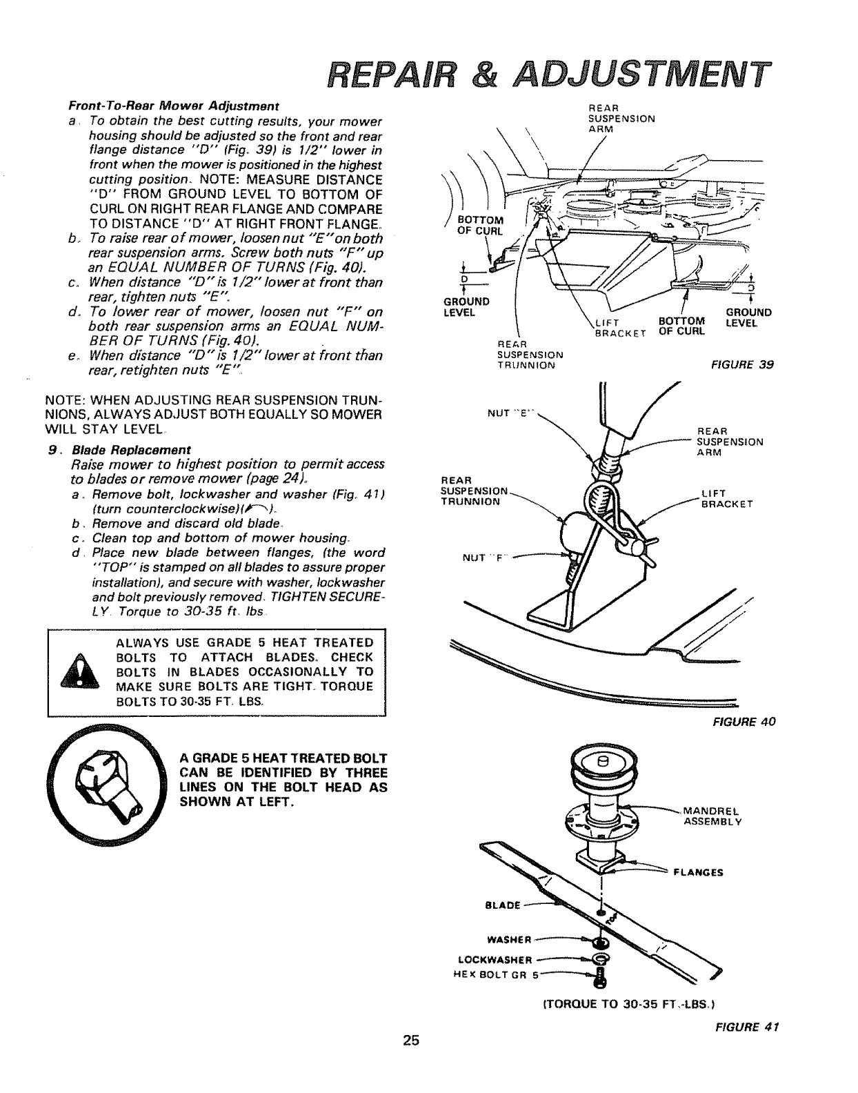
Front-To-Rear Mower Adjustment
a, To obtain the best cutting results, your mower
housing should be adjusted so the front and rear
flange distance "D'" (Fig° 39) is 1/2" lower in
front when the mower is positioned in the highest
cutting position. NOTE: MEASURE DISTANCE
°'D" FROM GROUND LEVEL TO BOTTOM OF
CURL ON RIGHT REAR FLANGE AND COMPARE
TO DISTANCE "'D'" AT RIGHT FRONT FLANGE°
bo To raise rear of mower, loosennut "E" on both
rear suspension arms. Screw both nuts "F" up
an EQUAL NUMBER OF TURNS (Fig. 40).
co When distance "D" is l/2"" lower at front than
rear, tighten nuts "E"
d. To lower rear of mower, loosen nut "F" on
both rear suspension arms an EQUAL NUM-
BER OF TURNS (Fig. 40).
eo When distance "D" is 1/2" lower at front than
rear, retighten nuts "E",
\
\
BOTTOM
OF CURL
.L_.
o
T---
GROUND
LEVEL
ADJUS
REAR
SUSPENSION
\ ARM
\
REAR
SUSPENSION
TRUNNION
LIFT
BRACKET
BOTTOM
OF CURL
T
FIGURE 39
NOTE: WHEN ADJUSTING REAR SUSPENSION TRUN-
NIONS, ALWAYS ADJUST BOTH EQUALLY SO MOWER
WILL STAY LEVEL
9, Blade Replacement
Raise mower to highest position to permit access
to blades or remove mower (page 24)°
aoRemove bolt, Iockwasher and washer (Fig° 4 I)
(turn counterclockwise)(_-'_ )o
b, Remove and discard old blade_
co Clean top and bottom of mower housing°
d, Place new blade between flanges, (the word
"TOP" is stamped on all blades to assure proper
installation), and secure with washer, Iockwasher
and bolt previously removed, TIGHTEN SECURE-
LY. Torque to 30-35 ft, ibs
NUT
REAR
TRUNNION
NUT 'F
REAR
SUSPENSION
ARM
LIFT
ALWAYS USE GRADE 5 HEAT TREATED
BOLTS TO ATTACH BLADES° CHECK
BOLTS tN BLADES OCCASIONALLY TO
MAKE SURE BOLTS ARE TtGHT_ TORQUE
BOLTS TO 30-35 FT, LBSo
A GRADE 5 HEAT TREATED BOLT
CAN BE IDENTIFIED BY THREE
LINES ON THE BOLT HEAD AS
SHOWN AT LEFT.
25
FIGURE 40
MANDREL
ASSEMBLY
FLANGES
BLADE _q__,_
LOCKWAS.ER
{TORQUE TO 30-35 FT,-LBS)
FIGURE 41
& ADJUSTMENT
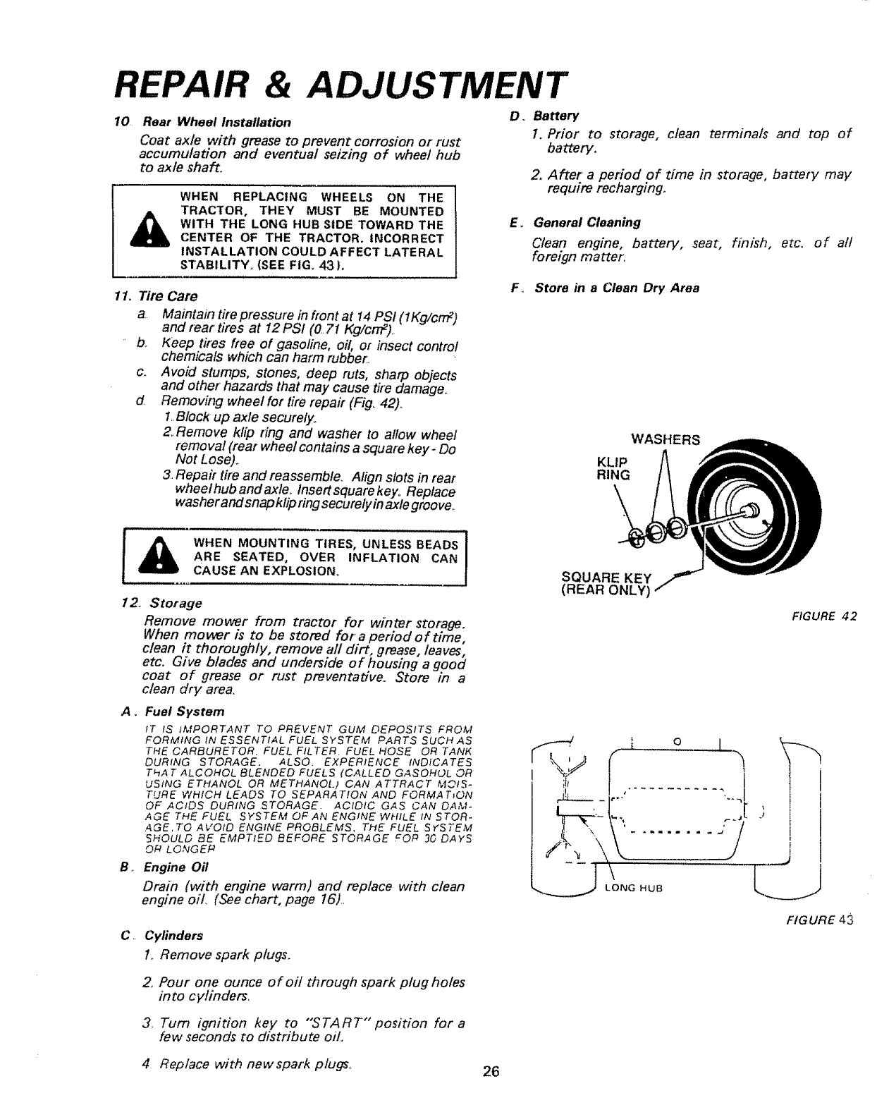
10 Rear Wheel Installation
Coat axle with grease to prevent corrosion or rust
accumulation and eventual seizing of wheel hub
to axle shaft.
WHEN REPLACING WHEELS ON THE
TRACTOR, THEY MUST BE MOUNTED
WITH THE LONG HUB SIDE TOWARD THE
CENTER OF THE TRACTOR. INCORRECT
INSTALLATION COULD AFFECT LATERAL
STABILITY. (SEE FIG. 43).
O_ Battery
1. Prior to storage, clean terminals and top of
battery.
2, After a period of time in storage, batter]/may
require recharging.
E_ General Cleaning
Clean engine, battery, seat, finish, etc. of at/
foreign matter;
11. Tire Care
a Maintain tire pressure in front at 14 PSI (1Kg/crrF)
and rear tires at 12 PSI (0 7t Kg/crrP)..
b. Keep tires fr,ee of gasoline, oil, or insect control
chemicals which can harm rubber,.
c. Avoid stumps, stones, deep ruts, sharp objects
and other hazards that may cause tim damage.
dRemoving wheel for tire repair, (Fig. 42).
1..Block up axle securely.
2..Remove klip ring and washer to allow wheel
removal (rear wheel contains a square key. Do
Not Lose)..
3. Repair tire and reassemble. Align slots in rear
wheel hub and axle. Insert square key. Replace
washer and snap klip ringsecurely inaxle groove,
F. Store in a Clean Dry Area
WASHERS
KLIP
RING
_1_ WHEN MOUNTING TIRES, UNLESS BEADS 1
ARE SEATED, OVER INFLATION CAN
CAUSE AN EXPLOSION.
12. Storage
Remove mower from tractor for winter storage.
When mower is to be stored for a period of time,
clean it thoroughly, remove all dirt, grease, leaves,
etc. Give blades and underside of housing a good
coat of grease or rust preventative. Store in a
clean dry area.
A_ Fuel System
IT IS IMPORTANT TO PREVENT GUM DEPOSITS FROM
FORMING IN ESSENTIAL FUEL SYSTEM PARTS SUCH AS
THE CARBURETOR. FUEL FILTER. FUEL HOSE OR TANK
DURING STORAGE. ALSO. EXPERIENCE INDICATES
THA T ALCOHOL BLENDED FUELS (CALLED GASOHOL OR
USING ETHANOL OR METHANOl.) CAN ATTRACT MOIS-
TURE WHICH LEADS TO SEPARATION AND FORMATJON
OF ACIDS DURING STORAGE. ACIDIC GAS CAN DAM-
AGE THE FUEL SYSTEM OF AN ENGINE WHILE IN STOR-
AGE,TO AVOID ENGINE PROBLEMS, THE FUEL SYSTEM
SHOULD BE EMPTIED BEFORE STORAGE FOP 3G DAYS
OR LONGEP
B,. Engine Oil
Drain (with engine warm) and replace with clean
engine oil (See chart, page 16).
C,, Cylinders
1..Remove spark plugs.
2, Pour one ounce of oi/ through spark plug holes
into cylinders,
3. Turn ignition key to "'START" position for a
few seconds to distribute oil.
SQUARE KEY
(REAR ONLY)
FIGURE 42
X
FIGURE 43
4 Replace with new spark plugs., 26
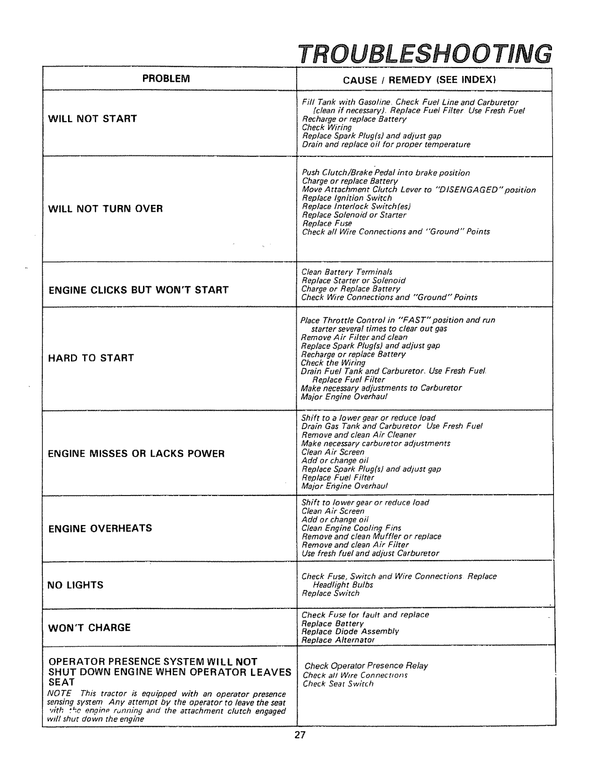
TROUBLESHOOTING
WILL NOT START
WILL NOT TURN OVER
ENGINE CLICKS BUT WON'T START
HARD TO START
PROBLEM CAUSE tREMEDY (SEE INDEX)
ENGINE MISSES OR LACKS POWER
ENGINE OVERHEATS
NO LIGHTS
WON'T CHARGE
OPERATOR PRESENCE SYSTEM WILL NOT
SHUT DOWN ENGINE WHEN OPERATOR LEAVES
SEAT
NOTE This tractor is equipped with an operator presence
sensing system Any attempt by the operator to leave the seat
vith t_a engii_p rumdng and the artachment clutch engaged
wdt shut down the engine
Fill Tank with Gasoline, Check Fuet Line and Carburetor
(clean if necessary)., Replace Fuel Filter Use Fresh Fuel
Recharge or replace Battery
Check Wiring
Replace Spark Plug(s) and adjust gap
Drain and replace oil for proper temperature
Push Clutch/Brake "Pedal into brake position
Charge or replace Battery
Move Attachment Clutch Lever to "'DISENGAGED "position
Replace Ignition 5witch
Replace Interlock Switch (as)
Replace Solenoid or Starter
Replace Fuse
Check all Wire Connections and "Ground" Points
Clean Battery Terminals
Replace Starter or Solenoid
Charge or Replace Battery
Check Wire Connections and "'Ground" Points
Place Throttle Control in "'FAST'position and run
starter several times to clear out gas
Remove Air Fil_er and clean
Replace Spark Plug(s) and adjust gap
Recharge or replace Battery
Check the Wiring
Drain Fuel Tank and Carburetor, Use Fresh Fuel.
Replace Fuel Filter
Make necessary adjustments to Carburetor
Major Engine Overhaul
Shift to atower gear or reduce toad
Drain Gas Tank and Carburetor Use Fresh Fuel
Remove and clean Air Cleaner
Make necessary carburetor adjustments
Clean Air Screen
Add or change oil
Replace Spark Plug(s) and adlust gap
Replace Fuel Filter
Major Er_gine Overhaul
Shift to Iower gear or reduce load
Clean Air Screen
Add or change oil
Clean Engine Cooling Fins
Remove and clean Muffler or replace
Remove and clean Air Filter
Use fresh fuel and adjust Carburetor
Check Fuse, Switch and Wire Connections Replace
Headlight Bulbs
Replace Switch
Check Fuse for fault and replace
Replace Battery
Replace Diode Assembly
Replace Alternator
Check Operator Presence Relay
Check all Wire Connecttot]_
Check Seat Switch
27
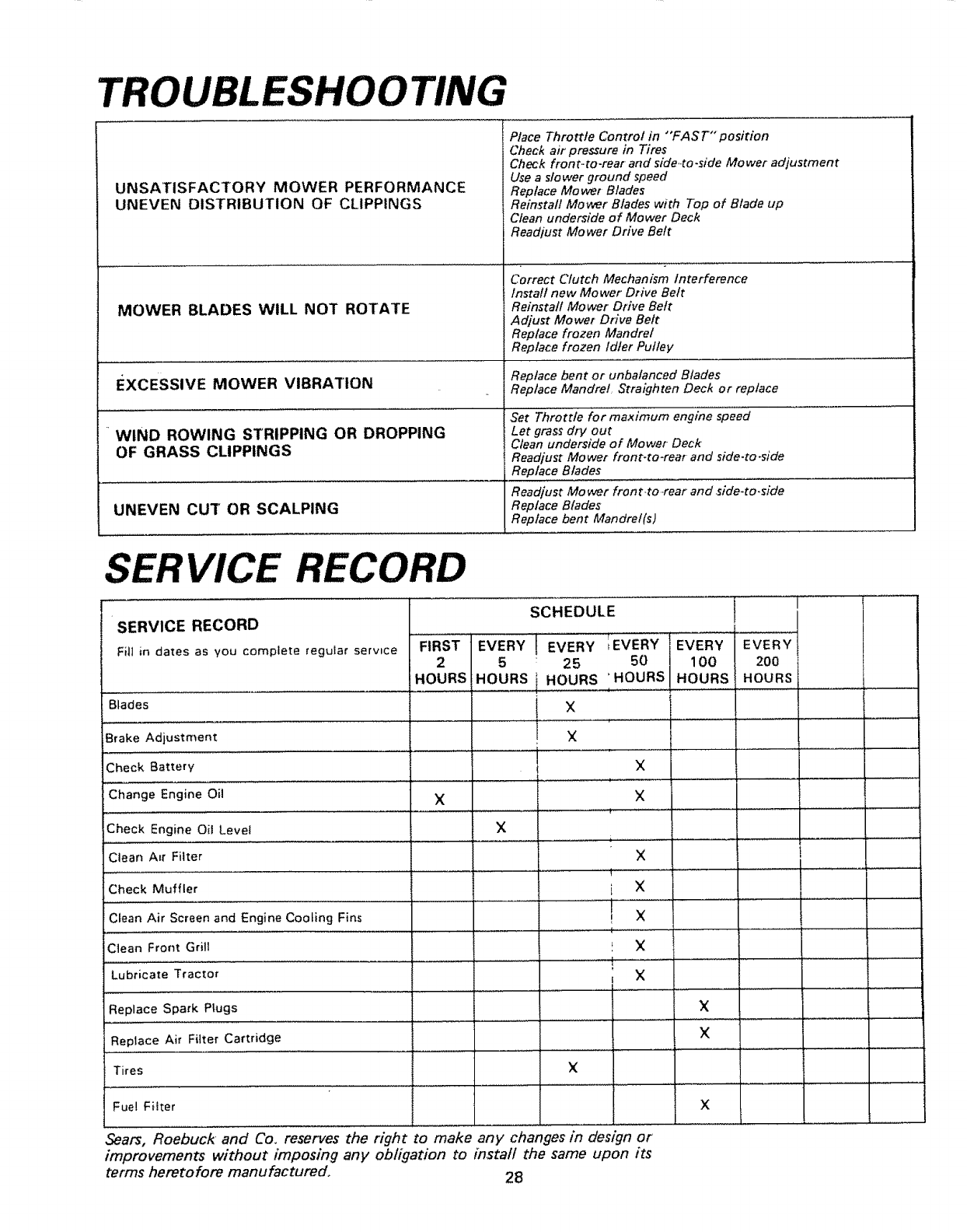
TROUBLESHOOTING
UNSATISFACTORY MOWER PERFORMANCE
UNEVEN DISTRIBUTION OF CLIPPINGS
MOWER BLADES WILL NOT ROTATE
EXCESSIVE MOWER VIBRATION
"WIND ROWING STRIPPING OR DROPPING
OF GRASS CLIPPINGS
UNEVEN CUT OR SCALPING
Place Throttle Control in "'FAST"position
Check air pressure in Tires
Check fron t,.to-rear and side-to-side Mower adjustment
Use a slower ground speed
Replace Mower Blades
Reinstall Mower Blades with Top of Blade up
Clean underside of Mower Deck
Readjust Mower Drive Beft
Correct Clutch Mechanism Interference
Install new Mower Drive Beft
Reinstall Mower Drive Belt
Adjust Mower Drive Belt
Replace frozen Mandrel
Replace frozen idler Pulley
Replace bent or unbalanced Blades
Replace Mandrel Straighten Deck or replace
Set Throttle for maximum engine speed
Let grass dry out
Clean underside of Mower Deck'
Readjust Mo wet front-to-rear and side.to-side
Replace Blades
Readjust Mower front_to ,rear and side-to.side
Replace Blades
Replace bent Mandrel(s)
SERVICE RECORD
SERVICE RECORD
FitI in dates as you complete reguIar serwce
Blades
Brake Adjustment
....................... i
SCHEDULE ,!
T
FIRST EVERY EVERY iEVERY I EVERY EVERY
2 5 25 50 J 1 O0 200
HOURS HOURS HOURS 'HOURS HOURS HOURS
........ , ..............
X
X
Check Battery
Change Engine Oil
= .......................
Check Engine Oil Level
Clean A_r Filter
Check Muffler
Clean Air Screen and Engine Cooling Fins
Clean Front Grill
Lubricate Tractor
Replace Spark Plugs
×
X
X
×
! .......... × 1
X
............. , ,
t×
,,j........ ,....................
X
X
Replace Air Filter Cartridge _=.....
Tires X
:.......................... t
Fue! FHter
Sears, Roebuck and Co. reserves the right to make any changes in design or
improvements without imposing any obligation to install the same upon its
terms heretofore manufactured° 28
lX
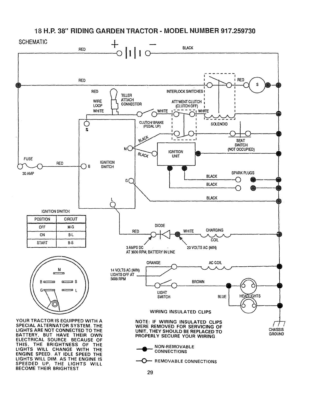
18 H.P. 38" RIDING GARDEN TRACTOR - MODEL NUMBER 917.259730
SCHEMATIC
RED BLACK
FUSE
30AMP
RED
1
-O
S
RED O B
3AMPSIX;
AT 3600RPM,BATTERYIN LINE
IGNITIONSWITCH
PosmoN........C_RCUiT
.i, ...H ...........
OFF M-G
ON B-L
START B_
ORANGE
14VOLTSAC(MIN) I
LIGHTSOFF AT
3600RPM _
LIGHT
SWITCH
BROWN
ACCOiL
WIRING INSULATED CLIPS
YOUR TRACTOR IS EQUIPPED WITH A
SPECIAL ALTERNATOR SYSTEM, THE
LIGHTS ARE NOT CONNECTED TO THE
BATTERY, BUT HAVE THEIR OWN
ELECTRICAL SOURCE BECAUSE OF
THIS, THE BRIGHTNESS OF THE
LIGHTS WILL CHANGE WITH THE
ENGINE SPEED, AT IDLE SPEED THE
LIGHTS WILL DIM, AS THE ENGINE IS
SPEEDED UP, THE LIGHTS WILL
BECOME THEIR BRIGHTEST
NOTE: tF WIRING INSULATED CLIPS
WERE REMOVED FOR SERVICING OF
UNIT, THEY SHOULD BE REPLACED TO
PROPERLY SECURE YOUR WIRING
NON-REMOVABLE
CONNECTIONS
""O" REMOVABLE CONNECTIONS
29
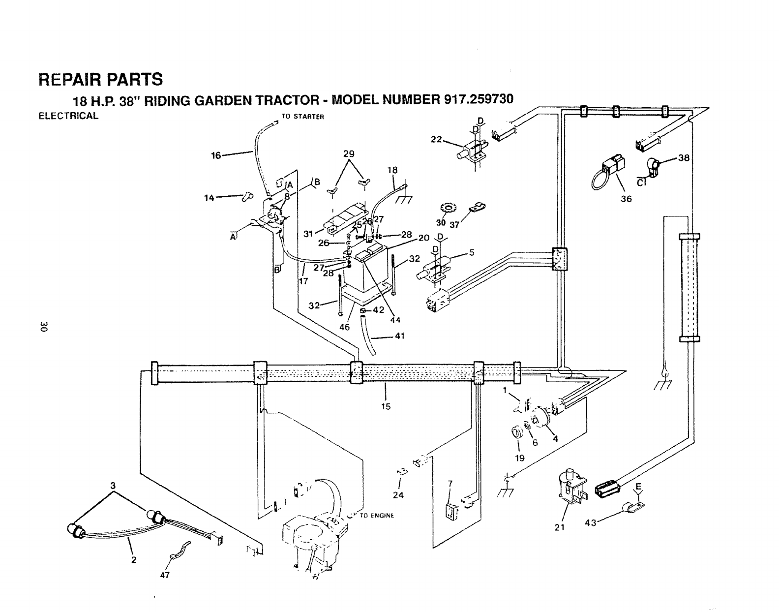
REPAIR PARTS
18 H.P. 38" RIDING GARDEN TRACTOR -MODEL NUMBER 917.259730
ELECTRICAL TOSTARTER
3
o
._.
1
15
7f
1
19
6
21
.,,,,L
KEY PART
NO. NO.
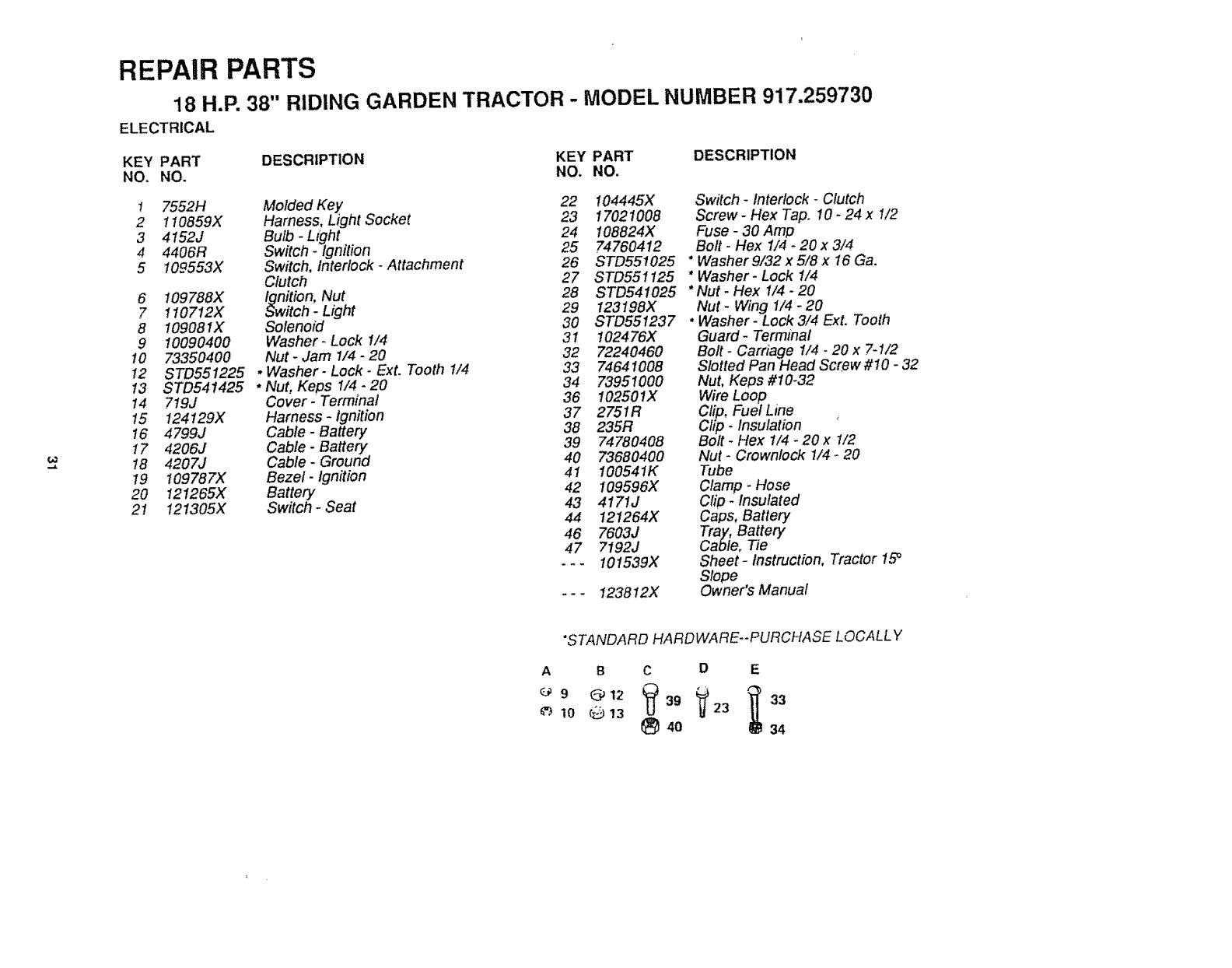
REPAIR PARTS
18 H.P. 38" RIDING GARDEN TRACTOR - MODEL NUMBER 917.259730
ELECTRICAL
DESCRIPTION KEY PART DESCRIPTION
NO. NO.
I7552H Molded Key 22 104445X
2 110859X Harness, Light Socket 23 17021008
3 4152J Bulb -Light 24 I08824X
4 4406R Switch -Ignition 25 74760412
5 109553X Switch, Interlock -Attachment 26 STD551025
Clutch 27 STD551125
28 STD541025
6 109788X Ignition, Nut
7 1107t2X Switch _Light 29 123198X
8 !09081X Solenoid 30 STD551237
9 10090400 Washer- Lock I/4 31 102476X
10 73350400 Nut -Jam 1/4 -20 32 72240460
12 STD551225 * Washer- Lock -Ext. Tooth t/4 33 74641008
13 STD541425 *Nut, Keps t/4 -20 34 73951000
14 719J Cover-Terminal 36 !02501X
!5 !24129X Harness -ignition 37 2751R
!6 4799J Cable- Battery 38 235R
17 4206J Cable -Battery 39 74780408
18 4207J Cable -Ground 40 73680400
19 109787X Bezel- Ignition 41 I00541K
42 109596X
20 121265X Battery
21 121305X Switch -Seat 43 4171J
44 121264X
46 7603J
47 7192J
--- I01539X
*-- 123812X
Switch- Interlock -Clutch
Screw- Hex Tap. 10- 24 x 1/2
Fuse -30 Amp
Bolt -Hex 1/4 -20 x 3/4
* Washer 9/32 x 5/8 x 16 Ga.
* Washer- Lock !/4
*Nut -Hex 1/4 -20
Nut- Wing 1/4- 20
*Washer -Lock 3/4 Ext. Tooth
Guard- Terminal
Bolt - Carriage 1/4 -20 x 7-1/2
Slotted Pan Head Screw #10 -32
Nut, Keos #10-32
Wire Loop
Clip. Fuel Line
Cl!p- Insulation '
Bolt -Hex 1/4 -20 x 1/2
Nut -Crownlock 1/4 -20
Tube
Clamp -Hose
Clip _Insulated
Caps, Battery
Tray, Battery
Cable. Tie
Sheet- Instruction, Tractor 15_
Slope
Owner's Manual
*STANDARD HARDWARE--PURCHASE LOCALLY
A B CD E
10 _ !3 _ 40 34
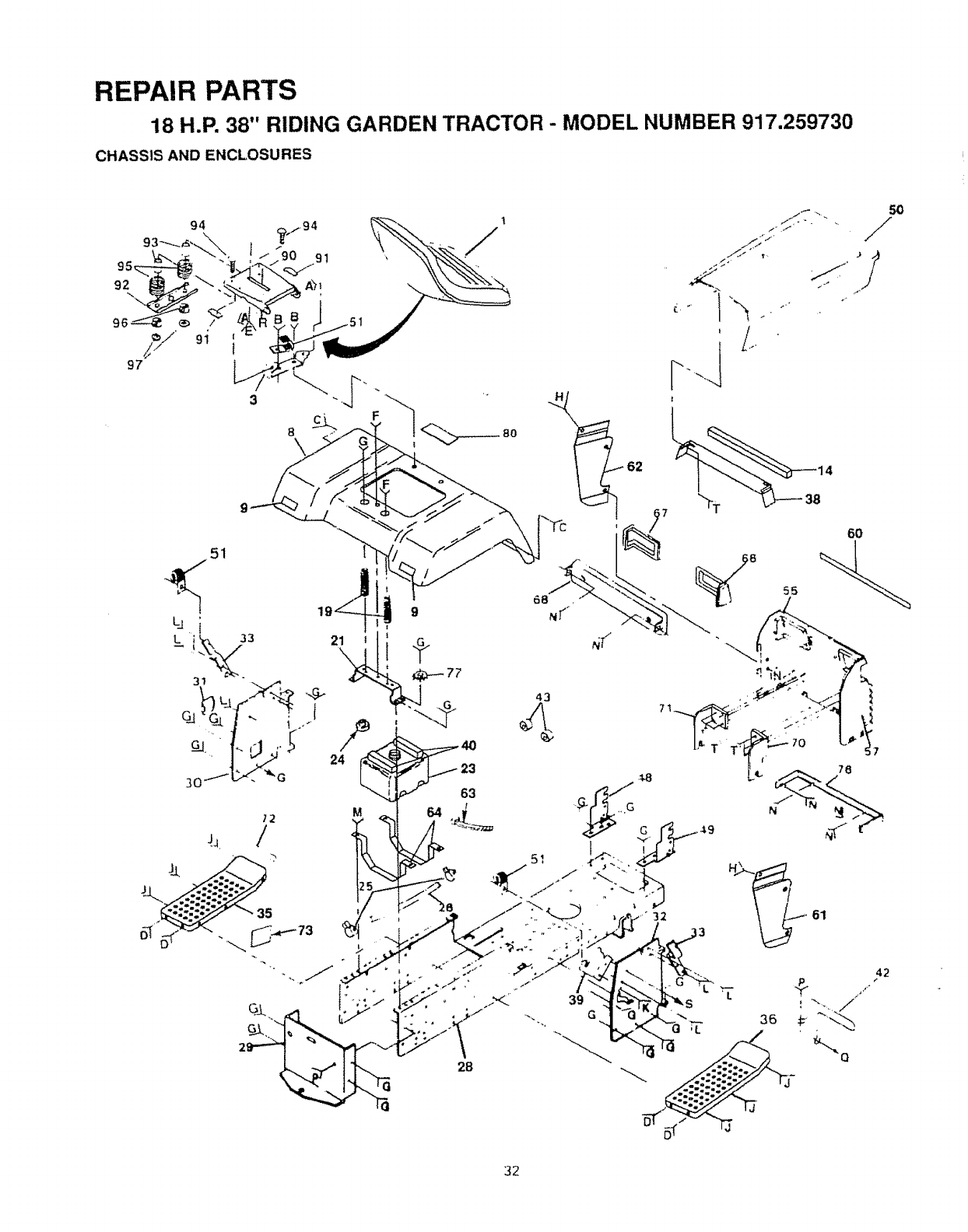
REPAIR PARTS
18 H.P. 38" RIDING GARDEN TRACTOR - MODEL NUMBER 917.259730
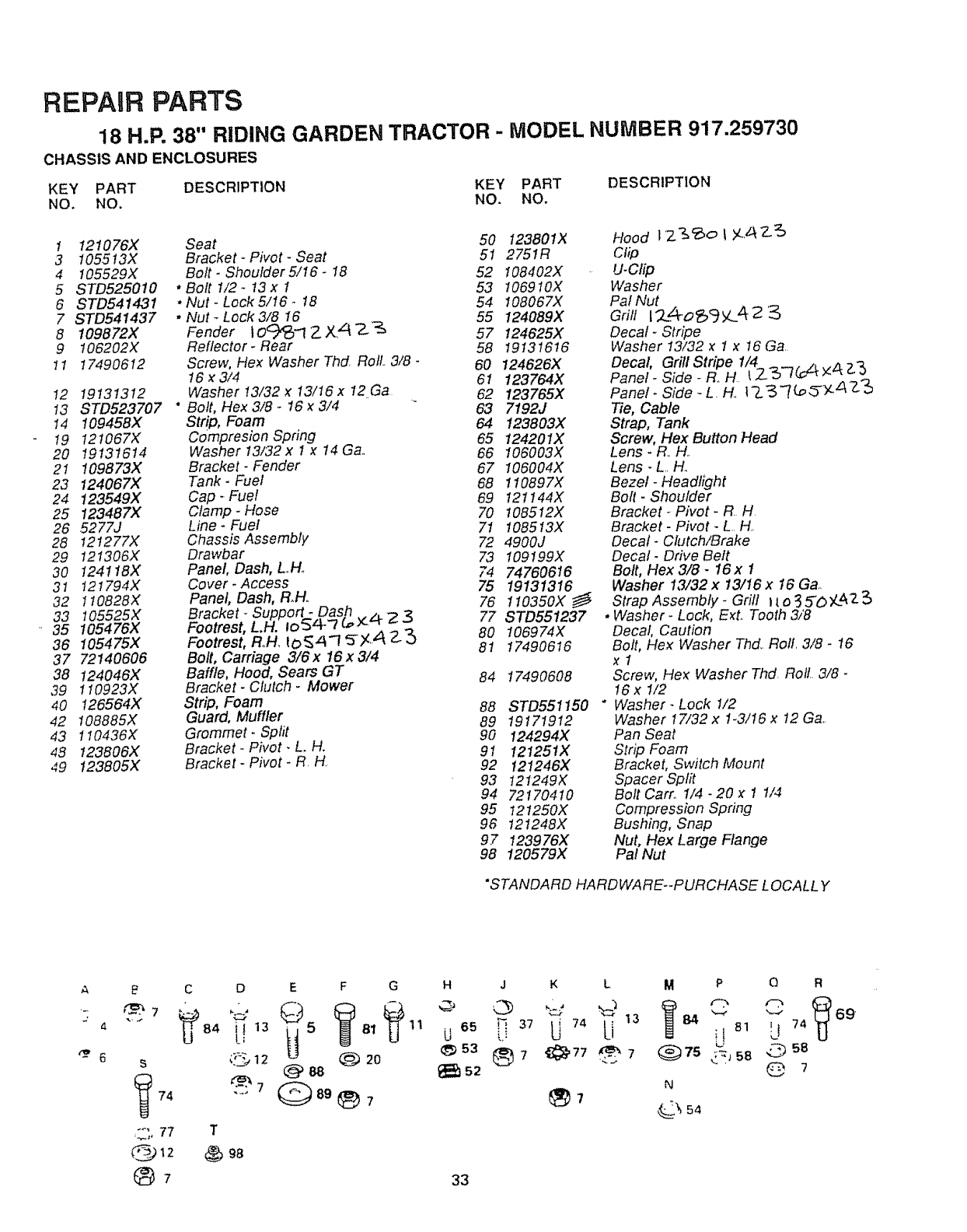
CHASSIS AND ENCLOSURES
1
/
43
51
42
32
REPAIR PARTS
18 H,P. 38" RIDING GARDEN TRACTOR - MODEL NUMBER 917.259730
CHASSIS AND ENCLOSURES
KEY PART DESCRIPTION KEY PART DESCRIPTION
NO. NO. NO. NO.
1 121076X Seat 50 I23801X Hood IZ&_o Iy..._7_._
3 t055!3X Bracket -Pivot -Seat 51 2751R Clip
4 105529X Bolt- Shoulder5!16- I8 52 108402X U-Clip
5 STD5250t0 * Bolt 1/2- 13 x I53 106910X Washer
6 STD541431 * Nut- Lock 5/16 -18 54 108067X Pal Nut
7 STD541437 * Nut- Lock3/8 16 55 124089X Grill l'2_4o_gy.._Z_2
8 109872X Fender 10°/_-t 2X_ -2-%57 124625X Decal -Stripe
9 t06202X Reflector- Rear 58 1913!616 Washer I3/32 x 1 x 16 Ga
t I 17490612 Screw, Hex Washer ThcLRoll 3/8- 60 124626X Decal, Grill Stripe I/4 _ _, z,, /_ 7_
16x3/4 61 123764X Panel-Side-Roll L/_3/_--tx'_ _)
I2 19131312 Washer13/32x 13/16x 12Ga 62 123765X Panel- Side-L H t-L_'7(_,._Y --z_Z'_
t3 STD523707 "Bolt, Hex 3/8 -16 _3/4 63 7192J Tie, Cable
14 109458X Strip, Foam 64 123803X Strap, Tank
t9 121067X Compresion Spring 65 124201X Screw, Flex Button Head
20 19131614 Washer 13/32x 1 x 14 Ga 66 106003X Lens -R. H
21 109873X Bracket- Fender 67 106004X Lens - L H.
23 124067X Tank -Fuel 68 I10897X Bezel -Headlight
24 123549X Cap -Fuel 69 121144X Bolt. Shoulder
25 123487X Clamp -Hose 70 108512X Bracket. Pivot -R H
26 5277J Line -Fuel 7! 108513X Bracket- Pivot -L H
28 12t277X Chassis Assembly 72 4900J Decal -Clutch/Brake
29 121306X Drawbar 73 109199X Decal- Drive Belt
30 124118X Panel, Dash, LH. 74 74760616 Bolt, Hex3/8- 16x I
31 t21794X Cover.Access 75 19131316 Washer 13/32x 13/16x 16 Gao
32 1t0828X Panel, Dash, R.H.
33 105525X B=racket- Suppo_: .Dash .,,, -) 76 1!0350X _ Strap Assembt/- Grill Ito.3_O'/,L423
35 105476X Footrest, LH. |o'54-'7 €,,,:_'-r _ 3 77 STD551237 * Washer -Lock, Exto Tooth 3/'8
36 105475X Footrest, Roll. lO_z_ "1 _ _ 2_ 80 106974X Decal, Caution
37 72140606 Bolt, Carriage 3/6x 16x3/4 81 17490616 Bolt, Hex Washer Thd Roll 3/8.16
38 124046X Baffle, Hood, Sears GT x 1
39 t 10923X Bracket- Clutch -Mower 84 17490608 Screw, Hex Washer Thd Roll 3/8 -
16x I/2
40 !26564X Strip, Foam 88 STD551150 * Washer. Lock 1/2
42 t08885X Guard, Muffler 89 19171912 Washer 17/32 x 1.3/16 x t2 Ga
43 110436X Grommet. Sprit 90 124294X Pan Seat
4S 123806X Bracket -Pivot. L. H_ 91 121251X Strip Foam
49 123805X Bracket- Pivot -R H 92 121246X Bracket, Switch Mount
93 121249X Spacer Split
94 72170410 Bolt Carro I/4 -20 x 1 1/4
95 121250X Compression Spring
96 121248X Bushing, Snap
97 123976X Nut, Hex Large Flange
98 120579X Pal Nut
"STANDA RD HARD WARE--PURCHASE LOCALL Y
A _ C D E F G H JKL M P O R
"" B4 [!_3 5B_ 1t U°5 _U_7 74 Li 13 84 _ilB1 _L!74 69
@88 _s2 @ ?
74 -_ 89 _7
"'_ 77 T
@_2 _ 98
®7 33
N
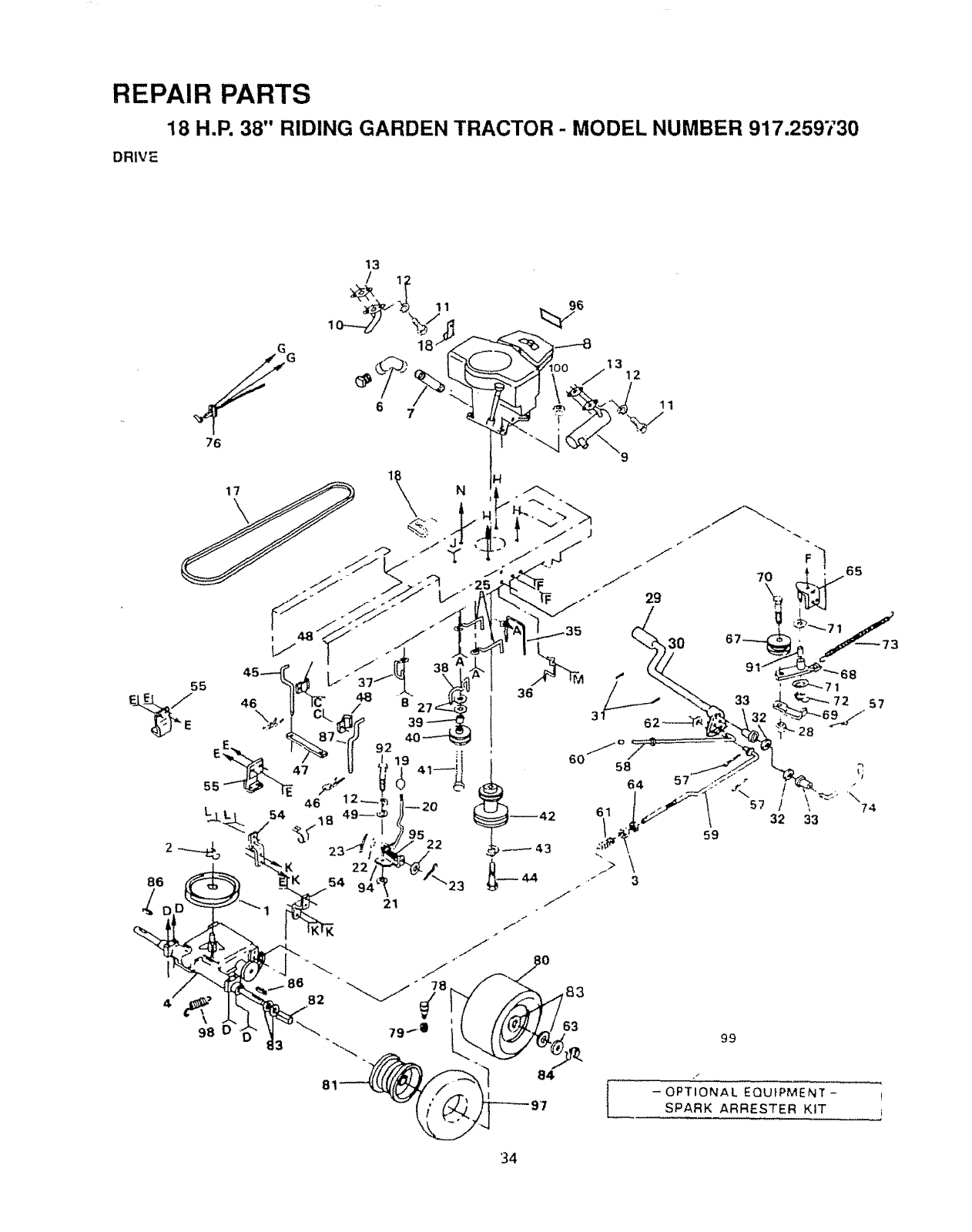
REPAIR PARTS
18 H.P. 38" RIDING GARDEN TRACTOR - MODEL NUMBER 917,259730
DRIVE
t3
84 /
-OPTIONAL EQUIPMENT- !
SPARK ARRESTER KIT
34
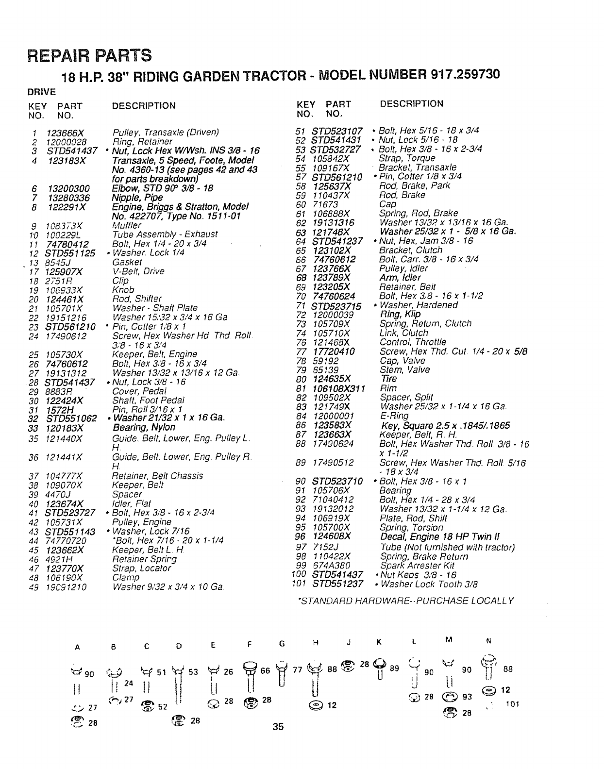
REPAIR PARTS
18 H.P. 38" RIDING GARDEN TRACTOR -MODEL NUMBER 917.259730
DRIVE
KEY PART DESCRIPTION KEY PART DESCRIPTION
NO. NO. NO, NO.
1 123666X Pulley, Transaxle (Driven) 51 STD523107
2 12000028 Ring, Retainer 52 STD541431
3 STD541437 • Nut, Lock Hex W/Wsh. INS 3/8 - 16 53 STD532727
4 123183X Transaxle, 5 Speed, Foote, Model 54 105842X
No. 4360-13 (see pages 42 and 43 55 109167X
for parts breakdown) 57 STD561210
6 13200300 Elbow, STD 90 _3/8 -18 58 125637)(
7 13280336 Nipple, Pipe 59 110437X
8 122291X Engine, Briggs & Stratton, Model 60 71673
No. 422707, Type Noo 1511-01 61 106888X
9 108373>I Muffler 62 19131316
1"0 100229L Tube Assembly -Exhaust 63 121748X
11 74780412 Bolt, HeY t/4 -20 x 3/4 64 STD541237
t2 STD551125 . Washer. Lock t/4 65 123102X
13 8545J Gasket 66 74760612
t7 I25907X V-Belt, Drive 67 _23766X
t8 2751R Clip 68 123789X
I9 !06933X Knob 69 123205X
20 124461X Rod, Shifter 70 74760624
2I t05701X Washer- Shaft Plate 7t STD523715
22 19151216 Washer 15,'32 x 3,'4 x 16 Ga 72 12000039
23 STD561210 * Pin, Cotter 1,'8 x I 73 I05709X
24 17490612 Screw, Hex WasherHd Thd Roll 74 1057IOX
3,'8 -t6 x 3/4 76 121468X
25 105730X Keeper, Belt, Engine 77 17720410
26 74760612 Bolt, Hex 3/8 -t6 x 3/4 78 59192
27 19131312 Washer13/32 x 13/16x 12 Ga.. 79 65139
..28 STD541437 .Nut, Lock3/8- 16 80 124635X
29 8863R Cover, Pedal 81 106108X311
30 122424X Shaft, Foot Pedaf 82 109502X
3I 1572H Pin, Rol13/t6x I 83 121749X
32 STD551062 * Washer21/32x I x 16Ga,. 84 12000001
33 120183X Bearing, Nylon 86 123583X
35 I2t440X Guide. Belt, Lower, Eng. Pufley L. 87 123663X
H. 88 17490624
36 I21441X Guide, Belt, Lower, Eng. Pulley R.
H 89 17490512
37 t04777X Retainer, Belt Chassis
38 t09070X Keeper, Belt 90 ST0523710
9t 105706X
39 4470J Spacer
40 123674X Idler, Flat 92 71040412
4! STD523727 *Bolt, Hex3/8-16x2-3/4 93 19132012
94 106919X
42 I05731X Pulley, Engine
43 STD551143 * Washer, Lock 7/t6 95 105700X
44 74770720 "Bolt, Hex 7/16- 20 xI-1/4 96 124608X
45 !23662X Keeper, Belt L H. 97 7152J
46 4921H Retainer Spring 98 1 I0422X
47 123770X Strap, Locator 99 674A380
48 I06190X Clamp 100 STD541437
49 1_091210 Washer9/32x3/4x 10Go 10! STD551237
Bolt, Flex 5/t6 -I8 x3/4
Nut, Lock 5/I6 -18
Bolt, Hex 3/8 -16 x2-3/4
Strap, Torque
Bracket, Transaxte
•Pin, Cotter 1/8 x 3/4
Rod, Brake, Park
Rod, Brake
Cap
Spring, Rod, Brake
Washer I3/32 x 13/I6 x 16 Ga.
Washer25/32 x I -5/8 x 16 Ga.,
• Nut, Flex, Jam 3/8 -16
Bracket, Clutch
Bolt, Cart. 3/8 -I6 .x3/4
Pulley, Idler
Arm, Idler
Retainer, Belt
Bolt, Hex 3,8 -16 x 1-1/2
•Washer, Hardened
Ring, Klip
Spring, Return, Clutch
Link, Clutch
Control, Throttle
Screw, He>_Thd.. Cut. I/4 -20 x 5/8
Cap, Valve
Stem, Valve
Tire
Rim
Spacer, Split
Washer 25/32 x1-1/4 )_16 Ga
E-Ring
Key, Square 2.5 x o1845/. 1865
eeper, Belt, R. H_
Bolt, Hex Washer Thd. Roll. 3/8 -t6
x 1-1/2
Screw, He.): Washer Thd.. Roll 5/I6
-t8 x 3/4
• Bolt, Hex 3/8 -I6 _1
Bearing
Bolt, Hex 1/4 -28 x 3/4
Washer 13/32 x 1-1/4 x 12 Go..
Plate, Rod, Shift
Spring, Torsion
Decal Engine 18 HP Twin 11
Tube (Not furnished with tractor)
Spring, Brake Return
Spark Arrestor Ktt
*Nut Keps 3/8 -t6
• Washer Lock Tooth 3/8
*STANDARD HARDWARE-PURCHASE LOCALL Y
A B C
II ii I1
......,*"27 %__..352
28
D E F G
Q 28 28
28 35
HJK L M N
77 88 _" 28 89 _ 90
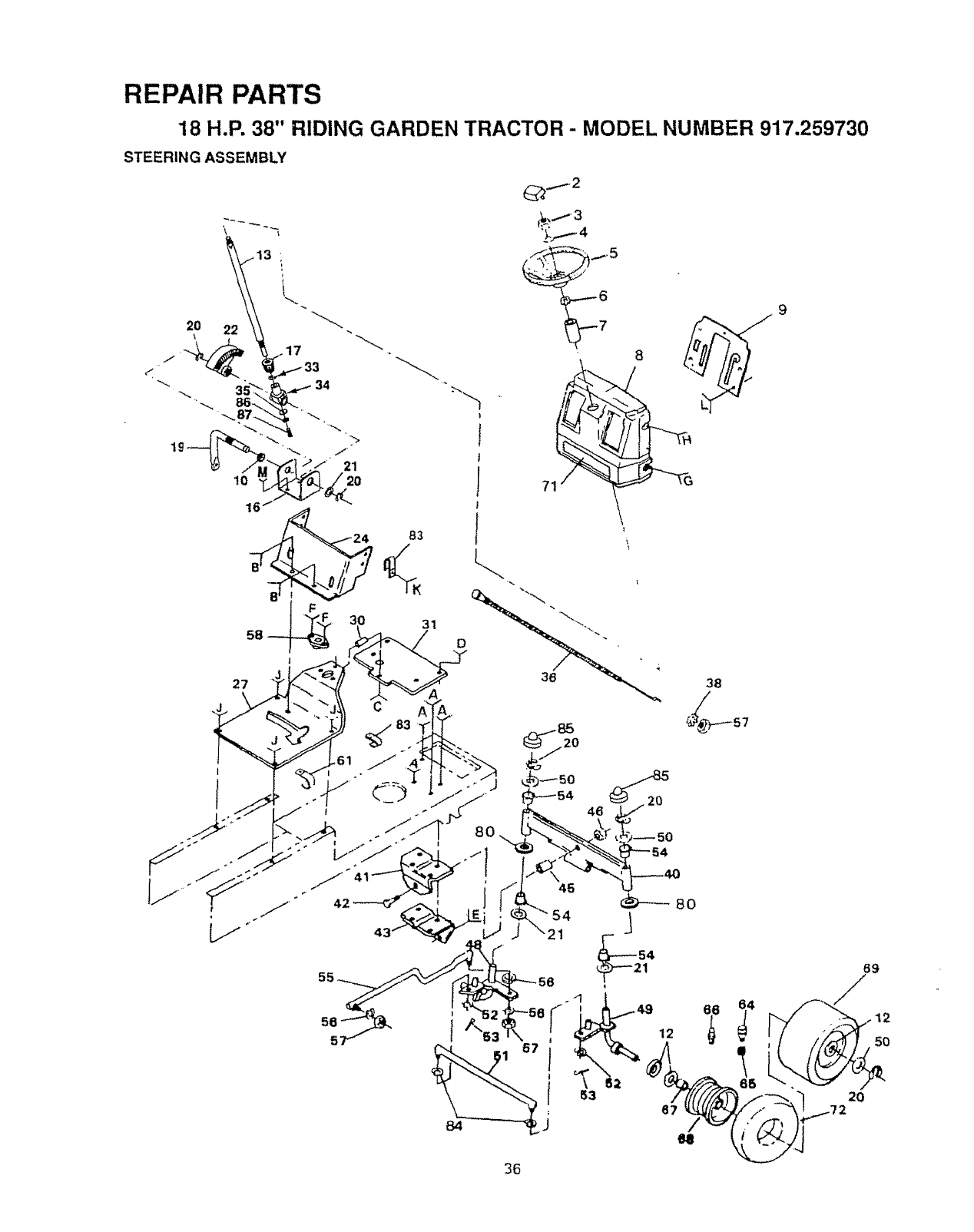
REPAIR PARTS
18 H.P. 38" RIDING GARDEN TRACTOR - MODEL NUMBER 917.259730
STEERIN G ASSEMBLY
,,--,'2
27
¢
83
K
31
\
\
36 38
,61
I
46
45
54
._1
36
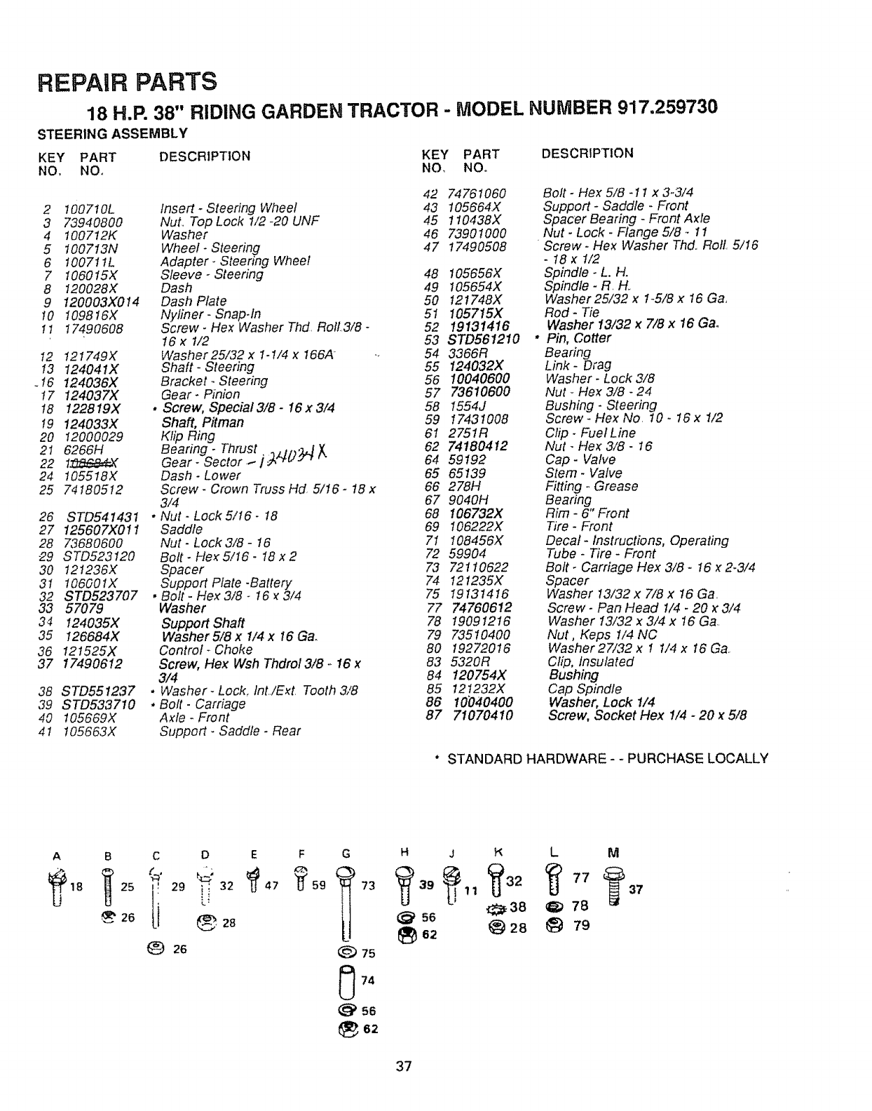
REPAIR PARTS
18 H.P. 38" RIDING GARDEN TRACTOR - MODEL NUMBER 917.259730
STEERING ASSEMBLY
KEY PART DESCRIPTION KEY PART
NO. NOo NO. NOo
42 74761060
21007t0L Insert -Steering Wheel 43 105664X
3 73940800 Nut. Top Lock t/2 -20 UNF 45 110438X
4 !00712K Washer 46 73901000
5 100713N Wheel -Steering 47 17490508
6 100711L Adapter- Steering Wheel
7 1060t5X Sleeve -Steering 48 105656X
8 120028X Dash 49 105654X
9 120003X0!4 Dash Plate 50 121748X
t0 I09816X Nyfiner- Snap-fn 51 105715X
1t 17490608 Screw- Hex Washer Thd RolL3/8- 52 19131416
16 x 1/2 53 STD561210
I2 I21749X Washer25/32 x 1-1/4 x 166A 54 3366R
t3 124041X Shaft-Steering 55 124032X
.I6 124036>( Bracket- Steering 56 10040600
t7 124037X Gear-Pinion 57 73610600
18 122819X • Screw, Special3/8- 16x3/4 58 1554J
t9 124033X Shaft, Pitman 59 17431008
20 12000029 KfipBing 61 2751R
2I 6266H Bearing-Thrust_,,O.:bjX..._._.,. 62 74180412
22 17_a£4_ Gear- Sector I 64 59192
24 !05518X Dash- Lower 65 65139
25 74180512 Screw- Crown Truss Hd 5/16- 18 x 66 278H
3/4 67 9040H
26 STD541431 * Nut- Lock 5/t6- 18 68 106732)(
27 125607X01I Saddle 69 106222X
28 73680600 Nut- Lock3/8 -16 7t 108456X
29 STD523t20 Bolt-He_5/16-I8x2 72 59904
30 121236X Spacer 73 72110622
3I 106001X Support Plate -Battery 74 121235X
32 STD523707 ,Bolt- Hex3/8- 16 _3/4 75 19131416
33 57079 Washer 77 74760612
34 124035X SupportShaft 78 19091216
35 126684X Washer 5/8 x 1/4 x 16 Ga. 79 73510400
36 I2t525X Control-Choke 80 19272016
37 17490612 Screw, Hex Wsh Thdrol3/8 -16 x 83 5320R
3/4 84 120754X
38 STD551237 • Washer- Lock. lnt/Ezt Tooth 3/8 85 12t232X
39 STD533710 ,Bolt- Carriage 86 ld040400
40 105669X Axle-Front 87 71070410
41 !05663X Support- Saddle -Rear
DESCRIPTION
Bolt -Hex 5/8 -11 x 3-3/4
Support- Saddle -Front
Spacer Bearing -Front Axle
Nut -Lock -Flange 5/8 _11
Screw- Hex Washer Thd Roll 5/I6
-18x 1/2
Spindle -L. H.
Spindle -R, H,,
Washer25/32 x 1_5/8x 16 Ga,
Rod- Tie
Washer 13/32 x 7/8 x 16 Gao
* Pin, Cotter
Bearing
Link- Drag
Washer -Lock 3/8
Nut -Hex 3/8 - 24
Bushing- Steering
Screw -Hex No 10.16 x 1/2
Clip- Fuel Line
Nut -Hex 3/8 -16
Cap- Valve
Stem- Valve
Fitting- Grease
Bearing
Rim -6" Front
Tire -Front
Decal- Instructions, Operating
Tube -Tire -Front
Bolt- Carriage Hex 3/8- I6 _2.3/4
Spacer
Washer 13/32 x 7/8 x 16 Ga
Screw- Pan Head 1/4 -20 x 3/4
Washer I3/32 x 3/4 x 16 Ga
Nut, Keps I/4 NC
Washer27/32 x 1 1/4 x 16 Ga
Clip, Insulated
Bushing
Cap Spindle
Washer, Lock !/4
Screw, Socket Hex 1/4 -20 x 5/8
° STANDARD HARDWARE - - PURCHASE LOCALLY
AB C D
25 _', 29 _; 32
26 28
EG
_) 75
56
62
H
73 _ 39
@ 5s
e2
JLM
{_38 _ 78
28 I_ 79
37
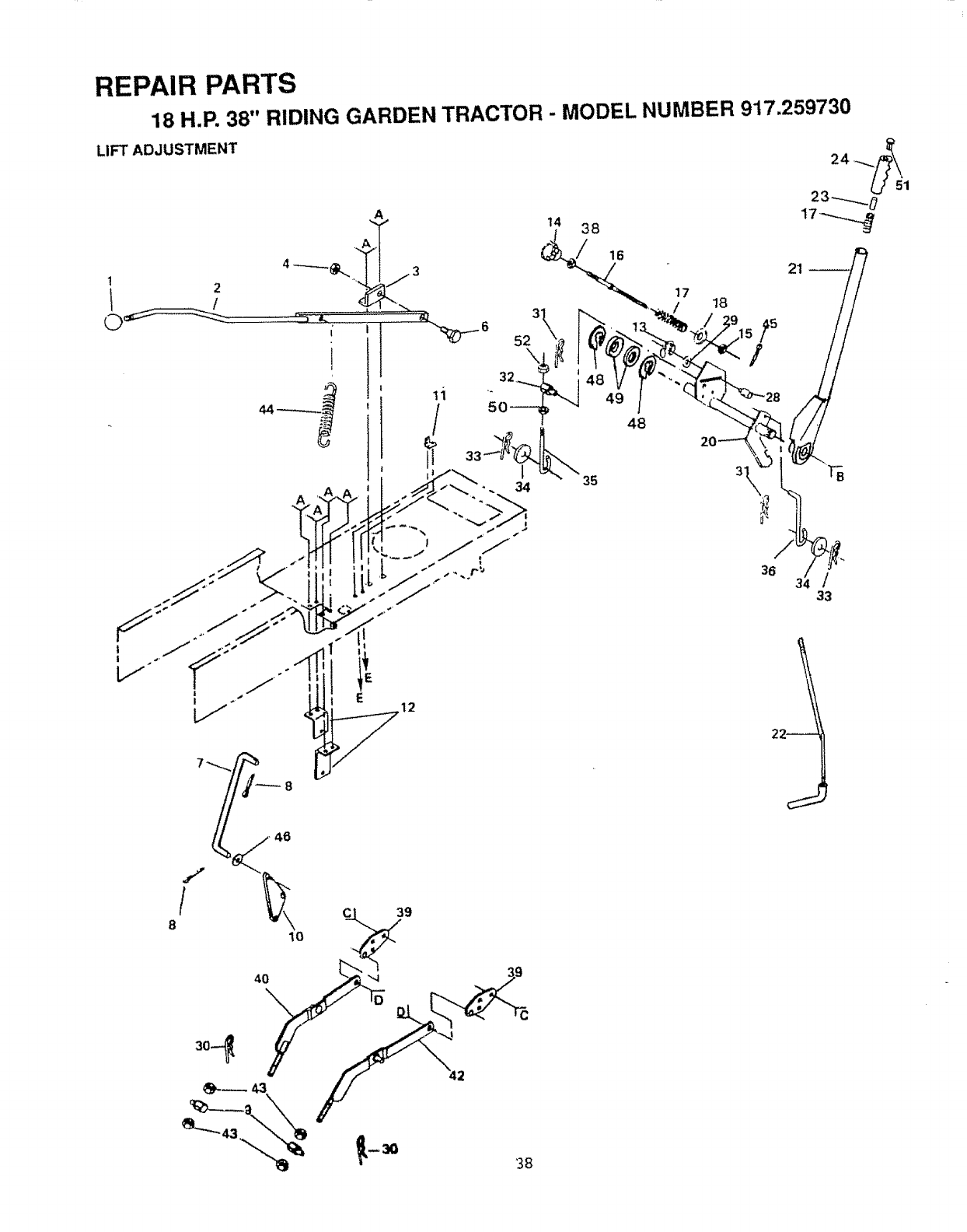
REPAIR PARTS
18 H.P. 38" RIDING GARDEN TRACTOR - MODEL NUMBER 917.259730
LIFT ADJUSTMENT
14 38
/
A
16
32
5C
17 18
52
48
21
2
J
/
8
38
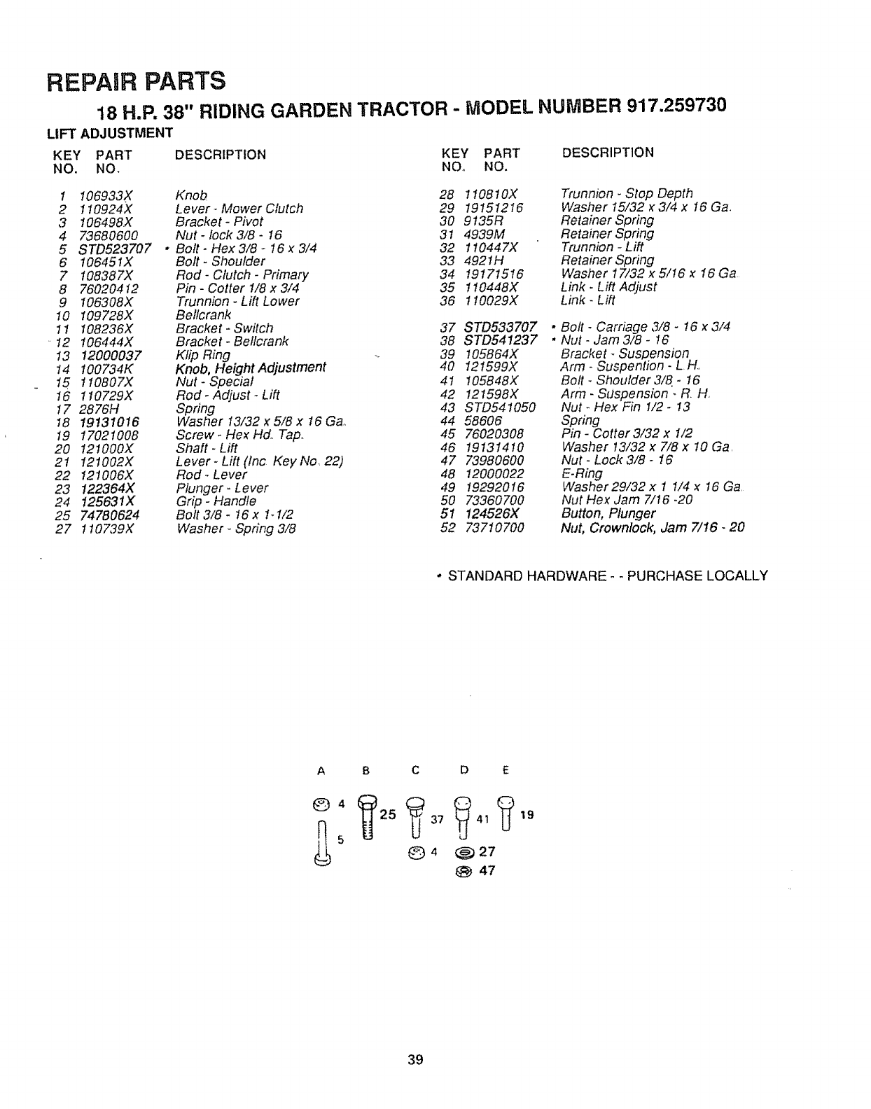
REPAIR PARTS
18 H,P. 38" RIDING GARDEN TRACTOR - MODEL NUr BER 917,259730
LIFT ADJUSTMENT
KEY PART DESCRIPTION KEY PART DESCRIPTION
NO. NO, NOo NO.
1 106933X Knob 28 1108t0X
2 110924X Lever- Mower Clutch 29 19151216
3 106498X Bracket- Pivot 30 9135R
4 73680600 Nut -lock 3/8 -16 31 4939M
5 STD523707 * Bolt- Hex3/8 -16x 3/4 32 110447X
6 106451X Bolt- Shoulder 33 4921H
7 108387X Rod -Clutch -Primary 34 19171516
8 76020412 Pin-Cotterl/8x3i4 35 110448X
9 106308X Trunnion -Lift Lower 36 1 I0029X
10 109728X Bellcrank
11 108236X Bracket -Switch 37 STD533707
"12 106444X Bracket -Bellcrank 38 STD541237
13 12000037 KlipRing 39 I05864X
14 !00734K Knob, Height Adjustment 40 121599X
15 1 I0807X Nut -Special 41 t05848X
16 110729X Rod -Adjust _Lift 42 121598X
17 2876H Spring 43 STD541050
18 19131016 Washer 13/.32 x 5/8 x 16 Gao 44 58606
19 17021008 Screw. Hex Hd,, Tap., 45 76020308
20 121000X Shatt-Lift 46 19131410
21 121002X Lever- Lift (inc Key No, 22) 47 73980600
22 121006X Rod-Lever 48 12000022
23 122364X Plunger-Lever 49 19292016
24 125631X Grip -Handle 50 73360700
25 74780624 Bolt3/8- 16x t-1/2 51 124526X
27 110739X Washer -Spring 3/8 52 73710700
Trunnion - Stop Depth
Washer 15/32 x 3/4 x I6 Ga.
Retainer Spring
Retainer Spring
Trunnion -Lift
Retainer Spring
Washer 17/32 x 5/16 x 16 Ga
Link -Lift Adjust
Link -Lift
* Bolt- Carriage ,3/8- 16 x3/4
*Nut -Jam 3/8 - 16
Bracket _Suspension
Arm- Suspention -L t4..
Bolt -Shoulder 3/8. - 16
Arm- SLtspension .R. H,
Nut -Hex Fin 1/2 -13
Spring
Pin -Cotter3!32 x 1/2
Washer 13/32 x 7/8 x 10 Ga.
Nut- Lock 3/8- t6
E.Ring
Washer29/32 x 1 1/4 x 16 Ga.
Nut Hex Jam 7/t6 -20
Button, Plunger
Nut, Crownlock, Jam 7/16- 20
" STANDARD HARDWARE- - PURCHASE LOCALLY
A
©4
B C D E
_)4 @27
47
19
39
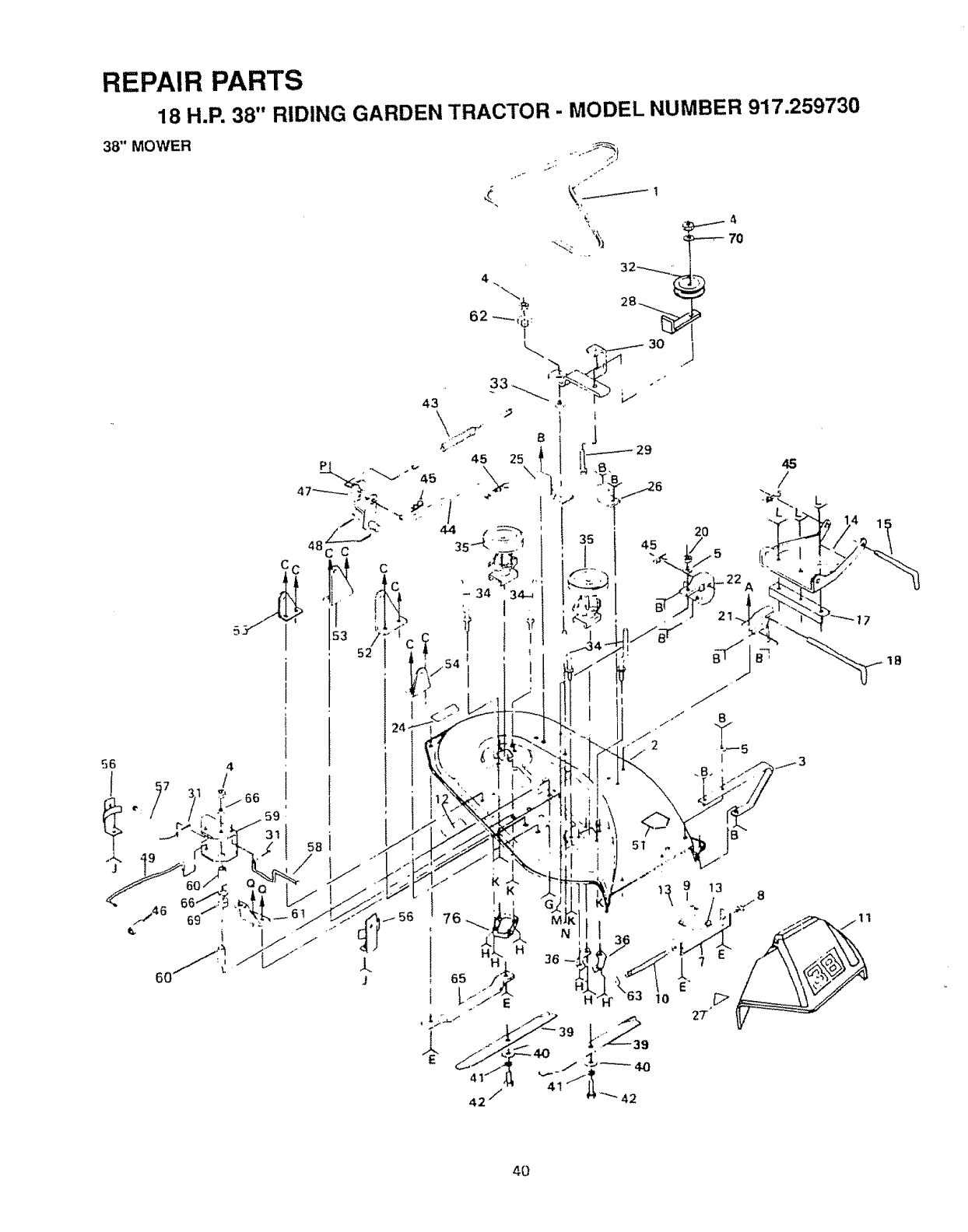
REPAIR PARTS
18 H.P. 38" RIDING GARDEN TRACTOR - MODEL NUMBER 917.259730
38" MOWER
56
t
J
<;
43
59
I
j-
4O
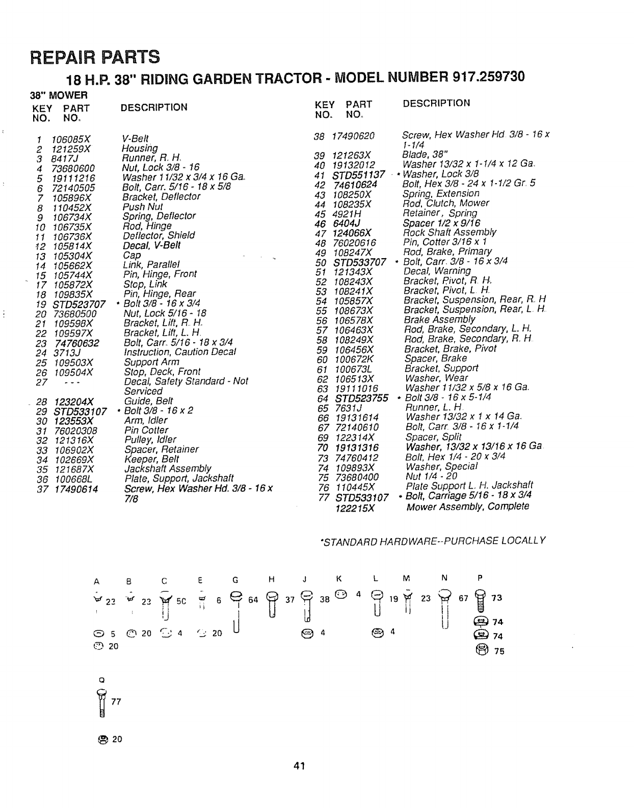
REPAIR PARTS
18 H.R 38" RIDING GARDEN TRACTOR - MODEL NUMBER 917.259730
_"MOWER
KEY PART DESCRIPTION KEY PART DESCRIPTION
NO. NOo NO. NOo
! 106085X V-Belt 38
2 I21259X Housing
3 8417J Runner, R, H_ 39
4 73680600 Nut, Lock 3/8- 16 40
5 19111216 Washer 11/32x3/4x 16Ga. 41
6 72140505 Bolt, Cart. 5/!6.18x5/8 42
7 105896X Bracket, Deflector 43
8 110452X Push Nut 44
9 106734X Spring, Deflector 45
10 106735X Rod, Hinge 46
11 106736X Deflector, Shield 47
-12 I05814X Decal V-Belt 48
13 105304X Cap 49
14 105662X Link, Parallel 50
15 105744X Pin, Hinge, Front 51
17 t05872X Stop, Link 52
18 109835X Pin, Hinge, Rear 53
I9 STD523707 "Bott 3/8 -I6 x 3/4 54
20 7,3680500 Nut, Lock 5/16 -18 55
21 109598X Bracket, Lift, R He 56
22 109597X Bracket, Lift, L. H. 57
23 74760632 Bolt, Cart. 5/t6- 18 x 3/4 58
24 3713J Instruction, Caution Decal 59
25 109503X Support Arm 60
26 109504X Stop, Deck, Front 61
27 - - -Decal, Safety Standard -Not 62
SePt,iced 63
28 123204X Guide, Belt 64
29 STD533107 * Bolt 3/8 -16 x 2 65
30 123553X Arm, Idler 66
31 76020308 Pin Cotter 67
32 12!3t6X Pulley, Idfer 69
33 106902X Spacer, Retainer 70
34 102669X Keeper, Belt 73
35 !21687X Jackshaft Assembly 74
36 !00668L Plate, Support, Jackshaft 75
37 17490614 Screw, Flex Washer Hd, 3/8 -16x 76
7/8 77
17490620 Screw, Hez Washer Hd 3/8 -16x
I_1/4
12!263X Blade, 38"
19132012 Washer 13/32 x 1-1/4 _12 Ga.
STD551137 .* Washer, Lock 3/8
74610624
108250X
108235X
4921H
6404J
124066X
76020616
108247X
STD533707
121343X
108243X
108241X
105857X
108673X
1065 78X
106463X
108249X
106456X
100672K
100673L
106513X
19111016
STD523755
7631J
19131614
72140610
122314X
19131316
74760412
!09893X
73680400
110445X
STD533107
122215X
Bolt, Flex 3/8- 24 _1.1/2 Gr 5
Spring, Extension
Rod, Clutch, Mower
Retainer, Spring
Spacer 1/2 x 9/I6
Rock Shaft Assembly
Pin, Cotter3/16 x 1
Rod, Brake, Primary
* Bolt, Carr. 3/8 -16x 3/4
Decal, Warning
Bracket, Pivot, R H.o
Bracket, Pivot, L H.
Bracket, Suspension, Rear, R. H
Bracket, Suspension, Rear, L H
Brake Assembly
Rod, Brake, Secondary, L. H.
Rod, Brake, Secondary, R_H
Bracket, Brake, Pivot
Spacer, Brake
Bracket, Support
Washer, Wear
Washer 11/32x 5/8 x 16 G&
, Bolt 3/8 _16 x 5-1/4
Runner, L. H
Washer 13/32 x t x 14 Ga.
Bolt, Cart. 3/8. I6 x 1-t/4
Spacer, Split
Washer, 13/32 x 13/16 x 16 Ga
Bolt, Flex I/4.20 _3/4
Washer, Special
Nut 1/4 -20
Plate Support L. H, Jackshaft
* Bolt, Carriage 5/I6- 18 x 3/4
Mower Assembly, Complete
*STANDARD HARDWARE--PURCHASE LOCALL Y
A
"_ 22
8 C E G
22 5c 6 64
' !J
020 '_'
L> 4 "__ 20
HJK
04
L M N P
[J _ 74
® 4
75
Q
20
41
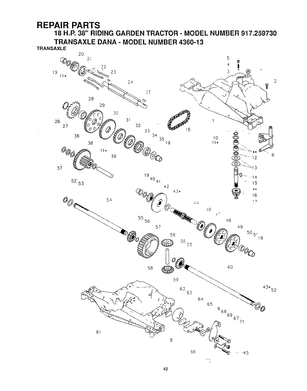
REPAIR PARTS
18 H.P. 38" RIDING GARDEN TRACTOR - MODEL NUMBER 917.259730
TRANSAXLE DANA -MODEL NUMBER 4360-13
26
37
36
28
29
5O
39
52 53
24
32 33 34 35 19
19
4041
42
43-
5
4
3
IO
1t*
1®
2
55 56
_9
5O
19
43. 52
42
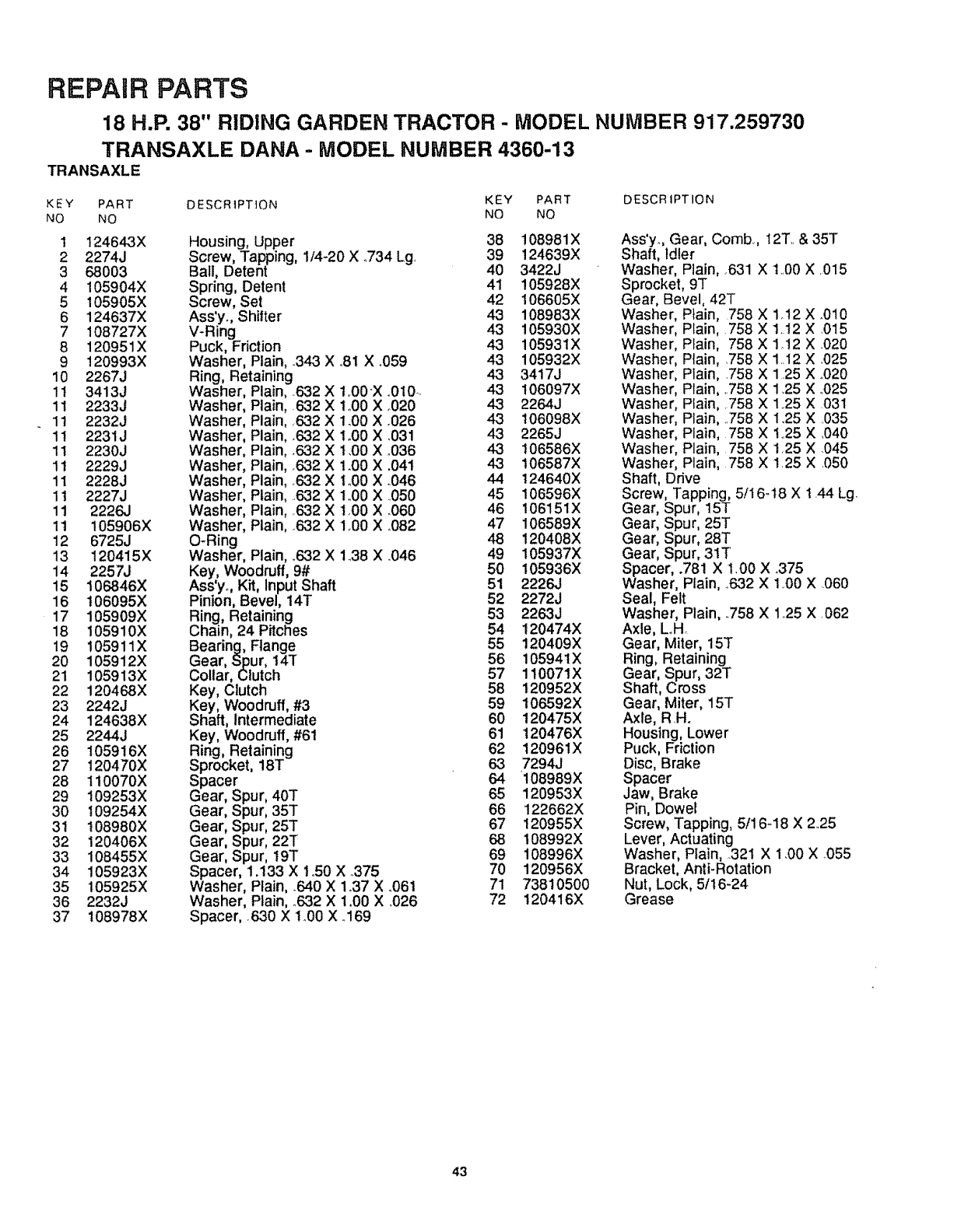
REPAIR PARTS
18 H.P. 38" RIDING GARDEN TRACTOR - MODEL NUMBER 917.259730
TRANSAXLE DANA - MODEL NUMBER 4360-13
TRANSAXLE
KEY PART DESCRIPTION KEY PART
NO NO NO NO
1 t24643X
2 2274J
3 68003
4 !05904X
5105905X
6 124637X
7 108727X
8 120951X
9 120993X
10 2267J
11 3413J
11 2233J
1t 2232J
11 2231J
11 2230J
1t 2229J
11 2228J
1t 2227J
11 2226J
11 105906X
12 6725J
13 120415X
14 2257J
15 I06846X
16 106095X
17 105909X
18 105910X
19 105911X
20 105912X
21 105913X
22 120468X
23 2242J
24 124638X
25 2244J
26 105916X
27 120470X
28 tt0070X
29 109253X
30 I09254X
31 108980X
32 120406X
33 108455X
34 105923X
35 105925X
36 2232J
37 t08978X
Housing, Upper
Screw, Tapping, 1/4-20 X .734 Lg,
Ball, Detent
Spring, Detent
Screw, Set
Ass'y. Shifter
V-Ring
Puck, Friction
Washer, Plain, .343 X o81X °059
Ring, Retaining
Washer Plain, .632 X 1.00-X _.010..
Washer Plain, 632 X t..00 X °020
Washer Plain, ,632 X 1.00 X .026
Washer Plain, _632X 1.00 X .031
Washer Plain, _632X 1,00 X °036
Washer Plain, r632 X lm00X .041
Washer Plain, _632X 1o00X .046
Washer Plain, ,632 X 1..00X 050
Washer Plain, ,632 X tO0 X .060
Washer Plain, .632 X 1_00X .082
O-Ring
Washer, Plain, .6.32X 1.38 X .046
Key, Woodruff, 9#
Ass'y,., Kit, Input Shaft
Pinion, Bevel, 14T
Ring, Retaining
Chain, 24 Pitches
Bearing, Flange
Gear, Spur, 14T
Collar, Clutch
Key, Clutch
Key, Woodruff, #3
Shaft, Intermediate
Key, Woodruff, #61
Ring, Retaining
Sprocket, 18T
Spacer
Gear, Spur, 40T
Gear, Spur, 35T
Gear, Spur, 25T
Gear, Spur, 22T
Gear, Spur, 19T
Spacer, 1.133 X 1°50 X °375
Washer, Plain, _640X 1_37 X ..061
Washer, Plain, _632X 1.00 X .026
Spacer, 630 X 1.00 X o169
38 108981X
39 124639X
40 3422J
41 105928X
42 106605X
43 108983X
43 105930X
43 105931X
43 105932X
43 3417J
43 106097X
43 2264J
43 106098X
43 2265J
43 106586X
43 106587X
44 124640X
45 106596X
46 106151X
47 106589X
48 120408X
49 105937X
50 I05936X
51 2226J
52 2272J
53 2263J
54 !20474X
55 120409X
56 105941X
57 110071X
58 120952X
59 106592X
60 120475X
61 t20476X
62 120961X
63 7294J
64 108989X
65 120953X
66 122662X
67 120955X
68 I08992X
69 108996X
70 120956X
71 73810500
72 120416X
DESCR tPTION
Ass'y., Gear, Comb., t2T,. & 35T
Shaft, Idler
Washer, Plain, 631 X 1_.00X .015
Sprocket, 9T
Gear, Bevel, 42T
Washer, Plain, 758 X 1.12 X _010
Washer, Plain, 758 X 1.12 X 015
Washer, Plain, 758 X 1,12 X .020
Washer, Plain, ,758 X 1.12 X ,025
Washer, Plain, .758 X 125 X .020
Washer, Plain, ,758 X 1.25 X ..025
Washer, Plain, _758X 1..25X 031
Washer, Plain, 758 X 1.25 X .035
Washer, Plain, 758 X 1.25 X .040
Washer, Plain, 758 X t,25 X .045
Washer, Plain, 758 X 125 X 050
Shaft, Drive
Screw, Tapping, 5/16o18 X 144 Lg.
Gear, Spur, 15T
Gear, Spur, 25T
Gear, Spur, 28T
Gear, Spur, 31T
Spacer, .781 X 1_00X .375
Washer, Plain, ..632 X 1,00 X .060
Seal, Felt
Washer, Plain, .758 X 125 X 062
Axle, Loll
Gear, Miter, 15T
Ring, Retaining
Gear, Spur, 32T
Shaft, Cross
Gear, Miter, 15T
Axle, R .H.
Housing, Lower
Puck, Friction
Disc, Brake
Spacer
Jaw, Brake
Pin, Dowel
Screw, Tapping, 5tl 6-18 X 2,.25
Lever, Actuating
Washer, Plain, 321 X 1,00 X .055
Bracket, Anti-Rotation
Nut, Lock, 5tt6-24
Grease
43
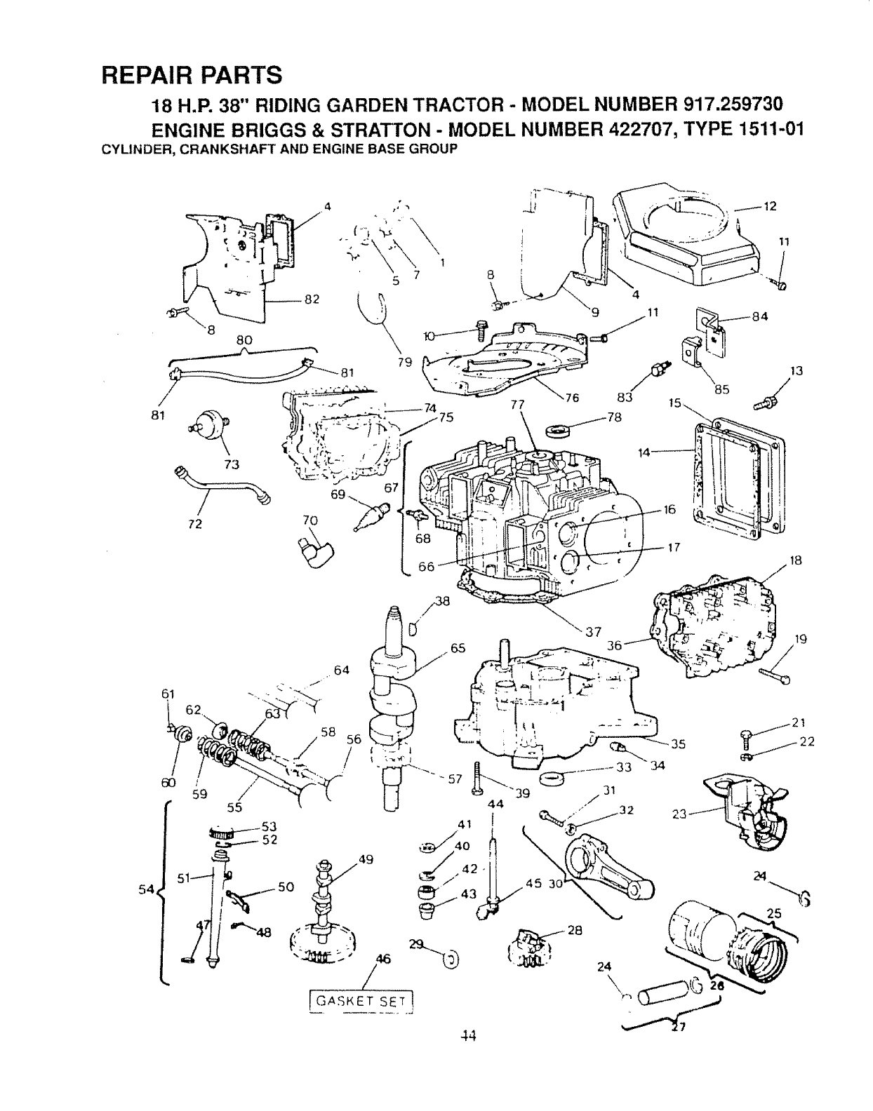
REPAIR PARTS
18 H,P. 38" RIDING GARDEN TRACTOR - MODEL NUMBER 917.259730
ENGINE BRIGGS & STRATTON- MODEL NUMBER 422707, TYPE 1511-,01
CYLINDER, CRANKSHAFT AND ENGINE BASE GROUP
54 45 3C
24
\
24
..,., . 25
44
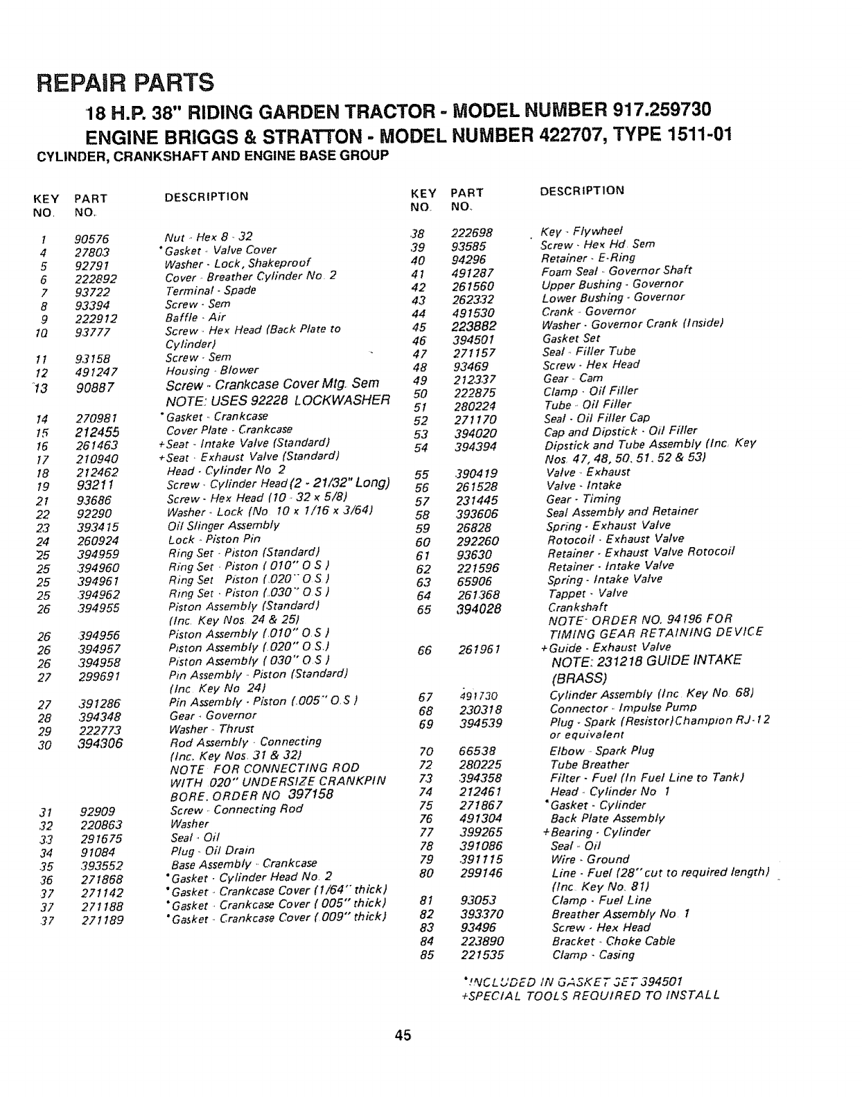
REPAIR PARTS
18 H.P. 38" RIDING GARDEN TRACTOR - MODEL NUMBER 917.259730
ENGINE BRIGGS & STRATTON - MODEL NUMBER 422707, TYPE 1511-01
CYLINDER, CRANKSHAFT AND ENGINE BASE GROUP
KEY PART DESCRIPTION KEY PART DESCRIPTION
NO, NO,. NO. NO.,
1 90576
4 2780,3
592791
6 222892
7 93722
8 93394
9 222912
1Q 93777
l I 9,2158
12 491247
13 90887
14 270981
t5 212455
16 261463
t7 210940
18 212462
t9 93211
21 93686
22 92290
23 393415
24 260924
25 394959
25 394960
25 39496 t
25 394962
26 ,394955
26 .394956
26 394957
26 ,394958
27 299691
27 ,391286
28 ,294348
29 222773
3O 394306
31 92909
32 220863
3.3 291675
34 91084
35 393552
36 27 I868
37 271142
37 271188
.27 27I 189
Nut _,Hex 8 _32 38
"Gasket -, Valve Cover 39
Washer. Lock, Shakeproof 40
Cover _.Breather Cylinder No 2 4 l
Terminal- Spade 42
Screw. Sem 43
Baffle ..Air 44
Screw ,, Hex Head (Back Plate to 45
Cylinder) 46
Screw .. Sem 47
Housing ,Blower 48
Screw _Crankcase Cover Mtg. Sem 49
NOTE,: USES 92228 LOCKWASHER 50
"Gasket ,, Crankcase 5!
Cover Plate - Crankcase 52
+Seat -Intake Valve (Standard) 53
+Seat, Exhaust Valve (Standard) 54
Head. Cylinder No 2
Screw Cylinder Head (2 -21/,32" Long) 55
56
Screw- Hex Head (10 ,. 32 x5/8) 57
Washer_ Lock (No I0 x1/16 x3/64) 58
Oil Slinger Assembly 59
Lock oPiston Pin 60
Ring Set., Piston (Standard) 61
Ring Set, Piston ( 010 °' 0 S) 52
Ring Set Ptston f,020" 0 S )63
Ring Set • Piston (030 "° O S ) 64
Piston Assembly (Standard) 65
(tnc Key Nos 24 & 25)
Piston Assembly (,010" 0 S )
Piston Assembly (, 020" O S,) 66
Piston Assembly (030" O.S )
Pm Assembly ,. Piston (Standard)
(lnc Key No 24)
Pin Assembly •Piston (..005"' O, S) 67
Gear_ Governor 68
Washer., Thrust 69
Rod Assembly _Connecting
(inc. Key Nos, 3 f & 32/ 70
NOTE FOR CONNECTING ROD 72
WITH 020"" UNDERSIZE CRANKPIN 73
BORE, ORDER NO 397158 74
Screw- Connecting Rod 75
Washer 76
Seat-, Oi! 77
Plug .. Oil Dram 78
Base Assembly _Crankcase 79
"Gasket - Cylinder Head No, 2 80
"Gasket., Crankcase Cover (I/64 "°thick)
"Gasket , Crankcase Cover (005" thick)
"Gasket ,. Crankcase Cover (,009" thick)
81
82
83
84
85
222698
93585
94296
491287
261560
2623.32
491530
223882
394501
271157
93469
2723.37
222875
28022_
271170
394020
394394
390419
261528
231445
393606
26828
292260
93630
221596
65906
261368
394028
261961
497730
230318
394539
66538
280225
394358
212461
271867
491304
399265
391086
391115
299146
93053
393.270
93496
223890
221535
Key-. Flywheel
Screw. He× Hd Sere
Retainer., E.Ring
Foam Seal ,. Governor Shaft
Upper Bushing- Go vern or
Lower Bushing. Go vernor
Crank _,Governor
Washer. Governor Crank (Inside)
Gasket Set
Seal ,, Filler Tube
Screw. Hex Head
Gear ,. Cam
Clamp- Off Fitler
Tube., OH Filler
Seal. Oil Filler Cap
Cap and Dipstick •Oil Filler
Dipstick and Tube Assembly (Inc, Key
Nos, 47, 48, 50, 51, 52 & 53)
Valve., Exhaust
Valve- Intake
Gear. Timing
Seal Assembly and Retainer
Spring. Exhaust Valve
Rotocoil. E_haust Valve
Retainer _E_haust Valve Rotocoit
Retainer. Intake Valve
Spn'ng- Intake Valve
Tappet. Valve
Crankshaft
NOTE ORDER NO. 94 t96 FOR
TIMING GEAR RETAINING DEVICE
+Guide. Exhaust Valve
NOTE: 231218 GUIDE INTAKE
(BRASS)
Cyfinder Assembly (Inc Key No 68)
Connector ,, Impulse Pump
Plug - Spark (Resistor)Champlon RJ. t 2
or equivalent
Elbow ,, Spark Plug
Tube Breather
Filter- Fuel (In Fuel Line to Tank)
Head. Cylinder No 1
"Gasket. Cylinder
Back Plate Assembly
+Bearing. Cylinder
Seat ,, Oil
Wire. Ground
Line -Fuel (28" cut to required length)
(tnc Key No, 81)
Clamp -Fuet Line
Breather Assemb]y No 1
Screw, Hex Head
Bracket., Choke Cable
Clamp. Casing
"!,_ICLUDED tN G,_SKET SET S94501
+SPECIAL TOOLS REQUIRED TO INSTALL
45
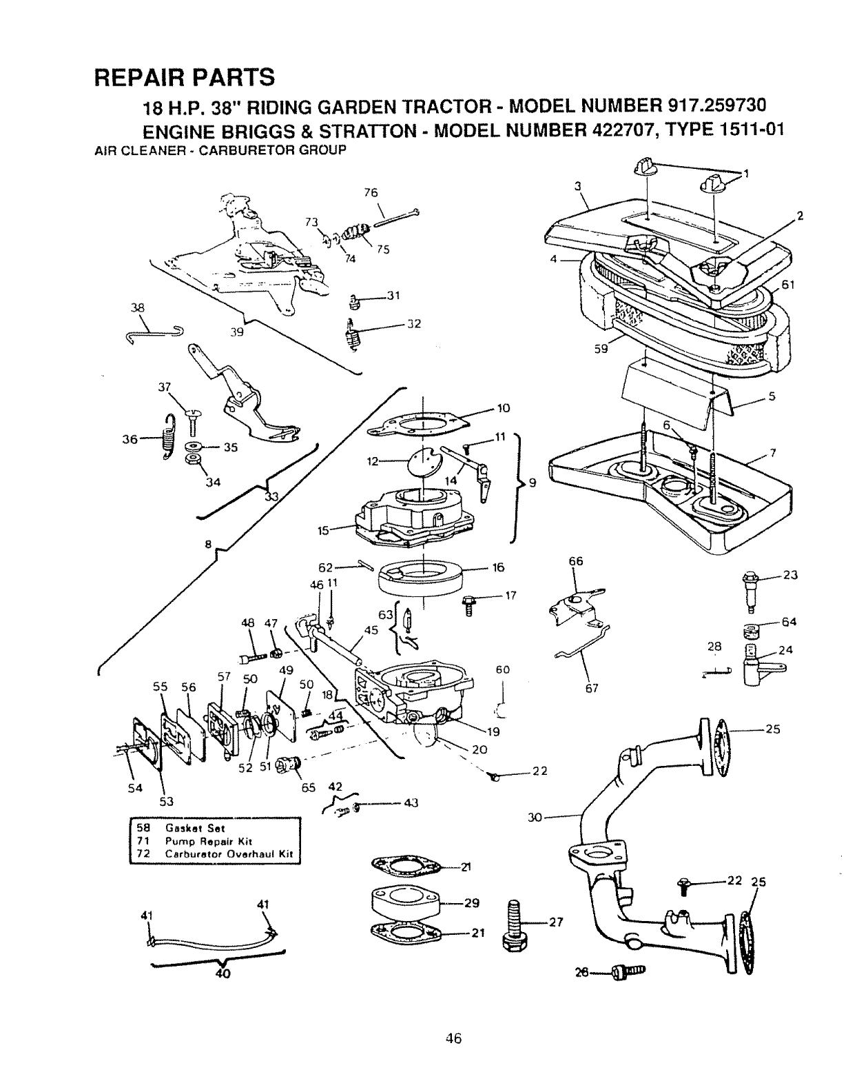
REPAIR PARTS
18 H.P. 38" RIDING GARDEN TRACTOR- MODEL NUMBER 917.259730
ENGINE BRIGGS & STRATTON - MODEL NUMBER 422707, TYPE 1511-01
AIR CLEANER -CARBURETOR GROUP
76 3_1
,\
59
66
,.j
%
49
57 5O
55 56
6O
,I 67
54
71
72
41
I
52 51
65 42
53
Gasket Set ]
Pump Repair Kit
Carburetor Overhaul Kit
41
46
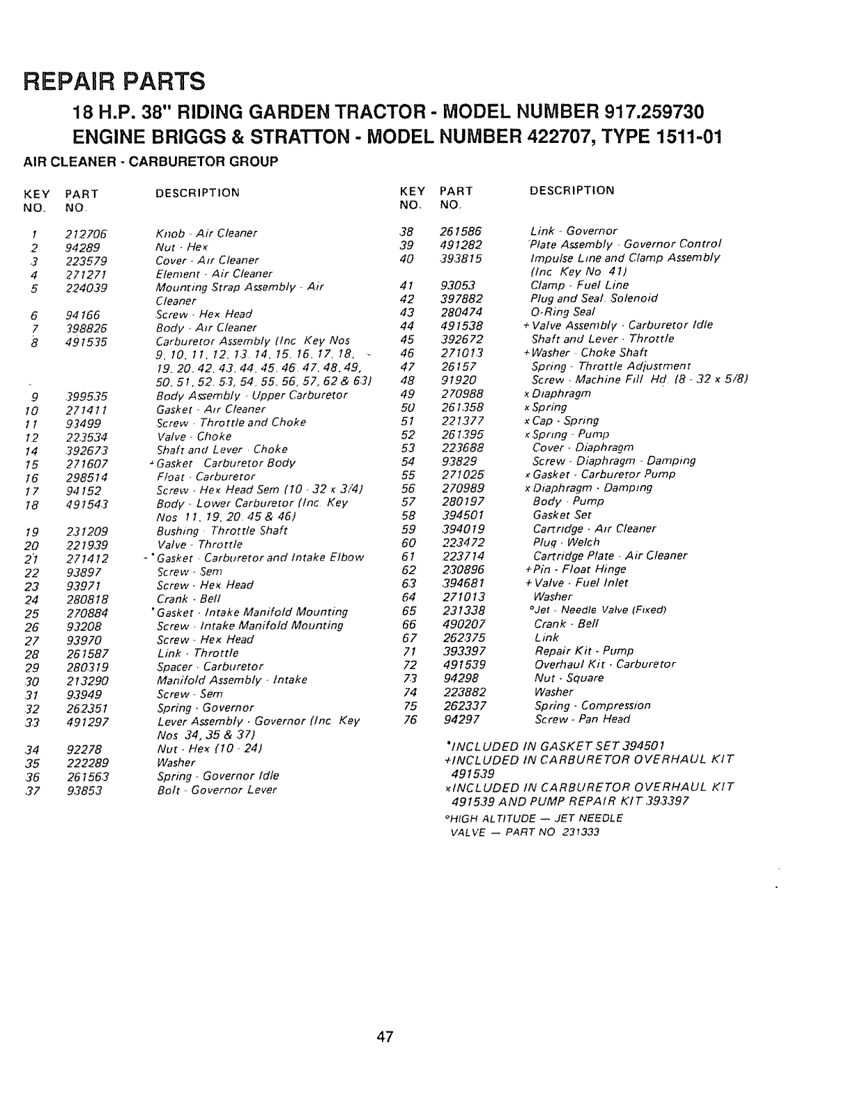
REPAUR PARTS
18 H.P. 38" RIDING GARDEN TRACTOR - MODEL NUMBER 917.259730
ENGINE BRIGGS & STRATTON - MODEL NUMBER 422707, TYPE 1511-01
AIR CLEANER -CARBURETOR GROUP
KEY pART DESCRIPTION KEY PART DESCRIPTION
NO., NO. NO, NO,.
12t.2705 Knob, Air Cleaner 38 261586 Link ,. Governor
,2 94289 Nut - Hex 39 491282 Plate Assembly, Governor Control
3 223579 Cover ,, Air Cleaner 40 393815 Impulse Line and Clamp Assembly
4.271271 Element. Air Cleaner (lnc Key No 4t)
5 ,224039 Mounting Strap Assembly • Air 4I 93053 Clamp ,. Fuel Line
Cleaner 42 397882 Plug and Seat. Solenoid
6 94 t66 ,Screw. Hex Head 43 280474 O.Ring Seal
7298826 Body ,,Air Cleaner 44 491538 + Valve Assembly., Carburetor Idle
84915.25 Carburetor Assembly tlnc Key Nos 45 392672 ,Shaft and Lever-, Throttle
9, 10, It, t2, 1,3, t4. t5_ t5. I7, 18, ,. 46 27101,2 +Washer, Choke Shaft
19.20, 42, 4,2, 44, 45, 46 47, 48.49, 47 26157 Spring • Throttle Adjusrment
50.5t. 5.2.53, 54_ 55. 56, 57, 62 & 63) 48 91920 .Screw. Machine F_tl Hd (8 _,32 x5/8)
9399535 Body Assembly , Upper Carburetor 49 270988 xDiaphragm
10 271411 Gasket , Atr Cleaner 50 261358 xSpring
t t 9.3499 Screw. Throttle and Choke 5! 2.21377 x Cap • Spnng
1,2 22,3534 Valve, Choke 52 261,395 _Spring -.Pump
I4 392673 Shaft and Lever Choke 5.3 22,2688 Cover • Diaphragm
15 271607 _Gasket Carburetor Body 54 93829 Screw .. Diaphragm., Damping
!6 298514 Float. Carburetor 55 2 7t025 _Gasket - CarbureTor Pump
17 94 I52 Screw -,He_ Head Sem (I0,32 _3/4) 56 270989 x Diaphragm •Dampmg
t8 49154-2 Body ,, Lower Carburetor fine Key 57 280197 Body, Pump
Nos 1 I, t9, 20, 45 & 45] 58 394501 Gasket Set
t9 231209 Bushing, Throttle Shaft 59 394019 Cartridge -Air Cleaner
20 221939 Valve, Throttle 60 223472 Pfuq., Welch
2"t 271412 - *Gasket Carburetor and intake Elbow 61 223714 Cartridge Plate •Air Cleaner
22 93897 ;crew ,. ,Sere 62 230896 +Pin -Float Hinge
2,3 93971 Screw_ He_ Head 63 394681 + Valve. Fuel Inlet
,24 280818 Crank. Bell 64 271013 Washer
25 270884 *Gasket .. Intake Manifold Mounting 65 231338 °Jet _,Needle Valve (Fixed)
26 93208 Screw _Intake Manifold Mounting 66 490207 Crank -Bell
27 93970 Screw .. Hex Head 67 262,275 Link
28 261587 Link -Throttle 7t 393397 Repair Kit -Pump
29 280219 Spacer, Carburetor 72 49153.9 Overhaul Kit. Carburetor
30 213290 Manifold Assembly -. Intake 73 94298 Nut. Square
3t 9.3949 Sere w.. Sern 74 223882 Washer
.32 2512351 Spring.. Governor 75 262337 Spring - Compression
.3.3 491297 Lever Assembly • Governor (lnc Key 76 94297 Screw *Pan Head
Nos 34, 35 & ,37)
34 92278 Nut .. Hex (10 ..24) "INCLUDED IN GASKET SET 39450t
35 222289 Washer +INCLUDED IN CARBURETOR OVERHAUL KIT
36 251563 Spring .. Governor tdte 491539
37 9,3853 Bolt .. Governor Lever _INCLUDED tN CARBURETOR OVERHAUL KIT
4915,39 AND PUMP REPAIR KI T ,393397
_HtGH AL TfTUDE _ .JET NEEDLE
VALVE _PART NO 231333
47
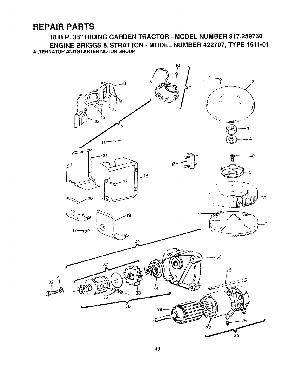
REPAIR PARTS
18 _.P. 38 RtD|NG GARDEN TRACTOR" MODEL NUMBER 917.259730
ENGINE BR|GGS & sTRAT'['ON" MODEL NUMBER 422707, TYPE -t511-01
ALTERNATOR AND STARTER MOTOR GROUP
.f
J
_+
il _ _- - 39
28
31
48
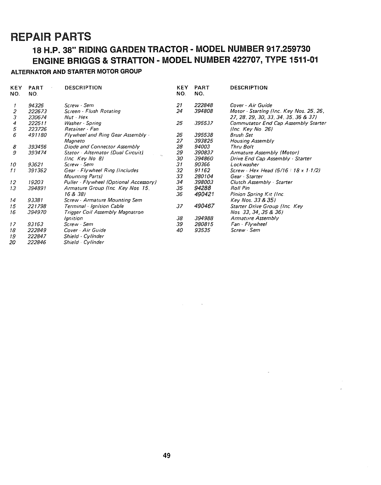
REPAIR PARTS
18 H.P. 38" RIDING GARDEN TRACTOR -MODEL NUMBER 917.259730
ENGINE BRIGGS & STRATTON -MODEL NUMBER 422707, TYPE 1511-01
ALTERNATOR AND STARTER MOTOR GROUP
KEY PART DESCRIPTION KEY PART DESCRIPTION
NO., NO, NO, NO,
I
2
3
4
5
6
8
9
to
rt
12
13
14
15
t6
t7
t8
19
20
94326 Sofew _ Sem 21 222848
22267.3 Screen, Flush Rotating 24 394808
230674 Nut, Hex
222511 Washer, Spring 25 395537
223726 Retainer, Fan
49 t t80 Flywheel and Ring Gear Assembly, 26 395538
Magneto 27 393825
,293456 Diode and Connector Assembly 28 94003
393474 Stator. Alternator (Dual Circuit_ 29 390837
(tnc Key No 8) 30 39486'0
93621 Screw, Sere 31 90,266
391362 Gear, Flywheel Ring (Includes 32 9116'2
Mounting Parts) 33 280104
19203 Puller ,. Flywheel (Optional Accessory) 34 398003
394891 Armature Group (tnc Key Nos 15. 35 94288
t6 & 38) 36 490421
93381 Screw. Armature Mounting Sem
22 t 798 Terminal _,Ignition Cable 37 490467
394970 Trigger Coil Assembly Magnatron
Ignition 38 394988
93163 Screw, Sere 39 280815
222849 Cover. Air Guide 40 93535
222847 Shield- Cylinder
222846 Shield. Cylinder
Cover. Air Guide
Motor, Starting (tnc, Key Nos,, 25, 26,
27, 28, 29, 30, 33, 34.35, 36 & 37)
Commutator End Cap Assembly Starter
[tnc, Key No 26)
Brush Set
Housing Assembly
Thru Bolt
Armature Assembly (Motor)
Drive End Cap Assembly - Starter
L oc k wash e r
Screw., Flex Head f5/16 ,: t8 xt,1/2)
Gear ,. Starter
Clutch Assembly., Starter
Roll Pin
Pinion Spring Kit (tnc
Key Nos, 33 & 35)
Starter Drive Group (tnc Key
Nos 33, 34, 35 & 36)
Armature Assembly
Fan ,, Flywheel
Screw, Sere
49
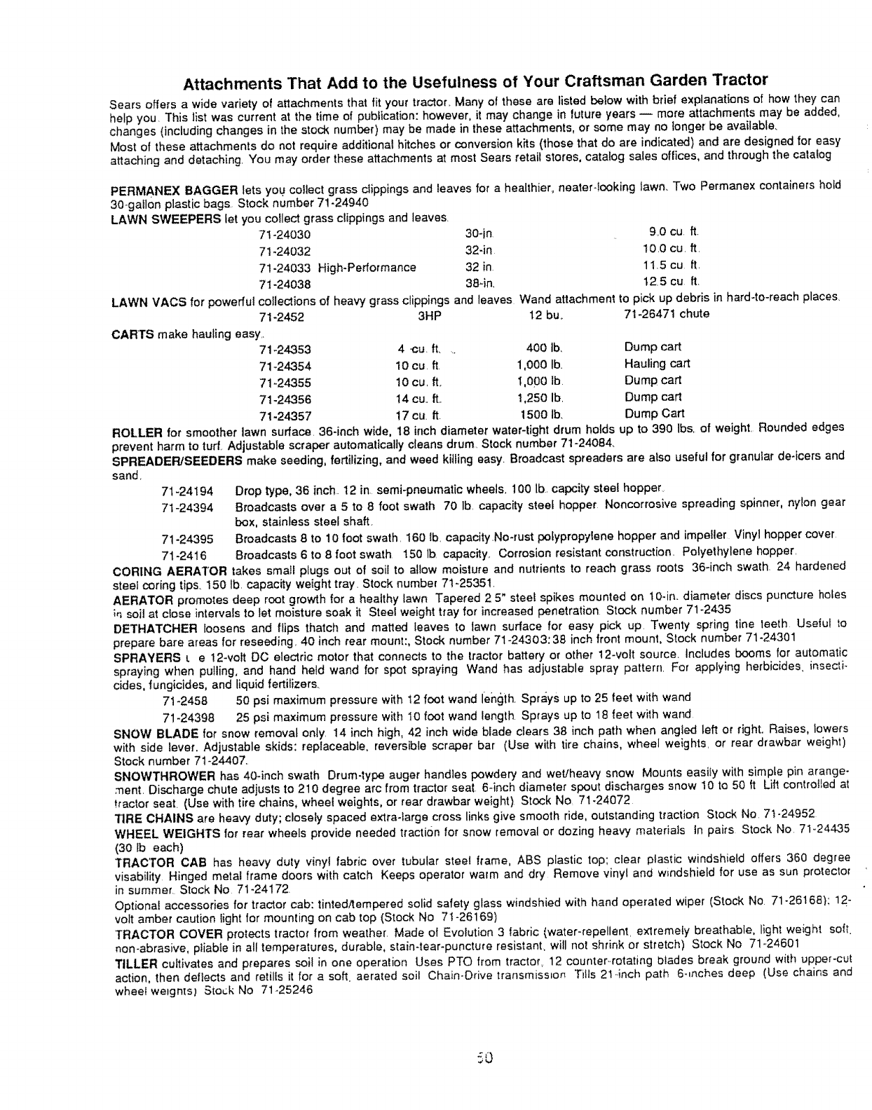
Attachments That Add to the Usefulness of Your Craftsman Garden Tractor
Sears offers a wide variety of attachments that fit your tractor. Many of these are listed below with brief explanations of how they can
help you. This list was current at the time of publication: however, it may change in future years -- more attachments may be added,
changes (including changes in the stock number) may be made in these attachments, or some may no longer be available.
Most of these attachments do not require additional hitches or conversion kits (those that do are indicated) and are designed for easy
attaching and detaching. You may order these attachments at most Sears retail stores, catalog sales offices, and through the calalog
PERMANEX BAGGER lets you collect grass clippings and leaves for a healthier, nearer-looking lawn. Two Permanex containers hold
30-gallon plastic bags. Stock number 71-24940
LAWN SWEEPERS let you collect grass clippings and leaves.
71-24030 30-in 9,0 cu ft.
71-24032 32-in 10.0 cu. ft.
71-24033 High-Performance 32 in 11.5 cu ft,
71-24038 384n, t25 cu ft.
LAWN VACS for powerful
71-2452
CARTS make hauling easy..
71-24353
71-24354
71-24355
71-24-356
71-24357
collections of heavy grass clippings and leaves Wand attachment to pick up debris in hard4o-reach places,
3HP 12 buo 71-26471 chute
4-cu. ft.... 400 tb, Dump cart
10 cu ft 1,000 Ib. Hauling cart
10 cu, It. t,0.00 Ib. Dump cart
t4 cu.. it !,250 ib. Dump cart
17cu 1t. 1500 Ib. Dump Cart
ROLLER for smoother lawn surface. 36-inch wide, 18 inch diameter water-tight drum holds up to 390 Ibs, of weight. Rounded edges
prevent harm to turf. Adjustable scraper automatically cleans drum. Stock number 71-24084.
SPREADER/SEEDERS make seeding, fertilizing, and weed killing easy Broadcast spreaders are also useful for granular de4cers and
sand.
71-24194
71-24394
Drop type, 36 inch 12 in semi-pneumatic wheels. 100 lb. capcity steel hopper,
Broadcasts over a 5 to 8 foot swath 70 lb. capacity steel hopper Noncorrosive spreading spinner, nylon gear
box, stainless steel shaft.
71-24395 Broadcasts 8 to 10 foot swath. 160 lb capacity No-rust pofypropylene hopper and impeller Vinyl hopper cover
71-2416 Broadcasts 6 to 8 foot swath 150 lb. capacity, Corrosion resistant construction. Polyethylene hopper,
CORING AERATOR takes small plugs out of soil to allow moisture and nutrients to reach grass roots 36-inch swath. 24 hardened
steel coring tips. t50 lb. capacity weight tray. Stock number 7!-2535!.
AERATOR promotes deep root growth for a healthy lawn Tapered 2 5" steel spikes mounted on !0-in.. diameter discs puncture holes
in soil at close intervals to let moisture soak it Steel weight tray for increased penetration Stock number 71-2435
DETHATCHER loosens and flips thatch and matted leaves to lawn surface for easy pick up Twenty spring fine teeth Useful to
prepare bare areas for reseeding, 40 inch rear mount:, Stock number 71-24303:38 inch front mount, Stock number 71-24301
SPRAYERS _ e 12-volt DC electric motor that connects to the tractor battery or other 12-volt source_ Includes booms for automatic
spraying when pulling, and hand held wand for spot spraying Wand has adjustable spray pattern. For applying herbicides, insecti-
cides, fungicides, and liquid fertilizers.
7t-2458 50 psi maximum pressure w_h t2 foot wand leh0ih Sprays up to 25 feet with wand
71-24398 25 psi maximum pressure with 10 foot wand length Sprays up to 18 feet with wand
SNOW BLADE for snow removal only. t4 inch high, 42 inch wide blade clears 38 inch path when angled left or right. Raises, lowers
with side lever. Adjustable skids: replaceable, reversible scraper bar (Use with tire chains, wheel weights, or rear drawbar weigh1)
Stock number 7t-24407..
SNOWTHROWER has 404rich swath Drum-type auger handles powdery and wet'heavy snow Mounts easily with simple pin arange-
ment. Discharge chute adjusts to 2t0 degree arc from tractor seat 6-inch diameter spout discharges snow 10 to 50 tt Lift controlled at
tractor seat. (Use with tire chains, wheel weights, or rear drawbar weight) Stock No, 71-24072
TiRE CHAINS are heavy duty; closely spaced extra-large cross links give smooth ride, outstanding traction Stock No 71-24952
WHEEL WEIGHTS for rear wheels provide needed traction for snow removal or dozing heavy materials In pairs Stock No 71o24435
(30 lb each)
TRACTOR CAB has heavy duty vinyl fabric over tubular steel frame, ABS plastic top; clear plastic windshield offers 360 degree
visabitity Hinged metal frame doors with catch Keeps operator warm and dry Remove vinyl and windshield for use as sun protector
in summer. Stock No 71-24172.
Optional accessories for tractor cab: tinted/tempered solid safety glass windshied with hand operated wiper (Stock No 71-26168}; 12-
volt amber caution light for mounting on cab top (Stock No 71-26169)
TRACTOR COVER protects tractor from weather. Made of Evolution 3 fabric (water-repellent, extremely breathable, lighl weight soil.
non-abrasive, pliable in all temperatures, durable, stain-tear-puncture resistanL will not shrink or stretch) Stock No 71,,24601
TILLER cultivates and prepares soil in one operation Uses PTO from tractor, 12 counter..rotating blades break ground with upper-cut
action, then deflects and retills it for a soft aerated soil Chain-Drive transmission Tills 21..inch path 6-,riches deep (Use chains and
wheel weights) S[o_k No 71-25246

SUGGESTED GUIDE FOR SiGHTiNG SLOPES FOR SAFE OPERATION
ol
SIGHTING
ONLY RIDE UP AND DOWN HILL,
NOT ACROSS HILL
SIGHT AND HOLD THIS LEVEL WITH
SKY LINE OR TREE.
15 ° MAX.
IJLIIII I IIIII IIIIIIII I II IIIIIIIIIIIIII II I Jllllll
AOperate your Tractor up and down the face of slopes (not
_J ,_ greater than 15 °) never across the face. Make turns gradu-
_J _ ally to prevent tipping or loss of control. Exercise extreme
caution when changing direction on slopes. .....
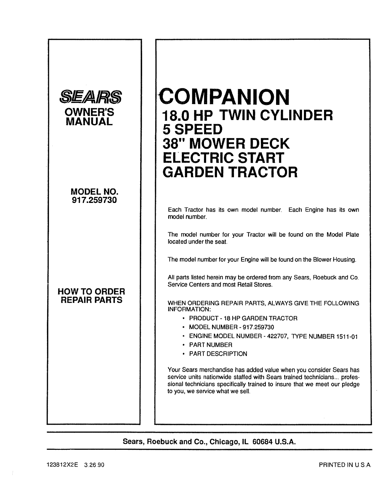
OWNER'S
MANUAL
MODEL NO.
917.259730
HOW TO ORDER
REPAIR PARTS
ICOMPANION
B.0 HP TWIN CYLINDER
38" MOWER DECK
START
GARDEN TRACTOR
Each Tractor has its own model number. Each Engine has its own
modelnumber.
The model number for' your Tractor will be found on the Model Plate
located under the seat..
The modelnumber'foryourEnginewillbe foundon theBlowerHousing.
All parts listed herein may be ordered from any Sears, Roebuck and Co.
Service Centers and most Retail Stores.
WHEN ORDERING REPAIR PARTS, ALWAYS GIVE THE FOLLOWING
INFORMATION:
* PRODUCT - 18 HP GARDEN TRACTOR
°MODEL NUMBER - 917.259730
- ENGINE MODEL NUMBER - 422707, TYPE NUMBER 1511-0t
, PART NUMBER
,PART DESCRIPTION
Your Sears merchandise has added value when you consider Sears has
service units nationwide staffed with Sears trained technicians., profes-
sional technicians specifically trained to insure that we meet our pledge
to you, we service what we sell.
lUIll iijlllllllll ,,,,,,,,,,,,,,,,,,,,IlllJllJlIIJl ill Jl IIJIJ Ill ii I I I I I I I
Sears, Roebuck and Co., Chicago, IL 60684 U.S.A.
123812X2E 3.26.90 PRINTED IN USA
