Craftsman 917270514 User Manual LAWN TRACTOR Manuals And Guides L9910335
CRAFTSMAN Lawn, Tractor Manual L9910335 CRAFTSMAN Lawn, Tractor Owner's Manual, CRAFTSMAN Lawn, Tractor installation guides
User Manual: Craftsman 917270514 917270514 CRAFTSMAN LAWN TRACTOR - Manuals and Guides View the owners manual for your CRAFTSMAN LAWN TRACTOR #917270514. Home:Lawn & Garden Parts:Craftsman Parts:Craftsman LAWN TRACTOR Manual
Open the PDF directly: View PDF ![]() .
.
Page Count: 60

Owner's Manual
£RI:IFTXMAN
14.5 HP
ELECTRIC START
42" MOWER
6 SPEED TRANSAXt_E i
LAWN TRACT
Model No.
917.270514
• Safety
• Assembly
• Operation
•Maintenance
•Repair Parts
CAUTION:
Read and follow all Safety
Rules and Instructions before
operating this equipment.
For answers to your questions
about this product, Call:
1-800-659-5917
Sears Craftsman Help Line
5 am-5pm, Mon-Sat
Sears, Roebuck and Co., Hoffman Estates, II60179
Visit our Craftsman website:www.sears.comlcraftsman
Warranty...............................................2
SafetyRules..........................................2
ProductSpecifications..........................5
Assembly...............................................8
Operation...........:................................11
MaintenanceSchedule......................17
Maintenance.......................................17
ServiceandAdjustments....................21
Storage...............................................27
Troubleshooting.................................28
Repair Parts ........................................ 32
Parts Ordering ..................... Back Cover
LIMITED TWO YEAR WARRANTY ON CRAFTSMAN RIDING EQUIPMENT
For two (2) years from the date of purchase, if this Craftsman Riding Equipment is
maintained, lubricated and tuned up according to the instructions in the owner's
manual, Sears will repair or replace, free of charge, any parts found to be defective in
material or workmanship.
This Warranty does not cover:
• Expendable items which become worn during normal use, such as blades, spark
plugs, air cleaners, belts, etc.
• Tire replacement or repair caused by punctures from outside objects, such as nails,
thorns, stumps, or glass.
• Repairs necessary because of operator abuse, negligence, improper storage or acci-
dent or the failure to maintain the equipment according to the instructions contained
in the owner's manual.
• Riding equipment used for commercial or rental purposes.
LIMITED 90 DAY WARRANTY ON BATIERY
For ninety (90) days from date of purchase, if any battery included with this riding
equipment proves defective in material or workmanship and our testing determines the
battery will not hold a charge, Sears will replace the battery at no charge. In-home
warranty service on your Craftsman riding equipment is available at no charge for 30
days from the date of purchase. Please contact your nearest service center. After 30
days from the date of purchase, warranty service is available by taking your Craftsman
riding equipment to your nearest Sears Service Center. (In-home warranty service will
still be available after 30 days from the date of purchase but a standard trip charge will
apply). This warranty applies only while this product is in the United States. This
Warranty gives you specific legal rights, and you may also have other rights which may
vary from state to state.
Sears, Roebuck and Co., D/617 WA, Hoffman Estates, IL 60179
IMPORTANT: This cutting machine is
capable of amputating hands and feet
and throwing objects. Failure to observe
the following safety instructions could re-
sult in serious injury or death.
GENERAL OPERATION
•Read, understand, and follow all in-
structions in the manual and on the
machine before starting.
•Only allow responsible adults, who are
familiar with the instructions, to oper-
ate the machine.
• Clear the area of objects such as
rocks, toys, wire, etc., which could be
picked up and thrown by the blade.
• Be sure the area is clear of other 2
people before mowing. Stop machine
if anyone enters the area.
• Never carry passengers.
• Do not mow in reverse unless abso-
lutely necessary. Always look down
and behind before and while backing.
•Be aware of the mower discharge di-
rection and do not point it at anyone.
Do not operate the mower without ei-
ther the entire grass catcher or the
guard in place.
• Slow down before turning.
• Never leave a running machine unat-
tended. Always turn off blades, set
parking brake, stop engine, and re-
move keys before dismounting.
•Turn off blades when not mowing.
• Stop engine before removing grass
catcher or unclogging chute.
• Mow only in daylight or good artificial
light.
• Do not operate the machine while un-
der the influence of alcohol or drugs.
*Watch for traffic when operating near
or crossing roadways.
• Use extra care when loading or un-
loading the machine into a trailer or
truck.
• Data indicates that operators, age 60
years and above, are involved in a
large percentage of riding mower-
related injuries. These operators
should evaluate their ability to operate
the riding mower safely enough to
protect themselves and others from
serious injury.
SLOPE OPERATION
Slopes are a major factor related to loss-
of-control and tipover accidents, which
can result in severe injury or death. All
slopes require extra caution. If you can-
not back up the slope or if you feel un-
easy on it, do not mow it.
DO:
•Mow up and down slopes, not across,
•Remove obstacles such as rocks, tree
limbs, etc.
•Watch for holes, ruts, or bumps, Un-
even terrain could overturn the ma-
chine. Tall grass can hide obstacles.
•Use slow speed. Choose a low gear
so that you will not have to stop or shift
while on the slope.
•Follow the manufacturer's recommen-
dations for wheel weights or counter-
weights to improve stability.
• Use extra care with grass catchers or
other attachments. These can change
the stability of the machine.
•Keep all movement on the slopes slow
and gradual. Do not make sudden
changes in speed or direction.
• Avoid starting or stopping on a slope. If
tires lose traction, disengage the
blades and proceed slowly straight
down the slope,
DO NOT:
•Do notturn on slopes unless neces-
sary, and then, turn slowly and gradu-
ally downhill, if possible. 3
•Do not mow near drop-offs, ditches, or
embankments. The mower could sud-
denly turn over if a wheel is over the
edge of a cliff or ditch, or if an edge
caves in.
•Do not mow on wet grass. Reduced
traction could cause sliding.
•Do nottry to stabilize the machine by
putting your foot on the ground.
•Do not use grass catcher on steep
slopes.
CHILDREN
Tragic accidents can occur if the operator
is not alert to the presence of children.
Children are often attracted to the ma-
chine and the mowing activity. Never as-
sume that children will remain where you
last saw them.
• Keep children out of the mowing area
and under the watchful care of another
responsible adult.
•Be alert and turn machine off if chil-
dren enter the area.
• Before and when backing, look behind
and down for small children.
• Never carry children. They may'fall off
and be seriously injured or interfere
with safe machine operation.
• Never allow children to operate the
machine.
• Use extra care when approaching
blind corners, shrubs, trees, or other
objects that may obscure vision.
SERVICE
•Use extra care in handling gasoline
and other fuels. They are flammable
and vapors are explosive.
Use only an approved container.
Never remove gas cap or add fuel
with the engine running. Allow en-
gine to cool before refueling. Do
not smoke.
Never refuel the machine indoors.
Never store the machine or fuel
container inside where there is an
open flame, such as a water heat-
er.
• Never run amachine inside a closed
area.
• Keep nuts and bolts, especially blade
attachment bolts, tight and keep equip-
ment in good condition.
• Never tamper with safety devices.
Check their proper operation regularly.
•Keep machine free of grass, leaves, or
other debris build-up. Clean oil or fuel
spillage. Allow machine to cool before
storing.
•Stop and inspect the equipment if you
strike an object. Repair, if necessary,
before restarting.
• Never make adjustments or repairs
with the engine running.
• Grass catcher components are subject
to wear, damage, and deterioration,
which could expose moving parts or
allow objects to be thrown. Frequently
check components and replace with
manufacturer's recommended parts,
when necessary.
Mower blades are sharp and can cut.
Wrap the blade(s) or wear gloves, and
use extra caution when servicing
them.
• Check brake operation frequently.
Adjust and service as required.
• Be sure the area is clear of other
people before mowing. Stop machine
if anyone enters the area.
• Never carry passengers.
• Do not mow in reverse unless abso-
lutely necessary. Always look down
and behind before and while backing.
• Never carry children. They may fall off
and be seriously injured or interfere
with safe machine operation.
• Keep children out of the mowing area
and under the watchful care of another
responsible adult.
•Be alert and turn machine off if chil-
dren enter the area.
•Before and when backing, look behind
and down for small children.
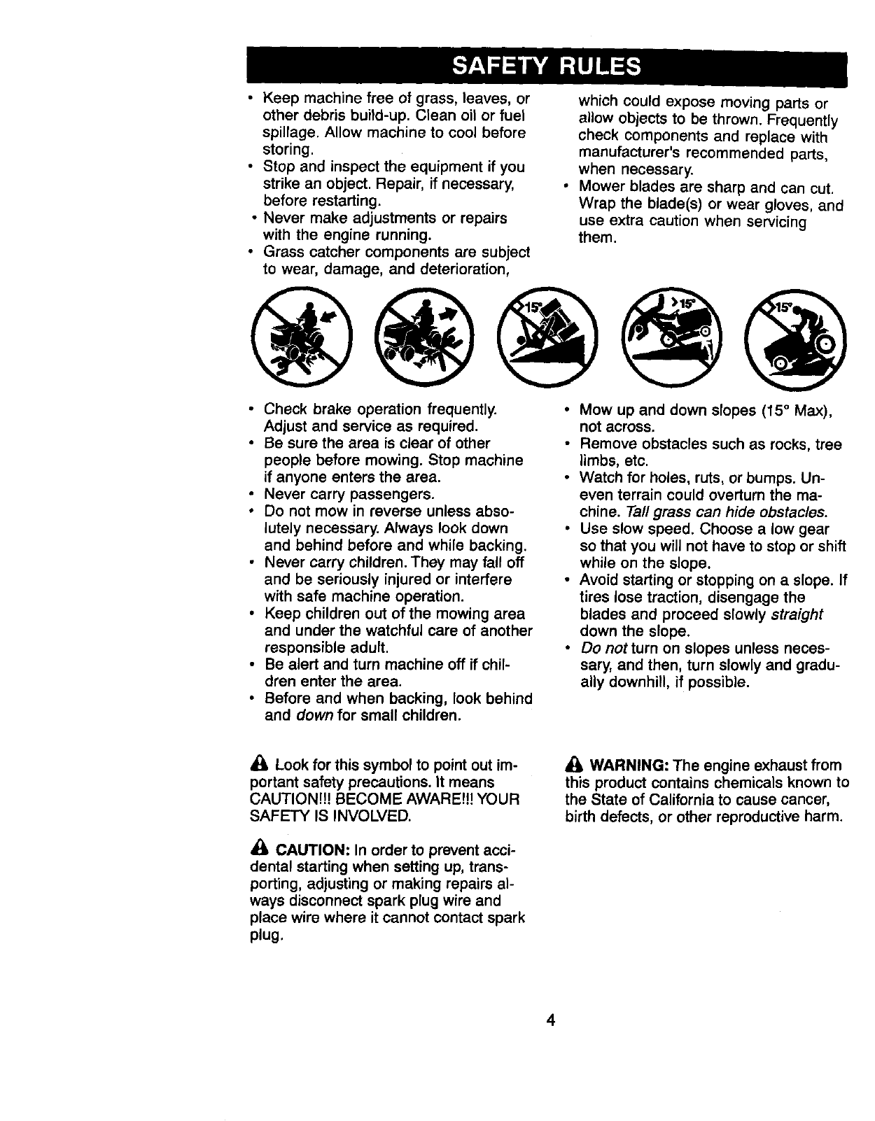
•Mow up and down slopes (15 °Max),
not across.
•Remove obstacles such as rocks, tree
limbs, etc.
•Watch for holes, ruts, or bumps. Un-
even terrain could overturn the ma-
chine. Tall grass can hide obstacles.
•Use slow speed. Choose a low gear
so that you will not have to stop or shift
while on the slope.
•Avoid starting or stopping on a slope. If
tires lose traction, disengage the
blades and proceed slowly straight
down the slope.
•Do not turn on slopes unless neces-
sary, and then, turn slowly and gradu-
ally downhill, if possible.
•k Look for this symbol to point out im-
portant safety precautions. It means
CAUTION!!! BECOME AWARE!N YOUR
SAFETY IS INVOLVED.
CAUTION: In order to prevent acci-
dental starting when setting up, trans-
porting, adjusting or making repairs al-
ways disconnect spark plug wire and
place wire where it cannot contact spark
plug,
WARNING: The engine exhaust from
this product contains chemicals known to
the State of California to cause cancer,
birth defects, or other reproductive harm.
4
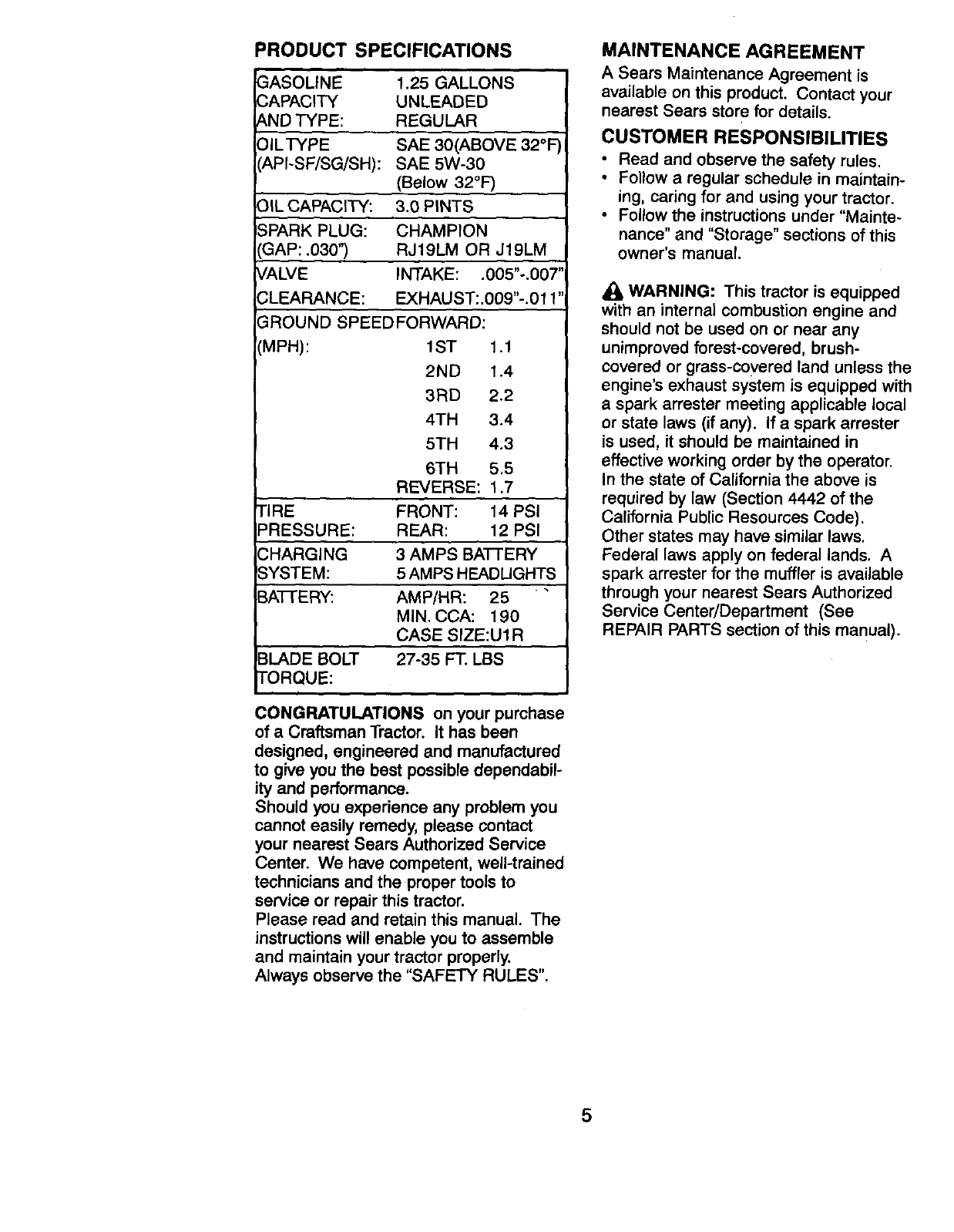
PRODUCT SPECIFICATIONS
GASOLINE
CAPACITY
AND TYPE:
OILTYPE
API-SF/SG/SH):
f .25 GALLONS
UNLEADED
REGULAR
SAE 30(ABOVE 32°F
SAE 5W-30
(Below 32°1=)
OIL CAPACITY: 3.0 PINTS
;PARK PLUG: CHAMPION
3AP: .030'_ RJ19LM OR J19LM
rALVE INTAKE: .005"-.007'
;LEARANCE: EXHAUST:.009"-.011'
"ROUND SPEEDFORWARD:
MPH): 1ST 1.1
2ND 1.4
3RD 2.2
4TH 3.4
5TH 4.3
6TH 5.5
REVERSE: 1.7
TIRE FRONT: 14 PSI
PRESSURE: REAR: 12 PSI
:HARGING 3 AMPS BAI-['ERY
IYSTEM: 5 AMPS HEADLIGHTS
BA-I-FE RY: AMP/HR: 25
MIN. CCA: 190
CASE SIZE:U1R
IBLADE BOLT 27-35 FT, LBS
rTORQUE:
L
CONGRATULATIONS on your purchase
of a Craftsman Tractor. It has been
designed, engineered and manufactured
to give you the best possible dependabil-
ity and performance.
Should you experience any problem you
cannot easily remedy, please contact
your nearest Sears Authorized Service
Center. We have competent, well-trained
technicians and the proper tools to
service or repair this tractor.
Please read and retain this manual. The
instructionswill enable you to assemble
and maintain your tractor properly.
Always observe the "SAFETY RULES".
MAINTENANCE AGREEMENT
A Sears Mamtenance Agreement is
available on this product. Contact your
nearest Sears store for details.
CUSTOMER RESPONSIBILITIES
•Read and observe the safety rules.
•Follow a regular schedule in maintain-
ing, caring for and using your tractor.
•Follow the instructions under "Mainte-
nance" and "Storage" sections of this
owner's manual.
,_ WARNING: This tractor is equipped
with an internal combustion engine and
should not be used on or near any
unimproved forest-covered, brush-
covered or grass-covered land unless the
engine's exhaust system is equipped with
a spark arrester meeting applicable local
or state laws (if any). If a spark arrester
is used, it should be maintained in
effective working order by the operator.
In the state of California the above is
required by law (Section 4442 of the
California Public Resources Code).
Other states may have similar laws.
Federal laws apply on federal lands. A
spark arrester for the muffler is available
through your nearest Sears Authorized
Service Center/Department (See
REPAIR PARTS section of this manual ).
5
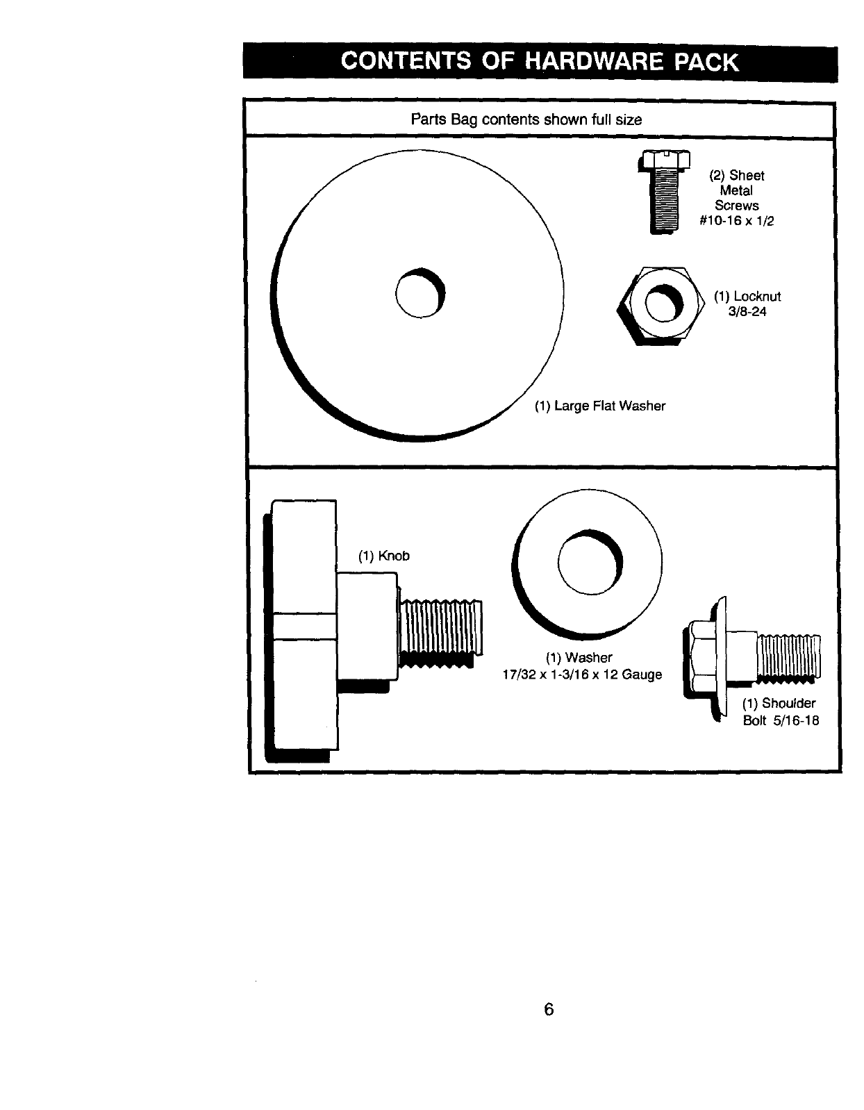
Parts Bag contents shown full size
(2) Sheet
Metal
Screws
#10-16 x 1/2
(1) Locknut
3/8-24
(1) Large Flat Washer
(1) Knob
(1) Washer
17/32 x 1-3/16 x 12 Gauge
(1) Shoulder
Bolt 5/16-18
6
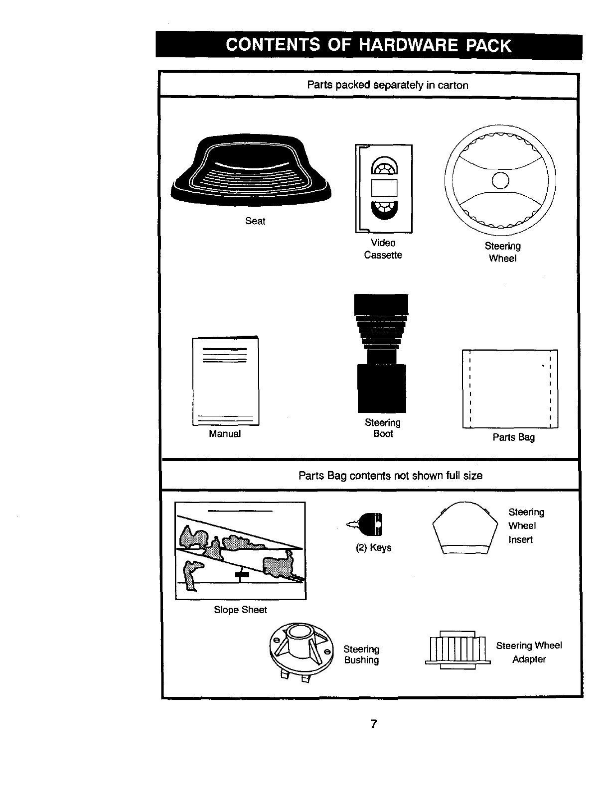
Parts packed separately in carton
Seat
v
Video
Cassette Steering
Wheel
I
m
Manual Steering
Boot , I
Parts Bag
Parts Bag contents not shown full size
(2) Keys Steering
Wheel
Insert
Slope Sheet 0Steering
Bushing Steering Wheel
, , Adapter
7
Your new tractor has been assembled at the factory with exception of those parts left
unassembled for shipping purposes. To ensure safe and proper operation of your
tractor all parts and hardware you assemble must be tightened securely. Use the
correct tools as necessary to insure proper tightness. Review the video cassette before
you begin.
TOOLS REQUIRED FOR
ASSEMBLY
A socket wrench set will make assembly
easier. Standard wrench sizes you need
are listed below.
(1) 9/16" wrench
(1) 1/2" wrench
(1) 5/16" wrench
(1) Phillips
Screwdriver
(1) Pliers
(1) Utility knife
(1) Tire pressure
gauge
When right or left hand is mentioned in
this manual, it means, from your point of
view, when you are in the operating
position (seated behind the steering
wheel).
TO REMOVETRACTOR FROM
CARTON
UNPACK CARTON
• Remove all accessible loose parts
and parts cartons from carton.
• Cut, from top to bottom, along lines on
all four corners of carton, and lay
panels flat.
•Check for any additional loose parts
or cartons and remove.
BEFORE ROLUNGTRACTOR OFF
SKID
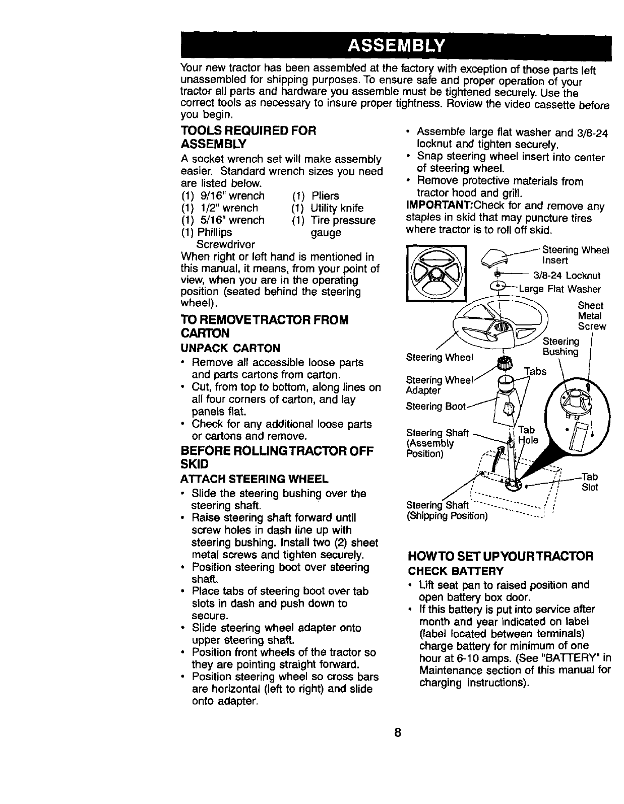
• Assemble large flat washer and 3/8-24
Iocknut and tighten securely.
• Snap steering wheel insert into center
of steering wheel.
• Remove protective materials from
tractor hood and grill.
IMPORTANT:Check for and remove any
staples in skid that may puncture tires
where tractor is to roll off skid.
I ._. I _Steering Wheel
Inse
!tJqL \l}l _3/8-24 Locknut
_'-Large Flat Washer
")/ Metal
Steerin_Wh_ SBtuesel_ingg
Tabs
Steering
Adapter
Steering
Steering
(Assembly
Position)
ATTACH STEERING WHEEL
• Slide the steering bushing over the
steering shaft.
•Raise steering shaft forward until
screw holes in dash line up with
steering bushing. Install two (2) sheet
metal screws and tighten securely.
• Position steering boot over steering
shaft.
• Place tabs of steering boot over tab
slots in dash and push down to
secure.
•Slide steering wheel adapter onto
upper steering shaft.
• Position front wheels of the tractor so
they are pointing straight forward.
• Position steering wheel so cross bars
are horizontal (left to right) and slide
onto adapter.
;,f
"'-. n f
• --.. ;i
Steenng Shaft ......... -..... ( ;
(Shipping Position) ......... '
Slot
HOWTO SET UPYOUR TRACTOR
CHECK BATTERY
•Lift seat pan to raised position and
open battery box door.
•If this battery is put into service after
month and year indicated on label
(label located between terminals)
charge battery for minimum of one
hour at 6-10 amps. (See "BATTERY" in
Maintenance section of this manual for
charging instructions).
8
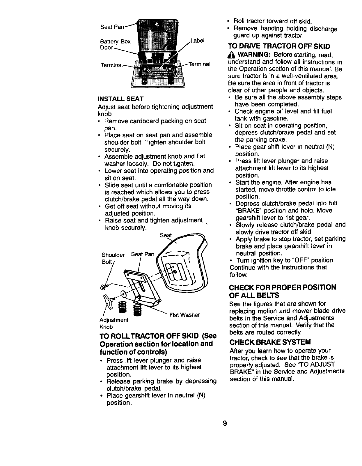
Seat
Battery Box Label
INSTALL SEAT
Adjust seat before tightening adjustment
knob.
• Remove cardboard packing on seat
pan.
•Place seat on seat pan and assemble
shoulder bolt. Tighten shoulder bolt
securely.
• Assemble adjustment knob and flat
washer loosely. Do not tighten.
• Lower seat into operating position and
sit on seat.
• Slide seat until a comfortable position
is reached which allows you to press
clutch/brake pedal all the way down.
•Get off seat without moving its
adjusted position.
• Raise seat and tighten adjustment •
knob securely.
Seat
Shoulder
Bolt
Flat Washer
Adjustment
Knob
TO ROLLTRACTOR OFF SKID (See
Operation section for location and
function of controls)
•Press lift lever plunger and raise
attachment lift lever to its highest
position.
•Release parking brake by depressing
clutch/brake pedal.
• Place gearshift lever in neutral (N)
position.
• Roll tractor forward off skid.
• Remove banding holding discharge
guard up against tractor.
TO DRIVE TRACTOR OFF SKID
•k, WARNING: Before starting, read,
understand and follow all instructions in
the Operation section of this manual. Be
sure tractor is in a well-ventilated area.
Be sure the area in front of tractor is
clear of other people and objects.
•Be sure all the above assembly steps
have been completed.
•Check engine oil level and fill fuel
tank with gasoline.
•Sit on seat in operating position,
depress crutch/brake pedal and set
the parking brake.
• Place gear shift lever in neutral (N)
position.
• Press lift lever plunger and raise
attachment lift lever to its highest
position.
• Start the engine. After engine has
started, move throttle control to idle
position.
• Depress clutch/brake pedal into full
"BRAKE" position and hold. Move
gearshift lever to 1st gear.
• Slowly release clutch/brake pedal and
slowly drive tractor off skid,
• Apply brake to stop tractor, set parking
brake and place gearshift lever in
neutral position.
• Turn ignition key to "OFF" position.
Continue with the instructions that
follow.
CHECK FOR PROPER POSITION
OF ALL BELTS
See the figures that are shown for
replacing motion and mower blade drive
belts in the Service and Adjustments
section ofthis manual. Verify that the
belts are routed correctly.
CHECKBRAKESYSTEM
After you learn how to operate your
tractor, check to see that the brake is
properly adjusted. See 'q'O ADJUST
BRAKE" in the Service and Adjustments
section of this manual.
9
CHECKTIREPRESSURE
The tires on your tractor were overin-
flated at the factory for shipping pur-
poses. Correct tire pressure is important
for best cutting performance.
•Reduce tire pressure to PSI shown in
"PRODUCT SPECIFICATIONS"
section of this manual.
CHECK DECK LEVELNESS
For best cutting results, mower housing
should be properly leveled. See "TO
LEVEL MOWER HOUSING" in the
Service and Adjustments section of this
manual.
,/'CHECKLIST
BEFOREYOU OPERATE AND ENJOY
YOUR NEW TRACTOR, WE WISH TO
ASSURE THAT YOU RECEIVE THE
BEST PERFORMANCE AND
SATISFACTION FROM THIS QUALITY
PRODUCT.
PLEASE REVIEW THE FOLLOWING
CHECKLIST:
,/All assembly instructions have been
completed.
,/No remaining loose parts in carton.
,/Battery is properly prepared and
charged. (Minimum 1 hour at 6
amps).
,/Seat is adjusted comfortably and
tightened securely.
•/All tires are properly inflated. (For
shipping purposes, the tires were
overinflated at the factory).
,/Be sure mower deck is properly
leveled side-to-side/front-to-rear for
best cutting results. (Tires must be
properly inflated for leveling).
,/Check mower and drive belts. Be sure
they are routed properly around pulleys
and inside all belt keepers.
,/Check wiring. See that all connections
are still secure and wires are properly
clamped.
WHILE LEARNING HOW TO USE YOUR
TRACTOR, PAY EXTRA A'I-I'ENTION TO
THE FOLLOWING IMPORTANT ITEMS:
,/Engine oil is at proper level.
,/Fuel tank is filled with fresh, clean,
regular unleaded gasoline.
,/Become familiar with all controls - their
location and function. Operate them
before you start the engine.
,/Be sure brake system is in safe
operating condition.
10
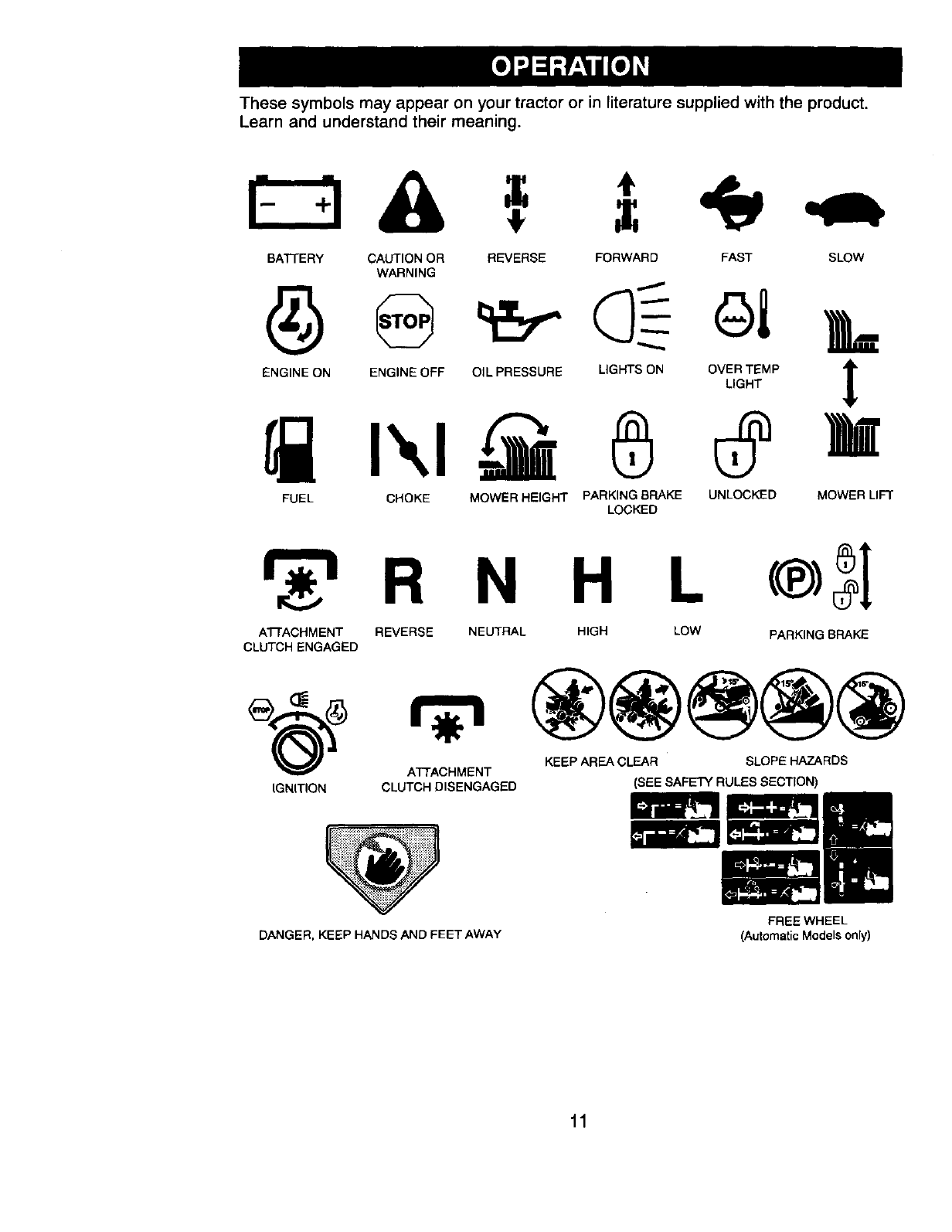
These symbols may appear on your tractor or in literature supplied with the product.
Learn and understand their meaning.
BATTERY CAUTION OR
WARNING
ENGINE ON ENGINE OFF
REVERSE FORWARD FAST SLOW
OIL PRESSURE
FUEL CHOKE MOWER HEIGHT
LIGHTS ON
PARKING BRAKE
LOCKED
OVER TEMP I
LIGHT
UNLOCKED MOWER LIFT
R N H L
A1-FACHMENT REVERSE NEUTRAL HIGH LOW PARKING BRAKE
CLUTCH ENGAGED
KEEP AREA CLEAR SLOPE HAZARDS
ATTACHMENT
IGNITION CLUTCH DISENGAGED
DANGER, KEEP HANDS AND FEET AWAY
(SEE SAFETY RULES SECTION)
FREE WHEEL
(Automatic Models only)
11
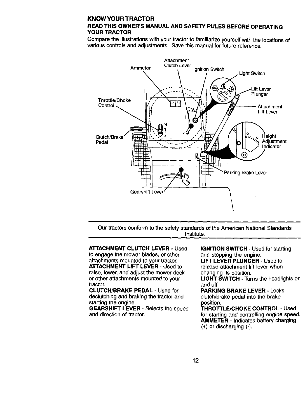
KNOWYOUR TRACTOR
READ THIS OWNER'S MANUAL AND SAFETY RULES BEFORE OPERATING
YOUR TRACTOR
Compare the illustrations with your tractor to familiarize yourself with the locations of
various controls and adjustments. Save this manual for future reference.
Ammeter
Attachment
Clutch Lever Ignition Switch
Throttle/Choke
Control
Lever
Plunger
Attachment
Lift Lever
Pedal Height
Adjustment
Indicator
Brake Lever
Gearshift Lever
Our tractors conform to the safety standards of the American National Standards
Institute.
ATTACHMENT CLUTCH LEVER oUsed
to engage the mower blades, or other
attachments mounted to your tractor.
ATTACHMENT LIFT LEVER -Used to
raise, lower, and adjust the mower deck
or other attachments mounted to your
tractor.
CLUTCH/BRAKE PEDAL -Used for
declutching and braking the tractor and
starting the engine.
GEARSHIFT LEVER -Selects the speed
and direction of tractor.
IGNITION SWITCH - Used for starting
and stopping the engine.
LIFT LEVER PLUNGER - Used to
release attachment lift lever when
changing its position.
LIGHT SWITCH -Turns the headlights on
and off.
PARKING BRAKE LEVER - Locks
clutch/brake pedal into the brake
position.
THRO'n'LE/CHOKE CONTROL - Used
for starting and controlling engine speed.
AMMETER - Indicates battery charging
(+) or discharging (-).
12
The operation of any tractor can result in foreign objects thrown into
the eyes, which can result in severe eye damage. Always wear safety
glasses or eye shields while operating your tractor or performing any
adjustments or repairs. We recommend a wide vision safety mask
over spectacles or standard safety glasses.
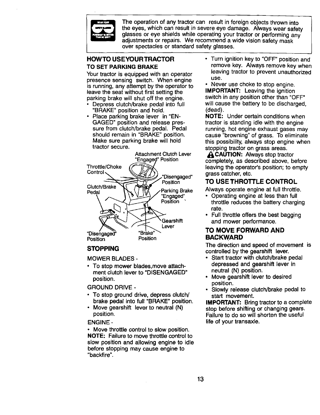
HOWTO USEYOURTRACTOR
TO SET PARKING BRAKE
Your tractor is equipped with an operator
presence sensing switch. When engine
is running, any attempt by the operator to
leave the seat without first setting the
parking brake will shut off the engine.
• Depress clutch/brake pedal into full
"BRAKE" position and hold.
• Place parking brake lever in "EN-
GAGED" position and release pres-
sure from clutch/brake pedal. Pedal
should remain in "BRAKE" position.
Make sure parking brake will hold
tractor secure.
Attachment Clutch Lever
"Position
Throttle/Choke
Pedal
Position
Brake
"Engaged"
Position •
Lever
"Disengaged"
Position Position
STOPPING
MOWER BLADES -
•To stop mower blades,move attach-
ment clutch lever to "DISENGAGED"
position.
GROUND DRIVE-
• To stop ground drive, depress clutch/
brake pedal into full "BRAKE" position.
•Move gearshift lever to neutral (N)
position.
ENGINE-
•Move throttle control to slow position.
NOTE: Failure to move throttle control to
slow position and allowing engine to idle
before stopping may cause engine to
"backfire".
• Turn ignition key to "OFF" position and
remove key. Always remove key when
leaving tractor to prevent unauthorized
use.
•Never use choke to stop engine.
IMPORTANT: Leaving the ignition
switch in any position other than "OFF"
will cause the battery to be discharged,
(dead).
NOTE: Under certain conditions when
tractor is standing idle with the engine
running, hot engine exhaust gases may
cause "browning" of grass. To eliminate
this possibility, always stop engine when
stopping tractor on grass areas.
_iCAUTION: Always stop tractor
completely, as described above, before
leaving the operator's position; to empty
grass catcher, etc.
TO USE THROTTLE CONTROL
Always operate engine at full throttle.
•Operating engine at less than full
throttle reduces the battery charging
rate.
• Full throttle offers the best bagg!ng
and mower performance.
TO MOVE FORWARD AND
BACKWARD
The direction and speed of movement is
controlled by the gearshift lever.
•Start tractor with clutch/brake pedal
depressed and gearshift lever in
neutral (N) position,
•Move gearshift lever to desired
position.
•Slowly release clutch/brake pedal to
start movement.
IMPORTANT: Bring tractor to a complete
stop before shifting or changing gears.
Failure to do so will shorten the useful
life of your transaxle.
13
TO ADJUST MOWER CUTTING
HEIGHT
The position of the attachment lift lever
determines the cutting height.
•Grasp lift lever.
• Press plunger with thumb and move
lever to desired position.
The cutting height range is approxi-
mately 1-1/2 to 4". The heights are
measured from the ground to the blade
tip with the engine not running. These
heights are approximate and may vary
depending upon soil conditions, height
of grass and types of grass being
mowed.
•The average lawn should be cut to
approximately 2-1/2 inches during the
cool season and to over 3 inches
during hot months. For healthier and
better looking lawns, mow often and
after moderate growth.
• For best cutting performance, grass
over 6 inches in height should be
mowed twice. Make the first cut
relatively high; the second to desired
height.
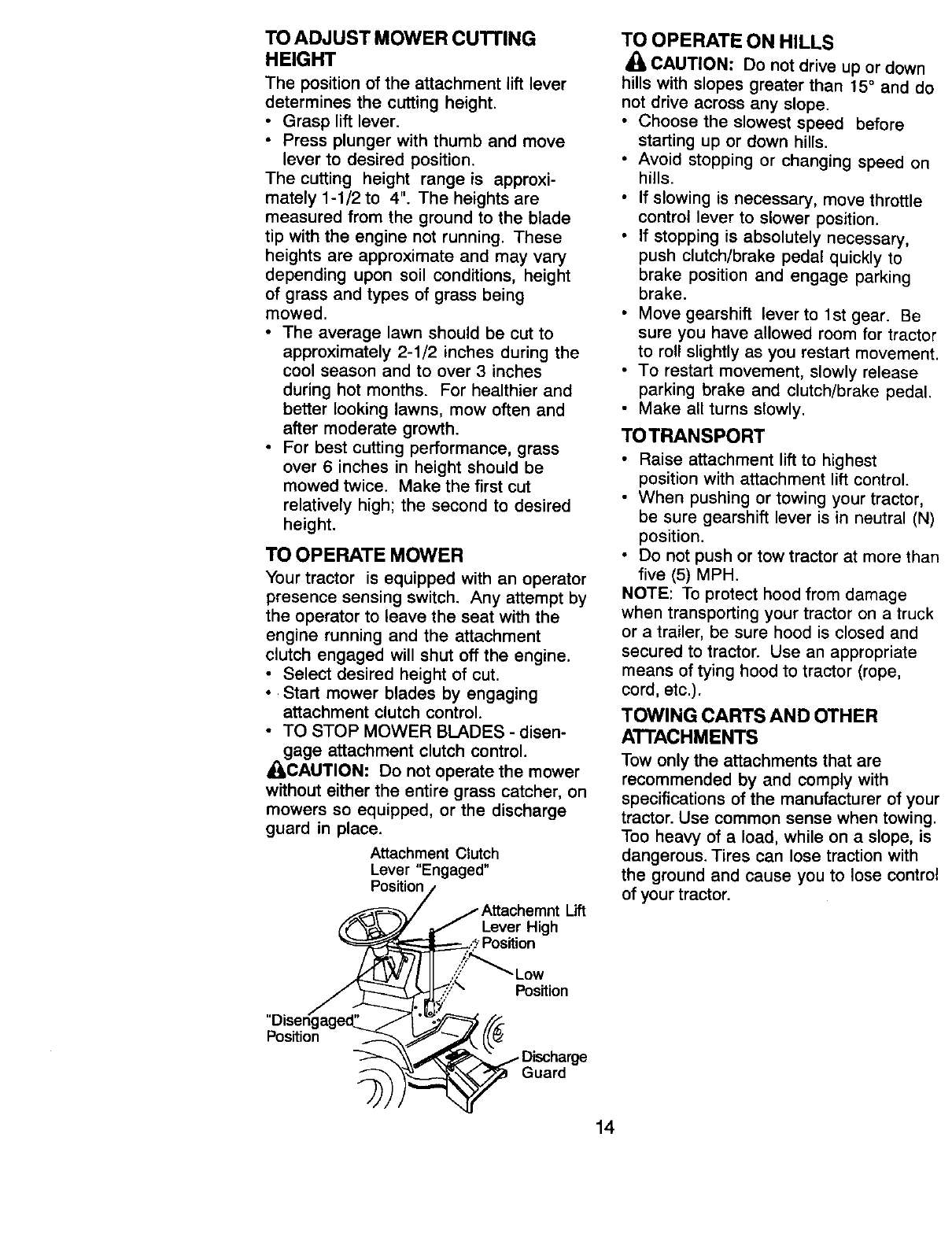
TO OPERATE MOWER
Your tractor is equipped with an operator
presence sensing switch. Any attempt by
the operator to leave the seat with the
engine running and the attachment
clutch engaged will shut off the engine.
• Select desired height of cut.
•Start mower blades by engaging
attachment clutch control.
•TO STOP MOWER BLADES - disen-
gage attachment clutch control.
_,CAUTION: Do not operate the mower
without either the entire grass catcher, on
mowers so equipped, or the discharge
guard in place.
Attachment Clutch
Lever "Engaged"
Position/
., / .-- Attachemnt Lift
_ _ Lever High
_Position
l ,.':':!:"_'_ Low
z_u,._d_,.::,_ Position
'pDo_ingage _ "__j Discharge
14
TO OPERATE ON HILLS
CAUTION: Do not drive up or down
hills with slopes greater than 15° and do
not drive across any slope.
•Choose the slowest speed before
starting up or down hills.
•Avoid stopping or changing speed on
hills.
•If slowing is necessary, move throttle
control lever to slower position.
•If stopping is absolutely necessary,
push clutch/brake pedal quickly to
brake position and engage parking
brake.
•Move gearshift lever to 1st gear. Be
sure you have allowed room for tractor
to roll slightly as you restart movement,
•To restart movement, slowly release
parking brake and clutch/brake pedal.
• Make all turns slowly.
TO TRANSPORT
• Raise attachment lift to highest
position with attachment lift control.
• When pushing or towing your tractor,
be sure gearshift lever is in neutral (N)
position.
• Do not push or tow tractor at more than
five (5) MPH.
NOTE: To protect hood from damage
when transporting your tractor on a truck
or a trailer, be sure hood is closed and
secured to tractor. Use an appropriate
means of tying hood to tractor (rope,
cord, etc.).
TOWING CARTS AND OTHER
ATTACHMENTS
Tow only the attachments that are
recommended by and comply with
specifications of the manufacturer of your
tractor. Use common sense when towing.
Too heavy of a load, while on a slope, is
dangerous. Tires can lose traction with
the ground and cause you to lose control
of your tractor.
BEFORE STARTINGTHE ENIGNE
CHECK ENGINE OIL LEVEL
• The engine in your tractor has been
shipped, from the factory, already filled
with summer weight oil.
• Check engine oil with tractor on level
ground.
• Remove oil fill cap/dipstick and wipe
clean, reinsert the dipstick and screw
cap tight, wait for a few seconds,
remove and read oil level. If neces-
sary, add oil until "FULL" mark on
dipstick is reached. Do not overfill.
• For cold weather operation you should
change oil for easier starting (See "OIL
VISCOSITY CHART" in the Mainte-
nance section of this manual).
• To change engine oil, see the Mainte-
nance section in this manual.
ADDGASOLINE
• Fill fuel tank. Use fresh, clean, regular
unleaded gasoline with a minimum of
87 octane. (Use of leaded gasoline
will increase carbon and lead oxide
deposits and reduce valve life). Do
not mix oil with gasoline. Purchase
fuel in quantities that can be used
within 30 days to assure fuel fresh-
ness.
IMPORTANT: When operating in
temperatures below 32°F(0°C), use
fresh, clean winter grade gasoline to
help insure good cold weather starting.
_l WARNING: Experience indicates that
alcohol blended fuels (called gasohol or
using ethanol or methanol) can attract
moisture which leads to separation and
formation of acids during storage. Acidic
gas can damage the fuel system of an
engine while in storage. To avoid engine
problems, the fuel system should be
emptied before storage of 30 days or
longer. Drain the gas tank, start the
engine and let it run until the fuel lines
and carburetor are empty. Use fresh fuel
next season. See Storage Instructions
for additional information. Never use
engine or carburetor cleaner products in
the fue! tank or permanent damage may
occur.
A_LCAUTION: Fill to bottom of gas tank
filler neck. Do not overfill. Wipe off any
spilled oil or fuel. Do not store, spill or
use gasoline near an open flame.
TO START ENGINE
When starting the engine for the first time
or if the engine has run out of fuel, it will
take extra cranking time to move fuel
from the tank to the engine.
• Sit on seat in operating position,
depress clutch/brake pedal and set
parking brake.
• Place gear shift lever in neutral (N)
position.
•Move attachment clutch to "DISEN-
GAGED" position.
• Move throttle control to choke position.
NOTE: Before starting, read the warm
and cold starting procedures below.
• Insert key into ignition and turn key
clockwise to "START" position and
release key as soon as engine starts.
Do not run starter continuously for
more than fifteen seconds per minute.
If the engine does not start after
several attempts, move throttle control
to fast position, wait a few minutes and
try again. If engine still does not start,
move the throttle control back to the
choke position and retry.
WARM WEATHER STARTING (50 °F and
above)
• When engine starts, move the throttle
control to the fast position.
• The attachments and ground drive can
now be used. If the engine does not
accept the load, restart the engine and
allow it to warm up for one minute
using the choke as described above.
COLD WEATHER STARTING ( 50 ° F and
below)
•When engine starts, allow engine to
run with the throttle control in the
choke position until the engine runs
roughly, then move throttle control to
fast position. This may require an
engine warm-up period from several
seconds to several minutes, depend-
ing On the temperature.
•The attachments can also be used
during the engine warm-up period.
NOTE: If at a high altitude (above 3000
feet) or in cold temperatures (below 32
F) the carburetor fuel mixture may need
to be adjusted for best engine perfor-
mance. See "TO ADJUST CARBURE-
TOR" in the Service and Adjustments
section of this manuat.
15
MOWlNGTIPS
•Tire chains cannot be used when the
mower housing is attached to tractor.
•Mower should be properly leveled for
best mowing performance. ,See 'TO
LEVEL MOWER HOUSING in the
Service and Adjustments section of
this manual.
• The left hand side of mower should be
used for trimming.
• Drive so that clippings are discharged
onto the area that has been cut. Have
the cut area to the right of the tractor.
This will result in a more even distribu-
tion of clippings and more uniform
cutting.
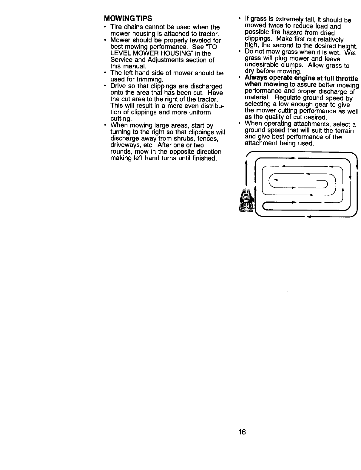
•When mowing large areas, start by
turning to the right so that clippings will
discharge away from shrubs, fences,
driveways, etc. After one or two
rounds, mow in the opposite direction
making left hand turns until finished.
• If grass is extremely tall, it should be
mowed twice to reduce load and
possible fire hazard from dried
clippings. Make first cut relatively
high; the second to the desired height.
• Do not mow grass when it is wet. Wet
grass will plug mower and leave
undesirable clumps. Allow grass to
dry before mowing.
•Always operate engine at full throttle
when mowing to assure better mowing
performance and proper discharge of
material. Regulate ground speed by
selecting alow enough gear to give
the mower cutting performance as well
as the quality of cut desired.
•When operating attachments, select a
ground speed that will suit the terrain
and give best performance of the
attachment being used.
16
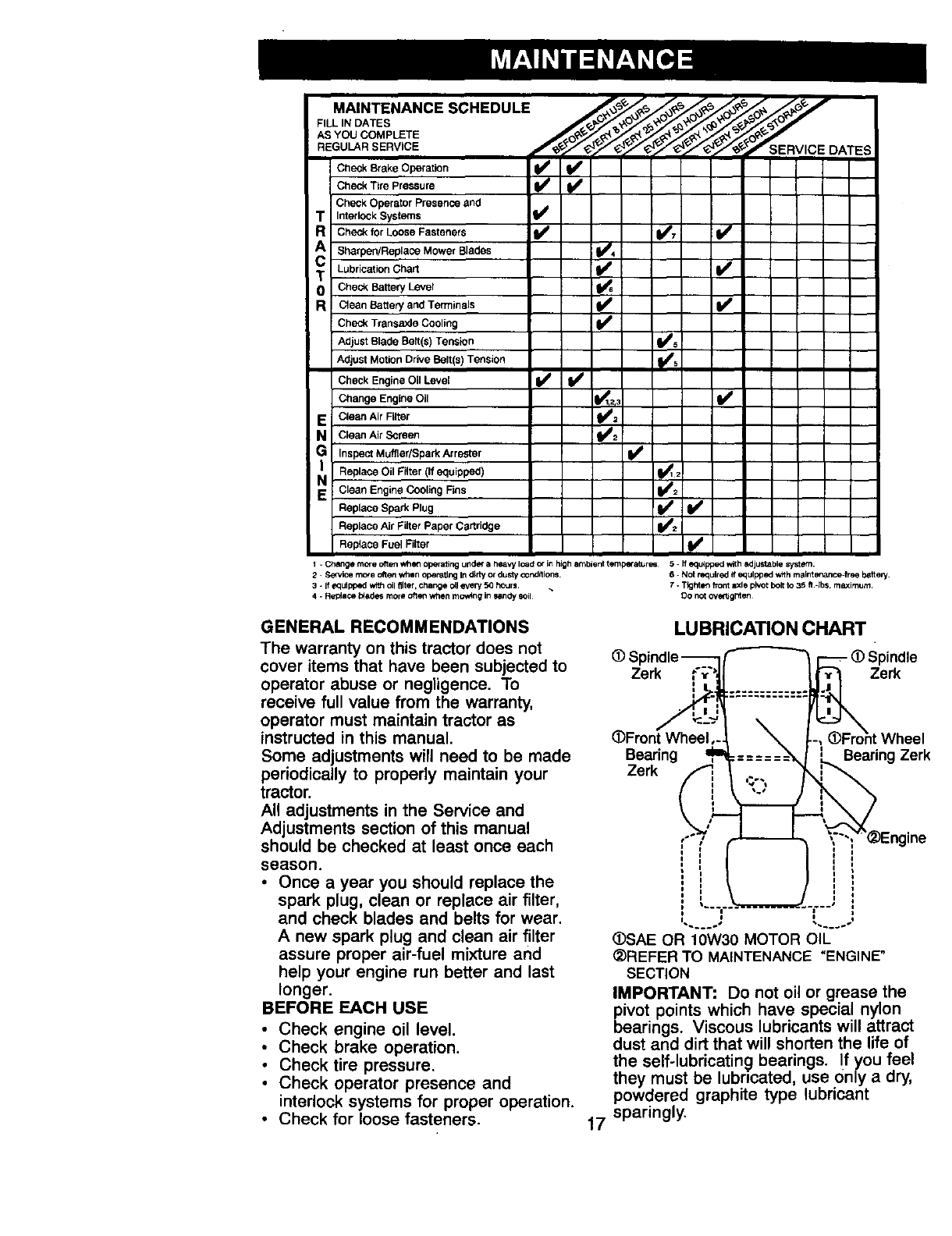
MAINTENANCE SCHEDULE ____
_'_ ._ '_ _. _ _'-'_ DATES
//////
Check Brake Operation _
Check Tire Pressure
Check Operator Presence and
TInterlock Systems I_
RCheck for Loose Fasteners I_ 1_7 I1_
cA Sharpen!Replace Mower Blades i4
T Lubrication Chart I_
0Check Battery Level
RClean Batlery and Terminals I_
Check Transaxle Cooling I_
Adjust Blade Bert(s] Tension I_s
1,',
Adjust Motion Drive Belt(s) Tension
Check Engine Oil Level I_ Ii_
Change Engine Oil I_12,3 I_
E Clean Air Filter _1_=
Nc_e_ Air Screen _2
G Inspect Muffler/Spark Ar rester I_
Replace Oil Filter (If equipped) I_1;
N Clean Engine Cooling Nns _/d2
Replace Spark Plug I_
Replace Air Filter Paper Cartridge
Replace Fuel Filter I I1_
l-ChangemcreoftenwhenoperatingurlderaheavyloedOrinh_ghambienttem_r_ 5 ffequlppedwithsdjustablesystem
2-Semite more o_en when operating Ind_ny or dusty oondltions. 6 - Not required if equipped wffhm_int 6P,_nce=freebsttery.
3 - If equipped w;_ oilfilter, change c_leveP/50 h_Jrl. 7 - Tighten front axle pivot bolt to 35 ft -Ibs. maximum¸
4 - Repie_ t_adt_ more often when moving in P*sndySOil¸ DO not ove_g_en
GENERAL RECOMMENDATIONS
The warranty on this tractor does not
cover items that have been subjected to
operator abuse or negligence. To
receive full value from the warranty,
operator must maintain tractor as
instructed in this manual.
Some adjustments will need to be made
periodically to properly maintain your
tractor.
All adjustments in the Service and
Adjustments section of this manual
should be checked at least once each
season.
•Once a year you should replace the
spark plug, clean or replace air filter,
and check blades and belts for wear.
Anew spark plug and clean air filter
assure proper air-fuel mixture and
help your engine run better and last
longer.
BEFORE EACH USE
• Check engine oil level.
• Check brake operation.
•Check tire pressure.
•Check operator presence and
interlock systems for proper operation.
•Check for loose fasteners.
LUBRICATION CHART
Spindle
Ze,
(DFron[ Wheel,-.
Bearin ,rib
Zerk
,-.-
I
............. _Zerk
:== iBearing Zerk
¢'°" "T" ngine
i
i
_SAE OR 10W30 MOTOR OIL
_)REFER TO MAINTENANCE "ENGINE"
SECTION
IMPORTANT: Do not oil or grease the
pivot points which have special nylon
bearings. Viscous lubricants will attract
dust and dirt that will shorten the life of
the self-lubricatin_ bearings. If you feel
they must be lubricated, use 0nly a dry,
powdered graphite type lubricant
17 sparingly.
TRACTOR
Always observe safety rules when
performing any maintenance.
BRAKE OPERATION
If tractor requires more than six (6) feet
stopping distance at high speed in
highest gear, then brake must be
adjusted. (See "TO ADJUST BRAKE" in
the Service and Adjustments section of
this manual).
TIRES
•Maintain proper air pressure in all tires
(See "PRODUCT SPECIFICATIONS"
section of this manual).
• Keep tires free of gasoline, oil, or
insect control chemicals which can
harm rubber.
• Avoid stumps, stones, deep ruts, sharp
objects and other hazards that may
cause tire damage.
NOTE: To seal tire punctures and
prevent flat tires due to slow leaks, tire
sealant may be purchased from your
local parts dealer. Tire sealant also
prevents tire dry rot and corrosion.
OPERATOR PRESENCE SYSTEM
Be sure operator presence and interlock
systems are working properly. If your
tractor does not function as described,
repair the problem immediately.
• The engine should not start unless the
clutch/brake pedal is fully depressed
and attachement clutch control is in
the disengaged position.
• When the engine is running, any
attempt by the operator to leave the
seat without first setting the parking
brake should shut off the engine.
•When the engine is running and the
attachment clutch is engaged, any
attempt by the operator to leave the
seat should shut off the engine.
• The attachment clutch should never
operate unless the operator is in the
seat.
BLADE CARE
For best results mower blades must be
kept sharp. Replace bent or damaged
blades.
BLADE REMOVAL
Raise mower to highest position to
allow access to blades.
•Remove hex bolt, lock washer and flat
washer securing blade.
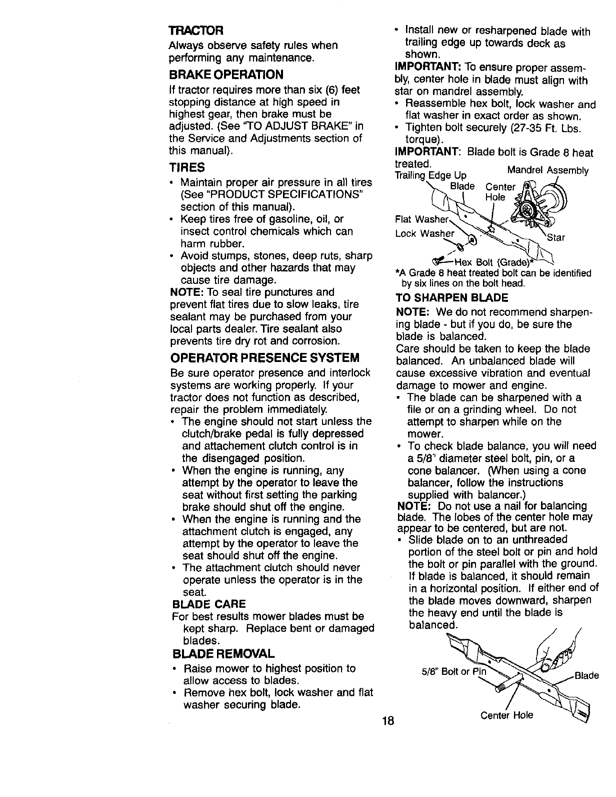
• Install new or resharpened blade with
trailing edge up towards deck as
shown.
IMPORTANT: To ensure proper assem-
bly, center hole in blade must align with
star on mandrel assembly.
• Reassemble hex bolt, lock washer and
flat washer in exact order as shown.
• Tighten bolt securely (27-35 Ft. Lbs.
torque).
IMPORTANT: Blade bolt is Grade 8 heat
treated.
Trailing Edge Up Mandrel Assembly
Blade Center
Hole
Flat Washer
Lock Washer
• _---Hex Bolt (Grade)
•A Grade 8heat treated bolt can be identified
by six lines on the bolt head.
TO SHARPEN BLADE
18
NOTE: We do not recommend sharpen-
ing blade - but if you do, be sure the
blade is balanced.
Care should be taken to keep the blade
balanced. An unbalanced blade will
cause excessive vibration and eventual
damage to mower and engine.
•The blade can be sharpened with a
file or on a grinding wheel. Do not
attempt to sharpen while on the
mower.
• To check blade balance, you will need
a 5/8' diameter steel bolt, pin, or a
cone balancer. (When using a cone
balancer, follow the instructions
supplied with balancer.)
NOTE: Do not use a nail for balancing
blade. The lobes of the center hole may
appear to be centered, but are not.
• Slide blade on to an unthreaded
portion of the steel bolt or pin and hold
the bolt or pin parallel with the ground.
If blade is balanced, it should remain
in a horizontal position. If either end of
the blade moves downward, sharpen
the heavy end until the blade is
balanced.
5/8" _ade
Center Hole _/
BATrERY
Your tractor has abattery charging
system which is sufficient for normal use.
However, periodic charging of the battery
with an automotive charger will extend
its life.
•Keep battery and terminals clean.
•Keep battery bolts tight.
• Keep small vent holes open.
•Recharge at 6-10 amperes for 1 hour.
NOTE: The original equipment battery on
your tractor is maintenance free. Do not
attempt to open or remove caps or
covers. Adding or checking level of
electrolyte is not necessary.
TO CLEAN BAI-FERY AND TERMINALS
Corrosion and dirt on the battery and
terminals can cause the battery to "leak"
power.
•Open battery box door.
• Disconnect BLACK battery cable first
then RED battery cable and remove
battery from tractor.
Rinse the battery with plain water and
dry.
• Clean terminals and battery cable
ends with wire brush until bright.
• Coat terminals with grease or petro-
leum jelly.
• Reinstall battery (See "REPLACING
BA-I-FERY" in the SERVICE AND
ADJUSTMENTS section of this
manual).
V-BELTS
Check V-belts for deterioration and wear
after 100 hours of operation and replace
if necessary. The belts are not adjustable.
Replace belts if they begin to slip from
wear.
TRANSAXLE COOLING
Keep transaxle free from build-up of dirt
and chaff which can restrict cooling.
ENGINE
LU BRICATION
Only use high quality detergent oil rated
with API service classification SF, SG, or
SH. Select the oil's SAE viscosity grade
according to your expected operating
temperature.
NOTE: Although multi-viscosity oils
(5W30, 10W30 etc.) improve starting in
cold weather, these multi-viscosity oils
will result in increased oil consumption
when used above 32°E Check your
engine oil level more frequently to avoid
possible engine damage from running
low on oil.
Change the oil after every 25 hours of
operation or at least once a year if the
tractor is not used for 25 hours in one
year.
Check the crankcase oil level before
starting the engine and after each eight
(8) hours of operation. Tighten oil fill cap/
dipstick securely each time you check
the oil level.
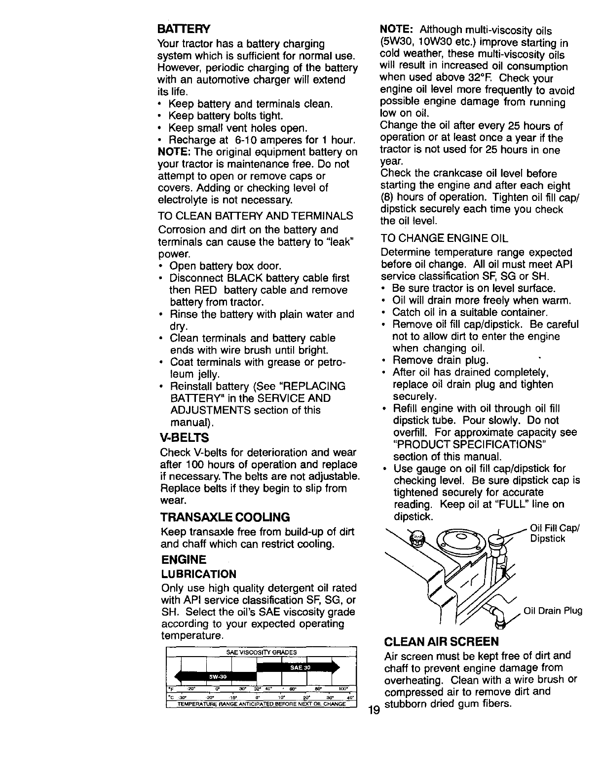
TO CHANGE ENGINE OIL
Determine temperature range expected
before oil change. All oil must meet API
service classification SF, SG or SH.
• Be sure tractor is on level surface.
• Oil will drain more freely when warm.
• Catch oil in a suitable container.
• Remove oil fill cap/dipstick. Be careful
not to allow dirt to enter the engine
when changing oil.
• Remove drain plug.
• After oil has drained completely,
replace oil drain plug and tighten
securely.
•Refill engine with oil through oil fill
dipstick tube. Pour slowly. Do not
overfill. For approximate capacity see
"PRODUCT SPECIFICATIONS"
section of this manual.
• Use gauge on oil fill cap/dipstick for
checking level. Be sure dipstick cap is
tightened securely for accurate
Keep oil at "FULL" line onreading.
dipstick.
(
Oil Fill Cap/
Dipstick
Oil Drain Plug
CLEAN AIR SCREEN
Air screen must be kept free of dirt and
chaff to prevent engine damage from
overheating. Clean with a wire brush or
compressed air to remove dirt and
19 stubborn dried gum fibers,
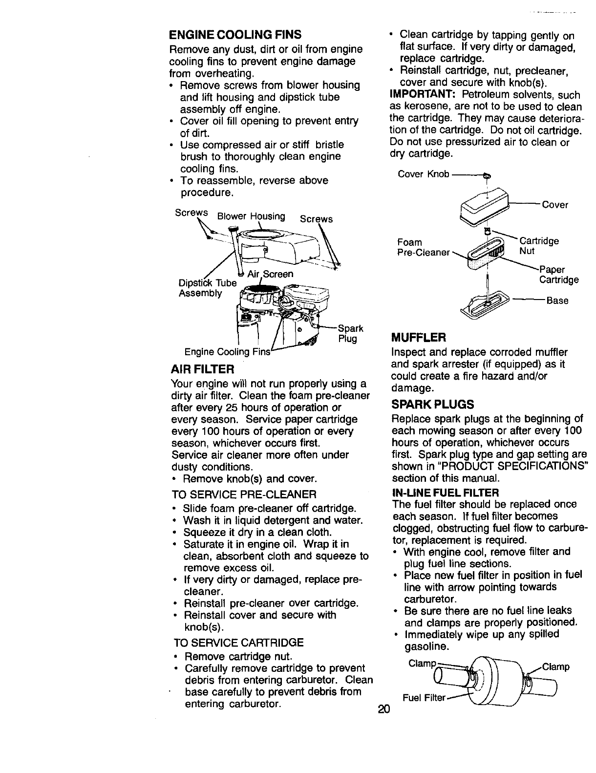
ENGINE COOLING FINS
Remove any dust, dirt or oil from engine
cooling fins to prevent engine damage
from overheating.
•Remove screws from blower housing
and lift housing and dipstick tube
assembly off engine.
•Cover oil fill opening to prevent entry
of dirt.
• Use compressed air or stiff bristle
brush to thoroughly clean engine
cooling fins.
• To reassemble, reverse above
procedure.
Screws Blower Housing Screws
Dipstick Tube
Assembly
Plug
Engine Cooling
AIR FILTER
Your engine will not run properly using a
dirty air filter. Clean the foam pre-cleaner
after every 25 hours of operation or
every season. Service paper cartridge
every 100 hours of operation or every
season, whichever occurs first.
Service air cleaner more often under
dusty conditions.
• Remove knob(s) and cover.
TO SERVICE PRE-CLEANER
•Slide foam pre-cleaner off cartridge.
•Wash it in liquid detergent and water.
• Squeeze it dry in a clean cloth.
• Saturate it in engine oil. Wrap it in
clean, absorbent cloth and squeeze to
remove excess oil.
• If very dirty or damaged, replace pre-
cleaner.
•Reinstall pre-cleaner over cartridge.
• Reinstall cover and secure with
knob(s).
TO SERVICE CARTRIDGE
• Remove cartridge nut.
• Carefully remove cartridge to prevent
debris from entering carburetor. Clean
base carefully to prevent debris from
entering carburetor.
• Clean cartridge by tapping gently on
flat surface. If very dirty or damaged,
replace cartridge.
• Reinstall cartridge, nut, precleaner,
cover and secure with knob(s).
IMPORTANT: Petroleum solvents, such
as kerosene, are not to be used to clean
the cartridge. They may cause deteriora-
tion of the cartridge. Do not oil cartridge.
Do not use pressurized air to clean or
dry cartridge.
Cover Knob
_Cover
Foam _-_---_ Cartridge
Pre-Cleaner _ut
_ _-Paper
Cartridge
-- Base
20
MUFFLER
Inspect and replace corroded muffler
and spark arrester (if equipped) as it
could create a fire hazard and/or
damage.
SPARK PLUGS
Replace spark plugs at the beginning of
each mowing season or after every 100
hours of operation, whichever occurs
first. Spark plug type and gap setting are
shown in "PRODUCT SPECIFICATIONS"
section of this manual.
IN-MNE FUEL FILTER
The fuel filter should be replaced once
each season. If fuel filter becomes
clogged, obstructing fuel flow to carbure-
tor, replacement is required.
•With engine cool, remove filter and
plug fuel line sections.
• Place new fuel filter in position in fuel
line with arrow pointing towards
carburetor.
• Be sure there are no fuel line leaks
and clamps are properly positioned.
•Immediately wipe up any spilled
gasoline.
Clamp_amp
Fuel Fliter _'"_.____
CLEANING
i Clean engine, battery, seat, finish, etc.
of all foreign matter.
Keep finished surfaces and wheels
free of all gasoline, oil, etc.
• Protect painted surfaces with automo-
tive type wax.
We do not recommend using a garden
hose to clean your tractor unless the
electrical system, muffler, air filter and
carburetor are covered to keep water out.
Water in engine can result in a short-
ened engine life.
_CAUTION: Before performing any service or adjustments:
•Depress clutch/brake pedal fully and set parking brake.
Place gearshift lever in neutral (N) position.,,
•Place attachment clutch in "DISENGAGED position.
Turn ignition key "OFF" and remove key.
Make sure the blades and aJi moving parts have completely stopped.
• Disconnect spark plug wire from spark plug and place wire where it cannot
come in contact with plug.
TRACTOR
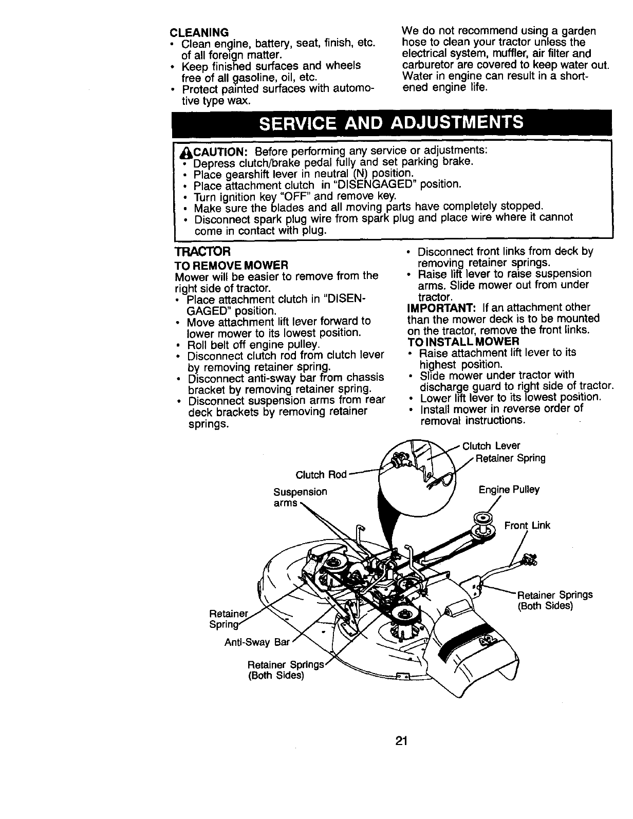
TO REMOVE MOWER
Mower will be easier to remove from the
right side of tractor.
•Place attachment clutch in "DISEN-
GAGED" position.
• Move attachment lift lever forward to
lower mower to its lowest position.
Roll belt off engine pulley.
Disconnect clutch rod from clutch lever
by removing retainer spring.
• Disconnect anti-sway bar from chassis
bracket by removing retainer spring.
• Disconnect suspension arms from rear
deck brackets by removing retainer
springs.
• Disconnect front links from deck by
removing retainer springs.
• Raise lift lever to raise suspension
arms. Slide mower out from under
tractor.
IMPORTANT: If an attachment other
than the mower deck is to be mounted
on the tractor, remove the front links.
TO INSTALL MOWER
• Raise attachment lift lever to its
highest position.
• Slide mower under tractor with
discharge guard to right side of tractor
Lower lift lever to its lowest position.
Install mower in reverse order of
removal instructions.
Lever
Clutch
Suspension
Front Link
Retainer Springs
(Both Sides)
Anti-Sway
Retainer Springs
(Both Sides)
21
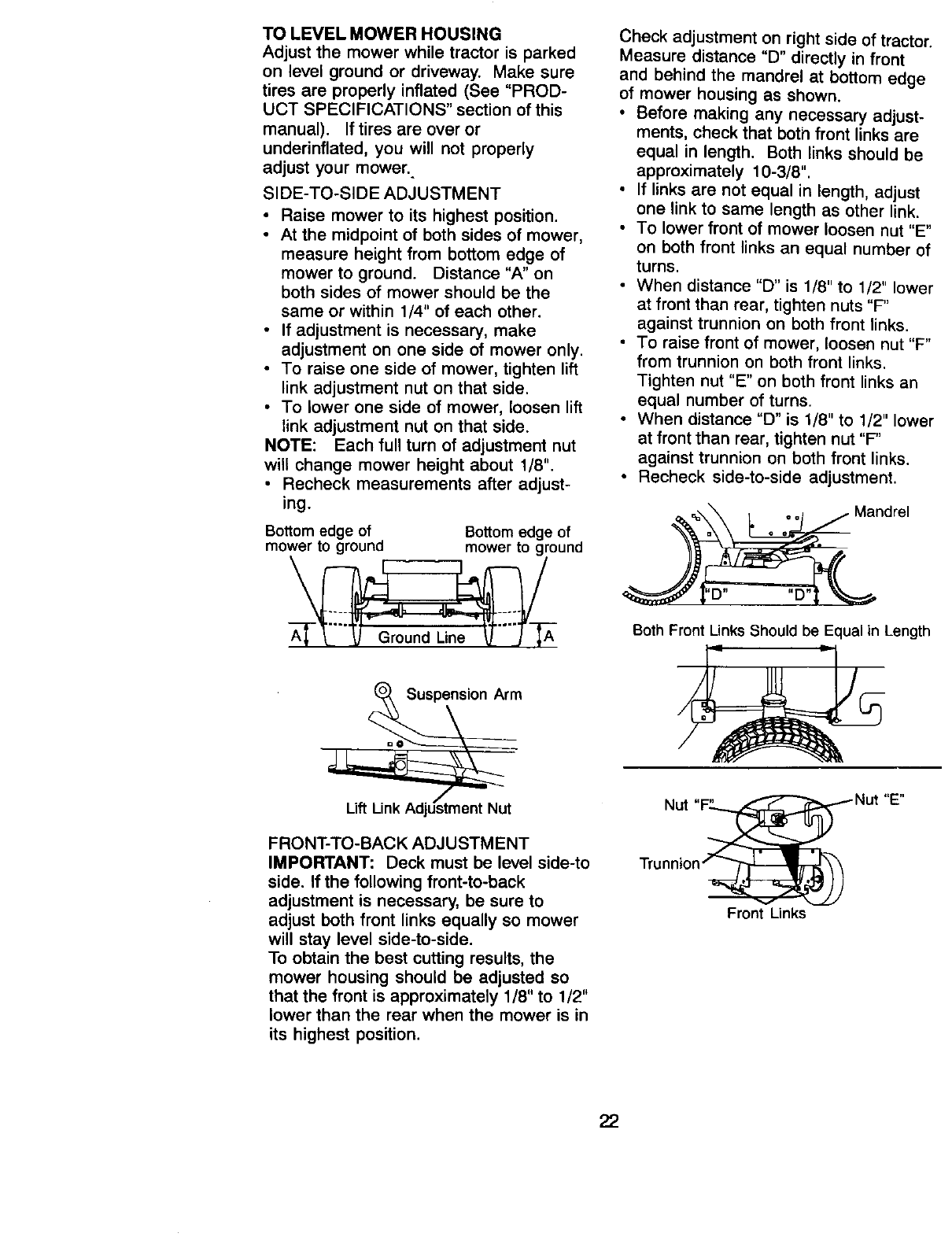
TO LEVEL MOWER HOUSING
Adjust the mower while tractor is parked
on level ground or driveway. Make sure
tires are properly inflated (See "PROD-
UCT SPECIFICATIONS" section of this
manual). If tires are over or
underinflated, you will not properly
adjust your mower.
SIDE-TO-SIDE ADJUSTMENT
•Raise mower to its highest position.
• At the midpoint of both sides of mower,
measure height from bottom edge of
mower to ground. Distance "A" on
both sides of mower should be the
same or within 1/4" of each other.
•If adjustment is necessary, make
adjustment on one side of mower only.
• To raise one side of mower, tighten lift
link adjustment nut on that side.
• To lower one side of mower, loosen lift
link adjustment nut on that side.
NOTE: Each full turn of adjustment nut
will change mower height about 1/8".
• Recheck measurements after adjust-
ing.
Bottom edge of Bottom edge of
mower to ground mower to ground
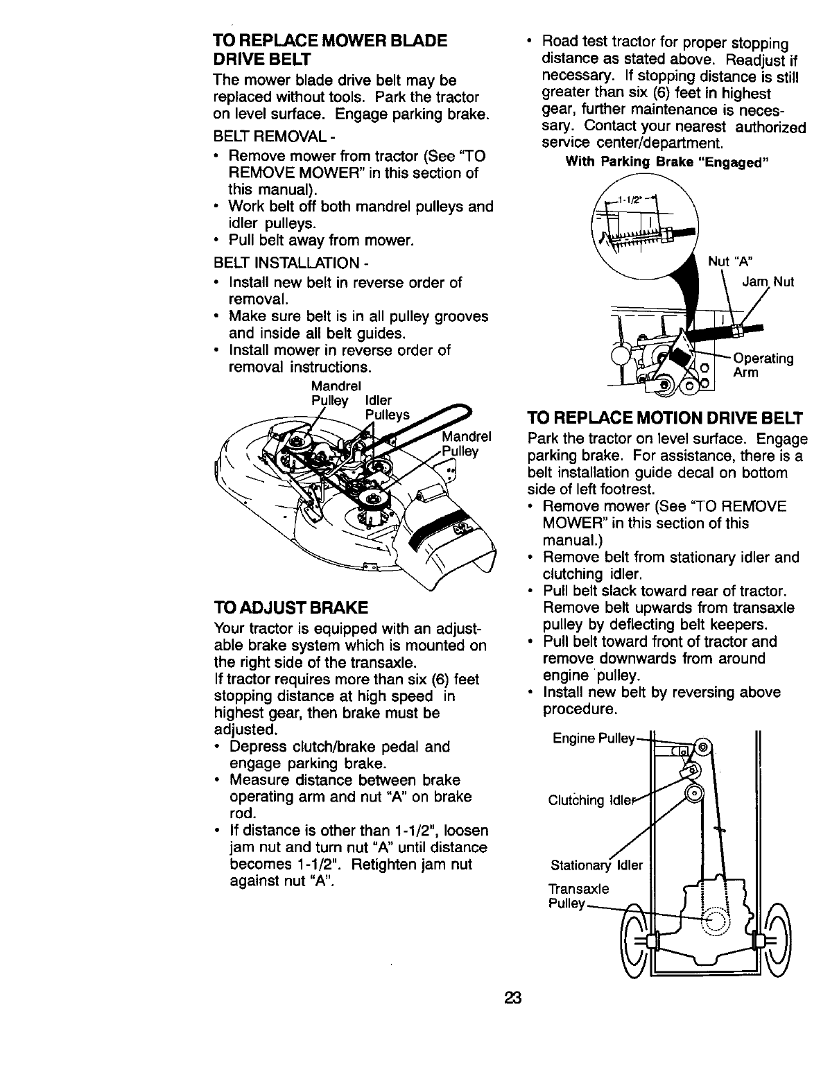
Check adjustment on right side of tractor.
Measure distance "D" directly in front
and behind the mandrel at bottom edge
of mower housing as shown.
• Before making any necessary adjust-
ments, check that boti_ front links are
equal in length. Both links should be
approximately 10-3/8".
• If links are not equal in length, adjust
one link to same length as other link.
• To lower front of mower loosen nut "E"
on both front links an equal number of
turns.
• When distance "D" is 1/8" to 1/2" lower
at front than rear, tighten nuts "F"
against trunnion on both front links.
• To raise front of mower, loosen nut "F"
from trunnion on both front links.
Tighten nut "E" on both front links an
equal number of turns.
• When distance "D" is 1/8" to 1/2" lower
at front than rear, tighten nut "F"
against trunnion on both front links.
• Recheck side-to-side adjustment.
'D .... D"
Both Front Links Should be Equal in Length
Arrn
FRONT-TO-BACK ADJUSTMENT
IMPORTANT: Deck must be level side-to
side. If the following front-to-back
adjustment is necessary, be sure to
adjust both front links equally so mower
will stay level side-to-side.
To obtain the best cutting results, the
mower housing should be adjusted so
that the front is approximately 1/8" to 1/2"
lower than the rear when the mower is in
its highest position.
Nut ttEii
Front Unks
22
TO REPLACE MOWER BLADE
DRIVE BELT
The mower blade drive belt may be
replaced without tools. Park the tractor
on level surface. Engage parking brake.
BELT REMOVAL -
•Remove mower from tractor (See "TO
REMOVE MOWER" in this section of
this manual).
• Work belt off both mandrel pulleys and
idler pulleys.
• Pull belt away from mower.
BELT INSTALLATION -
•Install new belt in reverse order of
removal.
• Make sure belt is in all pulley grooves
and inside all belt guides.
•Install mower in reverse order of
removal instructions.
Mandrel
Pulley Idler
dley
TO ADJUST BRAKE
Your tractor is equipped with an adjust-
able brake system which is mounted on
the right side of the transaxle.
If tractor requires more than six (6) feet
stopping distance at high speed in
highest gear, then brake must be
adjusted.
•Depress clutch/brake pedal and
engage parking brake.
• Measure distance between brake
operating arm and nut "A" on brake
rod.
• If distance is other than 1-1/2", loosen
jam nut and turn nut "A" until distance
becomes 1-1/2". Retighten jam nut
against nut "A".
• Road test tractor for proper stopping
distance as stated above. Readjust if
necessary. If stopping distance is still
greater than six (6) feet in highest
gear, further maintenance is neces-
sary. Contact your nearest authorized
service center/department.
With Parking Brake "Engaged"
Nut "A"
Jam Nut
g
Arm
TO REPLACE MOTION DRIVE BELT
Park the tractor on level surface. Engage
parking brake. For assistance, there is a
belt installation guide decal on bottom
side of left footrest.
• Remove mower (See "TO REMOVE
MOWER" in this section of this
manual.)
• Remove belt from stationary idler and
clutching idler.
• Pull belt slack toward rear of tractor.
Remove belt upwards from transaxle
pulley by deflecting belt keepers.
• Pull belt toward front of tractor and
remove downwards from around
engine pulley.
• Install new belt by reversing above
procedure.
Engine Pulley_
Clutching IdlePt
:taa :s:
Pulley_
23
TO ADJUST STEERING WHEEL
AUGNMENT
If steering wheel crossbars are not
horizontal (left to right) when wheels are
positioned straight forward, remove
steering wheel and reassemble per
instructions in the Assembly section of
this manual.
FRONTWH EELTOE-IN/CAMBER
The front wheel toe-in and camber are
not adjustable on your tractor. If damage
has occurred to affect the front wheel
toe-in or camber, contact your nearest
authorized service center/department.
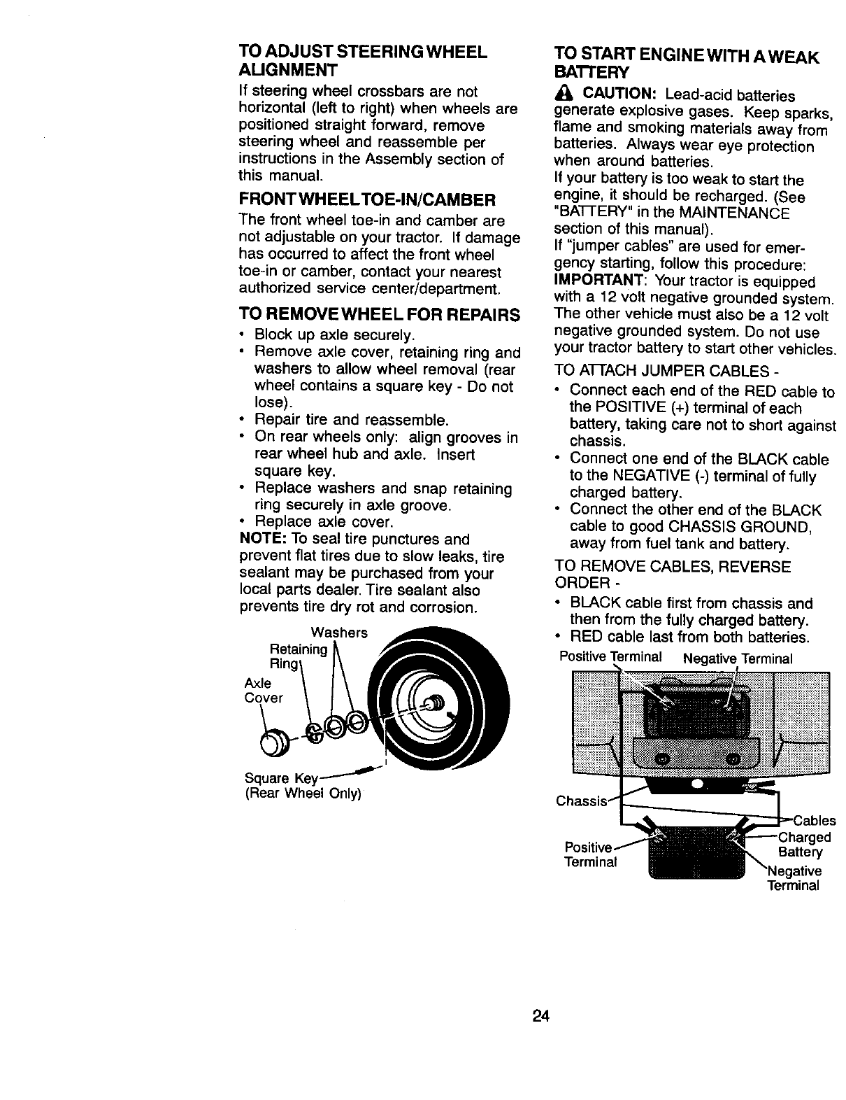
TO REMOVEWHEEL FOR REPAIRS
•Block up axle securely.
• Remove axle cover, retaining ring and
washers to allow wheel removal (rear
wheel contains asquare key -Do not
lose).
•Repair tire and reassemble.
• On rear wheels only: align grooves in
rear wheel hub and axle. Insert
square key.
•Replace washers and snap retaining
ring securely in axle groove.
•Replace axle cover.
NOTE: To seal tire punctures and
prevent flat tires due to slow leaks, tire
sealant may be purchased from your
local parts dealer. Tire sealant also
prevents tire dry rot and corrosion.
Washers
Retaining
Axle
Cover
TO START ENGINEWITH AWEAK
BA'n'ERY
_, CAUTION: Lead-acid batteries
generate explosive gases. Keep sparks,
flame and smoking materials away from
batteries. Always wear eye protection
when around batteries.
If your battery is too weak to start the
engine, it should be recharged. (See
"BA'FIERY" in the MAINTENANCE
section of this manual).
If "jumper cables" are used for emer-
gency starting, follow this procedure:
IMPORTANT: Your tractor is equipped
with a 12 volt negative grounded system.
The other vehicle must also be a 12 volt
negative grounded system. Do not use
your tractor battery to start other vehicles.
TO AI-I'ACH JUMPER CABLES -
•Connect each end of the RED cable to
the POSITIVE (+) terminal of each
battery, taking care not to short against
chassis.
•Connect one end of the BLACK cable
to the NEGATIVE (-) terminal of fully
charged battery.
•Connect the other end of the BLACK
cable to good CHASSIS GROUND,
away from fuel tank and battery.
TO REMOVE CABLES, REVERSE
ORDER -
• BLACK cable first from chassis and
then from the fully charged battery.
• RED cable last from both batteries.
PositiveTerminal Negative Terminal
I
Square Key --'-'''_
(Rear Wheel Only)
Terminal Battery
Terminal
24
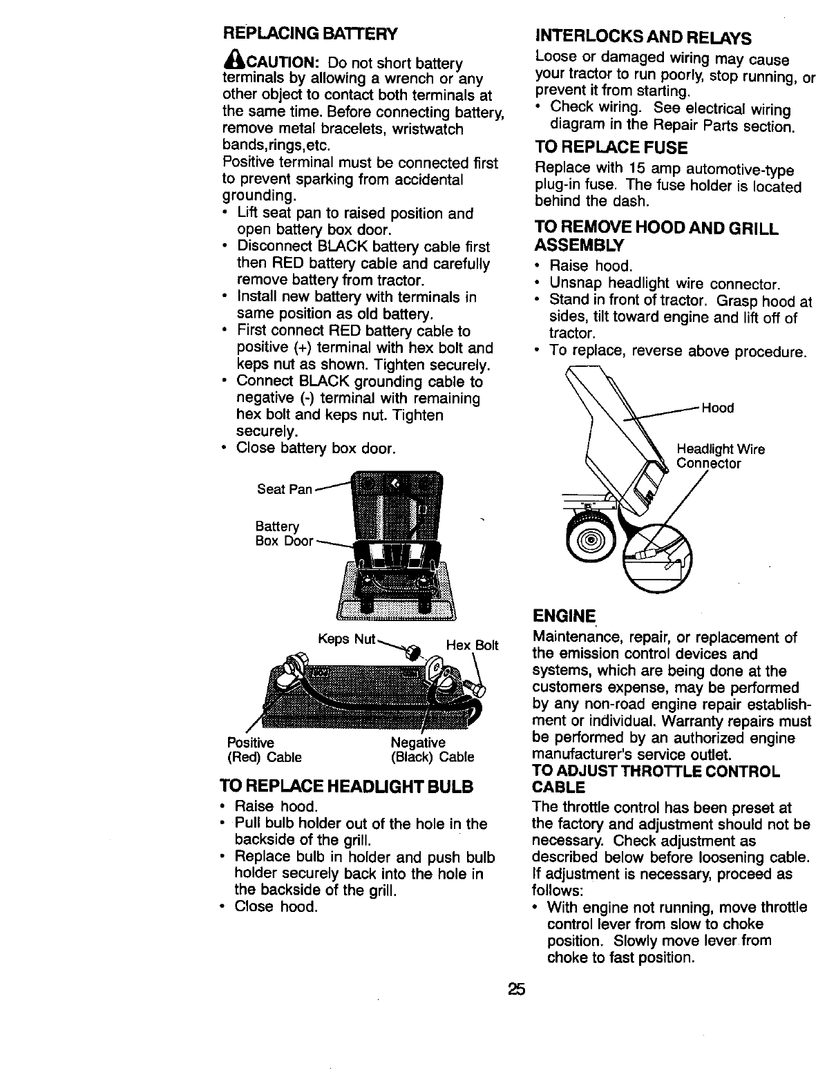
REPLACING BA'B'ERY
,_CAUTION: Do not short battery
terminals by allowing a wrench or any
other object to contact both terminals at
the same time. Before connecting battery,
remove metal bracelets, wristwatch
bands,rings,etc.
Positive terminal must be connected first
to prevent sparking from accidental
grounding.
•Lift seat pan to raised position and
open battery box door.
•Disconnect BLACK battery cable first
then RED battery cable and carefully
remove battery from tractor.
•Install new battery with terminals in
same position as old battery.
•First connect RED battery cable to
positive (+) terminal with hex bolt and
keps nut as shown. Tighten securely.
•Connect BLACK grounding cable to
negative (-) terminal with remaining
hex bolt and keps nut. Tighten
securely.
•Close battery box door.
Battery
Box
It
Positive Negative
(Red) Cable (Black) Cable
TO REPLACE HEADUGHT BULB
•Raise hood.
•Pull bulb holder out of the hole in the
backside of the grill.
•Replace bulb in holder and push bulb
holder securely back into the hole in
the backside of the grill.
•Close hood.
INTERLOCKS AND RELAYS
Loose or damaged wiring may cause
your tractor to run poorly, stop running, or
prevent it from starting.
•Check wiring. See electrical wiring
diagram in the Repair Parts section.
TO REPLACE FUSE
Replace with 15 amp automotive-type
plug-in fuse. The fuse holder is located
behind the dash.
TO REMOVE HOOD AND GRILL
ASSEMBLY
• Raise hood.
•Unsnap headlight wire connector.
• Stand in front of tractor. Grasp hood at
sides, tilt toward engine and lift off of
tractor.
• To replace, reverse above procedure.
Hood
ligchtt Wire
ENGINE
Maintenance, repair, or replacement of
the emission control devices and
systems, which are being done at the
customers expense, may be performed
by any non-road engine repair establish-
ment or individual. Warranty repairs must
be performed by an authorized engine
manufacturer's service outlet.
TO ADJUST THROTTLE CONTROL
CABLE
The throttle control has been preset at
the factory and adjustment should not be
necessary. Check adjustment as
described below before loosening cable.
If adjustment is necessary, proceed as
follows:
•With engine not running, move throttle
control lever from slow to choke
position. Slowly move lever from
choke to fast position.
25
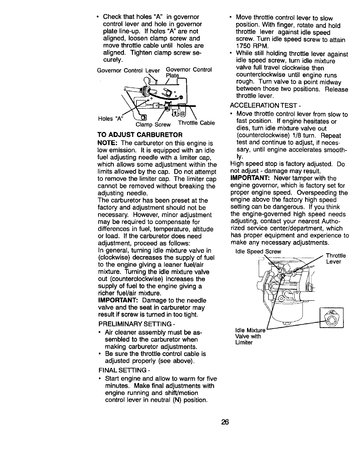
•Check that holes "A" in governor
control lever and hole in governor
plate line-up. If holes "A" are not
aligned, loosen clamp screw and
move throttle cable until holes are
aligned. Tighten clamp screw se-
curely.
Governor Control Lever Governor Control
Holes "A Clamp Screw Throttle Cable
TO ADJUST CARBURETOR
NOTE: The carburetor on this engine is
low emission. It is equipped with an idle
fuel adjusting needle with a limiter cap,
which allows some adjustment within the
limits allowed by the cap. Do not attempt
to remove the limiter cap. The limiter cap
cannot be removed without breaking the
adjusting needle.
The carburetor has been preset at the
factory and adjustment should not be
necessary. However, minor adjustment
may be required to compensate for
differences in fuel, temperature, altitude
or load. If the carburetor does need
adjustment, proceed as follows:
In general, turning idle mixture valve in
(clockwise) decreases the supply of fuel
to the engine giving a leaner fuel/air
mixture. Turning the idle mixture valve
out (counterclockwise) increases the
supply of fuel to the engine giving a
richer fuel/air mixture.
IMPORTANT: Damage to the needle
valve and the seat in carburetor may
result if screw is turned in too tight.
PRELIMINARY SETTING -
•Air cleaner assembly must be as-
sembled to the carburetor when
making carburetor adjustments.
• Be sure the throttle control cable is
adjusted properly (see above).
FINAL SETTING -
• Start engine and allow to warm for five
minutes. Make final adjustments with
engine running and shift/motion
control lever in neutral (N) position.
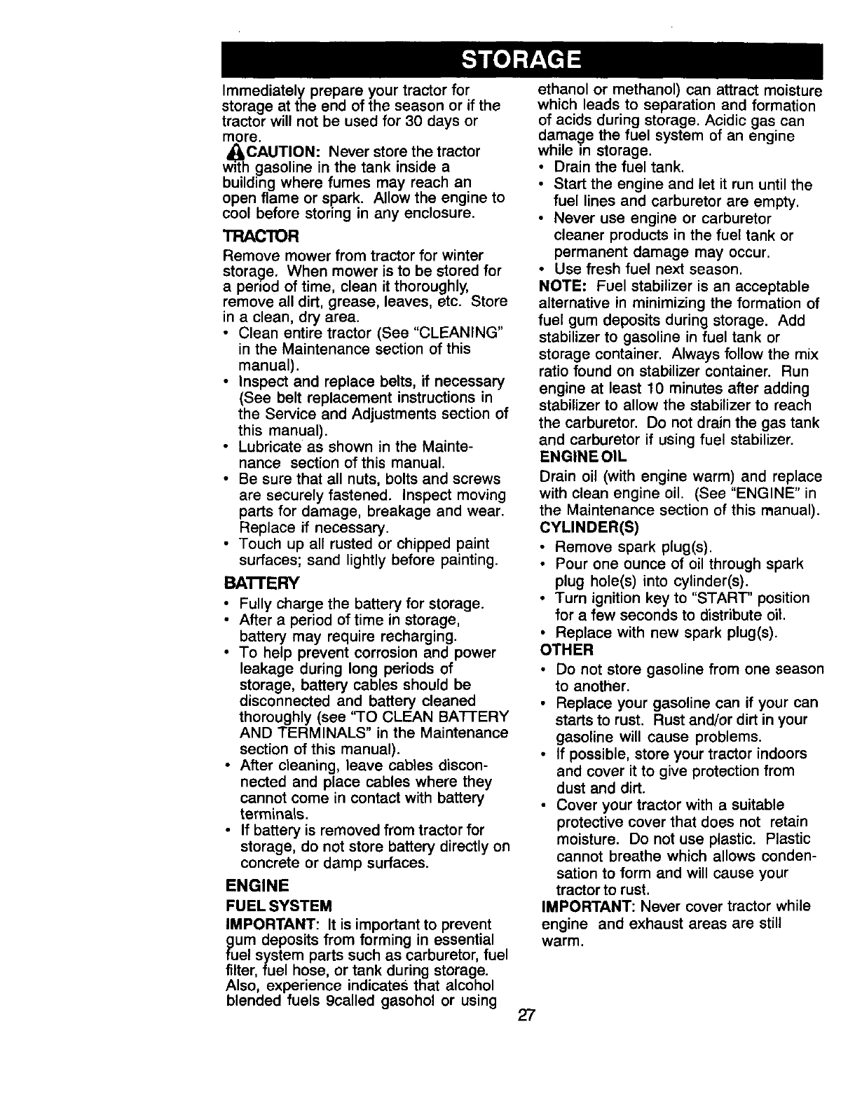
•Move throttle control lever to slow
position. With finger, rotate and hold
throttle lever against idle speed
screw. Turn idle speed screw to attain
1750 RPM.
• While still holding throttle lever against
idle speed screw, turn idle mixture
valve full travel clockwise then
counterclockwise until engine runs
rough. Turn valve to a point midway
between those two positions. Release
throttle lever.
ACCELERATION TEST -
•Move throttle control lever from slow to
fast position. If engine hesitates or
dies, turn idle mixture valve out
(counterclockwise) 1/8 turn. Repeat
test and continue to adjust, if neces-
sary, until engine accelerates smooth-
ly.
High speed stop is factory adjusted. Do
not adjust - damage may result.
IMPORTANT: Never tamper with the
engine governor, which is factory set for
proper engine speed. Overspeeding the
engine above the factory high speed
setting can be dangerous. If you think
the engine-governed high speed needs
adjusting, contact your nearest Autho-
rized service center/department, which
has proper equipment and experience to
make any necessary adjustments.
Idle Speed Screw
_'X_ _ Thro_,e
Idle Mixt!_
Valve with
IJmiter
26
Immediately prepare your tractor for
storage at the end of the season or if the
tractor will not be used for 30 days or
more.
w_hCAUTION: Never store the tractor
gasoline in the tank inside a
building where fumes may reach an
open flame or spark. Allow the engine to
cool before storing in any enclosure.
TRACTOR
Remove mower from tractor for winter
storage, When mower is to be stored for
a period of time, clean it thoroughly,
remove all dirt, grease, leaves, etc. Store
in a clean, dry area.
•Clean entire tractor (See "CLEANING"
in the Maintenance section of this
manual).
•Inspect and replace belts, if necessary
(See belt replacement instructions in
the Service and Adjustments section of
this manual).
•Lubricate as shown in the Mainte-
nance section of this manual.
• Be sure that all nuts, bolts and screws
are securely fastened. Inspect moving
parts for damage, breakage and wear.
Replace if necessary.
• Touch up all rusted or chipped paint
surfaces; sand lightly before painting.
BA'B'ERY
•Fully charge the battery for storage.
• After a period of time in storage,
battery may require recharging.
• To help prevent corrosion and power
leakage during long periods of
storage, battery cables should be
disconnected and battery cleaned
thoroughly (see 'q'O CLEAN BA-I-FERY
AND TERMINALS" in the Maintenance
section of this manual).
• After cleaning, leave cables discon-
nected and place cables where they
cannot come in contact with battery
terminals.
• If battery is removed from tractor for
storage, do not store battery directly on
concrete or damp surfaces.
ENGINE
FUEL SYSTEM
IMPORTANT: It is important to prevent
puUmdeposits from forming in essential
el system parts such as carburetor, fuel
filter, fuel hose, or tank during storage.
Also, experience indicates that alcohol
blended fuels 9called gasohol or using
ethanol or methanol) can attract moisture
which leads to separation and formation
of acids during storage. Acidic gas can
damage the fuel system of an engine
while m storage.
• Drain the fuel tank.
• Start the engine and let it run until the
fuel lines and carburetor are empty.
• Never use engine or carburetor
cleaner products in the fuel tank or
permanent damage may occur.
• Use fresh fuel next season.
NOTE: Fuel stabilizer is an acceptable
alternative in minimizing the formation of
fuel gum deposits during storage. Add
stabilizer to gasoline in fuel tank or
storage container. Always follow the mix
ratio found on stabilizer container. Run
engine at least 10 minutes after adding
stabilizer to allow the stabilizer to reach
the carburetor. Do not drain the gas tank
and carburetor if using fuel stabilizer.
ENGINE OIL
Drain oil (with engine warm) and replace
with clean engine oil. (See "ENGINE" in
the Maintenance section of this manual).
CYLINDER(S)
•Remove spark plug(s),
•Pour one ounce of oil through spark
plug hole(s) into cylinder(s),
•Turn ignition key to "START' position
for a few seconds to distribute oil,
•Replace with new spark plug(s).
OTHER
•Do not store gasoline from one season
to another.
Replace your gasoline can if your can
starts to rust. Rust and/or dirt in your
gasoline will cause problems.
• If possible, store your tractor indoors
and cover it to give protection from
dust and dirt.
• Cover your tractor with a suitable
protective cover that does not retain
moisture. Do not use plastic. Plastic
cannot breathe which allows conden-
sation to form and will cause your
tractor to rust.
IMPORTANT: Never cover tractor while
engine and exhaust areas are still
warm.
27
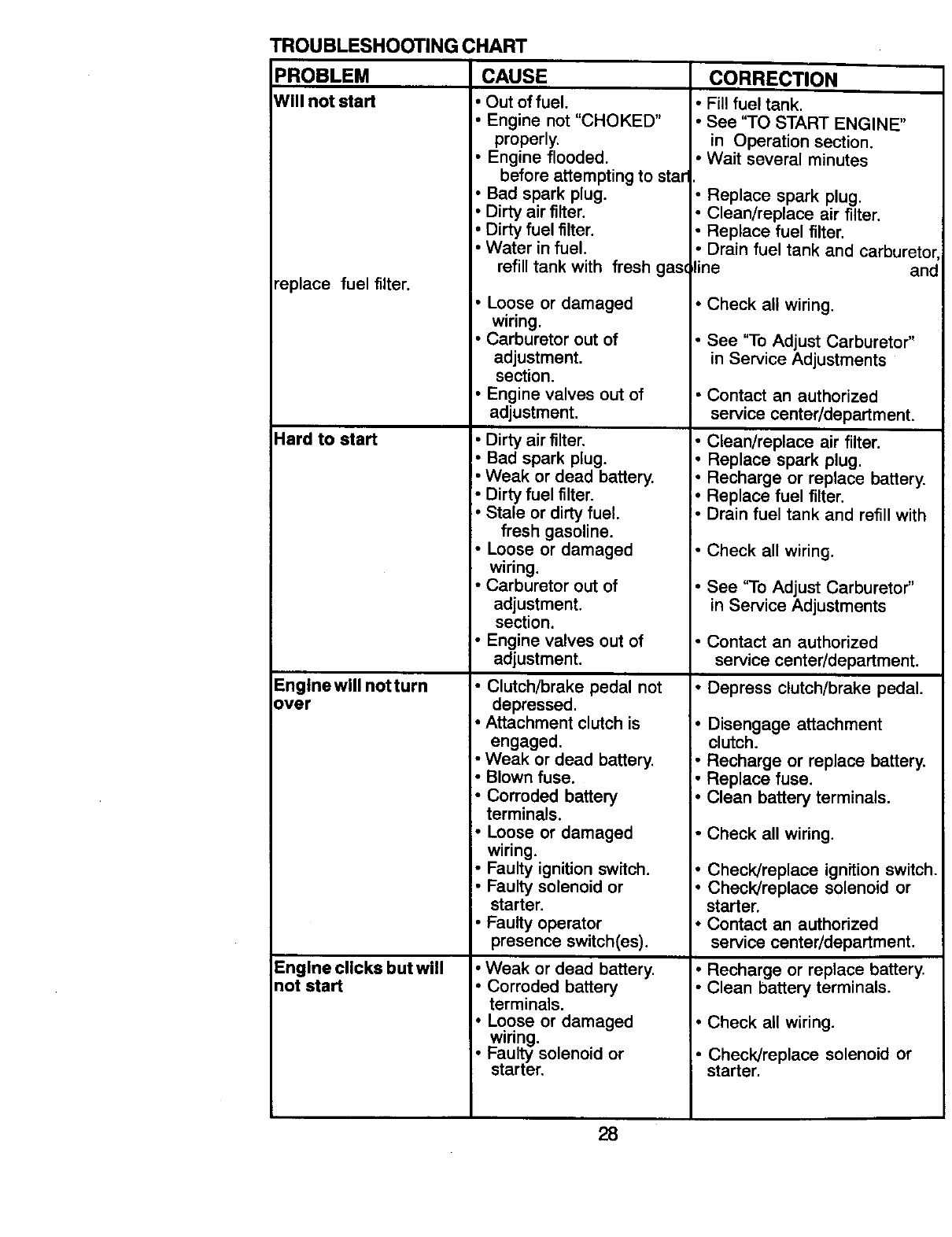
TROUBLESHOOTING CHART
PROBLEM CAUSE
Will not start •Out of fuel.
• Engine not "CHOKED"
properly.
• Engine flooded.
before attempting to star
• Bad spark plug.
• Dirty air filter.
•Dirty fuel filter.
Water in fuel.
refill tank with fresh gas(
"eplace fuel filter.
Hard to start
Englnewill not turn
over
Engine clicks but will
not start
• Loose or damaged
wiring.
• Carburetor out of
adjustment.
section.
• Engine valves out of
adjustment.
• Dirty air filter.
• Bad spark plug.
• Weak or dead battery.
•Dirty fuel filter.
• Stale or dirty fuel.
fresh gasoline.
• Loose or damaged
wiring.
• Carburetor out of
adjustment.
section.
• Engine valves out of
adjustment.
• Clutch/brake pedal not
depressed.
• Attachment clutch is
engaged.
Weak or dead battery,
• Blown fuse.
• Corroded battery
terminals.
• Loose or damaged
wiring.
• Faulty ignition switch.
• Faulty solenoid or
starter,
• Faulty operator
presence switch(es).
• Weak or dead battery.
• Corroded battery
terminals.
• Loose or damaged
wiring.
• Faulty solenoid or
starter.
CORRECTION
•Fill fuel tank,
•See "TO START ENGINE"
in Operation section.
• Wait several minutes
• Replace spark plug.
• Clean/replace air filter.
• Replace fuel filter.
• Drain fuel tank and carbureto_
line and
• Check all wiring.
• See "To Adjust Carburetor"
in Service Adjustments
• Contact an authorized
service center/department.
• Clean/replace air filter.
• Replace spark plug.
i" Recharge or replace battery.
• Replace fuel filter.
• Drain fuel tank and refill with
• Check all wiring.
•See '3o Adjust Carburetor"
in Service Adjustments
• Contact an authorized
service center/department.
• Depress clutch/brake pedal.
•Disengage attachment
clutch.
• Recharge or replace battery.
• Replace fuse.
• Clean battery terminals.
• Check all wiring.
• Check/replace ignition switch.
• Check/replace solenoid or
starter.
•Contact an authorized
service center/department.
•Recharge or replace battery.
• Clean battery terminals.
• Check all wiring,
• Check/replace solenoid or
starter.
28
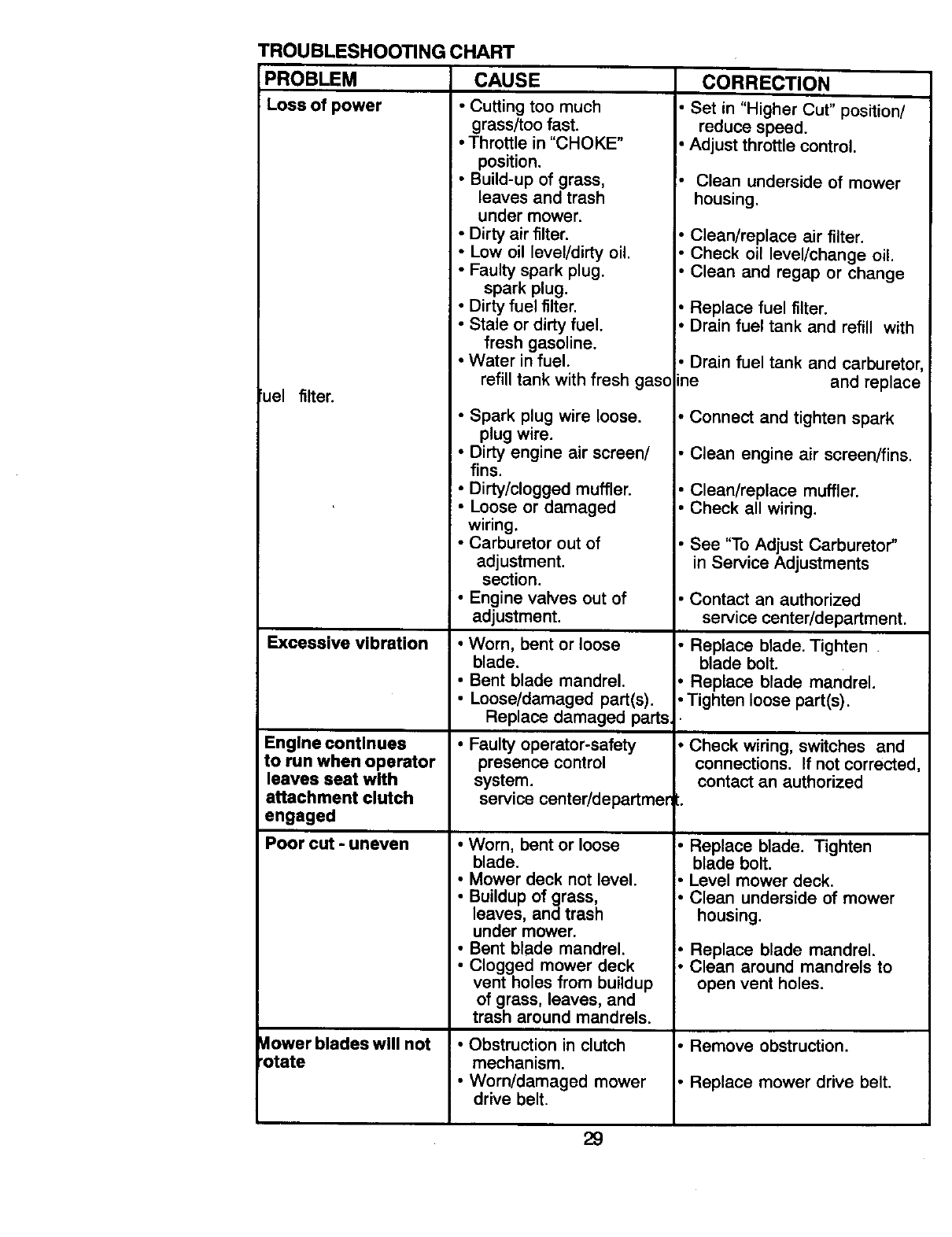
TROUBLESHOOTING CHART
PROBLEM CAUSE CORRECTION
Loss of power
uel filter.
Excessive vibration
Engine continues
to run when operator
leaves seat with
attachment clutch
engaged
Poor cut - uneven
Mower blades will not
rotate
•Cutting too much
grass/too fast.
•Throttle in "CHOKE"
position.
•Build-up of grass,
leaves and trash
under mower.
• Dirty air filter.
• Low oil level/dirty oil.
• Faulty spark plug.
spark plug.
• Dirty fuel filter.
• Stale or dirty fuel.
fresh gasoline.
• Water in fuel.
refill tank with fresh gaso
• Spark plug wire loose.
plug wire.
• Dirty engine air screen/
fins.
• Dirty/clogged muffler.
• Loose or damaged
wiring.
• Carburetor out of
adjustment.
section.
•Engine valves out of
adjustment.
• Worn, bent or loose
blade.
• Bent blade mandrel.
• Loose/damaged part(s).
Replace damaged parts.
• Faulty operator-safety
presence control
system.
service center/departmer
• Worn, bent or loose
blade.
• Mower deck not level.
• Buildup of grass,
leaves, and trash
under mower.
• Bent blade mandrel.
• Clogged mower deck
vent holes from buildup
of grass, leaves, and
trash around mandrels.
• Obstruction in clutch
mechanism.
• Worn/damaged mower
drive belt.
Set in "Higher Cut" position/
reduce speed.
Adjust throttle control.
• Clean underside of mower
housing.
•Clean/replace air filter.
• Check oil level/change oil.
• Clean and regap or change
• Replace fuel filter.
• Drain fuel tank and refill with
• Drain fuel tank and carburetor
me and replace
• Connect and tighten spark
• Clean engine air screen/fins.
• Clean/replace muffler.
• Check all wiring.
• See "To Adjust Carburetor"
in Service Adjustments
• Contact an authorized
service center/department.
•Replace blade. Tighten
blade bolt.
•Replace blade mandrel.
• Tighten loose part(s).
• Check wiring, switches and
connections. If not corrected,
contact an authorized
l.
• Replace blade. Tighten
blade bolt.
• Level mower deck.
• Clean underside of mower
housing.
•Replace blade mandrel.
• Clean around mandrels to
open vent holes.
• Remove obstruction.
• Replace mower drive belt.
29
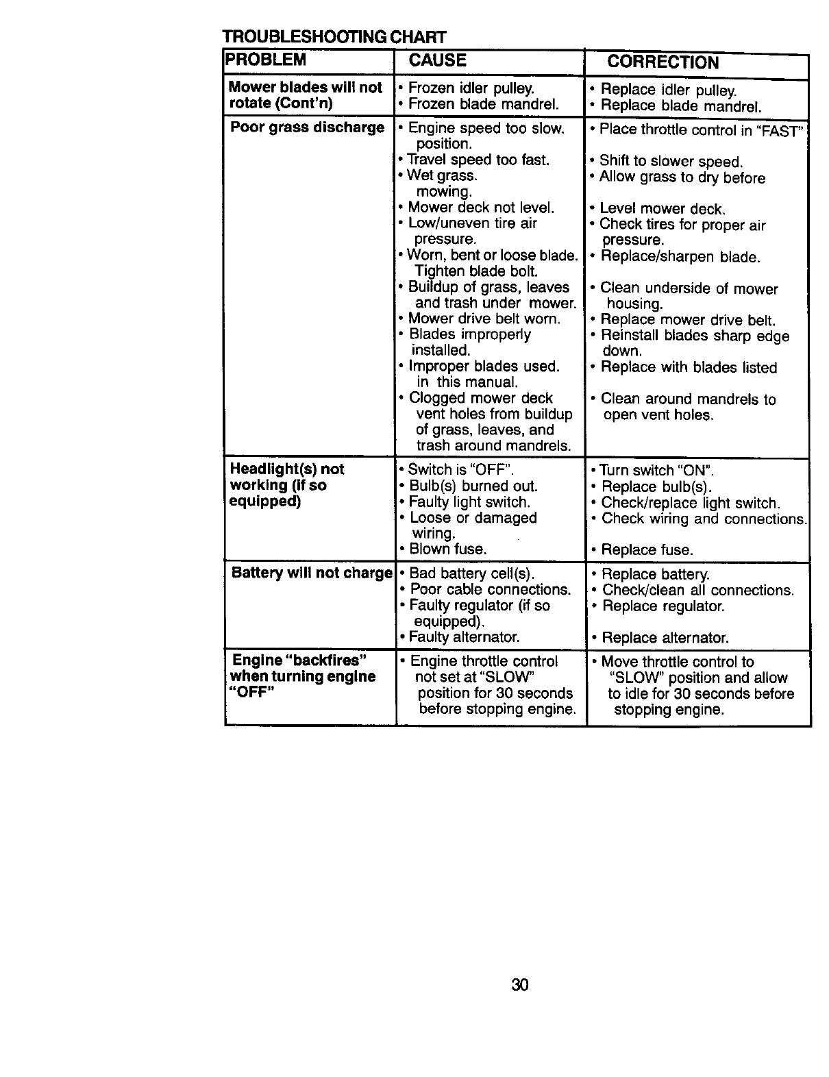
TROUBLESHOOTING CHART
PROBLEM CAUSE CORRECTION
Mower blades will not •Frozen idler pulley. •Replace idler pulley
rotate (Cont'n) •Frozen blade mandrel. •Replace blade mandrel
Poor grass discharge •Engine speed too slow, •Place throttle control in "FAST'
position.
•Travel speed too fast.
•Wet grass.
mowing.
• Mower deck not level.
• Low/uneven tire air
pressure.
•Worn, bent or loose blade.
Tighten blade bolt.
•Buildup of grass, leaves
and trash under mower.
Mower drive belt worn.
Blades improperly
installed.
•Improper blades used.
in this manual.
• Clogged mower deck
vent holes from buildup
of grass, leaves, and
trash around mandrels.
Headlight(s) not
working (If so
equipped)
Battery will not charge
Engine "backfires"
when turning engine
"OFF"
• Switch is "OFF".
•Bulb(s) burned out.
•Faulty light switch.
•Loose or damaged
wiring.
•Blown fuse.
Bad battery cell(s).
Poor cable connections.
Faulty regulator (if so
equipped).
• Faulty alternator,
• Engine throttle control
not set at "SLOW"
position for 30 seconds
before stopping engine.
Shift to slower speed.
• Allow grass to dry before
•Level mower deck.
• Check tires for proper air
pressure.
•Replace/sharpen blade.
• Clean underside of mower
housing.
• Replace mower drive belt.
•Reinstall blades sharp edge
down.
•Replace with blades listed
•Clean around mandrels to
open vent holes.
• Turn switch "ON".
• Replace bulb(s).
• Check!replace light switch.
• Check wiring and connections
•Replace fuse.
• Replace battery.
• Check/clean all connections.
•Replace regulator.
•Replace alternator.
•Move throttle control to
"SLOW" position and allow
to idle for 30 seconds before
stopping engine.
30
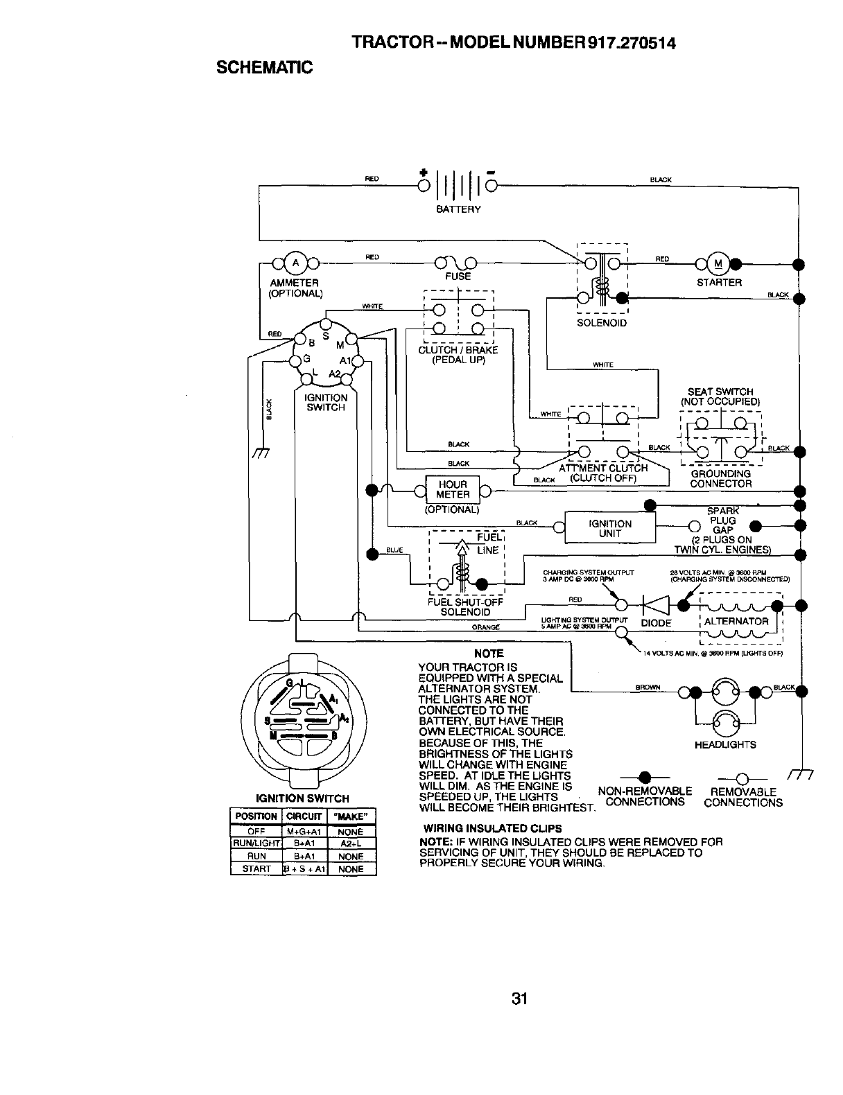
SCHEMATIC
TRACTOR-- MODEL NUMBER 917.270514
BATTERY
RE_ _RED
FUSE STARTER
...... I
SOLENOID
W_IT E I ........ i
SEAT SWITCH
NOT OCCUPIED)
(CLUTCH OF_
(OPTIONAL) SPARK
IGNITION PLUG
I FUELI UNIT GAP
I (2 PLUGS ON
TW1N CYL. ENGINES) •
CHARGING SYSTEM OUTPGT
3AMp DC @ 3600 RPM 28 VOLTS AC MIN @3600 RPM
(CHARGING _yb_rEM E_SCONNECT_D}
IGNITION SWITCH
POSITION ICIRCUIT =MAKE"
OFF tM+G+A1 NONE
RUN/LIGHT B+A1 A2+L
RUN B+A1 NONE
START I_ + S + A1 NONE
FUELSHUT-OFF rEo I"" *
SOLENOID
ORANGE 5 AMPAG @ 3600 RPM I
-- ---_ L.........
NOTE _ 14VOLTSACuIN@_eooRPM_TS oF_
!
YOUR TRACTOR IS /
EQUIPPED WITH ASPECIAL /
ALTERNATOR SYSTEM, /
THE LIGHTS ARE NOT
CONNECTED TO THE
BATTERY, BUT HAVE THEIR
OWN ELECTRICAL SOURCE.
BECAUSE OF THIS, THE
BRIGHTNESS OF THE LIGHTS
WILL CHANGE WITH ENGINE
SPEED. AT IDLE THE LIGHTS
WILL DIM. AS THE ENGINE IS
HEADLIGHTS
NON-REMOVABLE REMOVABLE
SPEEDED UP, THE LIGHTS CONNECTIONS CONNECTIONS
WILL BECOME THEIR BRIGHTEST,
WIRING INSULATED CLIPS
NOTE: IF WIRING INSULATED CLIPS WERE REMOVED FOR
SERVICING OF UNIT, THEY SHOULD BE REPLACED TO
PROPERLY SECURE YOUR WIRING.
31
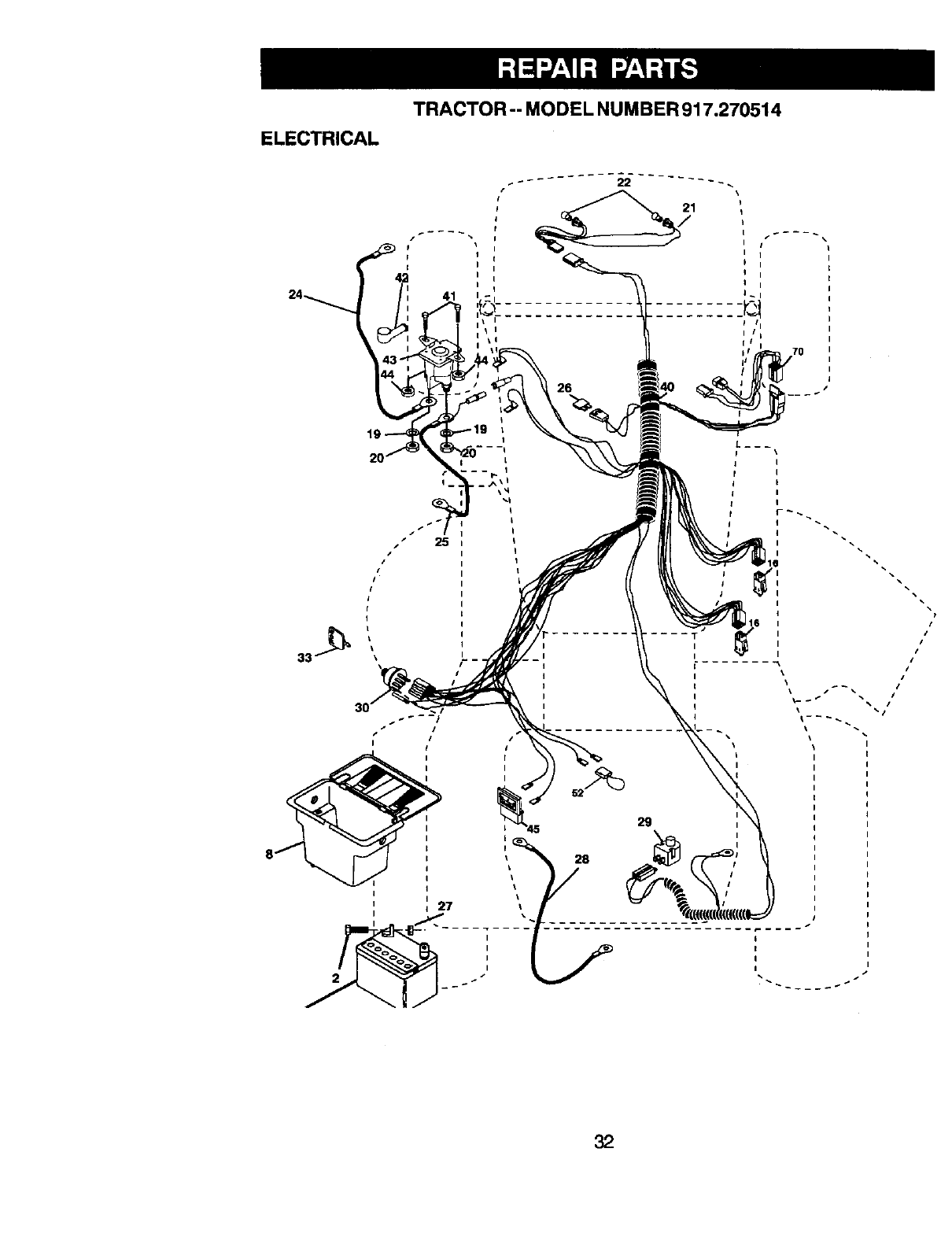
TRACTOR -- MODEL NUMBER 917.270514
ELECTRICAL
41
70
25 I
29
//
/
/
//
ii
s •
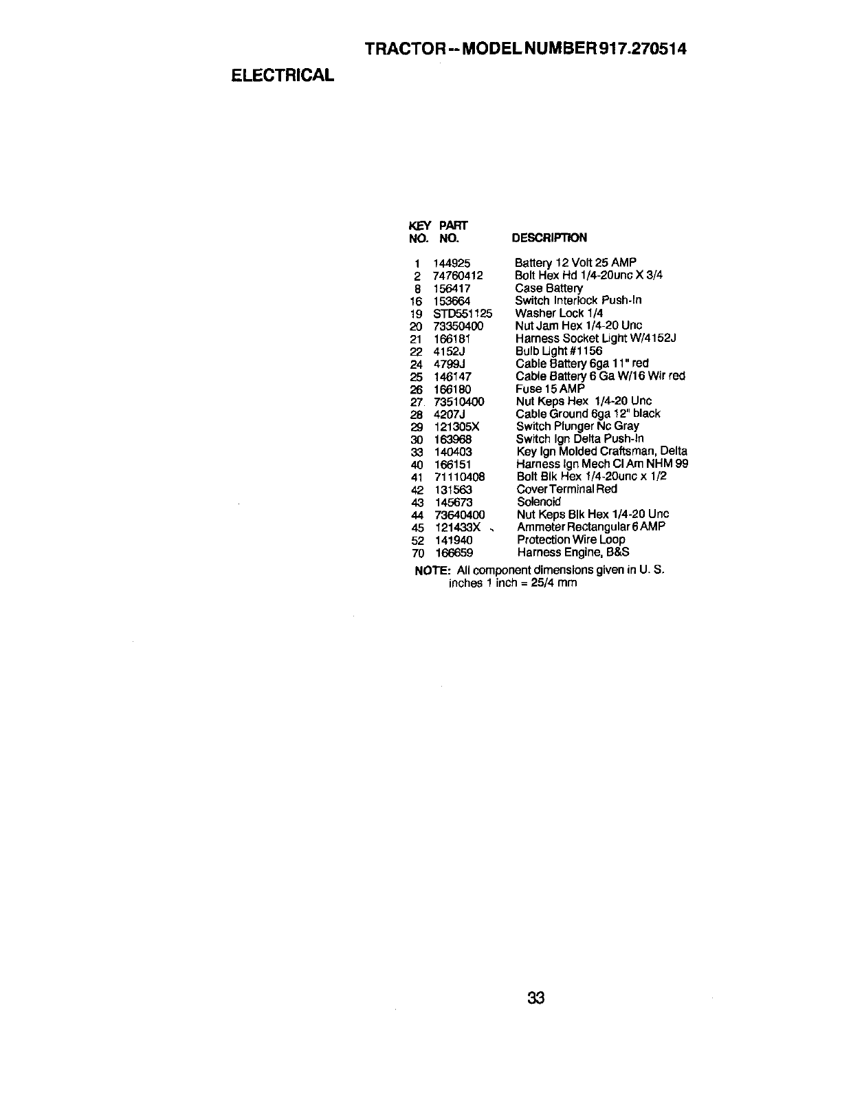
ELECTRICAL
TRACTOR -- MODEL NUMBER 917.270514
KEY PART
NO. NO. DESCRIPTION
1 144925
2 74760412
8156417
16 153664
19 STD551125
20 73350400
21 166181
22 4152J
24 4799J
25 146147
26 166180
27 73510400
28 4207J
29 121305X
30 163968
33 140403
40 166151
41 71110408
42 131563
43 145673
44 7364O4OO
45 121433X.
52 141940
Battery 12 Volt 25 AMP
Bolt Hex Hd 1/4-20unc X 3/4
Case Battery
Switch InterlockPush-In
Washer Lock 1/4
NutJam Hex 1/4-20 Uric
Harness Socket LightW/4152J
BulbUght #1156
Cable Battery 6ga 11" red
Cable Battery 6 Ga W/16 wir red
Fuse 15AMP
Nut Keps Hex 1/4-20 Unc
Cable Ground6ga 12" black
Switch PlungerNc Gray
Switch Ign Delta Push-In
Key IgnMolded Craftsman, Delta
Harness Ign Mech CIAm NHM 99
Bolt BIk Hex 1/4-20unc x 1/2
Cover TerminalRed
Solenoid
Nut Keps BIk Hex 1/4-20 Unc
Ammeter Rectangular6 AMP
ProtectionWire Loop
70 166659 Harness Engine, S&S
NOTE: All componentdimensionsgiven in U. S,
inches 1 inch = 25/4 mm
33
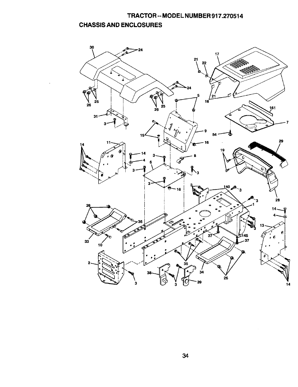
TRACTOR -- MODEL NUMBER 917.270514
CHASSIS AND ENCLOSURES
3O
26 31 '_
14
26
21
5
18
26 5 TJ
17
19
161
29
28
33 10
26
14
34

TRACTOR-- MODEL NUMBER 917.270514
CHASSIS AND ENCLOSURES
KEY PART
NO. NO. DESCRIPTION
1 165480
2 140356
3 17490612
4 STD55107.5
5 155272
6 155924X015
7126842X
8155138
9166322X015
10 STD533710
11 155927
13 155934X010
14 17490608
15 74180512
16 STD541431
17 154989X558
19 126_138X
19 17411310
21 122933X
22 124479X
24 STD5'23710
25 19131312
26 STD541437
28 140135X428
29 124029X599
30 166884X558
31 136619
33 145244X558
34 145243X558
35 STD533707
37 17490508
38 139886
39 139887
54 161464.
140 158418
145 156524
161 161547
- - 5479J
Chassis
DrawbarStretch
Screw Thdrol 3/8-16 x 3/4 Ty-tt
Washer 13/32 X 3/4 X 16 Ga
Bumper Dash Hood
Saddle Slkscr
Shield Ht. Hood Kohl/Dia Engine
Clip Retainer Slide On
Dash Slkscr 1-pc
Dolt Rdhd Sqnk 3/8-16unc X 1
Panel Dash LH
Panel SlkscrDash RH
ScrewThdrol 3/8-16 x 1/2 Ty-tt
Screw Mach TRHD 5/16-18 unc x 3/4
Nut Keps 5/16-18 Unc
Hood Asm Pnt SlopeWeld Ms-558
DumperHood
Screw Hex Wsh #13-16
Rivet Ratchet Nylon
Washer Nylon BIk 28 x 75 x 19
Bolt Fin Hex 3/8-16 unc x 1 Gr. 5
Washer 13/32 X 13/16 x 12 Ga
Nut Hex Lock W/Ins. 3/8-16 Unc
Grille Black
Lens Headlight Bar C_ear
Fender Pnt LT W/o Shift
Bracket Fender Repl 109873x
Footrest Pnt Lh
Footrest Pnt Rh
Bolt Rdhd Sht Sqnk 3/8-16 x 3/4
ScrewThdrol. 5/16-18x 1/2
Bracket Asm Pvt LH MWR Rear
Bracket Asm Pvt RH MWR Rear
Screw Hex Wshd 8-18 x 7/8
Bracket Suspension Front
Rod Pivot Chassis/Hood
Extrusion Bumper
Plug Button BIk 359 Dia Choke
NOTE: All component dimensionsgiven in U, S.
inches 1 inch = 25/4 mm
35
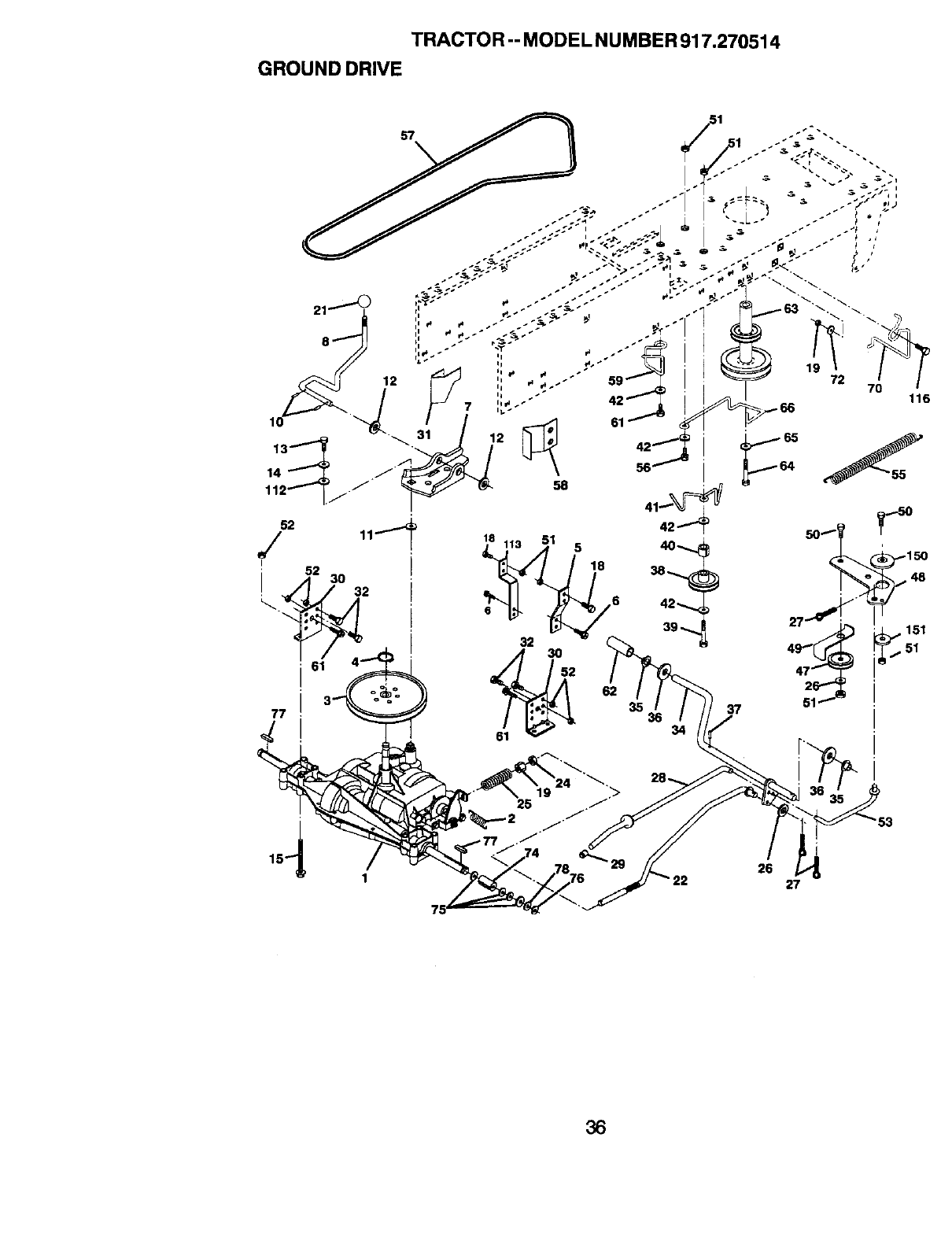
TRACTOR -- MODEL NUMBER 917.270514
GROUND DRIVE
77
8
6
32
27 '
37
i
26
27
36
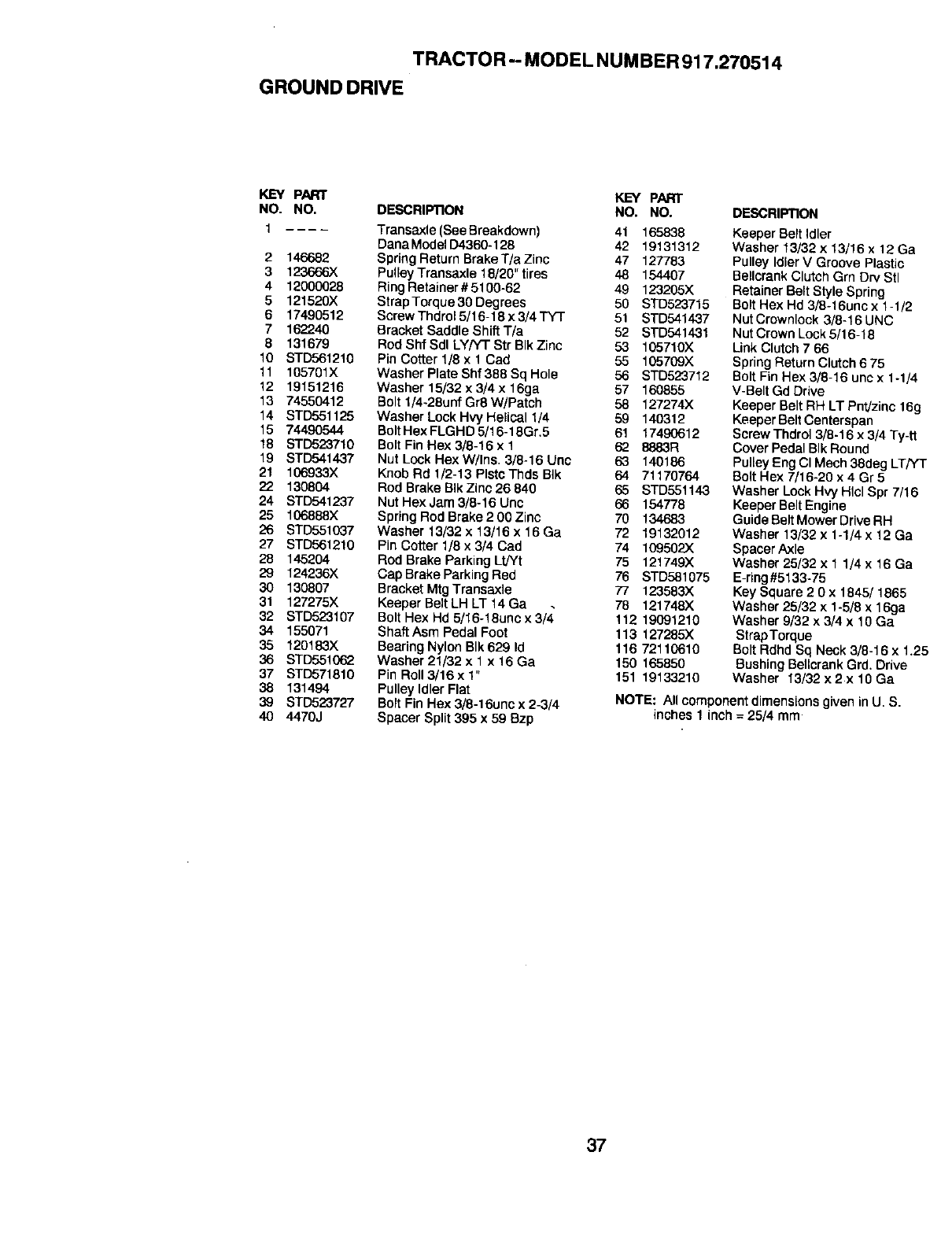
TRACTOR -- MODEL NUMBER 917.270514
GROUNDDRIVE
KEY PART KEY PART
NO. NO. DESCRIPTION NO. NO. DESCRIPTION
2146682
3123666X
412000028
5121520X
6 17490512
7 162240
8131679
10 STD561210
11 105701X
12 19151216
13 74550412
14 STD551125
15 74490544
18 $TD523710
19 STD541437
21 106933X
22 130804
24 STD541237
25 106888X
26 STD551037
27 BTD56121g
28 145204
29 124236X
30 130807
31 127275X
32 STD523107
34 155071
35 120183X
36 STD551062
37 STD571810
38 131494
39 STD523727
4O 4470J
Transaxle (See Breakdown) 41 165838
[3anaModelO4360-126 42 19131312
Spring Return Brake T/a Zinc 47 127783
Pulley Transaxle 18/20" tires 48 154407
Ring Retainer # 5100-62 49 123205X
Strap Torque 30 Degrees 50 STD523715
Screw Thdrol 5/16-18 x 3/4 TYT 51 STD541437
Bracket Saddle Shift T/a 52 STD5414.31
Rod S_ Sdl LY/'f-fStr BIk Zinc 53 105710)(.
Pin Cotter 1/8 x 1 Cad 55 105709X
Washer Plate Shf 388 Sq Hole 56 STD52"3712
Washer 15/32 × 3/4 x 16ga 57 160855
Bolt 1/4-28unf Gr8W/Patch 58 127274X
Washer Lock Hvy Helical 1/4 59 140312
Bolt Hex FLGHD 5/16-18Gr,5 61 17490612
Bolt Fin Hex 3/8-16 x 1 62 8883R
Nut Lock Hex W/Ins. 3/8-16 Unc 63 140186
Knob Rd 1/2-13 PlstcThds BIk 64 71170764
Rod Brake B_kZinc 26 640 65 STD551143
Nut Hex Jam 3/8-16 Unc 66 154778
Spring Rod Brake 2 00 Zinc 70 134683
Washer 13/32 x 13/16 x 16 Ga 72 19132012
Pin Cotter 1/8 x 3/4 Cad 74 109502X
Rod Brake Parking Lt/Yt 75 121749X
Cap Brake Parking Red 76 STD581075
Bracket Mtg Transaxle 77 123583X
Keeper Belt LH LT t4 Ga 78 121748X
Bolt Hex Hd 5/16-18unc x 3/4 112 19091210
Shaft Asm Pedal Foot 113 127285X
Bearing Nylon BIk 629 Id 116 721t 0610
Washer 21/32 x 1x 16 Ga 150 165850
Pin Roll 3/16 x 1" 151 19133210
Pulley Idler Flat
Bolt Fin Hex 3/8-16unc x 2-3/4
Spacer Split 395 x 59 Bzp
Keeper Belt Idler
Washer 13/32 x 13/16 x 12 Ga
Pulley IdlerV Groove Plastic
Bellcrank Clutch Grn Drv Stl
Retainer Belt Style Spring
Bolt Hex Hd 3/8-16unc x 1-1/2
Nut Crownlock 3/8-16 UNC
Nut Crown Lock 5/16-18
Link Clutch 7 66
Spring Return Clutch 6 75
Bolt Fin Hex 3/8-16 unc x 1-1/4
V-Belt Gd Drive
Keeper Belt RH LT Pnt/zinc 16g
Keeper Belt Centerspan
Screw Thdrol 3/8-16 x 3/4 Ty-tt
Cover Pedal BIk Round
Pulley Brig CI Mech 38deg LT/YT
Bolt Hex 7/16-20 x 4 Gr 5
Washer Lock HWH_cLSpr 7/16
Keeper Belt Engine
Guide Belt Mower DriveRH
Washer 13/32 x 1-1/4 x t2 Ga
Spacer Axle
Washer 25/32 x 1 1/4 x 16 Ga
E-ring#5133-75
Key Square 2 0x t845] 1865
Washer 25/32 x 1-5/8 x 16ga
Washer 9/32 x 3/4 x 10 Ga
StrapTorque
Bolt Rdhd Sq Neck 3/8-16 x 1.25
Bushing Bellcrank Grd. Drive
Washer 13/32 x 2 x 10 Ga
NOTE: All componentdimensions given in U. S.
inches 1 inch = 25/4 mm
37
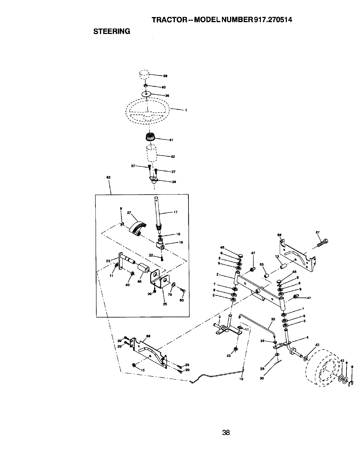
STEERING
TRACTOR -- MODEL NUMBER 917.270514
i-','--'----so
-_40
/I_ \i lj--_ I
_41
,"-'---'-42
8
27 117
.j19
.J _->jo/
60
47
_5
3O
67
43
38

STEERING
TRACTOR -- MODEL NUMBER 917,270514
KEY PART
NO. NO. DESCRIPTION
1 139768
2 154427
3 156483
4 157473
5 6266H
6 121748X
7 19272016
812000029
9 3366R
10 156438
11 10040600
13 154779
15 73901000
17 156545
18 57079
19 160395
22 165857
23 165851
25 154406
26 126847X
27 136874
28 19131416
29 17490612
30 STD561210
32 130465
36 155099
37 152927
38 139769
39 19133808
40 7810H
41 104820X
42 124417X
43 121749X
46 121232X
47 6855M
62 167903
65 154780
66 154404
67 74781044
68 154429
79 19132012
80 74950612
Wheel Steering Opp Sears BIk
Axle Asm Front Lt
SpindleAsm Lh
SpindleAsm Rh
Washer Thrust .75 x 1.230
Washer 25/32 x 1-5/8 x 16 Ga.
Washer 27/32 x 1-1/4 x 16 Ga.
RingK]ip#3"5304-75
BearingCol Strg BIk
Draglink Extended Stamped
Washer LockHvy Hlcl Spr 3/8
Bearing Axle
Locknut Flange 5/8-11 UNC
Shaft Asm Strg 5/8 x 15.19 Lt
Washer Th, _st .515 x .750 x .033
Support Sh_ ft
Screw Hex Wsh Hd Torx
Shaft Asm Pitman
Bracket Steering
Bushing Unk Drag BIk LR
Gear Sector 22 Teeth
Washer 13/32 x 7/8 x 16 Ga.
Screw Thdrol 3/8-16 x 3/4 TY-'FI"
Pin Cotter 1/8 x 3/4 Cad
Rod Tie Wire Form 19.75 Mech
Bushing Strg. 5/8 ID Dash
Screw
Cap Wheel Steer Opp Sears USA
Washer 13/32 x 2-3/8 x 8 Ga.
Nut Lock Center 3/8-24
Adaptor Wheel Strg, ,640/.635 Id
BootShaft Steering Craftsman
Washer 25/32 x 1-1/4 x 16 Ga.
Cap Spindle Fr Top BIk
Fitting Grease
Steering Assembly
Spacer Axle
BearingArm Pittman
Bolt Fin Hex 5/8-11 UNC x 2-3/4
Brace Axle
Washer 13/32 x 1-1/4 x 12 Ga
Bolt Hex Nylon 3/8-16 x 3/4
NOTE: All component dimensions given in U. S.
inches 1 inch = 25/4 mm
39
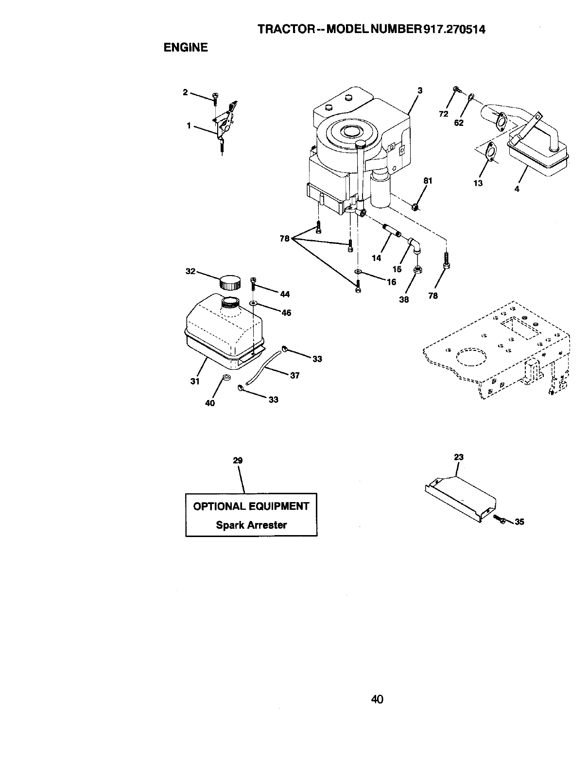
ENGINE
TRACTOR-- MODEL NUMBER 917,270514
33
81
38 78
2g
OPTIONAL EQUIPMENT
Spark Arrester I
4O
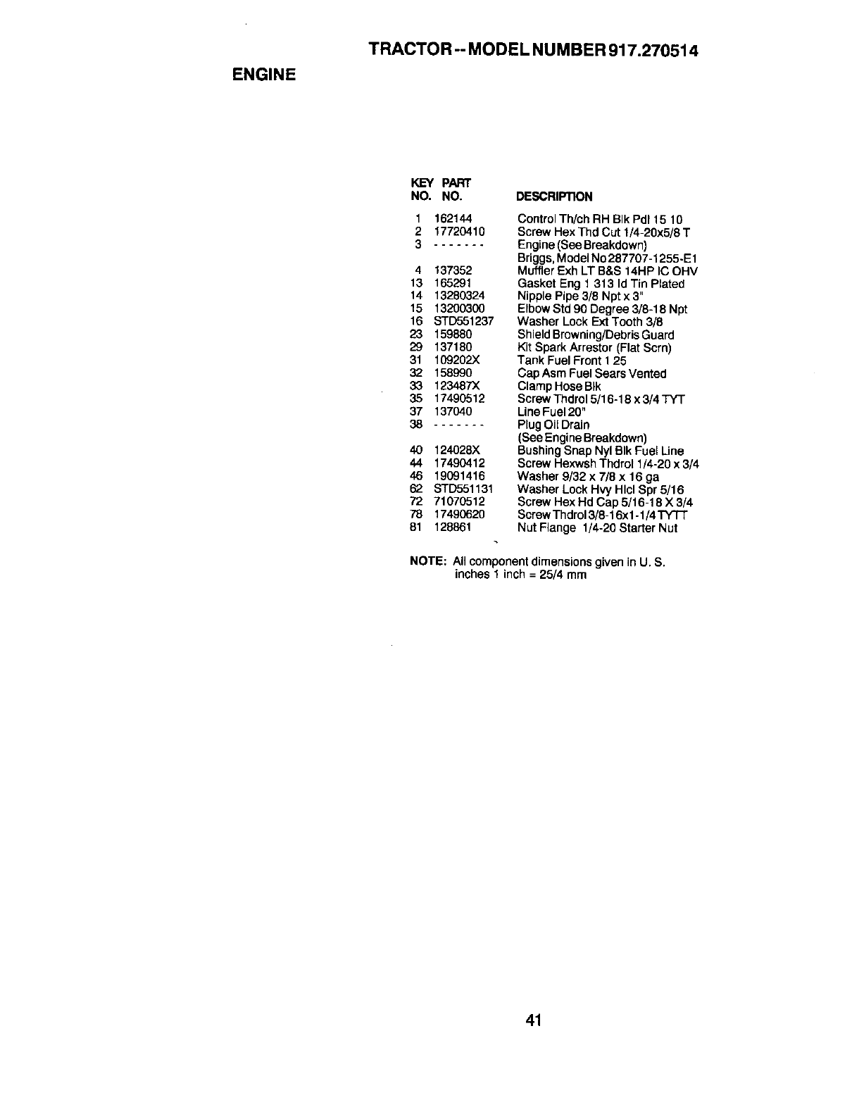
ENGINE
TRACTOR -- MODEL NUMBER 917.270514
KEY PART
NO. NO. DESCRIPTION
1162144
217720410
3
4 137352
13 165291
14 13280324
15 13200300
16 STD551237
23 159880
29 137180
31 109202X
32 158990
33 123487X
35 17490512
37 137040
38
40 124028X
44 17490412
46 19091416
62 STD551131
72 71070512
78 17490620
81 128861
Control Th/ch RH BIk Pdt 15 10
Screw Hex Thd Cut 1/4-20x5/8 T
Engine (See Breakdown)
Briggs, Model No 287707-1255-E1
Muffler Exh LT B&S 14HP IC OHV
Gasket Eng 1 313 Id Tin Plated
Nipple Pipe 3/8 Npt x 3"
Elbow Std 90 Degree 3/8-18 Npt
Washer Lock Ext Tooth 3/8
Shield Browning/Debris Guard
Kit Spark Arrestor (Flat Scrn)
Tank Fuel Front 1 25
Cap Asm Fuel Sears Vented
Clamp Hose BIk
Screw Thdrol 5/16-18 x 3/4 TYT
Line Fuel 20"
Plug Oil Drain
(See Engine Breakdown)
Bushing Snap Nyl BIk Fuel Line
Screw Hexwsh Thdrol 1/4-20 x 3/4
Washer 9/32 x 7/8 x 16 ga
Washer Lock Hvy Hlcl Spr 5/16
Screw Hex Hd Cap 5/16-18 X 3/4
Screw Thdrol 3/8-16xl -1/4 TY3-I"
Nut Flange 1/4-20 Starter Nut
NOTE: All componentdimensionsgiven in U. S.
inches 1 inch = 25/4 mm
41
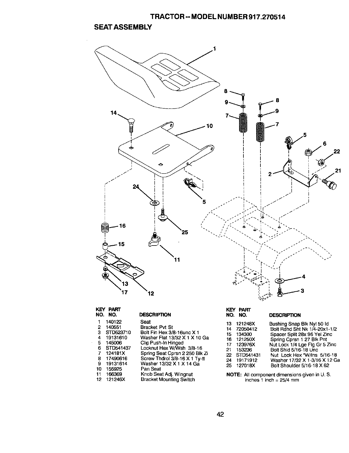
TRACTOR -- MODEL NUMBER 917.270514
SEAT ASSEMBLY
KEY PART
NO. NO.
1 140122
2 140551
3STD523710
4 19131610
5145OO6
6 STD541437
7 124181X
6 17490616
9 19131614
10 155925
11 166369
12 121246X
5
DESCRIPTION
Seat
Bracket Pvt St
Bolt Fin Hex 3/8-16unc X 1
Washer Flat 13/32 X 1 X 10 Ga
Clip Push-In Hinged
Locknut Hex W/Wsh 3/8-16
Spring Seat Cprsn 2 250 BIk Zi
Screw Thdrol 3/8-16 X 1 Ty-tt
Washer 13/32 X 1 X 14 Ga
Pan Seat
Knob Seat Adj. Wingnut
Bracket Mounting Switch
5
21
KEY PART
NO. NO. DESCRIPTION
13 121248X
14 72050412
15 134300
16 121250X
17 123976X
21 153236
22 STD541431
24 19171912
25 127018X
Bushing Snap BIk Ny150 Id
Bolt Rdhd Sht Nk 1/4-20x1-1/2
Spacer Split 28x 96 Yel Zinc
Spring Cprsn 1 27 BIk Pnt
Nut Lock 1/4 Lge Fig Gr 5 Zinc
Bolt Shld 5/16-18 Unc
Nut Lock Hex"W/Ins 5/16-18
Washer 17/32 X 1-3/16 X 12 Ga
Bolt Shoulder 5/16-18 X 62
NOTE: All component dimensions given in U. S.
inches 1 inch = 25/4 mm
42
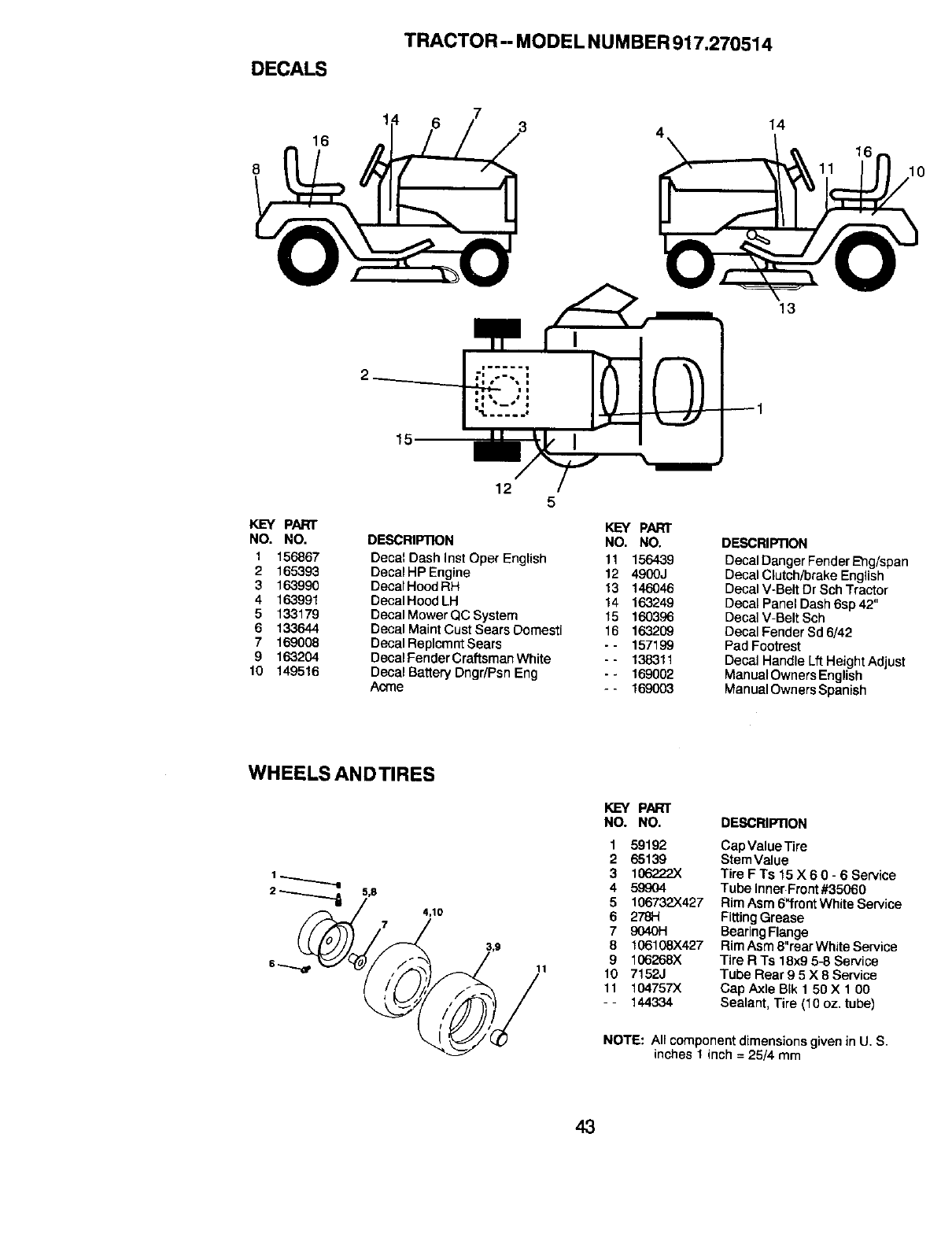
DECALS
TRACTOR - MODEL NU MBER 917.270514
8
16 414
1(
13
15
KEY PART
NO. NO.
1156867
2 165393
3 163990
4 163991
5 133179
6 133644
7 169008
9163204
10 149516
12 5
DESCRIPTION
Decal Dash Inst Oper English
Decal HP Engine
Decal Hood RH
Decal Hood LH
Decal Mower QC System
Decal Maint Cust Sears Domesti
Decal Replcmnt Sears
Decal Fender Craftsman White
Decal Battery Dngr/Psn Eng
Aome
KEY PART
NO. NO.
11 156439
12 4900J
13 146046
14 163249
15 160396
16 163209
- - 157199
- - 138311
--169002
- - 169003
DESCRIPTION
Decal Danger Fender E'ng/span
Decal Clutch/brake English
Decal V-Belt Dr Sch Tractor
Decal Panel Dash 6sp 42"
Decal V-Belt Sch
Decal Fender Sd 6/42
Pad Footrest
Decal Handle Lft Height Adjust
Manual Owners English
Manual Owners Spanish
WHEELS ANDTIRES
11
KEY PART
NO. NO.
159192
2 65139
3106222)<
4 599o4
5106732X427
6 278H
79040H
B106108X427
9 106268X
10 7152J
It 104757X
- - 144334
DESCRIPTION
CapValue_re
SternValue
Tire FTs 15 X 6 O-6 Service
Tube Inner Front#35060
Rim Asm 6"frontWhite Service
FittingGTease
BearingFlange
Rim Asm 8"rear White Service
Tire R Ts 18x9 5-8 Service
Tube Rear 9 5 X 8 Service
Cap AxLeB_kt 56 X 160
Sealant, Tire (10 oz, tube)
NOTE: All component dimensions given in U, S.
inches 1 inch = 25/4 mm
43
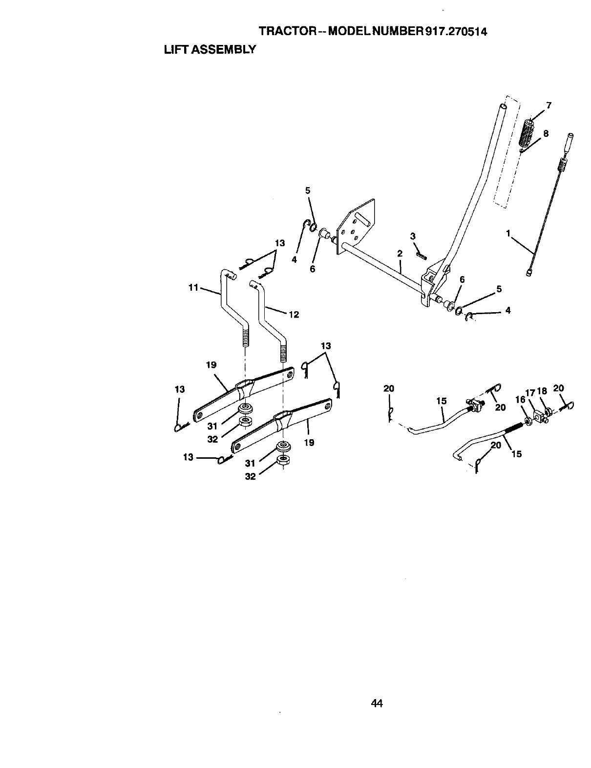
TRACTOR-- MODEL NUMBER 917.270514
LIFT ASSEMBLY
7
11
5
13 3
2
8
/ /' '_
,/ !'
,/ /'
,! /'
65
19
13
31
32
13
19
2O 20
44

TRACTOR -- MODEL NUMBER 917.270514
LIFT ASSEMBLY
KEY PART
NO. NO. DESCRIPTION
1 159460 Wire Asm Inner/Sprg W/plunger LT
2 159474 Shaft Asm Lift
3 105767X Pin Groove 1 500 Zinc
4 12000002 E Ring #5133-62
5 19211621 Washer Pltd 21/32 X 1X 21ga
6 120183X Bearing Nylon BIk 629 Id
7 125631X Grip Handle Fluted BIk
8 122365X Button Plunger Red
11 139865 Link Lift LH
12 139866 Link Lift RH
13 STD624008 Retainer Spdng
15 127218 Link Front
16 73350800 Nut Jam Hex 1/2-13 Uric
17 130171 Trunnion BIk Zinc
18 73680800 Nut Crownlock 1/2-13unc
19 139868 ArmSuspensionRear
20 163552 Retainer SpringZinc
31 140302 Bearing Pvt Uft Spherical
32 73540600 Nut Crownlook 3/8-24
NOTE: All component dimensions given in U. S,
inches1 inch = 25/4 mm
45
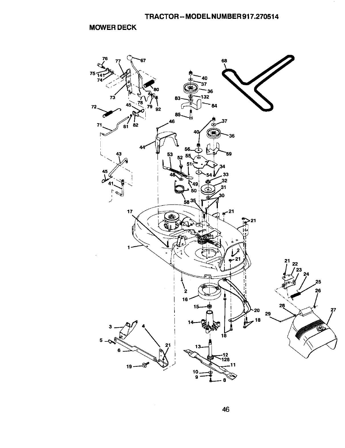
TRACTOR -- MODEL NUMBER 917.270514
MOWER DECK
71
17
€ ""'40
_'37
_ _ "'_ 36
_132
36
32
31
\2
29
,18
21 22
3 24
26
27
46
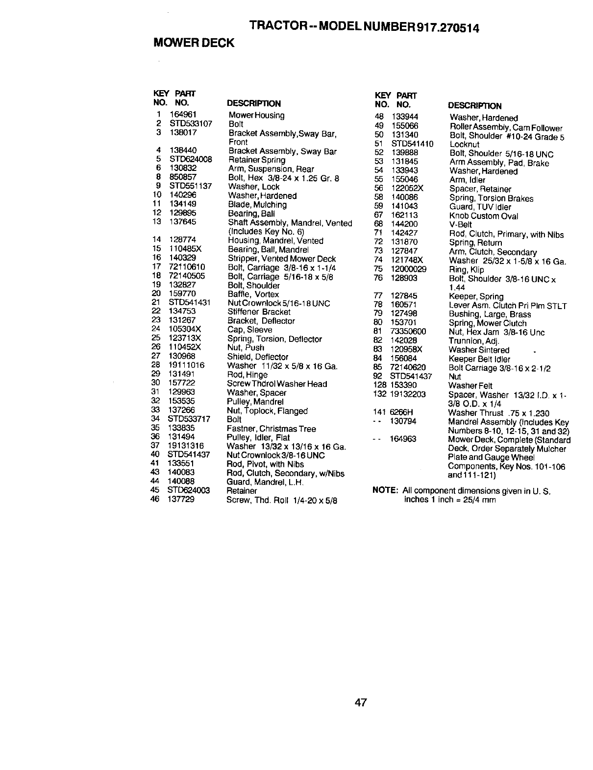
TRACTOR -- MODEL NUMBER 917.270514
MOWER DECK
KEY PART KEY PART
NO. NO. DESCRIPTION NO. NO.
1164961 MowerHousing 48 133944
2STD533107 Bolt 49 155066
3 138017 Bracket Assembly,Sway Bar, 50 131340
Front 51 STD541410
4 138440 Bracket Assembly, Sway Bar 52 139888
5STD624008 RetainerSpring 53 131845
6 130832 Arm, Suspension, Rear 54 133943
8850857 Bolt, Hex 3/8-24 x 1.25 Gr. 8 55 155046
9 STD551137 Washer, Lock 56 122052X
10 140296 Washer, Hardened 58 140086
11 134149 Blade, Mulching 59 141043
12 129895 Bearing, Ball 67 162113
13 137645 Shaft Assembly, Mandrel, Vented 68 144200
(Includes Key No. 6) 7! 142427
14 128774 Housing, Mandrel, Vented 72 131870
15 110485X Bearing, Bali, Mandrel 73 127847
16 140329 Stripper, Vented Mower Deck 74 121748X
17 72110610 Bolt, Cardage 3/8-16 x 1-1/4 75 12000029
18 72140505 Bolt,Carriage 5/16-18 x 5/8 76 128903
19 132827 Bolt, Shoulder
20 159770 Baffle, Vortex 77 127845
21 STD541431 NutCrownlock5/16-18UNC 78 160571
22 134753 Stiffener Bracket 79 127498
23 131267 Bracket, Deflector 80 153791
24 105394X Cap, Sleeve 81 73350600
25 123713X Spring, Torsion, Deflector 82 142028
26 110452X Nut, Push 83 120958X
27 130968 Shield, Deflector 84 156084
28 19111016 Washer 11/32x5/6x16Ga. 85 72140620
29 131491 Rod, Hinge 92 STD541437
30 157722 ScrewThdrctWasherHead 128 153390
31 129963 Washer, Spacer 132 19132203
32 153535 Pulley, Mandrel
33 137266 Nut,Toplock, Flanged 141 6266H
34 STD533717 Bolt -- 130794
35 133835 Fastner, ChristmasTree
36 131494 Pulley, Idler, Flat - - 164963
37 19131316 Washer 13/32 x 13/16 x 16 Ca.
40 STD541437 Nut Crownlock 3/8-16 UNC
41 133551 Rod, Pivot, with Nibs
43 140083 Rod, Crutch,Secondary, w/Nibs
44 140088 Guard, MandreI, L.H.
45 STD624003 Retainer
46 137729 Screw, Thd. Roll 1/4-20 x 5/6
DESCRIFIION
Washer, Hardened
RollerAssembly,Cam Follower
Bolt,Shoulder #10-24 Grade 5
Locknut
Bolt,Shoulder 5/16-18 UNC
Arm Assembly, Pad, Brake
Washer, Hardened
Arm, Idler
Spacer, Retainer
Spring, Torsion Brakes
Guard, TUV Idler
Knob Custom Oval
V-Belt
Rod,Clutch, Primary, withNibs
Spring, Return
Arm, Clutch, Secondary
Washer 25/32 x 1-5/8 x16 Ga.
Ring,Klip
Bolt,Shoulder 3/8-16 UNC x
1.44
Keeper, Spring
Lever Asm. Clutch Pri PIm STLT
Bushing, Large, Brass
Spring,Mower Crutch
Nut, Hex Jam 3/8-16 Uee
Trunnion,Adj.
WasherSintered
Keeper Belt Idler
Bolt Carriage 3]8-16 x 2-1/2
Nut
WasherFelt
Spacer, Washer 13/32 I.D. x1-
3/80.D. x 1/4
Washer Thrust .75 x 1.230
Mandrel Assembly(Includes Key
Numbers 8-10, 12-15, 31 and 32)
Mower Deck, Complete (Standard
Deck; Order Separately Muleher
Plate and Gauge Wheel
Components, Key Nos. 101-106
and111-121)
NOTE: All componentdimensionsgiven in U. S.
inches 1inch = 25/4 mm
47
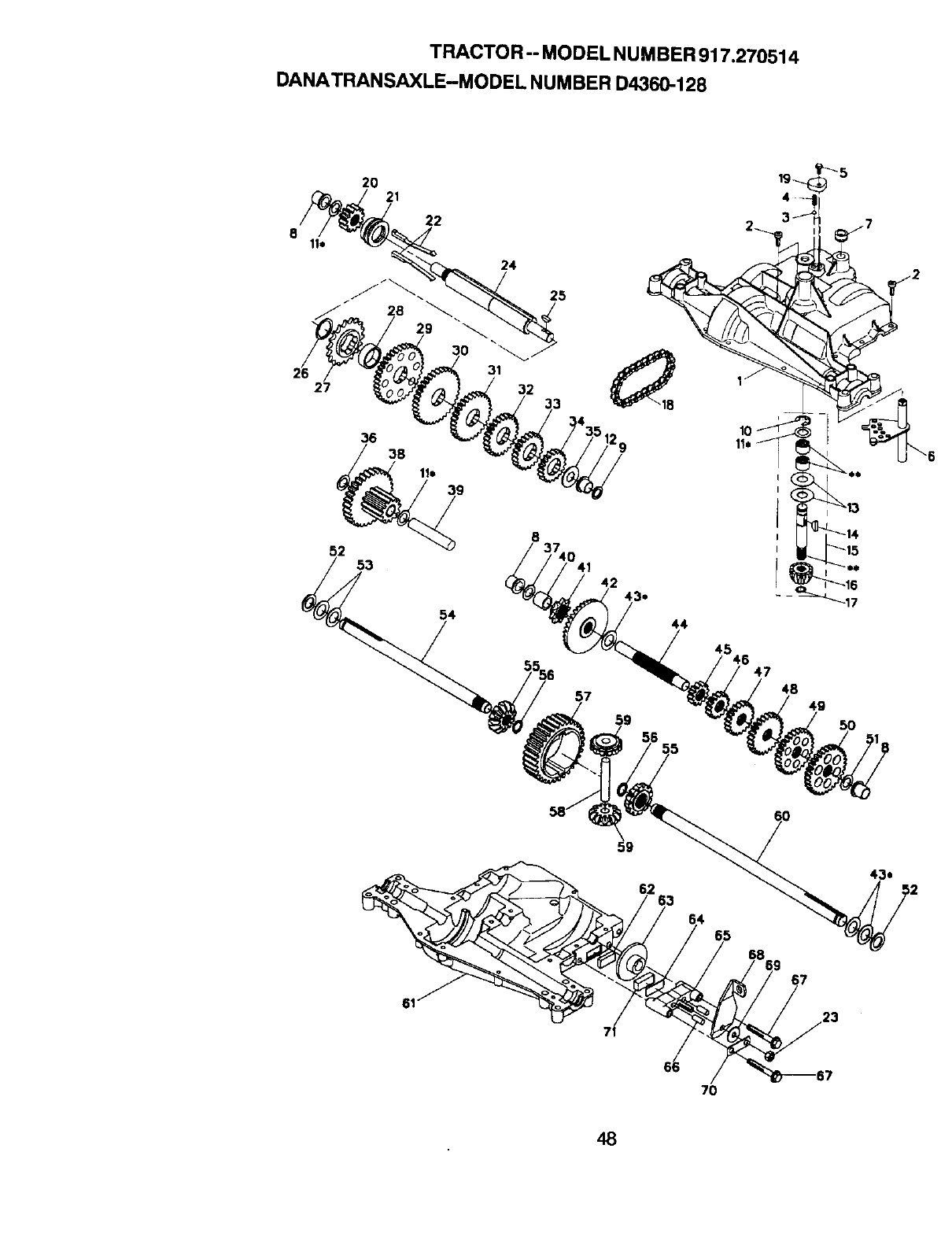
TRACTOR-- MODEL NUMBER 917.270514
DANATRANSAXLE-MODEL NUMBER D4360-128
20 21
22
24
25
27
36 38
31
32 33
52 53
54
8
41 42 43,.
57
56
44
45 4.6 47
48
4g
59
62 63
64 65
67
70
48
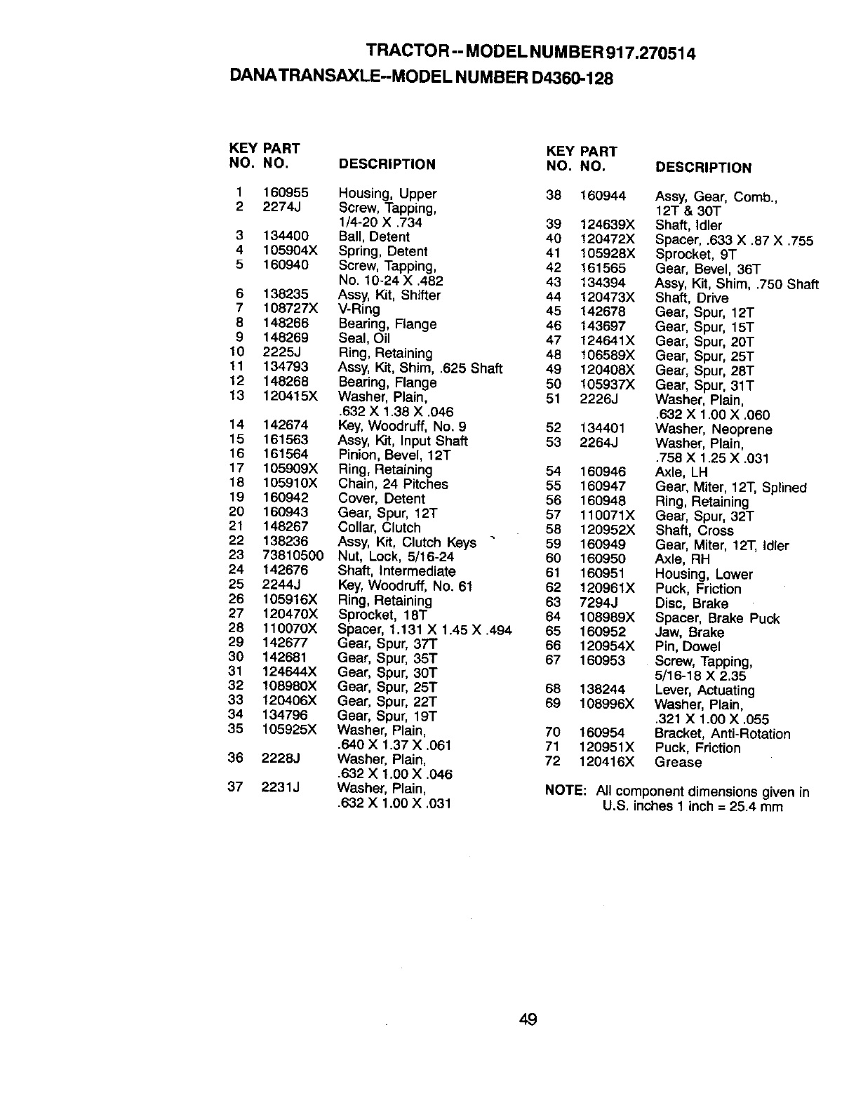
TRACTOR-- MODELNUMBER917,270514
DANATRANSAXLE-MODEL NUMBER D4360-128
KEY PART KEY PART
NO. NO. DESCRIPTION NO. NO.
1 160955 Housing, Upper 38 160944
2 2274J Screw, Tapping,
1/4-20 X .734 39 124639X
3 134400 Ball, Detent 40 120472X
4 105904X Spring, Detent 41 105928X
5 160940 Screw, Tapping, 42 161565
No. 10-24 X .482 43 134394
6 138235 Assy, Kit, Shifter 44 120473X
7 108727X V-Ring 45 142676
8 148266 Bearing, Flange 46 143697
9 148269 Seal, Oil 47 124641X
10 2225J Ring, Retaining 48 106589X
11 134793 Assy, Kit, Shim, .625 Shaft 49 120408X
12 148268 Bearing, Flange 50 105937X
13 120415X Washer, Plain, 51 2226J
.632 X 1.38 X .046
14 142674 Key, Woodruff, No. 9 52 134401
15 161563 Assy, Kit, Input Shaft 53 2264J
16 161564 Pinion, Bevel, 12T
17 105909X Ring, Retaining 54 160946
18 105910X Chain, 24 Pitches 55 160947
19 160942 Cover, Detent 56 160948
20 160943 Gear, Spur, 12T 57 110071X
21 148267 Collar, Clutch 58 120952X
22 138236 Assy, Kit, Clutch Keys "59 160949
23 73810500 Nut, Lock, 5/16-24 60 160950
24 142676 Shaft, Intermediate 61 160951
25 2244J Key, Woodruff, No. 61 62 120961X
26 105916X Ring, Retaining 63 7294J
27 120470X Sprocket, 18T 64 108989X
28 110070X Spacer, 1.131 X 1.45 X .494 65 160952
29 142677 Gear, Spur, 371" 66 120954X
30 142681 Gear, Spur, 35T 67 160953
31 124644X Gear, Spur, 30T
32 108980X Gear, Spur, 25T 68 138244
33 120406X Gear, Spur, 22T 69 108996X
34 134796 Gear, Spur, 19T
35 105925X Washer, Plain, 70 160954
.640 X 1.37 X .061 71 120951X
36 2226J Washer, Plain, 72 120416X
.632 X 1.00 X .046
37 2231J Washer, Plain,
.632 X 1.00 X .031
DESCRIPTION
Assy, Gear, Comb.,
12T & 30T
Shaft, Idler
Spacer, .633 X .87 X .755
Sprocket, 9T
Gear, Bevel, 36"I"
Assy, Kit, Shim, .750 Shall
Shaft, Drive
Gear, Spur, 12T
Gear, Spur, 15T
Gear, Spur, 20T
Gear, Spur, 25T
Gear, Spur, 28"I"
Gear, Spur, 31T
Washer, Plain,
.632 X 1.00 X ,060
Washer, Neoprene
Washer, Plain,
.758 X 1.25 X .031
Axle, LH
Gear, Miter, 12T, Splined
Ring, Retaining
Gear, Spur, 32T
Shaft, Cross
Gear, Miter, 12T, Idler
Axle, RH
Housing, Lower
Puck, Friction
Disc, Brake
Spacer, Brake Puck
Jaw, Brake
Pin, Dowel
Screw, Tapping,
5/16-18 X 2.35
Lever, Actuating
Washer, Plain,
.321 X 1.00 X .055
Bracket, Anti-Rotation
Puck, Friction
Grease
NOTE: All component dimensions given in
U.S. inches 1 inch = 25.4 mm
49
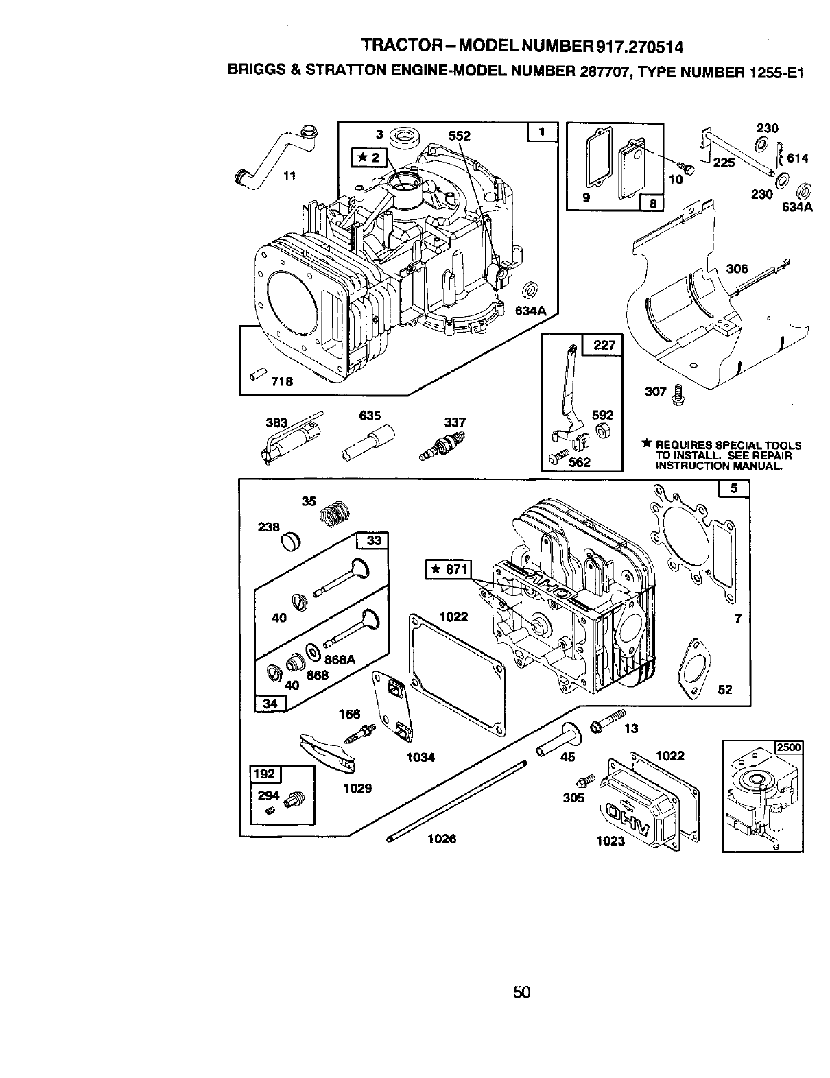
TRACTOR -- MODEL NUMBER 917.270514
BRIGGS & STRATI'ON ENGINE-MODEL NUMBER 287707, TYPE NUMBER 1255°E1
11
238 0
635
552 I 1
@
337
3o7
562
"_rREQUIRES SPECIAL TOOLS
TO INSTALL. SEE REPAIR
INSTRUCTION MANUAl_
1026
_13
45
305
1023
1022
7
52
5O
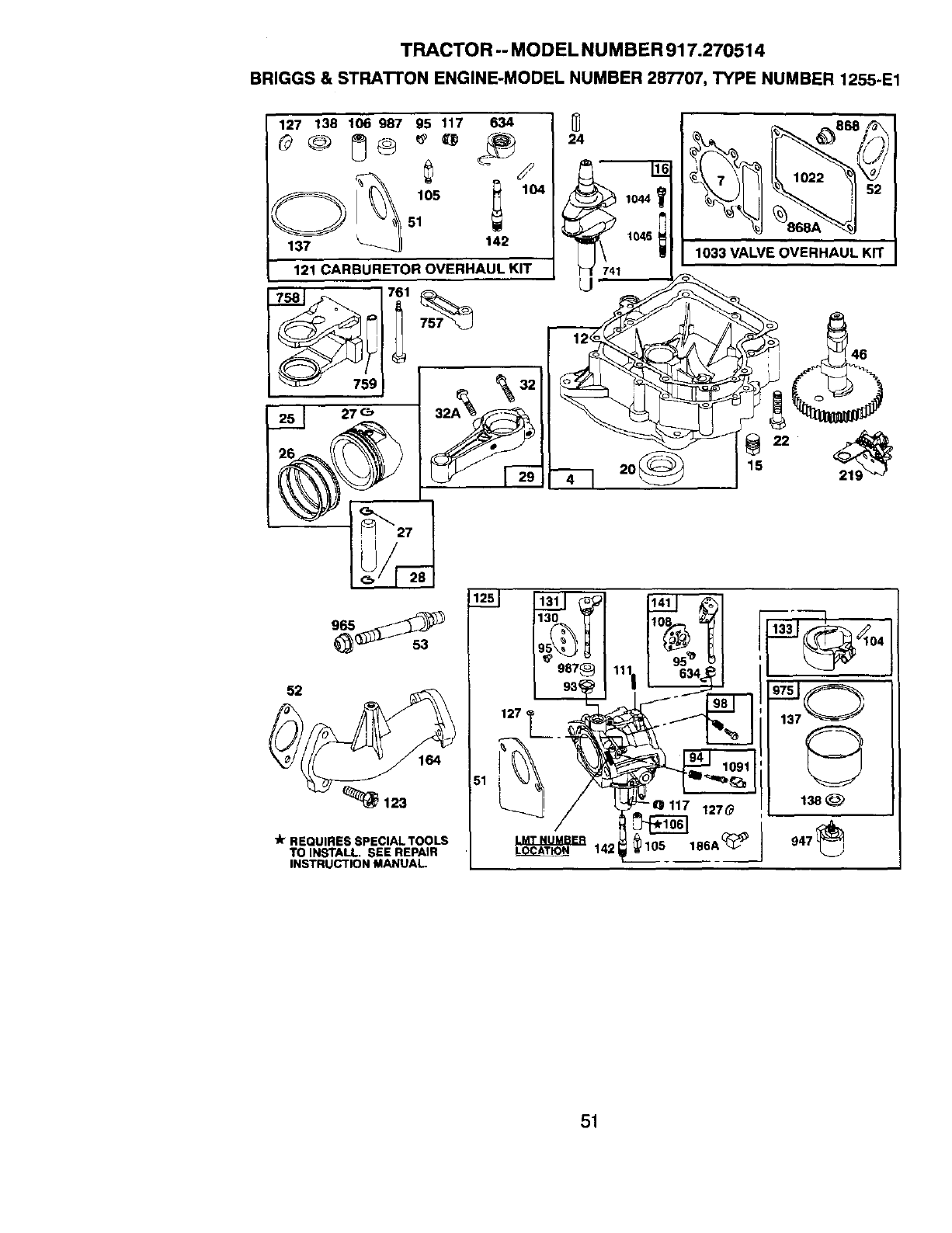
TRACTOR -- MODEL NUMBER 917.270514
BRIGGS & STRA'I'rON ENGINE-MODEL NUMBER 287707, TYPE NUMBER 1255.E1
127 138 106 987 95 117 634
_137 _-_ 142
|121 CARBURETOR OVERHAUL KIT
91'i
52
_123
lit REQUIRES SPECIALTOOLS
TO INSTALL. SEE REPAIR
INSTRUCTION MANUAL.
51
24
741 1046
o
52
_se_
1033 VALVE OVERHAUL KIT
51
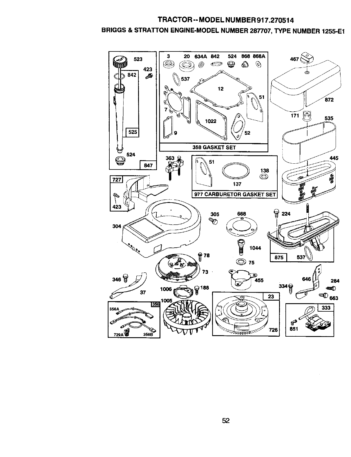
TRACTOR -- MODEL NUMBER 917.270514
BRIGGS & STRATrON ENGINE-MODEL NUMBER 287707, TYPE NUMBER 1255oE1
3
423
3 20 634A 842 524 868 868A I
o 51
358 GASKET SET
_@ _1 138
137
977 CARBURETOR GASKET SET
171 535
3O4
305 668
1044
75
333
851_
52
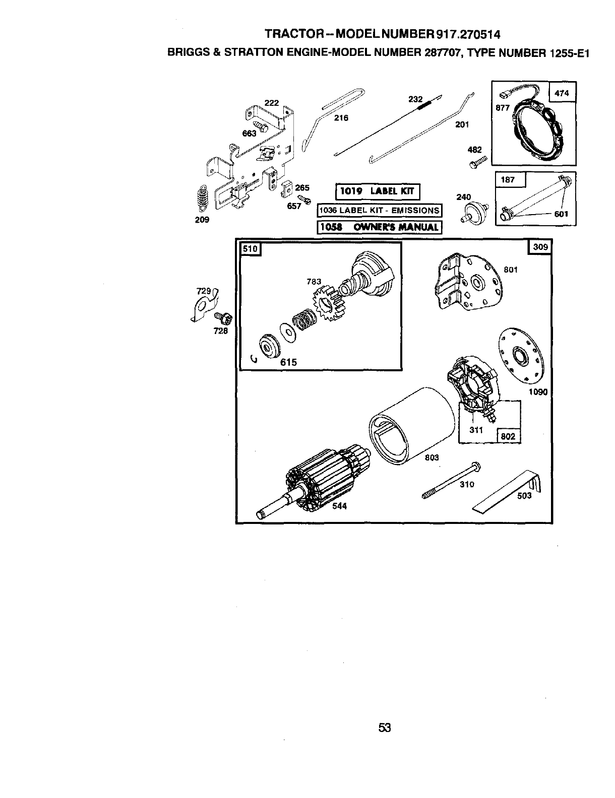
TRACTOR -- MODEL NUM BER 917.270514
BRIGGS & STRA'I-I'ON ENGINE-MODEL NUMBER 287707, TYPE NUMBER 1255-E1
222 I,,
2O9
783
7'28
J1019 LABELKIT J
[1036 LABEL KIT- E.,SS,ONSI
[lo_ O_E__.u_,l
44
201
482
801
1090
803
1
5,3
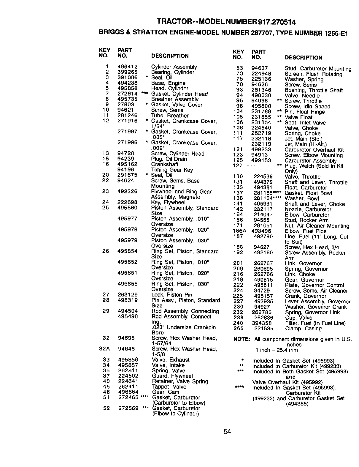
TRACTOR-- MODEL NUMBER 917.270514
BRIGGS & STRATrON ENGINE-MODEL NUMBER 287707, TYPE NUMBER 1255-E1
KEY PART KEY PART
NO. NO. DESCRIPTION NO. NO. DESCRIPTION
1496412 Cylinder Assembly 53 94637 Stud, Carburetor Mountin(.
2 399265 Bearing, Cylinder 73 224948 Screen, Flush Rotating
3 391086 * Seal, Oil 75 225136 Washer, Spring
4 494238 Base, Engine 78 94626 Screw, Sems
5 495858 Head, Cylinder 93 281346 Bushing, Throttle Shaft
7 272614 *** Gasket, Cylinder Head 94 498030 Valve, Needle
8 495735 Breather Assembly 95 94098 ** Screw, Throttle
9 27803 * Gasket, Valve Cover 98 495800 Screw, Idle Speed
10 94621 Screw, Sems 104 231789 ** Pin, Float Hinge
11 281246 Tube, Breather 105 231855 ** Valve Float
12 271916 *Gasket, Crankcase Cover, 106 231854 ** Seat, tn_etValve
1/64" 108 224540 Valve, Choke
271997 *Gasket, Crankcase Cover, 111 262719 Spring, Choke
.005" 117 232118 Jet, Main (Std.)
271996 *Gasket, Crankcase Cover, 232119 Jet, Main (Hi-AIt.)
.009" 121 499233 Carburetor Overhaul Kit
13 94728 Screw, Cylinder Head 123 94913 Screw, Elbow Mounting
15 94239 Plug, OII Drain 125 499153 Carburetor Assembly
16 495162 Crankshaft 127 --- ** Plug, Welch (Sold in Kit
94196 Timing Gear Key Only)
20 291675 *Seal, Oil 130 224539 Valve, Throttle
22 94624 Screw, Seres, Base 131 494379 Shaft and Lever, Throttle
Mounting 133 494381 Float, Carburetor
23 492326 Flywheel and Ring Gear 137 281165"*** Gasket, Float Bowl
Assembly, Magneto 138 281164"*** Washer, Bowl
24 222698 Key, Flywheel 141 495931 Shaft and Lever, Choke
25 495860 Piston Assembly, Standard 142 232117 Nozzle, Carburetor
Size 164 214047 Elbow, Carburetor
495977 Piston Assembly, .010" t66 94555 Stud, Rocker Arm
Oversize 171 281051 Nut, Air Cleaner Mounting
495978 Piston Assembly, .020" 186A 493496 Elbow, Fuel Pipe
Oversize t87 492790 Line, Fuel (11" Long, Cut
495979 Piston Assembly, .030" to Suit)
Oversize 188 94627 Screw, Hex Head, 3/4
26 495854 Ring Set, Piston, Standard 192 492160 Screw Assembly, Rocker
Size Arm
495852 Ring Set, Piston, .0t0" 201 262767 Link, Governor
Oversize 209 260695 Spring, Governor
495851 Ring Set, Piston, .020" 216 262766 Link, Choke
Oversize 219 490815 Gear, Governor
495855 Ring Set, Piston, .030" 222 495611 Plate, Governor Control
Oversize 224 94729 Screw, Sems, Air Cleaner
27 263129 Lock, Piston Pin 225 495157 Crank, Governor
28 498319 Pin Assy., Piston, Standard 227 493935 Lever Assembly, Governo,
Size 230 94927 Washer, Governor Crank
29 494504 Rod Assembly, Connecting 232 262785 Spring, Governor Link
495490 Rod Assembly, Connect- 238 262836 Cap, Valve
ing, 240 394358 Filter, Fuel (In Fuel Line)
.020" Undersize Crankpin 265 221535 Clamp, Casing
Bore
32 94695 Screw, Hex Washer Head, NOTE: All component dimensions given in U._
1-57/84 inches
32A 94648 Screw, Hex Washer Head, 1 inch = 25.4 mm
1-5/8
33 495856 Valve, Exhaust * |nc_uded In Gasket Set (495993)
34 495857 Valve, Intake ** Included in Carburetor Kit (499233)
35 262811 Spring, Valve *'* Included In Both Gasket Set (495993)
37 224502 Guard, Flywheel and
40 224641 Retainer, Valve Spring Valve Overhaul Kit (495992)
45 262411 Tappet, Valve **** Included In Gasket Set (495993),
46 496884 Gear, Cam Carburetor Kit
51 272465 **** Gasket, Carburetor (499233) and Carburetor Gasket Set
(Carburetor to Elbow) (494385)
52 272569 *** Gasket, Carburetor
(Elbow to Cylinder)
54
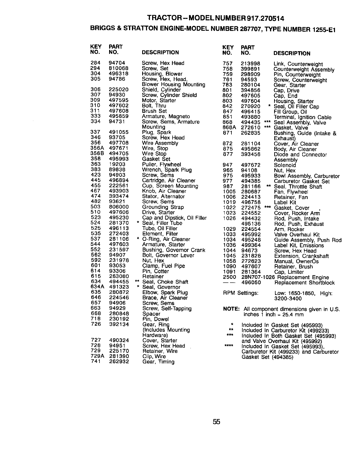
TRACTOR -- MODEL NUMBER 917.270514
BR|GGS & STRATTON ENGINE-MODEL NUMBER 287707, TYPE NUMBER 1255-E1
KEY PART KEY PART
NO, NO. DESCRIPTION NO. NO, DESCRIPTION
284 94704 Screw, Hex Head 757 213998
294 810068 Screw, Set 758 399891
304 496318 Housing, Blower 759 298909
305 94786 Screw, Hex, Head, 761 94593
Blower Housing Mounting 783 280104
306 225020 Shield, Cylinder 801 394856
307 94930 Screw, Cylinder Shield 802 497605
309 497595 Motor, Starter 803 497604
310 497602 Bolt, Thru 842 270920
311 497608 Brush Set 847 496415
333 495859 Armature, Magneto 851 493880
334 94731 Screw, Sems, Armature 868 494435
Mounting 868A 272610
337 491055 Plug, Spark 871 262835
346 93705 Screw, Hex Head
356 497708 Wire Assembly 872 261104
356A 497671 Wire, Stop 875 495862
356B 494705 Wire Stop 877 393456
358 495993 Gasket Set
363 19203 Puller, Flywheel 947 497672
383 89838 Wrench, Spark Plug 965 94108
423 94903 Screw, Sems 975 495933
445 496894 Cartridge, Air Cleaner 977 494385
455 222561 Cup, Screen Mounting 987 281166
467 493903 Knob, Air Cleaner 1005 280687
474 393474 Stator, Alternator 1006 224413
462 93621 Screw, Sems 1019 496768
503 806000 Grounding Strap 1022 272475
510 497606 Drive, Starter 1023 224552
523 495230 Cap and Dipstick, Oil Filler 1026 494432
524 281370 *Seal, Filler Tube 495136
525 496113 Tube, Oil Filler 1029 224554
535 272403 Element, Filter 1033 495992
537 281106 * O-Ring, Air Cleaner 1034 495248
544 497603 Armature, Starter 1036 499364
552 231597 Bushing, Governor Crank 1044 94673
562 94907 Bolt, Governor Lever 1045 231826
592 231978 Nut, Hex 1058 272623
601 93053 Clamp, Fuel Pipe 1090 497607
614 93306 Pin, Cotter 1091
615 263080 Retainer 2500
634 494455 ** Seal, Choke Shaft
634A 491323 * Seal, Governor
635 280872 Elbow, Spark Plug
846 224546 Brace, Air Cleaner
657 94906 Screw, Sems
663 94929 Screw, Self-Tapping
668 280848 Spacer
718 230192 Pin, Dowel
726 392134 Gear, Ring
(Includes Mounting
Hardware)
727 490324 Cover, Starter
728 94951 Screw, Hex Head
729 225170 Retainer, Wire
729A 281390 Clip, Wire
741 262932 Gear, Timing
Link, Counterweight
Counterweight Assembly
Pin, Counterweight
Screw, Counterweight
Gear, Starter
Cap, Drive
Cap, End
Housing, Starter
* Seal, Oil Filler Cap
Fill Group, Oil
Terminal, Ignition Cable
*'*'* Seal Assembly, Valve
*** Gasket, Valve
Bushing, Guide (Intake &
Exhaust)
Cover, Air Cleaner
Body, Air Cleaner
Diode and Connector
Assembly
Solenoid
Nut, Hex
Bowl Assembly, Carburetor
Carburetor Gasket Set
** Seal, Throttle Shaft
Fan, Flywheel
Retainer, Fan
Label Kit
*** Gasket, Cover
Cover, Rocker Arm
Rod, Push, Intake
Rod, Push, Exhaust
Arm, Rocker
Valve Overhaul Kit
Guide Assembly, Push Rod
Label Kit, Emissions
Screw, Hex Head
Extension, Crankshaft
Manual, OwnerOs
Retainer, Brush
281364 Cap, Limiter
28N707-1026 Replacement Engine
496050 Replacement Shortblock
RPM Settings: Low: 1650-1850, High:
3290-3400
NOTE: All component dimensions given in U.S.
inches 1inch = 25.4 mm
*Included In Gasket Set_495993)
** Itlcluded In Carburetor Kit (499233)
*** Included In Both Gasket Set (495993)
and Valve Overhaul Kit (495992)
**** Included In Gasket Set (495993),
Carburetor Kit (499233) and Carburetor
Gasket Set (494385)
55

56

57

58

SUGGESTED GUIDE FOR SIGHTING SLOPES FOR SAFE OPERATION
SIGHTING "..._CUT
GUIDE TH_s
ONLY RIDE UP AND DOWN HILL,
NOT ACROSS HILL
/_ Operate your Tractor up and down the face of slopes (not
iN A,A greater than 15°), never across.the face. Make turns gradu-
ill _ ally to prevent tipping or loss of control. Exercise extreme
:ill caution when changing direction on slopes.

For in-home major brand repair service:
Call 24 hours a day, 7 days a week
1-800-4-MY-HOME sM (1-800-469-4663)
Para pedir servicio de reparacibn a domicilio
1-800-676-5811
In Canada for all your service and parts needs call
Au Canada pour tout le service ou les pi_ces
1-800-665-4455
For the repair or replacement parts you need:
Call 6 am - 11 pm CST, 7 days a week
PartsDirect sM
1-800-366-PART (1-800-366-7278)
Para ordenar piezas con entrega a domicilio
1-800-659-7084
For the location of a Sears Parts and Repair Center
in your area:
Call 24 hours a day, 7 days a week
1-800-488-1222
For information on purchasing a Sears Maintenance
Agreement or to inquire about an existing Agreement:
Call 9 am - 5 pro, Monday - Saturday
1-800-827-6655
r •
169002 Rev. 7 9.21.99 TR/RD/TR/RH/TR/RH/MH Printed in U.S.A.
