Craftsman 917270621 User Manual TRACTOR Manuals And Guides L0810051
CRAFTSMAN Lawn, Tractor Manual L0810051 CRAFTSMAN Lawn, Tractor Owner's Manual, CRAFTSMAN Lawn, Tractor installation guides
User Manual: Craftsman 917270621 917270621 CRAFTSMAN TRACTOR - Manuals and Guides View the owners manual for your CRAFTSMAN TRACTOR #917270621. Home:Lawn & Garden Parts:Craftsman Parts:Craftsman TRACTOR Manual
Open the PDF directly: View PDF ![]() .
.
Page Count: 60

Owner's Manual
@
15.5 HP
ELECTRQC STAR'["
42" MOWER
HYDROSTATIC (AUTOMATIC)
LAW TRACTOR
Model No.
917.270621
° Safety
o Assembly
o Operation
o Maintenance
o Repair Parts
CAUTION:
Read and follow all
Safety RuSes and Instructions
before operating this equip-
ment.
For answers to your questions
about this product, Call:
1o800o659o5917
Sears Craftsman Help Line
5 am - 5 pm, Mon - Sat
Sears, Roebuck and Co_, Hoffman Estates, IL 60179
Warranty ............................................................2 Product Specifications .............................. 19
Safety Rules ................................................. 2 Service and Adjustments ........................ 22
Operation ........................................................ 11 Troubleshooting ...................................................30
Maintenance Schedule ...............................18 Repair Parts ........................................................36
Maintenance ......................................................18 Parts Ordering ....................... Back Cover
LIMITED TWO YEAR WARRANTY ON CRAFTSMAN RIDING EQUIPMENT
For two (2) years from the date of purchase, if this Craftsman Riding Equipment is main-
tained, lubricated and tuned up according to the instructions in the owner's manual,
Sears will repair or replace, free of charge, any parts found to be defective in material or
workmanship,,
This Warranty does not cover:
. Expendable items which become worn during normal use, such as blades, spark
plugs, air cleaners, belts, etco
o Tire replacement or repair caused by punctures from outside objects, such as nails,
thorns, stumps, or glass.
o Repairs necessary because of operator abuse, negligence, improper storage or' acci-
dent or the failure to maintain the equipment according to the instructions contained in
the owner's manual.
= Riding equipment used for commercial or rental purposes..
LIMITED 90 DAY WARRANTY ON BATTERY
For ninety (90) days from date of purchase, if any battery included with this riding equip-
ment proves defective in material or workmanship and our testing determines the bat-
tery will not hold a charge, Sears wilt replace the battery at no charge, in-home warranty
service on your Craftsman riding equipment is available at no charge for' 30 days from
the date of purchaser Please contact your nearest service center. After' 30 days from the
date of purchase, warranty service is available by taking your Craftsman riding equip-
ment to your nearest Sears Service Center, (In-home warranty service will still be avail-
able after 30 days from the date of purchase but a standard trip charge will apply)° This
warranty applies only while this product is in the United States.. This Warranty gives you
specific legal rights, and you may also have other rights which may vary from state to
state
Sears, Roebuck and Co. D/817 WA, Hoffman Estates, IL 60179
GENERAL: OPERATION
° Read, understand, and follow all insiruc-
tions in the manual and on the machine
before starting..
o Only allow responsible adults, who are
familiar with the instructions, to operate
the machine.
o Clear the area of objects such as rocks,
toys, wire, etc., which could be picked
up and thrown by the blade.
,, Be sure the area is clear of other people
before mowing.. Stop machine if anyone
enters the area,.
2
Never carry passengers.
° Do not mow in reverse unless absolute-
ly necessary. Always look down and
behind before and while backing.
o Be aware of the mower discharge direc-
tion and do not point it at anyone. Do
not operate the mower without either
the entire grass catcher or the guard in
place..
o Stow down before turning.
o Never leave a running machine unat-
tended, Always turn off blades, set park-
ing brake, stop engine, and remove
keys before dismounting.
,, Turnoffbladeswhennot mowing..
o Stopenginebeforeremovinggrass
catcheror uncloggingchute..
• Mowonlyin daylightor goodartificial
light°
o Donotoperatethemachinewhileunder
the influenceof alcoholor drugs°
o Watchfor trafficwhenoperatingnearor
crossingroadways.
o Useextracarewhenloadingor unload-
ingthe machineintoa trailerortruck.,
SLOPE OPERATION
Slopesarea majorfactorrelatedto loss-
of-controlandtipoveraccidents,which
can resultinsevereinjuryordeath..All
slopesrequireextracaution.Ifyoucannot
backup the slopeor if youfeeluneasyon
it,do notmowit.
DO:
• Mowupanddown.slopes,notacross.
° Removeobstaclessuchas rocks,tree
limbs,etc..
oWatch for holes, ruts, or bumps_ Uneven
terrain could overturn the machine. Tall
grass can hide obstacles°
o Use slow speed. Choose a low gear so
that you will not have to stop or shift
while on the slope.
° Follow the manufacturer's recommen-
dations for wheel weights or counter-
weights to improve stability_
o Use extra care with grass catchers or
other attachments. These can change
the stability of the machine.
o Keep all movement on the slopes slow
and gradual.. Do not make sudden
changes in speed or direction°
,, Avoid starting or stopping on a slope. If
tires lose traction, disengage the blades
and proceed slowly straight down the
slope..
DO NOT:
oDo not turn on slopes unless necessary,
and then, turn slowly and gradually
downhill, if possible_
oDo not mow near drop-offs, ditches, or
embankments.. The mower could sud-
denly turn over if a wheel is over the
edge of a cliff or ditch, or if an edge
caves in o
oDo not mow on wet grass. Reduced
traction could cause sliding,,
Do not try to stabilize the machine by
putting your foot on the ground.
oDo not use grass catcher on steep
slopes.
CHILDREN
Tragic accidents can occur if the operator
is not alert to the presence of children.
Children are often attracted to the
machine and the mowing activity. Never
assume that children will remain where
you last saw them
o Keep children out of the mowing area
and under the watchful care of another
responsible adult.
° Be alert and turn machine off if children
enter the area°
o Before and when backing, look behind
and down for small children°
o Never carry children° They may fall off
and be seriously injured or interfere with
safe machine operation°
o Never allow children to operate the
machine..
o Use extra care when approaching blind
corners, shrubs, trees, or other objects
that may obscure vision.
SERVICE
oUse extra care in handling gasoline and
other fuels, They are flammable and
vapors are explosive°
- Use only an approved container.
- Never remove gas cap or add fuel
with the engine running° Allow en-
gine to cool before refueling.. Do not
smoke.
Never refuel the machine indoors°
Never store the machine or fuel
container inside where there is an
open flame, such as a water heater,.
o Never run a machine inside a closed
area.
o Keep nuts and bolts, especially blade
attachment bolts, tight and keep equip-
ment in good condition.
,_ Never tamper with safety devices.
Check their proper operation regularly
o Keep machine free of grass, leaves, or
other debris build-up. Clean oil or fuel
spillage. Allow machine to cool before
storing..
o Stop and inspect the equipment if you
strike an object,. Repair, if necessary,
3
O
before restarting, manufacturer's recommended parts,
Never make adjustments or repairs with when necessary.
_:tbe_.eng_e runningi ::,_:,_;::, .............................._i-_:_:_!Mower>b!ades,-are sha,rp:and,_ canput:._:_
Grass catcher components are subject Wrap the blade(s) or wear gloves, and
to wear; damage, and deterioration, use extra caution when sewicing them,
which could expose moving parts or - Check brake operation frequently°
allow objects to be th[own, Frequently Adjust and service as required.
check components and replace with
o Be sure the area is clear of other people
before mowing. Stop machine if anyone
enters the area..
o Never'carry passengers°
° Do not mow in reverse unless absolute-
ly necessary. Always look down and
behind before and while backing.,
o Never carry children,, They may fall off
and be seriously injured or interfere with
safe machine operation.
. Keep children out of the mowing area
and under the watchful care of another'
responsible adult.
o Be alert and turn machine off if children
enter the area.
o Before and when backing, look behind
and down for small children,,
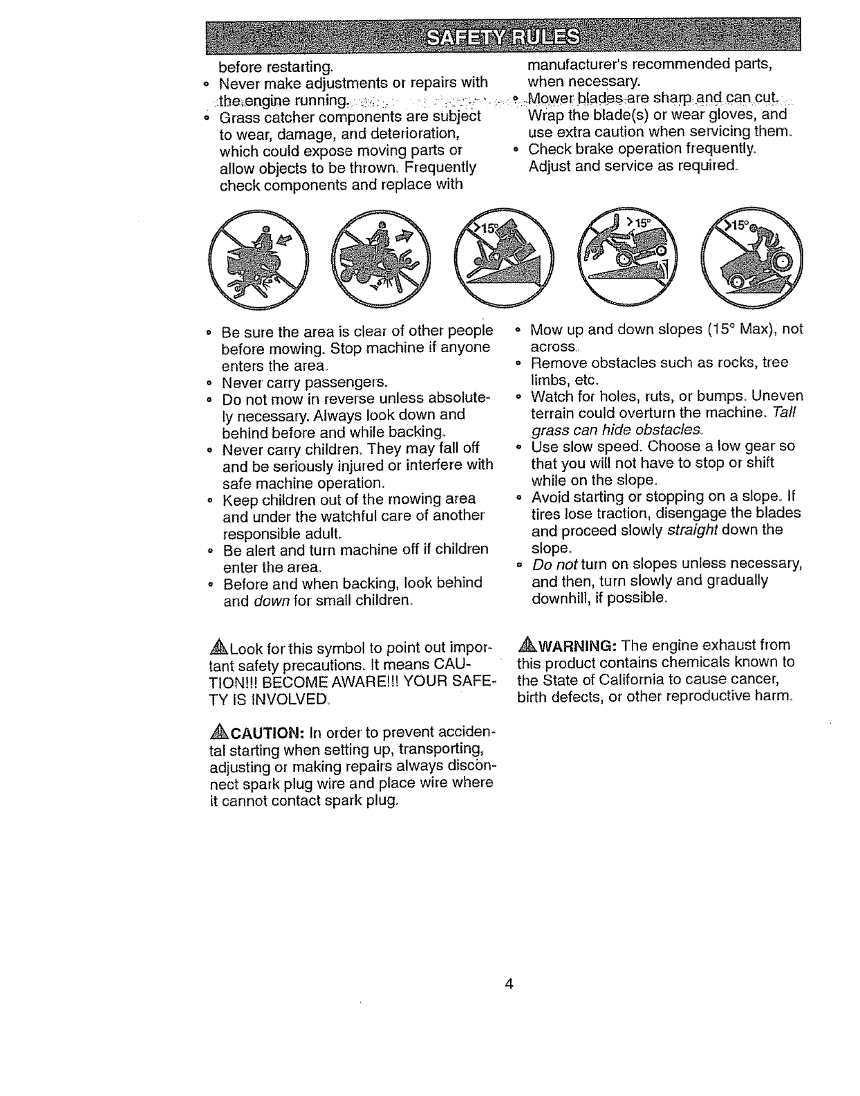
o Mow up and down slopes (15 ° Max), not
across.
• Remove obstacles such as rocks, tree
limbs, etc..
° Watch for' holes, ruts, or bumps.. Uneven
terrain could overturn the machine. Tall
grass can hide obstacles..
o Use slow speed. Choose a low gear' so
that you will not have to stop or shift
while on the slope.
o Avoid starting or stopping on a slope, tf
tires lose traction, disengage the blades
and proceed slowly straight down the
slope_
oDo notturn on slopes unless necessary,
and then, turn slowly and gradually
downhill, if possible°
,_Look for this symbo! to point out impor-
tant safety precautions. It means CAU-
TION!!! BECOME AWARE!!! YOUR SAFE-
TY IS INVOLVED,.
_CAUTION: In order to prevent acciden-
tal starting when setting up, transporting,
adjusting or making repairs always disc6n-
nect spark plug wire and place wire where
it cannot contact spark plug.
_WARNING: The engine exhaust from
this product contains chemicals known to
the State of California to cause cancer,
birth defects, or other reproductive harm°
4
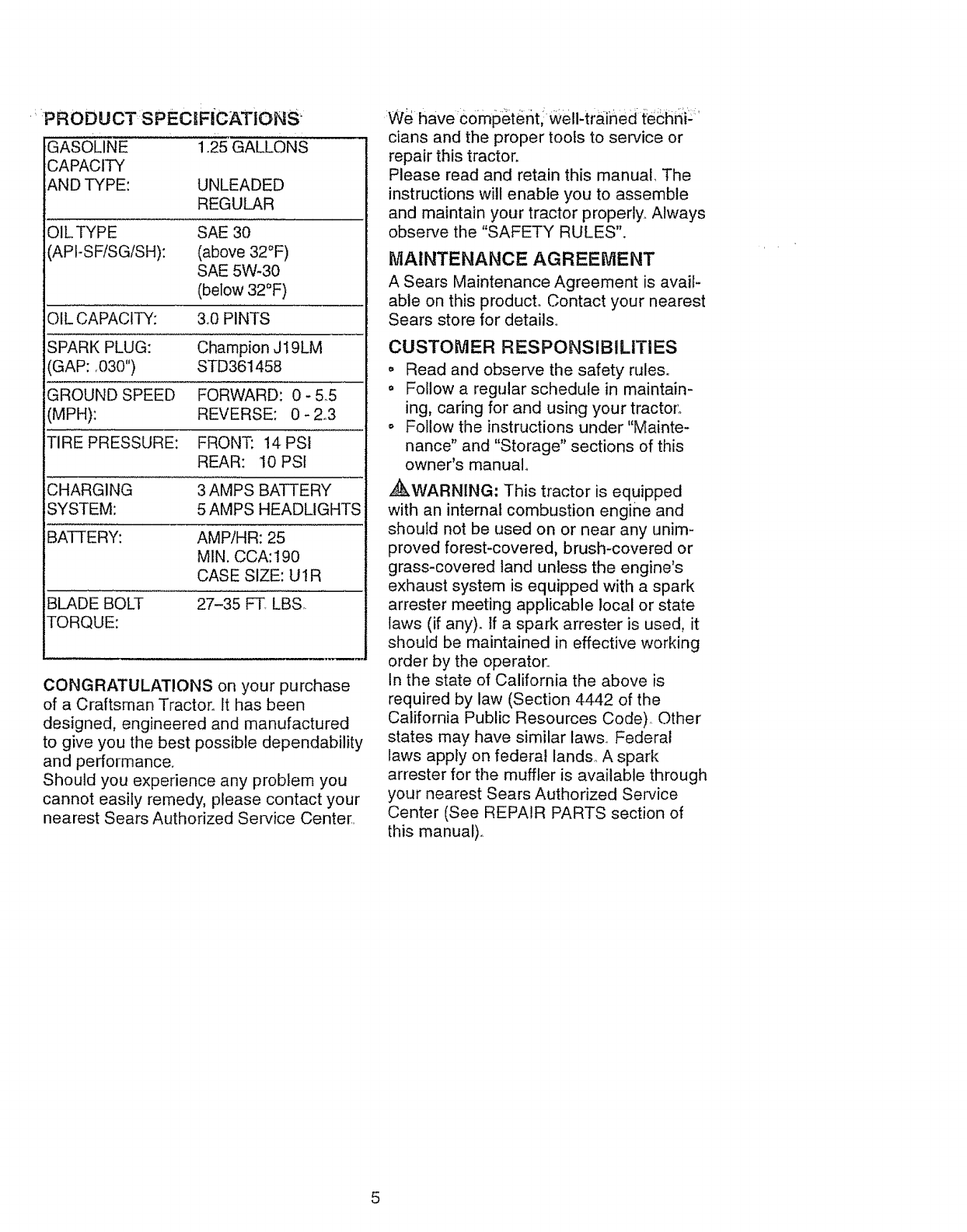
GASOLINE
CAPACITY
ANDT'(PE:
1.25GALLONS
UNLEADED
REGULAR
OIL TYPE
(APIoSF/SG/SH):
SAE 30
(above 32°F)
SAE 5W-30
(below 32°F)
OIL CAPACITY: 3,0 PINTS
SPARK PLUG: Champion J19LM
(GAP: .030") STD361458
GROUND SPEED FORWARD: 0- 5.5
(MPH): REVERSE: 0-2o3
TIRE PRESSURE: FRONT: 14 PSI
REAR: 10PSt
CHARGING 3 AMPS BATTERY
SYSTEM: 5 AMPS HEADLIGHTS
BATTERY: AMP/HR: 25
M1N. CCA:t90
CASE SIZE: U1R
BLADE BOLT 27-35 FT LBS,.
TORQUE:
CONGRATULATIONS on your purchase
of a Craftsman Tractor. It has been
designed, engineered and manufactured
to give you the best possible dependability
and performance.
Should you experience any problem you
cannot easily remedy, please contact your
nearest Sears Authorized Service Center.
We have €ompeter_ti well-trained {-eshni::
clans and the proper tools to service or
repair this tractor.
Please read and retain this manual, The
instructions will enable you to assemble
and maintain your tractor properly.. Always
observe the "SAFETY RULES".
MAINTENANCE AGREEMENT
A Sears Maintenance Agreement is avail-
able on this product. Contact your nearest
Sears store for details..
CUSTOMER RESPONSIBILITIES
o Read and observe the safety rules°
o Follow a regular schedule in maintain-
ing, caring for and using your tracto[:
o Follow the instructions under"Mainte-
nance" and "Storage" sections of this
owner's manual°
,4&WARNING: This tractor is equipped
with an internal combustion engine and
should not be used on or near any unim-
proved forest-covered, brush-covered or
grass-covered land unless the engine's
exhaust system is equipped with a spark
arrester meeting applicable local or state
laws (if any). tf a spark arrester is used, it
should be maintained in effective working
order by the operator.
In the state of California the above is
required by law (Section 4442 of the
California Public Resources Code), Other
states may have similar laws,. Federal
laws apply on federal lands,, A spark
arrester for the muffler is available through
your nearest Sears Authorized Service
Center (See REPAIR PARTS section of
this manual).
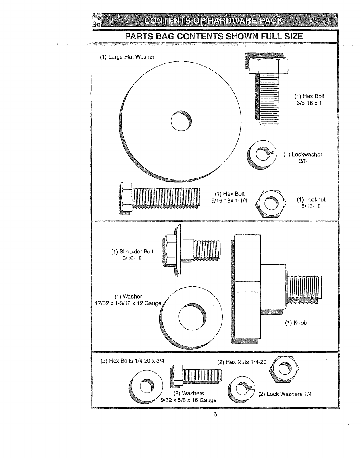
PARTS BAG CONTENTS SHOWN FULL SiZE
(1) Large Flat Washer
(1) Hex Bolt
3t8-16 x 1
(1) Lockwasher
3/8
(1) Hex Bolt
5/16-18x 1-1/4 @ (1) Locknut
5/t6-18
(1) Shoutder Bolt
5/16-18
(1) Washer
17/32 x 1-3/16 x 12 Gauge
(1) Knob
(2) Hex Bolts 1/4-20 x 3/4 (2) Hex Nuts 1/4o20
(2) Washers _ (2) Lock Washers 1/4
9132 x 5/8 x 16 Gauge
6
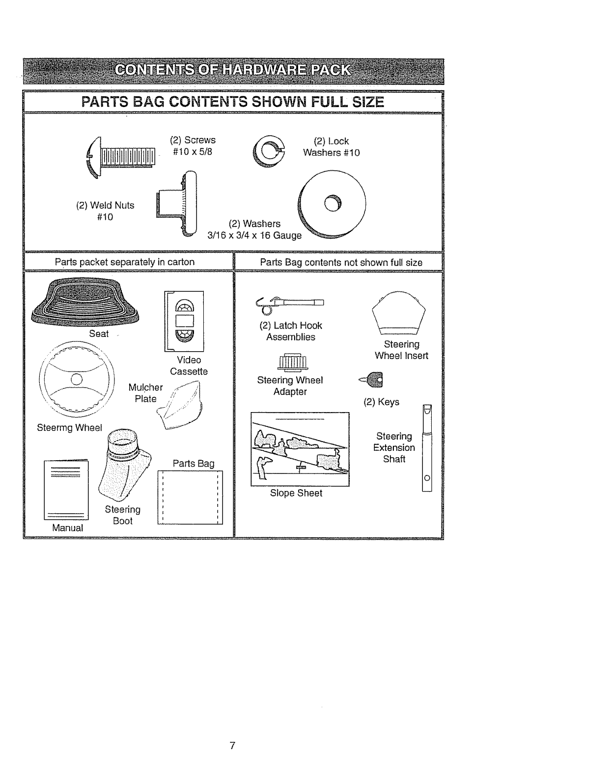
(2) Screws (2) Lock
#10 x 5/8 Washers #10
(2)WeldNuts
#I0 (2) Washers
3/16 x 3/4 x 16 Gauge
_qG _ hw ;¸_ .... ,_ <;, ;;b;;h;_ ;K(_._; ;; -; _
Parts packet separately in carton
Steermg Wheel
Video
Cassette
Mulcher ,;'-J_I
Plate ,/: ,:::'t
Manual
Parts Bag
, J
, ,
Steering ',
Boot
Seat
Parts Bag contents not shown full size
(2) Latch Hook
Assemblies
Steering Wheel
Adapter
Steering
Wheel Insert
(2) Keys
Slope Sheet
Steering
Extension
Shaft
o
7

Yournewtractorhasbeenassembledat thefactorywithexceptionof thosepartsleft
unassembtedfor shippingpurposes,Toensuresafeandproperoperationof your tractor
_:,-a!t,.,p_rtg:andhardware:youassemble..mustbe,tightened:,#ecu.rely.Use.:the:,¢o_rect_toots.,.:r
as necessaryto insurepropertiglitnesslReviewthe Videocassettebef0rey0u_begin.
TOOLS REQUIRED FOR
ASSEMBLY
A socket wrench set wil!make assembly
easier,, Standard wrench sizes you need
are listed below,,
(1) 9/t6" wrench
(2) 7/16" wrenches
(2) t/2" wrench
(1) 3/4" wrench
(1) Utility knife
(1)Pliers
(I) 3/4" Socket w/
drive rachet
(1) Phillips Screw-
driver
(1) Tire pressure
gauge
When right or left hand is mentioned in
this manual, it means, from your point of
view, when you are in the operating posi-
tion (seated behind the steering wheel).
TO REMOVE TRACTOR FROM
CARTON
UNPACK CARTON
o Remove all accessible loose parts and
parts boxes from shipping carton (See
page 6)_
o Cut, from top to bottom, along lines on
all four corners of shipping carton, and
lay panels flat.
o Remove mower and package materials.
o Check for any additional loose parts or
boxes and remove,
BEFORE ROLLING TRACTOR OFF
SKiD
ATTACH STEERING WHEEL
ASSEMBLE EXTENSION SHAFT AND
BOOT
° Slide extension shaft onto lower steer-
ing shafL Align rnounting holes in exten-
sion and lower shafts and install 5/16
hex bolt and IocknuL Tighten securely.
IMPORTANT: Tighten bolt and nut secure-
ty to 18-22 ft. lbs,. torque°
o Place tabs of steering boot over tab
slots in dash and push down to secure.,
INSTALL STEERING WHEEL
° Position front wheels of the tractor so
they are pointing straight fop_vardo
° Slide steering wheel adapter' onto steer-
ing shaft extension.
o Position steering wheel so cross bars
&re horizontal (left to right) and slide
inside boot and onto adapter'.
o Assemble large flat washer, 3/8 lock
washer, 3/8 hex bolt and tighten securely°
• Snap steering wheel insert into center
of steering wheel°
o Remove protective materials from trac _
tor hood and grill.
IMPORTANT: Check for and remove any
staples in skid that may puncture tires
where tractor-is to roll off skid°
Insert
_f..1_ 3/8 Lockwasher
Large Flat
Steering _ Steenng
Wheel _'Boot
Extension _//Adapter
Shaft _ _ 5t16 Hex
Bolt
5/16 Lockn ut ---.._,,.._.,...._/
•°"--i- ,'.'.
Lower Steering--mz__.___R ---'----.
,. ,
Shaft ' I
TO ROLL TRACTOR OFF SKID (See
Operation section for location and
function of controls)
° Press lift lever plunger and raise attach-
ment lift lever' to its highest position.
o Release parking brake by depressing
clutch/brake pedal.
• Place freewheel control in freewheeling
position to disengage transmission (See
"TO TRANSPORT" in the Operation
section of this manual),
o Roll tractor backwards off skid.
o Remove banding holding discharge
guard up against tractor..
HOW TO_'SET U P :YOU R TRACTOR" ' INsTALEsEAT
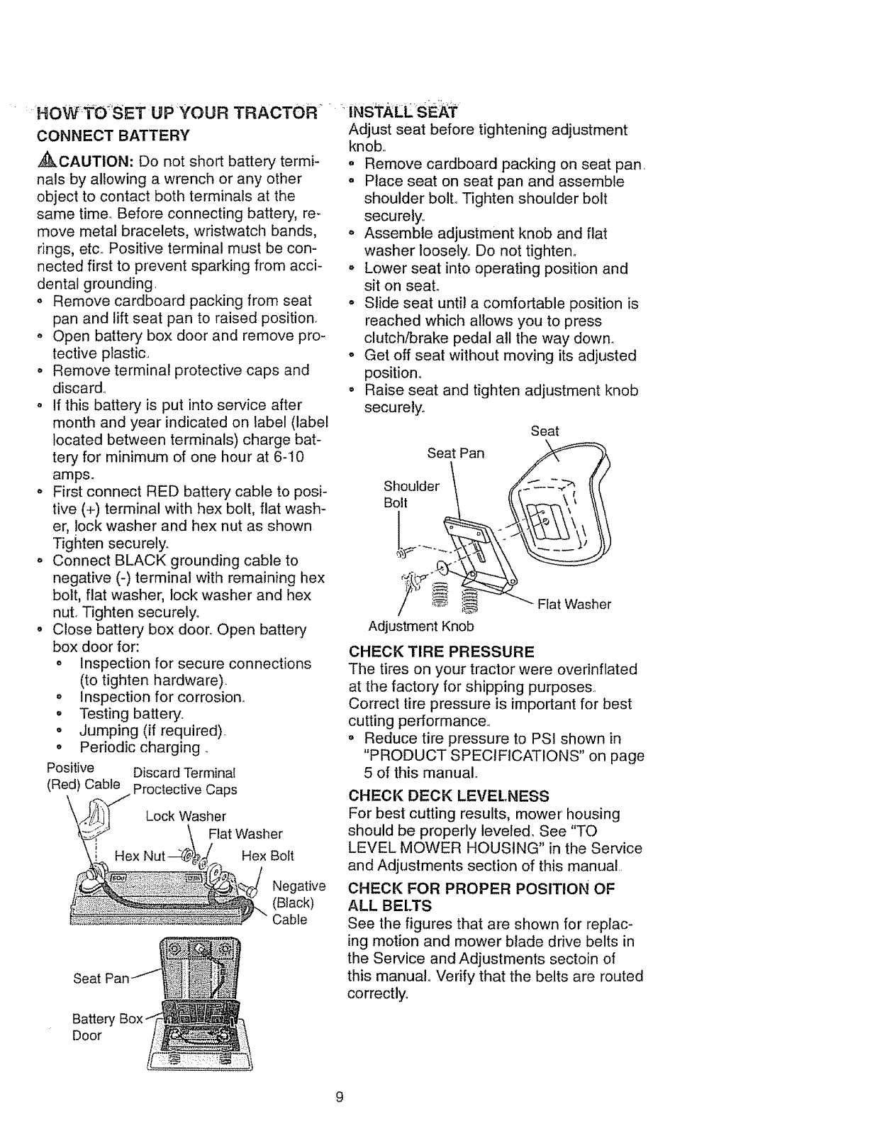
CONNECT BATTERY
_CAUTION: Do not short battery termi-
nals by allowing a wrench or any other
object to contact both terminals at the
same time. Before connecting battery, re-
move metal bracelets, wristwatch bands,
rings, etc., Positive terminal must be con-
nected first to prevent sparking from acci-
dental grounding,
o Remove cardboard packing from seat
pan and lift seat pan to raised position.
Open battery' box door and remove pro-
tective plastic.,
• Remove terminal protective caps and
discard.,
o If this battery is put into service after
month and year indicated on label (label
tocated between terminals) charge bat-
tery for minimum of one hour at 6-10
amps_
• First connect RED battery cable to posi-
tive (+) terminal with hex bolt, flat wash-
er, lock washer and hex nut as shown
Tighten securely.
o Connect BLACK grounding cable to
negative (-) terminal with remaining hex
bolt, flat washer, lock washer and hex
nut, Tighten securely.
oClose battery box door,, Open batten/
box door for:
oinspection for secure connections
(to tighten hardware).
o Inspection for corrosion°
•Testing battery,,
o Jumping (if required)..
o Periodic charging_
Positive Discard Terminal
(Red) Cable Proctective Caps
Lock Washer
Flat Washer
Hex Bolt
Negative
(Black)
Cable
Seat
Battery
Door
Adjust seat before tightening adjustment
knob,,
o Remove cardboard packing on seat pan,
o Place seat on seat pan and assemble
shoulder bolt. Tighten shoulder bolt
securely,,
o Assemble adjustment knob and flat
washer loosely, Do not tighten.
o Lower seat into operating position and
sit on seal
o Slide seat until a comfortable position is
reached which allows you to press
clutch/brake pedal all the way down.
o Get off seat without moving its adjusted
position°
° Raise seat and tighten adjustment knob
securely.
Seat Pan
Shoulder
Bolt
Seat
"_ Flat Washer
Adjustment Knob
CHECK TIRE PRESSURE
The tires on your tractor were overinflated
at the factory for shipping purposes,
Correct tire pressure is important for best
cutting performance,,
Reduce tire pressure to PSI shown in
"PRODUCT SPECIFICATIONS" on page
5 of this manual,,
CHECK DECK LEVELNESS
For best cutting results, mower housing
should be properly leveled. See "TO
LEVEL MOWER HOUSING" in the Service
and Adjustments section of this manual,,
CHECK FOR PROPER POSITION OF
ALL BELTS
See the figures that are shown for replac-
ing motion and mower blade drive belts in
the Service and Adjustments sectoin of
this manual,, Verify that the belts are routed
correctly°
CHECKBRAKE SYSTEM
After you learn how to operate your' trac-
tor, check to see that the brake is properly
adjusted. See 'q'O ADJUST BRAKE" in
fi'le ServiCe an'd.Adjds'tments:Sectiori of
[his manual
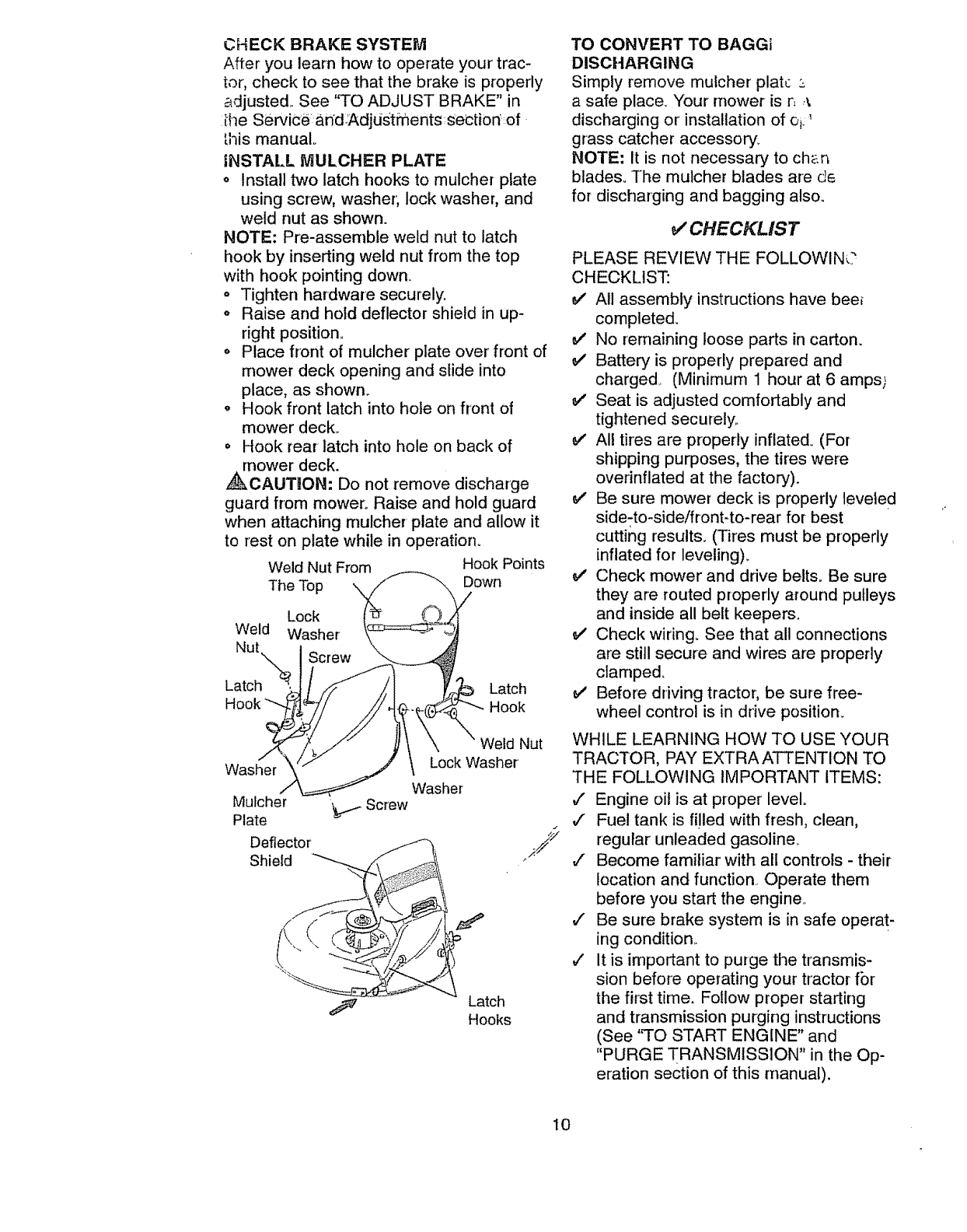
INSTALL MULCHER PLATE
o Install two latch hooks to mulcher plate
using screw, washer; lock washer, and
weld nut as shown.
NOTE: Pre-assernbte weld nut to latch
hook by inserting weld nut from the top
with hook pointing down.
o Tighten hardware securely.
= Raise and hold deflector shield in up-
right position.
o Place front of mulcher plate over front of
mower deck opening and slide into
place, as shown..
,, Hook front latch into hole on front of
mower deck.
,, Hook rear latch into hole on back of
,_,nower deck.
CAUTION," Do not remove discharge
guard from mower° Raise and hold guard
when attaching mulcher plate and allow it
to rest on plate while in operation°
Weld Nut From Hook Points
The Top Down
Lock
Weld Washer
Nut
Latch Latch
Hook
Weld Nut
Lock Washer
Washer
Latch
Hooks
TO CONVERT TO BAGGi
DISCHARGING
Simply remove mulcher plate
a safe place. Your mower is rl _
discharging or' installation of oi: '
grass catcher accessory.
NOTE; It is not necessary to ch_.n
blades_ The mulcher blades are d6
for discharging and bagging also_
V' CHECKLIST
PLEASE REVIEW THE FOLLOWIN(?
CHECKLIST:
v' All assembly instructions have bee_
completed.
v' No remaining loose parts in carton.
v' Battery is properly prepared and
charged (Minimum 1 hour at 6 amps)
e,,' Seat is adjusted comfortably and
tightened securely..
e/' All tires are properly inflated_ (For
shipping purposes, the tires were
overinflated at the factory).
v' Be sure mower deck is properly leveled
side-to-sideifront-to-rear for best
cutting results. (Tires must be properly
inflated for leveling).
_,' Check mower and drive belts. Be sure
they are routed properly around pulleys
and inside all belt keepers.
v' Check wiring_ See that all connections
are still secure and wires are properly
clamped.
v' Before driving tractor, be sure free-
wheel control is in drive position.
WHILE LEARNING HOW TO USE YOUR
TRACTOR, PAY EXTRA ATTENTION TO
THE FOLLOWING IMPORTANT ITEMS:
v" Engine oil is at proper level°
,/ Fuel tank is filled with fresh, clean,
regular unleaded gasoline.
,/ Become familiar with all controls - their
location and function. Operate them
before you start the engine.
,/ Be sure brake system is in safe operat-
ing condition.
v' it is important to purge the transmis-
sion before operating your tractor fbr
the first time. Follow proper starting
and transmission purging instructions
(See 'q'O START ENGINE" and
"PURGE TRANSMISSION" in the Op-
eration section of this manual).
10
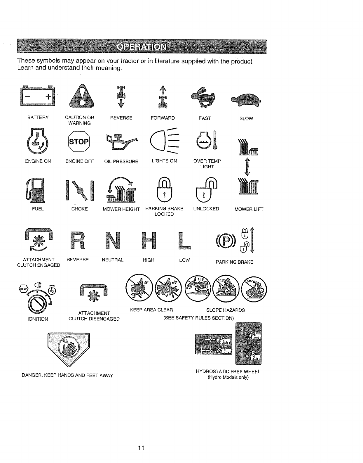
Thesesymbolsmayappearonyourtractoror in literaturesuppliedwiththeproduct,
Learnand understandtheirmeaning,
E 3,&
BATTERY CAUTION OR
WARNING
ENGINE ON ENGINE OFF
FUEL
REVERSE SLOW
OIL PRESSURE
MOWER HEIGHT
FORWARD FAST
LIGHTS ON OVER TEMP
LIGHT
PARKING BRAKE UNLOCKED
LOCKED MOWER LIFT
ATTACHMENT REVERSE
CLUTCH ENGAGED
NEUTRAL LOW
®;
PARKING BRAKE
IGNITION
ATTACHMENT
CLUTCH DISENGAGED
KEEP AREA CLEAR SLOPE HAZARDS
(SEE SAFETY RULES SECTION)
DANGER, KEEP HANDS AND FEET AWAY HYDROSTATIC FREE WHEEL
(Hydro Models only)
1t
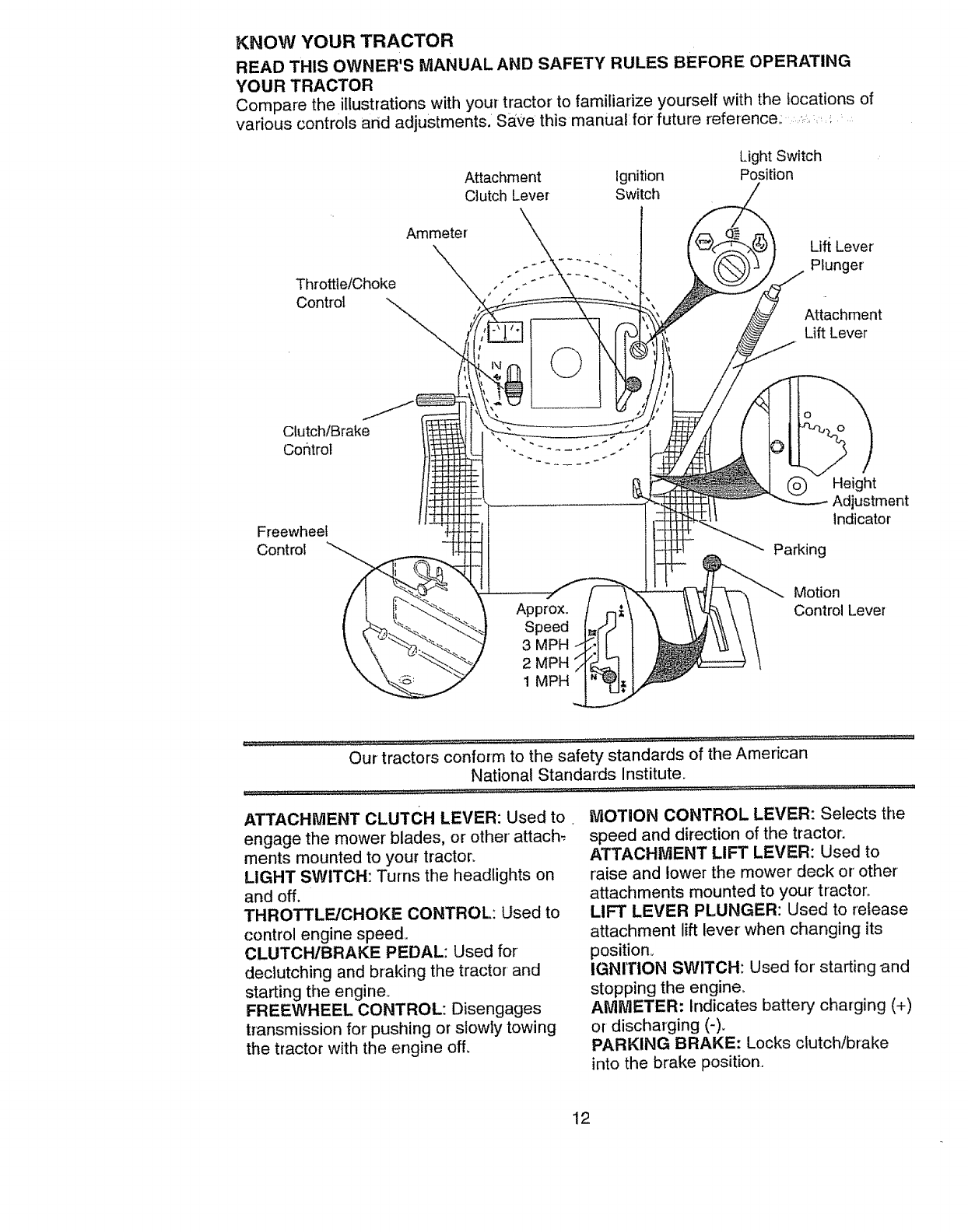
KNOW YOUR TRACTOR
READ THIS OWNER'S MANUAL AND SAFETY" RULES BEFORE OPERATING
YOUR TRACTOR
Compare the illustrations with your tractor to familiarize yourself with the locations of
various controls and adjustments. SAve this manualfor future reference: ,_
Throttle/Choke
Control
Attachment Ignition
Clutch Lever Switch
Ammeter
©
Light Switch
Position
Lift Lever
Plunger
Attachment
Lift Lever
Clutch/Brake
Control
Freewheel
Control
O
Parking
Height
Adjustment
Indicator
Approx.
Speed
3 MPH
2 MPH
1 MPH
Motion
Control Lever
Our tractors conform to the safety standards of the American
National Standards Institute.
ATTACHMENT CLUTCH LEVER: Used to,
engage the mower blades, or other' attach _,
ments mounted to your tractor.
LIGHT SWITCH: Turns the headlights on
and off.
THROTTLE/CHOKE CONTROL: Used to
control engine speed°
CLUTCHIBRAKE PEDAL: Used for
declutching and braking the tractor and
starting the engine,,
FREEWHEEL CONTROL: Disengages
transmission for pushing or slowly towing
the tractor with the engine off.
MOTION CONTROL LEVER: Selects the
speed and direction of the tractor.
ATTACHMENT LIFT LEVER: Used to
raise and lower the mower deck or other
attachments mounted to your tractor°
LIFT LEVER PLUNGER: Used to release
attachment lift lever when changing its
position,,
IGNITION SWITCH: Used for starting and
stopping the engine_
AMMETER: Indicates battery charging (+)
or discharging (-).
PARKING BRAKE: Locks clutch/brake
into the brake position.
12
' he operatidnof anytractorCan-resultih foreign'0B)6ctsthrownint5the.......
eyes,whichcan resultinsevereeyedamage°Alwayswearsafetyglasses
oreyeshieldswhileoperatingyourtractoror performinganyadjustmentsor'
repairs.Werecommendawidevisionsafetymaskoverthespectacles,or
standardsafetyglasses,
HOW TO USE YOUR TRACTOR
Your tractor is equipped with an operator
presence sensing switch, When engine is
running, any attempt by the operator to
leave the seat without first setting the
parking brake will shut off the engine,
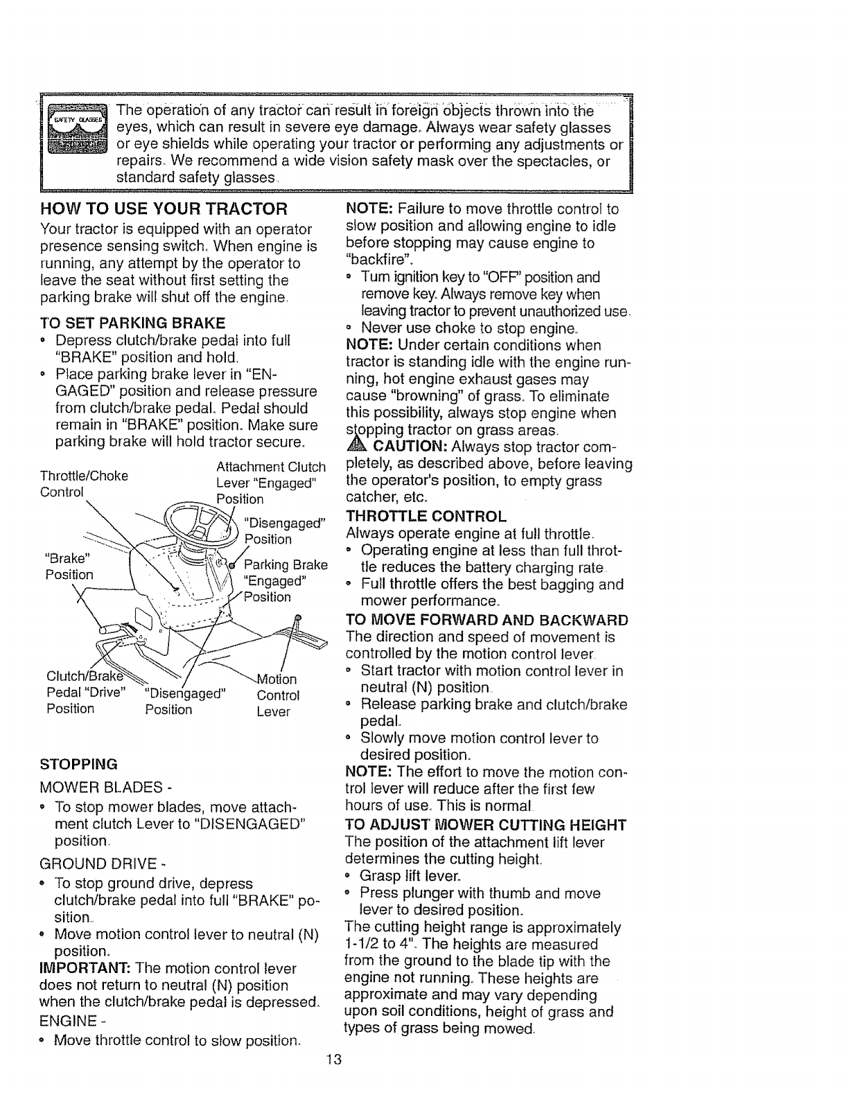
TO SET PARKING BRAKE
o Depress clutch/brake pedal into full
"BRAKE" position and hold.
• Place parking brake lever in "EN-
GAGED" position and release pressure
from clutch/brake pedal Pedal should
remain in "BRAKE" position. Make sure
parking brake will hold tractor secure°
Attachment Clutch
Throttle/Choke Lever "Engaged"
Control
_... Position
_--_-'_, "Disengaged"
,, _ Position
Brake" "'_x"_'_.,_/Parking Brake
Position \ _". ',., _\.iii "En_a-ed ''
Clutc_/_raKe-_._.. "-'-/ "--Motion
Pedal "Drive .... Disengaged" Control
Position Position Lever
STOPPING
MOWER BLADES-
• To stop mower blades, move attach-
ment clutch Lever to "DISENGAGED"
position.
GROUND DRIVE -
• To stop ground drive, depress
clutch/brake pedal into full "BRAKE" po _
sition.,
° Move motion control lever to neutral (N)
position,,
IMPORTANT: The motion control lever
does not return to neutral (N) position
when the clutch/brake pedal is depresse&
ENGINE -
• Move throttle control to slow position.
NOTE: Failure to move throttle control to
stow position and allowing engine to idle
before stopping may cause engine to
"backfire",.
• Turn ignition key to "OFF" position and
remove key. Always remove key when
leaving tractor to prevent unauthorized use,
o Never use choke to stop engine,.
NOTE: Under certain conditions when
tractor is standing idle with the engine run-
ning, hot engine exhaust gases may
cause "browning" of grass,. To eliminate
this possibility, always stop engine when
,_pping tractor on grass areas,
CAUTION: Always stop tractor com-
pletely, as described above, before leaving
the operator's position, to empty grass
catcher, etc_
THROTTLE CONTROL
Always operate engine at ful! throttle.
° Operating engine at less than full throt-
tle reduces the battery charging rate
o Full throttle offers the best bagging and
mower performance,.
TO MOVE FORWARD AND BACKW'ARD
The direction and speed of movement is
controlled by the motion control lever
o Start tractor with motion control lever in
neutral (N) position.
o Release parking brake and clutch/brake
pedal..
o Slowly move motion control lever to
desired position..
NOTE: The effort to move the motion con-
trol lever will reduce after the first few
hours of use_ This is normal
TO ADJUST MOWER CUTTING HEIGHT
The position of the attachment lift lever
determines the cutting height,
o Grasp lift lever.
o Press plunger with thumb and move
lever to desired position.
The cutting height range is approximately
1-1/2 to 4". The heights are measured
from the ground to the blade tip with the
engine not running° These heights are
approximate and may vary depending
upon soil conditions, height of grass and
types of grass being mowed,
13
Theaveragelawnshouldbe cutto
approximately2-1/2inchesduringthe
cool seasonandto over3 inchesduring
hotmonths.,For healthierand better
lookinglawns,,mowoften.andafter
m o;derateg°i;owi_fi:............." ....._" : .....
Forbestcuttingperformance,grass
over6 inchesin heightshouldbe
mowedtwice.Makethe first cut relative-
ly high;thesecondto desiredheight.,
"0 OPERATE MOWER
'our..tractor is equipped with an operator
_resence sensing switch. Any attempt by
he operator to leave the seat with the
:ngine running and the attachment clutch
;ngaged will shut off the engine°
Select desired height of cut,.
Start mower blades by engaging attach-
ment clutch control
TO STOP MOWER BLADES - disen-
age attachment clutch control..
CAUTION: Do not operate the mower
vithout either the entire grass catcher, on
nowers so equipped, or the discharge
]uard in place.
ge
Move motion control lever to neutral (N)
position,.
IMPORTANT: The motion control lever
does not return to neutral (N) position
when the clutch/brake pedal is depressed
o TO restart movement, slowly release "
parking brake and clutch/brake pedal..
oSlowly move motion control lever to
slowest setting.
o Make all turns slowly.
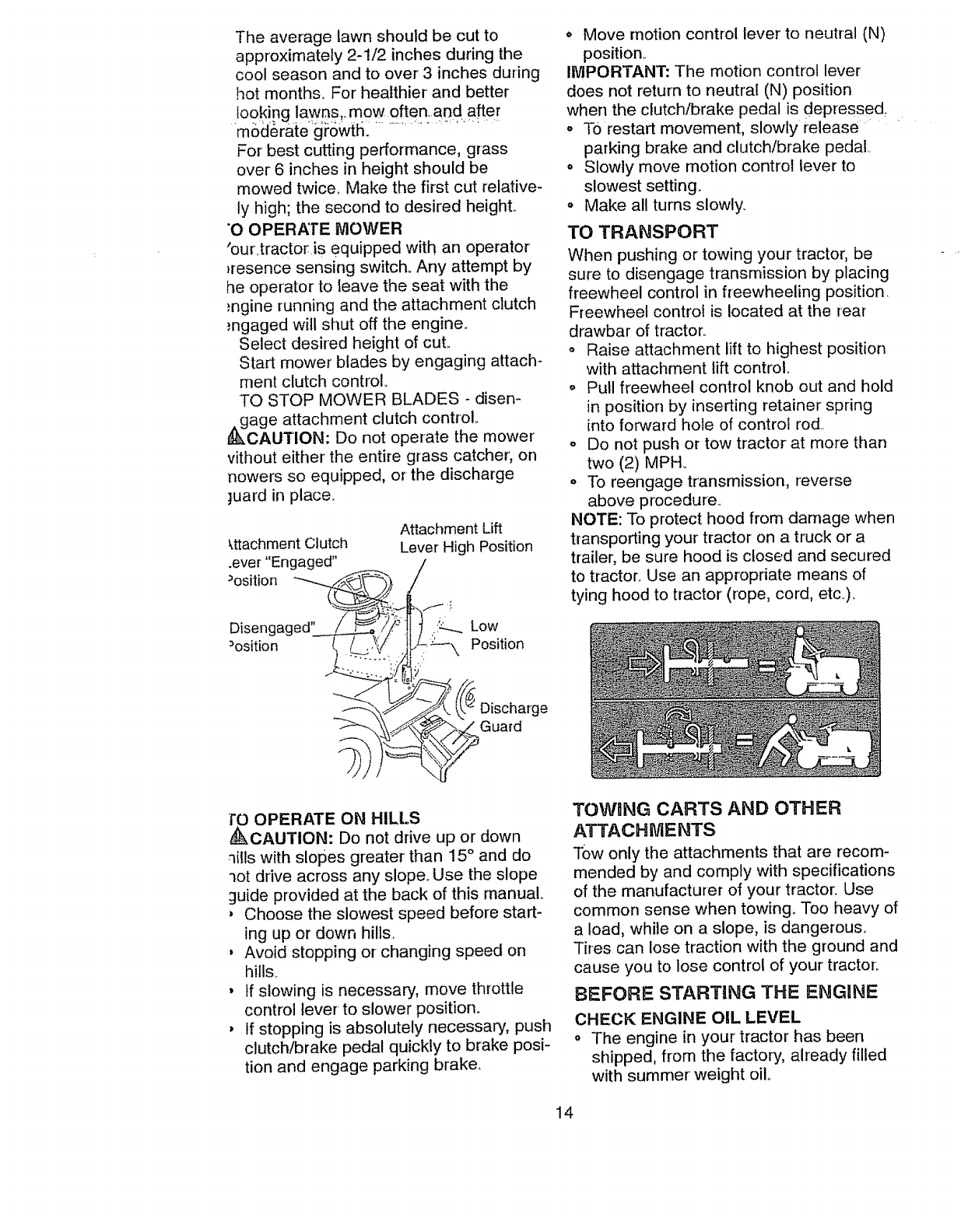
TO TRANSPORT
When pushing or towing your tractor, be
sure to disengage transmission by placing
freewheel control in freewheeling position.
Freewheel control is located at the rear
drawbar of tractor..
o Raise attachment lift to highest position
with attachment lift control.
o Pull freewheel control knob out and hold
in position by inserting retainer spring
into forward hole of control rod..
o Do not push or tow tractor at more than
two (2) MPH_
o ]b reengage transrnission, reverse
above procedure,
NOTE: To protect hood from damage when
transporting your tractor on a truck or a
trailer, be sure hood is closed and secured
to tractor. Use an appropriate means of
tying hood to tractor (rope, cord, etc_).
TO OPERATE ON HILLS
_)kCAUTION: Do not drive up or down
qitls with slopes greater than 15 °and do
"_ot drive across any slope.. Use the slope
guide provided at the back of this manual
, Choose the slowest speed before start-
ing up or down hills.
, Avoid stopping or-changing speed on
hills,.
, If slowing is necessary, move throttle
control lever to slower position.
, If stopping is absolutely necessary, push
clutch/brake pedal quickly to brake posi-
tion and engage parking brake,
TOWnNG CARTS AND OTHER
ATTACHMENTS
TOWonly the attachments that are recom-
mended by and comply with specifications
of the manufacturer of your tractor. Use
common sense when towing. Too heavy of
a load, while on a slope, is dangerous,.
Tires can lose traction with the ground and
cause you to lose control of your tractor..
BEFORE STARTING THE ENGINE
CHECK ENGINE OIL LEVEL
o The engine in your tractor has been
shipped, from the factory, already filled
with summer' weight oil
14
o Checkengineoil withtractoron level
o Removeoilfill cap/dipstickandwipe
clean,reinsertthedipstickandscrew
cap tight,waitfor a fewseconds,
removeandreadoiilevel Ifnecessary,
addoil until"FULL"markondipstickis
reached..Donotoverfill..
o For coldweatheroperationyou should
changeoi!for easierstarting(See"OIL
VISCOSITYCHART"inthe Mainte-
nancesectionof thismanual).
o Tochangeengineoil, seethe Mainte-
nancesectionin thismanual.,
ADD GASOLINE
o Fill fuel tank,. Use fresh, clean, regular
unleaded gasoline with a minimum of 87
octane° (Use of leaded gasoline will
increase carbon and lead oxide
deposits and reduce valve life).. Do not
mix oil with gasoline.. Purchase fuel in
quantities that can be used within 30
days to assure fuel freshness..
IMPORTANT; Wh.en operating in tempera-
tures below 32°F(0°C), use fresh, clean
winter grade gasoline to help insure good
weather •starting.
RNING: Experience indicates that
alcohol blended fuels (called gasohol or
using ethanol or methanol) can attract
moisture which leads to separation and
formation of acids during storage.. Acidic
gas can damage the fuel system of an
engine while in storage. To avoid engine
problems, the fuel system should be emp-
tied before storage of 30 days or longer..
Drain the gas tank, start the engine and let
it run until the fuel lines and carburetor are
empty. Use fresh fuel next season. See
Storage Instructions for additional informa-
tion. Never use engine or carburetor
cleaner products in the fuel tank or perma-
nent damage may occur.
,_J_kCAUTION: Fill to bottom of gas tank
filler neck.. Do not overfill., Wipe off any
spilled oil or fuel Do not store, spill or use
gasoline near an open flame.
TO START ENGINE
When starting the engine for the first time
or if the engine has run out of fuel, it will
take extra cranking time to move fuel from
the tank to the engine..
o Be sure freewheel control is in the
transmission engaged position_
° Sit on seat in operating position, depress
clutc!-Vbrake pedal and set parking brake.
o Plac e motion control lever in neutral (N)
position.
o Move attachment clutch to "DISEN-
GAGED" position..
° Move throttle control to choke position.
NOTE: Before starting, read the warm and.
cold starting procedures below_
o Insert key into ignition and turn key
clockwise to "START" position and
release key as soon as engine start&
Do not run starter continuously for more
than fifteen seconds per minute,. If the
engine does not start after several
attempts, move throttle control to fast
position, wait a few minutes and try'
again° If engine still does not start,
move the throttle control back to the
choke position and retry.
WARM WEATHER STARTING (50 ° F and
above)
o When engine starts, move the throttle
control to the fast position..
o The attachments and ground drive can
now be used. If the engine does not
accept the load, restart the engine and
allow it to warm up for one minute using
the choke as described above.
COLD WEATHER STARTING ( 50 ° F and
below)
o When engine starts, allow engine to run
with the throttle control in the choke
position until the engine runs roughly,
then move throttle control to fast post-
lion.. This may require an engine warm-
up period from several seconds to sev-
eral minutes, depending on the temper-
atureo
HYDROSTATIC TRANSMISSION WARM
UP
o Before driving the unit in cold weather,
the transmission should be warmed up
as follows:
o Be sure the tractor is on level ground_
o Place the motion control lever' in neutral
Release the parking brake and let the
clutch/brake slowly return to operating
position.
o Allow one minute for transmission to
warm up This can be done during the
engine warm up period.
o The attachments can also be used dur-
ing the engine warm-up period after the
transmission has been warmed up.
NOTE: At a high altitude (above 3000
feet) or in cold temperatures (below 32 F)
the carburetor fuel mixture may need to be
adjusted for best engine performance,
15
See"TOADJUSTCARBURETOR"inthe
ServiceandAdjustmentssectionof this
manual
RGE TRANSMISSION
CAUTION: Never-engage or disen-.
gage freewheel lever while the engine is
running_
To ensure proper operation and perfor-
mance, it is recommended that the trans-
mission be purged before operating tractor
for the first time., This procedure will
remove any trapped air inside the trans-
mission which may have developed during
shipping of your' tractor_
IMPORTANT: Should your transmission
require removal for' service or replace-
ment, it should be purged after reinstalla-
lion before operating the tractor.
o Place tractor safely on level surface with
engine off and parking brake set..
o Disengage transmission by placing free-
wheel control in freewheeling position
(See "TO TRANSPORT" in this section
of manual)°
o Sitting in the tractor seat, start engine.
After the engine is running, move throt-
tle control to slow position.. With motion
control lever' in neutral (N) position,
slowly disengage clutch!brake pedal.,
o Move motion control lever to full forward
position and hold for five (5) seconds.
Move lever to full reverse position and
hold for five (5) seconds. Repeat this
procedure three (3) times.
NOTE: During this procedure there will be
no movement of drive wheels° The air is
being removed from hydraulic drive sys-
tern,.
o Move motion control lever to neutral (N)
position. Shut off engine and set parking
brake_
o Engage transmission by placing free-
wheel control in driving position (See
"TO TRANSPORT" in this section of
manual).,
= Sitting in the tractor seat, start engine.
After the engine is running, move throt-
tle control to half (i/2) speed., With
motion control lever in neutral (N) posi-
tion, slowly disengage clutch/brake
pedal.
° Slowly move motion control lever for-
ward; after the tractor moves approxi-
mately five (5) feet, slowly move motion
control lever to reverse position,. After
the tractor moves approximately five (5)
feet return the motion control lever to
the neutral (N) position, Repeat this pro-
cedure with the motion control lever'
three (3) times_
o Your tractor is nowpurged 'and ready for
n0rmal'_)pei;ation.
IVIOWIING TiPS
•Tire chains cannot be used when the
mower housing is attached to tractor,
° Mower should be properly leveled for
best mowing performance. See "TO
LEVEL MOWER HOUSING" in the
Service and Adjustments section of this
manual_
• The left hand side of mower should be
used for' trimming.
o Drive so that clippings are discharged onto
the area that has been cut.. Have the cut area
to the right of the tractor: This will result in a
more even distribution of clippings and more
uniform cutting_
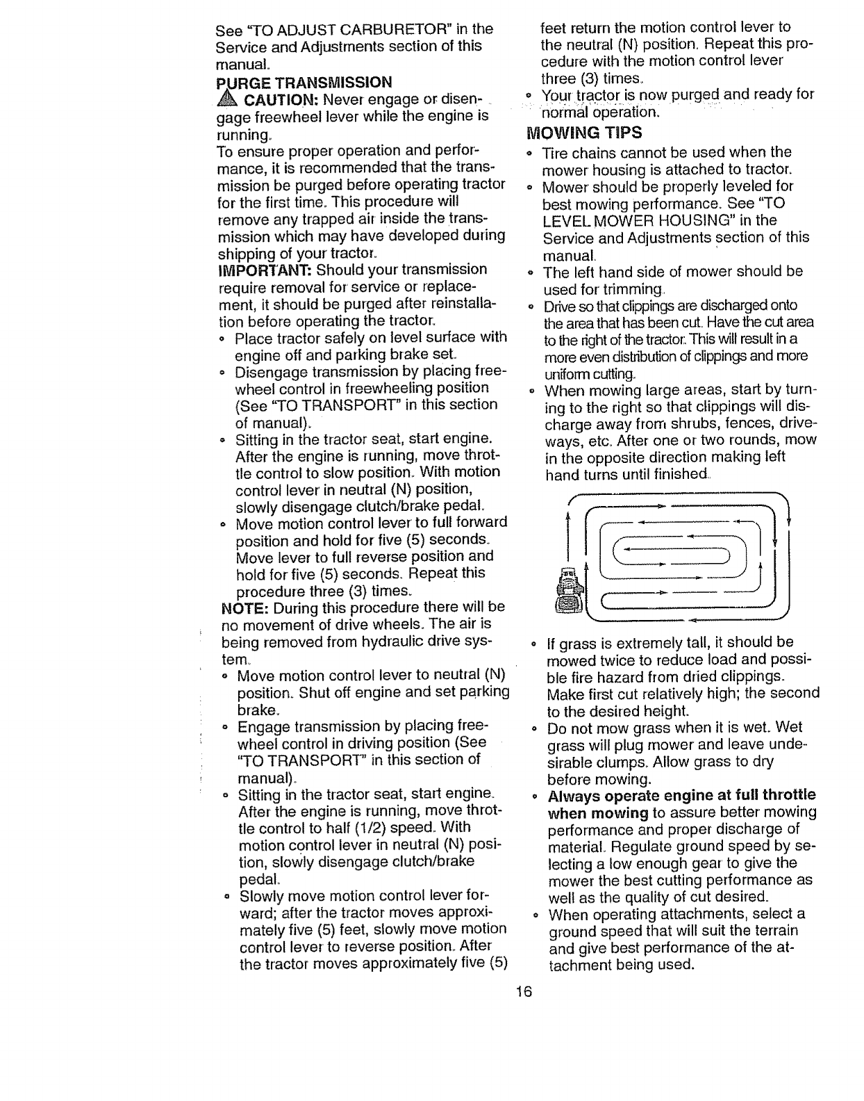
o When mowing large areas, start by turn-
ing to the right so that clippings will dis-
charge away from shrubs, fences, drive-
ways, etc. After one or-two rounds, mow
in the opposite direction making left
hand turns until finished..
f.
1
o If grass is extremely tall, it should be
mowed twice to reduce load and possi-
ble fire hazard from dried clippings..
Make first cut relatively high; the second
to the desired height.
o Do not mow grass when it is wet. Wet
grass will plug mower and leave unde _
sirable clumps. Allow grass to dry
before mowing.
•Always operate engine at full throttle
when mowing to assure better mowing
performance and proper discharge of
material., Regulate ground speed by se-
lecting a tow enough gear' to give the
mower the best cutting performance as
well as the quality of cut desired.
° When operating attachments, select a
ground speed that will suit the terrain
and give best performance of the at-
tachment being used.
16
MULCHING MOWING TiPS ..........
IMPORTANT: For best performance, keep
mower housing free of built-up grass and
trash. Clean after each use..
• The special mulching blade will recur
the grass clippings many times and
reduce them in size so that as they fall
onto the lawn they will disperse into the
grass and not be noticed,. Also, the
mulched grass will biodegrade quickly
to provide nutrients for the lawn, Always
mulch with your highest engine (blade)
speed as this will provide the best recut-
ting action of the blades.
,, Avoid cutting your lawn when it is weL
Wet grass tends to form clumps and
interferes with the mulching action. The
best time to mow your lawn is the early
afternoon.. At this time the grass has
dried and the newly cut area will not be
exposed to the direct sun°
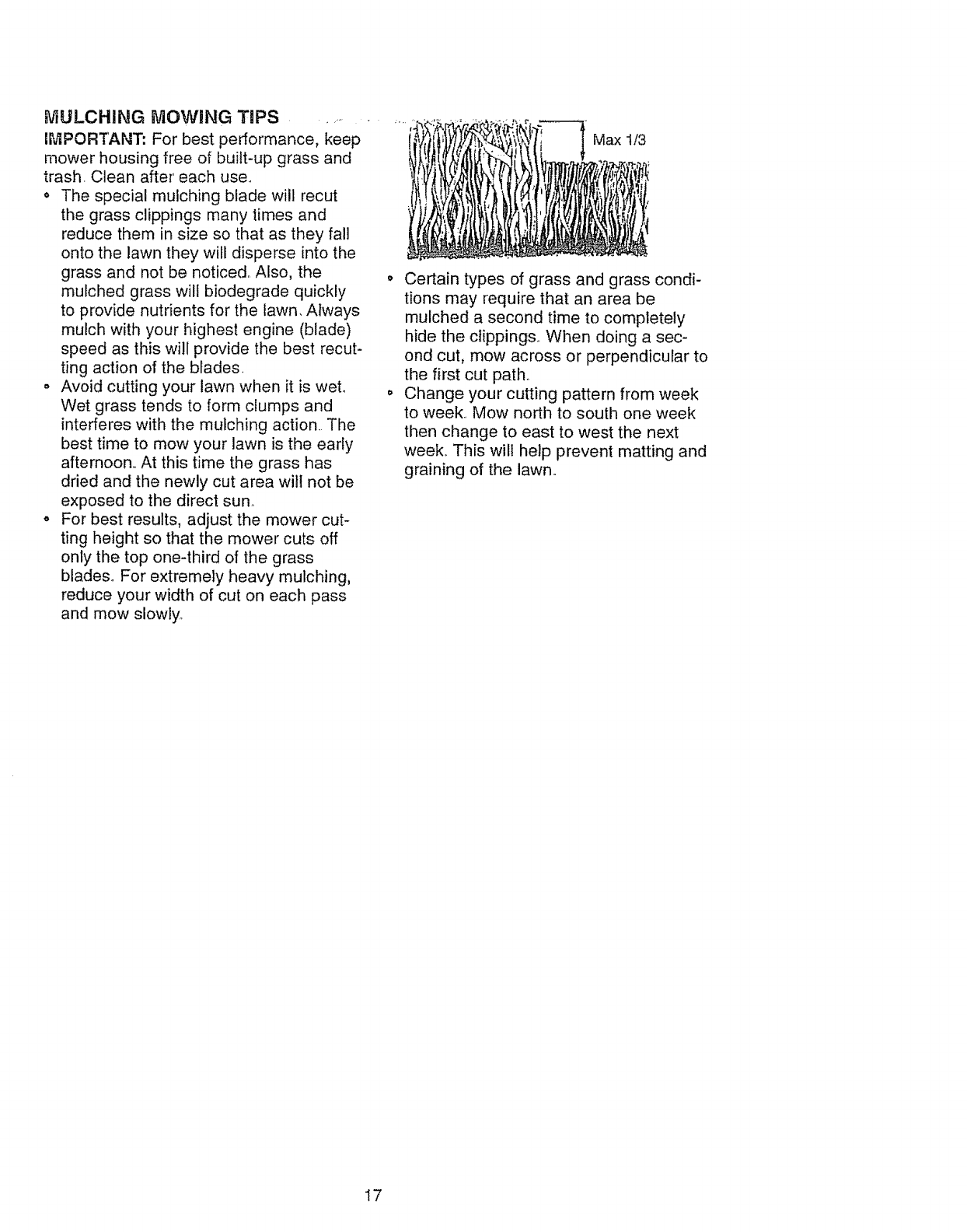
° For best results, adjust the mower cut-
ting height so that the mower cuts off
only the top one-third of the grass
blades° For extremely heavy mulching,
reduce your width of cut on each pass
and mow slowly_
Max 1/3
o Certain types of grass and grass condi-
tions may require that an area be
mulched a second time to completely
hide the clippings,. When doing a sec-
ond cut, mow across or perpendicular to
the first cut path°
o Change your cutting pattern from week
to week,. Mow north to south one week
then change to east to west the next
week,. This wil! help prevent matting and
graining of the lawno
I7
r_USTOMERRESPONSIBILiTiES
_-'_.......MABNTENANCE SCHEDULE
FILL IN DATES
AS YOU COMPLETE
REGULAR SERVICE
Check Brake Operation 6# 4
2-Service mote often when operatJ;qg in dirty ot dusty cond_|ions
3* if equipped with oil f_ltor, char}go oil ovary 50 hours
4-Replace blades mere otien when mewing in sandy soil
GENERAL RECOMMENDATIONS
The warranty on this tractor does not cover
items that have been subjected to operator
abuse or negligence. To receive full value
from the warranty, operator must maintain
tractor as instructed in this manual. Some
adjustments will need to be made periodi-
ca!!y to properly maintain your tractor.
All adjustments in the Service and
Adjustments section of this manual should
be checked at least once each season..
,, Once a year you should replace the _J
spark plug, clean or replace air filter, &nd
check blades and belts for wear. A new
spark plug and clean air filter assure
proper air-fuel mixture and help your
SERVICE DATES
= .......... , ,
t .......... i i E
Check Tire Pressure _/
Check Operator Presence and
TInterlock System s ....
RCheck for Loose Fasteners 6#46#47
ASha_e,,_Repia'co''MoWerB_des " ........ _,", ....................
.............. = ' .......... ....... !
0Check Battery Level _, , _ ............._ . . .
R i Clean Batteryand Ten'ninais/Recharge [" _ $f
Check Transaxle Cooling _ =
....Ad!Us! Blade Bel{(_}Tension ......... 64', ..................................
Adjust Motion Drive Belt(s) Tension Ks
Check Engine Oil Level _ 6f , .......
Change&gi,eO"......... _._ _" ................
..Clean Air Filter ........................
Clean Air Screen .......... 64_ ....
GInspect Muffler/Spark Arrestor 6# #
N_ '"Repiao_,b'"'F,te,-(.,;_'ulppo,_) _._ ....................
, ' ............ ....
Replace Spark Plug ........... = ...........
Rep_,,,_eAirF,te,"PaperCa',4';i'dge...........e', .........
Replace Fuel Filter ,_,
1 - Change more elteo whet_ operating unde_ _heavy lead or in high amblenl temperatures. 5 -It equipped with callus{able system,
6-Not required It aqu}pped with maintenence,4ree battery
7 * Tighter_ front axle pivot bolt to 35 ft -tbs maximt_m
De net ovettightet_
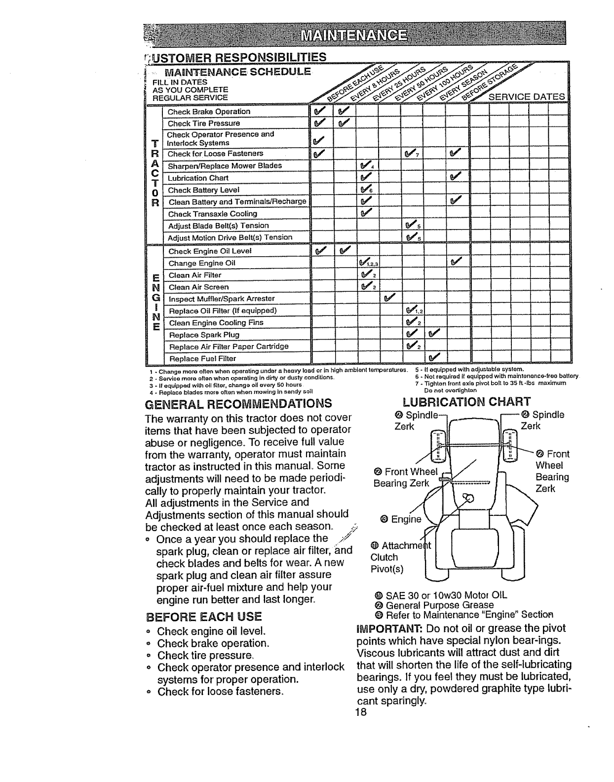
LUBRiCATiON CHART
O S Spindle
Zerk Zerk
Front
Wheel
O Front Wheel Bearing
Bearing Zerk Zerk
0 Engine
@
Clutch
Pivot(s)
@ SAE 30 or i0w30 Motor OIL
engine run better and last longer'.
BEFORE EACH USE
o Check engine oil level.
o Check brake operation.
o Check tire pressure.
OCheck operator presence and interlock
systems for proper operation.
Check for loose fasteners.
@ General Purpose Grease
O Refer to Maintenance Engine" Sectioa
iiVlPORTANT: Do not oil or grease the pivot
points which have special nylon bear-ings.
Viscous lubricants will attract dust and dirt
that will shorten the life of the self-lubricating
bearings. If you feel they must be lubricated,
use only a dry, powdered graphite type lubri-
cant sparingly.
18

.TRACTOR: ................
Always observe safety rules when per-
forming any maintenance.
BRAKE OPERATION
If tractor requires more than six (6) feet
stopping distance at high speed in highest
gear, then brake must be adjusted (See
"TO ADJIJST BRAKE" in the Service and
Adjustments section of this manual)..
TIRES
• Maintain proper air pressure in all tires
(See "PRODUCT SPECIFICATIONS"
on page 5 of this manual)°
o Keep tires free of gasoline, oil, or insect
control chemicals which can harm rub-
ber.
• Avoid stumps, stones, deep ruts, sharp
objects and other hazards that may
cause tire damage.
NOTE: To seal tire punctures and prevent
flat tires due to slow leaks, tire sealant
may be purchased from your local parts
dealer. Tire sealant also prevents tire dry
rot and corrosion..
BLADE CARE
For best results mower blades must be
kept sharp.. Replace bent or damaged
blade&
BLADE REMOVAL
° Raise mower to highest position to allow
access to blades°
o Remove hex bolt, lock washer and flat
washer securing blade°
o install new or resharpened blade with
trailing edge up towards deck as shown.
o Reassemble hex bolt, lock washer and
flat washer in exact order as shown.
° Tighten bolt securely (30-35 FL Lbs.
torque)..
IMPORTANT: Blade bolt is Grade 8 heat
treated.
Blade _(C_',_ Mandrel
\\.X_. _ Assembly
.. her _,_-_.._ _ Trailing
Fiat washer. "<.._.'-...
"--.,.,."-_j_._,. Edge Up
L°ck Was_._,T.. _
Hex Bolt (Grade 8)L._ ...._<_._
*A Grade 8 heat treated bolt can be
identified by six lines on the bolt head.
.TO ,SHARPEN BLADE
NOTE= We do not recommend sharpening
blade, but if you do, be sure the blade is
balanced.
Care should be taken to keep the blade
balanced.. An unbalanced blade will cause
excessive vibration and eventual damage
to mower and engine.
o The blade can be sharpened with a file
or on a grinding wheel Do not attempt
to sharpen while it is on the mower..
o To check blade balance, you wilt need a
5/8" diameter steel bolt, pin, or a cone
balancer.. (When using a cone balancer,
follow the instructions supplied with bal-
ancer)..
NOTE: Do not use a nail for balancing
blade. The lobes of the center hole may
appear to be centered, but are not.
o Slide blade onto an unthreaded portion
of the steel bolt or pin and hold the bolt
or pin parallel with the ground., If blade
is balanced, it should remain in a hori-
zontal position. If either end of the blade
moves downward, sharpen the heavy
end until the blade is balanced.
Center Hole
5/8" Bolt
or Pin
Blade
BATTERY
Your tractor has a battery charging system
which is sufficient for normal use. Howev-
er, periodic charging of the battery with an
automotive charger will extend its life.
o Keep battery and terminals clean..
o Keep battery bolts tight.
o Keep small vent holes open,.
o Recharge at 6-10 amperes for 1 hour..
NOTE: The original equipment battery on
your tractor is maintenance free. Do not
attempt to open or remove caps or covers..
Adding or checking level of electrolyte is
not necessary..
TO CLEAN BATTERY AND TERMINALS
Corrosion and dirt on the battery and ter-
minals can cause the battery to "leak"
power,
° Remove terminal guard,,
o Disconnect BLACK battery cable first
then RED batter,/cable and remove
battery from tractor.
19
. Rinsethe batterywithplainwaterand
dry_
- Cleanterminalsand batterycableends
withwire brushuntilbright.,
,,*Goat-terminalswith greaseor petroleum
jelly.
o Reinstallbattery(See"CONNECTBAT-
TERY"in theAssemblysectionof this
manual).
V-BELTS
Check V-belts for deterioration and wear
after 100 hours of operation and replace if
necessary, The belts are not adjustable..
Replace belts if they begin to slip from
wear,
TRANSAXLE COOLING
The transmission fan and cooling fins
should be kept clean to assure proper
cooling.
Do not attempt to clean fan or transmis-
sion while engine is running or while the
transmission is hot°
oInspect coofing fan to be sure fan
blades are intact and clean.
- Inspect cooling fins for dirt, grass clip-
pings and other materials. To prevent
damage to seals, do not use com-
pressed air or high pressure sprayer to
clean cooling fins,,
TRANSAXLE PUMP FLUID
The transaxle was sealed at the factory
and fluid maintenance is not required for
the life of the transaxte. Should the
transaxle ever leak or require servicing,
contact your nearest authorized service
center,.
ENGINE
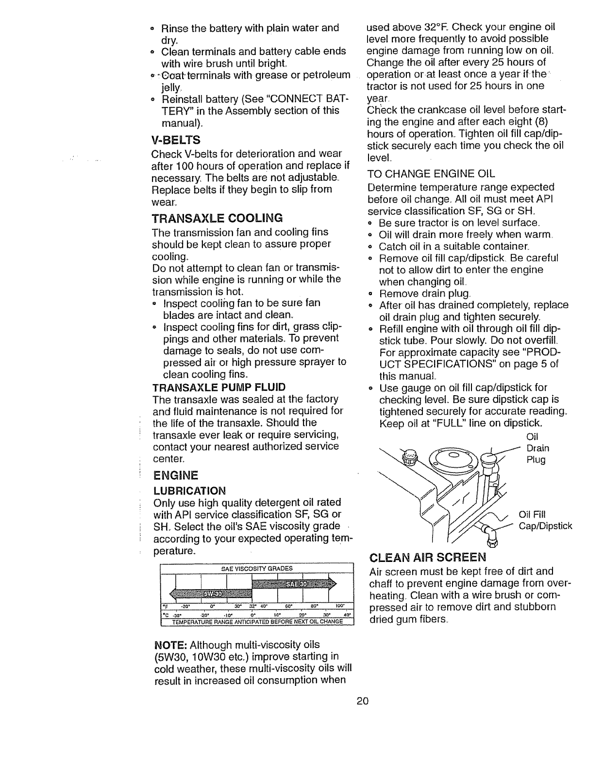
LUBRICATION
Only use high quality detergent oil rated
with AP! service classification SF, SG or
SH_ Select the oil's SAE viscosity grade .
according to your expected operating tem-
perature.
SAE VISCOSITY GRADES
l
TEMPERATURE RANGE ANTICIPATED BEFORE NEXT OIL CHANGE
used above 32°R Check your engine oil
level more frequently to avoid possible
engine damage from running tow on oil,
Change the oil after every 25 hours of
operation or,at least once a year if the:
tractor is not used for 25 hours in one
year.
Check the crankcase oil level before start-
ing the engine and after each eight (8)
hours of operation. Tighten oil fill cap/dip-
stick securely each time you check the oil
level,,
TO CHANGE ENGINE OiL
Determine temperature range expected
before oil change,. All oil must meet API
service classification SF, SG or SHo
,Be sure tractor is on level surface..
o Oil wilt drain more freely when warm.
° Catch oil in a suitable container.
o Remove oil fill cap!dipstick. Be careful
not to allow dirt to enter the engine
when changing oil..
° Remove drain plug
o After oil has drained completely, replace
oil drain plug and tighten securely.
o Refill engine with oil through oil fill dip-
stick tube. Pour slowly. Do not overfill.
For approximate capacity see "PROD-
UCT SPECIFICATIONS" on page 5 of
this manual
o Use gauge on oil fill cap/dipstick for
checking level.. Be sure dipstick cap is
tightened securely for accurate reading.
Keep oil at "FULU' line on dipstick.
Oil
_ _ Drain
Plug
_'/]j/__ Oil Fill..
/_ Cap/DIpsbck
CLEAN AiR SCREEN
Air screen must be kept free of dirt and
chaff to prevent engine damage from over'-
heating.. Clean with a wire brush or com-
pressed air to remove dirt and stubborn
dried gum fibers.
NOTE: Although multi-viscosity oils
(5W30, I 0W30 etco) improve starting in
cold weather, these multi-viscosity oils will
result in increased oil consumption when
20

AIRF|LTER ........
Yourenginewill notrunproperlyusinga
dirtyairfilter.,Cleanthefoampre-cleaner
afterevery25 hoursof operationor every
season° Service paper cartridge every !00
hours of operation or every season,
whichever occurs first.
Service air cleaner more often under.dusty
conditions,,
o Remove knob(s) and cover,,
TO SERVICE PRE-CLEANER
Slide foam pre-cleaner off cartridge..
° Wash it in liquid detergent and water,.
° Squeeze it dry in a clean cloth.
° Saturate it in engine oil., Wrap it in clean,
absorbent cloth and squeeze to remove
excess oil..
° If very dirty or damaged, replace pre-
cleaner.
o Reinstall pre-cteaner over cartridge..
o Reinstall cover and secure with knob(s)_
TO SERVICE CARTRIDGE
o Remove cartridge nut.
. Carefully remove cartridge to prevent
debris from entering carburetor. Clean
base carefully to prevent debris from
entering carburetor.
° Clean cartridge by tapping gently on flat
surface,. If very dirty or damaged,
replace cartridge..
.Reinstall cartridge, nut, precleaner,
cover and secure with knob(s).
IMPORTANT: Petroleum solvents, such as
kerosene, are not to be used to clean the
cartridge.. They may cause deterioration of
the cartridge_ Do not oil cartridge. Do not
use pressurized air to clean or dry car-
tridge.
Cover
Knob
Cartridge
Cover Nut
Foam
Pre-Cleaner
Paper
Cartridge
__------_ Base
ENGINE COOLING FINS ...........
Remc;_e anydust, dirt or 0il from engine
cooling fins to prevent engine damage
from overheating_
o Remove screws from blower housing
and lift housing and dipstick tube
assembly off engine..
o Cover 0il fill opening to prevent entry of
dirt.
Use compressed air or stiff bristle brush
to thoroughly clean engine cooling fins.
° To reassemble, reverse above proce-
dure.
Blower Housing
Screws Screws
air screen __
MUFFLER
Inspect and replace corroded muffler and
spark arrester (if equipped) as it could cre-
ate a fire hazard and/or damage
SPARK PLUGS
Replace spark plugs at the beginning of
each mowing season or after every 100
hours of operation, whichever occurs first.
Spark plug type and gap setting are
shown in "PRODUCT SPECIFICATIONS"
on page 5 of this manual.
tN-UNE FUEL FILTER
The fuel filter should be replaced once
each season.. If fuel filter becomes
clogged, obstructing fuel flow to carbure-
tor, replacement is required.
• With engine cool, remove filter and plug
fuel line sections.
o Place new fuel filter in position in fuel
line with arrow pointing towards carbu-
retor.
o Be sure there are no fuel line leaks and
clamps are properly positioned_
21
Clamp ......
Z2:,.....
Filter
CLEANING
o Clean engine, battery, seat, finish, etc.
of all foreign matter.
oKeep finished surfaces and wheels free
of all gasoline, oil, etc.
= Protect painted surfaces with automo-
tive type wax.
We do not recommend using a garden
.....f_ose: to:_;f_:n"_{Ji :_tradtSi _iiSl_s_ _the elec: ..... _
trical system, muffler, air filter' and carbure-
tor are covered to keep water out. Water
in engine can result in a shortened engine
life.
A_-CAUTION: Before performing any service or adjustments:
o Depress clutch/brake pedal fully and set parking brake.
o Place motion control lever in neutral (N) position.
= Place attachment clutch in "DISENGAGED" position.
° Turn ignition key "OFF" and remove key.
• Make sure the blades and all moving parts have completely stopped_
,, Disconnect spark plug wire from spark plug and place wire where it cannot come
in contact with plug.
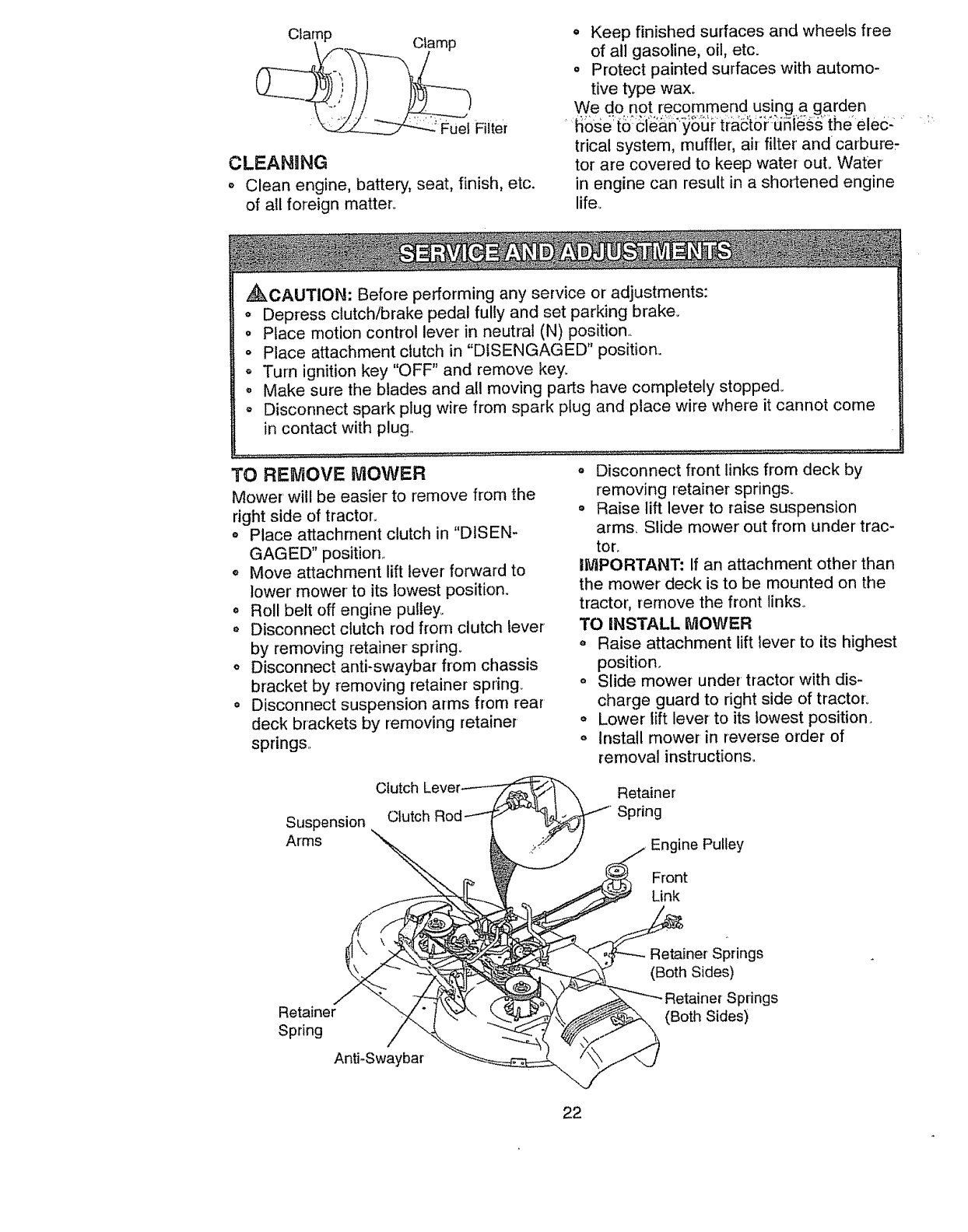
TO REMOVE MOWER
Mower' will be easier to remove from the
right side of tractor.
o Place attachment clutch in "DISEN-
GAGED" position _
o Move attachment lift lever forward to
lower' mower to its lowest position.
= Roll belt off engine pu!ley_
o Disconnect clutch rod from clutch lever
by removing retainer spring.
oDisconnect anti-swaybar from chassis
bracket by removing retainer spring_
° Disconnect suspension arms from rear
deck brackets by removing retainer
springs,
° Disconnect front links from deck by
removing retainer springs_
o Raise lift lever to raise suspension
arms, Slide mower out from under trac-
tor.
IMPORTANT: If an attachment other than
the mower deck is to be mounted on the
tractor', remove the front links.
TO iNSTALL MOWER
o Raise attachment lift lever to its highest
position,
o Slide mower under tractor with dis-
charge guard to right side of tractor_
°Lower lift lever to its lowest position.
o Install mower in reverse order of
removal instructions,
Suspension
Arms
Clutch
Clutch
Retainer
Spring
Engine Pulley
Front
Link
Retainer
Spring
Anti-Swaybar
Retainer Springs
(Both Sides)
Springs
(Both Sides)
22

TO LEVEL NiOWER HOUSING
Adjust the mower while tractor is parked
on level ground or driveway. Make sure
tires are properly inflated (See "PROD-
UCT SPECIFICATIONS" on page 5 of this
manual).. If tires are over or underinflated,
you will not properly adjust your mower,.
SIDE-TO-SIDE ADJUSTMENT
o Raise mower to its highest position
o Measure height from bottom of deck
curl to ground level at front corners of
mower. Distance "A" on both sides of
mower should be the same.
° If adjustment is necessary, make adjust-
ment on one side of mower only.
o To raise one side of mower, tighten lift
link adjustment nut on that side.
o To lower one side of mower, loosen lift
link adjustment nut on that side°
NOTE: Each half turn of adjustment nut
will change mower height about 3/16".
° Recheck measurements after adjusting.,
Bottom Bottom
o,
.:. o tf links are notLequal in length, . adjust. ;:
one link to same length as other link..
o To lower front of mower housing, loosen
nut "G" on both front links an equal
number of turns.
o When distance "F' is 1/8" to 1/2" lower
at front than rear, tighten nut "H" against
trunnion on both front links..
o To raise front of mower housing, loosen
nut "H" from trunnion on both front links..
Tighten nut "G" on both front links an
equal number of turns,,
o When distance "F" is 1/8" to 1/2" lower
at front than rear, tighten nut "H"
against trunnion on both front links.
NOTE: Each full turn of nut "G" will
change dim. "F" by approximately 3/8".
o Recheck side-to-side adjustmenL
Mandrel
\
Both Front Links Should be Equal in Length
='1
Lift Link Adjustment Nut
FRONT-TO-BACK ADJUSTMENT
IMPORTANT: Deck must be level side-to-
side. If the following front-to-back adjust-
ment is necessary, be sure to adjust both
front links equally so mower will stay level
side-to-side,.
To obtain the best cutting results, the
mower housing should be adjusted so the
front is approximately 1/8" to 1/2" lower
than the rear when the mower is in its
highest position..
Check adjustment on right side of tractor,.
Measure distance "F" directly in front of
and behind the mandrel at bottom edge of
mower housing as shown.
°Before making any necessary adjust-
ments, check that both front links are
equal in length.
Nut "G"
Front Links
TO REPLACE MOWER BLADE DRIVE
BELT (See illustration Next Page)
The mower blade drive belt may be
replaced without tools° Park the tractor on
level surface.. Engage parking brake,.
BELT REMOVAL-
o Remove mower from tractor (See "TO
REMOVE MOWER" in this section of
this manual)..
• Work belt off both mandrel pulleys and
idler pulleys..
Pull belt away from mower°
23

, Installnewbeltin reverse order' of
removal.
and inside all belt guides,.
o Install mower in reverse order of
removal instructions.
Mandrel
Pulley
Idler
Pulleys
Mandrel
Pulley
TO ADJUST BRAKE
Your tractor is equipped with an adjustable
brake system which is mounted on the
side of the transaxle.
If tractor requires more than six (6) feet
stopping distance at high speed in highest
gear, then brake must be adjusted..
o Depress clutch/brake pedal and engage
parking brake°
o Measure distance between brake oper-
ating arm and nut "A" on brake rod.
° If distance is other than 1½" loosen jam
nut and turn nut "A" until distance
becomes 1½". Retighten jam nut against
nut "A"o
o Road test tractor for proper stopping
distance as stated above. Readjust if
necessary, If stopping distance is still
greater than six (6) feet in highest gear,
further maintenance is necessary.
Contact your nearest authorized service
center_
With Parking Brake "Engaged"
Nut "A"
_. Jam Nut
" rating
24
TO REPLACE MOTION DRIVE BELT
Park the tractor on level surface. Engage
parking brake. For assistance, there is a
belt installation guide decal on bottom side
of left footrest,
° Remove mower (See "TO REMOVE
MOWER" in this section of this manual.)
• Remove upper belt keeper.
o Remove belt from stationary idler and
clutching idler.
o Pull belt slack toward rear of tractor.
Carefully remove belt upwards from
transmission input pulley and over cool-
ing fan blades.
o Pull belt toward front of tractor and
remove downward from around engine
pulley.
o Install new belt by reversing above pro-
cedure.
IMPORTANT: Make sure upper belt keep-
er is positioned properly between iocator
tab.
Engine
Pulley
Clutching Idler---
Stationary Idler-
Transmission
Input Pulley
Q
I Locator Tab
\ Upper Belt
Keeper

TO ADJUST MOTION CONTROL, LEVER .,_•
The motion control lever has been preset
at the factory and adjustment should not
be necessary., °
tf for any reason the motion control lever o
will not hold its position while at a selected
speed, it may be adjusted at the friction
pack located on the right side of transmis-
sion.
o Park tractor on level surface., Stop trac-
tor by turning ignition key to "OFF" posi-
tion, and engage parking brake.
• Adjust motion control lever by tightening
adjustment Iocknut one half (112) turn.
NOTE: If for any reason the effort to move
the motion control lever becomes too
excessive, reverse the above adjustment
procedure by loosening locknut 1/4 to 1/2
turn_
Road test tractor after adjustment and
repeat procedure if necessary.,
TRANSMISSION REMOVAL/REPLACE-
MENT
Should your transmission require removal
for service or replacement, it should be
purged after reinsta!lation and before
operating the tractor° See "PURGE
TRANSMISSION" in the Operation section
of this manual.
Adjustment
_;d_ Locknut
TO ADJUST STEERING WHEEL ALIGN-
MENT
If steering wheel crossbars are not hori-
zontal (left to right) when wheels are posi-
tioned straight forward, remove steering
wheel and reassemble per instructions in
the Assembly section of this manual.
FRONT WHEEL TOE-IN/CAMBER
The front wheel toe-in and camber are not
adjustable on your tractor. If damage has
occurred to affect the front wheel toe-in or
camber, contact your' nearest authorized
service center
TO REMOVE WHEEL FOR REPAIRS
• Block up axle securely,
o Remove axle cover; retaining ring and
wash.e rs:t0 al!.o.w, w.h.ee!,removal (rear
wheel contains a square key- Do not
lose).
Repair tire and reassemble,.
On rear wheels only: align grooves in
rear wheel hub and axle,, insert square
key,_
o Replace washers and snap retaining
ring securely in axle groove.
o Replace axle cover,,
NOTE: To seal tire punctures and prevent
flat tires due to slow leaks, tire sealant
may be purchased from your local parts
dealer. Tire sealant also prevents tire dry
rot and corrosion.
Washers
Retaining
Ring
Axle Cover '_-._. Square Key
(Rear Wheel Only)
TO START ENGINE THAT HAS A WEAK
BATTERY (See lilustration Next Page)
,_CAUTION: Lead-acid batteries gener-
ate explosive gases. Keep sparks, flame
and smoking materials away from batter-
ies.. Always wear eye protection when
around batteries,
If your battery is too weak to start the
engine, it should be recharged. If "jumper
cables" are used for emergency starting,
follow this procedure:
IMPORTANT: Your tractor is equipped
with a 12 volt negative grounded system..
The other vehicle must also be a 12 volt
negative grounded system, Do not use
your tractor batter,./to start other vehicles,.
TO ATTACH JUMPER CABLES -
° Connect each end of the RED cable to
the POSITIVE (+) terminal of each bat-
tery, taking care not to short against
chassis..
o Connect one end of the BLACK cable to
the NEGATIVE (-) terminal of fully
charged battery.
o Connect the other end of the BLACK
cable to good CHASSIS GROUND,
away from fuel tank and battery_
25
TO REMOVECABLES,REVERSE
_qDER-
_moveBLACKcablefirstfromchassis
" ' thenfrom thefully chargedbattery.
_-_ernoveREDcablelastfrombothbat-
teries.
PositiveTerminal NegativeTerminal
\
\
\
Hood
Headlight
Wire
Connector
Positive Terminal
ted
Battery
Negative Terminal
TO REPLACE HEADLIGHT BULB
o Raise hood.
o Pull bulb holder out of the hole in the
backside of the grill°
o Replace bulb in holder and push bulb
holder securely back into the hole in the
backside of the grill.
,, Close hood.
INTERLOCKS AND RELAYS
Loose or damaged wiring may cause your
tractor to run poorly, stop running, or pre-
vent it from starting°
o Check wiring. See electrical wiring dia-
gram in the Repair Parts section of this
manual..
TO REPLACE FUSE _/-_
Replace with 30 amp automotive-type ._,"
//
plug-in fuse_ The fuse holder is located
behind the dash,
TO REMOVE HOOD AND GRILL AS-
SEMBLY
° Raise hood.
o Unsnap headlight wire connector.
o Stand in front of tractor. Grasp hood at
sides, tilt toward engine and lift off of
tractor.
o To replace, reverse above procedures,,
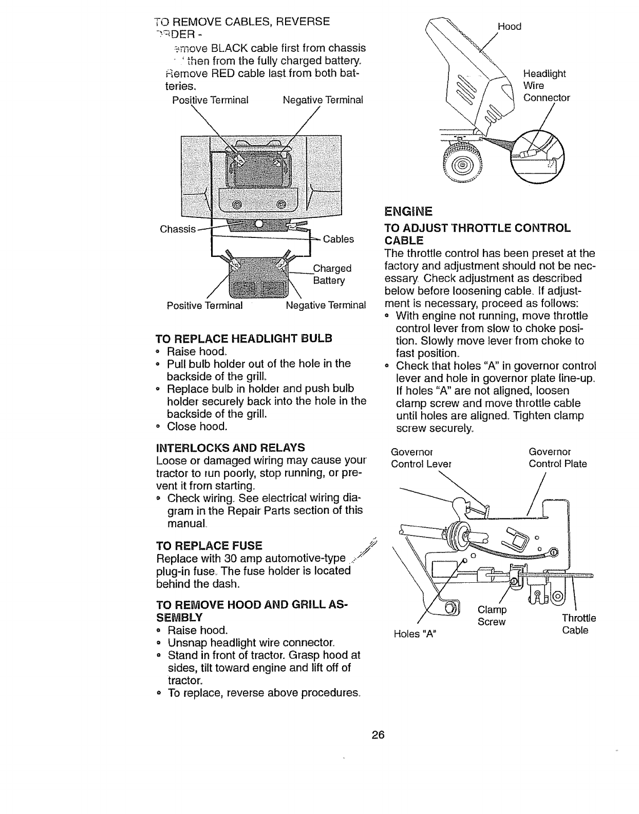
ENGINE
TO ADJUST THROTTLE CONTROL
CABLE
The throttle control has been preset at the
factory and adjustment should not be nec-
essary Check adjustment as described
below before loosening cabte_ ff adjust-
ment is necessary, proceed as follows:
• With engine not running, move throttle
control lever from slow to choke posi-
tion. Slowly move lever from choke to
fast position_
o Check that holes "A" in governor control
lever and hole in governor' plate line-up.
If holes "A" are not aligned, loosen
clamp screw and move throttle cable
until holes are aligned. Tighten clamp
screw securely_
Governor Governor
Control Lever Control Plate
Holes "A"
Clamp
Screw Throttle
Cable
26
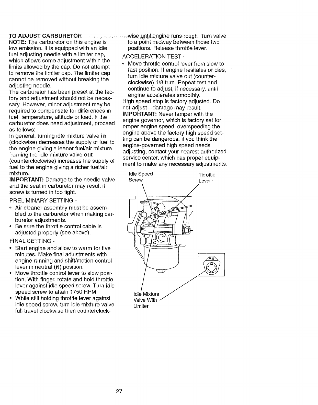
TOADJUSTCARBURETOR
NOTE:The carburetoronthis engineis
lowemission..It is equippedwithanidle
fueladjustingneedlewitha limitercap,
whichallowssomeadjustmentwithinthe
limitsallowedbythe c&p..Donotattempt
to removethe limitercap°Thetimitercap
cannotberemovedwithoutbreakingthe
adjustingneedle.
Thecarburetorhas beenpresetat thefac-
tory andadjustmentshouldnotbe neces-
sary.However,minoradjustmentmaybe
requiredto compensatefor differencesin
fuel,temperature,altitudeor load..Ifthe
carburetordoesneedadjustment,proceed
asfollows:
in general,turningidlemixturevalvein
(clockwise)decreasesthesupplyof fuel to
theenginegivinga leanerfuel/airmixture.
Turningthe idlemixturevalveout
(counterclockwise)increasesthesupplyof
fuelto the enginegivinga richerfuel/air
mixture..
IMPORTANT:Damageto theneedlevalve
andthe seatinca¢buretormayresultif
screwis turnedintootight.
....,.:,:___,............:wis_:,u8ti) ;engine runs rough. Turn valve
to a point midway between those two
positions. Release throttle lever.
ACCELERATION TEST
o Move throttle control lever from stow to
fast position., If engine hesitates or dies,
turn idle mixture valve out (counter-
clockwise) I/8 turn° Repeat test and
continue to adjust, if necessary, until
engine accelerates smoothly.
High speed stop is factory adjusted.. Do
not adjust--damage may result.
IMPORTANT: Never tamper with the
engine governor, which is factory set for
proper engine speed, overspeeding the
engine above the factory high speed set-
ting can be dangerous° if you think the
engine-governed high speed needs
adjusting, contact your nearest authorized
service center, which has proper equip-
ment to make any necessary adjustments,.
Idle Speed Throttle
Screw Lever"
PRELIMINARY SETTING -
,' Air cleaner assembly must be assem-
bled to the carburetor when making car-
buretor adjustments.
• Be sure the throttle control cable is
adjusted properly (see above)..
FINAL SETTING -
Start engine and allow to warm for five
minutes° Make final adjustments with
engine running and shift/motion control
lever in neutral (N) position.
• Move throttle control lever to slow posi-
tion. With finger, rotate and hold throttle
lever against idle speed screw. Turn idle
speed screw to attain 1750 RPM,
° While still holding throttle lever against
idle speed screw, turn idle mixture valve
full travel clockwise then counterclock-
27
Immediately prepare your tractor for stor-
age at the end of the seaso n or if the trac-
tor will not be used for' 30 days or more°
,_kCAUTION: Never store the tractor with
gasoline in the tank inside a building
where fumes may reach an open flame or
spark_ Allow the engine to cool before stor-
ing in any enclosure.
TRACTOR
Remove mower from tractor for winter
storage. This wilt allow you to clean it thor-
oughty. Remove all dirt, grease, leaves,
etc. Store in a clean, dry area.
o Clean entire tractor' (See "CLEANING" in
the Maintenance section of this manual)..
o Inspect and replace belts, if necessary
(See belt replacement instructions in the
Service and Adjustments section of this
manual)_
. Lubricate as shown in the Maintenance
section of this manual..
- Be sure that all nuts, bolts and screws
are securely fastened.. Inspect moving
parts for damage, breakage and weary
Replace if necessary_
o Touch up all rusted or chipped paint sur-
faces; sand lightly before painting.
oFully charge the battery for storage°
o After a period of time in storage, battery
may require recharging.
o To help prevent corrosion and power
leakage during tong periods of storage,
battery cables should be disconnected
and battery cleaned thoroughly (see "TO
CLEAN BATTERY AND TERMINALS" in
the Maintenance section of this manual).
o After cleaning, leave cables disconnect-
ed and place cables where they cannot
come in contact with battery terminals.
o If battery is removed from tractor for "
storage, do not store battery directly on
concrete or damp surfaces.
ENGmNE
FUEL SYSTEM
iMPORTANT: It is important to prevent
gum deposits from forming in essential fuel
system parts such as carburetor, fuel filter,
fuel hose, or tank during storage. Also,
experience indicates that alcohol blended
fuels (called gasohol or using ethanol or'
methanol) can attract moisture which leads
to separation and formation of acids during
storage. Acidic gas can damage the fuel
system of an engine while in storage.
oBrain the fuel tank_
° Start the engine and let it run until the
fuel lines and carburetor are empty.
o Never use engine or carburetor cleaner
products in the fuel tank or permanent
damage may occur:
° Use fresh fuel next season.
NOTE: Fuel stabilizer is an acceptable
alternative in minimizing the formation of
fuel gum deposits during storage° Add sta-
bilizer to gasoline in fuel tank or-storage
container: Always follow the mix ratio
found on stabilizer containert Run engine
at least 10 minutes after adding stabilizer'
to allow the stabilizer to reach the carbure-
tor:. Do not drain the gas tank and carbure-
tor if using fuel stabilizer:,
ENGINE OIL
Drain oil (with engine warm) and replace
with clean engine oil (See "ENGINE" in
the Maintenance section of this manual).
CYLINDERS
o Remove spark ptug(s)_
o Pour-one ounce of oil through spark_plug
hole(s) into cylinder(s).
o Turn ignition key to "START" position for
a few seconds to distribute oil,,
o Replace with new spark plug(s).
OTHER
o Do not store gasoline from one season
to another.
o Replace your gasoline can if it starts to
rust° Rust and/or dirt in your gasoline will
cause problems.
o If possible, store your tractor indoors
and cover' it to give protection frorn dust
and dirt.
o Cover your tractor with a suitable protec-
tive cover that does not retain moisture°
Do not use plastic. Plastic cannot
breathe, which allows condensation to
form and cause your tractor to rust.
I_PORTANT: Never cover tractor while
engine and exhaust areas are still warm.
28
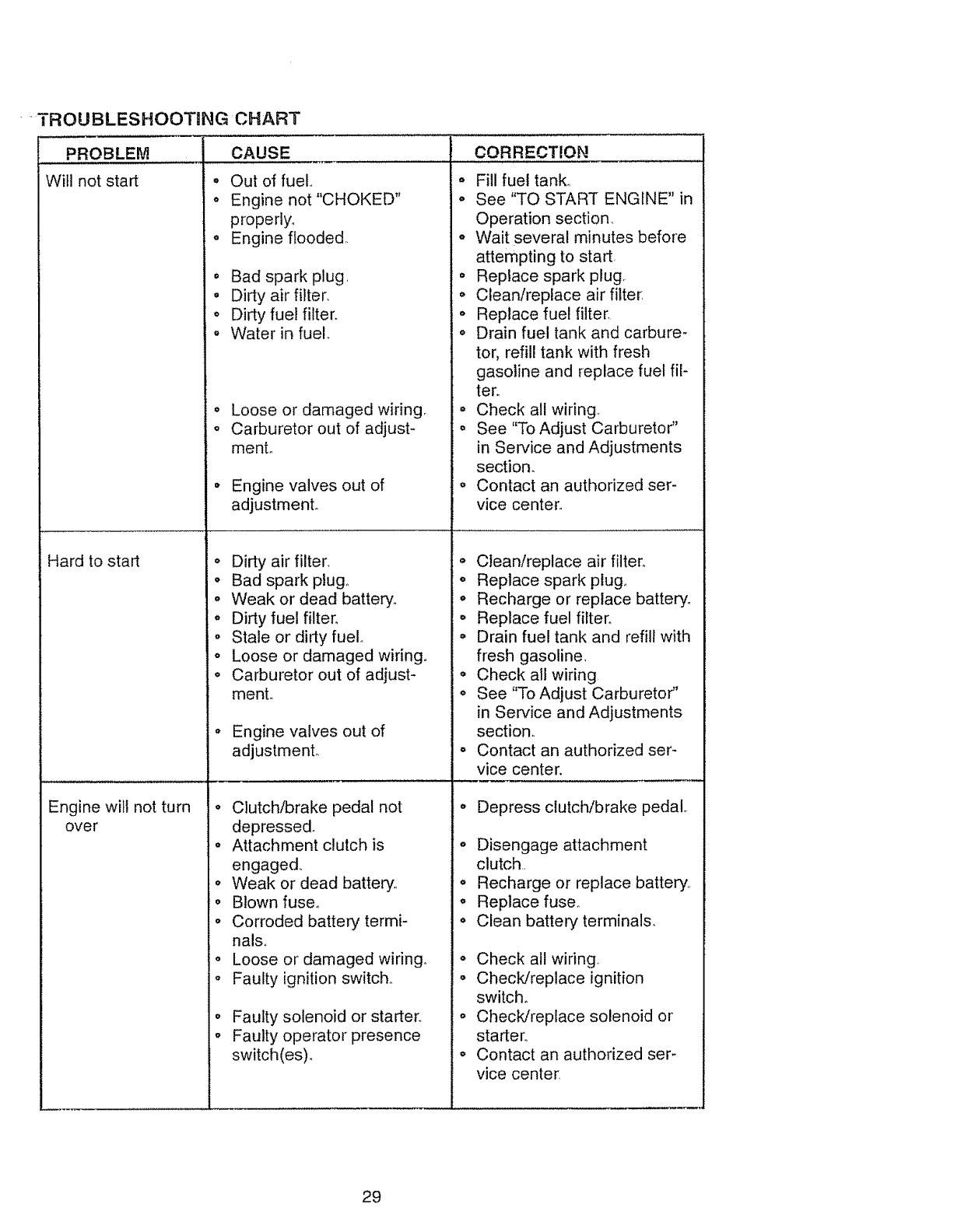
....TROUBLESHOOTaNG CHART
PROBLEM
Will not start
Hard to start
Engine will not turn
over
oOut of fuel.,
o Engine not "CHOKED"
properly.
o Engine flooded,.
o Bad spark plug,
= Dirty air filter.
o Dirty fuel filter.
o Water in fuel
°
o
Loose or damaged wiring
Carburetor out of adjust-
menL
Engine valves out of
adjustment°
o Dirty air filter.
•Bad spark plugo
.Weak or dead battery,,
o Dirty fuel filter.
Stale or dirty fuel,,
o Loose or damaged wiring.
o Carburetor out of adjust-
ment,,
Engine valves out of
adjustment.
o Clutch!brake pedal not
depressed.
o Attachment clutch is
engaged,.
o Weak or dead battery..
• Blown fuse°
o Corroded battery termi-
nalso
,, Loose or damaged wiring.
o Faulty ignition switch..
o
°
Faulty solenoid or starter,,
Faulty operator presence
switch(es) o
CORRECT!ON ...................
o Fill fuel tank,,
• See "TO START ENGINE" in
Operation section,
•Wait several minutes before
attempting to start,
o Replace spark plug
.Clean!replace air filter:
o Replace fue! filter,
o Drain fuel tank and carbure-
tor, refill tank with fresh
gasoline and replace fuel ill-
tern
• Check all wiring,,
• See "To Adjust Carburetor"
in Service and Adjustments
section.
o Contact an authorized ser-
vice center,,
Clean/replace air filter,,
o Replace spark plug_
• Recharge or replace battery_
o Replace fuel filter.,
o Drain fuel tank and refill with
fresh gasoline,
• Check all wiring,
o See "To Adjust Carburetor"
in Service and Adjustments
section.
o Contact an authorized ser-
vice center.
Depress clutch/brake pedal,.
° Disengage attachment
clutch,.
o Recharge or replace battery,,
o Replace fuse.
o Clean battery terminals_
• Check all wiring
• Check/replace ignition
switch°
o Check/replace solenoid or
starter.,
o Contact an authorized ser-
vice center
29
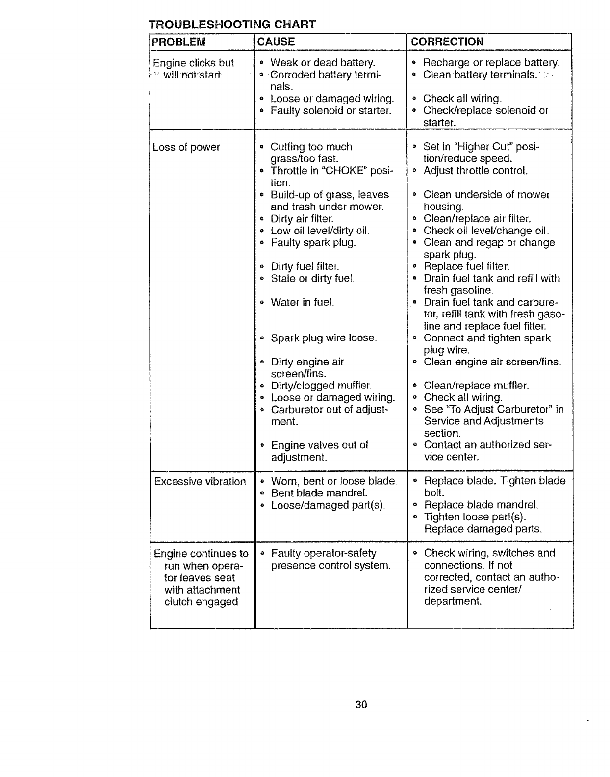
TROUBLESHOOTING CHART
PROBLEM CAUSE
Engine clicks but • Weak or dead batterc.
i:'_will not!start o'Oorroded battery termi-
nalso
o Loose or damaged wiring_
= Faulty solenoid or starter:
o Cutting too much
grass/too fast.
° Throttle in "CHOKE" posi-
tion.
° Build-up of grass, leaves
and trash under mower.
o Dirty air filter:
° Low oil level/dirty oil,
o Faulty spark plug.
o Dirty fuel filter:.
o Stale or dirty fuel,,
Loss of power
o Water in fuel,,
° Spark plug wire loose,,
o Dirty engine air
screen/fins,
° Dirty/clogged muffler.
O
Excessive vibration o
e
e
Engine continues to o
run when opera-
tor leaves seat
with attachment
clutch engaged
Loose or damaged wiring.
Carburetor out of adjust-
menL
Engine valves out of
adjustment.
, i,i
Worn, bent or loose blade.
Bent blade mandrel.
Loose/damaged part(s),
Faulty operator-safety
presence control system.
CORRECTION
° Recharge or replace battery.
° Clean batteryterminalso: :
° Check all wiring.
- CheckJreplace solenoid or
starter.
° Set in "Higher Cut" posi-
tion/reduce speed.
= Adjust throttle control,,
• Clean underside of mower
housing.
o Clean/replace airfilter1.
• Check oil level/change oil.
= Clean and regap or change
spark plug.
° Replace fuel filter.
° Drain fuel tank and refill with
fresh gasoline.
= Drain fuel tank and carbure-
tor; refill tank with fresh gaso-
line and replace fuel filter:,
° Connect and tighten spark
plug wire.
o Clean engine air screen/fins,,
o Clean/replace muffler,.
o Check all wiring.
o See "To Adjust CarburetoP in
Service and Adjustments
section.
= Contact an authorized ser-
vice center.
o Replace blade,, Tighten blade
bolt.
o Replace blade mandrel.
o Tighten loose part(s)o
Replace damaged parts.
Check wiring, switches and
connections. If not
corrected, contact an autho-
rized service center/
departmenL
3O

PROBLEM
Poorcut- uneven
TROUBLESHOOTING CHART
CAUSE
o Worn,bentor looseblade_
Mowerbladeswill
notrotate
Poorgrassdis-
charge
,, Mowerdecknotlevel..
o Buildupof grass,leaves,
andtrashundermower,.
•Bent blade mandrel,.
o Clogged mower deck vent
holes from buildup of
grass, leaves, and trash
around mandrels.
o Obstruction in clutch
mechanism.
o Worn/damaged mower'
drive belt.
o Frozen idler pulley.
o Frozen blade mandrel.,
o Engine speed too slow..
Headlight(s) not
working (if so
equipped)
• Travel speed too fast..
o Wet grass..
o Mower deck not level
o Low/uneven tire air pres-
sure,.
o Worn, bent or loose blade°
o Buildup of grass, leaves
and trash under mower,
o Mower drive belt worn.,
o Blades improperly
installed.
o Improper blades used..
O
O
o
o
o
Battery will not
charge
o
o
O
Clogged mower deck vent
holes from buildup of
grass, leaves, and trash
around mandrels.
Switch is "OFF".
Bulb(s) burned out.
Faulty light switch.
Loose or damaged wiring
Blown fuse_
Bad battery cell(s)o
Poor cable connections,.
Faulty regulator (if so
equipped).
Faulty alternator.,
CORRECTION
,,,,,, ,,,,, , ......................
o Replace blade. Tighten blade
boll
o Level mower deck.
° Clean underside of mower
housing.
o Replace blade mandrel.
,, Clean around mandrels to
open vent holes°
o Remove obstruction,
o Replace mower drive belt,
o Replace idler pulley.
,, Replace blade mandrel,
o Place throttle control in
"FAST" position.
o Shift to slower speed,
,, Allow grass to dry before
mowing.
,, Level mower deck,.
,, Check tires for proper air
pressure.,
o Replace/sharpen blade_
Tighten blade bolt.
o Clean underside of mower
housing.
o Replace mower drive belto
o Reinstall blades sharp edge
down,.
o Replace with blades listed in
this manual.
o Clean around mandrels to
open vent holes,.
o Turn switch "ON"_
° Replace bulb(s).
o Check/replace light switch.
o Check wiring and connections,,
" Replace fuse..
o Replace battery.
,, Check/clean all connections°
,, Replace regulator.
* Replace alternator,
31
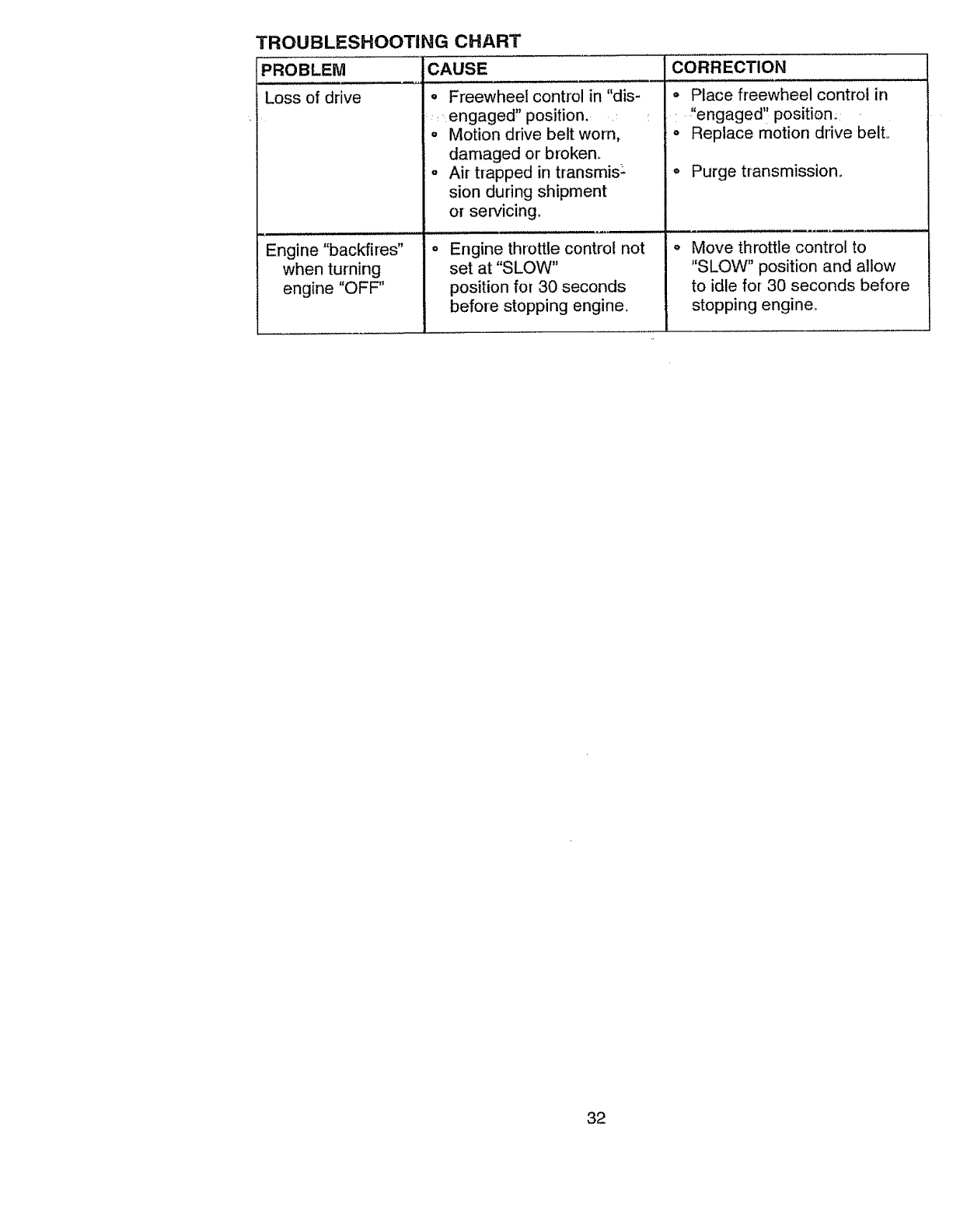
TROUBLESHOOTING CHART
CAUSE
Loss of drive
Engine "backfires"
when turning
engine "OFF"
o Freewheel control in "dis-
_engaged" position. :
o Motion drive belt worn,
damaged or broken.
= Air trapped in transmis:
sion during shipment
or servicing.
Engine throttle control not
set at "SLOW"
position for 30 seconds
before stopping engine.
CORRECTION
° Place freewheel control in
..... "engaged'! position.;
o Replace motion drive bell
o Purge transmission.
Move throttle control to
"SLOW" position and allow
to idle for 30 seconds before
stopping engine.
32

SCHEMATIC
TRACTOR -- _AODEL NUMBER 9'I7.270621
RED °1{
of!!o,
BATTERY
BLACK
AMMETER
(OPTIONAL)
IGNITION
SWITCH
WHITE
FUSE 30 AMP
r ....
L ....... ,,t
CLUTCH /BRAKE
(PEDAL UP)
BLACK
(OPTIONAL)
SOLENOID
IGNITION SWITCH
PosmoN ciBcurr "MAKE;;'"
....... ; NONE'
RUN B + L NONE
START B + L +S NONE
RED
STARTER
BLAC._, _)
........ I (NOT OCCUPIED)
! ........ 1
........ _,.1 L_J ' I
...........
| (CLUTCH OFF) 1 GROUNDING
CONNECTOR
B_ACK _ IGNITIONUNIT
(
i SPARK PLUG
GAP
_(2 PLUGS ON
TWIN CYL, ENGINES)
CHARGING SY_;TEM OUTPUT
3AMP D_ _ 3_,_00 RPM 2_ VOLTS AC M,]N.,_-3600 RPM
LIGIITIt_IG SYSTEM OUTPUT ..... I ALTERNATOR I :
5A_PAC@3600RP_,_ ,_ UIL)U_ 1_1 Il
' _4VOLTS ACMIN e360ORpM(uGHT._QFF)
BROWN
HEADLIGHTS
NOTE
YOUR TRACTOR IS
EQUIPPED WITH A SPECIAL
ALTERNATOR SYSTEM.
THE LIGHTS ARE NOT
CONNECTED TO THE
BATTERY, BUT HAVE THEI R
OWN ELECTRICAL SOURCE.
BECAUSE OF THIS, THE
BRIGHTNESS OF THE LIGHTS
WELL CHANGE WITH ENGINE
SPEED, AT IDLE THE LIGHTS
WILL DIM. AS THE ENGINE IS
SPEEDED UP, THE LIGHTS
WILL BECOME THEIR BRIGHTEST
@ 0
NON-REMOVABLE REMOVABLE
CONNECTIONS CONNECTIONS /--/
WIRING INSULATED CLIPS
NOTE: IF WIRING INSULATED
CLIPS WERE REMOVED FOR
SERVICING OF UNIT, THEY
SHOULD BE REPLACED TO
PROPERLY SECURE YOUR WIRING,
33
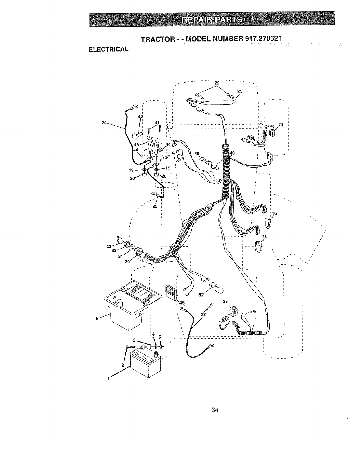
TRACTOR - - MODEL NUMBER 917.270621
....... ELECTRICAL .....
7O
26 i
II
t
I
I
1
16
29
?
i
/
/
/
)
/
/
/
34

ELECTR_r" _ t_
_TRACTOR.:- -..MODEL NUMBER 917,270621
KEY PART
NO. NO.
t 144925
2 74760412
3 STD551025
4 STD551125
6 STD541025
8 156417
16 153664
19 STD551125
20 73350400
21 147430
22 4t52J
24 4799J
25 146147
26 108824X
28 4207J
29 121305X
30 140301
3t 124211X
32 141226
33 109310X
40 156442
4t 71110408
42 131563
43 145673
44 73640400
45 121433X
52 141940
70 140422
DESCRIPTION
Battery 12 VOLT 25 AMP
Bolt Hex Hd 1/4-20unc x 3/4
Vv'asher9/32 x 5/8 x 16 Ga
Washer Lock Hvy Helical 1/4
Nut Fin Hex 1/4-20 Uric
Case Battery
Switch, Interlock Push4n
Washer Lock t/4
Nut Jam Hex 1/4-20 Unc
Harness Asm Light W/4152j
Bulb Light #t156
Cable Battery 6 Ga II" red
Cable Battery 6 Ga w/t6 wire red
Fuse 30 AMP Auto Green
Cable Ground 6 Ga 12" black
Switch Plunger Nc Gray
Switch Ign 4 Pos
Nut Ignition
Cover Sw Key BIk I 25 Text SLT
Key lgn Molded Craftsman
Harness Ign Man C1Am Hm 97
Bolt BIk,,Fin Hex 1/4-20 Unc x 1/2
Cover Terminal Red
Solenoid
Nut Keps Bfk Hex 1/4-20 Unc
Ammeter Rectangular 6 Amp
Protection Wire Loop
Harness Engine B&S 14OHV
NOTE: All component dimensions given in U,S, inches
t inch = 25 4 mm
35

TRACTOR- -MODEL NUMBER 917.270621
CHASSIS AND ENCLOSURES
25
26
28
53 51 52 55 57
26
3
54
33 10
35
26
14
36

TRACTOR ,'_ MODEL N0tVBER 917.270621
CHASSIS AND ENCLOSURES
KEY PART
NO, NO. DESCRIPTION
1 160393
2 140356
3 17490612
4 STD551025
5 155272
6 155923
8 t26471X
9 161938X010
10 STD5337!0
II 155927
!2 145660
!3 I55934X010
14 17490608
15 74180512
I6 STD541431
17 144983X558
18 126938X
24 STD523710
25 19131312
26 STD541437
28 145198X558
29 155217
30 157583X558
31 136619
33 t45244X558
34 t45243X558
35 STD533707
37 17490508
38 139886
39 139887
51 73800400
52 19091416
53 145201
54 161464
55 145202
57 STD522507
140 158418
t45 156524
-- 5479J
Chassis Assembly
Drawbar
Screw, Thd Roll 3/8-16 x 3/4
Washer 13/32 x 3/4 x t6 Gauge
Bumper Hood/Dash
Saddle
Clip Insulator 406 Mtg Hole
Dash
Bolt, Carriage 318-16x 3/4
Panel, Dash, L H
Clip Tinnerman Grilie P!L
Panel, Dash, R H
Screw Thdroi 3/8-16 x t/2
Screw, Machine, Truss Head
5/t6-I8 UNC x 3/4
Nut
Hood Assembly
Bumper Hood
Belt
Washer 13/32 x 13/16 x I2 Gauge
Nut
Grille w/Clips MS_558
Lens, Grille
Fender
Bracket, Fender
Footrest, L H,
Footrest, R,H.
Bol_
ScrewThdrol 5/16-I8 x 1/2
Pivot Bracket Assembly, L H
Pivot Bracket Assembly, RH
Nut Lock w/Insert 1/4-20 UNC
Washer 9/32 x 7t8 x 16 Ga
Bracket Grille Pickoff LH
Screw Hex Wshd #8-8 x 7/8
Bracket Grille Pickoff RH
Bolt, Fin Hex 1/4-20 UNC x .75
Bracket Front Suspension
Rod Pivot Chassis!Hood
Plug, Button
NOTE: All component dimensions given in US.. inches
1 inch = 25,4 mm
37

TRACTOR - - MODEL NUMBER 917.270621
GROUND DRIVE
38
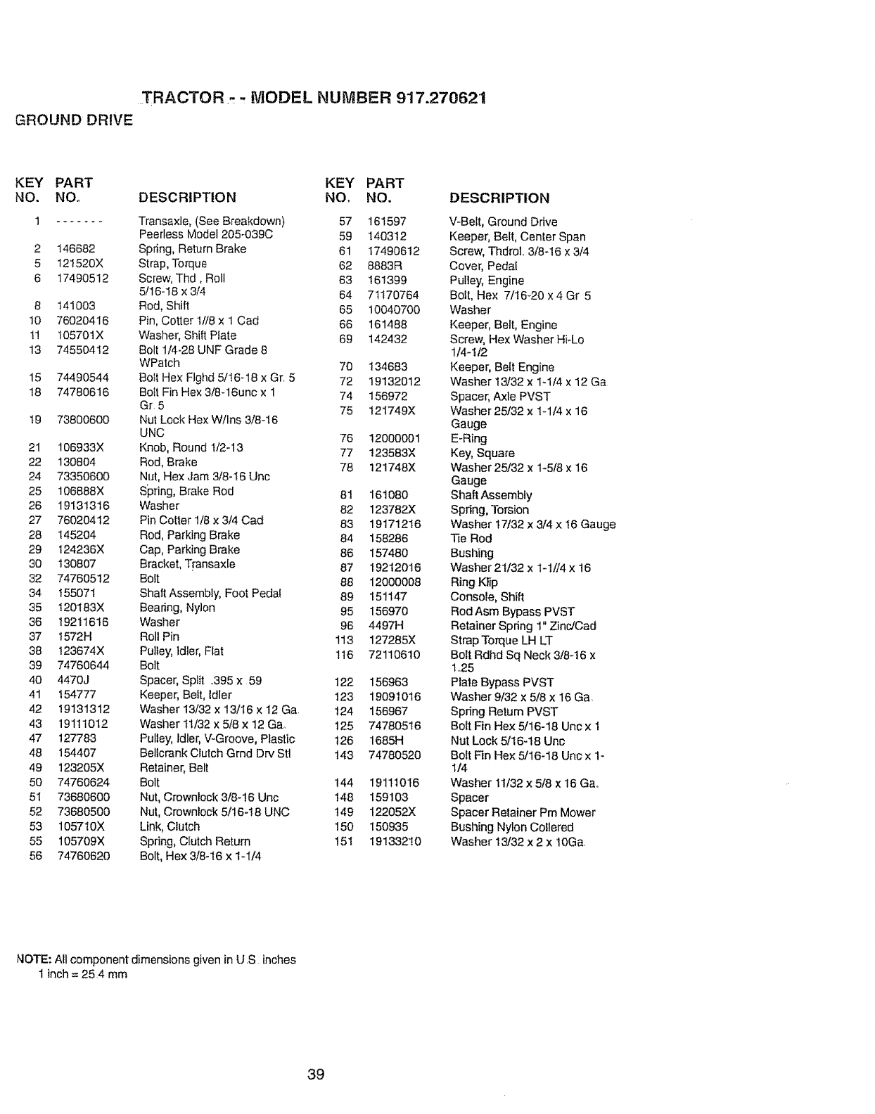
TRACTOR,.- - MODEL NUMBER 917.270621
GROUND DRIVE
KEY PART KEY PART
NO. NO. DESCRIPTION NO, NO.
1 Transaxte,(See Breakdown) 57 161597
Peerless Mode1205-039C 59 140312
2 146682 Spring, Return Brake 61 17490612
5 t21520X Strap, Torque 62 8883R
6 17490512 Screw, Thd, Roll 63 161399
5/16-18 x 3/4 64 71170764
8 141003 Rod, Shift 65 10040700
10 76020416 Pin, Cotter 1//8 x 1 Cad 66 161488
1! 105701X Washer, Shift Plate 69 142432
13 74550412 Bolt 1/4-28 UNF Grade 8
WPatch 70 134683
15 74490544 Boll Hex Flghd 5/I6q8 xGr. 5 72 19132012
18 74780616 Bolt Fin Hex 3/8-16unc x 1 74 156972
Gr. 5 75 t21749X
19 73800600 Nut Loci{ HexW/Ins 3/8-16
UNC 76 12000001
21 106933X Knob, Round 1/2-13 77 123583X
22 130804 Rod, Brake 78 121748X
24 73350600 Nut, Hex Jam 3/8-!6 Unc
25 106888X Spring, Brake Rod 81 16t080
26 19131316 Washer 82 123782X
27 76020412 Pin Cotter 1/8 x3/4 Cad 83 19171216
28 145204 Rod, Parking Brake 84 158286
29 124236X Cap, Parking Brake 86 157480
30 130807 Bracket, Transaxle 87 19212016
32 74760512 Bolt 88 12000008
34 155071 ShaftAssembiy, Foot Pedal 89 151147
35 t20t83X Bearing, Nylon 95 156970
36 192116t6 Washer 96 4497H
37 t572H Roll Pin 113 127285X
38 t23674X Pulley, Idler, Flat 1t6 72110610
39 74760644 Bolt
40 4470J Spacer, Split ..395 x 59 122 156963
41 154777 Keeper, Belt, idler 123 19091016
42 19131312 Washer 13/32 x 13/t6 x t2 Ga. 124 156967
43 19111012 Washer 11/32 x 5/8 x 12 Ga. 125 74780516
47 127783 Pulley, Idler, V-Groove, Plastic 126 1685H
48 154407 Beltcrank Clutch Grnd Dry Stl 143 74780520
49 123205X Retainer, Belt
50 74760624 Bolt 144 19111016
51 73680600 Nut, Crownlock 3/8-16 Uric 148 159103
52 73680500 Nut, Crownlock 5/t6-t8UNC 149 I22052X
53 105710X Link, Clutcl_ 150 150935
55 105709X Spring, Clutch Return 151 19133210
56 74760620 Bolt, Hex 3/8-I6 x 1-1/4
DESCRIPTION
V-Belt, Ground Drive
Keeper, Belt, Cenler Span
Screw, ThdroL 3/8-16 x 3/4
Cover, Peda!
Pulley, Engine
Bolt, Hex 7/t6_20 x 4 Gr 5
Washer
Keeper, Belt, Engine
Screw, Hex Washer Hi-Lo
1/4-112
Keeper, Belt Engine
Washer 13/32 x 1-1/4 x 12 Ga
Spacer, Axle PVST
Washer 25/32 × lq/4 x 16
Gauge
E-Ring
Key, Square
Washer 25/32 x 1-5!8 x 16
Gauge
Shaft Assembly
Spring, Torsion
Washer 17/32 x 3/4 x 16 Gauge
Tie Rod
Bushing
Washer 21/32 x 1_1//4x 16
Ring Ktip
Console, Shift
Rod Asm Bypass PVST
Retainer Spring 1" Zinc/Cad
Strap Torque LH LT
Bolt Rdhd Sq Neck 3/8-16 x
1,,25
Plate Bypass PVST
Washer 9/32 x 5/8 x 16 Ga
Spring Return PVST
Bolt Fin Hex 5/16-18 Unc x 1
Nut Lock 5/16-18 Unc
Bolt Fin Hex 5/16-18 Unc x 1-
t/4
Washer 11t32x 5/8 x 16 Ga,,
Spacer
Spacer Retainer Pm Mower
Bushing Nylon Coffered
Washer 13/32 x 2 x t0Ga,
NOTE: All component dimensions given in U S inches
! inch = 25.4 mrn
39

TRACTOR --, MODEL NUMBER 917.270621
STEERING ASSEMBLY
62
51 54
\
\
27
\
\
>
40
118
46
6B 67
7
32 5
40

TRACTOR - - MODEL NUMBER 917.270621
STEERING ASSEMBLY
KEY PART
NOo NO, DESCRIPTION
1 139768
2 154427
3 156483
4 157473
5 6266H
6 121748X
7 19272016
8 12000029
9 3366R
10 156438
tl STD551137
13 154779
15 73901000
17 156546
18 57079
19 t24035X
20 t26684X
22 71200410
23 127501
25 154406
26 126847X
27 136874
28 19131416
29 17490612
30 STD5612t0
32 130465
36 155099
37 152927
38 139769
39 19133808
40 STD541537
4t I0071tL
42 145054
43 t21749X
44 153720
46 121232X
47 6855M
51 STD541431
54 STD523112
62 156594
63 74780616
65 154780
66 154404
67 74781044
68 154429
Steering Wheel
Front Axle Assembly
Spindle Assembly, LH.
Spindle Assembly, RH
Bearing, Race, Thrust, Hardened
Washer 25/32 x I-5/8 x I6 Gauge
Washer 27/32 x 1-t/4 x t6 Gauge
Ring, Klip
Bearing, Steering Co{utah
Link, Drag
Washer, Lock
Spacer, Bearing, Front Axle
Nut, Lock, Flange 5/8-11 UNC
Shaft Assembly, Steering
Washer, Thrust 515 x 750 x 033
Support, Shaft
Washer, Shim 1/4 x 5/6 x 062
Screw Hex Socket 1/4-20 x 5/6
Pittman Shaft Assembly
Bracket, Steering
Bushing, Link, Drag
Gear, Sector
Washer 13/32 x 7/8 x 16 Gauge
Screw, Thd,, RoIl 3/8-16 x 3/4
Pin
Rod, Tie
Bushing, Steering
Screw TT #10-32 x 5 x 3t8 Flange
Insert, Steering Wheei
Washer 13132x 2-3/8 x 8 Gauge
Gripco Nut
Adapter, Steering Wheel
Boot, Steering Dash PiL Mtt Blk
Washer 25/32 x 1-1/4 x I6 Gauge
Exlension Steering Non-Adjust
Cap, Spindle
Fitting, Grease
Nut Lock Hx W/ins 5/16-18 UNC
Bolt Fin Hex 5/16-18 UNC x 1-t/4
Kit, Steering Assembly, Service
Bolt Fin Hex 3/8-16 unc,,x 1 Gr, 5
Spacer Axle
Bearing Arm Pittman
Bolt Fin Hex 5/8-1! unc x 2-3/4
Brace Axle
NOTE: All component dimensions given in U S, inches
t inch = 254 mm
41
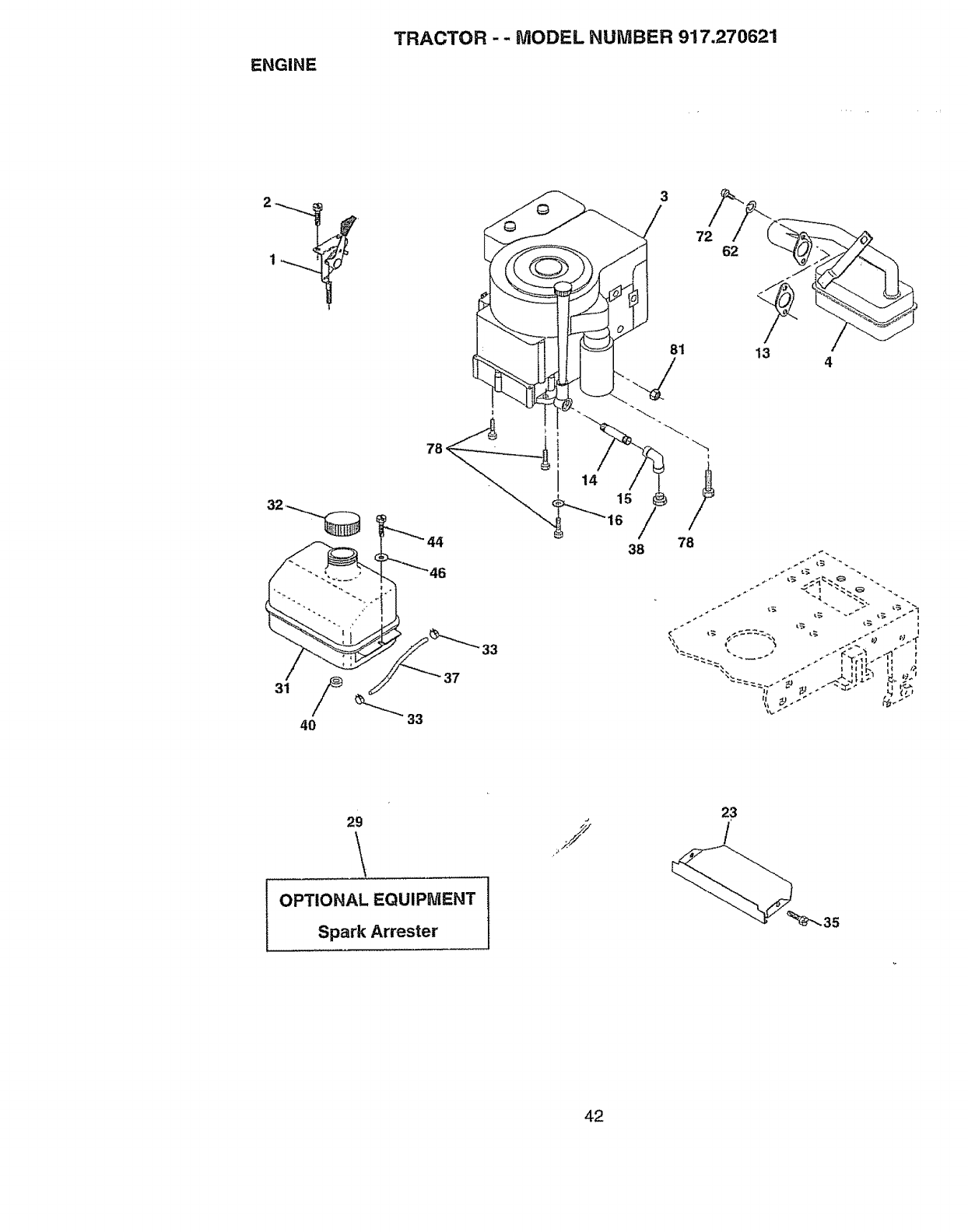
ENGINE
TRACTOR - - MODEL NUMBER 917.270621
40
78
33
33
3
81
38 78
4
29
OPTIONAL EQUIPMENT
Spark Arrester
23
/
42
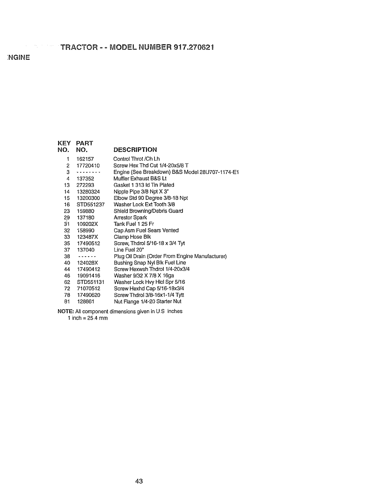
.... TRACTOR - o MODEL NUMBER 917.27062_
INGINE
KEY PART
NO. NO,
! 162157
2 17720410
3--------
4 137352
t3 272293
14 13280324
15 13200300
16 STD551237
23 159880
29 137180
31 109202X
32 158990
33 123487X
35 17490512
37 137040
38 ......
40 124028X
44 17490412
46 19091416
62 STD55113t
72 71070512
78 17490620
81 128861
DESCRIPTION
Control Throt/Ch Lh
Screw He×Thd Cut 1/4_20x5t8T
Engine (See Breakdown) B&S Model 28U707_1174-E1
Muffler Exhaust B&S Lt
Gasket 1 313 ld Tin Plated
Nipple Pipe 3/8 Npt X 3"
Elbow Std 90 Degree 3/8-18 Npt
Washer Lock Ext Tooth 3/8
Shield Brownfng/Debris Guard
Arrestor Spark
Tank Fuel t 25 Fr
Cap Asm Fuel Sears Vented
Clamp Hose BIk
Screw, Thdrol 5/16-18 x 3/4 Tyt
Line Fuel 20"
Plug Oi! Drain (Order From Engine Manufacturer)
Bushing Snap Nyl Blk Fuel Line
Screw Hexwsh Thdrol 1/4-20x3/4
Washer 9/32 X 7/8 X 16ga
Washer Lock Hvy Hlcl Spr 5/16
Screw Hexhd Cap 5/16-18×3/4
Screw Thdrot 3/8-16x1-1/4 Tytt
Nut Flange 1/4-20 Starter Nut
NOTE: All component dimensions given in US inches
1 inch = 25.4 mm
43
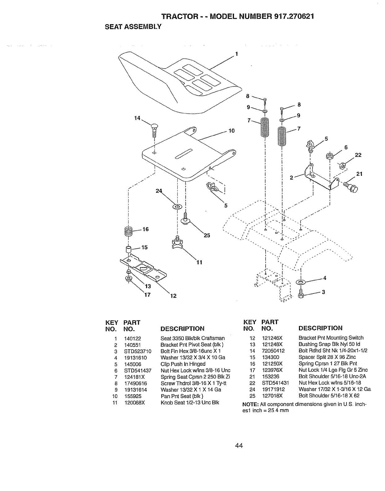
TRACTOR-- MODEL NUMBER 917.270621
SEAT ASSEMBLY
i
I
15
1
5
.21
KEY
NO,
1
2
3
4
5
6
7
8
9
lO
1t
PART
NO.
140122
14O551
STD5237t0
19131610
145006
STD541437
t24181X
1749O616
19131614
155925
120068X
KEY PART
DESCRIPTION NO. NO. DESCRIPTION
Seat 3350 Blk!blk Craftsman 12
Bracket Pnt Pivot Seat (btk) 13
Bolt Fin Hex 3/6-t6une X t t4
Washer 13/32 X 3/4 X 10 Ga t5
Clip Push In Hinged 16
Nut Hex Lock w/ins 3/8-16 Unc 17
Spring Seat Cprsn 2 250 Blk Zi 21
Screw Thdrol 3f8-t6 X 1 Ty*tt 22
Washer t3/32 X 1 X I4 Ga 24
Pan Pnt Seat (blk) 25
Knob Seat 1/2-13 Unc Btk
121246X
121248)(
72050412
134300
!21250X
123976X
153236
STD541431
19171912
t270t8X
Bracket Pn| Mounting Switch
Bushing Snap Blk Nyl 50 Id
Bolt Rdhd Sht Nk 1/4-20x1-1/2
Spacer Split 28 X 96 Zinc
Spring Cprsn 1 27 Blk Pnt
Nut Lock 1/4 Lge Fig Gr 5 Zinc
Bolt Shoulder 5/16-18 Unc-2A
Nut Hex Lock w/Ins 5/16-t8
Washer t7/32 X t-3/t6 X 12 Ga.
Bolt Shoulder 5/16-18 X 62
NOTE: All component dimensions given in US, inch-
esl inch = 25 4 mm
44
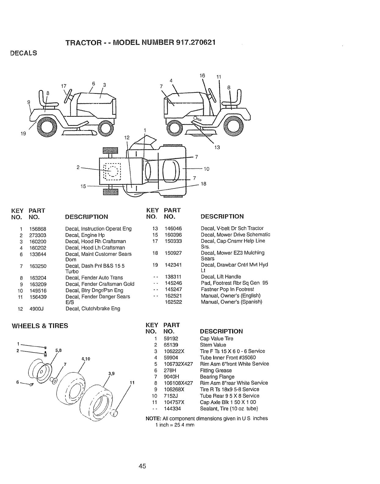
DECALS
TRACTOR - - MODEL NUMBER 9'17.270621
t9 t2
4
7
t6 1t
13
15
7
t8
KEY
NO, PART KEY PART
NO. DESCRIPTION NO. NO,
1 156868 Decal, Instruction Operat Eng 13 146046
2 273303 Decal, Engine Hp 15 160396
3 160200 Decal, Hood Rh Craftsman 17 150333
4 160202 Decal, Hood Lh Craftsman
6 t33644 Decal, Maint Customer Sears 18 t50927
Dom
7 163250 Decal, Dash Pnt B&S 15 5 19 t42341
Turbo
8 163204 Decal, Fender Auto Trans -- t38311
9 163209 Decal, Fender Craftsman Gold -- 145246
10 149516 Decal, Btry Dngr/Psn Eng *- 145247
11 156439 Decal, Fender Danger Sears - _ 162521
E/S 162522
t2 4900J Decal, Clutch/brake Eng
DESCRIPTION
Decal, V-belt Dr SchTractor
Decal, Mower Drive Schematic
Decal, Cap Cnsmr Help Line
Srs..
Decal, Mower EZ3 Mulching
Sears
Decal, Drawbar Cntrl Mvl Hyd
Lt
Decal, Lift Handle
Pad, Footrest Rbr Sq Gen 95
Fastner Pop In Footrest
Manual, Owner's (English)
Manual, Owner's (Spanish)
WHEELS & TIRES
5_8
4,10
KEY PART
NO, NO. DESCRIPTION
I 59192 Cap Value Tire
2 65139 Stem Value
3 106222X ]]re F"Is 15 X 6 0 - 6 Service
4 59904 Tube Inner Front #35060
5 106732X427 Rim Asm 6"front White Service
6 278H Fitting Grease
7 9040H Bearing Flange
8 106106X427 RimAsm 8"rearWhile Service
9 106268X Tire RTs 18x9 5-8 Service
I0 7152J Tube Rear 9 5 X 8 Service
tl 104757X Cap Axle Blk 1 50 X 1 00
o- 144334 Sealant, Tire (10 oz. tube)
NOTE: Atl component dimensions given in U S inches
1 inch = 25 4 mm
45
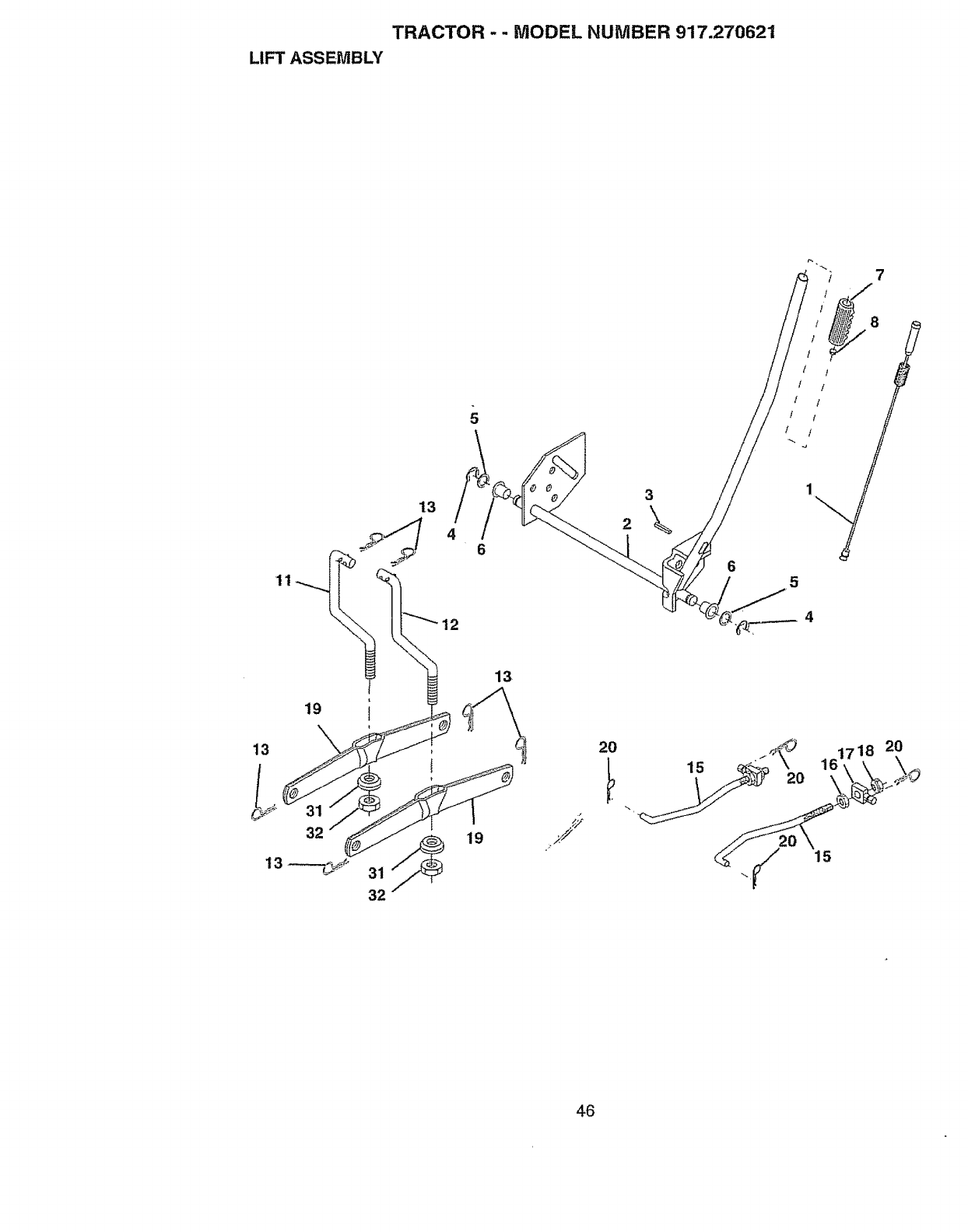
TRACTOR - - MODEL NUMBER 917.270621
LIFT ASSEMBLY
7
11
3
13 2
46
8
/ /
/ !
! !
! !
!'i
5
32
19
13
J15
2O
46

TRACTOR - -MODEL NUMBER 917.270621
JFTASSEMBLY
KEY PART
NO. NO. DESCRIPTION
I 159460 WasherAsm Inner Spring W/Plunger
2 159471 Sha[tAsm Lift
3 105767X Pin Groove
4 12000002 E Ring #5133-62
5 19211621 Washer21i32x t x21 Ga
6 120183X Bearing Nylong
7 125631X Grip Handle Fluted
8 122365X Button Plunger Read
11 139865 Link Asm Lift LH
12 139866 Link Asm Lift RH
13 STD624008 Retainer Spring
t5 127218 Link Front
t6 73350800 Nut Jam Hex 1/2-13 Unc
i7 130171 Trunnion BlkZinc
18 73800800 Nul LockWNVsh 1/2-I3 Unc
t9 139868 Arm Suspension Mower
20 STD624008 Retainer Spring
31 140302 Bearing, Pvt Lift Spherical
32 73540600 Nul Crownlock 3/8-24
NOTE: All component dimensions given in U S inches
I inch = 254 rnm
47
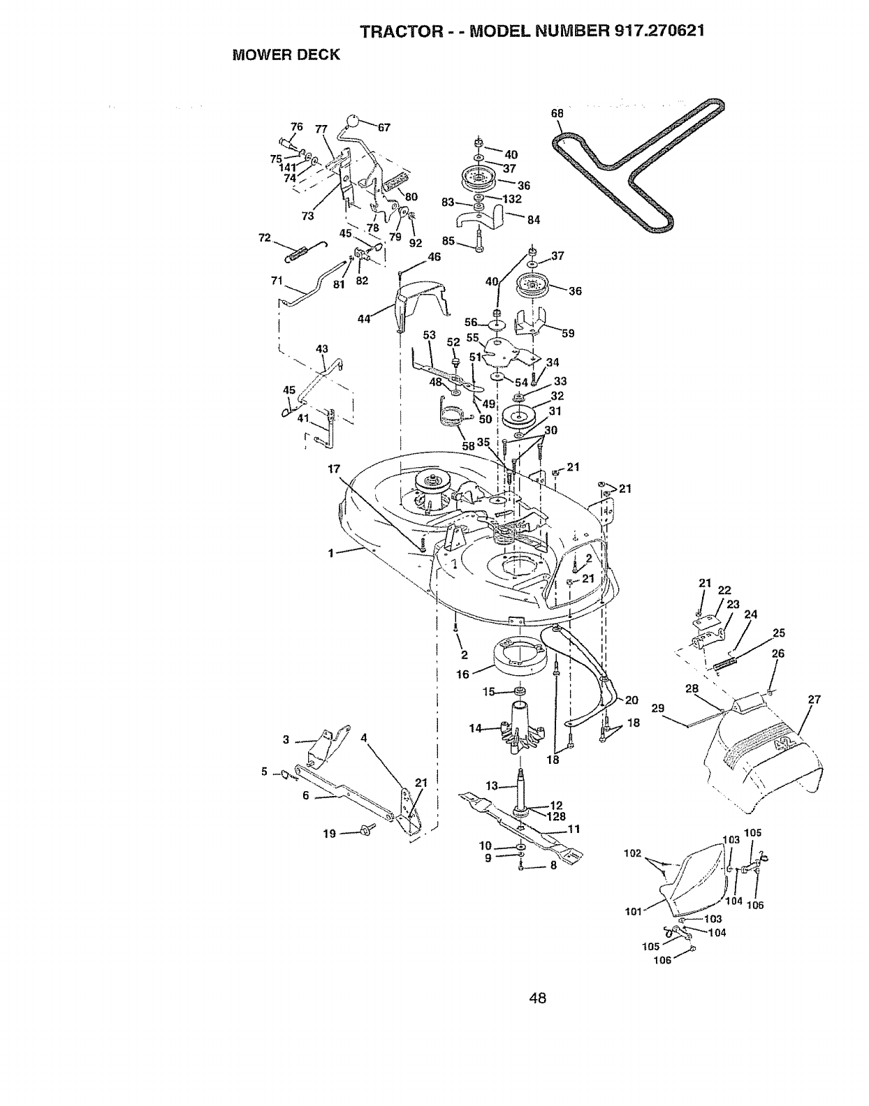
TRACTOR --MODEL NUMBER 917.270621
MOWER DECK
\
2
21 22
18
24
25
103 105
101.__ 3 1 106
48

TRACTOR - - MODEL NUMBER 917.27062'1
t'_OWERDECK
KEY PAR]" KEY PART
NO, NO. DESCRIPTION NO. NO.
1 144393 Mower Housing 50 131340
2 STD533t07 Bolt 51 STD54t410
3 t380!7 Bracket Assembly, Sway Bar, 52 t39888
Front 53 131845X900
4 138440 BracketAssembIy, Sway Bar 54 133943
5 STD624008 Retainer Spring 55 t55046
6 130832 Arm, Suspension, Rear 56 t22052X
8 850857 Bolt, Hex 3/8-24 x t 25 Gr 8 58 140086
9 STD55t137 Washer, Lock 59 141043
!0 140296 Washer, Hardened 67 162113
11 134149 Blade, Mulching 68 144200
12 129895 Bearing, Ball 7t 142427
13 t37645 Stlaft Assembly, Mandrel, 72 t3!870
Vented (]nct Key Number 6) 73 t27847
t4 128774 Housing, Mandrel, Vented 74 121748X
I5 110485X Bearing, Ball, Mandrel 75 12000029
16 140329 Stripper, Vented Mower Deck 76 128903
17 72110610 Bolt, Carriage 3/8-16 x 2-1/4
18 72140505 Bolt, Carriage 5/164 8 x 5/8 77 127845
19 132827 Bolt, Shoulder 78 160570
20 136888 Baffle, Vortex 79 127498
21 STD541431 Nut, Crownlock 5/16-18 UNC 80 153701
22 134753 Stiffener Bracket 81 73350600
23 131267 Bracket, Deflector 82 t42028
24 105304X Cap, Sleeve 83 t20958X
25 123713X Spring, To_sion, Deflector 84 156084
26 1!0452X Nut, Push 85 72140618
27 130968 Shield, Deflector 92 STD54t437
28 19111016 Washer II/32 x 5/8 x t6 Ga..
29 131491 Rod, Hinge 10t 136420
30 !57722 Screw Thdrot Rolling Wsh Hd 102 71161010
3t 129963 Washer, Spacer
32 153535 Pulley, Mandrel I03 19061216
33 137266 Nut, Toplock, Flanged 104 I0071000
34 STD533717 Boit 105 160793
35 133835 Fastner, Christmas Tree 106 2029J
36 131494 Pulley, Idler, Flat t28 153390
37 STD551037 Washer 13/32 x 13/16 × t6 Ga 132 19132203
40 STD541437 Nut, Crownlock3/8-16 UNC 14.1 6266H
41 133551 Rod, Pivot, with Nibs - - 130794
43 140083 Rod, Clutch, Secondary, w/Nibs
44 140088 Guard, Mandret, LH
45 STD624003 Retainer -- 145411
46 137729 Screw, Thd Roll 1/4-20 x 5/8
48 133944 Washer, Hardened
49 155066 RolierAssembly, Cam Follower
DESCRIPTION
Bolt, Shoulder #10_24 Grade 5
Locknut
Bo_t,Shoulder 5/16-18 UNC
Arm Assembly, Pad, Brake
Washer, Hardened
Arm, {d]er
Spacer, Retainer
Spring, Torsion Brakes 4Z'
Guard, Tuv Idter (94)
Knob Custom Ova1
V-Belt
Rod, Clutch, Primary, will'! Nibs
Spring, Return
Arm, Clutch, Secondary
Washer 25/32 x 1-5/8 x 16 Ga
Ring, KIip
Bolt, Shoulder 3/8-16 UNC x
1.44
Keeper, Spring
Arm, Clutch, Primary
Bushing, Large, Brass
Spring, Mower CIutch
Nut, Hex Jam 3/8-16 UNC
Trunnion Adj 94
Washer Sintered
Keeper Belt Idler
Bolt Carriage 3/8-16 × 2-I/4
Locknut, Hex W/Wsh 3/8-16
UNC
Cover Mulching 42" Black
Screw Truss Head Phil 10-24 x
5/8
Washer #10
Washer Lock #10
Latch Asm Bagger
Nut Ward
Washer Felt
Washer 13/32 x 1-3/8 x 3 Ga.
Washer Thrust 75 x 1 230
Mandrel Assembly (Includes
Key Numbers 8-10, I2-15, 3t
and 32)
Mower Deck, Complete (Std
deck - order separately mulcher
plate components key nos. 101-
106)
NOTE: AIt component dimensions given inU S.inches
t inch = 25 4 mm
49

TRACTOR-- MODEL NUMBER 917.270621
HYDRO GEAR TRANSAXLE - - MODEL NUMBER 205-039C
209
191 190 /
18o 45
37
40 46A
42A
_42
50

TRACTOR - - MODEL NUMBER 917.270621 _ .....
IYDRO GEAR TRANSAXLE - -MODEL NUMBER 205-039C
KEY PART
NO, NO. DESCRIPTION
36 790075 Brake, Disc
37 790007 Brake Pad Plate
38 799021 Brake Pad (Pkg of 2)
39 786026 Dowel Pin
39B 798033 Belt Guide
40 792076A Flat Wasf_er
41B 790085 Brake Lever
42 792073A Screw, 1/4_20x t-1/4"
42A 792085A Screw, I/4-20 x 2-1/4"
43 792075 Locknut, 5/I6-24
44 790025 Brake Pad Holder
45 786066 Spacer
46A 790086 Brake Lever Bracket
7! 788069 Square Cut Ring
71A 792162 Pushnut, 9/I6"
79 792144 Spring
85 792154 Oil Fill Plug
85A 792182 Tube Plug, 3/8"
•87 788035 Oil Seal, 5/8"
180 730229A Gear,Oil, 80W90
189 792168 Drive Screw #6 x I/2"
189A 792171 Screw, 10-24 x I/2"
t90 792150 Leckwasher
191 792151 Nut, 7/t6-20
208B 798025 Fan!Coupling, (lncf, t89 & I89A)
209 798024 Control Lever
900 794687 Replacement 205-039C Transaxle
51
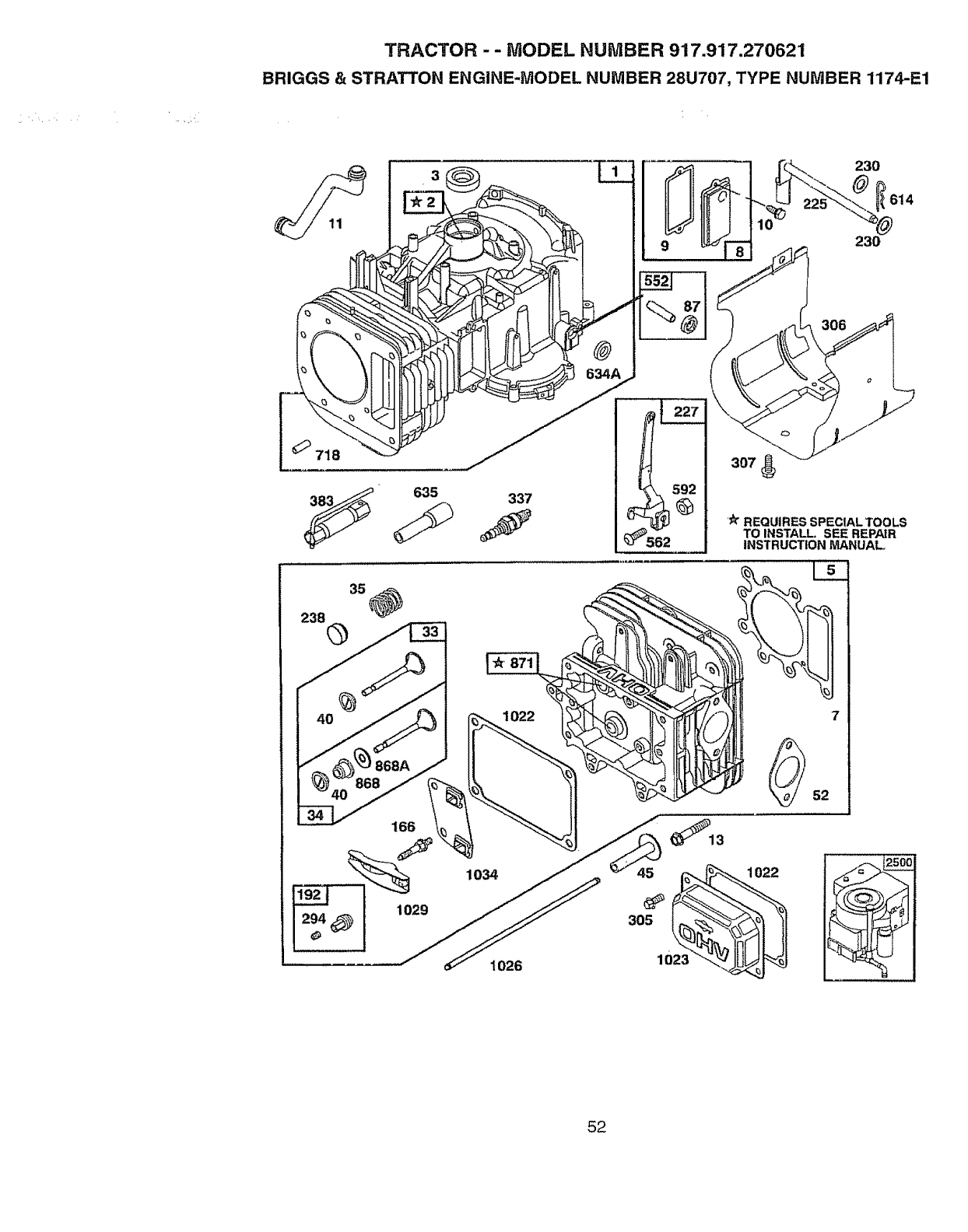
TRACTOR - - MODEL NUMBER 917.917.270621
BRIGGS & STRATTON ENGINE-MODEL NUMBER 28U707, TYPE NUMBER 1174-E1
_230 614
_635
337
230
REQUIRES SPECIAL TOOLS
TO INSTALL SEE REPAIR
INSTRUCTION MANUAL
166
1026
52
52
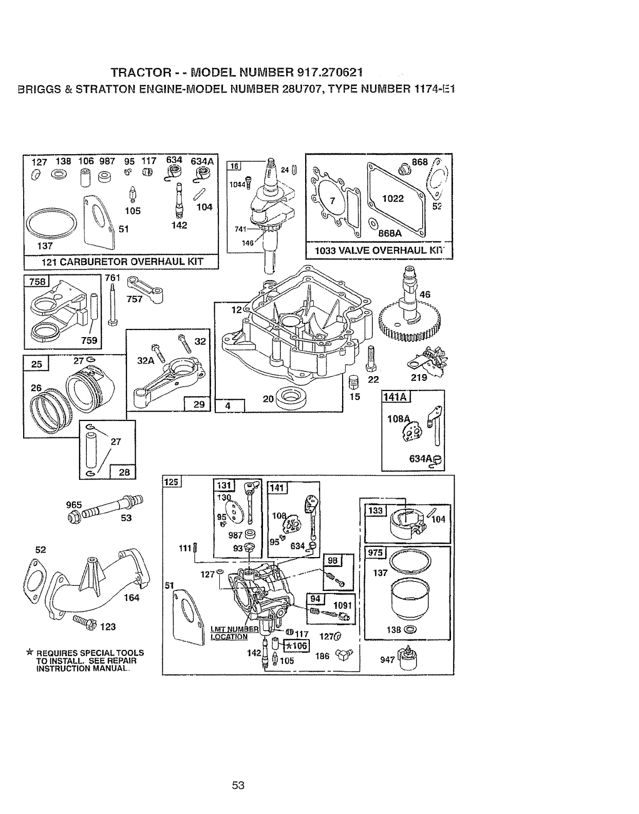
TRACTOR - - MODEL NUMBER 9'17.27062!
BR!GGS & STRATTON ENGINE-MODEL NUMBER 28U707, TYPE NUMBER 1174-E1
127 138 106 987 95 117 6_ 634A
121 CARBURETOR OVERHAUL KIT
759 _32
-__
52
164
_123
_t_REQUIRES SPECIAL TOOLS
TO INSTALL. SEE REPAIR
INSTRUCTION MANUAL,
186
I '=j'°
53

TRACTOR - -MODEL NUM BE R 917.917.276621
BRIGGS &STRATTON ENGINE-MODEL NUMBER 28U707, TYPE NUMBER 1174-E1
523
423
9
20 634A 842 524 868 868A
%
_51
358 GASKET SET
E__51 138
@
137
977 CARBURETOR GASKET SET
171 _535
304
305_ 468
lO0_
75
334
54

TRACTOR - " MODEL NUMBER 9'1'7.917.270_21
BRIGGS & STRATTON ENGINE-MODEL NUMBER 28U707, TYPE NUMBER t174-Et
__ 222
2O9
201
728
783
615
482
t0t9 LABEL KiT] 240
11036 LABEL KIT- EMISSIONS !
to_=ow.=.'s-A.uA_-I
/
8O3
601
802
5O3
55

TRACTOR - - MODEL NUMBER 917.917.270621
BRIGGS & STRATTON ENGINE-MODEL NUMBER 28U707, TYPE NUMBER 1174-E1
KEY PART
NO. NO.
1 496412
2 399265
3 391086
4 494238
5 495858
7 273280
8 495735
9 27803
10 94621
11 281246
t2 271916
271997
271996
13 94728
15 94239
16 498971
94196
20 291675
22 94624
23 492326
24 222698
25 495860
495977
495978
495979
26 495854
495852
495851
495855
27 263129
28 498319
498320
29 494504
495490
32 94695
32A 94648
33 495856
34 495857
35 262811
37 224502
40 224641
45 262411
46 496884
51 272465
52 272569
53 94637
75 225136
78 94832
87 491323
KEY PART
DESCRIPTION NO. NO. DESCRIIPTION
Cylinder Assembly 93 281346 Bushing, Throttle Shaft
Bearing, Cylinder 9'4 498030 Valve, Needle
*Seal, Oil 95 94098 ** Screw, ThrotUe
Base, Engine 98 495800 Screw, Idle Speed
Head, Cylinder 104 231789 ** Pin, Float Hinge
**" Gasket, Cylinder Head 106 231855 "* Valve Float
BreatherAssembly 106 231854 "* Seat, InletValve
" Gasket, Valve Cover 108 224558 Valve, Choke (Lmt 153)
Screw, Sems 10BA 224540 Valve, Choke (Lint 154)
Tube, Breather 111 262715 Spring Choke (Lint 155)
* Gasket, Crankcase Cover, .015" 117 232118 *" Jet, Needle Valve (Std_)
" Gasket, Crankcase Cover, .005" 232119 Jet, Needle Valve (HFAtt)
"Gasket, Crankcase Cover, 009" 121 499233 Carburetor Overhaul Kit
Screw, Cylinder Head 123 94913 Screw, Elbow Mounting
Plug, Oil Drain 125 499153 Carburetor Assembly
Crankshaft 127 - - - ** PIug, Welch (Sold in Kit Only)
Timing Gear Key 130 224539 Valve, Throttle
* Seat, Oil 131 494379 Shaft and Lever, Throttle
Screw, Seres, Base Mounting 133 494381 Float, Carburetor
Flywheel and Ring Gear 137 281165 .... Gasket, Float Bow[
Assembly, Magneto 138 281164 .... Washer, Bowl
Key, Flywheet 141 495097 Choke, Shaft Kit (Choke-A-
Piston Assembly, Standard Size Matic)
PlstonAssembiy, 010 ° 141A 495931 Choke, Shaft Kit(Choke-A-
Oversize Matic)
PistonAssembiy, 020" 142 232117 *" Nozzle, Carburetor
Oversize 146 94196 Key,Timing Gear
Piston Assembly, _030" 164 214047 Elbow, Carburetor
Oversize 166 94555 Stud, RockerArm
Ring Set, Piston, Standard Size 171 281051 Nut, Air Cleaner Mounting
Ring Set, Piston, 010" Oversize 186 493496 Connector, Hose
Ring Set, Piston, 020" Oversize 187 298099 Line, Fuel (Cut to Suit)
Ring Set, Piston, 030" Oversize 188 94627 Screw, Sems
Lock, Piston Pin 192 492160 Screw Assembly, RockerArm
Pin Assy, Piston, Standard Size 201 262767 Link, Governor
Pin Assy, Piston, 005" 209 260695 Spring, Governor
Oversize 216 262766 Link, Choke
Rod Assembly, Connecting 219 490815 Gear, Governor
Rod Assembly, Connecting, 222 495611 Plate, Governor Control
.020" Undersize Crankpin Bore 224 94905 Screw, Seres, Air Cteaner
Screw, Hex Washer Head, 225 495157 Crank, Governor
1_57/64 227 493935 LeverAssembly, Govemor
Screw, Hex Washer Head, 1-
5/8 230 94742 Washer, Governor Crank
232 262785 Spring, Governor Link
Valve, Exhaust 238 262836 Cap, Vaive
Valve, intake 240 394358 Filter,Fuel (In Fuel Line)
Spring, Valve 265 221535 Clamp, Casing
Guard Fiywheei
Retainer, Valve Spnng 284 94704 Screw, Hex Head
Tappet, Valve * included inGasket Set (495993)
Gear, Cam "" Included in Carburetor Kit (499233)
.... Gasket, Carburetor *'* included in both Gasket Set (495993) and
(Carburetor to Elbow) Valve Overhaul Kit (495992)
*** Gasket, Carburetor .... included in Gasket Set (495993), Carburetor
(Elbow to Cylinder) Kit (499233) and Carburetor Gasket Set
Stud, Carburetor Mounting (494385)
Washer, Spring
Screw, Pan Head NOTE: All component dimensions given in US inches
"Seat, Governor Shaft 1 inch = 254 mm
56

TRACTOR - - MODEL NUMBER 917.9t 7.270621
BR1GGS & STRATTON ENGINE-MODEL NUMBER 28U707, TYPE NUMBER 1174,
KEY PART
NO. NO.
294 810068
304 496280
305 94788
306 225020
307 94930
309 497595
310 497602
311 497808
333 495859
334 94731
337 491055
346 93705
356 497706
358 495993
363 t9203
383 89638
423 94903
445 4939o9
467 493903
468 494439
474 393474
462 93621
503 806000
510 497605
523 495230
524 281370
525 496113
535 272403
537 281106
544 497603
552 491986
562 949O7
592 231978
60t 93053
6t4 93306
6t5 263080
618 262803
634 494453
634A 494455
635 280872
646 224546
657 94906
663 94620
7t8 230192
726 399676
727 490324
728 94951
729 28139O
729A 225170
74l 262932
KEY PART
DESCRIPTION NO. NO. DESCRIPTION
Screw, Set 757 213998 Link, Counterweight
Housing, Blower 758 399891 Counterweight Assembly
Screw, Hex, Head, 759 298909 Pin, Counterweight
Blower Housing Mounting 761 94593 Screw, Counterweight
Shield, Cylinder 783 280104 Gear, Starter
Screw, Cylinder Shield 801 394856 Cap, Drive
Motor, Starter 802 497605 Cap, End
Bolt, Thin 803 497604 Housing, Starter
Brush Set 842 270920 * Seal, Oil FitterCap
Armature, Magneto 847 496415 Fill Group, Oil
Screw, Sems, Armature 85t 224110 Terminal, lgnilion Cable
Mounting 868 494435 "* Sea!Assembly, Valve
Plug, Spark 868A 272610 "" Gasket, Valve
Screw, Hex Head 871 262835 Bushing, Guide (Intake &
Wire Assembly Exhaust)
Gasket Set 672 281361 Cover, Air Cleaner
Puller, Flywheel 875 495862 Body, Air Cleaner
Wrench, Spark Plug 877 393456 Diode and Connector Assembly
Screw, Sems 947 497672 Solenoid
Cartridge, Air Cleaner 965 94010 Nut, Hex
Knob, Air Cleaner 975 495933 Bowl Assembly, Carburetor
Screen, Flush Rotating 977 494385 Carburetor Gasket Set
Stator, Alternator 987 281166 ** Seal, Throttle Shaft
Screw, Seres !005 281400 Fan, Flywheel
Strap, Starter 1006 224413 Retainer, Fan
Drive, Starter !019496758 Label Kit
Cap and Dipstick Oil Filler 1022 272475 "** Gasket, Cover
• Seal, FillerTube 1023 224552 Cover, RockerArm
Tube, Oil Filler t026 494432 Rod, Push, Intake
Element, Filter 495136 Rod, Push, Exhaust
• O-Ring, Air Cleaner I029 224554 Arm, Rocker
Armature, Starter 1033 495992 Valve Overhau! Kit
Bushing, Governor Crank t034 495248 Guide Assembly, Push Rod
Bolt, Carriage !036 499364 Label Kit, Emissions
Nut, Hex t044 94673 Screw, Hex Head
Clamp, Fuel Pipe t054 270723 Tie, Cable
Pin, Cotter 1058 272623 Manual, Owner's
Retainer 1090 497607 Retainer, Brush
Spdng, Choke Return 1091 28t364 Cap, Limiler
•" Seal, SpringAssy 2500 28N707-1026 Replacement Engine
"* Seal, Spring Assy 496050 Replacement Shortblock
Boot, Spark Plug
Brace, Air Cleaner RPM Seltings: Low: t650-1850, High: 3200-3400
Screw, Sems
Screw, Self-Tapping " Included in Gasket Set (495993)
Pin, Dowel "" Included in Carburelor Kit(499233)
Gear, Ring **' Included in both Gasket Set (495993) and
(includes Mounting Hardware) Valve Overhaul Kit (495992)
Cover, Starter .... Included in Gasket Set (495993), Carburelor
Screw, Torx_ Kit (499233) and Carburetor Gasket Set
Clip, Wire (494385)
Relainer, Wire NOTE: All component dimensions given in U S inches
Gear, Timing 1 inch = 254 mm
57

58
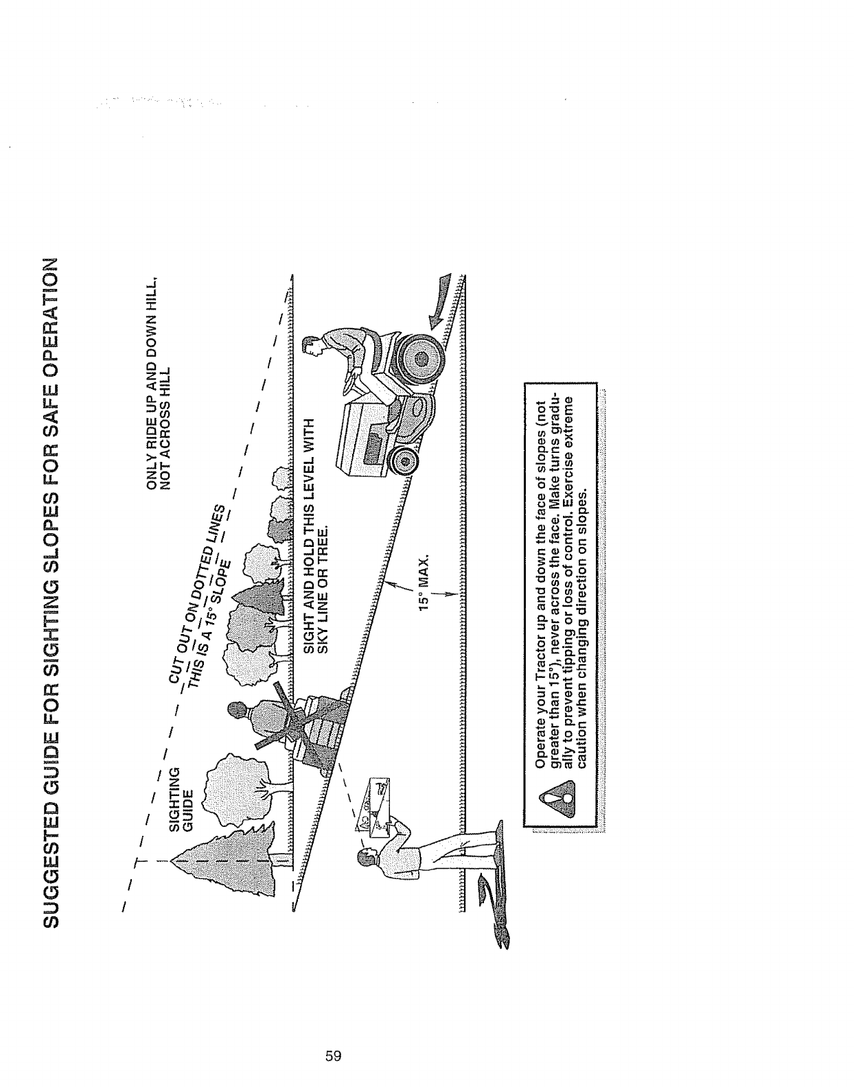
0
b_
W
0.,
0
W
r_
0
Iii
0
_J
0
11!
0
0
In
l,-
I,LI
0
I
Z
0
0
Q_
Z._l
<y:
fro
zo
Oz
/
/
/
0
/
/-
/
!
/
1
/
/
/
/
/
/
59
For the repair' or replacement parts you need
delivered directly to your' home
Call 7 am - 7 pm, 7 days a week
l ..800, 366.,PART :
(1-800-366-7278)
Para ordenar piezas con entrega a
domicilio - 1-800-659-7084
For in-house major brand repair service
Call 24 hours a day, 7 days a week
I=800..4=REPABR
(1-800-473-7274)
Para pedir servicio de reparacibn a
domicilio - 1-800-676-5811
For the location of a Sears Parts and
Repair Center in your area
Call 24 hours a day, 7 days a week
1=800.-488=1222
For information on purchasing a Sears
Maintenance Agreement or to inquire
about an existing Agreement
Call 9 am - 5 pm, Monday-Saturday
1-800=827°6655
When requesting service or ordering
parts, always provide the following
information:
o Product Type = Part Number
o Model Number o Part Description
AmenCa "sRepair SpectaJtsts
162521 Rev, 1 11,13.97 KFSW Printed in U.S.A.
