Craftsman 917270653 User Manual 15.5HP LAWN MOWER Manuals And Guides L9120312
CRAFTSMAN Lawn, Tractor Manual L9120312 CRAFTSMAN Lawn, Tractor Owner's Manual, CRAFTSMAN Lawn, Tractor installation guides
User Manual: Craftsman 917270653 917270653 CRAFTSMAN CRAFTSMAN 15.5HP LAWN MOWER - Manuals and Guides View the owners manual for your CRAFTSMAN CRAFTSMAN 15.5HP LAWN MOWER #917270653. Home:Lawn & Garden Parts:Craftsman Parts:Craftsman CRAFTSMAN 15.5HP LAWN MOWER Manual
Open the PDF directly: View PDF ![]() .
.
Page Count: 60
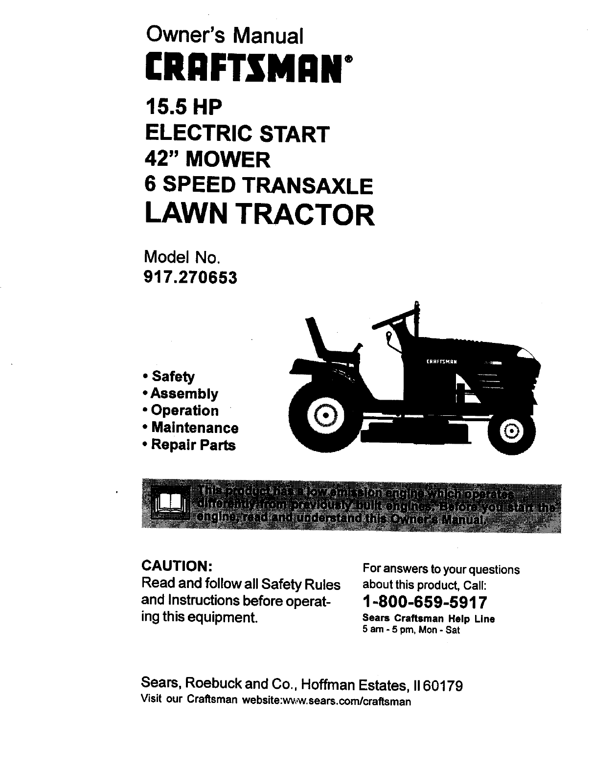
Owner's Manual
CRAFTSMAN"
15.5 HP
ELECTRIC START
42" MOWER
6 SPEED TRANSAXLE
LAWN TRACTOR
Model No.
917.270653
• Safety
•Assembly
• Operation
•Maintenance
• Repair Parts
CAUTION:
Read and follow all Safety Rules
and Instructionsbefore operat-
ing this equipment.
For answers to your questions
about this product, Call:
1-800-659-5917
Sears Craftsman Help Line
5 am - 5 pm, Mon- Sat
Seam, Roebuck and Co., Hoffman Estates, II60179
Visit our Craltsman website:w_,w.sears,com/craftsman
Warranty.;............ :........ _......... 2
Safety Rules ._......;...... i......_,.................. 2
Product Specifications _...................... 5
Assembly ;......,....j ...... :........................ 7
Operation _......._............. _......;........... i.... 10
Maintenance ................ 16
Service and Adjustments ............... 20
Storage ............................................... 27
Troubleshooting ................................. 28
Repair Pads ........................................ 32
Pads Ordedng ..................... Back Cover
LIMITED TWO yEAR WARSANTY ON CRAFTSMAN RIDING EQUIPMENT
Fdr two (2)_yearn;from the date of purchase, if this Craftsman Riding Equipment is
maintained, lubricated And tuned up according to the instructions in the owner's
manual, Sears will (epair or replace, free of charge, any parts found to be defective in
material or workmanship;
This Warranty does not cover:
•Expendable items which become worn during normal use, such as blades, spark
plugs, air cleaners, belts, etc.
•Tire replacement or repair caused by punctures from outside objects, such as nails,
thorns, stumps, or glass.
•Repairs necessary because of operator abuse, negligence, improper storage or
accident or the failure to maintain the equipment according to the instructions
contained in the owner's manual.
•Riding equipment used for commemial or rental purposes.
LIMITED 90 DAY WARRANTY ON BATTERY
For ninety (90) days from date of purchase, if any battery included with this riding
equipment proves defective in material or workmanship and our testing determines the
battery Will not hold a charge, Sears will replace the battery at no charge. In-home
warranty service on your Craftsman riding equipment is available at no charge for 30
days from the date of purchase. Please contact your nearest service center. After 30
days from the date of purchase, warranty service is available by taking your Craftsman
riding equipment to your nearest Sears Service Center. (In-home warranty service will
still be available after 30 days from the date of purchase but a standard trip charge will
apply). This warranty applies only while this product is in the United States. This
Warranty gives you specific legal rights, and you may also have other rightswhich ma_
vary from state to state.
Sears, Roebuck and Co., D/817 WA, Hoffman Estates, IL 60179
IMPORTANT: This cutting machine is
capable of amputating hands and feet
and throwing objects. Failure to observe
the following safety instructions could
result in serious injury or death.
GENERAL OPERATION
•Read, understand, and follow all
instructions in the manual and on the
machine before starting.
•Only allow responsible adults, who are
familiar with the instructions, to
operate the machine.
•Clear the area of objects such as
rocks, toys, wire, etc., which could be
picked up and thrown by the blade.
•Be sure the area is clear of other
people before mowing. Stop machine
if anyone enters the area.
•Never carry passengers.
•Do not mow in reverse unless abso-
lutely necessary. Always look down
and behind before and while backing.
•Be aware of the mower discharge
direction and do not point it at anyone.
Do not operate the mower without
either the entire grass catcher or the
guard in place.
•Slow down before turning.
•Never leave a running machine
unattended. Always turn off blades, set
parking brake, stop engine, and
2 remove keys before dismounting.
• Turn off blades when not mowing.
•Stop engine before removing grass
catcher or unclogging chute.
• Mow only in daylight or good artificial
light.
•Do not operate the machine while
under the influence of alcohol or
drugs.
•Watch for traffic when operating near
or crossing roadways.
• Use extra care when loading or
unloading the machine into a trailer or
truck.
•Data indicates that operators, age 60
years and above, are involved in a
large percentage of riding mower-
related injuries. These operators
should evaluate their ability to operate
the riding mower safely enough to
protect themselves and others from
sedous injury.
SLOPE OPERATION
Slopes are amajor factor related to loss-
of-control and tipover accidents, which
can result in severe injury or death. All
slopes require extra caution. If you
cannot back up the slope or if you feel
uneasy on it, do not mow tt.
DO:
•Mow up and down slopes, not across.
•Remove obstacles such as rocks, tree
limbs, etc.
•Watch for holes, ruts, or bumps.
Uneven terrain could overturn the
machine. Tall grass can hide ob-
stacles.
• Use slow speed. Choose a low gear
so that you will not have to stop or shift
while on the slope.
•Follow the manufacturer's recommen-
dations for wheel weights or counter-
weights to improve stability.
•Use extra care with grass catchers or
other attachments. These can change
the stability of the machine.
•Keep all movement on the slopes slow
and gradual. Do not make sudden
changes in speed or direction.
•Avoid starting or stopping on a slope. If
tires lose traction, disengage the
blades and proceed slowly straight
down the slope.
DO NOT:
•Do not tum on slopes unless neces-
sary, and then, turn slowly and
gradually downhill, if possible.
•Do not mow near drop-offs, ditches, o
embankments. The mower could
suddenly tum over if a wheel is over
the edge of a cliff or ditch, or if an edg
caves in.
•Do not mow on wet grass. Reduced
traction could cause sliding.
•Do not try to stabilize the machine by
putting your foot on the ground.
•Do not use grass catcher on steep
slopes.
CHILDREN
Tragic accidents can occur if the operatc
is not alert to the presence of children.
Children are often attracted to the
machine and the mowing activity. Never
assume that children will remain where
you last saw them.
•Keep children out of the mowing area
and under the watchful care of anoth(
responsible adult.
•Be alert and turn machine off if
children enter the area.
•Before and when backing, look behin_
and down for small children.
•Never carry children. They may fall off
and be seriously injured or intedere
with safe machine operation.
•Never allow children to operate the
machine.
•Use extra care when approaching
blind corners, shrubs, trees, or other
objects that may obscure vision.
SERVICE
•Use extra care in handling gasoline
and other fuels. They are flammable
and vapors are explosive.
Use only an approved container.
Never remove gas cap or add fuel
with the engine running. Allow en-
gine to cool before refueling. Do
not smoke.
Never refuel the machine indoors.
Never store the machine or fuel
container inside where there is an
open flame, such as awater heat-
er.
•Never run a machine inside a closed
area.
3
•Keep nuts and bolts, especially blade
attachment bolts, tight and keep
equipment in good condition.
•Never tamper with safety devices.
Check their proper operation regularly.
•Keep machine free of grass, leaves, or
other debris build-up. Clean oil or fuel
spillage. Allow machine to cool before
storing.
•Stop and inspect the equipment if you
strike an ob_'t. Repair, if necessary,
before restarting.
• Never make adjustments or repairs
with the engine running.
•Grass catcher components are subject
to wear, damage, and deterioretion,
which could expose moving parts or
allow objects to be thrown. Frequently
check components and replace with
manufacturer's recommended parts,
when necessary.
•Mower blades are sharp and can cut.
Wrap the blade(s) or wear gloves, and
use extra caution when servicing
them.
• Check brake operation frequently.
Adjust and service as required.
•Be sure the area is clear of other
people before mowing. Stop machine
if anyone enters the area.
•Never carry passengers or children
even with the blades off.
•Do not mow in reverse unless abso-
lutely necessary. Always look down
and behind before and while backing.
•Never carry children. They may fall off
and be seriously injured or interfere
with safe machine operation.
•Keep children out of the mowing area
and under the watchful care of another
responsible adult.
•Be alert and turn machine off if chil-
dren enter the area.
•Before and when backing, look behind
and down for small children.
_Look for this symbol .topoint out impor-
tant safety precautions. It means _Au-
TIONI!! BECOME AWAREI!! YOUR
SAFETY IS INVOLVED.
_IbCAUTION: In order to prevent acciden-
tal starting when setting up, transporting,
adjusting or making repairs always dis-
connect spark plug wire and place wire
where it cannot contact spark plug.
_CAUTION: Do not coast down a hill in
neutral, you may lose control of the tractor.
4
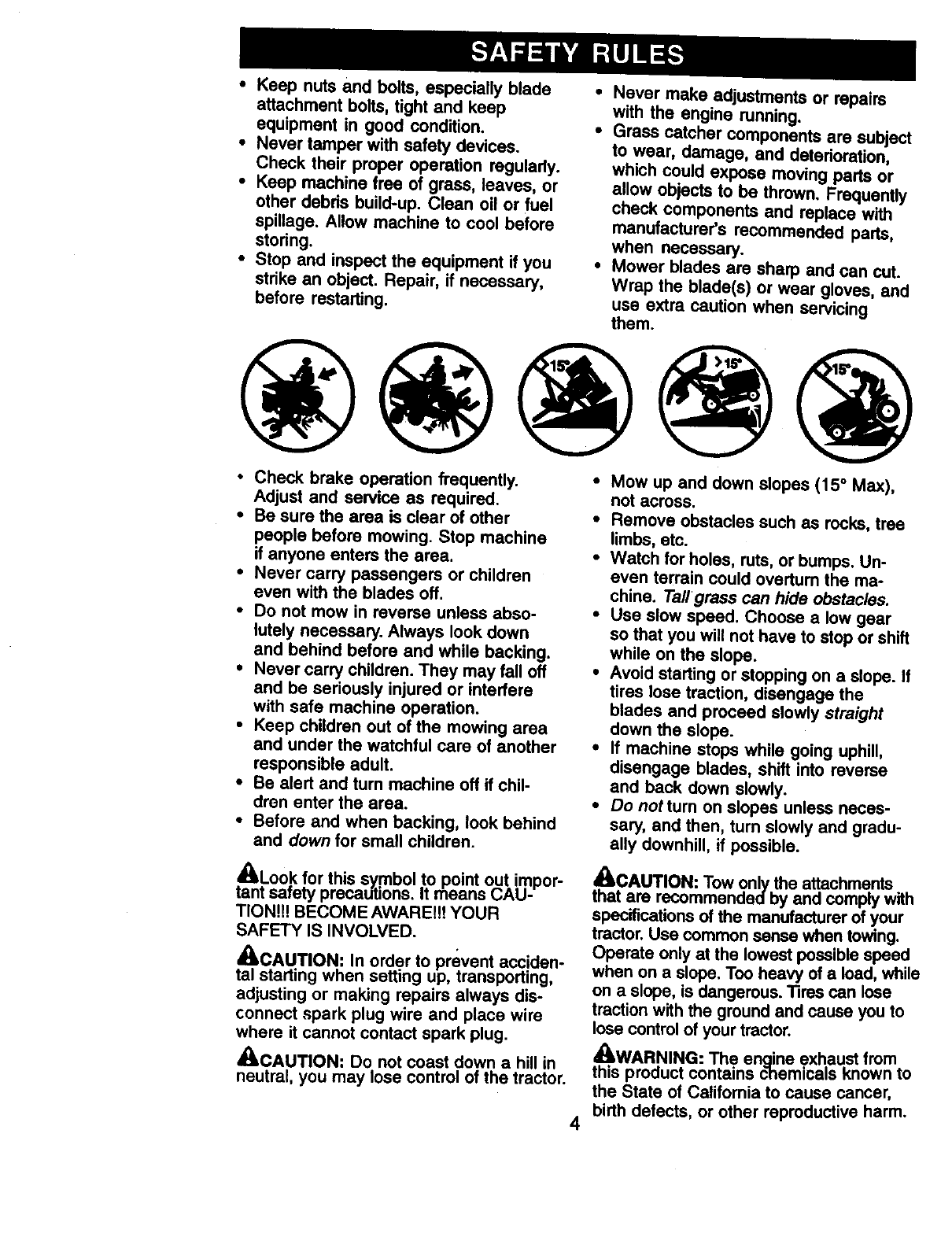
•Mow up and down slopes (15° Max),
not across.
•Remove obstacles such as rocks, tree
limbs, etc.
•Watch for holes, ruts, or bumps. Un-
even terrain could overturn the ma-
chine. Tall grass can hide obstacles.
•Use slow speed. Choose a low gear
so that you will not have to stop or shift
while on the slope.
•Avoid starting or stopping on a slope. If
tires lose traction, disengage the
blades and proceed slowly straight
down the slope.
• If machine stops while going uphill,
disengage blades, shift into reverse
and back down slowly.
•Do not turn on slopes unless neces-
sary, and then, turn slowly and gradu-
ally downhill, if possible.
_CAUTION: Tow only the attachments
that are recommended by and comply with
specifications of the manufacturer of your
tractor. Use common sense when towing.
Operate only at the lowest possible speed
when on a slope. Too heavy of a load, while
on a slope, is dangerous. Tires can lose
traction with the ground and cause you to
lose control of your tractor.
.._. WARNING: The enaine exhaust from
this product contains chemicals known to
the State of Califomia to cause cancer,
birth defects, or other reproductive harm.
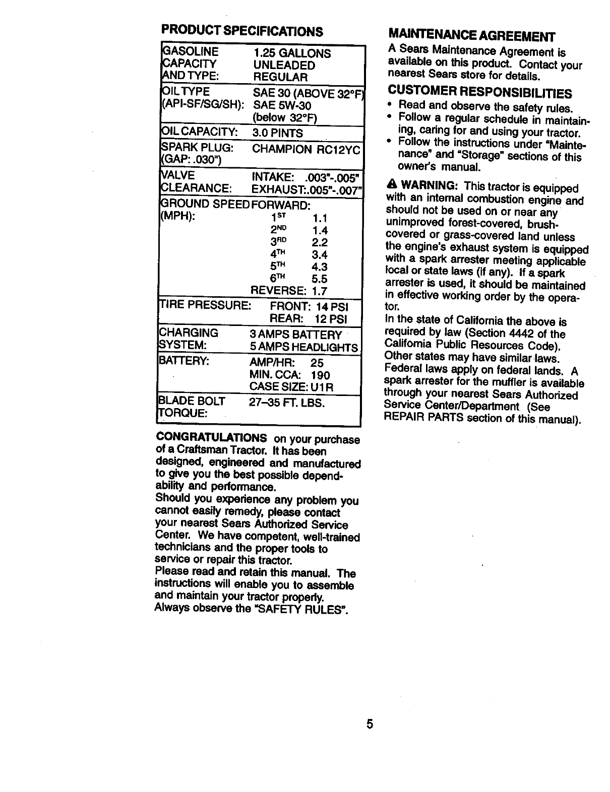
PRODUCTSPECIFICA_ONS
3ASOLINE
CAPACITY
AND TYPE:
OILTYPE
API-SF/SG/SH):
1.25 GALLONS
UNLEADED
REGULAR
SAE 30 (ABOVE 32°F
SAE 5W-30
(below 32°F)
OILCAPACITY: 3.0 PINTS
SPARK PLUG: CHAMPION RC12YC
GAP: .030")
VALVE INTAKE: .003"-.005"
CLEARANCE: EXHAUST:.005"-.007"
_ROUND SPEED FORWARD:
MPH): 1sT 1.1
2 ND 1.4
3"0 2.2
4TM 3,4
5TM 4.3
6TM 5.5
REVERSE: 1.7
TIRE PRESSURE: FRONT: 14 PSI
REAR: 12 PSi
_HARGING 3 AMPS BATTERY
YSTEM: 5 AMPS HEADLIGHTS
3ATI'ERY: AMP/HR: 25
MIN. CCA: 190
CASE SIZE: Ul R
3LADE BOLT 27-35 FT. LBS.
rORQUE:
CONGRATULATIONS on your purchase
of a Craftsman Tractor. It has been
designed, engineered and manufactured
to give you the best possible depend-
ability and performance.
Should you expedence any problem you
cannot easily remedy, please contact
your nearest Sears Authorized Service
Center. We have competent, well-trained
technicians and the prper tools to
service or repair this tractor.
Please read and retain this manual. The
instructions will enable you to assemble
and maintain your tractor propedy.
Always observe the =SAFETY RULES".
MAINTENANCE AGREEMENT
A Sears Maintenance Agreement is
available on this product. Contact your
nearest Sears store for details.
CUSTOMER RESPONSIBILITIES
• Read and observe the safety rules.
•Follow a regular schedule in maintain-
ing, cedng for and using your tractor.
•Follow the instructions under =Mainte-
nance" and =Storage" sections of this
owner's manual.
AWARNING: This tractor is equipped
with an intemal combustion engine and
should not be used on or near any
unimproved forest-covered, brush-
covered or grass-oovered land unless
the engine's exhaust system is equipped
with a spark arrester meeting applicable
local or state laws (if any). If a spark
attester is used, it should be maintained
in effective working order by the opera-
tor.
in the state of California the above is
required by law (Section 4442 of the
California Public Resources Code).
Other states may have similar laws.
Federal laws apply on federal lands. A
spark arrester for the muffler is available
through your nearest Sears Authorized
Service Canter/Depadment (See
REPAIR PARTS section of this manual).
5
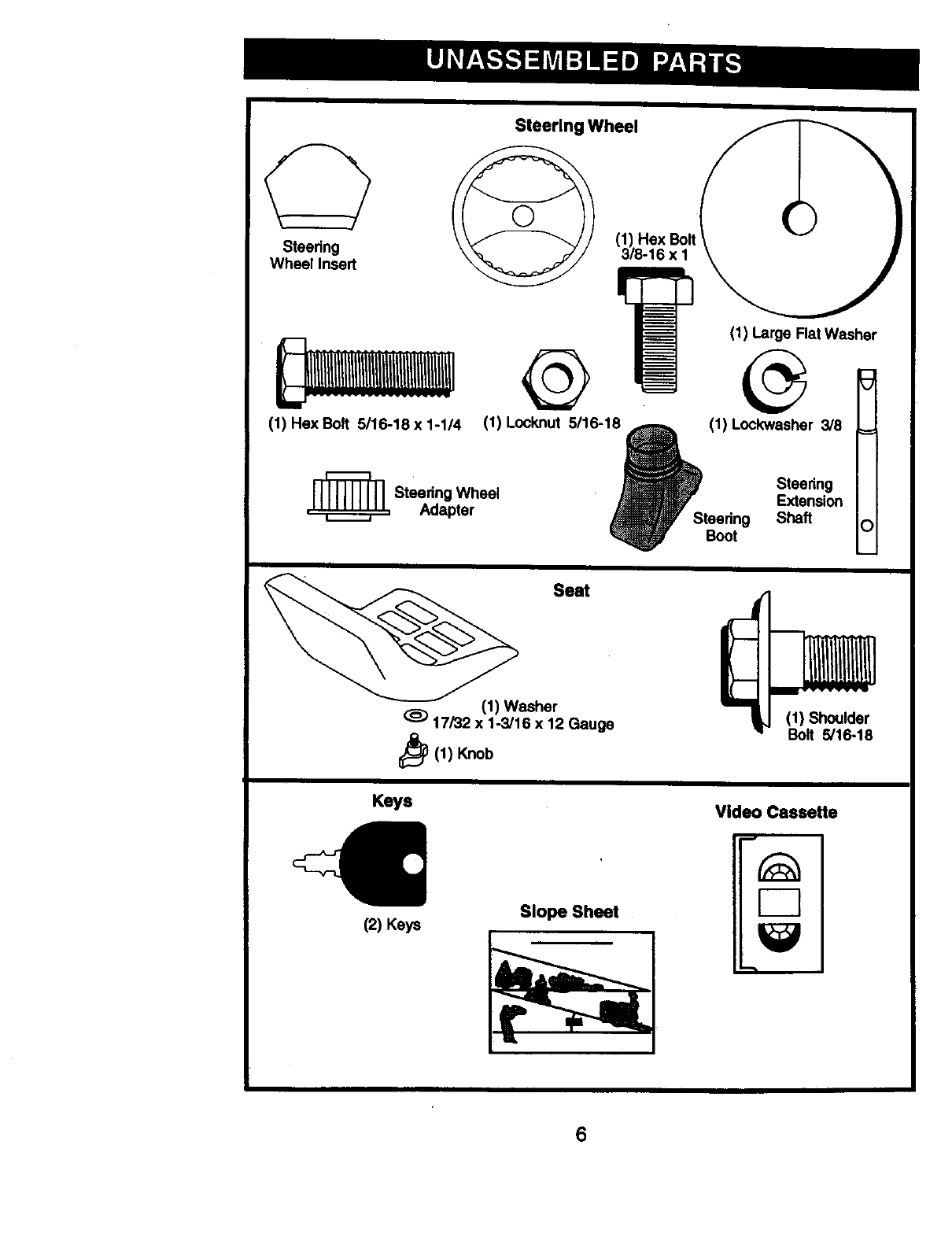
Steering Wheel
Steering
Wheel Insert
(1) Hex Bolt 5116-18 x 1-1/4
,_ Steedng Wheel
Adapter
(1) Hex Bolt
3/8-16 x 1
(1) Large Flat Washer
(1) Locknut 5/16-1° _(1) Lockwasher 3/8
ISteedng
Extension
Steering Shaft
Boot
Seat
(1) Washer
(_) 17/32 x 1-3/16 x 12 Gauge
b(1) Knob
(1) Shoulder
Bolt 5/16-18
Keys Video Cassette
(2) Keys Slope Sheet
6
Your new tractor has been assembled at the factory with exception of those parts left
unassembled for shipping purposes. To ensure safe and proper operation of your
tractor all parts and hardware you assemble must be tightened securely. Use the
correct tools as necessary to insure proper tightness. Review the video cassette before
you begin.
TOOLS REQUIRED FOR
ASSEMBLY
A socket wrench set will make assembly
easier. Standard wrench sizes you need
are listed below.
(1) 9/16" wrench (1) Pliers
(2) 1/2"wrench (1) Utility knife
(1) Tire pressure gauge
When right or left hand is mentioned in
this manual, it means, from your point of
view, when you are in the operating
position (seated behind the steering
wheel).
TO REMOVE TRACTOR FROM
CARTON
UNPACK CARTON
•Remove all accessible loose parts
and parts boxes from shipping carton.
•Cut, from top to bottom, along lines on
all four corners of shipping carton, and
lay panels flat.
•Check for any additional loose parts or
boxes and remove.
BEFORE REMOVING TRACTOR
FROM SKID
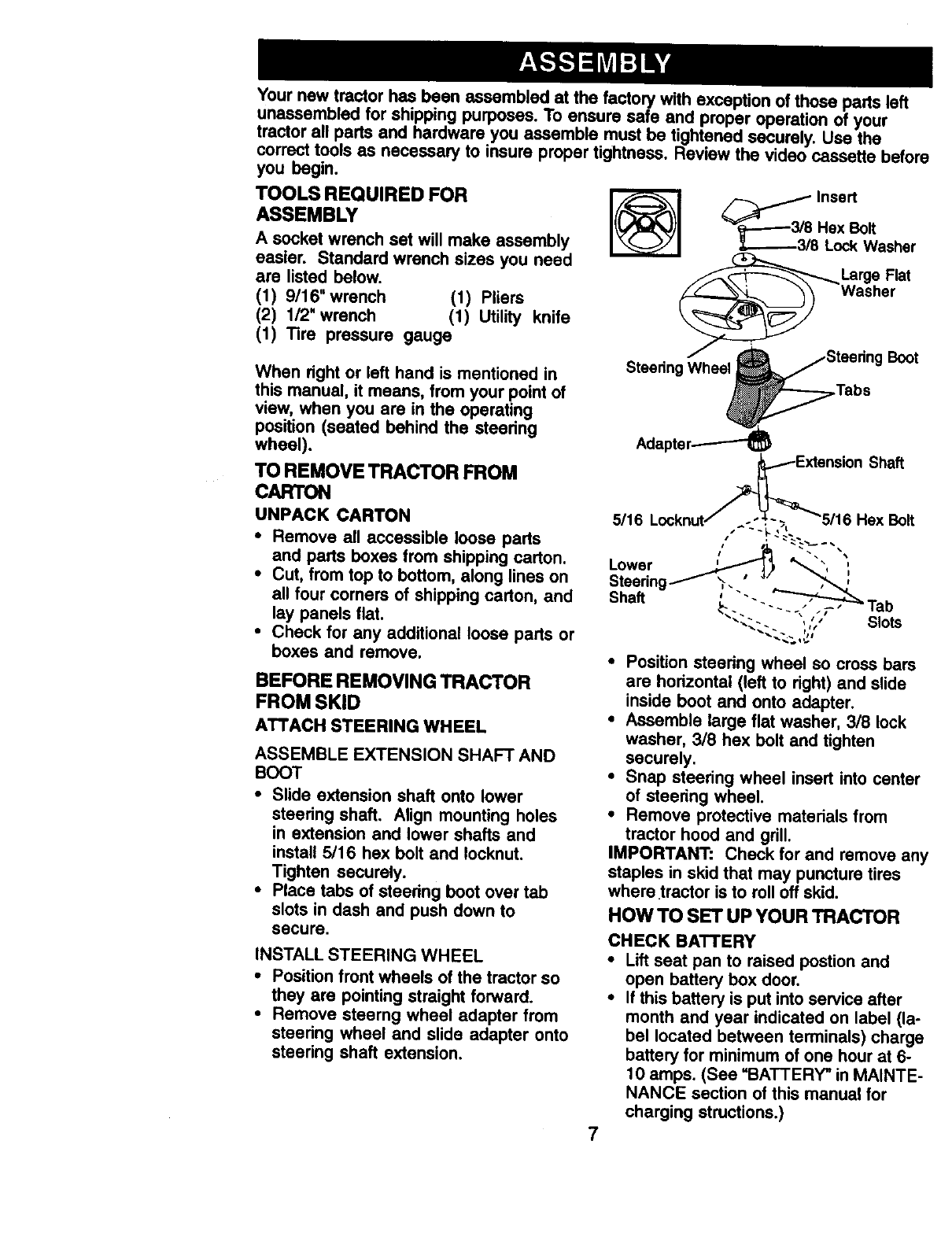
ATTACH STEERING WHEEL
ASSEMBLE EXTENSION SHAFT AND
BOOT
• Slide extension shaft onto lower
steering shaft. Align mounting holes
in extension and lower shafts and
install 5116 hex bolt and Iocknut.
Tighten securely.
• Place tabs of steedng boot over tab
slots in dash and push down to
secure.
INSTALL STEERING WHEEL
•Position front wheels of the tractor so
they are pointing straight forward.
•Remove steerng wheel adapter from
steedng wheel and slide adapter onto
steering shaft extension.
Adaptc Shaft
7
•Position steedng wheel so cross bars
are hodzontal (left to right) and slide
inside boot and onto adapter.
•Assemble large flat washer, 318 lock
washer, 3/8 hex bolt and tighten
securely.
•Snap steedng wheel insert into center
of steedng wheel.
•Remove protective matedals from
tractor hood and grill.
IMPORTANT: Check for and remove any
staples in skid that may puncture tires
where tractor is to roll off skid.
HOW TO SET UP YOUR TRACTOR
CHECK BATTERY
•Lift seat pan to raised postJon and
open battery box door.
•If this battery is put into service after
month and year indicated on label (la-
bel located between terminals) charge
battery for minimum of one hour at 6-
10 amps. (See =BATTERY" in MAINTE-
NANCE section of this manual for
charging stmctions.)
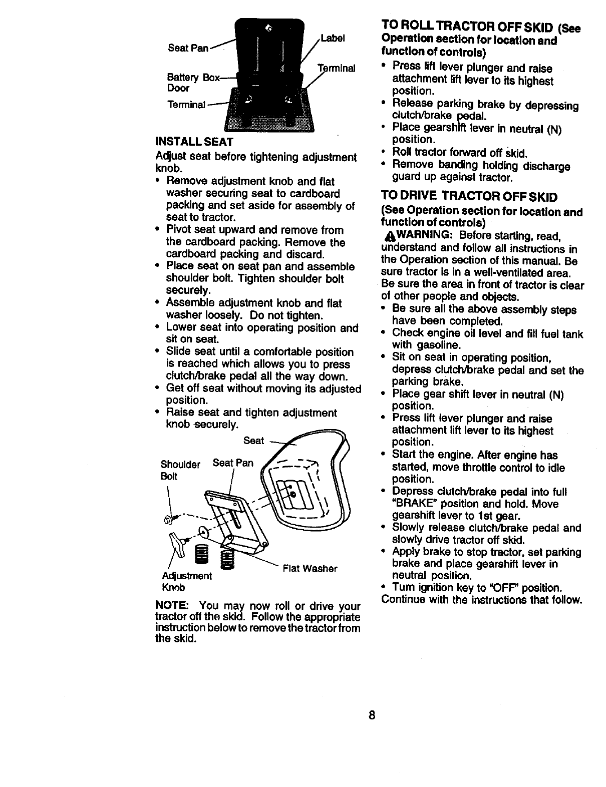
Label
BatteP
Door
INSTALL SEAT
Adjust seat before tightening adjustment
knob.
•Remove adjustment knob and flat
washer securing seat to cardboard
packing and set aside for assembly of
seat to tractor.
•Pivot seat upward and remove from
the cardboard packing. Remove the
cardboard packing and discard,
•Place seat on seat pan and assemble
shoulder bolt. Tighten shoulder bolt
securely.
•Assemble adjustment knob and flat
washer loosely. Do not tighten.
•Lower seat into operating position and
sit on seat.
•Slide seat until a comfortable position
is reached which allows you to press
clutch/brake pedal all the way down.
•Get off seat without moving its adjusted
position.
•Raise seat and tighten adjustment
knob securely.
Seat
Shoulder Seat Pan
Bolt
Flat Washer
Adjustment
Knob
NOTE: You may now roll or drive your
tractor offthe skid. Follow the appropriate
instructionbelow to remove the tractorfrom
the skid.
TO ROLL TRACTOR OFF SKID (See
Operation section for location end
functlon of controls)
•Press lift lever plunger and raise
attachment lift tever to its highest
position.
•Release parking brake by depressing
clutch/brake pedal.
• Place gearshift lever in neutral (N)
position.
•Roll tractor forward off Skid.
•Remove banding holding discharge
guard up against tractor.
TO DRIVE TRACTOR OFF SKID
(See Operation sectlon for location and
functlon of controls)
_WARNING: Before starting, read,
understand and follow all instructions in
the Operation section of this manual. Be
sure tractor is in a well-ventilated area.
Be sure the area in front of tractor is clear
of other people and objects.
•Be sure all the above assembly steps
have been completed.
•Check engine oil level and fill fuel tank
with gasoline.
•Sit on seat in operating position,
depress clutch/brake pedal and set the
parking brake.
• Place gear shift lever in neutral (N)
position.
•Press lift lever plunger and raise
attachment lift lever to its highest
position.
•Start the engine. After engine has
started, move throttle control to idle
position.
•Depress clutch/brake pedal into full
"BRAKE" position and hold. Move
gearshift lever to 1st gear.
•Slowly release clutch/brake pedal and
slowly drive tractor off skid.
•Apply brake to stop tractor, set parking
brake and place gearshift lever in
neutral position.
•Turn ignition key to =OFF" position,
Continue with the instructions that follow.
8
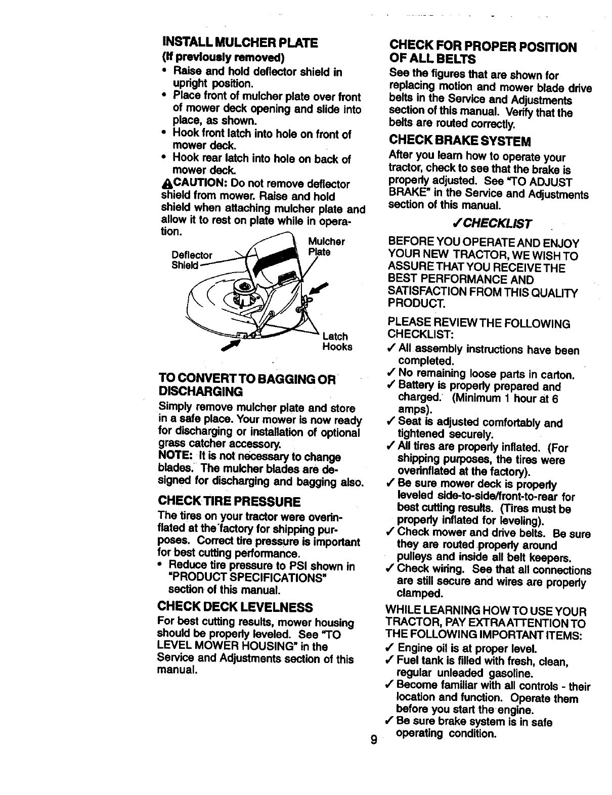
INSTALL MULCHER PLATE
(if previously removed)
• Re'me and hold deflector shield in
upright position.
•Place front of mulcher plate over front
of mower deck opening and slide into
place, as shown.
•Hook front latch into hole on front of
mower deck.
•Hook rear latch into hole on back of
mower deck.
ACAUTION: Do not remove deflector
shield from mower. Raise and hold
shield when attaching mulcher plate and
allow it to rest on plate while in opera-
tion. Mulcher
Deflector Plate
Latch
jlr Hooks
TO CONVERT TO BAGGING OR
DISCHARGING
Simply remove mulcher plate and store
in a safe place. Your mower is now ready
for discharging or installation of optional
grass catcher accessory.
NOTE: It is not necessary to change
blades. The mulcher blades are de-
signed for discharging and begging also.
CHECKTIRE PRESSURE
The tires on your tractor were ovefin-
flated at the'factory for shipping pur-
poses. Correct tire pressure is important
for best cutting performance.
•Reduce tire pressure to PSI shown in
=PRODUCT SPECIFICATIONS"
section of this manual.
CHECK DECK LEVELNESS
For best cutting results, mower housing
should be properly leveled. See "TO
LEVEL MOWER HOUSING" in the
Service and Adjustments section of this
manual.
CHECK FOR PROPER POSITION
OF ALL BELTS
See the figures that are shown for
replacing motion and mower blade drive
belts in the Service and Adjustments
section of this manual. Verify that the
belts are routed correctly.
CHECK BRAKE SYSTEM
After you leam how to operate your
tractor, check to see that the brake is
properly adjusted. See =TO ADJUST
BRAKE" in the Service and Adjustments
section of this manual.
/CHECKUST
BEFORE YOU OPERATE AND ENJOY
YOUR NEW TRACTOR, WE WISH TO
ASSURE THAT YOU RECEIVE THE
BEST PERFORMANCE AND
SATISFACTION FROM THIS QUALITY
PRODUCT.
9
PLEASE REVIEWTHE FOLLOWING
CHECKLIST:
,/All assembly instructions have been
completed.
,/No remaining loose parts in carton.
/Battery is propedy prepared and
charged. (Minimum 1 hour at 6
amps).
/Seat is adjusted comfortably and
tightened securely;
,/All tires are properly inflated. (For
shipping purposes, the tires were
ovefinflated at the factory).
,/Be sure mower deck is propedy
leveled side-to-side/front-to-rear for
best cutting results. (Tires must be
properly inflated for leveling).
,/Check mower and drive belts. Be sure
they are routed .property around
pulleys and inside all belt keepers.
/Check wiring. See that all connections
are still secure and wires are propedy
clamped.
WHILE LEARNING HOW TO USE YOUR
TRACTOR, PAY EXTRAATFENTION TO
THE FOLLOWING IMPORTANT ITEMS:
/Engine oil is at proper level.
,/Fuel tank is filled with fresh, clean,
regular unleaded gasoline.
•/Become familiar with all controls -their
location and function. Operate them
before you start theengine.
/Be sure brake system is in safe
operating condition.
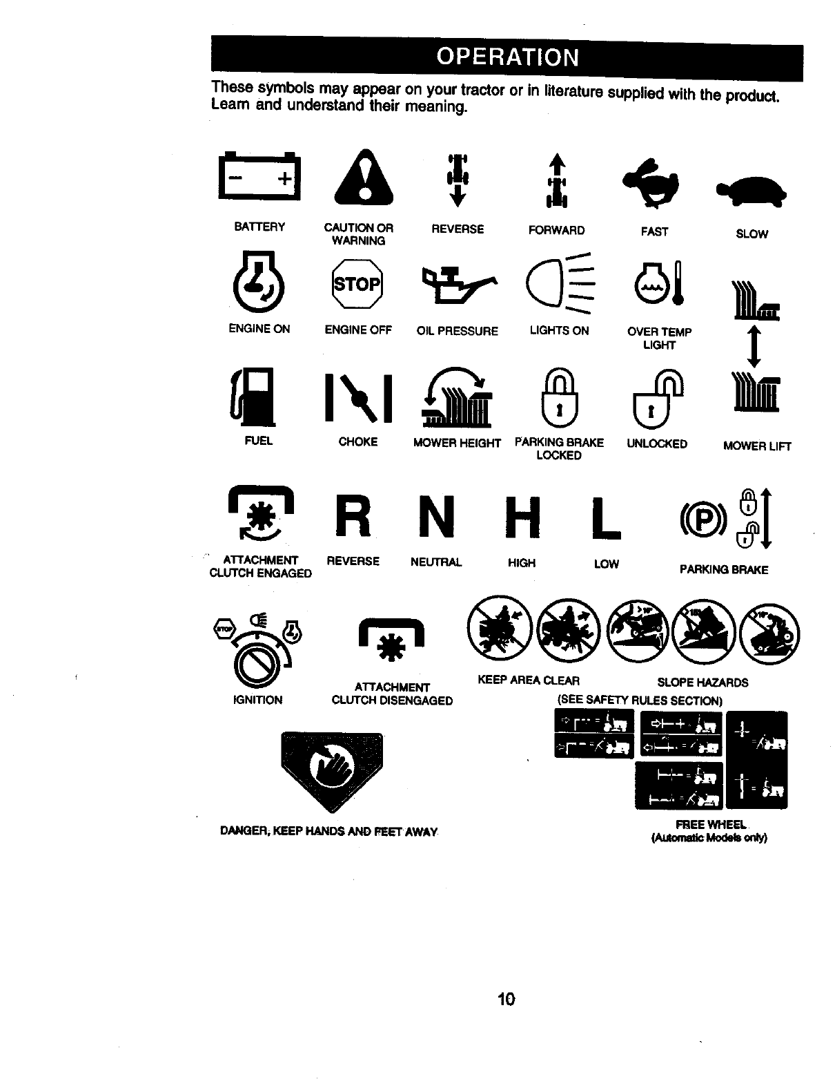
These symbols may appear on your tractor or in literature supplied with the product.
Learn and understand their meaning.
÷
BATTERY CAUTION OR REVERSE FORWARD FAST SLOW
WARNING
ENG,NEONENG,NEOFFO,'PRESSOREL,ONTSONOV_,_T_.P_=
FUEL CHOKE MOWER HEIGHT PARKINGBRAKE UNLOCKED MOWER LIFT
LOCKED
R N H L
ATTACHMENT REVERSE NEUTRAL HIGH LOW
CLUTCH ENGAGED PARKING BRAKE
_(_) ATTACHMENT KEEP AREA CLEAR SLOPE HAZARDS
IGNITION CLUTCH DISENGAGED (SEE SAFETY RULES SECTION)
DANGER; KEEP HANDS AND FELT AWAY FREE WHEEL
(Automa_Moth o,_y)
I0
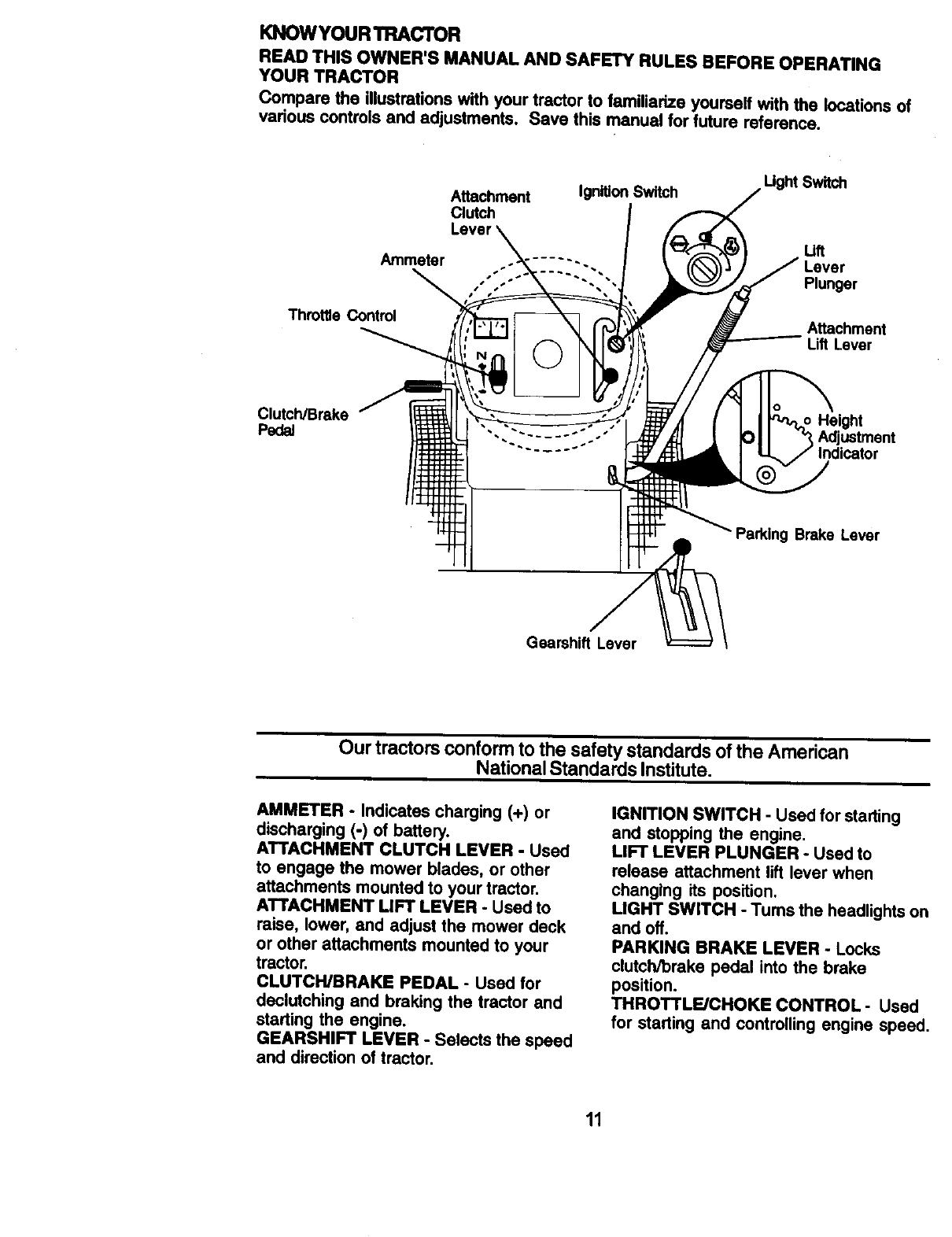
KNOWYOUR TRACTOR
READ THIS OWNER'S MANUAL AND SAFETY RULES BEFORE OPERATING
YOUR TRACTOR
Compare the illustrationswith your tractor to familiarize yourself with the locations of
vadous controls and adjustments. Save this manuel for future reference.
Attachment
Clutch
Ignition Switch
Amme_r
ThrottleControl
Lift
..... "- Lever
.... "-"" Plunger
Attachment
Li_ Lever
Clutch/Brake Height
Pedal "- ...... °
Parking Brake Lever
GearshiftLever
Our tractors conform to the safety standards of the American
National Standards Institute.
AMMETER - Indicates charging (+) or
discharging (-) of battery.
ATTACHMENT CLUTCH LEVER -Used
to engage the mower blades, or other
attachments mounted to your tractor.
ATTACHMENT LIFT LEVER - Used to
raise, lower, and adjust the mower deck
or other attachments mounted to your
tractor.
CLUTCH/BRAKE PEDAL -Used for
declutching and braking the tractor and
starting the engine.
GEARSHIFT LEVER -Selects the speed
and direction of tractor.
IGNITION SWITCH -Used for starting
and stopping the engine,
LIFT LEVER PLUNGER -Used to
release attachment lift lever when
changing its position.
LIGHT SWITCH -Tums the headlights or
and off.
PARKING BRAKE LEVER -Locks
clutch/brake pedal into the brake
position.
THROTTLE/CHOKE CONTROL -Used
for starting and controlling engine speed.
11
The operation of any tractor can result in foreign objects thrown into
the eyes, which can result in severe eye damage. Always wear safety
glasses or eye shields while operating your tractor or performing any
adjustments or repairs. We recommend a wide vision safety mask
over spectacles or standard safety glasses.
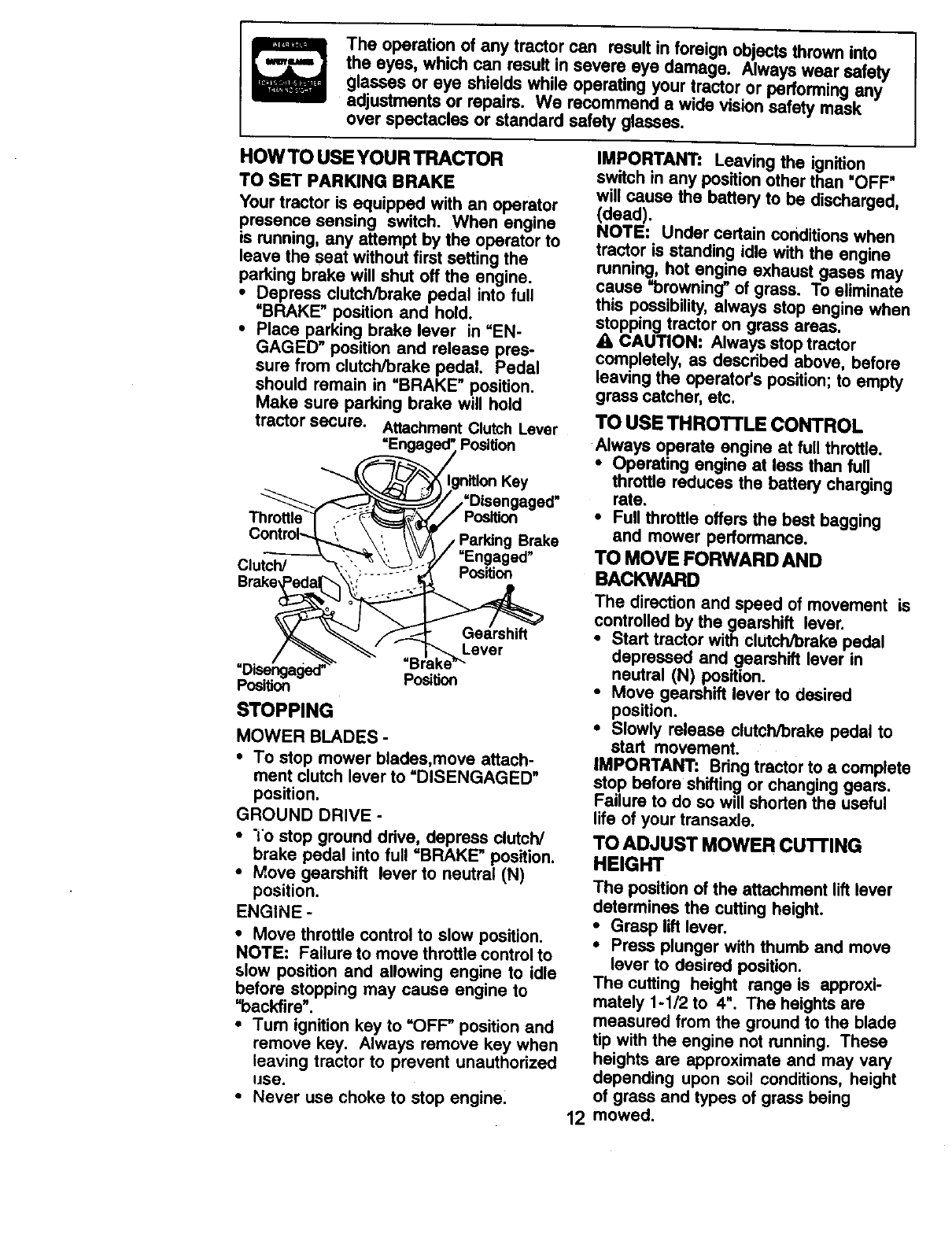
HOWTO USE YOUR TRACTOR
TO SET PARKING BRAKE
Your tractor is equipped with an operator
presence sensing switch. When engine
is running, any attempt by the operator to
leave the seat without first setting the
parking brake will shut off the engine.
• Depress clutch/brake pedal into full
=BRAKE" position and hold.
•Place parking brake lever in =EN-
GAGED" position and release pres-
sure from clutch/brake pedal. Pedal
should remain in =BRAKE" position.
Make sure parking brake will hold
tractor secure. AttachmentClutch Lever
=Engaged", Position
_gniUon Key
__//'Disengaged"
Thro.ttl.e_f.-:_5_ PositJon
Contro_ \, _K /Parking Brake
-, ._ ',,_,, \_'_)/ =Engaged"
_iutch/ -_.:.________S.--._ Position
STOPPING
MOWER BLADES -
•To stop mower blades,move attach-
ment clutch lever to =DISENGAGED"
position.
GROUND DRIVE -
•"io stop ground drive, depress clutch/
brake pedal into full "BRAKE" position.
•Move gearshift lever to neutral (N)
position.
ENGINE -
•Move throttle control to slow position,
NOTE: Failure to move throttle control to
slow position and allowing engine to idle
before stopping may cause engine to
=backfire'.
•Tum ignition key to =OFF" position and
remove key. Always remove key when
leaving tractor to prevent unauthorized
use.
•Never use choke to stop engine.
IMPORTANT: Leaving the ignition
switch in any position other than "OFF"
will cause the battery to be discharged,
(dead).
NOTE: Under certain conditionswhen
tractor is standing idle with the engine
running, hot engine exhaust gases may
cause =browning" of grass. To eliminate
this possibility,always stop engine when
stopping tractor on grass areas,
ACAUTION: Always stop tractor
completely, as dascribed above, before
leaving the operators position; to empty
grass catcher, etc.
TO USE THROTrLE CONTROL
Always operate engine at full throttle.
•Operating engine at less than full
throttle reduces the battery charging
rate.
•Full throttle offers the bast bagging
and mower performance.
TO MOVE FORWARD AND
BACKWARD
The direction and speed of movement is
controlled by the gearshift lever.
•Start tractor with clutch/brake pedal
depressed and gearshift lever in
neutral (N) position.
•Move gearshift lever to desired
position.
•Slowly release clutch/brake pedal to
start movement.
IMPORTANT: Bring tractor to a complete
stop before shifting or changing gears.
Failure to do so will shorten the useful
life of your transaxle.
TO ADJUST MOWER CU'I-rlNG
HEIGHT
The position of the attachment lift lever
determines the cutting height.
• Grasp lilt lever.
•Press plunger with thumb and move
lever to desired position.
The cutting height range is approxi-
mately %1/2 to 4". The heights are
measured from the ground to the blade
tip with the engine not running. These
heights are approximate and may vary
depending upon soil conditions, height
of grass and types of grass being
12 mowed.
•The average lawn should be cut to
approximately 2-1/2 inches dudng the
cool season and to over 3 inches
dudng hot months. For healthier and
better looking lawns, mow often and
after moderate growth.
, For best cutting pedormance, grass
over 6 inches in height should be
mowed twice. Make the first cut
relatively high; the second to desired
height.
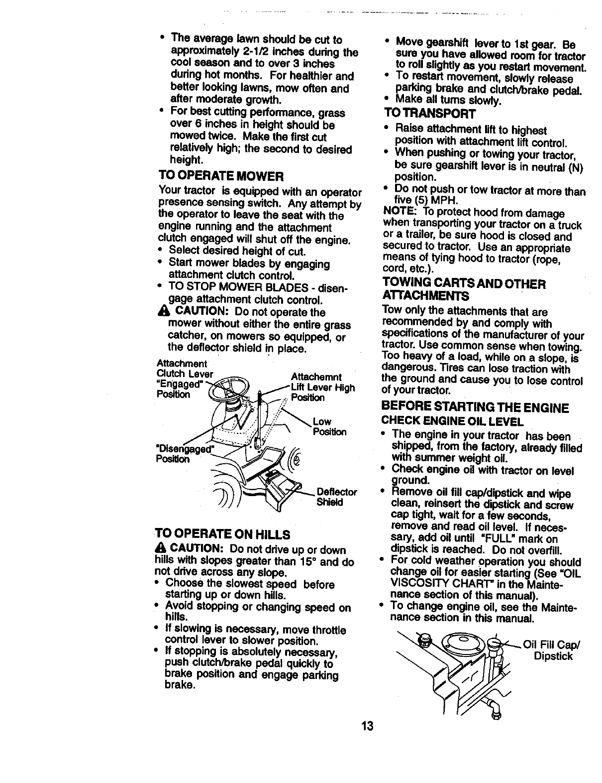
TO OPERATE MOWER
Your tractor is equipped with an operator
presence sensing switch. Any attempt by
the operator to leave the seat with the
engine running and the attachment
clutch engaged will shut off the engine.
• Select desired height of cut.
•Start mower blades by engaging
attachment clutch control.
•TO STOP MOWER BLADES -disen-
gage attachment dutch control.
_1_CAUTION: Do not operate the
mower without either the entire grass
catcher, on mowers so equipped, or
the deflector shield In place.
Attachment
Clutch Lever
Podtk)n
Attachemnt
High
._ Position
Low
PosiUon
Pos_on
Deflector
Shield
TO OPERATE ON HILLS
A CAUTION: Do not ddve up or down
hills with slopes greater than 15° and do
not drive across any slope.
•Choose the slowest speed before
starting up or down hills.
•Avoid stopping or changing speed on
hills.
• If slowing is necessary, move throttle
control lever to slower position.
•If stopping is absolutely necessary,
push clutch/brake pedal quickly to
brake position and engage parking
brake.
•Move gearshift lever to 1st gear. Be
sure you have allowed room for tractor
to roll slightly as you restart movement.
•To restart movement, slowly release
parking brake and clutch/brake pedal.
•Make all turns slowly.
TOTRANSPORT
•Raise attachment lift to highest
position with attachment lift control.
•When pushing or towing your tractor,
be sure gearshift lever is in neutral (N)
position.
•Do not push or tow tractor at more than
five (5) MPH.
NOTE: To protect hood from damage
when transporting your tractor on a truck
or a trailer, be sure hood is closed and
secured to tractor. Use an appropriate
means of tying hood to tractor (rope,
cord, etc.).
TOWING CARTS AND OTHER
ATrACHMENTS
Tow only the attachments that are
recommended by and comply with
specifications of the manufacturer of your
tractor. Use common sense when towing.
Too heavy of a load, while on aslope, is
dangerous. Tires can lose traction with
the ground and cause you to lose control
of yourtractor.
BEFORE STARTING THE ENGINE
CHECK ENGINE OIL LEVEL
•The engine in your tractor has been
shipped, from the factory, already filled
with summer weight oil.
•Check engine oil with tractor on level
ground.
• Remove oil fill cap/dipstick and wipe
clean, ralnsert the dipstick and screw
cap tight, wait for a few seconds,
remove and read oil level. If neces-
sary, add oil until "FULL" mark on
dipstick is reached. Do not overfill.
•For cold weather operation you should
change oil for easier starting (See "OIL
VISCOSITY CHART" in the Mainte-
nance section of this manual),
•To change engine oil, see the Mainte-
nance section in this manual.
i
Oil Fill Cap/
_Dipstick
N/
13
ADD GASOLINE
• Fill fuel tank. Use fresh, clean, regular
unleaded gasoline with aminimum of
87 octane. (Use of leaded gasoline
will Increase carbon and lead oxide
deposits and reduce valve life). Do
not mix oil with gasoline. Purchase
fuel in quantities that can be used
within 30 days to assure fuel fresh-
ness.
IMPORTANT: When operating in
temperatures below 32°F(0°C), use
fresh, clean winter grade gasoline to
help insure good cold weather starting.
WARNING: Experience indicates that
aTcoholblended fuels (called gasohol or
using ethanol or methanol) can attract
moisture which leads to separation and
formation of acids during storage. Acidic
gas can damage the fuel system of an
engine while in storage. To avoid engine
problems, the fuel system should be
emptied before storage of 30 days or
longer. Drain the gas tank, start the
engine and let it run until the fuel lines
and carburetor are empty. Use fresh fuel
next season. See Storage Instructions
for additional information. Never use
engine or carburetor cleaner products in
the fuel tank or permanent damage may
occur.
_IbeCAUTION: Fillto bottom of gas tank
r neck. Do not overfill. Wipe off any
spilled oil or fuel. Do not store, spill or
use gasoline near an open flame.
TO START ENGINE
When starting the engine for the first time
or if the engine has run out of fuel, it will
take extra cranking time to move fuel
from the tank to the engine.
• Sit on seat in operating position,
depress clutch/breke pedal and set
parking brake.
•Place gear shift lever in neutral (N)
position.
•Move attachment clutch to "DISEN-
GAGED" poe_Qn.
• Move throttle €ontrettochoke pnsition,
NOTE: Before sty, read the warm •
and cold starting,procedures belOw_
•Insert key into ignition and turn key
clockwise to =START" position and
release key as soon as engine starts.
Do not run starter continuously for
more than fifteen seconds per minute.
If the engine does not start after
several attempts, move throttle control
to fast position, wait a few minutes and
try again. If engine still does not start,
move the throttle control back to the
choke position and retry.
WARM WEATHER STARTING (50 ° F and
above)
•When engine starts, move the throttle
control to the fast position.
•The attachments and ground drive can
now be used. If the engine does not
accept the load, restart the engine and
allow it to warm up for one minute
using the choke as described above.
COLD WEATHER STARTING ( 50° F and
below)
•When engine starts, allow engine to
run with the throttle control in the
choke position until the engine runs
roughly,then move throttle controlto
fast position. This may require an
engine warm-up pedod from several
seconds to several minutes, depend-
ing on the temperature.
•The attachments can also be used
dudng the engine warm-up pedod.
NOTE: If at a high altitude (above 3000
feet) or in cold temperatures (below 32
F) the carburetor fuel mixture may need
to be adjusted for best engine perfor-
mance. See =TO ADJUST CARBURE-
TOR" in the Service and Adjustments
section of this manual.
14
MOWING TIPS
• Mower should be properly leveled for
best mowing performance. See "TO
LEVEL MOWER HOUSING" in the
Service and Adjustments section of
this manual.
•The left hand side Of mower should be
used for trimming.
•Ddve so that clippings are discharged
onto the area that has been cut. Have
the cut area to the dght of the tractor.
This will result in a more even distribu-
tion of clippings and more uniform
cutting.
•When mowing large areas, start by
tuming to the right so that clippings will
discharge away from shrubs, fences,
ddveways, etc. After one or two
rounds, mow in the opposite direction
making left hand tums until finished.
•If grass is extremely tall, it should be
mowed twice to reduce load and
possible fire h_ard from dried
clippings. Make first cut relatively
high; the second to the desired height.
•Do not mow grass when it is wet. Wet
grass will plug mower and leave
undesirable clumps. Allow grass to
dry before mowing.
•Always operate engine at full throttle
when mowing to assure better mowing
performance and proper discharge of
material. Regulate ground speed by
selecting a low enough gear to give
the mower cutting performance as well
as the quality of cut desired.
•When operating attachments, select a
ground speed that will suit the terrain
and give best performance of the
attachment being used.
[[
T
tL_
MULCHING MOWING TIPS
IMPORTANT: For best performance,
keep mower housing free of built-up
grass and trash. Clean after each use.
•The special mulching blade will recut
the grass clippings many times and
reduce them in size so that as they fall
onto the lawn they will disperse into
the grass and not be noticed. Also, the
mulched grass will biodegrade quickly
to provide nutrients for the lawn.
Always mulch with your highest
engine (blade) speed as this will
provide the best recutting action of the
blades.
•Avoid cutting your lawn when it is wet.
Wet grass tends to form clumps and
interferes with the mulching action.
The best time to mow your lawn is the
eaHy aftemoon. At this time the gi'ass
has dried and the newly cut area will
not be exposed to the direct sun.
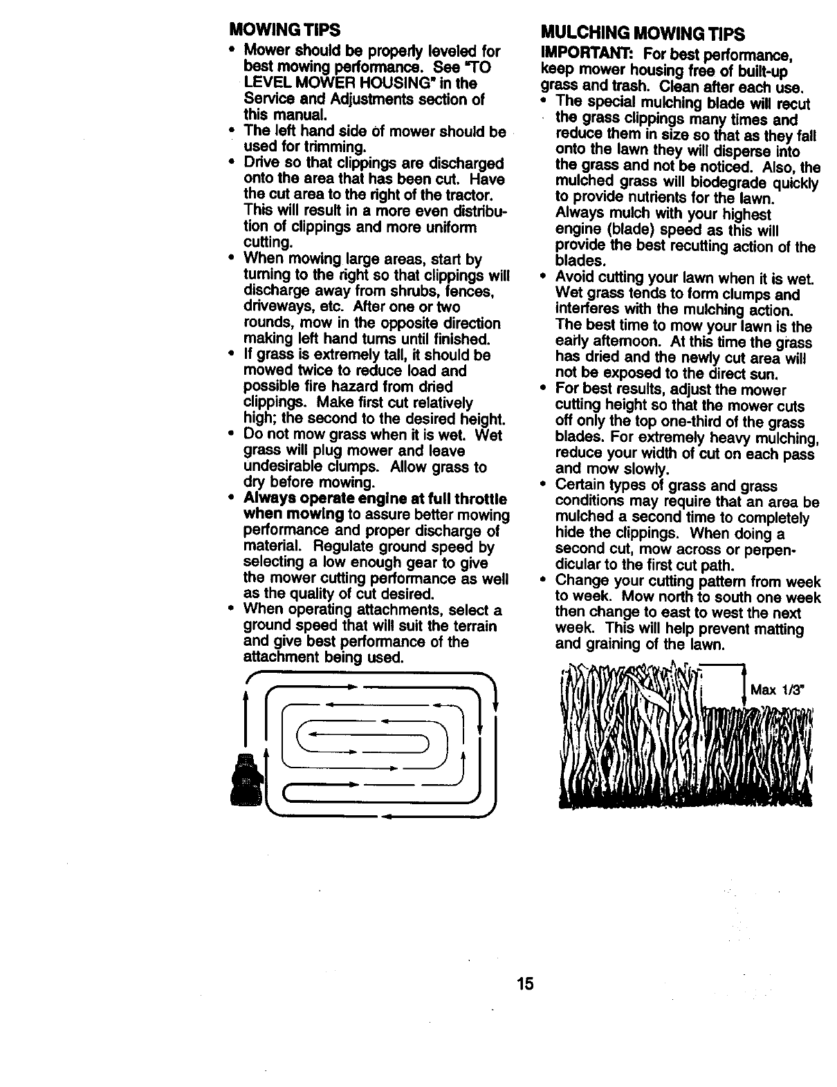
•For bast results, adjust the mower
cutting height so that the mower cuts
off only the top one-third of the grass
blades. For extremely heavy mulching,
reduce your width of cut on each pass
and mow slowly.
•Certain types of grass and grass
conditions may require that an area be
mulched a second time to completely
hide the clippings. When doing a
second cut, mow across or perpen-
dicular to the first cut path.
•Change your cutting pattern from week
to week. Mow north to south one week
then change to east to west the next
week. This will help prevent matting
and graining of the lawn.
i|y(lil l[, i , lWli Max113"
.i
"b i
i
15
AS YOU COMPLETE _'_ _'_
_ "rim t_4m_'e
R Ch=__" Loo_Famr_ t/, t1'
T L_'_ C_ I/
0 Checkk_e_y Level
R c_an BatteryandT_m a/ _'
C_eck Tr_a_ Coding
Adjust Motion Ddve _dl(s) Tems_ ii_s
c_ En_ _I/=j
E QeanAlrFi.er
N CleanAir Scme_
In_ MufflerfBped_ An'e_er I_
Replace Spm'kPlug I_
P,e_sce_r F_orP_ Cs*Iddge
ReplaceFuel niter I_
I. Chm_ n_r_ _t_,_*t_n _er_g undera he_y k)a__I. l_lh arr_ent_mperatu._. S- _e_d w_h_W_,_
2- S_O moil)_ten whon_mi_ng Ind_y ordmty€o_. 0- N_tmqUlelX_#e_#_Kl tdthn1_l_l ba_.
3 - If _wahd fl_tr, _ol 4w_y 50heurs. ? - Ti_en f_z a_ plw:lb_ to36 tt.-l_, ma._num
4 - R_ bl_dmn_xe _v,,'l_enmowin0inmm_y_a. Oono_o'_nigh(_.
GENERAL RECOMMENDATIONS
The warranty on this tractor does not
cover items that have been subjected to
operator abuse or negligence. To
receive full value from the warranty,
operator must maintain tractor as
instructed in this manual.
Some adjustments will need to be made
periodically to properly maintain your
tractor.
All adjustments in the Service and
Adjustments section of this manual
should be checked at least once each
season.
• Once a year you should replace the
spark plug, clean or replace air filter,
and check blades and belts for wear.
A new spark plug and clean air filter
a_sure proper air-fuel mixture and
help your engine run better and last
longer.
BEFORE EACH USE
: Check engine oil level.
Check brake operation.
• Check tire pressure.
•Check operator presence and
interlock systems for proper operation.
•Check for loose fasteners.
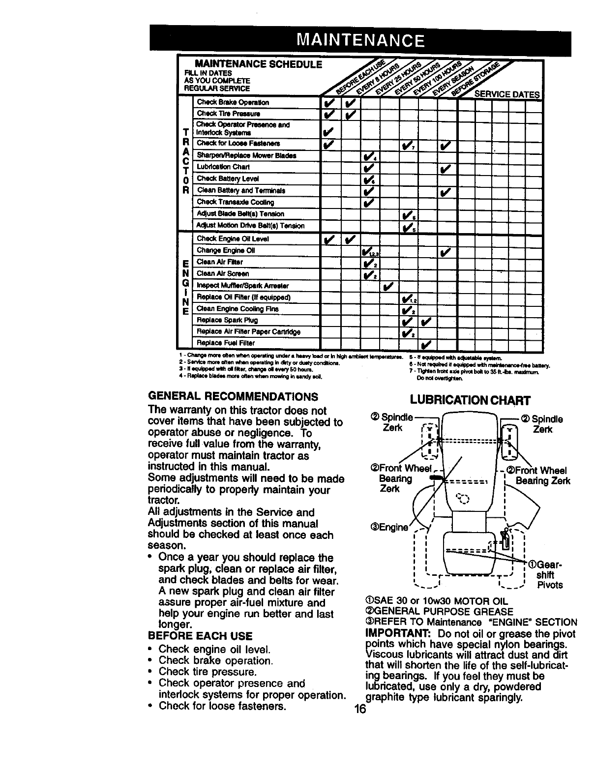
LUBRICATION CHART
_) Spindle
Zerk _"_-'
I
-_Spindle
Zerk
_Front Wheel
Bearing
Zerk
Wheel
Bearing Zerk
III
I I I
i I I
I i
0 I
iT- • i shift
'i 1. JPivots
(_)SAE 30 or 10w30 MOTOR OIL
_3ENERAL PURPOSE GREASE
_)REFER TO Maintenance =ENGINE" SECTION
IMPORTANT: Do not oil or grease the pivot
points which have special nylon bearings.
Viscous lubricants will attract dust and dirt
that will shorten the life of the self-lubricat-
ing bearings. If you feel they must be
lubricated, use only a dry, powdered
graphite type lubricant sparingly.
16
TRACTOR
Always observe safety rules when
performing any maintenance.
BRAKE OPERATION
if tractor requires more than six (6) feet
stopping distance at high speed in
highest gear, then brake must be
adjusted. (See =TO ADJUST BRAKE" in
the Service and Adjustments sectJonof
this manual).
TIRES
• Maintain proper air pressure in all tires
(See "PRODUCT SPECIFICATIONS"
section of this manual).
•Keep tires free of gasoline, oil, or
insect control chemicals which can
harm rubber.
•Avoid stumps, stones, deep ruts, sharp
objects and other hazards that may
cause tire damage.
NOTE: To seal tire punctures and
prevent flat tires due to slow leaks, tire
sealant may be purchased from your
local parts dealer. "l]re sealant also
prevents tire dry rot and corrosion.
OPERATOR PRESENCE SYSTEM
Be sure operator presence and interlock
systems are working property. If your
tractor does not function as dascdbed,
repair the problem immediately.
•The engine should not start unless the
clutch/brake pedal is fully depressed
and attachement clutch control is in
the disengaged position.
•When the engine is running, any
attempt by the operator to leave the
seat withoutfirst setting the parking
brake should shut off the engine.
• When the engine is running and the
attachment clutch is engaged, any
attempt by the operator to leave the
seat should shut off the engine.
•The attachment clutch should never
operate unless the operator is in the
seat.
BLADE CARE
For best results mower blades must be
kept sharp. Replace bent or damaged
blades.
BLADE REMOVAL
•Raise mower to highest position to
allow access to blades.
•Remove hex bolt, lock washer and flat
washer securing blade.
•Install new or resharpaned blade with
trailing edge up towards deck ,as
shown.
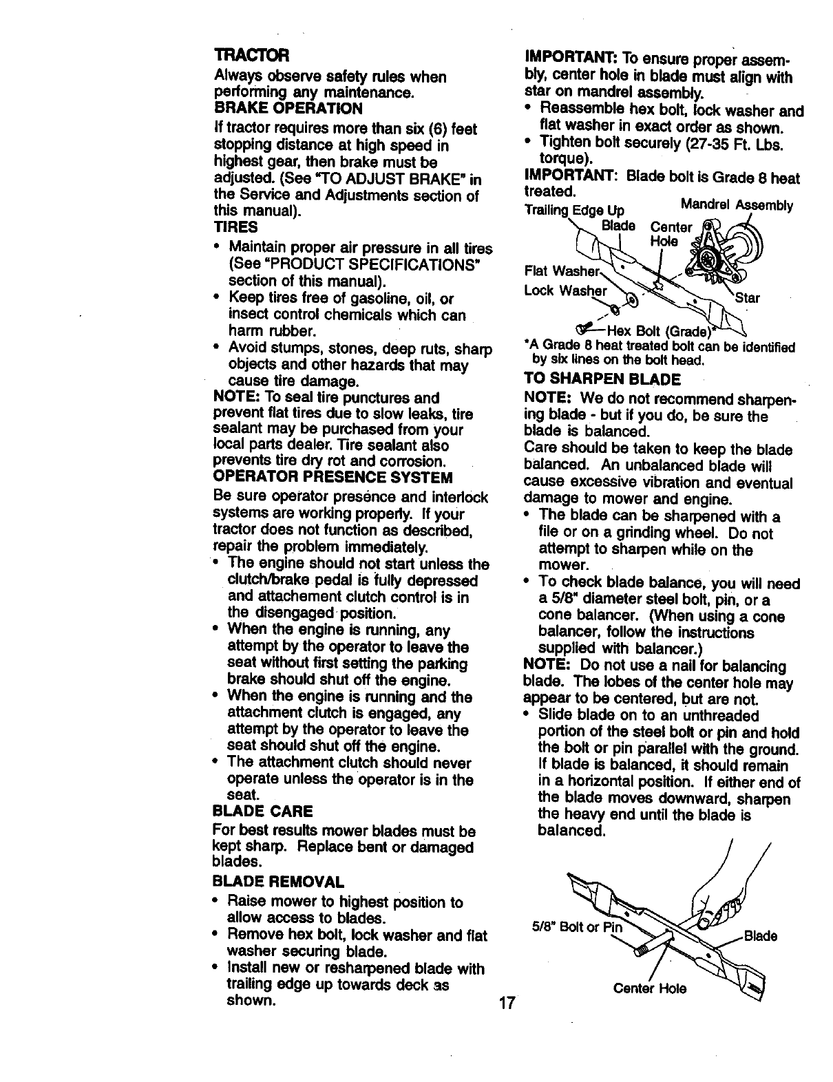
IMPORTANT: To ensure proper assem-
bly, center hole in blade must align with
star on mandrel assembly.
•Reassemble hex bolt, lock washer and
flat washer in exact order as shown.
•Tighten bolt securely (27-35 Ft. Lbs.
torque).
IMPORTANT: Blade bolt is Grade 8 heat
treated.
Trailing Edge Up Mandrel A,ssembly
Blade Center # b,_q_
Flat Washer\'._._ _)
Hex Bolt (Grade)
*A Grade 8 heat treated bolt can be identified
by six lines on the bolt head.
TO SHARPEN BLADE
NOTE: We do not recommend sharpen-
ing blade -but if you do, be sure the
blade is balanced.
Care should be taken to keep the blade
balanced. An unbalanced blade will
cause excessive vibration and eventual
damage to mower and engine.
•The blade can be sharpened with a
file or on a grinding wheel. Do not
attempt to sharpen while on the
mower.
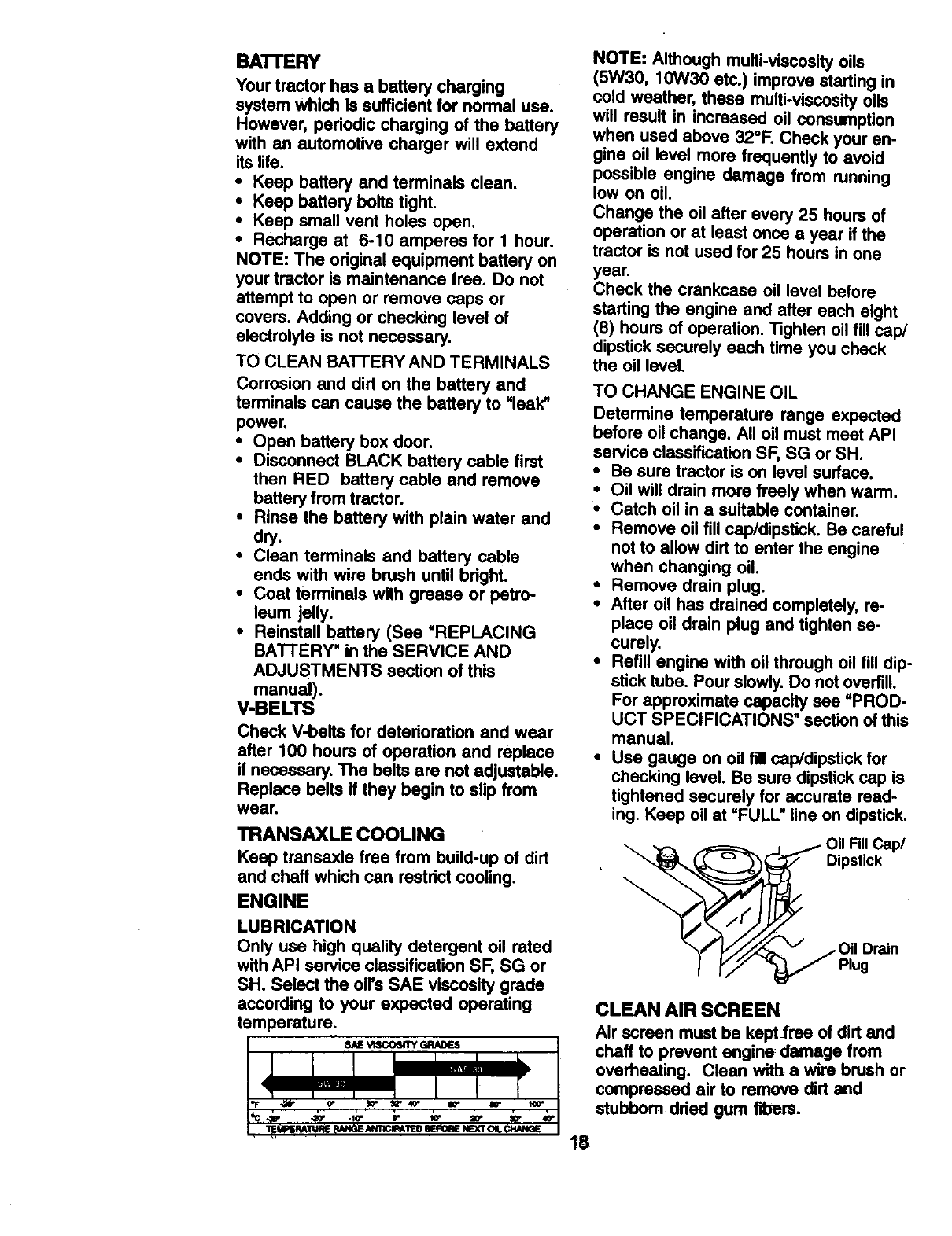
•To check blade balance, you will need
a 5/8' diameter steel bolt, pin, or a
cone balancer. (When using a (>one
balancer, follow the instructions
supplied with balancer.)
NOTE: Do not use anail for balancing
blade. The lobes of the center hole may
appear to be centered, but are not.
•Slide blade on to an unthreaded
portion of the steel bolt or pin and hold
the bolt or pin parallel with the ground.
If blade is balanced, it should remain
in a hodzontal position. If either end of
the blade moves downward, sharpen
the heavy end until the blade is
balanced.
Ce_erH_e
17
BAI"rERY
Your tractor has a battery charging
system which is sufficient for normal use.
However, periodic charging of the battery
with an automotive charger will extend
its life.
•Keep battery and terminals clean.
•Keep battery bolts tight.
•Keep small vent holes open.
•Recharge at 6-10 amperes for 1 hour.
NOTE: The original equipment battery on
your tractor is maintenance free. Do not
attempt to open or remove caps or
covers. Adding or checking level of
electrolyte is not necessary.
TO CLEAN BA'I-rERY AND TERMINALS
Corrosion and dirt on the battery and
terminals can cause the battery to =leak"
power,
•Open battery box door.
•Disconnect BLACK battery cable first
then RED battery cable and remove
battery from tractor.
•Rinse the battery with plain water and
dry.
•Clean terminals and battery cable
ends with wire brush until bright.
•Coat terminals with grease or petro-
leum jelly.
•Reinstall battery (See =REPLACING
BATTERY _in the SERVICE AND
ADJUSTMENTS section of this
manual).
V-BELTS
Check V-belts for deterioration and wear
after 100 hours of operation and replace
if necessary, The belts are not adjustable.
Replace belts if they begin to slip from
wear.
TRANSAXLE COOLING
Keep transaxlefree frombuild-upofdirt
and chaffwhichcan restrictcooling.
ENGINE
LUBRICATION
Only use high quality detergent oil rated
with API service classification SF, SG or
SH. Select the oil's SAE viscosity grade
according to your expected operating
temperature.
NOTE: Although multi-viscosityoils
(5W30, 10W30 etc.) improve starting in
cold weather, these multi-viscosity oils
will result in increased oil consumption
when used above 32°F. Check your en-
gine oil level more frequently to avoid
possible engine damage from running
low on oil.
Change the oil after every 25 hours of
operation or at least once ayear if the
tractor is not used for 25 hours in one
year.
Check the crankcase oil level before
starting the engine and after each eight
(8) hours of operation. Tighten oil flit cap/
dipstick securely each time you check
the oil level.
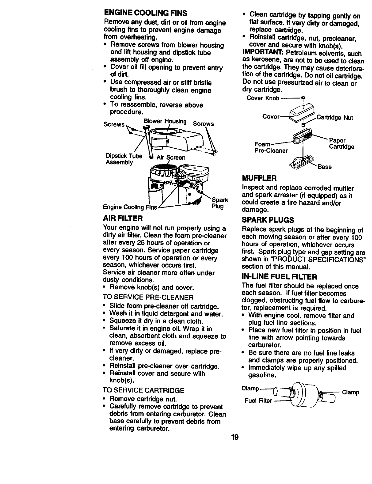
TO CHANGE ENGINE OIL
Determine temperature range expected
before oil change. All oil must meet API
service classification SF, SG or SH.
•Be sure tractor is on level surface.
•Oil will drain more freely when warm.
•Catch oil in a suitable container.
•Remove oil fill cap/dipstick. Be careful
not to allow dirt to enter the engine
when changing oil.
° Remove drain plug.
•After oil has drained completely, re-
place oil drain plug and tighten se-
curely.
•Refill engine with oil through oil fill dip-
stick tube. Pour slowly. Do not overfill.
For approximate capacity see =PROD-
UCT SPECIFICATIONS" section of this
manual.
•Use gauge on oil fill cap/dipstick for
checking level. Be sure dipstick cap is
tightened securely for accurate read-
ing. Keep oil at =FULL" line on dipstick.
Oil FillCap/
Dipstick
Oil Drain
Plug
CLEAN AIR SCREEN
Air screen must be kept frse of dirt and
chaff to prevent engine:damage from
overheating. Clean with a wire brush or
compressed air to remove dirt and
stubborn dded gum fibers.
18
Engine Cooling Fins
ENGINE COOLING FINS
Remove any dust, dirt or oil from engine
cooling fins to prevent engine damage
from overheating.
•Remove screws from blower housing
and lift housing and dipstick tube
assembly oft engine.
• Cover oil fill opening to prevent entry
of dirt.
•Use compressed air or stiff bdstle
brush to thoroughly clean engine
cooling fins.
•To reassemble, reverse above
procedure.
S Blower Housing Screw"
crews__ "=
Dipstick T_ _
Assembly _Spark
Plug
AIR FILTER
Your engine will not run properly using a
dirty air filter. Clean the foam pre-cleaner
after every 25 hours of operation or
every season. Service paper cartridge
every 100 hours of operation or every
season, whichever occurs first.
Service air cleaner more often under
dusty conditions.
•Remove knob(s) and cover.
TO SERVICE PRE-CLEANER
•Slide foam pre-cleaner oft cartridge.
•Wash it in liquid detergent and water.
•Squeeze it dry in a clean cloth.
•Saturate it in engine oil. Wrap it in
clean, absorbent cloth and squeeze to
remove excess oil.
•If very dirty or damaged, replace pro-
cleaner.
•Reinstall pre-cleaner over cartridge.
•Reinstall cover and secure with
knob(s).
TO SERVICE CARTRIDGE
• Remove cartridge nut.
•Carefully remove cartridge to prevent
debds from entering carburetor. Clean
base carefully to prevent debds from
entedng carburetor.
•Clean cartddge by tapping gently on
flat sudace. If very dirty or damaged,
replace cartddge.
•Reinstall cartddge, nut, precleaner,
cover and secure with knob(s).
IMPORTANT: Petroleum solvents, such
as kerosene, are not to be used to clean
the cartddge. They may cause detedora-
tion of the cartridge. Do not oil cartridge.
Do not use pressurized air to clean or
dry cartddge.
Cover Knob
Pre-Cleaner ._ Cartddge
"Base
MUFFLER
Inspect and replace corroded muffler
and spark arrester (if equipped) as it
could create a fire hazard and/or
damage.
SPARK PLUGS
Replace spark plugs at the beginning of
each mowing season or after every 100
hours of operation, whichever occurs
first. Spark plug type and gap setting are
shown in "PRODUCT SPECIFICATIONS"
section of this manual.
IN-LINE FUEL FILTER
The fuel filter should be replaced once
each season. If fuel filter becomes
clogged, obstructing fuel flow to carbure-
tor, replacement is required.
•With engine cool, remove filter and
plug fuel line sections.
•Place new fuel filter in position in fuel
line with arrow pointing towards
carburetor.
•Be sure there are no fuel line leaks
and clamps are properly positioned.
•Immediately wipe up any spilled
gasoline.
Clamp _Clamp
Fuel Filter
19
CLEANING
ilean engine, battery, seat, finish, etc.
of all foreign matter.
Keep finished surfaces and wheels
free of all gasoline, oil, etc.
Protect painted surfaces with automo-
tive type wax.
tWoedo not recommend using agarden
se to clean your tractor unless the
eloctricai system, muffler, air filter and
carburetor are covered to keep water out.
Water in engine can result in a short-
ened engine life.
_CAUTION: Before performing any service or adjustments:
•Depress clutch/brake pedal fully and set parking brake,
•Place gearshift lever in neutral (N) position.
•Place attachment clutch in =DISENGAGED" position.
Turn ignition key =OFF" and remove key.
iMake the blades and all have completely stopped.
sure moving parts
Disconnect spark _lug wire from spark plug and place wire where it cannot
come in contact with plug.
TRACTOR
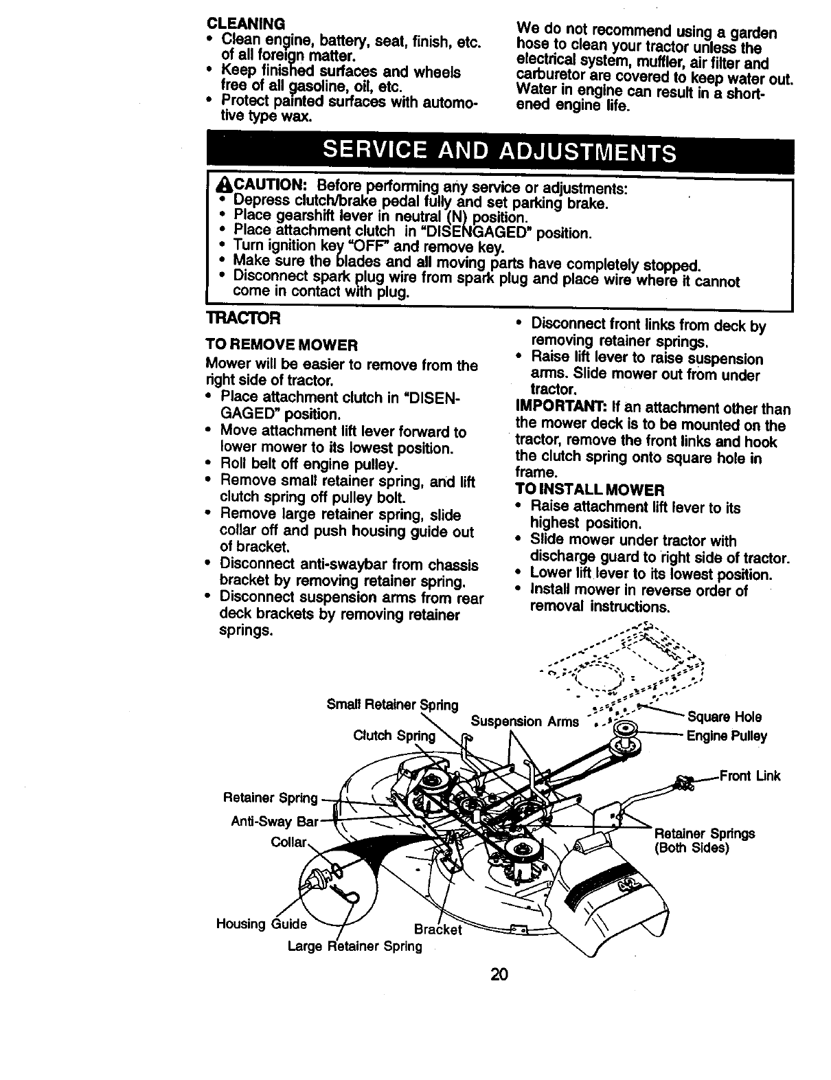
TO REMOVE MOWER
Mower will be easier to remove from the
right side of tractor.
•Place attachment clutch in =DISEN-
GAGED" position.
•Move attachment lift lever forward to
lower mower to its lowest position.
• Roll belt off engine pulley.
•Remove small retainer spring, and lift
clutch spring off pulley bolt.
•Remove large retainer spring, slide
collar off and push housing guide out
of bracket.
•Disconnect anti-swaybar from chassis
bracket by removing retainer spring.
•Disconnect suspension arms from rear
deck brackets by removing retainer
springs.
Small Retainer Spring
Clutch
•Disconnect front links from deck by
removing retainer spdngs.
•Raise lift lever to raise suspension
arms. Slide mower out from under
tractor.
IMPORTANT: If an attachment other than
the mower deck is to be mounted on the
tractor, remove the front links and hook
the clutch spring onto square hole in
frame.
TO INSTALL MOWER
•Raise attachment lift lever to its
highest position.
•Slide mower under tractor with
discharge guard to right side of tractor.
•Lower lift lever to its lowest position.
•Install mower in reverse order of
removal instructions.
Suspension Arms °, -J ;'"_ SquareHole
Link
Retainer
Anti-Swa_ Springs
(Both S_les)
Housing Guide
Large Spring
20
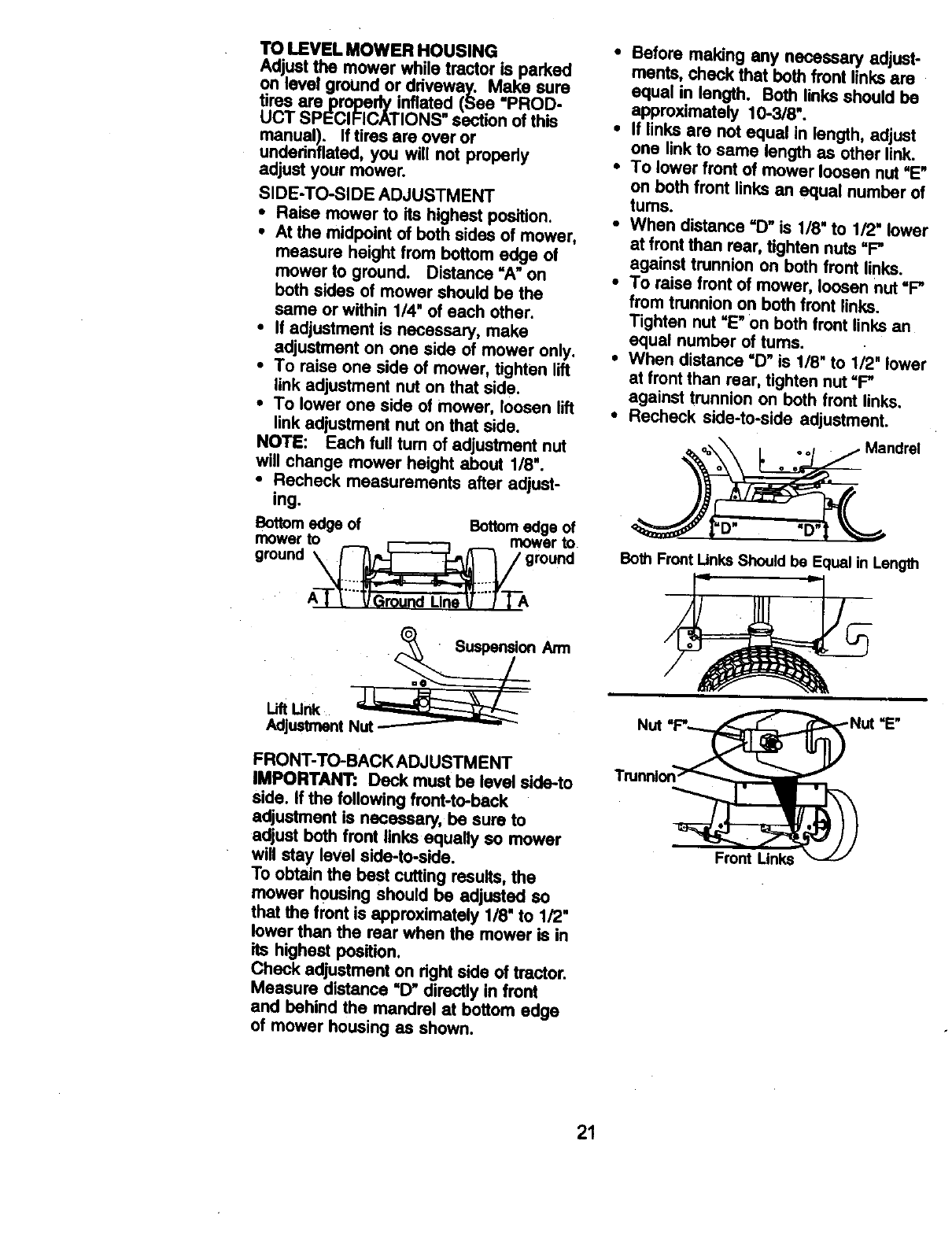
TO LEVEL MOWER HOUSING
AdjuSt the mower while tractor is parked
on level ground or driveway. Make sure
tires areproperly inflated (See "PROD-
UCT SPECIFICATIONS" section of this
manual). If tires are over or
undednflated, you will not properly
adjust your mower.
SIDE-TO-SIDE ADJUSTMENT
•Raise mower to its highest position.
•At the midpoint of both sides of mower,
measure height from bottom edge of
mower to ground. Distance "A" on
both sides of mower should be the
same or within 1/4" of each other.
•If adjustment is necessary, make
adjustment on one side of mower only.
•To raise one side of mower, tighten lift
link adjustment nut on that side.
•To lower one side of mower, loosen lift
link adjustment nut on that side.
NOTE: Each full tum of adjustment nut
will change mower height about 1/8'.
•Recheck measurements after adjust-
ing.
Bottom edge of Bottom edge of
mower to mower to
ground _ground
A-T_Ground Llrm V_IT-A
Arm
Adjustment
FRONT-TO-BACK ADJUSTMENT
IMPORTANT: Deck must be level side-to
side. If the following front-to-beck
adjustment is necessary, be sure to
adjust both front links equally so mower
will stay level side-to-side.
To obtain the best cutting results, the
mower housing should be adjusted so
that the front is approximately 1/8"to 1/2"
lower than the rear when the mower is in
its highest position.
Check adjustment on right side of tractor.
Measure distance =D"directly in front
and behind the mandrel at bottom edge
of mower housing as shown.
•Before making any necessary adjust-
ments, check that both front links are
equal in length. Both links should be
approximately 10-3/8".
•If links are not equal in length, adjust
one link to same length as other link.
•To lower front of mower loosen nut "E"
on both front links an equal number of
turns.
• When distance "D" is 1/8' to 1/2" lower
at front than rear, tighten nuts =F"
against trunnion on both front links.
•To raise front of mower, loosen nut "F"
from trunnion on both front links.
Tighten nut =E"on both front links an
equal number of tums.
• When distance =D"is 1/8" to 1/2" lower
at front than rear, tighten nut =P"
against trunnion on both front links.
•Recheck side-to-side adjustment.
Mandrel
Both FrontUnks Shouldbe Equalin Length
=E"
Front Links
21
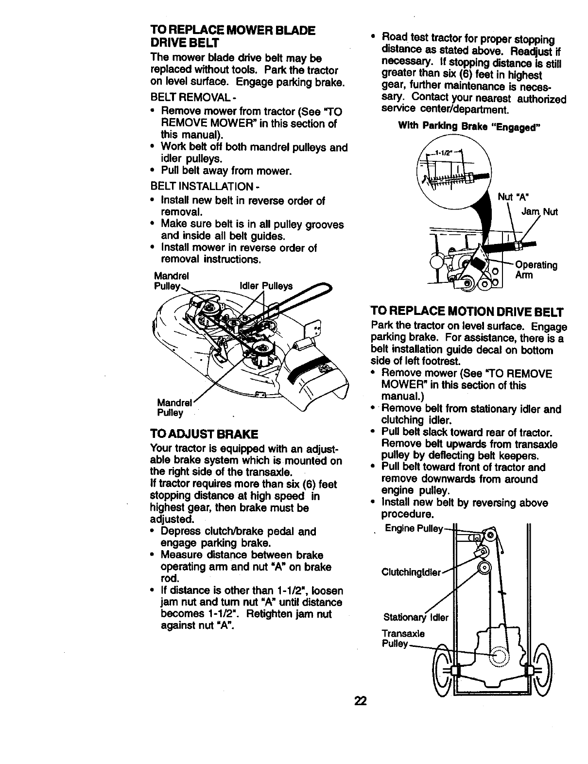
TO REPLACE MOWER BLADE
DRIVE BELT
The mower blade drive belt may be
replaced without tools. Park the tractor
on level surface. Engage parking brake.
BELT REMOVAL -
• Remove mower from tractor (See "TO
REMOVE MOWER" in this section of
this manual).
•Work belt off both mandrel pulleys and
idler pulleys.
• Pull belt away from mower.
BELT INSTALLATION -
• Install new belt in reverse order of
removal.
•Make sure belt is in all pulley grooves
and inside all belt guides,
•Install mower in reverse order of
removal instructions,
Mandrel Idler
•Road test tractor for proper stopping
distance as stated above. Readjust if
necessary. If stopping distance is still
greater than six (6) feet in highest
gear, further maintenance is neces-
sary, Contact your nearest authorized
service centeddepartment.
With Parking Brake "Engaged"
Nut "A"
Jam Nut
Arm
Pulley
TO ADJUST BRAKE
Your tractor is equipped with an adjust-
able brake system which is mounted on
the right side of the traneaxle.
If tractor requires more than six (6) feet
stopping distance at high speed in
highest gear, then brake must be
adjusted.
•Depress clutch/brake pedal and
engage parking brake.
•Measure distance between brake
operating arm and nut =A" on brake
rod.
•If distance is other than 1-1/2', loosen
jam nut and tum nut "A" until distance
becomes 1-1/2". Retighten jam nut
against nut =A".
22
TO REPLACE MOTION DRIVE BELT
Park the tractor on level sudace. Engage
parking brake, For assistance, there is a
belt installation guide decal on bottom
side of left footrest.
•Remove mower (See "TO REMOVE
MOWER" in this section of this
manual.)
•Remove belt from stationary idler and
clutching idler.
Pull belt slack toward rear of tractor.
Remove belt upwards from transaxle
pulley by deflecting belt keepers.
Pull belt toward front of tractor and
remove downwards from around
engine pulley.
Install new belt by reversing above
procedure.
Engine Pulley-
Clutchingldlert
Sta_onary er
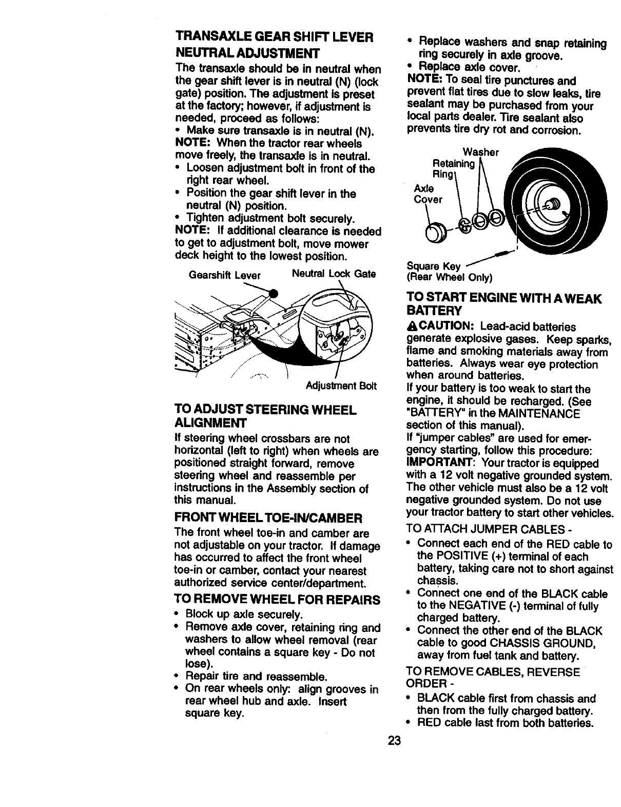
TRANSAXLE GEAR SHIFT LEVER
NEUTRAL ADJUSTMENT
The transexle should be in neutral when
the gear shift lever is in neutral (N) (lock
gate) position. The adjustment is preset
at the factory; however, if adjustment is
needed, proceed as follows:
• Make sure transaxle is in neutral (N).
NOTE: When the tractor rear wheels
move freely, the transaxle is in neutral.
•Loosen adjustment bolt in front of the
right rear wheel.
• Position the gear shift lever in the
neutral (N) position.
•Tighten adjustment bolt securely.
NOTE: If additional clearance is needed
to get to adjustment bolt, move mower
deck height to the lowest position.
Gearshift Lever Neutral Lock Gate
.,." "
AdjustmentBolt
TO ADJUST STEERING WHEEL
ALIGNMENT
If steering wheel crossbars are not
hodzontal (left to right) when wheels are
positioned straight forward, remove
steering wheel and reassemble per
instructions in the Assembly section of
this manual
FRONT WHEEL TOE-IN/CAMBER
The front wheel toe-in and camber are
not adjustable on your tractor. If damage
has occurred to affect the front wheel
toe-in or camber, contact your nearest
authorized service center/department.
TO REMOVE WHEEL FOR REPAIRS
•Block up axle securely.
•Remove axle cover, retaining dng and
washers to allow wheel removal (rear
wheel contains a square key - Do not
lose).
•Repair tire and reassemble.
•On rear wheels only: align grooves in
rear wheel hub and axle. Insert
square key.
•Replace washers end snap retaining
ring secumty in axle groove.
•Replace axle cover.
NOTE: To seal tire punctures and
prevent fiat tires due to slow leaks, tire
sealant may be purchased from your
local parts dealer. "13resealant also
prevents tire dry rot and corrosion.
Washer
Retaining
Axle
Cover
23
Square Key /'
(Rear Wheel Only)
TO START ENGINE WITH A WEAK
BATI'ERY
_,CAUTION: Lead-acid batteries
generate explosive gases. Keep sparks
flame and smoking materials away from
batteries. Always wear eye protection
when around batteries.
If your battery is too weak to start the
engine, it should be recharged. (See
"BATTERY' in the MAINTENANCE
section of this manual).
If "jumper cables" are used for emer-
gency starting, follow this procedure:
IMPORTANT: Your tractor is equipped
with a 12 volt negative grounded systen
The other vehicle must also be a 12 volt
negative grounded system. Do not use
your tractor battery to start other vehicle.=
TO ATTACH JUMPER CABLES -
•Connect each end of the RED cable t<
the POSITIVE (+) terminal of each
battery, taking care not to short agalm
chassis.
•Connect one end of the BLACK cable
to the NEGATIVE (-) terminal of fully
charged battery.
•Connect the other end of the BLACK
cable to good CHASSIS GROUND,
away from fuel tank and battery.
TO REMOVE CABLES, REVERSE
ORDER -
•BLACK cable first from chassis and
then from the fully charged battery.
•RED cable last from both batteries.
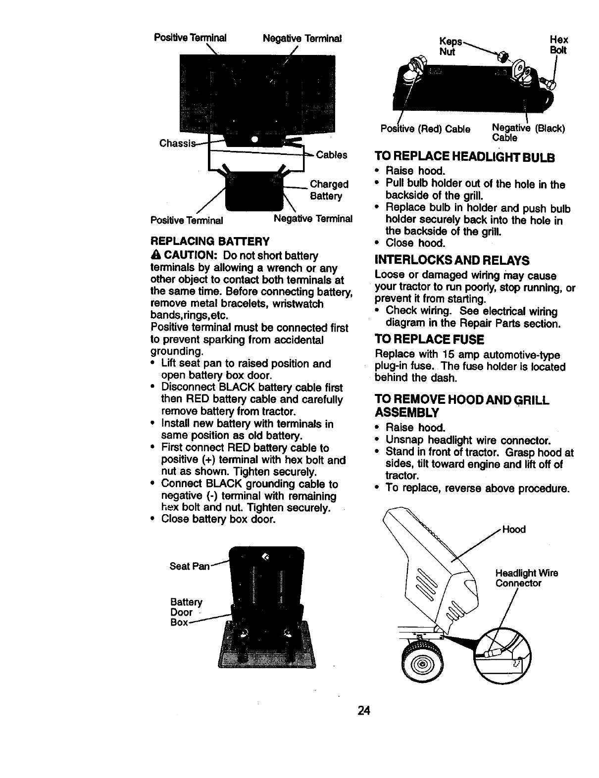
PositiveTerminal NegativeTerminal Ke Hex
Nut Bolt
Battery
Positive Ten_.nal Negative Terminal
REPLACING BATTERY
A CAUTION: Do not short battery
termir_Ls by allowing a wrench or any
other object to contact both terminals at
the same time. Before connecting battery,
remove metal bracelets, wdstwatch
bands,rings,etc.
Positive terminal must be connected first
to prevent sparking from accidental
grounding.
•Lift seat pan to raised position and
open battery box door.
•Disconnect BLACK battery cable first
then RED battery cable and carefully
remove battery from tractor.
•Install new battery with terminals in
same position as old battery.
•First connect RED battery cable to
positive (+) terminal with hex bolt and
nut as shown, Tighten securely.
• Connect BLACK grounding cable to
negative (-) terminal with remaining
hex bolt and nut. Tighten securely.
•Close battery box door.
Sea
Battery
Door
IRed) Cable Negative (Black)
Cable
TO REPLACE HEADLIGHT BULB
• Raise hood.
• Pull bulb holder out of the hole in the
backside of the grill.
• Replace bulb in holder and push bulb
holder securely back into the hole in
the backside of the gdlL
•Close hood.
INTERLOCKS AND RELAYS
Loose or damaged wiring may cause
your tractor to run poody,stop running, or
prevent it from starting.
•Check wiring. See electrical widng
diagram in the Repair Parts section.
TO REPLACE FUSE
Replace with 15 amp automotive-type
plug-in fuse. The fuse holder is located
behind the dash.
TO REMOVE HOOD AND GRILL
ASSEMBLY
•Raise hood.
• Unsnap headlight wire connector.
•Stand in front of tractor. Grasp hood at
sides, tilt toward engine end lift off of
tractor.
•To replace, reverse above procedure.
e_dli°°dghtWire
onnector
24
ENGINE
Maintenance, repair, or replacement of
the emission control devices and
systems, which are being done at the
customers expense, may be performed
by any non-road engine repair establish-
merit or individual. Warranty repairs must
be performed by an authodzed engine
manufacturer's service outlet.
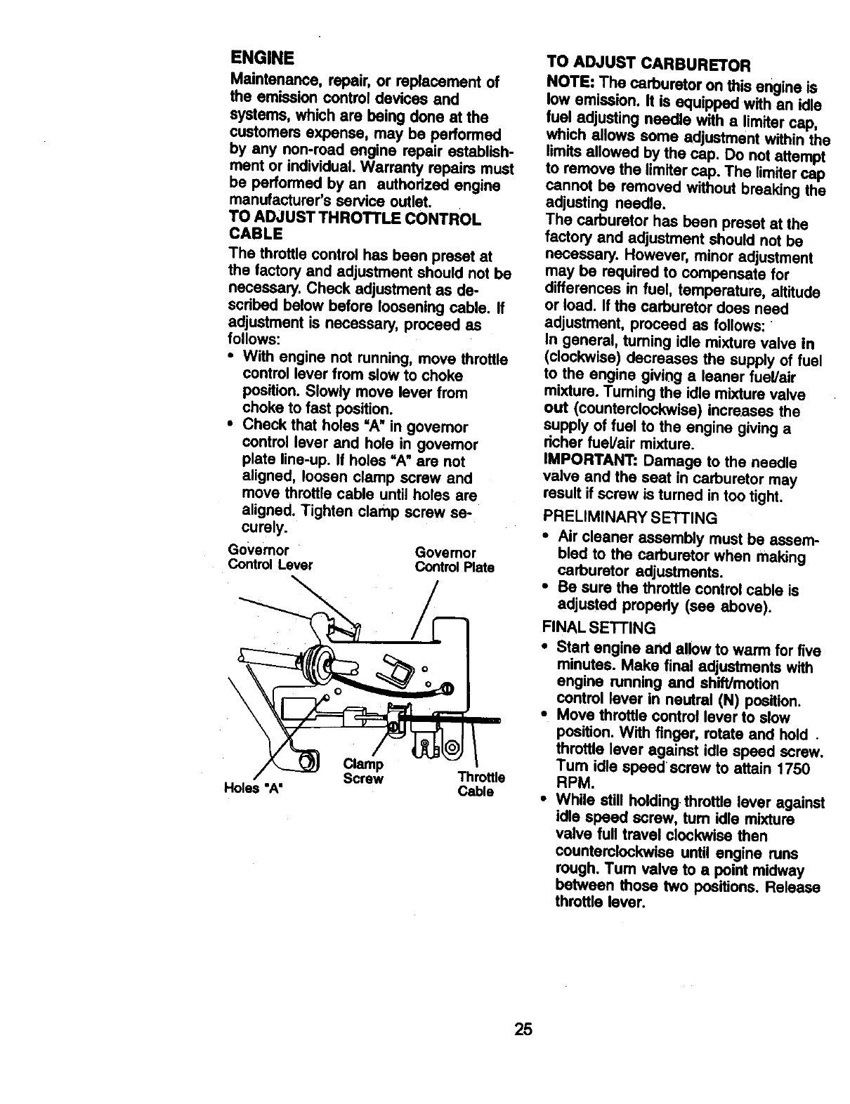
TO ADJUST THROTTLE CONTROL
CABLE
The throttle control has been preset at
the factory and adjustment should not be
necessary. Check adjustment as de-
scdbed below before loosening cable. If
adjustment is necessary, proceed as
follows:
•With engine not running, move throttle
control lever from slow to choke
position. Slowly move lever from
choke to fast position.
•Check that holes =A"in governor
control lever and hole in governor
plate line-up. If holes "A" are not
aligned, loosen clamp screw and
move throttle cable until holes are
aligned, Tighten clamp screw se-
curely.
Governor Governor
ControlLever ControlPlate
\.
\
Clamp
Screw Throttle
Holes "A' Cable
TO ADJUST CARBURETOR
NOTE: The carburetor on this engine is
low emission. It is equipped with an idle
fuel adjusting needle with a limiter cap,
which allows some adjustment within the
limits allowed by the cap. Do not attempt
to remove the limiter cap. The limiter cap
cannot be removed without breaking the
adjusting needle.
The carburetor has been preset at the
factory and adjustment should not be
necessary. However, minor adjustment
may be required to compensate for
differences in fuel, temperature, altitude
or load. If the carburetor does need
adjustment, proceed as follows:
In general, tuming idle mixture valve in
(clockwise) decreases the supply of fuel
to the engine giving a leaner fuel/air
mixture. Turning the idle mixture valve
out (counterclockwise) increases the
supply of fuel to the engine giving a
dcher fuel/air mixture.
IMPORTANT: Damage to the needle
valve and the seat in carburetor may
result if screw is turned in too tight.
PRELIMINARY SETTING
•Air cleaner assembly must be assem-
bled to the carburetor when making
carburetor adjustments.
•Be sure the throttle control cable is
adjusted propedy (see above).
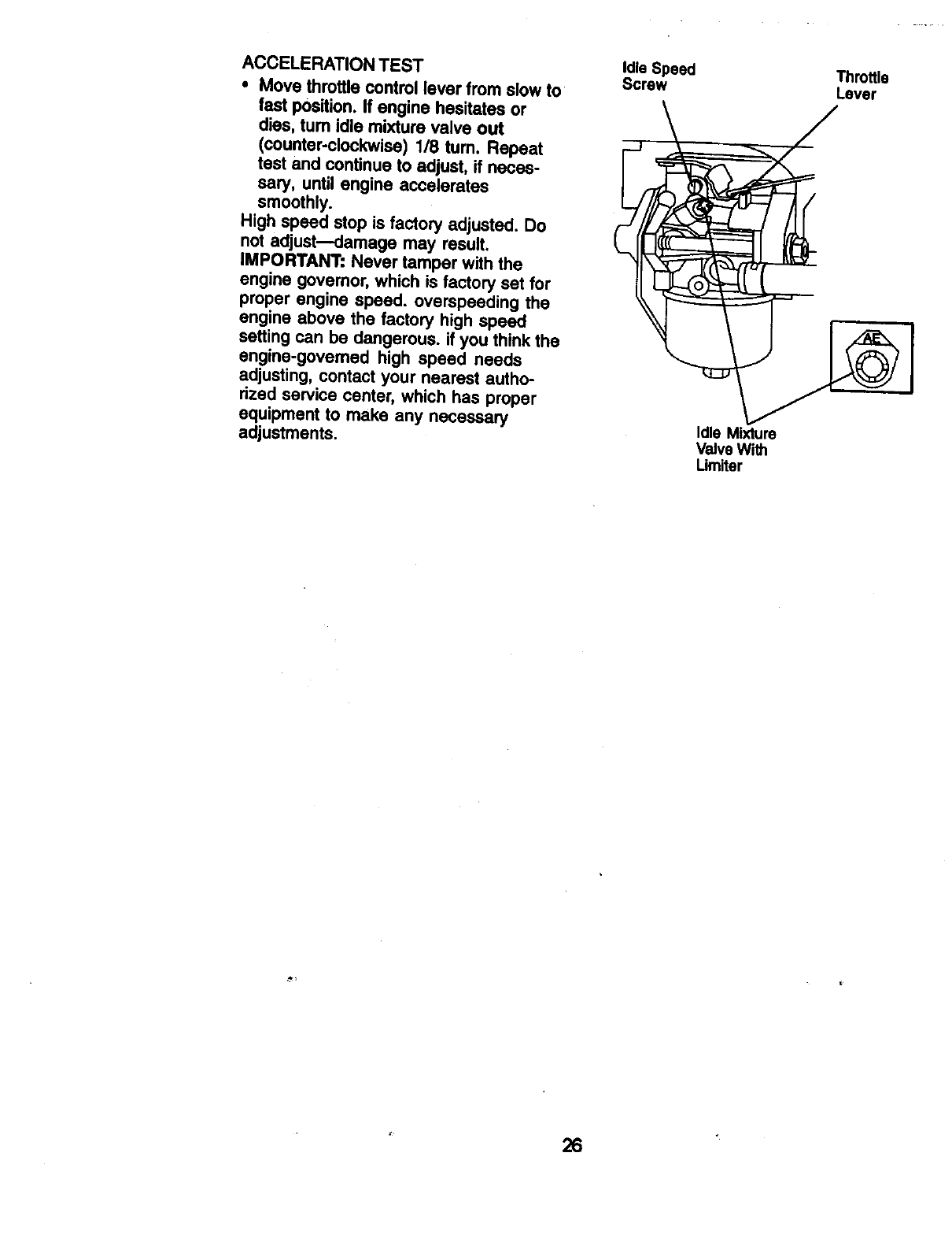
FINAL SETTING
•Start engine and allow to warm for five
minutes. Make final adjustments with
engine running and shift/motion
control lever in neutral (N) position.
•Move throttle control lever to slow
position. With finger, rotate and hold .
throttle lever against idle speed screw.
Turn idle speed screw to attain 1750
RPM.
•While still holding,throttle lever against
idle speed screw, turn idle mixture
valve full travel clockwise then
counterclockwise until engine runs
rough. Tum valve to a point midway
between those two positions. Release
throttle lever.
25
ACCELERATION TEST
•Move throttle control lever from slow to
fast position. If engine hesitates or
dies, turn idle mixture valve out
(counter-clockwise) 1/8 turn. Repeat
test and continue to adjust, if neces-
sary, until engine accelerates
smoothly.
High speed stop is factory adjusted. Do
not adjust---damage may result.
IMPORTANT: Never tamper with the
engine governor, which is factory set for
proper engine speed, overspeeding the
engine above the factory high speed
setting can be dangerous, if you think the
engine-governed high speed needs
adjusting, contact your nearest autho-
rized service center, which has proper
equipment to make any necessary
adjustments.
Idle Speed Throttle
Screw Lever
Idle Mixture
Valve With
Urniter
26
Immediately prepare your tractor for
storage at the end of the season or if the
tractor will not be used for 30 days or
more.
_. CAUTION: Neverstore the tractor
with gasoline in the tank inside a
building where fumes may reach an
open flame or spark. Allow the engine to
cool before stonng in any enclosure.
TRACTOR
Remove mower from tractor for winter
storage. When mower is to be stored for
a period of time, clean it thoroughly,
remove all dirt, grease, leaves, etc. Store
in a dean, dry area.
• Clean entire tractor (See =CLEANING"
in the Maintenance section of this
manual).
•Inspect and replace belts, if necessary
(See belt replacement instructions in
the Service and Adjustments section of
this manual).
•Lubricate as shown in the Mainte-
nance section of this manual.
• Be sure that all nuts, belts and screws
are securely fastened. Inspect moving
parts for damage, breakage and wear.
Replace if necessary.
•Touch up all rusted or chipped paint
surfaces; sand lightly before painting.
BAI"FERY
•Fully charge the battery for storage.
•After a period of time in storage,
battery may require recharging.
• To help prevent corrosion and power
leakage during long periods of
storage, battery cables should be
disconnected and battery cleaned
thoroughly (see "TO CLEAN BATTERY
AND TERMINALS" in the Maintenance
section of this manual).
•After cleaning, leave cables discon-
nected and place cables where they
cannot come in contact with battery
terminals.
•If battery is removed from tractor for
storage, do not store battery directly on
concrete or damp surfaces.
ENGINE
FUEL SYSTEM
IMPORTANT: It is important to prevent
gum deposits from forming in essential
fuel system parts such as carburetor, fuel
filter, fuel hose, or tank dudng storage.
Also, expedence indicates that alcohol
blended fuels 9called gasohol or using
ethanol or methanol) can attract moisture
which leads to separation and formation
of acids dudng storage. Acidic gas can
damage the fuel system of an engine
while in storage.
•Drain the fuel tank.
•Start the engine and let it run until the
fuel lines and carburetor are empty.
•Never use engine or carburetor
cleaner products in the fuel tank or
permanent damage may occur.
•Use fresh fuel next season.
NOTE: Fuel stabilizer is an acceptable
aitemative in minimizing the formation of
fuel gum deposits dudng storage. Add
stabilizer to gasoline in fuel tank or
storage container. Always follow the mix
ratio found on stabilizer container. Run
engine at least 10 minutes after adding
stabilizer to allow the stabilizer to reach
the carburetor. Do not drain the gas tank
and carburetor if using fuel stabilizer.
ENGINEOIL
Drain oil (with engine warm) and replace
with clean engine oil. (See =ENGINE" in
the Maintenance section of this manual).
CYLINDER(S)
•Remove spark plug(s).
•Pour one ounce of oil through spark
plug hole(s) into cylinder(s).
•Turn ignition key to USTAR'I" position
for a few seconds to distribute oil.
•Replace with new spark plug(s).
OTHER
•Do not store gasoline from one season
to another.
•Replace your gasoline can if your can
starts to rust. Rust and/or dirt in your
gasoline will cause problems.
•If possible, store your tractor indoors
and cover it to give protection from
dust and dirt.
•Cover your tractor with a suitable
protective cover that does not retain
moisture. Do not use plastic. Plastic
cannot breathe which allows conden-
sation to form and will cause your
tractor to rust.
IMPORTANT: Never cover tractor while
engine and exhaust areas are still
warm.
27
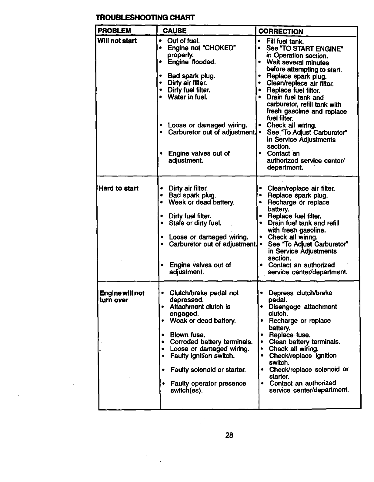
TROUBLESHOOTING CHART
PROBLEM CAUSE
Will not start * Out of fuel.
Hard to start
Englnewlll not
turn over
i
!, Engine not "CHOKED _
properly.
• Engine flooded.
• Bad spark plug.
•Dirty air filter.
•Dirty fuel filter.
• Water in fuel.
•Loose or damaged widng.
•Carburetor out of adjustment
•Engine valves out of
adjustment.
•Dirty air filter.
•Bad spark plug.
•Weak or dead battery.
•Dirty fuel filter.
•Stale or dirty fuel.
•Loose or damaged wiring.
•Carburetor out of adjustment
•Engine valves out of
adjustment.
Clutch/brake pedal not
depressed.
Attachment clutch is
engaged.
Weak or dead battery.
Blown fuse.
Corroded battery terminals.
Loose or damaged wiring.
Faulty ignition switch.
Faulty solenoid or starter.
Faulty operator presence
switch(es).
CORRECTION
•Fill fuel tank.
*See "TO START ENGINE"
in Operation section.
•Wait several minutes
before attempting to start.
•Replace spark plug.
•Clean/replace air filter.
•Replace fuel filter.
•Drain fuel tank and
carburetor, refilltank with
fresh gasoline and replace
fuel filter.
•Check all wiring.
•See =ToAdjust Carburetor"
in Service Adjustments
I' section.
Contact an
authorized service center/
department.
•Clean/replace air filter.
• Replace spark plug.
• Recharge or replace
battery.
•Replace fuel filter.
•Drain fuel tank and refill
with fresh gasoline.
•Check all widng.
•See =ToAdjust Carburetor"
in Service Adjustments
section.
•Contact an authorized
service center/department.
•Depress clutch/brake
pedal.
•Disengage attachment
clutch.
•Recharge or replace
battery.
•Replace fuse,
•Clean battery terminals.
•Check all wiring.
•Check/replace ignition
switch.
•Check/replace solenoid or
starter.
•Contact an authorized
service center/department.
28
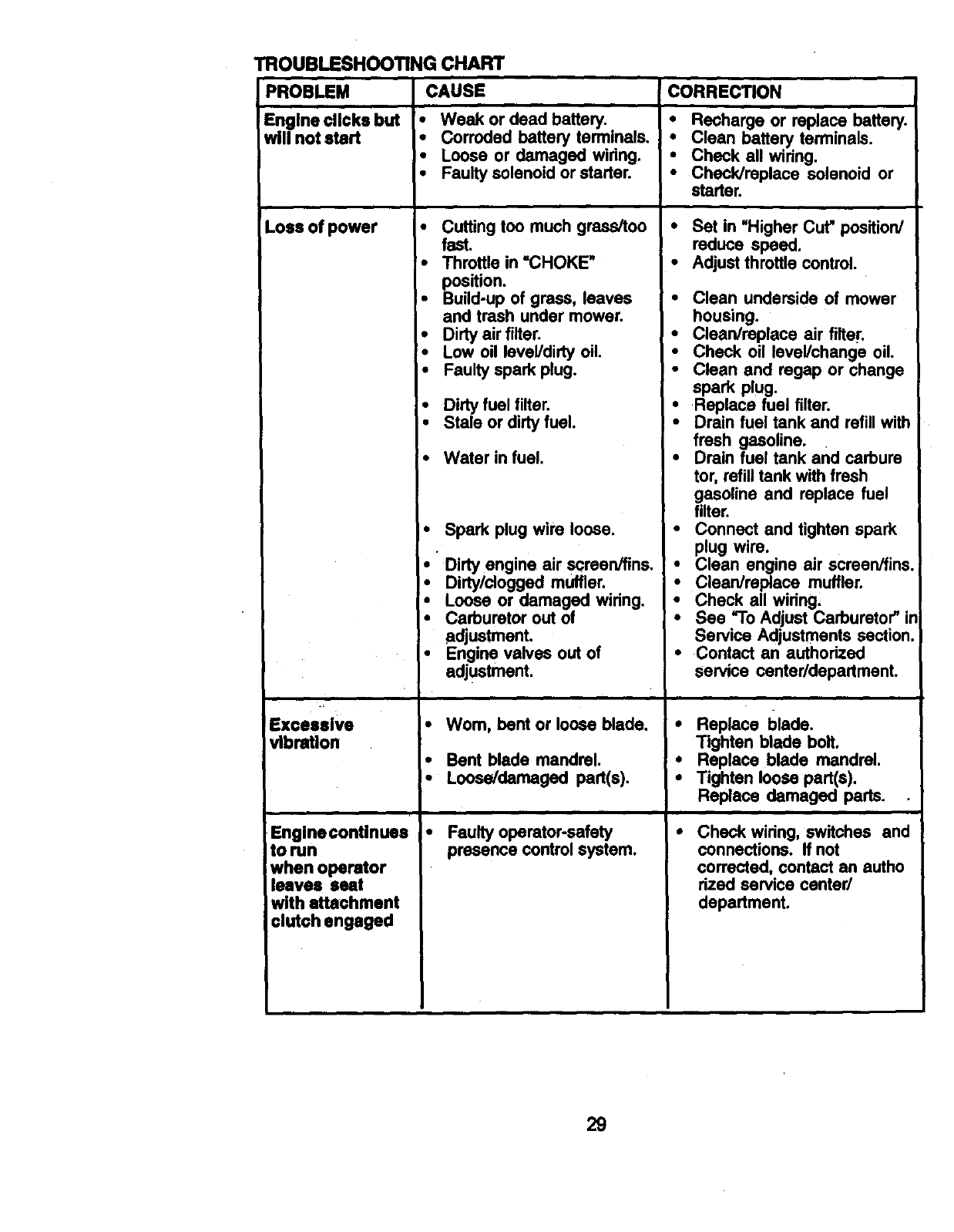
TROUBLESHOOTING CHART
PROBLEM CAUSE CORRECTION
Engine clicks but •Weak or dead battery. • Recharge or replace battery.
will not start •Corroded battery terminals. • Clean battery terminals.
• Loose or damaged wiring. , Check all wiring.
•Faulty solenoid or starter. • Check/replace solenoid or
starter.
Loss of power
Excessive
vibration
Englnecontinuee
to run
when operator
leaves seat
with attachment
clutch engaged
•Cutting too much grass/too
fast.
•Throttle in "CHOKE"
position.
•Build-up of grass, leaves
and trash under mower.
•Dirty air filter.
•Low oil level/dirty oil.
•Faulty spark plug.
•Dirty fuel filter.
Stale or dirty fuel.
•Water in fuel.
Spark plug wire loose.
• Dirty engine air screen/fins.
•Dirty/clogged muffler.
•Loose or damaged wiring.
•Carburetor out of
adjustment.
•Engine valves out of
adjustment.
•Worn, bent or loose blade.
•Bent blade mandrel.
•Loose/damaged part(s).
•Faulty operator-safety
presence control system.
•Set in =Higher Cut" position/
reduce speed.
•Adjust throttle control.
Clean underside of mower
housing.
Clean/replace air filte!'.
Check oil level/change oil.
Clean and regap or change
spark plug.
Replace fuel filter.
Drain fuel tank and refill with
fresh gasoline.
Drain fuel tank and carbure
tor, refill tank with fresh
gasoline and replace fuel
filter.
Connect and tighten spark
plug wire.
Clean engine air ecreen/fins.
Clean/replace muffler.
Check all wiring.
See "To Adjust Carburetor" in
Service Adjustments section.
Contact an authorized
service canter/department.
•Replace blade.
Tighten blade bolt.
•Replace blade mandrel.
• Tighten loose part(s).
Replace damaged parts.
Check wiring, switches and
connections. If not
corrected, contact an autho
rized service canted
department.
29
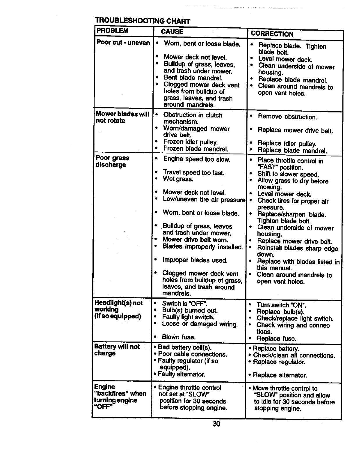
TROUBLESHOOTING CHART
i
PROBLEM CAUSE CORRECTION
Poor out -uneven
Mower bladeswill
not rotate
Poor grass
discharge
Headlight(s) not
working
(If so equipped)
Battery will not
charge
Engine
"backfires" when
tumingenglne
"OFF"
• Worn, bent or loose blade.
•Mower deck not level.
•Buildup of grass, leaves,
and trash under mower.
•Bent blade mandrel.
• Clogged mower deck vent
holes from buildup of
grass, leaves, and trash
around mandrels.
Obstruction in clutch
mechanism.
•Worn/damaged mower
drive belt.
•Frozen idler pulley.
•Frozen blade mandrel.
•Engine speed too slow.
•Travel speed too fast.
• Wet grass.
•Mower deck not level.
• Lowluneven tire air pressure
•Wom, bent or loose blade.
• Buildup of grass, leaves
and trash under mower.
•Mower drive bell worn.
•Blades impropedy installed.
•improper blades used.
Clogged mower deck vent
holes from buildup of grass,
leaves, and trash around
mandrels.
•Switch is "OFF'.
•Bulb(s) burned out.
•Faulty light switch.
• Loose or damaged wiring.
•Blown fuse.
•Bad battery cell(s).
•Poor cable connections.
•Faulty regulator (if so
equipped).
•Faulty alternator.
•Engine throttle control
not set at "SLOW"
position for 30 seconds
before stopping engine.
•Replace blade. TIghton
blade bolt.
•Level mower deck.
•Clean underside of mower
housing.
•Replace blade mandrel.
• Clean around mandrels to
open vent holes.
• Remove obstruction.
•Replace mower drive belt.
•Replace idler pulley.
•Replace blade mandrel.
•Place throttle control in
=FAST" position.
•Shift to slower speed.
•Allow grass to dry before
mowing.
•Level mower deck.
•Check tires for proper air
pressure.
!• Replace/sharpen blade.
Tighten blade boll.
•Clean underside of mower
housing.
• Replace mower drive bell.
•Reinstall blades sharp edge
down.
•Replace with blades listed in
this manual.
•Clean around mandrels to
open vent holes.
• Tum switch =ON".
• Replace bulb(s).
•Check/replace light switch.
• Check widng and connec
tioos.
•Replacefuse.
• Replace battery,
•Check/clean all connections.
•Replace regulator.
•Replace altemator.
i
•Move throttle controlto
"SLOW" position and allow
toidla for 30 seconds before
stopping engine.
L30
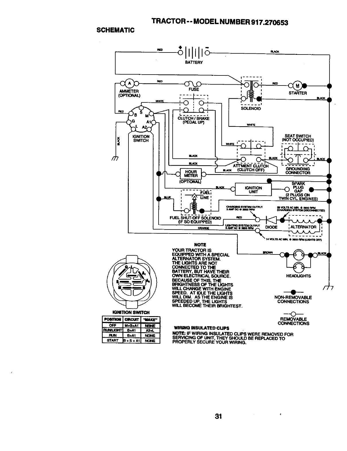
SCHEMATIC
TRACTOR -- MODEL NUMBER 917.270653
"BATTERY
AMMETER
(OP11(_'qAq
)G AI(
IGNITION
SWITCH
IGm swrrclt
FUSE
L ....... i
CLUTCH/BRAKE
(PEDALuP)
EtJCK
,STARTER
...... I
D
........ (NOTSEATOCCUPIED)SWITCH
,......X._ , _ -
kTI"MENT CLUTCH ........
GROUNDING
A
,,m SPARK
:..... _=0_L; u.rr
I (2 PLUGSON
m._ UHE 'I_ C_ EHGtNES)
f
i I
i I C_,Nq_Na S'_6t'EM OUTPUT M _*C¢_'rl ,¢C MIN. • _III00 RRt4
IAMP O(; O N00 RPM _HARG4NG 8"tS't EM I;qmCOI*_IEC 1B))
FUELSHUT-OFFSOLENOID me ;"......... t
(IF SO EQUIPPED) J
.,u=._..=,._=,,_ _OOE . ,
NOTE
YOUR TRACTOR IS
EQUIPPED WITH A SPECIAL
ALTERNATOR SYSTEM.
THE LIGHTS ARE NOT
CONNECTED TO THE
BAI"rERY, BUT HAVE THEIR
OWN ELECTRICAL SOURCE.
BECAUSE OF THIS. THE
BRIGHTNESS OF THE LIGHTS
WILL CHANGE WITH ENGINE
SPEED. AT IDLE THE LIGHTS
WILL DIM. AS THE ENGINE IS
SPEEDED UP, THE LIGHTS
WILL BECOME THEIR BRIGHTEST.
•lSUtJkl"_OCUPS
HEAOUGHTS
---e--
NON-REMOVABLE
CONNECTIONS
REMOVABLE
CONNECTIONS
NOTE: IF WIRING INSULATED CLIff3 WERE REMOVED FOR
SERVICING OF UNIT, THEY SHOULD BE REPLACED TO
PROPERLY SECURE YOUR WIRING.
31
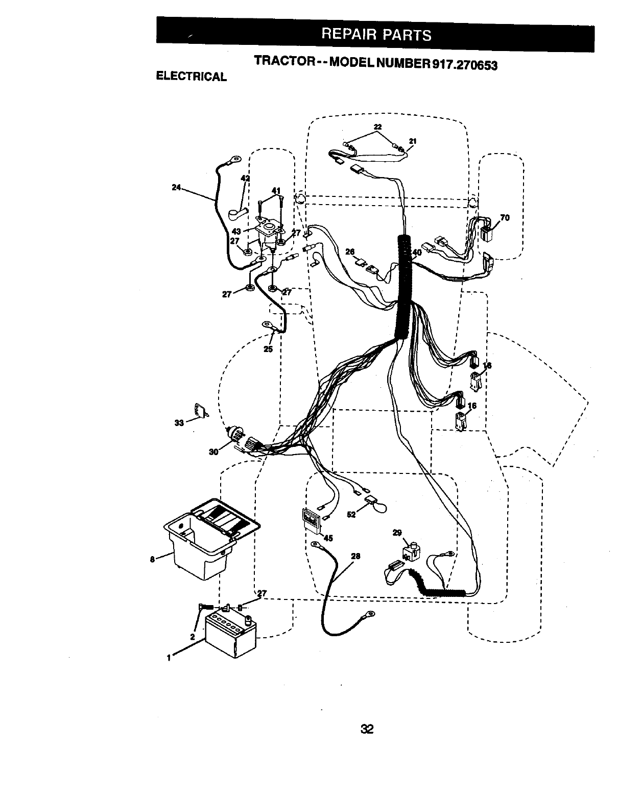
ELECTRICAL TRACTOR -- MODE L NUMBER 917.270653
fI
I I
41
I
I
I
I
I
I
I
II
I
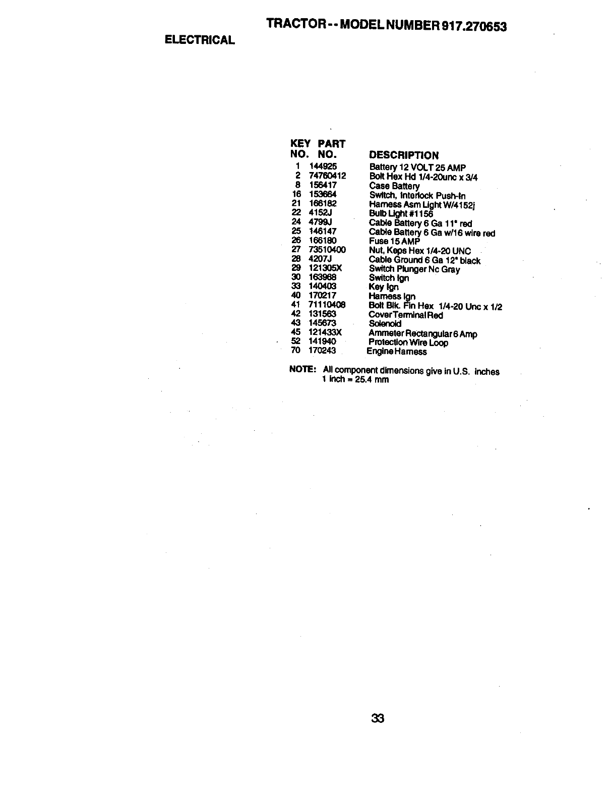
ELECTRICAL
TRACTOR - - MODEL NUMBER 917.270653
KEY PART
NO. NO. DESCRIPTION
1 144925 Battery 12 VOLT 25 AMP
2 74760412 Bolt Hex Hd 1/4-20unc x 3/4
8 156417 Case Battery
16 153664 Switch, Interlock Push-in
21 166182 Hamese Asm LightW/4152J
22 4152J BulbLl_t #1156
24 4799J Cable Battery 6 Ga 11" red
25 146147 Cable Battery 6 Ga w/16 wire red
26 166180 Fuse 15AMP
27 73510400 Nut, Keps Hex 1/4-20 UNC
28 4207J Cable Ground 6 Ga 12" black
29 121305X SwitchPlungerNc Gray
30 163968 $wltch_
33 140403 Key Ign
40 170217 Hamese Ign
41 71110408 BoltBIk. FinHex 1/4-20Uncxli2
42 131563 Cover TerminalRed
43 145673 Solenoid
4,5 121433X Amrseter Rectangular6 Amp
52 141940 ProtecllonWi_ Loop
70 170243 Engine Hemees
NOTE: NI component dimensionsgive inU.S. inches
1 inch = 25.4 mm
33

TRACTOR -- MODEL NUMBER 917.270653
CHASSISAND ENCLOSURES
28
12
@
54
55
74
34
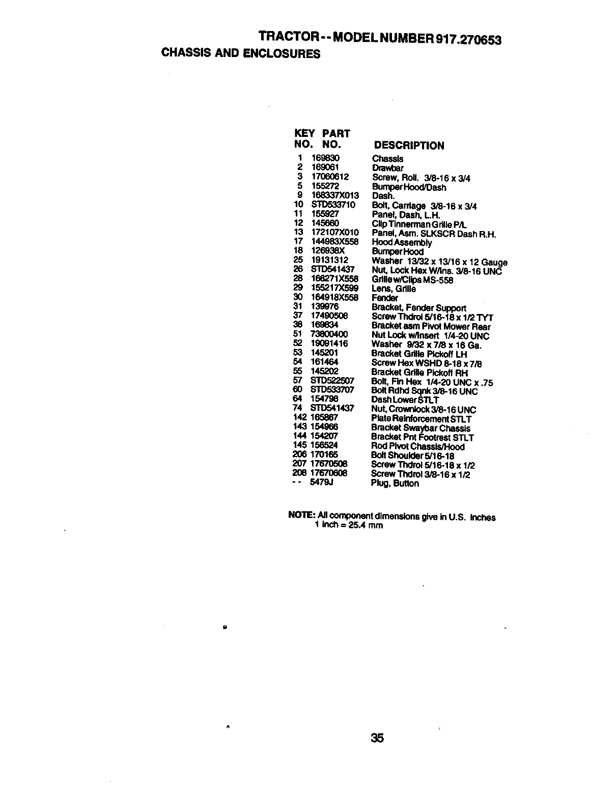
TRACTOR - - MODEL NUMBER 917.270653
CHASSISANDENCLOSURES
KEY PART
NO. NO.
1 169830
2 16g061
3 17060612
5 155272
9 168337X013
10 STO533710
11 155927
12 145660
13 17210",'X010
17 144983X558
18 126938X
25 19131312
26 STD541437
28 166271X558
29 155217X599
30 164918X558
31 139976
37 17490508
38 16_834
51 738004(X)
52 lg091416
53 145201
54 161464
55 145202
57 STD522507
60 S10533707
64 1547g8
74 STD54143"/
142 165867
143 154,966
144 154207
145 156524
206 170165
207 1767(3508
208 17670608
-- 5479,}
DESCRIPTION
Chassis
Drav/oar
Screw, Roll. 3/8-16 x 3/4
BumperHood/Dash
Dash.
Bolt,Canfage 3/8-16 x 3/4
Panel, Dash, L.H.
Clip"rlnnermanGdlleP/t.
Panel, Asm. SLKSCR Dash R.H.
HoodAssembly
BumberHood
Washer 13/32 x 13/16 x 12 Gauge
Nut, Lock Hex W/Ins. 3/8-16 UNC
Gdltew/CtipsMS-558
Lens, Grille
Fender
Bracket, Fender Support
Screw Thdrol5/16-18 x 1/2 TYT
Bracket asm Pivot Mower Rear
Nut Lock w/Inasrt 1/4-20 UNC
Washer 9/32 x 7/8 x 16 Ga.
Bracket Gdlte Plckoff !_H
Screw Hex WSHD 8-18 x 7/8
Bracket Gdlle PIckofl RH
Bolt, Fin Has 1/4-20 UNC x .75
Bolt Rdhd Sqnk 3/8-16 UNC
Dash Lower STLT
Nut, Crownfock3/8-16 UNC
PlatoReinforcementSTLT
Bracket Swayt)ar Chassis
Bracket Pnt Footrest STLT
Rod Pivot ChasslstHood
BoltShoelder 5/16-18
Screw Thdrol5/16-18 x 1/2
Screw Thdrol 3/8-16 x 1/2
Plug, Button
NOTE: All componentdimensions give in U.S. inches
1 inch,= 25,4 mm
35
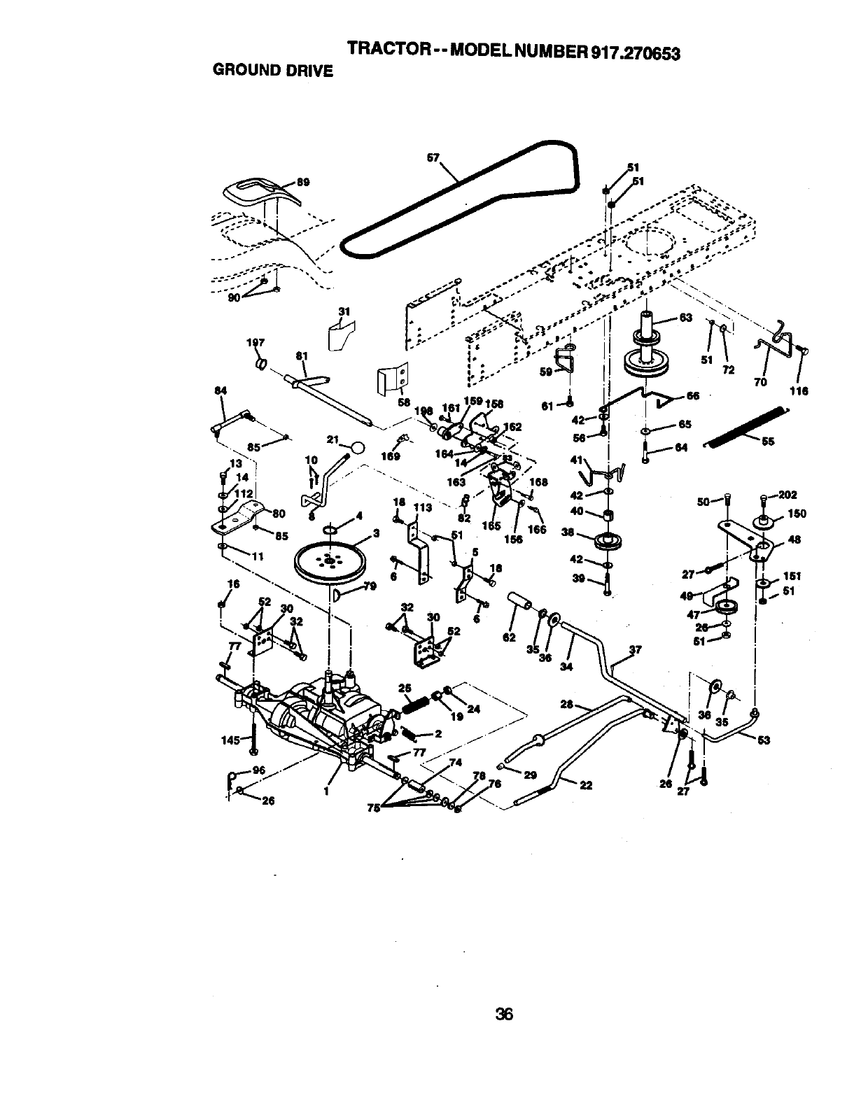
TRACTOR - - MODEL NUMBER 917.27_53
GROUND DRIVE
2111
36
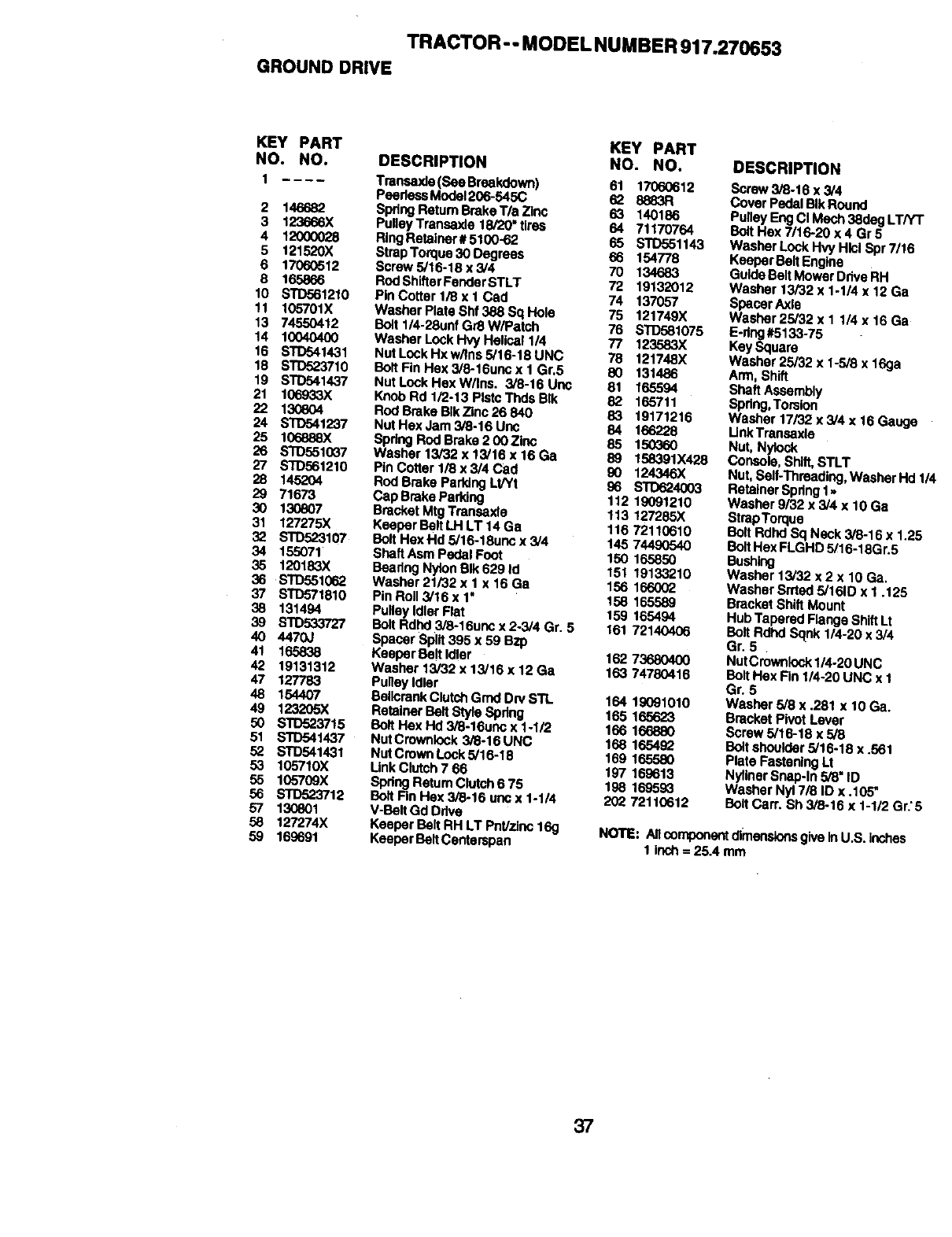
TRACTOR -- MODEL NUMBER 917.270653
GROUNDDRIVE
KEY PART KEY PART
NO. NO. DESCRIPTION NO. NO.
1 Traneexie (See Breakdown) 61 17060612
PeerlessModel206-545C 62 8883R
Spdng Return Brake Tla Zk,,c 63 140186
Pulley Transaxle 18/20"tires 64 71170764
RingRetainer #5100-62 65 STD551143
Strap Torque 30 Degrees 66 154778
Screw 5/16-18 x 3/4 70 134683
Rod Sh|tterFender STLT 72 19132012
Pin Cotter 1/8 x 1 Cad 74 137057
Washer Pleta SN 388 Sq Hole 75 121749)(
Bolt 1/4-28unf G/3 W/Patch 76 STD581075
Washer Lock Hvy Helical 114 77 123583X
Nut Lock Hx wilns 5/16-18 UNC 78 121748X
Bolt Fin Hax 3/8-16uno x 1 Gr.5 80 131486
NutLockHexW/|ns. 3/8-16Uno 81 165594
Knob Rd 1/2-13 Plstc Thds BIk 82 165711
Rod Brake BIk Zinc 26 840 83 19171216
Nut Hex Jam 3/8-16 Unc 84 166228
Spdng Rod Brake 2 00 Zinc 85 150360
Washer 13/32 x 13/16 x 16 Ga 89 158391X428
Pin Cotter 1/8 x 3/4 Cad 90 124346X
ROdBrake Parking Lt/Yt 96 STO624003
Cap Brake Paddng 112 19091210
Bracket MtgTransaxle 113 127285X
Keeper Belt LH LT 14 Ga 116 72110610
Bolt HexHd 5/16-18uno x 3/4 145 74490540
Shaft Asm Pedal Foot 150 165850
Beadng Nylon BIk 629 Id 151 19133210
Washer 21/32 x I x 16 Ga 156 166002
Pin Roll 3/16 x 1" 158 165589
Pulley Idler Flat 159 165494
Bolt Rdhd 3/8-16uno x 2-3/4 Gr. 5 161 72140406
Spacer Split395 x 59 BZp
Keeper Bert Idler 162 73680400
Washer 13/32 x 13/16 x 12 Ga 163 74780416
Pulley Idler
BellcrankClutchGrad Dry STL 164 19091010
Retainer Belt StyleSpdng 165 165623
BoY(Hex Hd 3/8-16unc x I-I/2 166 166880
NutCrownlock 3/8-16 UNC 168 165432
Nut Crown Lock 5/16-18 169 165580
Link Clutch 766 197 169613
Spdng ReturnClutCh6 75 198 169593
Bolt Fin Hax 3/8-16 uric x 1-1/4 202 72110612
V-Belt Gd Drive
Keeper Belt RH LT Pnt/zioc 169
Keeper Belt Centarspan
2 146682
3 123666X
4 12O0OO28
5 121520X
6 17060512
8 165866
10 STD561210
11 105701X
13 74550412
14 10040400
16 STD541431
18 STD523710
19 STDr'J,1437
21 106933X
22 1308O4
24 STD541237
25 106888X
26 b'3D551037
27 S'ID561210
28 145204
29 71673
30 130807
31 127275X
32 STD523107
34 155071
35 120183X
36 STD551_62
37 STD571810
38 131494
39 STD533727
40 4470J
41 165838
42 19131312
47 127783
48 154407
49 123205X
5O STD523715
51 STD541437
52 STD541431
53 105710X
55 lC6709X
56 STD523712
57 130801
58 127274X
59 169691
DESCRIPTION
Scraw 3/8-16 x 3/4
Cover Pedal BIkRound
Pulley Eng Ct Mech 38deg LTPtT
BottHex 7/16-20 x 4 Gr5
Washer Lock Hvy Hlcl Spr 7/16
Keeper Belt Engine
Guide Belt Mower Ddve RH
Washer 13/32 x 1-1/4 x 12 Ga
Spacer Axle
Washer 25/32 x 11/4 x 16 Ga
E-dng#5133-75
Key Square
Washer 25/32 x 1-5/8 x 16ga
Arm, Shift
Shaft Assembly
Spring,Torsion
Washer 17/32 x 3/4 x 16 Gat.v3e
LinkTransaxle
Nut, Nylock
Console, Shift,STLT
Nut, Self-Thraading,Washer Hd 1
Retah'terSpflng1,,
Washer 9/32 x 3/4 x 10 Ga
BtrapTorque
Bolt Rdhd Sq Neck 3/8-16 x 1.25
BoltHex FLGHD 5/16-18G r.5
Bushing
Washer 13/32 x 2 x 10 Ga.
Washer Srtted5/161D x I .125
Bracket Shift Mount
Hub Tapered Flange Shift Lt
Bolt Rdhd Sqnk 1/4-20 x 3/4
Gr. 5
NutCrowntock114-20UNC
Bolt Hex Fin 114-20UNC x 1
Gr. 5
Washer 5/8 x .281 x 10 Ga,
Bracket Pivot Laver
Screw 5/16-18 x 5/8
Boltshoulder 5/16-18 x .561
Plate Fastening Lt
NyfinerSnep-ln 5/8=ID
Washer Nyl 7/8 ID x .105"
Belt Carr. Sh 3/8-16 x 1-1/2 Gr.'5
NOTE: Allcomponentdimensionsgive InU.S. inches
1 inch = 25.4 mm
37
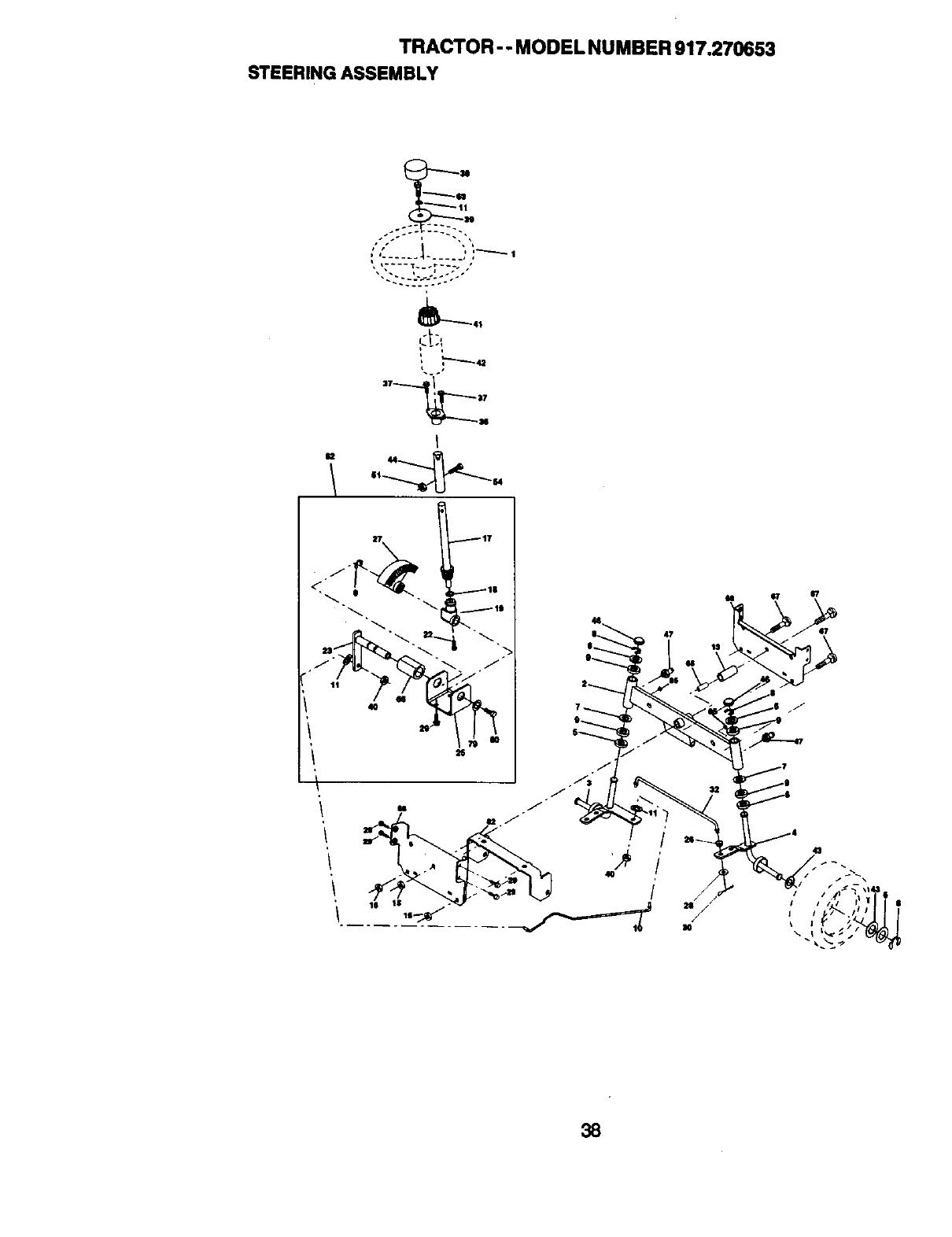
TRACTOR-- MODEL NUMBER 917.270653
STEERING ASSEMBLY
_41
i,
I
U44
4O
/
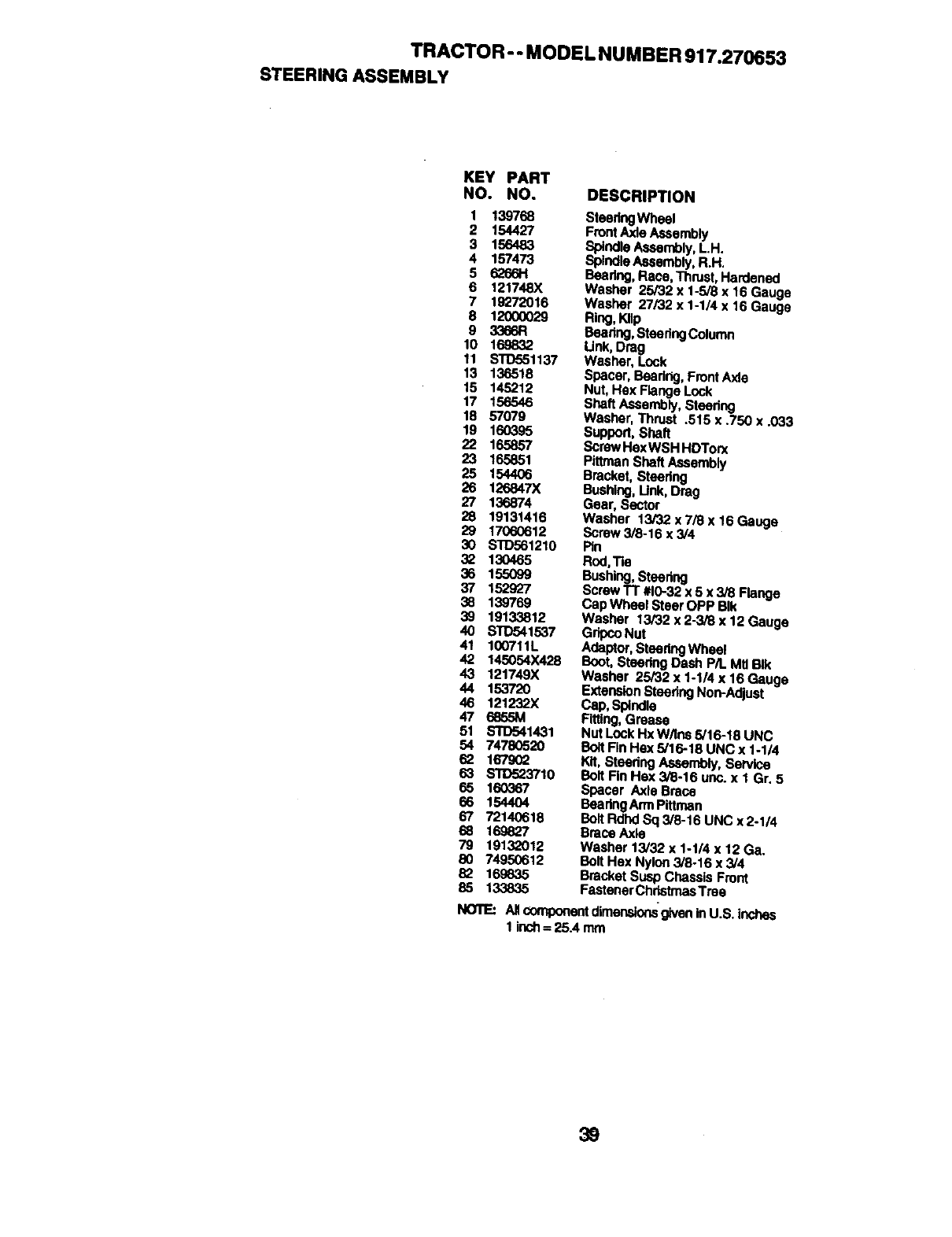
TRACTOR - - MODEL NUMBER 917.270653
STEERING ASSEMBLY
KEY PART
NO. NO. DESCRIPTION
1 139768
2 154427
3 156483
4 157473
56266H
6 121748X
7 19272016
8 1200O029
93366R
10 169832
11 STO551137
13 136518
15 145212
17 156546
18 57079
19 160395
22 165857
23 165851
25 154406
26 126847X
27 136874
28 19131416
29 17060612
30 srD561210
32 130465
36 155099
37 152927
38 139769
39 19133812
40 STD541537
41 100711L
42 145054X428
43 121749X
44 153720
46 121232X
47
51 S'fD541431
54 74780520
16790_
63 S'IO523710
65 160367
66 1544O4
67 72140618
68 169827
79 19132012
8O 7495O612
82 169635
SteeringWheel
Front Axle Assembly
Spindle Assembly,LH.
SpindleAssembly, R.H.
Beedng, Race, Thrust,Hardened
Washer 25/32 x 1-5/8 x 16 Gauge
Washer 27/32 x 1-1/4 x 16 Gauge
Ring, KIIp
Bearing,Sleering Column
Unk, Drag
Washer, Lock
Spacer, Beadng, Front Axle
Nut, Hex Flange Lock
Shaft Assembly, Steering
Washer, Thrust .515 x .750 x .033
Support, Shaft
Screw HexWSH HDTorx
Pltlman Shaft Assembly
Bracket, Steedng
Bushing, Unk, Drag
Gear, Sector
Washer 13/32 x 7/8 x 16 Gauge
Screw 3/8-16 x 3/4
Pin
Rod,Tie
Bushing,Steering
Screw TT #10-32x 5 x 318Flange
Cap Wheel Steer OPP BIk
Washer 13/32 x 2-3/8 x 12 Gauge
GripcoNut
Adaptor,Steedng Wheel
Boot, Steering Dash P/L Mtl BIk
Washer 25/32 x 1-1/4 x 16 Gauge
ExtensionStasdng Non-Adjust
Cap, Spindle
Rtttng,Grease
Nut Lock Hx W/Ins 5/16-18 UNC
Bo_tFir=Hex 5/16-18 UNC x 1-1/4
KH,Steedng Assembly, Service
Bolt Fin Hex 3/8-16 uric.x 1 Gr. 5
Spacer Axle Brans
Beadng ArmPittman
Bolt Rdnd Sq 3/8-16 UNC x 2-1/4
Brace Axle
Washer 13/32 x I-1/4 x 12 Ga.
Bolt Hax Nylon 3/8-16 x 3/4
Bracket Susp Chassis Front
85 133835 Fastener ChristmasTree
1 inch= 25A mm
39
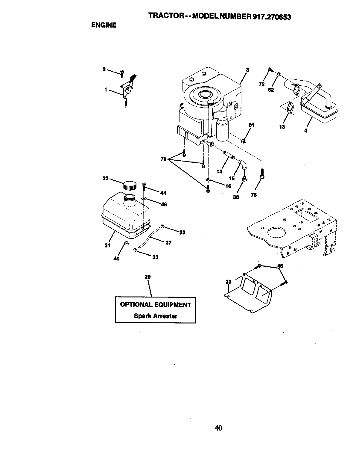
ENGINE
TRACTOR - - MODEL NUMBER 917.270653
29
I OPTIONAL EQUIPMENT
Spark Arrester
$
72 62
13 4
4O
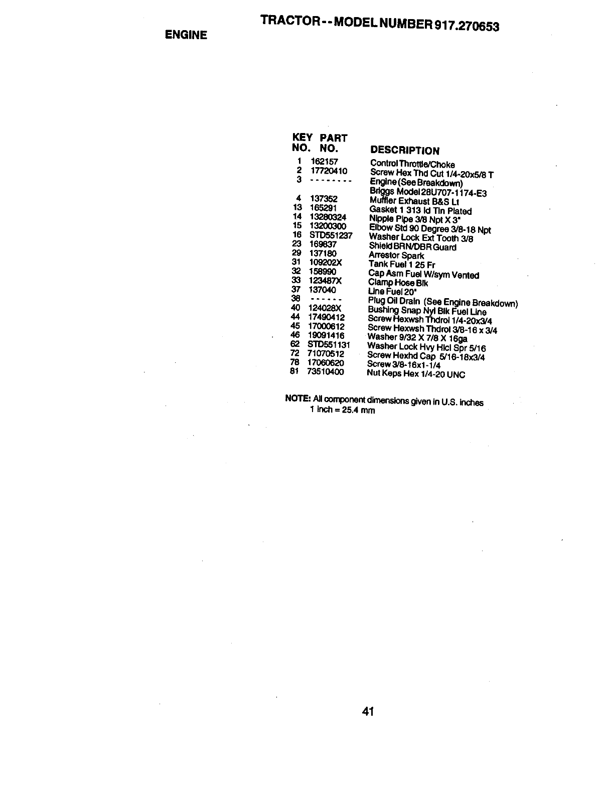
ENGINE
TRACTOR-- MODEL NUMBER 917.270653
KEY PART
NO. NO. DESCRIPTION
1 162157
2 17720410
3 ........
4 137352
13 165291
14 13280324
15 13200300
16 STD551237
23 169637
29 137180
31 10g_202X
32 1589g0
33 123487X
37 137040
40 124028)(
44 17490412
45 17000612
46 19091416
62 STD551131
72 71070512
78 17060620
81 73510400
ControlThroffie/Choke
Screw Hex Thd Cut 1/4-20x5/8 T
Engine (See Breakdown)
Brigg,sModel28U707-1174-E3
Muffler Exhaust B&S Lt
Gasket I 313 |d T_nPlated
Nipple Pipe 3/8 Npt X 3"
EtbowStd90 Degree 3/8-18 Npt
Washer Lock Ext Tooth 3/8
ShieldBRN/DBR Guard
Arrestor Spark
Tank Fuel I 25 Fr
Cap Asm Fuel W/sym Vented
Clamp Hose Bfk
Line Fuel 20'
Plug Oil Drain (See Engine Breakdown)
BushingSnap Ny_Blk Fuel Line
Screw Hexwsh Thdrol 1/4-20x3/4
Screw Hexwsh Thdrot 3/8-16 x 3/4
Washer 9/32 X 718X 16ga
Washer Lock HW Hlcl Spr 5/16
Screw Hexhd Cap 5/16-18x3/4
Screw 3/8-16x1-1/4
Nut Keps Hex 1/4-20 UNC
NOTE: Alloomponent dimensionsgiveninU.S. inches
1 Inch = 25.4 mm
41
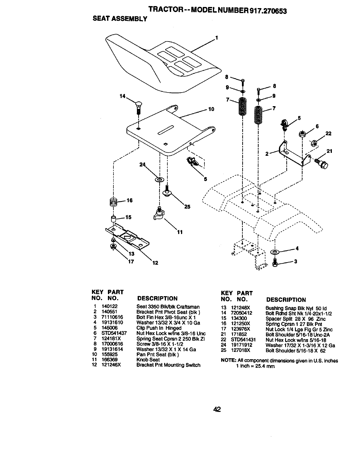
TRACTOR - - MODEL NUMBER 917.270653
SEATASSEMBLY
KEY PART
NO. NO.
1 140122
2 140551
3 71110616
4 19131610
5 1450O6
6 STD541437
7 124181X
8 17000616
9 19131614
10 155925
11 166369
12 121246X
DESCRIPTION KEY PART
NO. NO.
Seat 3350 BIk/olk Craftsman 13 121248X
Bracket Pnt Pivot Seat (blk) 14 72050412
Bolt Fin Hex 3/8-16unc X 1 15 134300
Washer 13/32 X 3/4 X 10 Ga 16 121250X
Clip Push In Hinged 17 123976X
Nut Hex Lock w/Ins 3/8-16 Uric 21 171852
Spring Seat Cprsn 2 250 BIk Zi 22 STD541431
Screw3/8-16 X 1-1/2 24 19171912
Washer 13/32 X 1 X 14 Ga 25 127018X
Pan Pnt Seat (blk)
Knob Seat
Bracket Pnt Mounting Switch
DESCRIPTION
BushingSnap BIk Nyl 50 Id
Bolt Rdhd Sht Nk 1/4-20x1-1/2
Spacer Split 28 X 96 Zinc
Spring Cprsn 127 BlltPnt
Nut Lock 114Lge Fig Gr 5 Zinc
Bolt Shoulder5/16-18 Unc-2A
Nut Hax Lock w/Ins 5/16-18
Washer 17/32 X 1-3/16 X 12 Ga
Bolt Shoulder 5/16-18 X 62
NOTE: Allcomponentdimensionsgivenin U.S. inches
1 inch = 25.4 mm
42
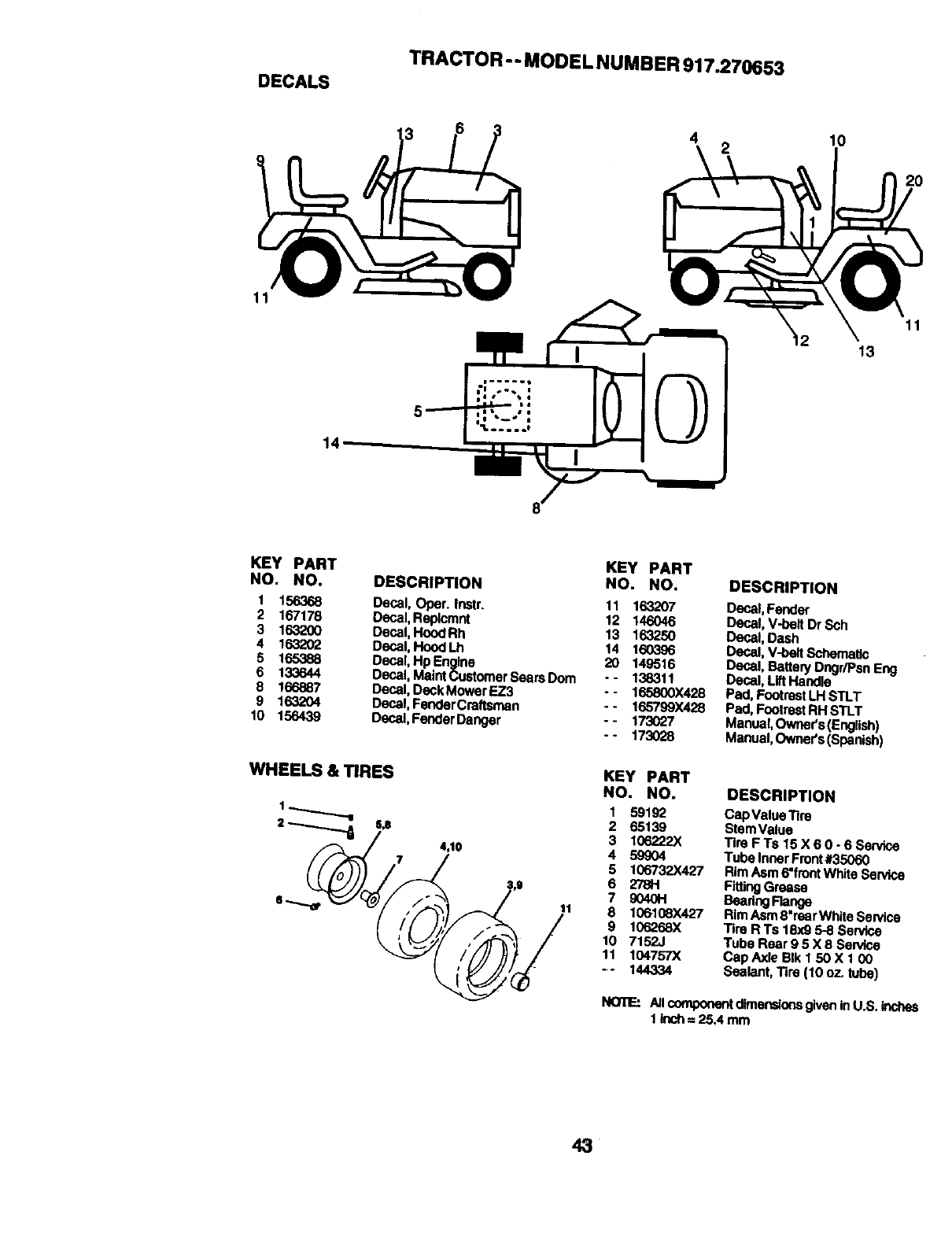
DECALS
TRACTOR -- MODE LNUMBER 917.270653
4 I0
2O
11
14
13
11
KEY PART
NO, NO,
1 156368
2 167178
3 163200
4 163202
5165388
6 133644
8 166887
9 1632O4
t0 156439
KEY PART
DESCRIPTION NO. NO.
Decal, Opar. Instr. 11 163207
Desal, Reptcmnt 12 146046
Decal, Hood Rh 13 163250
Oeca|,Hood Lh 14 160396
Decal, Hp En_line 20 149516
Oecal, Maintcustomer Se_rs Dora -- 138311
Decal, Deck Mower EZ3 - -165800X428
Decal, FenderCraftsman -- 165799X428
Decal, Fender Danger -- 173027
- - 173028
WHEELS&_RES
U
4,10
11
DESCRIPTION
Decal, Fender
Dec,at, VJoeltDr Sch
Decal, Dash
Oecal, V-heR Schematic
Decal, Battery Dngr/Psn Eng
Decal, Lift Handle
Pad, FootrestLH STLT
Pad, Footrest RH STLT
Manual,Owner's (English)
Manual,Owner's (Spanish)
KEY PART
NO. NO.
1 59192
2 65139
3 106222X
4 59904
5 106732X427
6 278H
? 90401-1
8 100108X427
9 106268X
10 7152,.I
11 104757X
-- 144334
DESCRIPTION
Cap Value Tim
Stem Value
Tire FTs 15X60-6 Service
Tuba Inner Front#35060
RimAsm 6"frontWhite Service
FittingGrease
Seadng Range
RimAsrn8"rear White Service
Tim R Ts 18x9 5-.8Sendce
Tube Rear 9 5 X 8 Service
Cap Axle Blk 1 50X1 O0
Sealant, Tire (10 oz. tube)
NOTE: All componentdimensionsgivenin U.S. inches
1 klch = 25A mm
43
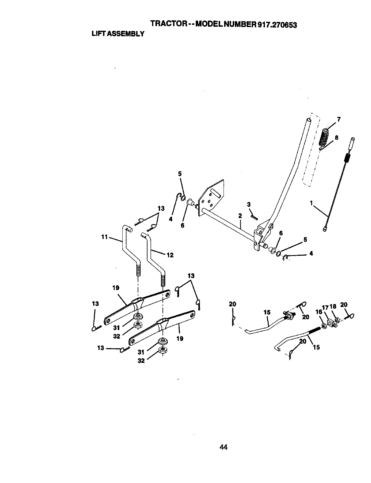
TRACTOR -- MODEL NUMBER 917.270653
LIFTASSEMBLY
7
13
$
46
2
3
19
13
32
31
32
13
19
20
44
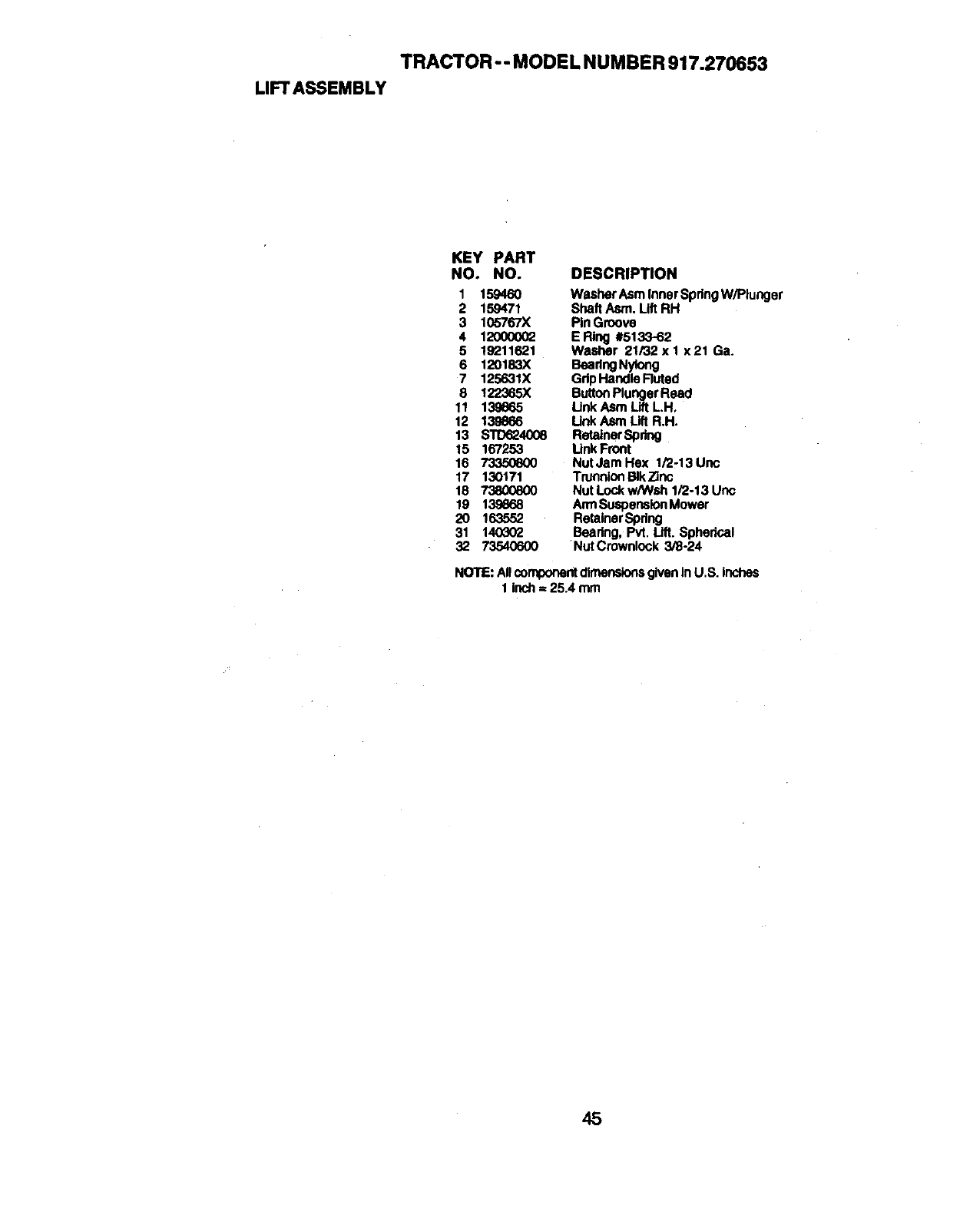
TRACTOR -- MODEL NUMBER 917.270653
LIFTASSEMBLY
KEY PART
NO. NO. DESCRIPTION
1 159460 Washer Asm Inner SpdngW/Plunger
2 159471 Shaft Asm. Lift RH
3 105767X Pin Groove
4 1200O002 ERing #5133-62
5 19211621 Washer 21/32 x 1 x 21 Ga.
6 120183X BeadngNylong
7 125631X GdpHandle Ruted
8 122365X ButtonPlunger Reacl
11 139865 Link Asm Lift LH,
12 139866 Unk Asm Lift R.H.
13 STD624008 Retainer Spring
15 167253 Unk Front
16 73350600 NutJamHex 1/2_13Unc
17 130171 TrurmionBIkZinc
18 _Nut Lock w/Wsh 1/2-13 Unc
19 138668 ArmSuspensionMower
20 163552 RetainerSpdng
31 140302 Beadng, Pvt, Lift. Spherical
32 73540600 Nut Crownlock 3/8-24
NOTE: AllcomponentdimensionsgivenIn U.S. inches
1 inch = 25.4 mm
45
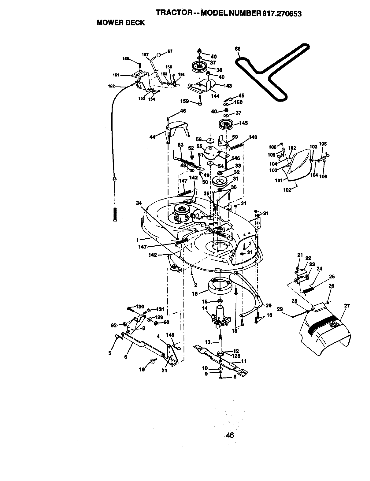
TRACTOR -- MODEL NUMBER 917.270653
MOWERDECK
167
161
IS2
34 "_21
16
1
21
28
29
22
3 24
25
27
46
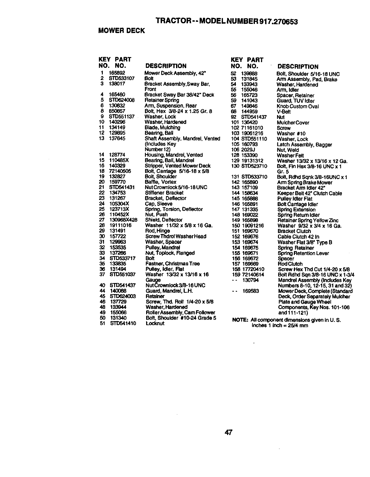
TRACTOR - - MODEL NUMBER 917.270653
MOWER DECK
KEY PART KEY PART
NO. NO. DESCRIPTION NO. NO.
1 165892 MowerDeckAssembly,42" 52 139888
2 STD533107 Bolt 53 131845
3 138017 Bracket Assembly,Sway Bar, 54 133943
Front 55 155O46
4 165460 Brecket Sway Bar 38/42" Deck 56 165723
5_40(_ RetairlerSpdng 59 141043
6 130632 Arm, Suspension, Rear 67 149846
8 850857 Bolt, Hex 3/8-24 x 1.25 Gr. 8 68 144959
8 STD551137 Washer, Lock 92 STD541437
10 140296 Washer, Hardened 101 136420
11 134149 Blade,Mulching 102 71161010
12 129895 Beadng, Ball 103 19061216
13 137645 Shaft Assembly, MandraI, Vented 104 STD551110
(Includes Key 105 160793
Number12) 106 2029J
14 128774 Housing,Mandrel, Vented 128 153390
15 110485X Bearing,Boll, Mandrel 129 19131312
16 140329 Stripper, Vented Mower Deck 130 S'10523710
18 72140505 Bolt, Carriage 5/16.18x5/8
19 132827 Bolt, Shoulder 131 S_710
20 159770 Baffle, Vortex 142 165890
21 STD541431 NutCrownlockS/16-18UNC 143 157109
22 134753 Stiffener Bracket 144 158634
23 131267 Bracket, Deflector 145 165888
24 105304X Cap, Sleeve 146 165891
25 123713X Spdng,Torsion, Detlector 147 131335
26 11045,?.X Nut, Push 148 169022
27 130968X428 Shield, Deflactor 149 165898
28 19111016 Washer 11/32xS/8x16Ga. 150 19091216
29 131491 Rod, Hinge 151 169670
30 157722 ScrewThdrolWeaherHesd 152 169676
31 129963 Washer, Spacer 153 160674
32 153535 Pulley, Mandrel 154 169675
33 137266 Nut, Toplock, Ranged 155 169671
34 STD533717 Bolt 156 169672
35 133835 Fastner, ChdetmaeTrae 157 169669
36 131494 Pulley, Idler, Flat 158 17720410
37 _10Q7 Washer 13/32 x13/16 x16 15972140614
Gauge -- 130794
40 STD541437 NutCrownlock3/8-16 UNC
44 140088 Guard, Mandrel, LH. - - 169583
45 _4003 Retainer
46 137729 Screw, Thd. Rolt 1/4-20 x 5/8
48 133.944 Washer, Hardened
49 155066 RollerAesembly,Gain Follower
50 131340 BoR,Shoulder #10-24 Grade 5
51 STD841410 Locknut
DESCRIPTION
Bolt, Shoulder 5/16-18 UNC
Arm Assembly, Pad, Brake
Washer, Hardened
Arm, Idler
Spacer,Retainer
Guard, TUV Idler
KnobCustom Oval
V-Bait
Nut
MulcherCover
Screw
Washer #10
Washer, Lock
Latch Assembly, Bagger
Nut, Weld
Washer Felt
Washer 13/32 x 13/16 x 12 Ga.
Bolt, Fin Hex 3/8-16 UNC x 1
Gr. 5
Bolt, Rdhd Sqnk 3/8.16UNC x 1
Arm SpdngBrake Mower
Bracket Arm Idler42"
Keeper Belt42" ClutchCable
Pulley Idler Flat
Bolt Cardage Idler
Spring Extension
Spdng ReturnIdler
Retainer SpringYellow Zinc
Washer 9/32 x 3/4 x 16 Ga.
Bracket Clutch
Cable Clutch42 In
Washer Flat 3/8" Type B
Spdng Retainer
Spring RetentionLever
Spacer
RndChJtch
Screw Hex Thd Cut 1/4-20 x 5/8
Bolt Rdhd Sqn 3/8-16 UNC x 1-3/4
Mandrel Assembly(IncludesKey
Numbers 8-10, 12-15, 31 and 32)
Mower Deck, Complete (Standard
Deck, Order Separately Mulcher
Plate andGauge Wheal
Components, Key Nce. 101-106
and 111-121)
NOTE: Allcomponent dimensionsgiven in U. S.
Inches 1 Inch =25/4 mm
47
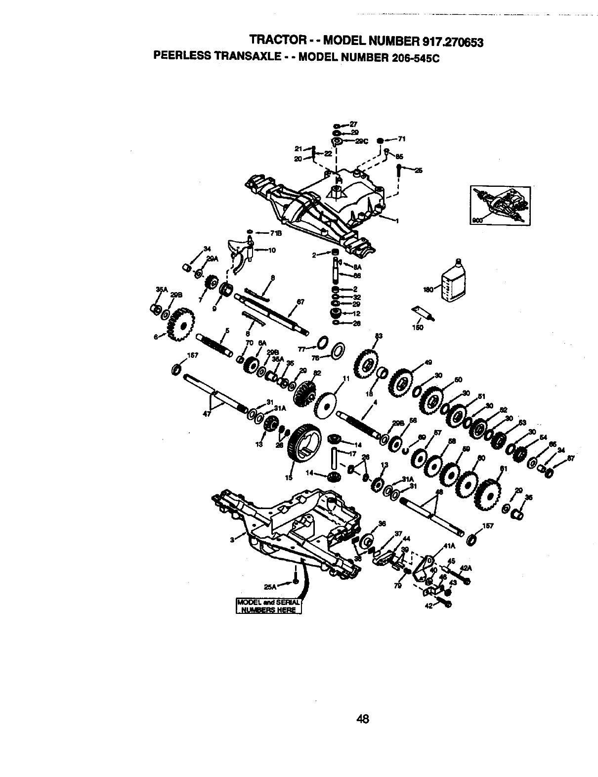
TRACTOR - - MODEL NUMBER 917.270653
PEERLESSTRANSAXLE- - MODELNUMBER206-545C
187
O_71B
160
48

TRACTOR - - MODEL NUMBER 917.270653
PEERLESSTRANSAXLE- - MODELNUMBER206-545C
KEY PART KEY PART
NO. NO. DESCRIPTION NO. NO.
1 772147 Transaxle Cover 41A 790079
2 780086A Needle Beadng 5/8" 42 792073A
3 770128 Transaxle Case 42A 792085A
4 776395 Countershaft 43 792075
5 776409 Output Shaft 44 790025
6 778364 Spur Gear (38 teeth) 45 786066
6A 78369 Spur Gear (15 teeth) 46 786086
7 778330 Spur Gear (11 teeth) 47 774690
8 792180 Shift Key 48 774691
8A 792047 Woodruff Key #9 49 778356
9 784352 Shift Collar 50 778338
10 784378 Shift Rod & Fork 51 778354
11 778334 Bevel Gear (30 teeth) 52 778352
12 778309 Input Bevel Pinion (13 teeth) 53 778350
13 778368 Bevel Gear (13 teeth) 54 778346
(Include, 14) 56 778355
14 778368 Bevel Pinion (13 teeth) 57 778337
(Include. 13) 58 778353
15 778370 Ring Gear (43 teeth) 59 778351
17 786188 Drive Pin 60 778349
18 786102 Spacer 1.130 X .695 61 778345
20 792077A Ball 5/16" dia 65 780189
21 '792078 Set Screw 3/8 -16 x 3/8" 66 776422
22 792079 Spring .310 OD x .625 L 67 776396
25 792073A Screw 1/4 -20 x 1-1/4" 69 792170
25A 792177 Screw 1/4-20 x 1-3/8" 70 786187
26 792125 Retaining Ring (pkg of 2) 71 788069
27 792035 Retaining Ring 71B 788092
26 788040 Retaining Ring 76 780090
29 780072 Thrust Washer .627 ID x
.031W 77 788078A
29A 780160 Thrust Washer .762 ID x 79 792144
.031W 82 778333
29B 780051 Thrust Washer ,762 ID x
.031W 83 778338
29C 780199 Anti-Rotation Washer .632 85 792154
30 780108 Cup Washer 1.127 ID x 87 788089A
.032W 150 788093A
31 780001 Flat Washer ,750 ID x .056W 157 788088A
(Use As Needed) 180 730229A
31A 780195 Flat Washer .750 ID x .062W 900 794712
32 788083 Oil Seal 5/8"
34 780194 Bushing .563
35 780193 Flanged Bushing 5 /8" ID
35A 780197 Flanged Bushing ,751
36 790075 Brake Disk
37 790007 Brake Pad Plate
38 799021 Brake Pad (pkg of 2)
39 786026 Dowel Pin
40 792076A Flat Washer .312 ID x .059W
DESCRIPTION
Brake Lever
Screw 114 - 20 x I-I 14"
Screw I/4 - 20 x 2 I14"
Locknut 5 116 - 24
Brake Pad Holder
Spacer ,2625 x 1.0
Brake Lever Bracket
Axle (11-15/16" Long)
Axle (16 -1/2" long)
Spur Gear (29 teeth)
Spur Gear (27 teeth)
Spur Gear (23 teeth)
Spur Gear (19 teeth)
Spur Gear (16 teeth)
Spur Gear (15 teeth)
Spur Gear (11 teeth)
Spur Gear (13 teeth)
Spur Gear (17 teeth)
Spur Gear (21 teeth)
Spur Gear (24 teeth)
Spur Gear (25 teeth)
Flat Washer .563 ID x .062W
Input Shaft
Shifter & Brake Shaft
Retaining Ring
Spacer .890
Square Cut Ring
"O" Ring
Flat Washer 1.128 ID x
.058W
Inverted Retaining Ring
Spring .430 OD x .5000 L
Bevel & Spur Gear (30 & 13
teeth)
Spur Gear (27 teeth)
Oil Fill Plug
Oil Seal 9/16"
Liquid Gasket RTV Silicone
Oil Seal 3/4"
Gear Oil 80W90
Replacement MST -206-545
Transaxle
NOTE: All component dimensions given in
U.S. inches 1 inch = 25.4 mm
49
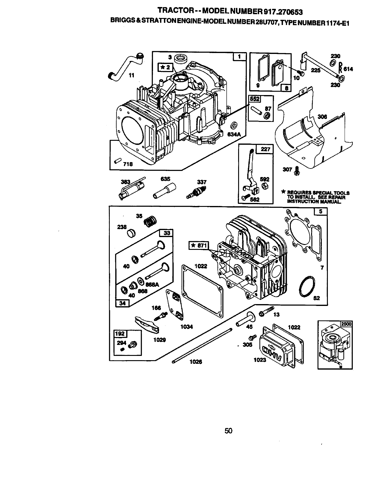
TRACTOR - - MODEL NUMBER 917.270653
BRIGGS & STRATrON ENGINE-MODEL NUMBER 28U707, TYPE NUMBER 1174-E1
23O
_614
lit REQUIRESSPECIALTOOL$
TO INSTALL. SEEREPAIR
INSTRUCTIONMANUAl.
1026
5O
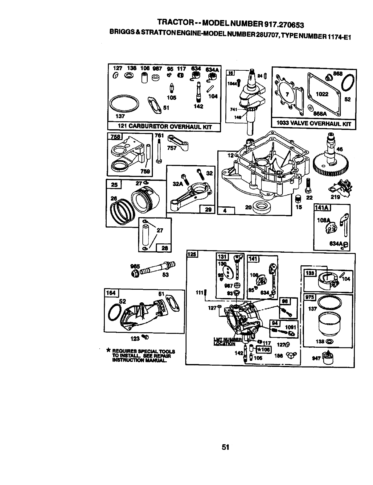
TRACTOR -- MODEL NUMBER 917.270653
BRIGGS & STRAI"rON ENGINE-MODEL NUMBER 28U707,TYPE NUMBER 1174.E1
127 138 106N7' N117 _11_42_AI __ I___,
O _ 105 104 I
137 I1_'_ _1033 VALVE OVERHAUL KIT
121 CARBURETOR OVERHAUL KIT
A"REQUIRESSPECIALTOOUS
TOtHSTALI. SEEREPAm
INSTRUCllON MANUAL.
51
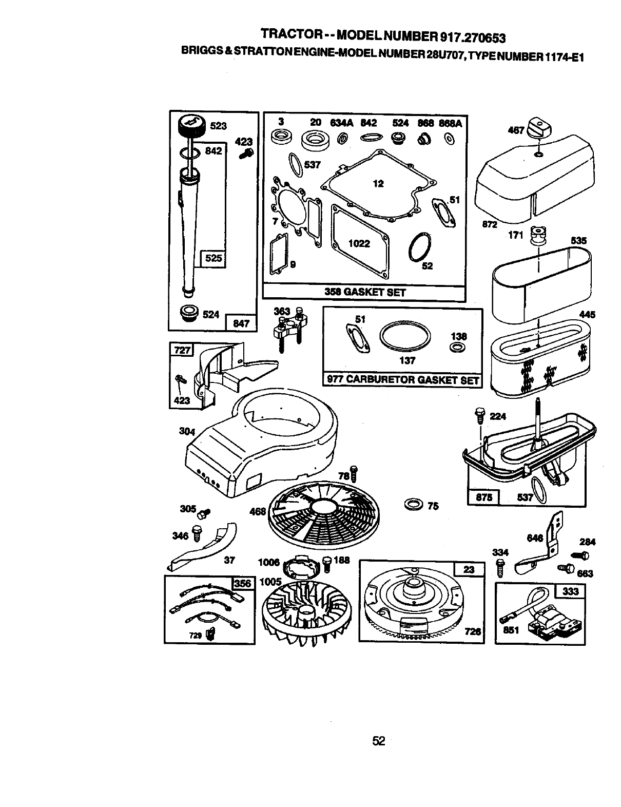
TRACTOR - - MODEL NUMBER 917.270653
BRIGGS & STRATTON ENGINE-MODEL NUMBER 28U707,TYPE NUMBER 1174..EI
137
977 CARBURETOR GASKET SET
467
171 _ 835
445
_224
1°°el W _ _ss
52
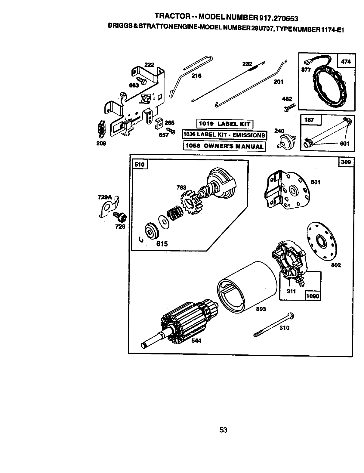
TRACTOR - - MODEL NUMBER 917.270653
BRIGGS & STRA'n'ON ENGINE-MODEL NUMBER 28U707, TYPE NUMBER 1174-E1
i2. I,o,B_..L K,TI .._
11036 LABEL KIT- EMISSIONS]
20, I,o- o....I.A.uA.I
783
728
615
311
8O3
801
474
601
8O2
53
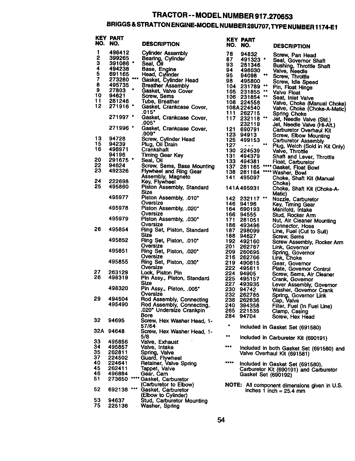
TRACTOR -- MODEL NUMBER 917.270653
BRIGGS &STRATTON ENGINE-MODEL NUMBER 28U707, TYPE NUMBER 1174-E1
KEY PART KEY PART
NO. NO. DESCRIPTION NO. NO. DESCRIPTION
I 496412 CylinderAssembly 78 94832
2 399265 Beadng, Cylinder 87 491323
3 391086 * Seal, Oil 93 281346
4 494238 Base, Engine 94 498030
5 691165 Head, Cyl'mder 95 94098
7 273280 *** Gasket, Cylinder Head 98 495800
8 495735 Breather Assembly 104 231789
9 27803 * Gasket, Valve Cover 165 231855
t0 94621 Screw, Sems 106 231854
11 281246 Tube, Breather 108 224558
12 271916 *Gasket, Crankcase Cover, 108A224540
.015" 111 262715
271997 * Gasket, Crankcase Cover, 117 232118
.005" 232119
271996 * Gasket, Crankcase Cover, 121 690791
.009" 123 94913
13 94728 Screw, CylinderHead 125 499153
15 94239 Plug, OilDrain 127 - - -
16 498971 Crankshaft 130 224539
94196 Timing Gear Key 131 494379
20 291675 * Seal, Oil 133 494381
22 94624 Screw, Sems, Base Mounting 137 281165
23 492326 Flywheel and Ring Gear 138 281164
Assembly, Magneto t41 495097
24 222696 Key, Flywheel
25 495860 Piston Assembly, Standard 141A495931
Size
495977 Piston Assembly, .0t0" t42 232117
Oversize 146 94196
495978 Piston Assembly, .020" 164 690193
Oversize 166 94555
495979 Piston Assembly,.030" 171 281051
Oversize 186 493496
26 495854 Ring Set, Piston, Standard 187 298099
Size 186 94627
495852 Ring Set, Piston, .OlO" t92 492160
Oversize 201 262767
495851 Ring Set, Piston, .020" 209 260695
Oversize 216 262766
495855 Ring Set, Piston, .030" 219 490815
Oversize 222 495611
27 263129 Lock, Piston Pin 224 94905
28 498319 Pin Assy., Piston, Standard 225 495157
Size 227 493935
498320 Pin Assy., Piston, .005" 230 94742
Oversize 232 262785
29 494504 Rod Assembly, Connecting 238 262836
495490 Rod Assembly, Connecting, 240 394358
.020" Undersize Crankpin 265 221535
Bore 284 94704
32 94695 Screw, Hex Washer Head, 1-
57164
32A 94648 Screw, Hex Washer Head, I-
5/8
33 495856 Valve, Exhaust
34 495857 Valve, Intake
35 262811 Spdng, Valve
37 224502 Guard, Flywheel
40 224641 Retainer, Valve Spring
45 262411 Tappet, Valve
46 496884 Gear, Cam
51 273650 **** Gasket, Carburetor
(Carburetorto Elbow)
52 692138 *** Gasket, Carburetor
(=Elbowto Cylinder)
53 94637 Stud, Carburetor Mounting
76 225136 Washer, Spring
Screw, Pan Head
*Seal Governor Shaft
Bushing, Throttle Shaft
Valve, Needle
*" Screw, Throttle
Screw, Idle Speed
** Pin, Float Hinge
"" Valve Fk3at
** Seat, Inlet Valve
Valve, Choke (Manual ChekE
Valve, Choke (Choke-A-Mati(
Spring Choke
*° Jet, Needle Valve (Std.)
Jet, Needle Valve (Hi-Ait.)
Carburetor OverhaulKit
Screw, Elbow Mounting
Carburetor Assembly
°* Plug, Welch (Sold in Kit Only)
Valve, Throttle
Shaft and Lever, Throttle
Float, Carburetor
.... Gasket, Float Bowl
****Washer, Bowl
Choke, Shaft Kit (Manual
Choke)
Choke, Shaft Kit (Choke-A-
Matic)
** Nozzle, Carburetor
Key, Timing Gear
Manifold, Intake
Stud, Rocker Arm
Nut, Air Cleaner Mounting
Connector, Hose
Line, Fuel (Cut to Suit)
Screw, Seres
Screw Assembly,RockerArm
Link, Governor
Spdng, Governor
Link, Choke
Gear, Governor
Plate, Governor Control
Screw, Seres, Air Cleaner
Crank, Governor
Lever Assembly,Governor
Washer. Governor Crank
Spdng, Govemor Link
Cap, Valve
Filter, Fuel (In Fuel Line)
Clamp, Casing
Screw, Hex Head
_ncLododin Gasket Set (691580)
*° Included in Carburetor Kit (690191)
*** Included in both Gasket Set (691580) and
Valve Overhaul Kit (691581)
.... Included in Gasket Set (691580),
Carburetor Kit (690191) and Carburetor
Gasket Set (690192)
NOTE: All componentdimensionsgiven in U.S.
inches 1 inch = 25.4 mm
54
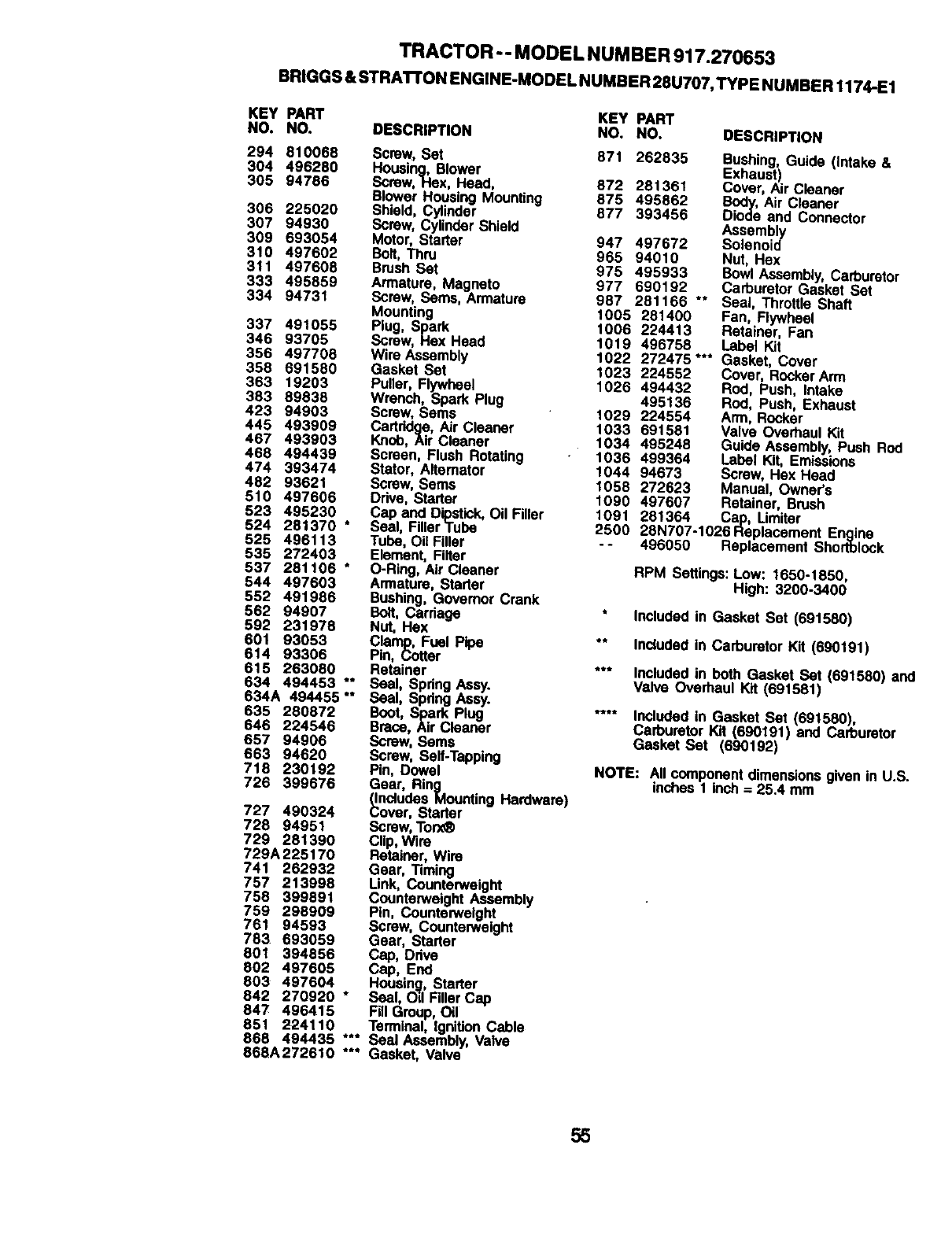
TRACTOR -- MODEL NUMBER 917.270653
BR|GGS & STRAI"rON ENGINE-MODEL NUMBER 28U707,TYPE NUMBER 1174-E1
KEY PART KEY PART
NO. NO. DESCRIPTION NO. NO. DESCRIPTION
294 810068
304 496280
305 94786
306 225020
307 94930
309 693054
310 497602
3tl 497608
333 495859
334 94731
337 491055
346 93705
356 497708
358 691580
363 19203
383 89838
423 94903
445 493909
467 493903
468 494439
474 393474
482 93621
510 497606
523 495230
524 281370 *
525 496113
535 272403
537 281106 *
544 497603
552 491986
562 94907
592 231978
601 93053
614 93306
615 263080
634 494453 **
634A 494455 "*
635 280872
646 224546
657 94906
663 94620
718 230192
726 399676
727 490324
728 94951
729 281390
729A225170
741 262932
757 213998
758 399891
759 296909
761 94593
783 693059
801 394856
802 497605
603 497604
842 270920
847 496415
851 224110
668 494435
868A272610
t
,t*e
t/,e
Screw, Set
Housing, Blower
Screw,Hex, Head,
Blower Housing Mounting
Shield, Cylinder
Screw, CylinderShield
Motor, Starter
Bolt, Thru
BrushSet
Armature, Magneto
Screw, Seres, Armature
Mounting
Plug, Spark
Screw, Hex Head
Wire Assembly
Gasket Set
Puller, Flywheel
Wrench, Spark Plug
Screw, Soms
Cartridge, Air Cleaner
Knob, Air Cleaner
Screen, Flush Rotating •
Stator, Alternator
Screw,Seres
Ddve, Starter
Cap and Dipstiok,Oil Filler
Seal, Filler Tube
Tube, Oil Filler
Element, Filter
O-Ring, Air Cleaner
Armature, Starter
Bushing, Governor Crank
Bolt, Cardage
Nut, Hex
Clamp, Fuel Pipe
Pin, Cotter
Retainer
Seal, Spdng Assy.
Seal, Spdng Assy.
Bout, Spark Plug
Brace, Air Cleaner
Screw,Sems
Screw, Serf-Tapping
Pin, Dowel
Gear, Ring
(IncludesMounting Hardware)
Cover, Starter
Screw, Torx_
Clip, Wire
Retainer, Wire
Gear, Timing
Link, Counterweight
CounterweightAssembly
Pin, Counterweight
Screw, Counterweight
Gear, Starter
Cap, Ddve
Cap, End
Housing, Starter
Seal, Od Filler Cap
Fill Group,Oil
Terminal, IgnitionCable
Seal Assembly,Valve
Gasket, Valve
871 262835 Bushing, Guide (Intake &
Exhaust)
872 281361 Cover, Air Cleaner
875 495862 Body,Air Cleaner
877 393456 Diode and Connector
Assembly
947 497672 Solenoid
965 94010 Nut, Hex
975 495933 Bowl Assembly,Carburetor
977 690192 Carburetor Gasket Set
987 281166 ** Seal, Throttle Shaft
1005 281400 Fan, Flywheel
1006 224413 Retainer, Fan
1019 496758 Label Kit
1022 272475"** Gasket, Cover
1023 224552 Cover, Rocker Arm
1026 494432 Rod, Push, Intake
495136 Rod, Push, Exhaust
1029 224554 Arm, Rocker
1033 691581 Valve Overhaul Kit
1034 495248 Guide Assembly,Push Rod
1036 499364 Label Kit, Emissions
1044 94673 Screw, Hex Head
1058 272623 Manual, Owner's
1090 497607 Retainer, Brush
1091 261364 Cap, Limitar
2500 28N707-1026Replacement Engine
-- 496050 Replacement Shortblock
RPM Settings: Low: 1650-1850,
High: 3200-3400
* Included in Gasket Set (691580)
** Includedin Carburetor Kit (690191)
*** Included in both Gasket Set (691580) and
Valve Overhaul Kit (691581)
.... Included in Gasket Set (691580),
Carburetor Kit (690191) and Carburetor
Gasket Set (690192)
NOTE: All componentdimensionsgiven in U.S.
inches 1 inch = 25.4 mm
55

56

57

58

SUGGESTED GUIDE FOR SIGHTING SLOPES FOR SAFE OPERATION
"_"
SIGHTING
ONLY RIDE UP AND DOWN HILL,
NOT ACROSS HILL
SIGHT AND HOLD THIS LEVEL WITH
SKY LINE OR TREE.
I
Operate your Tractor up and down the face of slopes (not I
greater than 15 ), never across the face. Make turns gradu- I
ally to prevent tipping or loss of control. Exercise extreme
caution when changing direction on slopes.

I I
For in-home major brand repair service:
Call 24 hours a day, 7 days a week
1-800-4-MY-HOME _(1-800-469-4663)
Para pedir servicio de reparaci6n a domicilio
1-800-676-5811
In Canada for all your service and parts needs call
Au Canada pour tout le service ou les pi_ces
1-800-665-4455
For the repair or replacement parts you need:
Call 6 am -11 pm CST, 7 days a week
PartsDirectsM
1-800-366-PART (1-800-366-7278)
Para ordenar piezas con entrega a domicilio
1-800-659-7084
For the location of a Sears Parts and Repair Center
in your area:
Call 24 hours a day, 7 days aweek
1-800-488-1222
For information on purchasing a Sears Maintenance
Agreement or to inquire about an existing Agreement:
Call 9 am -5 pm, Monday -Saturday
1-800-827-6655
pr
I I
173027 11 18.99 TR Printed in U.S.A.
