Craftsman 917270712 User Manual LAWN TRACTOR Manuals And Guides 99030796
CRAFTSMAN Lawn, Tractor Manual 99030796 CRAFTSMAN Lawn, Tractor Owner's Manual, CRAFTSMAN Lawn, Tractor installation guides
User Manual: Craftsman 917270712 917270712 CRAFTSMAN LAWN TRACTOR - Manuals and Guides View the owners manual for your CRAFTSMAN LAWN TRACTOR #917270712. Home:Lawn & Garden Parts:Craftsman Parts:Craftsman LAWN TRACTOR Manual
Open the PDF directly: View PDF ![]() .
.
Page Count: 60
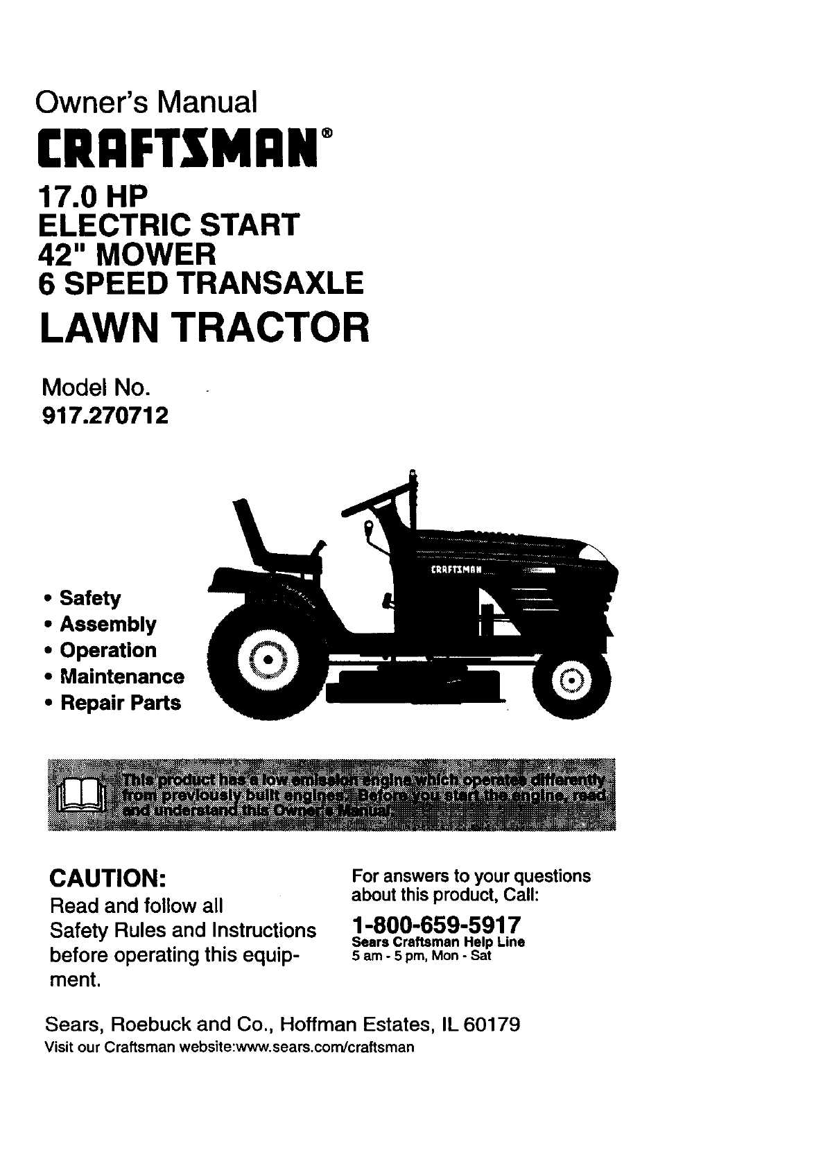
Owner's Manual
rRI:IFTXMi:IN
17.0 HP
ELECTRIC START
42" MOWER
6 SPEED TRANSAXLE
LAWN TRACTOR
Model No.
917.270712
•Safety
•Assembly
•Operation
•Maintenance
•Repair Parts
CAUTION:
Read and follow all
Safety Rules and Instructions
before operating this equip-
ment.
For answers to your questions
about this product, Call:
1-800-659-5917
Sears Craftsman Help Line
5 am -5 pro, Mon- Sat
Sears, Roebuck and Co., Hoffman Estates, IL 60179
Visit our Craftsman website:www.sears.com/craftsman
Warranty.................................................2
SafetyRules...........................................2
ProductSpecifications...........................5
Assembly................................................8
Operation..............................................12
MaintenanceSchedule.........................18
Maintenance.........................................18
ServiceandAdjustments......................22
Storage.................................................29
Troubleshooting....................................30
RepairParts.........................................34
PartsOrdering.......................BackCover
LIMITEDTWOYEARWARRANTYONCRAFTSMANRIDINGEQUIPMENT
Fortwo (2)yearsfromthe dateof purchase,ifthis CraftsmanRidingEquipment is main-
tained, lubricated and tuned up according to the instructions in the owner's manual,
Sears will repair or replace, free of charge, any parts found to be defective in material or
workmanship.
This Warranty does not cover:
• Expendable items which become worn during normal use, such as blades, spark
plugs, air cleaners, belts, etc,
• Tire replacement or repair caused by punctures from outside objects, such as nails,
thorns, stumps, or glass.
• Repairs necessary because of operator abuse, negligence, improper storage or acci-
dent or the failure to maintain the equipment according to the instructions contained in
the owner's manual.
• Riding equipment used for commercial or rental purposes.
LIMITED 90 DAY WARRANTY ON BATI'ERY
For ninety (90) days from date of purchase, if any battery included with this riding equip-
ment proves defective in material or workmanship and our testing determines the bat-
tery will not hold a charge, Sears will replace the battery at no charge. In-home warranty
service on your Craftsman riding equipment is available at no charge for 30 days from
the date of purchase. Please contact your nearest service center. After 30 days from the
date of purchase, warranty service is available by taking your Craftsman riding equip-
ment to your nearest Sears Service Center. (In-home warranty service will still be avail-
able after 30 days from the date of purchase but a standard trip charge will apply). This
warranty applies only while this product is in the United States. This Warranty gives you
specific legal rights, and you may also have other rights which may vary from state to
state.
Sears, Roebuck and Co., D/817 WA, Hoffman Estates, IL 60179
GENERAL OPERATION
•Read, understand, and follow all instruc-
tions in the manual and on the machine
before starting.
• Only allow responsible adults, who are
familiar with the instructions, to operate
the machine.
• Clear the area of objects such as rocks,
toys, wire, etc., which could be picked
up and thrown by the blade.
•Be sure the area is clear of other people
before mowing. Stop machine if anyone
enters the area.
2
• Never carry passengers.
•Do not mow in reverse unless absolute-
ly necessary. Always look down and
behind before and while backing.
•Be aware of the mower discharge direc-
tion and do not point it at anyone. Do
not operate the mower without either
the entire grass catcher or the guard in
place.
•Slow down before turning.
•Never leave a running machine unat-
tended. Always turn off blades, set park-
ing brake, stop engine, and remove
keys before dismounting.

• Turnoffblades when not mowing.
•Stop engine before removing grass
catcher or unclogging chute.
• Mow only in daylight or good artificial
light.
•Do not operate the machine while under
the influence of alcohol or drugs.
•Watch for traffic when operating near or
crossing roadways.
• Use extra care when loading or unload-
ing the machine into a trailer or truck.
SLOPE OPERATION
Slopes are amajor factor related to loss-
of-control and tipover accidents, which
can result in severe injury or death. All
slopes require extra caution. If you cannot
back up the slope or if you feel uneasy on
it, do not mow it.
DO:
•Mow up and down slopes, not across.
•Remove obstacles such as rocks, tree
limbs, etc.
•Watch for holes, ruts, or bumps. Uneven
terrain could overturn the machine. Tall
grass can hide obstacles.
•Use slow speed. Choose a low gear so
that you will not have to stop or shift
while on the slope.
•Follow the manufacturer's recommen-
dations for wheel weights or counter-
weights to improve stability.
•Use extra care with grass catchers or
other attachments. These can change
the stability of the machine.
• Keep all movement on the slopes slow
and gradual. Do not make sudden
changes in speed or direction.
•Avoid starting or stopping on a slope. If
tires lose traction, disengage the blades
and proceed slowly straight down the
slope.
DO NOT:
•Do nottum on slopes unless necessary,
and then, turn slowly and gradually
downhill, if possible.
•Do not mow near drop-offs, ditches, or
embankments. The mower could sud-
denly turn over if a wheel is over the
edge of acliff or ditch, or if an edge
caves in.
•Do not mow on wet grass. Reduced
traction could cause sliding.
•Do nottry to stabilize the machine by
puttingyour foot on the ground.
•Do not use grass catcher on steep
slopes.
CHILDREN
Tragic accidents can occur if the operator
is not alert to the presence of children.
Children are often attracted to the
machine and the mowing activity. Never
assume that children will remain where
you last saw them.
•Keep children out of the mowing area
and under the watchful care of another
responsible adult.
•Be alert and tum machine off if children
enter the area.
•Before and when backing, look behind
and down for small children.
•Never carry children. They may tall off
and be seriously injured or interfere with
safe machine operation.
•Never allow children to operate the
machine.
•Use extra care when approaching blind
comers, shrubs, trees, or other objects
that may obscure vision.
SERVICE
*Use extra care in handling gasoline and
other fuels. They are flammable and
vapors are explosive.
Use only an approved container.
Never remove gas cap or add fuel
with the engine running. Allow en-
gine to cool before refueling. Do not
smoke.
Never refuel the machine indoors.
Never store the machine or fuel
container inside where there is an
open flame, such as a water heater.
•Never run a machine inside aclosed
area.
•Keep nuts and bolts, especially blade
attachment bolts, tight and keep equip-
ment in good condition.
•Never tamper with safety devices.
Check their proper operation regularly.
•Keep machine free of grass, leaves, or
other debris build-up. Clean oil or fuel
spillage. Allow machine to cool before
storing.
•Stop and inspect the equipment if you
strike an object. Repair, if necessary,
before restarting.
3
•Never make adjustments or repairs with .
the engine running.
•Grass catcher components are subject
to wear, damage, and deterioration,
which could expose moving parts or
allow objects to be thrown. Frequently
check components and replace with
manufacturer's recommended parts,
when necessary.
Mower blades are sharp and can cut.
Wrap the blade(s) or wear gloves, and
use extra caution when servicing them.
Check brake operation frequently.
Adjust and service as required. • Be
sure the area is clear of other people
before mowing. Stop machine if anyone
enters the area.
•Never carry passengers.
•Do not mow in reverse unless absolute-
ly necessary. Always look down and •
behind before and while backing.
•Never carry children. They may fall off
and be sadously injured or interfere with •
safe machine operation.
•Keep children out offthe mowing area
and under the watchful care of another •
responsible adult.
•Be alert and turn machine off if children
enter the area.
•Before and when backing, look behind •
and down for small children.
• Mow up and down elopes (15 ° Max), not
across.
,A Look for this symbol to point out impor-
tant safety precautions. It means CAU-
TIONI!! BECOME AWARE!!! YOUR SAFE-
TY IS INVOLVED.
Remove obstacles such as recks, tree
limbs, etc.
Watch for holes, ruts,or bumps. Uneven
terrain cOuldoverturn the machine. Tall
grass can hide obstacles.
Use slow speed. Choose a low gear so
that you will not have to stop or shift
while on the slope.
Avoid starting or stopping on a slope. If
tires lose traction, disengage the blades
and proceed slowly straight down the
slope.
Do notturn on slopes unless necessary,
and then, turn slowly and gradually
downhill, if possible.
,_WARNING: The engine exhaust from
this product contains chemicals known to
the State of California to cause cancer,
birth defacts, or other reproductive harm.
ACAUTION: In order to prevent acciden-
tal starting when setting up, transporting,
adjusting or making repairs always discon-
nect spark plug wire and place wire where
it cannot contact spark plug.
4
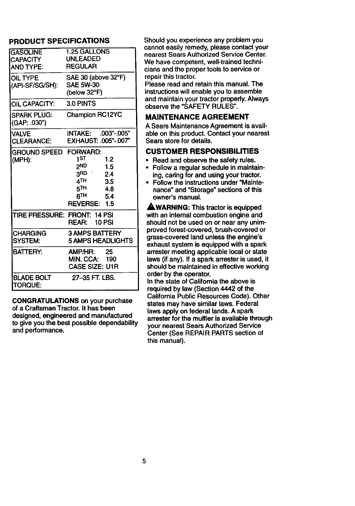
PRODUCT SPECIFICATIONS
IASOLINE 1.25 GALLONS
',APACITY UNLEADED
_NDTYPE: REGULAR
)ILTYPE SAE 30 (above 32°F)
_,PI-SF/SG/SH): SAE 5W-30
(below 32°F)
,IL CAPACITY: 3.0 PINTS
;PARK PLUG: Champion RC12YC
GAP: .030")
VALVE INTAKE: .003"-.005"
CLEARANCE: EXHAUST: .005"-.007"
GROUND SPEED
MPH):
FORWARD:
1ST 1.2
2ND 1.5
3RD "2.4
4TM 3.5
5TH 4.8
6TM 5.4
REVERSE: 1.5
TIRE PRESSURE: FRONT: 14 PSI
REAR: 10 PSI
3HARGING 3 AMPS BA'I-I'ERY
SYSTEM: 5 AMPS HEADLIGHTS
BA'I-rERY: AMP/HR: 25
MIN. CCA: 190
CASE SIZE: U1R
BLADE BOLT 27-35 FT. LBS.
TORQUE:
CONGRATULATIONS on your purchase
of a Craftsman Tractor. It has been
designed, engineered and manufactured
to give you the best possible dependability
and performance.
Should you experience any problem you
cannot easily remedy, please contact your
nearest Sears Authorized Service Center.
We have competent, well-trained techni-
cians and the proper tools to service or
repair this tractor.
Please read and retain this manual. The
instructions will enable you to assemble
and maintain your tractor properly. Always
observe the "SAFETY RULES".
MAINTENANCE AGREEMENT
A Sears Maintenance Agreement is avail-
able on this product. Contact your nearest
Sears store for details.
CUSTOMER RESPONSIBILITIES
• Read and observe the safety rules.
•Follow a regular schedule in maintain-
ing, caring for and using your tractor.
• Follow the instructions under "Mainte-
nance" and =Storage" sections of this
owner's manual.
_,WARNING: This tractor is equipped
with an intemal combustion engine and
should not be used on or near any unim-
proved forest-covered, brush-covered or
grass-covered land unless the engine's
exhaust system is equipped with a spark
arrester meeting applicable local or state
laws (if any). If aspark arrester is used, it
should be maintained in effective working
order by the operator.
In the state of California the above is
required by law (Section 4442 of the
California Public Resources Code). Other
states may have similar laws. Federal
laws apply on federal lands. Aspark
arrester for the muffler is available through
your nearest Sears Authorized Service
Center (See REPAIR PARTS section of
this manual).
5
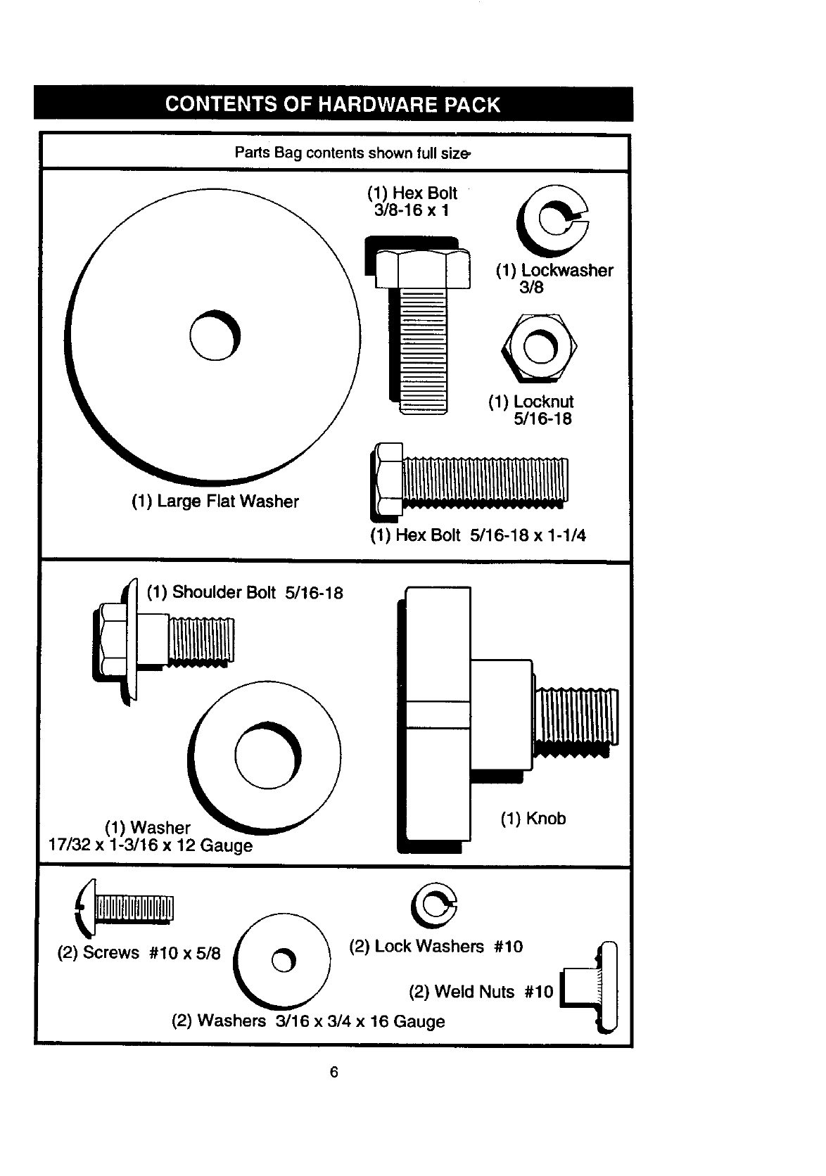
PartsBag contents shown full size-
(1) Hex Bolt
3/8-16 x 1
(1) Lockwasher
3/8
O
(1) Locknut
5/16-18
(1) Large Flat Washer
(1) Hex Bolt 5/16-18 x 1-1/4
(1) Shoulder Bolt 5/16-18
©
(1) Washer
17/32 x 1-3/16 x 12 Gauge
(1) Knob
(2) Screws #10 x5/8 Q(2) LockWashers(2)Weld Nuts#10#10
(2) Washers 3/16 x 3/4 x 16 Gauge
6
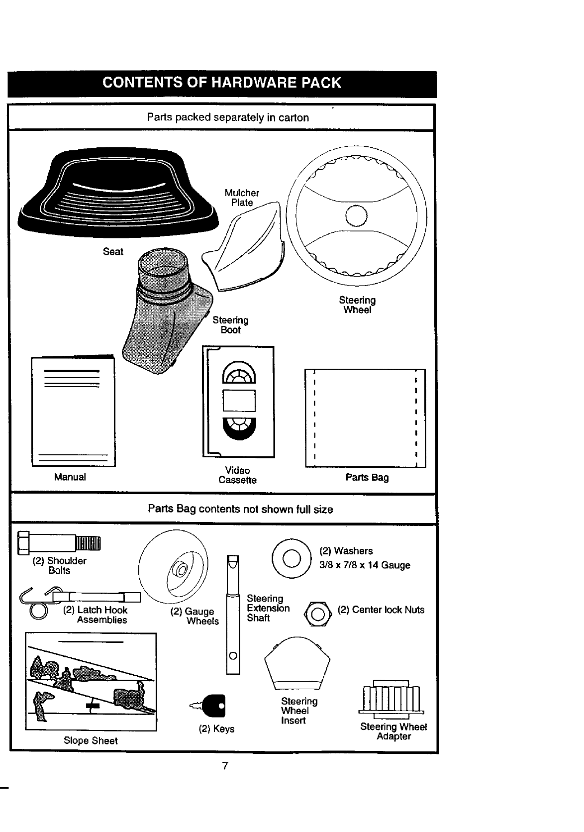
Parts packed separately in carton
Seat
Mulcher
Plate ©
Manual
Boot
Video
Cassette
Steering
Wheel
I
Parts Bag
Parts Bag contents not shown full size
o tU'°m
"-_'_--" (2) Latch Hook (2) Gauge
_" Assemblies Wheels
Slope Sheet
Steering
Extension
Shaft
(2) Keys
O
(2) Washers
3/8 x 7/8 x 14 Gauge
Q(2)
C?
Steering
Wheel
Insert
Center lock Nuts
Steering Wheel
Adapter
7
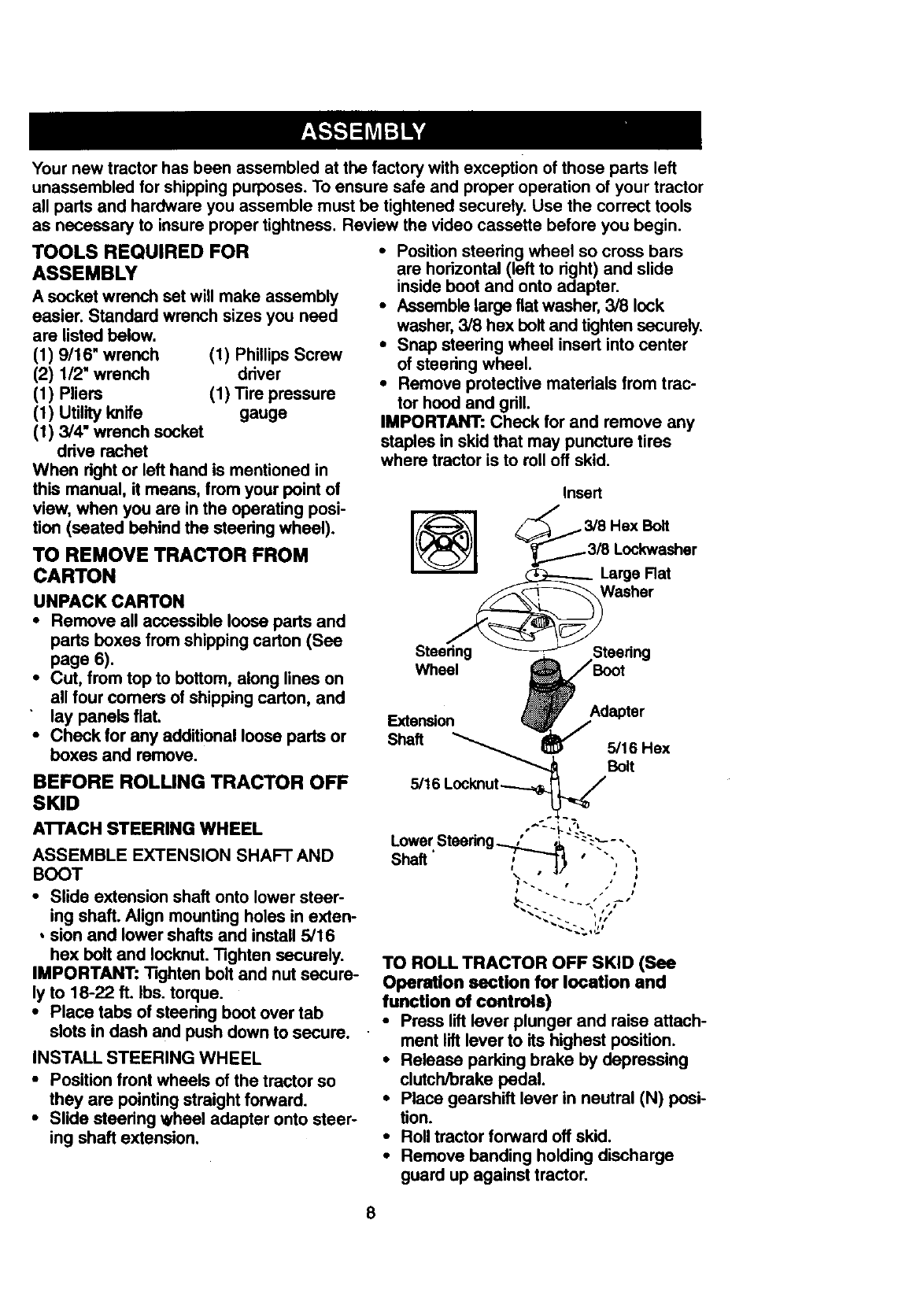
Your new tractor has been assembled at the factory with exception of those parts left
unassembled for shipping purposes. To ensure safe and proper operation of your tractor
all parts and hardware you assemble must be tightened securely. Use the correct tools
as necessary to insure proper tightness. Review the video cassette before you begin.
TOOLS REQUIRED FOR
ASSEMBLY
A socket wrench set will make assembly
easier. Standard wrench sizes you need
are listed below.
(1) 9116"wrench
(2) 1/2" wrench
(1) Pliers
(1) Utility knife
(1) 3/4" wrench socket
drive rachet
When right or left hand is mentioned in
this manual, it means, from your point of
view, when you are in the operating posi-
tion (seated behind the steering wheel).
(1) Phillips Screw
ddver
(1) Tire pressure
gauge
TO REMOVE TRACTOR FROM
CARTON
UNPACK CARTON
• Remove all accessible loose parts and
parts boxes from shipping carton (See
page 6).
•Cut, from top to bottom, along lines on
all four comers of shipping carton, and
lay panels flat.
•Check for any additional loose parts or
boxes and remove.
BEFORE ROLUNG TRACTOR OFF
SKID
AI"rACH STEERING WHEEL
ASSEMBLE EXTENSION SHAFT AND
BOOT
•Slide extension shaft onto lower steer-
ing shaft. Align mounting holes in exten-
,sion and lower shafts and install 5/16
hex bolt and Iocknut. Tighten securely.
IMPORTANT: Tighten bolt and nut secure-
ly to 18-22 ft. Ibs. torque.
•Place tabs of steedng boot over tab
slots in dash and push down to secure.
INSTALL STEERING WHEEL
•Position front wheels of the tractor so
they are pointing straight forward.
•Slide steedng wheel adapter onto steer-
ing shaft extension.
• Position steering wheel so cross bars
are horizontal (left to dght) and slide
inside boot and onto adapter.
•Assemble large flat washer, 3/8 lock
washer, 3/8 hex bolt and tighten securely.
•Snap steering wheel insert into center
of steedng wheel.
•Remove protective materials from trac-
tor hood and gdll.
IMPORTANT: Check for and remove any
staples in skid that may puncture tires
where tractor is to roll off skid.
TO ROLL TRACTOR OFF SKID (See
Operation section for location and
function of controls)
• Press lift lever plunger and raise attach-
ment lift lever to its highest position.
•Release parking brake by depressing
clutch/brake pedal.
•Place gearshift lever in neutral (N) posi-
tion.
• Roll tractor forward off skid.
•Remove banding holding discharge
guard up against tractor.
8
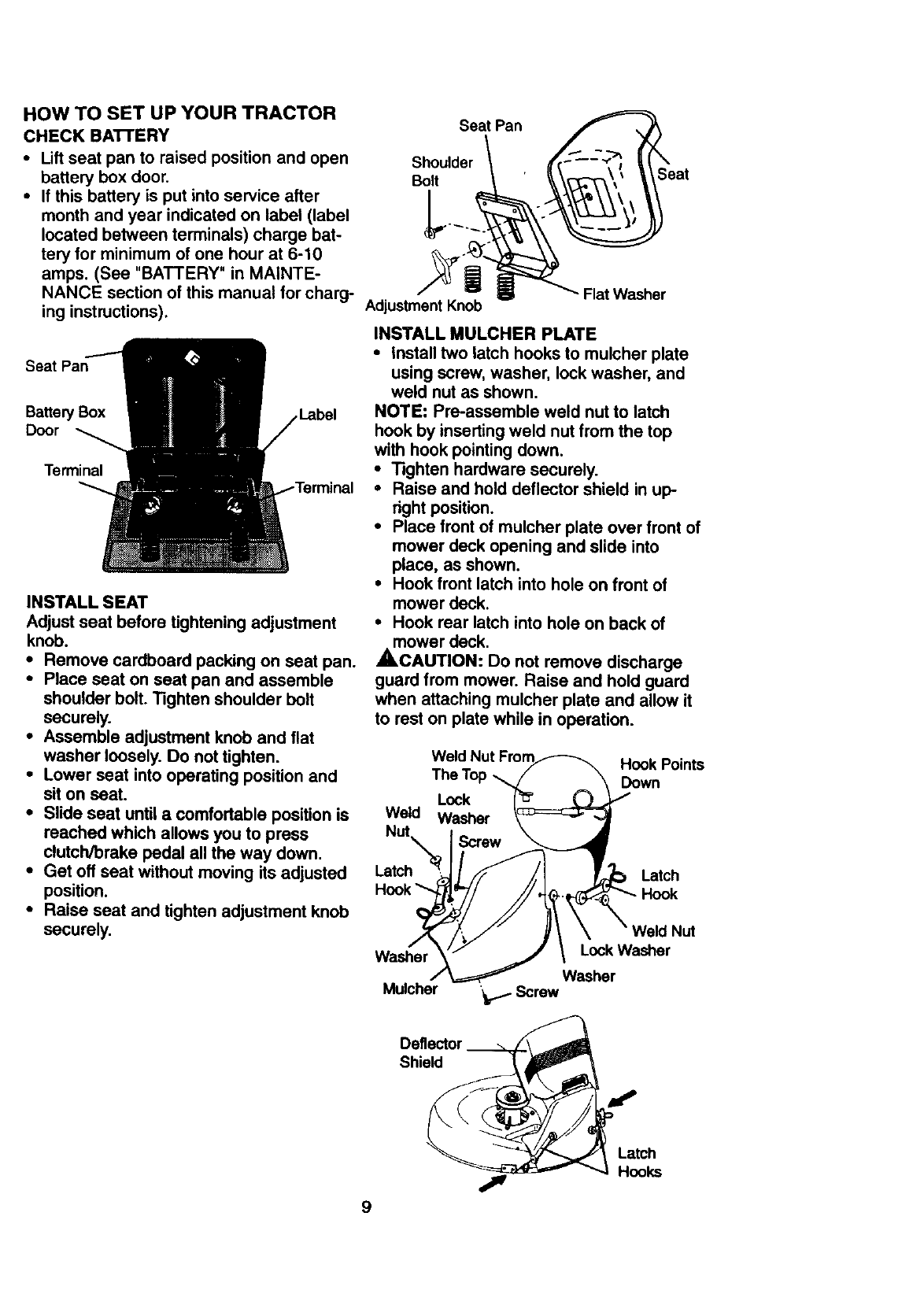
HOW TO SET UP YOUR TRACTOR Seat Pan
CHECK BATI'ERY
• Lift seat pan to raised position and open Shoulder
battery box door. Bolt
•If this battery is put into service after |
month and year indicated on label (label
located between terminals) charge bat- _
tery for minimum of one hour at 6-10
amps. (See "BATTERY" in MAINTE-
NANCE section of this manual for charg- Adjustment Knob
ing instructions).
Seat Pan
Battery Box ,Label
Door
Terminal
INSTALL SEAT
Adjust seat before tightening adjustment
knob.
•Remove cardboard packing on seat pan.
•Place seat on seat pan and assemble
shoulder bolt. Tighten shoulder bolt
securely.
•Assemble adjustment knob and flat
washer loosely. Do not tighten.
•Lower seat into operating position and
sit on seat.
•Slide seat until a comfortable position is
roached which allows you to press
clutch/brake pedal all the way down.
•Get off seat without moving its adjusted
position.
•Raise seat and tighten adjustment knob
securely.
Flat Washer
INSTALL MULCHER PLATE
•Install two latch hooks to mulcher plate
using screw, washer, lock washer, and
wetd nut as shown.
NOTE: Pro-assemble weld nut to latch
hook by inserting weld nut from the top
with hook pointing down.
•Tighten hardware securely.
• Raise and hold deflector shield in up-
nght position.
•Place front of mulcher plate over front of
mower deck opening and slide into
place, as shown.
• Hook front latch into hole on front of
mower deck.
•Hook rear latch into hole on back of
mower deck.
ACAUTION: Do not remove discharge
guard from mower. Raise and hold guard
when attaching mulcher plate and allow it
to rest on plate while in operation.
Weld
Nut
The Top
Lock
Washer
Hook Points
Down
Latch Latch
Hook
Washer
Mulcher
Nut
Lock Washer
Washer
_Screw
Deflector
Shield
Latch
Hooks
9
TO CONVERTTOBAGGINGOR
DISCHARGING
Simplyremovemulcherplateand storein
a safeplace.Yourmoweris now readyfor
dischargingor installationof optional
grasscatcheraccessory.
NOTE:It is notnecessaryto change
blades.The mulcherbladesaredesigned
for dischargingandbaggingalso.
ASSEMBLEGAUGEWHEELSTO
MOWERDECK
The gaugewheelsaredesignedto keep
the mowerdeckin properpositionwhen
operatingmower.Be surethey areprop-
erlyadjustedto ensureoptimummower
performance.
•Assemble gauge wheels with tractor on
aflat level surface.
•Adjust mower to desired cutting height
(See "TO ADJUST MOWER CUTI'ING
HEIGHT* in the Operation section of
this manual).
•With mower in desired height of cut
position, gauge wheels should be
assembled so they aro slightly off the
ground. Install gauge wheel in appropri-
ate hole with shoulder bolt, 3/8 washer,
and 3/8-16 Iocknut and tighten securely.
•Repeat for opposite side installing
gauge wheel in same adjustment hole.
Gauge Wheel Mounting
Bracket
CHECK TIRE PRESSURE
The tires on your tractor were overinflated
at the factory for shipping purposes.
Correct tire pressure is important for best
cutting performance.
•Reduce tire pressure to PSI shown in
"PRODUCT SPECIFICATIONS" on
page 5 of this manual.
CHECK DECK LEVELNESS
For best cutting results, mower housing
should be properly leveled. See "TO
LEVEL MOWER HOUSING" in the
Service and Adjustments section of this
manual.
CHECK FOR PROPER POSITION OF
ALL BELTS
See the figures that are shown for replac-
ing motion and mower blade drive belts in
the Service and Adjustments section of
this manual. Verify that the belts are rout-
ed correctly.
CHECK BRAKE SYSTEM
After you learn how to operate your trac-
tor, check to see that the brake is properly
adjusted. See "TO ADJUST BRAKE" in
the Service and Adjustments section of
this manual.
3/8-16
Locknut
eWheel
10
/ CHECKLIST
PLEASE REVIEW THE FOLLOWING
CHECKLIST:
•/All assembly instructions have been
completed.
,/ No remaining loose parts in carton.
•/Battery is properly prepared and
charged. (Minimum 1 hour at 6 amps).
,/ Seat is adjusted comfortably and
tightened securely.
•/All tires are properly inflated.'(For
shipping purposes, the tires were
overinflated at the factory).
,/ Be sure mower deck is properly leveled
side-to-side/front-to-rear for best
cutting results. ('13res must be properly
inflated for leveling).
/Check mower and ddve belts. Be sure
they are routed properly around pulleys
and inside all belt keepers.
,/ Check wiring. See that all connections
are still secure and wires are properly
clamped.
WHILE LEARNING HOW TO USE YOUR
TRACTOR, PAY EXTRAATTENTION TO
THE FOLLOWING IMPORTANT ITEMS:
,/ Engine oil is at proper level.
,/ Fuel tank is filled with fresh, clean,
regular unleaded gasoline.
,/ Become familiar with all controls -their
location and function. Operate them
before you start the engine.
,/ Be sure brake system is in safe
operating condition.
11
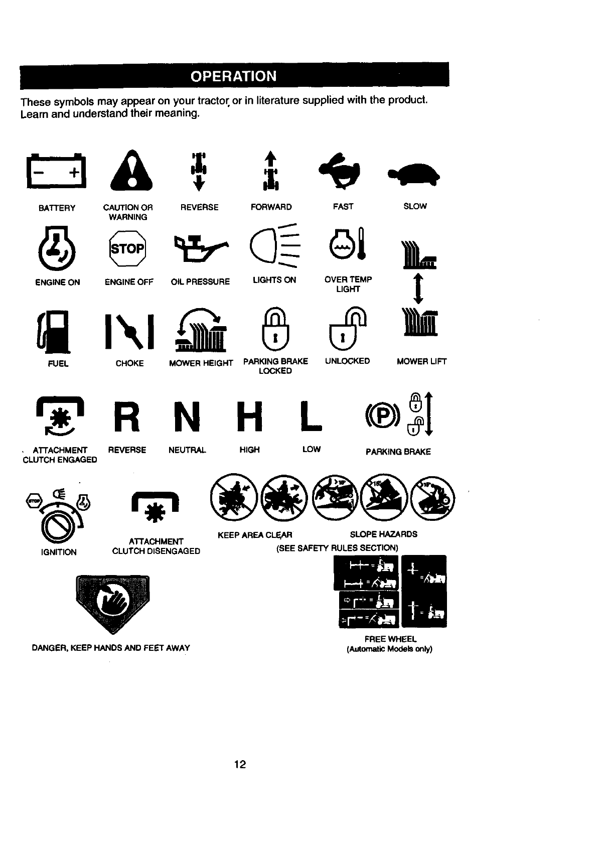
Thesesymbolsmayappearonyourtractoror inliteraturesuppliedwiththe product.
Learnandunderstandtheir meaning.
BATTERY CAUTION OR REVERSE FORWARD FAST SLOW
WARNING
ENGINE ON ENGINE OFF OIL PRESSURE LIGHTS ON OVER TEMP
LIGHT
FUEL CHOKE MOWER HEIGHT PARKING BRAKE UNLOCKED MOWER LIFT
LOCKED
R N H L
•ATTACHMENT REVERSE NEUTRAL HIGH LOW PARKING BRAKE
CLUTCH ENGAGED
ATTACHMENT KEEP AREA CLEAR SLOPE HAZARDS
IGNITION CLUTCH DISENGAGED (SEE SAFETY RULES SECTION)
DANGER,KEEP HANDS AND FEET AWAY FREE WHEEL
(AutomaticModelson_y)
12
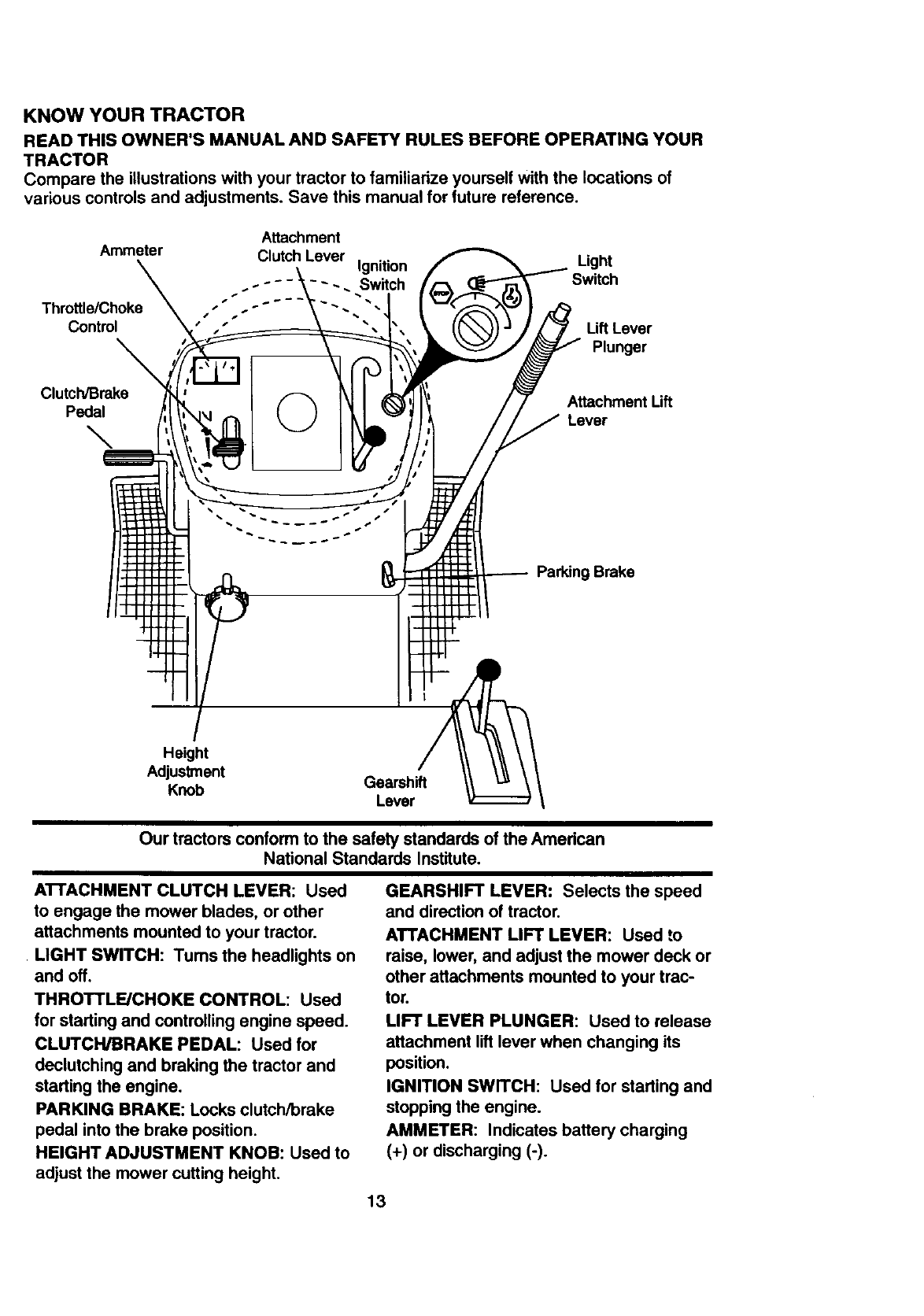
KNOW YOUR TRACTOR
READ THIS OWNER'S MANUAL AND SAFETY RULES BEFORE OPERATING YOUR
TRACTOR
Compare the illustrations with your tractor to familiadze yourself With the locations of
various controls and adjustments. Save this manual for future reference.
Attachment
Ammeter Clutch Lever Ignition
~--. Switch
Throttle/Choke "- -.
Control
Light
Lift Lever
Plunger
Clutch/Brake
Pedal
\
Attachment Lift
Lever
Parking Brake
Height
Adjustment
Knob Gearshift
Lever
Our tractors conform to the safety standards of the American
National Standards Institute,
AI-I'ACHMENT CLUTCH LEVER: Used
to engage the mower blades, or other
attachments mounted to your tractor.
LIGHT SWITCH: Tums the headlights on
and off.
THROTTLE/CHOKE CONTROL: Used
for starting and controlling engine speed.
CLUTCH/BRAKE PEDAL: Used for
declutching and braking the tractor and
starting the engine.
PARKING BRAKE: Locks clutch/brake
pedal into the brake position.
HEIGHT ADJUSTMENT KNOB: Used to
adjust the mower cutting height.
GEARSHIFT LEVER: Selects the speed
and direction of tractor.
ATTACHMENT LIFT LEVER: Used to
raise, lower, and adjust the mower deck or
other attachments mounted to your trac-
tor.
LIFT LEVER PLUNGER: Used to release
attachment lift lever when changing its
position.
IGNITION SWITCH: Used for starting and
stopping the engine.
AMMETER: Indicates battery charging
(+) or discharging (-).
13
The operation of any tractor can result in foreign objects thrown into the |
eyes, which can result in severe eye damage. Always wear safety glass- I
es or eye shields while operating your tractor or performing any adjust-
ments or repairs. We recommend a wide vision safety mask over specta-
cles, or standard safety glasses.
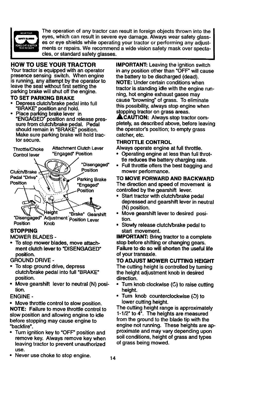
HOW TO USE YOUR TRACTOR
Your tractor is equipped with an operator
presence sensing switch. When engine
is running, any attempt by the operator to
leave the seat without first setting.the
parking brake will shut off the engine.
TO SET PARKING BRAKE
•Depress clutch/brake pedal into full
"BRAKE" position and hold.
•Placeparldng brake lever in
"ENGAGED" position and release pres-
sure from clutch/brake pedal. Pedal
should remain in =BRAKE" position.
Make sure parking brake will hold trac-
tor secure.
Throttle/Choke Attachment Clutch Lever
Control lever "Engaged" Position
"_'_._ "Disengaged"
Cl -c ra,.. _os,0on
Pedal Ddve" .-_!_=ffParking Brake
Position _ ", '_',, _/_ "Engaged"
%'-_ ,_,v,,= "Brake" Gearsh ft
"Disengaged" Adjustment "PositionLever
Position Knob
STOPPING
MOWER BLADES -
•To stop mower blades, move attach-
ment clutch lever to =DISENGAGED"
position.
GROUND DRIVE -
•To stop ground drive, depress
clutch/brake pedal into full "BRAKE"
position.
•Move gearshift lever to neutral (N) posi-
tion.
ENGINE -
•Move throttle control to slow position.
NOTE: Failure to move throttle control to
slow position and allowing engine to idle
before stopping may cause engine to
=backfire'.
•Tum ignition key to =OFF" position and
remove key. Always remove key when
leaving tractor to prevent unauthorized
use.
•Never use choke to stop engine.
IMPORTANT: Leaving the ignition switch
in any position other than =OFF" will cause
the battery to be discharged (dead).
NOTE: Under certain conditions when
tractor is standing idle with the engine run-
ning, hot engine exhaust gases may
cause "browning" of grass. To eliminate
this possibility, always stop engine when
,_ol_ping tractor on grass areas.
AUTION: Always stop tractor com-
pletely, as described above, before leaving
the operator's position; to empty grass
catcher, etc.
THROI"rLE CONTROL
Always operate engine at full throttle.
•Operating engine at less than full throt-
tle reduces the battery charging rate.
•Full throttle offers the best bagging and
mower performance.
TO MOVE FORWARD AND BACKWARD
The direction and speed of movement is
controlled by the gearshift lever.
• Start tractor with clutch/brake pedal
depressed and gearshift lever in neutral
(N) position.
•Move gearshift lever to desired posi-
tion.
•Slowly release clutch/brake pedal to
start movement.
IMPORTANT: Bring tractor to a complete
stop before shifting or changing gears.
Failure to do so will shorten the useful life
of your transaxle.
TO ADJUST MOWER CUTTING HEIGHT
The cutting height is controlled by turning
the height adjustment knob in desired
direction.
•Tum knob clockwise (G) to raise cutting
height.
•Tum knob counterclockwise (O)to
lower cutting height.
The cutting height range is approximately
1-112" to 4". The heights are measured
from the ground to the blade tip with the
engine not running. These heights are ap-
proximate and may vary depending upon
soil conditions, height of grass and types
of grass being mowed.
14
•The average lawn should be cut to
approximately 2-1/2 inches during the
cool season and to over 3 inches during
hot months. For healthier and better
looking lawns, mow often and after
moderate growth.
• For best cutting performance, grass
over 6 inches in height should be
mowed twice. Make the first cut rela-
tively high; the second to desired
height.
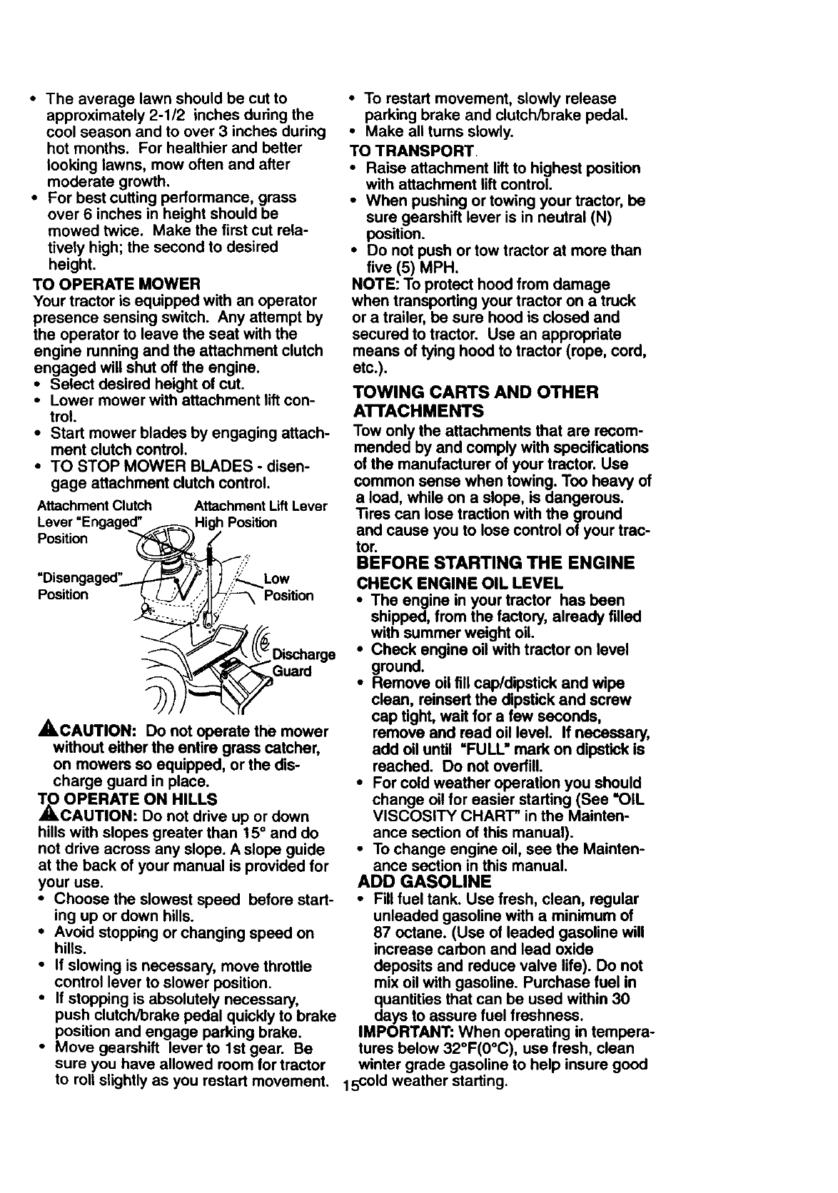
TO OPERATE MOWER
Your tractor is equipped with an operator
presence sensing switch. Any attempt by
the operator to leave the seat with the
engine running and the attachment clutch
engaged will shut off the engine.
•Select desired height of cut.
•Lower mower with attachment lift con-
trol.
•Start mower blades by engaging attach-
ment clutch control.
• TO STOP MOWER BLADES -disen-
gage attachment clutch control.
Attachment Clutch
Position
Attachment LiftLever
High Position
Low
Position Position
Guard
_,CAUTION: Do not operate the mower
without either the entire grass catcher,
on mowers so equipped, or the dis-
charge guard in place.
TO OPERATE ON HILLS
_CAUTION: Do not drive up or down
hills with slopes greater than 15 ° and do
not drive across any slope. A slope guide
at the back of your manual is provided for
your use.
•Choose the slowest speed before start-
ing up or down hills.
•Avoid stopping or changing speed on
hills.
•If slowing is necessary, move throttle
control lever to slower position.
•If stopping is absolutely necessary,
push clutch/brake pedal quickly to brake
position and engage parking brake.
•Move gearshift lever to 1st gear. Be
sure you have allowed room for tractor
to roll slightly as you restart movement.
•To restart movement, slowly release
parking brake and clutch/brake pedal.
•Make all turns slowly.
TO TRANSPORT.
•Raise attachment lift to highest position
with attachment lift control.
•When pushing or towing your tractor, be
sure gearshift lever is in neutral (N)
position.
•Do not push or tow tractor at more than
five (5) MPH.
NOTE: To protect hood from damage
when transporting your tractor on a truck
or a trailer, be sure hood is closed and
secured to tractor. Use an appropriate
means of tying hood to tractor (rope, cord,
etc.).
TOWING CARTS AND OTHER
ATTACHMENTS
Tow only the attachments that are recom-
mended by and comply with specifications
of the manufacturer of your tractor. Use
common sense when towing. Too heavy of
a load, while on a slope, is dangerous.
Tires can lose traction with the ground
and cause you to lose control of your trac-
tor.
BEFORE STARTING THE ENGINE
CHECK ENGINE OIL LEVEL
•The engine in your tractor has been
shipped, from the factory, already filled
with summer weight oil.
• Check engine oil with tractor on level
ground.
•Remove oil fill cap/dipstick and wipe
clean, reinsert the dipstick and screw
cap tight, wait for a few seconds,
remove and read oil level. If necessary,
add oil until =FULL" mark on dipstick is
reached. Do not overfill.
•For cold weather operation you should
change oil for easier starting (See "OIL
VISCOSITY CHART" in the Mainten-
ance section of this manual).
•To change engine oil, see the Mainten-
ance section in this manual.
ADD GASOLINE
•Fill fuel tank. Use fresh, clean, regular
unleaded gasoline with a minimum of
87 octane. (Use of leaded gasoline will
increase carbon and lead oxide
deposits and reduce valve life). Do not
mix oil with gasoline. Purchase fuel in
quantities that can be used within 30
days to assure fuel freshness.
IMPORTANT: When operating in tempera-
tures below 32°F(0°C), use fresh, clean
winter grade gasoline to help insure good
15c°ld weather starting.
_,WARNING: Experience indicates that
alcohol blended fuels (called gasohol or
using ethanol or methanol) can attract
moisture which leads to separation and
formation of acids during storage. Acidic
gas can damage the fuel system of an
engine while in storage. To avoid engine
problems, the fuel system should be emp-
tied before storage of 30 days or longer.
Drain the gas tank, start the engine and let
it run until the fuel lines and carburetor are
empty. Use fresh fuel next season. See
Storage Instructions for additional informa-
tion. Never use engine or carburetor
cleaner products in the fuel tank or perma-
_nct damage may occur.
AUTION: Fill to bottom of gas tank
filler neck. Do not overfill Wipe off any
spilled oil or fuel. Do not store, spill or use
gasoline near an open flame.
TO START ENGINE
When starting the engine for the first time
or if the engine has run out of fuel, it will
take extra cranking time to move fuel from
the tank to the engine.
•Sit on seat in operating position,
depress clutch/brake pedal and set
parking brake.
• Place gear shift lever in neutral (N) posi-
tion.
'• Move attachment clutch to uDISEN-
GAGED" position.
•Move throttle control to choke position.
NOTE: Before starting, read the warm
and cold starting procedures below.
•Insert key into ignition and tum key
clockwise to "START" position and
release key as soon as engine starts.
Do not run starter continuously for more
than fifteen seconds per minute. If the
engine does not start after several
•attempts, move throttle control to fast
position, wait a few minutes and try
again. If engine still does not start,
move the throttle control back to the
choke position and retry.
WARM WEATHER STARTING (50 °F and •
above)
•When engine starts, move the throttle
control to the fast position.
•The attachments and ground drive can
now be used. tf the engine does not
accept the load, restart the engine and
allow it to warm up for one minute using
the choke as descdbed above.
16
COLD WEATHER STARTING ( 50 ° F AND
BELOW)
• When engine starts, allow engine to run
with the throttle control in the choke
position until the engine runs roughly,
then move throttle control to fast posi-
tion. This may require an engine warm-
up period from several seconds to sev-
eral minutes, depending on the temper-
ature.
•The attachments can also be used dur-
ing the engine warm-up period.
NOTE: If at a high altitude (above 3000
feet) or in cold temperatures (below 32 F)
the carburetor fuel mixture may need to be
adjusted for best engine performance.
See "TO ADJUST CARBURETOR" in the
Service and Adjustments section of this
manual.
MOWING TIPS
•Tire chains cannot be used when the
mower housing is attached to tractor.
•Mower should be properly leveled for
best mowing performance. See "TO
LEVEL MOWER HOUSING" in the
Service and Adjustments section of this
manual.
•The left hand side of mower should be
used for trimming.
•Drive so that clippings are discharged
onto the area that has been cut. Have
the cut area to the right of the machine.
This will result in a more even distribu-
tion of clippings and more uniform cut-
ting.
•When mowing large areas, start by tum-
ing to the right so that clippings will dis-
charge away from shrubs, fences, drive-
ways, etc. After one or two rounds,
mow in the opposite direction making
left hand turns until finished
•If grass is extremely tall, it should be
mowed twice to reduce load and possi-
ble fire hazard from dried clippings.
Make first cut relatively high; the second
to the desired height.
•Do not mow grass when it is wet. Wet
grass will plug mower and leave unde-
sirable clumps. Allow grass to dry
before mowing.
•Always operate engine at full throttle
when mowing to assure better mowing
performance and proper discharge of
material Regulate ground speed by se-
lecting a low enough gear to give the
mower the best cutting performance as
well as the quality of cut desired.
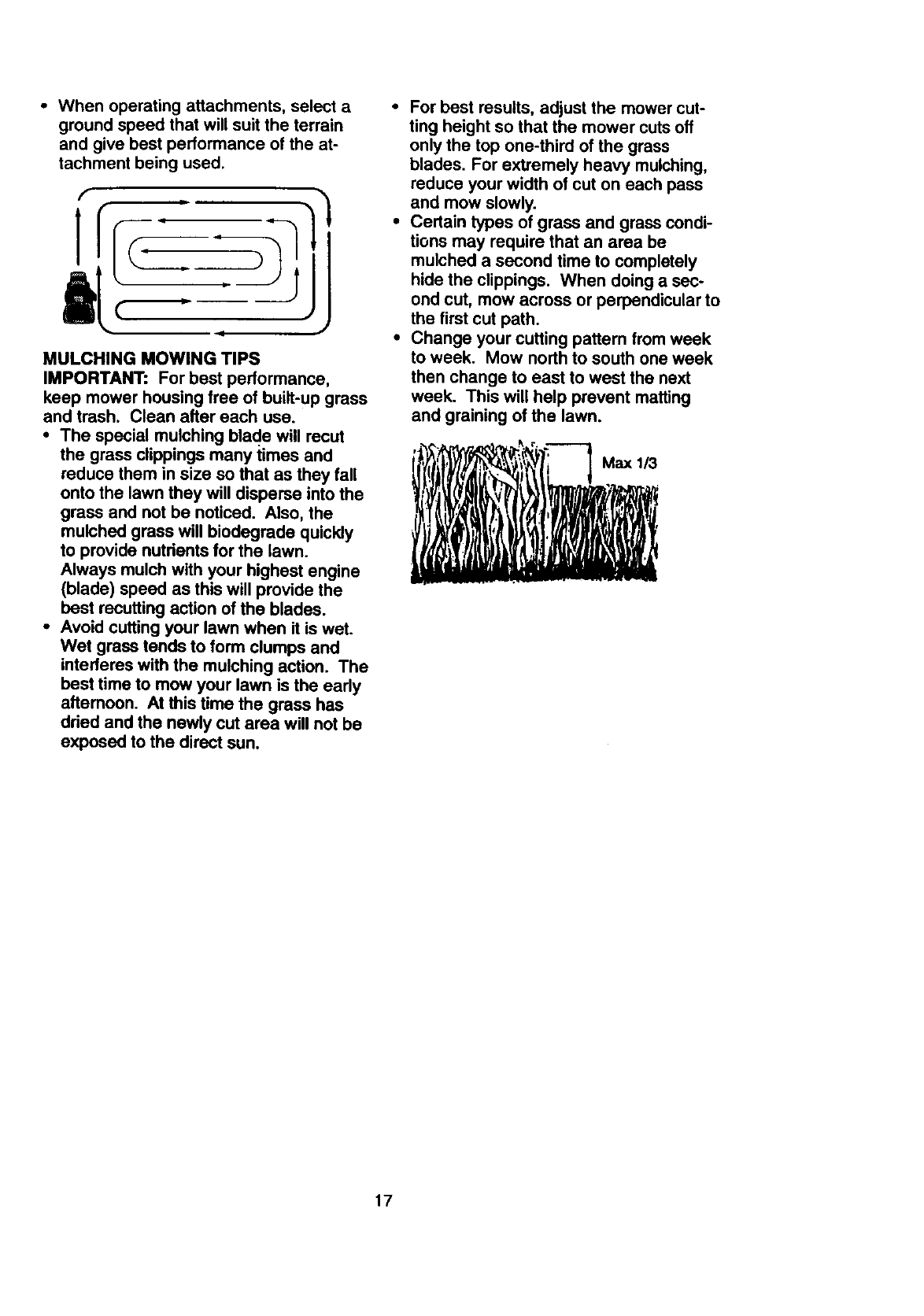
•When operating attachments, select a
ground speed that will suit the terrain
and give best performance of the at-
tachment being used.
MULCHING MOWING TIPS
IMPORTANT: For best performance,
keep mower housing free of built-up grass
and trash. Clean after each use.
• The special mulching blad.ewill recur
the grass clippings many times and
reduce them in size so that as they fall
onto the lawn they will disperse into the
grass and not be noticed. Also, the
mulched grass will biodegrade quickly
to provide nutrients for the lawn.
Always mulch with your highest engine
(blade) speed as this will provide the
best recutting action of the blades.
•Avoid cutting your lawn when it is wet.
Wet grass tends to form clumps and
interferes with the mulching action. The
best time to mow your lawn is the early
aftemoon. At this time the grass has
dried and the newly cut area will not be
exposed to the direct sun.
•For best results, adjust the mower cut-
ting height so that the mower cuts off
only the top one-third of the grass
blades. For extremely heavy mulching,
reduce your width of cut on each pass
and mow slowly.
•Certain types of grass and grass condi-
tions may require that an area be
mulched a second time to completely
hide the clippings. When doing a sec-
ond cut, mow across or perpendicular to
the first cut path.
•Change your cutting pattern from week
to week. Mow north to south one week
then change to east to west the next
week. This will help prevent matting
and graining of the lawn.
r" - _r'F,
17
MAINTENANCE SCHEDULE __?.._:"_ =_ __'_ f
,B ooco,P, rE .......DATES
Check Brake Operation
Check Tire Pre_um _
Check Operator P_ and
TInterlock Systems II_
RCheck for Loose Fasteners I_ _7 :
A Sharpen/Replace Mower Blade6 I_4
TLubrication Chart _
0 Che_ Be.eryLevee !
Rclean Battery and Temlioala ! I_
Check Transaxla Cooling V'
Adjust Blade Belt(s) Tension q_'s
Adjust Motion Drive Belt(s) Tension Ks
Check Engine Oil Level _I1_
Change Engine Oil 1_1.=,_
E Claan Air Filter _V':
N Clean Air Screen
Inspect Muffler/Spark Arrester V'
Replace Oil Filter (If equipped) _,=
N Clean Engine Cooling Fln8 v',
Repla,_o Spark Plug I_ v"
v'.
Replace Air Filter Paper Cartridge
Replace Fuel Filter V'
1 -ChangemoreoCtinwtllmopefatlngtmderMhom.yloadO4"lnh_a_ttomporubJrel. S-IfoquJppe_w_l_Justablosyste_.
2 * 84mrice mo_ often when operg, lng kl dkly or dugty c_.:dlUor)8. • - Not roqu._'od if equipped wtth makltmlanc_fyee bet_ery.
3 - if 8_ped w4th oil RJtor. change OE eve_ SO houm. 7 - TIghtlm front m[_ p_vot bolt to 35 _-It_. m_lmum.
4"R'I*I_4_'_ b#_0 m °_ °Nen whe¢_ mowtlg In mmdY lid* Do no( overtlghtml.
GENERAL RECOMMENDATIONS
The warranty on this tractor does not cover
items that have been subjected to operator
abuse or negligence. To receive full value
from the warranty, operator must maintain
tractor as instructed in this manual. Some
adjustments will need to be made periodi-
cally to properly maintain your tractor.
All adjustments in the Service and
Adjustments section of this manual should
be checked at least once each season.
• Once a year you should replace the
spark plug, clean or replace air filter, and
check blades and belts for wear. A new
spark plug and clean air filter assure
proper air-fuel mixture and help your
engine run better and last longer.
BEFORE EACH USE
•Check engine oil level.
•Check brake operation.
•Check tire pressure.
•Check operator presence and intedock
systems for proper operation.
•Check for loose fasteners.
LUBRICATION CHART
Zerk Zerk
•Front Wheel Wheel
Bearing Zerk , Bearing
Zerk
•Engine
I
0Attachment *, ,
i,0Gear-
Clutch ' ,
,_shift
Pivot(s) : ,
,. . l.' Pivots
0SAE 30 or 10w30 Motor OIL
0General Purpose Grease
•Refer to Maintenance =Engine" Section
IMPORTANT: Do not oil or grease the
pivot points which have special nylon bear-
ings. Viscous lubricants will attract dust
and dirt that will shorten the life of the self-
lubricating bearings. If you feel they must
be lubricated, use only a dry, powdered
graphite type lubricant sparingly.
18
TRACTOR
Alwaysobservesafetyruleswhenper-
forminganymaintenance.
BRAKEOPERATION
Iftractor requiresmorethansix (6)feet
stopping distance at high speed in highest
gear, then brake must be adjusted. (See
=1"OADJUST BRAKE" in the Service and
Adjustments section of this manual).
TIRES
• Maintain proper air pressure in all tires
(See "PRODUCT SPECIFICATIONS"
on page 3 of this manual).
• Keep tires free of gasoline, oil, or insect
control chemicals which can harm rub-
bet.
• Avoid stumps, stones, deep ruts, sharp
objects and other hazards that may
cause tire damage.
NOTE: To seal tire punctures and prevent
flat tires due to slow leaks, tire sealant
may bepurchased from your local parts
dealer. Tire sealant also prevents tire dry
rot and corrosion.
OPERATOR PRESENCE SYSTEM
Be sure that operator presence and inter-
lock systems are working properly. Ifyour
tractor does not function as described
below, repair the problem immediately.
•The engine should not start unless the
clutch/brake pedal is fully depressed
and attachment clutch control is in the
disengaged position.
•When the engine is running, any
attempt by the operator to leave the
seat without first setting the parking
brake should shut off the engine.
•When the engine is running and the
attachment clutch is engaged, any
attempt by the operator to leave the
seat should shut off the engine.
•The attachment clutch should never
operate unless the operator is in the
seat.
BLADE CARE
For best results mower blades must be
kept sharp. Replace bent or damaged
blades.
BLADE REMOVAL
•Raise mower to highest position to allow
access to blades.
•Remove hex bolt, lock washer and flat
washer securing blade.
•Install new or resharpened blade with
trailing edge up towards deck as shown
IMPORTANT: To ensure proper assembly,
center hole in blade must align with star
on mandrel assembly.
•Reassemble hex bolt, lock washer and
flat washer in exact order as shown.
• 13ghten bolt securely (27-35 Ft. Lbs.
torque).
IMPORTANT: Blade bolt is Grade 8 heat-
treated.
Flat Washer _, Mandrel
Assembly
Lock Washer--_ Star
Hex Bolt (Grade 8)'
*A Grade 8 heat treated bolt can be
identified by six lines on the bolt head.
TO SHARPEN BLADE
NOTE: We do not recommend sharpening
blade, but if you do, be sure the blade is
balanced.
Care should be taken to keep the blade
balanced. An unbalanced blade will cause
excessive vibration and eventual damage
to mower and engine.
•The blade canbe sharpened with a file
or on agrinding wheel. Do not attempt
to sharpen while it is on the mower.
•To check blade balance, you will need a
5/8" diameter steel bolt, pin, or a cone
balancer. (When using a cone balancer,
follow the instructions supplied with bal°
ancer).
NOTE: Do not use a nail for balancing
blade. The lobes of the center hole may
appear to be centered, but are not.
•Slide blade onto an unthreaded portion
of the steel bolt or pin and hold the belt
or pin parallel with the ground. If blade
is balanced, it should remain in a hori-
zontal position. If either end of the blade
moves downward, sharpen the heavy
end until the blade is balanced.
Center Hole
5/8" Bolt
or Pin
Blade
BA'I-rERY
Your tractor has a battery charging system
which is sufficient for normal use.Howev-
er, periodic charging of the battery with an
automotive charger will extend its life.
ieep battery and terminals clean.
Keep battery bolts tight.
Keep small vent holes open.
•Recharge at 6-10 amperes for I hour.
NOTE: The original equipment battery on
your tractor is maintenance free. Do not
attempt to open or remove caps or covers.
Adding or checking level of electrolyte is
not necessary.
19
TO CLEAN BA'I-I"ERY AND TERMINALS
Corrosion and dirt on the battery and ter-
minals can cause the battery to =leak"
power.
Open batterybox door.
D=sconnectBLACK battery cable first
then RED battery cable and remove
battery from tractor.
•Rinse the battery with plain water and
dry.
•Clean terminals and battery cable ends
with wire brush until bright.
•Coat terminals with grease or petroleum
jelly.
•Reinstall battery (See"REPLACING
BATTERY" in the SERVICE AND
ADJUSTMENTS section of this
manual).
V-BELTS
Check V-belts for deterioration and wear
after 100 hours of operation and replace if
necessary. The bells are not adjustable.
Replace belts if they begin to slip from
wear.
TRANSAXLE COOLING
Keep transaxle free from build-up of dirt
and chaff which can restrict coo, ng.
ENGINE
LUBRICATION
Only use high quality detergent oil rated
with API service classification SF, SG or
SH, Select the oil's SAE viscosity (]rade
according to your expected operating tem-
perature.
SAE VISCOSITY GRADES
.20- .10- 20" 30-
TEMPERATURE RANGE ANTICIPATED BEFORE NEXT OIL CHANGE
NOTE: Although mulli-viscosity oils
(5W30 10W30 etc.) improve starting in
co d weather, these multi-viscosity o'ls w'll
result in increased oil consumption when
used above 320[=.Check your engine oil
level more frequently to avoid possible
engine damage from running low on oil.
Change the od after every 25 hours of
operation or at least once a year if the
tractor is not used for 25 hours in one
year.
Check the crankcase oil level before stad-.
ing the engine and after each eight (8)
hours of operation. Tighten oil fill cap/dip-
stick securely each time you check the oil
level.
TO CHANGE ENGINE OIL
Determine temperature range expected
before oil change. All oil must meet API
service classifi.cation SF, SG or SH.
•Be sure tractor is on level surface.
• Oil will drain more freely when warm.
•Catch oil in a suitable container.
•Remove oil fill cap/dipstick. Be careful
not to allow did tO enter the engine
when changing oil.
•Remove drain plug.
i fter oil has drained completely, replace
oil drain plug and tighten securely.
Refill engine with oil through oil fill dip-
stick tube. Pour slowly. Do not overfill.
For approximate capacity see "PROD-
UCT SPECIFICATIONS"on page 5 of
this manual.
• Use gauge on oil fill cap/dipstick for
checking level. Be sure dipstick cap is
tightened securely for accurate reading.
Keep oil at "FULL" line on dipstick.
Oil Fill
_'-_Cap/Dips_ck
p, Oil Drain
_/Plug
AIR FILTER
Your engine will not runproperly using a
dirty airfiller. Clean the foam pre-cleaner
after every 25 hours of operation or every
season. Service paper cadridge every 100
hours ot operation or every season,
whichever occurs first.
Service air cleaner more often under dusty
conditions.
•Remove knob(s) and cover.
TO SERVICE PRE-CLEANER
Slide foam pre-cleaner off cartridge.
Wash it in liquid detergent and water.
•Squeeze it dry in a clean cloth.
•Saturate it in engine oil. Wrap it in clean,
absorbent cloth and squeeze to remove
excess oil.
•If very dirty or damaged, replace pre-
cleaner.
•Reinstall pre-cleaner over cartridge.
•Reinstall cover and secure with knob(s).
TO SERVICE CARTRIDGE
• Remove cartridge nut.
•Carefully remove cartridge to prevent
debris from entering carburetor. Clean
base carefully to prevent debris from
entering carburetor.
•Clean cartridge by tapping gently on flat
surface. If very dirty or damaged,
replace cartridge.
•Reinstall cartridge, nut, precleaner,
cover and secure with knob(s).
2O
IMPORTANT: Petroleum solvents, such as
kerosene, are not to be used to clean the
cartridge. They may cause deterioration of
the cartridge. Do not oil cartridge. Do not
use pressurized air to clean or dry car-
tridge.
Cover
Knob
Co _Cadddge
Foam -I'_'i Paper
Pre-Cleane_ CaBas_:dge
CLEAN AIR SCREEN
Air screen must be kept free of dirt and
chaff to prevent engine damage from over-
heating. Clean with a wire brush or com-
pressed air to remove dirt and stubbom
dded gum fibers.
ENGINE COOLING FINS
Remove any dust, dirt or oil from engine
cooling fins to prevent engine damage
from overheating.
•Remove screws from blower housing
and lift housing and dipstick tube
assembly off engine.
•Cover oil fill opening to prevent entry of
dirt.
•Use compressed air or stiff bdstle brush
to thoroughly clean engine cooling fins.
•To reassemble, reverse above proce-
dure.
Screws Blower Housing Screws
DipstickTube
Assembly
MUFFLER
Inspect and replace corroded muffler and
spark arrester (if equipped) as it could cre-
ate a fire hazard and/or damage.
SPARK PLUGS
Replace spark plugs at the beginning of
each mowing season or after every 100
hours of operation, whichever occurs first.
Spark plug type and gap setting are
shown in =PRODUCT SPECIFICATIONS"
on page 5 of this manual.
IN-LINE FUEL FILTER
The fuel filter should be replaced once
each season. If fuel filter becomes
clogged, obstructing fuel flow to carbure-
tor, replacement is required.
•With engine cool, remove filter and plug
fuel line sections.
•Place new fuel filter in position in fuel
line with arrow pointing towards carbu-
retor.
•Be sure there are no fuel line leaks and
clam.
CLEANING
•Clean engine, battery, seat, finish, etc.
of all foreign matter.
•Keep finished surfaces and wheels free
of all gasoline, oil, etc.
•Protect painted surfaces with automo-
tive type wax.
We do not recommend using a garden
hose to clean your tractor unless the elec-
trical system, muffler, air filter and carbure-
tor are covered to keep water out. Water
in engine can result in a shortened engine
life.
Engine Cooling
Plug
21
,ACAUTION: Before performing any service or adjustments:
• Depress clutch/brake pedal fully and set parking brake.
•Place gearshift lever in neutral (N) position.
• Place attachment clutch in "DISENGAGED" position.
• Turn ignition key "OFF" and remove key.
• Make sure the blades and all moving parts have completely stopped.
• Disconnect spark plug wire from spark plug and place wire where it cannot come
in contact with plug.
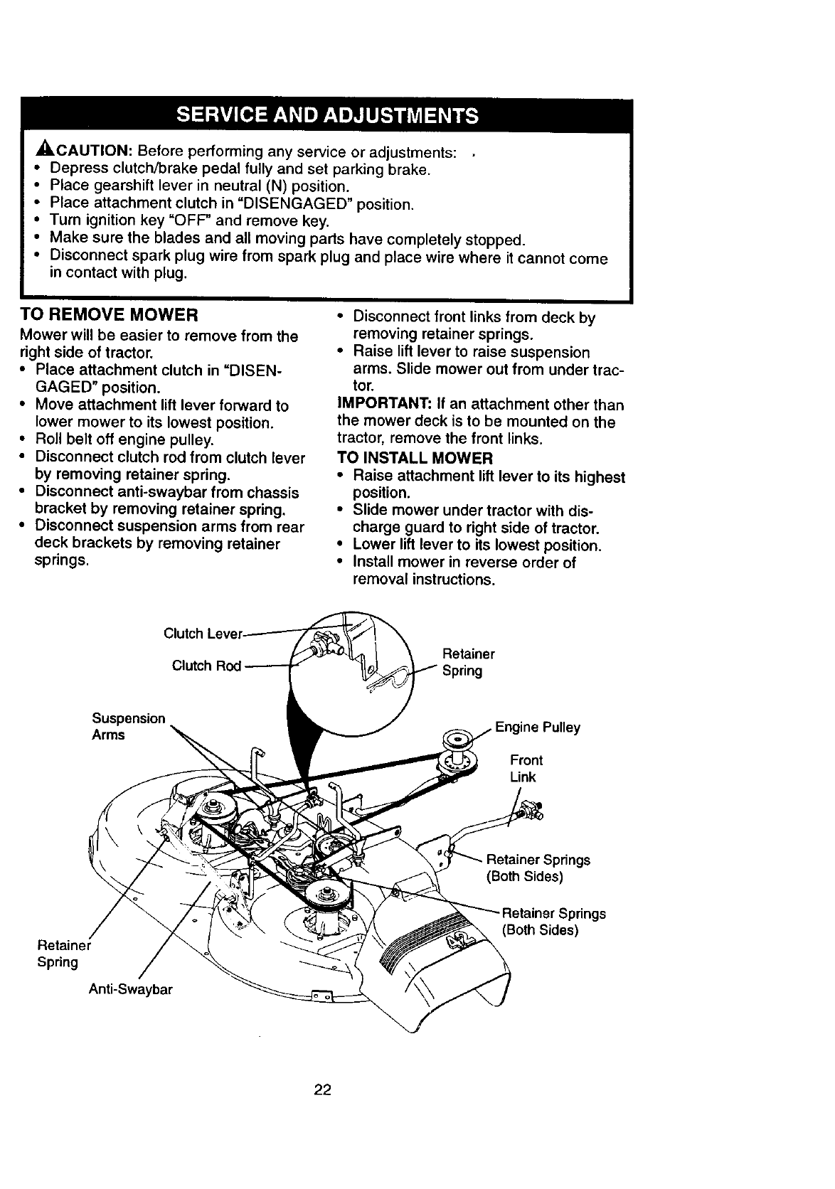
TO REMOVE MOWER
Mower will be easier to remove from the
right side of tractor.
•Place attachment clutch in "DISEN-
GAGED" position.
• Move attachment lift lever forward to
lower mower to its lowest position.
• Roll belt off engine pulley.
• Disconnect clutch rod from clutch lever
by removing retainer spring.
• Disconnect anti-swaybar from chassis
bracket by removing retainer spring.
• Disconnect suspension arms from rear
deck brackets by removing retainer
springs.
• Disconnect front links from deck by
removing retainer springs.
• Raise lift lever to raise suspension
arms. Slide mower out from under trac-
tor.
IMPORTANT: If an attachment other than
the mower deck is to be mounted on the
tractor, remove the front links.
TO INSTALL MOWER
• Raise attachment lift lever to its highest
position.
•Slide mower under tractor with dis-
charge guard to right side of tractor.
•Lower lift lever to its lowest position.
•Install mower in reverse order of
removal instructions.
Retainer
Suspension
Arms Engine Pulley
Front
Link
Retainer
Spring
Anti-Swaybar
(Both Sides)
Springs
(Both Sides)
22
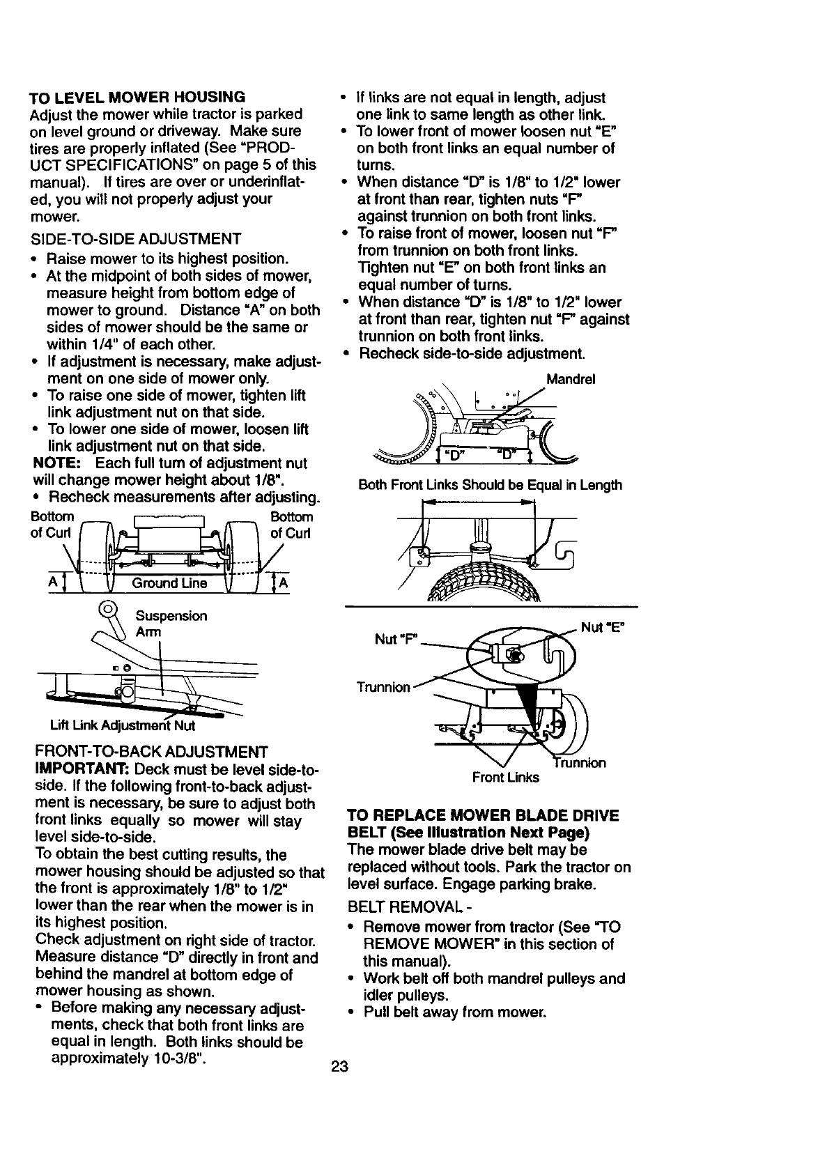
TO LEVEL MOWER HOUSING
Adjust the mower while tractor is parked
on level ground or driveway. Make sure
tires are properly inflated (See =PROD-
UCT SPECIFICATIONS" on page 5 of this
manual). If tires are over or underinflat-
ed, you will not properly adjust your
mower.
SIDE-TO-SIDE ADJUSTMENT
• Raise mower to its highest position.
• At the midpoint of both sides of mower,
measure height from bottom edge of
mower to ground. Distance "A" on both
sides of mower should be the same or
within 1/4" of each other.
•If adjustment is necessary, make adjust-
ment on one side of mower only.
•To raise one side of mower, tighten lift
link adjustment nut on that side.
•To lower one side of mower, loosen lift
link adjustment nut on that side.
NOTE: Each full tum of adjustment nut
will change mower height about 1/8".
•Recheck measurements after adjusting.
Bottom _Bottom
of Cu_Cud
XSuspension
FRONT-TO-BACK ADJUSTMENT
IMPORTANT: Deck must be level side-to-
side. If the following front-to-back adjust-
ment is necessary, be sure to adjust both
front links equally so mower will stay
level side-to-side.
To obtain the best cutting results, the
mower housing should be adjusted so that
the front is approximately 1/8" to 1/2"
lower than the rear when the mower is in
its highest position.
Check adjustment on right side of tractor.
Measure distance "D" directly in front and
behind the mandrel at bottom edge of
mower housing as shown.
•Before making any necessary adjust-
ments, check that both front links are
equal in length. Both links should be
approximately 10-3/8".
•If links are not equal in length, adjust
one link to same length as other link.
•To lower front of mower loosen nut "E"
on both front links an equal number of
turns.
•When distance "D" is 118Nto 1/2" lower
at front than rear, tighten nuts =P
against trunnion on both front links.
•To raise front of mower, loosen nut "P
from trunnion on beth front links.
"13ghten nut =E" on both front links an
equal number of turns.
•When distance =D" is 1/8" to 1/2" lower
at front than rear, tighten nut "P against
trunnion on both front links.
•Recheck side-to-side adjustment.
Mandrel
Both Front Links Should be Equal in Length
Nut "P Nut "E"
Front Links
TO REPLACE MOWER BLADE DRIVE
BELT (See IllustraUon Next Page)
The mower blade drive belt may be
replaced without tools. Park the tractor on
level surface. Engage parking brake.
BELT REMOVAL -
•Remove mower from tractor (See =TO
REMOVE MOWER" in this section of
this manual).
•Work belt off both mandrel pulleys and
idler pulleys.
•Pull belt away from mower.
23
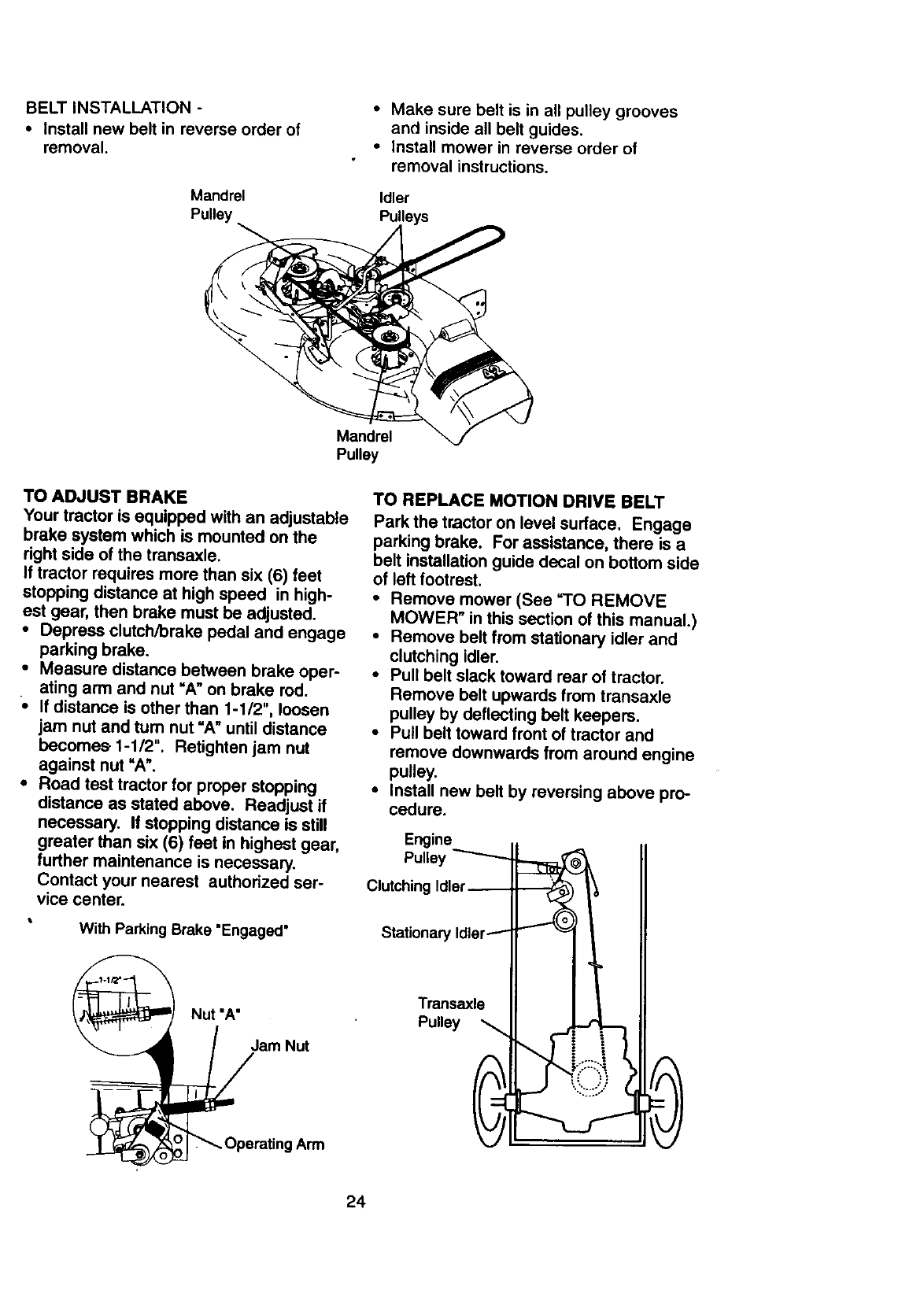
BELT INSTALLATION -
• Install new belt in reverse order of
removal.
Mandrel
Pulley
• Make sure belt is in all pulley grooves
and inside all belt guides.
• Install mower in reverse order of
removal instructions.
Idler
Pulleys
Mandrel
Pulley
TO ADJUST BRAKE
Your tractor is equipped with an adjustable
brake system which is mounted on the
right side of the transaxle.
If tractor requires more than six (6) feet
stopping distance at high speed in high-
est gear, then brake must be adjusted.
•Depress clutch/brake pedal and engage
parking brake.
•Measure distance between brake oper-
ating arm and nut =A"on brake rod.
•If distance is other than 1-1/2", loosen
jam nut and tum nut "A"until distance
becomes 1-1/2". Retighten jam nut
against nut "A".
•Road test tractor for proper stopping
distance as stated above. Readjust if
necessary. If stopping distance is still
greater than six (6) feet in highest gear,
further maintenance is necessary.
Contact your nearest authorized ser-
vice center.
• With Parking Brake "Engaged"
Nut "A"
/am Nut
_Operating Arm
TO REPLACE MOTION DRIVE BELT
Park the tractor on level surface. Engage
parking brake. For assistance, there is a
belt installation guide decal on bottom side
of left footrest.
•Remove mower (See "TO REMOVE
MOWER" in this section of this manual.)
•Remove belt from stationary idler and
clutching idler.
•Pull belt slack toward rear of tractor.
Remove belt upwards from transaxle
pulley by deflecting belt keepers.
•Pull belt toward front of tractor and
remove downwards from around engine
pulley.
•Install new belt by reversing above pro-
cedure.
Engine
Pulley
Clutching
Stationary
Transaxle
Pulley
24
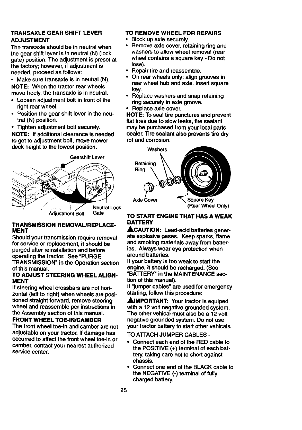
TRANSAXLE GEAR SHIFT LEVER
ADJUSTMENT
The transaxle should be in neutral when
the gear shift lever is !n neutral (N) (lock
gate) position. The adjustment is preset at
the factory; however, if adjustment is
needed, proceed as follows:
•Make sure transaxle is in neutral (N).
NOTE: When the tractor rear wheels
move freely, the transaxle is in neutral.
•Loosen adjustment bolt in front of the
right rear wheel.
•Position the gear shift lever in the neu-
tral (N) position.
• Tighten adjustment bolt securely.
NOTE: If additional clearance is needed
to get to adjustment bolt, move mower
deck height to the lowest position.
Gearshift Lever
TO REMOVE WHEEL FOR REPAIRS
•Block up axle securely.
•Remove axle cover, retaining ring and
washers to allow wheel removal (rear
wheel contains a square key -Do not
lose).
•Repair tire and reassemble.
•On rear wheels only: align grooves in
rear wheel hub and axle. Insert square
key.
•Replace washers and snap retaining
ring securely in axle groove.
•Replace axle cover.
NOTE: To seal tire punctures and prevent
flat tires due to slow leaks, tire sealant
may be purchased from your local parts
dealer. Tire sealant also prevents tire dry
rot and corrosion.
Washers
Retaining
Ring
f
/
• ....:..... Neutral Lock
Adjustment Bolt Gate
TRANSMISSION REMOVAL/REPLACE-
MENT
Should your transmission require removal
for service or replacement, it should be
purged after reinstallation and before
operating the tractor. See =PURGE
TRANSMISSION" in the Operation section
of this manual.
TO ADJUST STEERING WHEEL ALIGN-
MENT
If steering wheel crossbars are not hori-
zontal (left to right) when wheels are posi-
tioned straight forward, remove steedng
wheel and reassemble per instructions in
the Assembly section of this manual.
FRONT WHEEL TOE-IN/CAMBER
The front wheel toe-in and camber are not
adjustable on your tractor. If damage has
occurred to affect the front wheel toe-in or
camber, contact your nearest authorized
service center.
Axle Cover '_
(Rear Wheel Only)
TO START ENGINE THAT HAS A WEAK
BATrERY
ACAUTION: Lead-acid batteries gener-
ate explosive gases. Keep sparks, flame
and smoking matedals away from batter-
ies. Always wear eye protection when
around battedes.
If your battery is too weak to start the
engine, it should be recharged. (See
"BATTERY" in the MAINTENANCE sec-
tion of this manual).
If =jumper cables" are used for emergency
starting, follow this procedure:
AIMPORTANT: Your tractor Is equiped
with a 12 volt negative grounded system.
The other vehical must also be a 12 volt
negative grounded system. Do not use
your tractor battery to start other vehicals.
TO ATTACH JUMPER CABLES -
•Connect each end of the RED cable to
the POSITIVE (+) terminal of each bat-
tery, taking care not to short against
chassis.
•Connect one end of the BLACK cable to
the NEGATIVE (-) terminal of fully
charged battery.
25
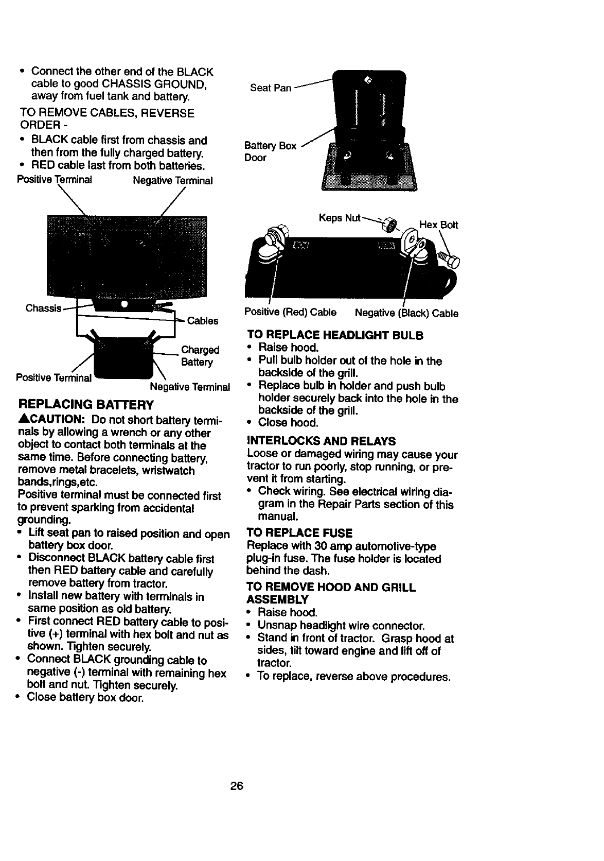
• Connect the other end of the BLACK
cable to good CHASSIS GROUND,
away from fuel tank and battery.
TO REMOVE CABLES, REVERSE
ORDER -
•BLACK cable first from chassis and
then from the fully charged battery.
•RED cable last from both batteries.
Positive Terminal Negative Terminal
Seat Pan
Battery Box
Door
Charged
Battery
Positive Terminal Negative Terminal
REPLACING BA'I'rERY
ACAUTION: Do not short battery termi-
nals by allowing a wrench or any other
object to contact both terminals at the
same time. Before connecting battery,
remove metal bracelets, wdstwatch
bands,rings,etc.
Positive terminal must be connected first
to prevent sparking from accidental
grounding.
• Lilt seat pan to raised position and open
battery box door.
•Disconnect BLACK battery cable first
then RED battery cable and carefully
remove battery from tractor.
•Install new battery with terminals in
same position as old battery.
•First connect RED battery cable to posi-
tive (+) terminal with hex bolt and nut as
shown. T_hten securely.
•Connect BLACK grounding cable to
negative (-) terminal with remaining hex
belt and nut. Tighten securely.
•Close battery box door.
Positive (Red) Cable Negative (Black) Cable
TO REPLACE HEADLIGHT BULB
•Raise hoed.
•Pull bulb holder out of the hole in the
backside of the grill.
•Replace bulb in holder and push bulb
holder securely back into the hole in the
backside of the grill.
•Close hood.
INTERLOCKS AND RELAYS
Loose or damaged wiring may cause your
tractor to run poorly, stop running, or pre-
vent it from starting.
•Check wiring. See electrical wiring dia-
gram in the Repair Parts section of this
manual.
TO REPLACE FUSE
Replace with 30 amp automotive-type
plug-in fuse. The fuse holder is located
behind the dash.
TO REMOVE HOOD AND GRILL
ASSEMBLY
•Raise hood.
•Unsnap headlight wire connector.
•Stand in front of tractor. Grasp hood at
sides, tilt toward engine and lilt off of
tractor.
•To replace, reverse above procedures.
26
Headlight
Wire Connector
ENGINE
Maintenance, repair, or replacement of the
emission control devices and systems,
which are being done at the customers
expense, may be performed by any non-
road engine repair establishment or indi-
vidual. Warranty repairs must be per-
formed by an authorized engine manufac-
turer's service outlet.
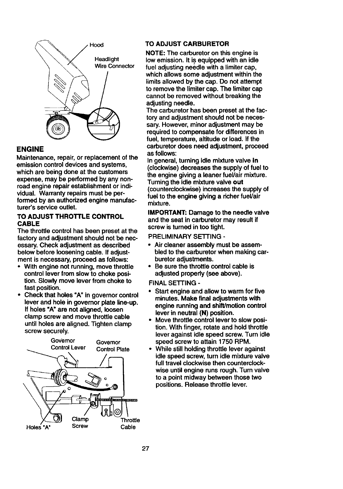
TO ADJUST THROTTLE CONTROL
CABLE
The throttle control has been preset at the
factory and adjustment should not be nec-
essary. Check adjustment as described
below before loosening cable. If adjust-
ment is necessary, proceed as follows:
• With engine not running, move throttle
control lever from slow to choke posi-
tion. Slowly move lever from choke to
fast position.
• Check that holes "A" in governor control
lever and hole in governor plate line-up.
If holes "A" are not aligned, loosen
clamp screw and move throttle cable
until holes are aligned. Tighten clamp
screw securely.
Go_iemor Governor
Control Lever Control Plate
\
TO ADJUST CARBURETOR
NOTE: The carburetor on this engine is
low emission. It is equipped with an idle
fuel adjusting needle with a limiter cap,
which allows some adjustment within the
limits allowed by the cap. Do not attempt
to remove the limiter cap. The limiter cap
cannot be removed without breaking the
adjusting needle.
The carburetor has been preset at the fac-
tory and adjustment should not be neces-
sary. However, minor adjustment may be
required to compensate for differences in
fuel, temperature, altitude or load. If the
carburetor does need adjustment, proceed
as follows:
In general, turning idle mixture valve in
(clockwise) decreases the supply of fuel to
the engine giving a leaner fuel/air mixture.
Turning the idle mixture valve out
(counterclockwise) increases the supply of
fuel to the engine giving a richer fuel/air
mixture.
IMPORTANT: Damage to the needle valve
and the seat in carburetor may result if
screw is turned in too tight.
PRELIMINARY SETI'ING -
•Air cleaner assembly must be assem-
bled to the carburetor when making car-
buretor adjustments.
•Be sure the throttle control cable is
adjusted propedy (see above).
FINAL SE'I-rlNG -
•Start engine and allow to warm for five
minutes. Make final adjustments with
engine running and shift/motion control
lever in neutral (N) position.
•Move throttle control lever to slow posi-
tion. With finger, rotate and hold throttle
lever against idle speed screw. Turn idle
speed screw to attain 1750 RPM.
•While still holding throttle lever against
idle speed screw, turn idle mixture valve
full travel clockwise then counterclock-
wise until engine runs rough. Tum valve
to a point midway between those two
positions. Release throttle lever.
Clamp Throttle
Holes "A" Screw Cable
27
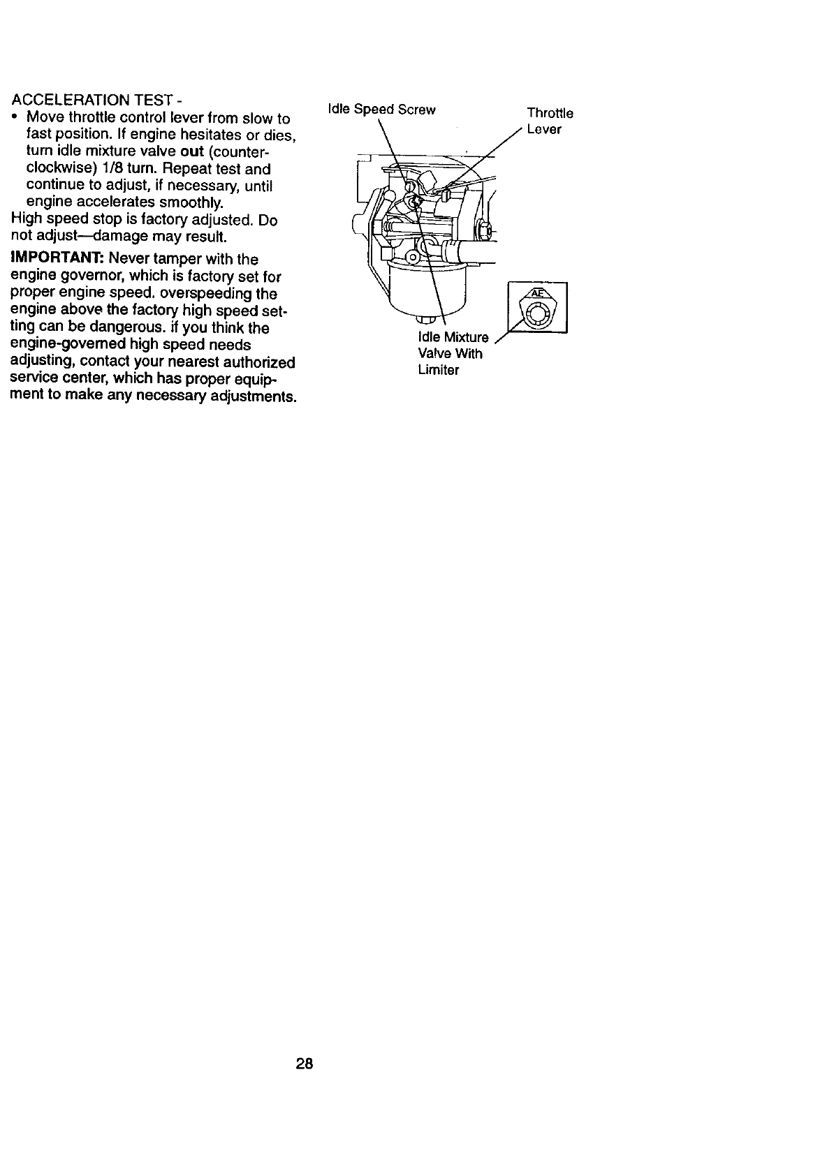
ACCELERATION TEST -
• Move throttle control lever from slow to
fast position. If engine hesitates or dies,
turn idle mixture valve out (counter-
clockwise) 1/8 turn. Repeat test and
continue to adjust, if necessary, until
engine accelerates smoothly.
High speed stop is factory adjusted. Do
not adjust--damage may result.
IMPORTANT: Never tamper with the
engine governor, which is factory set for
proper engine speed, overspeeding the
engine above the factory high speed set-
ting can be dangerous, if you think the
engine-governed high speed needs
adjusting, contact your nearest authorized
service center, which has proper equip-
ment to make any necessary adjustments.
Idle Speed Screw Throttle
dl ixtur
Valve With
Limiter
28
Immediatelyprepareyourtractorfor stor-
age at theend of theseasonor if thetrac-
tor will notbeusedfor 30 daysor more.
_,CAUTION: Never store the tractor with
gasoline in the tank inside a building
where fumes may reach an open flame or
spark. Allow the engine to cool before stor-
ing in any enclosure.
TRACTOR
Remove mower from tractor for winter
storage. This will allow you to clean it thor-
oughly. Remove all dirt, grease, leaves,
etc. Store in a clean, dry area.
• Clean entire tractor (See "CLEANING"
in the Maintenance section of this manu-
al).
• Inspect and replace belts, if necessary
(See belt replacement instructions in the
Service and Adjustments section of this
manual).
• Lubricate as shown in the Maintenance
section of this manual.
• Be sure that all nuts, bolts and screws
are securely fastened. Inspect moving
parts for damage, breakage and wear.
Replace if necessary.
• Touch up all rusted or chipped paint sur-
faces; sand lightly before painting.
BATTERY
• Fully charge the battery for storage.
• After aperiod of time in storage, battery
may require recharging.
•To help prevent corrosion and power
leakage during long pedods of storage,
battery cables should be disconnected
and battery cleaned thoroughly (see "TO
CLEAN BAI-rERY AND TERMINALS" in
the Maintenance section of this manual).
•After cleaning, leave cables disconnect-
ed and place calbes where they cannot
come in contact with battery terminals.
•If battery is removed from tractor for
storage, do not store battery directly on
concrete or damp surfaces.
ENGINE
FUEL SYSTEM
IMPORTANT: It is important to prevent
gum deposits from forming in essential
fuel system parts such as carburetor, fuel
filter, fuel hose, or tank during storage.
Also, experience indicates that alcohol
blended fuels (called gasohol or using
ethanol or methanol) can attract moisture
which leads to separation and formation of
acids during storage. Acidic gas can dam-
age the fuel system of an engine while in
storage.
• Drain the fuel tank.
• Start the engine and let it run until the
fuel lines and carburetor are empty.
• Never use engine or carburetor cleaner
products in the fuel tank or permanent
damage may occur.
• Use fresh fuel next season.
NOTE: Fuel stabilizer is an acceptable
alternative in minimizing the formation of
fuel gum deposits during storage. Add sta-
bilizer to gasoline in fuel tank or storage
container. Always follow the mix ratio
found on stabilizer container. Run engine
at least 10 minutes after adding stabilizer
to allow the stabilizer to reach the carbure-
tor. Do not drain the gas tank and carbure-
tor if using fuel stabilizer.
ENGINE OIL
Drain oil (with engine warm) and replace
with clean engine oil. (See "ENGINE" in
the Maintenance section of this manual).
CYLINDER(S)
•Remove spark plug(s).
•Pour one ounce of oil through spark
plug hole(s) into cylinder(s).
•Turn ignition key to "START" position for
a few seconds to distribute oil.
•Replace with new spark plug(s).
OTHER
•Do not store gasoline from one season
to another.
•Replace your gasoline can if it starts to
rust. Rust and/or dirt in your gasoline
will cause problems.
•If possible, store your tractor indoors
and cover it to give protection from dust
and dirt.
•Cover your tractor with a suitable pro-
tective cover that does not retain mois-
ture. Do not use plastic. Plastic cannot
breathe, which allows condensation to
form and cause your tractor to rust.
IMPORTANT: Never cover tractor while
engine and exhaust areas are still warm.
29
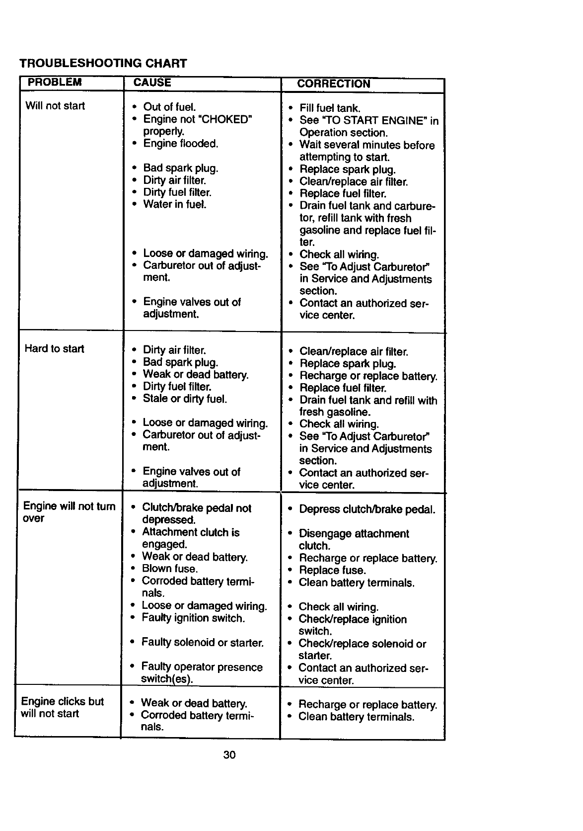
TROUBLESHOOTING CHART
PROBLEM
Will not start
Hard to start
Engine will not turn
over
Engine clicks but
will not start
CAUSE
•Out of fuel. •
•Engine not =CHOKED"
properly.
•Engine flooded. •
•Bad spark plug. •
• Dirty air filter. •
•Dirtyfuel filter. •
•Water in fuel. °
•Loose or damaged wiring. •
•Carburetor out of adjust- •
ment.
•Engine valves out of °
adjustment,
•Dirty air filter. •
•Bad spark plug. •
•Weak or dead battery. •
• Dirty fuel filter. •
•Stale or dirty fuel. •
•Loose or damaged wiring. •
•Carburetor out of adjust- •
ment.
•Engine valves out of
adjustment,
•Clutch/brake pedal not •
depressed.
•Attachment clutch is •
engaged,
•Weak or dead battery. •
•Blown fuse. •
•Corroded battery termi- °
nals.
•Loose or damaged wiring. •
•Faulty ignition switch. •
•Faulty solenoid or starter. °
•Faulty operator presence •
switch(es).
•Weak or dead battery. •
•Corroded battery termi- •
nals.
CORRECTION
Fillfuel tank.
See "TO START ENGINE" in
Operation section.
Wait several minutes before
attempting to start.
Replace spark plug.
Clean/replace air filter.
Replace fuel filter.
Drain fuel tank and carbure-
tor, refill tank with fresh
gasoline and replace fuel fil-
ter.
Check all wiring.
See "To Adjust Carburetor"
in Service and Adjustments
section.
Contact an authorized ser-
vice center.
Clean/replace air filter.
Replace spark plug,
Recharge or replace battery.
Replace fuel filter.
Drain fuel tank and refill with
fresh gasoline.
Check all wiring.
See "To Adjust Carburetor"
in Service and Adjustments
section.
Contact an authorized ser-
vice center.
Depress clutch/brake pedal.
Disengage attachment
clutch.
Recharge or replace battery.
Replace fuse.
Clean battery terminals.
Check all wiring.
Check/replace ignition
switch.
Check/replace solenoid or
starter.
Contact an authorized ser-
vice center.
Recharge or replace battery.
Clean battery terminals.
3O
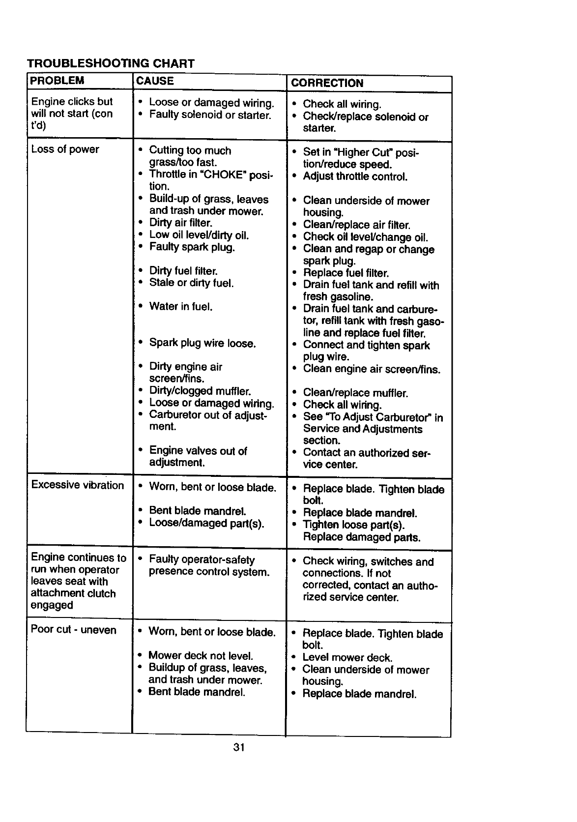
TROUBLESHOOTING CHART
PROBLEM CAUSE CORRECTION
Engineclicksbut •Loose or damaged wiring. •Check all wiring.
will not start (con • Faulty solenoid or starter. • Check/replace solenoid or
I'd) starter.
Loss of power •Set in "Higher Cut" posi-
tion/reduce speed.
•Adjust throttle control.
•Cutting too much
grass/too fast.
I•Throttle in =CHOKE _ posi-
tion.
•Build-up of grass, leaves
and trash under mower.
•Dirty air filter.
•Low oil level/dirty oil.
•Faulty spark plug.
•Dirty fuel filter.
•Stale or dirty fuel.
•Water in fuel.
•Spark plug wire loose.
•Dirty engine air
screen/fins.
•Dirty/clogged muffler.
•Loose or damaged wiring.
•Carburetor out of adjust-
ment.
•Engine valves out of
adjustment.
Excessive vibration *Worn, bent or loose blade.
•Bent blade mandrel.
•Loose/damaged part(s).
Engine continues to
run when operator
leaves seat with
attachment clutch
engaged
•Faulty operator-safety
presence control system.
Poor cut -uneven *Worn, bent or loose blade.
=• Mower deck not level.
•Buildup of grass, leaves,
and trash under mower.
•Bent blade mandrel.
•Clean underside of mower
housing.
•Clean/replace air filter.
•Check oil level/change oil.
•Clean and regap or change
spark plug.
•Replace fuel filter.
•Drain fuel tank and refill with
fresh gasoline.
•Drain fuel tank and carbure-
tor, refill tank with fresh gaso-
line and replace fuel filter.
•Connect and tighten spark
plug wire.
•Clean engine air screen/fins.
• Clean/replace muffler.
•Check all wiring.
•See "To Adjust Carburetor" in
Service and Adjustments
section.
• Contact an authorized ser-
vice center.
•Replace blade. Tighten blade
bolt.
•Replace blade mandrel.
• Tighten loose part(s).
Replace damaged parts,
•Check wiring, switches and
connections. If not
corrected, contact an autho-
rized service center.
•Replace blade. Tighten blade
bolt.
•Level mower deck.
•Clean underside of mower
housing.
•Replace blade mandrel.
31
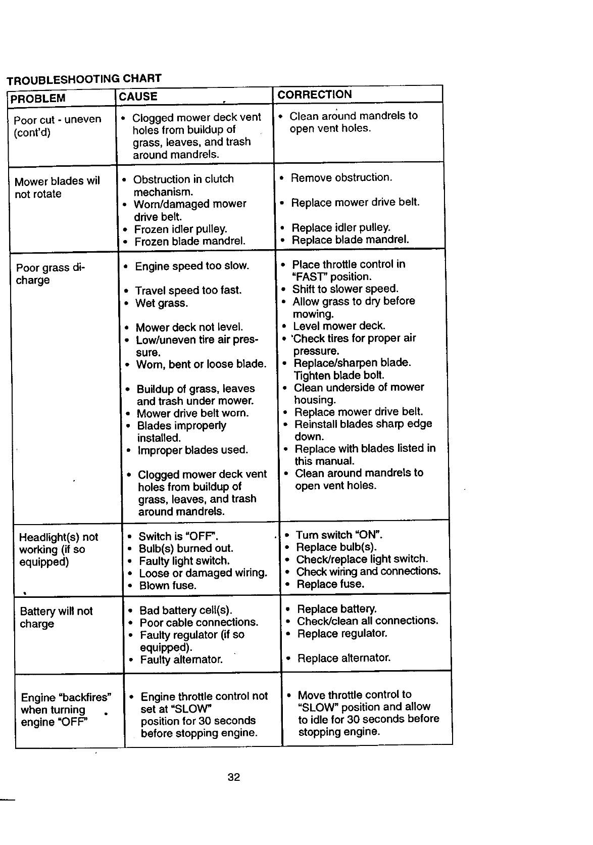
TROUBLESHOOTINGCHART
_ROBLEM CAUSE r
Poor cut -uneven
(cont'd)
Mower blades wil
not rotate
Poor grass di-
charge
Headlight(s) not
working (if so
equipped)
Battery will not
charge •
Engine "backfires"
when turning
engine =OFF"
• Clogged mower deck vent
holes from buildup of
grass, leaves, and trash
around mandrels.
• Obstruction in clutch
mechanism.
• Worn/damaged mower
drive belt.
•Frozen idler pulley.
• Frozen blade mandrel.
• Engine speed too slow.
• Travel speed too fast.
• Wet grass.
I°Mower deck not level.
• Low/uneven tire air pres-
sure.
Worn, bent or loose blade.
Buildup of grass, leaves
and trash under mower.
Mower drive belt worn.
Blades improperly
installed.
Improper blades used.
Clogged mower deck vent
holes from buildup of
grass, leaves, and trash
around mandrels.
Switch is "OFF".
Bulb(s) burned out.
Faulty light switch.
Loose or damaged wiring.
Blown fuse.
Bad battery cell(s).
Poor cable connections.
Faulty regulator (if so
equipped).
Faulty alternator.
Engine throttle control not
set at "SLOW"
position for 30 seconds
before stopping engine.
CORRECTION
• Clean around mandrels to
open vent holes.
• Remove obstruction.
• Replace mower drive belt.
•Replace idler pulley.
• Replace blade mandrel.
• Place throttle control in
"FAST" position.
I°Shift to slower speed.
• Allow grass to dry before
mowing.
•Level mower deck.
•'Check tires for proper air
pressure.
•Replace/sharpen blade.
Tighten blade bolt.
•Clean underside of mower
housing.
•Replace mower drive belt.
• Reinstall blades sharp edge
down.
• Replace with blades listed in
this manual.
• Clean around mandrels to
open vent holes.
•Turn switch =ON".
• Replace bulb(s).
• Check/replace light switch.
•Check wiring and connections.
•Replace fuse.
• Replace battery.
• Check/clean all connections.
•Replace regulator.
• Replace alternator.
Move throttle control to
"SLOW" position and allow
to idle for 30 seconds before
stopping engine.
32
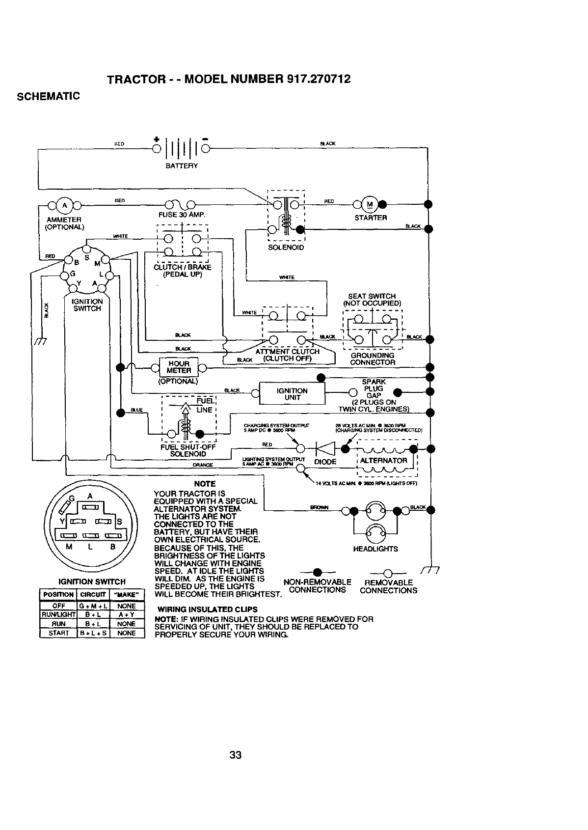
SCHEMATIC
TRACTOR --MODEL NUMBER 917,270712
BA'fTERY
AMMETER
(OPTIONAL)
W_TE
FUSE 30 AMP.
L ....... J
CLUTCH /BRAKE
(PEDAL UP)
i I
I RED
=_S_LE_ _1.= STARTER
_ACK
D
t
SEAT SWITCH
I....... J (NOT OCCUPIED)
i
BLUE
IGNITION SWITCH
POSITIONICIRCUIT "MAKE"
I
OFF G+M+L NONE
RUi_t_IGHT B+ L A +Y
RUN B+ L NONE
START B + L+ S NONE
LINE
FUEL SHUT-OFF
SOLENOID J
NOTE
YOUR TRACTOR IS
EQUIPPED WITH ASPECIAL
ALTERNATOR SYSTEM.
THE LIGHTS ARE NOT
CONNECTED TO THE
BATTERY, BUT HAVE THEIR
OWN ELECTRICAL SOURCE.
BECAUSE OF THIS, THE
BRIGHTNESS OF THE LIGHTS
WILL CHANGE WITH ENGINE
SPEED. AT IDLE THE LIGHTS
WILL DIM. AS THE ENGINE IS
SPEEDED UP, THE LIGHTS
•SPARK
,GNmON
UNIT PLUGS ON
]_NIN CYI-. ENGINES)
(_ARGING SYSTI_M(_ITFIJT 2B_I_TSACMIN a36001_'_1
3 AMP DC •3600 RPM (CHARGING SysTI_M (_SCONNECTED)
R_.O I i
L_TmSYSTE_r_n tALTERNATOR =
s_Ac e_oePa DIODE =
......... J
_14 V_I_TS AC MIN Q3EGO FIPM ILINS (_T)
HEADLIGHTS
NON-REMOVABLE REMOVABLE
WILL BECOME THEIR BRIGHTEST. CONNECTIONS CONNECTIONS
WIRING INSULATED CUPS
NOTE: IF WIRING INSULATED CLIPS WERE REMOVED FOR
SERVICING OF UNIT, THEY SHOULD BE REPLACED TO
PROPERLY SECURE YOUR WIRING.
33
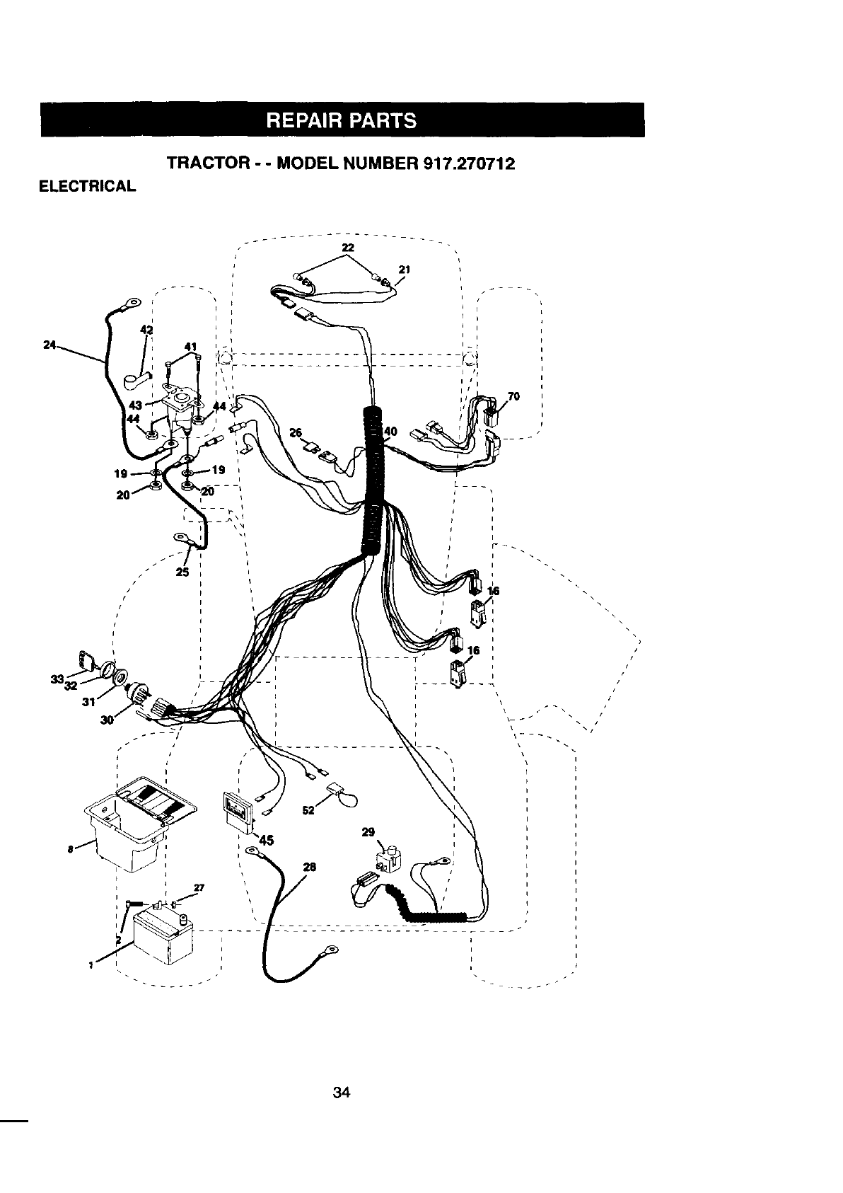
ELECTRICAL
TRACTOR - - MODEL NUMBER 917.270712
I
26
I
I
I
I
I
I
I
k
l
\
I I
i I
I
i
34

ELECTRICAL
TRACTOR - - MODEL NUMBER 917.270712
KEY PART
NO. NO. DESCRIPTION
1144925 Battery 12 VOLT 25 AMP
2 74760412 BoltHex Hd 1/4-20unc x 3/4
8 156417 Case Battery
16 153664 Switch,InterlockPush-In
19 STD551125 Washer Lock 114
20 73350400 NutJam Hex 1/4-20 Unc
21 166182 Harness Asm Iight W/4152j
22 4152J BulbLight#1156
24 4799J Cable Battery 6 Ga 11" red
25 146147 Cable Battery 6 Ga w/16 wire red
26 166180 Fuse 15AMP
27 73510400 Nut, Keps Hex 1/4-20 UNC
28 4207J Cable Ground 6 Ga 12" black
29 121305X SwitchPlunger Nc Gray
30 140301 SwitchIgn 4 Pos
31 124211X Nut Ignition
32 141226 Cover Sw Key BIk 1 25 Text SLT
33 109310X Key Ign MoldedCraftsman
40 166145 Harness Ign
41 71110408 Bolt BIk. Fin Hex 1/4.20 Unc x 1/2
42 131563 Cover Terminal Red
43 145673 Solenoid
44 73640400 Nut Keps BIkHex 1/4-20 Unc
45 121433X Ammeter Rectangular6 Amp
52 141940 ProtectionWire Loop
70 166659 Harness Engine
NOTE: Allcomponentdimensionsgive in U.S.
1 inch = 25.4 mm
35
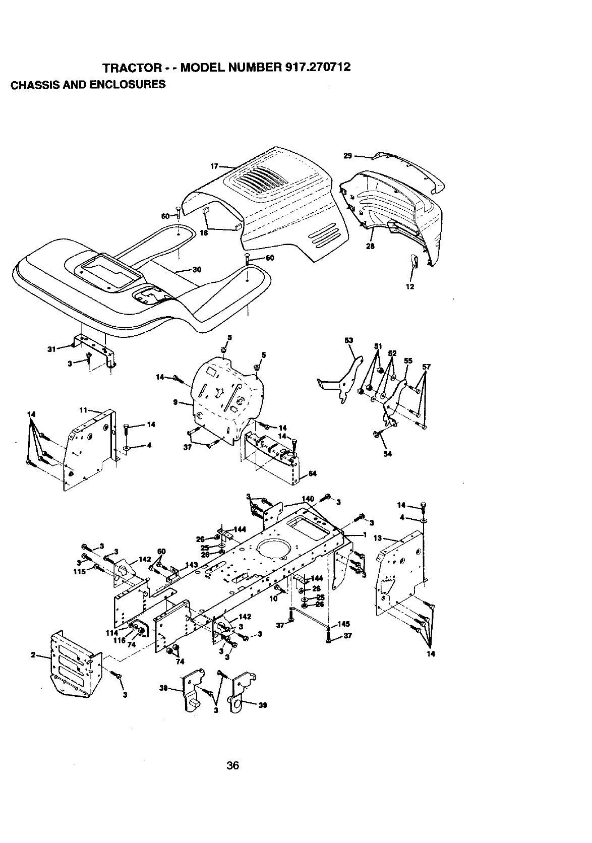
TRACTOR o - MODEL NUMBER 917.270712
CHASSIS AND ENCLOSURES
14
31
5
54
14
36
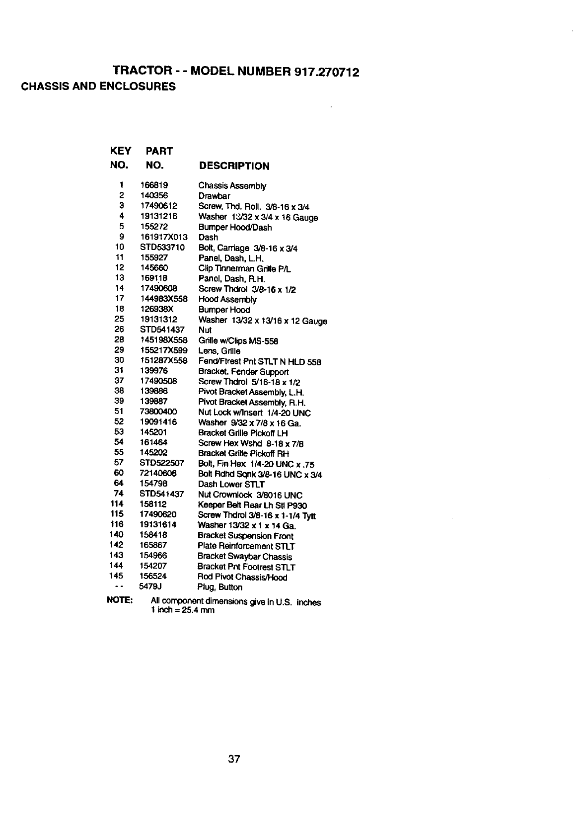
TRACTOR - - MODEL NUMBER 917.270712
CHASSIS AND ENCLOSURES
KEY PART
NO. NO. DESCRIPTION
1 166819
2 140356
3 17490612
4 19131216
5155272
9 161917X013
10 STD533710
11 155927
12 145660
13 1691,18
14 17490608
17 144983X558
18 126938X
25 19131312
26 STD541437
23 145198X558
29 155217X599
30 151287X558
31 139976
37 17490508
38 139886
39 139887
51 738OO4OO
52 19091416
53 14.r_?.01
54 161464
55 145202
57 STD522507
60 721406O6
64 154798
74 STD541437
114 158112
115 17490620
116 19131614
140 158418
142 165867
143 154966
144 154207
145 156524
- - 54793
NOTE:
ChassisAssembly
Drawbar
Screw,Thd. Roll. 3,'8-16x 3/4
Washer 13732x 3/4 x 16 Gauge
Bumper Hood/Dash
Dash
Bolt,Carriage 3/8-16 x3/4
Panel, Dash, LH.
Clip"rinnermanGdlleP/L
Panel, Dash, R.H.
Screw Thdrol 3/8-16 x 1/2
HoodAssembly
Bumper Hood
Washer 13/32 x 13/16 x 12 Gauge
Nut
Gdllew/Clips MS-558
Lees, Gdne
FancVFtrestPntSTLT N HLD 558
Bracket,Fender Support
ScrewThdrol 5/16-18 x 1/2
P_VOtBracketAssembly,L.H.
Pivot BracketAssembly, R.H.
Nut Lock w/Insert 1/4-20 UNC
Washer 9/32 x 7/8 x 16 Ga.
Bracket GdUePickoffLH
Screw Hex Wshd 8-18 x 7/8
BracketGdlle PickoffRH
Bolt, FinHex 1/4-20 UNC x .75
Bolt RdlxI Sqnk 3/8-16 UNC x 3/4
Dash Lower STLT
NUtCrownlook 3/8016 UNC
Keeper BeltRear Lh StlP930
Screw Thdml 3/8-16 x 1-1/4 Tytt
Washer 13/32 x 1 x 14 Ga.
BracketSuspensionFront
Plate ReinforcementSTLT
BracketSwaybar Chassis
BracketPnt Footrest STLT
Rod PivotChassis/Hood
Plug, Button
Allcomponentdimensionsgive In U.S, inches
1 inch= 25.4 mm
37
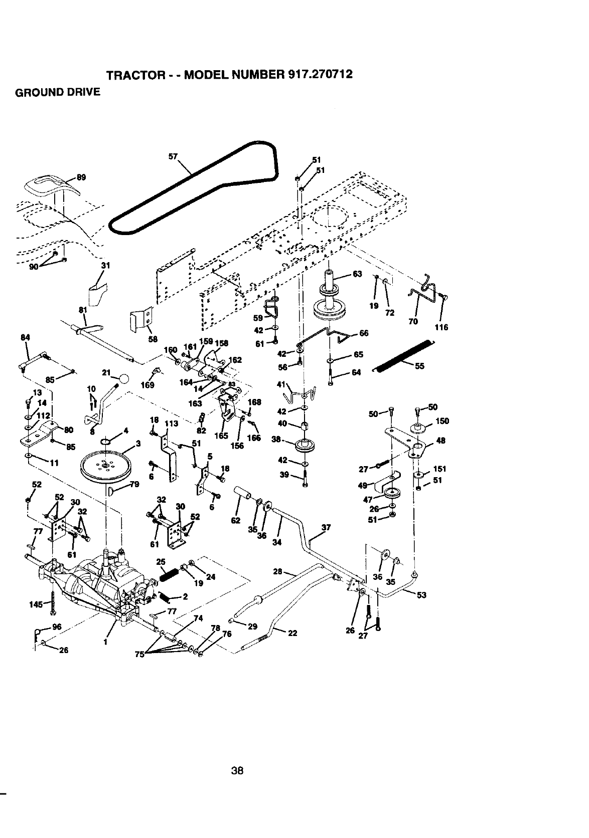
TRACTOR - - MODEL NUMBER 917.270712
GROUND DRIVE
57
50-"_ 150
48
2_ 151
51
37
25 27
38
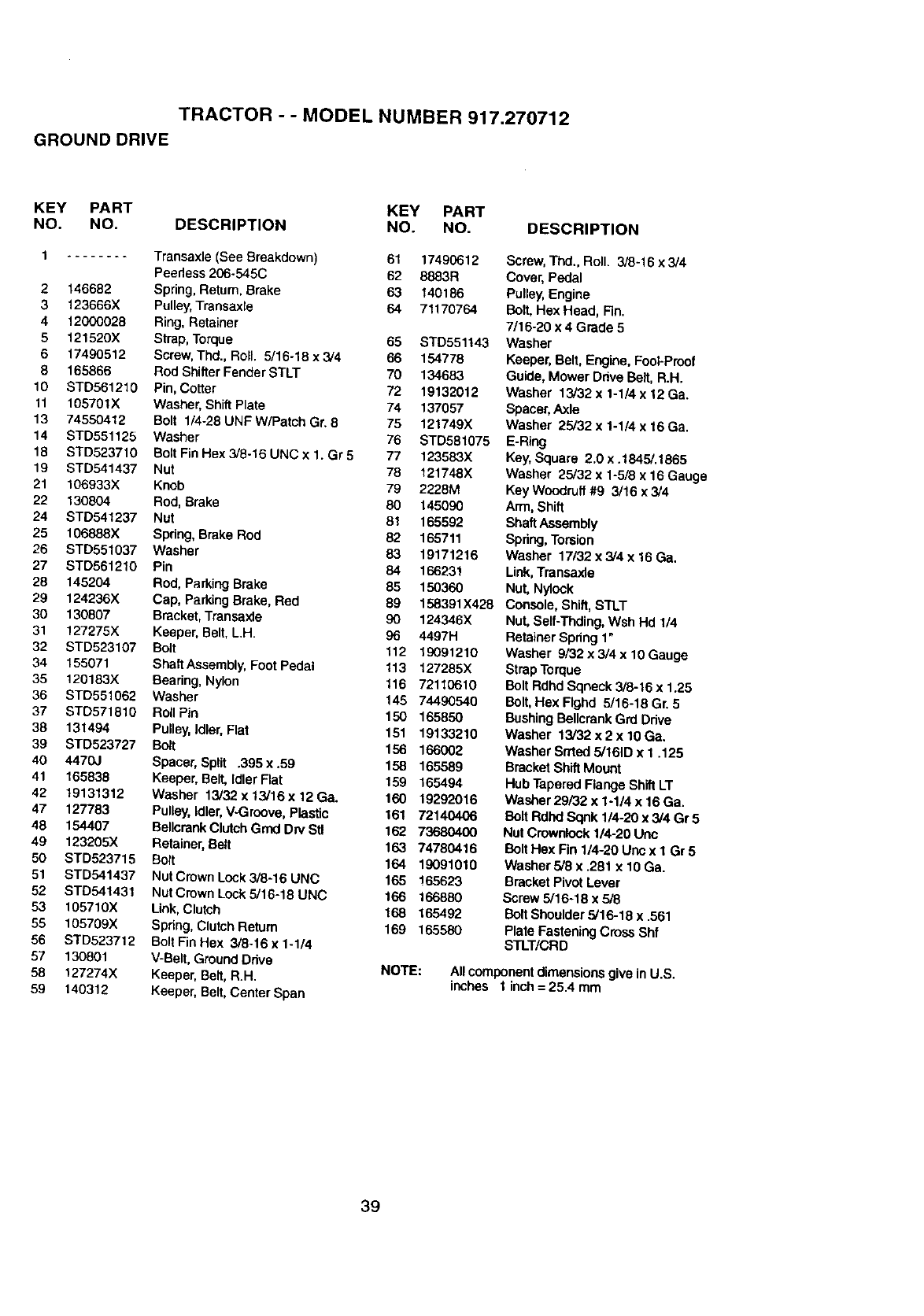
TRACTOR - - MODEL NUMBER 917.270712
GROUND DRIVE
KEY PART KEY PART
NO. NO. DESCRIPTION NO. NO.
1........ Transaxle (See Breakdown) 61 17490612
Peedass 206-545C 62 8883R
2 146682 Spring, Return, Brake 63 140186
3 123666X Pulley, Transaxle 64 71170764
4 12000028 Ring, Retainer
5 121520X Strap, Torque 65 STD551143
617490512 Screw, Thd., ROll. 5/16-18 x 3/4 66 154778
8 165866 Rod ShifterFender STLT 70 134683
10 STD561210 Pin, Cotter 72 19132012
11 105701X Washer, Shift Plate 74 137057
13 74550412 Bolt 1/4-28 UNFW/Patch Gr. 8 75 121749X
14 STD551125 Washer 76 STD581075
19 STD523710 Bolt Fin Hex 3/8-16 UNC x 1. Gr 5 77 123583X
19 STD541437 Nut 78 121748X
21 106933X Knob 79 2228M
22 130804 Rod, Brake 80 145090
24 STD541237 Nut 81 165592
25 106888X Spring, Brake Rod 82 165711
26 STD551037 Washer 83 19171216
27 STD561210 Pin 84 166231
2B 145204 Rod, ParkingBrake 85 150360
29 124236X Cap, Parking Brake, Red 89 158391X428
30 130807 Bracket, Transaxle 90 124346X
31 127275X Keeper, Belt, L.H. 96 4497H
32 STD523107 Bolt 112 19091210
34 155071 ShaitAssembly, Foot Pedal 113 127285X
35 120183X Beadng, Nylon 116 72110610
36 STD551062 Washer 145 74490540
37 STD571810 Roll Pin 150 165850
38 131494 Pulley,Idler, Flat 151 19133210
39 STD523727 Bolt 156 166002
40 4470J Spacer, Split .395x.59 158 165589
41 165838 Keeper, Belt, tdterFlat 159 165494
42 19131312 Washer 13/32x13/16x12Ge. 160 19292016
47 127783 Pulley, Idler, V-Groove, Plastic 161 72140406
48 154407 Bellcrank ClutchGrod Dn/Stl 162 73680400
49 123205X Retainer, Belt 163 74780416
50 STD523715 Bolt 164 19091010
51 STD541437 Nut Crown Lock3/8-16 UNC 165 165623
52 STD541431 NutCrownLockS/16-18UNC 166 166BB0
53 105710X Link, Clutch 168 165492
55 105709X Spdng, Clutch Return 169 165580
56 STD523712 Bolt Fin Hex 3/8.16 x 1-1/4
57 130801 V-Belt, Ground Ddve NOTE:
58 127274X Keeper, Belt, R.H.
59 140312 Keeper, Belt, Center Span
DESCRIPTION
Screw, rod., Roll. 3/8.16 x3/4
Cover, Pedal
Pulley,Engine
Bolt, Hex Head, Fin.
7/16-20 x 4 Grade 5
Washer
Keeper, Belt, Engine,Fool-Proof
Guide, Mower Ddve Belt, R.H.
Washer 13/32 x1-114x 12 Ga.
Spacer,Axle
Washer 25/32 x 1-1/4 x 16 Ga.
E-Ring
Key,Square 2.0 x .1845/.1865
Washer 25/32 x 1-5/Bx 16 Gauge
Key Woodruff#9 3/16 x 3/4
Arm, Shift
ShaftAssembly
Spdng, Torsion
Washer 17/32 x 3/4 x 16 Ga,
Link,Transaxle
Nut, Nytock
Console, Shift,STLT
Nut, Self-Thding, Wsh Hd 1/4
Retainer Spdng 1"
Washer 9/32 x 3/4 x 10 Gauge
StrapTorque
Bolt Rdhd Sqneck 3/8-16 x 1.25
Bolt,Hex Ftgb.d 5/16-18 Gr. 5
BushingBellcrankGrd Ddve
Washer 13/32 x 2 x 10 Ga.
Washer Srrted 5/161D x 1.125
Bracket ShiftMount
Hub Tapered Flange Shift LT
Washer 29/32 x 1-1/4 x 16 Ga.
Bolt Rdhd Sqnk 1/4-20 x3/4 Gr5
Nut Crownlock1/4-20 Unc
BoltHex Fin 1/4-20 Uric x I Gr 5
Washer 5/8 x ,281 x 10 Ga.
Bracket Pivot Lever
Screw 5/16-18 x5/8
Bolt Shoulder 5/16-18 x .561
Plate Fastening Cross Shf
STLT/CRD
Allcomponent dimensions give in U.S.
inches I inch = 25.4 mm
39
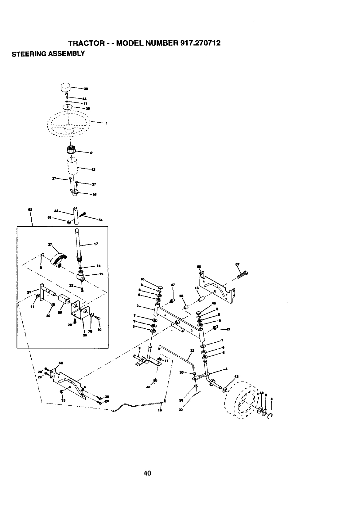
TRACTOR - - MODEL NUMBER 917.270712
STEERING ASSEMBLY
/• i • +
_'_41
i
_.+÷s
I
u
g
13
4O
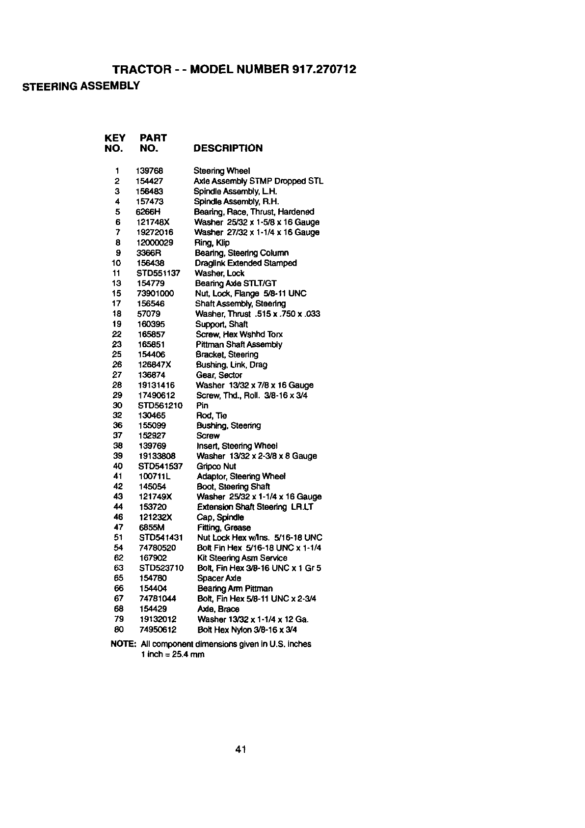
TRACTOR - - MODEL NUMBER 917.270712
STEERING ASSEMBLY
KEY PART
NO. NO. DESCRIPTION
1 139768
2 154427
3 156483
4 157473
5 6266H
6 121748X
7 19272016
8 12000029
9 3366R
10 156438
11 STD551137
13 154779
15 73901O00
17 156546
18 57079
19 160395
22 165857
23 165851
25 154406
26 126847X
27 136874
28 19131416
29 17490612
30 STD561210
32 130465
36 155099
37 152927
38 139769
39 19133808
40 STD541537
41 100711L
42 145054
43 121749X
44 153720
46 121232X
47 6855M
51 S'FD541431
54 74780520
62 167902
63 STD523710
65 154780
66 154404
67 74781044
68 154429
79 19132012
80 74950612
SteeringWheel
AxleAssembly STMP Dropped STL
SpindleAssembly,LH.
SpindleAssembly,R.H.
Beadng, Race, Thrust, Hardened
Washer 25/32 x 1-5/8 x 16 Gauge
Washer 27/32 x 1-1/4 x 16 Gauge
Ring, Klip
Beadng, SteeringColumn
DraglinkExtendedStamped
Washer, Lock
BeadngAxle STLTIGT
Nut, Lock, Flange 5/8-11 UNC
ShaftAssembly,Steering
Washer,Thrust .515 x ,750 x .033
Support,Shaft
Screw, Hex Wshhd Torx
Pittman ShaftAssembly
Bracket, Steering
Bushing,Link, Drag
Gear, Sector
Washer 13/32 x 7/8 x 16 Gauge
Screw, Thd., Roll. 3/8-16 x 3/4
Pin
Rod,_e
Bushing,Steering
Screw
Insert, SteeringWhsel
Washer 13/32 x 2-3/8 x 8 Gauge
GripcoNut
Adaptor,SteeringWheel
Boot, SteeringShaft
Washer 25/32 x 1-1/4 x 16 Gauge
Extension ShaftSteering LR.LT
Cap, Spindle
Fitting,Grease
Nut Lock Hex wflns, 5/16-18 UNC
Bolt FinHex 5/16-18 UNC x 1-1/4
Kit SteeringAsm Service
Bolt, Fin Hex 3/8-16 UNC x 1 Gr 5
Spacer Axle
BearingArm Pittman
Bolt,Fin Hex 5/8-11 UNC x 2-3/4
Axis, Brace
Washer 13/32 x 1-1/4 x 12Ga.
Bolt Hex Nylon3/8-16 x 3/4
NOTE: All componentdimensionsgiven in U.S. inches
1inch = 25.4 mm
41
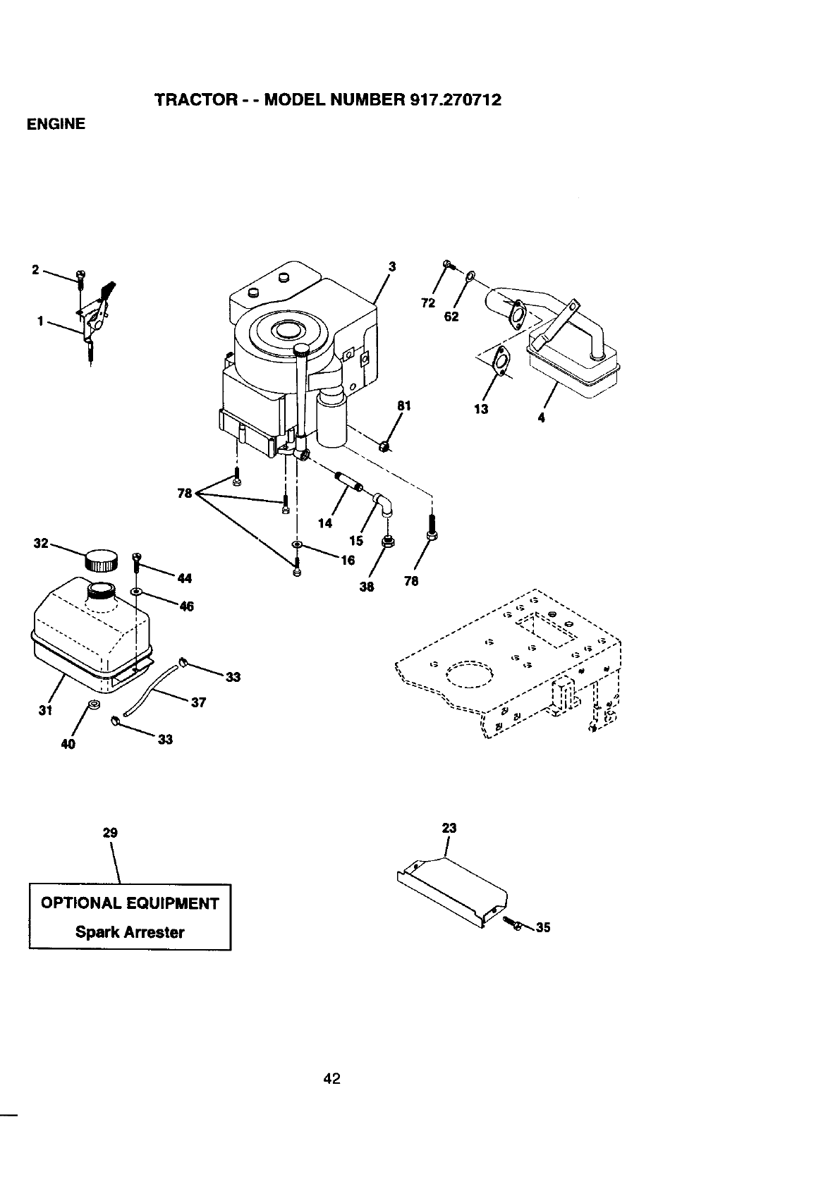
ENGINE
TRACTOR - - MODEL NUMBER 917.270712
3
72
81
62
13 4
78q
37
38 78
29
OPTIONAL EQUIPMENT
Spark Arrester
23
/
42
ENGINE TRACTOR - - MODEL NUMBER 917.270712
KEY PART
NO. NO.
1 162157
2 17720410
3
4 137352
13 165291
14 13280324
15 13200300
16 STD551237
23 159880
29 137180
31 109202X
32 15899O
33 123487X
35 17490512
37 137040
38 .......
40 124028X
44 17490412
46 19091416
62 STD551131
72 71070512
78 17490620
81 128861
DESCRIPTION
Control,Throttle/Choke
Screw, Hex Head, Thread Cutting1/4-20 x 5/8
Engine,B&S, (See Breakdown)No. 311707, Type No. 0132-E1
Muffler
Gasket, Exhaust
Nipple, Pipe 3/8 NPT x 3
Elbow, Standard 90 °, 3/8-18 NPT
Washer
Shield,Brn/Dbr Guard
Arrestor,Spark
Tank, Fuel
CapAssembly,Fuel Tank, Vented
Clamp, Hose
Screw Thdrol5/16-18 x 3-4 Tyt
line, Fuel
Plug, Oil Drain (Order From Engine Manufacturer)
Bushing,Snap, Fuel Une
Screw, Hex Washer Head, TIxI., Roll. 1/4-20 x 3/4
Washer 9/32 x 718 x 16 Gauge
Washer, Lock
Screw,Hex Cap Head 5/16-18 x 3/4
Screw, Thd., Roll. 3/8-16 x 1-1/4
Nut Range 114.20Starter Nut
NOTE: Allcomponentdimensionsgivenin U.S. inches
1 inch = 25.4 mm
43
TRACTOR - - MODEL NUMBER 917.270712
SEAT ASSEMBLY
KEY
NO.
41
2
3
4
5
6
7
8
9
10
11
12
PART KEY PART
NO. DESCRIPTION NO. NO. DESCRIPTION
140123 Seat 13 121248X BushingSnap BIkNy150 Id
140551 BracketPnt PivotSeat (bik) 14 72050412 BoltRdhdSht Nk 1/4-20x1-1/2
STD523710 Bolt FinHex 3/6-16unc X 1 15 134300 Spacer Split28 X 96 Zinc
19131610 Washer 13/32 X 3/4 X 10 Ga 16 121250X SpringCprsn 1 27 BIk Pnt
145006 Clip Push In Hinged 17 123976X Nut Lock 1/4 Lge FigGr 5 Zinc
STD541437 Nut He)( Lock w/lns 3/8-16 Unc 21 153236 BoltShoulder5/16-18 Unc-2A
124181X SpringSeat Cprsn2 250 BIk Zi 22 STD541431 Nut Hex Lock w/Ins 5/16-18
17490616 Screw Thdrol3/6-16 X 1Ty-tt 24 19171912 Washer 17/32 X 1-3/16 X 12 Ga.
19131614 Washer 13/32 X 1 X 14 Ga 25 127018X BoltShoulder5/16-18 X 62
155925 Pan Pnt Seat (blk)
• 166369 Knob Seat NOTE: All component dimensionsgiven in U.S. inch-
121246X oBracketPnt Mounl_ngSwitch esl inch = 25.4 mm
44
DECALS
TRACTOR - - MODEL NUMBER 917.270712
9
13 6 3 4 5
13 10
2O
21 8
\
12
KEY
NO. PART
NO.
1 156368
2 165406
3 163200
4 163202
5 167178
6 133644
8 166887
9 163204
10 156439
12 146046
KEY PART
DESCRIPTION NO. NO.
Decal, Oper. Instr. 13 163254
Decal, Hp Engine 14 160396
Deus$,Hood, R.H. 20 149516
Decal, Hood, L.H. 21 163207
Decal, Replacement Srs -- 138311
Decal, Customer Maintenance - - 154515
Decal, Deck EZ3 - - 154516
Oeca$,Fender, Craftsman - - 169208
Decal, Fender Danger - - 169209
Decal, V-Belt Drive Schematic
DESCRIPTION
Decal, Dash Panel B&S
Decal, V-Belt Schematic
Decal Battery Dngr/Psn Eng
Decal, Fender Sd. Wht
Decal, LiftHandle
Pad FootrestLH STLT
Pad FootrestRH STLT
Owner's Manual, Eng$=,sh
Owners Manual, Spanish
WHEELS & TIRES
4,10
11
KEY PART
NO. NO.
1 59192
2 65139
3 106222X
4 59904
8
9
10
11
..
NOTE:
45
106732X427
278H
9040H
106108X427
122082X
7152J
1_7_X
144334
DESCRIPTION
Valve Cap, l_re
Stem, Valve
1]re, Front
Tube, Front1]re
(Not Provided,Service Item
Only)
Rim, Front
F_ng, Grease (FrontWheel
Only)
Bearing,Flange(Front Wheel
Only)
Rim, Rear
1ire, Rear
Tube, Rear 1]re
(Not Provided,Service Item
only)
Cap,/ude
Sealant, "fire10 oz.
AllcomponentdimensionsgivenInU.S. inches
1 inch = 25.4 mm
TRACTOR -- MODEL NUMBER 917.270712
LIFT ASSEMBLY
27
25 2423
7
5
13
13
49
3O
3\
/18
i/
I I'
2O 20
46
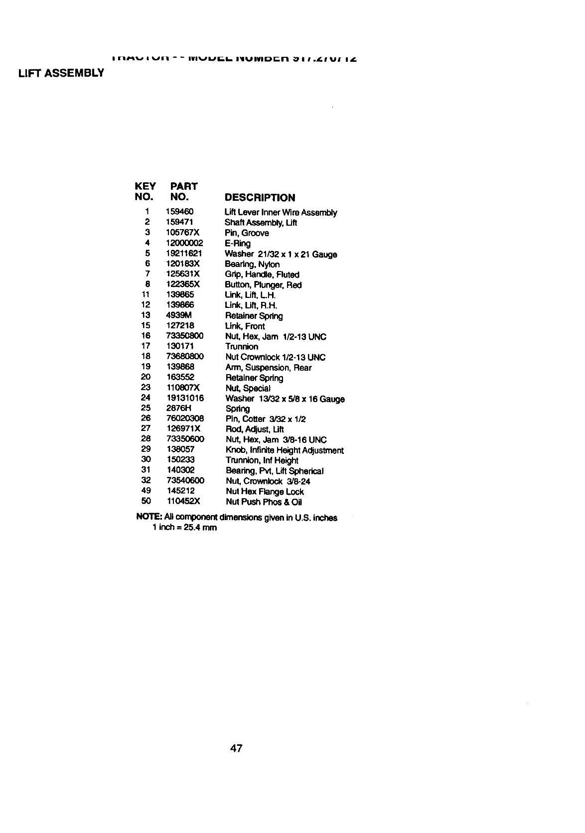
I FI/'lli,,o I _JI1 - - IVIVUI[._6 i_llUiVli_Fmrl _1 Il.L.I UI If.
LIFT ASSEMBLY
KEY PART
NO. NO. DESCRIPTION
1 159460 Lift Lever Inner Wire Assernbty
2 159471 ShaftAssembly,Lift
3 105767X Pin, Groove
4 12000002 E-Ring
5 19211621 Washer 21132 x 1 x 21 Gauge
6 120183X Bearing,Nylon
7 125631X Grip, Handle, Fluted
8 122365X Button,Plunger,Red
11 139865 Link, Lift,LH.
12 139866 Link, Lift, R.H.
13 4939M Retainer Spnng
15 127218 Link, Front
16 7335C800 Nut, Hex, Jam 1/2-13 UNC
17 130171 Trunnion
18 73680800 Nut CrownlockI/2-13 UNC
19 139868 Arm, Suspension,Rear
20 163552 Retainer Spring
23 110807X Nut, Special
24 19131016 Washer 13/32 x 5/8 x 16 Gauge
25 2876H Spring
26 76020308 Pin, Cotter 3/32 x 1/2
27 126971X Rod, Adjust,Lift
28 73350600 Nut, Hex, Jam 3/8-16 UNC
29 138057 Knob, InfiniteHeightAdjustment
30 150233 Trunnion,Inf Height
31 140302 Bearing, Pvt, Lift Spherical
32 73540600 Nut, Crowniock 3/8-24
49 145212 Nut Hex Flange Lock
50 110452X Nut Push Phos & Oil
NOTE: All componentdimensionsgiven in U.S. inches
1 inch = 25.4 mm
47
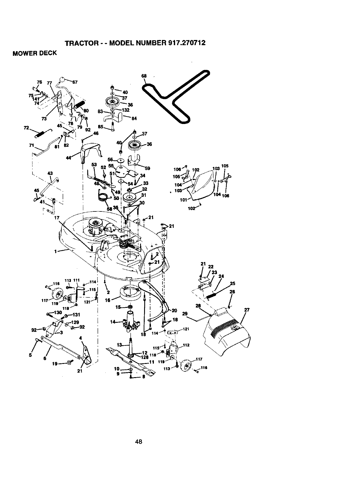
TRACTOR - - MODEL NUMBER 917.270712
MOWER DECK
76
73
106_, 102 _10310S
5
21 22
324
\26
27
48
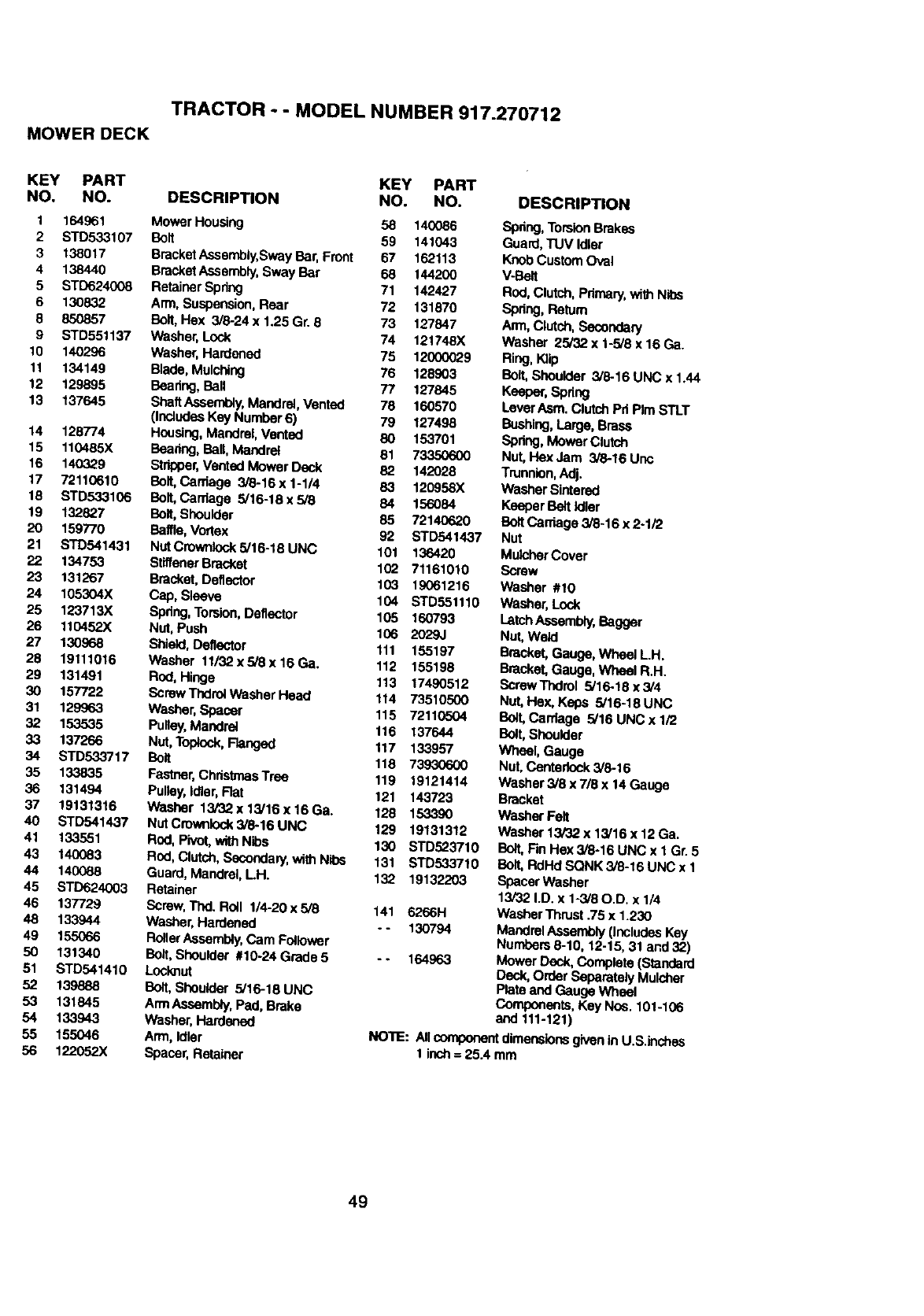
TRACTOR --MODEL NUMBER 917.270712
MOWER DECK
KEY PART KEY PART
NO. NO. DESCRIPTION NO. NO.
1 164961 Mower Housing 58 140086
2 STD533107 Bolt 59 141043
3 138017 BracketAssembly,Sway Bar, Front 67 162113
4 138440 BracketAssembly,Sway Bar 68 144200
5 STD624008 Retainer Spring 71 142427
6 130832 Arm, Suspension, Rear 72 131870
8 850857 Bolt,Hax 3/6-24 x 1.25 Gr. 8 73 127847
9 STD551137 Washer, Lock 74 121748X
10 140296 Washer, Hardened 75 12000029
11 134149 Bade, Mulching 76 128903
12 129895 Baadng, Ball 77 127845
13 137645 ShaftAssembly,Mandrel, Vented 78 160570
(IncludesKey Number 6) 79 127498
14 128774 Housing,Mandrel, Vented 80 153701
15 110485X Bearing,Ball,Mandrel 81 73350600
16 140329 Strtaper,Vented Mower Deck 82 142028
17 72110610 Bolt,Carriage 3/8-16x 1-1/4 83 120958X
18 STD533106 Balt, Canlage 5/16-18x5/8 84 156084
19 132827 Bolt,Shoulder 85 72140620
20 159770 Baffle, Vortex 92 STD541437
21 STD541431 Nut Crownlock5/16-18 UNC 101 136420
22 134753 StltfenerBracket 102 71161010
23 131267 Bracket, Deflector 103 19061216
24 105304X Cap, Sleeve 104 STD551110
25 123713X Spring,Torsior_,Deflector 105 160793
26 110452X Nut, Push 106 2029J
27 130968 Shield,Denoctor 111 155197
28 19111016 Washer 11/32xs/8x16Ga. 112 155198
29 131491 Rod, Hinge 113 17490512
30 157722 Scraw Thdtel washer Head 114 73510500
31 129963 Washer, Spacer 115 72110504
32 153535 Pulley, Mandrel 116 137644
33 137266 NUt, Toplock,Flanged 117 133957
34 STD533717 Bolt 118 73930600
35 133835 Fastner,ChristmasTme 119 19121414
36 131494 Pulley,idler, Rat 121 143723
37 19131316 Washer 13/32x13/16x16Ga. 128 153390
40 STD541437 NutCrownlock3/6-16UNC 129 19131312
41 133551 Rnd, Pivot, withNibs 130 STD523710
43 140083 Rod, Clutch,Secondary,with Nibs 131 STD533710
44 140088 Guard, MaP,drel, LH. 132 19132203
45 STD624003 Retainer
46 137729 Screw, Thd. ROlt 1/4-20 x 5/8 141 6266H
48 133944 Washer, Hardened - - 130794
49 155066 RollerAssembly,Cam Follower
50 131340 Bolt, Shoulder #1024Grade5 -. 164963
51 STD541410 Locknut
52 139888 Bolt, Shoulder 5/16-18 UNC
53 131845 ArmAssembly,Pad, Brake
54 133943 Washer, Hardened
55 155046 Arm, Idler
56 122052X Spacer, Retainer
DESCRIPTION
Spring, TorsionBrakes
Guard, TUV td_er
KnobCustom Oval
V-Bait
Rod,Clutch, Primary,withNibs
Spring, Return
Arm,Clutch,Secondan/
Washer 25/32 x 1-5/8 x 16 Ga.
Ring,K_
Bolt,Shoulder 5/8-16 UNC x 1.44
Keeper,Spring
Lever Asm. Clutch Pd PIm STLT
Bushing,Large, Brass
Spring, Mower Clutch
Nut, I-laxJam 3/8-16 Unc
Trunnion,Adj.
Washer Sintered
Keeper Belt idler
BoltCawlage 3/8-16 x 2-1/2
Nut
Mulcher Cover
Screw
Washer #10
Washer, Lock
Latch Aseambly,Bagger
Nut, Weld
Bracket, Gauge, Wheel L.H.
Bracket, Gauge, Wheel R.H.
ScrewTndml 5/16-13 x3/4
Nut, Hex, Kaps 5/16-18 UNC
Belt, Carriage 5/16 UNC x 1/2
Bolt,Shoulder
Wheel, Gauge
Nut, Centedock3/6-16
Washer 3/8 x 7/8 x 14 Gauge
Bracket
Washer Felt
Washer 13/32 x 13/16 x 12 Ga.
B_t, F'mHex 3_-16 UNC x 1 Gr. 5
Bolt,RdHd SQNK 3/8-16 UNC x 1
Spacer Washer
13/32 I.D. x 1-3/80.D. x 1/4
Washer "rhrust.75 x 1.230
Mandrel Assembly (IncludesKey
Numbers 8-10, 12-15, 31 and 32)
Mower Deck, Complete (Standard
Deck, Order Separately Mulsher
Plate and Gauge Wheal
Components, Key Nea. 101-106
and 111-121)
NO'RE: Allcomponentdimensionsgiven in U.S.inches
1lach= 25.4 mm
49
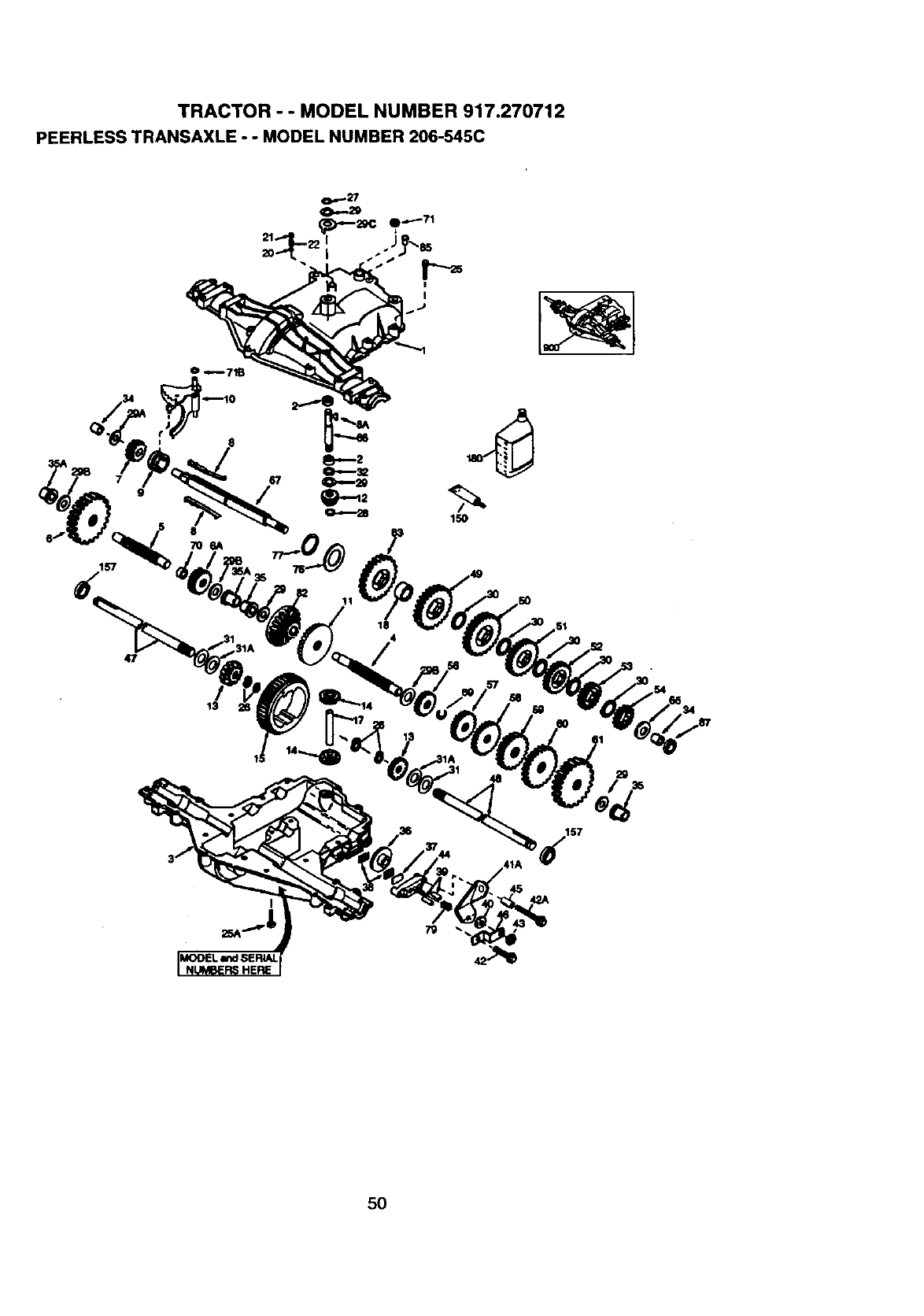
TRACTOR - - MODEL NUMBER 917.270712
PEERLESS TRANSAXLE - -MODEL NUMBER 206-545C
I
8
11
150
47
13
41A 57
5O
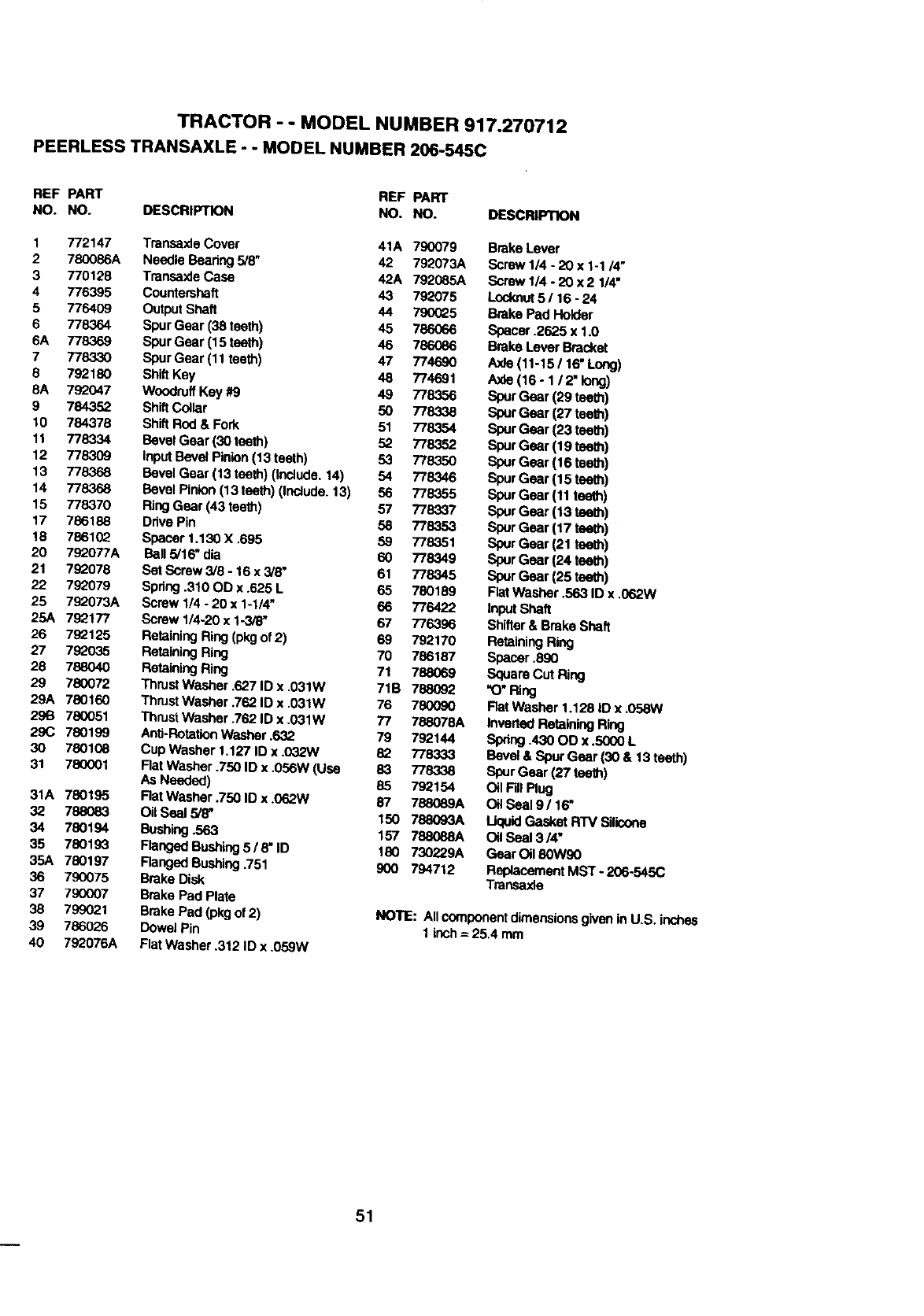
TRACTOR - - MODEL NUMBER 917.270712
PEERLESS TRANSAXLE - - MODEL NUMBER 206-545C
REF PART REF PART
NO. NO. DESCRIPTION NO. NO. DESCRIPTION
1 772147 TransaxleCover 41A 790079
2 780086A Needle Bearing 5/6, 42 792073A
3 770128 Transaxla Case 42A 792085A
4 776395 Countershaft 43 792075
5 776409 Output Shaft 44 790025
6 778364 Spur Gear (38 teeth) 45 786066
6A 778369 Spur Gear (15 teeth) 46 786086
7 7783,30 Spur Gear (11 teeth) 47 774690
8 792180 ShiftKey 48 774691
5A 792047 Woodruff Key #9 49 778356
9 784352 Shift Coalar 50 778338
10 784378 Shift Rod & Fork 51 778354
11 778334 Bevel Gear (30 teeth) 52 778352
12 778309 Input Bevel Pinion(13 teeth) 53 778350
13 778368 Bevel Gear (13 teeth) (include. 14) 54 778346
14 778368 Bevel Pinion (13 teeth) (Include. 13) 56 778355
15 778370 RingGear (43 teeth) 57 778337
17 786188 Drive Pin 50 778353
18 786102 Spacer 1.130 X .695 59 778351
20 792077A Bell 5/16" dia 60 778349
21 79_078 Set Screw 3/8 - 16 x 3/8" 61 778345
22 792079 Spdng .310 OD x .625 L 65 780189
25 792073A Screw 1/4 -20 x 1-1/4" 66 776422
25A 792"177 Screw 1/4-20 x 1-3/8" 67 776396
26 792125 Retaining Ring (pkgof 2) 69 792170
27 792035 Retaining Ring 70 786187
28 788040 Retaining Ring 71 788069
29 780072 Thrust Washer .627 ID x ,031W 71B 788092
29A 780160 ThrustWasher .762 ID x .031W 76 780090
29B 780051 Thrust Washer .762 ID x .031W 77 788078A
2gC 780199 Anti-RotationWasher .632 79 792144
30 780108 Cup Washer 1.127 ID x .032W 82 778333
31 780001 FlatWasher .750 ID x .056W (Use 83 778338
As Needed) 85 792154
31A 780195 FiatWasher .750 ID x .062W 87 788089A
32 788083 Oit Seal 5/8" 150 788093A
34 780194 Bushing.563 157 788088A
35 780193 Flanged Bushing5 /8" ID 180 730229A
35A 780197 Flanged Bushing.751 900 794712
36 790075 Brake Disk
37 790007 Brake Pad Plate
38 799021 Brake Pad (pkg of 2)
39 786026 Dowel Pin
40 792076A Flat Washer .312 ID x .059W
BrakeLever
Scraw 1/4- 20 x 1-1/4"
Screw 1/4 - 20 x 2 1/4"
Leeknut5 /16 - 24
Brake Pad Holder
Spacer .2625 x 1.0
Brake Lever Bracket
A)de(11-15 /16" Long)
Axle (16- 1 /2" long)
Spur Gear (29 teeth)
SpurGear (27 teeth)
SpurGear (23 teeth)
SpurGear (19 teeth)
SpurGear (16 teeth)
Spur Gear (15 teeth)
Spur Gear (11 teeth)
Spur Gear (_3 teeth)
Spur Gear (17 tee_)
Spur Gear (21 teeth)
Spur Gear (24 tea_)
Spur Gear (25 tea_)
Fiat Washer .563 ID x .062W
Input Shaft
SNfter & Brake Shaft
Retaining Ring
Spacer .8gO
Square Cut Ring
"O"Ring
Rat Washer 1.128 |D x .058W
InvertedRetaining Ring
Spring.430 OO x.5000 L
Bevel & Spur Gear (30 & 13 teeth)
Spur Gear (27 teeth)
Oil Fill Plug
Oil Soal9/16"
Uqu_dGasket RW S'_
Oil Seal 3/4"
Gear Oil 80W90
Replacement MST - 206-545C
Transe)de
NOTE: All componentdimensionsgivenin U.S. inches
1 kP,,h= 25.4 mm
51
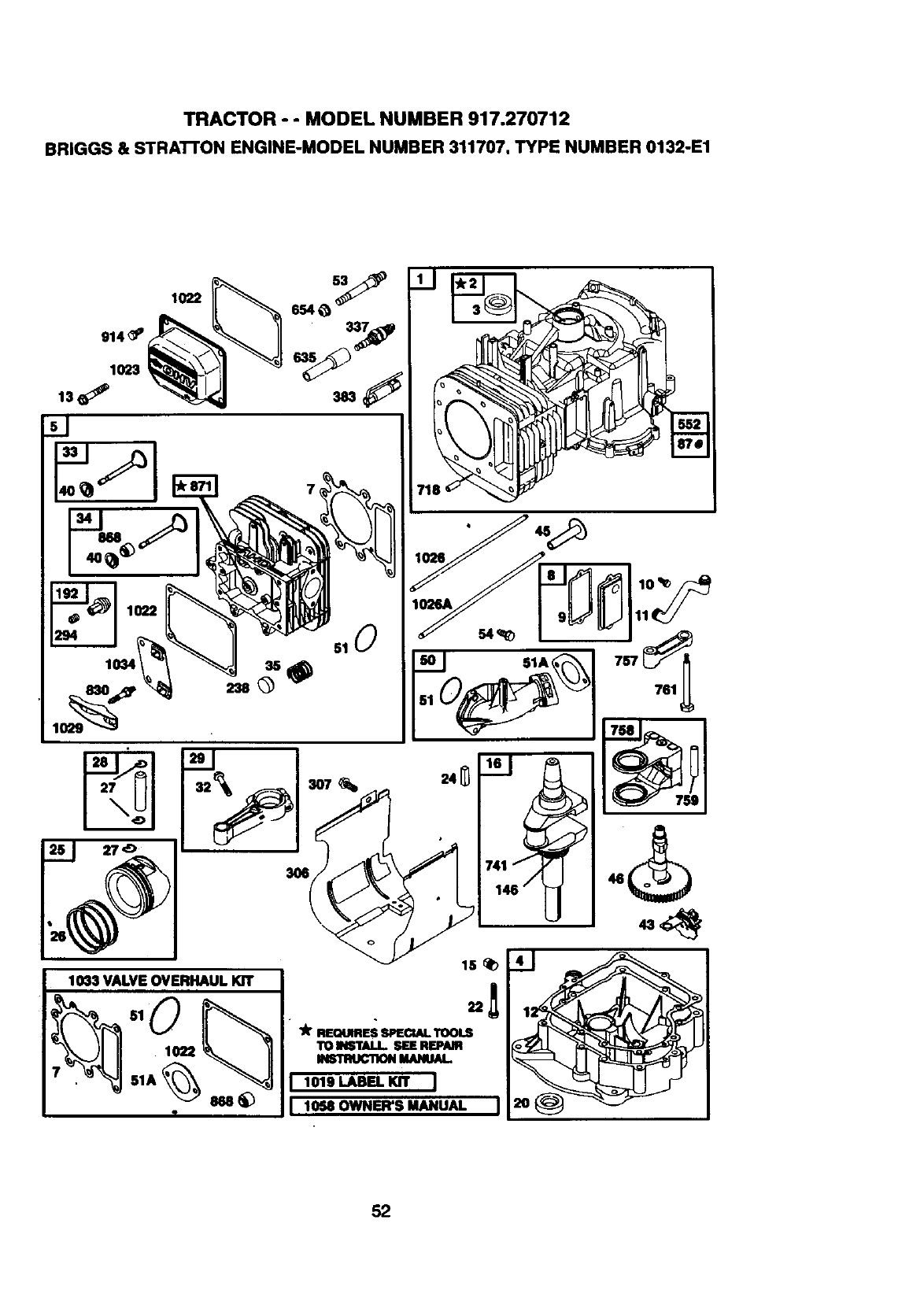
TRACTOR - - MODEL NUMBER 917.270712
BRIGGS & STRA'I-rON ENGINE-MODEL NUMBER 311707, TYPE NUMBER 0132-E1
914_
1023
13J
27 32
1033 VALVEOVERHAUL lOT
3O6
15
•k REGimES SPECU_LTOOLS
TOINSTALL.SEEREPAm
_MANUAL
1019 LABEL KIT
I1058 OWNER'S MANUAL
52
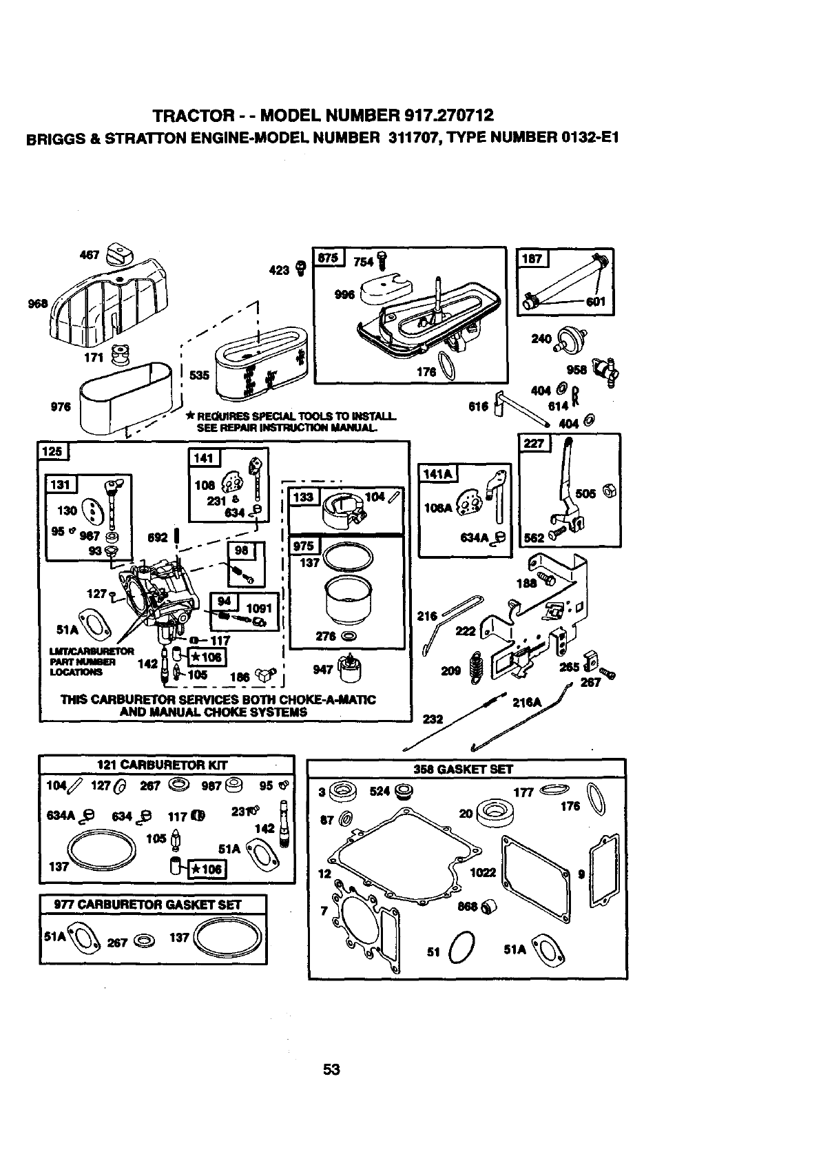
TRACTOR - - MODEL NUMBER 917.270712
BRIGGS& STRAI"FONENGINE-MODELNUMBER 311707,TYPENUMBER0132-E1
467
i535 176
976 , . _'_4rREOUIRESSPECIALTOOLSTOINSTALL.
_" SEEREPAIRINSTTWCllONIdANUAI..
137 9
121 CARBURETOR KIT
104_ 127# 267 _987_ 95
.4A_ .4_ .70 23_
_--_ 105 6$1A _'_
I977 CARBURETOR GASKET SET I
SIA_ 267 _) 13701
358 GASKET SET
_r_ 51 051A
53
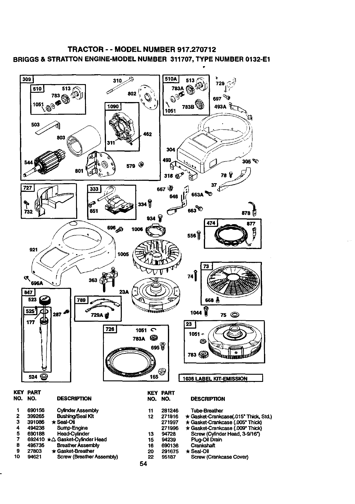
TRACTOR - - MODEL NUMBER 917.270712
BRIGGS& STRATTONENGINE-MODELNUMBER 311707,TYPENUMBER0132-E1
921
2r/_
524 I 1036 LABEL KIT-EMISSION I
KEY PART
NO. NO. DESCRIPTION KEY PART
NO. NO. DESCRIPTION
1 690156 CylinderAseambly
2 399265 Bushing/Seallot
3 391086 _Seal-Oil
4 494238 SumlPEngine
5 690188 Head-Cylinder
7 692410 -kA Gasket-Cylinder Head
8 495735 BreatherAssembly
9 27803 -k Gasket-Bmathar
10 94621 Screw (Breather A,ssend_y)
11 281246
12 271916
271997
271996
13 94728
15 94239
16 690136
20 291675
22 95167
54
Tube-Breather
"kGasket-Crankcaea(.015"Thick. Std.)
.k Gasket-Crankcase (.005" Thick)
-kGasket-Crankcase (.009" Thick)
Screw (Cylinder Head. 3-9/16")
Plug-Oil Drain
Crankshaft
-k Seal-Oil
Screw (Crankcase Cover)
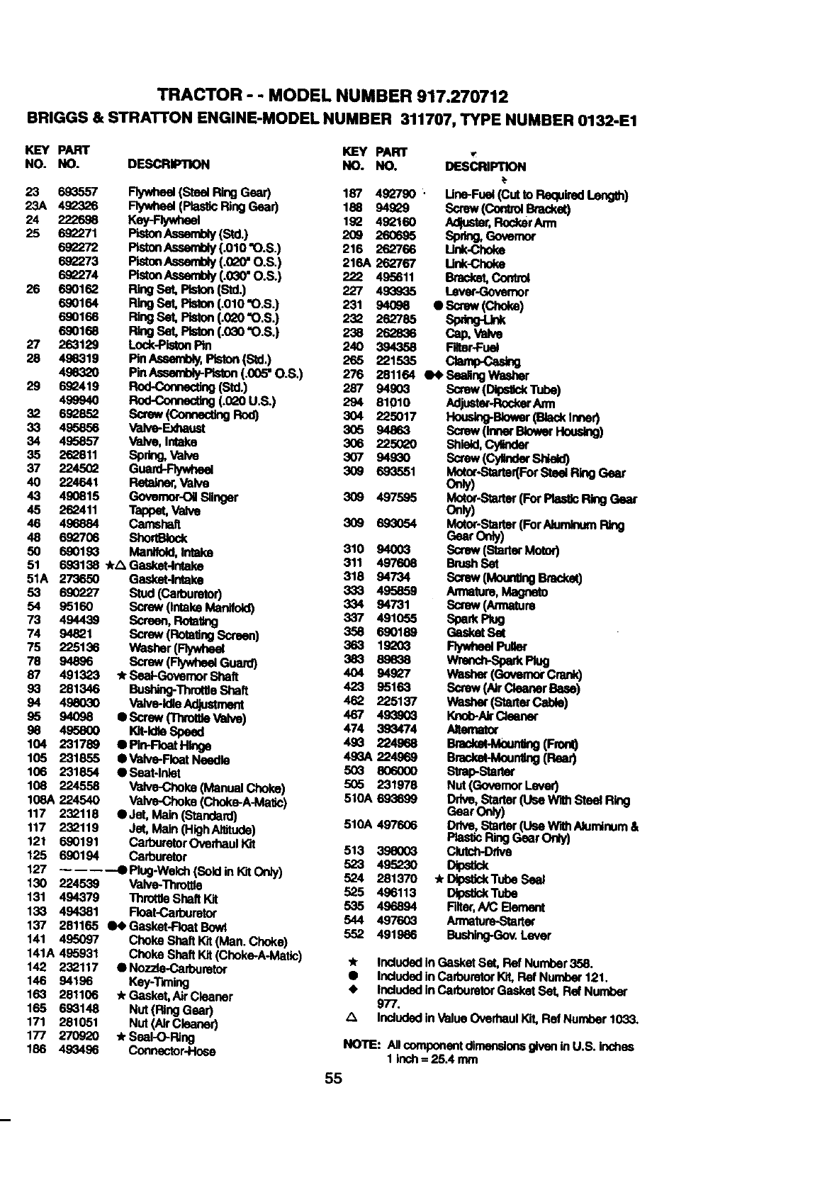
TRACTOR - - MODEL NUMBER 917.270712
BRIGGS & STRATTON ENGINE-MODEL NUMBER 311707, TYPE NUMBER 0132-E1
KEY PART KEY PART 1.
NO. NO. DESCRIP1RON NO. NO. DESCRIPTION
23 693557 Ftywheel(Steel P.ingGear) 187 49_2790 . Une-Fuel (Cutto Required I-englh)
23A 492326 Flywheel(_RlngGear) 18e 94829 Screw (Contr01Bracket)
24 222696 Key-F_ 19_ 492160 Adjuetar,RockerAmt
25 692271 PistonAssembly (Std.) 209 260695 Spry, Governor
892272 pletonAssemloly(.O10 "O.S.) 216 262766 Link.Choke
692273 PistonAssembly (.0LoO"O.S.) 216A 262767 Unk-Choke
692274 PletonAssemtW (.030" O.S.) 222 495611 Bracket, Cordrol
26 690162 Ring Set, Pteton (Std.) 227 493935 I_evec-Govemor
690164 Ring Set, Pist0n(.010 "O.S.) 231 94098 e Screw (Choke)
690166 Ring Set, Piston (.0_0 "O.S.) 232 262785 Spdng-Ltnk
6901e8 Ring Set, Piston (.030 "O.S.) 238 262836 Cap, Valve
27 263129 Lock-PistonPin 240 394358 Falter-Fuel
28 498319 pin Assemlbty,P_ton (Std.) 265 221535 Clamp-Casing
4983_) PinAssembly-Pteton(.005"O.S,) 276 281164 e_SeallngWasher
29 6g_419 Rod-Correcting (Std.) 287 94903 Screw (DIpetlckTube)
499940 _(.0_0 U.S.) 294 81010 Adjueter-Rock_Ann
32 8s_es2 Sc_w(ComecUngRod} 3O4 225o17 Hous_-Bower(Ba_tnne0
33 495856 Valve-_ 3O5 94863 Screw (Inner Blower Housing)
34 495857 Valve, Intake 306 2250_0 Shield,Cylinder
262811 Sprk_ _h,e 3O7 94930 Screw (Cy_der Shield)
37 22*,5_ Guam'-Rywheel 30g 6..°_51 Motor-StarteKForSt_R_Gear
40 224641 Reta}ner,Valve Only)
43 490815 Govemor-Oil Slinger 309 497595 Motor-Starter (For P_=-,,s_RingGear
45 262411 Tappet, Valve Onty)
46 496884 _ft 309 693054 Motor-Starter(For Aluminum
GearO_y)
48 692706 ShortBIock 310 94003 Screw (Stader Motor)
50 690193 ManY.d, _311 497608 BrushSet
51 693138 .kZIGasket-lntake 318 94734 Screw (MountingBnzcket)
51A 273650 Gasket-lr_ake 333 495859 Armature, Magneto
53 690227 Stud(Carburetor) 334 94731 Scmw(/_tme
54 95160 Screw (Intake Manifold) 337 491055 Spark Plug
73 494439 Screen, P,ot_ 358 690189 Gasket Set
74 94821 Screw (RotetJngScreen) 363 19L:=03 FlywheelPuget
75 225136 Washer(Flywheel 383 89838 V_imcl1-SparkPlug
78 94896 Screw (Flywheel Guard) 4O4 g49_7 We_he_(GovernorOan_
87 491323 #r SeaI-Govemor Shaft 423 95163 Screw(NrCleanerBMe)
93 281346 Bushin_Throete Shaft 462 225137 Wash_ (Starter C_01e)
94 498030 VaNe-Idle Adjustment 467 493903 I01o_/dr C_mner
95 94098 IScrew (Thn;_e Vs_ve) 474 393474 Anemator
98 4g_00 10t-IdleSpeed 493 224968 Brack_-M0un_eg(Fro_
104 231789 ePIn-FloatHInge 493A224969 Bracket-Moun_v_(Rear)
105 231855 •Valve-FloatNeedle
106 231854 eSeat-lnlet 503 806000 Slz'ap-Slartm
505 231978 Nut (Governor Lever)
108 224558 Valve-Choke (M_nual Choke) 510A 693699 Ddve, Stader (Use With Steel Ring
108A 224540 Valve-Choke (Choke-A-Matic) Gear Only)
117 23_118 _Jet, Mak_(Standa;d) 510A 497606 Ddve,Stader(t)seWithAlumlnum&
117 232119 Jet, Main (HighAIl#ude) PlasticRingGear Only)
121 690191 Cad_uretorOved_aull_t 513 398003 Clutch-Drive
125 690194 C_d3uretor 523 495230 Dipstick
127 •Plug-Welch(SoldinKitOrdy) 524 281370 .Dtpet_kTubeSeal
130 224539 Valve-Throt_e 525 496113 Dil_tJckTube
131 494379 n_mttle Shaft Kit 535 496894 Rlter,A/CElement
133 494381 Float-Carburetor 544 497603 Armatum-Starte¢
137 281165 _N_Gasket.FloatBowl 552 491986 Bushing-Gov.Lever
141 495097 Choke Shaft Kit (Man. Choke)
141A 495931 Choke ShaftKil (Choke-A-M_tic) ,k Included in Gasket Set, FiefNumber 358.
142 232117 e Nozzle-Carburetor •includedIn CafouretorKiLRet Number 12 I.
146 94196 Key:Rming •includedInCadouretorGasket Set, Ref Number
163 281106 ,kGasket, AirCleaner 977.
165 693148 Nut (Ring Gear) _, IncludedIn ValueOverhaul I_, Ref Number 1033.
171 281051 Nut (Air Clea_
177 270920 *Seal-O-Ping NOTE: AIIcomponentdlmenslonsglvenlnU.S. Inches
186 49_496 Connector-Hose 11nch=25.4mm
55
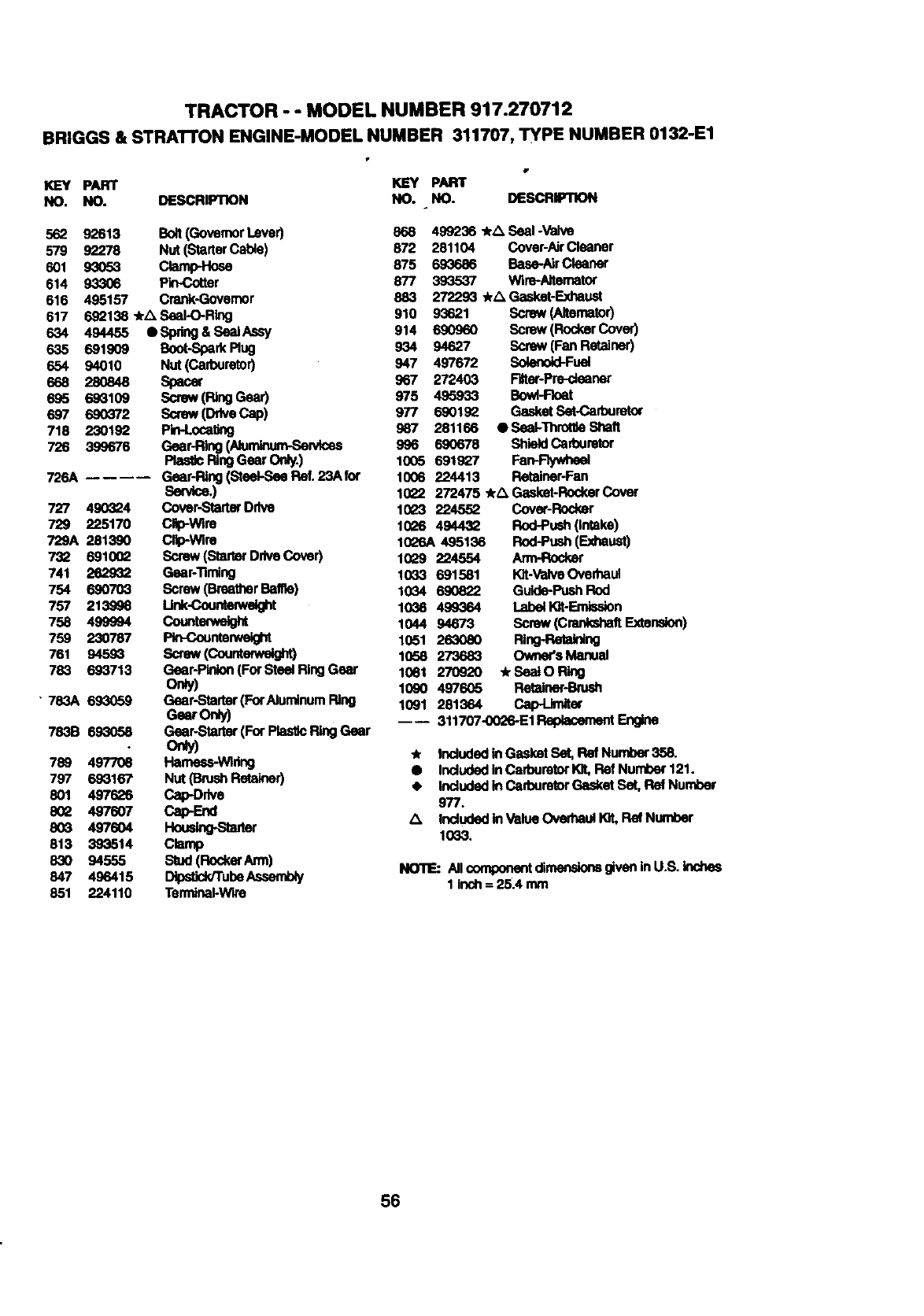
TRACTOR - - MODEL NUMBER 917.270712
BRIGGS & STRA'n'ON ENGINE-MODEL NUMBER 311707, TYPE NUMBER 0132-E1
KEY PART KEY PART
NO. NO. DESCRIPTION NO. NO. DESCRMllON
562
579
601
614
616
617
634 494455
635 6919O9
654 94010
668 28O848
695 693109
697 690372
718 2301_
726 399676
726A
727 490_24
729 225170
729A 281390
732 6910O2
741 262932
754 690703
757 213996
758 499994
759 230787
761 94593
783 693713
• 783A 693059
783B 693058
92613 Bolt(GovernorLever)
92278 Nut (StarterCable)
93o53 OampHoea
93306 Pin-Cotter
495157 Crenk-Governor
692138 _rix Seal-O-Ring
e Sprig&S_J_sy
Boot-SparkRug
Nut(Carburetor)
Spacer
Screw (Ring Gear)
Screw(D_veCap)
Prn-Loca_ng
Gear-Ring [Aiumlnum-,Se_ea
Rea_ RingGearOrgy.)
Gear-Ring (Steal-See Fief.23A for
Ban_ce.)
Cover-Starter Ddve
Clip-Wire
Clip-wire
Screw (Starter Ddve Cover)
Gear-Timing
Screw (BreatherBalfle)
unk_ght
Counterwe_
Rn-counterwelght
screw(counte_,'e_
Gear-Pinion(For Steel Ring Gear
Only)
Gear-Stalter (For AlurnlnumRing
Gear Only)
Gear-Starter (For PlasticRing Gear
o_y)
789 497708 Hameas-Wldng
797 693167 Nut (BrushRetainer)
801 497626 Cap-Drive
802 497607 Cap*End
803 4976O4 Hous_g-Staner
813 393514 Clamp
830 94555 Stud (FlockerArm)
847 496415 Clp6tid_rube Aseambly
851 224110 Temdnal-Wlre
868 499236 *_. Seal -Valve
872 281104 Cover-Air Cleaner
875 693686 Base-AirCleaner
877 393537 Wire-Aitemetor
883 272293 */_ Gasket-Exhaust
910 93621 Screw (Alternator)
914 690960 Screw (RockerCover)
934 94627 Screw (Fen Retainer)
947 497672 Solenoid-Fuel
967 272403 Fi6ter-Pre-deener
975 495933 Bowl-Float
977 690192 Gasket Set-Cafoureto¢
987 281166 • SeakThroMleShaft
996 690678 ShieldCarburetor
1005 691927 Fan-_
1006 224413 Retainer-Fen
1022 272475 4r/_ Geaket-RockerCover
1023 224552 Cover-Rode_
10L_6 494432 Rod-Push(intake)
1026A 495136 Rod-Push (Exhaust)
1029 224554 Arm-Rocker
1033 691581 Kit-ValveOved_aul
1034 690822 Guide-PushRod
1036 499364 LabellOt-Emission
1044 94673 Screw (CreakehaftF_xtenslon)
1051 263080 Ring-Retaining
1058 273683 Owner's Manual
1081 270920 .kSeaIORing
1090 497605 Retainer-Bru_
1091 281364 Cap--Lk_er
---- 311707-0026-E1Replacement Engine
_r Includedin Gasket Set, Ref Number 358.
•Includedin Carburetor)or, FiefNumber 121.
• Includedin CaYoumtorGasket Set, P_ Number
977.
Zl IncludedinValue Ovedlaul Kit, Ref Number
1033.
NOTE: All _rnponent dimensionsgiven inU.S. inches
1 inch = 25.4 mm
56

57


SUGGESTED GUIDE FOR SIGHTING SLOPES FOR SAFE OPERATION
O1
cD
SIGHTING
GUIDE
ONLY RIDE UP AND DOWN HILL,
NOT ACROSS HILL
I
Operate your Tractor up and down the face of slopes (not I
greater than 15°), never across the face. Make turns gredu- I
ally to prevent tipping or loss of control. Exercise extreme
caution when changing direction on slopes.
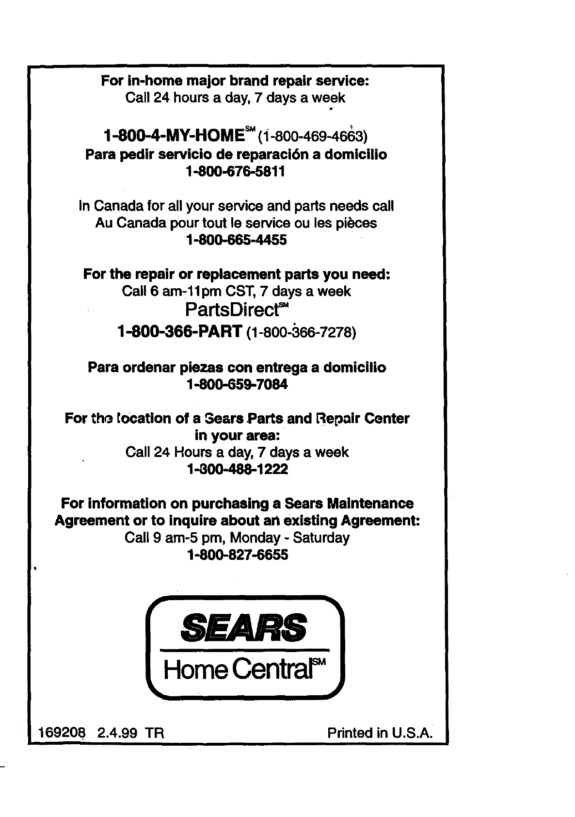
For in-home major brand repair service:
Call 24 hours aday, 7 days a week
1-800-4-MY-HOM E=(i-800-469-4663)
Para pedir servicio de reparaci6n a domicilio
1-880-676-5811
In Canada for all your service and parts needs call
Au Canada pour tout le service ou les pibces
1-800-665-4455
For the repair or replacement parts you need:
Call 6 am-11pm CST, 7 days aweek
PartsDirect=
1-800-366-PART (1-800-366-7278)
Para ordenar piezas con entrega a domicilio
1-800-659-7084
For the. location of a 3ears Parts and Repair Center
in your area:
Call 24 Hours a day, 7 days a week
1-300-488-1222
For information on purchasing a Sears Maintenance
Agreement or to inquire about an existing Agreement:
Call 9 am-5 pm, Monday -Saturday
1-600-827-6655
SEARS
HomeCentraF
169208 2.4.99 TR Printed in U.S.A.
