Craftsman 917270820 User Manual TRACTOR Manuals And Guides L0905355
CRAFTSMAN Lawn, Tractor Manual L0905355 CRAFTSMAN Lawn, Tractor Owner's Manual, CRAFTSMAN Lawn, Tractor installation guides
User Manual: Craftsman 917270820 917270820 CRAFTSMAN TRACTOR - Manuals and Guides View the owners manual for your CRAFTSMAN TRACTOR #917270820. Home:Lawn & Garden Parts:Craftsman Parts:Craftsman TRACTOR Manual
Open the PDF directly: View PDF ![]() .
.
Page Count: 60

Owner's Manual
®
t9o5 HP
ELEC:TR_C START
42" MOWER
AUTOMATHC
TRACTOR
Model No.
917,270820
o Safety
®Assembly
®Operation
® Maintenance
Repair Parts
CAUTION:
Read and follow all
Safety Rules and Instructions
before operating this equip-
ment.
For answers to your questions
about this product, Call:
!-800-659.-5917
Sears Craftsman Help Line
5 am - 5 pm, Mon - Sat
Seal's, Roebuck and Co., Hoffman Estates, IL 60179
Warranty ................................................. 2
Safety Rules ............................................. 2
Product Specifications ............................ 5
Assembly ................................................. 8
Operation ................................................... 12
Maintenance Schedule ......................... 19
Maintenance .......................................... 19
Service and Adjustments ...................... 23
Storage ................................................... 29
Troubleshooting ....................................... 31
Repair Parts ....................................................34
Parts Ordering ........................ Back Cover
LIMITED TWO YEAR WARRANTY ON CRAFTSMAN RIDING EQUIPMENT
For two (2) years from the date of purchase, if tMs Craftsman Riding Equipment is main-
tained, lubricated and tuned up according to the instructions in the owner's manual,
Sears will repair or replace, free of charge, any parts found to be defective in material or
workmanship.
This Warranty does not cover:
o Expendable items which become worn during normal use, such as blades, spark
plugs, air cleaners'; belts, etc
o Tire replacement or repair caused by punctures from outside objects, such as nails,
thorns, stumps, or glass.
,, Repairs necessary because of operator abuse, negligence, improper storage or acci-
dent or the failure to maintain the equipment according to the instructions contained in
the owner's manual
o Riding equipment used for commercial or rental purposes.
LIMITED 90 DAY WARRANTY ON BATTERY
For ninety (90) days from date of purchase, if any battery included with this riding equip.,
ment proves defective in material or workmanship and our testing determines the bat-
tery will not hold a chargd; Sears will replace the batte_'at no charge. In-home warranty
service on your Craftsman riding equipment is available at no charge for 30 days from
the date of purchase° Please contact your nearest service center: After 30 days flom the
date of purchase, warranty service is available by taking your Craftsman riding equip-
ment to your nearest Sears Service Center. (lmhome warranty service will still be avail-
able after 30 days f_om the date of purchase but a standard trip charge will apply) This
warranty applies only while this product is in the United States. This Warranty gives you
specific legal rights, and you may also have other i'ights which may vary from state to
state_
Sears, Roebuck and Co., D/8t7 WA, Hoffman Estates, 1L 60179
GENERAL OPERATION
o Read, understand, and follow all instruc-
tions in the manual and on the machine
before starting.
o Only allow responsible adults, who are
familiar with the instructions, to operate
the machine.
o Clear the area of objects such as rocks,
toys, wire, etc. which could be picked
up and thrown by the blade,
o Be sure the area is clear of other people
before mowing Stop machine if anyone
enters the area,. i!,
2
,, Never carry passengers..
,, Do not mow in reverse unless absolute-
ly necessary,. Always look down and
behind before and while backing.
o Be aware of the mower discharge direc-
tion and do not point it at anyone. Do
not operate the mower without either
the entire grass catcher or the guard in
place°
o Slow down before turning.
o Never leave a running macMne unat-
tended. Always turn off blades, set park-
ing brake, stop engine, and remove
keys before dismounting,.
o Turnoffbladeswhen notmowing..
,, Stopenginebeforeremovinggrass
catcheror uncloggingchute.
,, Mow only in daylight or good artificial
light°
o Do not operate the machine while under
the influence of alcohol or drugs.
o Watch for traffic when operating near or
crossing roadways.
o Use extra care when loading or unload-
ing the machine into a trailer or truck.
SLOPE OPERATION
Slopes are a major factor related to loss-
of-control and tipover accidents, which
can result in severe injury or death. Al!
slopes require extra caution. If you cannot
back up the slope or if you feel uneasy on
it, do not mow it.
DO:
,, Mow up and down slopes, not across.
,, Remove obstacles such as rocks, tree
limbs, etc.
o 'Watch for holes, ruts, or bumps. Uneven
terrain could overturn the machine Tall
grass can hide obstacles. '_;:_
• Use slow speed. Choose a low gear so
that you will not have to stop or shift
while on the slope.
o Follow the manufacturer's recommen-
dations for wheel weights or counter-
weights to improve stability.
o Use extra care with grass catchers or
other attachments. These can change
the stability of the machine.
,, Keep all movement on the slopes slow
and gradual. Do not make sudden
changes in speed or direction_
_, Avoid starting or stopping on a slope. If
tires lose traction, disengage the blades
and proceed slowly straight down the
slope°
DO NOT: t
oDo not turn on slopes unless necessary,
and then, turn slowly and gradually
downhill, if possible.
oDo not mow near drop-offs, ditches, or
embankments. The mower could sud-
denly turn over if a wheel is over the
edge of a cliff or ditch, or if an edge
caves in.
oDo not mow on wet grass° Reduced
traction could cause sliding.
o Do not try to stabilize the machine by
putting your foot on the ground.
oDo not use grass catcher on steep
slopes.
CHILDREN
Tragic accidents can occur if the operator
is not alert to the presence of children.
Children are often attracted to the
machine and the mowing activity_ Never
assume that children will remain where
you last saw them.
oKeep children out of the mowing area
and under the watchful care of another
responsible adult.
,, Be alert and turn machine off if children
enter the area.
,_ Before and when backing, look behind
and down for small children..
o Never carry children. 'They may fall off
and be seriously injured or interfere with
safe machine operation°
o Never allow children to operate the
machine.
o Use extra care when approaching blind
comers, Shrubs, trees, or other objects
that may ob._c[_re vision.
SERVICE
,, Use extra care in handling gasoline and
other fuels. They are flammable and
vapors are explosive°
Use only an approved container.
Never remove gas cap or add fuel
with the engine running. Allow em
gine to cool before refueling, Do not
smoke_
Never refuel the machine indoors.
Never store the machine or fuel
container inside where there is an
open flame, such as a water heater.
oNever run a machine inside a closed
area,
o Keep nuts and bolts, especially blade
attachment bolts, tight and keep equip.
ment in good condition,
o Never tamper with safety devices.
Check their proper operation regularly
o Keep machine free of grass, leaves, or
other debris build-up.,Clean oil or fuel
spillage,, Allow machine to cool before
storing.
,, Stop and inspect the equipment if you
strike an object. Repair, if necessary,
before restarting,
o
Never make adjustments or repairs with
the engine running.
Grass catcher components are subject
to wear, damage, and deter!oration,
which could expose moving pairs or
allow objects to be thrown. Frequently
check components and replace with
manufacturePs recommended pads,
when necessary. _
,, Be sure the area is clear of other people
before mowing_ Stop machine if anyone
enters the area.
,, Never carry passengers.
Do not mow in reverse unless absolute_
ly necessary. Always took down and
behind before and while backing.
o Never carry children. They may fall off
and be seriously injured or interfere with
safe machine operation.
o Keep children out of the mowiog area
and under the watchful care of another
responsible adult.,
o Be alert and turn machine off if children
enter the area.
o Before and when backing, look behind
and down for small children.
o Mower blades are sharp and can cut,
Wrap the blade(s) or wear gloves, and
use extra caution when servicing them°
o Check brake operation frequently,
Adjust and service as required.
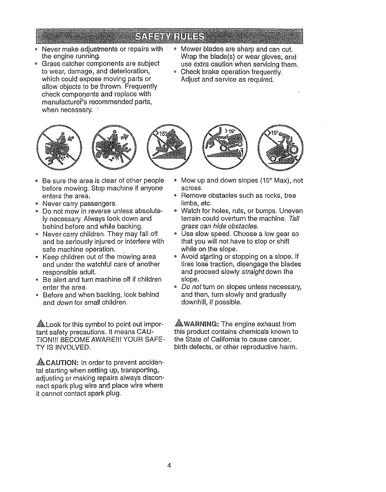
o Mow up and down slopes (15 ° Max), not
across.
o Remove obstacles such as rocks, tree
limbs, etc..
o Watch for holes, ruts, or bumps, Uneven
terrain could overturn the machine. Ta!l
grass can hide obstacles,
o Use slow speed. Choose a low gear so
that you will not have to stop or shift
while on the slope.
o Avoid slurring or stopping on a slope, if
tires lose traction, disengage the blades
and proceed slowly straight down the
slope.
oDo not turn on slopes unless necessary,
and then, turn slowly and gradually
downhill, if possible..
,_i)kLook for this symbol to point, out impor-
tant safety precautions. It means CAU-
TION!H BECQME AWARE!!! YOUR SAFE..
TY IS INVOLVED°
,_kCAUTION: In order to prevent accidem
tal stading when setting up, transporting,
adjusting or making repairs always discon_
nect spark plug wire and place wire where
it cannot contact spark plug.
,_WARNtNG: Tile engine exhaust from
this product contains chemicals known to
the State of California to cause cancer,
birth defects, or other reproductive harm.
4
PROOUCT SPECBFRCAT_ONS
GASOLINE 3.5 GALLONS
CAPACITY
AND TYPE: UNLEADED
REGULAR
OIL TYPE SAE 30
(APFSFiSG/SH): (above 32°F)
SAE 5W-30
(below 32°F)
OIL CAPACITY': &0 PINTS
SPARK PLUG: Champion RJ19LM
(GAP: 030") OR J19LM
GROUND SPEED FORWARD: O- 5,5
(MPH): REVERSE: 0- 2.4
_iREPRESSURE: FRONT: 14 PSi
REAR: 10 PSl
CHARGING 3 AMPS BATTERY
SYSTEM: 5 AMPS HEADLIGHTS
BATTERY: AMPiHR:30
MIN. CCA:240
CASE SIZE: U1R
BLADE BOLT 27-35 FT. LBS.
TORQUE:
CONGRATULATIONS on your purchase
of a Craftsman Tractor. It has been
designed, engineered and manufactured
to give you the best possible dependability
and performance.
Should you experience any problem you
cannot easily remedy, please contact your
nearest Sears Authorized Service Center.
We have competent, well-trained techni-
cians and the proper tools to service or
repair this tractor,
Please read and retain this manual, The
instructions wilt enable you to assemble
and maintain your tractor properly° Always
observe the "SAFETY RULES".
MABNTENANCE AGREEMENT
A Sears Maintenance Agreement is avail ....
able on this product. Contact your nearest
Sears store for details,
CUSTOMER RESPONSIBILITIES
o Read and observe the safety rules.
° Follow a regular schedule in maintain-
ing, caring for and using your tractor..
Follow the instructions under "Mainte-
nance" and "Storage" sections of this
owner's manual.
_kWARNING: This tractor is equipped
with an internal combustion engine and
should not be used on or near any unim-
proved forest-covered, brush-covered or
grass-covered land unless the engine's
exhaust system is equipped with a spark
arrester meeting applicable local or state
laws (if any). If a spark arrester is used, it
should be maintained in effective working
order by the operator:
In the state of California the above is
required by law (Section 4442 of the
California Public Resources Code). Other
states may have similar' laws. Federal
taws apply on federal lands, A spark
arrestor for the muffler is available through
your nearest Sears Authorized Service
Center (See REPAIR PARTS section of
this manual).
5
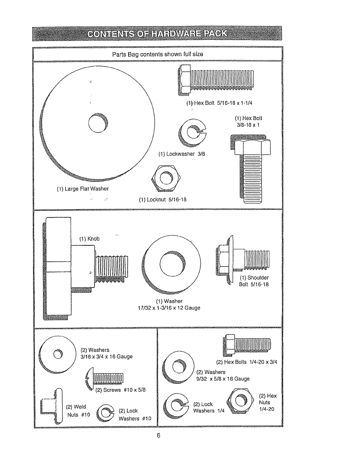
(1,_Hex Bolt 5f16-18 x t-I/4
_ (1) He× Bolt
3/8-16 x t
(1) Lockwasher 3f8
(i) Large Flat Washer
_' (1) Locknut 5t16-18
(1) Knob
(1) Washer
17/32 x 1-3/16 × t2 Gauge
(1) Shoulder
Bolt 5/!6.18
(2) Washers
3/16 x 3/4 x t6 Gauge
(2) Screws #I0 x 518
(2) Weld ,_
Nuts #I0 (2) Lock
Washers #10
(2) Hex Bolts 114-20 x 314
(2) Washers
9/32 x 518 x 16 Gauge
@ (2) Hex
(2) Lock Nuts
Washers 1/4 1/4-20
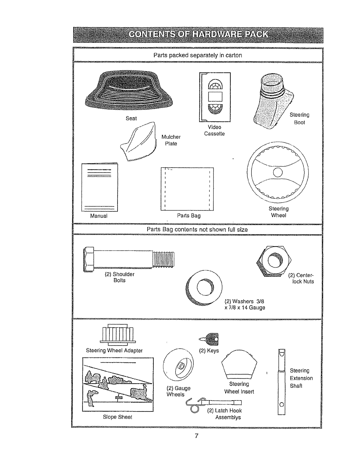
Parts packed separately in carton
Seat
Mutcher
Plate
C2
Video
Cassette
Steering
Bool
Steedng
Manual Wheel
I I
t |
I 1
t 1
I 1
l l
I t
t t
Pa_s Bag
Pa_s Bag contents not shown full size
(2) Shoulder __
Bolls lock Nuts
(2) Washers _8
x 7/8 x 14 Gai_ge
Steering Wheel Adapter (2) Keys
Slope Sheet
(2) Gauge
Wheels
_ Steering
Extension
Steering Shaft
Wheel Insert
Assemblys
7
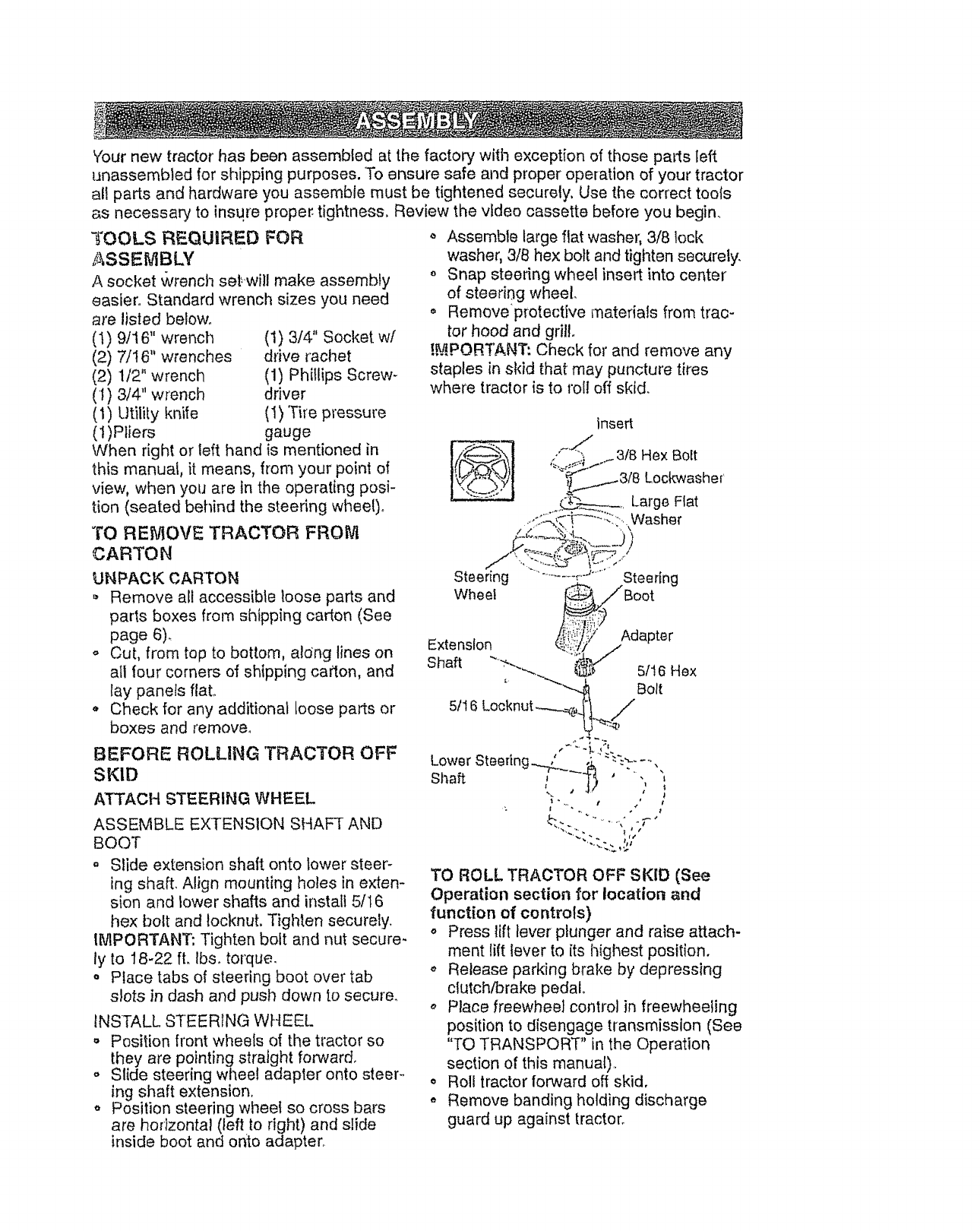
Yournew tractorhas beenassembledatthe factorywith exceptionofthosepalls left
unassemMedfor shippingpurposes,To ensuresafeandproperope[ationof yourtractor
all partsand hardwareyou assemblemustbe tightenedsecurely,Usethe correcttools
as necessaryto insurepropertightness,Reviewthevideocassettebeforeyoubegin.
":_'OOLS REQUIRED FOR
,ASSEMBLY
A socket wrench sef,will make assembly
easier, Standard wrench sizes you need
are I)sted below°
(I) 9/t6" wrench
(2) 7/16" wrenches
(2) 112" wrench
(1) 3/4" wrench
(1) Utility knife
(1)Pliers
(1) 3/4" Socket wf
drive rachet
(1) Phillips Screw-
driver
(1) Tire pressure
gauge
When right or left hand is mentioned in
this manual, it means, from your point of
view, when you are in the operating posi-
tion (seated behind the steering whee!)_
TO REMOVE TRACTOR FROM
CARTON
UNPACK CARTON
Remove all accessible loose parts and
parts boxes from shipping cation (See
page 6).
o Cut, from top to bottom, aldng lines on
all four corners of shipping carton, and
lay panels flat..
o Check for any additional loose parts or
boxes and remove..
BEFORE ROLUNG 'TRACTOR OFF
SKID
ATTACH STEERING WHEEL
ASSEMBLE EXTENSION SHAFT AND
BOOT
° Slide extension shaft onto lower steer-
ing shaft. Align mounting holes in exten-
sion and lower shafts and install 5/t 6
hex bolt and Iocknut, Tighten securely.
IMPORTANT: Tighten bolt and nut secure-
ly to 18-22 ft. Ib& toique.
• Place tabs of steering boot over tab
slots in dash and pustl down to secure.
INSTALL STEERING WHEEL
o Position front wheels of the tractor so
they are pointing straight forward.
o Slide steering wheel adapter onto steer-
ing shaft extension,
o Position steering wheel so cross bars
are horizontal (left to right) and slide
inside boot and onto adapter°
,, Assemble large flat washer, 3/8 lock
washer, 3/8 hex bolt and tighten securely.
o Snap steering wheel insert into center
of steering wheel.
• Removeprotective materials from trac-
tor hood and grill
!._.PORTANT: Cheek for and remove any
staples in skid that may puncture tires
where tractor is to roll off skid.
insert
D
_' ,:_}._4..f 3/8 HexBolt
_'_ 3/8 Lockwasher
,,-_a Large Fiat
.....-_:_!_-[...... ::::"..Washer
Steering .................r'->.......Steering
Wheel _Boot
i_i.:_?_i,liii_'_:"
Extension _Y Adapter
Shaft "_' "_,-.,_ 5It6 Hex
' ""_'_ Bolt
5!16 Locknut...--___,._"lo_._//
Lower Steering......,L I_, ". -
!. ;I
TO ROLL TRACTOR OFF SKID (See
Operation section for location and
function of controls)
o Press lift lever plunger and raise attach-
ment lift lever to its highest position,
o Release parking brake by depressing
clutch/brake pedal.
,, Place freewheel control in freewheeling
position to disengage transmission (See
"TO TRANSPORT" in the Operation
section of this manual).
o Roll tractor forward off skid,
* Remove banding holding discharge
guard up against tractor.
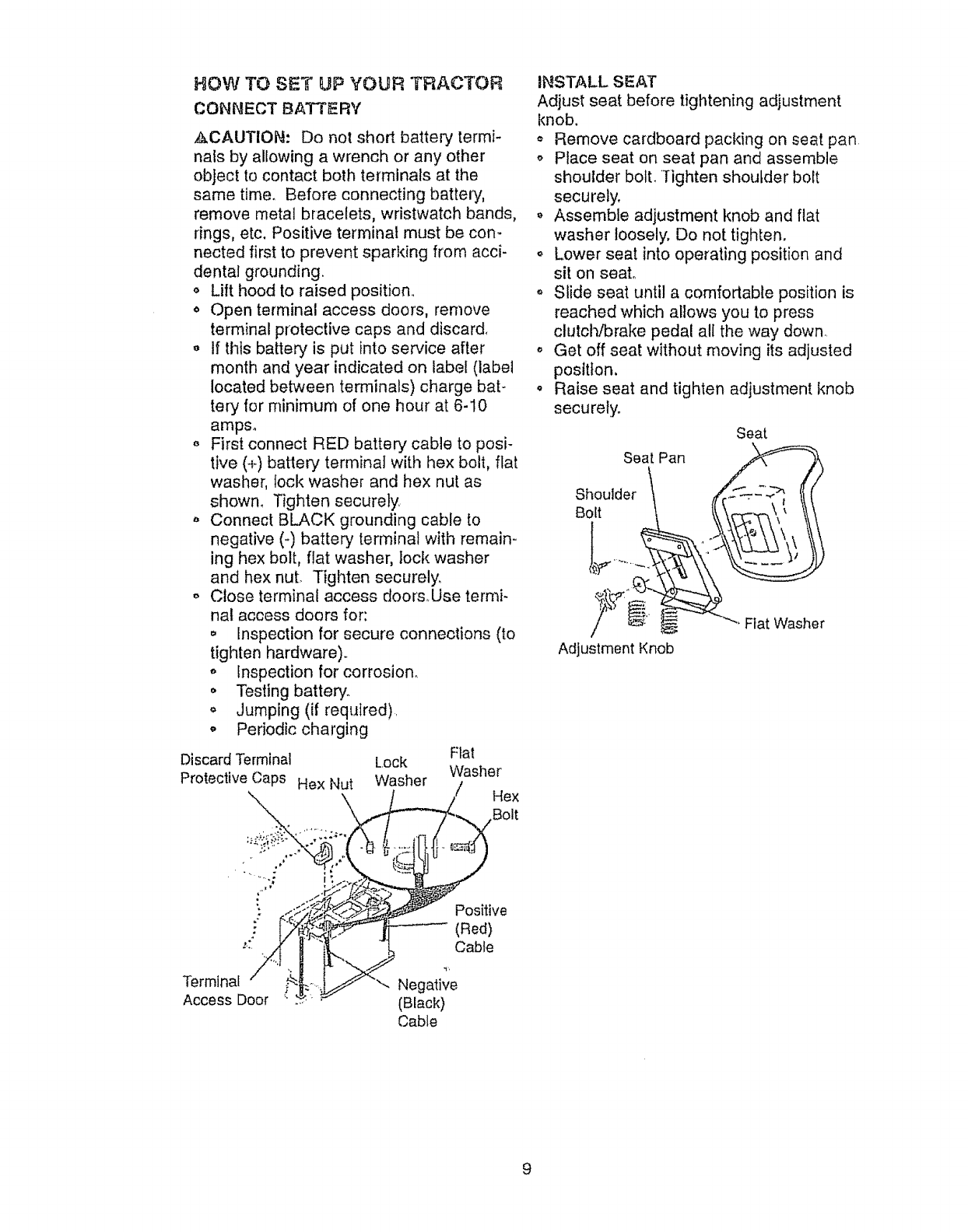
HOW TO SE"_¢UP YOUR TRACTOR
CONNECT BATTERY
,&CAUTION: Do not short battery termi-
nals by allowing a wrench or any other
object to contact both terminals at the
same time. Before connecting battery,
remove metal bracelets, wristwatch bands,
rings, etc. Positive terminal must be con-
nected first to prevent sparking from acci-
dental grounding.
,_ Lift hood to raised position..
o Open terminal access doors, remove
terminal protective caps and discard,
- If this battery is put into service after
month and year indicated on label (label
located between terminals) charge bat-
tery for minimum of one hour at 6-10
amps.
,, First connect RED battery cable to posi-
tive (+) battery terminal with hex bolt, flat
washer, lock washer and hex nut as
shown_ Tighten securely.
o Connect BLACK grounding cable to
negative (-) battery terminal with remain-
ing hex bolt, flat washer, loci{ washer
and hex nut. Tighten securely.
o Close terminal access doors.Use termi-
nal access doors for:
o Inspection for secure connections (to
tighten hardware).
o inspection for corrosion.
o Testing battery.
,, Jumping (if required).
o Periodic charging
Flat
Washer
/Hex
Bolt
Discard Terminal Lock
Protective Caps Hex Nut Washer
INSTALL SEAT
Adjust seat before tightening adjustment
knob,
,, Remove cardboard packing on seat pan
o Place seat on seat pan and assemble
shoulder bolt. 'Tighten shoulder bolt
securely,
,, Assemble adjustment knob and flat
washer loosely, Do not tighten.
o Lower seat into operating position and
sit on seat°
o Slide seat until a comfortable position is
reached which allows you to press
clutch/brake pedal all the way down.
o Get off seat without moving its adjusted
position,
o Raise seat and tighten adjustment knob
securely.
Seat Pan
Shoulder 1
Bolt
y@.,
Adjustment Knob
Seat
"'_ Fiat Washer
" Positive
: (Red)
'_" Cable
Terminal
Access Door
9
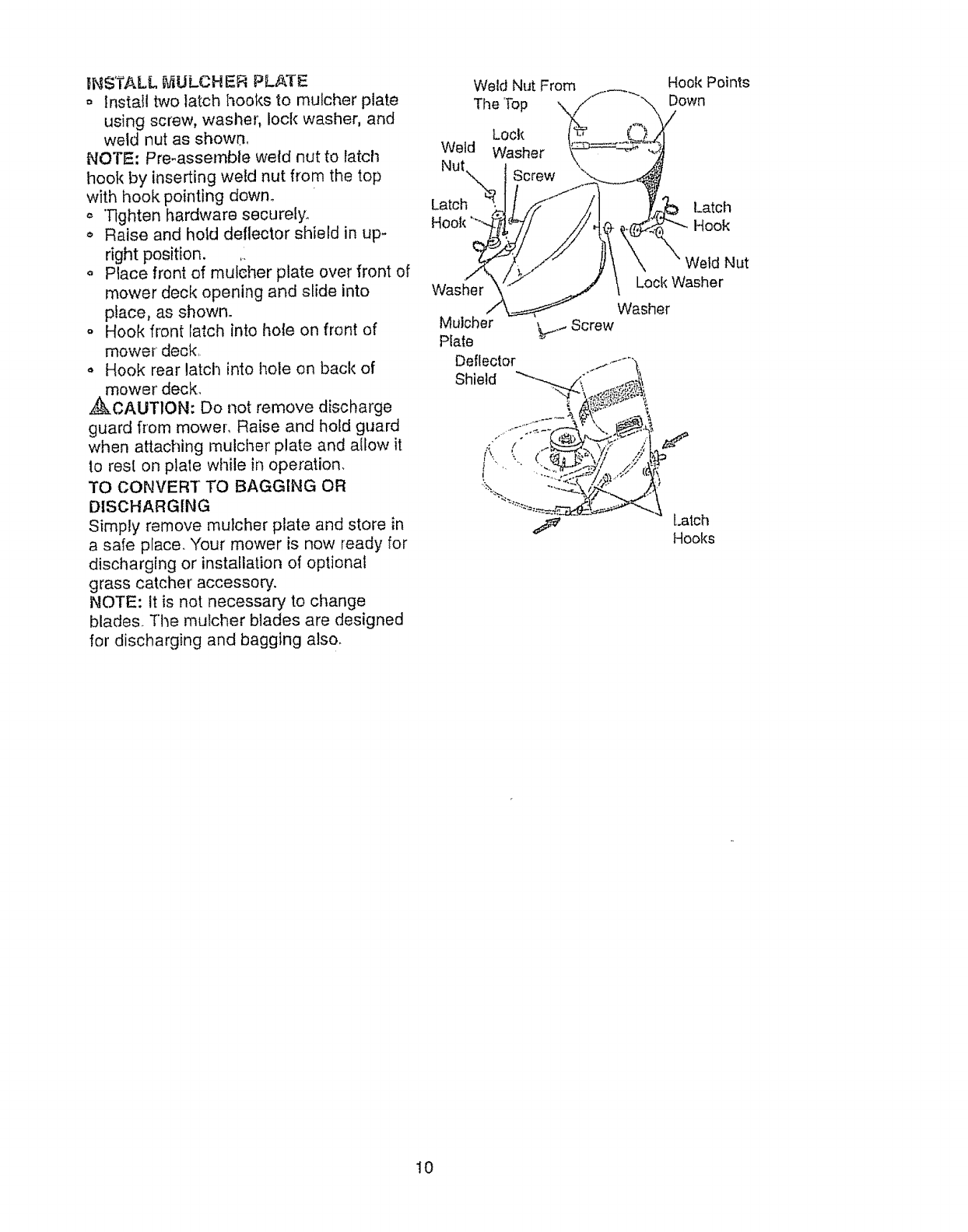
I_NSTALL_ULCHER PLATE
= Installtwolatchhooksto mutcherplate
usingscrew,washehloci<washer,and
weld nut as shown,
NOTE: Pre-assemble weld nut to latch
hook by inserting weld nut from the top
with hook pointing down,
o"Tighten hardware securely,
o Raise and hold deflector shield in up-
right position.
o Place front of mulcher plate over front of
mower deck opening and slide into
place, as shown.
o Hook front latch into hole on front of
mower deck,
,, Hook rear latch into hole on back of
mower deck_
,_CAUTION: Do not remove discharge
guard from mower, Raise and hold guard
when attaching rnulcher plate and allow it
to rest on plate while in operation.
TO CONVERT TO BAGGING OR
DISCHARGING
Simply remove mulcher plate and store in
a safe place. "Your mower is now ready for
discharging or installation of optional
grass catcher accessory.
NOTE: It is not necessary to change
blades. The mulcher blades are designed
for discharging and bagging also.
Weld Nut From
The 'Top
Lock
Weld Washer
Nut
Latch
Hook
Washer
Mulcher
Plate
Deflector
Shield
_._..- Screw
Hook Points
Down
Latch
Hook
Weld Nut
Lock Washer
Washer
[.arch
Hooks
10
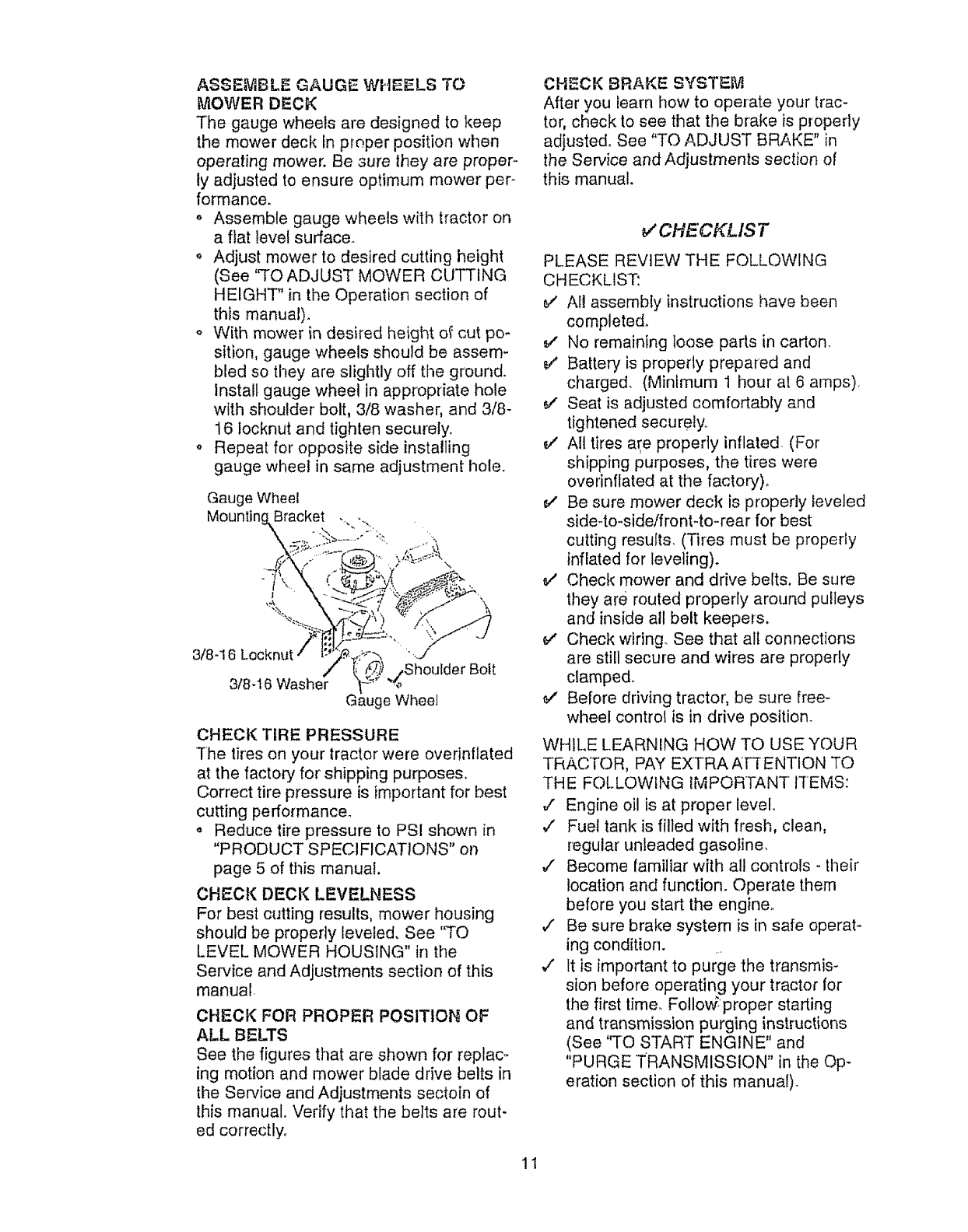
ASSEMBLE GAUGE WHEELS TO
MOWER DECK
The gauge wheels are designed to keep
the mower deck In proper position when
operating mower, Be sure they are proper-
ly adjusted to ensure optimum mower per-
formance.
,, Assemble gauge wheels with tractor on
a fiat level surface.
o Adjust mower to desired cutting height
(See "TO ADJUST' MOWER CUTTING
HEIGHT" in the Operation section of
this manual).
o With mower in desired height of cut po-
sition, gauge wheels should be assem-
bled so they are slightly off the ground.
Install gauge wheel in appropriate hole
with shoulder bolt, 3/8 washer, and 3/8-
16 locknut and tighten securely_
oRepeat for opposite side installing
gauge wheel in same adjustment hole.
Gauge Wheel
Mountinc Bracket ._...,.
3/8-16 Locknut
3/8 -16
\
G__ugeWheel
CHECK TIRE PRESSURE
]he tires on your tractor were overinflated
at the factory for shipping purposes.
Correct tire pressure is important for best
cutting performance_
,, Reduce tire pressure to PSI shown in
"PRODUCT SPECIFICATIONS" on
page 5 of tilts manual,
CHECK DECK LEVELNESS
For best cutting results, mower housing
should be properly leveled, See "TO
LEVEL MOWER HOUSING" in the
Service and Adjustments section of this
manual
CHECK FOR PROPER POSITION OF
ALL BELTS
See the figures that are shown for replac-
ing motion and mower blade drive belts in
the Service and Adjustments sectoin of
this manual. Verify that the belts are rout-
ed correctly,
CHECK BRAKE SYSTE_'_
After you learn how to operate your trac-
tor, check to see that the brake is properly
adjusted, See "TO ADJUST BRAKE" in
the Service and Adjustments section of
this manual.
_CHECKLIST
PLEASE REVIEW THE FOLLOWING
CHECKLIST:
e/Al! assembly instructions have been
complete&
v" No remaining loose pads in carton,
_/ Battery is properly prepared and
charged. (Minimum 1 hour at 6 arnps),
e," Seat is adjusted comfortably and
tightened securely.
All tires are properly inflated. (For
shipping purposes, the tires were
overinftated at the factory)_
Be sure mower deck is properly leveled
side-to-side/frontqo-rear for best
cutting results, (Tires must be properly
inflated for leveling).
_" Check mower and drive belts, Be sure
they are routed properly around pulleys
and inside all belt keepers.
e,' Check wiring. See that all connections
are still secure and wires are properly
clamped.
e,' Before driving tractor, be sure free-
wheel control is in drive position.
WHILE LEARNING HOW TO USE YOUR
TRACTOR, PAY EXTRA AFTENTION TO
THE FOLLOWING IMPORTANT ITEMS:
,/ Engine oil is at proper level
v" Fuel tank is filled with fresh, clean,
regular unleaded gasoline,
,/ Become familiar with all controls - their
location and function. Operate them
before you start the engine.
,/ Be sure brake system is in safe operat_
ing condition. ..
v" It is important to purge the transmis-
sion before operating your tractor for
the first time. Follov,,_proper starting
and transmission purging instructions
(See "TO START ENGINE" and
"PURGE TRANSMISSION" in the Op-
eration section of this manual).
11

These symbolsmayappearonyourtractoror in literaturesuppliedwiththe product°
Learnand understandtheir meaning,
r
BATTERY CAUT ION OR REVERSE FORWARD' _ FAST
WARNING
ENGINE ON ENGtNE OFF OIL PRESSURE LIGHTS ON OVER TEMP
LIGHT
\
CHOKE
SLOW
0
PARKING BRAKE
LOCKED
\\\\
ja._
!
FUEL MOWER HEIGHT UNLOCKED MOWER LIFT
R N
ATTACHMENT REVERSE NEUTRAL
CLUTCH ENGAGED
IGNITION
ATTACHMENT
CLUTCH DISENGAGED
N L oS;
"r"
HIGH LOW PARKING BRAKE
KEEP AREA CLEAR SLOPE HAZARDS
(SEE' SAFETY RULES SECTION)
DANGER, KEEP HANDS AND FEET AWAY
FREE WHEEL
(Aulomalic Modets only)
12
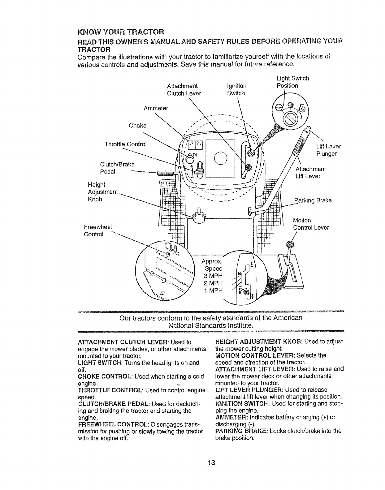
KNOW YOUR TRACTOR
READ THIS OWNER'S MANUAL AND SAFETY RULES BEFORE OPERATING YOUR
TR AOTO R
Compare the illustrations with your tractor to familiarize yourself with the locations of
various controls and adjustments, Save this manual for future reference.
Attachment Ignition
Clutch Lever Switch
Light Switch
Position
Ammeter
Cl_oke
Throttle Control
Clutch/Brake
Pedal
Height
Adjustment
Knob
Freewheel
Control
Lift Lever
Plunger
Attachment
Lift Lever
Motion
Control Lever
Approx,
Speed
3 MPH
2 MPH
1 MPH
Our tractors conform to the safety standards of the American
National Standards Institute,,
ATTACHMENT CLUTCH LEVER: Used to
engage the mower blades, or other attachments
mounted to your tractor,.
LIGHT SWITCH: Turns the headlights on and
off..
CHOKE CONTROL: Used when starting a cold
engine. ,_
THROTTLE CONTROL: Used to control engine
speed
CLUTCHIBRAKE PEDAL: Used for declutch-
lng and braking the tractor and starting the
engine,
FREEWHEEL CONTROL: Disengages trans-
mission for pushing or slowly towing the tractor
with the engine off.
HEIGHT ADJUSTMENT KNOB: Used to adjust
the mower cutting height..
MOTION CONTROL LEVER: Selects the
speed and direction of the tractor,
ATTACHMENT LIFT LEVER: Used to raise and
lower the mower deck or other attachments
mounted to your tractor,
LIFT LEVER PLUNGER: Used to release
attachment lift lever when changing its position.,
IGNITION SWITCH: Used for starting and stop-
ping the engine.
AMMETER: Indicates battery charging (_) or
discharging (-),
PARKING BRAKE: Locks clutch/brake into the
brake position,
13
heo_per=_tiol_"of"_an'_=y'iractorcan res_u{tinfore'_----_g-'n-0bjects_ih;ownintoth__
yes,whichcan resultin severe eye damage. Always wear safety glasses
r eye shields while operating your tractor or performing any adjustments or
pairs, We recommend a wide vision safety mask over the spectacles, or"
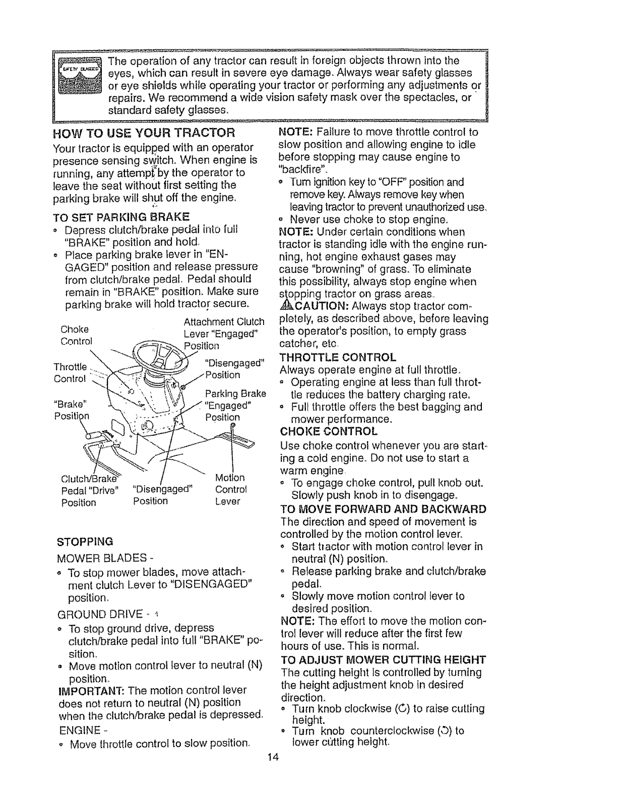
HOW' TO USE YOUR TRACTOR
Your tractor is equipped with an operator
presence sensing switch,, When engine is
running, any attempt, by the operator to
leave the seat without first setting the
parking brake will shut off the engine.
TO SET PARKING BRAKE
. Depress clutch/brake pedal into full
"BRAKE" position and hold
o Place parking brake lever in "EN-
GAGED" position and release pressure
from clutch/brake pedal. Pedal should
remain in "BRAKE" position. Make sure
parking brake wili hold tractor secure.
Attachment Clutch
Choke Lever "Engaged"
Control Position
Throttle "Disengaged"
Control ',ilion
Parking Brake
"Brake" led"
Positi_ _ Position
Motion
Pedal "Drive .... Disengaged" Control
Position Position Lever
STOPPING
MOWER BLADES -
,, To stop mower blades, move attach-
ment clutch Lever to "DISENGAGED"
position_
GROUr,,1D DRIVE _ ._
o To stop ground drive, depress
clutchlbrake pedal into ful! "BRAKE" po-
sition.
. Move motion control lever to neutral (N)
position°
IMPORTANT: The motion control lever
does not return to neutral (N) position
when lhe clutch/brake pedal is depressed,
ENGINE -
,, Move throttle control to slow position.
NOTE: Failure to move throttle control to
slow position and allowing engine to idle
before stopping may cause engine to
"bacldire"_
TUrn ignition key to "OFF" position and
remove key. Always remove key when
leaving tractorto prevent unauthorized use.
oNever use choke to stop engine,
NOTE: Under' certain conditions when
tractor is standing idle with the engine run-
ning, hot engine exhaust gases may
cause "browning" of grass. To eliminate
this possibility, always stop engine when
pping tractor on grass areas..
CAUTION. Always stop tractor com.,
pletely, as described above, before leaving
the operator's position, to empty grass
catcher, etc
THROTTLE CONTROL
Always operate engine at full throttle,
= Operating engine at less than full throt-
tle reduces the battery charging rate,
. Full throttle offers the best bagging and
mower performance.
CHOKE CONTROL,
Use choke control whenever you are start.,,
ing a cold engine. Do not use to start a
warm engine
° To engage choke control, pull knob out.
Slowly push knob in to disengage°
TO MOVE FORWARD AND BACKWARD
The direction and speed of movement is
controlled by the motion control lever,,
o Stall hactor with motion control lever in
neutra! (N) position,,
o Release parking brake and clutch/brake
pedal
o Slowly move motion control lever to
desired position.
NOTE: The effort to move the motion con-
trol lever well reduce after the first few
hours of use. This is normal.
TO ADJUST MOWER CUTTING HEIGHT
The cutting height is controlled by turning
the height adjustment knob in desired
direction.
o Turn knob clockwise (©) to raise cutting
height.
. Turn knob countercloclw_'ise (©)to
lower ct'_tting height.
14
The clurlin_,,height range is approximately
1-1/2 to 4L The heights are measured
from tt_e ground to the blade tip with the
engine not running, These heights are ap-
proximate and may vary depending upon
soil conditions, height of grass andtypes
of grass being mowed.
oThe average lawn should be cut to
approximately 2-1/2 inches during the
cool season and to over 3 inches during
hot months. For healthier and better
looking lawns, mow often and after
moderate growth.
• For best cutting performance, grass
over 6 inches in height should be
mowed twice.. Make the first cut rela-
tively high; the second to desired height,
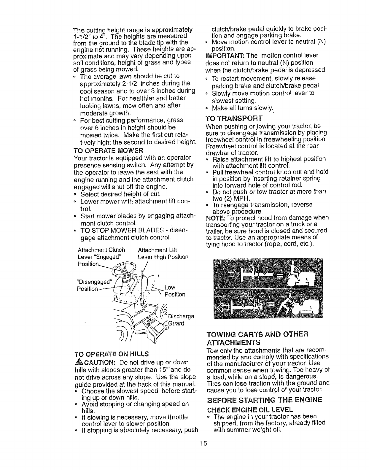
TO OPERATE MOWER
Your tractor is equipped with an operator
presence sensing switch. Any attempt by
the operator to leave the seat with tile
eng{ne running and the attachment ciutch
engaged will shut off the engine.
• Select desired height of cut.
• Lower mower with attachment lift con-
trot.
• Start mower blades by engaging attach*
ment clutch control,
,, TO STOP MOWER BLADES -disem
gage attachment clutch control.
Attachment Clutch
Lever "Engaged"
Attachment Lift
Lever High Position
clutch!brake pedal quickly to brake posi-
tion and engage parking brake,
o Move motion control lever to neutral (N)
position.
I_.!iPORTANT: "The motion control lever
does not return to neutral (N) position
when the clutch/brake pedal is depressed.
To restart movement, slowly retease
parking brake and clutch/brake pedal,
o Slowly move motion control lever to
slowest setting.
,, Make all turns slowly.
TO TRANSPORT
When pushing or towing your tractor, be
sure to disengage transmission by placing
freewheel control in freewheeling position.
Freewheel control is located at the rear
drawbar of tractor,.
o Raise attachment Iift to highest position
w_th attachment lift control
o Pull freewheel control knob out and hold
in position by inserting retainer spring
into forward hole of control rod.
oDo not push or tow tractor at more than
two (2) MPH.
o To reengage transmission, reverse
above procedure°
NOTE: To protect hood from damage when
transporting your tractor on a truck or a
traiter, be sure hood is closed and secured
to tractor. Use an appropriate means of
tying hood to tractor (rope, cord, etc.)_
"Disengaged"
Position Low
Position
Discharge
Guard
TO OPERATE ON HILLS
,_CAUTION: Do not drive up or down
hills with slopes greater than 15°'&nd do
not drive across any slope. Use the slope
guide provided at the back of this manual.
o Choose the slowest speed before start-
ing up or down hills.
,, Avoid stopping or changing speed on
hills°
o If slowing is necessary, move throttle
control lever to stower position.
,, If stopping is absolutely necessary, push
TOWING CARTS AND OTHER
ATTACHMENTS
Tow only the attachments that are recom-
mendedby and comply with specifications
of the manufacturer of your tractor. Use
common sense when towing, Too heavy of
a load, while on a slop_, is dangerous.
Tires can lose traction with the ground and
cause you to lose contrpf of your tractor.
BEFORE STARTING THE ENGINE
CHECK ENGINE OIL LEVEL
,, The engine in your tractor has been
shipped, from the factory, already filled
with summer weight oil
15
* Check engine oil with tractor' on level
ground,
o Remove oil fill cap/dipstick and wipe
clean, reinsert the dipstick and screw
cap tight, wait for a few seconds,
remove and read oll level° tf necessary,
add oil until "FULL" mark on dipstick is
reached. Do not overfill,
o For cold weather 0peration you should
change oi! for easter starting (See "OIL
VISCOSITY CHART" in the Mainte.,
nance section of this manual).
To change engine oil, see the Mainte-
nance section in tllis manual
z
ADD GASOUNE
,, Fil! fuel tank. Use fresh, clean, regular
unleaded gasoline with a minimum of 87
octane. (Use of leaded gasoline wilt
increase carbon and lead oxide
deposits and reduce valve life), Do not
mix oil with gasoline, Purchase fuel in
quantities that can be used within 30
days to assure fuej freshness°
!MPORTANT: Whet;operating in tempera-
tures below 32°F(0°C), use fresh, clean
winter grade gasotine to help insure good
cold weather starling,
,_kWARNtNG: Experience indicates that
alcohol blended fuels (called gasohol or
using ethanol or methanol) can attract
moisture which leads to separation and
formation of acids during storage. Acidic
gas can damage the'fuel system of an
engine while in storage. To avoid engine
problems, the fuel system should be emp-
tied before storage of 30 days or longer.
Drain the gas tank, start the engine and let
it run until the fuel lines and carburetor are
empty. Use fresh fuel next season, See
Storage Instructions for additional informa-
lion. Never use engine or carburetor
cleaner products in the fuel tank or' perma-
,_nct damage may occur.
AUTION: Fill to bottom of gas tank
filler neck. Do not overfill Wipe off any
spilled oil or fue!. Do not store, spill or use
gasoline near an open flame°
TO START ENGINE
When starting the engine for the first time
or if the engine has run out of fuel, it will
take extra cranking time to move fuel from
the tank to the engine.
o Be sure freewheel control is in the
transmission engaged position,
o Sit on seat in operating position,
depress clutch!brake pedal and set
parking b_ake.
o Place rnotion control lever' in neutral (N)
position°
Move attachment clutch to "DISEN-
GAGED" posiLion,.
- Move throttle control to fast position
,, Pull choke control out for a cold engine
start attempt° For a warm engine start
attempt the choke control may not be
needed.
Note: Before starting, read the warm and
cold starting procedures below.
• Insert key into ignition and turn key
clockwise to "START" position and
release key as soon as engine starts.
Do not run starter continuously for more
than fifteen seconds per minute. If the
engine does not start after several
attempts, push choke control in, watt a
few minutes and try again If engine stltl
does not start, pull the choke control out
and retry.
WARM WEATHER STARTING (50 ° F
AND ABOVE)
o When engine starts, slowly push choke
control in until the engine begins to run
smoothJy_ tf the engine starts to run
roughly, pull the choke control out slight-
ly for a few seconds and then continue
to push the control in slowly.
o The attachments and ground drive can
now be used. If the engine does not
accept the load, restart the engine and
allow it to warm up for one minute using
the choke as described above.
COLD wEATHER STARTING (50 ° F AND
BELOW)
o When engine starts, slowly push choke
contro! in until the engine begins to run
smoothly, Continue to push the choke
contro! in small steps allowing the
engine to accept small changes in
speed and load, until the choke control
is fully in, If the engine starts to run
roughly, pull the choke control out slight-
ly for a few seconds and then continue
to push the control in slowly. This may
require an engine warm-up period from
several seconds to several minutes,
depending on the temperature.
AUTOMATIC TRANSMISSION WARM-UP
Before driving the unit in cold weather,
the transmission should be warmed up
as follows:
,, Be sure the tractor is on level ground.
o Placethe motioncontrolleverin neu-
tral. Releasethe parking brake and
let the clutch!brake slowly return to
operating position
o Allbw one minute for transmission to
warm up This can be done during the
engine warm up period.
o The attachments can be used during
the engine warm-up period after the
transmission has been warmed up and
may require the choke control be pulled
out slightly
NOTE: A high altitude (above 3000 feet)
or in cold temperatures (below 32 F) the
carburetor fuel mixture may need to be
adjusted for best engine performance.
See '%0 ADJUST CARBURETOR" in the
Service and Adjustments section of this
manual..
PURGE TRANSMISSION
,_,CAUTION: Never engage or disen-
gage freewheel lever while the engine is
running
To ensure proper operation and pedor-
mance, it is recommended that the trans ,,
mission be purged before operating tractor
for the first time° This procedure wilt
remove any trapped air inside the trans-
mission which may have developed during
shipping of your tractor.
IMPORTANT: Should your transmission
require removal for service or replace-
ment, it should be purged after reinsta]la-
lion before operating the tractor,
oPlace tractor safely on level surface with
engine off and parking brake sol
= Disengage transmission by placing free-
wheel control in fre_wilee]ing position
(See "TO TRANSPORT" in this section
of manual).
o Sitting in the tractor seat, start engine
After the engine is running, move throF
tie control to slow position. With motion
control lever in neutral (N) position,
slowly disengage clutch/brake pedal
o Move motion control lever to full forward
position and hold for five (5) seconds.
Move lever to full reverse position and
hold for five (5) seconds. Repeat this
procedure three (3) times.
NOTE: During this procedure there will be
no movement of drive wheels. The air is
being removed from hydraulic drive sys-
tem.
o Move motion control lever to neutral (N)
position. Shut off engine and set parking
brake. 17
o Engage transmission by placing free-
wheel control in driving position (See
"TO TRANSPORT' in this section of
manual),
o Sitting in the tractor seat, start engine.
After the engine is running, move throt-
tle control to half (1/2) speed. With
motion control lever in neutral (N) posi-
tion, slowly disengage clutch/brake
pedal.
,, Slowly move motion control level' for-
ward; after the tractor moves approxF
mately five (5) feet, slowly move motion
control lever to reverse position. After
the tractor moves approximately five (5)
feet return the motion control lever to
the neutral (N) position. Repeat this pro-
cedure with the motion control lever
three (3) times°
° Your tractor is now purged and ready for
normal operation.
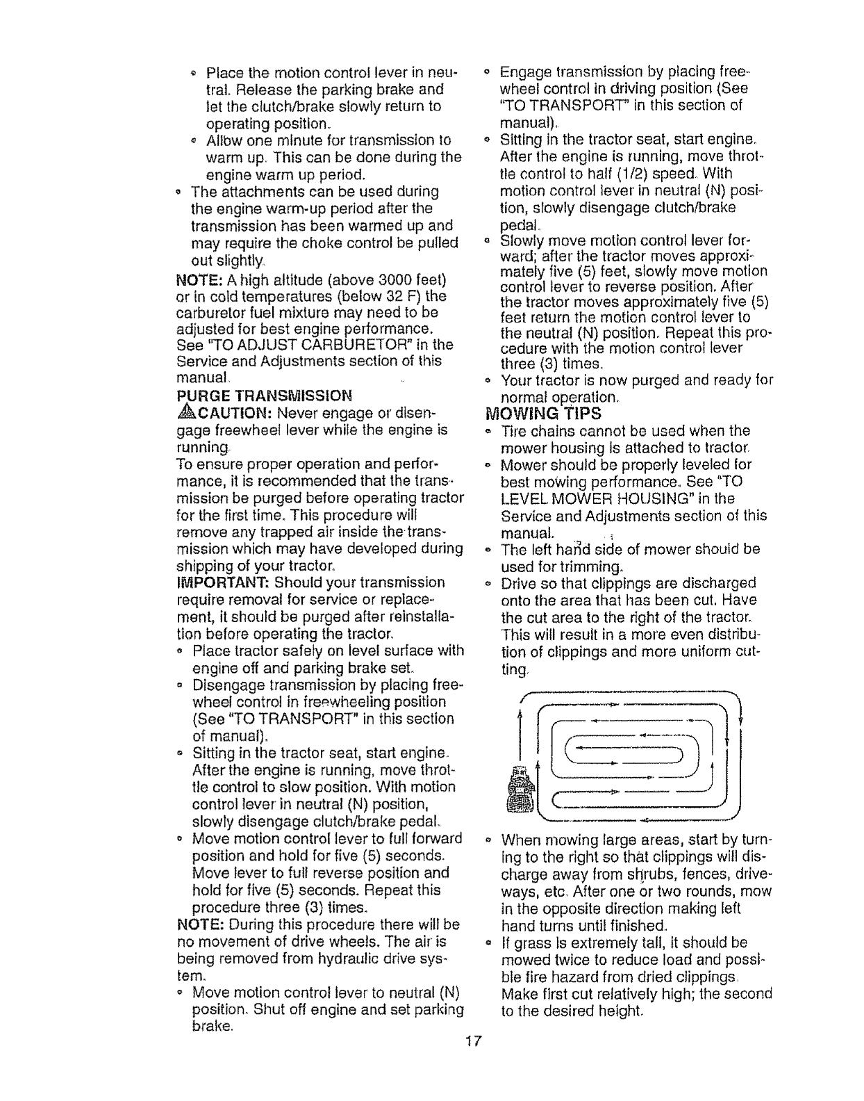
MOWING TIPS
,, Tire chains cannot be used when the
mower housing ts attached to tractor.
o Mower should be properly leveled for
best mowing performance.. See "'TO
LEVEL. MOWER HOUSING" in the
Service and Adjustments section of this
manual. _.
o The left ha_d side of mower should be
used for trimming..
o Drive so that clippings are discharged
onto the area that has been cut, Have
the cut area to the right of the tractor.
]his will result in a more even distribu-
tion of clippings and more uniform cut-
ting
o When mowing large areas, start by turn.-
ing to the right so that cfippings will dis-
charge away from shrubs, fences, drive-
ways, etc_ After one or two rounds, mow
in the opposite direction making left
hand tums until finished..
,, If grass Is extremely tall, It should be
mowed twice to reduce load and possi-
ble fire hazard from dried clippings.
Make first cut relatively high; the second
to the desired height.
o Donot mowgrasswhenit ts wet°Wet
grasswillplugmowerandleaveunde-
sirableclumps.Allowgrassto dry
beforemowing.
,, Always operate engine at _ull throtlle
when mowing to assure better mowing
performance and proper discharge of
material. Regulate ground speed by se-
lecting alow enough gear to give the
mower the best cutting performance as
well as the quality of cut desired.
, When operating attachments, select a
ground speed that wilt suit the terrain
and give best performance of the at-
tachment being used.
MULCHING _IOWING TiPS
IMPORTANT: For best performance, keep
mower housing free of built-up grass and
trash. Clean after each use°
,, The special mulching blade will recut
the grass clippings many times and
reduce them in size so that as they fall
onto the lawn they will disperse into the
grass and not be noticed. Also, the
mulched grass wi!! biodegrade quicldy
to provide nutrients for the lawn_ Always
mulch with your highest engine (blade)
speed as this wilt provide the best recut-
ring action of the blades,
o Avoid cutting your lawn when it is wet,
Wet grass tends to form clumps and
interferes with the mulching action. The
best time to mow your lawn is the early
afternoon. At this time the grass has
dried and the newly cut area will not be
exposed to the direct sun.
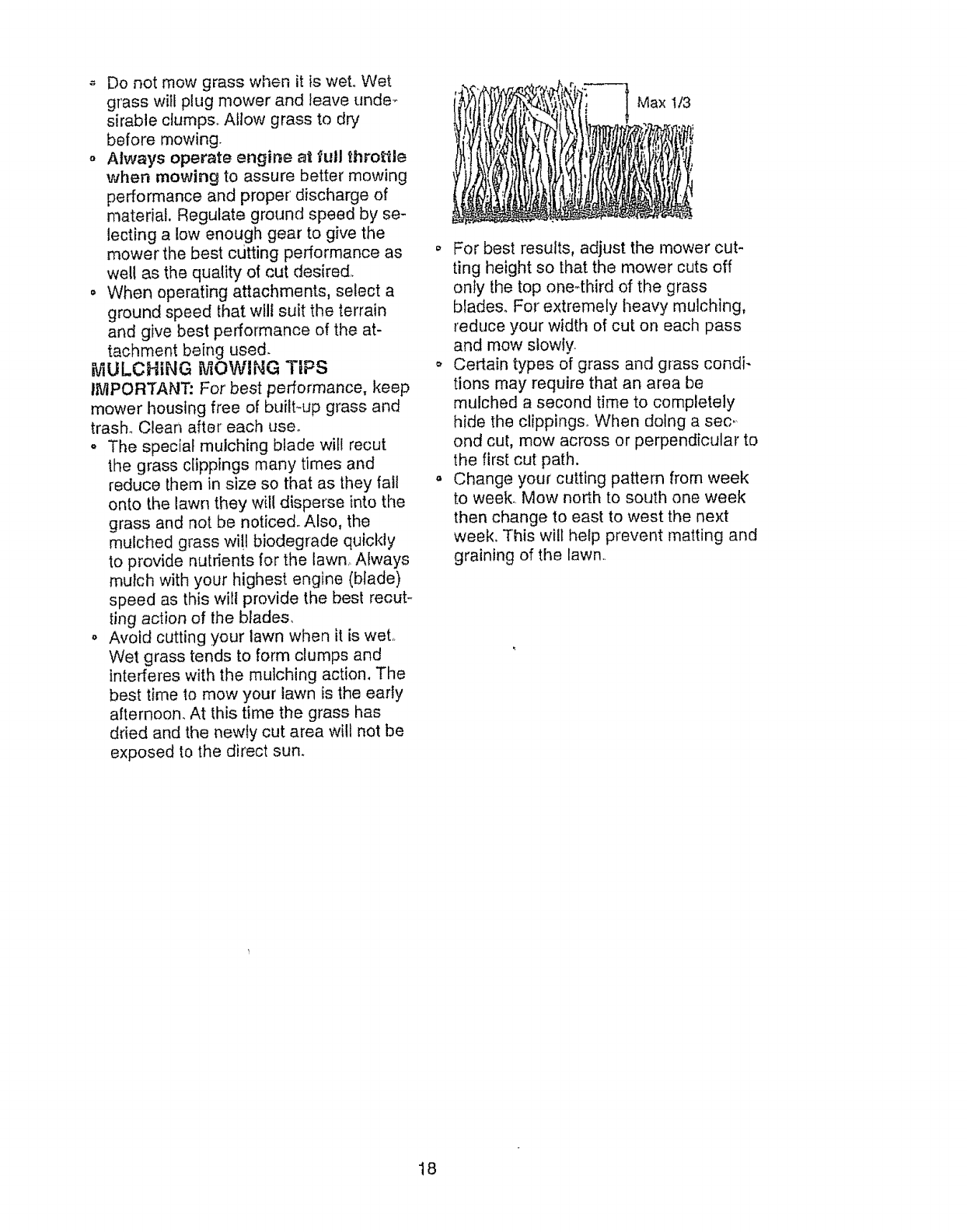
Max 1/3
o For best results, adjust the mower cut-
ting height so that the mower cuts off
only the top one4hird of the grass
blades. For extremely heavy mulching,
reduce your width of cut on each pass
and mow slowly
o Certain types of grass and grass condi-
tions may require that an area be
mulched a second time to completely
hide the clippings, When doing a sec.
ond cut, mow across or perpendicular to
the first cut path.
,, Change your cutting pattern from week
to week. Mow north to south one week
then change to east to west the next
week, This will help prevent matting and
graining of the lawn.
18
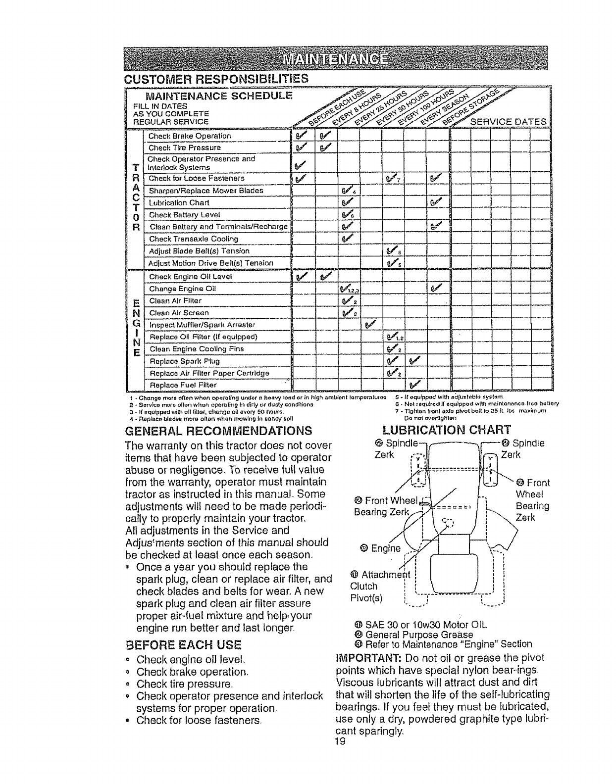
CUSTOMER RESPONSIBILITtIES
MAINTENANCE SCHEDULE.
FILL IN DATES
AS YOU COMPLETE
REGULAR SERVICE
Check Br_ke Operation
Check Tire Pressure
Check Operator Presence and
Tfntedeck Systems
F{ Check |or Loose Fas'=eners
A SharpenfReptace Mowe{ Blades
CLubrication Chart 6/
T
0 Check Battery Level
RClean Battery and Terminals/Recharge
Check Traneexlo Cooling
Adjust Blade Bolt(s) Tension
Adjust Motion Drive Belt(s) Tension
Check Engine 011 Level
Ch4enge Engine Oii
E CleanAtr Filter
N Ctean Air Screen
G Inspect Muff_,erJSparl_ Attester
tReptace ell Ftlter (If equipped)
N
E Clean Engine Cooling Fins
Replace Spark Plug
Replace Air Filter Paper Cartridge
Replaee Fuel Filter
-Chnng_ n_ota often when o_pe,ro_ng _tnder {t henry' fond or _n hIgh amL_ienl tom
-,Sen,,}ce more ellen when epototJng tn diriy or dust',,/conditions
-It equipped wig} oil liIIer, ch_ng_ ell every 50 hm_e.
-Replace bl=del; mote o{ton when tr._wtng In _andy t;olI
GENERAL RECOMMENDATIONS
The warranty on this tractor does not cover
items that have been subjected to operator
abuse or negligence. To receive futl vahJe
from the warranty, operator must maintain
tractor as instructed in this manual.. Some
adjustments will need to be made periodi.-
ca!ty to properly maintain your tractor,
All adjustments in the Service and
Adjus:ments section of this manual should
be checked at least once each season.
,, Once a year you should replace the
spark plug, clean or replace air filter, and
check blades and belts for wear° A new
spark plug and clean air filter assure
proper air-fuel mixture and help, your
engine run better and last longer.
BEFORE EACH USE
= Check engine oil level.
,, Check brake operation.
,, Check tire pressure..
o Check operator presence and interlock
systems for proper operation.
Check for loose fasteners.
t.Ot_{Ulg_7
I
5 - tt aqu_ppe, dwi_'] ad/tt={,cble =ys{om
0 Front
Whee!
@ Front Wileel Bearing
Bearln( Zerk
@ Engine
@ At
Clutch i
Pivot(s) i I
i:
@ SAE 30 or 10w30 Motor OIL
@ General Purpose Grease
@ Refer to Maintenance "Engine" Section
tIViPORTANT; Do not oil or grease the pivot
points which have special nylon bear-ings.
Viscous lubricants will attract dust and dirt
that will shorten the life of the seff-lubricating
bearings, if you feet they must be lubricated,
use only a dry, powdered graphite type lubri.-.
cant sparingly.
19
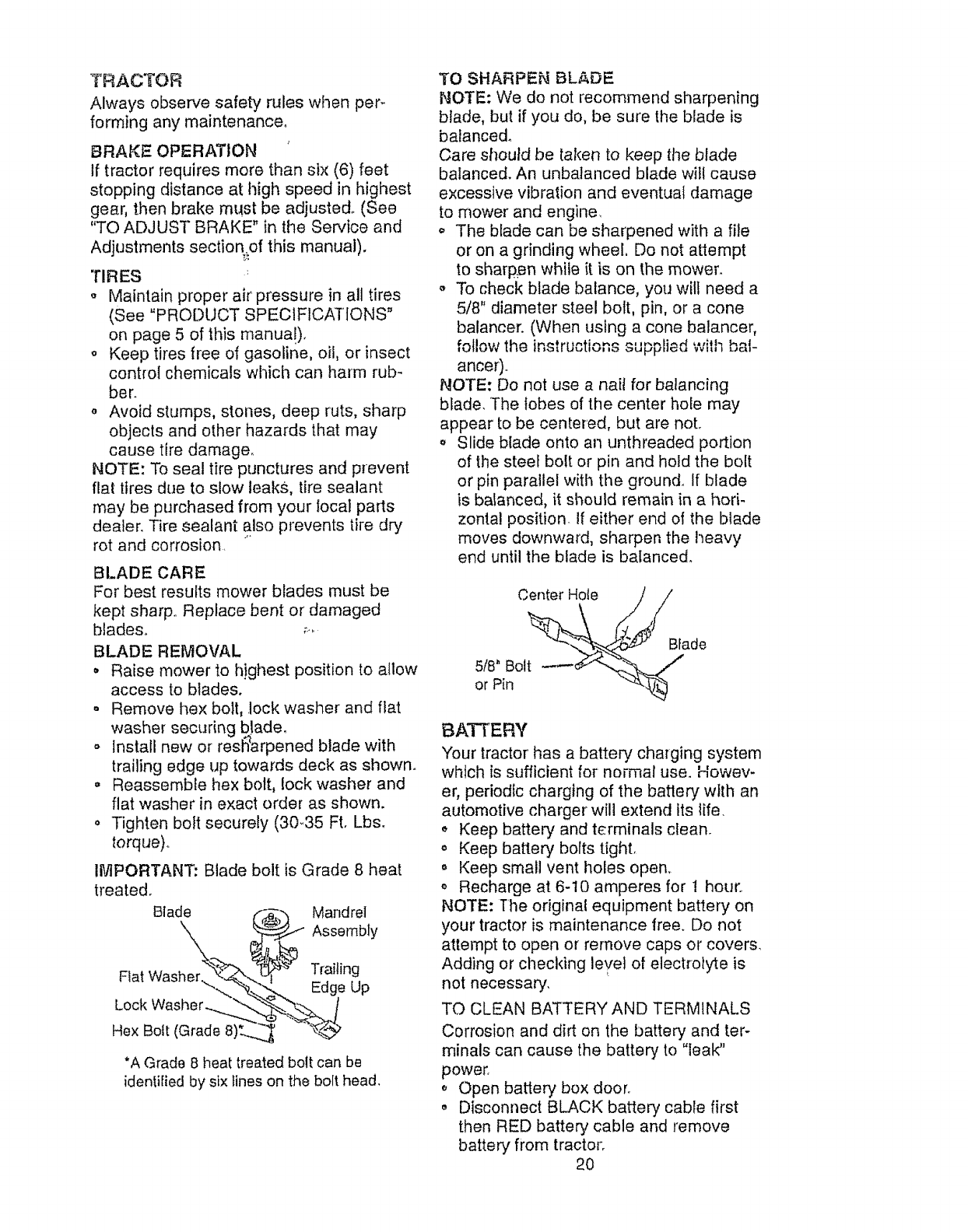
TRACTOR
Always observe safety rules when per-
forming any maintenance°
BRAKE OPERATION
If tractor requires more than six (6) feet
stopping distance at high speed in highest
gear, then brake must be adjusted° (See
"TO ADJUST BRAKE" in the Service and
Adjustments section.of this manual).
TIRES
,, Maintain proper air pressure in all tires
(See "PRODUCT SPECIFICATIONS"
on page 5 of this manua!),
o Keep tires free of gasoline, oil, or insect
control chemicals which can harm rub-
ber.
,, Avoid stumps, stones, deep ruts, sharp
objects and other hazards that may
cause tire damage.
NOTE: To seal tire punctures and prevent
flat tires due to slow leaks, tire sealant
may be purchased from your local parts
dealer. Tire sealant also prevents tire dry
rot and corrosion.
BLADE CARE
For best results mower blades must be
kept sharp° Replace bent or damaged
blades_ _-,.
BLADE REMOVAL
o Raise mower to h}ghest position to allow
access to blades,
- Remove hex bolt, .lock washer and flat
washer securing blade.
o Install new or resl_arpened blade with
trailing edge up towards deck as shown.
o Reassemble hex bolt, lock washer and
flat washer in exact order as shown.
• Tighten bolt securely (3G35 Ft. Lbs.
torque).
IMPORTANT: Blade bolt is Grade 8 heat
treated.
Blade _ Mandrel
Ftat Was Trailing
Lock Washer
Hex Bolt (Grad 8)t.__._ "_
*A Grade 8 heat treated bolt can be
identified by six lines on the bolt head,
TO SHARPEN BLADE
NOTE: We do not recommend sharpening
blade, but if you do, be sure the blade is
balanced_
Care should be taken to keep the blade
balanced. An unbalanced blade will cause
excessive vibration and eventual damage
to mower and engine.
o The blade can be sharpened with a file
or on a grinding wheel. Do not attempt
to sharpen while it is on the mower.
To check blade balance, you will need a
5/8" diameter steel bolt, pin, or a cone
balancer. (When using a cone balancer,
follow the instructions oupvhed with bal-
ance0.
NOTE: Do not use a nail for balancing
blade. The lobes of the center hole may
appear to be centered, but are not.
o Slide blade onto an unthreaded portion
of the steel bolt or pin and hold the bolt
or pin parallel with the ground.. If blade
is balanced, it should remain in a hori-
zontal position, if either end of the blade
moves downward, sharpen the heavy
end until the blade is balanced.
Center Hole
518"Bolt
or Pin
Blade
BATTERY
Your tractor has a battery charging system
which is sufficient for normal use. Howev-
er, periodic charging of the battery with an
automotive charger will extend its life.
,, Keep battery and terminals clean.
o Keep battery bolts tight,
o Keep small vent holes open,
o Recharge at 6-10 amperes for 1 hour..
NOTE: The original equipment battery on
your tractor is maintenance free.. Do not
attempt to open or remove caps or covers,
Adding or checking level of electrolyte is
not necessary.
TO CLEAN BATTERY AND TERMINALS
Corrosion and dirt on the battery and ter-
minals can cause the battery to "leak"
power.
Open battery box door.
o Disconnect BLACK battery cable first
then RED battery cable and remove
battery from tractor.
2O
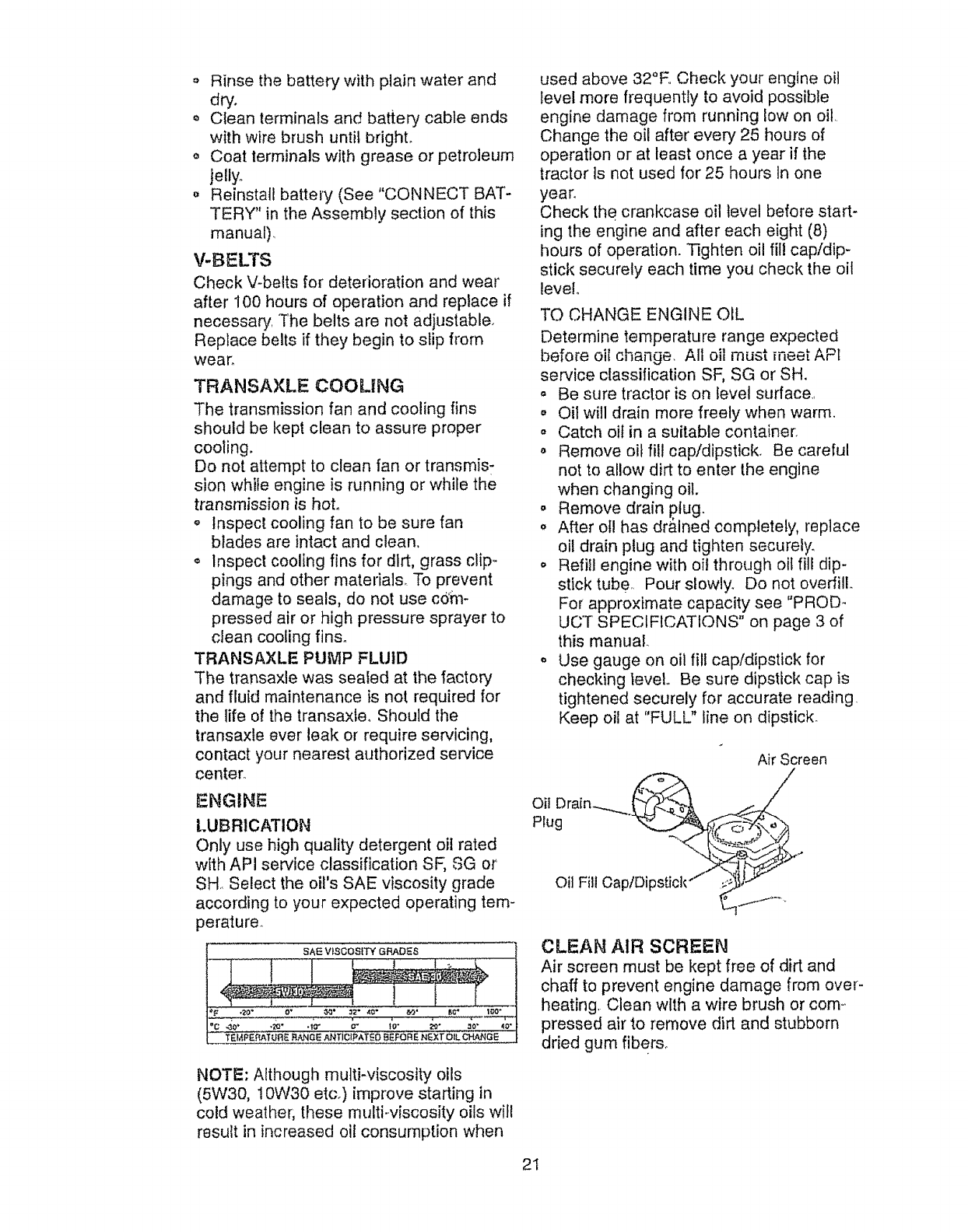
,, Rinsethebatterywithplainwaterand
dry.
,, Cleanterminalsand batterycableends
withwirebrushuntilbright.
o Coatterminalswithgreaseor petroleum
jelly°
o Reinstallbattery(See"CONNECTBAT-
TERY"in theAssemblysectionof this
manual),
V-BELTS
Check V-belts for deterioration and wear
after 100 hours of operation and replace if
necessary. The belts are not adjustable.
Replace belts if they begin to slip from
wear_
TRANSAXLE COOLING
The transmission fan and cooling fins
should be kept clean to assure proper
cooling.
Do not attempt to clean fan or transmis-
sion while engine is running or while the
transmission is hot,
o Inspect cooling fan to be sure fan
blades are intact and clean,
o Inspect cooling fins for dirt, grass clip-.
pings and other materials_ To prevent
damage to seals, do not use com-
pressed air or high pressure sprayer to
clean cooling fins_
TRANSAXLE PUMP FLUID
The transaxle was sealed at the factory
and fluid maintenance is not required for
the life of the transaxle, Should the
transaxte ever leak or require servicing,
contact your nearest authorized service
center_
ENGINE
LUBRICATION
Only use high quality detergent oil rated
with API service classification SF, SG or
SH Select the oil's SAE viscosity grade
according to your expected operating tem-
perature.
NOTE: Although multi-viscosity oils
(5W30, IOW30 etc.) improve starting in
cold weather, these multi-viscosity oils will
result in increased oil consumption when
used above 32°E. Check your engine oil
level more frequently to avoid possible
engine damage from running low on oil
Change the oil after every 25 hours of
operation or at least once a year if the
tractor ts not used for 25 hours In one
year.
Check the crankcase oil level before start-
ing the engine and after each eight (8)
hours of operation. Tighten oil fill cap!dip-
stick securely each time you check the oil
level
TO CHANGE ENGINE OIL
Determine temperature range expected
before oiI change. Alt oil must meet API
service classification SF, SG or SH.
o Be sure tractor is on level surface._
,, Oil will drain more freely when warm,
o Catch oit in a suitable container.
o Remove oil fill cap/dipstick. Be careful
not to allow dirt to enter the engine
when changing oil.
- Remove drain plug.
o After otl has dr&lned completely, replace
oil drain plug and tighten securely.
o Refill engine with oft through oil fill dip-
stick tube, Pour slowly. Do not overfill.
For approximate capacity see "PROD -
UC'T SPECIFICATIONS" on page 3 of
this manual.
,, Use gauge on oil fill cap/dipstick for
checking teveL Be sure dipstick cap is
tightened securely for accurate reading
Keep oil at "FULL" line on dipstick.
Air Screen
Oil Drain .._.___._'_ .._,.7_
CLEAN AIR SCREEN
Air screen must be kept free of dirt and
chaff to prevent engine damage from over-
heating, Clean with a wire brush or corn-,
pressed air to remove dirt and stubborn
dried gum fibers_
21
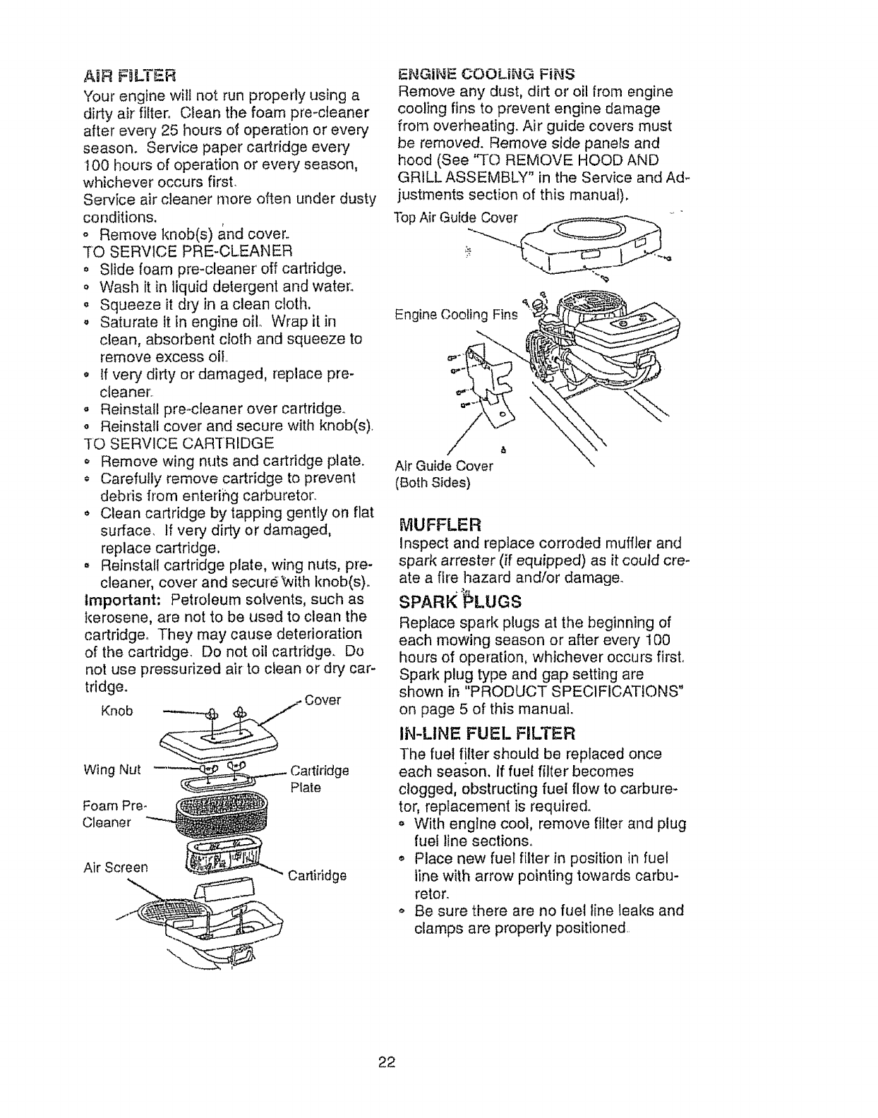
AiR FILTER
Yourenginewiltnotrunproperlyusinga
dirtyairfilter. Cleanthe foampre-cteaner
afterevery25 hoursof operationor every
season. Servicepapercartridgeevery
I00 hoursof operationor everyseason,
whicheveroccursfirst.
Serviceaircleanermoreoftenunderdusty
conditions.
o Removeknob(s)andcover.
"TOSERVICEPRE-CLEANER
o Slidefoampre-cleaneroffcartridge.
o Washit inliquiddetergentandwater:
o Squeezeit dryin acleancloth.
,, Saturateit in engineclio Wrapit in
clean,absorbentclothand squeezeto
removeexcessoil.
Ifverydirtyor damaged,replacepre-
cleaner',
,, Reinstallpreocteanerovercartridge.,
,, Reinstall cover and secure with knob(s).
TO SERVICE CARTRIDGE
o Remove wing nuts and cartridge plate.
Carefully remove cartridge to prevent
debris fl'om entering carburetor.
,, Clean cartridge by tapping gently on flat
surface. If very dirty or damaged,
replace cartridge,
,, Reinstall cartridge plate, wing nuts, pre-
cleaner, cover and secureWith knob(s).
Important: Petroleum solvents, such as
kerosene, are not to be used to clean the
cartridge° They may cause deterioration
of the cartridge. Do not oil cartridge. Do
not use pressurized air to clean or dry car-
tridge.
Knob
Wing Nut Cadiddge
Plate
Foam Pre-
Cleaner
Air Screen Cartiridge
ENGINE COOLING FiNS
Remove any dust, dirt or oil from engine
cooling fins to prevent engine damage
from overheating. Air guide covers must
be removed. Remove side paners and
hood (See "TO REMOVE HOOD AND
GRILL ASSEMBLY" in the Service and Ad-.
justments section of this manual),
Top Air Guide Cover __----_ '
Engine Cooling Fins
Air Guide Cover
(Both Sides)
MUFFLER
Inspect and replace corroded muflJer and
spark arrester (if equipped) as it could cre-
ate a fire hazard and/or damage.
SPARK _LUGS
Replace spark plugs at the beginning of
each mowing season or after every 100
hours of operation, whichever occurs first.
Spark plug type and gap setting are
shown in "PRODUCT SPECIFICATIONS"
on page 5 of this manual.
IN-LINE FUEL FILTER
The fuel filter should be replaced once
each season, if fuel filter becomes
clogged, obstructing fuel flow to carbure-
tor, replacement is required.
o With engine coot, remove filter and plug
fuel line sections.
,, Place new fuel filter in position in fuel
fine with arrow pointing towards carbu-
retor.
o Be sure there are no fuel line leaks and
clamps are properly positioned.
22
Clamp C.lamp
_-_--_-_--- Fuel Filter
CLEANING
,, Clean engine, battery, seat, finish, etc.
of all foreign matter,
,, Keep finished surfaces and wheels free
of all gasoline, oil, etc.
,, Protect painted surfaces with automo-
tive type wax,
We do not recommend using a garden
hose to clean your tractor unless the elec-
trical system, muffler, air filter and carbure-
tor are covered to keep water out Water
In engine can result in a shortened engine
life,
.,_IkCAUTION: Before performing any service or adjustments:
o Depress clutch/brake pedal fully and set parking brake.
• Place motion control lever in neutral (N) position°
,, Place attachment clutch in "DISENGAGED" position.
,, Turn ignition key "OFF" and remove key.
o Make sure the blades and all moving parts have completely stopped_
• Disconnect spark plug wire from spark plug and place wire where it cannot come
in contact with plug.
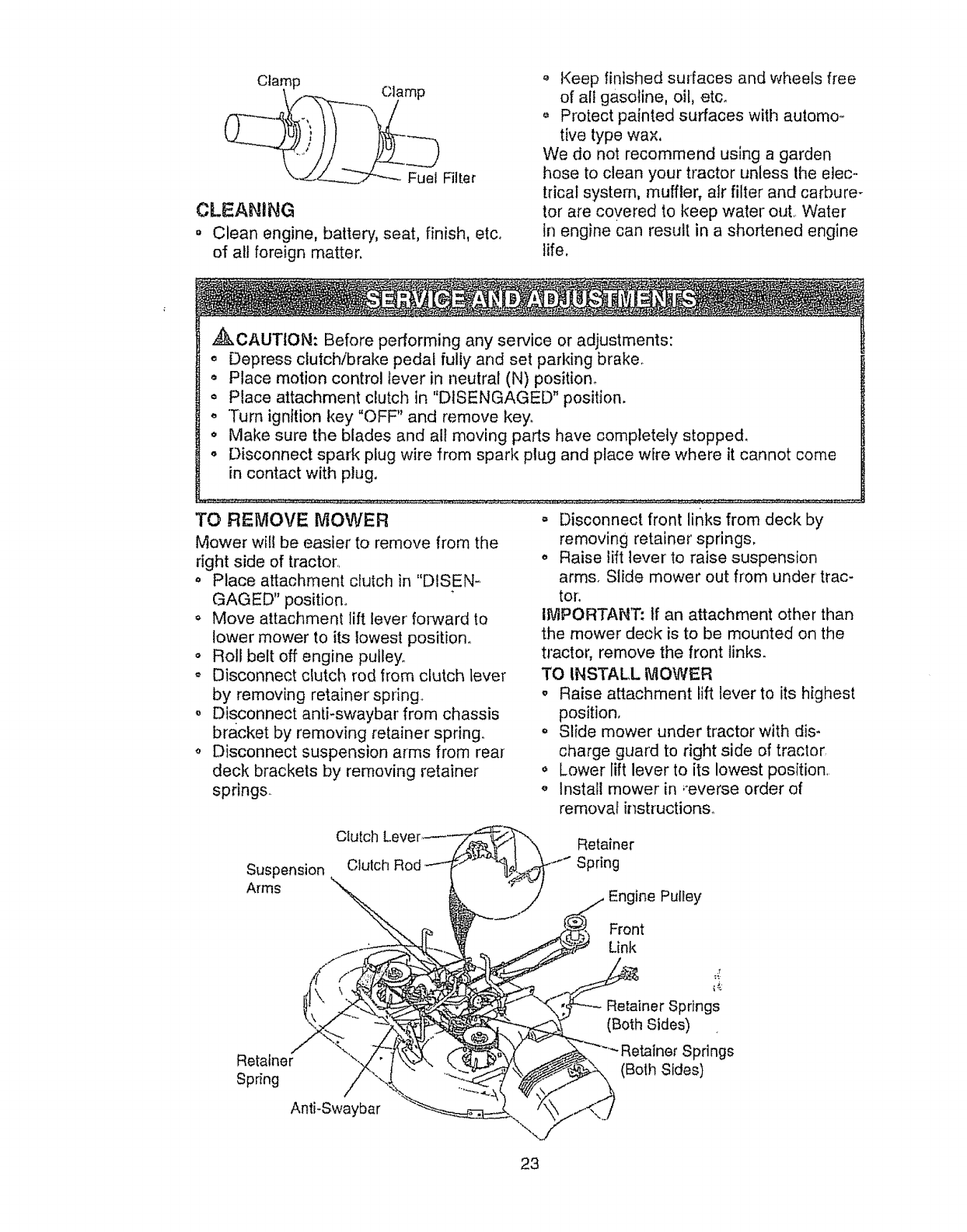
TO REMOVE MOWER
Mower will be easier to remove from the
right side of tractOrr
o Place attachment clutch in "DISEN-
GAGED" position°
o Move attachment lift lever folward to
lower mower to its lowest position.
o Roll belt off engine pulley.
• Disconnect clutch rod from clutch lever
by removing retainer spring.
,, Disconnect anti-swaybar from chassis
bracket by removing retainer spring.
o Disconnect suspension arms from rear
deck brackets by removing retainer
springs
o Disconnect front links from deck by
removing retainer springs.
o Raise lift lever to raise suspension
arms. Slide mower out from under trac-
tor.
IMPORTANT: If an attachment other than
the mower deck is to be mounted on the
tractor, remove the front links.
TO INSTALL MOWER
oRaise attachment lift lever to its highest
position,
o Slide mower under tractor with dis-
charge guard to right side of tractor
,, Lower lift lever to its lowest position
', Install mower in ,'everse order of
removal instructions°
Suspension
Arms
Otutch
Clutch Rod
Retainer
Spring
Engine Pulley
Front
Link
Retainer
Spring
Retainer Springs
(Both Sides)
Springs
(Both Sides)
Anti-Swaybar
23
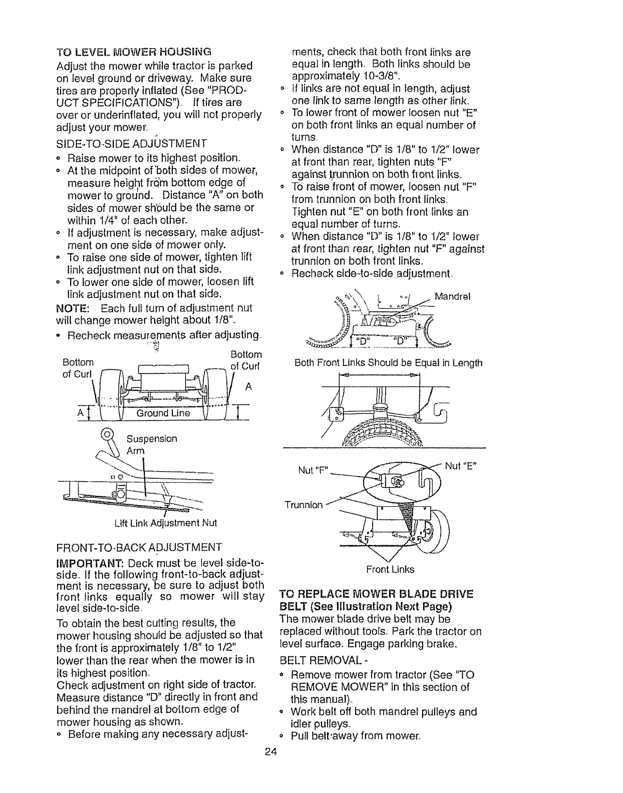
TO LEVELMOWERHOUSING
Adjustthemowerwhiletractoris parked
on levelgroundor driveway°Makesure
tiresareproperlyinflated(See"PROD-
UCTSPECIFICAT'IONS"),.If tiresare
overor underinflated,youwill notproperly
adjustyourmower,.
SIDE-TO-SIDEADJOSTMENT
.Raise mower to its highest position,,
,, At the midpoint of'both sides of mower,
measure height frdm bottom edge of
mower to ground, Distance on both
sides of mower sh'0uld be the same or
within I/4" of each other°
o tf adjustment is necessary, make adjust-
ment on one side of mower only.
,' To raise one side of mower, tighten lift
link adjustment nut en that side.
o To lower one side of mower, loosen lift
link adjustment nut on that side.
NOTE: Each full turn of adjustn1ent nut
will change mower height about 1/8"o
,, Recheck measurements after adjusting,,
Bottom
Bottom _ _ _ of Curl
_,_ A
__ ._
merits, check that both front links are
equal in length. Both links should be
approximately 10-3/8"o
o if links are not equal in length, adjust
one link to same length as other link.
o To lower front of mower loosen nut "E"
on both front links an equal number of
turns,
When distance "D" is 1/8" to 1/2" lower
at front than real', tighten nuts "F"
against trunnion on both fiont links.
o To raise front of mower, loosen nut "F"
from trunnion on both front links.
Tighten nut "E" on both front links an
equal number of turns,
o When distance "D" is 1/8" to 1/2" lower
at front than rear, tighten nut "F" against
trunnion on both front links°
o Recheckslde4o-side adjustment.
_. o,;..'X _ ..../_ Mandrel
Both Front Links Should be Equal In Length
Suspension
Arm
Lift Link Adjustment Nut
FRONT-TO-BACK ADJUSTMENT
IMPORTANT: Deck must be level side-to-
side. If the followingfront4o-back adjust-
ment is necessary, be sure to adjust both
front links equally so mower will stay
level side-to-side,
To obtain the best cutting results, the
mower housing should be adjusted so that
the front is approximately 1/8" to 1/2"
lower than the rear when the mower is in
its highest position,
Check adjustment on right side of tractor,.
Measure distance "D" directly in front and
behind the mandrel at bottom edge of
mower housing as shown_
o Before making any necessary adjust-
i _ Nut "E"
Front Unks
TO REPLACE MOWER BLADE DRIVE
BELT (See Illustration Next Page)
The mower blade drive belt may be
replaced without tools. Park the tractor on
level surface. Engage parking brake,
BELT REMOVAL-
o Remove mower from tractor (See "TO
REMOVE MOWER" in this section of
this manual),,
o Work belt off both mandrel pulleys and
idler pulleys..
o Pull bett'away from mower.
24
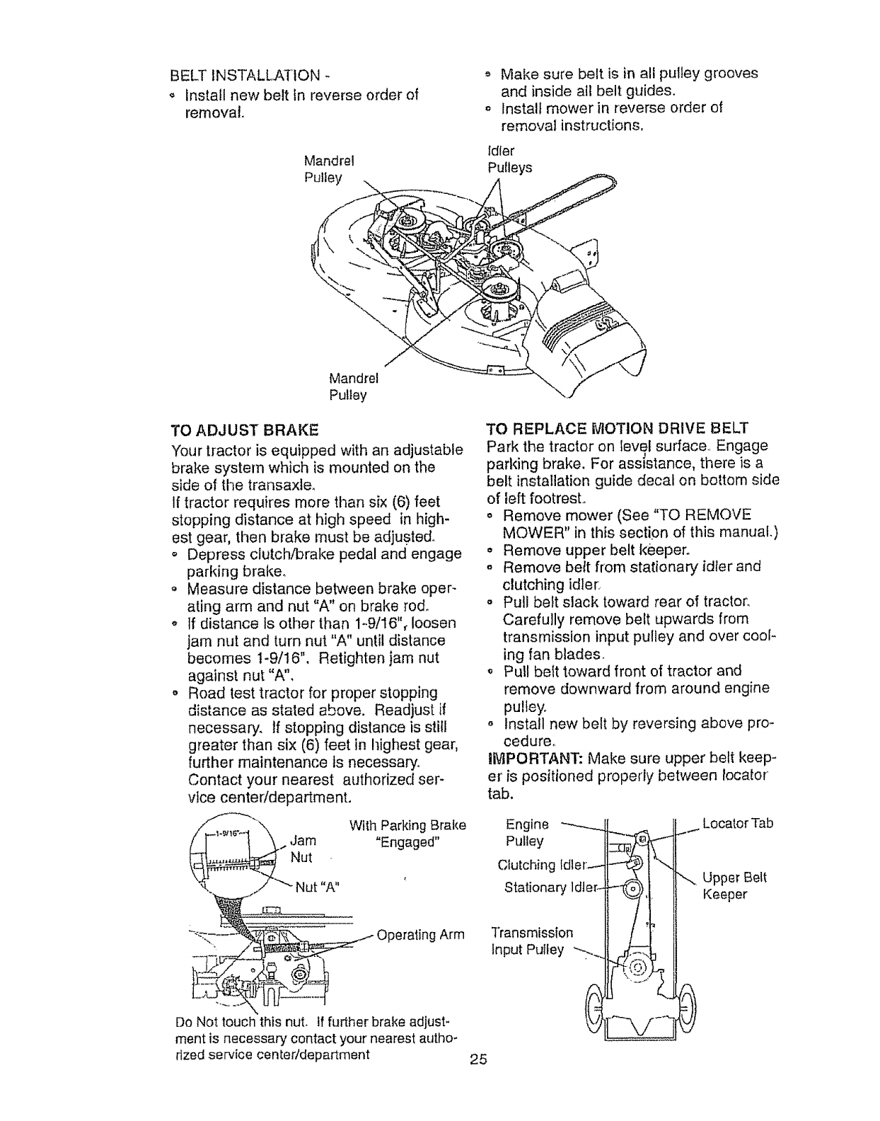
BELTINSTALLATION..
,_ Install new belt In reverse order of
removal.
Mandrel
Pulley
Make sure belt is in alf pulley grooves
and inside all belt guides.
,, Install mower in reverse order of
removal instructions,
Idler
Pulleys
Mandrel
Pulley
TO ADJUST BRAKE
Your tractor is equipped with an adjustable
brake system which is mounted on the
side of the transaxle,
If tractor requires more than six (6) feet
stopping distance at high speed in high-
est gear, then brake rnust be adjusted.
o Depress clutch/brake pedal and engage
parking brake.
o Measure distance between brake oper-
ating arm and nut "A" on brake rod.
o tf distance Is other than 1-9/16", loosen
jam nut and turn nut "A" until distance
becomes t-9/16", Retighten jam nut
against nut "A",
o Road test tractor for proper stopping
distance as stated above. Readjust if
necessary, tf stopping distance is still
greater than six (6) feet in highest gear,
further maintenance Is necessary.
Contact your nearest authorized ser-
vice center/department.
_"'_.. Jam w'th Parking Brake"Engaged"
Do Not touch this nut. If further brake adjust-
ment is necessary contact your nearest autho-
rized service centeddepartment
TO REPLACE MOTION DRIVE BELT
Park the tractor on level surface Engage
parking brake. For assistance, there is a
belt installation guide decal on bottom side
of left footresL
o Remove mower (See "TO REMOVE
MOWER" in this section of this manual.)
o Remove upper belt keeper.
o Remove belt from stationary idler and
clutching idler.
° Pull belt slack toward rear of tractor,
Carefully remove beet upwards from
transmission input pulley and over cool-
ing fan blades.
,_ Pull belt toward front of tractor and
remove downward from around engine
pulley.
o Install new belt by reversing above pro-
cedureo
iMPORTANT: Make sure upper belt keep-
er is positioned properly between locator
tab.
Engine ---_-._ _.
Transmission !1 /|_
Input Putley "_... __
Locator Tab
_._ Upper Belt
Keeper
25
TOADJUSTMOTIONCONTROLLEVER
]"he motioncontrolleverhasbeenpreset
at thefactoryand adjustmentshouldnot
be necessary°
Iffor anyreasonthemotioncontrollever
wiltnot holdits posit!onwhile at a selected
speed, it maybe adjustedatthe friction
packlocatedon therightside of transmis-
sion..
o Parktractoron levelsurface. Stoptrac-
tor by turningignitionkey to "OFF"posi-
tion,andengageparkingbrake.
o Adjustmotioncontrollever bytightening
adjustmentlocknutone half(I/2) turn.
NOTE: Iffor anyreasonthe effortto
movethe motioncontrolleverbecomes
tooexcessive,reversethe aboveadjust-
mentprocedurebylooseningIocknut1/4
to 1/2turn.
Roadtesttractorafteradjustmentand
repeatprocedureif necessary.
TRANSMISSIONREMOVAL!REPLACE-
MENT
Shouldyourtransmissionrequireremoval
for serviceor replacement,it shouldbe
purgedafterreinstaIlationandbefore
operatingthe tractor. See "PURGE
TRANSMISSION" in the Operation section
of this manual. ,_-
Adjustment
....... Locknut
TO ADJUST STEERING WHEEL ALIGN-
MENT
If steering wheel crossbars are not hori-
zontal (left to right) when wheels are posi-
tioned straight forward, remove steering
wheel and reassemble per instructions in
the Assembly section of this manual.
FRONT WHEEL TOE-INtCAMBER
The front wheel toe4n and camber are not
adjustable on your tractor, tf damage has
occurred to affect the front wheel toe-in or
camber, contact your nearest authorized
service centen
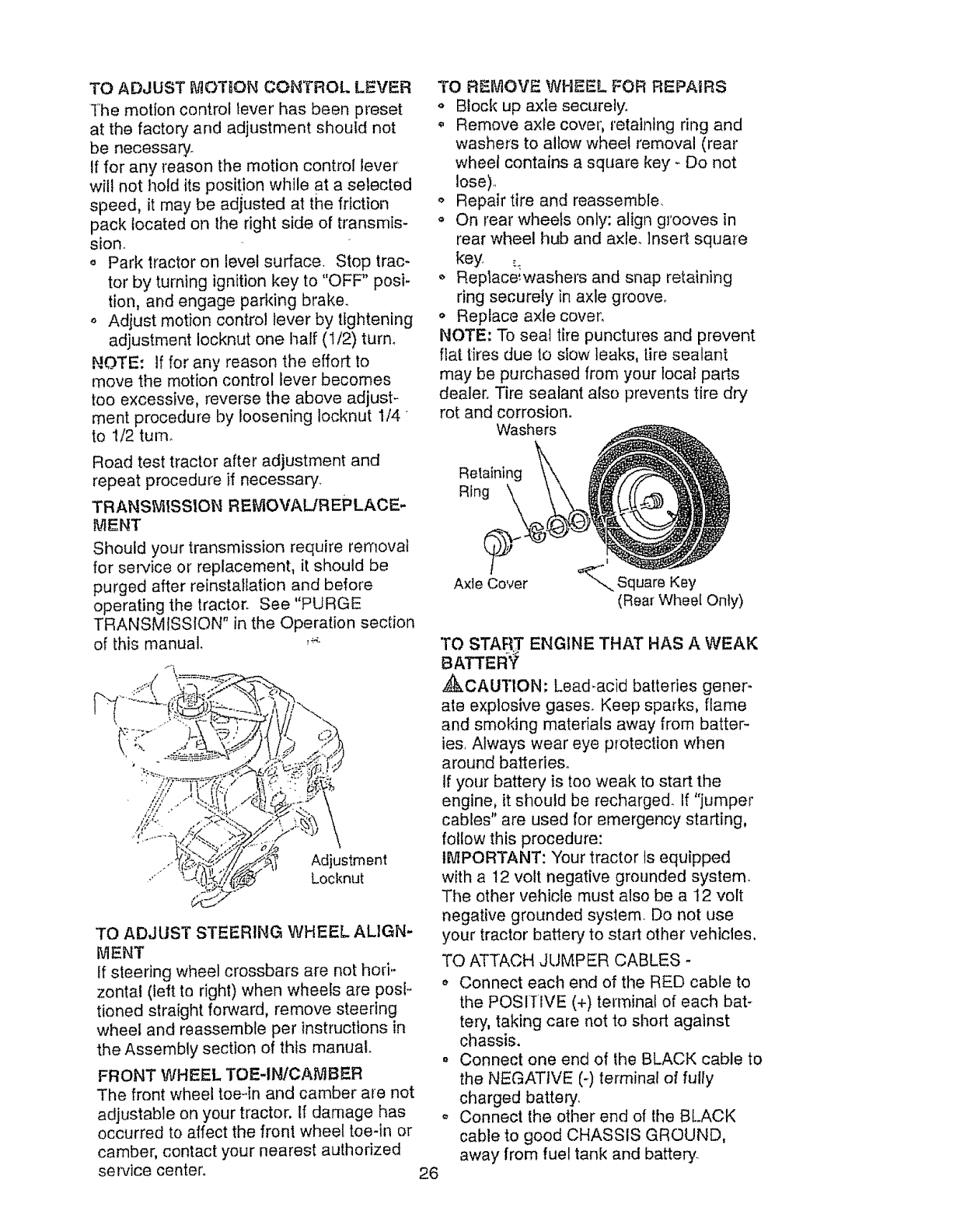
TO REMOVE WHEEL FOR REPAIRS
o Block up axle securely,.
• Remove axle cover, retaining ring and
washers to allow wheet removal (rear
wheel contains a square key - Do not
lose)..
o Repair tire and reassemble,
o On rear wheels only: align grooves in
rear wheel hub and axle. Insert square
key .:_
,, Replace:washers and snap retaining
ring securely in axle groove.
o Replace axle cover.
NOTE: To seal tire punctures and prevent
flat tires due to slow leaks, tire sealant
may be purchased from your local parts
dealer. Tire sealant also prevents tire dry
rot and corrosion.
Washers
Retaining
Ring
Axle Cover
|
_.,, Square Key
(Rear Wheel Only)
TO START ENGINE THAT HAS A WEAK
BATTEF
_CAUTION: Lead.acid batteries gener-
ate explosive gases. Keep sparks, flame
and smoking materials away from batter-
ies, Always wear eye protection when
around batteries°
if your battery is too weak to start the
engine, it should be recharged. If "jumper
cables" are used for emergency starting,
follow this procedure:
IMPORTANT: Your tractor ts equipped
with a 12 volt negative grounded system_
The other vehicle must also be a 12 volt
negative grounded system Do not use
your tractor battery to start other vehicles,
TO ATTACH JUMPER CABLES -
_, Connect each end of the RED cable to
the POSITIVE (+) terminal of each bat-
tery, taking care not to short against
chassis.
° Connect one end of the BLACK cable to
the NEGATIVE (-.) terminal of fully
charged battery,
o Connect the other end of the BLACK
cable to good CHASSIS GROUND,
away from fuel tank and battery.
26
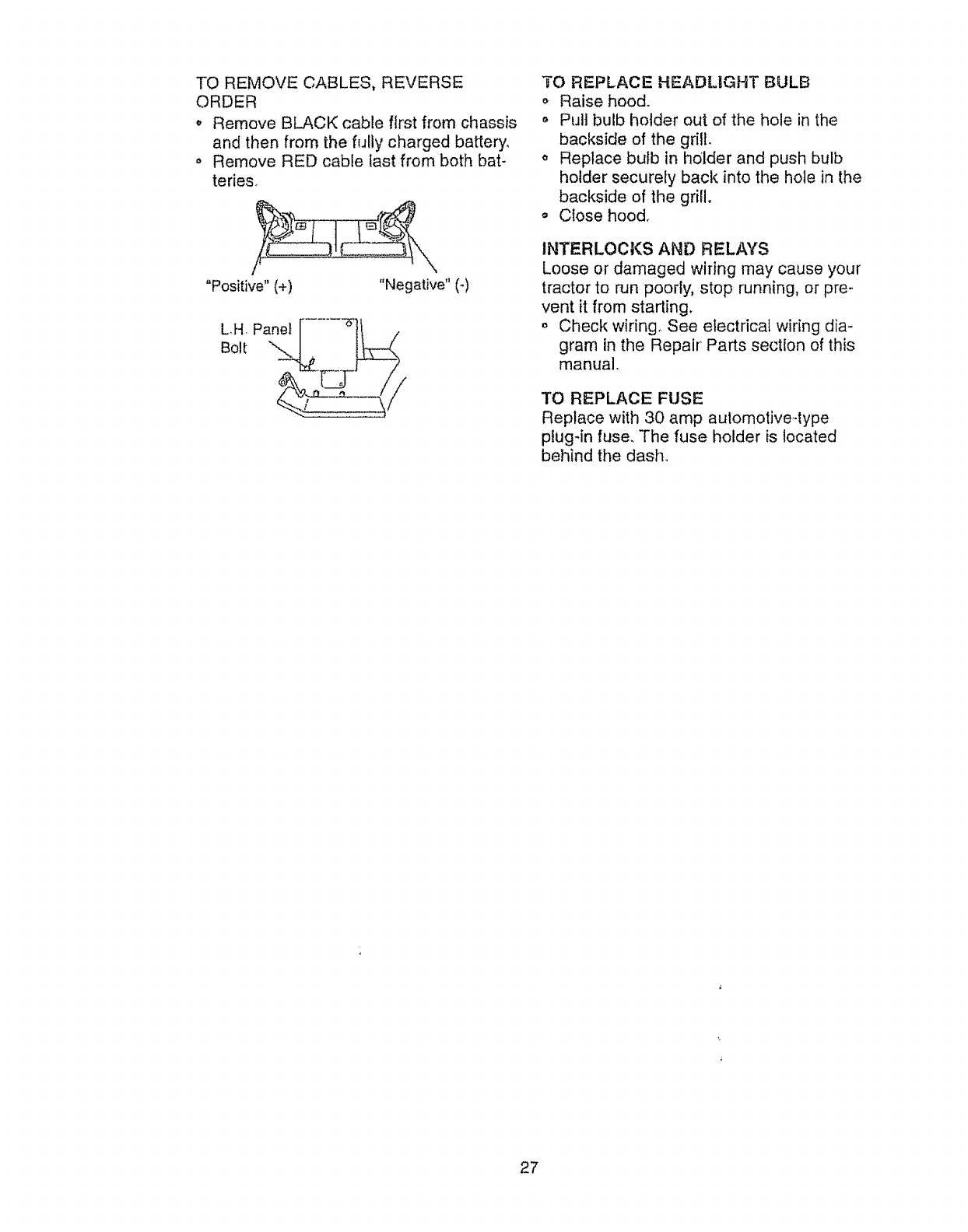
TOREMOVECABLES,REVERSE
ORDER
o RemoveBLACKcablefirstfrom chassis
andthen from thefully chargedbattery,
o RemoveREDcablelastfrombothbat-
teries.
"Positive"(+) "Negative"(*)
Panel .... -6"
LH, ._
Bolt
TO REPLACE HEADUGHT BULB
o Raise hood.
o Pull bulb holder out of the hole in the
backside of the grill.
,, Replace bulb in holder and push bulb
holder securely back into the hole in the
backside of the grill.
o Ctose hood.
INTERLOCKS AND RELAYS
Loose or damaged wiring may cause your
tractor to run poorly, stop running, or pre-
vent it from starting.
,, Check wiring. See electrical wiring dia-
gram in the Repair Parts section of this
manual.
TO REPLACE FUSE
Replace with 30 amp automotive-type
plug-in fuse. The fuse holder is located
behind the dash.
27
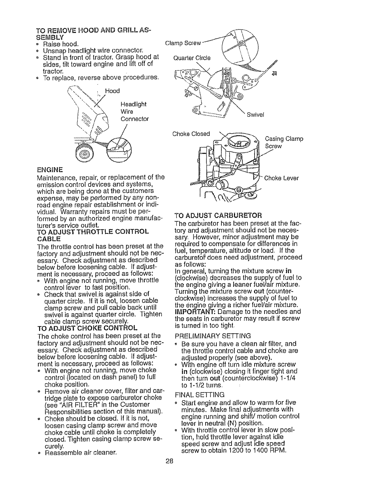
TO REMOVEHOODAND GRILLAS-
SEMBLY
,_ Raisehood°
,, Unsnapheadlightwireconnector.
o Standin front of tractor: Grasp hood at
sides, tilt toward engine and lift off of
tractor.
, To replace, reverse above procedures.
ENGINE
Maintenance, repair, or replacement of the
emission control devices and systems,
which are being done at the customers
expense, m_y be performed by any non-
road engine repair establishment or indF
vidual. Warranty repairs must be per-
formed by an authorized engine manufac-
turer's service outlet.
TO ADJUST THROTTLE CONTROL
CABLE
The throttle control has been preset at the
factory and adjustment should not be nec-
essary. Check adjustment as described
below before loosening cable. If adjust..
merit is necessary, proceed as follows:
o With engine not running, move throttle
control lever to fast position.
o Check that swivel.is against side of
quarter circle° li it is not, loosen cable
clamp screw and pull cable back until
swivel is against quarter circle. Tighten
cable clamp screw securely.
TO ADJUST CHOKE CONTROL
The choke control has been preset at the
factory and adjustment should not be nec-
essary. Check adjustment as described
below before loosening cable. If adjust-
ment is necessary, proceed as follows:
° With engine not running, move choke
control (located on dash panel) to full
choke position.
Remove air cleaner cover, filter and car-
tridge plate to expose carburetor choke
(see 'AfR FILTER' in the Customer
Responsibilities section of this manual)°
o Choke should be closed, tf it is not,
loosen casing clamp screw and move
choke cable until choke is completely
closed, Tighten casing clamp screw se-
curely,
o Reassemble air cleaner,
28
Choke Cto_ed Casing Clamp
Screw
Choke Lever
TO ADJUST CARBURETOR
The carburetor has been preset at the fac-
tory and adjustment should not be neces-
sary However, minor adjustment may be
required to compensate for differences in
fuel, temRerature , altitude or load. If the
carburets# does need adjustment, proceed
as follows:
In general, turning the mixture screw in
(clockwise) decreases the supply of fuel to
the engine giving aleaner fuel/air mixture.
Turning the mixture screw out (counter-
clockwise) increases the supply of fuel to
the engine giving a richer fuel/air mixture.
IMPORTANT zDamage to the needles and
the seats in carburetor may result if screw
is turned in too tight.
PRELIMINARY SETTING
" Be sure you have a clean air filter, and
the throttle conlrol cable and choke are
adjusted properly (see above),
With engine off turn idle mixture screw
in (clockwise) closing it finger' tight and
then turn out (counterclockwise) t-1/4
to 1-1!2 turns.
FINAL SE'I-FING
,, Start engine and allow to warm for five
minutes. Make final adjustments with
engine running and shift/motion control
lever in neutral (N) position.
o With throttle control lever in slow posi-
tion, hold throttle lever against idle
speed screw and adjust idle speed
screw to obtain 1200 to t400 RPM.
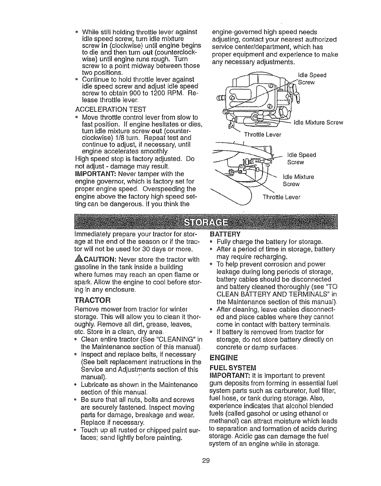
,, While still holding throttle lever against
idle speed screw, turn idle mixture
screw in(c!oclwvise) until engine begins
to die and then turn out (counterclock-
wise) until engine runs rough. Turn
screw to a point midway between those
two positions.
° Continue to hold throttle lever against
idle speed screw and adjust idle speed
screw to obtain 900 to t200 RPM Re-
lease throttle lever.
ACCELERATION TEST
• Move throttle control lever from slow to
fast position. If engine hesitates or dies,
turn idle mixture screw out (counter-
cteclwvise) 1/8 turn. Repeat test and
continue to adjust, if necessary, until
engine accelerates smoothly.
High speed stop is factory adjusted., Do
not adjust - damage may result.
IMPORTANT: Never tamper with the
engine governor, which is factory set for
proper engine speed. Overspeeding the
engine above the factory high speed set-
ting can be dangerous. If you think the
engine-governed high speed needs
adjusting, contact your nearest authorized
service centeddepartment, which has
proper equipment and experience to make
any necessary adjustments.
Idle Speed
Screw
Idle Mixture Screw
'Throttle Lever
_. Idle Speed
Screw
Throttle Lever
Immediately prepare your tractor for stor-
age at the end of the season or if the trac-
tor will not be used for 30 days or more,
,_CAUTION: Never store the tractor witll
gasoline in the tank inside a building
where fumes may reach an open flame or
spark. Allow the engine to cool before stor-.
ing in any enclosure°
TRACTOR
Remove mower from tractor for winter
storage, This will allow you to clean it thor-
oughly, Remove all dirt, grease, leaves,
etc. Store in a clean, dry area.
,, Clean entire tractor (See "CLEANING" in
the Maintenance section of this manual).
,, Inspect and replace belts, if necessary
(See belt replacement instructions in the
Service and Adjustments section of this
manual),
Lubricate as shown in the Maintenance
section of this manual,
o Be sure that all nuts, bolts and screws
are securely fastened, Inspect moving
parts for damage, breakage and wear.
Replace if necessary.
o Touch up all rusted or chipped paint sur-
faces; sand lightly before painting.
BATTERY
° Fully charge the battery for storage.
° After a period of time in storage, battery
may require recharging.
_, To help prevent corrosion and power
leakage during long periods of storage,
batter,/cables should be disconnected
and battery cleaned thoroughly (see '%0
CLEAN BATTERY AND TERMINALS" in
the Maintenance section of this manual),
After cleaning, leave cables disconnect-
ed and place cables where they cannot
come in contact with battery terminals
o If battery Is removed from tractor for
storage, do not store battery directly on
concrete or damp surfaces.
ENGINE
FUEl. SYSTEM
IMPORTANT: It is important to prevent
gum deposits from forming in essential fuel
system parts such as carburetor, fuel filter,
fuel hose, or tank during storage. Also,
experience indicates that alcoho! blended
fuels (called gasohol or using ethanol or
methanol) can attract moisture which leads
to separation and formation of acids during
storage. Acidic gas can damage the fuel
system of an engine while in storage.
29
o Drainthefueltank.
o Starttheengineand let it rununtilthe
fuel linesandcarburetorareempty.
Never use engine or carburetor cleaner
products in the rue! tank or permanent
damage may occur.
_, Use fresh fuel next season.
NOTE: Fuel stabilizer is an acceptable
alternative in minimizing the formation of
fuel gum deposits during storage. Add sta-
bilizer to gasoline ini:fuel tank or storage
container, Always follow the mix ratio
found on stabilizer container, Run engine
at least 10 minutes afte[ adding stabilizer
to allow the stabilizer to reach the carbure-
tor. Do not drain the gas tank and carbure-
tor if using fuel stabilizer,
ENGINE OIL
Drain oil (with engine warm) and replace
with clean engine oil. (See "ENGINE" in
the Maintenance section of this manual).
CYLINDER(S)
o Remove spark plug(s).
o Pour one ounce of oil through spark plug
hole(s) into cylinder(s).
o Turn ignition key to "START" position for
a few seconds to distribute oil
,, Replace with new spark plug(s).
OTHER
oDo not store gasoline from one season
to another.
o Replace your gasoline can if it starts to
rust, Rust and/or did in your gasoline will
cause problems.
o If possible, store your tractor indoors
and cover it to give protection from dust
and dirt.
o Cover your tractor with asuitable proteco
tire cover that does not retain moisture.
Do not use plastic. Plastic cannot
breathe, which allows condensation to
form and cause your tractor to rust,
iMPORTANT: Never cover tractor while
engine and exhaust areas are still warm.
3O

TROUBLESHOOTaNG CHART
Will not start
Hard to start
Engine w!ll not turn
over
CAUSE
o Out of fuel,
Engine not "CHOKED" prop*
erly,
° Engine flooded.
Engine clicks but will
not start
° Bad spark plug.
o Dlrty air filter,
o Dirty fuel filter,
o Waterin fuel.
Loss of power
o Loose oi damaged wiring,
o Carburetor out of adjustment_
° Engine valves out of adjust-
ment.
,, Dirty air filter.
Bad spark plug.
-Weak or dead battery,
Dirty fuel fitter_
o Stale or dirty fuel.
Loose or damaged wiring.
= Carburetor out of adjuslment.
o Engine valves out of adjust-
ment.
o Ctutchtbrake pedal not
depressed.
• Attachment clutch is engaged,
° Weak or dead battery.
Blown fuse°
• Corroded battery terminals.
° Loose or damaged wtrlng.
o Faulty ignition swllch.
o Faulty solenoid or starter.
° Faulty operator presence
switch(es).
o Weak or dead battery,
Corroded battery terminals.
= Loose or damaged wiring.
° Faulty solenoid or starter,
° Cutting too much grass/too
fast,,
° Throttle in "CHOKE" position.
CORRECTION .....
° Fill fuel tank.
,, See %0 START ENGINE" in
Operation section.
o Wait several minutes before
attempting to starL
o Replace spark plug.
o Cfeantreplace airfitter.
. Replace fuel filter.
o Drain fuel tank and carburetor,
refill tank wifh fresh
gasoline and replace fuel filter°
-,, Check all wiring_
o See "To Adjust Carburetor" tn
Service and Adiustments
section_
o Contact an authorized service
center,
o Clean/replace air filter,
• Replace sparkplug
° Recharge or replace battery.
o Replace fuel filter.
° Drain fuel tank and refill witl_
fresh gasoline,
,, Check all wiring.
o See "To Adjust Carburetor" in
Service and Adjustments
section.
° Contact an authorized service
center
o Depress clutch/brake pedal..
o Disengage attachment clutch
Recharge or replace battery
o Replace fuse..
o Clean batteryterminafs..
o Check all wiring.
o Check/replace ignition switch
o Check/replace solenoid or
starter,.
,, Contact an authorized service
center
o Recharge or replace battery.
o Clean battery terminals,.
°Check all wiring,
o Checldreplace solenoid or
starter.,
o Set in "Higher Cur' posi.
tion/reduce speed,
_, Adjust throttle control
3I
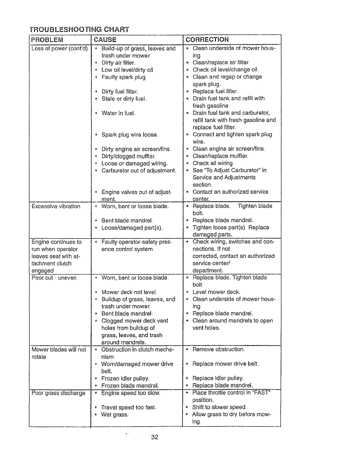
1tROUBLESHOOTiNG CHART
PROBLEM CAUSE
Loss of power (cont'd) • Build-,up of grass, leaves and
trash under mower.,
oDirty air filter.
o Low oil level/dirty oil.
. Faulty spark plug.
• Dirty fuel filter.
• Stale or didy fuel.,
Water in fuel.
• Spark plug wire loose.
Excessive vibration
Engine continues to
run when operator
leaves seat with at-
tachment clutch
engaged _____
Poor cut - uneven
Mower blades wilt not
rotate
Poor grass discharge
. Dirty engine air screentfins.
. Dfrtylclogged muffler,
° Loose or damaged wiring.
o Carburetor out of adjustmenL
° Engine valves out of adjust-
menL
. Worn, bent or loose blade,
.Bentblade mandrel,
• Loose/damaged part(s).
- Faulty operator-safely pres-
ence control system-
. Worn, bent or loose blade.
° Mower deck not level,
° Buildup of grass, leaves, and
trash under mower.
°Bent blade mandrel.
o Clogged mower deck vent
holes from buildup of
grass, leaves, and trash
around mandrels.
°Obstruction in clutch mecha-
nism.
- Womldamaged mower drive
belt.
• Frozen idler pulley.
• Frozen blade mandrel,
_speed too stow.
•'Travel speed too fasL
• Wet grass.
CORRECTION
o Clean underside of mower hous-
ing.
o Cfean/replace air filter.
o Check oil level!change oilo
- Clean and regap or change
spark plug.,
o Replace fuet filter,,
Drain fue! tank and refill with
fresh gasoline.
Drain fuel tank and carburetor,
refill tank with fresh gasoline and
replace fuel filter.
o Connect and tighten spark plug
were.
° Clean engine air screen/fins,,
,, Clean/replace muffler,
°Check all wiring.
o See "To Adjust Carburetor" in
Service and Adjustments
section,.
,, Contact an authorized service
center.
• Replace blade., Tighten blade
bolt.
. Replace blade mandrel.
. Tighten loose part(s) Replace
damaged parts,
o Check wiring, switches and con-
nections. If not
corrected, contact an authorized
service center/
department.
oReplace blade. Tighten blade
bolt
= Level mower deck.
oClean underside of mower hous-
ing
o Replace blade mandrel.
• Clean around mandrels to open
vent holes.
"-- i%mo; ;e-or -siructlon....... .....
. Replace mower drive belt.
. Replace Idler pulley_
o Replace blade mandrel.
o Place throttle control In "FAST"
postttom
o Shift to slower speed.
o Allow grass to dry before mow.
ing.
1 ' 32
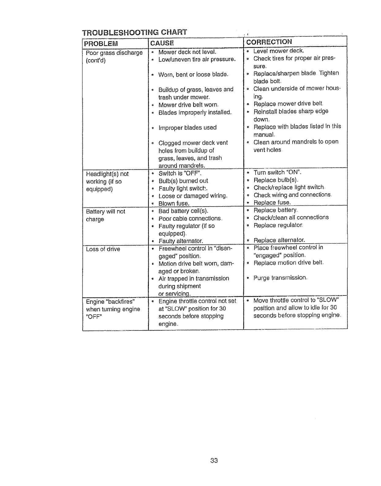
TROUBLESHOOTING CHART
PROBLEM CAUSE
Poor grass discharge o Mower deck not level,
(cont'd) o Low/uneven tire air pressure.
Headlight(s) not
working (if so
equipped)
Battery will not
charge
Loss of drive
Engine "backfires"
when turning engine
"OFF"
,, Worn, bent or loose blade.
• Buildup of grass, leaves and
trash under mower.
. Mower drive belt worn.
- Blades improperlyinstalted.
o Improper blades used
. Clogged mower deck vent
holes from buildup of
grass, leaves, and trash
around mandrels,
o Switch is "OFF".
,, Bulb(s) burned out
o Faulty light switch.
o Loose or damaged wiring.
° Blown fuse.
° Bad battery celt(s).
.Poor cable connections.
. Faulty regulator (if so
equfpped),
° Faulty. alternator.
o Freewheel control in "disen-
gaged" position.,
o Motion drive belt worn, dam-
aged or broken,
o Air trapped in transmission
during shipment
or servtcing_ ....
°Engine throttle control not set
at "SLOW_'position for 30
seconds before stopping
engine.,
CORRECTION
o Level mowerdeck.
. Check tires for proper air pres-
sure.
Replace/sharpen blade Tighten
blade bolt.
o Clean underside of mower hous -
[rig,
,_ Replace mower drive belt.
Reinstall blades sharp edge
down..
o Replace with blades listed in this
manuat.
Clean around mandrels to open
vent tloles
Turn switch "ON".
. Replace bulb(s).
o Checldreplace light switch.
Check wiring and connections.
,, Replace fuse.
° Replace battery.,
o ChecWclean all connections
o Replace regulator.
° Replace alternator.
,, Place freewheel control in
"engaged" position.
. Replace motion drive bell.
° Purge transmission.
o Move throttle control to"SLOW"
posftion and allow to idle for 30
seconds before stopping engine.
33
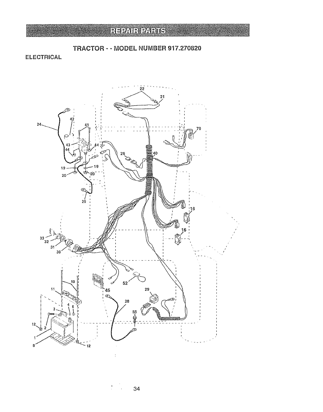
ELECTRICAL
TRACTOR - - MODEL NUMBER 917.270820
12
It
I
I
I
28
55
1
t2
t
I
!
!
¢
t
t34

ELECTRICAL
TRACTOR -- MODEL NUMBER 9!7.270820
KEY PART
NO. NO. DESCRIPTION
t 163465 Battery
2 74760412 Bolt, Hex 1/4-20 x3/4
3 STD551025 Washer 9/32 x 5/8 x t6 Gauge
4 8TD55t125 Washer, Lock 1/4
6 STD541025 Nut, He× t/4-20
8 7603J Tray, Battery
1(} 145211 Bolt, Btr Front 1/4-20 x 7_1/2
11 150109 Holddown Baltery Front Mount
12 145769 Nut, Push Nyton Battery Front t/4
I6 153664 Switch Interlock Push-ln
!9 STD55t125 Washer, Lock 1/4
20 73350400 Nut, Hex, Jam 1/4-20
2t 147430 Harness, Ugh[ Socket (w14152J)
22 4152J Light Bulb
24 4799J Cable, Battery
25 146148 Cable, Baltery
26 108824X Fuse
28 145491 Cable, Ground
29 12t305X Switch, Seat
30 140301 Switch, Ignition 4 Position
3I 12421tX Nut, Ignition
32 141226 Cover, Ignltton Swilch
33 10931OX Key, Molded, Craftsman
40 156442 Harness, Ignition
41 71110408 Bolt Btk Fin Hex 1/4-20 UNC x t/2
42 131563 Cover, Termfna_
43 145673 Solenoid
44 73640400 Nut Keps Btk Hex 1/4.20 UNC
45 121433X Ammeter Rectangular 6 Amp
52 14t940 Profec_ionWire Loop {Hour Meter)
55 17490508 ScrewThdrol 5/16-18 x 1/2
70 140413 Harness Engine B&SiTec Dual
No]rE: All component dimensions given in US inches
1 inch = 25 4 mm
b5
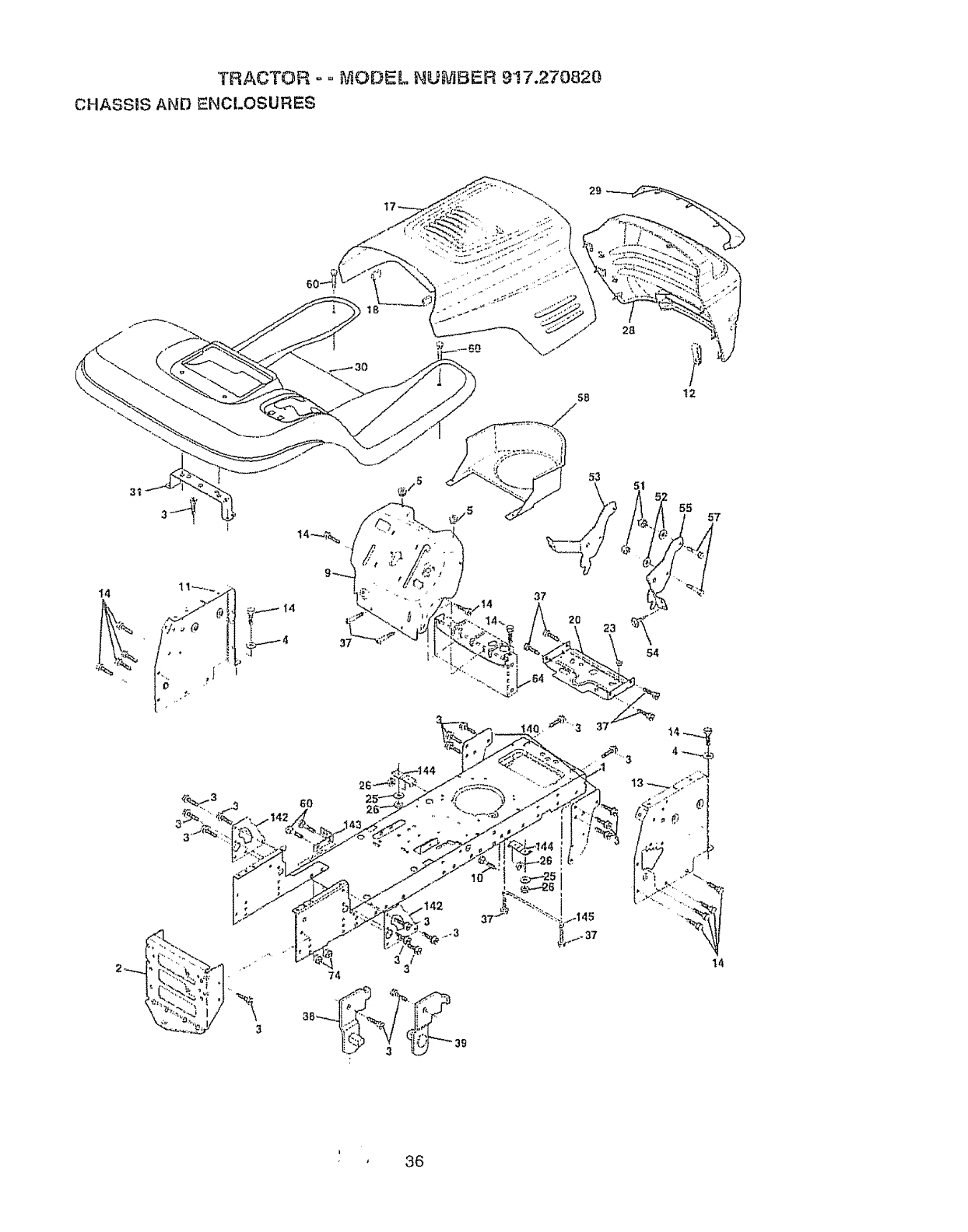
'TRACTOR ° ° ,_-_ODEL NUMBER 9'17.270820
CHASSIS AND ENCLOSURES
28
5B t2
37
_3
55 57
54
37
14
i'36

TRACTOR -- MODEL NU_BEIR 917.2'70820
CHASSIS AND ENCLOSURES
KEY PART
NO. NO. DESCRIPTION
1 160392
2 140356
3 17490612
4 STD551025
5 155272
9 !61917X013
tO STD533710
11 155927
I2 145660
13 155936
t4 17490608
I7 I44983X558
18 126938X
20 156437
23 t24028X
25 19131312
26 STD541437
28 145198X558
29 155217
30 t5t287X558
3I 139976
37 17490508
38 139886
39 139887
51 73800400
52 19091416
53 145201
54 161464
55 145202
57 STD552507
58 140547
60 72140606
64. 154798
74 STD541437
140 158418
142 156095
t43 154966
144 154207
145 156524
Chassis
Drawbar
Screw, Thd., Roll. 318-t6 x 3/4 Type TT
Washer 13/32 x 3/4 x 16 Gauge
Bumper Hood/Dash
Dash, Silt{screened
Bolt, Cardage 3/8-16 x 1
Panel, Dash, LH
Clip Tinnerman Gdlle P/t.
Panel, Dash, RH
Screw, Tnd., Roll 3/8-16 x 1/2 Type TT
Hood Assembly
Bumber Hood
Plate Mtg Battery Fuel Tank
Bushing, Snap, Nylon, Fuel Line
Washer t3/32 x 13/16 x I2 Gauge
Locknut, Hex, with lnserl 3/6-!6 UNC
Grille, W/Clips MS-558
Lens, Gdlte
Fender/Footrest
Bracket, FendedSupport
Screw, ThdroL 5/16-t8 x 1/2 TYT
Pivot Bracke_Assembly, LH, Mower, Rear
Pivot Bracket Assembly, RH, Mower, Rear
Nut Lock Wflnserl 1/4 - 20 UNC
Washer 9/32 X 7/8 X t6 Ga.
Bracket Grille Pickoff LH
Screw, He×Wshd #8-18 x 7/8
Bracket Grille Pickofl RH
Boil FinHex 1/4 -20 UNC X.75
Air Duct P/L t8HP B&S Opp. Twin
Bolt Rdhd Sqnk 3/8.16 UNC x 3/4
Dash Lower STLT
Nul Crownlock 3/8-16 UNC
Bracket SuspensionFront
Pta[e Reinforcement STLT
Bracket Swaybar Chassis
Bracket Footrest STLT
Rod Pivol Chassis/Hood
NOTE: All component dimensions given in [J S inches
1 inch = 25 4 mm
37
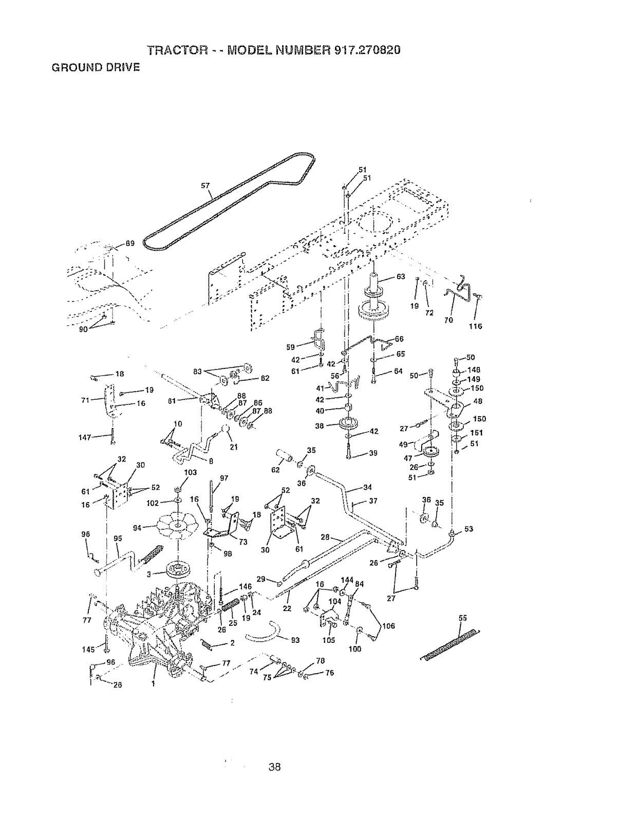
i
I
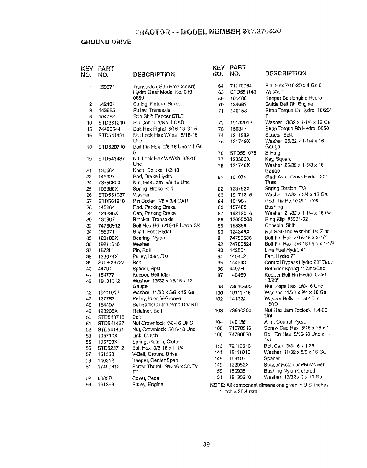
TRAOTOR - - JiODEL NUMBER 917.270820
GROUND DRIVE
KEY PART KEY PART
NO. NO. DESCRIPTION NO, NO,.
I 150071 Transaxte (See Breakdown) 64 71170764
Hydro GearModel No. 310- 65 STD551143
0650 66 !6t488
2 142431 Spring, Return, Brake 70 134683
3 143995 Pulley, Transaxle 71 140158
8 154792 Rod Sf_ifl Fender STLT
10 STD561210 Pin Cotter I/8 x t CAD 72 19132012
t5 74490544 BottHex Ftghd 5/16-18 Gr 5 73 156347
16 STD54143I Nut Lock HexWitns 5116-t8 74 t2!t99X
Unc 75 t21749X
I8 STD523710 BoltFtnHex 3/8-16Uncx1 Gr.
5 76 STD581075
19 $3D541437 Nul. Lock Hex W/Wsh 3/8-t6 77 123583X
Unc 78 121748X
21 130564 Knob, Deluxe t/2-13
22 145627 Rod, Brake Hydro 81 161079
24 73350600 Nut, Hex Jam 3/8.t6 Unc
25 I06888X Sprfng, Brake Rod 82 123782X
26 STD55!O37 Washer 83 19171216
27 8TD561210 Pin Cotter t/Bx 3/4 CAD.. 84 161901
28 145204 Rod, Parking Brake 86 157480
29 124236X Cap, Parking Brake 87 19212016
30 130807 Bracket, Transaxte 88 12000008
32 74760512 BoltHex Hd 5/16-18 Unc x 3/4 89 158386
34 155071 Shaft, Foot Pedal 90 t24346X
35 t20183X Bearing, Nylon 91 74780536
36 19211616 Washer 92 74780524
37 I572H Pin, Rott 93 142564
38 123674X Pulley, Idler, Flat 94 140462
39 STD523727 Bolt 95 144643
40 4470J Spacer, Split 96 4497H
41 154777 Keeper, Belt Idler 97 140469
42 19131312 Washer 13/32 x 13116 x !2
Gauge 98 73510600
43 19111012 Washer 11/32xSiSx12Ga 100 19111216
47 127783 Pulley, ldter, V-Groove 102 14 t322
48 154407 Bellcrank Clutch Gmd Dr',/SlrL
49 t23205X Retainer, Belt t03 73940800
50 STD523715 Bott
51 STD541437 NutCrowrilook 3/8-16 UNC t04 140156
52 STD54143! Nut, Crownlock 5/16-18 Unc 105 71070516
53 t05710X Link, Clutch 106 74780520
55 I05709X Spdng, Return, Clutch
56 S'fD523712 Boft Hex 3/8-16 x t-1/4 1t6 72110610
57 161588 V-Belt, Ground Drive 144 19111016
59 !40312 Keeper, Cenler Span 148 t59t03
6t 17490612 Screw fhdroL 3/6-16 x3/4 Ty 149 122052X
TT 150 !50935
62 8883R Cover, Pedal 151 t9133210
63 161399 Pulley, Engine
DESCRIPTION
Bott Hex 7/16-20 x 4 Gr. 5
Wasl_er
Keeper Bell. Engine Hydro
Guide Bell RH Engine
Sb'apTorque Lh Hydro 18/20"
T
Washer 13/32 x !-t/4 x !2 Ga
SlrapTorque Rh Hydro 0650
Spacer, Spill
Washer 25/32 x 1-1/4 x 16
Gauge
E-Ring
Key, Square
Washer 25/32 x 1-5/8 x I6
Gauge
ShaitAsm Cross Hydro 20"
Tires
Spring Torsion T/A
Washer 17/32x 3/4 x 16 Ga..
Rod, Tie Hydro 20" Tires
Bushing
Washer 21/32 x 1-1/4 x 16 Ga
Ring Klip t15304-62
Console, Sililt
Nut SeiFThd Wsh-hd 114Zinc
Boil Fin Hex 5/16-18 × 2-1/4
Bolt Fin Hex 5/6-18 Unc x 1-1/2
Line Fuel Hydro 4"
Fan, Hydro T'
Control Bypass Hydro 20" Tires
Retainer Spdng 1"ZindCad
Keeper Boll Rh Hydro 0750
18120"
Nut Keps Hex 3/8-16 Unc
Washer 11/32 x3/4 x !6 Ga
Wasf_er Bellvllte .,501Dx
1 50D
Nut Hex Jam Teplock 1/4-20
Unf
Arm, Control Hydro
ScrewCap Hex 5/t6 x t8 x 1
Bolt Fin Hex 5/16-t8 Uric x I
t/4
Bolt Carr, 3/8-t6 x ! 25
Washer !1/32 x 5/8 x t6 Ga
Spacer
Spacer Retainer PM Mower
Bushing Nylon Col]ered
Washer t3/32 x2 x 10 Ga
NOTE: All component dimensions given In U S inches
1 inch = 25,,4 mm
39
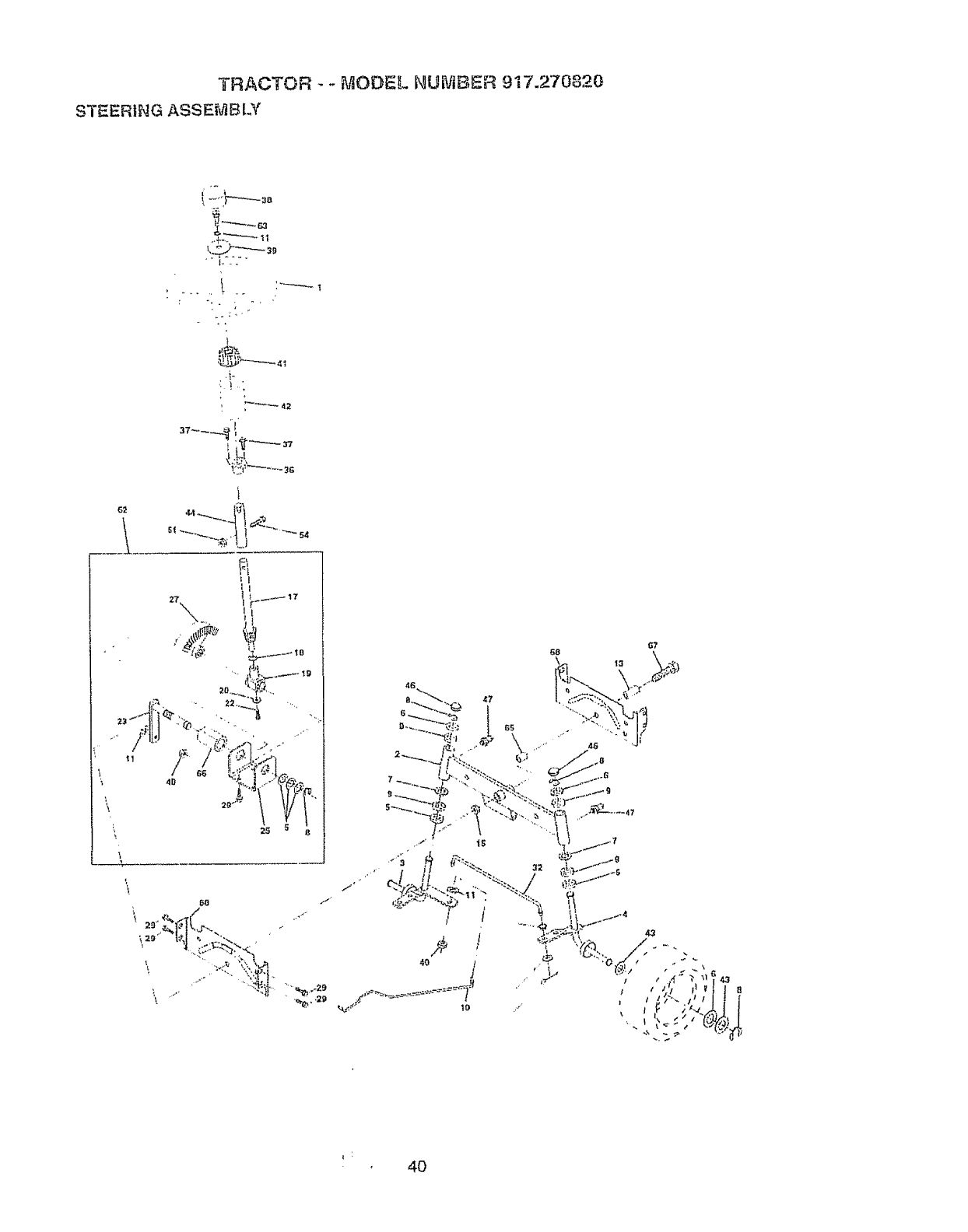
TRACTOR - -MODEL NUMBER 917.270820
STEERING ASSE[_BLY
i i
t -"'IF-"-----=B
.. i_f. -_
t
_ _2
_7__.._tI
x. :I; i',,----
\
_----_
68 G7
40

TRACTOR _-_'vlODSL NUMBER 917.270820
STEERING ASSEMBLY
KEY PART
NO. NO. DESCRIPTION
t 139768
2 154427
3 156483
4 157473
5 6266H
6 t21748X
7 19272016
,_O000_
9 3366R
t0 156438
1t STD551137
13 154779
t5 73901000
_7 156546
!8 57079
1£ 124035X
20 126684X
22 71200410
23 127501
25 154406
26 126847X
27 136874
28 19131416
29 17490612
30 STD561210
32 130465
36 155099
37 152927
38 139769
39 19133808
40 STD54t537
4't I00711L
42 145054
43 121749X
44 153720
46 121232X
47 6855M
5t 73800500
54 74780520
62 156594
63 74780616
65 154780
66 154404
67 74781044
68 154429
Steering Wheef
Front AxJeAssembly
Spfndie Assemb)y, L,H
Spindle Assembly, RH
Beating, Race, Thrust, Hardened
Washer 25/32 x 1-5/8 x I6 Gauge
Wasller 27/32 x 1-1/4 x I6 Gauge
Ring, Kltp
Bearing, Steering Column
Link, Drag
Washer, Lock
Spacer, Beadng, Front Axle
Nut, Lock, Flange 5/8-11 UNC
Shaft Assembly, Steering
Washer, Thrust 515 x 750 x 033
Support, Shaft
Washer, Shim 1/4 x 5/8 x .,062
Screw Hex Socket t/4-20 x 5/8
Pittman Shaft Assembly
Brackel, Steering
Bushing, Link, Drag
Gear, Sector
Washer 13/32 x 7/8 x 16 Gauge
Screw, Thd, Roll 318-16x 3/4
Pin
Rod, lie
Bushing, Steering
Screw "FF#10-32x 5 x 3/8 Flange
Insert, Steering Wheel
Washer 13/32 x 2o3/8x 8 Gauge
Gdpco Nut
Adaptor, Steering Wheel
Boot, Steering Dash P/L Mr}BIk
Washer 25/32 x 1-1/4 x 16 Gauge
Extension St.eedngNon-Adjust
Cap, Spindle
Ftfting, Grease
Nut Lock Hx W/Ins 5/16.,I8 UNC
BoLLFin Hex 5/16-18 UNC x ! -1/4
Kit, Steering Assembly, Service
Boll Fin Hex3i8-16 unc x t Gr 5
SpacerAxle
Bearing Arm Plttman
Boil Fin Hex 5/8-tlunc x 2-3/4
Brace Axle
NOTE: AI]component dimensions given in US inches
1inch= 25 4 mm
41
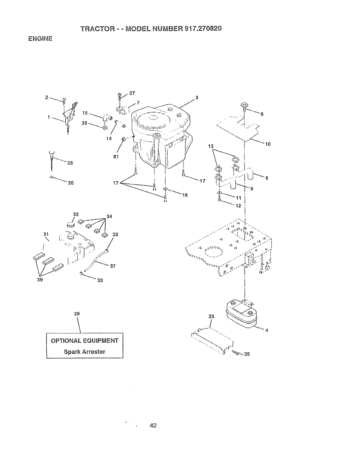
ENGINE
TRACTOR - -E_ODEL NUMBER 9t7.270820
14
81
29
\
OPTIONAL EQUIPMENT
Spark Arrester
<.,_%
23 L2"a_.,""---_'_,
, 42

ENGINE
TRACTOR -- MODEL NUtViBEF_ 9"_7.270820
KEY PART
NO, NO.
t 162152
2 17720410
4 149723
5 144069
6 144068
7 138129
8 150176
10 145552
1t STD55t125
12 STD522507
13 272250
14 132B0336
15 13200300
16 STD551237
17 17490624
23 159880
25 145996
26 73920600
27 152927
29 137180
3! 157103
32 161696
33 I23487X
34 106082X
35 17490512
37 8543R
38 ........
39 t09227X
40 364&, _
41 139277
81 128861
DESCRIPTION
Control Throt Paddle 32 22
Screw Hex Thd Cut 1/4-20x5/8 T
Engfne (See Breakdown) Briggs
Model No. 42ET07-2631,E1
Muffler Exhaus!
Exhaust Asm, Lell
Exhaust Asm. Right
Clamp Tube Double Engine
Bolt 5116- 18 UNC X 3/4 W/Sems
Heal: Shield Lt
WasherLeck Hvy, Hetica{ 1/4
Bolt Rn Hex 1/4-20 x 3/4
Gasket Muflter
Nipple Pipe 4oit2"
Elbow Sld 90 Degree 3/8-18 Npt
Washer Lock EXlTooth 3/8
Screw Thdrol 3/8.,16×t-1/2 Tyt!
Shtetd Browning/Debris Guard
Control Choke
Nut Keps 3/8-24 Un!
Screw TT tt10_32 x 5 x 3/8 Flange
Arrestor Spark
Tank Fuel 3 50 Rear
Cap Fuel Guage STLT
Clamp Hose Blk
Spacer Pad
Screw ThdroI 5/16-t8 x 3/4 -rift
Line Fuel
Plug Oil Drain (Order From Engine Manufacturer)
Pad Idler 175 x 25 x 06
Bushir'r{:j
Stem Tank Fuel
Nul, Flange tt4-20 Starter Nut
NOTE: All component dimensions given in US, inches
t inch = 25,4 mrn
43
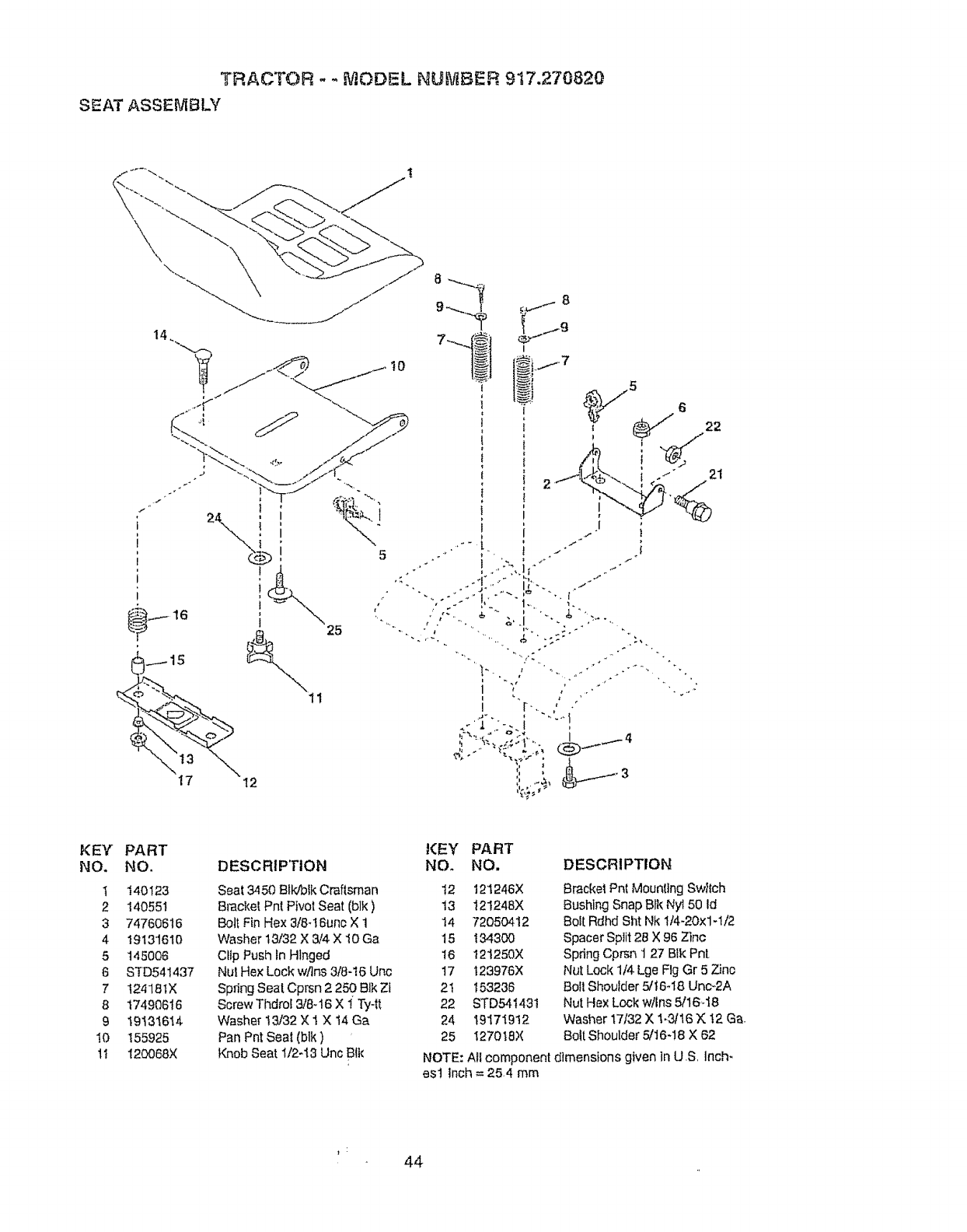
TRACTOR - - _,ilODSL NUB)IIBER 9t7.270820
SEAT ASSEMBLY
\
5
21
KEY
NO.
t
2
3
4
5
6
7
8
9
10
tl
PART K:EY PART
NO. DESCRIP!riON NO. NO,
140123 Seat 3450 Blldblk Craftsman t2 121246X
I40551 Br'acke[Pnt PivotSeat (blk) ! 3 12!248X
74760616 Bolt Fin Hex 3/8-16unc X 1 14 72050412
19131610 Washer 13/32 X 3/4 X 10Ga 15 134300
t45006 Cllp Push In Hlnged 16 121250X
STD541437 Nul Hex Lock wflns 3/8-t6 Unc t7 "123976X
1241B_X Spring Seat Cprsn 2 250 Blk Zt 21 t 53236
17490616 Screw Thdrol 3/8-I6 X 1 Ty-tt 22 STD54143t
19131614 Washer 13/32 X 1 X t4 Ga 24 19171912
155925 Pan PntSeat(blk) 25 I270t8X
I20068X Knob Seat 1t2-t3 Uric Btk
DESCRIPTION
Bracket Pnt Mounting SwIlch
Bushing Snap Bfk Ny150 Id
Bolt Rdhd Sht Nk 1/4-20×1-1/2
Spacer Split 28 X 96 Zinc
Spring Cprsn 't 27 Blk Pnl.
Nut Lock 1/4 Lge Fig Gr 5 Zinc
Boll Shoulder 5/t6-18 Unc_2A
Nut Hex Lock wllns 5/16,-18
Washer 17/32 X 1.3/16 X: !2 Ga.
Bolt Shoulder 5/16-!8 X 62
NOTE: All component dimensions given In U.S, Inch-
es! inch = 25.4 mm
44
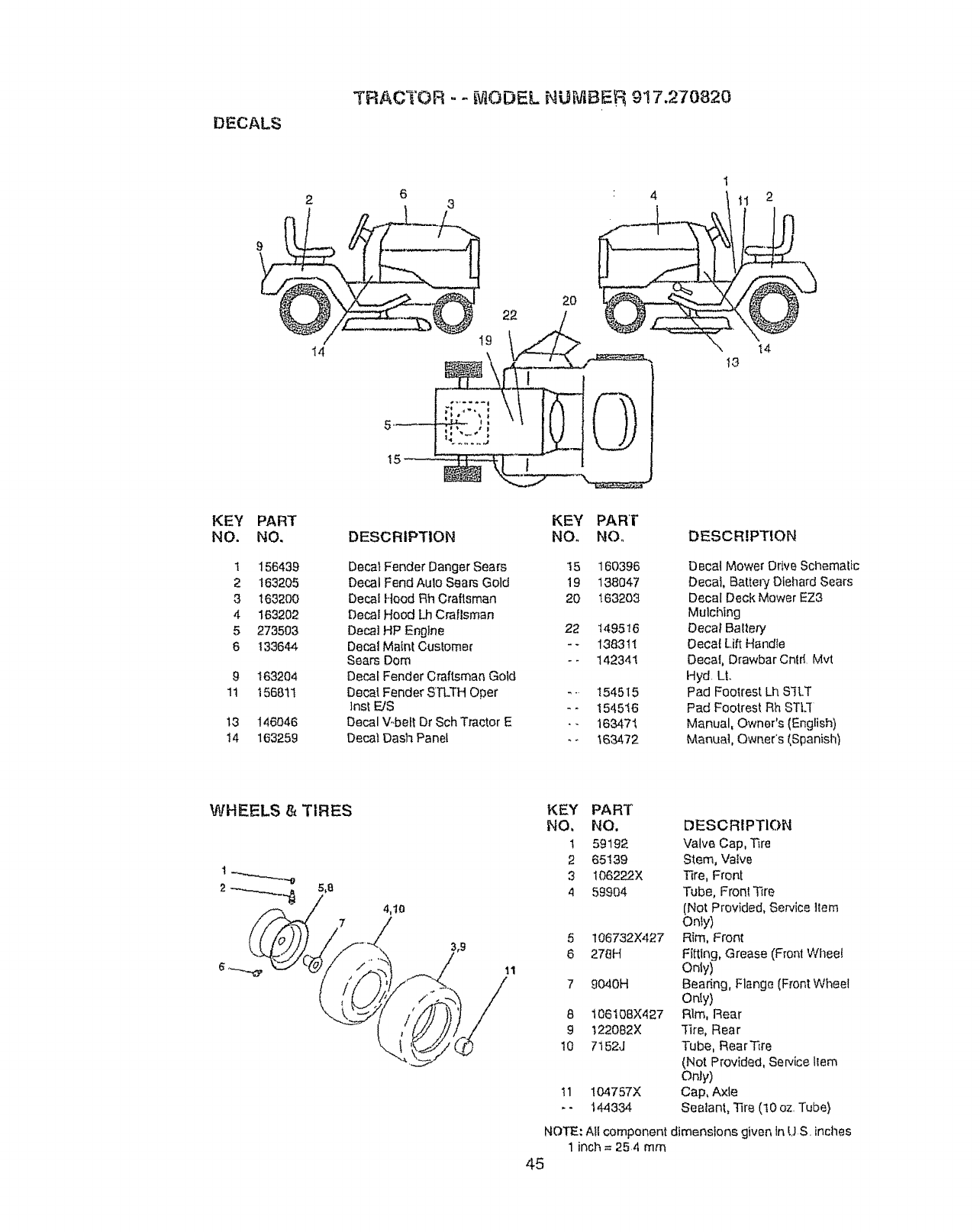
DECALS
TRACI'OR - -_v]ODEL NUi'_BEf_ 917.270820
2O
41
tl 2
I4 14
13
KEY
NO.
1
2
3
4
5
6
9
1t
13
t4
PART
NO.
156439
163205
163200
163202
273503
133644
163204
156811
146046
163259
DESCRIPTION
Decal Fender Danger Sears
Decal FendAulo Sears Gold
Decal Hood Rh Craftsman
Decal Hood LhCraflsman
Decal HP Engine
Decal MalnI Cuslomer
Sears Dorn
Decal Fender Craftsman Gold
Decal Fender SFLTH Oper
]nst FJS
Decal V,.beftDr Sch Tractor E
Decal Dash Panet
KEY
Nee
15
19
20
22
PART
NO,, DESCRIPTION
160396 Decal Mower Drive Schematic
138047 Decal, Battery Diehard Sears
163203 Decal Deck Mower EZ3
Mulching
t495 t6 Deca_ BaItery
1383tt Decaf Lift HandIe
142341 Decal, Drawbar Cntrf Mvt
Hyd L|.
154515 Pad Footrest Lh S'fLT
t545t6 Pad Footrest Rh STLf
163471 Manual, Owner's (English)
t634'72 Manua], Owner's (Spanish)
WHEELS & TIRES
11
KEY PART
NO, NO, DESCRIPTION
1 59192 Valve Cap, Tire
2 65139 Stem, Valve
3 1062P__.2X Tire, Front
4 59904 Tube, Fronl Tire
(Not Provided, Service Item
Only)
5 106732X427 Rim, Front
6 278H Fitting, Grease (Front Whee_
Only)
7 9040H Bearing, Flang_ (Front Wheel
Only)
6 106108X427 Rim, Rear
9 t22082X "1ire, Rear
10 7152J Tube, RearTire
(Not Provided, Service llem
Only)
t 1 !04757X Cap, Axle
- 14433,I. Sealant, Tire (t0 oz Tube}
NOTE: All component dimensions given in US inches
1 inch = 254 mm
45
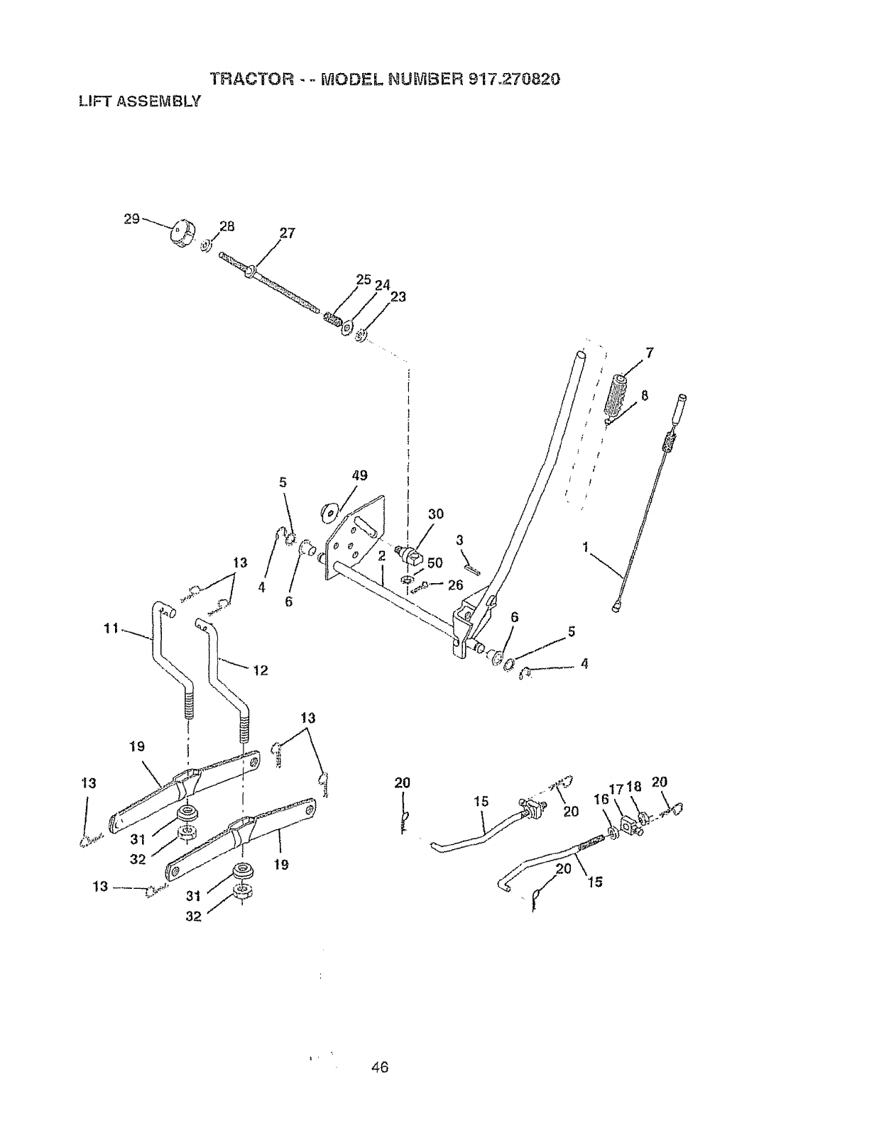
TRACTOR - - MODE[. NL_BER 917.270820
LIFT ASSEMBLY
29 --._._ 28 27
25 2423
\ 12
5
6
49
3O
5O
3
\
26
6
19
\
13
32
32
13
20 2O
46

TRACTOR --it,'iODEL NU_BER 917.270820
LIFT ASSEMBLY
KEY PART
NO. NO, DESCRIPTION
1 !59460 Lift Lever Inner Wire Asm
2 159471 Sha|tAsm Lift
3t05767X Pin Groove
4 120&q,002 E Ring
5 19211621 Washer 21t32 x t x 2t Ga
6 t20183X Bearing Nytong
7 12563IX Grip Handfe Fluted
8 t22365X Button Plunger Read
! t 139865 Link Asm Lilt L H
12 139866 LinkAsm Lilt RH
13 STD624008 RetatnerSpring
15 127218 Link Fronl
I6 73350800 Nut Jam Hex 1t2-t3 Unc
17 130174 Trunnion BlkZinc
18 73680800 Nut,Lock W,,Wsh 1t2-.I3 Unc
I9 139868 Arm Suspension Mower
20 STD624008 Retainer Spring
23 110807X Nut, Special
24 19131016 Washer 13/32x5/Sx 16Ga
25 2876H Spring
26 76020308 Pfn, Cotter 3/32 x 1/2
27 t26971X Rod, Adjust Life
28 73350600 Nul, Hex Jam 3/8-!6 UNC
29 138057 Knob, lnfinile Height Admustment
30 150233 Trunnion. Inf, Height
3t 140302 Bearing, Pvt, Lift, Spherical
32 73540600 Nut Crownlock 3t8-24
49 145212 Nul, Hex Flange Lock
50 t10452X Nut, Push Phos, & Oil
NOTE: Allcomponent dimensions given in U.S. inches
t inch = 25.4 mm
47
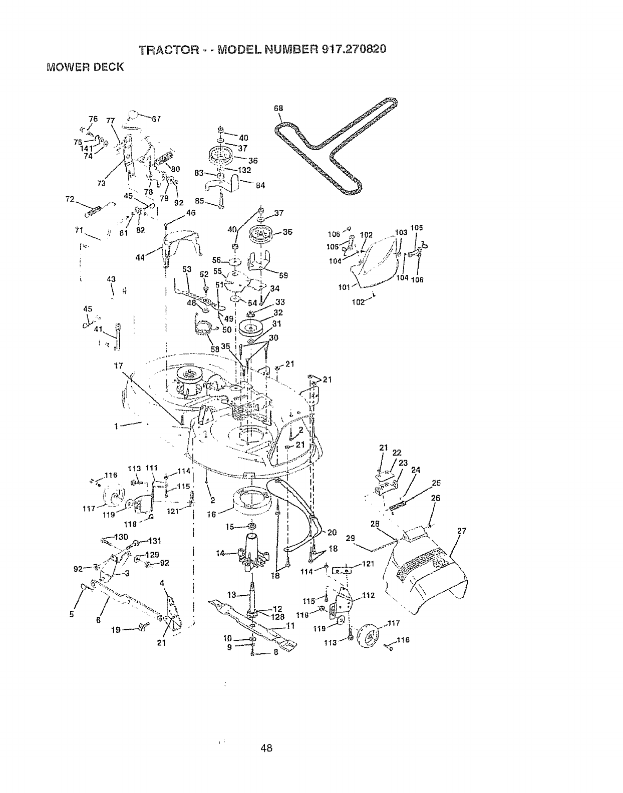
TRACTOR ,.- _ODEL NU[_,r_BER9'17.270820
MOWERDECK
73
72 z
71
i 43
45
17
tot
,34
33 IOZ ''_"
32
105
103
/
6
21 22
2'7
i48
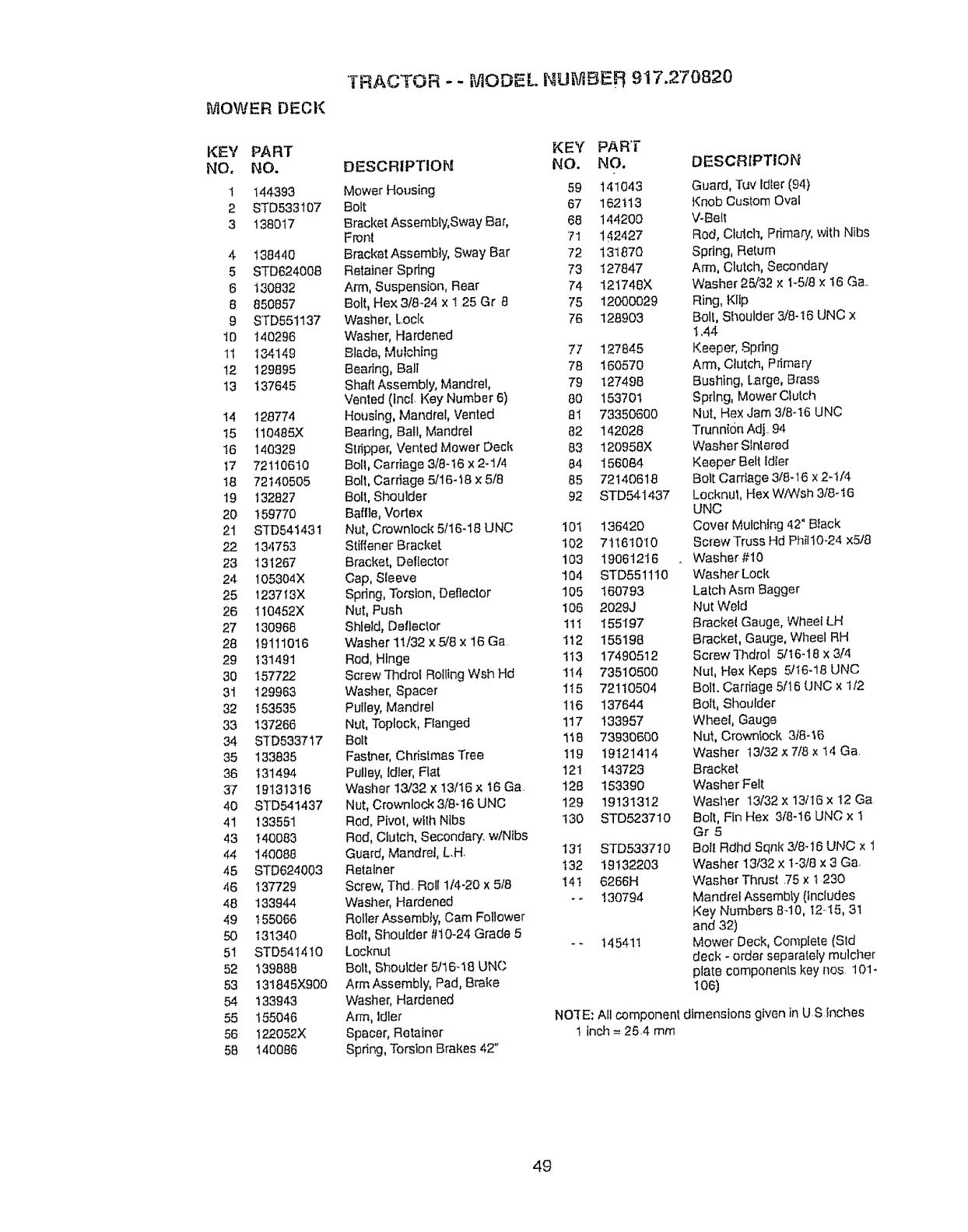
"TRACTOR -- MODEL NUI'vIBER 917.270820
MOWER DECK
KEY PART KEY PAR'i"
NO. NO. DESCRIPTION NO. NO.
1 144393 Mower Housing 59 141043
2 STD533107 Bolt 67 162113
3 138017 Bracket Assembly,Sway Bar, 68 144200
Front 71 142427
4 138440 Bracket Assembly, Sway Bar 72 131870
5 STD824008 Retainer Spring 73 t27847
6 130832 Arm, Suspension, Rear 74 121748X
8 850857 Bolt, Hex 3/8-24 x ! 25 Gr 8 75 12000029
9 STD551137 Washer, Lock 76 128903
10 140296 Washer, Hardened
11 134149 Blada, Mu_ching 77
12 129895 Bearing, Ball 78
13 137645 Shall Assembly, Mandrel, 79
Vented (tnct Key Number 6) 80
14 128774 Housing, Mandrel, Vented 81
15 110485X Bearing, Ball, Mandrel 82
!6 140329 Stripper, Vented Mower Deck 83
17 72110610 Boll, Carriage 3/8-16 x2-1/4 84
t8 72140505 Bolt, Carriage 5/16q8 x5/8 85
t9 132827 Bolt, Shoulder 92
20 159770 Baflle, Vode×
21 STD54143I Nut, Crownlock 5/!6-18 UNC 10t
22 13,t753 Stiffener Bracket 102
23 131267 Bracket, Deflector 103
24 105304X Cap, Sleeve 104
25 1237t3X Spring, Torsion, Deflector 105
26 !10452X Nut, Push 106
27 130968 Shield, Deltec{or tt 1
28 19111016 Washer 1t/32 x 5/8 x 16 Ga I12
29 131491 Rod, Hinge 113
30 157722 Screw Thdrol Rolling Wsh Hd It4
31 129983 Washer, Spacer 1t 5
32 153535 Pulley, Mandrel 1t6
33 137268 Nut, Topleck, Ftanged 117
34 STD533717 Bolt 118
35 133835 Faslner, Chrislmas Tree 119
36 131494 Pulley, Idler, Flat 121
37 19131316 Washer 13/32 x 13/16 x 16 Ga 128
40 STD541437 Nut, Crownlock 3/8-t6 UNC 129
41 133551 ROd,Pivot, with Ntbs 130
43 140083 Rod, Clutch, Secondary. wlNIbs
44 140088 Guard, Mandre/, L,H, t3t
45 8TD624003 Relalner 132
46 137729 Screw, Thd. RoI[ !/4-20 x 5/8 141
48 133944 Washer, Hardened - -
49 t55086 Rotler Assembly', Cam Follower
50 131340 Bott, Shoulder #10-24 Grade 5
51 STD5414IO Locknut -- 145411
52 139888 Bolt, Shoulder 5116_t8 UNC
53 ! 3t845X900 Arm Assembly, Pad, Bral{e
54 t33943 W'asher, Hardened
55 155046 Arm, Idler
56 122052>( Spacer, Retainer
58 140086 Spdng, Torsion Brakes 42"
DESCRIPTION
Guard, Tuv Idler (94)
Knob Custom Oval
V-Boil
Rod, Clutcl_, Primary, with Nibs
Spring, Return
Arm, Clutch, Secondary
Washer25!32 × I-5/8 × 16 Ga
Ring, Kllp
Bolt, SI_oulder 3/8-t6 UNC x
! ,44
127845 Keeper, Spring
160570 Arm, Clutch, Primary
127498 Bushing, Large, Brass
153701 Spring, Mower Clu(ch
73350600 Nut, Hex Jam 3/8-!6 UNC
142028 Trunnion Adj 94
120958X Washer Slntered
156084 Keeper Bell: Idler
72140618 Bolt Carriage 3!8-16 x 2-1/4
STD541437 Locknul, Hex WfWsh 318-t6
UNC
136420 Cover Mulching 42" Black
71161010 Screw '['russ Hd Phil10-24 x5]8
19061216 Washer #10
STD551110 Washer Lock
I60793 Latch Asm Bagger
2029J Nut Weld
155197 Bracket Gauge, Wheel LH
155198 Bracket, Gauge, Wheel RH
17490512 Screw Thdrot 5/16-18 x 3/4
73510500 Nut, Hex Keps 5/t6-18 UNC
72110504 Boll. Carriage 5/16 tJNC x 1/2
137644 Bolt, Shoulder
133957 Wheel, Gauge
73930600 Nut, Crownfock 3t8-t6
19121414 Washer 13/32x 7/8x 14 Ga.
t43723 Bracket
t53390 Washer Felt
19131312 Washer I3/32 x 13/16 x 12 Go.
STD523710 Bolt, Fin Hex 318-16UNC x 1
Gr 5
STD533710 Bof! Rdhd Sqnf<3/8-16 UNC x 1
19132203 Washer 13/32 x t-3/8 x 3 Go.
6266H Washer Thrust .75× t 230
t 30794 Mandrel Assembty (Includes
Key Numbers 8-10, 12.!5, 3!
and 32)
Mower Deck, CompLete(Sld
deck -order separately mulcher
plate components key tics 101-
1o6)
NOIE: All component dimensions given in U S Inches
1 inch = 25.4 mm
4g
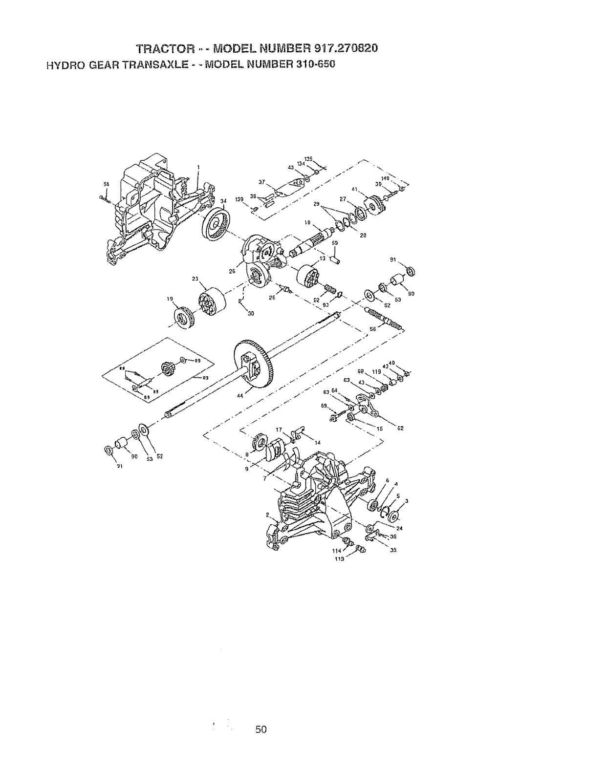
TRACTOR -- MODEL NU_,_Et,ER 917.2.70820
HYDRO GEAR TRANSAXLE - -_,/tODI:=L NU_'_BER 310-650
91
!
t
5O
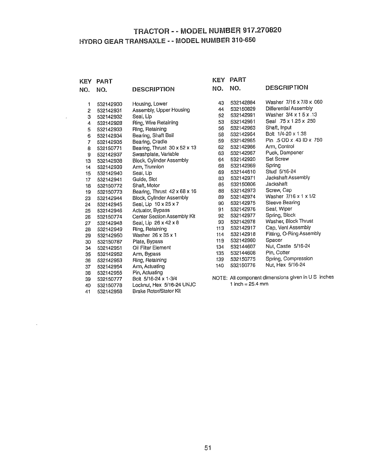
TRACTOR - - MODEL f'_U_diBER 917.270820
HYDRO GEAR TRANSAXLE - - MODEL NUMBER 310-650
KEY PART KEY PART
NO, NO. DESCRIPTION NO. NO,
1 532142930 Housing, Lower 43 532142884
2 532142931 Assembly, UpperHoustng 44 532150829
3 532142932 Seal, Llp 52 532142991
4 532142928 Ring, Wire Retaining 53 532142961
5 532142933 Ring, Retaining 56 532142963
6 532142934 Bearing, Shaft Baii 56 532142984
7 532142935 Bearing, Cradle 59 532142965
8 532150771 Bearing, Thrust 30x52 x 13 62 532142966
9 532142937 Swashplale, Vadab[e 63 532142967
13 532142938 Block, Cytinder Assembly 64 532142920
t4 532142939 Arm, TnJnnion 68 532142969
I5 532142940 Seal, Lip 69 532144610
I7 532142941 Guide, Stot 83 53214297_
t8 532150772 Shaft, Motor 85 532t 50806
19 532150773 Bearing,'Thrust 42x 68 x 16 88 532142973
23 532142944 Block, CyI]nderAssembly 89 532142974
24 532142945 Seal Lip 10 x 25 x 7 90 532142975
25 532142946 Actuator, Bypass 9t 532142976
26 532150774 Center SecttonAssembly KIt 92 532142977
27 532142948 Seal, Lip 26 x42 x8 93 532142978
28 532142949 Ring, ReIalnfng I13 532142917
29 532142950 Washer 26x 35 x 1 t14 532142918
30 532150787 PIate, Bypass !19 532!42980
34 532142951 Oit F31[erElement I34 532144607
35 532142952 Arm, Bypass I35 532144608
38 532f42953 Ring, Retafn_ng 139 532_50775
37 532142954 Arm, Acluating t40 532150776
38 532142955 Pin, Actuating
39 532150777 Deft 5/16-24 x 1-3/4 NOTE:
40 532150778 Locknut, Hex 5/16-24 UNJC
41 532142958 Brake Rotor/Staler Kit
DESCRIPTION
Wasiler 7/16 x 7/8 × .060
Dtlferentlal Assembly
Washer 3/4 x t 5 x ,13
Seal ,75x 125 x 250
Shaft, fnput
Bolt 1/4..20 x 1.38
Pin ,50Dx.43 ID x 750
Arm, Control
Puck, Dampener
Set Screw
Spring
Slud 5/16-24
Jacks_]att Assembly
Jackshaft
Screw, Cap
Washer 7t16 x 1 x 1/2
Sleeve Bearing
Seal, Wiper
Spring, Block
Washer, Block Thrust
Cap, Vent Assembly
Filling, O-Ring Assembly
Spacer
Nul, Casfle 5/16-24
Pin, Cotler
Spring, Compression
Nut, Hex 5/I6-24
Atl component dimensions given in U S inct_es
I inch = 25.4 mm
5t
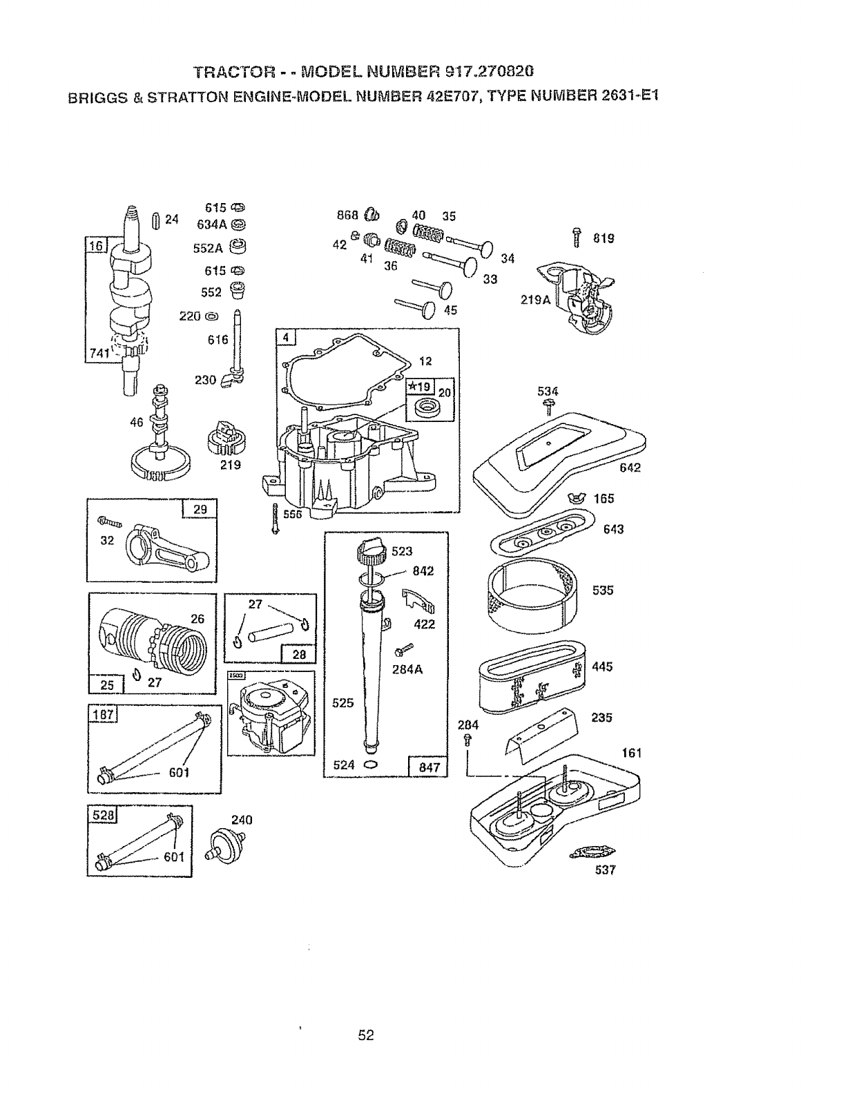
TRACTOR -° MODEL NUMBER 9t7.270820
BRIGGS& STRATTONENGINE-MODELNUMBER42E707,TYPENUMBER2631.-E1
220 @3
230 _-_
219
240
525
524 O
523
..,_ 842
%
422
284A
642
£_t 165
643
535
445
235
161
537
52
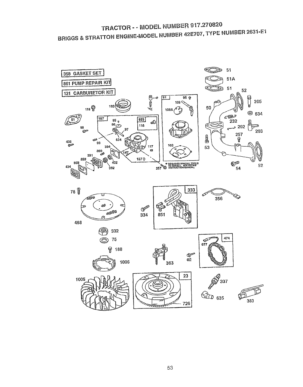
TRACTOR - -MODEL NUMBER 9t 7.270820
BRtGGS & STRATTON ENGINE-MODEL NUMBER 42E707, TYPE NUMBER 2631-E1
121 CARBURETOR KiT]
5t
51A
•51 52
54
205
@ 634
52
468
332
@75
188
i006
_635 383
53
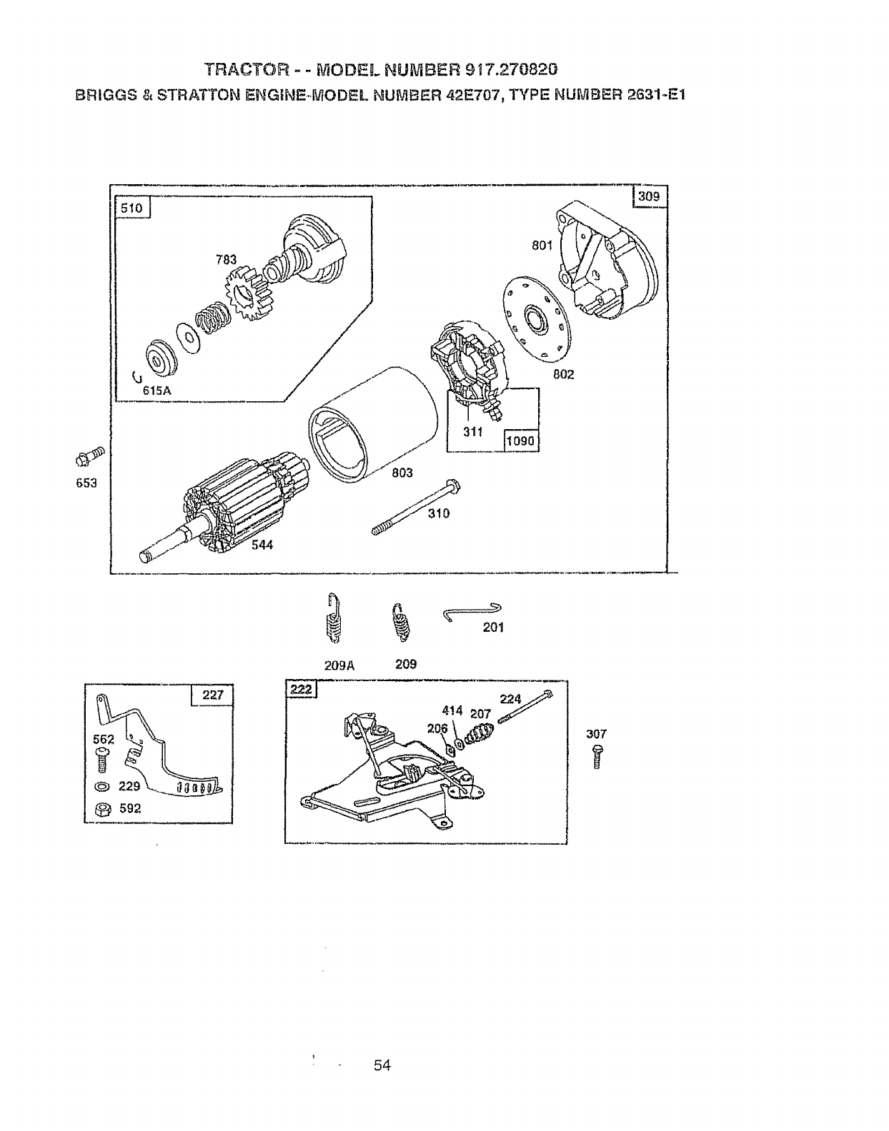
TRACTOF'Y - -_IODEL NUMBER 9_ 7.270820
BRIGG$ & STRATTON ENGtNE.4VtODEL NUMBER 42E707, TYPE; NUMBER 2G31-E1
783
_ L_61s_A......................... //
544
803
801
802
@ ss2
209A 209
201
414 207 y
307
54
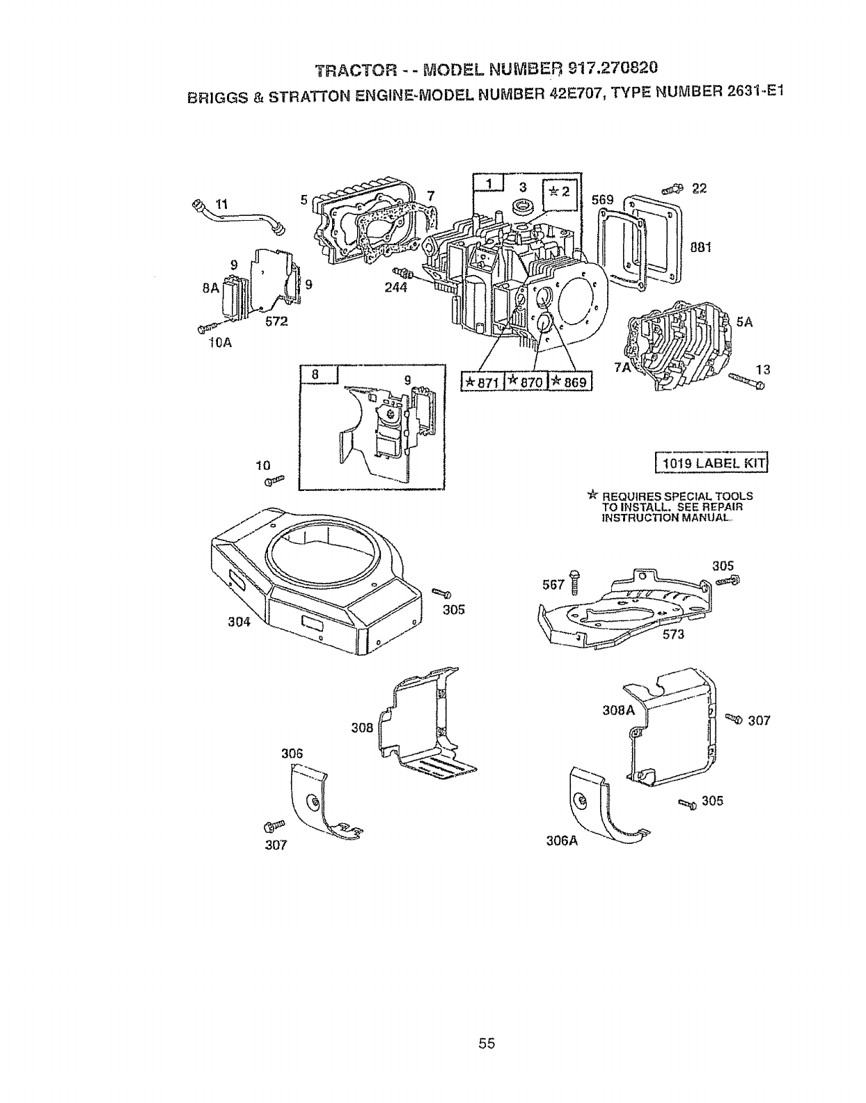
TRACTOR - -MODEL NUMBEF_ 917,270820
BRIGGS & STRATTON ENGINE-MODEL NUMBER 42E707, TYPE NUMBER 2631.-E1
8A
IOA
304
572
10
244
305
881
1019 LABEL KITl
_t_ REQUIRES SPECIAL TOOLS
TO INSTALL. SEE REPAIR
INSTRUCTION MANUAL
305
306
307
_oI--"_\\
"A__.__" _,=_ 305
306
55
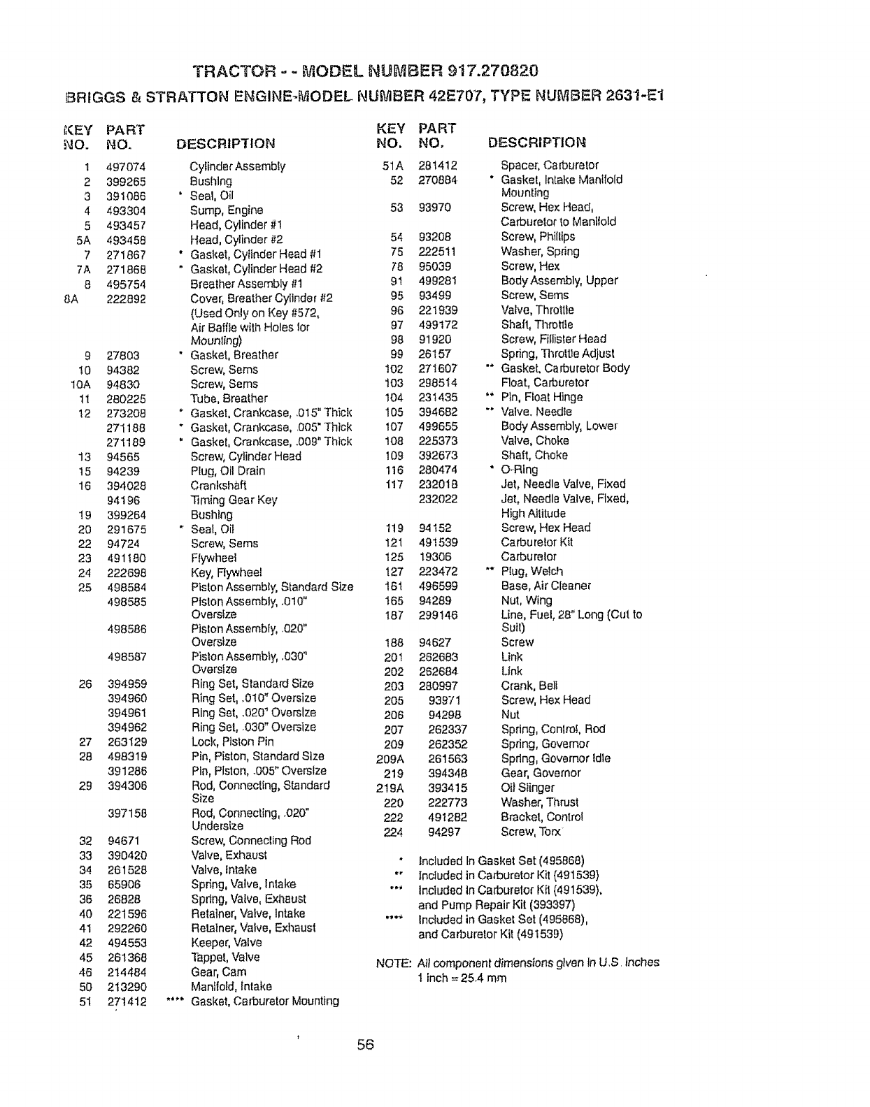
TRACTOR - - _]ODEL NU_P_,ER 917.270820
BRtGGS & STRATTON ENGINE-MODEL NUMBER 42E707, TYPE NUMBER 2631-E1
_<EY PART KEY PART
NO. NO, DESCRIPTION NO, NO, DESCRIPTION
I 497074
2 399265
3 391086
4 493304
5 493457
5A 493458
7 271867
7A 271868
8 495754
8A 222892
9 27803
t0 94382
10A 94830
tt 280225
!2 273208
271188
271189
13 94565
15 94239
16 394028
94.i96
19 399264
20 291675
22 94724
23 491180
24 222698
25 498584
498585
498586
498587
26 394959
394960
394961
394962
27 263129
28 498319
391286
29 394306
397158
32 94671
33 390420
34 261528
35 65906
36 26828
40 221596
4t 292260
42 494553
45 261366
46 214484
50 213290
5I 271412
CyfinderAssembly 51A 281412 Spacer, Carburetor
Bushlng 52 270884 " Gasket, Intake Manifold
" Seal, Oil Mounting
Sump, Engine 53 93970 Screw, Hex Head,
Head, Cylinder #1 Carburetor to Manilold
Head, Cylinder #2 54 93208 Screw, Phillips
" Gasket, CylfnderHead #I 75 222511 Washer, Spdng
" Gasket, CyitnderHead #2 78 95039 Screw, Hex
BreatherAssembly #t 9! 499281 Body Assembly, Upper
Cover, Breather Cylinder #2 95 93499 Screw, Seres
(Used Only on Key #572, 96 22!939 Valve, Throlffe
Air Baffle with Holes for 97 499172 Shaft, Tllrottle
Mounting) 98 91920 Screw, Fiflisler Head
" Gasket, Breatf_er 99 26157 Spring, Thro|tle Adjust
Screw, Sems 102 271607 "* Gasket, Carburetor Body
Screw, Sems I03 298514 Float, Carburetor
Tube, Breather 104 231435 "" Ptn, Float Hinge
" Gasket, Crankcase, .015" Thick 105 394682 "" Valve_Needte
"Gasket, Crankcase, 005" Thick 107 499655 Body Assembly, Lowe_
" Gasket, Crankcase, 009" Thick 108 225373 Valve, Choke
Screw, Cylinder Head 109 392673 Shall, Choke
Plug, Oil Drain t16 280474 *O_Ring
Crankshaft I17 232018 Jet, Needle Valve, Fixed
Timing Gear Key 232022 Jet, Needle Valve, Fixed,
Bushing High Altitude
• Seal, Oil 119 94152 Screw, Hex Head
Screw, Sems 12t 491539 Carburetor Kit
FIywheei 125 19306 Carburelor
Key, Flywheel 127 223472 *" PIug, Welch
Piston Assembly, Standard Size 16t 496599 Base, Air CIeaner
Piston Assembly, .010" t65 94289 Nut, Wing
Oversize 187 299146 Line, Fuel, 28" Long (Cut to
Pislon Assembly, 020" Suit)
Oversize 188 94627 Screw
Pislon Assembly, ,030" 201 262683 Link
Oversize 202 262684 Link
Ring Set, Standard Size 203 280997 Crank, Belt
Ring Set, ,.010"Oversize 205 939/1 Screw, Hex Head
Ring Set, .020_Oversize 206 94298 Nut
Ring Set, .030" Oversize 207 262337 Spdng, Centre!, Rod
Loci{, Piston Pin 209 262352 Spring, Governor
Pin, Piston, Standard Size 209A 261563 Spring, Governor Idle
Pin, Piston, .005" Oversize 219 394348 Gear, Governor
Rod, Connecting, Standard 219A 393415 Oit Stinger
Size 220 222773 Washer, Thrust
Rod_Connecting, _020" 222 491282 Bracket, Control
Undersize 224 94297 Screw, Torx
Screw, Connecting Rod
Valve, Exhaust " Included tn Gasket Set (495868)
Valve, Intake *" Included in Carburetor Kit (491539}
Spring, Valve, intake *" Included In Carburetor Ktl (491539),
Spdng, Valve, Exhaust and Pump Repair Kit (393397)
Retainer, Valve, Intake .... Included in Gasket Set (495868),
Retainer, Valve, Exhaust and Carburetor Kit (49! 539)
Keeper, Valve
"f_ppet, Valve NOTE: A_tcomponent dimensions given In US inches
Gear, Cam 1 inch = 25.4 mm
Manifold, Intake
•'** Gasket, Carburetor Mounting
56

TRACTOR - - MODEL NUMBER 917.270820
BRIGGS & STRATTON ENGINE-MODEL NUMBER 42E707, TYPE NUMBER 2631-E1
KEY PART
NO. NO.
227 491297
229 62199
230 223882
235 224995
240 394358
2¢4 230318
257 93897
284 94674
284A 94882
304 495469
305 94786
306 222846
306A 223734
307 94930
308 224774
308A 2247'75
309 497596
3t0 94003
31t 497608
332 230674
333 394891
334 94731
337 802592
356 494705
358 495868
363 19203
383 89838
391 280197
392 261395
394 272638
414 220680
422 222875
432 221377
434 223888
435 93829
445 394O19
468 497908
474 393474
482 93621
510 497606
523 494947
524 271157
525 495348
528 393815
534 94823
535 272490
537 271411
5¢4 497603
552 262332
552A 262331
556 93585
562 93853
567 94811
KEY PART
DESCRIPTION NO. NO. DESCRIPTION
Lever Assembly, Governor 569 272645 " Gasket, Base
Washer 572 224816 Bafiie, Air, Cylinder #2
Wasi_er,GovemorCrank, Inside 573 491304 Ptate, Back
Shteld, Fuel Spray 592 92278 Nut, Hex_
Fitter, Fuel 601 93053 Clamp, Hose
Connector, Fuel Line 615 94296 Retainer, E-Ring
Screw, Seres 6!5A 263080 Retainer
Screw, Hex Head 616 491530 Crank, Governor
Screw, Hex Head 634 271013 " W'asher, 'Throttle Shait
Housing, Blower, Red 634A 491287 " Sea[, GovemorShaft
Screw, Seres 635 66538 Boo!, Spark Plug
Shield, Cylinder 642 225008 Cover, Air Cleaner
Sl_ietd, Cylinder 643 496700 Rate, Air Cleaner
Screw, Seff-'Papping 653 93585 Screw, Hex Head
Cover, Atr Guide 726 391362 Gear, Ring
Cover, Air Guide (Includes Mounting Pads)
Motor, Starter 741 262989 Gear, "riming
Bolt, Thru 783 280104 Gear, Starter
BrushSet 801 394860 Cap, Drive
Nut, Hex 802 497607 Cap, End
Armature, Magneto 803 497604 Housing, Starter
Screw, Sems 819 94675 Screw, Hex Head
Plug, Spark 842 270920 * Seal, Cap
Wire, Stop 847 495715 Tube Assembly, Oil
Gasket Set 851 493880 Terminal, Cabte
F{ywhee[ PuIler 858 270989 *'* Diaphragm, Carburetor
Wrench, Spark Plug 859 271025 **' Gasket, Pump
Body, Pump 860 261358 "'" Spdng, Diaphragm
"°" Spring, Diaphragm 861 393397 RepatrKit, Pump
"** DIaphragm, Carburelor 868 497212 Seat, Valve
Wasller 869 261463 Seat, Valve, Intake
Bracket, Oil Fill 870 213316 Seat, Valve, Exhaust
"'" Cap, Spdng 871 261961 Bushing, Guide (Exhaust Only)
Cover, Diaphragm 231218 Bushing, Guide (Intake, Brass)
Screw, Diaphragm Cover 877 393456 Wire, Alternator
Fitter, Air 881 495901 Plate, Cover
Screen, Rolating 955 397882 Plug and Seal, Solenoid
Alternator 1005 281053 Fan, Ftywheet
Screw, 1006 224901 Retainer, Fan
Ddve, Starter 1019 496726 Label Kit
Cap, 0tt Fill 1090 97605 Retainer, Brush
•Seal, Fill Tube 2500 42E707-2631 Replacement Engine
Tube, Oil Fill (Includes Seals 498543 Replacement Shortblock
Hose, Vacuum
Screw, Air Cleaner ' Included in Gasket Sol (495868)
Filter, Air "* Included inCarburetor Kit (491539)
.... Gasket, Air Cleaner **" Included In Carburetor Kit (491539),
Armature, Starter and Pump Repair Kit (393397)
Lower Bushing. Governor .... Included in Gasket Set (495868),
kipper Bushing, Governor and CarbtJrotor Kit (49t 539)
Screw, Hex Head
Bolt, Governor Lever NOTE: All component dimensions given in U S. inches
Screw, Hex Head, 1 inch = 25 4 mm
Back Plale to Cylinder
57
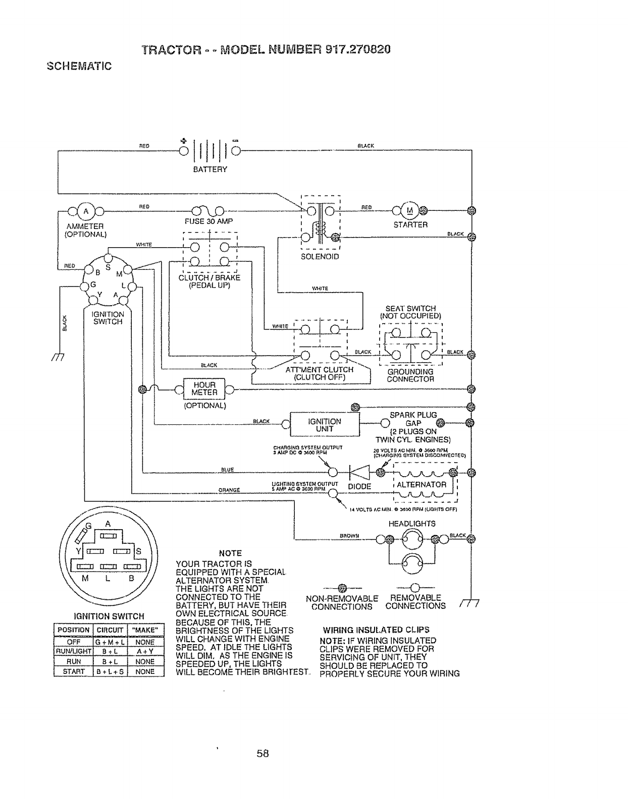
SCHEMATIC
TRACTOR o o _'v'IODEL NUMBER 917,270820
BATTERY
AMMETER
_OPTIONAL)
IGNITION
SWITCH
IGNITION SWITCH
PosmoN CIRCUIT "MAKE"
G_,4t #__.ONE.....
RUN B 4-L NONE.
START B +L ÷ S NONE
O--\jD,
FUSE 30 AMP
',C,W--,
---TO :'
l ........ ,J
CLUTCH !BRAKE
(PEDAL UP)
8_ACK
I
(OPTIONAL)
R_O
STARTER
BL_CK
SEAT SWITCH
...... / (NOTOCCUPIED)
WHILE l......... I J I ........... I
..... ATT MENT CLUTCH "q r'-r4OIINDtNG
(CLUTCH OFF) J C'O't_r_&CTOR
_LA.C* CJ tGNtTIONuNtT
[SPARK PLUG
I----O GAP
_(2 PLUGS ON
TWIN CYL ENGINES)
20 VOLTS ,_o MP4, 036(_ rlpl,f
CHA,c._tIN _ SYI;1"EM OUTPUT
/_P OC ¢ _,oo RPM ICI-IA_qGIFI(1 SYSTEM DIBCONttECTED)
UGHT]iq(I fIysIEM OUTPUT DIOD c tALTERNATOR_, I
)
NOTE
YOUR TRACTOR IS
EQUIPPED WITH A SPECIAL.
ALTERNATOR SYSTEM.
THE LIGHTS ARE NOT
CONNECTED TO THE
BATTERY, BUT HAVE THEIR
OWN ELECTRICAL SOURCE.
BECAUSE OF THIS, THE
BRIGHTNESS OF THE LIGHTS
WILL CHANGE WITH ENGINE
SPEED, AT IDLE THE LIGHTS
Will DIM. AS THE ENGINE IS
SPEEDED UP, THE LIGHTS
WILL BECOME THEIR BRIGHTEST..
HEADLIGHTS
NON-REMOVABLE REMOVABLE _
CONNECTIONS CONNECTIONS /," /
WIRING INSULATED CLIPS
NOTE: IF WIRING INSULATED
CLIPS WERE REMOVED FOR
SERVICING OF UNIT, THEY
SHOULD BE REPLACED TO
PROPERLY SECURE YOUR WIRING
58

SUGGESTED GUIDE FOR SBGHTING SLOPES FOR SAFE OPERATION
SIGHTING
ONLY RIDE UP AND DOWN HILL,
NOT ACROSS HILL
Lq
G3 SIGHT AND HOLD THIS LEVEL WITH
SKY LINE OR TREE.
15o MAX.
i
_ A Operate your Tractor up and down the face of slopes (not I
_,_ _,_ greater than 15°}, never across the face. Make turns gradu- i
_ ally to prevent tipping or toss of control. Exercise extreme !
caution when changing direction on siopes. I
|

For the repair or replacement parts you need
delivered directly to your home
Call 7 am - 7 pro, 7 days a week
loS00-366 PART
(1-800-366-7278)
Para ordenar piezas con entrega a
dornicilio - 1,,800-659-7084
For in-house major brand repair service
Call 24 hours a day, 7 days a week
1-800o4-REPA R
(I -800-473-.7274)
Para pedir servicio de reparaci6n a
dornicilio - 1-800-676-5811
For the location of a Sears Parts and
Repair Center in your area
Call 24 hours a day, 7 days a week
! -800.-488=1222
For information on purchasing a Sears
Maintenance Agreement or to inquire
about an existing Agreement
Call 9 am - 5 pro, Monday-Saturday
1-800-827-6655
When requesting service or ordering
parts, always provide the following
information:
• Product Type ,, Part Number
,, Model Number ,, Part Description 8EAR,
Amenca-s Repatr Specialists
163471 Rev. 3 3.13.98 JH , Printed in U.S.A.
