Craftsman 917270920 User Manual TRACTOR Manuals And Guides L9120313
CRAFTSMAN Lawn, Tractor Manual L9120313 CRAFTSMAN Lawn, Tractor Owner's Manual, CRAFTSMAN Lawn, Tractor installation guides
User Manual: Craftsman 917270920 917270920 CRAFTSMAN TRACTOR - Manuals and Guides View the owners manual for your CRAFTSMAN TRACTOR #917270920. Home:Lawn & Garden Parts:Craftsman Parts:Craftsman TRACTOR Manual
Open the PDF directly: View PDF ![]() .
.
Page Count: 60

•Owner's Manual
CRAFTSMAN"
19.5 HP
ELECTRIC START
42" MOWER
AUTOMATIC
LAWN TRACTOR
Model No.
917.270920
• Safety
• Assembly
•Operation
• Maintenance
•Repair Parts
CAUTION:
Read and follow all Safety Rules
and Instructionsbefore operat-
ingthis equipment.
For answers to your questions
about this product, Call:
1-800-659-5917
Sears Craftsman Help Line
5 am -5 pm, Mon -Sat
Seam, Roebuck and Co., Hoffman Estates, II60179
Visit our Craftsman website:www.sears.com/craftsman
Warr_Lnty "_....._...... :...... ......i .................... 2
Safety R=Jles. ...... :...... ......;...... .............. 2
ProdUct Spec_ficatlons ........................... 5
Assembly ..... .?,.,._ ...... ,........................... 7
Operation ....... '.............. _........................ 11
Maintenance Schedule ;................... 178
Maintenance ....................................... 18
Service and Adjustments .................... 22
Storage ............................................... 29
Troubleshooting ................................. 30
Repair Parts ........................................ 34
Parts Ordering ..................... Back Cover
LIMITED TWO YE_,R WARRANTY ON CRAFTSMAN RIDING EQUIPMENT
For two (2) years from the date of purchase, if this Craftsman Riding Equipment is
maintained, lubricated and tuned up according to the instructions in the owner's
manual, Sears will repair or replace, free of charge, any parts found to be defective in
material or workmanship.
This Warranty does not cover:
•Expendable items which become worn during normal use, such as blades, spark
plugs, air cleaners, belts, etc.
•Tire replacement or repair caused by punctures from outside objects, such as nails,
thorns, stumps, or glass.
•Repairs necessary because of operator abuse, negligence, improper storage or
accident or the failure to maintain the equipment according to the instructions
contained in the owner's manual.
• Riding equipment used for commercial or rental purposes.
LIMITED 90 DAY WARRANTY ON BATTERY
For ninety (90) days from date of purchase, if any battery included with this riding
equipment proves defective in material or workmanship and our testing determines the
battery will not hold a charge, Sears will replace the battery at no charge. In-home
warranty service on your Craftsman riding equipment is available at no charge for 30
days from the date of purchase. Please contact your nearest service center. After 30
days from the date of purchase, warranty service is available by taking your Craftsman
riding equipment to your nearest Sears Service Center. (In-home warranty service will
still be available after 30 days from the date of purchase but a standard trip charge will
apply). This warranty applies only while this product is in the United States. This
Warranty gives you specific legal rights, and you may alsohave other rights which may
vary from state to state.
SEARS, ROEBUCK AND CO., D/817 WA, HOFFMAN ESTATES, iL 60179
IMPORTANT" This cutting machine is
capable of amputating hands and feet
and throwing objects. Failure to observe
the following safety instructions could
result in serious injury or death.
GENERAL OPERATION
•Read, understand, and follow all
instructions in the manual and on the
machine before starting.
•Only allow responsible adults, who are
familiar with the instructions, to
operate the machine.
• Clear the area of objects such as
rocks, toys, wire, etc., which could be
picked up and thrown by the blade.
•Be sure the area is clear of other
people before mowing. Stop machine
if anyone enters the area.
• Never carry passengers.
•Do not mow in reverse unless abso-
lutely necessary. Always look down
and behind before and while backing.
• Be aware of the mower discharge
direction and do not point it at anyone.
Do not operate the mower without
either the entire grass catcher or the
2 guard in place.
•Slow down before tuming.
•Never leave arunning machine
unattended. Always turn off blades, set
parking brake, stop engine, and
remove keys before dismounting.
•Tum off blades when not mowing.
•Stop engine before removing grass
catcher or unclogging chute.
• Mow only in daylight or good artificial
light.
•Do not operate the machine while
under the influence of alcohol or
drugs.
•Watch for traffic when operating near
or crossing roadways.
•Use extra care when loading or
unloading the machine into a trailer or
truck.
•Data indicates that operators, age 60
years and above, are involved in a
large percentage of riding mower-
related injuries. These operators
should evaluate their ability to operate
the riding mower safely enough to
protect themselves and others from
senous injury.
SLOPE OPERATION
Slopes are a major factor related to loss-
of-control and tipover accidents, which
can result in severe injury or death. All
slopes require extra caution. If you
cannot back up the slope or if you leel
uneasy on it, do not mow it.
DO:
•Mow up and down slopes, not across.
•Remove obstacles such as rocks, tree
limbs, etc.
•Watch for holes, ruts, or bumps.
Uneven terrain could overturn the
machine. Tall grass can hide ob-
stacles.
•Use slow speed• Choose a low gear
so that you will not have to stop or shift
while on the slope.
•Follow the manufacturer's recommen-
dations for wheel weights or counter-
weights to improve stability.
•Use extra care with grass catchers or
other attachments. These can change
the stability of the machine.
•Keep all movement on the slopes slow
and gradual. Do not make sudden
changes in speed or direction.
•Avoid starting or stopping on a slope. If
tires lose traction, disengage the
blades and proceed slowly straight
down the slope.
DO NOT:
•Do not turn on slopes unless neces-
sary, and then, tum slowly and
gradually downhill, if possible.
•Do not mow near drop-offs, ditches, or
embankments. The mower could
suddenly tum over if a wheel is over
the edge of a cliff or ditch, or if an edge
caves in.
•Do not mow on wet grass. Reduced
traction could cause sliding.
•Do nottry to stabilize the machine by
putting your foot on the ground.
•Do not use grass catcher on steep
slopes.
CHILDREN
Tragic accidents can occur if the operator
is not alert to the presence of children.
Children are often attracted to the
machine and the mowing activity. Never
assume that children will remain where
you last saw them.
•Keep children out of the mowing area
and under the watchful care of another
responsible adult.
•Be alert and turn machine off if
children enter the area.
•Before and when backing, look behind
and down for small children.
•Never carry children. They may fall off
and be seriously injured or interfere
with safe machine operation.
•Never allow children to operate the
machine.
•Use extra care when approaching
blind comers, shrubs, trees, or other
objects that may obscure vision.
SERVICE
•Use extra care in handling gasoline
and other fuels. They are flammable
and vapors are explosive.
Use only an approved container.
Never remove gas cap or add fuel
with the engine running. Allow
engine to cool before refueling. Do
not smoke.
Never refuel the machine indoors.
Never store the machine or fuel
cOntainer inside where there is an
open flame, such as a water
heater.
•Never run a machine inside a closed
3 area.
• Keepnuts and bolts, especiallyblade
attachmentbolts,tight and keep
equipment in good condition.
•Never tamper with safety devices.
Check their proper operation regu-
larly.
•Keep machine free of grass, leaves, or
other debris build-up. Clean oil or fuel
spillage. Allow machine to cool before
storing.
•Stop and inspect the equipment if you
strike an object. Repair, if necessary,
before restarting.
•Never make adjustments or repairs
with the engine running.
•Grass catcher components are subject
to wear, damage, and deterioration,
which could expose moving parts or al-
low objects to be thrown. Frequently
check components and replace with
manufacturer's recommended parts,
when necessary.
•Mower blades are sharp and can cut.
Wrap the blade(s) or wear gloves, and
use extra caution when sewicing them.
•Check brake operation frequently. Ad-
just and service as required.
•Be sure the area is clear of other
people before mowing. Stop machine
if anyone enters the area.
•Never carry passengers or children
even with the blades off.
•Do not mow in reverse unless abso-
lutely necessary. Always |ook down
and behind before and while backing.
•Never carry children: They may fall off
and be seriously injured or interfere
with safe machine operation.
•Keep children out of the mowing area
and under the watchful care of another
responsible adult.
•Be alert and turn machine off if
children enter the area.
•Before and when backing, look behind
and down for small children.
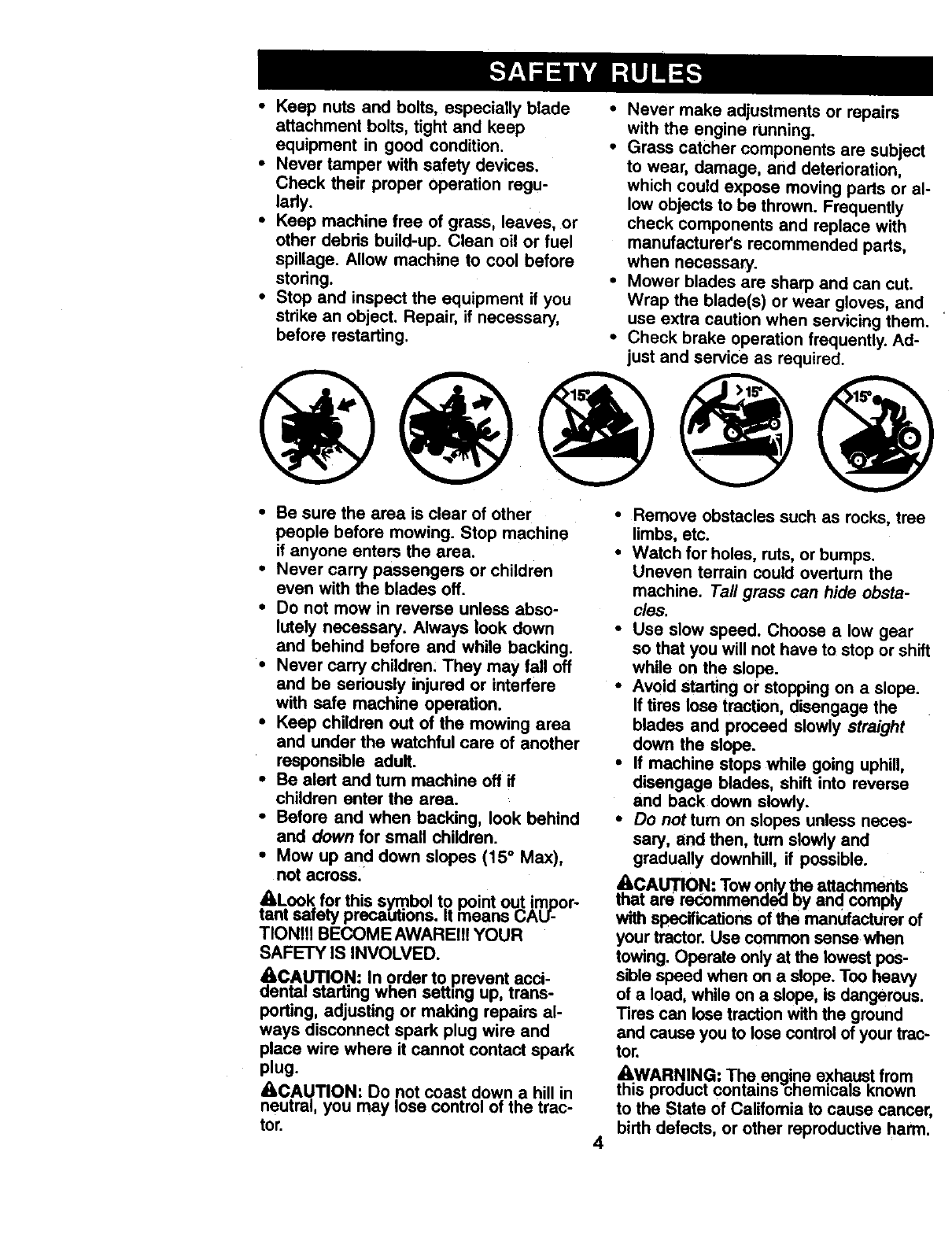
•Mow up and down slopes (15 ° Max),
not across.
ALook for this symbol to point out impor-
tant safety preca[Jtions. It fneans CAU-
TIONItt BECOME AWAREII! YOUR
SAFETY IS INVOLVED.
c,AeCA.Ul_.IO.N:In order to.prevent.acci-
nta=starting wnen setting up, trans-
porting, adjusting or making repairs al-
ways disconnect spark plug wire and
place wire where it cannot contact spark
plug.
_kCAUTION: Do not coast down a hill in
neutral, you may lose control of the trac-
tor.
•Remove obstacles such as recks, tree
limbs, etc.
•Watch for holes, ruts, or bumps.
Uneven terrain could overturn the
machine. Tall grass can hide obsta-
cles.
•Use slow speed. Choose a low gear
so that you will not have to stop or shift
while on the slope.
•Avoid starting or stopping on a slope.
if tires Iosa traction, disengage the
blades and proceed slowly straight
down the slope.
•If machine stops while going uphill,
disengage blades, shift into reverse
and back down slowly.
• Do not turn on slopes unless neces-
sary, and then, tum slowly and
gradually downhill, if possible.
tAhCAUTION: Tow o.nly_atta._men.ts
at are recommeno_a by aria comply
with specifications of the manufacturer of
your tractor. Use common sense when
towing. Operate only at the lowest pos-
sibio speed when on a slope. Too heavy
of a load, while on a slope, is dangerous.
Tires can lose traction with the ground
and cause you to loss control of your trac-
tor.
&WARN.IN.G: Th.e engi.ne exhaus.t from
this pro<_uct contains chemicals Known
to the State of Califomia to cause cancer,
birth defects, or other reproductive harm.
4
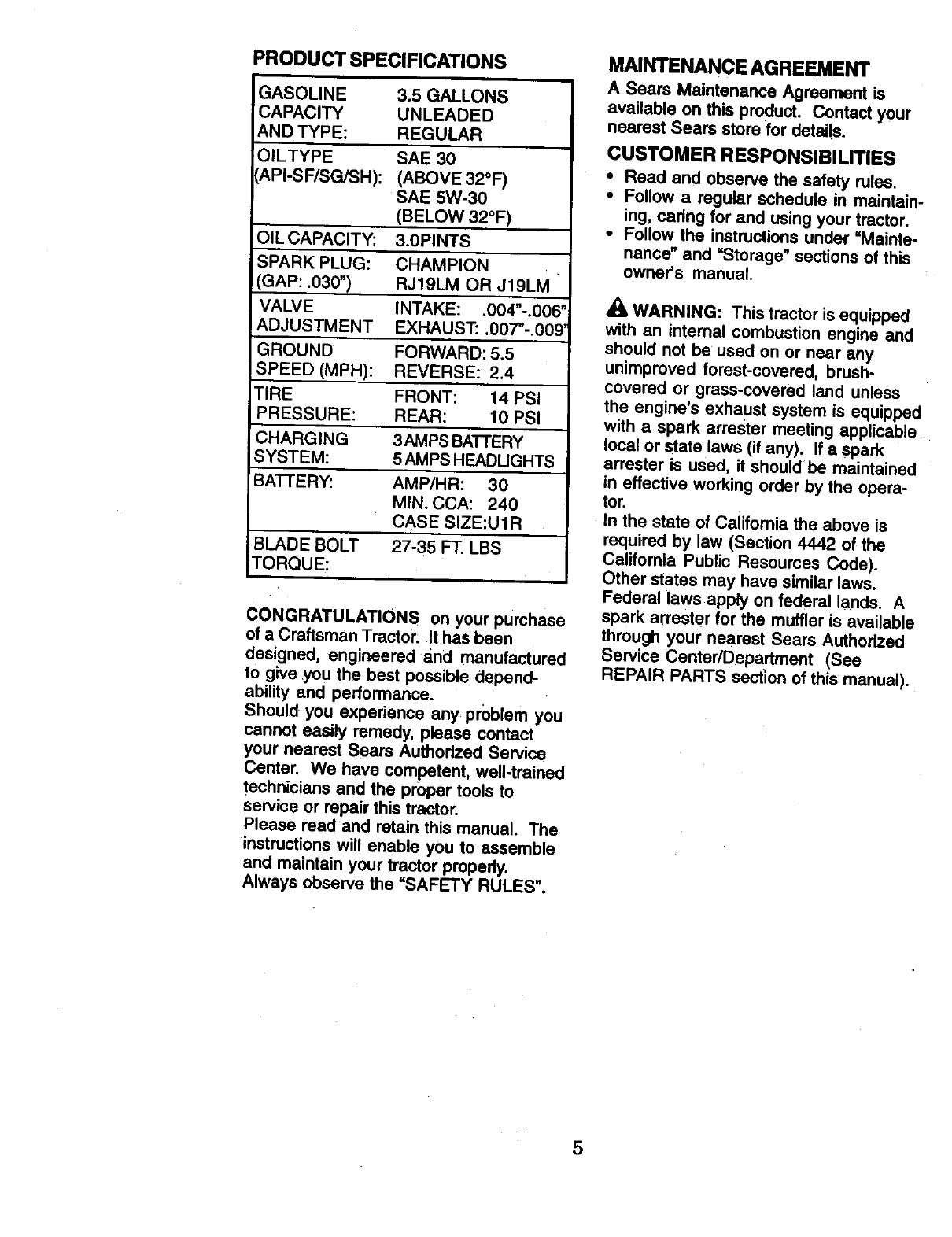
PRODUCT SPECIFICATIONS
GASOLINE
CAPACITY
AND TYPE:
OILTYPE
API-SF/SG/SH):
OIL CAPACITY:
SPARK PLUG:
GAP: .030")
VALVE
ADJUSTMENT
GROUND
SPEED (MPH):
TIRE
PRESSURE:
CHARGING
SYSTEM:
BA'I-FERY:
BLADE BOLT
TORQUE:
3.5 GALLONS
UNLEADED
REGULAR
SAE 30
(ABOVE 32°F)
SAE 5W-30
(BELOW 32°F)
3.0PINTS
CHAMPION
RJ19LM OR J19LM
INTAKE: .004"-.006"
EXHAUST'..007"-.009'
FORWARD: 5.5
REVERSE: 2.4
FRONT: 14 PSi
REAR: 10 PSI
3AMPS BATTERY
5 AMPS HEADLIGHTS
AMP/HR: 30
MIN. CCA: 240
CASE SIZE:U1R
27-35 FT. LBS
CONGRATULATIONS on your purchase
of a Craftsman Tractor. It has been
designed, engineered and manufactured
to give you the best possible depend-
ability and performance.
Should you experience any problem you
cannot easily remedy, please contact
your nearest Sears Authorized Service
Center. We have competent, well-trained
technicians and the proper tools to
service or repair this tractor.
Please read and retain this manual. The
instructions will enable you to assemble
and maintain your tractor properly.
Always observe the "SAFETY RULES".
MNNTENANCE AGREEMENT
A Sears Maintenance Agreement is
available on this product. Contact your
nearest Sears store for details.
CUSTOMER RESPONSIBILITIES
• Read and observe the safety rules.
•Follow a regular schedule in maintain-
ing, caring for and using your tractor.
•Follow the instructions under =Mainte-
nance" and =Storage" sections of this
owner's manual.
WARNING: This tractor is equipped
with an internal combustion engine and
should not be used on or near any
unimproved forest-covered, brush-
covered or grass-covered land unless
the engine's exhaust system is equipped
with a spark arrester meeting applicable
local or state laws (if any). Ira spark
arrester is used, it should be maintained
in effective working order by the opera-
tor.
In the state of California the above is
required by law (Section 4442 of the
California Public Resources Code).
Other states may have similar laws.
Federal laws apply on federal lands. A
spark attester for the muffler is available
through your nearest Sears Authorized
Service Center/Department (See
REPAIR PARTS section of this manual).
5
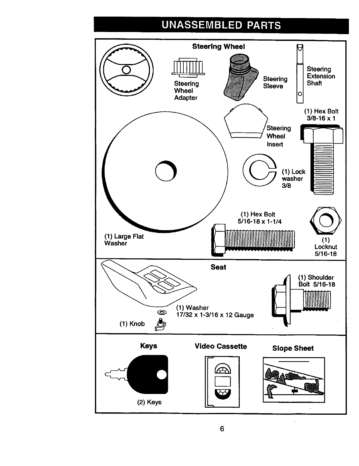
Steerlng Wheel t
_ _ Steering
Steering Extension
Sleeve Shaft
Adapter
(1) Hex Bolt
3/8-16 x 1
Wheel g
II (, 1J_ _. /--/ (1) Lock
(_/)sLaregeF'at _L_>lCk._t_
sher Seat
17/32 x 1-3/16 x12 Gauge
(1) Knob
(1) Shoulder
Bolt 5/16-18
Keys
(2) Keys
Video Cassette
"-1
Slope Sheet
6
Your new tractor has been assembled at the factory with exception of those parts left
unassembled for shipping purposes. To ensure safe and proper operation of your
tractor all parts and hardware you assemble must be tightened securely. Use the
correct tools as necessary to insure proper tightness.
TOOLS REQUIRED FOR ASSEMBLY
A socket wrench set will make assembly
easier. Standard wrench sizes you need
are listed below.
(1) 9/16" wrench (1) Pliers
(2) 1/2" wrench (1) Utility knife
(1) 3/4" socket with (1) Tire pressure
drive ratchet gauge
When right or left hand is mentioned in
this manual, it means, from your point of
view, when you are in the operating
position (seated behind the steering
wheel).
TO REMOVE TRACTOR FROM
CARTON
UNPACK CARTON
•Remove all accessible loose parts and
parts boxes from shipping carton.
•Cut, from top to bottom, along lines on
all four corners of shipping carton, and
lay panels flat.
•Check for any additional loose pads or
boxes and remove.
BEFORE REMOVING TRACTOR
FROM SKID
ATTACH STEERING WHEEL
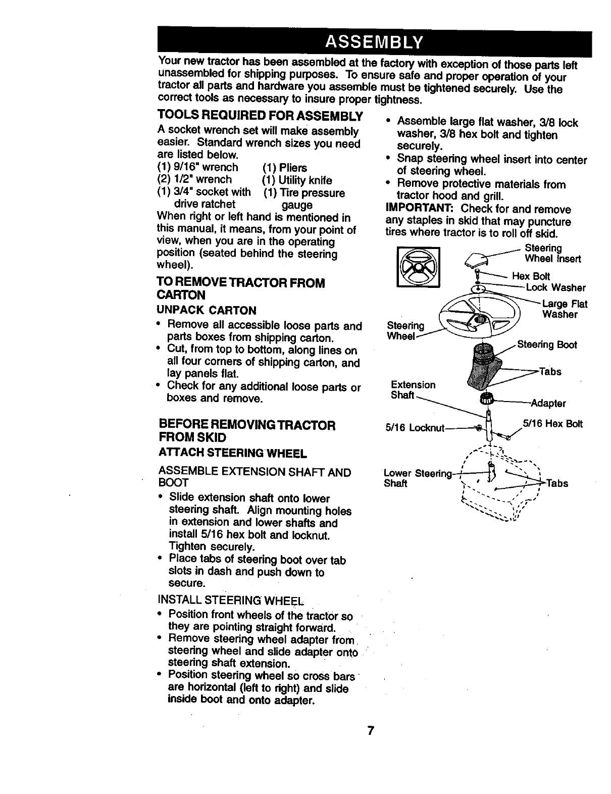
ASSEMBLE EXTENSION SHAFT AND
BOOT
•Slide extension shaft onto lower
steering shaft. Align mounting holes
in extension and lower shafts and
install 5/16 hex bolt and Iocknut.
Tighten securely.
•Place tabs of steedng boot over tab
slots in dash and push down to
secure.
INSTALL STEERING WHEEL
•Position front wheels of the tractor so
they are pointing straight forward.
•Remove steedng wheel adapter from
steedng wheel and slide adapter onto
steedng shaft extension.
•Position steedng wheel so cross bars
are horizontal (left to dght) and slide
inside boot and onto adapter.
•Assemble large flat washer, 3/8 lock
washer, 3/8 hex bolt and tighten
securely.
•Snap steering wheel insert into center
of steedng wheel.
•Remove protective materials from
tractor hood and grill.
IMPORTANT: Check for and remove
any staples in skid that may puncture
tires where tractor is to roll off skid.
7
HOWTO SETUPYOURTRACTOR
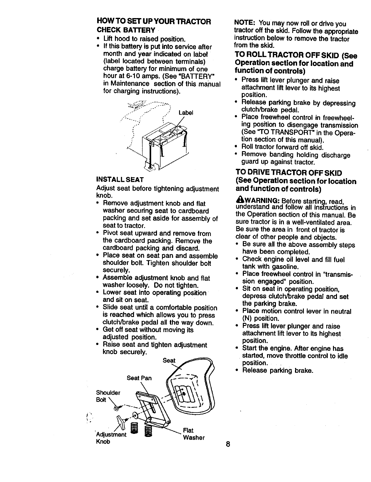
CHECK BA'n'ERY
•Lift hood to raised position.
•If this battery is put into service after
month and year indicated on label
(label located between terminals)
charge battery for minimum of one
hour at 6-10 amps. (See =BATTERY"
in Maintenance section of this manual
for charging instructions).
Y"' "Label
• .o'
:-::i..........
iNSTALL SEAT
Adjust seat before tightening adjustment
knob.
•Remove adjustment knob and flat
washer securing seat to cardboard
packing and set aside for assembly of
seat to tractor,
•Pivot seat upward and remove from
the cardboard packing. Remove the
cardboard packing and discard.
•Place seat on seat pan and assemble
shoulder bolt. Tighten shoulder bolt
securely.
•Assemble adjustment knob and flat
washer loosely. Do not tighten,
• Lower seat into operating position
and sit on seat.
•Slide seat until acomfortable position
is reached which allows you to press
clutch/brake pedal all the way down.
•Get off seat without moving its
adjusted position.
•Raise seat and tighten adjustment
knob securely,
Seat
Seat Pan
NOTE: You may now rollor drive you
tractor off the skid. Follow the appropriate
instructionbelow to remove the tractor
from the skid.
TO ROLL TRACTOR OFF SKID (See
Operation section for location and
function of controls)
•Press lift lever plunger and raise
attachment lift lever to its highest
position.
•Release parking brake by depressing
clutch/brake pedal.
•Place freewheel control in freewheel-
ing position to disengage transmission
(See _'O TRANSPORT" in the Opera-
tion section of this manual),
•Roll tractor forward off skid.
•Remove banding holding discharge
guard up against tractor.
TO DRIVE TRACTOR OFF SKID
(See Operation section for location
and function of controls)
_kWARNING: Before starting, read,
understand and follow all instructions in
the Operation section of this manual• Be
sure tractor is in a well-ventilated area•
Be sure the area in front of tractor is
clear of other people and objects.
•Be sure all the above assembly steps
have been completed.
•Check engine oil level and fill fuel
tank with gasoline.
•Place freewheel control in "transmis-
sion engaged" position.
•Sit on seat in operating position,
depress clutch/brake pedal and set
the parking brake.
•Place motion control lever in neutral
(N) position.
•Press lift lever plunger and raise
attachment lift lever to its highest
position.
•Start the engine. After engine has
started, move throttle control to idle
position.
•Release parking brake.
Shoulder
Flat
'Adjustment Washer
Knob 8
• Slowly move the motion control lever
forward and slowly drive tractor off
skid.
• Apply brake to stop tractor, set parking
brake and place motion control lever
in neutral position.
•Tum ignition key to "OFF" position.
Continue with the instructions that follow.
CHECK TIRE PRESSURE
The tires on your tractor were overin-
flated at the factory for shipping pur-
poses. Correct tire pressure is important
for best cutting performance.
•Reduce tire pressure to PSI shown in
=PRODUCT SPECIFICATIONS"
section of this manual.
CHECK DECK LEVELNESS
For best cutting results, mower housing
should be property leveled. See "I"O
LEVEL MOWER HOUSING" in the
Service and Adjustments section of this
manual.
CHECK FOR PROPER POSITION
OF ALL BELTS
See the figures that are shown for
replacing motion and mower blade drive
belts in the Service and Adjustments
section of this manual. Verify that the
belts are routed correctly.
CHECK BRAKE SYSTEM
After you learn how to Operate your
tractor, check to see that the brake is
properly adjusted. See =TO ADJUST
BRAKE" in the Service and Adjustments
section of this manual.
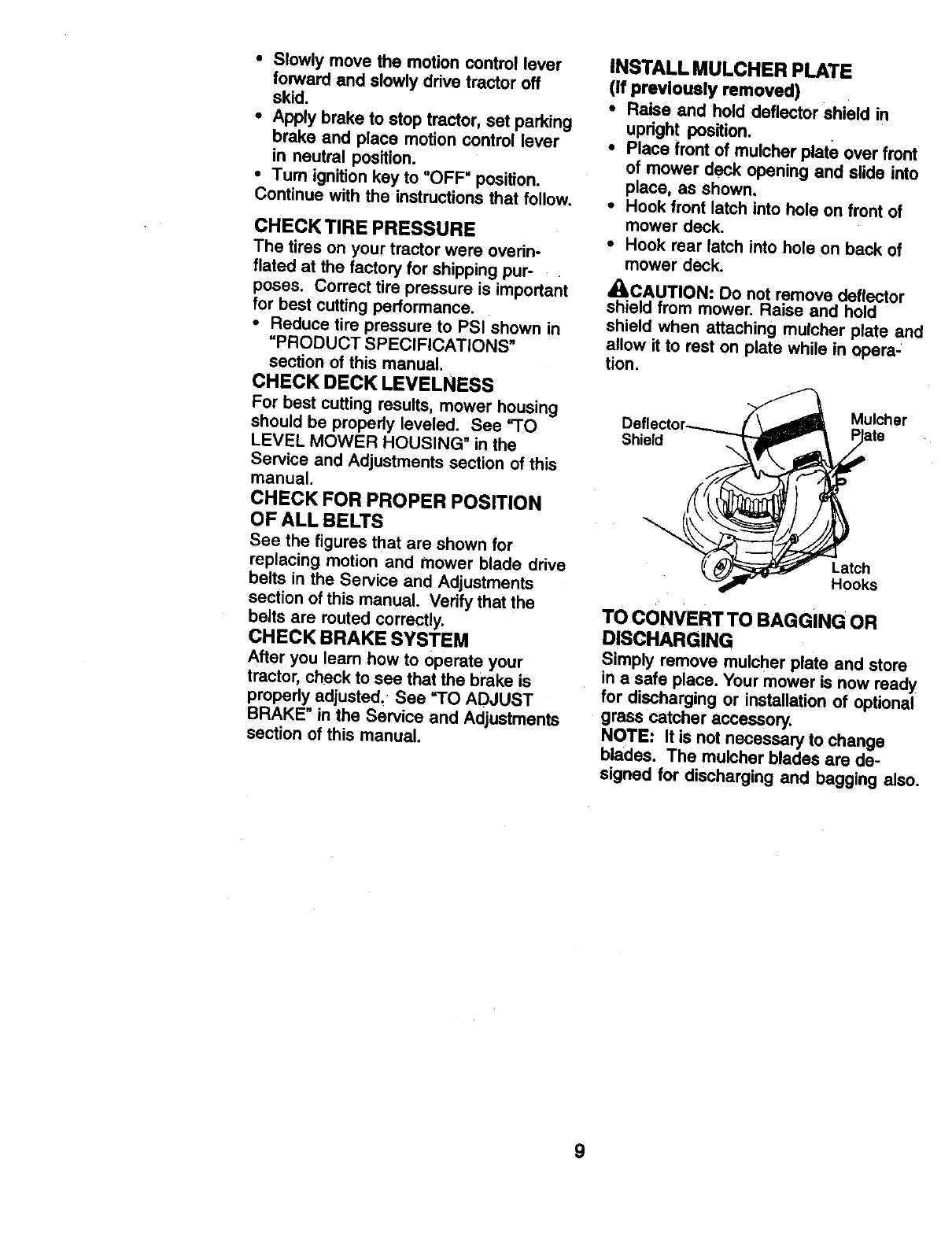
INSTALL MULCHER PLATE
(If previously removed)
•Raise and hold deflector shield in
upright position.
•Place front of mulcher plate over front
of mower deck opening and slide into
place, as shown.
• Hook front latch into hole on front of
mower deck.
•Hook roar latch into hole on back of
mower deck.
,I_!ILCAUTION: Do not remove deflector
shield from mower. Raise and hold
shield when attaching mulcher plate and
allow it to rest on plate while in opera-
tion.
Shield
Mulcher
Latch
Hooks
TO CONVERT TO BAGGING OR
DISCHARGING
Simply remove mulcher plate and store
in a safe place. Your mower is now ready
for discharging or installation of optional
grass catcher accessory,
NOTE: It is not necessary to change
blades. The mulcher blades are de-
signed for discharging and bagging also.
9
t/CHECKLIST
BEFORE YOU OPERATE AND ENJOY
YOUR NEW TRACTOR, WE WISH TO
ASSURE THAT YOU RECEIVE THE
BEST PERFORMANCE AND
SATISFACTION FROM THIS QUALITY
PRODUCT.
PLEASE REVIEW THE FOLLOWING
CHECKLIST:
,# All assembly instructions have been
completed.
,/No remaining loose parts in carton.
4Battery is properly prepared and
charged. (Minimum 1 hour at 6
amps).
4Seat is adjusted comfortably and
tightened securely.
/All tires are properly inflated. (For
shipping purposes, the tires were
overinflated at the factory).
/Be sure mower deck is propedy
leveled side-to-side/front-to-rear for
best cutting results. (Tires must be
properly inflated for leveling).
JCheck mower and ddve belts. Be sure
they are routed propedy around
pulleys and inside all belt keepers.
4" Check wiring. See that all connections
are still secure and wires are properly
clamped.
,/Before driving tractor, be sure free-
wheel control is in ddve position.
WHILE LEARNING HOW TO USE YOUR
TRACTOR, PAY EXTRAATTENTION TO
THE FOLLOWING IMPORTANT ITEMS:
,I Engine oil is at proper level.
,/Fuel tank is filled with fresh, clean,
regular unleaded gasoline.
,I Become familiar with all controls - their
location and function. Operate them
before you start the engine.
4Be sure brake system is in safe
operating condition.
4It is important to purge the transmis-
sion before operating your tractor for
the first time. Follow proper starting
and transmission purging instructions
(See "TO START ENGINE" and
"PURGE TRANSMISSION" in the
Operation section of this manual).
10
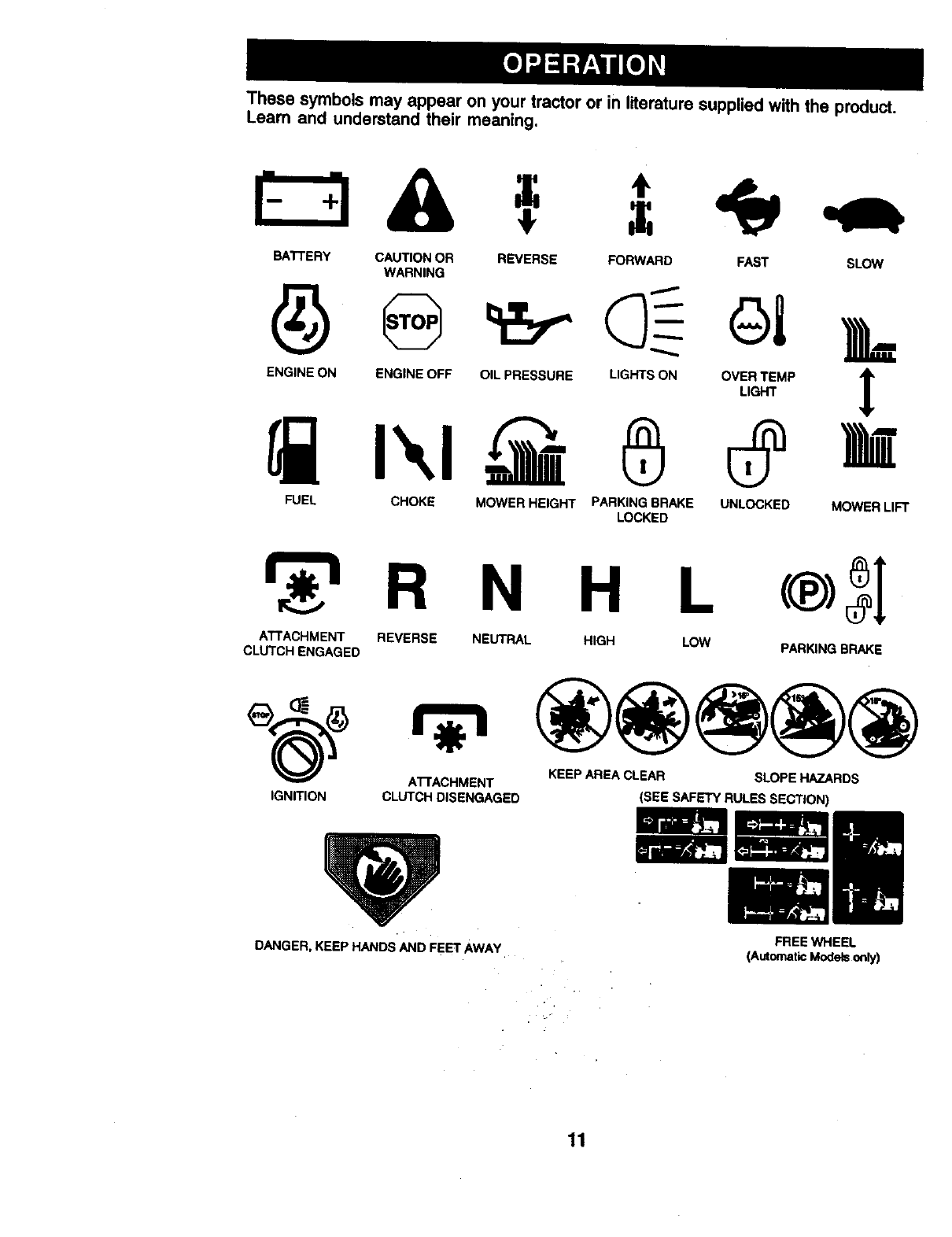
These symbols may appear on your tractor or in literature supplied with the product.
Learn and understand their meaning.
BATTERY CAUTION OR REVERSE FORWARD FAST SLOW
WARNING
ENG,NEONENG,NEOFFO.LPRESSUREL,G'SONO%T_.P
FUEL CHOKE MOWER HEIGHT PARKINGBRAKE UNLOCKED MOWER LIFT
LOCKED
H L
ATTACHMENT REVERSE NEUTRAL HIGH LOW
CLUTCH ENGAGED PARKING BRAKE
ATFACHMENT KEEP AREA CLEAR SLOPE HAZARDS
IGNITION CLUTCH DISENGAGED (SEE SAFETY RULES SECTION)
DANGER, KEEP HANDS AND FEET AWAY• FREE WHEEL
(AutomaticModelsonly)
11
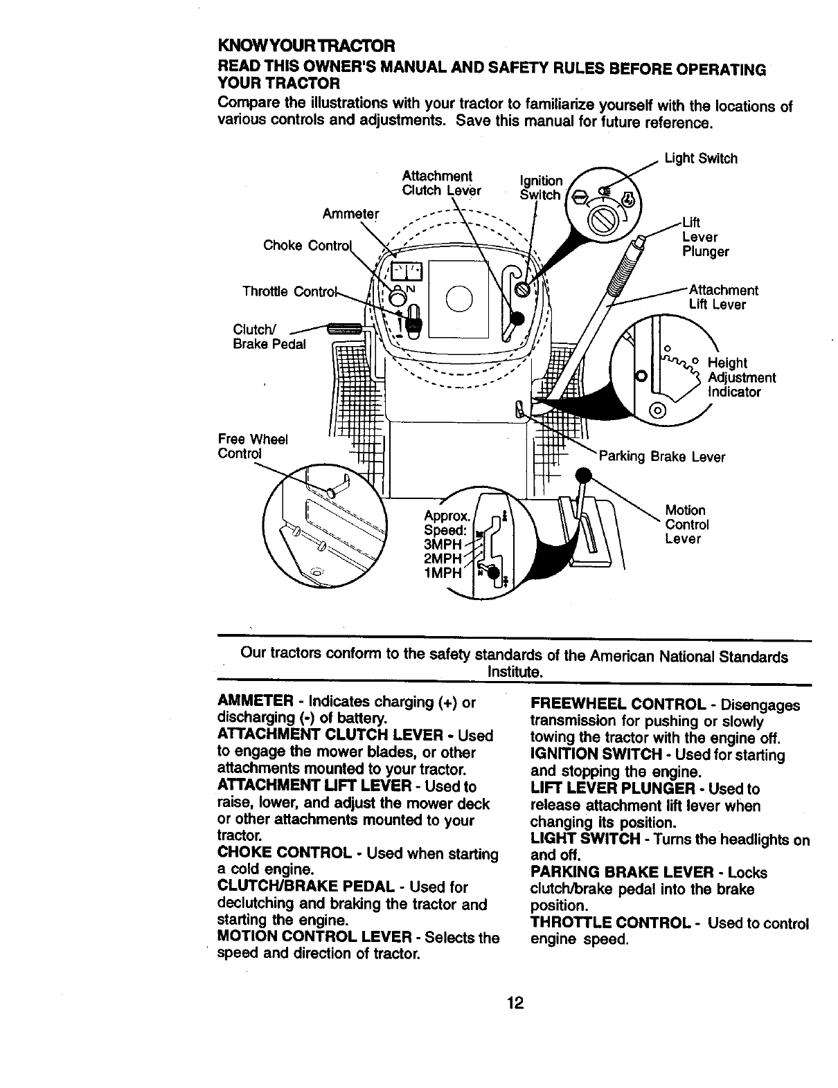
KNOWYOUR TRACTOR
READ THIS OWNER'S MANUAL AND SAFETY RULES BEFORE OPERATING
YOUR TRACTOR
Compare the iUustrationswith your tractor to familiarize yourself with the locations of
various controls and adjustments, Save this manual for future reference.
Attachment Ignition
Clutch Lever
Light Switch
Lever
Choke Plunger
Throttle
Clutch/
Brake Pedal
Lift Lever
Height
Adjustment
Indicator
Free Wheel
Control g Brake Lever
Motion
Control
Lever
Our tractors conform to the safety standards of the American National Standards
Institute.
AMMETER - Indicates charging (+) or
discharging (-) of batten].
ATTACHMENT CLUTCH LEVER -Used
to engage the mower blades, or other
attachments mounted to your tractor.
ATTACHMENT MFT LEVER -Used to
raise, lower, and adjust the mower deck
or other atlachments mounted to your
tractor.
CHOKE CONTROL -Used when starting
a cold engine.
CLUTCWBRAKE PEDAL - Used for
declutching and braking the tractor and
starting the engine.
MOTION CONTROL LEVER -Selects the
speed and direction of tractor.
FREEWHEEL CONTROL - Disengages
transmission for pushing or slowly
towing the tractor with the engine off.
IGNITION SWITCH -Used for starting
and stopping the engine.
LIFT LEVER PLUNGER -Used to
release attachment lift lever when
changing its position.
LIGHT SWITCH -Turns the headlights on
and off.
PARKING BRAKE LEVER - Locks
clutch/brake pedal into the brake
position.
THROTTLE CONTROL -Used to control
engine speed.
12
The operation of any tractor can result in foreign objects thrown into
the eyes, which can result in severe eye damage. Always wear safety
glasses or eye shields while operating your tractor or performing any
adjustments or repairs. We recommend a wide vision safety.mask
over spectacles or standard safety glasses.
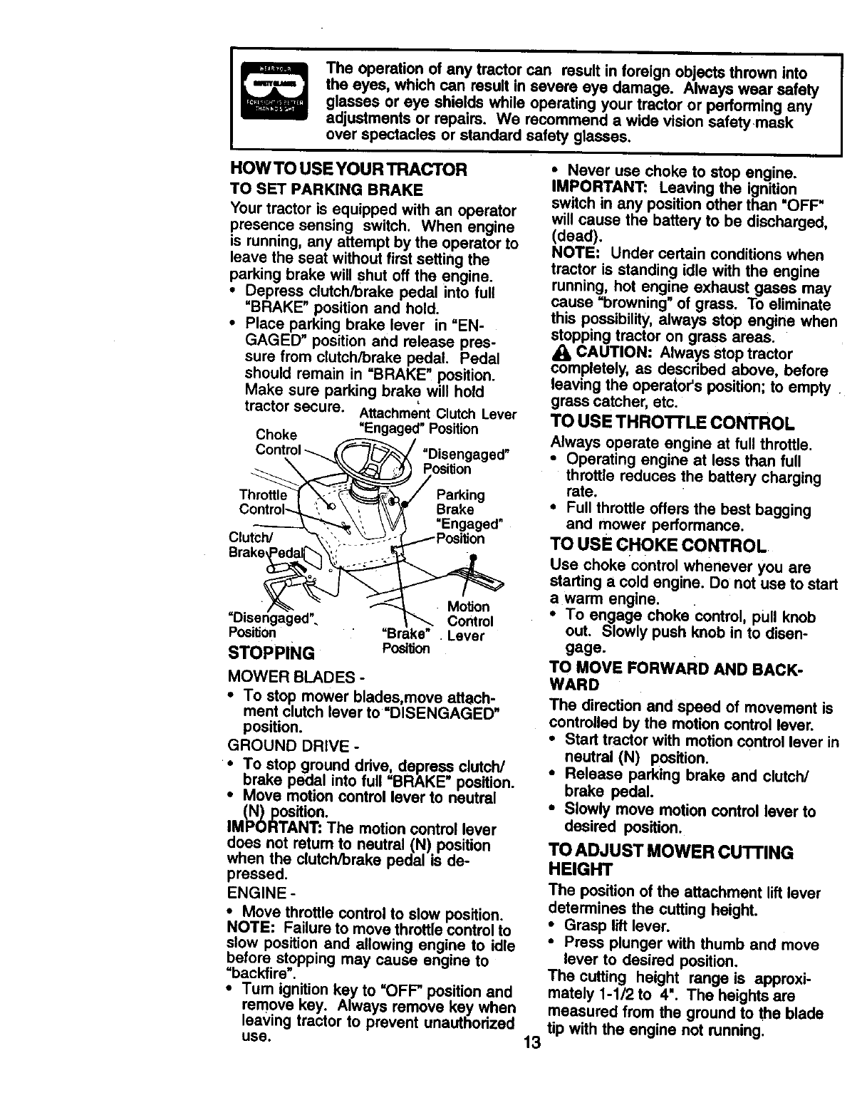
HOW TO USE YOUR TRACTOR
TO SET PARKING BRAKE
Your tractor is equipped with an operator
presence sensing switch. When engine
is running, any attempt by the operator to
leave the seat without first setting the
parking brake will Shut off the engine.
•Depress clutch/brake pedal into full
=BRAKE" position and hold.
•Place parking brake lever in "EN-
GAGED" position and release pres-
sure from clutch/brake pedal. Pedal
should remain in =BRAKE" position.
Make sure parking brake will hold
tractor secure. Attachment Clutch Lever
Choke =Engaged" Position
Control __ =Disengaged"
___.__ Position
Park,ng
Control---,L "_'_ \ ,,_-'_\\_ Brake ,
------_'_ _', \V/I Engaged
Clutch/ "_,"_ '_\'__-S_-__--j.1--'_ Position
Brake_
._ _ Motion
Dis.e.n ag ged". =.._1____. Control
Position "Brake .Lever
STOPPING Position
MOWER BLADES -
•To stop mower blades,move attach-
ment clutch lever to =DISENGAGED"
position.
GROUND DRIVE -
• To stop ground drive, depress clutch/
brake pedal into full =BRAKE" position.
• Move motion control lever to neutral
(N) position.
IMPORTANT: The motion control lever
does not retum to neutral (N) position
when the clutch/brake pedal is de-
pressed.
ENGINE -
•Move throttle control to s!ow position.
NOTE: Failure to move throttle control to
slow position and allowing engine to idle
before stopping may cause engine to
=backfire".
•Tum ignition key to =OFF" position and
remove key. Always remove key when
leaving tractor to prevent unauthorized
use. 13
• Never use choke to stop engine.
IMPORTANT: Leaving the ignition
switch in any posdion other than 'OFF'
will cause the battery to be discharged,
(dead).
NOTE: Under certain conditions when
tractor is standing idle with the engine
running, hot engine exhaust gases may
cause =browning" of grass. To eliminate
this possibility, always stop engine when
stopping tractor on grass areas.
CAUTION: Always stop tractor
completely, as described above, before
leaving the operator's position; to empty
grass catcher, etc.
TO USE THROI'FLE CONTROL
Always operate engine at full throttle.
•Operating engine at less than full
throttle reduces the battery charging
rate.
•Full throttle offers the best bagging
and mower performance.
TO USE CHOKE CONTROL
Use choke control whenever you are
starting a cold engine. Do not use to start
a warm engine.
•To engage choke control, pull knob
out. Slowly push knob in to disen-
gage.
TO MOVE FORWARD AND BACK-
WARD
The direction and speed of movement is
controlled by the motion control lever.
•Start tractor with motion control lever in
neutral (N) position.
•Release parking brake and clutch/
brake pedal.
•Slowly move motion control lever to
desired position.
TO ADJUST MOWER CUTFING
HEIGHT
The position of the attachment lift lever
determines the cutting height.
•Grasp lift lever.
•Press plunger with thumb and move
lever to desired position.
The cutting height range is approxi-
mately 1-1/2 to 4". The heights are
measured from the ground to the blade
tip with the engine not running.
Theseheightsare approximateand may
vary depending upon soil conditions,
height of grass and types of grass being
mowed.
•The average lawn should be cut to
approximately 2-1/2 inches during the
cool season and to over 3 inches
during hot months. For healthier and
better looking lawns, mow often and
after moderate growth.
•For best cutting performance, grass
over 6 inches in height should be
mowed twice. Make the first cut
relatively high; the second to desired
height.
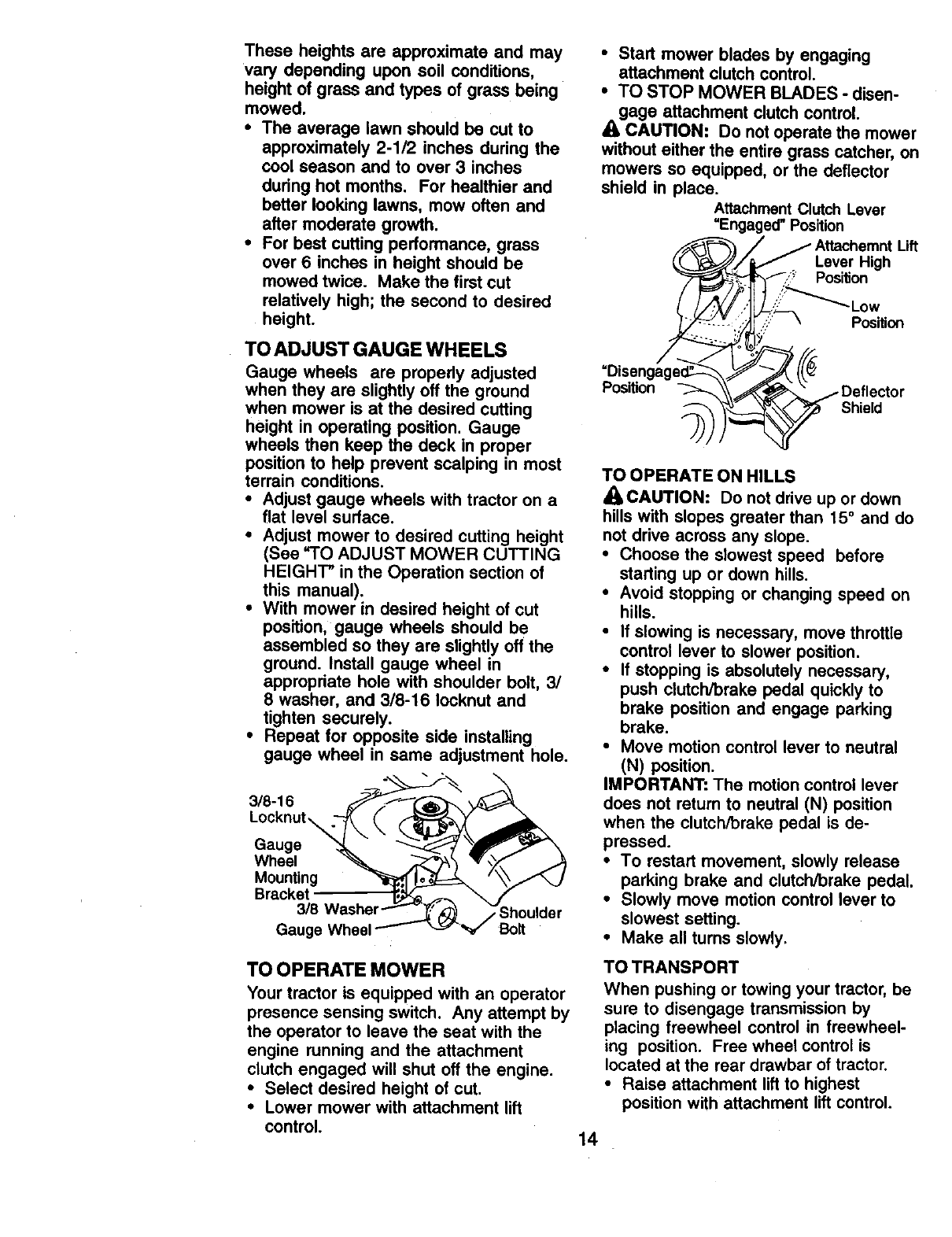
TO ADJUST GAUGE WHEELS
Gauge wheels are propedy adjusted
when they are slightly off the ground
when mower is at the desired cutting
height in operating position. Gauge
wheels then keep the deck in proper
position to help prevent scalping in most
terrain conditions.
•Adjust gauge wheels with tractor on a
flat level surface.
•Adjust mower to desired cutting height
(See "TO ADJUST MOWER CUTTING
HEIGHT" in the Operation section of
this manual).
• With mower in desired height of cut
position, gauge wheels should be
assembled so they are slightly off the
ground. Install gauge wheel in
appropdate hole with shoulder bolt, 3/
8 washer, and 3/8-16 lecknut and
tighten securely.
• Repeat for opposite side installing
gauge wheel in same adjustment hole.
Locknut\
Gauge
Wheel _ _--'_ _lv,,_,Z_
Mounting _ _ '"_._
Bracket_ _ _ f
3/8 Washer Shoulder
Gaug' Washe_'_ulderwheel
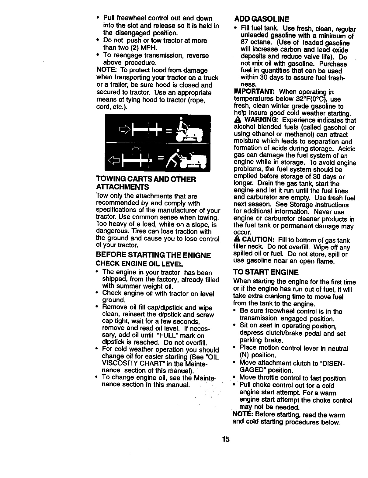
TO OPERATE MOWER
Your tractor is equipped with an operator
presence sensing switch. Any attempt by
the operator to leave the seat with the
engine running and the attachment
clutch engaged will shut off the engine.
•Select desired height of cut.
•Lower mower with attachment lift
control.
•Start mower blades by engaging
attachment clutch control.
•TO STOP MOWER BLADES - disen-
gage attachment clutch control.
ACAUTION.'. Do not operate the mower
without either the entire grass catcher, on
mowers so equipped, or the deflector
shield in place.
AttachmentClutchLever
"Engaged" Position
Lever High
Position
uft
bLow
Position
Position
Shield
TO OPERATE ON HILLS
_CAUTION: Do not drive up or down
hills with slopes greater than 15°and do
not drive across any slope.
•Choose the slowest speed before
starting up or down hills.
•Avoid stopping or changing speed on
hills.
•If slowing is necessary, move throttle
control lever to slower position.
•If stopping is absolutely necessary,
push clutch/brake pedal quickly to
brake position and engage parking
brake.
•Move motion control lever to neutral
(N) position.
IMPORTANT: The motion control lever
does not return to neutral (N) position
when the clutch/brake pedal is de-
pressed.
•To restart movement, slowly release
parking brake and clutch/brake pedal.
•Slowly move motion control lever to
slowest setting.
• Make all turns slowly.
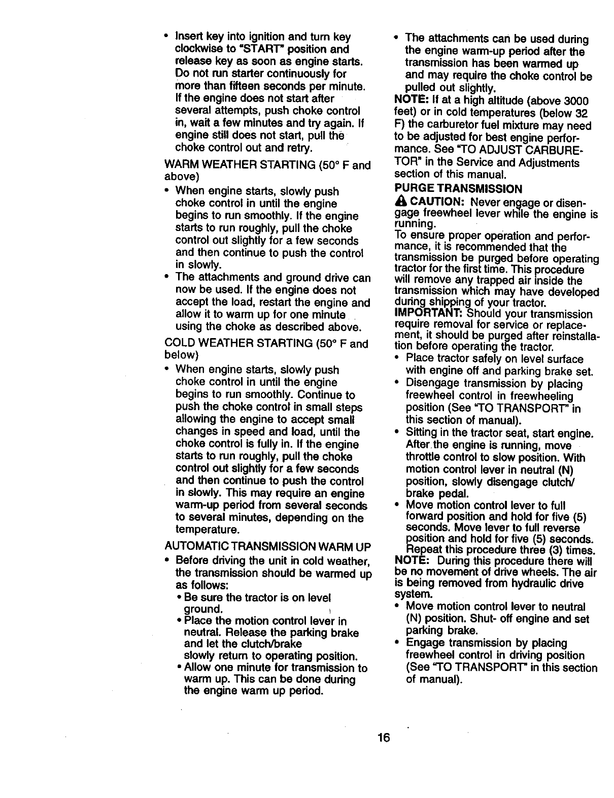
TOTRANSPORT
When pushing or towing your tractor, be
sure to disengage transmission by
placing freewheel control in freewheel-
ing position. Free wheel control is
located at the rear drawbar of tractor.
•Raise attachment lift to highest
position with attachment lift control.
14
•Pull freewheel control out and down
into the slot and release so it is held in
the disengaged position.
•Do not push or tow tractor at more
than two (2) MPH.
•To reengage transmission, reverse
above procedure.
NOTE: To protect hood from damage
when transporting your tractor on a truck
or a trailer, be sure hood is closed and
secured to tractor. Use an appropriate
means of tying hood to tractor (rope,
cord, etc.).
TOWING CARTS AND OTHER
ATTACHMENTS
Tow only the attachments that are
recommended by and comply with
specifications of the manufacturer of your
tractor. Use common sense when towing.
Too heavy of aload, while on a slope, is
dangerous. Tires can lose traction with
the ground and cause you to lose control
of your tractor.
BEFORE STARTING THE ENIGNE
CHECK ENGINE OIL LEVEL
•The engine in your tractor has been
shipped, from the factory, already filled
with summer weight oil.
•Check engine oil with tractor on level
ground.
•Remove oil fill cap/dipstick and wipe
clean, reinsert the dipstick and screw
cap tight, wait for a few seconds,
remove and read oil level. If neces-
sary, add oil until "FULL" mark on
dipstick is reached. Do not overfill.
• For cold weather operation you should
change oil for easier starting (See =OIL
VISCOSITY CHART" in the Mainte-
nance section of this manual).
•To change engine oil, see the Mainte-
nance section in this manual.
ADD GASOLINE
•Fillfuel tank. Use fresh, clean, regular
unleaded gasoline with a minimum of
87 octane, (Use of leaded gasoline
will increase carbon and lead oxide
deposits and reduce valve life). Do
not mix oil with gasoline. Purchase
fuel in quantities that can be used
within 30 days to assure fuel fresh-
ness.
IMPORTANT: When operating in
temperatures below 32°F(0°C), use
fresh, clean winter grade gasoline to
help insure good cold weather starting.
WARNING: Experience indicates that
alcohol blended fuels (called gasohol or
using ethanol or methanol) can attract
moisture which leads to separation and
formation of acids during storage. Acidic
gas can damage the fuel system of an
engine while in storage. To avoid engine
problems, the fuel system should be
emptied before storage of 30 days or
longer. Drain the gas tank, start the
engine and let it run until the fuel lines
and carburetor are empty. Use fresh fuel
next season. See Storage Instructions
for additional information. Never use
engine or carburetor cleaner products in
the fuel tank or permanent damage may
Occur,
ACAUTION: Fillto bottom of gastank
filler neck. Do not ovedill. Wipe off any
spilled oil or fuel. Do not store, spill or
use gasoline near an open flame.
TO START ENGINE
When starting the engine for the first time
or if the engine has run out of fuel, it will
take extra cranking time to move fuel
from the tank to the engine.
•Be sure freewheel control is in the
transmission engaged position.
•Sit on seat in operating position,
depress clutch/brake pedal and set
parking brake.
•Place motion control lever in neutral
(N) position.
•Move attachment clutchto uDISEN-
GAGED" position.
•Move throttle control to fast position
,, Pull choke control out for a cold
engine start attempt. For awarm
engine start attempt the choke control
may not be needed.
NOTE: Before starting, read the warm
and cold starting procedures below.
15
•Insert key into ignition and tum key
clockwise to =START" position and
release key as soon as engine starts.
Do not run starter continuously for
more than fifteen seconds per minute.
If the engine does not start after
several attempts, push choke control
in, wait a few minutes and try again. If
engine still does not start, pull the
choke control out and retry.
WARM WEATHER STARTING (50 ° F and
above)
•When engine starts, slowly push
choke control in until the engine
begins to run smoothly. If the engine
starts to run roughly, pull the choke
control out slightly for afew seconds
and then continue to push the control
in slowly.
•The attachments and ground drive can
now be used. If the engine does not
accept the load, restart the engine and
allow it to warm up for one minute
using the choke as described above.
COLD WEATHER STARTING (50 ° Fand
below)
• When engine starts, slowly push
choke control in until the engine
begins to run smoothly. Continue to
push the choke control in small steps
allowing the engine to accept small
changes in speed and load, until the
choke control is fully in. If the engine
starts to run roughly, pull the choke
control out slightly for a few seconds
and then continue to push the control
in slowly. This may require an engine
warm-up period from several seconds
to several minutes, depending on the
temperature.
AUTOMATIC TRANSMISSION WARM UP
•Before driving the unit in cold weather,
the transmission should be warmed up
as follows:
•Be sure the tractor is on level
ground.
•Place the motion control lever in
neutral. Release the parking brake
and let the clutch/broke
slowly return to operating position.
•Allow one minute for transmission to
warm up. This can be done during
the engine warm up period.
•The attachments can be used during
the engine warm-up period after the
transmission has been warmed up
and may require the choke control be
pulled out slightly.
NOTE: If at a high altitude (above 3000
feet) or in cold temperatures (below 32
F) the carburetor fuel mixture may need
to be adjusted for best engine perfor-
mance. See =TO ADJUST CARBURE-
TOR _in the Service and Adjustments
section of this manual.
PURGE TRANSMISSION
CAUTION: Never engage or disen-
gage freewheel lever while the engine is
running.
To ensure proper operation and perfor-
mance, it is recommended that the
transmission be purged before operating
tractor for the first time. This procedure
will remove any trapped air reside the
transmission which may have developed
during shipping of your tractor.
IMPORTANT: Should your transmission
require removal for service or replace-
ment, it should be purged after reinstaila-
tion before operating the tractor.
•Place tractor safely on level surface
with engine off and parking brake set.
•Disengage transmission by placing
freewheel control in freewheeling
position (See =TO TRANSPORT" in
this section of manual).
•Sitting in the tractor seat, start engine.
Afterthe engine is running, move
throttle control to slow position. With
motion control lever in neutral (N)
position, slowly disengage clutch/
brake pedal.
•Move motion control lever to full
forward position and hold for five (5)
seconds. Move lever to full reverse
position and hold for five (5) seconds.
Repeat this procedure three (3) times.
NOTE: During this procedure there will
be no movement of ddve wheels. The air
is being removed from hydraulic drive
system.
•Move motion control lever to neutral
(N) position. Shut- off engine and set
parking brake.
•Engage transmission by placing
freewheel control in driving position
(See "TO TRANSPORT" in this section
of manual).
16
• Sitting in the tractor seat, start engine.
Alter the engine is running, move
throttle control to half (1/2) speed. With
motion control lever in neutral (N)
position, slowly disengage clutch/
brake pedal.
•Slowly move motion control lever
forward, alter the tractor moves
approximately five (5) feet, slowly
move motion control lever to reverse
position. After the tractor moves
approximately five (5) feet return the
motion control lever to the neutral (N)
position. Repeat this procedure with
the motion control lever three (3)
times.
•Your tractor is now purged and now
ready for normal operation.
MOWING TIPS
•Mower should be propedy leveled for
best mowing performance. See "TO
LEVEL MOWER HOUSING" in the
Service and Adjustments section of
this manual.
•The left hand side of mower should be
used for tdmming.
•Drive so that clippings are discharged
onto the area that has been cut. Have
the cut area to the right of the tractor:
This will result in a more even distribu-
tion of clippings and more uniform
cutting.
•When mowing large areas, start by
turning to the right so that clippings will
discharge away from shrubs, fences,
driveways, etc. Alter one or two
rounds, mow in the opposite direction
making left hand tums until finished.
• If grass is extremely tall, it should be
mowed twice to reduce load and
possible fire hazard from dried
clippings. Make first cut relatively
high; the second to the desired height.
•Do not mow grass when it is wet. Wet
grass will plug mower and leave
undesirable clumps. Allow grass to
dry before mowing.
•Always operate engine st full throttle
when mowing to assure better mowing
performance and proper discharge of
material. Regulate ground speed by
selecting a low enough gear to give
the mower cutting performance as well
as the quality of cut desired.
•When operating attachments, select a
ground speed that will suit the terrain
and give best performance of the
attachment being used.
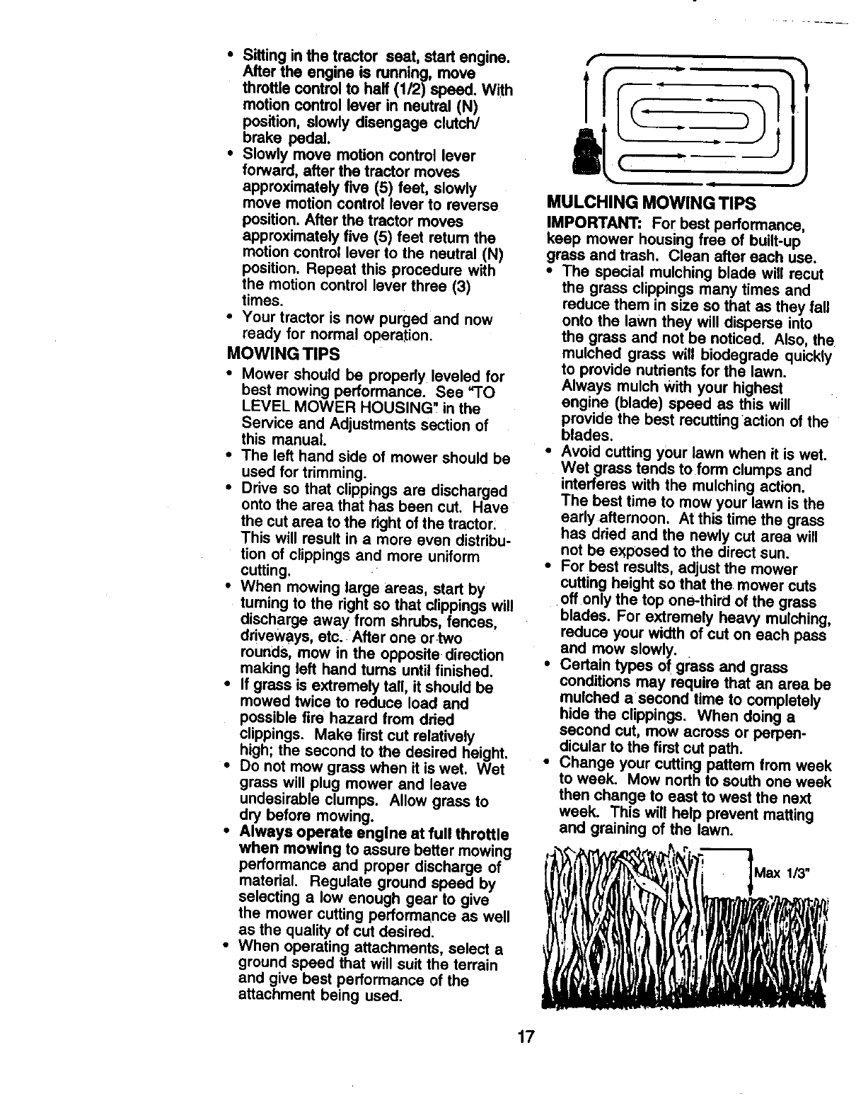
MULCHING MOWING TIPS
IMPORTANT: For best performance,
keep mower housing free of built-up
grass and trash. Clean alter each use.
•The special mulching blade will recut
the grass clippings many times and
reduce them in size so that as they fall
onto the lawn they will disperse into
the grass and not be noticed. Also, the
mulched grass will biodegrade quickly
to provide nutrients for the lawn.
Always mulch With your highest
engine (blade) speed as this will
provide the best recuttingaction of the
blades.
•Avoid cutting your lawn when it is wet.
Wet grass tends to form clumps and
interferes with the mulching action.
The best time to mow your lawn is the
early afternoon. At this time the grass
has dried and the newly cut area will
not be exposed to the direct sun.
•For best results, adjust the mower
cutting height so that the mower cuts
offonly the top one+thirdof the grass
blades. For extremely heavy mulching,
reduce your width of cut on each pass
and mow slowly.
•Certain types of grass and grass
conditions may require that an area be
mulched a second time to completely
hide the clippings. When doing a
second cut, mow across or perpen-
dicular to the first cut path.
•Change your cutting pattern from week
to week. Mow northto south one week
then change to east to west the next
week. This will help prevent matting
and graining of the lawn. ,]++
IIl,
17
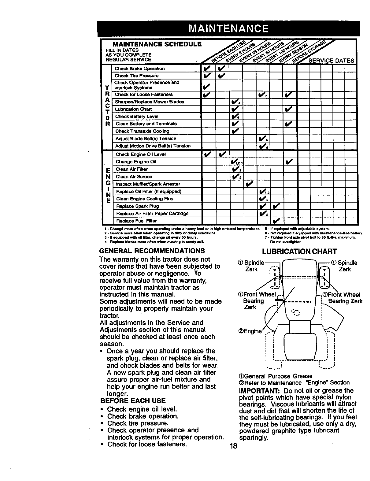
MAINTENANCE SCHEDULE .._,_ _ _' _ _--
FILL IN DATES
_Bm_ O_mt_
Check Tire Pressure _ _
Check Operator Presence and
TInterlockSyatems I/
R Check for Loose Fasteners I_ 1_7
ASh'lpen/Replsce M°wer Blades _#'
Lubdcation Chad
JT Check BatterY Level
RClean Battery end Terminals (l_
Check Trar!_.axle Cooling V*
Adjust Blade Belt(s) Tension (l_s i
Adjust Motion Odve Belt(s} Tension lldPs :
Check Engine Oil Level 14 /Id f
Change Engine Oil _: ll_
EClean Air Filter
NClean Air Screen
GI Inspect Muffler/Spark An'ester
ReplaCe Oil Finer (If equipped) ._:
N Clean Engine Coo_ing Fins
Replace Spark Plug _
Replace Air Filter Paper Cartridge 1_2
Replace Fuel Filter
1* Change more often whenopefllitingi/41der•heavy load or WIhighambient teri!penttures. 5- Ifequipped wi_ adjustablesystem,
2-Service more often whenoperating indirty or dusty conditions, 6 - Not required ifequippedw_thmaintenance-freeho_eq_.
3-IfequiPPedwlth oil filter,change oil mm¢-/50 hour=. 7 - Tighten horn axle pivotbolt to 35 ft..Ibs, maximum,
4 - P_ blade=mrs olten w_m mowing insandy so#, Do no_oYirifghten.
GENERAL RECOMMENDATIONS
The warranty on this tractor does not
cover items that have been subjected to
operator abuse or negligence. To
receive full value from the warranty,
operator must maintain tractor as
instructed in this manual.
Some adjustments will need to be made
periodically to properly maintain your
tractor.
All adjustments in the Service and
Adjustments section of this manual
should be checked at least once each
LUBRICATION CHART
(t) S-_) Spindle
Zerk Zerk
_)Front Wheel eel
Bearing Bearing Zerk
Zerk
_Engine /
season.
•Once a year you should replace the
spark plug, clean or replace air filter,
and check blades and belts for wear,
A new spark plug and clean air filter
assure proper air-fuel mixture and
help your engine run better and last
longer.
BEFORE EACH USE
•Check engine oil level.
•Check brake operation.
•Check tire pressure.
•Check operator presence and
interlock systems for proper operation.
•Check for loose fasteners.
,...J L ..
(DGeneral Purpose Grease
_Refer to Maintenance =Engine" Section
IMPORTANT: Do not oil or grease the
pivot points which have special nylon
bearings. Viscous lubricants will attract
dust and dirt that will shorten the life of
the self-lubricatin_l bearings. If you feel
they must be lubncated, use only adry,
powdered graphite type lubricant
sparingly.
18
TRACTOR
Always observe safety rules when
performing any maintenance.
BRAKE OPERA'nON
If tractor requires more than six (6) feet
stopping distance at high speed ,n
highestgear, then brake must be
adjusted. (See "TO ADJUST BRAKE" in
the Service and Adjustments section of
this manual).
TIRES
•Maintain proper air pressure in all tires
(See "PRODUCT SPECIFICATIONS"
section of this manual).
•Keep tires free of gasoline, oil, or
insect control chemicals which can
harm rubber.
•Avoid stumps, stones, deep ruts, sharp
objects and other hazards that may
cause tire damage.
NOTE: To seal tire punctures and
prevent flat tires due to slow leaks, tire
sealant may be purchased from your
local parts dealer. "13resealant also
prevents tire dry rot and corrosion.
OPERATOR PRESENCE SYSTEM
Be sure operator presence and interlock
systems are working properly. If your
tractor does not function as described,
repair the problem immediately.
•The engine should not start unless the
clutch/brake pedal is fully depressed
and attachement clutch control is in
the disengaged position.
°When the engine is running, any
attempt by the operator to leave the
seat without first setting the parking
brake should shut off the engine.
•When the engine is running and the
attachment clutch is engaged, any
attempt by the operator to leave the
seat should shut off the engine.
• The attachment clutch should never
operate unless the operator is in the
seat.
BLADE CARE
For best results mower blades must be
kept sharp. Replace bent or damaged
blades.
BLADE REMOVAL
•Raise mower to highest pesition to
allow access to blades.
•Remove hex bolt, lock washer and flat
washer securing blade.
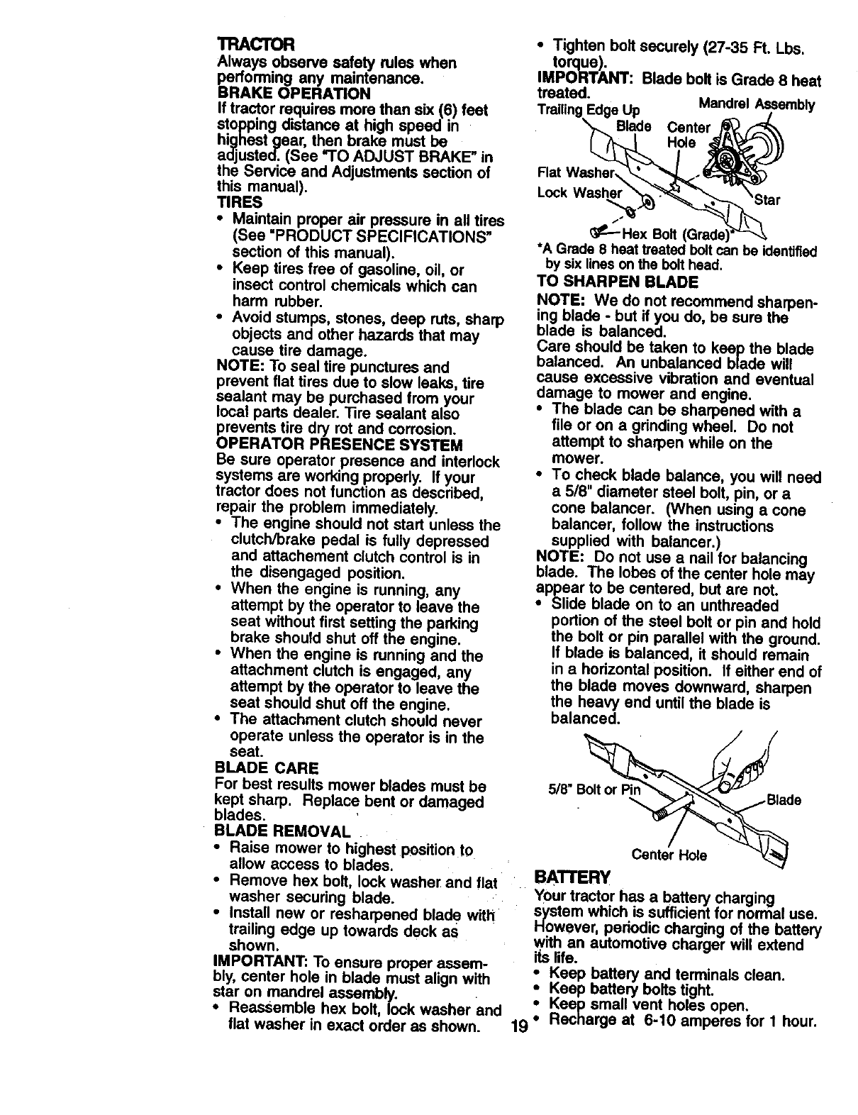
•Install new or resharpened blade with
trailing edge up towards deck as
shown.
IMPORTANT: To ensure proper assem-
bly, center hole in blade must align with
star on mandrel assembly.
•Reassemble hex bolt, lock washer and
flat washer in exact order as shown.
•Tighten bolt securely (27-35 Ft. Lbs.
torque).
IMPORTANT: Blade bolt is Grade 8 heat
treated.
Trailing Edge Up Mandrel Assembly
X_ Blade Center j_/_
Flat W..ashyr_...._-'__
• _---Hex Bolt (Grade)_Z-x_._
•A Grade 8 heat treated bolt can be identified
by six lines on the bolt head.
TO SHARPEN BLADE
NOTE: We do not recommend sharpen-
ing blade - but if you do, be sure the
blade is balanced.
Care should be taken to keep the blade
balanced. An unbalanced blade will
cause excessive vibration and eventual
damage to mower and engine.
•The blade can be sharpened with a
file or on a grinding wheel. Do not
attempt to sharpen while on the
mower.
•To check blade balance, you will need
a 518" diameter steel bolt, pin, or a
cone balancer. (When using acone
balancer, follow the instructions
supplied with balancer.)
NOTE: Do not use anail for balancing
blade. The lobes of the center hole may
appear to be centered, but are not.
•Slide blade on to an unthreaded
portion of the steel bolt or pin and hold
the bolt or pin parallel with the ground.
If blade is balanced, it should remain
in a horizontal position. If either end of
the blade moves downward, sharpen
the hea W end until the blade is
balanced.
5/8" " •
Center Hole
BATTERY
Your tractor has a battery charging
system which is sufficient for normal use.
However, periodic charging of the battery
with an automotive charger will extend
iLslife.
ieep battery and terminals clean.
Keep battery bolts tight.
Keep small vent holes open.
19 °Recharge at 6-10 amperes for I hour.
NOTE:The originalequipmentbatteryon
yourtractoris maintenancefree. Donot
attemptto openor removecapsor
covers.Addingor checkinglevelof
electrolyteis not necessary.
TOCLEANBATTERYANDTERMINALS
Corrosionand dirt onthe batteryand
terminalscan causethe batteryto "leak"
power.
: Removeterminalguard.
DisconnectBLACKbatterycablefirst
thenRED batterycable and remove
batteryfrom tractor.
•Rinse the battery with plain water and
dry.
•Clean terminals and battery cable
ends with wire brush until bright.
•Coat terminals with grease or petro-
leum jelly.
• Reinstall b.attery (See =REPLACING
BATTERY in the SERVICE AND
ADJUSTMENTS section of this
manual).
V-BELTS
Check V-belts for deterioration and wear
after 100 hours of operation and replace
if necessary. The belts are not adjustable.
Replace belts if they begin to slip from
wear.
TRANSAXLE COOLING
The transmission fan and cooling fins
should be kept clean to assure proper
cooling.
Do not attempt to clean fan or transmis-
sion while engine is running or while the
transmission is hot. To prevent possible
damage to seals, do not use high
pressure water or steam to clean
transaxle.
•Inspect cooling fan to be sure fan
blades are intact and clean.
•Inspect cooling fins for dirt, grass
clippings and other materials. To
prevent damage to seals, do not use
compressed a=r or high pressure
sprayer to clean cooling fins.
TRANSAXLE PUMP FLUID
The transaxle was sealed at the factory
and fluid maintenance is not required for
the life of the transaxle. Should the
transaxle ever leak or require servicing,
contact your nearest authorized service
center/department.
ENGINE
LUBRICATION
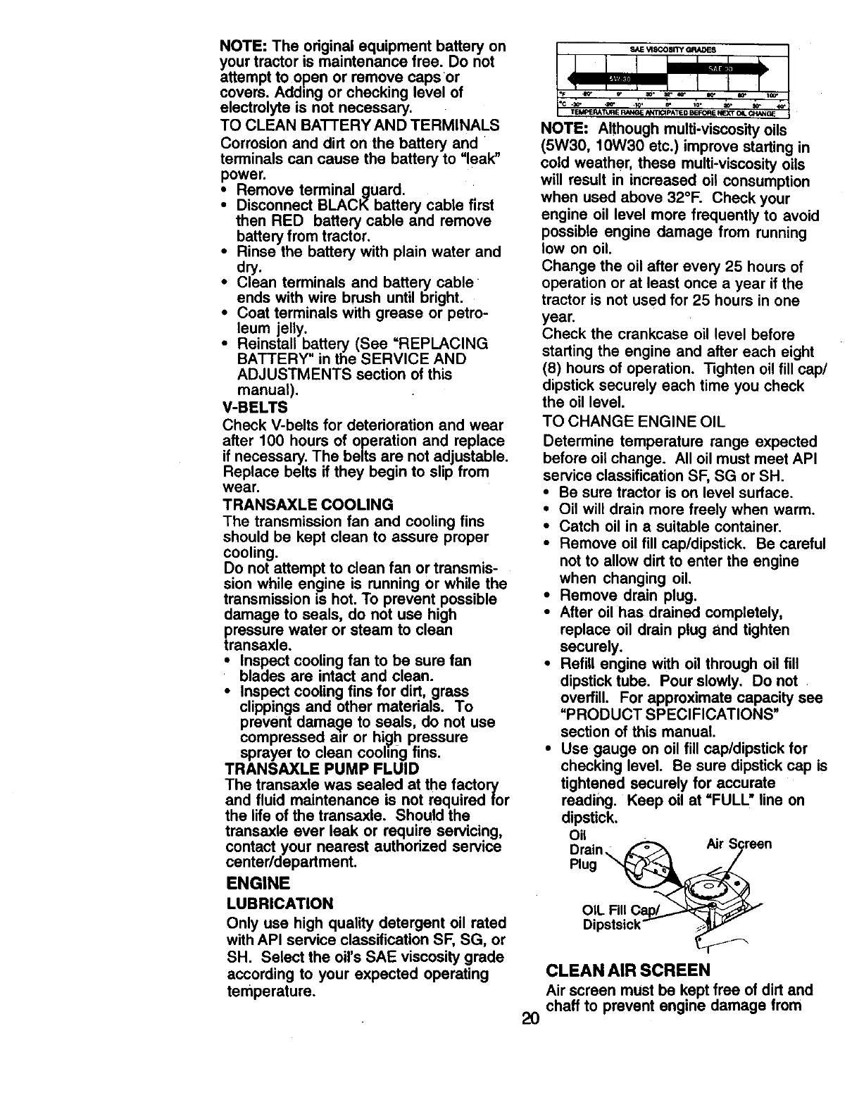
Only use high quality detergent oil rated
with API service classification SF, SG, or
SH. Select the oil's SAE viscosity grade
according to your expected operating
temperature.
_c ._
TEk_JE RA_dPJ£ RN, IG_E_mCI_ATIE D B_0_ E N_I_T Q4
NOTE: Although multi-viscosity oils
(5W30, 10W30 etc.) improve starting in
cold weather, these multi-viscosity oils
will result in increased oil consumption
when used above 32°F. Check your
engine oil level more frequently to avoid
possible engine damage from running
low on oil.
Change the oil after every 25 hours of
operation or at least once a year it the
tractor is not used for 25 hours in one
year.
Check the crankcase oil level before
starting the engine and after each eight
(8) hours of operation. Tighten oil fill cap/
dipstick securely each time you check
the oil level.
TO CHANGE ENGINE OIL
Determine temperature range expected
before oil change. All oil must meet API
service classification SF, SG or SH.
•Be sure tractor is on level surface.
•Oil will drain more freely when warm.
•Catch oil in a suitable container.
•Remove oil fill cap/dipstick. Be careful
not to allow dirt to enter the engine
when changing oil.
•Remove drain plug.
•After oil has drained completely,
replace oil drain plug and tighten
securely.
•Refill engine with oil through oil fill
dipstick tube. Pour slowly. Do not
overfill. For approximate capacity see
=PRODUCT SPECIFICATIONS"
section of this manual.
•Use gauge on oil fill cap/dipstick for
checking level. Be sure dipstick cap is
tightened securely for accurate
reading. Keep oil at =FULL" line on
dipstick.
Oil
Drain
Plug
OIL
2O
CLEAN AIR SCREEN
Air screen must be kept free of dirt and
chaff to prevent engine damage from
overheating. Cleanwitha wire brushor
compressedairto removedirtand
stubbomdriedgumfibers.
CLEAN AIR INTAKE/COOLING
AREAS
To insure proper cooling, make sure the
grass screen, cooling fins, and other
extemal surfaces of the engine are kept
clean at all times.
Every 100 hours of operation (more often
under extremely dusty, dirty conditions),
remove the blower housing and other
cooling shrouds. Clean the cooling fins
and external surfaces as necessary. Make
sure the cooling shrouds are reinstalled.
NOTE: Operating the engine with a
blocked grass screen, dirty or plugged
cooling fins, and/or cooling shrouds
removed will cause engine damage due to
overheating.
AIR FILTER
Your engine will not run propedy using a
dirty air filter. Clean the foam pre-cleaner
after every 25 hours of operation or
every season. Service paper cartridge
every 100 hours of operation or every
season, whichever occurs first.
Service air cleaner more often under
dusty conditions.
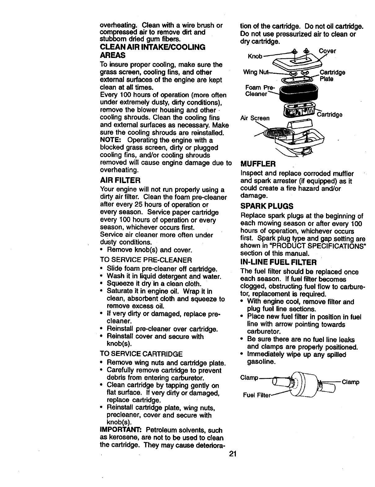
•Remove knob(s) and cover.
TO SERVICE PRE-CLEANER
•Slide foam pre-cleaner off cartridge.
•Wash it in liquid detergent and water.
•Squeeze it dry in aclean cloth.
•Saturate it inengine oil. Wrap it in
clean, absorbent cloth and squeeze to
remove excess oil.
•If very dirty or damaged, replace pre-
cleaner,
•Reinstall pre-cleaner over cartridge.
•Reinstall cover and secure with
knob(s).
TO SERVICE CARTRIDGE
•Remove wing nuts and cartridge plate.
•Carefully remove cartridge to prevent
debris from entering carburetor.
• Clean cartridge by tapping gently on
flat surface, if very dirty or damaged,
replace cartridge.
•Reinstall cartridge plate, wing nuts,
prscleaner, cover and secure with
knob(s).
IMPORTANT: Petroleum solvents, such
as kerosene, are not to be used to clean
the cartridge. They may cause deteriora-
tion of the cartridge. Do not oil cartridge.
Do not use pressurized air to clean or
dry cartridge.
Knob
Wing Cartridge
Plate
Foam Pre-
Air Screen
MUFFLER
Inspect and replace corroded muffler
and spark arrester (if equipped) as it
could create a fire hazard and/or
damage.
SPARK PLUGS
Replace spark plugs at the beginning of
each mowing season or after every 100
hours of operation, whichever occurs
first. Spark plug type and gap setting are
shown in =PRODUCT SPECIFICATIONS"
section of this manual.
IN-LINE FUEL FILTER
The fuel filter should be replaced once
each season. If fuel filter becomes
clogged, obstructing fuel flow to carbure-
tor, replacement is required.
•With engine cool, remove filter and
plug fuel line sections.
•Place new fuel filter in position in fuel
line with arrow pointing towards
carburetor.
•Be sure there are no fuel line leaks
and clamps are properly positioned.
•Immediately wipe up any spilled
gasoline.
21
CLEANING
Clean engine, battery, seat, finish, etc.
of all foreign matter.
Keep finished surfaces and wheels
free of all gasoline, oil, etc.
• Protect painted surfaces with automo-
tive type wax.
We do not recommend using a garden
hose to clean your tractor unless the
electrical system, muffler, air filter and
carburetor are covered to keep water out.
Water in engine can result in a short-
ened engine life.
_1_CAUTION: Before performing any service or adjustments:
•Depress clutch/brake pedal fully and set parking brake.
•Place motion control lever in neutral (N) position.
•Place attachment clutch in =DISENGAGED" position.
•Turn ignition key =OFF" and remove key.
• Make sure the blades and all moving parts have completely stopped.
•Disconnect spark plug wire from spark plug and place wire where it cannot
come in contact with plug.
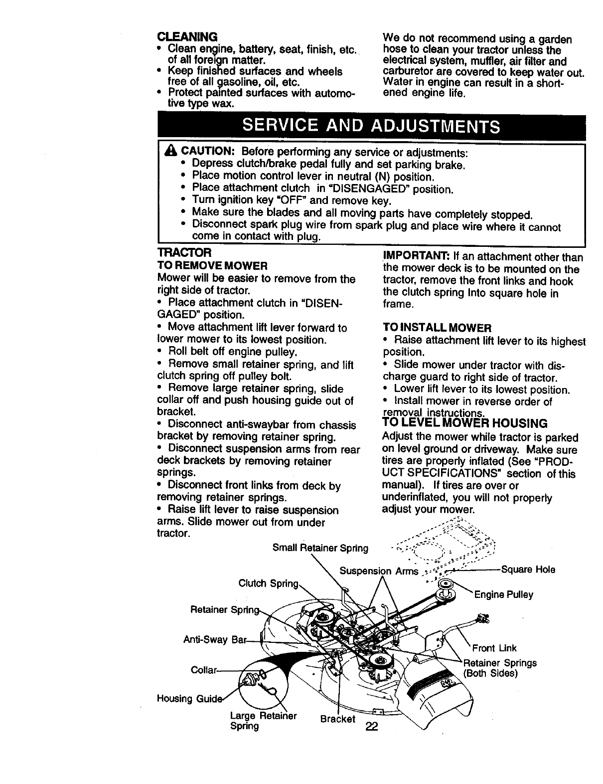
TRACTOR
TO REMOVE MOWER
Mower will be easier to remove from the
right side of tractor.
•Place attachment clutch in "DISEN-
GAGED" position.
•Move attachment lift lever forward to
lower mower to its lowest position.
• Roll belt off engine pulley.
• Remove small retainer spring, and lift
clutch spring off pulley bolt.
• Remove large retainer spring, slide
collar oft and push housing guide out of
bracket.
•Disconnect anti-swaybar from chassis
bracket by removing retainer spring•
•Disconnect suspension arms from rear
deck brackets by removing retainer
springs.
•Disconnect front links from deck by
removing retainer springs.
•Raise lift lever to raise suspension
IMPORTANT: If an attachment other than
the mower deck is to be mounted on the
tractor, remove the front links and hook
the clutch spring Into square hole in
frame.
TO INSTALL MOWER
•Raise attachment lift lever to its highest
position.
•Slide mower under tractor with dis-
charge guard to right side of tractor.
•Lower lift lever to its lowest position.
• Install mower in reverse order of
removal instructions.
TO LEVEL MOWER HOUSING
Adjust the mower while tractor is parked
on level ground or driveway. Make sure
tires are properly inflated (See "PROD-
UCT SPECIFICATIONS" section of this
manual). If tires are over or
underinflated, you will not properly
adjust your mower.
Retainer S
Link
Sides)
Housing
Large Retainer Bracket
Spring 22
TO LEVEL MOWER HOUSING
Adjust the mower while tractor is parked
on level ground or driveway. Make sure
tires are properly inflated (See "PROD-
UCT SPECIFICATIONS" section of this
manual). If tires are over or
underinflated, you will not propedy
adjust your mower.
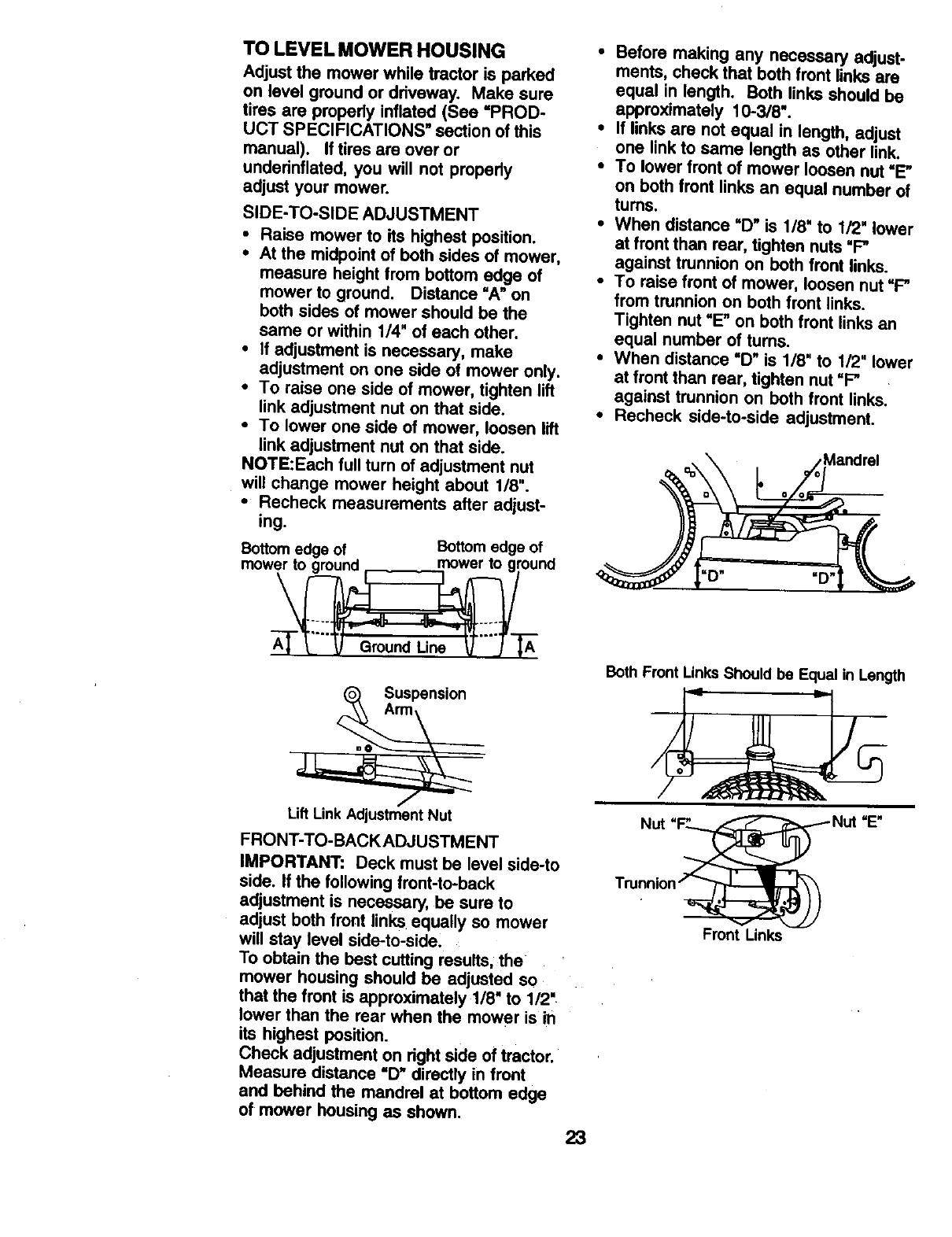
SIDE-TO-SIDE ADJUSTMENT
• Raise mower to its highest position.
• At the midpoint of both sides of mower,
measure height from bottom edge of
mower to ground. Distance "A" on
both sides of mower should be the
same or within 1/4" of each other.
•If adjustment is necessary, make
adjustment on one side of mower only.
•To raise one side of mower, tighten lift
link adjustment nut on that side.
•To lower one side of mower, loosen lift
link adjustment nut on that side.
NOTE:Each full turn of adjustment nut
will change mower height about 1/8".
•Recheck measurements after adjust-
ing.
Bottom edge of Bottom edge of
mower to nround mower to ground
=o__ Suspensi°n
Lift Link Adjustment Nut
FRONT-TO-BACK ADJUSTMENT
IMPORTANT: Deck must be level side-to
side. If the following front-to-back
adjustment is necessary, be sure to
adjust both front links equally so mower
will stay level side-to-side.
To obtain the best cutting results, the
mower housing should be adjusted so
that the front is approximately 1/8" to 1/2'
lower than the rear when the mower is in
its highest position.
Check adjustment on right side of tractor.
Measure distance "D" directly in front
and behind the mandrel at bottom edge
of mower housing as shown. 23
•Before making any necessary adjust-
ments, check that both front links are
equal in length. Both links should be
approximately 10-3/8".
•If links are not equal in length, adjust
one link to same length as other link.
•To lower front of mower loosen nut "E"
on both front links an equal number of
turns.
•When distance "D" is 1/8" to 1/2" lower
at front than rear, tighten nuts =F"
against trunnion on both front links.
•To raise front of mower, loosen nut "P'
from trunnion on both front links.
Tighten nut "E" on both front links an
equal number of turns.
•When distance "D" is 1/8" to 1/2" lower
at front than rear, tighten nut "F"
against trunnion on beth front links.
•Recheck side-to-side adjustment.
Both Front Links Should be Equal in Length
Nut
Front Links
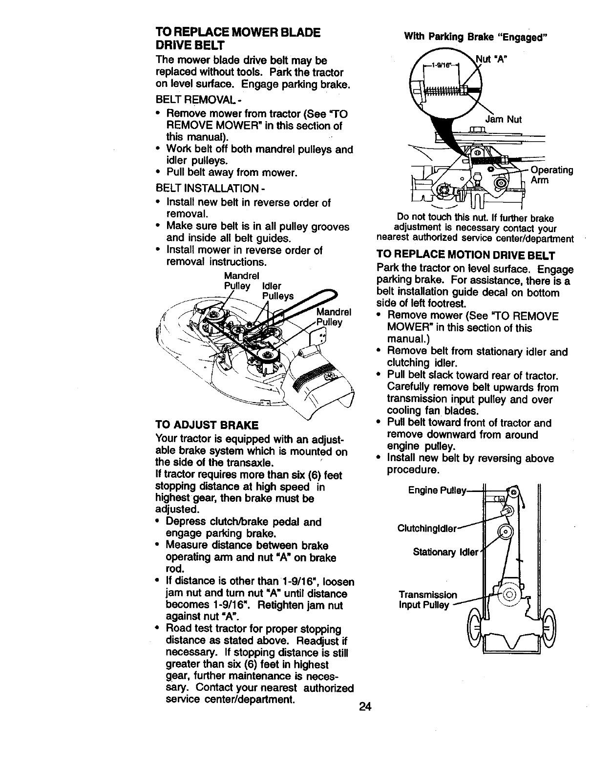
TO REPLACE MOWER BLADE
DRIVE BELT
The mower blade drive belt may be
replaced without tools. Park the tractor
on level surface. Engage parking brake.
BELT REMOVAL-
•Remove mower from tractor (See =TO
REMOVE MOWER" in this section of
this manual).
•Work belt off both mandrel pulleys and
idler pulleys.
•Pull belt away from mower.
BELT INSTALLATION -
•Install new belt in reverse order of
removal.
•Make sure belt is in all pulley grooves
and inside ali belt guides.
•Install mower in reverse order of
removal instructions.
Mandrel
Pulley Idler
TO ADJUST BRAKE
Your tractor is equipped with an adjust-
able brake system which is mounted on
the side of the transaxle.
If tractor requires more than six (6) feet
stopping distance at high speed in
highest gear, then brake must be
adjusted.
•Depress clutch/brake pedal and
engage parking brake.
•Measure distance between brake
operating arm and nut "A" on brake
rod.
•If distance is other than 1-9/16", loosen
iam nut and tum nut =A" until distance
becomes 1-9/16". Retighten jam nut
against nut "A".
•Road test tractor for proper stopping
distance as stated above. Readjust if
necessary. If stopping distance is still
greater than six (6) feet in highest
gear, further maintenance is neces-
sary. Contact your nearest authorized
service center/department
With Parking Brake "Engaged"
Nut =A"
Jam Nut
Arm
Do not touch this nut. If further brake
adjustment is necessary contact your
nearest authodzed service center/department
TO REPLACE MOTION DRIVE BELT
Park the tractor on level surface. Engage
parking brake. For assistance, there is a
belt installation guide decal on bottom
side of left footrest.
•Remove mower (See rl'O REMOVE
MOWER" in this section of this
manual.)
•Remove belt from stationary idler and
clutching idler.
•Pull belt slack toward rear of tractor.
Carefully remove belt upwards from
transmission input pulley and over
cooling fan blades.
•Pull belt toward front of tractor and
remove downward from around
engine pulley.
•Install new belt by reversing above
procedure,
StalJonary Idler'
Transmission
24
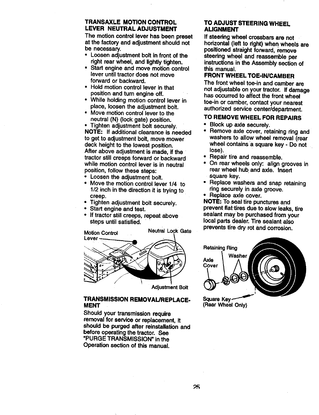
TRANSAXLE MOTION CONTROL
LEVER NEUTRAL ADJUSTMENT
The motion control lever has been preset
at the factory and adjustment should not
be necessary.
• Loosen adjustment bolt in front of the
right rear wheel, and lightly tighten.
•Start engine and move motion control
lever until tractor does not move
forward or backward.
•Hold motion control lever in that
position and tum engine off.
•While holding motion control lever in
place, loosen the adjustment bolt.
•Move motion control lever to the
neutral (N) (lock gate) position,
•Tighten adjustment bolt securely.
NOTE: If additional clearance is needed
to get to adjustment bolt, move mower
deck height to the lowest position.
After above adjustment is made, if the
tractor still creeps forward or backward
white motion control lever is in neutral
position, follow these steps:
• Loosen the adjustment bolt.
• Move the motion control lever 1/4 to
1/2 inch in the direction it is trying to
creep.
• Tighten adjustment bolt securely.
•Start engine and test.
•If tractor still creeps, repeat above
steps until satisfied.
Motion Control Neutral Lock Gate
TO ADJUST STEERING WHEEL
AUGNMENT
If steedng wheel crossbars are not
hodzontal (left to right) whe n wheels are
positioned straight forward, remove
steedng wheel and reassemble per
instructions in the Assembly section of
this manual.
FRONT WHEEL TOE-IN/CAMBER
The front wheel toe-in and camber are
not adjustable on your tractor. If damage
has occurred to affect the front wheel
toe-in or camber, contact your nearest
authorized service center/department.
TO REMOVE WHEEL FOR REPAIRS
•Block up axle securely.
•Remove axle cover, retaining ring and
washers to allow wheel removal (rear
wheel contains a square key -Do not
lose).
•Repair tire and reassemble.
•On rear wheels only: align grooves in
rear wheel hub and axle. Insert
square key.
•Replace washers and snap retaining
ring securely in axle groove.
•Replace axle cover.
NOTE: Toseal tire punctures and
prevent flattires due to slow leaks, tire
sealant may be purchased from your
local parts dealer. _re sealant also
prevents tire dry rot and corrosion.
Retaining Ring
Washer
Axle
Cover
\Adjustment Bolt
TRANSMISSION REMOVAL/REPLACE-
MENT
Should your transmission require
removal for service or replacement, it
should be purged after retnsta||ation and
before operating the tractor. See
"PURGE TRANSMISSION" in the
Operation section of this manual.
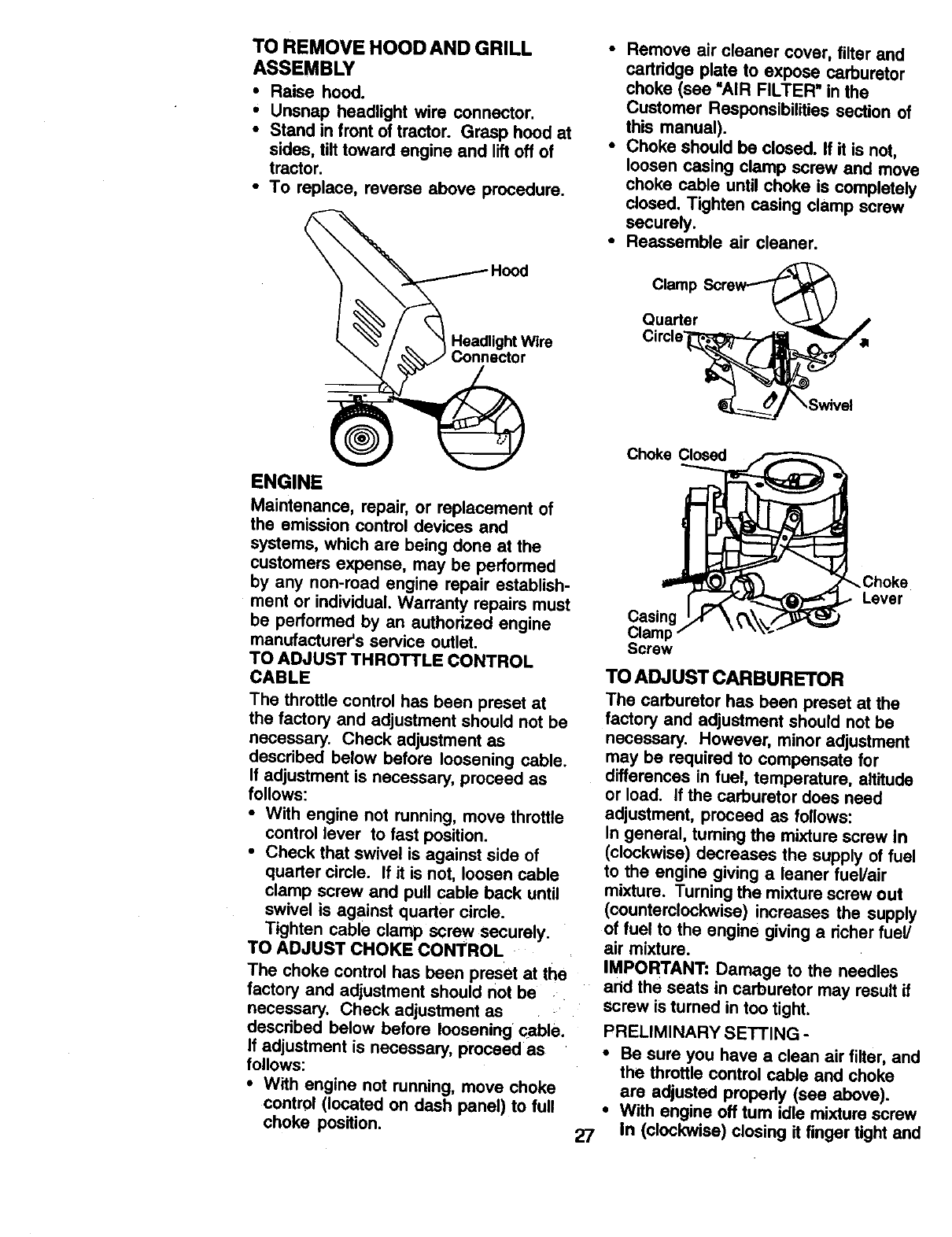
TO START ENGINE WITH A WEAK
BA'n'ERY
CAUTION: Lead-acid batteries
generate explosive gases. Keep sparks,
flame and smoking materials away from
batteries. Always wear eye protection
when around batteries.
If your battery is too weak to start the
engine, it should be recharged. (See
"BATTERY" in the MAINTENANCE
section of this manual).
If "jumper cables" are used for emer-
gency starting, follow this procedure:
IMPORTANT: Your tractor is equipped
with a 12 volt negative grounded system.
The other vehicle must also be a 12 volt
negative grounded system. Do not use
your tractor battery to start other vehicles.
TO ATTACH JUMPER CABLES -
•Connect each end of the RED cable to
the POSITIVE (+) terminal of each
battery, taking care not to short against
chassis.
•Connect one end of the BLACK cable
to the NEGATIVE (°) terminal of fully
charged battery.
•Connect the other end of the BLACK
cable to good CHASSIS GROUND,
away from fuel tank and battery.
TO REMOVE CABLES, REVERSE
ORDER -
•BLACK cable first from chassis and
then from the fully charged battery.
•RED cable last from both batteries.
"Positive" (+) "Negative" (-)
Bolt
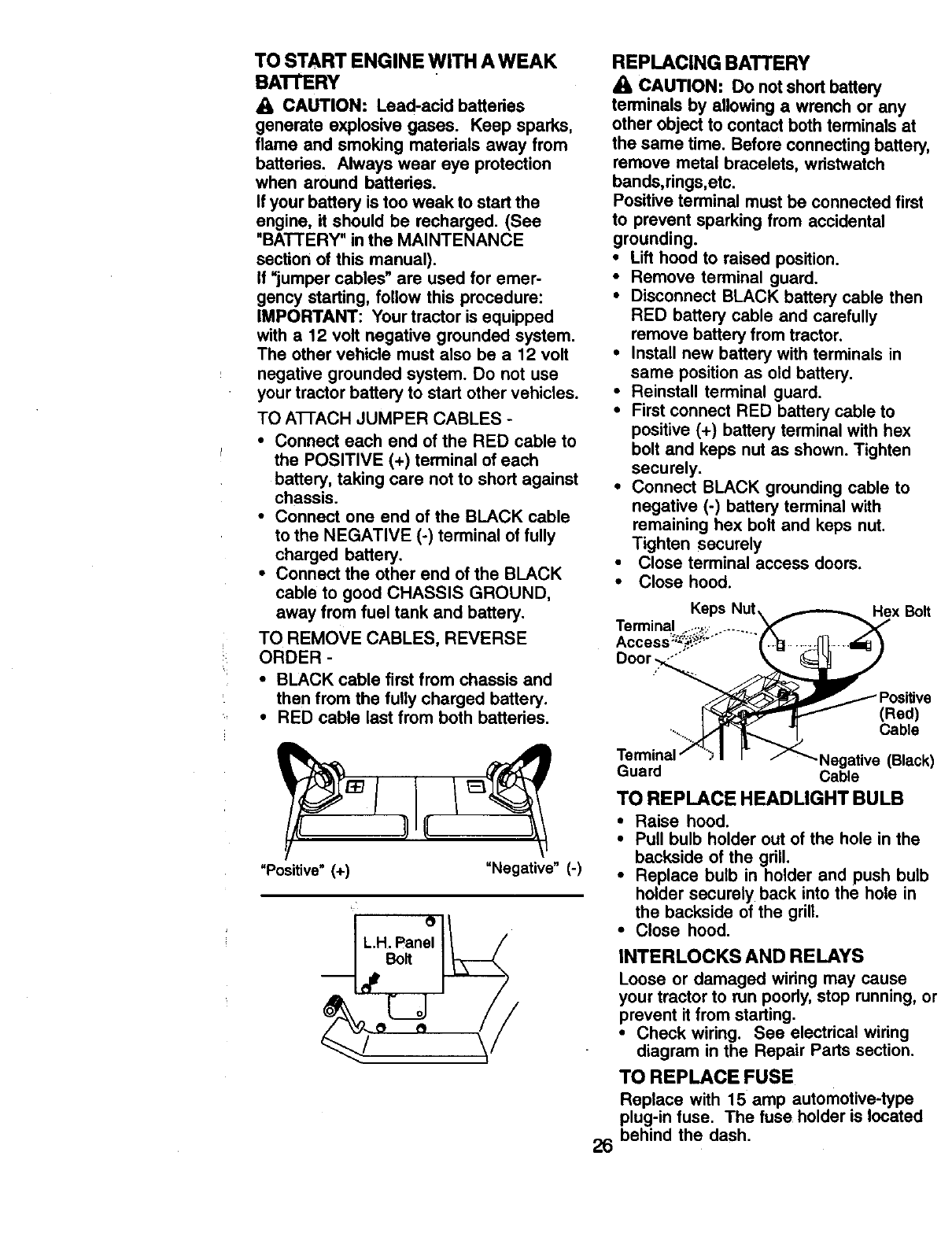
REPLACING BATTERY
CAUTION: Do not short battery
terminals by allowing awrench or any
other object to contact both terminals at
the same time. Before connecting battery,
remove metal bracelets, wristwatch
bands,rings,etc.
Positive terminal must be connected first
to prevent sparking from accidental
grounding.
•Lift hood to raised position.
•Remove terminal guard.
•Disconnect BLACK battery cable then
RED battery cable and carefully
remove battery from tractor.
•Install new battery with terminals in
same position as old battery.
•Reinstall terminal guard.
•First connect RED battery cable to
positive (+) battery terminal with hex
bolt and keps nut as shown. Tighten
securely.
•Connect BLACK grounding cable to
negative (-) battery terminal with
remaining hex bolt and keps nut.
Tighten securely
•Close terminal access doors.
•Close hood.
Hex Bolt
(Red)
Cable
26
.Negative (Black)
Guard Cable
TO REPLACE HEADLIGHT BULB
•Raise hood.
•Pull bulb holder out of the hole in the
backside of the grill.
•Replace bulb in holder and push bulb
holder securely back into the hole in
the backside of the grill.
•Close hood.
INTERLOCKS AND RELAYS
Loose or damaged wiring may cause
your tractor to run poorly, stop running, or
prevent it from starting.
•Check wiring. See electrical wiring
diagram in the Repair Parts section.
TO REPLACE FUSE
Replace with 15 amp automotive-type
plug-in fuse. The fuse holder is located
behind the dash.
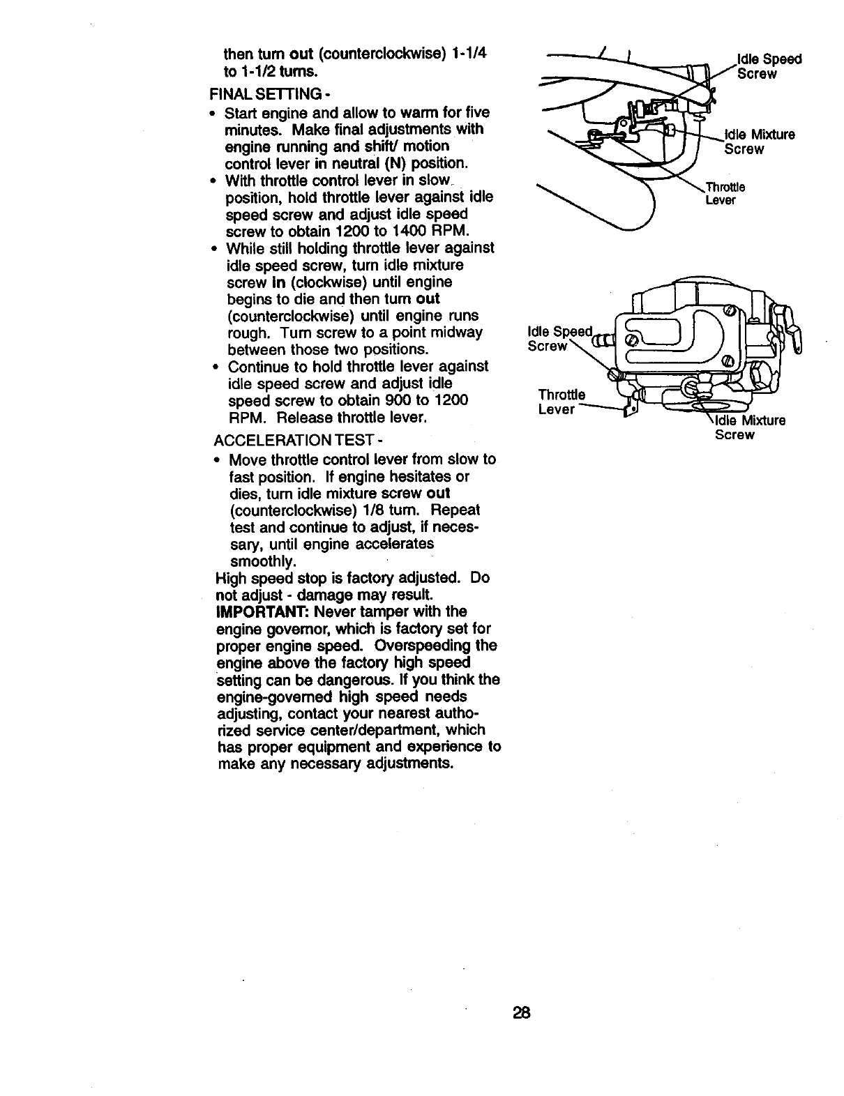
TO REMOVE HOOD AND GRILL
ASSEMBLY
• Raise hood.
•Unsnap headlight wire connector.
• Stand in front of tractor. Grasp hood at
sides, tilt toward engine and lift off of
tractor.
• To replace, reverse above procedure.
ENGINE
Maintenance, repair, or replacement of
the emission control devices and
systems, which are being done at the
customers expense, may be performed
by any non-toed engine repair establish-
ment or individual. Warranty repairs must
be performed by an authorized engine
manufacturer's service outlet.
TO ADJUST THROTTLE CONTROL
CABLE
The throttle control has been preset at
the factory and adjustment should not be
necessary. Check adjustment as
described below before loosening cable.
if adjustment is necessary, proceed as
follows:
•With engine not running, move threttle
control lever to fast position.
•Check that swivel is against side of
quarter circle. If it is not, loosen cable
clamp screw and pull cable back until
swivel is against quarter circle.
Tighten cable clamp screw securely.
TO ADJUST CHOKE CONTROL
The choke control has been preset at the
factory and adjustment should not be
necessary. Check adjustment as
described below before loosening cable.
if adjustment is necessary, proceed as
follows:
•With engine not running, move choke
control (located on dash panel) to full
choke position.
•Remove air cleaner cover, filter and
cartridge plate to expose carburetor
choke (see "AIR FILTER" in the
Customer Responsibilities section of
this manual).
•Choke should be closed. If it is not,
loosen casing clamp screw and move
choke cable until choke is completely
dosed. Tighten casing clamp screw
securely.
•Reassemble air cleaner.
27
Clamp
Quarter
Choke Closed
Choke
Lever
Casing
Clamp
Screw
TO ADJUST CARBURETOR
The carburetor has been preset at the
factory and adjustment should not be
necessary. However, minor adjustment
may be required to compensate for
differences in fuel, temperature, altitude
or load. If the carburetor does need
adjustment, proceed as follows:
In general, turning the mixture screw in
(clockwise) decreases the supply of fuel
to the engine giving a leaner fuel/air
mixture. Turning the mixture screw out
(counterclockwise) increases the supply
of fuel to the engine giving a richer fuel/
air mixture.
IMPORTANT: Damage to the needles
and the seats in carburetor may result if
screw is turned in too tight.
PRELIMINARY SETTING -
•Be sure you have a clean air filter, and
the throttle control cable and choke
are adjusted properly (see above).
•With engine off tum idle mixture screw
In (clockwise) closing it finger tight and
then turn out (counterclockwise) 1-1/4
to 1-1/2 turns.
FINAL SETTING -
• Start engine and allow to warm for five
minutes. Make final adjustments with
engine running and shift/motion
control lever in neutral (N) position.
•With throttle control lever in slow.
position, hold throttle lever against idle
speed screw and adjust idle speed
screw to obtain 1200 to 1400 RPM.
•While still holding throttle lever against
idle speed screw, turn idle mixture
screw In (clockwise) until engine
begins to die and then turn out
(counterclockwise) until engine runs
rough. Turn screw to a point midway
between those two positions.
•Continue to hold throttle lever against
idle speed screw and adjust idle
speed screw to obtain 900 to 1200
RPM. Release throttle lever.
ACCELERATION TEST -
•Move throffie control lever from slow to
fast position. If engine hesitates or
dies, tum idle mixture screw out
(counterclockwise) 1/8 turn. Repeat
test and continue to adjust, if neces-
sary, until engine accelerates
smoothly.
High speed stop is factory adjusted. Do
not adjust - damage may result.
IMPORTANT: Never tamper with the
engine govemor, which is factory set for
proper engine speed. Overspeeding the
engine above the factory high speed
Setting can be dangerous. If you think the
engine-govemed high speed needs
adjusting, contact your nearest autho-
rized service center/department, which
has proper equipment and experienco to
make any necessary adjustments.
Idle
Throttle
Idle Mixture
Screw
Lever
qdle Mixture
Screw
28
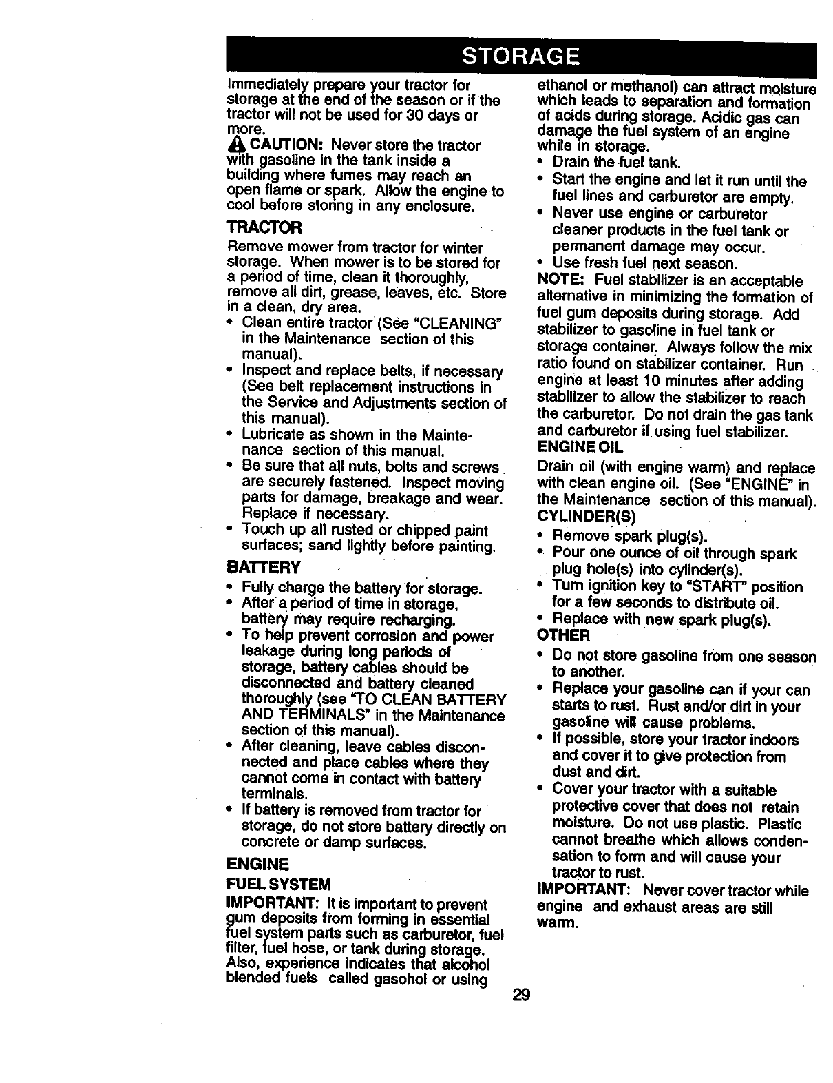
Immediately prepare your tractor for
storage at the end of the season or if the
tractor will not be used for 30 days or
more.
CAUTION: Never store the tractor
w=thgasoline in the tank inside a
building where fumes may reach an
open flame or spark. Allow the engine to
cool before storing in any enclosure.
TRACTOR
Remove mower from tractor for winter
storage. When mower is to be stored for
a penod of time, clean it thoroughly,
remove all dirt, grease, leaves, etc. Store
in ac_ean, dry area.
•Clean entire tractor(See "CLEANING"
in the Maintenance section of this
manual).
•Inspect and replace belts, if necessary
(See belt replacement instructions in
the Service and Adjustments section of
this manual).
•Lubricate as shown in the Mainte-
nance section of this manual.
•Be sure that all nuts, bolts and screws
are securely fastened. Inspect moving
parts for damage, breakage and wear.
Replace if necessary.
•Touch up all rusted or chipped paint
surfaces; sand lightly before painting.
BA'I-FERY
•Fully charge the battery for storage.
•After a period Oftime in storage,
battery may require recharging.
•To help prevent corrosion and power
leakage during long pedods of
storage, battery cables should be
disconnected and battery cleaned
thoroughly (see "TO CLEAN BATTERY
AND TERMINALS" in the Maintenance
section of this manual).
•After cleaning, leave cables discon-
nected and place cables where they
cannot come in contact with battery
terminals.
•If battery is removed from tractor for
storage, do not store battery directly on
concrete or damp surfaces.
ENGINE
FUELSYSTEM
IMPORTANT: It is important to prevent
gum deposits trom forming in essential
fuel system parts such as carburetor, fuel
filter,fuel hose, or tank during storage.
Also, experience indicates that alcohol
blended fuels called gasohol or using
ethanol or methano!) can attract moistur(
which leads to separation and formation
of acids during storage. Acidic gas can
damage the fuel system of an engine
while in storage.
• Drain the fuel tank.
•Start the engine and let it run until the
fuel lines and carburetor are empty.
•Never use engine or carburetor
cleaner products in the fuel tank or
permanent damage may occur.
• Use fresh fuel next season.
NOTE: Fuel stabilizer is an acceptable
alternative in minimizing the formation ol
fuel gum deposits during storage. Add
stabilizer to gasoline in fuel tank or
storage container. Always follow the mix
ratio found on stabilizer container. Run
engine at least 10 minutes after adding
stabilizer to allow the stabilizer to reach
the carburetor. Do not drain the gas tank
and carburetor if using fuel stabilizer.
ENGINE OIL
Drain oil (with engine warm) and replac_
with clean engine oil. (See =ENGINE" in
the Maintenance section of this manual)
CYUNDER(S)
•Remove spark plug(s).
•Pour one ounce of oil through spark
plug hole(s) into cylinder(s)_
•Tum ignition key to "START" position
for a few seconds to distribute oil.
•Replace with new spark plug(s).
OTHER
•Do not store gasoline from one seaso=
to another.
•Replace your gasoline can if your can
starts to rust. Rust and/or dirt in your
gasoline will cause problems.
•If possible, store your tractor indoors
and cover it to give protection from
dust and dirt.
•Cover your tractor with a suitable
protective cover that does not retain
moisture. Do not use plastic. Plastic
cannot breathe which allows conden-
sation to form and will cause your
tractor to rust.
IMPORTANT: Never cover tractor while
engine and exhaust areas are still
warm.
29
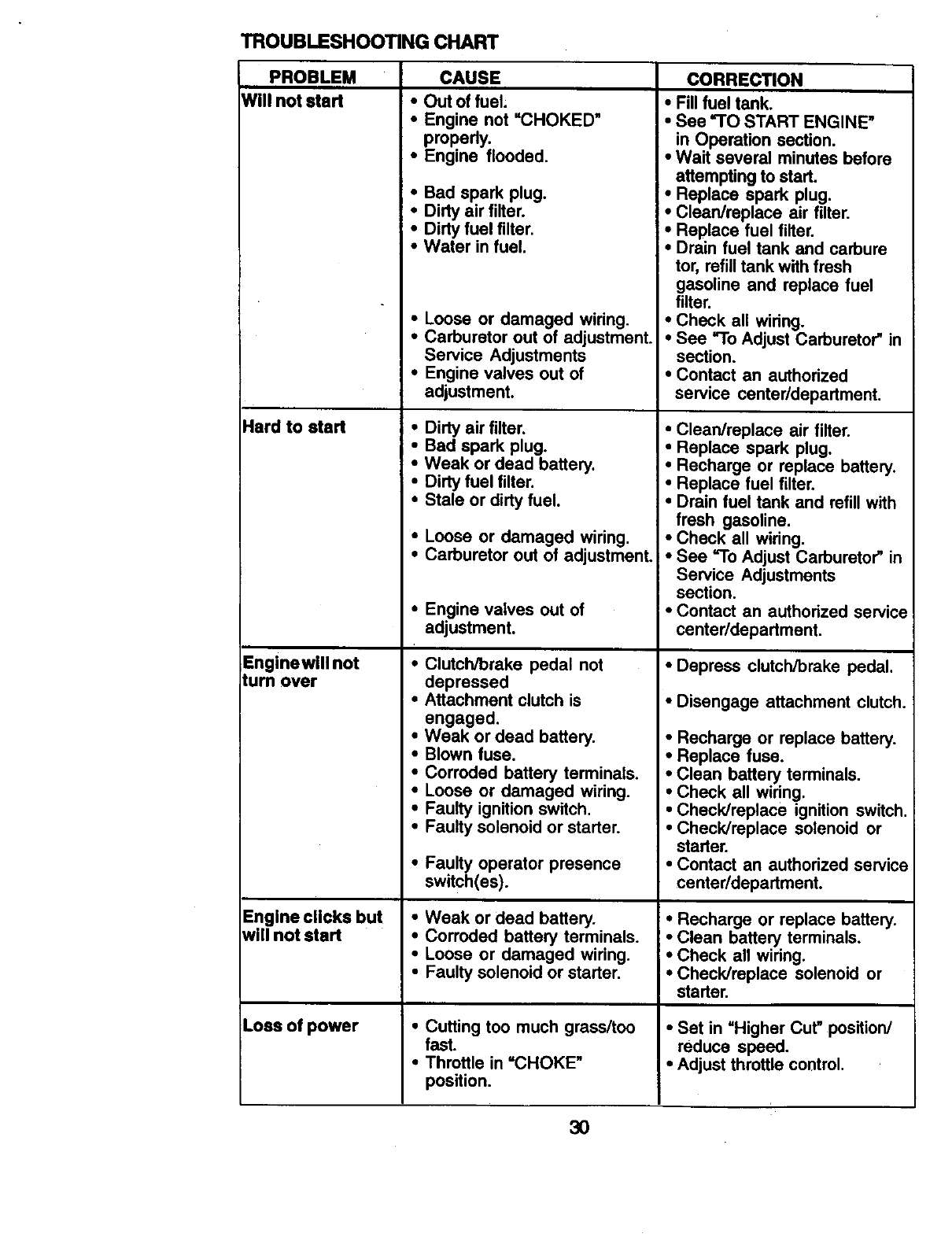
TROUBLESHOOTING CHART
PROBLEM CAUSE CORRECTION
Will not start • Out of fuel;
•Engine not "CHOKED"
propedy.
•Engine flooded.
Hard to start
Enginewill not
turn over
Engine clicks but
will not start
Loss of power
•Bad spark plug.
•Dirty air filter.
•Dirty fuel filter.
•Water in fuel.
•Loose or damaged wiring.
•Carburetor out of adjustment.
Service Adjustments
•Engine valves out of
adjustment.
•Dirty air filter.
•Bad spark plug.
•Weak or dead battery.
• Dirty fuel filter.
• Stale or dirty fuel.
•Loose or damaged wiring.
•Carburetor out of adjustment.
•Engine valves out of
adjustment.
•Clutch/brake pedal not
depressed
• Attachment clutch is
engaged.
•Weak or dead battery.
•Blown fuse.
•Corroded battery terminals.
•Loose or damaged wiring.
•Faulty ignition switch.
•Faulty solenoid or starter.
•Faulty operator presence
switch(es).
•Weak or dead battery.
•Corroded battery terminals.
• Loose or damaged wiring.
•Faulty solenoid or starter.
•Cutting too much grass/too
fast.
•Throttle in =CHOKE"
position.
•Fill fuel tank.
•See "TO START ENGINE"
in Operation section.
•Wait several minutes before
attempting to start.
•Replace spark plug.
•Clean/replace air filter.
•Replace fuel filter.
•Drain fuel tank and carbure
tor, refill tank with fresh
gasoline and replace fuel
filter.
•Check all wiring.
•See "To Adjust Carburetor" in
section.
•Contact an authorized
service center/department.
•Clean/replace air filter.
•Replace spark plug.
•Recharge or replace battery.
•Replace fuel filter.
•Drain fuel tank and refill with
fresh gasoline.
•Check all wiring.
• See "To Adjust Carburetor" in
Service Adjustments
section.
• Contact an authorized service
center/department.
•Depress clutch/brake pedal.
•Disengage attachment clutch.
•Recharge or replace battery.
•Replace fuse.
•Clean battery terminals.
•Check all wiring.
•Check/replace ignition switch.
•Check/replace solenoid or
starter.
•Contact an authorized service
center/department.
•Recharge or replace battery.
•Clean battery terminals.
•Check all wiring.
•Check/replace solenoid or
starter.
•Set in =Higher Cut" position/
reduce speed.
•Adjust throttle control.
3O
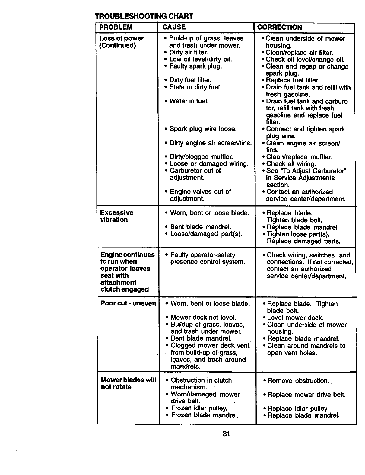
TROUBLESHOOTING CHART
PROBLEM
Loss of power
(Continued)
Excessive
vibration
Engine continues
to run when
operator leaves
seat with
attachment
clutch engaged
Poorcut-uneven
Mowerblsdeswill
not rotate
CAUSE
• Build-up of grass, leaves
and trash under mower.
•Dirty air filter.
•Low oil level/dirty oil
• Faulty spark plug.
•Dirty fuel filter.
•Stale or dirtyfuel.
•Water in fuel.
,; Spark plug wire loose.
•Dirty engine air screen/fins.
•Dirty/clogged muffler.
•Loose or damaged widng.
•Carburetor out of
adjustment.
•Engine valves out of
adjustment.
•Wom, bent or loose blade.
•Bent blade mandrel.
•Loose/damaged part(s).
•Faulty operator-safety
presence control system,
•Wom, bent or loose blade.
•Mower deck not level.
•Buildup of grass, leaves,
and trash under mower.
•Bent blade mandrel.
•Clogged mower deck vent
from build-up of grass,
leaves, and trash around
mandrels.
•Obstruction in clutch
mechanism.
•Worn/damaged mower
drive belt.
• Frozen idler pulley.
•Frozen blade mandrel.
CORRECTION
•Clean underside of mower
housing.
•Clean/replace air filter.
•Check oil level/change oil.
•Clean and regap or change
spark plug.
•Replace fuel filter.
•Drain fuel tank and refill with
fresh gasoline.
•Drain fuel tank and carbure-
tor, refill tank with fresh
gasoline and replace fuel
filter.
•Connect and tighten spark
plug wire.
•Clean engine air screen/
fins.
•Clean/replace muffler.
•Check all widng.
•See =To Adjust Carburetor"
in Service Adjustments
section.
•Contact an authodzed
service center/department.
•Replace blade.
Tighten blade bolt.
•Replace blade mandrel.
•Tighten loose part(s).
Replace damaged parts.
•Check wiring, switches and
connections. If not corrected
contact an authorized
service center/department.
•Replace blade. Tighten
blade bolt.
•Level mower deck.
•Clean underside of mower
housing.
•Replace blade mandrel.
•Clean around mandrels to
open vent holes.
• Remove obstruction.
•Replace mower ddve belt.
•Replace idler pulley.
•Replace blade mandrel.
31
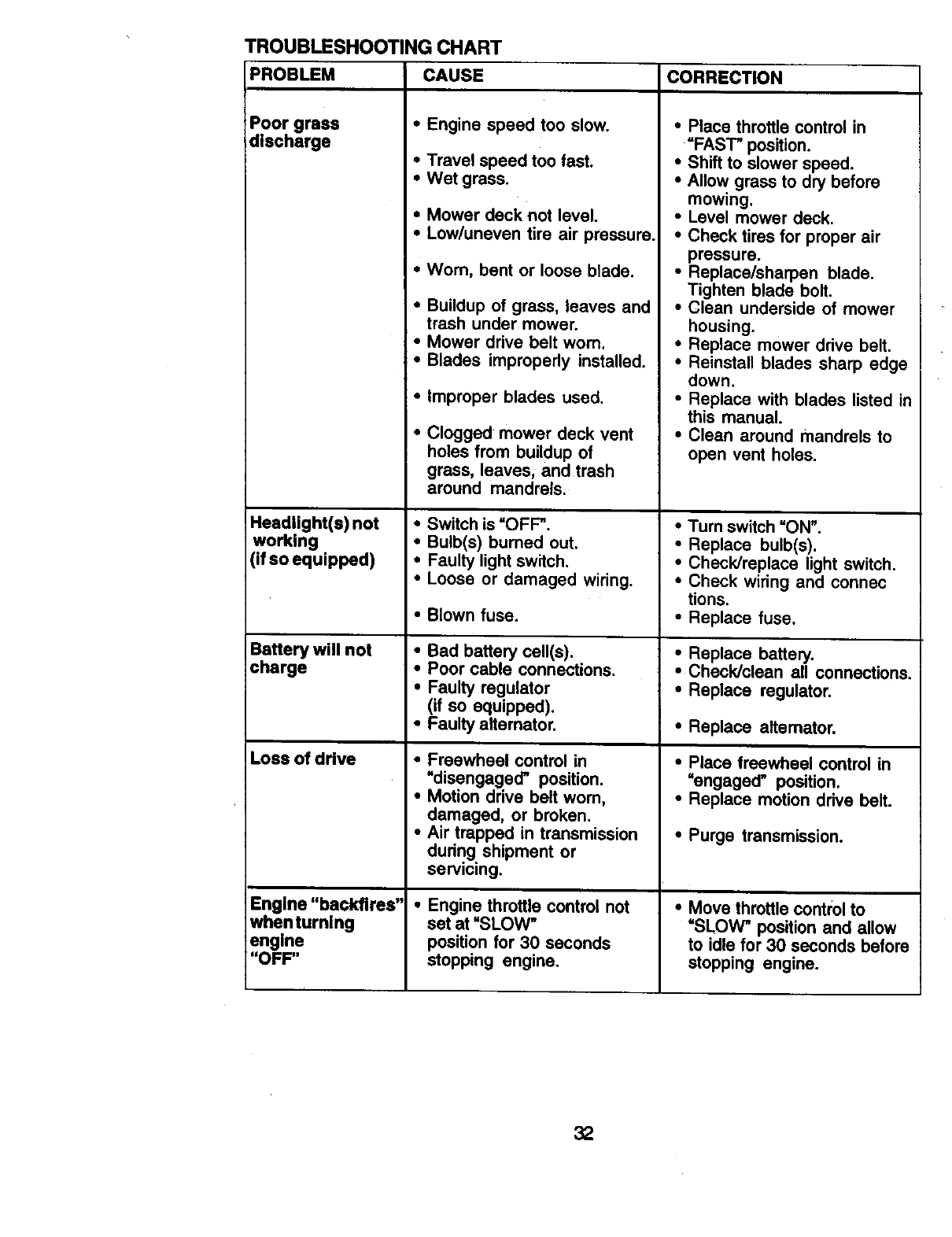
TROUBLESHOOTING CHART
PROBLEM
Poor grass
discharge
Headlight(s) not
working
(if so equipped)
Battery will not
charge
Loss of drive
Engine "backfires"
whenturning
engine
"OFF"
CAUSE
• Engine speed too slow.
•Travel speed too fast.
• Wet grass.
•Mower deck not level.
•Low/uneven tire air pressure.
•Wom, bent or loose blade.
•Buildup of grass, leaves and
trash under mower.
•Mower drive belt worn.
• Blades improperly installed.
• Improper blades used.
•Clogged mower deck vent
holes from buildup of
grass, leaves, and trash
around mandrels.
•Switch is =OFF _.
•Bulb(s) burned out.
• Faulty light switch.
•Loose or damaged wiring.
• Blown fuse.
•Bad battery celt(s).
•Poor cable connections.
•Faulty regulator
(if so equipped).
•Faulty altemator.
•Freewheel control in
=disengaged' position.
•Motion drive belt worn,
damaged, or broken.
•Air trapped in transmission
during shipment or
servicing.
•Engine throttle control not
set at =SLOW"
position for 30 seconds
stopping engine.
CORRECTION
•Place throttle control in
=FAST" position.
•Shift to slower speed.
•Allow grass to dry before
mowing.
•Level mower deck.
•Check tires for proper air
pressure.
•Replace/sharpen blade.
Tighten blade bolt.
•Clean underside of mower
housing.
•Replace mower drive belt.
•Reinstall blades sharp edge
down.
•Replace with blades listed in
this manual.
•Clean around mandrels to
open vent holes.
•Turn switch =ON".
•Replace bulb(s).
•Check/replace light switch.
•Check wiring and connec
tions.
•Replace fuse.
•Replace battery.
•Check/clean all connections.
•Replace regulator.
•Replace altemator.
•Place freewheel control in
=engaged" position.
•Replace motion drive belt.
•Purge transmission.
•Move throttle control to
=SLOW" position and allow
to idle for 30 seconds before
stopping engine.
32
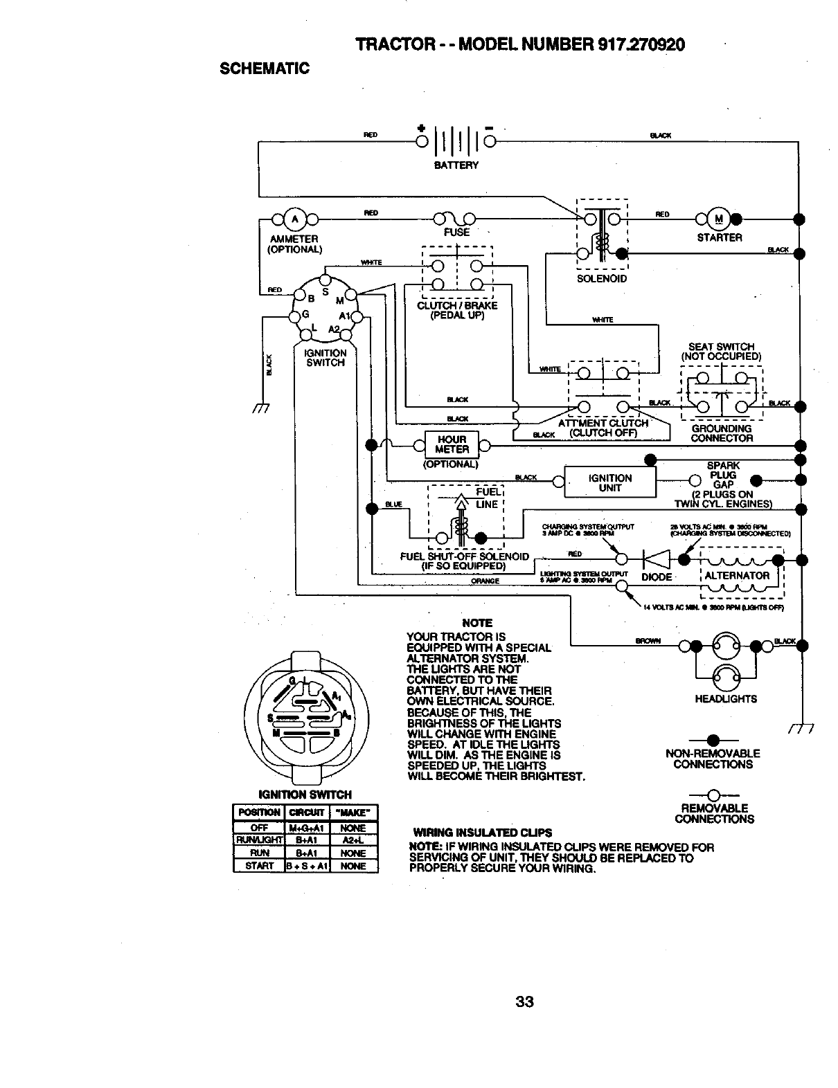
SCHEMATIC
TRACTOR - - MODEL NUMBER 917.270920
-tl111 +
BATTERY
AMMETER
(OPTIONAL)
IGNITION
SWITCH
iGNITION swrrcH
L ....... J
CLUTCH /BRAKE
(PEDALUP)
BLACK
...... I
SOLENOID
WHmE
SEAT SWITCH
• (NOT OCCUPIED)
i........ 1
(
:_'UTCH" GROUNDING
(CLUTCH OFF) CONNECTOR
(OPTIONAL) Q__ SPARK
. e_CK IGNITION _PLUG
=FUE-LI UNIT GAP
iJ 1W[_ ,PLUGS ON
FUEL SHUT-OFF SOLENOID REO
uama_ S_'mUoumur =ALTERNATOR
•ORANGE $NhIP_¢ e II_ RFtl ,,-_ DIODE I •
•t.. .........
" I _. "_'rs._ m,. e _o m_ _'s o_
NOTE I
YOUR TRACTOR IS _ _ _ _.-,a,._,
EQUIPPED WITH A SPECIAL ' _
ALTERNATOR SYSTEM, I _'J J
"n-lE UGHTS ARE NOT I _I
CONNECTED TO THE '_p o_
BATTERY, BUT HAVE THEIR
OWN ELECTRICAL SOURCE. HEADLIGHTS
BECAUSE OF THIS, THE
BRIGH'INESS OF THE LIGHTS /,_
WILL CHANGE wrn-I ENGINE
SPEED, AT IDLE THE UGHTS
WILL DIM. AS THE ENGINE IS NON-REMOVABLE
SPEEDED UP, THE LIGHTS CONNECTIONS
WILL BECOME THEIR BRIGHTEST.
O
REMOVABLE
CONNECTIONS
WIRING INSULATED CUPS
NOTE: IF WIRING INSULATED CUPS WERE REMOVED FOR
SERVICING OF UNIT, THEY SHOULD BE REPLACED TO
PROPERLY SECURE YOUR WIRING.
33
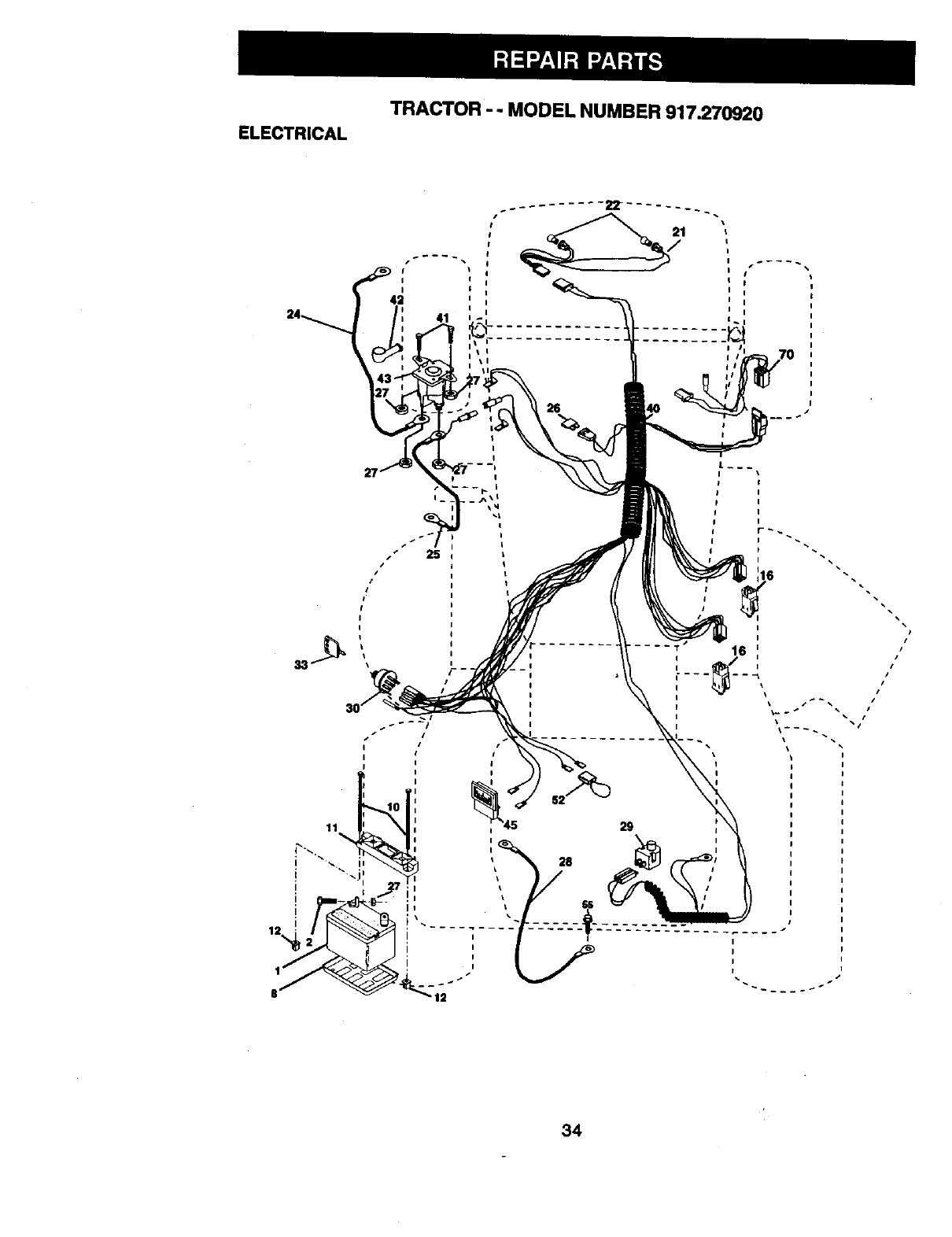
TRACTOR - - MODEL NUMBER 917.270920
ELECTRICAL
41
Ii
I i
\
I
I
I
I
r_
i
i
i
i
\\
34
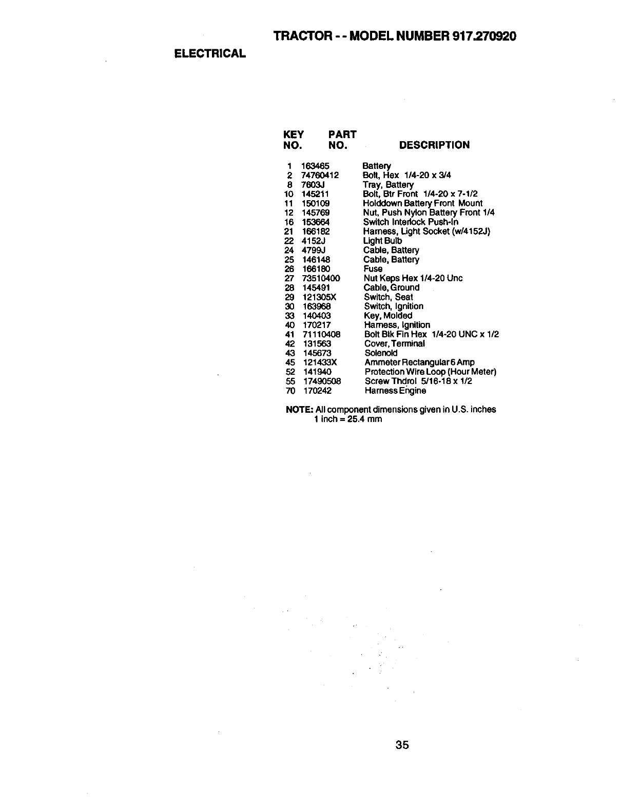
ELECTRICAL
TRACTOR --MODEL NUMBER 917.270920
KEY PART
NO. NO. DESCRIPTION
1 163465 Battery
2 74760412 Bolt, Hex 1/4-20x3/4
8 7603J Tray, Battery
10 145211 Bolt, Btr Front 1/4-20 x 7-1/2
11 150109 Holddown Battery Front Mount
12 145769 Nut, Push Nylon Battery Front 1/4
16 153664 Switch Intedock Push-in
21 166182 Harness, Light Socket (w/4152J)
22 4152J Light Bulb
24 4799J Cable, Battery
25 146148 Cable, Battery
26 166180 Fuse
27 73510400 Nut Keps Hex 1/4-20 Unc
28 145491 Cable, Ground
29 121305X Switch, Seat
30 163968 Switch, Ignition
33 140403 Key, Molded
40 170217 Harness, Ignition
41 71110408 BoltBIkFinHex 1/4-20UNCx1/2
42 131563 Cover,Terminal
43 145673 Solenoid
45 121433X Ammeter Roctangular6 Amp
52 141940 ProtectionWire Loop(Hour Meter)
55 17490508 ScrewThdrol 5/16-18xl/2
70 170242 Harness Engine
NOTE: Allcomponent dimensionsgiven inU.S. inches
1 inch = 25.4 mm
35
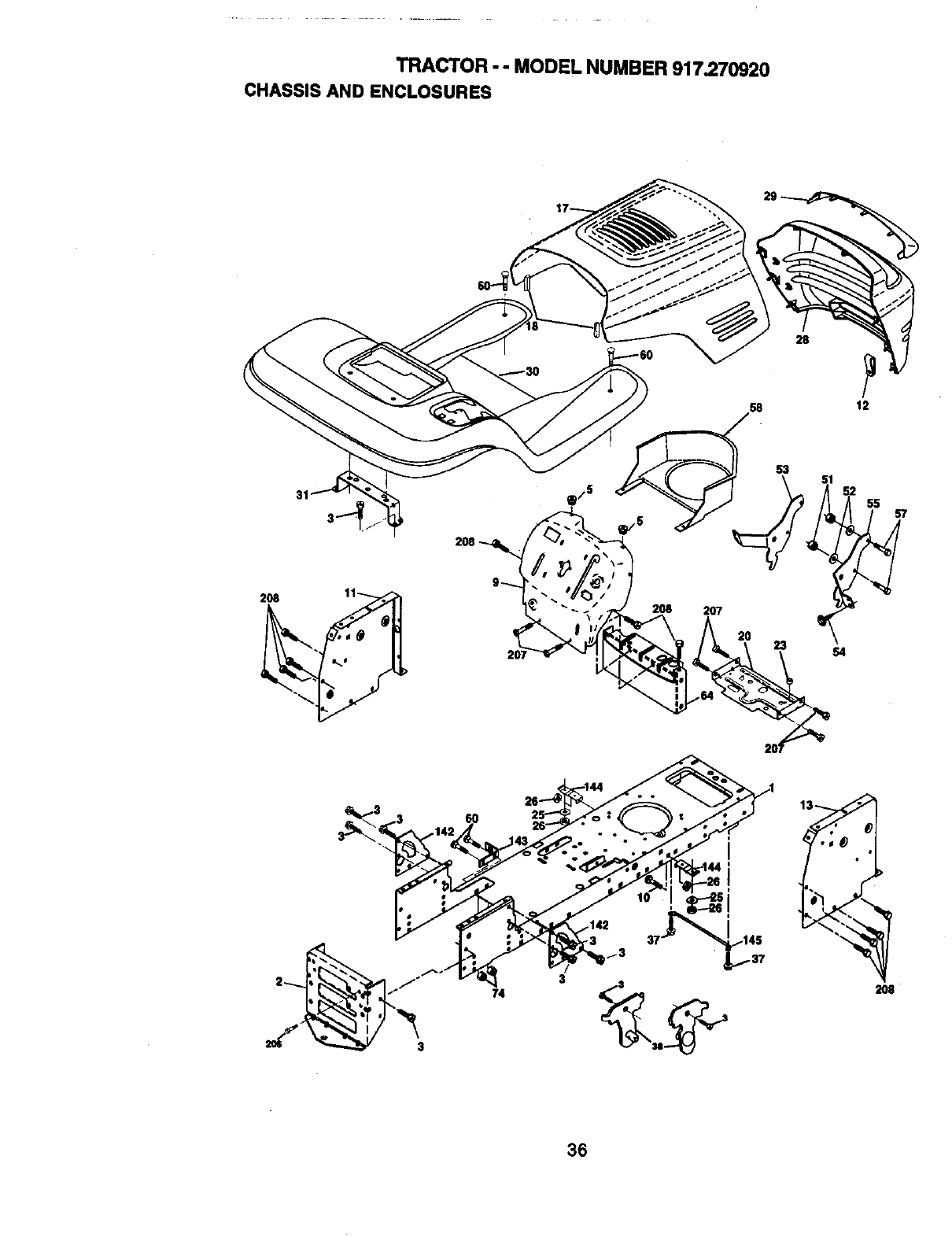
TRACTOR -- MODEL NUMBER 917.270920
CHASSIS AND ENCLOSURES
28
,58 12
208
31
208 207
53
23 S4
55
3
74
3
36
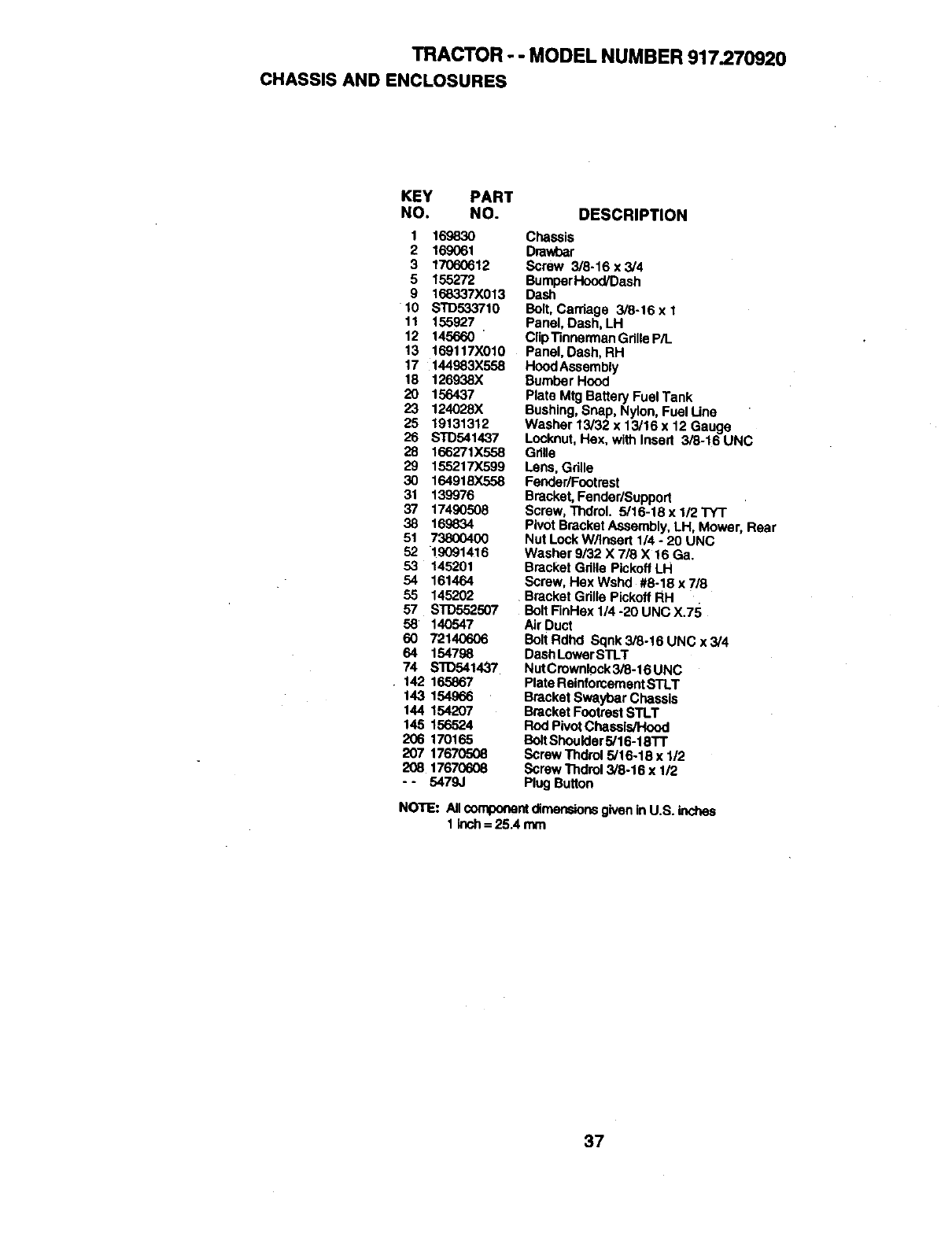
TRACTOR - - MODEL NUMBER 917.270920
CHASSISANDENCLOSURES
KEY PART
NO. NO. DESCRIPTION
1 169830
2 169061
3 17060612
5 155272
9 168337X013
10 STD533710
11 155927
12 145660
13 169117)(010
17 144983)(558
18 126938X
20 156437
23 124028X
25 19131312
26 STD541437
28 166271X558
29 155217)(599
30 164918X558
31 139976
37 17490508
38 169834
51 73800400
52 19091416
53 145201
54 161464
55 145202
57 STD552507
58 140547
60 72140606
64 154798
74 S'1_54143"/
142 165867
143 154966
144 154207
145 156524
206 170165
207 17670r'_6
208 17670608
-- 5479,}
Chassis
Dmwbar
Screw 3/8-16 x3/4
BumperHood/Dash
Dash
Bolt, Carriage 3/8-16 x I
Panel, Dash, LH
ClipTinnerman Grille P/L
Panel, Dash, RH
HoodAssembly
Bumber Hood
Plate Mtg Battery Fuel Tank
Bushing, Snap, Nylon, Fuel Line
Washer 13/32 x 13/16 x 12 Gauge
Locknut, Hex, with Insert 3/8-16 UNC
Grille
Lens, Grille
Fender/Footrest
Bracket, Fender/Support
Screw, Thdrol. 5/16-18 x 1/2 TYT
Pivot Bracket Assembly, LH, Mower, Rear
Nut Lock W/Insert 1/4 o20 UNC
Washer 9/32 X 7/3 X 16 Ga.
Bracket Gdlle Pickoff LH
Screw, Hex Wshd #8-18 x 7/8
Bracket Grille Pickoff RH
Bolt FinHax 1/4 -20 UNC X.75
Air Duct
Bolt Rdhd Sqnk 3/8-19 UNC x 3/4
Dash LowerSTLT
NutCmwnlock3/8-16 UNC
Plate ReinforcementSTLT
Bracket Swaybar Chassis
Bracket Footrest STLT
Rod PivotChassis/Hood
BoRShoulder5/16-18TT
Screw Thdrol 5/t6-18 x 112
Screw Thdml 3/8-16 x 1/2
Plug Button
NOTE: Allcomponentdimensionsgiven inU.S. incttss
1 inch= 25.4 mm
37
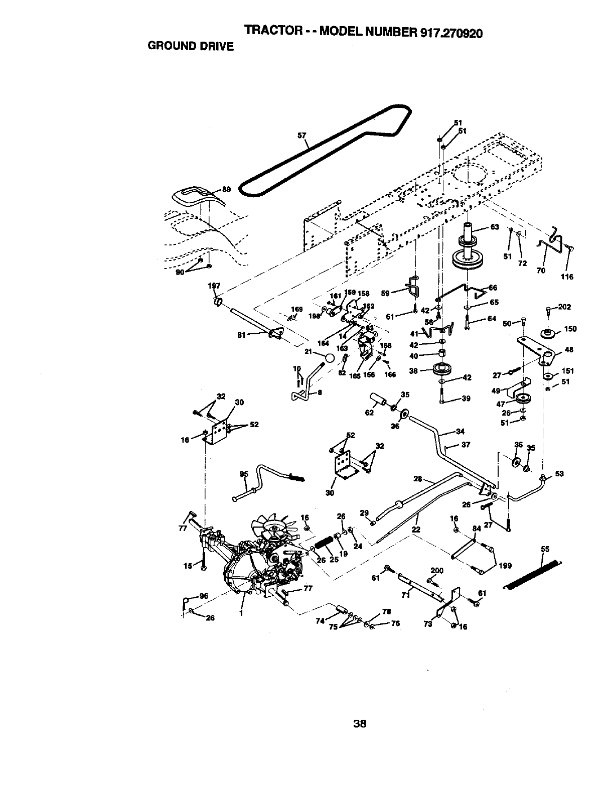
TRACTOR - - MODEL NUMBER 917.270920
GROUND DRIVE
35
36
i
72
116
38
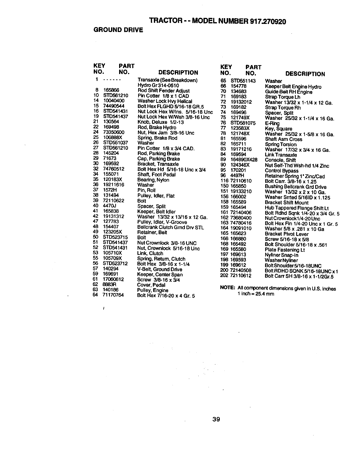
TRACTOR - -MODEL NUMBER 917.270920
GROUND DRIVE
KEY PART KEY PART
NO. NO. DESCRIPTION NO. NO.
1...... Transaxla(SeeBreakdown) 65 STD551143
8 165866
10 STD561210
14 10040400
15 74490544
16 STD541431
19 STD541437
21 130564
22 169498
24 73350600
25 106888X
26 STD551037
27 STD561210
28 145204
29 71673
30 169592
32 74760512
34 155071
35 120183X
36 19211616
37 1572H
38 131494
39 72110622
40 4470J
41 165838
42 19131312
47 127783
48 154407
49 123205)(
50 STD523715
51 STD541437
52 STD541431
53 105710X
55 105709X
56 STD523712
57 140294
59 169691
61 17060612
62 8883R
63 140186
64 71170764
Hydro Gr314-0510 66 154778
Rod Shift Fender Adjust 70 134683
Pin Cotter 1/8 x 1 CAD 71 169183
Washer Lock Hvy Helical 72 19132012
BoltHex FLGHD 5/16-18 GR.5 73 169182
NutLockHexW/Ins. 5/16-18Unc 74 169496
Nut Lock Hax W/Wsh 3/8-16 Unc 75 121749X
Knob, Deluxe 1/2-13 76 STD581075
Rod, Brake Hydro 77 123583X
Nut, Hex Jam 3/8-16 Unc 78 121748X
Spring, Brake Rod 81 165596
Washer 82 165711
Pin Cotter 1/8 x 3/4 CAD. 83 19171216
Rod,Park|ng Brake 84 169594
Cap, Parking Brake 89 164890X428
Bracket, Transaxle 90 124346X
BottHexHd 5/16-18Uncx3/4 95 170201
Shaft, Foot Pedal 96 44971-1
Beadng, Nylon 116 72110610
Washer 150 165850
Pin, Roll 151 19133210
Pulley, Idler, Flat 156 166002
Bolt 158 165589
Spacer, Split 159 165494
Keeper, Belt Idler 161 72140406
Washer 13/32 x 13/16 x 12 Ga. 162 73680400
Pulley, Idler, V-Groove 163 74780416
BellcrankClutch Gmd Drv STL 164 19091010
Retainer, Belt 165 165623
Bolt 166 166880
NutCrownlock 3/8-16UNC 168 165492
Nut, Crownlock 5/16-18 Unc 169 165580
Link, Clutch 197 169613
Spdng, Return,Clutch 198 169593
Bolt Hex 3/8-16 x 1-1/4 199 169612
V-Belt, Ground Ddve 200 72140508
Keeper, Center Span 202 72110612
Screw 3/8-16 x 3/4
Cover, Pedal
Pulley,Engine
Bolt Hax 7/16-20 x 4 Gr. 5
DESCRIPTION
Washer
Keeper BeltEngine Hydro
Guide BeltRH Engine
Strap Torque Lh
Washer 13/32 x 1-1/4 x 12 Ga.
StrapTorque Rh
Spacer, Split
Washer 25/32 x 1-1/4 x 16 Ga.
E-Ring
Kay, Square
Washer 25/32 x 1.5/8 x 16 Ga.
Shaft Asm Cross
SpdngTorsion
Washer 17/32 x 3/4 x 16 Ga.
LinkTransaxle
Console, Shift
Nut Self-Thd Wsh-hd 1/4 Zinc
Contro_Bypass
Retainer Spdng1"Zinc/Cad
Bolt Cam 3/8-16 x 1,25
BushingBeUcrank Grd Ddve
Washer 13/32 x2 x 10 Ga.
Washer Srrted 5/161Dx 1.125
Bracket Shift Mount
Hub Tappered Flange Shift Lt
Bolt Rdhd Sqnk 1/4-20 x 3/4 Gr. 5
NutCrownlockl/4-20 Unc
Bolt Hax Fin 1/4-20 Unc x 1 Gr. 6
Washer 5/8 x .281 x 10 Ga
Bracket Pivot Lever
Screw 5/16-18 x 5/6
Bolt Shoulder 5/16-18 x .561
Plate Fastening Lt
NylinerSnap-In
Washer NyUner
BoltShoulder5/16-t 6UNC
Bolt RDHD SQNK 5/16-18UNC x 1
Bolt Cart SH 3/8-16 x1-1/2Gr.5
NOTE: Allcomponentdimensionsgivenin U.S. inches
1 inch= 25.4 mm
39
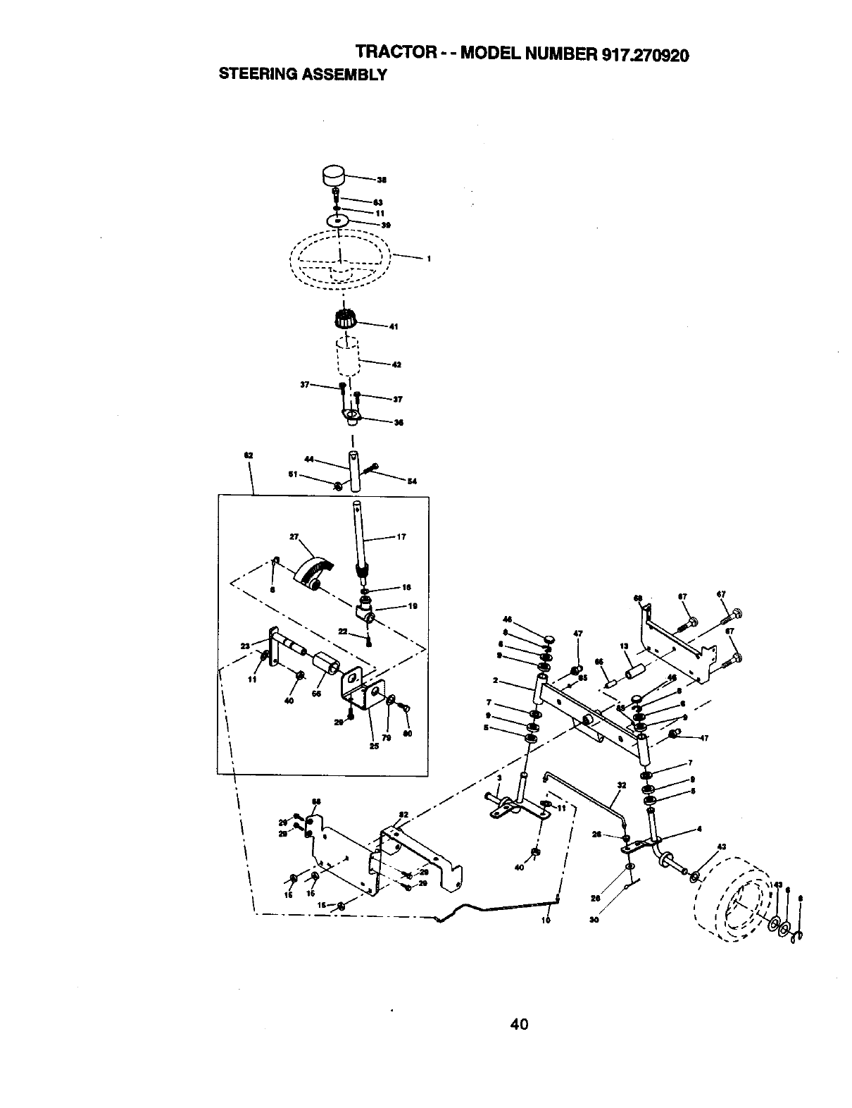
TRACTOR -- MODEL NUMBER 917.270920
STEERING ASSEMBLY
_41
L,,----_._43
"t
I
44
40
47
/
40
/
4O
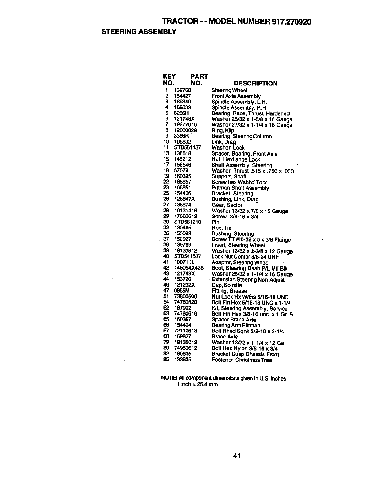
TRACTOR - - MODEL NUMBER 917.270920
STEERING ASSEMBLY
KEY PART
NO. NO,
1 139768
2 154427
3 169840
4 169839
5 626611
6 121748X
7 19272016
8 12000029
9 3366R
10 169832
11 STD551137
13 136518
15 145212
17 156546
18 57079
19 160395
22 165857
23 165851
25 154406
26 126847X
27 136874
28 19131416
29 17060612
30 STD561210
32 130465
36 155099
37 152927
38 139769
39 19133812
40 STD541537
41 100711L
42 145054X428
43 121749X
44 153720
46 121232X
47 6855M
51 73800500
54 74780520
62 167902
63 74780616
65 160367
66 1544O4
67 72110618
68 16.9827
79 19132012
80 74950612
82 169835
85 133835
DESCRIPTION
SteedngWheel
Front Axle Assembly
Spindle Assembly, LH.
SpindleAssembly, R.H.
Beadng, Race, Thrust, Hardened
Washer 25/32 x 1-5/8 x 16 Gauge
Washer 27/32 x 1-114 x 16 Gauge
Ring, Klip
Beadng, SteedngColumn
Link, Drag
Washer, Lock
Spacer, Beadng, FrontAxle
Nut, Hexflange Lock
Shaft Assembly, Steedng
Washer, Thrust .515 x .750 x .033
Support, Shaft
Screw hex Wshhd Torx
Pittman Shaft Assembly
Bracket, Steedng
Bushing, Link, Drag
Gear, Sector
Washer 13/32 x 7/6 x 16 Gauge
Screw 3/8-16 x 3/4
Pin
Rod,Tie
Bushing, Steering
Screw TT #10-32 x 5 x 3/8 Flange
Insert, Steering Wheel
Washer 13/32 x 2-3/8 x 12 Gauge
Lock NutCenter 3/6,24 UNF
Adaptor, Steedng Wheel
Boot, Steedng Dash P/L Mtl BIk
Washar 25/32 x 1-1/4 x 16 Gauge
ExtensionSteedng Non-Adjust
Cap, Spindle
Rtting, Grease
Nut Lock Hx W/Ins 5/16-18 UNC
Bolt Rn Hex 5/16-18 UNC x 1-1/4
Kit, Steedng Assembly, Service
Bolt Fin Hex 3/8-16 unc. x I Gr. 5
Spacer Brace Axle
Beadng Arm Pittman
Bolt Rhnd Sqnk 3/8-16 x 2-1/4
Brace Axle
Washer 13/32 x 1-1/4 x 12 Ga
Bolt Hex Nylon 3/8-16 x 3/4
Bracket Susp Chassis Front
Fastener ChristmasTree
NOTE: AllcomponentdimensionsgiveninU.S. inches
1 Inch = 25.4 mm
41
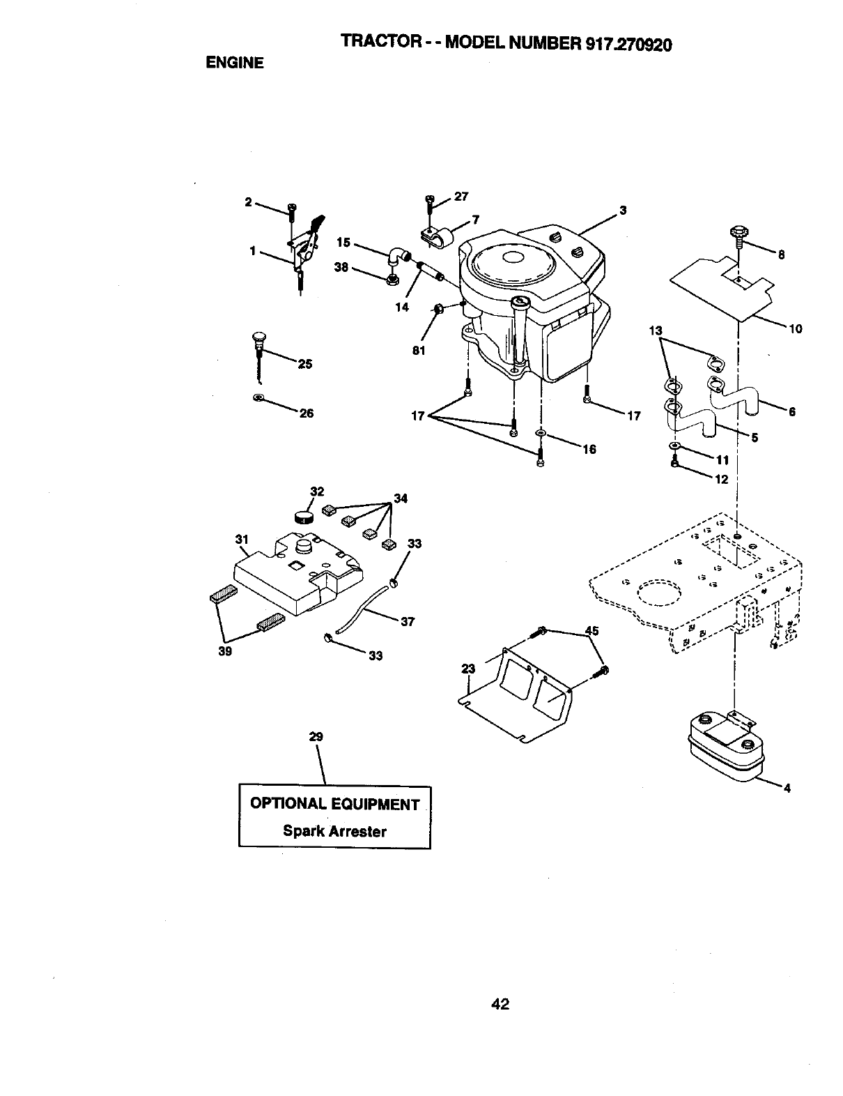
ENGINE TRACTOR - - MODEL NUMBER 917.270920
32
39 _" 33
29
OPTIONAL EQUIPMENT I
Spark Arrester
42
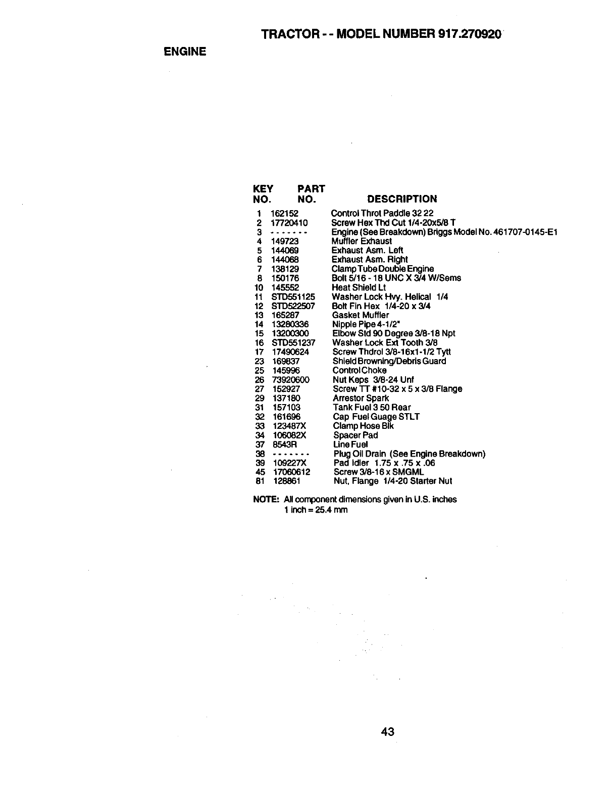
ENGINE
TRACTOR - - MODEL NUMBER 917.270920
KEY PART
NO. NO.
1162152
2 17720410
3.......
4 149723
5 144069
6 144068
7 138129
8 150176
10 145552
11 STD551125
12 S'I'D522507
13 165287
14 13280336
15 13200300
16 STD551237
17 17490624
23 169837
25 145996
26 73920600
27 152927
29 137180
31 157103
32 161696
33 123487X
34 106082X
37 8543R
38 .......
39 109227X
45 17060612
81 128861
DESCRIPTION
Control Throt Paddle 32 22
Screw Hex Thd Cut 1/4-20x5/8 T
Engine (See Breakdown) BriggsModel No. 461707-0145-E1
Muffler Exhaust
Exhaust Asm. Left
Exhaust Asm. Right
Clamp Tube Double Engine
Bolt 5/16 - 18 UNC X 3/4 W/Seres
Heat Shield Lt
Washer Lock Hvy. Helical 1/4
Bolt Fin Hex 1/4-20 x 3/4
Gasket Muffler
NipplePipe4-1/2"
Elbow Std 90 Degree 3/8-18 Npt
Washer Lock Ext Tooth 3/8
Screw Thdrol 3/8-16xl -1/2 Tytt
ShieldBrowning/DebrisGuard
ControlChoke
Nut Keps 3/8-24 Unt
Screw "IT #10-32 x 5 x 3/8 Flange
Arrestor Spark
Tank Fuel 3 50 Hear
Cap Fuel Guage STLT
Clamp Hose BIk
Spacer Pad
LineFuel
PlugOil Drain (See Engine Breakdown)
Pad Idler 1.75 x ,75 x .06
Screw 3/8-16 x SMGML
Nut, Flange 114-20 Starter Nut
NOTE: Allcomponentdimensionsgivenin U.S. inches
1 inch= 25.4 mm
43
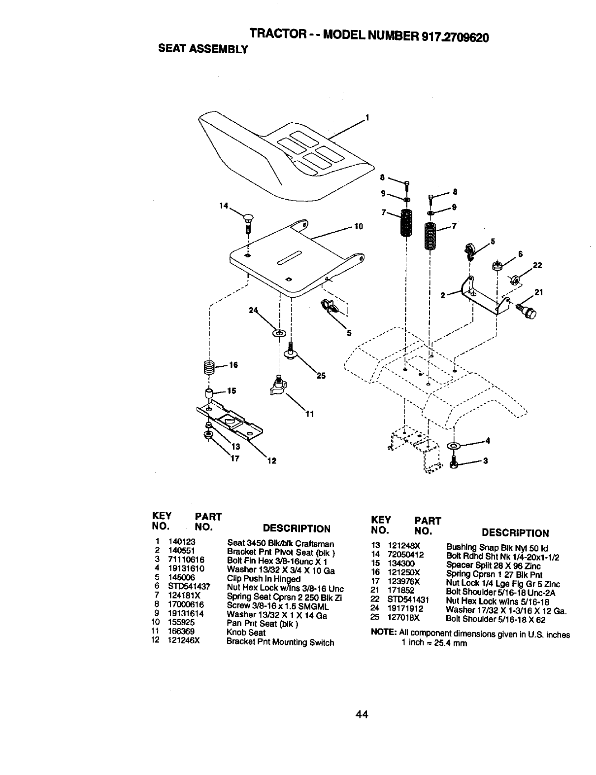
TRACTOR - - MODEL NUMBER 917.2709620
SEATASSEMBLY
22
21
KEY PART
NO. NO.
1 140123
2 140551
3 71110616
4 19131610
5 145OO6
6STD541437
7 124181X
8 17000616
9 19131614
10 155925
11 166369
12 121246X
KEY PART
DESCRIPTION NO. NO. DESCRIPTION
Seat 3450 BIk/blkCraftsman
Bracket Pnt Pivot Seat (blk)
BOttFin Hex 3/8-16unc X 1
Washer 13/32 X 3/4 X 10 Ga
ClipPush In Hinged
Nut Hex Lock w/Ins 3/8-16 Uno
Spring Seat Cprsn 2 250 BIk Zi
Screw 3/8-16 x 1.5 SMGML
Washer 13/32 X 1 X 14 Ga
Pan Pnt Seat (t_k)
Knob Seat
Bracket Pnt MountingSwitch
13 121248X
14 72050412
15 134300
16 121250X
17 123976X
21 171852
22 STD541431
24 19171912
25 127018X
BushingSnap BIk Nyl 50 Id
Bolt Rdhd Sht Nk 1/4-20x1-1/2
Spacer Split28 X 96 Zinc
Spring Cprsn 1 27 BIk Pnt
Nut Lock 1/4 Lge Fig Gr 5 Zinc
Bolt Shoulder 5/16-18 Unc-2A
Nut Hex Lock w/Ins 5/16-18
Washer 17/32 X 1-3/16 X 12 Ga.
Bolt Shoulder 5/16-18 X 62
NOTE: All componentdimensionsgiven inU.S. inches
1 inch = 25.4 mm
44
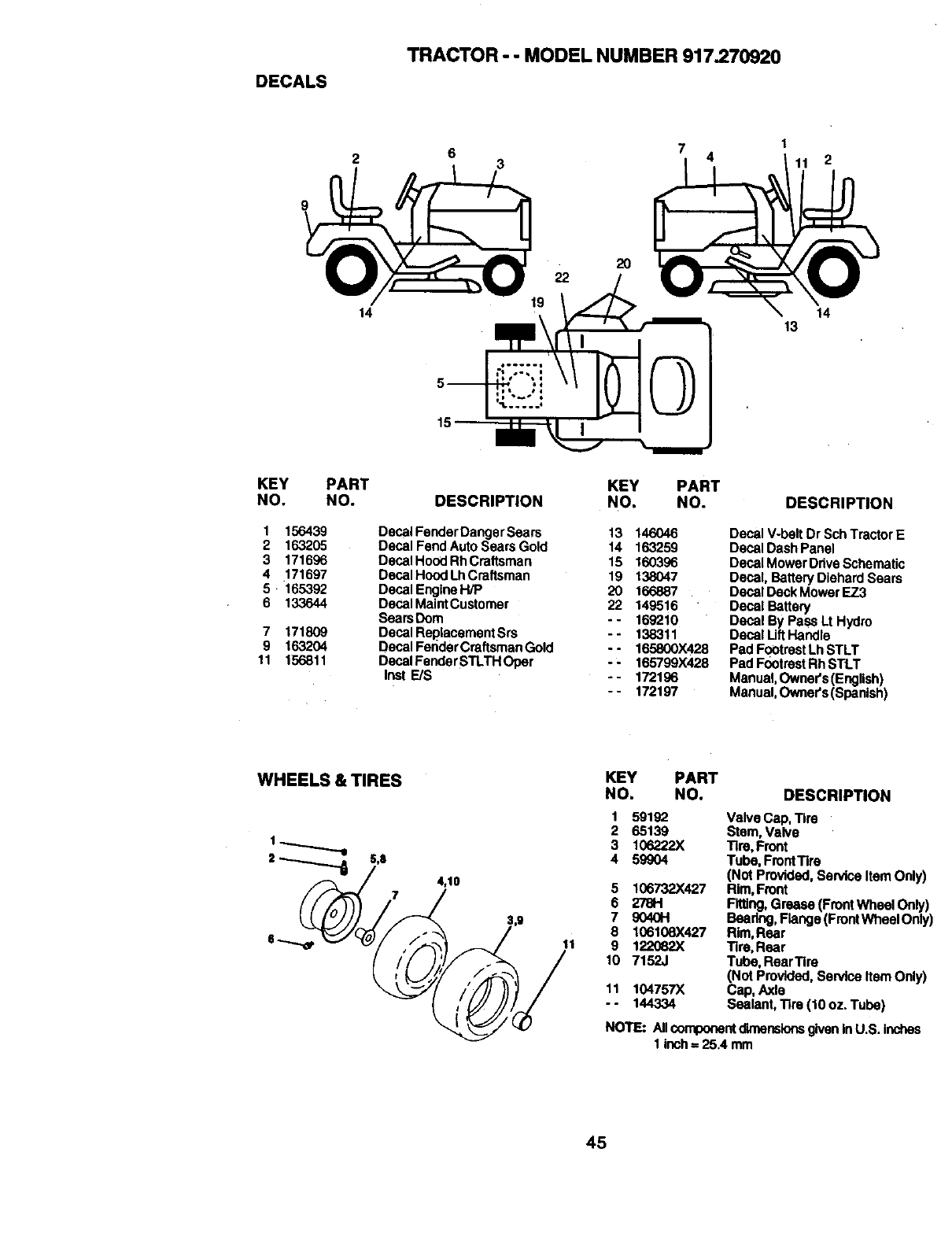
DECALS
TRACTOR - - MODEL NUMBER 917.270920
23741
11 2
9
14
KEY PART
NO. NO.
1 156439
2 163205
3 171696
4 171697
5 165392
6 133644
7 171809
9 163204
11 156811
KEY PART
DESCRIPTION NO. NO.
Decal Fender Danger Sears 13 146046
Decal Fend Auto Sears Gold 14 163259
Decal Hood Rh Craftsman 15 160396
Decal Hood Lh Craftsman 19 138047
Decal Engine H/P 20 166887
Decal MaintCustomer 22 149516
SearsDoro - - 169210
Decal ReplacementSrs -- 138311
Decal FeridarCraftsman Gold -- 165800)(428
DecalFenderSTLTHOper - - 165799)(428
Inst E/S -- 172196
-- 172197
14
13
DESCRIPTION
Decal V-belt Dr Sch Tractor E
Decal Dash Panel
Decal MowerDdve Schematic
Decal, Battery Diehard Sears
Decal Deck M_wer EZ3
Decal Battery
Decal By Pass Lt Hydro
Decal Uft Handle
Pad FootrestLh STLT
Pad FootrestRh STLT
Manual, OwneYs (English)
Manual,Owner's(Spardsh)
WHEELS & TIRES
4,10
11
KEY PART
NO. NO. DESCRIPTION
1
2
3
4
5
6
7
8
9
10
11
59192 Valve Cap, Tire
65139 Stem, Valve
106222X Tire, Front
59_04 Tube, FrontTire
(Not Provided, Service Item Only)
106732X427 Rim, Front
27811 Fitting, Grease (FrontWbeal Only)
9040H Beadng, Flange (FrontWheal Only
106106X427 Rim, Rear
122O82X Tire, Rear
7152J Tube, RearTire
(Not Provided, Service Item Only)
104757X Cap, Axle
144334 Sealant, Tire ('tOoz. Tube)
NOTE: Allcomponentdimensionsgiven In u.s, Inches
1inch = 25.4 taro
45
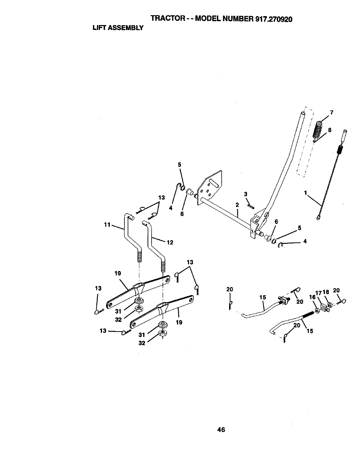
TRACTOR - - MODEL NUMBER 917.270920
LIFTASSEMBLY
13
5
3
8
j! •
65
19
13
32
13
19
2O
15
46
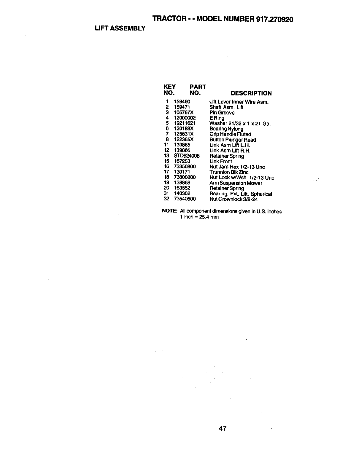
TRACTOR -- MODEL NUMBER 917.270920
LIFT ASSEMBLY
KEY PART
NO. NO. DESCRIPTION
1 159460 Lift Lever Inner Wire Asm.
2 159471 Shaft Asm. Lift
3 105767X PinGroove
4 12000002 E Ring
5 19211621 Washer21/32x1 x21 Ga.
6 120183X BeadngNytong
7 125631X GdpHandle Ruted
8 122365X ButtonPlunger Read
11 139865 Link Asm Lift L.H.
12 139866 Link Asm Lift R.H.
13 $10624008 RetainerSpdng
15 167253 LinkFront
16 73350800 Nut Jam Hex 1/2.13 Unc
17 130171 Trunnion BIk Zinc
18 73800800 Nut Lock w/Wsh 1/2-13Unc
19 139868 An'nSuspensionMower
20 163552 RetainerSpdng
31 140302 Beadng, Pvt. Lift. Spherical
32 73540600 NutCrownlock3/8-24
NOTE: Allcomponentdimensionsgiven inU.S. inches
1 inch= 25.4 mm
47
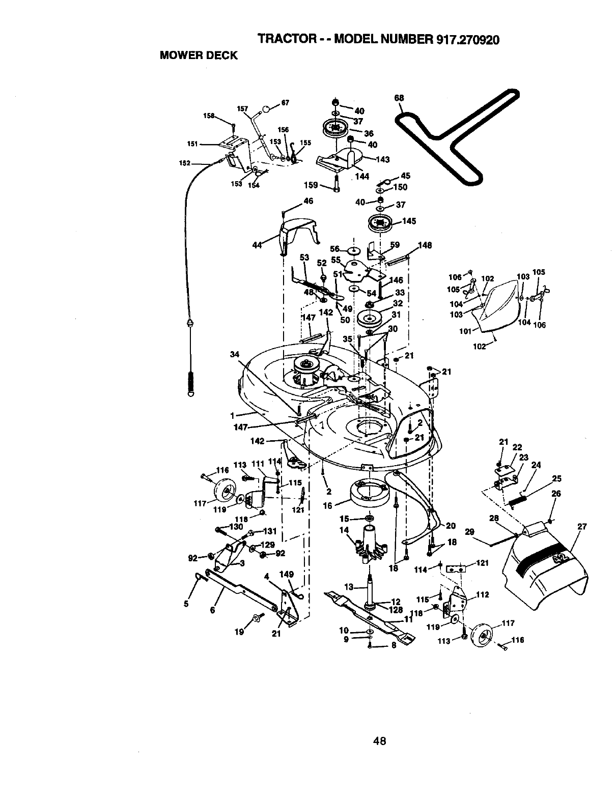
MOWER DECK
TRACTOR - - MODEL NUMBER 917.270920
'---..,_,. _T__,
153 I_4 i9,_
,148
>21
21 22
24
16
1
18
26
27
48
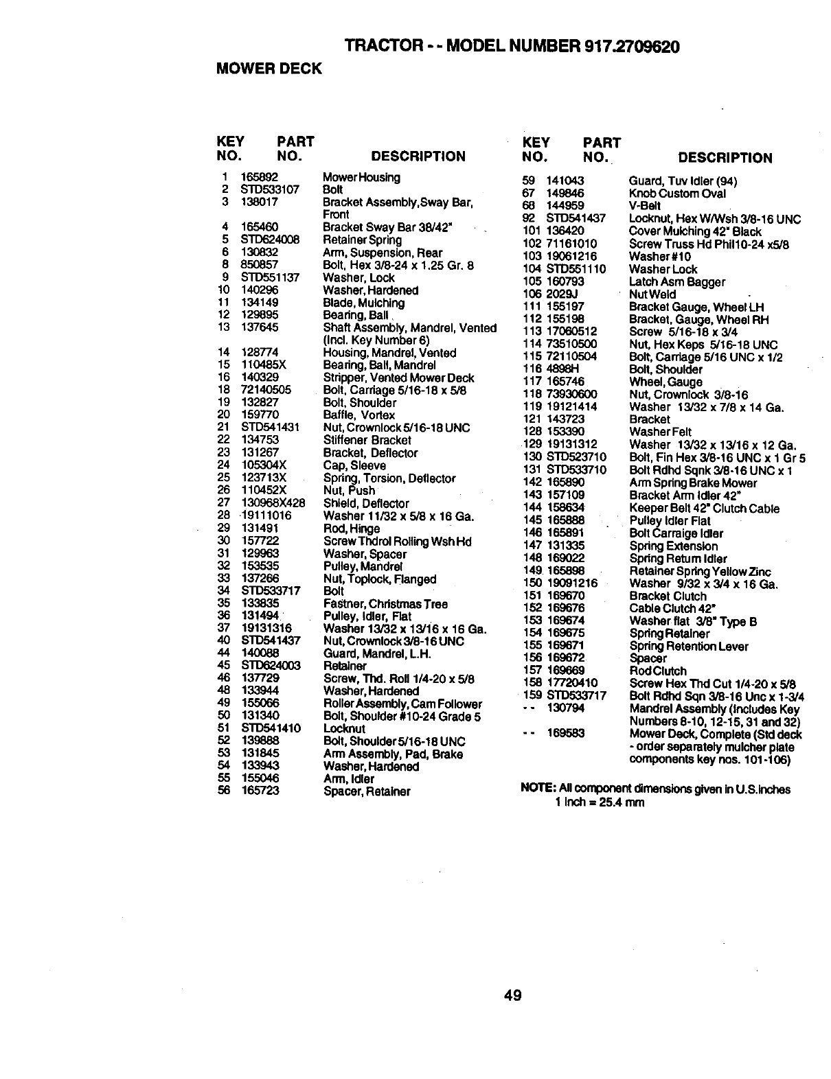
TRACTOR - - MODEL NUMBER 917.2709620
MOWER DECK
KEY PART KEY PART
NO. NO. DESCRIPTION NO. NO.
1 165892 MowerHousing 59 141043
2 STD533107 Bolt 67 149846
3 138017 Bracket Assembly,Sway Bar, 68 144959
Front 92 STD541437
4 165460 Bracket Sway Bar 38/42" 101 136420
5 STD624008 RetainerSpring 102 71161010
6 130832 Arm, Suspension, Rear 103 19061216
8 850857 Boll Hex 3/8-24 x 1.25 Gr. 8 104 STD561110
9 STD551137 Washer, Lock 105 160793
10 140296 Washer, Hardened 106 2029J
11 134149 Blade,Mulching 111 155197
12 129895 Beadng, Ball. 112 155198
13 137645 ShaffAssembly, MandreI, Vented 113 17060512
(Incl. Key Number 6) 114 73510500
14 128774 Housing,Mandrel,Vented 115 72110504
15 110485)( Beadng, BalI, Mandrel 116 4896H
16 140329 Stdpper, Vented MowerDeck 117 165746
18 72140505 Bolt,Carriage 5/16-18 x 5/8 118 73930600
19 132827 Bolt,Shoulder 119 19121414
20 159770 Baffle, Vortex 121 143723
21 STD541431 Nut, Crownlock5/16-18UNC 128 153390
22 134753 Stiffener Bracket 129 19131312
23 131267 Bracket, Deflector 130 STD523710
24 105304X Cap, Sleeve 131 STD533710
25 123713X Spdng, Torsion, Deflector 142 165890
26 110452X Nut; Push 143 157109
27 130968X428 Shield, Deflector 144 158634
28 19111016 Washer 11/32 x 5/8 x 16 Ga. 145 165888
29 131491 Rod,Hinge 146 165891
30 157722 ScrawThdrolRoUingWshHd 147 131335
31 129963 Washer, Spacer 148 169022
32 153535 Pulley,Mandrel 149 165898
33 137266 Nut, Toplock,Flanged 150 19091216
34 STD533717 Bolt 151 169670
35 133835 FaStner,ChdstmasTrse 152 169676
36 131494 Pulley, Idler, Flat 153 169674
37 19131316 Washer13i32x13/16x16Ga. 154 169675
40 STD541437 Nut, Crownlock3/8-16UNC 155 169671
44 140088 Guard, Mandrel, LH. 156 169672
45 $10624003 Retainer 157 169669
46 137729 Screw, Thd. Roll 1/4-20 x 5/8 158 17720410
48 133944 Washer, Hardened 159 STD533717
49 155066 RollerAssembly, CamFollower -- 130794
50 131340 Bolt, Shoulder #10-24 Grade 5
51 $10541410 Locknut --169583
52 139888 Bo_t,Shoulder5/16-18 UNC
53 131845 Arm Assembly, Pad, Brake
54 133943 Washer, Hardened
55 155046 Arm, Idler
56 165723 Spacer, Retainer
DESCRIPTION
Guard, Tuv Idler (94)
Knob CustomOval
V-Belt
Locknut, Hex W/Wsh 3/8-16 UNC
Cover Mulching42" Black
Screw Truss Hd Phil10-24 x5/8
Washer#10
Washer Lock
Latch Asm Bagger
NutWeld
Bracket Gauge, Wheel LH
Bracket, Gauge, Wheel RH
Screw 5/16-18 x 3/4
Nut, Hex Keps 5/16-18 UNC
Bolt, Carriage 5/16 UNC x 1/2
Bait, Shoulder
Wheel, Gauge
Nut, Crownlock 3/8-16
Washer 13/32 x 7/8 x 14 Ga.
Bracket
Washer Felt
Washer 13/32 x 13/16 x 12 Ga.
Bolt,Fin Hex 3/8-16 UNC x 1 Gr 5
Bolt Rdhd Sqnk 3/8-16 UNC x 1
Arm SpringBrake Mower
Bracket Arm Idler 42"
Keeper Belt 42" Clutch Cable
Pulley IdlerFlat
BoltCarraige Idler
Spdng Extension
SpdngReturn Idler
Retainer SpdngYellowZinc
Washer 9/32 x 3/4 x 16 Ga.
Bracket Clutch
Cable Clutch42"
Washerflat 3/8"Type B
SpdngRetainer
SpdngRetention Lever
Spacer
RodClutch
Screw Hex Thd Cut 1/4-20 x 5/8
Bolt Rdhd Sqn 3/8-16 Uno x 1-3/4
Mandrel Assembly (Includes Key
Numbers 8-10, 12-15, 81 and 32)
Mower Deck, Complete (Srddeck
- order separately mulcherplate
components key nos. 101-106)
NOTE: Allcomponentdimensionsgiven inU.S.ioches
1 Inch= 25.4 mm
49
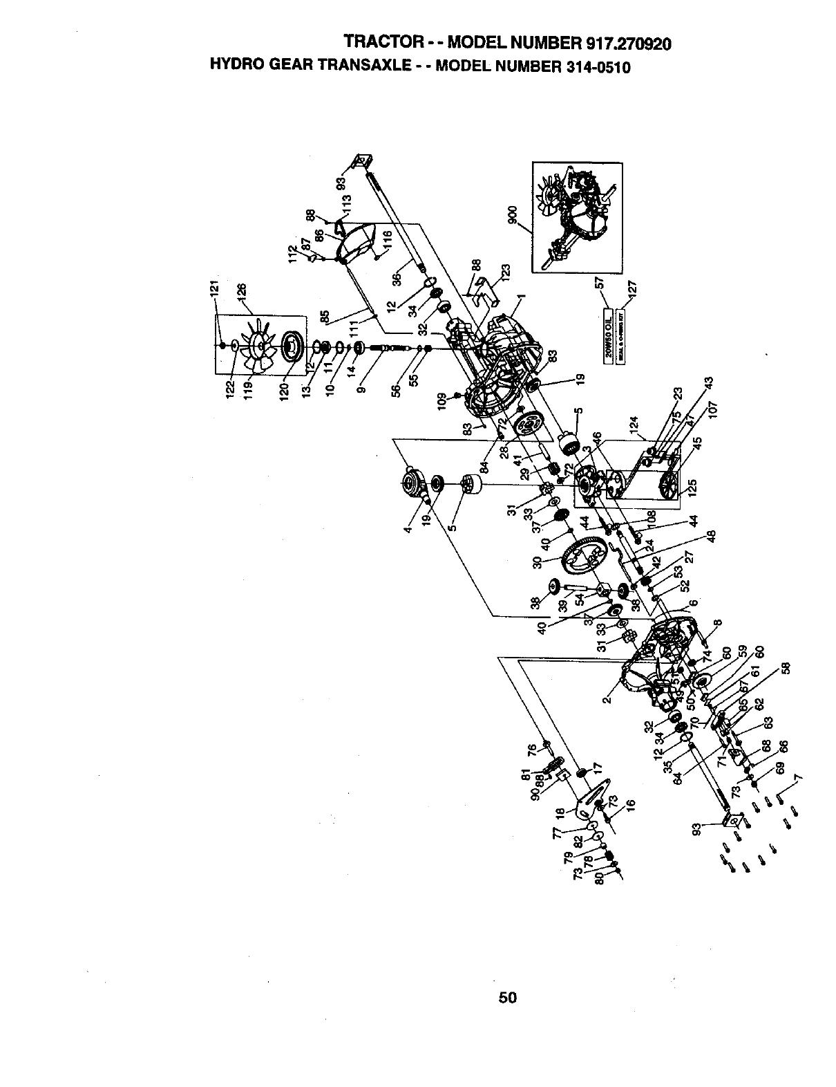
TRACTOR - -MODEL NUMBER 917_270920
HYDRO GEAR TRANSAXLE -. MODEL NUMBER 314-0510
\
50
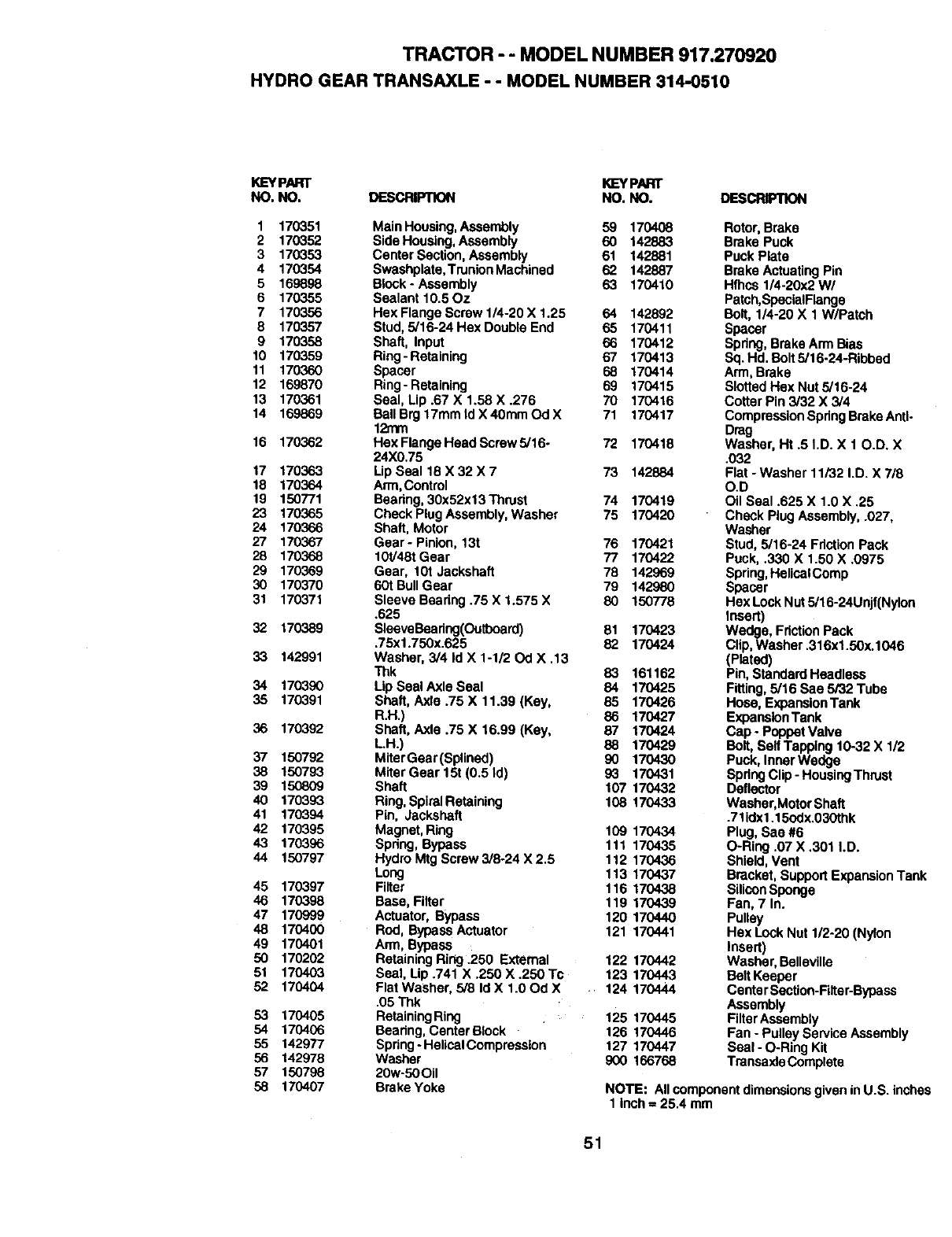
TRACTOR - - MODEL NUMBER 917.270920
HYDRO GEAR TRANSAXLE - - MODEL NUMBER 314-0510
KEYPART K]EYPART
NO. NO. DESCRIPTION NO. NO. DESCRIPTION
1 170351 Main Housing,Assembly 59 170408
2 170352 Side Housing, Assembly 60 142883
3 170353 Center Section, Assembly 61 142881
4 170354 Swashplata,TrunionMachinsd 62 142887
5169898 Block - Assembly 63 170410
6 170355 Sealant 10.50z
7 170356 Hex Flange Screw 1/4-20 X 1.25 64 142892
8 170357 Stud, 5/16-24 Hex Double End 65 170411
9 170358 Shaft, Input 66 170412
10 170359 Ring-Retaining 67 170413
11 170360 Spacer 68 170414
12 169870 Ring-Retaining 69 170415
13 170361 Seal, Lip .67 X 1.58 X .276 70 170416
14 169869 Ball B_117mm Id X 40mm Od X 71 170417
12mm
16 170362 HexFlangeHeadScrew5/16. 72 170418
24X0.75
17 170363 Lip Seal 18 X 32 X 7 73 142884
18 170364 Arm,Control
19 150771 Bearing, 30x52x13Thrust 74 170419
23 170365 Check PlugAssembly, Washer 75 170420
24 170366 Shaft, Motor
27 170367 Gear- Pinion, 13t 76 170421
28 170368 10t/48t Gear 77 170422
29 170369 Gear, 10t Jackshafl 78 142969
30 170370 60t BullGear 79 142980
31 170371 Sleeve Bearing.75 X 1.575 X 80 150778
.625
32 170389 SleeveBeadng(Outboard) 81 170423
,75x1.750x.625 82 170424
33 142991 Washer, 3/4 Id X 1-1/20d X .13
Thk 83 161162
34 1703,90 Lip Seal Axla Seal 84 170425
35 170391 Shaft, Axle .75 X 11.39 (Key, 85 170426
R.H.) 86 170427
36 170392 Shaft, Axle .75 X 16.99 (Key, 87 170424
LH.) 88 170429
37 150792 MiterGear(Splined) 90 170430
38 150793 Miter Gear 15t (0.5 Id) 93 170431
39 150809 Shaft 107 170432
40 170393 Ring,SpiralRetaining 108 170433
41 170394 Pin, Jackshaft
42 170395 Magnet, Ring 109 170434
43 170396 Spring, Bypass 111 170435
44 150797 Hydro Mtg Screw3/8-24 X2.5 112 170436
Long 113 170437
45 170397 Filter 116 170438
46 170398 Base, Filter 119 170439
47 170999 Actuator, Bypass 120 170440
48 170400 Rod, Bypass Actuator 121 170441
49 170401 Arm, Bypass
50 170202 Retaining Ring .250 External 122 170442
51 170403 Seal, Lip .741 X .250 X .250 Tc 123 170443
52 170404 Flat Washer, 5/8 Id X 1.00d X 124 170444
.05 Thk
53 170405 RetainingRing
54 170406 Bearing, Center Block
55 142977 Spring-HelicalCompression
56 142978 Washer
57 150798 20w-50Oil
58 170407 Brake Yoke
Rotor, Brake
Brake Puck
Puck Plate
Brake Actuating Pin
Hfhcs 1/4-20x2 W/
Patch,SpecialFlange
Bolt, 1/4-20 X 1 W/Patch
Spacer
Spring, Brake Arm Bias
Sq. Hd. Bolt 5/16-24-Ribbed
Arm, Brake
Slotted Hex Nut 5/16-24
Cotter Pin 3/32 X 3/4
CompressionSpringBrake Anti-
Drag
Washer, Ht .5 I.D. X 10.D. X
.032
Flat - Washer 11/32 I.D. X 7/8
O.D
Oil Seal .625 X 1.0 X .25
Check Plug Assembly, .027,
Washer
Stud, 5/16-24 FrictionPack
Puck, .330 X 1,50 X .0975
Spring,HelicaIComp
Spacer
Hex Lock Nut 5/16-24Unjf(Nylon
Insert)
Wedge, Friction Pack
Clip,Washer .316x1.5Ox.1046
(Plated)
Pin, Standard Headless
Fitting, 5/16 Sae 5/32 Tube
Hose, ExpansionTank
ExpansionTank
Cap - Poppet Valve
Bolt, Self Tapping 10-32 X 1/2
Puck, Inner Wedge
Spring Clip- HousingThrust
Deflector
Washar,MotorShaft
.711dx1.15edx.030thk
Plug, Sae #6
O-Ring .07 X .301 I.D.
Shield, Vent
Bracket, Support ExpansionTank
SiliconSponge
Fan, 7 In.
Pulley
Hex Lock Nut 1/2-20 (Nylon
Insert)
Washer, Bellevilla
Belt Keepor
Centa rSection-Filter-Bypass
Assembly
125 170445 FilterAssembly
126 170446 Fan - Pulley Service Assembly
127 170447 Seal -O-Ring Kit
900 166768 Trensaxle Complate
NOTE: All componentdimensions given inU.S. inches
1 inch =25.4 mm
51
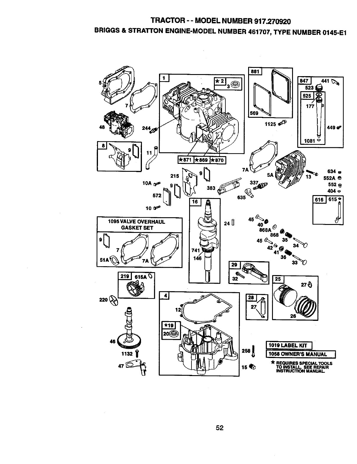
TRACTOR -- MODEL NUMBER 917.270920
BRIGGS & STRA'I-rON ENGINE-MODEL NUMBER 461707, TYPE NUMBER 0145-E1
1132
634 g
552A
552
404 o
11o.OWNER'S MANUAL I
"k REQUIRES SPECIAL TOOLS
15 _TO INSTALL SEE REPAIR
INSTRUCTION MANUAL
52
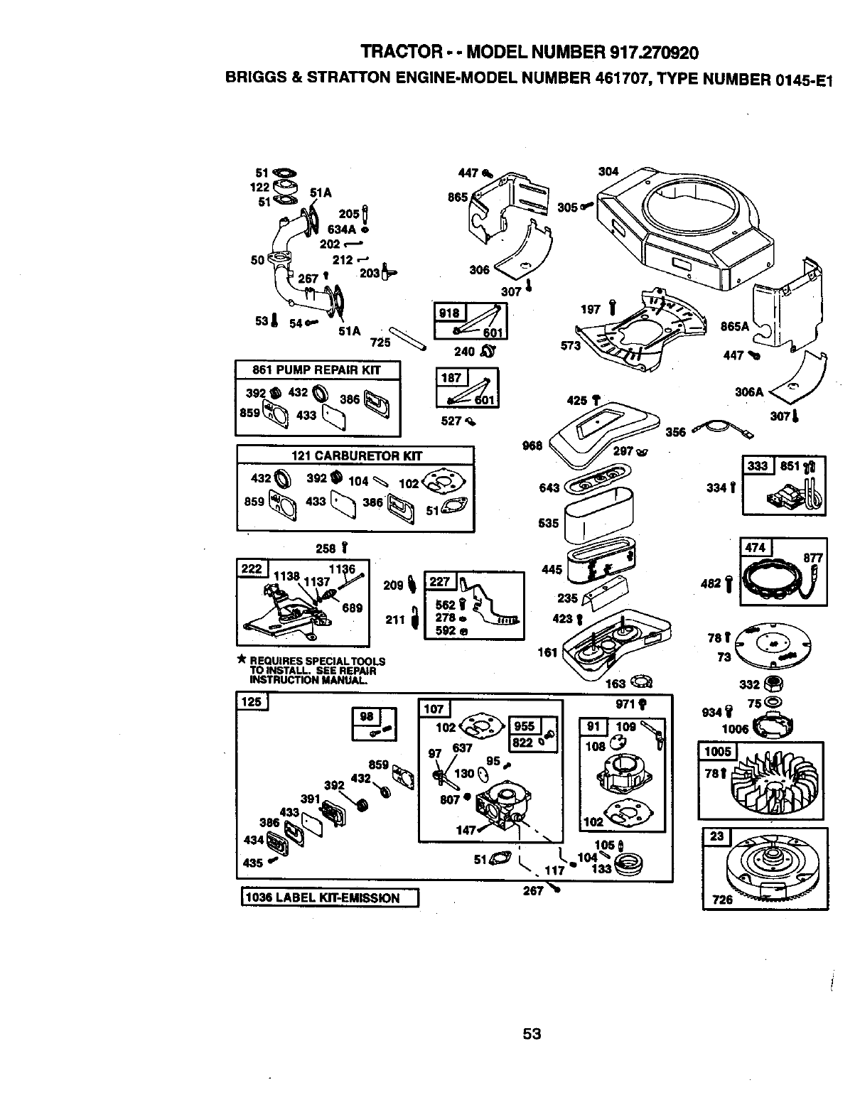
TRACTOR - -MODEL NUMBER 917.270920
BRIGGS & STRATTON ENGINE-MODEL NUMBER 461707, TYPE NUMBER 0145-E1
51
1221 51A
205
634A o
202
50_ 212 '-"
267 t 203_
53| 54+-
51A 725_
861 PUMP REPAIR KIT "1
/
302• 432_a00'_
859_ 433 _
307 _
240_'
_01 425 '
527
968
1
121 CARBURETOR KIT
432 63920104_ lO2_1 643<
535
250 V
_,,_1138 11:_6_,
,_2 i'
689 211 aim:
"I m,,, I
lk REQUIRES SPEClALTOOLS
TO INSTALL, SEE REPAIR
INSTRUCTION MANUAL.
304
11030LABEL KIT-EMISSION I
305
306A <
3o7L
267 "%
8O7•
53
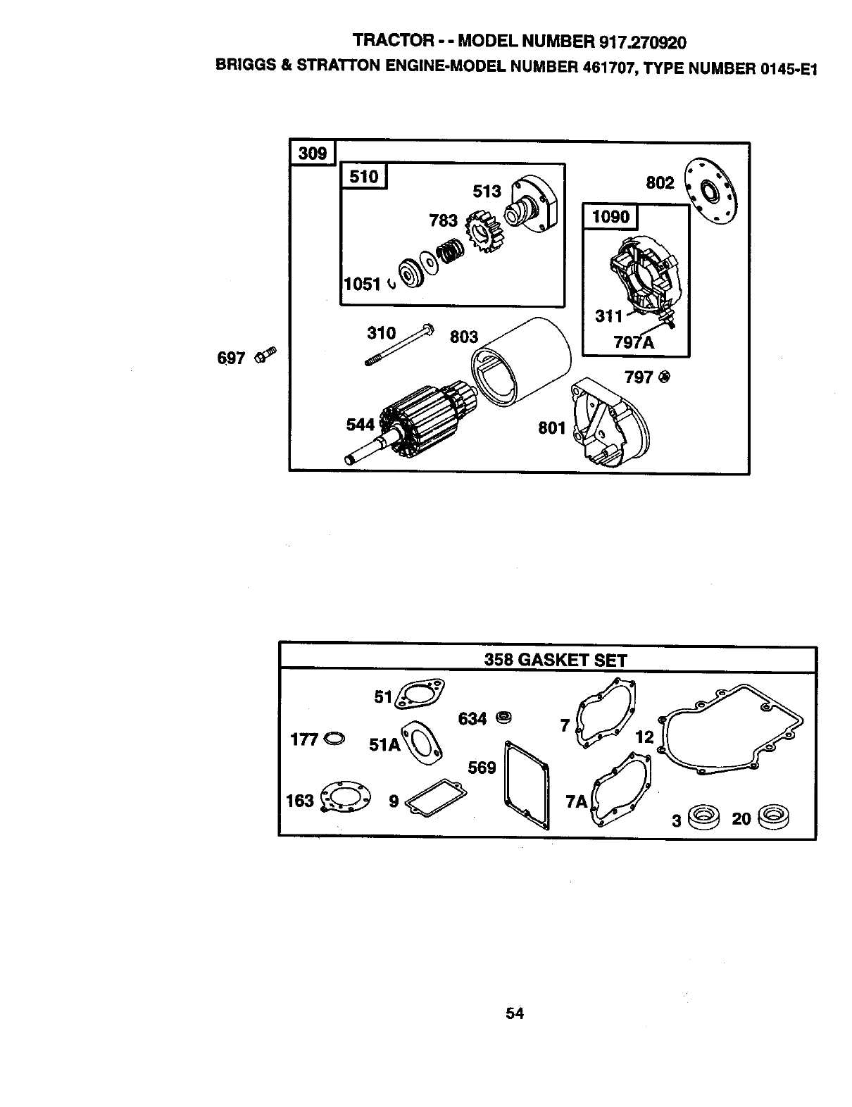
TRACTOR - - MODEL NUMBER 917.270920
BRIGGS & STRATTON ENGINE-MODEL NUMBER 461707, TYPE NUMBER 0145-E1
697 _#'
783
y803
544 ;
513 802 (_)_
801
797 @
358 GASKET SET
634
ooo
i
3@ 20@
54

TRACTOR - - MODEL NUMBER 917.270920
BRIGGS & STRATTON ENGINE-MODEL NUMBER461707, TYPE NUMBER 0145-E1
KEY PAFn" KEY PART
NO. NO. DESCRIPTION NO. NO. DESCRIPTION
1 498583 CylinderAssembly 95 690718 Screw('l'hmttleValve)
2 399265 Bushing/SealKit 97 693485 Shaft-Throttle
3 91086 "/__96 807923 Kit-IdleSpeed
4 493304 SurnlPEnglne 102 69_509 •Gasket-CarburetorBody
5 214517 Head-Cylindar#1 104 693506 •Pin-FloatHinge
5A 214518 Head-Cylinder#2 105 6g_078 •Valve-FleatNasdle
7 271867 _Gasket-CylinderHead #1 107 693482 BodyAseambly-Lower
7A 271868 _Gasket-CylinderHead#2 108 693505 Valve-Choke
8 495754 BreatherAssembly(Cytindar#1) 109 693498 Shaft-Choke
9 27803 _Gasket-Breather 117 693538 Jet-Main
10 94382 Screw (BreatherAssembly) 69_500 Jet-Main(High Altitude)
IOA 94380 Screw(BraatherCover) 121 491539 CarburetorKit
11 280_25 Tube-Braethar 122 281411 Spacer
273390 "k Gasket-Crankcase (.015" Thick, 125 693479 Carburetor
Std.) 130 693504 Valve-Throttle
271188 -k Gasket-Crankcase (.005" Thick) 133 693512 Fleat-Carburetor
271189 "/r Gasket-Crankcase(.009" Thick) 146 94196 Key-Tinting
13 94565 Screw(CylinderHead) 147 6935(]8 Jet-Pilot
15 94239 Plug--OitDrain 161 496599 Base-AirCisaner
16 690666 Crankshaft 163 271411 _r Gasket-AlrClaaner
19 399264 Bushing 177 271170 * Seat-O-Ring
20 291675 'Jr Seal-Oil 187 299146 Une-Fuel(CuttoRequlrad
23 491180 Flywheel Length)
24 222698 Key-Flywheel 197 95063 Screw (Back Plate)
25 499180 PistonAssembly(Standard) 202 262683 Unk-Mechanical Governor
499181 PistonAssembly (.010 "O.S.) 203 280997 Crank-Bell
499182 PistonAssembly (.020" O.S.) 205 93971 Screw (BallCrank)
499183 PistonAssembly (.030" O.S.) 209 262352 Spdng-Govemor
26 499184 Ring Set, Piston(Standard) 211 261563 Spnng-Governor
499285 Ring Set, Piston(.010 =O.S.) 212 693.985 Link-Throftla
499186 Ring Set, Piston(.020 =O.S.) 215 224816 Guide-Air
499187 Ring Set, Piston(.030 "O.S.) 219 394348 Gear-Governor
27 263129 Lock-PistonPin 220 222773 Washer-Thrust(GovernorGear)
28 498319 Pin Assembly,Piston (Std.) 222 491282 Brackst-Control
498320 Pin Assembly-Piston(.005" 227 491297 Lever-Governor
O.S.) 235 224995 Shlald-FuelSpray
29 498314 Rud-Connecting(Standard) 240 394358 Fiiter-Fuel
498541 Rod-Connecting(.020 U.S.) 244 230318 Connector-Hose(PulseUne)
32 95017 Screw (ConnectingRod) 258 94930 Screw (EngineSump)
33 390420 Valve-Exhaust (Include(s): 267 93897 Screw (CasingClamp)
4945.53 Keeper-Valve(Ref. No. 42)) 278 94942 Washer (GovernorLever)
34 691302 Valve-Intake 297 94289 Nut-Wing(Air FilterRetainer)
35 85906 Spring-Valve(Intake) 304 6913.90 I-_r
36 26828 Spring-Valve(Exhaust) 305 690960 Screw (BlowerHousing)
40 221596 Retainer-valve(Exhaust) 306 222846 Shisld-Cylinder
41 292260 Retainer-Valve(Exhaust) 306A 223734 Shisld-Cylinder
42 4945.53 Keeper-Valve 307 94930 Screw (CylinderShield)
45 261368 Tappet-Valve 309 497596 Motor-Starter
46 214487 Camshaft 310 94003 Bolt(Starter Motor)
47 393415 Slinger-Oil 311 497608 BrushSet
48 498542 Short Block 332 230674 Nut(Fly,#neel)
50 213290 Manifold-Intake 333 394891 An'nature-Magneto
51 271412 ,ke Gasket-Intake 334 94731 Screw(MagnetoArmature)
51A 270884 ,k_ Gasket-Intake 337 802592 Plug-Spark
53 93970 Screw (Carburetor) 356 494705 Wire-Stop
54 93208 Screw (Intake Manifold) 358 495868 Gasket Set
73 691438 Screen-Rotagng 383 89838 Wranch-SparkPlug
75 222511 Washer(Flywheel) 386 693490 e+ Gasket-Pump
78 691134 Screw (FlywheelFan) 391 693487 Body-Pump
91 693483 BodyAssembly-Upper 392 693491 e+ Spring-Pump Diaphragm
55
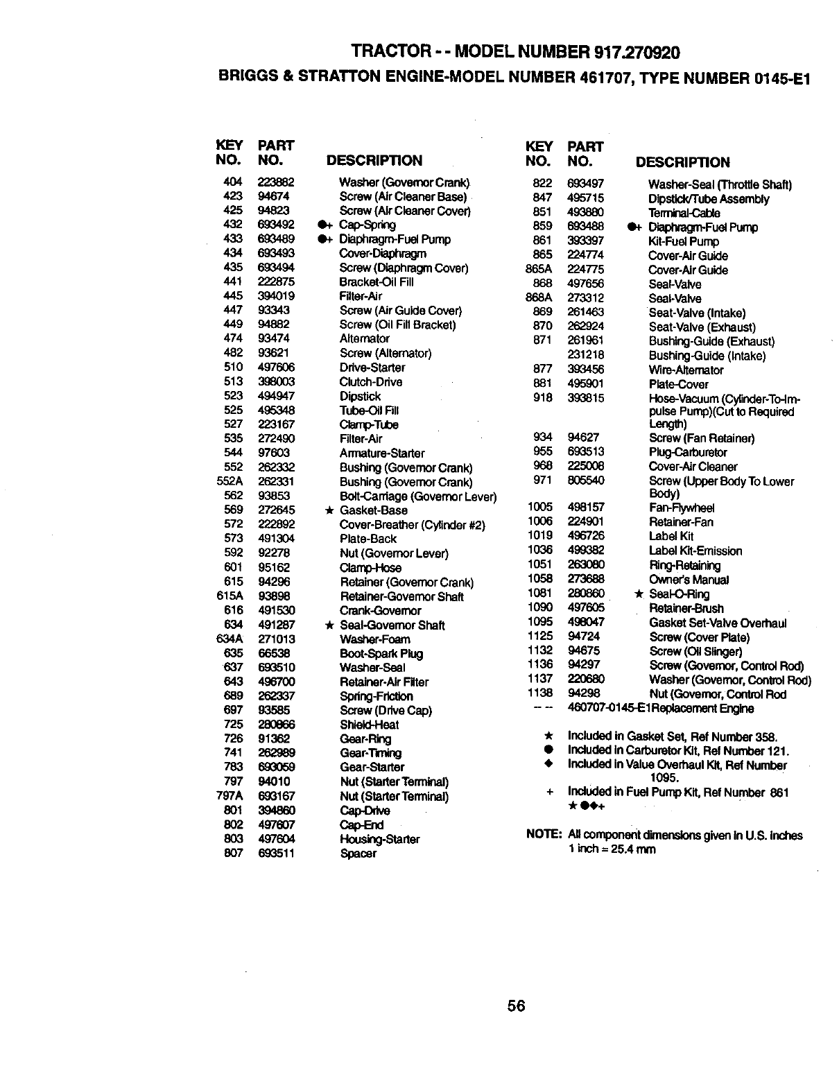
TRACTOR - -MODEL NUMBER 917.270920
BRIGGS & STRATTON ENGINE-MODEL NUMBER 461707, TYPE NUMBER0145-E1
K]EY PART KEY PART
NO. NO. DESCRIPTION NO. NO. DESCR|PTION
404 223882 Washer (GovemorCrank) 822 693497 Washer-Seal ('rhrottleShaft)
423 94674 Scraw(AirCleaner Base) 847 495715 DlpstiddTubeAssembly
425 94823 Screw (AirClaanerCover) 851 49_880 Te_
432 693492 O+ Cap-Spring 859 693488 •+ Dia_Fuel Pump
433 693489 qP_ Diaphragm-FuelPump 861 393397 Kit-FuelPump
434 693493 Cover.Diaphragm 865 224774 Cover-AirGuide
435 69_1494 Screw(DiaphragmCover) 865A 224775 Cover-Air Guide
441 222875 Bracket-OilFill 868 497656 Seal-Valve
445 394019 Filter-Air 868A 273312 Seal.Valve
447 93343 Screw (AirGuide Cover} 869 261463 Seat-Valve (Intake)
449 94882 Screw(Oil FillBracket) 870 262924 Seat-Valve (Exhaust)
474 93474 Alternator 871 261961 Bushing-Guide(Exhaust)
482 93621 Screw (Alternator) 231218 Bushing-Guide(intake)
510 497606 Ddve-Starter 877 399456 Wire-Aitamator
513 3.98003 Clutch-Drive 881 495901 Plate-Cover
523 494947 Dipstick 918 393815 Hose-Vacuum(Cylinder-ToJm-
525 495348 Tube-OitFdl pulse Pump)(Cut to Required
527 223167 Clamp-Tube Lang.)
535 272480 Filter-Air 934 94627 Screw(Fan Retainer)
544 97603 Armatare-Starter 955 693513 Plug-Carburetor
552 262"332 Bushing(GovernorCrank) 968 225008 CovepAh'Cleaner
552A 262331 Bushing(GovernorCrank) 971 806540 Screw (UpperBodyTo Lower
562 93853 Bolt-C=,rdage(GovernorLever) Body)
569 272645 * Gasket-Base 1005 498157 Fan-Flywheel
572 222892 Cover-Breather(Cytinder#2) 1006 224901 Retainer-Fan
573 491304 Plate-Back 1019 496726 LabelKit
592 92278 Nut (GovernorLever) 1036 499382 LabelKit-Emission
601 95162 Clamp-Hose 1051 _63080 Ring-Retelning
615 94296 Retainer(GovernorCrank) 1058 273688 Owner'sManual
615A 93898 Retainer-GovernorSha/t 1081 280860 * Seal-O-Ring
616 491530 Crank-Governor 1090 497605 Retainer-Brush
634 491287 _Seal-Governor Shaft 1095 496047 Gasket Bat-Valve Overhaul
634A 271013 Washer-Foam 1125 94724 Screw (Cover Plata)
635 66538 Boot-SparkPlug 1132 94675 Screw (Oil Slinger)
637 693510 Washer-Seal 1136 94297 Screw (Governor,Control Rod)
643 496700 Retainer-AirFilter 1137 220680 Washer (Governor,ControlRod)
689 262337 Spring-Friction 1138 94298 Nut(Govemor, CoetrolRod
697 93585 Scraw (DdveCap) .... 460707-0145-E1ReplacumentF__ngine
725 _Shlaid-Heat
726 91362 Gear-Ring .k Includedin Gasket Bat, Ref Number 358,
741 262989 Gear-Traing •IncludedinCad_JratorKit,Ref Number121.
783 693059 Gear-Staxter • IncludedinValueOverhaul lot, Ref Number
797 94010 Nut (StarterTerndr_) 1095.
797A 693167 Nut (StarterTerminal) +Includedin Fuel Pump Kit,RefNumber 861
"k••+
801 39486o Cap-Drive
802 497607 Cap-End NOTE: AllcomponentdimensionsgivenInU.S. inches
803 497604 Housing-Starter 1 inch=25.4rnm
807 693511 Spacer
56

57

58

SUGGESTED GUIDE FOR SIGHTING SLOPES FOR SAFE OPERATION
ONLY RIDE UP AND DOWN HILL,
NOT ACROSS HILL
ol
(D
I
Operate your Tractor up and down the face of slopes (not I
_qreaterthan 15°), never across the face. Make turns gradu- I
illy to prevent tipping or loss of control. Exercise extreme
cautlonwhen changing direction on slopes.

For in-home major brand repair service:
Call 24 hoursa day,7 days a week
1-800-4-MY-HOME s" (1-800-469-4663)
Para pedir servicio de reparaci6n a domicilio
1-800-676-5811
In Canada for all your service and parts needs call
Au Canada pour tout le service ou les pi_ces
1-800-665-4455
For the repair or replacement parts you need:
Call 6 am - 11 pm CST, 7 days aweek
PartsDirectsM
1-800-366-PART (1-800-366-7278)
Para ordenar piezas con entrega a domicilio
1-800-659-7084
For the location of a Sears Parts and Repair Center
in your area:
Call 24 hours a day, 7 days aweek
1-800-488-1222
For information on purchasing a Sears Maintenance
Agreement or to inquire about an existing Agreement:
Call 9 am -5 pm, Monday -Saturday
1-800-827-6655
8W/ S
Home CentralsM
172196 11.08.99 RH Printed in U.S,A.
