Craftsman 917271022 User Manual LAWN TRACTOR Manuals And Guides 98120017
CRAFTSMAN Lawn, Tractor Manual 98120017 CRAFTSMAN Lawn, Tractor Owner's Manual, CRAFTSMAN Lawn, Tractor installation guides
User Manual: Craftsman 917271022 917271022 CRAFTSMAN LAWN TRACTOR - Manuals and Guides View the owners manual for your CRAFTSMAN LAWN TRACTOR #917271022. Home:Lawn & Garden Parts:Craftsman Parts:Craftsman LAWN TRACTOR Manual
Open the PDF directly: View PDF ![]() .
.
Page Count: 60

Owner's Manual
rRAFTSMIIN+
15.5 HP
ELECTRIC START
42" MOWER
AUTOMATIC
LAWN TRACTOR
Model No.
917.271022
• Safety
•Assembly
•Operation
• Maintenance
• Repair Parts
CAUTION:
Read and follow all
Safety Rules and Instructions
before operating this equip-
ment.
For answers to your questions
about this product,Call:
1-800-659-5917
Sears Craftsman Help Line
5 am -5 pm, Mon- Sat
Seam, Roebuck and Co., Hoffman Estates, IL 60179
,....::.....;:; ..._- ...............2
...... ;••.o,..•••=....... _ .............. 2
Pre_!_ct SpecihcatjoR_ ..................... 5
••&E&._...... .i .=.•o .••••*••.•••••6 11
............ 18
i
Maintenance ......................................... 18
Service and Adjustments ...................... 22
Storage ................................................ 29
Troubleshooting .................................... 30
Repair Parts ......................................... 36
Parts Ordering ....................... Back Cover
YEaR 'dIAF CRAFTSMAN RIDING EQUIPMENT
he iof purchase, if this Craftsman Riding Equipment is main-
!to the instructions in the owner's manual,
any parts found to be defective in material or
This _ does n coven
=
iitems which become wom during normal use, such as blades, spark
a_ircleaners, belts_ etc;
•Tire replacement or repair caused by punctures from outside objects, such as nails,
thorns, stumps, or glass.
•Repairs necessary because of operator abuse, negligence, improper storage or acci-
dent or the failure to maintain the equipment according to the instructions contained in
the owner's manual•
•Riding equipment used for commercial or rental purposes.
LIMITED 90 DAY WARRANTY ON BATTERY
For ninety (90) days from date of purchase, if any battery included with this riding equip-
ment proves defective in material or workmanship and our testing determines the bat-
tery will not hold a charge, Sears will replace the battery at no charge• In-home warranty
service on your Craftsman riding equipment is available at no charge for 30 days from
the date of purchase. Please contact your nearest service center• After 30 days from the
date of purchase, warranty service is available by taking your Craftsman riding equip
merit to your nearest Sears Service Center• (In-home warranty service will still be avail-
able after 30 days from the date of purchase but a standard trip charge will apply)• This
warranty applies only while this product is in the United States• This Warranty gives you
specific legal rights, and you may also have other rights which may vary from state to
state•
Sears, Roebuck and Co., D/817 WA, Hoffman Estates, IL 60179
GENERALOPERATION-
•Read, understand, and follow all instruc-
tions in the manual and on the machine
before starting.
•Only allow responsible adults,-who are
familiar with the instructions, to operate
the machine•
•Clear the area of objects such as rocks,
toys, wire, etc., which could be picked
up and thrown by the blade.
• Be sure the area is clear of other people
before mowing. Stop machine if anyone
enters the area.
2
•Never carry passengers.
•Do not mow in reverse unless absolute-
ly necessary. Always look down and
behind before and while backing•
• Be aware of the mower discharge direc-
tion and do not point it at anyone. Do
not operate the mower without either
the entire grass catcher or the guard in
place•
•Slow down before turning.
• Never leave arunning machine unat-
tended. Always tum off blades, set park-
ing brake, stop engine, and remove
keys before dismounting.
•Tum off blades when not mowing.
•Stop engine before removing grass
catcher or unclogging chute.
•Mow only in daylight or good artificial
light.
•Do not operate the machine while under
the influence of alcohol or drugs.
•Watch for traffic when operating near or
crossing roadways.
•Use extra care when loading or unload-
ing the machine into atrailer or truck.
SLOPE OPERATION
Slopes are amajor factor related to loss-
of-control and tipover accidents, which
can result in severe injury or death. All
slopes require extra caution. If you cannot
back up the slope or if you feel uneasy on
it, do not mow it.
DO:
•Mow up and down slopes, not across.
•Remove obstacles such as rocks, tree
limbs, etc.
•Watch for holes, ruts, or bumps. Uneven
terrain could overturn the machine. Tall
grass can hide obstacles.
•Use slow speed. Choose a low gear so
that you will not have to stop or shift
while on the slope.
• Follow the manufacturer's recommen-
dations for wheel weights or counter-
weights to improve stability.
•Use extra care with grass catchers or
other attachments. These can change
the stability of the machine.
•Keep all movement on the slopes slow
and gradual. Do not make sudden
changes in speed or direction.
• Avoid starting or stopping on a slope. If
tires=lose traction, disengage the blades
and proceed slowly straight down the
slope. -,. ,,,
DO NOT:
•Do notturn on slopes unless necessary,
and then, turn slowly and gradually
downhill, if possible.
•Do not mow near drop-offs, ditches, or
embankments. The mower could sud-
denly turn over if a wheel is over the
edge of a cliff or ditch, or if an edge
caves in.
•Do not mow on wet grass. Reduced
traction could cause sliding.
•Do nottry to stabilize the machine by
putting your foot on the ground.
•Do notuse grass catcher on steep
slopes.
CHILDREN
Tragic accidents can occur if the operator
is not alert to the presence of children.
Children are often attracted to the
machine and the mowing activity. Never
assume that children will remain where
you last saw them.
•Keep children out of the mowing area
and under the watchful care of another
responsible adult.
•Be alert and tum machine off if children
enter the area.
•Before and when backing, look behind
and down for small children.
•Never carry children. They may fall off
and be seriously injured or interfere with
safe machine operation.
•Never allow children to operate the
machine.
•Use extra care when approaching blind
comers, shrubs, trees, or other objects
that may obscure vision.
SERVICE
•Use extra care in handling gasoline and
other fuels. They are flammable and
vapors are explosive.
Use only an approved container.
Never remove gas cap or add fuel
with the engine running. Allow en-
gine to cool before refueling. Do not
smoke.
Never refuel the machine indoors.
Never store the machine or fuel
container inside where there is an
open flame, such as a water heater.
•Never run a machine inside a closed
area.
•Keep nuts and bolts, especially blade
attachment bolts, tight and keep equip
ment in good condition.
•Never tamper with safety devices.
Check their proper operation regularly.
• Keep machine free of grass, leaves, or
other debris build-up. Clean oil or fuel
spillage. Allow machine to cool before
storing.
•Stop and inspect the equipment if you
strike an object. Repair, if necessary,
3
beforerestarting.
• Nevermakeadjustmentsor repairswith
theenginerunning.
•Grass catcher components are subject
to wear, damage, and deterioration,
which could expose moving parts or
allow objects to be thrown. Frequently
check components and replace with
manufacturer's recommended parts,
when necessary.
•Mower blades are sharp and can cut.
Wrap the blade(s) or wear gloves, and
use extra caution when servicing them.
•Check brake operation frequently.
Adjust and service as required.
•Be sure the area is clear of other people
before mowing. Stop machine if anyone
enters the area.
•Never carry passengers.
•Do not mow in reverse unless absolute-
ly necessary. Always look down and
behind before and while backing.
•Never carry children. They may fall oft
and be seriously injured or interfere with
safe machine operation.
•Keep children out of the mowing area
and under the watchful care of another
responsible adult.
•Be alert and turn machine off if children
enter the area.
•Before and when backing, look behind
and down for small children.
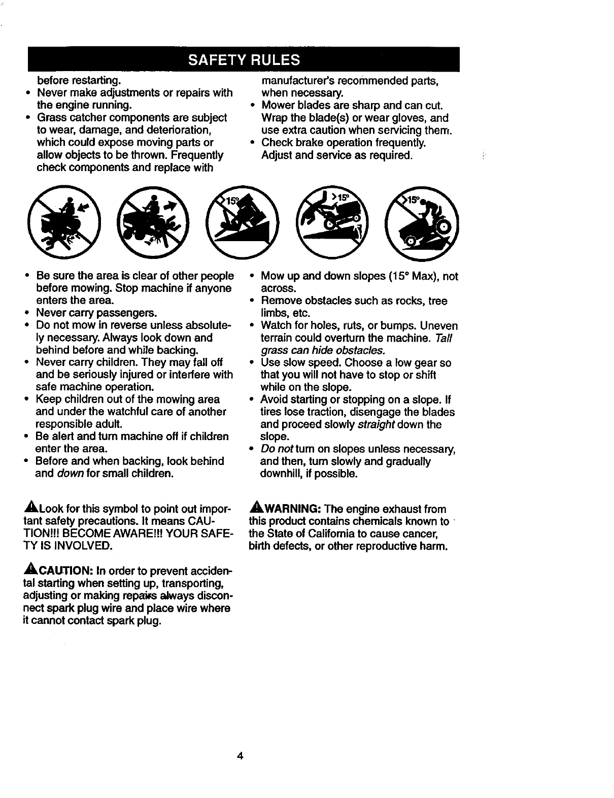
•Mow up and down slopes (15 ° Max), not
across.
•Remove obstacles such as rocks, tree
limbs, etc.
•Watch for holes, ruts, or bumps. Uneven
terrain could overtum the machine. Tall
grass can hide obstacles.
•Use slow speed. Choose a low gear so
that you will not have to stop or shift
while on the slope.
•Avoid starting or stopping on a slope. If
tires lose traction, disengage the blades
and proceed slowly straight down the
slope.
•Donottum on slopes unless necessary,
and then, tum slowly and gradually
downhill, if possible.
,_Look for this symbol to point out impor-
tant safety precautions. It means CAU-
TIONH! BECOME AWAREI!I YOUR SAFE-
TY IS INVOLVED.
ACALtTION: In order to prevent acciden-
tal starting when setting up, transporting,
adjusting or making repabs always discon-
nect spark plug wire and place wire where
it cannot contact spark plug.
AWARNING: The engine exhaust from
this product contains chemicals known to
the State of Califomia to cause cancer,
birth defects, or other reproductive harm.
4
PRODUCT SPECIFICATIONS
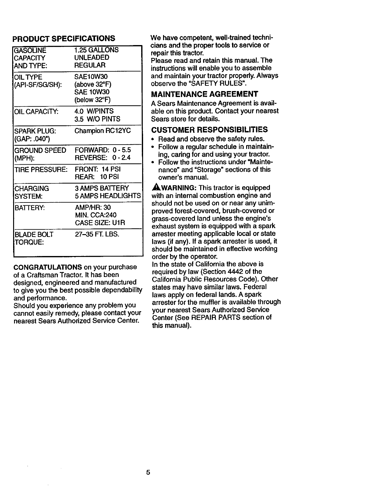
ASOLINE 1.25GALLONS
APACITY UNLEADED
NDTYPE: REGULAR
)ILTYPE SAE10W30
API-SF/SGJSH): (above 32°1=)
SAE 10W30
(below 32°F)
PlLCAPACITY: 4.0 W/PINTS
3.5 W/O PINTS
SPARK PLUG: Champion RC12YC
GAP: .040")
GROUND SPEED FORWARD: 0 - 5.5
(MPH): REVERSE: 0- 2.4
TIRE PRESSURE: FRONT: 14 PSI
REAR: 10 PSI
CHARGING 3 AMPS BATTERY
SYSTEM: 5 AMPS HEADLIGHTS
BAI-FERY: AMP/HR: 30
MIN. CCA:240
CASE SIZE: UIR
BLADE BOLT 27-35 FT. LBS.
TORQUE:
CONGRATULATIONS on your purchase
of a Craftsman Tractor. It has been
designed, engineered and manufactured
to give you the best possible dependability
and performance.
Should you experience any problem you
cannot easily remedy, please contact your
nearest Sears Authorized Service Center.
We have competent, well-trained techni-
cians and the proper tools to service or
repair this tractor.
Please read and retain this manual. The
instructions will enable you to assemble
and maintain your tractor properly. Always
observe the "SAFETY RULES'.
MAINTENANCE AGREEMENT
ASears Maintenance Agreement is avail-
able on this product. Contact your nearest
Sears store for details.
CUSTOMER RESPONSIBILITIES
•Read and observe the safety rules.
•Follow a regular schedule in maintain-
ing, caring for and using your tractor.
•Follow the instructions under =Mainte-
nance" and =Storage" sections of this
owner's manual.
A.WARNING: This tractor is equipped
with an internal combustion engine and
should not be used on or near any unim-
proved forest-covered, brush-covered or
grass-covered land unless the engine's
exhaust system is equipped with aspark
arrester meeting applicable local or state
laws (if any). If a spark arrester is used, it
should be maintained in effective working
order by the operator.
In the state of California the above is
required by law (Section 4442 of the
California Public Resources Code). Other
states may have similar laws. Federal
laws apply on federal lands. Aspark
arrester for the muffler is available through
your nearest Sears Authorized Service
Center (See REPAIR PARTS section of
this manual).
5
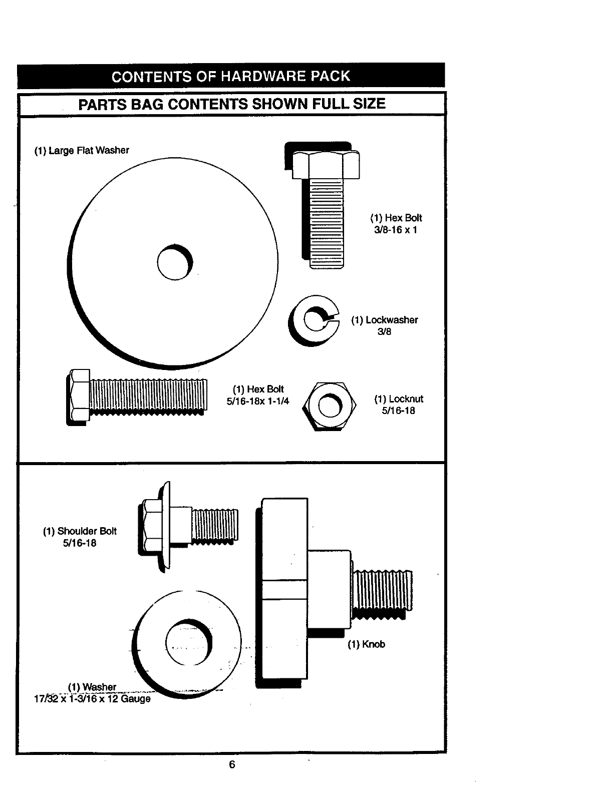
PARTS BAG CONTENTS SHOWN FULL SIZE
(1) Large Rat Washer
(1) Hex Bolt
3/8-16 x 1
(1) Lockwasher
3/8
(1) Hex Bolt
5/16-18x 1-1/4 (1) Locknut
5/16-18
(1) Shoulder Bolt
5/16-18
(1) Knob
6
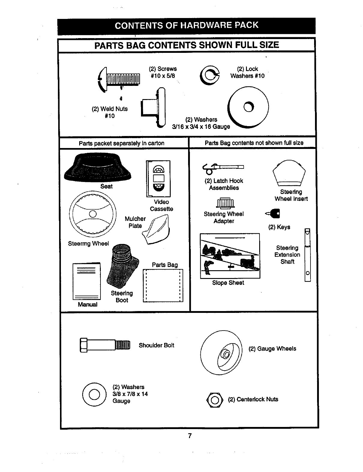
PARTS BAG CONTENTS SHOWN FULL SIZE
_(2)screws _(2)Lock
#10 x 5/8 Washers #10
(2) Weld Nuts
#10 (2) Washers
3/16 x 3/4 x 16 Gauge "_, '!
Parts packet separately in carton
Seat
Tm
r_
Parts Bag contents not shown full size
Video
, Cassette
Mulcher f/
,>,ateJ///,
, i I
Ii
Ii
iI
=Steering I ',
Boot I',
Manual
(2) Latch Hook
Assemblies Steering
._ Wheel Insert
Steedng Wheel
Adapter
Slope Sheet
I
(2) Keys
Steedng =
Extension
Shaft
_Shoulder Bolt
(_ (2) Washers
3/8 x 7/8 x 14
Gauge
I (2) Gauge Wheels
Q(2) Centedock Nuts
7
Yournewtractorhasbeenassembledat thefactorywithexcephonof thosepartsleft
unassembledfor shippingpurposes•Toensuresafeand properoperationof yourtractor
allpartsandhardwareyouassemblemustbe tightenedsecurely.Usethe correcttools
asnecessaryto insurepropertightness•Reviewthevideocassettebeforeyou begin,
TOOLS REQUIRED FOR
ASSEMBLY
Asocket wrench sdt will make assembly
easier• Standard w=(enchsizes you need
are listed below•
l) 9/16" wrench (1) 3/4" Socket w/
2) 1/2" wrench dnve rachet
1) 3/4" wrench (1) PhillipsScrew-
1) Utility knife drwer
1)Pliers (1) Tire pressure
auge
When nght or left hand =sment=oned=n
this manual, it means, from your point of
view, when you are in the operating posi-
tion (seated behind the steedng wheel).
TO REMOVE TRACTOR FROM
CARTON
UNPACK CARTON
•Remove all accessible loose parts and
parts boxes from shipping carton (See
page 6).
•Cut, from top to bottom, along lines on
all four comers of shipping carton, and
lay panels flat.
•Check for any additional loose parts or
boxes and remove.
BEFORE ROLLING TRACTOR OFF
SKID
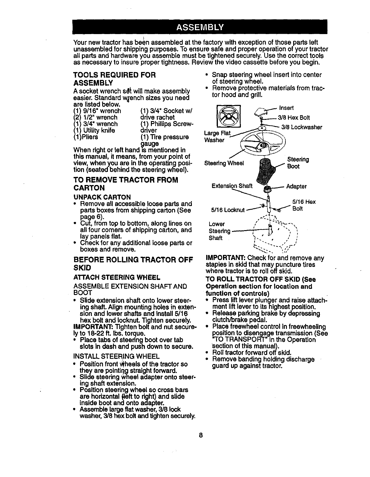
ATTACH STEERING WHEEL
ASSEMBLE EXTENSION SHAFT AND
BOOT
•Slide extension shaft onto lower steer-
ing shaft. Align mounting holes in exten-
sion and lower shafts and install 5/16
hex bolt and Iocknut. Tighten securely.
IMPORTANT: Tighten bolt and nut secure-
ly to 18-22 ft. Ibs. torque.
•Place tabs of steedng boot over tab
slots in dash and push down to secure•
INSTALL STEERING WHEEL
•Position front v_heelsof the tractor so
they are pointir_gstraightforward.
Slide steering Wheel adapter onto steer-
ing shaft extension.
Position steering wheel so cross bars
are horizontal{left to dght) and slide
inside boot and onto adapter•
Assemble largeflat washer, 3/8 lock
washer, 3/8 hex bolt and tighten securely.
•Snap steering wheel insert into center
of steering wheel.
•Remove protective materials from trac-
tor hood and grill.
_Insert
or,o
5/16 Locknut L_ Bolt
IMPORTANT: Check for and remove any
staples in skid that maypuncture tires
where tractor is to roll offskid.
TO ROLL TRACTOR OFFSKID (See
Operation section for location and
function of controls)
Press liftlever plunger and raise attach-
ment liftlever to ltshighest position.
Release parking brake by depressing
clutch/brake pedal.
Place freewheel control in freewheeling
positionto disengage transmission (See
=TOTRANSPORT" in the Operation
'sectionof this manual),
Roll tractor forward offskid.
•Remove banding holding discharge
guard up against tractor.
8
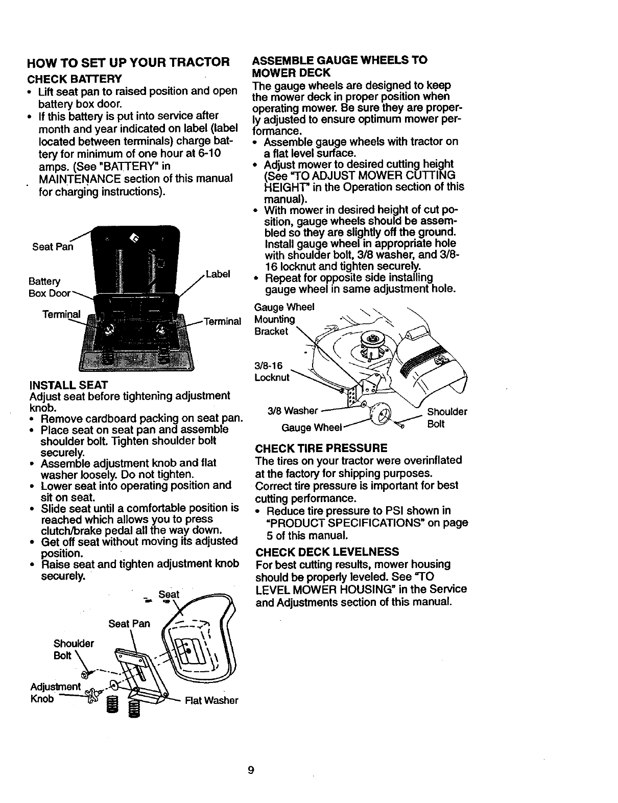
HOW TO SET UP YOUR TRACTOR
CHECK BATTERY
• Lift seat pan to raised position and open
battery box door.
•If this battery is put into service after
month and year indicated on label (label
located between terminals) charge bat-
tery for minimum of one hour at 6-10
amps. (See "BA-I-rERY" in
MAINTENANCE section of this manual
for charging instructions).
Seat Pan
Bakery
Terminal
ASSEMBLE GAUGE WHEELS TO
MOWER DECK
The gauge wheels are designed to keep
the mower deck in proper position when
operating mower. Be sure they are proper-
ly adjusted to ensure optimum mower per-
formance.
•Assemble gauge wheels with tractor on
aflat level surface.
•Adjust mower to desired cutting height
(See =TO ADJUST MOWER CUTTING
HEIGHT" in the Operation section of this
manual).
•With mower in desired height of cut po-
sition, gauge wheels should be assem-
bled so they are slightly off the ground.
Install gauge wheel in appropriate hole
with shoulder bolt, 318 washer, and 3/8-
16 Iocknut and tighten securely.
•Repeat for opposite side installing
gauge wheel in same adjustment hole.
Gauge Wheel
Moun_ng
Bracket
INSTALL SEAT
Adjust seat before tightening adjustment
knob.
•Remove cardboard packing on seat pan.
•Place seat on seat pan and assemble
shoulder bolt. 13ghten shoulder bolt
securely.
•Assemble adjustment knob and flat
washer loosely. Do not tighten.
•Lower seat into operating position and
sit on seat.
•Slide seat until a comfortable position is
reached which allows you to press
clutch/brake pedal all the way down.
•Get off seat without moving its adjusted
position.
•Raise seat and tighten adjustment knob
securely.
Seat
Seat Pan
Shoulder
BoR \
3/8-16
3/8 Washer Shoulder
Gauge Wheel Bolt
CHECK TIRE PRESSURE
The tires on your tractor were overinflated
at the factory for shipping purposes.
Correct tire pressure is important for best
cutting performance.
•Reduce tire pressure to PSI shown in
=PRODUCT SPECIFICATIONS" on page
5 of this manual.
CHECK DECK LEVELNESS
For best cutting results, mower housing
should be propedy leveled. See "TO
LEVEL MOWER HOUSING" in the Service
and Adjustments section of this manual.
Adjuslment _.,
Knob Rat Washer
9
CHECKFORPROPERPOSITIONOF
ALL BELTS
Seethefigures that are shown for replac-
ing motion and mower blade drive belts in
the Service and Adjustments sectoin of
this manual. Verify that the belts are rout-
ed correctly.
CHECK BRAKE SYSTEM
After you leam how to operate your trac-
tor, check to see that the brake is properly
adjusted. See =TO ADJUST BRAKE" in
the Service and Adjustments section of
this manual.
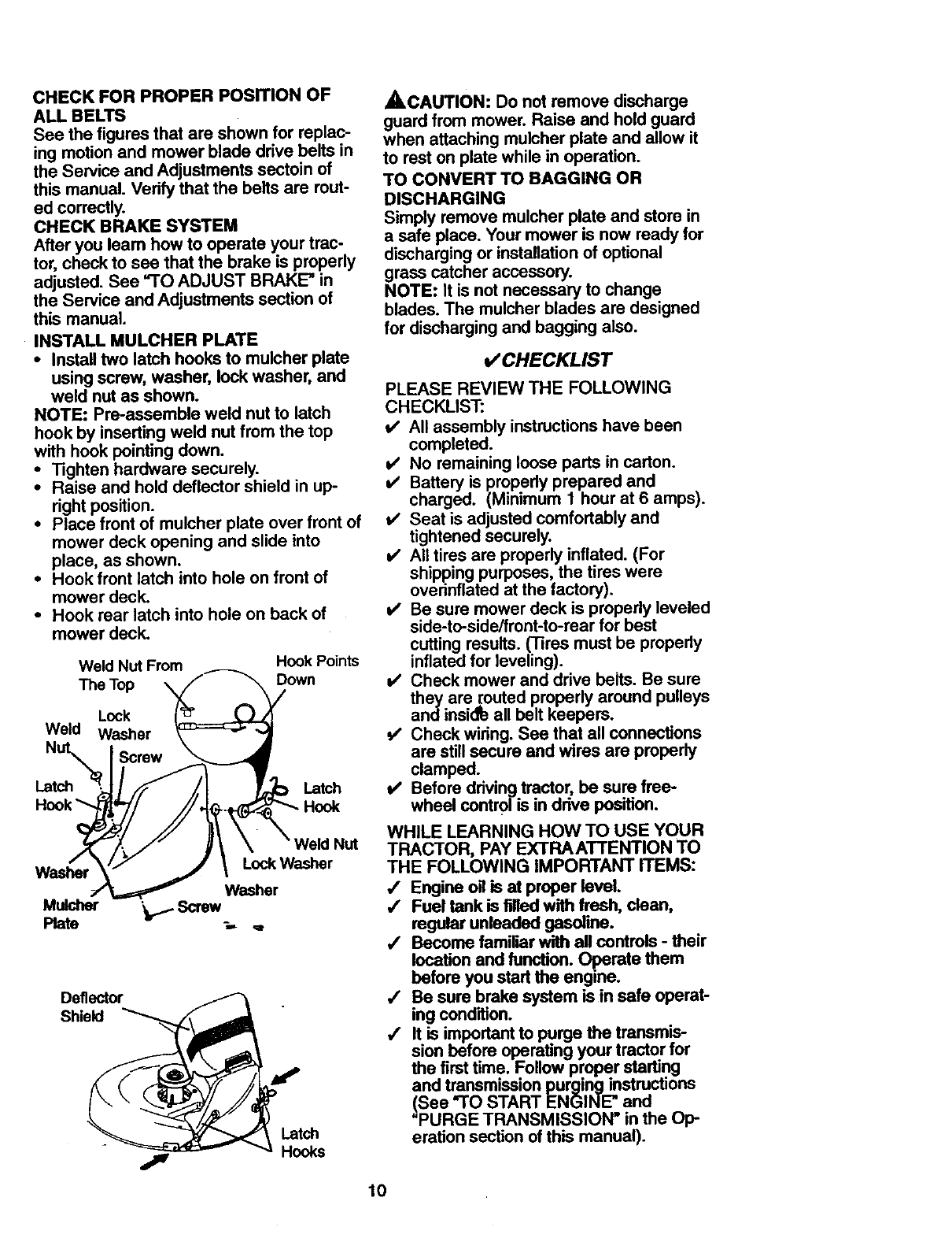
INSTALL MULCHER PLATE
• Install two latch hooks to mulcher plate
using screw, washer, lock washer, and
weld nut as shown.
NOTE: Pre-assemble weld nut to latch
hook by inserting weld nut from the top
with hook pointing down.
•Tighten hardware securely.
•Raise and hold deflector shield in up-
right position.
•Place front of mulcher plate over front of
mower deck opening and slide into
place, as shown.
•Hook front latch into hole on front of
mower deck.
•Hook rear latch into hole on back of
mower deck.
Weld Nut From Hook Points
The Top Down
Lock
Weld Washer
Latch Latch
Hook
Lock Washer
Washer Washer
Mulcher _Screw
Plate _, ._
Deflector
Shield
Latch
Hooks
A, CAUTION: Do not remove discharge
guard from mower. Raise and hold guard
when attaching mulcher plate and allow it
to rest on plate while in operation.
TO CONVERT TO RAGGING OR
DISCHARGING
Simply remove mulcher plate and store in
a safe place. Your mower is now ready for
discharging or installation of optional
grass catcher accessory.
NOTE: It is not necessary to change
blades. The mulcher blades are designed
for discharging and bagging also.
v' CHECKLIST
PLEASE REVIEW THE FOLLOWING
CHECKLIST:
V' All assembly instructions have been
completed.
v' No remaining loose parts in carton.
v' Battery is propedy prepared and
charged. (Minimum 1 hour at 6 amps).
v" Seat is adjusted comfortably and
tightened securely.
v' All tires are properly inflated. (For
shipping purposes, the tires were
ovednflated at the factory).
v' Be sure mower deck is propedy leveled
side-to-side/front-to-rear for best
cutting results. (Tires must be properly
inflated for leveling).
v' Check mower and drive belts. Be sure
they are routed properly around pulleys
andinsidre all belt keepers.
v' Check wiring. See that all connections
are still secure and wires are properly
clamped.
=/ Before driving tractor, be sure free-
wheel control is in drive position.
WHILE LEARNING HOW TO USE YOUR
TRACTOR, PAY EXTRAATTENTION TO
THE FOLLOWING IMPORTANT ITEMS:
,/ Engine oil is at proper level
,/ Fuel tank is filled with fresh, clean,
regular unleaded gasoline.
,/ Become familiar with all controls -their
location and function. Operate them
before you start the engine.
/Be sure brake system is in safe operat-
ing condition.
/It is important to purge the transmis-
sion before operating your tractor ror
the first time. Follow proper starting
and transmission purging instructions
(See =TO START ENGINE" and
"PURGE TRANSMISSION" in the Op-
eration section of this manual).
10
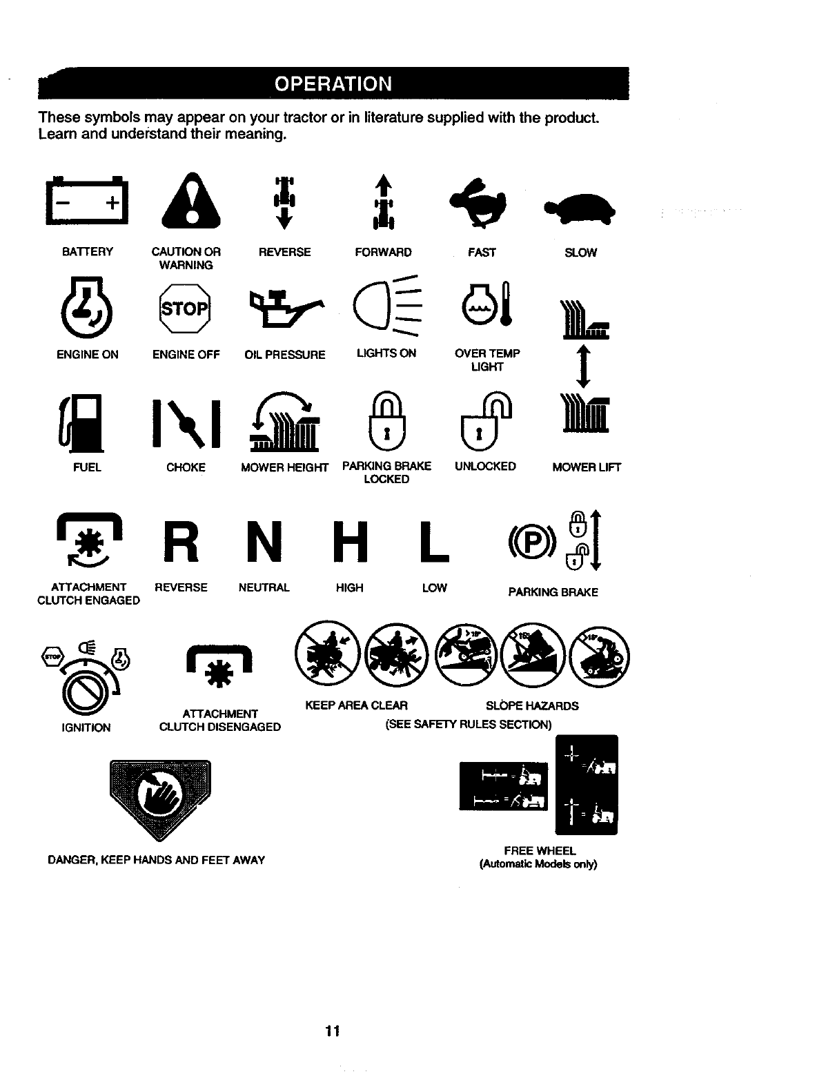
Thesesymbols may appear on your tractor or in literature supplied with the product.
Learn and understand their meaning.
BA'N'ERY CAUTION OR
WARNING
REVERSE FORWARD FAST SLOW
ENG,NEONENG,NEOFFO,'P.E_RE.GHTSO.O%_MP I
FUEL CHOKE MOWER HEIGHT PARKING BRAKE UNLOCKED MOWER LIFT
LOCKED
r 'h R N H L
ATTACHMENT REVERSE NEUTRAL HIGH LOW PARKING BRAKE
CLUTCH ENGAGED
ATTACHMENT KEEP AREA CLEAR SLOPE HAZARDS
IGNITION CLUTCH DISENGAGED (SEE SAFETY RULES SECTION)
DANGER, KEEP HANDS AND FEET AWAY FREE WHEEL
(AutomaticModelsonly)
11
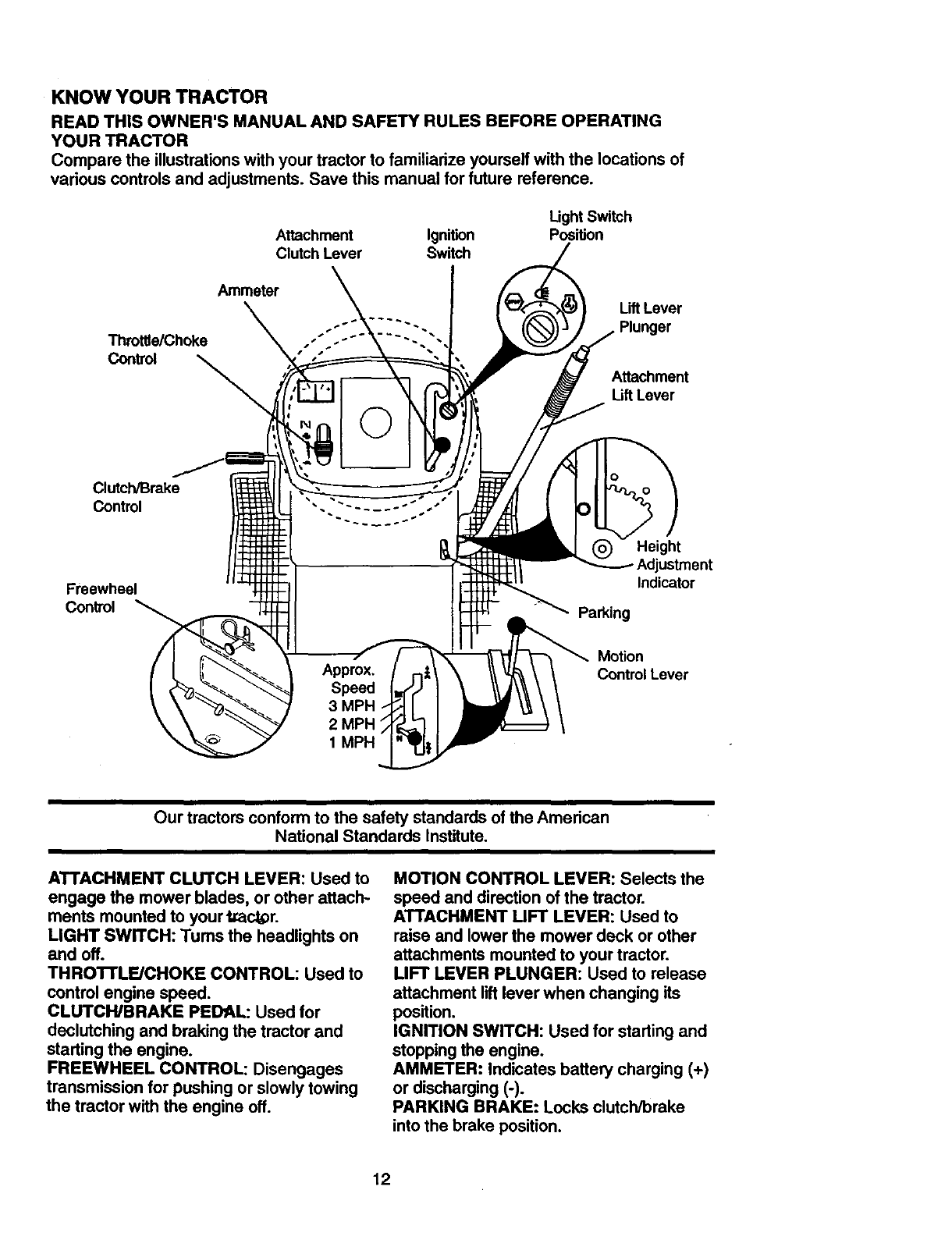
KNOW YOUR TRACTOR
READTHISOWNER'SMANUALANDSAFETYRULESBEFOREOPERATING
YOURTRACTOR
Comparethe illustrationswithyourtractorto familiarizeyourselfwiththe locationsof
variouscontrolsandadjustments.Savethis manualfor futurereference.
Attachment Ignition
Clutch Lever Switch
Light Switch
PosWon
Throttle/Choke
Control
Ammeter Lift Lever
Plunger
Attachment
Lift Lever
Clutch/Brake
Control
Freewheel
Control
Height
Adjustment
Indicator
Parking
Motion
Control Lever
1 MP_
Our tractors conform to the safety standards of the American
National Standards Institute,
ATTACHMENT CLUTCH LEVER: Used to
engage the mower blades, or other attach-
ments mounted to your tracer.
LIGHT SWITCH: Tums the headlights on
and off.
THRO'I'rLF.JCHOKE CONTROL: Used to
control engine speed.
CLUTCH/BRAKE PEDAL: Used for
declutching and braking the tractor and
starting the engine.
FREEWHEEL CONTROL: Disengages
transmission for pushing or slowly towing
the tractor with the engine off.
MOTION CONTROL LEVER: Selects the
speed and direction of the tractor.
ATTACHMENT UFT LEVER: Used to
raise and lower the mower deck or other
attachments mounted to your tractor.
LIFT LEVER PLUNGER: Used to release
attachment lift lever when changing its
position.
IGNITION SWITCH: Used for starting and
stopping the engine.
AMMETER: Indicates battery charging (+)
or discharging (-).
PARKING BRAKE: Locks clutch/brake
into the brake position.
12
_he operation of any tractor can result in foreign objects thrown into the I
eyes, which can result in severe eye damage. Always wear safety glasses i
or eye shields while operating your tractor or performing any adjustments or
repairs. We recommend a wide vision safety mask over spectacles, or stan-
dard safety ,qlasses.
HOW TO USE YOUR TRACTOR
Your tractor is equipped with an operator
presence sensing switch. When engine is
running, any attempt by the operator to
leave the seat without first setting the
parking brake will shut off the engine.
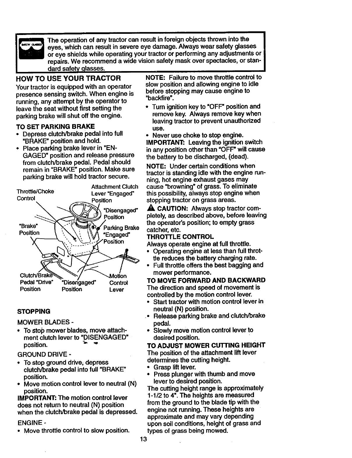
TO SET PARKING BRAKE
•Depress clutch/brake pedal into full
=BRAKE" position and hold.
•Place parking brake lever in "EN-
GAGED" position and release pressure
from clutch/brake pedal. Pedal should
remain in "BRAKE" position. Make sure
parking brake will hold tractor secure.
Attachment Clutch
Throttle/Choke Lever =Engaged"
Control Position
_"_'_ =Disengaged"
Posi on
=Brake" _r ,X,__#/Parking Brake
Position =•
_onn_._ ",,,._,, \_ "Engaged
Pedal Drive Disengaged Control
Position Position Lever
STOPPING
MOWER BLADES -
•To sto_) mower blades, move attach-
ment clutch lever to =DISENGAGED"
position. =_ "
GROUND DRIVE -
• To stop ground drive, depress
clutch/brake pedal into full =BRAKE"
position.
•Move motion control lever to neutral (N)
position.
IMPORTANT: The motion control lever
does not retum to neutral (N) position
when the clutch/brake pedal is depressed.
ENGINE -
•Move throttle control to slow position.
NOTE: Failure to move throttle control to
slow positionand allowing engine to idle
before stopping may cause engine to
=backfire".
•Tum ignition key to =OFF" position and
remove key. Always remove key when
leaving tractor to prevent unauthorized
use.
•Never use choke to stop engine.
IMPORTANT: Leaving the ignition switch
in any position other than =OFP will cause
the battery to be discharged, (dead).
NOTE: Under certain conditions when
tractor is standing idle with the engine run-
ning, hot engine exhaust gases may
cause "browning" of grass. To eliminate
this possibility, always stop engine when
stopping tractor on grass areas.
,_ CAUTION: Always stop tractor com-
pletely, as described above, before leaving
the operator's position; to empty grass
catcher, etc.
THRO'FI'LE CONTROL
Always operate engine at full throttle.
• Operating engine at less than full throt-
tle reduces the battery charging rate.
•Full throttle offers the best bagging and
mower performance.
TO MOVE FORWARD AND BACKWARD
The direction and speed of movement is
controlled by the motion control lever.
•Start tractor with motion control lever in
neutral (N) position.
•Release parking brake and clutch/brake
pedal.
• Slowly move motion control lever to
desired position.
TO ADJUST MOWER CUTTING HEIGHT
The position of the attachment lift lever
determines the cutting height.
•Grasp lift lever.
•Press plunger with thumb and move
lever to desired position.
The cutting height range is approximately
1-1/2 to 4". The heights are measured
from the ground to the blade tip with the
engine not running. These heights are
approximate and may vary depending
upon soil conditions, height of grass and
types of grass being mowed.
13
•The average lawn should be cut to
approximately 2-1/2 inches during the
cool season and to over 3 inches during
hot months. For healthier and better
looking lawns, mow often and after
moderate growth.
•For best cutting performance, grass
over 6 inches in height should be
mowed twice. Make the first cut relative-
ly high; the second to desired height.
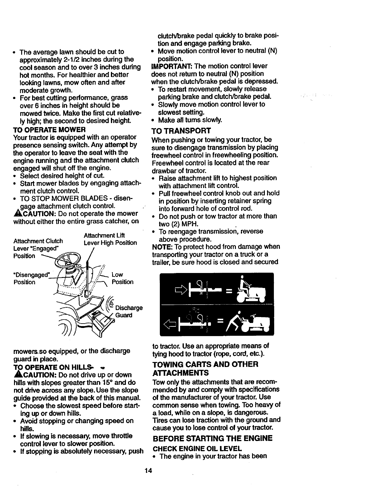
TO OPERATE MOWER
Your tractor is equipped with an operator
presence sensing switch. Any attempt by
the operator to leave the seat with the
engine running and the attachment clutch
engaged will shut off the engine.
•Select desired height of cut.
•Start mower blades by engaging attach-
ment clutch control.
•TO STOP MOWER BLADES -disen-
gage attachment clutch control.
CAUTION: Do not operate the mower
without either the entire grass catcher, on
Attachment Clutch
Lever "Engaged"
Position
Attachment Lift
Lever High Position
Low
Position Position
clutcWbreke pedal quickly to brake posi-
tion and engage parking brake.
•Move motion control lever to neutral (N)
position.
IMPORTANT: The motion control lever
does not retum to neutral (N) position
when the clutch/brake pedal is depressed.
•To restart movement, slowly release
parking brake and clutch/brake pedal.
•Slowly move motion control lever to
slowest setting.
•Make all tums slowly.
TO TRANSPORT
When pushing or towing your tractor, be
sure to disengage transmission by placing
freewheel control in freewheeling position.
Freewheel control is located at the rear
drawbar of tractor.
•Raise attachment lift to highest position
with attachment lift control.
•Pull freewheel control knob out and hold
in position by inserting retainer spring
into forward hole of control rod.
•Do not push or tow tractor at more than
two (2) MPH.
•To reengage transmission, reverse
above procedure.
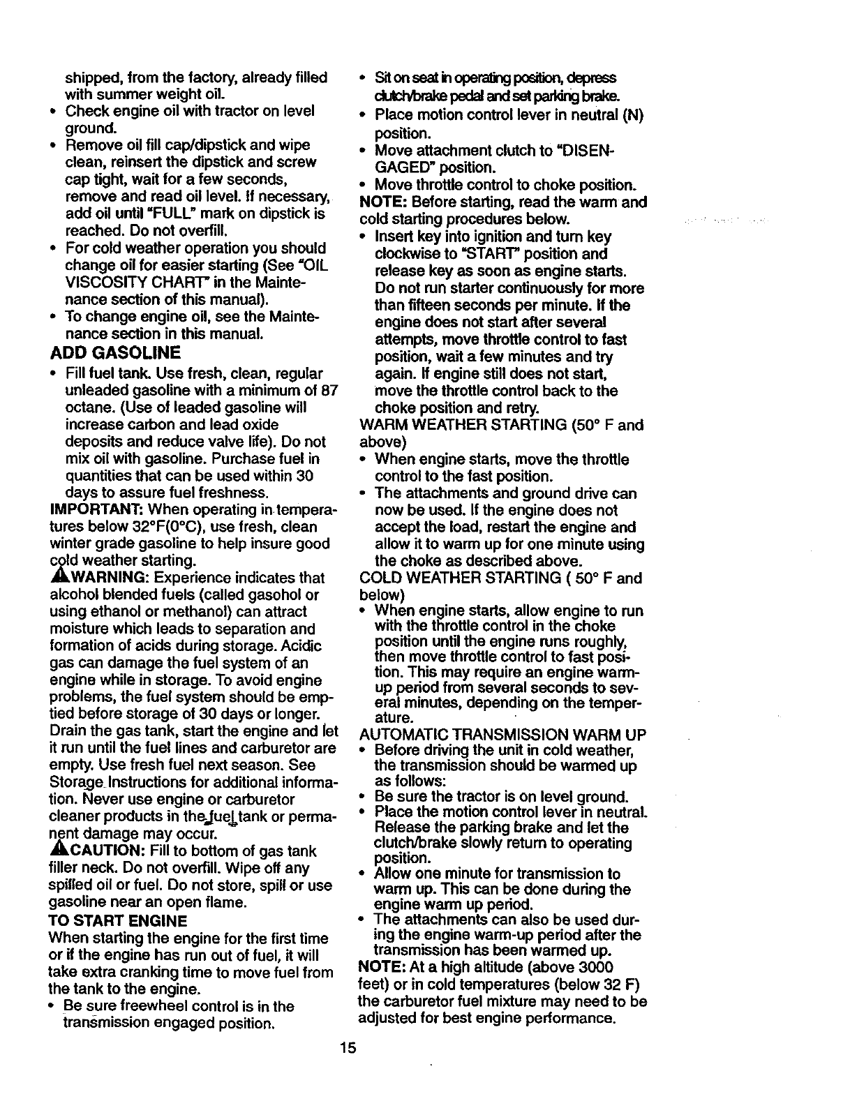
NOTE: To protect hood from damage when
transporting your tractor on a truck or a
trailer, be sure hood is closed and secured
Guard
mowemso equipped, or the discharge
guard in place.
_O OPERATE ON HILLS_ _,
CAUTION: Do not drive up or down
hillswith slopes greater than 15°and do
not drive across any slope. Use the slope
guide provided at the back of this manual.
•Choose the slowest speed before start-
ing up or down hills.
•Avoid stopping or changing speed on
hills.
•If slowing is necessary, move throttle
control lever to slower position.
•If stopping is absolutely necessary, push
to tractor.Use an appropriate means of
tying hood to tractor (rope, cord, etc.).
TOWING CARTS AND OTHER
ATTACHMENTS
Tow onlythe attachments that are recom-
mended by and comply with specifications
of the manufacturer of your tractor. Use
common sense when towing. Too heavy of
a load, while on a slope, is dangerous.
Tires can lose tractionwith the ground and
cause you to lose control of your tractor.
BEFORE STARTING THE ENGINE
CHECK ENGINE OIL LEVEL
•The engine in your tractor has been
14
shipped,fromthefactory,alreadyfilled
withsummerweightoil.
• Checkengineoil withtractoronlevel
ground.
•Remove oil fill cap/dipstick and wipe
clean, reinsert the dipstick and screw
cap tight, wait for a few seconds,
remove and read oil level. If necessary,
add oil until "FULL" mark on dipstick is
reached. Do not overfill.
•For cold weather operation you should
change oil for easier starting (See "OIL
VISCOSITY CHART" in the Mainte-
nance section of this manual).
•To change engine oil, see the Mainte-
nance section in this manual.
ADD GASOLINE
•Fill fuel tank. Use fresh, clean, regular
unleaded gasoline with a minimum of 87
octane. (Use of loaded gasoline will
increase carbon and lead oxide
deposits and reduce valve life). Do not
mix oil with gasoline. Purchase fuel in
quantities that can be used within 30
days to assure fuel freshness.
IMPORTANT: When operating in tempera-
tures below 32°F(0°C), use fresh, clean
winter grade gasoline to help insure good
,_d weather starting.
WARNING: Experience indicates that
alcohol blended fuels (called gasohol or
using ethanol or methanol) can attract
moisture which leads to separation and
formation of acids during storage. Acidic
gas can damage the fuel system of an
engine while in storage. To avoid engine
problems, the fuel system should be emp-
tied before storage of 30 days or longer.
Drain the gas tank, start the engine and let
it run until the fuel lines and carburetor are
empty. Use fresh fuel next season. See
Storage_ Instructions for additional informa-
tion. Never use engine or carburetor
cleaner products in th_jue_tank or perma-
Znct damage may occur.
AUTION: Fill to bottom of gas tank
filler neck. Do not overfill. Wipe off any
spilled oil or fuel. Do not store, spill or use
gasoline near an open flame.
TO START ENGINE
When starting the engine for the first time
or if the engine has run out of fuel, it will
take extra cranking time to move fuel from
the tank to the engine.
•Be sure freewheel control is in the
transmission engaged position.
•onseat oper= po on,dspreas
dutt brakepsd park brake.
•Place motion control lever in neutral (N)
position.
•Move attachment clutch to =DISEN-
GAGED" position.
•Move throttle control to choke position.
NOTE: Before starting, read the warm and
cold starting procedures below.
•Insert key into ignition and turn key
clockwise to "START" position and
release key as soon as engine starts.
Do not run starter continuously for more
than fifteen seconds per minute. If the
engine does not start after several
attempts, move throttle control to fast
position, wait a few minutes and try
again. If engine still does not start,
move the throttle control back to the
choke position and retry.
WARM WEATHER STARTING (50 ° F and
above)
•When engine starts, move the throttle
control to the fast position.
•The attachments and ground drive can
now be used. If the engine does not
accept the load, restart the engine and
allow it to warm up for one minute using
the choke as described above.
COLD WEATHER STARTING ( 50 ° F and
below)
•When engine starts, allow engine to run
with the throttle control in the choke
position until the engine runs roughly,
then move throttle control to fast posi-
tion. This may require an engine warm-
up period from several seconds to sev-
eral minutes, depending on the temper-
ature.
AUTOMATIC TRANSMISSION WARM UP
•Before driving the unit in cold weather,
the transmission should be warmed up
as follows:
Be sure the tractor is on level _lround.
Place the motion control lever m neutral.
Release the parking brake and let the
clutch/brake slowly retum to operating
position.
•Allow one minute for transmission to
warm up. This can be done during the
engine warm up period.
•The attachments can also be used dur-
ing the engine warm-up period after the
transmission has been warmed up.
NOTE: At a high altitude (above 3000
feet) or in cold temperatures (below 32 F)
the carburetor fuel mixture may need to be
adjusted for best engine performance.
15
See='1"OADJUST CARBURETOR" in the
Service and Adjustments section of this
manual.
_RGE TRANSMISSION
CAUTION. Never engage or disen-
gage freewheel lever while the engine is
running.
To ensure proper operation and perfor-
mance, it is recommended that the trans-
mission be purged before operating tractor
for the first time. This procedure will
remove any trapped air inside the trans-
mission which may have developed during
shipping of your tractor.
IMPORTANT: Should your transmission
require removal for service or replace-
ment, it should be purged after reinstalla-
tion before operating the tractor.
• Place tractor safely on level surface with
engine off and parking brake set.
•Disengage transmission by placing free-
wheel control in freewheeling position
(See "TO TRANSPORT" in this section
of manual).
•Sitting in the tractor seat, start engine.
After the engine is running, move throt-
tle control to slow position. With motion
control lever in neutral (N) position,
slowly disengage clutch/brake pedal.
•Move motion control lever to full forward
position and hold for five (5) seconds.
Move lever to full reverse position and
hold for five (5) seconds. Repeat this
procedure three (3) times.
NOTE: During this procedure there will be
no movement of drive wheels. The air is
being removed from hydraulic drive sys-
tem.
•Move motion control lever to neutral (N)
position. Shut off engine and set parking
brake.
•Engage transmission by placing free-
wheel control in ddving position (See
"TO TRANSPORT" in this section of
manual). _'-
•Sitting in the tractor seat, start engine.
After the engine is running, move throt-
tle control to half (1/2) speed. With
motion control lever in neutral (N)posi-
tion, slowly disengage clutch/brake
pedal.
•Slowly move motion control lever for-
ward; after the tractor moves approxi-
mately five (5) feet, slowly move motion
control lever to'reverse position. After
the tractor moves approximately five (5)
feet re_turnthe motion control lever to
the neutral (N) position. Repeat this pro-
cedure with the motion control lever
three (3) times.
•Your tractor is now purged and ready for
normal operation.
MOWING TIPS
• 13re chains cannot be used when the
mower housingis attached to tractor.
•Mower should be propedy leveled for
best mowing performance. See 9"0
LEVEL MOWER HOUSING" in the
Service and Adjustments section of this
manual.
• The left hand side of mower should be
used for trimming.
•Drivesothatcli_ are cisc_ onto
the areathathasbeencut.Have thecutarea
tothe dghtofthe tzactor.Thiswillresultina
moreeven_of d_0pingsandmorn
uniformcutting.
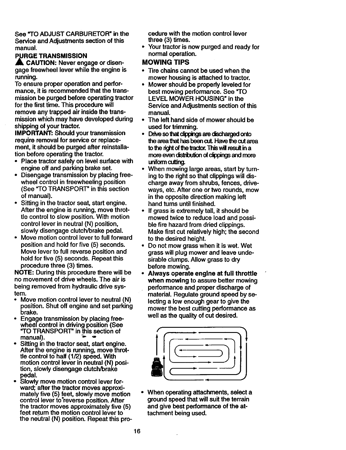
•When mowing large areas, start by turn-
ing to the dght so that clippingswill dis-
charge away from shrubs, fences, drive-
ways, etc. After one or two rounds, mow
in the opposite direction making left
hand tums untilfinished.
•If grass isextremely tall, it should be
mowed twice to reduce load and possi-
ble fire hazard from dried clippings.
Make first cut relatively high;the second
to the desired height.
•Do not mow grass when it is wet. Wet
grass will plug mower and leave unde-
sirable clumps. Allow grass to dry
before mowing.
•Always operate engine at full throttle
when mowing to assure better mowing
•performance and proper discharge of
material. Regulate ground speed by se-
lecting a low enough gear to give the
mower the best cutting performance as
well as the quality ofcut desired.
•When operating attachments, select a
ground speed that will suit the terrain
and give best performance of the at-
tachment being used.
16
MULCHING MOWING TIPS
IMPORTANT:Forbestperformance,keep
mowerhousingfree of built-upgrass and
trash. Clean after each use.
• The special mulching blade will recur
the grass clippings many times and
reduce them in size so that as they fall
onto the lawn they will disperse into the
grass and not be noticed. Also, the
mulched grass will biodegrade quickly
to provide nutrients for the lawn: Always
mulch with your highest engine (blade)
speed as this will provide the best recut-
ting action of the blades.
•Avoid cutting your lawn when it is wet.
Wet grass tends to form clumps and
interferes with the mulching action. The
best time to mow your lawn is the early
afternoon. At this time the grass has
dried and the newly cut area will not be
exposed to the direct sun.
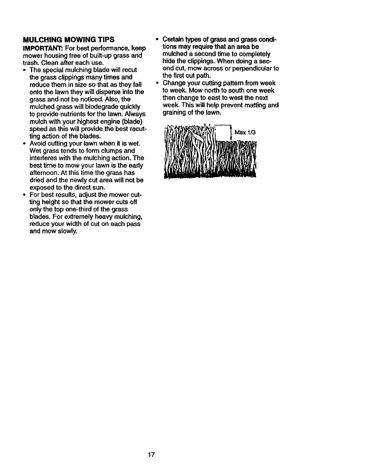
•For best results, adjust the mower cut-
ting height so that the mower cuts off
only the top one-third of the grass
blades. For extremely heavy mulching,
reduce your width of cut on each pass
and mow slowly.
•Certain types of grass and grass condi-
tions may require that an area be
mulched a second time to completely
hide the clippings. When doing a sec-
ond cut, mow across or perpendicular to
the first cut path.
•Change your cutting pattern from week
to week. Mow north to south one week
then change to east to west the next
week. This will help prevent matting and
graining of the lawn.
h r" .
17
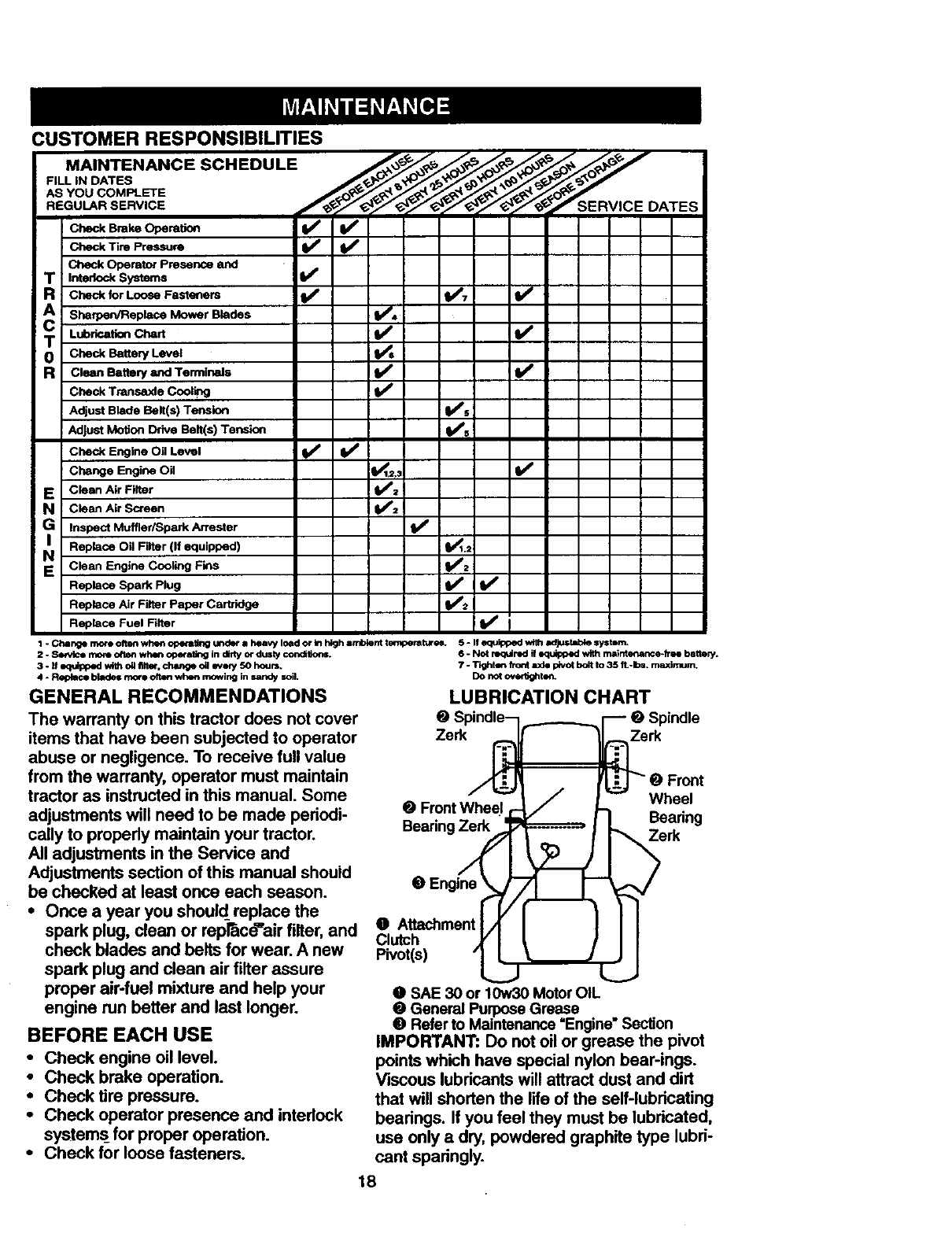
CUSTOMER RESPONSIBILITIES
MAINTENANCE SCHEDULE .___ ._< _'_ ,._ f"
FILL IN DATES
.EGo ..SE.V,CE f f f"F f SE"V'CE
Check Operator Presence and
Tint=tockSymms I/
aCheck for Loose Fasteners I_ VP7 tl_
T Lub,_st_oncha,t I/'
0 CheckBatteryLevel
Rcla=. Battery and Terminals I_
Check Transaxle Cooling If
Adjust Blade Belt(s) Tension II_s
Adjust Motion Drive Belt(s) Tension V's
Check Engine Oil Level VpI# #
Change Engi_ Oil _.: V'
E Clean Air Filter _V';
N cleanAirScreen i/
GI Inspect Muffler/Spark Arrester
Replace Oil Filter (If equipped) _.2
NClean Engine Cooling Fins t#/2
Replace Spark Plug If II_
Replace Air Filter Paper Cartridge fk_=
ReplaCe Fuel Filter V' I
1 - Change more often when operating undm" • heavy Ioed or In high an/o_nt temperatures. 5 -If equipped vK_hadJuslab_ systBm.
2. Sendce rnore often when op_-a_-_g in dlrly or dusty cormlSon=.
3 - If qu_0_ld "dlh dl lute, change dl INar/ SO houri.
4. RepUte bh_e= rllofe olten when mowing in _ndy soil.
GENERAL RECOMMENDATIONS
The warranty on this tractor does not cover
items that have been subjected to operator
abuse or negligence. To receive full value
from the warranty, operator must maintain
tractor as instructed in this manual. Some
adjustments will need to be made periodi-
cally to properly maintain your tractor.
All adjustments in the Service and
Adjustments section of this manual should
be checked at least once each season.
•Once a year you should replace the
spark plug, clean or repr&cd'airfilter, and
check blades and belts for wear. Anew
spark plug and clean air filter assure
proper air-fuel mixture and help your
engine run better and last longer.
BEFORE EACH USE
• Check engine oil level.
•Check brake operation.
• Check tire pressure.
•Check operator presence and interlock
systems for proper operation.
•Check for loose fasteners.
6 - Not required if equipped with msinte_ance-fr ee battery.
7 - Tighten front rode pivot bdt to 35 fL-Ibs, maximum,
DO not ovedJghle_.
LUBRICATION CHART
O Spindle--i,.,___..,_..__l---- O Spindle
_-"_ rw- e Front
"_/! -- Wheel
QFrontWheel _-_/_. Bearin
Beadng_ _erk g
Clutch ,YI tIII
Pivot(s) "L_j_.=__ _
O SAE 30 or 10w30 Motor OIL
•General Purpose Grease
•Refer to Maintenance "Engine"Section
IMPORTANT: Do not oil or grease the pivot
points which have special nylon bear-ings.
Viscous lubricants will attract dust and dirt
that will shorten the life of the self-lubricating
bearings. If you feel they must be lubricated,
use only a dry, powdered graphite type lubri-
cant sparingly.
18
TRACTOR
Always observe safety rules when per-
forming any maintenance.
BRAKE OPERATION
If tractor requires more than six (6) feet
stopping distance at high speed Jn highest
gear, then brake must be adjusted. (See
=TO ADJUST BRAKE" in the Service and
Adjustments section of this manual).
TIRES
• Maintain proper air pressure in all tires
(See PRODUCT SPECIFICATIONS
on page 3 of this manual).
•Keep tires free of gasoline, oil or insect
control chemicals wh ch can harm rub-
ber.
•Avoid stumps, stones, deep ruts, sharp
objects and other hazards that may
cause tire damage.
NOTE: To seal tire punctures and prevent
flat tires due to slow leaks, tire sealant
may be purchased from your local parts
dealer. nre sealant also prevents tire dry
rot and corrosion.
OPERATOR PRESENCE SYSTEM
Be sure that operator presence and inter-
lock systems are working properly. Ifyour
tractor does not function as described
below, repair the problem immediately.
•The engine should not start unless the
clutch/brake pedal is fully depressed
and attachment clutch control is in the
disengaged position.
ihen the engine is running, any
attempt by the operator to leave the
seat without first se_ing the parking
brake should shut off the engine.
When the engine is running and the
attachment clutch is engaged, any
attempt by the operator to leave the
seat shou|d shut off the engine.
The attachment clutch should never
operate unless the operator is in the
seat.
BLADE CARE
For best results mower blades must be
kept sharp. Replace be1'tt o'I'damaged
blades.
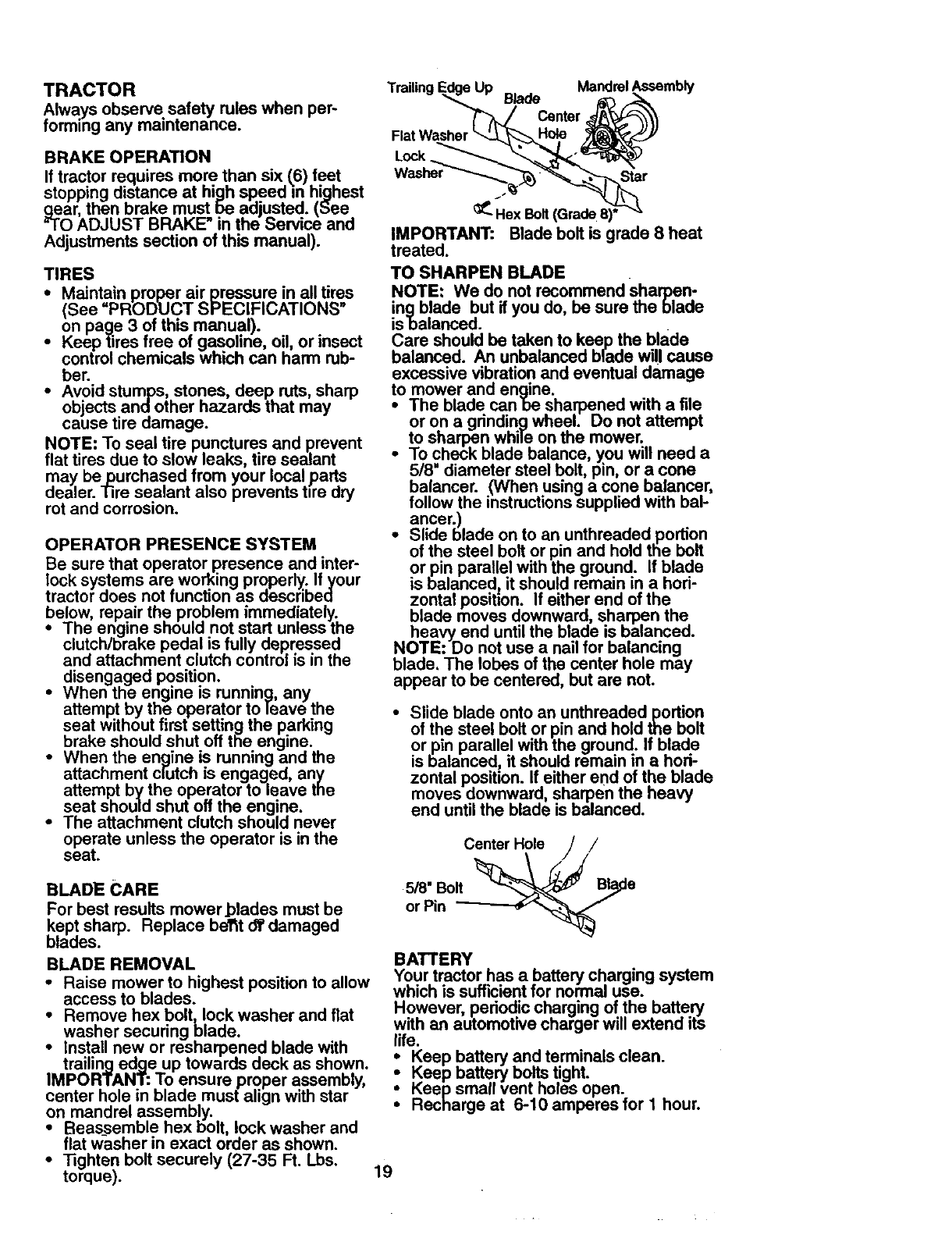
BLADE REMOVAL
•Raise mower to highest position to allow
access to blades.
•Remove hex bolt, lock washer and flat
washer securing blade.
•Install new or resharpened blade with
trailing edge up towards deck as shown.
IMPORTANT: To ensure proper assembly,
center hole in blade must align with star
on mandrel assembly.
•Beas_semble hex bolt, lock washer and
flat washer in exact order as shown.
•_ghten bolt securely (27-35 Ft. Lbs,
torque).
Trailing I
Flat
Lock
Up MandrelAssembly
Blade
Center
Star
Hex Bolt(Grade8)*
IMPORTANT: Blade bolt is grade 8 heat
treated.
TO SHARPEN BLADE
NOTE: We do not recommend sharpen-
ingblade but if you do, be sure the blade
isbalanced.
Care should be taken to keep the blade
balanced. An unbalanced blade will cause
excessive vibration and eventual damage
to mower and engine.
•The blade canbe sharpened with a file
or on agrinding wheel. Do not attempt
to sharpen while on the mower.
•To check blade balance, you will need a
5/8" diameter steel bolt, pin, or a cone
balancer. (When using a cone balancer,
follow the instructions supplied with bal-
ancer.)
•Slide blade on to an unthreaded portion
of the steel bolt or pin and hold the bolt
or pin parallel with the ground. If blade
is balanced it should remain in a hori-
zontal position. If either end of the
blade moves downward, sharpen the
heavy end until the blade is balanced.
NOTE: Do not use a nail for balancing
blade. The lobes of the center hole may
appear to be centered, but are not.
•Slide blade onto an unthreadedportion
of the steel bolt or pin and hold the bolt
or pin parallel with the ground. If blade
is balanced, it should remain in a hori-
zontal position. If either end of the blade
moves downward sharpen the heavy
end until the blaae is ba anced.
Center Hole /
5/8" Bolt
or Pin
BATTERY
Your tractor has a battery charging system
which is sufficientfor normal use.
However, periodic charging of the battery
with an automotive charger will extend its
life.
Keep battery and terminals clean.
Keep battery bolts tight.
Keep small vent holes open.
Recharge at 6-10 amperes for 1 hour.
19
TO CLEAN BATTERY AND TERMINALS
Corrosion and dirt on the battery and ter-
minals can cause the battery to "leak"
power.
• Open battery box door.
•DmconnectBLACK battery cable first
then RED battery cable and remove
battery from tractor.
•Rinse the battery with plain water and
dry.
• Clean terminals and battery cable ends
with wire brush until bdght.
• Coat terminals with grease or petroleum
jelly.
• Reinstall battery (See REPLACING
BATTERY" in the SERVICE AND
ADJUSTMENTS section of this manu-
al).
V-BELTS
Check V-belts for deterioration and wear
after 100 hours of operation and replace if
necessary. The belts are not adjustable.
Reptacebelts if they begin to shp from
wear.
TRANSAXLE COOLING
The transmission fan and cooling fins
should be kept clean to assure proper
cooling.
Do not attemp! to clean fan or transmis-
sion while engine is running or while the
transmission _s hot.
•Inspect cooling fan to be sure fan
blades are intact ano clean.
• Inspect cooling fins for dirt, grass clip-
pings and other matedals. To prevent
damage to seals, do not use com-
pressed air or high pressure sprayer to
clean cooling fins.
TRANSAXLE PUMP FLUID
The transaxle was sealed at the factory
and fluid maintenance is not required for
the lifeof the transaxle. Should the
transaxle ever leak or require servicing,
contact your nearest authorized service
center.
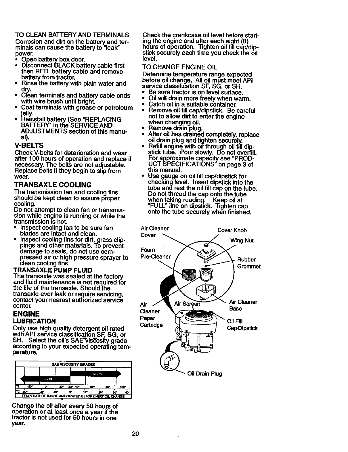
ENGINE
LUBRICATION
Only use high quality detergent oil rated
with API service classification SF, SG, or
SH. Select the oil's SAE_is_'osity grade
according to your expected operating tem-
perature.
Chan_le the oil after every 50 hours of
operation or at least once a year if the
tractor is not used for 50 hours in one
year.
20
Check the crankcase oil level before start-
ing the engine and after each ei_lht (8)
hours OToperation. Tighten oil rill cap/dip
stick securely each time you check the oil
level.
TO CHANGE ENGINE OIL
Determine temperature range expected
before oil change. All oil must meet API
service classification SF, SG, or SH.
• Be sure tractor is on level surface.
•Oil will drain more freely when warm.
Catch oil in a suitable container.
• Remove oil fill cap/dipstick. Be careful
not to allow dirt to enter the engine
when changing oil.
_• Remove drs.in plug.
After oil has drained completely, replace
oil drain plug and tighten securely.
Refill engine with o_through oil falldip-
stick tube. Pour slowly. Do not overfill.
For approximate capacity see =PROD-
UCT SPECIFICATIONS" on page 3 of
this manual.
•Use gauge on oil fill cap/dipstick for
checking level. Insert dipstick into the
tube and rest the oil fill cap on the tube.
Do not thread the cap onto the tube
when taking reading. Keep oil at
"FULL" line on dipst=ck. Tighten cap
onto the tube securely when finished.
Air Cleaner Cover Knob
Cover Wing Nut
Foam
Pre-Cleaner Rubber
Grommet
AirCleaner
Air Base
Cleaner
Paper OilFill
Cartridge Cap,Dipstick
Oil Drain Plug
CLEAN AIR SCREEN
Air screen must be kept free of dirt and
chaff to prevent engine damage from over-
heating. Clean with a wire brush or com-
pressed air to remove dirt and stubborn
dried gum fibers.
AIR FILTER
Your engine will not run properly using a
dirty air filter. Clean the foam pre-cleaner
• after every 25 hours of operation or every
season. Service paper cartridge every
100 hours of operation or every season,
whichever occurs first.
Service air cleaner more often under dusty
conditions.
•Remove knob and cover.
•Remove wing nut and air cleaner from
base.
TO SERVICE PRE-CLEANER
• Slide foam pre-cleaner off cartridge.
•Wash it in liquid detergent and water.
•Squeeze it dry in a clean cloth. Allow it
to dry.
•Saturate it in engine oil. Wrap it in
clean, absorbent cloth and squeeze to
remove excess oil
TO SERVICE CARTRIDGE
• Replace a dirty,bent, or damaged car-
tridge.
NOTE: Do not wash the paper cartridge
or use pressurized air, as this will damage
the cartridge.
• Reinstall the pre-cleaner (cleaned
and oiled) over the paper car-
tridge.
• Reassemble air cleaner, wing nut,
cover and tighten knob securely.
CLEAN AIR INTAKE/COOLING AREAS
To insure proper cooling, make sure the
grass screen, cooling fins, and other
external surfaces of th_=r,,en_neare kept
clean at all times.
Every 100 hours of operation (more often
under extremely dusty, dirty conditions),
remove the blower housing and other
cooling shrouds. Clean the cooling fins
and extemal surfaces as necessary. Make
sure the cooling shrouds are reinstalled.
NOTE: Operating the engine with a
blocked grass screen, dirty or plugged
cooling fins, and/or cooling shrouds re-
moved_will cause engine damage due to
overheating.
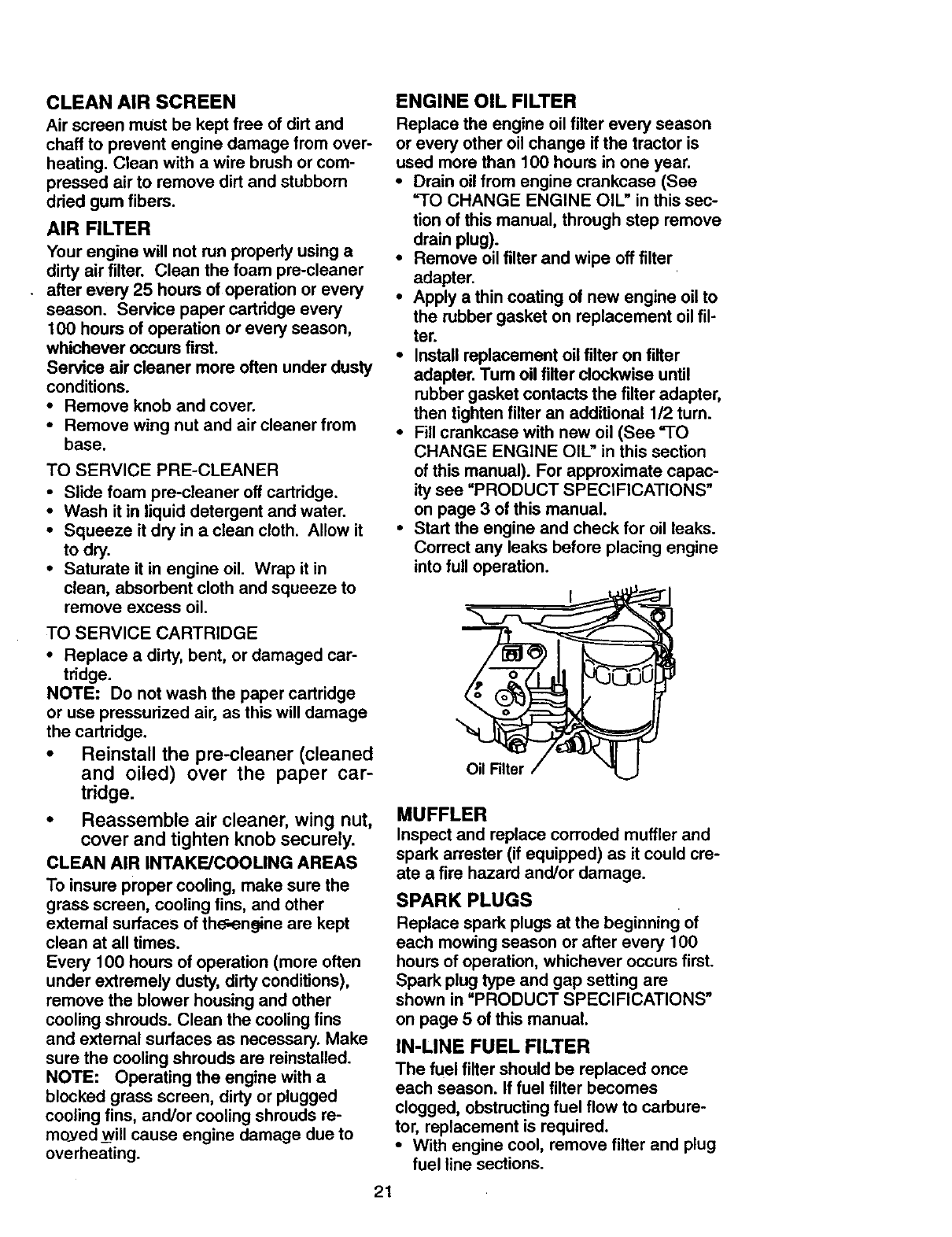
ENGINE OIL FILTER
Replace the engine oil filter every season
or every other oil change if the tractor is
used more than 100 hours in one year.
•Drain oil from engine crankcase (See
"TO CHANGE ENGINE OIL" in this sec-
tion of this manual, through step remove
drain plug).
•Remove oil filter and wipe off filter
adapter.
•Apply a thin coating of new engine oil to
the rubber gasket on replacement oil fil-
ter.
•Install replacement oil filter on filter
adapter. Tum oil filter clockwise until
rubber gasket contacts the filter adapter,
then tighten filter an additional 1/2 tum.
•Fill crankcase with new oil (See "TO
CHANGE ENGINE OIL" in this section
of this manual). For approximate capac-
ity see "PRODUCT SPECIFICATIONS"
on page 3 of this manual.
•Start the engine and check for oil leaks.
Correct any leaks before placing engine
into full operation.
MUFFLER
Inspect and replace corroded muffler and
spark arrester (if equipped) as it could cre-
ate a fire hazard and/or damage.
SPARK PLUGS
Replace spark plugs at the beginning of
each mowing season or after every 100
hours of operation, whichever occurs first.
Spark plug type and gap setting are
shown in "PRODUCT SPECIFICATIONS"
on page 5 of this manual.
IN-LINE FUEL FILTER
The fuel filter should be replaced once
each season. If fuel filter becomes
clogged, obstructing fuel flow to carbure-
tor, replacement is required.
•With engine cool, remove filter and plug
fuel line sections.
21
•Place new fuel filter in position in fuel
line with arrow pointing towards carbu-
retor.
•Be sure there are no fuel line leaks and
clam.ps are properly positioned.
CLEANING
•Clean engine, battery, seat, finish, etc.
of all foreign matter.
•Keep finished surfaces and wheels free
of all gasoline, oil, etc.
•Protect painted surfaces with automo-
tive type wax.
We do not recommend using a garden
hose to clean your tractor unless the elec-
trical system, muffler,air filter and carbure-
tor are covered to keep water out. Water
in engine can result in a shortened engine
A, CAUTION: Before performing any service or adjustments:
•Depress clutch/brake pedal fully and set parking brake.
•Place motion control lever in neutral (N) position.
• Place attachment clutch in =DISENGAGED" position.
•Tum ignition key =OFF" and remove key.
•Make sure the blades and all moving parts have completely stopped.
•Disconnect spark plug wire from spark plug and place wire where it cannot come in
contact with plug.
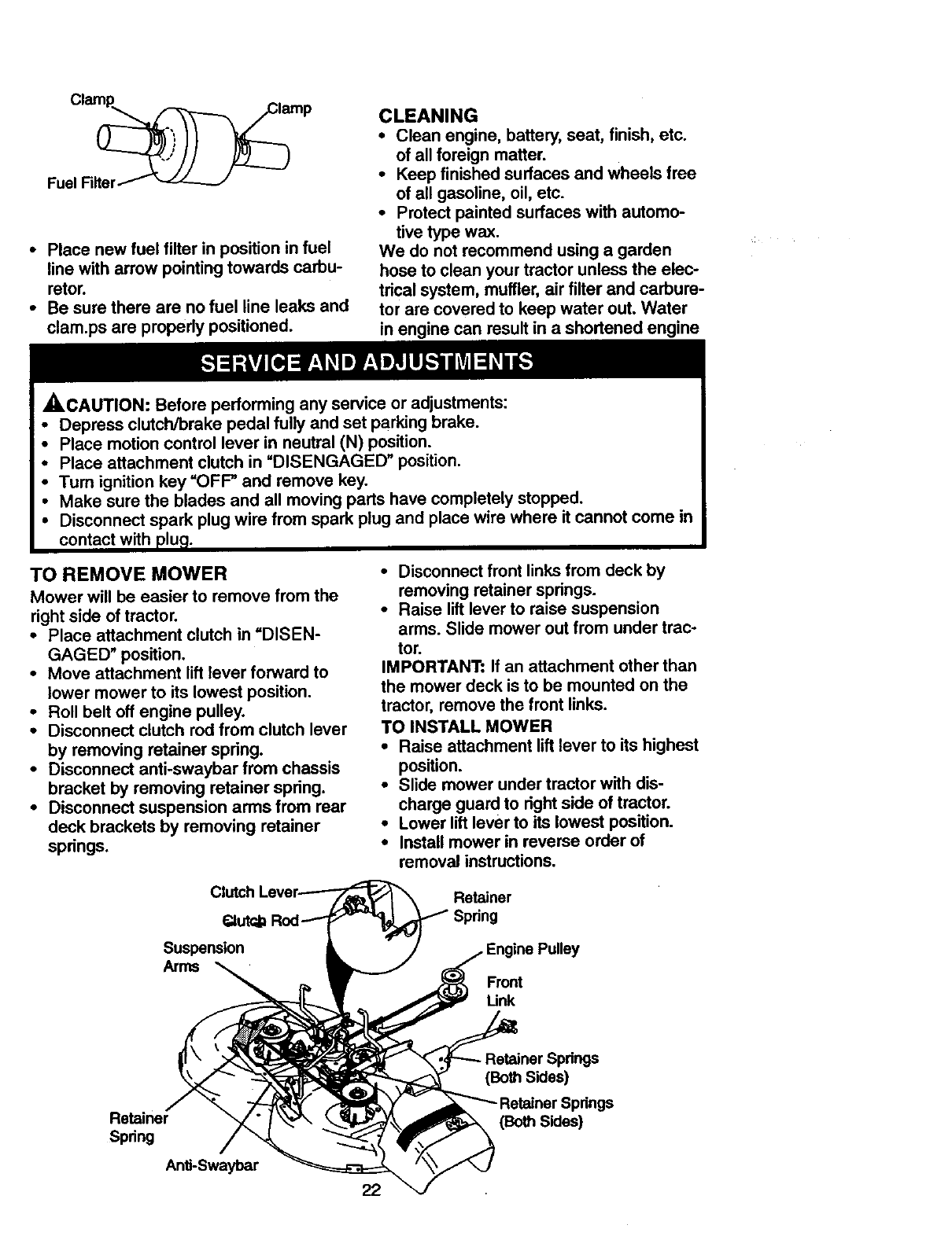
TO REMOVE MOWER
Mower will be easier to remove from the
right side of tractor.
•Place attachment clutch in =DISEN-
GAGED" position.
• Move attachment lift lever forward to
lower mower to its lowest position.
• Roll belt off engine pulley.
• Disconnect clutch rod from clutch lever
by removing retainer spring.
• Disconnect anti-swaybar from chassis
bracket by removing retainer spring.
• Disconnect suspension arms from rear
deck brackets by removing retainer
springs.
• Disconnect front links from deck by
removing retainer springs.
•Raise lift lever to raise suspension
arms. Slide mower out from under trac-
tor.
IMPORTANT: If an attachment other than
the mower deck is to be mounted on the
tractor, remove the front links.
TO INSTALL MOWER
•Raise attachment lift lever to its highest
position.
•Slide mower under tractor with dis-
charge guard to fight side of tractor.
•Lower lift lever to its lowest position.
•Install mower in reverse order of
removal instructions.
Clutch
P.Jut_
Suspension
Arms
Retainer
Spring
Front
Unk
Retainer
Spring
;prings
(Both Sides)
(Both Sides)
Anti-Swaybar
22
TO LEVELMOWERHOUSING
Adjustthe mowerwhiletractoris parked
onlevelgroundor driveway.Makesure
tiresarepropedyinflated(See"PROD-
UCT SPECIFICATIONS" on page 5 of this
manual). If tires are over or underinflated,
you will not propedy adjust your mower.
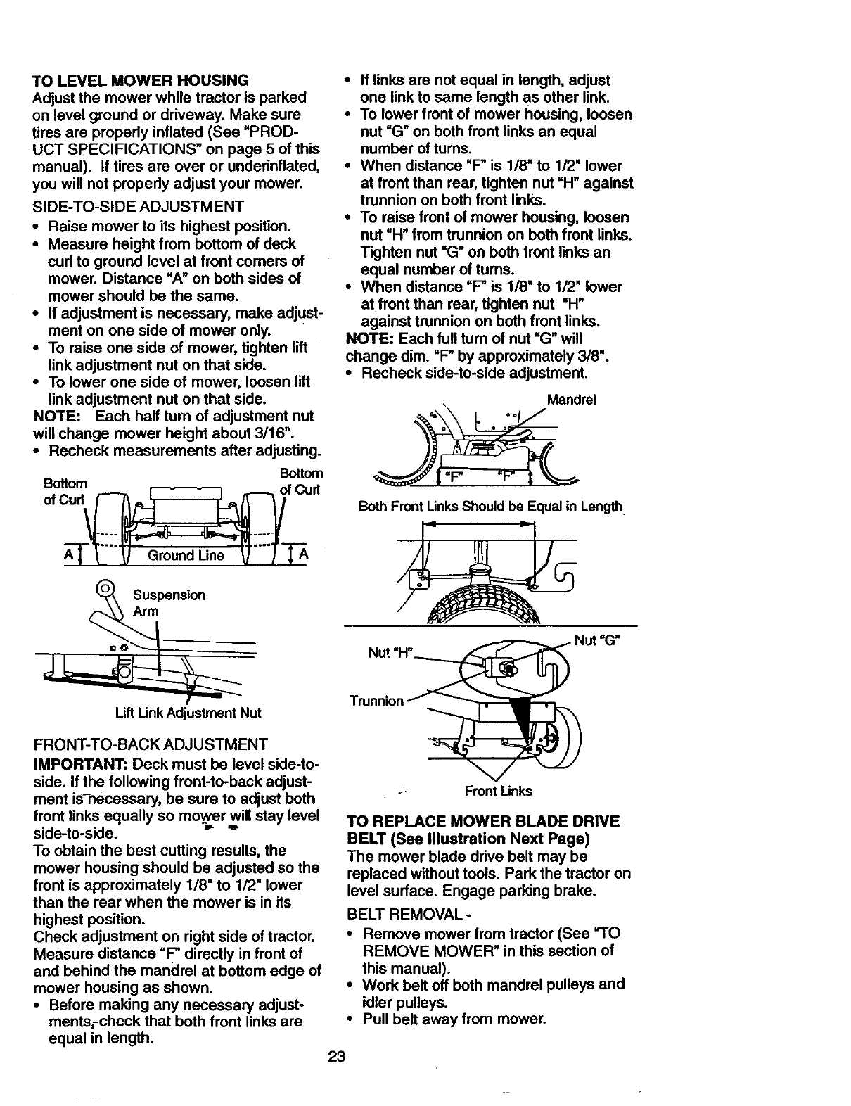
SIDE-TO-SIDE ADJUSTMENT
• Raise mower to its highest position.
• Measure height from bottom of deck
curl to ground level at front comers of
mower. Distance "A" on both sides of
mower should be the same.
• If adjustment is necessary, make adjust-
ment on one side of mower only.
• To raise one side of mower, tighten lift
link adjustment nut on that side.
• To lower one side of mower, loosen lift
link adjustment nut on that side.
NOTE: Each half turn of adjustment nut
will change mower height about 3/16".
• Recheck measurements after adjusting.
Bottom
A--]-'["-'_ Ground Line _T--_-'_
Suspenmon
_m
•If links are not equal in length, adjust
one link to same length as other link.
•To lower front of mower housing, loosen
nut "G" on both front links an equal
number of rums.
•When distance "P is 1/8" to 1/2" lower
at front than rear, tighten nut =H" against
trunnion on both front links.
•To raise front of mower housing, loosen
nut "H" from trunnion on both front links.
Tighten nut "G" on both front links an
equal number of turns.
•When distance "P is 1/8" to 1/2" lower
at front than rear, tighten nut "H"
against trunnion on both front links.
NOTE: Each full tum of nut "G" will
change dim. "P by approximately 3/8".
•Recheck side-to-side adjustment.
Mandrel
o • e
Both Front Links Should be Equal in Length
Lift Unk Adjustment Nut
FRONT-TO-BACK ADJUSTMENT
IMPORTANT: Deck must be level side-to-
side. If the following front-to-back adjust-
ment is-necessary, be sure to adjust beth
front links equally so mower will stay level
side-to-side.
To obtain the best cutting results, the
mower housing should be adjusted so the
front is approximately 1/8" to 1/2" lower
than the rear when the mower is in its
highest position.
Check adjustment on right side of tractor.
Measure distance "P directly in front of
and behind the mandrel at bottom edge of
mower housing as shown.
•Before making any necessary adjust-
mentsrcheck that both front links are
equal in length.
-' Front Links
TO REPLACE MOWER BLADE DRIVE
BELT (See lllustration Next Page)
The mower blade drive belt may be
replaced without tools. Park the tractor on
level surface. Engage parking brake.
BELT REMOVAL-
• Remove mower from tractor (See "TO
REMOVE MOWER" in this section of
this manual).
• Work belt off both mandrel pulleys and
idler pulleys.
• Pull belt away from mower.
23
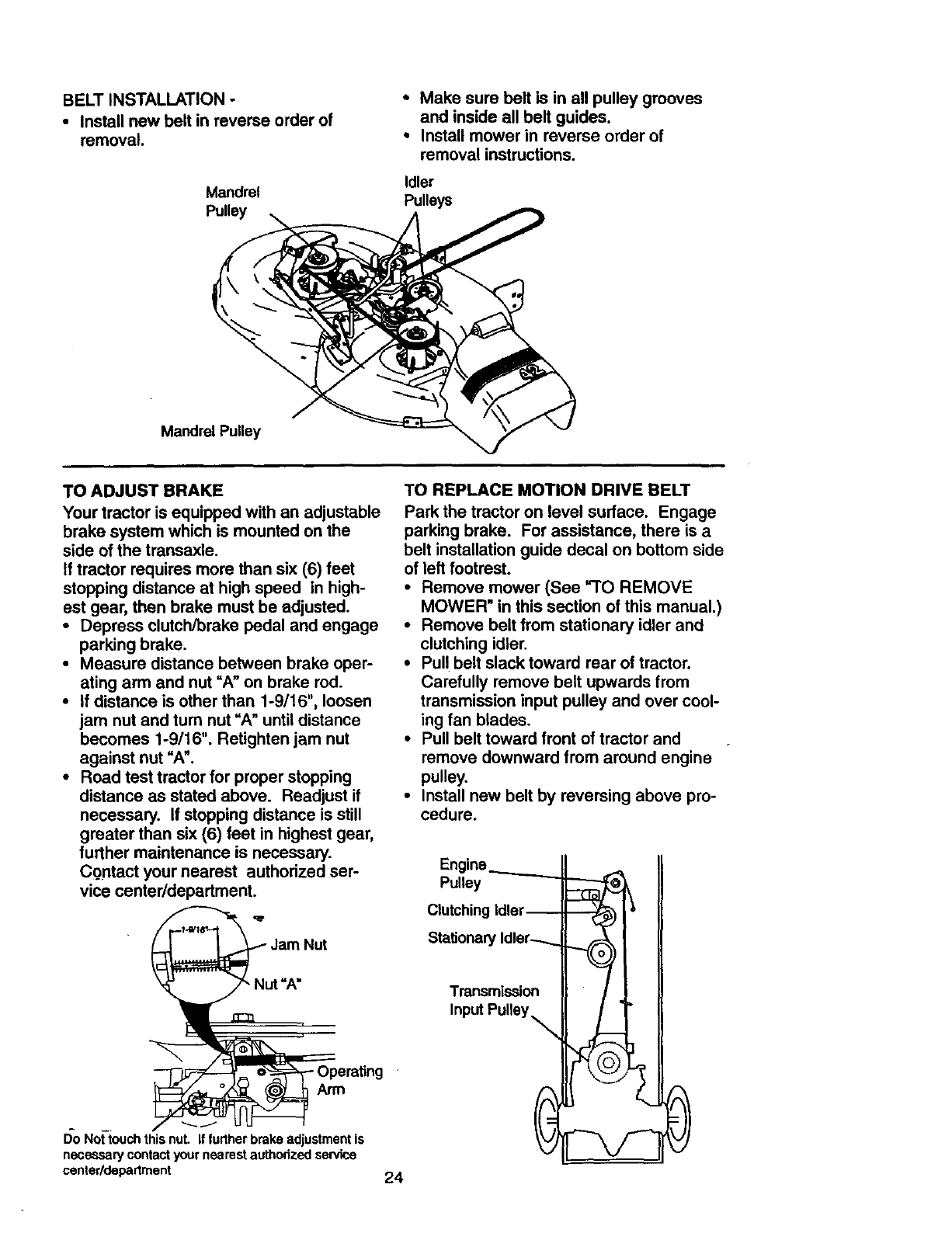
BELT INSTALLATION -
• Install new belt in reverse order of
removal.
Mandrel
Pulley
•Make sure belt is in all pulley grooves
and inside all belt guides.
•Install mower in reverse order of
removal instructions.
Idler
Pulleys
Mandrel Pulley
TO ADJUST BRAKE
Your tractor is equipped with an adjustable
brake system which is mounted on the
side of the transaxle.
If tractor requires more than six (6) feet
stopping distance at high speed in high-
est gear, then brake must be adjusted.
•Depress clutch/brake pedal and engage
parking brake.
•Measure distance between brake oper-
ating arm and nut =A" on brake rod.
•If distance is other than 1-9/16", loosen
jam nut and turn nut =A" until distance
becomes 1-9/16". Retighten jam nut
against nut =A'.
•Road test tractor for proper stopping
distance as stated above. Readjust if
necessary. If stopping distance is still
greater than six (6) feet in highest gear,
further maintenance is necessary.
Contact your nearest authorized ser-
vice center/department.
Jam Nut
I)o Not'touchthis nut. if furtherbrake adjustment is
necessary contact your nearest authodzed service
center/departrnent 24
TO REPLACE MOTION DRIVE BELT
Park the tractor on level surface. Engage
parking brake. For assistance, there is a
belt installation guide decal on bottom side
of left footrest.
•Remove mower (See =TO REMOVE
MOWER" in this section of this manual.)
•Remove belt from stationary idler and
clutching idler.
•Pull belt slack toward rear of tractor.
Carefully remove belt upwards from
transmission input pulley and over cool-
ing fan blades.
•Pull belt toward front of tractor and
remove downward from around engine
pulley.
•Install new belt by reversing above pro-
cedure.
Engine._..........__
Pulley
Clutching Idler--
Stationary Idler-.-...
Transmission
Input Pulley\
--@
,J_ /(--=_, 0
TO ADJUST MOTION CONTROL LEVER
The motion control lever has been preset
at the factory and adjustment should not
be necessary.
If for any reason the motion control lever
will not hold its position while at a selected
speed, it may be adjusted at the friction
pack located on the right side of transmis-
sion.
•Park tractor on level surface. Stop trac-
tor by turning ignition key to =OFF" posi-
tion, and engage parking brake.
•Adjust motion control lever by tightening
adjustment Iocknut one half (1/2) turn.
NOTE: If for any reason the effort to move
the motion control lever becomes too
excessive, reverse the above adjustment
procedure by loosening Iocknut 1/4 to 1/2
turn.
Road test tractor after adjustment and
repeat procedure if necessary.
TRANSMISSION REMOVAL/REPLACE-
MENT
Should your transmission require removal
for service or replacement, it should be
purged after reinstallation and before
operating the tractor. See "PURGE
TRANSMISSION" in the Operation section
of this manual.
Adjustment
Locknut
TO ADJUST STEERING WHEEL ALIGN-
MENT -
If steering wheel crossbars are not hori-
zontal (left to right) when v_dleels are posi-
tioned straight forward, remove steering
wheel and reassemble per instructions in
the Assembly section of this manual.
FRONT WHEEL TOE-IN/CAMBER
The front wheel toe-in and camber are not
adjustable on your tractor. If damage has
occurred to affect the front wheel toe-in or
camber, contact your nearest authorized
service center.
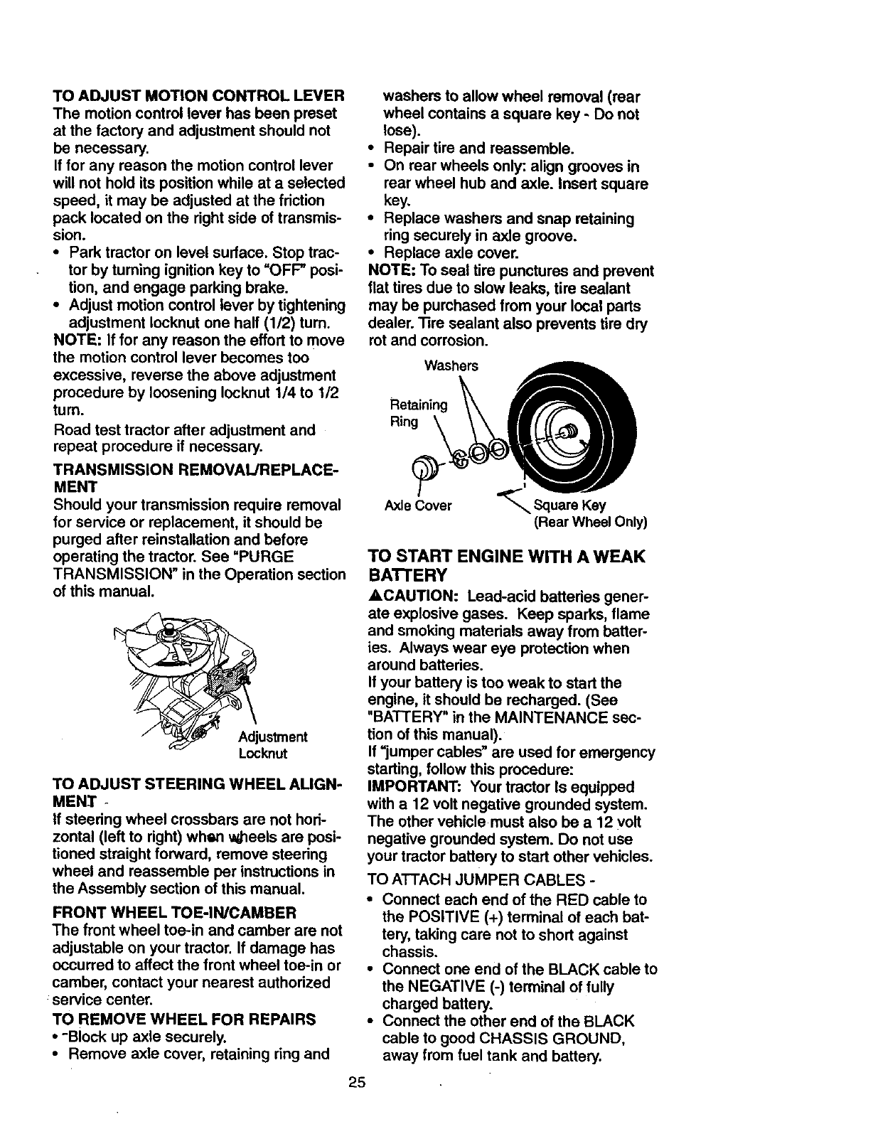
TO REMOVE WHEEL FOR REPAIRS
•-Block up axle securely.
•Remove axle cover, retaining ring and
washers to allow wheel removal (rear
wheel contains a square key - Do not
lose).
•Repair tire and reassemble.
•On rear wheels only: align grooves in
rear wheel hub and axle. Insert square
key,
•Replace washers and snap retaining
ringsecurely in axle groove.
•Replace axle cover.
NOTE: To seal tire punctures and prevent
flat tires due to slow leaks, tire sealant
may be purchased from your local parts
dealer. Tire sealant also prevents tire dry
rot and corrosion.
Washers
Retaining
Rin_r__
Axle Cover _Square Key
(Rear Wheel Only)
TO START ENGINE WITH A WEAK
BAI"FERY
ACAUTION: Lead-acid batteries gener-
ate explosive gases. Keep sparks, flame
and smoking materials away from batter-
ies. Always wear eye protection when
around batteries.
If your battery is too weak to start the
engine, it should be recharged. (See
"BATTERY" in the MAINTENANCE sec-
tion of this manual).
If =jumper cables" are used for emergency
starting, follow this procedure:
IMPORTANT: Your tractor Is equipped
with a 12 volt negative grounded system.
The other vehicle must also be a 12 volt
negative grounded system. Do not use
your tractor battery to start other vehicles.
TO ATTACH JUMPER CABLES -
• Connect each end of the RED cable to
the POSITIVE (+) terminal of each bat-
tery, taking care not to short against
chassis.
•Connect one end of the BLACK cable to
the NEGATIVE (-) terminal of fully
charged battery.
•Connect the other end of the BLACK
cable to good CHASSIS GROUND,
away from fuel tank and battery.
25
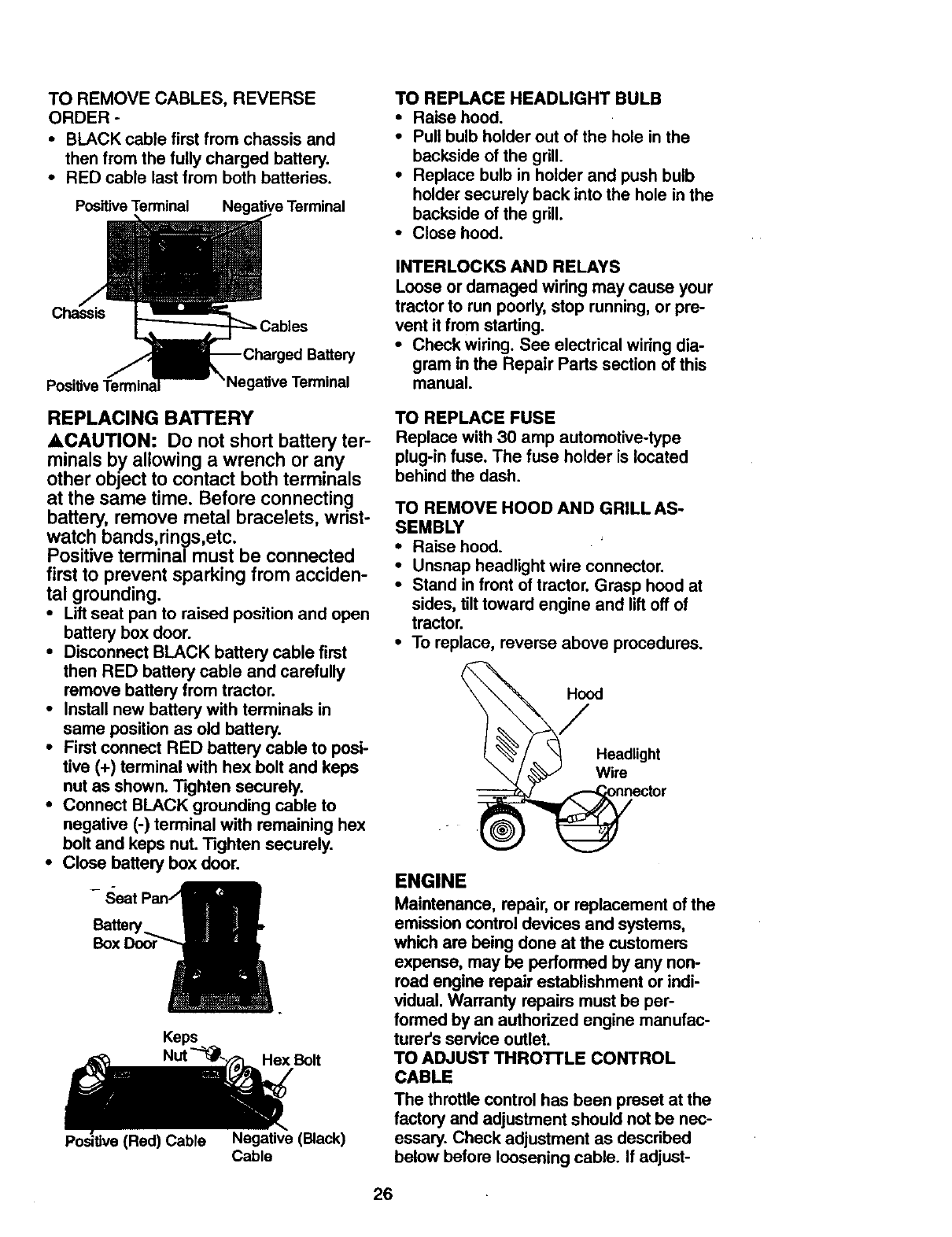
TO REMOVE CABLES, REVERSE
ORDER -
• BLACK cable first from chassis and
then from the fully charged battery.
• RED cable last from both batteries.
Positive Terminal Negative Terminal
TO REPLACE HEADLIGHT BULB
•Raise hood.
•Pull bulb holder out of the hole in the
backside of the grill.
•Replace bulb in holder and push bulb
holder securely back into the hole in the
backside of the grill.
•Close hood.
Chassis
Negative Terminal
INTERLOCKS AND RELAYS
Loose or damaged wiring may cause your
tractor to run poorly, stop running, or pre-
vent it from starting.
•Check widng. See electrical wiringdia-
gram in the Repair Parts section of this
manual.
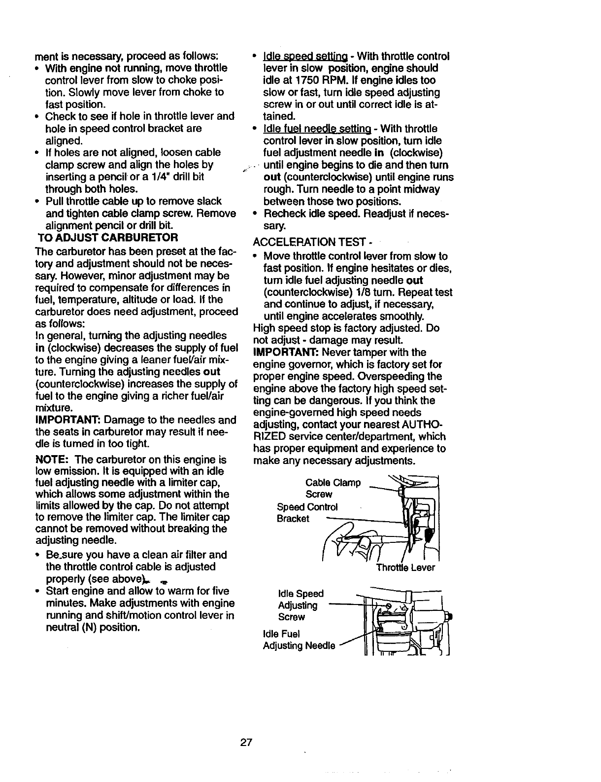
REPLACING BATTERY
ACAUTION: Do not short battery ter-
minals by allowing a wrench or any
other object to contact both terminals
at the same time. Before connecting
battery, remove metal bracelets, wrist-
watch bands,rings,etc.
Positive terminal must be connected
first to prevent sparking from acciden-
tal grounding.
•Liftseat pan to raised position and open
battery box door.
• Disconnect BLACK battery cable first
then RED battery cable and carefully
remove battery from tractor.
• Install new battery with terminals in
same position as old battery.
•First connect RED battery cable to posi-
tive (+) terminal with hex bolt and keps
nut as shown. Tighten securely.
• Connect BLACK grounding cable to
negative (-) terminal with remaining hex
bolt and keps nut. Tighten securely.
•Close battery box door.
Battery.
Keps
Hex Bolt
(Red) Cable Negative (Black)
Cable
TO REPLACE FUSE
Replace with 30 amp automotive-type
plug-in fuse. The fuse holder is located
behind the dash.
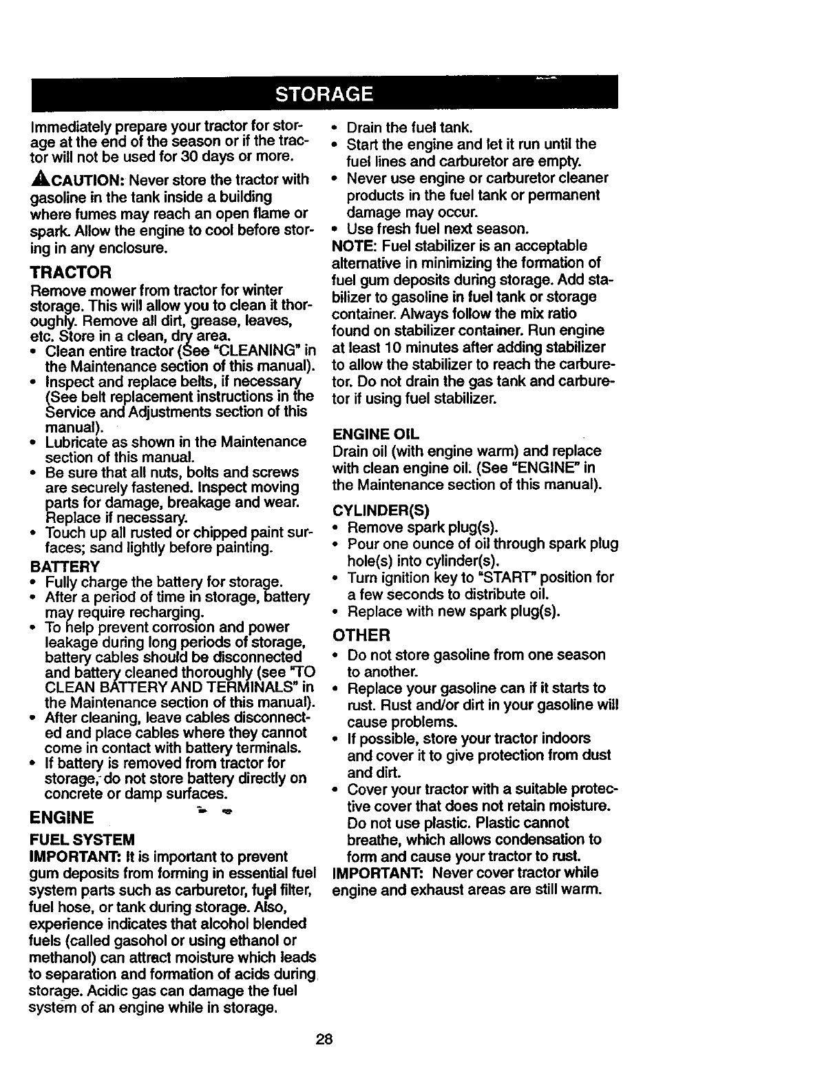
TO REMOVE HOOD AND GRILL AS-
SEMBLY
•Raise hood.
•Unsnap headlight wire connector.
•Stand in front of tractor. Grasp hood at
sides, tilt toward engine and lift off of
tractor.
•To replace, reverse above procedures.
_.'_ /_._ Headlight
•_ector
ENGINE
Maintenance, repair, or replacement of the
emission control devices and systems,
which are being done at the customers
expense, may be performed by any non-
road engine repair establishment or indi-
vidual. Warranty repairs must be per-
formed by an authorized engine manufac-
turer's service outlet.
TO ADJUST THROTTLE CONTROL
CABLE
The throttle control has been preset at the
factory and adjustment should not be nec-
essary. Check adjustment as described
below before loosening cable. If adjust-
26
meritis necessary,proceedasfollows:
• Withenginenot running,movethrottle
controlleverfromslowto chokeposi-
tion.Slowlymoveleverfromchoketo
fastposition.
•Check to see if hole in throttle lever and
hole in speed control bracket are
aligned.
•If holes are not aligned, loosen cable
clamp screw and align the holes by
inserting a pencil or a 1/4" drill bit
through both holes.
•Pull throttle cable up to remove slack
and tighten cable clamp screw. Remove
alignment pencil or drill bit.
TO ADJUST CARBURETOR
The carburetor has been preset at the fac-
tory and adjustment should not be neces-
sary. However, minor adjustment may be
required to compensate for differences in
fuel, temperature, altitude or load. If the
carburetor does need adjustment, proceed
as follows:
In general, turning the adjusting needles
in (clockwise) decreases the supply of fuel
to the engine giving a leaner fueVair mix-
ture. Turning the adjusting needles out
(counterclockwise) increases the supply of
fuel to the engine giving a richer fuel/air
mixture.
IMPORTANT: Damage to the needles and
the seats in carburetor may result if nee-
dle is turned in too tight.
NOTE: The carburetor on this engine is
low emission. It is equipped with an idle
fuel adjusting needle with a limiter cap,
which allows some adjustment within the
limits allowed by the cap. Do not attempt
to remove the limiter cap. The limiter cap
cannot be removed without breaking the
adjusting needle.
•Be_sure you have a clean air filter and
the throttle control cable is adjusted
properly (see above),, _,
•Start engine and allow to warm for five
minutes. Make adjustments with engine
running and shift/motion control lever in
neutral (N) position.
•Idle speed settino -With throttle control
lever in slow position, engine should
idle at 1750 RPM. If engine idles too
slow or fast, tum idle speed adjusting
screw in or out until correct idle is at-
tained.
• Idle fuel needle settin 9 - With throttle
control lever in slow position, turn idle
fuel adjustment needle in (clockwise)
,, • until engine begins to die and then turn
out (counterclockwise) until engine runs
rough. Turn needle to a point midway
between those two positions;
•Recheck idle speed. Readjust if neces-
sary.
ACCELERATION TEST -
°Move throttle control lever from slow to
fast position. If engine hesitates or dies,
tum idle fuel adjusting needle out
(counterclockwise) 1/8 tum. Repeat test
and continue to adjust, if necessary,
until engine accelerates smoothly.
High speed stop is factory adjusted. Do
not adjust -damage may result.
IMPORTANT: Never tamper with the
engine governor, which is factory set for
proper engine speed. Ovempeeding the
engine above the factory high speed set-
ting can be dangerous. If you think the
engine-govemed high speed needs
adjusting, contact your nearest AUTHO-
RIZED service center/department, which
has proper equipment and experience to
make any necessary adjustments.
Cable Clamp
Screw
Speed Control
Bracket
Throttle Lever
Idle Speed _-----------_l
Adj.s,ng., II
sc,ew II
Adjusting Needle / II ]_ J
27
Immediatelypreparayourtractorfor stor-
age at theendof theseasonor if thetrac-
tor will notbeusedfor 30 days or more.
,_CAUTION: Never store the tractor with
gasoline in the tank inside a building
where fumes may reach an open flame or
spark. Allow the engine to cool before stor-
ing in any enclosure.
TRACTOR
Remove mower from tractor for winter
storage. This will allow you to clean it thor-
oughly. Remove all did, grease, leaves,
etc. Store in a clean, dry area.
•Clean entire tractor (See =CLEANING" in
the Maintenance section of this manual).
•Inspect and replace belts, if necessary
(See belt replacement instructions in the
Service and Adjustments section of this
manual).
•Lubricate as shown in the Maintenance
section of this manual.
•Be sure that all nuts, bolts and screws
are securely fastened. Inspect moving
parts for damage, breakage and wear.
Replace if necessary.
•Touch up all rusted or chipped paint sur-
faces; sand lightly before painting.
BATTERY
•Fully charge the battery for storage.
After a period of time in storage, battery
may require recharging.
•To help prevent corrosion and power
leakage during long periods of storage,
battery cables should be disconnected
and battery cleaned thoroughly (see fro
CLEAN BATTERY AND TERMINALS" in
the Maintenance section of this manual).
•After cleaning, leave cables disconnect-
ed and place cables where they cannot
come in contact with battery terminals.
•If battery is removed from tractor for
storage,-do not store battery directly on
concrete or damp surfaces.
ENGINE _ "
FUEL SYSTEM
IMPORTANT: It is important to prevent
gum deposits from forming in essential fuel
system parts such as carburetor, fupl filter,
fuel hose, or tank during storage. Also,
experience indicates that alcohol blended
fuels (called gasohol or using ethanol or
methanol) can attract moisture which leads
to separation and formation of acids dudng
storage. Acidic gas can damage the fuel
system of an engine while in storage.
•Drain the fuel tank.
•Start the engine and let it run until the
fuel lines and carburetor are empty.
•Never use engine or carburetor cleaner
products in the fuel tank or permanent
damage may occur.
•Use fresh fuel next season.
NOTE: Fuel stabilizer is an acceptable
altemative in minimizing the formation of
fuel gum deposits during storage. Add sta-
bilizer to gasoline in fuel tank or storage
container. Always follow the mix ratio
found on stabilizer container. Run engine
at least 10 minutes after adding stabilizer
to allow the stabilizer to reach the carbure-
tor. Do not drain the gas tank and carbure-
tor if using fuel stabilizer.
ENGINE OIL
Drain oil (with engine warm) and replace
with clean engine oil. (See =ENGINE" in
the Maintenance section of this manual).
CYLINDER(S)
•Remove spark plug(s).
•Pour one ounce of oil through spark plug
hole(s) into cylinder(s).
•Turn ignition key to =START" position for
a few seconds to distribute oil.
•Replace with new spark plug(s).
OTHER
•Do not store gasoline from one season
to another.
•Replace your gasoline can if it starts to
rust. Rust and/or dirt in your gasoline will
cause problems.
•If possible, store your tractor indoors
and cover it to give protection from dust
and dirt.
•Cover your tractor with a suitable protec-
tive cover that does not retain moisture.
Do not use plastic. Plastic cannot
breathe, which allows condensation to
form and cause your tractor to rust.
IMPORTANT: Never cover tractor while
engine and exhaust areas are still warm.
28
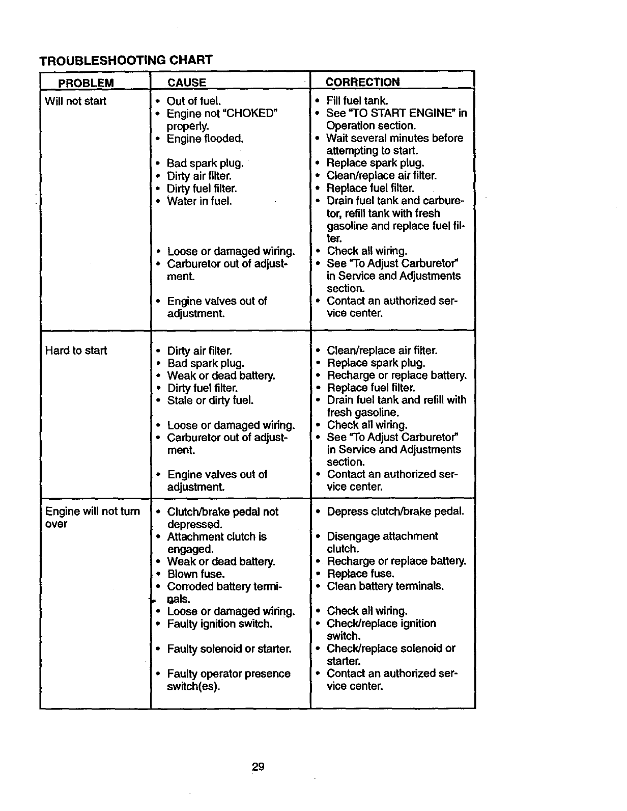
ROUBLESHOOTING CHART
PROBLEM CAUSE CORRECTION
Will not start
Hard to start
Engine will not turn
over
•Out of fuel, I °
•Engine not "CHOKED" •
properly.
• Engine flooded. =•
•Bad spark plug. •
•Dirty air filter. •
•Dirty fuel filter. •
•Water in fuel. •
• Loose or damaged wiring. •
• Carburetor out of adjust- •
ment.
• Engine valves out of •
adjustment.
•Dirty air filter. •
• Bad spark plug.
• Weak or dead battery. •
•Dirty fuel filter. •
•Stale or dirty fuel. •
•Loose or damaged wiring. •
•Carburetor out of adjust- •
ment.
•Engine valves out of •
adjustment.
•Clutch/brake pedal not
depressed.
•Attachment clutch is
engaged.
•Weak or dead battery.
•Blown fuse.
•Corroded battery termi-
.I_als.
•Loose or damaged wiring.
•Faulty ignition switch.
•Faulty solenoid or starter.
• Faulty operator presence
swltch(es).
Fill fuel tank.
See "TO START ENGINE" in
Operation section.
Wait several minutes before
attempting to start.
Replace spark plug,
Clean/replace air filter.
Replace fuel filter.
Drain fuel tank and carbure-
tor, refill tank with fresh
gasoline and replace fuel fil-
ter.
Check all wiring.
See "To Adjust Carburetor"
in Service and Adjustments
section.
Contact an authorized ser-
vice center,
Clean/replace air filter.
Replace spark plug.
Recharge or replace battery.
Replace fuel filter.
Drain fuel tank and refill with
fresh gasoline.
Check all wiring.
See "To Adjust Carburetor"
in Service and Adjustments
section.
Contact an authorized ser-
vice center.
•Depress clutch/brake pedal.
•Disengage attachment
clutch.
• Recharge or replace battery.
•Replace fuse.
•Clean battery terminals.
•Check all wiring.
•Check/replace ignition
switch.
•Check/replace solenoid or
starter.
•Contact an authorized ser-
vice center.
29
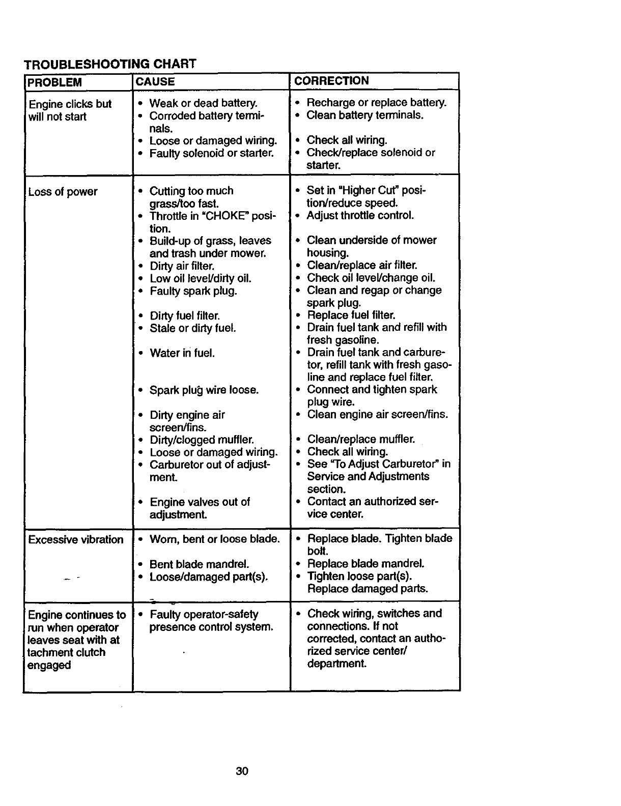
TROUBLESHOOTING CHART
CAUSEPROBLEM
Engine clicks but
will not start
Loss ofpower
Excessive vibration •
Engine continues to •
run when operator
leaves seat with at
tachment clutch
engaged
•Weak or dead battery.
•Corroded battery termi-
nals.
•Loose or damaged wiring.
•Faulty solenoid or starter.
•Cutting too much
grass/too fast.
•Throttle in =CHOKE" posi-
tion.
•Build-up of grass, leaves
and trash under mower.
•Dirty air filter.
•Low oil level/dirty oil.
• Faulty spark plug.
•Dirty fuel filter.
•Stale or dirty fuel.
Water infuel.
•Spark plu_] wire loose.
•Dirty engine air
screen/fins.
•Dirty/clogged muffler.
•Loose or damaged wiring.
•Carburetor out of adjust-
ment.
Engine valves out of
adjustment.
Worn, bent or loose blade.
Bent blade mandrel.
Loose/damaged part(s).
Faulty operator-safety
presence control system.
ICORRECTION
• Recharge or replace battery.
• Clean battery terminals.
• Check all wiring.
• Check/replace solenoid or
starter.
•Set in =Higher Cut" posi-
tion/reduce speed.
•Adjust throttle control.
•Clean underside of mower
housing.
•Clean/replace air filter.
•Check oil level/change oil.
•Clean and regap or change
spark plug.
•Replace fuel filter.
•Drain fuel tank and refill with
fresh gasoline.
•Drain fuel tank and carbure-
tor, refill tank with fresh gaso-
line and replace fuel filter.
•Connect and tighten spark
plug wire.
•Clean engine air screen/fins.
•Clean/replace muffler.
•Check all wiring.
•See =1-oAdjust Carburetor" in
Service and Adjustments
section.
•Contact an authorized ser-
vice center.
•Replace blade. Tighten blade
bolt.
•Replace blade mandrel.
• Tighten loose part(s).
Replace damaged parts.
•Check wiring, switches and
connections. If not
corrected, contact an autho-
rized service center/
department.
3O
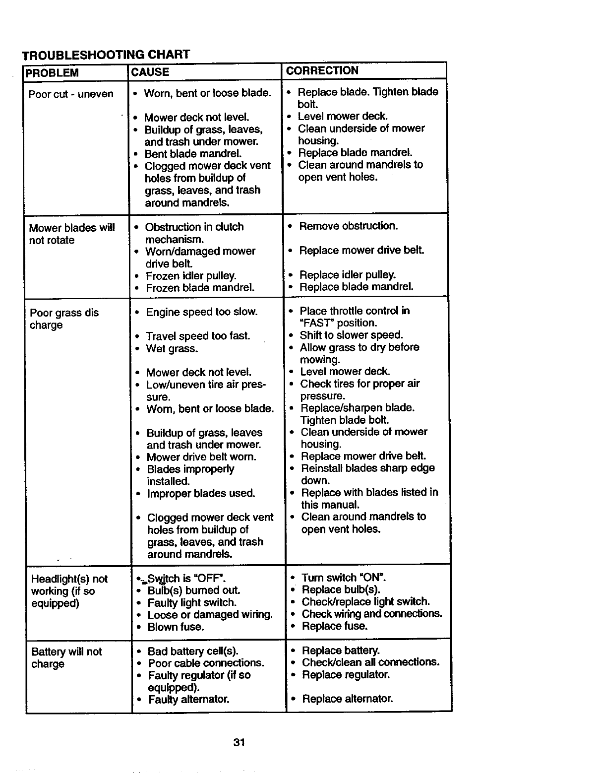
TROUBLESHOOTING CHART
PROBLEM CAUSE CORRECTION
Poorcut-uneven
_owerbladeswill
n_ mt_e
Poorgrass dis
charge
Headlight(s) not
working (if so
equipped)
Battery will not
charge
•Wom, bent or loose blade.
•Mower deck not level.
•Buildup of grass, leaves,
and trash under mower.
•Bent blade mandrel.
• Clogged mower deck vent
holes from buildup of
grass, leaves, and trash
around mandrels.
•Obstruction in clutch
mechanism.
• Worn/damaged mower
drive belt.
•Frozen idler pulley.
•Frozen blade mandrel.
•Engine speed too slow.
•Travel speed too fast.
•Wet grass.
•Mower deck not level.
•Low/uneven tire air pres-
sure.
•Worn, bent or loose blade.
•Buildup of grass, leaves
and trash under mower.
• Mower drive belt worn.
•Blades improperly
installed.
•Improper blades used.
•Clogged mower deck vent
holes from buildup of
grass, leaves, and trash
around mandrels.
%,Sv_tch is "OFP.
•Bulb(s) bumed out.
•Faulty light switch.
•Loose or damaged wiring.
•Blown fuse.
•Bad battery cell(s).
• Poor cable connections.
•Faulty regulator (if so
equipped).
•Faulty allemator.
• Replace blade. Tighten blade
boll.
•Level mower deck.
•Clean underside of mower
housing.
i _ Replace blade mandrel.
Clean around mandrels to
open vent holes.
•Remove obstruction.
• Replace mower drive belt.
•Replace idler pulley.
•Replace blade mandrel.
• Place throttle control in
"FAST" position.
• Shift to slower speed.
•Allow grass to dry before
mowing.
•Level mower deck.
•Check tires for proper air
pressure.
•Replace/sharpen blade.
Tighten blade bolt.
•Clean underside of mower
housing.
•Replace mower drive belt.
•Reinstall blades sharp edge
down.
•Replace with blades listed in
this manual,
•Clean around mandrels to
open vent holes.
• Tum switch "ON'.
•Replace bulb(s).
• Check/replace light switch.
•Check wiring and connections.
•Replace fuse.
•Replace battery.
•Check/clean all connections.
•Replace regulator.
• Replace allemator.
31
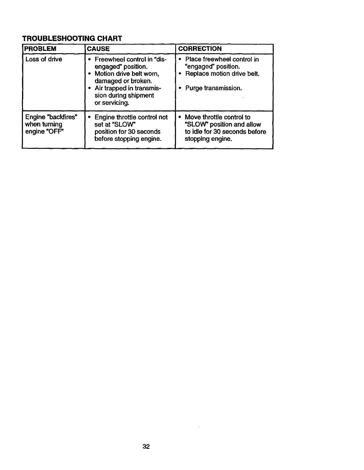
TROUBLESHOOTING CHART
PROBLEM CAUSE
_ _d_e
L
Engine =backfires"
when turning
engine =OFF"
•Freewheel control in =dis-
engaged" position.
•Motion drive belt worn,
damaged or broken.
•Air trapped in transmis-
sion during shipment
or servicing.
• Engine throttle control not
set at "SLOW _
position for 30 seconds
before stopping engine.
CORRECTION
•Place freewheel control in
"engaged" position.
•Replace motion drive belt.
• Purge transmission.
•Move throttle control to
"SLOW" position and allow
to idle for 30 seconds before
stopping engine.
32
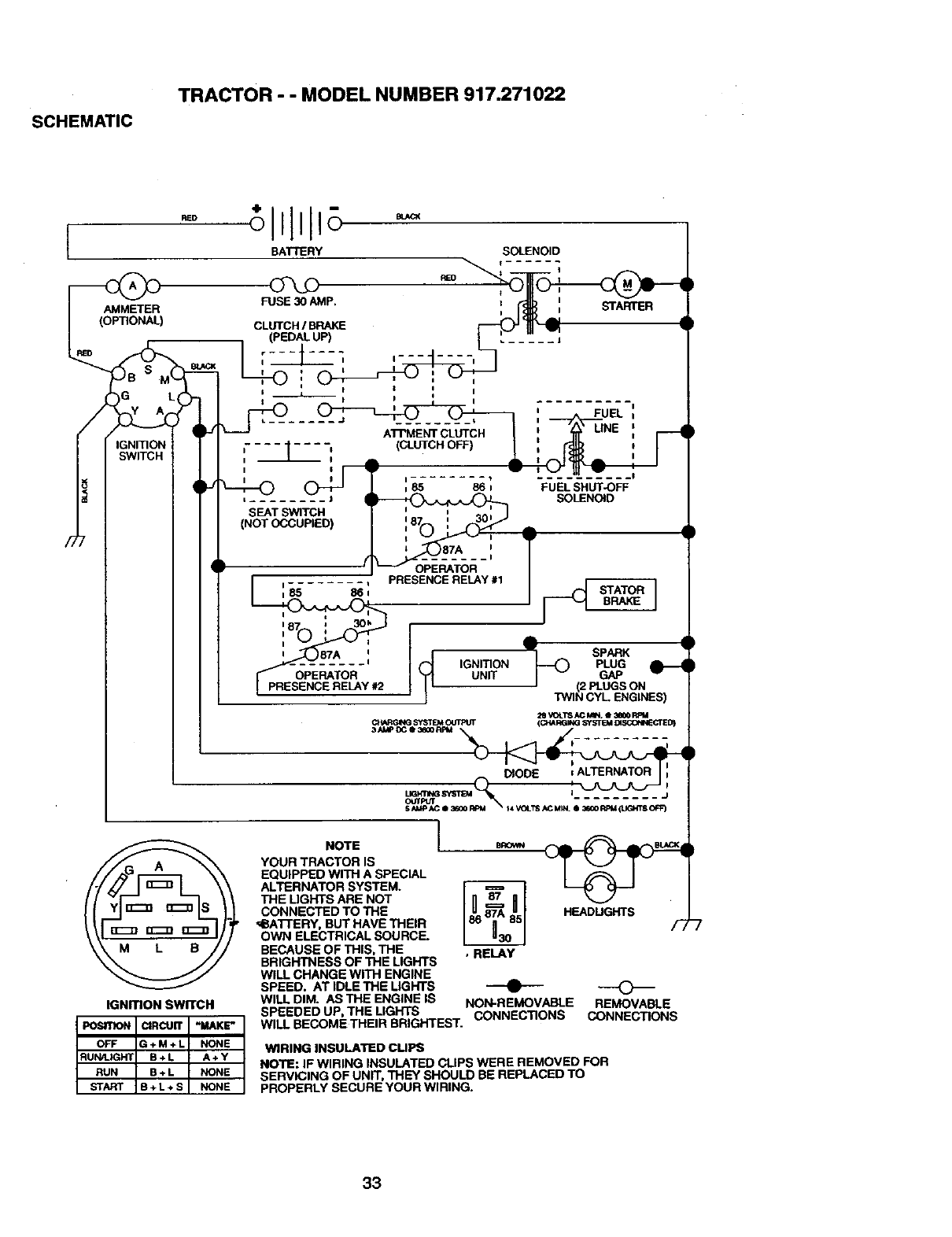
SCHEMATIC
TRACTOR"" MODEL NUMBER 917.271022
RED
BATTERY
AMMETER
Gy AL
FUSE 30 AMP.
CLUTCH IBR/_KE
•(pEDAL UP)
1
L+O, I
SOLENOID
RED
i....
NOTE "__ e_'_
YOUR TRACt'OR %S
EQUtPPED WITH A SPECIAL
ALTERNATOR SYSTEM.
THE L]GHTS ARE NOT
CONNECTED TO THE
ICBA'TI'ERY BUT HAVE 31_REctRE
OWN ELECTR CAL S_uHu .
BECAUSE OF THIS THE , RELAY
BRIGHTNESS OF THE L GHTS --AP-
HEADUGHTS
WILL CHANGE WITH ENGINE
SPEED. AT IDLE THE LIGHTS
WILL DIM. AS THE ENGINE |S NON-REMOVABLE
IGNmON SWITCH SPEEDED UP, THE LtGHTS CONNECTIONS
WiLL BECOMETHEIR BRIGHTEST-
[posI130N I CIRCUITI -M/_KE" ]
OFF G + M + L NONE WIRING INSULATED cuPS
IF WIRING INSULATED CLIPS WERE REMOVE_OFOR
NOTE: ....... '_'_ "D BE REPLACED TO
OF UNII, I _¢_ on,_.-
SERVICING N
PROPERLY SECURE yOUR WIRI G.
REMOVABLE
CONNECTIONS
33
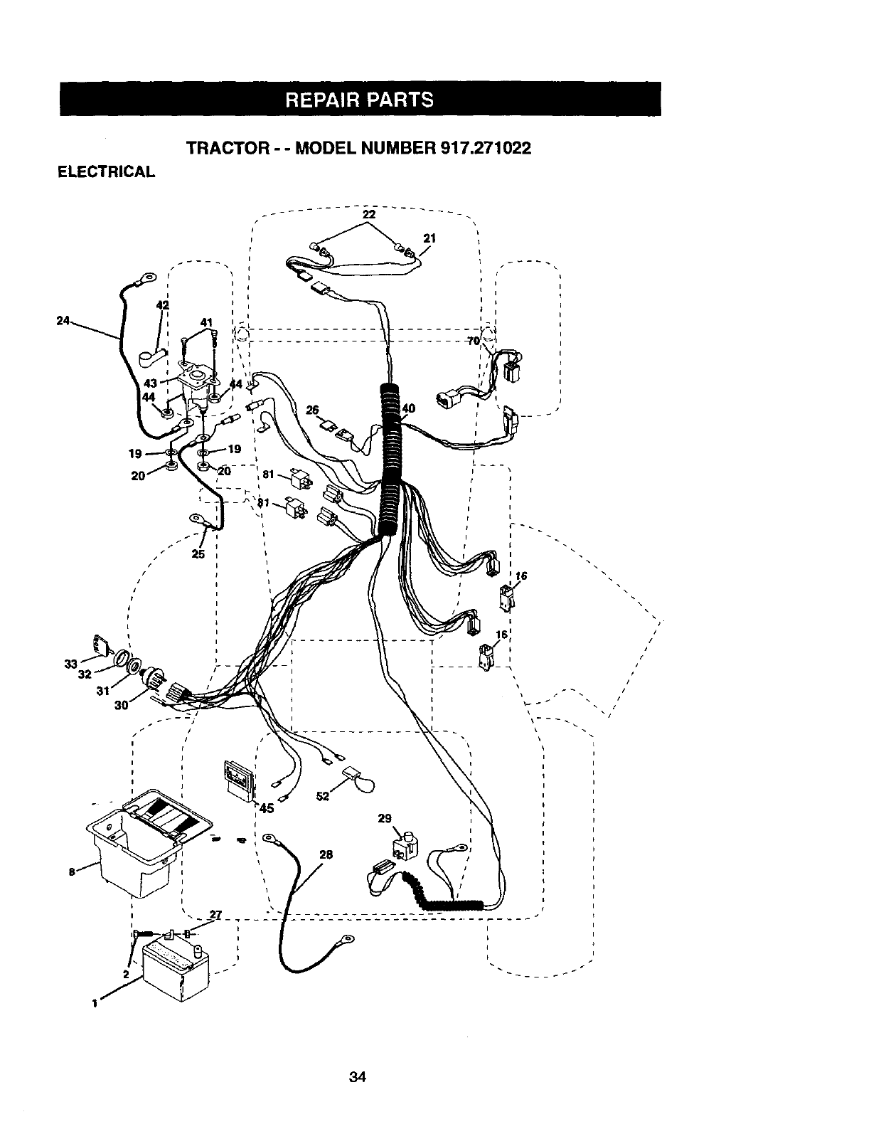
ELECTRICAL
TRACTOR --MODEL NUMBER 917.271022
26
21
I
t
34
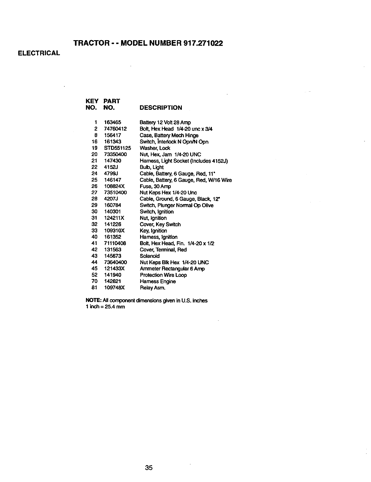
ELECTRICAL
TRACTOR - - MODEL NUMBER 917.271022
KEY PART
NO. NO. DESCRIPTION
1 163465
2 74760412
8 156417
16 161343
19 STD551125
20 73350400
21 147430
22 4152J
24 4799J
25 146147
26 108824X
27 73510400
28 4207J
29 160784
30 140301
31 124211X
32 141226
33 109310X
40 161352
41 71110408
42 131563
43 145673
44 7364O4OO
45 121433X
52 141940
70 142621
81 109748X
Battery 12 Volt28 Amp
Bolt, Hex Head 1/4-20 unc x 3/4
Case, BatteryMech Hinge
Switch,InterlockN OprvN Opn
Washer,Lock
Nut, Hex,Jam 1/4-20 UNC
Hamass, LightSocket (Includes4152J)
Bulb,Light
Cable, Battery, 6 Gauge, Red, 11"
Cable, Battery, 6 Gauge, Red, W/16 Wire
Fuse,30 Amp
Nut KepsHex 1/4-20 Unc
Cable, Ground,6 Gauge, Black, 12"
Switch,PlungerNormalOp Olive
Switch,Jgnition
Nut, Ignition
Cover, Key Switch
Key,Ignition
Harness,Ignition
Bolt,Hex Head, Fin. 1/4-20 x 1/2
Cover,Terminal,Red
Solenoid
Nut Keps BIkHex 1/4-20 UNC
Ammeter Rectangular6 Amp
ProtectionWire Loop
Hamess Engine
RelayAsm,
NOTE: Allcomponentdimensionsgiven inU.S. inches
1 inch= 25.4 mm
35
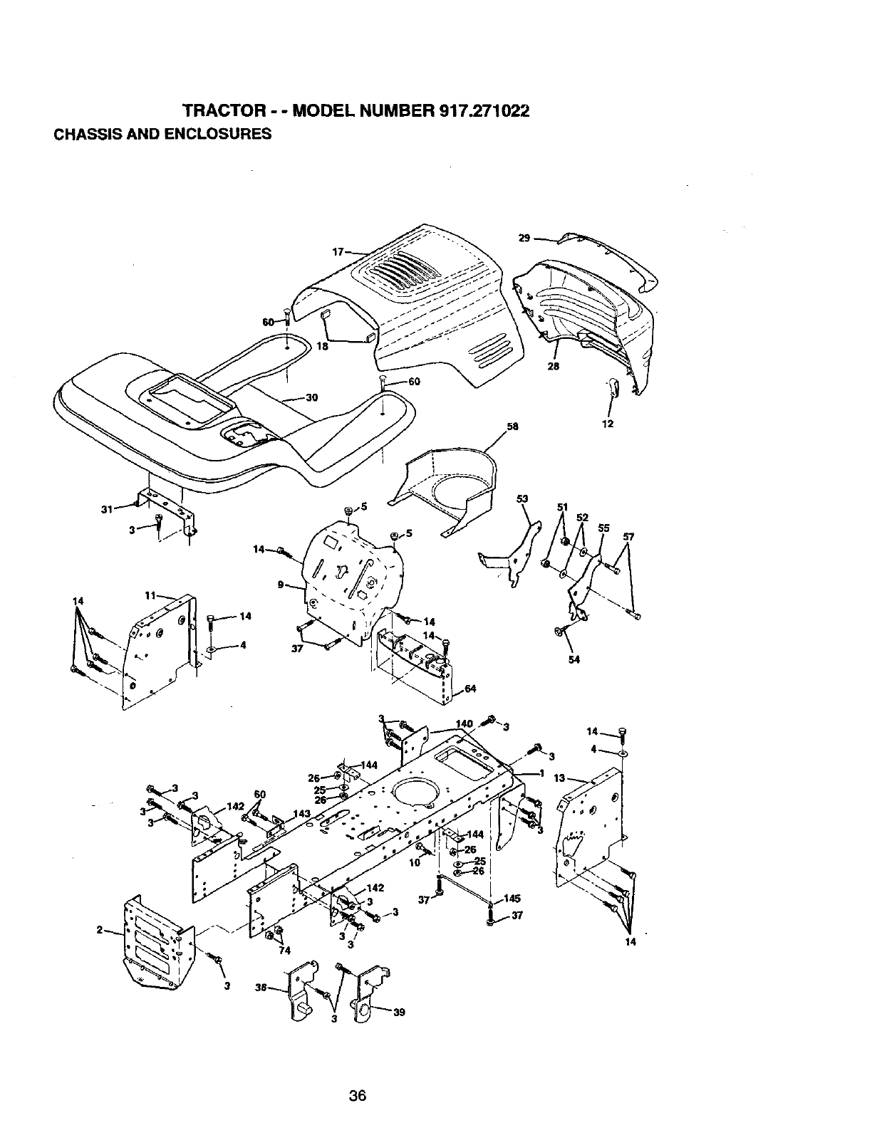
TRACTOR - - MODEL NUMBER 917.271022
CHASSIS AND ENCLOSURES
28
58 12
31
14 11
53
552 55
54
14
36
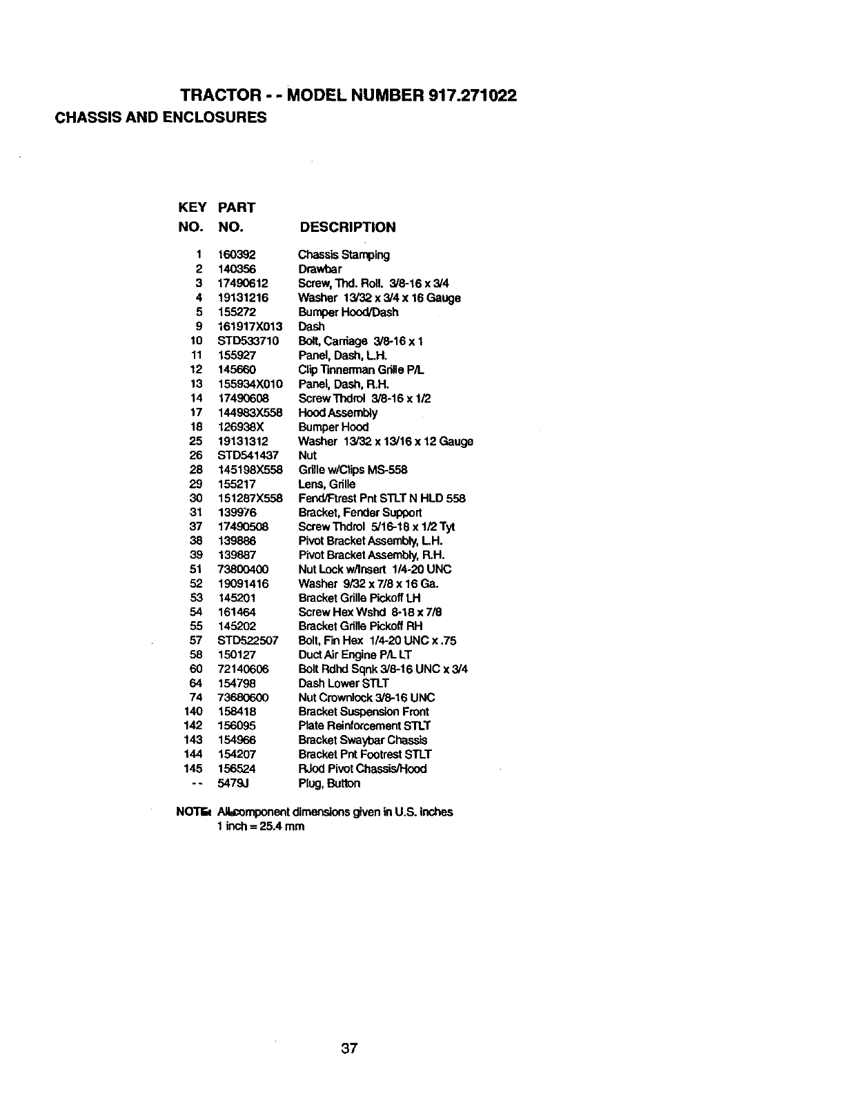
TRACTOR --MODEL NUMBER 917.271022
CHASSIS AND ENCLOSURES
KEY PART
NO. NO. DESCRIPTION
1160392
2 140356
3 17490612
4 19131216
5 155272
9 161917X013
10 STD533710
11 155927
12 145660
13 155934X010
14 17490608
17 144983X558
18 126_TJSX
25 19131312
26 STD541437
28 145198X558
29 155217
30 151287X558
31 139976
37 17490508
38 139886
39 139887
51 73800400
52 19091416
53 145201
54 161464
55 145202
57 STD522507
58 150127
60 72140606
64 154798
74 73680600
140 158418
142 156095
143 154966
144 154207
145 156524
-- 5479J
ChassisStamping
Drawtrar
Screw,Thd. Roll. 3/8-16 x 3/4
Washer 13/32.x 3/4 x 16 Gauge
BumperHood/Dash
Dash
Bolt,Cardage 3/8-16 x 1
Panel, Dash,L.H.
ClipTinnermanGrille P/L
Panel, Dash, R.H.
ScrewThdrol 3/8-16 x 1/2
HoodAssembly
BumperHood
Washer 13/'32x 13/16 x 12 Gauge
Nut
Grillew/ClipsMS-558
Lens,Grille
Fend/Ftrest PntSTLT N HLD 558
Bracket, Fender Support
ScrewThdrol 5/16-18 x 1/2 Tyt
PivotBracketAssembly,LH.
Pivot BracketAssembly,R.H.
Nut Lockw/Insert 114-20UNC
Washer 9/32 x 7/8 x 16Ga.
BracketGrille PickoffLH
Screw Hex Wshd 8-18 x 7/8
BracketGdlio PickoffRH
Bolt,FinHex 1/4-20 UNC x .75
Duct AirEngine P/L LT
Bolt RdhdSqnk 3/8-16 UNC x 3/4
Dash Lower STLT
Nut Crownfock3/8-16 UNC
BracketSuspensionFront
Plate ReinforcementSTLT
BracketSwaybarCha_is
BracketPnt FootrestSTLT
RJodPivot Chassis_ood
Plug, Button
NOTk Ailacomponent dimensionsgiven in U.S. inches
1 ir_h =25A mm
37
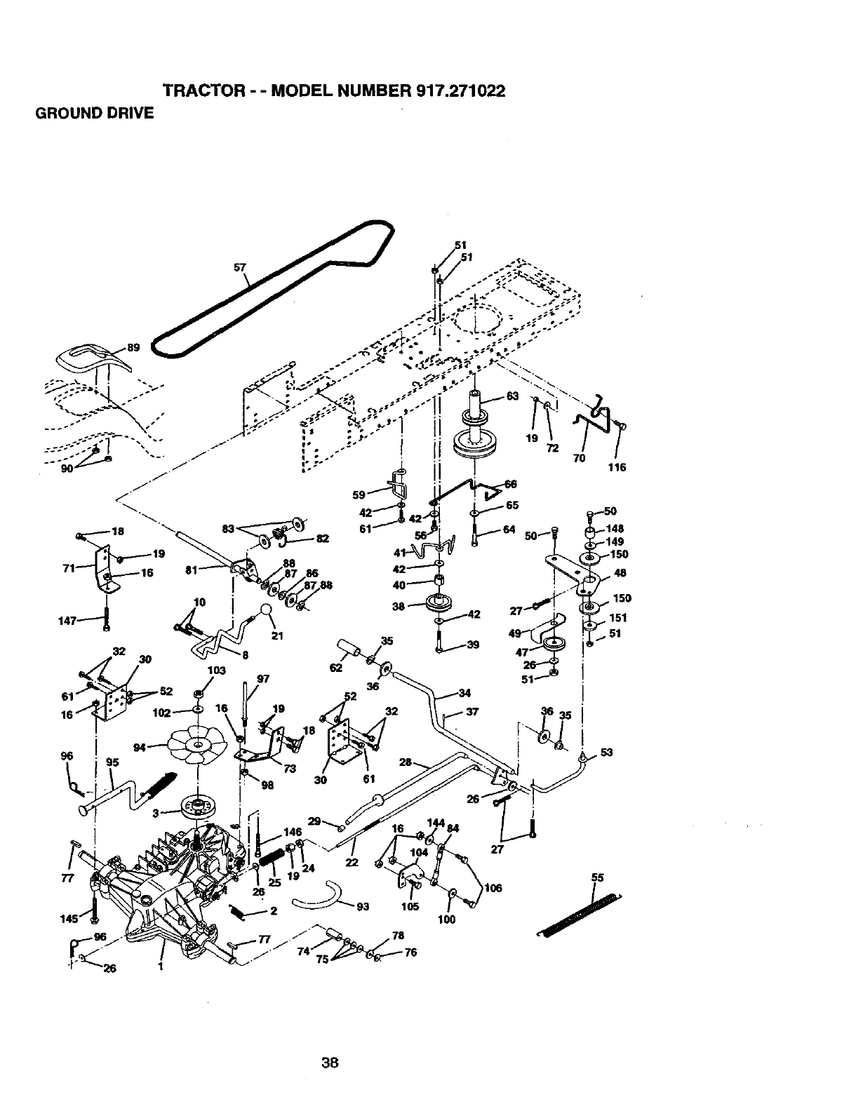
TRACTOR -- MODEL NUMBER 917.271022
GROUND DRIVE
32
,_, /30 103 97 62
16 102 16 ,19 32
_- 94__6_ %18_
• "' _98 30 61
.146
i
27
77 )106
lOO
55
38
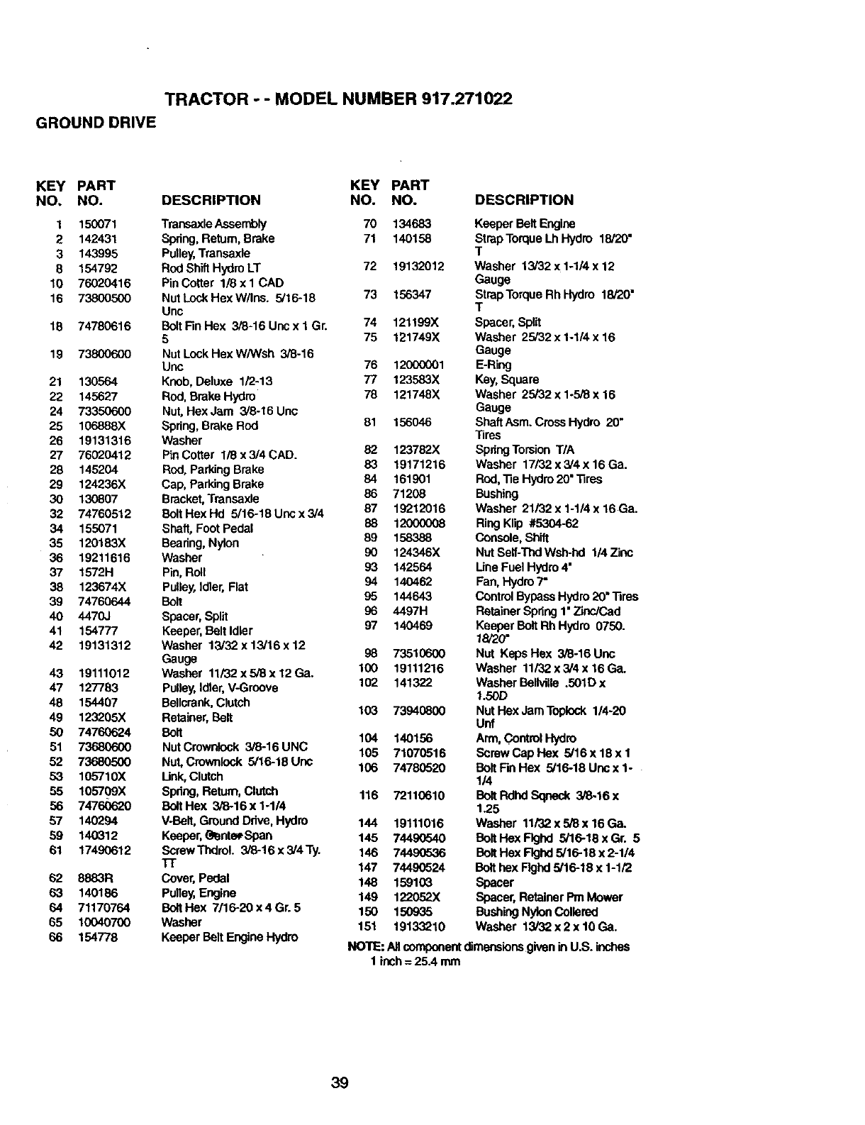
TRACTOR - - MODEL NUMBER 917.271022
GROUND DRIVE
KEY PART KEY PART
NO. NO. DESCRIPTION NO. NO.
1 150071 TransaxleAssembiy 70 134683
2 142431 Spring, Return, Brake 71 140158
3 143995 Pulley,Transaxle
8 154792 Rod Shift Hydro LT 72 19132012
10 76020416 Pin Cotter 1/8 x 1 CAD
16 738005G0 Nut Lock Hex W/Ins. 5/16-18 73 156347
Unc
16 74780616 BoltFin Hex 3/6-16 Unc x 1 Gr. 74 121199X
575 121749X
19 73800600 NutLockHexW/Wsh 3/8-16
Unc 76 12000001
21 130564 Kneb, Deluxe 1/2-13 77 123583X
22 145627 Rod, Brake Hydro 78 121748X
24 73350600 Nut, Hex Jam 3/8-16 Unc
25 106888X Spring,Brake Rod 81 156046
26 19131316 Washer
27 76020412 Pin Cotter 1/8 x 3/4 CAD. 82 123782X
28 145204 ROd,Parking Brake 83 19171216
29 124236X Cap, ParkingBrake B4 161901
30 130807 Bracket, Transaxle 86 71208
32 74760512 BoltHexHd 5/16-18Uncx3/4 87 19212016
34 155071 Shaft, Foot Pedal 88 12000008
35 120183X Bearing,Nylon 89 158388
36 19211616 Washer 90 124346)(
37 1572H Pin, Roll 93 142564
38 123674X Pulley, Idler,Flat 94 140462
39 74760644 Bolt 95 144643
40 4470J Spacer, Split 96 4497H
41 154777 Keeper,Belt Idler 97 140469
42 19131312 Washer 13/32x 13/16x 12
Gauge 98 73510600
43 19111012 Washer 11i32x5/8x12Ga. 100 19111216
47 127783 Pulley,Idler,V-Groove 102 141322
48 154407 Be,crank, Clutch
49 123206X Retainer,Belt 103 73940800
50 74760624 Bolt 104 140156
51 73680600 Nut Crownleck 3/6-16 UNC
62 73680500 Nut, Crownlock 5/16-18 Unc 105 71079516
53 105710X Unk, Clutch 106 74780520
55 105709X Spdng, Return,Clutch 116 72110610
56 74760620 BoltHex 3/6-16x1-1/4
57 140294 V-Belt,Ground Drive, Hydro 144 19111016
59 140312 Keeper,_rdePSpan 145 7449(_40
61 17490612 ScrewThdrol. 3/8-16x3/4Ty. 146 744905.36
37" 147 7449(2324
62 8883R Cover, Pedal 148 159103
63 140186 Pulley,Engine 149 122052X
64 71170764 BoitHex 7/16-20x4Gr.5 150 150935
65 10040700 Washer 151 19133210
66 154778 Keeper Bolt Engine Hydro
DESCRIPTION
Keeper Bolt Engine
StrapTorque LhHydro 18/20"
T
Washer 13/32 x 1-1/4 x 12
Gauge
TStrapTorqueRh Hydro 18/20"
Spacer,Split
Washer 25/32 x 1-1/4 x 16
Gauge
E-Ring
Key,Square
Washer 25/32 x 1.5/8 x 16
Gauge
ShaftAsm. Cross Hydro 20"
"liras
SpdngTorsion T/A
Washer 17/32 x 3/4 x 16 Ga.
Fk_, 1ie Hydro 20" "lires
Bushing
Washer 21/82 x 1-114X 16 Ga.
RingKlip #5304-62
Console,Shift
Nut Selt-Thd Wsh-P_ 1/4 Zinc
Une Fuel Hydro4"
Fan, Hydro7"
Control Bypass Hydro20"'lires
RetainerSpdng1"7inc/Cad
KeeperBolt Rh Hydro 0750.
18/20"
Nut Keps Hex 3/8-16 Unc
Washer 11/32 x 3/4 x 16 Ga.
Washer Bellville .501D x
1.50D
Nut Hex JamToplock 1/4-20
Unf
Arm,Co_t_ Hydro
Screw Cap Hex 5/16x18x1
Bolt Fm Hex 5/16-18 Unsx 1-
I/4
Bolt RdlKISqneck 3/6-16 x
1.25
Washer 11/32 x 5/8 x 16 Ga.
Bolt Hex Flghd 5/16-18xGr. 5
Bolt Hex FIghds/16-18 x2-1/4
Bolthex F!ghd5/16-18 x 1-1/2
Spacer
Spacer,Retainer Pm Mower
BushingNylonCollered
Washer 13/32 x2 x 10 Ga.
NO'r_: ANcomponentdimensionsgiven in U.S. inches
1 inch= 25.4 mrn
39
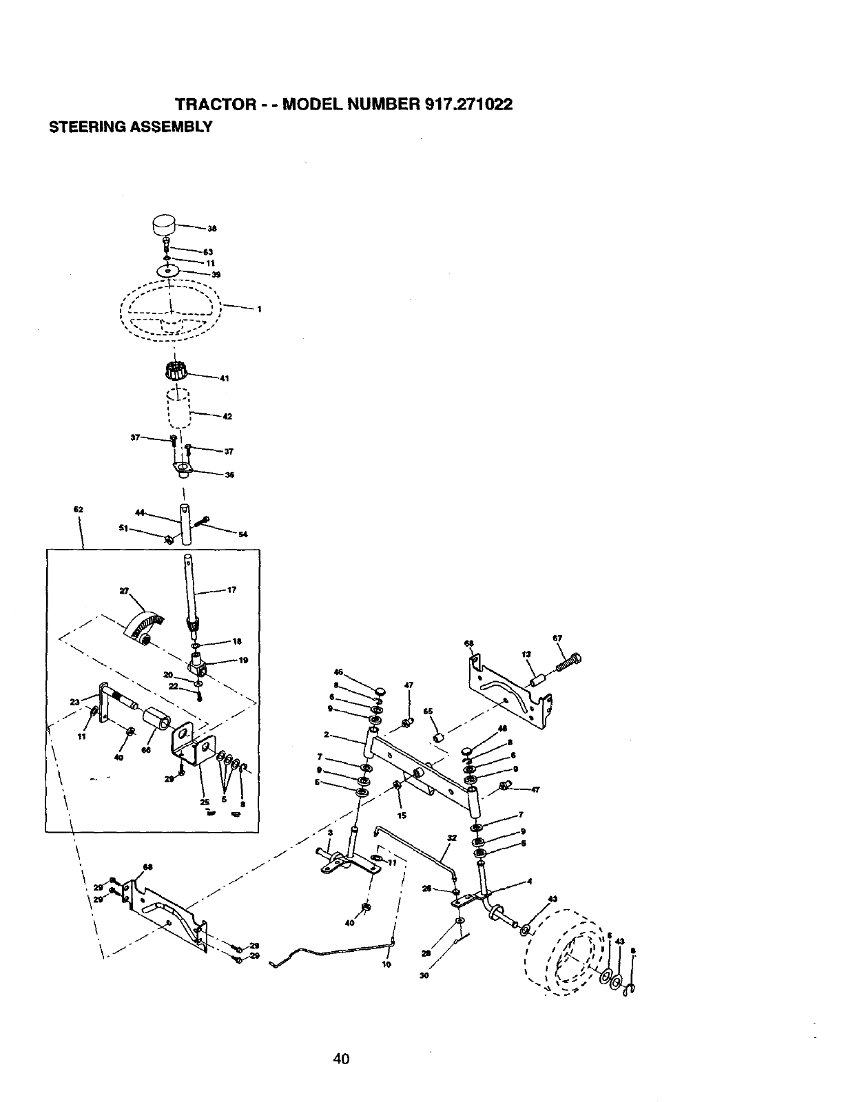
TRACTOR --MODEL NUMBER 917.271022
STEERING ASSEMBLY
----.-.__43
s i D-'---'-- 1
a ...... j
_41
62 44
4O
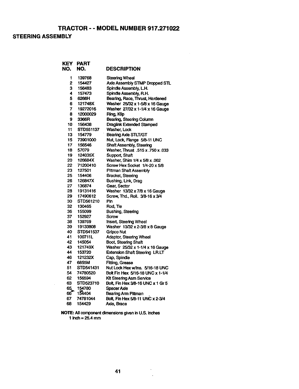
TRACTOR - - MODEL NUMBER 917.271022
STEERING ASSEMBLY
KEY PART
NO. NO. DESCRIPTION
1139768 SteedngWhest
2 154427 Axle AssemblySTMP DroppedSTL
3 156483 SpindleAssembly,L.H.
4 157473 SpindleAssembly,R.H.
5 6266H Beadng, Race,Thrust, Hardened
6 121748X Washer 25i32x1-5i8x16Gauge
7 19272016 Washer 27/32x1-1/4x16Gauga
612oooo29 R_g,_o
9 3366R Beadng,Steedng Column
10 156438 DraglinkExtendedStamped
11 STD551137 Washer, Lock
13 154779 ' BeadngAxleSTLT/GT
15 73901000 Nut, Lock,Flange 5/8-11 UNC
17 156546 ShaftAssembly,Steedng
18 57079 Washer,Thrust .515 x .750 x .033
19 124035X Support,Shaft
20 126684X Washer, Shim 1/4 x 5/8 x .062
22 71200410 Screw Hex Socket 1/4-20x5/8
23 127501 PittrnenShaftAssembly
25 154406 Bracket, Steering
26 126847X Bushing,Unk, Drag
27 136874 Gear, Sector
28 19131416 Washer 13/32 x 7/8 x16 Gauge
29 17490612 Scraw,Thd.,Roll. 3/8-16x3/4
30 STD561210 Pin
32 130465 Rod,"Re
36 155099 Bushing,Steedng
37 152927 Screw
38 139769 Insert,SteedngWheel
39 19133808 Washer 13i32x2-3,'8x8Gauge
40 STD541537 Gdpco Nut
41 100711L Adaptor,SteedngWheel
42 145054 Boot,Steedng Shaft
43 121749X Washer 25/32xl-1/4x16Gauge
44 153720 ExtensionShaftStesdng LR.LT
46 121232X Cap, Spindle
47 6855M FitUng,Grease
51 STD541431 Nut LockHex w/Ins. 5/16-18 UNC
54 74780520 Bolt Fin Hex 5/16-18 UNC x 1-1/4
62 156594 K"dSteedngAsm Service
63 STD523710 Bolt,FinHex 3/8-16 UNC x 1 Gr 5
65. 154780 Spacer Axle
66_1,_04 BeadngArm P_ltman
67 74781044 Bolt,FinHex 5/8-11 UNC x 2-3/4
68 154429 Axle, Brace
NOTE: All componentdimensionsgiven in U.S. inches
1 inch= 25.4 mm
41
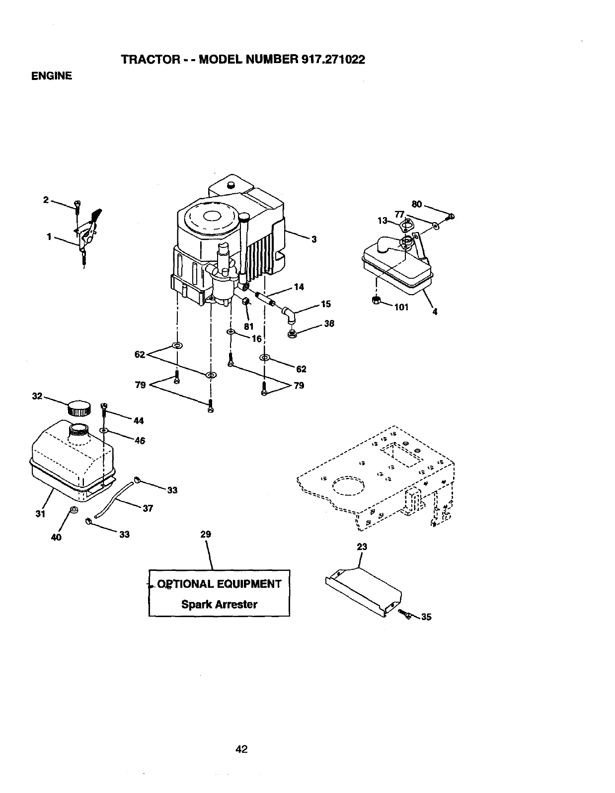
ENGINE
TRACTOR - - MODEL NUMBER 917.271022
4O
6
33
29
\
t,O_TIONAL EQUIPMENT
Spark Arrester I
4
._ i=. • _ _. I _ i
_ _.;, ¢._._-_.'_ L_ ss _ MI
23
42
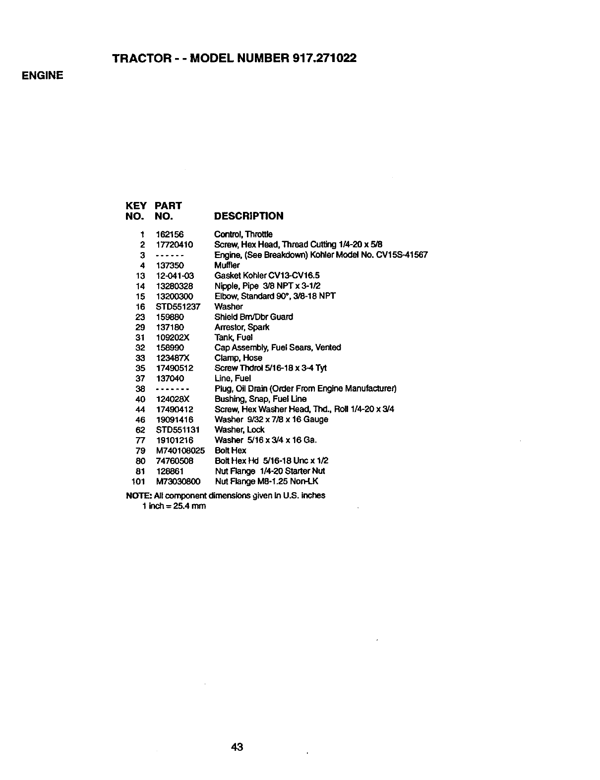
ENGINE
TRACTOR --MODEL NUMBER 917.271022
KEY PART
NO. NO. DESCRIPTION
1 162156
2 17720410
3......
4 137350
13 12-041-03
14 13280328
15 13200300
16 STD551237
23 159880
29 137180
31 109202X
32 158990
33 123487X
35 17490512
37 137040
38 .......
40 124028X
44 17490412
46 19091416
62 STD551131
77 19101216
79 M740108025
80 74760508
81 128861
101 M73030800
Control,Throttle
Screw,Hex Head, Thread Cuffing114-20x 5/8
Engine,(See Breakdown)KohlerModel No. CV15S-41567
Muffler
Gasket KohlerCV13-CV16.5
Nipple, Pipe 3/8 NPT x 3-1/2
Elbow,Standard90", 3/8-18 NPT
Washer
ShieldBrn/DbrGuard
Arrestor,Spark
Tank,Fuel
Cap Assembly,Fuel Sears, Vented
Clamp, Hose
Screw Thdrel 5/16-18 x 3-4 Tyt
Line, Fuel
Plug, Oil Drain(Order From Engine Manufacturer)
Bushing,Snap, Fuel Line
Screw,Hex Washer Head, Thd., Roll 1/4-20 x 3/4
Washer 9/32 x 7/8 x 16 Gauge
Washer, Lock
Washer 5/16 x 3/4 x 16 Ga.
Bolt Hex
Bolt Hex Hd 5/16-18 Unc x 1/2
Nut Flange 1/4-20 Starter Nut
Nut FlangeM8-1.25 Non-LK
NOTE: AllcomponentdimensionsgivenIn U.S. inches
1 inch= 25.4 mm
43
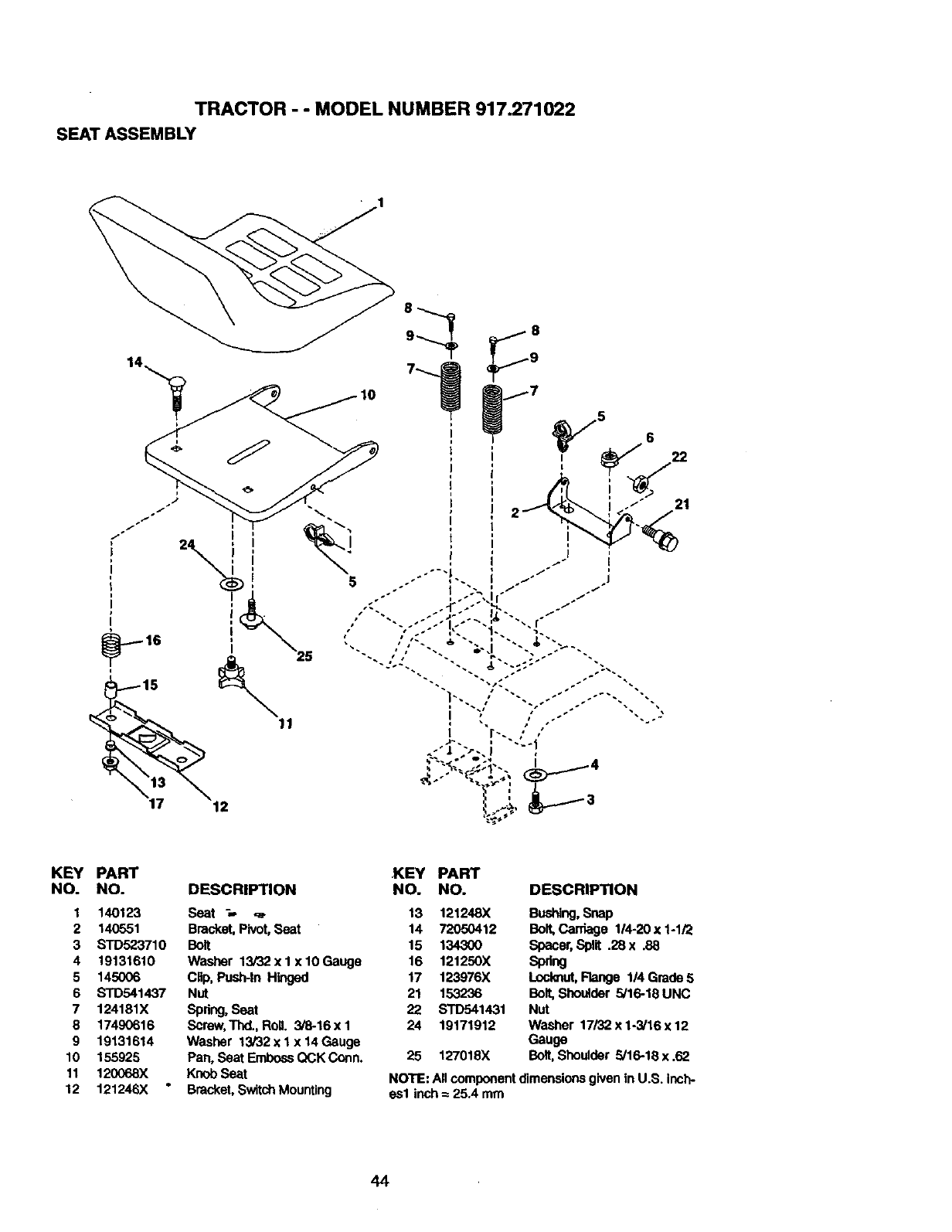
TRACTOR - - MODEL NUMBER 917.271022
SEAT ASSEMBLY
Ii
J
t
KEY PART
NO. NO.
1 140123
2 140551
3 STD523710
4 19131610
5 145006
6 STD541437
7 124181X
8 17490616
9 19131614
10 155925
11 120068X
12 121246X
KEY PART
DESCRIPTION NO. NO.
Seat ;,- ,_. 13 121248X
Bracket,Pivot, Seat 14 72050412
Bolt 15 1_
Washer 13/32 x I x 10 Gauge 16 121250X
Clip, Push-in Hinged 17 123976X
Nut 21 153236
Spdng,Seat 22 STD541431
Screw,Thd.,RoD. 3/8-16xl 24 19171912
Washer 13/32 x I x 14 Gauge
Pan, Seat EmbossQCK Conn. 25 127018X
Knob Seat
Bracket,Switch Mounting
DESCRIPTION
B(_, Snap
Bolt,Gan'_ge 114-20x 1-1/2
Spacer,Split .28 x .88
Spdng
Lcololut,Flange I/4 Grade 5
Bolt, Shoulder 5/16-18 UNC
Nut
Washer 17/32 x 1-3/16 x 12
Gauge
Bolt,Shoulder 5/16-18 x .62
NOTE: All componentdimensions givenin U.S. inch-
as1 inch = 25.4 mm
44
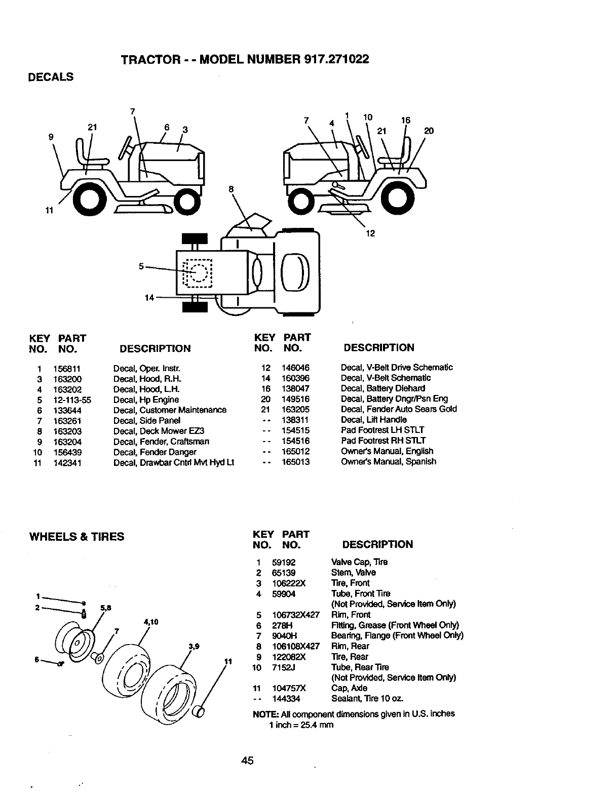
DECALS
TRACTOR --MODEL NUMBER 917.271022
921
77
6 3
1 10 16
2O
11
KEY PART
NO. NO.
1 156811
3 163200
4 163202
5 12-113,-55
6 133644
7 163261
8 163203
9 163204
10 156439
11 142341
KEY PART
DESCRIPTION NO. NO.
Decal, Opel'. Instr. 12 146046
Decal, Hood, R.H. 14 160396
Decal, Hood, LH. 16 138047
Decal, Hp Engine 20 149516
Decal, Customer Maintenance 21 163205
Decal, Side Panel -- 138311
Decal, Deck Mower EZ3 -- 154515
Decal, Fender,Craftsman -- 154516
Decal, Fender Danger - - 165012
Decal, Drawbar Cntrl Mvt HydLt - - 165013
12
DESCRIPTION
Decal, V-Belt DriveSchematic
Decal, V-BaitSchematic
Decal, Battery Diehard
Decal, Battery Dngr/Psn Eng
Decal, Fender Auto Sears Gold
Decal, LiftHandle
Pad FootrestLH STLT
Pad FootrestRH STLT
Owners Manual, English
OwneCsManual, Spanish
WHEELS & TIRES
4,10
11
KEY PART
NO. NO. DESCRIPTION
1
2
3
4
5
6
7
8
9
10
11
-.
59192 Valve Cap, 33re
65139 Stem, Valve
106227.X -fire, Front
59904 Tube, FrontTim
(Not Provided,SeMce Item Only)
106732)(427 Rim, Front
278H R_ng, Grease (FrontWheel Only)
9040H Bearing, Range (FrontWheel Only)
106108X427 Rim, Rear
122082X 1ire, Rear
7152J Tube, Rear-fire
(Not Provided, Service ItemOnly)
104757X Cap, Axle
144334 Sealant, "life 10 oz.
NOTE: All componentdimensionsgiven in U.S. inches
1 inch= 25.4 mm
45
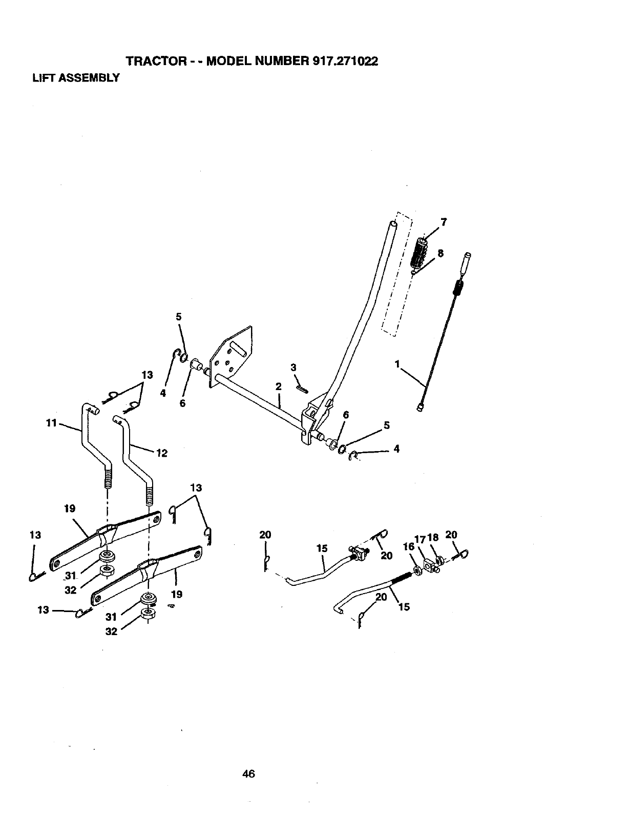
TRACTOR - -MODEL NUMBER 917.271022
LIFT ASSEMBLY
7
5
13
11__ 6
12
13
2
3
6
8
,I •
i,I I
20
46
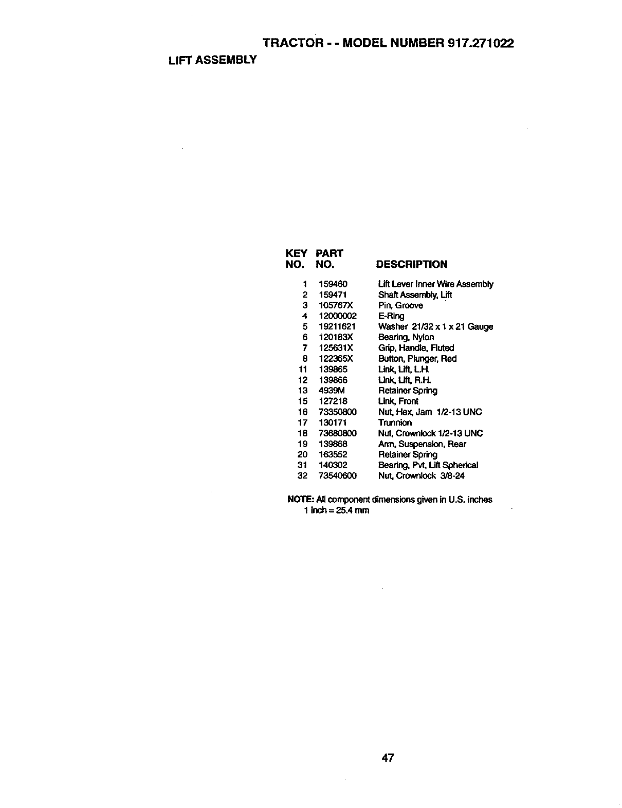
TRACTOR --MODEL NUMBER 917.271022
LIFT ASSEMBLY
KEY PART
NO. NO. DESCRIPTION
1 159460 Lift Lever Inner Wire Assembly
2 159471 ShaftAssembly,Lift
3 105767X Pin, Groove
4 12000002 E-Ring
5 19211621 Washer 21132x I x21 Gauge
6 120183X Bearing, Nylon
7 125631X Gdp, Handle, Ruted
8 122365X Button,Plunger,Red
11 139865 Unk, Lift,LH.
12 139866 Link, Lift, R.H.
13 4939M RetainerSpdng
15 127218 Link, Front
16 73350800 Nut, Hex,Jam 1/2-13 UNC
17 130171 Trunnion
18 73680800 Nut, Crownlock1/2-13 UNC
19 139668 Arm, Suspension,Rear
20 163552 RetainerSpdng
31 140302 Bearing, Pvt, LiftSpherical
32 73540600 Nut,Crowrdock 3/8-24
NOTE: Allcomponentdimensionsgiven inU.S. inches
1 inch= 25.4 mm
47
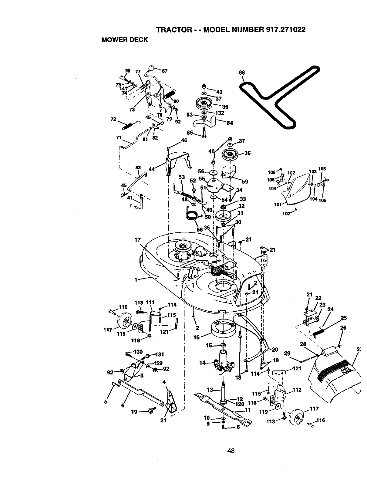
TRACTOR - - MODEL NUMBER 917.271022
MOWERDECK
21 22
t23
' 24
i
\2 26
2;
48
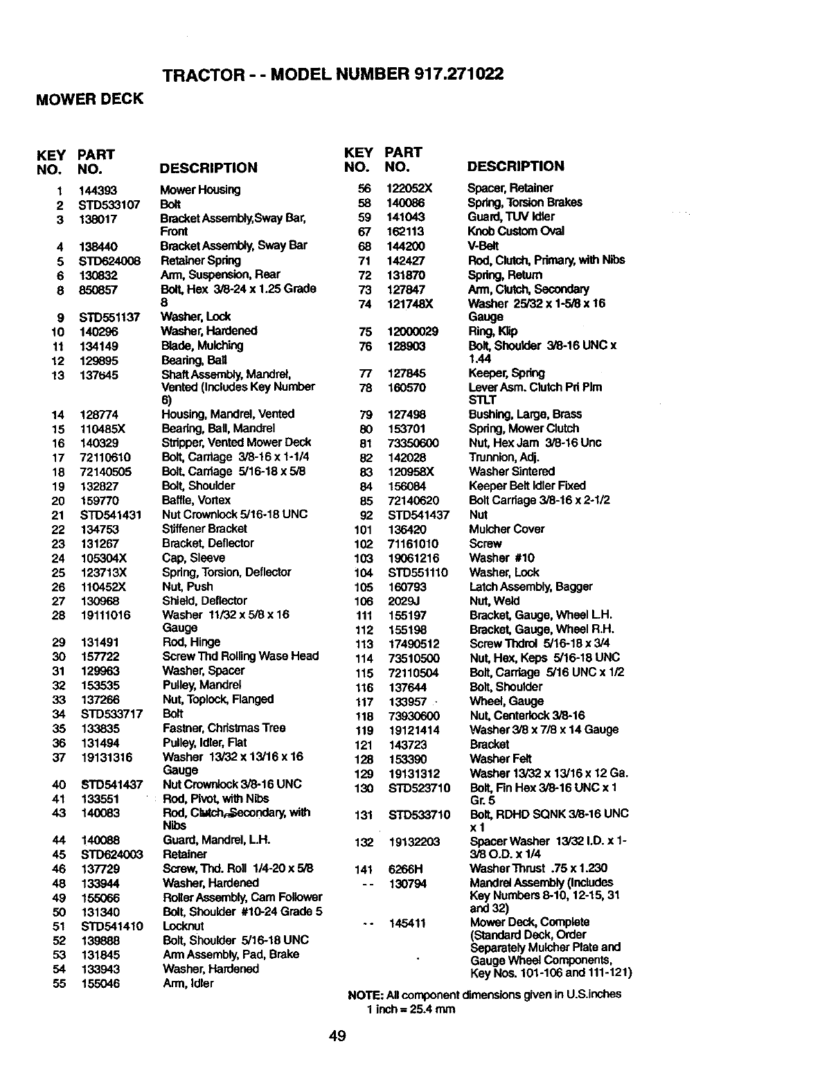
TRACTOR - - MODEL NUMBER 917.271022
MOWER DECK
KEY PART KEY PART
NO. NO. DESCRIPTION NO. NO,
1 144393 Mower Housing 56 122052X
2 STD533107 Bolt 58 140086
3 138017 BracketAssembly,Sway Bar, 59 141043
Front 67 162113
4 138440 BracketAssembly,Sway Bar 68 144200
5 STD624008 Retainer Spdng 71 142427
6 130832 Arm, Suspension,Rear 72 131870
8 850857 Bolt,Hex 3i8-24x1.25Grade 73 127847
874 121748X
9 STD551137 Washer, Lock
10 140296 Washer, Hardened 75 12000029
11 134149 Blade, Mulching 76 128903
12 129895 Beadng, Ball
13 137t_45 ShaftAssernbly,Mandrel, 77 127845
Vented (IncludesKey Number 78 160570
s)
14 128774 Hous_ Mandrel,Vented 79 127498
15 110485X Beadng, Ball, Mandrel 80 153701
16 140329 Stripper.Vented Mower Deck 81 733506o00
17 72110610 Bolt,Carriage 3/8-16 x 1-1/4 82 142028
18 72140505 BolLCardage 5/16-18x5/8 83 120958X
19 132827 Bolt, Shoulder 84 156084
20 159770 Baffle, Vortex 85 72140620
21 STD541431 Nut Crownlock5/16-18 UNC 92 STD541437
22 134753 StJffenerBracket 101 136420
23 131267 Bracket, Deflector 102 71161010
24 105304X Cap, Sleeve 103 19061216
25 123713X Spdng,Torsion.Deflector 104 STD551110
26 110452X Nut, Push 105 160793
27 130968 Shield, Deftactor 106 2029J
28 19111016 Washer 11i32x5i8x16 111 155197
Gauge 112 155198
29 131491 Rod, Hinge 113 17490512
30 157722 ScrewThdRollingWasaHead 114 73510500
31 129963 Washer, Spacer 115 72110504
32 153535 Pulley,Mandrel 116 137644
33 137266 Nut, Toplock,Flanged 117 133957
34 STD533717 BaR 118 73930600
35 133835 Fas_er, ChdstmasTree 119 19121414
36 131494 Pufley,rdter, Fiat 121 143723
37 19131316 Washer 13/32 x13/16 x16 128 153390
Gauge 129 19131312
40 STD541437 Nut Crowrdock3/8-16 UNC 130 STD5237"10
41 133551 Rod, Pivot, wi_ Nibs
43 140083 ROd,Clatch,_,Secondary,with 131 STD533710
Nibs
44 140088 Guard, Mandrel,L.H. 132 19132203
45 STD624003 Retainer
46 137729 Screw,'r_. Roll 1/4-20 x 5/8 141 6266H
48 133944 Washer,Hardened -- 130794
49 155066 RollerAssembly,Cam Follower
50 131340 Bolt,Shoulder #10-24 Grade 5
51 STD541410 Locknut -- 145411
52 139888 Bolt,Shoulder 5/16-18 UNC
53 131845 ArmAssembly,Pad, Brake
54 133943 Washer, Hardened
55 155046 Ann, Idler
DESCRIPTION
Spacer,Retainer
Spring,TorsionBrakes
Guard,TUV Idler
KnobCustom Oval
V-Belt
Rod, Clutch,Primary,_Nihe
Spring, Return
Arm, Clutch,Secondary
Washer 25/32 x 1-5/8 x 16
Gauge
Ring,Knp
Boll SheuMer 3/8-16 UNC x
1.44
Keeper, Spdng
Lever ASm. ClutchPd PIm
STLT
Bushing,LaKje, Brass
Spdng,Mower Clutch
Nut, HexJam 3/8-16Unc
Trunnion,Adj.
Washer Sintered
Keeper Belt IdlerFixed
BoltCarriage 3/8-16 x 2-1/2
Nut
MulcherCover
Screw
Washer #10
Washer, Lock
LatchAssembly,Bagger
Nut, Weld
Bracket, Gauge, Wheal LH.
Bracket, Gauge, Wheal R.H.
Screw Thdro#5/16-18 x3/4
Nut, Hex, Keps 5/16-18 UNC
Bolt,Carriage 5/16 UNC x 1/2
Bolt, Shoulder
Wheel, Gauge
Nut, Centarlock3/8-16
Washer 3/8 x 7/8 x 14 Gauge
Bracket
Washer Felt
Washer 13/32 x 13/16 x 12 Ga.
Bait, Fin Hex 3/8-16 UNC x 1
Gr. 5
Bolt,RDHD SQNK 3/8-16 UNC
xl
Spacer Washer 13/32 I.D. x 1-
3/80.D. x 1/4
Washer Thrust .75 x 1.230
Mandrel Assembly(Includes
Key Numbers 6-10, 12-15, 31
and32)
Mower Deck, C_nplete
(Standard Deck, Order
Separately Mulcher Plate and
Gauge Wheel Components,
Key Nos. 101-106 and 111-121)
NOTE: Allcomponentdimensionsgiven inU.S.inches
1 inch= 25A mrn
49
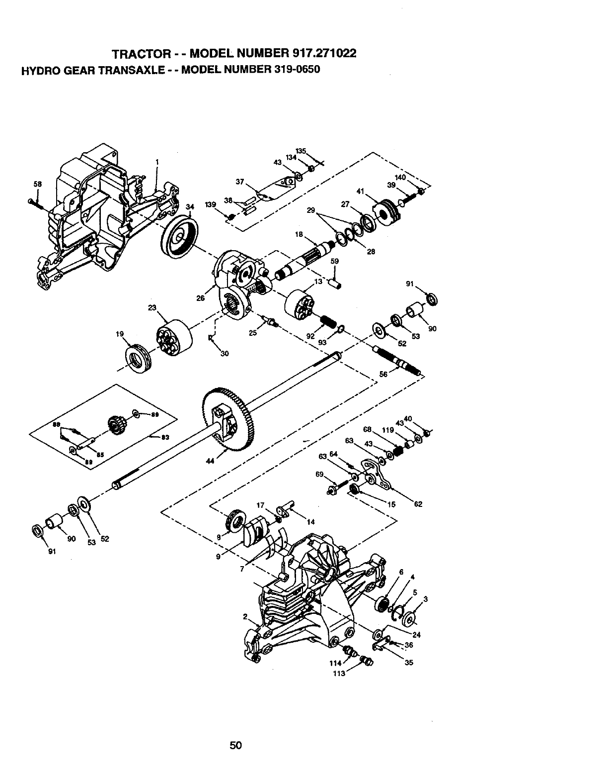
TRACTOR --MODEL NUMBER 917.271022
HYDRO GEAR TRANSAXLE --MODEL NUMBER 319-0650
58
139
41
91
23
19
28
59
35
5O
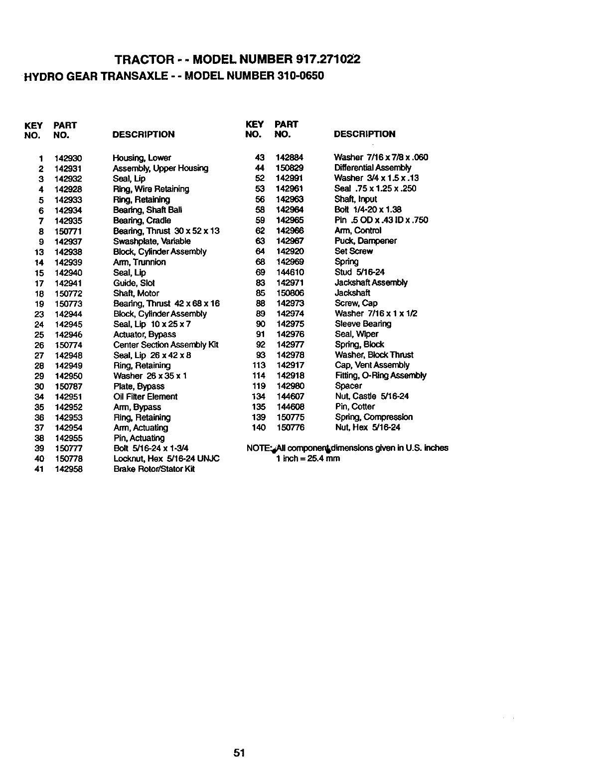
TRACTOR - - MODEL NUMBER 917.271022
HYDRO GEAR TRANSAXLE - - MODEL NUMBER 310-0650
KEY PART KEY PART
NO. NO. DESCRIPTION NO. NO. DESCRIPTION
1 142930 Housing,Lower 43 142884 Washer 7/16 x 7/8 x .060
2 142931 Assembly,Upper Housing 44 150829 DifferentialAssembly
3 142932 Seal, Up 52 142991 Washer 3/4x1.Sx.13
4 142928 Ring,Wire Retaining 53 142961 Seal .75 x 1.25 x .250
5 142933 Ring, Retaining 56 142963 Shaft, Input
6 142934 Bearing,Shaft Ball 58 142964 Bolt 114-20x 1.38
7 142935 Bearing,Cradle 59 142965 Pin .50D x.43 ID x .750
8 150771 Beadng, Thrust 30 x 52 x 13 62 142966 Arm, Control
9 142937 Swashplate, Variable 63 142967 Puck, Dampener
13 142938 Block,CylinderAssembly 64 142920 Set Screw
14 142939 Arm, Trunnion 68 142969 Spring
15 142940 Seal, Up 69 144610 Stud 5/16-24
17 142941 Guide, Slot 83 142971 JackshaftAssembly
18 150772 Shaft, Motor 85 150806 Jackshaft
19 150773 Bearing,Thrust 42x68x16 88 142973 Screw, Cap
23 142944 Block,CylinderAssembly 89 142974 Washer 7/16 x I x 1/2
24 142945 Seal, Lip 10 x 25 x 7 90 142978 Sleeve Baadng
25 142946 Actuator,Bypass 91 142976 Seal, Wiper
26 150774 Center SectionAssemblyKit 92 142977 Spring,Block
27 142948 Seal, Lip 26x42xB 93 142978 Washer, BIockThrust
28 142949 Ring,Retaining 113 142917 Cap, Vent Assembly
29 142950 Washer 26 x 35 x I 114 142918 Fitting,O-Ring Assembly
30 150787 Plate, Bypass 119 142980 Spacer
34 142951 Oil Filter Element 134 144607 Nut, Castle 5/16-24
35 142952 Arm, Bypass 135 144608 Pin, Cotter
36 142953 Ring,Retaining 139 150775 Spdng,Compression
37 142954 Arm, Actuating 140 150776 Nut, Hex 5/16-24
38 142955 Pin,Actuating
39 150777 Bolt 5/16-24 x 1-3/4 NOTE:dAIIcomponon_dimensionegiven in U.S. inches
40 150778 Locknut,Rex 5/16-24 UNJC 1 inch= 25.4 mm
41 142958 Brake Rotor/StatorKit
51
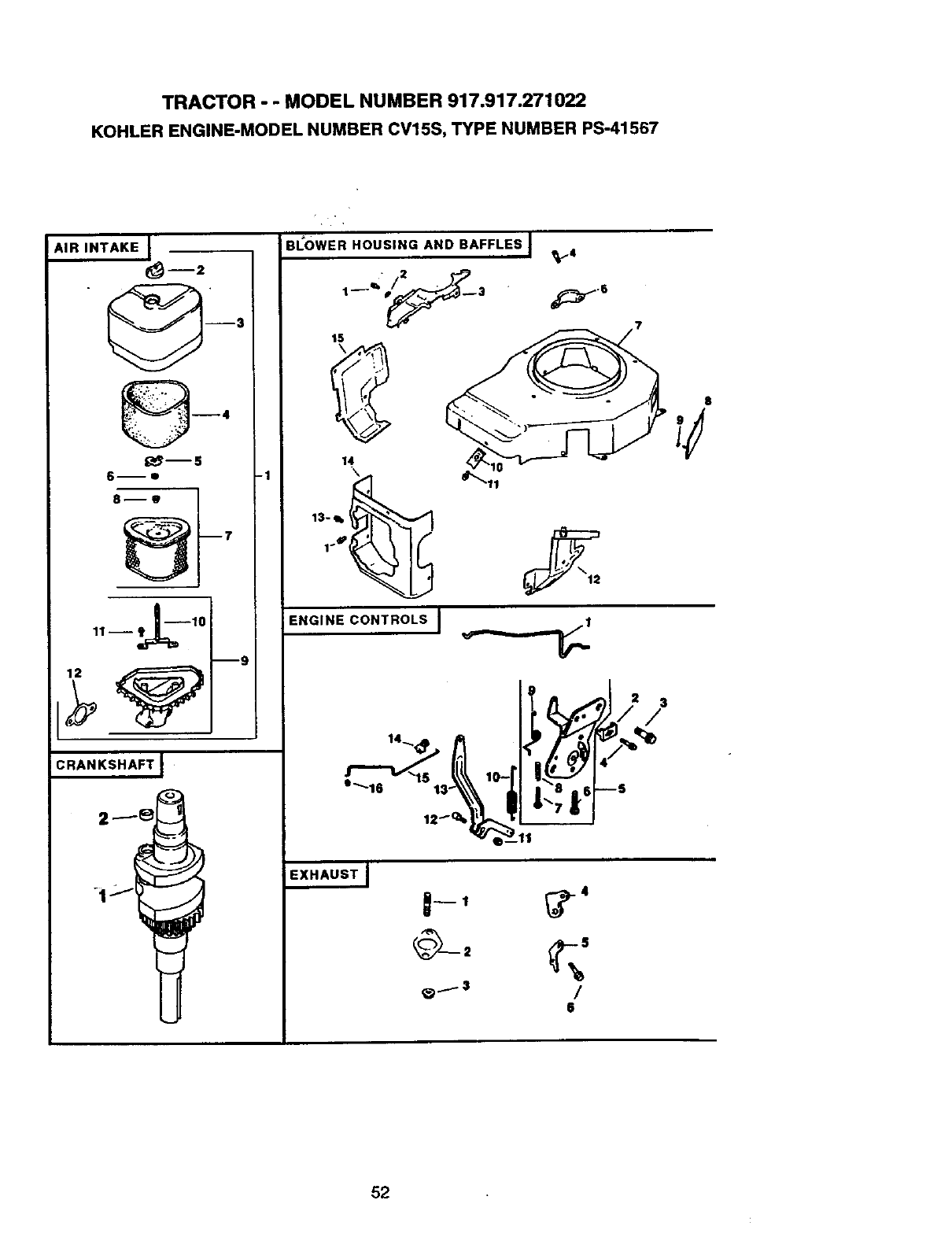
TRACTOR -- MODEL NUMBER 917.917.271022
KOHLER ENGINE-MODEL NUMBER CV15S, TYPE NUMBER PS-41567
/
AIR INTAKE
i 2
6--D
11 -- _--10
--9
CRANKSHAFT I
-1
I
BLOWER HOUSING AND BAFFLES J
1_3
15
14
13-1k
1_,
8
ENGINE CONTROLS I
3
/
6
52
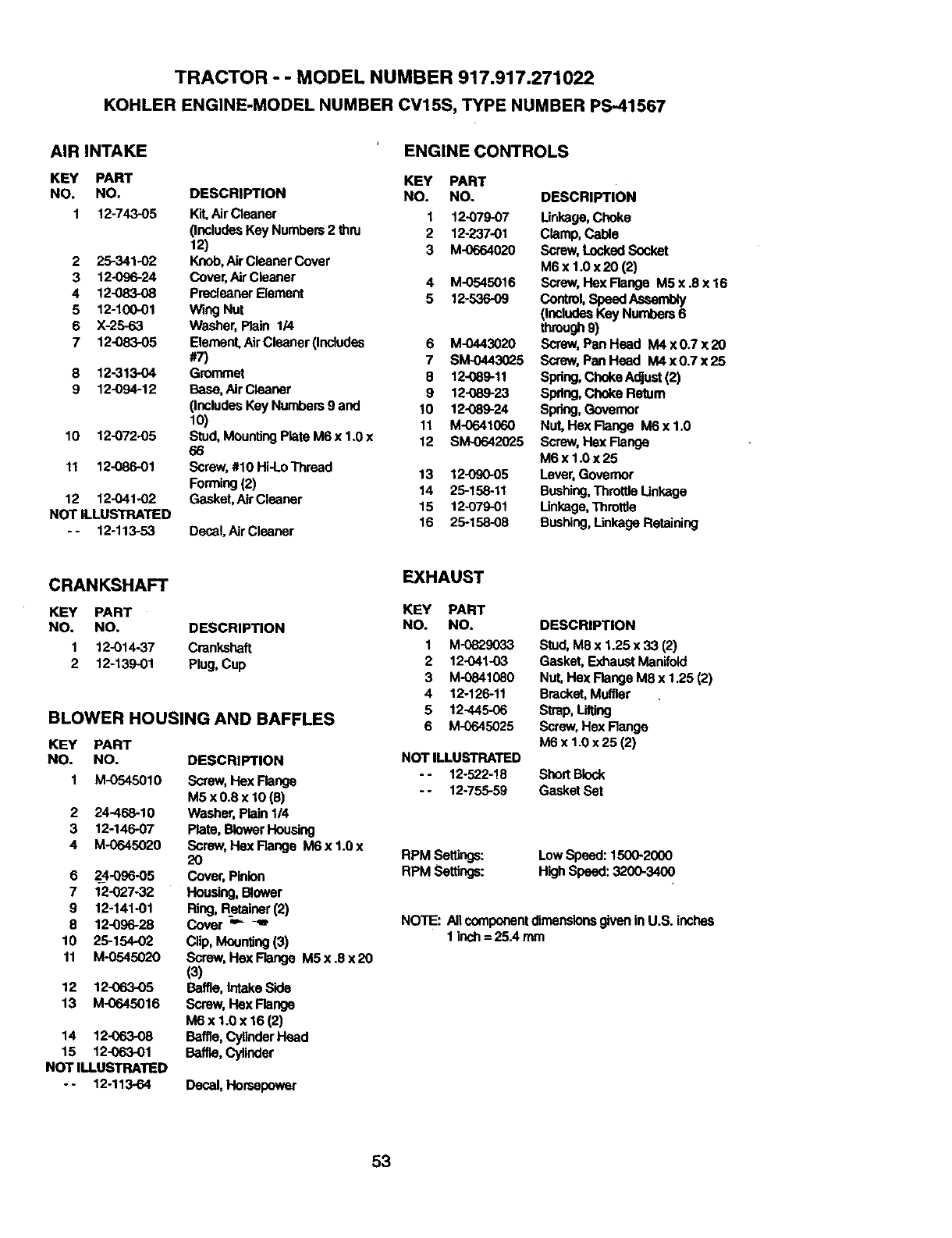
TRACTOR --MODEL NUMBER 917.917.271022
KOHLER ENGINE-MODEL NUMBER CV15S, TYPE NUMBER PS-41567
AIR INTAKE ENGINE CONTROLS
KEY PART KEY PART
NO. NO. DESCRIPTION NO. NO.
1 12_43-05 _AirCleaner
2 25-341-02
3 12-O96-24
4 12-083-08
5 12-100-01
6 X-25-63
7 12-083-05
8 12-313-04
9 12-094-12
10 12-072-05
11 12-086-01
12 12-041-02
NOT ILLUSTRATED
-- 12-113-53
(IncludesKey Numbers 2 thru
12)
Knob,AirCleaner Cover
Cover,AirCleaner
PrecleanerElement
Wing Nut
Washer, Plain 1/4
Element.AirCleaner (Includes
#7)
Grommet
Base, Air Cleaner
(IncludesKey Numbers9 and
10)
Stud, MountingPlateM6 x 1.0 x
66
Screw,#10 Hi-Lo Thread
Forming(2)
Gasket,Air Cleaner
Decal Air Cleaner
DESCRIPTION
1 12-079-07 Unkage, Choke
2 12-237-01 Clamp, Cable
3 M-0664020 Screw,LockedSocket
M6 x 1.0 x20 (2)
4 M-0545016 Screw, HexFlange M5x.8x16
5 12-536-09 Control,Speed Assembly
(IncludesKey Numbers6
through9)
6 M-044_020 Screw, Pan Head M4 x 0.7 x 20
7 SM-0443025 S_ew, Pan Read M4 x 0.7 x 25
812-089-11 Spdng, Choke Adjuet(2)
9 12-089-23 Spring,Choke Return
10 12-089-24 Spring,Governor
11 M-0641060 Nut. Hex Range M6 x 1.0
12 SM-0642025 Screw,He)( Range
M6x1.0x25
13 12-090-05 Lever, Governor
14 25-158-11 Bushing,Throttle Linkage
15 12-079-01 Linkage,Throttle
16 25-158-08 Bushing,Linkage Retaining
CRANKSHAFT EXHAUST
KEY PART KEY PART
NO. NO. DESCRIPTION NO. NO.
1 12-014-37 Crankshaft 1 M-0829033
2 12-139-01 Plug, Cup 2 12-O41-03
3 M-0841080
4 12-125-11
BLOWER HOUSING AND BAFFLES 5 12-445-06
6 M-0645025
Decal,Horsepower
DESCRIPTION
Stud, M8 x 1.25 x 33 (2)
Gasket, ExhaustManifold
Nut, Hex Flange M8 x 1.25 (2)
Bracket,Muffler
Strap, Lifting
Screw,Hex Range
M6 x 1.0 x 25 (2)
KEY PART
NO. NO. DESCRIPTION NOT ILLUSTRATED
1 M-0545010 Screw, Hex Range - - 12-522-18 ShortBlock
M5 x 0.8 x 10 (8) - - 12-755-59 Gasket Set
2 24-468-10 Washer, Plain 1/4
3 12-146-07 Plate, BlowerHousing
4 M-0645020 Screw, Hex Range M6 x 1.0 x
20 RPM Sefflngs:
6 2_4-096-05 Cover,Pinion RPM Settings:
7 12-027-32 Housing, Bower
9 12-141-01 Ring,Retainer (2)
8 12-096-28 Cover "= _"_ NOTE: All componentdimensionsgivenin U.S. inches
10 25-154-02 Clip, Mounting(3) 1 inch= 25.4 mm
11 M-0545020 Screw, HexFlange M5x.8x20
(3)
12 12-063-05 Baffle, IntakeSide
13 M-0645016 Screw,FlexRange
M6x 1.0 x 16(2)
14 12-063-08 Baffle, CyllnderHead
15 12-063-O1 Baffle,Cylinder
NOT ILLUSTRATED
-- 12-113-64
LowSpeed: 1500-2000
High Speed: 3200-3400
53
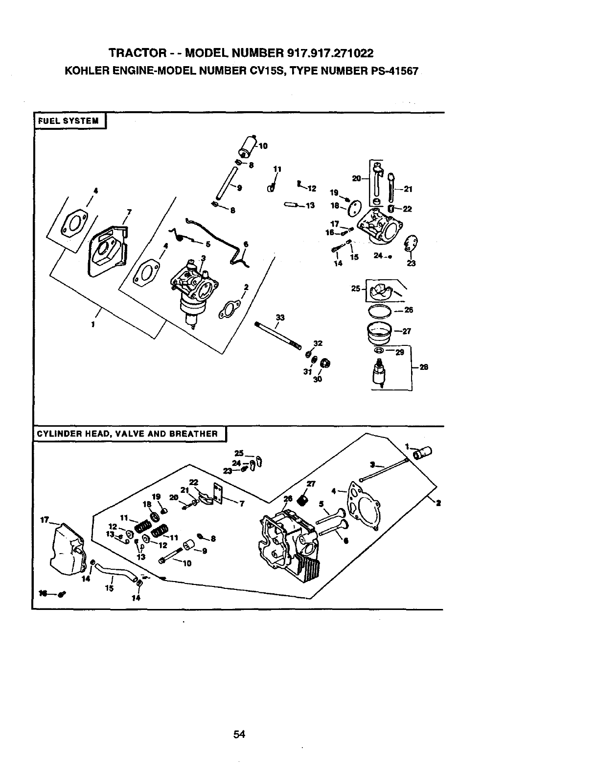
TRACTOR - -MODEL NUMBER 917.917.271022
KOHLER ENGINE-MODEL NUMBER CV15S, TYPE NUMBER PS-41567
FUEL SYSTEM I
4
/
2
; 26_
CYLINDER HEAD, VALVE AND BREATHER I
54
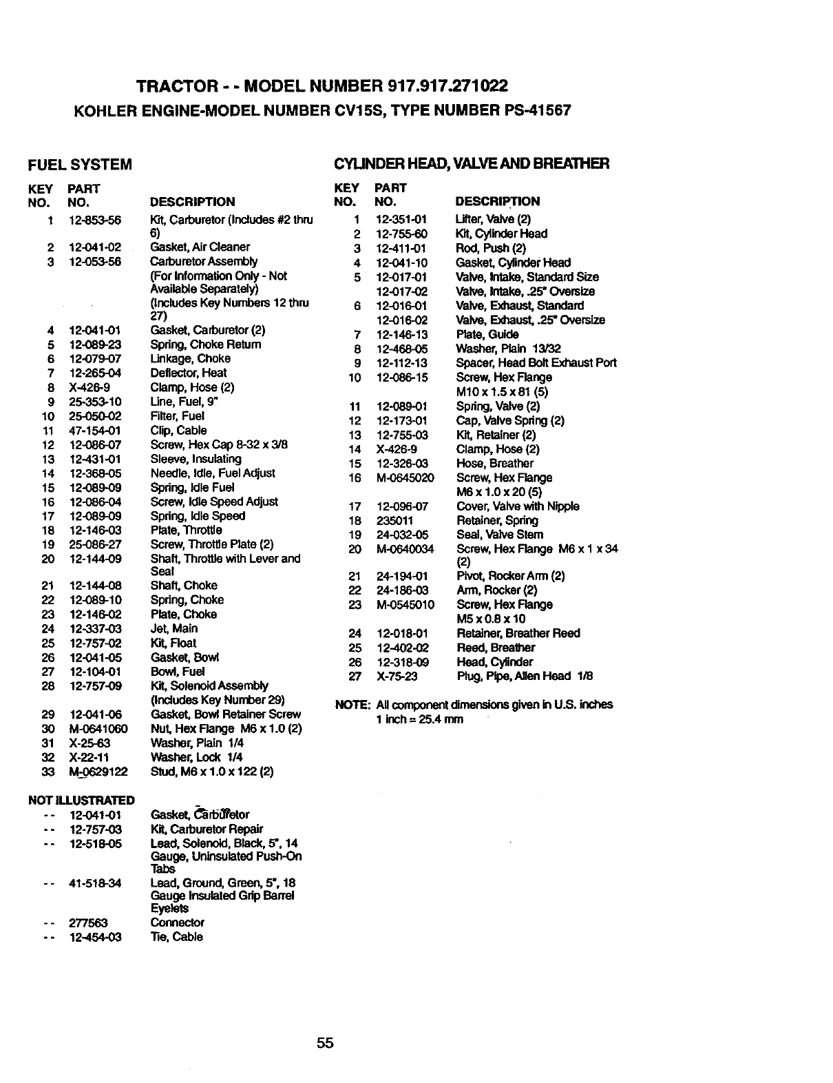
TRACTOR - -MODEL NUMBER 917.917.271022
KOHLER ENGINE-MODEL NUMBER CV15S, TYPE NUMBER PS-41567
FUEL SYSTEM
KEY PART
NO. NO.
1 12-853-56
2 12-041-02
3 12-053-56
412-041-01
5 12-089-23
6 12-079-07
7 12-265-04
8 X-426-9
9 25-353-10
10 25-050-02
11 47-15401
12 12-086-07
13 12-431-01
14 12-368-05
15 12-089-09
16 12-086-04
17 12-089-09
18 12-14603
19 25-085-27
20 12-144-09
21 12-144-08
22 12-089-10
23 12-146-02
24 12-337-03
25 12-757-02
26 12-041-05
27 12-104-01
28 12-757-09
29 12-041-06
30 M-0641060
31 X-25-63
32 X-22-11
33 M-O629122
NOT ILLUSTRATED
-- 12-041-01
- - 12-757-03
-- 12-518-05
- - 41-518-34
- - 277563
- - 12-454-03
CYLINDER HEAD, VALVE AND BREATHER
KEY PART
DESCRIPTION NO. NO.
Kit,Carburetor (Includes#2 thin 1 12-351-01
6) 2 12-755-60
Gasket,AirCleaner 3 12-411-01
CarburetorAssembly 4 12-041-10
(For InformationOnly- Not 5 12-017-01
Available Sepemtely) 12-017-0_
(IncludesKey Numbers 12 thin 6 12-016-01
27) 12-016-02
Gasket, Carburetor(2) 7 12-146-13
Spdng,Choke Retum 8 12-468-05
Unkage, Choke 9 12-112-13
Deflector,Heat 10 12-086-15
Clamp, Hose (2)
Une, Fuel, 9" 11 12-089-01
Filter,Fuel 12 12-173-01
Clip, Cable 13 12-755-03
Screw,Hex Cap 8-32 x 3/8 14 X-426-9
Sleeve, Insulating 15 12-326-03
Needle, Idle, Fuel Adjust 16 M-0645020
Spring, Idle Fuel
Screw, IdlaSpeedAdjuet 17 12-096-07
Spdng, IdleSpeed 18 235011
Plate, Throttle 19 24-032-05
Screw, Throftle Plate (2) 20 M-0640034
Shaft, Throttlewith Lever and
Seal 21 24-194-01
Shaft, Choke 22 24-18603
Spdng, Choke 23 M-0545010
Plate, Choke
Jet, Main 24 12-018-01
Kit,Float 25 12-402-0_
Gasket, Bowl 26 12-318-09
Bowl, Fuel 27 X-75-23
SolenoidAssembly
(IncludesKey Number 29)
Gasket, BowlRetainer Screw
Nut, Hex Flange IV_ x 1.0 (2)
Washer, Plain 1/4
Washer, Lock 114
Stud, M6 x 1.0 x 122 (2)
Gasket, _rbt_or
Kit,Carburetor Repair
Lead, Solenoid,Black, 5", 14
Gauge, UninsulatedPush-On
Tabs
Lead, Ground, Green, 5", 18
Gauge InsulatedGdp Barrel
Eyelets
Connector
"fie,Cable
DESCRIPTION
Lifter,Valve (2)
Kit,CylinderHead
Red, Push(2)
Gasket, CylinderHead
Valve, Intake, Standard Size
Valve, Intake, .25" Oversize
Valve, ExhaustStandard
Valve, Exhaust,.25"Oversize
Plate, Guide
Washer, Plain 13/32
Spacer,Head Bolt ExhaustPort
Screw, Hex Flange
M10x 1.5 x 81 (5)
Spdng,Valve (2)
Cap, _alve Spdng(2)
I_,t,Retainer (2)
Clamp, Hose (2)
Hose, Breather
Screw, Hex Flange
M6 x 1.0 x 20 (5)
Cover,Valvewith Nipple
Retainer,Spdng
Seal, Valve Stem
Screw,Hex Flange M6 x 1 x 34
(2)
Pivot,RockerArm(2)
Arm, Rocker(2)
Screw, Hex Flange
M5 x0o8x 10
Retainer, BreatherReed
Reed, Breather
Head, Cylinder
Plug, Pipe,Allen Head 1/8
NOTE: All componentdimensionsgiven in U.S. inches
1 inch=25.4 mm
55
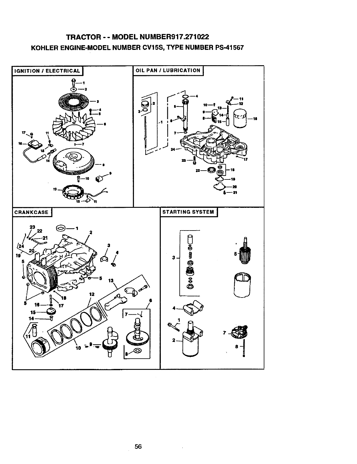
TRACTOR - - MODEL NUMBER917.271022
KOHLER ENGINE-MODEL NUMBER CV15S, TYPE NUMBER PS-41567
IGNITION /ELECTRICAL I
_-,
I- 0
_-,o_
OIL PAN ILUBRICATION I
6--II
CRANKCASE I
23 (_--1 2
3
4
STARTING SYSTEM I
'I
56
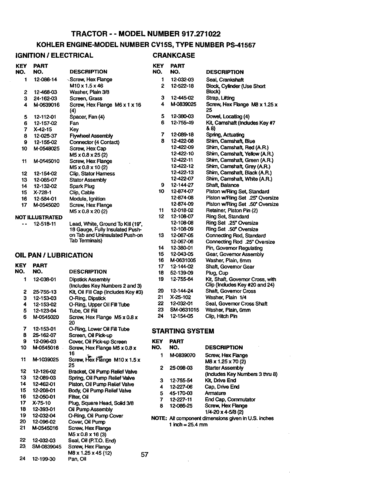
TRACTOR --MODEL NUMBER 917.271022
KOHLER ENGINE-MODEL NUMBER CV15S, TYPE NUMBER PS-41567
IGNITION !ELECTRICAL CRANKCASE
KEY PART KEY PART
NO. NO. DESCRIPTION NO. NO.
1 12-086-14 _Screw, Hex Flange 1 12-032-03
M10x 1.5x46 2 12-522-18
2 12-468-03 Washer, Plain 3/8
3 24-162-03 Screen, Grass 3 12-445-02
4 M-0639016 Screw, HexFlange M6xlx16 4 M-0839025
(4)
5 12-112-01 Spacer, Fan (4) 5 12-380-03
6 12-157-02 Fan 6 12-755-49
7 X-42-15 Key
8 12-025-37 FlywheelAssembly 7 12-089-18
9 12-155-02 Connector(4 Contact) 8 12-422-08
10 M-0548025 Screw, Hex Cap 12-422-09
M5 x 0.8 x 25 (2) 12-422-10
11 M-0FAS010 Screw, Hex Flange 12-422-11
M5 x 0.8 x 10 (2) 12-422-12
12 12-154-02 Clip, Stator Harness 12-422-13
13 12-085-07 StatorAssembly 12-422-07
14 12-132-02 SparkPlug 9 12-144-27
15 X-728-1 Clip, Cable 10 12-874-07
16 12-584-01 Module, Ignition 12-874-08
17 M-0545020 Screw, Hex Flange 12-874-09
M5 x 0.8 x20 (2) 11 12-018-02
NOT ILLUSTRATED 12 12-198-07
- - 12-518-11 Lead, White, GroundTo Kill(19", 12-108-08
18 Gauge, Fully InsulatedPush- 12-108-09
onTab and UninsulatedPush-on 13 12-067-05
TabTerminals) 12-067-06
14 12-380-01
OIL PAN ILUBRICATION 15 12-043-05
16 M-0631005
KEY PART 17 12-144-02
NO. NO. DESCRIPTION 18 52-139-09
1 12-038-01 DipstickAssembly 19 12-755-64
(includesKey Numbers2 and 3)
2 25-755-13 Kit, Oil FillCap (IncludesKey #3) 20 12-144-24
3 12-153-03 O-Ring, Dipstick 21 X-25-102
4 12-153-02 O-Ring, UpperOiIFiilTube 22 12-032-01
5 12-123.O4 Tube, Oil Fill 23 SM-0631015
6 M-0545020 Screw, Hex Flange M5 x 0.8 x 24 12-154-05
20
O-Ring, Lower Oil FillTube
Screen, Oil Pick-up
Cover,Oil Pick-upScreen
Screw, Hex Range M5 x 0.8 x
16
Screw,I_ex F_nge M10 x 1.5 x
25
Bracket,Oil Pump Relief Valve
Spdng,Oil Pump Relief Valve
Pistcrl,Oil Pump ReliefValve
Body.Oil Pump Relief Valve
Filter, Oil
Plug,Square Head, Solid 3/8
Oi/Pump Assembly
O-Ring, Oil Pump Cover
Cover,Oil Pump
Screw, Hex Range
M5 x 0.8 x 16 (3)
Seal, Oil (P.T.O.End)
Screw,Hex Flange
M8 x 1.25 x45 (12) 57
Pan, Oil
7 12-153-01
8 25-162-07
9 12-096-03
10 M-0545016
11 M-1039025
12 12-126-02
13 12-089-03
14 12-462-01
15 12-208-01
16 12-050-01
17 X-75-10
18 12-893-01
19 12-032-04
20 12-096-02
21 M-0545016
22 12-032-03
23 SM-0839045
24 12-199-30
DESCRIPTION
Seal, Crankshaft
Block,Cylinder(Use Short
Bk_k)
Strap, Lifting
Screw, Hex Flange M8 x 1.25 x
25
Dowel, LocaUng(4)
Kit,Camshaft (includesKey #7
&8)
Spring,Actuating
Shim, Camshaft, Blue
Shim, Camshaft, Red (A.R.)
Shim, Camshaft, Yellow(A.R.)
Shim, Camshaft, Green (A.R.)
Shim,Camshaft, Grey (A.R.)
Shim,Camshaft, Black (A.R.)
Shim,Camshaft, White (A.R.)
Shaft, Balance
PistonwiRing Set, Standard
Pistonw/Ring Set .25"Oversize
Pistonw/Ring Set .50"Oversize
Retainer, Piston Pin (2)
RingSet, Standard
RingSet .25" Oversize
RingSet .50" Oversize
ConnectingRod,Standard
Connecting ROd .25" Oversize
Pin, Governor RegulalJng
Gear, GovernorAseambly
Washer, Plain, 6mrn
Shaft,Governor Gear
Plug, Cup
Kit,Shaft, Govemor Cross,with
Clip (IncludesKey #20 and 24)
Shaft, Govemor Cross
Washer. Plain 1/4
Seal, GovernorCrossShaft
Washer, Plain, 6ram
Clip, Hitch Pin
STARTING SYSTEM
KEY PART
NO. NO.
1 M-0839070 Screw, Hex Flange
M8 x 1.25 x 70 (2)
2 25-098-03 StarterAssembly
(IncludesKey Numbers 3 thru 8)
3 12-755-54 K'_ Drive End
4 12-227-06 Cap, Drive End
5 45-170-03 Armature
7 12-227-11 EndCap, Commutator
8 12-086-25 Screw, Hex Range
1/4-20 x 4-5/8 (2)
NOTE: Allcomponentdimensionsgivenin U.S. inches
1 inch= 25.4 mm
DESCRIPTION

58

SUGGESTED GUIDE FOR SIGHTING SLOPES FOR SAFE OPERATION
_r _
I""
SIGHTING
GUIDE
ONLY RIDE UP AND DOWN HILL,
NOT ACROSS HILL
O1
(D
I
Operate your Tractor up and down the face of slopes (not I
greater than 15 '), never across the face. Make turns gradu- I
ally to prevent tipping or loss of control. Exercise extreme
caution when changing dlrecUon on slopes.

For the repair or replacement parts you need
delivered directly to your home
Call 7 am - 7 pm, 7 days a week
1-800-366-PART
(1-600-366-7278)
Para ordenar piezas con entrega a
domicilio - 1-600-659-7084
For in-house major brand repair service
Call 24 hours a day, 7 days a week
1-800-4-REPAIR
(1-800-473-7274)
Para pedir servicio de reparaci6n a
domicilio - 1-800-676-5811
For the location of a Sears Parts and
Repair Center in your area
Call 24 hours a day, 7 days a week
1-800-488-1222
For information on purchasing a Sears
Maintenance Agreement or to inquire
about an existing Agreement
Call 9 am - 5 pm, Monday-Saturday
1-800-827-6655
Iilii_
HI|H||
WherJ requesting service or ordering
parts, always provide the following
information:
•Product Type •Part Number
•Model Number -Part Description
SHARS
Amenca's Repair Specia/_sts
165012 REV.3 10.15.98 VB/RD/RH Printed in U.S.A.
