Craftsman 917271041 User Manual LAWN TRACTOR Manuals And Guides 98100082
CRAFTSMAN Lawn, Tractor Manual 98100082 CRAFTSMAN Lawn, Tractor Owner's Manual, CRAFTSMAN Lawn, Tractor installation guides
User Manual: Craftsman 917271041 917271041 CRAFTSMAN LAWN TRACTOR - Manuals and Guides View the owners manual for your CRAFTSMAN LAWN TRACTOR #917271041. Home:Lawn & Garden Parts:Craftsman Parts:Craftsman LAWN TRACTOR Manual
Open the PDF directly: View PDF ![]() .
.
Page Count: 64

Owner's Manual
rRRFTSMRN"
16.0 HP
ELECTRIC START
42" MOWER
AUTOMATIC
LAWN TRACTOR
Model No.
917.271041
• Safety
• Assembly
•Operation
• Maintenance
• Repair Parts
CAUTION:
Read and follow all
Safety Rules and Instructions
before operating this equip-
ment.
For answers to your questions
about this product, Call:
1-800-659-5917
Sears Craftsman Help Une
5 am- 5 pm, Mon - Sat
Seam, Roebuck and Co., Hoffman Estates, IL 60179
Warranty ................................................. 2
Safety Rules ........................................... 2
Product Specifications., ......................... 5
Assembly ................................................ 8
Operation .............................................. 11
Maintenance Schedule.. ............ _........ ,.18
Maintenance......................................... 18
Service and Adjustments ...................... 22
Storage ................................................. 28
Troubleshooting.................................... 29
Repair Parts ......................................... 34
Parts Ordedng ....................... Back Cover
LI_IITED TWO YEAR WARRANTY ON CRAFTSMAN RIDING EQUIPMENT
For two (2) years from the date of purchase, if this Craftsman Riding Equipment is main-
rained, lubdcated and tuned up according to the instructions in the owner's manual,
Sears will repair or replace, free of charge, any parts found to be defective in matadal or
workmanship.
This Warranty does not cover:.
• Expendable items which become worn during normal use, such as blades, spark
plugs, air cleaners, belts, etc.
•Tire replacement or repair caused by punctures from outside objects, such as nails,
thoms, stumps, or glass.
• Repairs necessary because of operator abuse, negligence, improper storage or acci-
dent or the failure to maintain the equipment according to the instructions contained in
the owner's manual.
•Riding equipment used for con_mercial or rental purposes.
LIMITED 90 DAY WARRANTY ON BATTERY
For ninety(90) days from date of purchase, if any battery included with this dding equip-
ment proves defective in material or workmanship and our testing determines the bat-
tery will not hold a charge, Sears will replace the battery at no charge. In-home warranty
service on your Craftsman dding equipment is available at no charge for 30 days from
the date of purchase. Please contact your nearest servicecenter. After 30 days from the
date of purchase, warranty service is available by taking your Craftsman dding equip-
ment to your nearest Sears Service Center. (In-home .warrantyservice will still be avail-
able after 30 days_rom the date ofpurchase but a standard tdp charge will apply). This
warranty applies only while this product is in the United States. This Warranty gives you
specific legal rights,and you may also have other dghts which may vary from state to
state.
Sears, Roebuck and Co., D/817 WA, Hoffman Estates, IL 60179
GENERAL OPERATION
•Read, understand, and follow all instruc-
tions in the manual and on the machine
before starting.
•Only allow responsible adults, who are
familiar with the instructions, to operate
the machine.
•Clear the area of objects such as rocks,
toys, wire, etc., which could be picked
up and thrown by the blade.
•Be sure the are_ is clear of other people
_bpfore mowing, iSto p machine if anyone
enters the area.
2
•Never carry passengers.
•Do not mow in reverse unless absolute-
ly necessary. Always look down and
behind before and while becking.
•Be aware of the mower discharge direc-
tion and do not point it at anyone. Do
not operate the mower without either
the entire grass catcher or the guard in
place,
•Slow down before turning.
•Never leave a running machine unat-
tended. Always tum off blades, set park-
ing brake, stop engine, and remove
keys before dismounting.
• Turnoff bladeswhennotmowing.
*Stop engine before removing grass
catcher or unclogging chute.
•Mow only in daylight or good artificial
ligM.
•Do not operate the machine while under
the influence of alcohol or drugs.
•Watch for traffic when operating near or
crossing roadways.
•Use extra care when _oeding or unload-
ing the machine into a trailer or truck.
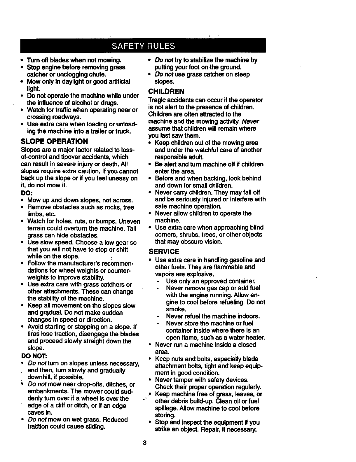
SLOPE OPERATION
Slopes are a major factor related to loss-
of-control and tipover accidents, which
can result in severe injury or death. All
slopes require extra caution, if you cannot
back up the slope or if you feel uneasy on
it, do not mow it.
DO-
* Mow up and down slopes, not across.
•Remove obstacles such as rocks, tree
limbs, etc.
• Watch for holes, ruts, or bumps. Uneven
terrain could overturn the machine. Tall
grass can hide obstacles.
•Use slow speed. Choose a low gear so
that you will not have to stop or shift
while on the slope.
•Follow the manufacturer's recommen-
dations for wheel weights or counter°
weights to improve stability.
•Use extra care with grass catchers or
other attachments. These can change
the stability of the machine.
•Keep all movement on the slopes slow
and gradual. Do not make sudden
changes in speed or direction.
•Avoid starting or stopping on a slope. If
tii:es lose traction, disengage the blades
and proceed slowly straight down the
slope.
DO NOT:
•Do nottum on slopes unless necessary,
and then, turn slowly and gradually
downhill, if possible.
Do not mow near drop-offs, ditches, or
embankments. The mower could sud-
donly turn over if a wheel is over the
edge of a cliff or ditch, or if an edge
caves in.
•Do not mow on wet grass. Reduced
tra_clion could cause sliding.
• DOnottry to stabilize the machine by
puttingyour foot on the ground.
•Do not use grass catcher on steep
slopes.
CHILDREN
Tragic accidents can occur if the operator
is not alert to the presence of children.
Children are oftenattracted tothe
machine and the mowingactivity. Never
assume that childrenwill remain where
you last saw them.
• Keep childrenout of the mowing area
and under the watchfulcare of another
responsible aduif.
•Be alert and turn machine off if children
enter the area.
•Before and when backing, lookbehind
and down for small children.
•Never carry children.They may fall off
and be seriouslyinjured or interfere with
safe machine operation.
•Never allow children to operate the
machine.
•Use extra care when approaching blind
comers, shrubs, trees, or other objects
that may obscurevision.
SERVICE
•Use extra care in handlinggasoline and
other fuels. They are flammable and
vapors are explosive.
Use onlyan approved container.
Never remove gas cap or add fuel
with the engine running. Allowen-
gine to cool before refueling. DO not
smoke.
Never refuel the machine indoors.
Never storethe machine or fuel
container inside where there is an
open flame, such as a water heater.
•Never run a machine inside a closed
area.
•Keep nuts and bolts,especially blade
attachment bolts,tightand keep equip-
ment in good condition.
•Never tamper with safety devices.
Check their proper operation regulady.
•Keep machinefree of grass, leaves, or
other debris build-up. Clean oilor fuel
spillage. Allow machine to cool before
stodng.
•Stop and inspectthe equipment ifyou
stdke an object. Repair, if necessary,
before restarting.
•Never make adjustments or repairs with
the engine running.
•Grass catcher components are subject
to wear, damage, and deterioration,
which could expose moving pads or
allow objects to be thrown. Frequently
check components and replace with
manufacturer'srecommended pads,
when necessary.
•Mower blades are sharp and can cut.
Wrap the blade(s) or wear gloves, and
use extra caution when servicing them.
•Check brake oparetion frequently.
Adjust and service as required.
•Be sure the area is clear of other people
before mowing. Stop machin e if anyone
enters the area.
•Never carry passengers.
•Do not mow in reverse unless absolute-
ly necessary. Always look down and
behind before and while backing.
•Never carry children. They may fall off
and be seriously injured or interfere with
safe machine operation.
• Keep children out of the mowing area
and under the watchful care of another
responsible adult.
• Be aled and turn machine off if children
enter the area.
•Before and when backing, look behind
and down for small children.
•Mow up and down slopes (15 ° Max), not
_CreSS,
•Remove Obstacles such as recks, tree
limbs, etc.
•Watch for holes, ruts, or bumps. Uneven
terrain could ovedum the machine. Tall
grass can hide obstacles.
•Use slow speed. Choose alow gear so
that ybu will not have to stop or shift
while on the slope.
•Avoid starting or stopping on a slope. If
tires lose traction, disengage the blades
and proceed slowly straight down the
slope.
•Donottumonslopasunlessnecessary,
and then, turn slowly and gradually
downhill, if possible.
_,Look for this symbol to point out impor-
tant safety precautions. It means CAU-
TIONifl BECOME AWARE!I! YOUR SAFE-
TY IS INVOLVED.
_,C-AUTION: In order to prevent acciden-
tal stading when setting up, trenspoding,
adjusting or making repairs always discon-
nect spark plug wire and place wire where
it cannot contact spark plug.
_,WARNING: The engine exhaust from
this product contains chemicals known to
the State of California to cause cancer,
bidh defects, or other reproductive harm.
4
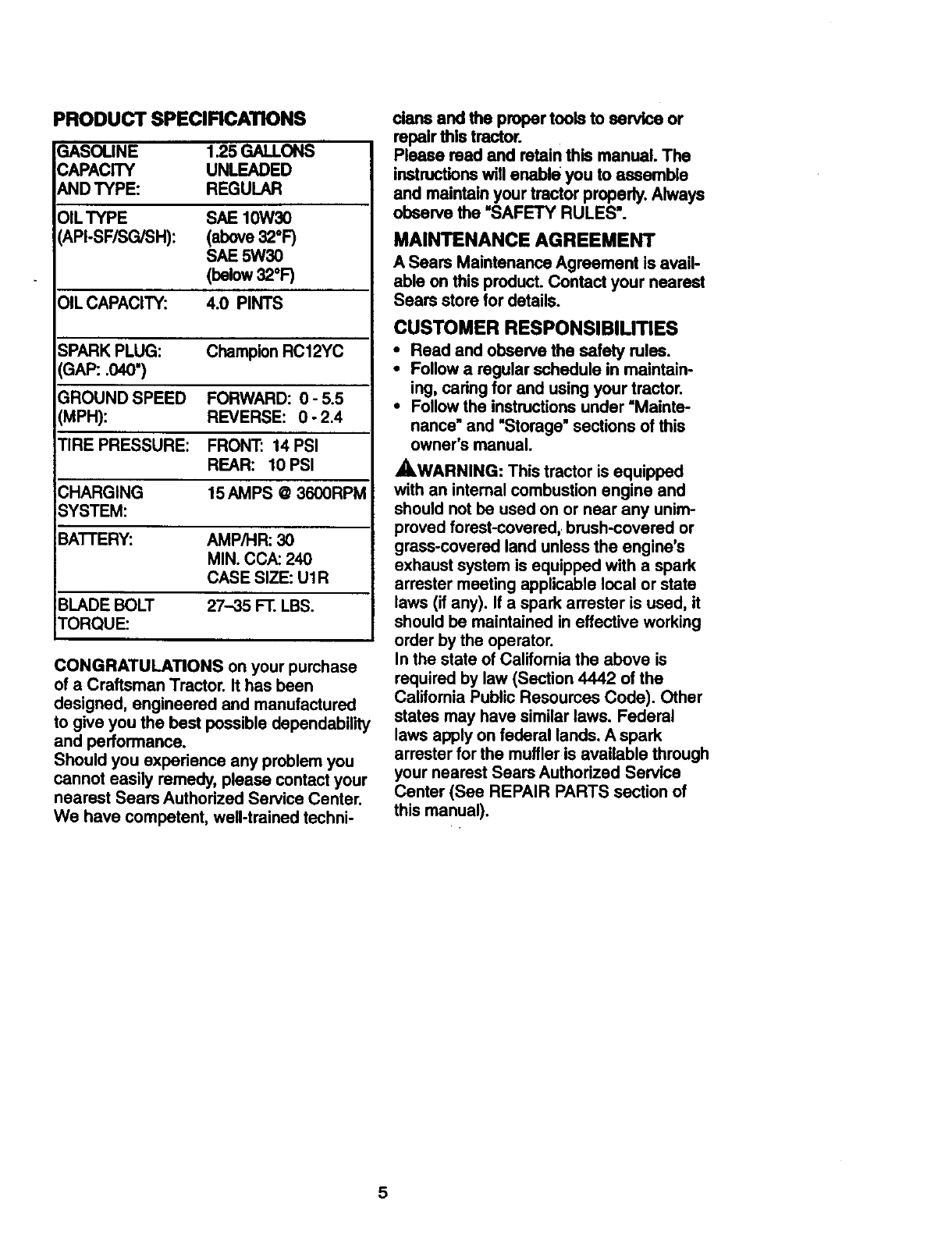
PRODUCT SPECIFICATIONS
3ASOUNE 1.25GALLONS
CAPACITY UNLEADED
fkNDTYPE: REGULAR
OILTYPE
API-SF/SG/SH):
OIL CAPACITY:
SAE 10W30
(above32°F)
SAP- 5W30
(below32°F)
4.0 PINTS
ChampionRC12YC
FORWARD: 0 - 5.5
REVERSE: 0 -2.4
SPARK PLUG:
GAP: .040")
GROUND SPEED
(MPH):
TIRE PRESSURE: FRONT: 14 PSI
REAR: 10 PSI
CHARGING 15 AMPS @3600RPM
;SYSTEM:
iBA'I'I'ERY: AMP/HR: 30
MIN. CCA:240
CASE SIZE:U1R
BLADEBOLT 27-35 FT. LBS.
TORQUE:
CONGRATULATIONS on your purchase
of a Craftsman Tractor. It has been
designed, engineered and manufactured
to give you the best possible dependability
and performance.
Should you experience any problem you
cannot easily remedy, please contact your
nearest Sears Authorized Service Center.
We have competent, well-trained techni-
clans and the proper tools to service or
repair this tractor.
Please read and retain this manual. The
instructionswill enable you to assemble
and maintain your tractor properly.Always
observe the =SAFETY RULES'.
MAINTENANCE AGREEMENT
ASears Maintenance Agreement is avail-
able on this product.Contact your nearest
Sears store for details.
CUSTOMER RESPONSIBILITIES
• Read and observe the safety rules.
•Follow a regular schedule in maintain-
ing, cadng tor and using yOur tractor.
•Follow the instructions under =Mainte-
nance" and "Storage" sections of this
owner's manual.
AWARNING: This tractor is equipped
with an intemal combustion engine and
should not be used on or near any unim-
proved forest-covered, brush-covered or
grass-covered land unless the engine's
exhaust system is equipped with a spark
arrester meeting applicable local or state
laws (if any). If a spark arrester is used, it
should be maintained in effective working
order by the operator.
In the state of California the above is
required by law (Section 4442 of the
California Public Resources Code). Other
states may have similar laws. Federal
laws apply on federal lands. A spark
arrester for the muffler is available through
your nearest Sears Authorized Service
Center (See REPAIR PARTS section of
this manual).
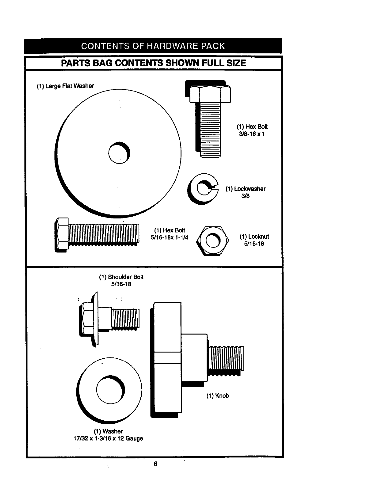
PARTS BAG CONTENTS SHOWN FULL SIZE
(1) Large Rat Washer
(1) Hex Bolt
3/8-16 x 1
(1) Lockwasher
3/8
(1) Hex Bolt
5/16-18x 1-1/4 @(1) Locknut
5/16-18
(1) Shoulder Bolt
5/16-18
©(1) Knob
(1) Washer
17/32 x 1-3/16 x 12 Gauge
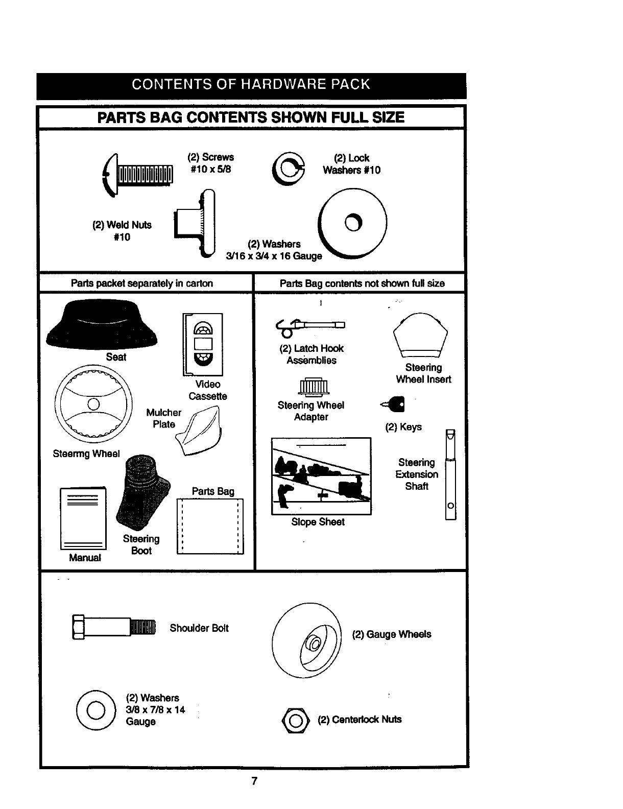
PARTS BAG CONTENTS SHOWN FULL SIZE
/(2) Screws /_ (2) Lock
i__ #10 x 5/8 _b_ Washers #10
._10_w_.ug
Parts packet separately in carton
Seat
,,,,
7m
r--n
Video
Cassefte
Mulcher f/
Plate'S_/!
Parts Bag
Steering ,
Boot
Manual
s
I
I
I
I
Parts Bag contents not shown full size
I
12) Latch Hook
Assemblies Steedng
Wheel Insert
SteeringWheel <:_
Adapter
Slope Sheet
I
(2) Keys
Steering =
Extension
Shaft
c
_I
(_ (2) Washers
3/8 x7/8 x 14
Gauge
Shoulder Bolt I (2) Gauge Wheels
2) Centedock Nuts
7
Your new tractor has been assembled at the factory with exception of those parts left
unassembled for shipping purposes.To ensure.safe and proper operation of your tractor
all partsand hardware you assemble must be t,ghtened securely. Use the correct tools
as necessary to insure propertightness. Review the video cassette before you begin.
TOOLS REQUIRED FOR • Remove protective materialsfrom trec-
ASSEMBLY tor hood and grill.
IMPORTANT: Check for and remove any
staples in skid that may puncturetires
where tractor is to roll offskid.
A socket wrench set will make assembly
easier. Standard wrench sizes you need
are listed below.
(1) 9/16" wrench (1) 3/4" Socket w/
(1) Pliers drive rachet
(2) 1/2" wrench (1) Phillips Screw-
(1) Utility knife driver
(._/).hTirepressure gauge (1) 3/4" wrench
en fight or lefthand is mentioned in
this manual, it means, from your point of
view, when you are in the operatmg posi-
tion (seated behind the steering wheel).
TO REMOVE TRACTOR FROM
CARTON
UNPACK CARTON
•Remove all accessible loose parts and
parts boxes from shipping carton (See
page 6).
•Cut, from top to bottom, along lines on
all four comers of shipping carton, and
lay panels flat.
• Check for any additional loose parts or
boxes and remove.
BEFORE ROLLING TRACTOR OFF
SKID
ATTACH STEERING WHEEL
ASSEMBLE EXTENSION SHAFTAND
BOOT
•Slide extension shaft onto lower steer-
ing shaft. Align mounting holes in exten-
sion and lower shafts and install 5/16
hex bolt and Iocknut. Tighten securely.
IMPORTANT: Tighten bolt and nut secure-
ly to 18-22 ft. Ibs. torque.
•Place tabs of steering boot over tab
slots in dash and push down to secure.
INSTALL STEERING WHEEL
•Position front wheels of the tractor so
they are pointingstraight forward.
•Slide steering wheel adapter onto steer-
ing shaft extension.
•Position steering wheel so cross bars
are horizontal (left to fight) and slide
inside boot and onto adapter.
issemble large fiat washer, 3/8 lock
washer, 3/8. hex bolt and tighten securely.
steenng wheel insert into center
of steering wheel.
Insert
_-. 3/8 Hex Bolt
Large Rat_"_<_
Washer ._ __8 Lockwasher
i I _ Steering
Steedng Wheel J _Boot
ExtensionShaft
__._ Adapter
5/16 Hex
5/16 Locknut_'_" _ Bolt
Lower ,' s, "_""
Steering-- -'1_, " ""
r i
Shaft :... .,
%,%-_ iI#
TO ROLL TRACTOR OFF SKID (See
Operation section for location and
function of controls)
Press lift lever plunger and raise attach-
ment lift lever to itshighest position.
Release parking brake by depressing
clutch/brake pedal.
Place freewheel control in freewheeling
p,.fOoSitionto disengage transmission (See
TRANSPORT" in the Operatton
section of this manual).
•Roll tractor forward off skid.
•Remove banding holding discharge
guard up against tractor.
8
HOW TO SET UP YOUR TRACTOR
CHECKBATTERY
• Liftseatpanto raisedpositionand open
battery box door.
• If this battery is put into service after
month and year indicated on label (label
located between terminals) charge bat-
tory for minimum of one hour at 6-10
amp6. (See "BATTERY" in Maintenance
section of this manual for charging
instructions).
Seat Pan
Battery
Label
Terminal
b •
ASSEMBLE GAUGE WHEELS TO
MOWER DECK
The gauge wheels are designed to keep
the mower deck in proper position when
_yooperatingmower. Be sure they are proper-
adjusted to ensure optimum mower per-
rmance.
•Assemble gauge wheels with tractor on
a flat level surface.
•Adjust mower to desired cuttingheight
(See "TO ADJUST MOWER CUTTING
HEIGHT" in the Operation section of this
manual).
With mower in desired height of cut po-
sition, gauge wheels should be assem-
bled so they are slightly off the ground.
Install gauge wheel in appropriate hole
with shoulder bolt, 3/8 washer, and 3/8-
16 Iocknut and tighten securely.
•Repeat for opposite side installing
gauge wheel in same adjustment hole.
Gauge Wheel
Mounting
Bracket
INSTALL SEAT
Adjust seat before tightening adjustment
knob.
•Remove cardboard packing on seat pan.
Place seat on seat pan and assemble
shoulder bolt. Tighten shoulder bolt
securely.
•Assemble adjustment knob and flat
washer loosely. Do not tighten.
•Lower seat into operating position and
sit on seat.
•Slide seat until a comfortable position is
reached which allows you to press
clutch/brake pedal all the way down.
•Get off seat without moving its adjusted
I_osition.
•Raise seat and tighten adjustment knob
securely.
Seat
_\
Seat Pan
Shoulder
3/8-16
3/8 Washer Shoulder
Gauge Wheel Bolt
CHECK TIRE PRESSURE
The tires on your tractor were ovednflated
at the factory for shipping purposes.
Correct tire pressure is important for best
cutting performance.
•Reduce tire pressure to PSI shown in
"PRODUCT SPECIFICATIONS" on page
5 of this manual.
CHECK DECK LEVELNESS
For best cutting results, mower housing
should be propedy leveled. See "TO
LEVEL MOWER HOUSING" in the Service
and Adjustments section of this manual.
Flat Washer
9
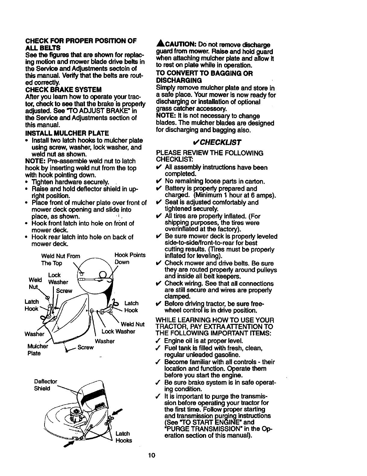
CHECKFORPROPERPosmoN OF
ALL BELTS
Seethefiguresthatare shown for replac-
ing motion and mower blade drive belts in
the Service and Adjustments ssctoln of
this manual. Verify that the belts are rout-
edcorrectly.
CHECK BRAKE SYSTEM
After you learn how to operate your trac-
tor, check to see that the brake is pmpedy
adjusted. See "TO ADJUST BRAKE" in
the Service and Adjustments section of
this manual.
INSTALL MULCHER PLATE
•Install two latch hooks to mulcher plate
using screw, washer, lock washer, and
weld nut as shown.
NOTE: Pre-assemble weld nut to latch
hook by inserting weld nut from the top
with hook pointing down.
•Tighten hardware securely.
Raise and hold deflector shieid in up-
right position.
•Place front of mulcher plate over front of
mower deck opening and elide into
place, as shown. J
•Hook front latch into hole on front of
mower deck.
•Hook rear latch into hole on back of
mower deck.
Weld Nut From Hook Points
The Top Down
Lock
Weld Washer
Latch Latch
Washer LockWasher
Washer
Mulcher "bl- Screw
Plate
Deflector
Shield
Latch
Hooks
,_CAtrnON: Do not remove discharge
guard from mower. Raise and hold guard
when attaching muicher plate and allow it
to rest on plate while in operation.
TO CONVERT TO RAGGING OR
DISCHARGING
Simply remove mulcher plate and store in
a safe place. Your mower is now ready for
dischargingor installationof optional
grass catcher accessory.
NOTE: It is not necessary to change
blades. The mulcher blades are designed
for dischargingand bagging also.
v"CHECKLIST
PLEASE REVIEW THE FOLLOWING
CHECKLIST:
v" All assembly instructions have been
completed.
i/ No remaining loose parts in carton.
i/ Battery is properly prepared and
charged. (Minimum I hour at 6 amps).
i/ Seat is adjusted comfortably and
tightened securely.
t/ All tires are properly inflated. (For
shipping purposes, the tires were
ovednflated at the factory).
v' Be sure mower deck is properly leveled
side-to-side/front-to-rear for best
cutting results. ('l]res must be propody
inflated for leveling).
v' Check mower and drive belts. Be sure
they are routed properly around pulleys
andinside all belt keepers.
v' Check wiring. See that all connections
are still secure and wires are propedy
clamped.
v' Before ddving tractor, be sure free-
wheel control is in ddve position.
WHILE LEARNING HOW TO USE YOUR
TRACTOR, PAY EXTRAA'I-I'ENTION TO
THE FOLLOWING IMPORTANT ITEMS:
/Engine oil is at proper level.
/Fuel tank is filled with fresh, clean,
regular unleaded gasoline.
,/ Become familiar with all controls -their
location and function. Operate them
before you start the engine.
,/ Be sure brake system is in safe operat-
ing condition.
/It is important to purge the transmis-
sion before operating your tractor for
the first time. Follow proper starting
and transmission purging instructions
(See "TO START ENGINE and
=PURGE TRANSMISSION" in the Op-
eration section of this manual).
10
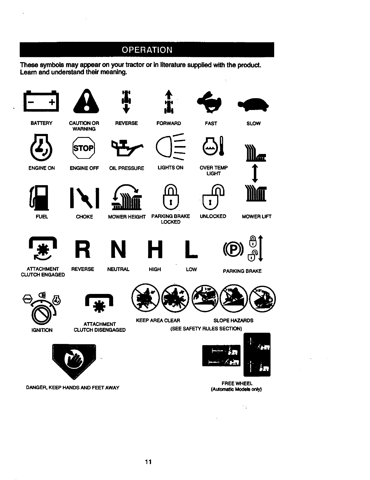
These symbols may appear on your tractoror in literaturesupplied with the product.
Leam and understand their meaning.
BATTERY CAUTION OR REVERSE FORWARD FAST SLOW
WARNING
ENGINE ON ENGINE OFF OIL PRESSURE UGHTS ON OVER TEMP "_
LIGHT
FUEL CHOKE MOWER HEIGHT PARKING BRAKE UNLOCKED MOWER LIFT
LOCKED
N H L
ATrACHMENT REVERSE NEUTRAL HIGH LOW PARKING BRAKE
CLUTCH ENGAGED
ATTACHMENT KEEP AREA CLEAR SLOPE HAZARDS
IGNITION CLUTCH DISENGAGED (SEE SAFETY RULES SECTION)
DANGER, KEEP HANDS AND FEET AWAY FREEWHEEL
(AutomaticModebon_y)
11
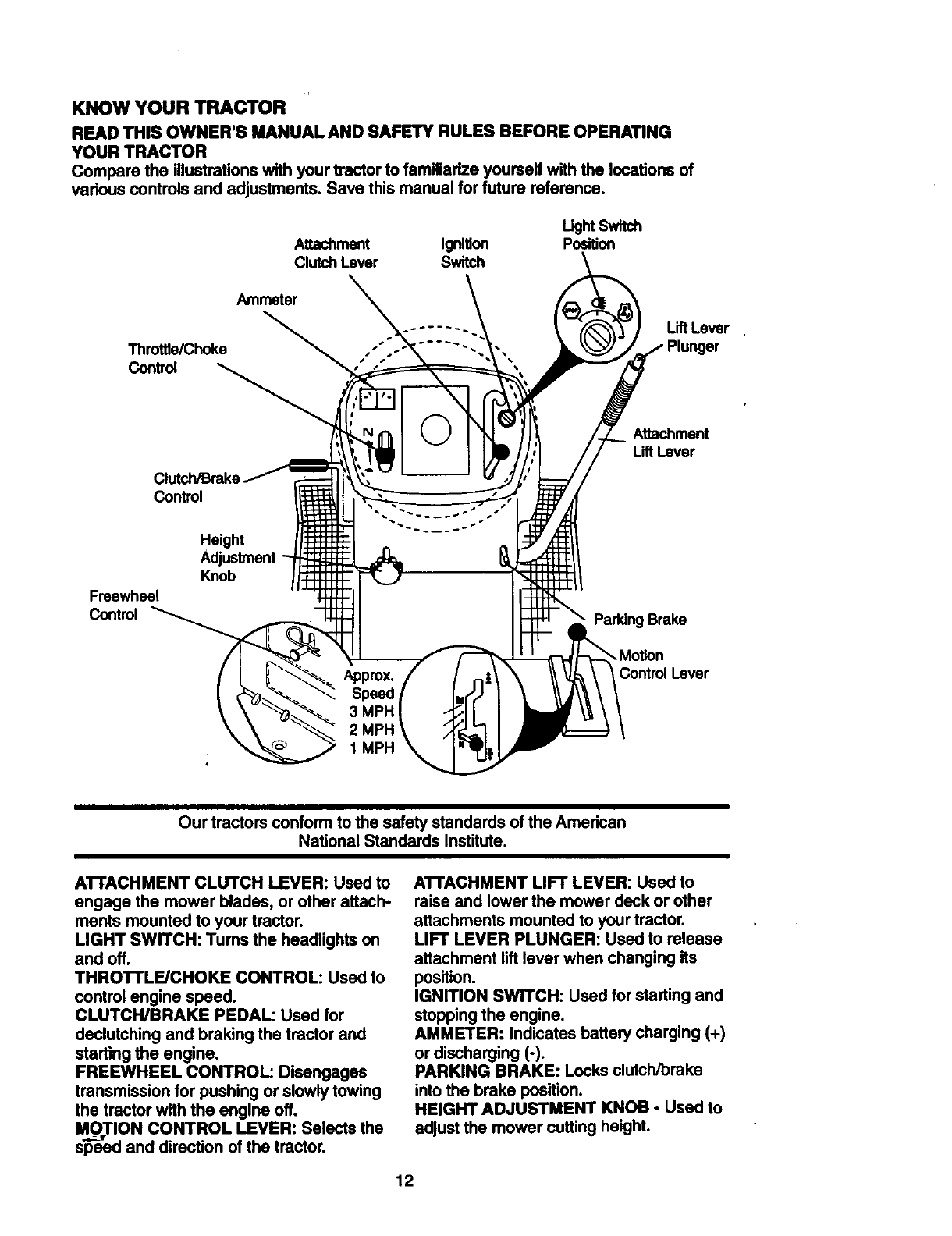
KNOW YOUR TRACTOR
READ THIS OWNER'S MANUAL AND SAFETY RULES BEFORE OPERATING
YOUR TRACTOR
Compare the illustrationswith yourtractorto familiarize youmelf with the locationsof
various controls and adjustments. Save thismanual for future reference.
Attachment Ignition
Clutch Lever Switch
Ught Switch
Position
Throttle/Choke
Control
Ammeter
Lift Lever
Attachment
LiftLever
Control
Freewheel
Control
Height
Knob
Approx•
Speed
3 MPH
1MPH
Brake
•Motion
ControlLever
Our tractors conform to the safety standards of the American
National Standards Institute.
A'n'ACHMENT CLUTCH LEVER: Used to
engage the mower blades, or other attach-
ments mounted to your tractor.
LIGHT SWITCH: Turns the headlights on
and off.
THRO'n'LE/CHOKE CONTROL: Used to
control engine speed.
CLUTCH/BRAKE PEDAL: Used for
declutching and braking the tractor and
starting the engine•
FREEWHEEL CONTROL: Disengages
transmission for pushing or slowly towing
the tractor with the engine off.
_ _CTION CONTROL LEVER: Selects the
speed and direction of the tractor.
ATTACHMENT LIFT LEVER: Used to
raise and lower the mower deck or other
attachments mounted to your tractor.
LIFT LEVER PLUNGER: Used to release
attachment lift lever when changing its
position.
IGNITION SWITCH: Used for starting and
stopping the engine.
AMMETER: Indicates battery charging (+)
or discharging (-).
PARKING BRAKE: Locks clutch/brake
into the brake position.
HEIGHT ADJUSTMENT KNOB - Used to
adjust the mower cutting height.
12
The operation ofany tractor can result in foreign objectsthrown intothe
eyes, which can result in severe eye damage. Always wear safety glasses
or eye shields while operatingyour tractoror performing any adjustments or
repaim. We recommend a wide vision safety mask over spectacles, or stan-
dard safety glasses.
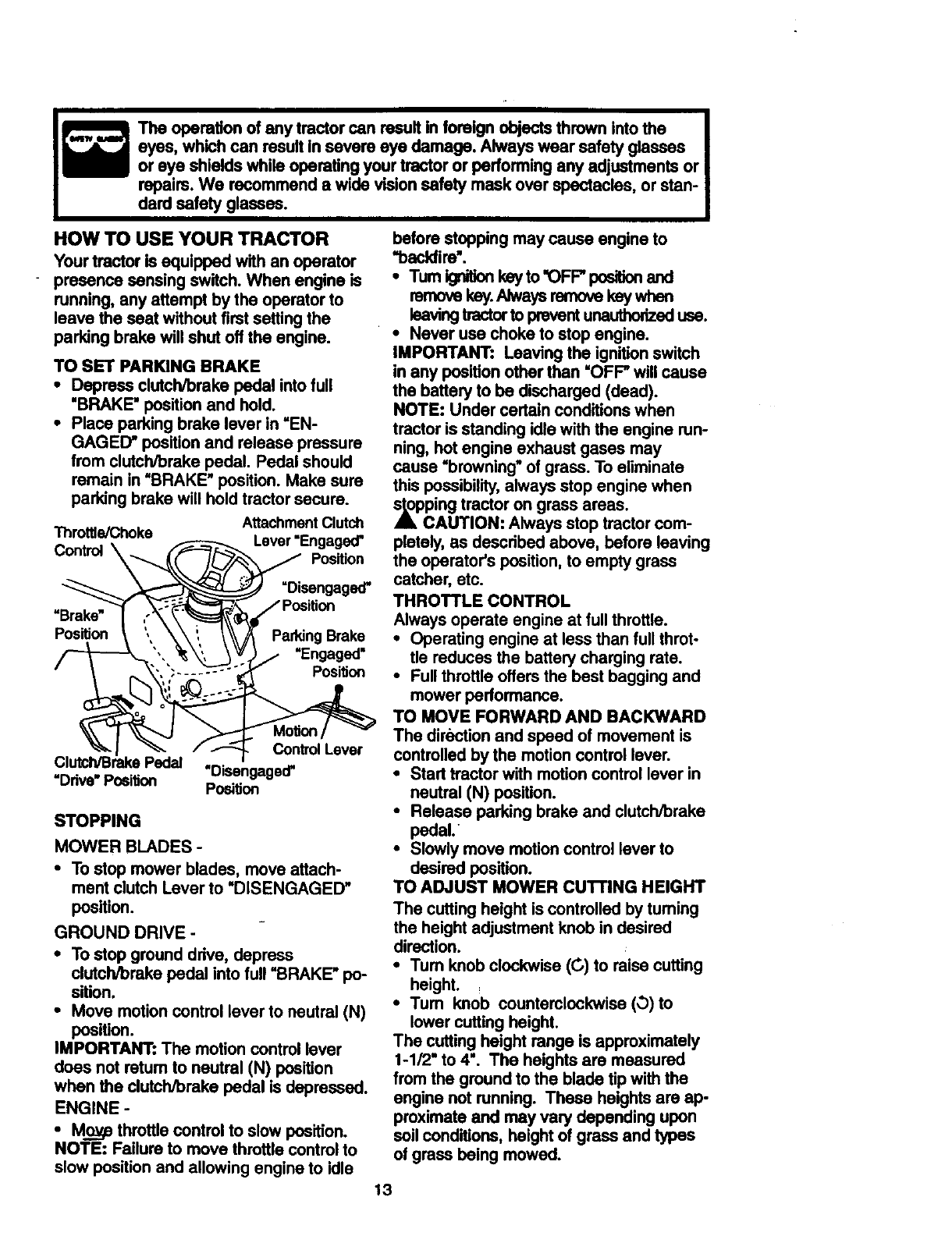
HOW TO USE YOUR TRACTOR
Your tractor is equipped with an operator
presence sensing switch. When engine is
running, any attempt by the operator to
leave the seat without first setting the
parking brake will shut off the engine.
TO SET PARKING BRAKE
• Depress clutch/brake pedal into full
"BRAKE" position and hold.
• Place parking brake lever in "EN-
GAGED" position and release pressure
from clutchlbrake pedal. Pedal should
remain in =BRAKE" position. Make sure
parking brake will hold tractor secure.
Attachment Clutch
Throttle/Choke Lever "Engaged"
Contr(d \__./_ Position
_ __ =Disengaged"
Posib_on \',\ _', _\_ PaddngBrake
,/_'_--_".._'_, 3_t)/ "Engaged"
_- I_/_Control Lever
Clutch/Brake Pedal
=Ddve"Position "Disengaged"
Position
STOPPING
MOWER BLADES -
• To stop mower blades, move attach-
ment clutch Lever to "DISENGAGED"
position.
GROUND DRIVE -
•To stop ground ddve, depress
clutch/brake pedal into full "BRAKE" po-
sition.
•Move motion control lever to neutral (N)
position.
IMPORTANT: The motion control lever
does not retum to neutral (N) position
when the clutch/brake pedal is depressed.
ENGINE -
•M.o.o_ethrottle control to slow position.
NOTE: Failure to move throttle control to
slow position and allowing engine to idle
before stopping may cause engine to
"backfire'.
•Tum ignition key to "OFF" position and
removekey.Alwaysremovekeywhan
leaving tractor to prevent unauthorized use.
•Never usa choke to stop engine.
IMPORTANT: Leaving the ignition switch
in any position other than =OFF" will cause
the battery to be discharged (dead).
NOTE: Under certain conditions when
tractor is standing idle with the engine run-
ning, hot engine exhaust gases may
cause "browning" of grass. To eliminate
this possibility, always stop engine when
,_pcPing tractor on grass areas.
AUTION: Always stop tractor com-
pletely, as descdbed above, before leaving
the operator's position, to empty grass
catcher, etc.
THROTTLE CONTROL
Always operate engine at full throttle.
• Operating engine at less than full throt-
tle reduces the battery charging rate.
•Full throttle offers the best bagging and
mower performance.
TO MOVE FORWARD AND BACKWARD
The direction and speed of movement is
controlled by the motion control lever.
•Start tractor with motion control lever in
neutral (N) position.
•Release parking brake and clutch/brake
pedal.
•Slowly move motion control lever to
desired position.
TO ADJUST MOWER CUTI'ING HEIGHT
The cutting height is controlled by tuming
the height adjustment knob in desired
direction.
•Tum knob clockwise (C,) to raise cuffing
height.
•Turn knob countemlockwise (O) to
lower cutting height.
The cutting height range is approximately
1-1/2" to 4". The heights are measured
from the ground to the blade tip with the
engine not running. These heights are ap-
proximate and may vary depending upon
soil conditions, height of grass and types
of grass being mowed.
13
• The average lawn should be cut to
approximately2-1/2 inches during the
cool season and to over 3 inches dudng
hot months. For healthier and better
lookinglawns, mow often and after
moderate growth.
•For best cutting performance, grass
over 6 inches in height should be
mowed twice. Make the first cut rela-
tivelyhigh;the second to desired height.
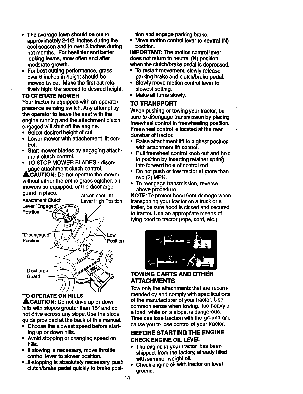
TO OPERATE MOWER
Your tractoris equipped with an operator
presence sensing switch.Any attempt by
the operatorto leave the seat with the
engine running and the attachment clutch
engaged will shut oftthe engine.
•Select desired height of cut.
•Lower mower with attachement liftcon-
trel.
•Start mower blades by engaging attach-
ment clutchcontrol.
•TO STOP MOWER BLADES - disen-
_cage attachment clutch control.
AUTION: Do not operate the mower
without either the entireLgrass catcher, on
mowers so equipped, or the discharge
guard in place. Attachment Lift
Attachment Clutch Lever High Position
Lever "Engaged_'_'_
Position __. /_.
Discharge "_ _
Guard )-_ _p
_OPERATE ON HILLS
CAUTION: Do not drive up or down
hills with slopes greater than 15° and do
not drive across any slope. Use the slope
guide provided at the back of this manual.
•Choose the slowest speed before start-
ing up or down hills.
•Avoid stopping or changing speed on
hills.
•If slowing is necessary, move throttle
control lever to slower position.
•.JfL_stoppingis absolutely necessary, push
clutch/brake pedal quickly to brake posi-
tion and engage perking brake.
•Move motion control lever to neutral (N)
position.
IMPORTANT" The motion controllever
does not ratum to neutral (N) position
when the clutch/brake pedal is depressed.
•To restart movement, slowlyrelease
parking brake and clutch/brake pedal.
•Slowly move motion controllever to
slowest setting.
•Make all turns slowly.
TO TRANSPORT
When pushing or towing your tractor, be
sure to disengage transmission by placing
freewheel control in freewheeling position.
Freewheel control is located at the rear
drawbar of tractor.
•Raise attachment lift to highest position
with attachment lift control.
•Pull freewheel control knob out and hold
in position by inserting retainer spriKg
into forward hole of control rod.
•Do not push or tow tractor at more than
two (2) MPH.
•To reengage transmission, reverse
above procedure.
NOTE: To protect hood from damage when
transporting your tractor on a truck or a
trailer, be sure hood is closed and secured
to tractor. Use an appropriate means of
tying hood to tractor (rope, cord, etc.).
TOWING CARTS AND OTHER
ATTACHMENTS
Tow only the attachments that are recom-
mended by and comply with specifications
of the manufacturer of your tractor. Use
common sense when towing. Too heavy of
a load, while on a slope, is dangerous.
Tires can lose traction with the ground and
cause you to lose control of your tractor.
BEFORE STARTING THE ENGINE
CHECK ENGINE OIL LEVEL
• The engine in your tractor has been
shipped, from the factory, already filled
with summer weight oil.
•Check engine oil with tractor on level
ground.
14
•Unthread and remove oil fill cap/dip
stick; wipe oil off. Reineert the dipstick
into the tube and rest oil fill cap on the
tube. Do not thread the cap onto the
tube. Remove and read oil level. If nec-
essary, add oil until "FULL" mark on
dipstick is reached. Do not overfill.
•For cold weather operation you should
change oil for easier starting (See "OIL
VISCOSITY CHART" in the
Maintenance section of this manual).
•To change engine oil, see the
Maintenance section in this manual.
ADD GASOLINE
•Fill fuel tank. Use fresh, dean, regular
unleaded gasoline with a minimum of 87
octane. (Use of leaded gasoline will
increase carbon and lead oxide
deposits and reduce valve life). DO not
mix oil with gasoline. Purchase fuel in
quantities that can be used within 30
days to assure fuel freshness.
IMPORTANT: When operating in tempera-
tures below 32°F(0°C), use fresh, clean
winter grade gasoline to help insure good
,_dwAweather starting.
RNING: Experience indicates that
alcohol blended fuels (called gasohol or
using ethanol or methanol) can attract
moisture which leads to separation and
formation of acids during storage. Acidic
gas can damage the fuel system of an
engine while in storage. To avoid engine
problems, the fuel system should be emp-
tied before storage of 30 days or longer.
Drain the gas tank, start the engine and let
it run until the fuel lines and carburetor are
empty. Use fresh fuel next season. See
Storage Instructions for additional informa-
tion. Never use engine or carburetor
cleene_r products in the fuel tank or perma-
,_nct damage may occur.
AUTION: Fill to bottom of gas tank
filler neck. Do not overfill. Wipe off any
spilled oil or fuel. Do not store, spill or use
gasoline near an open flame.
TO START ENGINE
When starting the engine for the first time
or if the engine has run out of fuel, it will
take extra cranking time to move fuel from
the tank to the engine.
• Be sure freewheel control is in the
transmission engaged position.
•onsest apera pos on,depe s
d0i orakeped and pa ngbrake.
•Place motion control lever in neutral (N)
position.
•Move attachment dutch to "DISEN-
GAGED" position.
•Move throttle control to choke position.
NOTE: Before starting, read the warm and
cold starting procedures below.
•Insert key into ignition and tum key
clockwise to "START" position and
release key as soon as engine starts.
DO not run starter continuously for more
than fifteen seconds per minute. If the
engine dues not start after several
attempts, move throttle control to fast
position, wait a few minutes and try
again. If engine still does not stad,
move the throttle control back to the
choke position and retry.
WARM WEATHER STARTING (50 ° F and
above)
•When engine starts, move the throttle
control to the fast position.
•The attachments and ground drive can
now be used. If the engine does not
acceptthe load, restart the engine and
allow it to warm up for one minute using
the choke as described above.
COLD WEATHER STARTING ( 50 °F and
below)
•When engine starts, allow engine to run
with the throttle control in the choke
position until the engine runs roughly,
then move throttle control to fast pesi-
tion. This may require an engine warm-
up period from several seconds to sev-
eral minutes, depending on the temper-
ature.
AUTOMATIC TRANSMISSION WARM UP
•Before driving the unit in cold weather,
the transmission should be warmed up
as follows:
•Be sure the tractor is on level ground.
•Place the motion control lever in neutral.
Release the parking brake and let the
clutch/brake slowly return to operating
position.
•Allow one minute for transmission to
warm up. This can be done during the
engine warm up period.
• The attachments can also be used dur-
ing the engine warm-up period after the
transmission has been warmed up._
NOTE: At a high altitude (above 3000
feet) or in cold temperatures (below 32 F)
the carburetor fuel mixture may need to be
adjusted for best engine performance.
See "TO ADJUST CARBURETOR" in the
Service and Adjustments section of this
manual.
15
_RGE TRANSMISSION
CAUTION: Never engage or disen-
gage freewheel lever while the engine is
running.
To ensure proper operation and perfor-
mance, it is recommended that the trans-
mission be purged before operating tractor
for the first time. This procedure will
remove any trapped air inside the trans-
mission which may have developed during
shipping of your tractor.
IMPORTANT: Should your transmission
require removal for service or replace-
ment, it should be purged after reinstalla-
tion before operating the tractor.
• Place tractor safely on level surface with
engine off and parking brake set.
• Disengage transmission by placing free-
wheel control in freewheeling position
(See "TO TRANSPORT" in this section
of manual).
•Sitting in the tractor seat, start engine.
After the engine is running, move throt-
tle control to slow position. With motion
control lever in neutral (N) position,
slowly disengage clutch/brake'pedal.
•Move motion control lever to full forward
position and hold for five (5) seconds.
Move lever to full reverse position and
hold for five (5) seconds. Repeat this
procedure three (3) times.
NOTE: During this procedure there will be
no movement of drive wheels. The air is
being removed from hydraulic drive sys-
tem.
•Move motion control lever to neutral (N)
position. Shut off engine and set parking
broke.
•Engage transmission by placing free-
wheel control in driving position (See
"TO TRANSPORT" in this section of
manual).
•Sitting in the tractor seat, start engine.
After the engine is running, move throt-
tle control to half (1/2) speed. With
motion control lever in neutral (N) posi-
tion, slowly disengage clutchJ'omke
pedal.
•Slowly move motion control lever for-
ward; after the tractor moves approxi-
mately five (5) feet, slowly move motion
control lever to reverse position. After
the tractor moves approximately five (5)
feet return the motion control lever to
the neutral (N) position. Repeat this pro-
"_dum with the motion control lever
three (3) times. 16
•Your tractor is now purged and ready for
normal operation.
MOWING TIPS
•Tim chains cannot be used when the
mower housing is attached to tractor.
•Mower should be propedy leveled for
best mowing performance. See "TO
LEVEL MOWER HOUSING" in the
Service and Adjustments section of this
manual.
•The left hand side of mower should be
used for trimming.
• Ddvesolhatcrq n aredecharg onto
the ares that has been cut. Have h_ecut area
to the dghtof _e tractor.This will resultina
moreevendstrbutionofcippixjsandmob
un ormcutUng.
•When mowing large areas, start by tum-
ing to the right so that clippings will dis-
charge away from shrubs, fences, drive-
ways, etc. After one or two rounds, mow
in the opposite direction making left
hand tums until finished.
•If grass is extremely tall, it should be
mowed twice to reduce load and possi-
ble fire hazard from dded clippings.
Make first cut relatively high; the second
to the desired height.
•Do not mow grass when it is wet. Wet
grass will plug mower and leave unde-
sirable clumps. Allow grass to dry
before mowing.
• Always operate engine at full throttle
when mowing to assure better mowing
performance and proper discharge of
material. Regulate ground speed by se-
lecting a low enough gear to give the
mower the best cutting performance as
well as the quality of cut desired.
•When operating attachments, select a
ground speed that will suit the terrain
and give best performance of the at-
tachment being used.
f
i
MULCHING MOWING TIPS
IMPORTANT:. For best performance, keep
mower housing free of built-up grass and
trash. Clean after each use.
• The special mulching blade will recut
the grass clippings many times and
reduce them In size so that as they fall
onto the lawn they will disperse into the
grass and not be noticed. Also, the
mulched grass will biodegrade quickly
to provide nutdents for the lawn. Always
mulch with your highest engine (blade)
speed as this will provide the best recut-
ting action of the blades.
•Avoid cutting your lawn when it is wet.
Wet grass tends to form clumps and
interferes with the mulching action. The
best time to mow your lawn is the early
aftemoon. At this time the grass has
dried and the newly cut area will not be
exposed to the direct sun.
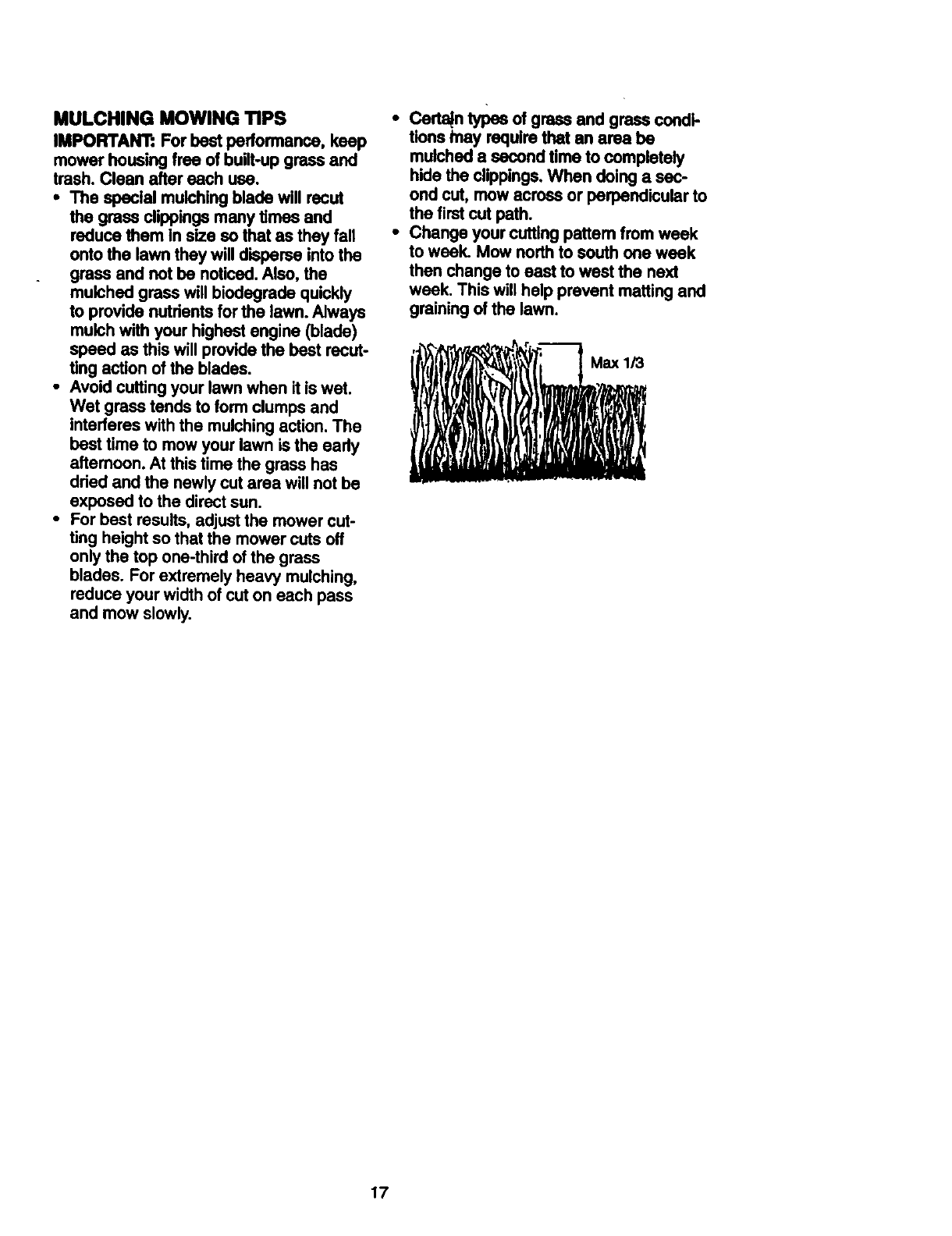
•For best results, adjust the mower cut-
ting height so that the mower cuts off
only the top one-third of the grass
blades. For extremely heavy mulching,
reduce your width of cut on each pass
and mow slowly.
•Certain types of grass and grass condi-
tions tnay require that an area be
mulched a second time to completely
hide the clippings.When doing a sec-
ond cut, mow across or perpendicular to
the firstcut path.
•Change your cutting pattem from week
to week. Mow north to south one weak
then change toeast to west the next
week. This will help prevent matting and
grainingof the lawn.
axl/3
17
CUSTOMER RESPONSIBILITIES
REGULAR SERVICE €l_'y
T interkx_s_t_s I/
R C_ck _Loo_ Famners IV" Ill'7 V'
A Shmpen/Replace Mower Blades _4
TLu_-, _
0_k Ba_l_ I._vel
RC_n Battew and Termlnals/Recharge I_
Check Transaxle Cooling t_'
Adjust BladeBelt(s)Tension k/'s
v',
AdjuSt Motion Drive Belt(s) Tension
Check Engine OH Level _V e
_a,_e Eugineoil Wry.: it/
E Clean Air Filter
NClean Air Screen
Inspect Muffler/Spark An'ester Vp
Replace Oil Filter (If equipped) . _.:
NClean Engine C°°ltng Firm _=
Replace Spark Plug V'
Replace Air Filter Paper Cartridge I_=
Replace Fuel Filter I_
1 .Ct_mo_whenopefalklgunderlheevytoad_lnhlghll_teffiperJtufee. 5-ifequlppedwib_mdJ_l_tstlflt.
2. Service rno_e oflam when operaUng In dirty or d_ condltlons.
3. If iqulpMd w_l oil Mot, ¢;11@ ol ivlfy 50 hcJtl.
4. R_ blad_ n-o_ often when r_ In slu_ly sol.
GENERAL RECOMMENDATIONS
The warranty on this tractor does not cover
items that have been subjected to operator
abuse or negligence. To receive full value
from the warranty, operator must maintain
tractor as instructed in this manual. Some
adjustments will need to be made periodi-
cally to properly maintain your tractor.
All adjustments in the Service and
Adjustments section of this manual should
be checked at least once each season.
• Once a year you shoul d replace the
spark plug, clean or replace air filter, and
check blades and belts for wear. Anew
spark plug and clean air filter assure
proper air-fuel mixture and help your
engine run better and last longer.
BEFORE EACH USE
• Check engine oil level.
•Check brake operation.
•Check tire pressure.
•Check operator presence and intedock
p_stems for proper operation.
•Check for loose fasteners.
e- Not r_qu_KI ff _qukopedwith m_lntenence-free b_tte_y.
7 - Tighten frontsxle pWotbott to 35 ft.Jbe, mexlmtml.
0o r_t ow_um.
LUBRICATION CHART
eS
Zerk Zerk
Wheel
@FrontWheel Bearing
Beadng Zerk Zerk
OAttachment
Clutch
•SAE 30 or 10w30 Motor OIL
• General Purpose Grease
@Refer to Maintenance "Engine"Section
IMPORTANT: Do not oil or grease the pivot
points which have special nylon bear-ings.
Viscous lubricants will attract dust and dirt
that will shorten the life of the self-lubricating
bearings. If you feel they must be. lubricated,
use only .a dry, powdered graphde type lubri-
cant spanngly.
18
TRACTOR
Always observe safety rules when perform-
ing any maintenance.
BRAKE OPERATION
If tractor requires more than six (6) feet
stopping distance at high speed in highest
gear, then brake must be adjusted. (See
- 'I"O ADJUST BRAKE" in the Service and
Adjustmentssection of this manual).
TIRES
• Maintain proper air pressure in all tires
(See "PRODUCT SPECIFICATIONS" on
page 3 of this manual).
•Keep tires free of gasoline, oil, or insect
controlchemicals which can harm rub-
ber.
•Avoid stumps, stones, deep ruts,sharp
objects and other hazards that may
cause tire damage.
NOTE: To seal tire punctures and prevent
flat tires due to slow leaks, tire sealant may
be purchased from your local parts dealer.
Tire sealant also prevents tire dry rot and
corrosion.
OPERATOR PRESENCE SYSTEM
Be sure that operator presence and inter-
lock systems are working properly. If your
tractor does not function as described
below, repair the problem immediately.
•The engine should not start unless the
clutch/brake pedal is fully depressed and
attachment clutch control is in the disen-
gaged position.
•When the engine is running, any attempt
by the operator to leave the seat without
first setting the parking brake should shut
off the engine.
•When the engine is running and the
attachment clutch is engaged, any
attempt by the operator to leave the seat
should shut off the engine._
•The attachment clutch should never
operate unless the operator is in the
mseat.
BLADE CARE
For best results mower blades must be
kept sharp. Replace bent or damaged
blades.
BLADE REMOVAL
•Raise mower to highest position to allow
access to blades.
•Remove hex bolt, lock washer and flat
wesh_er securing blade.
•Install new or resharpened blade with
trailing edge up towards deck as shown. 19
IMPORTANT: To ensure proper assembly,
center hole in blade must align with star on
mandrel assembly.
•Reassemble hex bolt, lock washer and
flat washer in exact order as shown.
•Tighten bolt securely (27-35 Ft. Lbs.
torque).
IMPORTANT: Blade belt is Grade 8 heat
Trailing Blade Mandrel Assembly
Edge Up",_/ Center_--"_
• w s ol,
•A Grade 8 heat treated bolt can be
identifiedby six lines on the bolt head.
treated.
TO SHARPEN BLADE
NOTE: We do not recommend sharpening
blade, but if you do, be sure the blade is
balanced.
Care should be taken to keep the blade
balanced. An unbalanced blade will cause
excessive vibration and eventual damage
to mower and engine.
•The blade can be sharpened with a file
or on a grinding wheel. Do not attempt to
sharpen while it is on the mower.
•To check blade balance, you will need a
5/8" diameter steel bolt, pin, or acone
balancer. (When using a cone balancer,
follow the instructions supplied with bal-
ancer).
•Slide blade onto an unthreaded portion
of the steel bolt or pin and hold the belt
or pin parallel with the ground. If blade is
balanced, it should remain in a horizontal
position. If either end of the blade moves
downward, sharpen the heavy end until
the blade is balanced.
NOTE: Oo not use a nail for balancing
blade. The lobes of the center hole may
appear to be centered, but are not.
Center Hole
or Pin
BATTERY
Yourtractor has a battery charging system
which is sufficientfor normal use.
However, periodic charging of the battery
with an automotive charger will extend its
life.
• Keep battery and terminals clean.
•Keep battery bolts tight.
• Keep small vent holes open.
• Recharge at 6-10 amperes for I hour.
TO CLEAN BATTERY AND TERMINALS
Corrosion and dirt on the battery and ter-
minals can cause the battery to =leak"
power.
•Open battery box door.
•Disconnect BLACK battery cable first
then RED battery cable and remove
battery from tractor.
•Rinse the battery with plain water and
dry.
•Clean terminals and battery cable ends
with wire brush until bright.
• Coat terminals with grease or petroleum
jelly.
•Reinstall battery (See =REPLACING
BATTERY" in the SERVICE AND
ADJUSTMENTS section of this manu-
al).
V BELTS
Check V-belts for deterioration and wear
after 100 hours of operation and replace if
necessary. The belts are not adjustable.
Replace belts if they begin to slip from
wear.
TRANSAXLE COOLING
The transmission fan and cooling fins
should be kept clean to assure proper
cooling.
Do not attempt to clean fan or transmis-
sion while engine is running or while the
transmission is hot:
•Inspect cooling fan to be sure fan
blades are intact and clean.
•Inspect cooling fins for did, grass clip
pings and other materials. To prevent
damage to seals, do not use com-
pressed air or high pressure sprayer to
clean cooling fins.
TRANSAXLE PUMP FLUID
The transaxle was sealed _t the factory
and fluid maintenance is not required for
the life of the transaxle. Should the
transaxle ever leak or require servicing,
contact your nearest authorized service
center.
ENGINE
LUBRICATION
Only use high quality detergent oil rated
with API service classification SF, SG, or
SH. Select the oil's SAE viscosity grade
acodr'ding to your expected operating tem-
perature.
_ItIJRE H_A_ _ NE_k'r€_4LN
Change the oil after every 50 hours of
operation or at least once a year if the
tractor is not used for 50 hours in one
year.
Check the crankcase oil level before start-
ing the engine and after each eight (8)
hours of operation. Tighten oil fill cap/dip
stick securely each time you check the oil
level.
TO CHANGE ENGINE OIL
Determine temperature range expected
before oil change. All oil must meet API
service classification SF, SG, or SH.
•Be sure tractor is on level surface.
•Oil will drain more freely when warm.
•Catch oil in a suitable container.
•Remove oil fill cap/dipstick. Be careful
not to allow dirt to enter the engine
when changing oil.
•Remove drain plug.
•After oil has drained completely, replace
oil drain plug and tighten securely.
•Refill engine with oil through oil fill dip-
stick tube. Pour slowly. Do not overfill.
For approximate capacity see =PROD-
UCT SPECIFICATIONS" on page 3 of
this manual.
•Use gauge on oil fill cap/dipstick for
checking level. Insert dipstick into the
tube and rest the oil fill cap on the tube.
Do not thread the cap onto the tube
when taking reading. Keep oil at
"FULL" line on dipstick. Tighten cap
onto the tube securely when finished.
Air Cleaner Cover Knob
Cover
Foam Nut
Pre-Cleane Rubber
Air Air Cleaner
Base
Papa r _
Cartridge RII
CapO;psUck
2O
CLEAN AIR SCREEN
Air screen must be kept free of dirt and
chaff to prevent engine damage from over-
heating. Clean with a wire brush or com-
pressed air to remove dirt and stubbom
dded gum fibers.
AIR FILTER
. Your engine will not run properly usinga
dirtyair filter. Clean the foam pre-cleaner
after every 25 hoursof operation or every
season. Service paper cartridge every
100 hours of operation or every season,
whichever occursfirst.
Sewice air cleaner more often under dusty
conditions.
•Remove knob and cover.
•Remove wing nut and air cleaner from
base.
TO SERVICE PRE-CLEANER
•Slide foam pre-cleaner off cartddge.
• Wash it in liquid detergent and water.
•Squeeze it dry in a clean cloth. Allow it
to dry.
•Saturate it in engine oil. Wrap it in
clean, absorbent cloth and squeeze to
remove excess oil.
TO SERVICE CARTRIDGE
•Replace a dirty, bent, or damaged car-
tddge.
NOTE: Do not wash the paper cartridge
or use pressurized air, as this will damage
the cartddge.
•Reinstall the pre-cleaner (cleaned
and oiled) over the paper car-
tridge.
•Reassemble air cleaner, wing nut,
cover and tighten knob securely.
CLEAN AIR INTAKE/COOLING AREAS
To insure proper cooling, make sure the
grass screen, coolingfins, and other
extemal surfaces of the engine are kept
clean at all times.
Every 100 hoursof operation (more often
under extremely dusty,dirtyconditions),
remove the blower housingand other
cooling shrouds. Clean the cooling fins
and external surfaces as necessary. Make
sure the coolingshroudsare reinstalled.
NOTE: Operating the engine with a
blocked grass screen, dirtyor plugged
cooling fins, and/or cooling shrouds re-
move_will cause engine damage due to
overheating.
ENGINE OIL'FILTER
Replace the engine oil filter every season
or every other oil change if the tractor is
used more than 100 hours in one year.
•Drain oil from engine crankcase (See
"TO CHANGE ENGINE OIL" in this sec-
tion of this manual, through step remove
drain plug).
•Remove oil filter and wipe off filter
adapter.
•Apply a thin coating of new engine oil to
the rubber gasket on replacement oil fil-
ter.
•Install replacement oil filter on filter
adapter. Tum oil filter clockwise until
rubber gasket contacts the filter adapter,
then tighten filter an additional 1/2 turn.
•Fill crankcase with new oil (See "TO
CHANGE ENGINE OIL" in this section
of this manual). For approximate capac-
ity see =PRODUCT SPECIFICATIONS"
on page 3 of this manual.
•Start the engine and check for oil leaks.
Correct any leaks before placing engine
into full operation.
MUFFLER
Inspect and replace corroded muffler and
spark arrester (if equipped) as it couldcre-
ate a fire hazard and/or damage.
SPARK PLUGS
Replace spark plugs at the beginning of i
each mowing season or after every 100
hours of operation, whichever occurs first.
Spark plug type and gap setting are
shown in =PRODUCT SPECIFICATIONS"
on page 5 of this manual.
IN-UNE FUEL FILTER
The fuel filter should be replaced once
each season. If fuel filter becomes
clogged, obstructingfuel flow to carbure-
tor, replacement is required.
•With engine cool, remove filterand plug
fuel line sections.
21
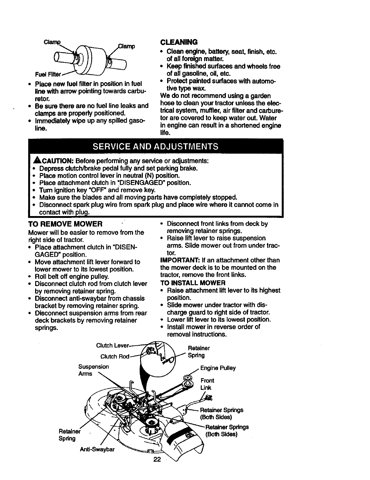
•Place new fuel filter in position in fuel
line with arrow pointing towards carbu-
retor,
•Be sure there are no fuel line leaks and
clamps are properly positioned.
•Immediately wipe up any spilled gaso-
line.
CLEANING
•Clean engine, battery, seat, finish, etc.
ofall foreign matter.
•Keep finished surfaces and wheels free
ofall gasoline, oil, etc.
•Protectpainted surfaces with automo-
tive type wax.
We do not recommend using a garden
hose to clean your tractor unless the elec-
tricalsystem, muffler,air filter and carbure-
tor are covered to keep water out. Water
in engine can result in a shortened engine
life.
ACAUTION: Before performing any service or adjustments:
Depress clutch/brake pedal fully and set parking brake.
Place motion control lever in neutral (N) position.
Place attachment clutch in =DISENGAGED" position.
Turn ignition key "OFF" and remove key.
Make sure the blades and all moving parts have completely stopped.
Disconnect spark plug wire from spark plug and place wire where it cannot come in
contact with plu_.
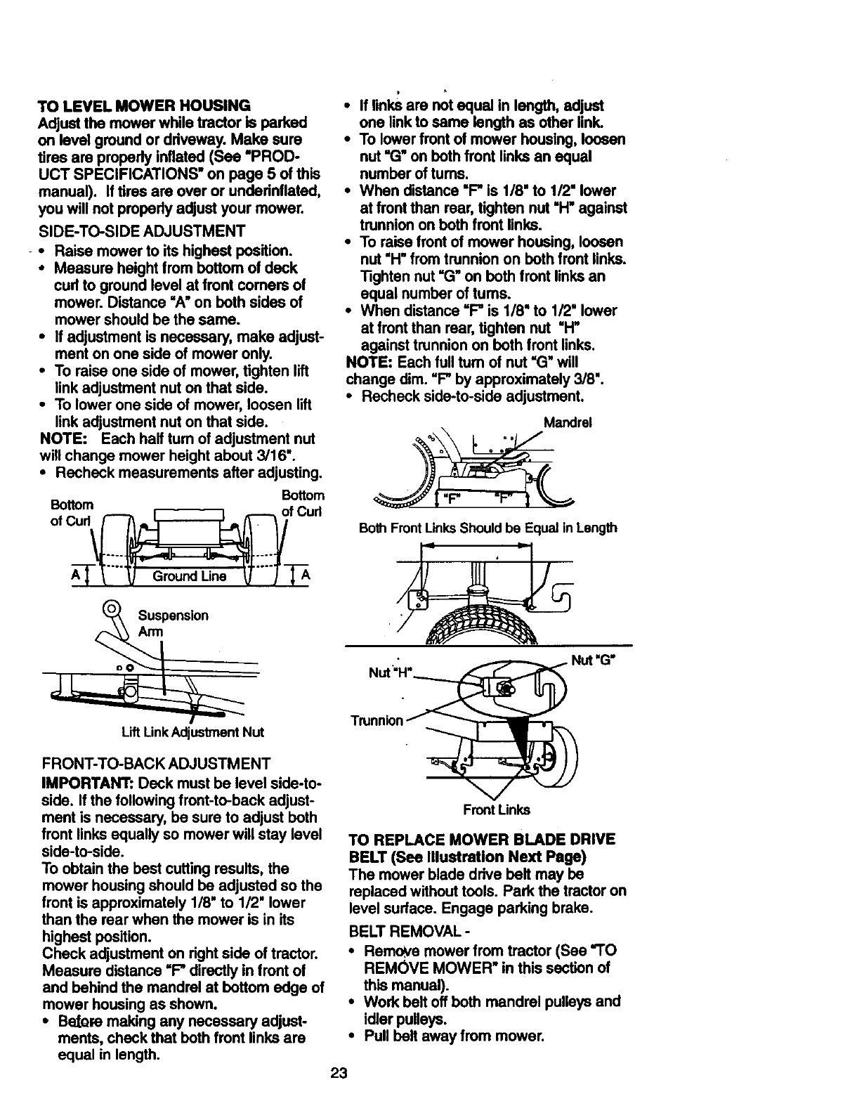
TO REMOVE MOWER "
Mower will be easier to remove from the
right side of tractor.
•Place attachment clutch in "DISEN-
GAGED" position.
•Move attachment lift lever forward to
lower mower to its lowest position.
•Roll belt off engine pulley,
•Disconnect clutch rod from clutch lever
by removing retainer spdng.
•Disconnect anti-swaybar from chassis
bracket by removing retainer spdng,
•Disconnect suspension arms from rear
deck brackets by removing retainer
springs.
•Disconnect front links from deck by
removing retainer spdngs.
•Raise lift lever to raise suspension
arms. Slide mower out from under trac-
tor.
IMPORTANT: If an attachment other than
the mower deck is to be mounted on the
tractor, remove the front links.
TO INSTALL MOWER
•Raise attachment lift lever to its highest
position.
•Slide mower under tractor with dis-
charge guard to right side of tractor.
•Lower lift lever to its lowest position.
•Install mower in reverse order of
removal instructions.
Clutch
Suspension
Arms
Retainer
Front
Link
Pulley
Retainer
Spring
Anti-Swaybar
22
(Both Sides)
(Both Sides)
TO LEVEL MOWER HOUSING
Adjust the mower while tractor is parked
on level ground or driveway. Make sure
tires are properly inflated (See "PROD-
UCT SPECIFICATIONS" on page 5 ofthis
manual). If tires are over or undednflated,
you will not propady adjust your mower.
SIDE-TO-SIDE ADJUSTMENT
• Raise mower to itshighest position.
• Measure height from bottom of deck
cud to ground level at front comers of
mower. Distance "A" on both sides of
mower should be the same.
• If adjustment is necessary, make adjust-
ment on one side of mower only.
•To raise one side of mower, tighten lift
link adjustment nut on that side.
•To lower one side of mower, loosen lift
link adjustment nut on that side.
NOTE: Each half tum of adjustment nut
will change mower height about 3/16".
• Recheck measurements after adjusting.
Bottom
o,oBo"°u; ' ou.
Suspension
Arm
p
•If links are not equal in length, adjust
one link to same length as other link.
•To lower front of mower housing, loosen
nut "G" on both front links an equal
number of tums.
•When distance "F" is 1/8" to 1/2" lower
at front than rear, tighten nut "H" against
trunnion on both front links.
•To raise front of mower housing, loosen
nut "H" from trunnion on both front links.
Tighten nut "G" on both front links an
equal number of turns.
•When distance "F" is 1/8" to 1/2" lower
at front than rear, tighten nut "H"
against trunnion on both front links.
NOTE: Each full turn of nut "G" will
change dim. "F" by approximately 3/8".
•Recheck side-to-side adjustment.
Mandrel
oo Do
ao •
Both FrontUnks Should be Equal in Length
Lift LinkAdjustment Nut
FRONT-TO-BACK ADJUSTMENT
IMPORTANT: Deck must be level side-to-
side. If the following front-to-back adjust-
ment is necessary, be sure to adjust both
front links equally so mower will stay level
side-to-side.
To obtain the best cutting results, the
mower housing should be adjusted so the
front is approximately 1/8" to 1/2" lower
than the rear when the mower is in its
highest position.
Check adjustment on right side of tractor.
Measure distance "F" directly in front of
and behind the mandrel at bottom edge of
mower housing as shown.
•Be_re making any necessary adjust-
ments, check that both front links are
equal in length.
FrontLinks
TO REPLACE MOWER BLADE DRIVE
BELT (See Illustration Next Page)
The mower blade drive belt may be
replaced without tools. Park the tractor on
level surface. Engage parking brake.
BELT REMOVAL -
•Remove mower from tractor (See "TO
REMOVE MOWER" in this section of
this manual).
•Work belt off both mandrel pulleys and
idler pulleys.
•Pull belt away from mower.
23
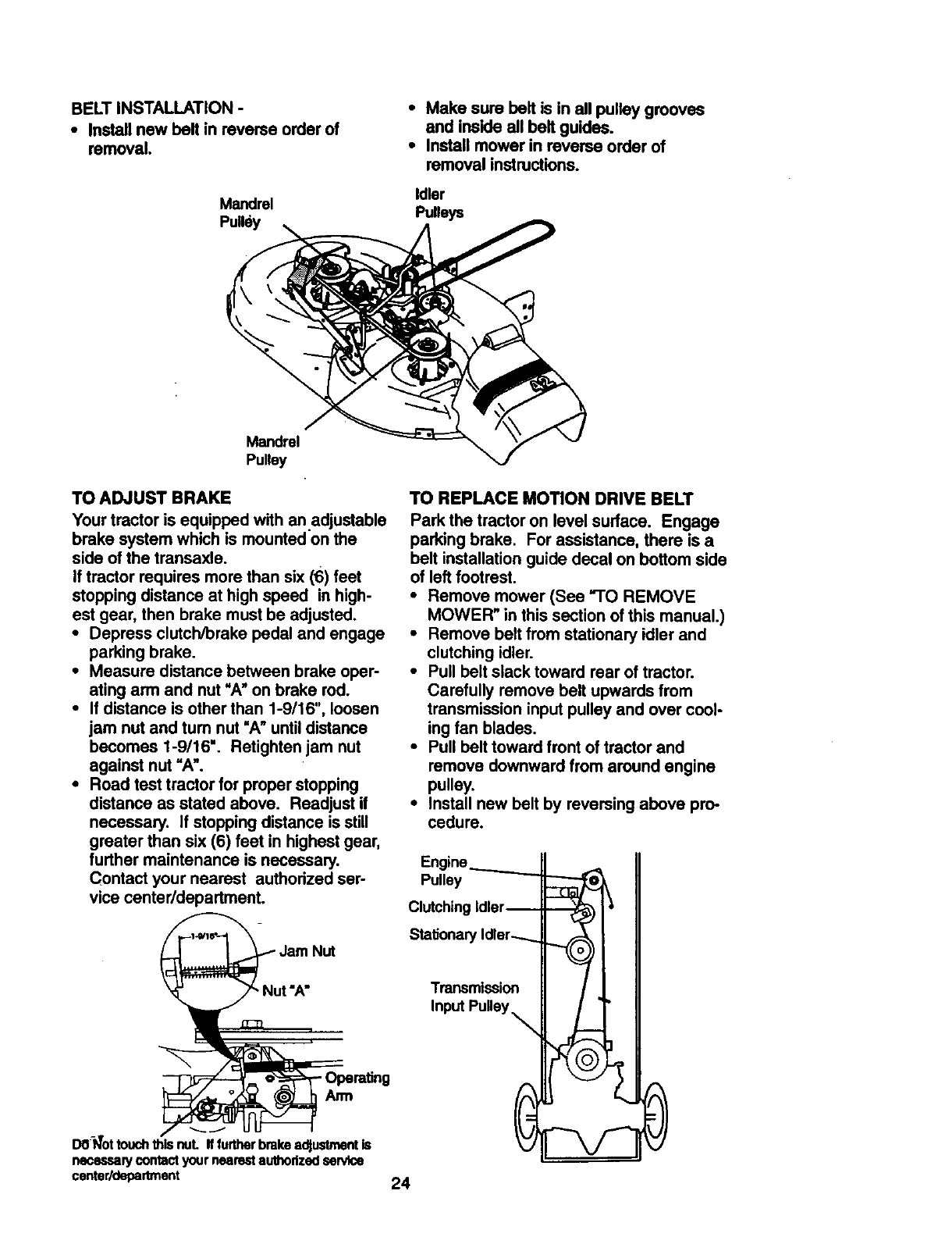
BELTINSTALLATION-
* Install new belt in reverse order of
removal.
Mandrel
Pulley
•Make sure belt is in all pulley grooves
and inskle all belt guides.
•Install mower in reverse order of
removal instructions.
Idler
Pulleys
Mandrel
Pulley
TO ADJUST BRAKE
Your tractor is equipped with an .adjustable
brake system which is mounted on the
side of the transaxle.
If tractor requires more than six (6) feet
stopping distance at high speed in high-
est gear, then brake must be adjusted.
•Depress clutch/brake pedal and engage
parking brake.
•Measure distance between brake oper-
ating arm and nut "A" on brake rod.
•If distance is other than 1-9/16",loosen
jam nut and turn nut =A" until distance
becomes I-9/16". Retightenjam nut
against nut "A".
•Road test tractor for proper stopping
distance as stated above. Readjust if
necessary. If stopping distance is still
greater than six (6) feet in highest gear,
further maintenance is necessary.
Contact your nearest authodzed ser-
vice centerldepartment.
TO REPLACE MOTION DRIVE BELT
Park the tractor on level surface. Engage
parking brake. For assistance, there is a
belt installation guide decal on bottom side
of left footrest.
•Remove mower (See "TO REMOVE
MOWER" in this section of this manual.)
•Remove belt from stationary idler and
clutching idler.
•Pull belt slack toward rear of tractor.
Carefully remove belt upwards from
transmission input pulley and over cool-
ing fan blades.
•Pull belt toward front of tractor and
remove downward from around engine
pulley.
•Install new belt by reversing above pro-
cedure.
Pulley
Clutching
Stationary
Nut "A" Transmission
Input Pulley_
- OperetJng
Arm
DO-I_Ottouch_ls nuL Iffurtherbrakeadjustmentis
necessap/contactyournearestauthorizedsendce
center/department 24
TOADJUSTMOTIONCONTROLLEVER
Themotioncontrolleverhasbeenpreset
atthefactoryand adjustmentshouldnot
benecessary.
If foranyreasonthemotioncontrollever
willnotholditspositionwhileat a selected
speed,it may be adjusted a_tthe fdction
pack located on the right side of transmis-
sion.
•Park tractor on level surface. Stop trac-
tor by turning ignition key to "OFF* posi-
tion, and engage parking brake.
•Adjust motion control lever by tightening
adjustment Iocknut one halt (1/2) turn.
NOTE: If for any reason the effort to move
the motion control lever becomes too
excessive, reverse the above adjustment
procedure by loosening Iocknut 1/4 to 1/2
tum.
Road test tractor after adjustment and
repeat procedure if necessary.
Locknut
TRANSMISSION REMOVAUREPLACE-
MENT
Should your transmission require removal
for service or replacement, it should be
purged after roinstallaUon and before
operating the tractor. See =PURGE
TRANSMISSION" in the Operation section
of this manual.
TO ADJUST STEERING WHEEL ALIGN-
MENT
If steedng wheel crossbars are not hod-
zontal (left to right) when wheels are posi-
tioned straight forward, remove steedng
wheel and reassemble per instructions in
the Assembly section of this manual.
FRONT WHEEL TOE-IN/CAMBER
The front wheel toe-in and camber are not
adjustable on your tractor. If damage has
occurred to affect the front wheel toe-in or
Camber, contact your nearest authorized
service center.
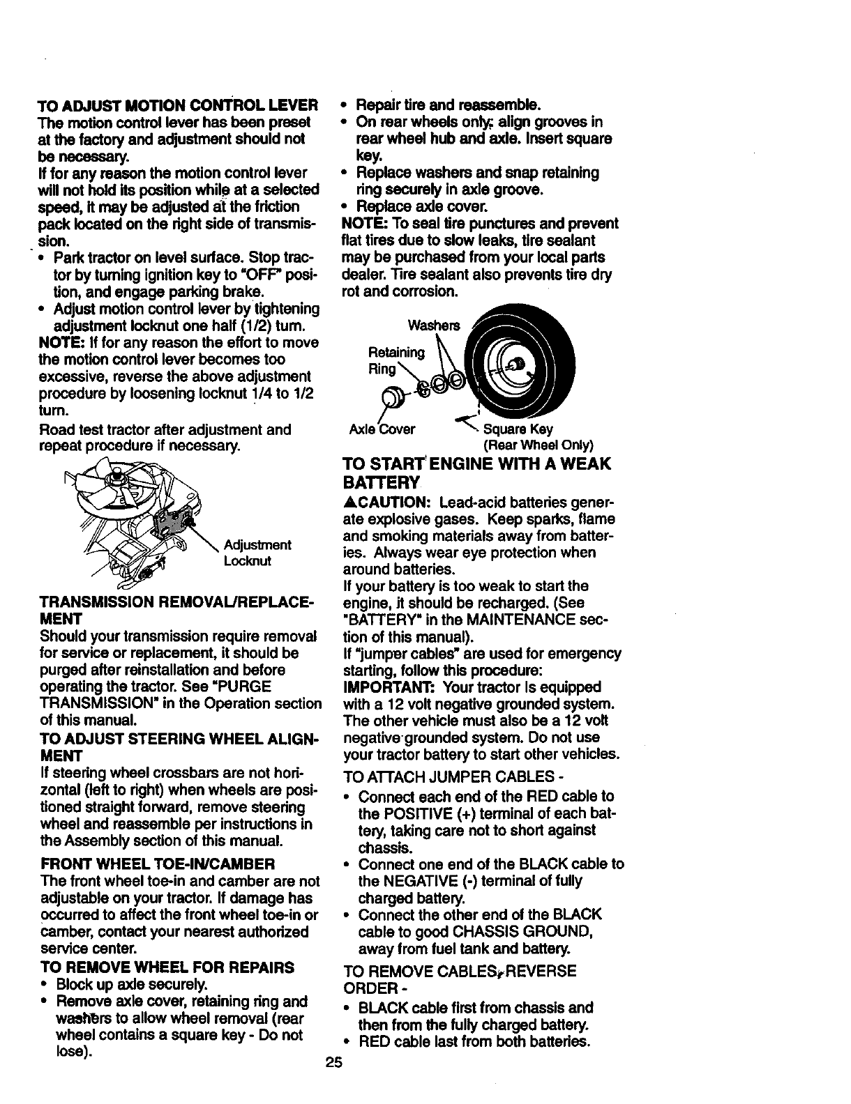
TO REMOVE WHEEL FOR REPAIRS
•Block up axle securely.
•Remove axle cover, retaining dng and
wseh_rs to allow wheel removal (roar
wheel contains a square key - Do not
lose).
•Repair tim and reassemble,
• On rear wheels only;,align grooves in
roar wheel hub and axle. Insert square
key.
•Replace washers and snap retaining
dng securely in axle groove.
•Replace axle cover.
NOTE: To seal tire punctures and prevent
flat tires due to slow leaks, tire sealant
may be purchased from your local parts
dealer. Tire sealant also prevents tire dry
rot and corrosion.
Washers A
Retaining _mHf [(._'_L'_
Ring'__Jl
Axle_ver '_'__'_y-J'
(Rear Wheel Only)
TO START' ENGINE WITH A WEAK
BATTERY
ACAUTION: Lead-acid battedes gener-
ate explosive gases. Keep sparks, flame
and smoking materials away from batter-
ies. Always wear eye protection when
around batteries.
If your battery is too weak to start the
engine, Jtshould be recharged. (See
•BATTERY" in the MAINTENANCE sec-
tion of this manual).
If "jumper cables" are used for emergency
starting, follow this procedure:
IMPORTANT: Your tractor Is equipped
with a 12 volt negative grounded system.
The other vehicle must also be a 12 volt
negativegrounded system. Do not use
your tractor battery to start other vehicles.
TO ATrACH JUMPER CABLES -
•Connect each end of the RED cable to
the POSITIVE (+) terminal of each bat-
tery, taking care not to short against
chassis.
•Connect one end of the BLACK cable to
the NEGATIVE (-) terminal of fully
charged battery.
•Connect the other end of the BLACK
cable to good CHASSIS GROUND,
away from fuel tank and battery.
TO REMOVE CABLES_REVERSE
ORDER -
•BLACK cable first from chassis and
then from the fully charged battery.
•RED cable last from both battedes.
25
Posl_ve Terminal Negative Terminal
Battery
Po6i_ve Terminal Negative Terminal
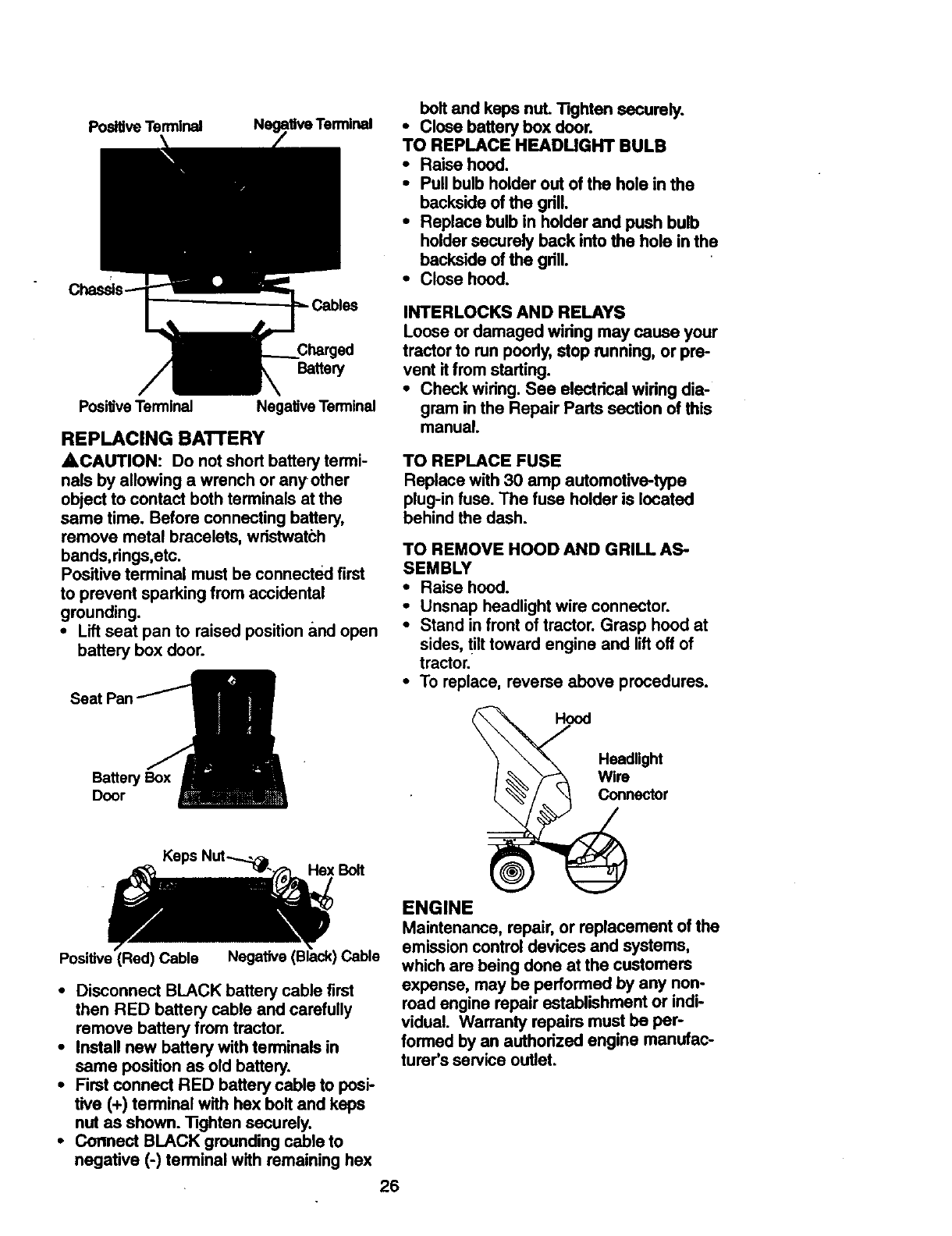
REPLACING BATTERY
4=CAUTION: Do not short battery termi-
nals by allowing awrench or anyother
object to contact both terminals at the
same time. Before connecting battery,
remove metal bracelets, wristwatch
bands,rings,etc.
Positive terminal must be connected first
to prevent sparking from accidental
grounding.
• Lift seat pan to raised position and open
battery box door.
bolt and keps nut. Tighten securely.
•Close battery box door.
TO REPLACE HEADUGHT BULB
•Raise hood.
• Pull bulb holder out of the hole in the
backside of the grill.
•Replace bulb in holder and push bulb
holder securely beck into the hole in the
backside of the grill.
•Close hood.
INTERLOCKS AND RELAYS
Loose or damaged wiring may cause your
tractorto run poorly, stop running, or pre-
vent itfrom starting.
•Check wiring. Sea electrical widng dia-
gram inthe Repair Parts section of this
manual.
TO REPLACE FUSE
Replace with 30 amp automotive-type
plug-in fuse. The fuse holder is located
behind the dash.
TO REMOVE HOOD AND GRILL AS-
SEMBLY
•Raise hood.
•Unsnap headlight wire connector.
•Stand in front of tractor. Grasp hood at
sides, tilt toward engine and lift off of
tractor.
•To replace, reverse above procedures.
Battery Box
Door
Headlight
Wire
Connector
Hex Bolt
Positive (Red) Cable Cable
•Disconnect BLACK battery cable first
then RED battery cable and carefully
remove battery from tractor.
•Install new battery with terminals in
same position as old battery.
•First connect RED battery cable to posi-
tive (+) terminal with hex bolt and keps
nut as shown. Tighten securely.
•Connect BLACK grounding cable to
negative (-) terminal with remaining hex
26
ENGINE
Maintenance, repair, or replacement of the
emission control devices and systems,
which are being done at the customers
expense, may be performed by any non-
road engine repair establishment or indi-
vidual. Warranty repairs must be per-
formed by an authorized engine manufac-
turer's service outlet.
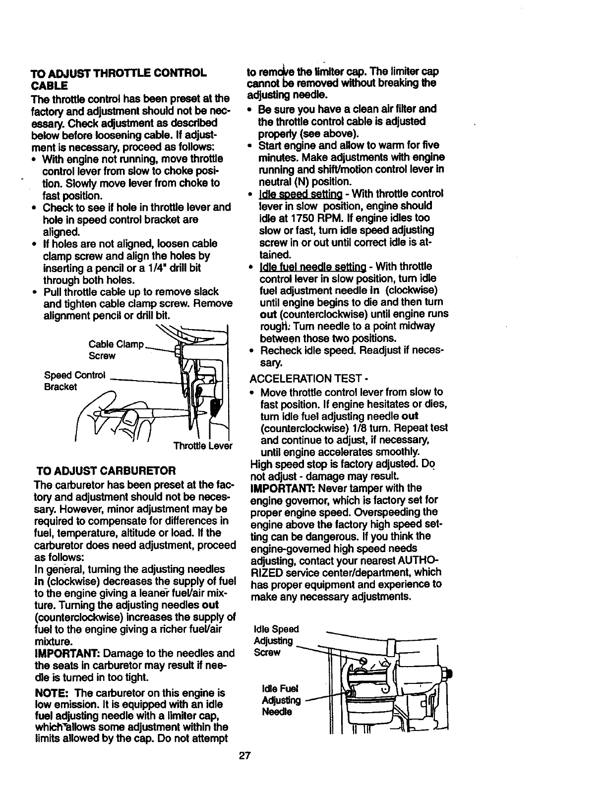
TO ADJUST THROTTLE CONTROL
CABLE
The throttle control has been preset at the
factory and adjustment should not be nec-
essary. Check adjustment as descdbed
below before loosening cable. If adjust-
ment is necessary, proceed as follows:
•With engine not running, move throttle
control lever from slow to choke posi-
tion. Slowly move lever from choke to
fast position.
•Check to see if hole inthrottle lever and
hole in speed controlbracket are
aligned.
•If holes are not aligned, loosen cable
clamp screw and align the holes by
inserting a pencil or a 1/4" ddll bit
through both holes.
•Pull throttle cable up to remove slack
and tighten cable clamp screw. Remove
alignment pencil or drill bit.
Screw
Speed Control
Bracket
Throttle Lever
TO ADJUST CARBURETOR
The carburetor has been preset at the fac-
tory and adjustment should not be neces-
sery. However, minoradjustment may be
required to compensate for differences in
fuel, temperature, altitudeor load. If the
carburetor does need adjustment, proceed
as follows:
In general, turning the adjusting needles
in (clockwise) decreases the supply of fuel
to the engine givinga leaner fuel/air mix-
ture. Turning the adjusting needles out
(counterclockwise)increases the supply of
fuel to the engine givinga richerfuel/air
mixture.
IMPORTANT: Damage to the needles and
the seats in carburetor may result if nee-
dle is tumed in too tight.
NOTE: The carburetor on this engine is
low emission. It is equipped with an idle
fuel adjusting needle with a limltercap,
whicl_allows some adjustment within the
limitsallowed by the cap. Do notattempt
to remdve the limlter cap. The limltercap
cannot be removed without breakingthe
adjustingneedle.
• Be sure you have a clean air filter and
the throttlecontrol cable is adjusted
properly (see above).
• Start engine and allow to warm for five
minutes. Make adjustments with engine
runningand shift/motioncontrollever in
neutral (N) position.
• _ - With throttlecontrol
lever in slow position,engine should
idle at 1750 RPM. If engine idles too
slow or fast, tum idle speed adjusting
screw in or out until correctidle is at-
tained.
•Idle fuel needle settina - With throttle
control lever in slow position,tum idle
fuel adjustment needle in (clockwise)
untilengine begins to die and then turn
out (counterclockwise)untilengine runs
rougl_:Tum needle to a point midway
between those two positions.
•Recheck idle speed. Readjust if neces-
sary.
ACCELERATION TEST -
•Move throttle control lever from slow to
fast position. If engine hesitates or dies,
tum idle fuel adjusting needle out
(counterclockwise)118tum. Repeat test
and continueto adjust, if necessary,
untilengine accelerates smoothly.
High speed stop is factory adjusted. Do
not adjust - damage may result.
IMPORTANT: Never tamper with the
engine govemor, which is factory set for
proper engine speed. Overspeeding the
engine above the factory high speed set-
ting can be dangerous. If you think the
engine-governed high speed needs
adjusting, contact your nearest AUTHO-
RIZED service centerldepartment, which
has proper equipment and experience to
make any necessary adjustments.
Idle Speed
Adjusting ._. _-"-'---n--'_,
screwIdle Fuel
Adju ng/Idl J I
Needle
27
Immediately prepare your tractorfor stor-
age at the end of the season or if the trac-
tor will not be used for 30 days or more.
_,CAUTION" Never store the tractorwith
gasoline in the tank insidea building
where fumes may reach an open flame or
spark.Allow the engine to cool before stor-
ing in any enclosure.
TRACTOR
Remove mower from tractor for winter
storage. This will allow you to clean it thor-
oughly.Remove all did,'grease, leaves,
etc. Store in aclean, dryarea.
• Clean entire tractor (See =CLEANING" in
the Maintenance section of this manual).
• Inspect and replace belts, if necessary
(See belt replacement instructionsin the
Sewice and Adjustmentssection of this
manual).
•Lubricate as shown in the Maintenance
section ofthis manual.
•Be sure that all nuts, boltsandscrews
are securely fastened. Inspect moving
partsfor damage, breakage and wear.
Replace if necessary.
•Touch up all rustedor chipped paint sur-
faces; sand lightlybefore painting.
BAI"FERY
•Fully charge the battery for storage.
•After apedod of time in storage, battery
may require recharging.
•To help prevent'corrosion and power
leakage dudng long periods of storage,
battery cables should be disconnected
and battery cleaned thoroughly (see "TO
CLEAN BA'I-I'ERY AND TERMINALS" in
the Maintenance section of this manual).
•After cleaning, leave sables disconnect-
ed and place cables where they cannot
come in contact with battery terminals.
•If battery is removed from tractor for
storage, do not store battery directly on
concrete or damp surfaces.
ENGINE
FUEL SYSTEM
IMPORTANT: it is importantto prevent
gum deposits from forming in essential fuel
system parts such as carburetor, fuel filter,
fuel hose, or tank during storage. Also,
expadence indicates that alcohol blended
fuels (called gasohol or usingethanol or
methanol)can attract moisture which leads
to separationand formation of acids dudng
storage. Acidicgas can damage the fuel
system ofan engine while in storage.
•Drain the fuel tank.
•Start the engine and let it run until the
fuel linesand carburetor are empty.
•Never use engine or carburetor cleaner
productsin the fuel tank or permanent
damage may occur.
•Use fresh fuel next season.
NOTE: Fuel stabilizer is an acceptable
alternative in minimizing the formation of
fuel gum depositsduring storage. Add sta-
bilizer togasoline in fuel tank or storage
container.Always follow the mix ratio
found on stabilizer container. Run engine
at least 10 minutes after adding stabilizer
to allow the stabilizer to reach the carbure-
tor. Do not drain the gas tank and carbure-
tor if usingfuel stabilizer.
ENGINE OIL
Drain oil (with engine warm) and replace
with clean engine oil. (See =ENGINE" in
the Maintenance section of this manual).
CYLINDER(S)
•Remove spark plug(s).
• Pour one ounce of oil through spark plug
hole(s) into cylinder(s).
•Tum ignition key to "START" position for
a few seconds to distribute oil.
•Replace with new spark plug(s).
OTHER
• Do not store gasoline from one season
to another.
•Replace your gasoline can if it starts to
rust. Rust and/or dirt in your gasoline will
cause problems.
•If possible, store your tractor indoors
and cover it to give protection from dust
and dirt.
•Cover your tractor with a suitable protec-
tive cover that does not retain moisture.
Do not use plastic. Plastic cannot
breathe, which allows condensation to
form and cause your tractor to rust.
IMPORTANT: Never cover tractor while
engine and exhaust areas are still warm.
28
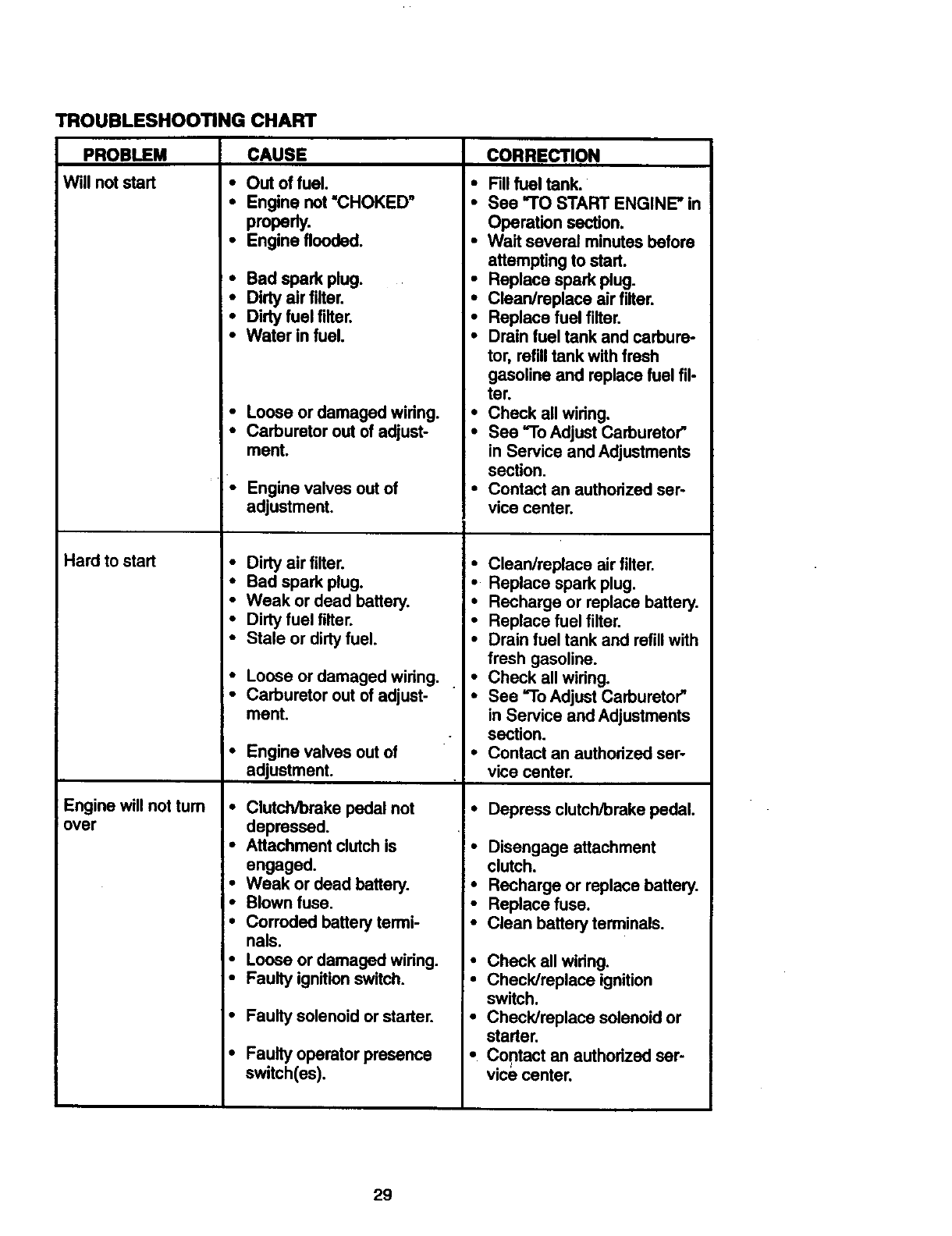
TROUBLESHOOTING CHART
PROBLEM
Will not start
Hard to start
CAUSE
•Out of fuel.
CORRECTION
Engine will not tum
over
•Fillfuel tank.
• Engine not =CHOKED" • See "TO START ENGINE" in
properly. Operation section.
• Engine flooded. • Wait several minutes before
attempting to start.
• Bad spark plug. • Replace spark plug.
•Dirty air filter. • Clean/replace air filter.
• Dirty fuel filter. • Replace fuel filter.
•Water in fuel. • Drain fuel tank and carbure-
tor, refilltank with fresh
gasoline and replace fuel fil-
ter.
• Loose or damaged wiring. • Check all wiring.
•Carburetor out of adjust- • See "To Adjust Carburetor"
ment. in Service and Adjustments
•Engine valves outof
adjustment.
•Dirty air filter.
•Bad spark plug.
•Weak or dead battery.
•Dirty fuel filter.
•Stale or dirty fuel.
•Loose or damaged wiring. •
•Carburetor out of adjust- •
ment.
• Engine valves outof
adjustment.
•CIutch/breke pedal not
depressed.
•Attachment clutchis
engaged.
•Weak or dead battery.
•Blown fuse.
•Corroded battery termi-
section.
Contact an authorized ser-
vice center.
Clean/replace air filter.
Replace spark plug.
Recharge or replace battery.
Replace fuel filter.
Drain fuel tank and refill with
fresh gasoline.
Check all wiring.
See "To Adjust Carburetor"
in Service and Adjustments
section.
Contact an authorized ser-
vice center.
Depress clutch/brake pedal.
Disengage attachment
clutch.
•Recharge or replace battery.
•Replace fuse.
• Clean battery terminals.
nals.
•Loose or damaged wiring.
•Faulty ignition switch.
•Faulty solenoid or starter.
•Faulty operator presence
switch(es).
• Check all widng.
•Check/replace ignition
switch.
•Check/replace solenoid or
starter.
•Contact an authodzed ser-
vice center.
29
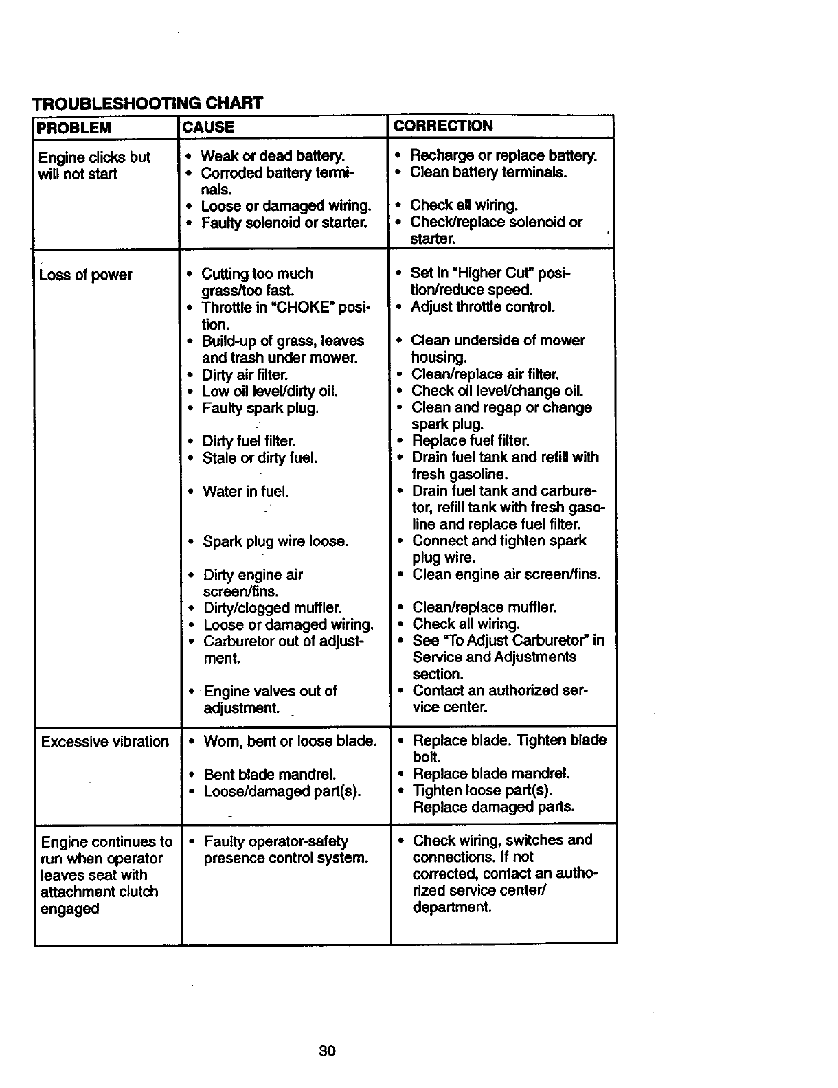
TROUBLESHOOTING CHART
CAUSE
PROBLEM
Engine clicks but
will not start
Loss of power
Excessive vibration
Engine continues to
run when operator
leaves seat with
attachment clutch
engaged
• Weak or dead battery.
• Corroded battery termi-
nals.
•Loose or damaged widng.
•Faulty solenoid or starter.
• Cutting too much
grass/too fast.
•Throttle in =CHOKE" posi-
tion.
•Build-up of grass, leaves
and trash under mower.
•Dirty air filter.
• Low oil level/dirty oil.
•Faulty spark plug.
•Dirty fuel filter.
•Stale or dirty fuel.
•Water in fuel.
•Spark plug wire loose.
•Dirty engine air
screen/fins.
•Dirty/clogged muffler.
•Loose or damaged widng.
•Carburetor out of adjust-
ment.
•Engine valves out of
adjustment.
•Worn, bent or loose blade.
•Bent blade mandrel.
•Loose/damaged part(s).
•Faulty operator-safety
presence control system.
CORRECTION
•Recharge or replace battery.
•Clean battery terminals.
•Check all widng.
•Check/replace solenoid or
starter.
•Set in "Higher Cut" posi-
tion/reduce speed.
•Adjustthrottle control.
•Clean underside of mower
housing.
•Clean/replace air filter,
•Check oil level/change oil.
•Clean and regap or change
spark plug.
•Replace fuel filter.
• Drain fuel tank and refill with
fresh gasoline.
•Drain fuel tank and carbure-
tor, refill tank with fresh gaso-
line and replace fuel filter.
•Connect and tighten spark
plug wire.
•Clean engine air screen/fins.
•Clean/replace muffler.
•Check all wiring.
•See =ToAdjust Carburetor" in
Service and Adjustments
section.
•Contact an authodzed ser-
vice center.
I° Replace blade. Tighten blade
• bolt.
i• Replace blade mandrel.
I•Tighten loose part(s).
Replace damaged pads.
Check wiring, switches and
connections. If not
corrected, contact an autho-
rized service center/
department.
3O
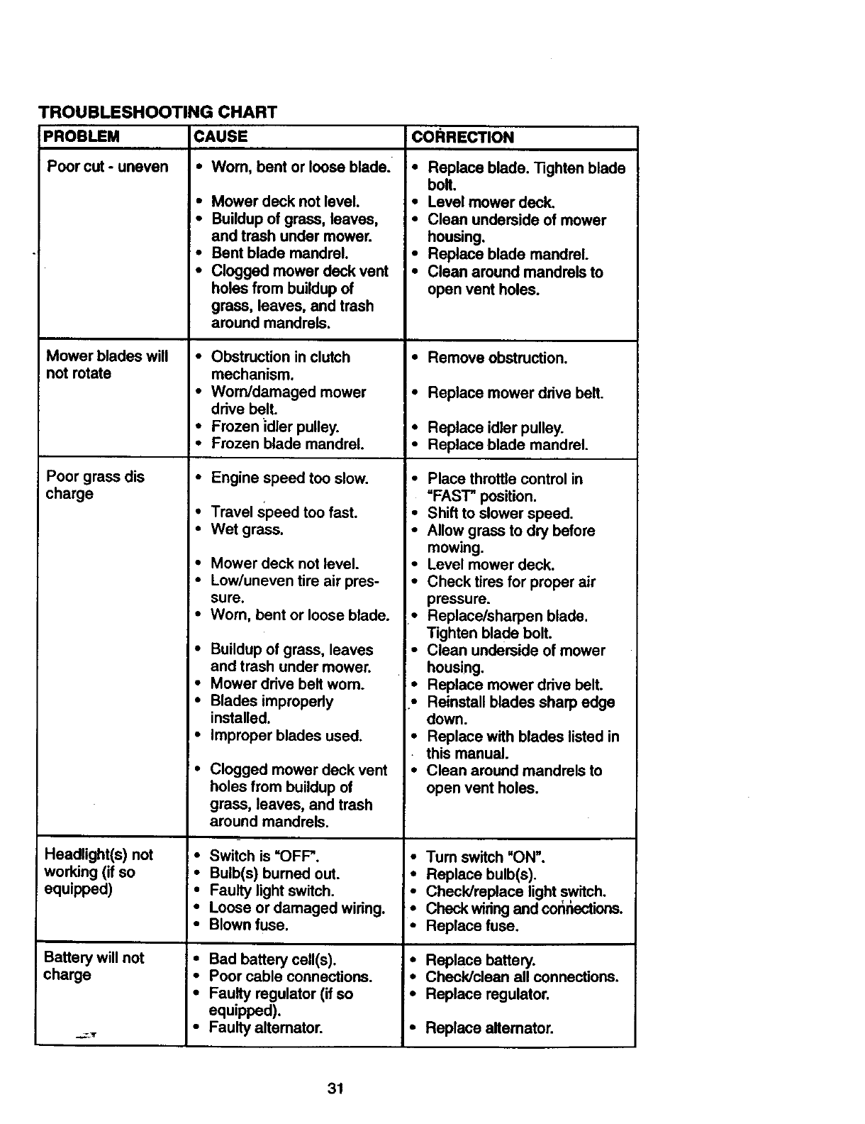
TROUBLESHOOTING CHART
PROBLEM
Poor cut - uneven
CAUSE
•Wom, bent or loose blade.
•Mower deck not level.
•Buildup of grass, leaves,
and trash under mower.
•Bent blade mandrel.
•Clogged mower deck vent
holes from buildup of
grass, leaves, and trash
around mandrels.
Mower blades will • Obstruction in clutch
not rotate mechanism.
•Worn/damaged mower *
drive belt.
•Frozen idler pulley. •
•Frozen blade mandrel. •
Poor grass dis •Engine speed too slow. °
charge
•Travel speed too fast. °
•Wet grass. •
•Mower deck not level. •
•Low/uneven tire air pres- •
sure.
•Worn, bent or loose blade. *
Buildup of grass, leaves •
and trash under mower.
Mower drive belt wom. •
Blades improperly *
installed.
Improper blades used. •
Clogged mower deck vent •
holes from buildup of
grass, leaves, and trash
around mandrels.
Switch is =OFF".
Bulb(s) burned out.
Headlight(s) not !•
working (if so i •
equipped)
Battery will not
charge
•Faulty light switch.
•Loose or damaged wiring.
•Blown fuse.
•Bad battery cell(s).
•Poor cable connections.
•Faulty regulator (if so
equipped).
•Faulty altemator.
CORRECTION
•Replace blade. Tighten blade
bolt.
•Level mower deck.
•Clean underside of mower
housing,
•Replace blade mandrel.
•Clean around mandrels to
open vent holes.
•Remove obstruction.
Replace mower drive belt.
Replace idler pulley.
Replace blade mandrel.
Place throttle control in
"FAST" position.
Shift to slower speed.
Allow grass to dry before
mowing.
Level mower deck.
Check tires for proper air
pressure.
Replace/sharpen blade.
Tighten blade bolt.
Clean underside of mower
housing,
Replace mower drive belt.
Reinstall blades sharp edge
down.
Replace with blades listed in
this manual.
Clean around mandrels to
open vent holes.
•Tum switch "ON".
•Replace bulb(s).
•Check/replace light switch.
•Check wiring and cor_r_ections.
•Replace fuse.
•Replace battery.
•Check/clean all conne_ons.
•Replace regulator.
•Replace alternator.
31
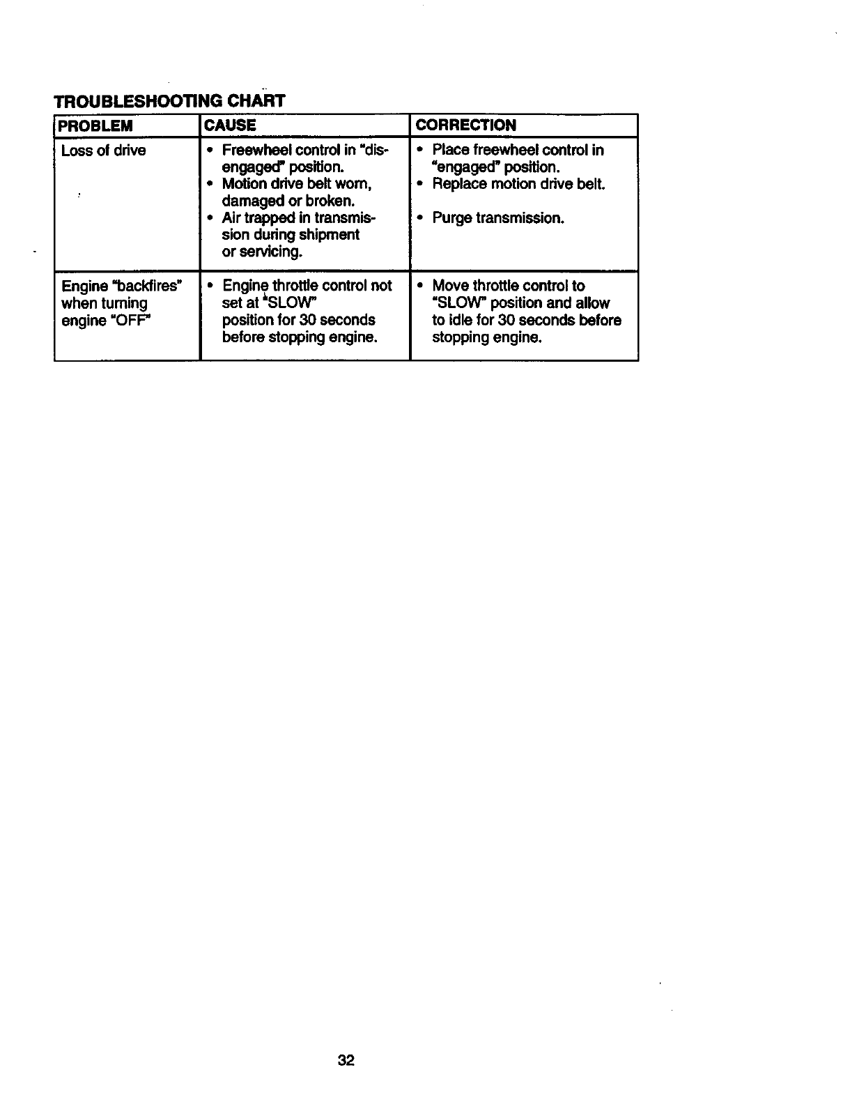
TROUBLESHOOTING CHAFn"
PROBLEM
Loss of ddve
Engine =backfires"
when tuming
engine "OFF"
CAUSE
• Freewheel control in "dis-
engaged" position.
•Motion drive belt wom,
damaged or broken.
•Air trapped in transmis-
sion during shipment
or servicing.
• Engine throttle controlnot
set at &SLOW_
positionfor 30 seconds
before stopping engine.
CORRECTION
•Place freewheel control in
=engaged" position.
•Replace motion drive belt.
•Purge transmission.
• Move throttlecontrolto
"SLOW" position and allow
to idle for 30 seconds before
stopping engine.
32
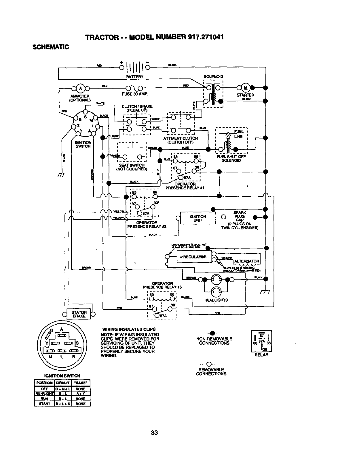
SCHEMATIC
TRACTOR - - MODEL NUMBER 917.271041
B_TTERY SOLENOID
_j_ •
I_SPARK •
- J C_ _NmON PLUG
OPERATOR iI UNn" GAP
(2PLUGSON
RELAY#2 "iWINCYL ENGINES)
I#_¢K
OPERATOR
PRESENCE RELAY #3
HEADLIGHTS
IGNrnoN SWITCH
WIRING INSULATED CUPS
NOTE: IF WIRING INSULATED
_CUPS WERE REMOVED FOR
SERVICING OF UNIT, THEY
SHOULD BE REPLACED TO
PROPERLY SECURE yOUR
W1RING.
NON-REMOVABLE
CONNECTIONS
RELAY
0
REMOVABLE
CONNECTIONS
33
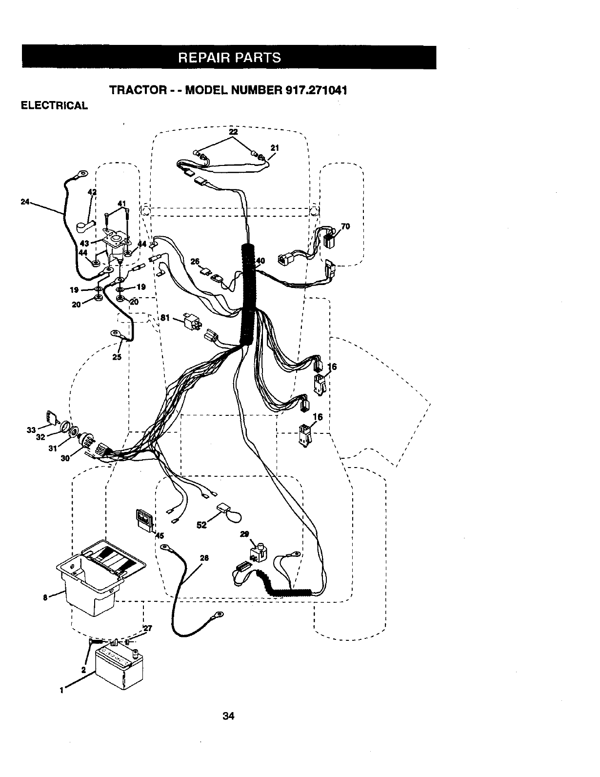
ELECTRICAL
TRACTOR --MODEL NUMBER 917.271041
24 41
I
iI
irI
I
tI
II
II
II
I
I i
t
26
i
J
I
\
i\
I
I
I
t
I
I
\
/J
34
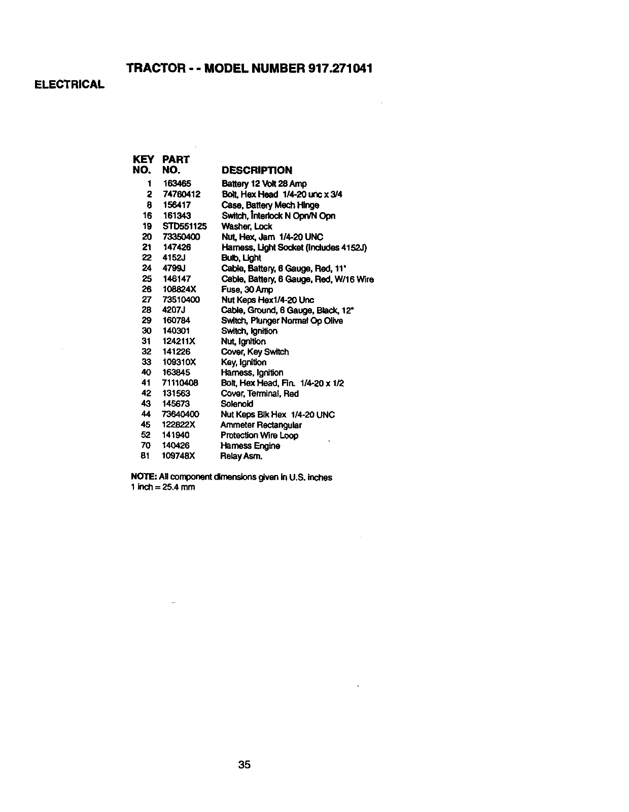
ELECTRICAL
TRACTOR - - MODEL NUMBER 917.271041
KEY PART
NO. NO.
1 163465
2 74760412
8 156417
16 161343
19 STD551125
20 7335O4O0
21 147426
22 4152J
24 4799,1
25 146147
26 108824X
27 73510400
28 4207J
29 160784
30 140301
31 124211X
32 141226
33 109310X
4O 163845
41 71110408
42 131563
43 145673
44 7364O4OO
45 122822X
52 141940
70 140426
81 109748X
DESCRIPTION
Batlep/12 Volt28 Amp
Bait, Hex Head 114-20uncx3/4
Case, BatteryMech Hinge
Switch,Tnter_ N Opn/N Opn
Washer,Lock
Nut, Hex. Jam 1/4-20 UNC
Harness, LightSocket (Includes4152,,')
BaMo,U0ht
Cable, Battery, 6 Gauge, Red, 11'
Gable, Battery, 6Gauge, Red, W/16 Wire
Fuse,30 Amp
Nut Keps HOx1/4-20Uno
Cable, Ground,6 Gauge, Black, 12"
Switch,PlungerNormal O1)Olive
Switch,Ignition
NUt,Ignition
Cover, Key Switch
Key,IgniSon
Hamess, Ignition
Bolt,Hex Head, Fin. 1/4-20 x 1/2
Cover, Terminal,Red
Solenoid
Nut Keps BIk Hex 1/4-20 UNC
Ammeter Rectangular
ProtecUonWire Loop
Ha_ Engine
ReleyAsm.
NOTE: Allcomponentdimensionsgivenin U.S. inches
1 inch = 25.4 mm
35
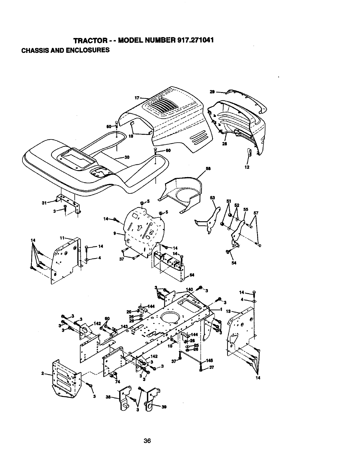
TRACTOR - - MODEL NUMBER 917.271041
CHASSIS AND ENCLOSURES
14 11
4
/3
3
74 3
54
36
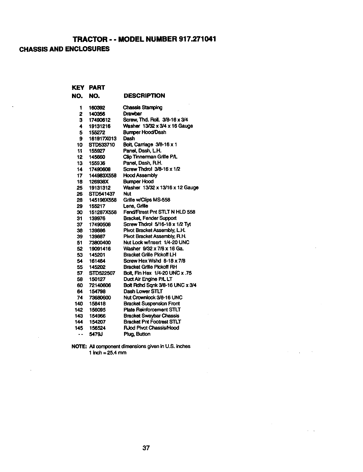
TRACTOR - - MODEL NUMBER 917.271041
CHASSIS AND ENCLOSURES
KEY PART
NO. NO. DESCRIPTION
1 160_92 Chassis Stamplng
2140356 Dmwbar
3 17490612 Screw,Thd. Reil. 3/8-16x3/4
4 19131216 Washer 13/32 x 3/4 x16 Gauge
5 155272 BumperHood/Gash
9 161917X013 Dash
10 STD533710 Bolt,Cardage 3/8-16 x 1
11 155927 Panel, Dash, LH.
12 145660 Clip'llnnerman GdlleP/L
13 155936 Panel, Dash, R.H.
14 17490608 ScrewThdrol 3/8-16 x 1/2
17 144983X558 HoodAssembly
18 126938X BumperHood
25 19131312 Washer 13/32 x 13/15 x 12 Gauge
26 STD541437 Nut
28 145198X558 Grillew/Clip6MS-558
29 155217 Lens, Gdlle
30 151287X558 Fend/Ftrest Pnf STLTN HLD 558
31 139976 Bracket, FenderSupport
37 174905G8 ScrewThdrol 5/16-18x1/2Tyt
38 139886 Pivot BracketAssembly,LH.
39 139887 Pivot BracketAssembly,R.H.
51 73800400 Nut Lockw/Insert 114-20UNC
52 19091416 Washer 9i32x718x16Ga.
53 145201 BracketGrille PickoffLH
54 161464 ScrewHexWshd 8-18x7/8
55 145202 BracketGdlla PickoffRH
57 STD522507 Bolt, Fin Hex 1/4-20 UNC x .75
58 150127 DuctAIr EngineP/LLT
60 72140606 Bolt Rdhd Sqnk3/8-16 UNC x 3/4
64 154798 Dash LowerSTLT
74 73680600 NutCrown4ock3/8-16 UNC
140 158418 BracketSuspensionFront
142 156095 PlateReinforcementSTLT
143 154966 BracketSwayt;arChassls
144 154207 BracketPnt FootrestSTLT
145 156524 RJodPivotChassis/Hood
-- 5479J PhJg,Button
NOTE:All componentdimensionsgiveninU.S. inches
1 inch= 25.4 mm
37
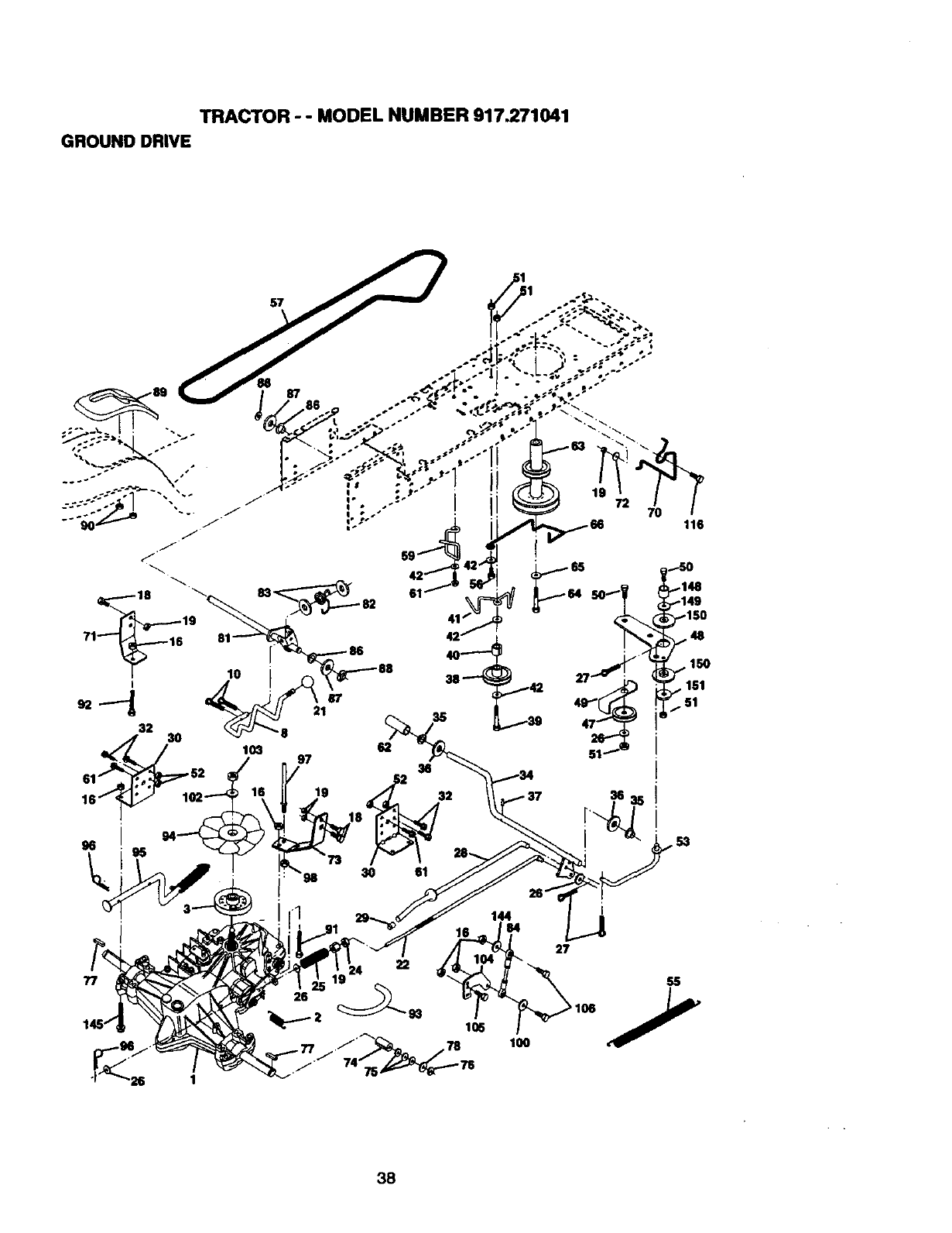
TRACTOR - - MODEL NUMBER 917.271041
GROUND DRIVE
,. 150
•151
• 51
77
26
98 30 61
ss
38
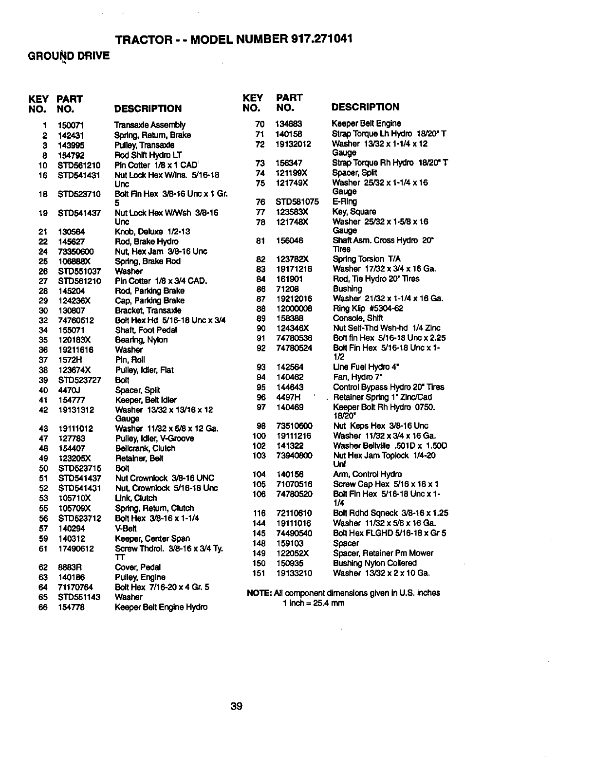
TRACTOR - - MODEL NUMBER 917.271041
GROUI_D DRIVE
KEY PART KEY PART
NO. NO. DESCRIPTION NO. NO.
I150071 TransaxleAssembly 70 134683
2 142431 Sprlng,Return,Brake 71 140158
3 143995 Pulley,Transaxle 72 19132012
8 154792 Rod ShiftHydroLT
10 STD561210 PInCotter 1/8xl CAD_73 156347
16 STD541431 NutLockHexW/Ins. 5/16-18 74 121199X
Unc 75 121749X
18 STD523710 BeltRnHex 3i8-16Uncxl Gr.
5 76 STD581075
19 STD541437 NutLockHexW/Wsh 3/8-16 77 123583X
Unc 78 121748X
21 130564 Knob,Deluxe 1/2-13
22 145627 Rod,Brake Hydro 81 156046
24 73350600 Nut, Hex Jam 3/8-16 Unc
25 106888X Spdng,Brake Rod 82 123782X
26 STD551037 Washer 83 19171216
27 STD561210 PinCotter 1i8x3/4CAD. 84 161901
28 145204 Rod, ParkingBrake 86 71208
29 124236X Cap, PaddngBrake 87 19212016
30 130807 Bracket,Transsxle 88 12000008
32 74760512 BoltHexHd 5/16-18Uncx3/4 59 158388
34 155071 Shaft, FootPedal 90 124346X
35 120183X Besdng, Nylon 91 74780536
36 19211616 Washer 92 74780524
37 1572H Pin, Roll
38 123674X Pulley,Idler,Flat 93 142564
39 STD523727 Bolt 94 140462
40 4470J Spacer,Split 95 144643
41 154777 Keeper, BeltIdler 96 4497H
42 19131312 Washer 13/32x 13/16x12 97 140469
Gauge
43 19111012 Washer 11/32x5/8x 12 Ga. 98 73510600
47 127783 Pulley,Idler,V-Groove 100 19111216
48 154407 Bellcrank,Clutch 102 141322
49 123205X Retainer,Bett 103 73940800
50 STD523715 Bo_t
51 STD541437 NutCrownlock 3/8-16UNC 104 140156
52 STD541431 Nut, Cmwnlock 5/16-18 Unc 105 71070516
53 105710X Link,Clutch 106 74780520
55 105709X Spring,Retum, Clutch 116 72110610
56 STD523712 BoltHex 3/8-16x1-1/4 144 19111016
57 140294 V.Belt 145 74490540
59 140312 Keeper,Center Span 148 159103
61 17490612 ScrewThdrol. 3/8-16x3/4Ty.
1"1" 149 122052X
62 8883R Cover,Pedal 150 150935
63 140186 Pulley,Engine 151 19133210
64 71170764 BoltHex 7/16-20x4Gr. 5
65 STD551143 Washer
66 154778 KeeperBelt Engine Hydro
DESCRIPTION
KeeperBelt Engine
Strap TorqueLh Hydro 18/20"T
Washer 13/32 x 1-1/4 x 12
Gauge
StrapTorqueRh Hydro 18/20"T
Spacer,Split
Washer 25/32 x 1-1/4 x 16
Gauge
E-Rlng
Key,Square
Washer 25/32 x 1-5/8 x 16
Gauge
ShaftAsm. Cross Hydro 20"
Tires
SpringTorsion T/A
Washer 17/32 x 3/4 x 16Ga.
Rod,"ReHydro20' Tires
Bushing
Washer 21/32 x 1-1/4 x 16 Ga.
RingFlip #5304-62
Console,Shift
Nut Self-Tlld Wsh.hd 1/4 Zinc
Belt finHsx 5/16-18 Unc x 2.25
Belt Fin Hex 5/16-18 Unc x 1-
1/2
Line Fuel Hydro4"
Fan, Hydro7"
ControlBypassHydro20"Tires
RetainerSpdng 1"ZlnciCad
Keeper Belt Rh Hydro 0750.
18/20"
Nut KepsHex 3/8-16Unc
Washer 11/32 x 3/4 x 16 Ga.
Washer Bellville .501D x 1.50D
Nut Hex JamToplock 1/4-20
Unf
Arm,Control Hydro
Screw Cap Hex 5/16 x 18x 1
BoltFin Hex 5/16-18 Unc x 1-
1/4
BoltRdhd Sqneck 3/6-16 x 1.25
Washer 11/32 x 5/8 x 16 Ga.
Belt Hex FLGHD 5/16-18 x Gr 5
Spacer
Spacer,Retainer Pm Mower
BushingNylonCohered
Washer 13/32 x 2 x 10 Ga.
NOTE: Allcomponentdimensionsgiven inU.S. inches
1 inch= 25.4 mm
39
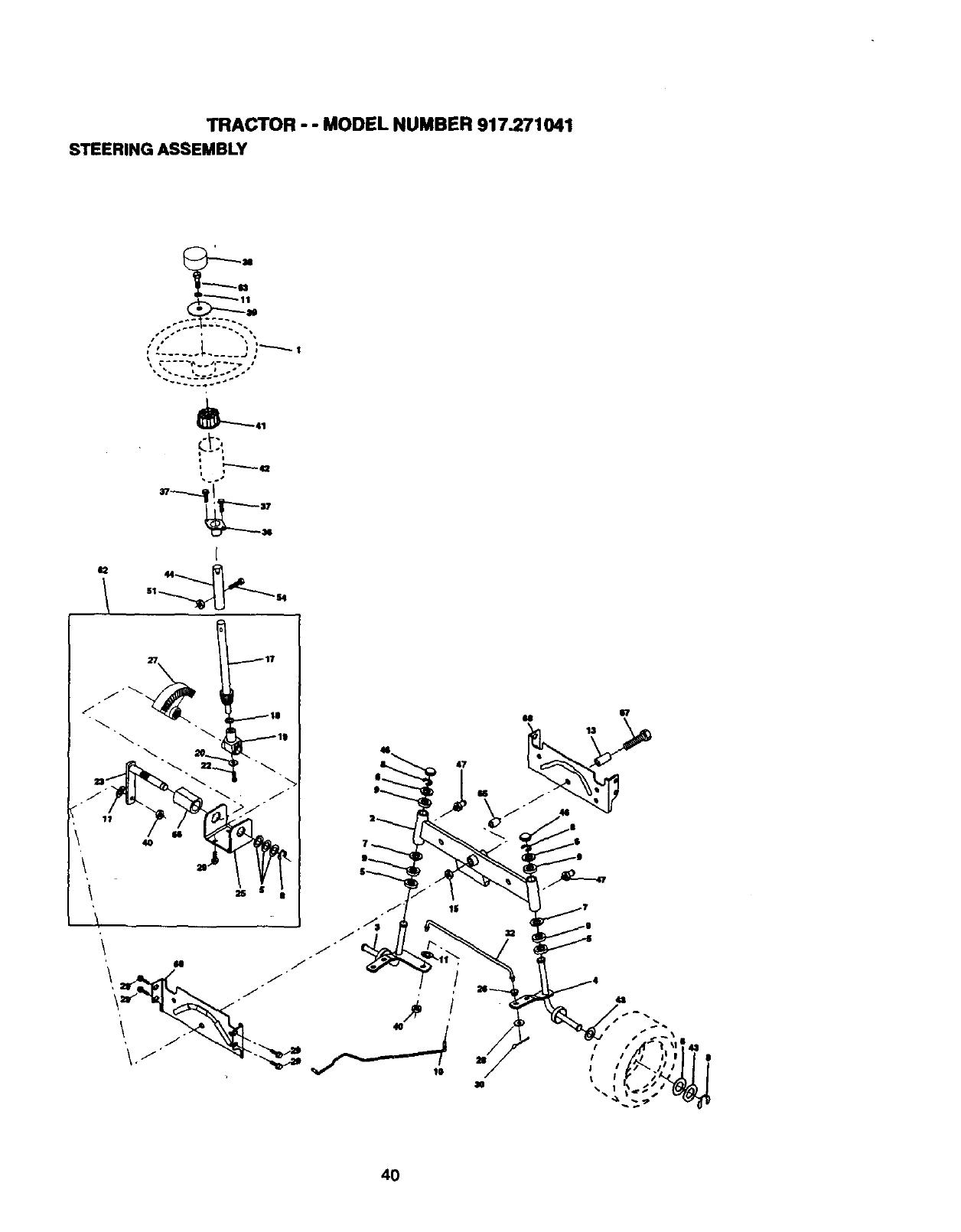
TRACTOR - - MODEL NUMBER 917.271041
STEERING ASSEMBLY
1
•S
_41
i
,"----a
I. - .*
41_ 441
4O
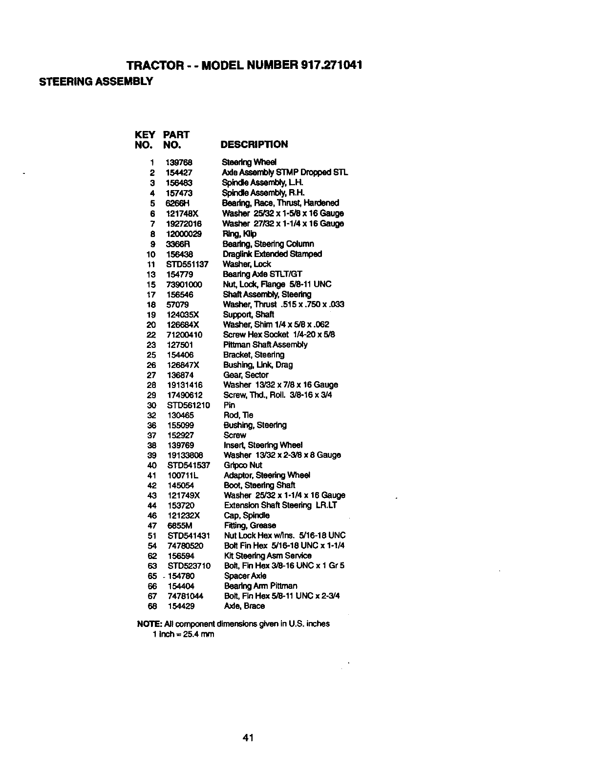
TRACTOR - - MODEL NUMBER 917.271041
STEERING ASSEMBLY
KEY PART
NO. NO. DESCRIPTION
1 139768
2 154427
3 156483
4 157473
5 62661-1
6 121748X
7 19272016
8 12000029
9 3366R
10 156438
11 STD551137
13 154779
15 73901000
17 156546
18 57079
19 124035X
20 126684X
22 71200410
23 127501
25 154406
26 126847X
27 136874
28 19131416
29 17490612
30 STD561210
32 130465
36 155099
37 152927
38 139769
39 19133808
40 STD541537
41 100711L
42 145054
43 121749X
44 153720
46 121232X
47 6855M
51 STD541431
54 74780520
62 156594
63 STD523710
65 - 154780
66 154404
67 74781044
68 154429
Steer_ Whe¢
AxleAssemblySTMP DroppedSTL
SpindleAssembly,LH.
SpindleAssembly,R.H.
Beadng, Race, Thrust,Hardened
Washer 25/32 x 1-5/8 x 16 Gauge
Washer 27/32 x 1-1/4 x 16 Gauge
PJug,Hip
Beadng, ShaeringColumn
DraglinkExtended Stamped
Washer,Lock
BearingAxle STLT/GT
Nut, Lock,Flange 5/8-11 UNC
ShaftAssembly,Steedng
Washer,Thrust .515 x .750 x .033
Support,Shaft
Washer,Shim 1/4 x 5/8 x .062
Screw Hex Socket 1/4-20 x 5/8
PittmanShaftAssembly
Bracket,Steering
Bushing,Link, Drag
Gear, Sector
Washer 13/32 x 7/8 x 16 Gauge
Screw,Thd., Roll. 3/6-16 x 3/4
Pin
Rod,"lle
Bushing, Steedng
Screw
Insert,Steadng Wheel
Washer 13/32 x 2-3/8 x 8 Gauge
GripcoNut
Adaptor,SteeringWheel
Boot,SteeringShaft
Washer 25/32 x 1-1/4 x 16 Gauge
Extension ShaftSteering LR.LT
Cap, Spindle
Fitting,Grease
Nut LockHex w/Ins. 5/16-18 UNC
BoltFin Hex 5/16-18 UNC x 1-1/4
_t SteeringAsm SePi,ce
Bolt, FinHex 3/8-16 UNC x 1 Gr5
SpacerAxle
BearingArmPittman
Bolt, FinHex 5/8-11 UNC x 2-3/4
Axle,Brace
NOTE: AllcomponentdimensionsgiveninU.S. inches
1 inch= 25.4 mm
41
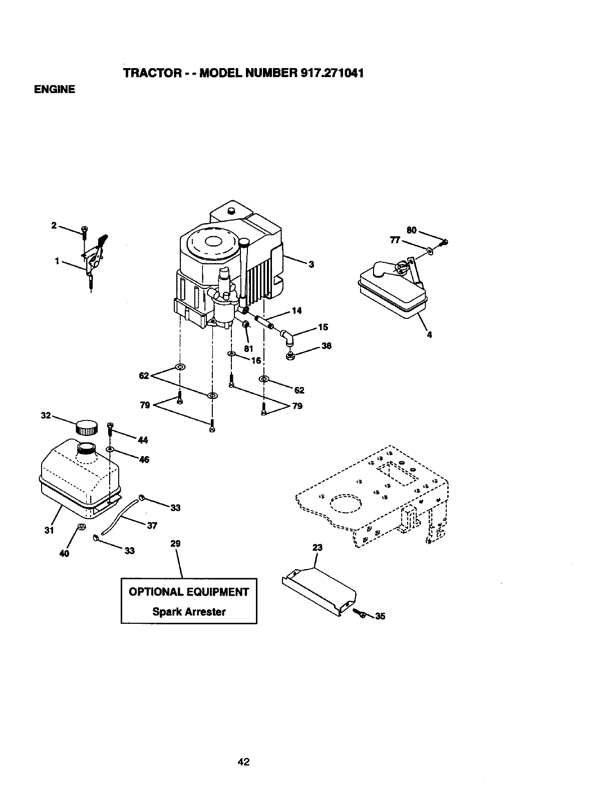
ENGINE
TRACTOR - - MODEL NUMBER 917.271041
i4
33
29
Spark Arrester
_- ', "? I;'-" -" ,
• • ill . /)
23 %'_"• _*"
42
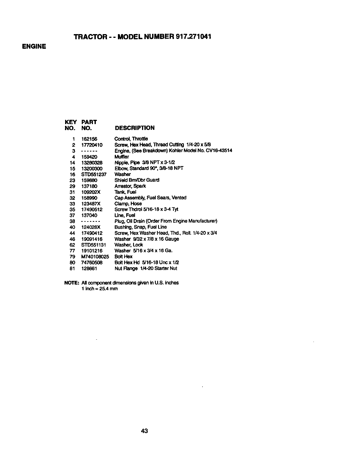
ENGINE
TRACTOR - - MODEL NUMBER 917.271041
KEY PART
NO. NO. DESCRIPTION
1 162156
2 17720410
3......
4 159420
14 132803_8
15 13200300
16 STD551237
23 159880
29 137180
31 109202X
32 158990
33 123487X
35 17490512
37 137040
38 .......
40 124028X
44 17490412
46 19091416
62 STD551131
77 19101216
79 M740108025
80 74760506
81 128861
Control,Thmttla
Sorew,Hex Head, Thread Cutting 1/4-20 x 5/8
Engine,(See Breakdown)KohlerModelNo. CV16.43514
Muffler
Nipple, Pipe 3/8 NPTx 3-1/'2
Elbow,Standard90",3/8-18 NPT
Washer
ShlatdBrn/DbrGuard
Arrestor,Spark
Tank,Fuel
Cap Aasembly,Fuel Sears, Vented
Clamp, Heae
Screw Thdrel5/16-18 x 3-4 Tyt
Une, Fuel
Plug, OilDrain (Order FromEngineManufacturer)
Bushing,Snap, Fuel Line
Screw, Hex Washer Head,Thd., Roll. 1/4-20 x 3/4
Washer 9/32 x 7/8 x 16 Gauge
Washer,Lock
Washer 5/16 x 3/4 x 16 Ga.
Bolt Hex
Bolt Hex Hd 5/16-18 Unc x 1/2
Nut Flange 1/4-20 StarterNut
NOTE: All componentdimensionsgivenIn U.S. inches
1 inch= 25.4 mm
43
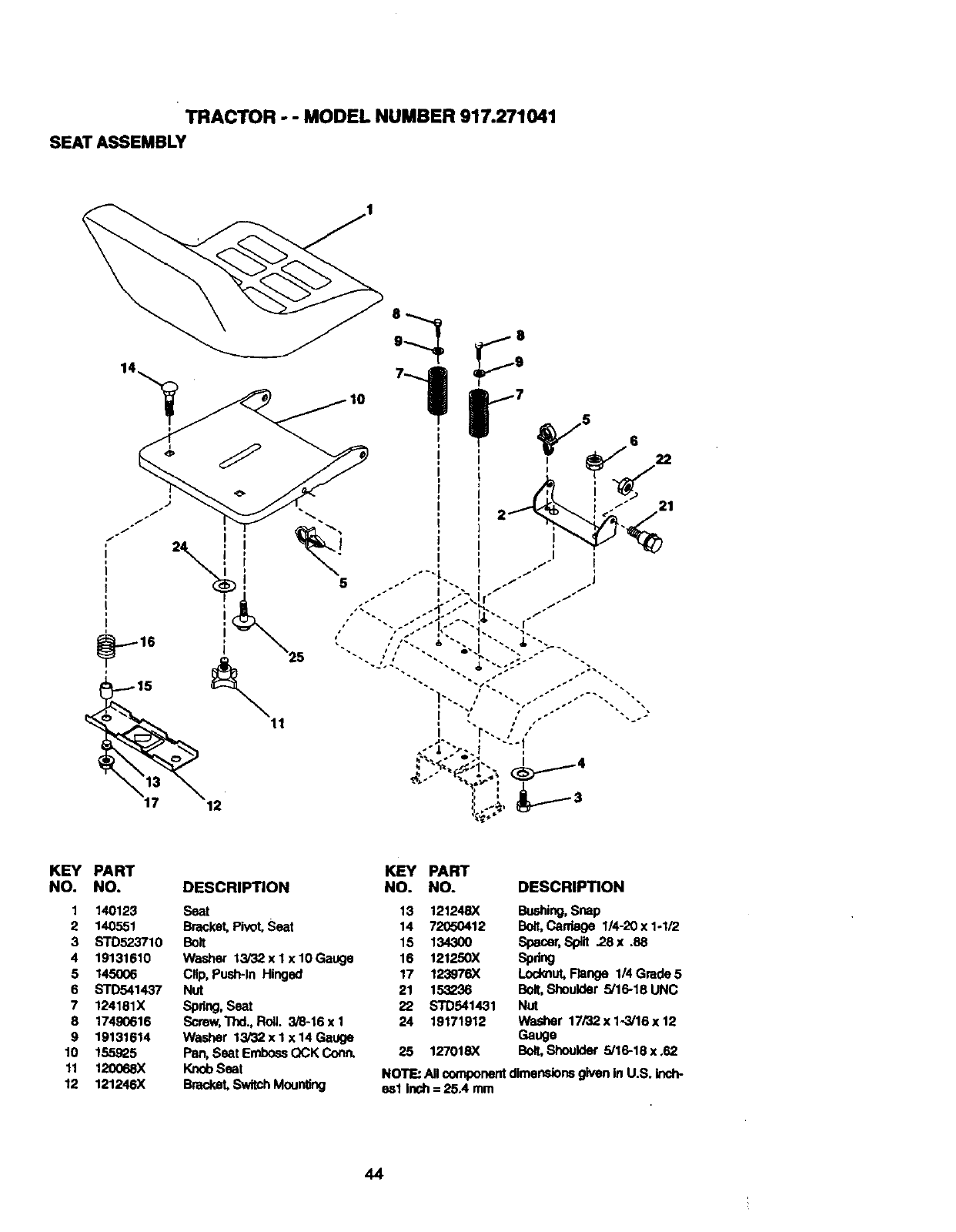
TRACTOR ..- MODEL NUMBER 917.271041
SEAT ASSEMBLY
KEY PART KEY PART
NO. NO. DESCRIPTION NO. NO. DESCRIPTION
1 140123 Seat 13 121248X Bushing,
2 140551 Bracket, Pivot,Seat 14 72050412 Bon,Carriage 1/4-20 x 1-1/2
3 STD523710 Bolt 15 134300 Spacer, Sp_lt .28x .88
4 19131610 Washer 13/32 x I x 10Gauge 16 121250X Spring
5 145006 CHip,Push-In Hinged 17 123976X Locknut,Flange 1/4 Grade 5
6 STD541437 Nut 21 153236 Bolt,Shoulder 5/16-18UNC
7 124131X Spdng, Seat 22 STD541431 Nut
8 17490616 Screw,Thd.,RolL 3/8-16xl 24 19171912 Washer 17/32 x1-3/16 x12
9 19131614 Washer 13/32 x I x 14 Gauge Gauge
10 155925 Pan,Seat EmbossQCK Conn. 25 127018X Bolt,Shoulder 5/16-18x.62
11 120068X KnobSeat NOTE: All componentdimensionsgiven in U.S. inch-
12 121246X Bracket,SwitchMounting esl Inch = 25.4 mm
44
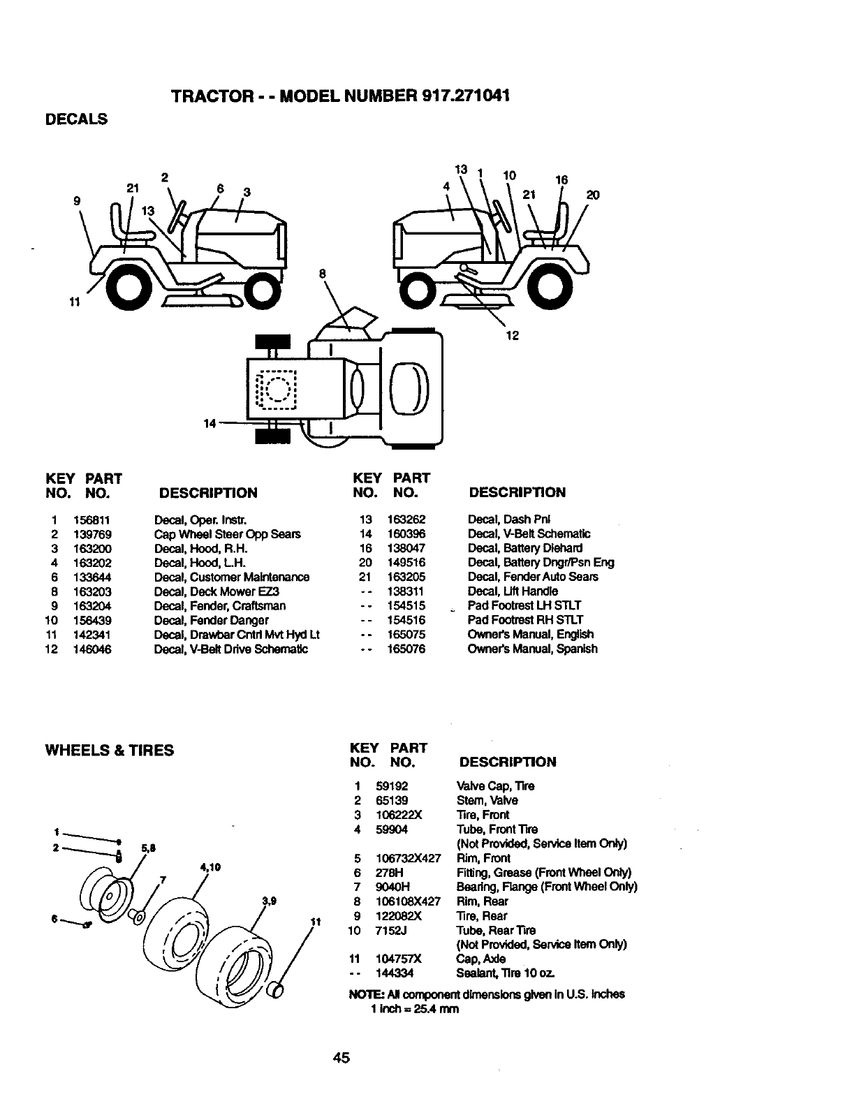
DECALS
TRACTOR - - MODEL NUMBER 917.271041
2
21 6 3
13 10
416 2O
11
12
KEY PART
NO. NO.
1 156811
2 139769
3 163200
4 163202
6 133644
8 163203
9 163204
10 156439
11 142341
12 146046
DESCRIPTION
Decal, Opec Instr.
Cap Wheel Stear Opp Seam
Decal, Hood, R.H.
Decal, Hood, LH.
Decal, CustomerMaintenance
Decal, Deck Mower EZ3
Decal, Fender,Craftsman
Decal, Fender Danger
Decal, DrawbarCntd Mvt Hyd Lt
Decal, V-Belt Ddve Schematic
KEY PART
NO. NO.
13 163262
14 160396
16 138047
20 149516
21 163205
- - 138311
- - 154515
- - 154516
-- 165075
- - 165076
DESCRIPTION
Decal, Dash Pnl
Dscal, V-BeltSchematic
Decal, BatteryDiehard
Decal, BatteryDngr/Psn Eng
Decal, Fender AutoSears
Decal, LiftHandle
Pad FootrestLH STLT
Pad FootrestRH STLT
Owner's Manual,Er@ish
Owner's Manual,Spanish
WHEELS & TIRES
74,10
11
KEY PART
NO. NO. DESCRIPTION
1 59192
2 65139
3 106222X
4 59904
5 106732X427
6 278H
7 9040H
8 106108X427
9 122082X
10 7152J
11 104757X
-- 144334
Valve Cap, Tire
Stern,Valve
Tire, Front
Tube, FrontTire
(NotProvided,Sewtce Item Only)
Rim, Front
Rlting,Grease (FrontWheel Only)
Bearing, Flange(FrontWheel Only)
Rim, Rear
Tire, Rear
Tube, Rear Tire
(Not Provided,Service ItemOnly)
Cap, Axle
Sealant, Tire 10 oz.
NOTE: AllcomponentdimensionsgiveninU.S. Inches
1 Inuh= 25A mm
45
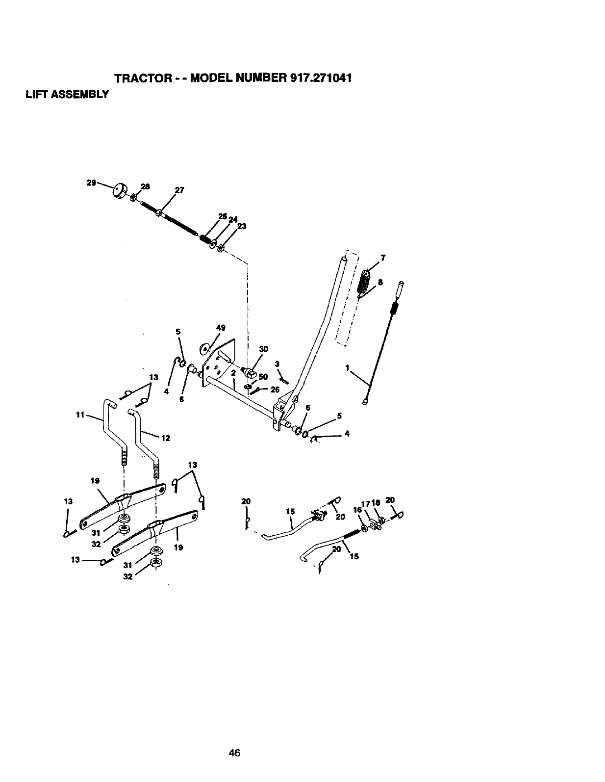
TRACTOR - - MODEL NUMBER 917.271041
LIFT ASSEMBLY
5 49
13
11__ 6 13
3
2O
46
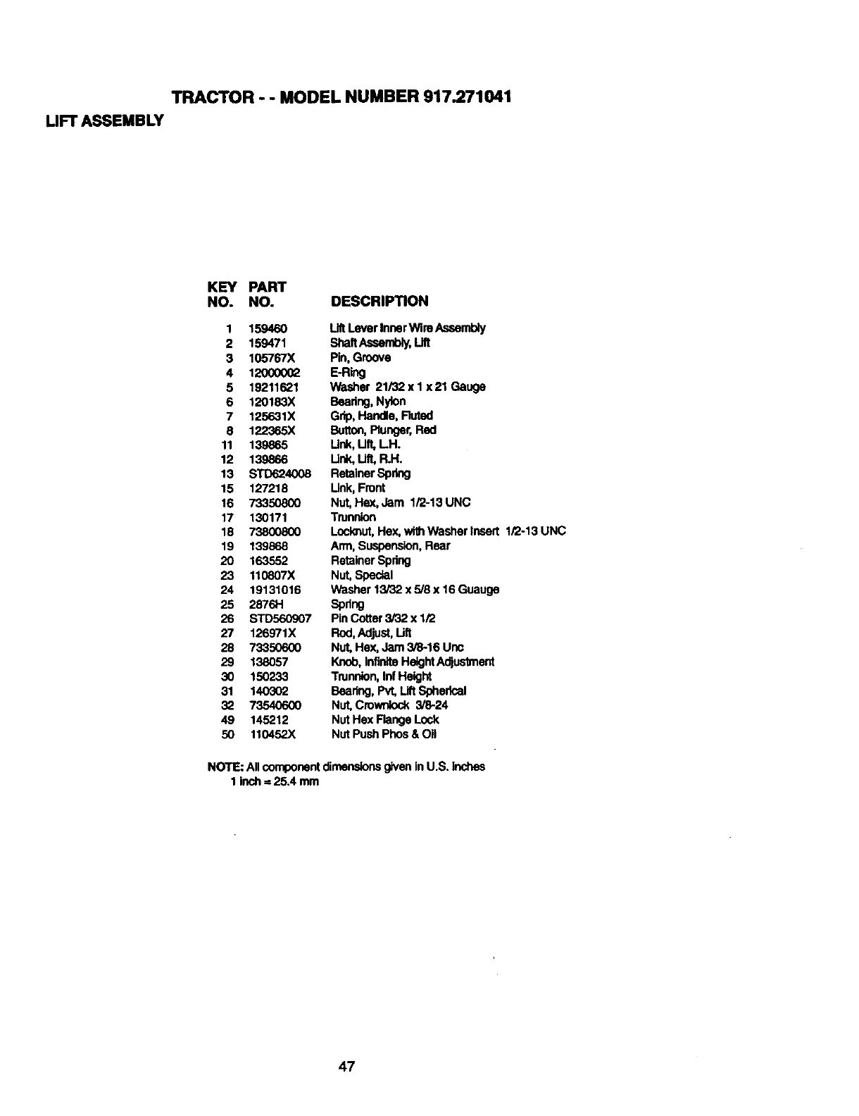
TRACTOR - - MODEL NUMBER 917.271041
UFT ASSEMBLY
KEY PART
NO. NO. DESCRIPTION
1 159460 LntLever InnerWireAssembly
2 159471 ShaftAssembly,Lift
3 105767X Pin, Groove
4 120000_ E-Ring
5 19211621 Washer 21i32xlx21 Gauge
6 120183X Beadng, Nylon
7 125631X Grip, Handle, Fluted
8 1_365X Button,Plunger,Red
11 139865 Unk, lift, LH.
12 139866 Ur#,, Lift,R.H.
13 STD624008 RetainerSpring
15 127218 Link,Front
16 73350800 Nut, Hex,Jam 1/2-13 UNC
17 130171 Trunnion
18 738(X)8_ Locknut,Hex,withWasher Insert 1/2-13 UNC
19 139868 Arm, Suspension,Rear
20 163552 RetainerSpring
23 110807X Nut, Special
24 19131016 Washer 13/32 x 5/8 x 16 Guauge
25 2876H Spring
26 STD560907 Pin Cotter3/32 x 1/2
27 126971X Rod,Adjust,Ult
28 73350600 Nut, Hex, Jam 3/8-16 Unc
29 138057 Knob, InfiniteHe4ghtAdjuslment
30 150233 Tmnnlon,Inf Height
31 140302 Bearing, Pvt, LiftSpherical
32 73540600 Nut, Cmw_ock 3/8-24
49 145212 NUtHex FlangeLock
50 110452X NUtPush Phos & OII
NOTE: All componentdimensionsgivenIn U.S. Inches
1 inch= 25.4 mm
47
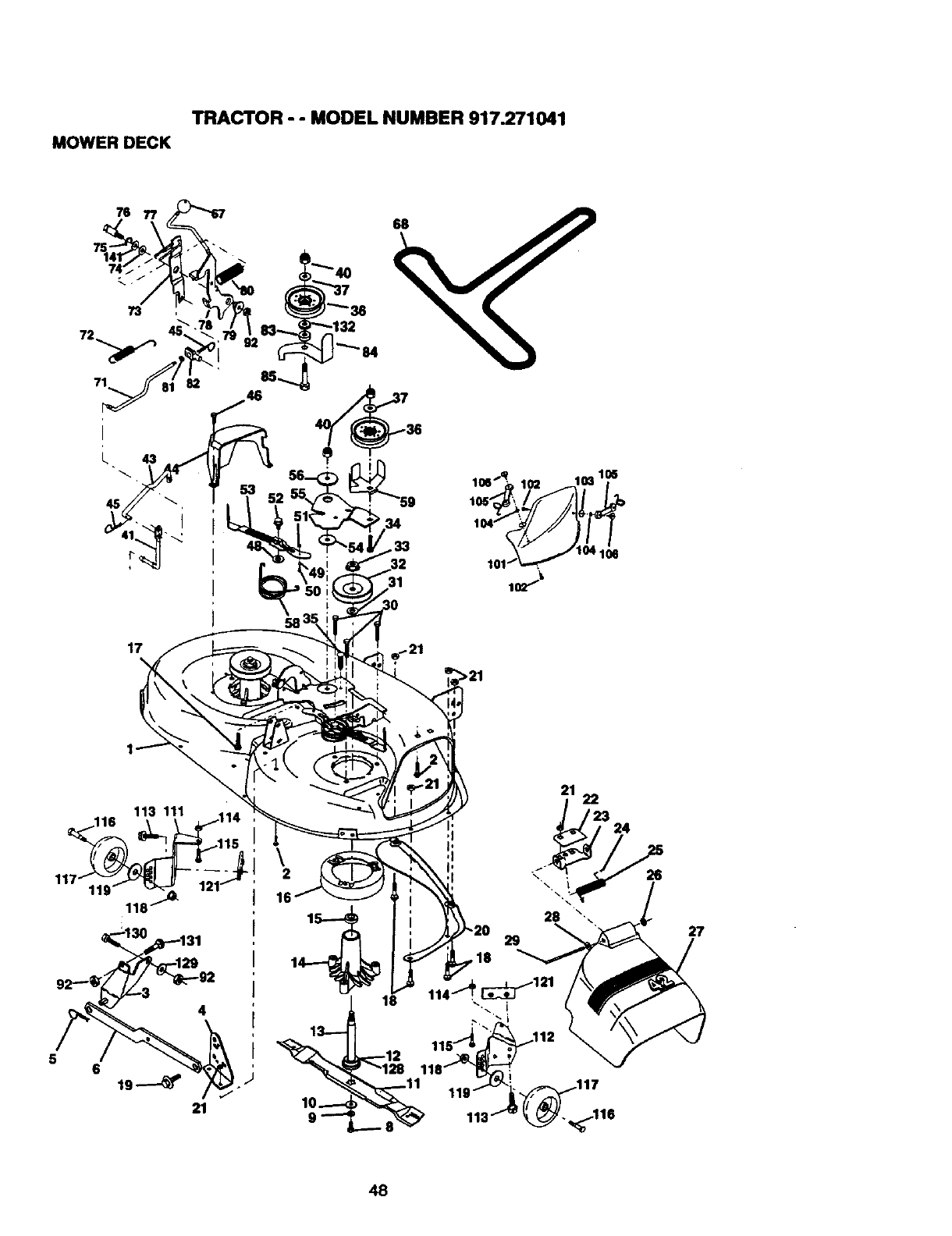
TRACTOR - - MODEL NUMBER 917.271041
MOWER DECK
73
71
79
82
31 1o_ -_
58
5
113 111
6
21
I
2
16
21 22
f23
*
,24
29
,18
26
27
48
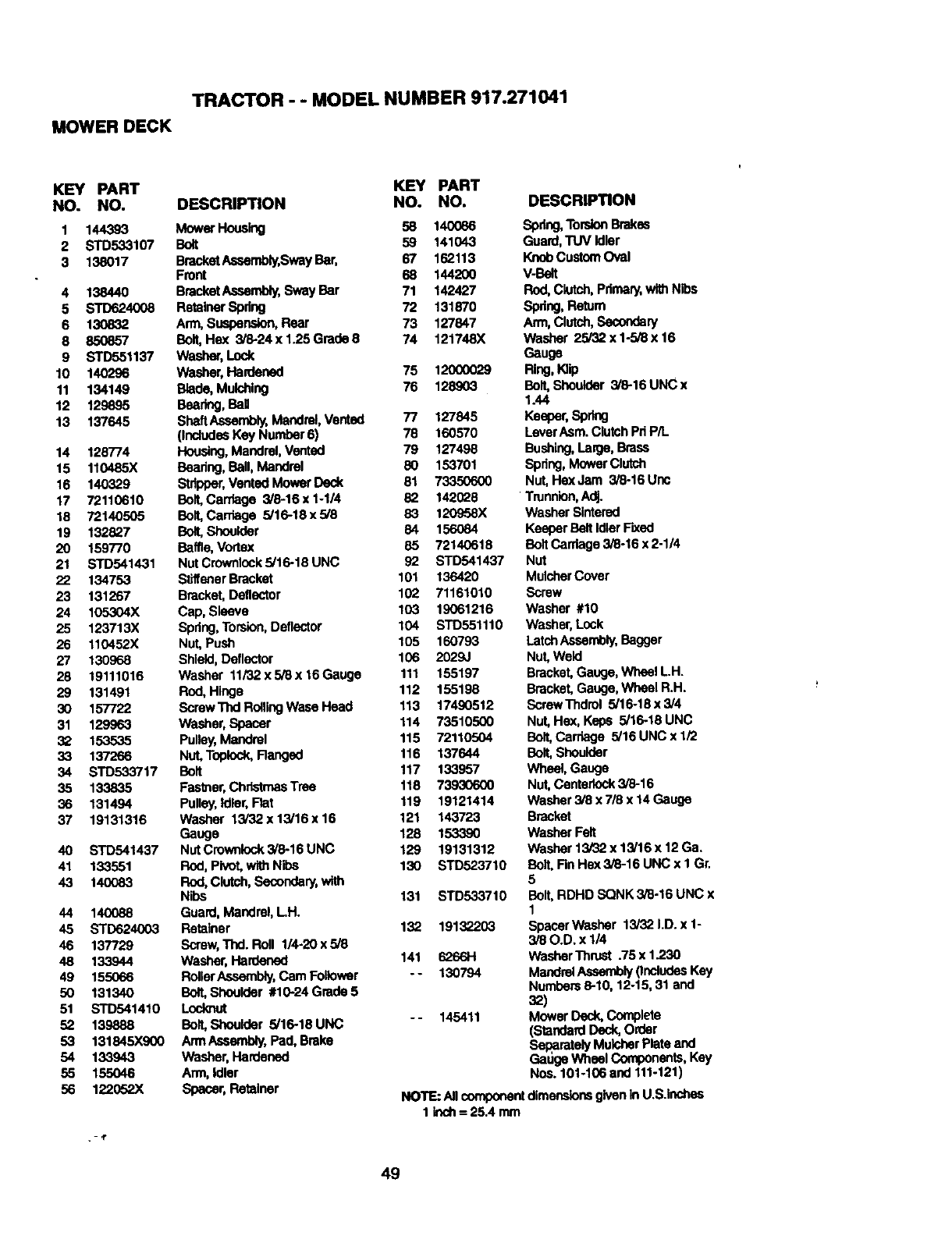
TRACTOR - - MODEL NUMBER 917.271041
MOWER DECK
KEY PART KEY PART
NO. NO. DESCRIPTION NO. NO.
1 144393 Mower Housing 58 140086
2 STD533107 Bolt 59 141043
3 138017 BracketAseambly,SwayBar, 67 162113
Front 68 144200
4 138440 BracketAseambly,Sway Bar 71 142427
5 STD624008 RetainerSpdng 72 131870
6 130832 Arm, Suspension,Rear 73 127847
8 850857 Bolt,He)( 3/8-24 x 1.25 Grade8 74 121748X
9 STD551137 Washer,Lock
10 140296 Washer,Hardened 75 12000029
11 134149 Blade, Mulching 76 128903
12 129895 Bearing,BaH
13 137645 Sh_tAssembly, Mandrel,Vented 77 127845
(IncludesKey Number6) 78 160570
14 128774 Housing,Mandrel,Vented 79 127498
15 110485X Beadng, Ball,Mandrel 80 153701
16 140329 Stripper,Vented MowerDeck 81 73350600
17 72110610 Bolt,Carriage 3/6-16x1-1/4 82 1420_8
18 72140505 Bolt, Carriage 5/16-18 x 5/8 83 120958X
19 132827 Bolt,Shoulder 84 156084
20 159770 Baffle, Vortex 85 72140618
21 STD541431 Nut Crownlock5/16-18 UNC 92 STD541437
22 134753 StJffenerBracket 101 136420
23 131267 Bracket,Deflector 102 71161010
24 105304X Cap, Sleeve 103 19061216
25 123713X Spring,Torsion,Deflector 104 STD551110
26 110452X Nut, Push 105 160793
27 130968 Shield, Deflector 106 2029J
28 19111016 Washer 11i32x5/8x 16Gauge 111 155197
29 131491 Rod, Hinge 112 155198
30 157722 Screw Thd RollingWase Head 113 17490512
31 129963 Washer,Spacer 114 73510500
32 153535 Pulley,Mandrel 115 72110504
33 137266 Nut, Topiock,Ranged 116 137644
34 STD533717 Bolt 117 133857
35 133835 Fasl_er, ChristmasTrea 118 73930600
36 131494 Pulley,Idler,Rat 119 19121414
37 19131316 Washer 13i32x13/16x16 121 143723
Gauge 128 153390
40 STD541437 NutCrownlock3/6-16UNC 129 19131312
41 133551 Rod,Pivot,withNibs 130 STD523710
43 140083 ROd,Clutsh,Secendery,with
Nibs 131 STD533710
44 140088 Guard,Mandrel,LH.
45 STD624003 Retainer 132 19132203
46 137729 Serew,Thd. Rolt 1/4-20x5/8
48 133944 Washer,Hardened 141 6266H
49 155066 RollerAssembly,Cam Follower -- 130794
50 131340 Bolt,Shoulder #10-24Grade5
51 STD541410 Locknut
52 139888 Bolt, Shoulder 5/16-18 UNC -- 145411
53 131845X900 Arm Assembly,Pad,Brake
54 133943 Washer, Hardened
55 155046 Arm, Idler
56 122052X Spacer,Retainer
.-,T
DESCRIPTION
Spring,TorsionBrakes
Guard,TUV Idler
KnobCustom Oval
V-Belt
Rod,Clutch,Pdmary,withNibs
Spdng, Return
Arm,Clutch,Secondary
Washer 25/32 x 1-5/8 x 16
Gauge
Ring,la_p
Bolt,Shoulder 3/6-16 UNC x
1.44
Keeper,Spring
Laver Asm.ClutchPdP/t.
Bushing,Lalge, Brass
Spdng, Mower Clutch
Nut, Hex Jam 3/8-16 Unc
Trunnion,Adj.
WasherSinternd
KeeperBelt IdlerRxed
BoltCarriage 3/8-16 x 2-1/4
Nut
MulcherCover
Screw
Washer #10
Washer,Lock
LatchAssembly,Bagger
Nut,Weld
Bracket,Gauge, Wheel LH.
Bracket,Gauge, Wheel R.H.
ScrewThdrol 5/16-18 x 3/4
Nut, Hex, Keps 5/16-18 UNC
Bolt,Carriage 5/16 UNC x 1/2
Bolt, Shoulder
Wheel, Gauge
Nut, Centariock3/8-16
Washer 3/8 x 7/8 x 14 Gauge
Bracket
Washer Felt
Washer 13/32 x 13/16 x 12 Ga.
Bolt, Rn Hex 3/8-16 UNC x 1 Gr.
5
Bolt,RDHD SQNK 3/8-16 UNC x
1
Spacer Washer 13/32 I.D. x 1-
3/80.D. x 1/4
WasherThrust .75 x 1.230
MandrelAssembly(IncludeaKey
Numbers 8-10, 12-15, 31 and
Mower Deck, Complete
(S=ndard Deck,Order
Separately MulcherPlate and
Ga=JgeWheel Components,Key
Nos. 101-106 and 111-121)
NOTE:All c_t-,penen_dimensionsgivenin U.S.inches
1 inch= 25.4 mm
49
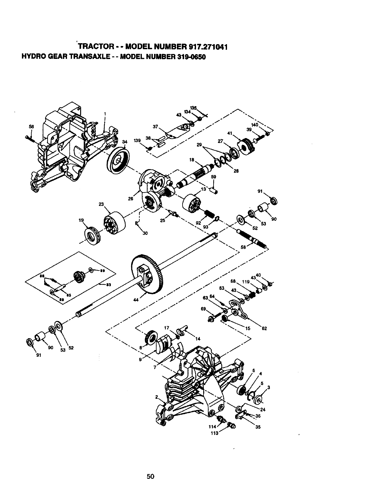
tTRACTOR - - MODEL NUMBER 917.271041
HYDRO GEAR TRANSAXLE - - MODEL NUMBER 319-0650
91
23
19
4
36
35
5O
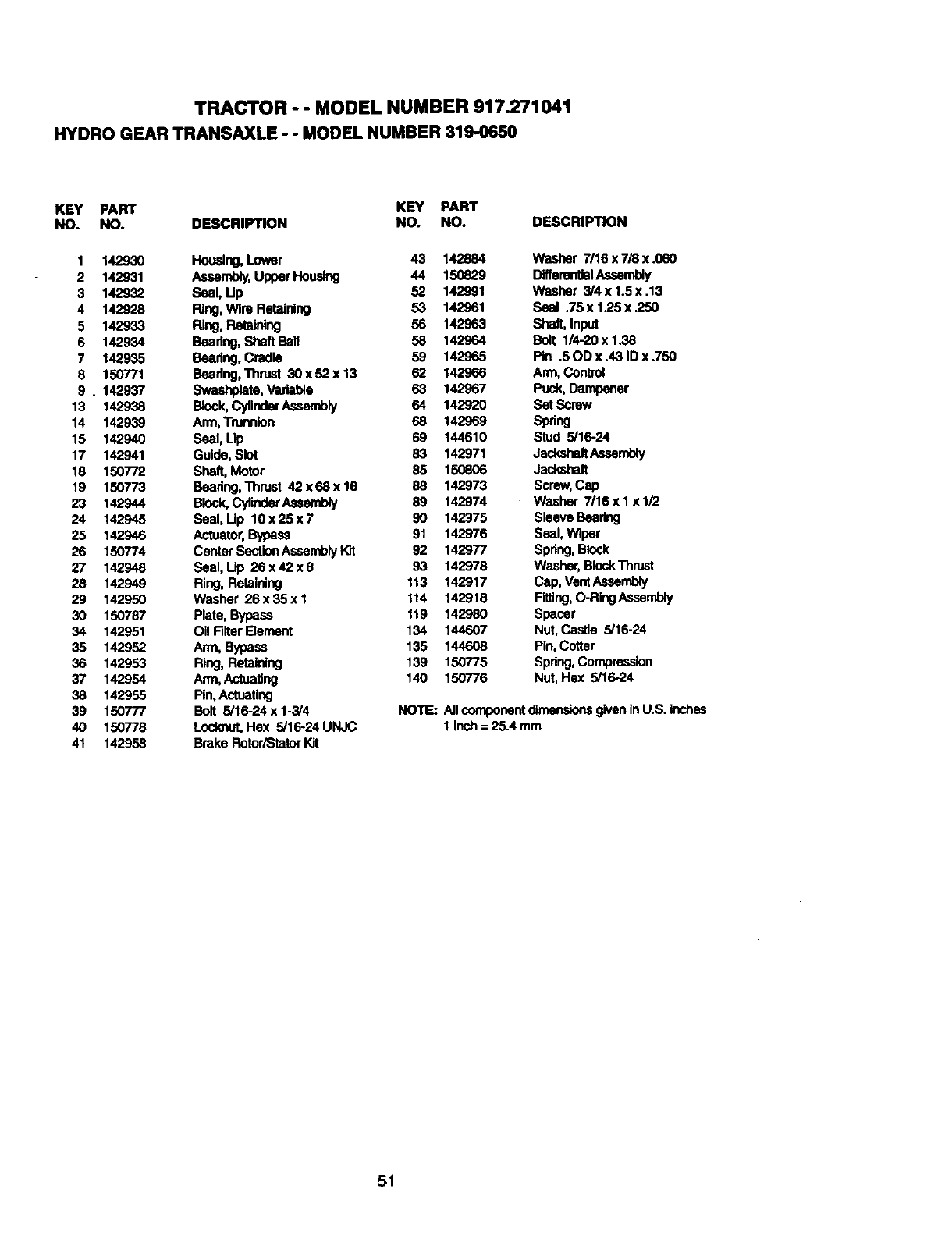
TRACTOR - - MODEL NUMBER 917.271041
HYDRO GEAR TRANSAXLE - - MODEL NUMBER 319-0650
KEY PART KEY PART
NO. NO. DESCRIPTION NO. NO.
1 142930 Housing,Lower 43 142884
2 142931 Assembly,UpperHousing 44 150629
3 142932 Seal, Up 52 142991
4 142928 Ring,Wire Retaining 53 142961
5 142933 Ring, Retaining 56 142963
6 142934 Bearing,Shaft Ball 58 142964
7 142935 Beadng, Cradle 59 142965
8 150771 Beadng, Thrust 30x52x13 62 142966
9 . 142937 Swashplate, Vadable 63 142967
13 142938 Block,CylinderAssembly 64 142920
14 142939 Arm,Trunnion 68 142969
15 142940 Seal, Up 69 144610
17 142941 Guide, Slot 83 142971
18 150772 Shaft, Motor 85 150806
19 150773 Beadng,l'hrust 42x68x16 88 142973
23 142944 Block,CylinderAssent_ 89 142974
24 142945 Seal, Up 10x25x7 90 142975
25 142946 Actuator,Bypass 91 142976
26 150774 Center SectionAssemblyKit 92 142977
27 142948 Seal, Up 26x42x9 93 142978
28 142949 Ring, Retaining 113 142917
29 142950 Washer 26x35x1 114 142918
30 150787 Plate, Bypass 119 142980
34 142951 Oil Fitter Element 134 144607
35 142952 Arm, Bypass 135 144608
36 142953 Ring, Retaining 139 150775
37 142954 Arm, Actuating 140 150776
38 142955 Pin, Actuating
39 150777 Bolt 5/16-24 x 1-3/4
40 150778 Locknut,Hex 5/16-24 UNJC
41 142958 Brake RetoriStator Kit
DESCRIPTION
Washer 7/16 x 7/8 x .060
Differen_al.A.ssembly
Washer 3/4 x 1.5x .13
Seal .75 x 1.25 x _50
Shaft, Input
Bolt 1/4-20 x 1.38
Pin .50D x .43 ID x .750
Arm, Control
Puck,Dampener
Set Screw
sprig
Stud 5/16-24
JackshaftAssembly
Jackshaft
Screw,Cap
Washer 7/16x I xl/2
Sleeve Beadng
Seal, Wiper
Spring,Block
Washer,BlockThrust
Cap, VentAssembly
Rtting, O-RingAssembly
Spacer
Nut, Castle 5/16-24
Pin, Cotter
Spring,Compression
Nut, Hex 5/16-24
NOTE: AllcomponentdimensionsgiveninU.S. inches
1 Inch= 25.4 mm
51
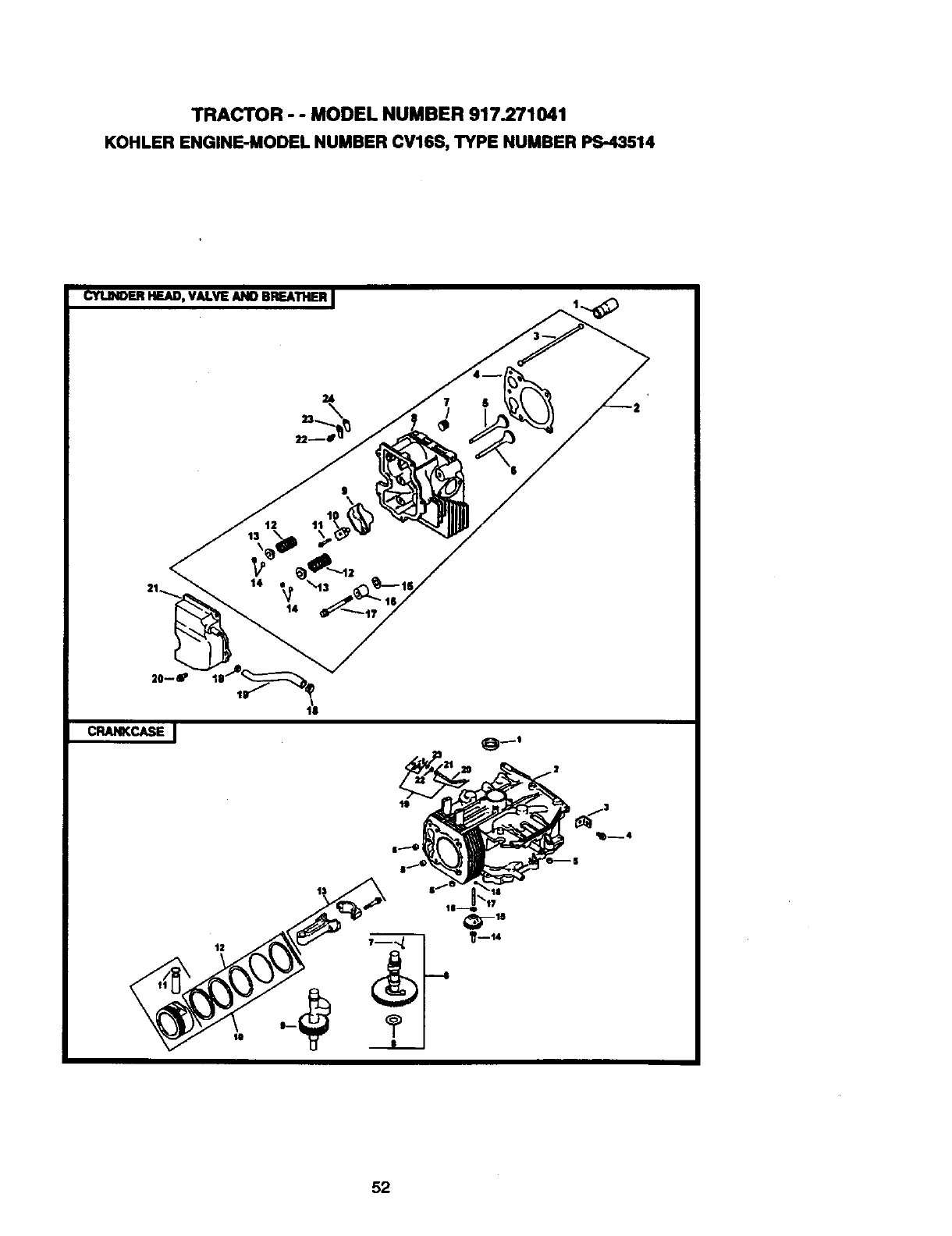
TRACTOR - - MODEL NUMBER 917.271041
KOHLER ENGINE-MODEL NUMBER CV16S, TYPE NUMBER PS-43514
CYUNOERHEAD, VALVE AND BREATHER.J
CRANKCASE
52
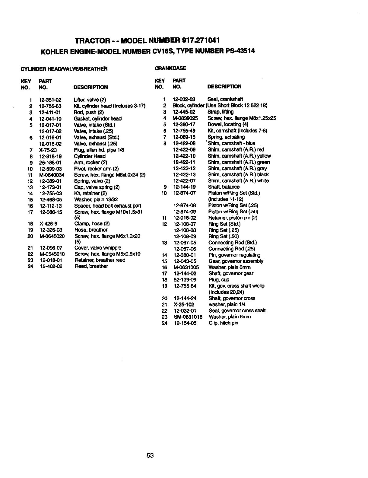
TRACTOR - - MODEL NUMBER 917.271041
KOHLER ENGINE-MODEL NUMBER CV16S, TYPE NUMBER PS-43514
CYUNDER HEAl)NAIVE/BREATHER
KEY PART
NO. NO.
CRANKCASE
1
2
3
4
5
7
8
9
10
11
12
13
14
15
16
17
18
19
20
21
22
23
24
12-351-02
12-755-63
12-411-01
12-041-10
12-017-01
12-017-02
12-016-01
12-016-02
X-75-23
12-318-19
25-186-01
12-599-0_
M-0640034
12-089-01
12-173-01
12-7,55-0_
12-468.O5
12-112-13
12086-15
X-426-9
12-326-03
M-0645020
12-096-07
M-0545010
12-018-01
12-4(_-02
PART
DESCRIPTION NO. NO. DESCRIPTION
Lifter,valve(2) 1
10Lcygnderhead (Includes3-17) 2
Rod,push (2) 3 12-445-02
Gasket,cyllr_lerhead 4 M-0839025
Valve,intake (Strt.) 5 12-380-17
Valve, intake (25) 6 12-755-49
Valve, exhaust (Std.) 7 12-089-18
Valve, exhaust (.25) 8 12-422-08
Plug, alla_ hd.pipe 1/8 12-422-09
CylinderHead 12-422-10
Arm, rocker(2) 12422-11
Pivot,rockerarm (2) 12-422-12
Screw, hex.flange M6xl.0x34 (2) 12-422-13
Spring,valve (2) 12-422-07
Cap, valve spring(2) 9 12-144-19
Kit,retainer(2) 10 12-874-07
Washer,plain 13/32
Spacer, head bolt exhaustport 12-874-08
Screw, hex. flangeM10x1.5x81 12-874-09
(5) 11 12-018-02
Clamp, hose (2) 12 12-108-07
Hose, breather 12-108-08
Screw, hax. flangeM6xl.0x20 12-108-09
(5) 13 12-067-05
Cover,valve w/nipple 12-067-06
Screw, hex. flangeM5x0.8xl0 14 12-380-01
Retainer,breatherreed 15 12-043-05
Reed,breather 16 M-0631005
17 12-144-02
18 52-139-09
19 12-755-64
20 12-144-24
21 X-25-102
22 12-032-01
23 SM-0631015
24 12-154-O5
12-032..0_ Seal, crenkshaft
Block,cylinder(Use ShortBlock12522 18)
Strap, lilting
Screw, hax. flange MSx1.25x25
Dowel,locating(4)
Kit,camshaft(Includes7-8)
Spring,actuatlng
Shim,camshaft-blue q
Shim,camshaft (A.R.) red
Shim,camshaft (A.R.) yellow
Shim,camshaft (A.R.) green
Shim,camshaft (A.R.) gray
Shim,camshaft(A.R.) black
Shim,camshaft(A.R.) white
Shaft,balance
Pistonw/Ring Set (Std.)
(Includes11-12)
Pistonw/RingSet (.25)
Pistonw/RingSet (.50)
Retainer,pistonpin (2)
RingSet (Strt.)
RingSet (.25)
RingSet (.50)
Connecting Rod (Std.)
ConnectingRod (.25)
Pin, governorregulating
Gear, governorassembly
Washer, plain 6mm
Shaft, governor gear
Plug,cup
Kit,gov.crossshaftw/clip
(Indudea 20,24)
Shaft,governor cross
washer, plain 114
Seal, govamor crossshaft
Washer, plain6mm
Clip, hitchpin
53
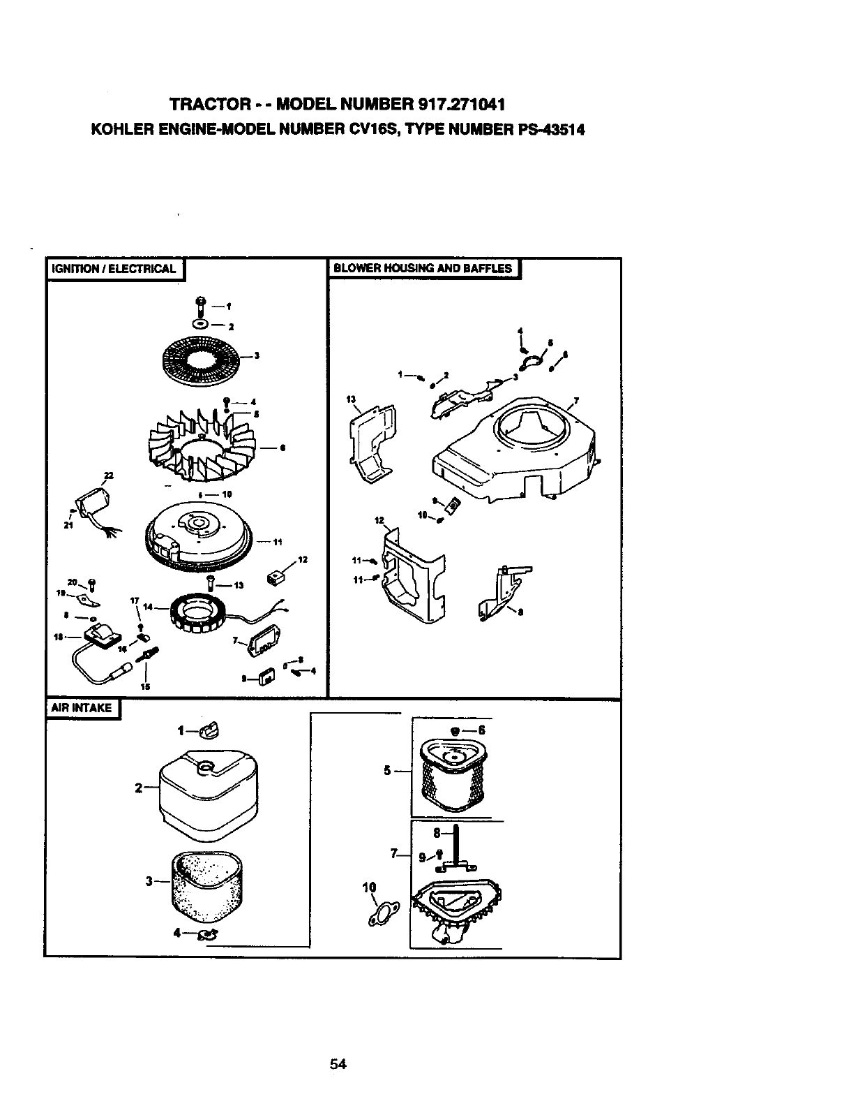
TRACTOR - - MODEL NUMBER 917.271041
KOHLER ENGINE-MODEL NUMBER CV16S, TYPE NUMBER PS-43514
IGNrrlON /ELECTRICAL I
--2
D6
-- I-- 10
--tt
,,-_;_ _ "_,-_
AIR INTAKE I ,-8
BLOWERHOUSINGAND BAFFLES I
4
54
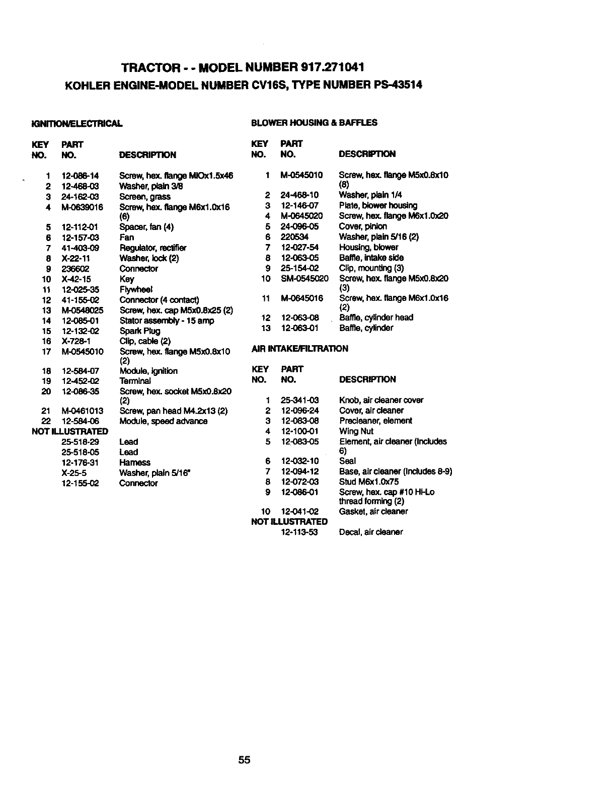
TRACTOR - - MODEL NUMBER 917.271041
KOHLER ENGINE-MODEL NUMBER CV16S, TYPE NUMBER PS-43514
IGNmON/ELEJ_rRI_?_d.
KEY PART
NO. NO.
BLOWER HOUSING & BAFFLES
K]EY PART
DESCRIPTION NO. NO. DESCRIPTION
1 12-086-14 Screw,hex. flangeMIOx1.5x46 1 M-0545010
2 12-468-03 Washer,plain 3/8
3 24-162-0_ Screen, grass 2 24-468-10
4 M-0639016 Screw,hex. flangeM6x1.0x16 3 12-146-07
(6) 4 M-0645020
5 12-112-01 Spacer,fan (4) 5 24-096-05
6 12-157-03 Fan 6 220534
7 41-403-09 Regulator,rectifier 7 12-027-54
8 X-22-11 Washer,lock(2) 8 12-063-05
9 236602 Connector 9 25-154-02
10 X-42-15 Key 10 SM-0545020
11 12-025-35 Flywheel
12 41-155-02 Connector(4 oontact) 11 M-0645016
13 M-0548025 Screw,hex. cap M5xO.8x25(2)
14 12-08501 Statoraasembly-15amp 12 12-063-08
15 12-132-02 Spark Plug 13 12-063-01
16 X-728-1 Clip, cable (2)
17 M-0545010 Screw, hex. flange M5xO.8xl0 AIR INTAKE/FILTRATION
(2)
18 12-584-07 Module,ignition KEY PART
19 12-452-_Z Terminal NO. NO.
20 12-086-35 Screw,he)(.socketM5xO.Sx20
(2) 1 25-341-03
21 M-0461013 Screw, pan head M4.2x13 (2) 2 12-096-24
22 12-584-06 Module, speedadvance 3 12-083-08
NOT ILLUSTRATED 4 12-100-01
25-518-29 Lead 5 12-083-05
25-518-05 Lead
12-176-31 Harness 6 12-032-10
X-25-5 Washer,plain 5/16" 7 12-094-12
12-155-02 Connector 8 12-072-03
9 12-086-01
Screw,hex. flangeM5xO.8xl0
(8)
Washer,plain 1/4
Plate, blowerhousing
Screw,hex. flangeM6xl.0x20
Cover,pinion
Washer,plain 5/16 (2)
Housing,blower
Baffle,intakeside
Clip, mounting(3)
Screw,hex. flange M5xO.8,_0
(3)
Screw,hax. flange M6xl.0x16
(2)
Baffle, cylinderhead
Baffle, cylinder
DESCRIPTION
10 12-041-02
NOT ILLUSTRATED
12-113-53
Knob,airdeacer cover
Cover,air cleaner
Predeaner, element
Wing Nut
Element,air cleaner(Includes
6)
Seal
Base, aircleaner(Includes8-9)
Stud M6xl.0x75
Screw,he)(.cap #10 Ht-Lo
thread forming(2)
Gasket, aircleaner
Decal, aircleaner
55
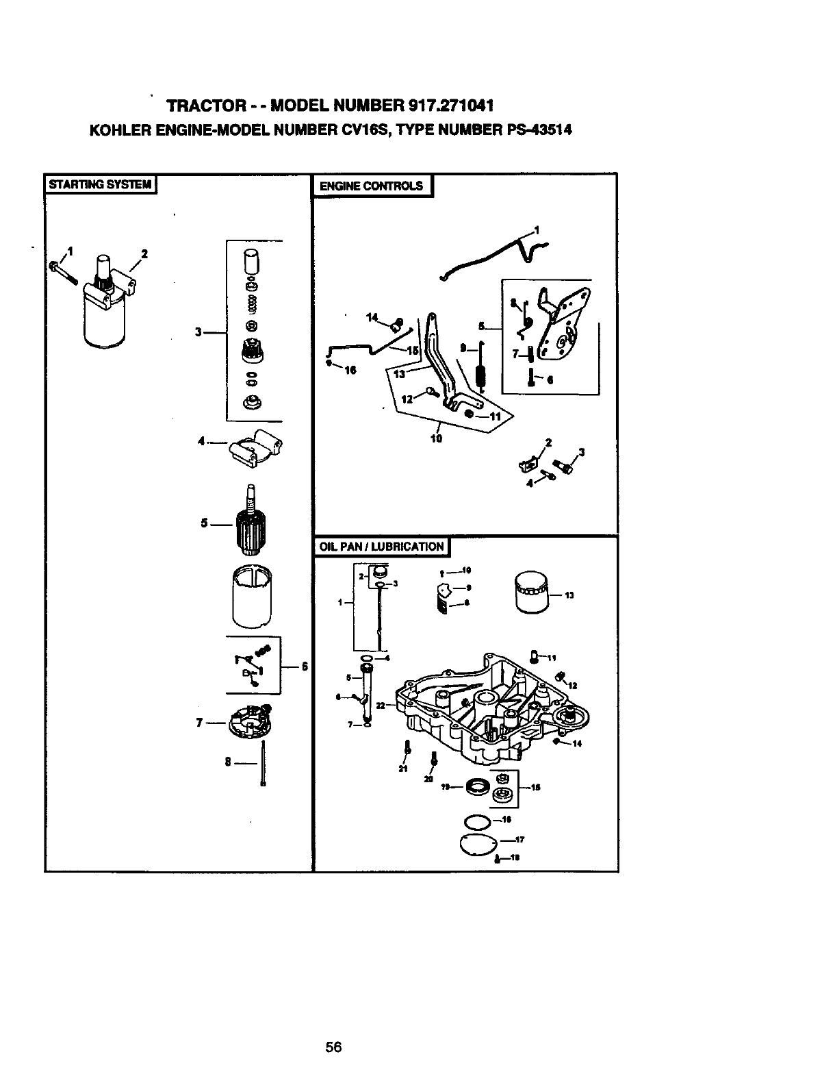
TRACTOR - - MODEL NUMBER 917.271041
KOHLER ENGINE-MODEL NUMBER CV16S, TYPE NUMBER PS.43514
STARTINGSTSll=M
o
3h @
o
O
ENGINE CONTROLS I
10
OIL PAN /LUBRICATION
i
3 t _le
13
m
0--4
O_lg
56
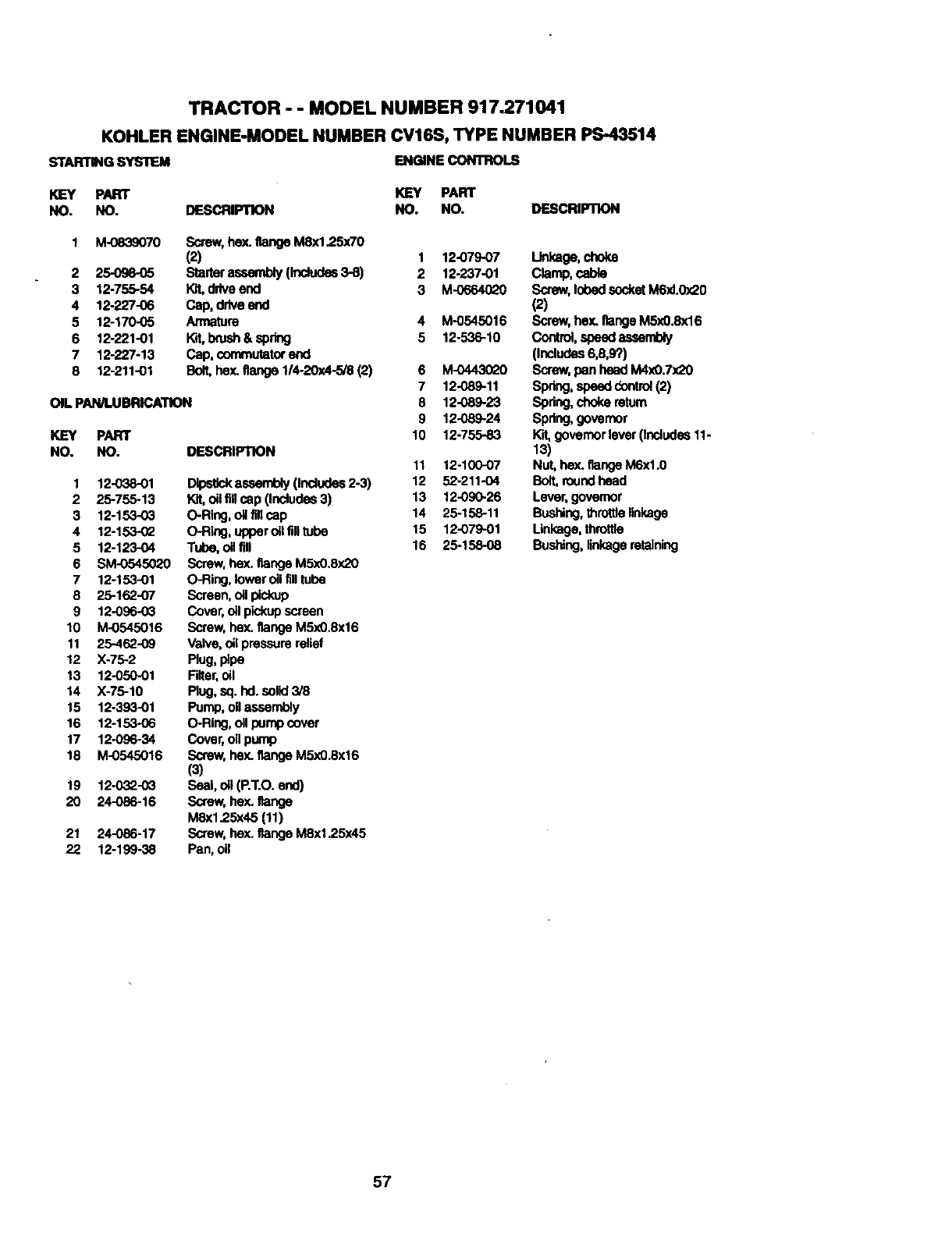
TRACTOR - - MODEL NUMBER 917.271041
KOHLER ENGINE-MODEL NUMBER CV16S, TYPE NUMBER PS-43514
STARTING SYSTEM ENGINE CONTROLS
KEY PART KEY PART
NO. NO. DESCRIPTK)N NO. NO. DESCRIP'nON
2
3
4
5
6
7
8
M-0839070 Screw,he_. flange M8x1.25x70
(2) 1 12-079-07
25-09e-_5 StaRerassembly (Includes3-8) 2 12-237-01
12-755-54 l<3t,driveend 3 M-0664(_Z0
12-227-06 Cap, driveend
12-170-05 Armature 4 M-0545016
12221-01 Kit, brush& spring 5 12-536-10
12-227-13 Cap, commutaforend
12-211-01 Bolt,hex.flange 1/4-20x4-5/8 (2) 6 M-0443020
7 12-089-11
OIL PAN/lUBRICATION 8 12-089-23
9 12-089-24
10 12-755-83KEY PART
NO. NO. DESCRIPTION
1
2
3
4
5
6
7
8
9
10
11
12
13
14
15
16
17
18
19
2O
21
22
12-038-01
25-755-13
12-153-03
12-153-02
12-123-04
SM-0545020
12-153-o1
25-162-07
12-096-03
M-0545016
25-462-09
X-75-2
12-050-01
X-75-10
12-393..01
12-153-06
12-096-34
M-0545016
12-032-03
24-086-16
24-086-17
12-199-38
DipsUckassembly(Includes2-3)
Kit,oil fl, cap (Includes3)
O-Ring, oilfillcap
O-Ring, upperoil filltube
Tube, oil fill
Screw,hex. flange M5xO.8x20
O-Ring, lowerOilfilltube
Screen,oilpickup
Cover,oll pickupscreen
Screw, hex.flange M5xO.8x16
Valve, oil pressurerelief
Rug, pipe
Filter,oil
Rug, sq. hd.solid3/8
Pump,oil assembly
O-Ring,oilpump cover
Cover,oil pump
Screw, hex.flange M5xO.8x16
(3)
Seal, oil (P.T.O.end)
Screw,hex.flange
MSx1.25x45 (11)
Screw, hex.flange MSx1.25x45
Pan, oil
11 12-100-07
12 52-211-O4
13 12-090-26
14 25-158-11
15 12-079-01
16 25-15808
Unkage, choke
Clamp, cable
Screw,lobedsocketM6xl.0x20
(2)
Screw,hey. flangeM5x0.8x16
Cont., speedassembly
(Includes6,8,9?)
Screw,pan head M4x0.7x20
Spdng,speed_ontroi (2)
Spring,chokereturn
Spring,governor
Kit, governorlever (Includes11-
13)
Nut, hex. flangeM6xl.0
Bolt,roundhead
Lever, governor
Bushing,throttlelinkage
Linkage,throttle
Bushing,linkageretaining
57
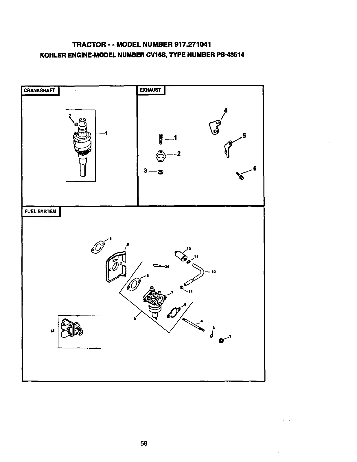
TRACTOR - - MODEL NUMBER 917.271041
KOHLER ENGINE-MODEL NUMBER CV16S, TYPE NUMBER PS-43514
CRANKSHAFT_
--1 • §__1
3--@
3
58
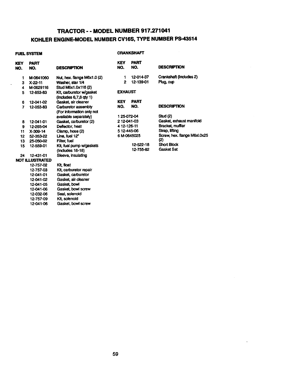
TRACTOR - - MODEL NUMBER 917.271041
KOHLER ENGINE-MODEL NUMBER CV16S, TYPE NUMBER PS-43514
FUEL SYSTEM
KEY PART
NO. NO.
1 M-0641060
3 X-22-11
4 M-0629116
5 12-853-83
6 12-041-02
7 12-053-83
8 12-041-01
9 12-265-04
11 X-309-14
12 52-353-22
13 25-050-02
15 12-559-01
24 12.431-01
NOT ILLUSTRATED
12-757-02
12-757-03
12-041-01
12-041-02
12-041-05
12-041-06
12-032-06
12-757-09
12-041-06
DESCRIPTION
Nut, hox. flange M6xI.0 (2)
Washer,star 1/4
StudM6x1.0x116 (2)
Kit,cafouretorw/gasket
(Includes6,7,8 qty 1)
Gasket, aircleaner
Carburetorassembly
(For informationonly not
availableseparetely)
Gasket, carburetor(2)
Deflector,heat
Clamp, hose (2)
Line, fuel12"
Filter,fuel
Kit,fuelpump w/gaskets
(Includes16-18)
Sleeve, insulating
Kit,float
Kit,carburetorrepair
Gasket,carburetor
Gasket, aircleaner
Gasket, bowl
Gasket, bowlscrew
Seal, solenoid
Kit,solenoid
Gasket,bowlscrew
CRANKSHAFT
KEY PART
NO. NO.
1 12-014-37
2 12-139-01
EXHAUST
KEY PART
NO. NO.
1 25-072-04
2 12.O41-03
4 12-126-11
5 12-445-06
6 M-0645025
12-522-18
12-755-82
DESCRIPTION
Crankshaft(Includes2)
Plug,cup
DESCRIPTION
Stud(2)
Gasket, exhaustmanifold
Bracket,muffler
Strap, lifting
Screw,hex.flangeM6xI.0x25
(2)
ShortBlock
Gasket Set
59

60

61

62

SUGGESTED GUIDE FOR SIGHTING SLOPES FOR SAFE OPERATION
I""
SIGHTING
GUIDE
ONLY RIDE UP AND DOWN HILL,
NOT ACROSS HILL
I_ Operate your Tractor up and down the face of slopes (not |
i
greater than 15'), never across the face. Make turns gradu- I
ally to prevent tipping or loss of control. Exercise extreme
ceutlon when changing direction on slopes.

For the repair or replacement parts you need
delivered directly to your home
Call 7 am - 7 pm, 7 days a week
1-800-366-PART
(1-800-366-7278)
Para ordenar piezas con entrega a
domicilio - 1-800-659-7084
For in-house major brand repair service
Call 24 hours a day, 7 days a week
1-800-4-REPAIR
(1-800-473-7274)
Para pedir servioio de reparaci6n a
domicilio - 1-800-676-5811
For the location of a Sears Parts and
Repair Center in your area
Call 24 hours a day, 7 days a week
1-800-488-1222
For information on purchasing a Sears
Maintenance Agreement or to inquire
about an existing Agreement
Call 9 am - 5 pm, Monday--Saturday
1-800-827-6655
Ha|H||
HBBHKH
When requesting service or ordering
pads, always provide the following
information:
•Product Type •Part Number
•Model Number •Part Description SEARS
Amenca's Repair Speciallsls
_5075 07.29.98 Rev. 5 RDIVB/RHIRD Printed in U.S.A.
