Craftsman 917271090 User Manual LAWN TRACTOR Manuals And Guides 99020019
CRAFTSMAN Lawn, Tractor Manual 99020019 CRAFTSMAN Lawn, Tractor Owner's Manual, CRAFTSMAN Lawn, Tractor installation guides
User Manual: Craftsman 917271090 917271090 CRAFTSMAN LAWN TRACTOR - Manuals and Guides View the owners manual for your CRAFTSMAN LAWN TRACTOR #917271090. Home:Lawn & Garden Parts:Craftsman Parts:Craftsman LAWN TRACTOR Manual
Open the PDF directly: View PDF ![]() .
.
Page Count: 60
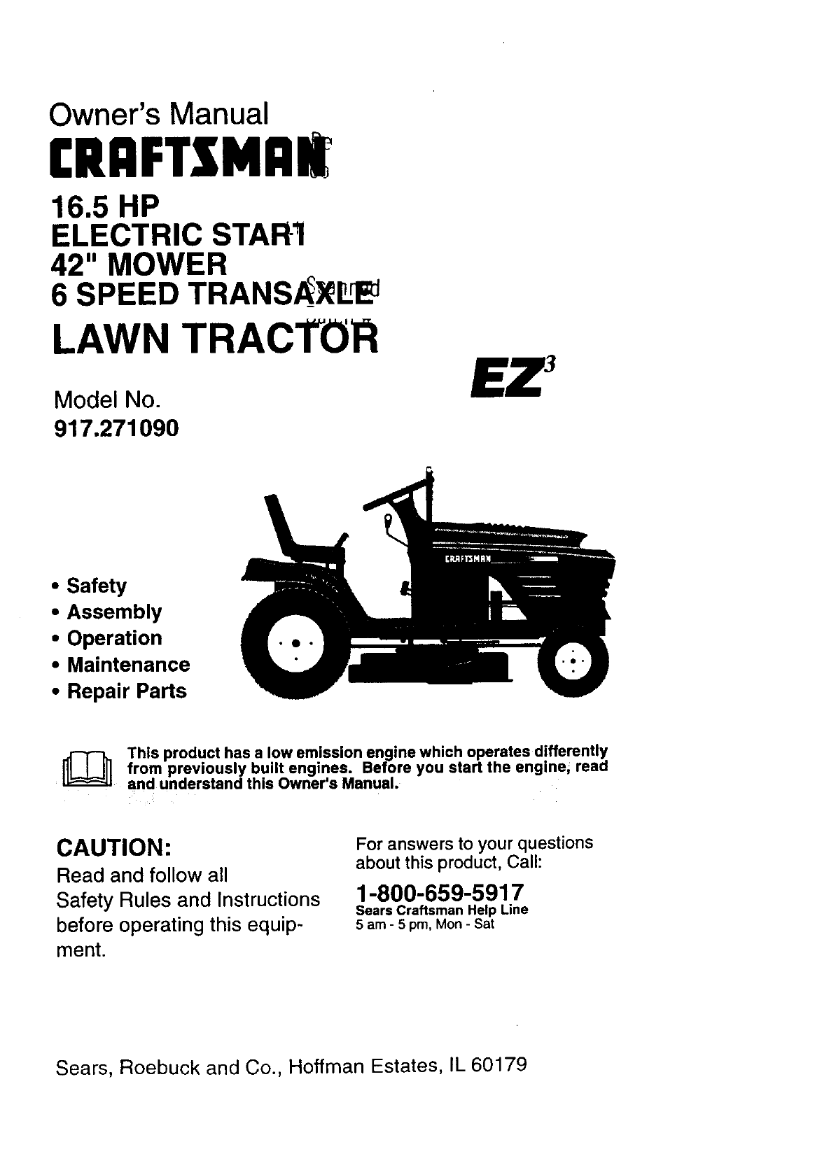
Owner's Manual
CRAFTSMnl[
16.5 HP
ELECTRIC STAR1
42" MOWER
6 SPEED TRANS_Lq_
LAWN TRACTOR
Model No.
917,271090
•Safety
•Assembly
•Operation
•Maintenance
•Repair Parts
This product has a low emission engine which operates differently
from built Before start the enginei read
previously engines. you
and understand this Owner's Manual.
CAUTION:
Read and follow all
Safety Rules and Instructions
before operating this equip-
ment.
For answers to your questions
about this product, Call:
1-800-659-5917
Sears Craftsman Help Line
5 am -5 pro, Mon- Sat
Sears, Roebuck and Co., Hoffman Estates, IL 60179
Warranty ................................................. 2
Safety Rules ........................................... 2
Product Specifications ........................... 5
Assembly ................................................ 8
Operation .............................................. 12
Maintenance Schedule ......................... 18
Maintenance ......................................... 18
Service and Adjustments ...................... 22
Storage ................................................. 27
Troubleshooting .................................... 29
Repair Parts ......................................... 32
Parts Ordering ....................... Back Cover
LIMITED TWO YEAR WARRANTY ON CRAFTSMAN RIDING EQUIPMENT
For two (2) years from the date of purchase, if-this Craftsman Riding Equipment is main-
tained, lubricated and tuned up according to the instructions in the owner's manual,
Sears will repair or replace, free of charge, any parts found to be defective in material or
workmanship.
This Warranty does not cover:
• Expendable items which become worn during normal use, such as blades, spark
plugs, air cleaners, belts, etc.
• Tire replacement or repair caused by punctures from outside objects, such as nails,
thorns, stumps, or glass.
• Repairs necessary because of operator abuse, negligence, improper storage or acci-
dent or the failure to maintain the equipment according to the instructions contained in
the owner's manual.
• Riding equipment used for commercial or rental purposes.
LIMITED 90 DAY WARRANTY ON BA'I-FERY
For ninety (90) days from date of purchase, if any battery included with this riding equip-
ment proves defective in material or workmanship and our testing determines the bat-
tery will not hold a charge, Sears will replace the battery at no charge. In-home warranty
service on your Craftsman riding equipment is available at no charge for 30 days from
the date of purchase. Please contact your nearest service center. After 30 days from the
date of purchase, warranty service is available by taking your Craftsman riding equip-
ment to your nearest Sears Service Center. (Imhome warranty service will still be avail-
able after 30 days from the date of purchase but a standard trip charge will apply). This
warranty applies only while this product is in the United States. This Warranty gives you
specific legal rights, and you may also have other rights which may vary from state to
state.
Sears, Roebuck and Co., D/817 WA, Hoffman Estates, IL 60179
GENERAL OPERATION
• Read, understand, and follow all instruc-
tions in the manual and on the machine
before starting.
• Only allow responsible adults, who are
familiar with the instructions, to operate
the machine.
• Clear the area of objects such as rocks,
toys, wire, etc., which could be picked
up and thrown by the blade.
• Be sure the area is clear of other people
before mowing. Stop machine if anyone
enters the area.
2
•Never carry passengers.
• Do not mow in reverse unless absolute-
ly necessary. Always look down and
behind before and while backing.
•Be aware of the mower discharge direc-
tion and do not point it at anyone. Do
not operate the mower without either
the entire grass catcher or the guard in
place.
•Slow down before turning.
•Never leave a running machine unat-
tended. Always turn off blades, set park-
ing brake, stop engine, and remove
keys before dismounting.
• Turnoffbladeswhennot mowing.
• Stop engine before removing grass
catcher or unclogging chute.
•Mow only in daylight or good artificial
light.
•Do not operate the machine while under
the influence of alcohol or drugs.
•Watch for traffic when operating near or
crossing roadways.
•Use extra care when loading or unload-
ing the machine into a trailer or truck.
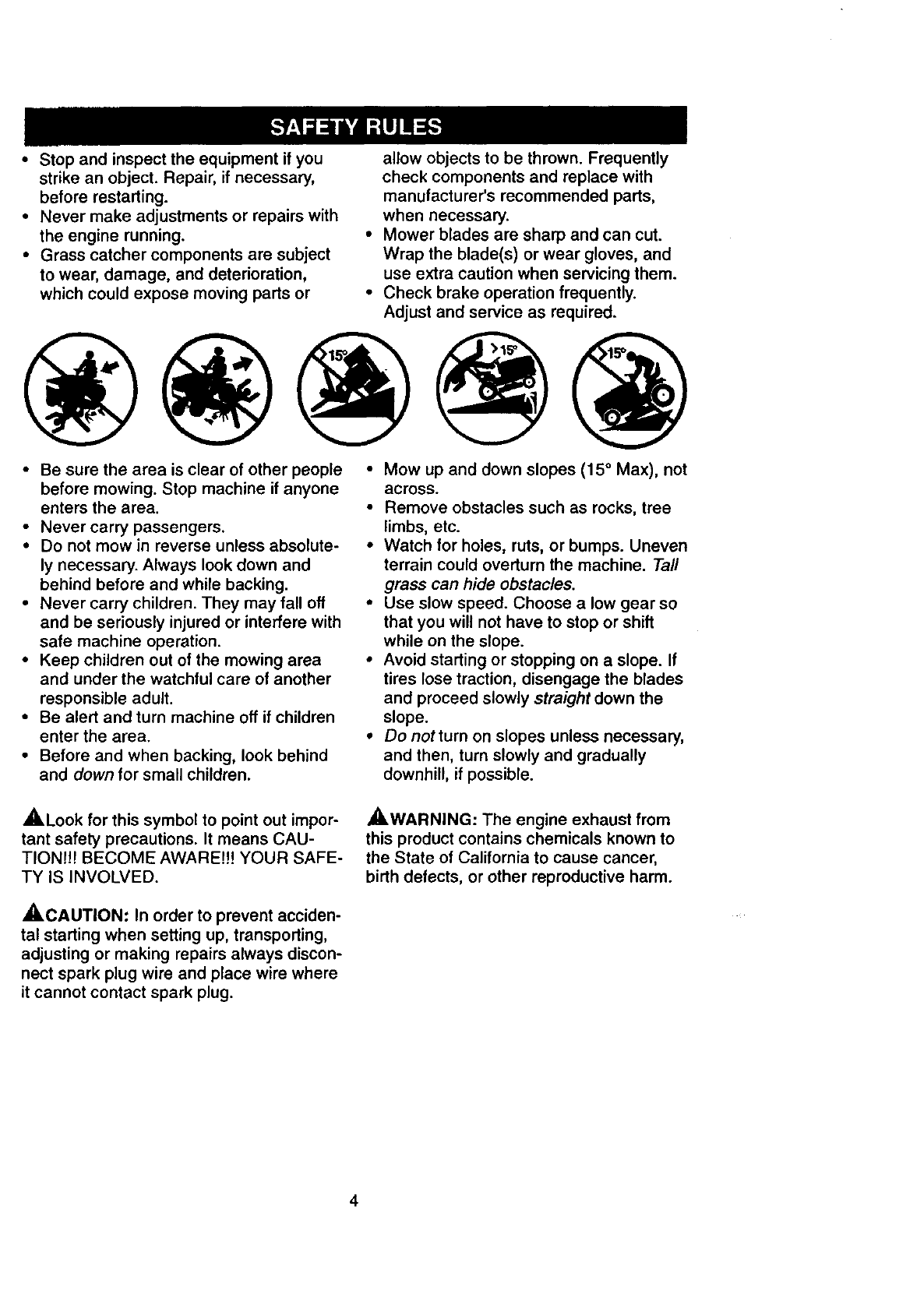
SLOPE OPERATION
Slopes are a major factor related to loss-
of-control and tipover accidents, which
can result in severe injury or death. All
slopes require extra caution. If you cannot
back up the slope or if you feel uneasy on
it, do not mow it.
DO:
•Mow up and down slopes, not across.
• Remove obstacles such as rocks, tree
limbs, etc.
•Watch for holes, ruts, or bumps. Uneven
terrain could overturn the machine. Tall
grass can hide obstacles.
•Use slow speed. Choose a low gear so
that you will not have to stop or shift
while on the slope.
• Follow the manufacturer's recommen-
dations for wheel weights or counter-
weights to improve stability.
•Use extra care with grass catchers or
other attachments. These can change
the stability of the machine.
•Keep all movement on the slopes slow
and gradual. Do not make sudden
changes in speed or direction.
•Avoid starting or stopping on a slope. If
tires lose traction, disengage the blades
and proceed slowly straight down the
slope.
DO NOT:
•Do notturn on slopes unless necessary,
and then, turn slowly and gradually
downhill, if possible.
•Do not mow near drop-offs, ditches, or
embankments. The mower could sud-
denly turn over if a wheel is over the
edge of a cliff or ditch, or if an edge
caves in.
•Do not mow on wet grass. Reduced
traction could cause sliding.
•Do nottry to stabilize the machine by
putting your foot on the ground.
•Do not use grass catcher on steep
slopes.
CHILDREN
Tragic accidents can occur if the operator
is not alert to the presence of children.
Children are often attracted to the
machine and the mowing activity. Never
assume that children will remain where
you last saw them.
•Keep children out of the mowing area
and under the watchful care of another
responsible adult.
•Be alert and turn machine off if children
enter the area.
•Before and when backing, look behind
and down for small children.
•Never carry children. They may fall off
and be seriously injured or interfere with
safe machine operation.
•Never allow children to operate the
machine.
•Use extra care when approaching blind
corners, shrubs, trees, or other objects
that may obscure vision.
SERVICE
•Use extra care in handling gasoline and
other fuels. They are flammable and
vapors are explosive.
Use only an approved container.
Never remove gas cap or add fuel
with the engine running. Allow en-
gine to cool before refueling. Do not
smoke.
Never refuel the machine indoors.
Never store the machine or fuel
container inside where there is an
open flame, such as a water heater.
•Never run a machine inside a closed
area.
• Keep nuts and bolts, especially blade
attachment bolts, tight and keep equip-
ment in good condition.
•Never tamper with safety devices.
Check their proper operation regularly.
•Keep machine free of grass, leaves, or
other debris build-up. Clean oil or fuel
spillage. Allow machine to cool before
storing.
3
• Stop and inspect the equipment if you
strike an object. Repair, if necessary,
before restarting.
° Never make adjustments or repairs with
the engine running.
• Grass catcher components are subject
to wear, damage, and deterioration,
which could expose moving parts or
allow objects to be thrown. Frequently
check components and replace with
manufacturer's recommended parts,
when necessary.
Mower blades are sharp and can cut.
Wrap the blade(s) or wear gloves, and
use extra caution when servicing them.
Check brake operation frequently.
Adjust and service as required.
•Be sure the area is clear of other people
before mowing. Stop machine if anyone
enters the area.
• Never carry passengers.
• Do not mow in reverse unless absolute-
ly necessary. Always look down and
behind before and while backing.
• Never carry children. They may fall off
and be seriously injured or interfere with
safe machine operation.
• Keep children out of the mowing area
and under the watchful care of another
responsible adult.
• Be alert and turn machine off if children
enter the area.
• Before and when backing, look behind
and down for small children.
• Mow up and clown slopes (15 °Max), not
across.
•Remove obstacles such as rocks, tree
limbs, etc.
•Watch for holes, ruts, or bumps. Uneven
terrain could overturn the machine. Tall
grass can hide obstacles.
•Use slow speed. Choose a low gear so
that you will not have to stop or shift
while on the slope.
• Avoid starting or stopping on a slope. If
tires lose traction, disengage the blades
and proceed slowly straight down the
slope.
•Do notturn on slopes unless necessary,
and then, turn slowly and gradually
downhill, if possible.
,_Look for this symbol to point out impor-
tant safety precautions. It means CAU-
TIONI!! BECOME AWARE!!! YOUR SAFE-
TY IS INVOLVED.
_CAUTION: In order to prevent acciden-
tal starting when setting up, transporting,
adjusting or making repairs always discon-
nect spark plug wire and place wire where
it cannot contact spark plug.
_,WARNING: The engine exhaust from
this product contains chemicals known to
the State of California to cause cancer,
birth defects, or other reproductive harm.
4
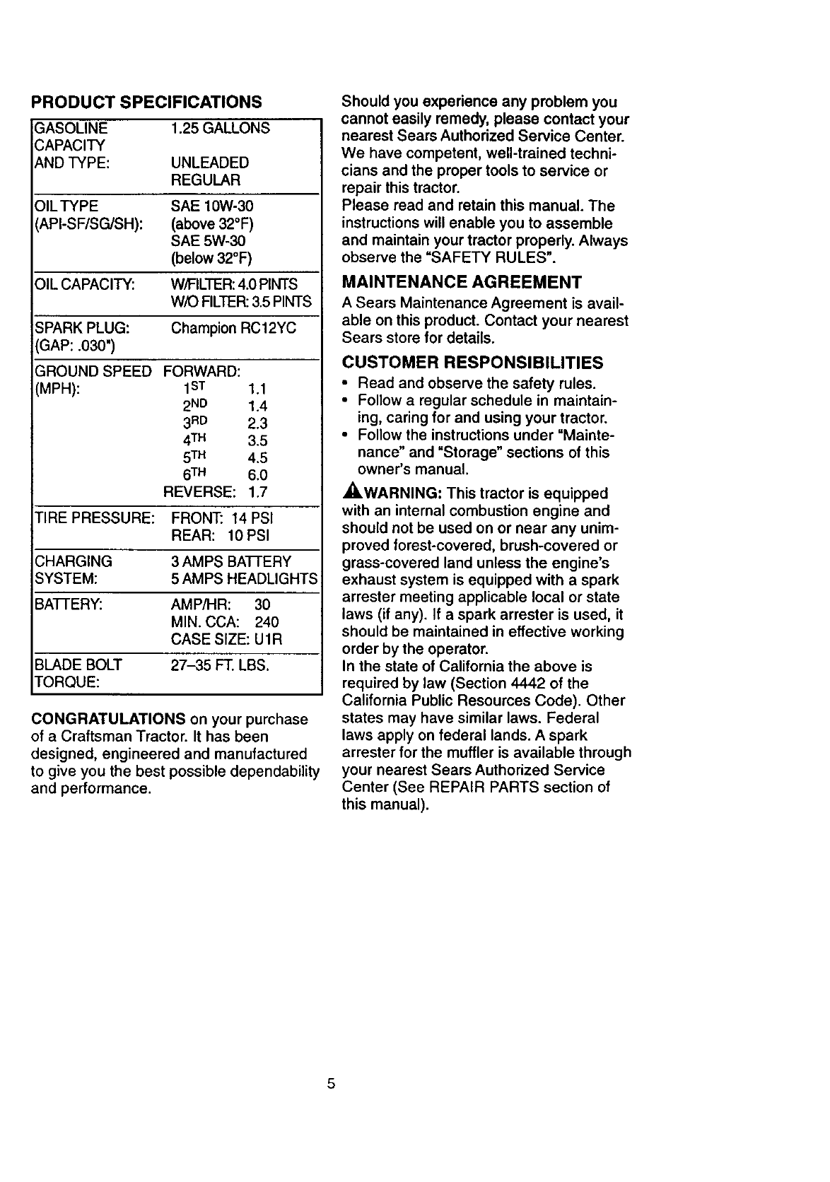
PRODUCT SPECIFICATIONS
GASOLINE 1.25 GALLONS
CAPACITY
AND TYPE: UNLEADED
REGULAR
OILTYPE SAE 10W-30
API-SF/SG/SH): (above 32°F)
SAE 5W-30
(below 32°F)
OIL CAPACITY: W/FILTER: 4.0 PINTS
WiO FILTER: 3.5 PINTS
SPARK PLUG: Champion RC12YC
GAP: .030")
GROUND SPEED FORWARD:
(MPH): 1sT 1.1
2ND 1.4
3RD 2.3
4 TM 3.5
5TM 4.5
6TM 6.0
REVERSE: 1.7
TIRE PRESSURE: FRONT: 14 PSI
REAR: 10 PSI
CHARGING 3 AMPS BAI-FERY
SYSTEM: 5 AMPS HEADLIGHTS
BAI-FERY: AMPiHR: 30
MIN. CCA: 240
CASE SIZE: U1R
BLADE BOLT 27-35 FT. LBS.
TORQUE:
CONGRATULATIONS on your purchase
of aCraftsman Tractor. It has been
designed, engineered and manufactured
to give you the best possible dependability
and performance.
Should you experience any problem you
cannot easily remedy, please contact your
nearest Sears Authorized Service Center.
We have competent, well-trained techni-
cians and the proper tools to service or
repair this tractor.
Please read and retain this manual. The
instructions will enable you to assemble
and maintain your tractor properly. Always
observe the "SAFETY RULES".
MAINTENANCE AGREEMENT
A Sears Maintenance Agreement is avail-
able on this product. Contact your nearest
Sears store for details.
CUSTOMER RESPONSIBILITIES
•Read and observe the safety rules.
• Follow a regular schedule in maintain-
ing, caring for and using your tractor.
• Follow the instructions under "Mainte-
nance" and "Storage" sections of this
owner's manual.
_WARNING: This tractor is equipped
with an internal combustion engine and
should not be used on or near any unim-
proved forest-covered, brush-covered or
grass-covered land unless the engine's
exhaust system is equipped with a spark
arrester meeting applicable local or state
laws (if any). If a spark arrester is used, it
should be maintained in effective working
order by the operator.
In the state of California the above is
required by law (Section 4442 of the
California Public Resources Code). Other
states may have similar laws. Federal
laws apply on federal lands. A spark
arrester for the muffler is available through
your nearest Sears Authorized Service
Center (See REPAIR PARTS section of
this manual).
5
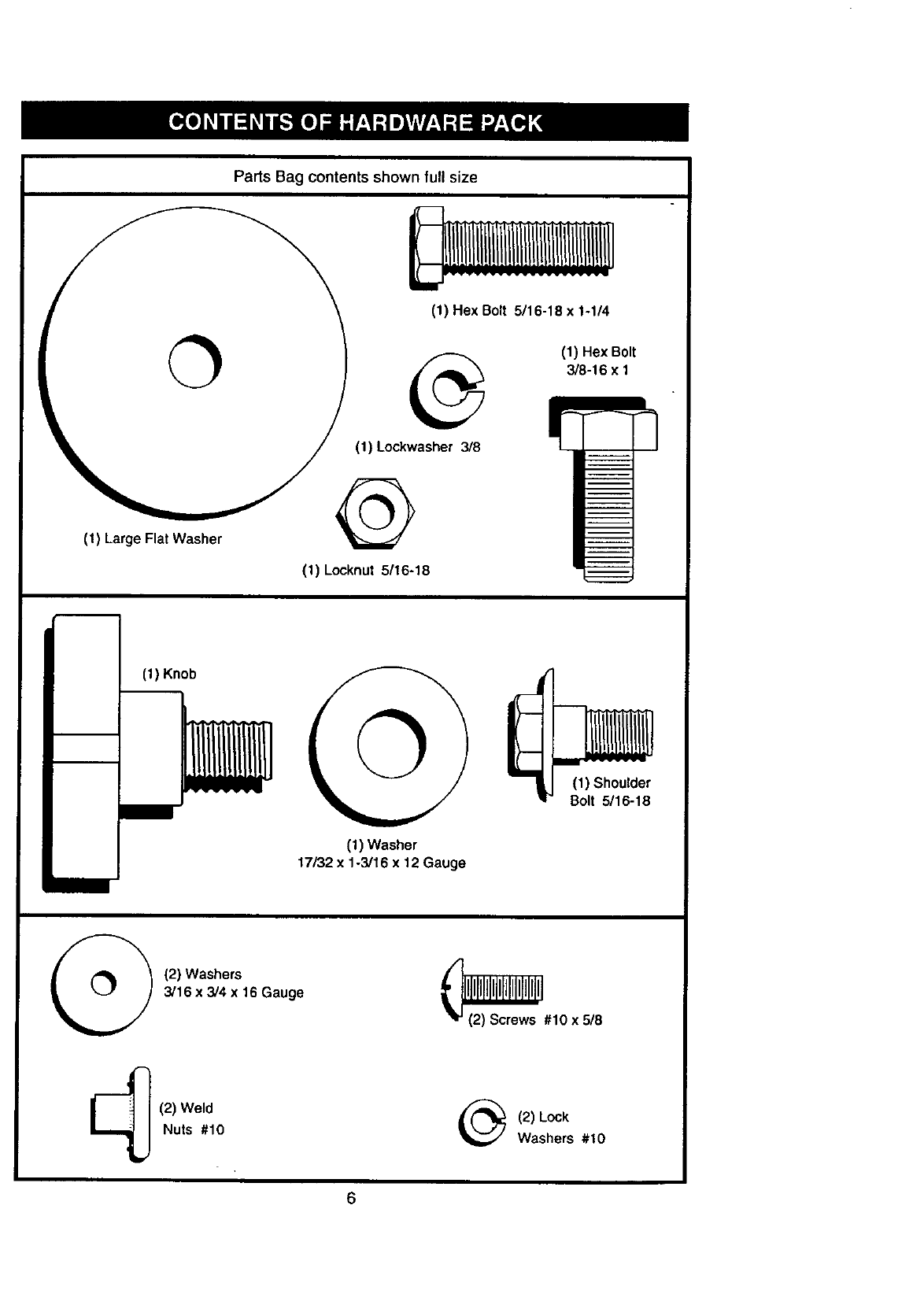
(1) Large Flat Washer
Parts Bag contents shown full size
(1) Hex Bolt 5/16-18 x 1-1/4
(1) Hex Bolt
3/8-t 6 x 1
(1) Lockwasher 3/8
@
(1) Locknut 5/16-18
(t) Knob
(t) Washer
17/32 x 1-3/16 x12Gauge
(1) Shoulder
Bolt 5/16-18
(2) Washers
3/16 x3/4 x16 Gauge _#10 x5/8
(2) Weld
Nuts #10 (2) Lock
Washers #10
6
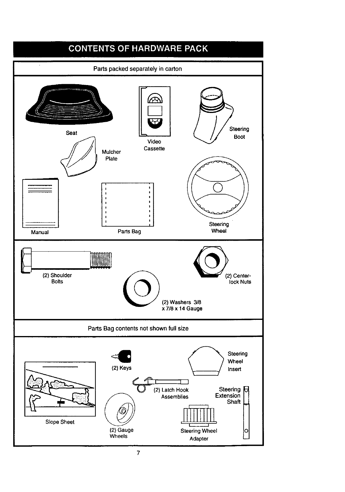
Parts packed separately in carton
Seat
Mulcher
Plate
Video
Cassette
Steering
Boot
Manual
i
Steering
Parts Bag Wheel
(2) Shoulder
Bolts
_(2) Center-
lock Nuts
(2) Washers 3/8
x 7/8 x 14 Gauge
Parts Bag contents not shown full size
Slope Sheet
,C_ _ Steering
Wheel
(2) Keys Insert
_I I I
(2) Latch Hook Steering I_l
._ Assemblies Extension I{
'_' Shaft _=_I I
(2) Gauge Steering Wheel IOI
Wheels Adapter CJ
7
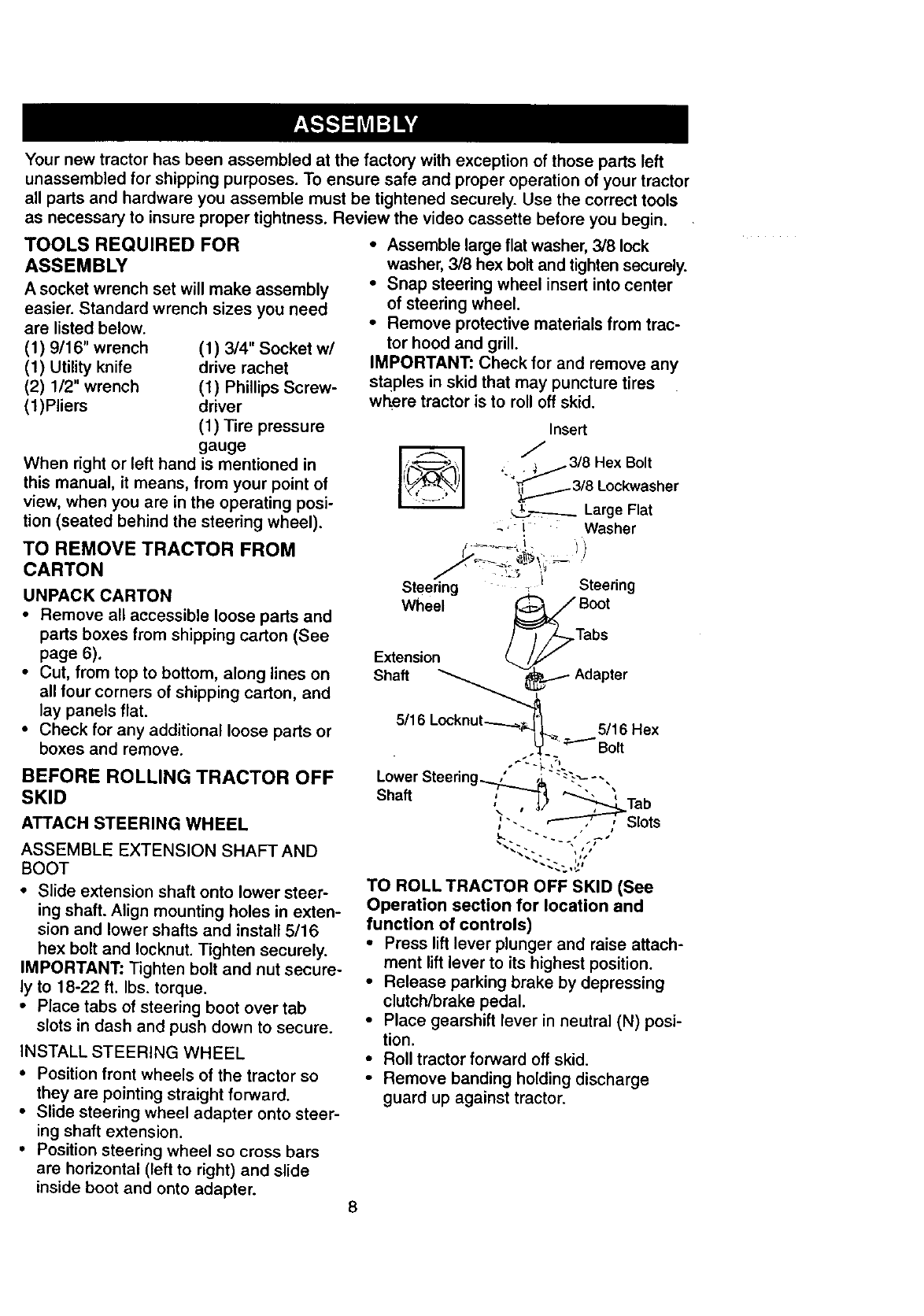
Your new tractor has been assembled at the factory with exception of those parts left
unassembled for shipping purposes• To ensure safe and proper operation of your tractor
all parts and hardware you assemble must be tightened securely. Use the correct tools
as necessary to insure proper tightness. Review the video cassette before you begin.
TOOLS REQUIRED FOR
ASSEMBLY
Asocket wrench set will make assembly
easier. Standard wrench sizes you need
are listed below.
(1) 9/16" wrench
(1) Utility knife
(2) 1/2" wrench
(1)Pliers
(1) 3/4" Socket w/
drive rachet
(1) Phillips Screw-
driver
(1) Tire pressure
gauge
When right or left hand is mentioned in
this manual, it means, from your point of
view, when you are in the operating posi-
tion (seated behind the steering wheel).
TO REMOVE TRACTOR FROM
CARTON
UNPACK CARTON
•Remove all accessible loose parts and
parts boxes from shipping carton (See
page 6).
• Cut, from top to bottom, along lines on
all four corners of shipping carton, and
lay panels flat.
•Check for any additional loose parts or
boxes and remove.
BEFORE ROLLING TRACTOR OFF
SKID
ATTACH STEERING WHEEL
ASSEMBLE EXTENSION SHAFT AND
BOOT
• Slide extension shaft onto lower steer-
ing shaft. Align mounting holes in exten-
sion and lower shafts and install 5/16
hex bolt and Iocknut. Tighten securely.
IMPORTANT: Tighten bolt and nut secure-
ly to 18-22 ft. Ibs. torque.
• Place tabs of steering boot over tab
slots in dash and push down to secure.
INSTALL STEERING WHEEL
• Position front wheels of the tractor so
they are pointing straight forward.
• Slide steering wheel adapter onto steer-
ing shaft extension.
• Position steering wheel so cross bars
are horizontal (left to right) and slide
inside boot and onto adapter. 8
•Assemble large flat washer, 3/8 lock
washer, 3/8 hex bolt and tighten securely.
•Snap steering wheel insert into center
of steering wheel.
•Remove protective materials from trac-
tor hood and grill.
IMPORTANT: Check for and remove any
staples in skid that may puncture tires
where tractor is to roll off skid.
insert
,_ _3/8 Hex Bolt
""_._3/8 Lockwashar
_--_---_.__ Large Flat
_- L Washer
Steering . _ I Steering
Wheel _,_ Boot
/3/-ia s
Extension
Shaft __._- Adapter
5/16 Locknut----__.=_,_'__ 5/16 Hex
.L___" "_"""Bolt
•,-_--._,-,...
Lower Steenng...._..= ,& -.-----,
Shaft ;_-"_ _ ,
-,_/ _Tab
"-. _ ,, Slots
TO ROLL TRACTOR OFF SKID (See
Operation section for location and
function of controls)
•Press lift lever plunger and raise attach-
ment lift lever to its highest position.
•Release parking brake by depressing
clutch/brake pedal.
•Place gearshift lever in neutral (N) posi-
tion.
•Roll tractor forward off skid.
•Remove banding holding discharge
guard up against tractor.
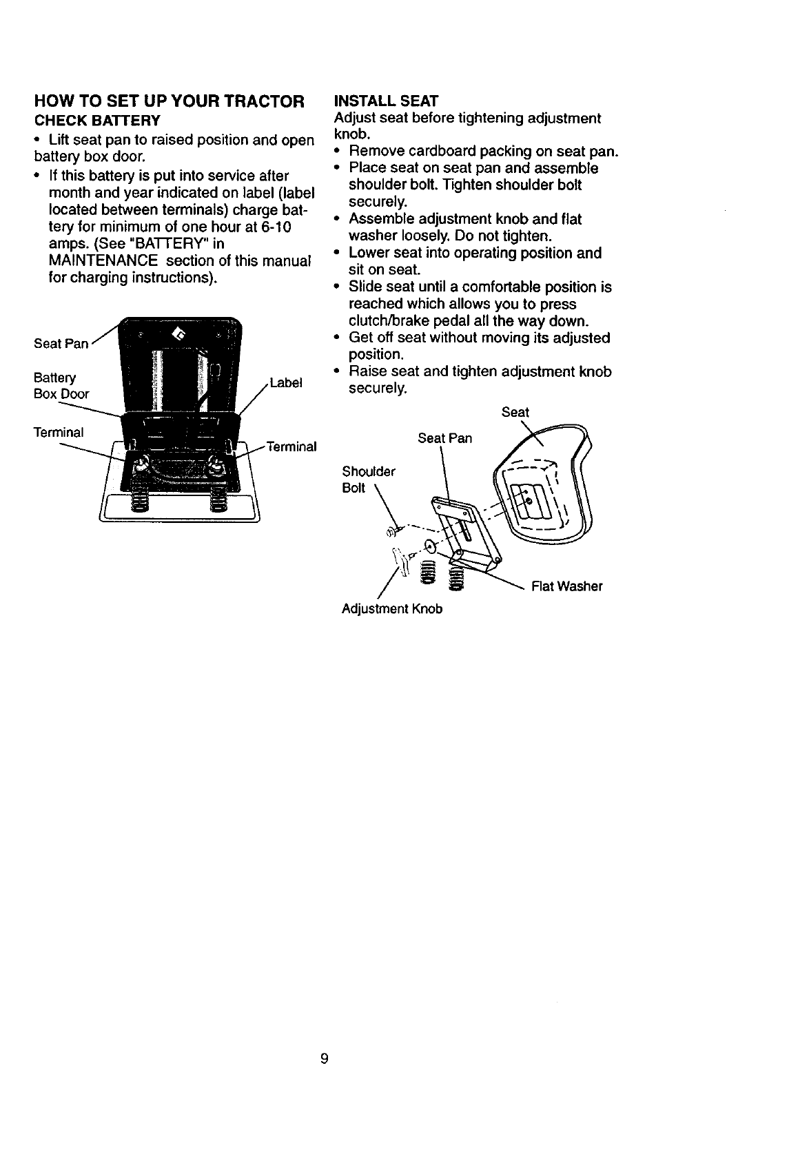
HOW TO SET UP YOUR TRACTOR
CHECKBATTERY
•Lift seat pan to raised position and open
battery box door.
•If this battery is put into service after
month and year indicated on label (label
located between terminals) charge bat-
tery for minimum of one hour at 6-10
amps. (See "BA-I3ERY" in
MAINTENANCE section of this manual
for charging instructions).
Se_
Battery Label
Box Door
Terminal ,rminal
INSTALL SEAT
Adjust seat before tightening adjustment
knob.
•Remove cardboard packing on seat pan.
•Place seat on seat pan and assemble
shoulder bolt. Tighten shoulder bolt
securely.
•Assemble adjustment knob and flat
washer loosely. Do not tighten.
•Lower seat into operating position and
sit on seat.
•Slide seat until a comfortable position is
reached which allows you to press
clutch/brake pedal all the way down.
• Get off seat without moving its adjusted
position.
•Raise seat and tighten adjustment knob
securely.
Seat
\
Seat Pan
Shoulder
Bolt
Adjustment Knob
Rat Washer
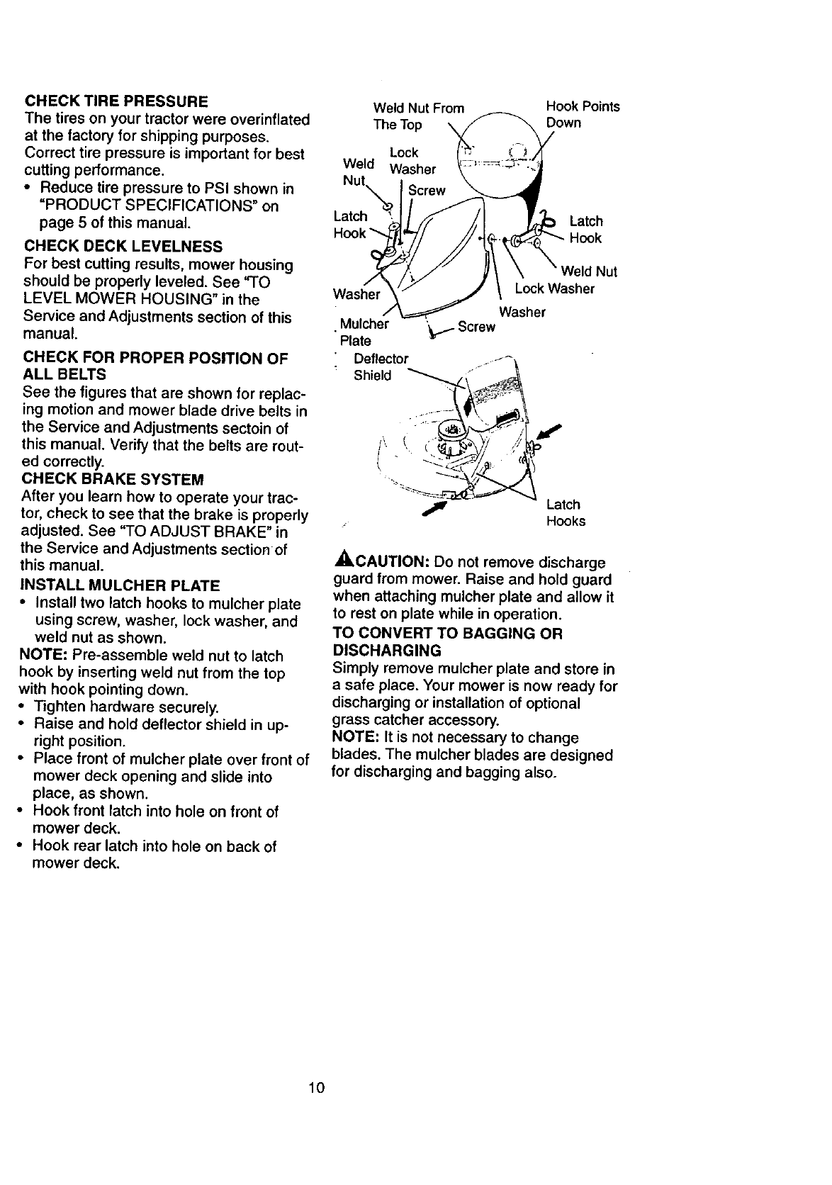
CHECK TIRE PRESSURE Weld Nut From
The tires on your tractor were overinftated The Top \
at the factory for shipping purposes.
Correct tire pressure is important for best Lock
cutting performance. Weld Washer
Nut
•Reduce tire pressure to PSI shown in Screw
=PRODUCT SPECIFICATIONS" on Latch
page 5 of this manual.
CHECK DECK LEVELNESS
For best cutting results, mower housing
should be properly leveled. See "TO
LEVEL MOWER HOUSING" in the
Service and Adjustments section of this
manual.
CHECK FOR PROPER POSITION OF
ALL BELTS
See the figures that are shown for replac-
ing motion and mower blade drive belts in
the Service and Adjustments sectoin of
this manual. Verify that the belts are rout-
ed correctly.
CHECK BRAKE SYSTEM
After you learn how to operate your trac-
tor, check to see that the brake is properly
adjusted. See "TO ADJUST BRAKE" in
the Service and Adjustments section of
this manual.
INSTALL MULCHER PLATE
•Install two latch hooks to mulcher plate
using screw, washer, lock washer, and
weld nut as shown.
NOTE: Pro-assemble weld nut to latch
hook by inserting weld nut from the top
with hook pointing down.
•Tighten hardware securely.
•Raise and hold deflector shield in up-
right position.
•Place front of mulcber plate over front of
mower deck opening and slide into
place, as shown.
•Hook front latch into hole on front of
mower deck.
•Hook rear latch into hole on back of
mower deck.
Hook Points
Down
Latch
Hook
Wa_er
Mulcher
Plate
Deflector
Shield
Weld Nut
LockWasher
Washer
_i- Screw
Latch
Hooks
_,CAUTION: Do not remove discharge
guard from mower. Raise and hold guard
when attaching mulcher plate and allow it
to rest on plate while in operation.
TO CONVERT TO BAGGING OR
DISCHARGING
Simply remove mulcher plate and store in
a safe place. Your mower is now ready for
discharging or installation of optional
grass catcher accessory.
NOTE: It is not necessary to change
blades. The mulcher blades are designed
for discharging and bagging also.
10
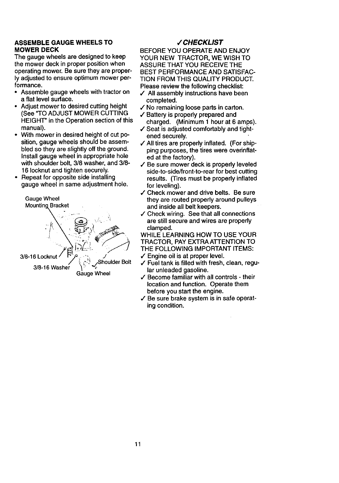
ASSEMBLEGAUGEWHEELSTO
MOWERDECK
The gaugewheelsaredesignedto keep
themowerdeckinproperpositionwhen
operatingmower.Besuretheyare proper-
ly adjusted to ensure optimum mower per-
formance.
•Assemble gauge wheels with tractor on
a flat level surface.
• Adjust mower to desired cutting height
(See "TO ADJUST MOWER CUI-I-ING
HEIGHT" in the Operation section of this
manual).
• With mower in desired height of cut po-
sition, gauge wheels should be assem-
bled so they are slightly off the ground.
Install gauge wheel in appropriate hole
with shoulder bolt, 3/8 washer, and 3/8-
16 Iocknut and tighten securely.
• Repeat for opposite side installing
gauge wheel in same adjustment hole.
Gauge Wheel
Mountin_acket
3/8-16 Washer
JdderBolt
Gauge Wheel
/ CHECKLIST
BEFORE YOU OPERATE AND ENJOY
YOUR NEW TRACTOR, WE WISH TO
ASSURE THAT YOU RECEIVE THE
BEST PERFORMANCE AND SATISFAC-
TION FROM THIS QUALITY PRODUCT.
Please review the following checklist:
,/ All assembly instructions have been
completed.
,/No remaining loose parts in carton.
,/Battery is properly prepared and
charged. (Minimum 1 hour at 6 amps).
•/Seat is adjusted comfortably and tight-
ened securely.
,/All tires are properly inflated. (For ship-
ping purposes, the tires were overinflat-
ed at the factory).
/Be sure mower deck is properly leveled
side-to-side/front-to-rear for best cutting
results. (Tires must be properly inflated
for leveling).
,/Check mower and drive belts. Be sure
they are routed properly around pulleys
and inside all belt keepers.
4 Check wiring. See that all connections
are still secure and wires are properly
clamped.
WHILE LEARNING HOW TO USE YOUR
TRACTOR, PAY EXTRA ATTENTION TO
THE FOLLOWING IMPORTANT ITEMS:
4" Engine oil is at proper level.
,/Fuel tank is filled with fresh, clean, regu-
lar unleaded gasoline.
•/Become familiar with all controls - their
location and function. Operate them
before you start the engine.
•/Be sure brake system is in safe operat-
ing condition.
11
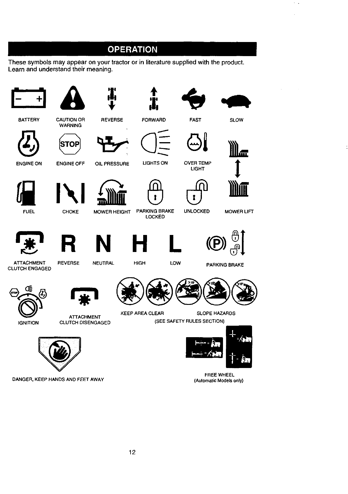
Thesesymbolsmayappearonyourtractoror inliteraturesuppliedwiththeproduct.
Learnandunderstandtheirmeaning.
BATTERY CAUTION OR
WARNING
REVERSE FORWARD FAST SLOW
I
ENGINE ON ENGINE OFF OIL PRESSURE LIGHTS ON OVER TEMP "_
!
LIGHT
FUEL CHOKE MOWER HEIGHT PARKING BRAKE UNLOCKED MOWER LIFT
LOCKED
r 'l R N H
ATTACHMENT REVERSE NEUTRAL HIGH
CLUTCH ENGAGED
L<®>31
LOW PARKING BRAKE
KEEP AREA CLEAR SLOPE HAZARDS
ATTACHMENT
IGNITION CLUTCH DISENGAGED (SEE SAFETY RULES SECTION)
DANGER, KEEP HANDS AND FEET AWAY FREE WHEEL
(Automatic Models only)
12
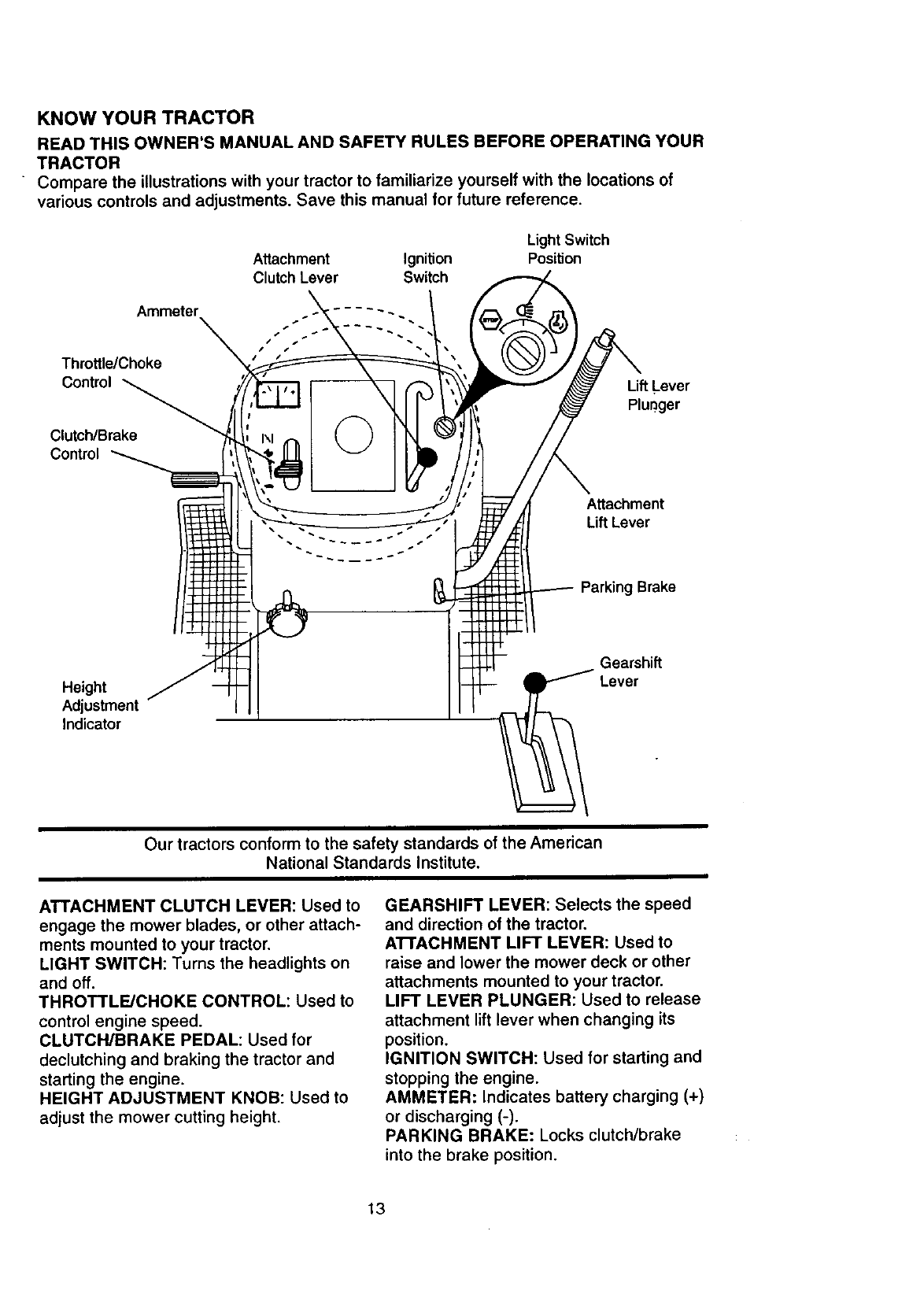
KNOW YOUR TRACTOR
READ THIS OWNER'S MANUAL AND SAFETY RULES BEFORE OPERATING YOUR
TRACTOR
Compare the illustrations with your tractor to familiarize yourself with the locations of
various controls and adjustments. Save this manual for future reference.
Attachment Ignition
Clutch Lever Switch
LightSwitch
Position
Ammeter
Throttle/Choke
Control
Clutch/Brake
Control
Lift Lever
Plunger
Attachment
Lift Lever
Parking Brake
Height
Adjustment
Indicator
Gearshift
Lever
Our tractors conform to the safety standards of the American
National Standards Institute.
ATTACHMENT CLUTCH LEVER: Used to
engage the mower blades, or other attach-
ments mounted to your tractor.
LIGHT SWITCH: Turns the headlights on
and off.
THROTTLE/CHOKE CONTROL: Used to
control engine speed.
CLUTCH/BRAKE PEDAL: Used for
declutching and braking the tractor and
starting the engine.
HEIGHT ADJUSTMENT KNOB: Used to
adjust the mower cutting height.
GEARSHIFT LEVER: Selects the speed
and direction of the tractor.
ATTACHMENT LIFT LEVER: Used to
raise and lower the mower deck or other
attachments mounted to your tractor.
LIFT LEVER PLUNGER: Used to release
attachment lift lever when changing its
position.
IGNITION SWITCH: Used for starting and
stopping the engine.
AMMETER: Indicates battery charging (+)
or discharging (-).
PARKING BRAKE: Locks clutch/brake
into the brake position.
13
The operation of any tractor can result in foreign objects thrown into the
eyes, which can result in severe eye damage. Always wear safety glasses
or eye shields while operating your tractor or performing any adjustments or
repairs. We recommend a wide vision safety mask over spectacles, or
standard safety glasses.
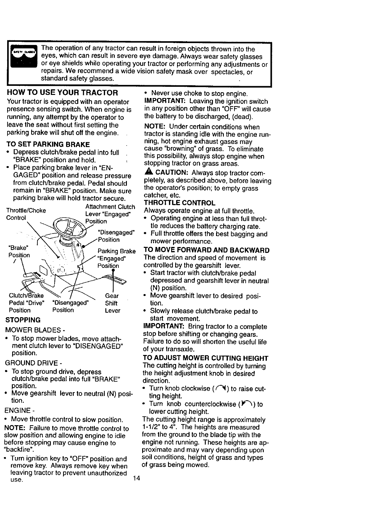
HOW TO USE YOUR TRACTOR
Your tractor is equipped with an operator
presence sensing switch. When engine is
running, any attempt by the operator to
leave the seat without first setting the
parking brake will shut off the engine.
TO SET PARKING BRAKE
•Depress clutch/brake pedal into full
"BRAKE" position and hold.
•Place parking brake lever in =EN-
GAGED" position and release pressure
from clutch/brake pedal. Pedal should
remain in "BRAKE" position. Make sure
parking brake will hold tractor secure.
Attachment Clutch
Throttle/Choke Lever
Control-_ _ Positlo"Engaged"
-(%,-'_'-, _"_-_ /Position
"Brake" , _ ',_.___.'l ,/ .....
•. ' \ ', . \ \\, I-'arKing I_raKe
P?l_on _ "_'}'_\_/ /"Engaged"
\ r'_.\'., i_ : _." Position
Clutch/Brake _ /_ Gear
Pedal "Drive" "Disengaged" Shift
Position Position Lever
STOPPING
MOWER BLADES -
• To stop mower blades, move attach-
ment clutch lever to "DISENGAGED"
position.
GROUND DRIVE -
• To stop ground drive, depress
clutch/brake pedal into full "BRAKE"
position.
• Move gearshift lever to neutral (N) posi-
tion.
ENGINE -
•Move throttle control to slow position.
NOTE: Failure to move throttle control to
slow position and allowing engine to idle
before stopping may cause engine to
"backfire".
• Turn ignition key to "OFF" position and
remove key. Always remove key when
leaving tractor to prevent unauthorized
use. 14
• Never use choke to stop engine.
IMPORTANT: Leaving the ignition switch
in any position other than "OFF" will cause
the battery to be discharged, (dead).
NOTE: Under certain conditions when
tractor is standing idle with the engine run-
ning, hot engine exhaust gases may
cause "browning" of grass. To eliminate
this possibility, always stop engine when
stopping tractor on grass areas.
,_ CAUTION: Always stop tractor com-
pletely, as described above, before leaving
the operator's position; to empty grass
catcher, etc.
THROTTLE CONTROL
Always operate engine at full throttle.
• Operating engine at less than full throt-
tle reduces the battery charging rate.
•Full throttle offers the best bagging and
mower performance.
TO MOVE FORWARD AND BACKWARD
The direction and speed of movement is
controlled by the gearshift lever.
•Start tractor with clutch/brake pedal
depressed and gearshift lever in neutral
(N) position.
•Move gearshift lever to desired posi-
tion.
•Slowly release clutch/brake pedal to
start movement.
IMPORTANT: Bring tractor to a complete
stop before shifting or changing gears.
Failure to do so will shorten the useful life
of your transaxle.
TO ADJUST MOWER CUTTING HEIGHT
The cutting height is controlled by turning
the height adjustment knob in desired
direction.
•Turn knob clockwise (F-_) to raise cut-
ting height.
•Turn knob counterclockwise (l_'_) to
lower cutting height.
The cutting height range is approximately
1-1/2" to 4". The heights are measured
from the ground to the blade tip with the
engine not running. These heights are ap-
proximate and may vary depending upon
soil conditions, height of grass and types
of grass being mowed.
• The average lawn should be cut to
approximately 2-1/2 inches during the
cool season and to over 3 inches during
hot months. For healthier and better
looking lawns, mow often and after
moderate growth.
•For best cutting performance, grass
over 6 inches in height should be
mowed twice. Make the first cut rela-
tively high; the second to desired height.
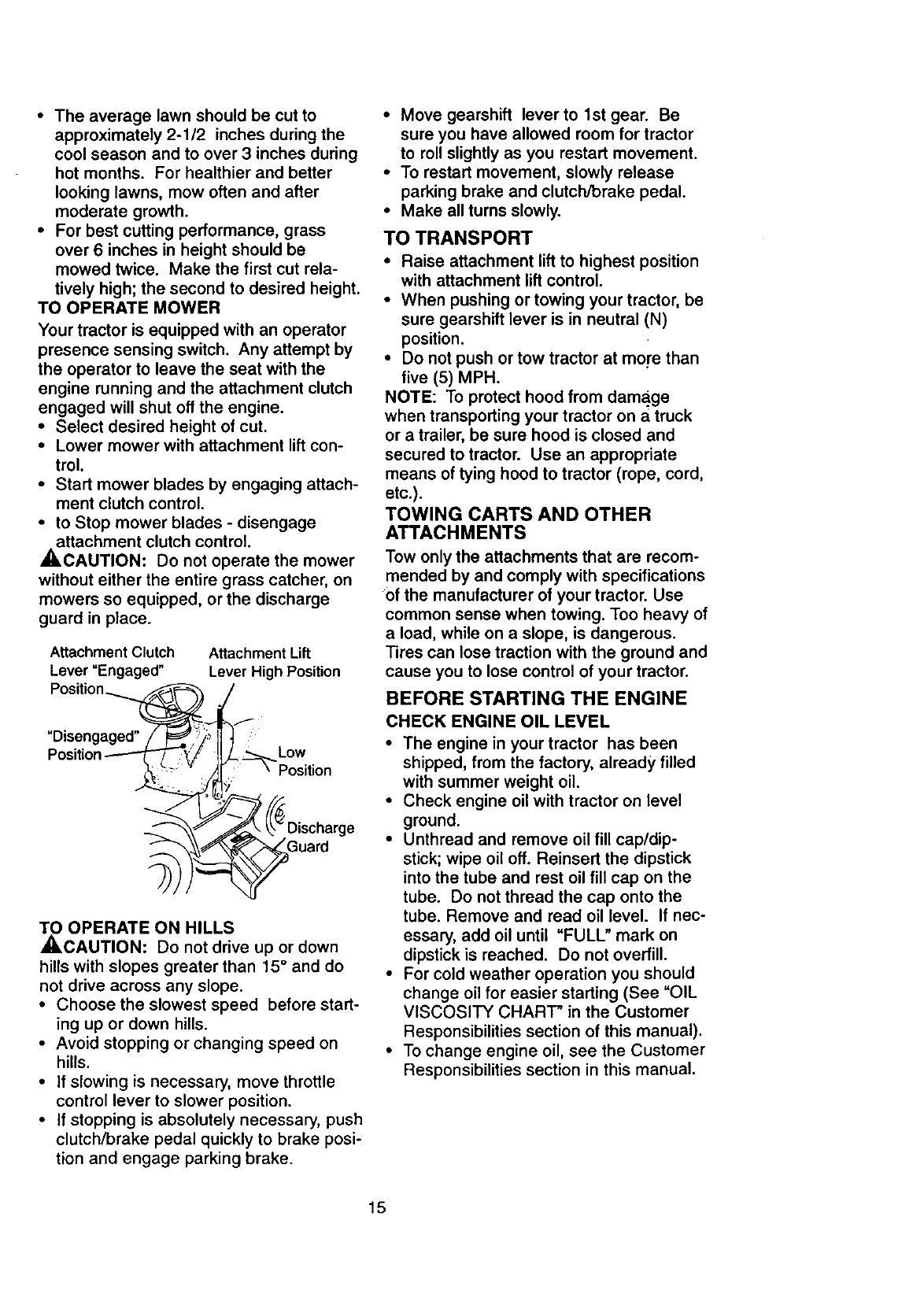
TO OPERATE MOWER
Your tractor is equipped with an operator
presence sensing switch. Any attempt by
the operator to leave the seat with the
engine running and the attachment clutch
engaged will shut off the engine.
•Select desired height of cut.
•Lower mower with attachment lift con-
trol.
• Start mower blades by engaging attach-
ment clutch control.
• to Stop mower blades - disengage
attachment clutch control.
_,CAUTION: Do not operate the mower
without either the entire grass catcher, on
mowers so equipped, or the discharge
guard in place.
Attachment Clutch
Lever "Engaged"
Position
Attachment Lift
Lever High Position
"Disengaged" Low
Guard
TO OPERATE ON HILLS
_,CAUTION: Do not drive up or down
hills with slopes greater than 15° and do
not drive across any slope.
• Choose the slowest speed before start-
ing up or down hills.
• Avoid stopping or changing speed on
hills.
• If slowing is necessary, move throttle
control lever to slower position.
•If stopping is absolutely necessary, push
clutch/brake pedal quickly to brake posi-
tion and engage parking brake.
• Move gearshift lever to lstgear. Be
sure you have allowed room for tractor
to roll slightly as you restart movement.
•To restart movement, slowly release
parking brake and clutch/brake pedal.
•Make all turns slowly.
TO TRANSPORT
• Raise attachment lift to highest position
with attachment lift control.
• When pushing or towing your tractor, be
sure gearshift lever is in neutral (N)
position.
• Do not push or tow tractor at more than
five (5) MPH.
NOTE: To protect hood from dama.ge
when transporting your tractor on atruck
or a trailer, be sure hood is closed and
secured to tractor. Use an appropriate
means of tying hood to tractor (rope, cord,
etc.).
TOWING CARTS AND OTHER
ATTACHMENTS
Tow only the attachments that are recom-
mended by and comply with specifications
of the manufacturer of your tractor. Use
common sense when towing. Too heavy of
a load, while on a slope, is dangerous.
Tires can lose traction with the ground and
cause you to lose control of your tractor.
BEFORE STARTING THE ENGINE
CHECK ENGINE OIL LEVEL
•The engine in your tractor has been
shipped, from the factory, already filled
with summer weight oil.
•Check engine oil with tractor on level
ground.
•Unthread and remove oil fill cap/dip-
stick; wipe oil off. Reinsert the dipstick
into the tube and rest oil fill cap on the
tube. Do not thread the cap onto the
tube. Remove and read oil level. If nec-
essary, add oil until "FULL" mark on
dipstick is reached. Do not overfill.
•For cold weather operation you should
change oil for easier starting (See "OIL
VISCOSITY CHART' in the Customer
Responsibilities section of this manual).
• To change engine oil, see the Customer
Responsibilities section in this manual.
15
ADDGASOLINE
•Fill fuel tank. Use fresh, clean, regular
unleaded gasoline with a minimum of 87
octane. (Use of leaded gasoline will
increase carbon and lead oxide
deposits and reduce valve life). Do not
mix oil with gasoline. Purchase fuel in
quantities that can be used within 30
days to assure fuel freshness.
IMPORTANT: When operating in tempera-
tures below 32°F(0°C), use fresh, clean
winter grade gasoline to help insure good
_d weather starting.
WARNING: Experience indicates that
alcohol blended fuels (called gasohol or
using ethanol or methanol) can attract
moisture which leads to separation and
formation of acids during storage. Acidic
gas can damage the fuel system of an
engine while in storage. To avoid engine
problems, the fuel system should be emp-
tied before storage of 30 days or longer.
Drain the gas tank, start the engine and
let it run until the fuel lines and carburetor
are empty. Use fresh fuel next season.
See Storage Instructions for additional
information. Never use engine or carbure-
tor cleaner products in the fuel tank or per-
_nent damage may occur.
CAUTION: Fill to bottom of gas tank
filler neck. Do not overfill. Wipe off any
spilled oil or fuel. Do not store, spill or use
gasoline near an open flame.
TO START ENGINE
When starting the engine for the first time
or if the engine has run out of fuel, it will
take extra cranking time to move fuel from
the tank to the engine.
• Sit on seat in operating position,
depress clutch/brake pedal and set
parking brake.
- Place gear shift lever in neutral (N) posi-
tion.
• Move attachment clutch to "DISEN-
GAG ED" position.
• Move throttle control to choke position.
NOTE: Before starting, read the warm
and cold starting procedures below.
Insert key into ignition and turn key
clockwise to "START" position and
release key as soon as engine starts.
Do not run starter continuously for more
than fifteen seconds per minute. If the
engine does not start after several
attempts, move throttle control to fast
position, wait a few minutes and try
again. If engine still does not start,
move the throttle control back to the
choke position and retry.
WARM WEATHER STARTING (50 ° F
AND ABOVE)
" • When engine starts, move the throttle
control to the fast position.
• The attachments and ground drive can
now be used. If the engine does not
accept the load, restart the engine and
allow it to warm up for one minute using
the choke as described above.
COLD WEATHER STARTING ( 50 ° F
AND BELOW)
• When engine starts, allow engine to run
with the throttle control in the choke
position until the engine runs roughly,
then move throttle control to fast posi-
tion. This may require an engine warm-
up period from several seconds to sev-
eral minutes, depending on the temper-
ature.
•The attachments can also be used dur-
ing the engine warm-up period.
NOTE: If at a high altitude (above 3000
feet) or in cold temperatures (below 32 F)
the carburetor fuel mixture may need to be
adjusted for best engine performance.
See "TO ADJUST CARBURETOR" in the
Service and Adjustments section of this
manual.
16
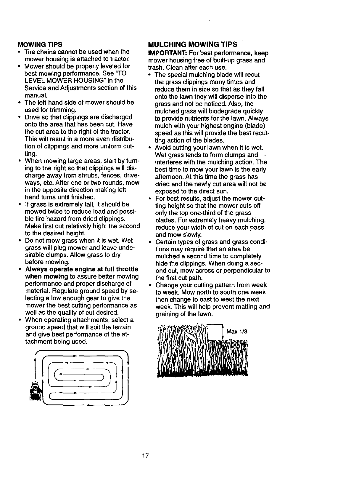
MOWINGTIPS
• Tirechainscannotbe usedwhenthe
mowerhousingisattachedto tractor.
•Mower should be properly leveled for
best mowing performance. See "TO
LEVEL MOWER HOUSING" in the
Service and Adjustments section of this
manual.
•The left hand side of mower should be
used for trimming.
•Drive so that clippings are discharged
onto the area that has been cut. Have
the cut area to the right of the tractor.
This will result in a more even distribu-
tion of clippings and more uniform cut-
ting.
•When mowing large areas, start by turn-
ing to the right so that clippings will dis-
charge away from shrubs, fences, drive-
ways, etc. After one or two rounds, mow
in the opposite direction making left
hand turns until finished.
•If grass is extremely tall, it should be
mowed twice to reduce load and possi-
ble fire hazard from dried clippings.
Make first cut relatively high; the second
to the desired height.
•Do not mow grass when it is wet. Wet
grass will plug mower and leave unde-
sirable clumps. Allow grass to dry
before mowing.
•Always operate engine at full throttle
when mowing to assure better mowing
performance and proper discharge of
material. Regulate ground speed by se-
lecting a low enough gear to give the
mower the best cutting performance as
well as the quality of cut desired.
•When operating attachments, select a
ground speed that will suit the terrain
and give best performance of the at-
tachment being used.
f
1
(
,J
MULCHING MOWING TIPS
IMPORTANT: For best performance, keep
mower housing free of built-up grass and
trash. Clean after each use.
•The special mulching blade will recut
the grass clippings many times and
reduce them in size so that as they fall
onto the lawn they will disperse into the
grass and not be noticed. Also, the
mulched grass will biodegrade quickly
to provide nutrients for the lawn. Always
mulch with your highest engine (blade)
speed as this will provide the best recut-
ting action of the blades.
•Avoid cutting your lawn when it is wet.
Wet grass tends to form clumps and =
interferes with the mulching action. The
best time to mow your lawn is the early
afternoon. At this time the grass has
dried and the newly cut area will not be
exposed to the direct sun.
•For best results, adjust the mower cut-
ting height so that the mower cuts off
only the top one-third of the grass
blades. For extremely heavy mulching,
reduce your width of cut on each pass
and mow slowly.
•Certain types of grass and grass condi-
tions may require that an area be
mulched a second time to completely
hide the clippings. When doing a sec-
ond cut, mow across or perpendicular to
the first cut path.
•Change your cutting pattern from week
to week. Mow north to south one week
then change to east to west the next
week. This will help prevent matting and
graining of the lawn.
17
CUSTOMER RESPONSIBILITIES
MAINTENANCE SCHEDULE .,_ ./._/_/_
F, L,.BATES
Check Brake Operation _
Check Tire Pressure
Check Operator Presence and
TInterlock Systems
RCheck for Loose Fasteners _V'7
Sharpen/Replace Mower Blades
T Lubrication Chart If
0 Check Baffery Level
RClean Battery and Terminals V'
Check Transaxle Cooling ll_
Adjust Blade Belt(s) Tension VPs
Adjust Motion Drive Belt(s) Tension II_s
Check Engine Oil Level If If
Change Engine Oil 1_1,2,: If
E CleanAi'Filter l_:
NClean Air Screen
GInspect Muffler/SparkAn'ester If
N_ Replace Oil Filter (If equipped) _.2
EClean Engine Cooling Fins I V_z
Replace Spark Plug If
Replace Air Filter Paper Cartridge IkS'2
Replace Fuel Filter Vp
1 - Change more often when opereling under e heavy load or in high annb_nt tei_peratur e_. 5 -If _Kluipped with adjustable system.
2 - See'ice more often when operating in ditty or dusly cortdition_.
3 - If e,quipped with oil filter, change o_1every 50 hours.
4-Replace blades more often when mowing In ser_ly soil.
GENERAL RECOMMENDATIONS
The warranty on this tractor does not cover
items that have been subjected to operator
abuse or negligence. To receive full value
from the warranty, operator must maintain
tractor as instructed in this manual. Some
adjustments will need to be made periodi-
cally to properly maintain your tractor.
All adjustments in the Service and
Adjustments section of this manual should
be checked at least once each season.
•Once a year you should replace the
spark plug, clean or replace air filter, and
check blades and belts for wear. A new
spark plug and clean air filter assure
proper air-fuel mixture and help your
engine run better and last longer.
BEFORE EACH USE
,Check engine oil level.
0 Check brake operation.
*Check tire pressure.
, Check operator presence and interlock
systems for proper operation.
, Check for loose fasteners.
6 - Not re_4Jired if equ_ped with mldntenance-/ree batt eej,
7 - TigMe_t front axle pivot bolt to 35 ft.-Ibs, mQximu m,
Do _0t overtighten.
LUBRICATION CHART
Spindl_ Spindle
Zerk
Wheel
O Front Wheel Bearing
Bearing Zerk Zerk
O Engine
0Attachrnenl_ ,_
Clutch i ,
i I
Pivot(s) '
0j,-_ Shift
f.... Pivots
O SAE 30 or 10w30 Motor OIL
OGeneral Purpose Grease
ORefer to Maintenance "Engine" Section
IMPORTANT: Do not oil or grease the pivot
points which have special nylon bear-ings.
Viscous lubricants will attract dust and dirt
that will shorten the life of the self-lubricating
bearings. If you feel they must be lubricated,
use only a dry, powdered graphite type lubri-
cant sparingly.
18
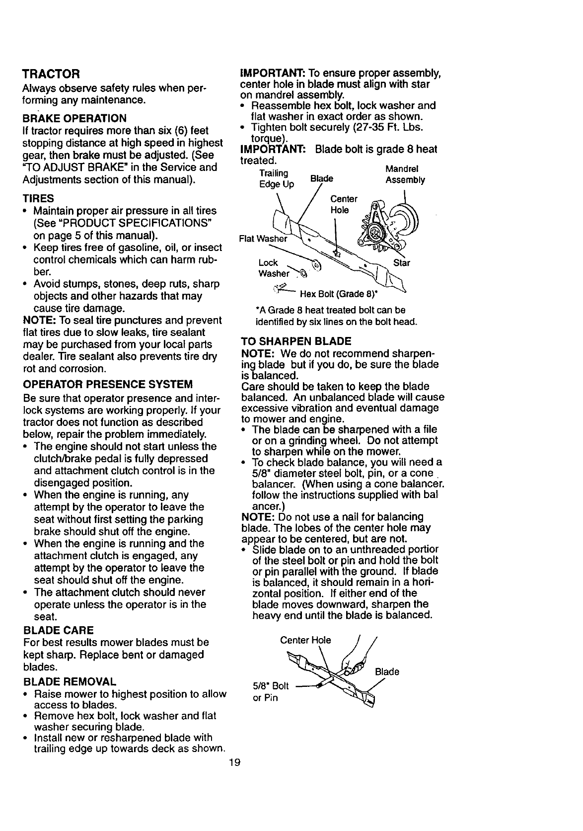
TRACTOR
Alwaysobservesafetyrules when per-
forming any maintenance.
BRAKE OPERATION
If tractor requires more than six (6) feet
stopping distance at high speed in highest
gear, then brake must be adjusted. (See
"TO ADJUST BRAKE" in the Service and
Adjustments section of this manual).
TIRES
• Maintain proper air pressure in all tires
(See "PRODUCT SPECIFICATIONS"
on page 5 of this manual).
•Keep tires free of gasoline, oil, or insect
control chemicals which can harm rub-
ber.
• Avoid stumps, stones, deep ruts, sharp
objects and other hazards that may
cause tire damage.
NOTE: To seal tire punctures and prevent
flat tires due to slow leaks, tire sealant
may be purchased from your local parts
dealer. Tire sealant also prevents tire dry
rot and corrosion.
OPERATOR PRESENCE SYSTEM
Be sure that operator presence and inter-
lock systems are working properly. If your
tractor does not function as described
below, repair the problem immediately.
•The engine should not start unless the
clutch/brake pedal is fully depressed
and attachment clutch control is in the
disengaged position.
•When the engine is running, any
attempt by the operator to leave the
seat without first setting the parking
brake should shut off the engine.
• When the engine is running and the
attachment clutch is engaged, any
attempt by the operator to leave the
seat should shut off the engine.
• The attachment clutch should never
operate unless the operator is in the
seat.
BLADE CARE
For best results mower blades must be
kept sharp. Replace bent or damaged
blades.
BLADE REMOVAL
•Raise mower to highest position to allow
access to blades.
•Remove hex bolt, lock washer and flat
washer securing blade.
•Install new or rasharpened blade with
trailing edge up towards deck as shown.
19
IMPORTANT: To ensure proper assembly,
center hole in blade must align with star
on mandrel assembly.
Reassemble hex bolt, lock washer and
flat washer in exact order as shown.
• Tighten bolt securely (27-35 Ft. Lbs.
torque).
IMPORTANT: Blade bolt is grade 8 heat
treated. Mandrel
Trailing Blade Assembly
Edge Up
Center
Hole
Flat Washer
Lock Star
_;"_}'_"-Hex Bolt (Grade 8)*
*A Grade 8 heat treated bolt can be
identifiedby six lines on the bolt head.
TO SHARPEN BLADE
NOTE: We do not recommend sharpen-
ing blade but if you do, be sure the blade
is balanced.
Care should be taken to keep the blade
balanced. An unbalanced blade will cause
excessive vibration and eventual damage
to mower and engine.
• The blade can be sharpened with a file
or on a grinding wheel. Do not attempt
to sharpen while on the mower.
•To check blade balance, you will need a
5/8" diameter steel bolt, pin, or a cone
balancer. (When using a cone balancer.
follow the instructions supplied with bal
ancer.)
NOTE: Do not use a nail for balancing
blade. The lobes of the center hole may
appear to be centered, but are not.
• Slide blade on to an unthreaded portior
of the steel bolt or pin and hold the bolt
or pin parallel with the ground. If blade
is balanced, it should remain in ahori-
zontal position. If either end of the
blade moves downward, sharpen the
heavy end until the blade is balanced.
Center Hole
5/8" Bolt
or Pin
Blade
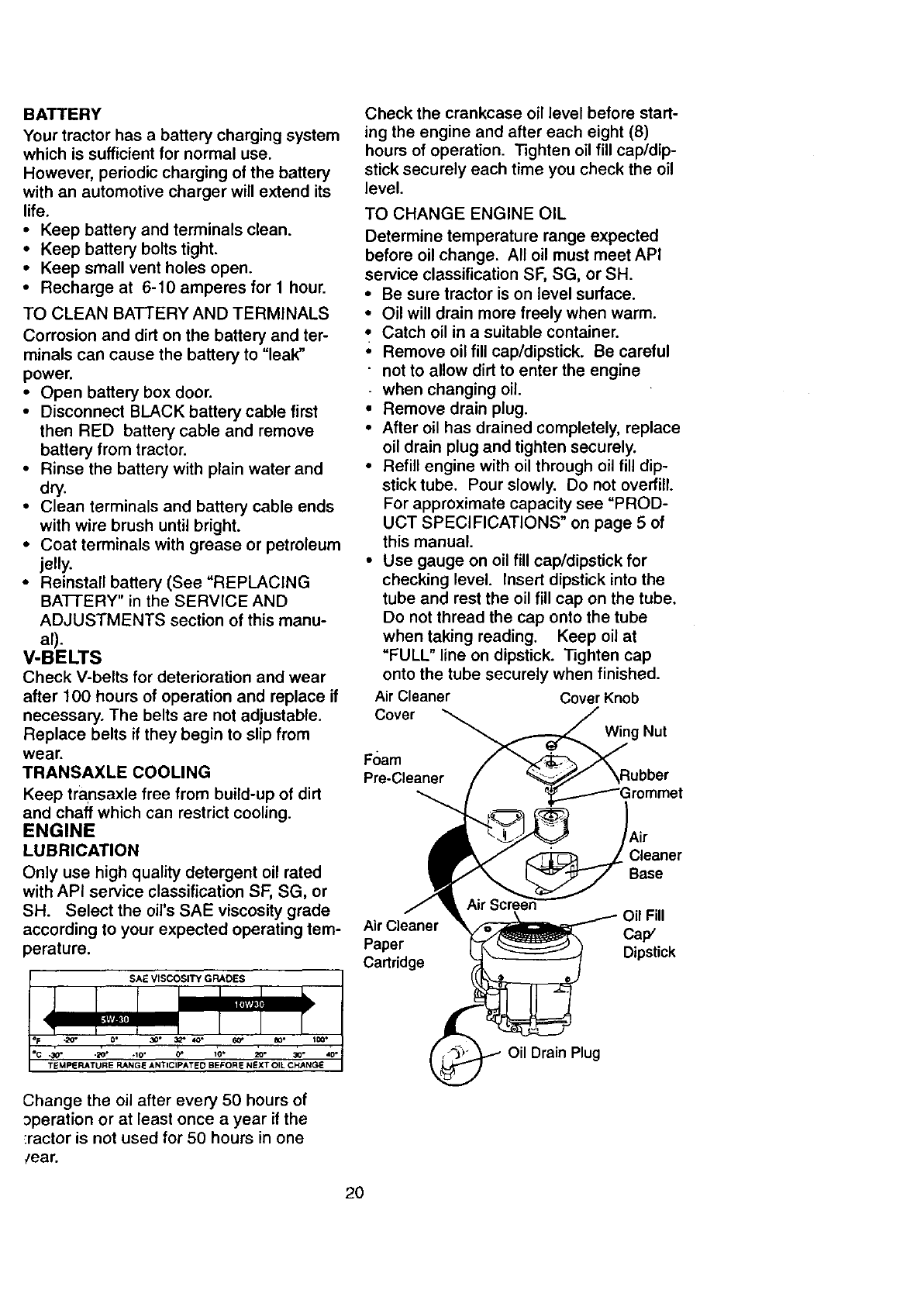
BATTERY
Your tractor has a battery charging system
which is sufficient for normal use.
However, periodic charging of the battery
with an automotive charger will extend its
life.
•Keep battery and terminals clean.
•Keep battery bolts tight.
•Keep small vent holes open.
•Recharge at 6-10 amperes for 1 hour.
TO CLEAN BATTERY AND TERMINALS
Corrosion and dirt on the battery and ter-
minals can cause the battery to "leak"
power.
• Open battery box door.
• Disconnect BLACK battery cable first
then RED battery cable and remove
battery from tractor.
• Rinse the battery with plain water and
dry.
• Clean terminals and battery cable ends
with wire brush until bright.
•Coat terminals with grease or petroleum
jelly.
• Reinstall battery (See "REPLACING
BAI-I-ERY" in the SERVICE AND
ADJUSTMENTS section of this manu-
al).
V-BELTS
Check V-belts for deterioration and wear
after 100 hours of operation and replace if
necessary. The belts are not adjustable.
Replace belts if they begin to slip from
wear.
TRANSAXLE COOLING
Keep transaxle free from build-up of dirt
and chaff which can restrict cooling.
ENGINE
LUBRICATION
Check the crankcase oil level before start-
ing the engine and after each eight (8)
hours of operation• Tighten oil fill cap/dip-
stick securely each time you check the oil
level.
TO CHANGE ENGINE OIL
Determine temperature range expected
before oil change. All oil must meet API
service classification SF, SG, or SH.
• Be sure tractor is on level surface.
• Oil will drain more freely when warm.
• Catch oil in a suitable container.
• Remove oil fill cap/dipstick. Be careful
• not to allow dirt to enter the engine
when changing oil
•Remove drain plug.
• After oil has drained completely, replace
oil drain plug and tighten securely.
• Refill engine with oil through oil fill dip-
stick tube. Pour slowly. Do not overfill.
For approximate capacity see "PROD-
UCT SPECIFICATIONS" on page 5 of
this manual.
•Use gauge on oil fill cap/dipstick for
checking level. Insert dipstick into the
tube and rest the oil fill cap on the tube.
Do not thread the cap onto the tube
when taking reading. Keep oil at
"FULL" line on dipstick. Tighten cap
onto the tube securely when finished.
Air Cleaner Cover Knob
Cover
Wing Nut
Foam
Pre-Cleaner
Only use high quality detergent oil rated
with API service classification SF, SG, or
SH. Select the oil's SAE viscosity grade
according to your expected operating tern- Air Cleaner
perature. Paper
Cartridge
SAE VISCOSITY GRADES
0•30" 32"
._o .10. _10" 20. 30,
TEMPERATURE N._GE ANTICIPATED BEFORE NEXT OIL C_NGE
Change the oil after every 50 hours of
_peration or at least once a year if the
:ractor is not used for 50 hours in one
/ear,
Cleaner
Base
il Fill
Ca_'
Dipstick
Drain Plug
20
CLEAN AIR SCREEN
Air screen must be kept free of dirt and
chaff to prevent engine damage from
overheating. Clean with a wire brush or
compressed air to remove dirt and stub-
born dried gum fibers.
AIR FILTER
Your engine will not run properly using a
dirty air filter. Clean the foam pre-cleaner
after every 25 hours of operation or every
season. Service paper cartridge every
100 hours of operation or every season,
whichever occurs first.
Service air cleaner more often under dusty
conditions.
•Remove knob and cover.
• Remove wing nut and air cleaner from
base.
TO SERVICE PRE-CLEANER
• Slide foam pre-cleaner off cartridge.
• Wash it in liquid detergent and water.
• Squeeze it dry in a clean cloth. Allow it
to dry.
• Saturate it in engine oil. Wrap it in
clean, absorbent cloth and squeeze to
remove excess oil.
TO SERVICE CARTRIDGE
• Replace a dirty, bent, or damaged car-
tridge.
NOTE: Do not wash the paper cartridge
or use pressurized air, as this will damage
the cartridge.
• Reinstall the pre-cleaner (cleaned and
oiled) over the paper cartridge.
• Reassemble air cleaner, wing nut, cover
and tighten knob securely.
CLEAN AIR INTAKE/COOLING AREAS
To insure proper cooling, make sure the
grass screen, cooling fins, and other
external surfaces of the engine are kept
clean at all times.
Every 100 hours of operation (more often
under extremely dusty, dirty conditions),
remove the blower housing and other
cooling shrouds. Clean the cooling fins
and external surfaces as necessary. Make
sure the cooling shrouds are reinstalled.
NOTE: Operating the engine with a
blocked grass screen, dirty or plugged
cooling fins, and/or cooling shrouds re-
moved will cause engine damage due to
overheating.
MUFFLER
Inspect and replace corroded muffler and
spark arrester (if equipped) as it could cre-
ate a fire hazard and/or damage.
SPARK PLUGS
Replace spark plugs at the beginning of
each mowing season or after every 100
hours of operation, whichever occurs first.
Spark plug type and gap setting are
shown in "PRODUCT SPECIFICATIONS"
on page 5 of this manual.
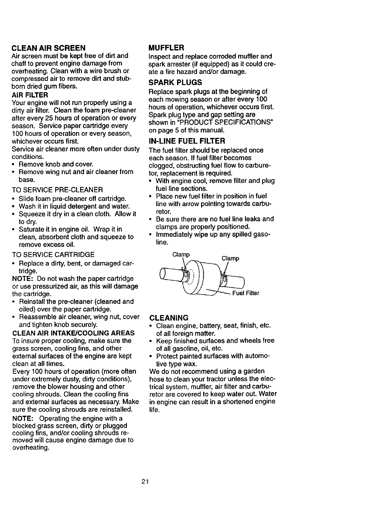
IN-LINE FUEL FILTER
The fuel filter should be replaced once
each season. If fuel filter becomes
clogged, obstructing fuel flow to carbure-
tor, replacement is required.
• With engine cool, remove filter and plug
fuel line sections.
• Place new fuel filter in position in fuel
line with arrow pointing towards carbu-
retor.
• Be sure there are no fuel line leaks and
clamps are properly positioned.
• Immediately wipe up any spilled gaso-
line.
_Filter
CLEANING
•Clean engine, battery, seat, finish, etc.
of all foreign matter.
• Keep finished surfaces and wheels free
of all gasoline, oil, etc.
•Protect painted surfaces with automo-
tive type wax.
We do not recommend using a garden
hose to clean your tractor unless the elec-
trical system, muffler, air filter and carbu-
retor are covered to keep water out. Water
in engine can result in a shortened engine
life.
21
_I, CAUTION: Before performing any service or adjustments:
• Depress clutch/brake pedal fully and set parking brake.
•Place gearshift lever in neutral (N) position.
• Place attachment clutch in "DISENGAGED" position.
• Turn ignition key "OFF" and remove key.
• Make sure the blades and all moving parts have completely stopped.
• Disconnect spark plug wire from spark plug and place wire where it cannot
come in contact with plug.
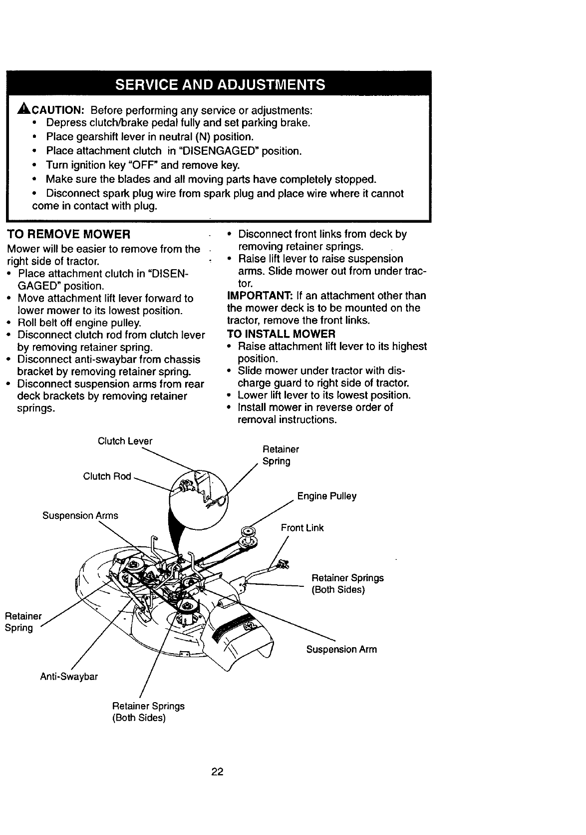
TO REMOVE MOWER
Mower will be easier to remove from the
right side of tractor.
• Place attachment clutch in "DISEN-
GAGED" position.
• Move attachment lift lever forward to
lower mower to its lowest position.
• Roll belt off engine pulley.
• Disconnect clutch rod from clutch lever
by removing retainer spring.
• Disconnect anti-swaybar from chassis
bracket by removing retainer spring.
• Disconnect suspension arms from rear
deck brackets by removing retainer
springs.
Clutch Lever
Clutch Rod_
Suspension Arms
• Disconnect front links from deck by
removing retainer springs.
•Raise lift lever to raise suspension
arms. Slide mower out from under trac-
tor.
IMPORTANT: If an attachment other than
the mower deck is to be mounted on the
tractor, remove the front links.
TO INSTALL MOWER
• Raise attachment lift lever to its highest
position.
• Slide mower under tractor with dis-
charge guard to right side of tractor.
• Lower lift lever to its lowest position.
• Install mower in reverse order of
removal instructions.
Retainer
Spring
Engine Pulley
Front Link
Retainer Springs
(Both Sides)
Retainer
Spring
Suspension Arm
Anti-Swaybar
Retainer Springs
(Both Sides)
22
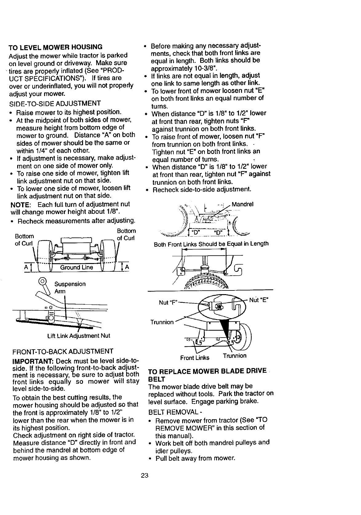
TO LEVEL MOWER HOUSING
Adjust the mower while tractor is parked
on level ground or driveway. Make sure
• tiros are properly inflated (See "PROD-
UCT SPECIFICATIONS"). If tires are
over or underinflated, you will not properly
adjust your mower.
SIDE-TO-SIDE ADJUSTMENT
• Raise mower to its highest position.
• At the midpoint of both sides of mower,
measure height from bottom edge of
mower to ground. Distance "A" on both
sides of mower should be the same or
within 1/4" of each other.
• If adjustment is necessary, make adjust-
ment on one side of mower only.
• To raise one side of mower, tighten lift
link adjustment nut on that side.
• To lower one side of mower, loosen lift
link adjustment nut on that side.
NOTE: Each full turn of adjustment nut
will change mower height about 1/8".
• Recheck measurements after adjusting.
Bottom
Bottom
of Curl\_ f Curl
Suspension
Arm
Lift Link Adjustment Nut
FRONT-TO-BACK ADJUSTMENT
IMPORTANT: Deck must be level side-to-
side. If the following front-to-back adjust-
ment is necessary, be sure to adjust both
front links equally so mower will stay
level side-to-side.
To obtain the best cutting results, the
mower housing should be adjusted so that
the front is approximately 1/8" to 1/2"
lower than the rear when the mower is in
its highest position.
Check adjustment on right side of tractor.
Measure distance "D" directly in front and
behind the mandrel at bottom edge of
mower housing as shown.
• Before making any necessary adjust-
ments, check that both front links are
equal in length. Both links should be
approximately 10-3/8".
• If links are not equal in length, adjust
one link to same length as other link.
• To lower front of mower loosen nut "E"
on both front links an equal number of
turns.
• When distance "D" is 1/8" to 1/2" lower
at front than rear, tighten nuts "F"
against trunnion on both front links.
• To raise front of mower, loosen nut "F"
from trunnion on both front links. -
Tighten nut "E" on both front links an
equal number of turns.
• When distance "D" is 1/8" to 1/2" lower
at front than rear, tighten nut "F" against
trunnion on both front links.
• Recheck side-to-side adjustment.
_%_ L ° °i/Mandrel
_i, L" .... -
Both Front Links Should be Equal in Length
5'o2
Front Links
ut
Trunnion
=E"
TO REPLACE MOWER BLADE DRIVE
BELT
The mower blade drive belt may be
replaced without tools. Park the tractor on
level surface. Engage parking brake.
BELT REMOVAL-
• Remove mower from tractor (See "TO
REMOVE MOWER" in this section of
this manual).
• Work belt off both mandrel pulleys and
idler pulleys.
• Pull belt away from mower.
23
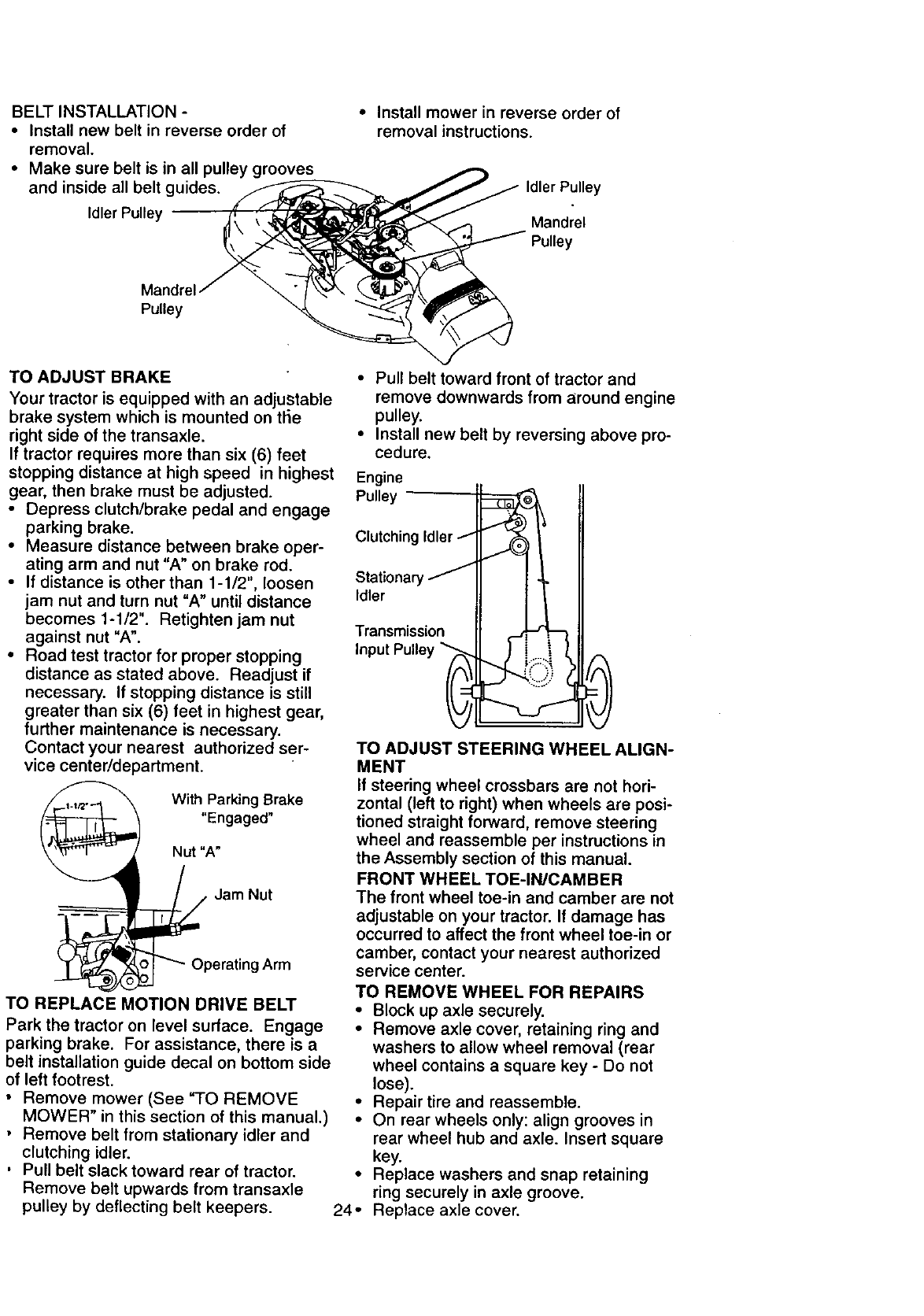
BELTINSTALLATION-
• Installnewbeltinreverseordero1
removal.
• Makesure beltis in all pulleygrooves
andinsideall beltguides.
IdlerPulley
•Install mower in reverse order of
removal instructions.
Idler Pulley
Mandrel
Pulley
Pulley
TO ADJUST BRAKE
Your tractor is equipped with an adjustable
brake system which is mounted on the
right side of the transaxle.
If tractor requires more than six (6) feet
stopping distance at high speed in highest
gear, then brake must be adjusted.
• Depress clutch/brake pedal and engage
parking brake.
• Measure distance between brake oper-
ating arm and nut "A" on brake rod.
• tf distance is other than 1-1/2", loosen
jam nut and turn nut "A" until distance
becomes 1-1/2". Retighten jam nut
against nut "A".
• Road test tractor for proper stopping
distance as stated above. Readjust if
necessary. If stopping distance is still
greater than six (6) feet in highest gear,
further maintenance is necessary.
Contact your nearest authorized ser-
vice center/department.
With Parking Brake
"Engaged"
Nut "A"
j Jam Nut
_Operating Arm
TO REPLACE _IOTION DRIVE BELT
Park the tractor on level surface. Engage
parking brake. For assistance, there is a
belt installation guide decal on bottom side
of left footrest.
• Remove mower (See =TO REMOVE
MOWER" in this section of this manual.)
• Remove belt from stationary idler and
clutching idler.
• Pull belt slack toward rear of tractor.
Remove belt upwards from transaxle
pulley by deflecting belt keepers.
• Pull belt toward front of tractor and
remove downwards from around engine
pulley.
• Install new belt by reversing above pro-
cedure.
Engine
Pulley -
Clutching Idler /
Stationary _
Idler
Transmission
Input Pulley _..
TO ADJUST STEERING WHEEL ALIGN-
MENT
If steering wheel crossbars are not hori-
zontal (left to right) when wheels are posi-
tioned straight forward, remove steering
wheel and reassemble per instructions in
the Assembly section of this manual.
FRONT WHEEL TOE-IN/CAMBER
The front wheel toe-in and camber are not
adjustable on your tractor. If damage has
occurred to affect the front wheel toe-in or
camber, contact your nearest authorized
service center.
TO REMOVE WHEEL FOR REPAIRS
• Block up axle securely.
• Remove axle cover, retaining ring and
washers to allow wheel removal (rear
wheel contains a square key - Do not
lose).
• Repair tire and reassemble.
• On rear wheels only: align grooves in
rear wheel hub and axle. Insert square
key.
• Replace washers and snap retaining
ring securely in axle groove.
24- Replace axle cover.
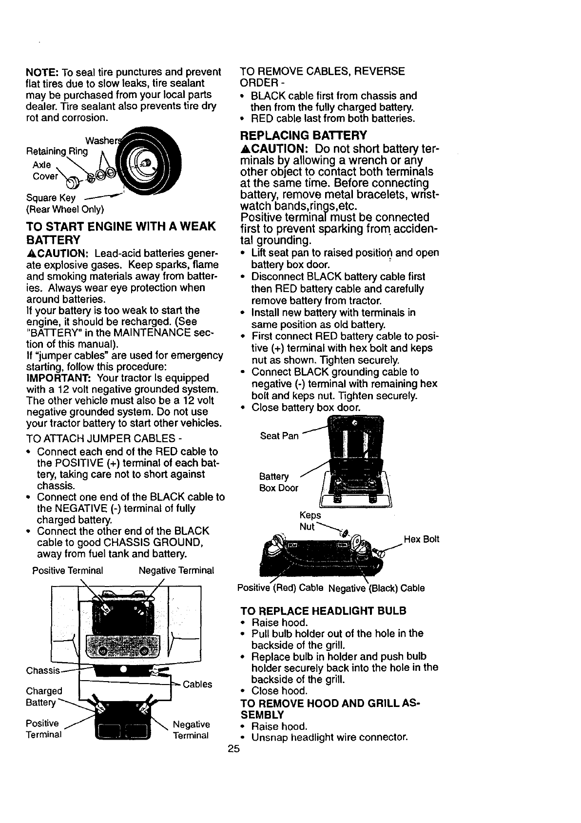
NOTE: To seal tire punctures and prevent
flat tires due to slow leaks, tire sealant
may be pumhased from your local parts
dealer. Tire sealant also prevents tire dry
rot and corrosion.
Retaining RingWasheA
Axle. Ik_IIL (*_||II
Cove r_"__J
Square Key .--_-"-_' .,_,..,,w
(Rear Wheel Only)
TO START ENGINE WITH A WEAK
BATTERY
•,CAUTION: Lead-acid batteries gener-
ate explosive gases. Keep sparks, flame
and smoking materials away from batter-
ies. Always wear eye protection when
around batteries.
If your battery is too weak to start the
engine, it should be recharged. (See
"BATTERY" in the MAINTENANCE sec-
tion of this manual).
If =jumper cables" are used for emergency
starting, follow this procedure:
IMPORTANT: Your tractor Is equipped
with a 12 volt negative grounded system.
The other vehicle must also be a 12 volt
negative grounded system. Do not use
your tractor battery to start other vehicles.
TO ATTACH JUMPER CABLES -
• Connect each end of the RED cable to
the POSITIVE (+) terminal of each bat-
tery, taking care not to short against
chassis.
•Connect one end of the BLACK cable to
the NEGATIVE (-) terminal of fully
charged battery.
• Connect the other end of the BLACK
cable to good CHASSIS GROUND,
away from fuel tank and battery.
Positive Terminal Negative Terminal
TO REMOVE CABLES, REVERSE
ORDER -
• BLACK cable first from chassis and
then from the fully charged battery.
•RED cable last from both batteries.
REPLACING BATTERY
ACAUTION: Do not short battery ter-
minals by allowing a wrench or any
other object to contact both terminals
at the same time. Before connecting
battery, remove metal bracelets, wrist-
watch bands,rings,etc.
Positive terminal must be connected
first to prevent sparking from acciden-
tal grounding.
•Liftseat pan to raised position,and open
battery box door.
• Disconnect BLACK battery cable first
then RED battery cable and carefully
remove battery from tractor.
•Install new battery with terminals in
same positionas old battery.
•First connect RED battery cable to posi-
tive (+) terminal with hex bolt and keps
nut as shown.Tighten securely.
• Connect BLACK grounding cable to
negative (-) terminal with remaining hex
bolt and keps nut. Tighten securely.
•Close battery box door.
Battery
Box Door
Keps
Hex Bolt
Positive (Red) Cable Negative (Black) Cable
C
Charged
Batter
Positive Negative
Terminal Terminal
TO REPLACE HEADLIGHT BULB
•Raise hood.
•Pull bulb holder out of the hole in the
backside of the grill.
•Replace bulb in holder and push bulb
holder securely back into the hole in the
backside of the grill.
•Close hood.
TO REMOVE HOOD AND GRILLAS-
SEMBLY
•Raise hood.
•Unsnap headlight wire connector.
25
•Stand in front of tractor. Grasp hood at
sides, tilt toward engine and lift off of
tractor.
• To replace, reverse above procedures.
\ Headlight Wire
,/i_;_ Connector
INTERLOCKS AND RELAYS
Loose or damaged wiring may cause your
tractor to run poorly, stop running, or pre-
vent it from starting.
•Check wiring. See electrical wiring dia -
gram in the Repair Parts section of this
manual.
TO REPLACE FUSE
Replace with 30 amp automotive-type
plug-in fuse. The fuse holder is located
behind the dash.
ENGINE
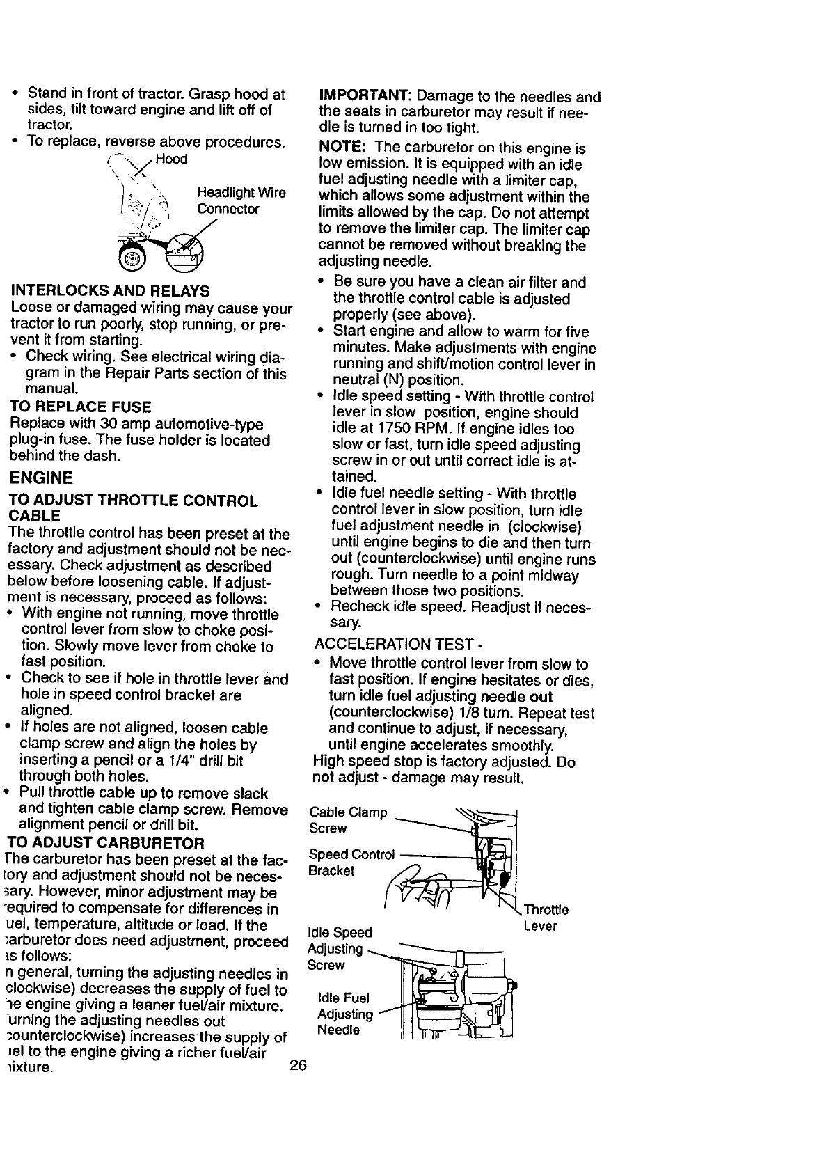
TO ADJUST THROTTLE CONTROL
CABLE
The throttle control has been preset at the
factory and adjustment should not be nec-
essary. Check adjustment as described
below before loosening cable. If adjust-
ment is necessary, proceed as follows:
• With engine not running, move throttle
control lever from slow to choke posi-
tion. Slowly move lever from choke to
fast position.
• Check to see if hole in throttle lever and
hole in speed control bracket are
aligned.
• If holes are not aligned, loosen cable
clamp screw and align the holes by
inserting a pencil or a 1/4" drill bit
through both holes.
• Pull throttle cable up to remove slack
and tighten cable clamp screw. Remove
alignment pencil or drill bit.
TO ADJUST CARBURETOR
]he carburetor has been preset at the fac-
;ory and adjustment should not be neces-
sary. However, minor adjustment may be
"equired to compensate for differences in
uel, temperature, altitude or load. If the
"arburetor does need adjustment, proceed
is follows:
ngeneral, turning the adjusting needles in
clockwise) decreases the supply of fuel to
le engine giving a leaner fuel/air mixture.
urning the adjusting needles out
:ounterclockwise) increases the supply of
Jel to the engine giving a richer fuel/air
_ixture.
IMPORTANT: Damage to the needles and
the seats in carburetor may result if nee-
dle is turned in too tight.
NOTE: The carburetor on this engine is
low emission. It is equipped with an idle
fuel adjusting needle with a limiter cap,
which allows some adjustment within the
limits allowed by the cap. Do not attempt
to remove the limiter cap. The limiter cap
cannot be removed without breaking the
adjusting needle.
• Be sure you have a clean air filter and
the throttle control cable is adjusted
properly (see above).
• Start engine and allow to warm for five
minutes. Make adjustments with engine
running and shift/motion control lever in
neutral (N) position.
• Idle speed setting - With throttle control
lever in slow position, engine should
idle at 1750 RPM. If engine idles too
slow or fast, turn idle speed adjusting
screw in or out until correct idle is at-
tained.
• Idle fuel needle setting - With throttle
control lever in slow position, turn idle
fuel adjustment needle in (clockwise)
until engine begins to die and then turn
out (counterclockwise) until engine runs
rough. Turn needle to a point midway
between those two positions.
• Recheck idle speed. Readjust if neces-
sary.
ACCELERATION TEST -
•Move throttle control lever from slow to
fast position. If engine hesitates or dies,
turn idle fuel adjusting needle out
(counterclockwise) 1/8 turn. Repeat test
and continue to adjust, if necessary,
until engine accelerates smoothly.
High speed stop is factory adjusted. Do
not adjust -damage may result.
Cable Clamp
Screw
Speed Control
Bracket
Idle Speed
Adjusting -_..._L"_
Screw __@
,d,eFuel
Adjusting f II I_'-----_ _ I
Needle il _'T'IT_-_F_-.- _LJ
Throttle
Lever
26
IMPORTANT: Never tamper with the
engine governor, which is factory set for
proper engine speed. Overspeeding the
engine above the factory high speed set-
ting can be dangerous. If you think the
engine-governed high speed needs
adjusting, contact your nearest AUTHO-
RIZED service center/department, which
has proper equipment and experience to
make any necessary adjustments•
Immediately prepare your tractor for stor-
age at the end of the season or if the trac-
tor will not be used for 30 days or more.
_,CAUTION: Never store the tractor with
gasoline in the tank inside a building
where fumes may reach an open flame or
spark. Allow the engine to cool before
storing in any enclosure.
TRACTOR
Remove mower from tractor for winter
storage. This will allow you to clean it thor-
oughly. Remove all dirt, grease, leaves,
etc. Store in aclean, dry area.
•Clean entire tractor (See "CLEANING"
in the Maintenance section of this man-
ual).
• Inspect and replace belts, if necessary
(See belt replacement instructions in the
Service and Adjustments section of this
manual).
•Lubricate as shown in the Maintenance
section of this manual.
•Be sure that all nuts, bolts and screws
are secure!y fastened. Inspect moving
parts for damage, breakage and wear.
Replace if necessary.
•Touch up all rusted or chipped paint sur-
faces; sand lightly before painting.
BATTERY
•Fully charge the battery for storage.
•After a period of time in storage, battery
may require recharging.
•To help prevent corrosion and power
leakage during long periods of storage,
battery cables should be disconnected
and battery cleaned thoroughly (see
"TO CLEAN BATTERY AND TERMI-
NALS" in the Maintenance section of
this manual).
• After cleaning, leave cables disconnect-
ed and place cables where they cannot
come in contact with battery terminals.
•If battery is removed from tractor for
storage, do not store battery directly on
concrete or damp surfaces.
ENGINE
FUEL SYSTEM
IMPORTANT: It is important to prevent
gum deposits from forming in essential
fuel system parts such as carburetor, fuel
filter, fuel hose, or tank during storage.
Also, experience indicates that alcohol
blended fuels (called gasohol or using
ethanol or methanol) can attract moisture
which leads to separation and formation of
acids during storage. Acidic gas can dam-
age the fuel system of an engine while in
storage.
•Drain the fuel tank.
• Start the engine and let it run u_ntil the
fuel lines and carburetor are empty.
• Never use engine or carburetor cleaner
products in the fuel tank or permanent
damage may occur.
• Use fresh fuel next season.
NOTE: Fuel stabilizer is an acceptable
alternative in minimizing the formation of
fuel gum deposits during storage. Add sta-
bilizer to gasoline in fuel tank or storage
container. Always follow the mix ratio
found on stabilizer container. Run engine
at least 10 minutes after adding stabilizer
to allow the stabilizer to reach the carbure-
tor. Do not drain the gas tank and carbure-
tor if using fuel stabilizer.
ENGINE OIL
Drain oil (with engine warm) and replace
with clean engine oil. (See "ENGINE" in
the Maintenance section of this manual).
CYLINDER(S)
•Remove spark plug(s),
•Pour one ounce of oil through spark
plug hole(s) into cylinder(s).
• Turn ignition key to "START" position for
afew seconds to distribute oil.
•Replace with new spark plug(s).
OTHER
• Do not store gasoline from one season
to another.
•Replace your gasoline can if it starts to
rust. Rust and/or dirt in your gasoline
will cause problems• • \
•If possible, store your tractor indoors
and cover it to give protection from dust
and dirt.
• Cover your tractor with asuitable pro-
tective cover that does not retain mois-
ture. Do not use plastic• Plastic cannot
breathe, which allows condensation to
form and cause your tractor to rust.
IMPORTANT: Never cover tractor while
engine and exhaust areas are still warm.
27
TROUBLESHOOTING CHART
CAUSE CORRECTIONPROBLEM
Willnotstart
Hard to start
Engine will not turn
over
Engine clicks but
will not start
• Out of fuel.
•Engine not"CHOKED"
properly.
•Engine flooded.
• Bad spark plug.
• Dirty air filter.
• Dirty fuel filter.
•Water in fuel.
• Loose or damaged wiring.
•Carburetor out of adjust-
ment.
• Engine valves out of
adjustment.
• Dirty air filter.
• Bad spark plug.
• Weak or dead battery.
• Dirty fuel filter.
• Stale or dirty fuel.
• Loose or damaged wiring.
• Carburetor out of adjust-
ment.
• Engine valves out of
adjustment.
• Clutch/brake pedal not
depressed.
•Attachment clutch is
engaged.
•Weak or dead battery.
•Blown fuse.
•Corroded battery termi-
nals.
•Loose or damaged wiring.
•Faulty ignition switch.
• Faulty solenoid or starter.
• Faulty operator presence
switch(es).
•Weak or dead battery.
• Corroded battery termi-
nals.
• Fill fueltank.
• See "TO STAR.T ENGINE" in
Operation section.
• Wait several minutes before
attempting to start.
• Replace spark plug.
• Clean/replace air filter.
• Replace fuel filter.
• Drain fuel tank and carbure-
tor, refill tank with fresh
gasoline and replace fuel fil-
ter.
• Check all wiring.
• See "To Adjust Carburetor"
in Service and Adjustments
section.
• Contact an authorized ser-
vice center.
• Clean/replace air filter.
• Replace spark plug.
• Recharge or replace battery.
•Replace fuel filter.
•Drain fuel tank and refill with
fresh gasoline.
•Check all wiring.
•See "To Adjust Carburetor"
in Service and Adjustments
section.
•Contact an authorized ser-
vice center.
• Depress clutch/brake pedal.
•Disengage attachment
clutch.
• Recharge or replace battery.
•Replace fuse.
•Clean battery terminals.
• Check all wiring.
• Check/replace ignition
switch.
• Check/replace solenoid or
starter.
• Contact an authorized ser-
vice center.
I•Recharge or replace battery.
• Clean battery terminals.
• Check all wiring.
28
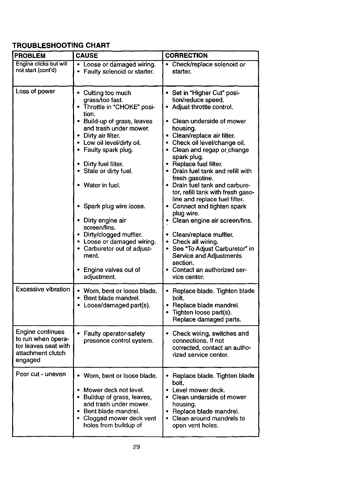
TROUBLESHOOTING CHART
PROBLEM CAUSE CORRECTION
Engine clicks butwill •Loose or damaged wiring. • Check/replace solenoid or
not start (cont'd) •Faulty solenoid or starter, starter°
Loss of power •Cutting too much
grass/too fast.
• Throttle in "CHOKE" posi- •
tion.
• Build-up of grass, leaves •
and trash under mower.
•Dirty air filter. •
• Low oil level/dirty oil. •
• Faulty spark plug. •
•Dirty fuel filter. •
• Stale or dirty fuel. •
• Water in fuel.
• Spark plug wire loose. •
• Dirty engine air •
screen/fins.
• Dirty/clogged muffler. •
•Loose or damaged wiring. •
• Carburetor out of adjust- •
ment.
• Engine valves out of
adjustment.
• Worn, bent or Iooseblade. •
• Bent blade mandrel.
•Loose/damaged part(s). •
• Faulty operator-safety •
presence control system.
•Worn, bent or loose blade. •
• Mower deck not level. •
• Buildup of grass, leaves, •
and trash under mower.
• Bent blade mandrel. •
•Clogged mower deck vent •
holes from buildup of
Excessive vibration
Engine continues
to run when opera-
tor leaves seat with
attachment clutch
engaged
Poor cut - uneven
•Set in "Higher Cut" posi-
tion/reduce speed.
Adjust throttle control.
Clean underside of mower
housing.
Clean/replace air filter.
Check oil level/change oil.
Clean and regap or_change
spark plug.
Replace fuel filter.
Drain fuel tank and refill with
fresh gasoline.
Drain fuel tank and carbure-
tor, refill tank with fresh gaso-
line and replace fuel filter.
Connect and tighten spark
plug wire.
Clean engine air screen/fins.
Clean/replace muffler.
Check all wiring.
See "To Adjust Carburetor" in
Service and Adjustments
section.
Contact an authorized ser-
vice center.
Replace blade. Tighten blade
bolt.
Replace blade mandrel.
Tighten loose part(s).
Replace damaged parts.
Check wiring, switches and
connections. If not
corrected, contact an autho-
rized service center.
Replace blade. Tighten blade
bolt.
Level mower deck.
Clean underside of mower
housing.
Replace blade mandrel.
Clean around mandrels to
open vent holes.
29
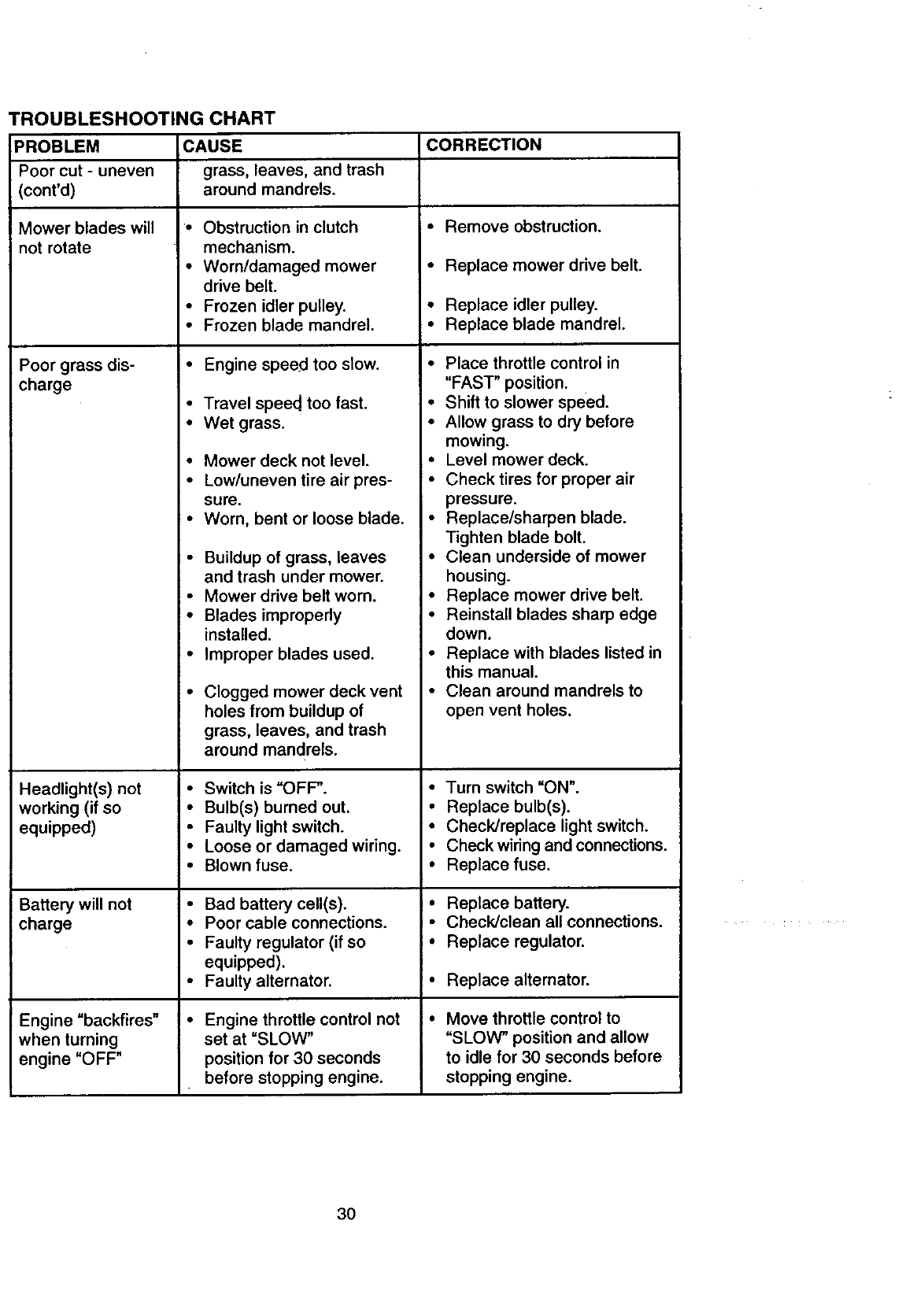
TROUBLESHOOTING CHART
PROBLEM CAUSE CORRECTION
Poor cut - uneven grass, leaves, and trash
(cont'd) around mandrels.
•Remove obstruction.
Mower blades will
not rotate
Poor grass dis- •
charge
Headlight(s) not
working (if so
equipped)
Battery will not
charge
Engine =backfires"
when turning
engine "OFF"
• Obstruction in clutch
mechanism.
• Worn/damaged mower
drive belt.
• Frozen idler pulley.
• Frozen blade mandrel.
Engine speed too slow.
• Travel speed too fast.
• Wet grass.
•Mower deck not level.
• Low/uneven tire air pres-
sure.
• Worn, bent or loose blade.
• Buildup of grass, leaves
and trash under mower.
• Mower drive belt worn.
• Blades improperly
installed.
• Improper blades used.
• Clogged mower deck vent
holes from buildup of
grass, leaves, and trash
around mandrels.
• Switch is "OFF.
• Bulb(s) burned out.
• Faulty light switch.
•Loose or damaged wiring.
•Blown fuse.
• Bad battery cell(s).
• Poor cable connections.
• Faulty regulator (if so
equipped).
• Faulty alternator.
•Engine throttle control not
set at =SLOW"
position for 30 seconds
before stopping engine.
• Replace mower drive belt.
• Replace idler pulley.
• Replace blade mandrel.
• Place throttle control in
"FAST" position.
• Shift to slower speed.
• Allow grass to dry before
mowing.
• Level mower deck.
•Check tires for proper air
pressure.
• Replace/sharpen blade.
Tighten blade bolt.
• Clean underside of mower
housing.
• Replace mower drive belt.
• Reinstall blades sharp edge
down.
• Replace with blades listed in
this manual.
• Clean around mandrels to
open vent holes.
• Turn switch "ON".
• Replace bulb(s).
• Check/replace light switch.
• Check wiring and connections.
• Replace fuse.
• Replace battery.
• Check/clean all connections.
• Replace regulator.
•Replace alternator.
Move throttle control to
"SLOW" position and allow
to idle for 30 seconds before
stopping engine.
30
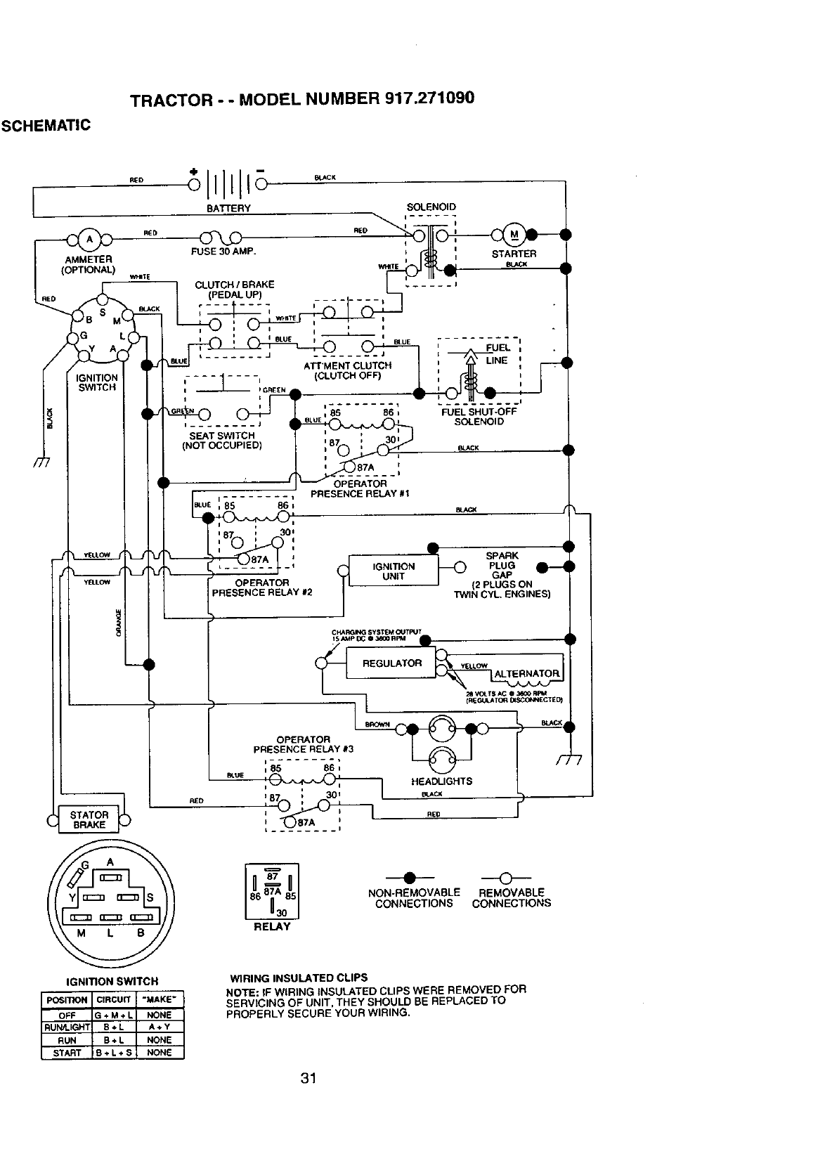
SCHEMATIC
TRACTOR -- MODEL NUMBER 917.271090
BATTERY SOLENOID
_ RE D I I
FUSE 30 AMP. ! _ II STARTER
_IE_ BLACK
CLUTCH IBRAKE ...... J
,(PEDAL UP) .......
"' : i "
mUE IFUEL ,
-J ATr'MENT CLUTCH i
........ = , (CLUTCH ii GREEN I
, ,qF -'
i 1
i85 86 DFUEL SHUT-OFF
jmuE =_= SOLENOID
SEAT SWITCH ' 87 ' 30 =
(NOT OCCUPIED) _. e_CK
PRESENCE RELAY #1
OPERATOR
RED
RED
AMMETER
(OPTIONAL) w_;E
BL_J<
€_) "
SPARK
IGNITION PLUG
UNIT GAP
(2 PLUGS ON
TWIN CYL, ENGINES)
CHA_ING SYSTEM (IITPUT
I SAMP I_; II 3_0 RPM
REGULATOR
--I
OPERATOR
PRESENCE RELAY #3
=85 86 =
STATOR
BRAKE
IGNITION SWITCH
HEADLIGHTS
_CK
RE0
NON-REMOVABLE REMOVABLE
CONNECTIONS CONNECTIONS
WIRING INSULATED CLIPS
POSITION CIRCUIT "MAKE"
OFF G + M +L NONE
RUN_I.IGHT B÷L A+Y
RUN B+L NONE
START S+L+S NONE
NOTE: IF WIRING INSULATED CLIPS WERE REMOVED FOR
SERVICING OF UNIT. THEY SHOULD BE REPLACED TO
PROPERLY SECURE YOUR WIRING.
31

ELECTRICAL
TRACTOR - - MODEL NUMBER 917.271090
41
33
25
i
i
32
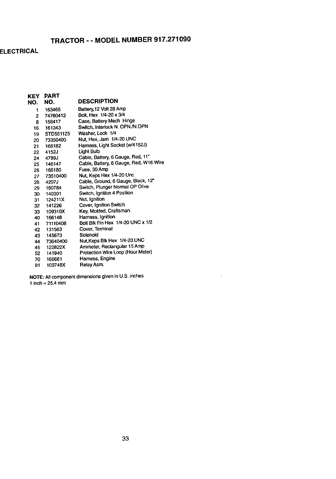
ELECTRICAL
TRACTOR -- MODEL NUMBER 917.271090
KEY PART
NO. NO.
1 163465
2 74760412
8 156417
16 161343
19 BTD551125
20 73350400
21 166182
22 4152J
24 4799,.I
25 146147
26 166180
27 73510400
28 4207J
29 160784
30 140301
31 124211X
32 141226
33 I09310X
40 166148
41 71110408
42 131563
43 145673
44 73640400
45 122822X
52 141940
70 166661
81 109748X
DESCRIPTION
Battery,12Volt 28 Amp
Bolt,Hex 114-20x 3/4
Case, Battery Mech Hinge
Switch,Intadock N. OPN./N.OPN
Washer,Lock 1/4
Nut, Hex, Jam 1/4-20 UNC
Hamess, LightSocket (w/4152J)
LightBulb
Cable, Battery,6 Gauge, Red, 11"
Cable, Battery,6 Gauge, Red, W16 Wire
Fuse, 30Amp
Nut, Keps Hex 1/4-20 Unc
Cable, Ground,6Gauge, Black, 12"
Switch, Plunger Normal OP Olive
Switch, Ignition 4 Position
Nut, Ignition
Cover, Ignition Switch
Key, Molded,Craftsman
Harness, Ignition
Bolt BIk Fin Hex 1/4-20 UNC x 1/2
Cover, Terminal
Solenoid
Nut,Keps Blk Hex 114-20UNC
Ammeter,Rectangular 15 Amp
ProtectionWire Loop(Hour Meter)
Harness, Engine
Relay Asm.
NOTE: Allcomponentdimensionsgivenin U.S. inches
1 inch= 25.4 mm
33
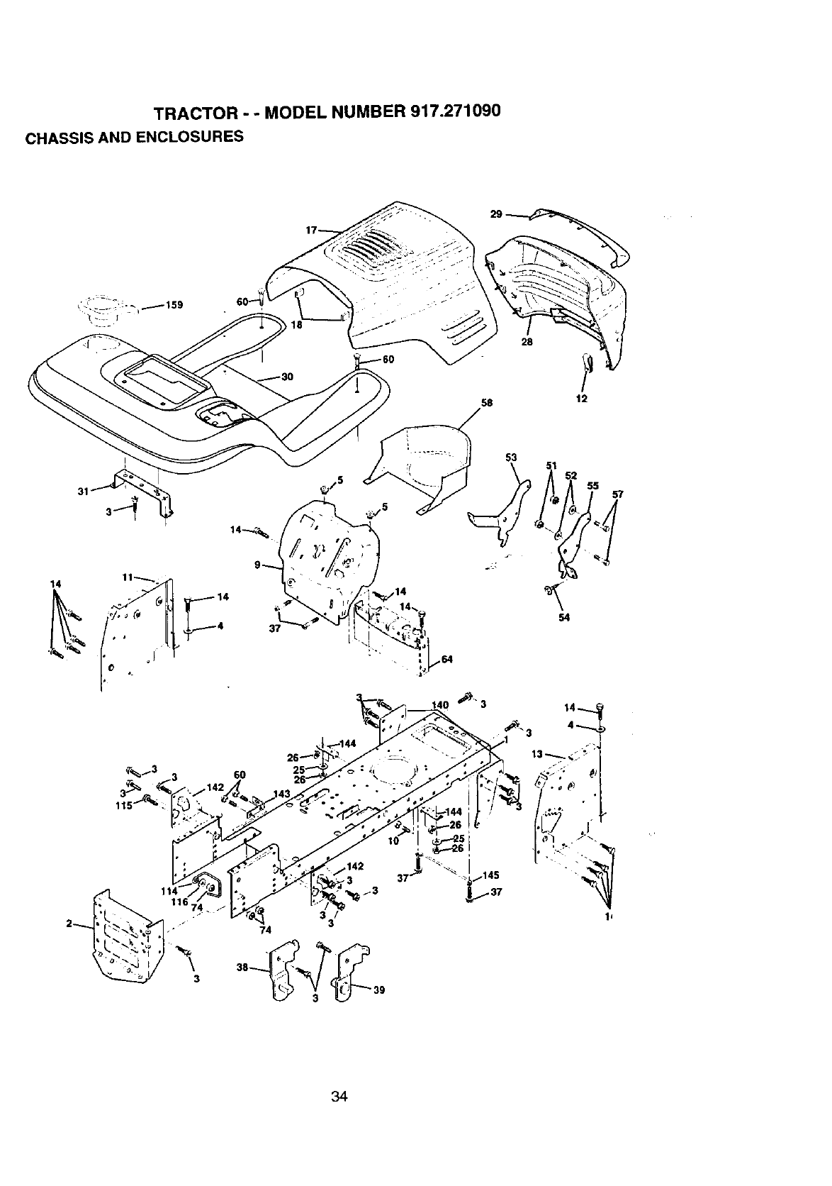
TRACTOR -- MODEL NUMBER 917.271090
CHASSIS AND ENCLOSURES
58
28
31
_1116 3
2i
$4
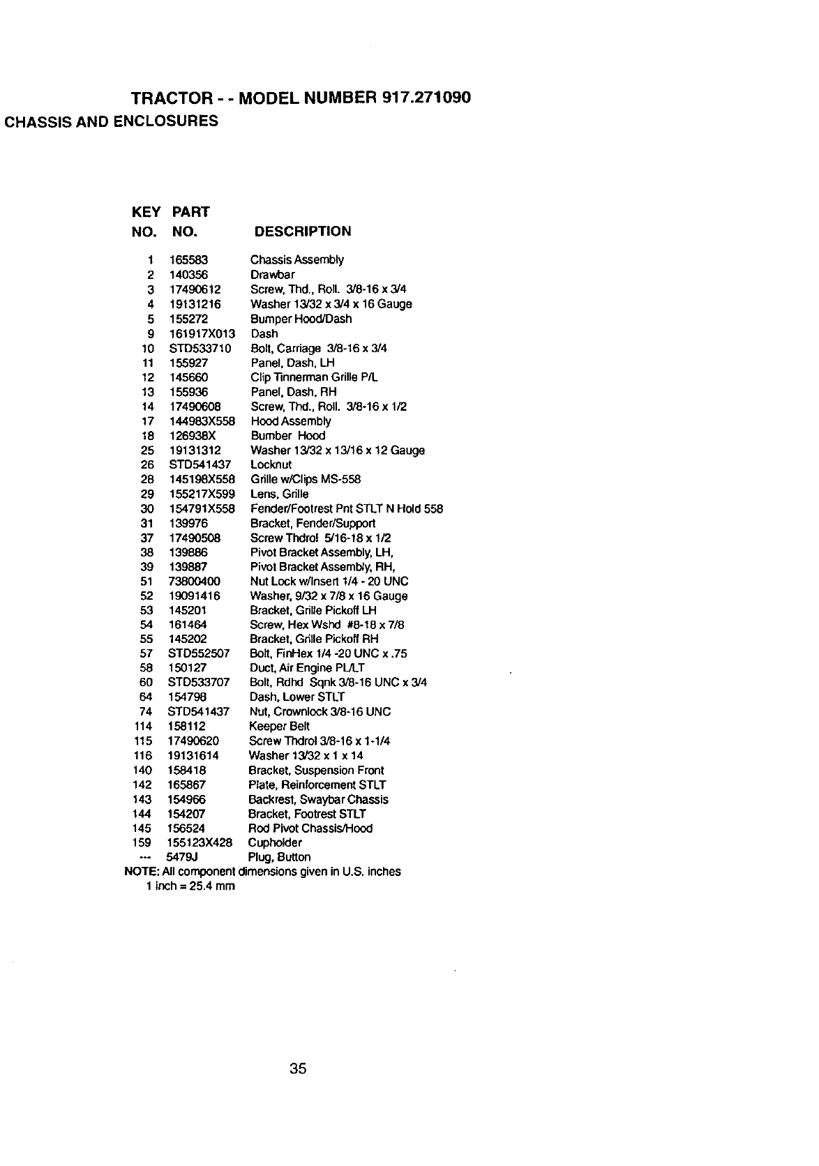
TRACTOR -- MODEL NUMBER 917.271090
CHASSIS AND ENCLOSURES
KEY PART
NO. NO. DESCRIPTION
1 165583
2 140356
3 17490612
4 19131216
5155272
9 161917X013
10 STD533710
11 155927
12 145660
13 155936
14 17490608
17 144983X558
18 126938X
25 19131312
26 STD541437
28 145198X558
29 155217X599
30 154791X558
31 139976
37 17490508
38 139886
39 139887
51 73800400
52 19091416
53 145201
54 161464
55 145202
57 STD552507
58 150127
60 STD533707
64 154798
74 STD541437
114 158112
115 17490620
116 19131614
140 158418
142 165867
143 154966
144 154207
145 156524
159 155123X428
-o 5479J
Chassis Assembly
Drawbar
Screw,Thd., Roll. 3/8-16 x 3/4
Washer 13/32 x 3/4 x 16Gauge
BumperHood/Dash
Dash
Bolt,Carriage 3/8-16 x 3/4
Panel, Dash, LH
Clip"nnnermanGdlle P/L
Panel, Dash, RH
Screw,Thd., Roll. 3/8-16 x1/2
HoodAssembly
Bumber Hood
Washer 13/32 x 13/16 x 12 Gauge
Locknut
Grillew/ClipsMS-558
Lens,Grille
Fender/FootrestPnt STLT N Hold 558
Bracket,Fender/Suppert
ScrewThdrol 5/16-18x 1i2
PivotBracketAssembly,LH,
PivotBracketAssembly,RH,
Nut Lock w/Insert1/4 *20 UNC
Washer, 9/32 x 7/8 x 16 Gauge
Bracket, GdllePickoffLH
Screw,Hex Wshd #8-18 x 7/8
Bracket, GdllePickoffRH
Bolt, FinHex 1/4 -20 UNC x.75
Duct,AirEngine PIJLT
Bolt, Rdhd Sqnk 3/8-16 UNC x 3/4
Dash, Lower STLT
Nut, Crownlock3/8-16 UNC
Keeper Belt
Screw Thdrol3/8-16 x 1-1/4
Washer 13/32 x 1x 14
Bracket,SuspensionFront
Plate, ReinforcementSTLT
Backrest,Swaybar Chassis
Bracket,FootrestSTLT
Rod Pivot Chassis/Hood
Cupholder
Plug, Button
NOTE: Allcomponentdimensionsgiven inU.S. inches
1inch = 25.4 mre
35
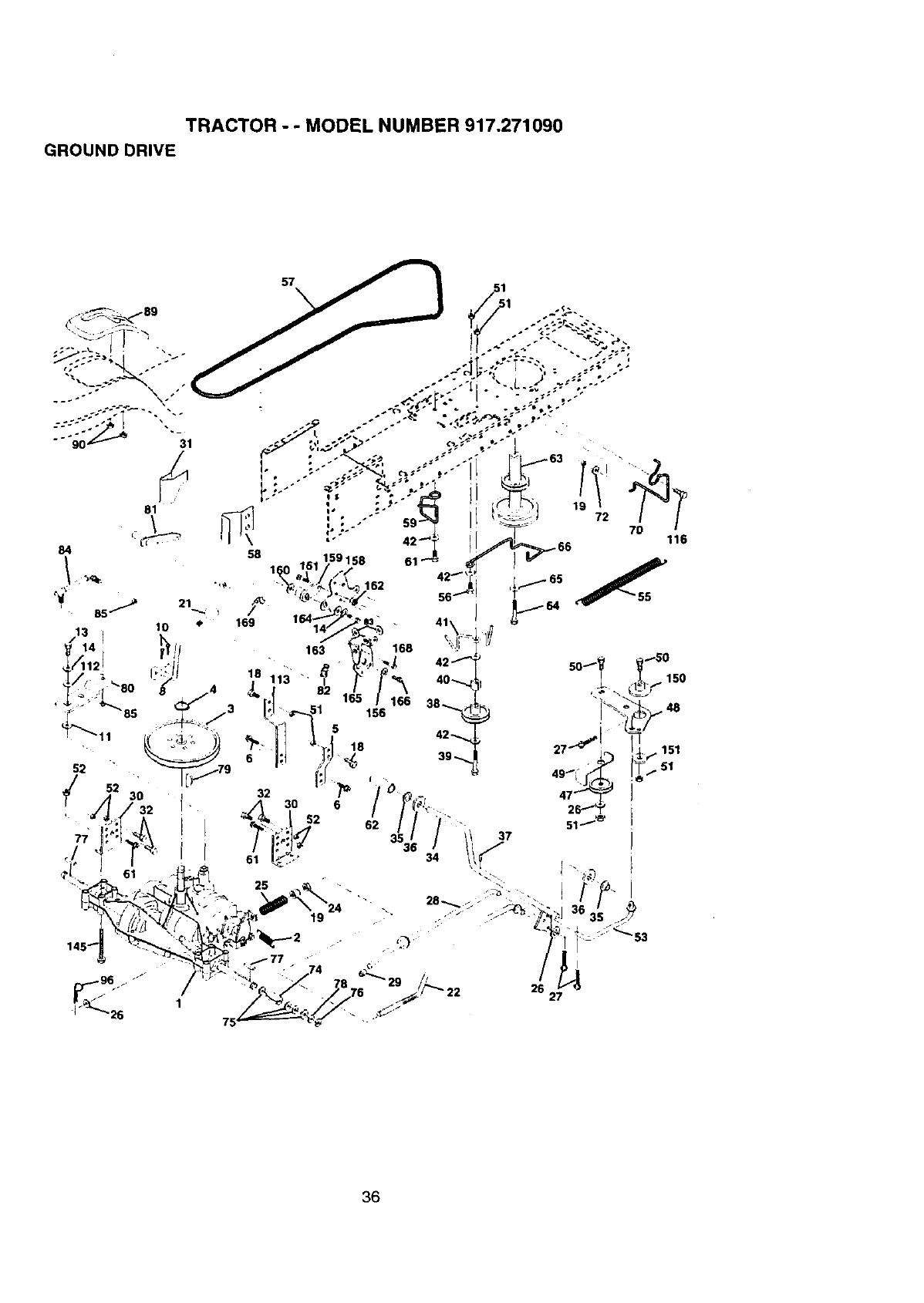
TRACTOR --MODEL NUMBER 917.271090
GROUND DRIVE
36
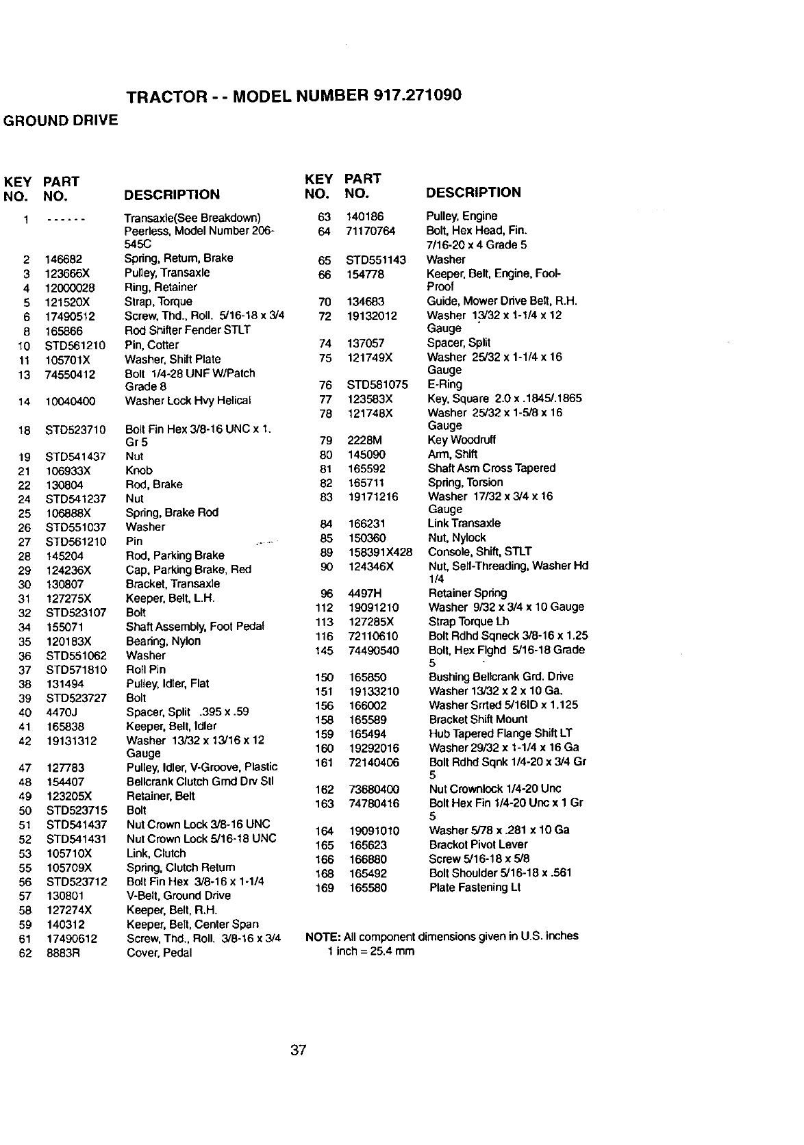
TRACTOR -- MODEL NUMBER 917.271090
GROUND DRIVE
KEY PART KEY PART
NO. NO. DESCRIPTION NO. NO.
1 ...... Transaxle(See Breakdown) 63 140186
Peedess, Model Number206- 64 71170764
545C
2 146682 Spring,Return, Brake 65 STD551143
3 123666X Pulley,Transaxle 66 154778
4 12000028 Ring, Retainer
5 121520X Strap, Torque 70 134683
6 17490512 Screw,Thd., Roll. 5/16-18 x 3/4 72 19132012
8165866 Rod Shifter Fender STLT
10 STD561210 Pin, Cotter 74 137057
11 105701X Washer, Shift Plate 75 121749X
13 74550412 Bolt l/4-28UNFW/Patch
Grade 8 76 STD581075
14 10040400 Washer Lock Hvy He]JcaJ 77 123583X
78 121748X
18 STD523710 Bolt Pin Hex3/8-16 UNC x 1.
Gr 5 79 2228M
19 STD541437 Nut 80 145090
21 106933X Knob 81 165592
22 130804 Rod, Brake 82 165711
24 STD541237 Nut 83 19171216
25 106888X Spring,Brake ROd
26 STD551037 Washer 84 166231
27 STD561210 Pin ....... 85 150360
28 145204 Rod, ParkingBrake 89 158391X428
29 124236X Cap, ParkingBrake, Red 90 124346X
30 130807 Bracket, Transaxle
31 127275X Keeper, Belt,L.H. 96 4497H
32 STD523107 Bolt 112 19091210
34 155071 ShaftAssembly,Foot Pedal 113 127285X
35 120183X Beadng, Nylon 116 72110610
36 STD551062 Washer 145 74490540
37 STD571810 Roll Pin
38 131494 Pulley, Idler, Flat 150 165850
39 STD523727 Bolt 151 19133210
40 4470J Spacer, Split .395 x .59 156 166002
41 165838 Keeper, Belt, Idler 158 165589
42 19131312 Washer 13/32 x 13/16 x 12 159 165494
Gauge 160 19292016
47 127783 Pulley,Idler,V-Groove, Plastic 161 72140406
48 154407 BellcrankClutchGrad DryStl
49 123205X Retainer,Belt 162 73680400
50 STD523715 Boil 163 74780416
51 STD541437 NutCrown Lock3/8-16 UNC 164 19091010
52 STD541431 Nut Crown Look5/16-18 UNC
53 105710X Link, Clutch t85 165623
55 105709X Spring,Clutch Return 166 166880
56 STD523712 Bolt Fin Hex 3/8-16 x 1-1/4 168 165492
57 130801 V-Belt, GroundDrive 169 165580
58 127274X Keeper, Belt, R,H.
59 140312 Keeper, Belt,Center Span
61 17490612 Screw, Thd., Roll. 3/8-16 x 3/4
62 8883R Cover, Pedal
DESCRIPTION
Pulley,Engine
Bolt,Hex Head, Fin.
7/16-20 x4Grade 5
Washer
Keeper,Belt, Engine,Fool-
Proof
Guide, Mower OdveBet1,R.H.
Washer 1.3/32x 1-1/4 x 12
Gauge
Spacer, Split
Washer 25/32 x 1-1/4 x 16
Gauge
E-Ring
Key,Square 2.0x .1845/.1865
Washer 25/32 x1-5/8 x 16
Gauge
Key Woodruff
Arm, Shift
ShaftAsm CrossTapered
Spdng,Torsion
Washer 17132x3/4 x 16
Gauge
LinkTransaxle
Nut, Nylock
Conso_, Shift,STLT
Nut, Self-Threading, Washer Hd
1/4
Retainer Spring
Washer 9/32 x 3/4 x 10 Gauge
Strap Torque Lh
Belt Rdhd Sqneck 3/8-16 x 1.25
Bolt,Hex Flghd 5/16-18 Grade
5
Bushing Bel_crank Grd. Drive
Washer 13/32 x 2 x 10 Ga.
WasherSrrted 5/161D x 1,125
BracketShiftMount
Hub Tapered Flange Shift LT
Washer29/32 x 1-1/4 x 16 Ga
BoltRdhd Sqnk 1/4-20 x 3,/4Gr
5
Nut Crownlook1/4-20 Unc
BeltHex Fin 1/4-20 Uoo x1Gr
5
Washer 5/78 x .281 x 10 Ga
BrackotPivotLever
Screw 5/16-18 x5/8
Belt Shoulder 5/16-18 x .561
Plate FasteningLt
NOTE: All componentdimensions given in U.S. inches
1inch= 25.4 mm
37
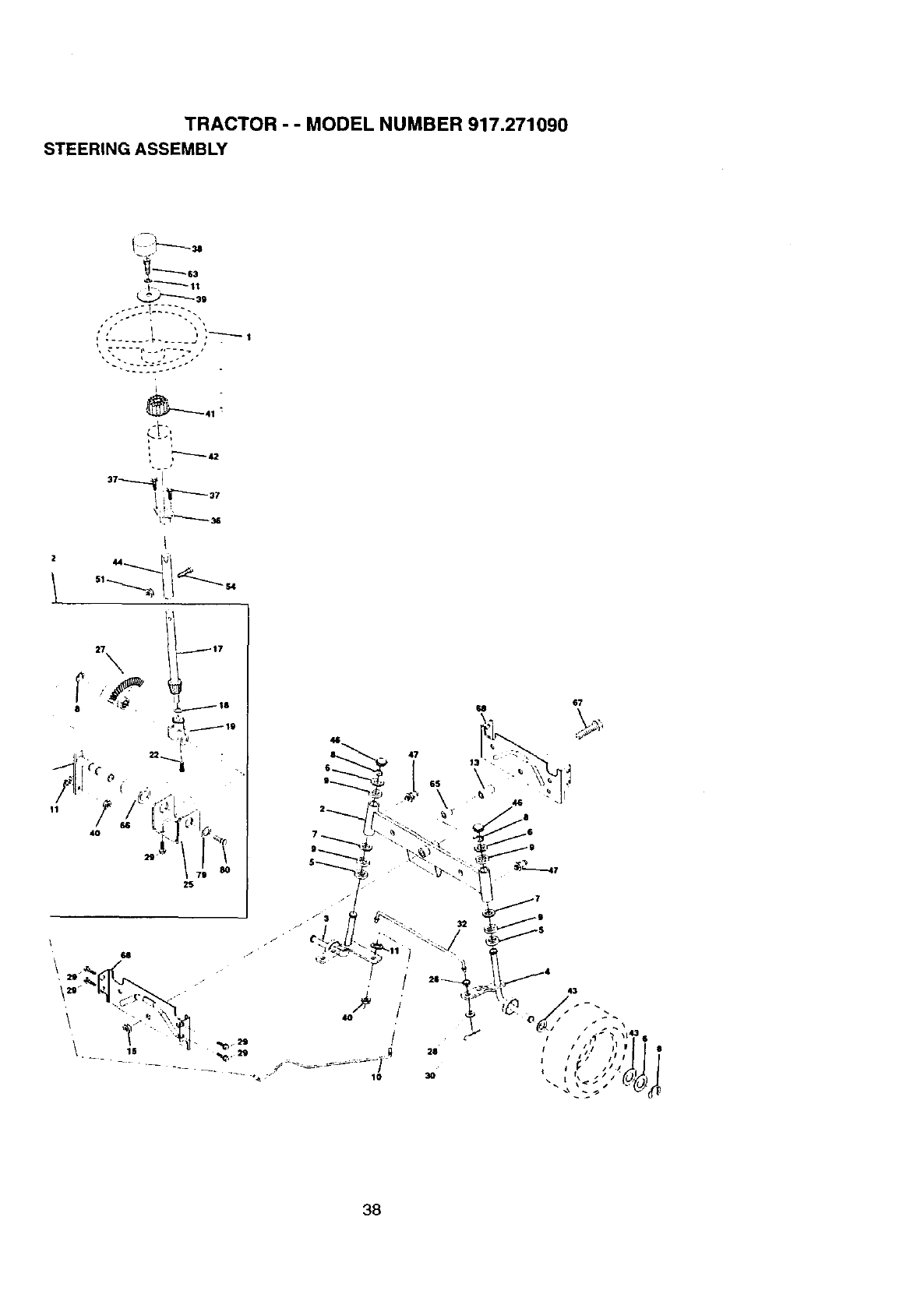
TRACTOR - - MODEL NUMBER 917.271090
STEERING ASSEMBLY
_lt
_-.._.J"-'-_ 39
I
+
+
2S
U
38
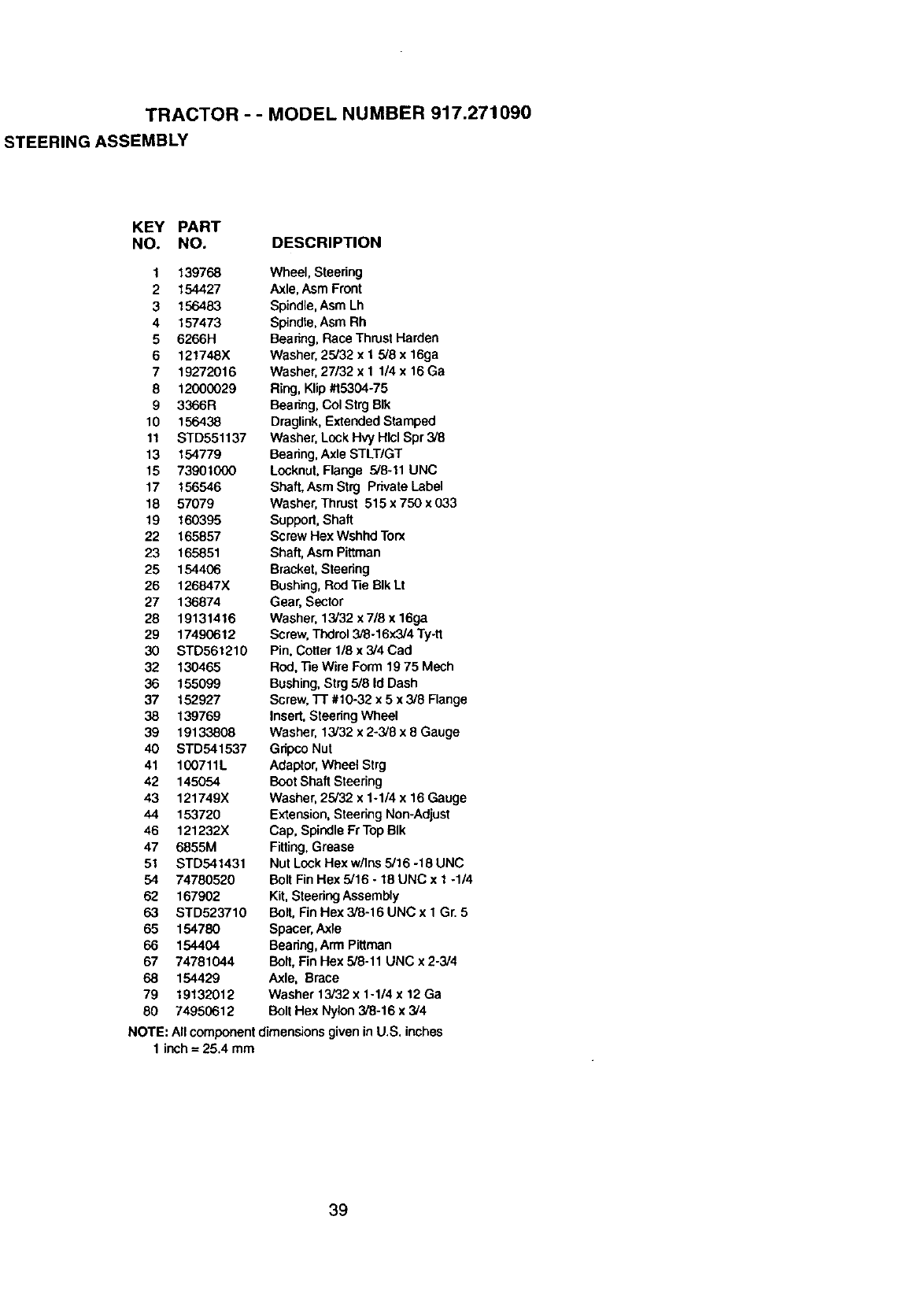
TRACTOR - - MODEL NUMBER 917.271090
STEERING ASSEMBLY
KEY PART
NO. NO. DESCRIPTION
1 139768
2 154427
3 156483
4 157473
56266H
6 121748X
7 19272016
8 12000029
9 3366R
10 156438
11 STD551137
13 154779
15 73901000
17 156546
18 57079
19 160395
22 165857
23 165851
25 154406
26 126847X
27 136874
28 19131416
29 17490612
30 STD561210
32 130465
36 155099
37 152927
38 139769
39 19133808
40 STD541537
41 100711L
42 145054
43 121749X
44 153720
46 121232X
47 6855M
51 STD541431
54 74780520
62 167902
63 STD523710
65 154780
66 154404
67 74781044
68 154429
79 19132012
80 74950612
Wheel, Steering
Axle, Asm Front
Spindle, Asm Lh
Spindte,Asm Rh
Beenng, Race Thrust Harden
Washer, 25/32 x I 5/8 x 16ga
Washer, 27/32 x 1 1/4 x 16 Ga
Ring,Klip #15304-75
Beenng, Col Strg BIk
Draglink, Extended Stamped
Washer, Lock Hvy Hlcl Spr 3/8
Bearing, Axle STLT/GT
Locknut,Flange 5/8-11 UNC
Shaft,AsmStrg PrivateLabel
Washer, Thrust 515 x 750 x 033
Support,Shaft
Screw Hex Wshhd Torx
Shaft, Asm Pittman
Bracket,Steering
Bushing,Rod "13eBIk Lt
Gear, Sector
Washer, 13/32 x 7/8 x 16ga
Screw, Thdrol3/8-16x3/4 Ty-tt
Pin, Cotter 1/8 x 3/4 Cad
Rod,"ReWire Form 19 75 Mech
Bushing,Strg 5/8 Id Dash
Screw,l-r #10-32 x 5 x 3/8 Flange
Insert,SteeringWheel
Washer, 13/32 x 2-3/8 x 8 Gauge
Gripco Nut
Adaptor, Wheel Strg
Boot Shaft Steering
Washer, 25/32 x 1-1/4 x 16 Gauge
Extension, Steering Non-Adjust
Cap, Spindle Fr Top BIk
Fitting, Grease
Nut Lock Hex w/Ins 5/16 -18 UNC
Bolt Fin Hex 5/16 - 18 UNC x 1 -1/4
Kit, Steedng Assembly
Bolt, Fin Hex 3/8-16 UNC x 1 Gr. 5
Spacer, Axle
Bearing, Arm Pittman
Bolt, Fin Hex 5/8-11 UNC x 2-3/4
Axle, Brace
Washer 13/32 x 1-1/4 x 12 Ga
Bolt Hex Nylon 3/8-16 x 3/4
NOTE: All componentdimensions given in U.S. inches
1 inch = 25.4 mm
39
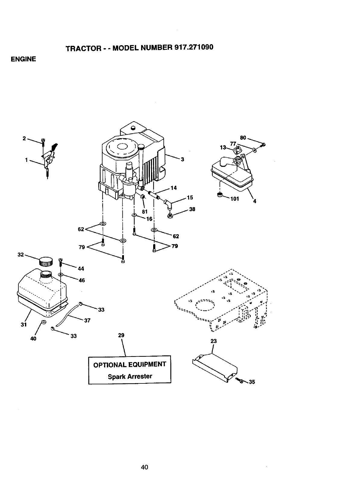
.f_p,c'TOP,""_°0_" _U_'EP' 9't7._..f.togo
\ \
_o
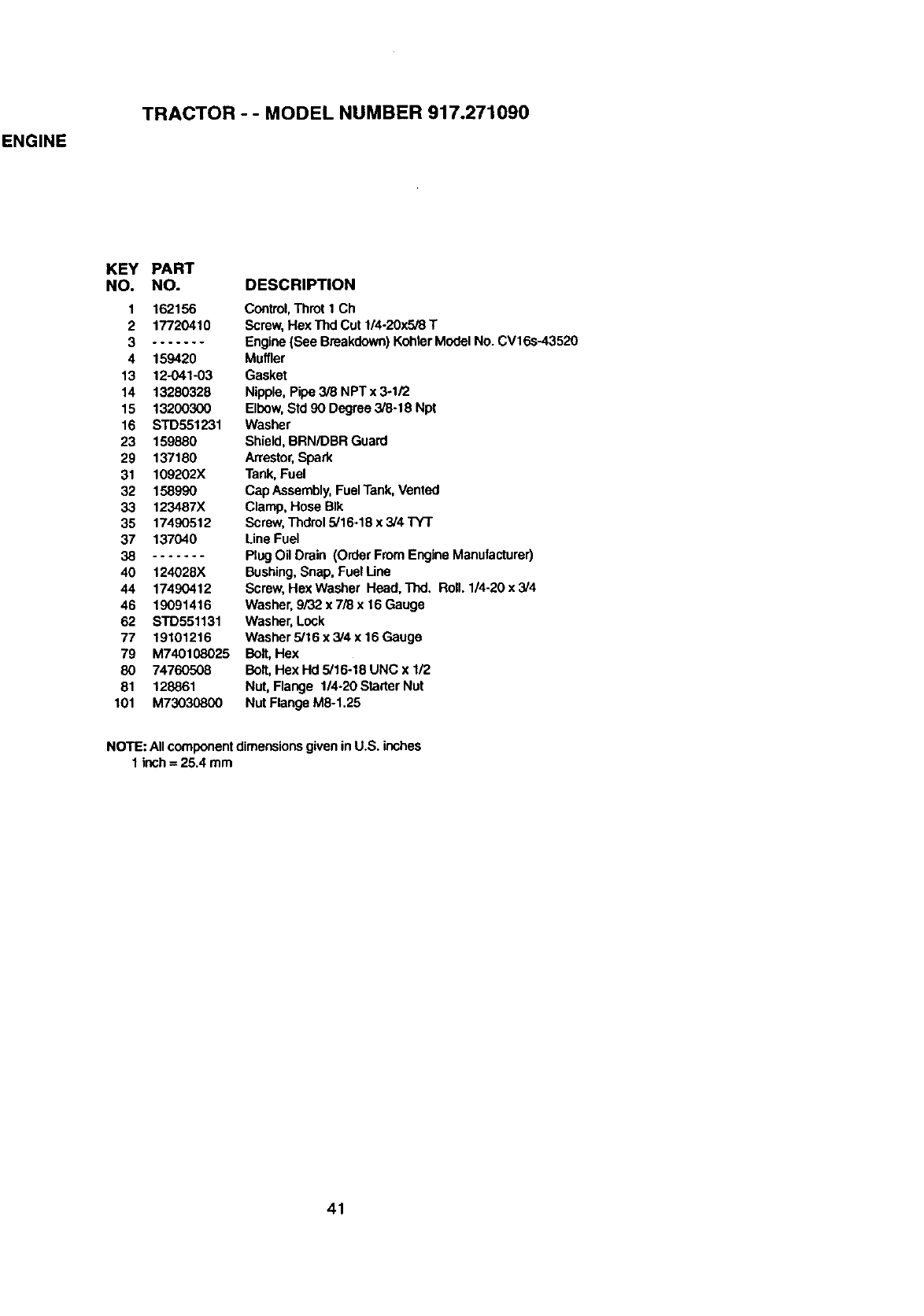
ENGINE
TRACTOR -- MODEL NUMBER 917.271090
KEY PART
NO. NO.
1162156
2 17720410
3 .......
4 159420
13 12-041-03
14 13280328
15 13200300
16 STD551231
23 159880
29 137180
31 109202X
32 158990
33 123487X
35 17490512
37 137040
38 .......
40 124028X
44 17490412
46 19091416
62 STD551131
77 19101216
79 M740108025
80 74760508
81 128861
101 M73030800
DESCRIPTION
Control, Throt ICh
Screw,Hex Thd Cut 1/4-20x5/8 T
Engine (See Breakdown) KohlerModel No. CV16s-43520
Muffler
Gasket
Nipple, Pipe 3[8 NPT x 3ol/2
Elbow,Std 90 Degree3/8-18 Npt
Washer
Shield, BRN/DBR Guard
Arrestor,Spark
Tank, Fuel
Cap Assembly,FuelTank, Vented
Clamp, Hose BIk
Screw,Thdrol 5/16o18 x 3/4 TY'T
Line Fuel
PlugOil Drain (Order From Engine Manufacturer)
Bushing,Snap, Fuel Line
Screw, Hex Washer Head. Thd. Roll. 1/4-20 x 3/4
Washer, 9/32 x 7/8 x 16Gauge
Washer, Lock
Washer 5/16 x 3/4 x 16 Gauge
Bolt,Hex
Bolt,Hex Hd 5/16o18 UNC x 1/2
Nut, Flange 1/4-20Starter Nut
Nut Flange M8-1.25
NOTE: Allcomponentdimensionsgivenin U.S. inches
1inch = 25.4 mm
41
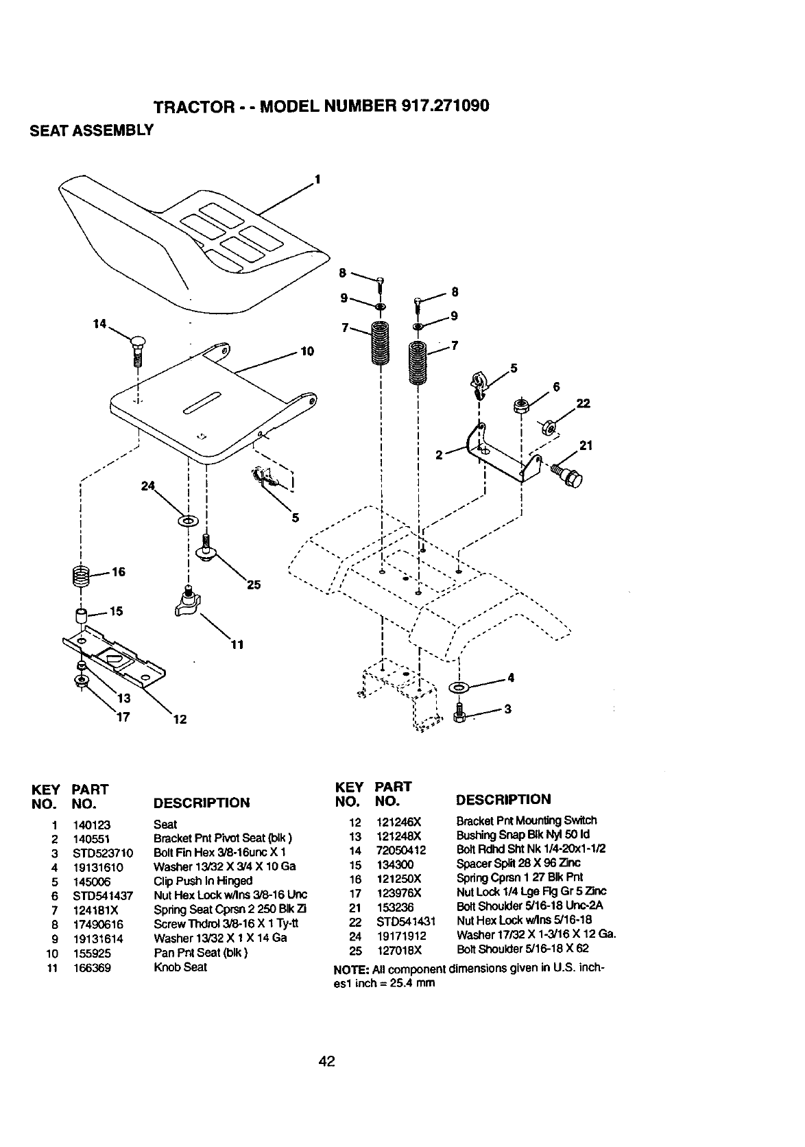
TRACTOR - -MODEL NUMBER 917.271090
SEAT ASSEMBLY
KEY PART KEY PART
NO. NO. DESCRIPTION NO. NO. DESCRIPTION
1 140123 Seat 12 121246X
2 140551 BracketPntPivotSeat Ooik) 13 121248X
3 STD523710 BoltFinHex 3/8-16uncX 1 14 72050412
4 19131610 Washer13i32X3/4X10Ga 15 134300
5 145006 ClipPush In Hinged 16 121250X
6 STD541437 NutHexLockw/ins3i6-16Unc 17 123976X
7 124181X SpdngSeatCprsn2250BIkTi 21 153236
8 17490616 Screw Thdrol3/8-16 X 1 Ty-tt 22 STD541431
9 19131614 Washer 13/32X 1 X 14Ga 24 19171912
10 155925 PanPntSeat(blk) 25 127018X
11 166369 KnobSeat
BracketPntMounting Switch
BushingSnap BIkNy150 Id
BoltRdhdShtNk 1/4-20x1-1/2
SpacerSplit28 X 96 Zinc
SpdngCprsnI 27 BIk Pnt
NutLock 1/4 Lga FigGr 5 Zinc
BoltShoulder5/16-18 Unc.2A
NutHex Lockw/Ins5/16-18
Washer17/32 X 1-3/16 X 12 Ga.
BoltShoulder5/16-18 X 62
NOTE: All componentdimensionsgiven in U.S. inch-
esl inch = 25.4 mm
42
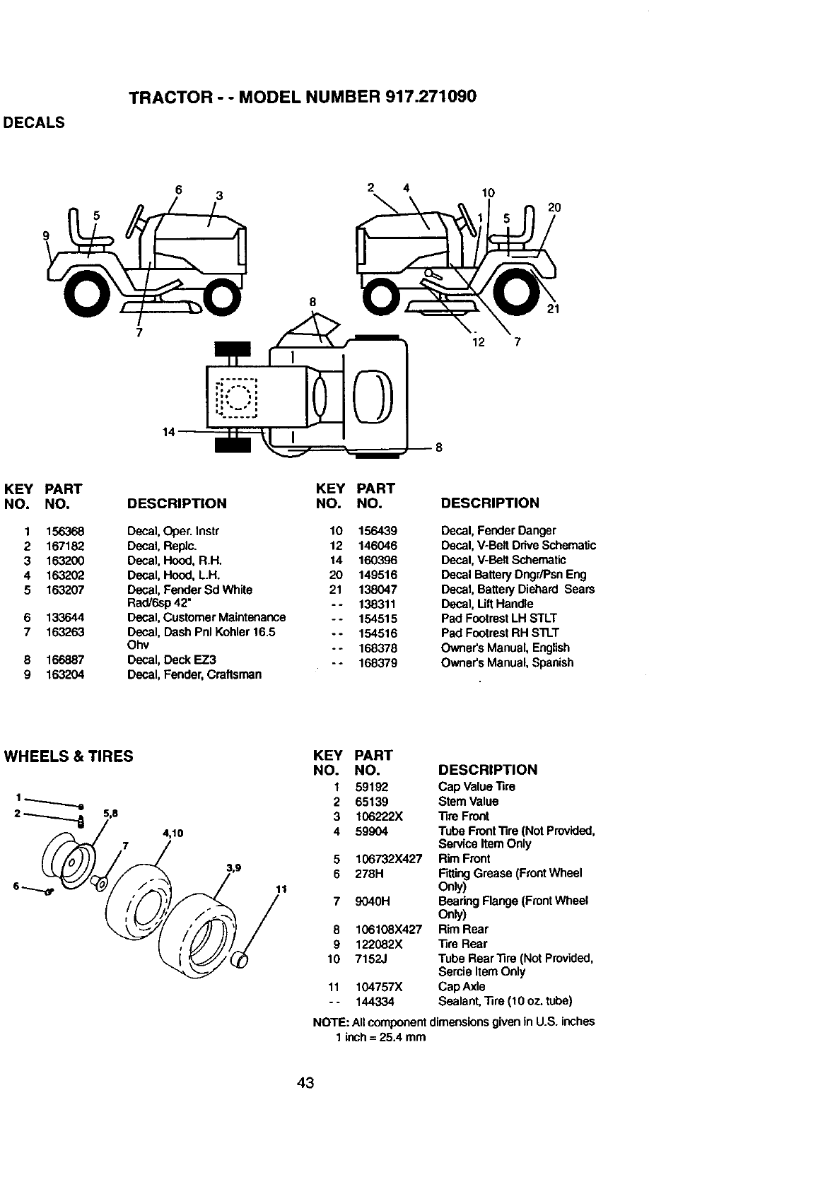
DECALS
TRACTOR - - MODEL NUMBER 917.271090
6 3 2 4 10
2O
12 7
KEY
NO.
1
2
3
4
5
6
7
8
9
PART
NO.
156368
167182
163200
163202
163207
133644
163263
166887
163204
KEY PART
DESCRIPTION NO. NO.
Decal, Oper. Instr 10 156439
Decal, Replc. 12 146046
Decal, Hood, R.H. 14 160396
Decal, Hood, L.H. 20 149516
Decal, Fender Sd White 21 138047
Rad/6sp 42" -- 138311
Decal, Customer Maintenance - - 154515
Decal, Dash Pnl Kohler 16.5 --154516
Ohv -- 168378
Decal, Deck EZ3 - -168379
Decal, Fender, Craftsman
DESCRIPTION
Decal, Fender Danger
Decal, V-Belt Drive Schematic
Decal, V-Belt Schematic
Decal Battery Dngr/PsnEng
Decal, BatteryDiehard Sears
Decal, LiftHandle
Pad Footrest LH STLT
Pad FootrestRH STLT
Owner'sManual, English
Owner'sManual, Spanish
WHEELS & TIRES
2_5,8 4,10
11
KEY PART
NO. NO. DESCRIPTION
1 59192 Cap Value Tire
2 65139 Stem Value
3 106222X Tire Fmnt
4 59904 Tube FrontTire (Not Providsd,
Service Item Only
5 106732X427 Rim Front
6 278H FittingGrease (FrontWheel
Only)
7 9040H Beadng Flange (FrontWheel
only)
8 106108X427 Rim Rear
9 122082X Tire Rear
10 7152J Tube RearTire (Not Provided,
Sercie Item only
11 104757X Cap Axle
- - 144334 Sealant, Tire (10 oz. tube)
NOTE: Allcomponentdimensionsgivenin U.S. inches
1 inch=25.4 mm
43
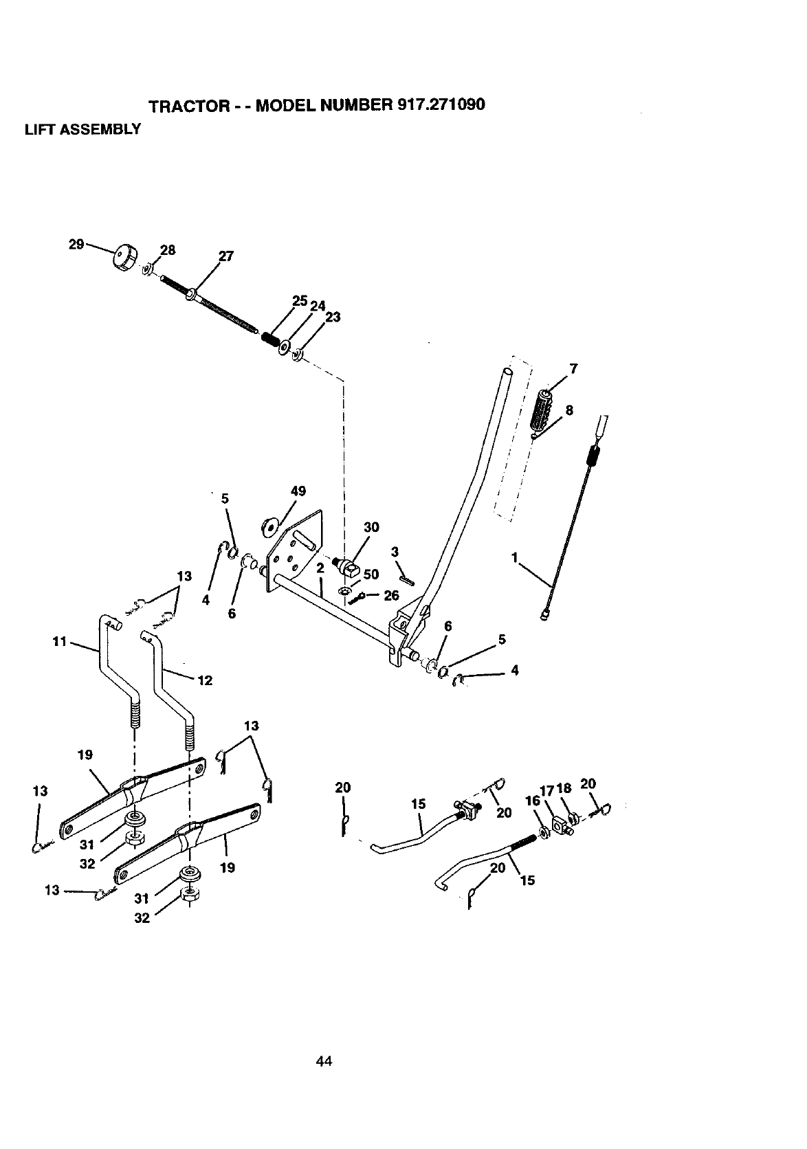
TRACTOR - - MODEL NUMBER 917.271090
LIFT ASSEMBLY
49
5
12
3O
3
\
26
8
I
/ /
/I'
13
31
32
13
19
2O 2O
15
44
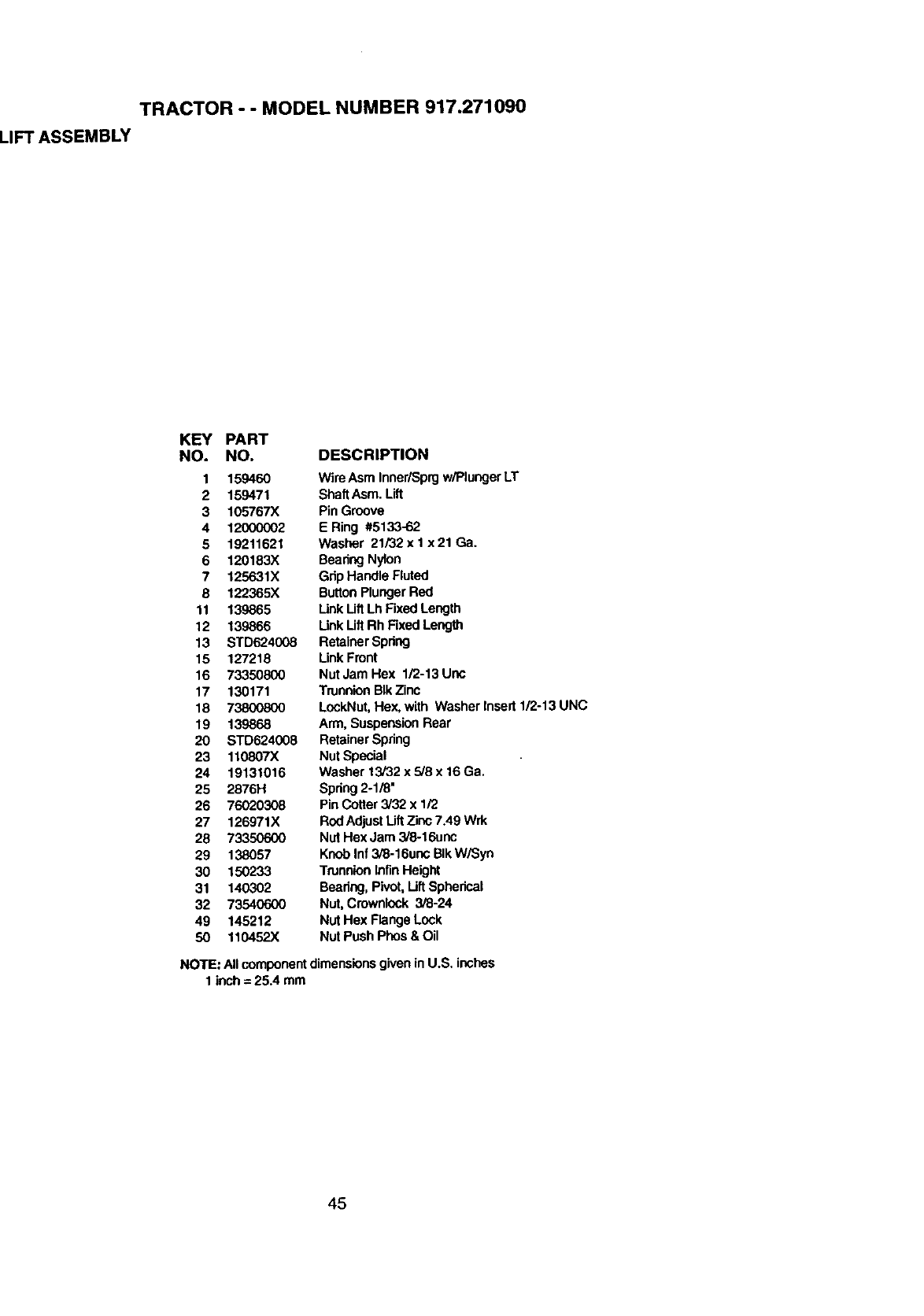
TRACTOR -- MODEL NUMBER 917.271090
LIFT ASSEMBLY
KEY PART
NO. NO. DESCRIPTION
1 159460 WireAsm Inner/Sprgw/PlungerLT
2 159471 ShaftAsm. Lift
3 105767X Pin Groove
4 12000002 E Ring #5133-62
5 19211621 Washer 21/32x I x21 Ga.
6 120183X BearingNylon
7 125631X Gdp Handle Fluted
8 122365X ButtonPlunger Red
11 139865 Link LiftLh Fixed Length
12 139866 Unk Lift Rh FixedLength
13 STD624008 RetainerSpring
15 127218 Unk Front
16 73350800 NutJam Hex 1/2-13 Unc
17 130171 TrunnionBIk Zinc
18 73800800 LockNut,Hex, with Washer Insert 1/2-13 UNC
19 139868 Arm, SuspensionRear
20 STD624008 RetainerSpring
23 110807X Nut Special
24 19131016 Washer 13/32 x 5/8 x 16Ga.
25 2876H Spring2-118"
26 76020308 Pin Cotter 3/32 x 1/2
27 126971X RedAdjust Lift Zinc 7.49 Wrk
28 73350600 Nut Hex Jam 3/8-16unc
29 138057 Knob Inf 3/8-16unc BIk W/Syn
30 150233 TrunnionInfinHeight
31 140302 Beedng, Pivot, LiftSpherical
32 73540600 Nut, Crownlock 3/8-24
49 145212 Nut Hex Flange Lock
50 110452X Nut Push Phos & Oil
NOTE: Allcomponentdimensionsgivenin U.S, inches
1 inch= 25.4 mm
45
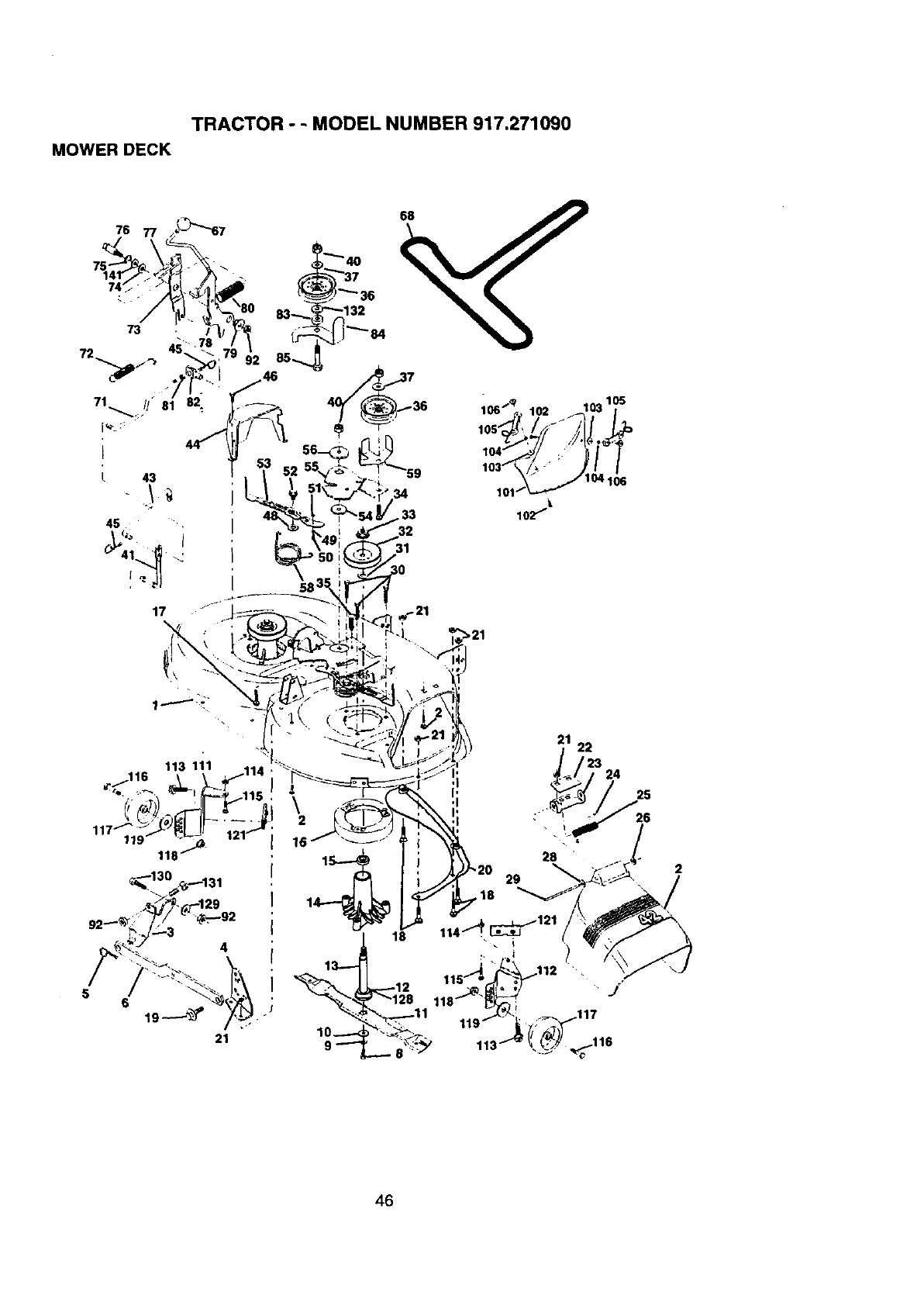
TRACTOR --MODEL NUMBER 917.271090
MOWER DECK
76
113 111 114
118/_t
56
21
/_ i_ 121
114
46
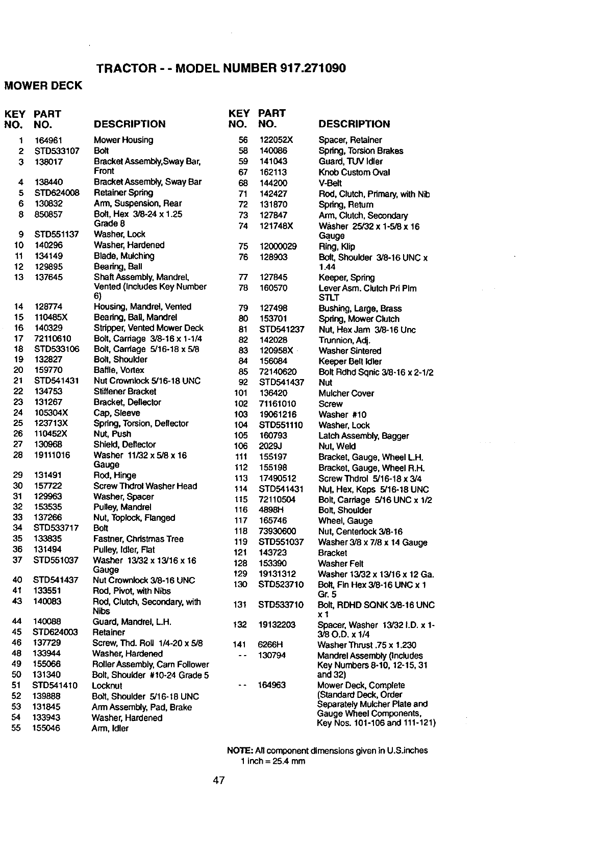
TRACTOR --MODEL NUMBER 917.271090
MOWER DECK
KEY PART KEY PART
NO. NO. DESCRIPTION NO. NO.
1 164961 Mower Housing 56 122052X
2 STD533107 Bolt 58 140(_B6
3 138017 BracketAssembly,SwayBar, 59 141043
Front 67 162113
4 138440 BracketAssembly,Sway Bar 68 144200
5 STD624008 Retainer Spring 71 142427
6 130832 Arm, Suspension,Rear 72 131870
8 850857 Bolt, Hex 3/8-24 x 1.25 73 127847
Grade 8 74 121748X
9 STD551137 Washer,Lock
10 140296 Washer,Hardened 75 12000029
11 134149 Blade, Mulching 76 128903
12 129895 Bearing,Ball
13 137645 ShaftAssembly,Mandrel, 77 127845
Vented (IncludesKey Number 78 160570
6)
14 128774 Housing,Mandrel, Vented 79 127498
15 110485X Bearing,Ball, Mandrel 80 153701
16 140329 Stripper,Vented Mower Deck 81 STD541237
17 72110610 Bolt,Carriage 3/8-16x 1-1/4 82 142028
18 STD533106 Bolt,Carriage 5/16-18 x 5/8 83 120958X
19 132827 Bolt, Shoulder 84 156084
20 159770 Baffle,Vortex 85 72140620
21 STD541431 Nut Crownlock5/16-18UNC 92 STD541437
22 134753 StiffenerBracket 101 136420
23 131267 Bracket, Deflector 102 71161010
24 105304X Cap, Sleeve 103 19061216
25 123713X Spring, Torsion.Deflector 104 STD551110
26 110452X Nut, Push 105 160793
27 130968 Shield, Deflector 106 2029J
28 19111016 Washer 11.i32x5/8x 16 111 155197
Gauge 112 155198
29 131491 Rod, Hinge 113 17490512
30 157722 ScrewThdrolWasherHead 114 STD541431
31 129963 Washer, Spacer 115 72110504
32 153535 Pulley, Mandrel 116 4898H
33 137266 Nut, Toplock,Flanged 117 165746
34 STD533717 Bolt 118 73930600
35 133835 Fastner,ChristmasTree 119 STD551037
36 131494 Pulley, Idler,Flat 121 143723
37 STD551037 Washer 13/32 x 13/16x 16 128 153390
Gauge 129 19131312
40 STD541437 Nut Crownlock3/8-16 UNC 130 STD523710
41 133551 Rod, Pivot,with Nibs
43 140083 Rod, Clutch,Secondary,with 131 STD533710
Nibs
44 140088 Guard, Mandrel, L.H. 132 19132203
45 STD624003 Retainer
46 137729 Screw, Thd. Roll 1/4-20 x 5/8 141 6266H
48 133944 Washer, Hardened -- 130794
49 155066 RollerAssembly,Cam Follower
50 131340 Bolt, Shoulder #10-24 Grade 5
51 STD541410 Locknut -- 164963
52 139888 Bolt, Shoulder 5/16-t8 UNC
53 131845 ArmAssembly,Pad, Brake
54 133943 Washer, Hardened
55 155046 Arm, Idler
DESCRIPTION
Spacer, Retainer
Spring,TorsionBrakes
Guard,TUV Idler
Knob CustomOval
V-Belt
Rod, Clutch,Primary,with Nib
Spring, Return
Arm, Clutch,Secondary
Washer 25/32 x 1.5/8 x 16
Ga.uge
Ring,Klip
Bolt,Shoulder 3/8-16 UNC x
1.44
Keeper, Spring
Lever ASm. ClutchPd PIm
STLT
Bushing,Large. Brass
Spring, Mower Clutch
Nut, Hex Jam 3/8-16 Unc
Trunnion,Adi.
Washer Sintered
Keeper BeltIdler
Bolt Rdhd Sqnic3/6-16 x 2-1/2
Nut
Mulcher Cover
Screw
Washer #10
Washer, Lock
LatchAssembly,Bagger
Nut, Weld
Bracket, Gauge, Wheel LH.
Bracket, Gauge, Wheel R.H.
Screw Thdrol 5/16-18 x3/4
Nut, Hex, Keps 5/16-18 UNC
Bolt, Carriage 5/16 UNC x 1/2
Bolt,Shoulder
Wheel, Gauge
Nut, Centedock3/8.16
Washer3/8 x 7/8 x 14 Gauge
Bracket
Washer Felt
Washer 13/32 x 13/16 x 12 Ga.
Bolt, Fin Hex 3/8-16 UNC x 1
Gr. 5
Bolt, RDHD SQNK 3/8-16 UNC
xl
Spacer, Washer 13/32 I.D. x 1-
3/80.D. x 1/4
WasherThnJst.75 x 1,230
Mandrel Assembly(Includes
Key Numbers8-10, 12-15, 31
and 32)
Mower Deck, Complete
(Standard Deck,Order
Separately MulcherPlate and
Gauge Wheel Components,
Key Nos. 101-106 and 111-121)
NOTE: Allcomponentdimensionsgiven inU.S.inches
1 inch= 25.4 mm
47
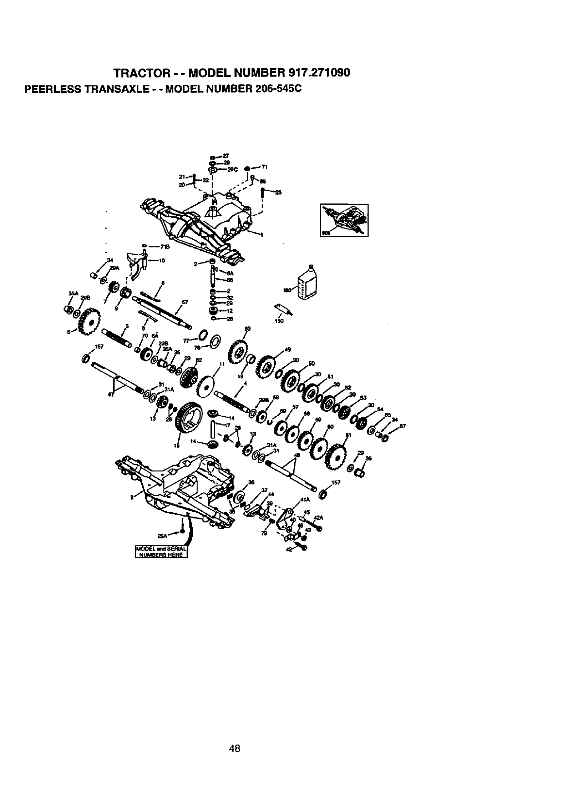
TRACTOR - - MODEL NUMBER 917.271090
PEERLESS TRANSAXLE - - MODEL NUMBER 206-545C
8
48
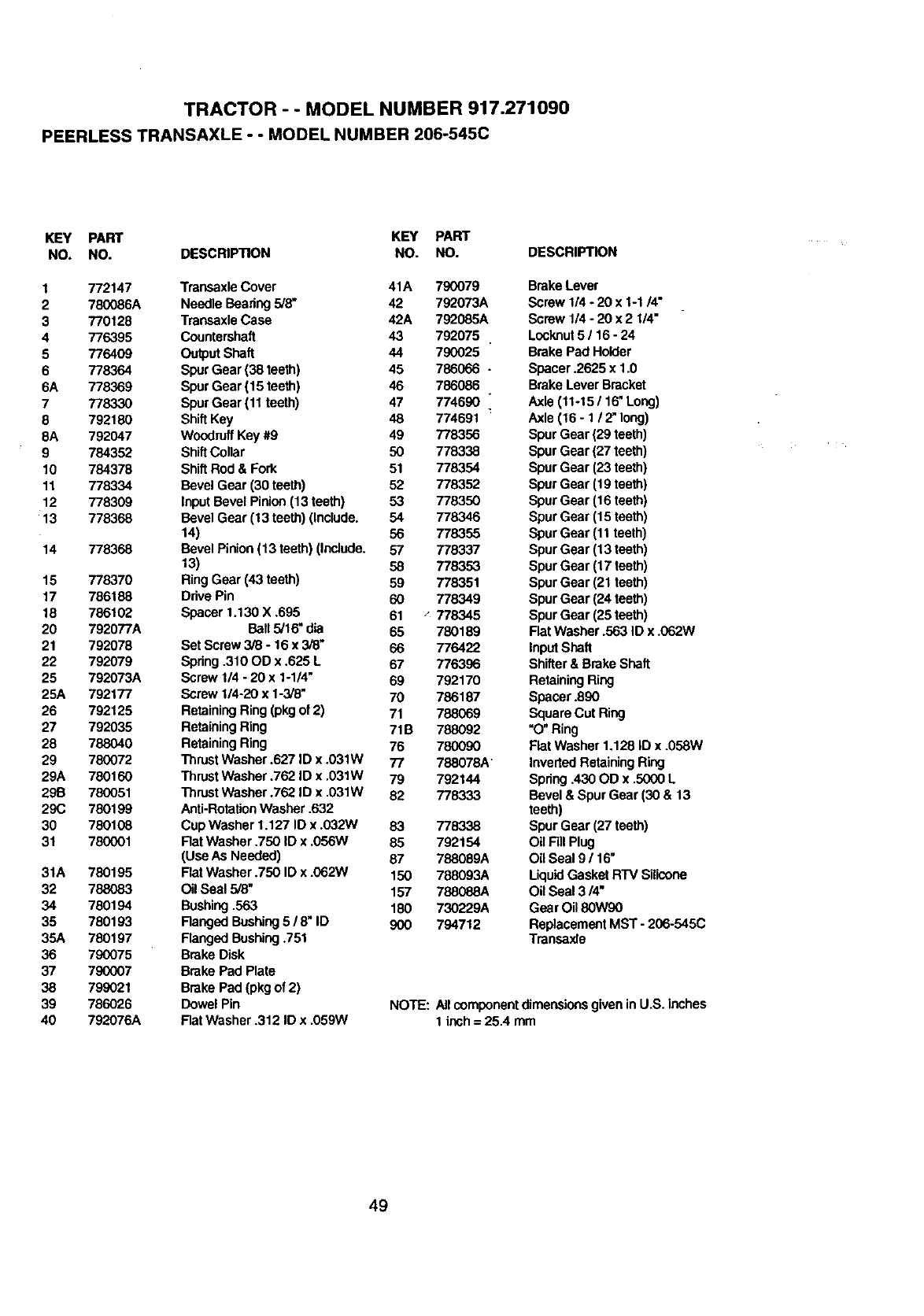
TRACTOR - - MODEL NUMBER 917.271090
PEERLESS TRANSAXLE - - MODEL NUMBER 206-545C
KEY PART KEY PART
NO. NO. DESCRIPTION NO. NO.
1 772147 Treneaxle Cover 41A 790079
2 780086A Needle Bearing 5/8" 42 792073A
3 770128 Transaxle Case 42A 792086A
4 776395 Countershaft 43 792075
5 776409 Output Shaft 44 790025
6 778364 SpurGear (38 teeth) 45 786066 -
6A 778369 SpurGear (15 teeth) 46 786086
7778330 SpurGear (11 teeth) 47 774690
8 792180 ShiftKey 48 774691
8A 792047 WoodruffKey #9 49 778356
9 784352 ShiftCollar 50 778338
10 784378 ShiftRod & Fork 51 778354
11 778334 Bevel Gear (30 teeth) 52 778352
12 778309 Input Bevel Pinion(13 teeth) 53 778350
13 778368 Bevel Gear (13 teeth)(Include. 54 778346
14) 56 778355
14 778368 Bevel Pinion(13 teeth) (Include. 57 778337
13) 58 778353
15 778370 Ring Gear (43 teeth) 59 778351
17 786188 DrivePin 60 778349
18 786102 Spacer 1.130 X .695 61 .° 778345
20 792077A Ball5/16" dia 65 780189
21 792078 Set Screw 3/8 - 16 x 3/8' 66 776422
22 792079 Spring.310 OD x .626 L 67 776396
25 792073A Screw 1/4 - 20 x 1-1/4" 69 792170
25A 792177 Screw 114-20x 1-3/6, 70 786187
26 792125 RetainingRing (pkgof 2) 71 788069
27 792035 RetainingRing 71B 788092
28 788040 RetainingRing 76 780090
29 780072 ThrustWasher .627 ID x .031W 77 788078A"
29A 780160 Thrust Washer .762 ID x .031W 79 792144
29B 780051 Thrust Washer .762 ID x .031W 82 778333
29C 780199 Anti-RotationWasher •632
30 780108 Cup Washer 1.127 ID x .032W 83 778338
31 780001 Rat Washer .750 ID x .056W 85 792154
(Use ASNeeded) 87 788089A
31A 780195 Rat Washer .750 ID x .062W 150 788093A
32 788083 Oil Seal 5/8" 157 788088A
34 780194 Bushing.563 180 730229A
35 780193 Ranged Bushing5 /8" ID 900 794712
36A 780197 Ranged Bushing.751
36 790075 Brake Disk
37 790007 Brake Pad Plate
38 799021 Brake Pad (pkg of 2)
39 786026 Dowel Pin
40 7_2076A FlatWasher .312 ID x .059W
DESCRIPTION
Brake Lever
Screw 1/4 -20 x 1-1/4"
Screw 1/4 -20 x 2 1/4"
Locknut5116 - 24
Brake Pad Holder
Spacer .2625 x 1.0
Brake Lever Bracket
Axle (11-15 /16" Long)
Axle (16 -1/2" long)
Spur Gear (29 teeth)
Spur Gear (27 teeth)
Spur Gear (23 teeth)
Spur Gear (19 teeth)
Spur Gear (16 teeth)
Spur Gear (15 teeth)
Spur Gear (11 teeth)
Spur Gear (13 teeth)
Spur Gear (17 teeth)
Spur Gear (21 teeth)
Spur Gear (24 teeth)
Spur Gear (25 teeth)
Flat Washer .563 ID x .062W
InputShaft
Shifter& BrakeShaft
RetainingRing
Spacer .890
Square Cut Ring
"O"Ring
Fiat Washer 1.128 ID x •058W
InvertedRetainingRing
Spring.430 OD x .5000 L
Bevel &Spur Gear (30 & 13
teeth)
Spur Gear (27 teeth)
Oil Fill Plug
Oil Seal 9 /16"
LiquidGasket RTV Silicone
Oil Seal 3/4"
Gear Oil 80W90
ReplacementMST -206-545C
Transaxle
NOTE: All componentdimensionsgiven inU.S. inches
1 inch=25.4 mm
49
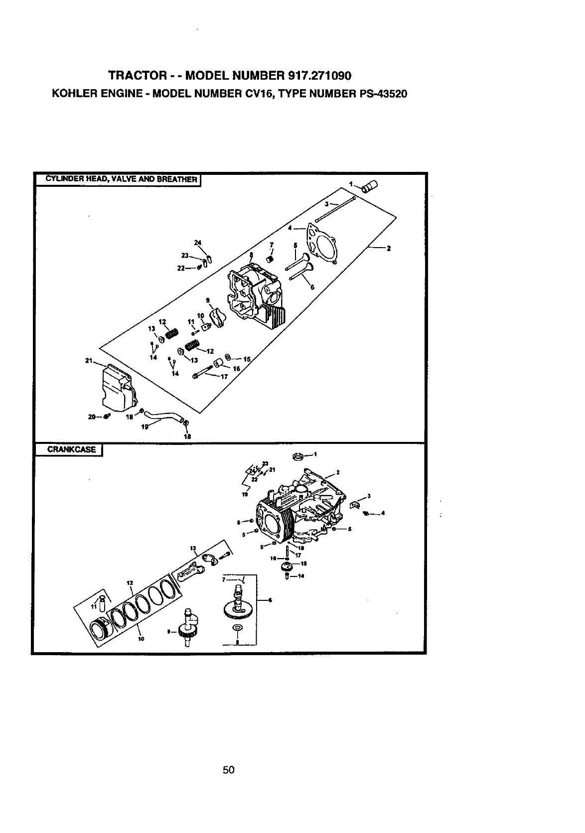
TRACTOR - - MODEL NUMBER 917.271090
KOHLER ENGINE -MODEL NUMBER CV16, TYPE NUMBER PS-43520
CYUNDER HEAD, VALVE AND EIREATHERJ
14
10
18
_'--t4
5O
TRACTOR - - MODEL NUMBER 917.271090
KOHLER ENGINE - MODEL NUMBER CV16, TYPE NUMBER PS-43520
CYUNDER HEAD/VALVE/BREATHER
KEY PART
NO. NO,
CRANKCASE
1
2
3
4
5
6
7
8
9
10
11
12
13
14
15
16
17
18
19
20
21
22
23
24
25-351-01
12o755-81
12-411-01
12-041-10
12-017-01
12-017-02
12-018-01
12..016-O2
X-75-23
12-318-19
25-186-01
12-59903
M-064(X)34
12..089-01
12-173-01
12-755-03
12-468-05
12-112-13
12-088-15
X-428-9
12-326-03
M-0645020
12-096-07
M-0545010
12-018-01
12-402-02
KEY PART
DESCRIPTION NO. NO.
Ufter,valve (2)
Kit,cylinderhead (includes3.17)
Rod, push(2)
Gasket, cylinderhead
Valve, intake(S_I.)
Valve. intake(.25)
Valve, exhaust (Std.)
Valve, exhaust(.25)
Plug, allen hd.pipe 1/8
CylinderHead
Arm. rocker(2)
Pivot,rockerarm (2)
Screw,hex. flange M6xL0x34 (2)
Spring.valve (2)
Cap, valvespring(2)
Kit,retainer(2)
Washer, plain 13/32
Spacer,head boltexhaust port
Screw, hox. flange Mt0x1.5x81 (5)
Clamp, hose (2)
Hose. breather
Screw, hex.flange M6xl.0x20 (5)
Cover,valve w/nipple
Screw, hex. flange MSxO.Bxl0
Retainer,breather reed
Reed, breather
DESCRIPTION
1
2
3
4
5
6
7
8
9
10
11
12
13
14
15
16
17
18
19
21
22
23
24
12-032-0_3 Seal, crankshaft
Block,cylinder(Use ShortBlock 12 522 18)
12-445-02
M-0839025
12-380-17
12-758-49
12-089-31
12-422-08
12-422-09
12-422o10
12-422-11
12-422-12
12,422-13
12,422-07
12-144-27
12-874-07
24-874-11
12-874-08
"_2-874-09
12-01802
12-10807
12-108-08
12-108-09
12-067-05
12-067-06
12-380-01
12-O43-05
M_631005
12-144-02
52-139-09
12-758-64
X-25-102
12-032-01
SM-0631015
12-154-05
Strap, lifting
Screw,hex. flangeM8xl.25x25
Dowel,locating(4)
Kit,camshaft(Includes7,8)
Spring.actuating
Shim,camshaft (A.R.) blue
Shim, camshaft (A.R.) red
Shim, camshaft (A.R.) yellow
Shim, camshaft (A.R.) green
Shim,camshaft (A.R.) gray
Shim, camshaft (A.R.) black
Shim, camshaft (A.R.) white
Shaft, balance
Pistonw/Ring Set (Std,)
(Includes 11-12)
Piston w/RingSet (.08)
Piston wiring Set (.25)
Piston w/RingSet (.50)
Retainer,pistonpin(2)
RingSet (Std.)
RingSet (.25)
RingSet (.5O)
ConnectingROd(Std.)
ConnectingROd(.25)
Pin, governorregulating
Gear, governor assembly
Washer, plain 6mm
Shaft, governor gear
Plug, cup
Kit,gov. crossshaftw/dip
(Includes 24)
washer,plain 1/4
Seal, governorcrossshaft
Washer, plain 8ram
Clip, hitchpin
51
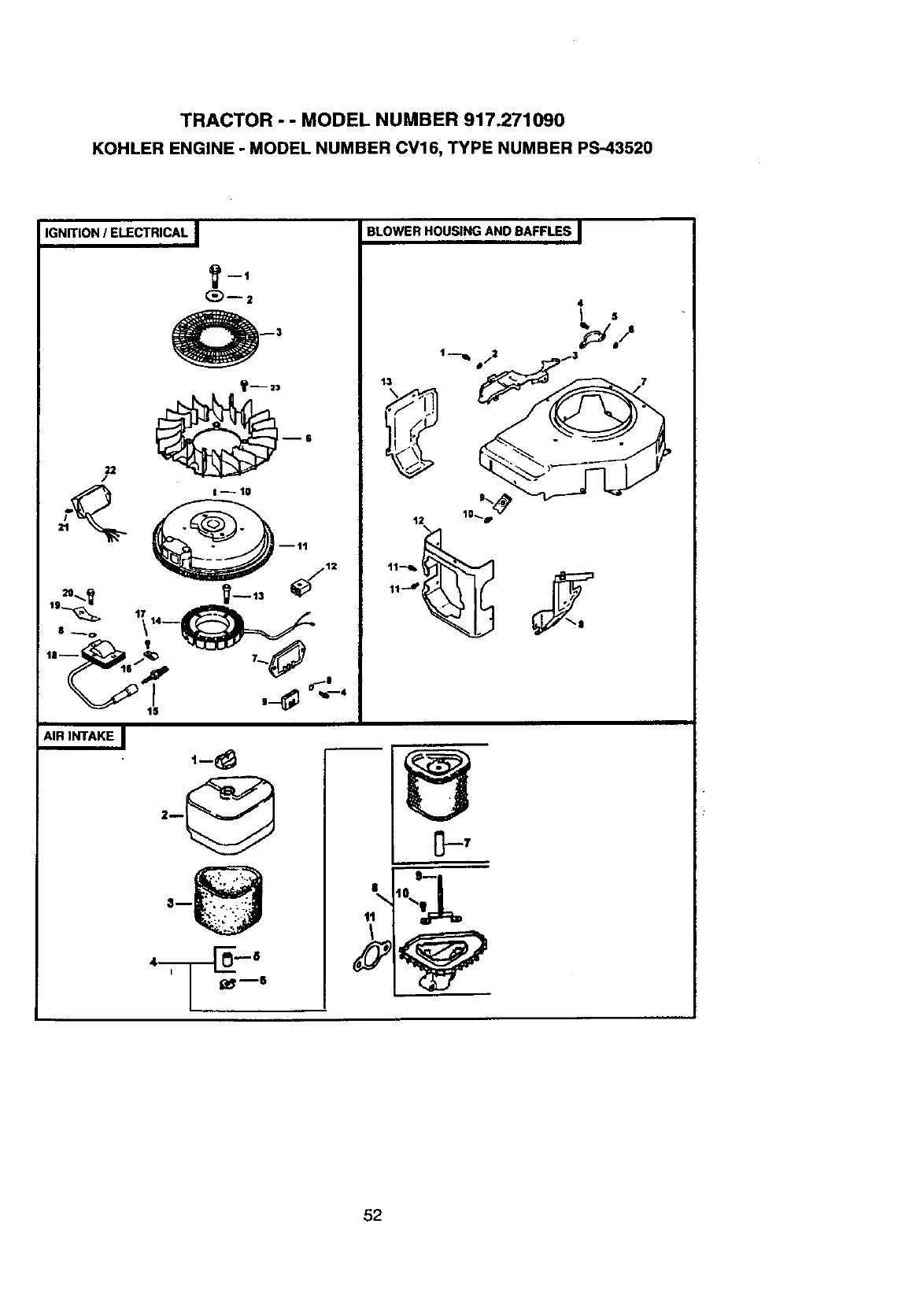
TRACTOR - - MODEL NUMBER 917.271090
KOHLER ENGINE - MODEL NUMBER CV16, TYPE NUMBER PS-43520
IGNITION /ELECTRICAL I
22
/
(_)--2
€-- 10
AIR INTAKE I t-8
BLOWER HOUSINGAND BAFFLES I
13
4
L. '
52
TRACTOR - - MODEL NU MBER 917.271090
KOHLER ENGINE -MODEL NUMBER CV16, TYPE NUMBER PS-43520
IGNITION/ELECTRICAL
KEY PART
NO. NO.
BLOWER HOUSING & BAFFLES
1 12-086-14
2 12-468-03
3 24-162-03
4 M-0639016
6 12-157-03
7 41-403-09
8 X-22-11
9 236602
10 X-42-15
11 12-025-35
12 41-155-02
13 M-0548025
14 12-085-01
15 12-132-02
16 X-728-1
17 M-0545010
18 12-584-08
19 12-452-02
20 12-086-35
21 M-0461013
22 12-584-12
23 25-086-47
NOT ILLUSTRATED
25-518-29
25-518-05
12-176-36
X-25-5
12-155-02
23-517-03
KEY PART
DESCRIPTION NO. NO. DESCRIPTION
Screw, hex. flange MIOx1.5x46 1 M-0545010
Washer, plain3/8
Screen, grass 2 24-468-10
Screw, hex.flange M6x1.0x16 3 12.146-07
(6) 4 24-086-18
Fan 524-086-05
Regulator,rectifier 6 220534
Washer, lock(2) 7 12-027-54
Connector 8 12-063-10
Key 9 25-154-02
Rywheel 10 12-086-37
Connector(4 contact)
Screw, hex.cap M5x0.8x25 (2) 11 M-0645016
Stator assembly-15 amp
Spark Plug 12 12-063-08
Clip, cable 13 12-063-09
Screw, hex. flange M5x0.8xl 0 NOT ILLUSTRATED
(2) X-25-92
Module, ignition
T_n'ninal
Screw,hex. socketM5x0.8x20 AIR INTAKE/FILTRATION
(2)
Screw, pan head M4.2xl 3 (2) KEY PART
Module, speed advance NO. NO.
Shoulder M6X1.0X16 (4)
Lead
Lead
Hamess
Washer,plain 5/16"
Connector
ClipCable
Screw, hex. flangeM5xO,8xl0
(8)
Washer,plain 1/4
-Plate, blowerhousing
Screw, phitliphd M4xO.7X8 (2)
• Cover,pinion
Washer,plain 5/16 (2)
Housing,blower
Baffle,intakeside
Clip, mounting(3)
Screw.captivewasherM5 X0.8
X20 (3)
Screw, hex. flange M6x1.0x16
(2)
Baffle, cylinderhead
Baffle,cylinder
WASHER, PLAIN 3/16" (2)
1 26-341-03
2 12-096-24
3 12-083-12
4 12-1083-10
5123O046
6 12-100-01
7 12-032-11
8 12-094-07
9 12-072-04
10 12-086-01
11 12-041-02
NOT ILLUSTRATED
12-113-53
DESCRIPTION
Knob, air cleanercover
Cover,air cleaner
Precleaner,element
Kit air cleanerelement
(Includes5,7)
Seal 3/4"
Wing Nut
Seal 1-7/16"
Base, aircleener(Includes
10,11)
Stud, mountingplate
M6X1.0X75
Screw, #10 HI-Lothread form-
ing(2)
Gasket, aircleaner
Decal, air cleaner
53
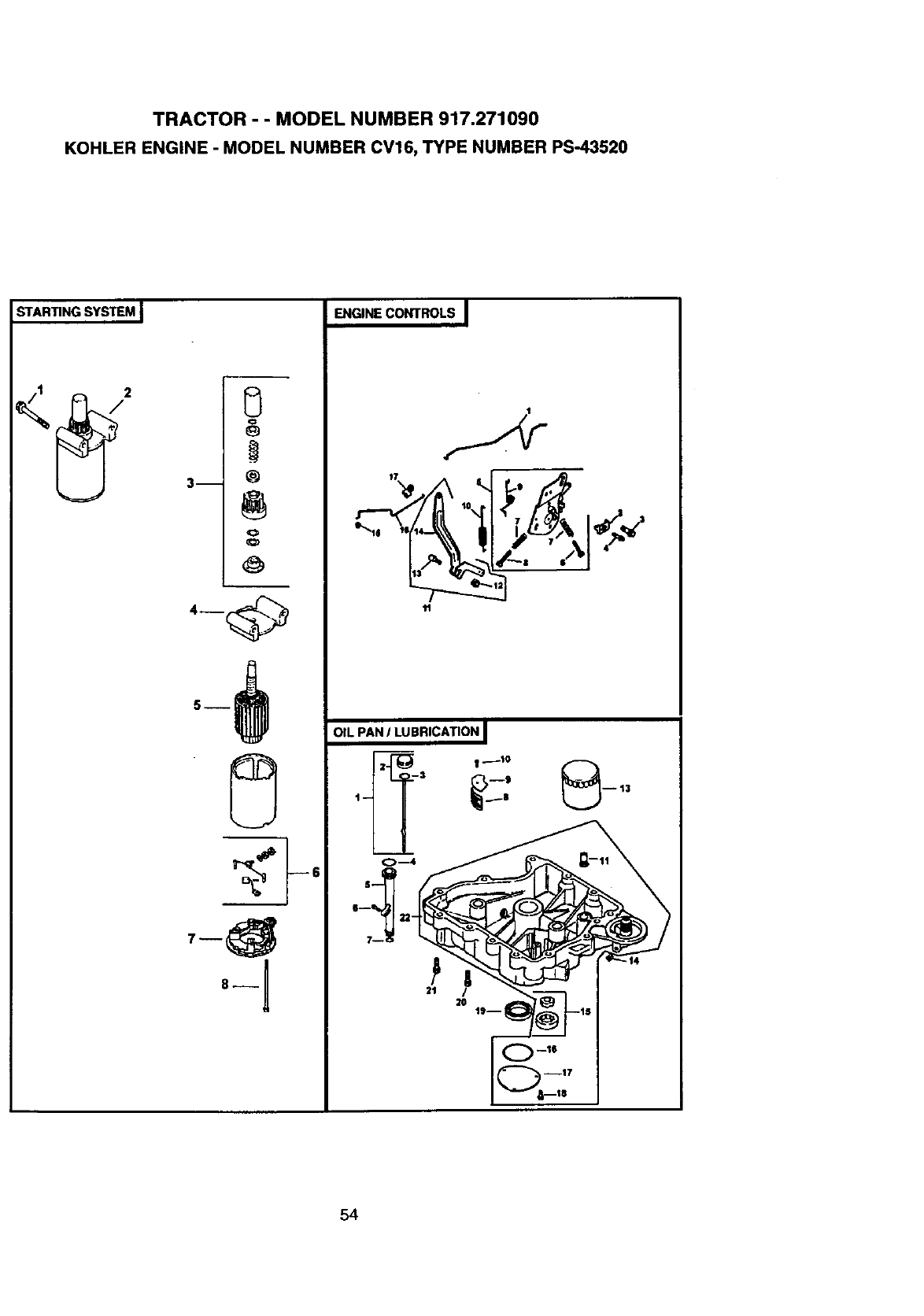
TRACTOR - - MODEL NUMBER 917.271090
KOHLER ENGINE -MODEL NUMBER CV16, TYPE NUMBER PS-43520
STARTING SYSTEM J
¢:
3m @
o
O
8--
ENGINE CONTROLS I
OIL PAN ILUBRICATION I
_ --13
t-- |
I--_ 22-
7__ I
111 _ 19
0_16
54
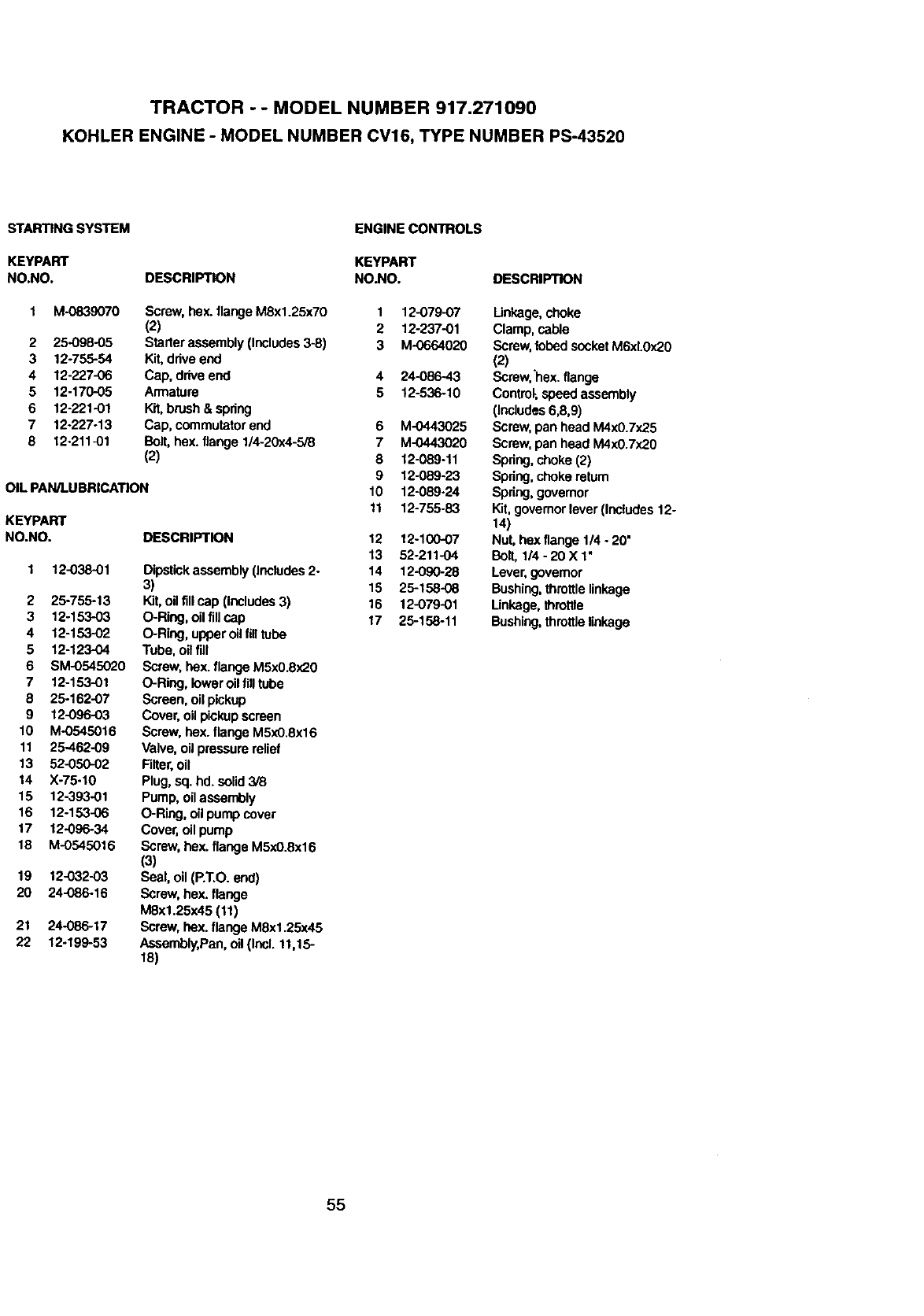
TRACTOR - - MODEL NUMBER 917.271090
KOHLER ENGINE -MODEL NUMBER CV16, TYPE NUMBER PS-43520
STARTING SYSTEM
KEYPART
NO.NO.
ENGINE CONTROLS
2
3
4
5
6
7
8
M-0839070
25.099-05
12-755-54
12-227-06
12-170-05
12-221-01
12_227-13
12-211-01
KEYPART
DESCRIPTION NO.NO. DESCRIPTION
OIL PAN/LUBRICATION
KEYPART
NO.NO.
Screw, hex. flange M8x1.25x70
(2)
Statler assembly (Includes3-8)
Kit, ddve end
Cap, drive end
Armature
Kit,brush & spdng
Cap, commutatorend
Bolt,hex. flange 1/4-20x4-5/8
(2)
1 12-038-01
2 25-755-13
3 12-153-03
4 12-153-02
5 12-123-O4
6 SM-0545020
7 12-153-01
8 25-162-07
9 12-096-O3
10 M-0545016
11 25-462-09
13 52-050-02
14 X-75-10
15 12-393-01
16 12-153-06
17 12-096-34
18 M-0545016
19 12-032-03
20 24-086-16
21 24-086-17
22 12-199-53
DESCRIPTION
Dipstickassembly (Includes2-
3)
Kit,oil fillcap (Includes3)
O-Ring, oil fill cap
O-Ring, upperoilfilltube
Tube, oil fill
Screw, hox. flange M5xO.8x20
O-Ring, loweroil filltube
Screen, oil pickup
Cover,oil pickupscreen
Screw, bex. flange M5xO.8x16
Valve,oil pressure relief
Rlter, oil
Plug,sq. hd. solid3/8
Pump, oilassembly
O-Ring, oil pump cover
Cover,oil pump
Screw, hex. flange M5xO.8x16
(3)
Seal, oil (P.T.O. end)
Screw,hex. flange
M8xl.25x45 (11)
Screw, hex. flange M8x1.25x45
Assembly,Pan, oil(Incl. 11,15-
18)
1 12-079-07 Linkage, choke
2 12-237-01 Clamp, cable
3 M-0664020 Screw, robedsocket M6xL0x20
(2)
4 24-086-43 Screw,'hex. flange
5 12-536-10 Control-,speed assembly
(Includes6,8,9)
6 M-0443025 Screw, pan head M4x0.7x25
7 M-0443020 Screw, pan head M4x0.7x20
8 12-089-11 Spdng,choke (2)
9 12-089-23 Spdng,chokereturn
10 12-089-24 Spdng, governor
11 12-755-83 Kit,governorlever (Includes 12-
14)
12 12-10007 Nut, hex flange 1/4 -20"
13 52-211-04 Bolt,1/4 -20 X 1"
14 12-090-28 Lever, governor
15 25-158-08 Bushing,throttlelinkage
16 12-079-01 Linkage,throttle
17 25-158-11 Bushing,throttlelinkage
55
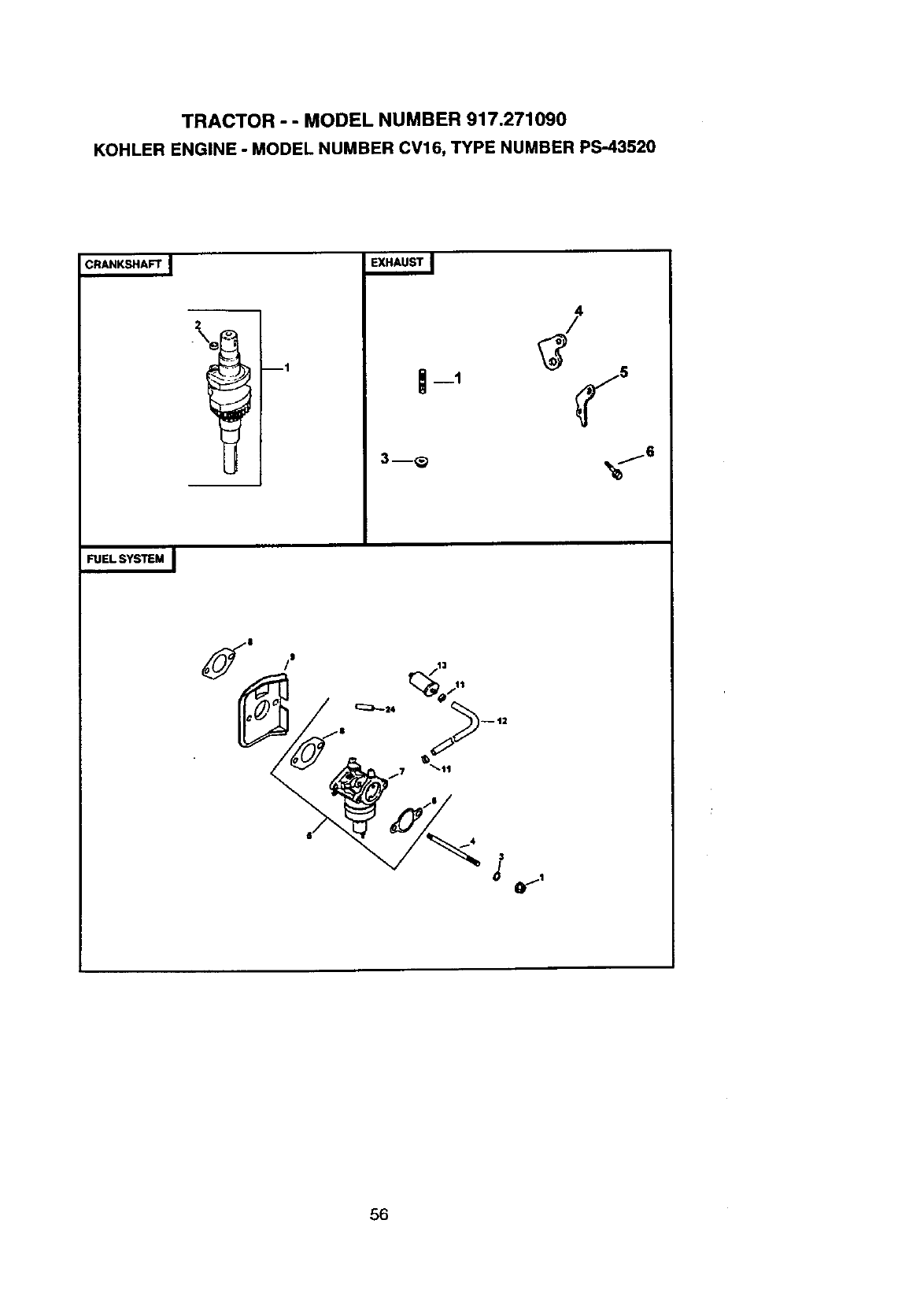
TRACTOR - - MODEL NUMBER 917.271090
KOHLER ENGINE -MODEL NUMBER CV16, TYPE NUMBER PS-43520
CRANKSHAFT I
11
3m_
FUEL SYSTEM I
"17 t,
56
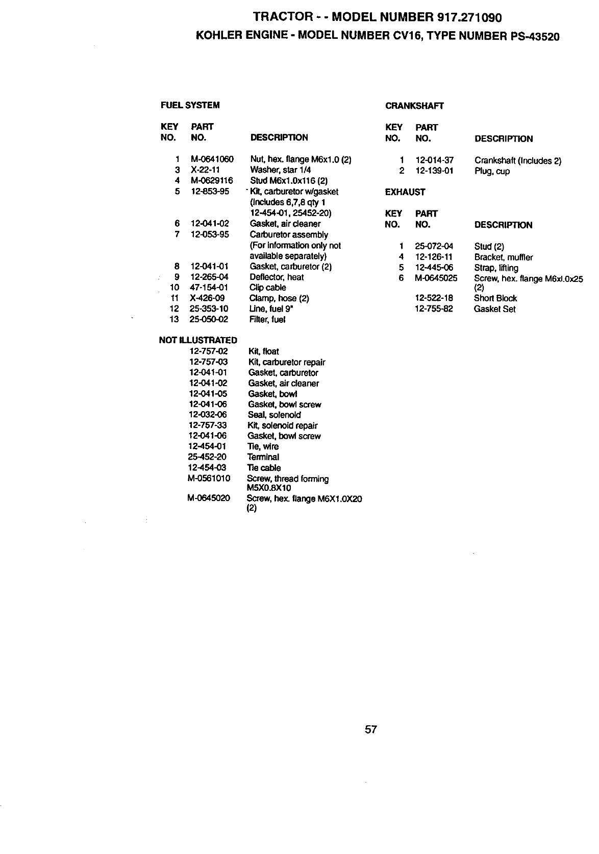
TRACTOR - - MODEL NUMBER 917.271090
KOHLER ENGINE -MODEL NUMBER CV16, TYPE NUMBER PS-43520
FUEL SYSTEM
KEY PART
NO. NO.
1 M-0641060
3 Xo22-11
4 M-0629116
5 12-853-95
612-041-02
7 12-053-95
8 12-041-01
9 12-265-04
10 47-154-01
11 X.426-09
12 25-353-10
13 25-050-02
NOT ILLUSTRATED
12-757-02
12-757-03
12-041-01
12-O41-02
12-041-05
12-041-06
12-032-06
12-757-33
12-041-06
12-454-01
25-452-20
12.454-03
M-0561010
M-06o45020
DESCRIPTION
Nut, he}(.flange M6xl.0 (2)
Washer,star 1/4
StudM6x1.0x116 (2)
"Kit,carburetorw/gasket
(Includes6,7,8 qty 1
12.454-01, 25452-20)
Gasket,air cleaner
Carburetorassembly
(For informationonlynot
availableseparately)
Gasket,carburetor(2)
Deflector,heat
Clipcable
Clamp, hose (2)
Une, fuel9"
Riter, fuel
Kit,float
Kit,carburetorrepair
Gasket, carburetor
Gasket, air cleaner
Gasket, howl
Gasket,bowl screw
Seal, solenoid
Kit,solenoidrepair
Gasket, howl screw
"Re,wire
Terminal
•Re cable
Screw,thread forming
M5XO.SXIO
Screw, hex. flange M6XI.0X20
(2)
CRANKSHAFT
KEY PART
NO. NO.
1 12-014-37
2 12-139-01
EXHAUST
KEY PART
NO. NO.
1 25-072-04
4 12-126-11
5 12.445-06
6 M-0645025
12-522-18
12-755-82
DESCRIPTION
Crankshaft (Includes2)
Plug, cup
DESCRIPTION
Stud(2)
Bracket, muffler
Strap, lifting
Screw, hex. flange M6xl.0x25
(2)
Short Block
Gasket Set
57

58

SUGGESTED GUIDE FOR SIGHTING SLOPES FOR SAFE OPERATION
SIGHTING
GUIDE
ONLY RIDE UP AND DOWN HILL,
NOT ACROSS HILL
ol
(.O
Ih Operate your Tractor up and down the face of slopes (not I
I
greater than 15 ), never across the face, Make turns gradu- I
ally to prevent tipping or loss of control. Exercise extreme
caution when changing direction on slopes.

For the repair or replacement parts you need
delivered directly to your home
Call 7 am - 7 pm, 7days a week
1-800-366-PART
(1-800-366-7278)
Para ordenar piezas con entrega a
domicilio - 1-800-659-7084
For in-house major brand repair service
Call 24 hours a day, 7 days a week
1-800-4-REPAIR
(1-800-473-7274) :
Para pedir servicio de reparaci6n a
domicilio - 1-800-676-5811
For the location of a Sears Parts and
Repair Center in your area
Call 24 hours a day, 7 days a week
1-800-488-1222
For information on purchasing a Sears
Maintenance Agreement or to inquire
about an existing Agreement
Call 9 am - 5 pm, Monday-Saturday
1-800-827-6655
When requesting service or ordering
parts, always provide the following
information:
• Product Type • Part Number
•Model Number •Part Description
SE /ARS
America's Repair Speciansts
168378 12.30.98 RD Printed in U.S.A.
