Craftsman 917271531 User Manual LAWN TRACTOR Manuals And Guides L0104094
CRAFTSMAN Lawn, Tractor Manual L0104094 CRAFTSMAN Lawn, Tractor Owner's Manual, CRAFTSMAN Lawn, Tractor installation guides
User Manual: Craftsman 917271531 917271531 CRAFTSMAN LAWN TRACTOR - Manuals and Guides View the owners manual for your CRAFTSMAN LAWN TRACTOR #917271531. Home:Lawn & Garden Parts:Craftsman Parts:Craftsman LAWN TRACTOR Manual
Open the PDF directly: View PDF ![]() .
.
Page Count: 56

Owner's Manual
ICRRFTSMRWI
14.5 HP
ELECTRIC START
42" MOWER
6 SPEED TRANSAXLE
LAWN TRACTOR
Model No.
917.271531
• Safety
• Assembly
•Operation
• Maintenance
•Repair Parts
CAUTION:
Read and follow all Safety
Rules and Instructions before
operating this equipment.
For answers to your questions
about this product, Call:
1-800-659-5917
Sears Craftsman Help Une
5 am *5 pro,Mon - Sat
Sears, Roebuck and Co., Hoffman Estates, II 60179
Visit our Craftsman website:www.sears.com/craftsman
t
Warranty ............................................... 2
Safety Rules ......................................... 3
Product Specifications .......................... 6
Assembly .............................................. 8
Operation ............................................ 11
Maintenance Schedule ...................... 17
Maintenance ....................................... 17
Service and Adjustments .................... 21
Storage ............................................... 27
Troubleshooting ................................. 28
Repair Parts ........................................ 32
Parts Ordedng ..................... Back Cover
LIMITED TWO YEAR WARRANTY ON CRAFTSMAN RIDING EQUIPMENT PARTS
For two (2) years from the date of purchase, if this Craftsman Riding Equipment is
maintained, lubricated and tuned up according to the instructionsin the owners
manual, Sears will repair or replace, free of charge, any parts found to be defective in
matadal or workmanship. Warranty service is available free of charge by returningyour
Craftsman riding equipment to your nearest Sears Service Center. In-home warranty
service is available but a trip charge will apply. This warranty applies only while this
productis in the United States.
This Warranty does not cover:
•Expendable items which become worn during normal use, such as blades, spark
plugs, air cleaners, belts and oil filters.
• Tire replacement or repair caused by punctures from outside objects, such as nails,
thorns, stumps, or glass.
•Repairs necessary because of operator abuse, including but not limited to, damage
caused by towing objects beyond the capability of the ddingequipment, impacting
objects that bend the frame or crankshaft, or over speeding the engine.
• Repairs necessary because of operator negligence, including but not limited to,
electrical and mechanical damage caused by improper storage, failure to use the
proper grade and amount of engine oil, failure to keep the deck clear of flammable
debds, or the failure to maintain the equipment according to the instructions con.
tained in the owner's manual.
• Engine (fuel system) cleaning or repairs caused by fuel determined to be contami-
nated or oxidized (stale). In general, fuel should be used within thirty (30) days of its
purchase date.
• Riding equipment used for commercial or rental purposes. A product is "used for
commercial purpose" if is used for any purpose other than single family household
dwellings or in usage where profit is made.
LIMITED 90 DAY WARRANTY ON BA]-FERY
For ninety (90) days from date of purchase, if any battery included with this riding
equipment proves defective in matedal or workmanship and our testing determines the
battery will not holdacharge, Sears will replace the battery at no charge. Warranty
service is available free of charge by returning your Craftsman dding equipment to
your nearest Sears Service Center. In-home warranty service is available but a trip
charge will apply.This warranty applies only while this product is in the United States.
TO LOCATE THE NEAREST SEARS SERVICE CENTER OR TO SCHEDULE IN-HOME
WARRANTY SERVICE, SIMPLY CONTACT SEARS AT 1-800-4-MY-HOME
This Warranty gives you specific legal rights, and you may also have other dghts which
may vary from state to state.
Sears, Roebuck and Co., D/817 WA, Hoffman Estates, IL 60179
IMPORTANT:This cutting machine is capable of amputating hands and feet and
throwingobjects. Failure to observe the following safety instructions could result in
senous injury or death.
I. GENERAL OPERATION
•Read, understand, and follow all
instructionsinthe manual and on the
machine before starting.
•Only allow responsibleadults, who are
familiar with the instructions,to operate
the machine.
•Clear the area of objects such as reeks,
toys, wire, etc., which couldbe picked
up and thrown by the blade.
•Be surethe area is dear of other people
before mowing. Stop machine if anyone
entersthe area.
•Never carry passengers.
• Do not maw in reverse unless absolutely
necessary. Always leek downand
behind before and while backing.
•Be aware of the mower discharge
directionand do not point it at anyone.
Do not operate the mower without either
the entiregrass catcher or the guard in
place.
• Slow down before tuming.
• Never leave a running machine
unattended. Always turn off blades, set
parking brake, stop engine, and remove
keys before dismounting.
•Tum off blades when not mowing.
•Stop engine before removing grass
catcher or uncloggingchute.
•Mow only in daylight or good artificial
light.
•Do not operate the machine while under
the influenceof alcoholor drugs.
•Watch for trafficwhen operating near or
crossing roadways.
•Use extra care when loadingor unload-
ing the machine into a trailer or truck.
•Data indicates that operators, age 60
years and above, are involved in alarge
pe.reantage of tiding mower-related
mjurles. These operatorsshould
evaluate their abilityto operate the riding
mower safely enough to protectthem-
salves and others fromsadoos injury.
•Keep machine free of grass, leaves or
other debris build-op which can touch
hot exhaust /engine parts and bum. Do
not allow the mower deck to plow leaves
or otherdebris which can cause build-
up to occur.Clean any ell or fuel
spitla_)ebefore operating or storing the
machine. Allow machine to cool before
storage. 3
n. SLOPE OPERATION
Slopes are a majer factor related to loss-of-
control and tipover accidents, which can re-
salt in severe injury or death. All slopes
require extra caution. Ifyou cannotbeck up
the slope or if you feel uneasy on it, do not
maw it.
DO:
•Mow up and down slopes, not across.
•Remove obstaclessuch as rocks,tree
limbs,etc.
Watch for holes, ruts,or bumps. Uneven
terraincould overture the machine. Tall
grass can hide obstacles.
Use slew speed. Cheese a low gear so
that you willnot have to stop or shift
while on the slope.
Follow the manufacturer's recommenda-
tions for wheel weightsor counter-
weightsto improvestability.
Use extra care with grass catchers or
other attachments. These can change
the stability of the machine.
Keep all movement on the slopes s/ow
and gradual. Do cot make sudden
changes in speed or direction.
Avoid startingor stopping on a slope. If
tires lose tracSon, disengage the blades
and proceed slowlystraight down the
slope.
DO NOT:
•Do not tum an slopes unless necessary,
and then, tum slowly and gradually
downhill, if possible.
•Do not mow near drep-offs, ditches, or
embankments, The mower could
suddenlyturn over if a wheel is over the
edge of a cliffor ditch, or it an edge
Caves in,
• Do not rnow on wet grass. Reduced
traction could cause sliding.
• Do not try to stabilizethe machine by
potting your foot on the ground.
•Do notuse grass catcher an steep
slopes.
IlLCHILDREN
Tragicaccidentscanoccuriftheoperator
isnotalerttothepresenceofchildren.
Childrenareoftenattractedtothe
machineandthemowingactivity.Never
assume that children will remain where
you last saw them.
•Keep children out of the mowing area
and under the watchful care of another
responsible adult.
•Be alert and turn machine off if children
enter the area.
•Before and when backing, look behind
and down for small children.
• Never carry children. They may fall off
and be seriously injured or interfere
with safe machine operation.
•Never allow children to operate the
machine.
•Use extra care when approaching blind
comers, shrubs,trees, or other objects
that may obscure vision.
IV. SERVICE
•Use extra care in handling gasoline
and other fuels. They are flammable
and vapors are explosive.
-Use only an approved container.
- Never remove gas cap or add fuel
with the engine running. Allow
engine to cool before refueling. Do
not smoke.
-Never refuel the machine indoors.
-Never store the machine or fuel
container inside where there is an
open flame, such as a water heater.
•Never run amachine inside a closed
area.
•Keep nuts and bolts, especially blade
attachment bolts, tight and keep
equipment in good condition.
•Never tamper with safety devices.
Check their proper operation regularly.
•Keep machine free of grass, leaves, or
other debris build-up. Clean oil or fuel
spillage. Allow machine to cool before
storing.
•Stop and inspectthe equipment if you
strike an object. Repair, ifnecessary,
before restarting.
•Never make adjustments or repairs
with the engine running.
•Grass catcher components are subject
to wear, damage, and deterioration,
which could expose moving parts or
allow objects to be thrown. Frequently
check components and replace with
manufacturer's recommended pads,
when necessary.
•Mower blades are sharp and can cut.
Wrap the blade(s) or wear gloves, and
use extra caution when servicing them,
•Check brake operation frequently.
Adjust and service as required.
•Be sure the area is clear of other
people before mowing. Stop machine if
anyone enters the area.
•Never carry passengers or children
even with the blades off.
•Do not mow in reverse unless abso-
lutely necessary. Always look down
and behind before and while backing.
•Never carry children. They may fall off
and be seriously injured or interfere
with safe machine operation.
•Keep children out of the mowing area
and under the watchful care of another
responsible adult.
•Be alert and turn machine off ifchildren
enter the area.
•Before and when backing, look behind
and down for small children.
•Mow up and down slopes (15° Max),
not across.
•Remove obstacles such as rocks, tree
limbs, etc.
•Watch for holes, ruts, orbumps.
Uneven terrain could overturn the
machine. Tall grass can hide obstacles.
• Usaslowspeed.Choosealowgearso
thatyouwillnothavetostoporshift
whileontheslope.
• Avoidstartingorstoppingonaslope.If
tireslosetraction,disengagethe
bladesandproce*_lslowlystraight
downtheslope.
•If machine stops while going uphill,
disengage blades, shift into reverse
and back down slowly.
• Do not turn on slopes unless neces.
sary, and then, tum slowly and gradu-
ally downhill, if possible.
_Look for this symbol to point out
importantsafety precautions. It means
CAUTIONlll BECOMEALERTIII YOUR
SAFETY IS INVOLVED.
_CAUTION: In order to prevent acci-
dental starting when setting up, transport-
ing, adjusting or making repairs, always
disconnect spark plug wire and place
wire where it cannot contact spark plug.
_IJCAUTION: Do not coast down a hill in
neutral,you may lose control of the
tractor.
_CAUTION: Tow only the attachments
that are recommendedby and comply
with specifications of the manufacturer of
your tractor. Use common sense when
towing. Operate only at the lowest
possible speed when on a slope. Too
heavy of a load, while on aslope, is
dangerous. Tires can lose traction with
the ground and cause you to lose control
of your tractor.
_WARNING: Engine exhaust_some of
its constituents,al_clcertain venicle
components contain or emit chemicals
known to the State of California to cause
cancer and birthdefects or other repro-
ductive harm.
_WARNING: Battery posts, terminals
and related accessones contain lead and
lead compounds, chemicals known to the
State of California to cause cancer and
birthdefects or other reproductive harm.
Wash hands after handling.
5
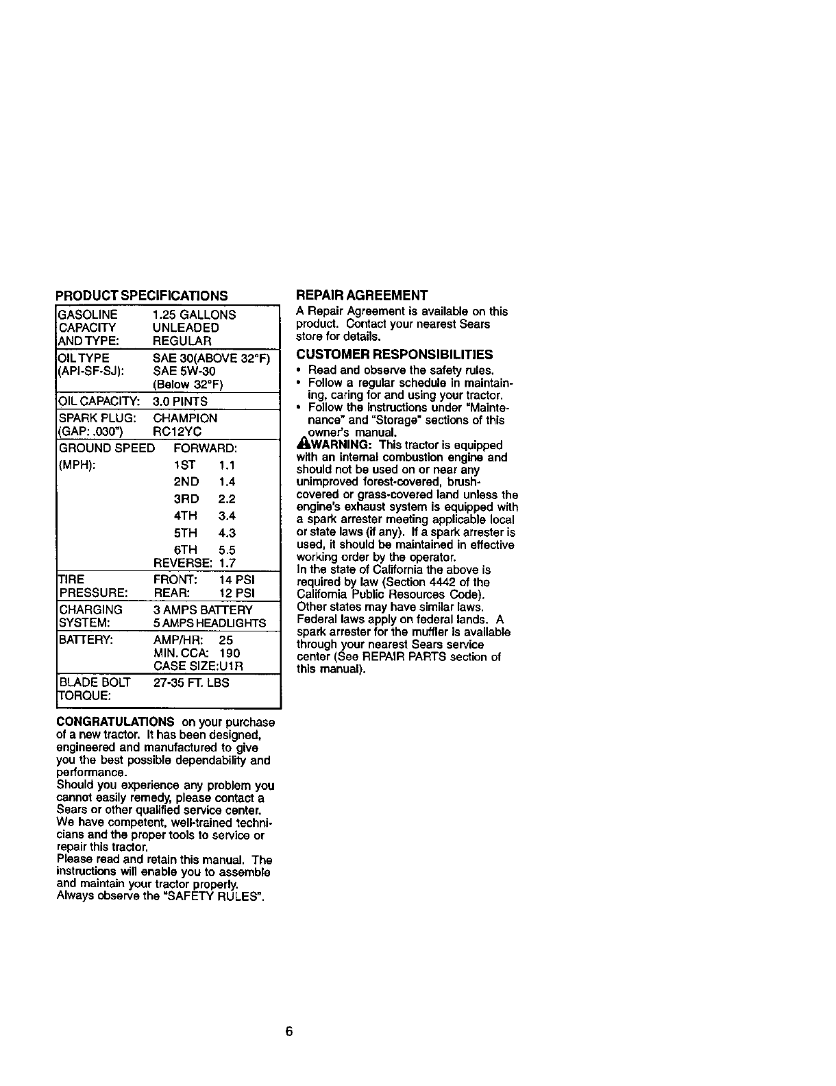
PRODUCT SPECIFICATIONS
3ASOLINE 1.25 GALLONS
CAPACITY UNLEADED
_NDTYPE: REGULAR
)ILTYPE SAE 30(ABOVE 32_F)
API-SF-SJ): SAE 5W-30
(Below 32°F)
3.0 PINTS
CHAMPION
RC12YC
FORWARD:
1ST 1.1
2ND 1.4
3RD 2.2
4TH 3.4
5TH 4.3
6TH 5.5
REVERSE: 1.7
nRE FRONT: 14 PSI
PRESSURE: REAR: 12 PSI
CHARGING 3 AMPS BATTERY
SYSTEM: 5 AMPB HEADLIGHTS
BATTERY: AMP/HR: 25
MIN. CCA: 190
CASE SIZE:Ut R
BLADE BOLT 27-35 FT. LBS
TORQUE:
OIL CAPACITY:
SPARK PLUG:
GAP: .030")
GROUND SPEED
(MPH):
CONGRATULATIONS on your purchase
of a new tractor. It has been designed,
engineered and manufactured to give
you the best possible depm,,dability and
performance.
Should you experience any problem you
cannot easily remedy, p_eaaecontact a
Sears or other qualified service center,
We have competent, well-trained techni-
cians and the proper tools 1o service or
repair this tractor.
Please read and retain this manual. The
instructionswill enable you to assemble
and maintain your tractor properly.
Always observe the "SAFETY RULES".
REPAIR AGREEMENT
A Repair Agreement is available on this
product, Contact your nearest Sears
store for details.
CUSTOMER RESPONSIBILITIES
•Read and observe the safety roles.
• Follow a regular schedule in maintain-
ing, caring for and using your tractor.
•Follow the instructions under "Ma|nte-
nance" and "Storage" sections of this
owner's manual.
_kWARNING: This tractor is equipped
with an internal combustion engine and
should not be used on or near any
unimproved forest-covered, brush°
covered or grass.covered land unless the
engine's exhaust system is equipped with
aspark arrestor meeting applicable local
or state laws (if any). If a spark arrestor is
used, it should be maintained in effective
working order by the operator.
In the state of California the above is
required by law (Section 4442 of the
California Public Resoumes Code).
Other states may have similar laws.
Federal laws apply on federal lands. A
spark arrester for the muffler is available
through your nearest Sears service
center (See REPAIR PARTS section of
this manual).
6
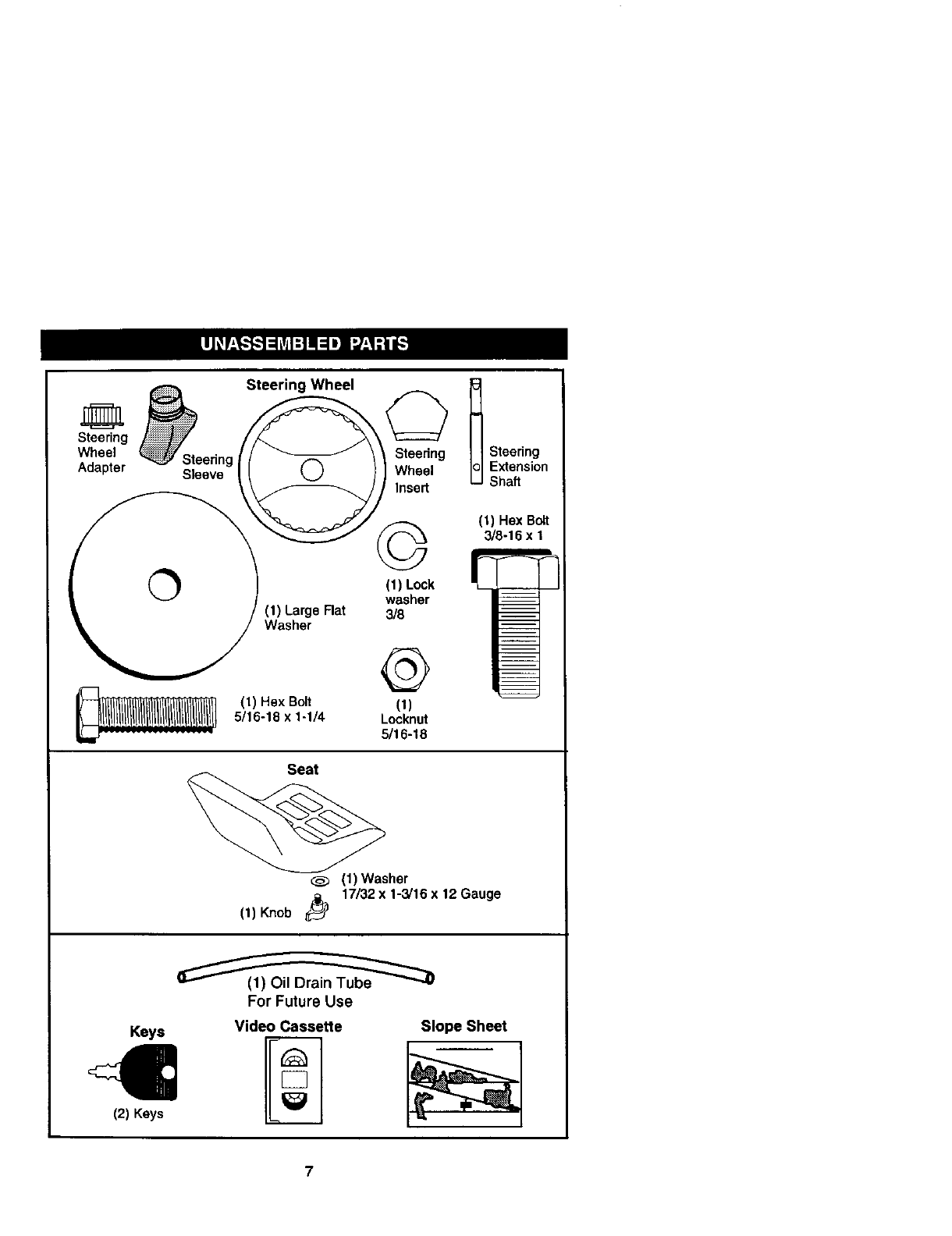
Steering Wheel _.
Wheel _ Steerin /_ \ \ Steering Steering
Adapter _ _eeevegl (Q )] Wheel Extension
\/ I Insert Shaft
3/8-16 x 1
1& /(1) Large Rat 318
_Washer
(1) Hex Belt (1)
5/16-18 x 1-1/4 Locknut
5/16-18
Seat
11) Washer
17/32 x 1-3/16 x 12 Gauge
(1)Knob
For Future Use
Keys
€(2) Keys
Video Cassette Slope Sheet
7
Your new tractor has been assembled at the factory with exception of those parts left
unassembled for shipping purposes. To ensure safe and proper operation of your
tractor all parts and hardware you assemble must be tightened securely. Use the
correct tools as necessary to insure proper tightness. Review the video cassette before
you begin.
TOOLS REQUIRED FOR
ASSEMBLY
A socket wrench set will make assembly
easier. Standard wrench sizes you need
are listed below.
(1) 9/16"wranch (1) Pliers
(1) 1/2"wrench (1) Utilityknife
(1) Tire pressure gauge
When right or left hand is mentioned in
this manual, it means, from your point of
view, when you are in the operating
position (seated behind the steering
wheel).
TO REMOVETRACTOR FROM
CARTON
UNPACK CARTON
1. Remove all accessible loose parts
and parts cartons from carton.
2. Cut, from top to bottom, along lines
on all four comers of carton, and lay
panels fiat.
3. Check for any additional loose parts
or cartons and remove.
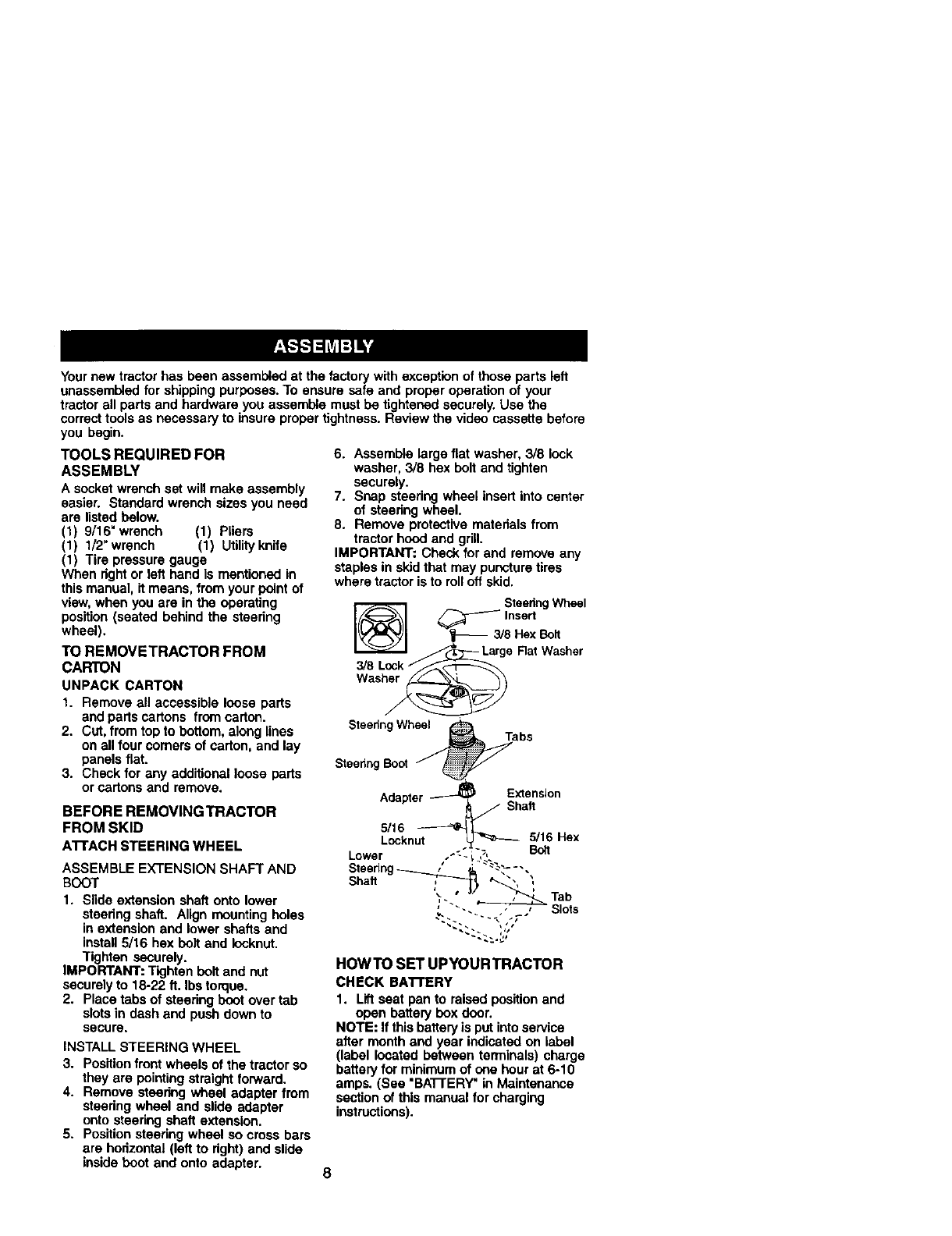
BEFORE REMOVING TRACTOR
FROM SKID
ATTACHSTEERINGWHEEL
ASSEMBLE EXTENSION SHAFT AND
BOOT
1. Slide extension shaft onto lower
steedng shaft. Align mounting holes
in extension and lower shafts and
install 5/16 hex bolt and Iocknut.
Tighten securely.
IMPORTANT: Tighten bolt and nut
securely to 18-22 ft. Ibs torque.
2. Place tabs of steering boot over tab
slots in dash and push down to
secure,
INSTALL STEERING WHEEL
3. Position front wheels of the tractor so
they are pointing straight forward.
4. Remove steering wheel adapter from
steedng wheel and slide adapter
onto steering shaft extension.
5. Position steering wheel so cross bars
are horizontal (left to right) and slide
inside boot and onto adapter.
6. Assemble large fiat washer, 3/8 lock
washer, 3/8 hex bolt and tighten
securely.
7. Snap steering wheel insert into center
of steering wheel.
8. Remove protective materials from
tractor hood and grill.
IMPORTANT: Check for and remove any
staples in skid that may puncture tires
where tractor is to roll off skid.
SteedngWheel
_Insert
3/8 Hex Bolt
LargeRat Washer
3/8
Wash_
S1eedngWhee_Ta bs
SteeringBoot f
Adapter _E_teflnsion
LS/loc6nu_ 5/1Boat6Hex
Shaft ,'_._ t._, ;
_. , Tab
'"'- _ Slots
HOWTO SET UPYOURTRACTOR
CHECK BAI-rERY
1. Lift seat pan to raised positionand
open battery box door.
NOTE: If this battery is put into service
after month and year indicated on label
(label located between terminals) charge
battery for minimum of one hour at 6-10
amps. (See "BA'I-rERY" in Maintenance
section of this manual for charging
instructions).
8
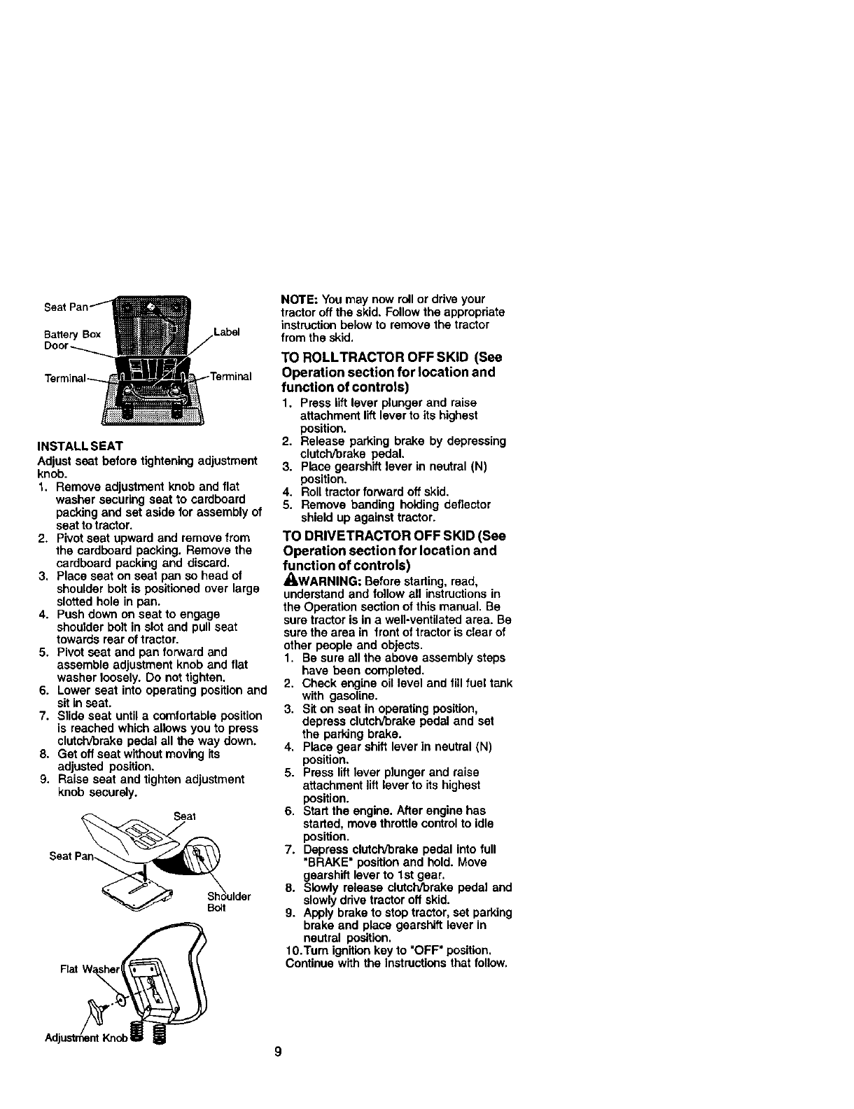
Battery Box Label
INSTALL SEAT
Adjust seat before tightening adjustment
knob.
1. Remove adjustment knob and flat
washer securing seat to cardboard
packing and set aside for assembly of
seat to tractor.
2. Pivot seat upward and remove from
the cardboard packing. Remove the
cardboard packing and discard,
3, Place seat on seat pan so head of
shoulder bolt is positioned over large
slotted hole in pan.
4. Push down on seat to engage
shoulder bolt in slot and pull seat
towards rear of tractor.
5. Pivot seat and pan forward and
assemble adjustment knob and flat
washer loosely. Do not tighten.
6. Lower seat into operating position and
sit in seat.
7. Slide seat until a comfortable position
is reached which allows you to press
clutch/brake pedal all the way down.
8. Get off seat without moving its
adjusted position.
9. Raise seat and tighten adjustment
knob securely.
Shkoulder
B_t
NOTE: Youmay now roll or drive your
tractor off the skid. Follow the appropriate
instruction below to remove the tractor
from the skid.
TO ROLLTRACTOR OFF SKiD (See
Operation section for location and
function of controls)
1. Press llft lever plunger and raise
attachment lift lever to its highest
position.
2. Release parking brake by depressing
clutch[orake pedal.
3. Place gearshift lever in neutral (N)
position.
4. Roll tractor forward oft skid.
5. Remove banding holding deflector
shield up against tractor.
TO DRIVETRACTOR OFF SKID (See
Operation section for location and
function of controls)
_WARNiNG: Before starting, read,
understand and follow all instructionsin
the Operation section of this manual. Be
sure tractor is in a well-ventilated area. Be
sure the area in front of tractor is clear of
other people and objects.
1. Be sure all the above assembly steps
have been completed.
2. Check engine oil level and fill fuel tank
with gasoline.
3. Sit on seat in operating position,
depress clatch/brake pedal and set
the parking brake.
4. Place gear shift lever in neutral (N)
position.
5. Press lift lever plunger and raise
attachment lift lever to its highest
position.
6. Start the engine. After engine has
started, move throttle control to idle
position.
7. Depress clutch/brake pedal into full
"BRAKE" position and hold. Move
gearshifl lever to 1st gear.
8. Slowly release clutch/brake pedal and
slowly drive tractor oft skid.
9. Apply brake to stoptractor, set parking
brake and place gearshift lever in
neutral position.
10.Turn ignition key to "OFF" position.
Continue with the instructionsthat follow.

CHECKTIRE PRESSURE
The tires on your tractor were ovednflated
at the factory for shipping purposes.
Correct tire pressure is important for best
cutting performance.
• Reduce tire pressure to PSI shown in
"PRODUCT SPECIFICATIONS" section
of this manual.
CHECK DECK LEVELNESS
For best cutting results, mower housing
should be propedy leveled. See "TO
LEVEL MOWER HOUSING" inthe
Service and Adjustments section of this
manual.
CHECK FOR PROPER POSITION OF
ALL BELTS
See the figures that are shown for
replacing motion and mower blade drive
belts in the Service and Adjustments
sectionof this manual. Verify that the
belts are routed correct/y.
CHECK BRAKE SYSTEM
After you learn how to operate your
tractor, check to see that the brake is
properlyadjusted. See "TO ADJUST
BRAKE" in the Service and Adjustments
section of this manual.
V"CHECKLIST
Before you operate and enjoy your new
tractor, we wish to assure that you receive
the best performance and satisfaction
from this Quality Product.
Please review the following checklist:
v'AII assembly instructionshave been
completed.
,f No remaining loose parts in carton.
v"Battery is propedy prepared and
charged. (Minimum 1 hour at 6 amps).
v"Seat Lsadjusted comfortably and
tightened securely.
v, AII tires are propedy inflated. (For
shipping purposes, the tires were
overinflated at the factory).
,,/Be sure mower deck is properly leveled
side-to-side/front-to.rear for best cutting
results. (Tires must be properly inflated
for levering).
v"Check mower and ddve belts. Be sure
they are routed properly around pulleys
and inside all belt keepers.
v_Check wiring. See that all connections
are stiUsecure and wires are properly
clamped.
While learning how to use your tractor,
pay extra attention to the following
=mportant items:
,(Engine oil is at proper level.
V"Fuel tank is filled with fresh, clean,
regular unleaded gasoline.
v"Become familiar with all controls - their
location and function. Operate them
before you start the engine.
,/'Be sure brake system is in safe
operating condition.
10
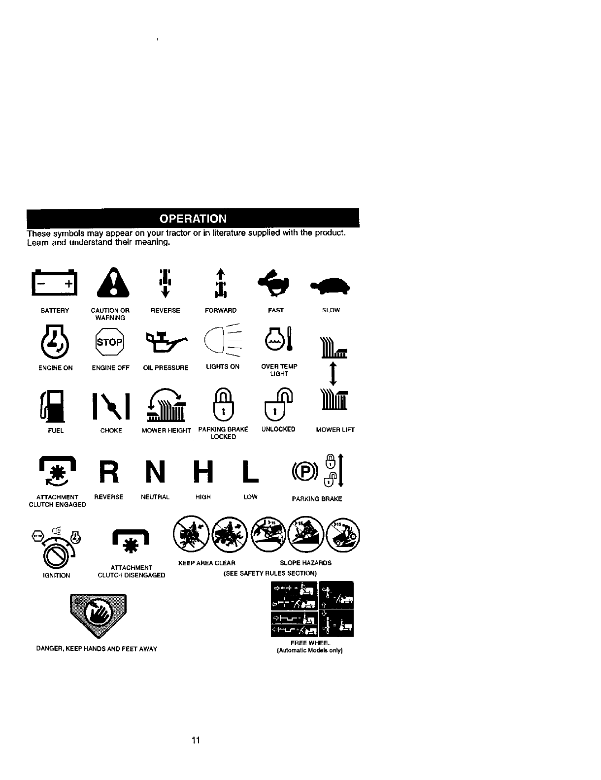
These symbols may appear on your tractor or in literature suppliedwith the product.
Learn and understand their meaning.
BATFERY CAUTION OR REVERSE FORWARD FAST SLOW
WARNING
ENGINE ON ENGINE OFF OIL PRESSURE LIGHTS ON OVER TEMP
LIGHT
FUEL CHOKE MOWER HEIGHT PARKING BRAKE UNLOCKED
LOCKED
!
MOWER LIFT
r_'t R N H L
ATTACHMENT REVERSE NEUTRAL HIGH LOW
CLUTCH ENGAGED
®3I
PARKING BRAKE
(_ _KEEP AREA CLEAR SLOPE HAZARDS
ATTACHMENT
IGN R'ION CLUTCH DISENGAGED
DANGER, KEEP HANDS AND FEET AWAY
(SEE SAFETY RULES SECTION)
I=-.
FREE WHEEL
(Automatic Models only)
11
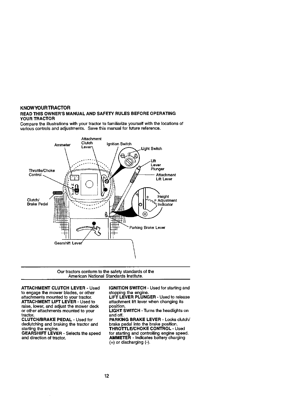
KNOWYOURTRACTOR
READ THIS OWNER'S MANUAL AND SAFETY RULES BEFORE OPERATING
YOUR TRACTOR
Compare the illustrationswith your tractor to familiarize yourself with the locations of
various controls and adjustments. Save this manual for future reference.
Attachment
Ammeter Clutch Ignition Switch ;witch
Lever
Throttle/Choke Plunger
L_ Lever
Height
Clutch/ _Adjustment
Brake Pedal Indicator
Brake Lever
Gearsh_ \
Our tractors conform to the safety standards of the
American National Standards Institute.
A'n'ACHMENT CLUTCH LEVER -Used
to engage the mower blades, or other
attachments mounted to your tractor,
A'I-FACHMENT LIFT LEVER -Used to
raise, lower, and adjust the mower deck
or other attachments mounted to your
tractor.
CLUTCWBRAKE PEDAL - Used for
declutchingand braking the tractor and
starting the engine.
GEARSHIFT LEVER - Selects the speed
and directionof tractor.
IGNITION SWITCH - Used for starting and
stopping the engine,
LIFT LEVER PLUNGER -Used to release
attachment lift lever when changing its
position.
LIGHT SWITCH -Turns the headlights on
and off.
PARKING BRAKE LEVER -Locksclutch/
brake pedal into the brake position.
THROTn.E/CHOKE CONTROL -Used
for starting and controllingengine speed.
AMMETER -Indicates battery charging
(+) or discharging (-),
12
The operation of any tractor can result in foreign objects thrown into the
eyes, which can result in severe eye damage. Always wear safety
glasses or eye shields while operating your tractor or performing any
adjustments or repairs. We recommend a wide visionsafety mask over
spectacles or standard safety glasses.
HOWTO USEYOURTRACTOR
TO SET PARKING BRAKE
Yourtractor is equipped with an operator
presence sensing switch. When engine
is running,any attempt by the operator to
leave the seat without first setting the
parking brake will shut offthe engine.
1. Depress clutch/brake pedal into full
=BRAKE" position and hold.
2. Place parking brake lever in =EN-
GAGED" position and release
pressure from clutch/brake pedal.
Pedal should remain in =BRAKE"
position. Make sure parking brake will
hold tractor secure.
Attachment Clutch Lever
Throttle/Choke Position
Ignition Key
Clutch/
Brake
Psdal
Brake
=Engaged"
Position
Gearshift
Lever
=Brake"
Position "Disengaged' _
Position
STOPPING
MOWER BLADES -
•TO stop mower blades,move attach-
ment clutch lever to =DISENGAGED"
position.
GROUND DRIVE -
•To stop ground drive, depress clutch/
brake pedal into full =BRAKE" position.
•Move gearshift lever to neutral (N)
position.
ENGINE -
•Move throttle control to slow position.
NOTE: Failure to move throttle controlto
slow position and allowing engine to idle
before stopping may cause engine to
"backfire".
• Tum ignitionkey to =OFF" position and
remove key. Always remove key when
leaving tractor to prevent unauthorized
use.
•Never use choke to stop engine.
IMPORTANT: Leaving the ignition switch
in any position other than "OFF" will
cause the battery to be discharged,
(dead).
NOTE: Under certain conditionswhen
tractor is standing idle with the engine
running, hot engine exhaust gases may
cause =browning" of grass. To eliminate
this possibility, always stop engine when
stopping tractor on grass areas.
_,CA.UTION: A,Iways stop tractor,
completmy, as aescribed above, Defore
leaving the operator's position; to empty
grass catcher, ere.
TO USE TH RoI-rLE CONTROL
Always operate engine at full throttle.
•Operating engine at loss than full
throttle reduces the battery charging
rate.
•Full throttle offers the best bagging and
mower performance.
TO MOVE FORWARD AND BACK-
WARD
The direction and speed of movement is
controlled by the gearshift lever.
1. Start tractor with clutch/brake pedal
depressed and gearshift lever in
neutral (N) position.
2. Move gearshift lever to desired
position.
3. Slowly release clutch/brake pedal to
start movement.
IMPORTANT: Bring tractor to a complete
stop before shifting or changing gears.
Failure to do so will shorten the useful life
of your transaxle.
TO ADJUST MOWER CUTTING HEIGHT
The position of the attachment lift lever
determines the cutting height.
•Grasp lift lever.
•Press plunger with thumb and move
lever to desired position.
13

The cutting height range is approxi-
mately 1-1/2 to 4". The heights are
measured from the ground to the blade
tip with the engine not running. These
heights are approximate and may vary
depending upon soil conditions, height of
grass and types of grass being mowed.
• The average lawn should be cut to
approximately 2-1/2 inches dudng the
cool season and to over 3inches
dudng hot months. For healthier and
better looking lawns, mow often and
after moderate growth.
• For best cutting performance, grass
over 6inches in height should be
mowed twice. Make the first cut
relatively high; the second to desired
height.
TO OPERATE MOWER
Your tractor is equipped with an operator
presence sensing switch. Any attempt by
the operator to leave the seat with the
engine running and the attachment clutch
engaged will shut off the engine.
1. Select desired height of cut.
2. Start mower blades by engaging
attachment clutch control.
To stop mower blades -
disengage attachment clutch control.
_CAUTION: Do not operate the mower
without either the entire grass catcher, on
mowers so equipped, or the deflector
shield in place. AttachmentClutchLever
Lift Lever
High Position
Position
Shield
TO OPERATE ON HILLS
_I, CAUTION: Do not drive up or down
hills with slopes greater than 15° and do
not drive across any slope.
•Choose the slowest speed before
starting up or down hills.
•Avoid stopping or changing speed on
hills.
•If slowing is necessary, move throttle
controllever to slower position.
•If stopping is absolutely necessary,
push clutsh/brake pedal quickly to
brake positionand engage parking
brake.
•Move gearshift lever to 1st gear. Be
sure you have allowed room for tractor
to roll slightlyas you restart movement.
•To restart movement, slowly release
parking brake and clutch/brake pedal.
•Make all turns slowly.
TO TRANSPORT
•Raise attachment liftto highest position
with attachment liftcontrol.
•When pushing or towing your tractor,
be sure gearshift lever is in neutral (N)
position.
• Do not push or tow tractor at more than
five (5) MPH.
NOTE: To protect hood from damage
when transportingyour tractor on a truck
or a trailer, be sure hood is closed and
secured to tractor. Use an appropriate
means of tying hood to tractor (rope, cord,
etc.).
TOWING CARTS AND OTHER ATTACH-
MENTS
Tow only the attachments that are
recommended by and comply with
specificationsof the manufacturer of your
tractor. Use common sense when towing.
Too heavy of a load, while on a slope, is
dangerous. Tires can lose traction with
the ground and cause you to lose control
of your tractor.
BEFORE STARTINGTHE ENGINE
CHECK ENGINE OIL LEVEL
The engine in your tractor has been
shipped, from the factory, already tilled
with summer weight oil.
1. Check engine oil with tractor on level
ground.
2. Remove oil fill cap/dipstick and wipe
clean, reinserf the dipstick and screw
cap tight, wait for a few seconds,
remove and read oil level. If neces-
sery, add oil until "FULL"mark on
dipstick is reached. Do not overfill.
•For cold weather operationyou should
change oil for easier starting(See "OIL
VISCOSffY CHART" in the Mainte-
nance section of this manual).
• To change engine oil, see the Mainte-
nance section in this manual.
14
ADD GASOLINE
•Fill fuel tank. Use fresh, clean, regular
unleaded gasoline with a minimum of
87 octane. (Use of leaded gasoline
will increase carbon and lead oxide
deposits and reduce valve life). Do not
mix oil with gasoline. Purchase fuel in
quantities that can be used within 30
days to assure fuel freshness.
IMPORTANT: When operating in
temperatures below 32°F(0°C), use fresh,
clean winter grade gasoline to help
insure good cold weather starting.
_kWARNING: Experience indicates that
alcohol blended fuels (called gasohol or
using ethanol or methanol) can attract
moisture which leads to separation and
formation of acids during storage. Acidic
gas can damage the fuel system of an
engine while in storage. To avoid engine
problems, the fuel system should be
emptied before storage of 30 days or
longer. Drain the gas tank, start the
engine and let it run until the fuel lines
and carburetor are empty. Use fresh fuel
next season. See Storage Instructions for
additional information. Never use engine
or carburetor cleaner products in the fuel
tank or permanent damage may occur.
_CAUTION: Fill to bottom of gas tank
filler neck. Do not overfill. Wipe off any
spilled oil or fuel. Do not store, spill or
use gasoline near an open flame.
TO START ENGINE
When starting the engine for the first time
or if the engine has run out of fuel, it will
take extra cranking time to move fuel from
the tank to the engine.
1. Sit on seat in operating position,
depress clutchrbrake pedal and set
parking brake.
2. Place gear shift lever in neutral (N)
position.
3. Move attachment clutchto =DISEN-
GAGED" position.
4. Move throttle controlto choke position.
NOTE: Before starting, read the warm
and cold starting procedures below.
5. Insert key into ignitionand turn key
clockwise to "START" position and
release key as soon as engine starts.
Do not run starter continuously for
more than fifteen seconds per minute.
If the engine does not start after
several attempts, move throttle control
to fast position, waif afew minutes and
try again. If engine still does not start,
move the throttle control back to the
choke position and retry.
WARM WEATHER STARTING (50° F and
above)
6. When engine starts, move the throttle
control to the fast position.
•The attachments and ground drive can
now be used. If the engine does not
accept the load, restart the engine and
allow if to warm up for one minute
using the choke as described above.
COLD WEATHER STARTING ( 50° F and
below)
6. When engine starts, allow engine to
run with Me throttle control in the
choke position until the engine runs
roughly, then move throttle control to
fast position. This may require an
engine warm-up period from several
seconds to several minutes, depend-
ing on the temperature.
•The attachments can also be used
during the engine warm.up period.
NOTE: If at a high altitude (above 3000
feet) or in cold temperatures (below 32 F)
the carburetor fuel mixture may need to
be adjusted for best engine performance.
See "TO ADJUST CARBURETOR" in the
Service and Adjustments section of this
manual.
15
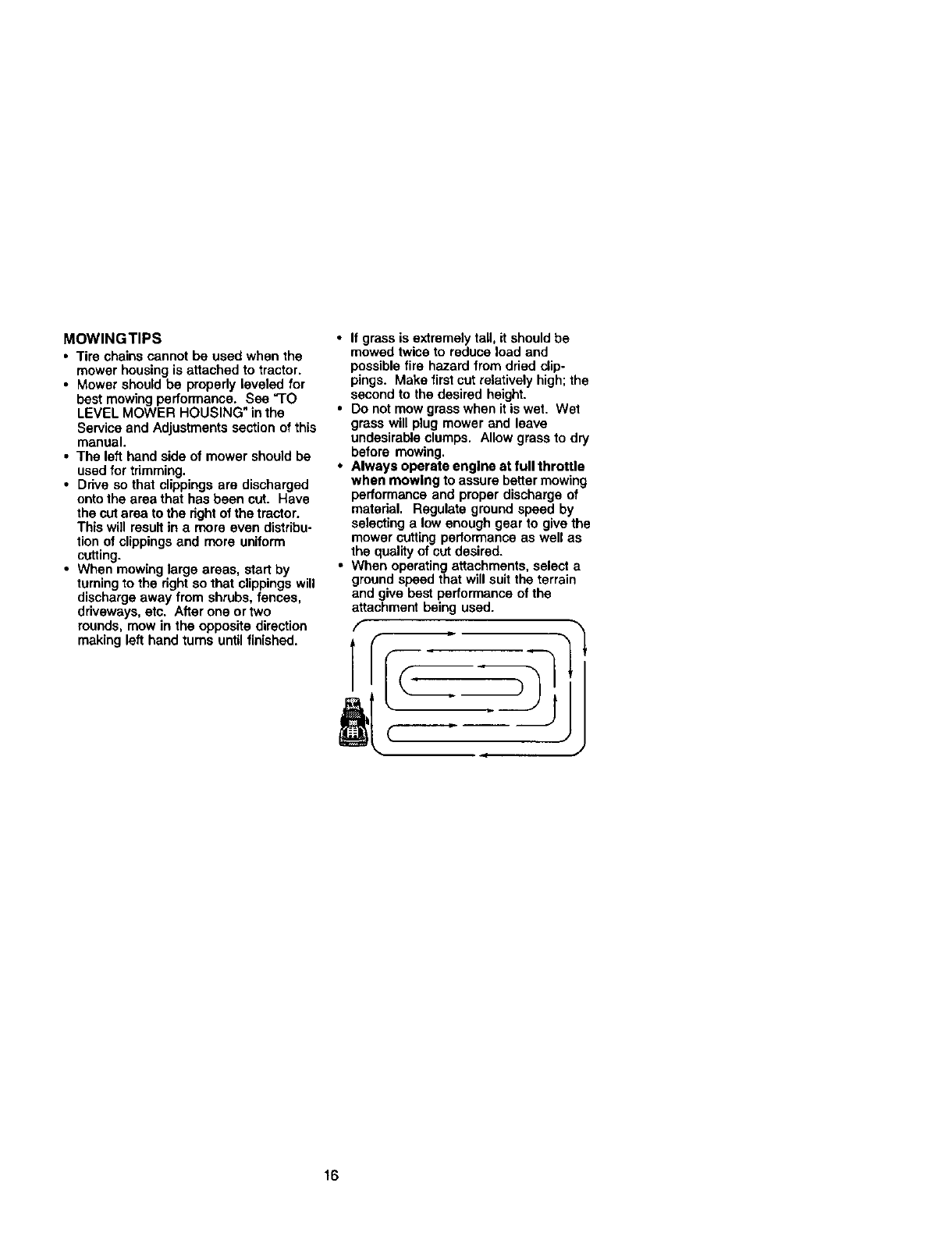
MOWlNGTIPS
. Tire chains cannot be used when the
mower housing is attached to tractor.
• Mower should be propedy leveled for
best mowing performance. See =TO
LEVEL MOWER HOUSING" in the
Service and Adjustments section of this
manual.
• The left hand side of mower should be
used for trimming.
• Ddve so that clippings are discharged
onto the area that has been cut. Have
the cut area to the dght of the tractor.
This will resutt in a more even distribu-
tion of clippings and more uniform
cutting.
•When mowing large areas, start by
turning to the right so that clippings will
discharge away from shrubs, fences,
driveways, etc. After one or two
rounds, mow in the opposite direction
making left hand turns until finished.
• If grass is extremely tall, it should be
mowed twice to reduce load and
possible fire hazard from dried dip-
pings. Make first cut relatively high; the
second to the desired height.
• Do not mow grass when it is wet. Wet
grass will plug mower and leave
undesirable clumps. Allow grass to dry
before mowing.
• Always operate engine at full throttle
when mowing to assure better mowing
performance and proper discharge of
matedal. Regulate ground speed by
selecting a low enough gear to give the
mower cutting performance as well as
the quality of cut desired.
•When operating attachments, select a
grc_nd speed that will suit t_ terrain
and give best performance of the
attachment being used.
f- I
16
FILL IN DA_
REGULAR SER_ICE DATES
c_,__op,_ 1/ 1/
CIl_ck _oe_c_ I_re_ ard
Tb,'_'b__', 1/
A
0 c_ _L._
R c_n_tt,,y=_T,,,n_ 1/ E/
ct,_ Tr,_.=_Cod_ J
Adjust Bade Belt(s)Tin.ion (1_,
Adjust _Dffve Belt(s) T0nilk_n ti_
E CleanAirFlier I/2
!I R°ptace Oil Flit or (If eql_P ed ) _j
Clea_ Engil e Cooing Fins fl_2
Roptace SPa rk Ptug 1/ I_
R_piac_/eFI=_Paper_ 1/_
2 S4_kJ0 mm nq_, w;t_ Opmlkl_ kl c4lty _ _/i;y _Mon_
3-#e<_k,pe,_wm ca m=. tit =.;e r4 =_.._ S0 r_
4-Rml_c_ bladu m_ _e¢ wP_ Ng I. _.=_oy=ok
GENERAL RECOMMENDATIONS
The warranty on this tractor does not
cover items that have been subjected to
operator abuse or negligence. To receive
full value from the warranty, operator must
maintain tractor as instructed in this
manual.
Some adjustments will need to be made
periodically to propedy maintain your
tractor.
All adjustments in the Service and
Adjustments section of this manual
should be checked at least once each
season.
•Once a year you should replace the
spark plug, clean or replace air filter,
and check blades and belts for wear. A
new spark plug and clean air filter
assure proper air-fuel mixture and help
your engine run better and last longer.
BEFORE EACH USE
1. Check engine oil level.
2. Check brake operation.
3. Check tire pressure.
4. Check operator presence and
intedock systems for proper operation.
5. Check for loose fasteners.
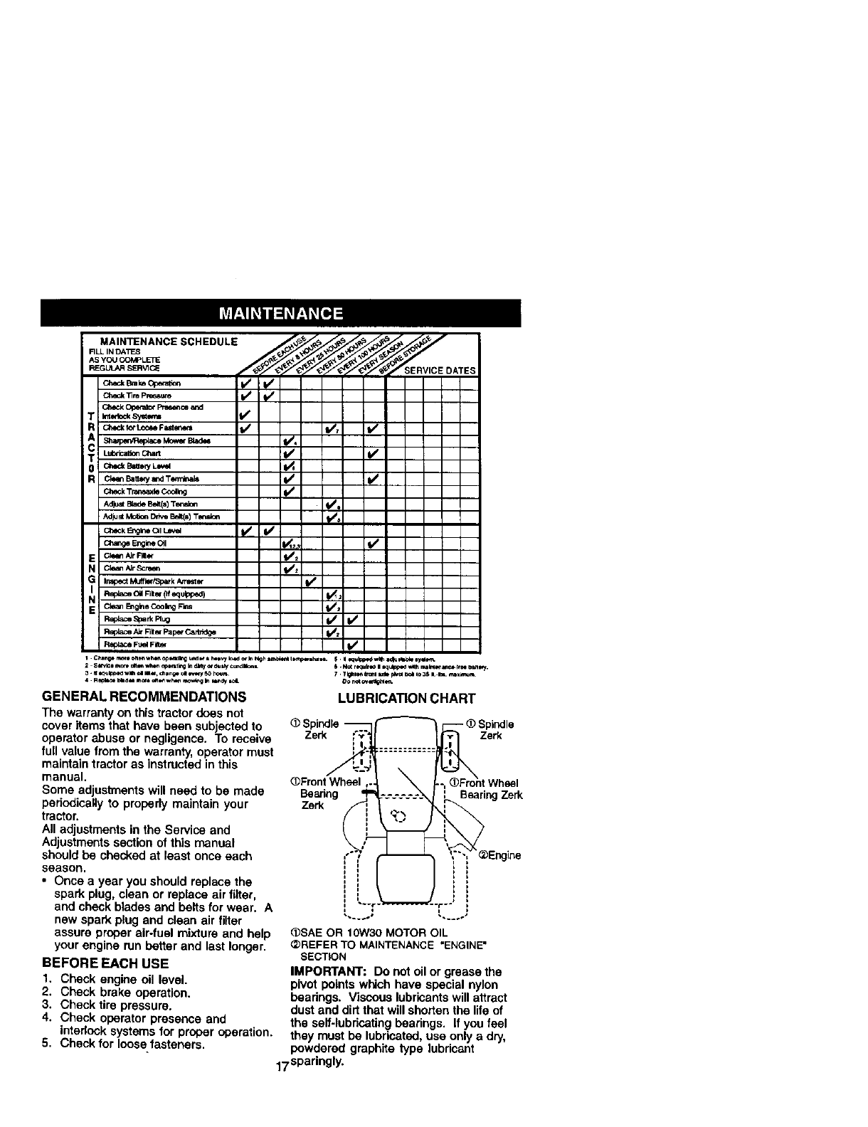
LUBRICATION CHART
(_Spindle
Zerk f:."
(_FrontWheal ,.
Bearing q"
1
l
I_ _ Spindle
ront Wheel
_"------"'- i Bearing Zerk
Engine
C_SAEOR 10W30 MOTOR OIL
_)REFERTO MAINTENANCE"ENGINE"
SECTION
IMPORTANT: DOnot oil or grease the
pivot points which have special nylon
beadngs. Viscous lubricantswill attract
dust and dirtthat will shorten the life of
the self-lubdcatingbeadngs. If you feel
they must be lubricated, use only a d_/,
powdered graphite type lubricant
17sparingly.
TRACTOR
Alwaysobserve safety rules when
performing any maintenance.
BRAKE OPERATION
If tractor requires more than six (6) feet
stopping distance at high speed in
highest gear, then brake must be ad-
justed. (See "TO ADJUST BRAKE in the
Service and Adjustments section of this
manual).
TIRES
• Maintain proper air pressure in all tires
(See "PRODUCT SPECIFICATIONS"
section of this manual).
•Keep tires free of gasoline, oil, or insect
control chemicals which san harm
rubber.
•Avoid stumps, stones, deep ruts, sharp
objects and other hazards that may
cause tire damage.
NOTE: To seal tire punctures and prevent
flat tires due to slow leaks, tire sealant
may be purchased from your local parts
dealer.Tire sealant also prevents tire dry
rot and corrosion.
OPERATOR PRESENCE SYSTEM
Be sure operator presence and interlock
systems are working properly. If your
tractor does not function as described,
repair the problem immediately.
•The engine should not start unless the
clutch/brake pedal is fully depressed
and attechement clutch control is in the
disengaged position.
•When the engine is running, any
attempt by the operator to leave the
seat without first setting the parking
brake should shut off the engine.
• When the engine is running and the
attachment clutch is engaged, any
attempt by the operator to leave the
seat should shut off the engine.
• The attachment clutch should never
operate unless the operator is in the
seat.
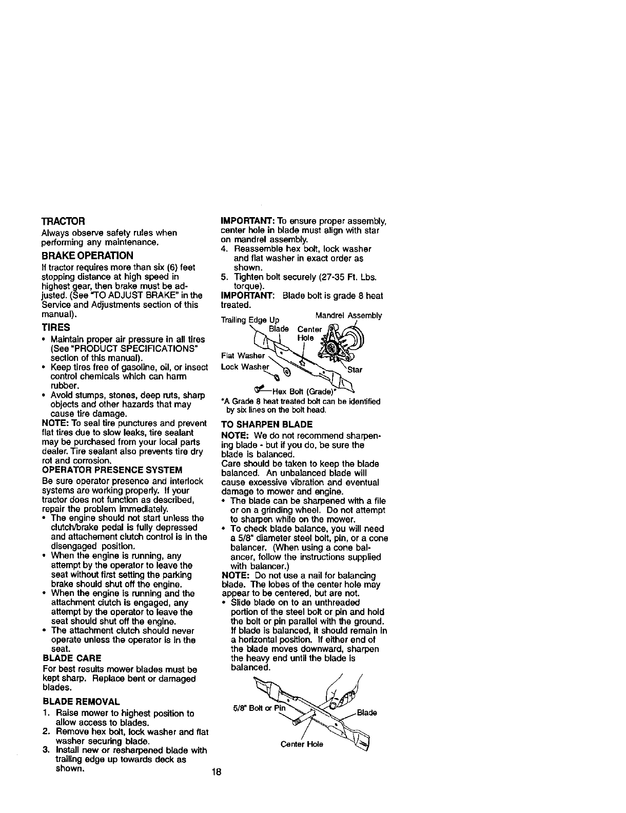
BLADE CARE
For best results mower blades must be
kept sharp. Replace bent or damaged
blades.
BLADE REMOVAL
1. Raise mower to highest positionto
allow access to blades.
2. Remove hex bolt, lock washer and flat
washer securing blade.
3. Install new or resharpened blade with
trailing edge up towards deck as
shown. 18
IMPORTANT: To ensure proper assembly,
center hole in blade must align with star
on mandrel assembly.
4. Reassemble hex bdt, lock washer
and flat washer in exact order as
shown.
5, "lighten bolt securely (27-35 Ft. Lbs.
torque).
IMPORTANT: Blade bolt is grade 8 heat
treated.
TrailingEdgeUp MandrelAssembly
Blade Center
Hole
FlatWasher,
Lock Washer
_-Nex Bo_l
"A Grade8deat _eatedboff canbe iden§fied
by six lines on theboH head.
TO SHARPEN BLADE
NOTE: We do not recommend sharpen-
ing blade -but if you do, be sure the
blade is balanced.
Care should be taken to keep the blade
balanced. An unbalanced blade will
cause excessive vibration and eventual
damage to mower and engine.
•The blade can be sharpened with a file
or on a grinding wheel. Do not attempt
to sharpen while on the mower.
•To check blade balance, you will need
a 5/8" diameter steel bolt, pin, or a cone
balancer. (When using acone bal-
ancer, follow the instructionssupplied
with balancer.)
NOTE: Do not use a nail for balancing
blade. The lobes of the center hole may
appear to be centered, but are not.
•Slide blade on to an unthreaded
portion of the steel belt or pin and hold
the bolt or pin parallel with the ground.
If blade is balanced, it should remain in
a horizontal position. If either end of
the blade moves downward, sharpen
the heavy end untilthe blade is
balanced.
5/_
Center Hole
BA'I-rERY
Your tractor has a battery charging system
which is sufficientfor normal use. How-
ever, periodic charging of the battery with
an automotive charger will extend its life.
•Keep battery and terminals clean.
•Keep battery boltstight.
•Keep small vent holes open.
•Recharge at 6-10 amperes for 1 hour,
NOTE: The originalequipment battery on
your tractor is maintenance free. Do not
attempt to open or remove caps or covers.
Adding or checking level of electrolyte is
not necessary.
TO CLEAN BA'I-rERY AND TERMINALS
Corrosion and dirt on the battery and
terminals can cause the battery to "leak"
power.
1. Open battery box door.
2. Disconnect BLACK battery cable first
then RED battery cable and remove
battery from tractor.
3. Rinse the battery with plain water and
dry.
4. Clean terminals and battery cable
ends with wire brush until bright.
5. Coat terminals with grease or petro-
leum jelly.
6. Reinstall battery (See "REPLACING
BATrERY" in the SERVICE AND
ADJUSTMENTS section of this
manual).
V-BELTS
Check V-bells for deterioration and wear
after 100 hours of operation and replace
if necessary. The belts are not adjustable.
Replace belts ifthey begin to slip from
wear.
TRANSAXLE COOLING
Keep transaxle free from build-up of dirt
and chaff which can restrictcooling.
ENGINE
LUBRICATION
Only use high quality detergent oil rated
with API service classificationSF-SJ
Select the oil's SAE viscositygrade
according to your expected operating
temperature.
NOTE: Although multi-viscosityoils
(5W30, 10W30 etc.) improve starting in
cold weather, these multi.viscosityoils
will result in increased oil consumption
when used above 32°F. Check your
engine oil level more frequently to avoid
possible engine damage from running
low on oil.
Change the oil after every 25 hours of
operation or at least once a year if the
tractor is not used for 25 hours in one
year.
Check the crankcase oil level before
starting the engine and after each eight
(8) hours of operation. Tighten oil fill cap/
dipstick securely each time you check the
oil level.
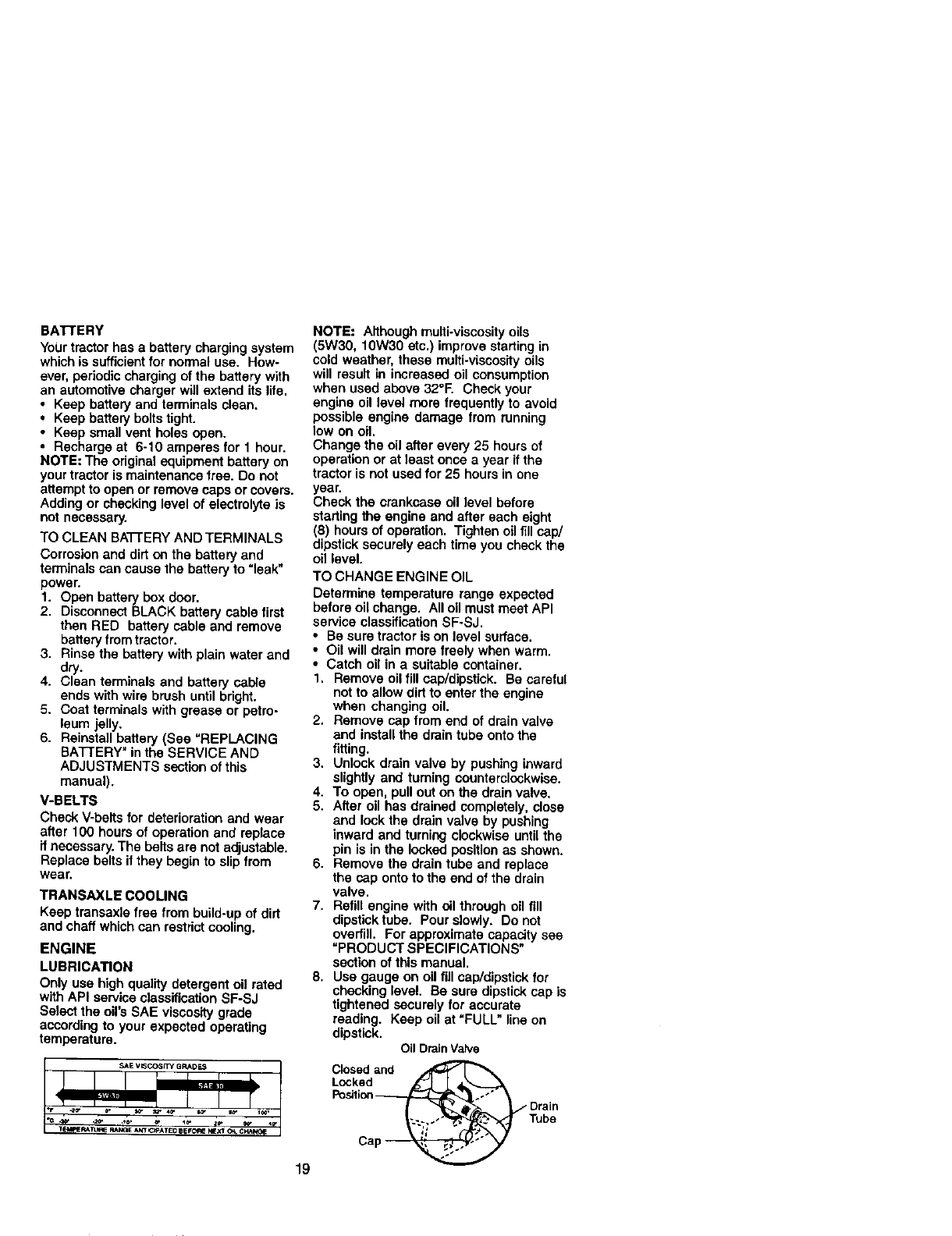
TO CHANGE ENGINE OIL
Determine temperature range expected
before oil change. All oil must meet API
service classification SF-SJ.
•Be sure tractor is on level surface.
• Oil will drain more freely when warm.
• Catch oil in asuitable container.
1. Remove oil fill cap/dipstick. Be careful
not to allow dirt to enter the engine
when changing oil.
2. Remove cap from end of drain valve
and install the drain tube onto the
fitting.
3. Unlock drain valve by pushing inward
slightly and turning counterclockwise.
4. To open, pull out on the drain valve.
5. After oil has drained completely, close
and lock the drain valve by pushing
inward and turning clockwise until the
pin is in the locked position as shown.
6. Remove the drain tube and replace
the cap onto to the end of the drain
valve.
7. Refill engine with oil through oil fill
dipstick tube. Pour slowly. Do not
overfill. For approximate capacity see
=PRODUCT SPECIFICATIONS"
section of this manual.
8, Use gauge on oil fill cap/dipstick for
checking level. Be sure dipstick cap is
tightened securely for accurate
reading. Keep oil at "FULL" line on
dipstick. Oil DrainValve
Closed and
Locked_
Position Drain
Tube
Ca
19
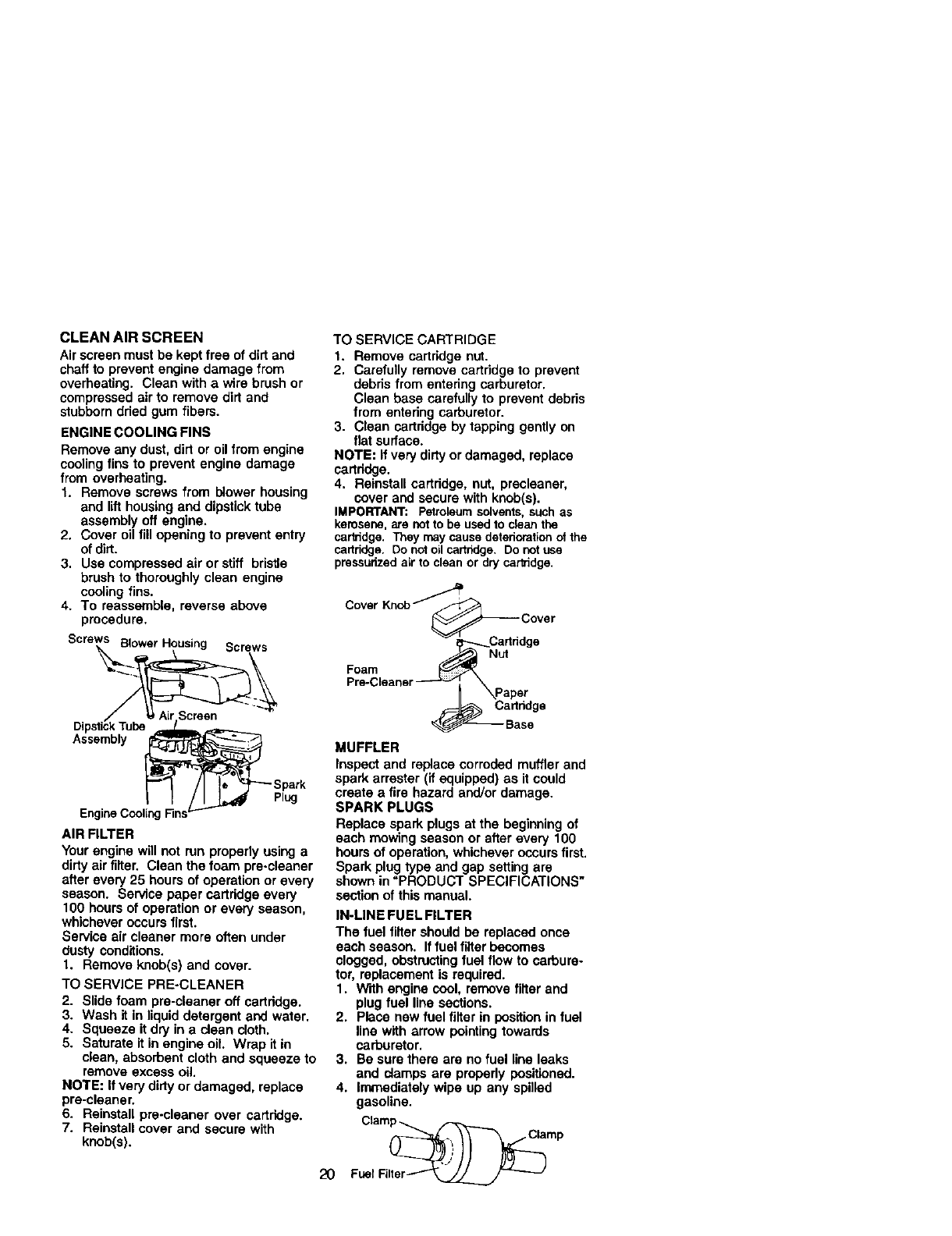
CLEAN AIR SCREEN
Air screen must be kept free of dirt and
chaff to prevent engine damage from
overheating. Clean with a wire brush or
compressed air to remove dirt and
stubborn dried gum fibers.
ENGINE COOLING FINS
Remove any dust, dirt or oil from engine
cooling fins to prevent engine damage
from overheating.
1. Remove screws from blower housing
and lifthousing and dipstick tube
assembly off engine.
2. Cover oil fill opening to prevent entry
of dirt.
3. Use compressed air or stiff bristle
brush to thoroughly clean engine
cooling fins.
4. To reassemble, reverse above
procedure.
Scre_.,_=BlowerHousing Screws
EngineCoolingFins'-'- Plug
AIR FILTER
Your engine will not run properly using a
dirty air filter. Clean the foam pre-cleaner
after every 25 hours of operation or every
season. Service paper cartridge every
100 hours of operation or every season,
whichever occurs first.
Service air cleaner more often under
dusty conditions.
1. Remove knob(s) and cover.
TO SERVICE PRE-CLEANER
2. Slide foam pre-claaner off cartridge.
3. Wash it in liquid detergent arid water.
4. Squeeze it dry in a clean cloth,
5. Saturate it in engine oil. Wrap it in
clean, absorbent cloth and squeeze to
remove excess oil.
NOTE: Ifvery dirty or damaged, replace
pre-cleaner.
6. Reinstall pre-cleaner over cartridge.
7. Reinstall cover and secure with
knob(s).
TO SERVICE CARTRIDGE
1. Remove cartridge nut.
2. Carefully remove cartridge to prevent
debris from entering carburetor.
Clean base carefully to prevent debris
from entering carburetor.
3. Clean cartridge by tapping gently on
flat surface.
NOTE: If very dirty or damaged, replace
cartridge.
4. Reinstall cartridge, nut, precleaner,
cover and secure with knob(s).
IMPORTANT: Petroleumsolvents,suchas
kemsane,are notto be usedto clean the
cartridge.They may causedeteriorationof the
cartridge.Do notoilcartndge. Do notuse
pressurizedair to clean or drycartridge.
Cover Knob"/''"_:::e r
Fr°e-a_leaher-_ _'paper
2O
MUFFLER
Inspect and replace corroded muffler and
spark arrester (if equipped) as it could
create afire hazard and/or damage.
SPARK PLUGS
Replace spark plugs at the beginning of
each mowing season or after every 100
hours of operation, whichever occurs first.
Spark plug type and gap setting are
shown in "PRODUCT SPECIFICATIONS"
section of this manual.
IN-LINE FUEL FILTER
The fuel filter should be replaced once
each season. If fuel filter becomes
clogged, obstructingfuel flow to carbure-
tor, replacement is required.
1. With engine cool, remove filter and
plug fuel line sections.
2. Place new fuel filter in positionin fuel
line with arrow pointing towards
carburetor.
3. Be sure there are no fuel line leaks
and clamps are properly positioned.
4. immediately wipe up any spilled
gasoline.
Clamp_
FuelNlter_
CLEANING
•Clean engine, battery, seat, finish, etc.
of all foreign matter.
• Keep finished surfaces and wheels free
of all gasoline, oil, etc.
•Protect painted surfaces with automo-
tive type wax.
We do not recommend using a garden
hose to clean your tractor unless the
electrical system, muffler, air filter and
carburetor are covered to keep water out.
Water in engine can result in a shortened
engine life.
ACAUTION: BEFORE PERFORMING ANY SERVICE OR ADJUSTMENTS:
1. Depress clutch/Drakepedal fully and set parking brake.
2. Place gearshift lever in neutral (N) position.
3. Place attachment clutch in "DISENGAGED" position.
4. "rum ignitionkey "OFF" and remove key.
5. Make sure the blades and all moving parts have completelystopped.
6, Disconnect spark plug wire from spark plug and place wire where it cannot
come in contact with plug.
TRACTOR
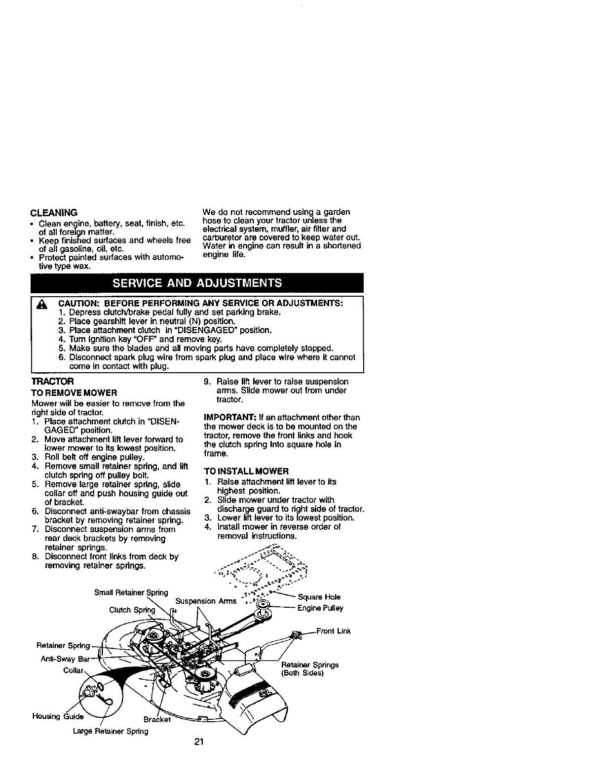
TO REMOVE MOWER
Mower will be easier to remove from the
right side of tractor.
1. Place attachment clutch in =DISEN-
GAGED" position.
2. Move attachment liftlever forward to
lower mower to its lowest position.
3, Roll belt off engine pulley.
4. Remove small retainer spring, and lift
clutch spring off pulley bolt.
5. Remove large retainer spring, slide
collar off and push housing guide out
of bracket.
6. Disconnect anti-swaybar from chassis
bracket by removing retainer spring.
7. Disconnect suspension arms from
rear deck brackets by removing
retainer spdngs.
8. Disconnect front linksfrom deck by
removing retainer springs.
Small Retainer Spdng
9. Raise lift lever to raise suspension
arms. Slide mower out from under
tractor.
IMPORTANT: if an attachment otherthan
the mower deck is to be mounted on the
tractor, remove the front links and hook
the clutch spring Into square hole in
frame,
TO INSTALL MOWER
1. Raise attachment lift lever to its
highest position.
2. Slide mower under tractor with
discharge guard to rightside of tractor,
3. Lower lift lever to its lowest position.
4. Install mower in reverse order of
removal instructions.
Clutch
Rutainer
A_i-Swa Retainer Springs
(Both Sides)
Housing Guide
Large Retainer Spdng
21
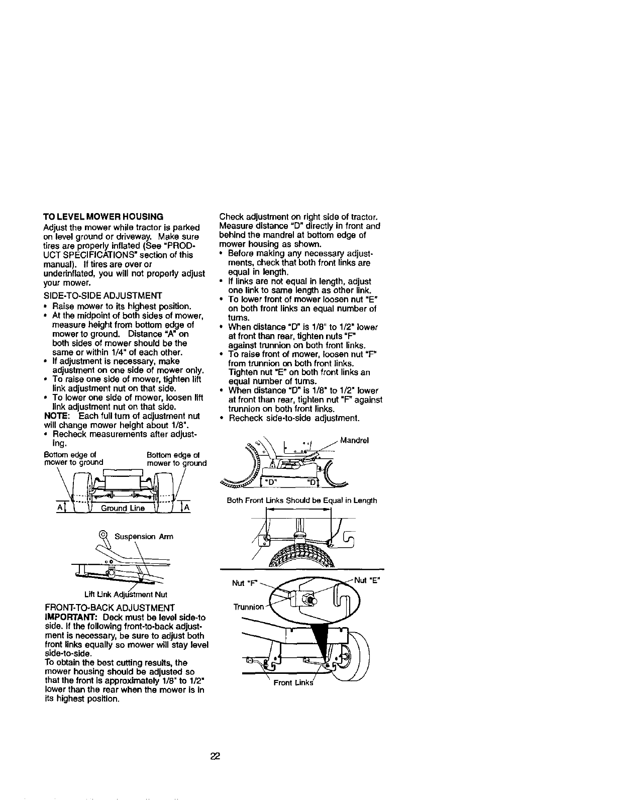
TO LEVEL MOWER HOUSING
Adjust the mower while tractor is parked
on level ground or driveway. Make sure
tires are properly inflated (See "PROD-
UCT SPECIFICATIONS" section of this
manual). If tires are over or
undednflated, you will not propedy adjust
your mower.
SIDE-TO-SIDE ADJUSTMENT
•Raise mower to its highest position.
•At the midpoint of both sides of mower,
measure height from bottom edge of
mower to ground. Distance "A" on
both sides of mower should be the
same or within 1/4" of each other.
•If adjustment is necessary, make
adjustment on one side of mower only.
•To raise one side of mower, tighten lift
link adjustment nut on that side.
• To lower one side of mower, loosen lift
linkadjustment nut on that side.
NOTE: Each full turn of adjustment nut
will change mower height about 1/8".
• Recheck measurements after adjust-
ing.
8ottorn edgeof Bottomedge of
mowerto ground mower to ground
FRONT-TO-BACK ADJUSTMENT
IMPORTANT." Deck must be level side-to
side. If the followingfront-to-back adjust-
ment is necessary, be sure to adjust both
front links equally so mower will stay level
side-to-side.
To obtainthe best cutting results, the
mower housing should be adjusted so
that the front is approximately 1/8" to 1/2"
lower than the rear when the mower is in
its highest position.
Check adjustment on right side of tractor,
Measure distance "D" directly in front and
behind the mandrel at bottom edge of
mower housing as shown.
• Before making any necessary adjust-
ments, check that both front links are
equal in length.
•If links are not equal in length, adjust
one linkto same length as other link.
•To lower front of mower loosen nut "E"
on both front links an equal number of
turns.
•When distance "D" is 1/8" to 1/2" lower
at front than rear, tighten nuts"F"
against trunnion on both front links.
•To raise front of mower, loosen nut "F"
from trunnion on both front links.
Tighten nut "E"on bothfront linksan
equal number of turns.
•When distance "D" is 1/8"to 1/2" lower
at front than rear, tighten nut =F"against
trunnion on both front links.
•Recheck side-to-side adjustment.
_Mandrel
BothFront Unks Shouldbe Equalin Length
Trunnion-
Front
22
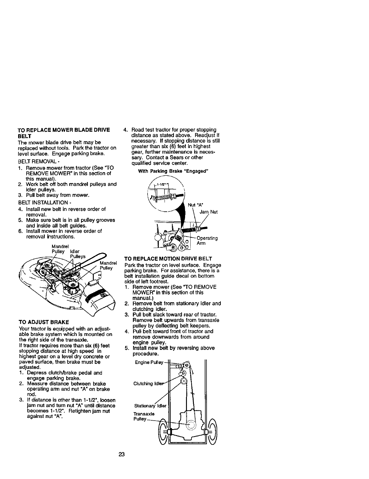
TO REPLACE MOWER BLADE DRIVE
BELT
The mower blade drive belt may be
replaced without tools. Park the trector on
level surface. Engage parking brake.
BELTREMOVAL -
1. Remove mower from tractor (See "TO
REMOVE MOWER" inthis section of
this manual).
2. Work belt off both mandrel pulleys and
idler pulleys.
3. Pull belt away from mower.
BELT INSTALLATION -
4. Install new belt in reverse order of
removal.
5. Make sure belt is in all pulley grooves
and inside all belt guides.
6. Install mower in reverse order of
removal instructions.
Mandrel
Pulley Idler
Mandret
Pulley
TO ADJUST BRAKE
Your tractor is equipped with an adjust-
able brake system which is mounted on
the rightside of the transaxle.
Iftractor requires more than six (6) feet
stoppingdistance at high speed in
highest gear on a level dry concrete or
paved surface, then brake must be
adjusted.
1. Depress clutcl'vbrake pedal and
engage parking brake.
2. Measure distance between brake
operating arm and nut "A" on brake
rod.
3. If distance is other than 1-1/2", loosen
jam nut and turn nut "A" until distance
becomes 1-1/2". Retighten jam nut
against nut =A".
4. Road test tractor for proper stopping
distance as stated above. Readjust if
necessary. If stoppingdistance is still
greater than six (6) feet in highest
gear, further maintenance is neces-
sary. Contact a Sears or other
qualified service center.
With Parking Brake "Engaged"
Nut =A"
Jam Nut
Arm
TO REPLACE MOTION DRIVE BELT
Park the tractor on levelsurface. Engage
parking brake. For assistance, there is a
belt installationguide decal on bottom
side of left footrest.
1. Remove mower (See "TO REMOVE
MOWER" in this section of this
manual.)
2. Remove belt from stationary idler and
clutching idler.
3. Pull belt slack toward rear of tractor.
Remove belt upwards from transaxle
pulley by deflecting belt keepers.
4. Pull belt toward front of tractor and
remove downwards from around
engine pulley.
5. Install new bolt by reversing above
procedure.
Ctutchin
Transaxle
23
TO ADJUST STEERING WHEEL ALIGN-
MENT
If steering wheel crossbars are not
horizontal (left to right) when wheels are
positioned straight forward, remove
steering wheel and reassemble per
instructionsin the Assembly section of
this manual.
FRONT WHEEL TOE-IN/CAMBER
The front wheel tca-in and camber are
not adjustable on your tractor. If damage
has occurred to affect the front wheal toe-
in or camber, contact a Sears or other
qualified service center.
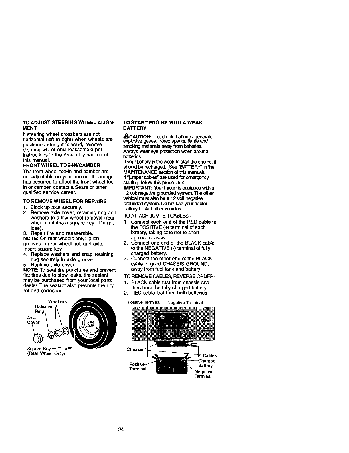
TO REMOVE WHEEL FOR REPAIRS
1. Blockup axle securely.
2. Remove axle cover, retaining ring and
washers to allow wheel removal (rear
wheel contains a square key - Do not
lose).
3. Repair tire and reassemble.
NOTE: On rear wheels only: align
grooves in rear wheel hub and axle.
Insert square key.
4. Replace washers and snap retaining
ring securely in axle groove.
5. Replace axle cover.
NOTE: To seal tire punctures and prevent
flat tires due to slow leaks, tire sealant
may be purchased from your local parts
dealer. Tire sealant also prevents tire dry
rot and corrosion.
Washers
Ret_dninc
Ring
Axle
Cover
TO START ENGINE WITH A WEAK
BA'n'ERY
_kCAUTION: Lead-add bettedes generate
explosivegases. Keep sparks,fl_ and
,_T_ldngmaterialsaway from batteries.
Alwayswear eye protectionwhen around
batteries.
Ifyourbatteryistoo weakto starttheengine, it
shouldbe recharged.(See "BA'I-TERY"inthe
MAINTENANCE sectionof thismanual).
if"jumper cables"are usedfor emergency
starting,folow this procedure:
IMPORTANT: Yourtractorisequippedwitha
12voltnegativegroundedsystem.The other
vehicalmustalso be a 12 voltnegative
grcandedsystem.Do notuse yourtractor
batteryk) start other vehicles.
TO ATTACHJUMPER CABLES -
1. Connect each end of the RED cable to
the POSITIVE (+) terminal of each
battery, taking sere not to short
against chassis.
2. Connect one end of the BLACK cable
to the NEGATIVE (-) terminal of fully
charged battery.
3. Connect the other end of the BLACK
cable to good CHASSIS GROUND,
away from fuel tank and battery.
TO REMOVE CABLES,REVERSE ORDER-
1. BLACK cable firstfrom chassis and
then from the fully charged battery.
2. RED cable last from both batteries.
Positive Terminal Negative Terminal
Terminal Battery
24
Terminal
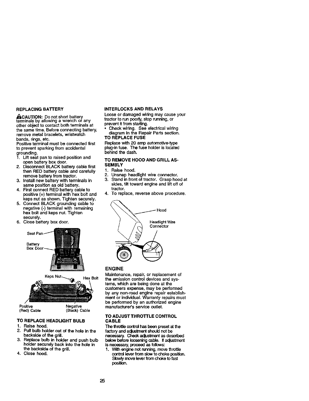
REPLACING BAI'FERY
_CAUTI.ON: Do not short ba,ttery
terminats Dy allowing a wrencn or any
other object to contact both terminals at
the same time. Before connecting battery,
remove metal bracelets, wristwatch
bands, rings, etc.
Positive terminal must be connected itrst
to prevent sparking from accidental
grounding.
1. Lift seat pan to raised position and
open battery box door.
2. Disconnect BLACK battery cable first
then RED battery cable and carefully
remove battery from tractor.
3. Install new battery with terminals in
same position as old battery.
4. First connect RED battery cable to
positive (+) terminal with hex bolt and
keps nut as shown. Tighten securely.
5. Connect BLACK grounding cable to
negative (-) terminal with remaining
hex bolt and keps nut. Tighten
securely.
6. Close battery box door.
Battery
Box
Bolt
Positive Negative
(Red) Cable (Black) Cable
TO REPLACE HEADLIGHT BULB
1. Raise hood.
2. Pull bulb holder out of the hole in the
backside of the gdU.
3. Replace bulb in holder and push bulb
holder securely back into the hole in
the backside of the grill.
4. Close hood.
INTERLOCKS AND RELAYS
Loose or damaged wiring may cause your
tractor to run poorly,stop running,or
preventit fromstarting.
•Check wiring. See electrical wiring
diagram in the Repair Parts section,
TO REPLACE FUSE
Replace with 20 amp automotive-type
plug-in fuse. The fuse holder is located
behind the dash.
TO REMOVE HOOD AND GRILL AS-
SEMBLY
1. Raise hood.
2. Unsnap headlight wire connector.
3. Stand in front of tractor. Grasp hood at
sides, tilt toward engine and lift off of
tractor.
4. To replace, reverse above procedure.
_H°O_h t
.,oWir°
ENGINE
Maintenance, repair, or replacement of
the emission control devices and sys-
tems, which are being done at the
customers expense, may be performed
by any non-road engine repair establish-
ment or individual. Warranty repairs must
be performed by an authodzed engine
manufacturer's service outlet.
TO ADJUST THRO'n'LE CONTROL
CABLE
Tbe thraltJecontrolhasbeen preset_t the
factoryand aclusknectshouldnot be
necessary. Check ao_stment as dascribed
below before Iousert_ cable. If a_ustment
is necessary, proceed as follows:
1. W'_ engine not running, move throttle
control lever from sJowto choke pasiifan.
Slowly movelever from choke to fast
po,._im.
25
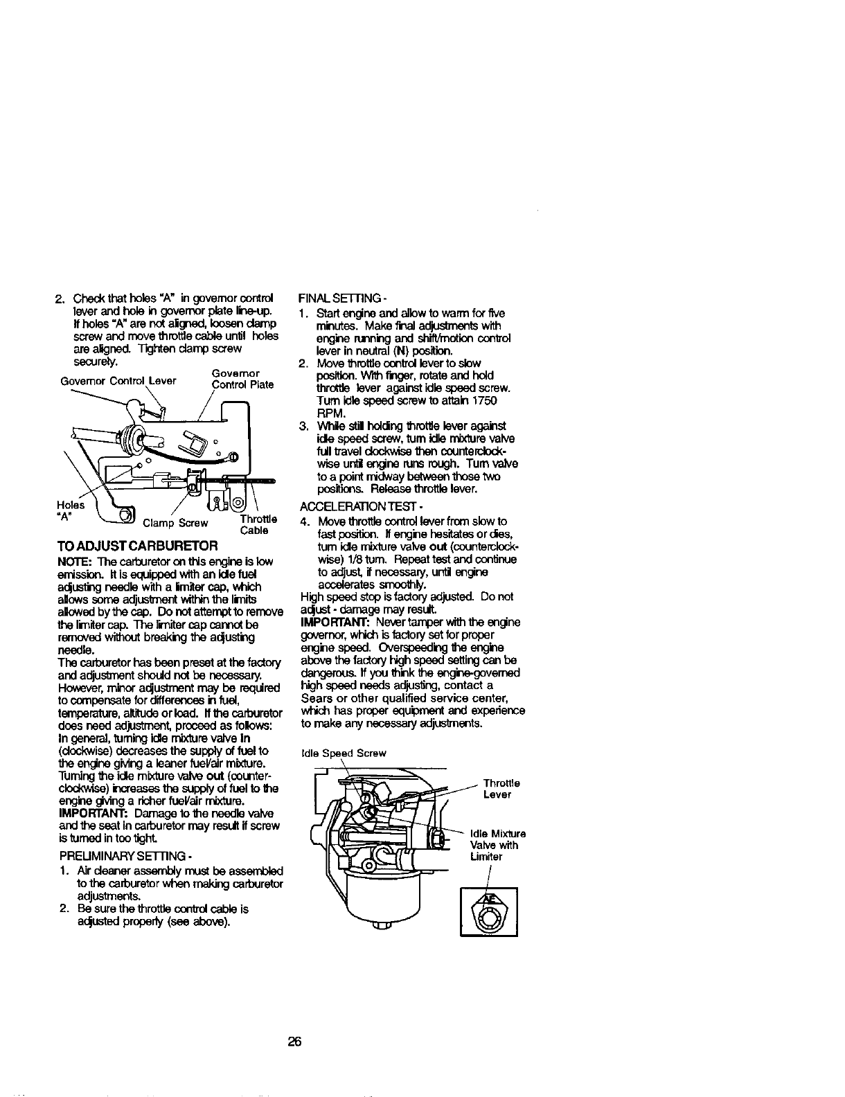
2. Checkthat holes "A" in governorcontrol
lever and hole in governor plate line-up.
Ifholes "A"are notaligned, loosendamp
screw and move throttlecable until holes
are a_ned. Tighten clamp screw
securely. Governor
GovernorControlLever ControlPlate
\
Holes
"A" Clamp Screw Throttle
Cable
TO ADJUST CARBURETOR
NOTE: The carburetoron thisengine is low
emission.If isequippedwifhan idlefuai
ac_ustingneedle witha limitercap,which
allows comeadj_ within the limits
alowed by the cap. Do notattemptto remove
the limitarcap. The limitarcap cannotbe
removedwithoutbreak_g the ac_usting
needle.
The carburetorhasbeen presetat thefactory
and adjustmentshould not be necessary.
However,minora_ustment may be required
to compensatefor differences in fuel,
temperature,altitude or load. ff the carburetor
does need adjustment,proceedas folows:
In general,turningidlemixture valve In
(dcokwise)decreases the supplyof fuelto
the engine gMng a leaner fueVairmixture.
Turningthe idle mixture valve out (counter-
clockwise) increases the supply of fuel to the
engine givinga richer fuel/air mixture.
IMPORTANT: Damageto the needlevalve
and the seatin cafouretormay resultifscrew
is turned intootight.
PREUMINARY SETTING -
1. Air cleaner assembly mustbe a_
to the carburetor when makingcarburetor
adjustments.
2. Be surethe throttle controlcable is
a_usted properly(see above).
FINAL SETIING -
1. Start engine end allow to warm for five
minutes. Make finaladjustments with
engine runningand shift/rootloncontrol
lever in neutral(N) position.
2. Move throttfacontrolleverto_
position.W'r_f=lger, rotateand hold
throttle lever against!diespeedscrew.
Turn idle speedscrewto attain 1750
RPM.
3. While stil holdingthrotlJelever against
idle speed screw,tom idle mixture valve
full travel clockwisethen counterclock.
wise unff engine runsrough. Turn valve
to a point midway between those two
pos_or_ Release throttle lever.
ACCELERATIONTEST -
4. Movethrottle scntrol lever from slow to
fast position, if engine hesitates orcr_s,
turn idle mix'lurevalve out (counterclock-
wise) 1/8turn. Repeat test end con_nue
to adjust,if necessary, unti engine
accelerates smoothly.
Highspeedstop isfactory adjusted. Do not
acjust- damage may result.
IMPORTANT: Nevertamperwiththe engine
governor,whichisfactory setfor proper
engine speed. Overspeedingthe engine
abovethefactoryhighspeed settingcanbe
dangerous. If you think_qeengine-govemed
high s_ needs adjusfing, contact a
Sears or other qualified service center,
which has proper edu'_ment and experience
to make any necessary adjustments.
IdleS'
IdleMixture
lyewith
26
Immediately prepare your tractor for
storage at the end of the season or if the
tractor will not be used for 30 days or
more.
_kCAUTION: Never store the tractor with
gasoline in the tank inside a building
where fumes may reach an open flame or
spark, Allow the engine to cool before
stodng in any enclosure.
TRACTOR
Remove mower from tractor for winter
storage. When mower is to be stored for
a period of time, clean if thoroughly,
remove ell dirt, grease, leaves, etc. Store
in a clean, dry area.
1. Clean entire tractor (See "CLEANING"
in the Maintenance section of this
manual).
2. Inspect and replace belts, if necessary
(See belt replacement instructions in
the Service and Adjustments section
oithis manual).
3. Lubricate as shown in the Mainte-
nance section of this manual.
4. Be sure that all nuts, bolts and screws
are securely fastened. Inspect moving
parts tot damage, breakage and wear.
Replace if necessary.
5. Touch up all rusted or chipped paint
surfaces; sand lightly before painting.
BA'I-rERY
• Fully charge the battery for storage.
•After a period of time in storage, battery
may require recharging.
• To help prevent corrosion and power
leakage during long pedods of storage,
battery cables should be disconnected
and battery cleaned thoroughly (see
"TO CLEAN _,A'N'ERY AND TERMi-
NALS" in the Maintenance section of
this manual).
• After cleaning, leave cables discon-
nected and place cables where they
canr_t come in cootact with battery
terminals.
•If battery is removed from tractor for
storage, do not store battery directly on
concrete or damp surfaces.
ENGINE
FUELSYSTEM
iMPORTANT: it is important to prevent
gum deposites from forming in essential
fuel system parts such as carburetor, fuel
hose, or tank during storage. Also,
expedance indicates that alcohol
blended fuels (called gasohol or using
ethanol or methanol) can attract moistura
which leads to separation and formation
of acids during storage. Acidic gas can
damage the fuel system of and engine
while in storage.
1. Drain the fuel tank.
2. Start the engine and let it run untilthe
fuel lines and carburetor are empty.
• Never use engine or carburetor cleaner
products in the fuel tank or permanent
damage may occur.
• Use fresh fuel next season.
NOTE: Fuel stabilizer is an acceptable
alternative in minimizing the formation ot
fuel gum deposits during storage. Add
stabilizer to gasoline in fuel tank or
storage container. Always follow the mix
ratio found on stabilizer container. Run
engine at least 10 minutes after adding
stabilizer to allow the stabilizer to reach
the carburetor. Do not drain the gas tank
and carburetor if using fuel stabilizer.
ENGINE OIL
Drain oil (with engine warm) and replace
with clean engine oil. (See =ENGINE" in
the Maintenance section of this manual).
CYLINDER(S)
1. Remove spark plug(s).
2. Pour one ounce of oil through spark
ping hole(s) into cylir_er(s).
3. Turn ignition key to =START" position
for afew seconds to distribute oil.
4. Replace with new spark plug(s).
OTHER
•Do not store gasoline from one season
to another.
•Replace your gasoline can if your can
stads to rust. Rust and/or dirtin your
gasoline will cause problems.
• If possible, store your tractor indoors
and cover it to give protectionfrom dust
and dirt.
•Cover your tra_or with a suitable
protective cover that does not retain
moisture. Do not use plastic. Plastic
cannot breathe which allows conden-
sation to form and will cause your
tractorto rust.
IMPORTANT: Never cover tractor while
engine and exhaust areas are stillwarm.
27
TROUBLESHOO_NG CHART
PROBLEM CAUSE CORRECTION
Willnotstart
Hard to start
Engine will not
turn over
1. Out of fuel.
2. Engine not =CHOKED"
properly.
3. Engine flooded.
4. Bad spark plug.
5. Dirty airrilter,
6. Dirty fuel filter,
7 Water in fuel,
8. Loose or damaged widng.
9. Carburetor out of adjustment.
10.Engine valves out of
adjustment.
1. Dirty airrilter.
2. Bad spark plug.
3. Weak or dead battery.
4. Dirty fuel rifler.
5. Stale or dirty fuel.
6. Loose or damaged widng.
i7. Carburetor out of adjustment.
8. Engine valves out of
adjustment.
1. Brake pedal not depressed.
2. Attachment clutch is
engaged.
3. Weak or dead battery.
4. Blown fuse.
5. Corroded battery terminals.
6. Loose or damaged wiring.
7. Faulty ignition switch.
8. Faulty solenoid or starter.
1. Fill fuel tank.
2. See=TO START ENGINE"
in Operation section.
3. Wait several minutes
before attempting to start.
4. Replace spark plug.
5. Clean/replace air filter.
6. Replace fuel filter.
7. Drain fuel tank and
carburetor, refill tank with
fresh gasoline and replace
fuel filter.
8. Check all wiring.
9, See =ToAdjust Carburetor"
in Service Adjustments
section.
10.Contact a Sears or other
qualified service center.
1. Clean/replace air rifler.
2. Replace spark plug.
3. Recharge or replace
battery.
4. Replace fuel rifler.
5. Drain fuel tank and refill
with fresh gasoline.
6. Check all widng.
7. See =To Adjust Carburetor"
in Service Adjustments
section.
8. Contact a Sears or other
qualified service center.
1. Depress brake pedal.
2. Disengage attachment
clutch.
3. Recharge or replace
battery.
4. Replace fuse.
5. Clean battery terminals.
6. Check all widng.
7. Check/replaca ignition
switch.
8. Check/replace solenoid or
starter.
9. Contact a Sears or ether
qualified service center.
9. Faulty operator presence
switch(es).
Engine clicks but 1. Weak or dead battery. 1. Recharge or replace battery
will not start 2. Corroded battery terminals. 2. Clean battery terminals.
3, Loose or damaged widng. 3. Check all widng.
4. Faulty solenoid or starter. 4, Check/replace solenoid or
starter.
28
TROUBLESHOOTING CHART
)ROBLEM
Loss of power
Excessive
vibration
CAUSE
1. Cutting too much grass/too
CORRECTION
fast.
2. Throttle in "CHOKE"
position.
3. Build-up of grass, leaves 3.
and trash under mower.
4. Dirtyair filter. 4.
5. Low oil level/didy oil. 5.
6. Faulty spark plug. 6.
7. Dirtyfuel rifler. 7.
8, Stale or dirty fuel. 8.
9. Water in fuel. 9.
10.Spark plug wire loose.
11. Dirty engine air screen/fins.
12. Dirty/clogged muffler.
13. Loose or damaged wiring.
14.Carburetor out of
adjustment.
15.Enginevalvesoutof
adjustment.
1. Worn, bent or loose blade.
Engine continues
to run
when operator
leaves seat with
with attachment
clutch engaged
Poor cut - uneven
2. Bent blade mandrel.
3, Loose/damaged part(s).
1. Faulty operator-sefety
presence control system.
1. Worn, bent or loose blade.
2. Mower deck not level.
3. Buildupof grass, leaves,
and trash under mower.
4. Bent blade mandrel.
5. Clogged mower deck vent
holes from buildup of
grass, leaves, and trash
around mandrels.
1. Set in "Higher Cut" position/
reduce speed.
2. Adjust throttle control
Clean underside of mower
housing.
Clean/replace air filter.
Check oil level/change oil.
Clean and ragap or change
spark plug.
Replace fuel rifler.
Drain fuel tank and refill with
fresh gasoline.
Drain fuel tank and carbure-
tor, refilltank withfresh
gasoline and replace fuel
rifler.
lO.Connect and tighten spark
plug wire.
11.Clean engine air screen/fins.
12.ClearVreplace muffler.
i13.Cbeck all widng.
14.See "To Adjust Carburetor"
in Service Adjustments
section.
15.Contact a Sears or other
qualified service center.
1. Replace blade.
Tighten blade bolt.
2. Replace blade mandrel.
3, Tighten loose part(s).
Replace damaged pads.
1. Check widng, switches and
connections. If not
contact a Sears or other
qualified service center.
1. Replace blade. Tighten
blade bolt.
2. Level mower deck.
3. Clean underside of mower
housing.
4. Replace blade mandrel.
5. Clean around mandrels to
open vent holes.
29
TROUBLESHOOTING CHART
PROBLEM CAUSE CORRECTION
Vlower blades will 1. Obstruction in clutch 1. Remove obstruction.
lot rotate mechanism.
2. Worn/damaged mower 2. Replace mower drive belt.
ddve bell.
3. Frozen idler pulley. 3. Replace idler pulley.
4. Frozen blade mandrel. 4. Replace blade mandrel.
_oor grass 1. Engine speed too slow.
:llschargo
Headlight(s) not
working
(if so equipped)
Battery will not
charge
2. Travel speed too fast.
3. Wet grass.
4. Mower deck not level.
5. Low/uneven tire air
pressure.
6. Worn, bent or loose blade.
7. Buildup of grass, leaves
and trash under mower.
8. Mower drive belt worn.
9. Blades improperly installed.
lO.Improper blades used,
11. Clogged mower deck vent
holes from buildup of grass,
leaves, and trash around
mandrels.
1. Switchis "OFF".
2. Bulb(s) or lamp(s) bumed out
3. Faulty light switch.
4, Loose or damaged widng,
5. Blown fuse.
1. Bad battery cell(s).
2. Poor cable connections.
1. Place throttle control in
=FAST" position.
2. Shiftto slower speed.
3. Allow grass to dry before
mowing.
4. Level mower deck.
5. Check tires for proper air
pressure.
6. Replace/sharpen blade.
Tighten blade bolt.
7. Clean underside of mower
housing.
8. Replace mower ddve bell.
9. Reinstall blades sharp edge
down.
10.Replace with blades listed
in this manual.
11.Clean around mandrels to
open vent holes.
1. Turn switch "ON",
2. Replace bulb(s) or lamp(s).
3, Check/replace light switch.
4. Check wiring and connec-
tions.
5. Replace fuse.
1. Replace battery.
2. Check/clean all connec-
tions.
3. Replace regulator.3. Faulty regulator
(if so equipped).
4. Faullyallernator. 4. Replace allemator.
Engine "backfires' t. Engine throttle control not 1. Move throttle controlto
whenturnlng set at "SLOW" position =SLOW" position and allow
.'nglno"OFF" for 30 seconds before to idle for 30 seconds before
stopping engine, stopping engine.
3O
SCHEMATIC
TRACTOR - MODEL NUMBER 917.271531
AMMEnER
f)G AK
K3NffI_
SWITCH
IGNmON SWITCH
FUSE n, n STAR31_I _ R
.........
',0 ', _ i'__2:__,
I:!SC,.E_O
(PEDAL UP)
_ b b ,........
(0P33(3_AL) q_O SPA_K
PLUG
nN_ IGNiTiON GAp
'FUEL, UNIT
I{2 pLUGS ON
tour ,LINE, TWI CYL. ENGaNES) I
i i ,
aAUFCCe moo_qlPu ic_a_oa_sys_u O_SCON_ml_)
FUEL SHUT_DFF SOLENC4D _' '
"°TR I
YOUR TRACTOR IS _a_c_
EQUIPPED WITH A SPECIAL
ALTERNATOR SYSTEM. L_
THE LIQHTS ARE NOT
CONNECTED TO TRE
BATTERY, BUT HAVE THEIR
OWN ELECTRICAL SOURCE.
BECAUSE OF THIS, THE
BRIGHTNESS OF THE LIGHTS
WILL CHANGE WITH ENGINE
SPEED. AT IDLE THE LIGHTS
WILL DIM. AS THE ENGINE IS
SPEEDED UP, THE LIGHTS
WILL BECOME TREIR BRIGHTEST.
WIRING INSULATED CUPS
HEADUGHTS
NON-REMOVABLE
CONNECTIONS
REMOVABLE
CONNECTIONS
NOTE: IF WIRING INSULATED CLIPS W1ERE REMOVED FOR
SERVICING OF UNIT, TREY SHOULD BE REPLACED TO
PROPERLY SECURE YOUR WIRING.
F_
31
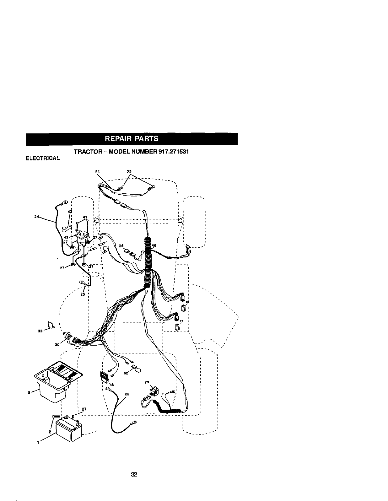
TRACTOR- MODELNUMBER917.271531
ELECTRICAL

ELECTRICAL TRACTOR - MODEL NUMBER 917.271531
KEY PART
NO. NO. DESCRIPTION
1
2
8
16
21
22
24
25
26
27
28
29
3O
33
4O
41
42
43
45
52
144925 Batte W12 Volt 25 AMP
747604_2 Bolt Hex Hd 1/4-20unc X 3/4
156417 Case Battery
153664 Switch Interlock Push-In
16618t Harness Socket Ught W/4152J
4152J Bulb Llgt_t#1156
4799J Cable Batte W6ga 11" red
146147 Cable Battery 6 Ga W/16 Wir red
175158 Fuse20AMP
73510400 Nut Keps Hex 1/4-20 Uric
4207J Cable Ground 6ga 12" black
121305X Switch Plunger Nc Gray
175566 Switch Ign Delta Push-In
140403 Key Ign Molded Craftsman, Delta
178437 Harness Ign
71110408 Bo_tB_kHex 1/4-20unc x 1/2
131563 Cover Terrrdnal Red
178861 Solenoid
121433X Ammeter Rectangular 6 AMP
141940 Protection Wire Loop
NOTE: All componen_ _rnenslons given InU. S.
inches 1Inch = 25.4 mm
33

TRACTOR- MODELNUMBER917.271531
CHASSISANDENCLOSURES
3O
29
_25 58 12
26 31 _. _ 26 s5
2O6 11
54
28
33 10
13_
:34

TRACTOR - MODEL NUMBER 917.271531
CHASSISAND ENCLOSURES
KEY
NO.
1
2
3
5
5
8
9
10
11
12
13
15
15
17
18
24
25
26
28
29
3O
31
33
34
35
37
38
51
52
53
54
55
57
58
145
2_5
206
2(_6
209
212
PART
NO. DESCRIPTION
174620 Chassis Lt Stamping
176554 Dlawber
17060612 Screw 3/8-15 x 3/4
155272 Bumper Hood/Dash
174643X010 Saddle SLKSCRE FLT SDL
126471X Clip insulator .406 Mtg Hole
168348X010 Dash Slkscr Phe Mech Syrn
72140608 Bolt RdHd Sqnk. 3/8-16 x 1
155927 Panel Asm. Dash Lh
145660 ClipTlnner m._nG dlle PA_
t72107X010 Panel D_sh Rh
74180512 Screw Mach Trhd 5/16-18unc x 3/4
73510500 Nu Keps 5116-18unc
159639X558 Hood Pnt Steel Private Label
126938X BumperHood
74780616 Belt Fin Hex 3/8-16 Uncx 1Gr, 5
19131312 Washer 13/32 x 13/15 x 12 Ga.
73800600 Nut Lock Hex w/Ins 3/8-16 Unc
140434 GrlllJLensAsm
t40273X599 LensGrille Private lahel
t 69465x55g Fender Pnt
136619 Bracket Fenrter Suppod
t45244X558 Footrest Pnt. Lh
145243X558 Footrest Pnt, Rh
72110606 Bo_tRdHd Silt. Sqnl(. 3_-16 x 3/4
17490508 Screw Tl_drol 5/t6-18 x ti2 Tyt
175710 Bmel(et Asm, Pivot Mower Rear
73800400 Nut Lock Hex W/Ins. 1/4_20
19091416 Washer g/32 x 7/8 x 16 Ga.
144697 BraCket Gdt[e LH
161464 Screw Hex Wshd #8-18 x 7/B
144696 Bracket, Glille RH
74780412 Bolt Fin Hex 1/4-20 x 3/4
150127 Air Duel Pnvate Label LT Engine
156524 Rod Pivot Chassis/Hood
17490608 Screw Thdrol 3/8-16 x 1/2
170165 Bolt Shcutder 5/16-18 TT
17670st_ ScrewThdrel. 3/8-15 x 1/2
17(X_612 Screw Hex Wsh Thdrel 3/_-16 BL
156229 Insert Lens Reflective
5479J Plug Button B_k.359 Dia. Choke
NOTE: All component dlrnenslons given in U. S.
Inches 1 inch =25.4 mm
35
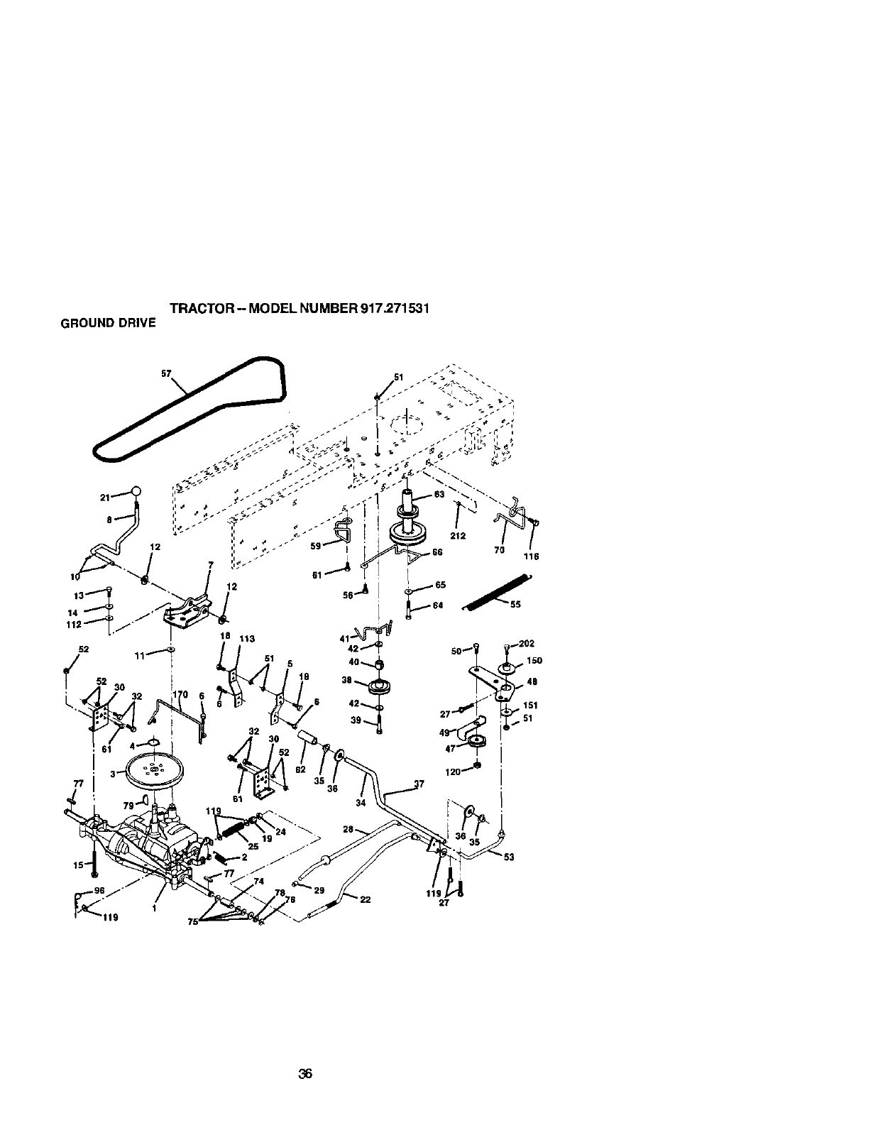
TRACTOR- MODELNUMBER917.271531
GROUNDDRIVE
D
'22 119,27
36

TRACTOR - MODEL NUMBER 917.271531
GROUNDDRIVE
KEY PART KEY PART
NO. NO. DESCRIPTION NO. NO. DESCRIPTION
1.... Transaxle (See Breakdown) 47 127783 Pulley Idler V Groove Plas6c
Dana4360-140 48 154407 Bellcrank Clutch Gm De/Stl
2146682 Spring Retum Brake T/a Zinc 49 123_05X Retainer Belt Style Spring
3 123666X Pugey Transaxle 18/26" tires 50 STD523715 Bolt Hex Hd 3/8-16unc x 1-1/2
4 12000028 RlngRet_dner#5100-62 51 S'1_541437 NutCrownlock 5/8-16UNC
5 12152OX Strap Torque 30 Degree_ 52 $3_541431 Nut Crown Lock 5/16-18
6 17(Tdl_12 Screw 5/16-18 x 3/4 53 105710)( Link Clutch 7 66
7 11_240 Bracket Saddle Sh_ T/a 55 105709X Spring Return Clutch 6 75
8 131679 Rod Sht Sdl LY/YT Sir Bik Zinc 56 s'rD523712 Bolt Fin Hex 3/8-16 unc x 1-1/4
10 STD561210 Pin Cotter 1/B x 1 Cad 57 160855 V-Belt Gd Drive
11 tO5701X Washer Plate Shf 388 Sq HoLe 59 169691 Keeper BeltCenterspan
12 19151216 Washer 13/32 x 3]4 x 16ga 61 17060612 Screw 3/8-16 x 3/4
13 74550412 Roit 1/4-28urff Gr8 W/Patch 62 8883R Cover Pedal B]k Round
14 S'rD551125 Washer Lock Hvy HellcaJ t/4 63 175410 Pulley Eng
15 74490544 Bdlt Hex ELGHD 5/16-18 Gr.5 64 71170764 Bcit Hex 7/16-20 x 4 Gr 5
15 S]D5237t0 BogFInHex3/8-t6xl 65 STD551143 WasherLockHvyHIclSpr7/16
19 $3D541437 Nut Lock Hex W/Ins. 5/8-16 Unc 66 154778 Keeper Belt Engine
21 106933X Knob Rd 1/2-13 PlstcThds BIk 70 134683 Guide Belt Mower Ddve RH
22 130804 Rod Brake BIkZinc 26 840 74 10_502X Specer Axle
24 STD541237 NutHexJam3/8-16Unc 75 t21749X Washer 25/32 x 1 1/4x 16Ga
25 106888X SpdngRodBrake20OZinc 76 STD581075 E-6-nng_#5133-75
26 19131016 Washer 15/32 x 5/8 x 16 Ga 77 123583X Key _lUme 2 0 x 1845/1865
27 S30561210 Pin Cotter I/8 x 3/4 Cad 78 121748X Washer 25132 x 1-5/8 x 16 Ga
28 175765 Rod Brake Parking Lt/Yt 79 2228M Key
29 71673 Cap Brake Parking 96 4497H Retainer Spdng 1,00
30 174973 Bracket Mtg Transaxle 112 19091210 Washer 9/32 x 3/4 x 10 Ga
32 STD523107 BogHexHd5!16-18uncxs/4 113 127285X StrapTorque
34 175578 Shaft Asm Pedal Foot 116 72110608 Bdlt Rdhd Sq Neck 3/8-16 x 1
35 120183X Beadng Nylo_ BIk 629 Id 120 73900600 Nut Lock Fig 3/8-16
36 $1_55106_ Washer21/32xlx16Ga 150 174456 SpacerRetainer
37 s'rD571810 Pin Roll s/16 x1" 151 19133210 Washer 13_2x2xt0Ga
38 165936 Pulley Idler Flat 170 173899 Keeper Belt Transaxle Gear
39 74760648 Bolt Fin Hex 5/8-16 Une X 3 202 72110614 Bolt CaR Sh 5/8-16 x1-5/4 Gr, 5
40 175461 Spacer Split 212 145212 Nut Hex Flange Lock
41 175556 Keeper Belt Idler NOTE: All Component dimensions given inU, S.
42 19131312 Washer 15/32 x 13/16 x 12 Ga. inches 1 inch= 25.4 rnm
37
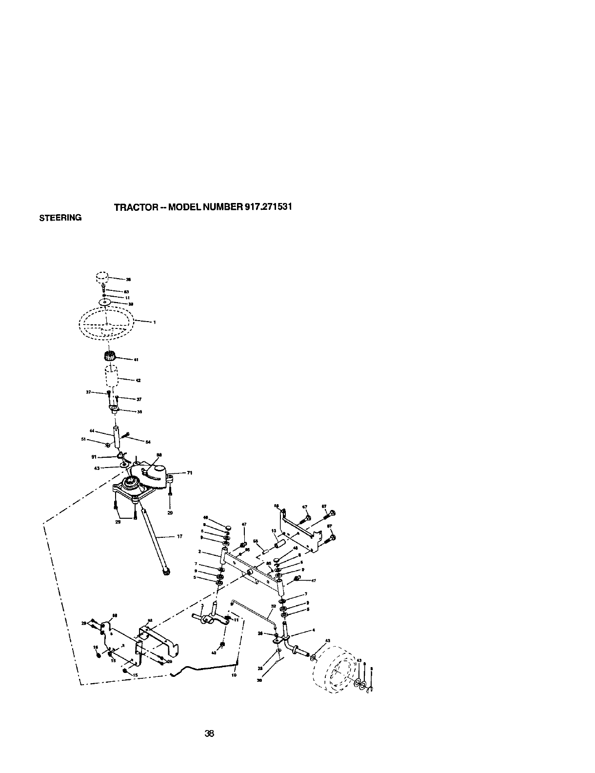
STEERING
TRACTOR - MODEL NUMBER 917.271531
ID

STEERING TRACTOR - MODEL NUMBER 917.271531
KEY PART
NO. NO. DESCRIPTION
I 139768 Wheel Steedng Opp Sears BIk
2 154427 Axle Asm Front Lt
3 136840 Spin_e Asm Lh
4 169839 Spindle Asm Rh
5 6236H Washer Thrust ,75 x 1,230
6 121748X Washer 25/32 x 1-5/8 x 16 G_L
7 19272016 Washer 27/32 X 1-1/4 X 16 Ga.
8 12000029 RingKllp#T5304-75
9 3366R Bearing Col Strg B_k
10 175121 Oraglink
11 1_ Washer Lock Hvy HIcl Spr 3_
13 136515 Spacer Brg Axle Front
15 145212 Nut Hexflange Lock
17 177876 Shalt Asrn Strg
26 126847X Bushing Link Drag BIk LR
27 136874 Gear Sector 22 Teeth
28 19131416 Washer 13/32 x 7/8 x 16 G&
29 17360612 Screw 3/8-16 x 3/4
3_ 130465 Rod _e Wlre Form 19.75 Mach
36 155099 Bushing S_'g. 5/8 ID Dash
37 152927 Screw
38 139769 Cap Wheel Steer Opp Sears USA
39 19133812 Washer 13/32 x 2-3/8 x 12 Ga.
40 78t0H Nut Lock Center 3/8-24
41 100711L Adaptor Wheel Strg.
42 145G54X428 Boot Steedng Dash P/l_ MTL BIk
43 t21749X Washer 25/32 x 1-1/4 x 16 G&
44 153720 Extension Steedng Non-adjust
46 121232X Cap Spindle FrTop B_k
47 3636M Fitting Grease
51 73800500 Nut Lock Hx W/Ins 5/t 6-18unc
54 74780520 Boit Fin Hex 5/16-18unc
63 74780616 Bo_tFin Hex 3/8-16unc x 1Gr. 5
65 160367 Spacer Axle
67 72140618 Boll Rdhd 3/8-16 x 2-1/4
68 136827 Brace Axle
71 175146 SteedngAsm
169835 Bracket Susp Chesis Front
85 133835 Fastner Christmas Tree
88 175118 Bolt Sheu_der7/I 6-20 Unc
91 175553 ClipSteedng
NOTE: All component dimensions _ven in U. S.
inches 1 inch = 25.4 mm
39
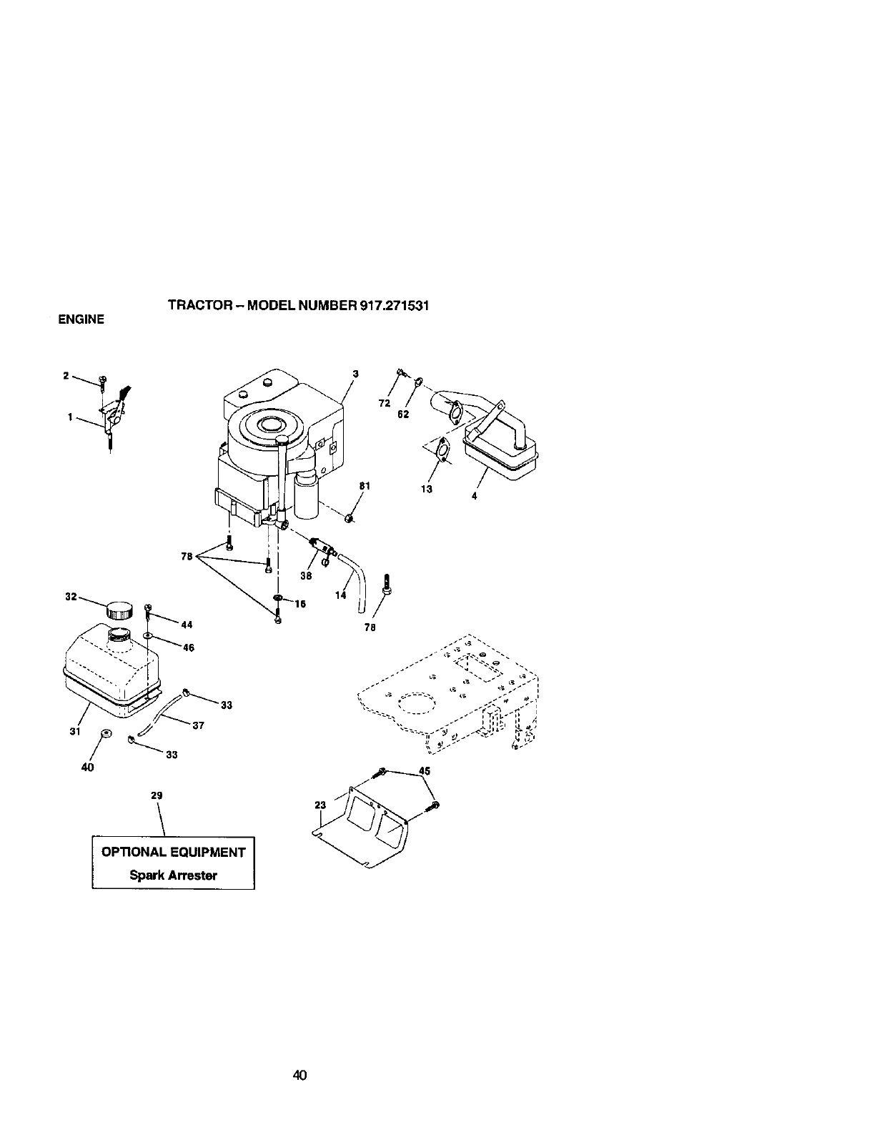
ENGINE TRACTOR - MODEL NUMBER 917,271531
78<
29
OPTIONAL EQUIPMENT
Spark Arrester
81
727
13
23
14
4O

ENGINE
TRACTOR - MODEL NUMBER 917.271531
KEY PART
NO. NO. DESCRIPTION
1 170545 ControlTWch
2 17720410 Screw Hex Thd Cut 1/4-20x5/8 T
3....... Engine (See Breakdown)
Briggs. Model No 287707-1255-E3
4 137"352 Muffler Exh LT B&S 14HP IC OHV
13 165291 Gasket Eng 1 313 Id ]In Plated
14 148456 Tuhe.drain
16 S]_551237 Washer Lock Ext Too_ 3!8
23 169837 S hleld BrownJn_Deb dsG uard
29 137180 Kit Spark Arrestc_ (Flat Scm)
31 10_(_X Tank Fuel Front 1 25
32 158990 Cap Asm Fuel Sears Vented
33 123487X Clamp HoSe BIk
37 137040 Line Fuel 20"
38 148315 plug.drain
40 124028X Bushing Snap Nyl BIk Fuel Line
44 17670412 Screw Hexwsh Thdrol 1/4-20 x 3/4
45 17000612 Screw Hex wsh Thdr 3/8-16 x/4
46 19091416 Washer 9/32 x 7/8 x lg ga
STD551131 Washer Lock H','/HIcJ Spr 5/16
72 71070512 Screw Hex Hd Cap 5/1g-18 X 3/4
78 17060620 Screw 3]8-16 x 1-1/4
81 73510400 Nut Keps Hex 1/4-20 Unc
NOTE: Arlcomponent dimensions given In U. S.
inches I inch = 25.4 mrn
41
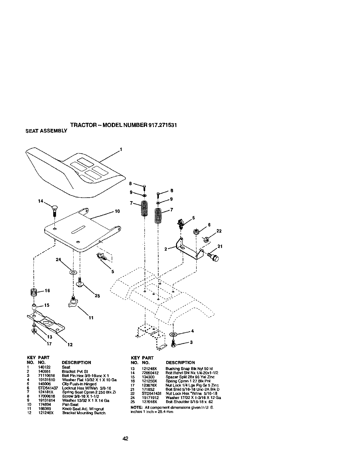
TRACTOR- MODELNUMBER917.271531
SEATASSEMBLY
KEY PART
NO. NO. DESCRIPTION
1 140122 Seat
2 140551 Bracket Pvt St
3 71110616 Bolt Fin Hex 3/8-16unc X 1
4 19131610 Washer F_t 13/32 X 1 X 10 Ga
5 145006 Clip PusPvln Hinged
6 S_:)541437 LocknutHexW/V/sh 3/8-16
7 124181X Spdng Seat Cprsn 2 250 Blk Zi
8 17000616 Screw 3/8-16 X 1-1/2
9 19131614 Washer 13/32 X 1 X 14 Ga
10 174894 Pan Seat
11 166369 Knob Seat Adj. Wingn_
12 121246X Bracket Mounting Sw_tch
KEY PART
NO. NO. DESCRIPTION
13 121248X BUShingSnap BIk Nyt 50 Id
14 72(_60412 Bolt Rdhd Sht Nk 1/4-20x1.1/2
15 134300 Spacer Split 2gx 96 Yel Zinc
16 12125OX Spdng Cprsn 127 B4kPhi
17 123G76X N_ Lock 1/4 tge Fig Gr 5 Zinc
21 171852 Bo_tShld 5/16-15 Unc-2A BJkD
22 S_:)541431 NLdL_Hex'W/Ins 5/16-18
24 19171912 Washer 17/32 X 1-3/16 X 12 Ga
25 127018X Bolt Shoulder 5/16-18 x 62
NOTE: All component din_nsions given In U S
inches 1 inch = 26,4 mm
42
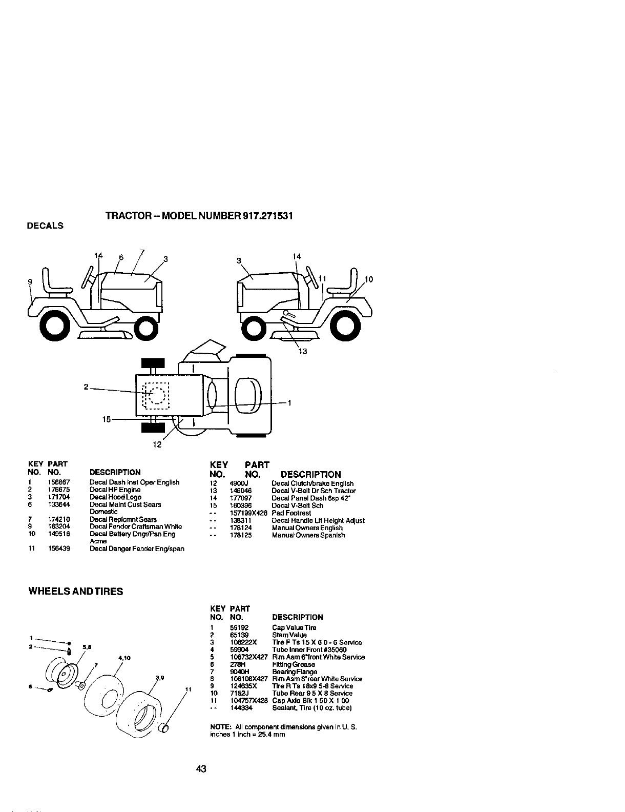
DECALS TRACTOR - MODEL NUMBER 917.271531
14
10
13
KEY PART
NO. NO,
1 156867
2 176675
3 171704
6 133644
7 174210
9 163204
10 149515
11 156439
12
KEY PART
DESCRIPTION NO. NO. DESCRIPTION
Decal Dash _nstOper English 12 490OJ Deca_Clutch/brake English
Decal HP Engine 13 146046 Decal V-Belt Dr Sch Tractor
Decal Hood Lngo 14 1770_7 Decal Panel Dash 6sp 42"
Decal Malnt Cust Sears 15 160396 Decal V-Bert Sch
Domestic - - 157199X428 Pad Footrest
Decal Replcrnnt Sears - - 138311 Decal Handle Lit Height Adjust
Decal Fender Craftsman White -- 178124 Manual Owners English
Decst BatteP/Dng{/Psn Eng -- 178125 Manual Ownnrs Spanish
Acres
Decal Danger Fender Eng/span
WHEELSANDTIRES
4,10
11
KEY PART
NO. NO. DESCRIPTION
1 59192 Cap Value Tim
2 65139 StemVstue
3 106222X Tire F Ts 15 X 6 0- 6 Sewice
4 59904 Tube Inner Front #35060
5 106732X427 Rim Asm 6"lTomWhlte Service
6278H FittingG_ease
7 9040H Beadng Flange
8 106108X427 Rim Asm 8"rear White Sarvice
9124635X T_re R "is 18x9 5-8 Service
10 7152J Tube Rear 9 5 X 8 Service
11 104757X428 Cap Axle BIk 1 50 X 1 CO
•. 144334 Sealant, Tim (10 OZ.tube)
NOTE: All component dimensions given in U, S.
inches 1 inch = 25.4 mm
43
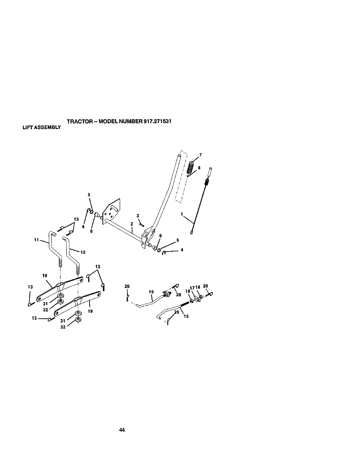
TRACTOR- MODELNUMBER917.271531
LIFTASSEMBLY
7
13 3
19
32
20
44

TRACTOR - MODEL NUMBER 917.271531
LIFT ASSEMBLY
KEY PART
NO. NO. DESCRIPTION
1 159460 WimAsm Inner/Sprg W/plunger LT
2 159471 Shaft Asm Lift
3 105767X Pin Groove I 500 Zinc
4'L2_ E Ring #5133-62
5 19211621 Washer Pttd 21/32 X 1 X 21ga
6 120183X Beadng Nylo11BIk629 Id
7 125631X Gdp Handle Fluted BIk
8 122365X Bulton Plunger Red
11 139855 Link Lift LH
12 139866 Link LiftRH
13 $1_624008 Retainer Spdng
15 173288 Link Front
16 73350800 Nut Jam Hex 1/2-13 Unc
17 175689 Trunnion
18 73800800 Nut Lock W/Wsh 1/2-13unc
19 13,9868 Arm Suspension Rear
20 163552 Ret_JnerSpringZinc
31 169865 Bearing PUt Lilt
32 73540600 Nut Crewnlc<:k 3_-24
NOTE: An component dimensions given In U. S.
inches 1 inch = 25.4 mm
45
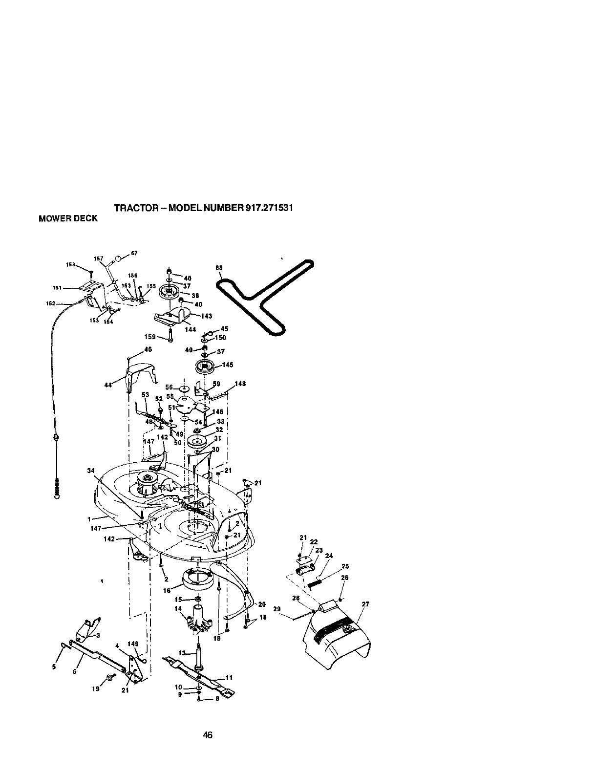
TRACTOR- MODELNUMBER917.271531
MOWERDECK
! ,148
34
I
46
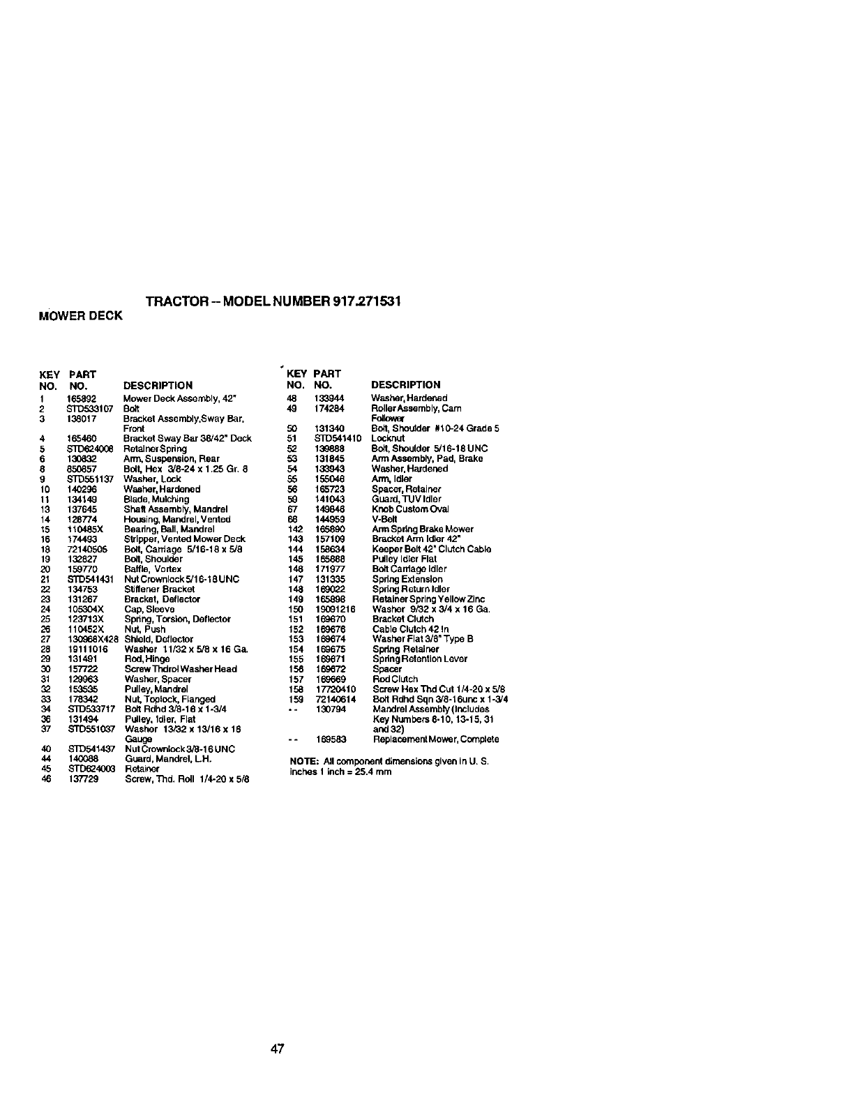
TRACTOR - MODEL NUMBER 917.271531
MOWERDECK
KEY PART KEY PART
NO. NO. DESCRIPTION NO. NO.
1 165892 Mower Deck Assembly, 42" 48 133944
2 S]D533107 Bult 49 174294
3 138017 Bracket Assembly,Sway Bar,
Front 50 131340
4 165460 Bracket Sway Bar 38t42" Deck 51 S]D541410
5 S_36240G6 Retainer Spdng 52 130888
6 130832 Arm. Suspension, Rear 53 131845
g 850857 Bult, Hex 3/8-24 x 1.25 Gr. 8 54 133943
9 S]_551137 Washer, Lock 55 155046
t0 140296 Washer, Hardened 56 165723
11 134149 Blade, Mulching 59 141043
13 137645 Shelf Assembly, Mandral 67 149848
14 128774 Housing, Mandrel, Vented 68 144959
15 110485X Beadng, Ball, Mandral 142 165890
16 174493 Stripper, Vented Mower Deck 143 157109
18 72140505 Bo0, Cardage 5/tT-10xg/8 144 158634
19 132827 Bo_l,Shoulder 145 165888
20 159770 Baffle, Vodex 148 171977
21 STD541431 NutCrownlockg/16-18UNC 147 131335
22 134753 Stiffener Bracket 148 1690_2
23 131267 Bracket, Deflector 149 165898
24 t05304X Cap, Sleeve 150 19091216
25 123713)< Spdng, Torsion, Defalctor 151 169670
26 It C452X Nut, PUSh 152 169676
27 130o_.8X428 Shield, Detlector 153 169674
28 19111016 Washer 11/32xg]gx16G& 154 169675
29 131491 Rod,Hinge 155 169671
30 157722 ScrewThdrol Washer Head 156 169672
31 129963 Washer, Spacer 157 169669
32 153535 Pulley, Mandrel 158 177'20410
33 178342 Nut, Toplcck, Flanged 159 72140614
34 STD533717 Bolt Rdhd 3/8-19 x 1-3/4 -* 130794
36 131494 Pulley, Idler, Flat
37 STD551037 Washer 13i32x13/16xlg
Gauge --169583
40 STD541437 Nut Crowetock 3/B-16 UNC
44 140088 Guard, Mandrel, LH.
45 STD624CO3 Retainer
46 137729 Screw, Thd. Roll 1/4-20 x 5/8
DESCRIPTION
Washer, Hardened
Roller Assembly, Cam
Fulk:_er
Bult, Shoutder #10-24 Grade 5
Lock,nut
Bo_t,Shoulder 5/16-18 UNC
Arm Assembly, Pad, Brake
Washer.Hardened
Arm, Idler
Spacer, Retainer
Guard, _JV Idler
Knob Custom Oval
V-Batt
ArmSpdng Brake Mower
Braaket Arm luler 42"
Keeper Belt 42" Clutch Cable
Pulley Idler Flat
Bolt Cardage Idler
Spdng Extension
Spdng Return Idler
Retainer Spdng Yellow Zinc
Washer 9/32 x 3/4 x 16 Ga.
Bracket Clutch
Cable Clutch 42 in
Washer Flat 3/8" Type B
Spdng RetaJnsr
Spdng Retention Lever
Spacer
ROdClUtCh
Screw Hex Thd Cut 1/4-20 x 518
Bult Rdhd Sqn 3/8-16unc x 1-3/4
Mandrel Assembly (Includes
Key NLm_hers8-10, 13-15, 31
and 32)
Replacemeet Mowe r, Comptete
NOTE: All component d_rnens]onsgiven in U. S.
inches 1 Inch = 25.4 turn
47
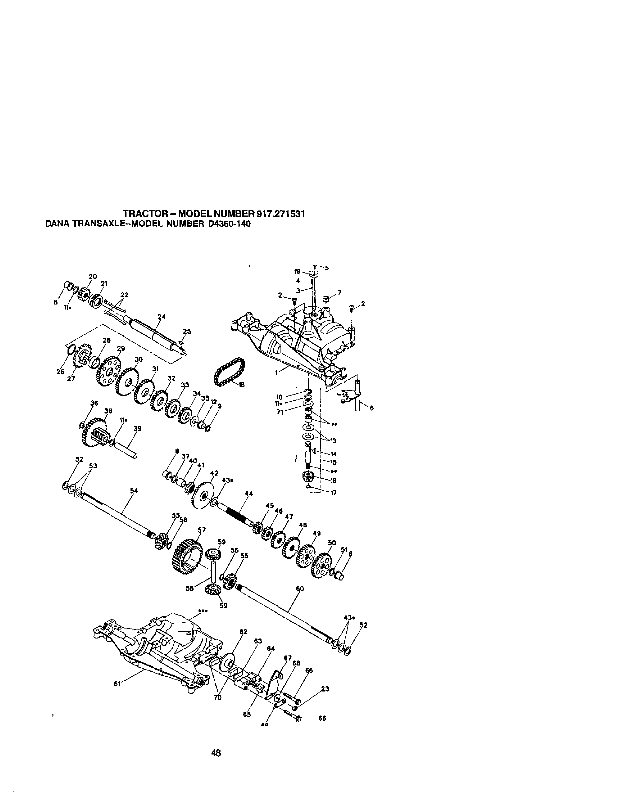
TRACTOR- MODELNUMBER917,271531
DANATRANSAXLE-MODELNUMBERD4360-140
20 21
22
36 38
53
4B
49
50
43o
48
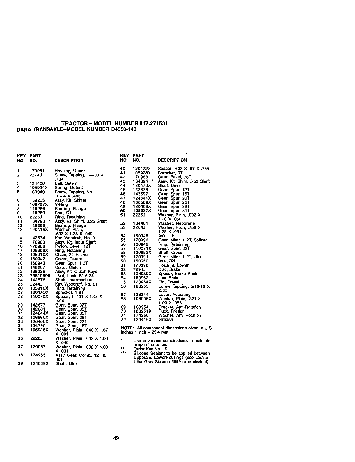
TRACTOR - MODEL NUMBER 917.271531
DANATRANSAXLE-MODEL NUMBER D4360-140
KEY PART KEY PART
NO. NO. DESCRIPTION NO. NO. DESCRIPTION
1 170981 Heualn ,Upper 40 120472X Spacer, .633 X .87 X .755
2 2274J Screw, _a 41 105928X Sprocket, 9T
pping, 1/4-20 X 42 170986 Gear, Bevel, 86T
.734 43 134394 * Assy, Kit, Shim, .750 Shaft
3 134400 Ball, Detent 44 120473X Shaft, Drive
4 105904X Spring, Detent 45 142678 Gear. Spur, 12T
5 160940 Screw. Tapping, No. 46 143697 Gear, Spur. 15T
10-24 X .482
6 138235 Ass , Kit, Shifter 47 124641X Gear, Spur. 20T
7 108727X V-_n 48 106589X Gear, Spur, 25T
g 49 120408X Gear, Spur, 28T
8 148266 Bearin , Flange
9 148269 Seal, _il 50 105937X Gear, Spur, 31T
10 2225J Ring, Retaining 51 2226J Washer, Plain, ,632 X
1.00 X .060
11 134793 * Assy, K3t, Shim, .625 Shaft 52 134401 Washer, Neoprene
12 148268 Bearing, Flange
13 120415X Washer, Plain, 63 2264J Washer, Plain, .758 X
1.25 X .031
.632 X 1.38 X .046 54 160946 Axle, LH
14 142674 Key, Woodruff, No. 9
15 170983 Assy, Kit, Input Shaft 55 170990 Gear, Miter, 1 2T, Splined
16 170986 Pinion, Bevel, 12T 56 160948 Ring, Retaioln
17 105909X Rin , Retainin 57 110071X Gear, Spur, _2gT
16 105910X C_a_n, 24 Pitches 58 120952X Shaft, Cress
59 170991 Gear, Miter. 1 23", idler
19 160942 Cover, Detent 60 160950 Axle, RH
20 160943 Gear, S_lur. 1 2T
21 148267 Collar, utch 61 170992 Housing, Lower
62 7294J Disc, Brake
22 138236 Assy, Kit. Clutch Keys
23 73810500 Nut, Lock, 5/10-24 643 106989X Spacer, Brake Puck
160952 Jaw, Brake
24 142676 Shaft, Intermediate 65 120954X Pin, Dowel
25 22443 Key, Woodruff. No. 61
26 105916X Ring, Retainin 66 160953 Screw, Tapping, 5/16-18 X
27 12047OX Sprocket, 1 8_ 2.35
28 110070X Spacer, 1. 131 X 1.45 X 67 138244 Lever, ActuaSng
68 108996X Washer, Plain, .321 X
.494 1,00 X.055
29 142677 Gear, Spur, 37T 69 160954 Bracket, Anti-RotalJon
30 142691 Gear, Spur, 3ST
31 124644X Gear, Spur, 30T 70 120951X Puck, Friction
71 174256 Washer, Anit Rotation
32 108980X Gear, Spur, 25T 72 120416X Grease
33 120406X Gear, Spur, 22T
34 134796 Gear, Spur, 19T NOTE: All component dimensions given in U.S.
35 105925X Washer. Plain, ,640 X 1.37
X .061 inches 1 inch = 25.4 mm
36 2228J Washer. Plain, .632 X 1.00 Use k_ various combinalJons to maintain
X.046 pro erclearances.
37 170987 Washer, Ptabl, .632 X 1.00 ** O_:/_r Key No. 15.
X .031 *** Silicone Seatant to be applied between
38 174255 Assy. Gear, Comb., 12T &Upperand LowerHoualngs (use Loc_ite
30T Ultra Gray Silicone 5699 or equivalent).
39 124639X Shaft. Idler
49
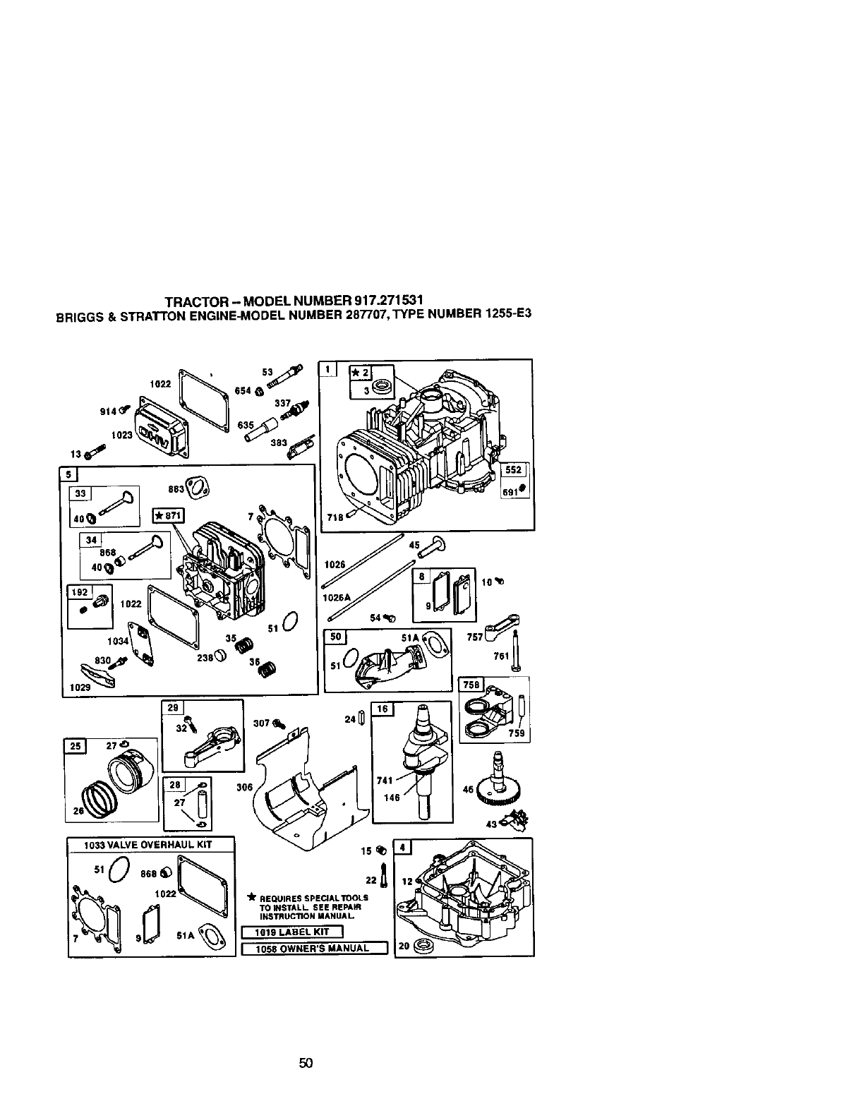
TRACTOR - MODEL NUMBER 917.271531
BRIGGS & STRATTONENGINE-MODELNUMBER 287707,TYPE NUMBER 1255-E3
lO
51
1033 VALVE OVERHAUL KiT
_10°°'_F"-,,
1O_
_9_ 51A _
24,11
306_ __ ._
lSq_
"Jr REQUIRESSPECIALTOOLS
TO INSTALL SEE RE_Wt
INSTRUCTIONMANUAL
I 101SLA.ELNiTI
1058 OWNER'S MANUAL I
,54
50
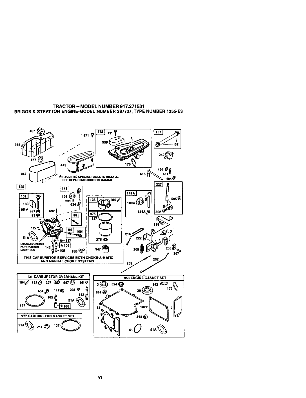
TRACTOR- MODELNUMBER917.271531
BRIGGS&STRATTONENGINE-MODELNUMBER287707,TYPENUMBER1255-E3
Q
' 276
LMT/CA R EPJRETO R i
PARTNUMUR 142 , 947
Loc,'no,.,_ 186__ I
THIS CARBURETOR SERVICES BOTH CHOKE-A-MATIC
AND MANUAL CHOKE SYSTEMS 232
121 CARBURETOR OVERHAUL KIT
,o,_ 1270 267_ .7@ 95
634._ 117_1 231
1370 105 _IA _
358 ENGINE GASKET SET
51
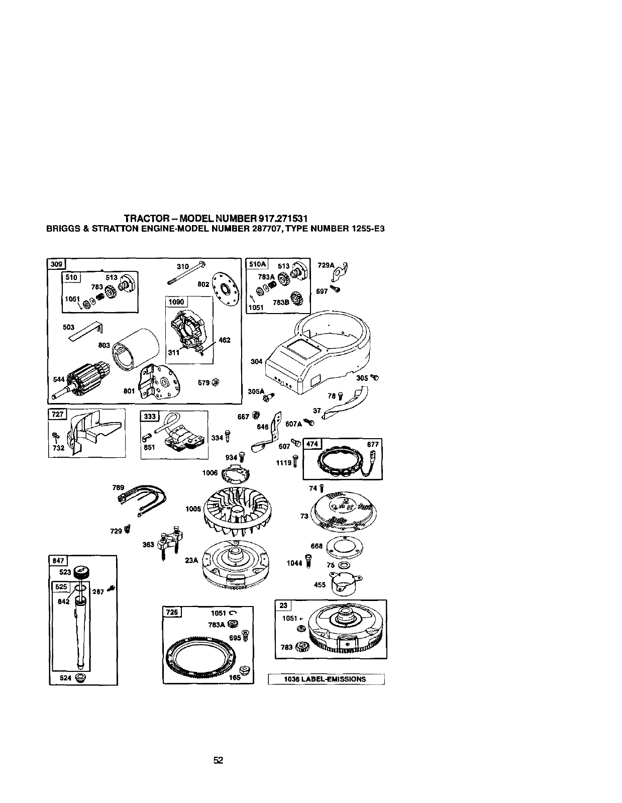
TRACTOR- MODELNUMBER917.271531
BRIGGS&STRATTONENGINE-MODELNUMBER287707,TYPENUMBER1255-E3
8O3
801
9_ 1005
363 _23A
524
74 _
668
1044_ 75
455
1036 LABEL-EMISSIONS 1
52
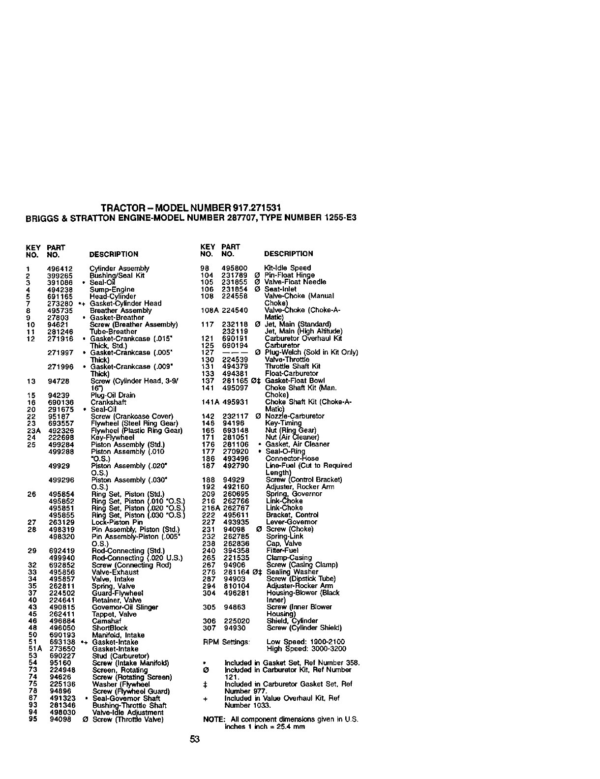
TRACTOR- MODELNUMBER917.271531
BRIGGS&STRATTONENGINE-MODELNUMBER287707,TYPENUMBER1255-E3
KEY PART KEY PART
NO. NO. DESCRIPTION NO. NO. DESCRIPTION
1496412 Cy]ioder Assembly 98 495800 Kit-Idle Speed
2 399265 Bushing/Seal Kit 104 231789 _1 Pin-Float Hin=n]g_e
3 391086 • SeaI-O, 105 231855 OValve-Fldst rqeodle
4 494238 Sum=p-tEngine 106 231854 OSeat-inlet
5 691165 Head.cytinder 108 224558 Valve.choke (Manual
7 273280 ,+ Gasket-Cylinder Head Choke)
8 495735 Breather Assembly 108A 224540 Valve43hnke (Choke-A-
9 27803 °Gasket-Breather Matic)
10 94621 Screw (Breather Assembly) 117 232118 O Jet, Main (Standard)
11 281246 Tube-Breather 232119 Jet, Main (High Altitude)
12 271916 •Gasket-Crankcase (.015 ° 121 690191 Carburetor Overhaul Kit
• Thick, Std.) 125 690194 Carburetor
271997 Gasket-Crankcase (.005" 127 ---- -- _Plug-Waich (Sold in Kit Only)
Thick) 130 224539 Valve-Throttle
271996 °Gasket.crankcase (.009 ° 131 494379 Throttle Shaft Kit
Thick) 133 494381 Float.carburetor
13 94728 Screw (Cylinder Head, 3-9/ 137 281165 _: Gasket-Float Bowl
16") 141 495097 Choke Shaft Kit (Man.
15 94239 Plug-Oil Drain Choke
16 690136 Crankshaft 141A 495931 Choke Shaft Kit Choke-A-
20 291675 , Seal-Oil MStic)
22 95187 Screw (Crankcase Cover) 142 232117 _l Nozzle-Carburetor
23 693557 Flywheel (Steel Ring Gear) 146 94196 Key-Tksing
23A 492326 Flywheel (Plastic Ring Gear 165 693148 Nut (RingGear)
24 222698 Key-Flywhee 171 281051 Nut (Air Cleaner)
25 499284 Piston Assembly (Std.) 176 261106 •Gasket, Air Cleaner
499288 Piston Assembly (.010 177 270920 * SeaI-O-Rin ig
"O.S.) 186 493496 Connector-Hose
49929 Piston Assembly (.020" 187 492790 Line-Fuel (Cut to Required
O.S.) Length
Screw (Con_ol Bracket)499296 Piston Assembly (.030" 188 94929
O.S.) 192 492160 Adjuster, Rocker Arm
26 495854 Ring Set, Piston (Std.) 209 260695 Sprin , Governor
495852 RingingSet, Piston {.OlO "O.B. ! 216 262766 Link-_hoke
495851 Ring Bet, Piston .020 "O.S. 216A 262767 Link-Choke
495855 Rin Set, Piston .030 _O.S. 222 495611 Bracket, Control
27 263129 Lock-Piston Pin 227 493935 Lever-Governor
28 498319 Pin Assembly, Piston (Std.) 231 94098 OScrew (Choke
498320 Pin Assembly-Piston (.005" 232 262785 Spring-L-Link
O.S.) 238 262836 Cap, Valve
29 692419 Rod-Connecting (Std.) 240 394358 FilteroFuet
499940 Rod-Connectldg (.020 U.S.) 265 221535 Clarnp-Casing
32 692852 Screw(ConneclJng Rod) 267 94906 Screw (Casing Clamp)
33 495856 Valve-Exhaust 276 281164 O:_ Sealing Washer
34 495857 Valve, Intake 287 94903 Screw (Dipstick Tube)
35 262811 Spnng, Valve 294 810104 Adueter-Ronker Arm
37 224502 Guard-Flywheel 304 496281 Housng-Bldwer Back
40 224641 Retainer, Valve Inner
43 490815 Govemor-OU Slinger 305 94863 Screw nner Bc_ver
45 262411 Tappet, Valve Housing)
46 496884 Camshaf 306 225020 Shield,Cylinder
48 496050 ShortBIock 307 94930 Screw (Cylinder Shield)
50 690193 Manifold, Intake
51 693138 *+ Gasket-Intake RPM Settings: Low S eed: 1900-2100
High _'Ppeed: 3000-320051A 273650 Gasket-Intake
53 690227 Stud (Carburetor)
54 95160 Screw (Intake Manifold) ° included ld Gasket Set, Ref Number 358.
73 224948 Screen, Rotating OIncluded in Carburetor Kit, Ref Number
74 94626 Screw (Rotating Screen) 121.
75 225136 Washer(Flywheel ._ Included in Carburetor Gasket Set, Ref
78 94896 Screw Flywheel Guard) Number 977.
87 491323 °Sea-Governor Shaft + Included ld Value Overhaul Kit, Ref
93 281346 Bushino-iThrottle Shaft Number 1033.
94 498030 Valve-lale Adjustment
95 94098 _ Screw (Throttle Valve) NOTE: All component dimensions given in U.S.
inches 1ldch = 25.4 mm
53

TRACTOR- MODELNUMBER917.271531
BRIGGS&STRA'rFONENGINE-MODELNUMBER287707,TYPENUMBER1255-E3
KEY PART KEY PART
NO. NO. DESCRIPTION NO. NO. DESCRIPTION
309 693551 Motor-starter(For Steel Ring 729 281390 Clip, Wire
Gear Only) 729A 225170 Clip, W_re
Motor-Starter _For Plas6c 732 94625 Screw(Starter Ddve Cover)
497595 Ring Gear OnJy) 741 262932 Gear-Timing
310 94003 Screw (Starter Motor) 757 213998 Link-Counterweight
311 497608 Brush Set 768 499994 Counterweight
318 94734 Screw (Mounting Bracket) 759 230787 Pin-Counterweight
333 495859 Armature, Magneto 761 94593 Screw (Counterweight)
334 94731 783 693713 Gear-Pinion (For Steel Ring
Screw _,rmature
337 491065 Spark lug Gear Only
358 690189 Gasket Set 783A 693059 Gear-Pnion ForAurnnum
363 19203 FFIvwheel Puller Ring Gear Only)
383 89838 W'rench-Spark Plug 783S 693058 Gear-Pinion For P!asgc
404 94927 Washer (Governor Crank) Ring Gear Onty)
423 95163 Screw (Air Cleaner Base) 789 497708 Harness, Widng
455 222561 Cup-Flywheel 801 497626 Cap-Drive
462 225137 Washer (Starter Cable) 802 497607 Cap-End
467 493903 Knob-Air Cleaner 803 497604 Housing-Starter
474 393474 Ahemator 830 94555 Stud-Rocker Arm
503 806000 Strap-Starter 847 496415 DipsSck/Tube Assemaly
505 231978 Net (Govemor Lever) 851 224110 Terminal-Cable
510A 693699 Drive. Starter (UseWith 868 499236 ,+ Seal- Valve
Steel Ring Gear Only) 871 262835 Bushinlg-Guide
510A 497606 Drive, Starter Use With 875 693686 Base, Air Cleaner
Aluminum &Plastic R ng 877 393456 Wire-Alternator
Gear One/) 878 393362 Harness-Ahemator
513 398003 Clutch-Dnve 883 272293 Gasket, Exhaust
523 495230 Dipstick 914 94863 Screw (Rocker Cover)
524 281370 • Dipstick Tube Seal 934 94627 Screw (Fan Retainer)
525 496113 Dips6ckTube 947 497672 Solenoid-Fuel
535 496894 Filter, NC Element 967 272403 Filter-pre Cleaner
544 497603 Armature-Starter 968 281758 Cover, Air Cleaner
552 491986 Bushin -Q-Gov. Lever 975 495933 Bow_-Float
556 93621 Screw _Altemetor) 977 690192 Gasket Set-Carburetor
562 94907 Bolt (Governer Lever) 987 281166 _ Scal-Tilrottle Shaft
579 92278 Net Starter Cable) 996 690678 Shield-Carburetor
601 93053 Camp-Hose 1005 691927 Fan-Flywheel
614 93306 Pin-Cotter 1006 224413 Retainer-Fan
616 495157 Crank-Governor 1019 496758 Label Kit
634 494453 I_ Seal-Spring 1022 272475 °+ Gasket-Rocker Cover
Assembly Manual Choke 1023 224552 Cover-Rocker
634A 494455 O Sca-Sprlng Assy. (Cheke-A- 1026 494432 Rod-Push Intake)
Metic) 1026A495136 Rod-Push Exhaust)
635 280872 Boot, Spark Plug 1029 224554 Arm-Rocker
646 224546 Brace-Air Cleaner 1033 690190 Valve Overhaul Kit
654 94010 Nut (Carbur_or) 1034 495248 Guide-Push Rod
663 94929 Screw (Air Cleaner Brace) 1036 499364 Label Kit-Emission
663A 94704 Screw (Air Cleaner Brace) 1044 94673 Screw Flywheel)
667 94010 Nut (Ak Cleaner Brace) 1051 263080 Ring-Retainer
668 280848 Spacer 1058 273683 Owner's Manual
692 262715 Spring-Detent 1090 497605 Retainer-Brush
695 693109 Screw (Ring Gear) 1091 281364 Cap-Limiter
697 94951 Screw (Starter Motor) ---- 28N707-1026-E1 Replacement Engine
711 94704 Screw (Carburetor Shiald)
718 230192 Dowel, Sleeve RPM Settings: Low Speed: 1900-2100
726 399676 Gear Ring(Atuminum- High Speed: 3000-3200
Services Plastic Ring Gear
Only) o Included in Gasket Set, Ref Number 358.
727 490324 Cover, Starter Drive _1 Included in Carburetor Knt, Ref Number
121.
$ Included in Carburetor Gasket Set, Ref
Number 977.
+Included in Value Overhaul lot, Ref
Number 1033.
NOTE: All componentdimensions given in U,S.
inches 1 Inch =26.4 mm
54
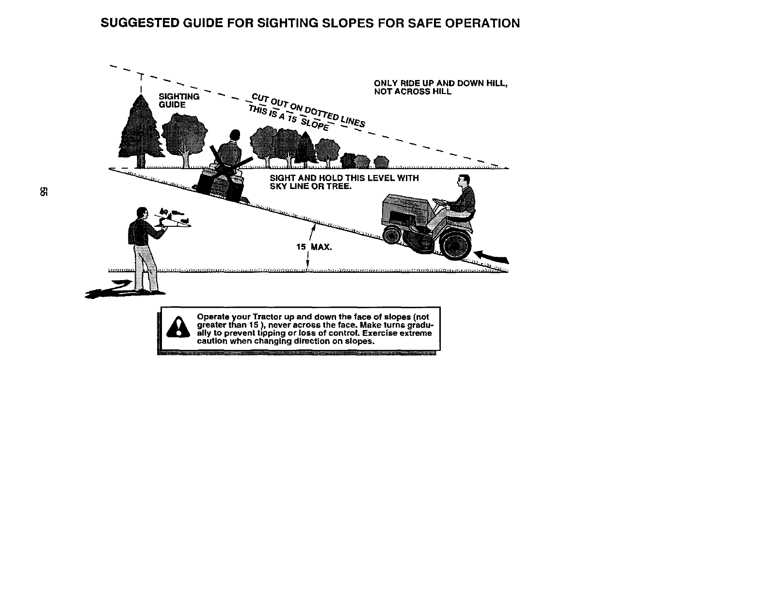
SUGGESTED GUIDE FOR SIGHTING SLOPES FOR SAFE OPERATION
ONLY RIDE UP AND DOWN HILL,
NOT ACROSS HILL
15 MAX.
/_ Operate your Tractor up and down the face of slopes (not I
1
greater than 15 ), never across the face. Make turns gradu- |
ally to prevent tipping or loss of control. Exercise extreme I
_ng direction on slopes. ]

Forrepairofcarry-inproductslike vacuums,lawnequipment,and
elect]'onics,callfor thenearestSears Partsand RepairCenter.
For the replacementparts, accessoriesand owner'smanuals
that you needto do-it-yourself,call Sears PartsDirectS_!
1-800-366-PART
(1_00-366-7278) 6 a.rrL-11 p.m., 7da_s aweek
(u.s._
To purchaseor inquireabout a SearsServiceAgreement
orSearsMaintenanceAgreement:
1-600-827-6655 (u.sA.) 1-800-361-6665 (Canada)
7a.m.- 5 p.m.,CST, Mol. - Sat 9a_m.- 8 p.m.EST, M - F,4p.nt Sat
®Registered Trademark /TM Trademark /su Service Mark of Sears, Roebuck and Co.
®Marca Registreda /TM MarCa de F6brlca /su Mama de Ser_cio de Sears, Roebuck and Co.
McMarque de commerce /uo Marque d6pos6e de Sears, Roebuck and Co.
178124 3.13.01 TR Printed in U.SgE.
