Craftsman 917271832 User Manual LAWN TRACTOR Manuals And Guides L0105086
CRAFTSMAN Lawn, Tractor Manual L0105086 CRAFTSMAN Lawn, Tractor Owner's Manual, CRAFTSMAN Lawn, Tractor installation guides
User Manual: Craftsman 917271832 917271832 CRAFTSMAN LAWN TRACTOR - Manuals and Guides View the owners manual for your CRAFTSMAN LAWN TRACTOR #917271832. Home:Lawn & Garden Parts:Craftsman Parts:Craftsman LAWN TRACTOR Manual
Open the PDF directly: View PDF ![]() .
.
Page Count: 60

Owner's Manual
21.0 HP
ELECTRIC START
42" MOWER
6 SPEED TRANSAXLE
LAWN TRACTOR
Model No.
917.271832
• Safety
•Assembly
•Operation
•Maintenance
•Repair Parts
CAUTION:
Read and follow all
Safety Rules and Instructions
before operating this equip-
ment.
For answers to your questions
about this product, Call:
1-800-659-5917
Sears Craftsman Help Line
5 am -5 pm, Mon _Sat
Sears, Roebuck and Co., Hoffman Estates, IL 60179
visit our Craftsman website: www.sears.com/craftsman
Warranty ............................................... 2
Safety Rules ......................................... 3
Product Specifications .......................... 6
Assembly .............................................. 8
Operation ............................................ 12
Maintenance Schedule ...................... 19
Maintenance ....................................... 19
Service and Adjustments .................... 23
Storage ............................................... 29
Troubleshooting .................................. 30
Repair Parts ........................................ 34
Parts Ordering ..................... Back Cover
LIMITED TWO YEAR WARRANTY ON CRAFTSMAN RIDING EQUIPMENT PARTS
For two (2) years from the date of pumhase, if this Craftsman Riding Equipment is
maintained, lubdcated and tuned up according to the instructionsin the owner's
manual, Sears will repair or replace, free of charge, any parts found to be defective in
material or workmanship. Warranty service is available free of charge by returning
your Craftsman dding equipment to your nearest Sears Service Center. In-home
warranty service is available but a trip charge will apply. This warranty applies only
while this product is in the United States.
This Warranty does not cover:
• Expendable items which become worn during normal use, such as blades, spark
plugs, air cleaners, belts and oil filters.
•Tire replacement or repair caused by punctures from outside objects, such as nails,
thorns, stumps, or glass.
•Repairs necessary because of operator abuse, including but not limited to, damage
caused by towing objects beyond the capability of the riding equipment, impacting
objects that bend the frame or crankshaft, or over speeding the engine.
• Repairs necessary because of operator negligence, including but not limited to,
electrical and mechanical damage caused by improper storage, failure to use the
proper grade and amount of engine oil, failure to keep the deck clear of flammable
debris, or the failure to maintain the equipment according to the instructions
contained in the owner's manual.
•Engine (fuel system) cleaning or repairs caused by fuel determined to be contami-
nated or oxidized (stale). In general, fuel should be used within thirty (30) days of its
purchase date.
• Riding equipment used for commercial or rental purposes. A product is "used for
commemial purpose" if is used for any purpose other than single family household
dwellings or in usage where profit is made.
LIMITED 90 DAY WARRANTY ON BATI'ERY
For ninety (90) days from date of purchase, if any battery includedwith this riding
equipment proves defective in matedal or workmanship and our testing determines
the battery will not hold a charge, Sears will replace the battery at no charge. War-
rant'/service is available free of charge by returning your Craftsman dding equipment
to your nearest Sears Service Center, In-home warranty service is available but a trip
charge will apply. This warranty applies only while this product is in the United States.
TO LOCATE THE NEAREST SEARS SERVICE CENTER OR TO SCHEDULE IN-
HOME WARRANTY SERVICE, SIMPLY CONTACT SEARS AT 1-800-4-MY-HOME
This Warranty gives you specific legal dghts, and you may also have other rights
which may vary from state to state.
Sears, Roebuck and Co., D/817 WA, Hoffman Estates, IL 60179
2
IMPORTANT: This cutting machine is capable of amputating hands and feet and
throwing objects. Failure to observe the following safety instructions could result in
serious injury or death.
I. GENERAL OPERATION
• Read, understand,and follow all
instructions inthe manual and on the
machine before starting.
• Only allow responsibleadults, who are
familiar withthe instructions,to operate
the machine.
•Clear the area of objects such as rocks,
toys, wire, etc., whichcould be picked
up and thrown by the blade.
•Be sure the area is clear of otherpeople
before mowing. Stop machine if anyone
enters the area.
•Never carry passengerS.
•Do not mow in reverse unlessabsolutely
necessary. Always look down and
behind before and while backing.
• Be aware of the mower discharge
direction and do not point itat anyone.
Do not operate the mower withouteither
the entire grass catcher or the guard in
placa.
• Slow down before turning.
•Never leave arunning machine
unattended. Arways turn off blades, set
parking brake, stop engine, end remove
keys before dismounting.
• Turn off blades when not mowing.
• Stop engine before removing grass
catcher or unclogging chute.
• Mow only in daylight or good artificial
light.
•Do not operate the machine while under
the influence of alcohol or drugs.
•Watch for trafficwhen operatingnear or
crossing roadways,
•Use extra care when loading or unload-
ing the machine into a traileror truck.
•Data indicatesthat operators, age 60
years and above, are involved in a large
percentage of riding mower-related
injuries. These operatorsshould
evaluate their abilityto operate the riding
mower safely enough to protect them-
selves and others from serious injury.
•Keep machine free of grass, leaves or
other debris build-up which can touch
hot exhaust / engine parts and bum. Do
not allowthe mower deck to plow leaves
or other debris which can cause build-
up to occur. Clean any oil or fuel
spillage before operating or storing the
machine. Allow machine to cool before
storage.
II. SLOPE OPERATION
Slopes are amajor factor related to loss-of-
controland tipover accidents,which can re-
sult in severe inury or death. AJl stopes
requ re extra caution. If you cannot back up
the slope or if you feel uneasy on it, do not
mow it.
DO:
•Mow up and down slopes, not across.
•Remove obstaclessuch as rocks,tree
limbs,etc.
Watch for holes, ruts,or bumps. Uneven
terrain couldovertum the machine. Taft
grass can hide obstacles.
Use slow speed. Choose alow gear so
that you wirrnot have to stop or shift
whire on the slope.
Follow the manufacturer's recommenda-
tions for wheel weights or counter-
weights to improve stability.
Use extra care with grass catchers or
other attachments. These can change
the stability of the machine.
Keep all movement on the slopes slow
and gradual. Do not make sudden
changes in speed or direction.
Avoid startingor stopping on a slope. If
tires lose traction, disengage the blades
and proceed slowly straightdown the
slope.
DO NOT:
•Do not turn on slopes unless necessary,
and then, turn slowly and gradually
downhill, if possible.
• Do not mow near drep-offs, ditches, or
embankments. The mower could
suddenly turn over if a wheel is over the
edge of a cliff or ditch, or if an edge
caves in.
• Do not mow on wet grass. Reduced
traction could cause sliding.
• Do not try to stabilizethe machine by
puttingyourfoot on the ground.
• Do notuse grass catcher on steep
slopes.
3
III. CHILDREN
Tragic accidents can occur if the operator
is not alert to the presence of children.
Children are often attracted to the
machine and the mowing activity. Never
assume that children will remain where
you last saw them.
• Keep children out of the mowing area
and under the watchful care of another
responsible adult.
•Be alert and turn machine off if children
enter the area.
• Before and when backing, look behind
and down for small children.
• Never carP/children. They may fall off
and be seriously injured or interfere
with safe machine operation.
• Never allow children to operate the
machine.
• Use extra care when approaching blind
corners, shrubs, trees, or other objects
that may obscure vision.
IV, SERVICE
•Usa extra care in handling gasoline
and other fuels. They are flammable
and vapors are explosive.
-Use only an approved container,
-Never remove gas cap or add fuel
with the engine running. Allow
engine to cool before refueling. Do
not smoke,
- Never refuel the machine indoors.
- Never store the machine or fuel
container inside where there is an
open flame, such as a water heater.
•Never run a machine inside a closed
area.
•Keep nuts and bolts, especially blade
attachment bolts, tight and keep
equipment in good condition.
• Never tamper with safety devices.
Check their proper operation regulady.
•Keep machine free of grass, leaves, or
other debris build-up. Clean oil or fuel
spillage. Allow machine to cool before
storing.
•Stop and inspect the equipment if you
strike an object. Repair, if necessary,
before restarting.
•Never make adjustments or repairs with
the engine running.
•Grass catcher components are subject
to wear, damage, and deterioration,
which could expose moving parts or
allow objects to be thrown. Frequently
check components and replace with
manufacturer's recommended parts,
when necessary.
•Mower blades are sharp and can cut.
Wrap the blade(s) or wear gloves, and
use extra caution when servicing them.
•Check brake operation frequently.
Adjust and service as required.
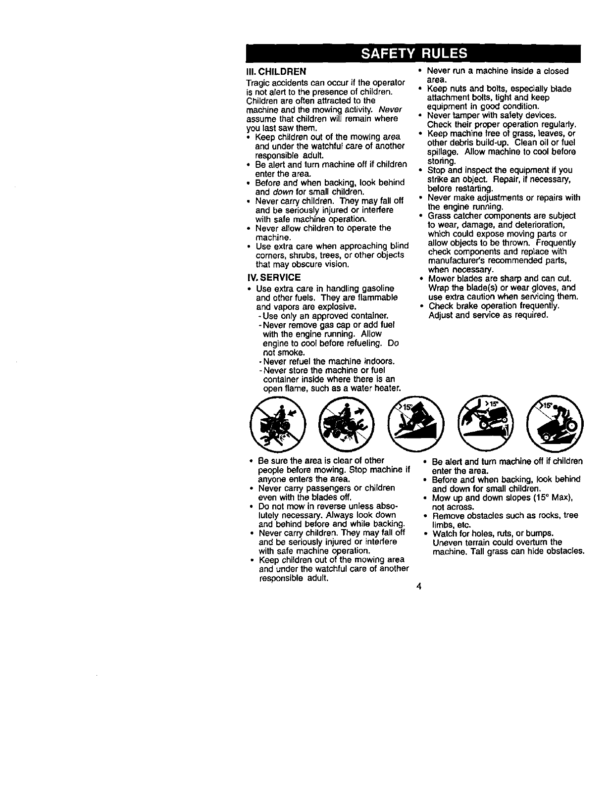
• Be sure the area is clear of other
people before mowing. Stop machine if
anyone enters the area.
• Never carry passengers or children
even with the blades off.
• Do not mow in reverse unless abso-
lutely necessary. Always look down
and behind before and while backing.
• Never carry children. They may fall off
and be seriously injured or interfere
with safe machine operation.
• Keep children out of the mowing area
and under the watchful care of another
responsible adult.
•Be alert and turn machine off if children
enter the area.
•Before and when backing, look behind
and down for small children.
•Mow up and down slopes (15 ° Max),
not across.
•Remove obstacles such as recks, tree
limbs,etc.
•Watch for holes, ruts, or bumps.
Uneven terrain could overturn the
machine. Tall grass can hide obstacles.
"Usa slow speed. Choose alow gear so
that you will not have to stop or shift
while on the slope.
•Avoid starting or stopping on a slope. If
tires lose traction, disengage the blades
and proceed slowly straight down the
slope.
• If machine stops while going uphill,
disengage blades, shift into reverse
and back down slowly.
• DO not turn on slopes unless neces-
sary, and then, turn slowly and gradu-
ally downhill, if possible.
,_Look for this symbol to point out
important safety precautions. It means
CAUTION.q BECOMEALERTfl! YOUR
SAFETY IS INVOLVED.
_CAUTION: In order to prevent
accidental starting when setting up,
transporting, adjusting or making repairs,
always disconnect spark plug wire and
place wire where it cannot contact spark
plug.
_b CAUTION: Do not coast down a hill
in neutral, you may lose control of the
tractor.
_, CAUTION: Tow only the attachments
that are recommended by and comply
with specifications of the manufacturer of
your tractor. Use common sense when
towing. Operate only at the lowest
possible speed when on a slope. Too
heavy of aload. while on a slope, is
dangerous. "fires can lose traction with
the ground and cause you to lose control
of your tractor.
_ILWARNING: Engine exhaust, some of
its constituents, and certain vehicle
components contain or emit chemicals
known to the State of California to cause
cancer and birth defects or other repro-
ductive harm.
_WARNING: Battery posts, terminals
and related accessories contain lead and
lead compounds, chemicals known to the
State of California to cause cancer and
birth defects or other reproductive harm.
Wash hands after handling.
5
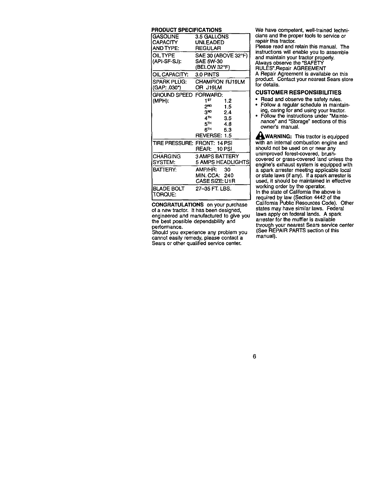
PRODUCT SPECIFICATIONS
GASOLINE 3.5 GALLONS
CAPACITY UNLEADED
ANDTYPE: REGULAR
OILTYPE SAE 30 (ABOVE 32°F
(API+SF-SJ): SAE 5W-30
(BELOW 32°F)
OIL CAPACITY: 3.0 PINTS
SPARK PLUG: CHAMPION RJ19LM
IGAP: .030") OR JtgLM
GROUND SPEED FORWARD:
(MPH): 1sT 1.2
2"o 1,5
3m° 2.4
4TM 3.5
5TM 4.8
6TM 5.3
REVERSE: 1,5
TIRE PRESSURE: FRONT: 14 PSI
REAR: 10 PSI
CHARGING 3AMPS BATTERY
SYSTEM: 5AMPS HEADLIGHTS
BA'I-[ERY: AMP/HR: 30
MIN, CCA: 240
CASE SIZE: U1 R
3LADE BOLT 27-35 F'£ LBS,
TORQUE:
CONGRATULATIONS on your purchase
of a new tractor. It has been designed,
engineered and manufactured to give you
the best possible dependability and
pedormance.
Should you experience any problem you
cannot easily remedy, please contact a
Sears or other qualified service center.
We have competent, well-trained techni-
cians and the proper tools to service or
repair this tractor.
Please read and retainthis manual. The
instructionswill enable you to assemble
and maintain your tractor properly.
Always observe the "SAFETY
RULES".Repair AGREEMENT
A Repair Agreement is available on this
product. Contact your nearest Sears store
for details.
CUSTOMER RESPONSIBILITIES
• Read and observe the safety rules.
•Follow a regular schedule in maintain-
ing, caring for and usingyour tractor.
•Follow the instructionsunder "Mainte-
nance" and "Storage" sections of this
owner's manual.
_I, WARNING: This tractor is equipped
with an internal combustion engine and
should not be used on or near any
unimproved forest-covered, brush-
covered or grass+covered land unless the
engine's exhaust system is equipped with
a spark arrester meeting applicable local
or state laws (if any). If a spark arrester is
used, it should be maintained in effective
working order by the operator.
In the state of California the above is
required by law (Section 4442 of the
California Public Resources Code). Other
states may have similarlaws. Federal
laws apply on federal lands. A Spark
arrester for the muffler is available
through your nearest Sears service center
(See REPAIR PARTS section of this
manual).
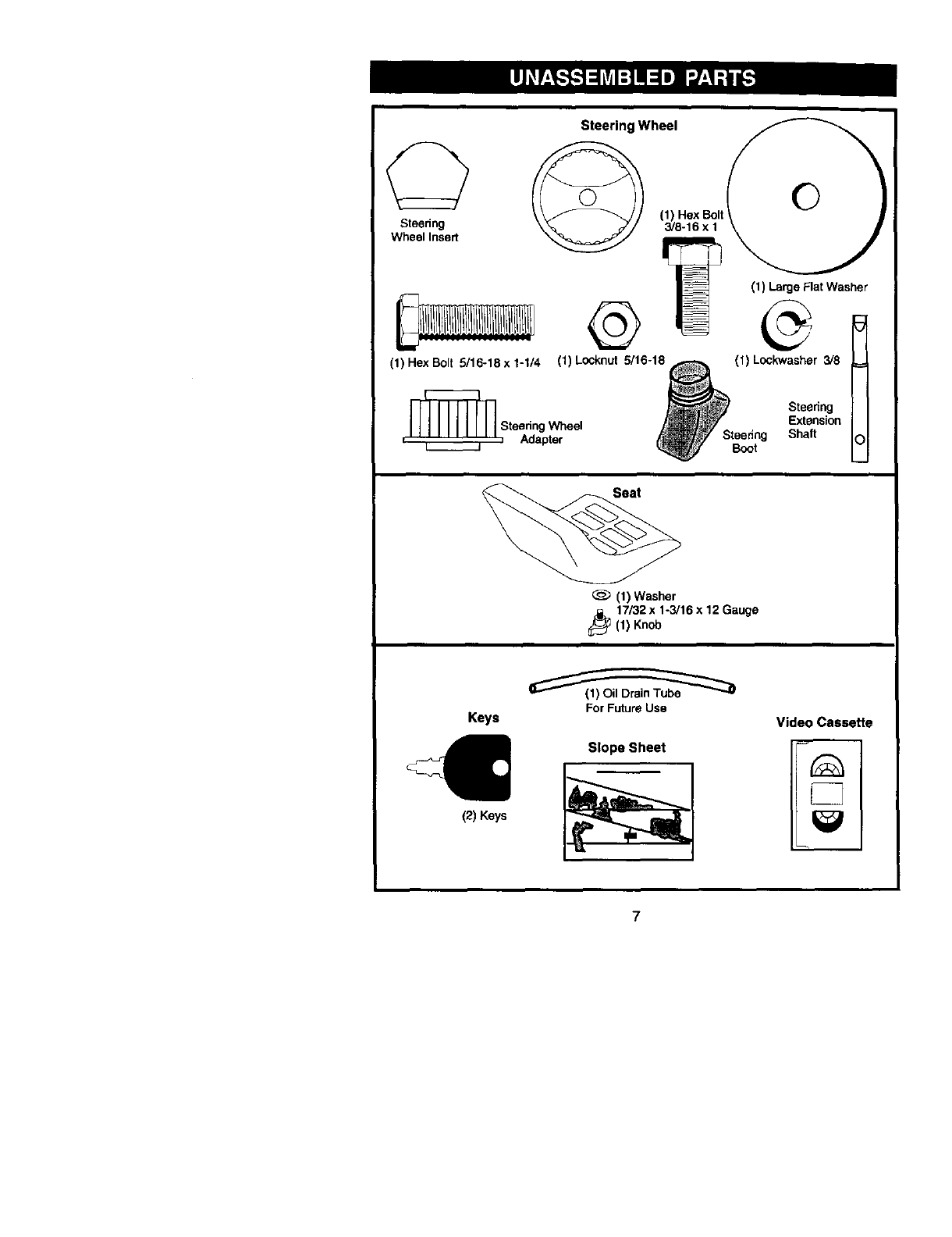
Steering Wheel
_,,_ ___..__n_o. _ '_,°;x_,'t
(1) Large Flat Washer
(1)HexBe,t_5/16-18x1-I/4 (1)Locknut 5/16-18_ (1)Lockwasher 3/8 M
IIIlilllll _, SteeringJl
IIIIIIIIll Steering Wheel _^ E._nsion II
, , Adapter _Sle_tg _)nan IO j
(1) Washer
17/32 x 1-3/16 x 12 Gauge
_(1) Knob
Keys
€
(2) Keys
For Future Use
Slope Sheet
Video Casseffe
7
Your new tractor has been assembled at the factory with exception of those parts left
unassembled for shipping purposes. To ensure safe and proper operation of your
tractor all parts and hardware you assemble must be tightened securely. Use the
correct tools as necessary to insure proper tightness. Review the video cassette before
you begin.
TOOLS REQUIRED FOR ASSEMBLY
A socket wrench set will make assembly
easier, Standard wrench sizes you need
are listed below,
(1) 9/16" wrench (2) 1/2" wrench
(1) Utility knife (1) Pliers
(1) "13repressure gauge
When right or left hand is mentioned in
this manual, it means, from your point of
view, when you are in the operating
position (seated behind the steering
wheel).
TO REMOVE TRACTOR FROM
CARTON
UNPACK CARTON
1. Remove all accessible loose parts
and parts cartons from carton.
2. Cut, from top to bottom, along lines on
all four comers of carton, and lay
panels fiat.
3. Check for any additional loose parts
or cartons and remove.
BEFORE REMOVING TRACTOR
FROM SKID
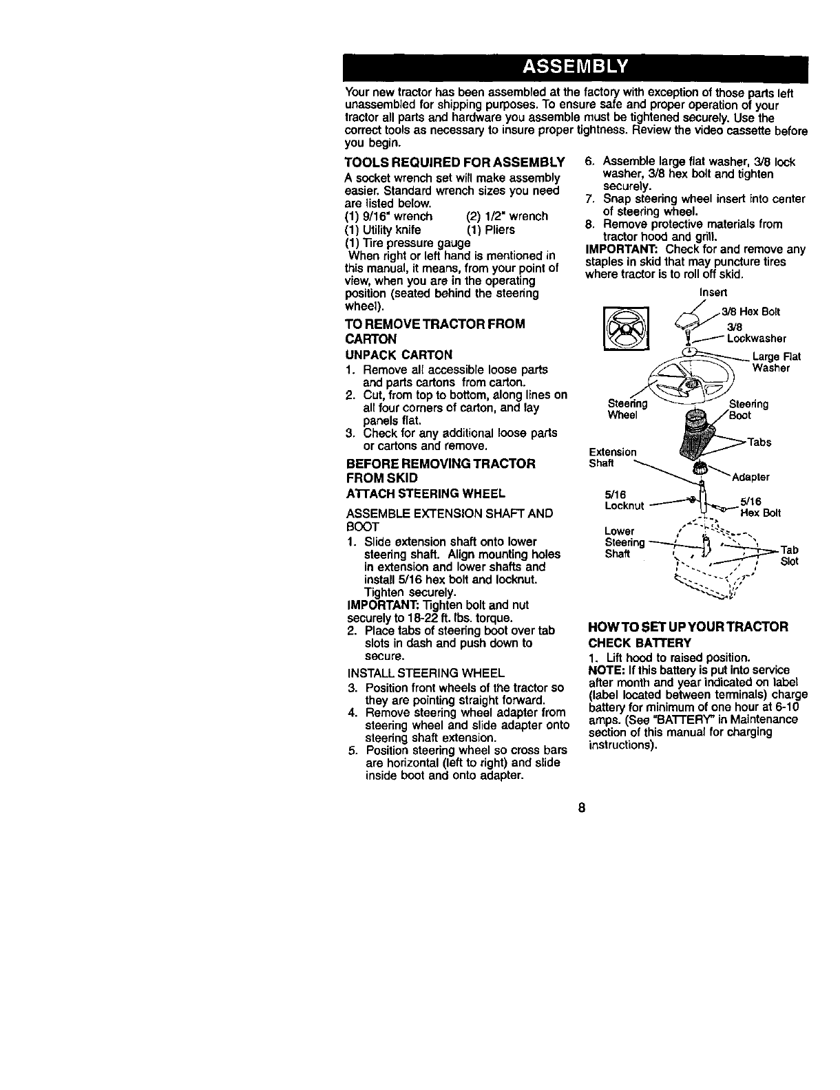
A'FI'ACHSTEERINGWHEEL
ASSEMBLE EXTENSION SHAFT AND
SOOT
1. Slide extension shaft onto lower
steering shaft. Align mounting holes
in extension and lower shafts and
install 5/16 hex bolt and Iocknut.
Tighten securely.
IMPORTANT: "nghtenbelt and nut
securely to 18-22 ft. Ibs. torque.
2. Place tabs of staedng boot over tab
slots in dash and push down to
secure.
INSTALL STEERING WHEEL
3. Position front wheels of the tractor so
they are pointing straight forward.
4. Remove steering wheel adapter from
steering wheel and slide adapter onto
steering shaft extension.
5. Position steering wheel so cross bars
are horizontal (left to right) and slide
inside boot and onto adapter.
6. Assemble large fiat washer, 3/8 lock
washer, 3/8 hex bolt and tighten
securely.
7. Snap steering wheel insert into center
of steering wheel.
8. Remove protective materials from
tractor hood and gritt.
IMPORTANT: Check for and remove any
staples in skidthat may puncturetires
where tractor is to rolloff skid.
HOWTO SET UPYOUR TRACTOR
CHECK BATrERY
1. Lift hood to raised position.
NOTE: It this battery is put intoservice
after month and year indicated on label
(label located between terminals) charge
battery for minimum of one hour at 6-10
amps. (Sea =BATrERY" in Maintenance
section of this manual for charging
instructions).
8
..,, ,Label
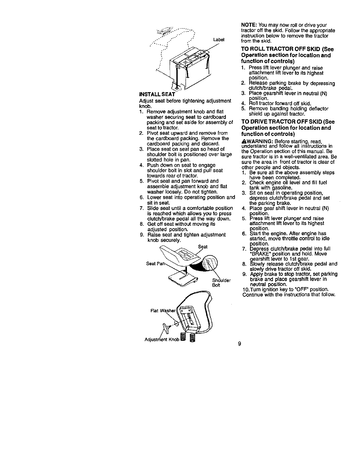
INSTALL SEAT
Adjust seat before tightening adjustment
knob.
1, Remove adjustment knob and flat
washer securing seat to cardboard
packing and set aside for assembly of
seat to tractor,
2. Pivot seat upward and remove from
the cardboard packing. Remove the
cardboard packing and discard.
3. Place seat on seat pan so head of
shoulder bolt is positioned over large
slotted hole in pan.
4. Push down on seat to engage
shoulder bolt in slot and pull seat
towards rear of tractor.
5. Pivot seat and pan forward and
assemble adjustment knob and flat
washer loosely. Do not tighten.
6. Lower seat into operating position and
sit in seat.
7. Slide seat until a comfortable position
is reached which allows you to press
clutch/brake pedal all the way down.
8. Get off seat without moving its
adjusted position.
9. Raise seat and tighten adjustment
knob securely.
SeatPan_ o,d°r
NOTE: You may now roll or drive your
tractor off the skid. Follow the appropriate
instruction below to remove the tractor
from the skid.
TO ROLL TRACTOR OFF SKID (See
Operation section for location and
function of controls)
1. Press liftlever plunger and raise
attachment lift lever to its highest
position.
2. Release parking brake by depressing
clutch/brake pedal.
3. Place gearshift lever in neutral (N)
position.
4. Roll tractor forward oft skid.
5. Remove banding holding deflector
shield up against tractor.
TO DRIVE TRACTOR OFF SKID (See
Operation section for location and
function of controls)
A.WARNING: Before starting read
understand and fo ow a nstructons n
the Operation section of this manual. Be
sure tractor is in a well-ventilated area. Be
sure the area in front of tractor is clear of
other people and objects.
t. Be sure all the above assembly steps
have been completed.
2. Check engine oil level and fill fuel
tank with gasoline.
3. Sit on seat in operating position,
depress clutch/brake pedal and set
the parking brake.
4. Place gear shift lever in neutral (N)
position.
5. Press lift lever plunger and raise
attachment lift lever to its highest
position.
6. Start the engine. After engine has
started, move throttle control to idle
position.
7. Depress clutch/brake pedal into full
"BRAKE" position and hold. Move
gearshift lever to tst gear.
8. Slowly release clutch/brake pedal and
slowly drive tractor off skid.
9. Apply brake to stop tractor, set parking
brake and place gearshift lever in
neutral position.
10.Turn ignition key to "OFF" position.
Continue with the instructions that follow.
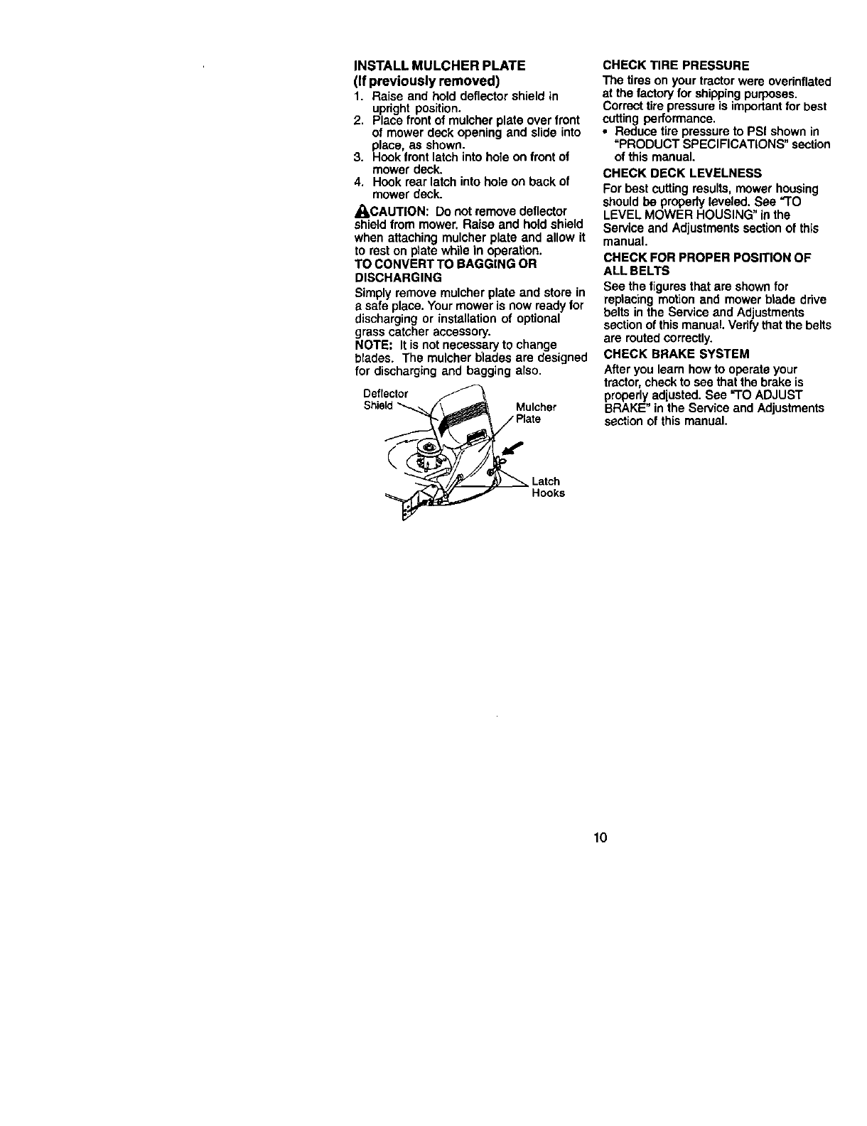
INSTALL MULCHER PLATE
(If previously removed)
1. Raise and hold deflector shield in
upright position.
2. Place front of mulcher plate over front
of mower deck opening and slide into
place, as shown.
3. Hook front latch into hole on front of
mower deck.
4, Hook rear latch into hole on back of
mower deck.
_II,CAUTION: Do not remove deflector
shield from mower. Raise and hold shield
when attaching mulcher plate and allow it
to rest on plate while in operation.
TO CONVERT TO BAGGING OR
DISCHARGING
Simply remove mulcher plate and store in
asafe place. Your mower is now ready for
discharging or installation of optional
grass catcher accessory.
NOTE: It is not necessary to change
blades. The mulcher blades are designed
for discharging and bagging also.
Deflector
Shield "_ Mulcher
Latch
Hooks
CHECK TIRE PRESSURE
The tires on your tractor were overinflated
at the factory for shipping purposes.
Correct tire pressure is importantfor best
cutting performance.
•Reduce tire pressure to PSI shown in
"PRODUCT SPECIFICATIONS" section
of this manual.
CHECK DECK LEVELNESS
For best cutting results, mower housing
should be properlyleveled. See "TO
LEVEL MOWER HOUSING" in the
Service and Adjustments sectionof this
manual.
CHECK FOR PROPER POSITION OF
ALL BELTS
See the figures that are shown for
reptacing motion and mower blade drive
belts in the Service and Adjustments
sectionof this manual. Vedfy that the belts
are routed correctly.
CHECK BRAKE SYSTEM
After you learn how to operate your
tractor,check to see that the brake is
properly adjusted. See "TO ADJUST
BRAKE" in the Service and Adjustments
section of this manual.
10
V'CHECKLIST
Before you operate and enjoy your new
tractor, we wish to assure that you receive
the best performance and satisfaction
from this quality product.
Please review the following checklist:
,/ All assembly instructions have been
completed.
,/No remaining loose parts in carton.
/Battery is properly prepared and
charged.(Minimum 1 hour at 6 amps).
,/Seat is adjusted comfortably and
tightened securely.
,/All tires are properly inflated. (For
shipping purposes, the tires were
overinflated at the factory).
,/Be sure mower deck is properly leveled
side-to-side/front-to-rear for best cutting
results. (Tires must be properlyinflated
for JeveJing).
,/Check mower end drive belts. Be sure
they are routed properly around pulleys
and inside all belt keepers.
,/Check wiring. See that all connections
are stillsecure and wires are properly
clamped.
While learning how to use your tractor,
pay extra attention to the following
important items:
,/Engine oil is at proper level.
,/Fuel tank is filled with fresh, clean,
regular unleaded gasoline.
,/Become familiar with all controls - their
location and function. Operate them
before you start the engine.
/" Be sure brake system is in safe operat-
ing condition.
11
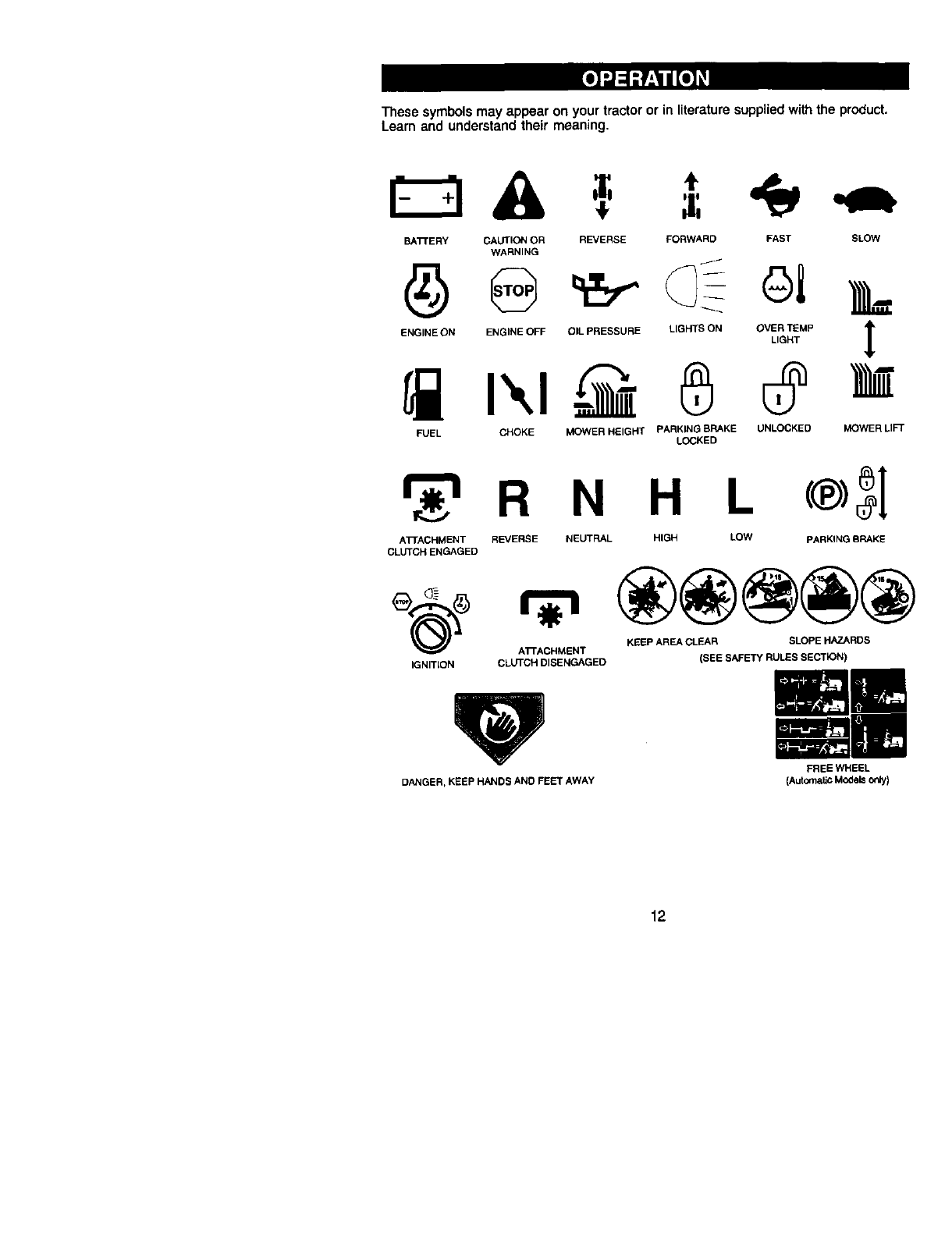
These symbols may appear on your tractor or in literature supplied with the product.
Learn and understand their meaning.
BATrERY CAUTION OR REVERSE FORWARD FAST SLOW
WARNING /
ENO,NEONENG,NEOFFO,LPRESSOREL,O._SONO%_.P ]_
FUEL CHOKE MOWER HEIGHT PARKING BRAKE UNLOCKED MOWER LIFT
LOCKED
R N H L
ATTACHMENT REVERSE NEUTRAL HIGH LOW PARKING SRAKE
CLUTCH ENGAGED
KEEP AREA CLEAR SLOPE HAZARDS
A'rFACHMENT
IGNITION CLUTCH DISENGAGED (SEE SAFETY RULES SECTION)
DANGER, KEEP HANDS ANO FEET AWAY
FREE WHEEL
(AutOma6cModels¢_ly)
12
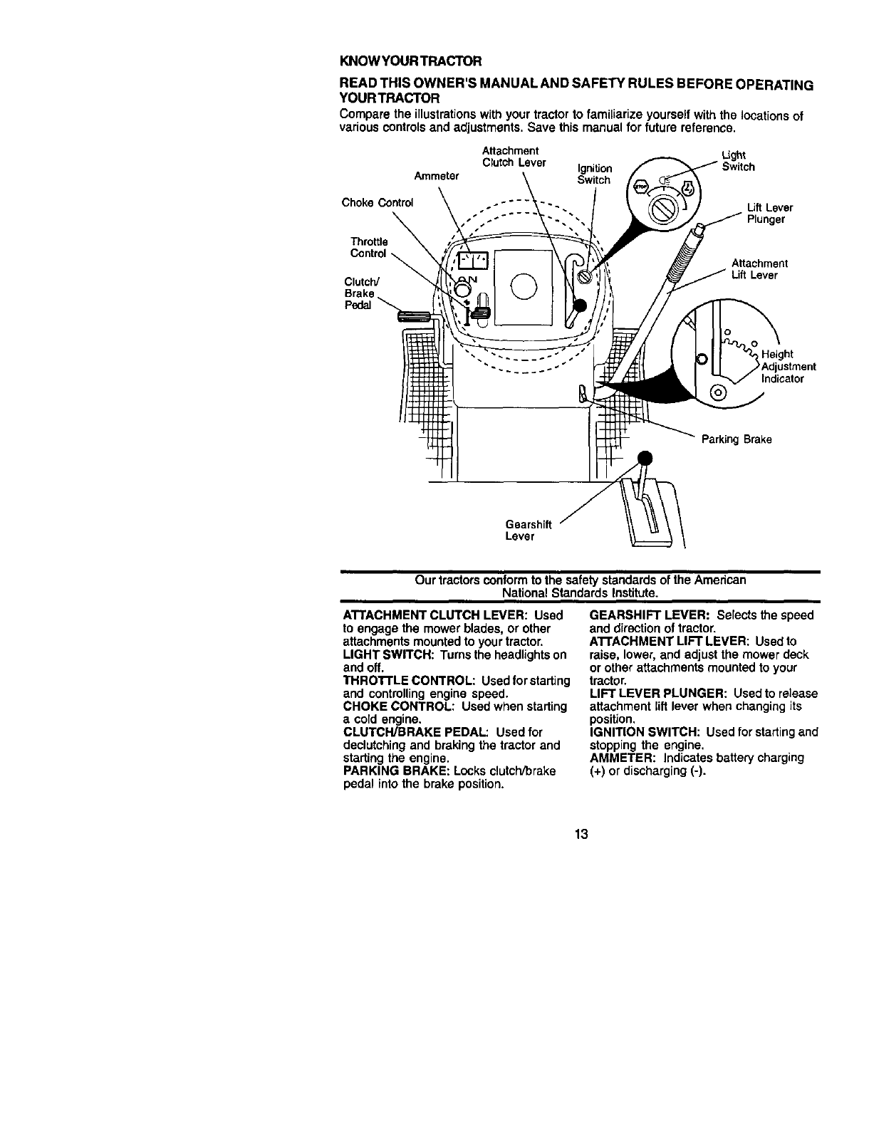
KNOWYOURTRACTOR
READTHISOWNER'SMANUALANDSAFETYRULESBEFOREOPERATING
YOURTRACTOR
Comparetheillustrationswithyourtractortofamiliarizeyourselfwiththelocationsof
variouscontrolsandadjustments.Savethismanualfor futurereference,
Attachment Li_:_t
Clutch Lever Ignition Switch
Ammeter Switch
Choke Control Lift Lever
Plunger
Throttle
Control _
Clutch/
Brake
Pedal
Attachment
Lift Lever
Height
Indicator
Parking Brake
Gearshift
Lever
Our tractorsconform to the safety standards of the American
National Standards Institute.
ATTACHMENT CLUTCH LEVER: Used
to engage the mower blades, or other
attachments mounted to your tractor.
LIGHT SWITCH: Turns the headlightson
and off.
THROI-I'LE CONTROL: Used for starting
and controlling engine speed.
CHOKE CONTROL: Used when starting
acold engine.
CLUTCH/BRAKE PEDAL: Used for
declutching and braking the tractor and
starting the engine.
PARKING BRAKE: Locks clutch/brake
pedal into the brake position.
GEARSHIFT LEVER: Selects the speed
and directionof tractor.
ATTACHMENT LIFT LEVER: Used to
raise, lower, and adjust the mower deck
or other attachments mounted to your
tractor.
LIFT LEVER PLUNGER: Used to release
attachment lift lever when changing its
position.
IGNITION SWITCH: Used for starting and
stopping the engine.
AMMETER: Indicates battery charging
(+) or discharging (-).
13
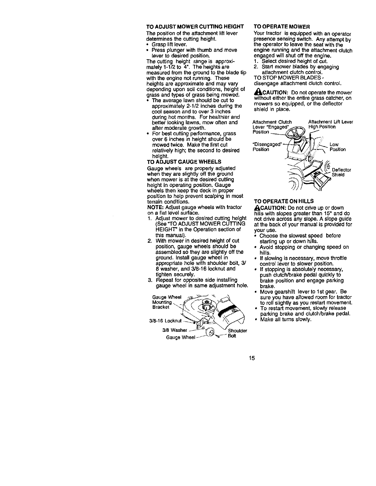
HOW TO USE YOUR TRACTOR
TO SET PARKING BRAKE
Your tractor is equipped with an operator
presence sensing switch. When engine
is running, any attempt by the operator to
leave the seat withoutfirst setting the
parking brake will shut off the engine.
1. Depress clutch/brake pedal into full
=BRAKE" positionand hold.
2. Place parking brake lever in "EN-
GAGED" position and release
pressure from clutch/brake pedal.
Pedal should remain in =BRAKE"
position. Make sure parking brake will
hold tractor secure.
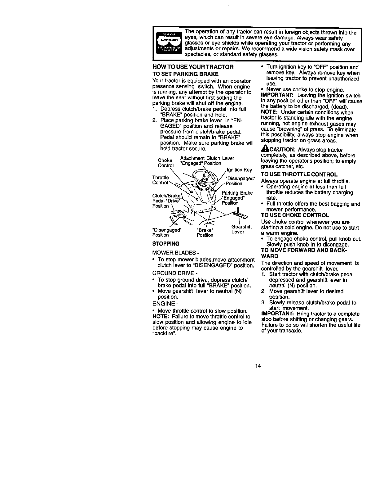
The operation of any tractor can result in foreign objects thrown intothe |
eyes, which can result in severe eye damage. Always wear safety I
glasses or eye shields while operating your tractor or performing any
adjustments or repairs. We recommend a wide vision safety mask over
spectacles, or standard safety glasses.
Choke Attachment Clutch Lever
Control "Engaged" Position
Throttle _
Control \ ,Position
Parking Brake
Pedal Position
Position
Gearshift
Lever
"Disengaged" "Brake"
Position Position
STOPPING
MOWER BLADES -
• To stop mower blades,move attachment
clutch lever to "DISENGAGED" position.
GROUND DRIVE -
• To stop ground drive, depress clutch/
brake pedal into full "BRAKE" position.
•Move gearshift lever to neutral (N)
position.
ENGINE-
•Move throttle control to slow position.
NOTE: Failure to move throttle control to
slow position and allowing engine to idle
before stopping may cause engine to
"backfire".
• Turn ignition key to "OFF" position and
remove key. Always remove key when
leaving tractor to prevent unauthorized
use.
•Never use choke to stop engine.
IMPORTANT: Leaving the ignitionswitch
in any positionother than "OFF" will cause
the battery to be discharged, (dead).
NOTE: Under certain conditions when
tractor is standing idle with the engine
running, hot engine exhaust gases may
cause =browning" of grass. To eliminate
this possibility, always stop engine when
stopping tractor on grass areas.
,_CAUTION: Always stop tractor
completely, as described above, before
leaving the operator's position;to empty
grass catcher, etc.
TO USE THROTTLE CONTROL
Always operate engine at full throttle.
•Operating engine at less than full
throttle reduces the battery charging
rate.
•Full throttle offers the best bagging and
mower performance.
TO USE CHOKE CONTROL
Use choke controlwhenever you are
startinga cold engine. Do not use to start
a warm engine.
•To engage choke control, pull knob out.
Slowly push knob in to disengage.
TO MOVE FORWARD AND BACK-
WARD
The direction and speed of movement is
controlled by the gearshift lever.
1. Start tractor with clutch/brake pedal
depressed and gearshift lever in
neutral (N) position.
2. Move gearshift lever to desired
position.
3. Slowly release clutch/brake pedal to
start movement.
IMPORTANT: Bring tractorto a complete
stop before shitting or changing gears.
Failure to do so willshorten the useful life
of your transaxle.
14
TO ADJUST MOWER CUTTING HEIGHT
The positionof the attachment liftlever
determines the cutting height.
•Grasp liftlever.
•Press plunger with thumb and move
lever to desired position.
The cutting height range is approxi-
mately 1-1/2 to 4". The heights are
measured from the ground to the blade tip
with the engine not running. These
heights are approximate and may vary
depending upon soil conditions, height of
grass and types of grass being mowed.
•The average lawn should be cut to
approximately 2-1/2 inches during the
cool season and to over 3inches
during hot months. For healthier and
better looking lawns, mow often and
after moderate growth.
• For best cuffing performance, grass
over 6 inches in height should be
mowed twice, Make the first cut
relatively high; the second to desired
height.
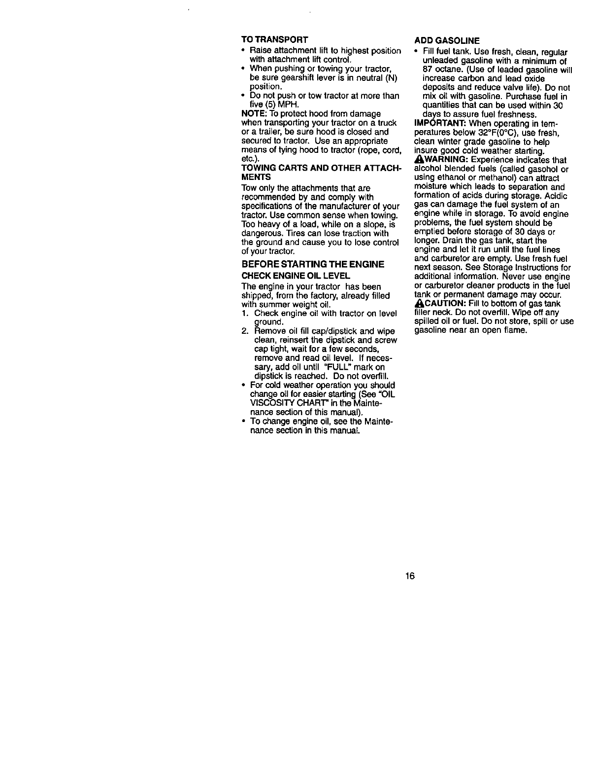
TO ADJUST GAUGE WHEELS
Gauge wheels are propedy adjusted
when they are slightly off the ground
when mower is at the desired cutting
height in operating position, Gauge
wheels then keep the deck in proper
position to help prevent scalping in most
terrain conditions.
NOTE: Adjust gauge wheels with tractor
on a flat level surface.
1. Adjust mower to desired cutting height
(See "TO ADJUST MOWER CU'I-rlNG
HEIGHT" in the Operation section of
this manual).
2. With mower in desired height of cut
position, gauge wheels should be
assembled so they are slightlyoff the
ground. Install gauge wheel in
appropriate hole with shoulder belt, 3/
8 washer, and 3/8÷16 Iocknut and
tighten securely.
3. Repeat for opposite side installing
gauge wheel in same adjustment hole.
Gauge Wheel "_
Bracket
3/8-16 Locknut-
3/8
Gauge Wheel
;houlder
TO OPERATE MOWER
Your tractor is equipped with an operator
presence sensing switch. Any attempt by
the operator to leave the seat with the
engine running and the attachment clutch
engaged will shut off the engine.
1. Select desired height of cut.
2. Start mower blades by engaging
attachment clutch control.
TO STOP MOWER BLADES °
disengage attachment clutch control
,_CAUTION: Do not operate the mower
without either the entire grass catcher, on
mowers so equipped, or the deflector
shield in place.
AttachmentClutch Attachment LiftLever
Lever "Engaged"_ HighPosition
Position_::
"Disengaged"--/_----_ _'_1 )/_._ Low
Position _ __ ./__,_/"-_ Position
'_ Dleifel;dCtor
TO OPERATE ON HILLS
_CAUTION: Do not drive up or down
hills with slopes greater than 15° and do
not drive across any slope. A slope guide
at the back of your manual is provided for
your use.
•Choose the slowest speed before
starting up or down hills.
•Avoid stopping or changing speed on
hills.
*If slowing is necessary, move throttle
control lever to slower position.
•If stopping is absolutely necessary,
push clutch/brake pedal quickly to
brake position and engage parking
brake.
•Move gearshift lever to 1st gear. Be
sure you have allowed room for tractor
to roll slightlyas you restart movement.
•To restart movement, slowly release
parking brake and clutch/brake pedal.
•Make all turns slowly.
15
TO TRANSPORT
•Raise attachment lift to highest position
with attachment lift control.
• When pushing or towing your tractor,
be sure gearshift lever is in neutral (N)
position.
• Do not push or tow tractor at more than
five (5) MPH.
NOTE: To protect hood from damage
when transporting your tractor on a truck
or a trailer, be sure hood is closed and
secured to tractor. Use an appropriate
means of tying hood to tractor (rope, cord,
etc.).
TOWING CARTS AND OTHER ATrACH-
MENTS
Tow only the attachments that are
recommended by and comply with
specifications of the manufacturer of your
tractor. Use common sense when towing.
Too heavy of a load, while on a slope, is
dangerous. 33ras can lose traction with
the ground and cause you to lose control
of yourtractor.
BEFORE STARTING THE ENGINE
CHECK ENGINE OIL LEVEL
The engine in your tractor has been
shipped, from the factory,already filled
with summer weight oil
1. Check engine oil with tractor on level
ground.
2. Remove oil flU cap/dipstick and wipe
clean, reinsert the dipstick and screw
cap tight, wait for a few seconds,
remove and read oil level, If neces-
sary, add oil until "FULL" mark on
dipstick is reached. Do not overfill.
•For cold weather operation you should
change o_1tor easier starting(See "OIL
VISCOSITY CHART" in the Mainte-
nance sectionof this manual).
•To change engine oil, see the Mainte-
nance sectionin this manual.
ADD GASOLINE
•Fill fuel tank. Usa fresh, clean, regular
unleaded gasoline with aminimum of
87 octane. (Use of leaded gasoline will
increase carbon and lead oxide
deposits and reduce valve life). Do not
mix oitwith gasoline. Purchase fuel in
quantities that can be used within 30
days to assure fuel freshness.
IMPORTANT: When operating in tem-
peratures below 32°F(0°C), use fresh,
clean winter grade gasoline to help
insure good cold weather starting.
_i, WARNING: Experience indicates that
alcohol blended fuels (called gasohol or
using ethanol or methanol) can attract
moisture which leads to separation and
formation of acids duringstorage. Acidic
gas can damage the fuel system of an
engine while in storage. To avoid engine
problems, the fuel system should be
emptied before storage of 30 days or
longer. Drain the gas tank, start the
engine and let it run until the fuel lines
and carburetor are empty. Use fresh fuel
next season. See Storage Instructions for
additional information. Never use engine
or carburetor cleaner products in the fuel
tank or permanent damage may occur.
• I,CAUTION: Fill to bottomof gas tank
fillerneck. Do not overfill. Wipe off any
spilled oil or fuel Do not store, spiltor use
gasoline near an open flame,
16
TO START ENGINE
Wbensta,'_rotbeer_ne fortbefirst_me orif
•e engineI-msrun outof fuel,il wgltakeexlra
crankingtimeto movefuelfromthetank tothe
engine.
1. Sit on seat in operating position,
depress clutch/brake pedal and set
parking brake.
2. Place gear shift lever in neutraJ(N)
position.
3. Move attachment clutch to "DISEN-
GAGED" position.
4. Move throttle controlto fast position
5. Pull choke controlout for a cold
engine start attempt. For a warm
engine start attempt the choke control
may not be needed.
NOTE: Beforestarting,read thewarmand
co!d starting procedures below.
6. Insert key into ignition and turn key
clockwise to "START" position and
release key as soon as engine starts.
Do not run starter continuously for
more than fifteen seconds per minute.
If the engine does not start after
several attempts, push choke control
in, wait a few minutes and try again. If
engine stilldoes not start, pull the
choke control out and retry.
WARM WEATHER STARTING (50°F and
above)
7. When engine starts, slowly push
choke control in untilthe engine
begins to run smoothly. If the engine
starts to run roughly, pull the choke
control out slightlyfor afew seconds
and then continue to push the control
in slowly.
•The attachments and ground drive can
now be used. If the engine does not
accept the load, restart the engine and
allow it to warm up for one minute using
the choke as described above.
COLD WEATHER STARTING (50° F and
below)
7. When engine starts, slowly push
choke control in until the engine
begins to run smoothly. Continue to
push the choke control in small steps
allowing the engine to accept small
changes in speed and load, until the
choke control is fully in. If the engine
starts to run roughly, pull the choke
control out slightly for a few seconds
and then continue to push the control
in slowly. This may require an engine
warm-up period from several seconds
to several minutes, depending on the
temperature.
•The attachments can be used during
the engine warm-up period and may
require the choke control be pulled out
slightly.
NOTE: If at a high altitude (above 3000
feet) or in cold temperatures (below 32 F)
the carburetor fuel mixture may need to
be adjusted for best engine performance.
See "TO ADJUST CARBURETOR" in the
Service and Adjustments section of this
manual.
17
MOWING TIPS
•Mower should be properly leveled for
best mowing performance. See "TO
LEVEL MOWER HOUSING" in the
Service and Adjustments section of this
manual.
•The left hand side of mower should be
used for trimming.
• Drive so that clippings are discharged
onto the area that has been cut. Have
the cut area to the right of the machine.
This will result in a more even distribu-
tion of clippings and more uniform
cutting.
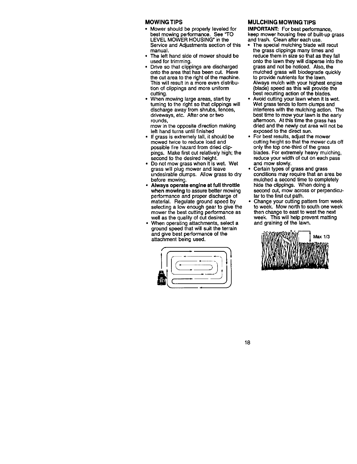
•When mowing large areas, start by
turning to the rightso that clippings will
discharge away from shrubs, fences,
driveways, etc. After one ortwo
rounds,
mow in the opposite direction making
left hand turns untilfinished
•If grass is extremely tall, it should be
mowed twice to reduce load and
possible fire hazard from dried clip-
pings. Make first cut relatively high; the
second to the desired height.
•Do not mow grass when it is wet. Wet
grass wig plug mower and leave
undesirable clumps. Allow grass to dry
before mowing.
•Always operate engine at full throttle
when mowing to assure better mowing
performance and proper discharge of
material. Regulate ground speed by
selecting a low enough gear to give the
mower the best cutting performance as
well as the quality of cut desired.
•When operating attachments, select a
ground speed that will suit the terrain
and give best performance of the
attachment being used.
MULCHING MOWING TIPS
IMPORTANT: For best performance,
keep mower housingfree of built-upgrass
and trash. Clean after each use.
• The special mulching blade will recut
the grass clippings many times and
reduce them in size so that as they fall
onto the lawn they will disperse into the
grass and not be noticed. Also, the
mulched grass will biodegrade quickly
to provide nutrients for the lawn.
Always mulch with your highest engine
(blade) speed as this will providethe
best recuttingaction of the blades.
•Avoid cutting your lawn when it is wet.
Wet grass tends to form clumps and
interferes with the mulching action. The
best time to mow your lawn is the eady
afternoon. At thistime the grass has
dried and the newly cut area will not be
exposed to the direct sun.
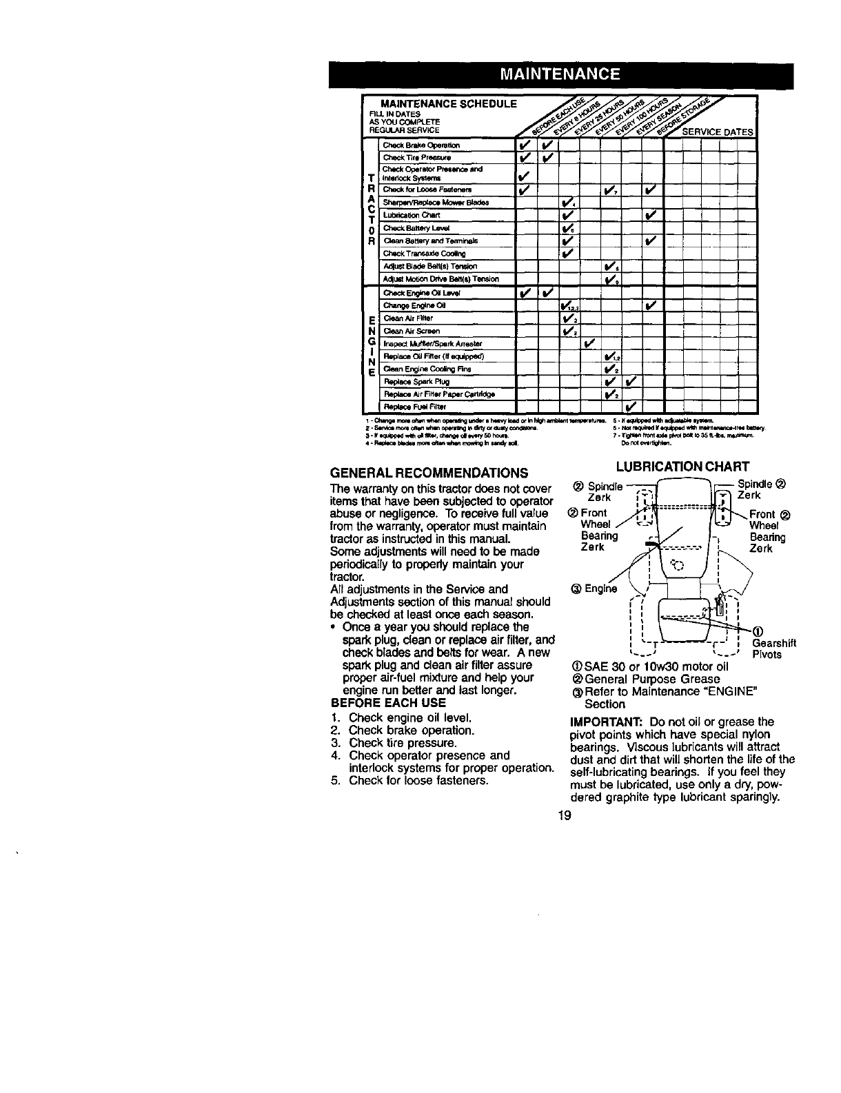
•For best results, adjust the mower
cutting heightso that the mower cuts off
only the top one-third of the grass
blades. For extremely heavy mulching,
reduce your width of cut on each pass
and mow slowly.
•Certain types of grass and grass
conditions may require that an area be
mulched a second time to completely
hide the clippings. When doing a
second cut, mow across or perpendicu-
larto the first cut path.
•Change your cutting pattern from week
to week. Mow north to south one week
then change to east to west the next
week. This will help prevent matting
and graining of the lawn.
Max 1/3
18
_. I_n_lp_ed_ _i a_,, ch_ _e_ir/SOI_XNt 7. Ti_d'q)qh'_ntL_depl'.'__OX_ 3__.4_a.rn_
GENERAL RECOMMENDATIONS
The warranty on this tractordoes not cover
items that have been subjected to operator
abuse or negligence. To receive full value
from the warranty, operator must maintain
tractor as instructedin thismanual.
Some adjustments willneed to be made
periodically to properly maintain your
tractor.
All adjustmentsin the Service and
Adjustmentssection of this manual should
be checkedat least once each season.
• Once ayear you should replace the
spark plug, clean or replace air filter, and
check blades and belts for wear. A new
spark plugand clean air filter assure
proper air-fuel mixture and help your
engine runbetter and last longer.
BEFORE EACH USE
t. Check engine oil level.
2. Check brake operation.
3. Check tire pressure.
4. Check operator presence and
interlock systems for proper operation.
5. Check for loose fasteners.
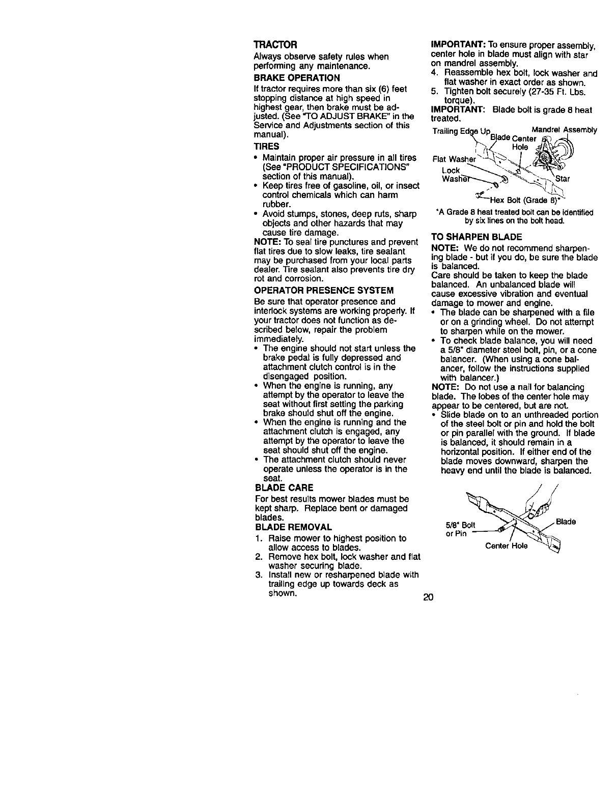
LUBRICATION CHART
Spindle
Zork Zerk
Front
Wheel Wheer
Beadng Bearing
Zerk Zork
Gearshift
_---' "---* Pivots
@SAE 30 or tow30 motor oil
@General Purpose Grease
@Refer to Maintenance "ENGINE"
Section
IMPORTANT: Do not oil or grease the
pivot points which have special nylon
bearings. Viscous lubricants will attract
dust and did that will shorten the life of the
self-lubricatingbearings. If you feel they
must be lubricated, use only a dry, pow-
dered graphite type lubricant sparingly.
19
TRACTOR
Always observe safety rules when
performing any maintenance.
BRAKE OPERATION
Ittractor requires more than six (6) feet
stoppingdistance at high speed in
highest gear, then brake must be ad-
justed. (See "TO ADJUST BRAKE" in the
Service and Adjustments section of this
manual).
TIRES
• Maintain proper air pressure in all tires
(See =PRODUCT SPECIFICATIONS"
section of this manual).
• Keep tires free of gasoline, oil, or insect
control chemicals which can harm
rubber.
•Avoid stumps, stones, deep ruts, sharp
objects and other hazards that may
cause tire damage.
NOTE: To seal tire punctures and prevent
flat tires due to slow leaks, tire sealant
may be purchased from your local parts
dealer. "13resealant also prevents tire dry
rot and corrosion.
OPERATOR PRESENCE SYSTEM
Be sure that operator presence and
interlock systems are working properly. If
your tractor does not function as de-
scribed below, repair the problem
immediately.
•The engine should not start unless the
brake pedal is fully depressed and
attachment clutch control is in the
disengaged position.
•When the engine is running, any
attempt by the operator to leave the
seat without first setting the parking
brake should shut off the engine,
•When the engine is running and the
attachment clutch is engaged, any
attempt by the operator to leave the
seat should shut off the engine.
•The attachment clutch should never
operate unless the operator is in the
seat.
BLADE CARE
For best results mower blades must be
kept sharp. Replace bent or damaged
blades.
BLADE REMOVAL
1. Raise mower to highest position to
allow access to blades.
2. Remove hex bolt, lock washer and flat
washer securing blade.
3. Install new or resharpened blade with
trailing edge up towards deck as
shown. 20
IMPORTANT: To ensure proper assembly,
center hole in blade must align with star
on mandrel assembly.
4. Reassemble hex belt, lock washer and
flat washer in exact order as shown.
5. Tighten bolt securely (27-35 Ft. Lbs.
torque).
IMPORTANT: Blade belt is grade 8 heat
treated,
TrailingEdaeUp MandrelAssembly
"_. BladeCenter _.-._L
3_'-Hex Bolt(Grade 8)°
*AGrade8 heattreatedboltcanbe identified
bysixlines onthebolthead.
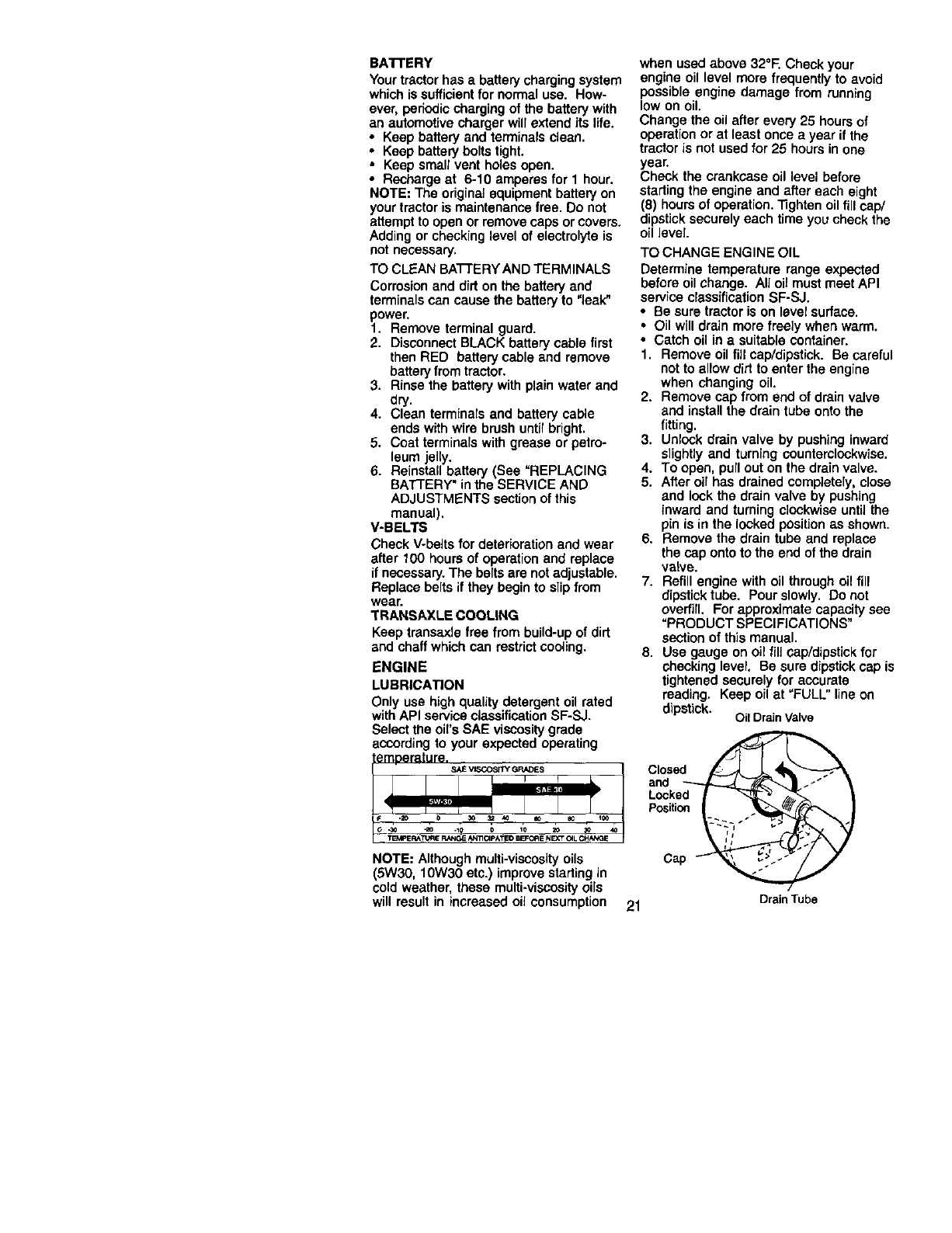
TO SHARPEN BLADE
NOTE: We do not recommend sharpen-
ing blade -but if you do, be sure the blade
is balanced.
Care should be taken to keep the blade
balanced. An unbalanced blade will
cause excessive vibration and eventual
damage to mower and engine.
•The blade can be sharpened with a file
or on a grindingwheel. Do not attempt
to sharpen while on the mower.
•To check blade balance, you will need
a 5/8" diameter steel bolt, pin, or a cone
balancer. (When using acone bal-
ancer, follow the instructionssupplied
with balancer.)
NOTE: Do not use a nail for balancing
blade. The lobes of the center hole may
appear to be centered, but are not.
•Slide blade on to an unthreaded portion
of the steel belt or pin and holdthe bolt
or pin parallel with the ground. If blade
is balanced, it should remain in a
horizontal position. If either end of the
blade moves downward, sharpen the
heavy end until the blade is balanced.
5/8" lade
or Pin _/
CenterHole
BA'I-rERY
Yourtractorhasabatterychargingsystem
whichissufficientfornormaluse.How-
ever,pedodicchargingofthebatterywith
an automotive charger will extend its life.
• Keep battery and terminals clean.
• Keep battery bolts tight.
• Keep small vent holes open.
• Recharge at 6-10 amperes for 1 hour.
NOTE: The original equipment battery on
your tractor is maintenance free. Do not
attempt to open or remove caps or covers,
Adding or checking level of electrolyte is
not necessary,
TO CLEAN BA'I-FERY AND TERMINALS
Corrosion and did on the battery and
terminals can cause the battery to "leak"
power.
1. Remove terminal guard.
2. Disconnect BLACK battery cable first
then RED battery cable and remove
battery from tractor.
3. Rinse the battery with plain water and
dry.
4. Clean terminals and battery cable
ends with wire brush until bright.
5. Coat terminals with grease or petro-
leum jelly.
6. Reinstall battery (See "REPLACING
BA'I-I'ERY" inthe SERVICE AND
ADJUSTMENTS section of this
manual).
V-BELTS
Check V-be_tsfor deterioration and wear
after 100 hours of operation and replace
if necessary. The belts are not adjustable.
Replace belts if they begin to slipfrom
wear.
TRANSAXLE COOLING
Keep transaxle free from build-up of dirt
and chaff which can restrict cooling.
ENGINE
LUBRICATION
Only use high quality detergent oil rated
with API service classificationSF-SJ.
when used above 32°F. Check your
engine oil level more frequently to avoid
possible engine damage from running
low on oil.
Change the oil after every 25 hours of
operation or at least once ayear if the
tractor is not used for 25 hours in one
year.
Check the crankcase oil level before
starting the engine and after each eight
(8) hours of operation. ]ighten oil fill cap/
dipstick securely each time you check the
oil level.
TO CHANGE ENGINE OIL
Determine temperature range expected
before oil change. All oil must meet API
service classification SF-SJ.
• Be sure tractor is on level surface.
•Oil will drain more freely when warm.
• Catch oil in a suitable container.
1. Remove oil fill cap/dipstick. Be careful
not to allow dirt to enter the engine
when changing oil.
2. Remove cap from end of drain valve
and install the drain tube onto the
fitting.
3. Unlock drain valve by pushing inward
slightly and turning counterclockwise.
4. To open. pull out on the drain valve.
5. After oil has drained completely, close
and lock the drain valve by pushing
inward and turning clockwise until the
pin is in the locked position as shown.
6. Remove the drain tube and replace
the cap onto tO the end of the drain
valve.
7. Refill engine with oil through oil fill
dipsticktube. Pour slowly. Do not
overfill. For approximate capacity see
"PRODUCT SPECIFICATIONS"
section of this manual.
8. Use gauge on oil fill cap/dipstick for
checking level, Be sure dipstick cap is
tightened securely for accurate
reading. Keep oil at "FULL"line on
dipstick. Oil DrainValve
Select the oil's SAE viscosity grade
according to your expected operating _1
temperature.
Close
and -----../_=_ --_._"_'_|..- "
LsckedI
Position
NOTE: Although multi-viscosity oils Ca
(5W30, 10W30 etc.) improve starting in
cold weather, these multi-viscosityoils
will result in increased oil consumption 21 DrainTube
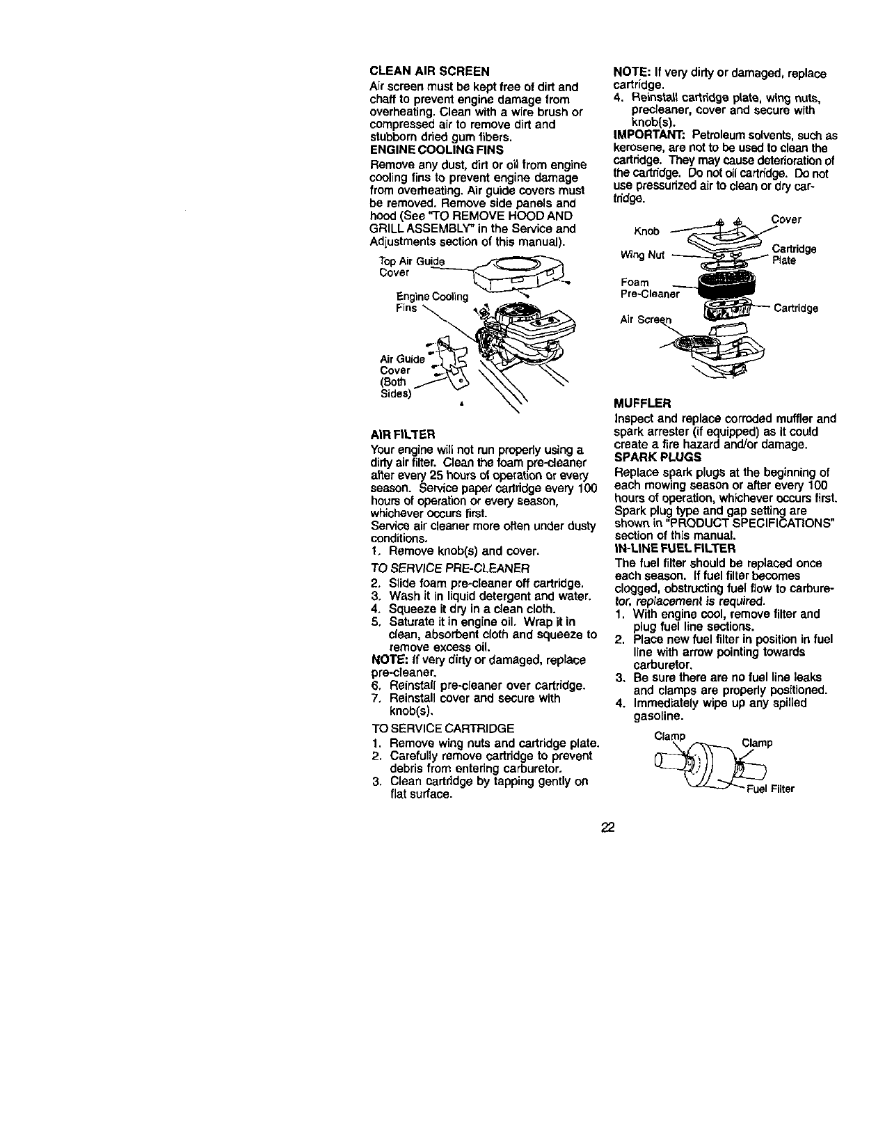
CLEANAIRSCREEN
Airscreenmustbekeptfreeofdirtand
chafftopreventengine damage from
overheating. Clean with a wire brush or
compressed air to remove dirt and
stubborn dried gum fibers.
ENGINE COOLING FINS
Remove any dust, dirt or oil from engine
cooling fins to prevent engine damage
from overheating. Air guide covers must
be removed. Remove side panels and
hood (See "TO REMOVE HOOD AND
GRILL ASSEMBLY" in the Service and
Adjustments section of this manual).
TopAir Guide
_;over _,_
EngineCooling +',,
Fins _
Cover
(Both
Sides)
AIR FILTER
Your engine willnot run properlyusing a
dirtyair filter. Clean the foam pre-cleaner
after every 25 hoursof operation or every
season. Service paper cartridge every 100
hoursof operation or every season,
whichever occursfirst.
Service air cleaner more often under dusty
conditions.
t, Remove knob(s) and cover.
TO SERVICE PRE-CLEANER
2, Slide foam pre*ctsaner off cartridge,
3, Wash it in liquid detergent and water.
4, Squeeze it dry in aclean cloth.
5, Saturate it in engine oil, Wrap it in
clean, absorbent cloth and squeeze to
remove excess oil.
No'rE: If very dirty or damaged, reptace
pre-cleaner.
6, Reinstall pre-cleaner over cartridge.
7, Reinstall cover and secure with
knob(s),
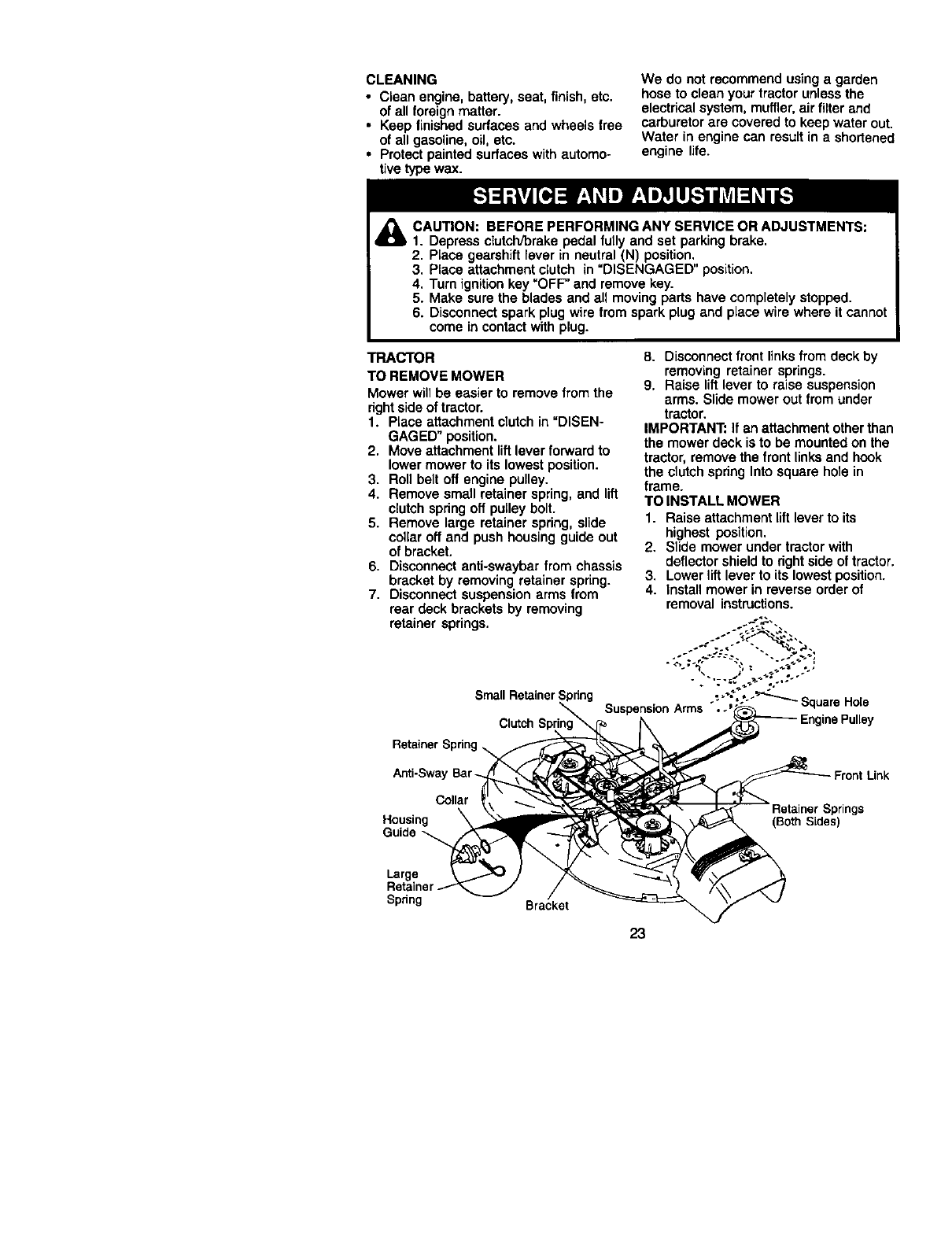
TO SERVICE CARTRIDGE
1. Remove wing nuts and cartridge plate.
2, Carefully remove certridge to prevent
debris from entering carburetor,
3, Clean cartridge by tapping gently on
flat surface.
NOTE: If very dirty or damaged, replace
cartridge.
4. Reinstall cartridge plate, wing nuts,
precleaner, cover and secure with
knob(s).
IMPORTANT: Petreleum solvents,such as
kerosene, are not to be used to clean the
cartridge. They may cause deterioration of
the cartridge. Do not oil certndge. Do not
use pressurizedair to clean or dry car-
tridge.
Knob _over
_Cartridge
Wing Nut _ i_late
Foam
Pre-Cleaner
_"-'- Cartridge
Air Scre_
MUFFLER
Inspect and replace corroded muffler and
spark arrester (if equipped) as it could
create a fire hazard and/or damage.
SPARK PLUGS
Replace spark plugs at the beginning of
each mowing season or after every 100
hours of operation, whichever occurs first.
Spark plug type and gap setting are
shown in "PRODUCT SPECIFICATIONS"
section of this manual.
IN-LINE FUEL FILTER
The fuel filter should be replaced once
each season. If fuel filter becomes
clogged, obstructingfuel flow to carbure-
tor, replacement is required.
1. With engine cool, remove filter and
plug fuel line sections.
2. Place new fuel filter in position in fuel
line with arrow pointing towards
carburetor.
3. Be sure there are no fuel line leaks
and clamps are properly positioned.
4. Immediately wipe up any spilled
gasoline.
__PFilter
22
CLEANING
•Clean engine, battery, seat, finish, etc.
of all foreign matter.
•Keep finished surfaces and wheels free
of all gasoline, oil, etc.
•Protect painted surfaces with automo-
tive type wax.
We do not recommend using a garden
hose to clean your tractor unless the
electrical system, muffler,air filter and
carburetor are covered to keep water out.
Water in engine can result in e shortened
engine life.
CAUTION: BEFORE PERFORMING ANY SERVICE OR ADJUSTMENTS:
1. Depress clutch/brake pedal fully and set parking brake.
2, Place gearshift lever in neutral (N) position,
3. Place attachment clutch in "DISENGAGED" position.
4. Turn ignition key "OFF" end remove key.
5. Make sure the blades and all moving parts have completely stopped.
6. Disconnect spark plug wire from spark plug and place wire where it cannol
come in contact with plug.
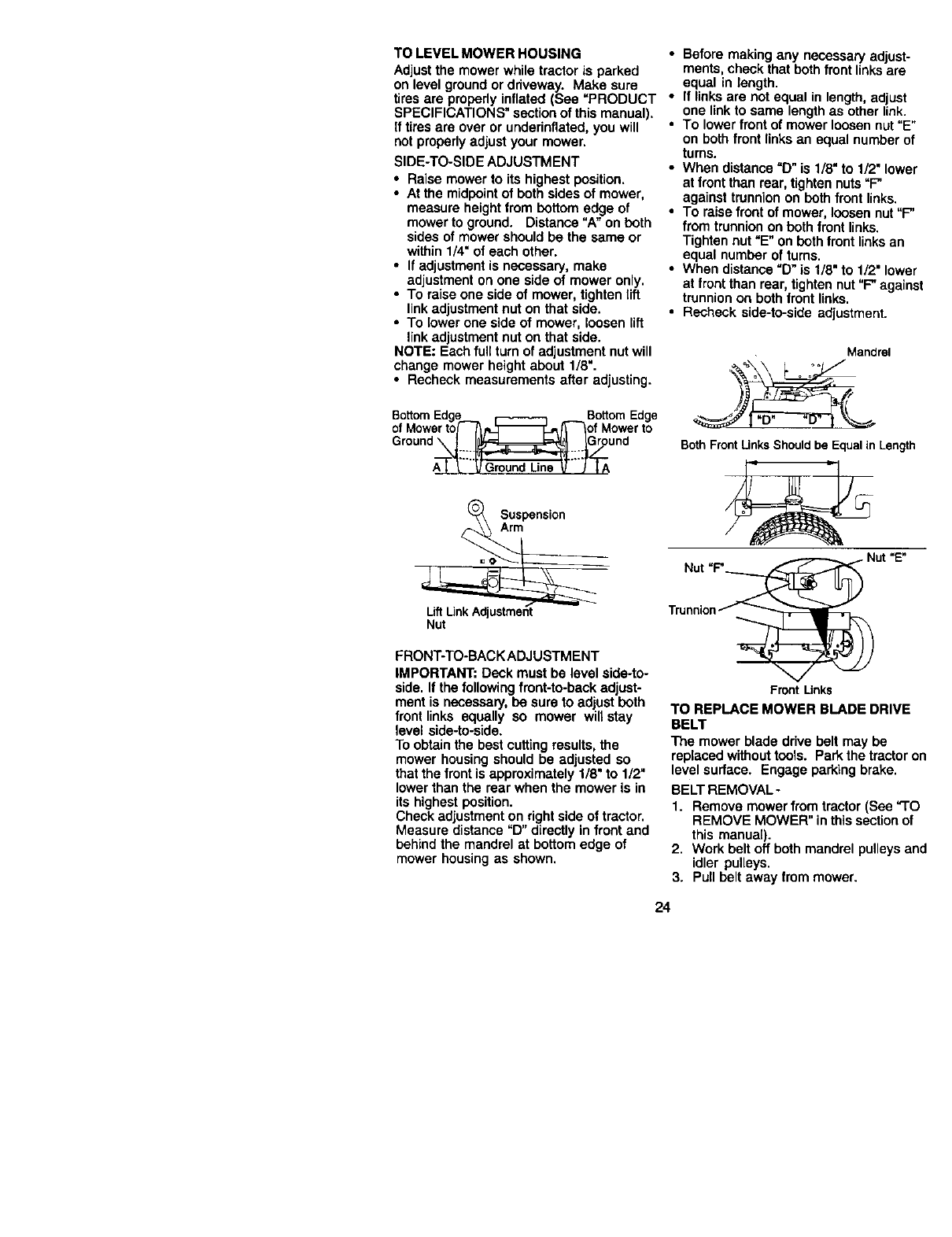
TRACTOR
TO REMOVE MOWER
Mower willbe easier to remove from the
rightside of tractor.
1. Place attachment clutch in =DISEN-
GAGED" position.
2. Move attachment lift lever forward to
lower mower to its lowest position.
3. Roll belt off engine pulley.
4. Remove small retainer spring, and lift
clutch spring oft pulley bolt.
5. Remove large retainer spring, slide
collar off and push housing guide out
of bracket.
6. Disconnect anti-swaybar from chassis
bracket by removing retainer spring.
7. Disconnect suspension arms from
rear deck brackets by removing
retainer springs.
Small Retainer Spring
Clutch S
8. Disconnect front links from deck by
removing retainer springs.
9. Raise lift lever to raise suspension
arms. Slide mower out from under
tractor.
IMPORTANT: If an attachment otherthan
the mower deck is to be mounted on the
tractor, remove the front links and hook
the clutch spring Into square hole in
frame.
TO INSTALL MOWER
1. Raise attachment lift lever to its
highest position.
2. Slide mower under tractor with
deflectorshield to right side of tractor.
3. Lower lift lever to its lowest position.
4. install mower in reverse order of
removal instructions.
-_ - SquareHc4e
Anti-Swa
Collar
Housing
Guide
Large
Spring Bracket
Front Link
(Both Sides)
23
TO LEVEL MOWER HOUSING
Adjustthe mower while tractor is parked
on level ground or ddveway. Make sure
tires are properly inflated (See "PRODUCT
SPECIFICATIONS" section of this manual),
If tires are over or underinflated, you will
not properly adjust your mower,
SIDE-TO-SIDE ADJUSTMENT
•Raise mower to its highest position.
•At the midpoint of both sides of mower,
measure height from bottom edge of
mower to ground. Distance "A"on both
sides of mower should be the same or
within 1/4" of each other.
•If adjustment is necessary, make
adjustment on one side of mower only,
•To raise one side of mower, tighten lift
link adjustment nut on that side.
•To lower one side of mower, loosen lift
link adjustment nut on that side.
NOTE: Each full turn of adjustment nut will
change mower height about 1/8".
•Recheck measurements after adjusting.
BottomEdge _BottomEdge
of Mowerto(----_/L_--_--_of Mowerto
r°und
Suspension
Arm
LiftLink Adjustment
Nut
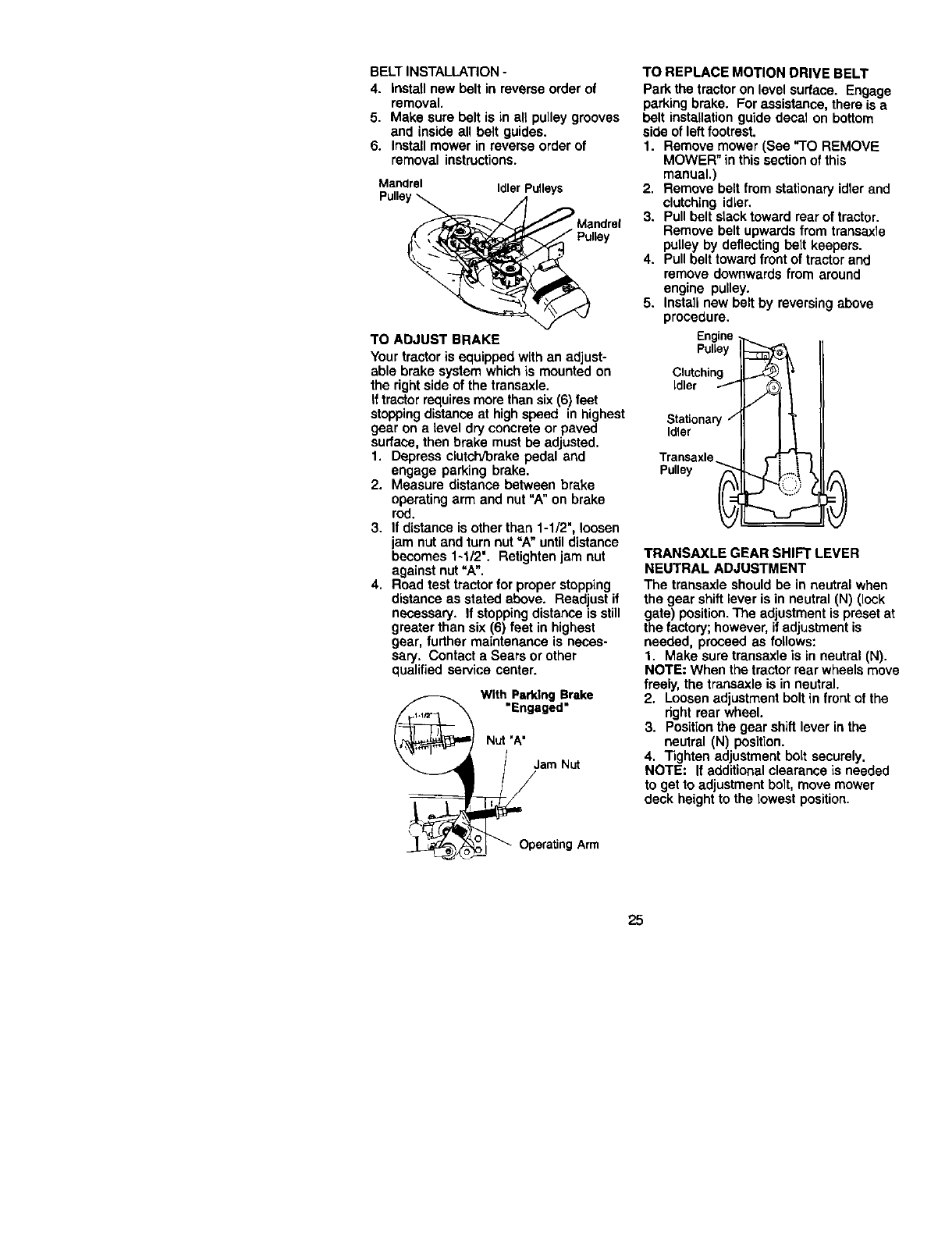
FRONT-TO-BACK ADJUSTM ENT
IMPORTANT: Deck must be level side-to-
side. If the following front-to-back adjust-
ment is necessary, be sure to adjust both
front links equally so mower will stay
level side-to-side.
To obtain the best cutting results, the
mower housing should be adjusted so
that the front is approximately 1/8" to 1/2"
lower than the rear when the mower is in
its highest position.
Check adjustment on right side of tractor.
Measure distance "D" directly in front and
behind the mandrel at bottom edge of
mower housing as shown.
•Before making any necessary adjust-
ments, check that both front links are
equal in length.
•If links are not equal in length, adjust
one link to same length as other link.
• To lower front of mower loosennut "E"
on both front linksan equal number of
turns.
•When distance =D" is 1/8" to 1/2"lower
at frontthan rear, tighten nuts"F"
against trunnion on both front links.
•To raise front of mower, loosen nut "F"
from trunnion on both front links.
Tighten nut "E" on both front linksan
equal number of turns.
•When distance "D" is 1/8" to 1/2" lower
at front than rear, tighten nut "F"against
trunnion on both front links.
•Recheck side-to-side adjustment.
Mandrel
_i \ oo'°
BothFrontUnks Shouldbe EqualinLength
.Nut "E"
Nut "P'_
Trunnion
FrontLinks
TO REPLACE MOWER BLADE DRIVE
BELT
The mower blade drive belt may be
replaced without tools. Park the tractor on
level surface. Engage parking brake,
BELT REMOVAL-
1. Remove mower from tractor (See "TO
REMOVE MOWER" in this section of
this manual).
2. Work belt oft both mandrel pulleys and
idler pulleys,
3. Pun belt away from mower.
24
BELT INSTALLATION -
4. Install new belt in reverse order of
removal.
5. Make sure belt is in all pulley grooves
and inside all belt guides.
6. Install mower in reverse order of
removal instructions.
Mandrel IdlerPulleys
Pulley_,_ ._
_:_,___'/_ _L,,f/ Mandrel
lley
TO ABJUST BRAKE
Your tractor is equipped with an adjust-
able brake system which is mounted on
the rightside of the transaxle.
If tractor requiresmore than six(6) feet
stoppingdistance at highspeed in highest
gear on a level dry concrete or paved
surface, then brake must be adjusted•
1. Depress clutcl'vbrake pedal and
engage parking brake•
2. Measure distance between brake
operating arm and nut =A" on brake
rod.
3. If distance is other than 1-1/2", loosen
jam nut and turn nut "A" until distance
becomes 1-1/2". Retightenjam nut
against nut "A".
4. Road test tractor for proper stopping
distance as stated above. Readjust if
necessary. If stopping distance is still
greater than six (6) feet in highest
gear, further maintenance is neces-
sary. Contact a Sears or other
qualified service center.
With Parking Brake
"Engaged"
N_'A"
_3_o_am N_
era_ng Arm
TO REPLACE MOTION DRIVE BELT
Park the tractor on level sudace. Engage
parking brake. For assistance, there is a
belt installation guide decal on bottom
side of leftfootrest.
1. Remove mower (See "TO REMOVE
MOWER" in this section of this
manual.)
2. Remove belt from stationery idler and
clutching idler.
3. Pull belt stacktoward rear of tractor.
Remove belt upwards from transaxle
pulley by deflecting belt keepers.
4. Pull belt toward frontof tractor and
remove downwards from around
engine pulley.
5. Install new belt by reversing above
procedure.
Engine
Pulley
Clutching
idler /
Stationary
Idler
yn_
TRANSAXLE GEAR SHIFT LEVER
NEUTRAL ADJUSTMENT
The transaxle should be in neutral when
the gear shift lever is in neutral (N) (lock
gate) position.The adjustment is preset at
the factory; however, if adjustment is
needed, proceed as follows:
1. Make sure transaxle is in neutral (N).
NOTE: When the tractor rear wheels move
freely, the transaxle is in neutral,
2. Loosen adjustment bolt in frontof the
right rear wheel.
3. Position the gear shift lever in the
neutral (N) position.
4. Tighten adjustment bolt securely.
NOTE: If additionalclearance is needed
to get to adjustment bolt, move mower
deck height to the lowest position.
25
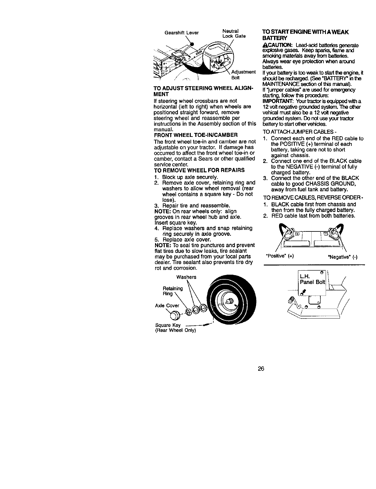
GearshiftLever Neutral
Lock Gate
_Adjustment
Bolt
TO ADJUST STEERING WHEEL ALIGN-
MENT
If steering wheel crossbars are not
hohzontal (left to right) when wheels are
positioned straight forward, remove
steering wheel and reassemble per
instructionsin the Assembly section of this
manual.
FRONT WHEEL TOE-IN/CAMBER
The front wheel toe-in and camber are not
adjustable on your tractor. If damage has
occurred to affect the front wheel toe-in or
camber, contact aSears or other qualified
service center.
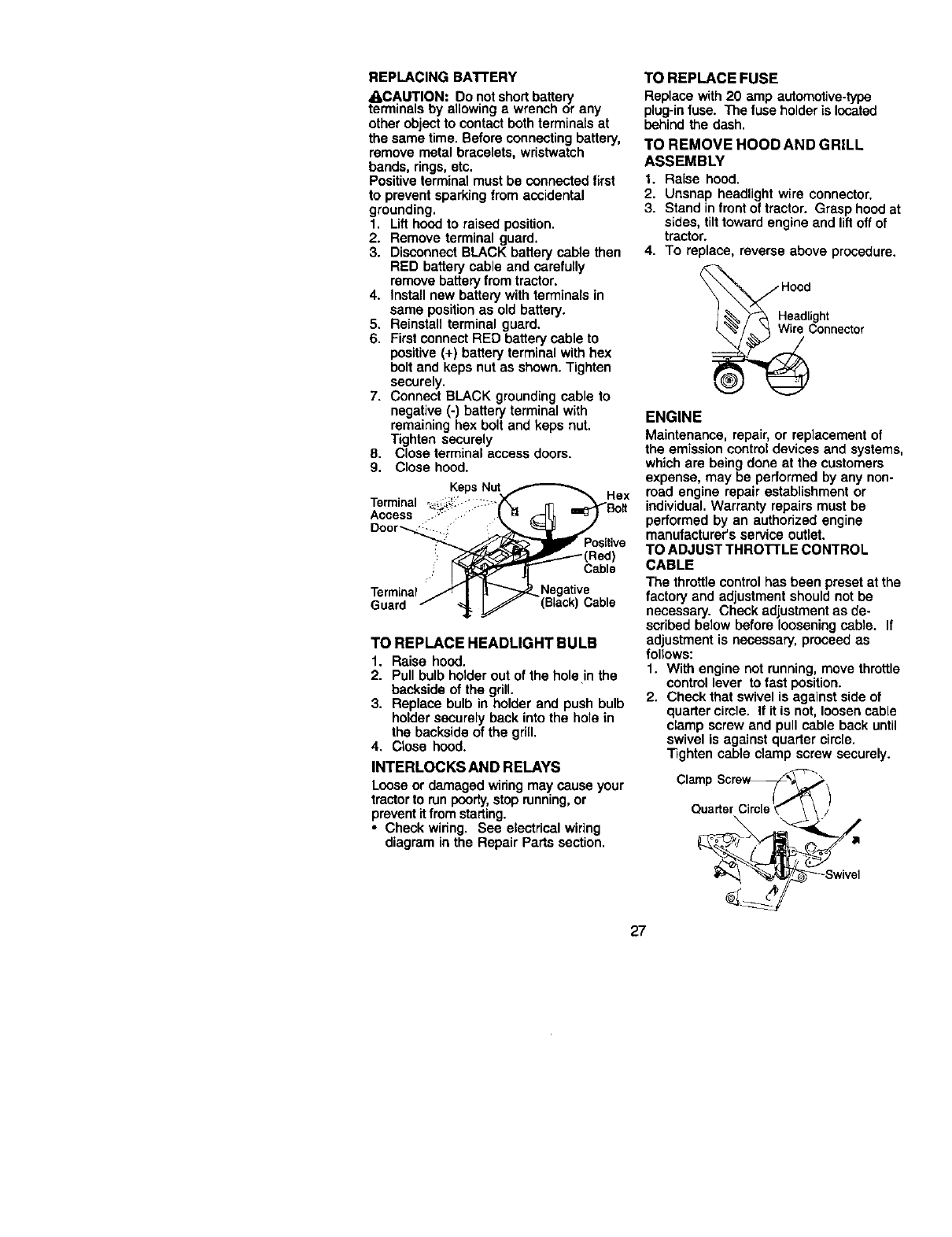
TO REMOVE WHEEL FOR REPAIRS
1. Block up axle securely.
2. Remove axle cover, retaining ring and
washers to allow wheel removal (rear
wheel contains a square key - Do not
lose).
3. Repair tire and reassemble.
NOTE= On rear wheels only: align
grooves in rear wheel hub and axle.
Insert square key.
4. Replace washers and snap retaining
ring securely in axle groove.
5. Replace axle cover.
NOTE: To seal tire punctures and prevent
flat tires due to stow leaks, tire sealant
may be purchased from your Iooal parts
dealer. Tire sealant also prevents tire dry
rot and corrosion.
Washers
Rso,n,og
Square Key _ _=,-_w,--
(Rear Wheel Only)
TO START ENGINE WITH AWEAK
BATTERY
ACAUTION: Lead-acidbatteries generate
explosive gasss. Keepsparks,flameand
smokingmaterialsaway frombattenes.
Always wear eye protec_onwhen around
batteries.
Ifyourbattery istooweak to starttheengine,it
shouldbe recharged.(See "BATTERY" inthe
MAINTENANCE section of this manual).
If "jumper cables"are used foremergency
starting,foUowthisprocedure:
IMPORTANT: Yourtractorisequ_opedwitha
12voif negativegrounded system. T_ other
vehical must alsobe a 12 voltnegative
grounded system. Do not useyour tractor
battery to start othervehicles.
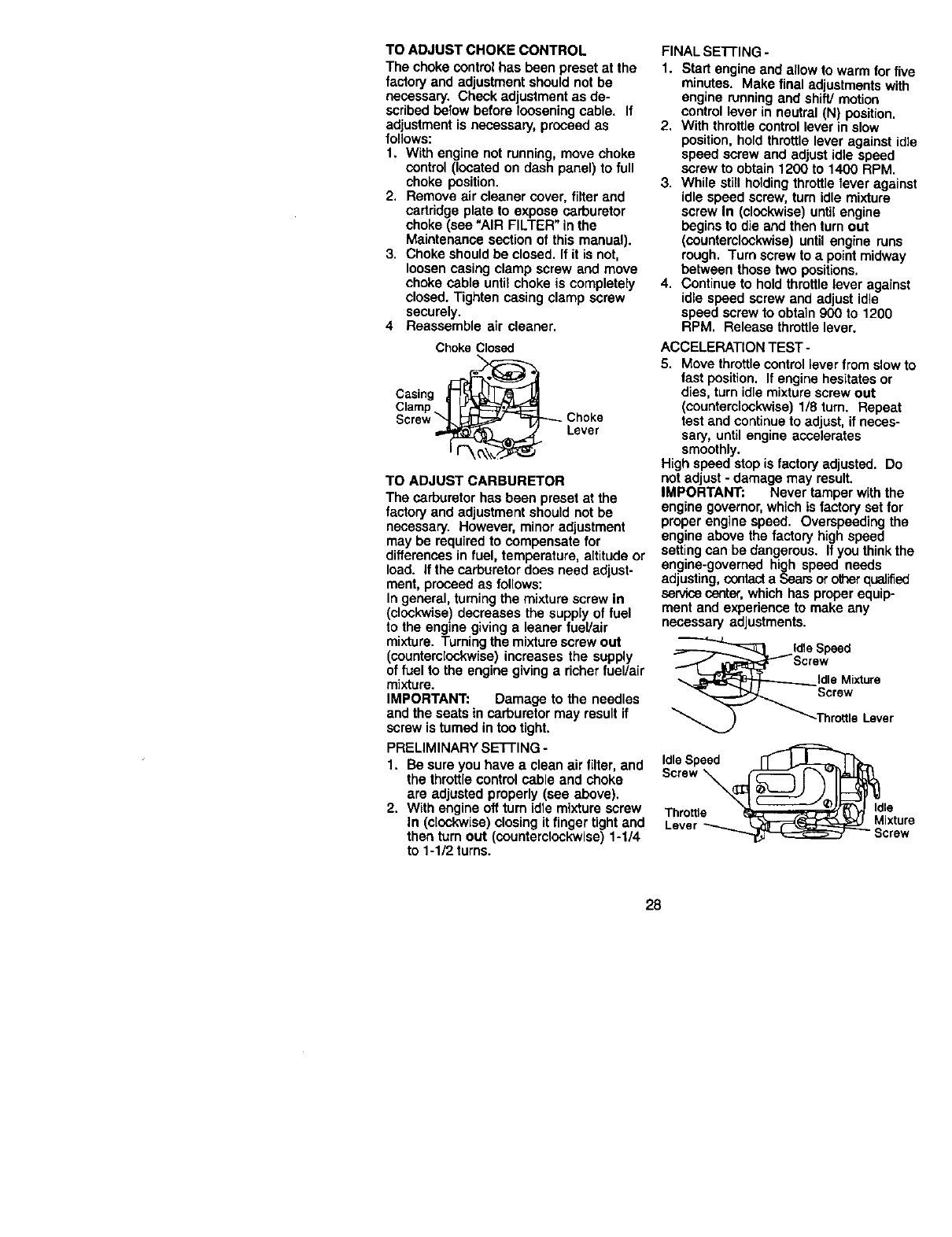
TO ATTACHJUMPER CABLES-
1. Connect each end ofthe RED cable to
the POSITIVE (+) terminal of each
battery, taking care not to short
against chassis.
2. Connect one end of the BLACK cable
to the NEGATIVE (-) terminal of fully
charged battery.
3. Connect the other end of the BLACK
cable to good CHASSIS GROUND,
away from fuel tank and battery.
TO REMOVE CABLES, REVERSE ORDER o
1. BLACK cable first from chassis and
then from the fully charged battery.
2. RED cable last from both batteries.
"Positive" (+) "Negative" (-)
26
REPLACING BAI"I'ERY
_I_CAUTION: Do not short battery
terminals by allowing a wrench or any
other object to contact both terminals at
the same time. Before connecting battery,
remove metal bracelets, wristwatch
bands, rings,etc.
Positive terminal must be connected first
to prevent sparking from accidental
grounding.
1. Lift hood to raised position.
2. Remove terminal guard.
3. Disconnect BLACK battery cable then
RED battery cable and cerefully
remove battery from tractor.
4. Install new battery with terminals in
same position as old battery.
5. Reinstall terminal guard.
6. First connect RED battery cable to
positive (+) battery terminal with hex
bolt and keps nut as shown. Tighten
securely.
7. Connect BLACK grounding cable to
negative (-) battery terminal with
remaining hex bolt and keps nut.
Tighten securely
8. Close terminal access doors.
9. Close hood.
Terminal
Access
Hex
Cable
Terminal
Guard (Black) Cable
TO REPLACE HEADLIGHT BULB
1. Raise hood.
2. Pull bulb holder out of the hole in the
backside of the grill.
3. Replace bulb in holder and push bulb
holder securely back into the hole in
the backside of the gdll.
4. Close hood.
INTERLOCKS AND RELAYS
Loose or damaged wiring may cause your
tractor to runpoody,stop running,or
preventitfrom starting.
• Check wiring. See electdcal wiring
diagram in the Repair Parts section.
TO REPLACE FUSE
Replace with 20 amp automotive-type
plug-infuse. The fuse holder is located
behind the dash.
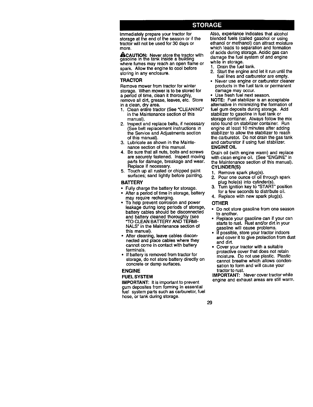
TO REMOVE HOOD AND GRILL
ASSEMBLY
1. Raise hoed.
2. Unsnap headlight wire connector.
3. Stand in front of tractor. Grasp hood at
sides, tilt toward engine end liftoft of
tractor.
4. To replace, reverse above procedure.
onnector
ENGINE
Maintenance, repair, or replacement of
the emission control devices and systems,
which are being done at the customers
expense, may be pedormed by any non-
road engine repair establishment or
individual. Warranty repairs must be
performed by an authorized engine
manufacturer's service outlet.
TO ADJUST THRO'I-I'LE CONTROL
CABLE
The throttle control has been preset at the
factory and adjustment should not be
necessary. Check adjustment as de-
scribed below before loosening cable. If
adjustment is necessary, proceed as
follows:
1. With engine not running, move throttle
control lever to fast position.
2. Check that swivel is against side of
quarter cimle. If it is not, loosen cable
clamp screw and pull cable back until
swivel is against quarter circle.
Tighten cable clamp screw securely.
27
TO ADJUST CHOKE CONTROL
The choke controlhas been preset at the
factory and adjustment should not be
necessary. Check adjustment as de-
scribed below before loosening cable, If
adjustment is necessary, proceed as
follows:
1. With engine not running, move choke
control (located on dash panel) to full
choke position.
2. Remove air cleaner cover, filter and
cartridge plate to expose carburetor
choke (see "AIR FILTER" in the
Maintenance section of this manual).
3. Choke should be closed. If it is not,
loosen casing clamp screw and move
choke cable untiechoke is completely
closed. Tighten casing clamp screw
securely.
4 Reassemble air cleaner.
Choke Closed
Screw
Choke
Lever
TO ADJUST CARBURETOR
The carburetor has been preset at the
factory and adjustment should not be
necessary. However, minor adjustment
may be required to compensate for
differences in fuel, temperature, altitude or
load. If the carburetor does need adjust-
ment, proceed as follows:
In general, turning the mixture screw In
(clockwise) decreases the supply of fuel
to the engine giving a leaner fuel/air
mixture. Turning the mixture screw out
(counterclockwise) increases the supply
of fuel to the engine giving aricher fuel/air
mixture.
IMPORTANT: Damage to the needles
and the seats in carburetor may result if
screw is turned in too tight.
PRELIMINARY SE'FFING -
1. Be sure you have a clean air filter, and
the throttle control cable and choke
are adjusted properly (see above).
2. With engine off turn idle mixture screw
In (clockwise) closing it finger tight and
then turn out (counterclockwise) 1-1/4
to 1-1/2 turns.
FINAL SETTING -
1. Start engine and allow to warm for five
minutes. Make final adjustments with
engine running and shift/motion
control lever in neutral (N) position.
2. With throttle control lever in slow
position, hold throttle lever against idle
speed screw and adjust idle speed
screw to obtain 1200 to 1400 RPM.
3. While still holding throttle fever against
idle speed screw, turn idle mixture
screw In (clockwise) until engine
begins to die and then turn out
(counterclockwise) until engine runs
rough. Turn screw to a point midway
between those two positions.
4. Continue to hold throttle lever against
idle speed screw and adjust idle
speed screw to obtain 900 to 1200
RPM. Release throttle lever.
ACCELERATION TEST-
5. Move throttle control lever from slow to
fast position. If engine hesitates or
dies, turn idle mixture screw out
(counterclockwise) 1/8 turn. Repeat
test and continue to adjust, if neces-
sary, until engine accelerates
smoothly.
High speed stop is factory adjusted. Do
not adjust - damage may result.
IMPORTANT: Never tamper with the
engine governor, which is factory set for
proper engine speed. Overspeeding the
engine above the factory high speed
settingcan be dangerous. If you think the
engine-governed high speed needs
adjusting, contact a Sears or other qualified
servicecenter,which has proper equip-
ment and experience to make any
necessary adjustments.
Idlepeed
ew
IdleMixture
Screw
ThrottleLever
IdleSpeed
Throttle _ Id!e
Lever Mixture
28
Immediately prepare your tractor for
storage at the end of the season or if the
tractor will not be used for 30 days or
more.
_CAUT ON Never store th(ptractor with
gasoline in the tank inside aouilding
where fumes may reach an open flame or
spark. Allow the engine to cool before
storing in any enclosure.
TRACTOR
Remove mower from tractor for winter
storage. When mower is to be stored for
a period of time, clean itthoroughly,
remove all dirt, grease, leaves, etc. Store
in aclean, dry area.
1. Clean entire tractor (See "CLEANING"
in the Maintenance section of this
manual).
2. Inspect and replace belts, if necessary
(See belt replacement instructions in
the Service and Adjustments section
of this manual).
3. Lubricate as shown in the Mainte-
nance section of this manual.
4. Be sure that all nuts, bolts and screws
are securely fastened. Inspect moving
parts for damage, breakage and wear.
Replace if necessary.
5. Touch up all rusted or chipped paint
surfaces; sand lightly before painting.
BATTERY
• Fully charge the battery for storage.
• After a period of time in storage, battery
may require recharging.
•To help prevent corrosion and power
leakage during long periods of storage,
battery cables should be disconnected
and battery cleaned thoroughly (see
"TO CLEAN BATTERY AND TERMI-
NALS" in the Maintenance section of
this manual).
•After cleaning, leave cables discon-
nected and place cables where they
cannot come in contact with battery
terminals.
• If battery is removed from tractor for
storage, do not store battery directly on
concrete or damp surfaces.
ENGINE
FUEL SYSTEM
IMPORTANT: Itis importantto prevent
gum deposites from forming in essential
fuet system parts such as carburetor, fuel
hose, or tank during storage.
Also, experiance indicates that alcohol
blended fuels (called gasohol or using
ethanol or methanol) can attract moisture
which leads to separation and formation
of acids duringstorage. Acidic gas can
damage the fuel system of and engine
while in storage,
1. Drain the fuel tank.
2. Start the engine and let it run untilthe
fuel lines and carburetor are empty.
• Never use engine or carburetor cleaner
products in the fuel tank or permanent
damage may occur.
• Use fresh fuel next season.
NOTE: Fuel stabilizer is an acceptable
alternative in minimizing the formation of
fuel gum deposits during storage. Add
stabilizer to gasoline in fuel tank or
storage container. Always follow the mix
ratio found on stabilizer container. Run
engine at least 10 minutes after adding
stabilizer to allow the stabilizer to reach
the carburetor. Do not drain the gas tank
and carburetor if using fuel stabilizer.
ENGINE OIL
Drain oil (with engine warm) and replace
with clean engine oil. (See "ENGINE" in
the Maintenance section of this manual).
CYLINDER(S)
1. Remove spark plug(s).
2. Pour one ounce of oil through spark
plug hole(s) into cylioder(s).
3. Turn ignitionkey to "START" position
for a few seconds to distribute oil.
4. Replace with new spark plug(s).
OTHER
•Do not store gasoline from one season
to another.
• Replace your gasoline can if your can
starts to rust. Rustand/or dirt inyour
gasoline will cause problems.
•If possible, store your tractor indoors
and cover it to give protectionfrom dust
and dirt.
•Cover your tractor with asuitable
protective cover that does not retain
moisture, Do not use plastic. Plastic
cannot breathe which allows conden-
sation to form and will cause your
tractor to rust,
IMPORTANT: Never cover tractor whUe
engine and exhaust areas are still warm,
29
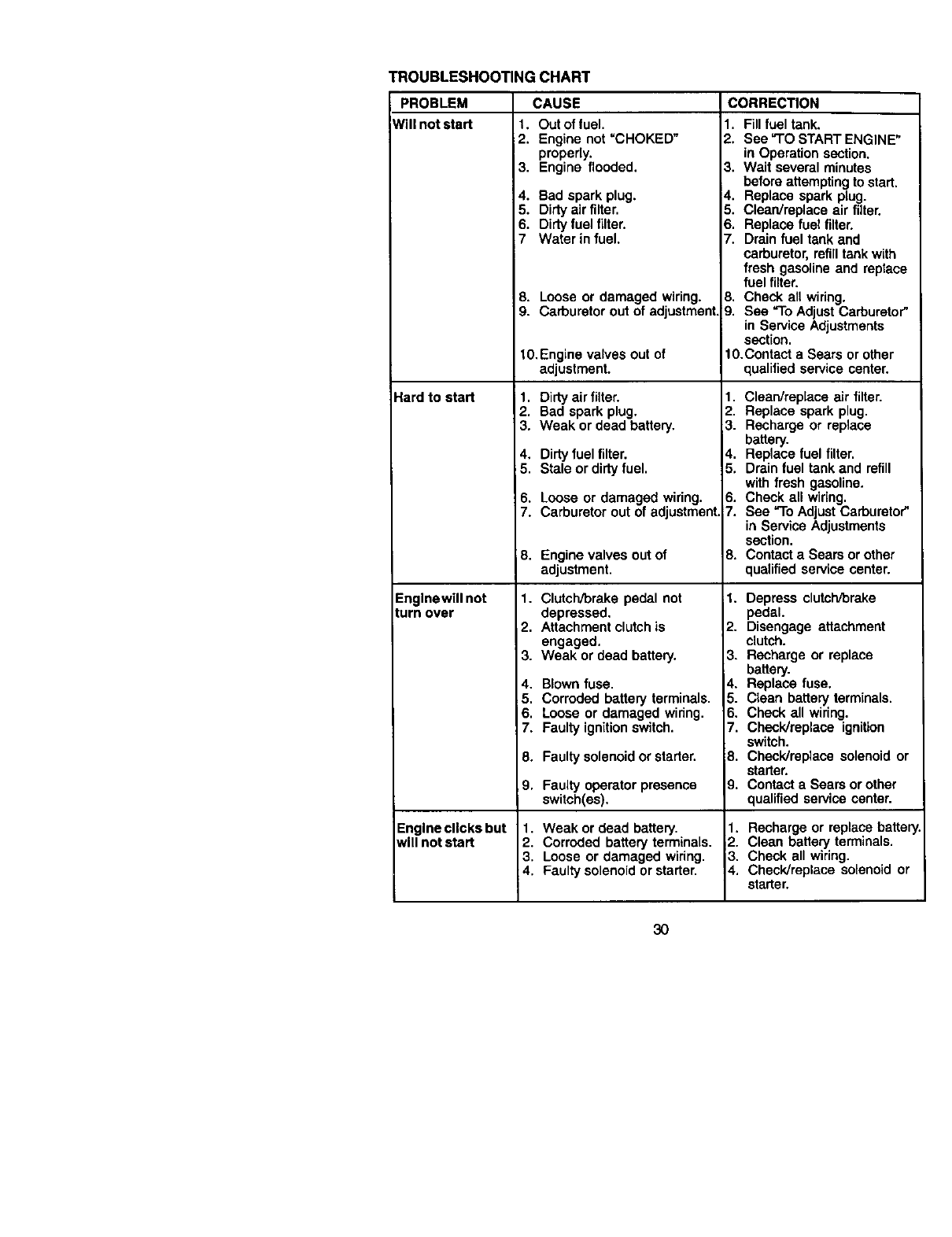
TROUBLESHOO_NGCHART
PROBLEM
Mill not start 2.
3,
4.
5.
6.
7
8.
9.
Hard to start
Englnewillnot
turn over
Englneclicksbut
wlllnotstart
CAUSE CORRECTION
1, Out of fuel.
Engine not "CHOKED"
properly.
Engine flooded.
Bad spark plug.
Dirty airfilte_
Dirty fueltilter.
Waterin fuel.
Loose or damaged wiring.
Carburetor out of adjustment
t0,Engine valves out of
adjustment.
1. Dirty air filter.
2. Bad spark plug.
3. Weak or dead battery,
4, Dirty fuel filter.
5. Stale or dirty fuel.
6. Loose or damaged wiring.
7. Carburetor out of adjustment.
8. Engine valves out of
adjustment.
1. Clutch/brake pedal not
depressed,
2, Attachment clutch is
engaged.
3. Weak or dead battery.
4. Blown fuse.
5. Corroded battery terminals.
6. Loose or damaged wiring.
7. Faulty ignition switch.
8. Faulty solenoid or starter.
9. Faultyoperatorpresence
switch(es).
1. Weak or dead battery.
2. Corroded battery terminals.
3. Loose or damaged wiring.
4. Faulty solenoid or starter.
1. Fill fuel tank.
2. See "ro START ENGINE"
in Operation section.
3. Wait several minutes
before attemptingto start.
14. Replace spark plug.
5. Clean/replace air filter.
6. Replace fuel filter.
7. Drain fuel tank and
carburetor, refilltank with
fresh gasoline and replace
fuel filter.
B. Check all wiring.
9. See "To Adjust Carburetor"
in Service Adjustments
section.
10.Contact a Sears or other
qualified service center.
1. Clean/replace air filter.
2. Replace spark plug.
3. Recharge or replace
battery.
4. Replace fuel filter.
5. Drain fuel tank and refill
with fresh gasoline.
6. Check all wiring.
7. See "To Adjust Carburetor"
in Service Adjustments
section.
8. Contact a Sears or other
qualified service center.
1. Depress clutch/brake
pedal.
2. Disengage attachment
clutch.
3. Recharge or replace
battery.
4. Replace fuse.
5. Clean battery terminals.
6. Check all wiring.
7. Check/replace ignition
switch.
8. Check/replace solenoid or
starter.
9. Contact a Sears or other
qualified service center.
1. Recharge or replace batter
2. Clean battery terminals.
3. Check all wiring.
4. Check/replace solenoid or
starter.
30
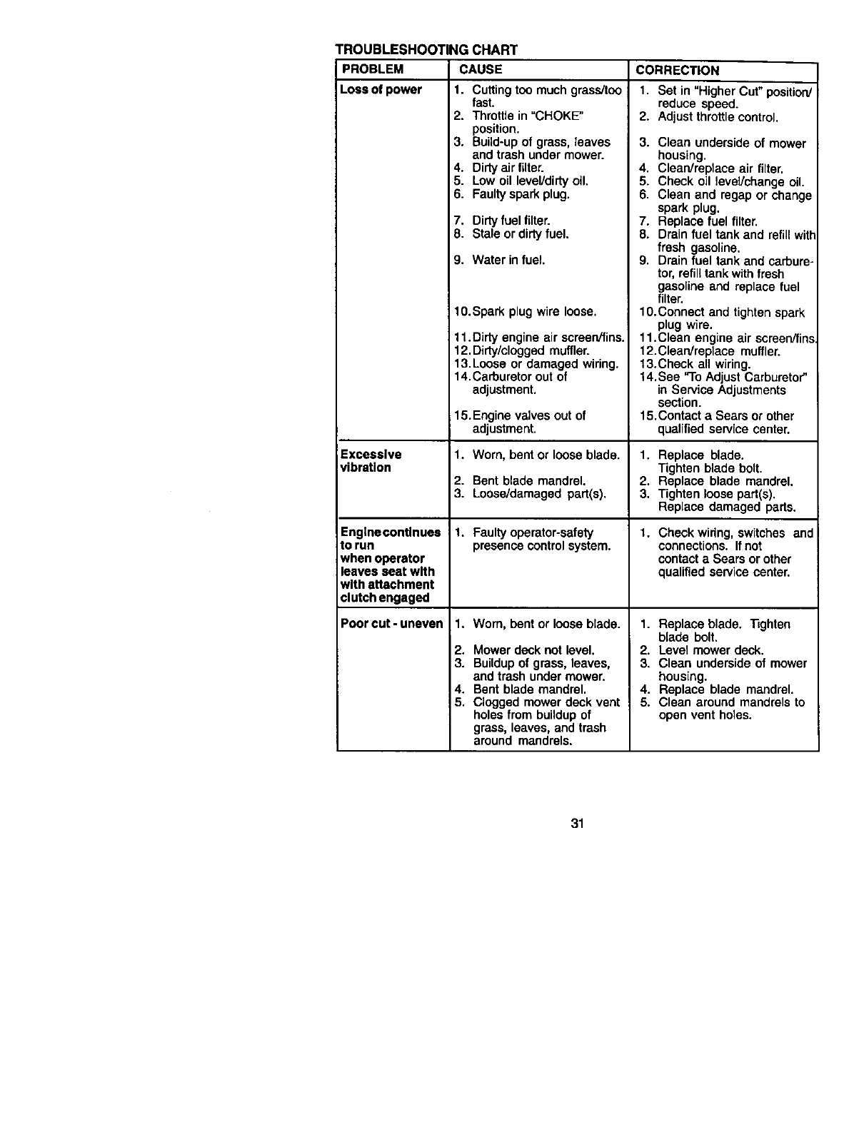
TROUBLESHOOTING CHART
PROBLEM CAUSE CORRECTION
Loss of power 1. Cutting too much grass/too
Excessive
vibration
Enginecontlnues
to run
when operator
leaves seat with
with attachment
clutch engaged
Poor cut-uneven
fast.
2. Throttle in "CHOKE"
position.
3. Build-up of grass, leaves
and trash under mower.
4. Dirty air filter.
5. Low oil level/dirty oil.
6. Faulty spark plug.
7. Dirty fuel filter.
8. Stale or dirty fuel.
9. Water in fuel.
10.Spark plug wire loose.
11.Dirty engine air screen/fins.
12.Dirty/clogged muffler.
13.Loose or damaged wiring.
14.Carburetor out of
adjustment.
15. Engine valves out of
adjustment.
1. Worn, bent or loose blade.
2. Bent blade mandrel.
3. Loose/damaged part(s).
1. Faulty operator-safety
presence controlsystem.
1. Worn, bent or loose blade.
2. Mower deck not level,
3. Buildup of grass, leaves,
end trash under mower.
4. Bent blade mandrel,
5. Clogged mower deck vent
holes from buildup of
grass, leaves, and trash
around mandrels.
1. Set in "Higher Cut" position/
reduce speed.
2. Adjust throttle control.
3. Clean underside of mower
housing.
4. Clean/replace air filter.
5. Check oil level/change oil.
6. Clean and regap or change
spark plug.
7. Replace fuel filter.
8. Drain fuel tank and refill with
fresh gasoline.
9. Drain fuel tank and carbure-
tor, refill tank with fresh
gasoline and replace fuel
filter.
10.Coonect and tighten spark
plug wire.
11.Clean engine air screen/fins
12.Clean/replece muffler.
13.Check all wiring.
14.See "To Adjust Carburetor"
in Service Adjustments
section.
15.Contact a Sears or other
qualified service center.
1. Replace blade.
Tighten blade bolt.
2. Replace blade mandrel.
3. Tighten loose part(s).
Replace damaged pads.
1. Check wiring, switches and
connections. If not
contact a Sears or other
qualified service center.
1. Replace blade. _ghten
blade bolt.
2. Level mower deck.
3. Clean underside of mower
housing.
4. Replace blade mandrel.
5. Clean around mandrels to
open vent holes.
31
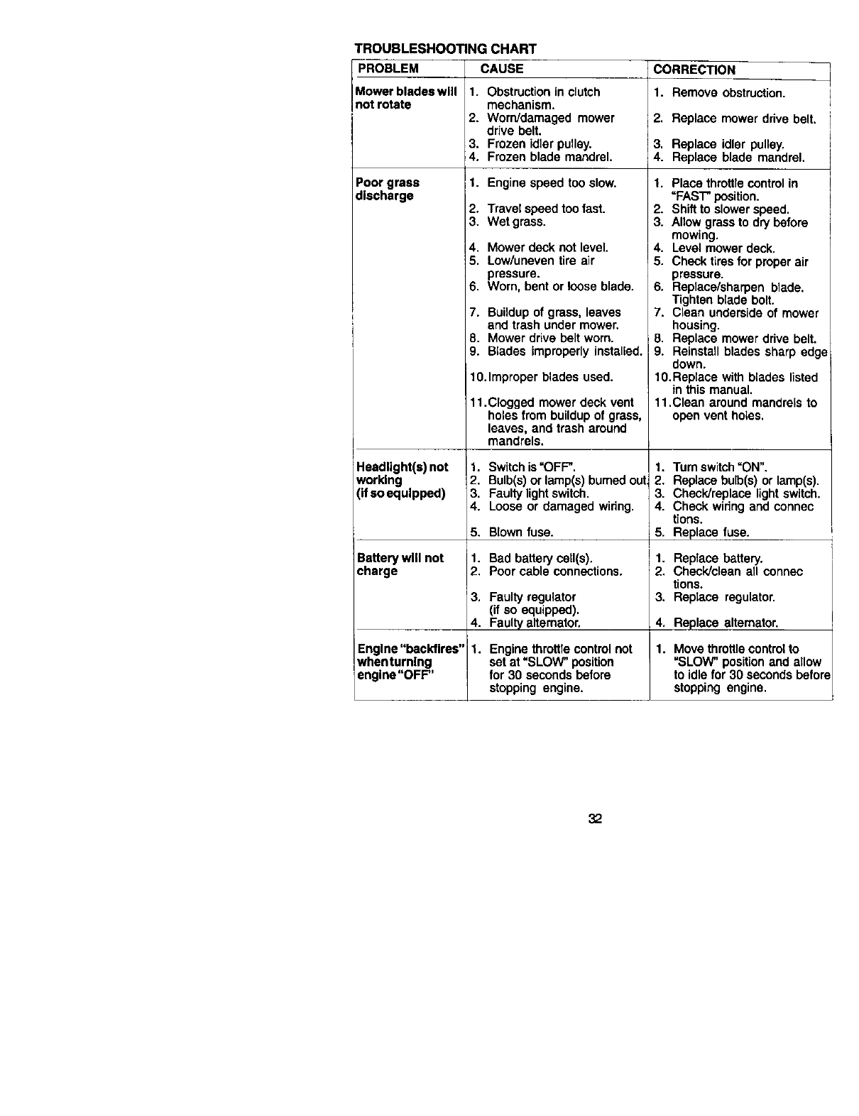
TROUBLESHOOTING CHART
PROBLEM CAUSE
Mower blades wlll 1. Obstruction in clutch
not rotate mechanism.
2. Worn/damaged mower
drive belt.
3. Frozen idler pulley.
4. Frozen blade mandrel.
Poor grass 1. Engine speed too slow.
discharge 2. Travel speed too fast.
3. Wet grass.
4. Mower deck not level.
5. Low/uneven tire air
pressure.
6. Worn, bent or loose blade.
7. Buildup of grass, leaves
and trash under mower.
8. Mower drive belt worn.
9. Blades improperly installed.
10.Improper blades used.
11.Clogged mower deck vent
holes from buildup of grass,
leaves, and trash around
mandrels.
Headlight(s) not 1. Switch is "OFF.
working 2. Bulb(s) or lamp(s) burned out
(if so equipped) 3. Faulty lightswitch.
4. Loose or damaged wiring.
5.
Battery will not 1.
charge 2.
3.
4.
Engine "backfires" 1.
when turning
engine"OFF"
Blown fuse.
Bad battery ceil(s),
Poor cable connections.
Faulty regulator
(if so equipped).
Faulty alternator,
Engine throttle control not
set at =SLOW" position
for 30 seconds before
stopping engine.
CORRECTION
1. Remove obstruction.
2. Replace mower drive belt.
3. Replace idler pulley.
4. Replace blade mandrel.
1, Place throttle control in
=PAST" position.
2. Shift to slower speed.
3. Allow grass to dry before
mowing.
4. Level mower deck.
5. Check tiresfor proper air
pressure.
6. Replace/sharpen blade.
Tighten blade bolt.
7. Clean underside of mower
housing.
8. Replace mower drive belt.
9, Reinstall blades sharp edge
down,
10.Replace with blades listed
in this manual,
11.Clean around mandrels to
open vent holes.
1. Turn switch"ON".
2. Replace bulb(s) or lamp(s).
3. Check/replace light switch,
4. Check wiring and connec
tions.
5. Replace fuse.
1. Replace battery.
2. Check/clean all connec
tions.
3. Replace regulator.
4. Replace alternator.
1. Move throttle control to
=SLOW" position and allow
to idle for 30 seconds befon
stopping engine.
32
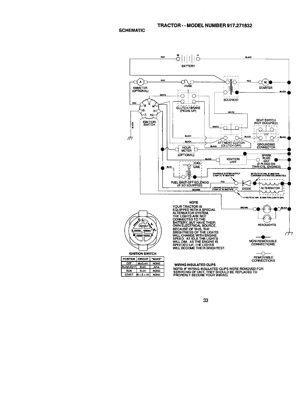
TRACTOR- - MODEL NUMBER 917.271832
SCHEMATIC
BATTERY
AMMETER
[OPTK3_AL)
IGNITION SWITCH
_ i REO
FUSE i, STARTER
ii'SOLENOID
SEATSWITCH
__' ,(NOTOCC _UPLED),
(OPTIONAL)
'FUEL'
i
FUELSHUT-OFFSOLENOID
(
_SPARK
IGNITION PLUG
UNIT GAP O--
J (2 PLUGS ON
TWI_ CYL ENGINES)
C_I_ S_TEM O_JT_JT _V_.T$ _C Mm e _R_4
3_¢C e_PM (c_t_o;,_ sy $_r_ o_scCeaN_CTEOI
5_,P*c e_FeM DIODE :ALTERNATOR
HEADLIGHTS
F
NON-REMOVABLE
CONNECTIONS
REMOVABLE
CONNECTIONS
NOTE
YOUR TRACTOR iS
EQUIPPED WITH A SPECIAL
ALTERNATOR SYSTEM,
THE LIGHTS ARE NOT
CONNECTED TO THE
BATTERY, BUT HAVE THEIR
OWN ELECTRICAl. SOURCE,
BECAUSE OF THIS, THE
BRIGHTNESS OF THE LIGHTS
WILL CHANGE WITH ENGINE
SPEED. AT iDLE THE LIGHTS
WILL DIM. AS THE ENGINE IS
SPEEDED UP, THE LIGHTS
WILL BECOME THEIR BRIGHTEST,
WIRING INSULATED CUPS
NOTE: IF WIRING INSULATED CLIPS WERE REMOVED FOR
SERVICING OF UNIT, THEY SHOULD BE REPLACED TO
PROPERLY SECURE YOUR WIRING.
33
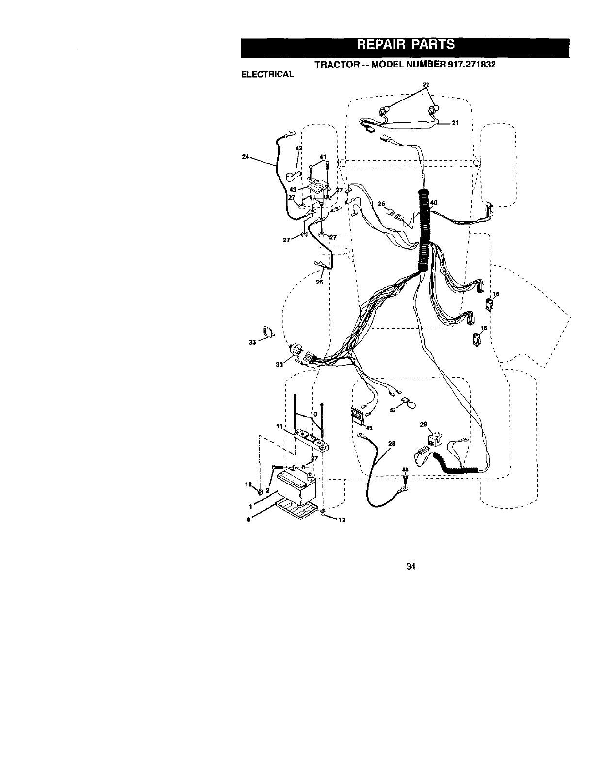
TRACTOR-- MODEL NUMBER 917.271832
ELECTRICAL
i
i
25
i
i
:34

TRACTOR -- MODEL NUMBER 917.271832
ELECTRICAL
KEY PART
NO. NO. DESCRIPTION
1 163465 Battery 12 VOLT 28 AMP
2 74760412 Bolt Hex Hd 1/4-20unc x 3/4
8 7603J Case Battery
10 145211 Bolt, Etr Front I/4-20 x 7-1/2
11 150109 Holddown Battery Front Mount
12 145769 Nut, Push Nylon Battery Front 1/4
16 153664 Switch, Interlock Push-In
21 175688 Harness Light Socket (W/4152j)
22 4152,.I Bulb Light #1156
24 4799J Cable Battery
25 146148 Cable Battery
26 175158 Fuse
27 735104_0 Nut Keps Hex 1/4-20 Unc
28 145491 Cable Ground
29 1213_5X Switch Seat
30 175566 Switch Ign
33 140403 Key Molded Cra;lsman
40 178437 Harness Ign
41 711104(_ Bolt BIk. Fin Hex 1/4-20 Unc x 1/2
42 131563 CoverTerminal
43 178861 So_encid
45 121433X Ammeter Rectangular 6 Amp
52 141940 Protection Wire Loop
56 174905(_ Screw Thdrol 5/16-18 x 1/2
NOTE: All component dimensions given in U. 8.
inches 1 inch = 25.4 mm
35
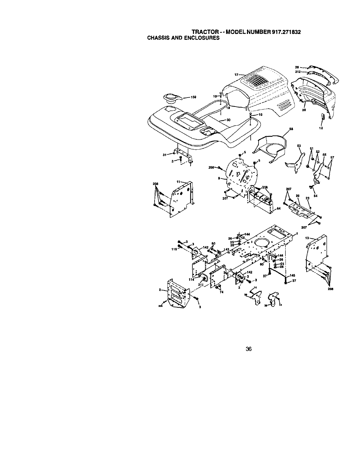
TRACTOR-- MODEL NUMBER 917.271832
CHASSISAND ENCLOSURES
12
57
3 14 2O8
36

TRACTOR-- MODEL NUMBER 917.271832
CHASSISAND ENCLOSURES
KEY PART
NO, NO. DESCRIPTION
1 174619 Chassis Assemb4y
2 176554 D_
3 17060612 Screw 3/8-16 x 3/4
5 155272 Bumper Hood/Dash
9 168337X013 Dash
10 SlIT,%n3710 Bo!l, Carriage 3/8-16 x 1
11 155927 Panel, Dash, LH.
12 145660 Clip Tinne rman Grille P/L
13 172107X010 Panel, Dash, R.H.
14 17490608 Screw Tndrol 3/8-16 x 1/2
17 144983X558 Hood Assembly
18 126938X Bumper Hood
20 156437 P_te Mtg Battery Fuel Tank
2:3 124028X Bushing, Snap, Nylon, Fuct Line
25 19131312 Washer 13/32 x 13/16 x 12 Gauge
26 ST_341437 Locknut, Hex, with Insert 3/8ol 6 Unc
28 178987X558 Grille/Lens Asm
29 155217X599 Lens, Grille
30 175692X558 Fend/Ftrest
31 13_976 Bracket, Fender Suppod
37 1749_-_(_ Screw Tndrct 5/16-18 x 1/2
38 175710 Pivot Bracket Assembly
51 73800400 Nut Lock w/Insert 114-20 UNC
52 19091416 Washer 9/32 x 7/8 x 16 Ga.
53 145201 Bracket Grilk_ Pickoff LH
54 161464 Screw Hex Wshd 8-18 x 7/8
55 145202 Bracket Grille Pickoff RH
57 S'1_$22507 Bolt, Fin Hex 1/4-20 UNC x .75
58 140547 Air Duct P/I. B&S
60 $1_533707 Bolt Rdhd Sqnk 3/8-16 UNC x 3/4
64 154798 Dash Lower STLT
74 $1IT041437 Nut Ctownlock 3/8-16 UNC
114 158112 Keeper Belt Rear Lh Stl
115 17060620 Screw 3/8-16x1-1/4
142 1757_ Plate Reinforcement STLT
143 154966 Bracket Swayb_" Chessis
144 175582 Bracket Pnt Footrest STLT
145 156524 Rod Pivot ChassisJHood
159 155123X42B Cuphelder
206 170165 Bolt Sheulder 5/16-18 TT
207 17676506 Screw Thdrol 5/16-18 x 1/2
208 17670606 Screw Thdrol 3,/8-16 x 1/2
211 145212 Nut Hexflange Lock
212 165919 Insert Lens Reflective
- - 5479J Plug Button
NOTE: All component dimensions given in U. S.
inches 1 inch =25.4 rnm
37
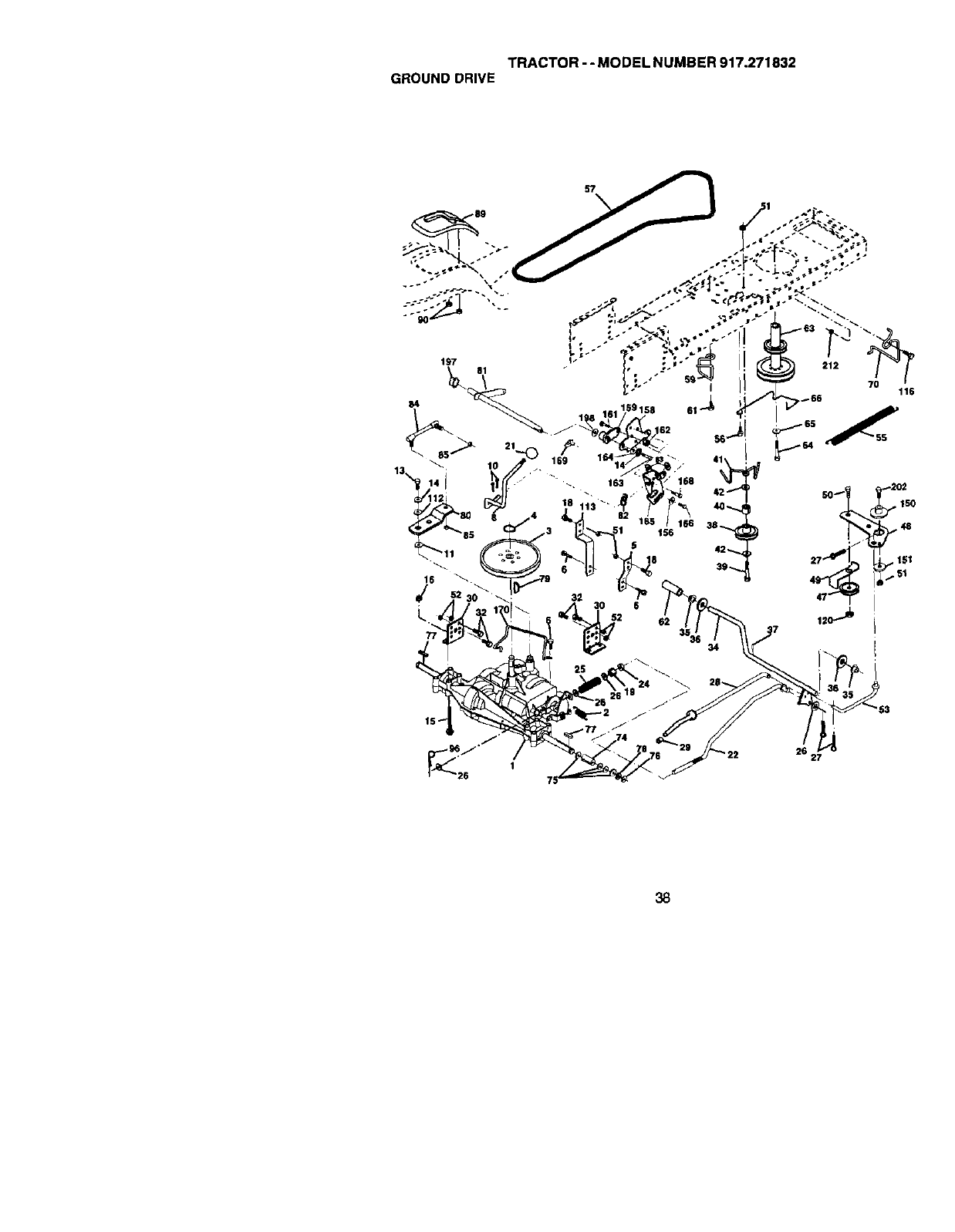
TRACTOR-- MODEL NUMBER 917.271832
GROUNDDRIVE
212
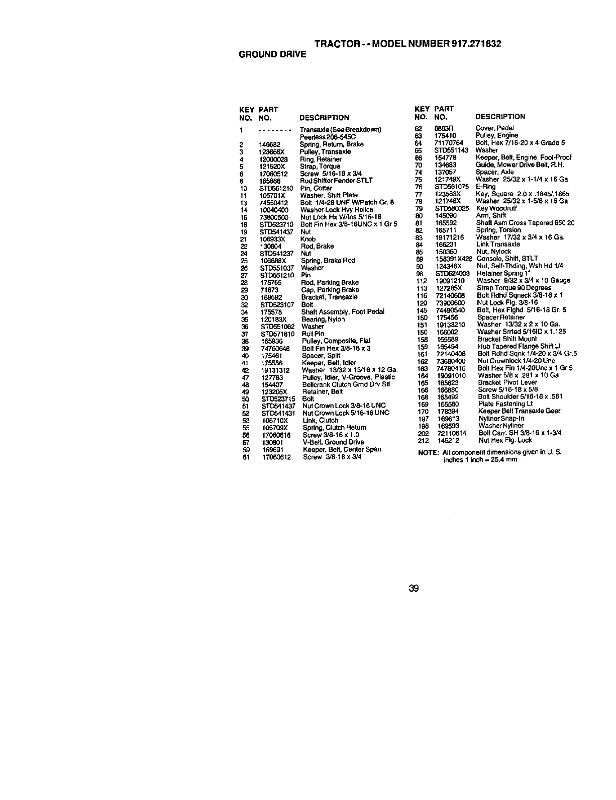
TRACTOR - - MODEL NUMBER 917.271832
GROUND DRIVE
KEY PART KEY PART
NO. NO. DESCRIPTION NO. NO. DESCRIPTION
1........ Transaxle (see Breakdown) 62
Peerless 266-545C 6_
2 146682 Spring, Return. Brake 64
3 123666X Pulley, Transaxla 65
4 120000_8 Ring, Retainer 66
5 121520X Strap, Torque 70
6 17060512 Screw 5/16-18 x 3/4 74
8 165866 Rod Shifter Fe_der STLT 75
10 $1_56121g Pin, Cotter 76
11 105701X Washer, Shift Plate 77
13 74_12 Butt t/4-28 UNF W/Patch Gr. 8 78
14 100404_0 Washer Lock Hvy Helica[ 79
16 738005(_ Nut LOCkHx W/ins 5/16-18 80
18 STD523710 Bolt Fin Hex 3/8-16UNC x 1Gr 5 81
19 $I_o41437 Nut 82
21 106_33X Knob 83
22 13G804 Rod, Brake 84
24 S_1237 NUt 85
25 106888X Spring, Brake Rod 89
26 STD551037 Washer 90
27 S'I_561210 Pin
28 175765 Rod, parking Brake 112
29 71673 Cap, parking Brake 113
30 16.9592 Bracket, Transaxle 116
3_ $1_523107 Bolt 120
34 175578 Shaft Assembly, Foot Pedal 145
35 120183X Beanng, Nylon 150
36 ST_o51062 Washer 151
37 STC571810 Roll Pin 156
38 165936 Pufley, Conlposlte, Flat 158
39 74760648 Belt Fin Hex 3/8-16 x 3 159
40 175461 Spacer, Split 161
41 175556 Keeper, Belt, Idler
42 19131312 Washer 13/32 x 13/16 x 12 Ga,
47 127783 Pulley, Idler, V-Groove, Plastic
48 154407 Bellcrank Clutch Grnd Dry Stl
49 1232_5X Retainer, Belt
50 ST0523715 Bolt
51 STD541437 NUtCrown Lock 3/8-16 UNC
52 STD541431 Nut Crown Lock 5/16-18 UNC
53 165710X Unk, Clutch
55 10570gx Spdng, Clutch Retum
56 17060616 Screw 3/8-16 x 1.0
57 13(_801 V-Belt. Ground Drive
59 169691 Keeper, Belt, Center Span
61 17060612 Screw 3/8-16 x3/4
8883R Cover, pedal
175410 Pulley, Engine
71170764 Bolt, Hex 7/16-20 x 4 Grade 5
STi_51143 Washer
154778 Keeper, Belt, Engine, FooI-Proo!
134683 Guide, Mower Drive Be_t,R.H.
137057 Spacer, Axle
121749X Washer 25/32 x 1-1/4 x 16 Ga,
STD581075 E-Ring
1235&3X Key, Square 2.0 x .1845/.1865
121748X Washer 25/32 x 1-5/8 x 16 Ga
STD580025 Key Woodruff
145090 Arm, Shift
165592 Shaft Asm Cross Tapered 650 20
165711 Spdng,Torsion
19171216 Washer 17/32 x 3/4 x 16 Ga.
166231 Link Transaxle
15(_60 Nut, NylOCk
158391X428 Console, Shift, STLT
124346X Nut, Self-Tnding, Wsh Hd t/4
STD624003 Retainer Bpdng 1"
19091210 Washer 9/32 x 3/4 x 10 Gauge
127285X Strap Torque 90 Degrees
72140608 Bolt Rdhd Bqneck 3/8-16 x 1
73900660 NUt Lock Fig. 3/8-16
74490540 Bolt, Hex Flghd 5/16-18 Gr. 5
175456 Spacer Retainer
19133210 Washer 13/32 x 2 x 10 Ga.
166002 W_sher Srrtod 5/161D x 1.t 25
16.5589 Bracket Shift Mount
165494 Hub Tapered Flange Shift LI
721_ Bolt Rdhd Sqnk 1/4-20 x 3/4 Gr.5
162 736804(X) Nut Crownlock 1/4-20 Unc
163 74780416 Bolt Hex Fin 1/4-2OUnc x 1 Gr 5
164 18091010 Washer 5/8 x 281 x10 Ga
165 165623 Bracket Pivot Lever
166 166880 Screw 5/16-18 x 5/8
168 165492 Bolt Shoulder 5/16-18 x .561
169 165580 Plate Fastening Lit
170 178394 Keeper Belt Transaxle Gear
197 169613 Nyliner SnapIn
198 16_593 Washer Nyliner
72110614 Bolt Cart. SH 3/8-16 x 1-3/4
212 145212 Nut Hex Fig. Lock
NOTE: All component dimensions given in U. S.
inches I inch = 25.4 mm
39
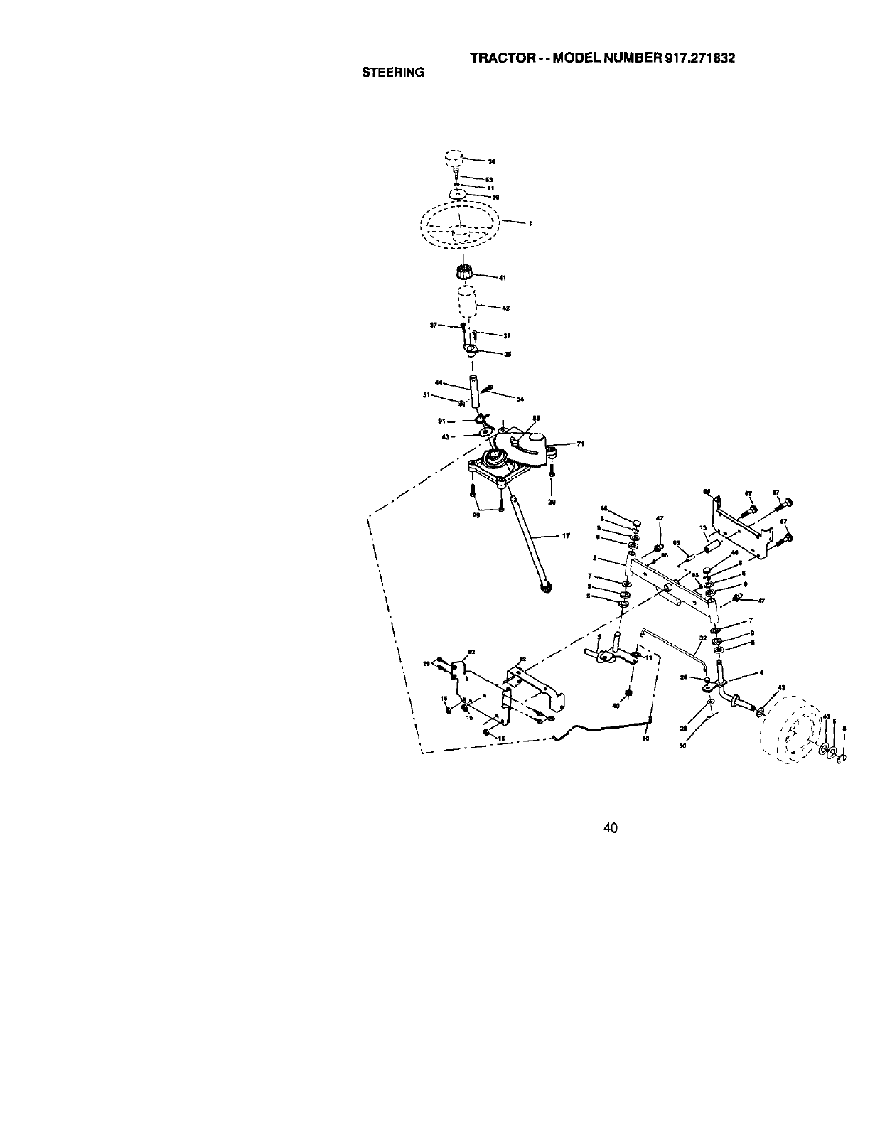
TRACTOR-- MODEL NUMBER 917.271832
STEERING
_n
&
I i
4O

TRACTOR -- MODEL NUMBER 917.271832
STEERING
KEY PART
NO. NO. DESCRIPTION
1
2
3
4
5
6
7
8
9
10
11
13
15
17
26
28
29
3O
32
36
37
38
39
40
41
42
43
44
46
47
51
54
63
65
67
68
71
85
88
91
13976B Steedng Wheel
154427 Axle Assembly STMP Dropped STL
169840 Spindle Assembly. L.H,
169839 Spindle Assembly, R.H.
6266H Bearing, Race, Thrust, Hardened
121748X Washer 25/32 x 1-5/8 x 16 Gauge
19272016 Washer 27/32 x 1-1/4 x 16 Gauge
1_Ring, Klip
3266R Bearing, Stee heg Column
175121 Drnglink
STD551137 W_sher, Lock
136518 Spacer, Bearing, Axle
145212 Nut, Hexflange Lock
177876 Shaft Assembly, Steering
126847X Bushing, Link, Drag
19131416 Washer 13/32 x 7/8 x 16 Gauge
17C_0612 Screw 3/6-16 x 3/4
STD561210 Pin Cotter
130465 Rod,Tk3
155099 Bushing, Steedng
152927 Screw
139769 Inset1. Steedng Wheel
19133812 Washer 13/32 x 2-3/8 x 12 Gauge
STD541537 Gdpco Nut
100711L Adaptor, Steering Wheel
145054X428 Boot, Steehng Shaft
121749X Washer 25/32 x 1-1/4 x 16 Gauge
153720 Extemsion Shaft Steering LR.LT
121232X Cap,Spindle
6855M Fitting, Grease
STD54t431 NutLockHexw/Ins. S/16-18UNC
74780520 Bolt Fin Hex 5/16-18 UNC x 1-1/4
$33Y_23710 Bolt, Fin Hex 3/8-16 UNC x 1 Gr 5
160367 Spacer .AxJe
72146618 Bolt RDHD SQNK 3/8-16 x2-1/4
169827 AxJe, Brace
175146 Steering Asm
169835 Bracket Susp Chassis Front
133835 FastnerChdstmas Tree
175118 Boff Shouioer 7/16-20
175553 ClipSteering
NOTE: hJIcomponent dimensions g_venin U. S.
inches 1 inch = 25A mm
41
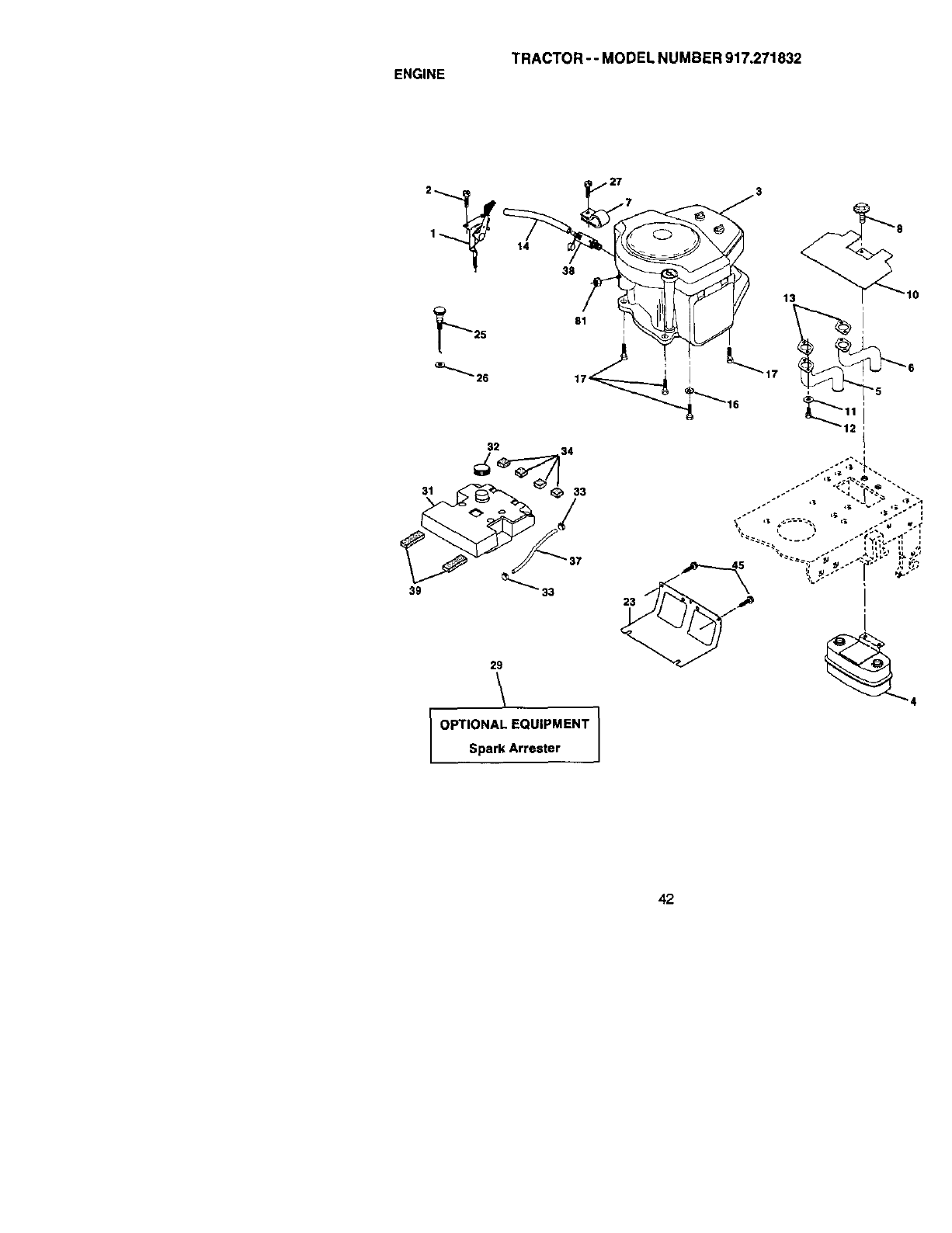
TRACTOR- - MODEL NUMBER 917.271832
ENGINE
31
39
2
1_ 14
32
38
81
33
33
29
\
OPTIONAL EQUIPMENT
Spark Arrester I
13
_17
_5
12
42

TRACTOR-- MODELNUMBER917.271832
ENGINE
KEY PART
NO, NO, DESCRIPTION
1 170547 Control, Throt Paddle
2 17720410 Screw, Hex Thd Cut 1/4-20 x 5/8
3...... Engine, B&S, (See 13reakdown) No. 461707-0147-E1
4 149723 Muffler Exhaust
5 144_ I_xhaust Asm. Left
6 1_ Exhaust Asm. Right
7 138129 Clamp Tube Double Engine
8 171877 Bolt 5/16-18unc x 3/4 W/Seres
10 145.552 Heat Shield Lt
11 ST[_51125 Washer LOCkHvy. Helical 1/4
12 S_T-a22507 Bolt Fin Hex 1/4-20Unc x .75
13 165287 Gasket, Muffler
14 148456 Tube Drain Oil Easy
16 ST_o51237 Washer Lock Ext Tooth 3/8
17 17490624 Screw Thdrol 3/8-16x 1-1F2Tytt
23 169837 Shield, BmJDbr Guard
25 145996 Control Choke
26 7_ Nut Keps 3/8-24 Unf
27 1529_7 Screw TT #10-32 x 5 x 3/8 Flange
29 137180 Arrestor, Spark
31 157103 Tank, Fuel
38 161696 Gap FuelGuage
33 123487X Clamp, HoSe
34 106082X Spacer Pad
37 8543FI Line,Fuel
38 148315 Plug, Oil Drain Easy
39 109387X Pad Idler
45 17000612 Screw Hex Wsh3/8-16 x 3/4
81 7351C4(_ Nut Keps Hex 1/4-20 Starter Nut
NOTE: All component dimensions g;ven in U. S.
inches 1 inch = 25.4 mm
43
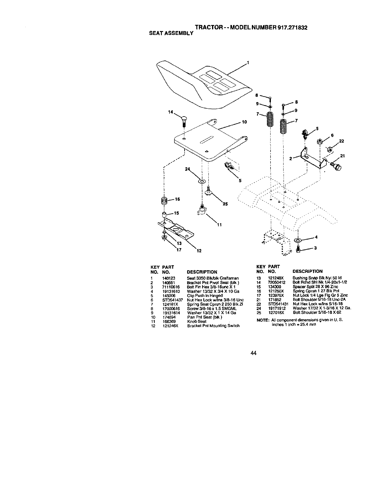
TRACTOR--MODELNUMBER917.271832
SEATASSEMBLY
KEY PART
NO, NO, DESCRIPTION
1 140123 Seat 3350 BIk_lk Craftsman
2 140551 Bracket Pnt Pivot Seat (blk)
3 71110618 Bolt Fin Hex 3/8-16unc X 1
4 19131610 Washer 13/32 X 3/4 X 10 Ga
5 145006 Clip Push In Hinged
6 STD541437 Nut Hex Lock w/ins 3/8-16 Unc
7 124t81X Spring Seat Cprsn 2 250 BIk Zi
8 170(XJ616 Screw 3/8-16 x 1,5 SMGML
9 19131614 Washer 13/32 X 1 X 14 Ga
19 174894 Pan Pnt Seat (blk)
11 166369 Knob Seat
12 121246X Bracket Pnt Mour=ting Switch
KEY PART
NO. NO. DESCRIPTION
13 121248X Bushing Snap BIk Ny150 Id
14 72050412 Bolt Rdhd Sht Nk 1/4-20x1-1/2
15 134300 Spacer Spilt 28 X g6 Zinc
16 121250X Spheg Cprsn 1 27 BIk Pnt
17 123976)( Nut Lock 1/4 Lge Fig Gr 8 Zinc
21 171852 BoltShoulder 5/16-18 Unc-2A
22 STD541431 Nut Hex LoCk w/Ins 5/16-18
24 19171912 Washer 17/32 X 1-3/16 X 12 Ga.
25 127018X Bolt Shoulder 5/16-18 X 62
NOTE: AJlcomponent dimensions given in U. S.
inches 1 ir_ch=25.4 ran1
44
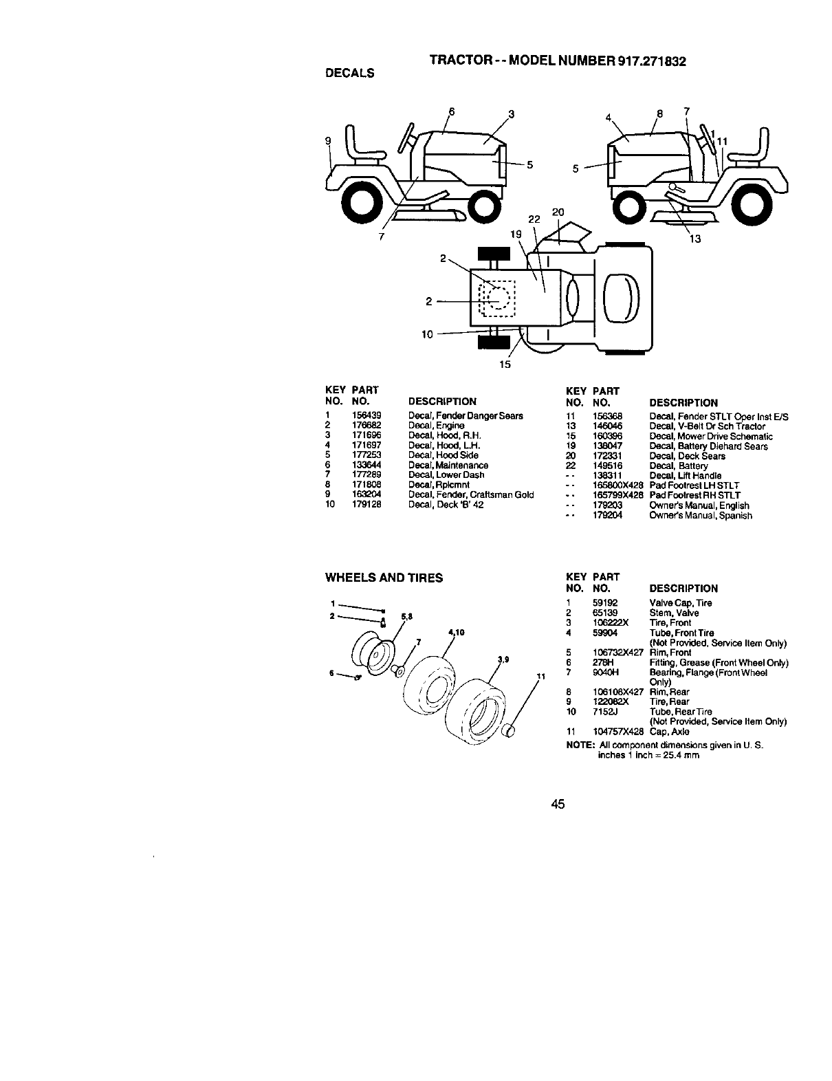
TRACTOR-- MODEL NUMBER 917.271832
DECALS
KEY PART
NO, NO,
1 156439
2 176682
3 171696
4 171697
5 177253
6 133644
7 177289
8 171808
9 163_04
10 179128
719
2
15
20
22
KEY PART
DESCRIPTION NO. NO,
Decal, Fender Danger Sears 11 156368
Decal, Engine 13 146046
Decal, Hood, R.H. 15 160396
Decal, Hood, LH. 19 138047
Decal, Hood Side 20 172331
Decal, Maintenance 22 149516
Decal, Lower Dash - - 138311
Deca;, Rpicmnt
Decal, Fender, Craftsman Gold
Decal, Deck 'B' 42
13
DESCRIPTION
Decal, Fender STLT Ober Inst E/S
Decal, V-Belt Dr Sch Tractor
Decal, Mower Drive Schematic
Decal, Battery Diehard Sears
Decal, Deck Sears
Decal, Battery
Decal, Lift Handle
-- 165800X428 Pad Footrest LH STLT
-- 165799X428 Pad Footrest RH STLT
-- 179203 Owner's Manual, English
-- 179204 Owner's Manual, Spanish
WHEELS AND TIRES
5,g
4,10
11
KEY PART
NO. NO. DESCRIPTION
1 59192 Valve Cap, Tire
2 65139 Stem, Valve
3106222X Tim, Front
4 59904 Tube, Front Tire
(Not Provided, Service Item Only)
5 106732X427 Rim, Front
6 278H Fitting, Grease (Front Wheel On_y)
7 9040H Bearing, Flange (Front Wheel
Only)
6 106108X427 Rim,Rear
9 1220_ Tire, Rear
10 7152J Tube, RearTire
(Not Provided, Se_,ica Item Only)
11 104757X428 Cap, AxEe
NOTE: All component dimensions given in U. S.
inches 1 inch =25.4 mm
45
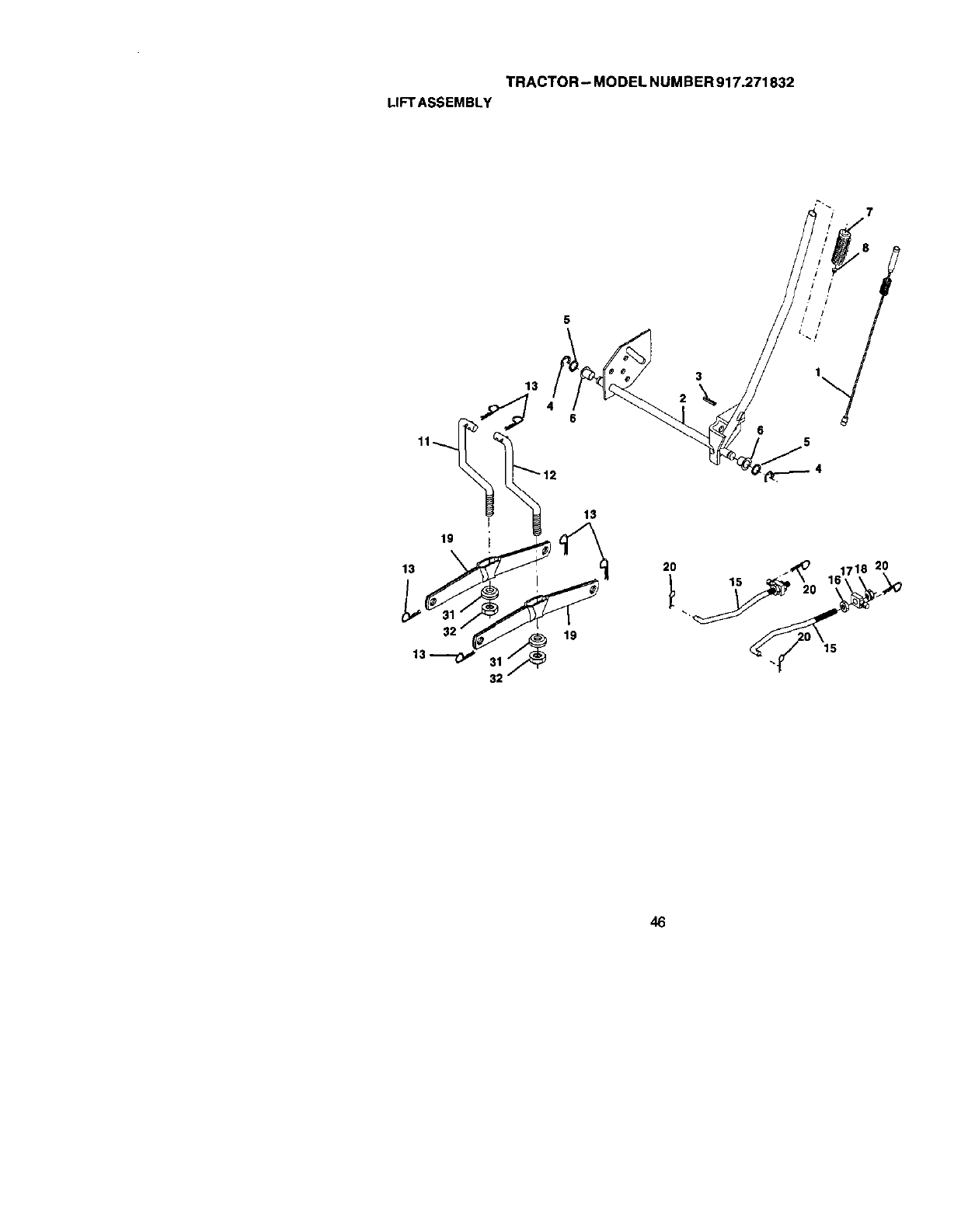
TRACTOR - MODEL NUM BER 917.271832
LIFTASSEMBLY
46

TRACTOR- MODELNUMBER917.271832
LIFTASSEMBLY
KEY PART
NO. NO. DESCRIPTION
1
2
3
4
5
6
7
8
11
12
13
15
16
17
18
19
2O
31
175150 Wire Asm, Inner
159471 Shaft Assembly, Lift
105767X Pin, Groove
1200(XX_ E-Ring
19_11621 Washer 21/32 x 1 x 21 Gauge
120183X 8eedng, Nylon
125631X Grip, Handle, Fluted
122365X Button, Plunger, Red
13.9865 Link, Lift, L.H.
139866 Link, Lift, R.H.
STD624008 Retainer Spring
173288 Link, Front
73350800 Nut, Hex, Jam 1/2-13 UNC
17568g Trunnion
738C_800 Nut Lock w/Wsh 1/2-13 UNC
139868 Arm, Suspension, Rear
163552 Retainer Spring
169865 Bearing, Pvt, Lift
73540600 Nut, Crowniock 3/8-24
NOTE: All component dimensions given in U. S.
inches 1 inch =25.4 mm
47
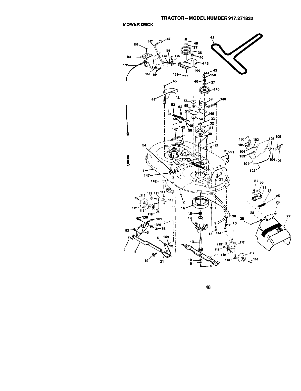
TRACTOR- MODELNUMBER917.271832
MOWERDECK
44 56 ! ! 9 148
] ..-. ; 32
I _,O_o :,..:,o ,o,o_
147 _1021
142 21 22
/.116 113 Ill 1 ' !i 24 25
92 I
48
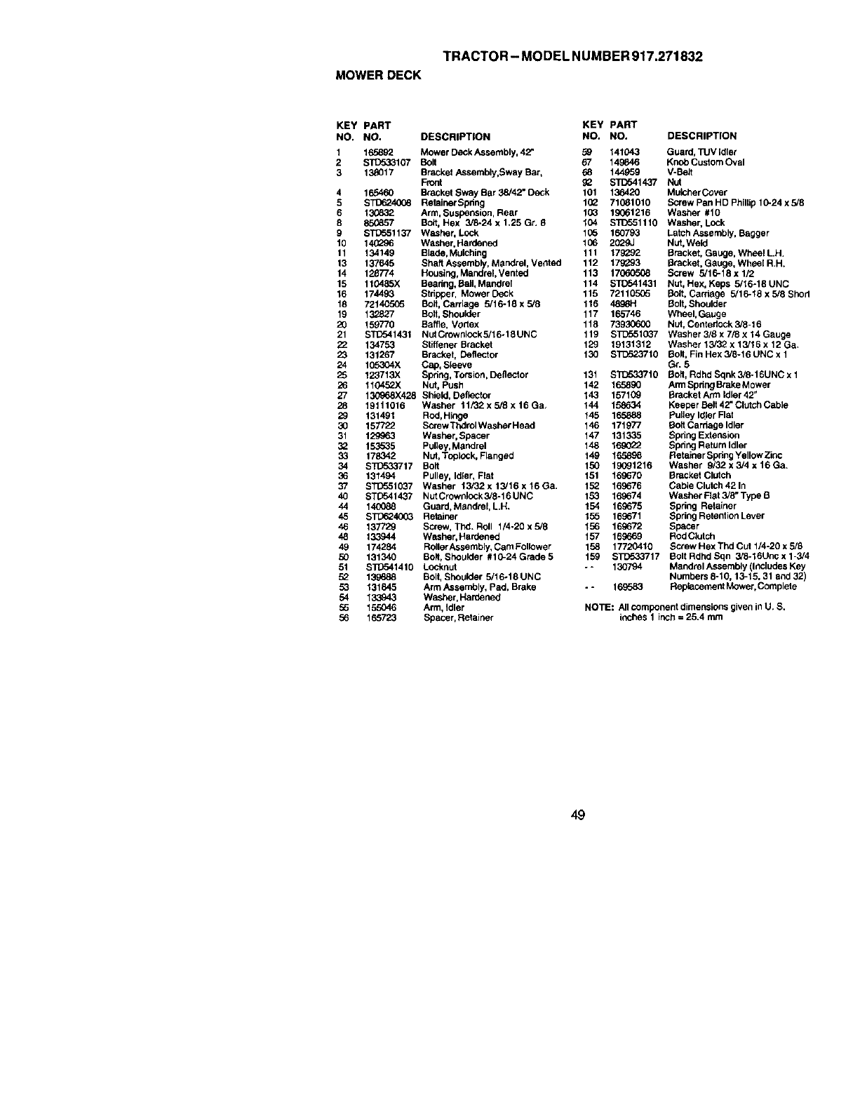
TRACTOR - MODEL N UMBER 917.271832
MOWER DECK
KEY PART KEY PART
NO, NO. DESCRIPTION NO. NO. DESCRIPTION
1 165892 Mower DeCk Assembly, 42" 59 141043 Guard, TUV Idler
2 STt_33107 Bolt 67 149846 Knob Custom Oval
3 13_017 Bracket Assembly,Sway Bar, 68 144959 V-Belt
Front 02 STD541437 Nut
4 165460 Bracket Sway Bar 38/42" De_k 101 136420 Mulcher Cover
5 STD624008 RetainerSpdng 102 710_1010 Screw Pan HD PhillJp10-24 x 5/8
6 13(_32 Arm, Suspension, Rear 103 19061216 Washer #10
8 850857 Bolt, Hex 3/8-24 x 1.25 Gr. 9 104 STD5511 t0 Washer, Lock
9 S'R_551137 Washer, Lock 105 160793 LatchAssembly, Bagger
10 14(_96 Washer, Hardened 106 2029J Nut, Weld
11 134149 Blade, Mulching 111 170292 Bracket, Gauge, Wheel LH.
13 137645 Shaft Assembly, Mandrel, Vented 112 170293 Bracket, Gauge, Wheel R,H.
14 128774 Housing, Mandrel Vented 113 1706(To08 Screw 5/16-18 x 1/2
15 110485X Bearing, Bali, Mandrel 114 ST[T541431 Nut, Hex, Keps 5/16-18UNC
16 174493 Stripper, Mower Deck 115 72110505 Bolt, Carriage 5/16-t6 x 5/8 Shod
18 72140565 Bolt, Carriage 5/16-18x5/8 116 4896H Bolt, Shoulder
19 132827 Bolt, Shoulder 117 165746 Wheel, Gauge
20 159770 Baffle, Vortex 118 73930600 Nut, Centedock3/6-16
21 ST_541431 NutCrownieckS/16olSUNC 119 S]D551027 Washer3/Sx7/_x14Gauge
22 134753 Stiffener Bracket 129 19131312 Washer 13/32 x 13/16 x 12 Ga.
23 131267 Bracket, Deflector 130 S'i_523710 Bolt, Fin Hex 3/8-16 UNC x 1
24 105304X Cap, Sleeve Gr. 5
25 123713X Spring, Torsion, De flector 131 S'FD_33710 Bolt, Rdhd Sqnk 3/0-16UNC x 1
26 110452X Nut, Push 142 165890 Arm Spdng Brake Mower
27 130968X428 Shield, Deflector 143 157109 BracketArmldier42 _
28 19111016 Washer 11FJ2xsiSx16Ga. 144 158634 KeeperBalt42_ClutchCabie
29 131491 Rod, Hinge 145 165888 Pulley I_lef"Flat
30 157722 Screw Thdrol Washer Head 146 171977 Bolt Carriage Idler
31 129963 Washer, Spacer 147 131335 Spring Exlension
02 153535 Pulley, Mandrel 148 169022 Spring Return Idler
33 178342 Nut, Toplock, Flanged 149 165898 Retainer Spdng Yeliew Zinc
34 S]_033717 Bolt 150 10091216 Washer 9/32x3/4x16Ga.
36 131494 Pulley, Idler, Flat 151 160270 Bracket Clutch
37 ST_551037 Washer 13/32x13/16x16Ga. 152. 169676 CabieClutch421n
40 ST[To41437 Nut Crownlock 3/8-16 UNC 153 169674 Washer FIst 3/8" Type B
44 14(3088 Guard, MandmI, L.H. 154 169675 Spring Retainer
45 S]_24003 Retainer 155 169671 Spring Retention Lever
46 137729 Screw, Thd. Roll 1/4-20 x 5/8 156 169672 Spacer
48 133944 Washer, Hardened 157 169669 Rod Clutch
49 174284 Roller Assembly, Cam Follower 158 17720410 Screw Hex Thri CUt 1/4-20 x 5/6
50 131340 Bolt, Shoulder #10-24Grade5 159 S]D53,3717 BoltRdhdSqn 3/8-16Uncx1-3!4
51 ST{To41410 Locknut -- 130794 Mandrel Assembly (61cludes Key
52 139688 Bolt,Shoulder 5/16*18 UNC Numbers 8-10, 13-15, 31 and 32)
53 131845 Arm Assembly, Ped, Brake -- 169583 Rapiecement Mower, Complele
54 133943 Washer, Hardened
55 155046 Arm, Idler NOTE: All component dimensions given in U. S.
56 165723 Spacer, Retainer inches 1 inch = 25.4 mm
49
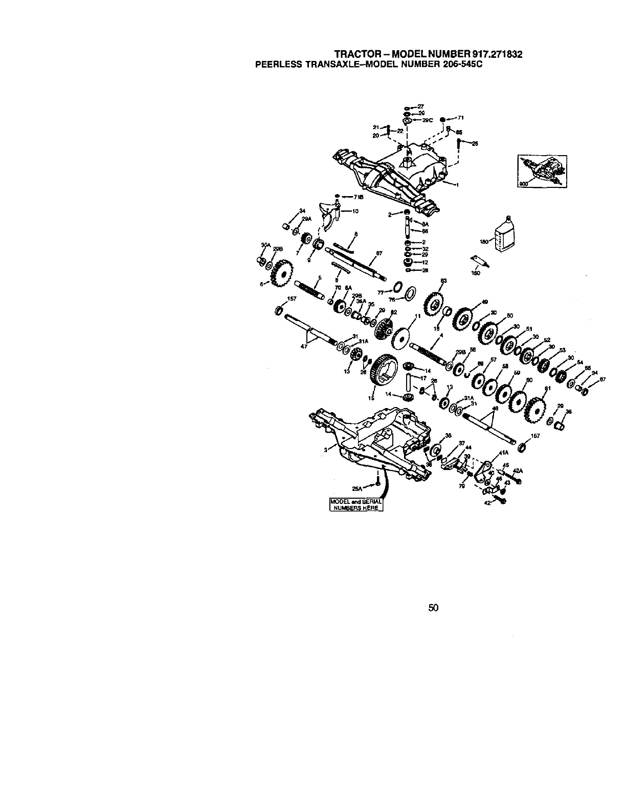
TRACTOR- MODELNUMBER917.271832
PEERLESSTRANSAXLE-MODELNUMBER206-545C
I
5O

TRACTOR - MODEL NUMBER 917.271832
PEERLESSTRANSAXLE-MODEL NUMBER 206-545C
KEY PART KEY PART
NO. NO. DESCRIPTION NO. NO. DESCRIPTION
1772147
2 780086A
3 770128
4 7763_5
5 776409
6 778364
6A 778369
7 778330
8 792180
8A 792047
9 784352
10 784378
11 778334
12 778309
13 778368
14 778368
15 778370
17 786188
18 786102
20 7920"/7A
21 792078
22 792079
25 792073A
25A 792177
26 792125
27 792O35
28 78804O
29 780072
29A 780160
29B 780051
29C 780199
30 780108
31 789001
31A 780195
32 788O83
34 780194
35 780193
35A 780197
36 790075
37 79(_07
38 79°_1
Transaxle Cover 39 786_26 DoweIPin
Needle Bearing 5_" 40 792076A FlatWasher
Transaxk_C_e ,312 ID x .059W
Counterst_ft 41A 7_079 Brake Lever
Output Shaft 42 792073A Screw 1/4 ÷20 x 1-1/4"
Spur Gear (38 teeth) 42A 792085A Screw 1/4 -20 x 2 1/4_
Spur Gear (15 teeth) 43 792075 Locknut 5 116 -24
Spur Gear ( 11 teeth) 44 790(_5 Brae Pad Holder
Shift Key 45 786066 Spacer .2625 x 1.0
Woodruff Key #9 46 786086 Brake Lever Bracket
Shift COlEar 47 774690 Axle ( 11-15 /16" Long)
Shift Rod & Fork 48 774691 Axle (16- 1 /2" _ong)
Bevel Ge_ (30 teeth) 49 778356 Spur Gear (29 teeth)
Input Bevel Pinion (13 teeth) 50 778338 Spur Gear (27 teeth)
Bevel Gear ( 13 teeth) 51 778354 Spur Gear (23 teeth)
(Include, 14) 52 778352 Spur Gear (19 teeth)
Bevel Pinion (13 teeth) 53 778350 Spur Gear (16 teeth)
(Include. 13) 54 778346 Spur Gear (15 teeth)
Ring Gear (43 teeth) 56 778355 Spur Gear ( 11 teeth)
Drive Pin 57 778337 Spur Gear (13 teeth)
Spacer 1,t30 X .695 58 778353 Spur Gear (17 teeth)
Ball 5/16" dia 59 778351 Spur Gear (21 teeth)
Set Screw 3/8 -16 x 3/8" 60 778349 Spur Gear (24 teeth)
Spring ,310 OD x ,625 L 61 778345 Spur Gear (25 teeth)
Screw 1/4 -20 x 1-1/4 _65 780189 Flat Washer
Screw 1/4_20 x 1°3/8" ,563 ID x .062W
Retaining Ring (pkg of 2) 66 776422 Input Shaft
Retaining Ring 67 776396 Shifter & Brake Shaft
Relaining Ring 69 792170 Retaining Ring
Thrust Washer 70 786187 Spacer .890
.627 ID x ,031W 71 788069 _uare Cut Ring
Thrust Washer 71B 788092 NO'Ring
.762 ID x ,031W 76 780090 Flat W_sher
ThruslWaSher 1.128 ID x .058W
,762 ID x .031W 77 788078A Inverted Retaining Ring
Anti-Rotation Washer .632 79 792144 Spnng ,430 OD x .5000 L
Cup Washer _778333 Bevel & Spur Gear (30 & 13
1.127 ID x .032W teeth)
Flat Washer .750 ID x .056W 83 778338 Spur Gear (27 teeth)
(Use As Needed) 85 792154 Oil Fill Plug
Flat Washer 87 788089A Oil Seal 9 /16_
.750 tD x ,062W 150 788093A Liquid Gasket RTV Silk:one
Oil Seal 5/8" 157 788088A Oil Seal 3/4 _
Bushing .563 180 730229A Gear Oil 80W90
Flanged Bushing 5 /8" rD 900 794712 Replacement MST
Flanged Bushing .751 206-545C Transaxle
Brake Disk
Brake Pad Plate NOTE: All component dimensions given in
Brake Pad (pkg of 2) U,S. inches 1 inch = 25,4 mrn
51
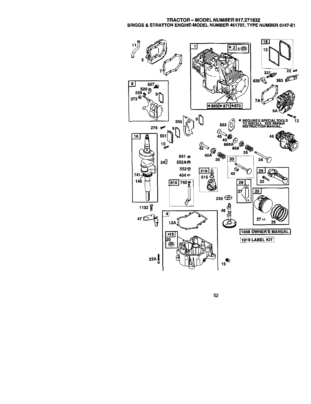
TRACTOR- MODELNUMBER917.271832
BRIGGS&STRATFONENGINE-MODELNUMBER461707,TYPENUMBER0147-E1
52
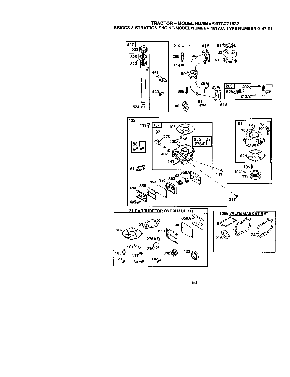
TRACTOR- MODELNUMBER917.271832
BRIGGS&STRA'I-I'ONENGINE-MODELNUMBER461707,TYPENUMBER0147-E1
449_
212 _51A 51
414o _
365 _
883_ I_ 51A
119_
51
1071 102_
97
394 391
"\ 117
121 CARBURETOR OVERHAUL KIT
102_
105_
1095 VALVE GASKET SET
53
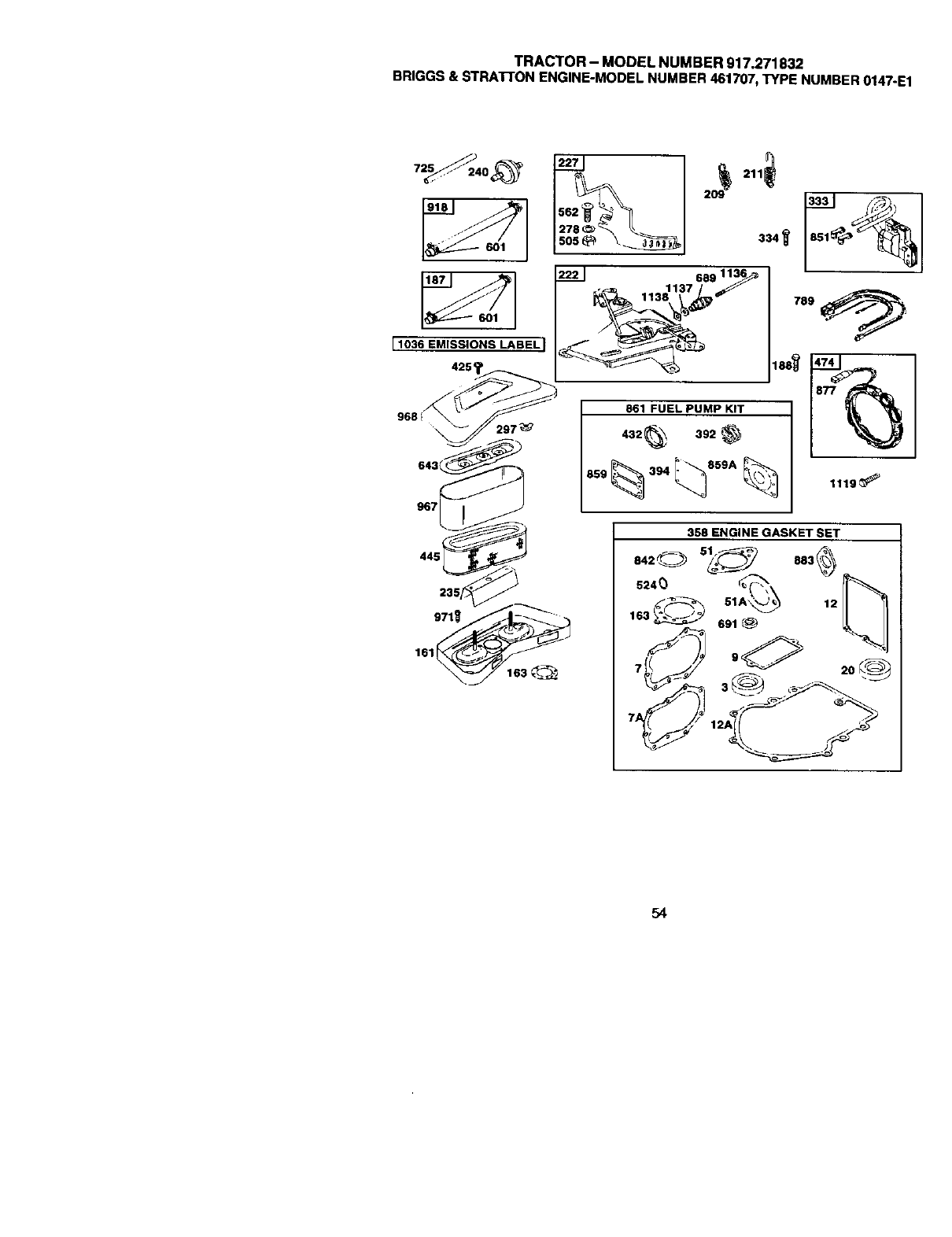
TRACTOR - MODEL NUMBER 917,271832
BRIGGS & STRATI'ON ENGINE-MODEL NUMBER 461707, TYPE NUMBER 0147-E1
910
11036 EMISSIONS LABEL I
4254
9681
207_; '
227 209_ 2110
680 11:
861 FUEL PUMP KfT
432_ 392_
1010
789
1119_
445
358 ENGINE GASKET SET
o,2o
_---_ 51A_ 12 1 '_t
lo+_ .1 + ELI
•,,.d" >' <,.--_ %
54
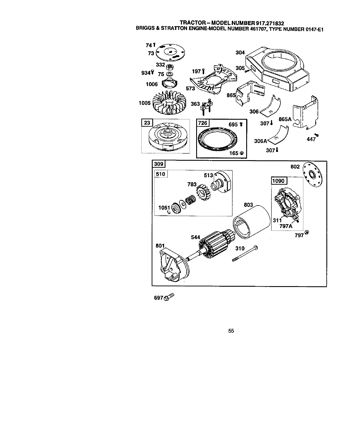
TRACTOR- MODEL NUMBER 917.271832
BRIGGS& STRATI'ONENGINE-MODELNUMBER461707,TYPE NUMBER0147-E1
165
513
783
105_
307 |
306 447
307 |
802
544 797'
697
55

TRACTOR- MODELNUMBER917.271832
BRIGGS&STRATrONENGINE-MODELNUMBER461707,TYPENUMBER0147-E1
KEY PART
NO. NO.
1 498583
2 399265
3 391086
4493304
5 691162
5A 591163
7 271867
7A 271866
8 495754
9 27803
10 690334
11 691899
12 692287
12A 692292
27t188
271189
13 691651
15 690946
15 690666
18 495901
19 399264
20 291675
22 691184
22A 693972
23 691976
24 222698
25 499180
499181
499182
499183
26 499184
499185
499186
499187
27 691299
28 498319
498320
29 497912
498317
32 691133
33 390420
34 691302
35 691597
36 691597
40 690656
40A 691939
42 494553
45 261368
46 691161
47 691964
48 498542
50 213290
51 692278
51A 692219
54 93208
73 692527
74 691677
75 691056
91 693483
95 690718
97 693486
KEY PART
DESCRIPTION NO. NO. DESCRIPTION
BCylinderAssembly 98 807923 Idle Speed Kit
ushing-Cylinder 102 693509 aGasket-Carburetor Body
•SeaI-O=l 104 693506 aPin-Float Hino_e
105 692078 _l Valve-Float NeedleSump-Engine
Head-Cylinder No. 1 107 693482 Body-Lower Carburetor
Head-Cylinder No, 2 108 693505 Valve-Choke
•+ Gasket-Cylinder Head #1 109 693498 Shaft-Choke
•+ Gasket-Cylinder Head #2 117 693507 _D Jet-Main (Standard)
Breather Assembly 693500 Jet-Main (High Altitude)
•+ Gasket-Breather 119 690720 Screw (Upper to Lower
Screw (BreatherAssy.) Carburetor Body)
Tube-Breather 121 693503 Carburetor Overhaul Kit
•Gasket-Crankcase 122 691926 Spacer-Carburetor
Gasket-Crankcase 1.0151 125 693479 Carburetor
Gasket-Crankcase .005 130 693504 Valve-Throttle
Gasket-Crankcase .009 133 693512 Float-Carburetor
Screw (Cylinder Head) 146 691639 Key-Timing
Plug-Oil Drain 147 693508 aJet*Pilot
Crankshaft 161 691401 Base-Air Cleaner
Cover-Crankcase 163 690273 •Gasket-Air Cleaner
Kit-Bushing/Seal 165 693148 Nut (Ring Gear
• Seat-Oil (PTO Side) 187 499167 Line-Fuel Cut to Required
Screw (Crankcase Cover/ Length)
Sump) 188 691003 Screw (Contro_Bracket)
Screw (Crankcase Cover/ 197 690364 Screw (Back Plate
Sump) 202 690570 Lnk-Mechancal Governor
Flywheel 203 493230 Crank-Bell
Key-Flywheel 205 690322 Screw (Bell Crank)
PistonAssembly (Std.) 209 691273 Spring-Governor
PistonAssembly 1.010 =O.S.) 211 691807 Sp igrin-Governed Idle
Piston Assembly_.020" O.S.j 212 693544 Link-/hrottle
Piston Assembly(.030" O.S.) 212A 690571 Link-Throttle
Ring Set-Piston (Std.) 219 394348 Gear-Governor
Ring Set-Piston (.010 "O.S.) 220 690412 Washer _Govemor Lever)
Ring Set-Piston I1020 =03. 222 691366 Bracket-Control
Ring Set-Piston .030 =O.S. 227 690762 Control Lever-Governor
Lock-PistonPin 235 691206 Shield- Fuel Spray
Pin-Piston Std.) 240 394358 Filter-Fuel
Pin-Piston (.005 _O.S.) 267 690316 Screw (Casing Clamp)
Rod-Connecting (Std.) 276 693510 6+ Sealing Washer
Rod-Connecting (.020_276A 693497 _Sealing Washer
Undersize) 278 692810 Washer (Gov. ControlLever)
Screw(Connecting Rod) 279 690366 Screw (Valve Cover
Valve-Exhaust 297 691331 Nut (A r F ter Retaner
Housln -Blower
Valve-Intake 304 495588 Screw ('Bg-lower
Spring-Valve Intake) 305 690960 Housing)
Spring-Valve (Exhaust) 306 690414 Shield-Cylinder
Retainer-Valve Intake) 306A 690435 Shield-C.L;yHlinder
Reta ner-Va ve Exhaust 307 691003 Screw _Cylinder Shield)
Motor-starter
Keeper-Valve 309 497596
Valve Tappet 310 690323 Bolt-StarterMotor
Cain Shaft 311 497608 Bmsh Set
Slinger-Oil 332 691059 Nut (Flywheel)
Short Block Replacement RPM Settings: Low Speed: 1900-2100
Engine 460_07-2637-E1) High Speed: 3000-3200
Manifold-intake
•Q Gasket-Intake Included in Engine Gasket Set, Key. No.
•+ Gasket-Intake 358
Screw (Intake Manifold) OIncluded in Carburetor Overhaul Kit, Key.
Screen-Rotating No. 121
Screw (Rotating Screen) + Included In Valve Gasket Bet, Key. No.
Washer (Flywheel) 1095
Bndy-UIpp_erCarburetor ±Included in Fuel Pump Kit, Key. NO.861
OScrew (Throttle Valve)
Shaft-Throttle NOTE: All comlponentdimensionsgivenin U.S.
inches linch = 25.4 mm
56

TRACTOR - MODEL NUMBER 917.271832
BRIGGS & STRATrON ENGINE-MODEL NUMBER 461707, TYPE NUMBER 0147-E1
KEY PART KEY PART
NO. NO. DESCRIPTION NO. NO. DESCRIPTION
333 394891 Armature-Magneto 797 690958 Nut (Brush Retainer)
334 691061 Screw (Armature) 797A 693167 Nut (Brush Retainer )
337 802592 SparkpJug 801 691967 Cap-Drive
358 495868 Gasket Set 802 691286 Cap-End
359 691077 Washer-Ground Terminal 803 691427 Housing-Starter
363 691062 Flywheel Puller 807 693511 ID Spacer-Throttle
365 690321 Screw (Carburetor) 842 271170 • O-Rin 9 Seal (Dipstick Tube)
370 691612 Nut (Ground Terminal) 847 495715 Dipstick/Tube Assembly
383 89838 Wrench-Spark Rug 851 493880 Terminal-Spark.plug
391 693487 Body-Fuel Pump 859 693488 ID± Gasket- Carburetor Pump
392 693491 0± Spring-Pump Diaphragm 859A 693490 6± Gasket+ Carburetor Pump
394 693489 6± Diaphragm-Carburetor 861 693502 Kit-Fuel Pump
395 690481 Cover-VaNe Chamber 865 691196 Cover-Air GuJde
404 690442 Washer (Governor Crank 865A 691197 Cover-Air Guide
414 691872 Washer (_ell Crank) 868 497656 Seal-Valve
425 691675 Screw (Air Cleaner Cover) 868A 273312 Seal-Valve
432 693492 6± Cap-Spring 869 691802 Seat*Valve (intake)
434 693493 Cover Diaphragm 870 691844 Seat-Valve (Exhaust)
435 693494 Screw Diaphragm Cover) 871 231218 Bushing-Valve (Exhaust
441 691176 Braoket-O Fill 871 231218 Bushing-Vafve (intake)
Wire/Connector-Alternator
445 394019 Filter-Aft Cleaner Cartridge 877 393456
447 690297 Screw (Air Guide Cover) 883 692282 • Gasket-Exhaust
449 691044 Screw (Oil Fill Bracket 918 393815 Hose-Vacuum (Cut to
474 691063 Aternator Required Length)
505 691029 Nut (Governor Control Lever) 934 691058 Screw (Fan Retainer)
507 691972 Insulator 955 693513 P_ug-Carburetor
510 497606 Drive-Starlet 967 272490 Filter-Pre Cleaner
513 692024 Clutch-Drive 968 691207 Caver-AirCleaner
620 691084 Terminal-Ground 971 691100 Screw (Air Cleaner Base)
523 691385 Dipstick 1005 498157 Fan-Flywheel
524 692532 •Seal-Dipstick Tube 1006 691247 Retainer-Fan
525 690823 Tube-Dipstick 1019 496726 KIt-Lapal
544 692034 Armature-Startar 1036 695702 Label-Emissions
551 690415 Cover-Valve 1051 691265 Ring-Retaining
552 690553 Bushing-Governor Crank 1058 274279 Owner's Manual
552A 690552 Bushing-Governor Crank 1090 691293 Retainer-Brush
562 690311 Bolt (Governor Lever) 1095 498047 Gasket Set+Valve
573 696040 Plate-Back 1119 691183 Screw (Alternator
601 95162 Clamp-Hose 1132 690353 Screw (Oil Slinger)
615 690317 Retainer-Governor Shaft 1136 690329 Screw (Control Bracket)
616 491530 Crank-Governor 1137 690390 Washer (Control Bracket)
629 262539 Spdn -Throttle Return 1138 690330 Nut (Control Bracket)
635 66536 Boot_-_parkplug High _eed: 3000-3200
RPM Settings: Low Seed: 1900-2100
643 496700 Retainer-Air Filter
689 690555 Spring--Friction
691 690657 •Seal-Governor Shaft Included in Engine Gasket Set, Key. No.
695 693149 Screw (RIn 9 Gear) 358
697 691625 Screw (Drive Cap) OIncluded in Carburetor Overhaul Kit, Key.
725 280866 Shield Heat No. 121
726 391362 Gear-Ring + Included in Valve Gasket Set, Key. No.
741 691285 Gear-Timing 1095
742 690328 Retainer-E Rin 9 ±Included in Fuel Pump Kit, Key. No.861
783 693059 Gear-Pinion
789 695050 Harness-Wiring NOTE: All component dimensions given in U.S.
inches linch =25.4 mm
57


:SU(_I:::STP_U GUIUE FOR SIGHTING SLOPES FOR SAFE OPERATION
SIGHTING
GUIDE
ONLY RIDE UP AND DOWN HILL,
NOT ACROSS HILL
I_IL Operate your Tractor up and down the face of slopes (not
greater than 15 ), never across the face. Make turns gradu-
ally to prevent tipping or loss of control. Exercise extreme
caution when changing dlrectlon on slopes.
Forrepairof majorbrandappliancesIn your own home...
nomatterwhome_e it,nomatterwhosold_
1-800-4-MY-HOME _Any_e,dayo__gtt
(1_0A69J_63) (U.SA and Canada)
wvA_'Jl_a_Lcorn _t41NJIOaPSJ¢8
Forrepairofcany-inproducts like vacuums,lawnequipmentand
electronics,callforthenearestSeam Partsand Repair Center.
FOrthe replacementparts,accessoriesandowner'smanuals
thatyouneedtodo-R-yourself,callSears PartsDirects"!
1-800-366-PART 6a.m,-11 p.m., 7days av,eek
O-_o-ass-rza) (u.sA o_y)
w,,H_
To pumhaseor inquireabouta SeamSeP_iceAgreement
or Sears MaintenanceAgreement
1-800-827-8655 (u.sA) 1-600-361-6665 (Canada)
7&n_ - 5 p.m.,CST, Mo_ - Sat. 9 a.m.- 8 p.m.EST, M - F,4p.m.SaL
®Registered Trademark /TM Trademark /su Service Mark of Sears, Roebuck and Co.
®Mama Registrada /TMMarca de Fdbdca /su Mama de Servicio de Sears, Roebuck and Co.
uc Marque de commerce /MeMarque ddpos_e de Sears. Roebuck and Co.
179203 04.27.01 RH Printedin U.S.A.
