Craftsman 917272030 User Manual LAWN TRACTOR Manuals And Guides 99030717
CRAFTSMAN Lawn, Tractor Manual 99030717 CRAFTSMAN Lawn, Tractor Owner's Manual, CRAFTSMAN Lawn, Tractor installation guides
User Manual: Craftsman 917272030 917272030 CRAFTSMAN LAWN TRACTOR - Manuals and Guides View the owners manual for your CRAFTSMAN LAWN TRACTOR #917272030. Home:Lawn & Garden Parts:Craftsman Parts:Craftsman LAWN TRACTOR Manual
Open the PDF directly: View PDF ![]() .
.
Page Count: 60
Owner's Manual
CRRFTXMRN
18.5 HP
ELECTRIC START
46" MOWER
6 SPEED TRANSAXLE
LAWN TRACTOR
Model No.
917.272030
• Safety
•Assembly
•Operation
•Maintenance
•Repair Parts
CAUTION:
Read and follow all
Safety Rules and Instructions
before operating this equip-
ment.
For answers to your questions
about this product, Call:
1-800-659-5917
Sears Craftsman Help Line
5am 5 pro, Mon Sat
Sears, Roebuck and Co., Hoffman Estates, IL 60179
Visit our Craftsman website: www.sears.com/craftsman
Warranty ................................................. 2
Safety Rules ........................................... 2
Product Specifications ........................... 5
Assembly ................................................ 8
Operation .............................................. 12
Maintenance Schedule ......................... 18
Maintenance......_ .................................. 18
Service and Adjustments ...................... 22
Storage .................... _........................... 29
Troubleshooting.................................... 30
Repair Parts ......................................... 34
Parts Ordering ....................... Back Cover
LIMITED TWO YEAR WARRANTY ON CRAFTSMAN RIDING EQUIPMENT
For two (2) years from the date of purchase, if this Craftsman Riding Equipment is main-
tained, lubricated and tuned up according to the instructionsin the owner's manual,
Sears will repair or replace, free of charge, any parts found to be defective in material or
workmanship.
This Warranty does not cover:
•Expendable items which become wom during normal use, such as blades, spark
plugs, air cleaners, belts, etc.
•Tire replacement or repair caused by punctures from outside objects, such as nails,
thorns, stumps, or glass.
•Repairs necessary because of operator abuse, negligence, improper storage or acci-
dent or the failure to maintain the equipment according to the instructions contained in
the owner's manual.
• Riding equipment used for commercial or rental purposes.
LIMITED 90 DAY WARRANTY ON BATTERY
For ninety (90) days from date of purchase, if any battery included with this ridingequip-
ment proves defective in material or workmanship and our testing determines the bat-
tery will not hold a charge, Sears will replace the battery at no charge. In-home warranty
service on your Craftsman ridingequipment is available at no charge for 30 days from
the date of purchase. Please contact your nearest service center. After 30 days from the
date of purchase, warranty service is available by taking your Craftsman riding equip-
ment to your nearest Sears Service Center. (In-home warranty service will still be avail-
able after 30 days from the date of purchase but a standard trip charge will apply). This
warranty applies only while this product is in the United States. This Warranty gives you
specific legal rights,and you may also have other dghts which may vary from state to
state.
Sears, Roebuck and Co., D/817 WA, Hoffman Estates, IL 60179
GENERAL OPERATION
• Read, understand, and follow all instruc-
tions in the manual and on the machine
before starting.
•Only allow responsible adults, who are
familiar with the instructions, to operate
the machine.
•Clear the area of objects such as rocks,
toys, wire, etc., which could be picked
up and thrown by the blade.
•Be sure the area is clear of other people
before mowing. Stop machine if anyone
enters the area.
2
•Nevercarry passengem.
•Do not mow in reverse unless absolute-
ly necessary. Always look down and
behind before and while backing.
•Be aware of the mower discharge direc-
tion and do not point it at anyone. Do
not operate the mower without either
the entire grass catcher or the guard in
place.
•Slow down before turning.
•Never leave a running machine unat-
tended. Always turn off blades, set park-
ing brake, stop engine, and remove
keys before dismounting.
•Tum off blades when not mowing.
•Stop engine before removing grass
catcher or unclogging chute.
•Mow only in daylight or good artificial
light.
•Do not operate the machine while under
the influence of alcohol or drugs.
•Watch for traffic when operating near or
crossing roadways.
• Use extra care when loading or unload-
ing the machine into a trailer or truck.
SLOPE OPERATION
Slopes are a major factor related to loss-
of-control and tipover accidents, which
can result in severe injury or death. All
slopes require extra caution. If you cannot
back up the slope or if you feel uneasy on
it, do not mow it.
DO:
•Mow up and down slopes, not across.
•Remove obstacles such as rocks, tree
limbs, etc.
•Watch for holes, ruts, or bumps. Uneven
terrain could overturn the machine. Tall
grass can hide obstacles.
•Use slow speed. Choose a low gear so
that you will not have to stop or shift
while on the slope.
•Follow the manufacturer's recommen-
dations for wheel weights or counter-
weights to improve stability.
•Use extra care with grass catchers or
other attachments. These can change
the stability of the machine.
•Keep all movement on the slopes slow
and gradual. Do not make sudden
changes in speed or direction.
•Avoid starting or stopping on a slope. If
tires lose traction, disengage the blades
and proceed slowly straight down the
slope.
DO NOT:
•Do nottum on slopes unless necessary,
and then, turn slowly and gradually
downhill, if possible.
•Do not mow near drop-otis, ditches, or
embankments. The mower could sud-
denly turn over if a wheel is over the
edge of a cliff or ditch, or if an edge
caves in.
•Do not mow on wet grass. Reduced
traction could cause sliding.
•Do not try to stabilize the machine by
putting your foot o'n the ground.
•Do not use grass catcher on steep
slopes.
CHILDREN
Tragic accidents can occur if the operator
is not alert to the presence of children.
Children are often attracted to the
machine and the mowing activity. Never
assume that childrenwill remain where
you last saw them.
•Keep children out of the mowing area
and under the watchful care of another
responsible adult.
•Be alert and turn machine off if children
enter the area.
•Before and when backing, look behind
and down for small children.
•Never carry children.They may fall off
and be seriously injured or interfere with
safe machine operation.
•Never allow children to operate the
machine.
•Use extra care when approaching blind
comers, shrubs, trees, or other objects
that may obscure vision.
SERVICE
•Use extra care in handling gasoline and
other fuels. They are flammable and
vapors are explosive.
Use only an approved container.
Never remove gas cap or add fuel
with the engine running. Allow en-
gine to cool before refueling. Do not
smoke.
Never refuel the machine indoors.
Never store the machine or fuel
container inside where there is an
open flame, such as a water heater.
•Never run a machine inside a closed
area.
•Keep nuts and bolts, especially blade
attachment bolts, tight and keep equip
ment in good condition.
•Never tamper with safety devices.
Check their proper operation regulady.
•Keep machine free of grass, leaves, or
other debris build-up. Clean oil or fuel
spillage. Allow machine to cool before
storing.
•Stop and inspect the equipment if you
strike an object. Repair, if necessary,
before restarting.
3
• Never make adjustments or repairs with
the engine running.
• Grass catcher components are subject
towear, damage, and deterioration,
which could expose moving parts or
allow objects to be thrown. Frequently
check components and replace with
manufacturer's recommended parts,
when necessary.
•Mower blades are sharp and can cut.
Wrap the blade(s) or wear gloves, and
use extra caution when servicing them.
•Check brake operat=on frequently.
Adjust and service as required. •Be
sure the area is clear of other people
before mowing. Stop machine if anyone
enters the area.
•Never carry passengers.
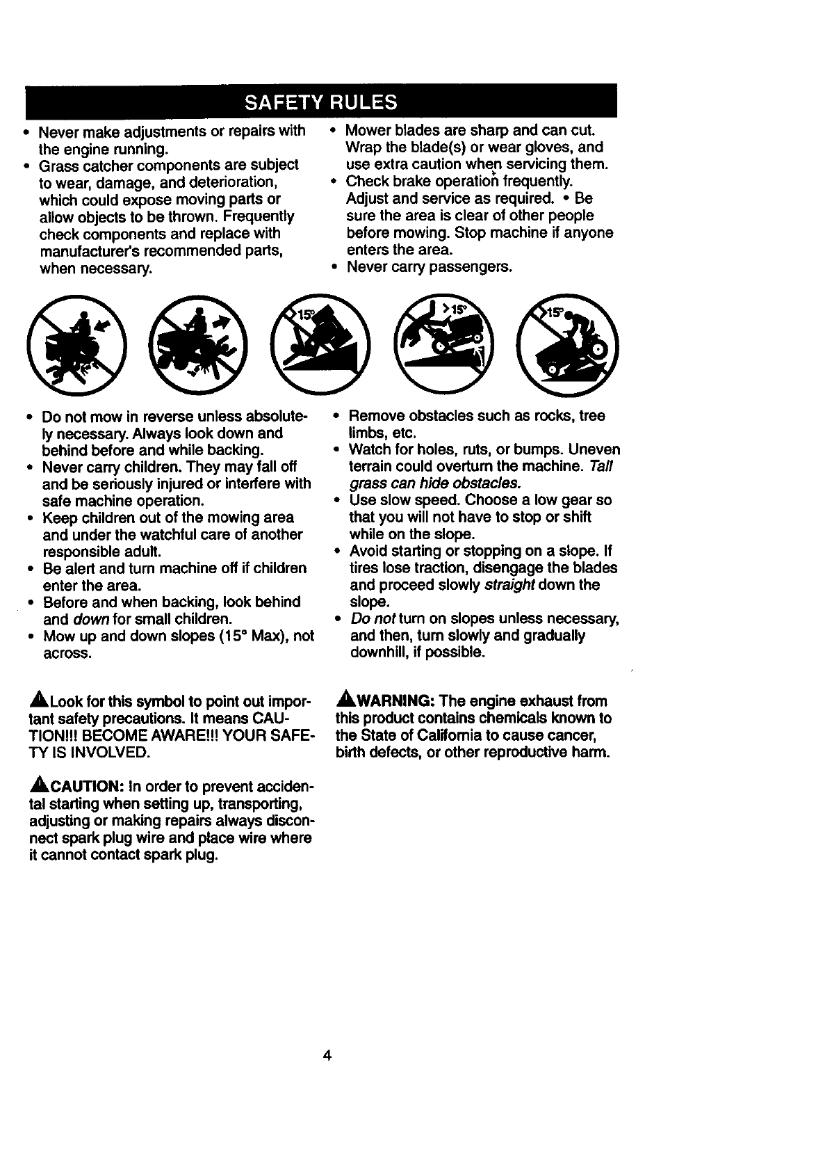
•Do not mow in reverse unless absolute-
ly necessary. Always look down and
behind before and while backing.
•Never carry children. They may fall off
and be seriously injured or interfere with
safe machine operation.
•Keep children out of the mowing area
and under the watchful care of another
responsible adult.
• Be alert and turn machine off if children
enter the area.
•Before and when backing, look behind
and down for small children.
•Mow up and down slopes (15 ° Max), not
across.
•Remove obstacles such as rocks, tree
limbs, etc.
•Watch for holes, ruts, or bumps. Uneven
terrain could overturn the machine. Tall
grass can hide obstacles.
•Use slow speed. Choose a low gear so
that you will not have to stop or shift
while on the slope.
•Avoid starting or stopping on a slope. If
tires lose traction, disengage the blades
and proceed slowly straight down the
slope.
•Donotturn on slopes unless necessary,
and then, turn slowly and gradually
downhill, if possible.
_,Look for this symbol to point out impor-
tant safety precautions. It means CAU-
TION!It BECOME AWARE!H YOUR SAFE-
TY IS INVOLVED.
_,CAUTION: In order to prevent acciden-
tal starting when setting up, transporting,
adjustingor making repairs always discon-
nect spark plug wire and place wire where
it cannot contact spark plug.
AWARNING: The engine exhaust from
this product contains chemicals known to
the State of Califomia to cause cancer,
birth defects, or other reproductive harm,
4
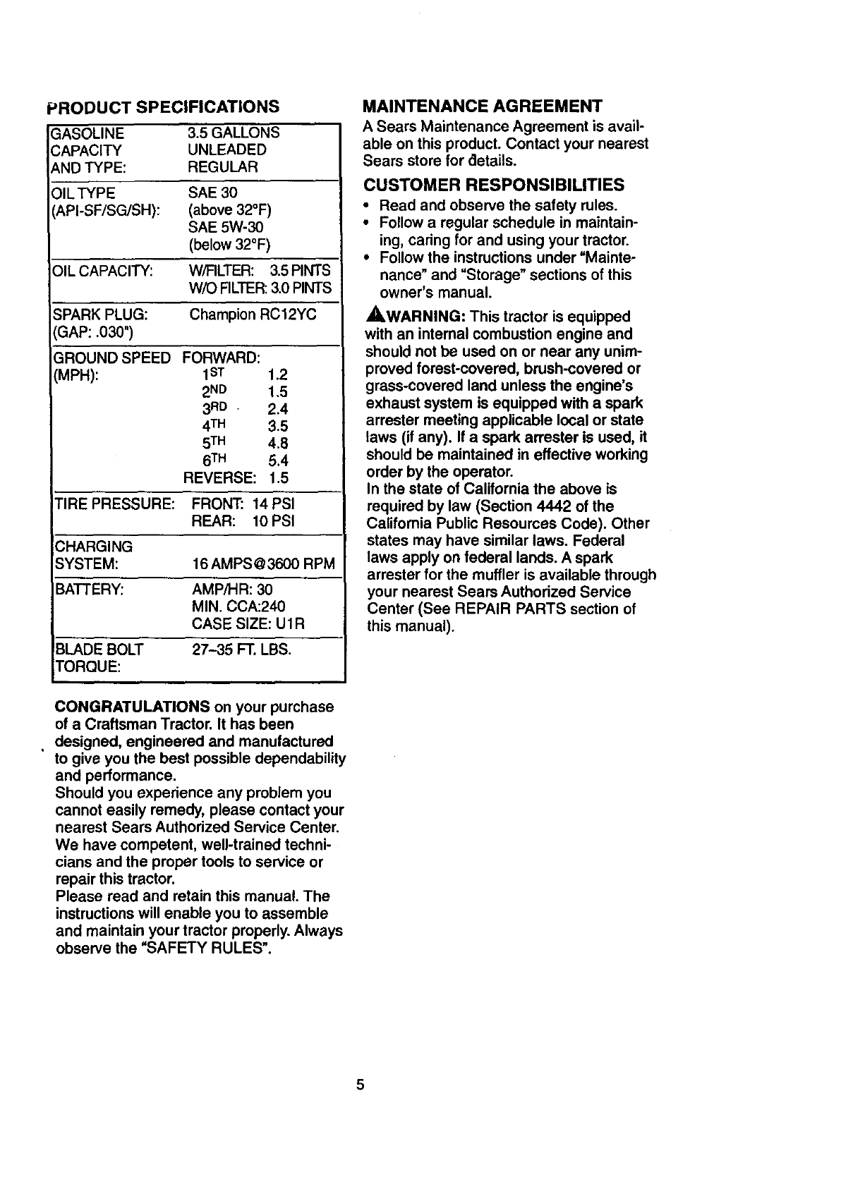
PRODUCT SPECIFICATIONS
GASOLINE 3.5 GALLONS
CAPACITY UNLEADED
AND TYPE: REGULAR
OIL TYPE SAE 30
API-SF/SG/SH): (above 32°F)
SAE 5W-30
(below 32°F)
OIL CAPACITY: W/FILTER: 3.5 PINTS
W/O FILTER: 3.0 PINTS
SPARK PLUG: Champion RC12YC
GAP: .030")
GROUND SPEED FORWARD:
(MPH): 1ST t .2
2ND 1.5
3 RD • 2.4
4TM 3.5
5TM 4.8
6TM 5.4
REVERSE: 1.5
TIRE PRESSURE: FRONT: 14PSI
REAR: 10 PSI
i
CHARGING
SYSTEM: 16 AMPS @3600 RPM
E3A'I-I'ERY: AMP/HR: 30
MIN. CCA:240
CASE SIZE: U1R
BLADE BOLT 27--35 FT. LBS.
TORQUE:
MAINTENANCE AGREEMENT
A Sears Maintenance Agreement is avail-
able on this product. Contact your nearest
Sears store for aetails.
CUSTOMER RESPONSIBILITIES
•Read and observe the safety rules.
•Follow a regular schedule in maintain-
ing, caring for and using your tractor.
•Follow the instructions under "Mainte-
nance" and "Storage" sections of this
owner's manual.
_,WARNING: This tractor is equipped
with an internal combustion engine and
should not be used on or near any unim-
proved forest-covered, brush-covered or
grass-covered land unless the engine's
exhaust system is equipped with a spark
arrester meeting applicable local or state
laws (if any). If a spark arrester is used, it
should be maintained in effective working
order by the operator.
In the state of California the above is
required by law (Section 4442 of the
California Public Resources Code). Other
states may have similar laws. Federal
laws apply on federal lands. A spark
arrester for the muffler is available through
your nearest Sears Authorized Service
Center (See REPAIR PARTS section of
this manual).
CONGRATULATIONS on your purchase
of a Craftsman Tractor. It has been
•designed, engineered and manufactured
to give you the best possible dependability
and performance.
Should you experience any problem you
cannot easily remedy, please contact your
nearest Sears Authorized Service Center.
We have competent, well-trained techni-
cians and the proper tools to service or
repair this tractor.
Please read and retain this manual. The
instructions will enable you to assemble
and maintain your tractor properly. Always
observe the "SAFETY RULES".
5
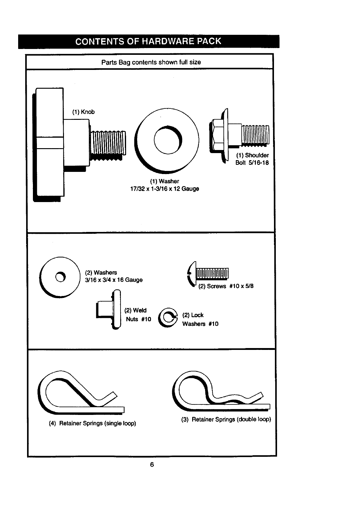
PartsBagcontentsshownfullsize
(1) Knob
(1) Washer
17/32 x 1-3/16 x 12 Gauge
(1) Shoulder
Bolt 5/16-18
(2) Washers
3/16 x3/4 x 16 Gauge
(2) Weld
Nuts #10 (2) Lock
Washers #10
(4) Retainer Springs(single loop) (3) Retainer Springs (double loop)
6
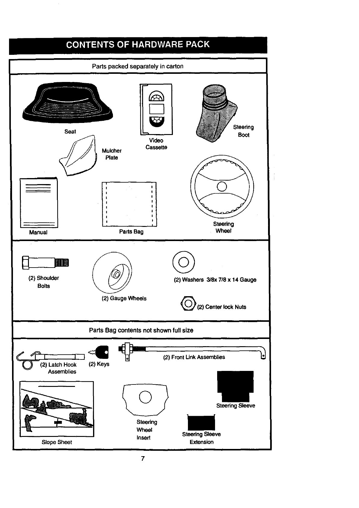
Parts packed separately in carton
Seat
Mulcher
Plate
Video
Cassette
Steering
Boot
iii
!__
Manual
,I
Pads Bag
Steedng
Wheel
(2) Shoulder
Bolts
(2) Gauge Wheels
©
(2) Washers 3/8x 7/8 x 14 Gauge
Q(2) Center lock Nuts
Parts Bag contents not shown full size
LatchHook
Assemblies
(2) Front Unk Assemblies
Slope Sheet
Steering
Wheel
Insert
Steering Sleeve
i
SteeringSleeve
Extension
7
Your new tractor has been assembled at the factory with exception of those parts left
unassemb_ed for shipping purposes. To ensure safe and proper operation of your tractor
all parts and hardware you assemble must be tigl_tened securely. Use the correct tools
as necessary to insure proper tightness. Review the video cassette before you begin.
TOOLS REQUIRED FOR
ASSEMBLY
A socket wrench set will make assembly
easier. Standard wrench sizes you need
are listed below.
(1) 3/4" wrench (1) 3/4" Socket w/
(2) 1/2" wrench drive rachet
(1) Pliers (1) PhillipsScrew-
(1) Utilityknife driver
(1) T_repressure gauge
When rightor left hand is mentioned in
this manual, it means, from your point of
view, when you are in the operating posi-
tion (seated behind the steering wheel).
TO REMOVE TRACTOR FROM
CARTON
UNPACK CARTON
•Remove all accessible loose parts and
parts boxes from shipping carton (See
page 6).
•Cut, from top to bottom, along lines on
all four corners of shipping carton, and
lay panels flat.
•Remove mower and package materials.
•Check for any additional loose parts or
boxes and remove.
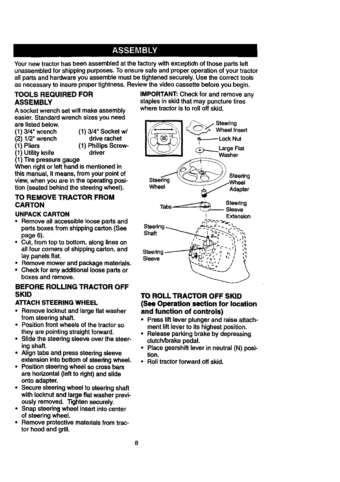
IMPORTANT: Check for and remove any
staples in skid that may puncture tires
where tractor is to roll off skid.
ii iI t.n
Wheel Insert
_.-_ Lock Nut
_j..__._ Large Flat
_r. Washer
Steering
Wheel
Steering
Adapter
Steering
Tabs _.._.._._ Sleeve
/Extension
I_ J t|
Steering ._., /
BEFORE ROLLING TRACTOR OFF
SKID
ATTACH STEERING WHEEL
•Remove Iocknut and large flat washer
from steering shaft.
•Position front wheels of the tractor so
they are pointing straight forward.
•Slide the steering sleeve over the steer-
ing shaft.
•Align tabs and press steedng sleeve
extension into bottom of steering wheel.
•Position steering wheel so cross bars
are horizontal (left to right) and slide
onto adapter.
•Secure steering wheel to steering shaft
with Iocknut and large flat washer previ-
ously removed. "13ghtensecurely.
•Snap steedng wheel insert into center
of steering wheel.
•Remove protective materials from trac-
tor hood and grill.
TO ROLL TRACTOR OFF SKID
(See Operation section for location
and function of controls)
•Press liftlever plunger and raise attach-
ment lift lever to its highest position.
•Release parking brake by depressing
clutch/brake pedal.
•Place gearshift lever in neutral (N) posi-
tion.
•Roll tractor forward off skid.
8
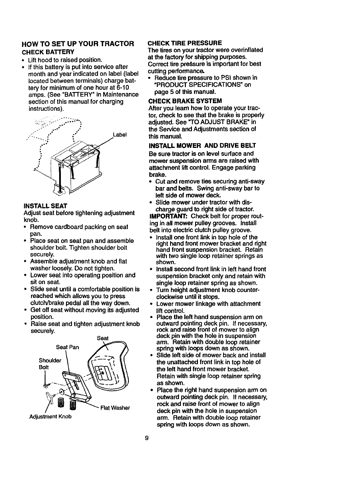
HOW TO SET UP YOUR TRACTOR
CHECKBATTERY
• Lifthoodto raised position.
• If this battery is put into service after
month and year indicated on label (label
located between terminals) charge bat-
tery for minimum of one hour at 6-10
amps. (See "BATTERY" in Maintenance
section of this manual for charging
instructions).
=.- ' _.....
_w p
o; Label
INSTALL SEAT
Adjust seat before tightening adjustment
knob.
• Remove cardboard packing on seat
pan.
• Place seat on seat pan and assemble
shoulder bolt. Tighten shoulder bolt
securely.
• Assemble adjustment knob and flat
washer loosely. Do not tighten.
• Lower seat into operating position and
sit on seat.
• Slide seat until a comfortable position is
reached which allows you to press
clutch/brake pedal all the way down.
•Get off seat without moving its adjusted
position.
• Raise seat and tighten adjustment knob
securely. Seat
Seat Pan
Shoulder
Bolt
Adjustment Knob
Flat Washer
CHECK TIRE PRESSURE
The tires on your tractor were overinflated
at the factory for shipping purposes.
Correct tire pre.,_sure is important for best
cutting performance.
•Reduce tire pressure to PSI shown in
"PRODUCT SPECIFICATIONS" on
page 5 of this manual.
CHECK BRAKE SYSTEM
After you learn how to operate your trac-
tor, check to see that the brake is properly
adjusted. See "TO ADJUST BRAKE" in
the Service and Adjustments section of
this manual.
INSTALL MOWER AND DRIVE BELT
Be sure tractor is on level surface and
mower suspension arms are raised with
attachment lift control. Engage parking
brake.
•Cut and remove ties securing anti-sway
bar and belts. Swing anti-sway bar to
left side of mower deck.
•Slide mower under tractor with dis-
charge guard to right side of tractor.
IMPORTANT: Check belt for proper rout-
ing in all mower pulley grooves. Install
belt into electric clutch pulley groove.
•Install one front link in top hole of the
right hand front mower bracket and right
hand front suspension bracket. Retain
with two single loop retainer springs as
shown.
•Install second front link in left hand front
suspension bracket only and retain with
single loop retainer spring as shown.
•Turn height adjustment knob counter-
clockwise until it stops.
•Lower mower linkage with attachment
lift control.
•Place the left hand suspension arm on
outward pointing deck pin. if necessary,
rock and raise front of mower to align
deck pin with the hole in suspension
arm. Retain with double loop retainer
spring with loops down as shown.
•Slide left side of mower back and install
the unattached front link in top hole of
the left hand front mower bracket.
Retain with single loop retainer spring
as shown.
•Place the right hand suspension arm on
outward pointing deck pin. If necessary,
rock and raise front of mower to align
deck pin with the hole in suspension
arm. Retain with double loop retainer
spring with loops down as shown.
9
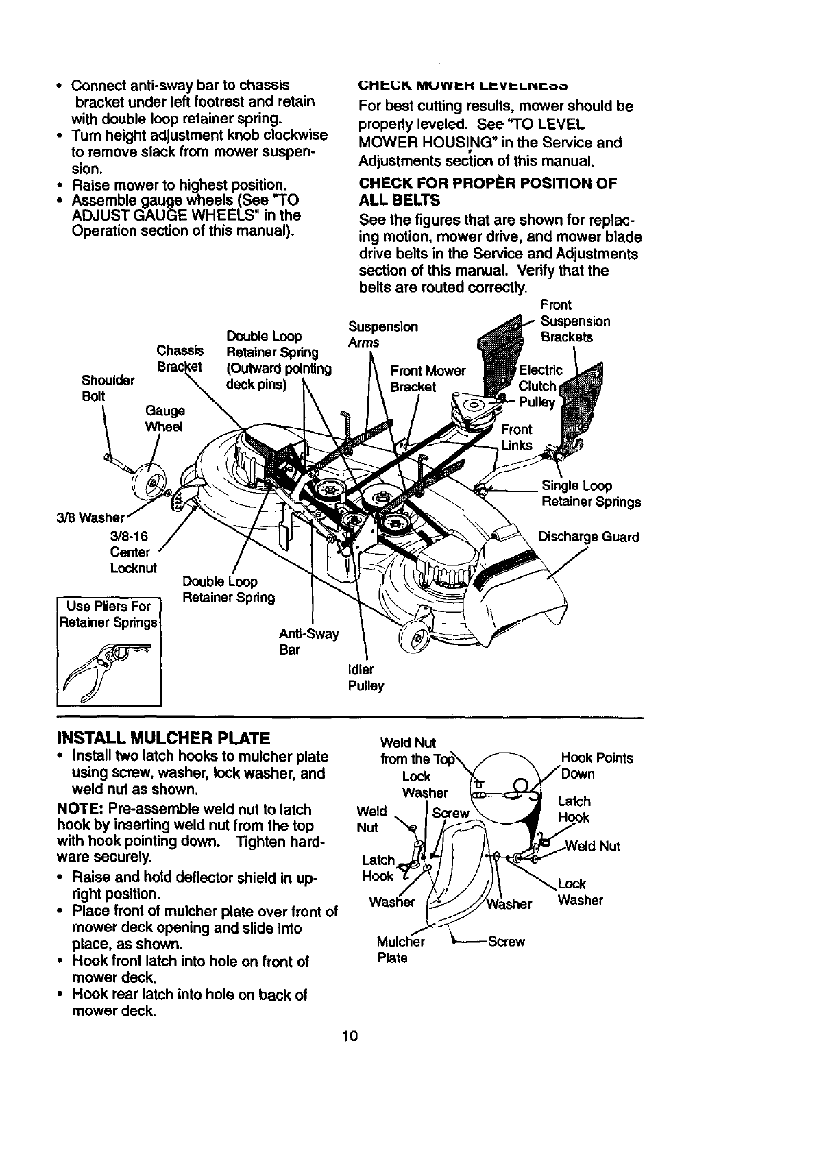
•Connect anti-sway bar to chassis
bracket under left footrest and retain
with double loop retainer spring.
•Turn height adjustment knob clockwise
to remove slack from mower suspen-
sion.
•Raise mower to highest position.
•Assemble gauge wheels (See "TO
ADJUST GAUGE WHEELS in the
Operation section of this manual).
Shoulder
Bolt
Double Loop
Chassis Retainer Spring
Bracket (Outward pointing
deck pins)
(.;Hb(,;R MUWP-I1 Lr.Vr.L.£Oo
For best cutting results, mower should be
properly leveled. See "TO LEVEL
MOWER HOUSING" in the Service and
Adjustments section of this manual.
CHECK FOR PROPI_R POSITION OF
ALL BELTS
See the figures that are shown for replac-
ing motion, mower drive, and mower blade
drive belts in the Service and Adjustments
section of this manual. Verify that the
belts are muted correctly. Front
Suspension Suspension
Arms Brackets
Front Mower
Bracket
3/8 Washel
3/8-16
Center
Locknut
Use Pliers For
Retainer Springs
Double Loop
Retainer Spdng
Anti-Sway
Bar
Idler
Pulley
Single Loop
Retainer Spdngs
Discharge Guard
INSTALL MULCHER PLATE Weld Nut
•Install two latch hooks to mulcher plate
using screw, washer, lock washer, and Lock
weld nut as shown. Washer
NOTE: Pre-assemble weld nut to latch Weld
hook by inserting weld nut from the top Nut
with hook pointing down. Tighten hard-
ware securely. Latch_
•Raise and hold deflector shield in up- Hook
right position.
•Place front of mulcher plate over front of
mower deck opening and slide into
place, as shown. Mulcher _,-----Screw
•Hook front latch into hole on front of Plate
mower deck.
•Hook rear latch into hole on back of
mower deck.
10
Hook Points
Latch
Lock
Washer
_i_',._ _>_--_<,,,I_L Latch
_Hooks
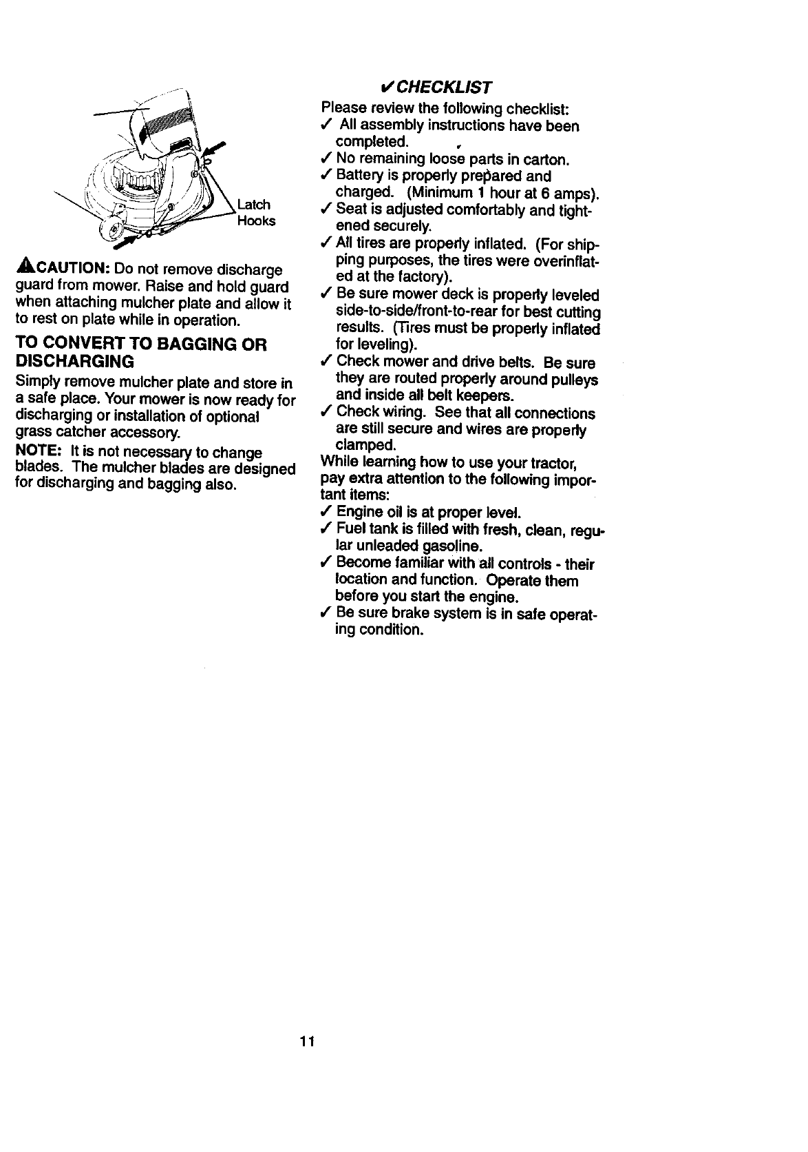
_CAUTION: Do not remove discharge
guard from mower. Raise and hold guard
when attaching mulcher plate and allow it
to rest on plate while in operation.
TO CONVERT TO BAGGING OR
DISCHARGING
Simply remove mulcher plate and store in
a safe place. Your mower is now ready for
discharging or installationof optional
grass catcher accessory.
NOTE: It is not necessary to change
blades. The mulcher blades are designed
for discharging and bagging also.
v' CHECKLIST
Please review the following checklist:
,/ All assembly instructions have been
completed.
/No remaining loose parts in carton.
/Battery is propedy prel_ared and
charged. (Minimum 1 hour at 6 amps).
/Seat is adjusted comfortably and tight-
ened securely.
/All tires are propedy inflated. (For ship-
ping purposes, the tires were overinflat-
ed at the factory).
,/Be sure mower deck is property leveled
side-to-side/front-to-rear for best cutting
results. (Tires must be properly inflated
for leveling).
/Check mower and drive belts. Be sure
they are routed properly around pulleys
and inside all belt keepers.
,/Check wiring. See that all connections
are still secure and wires are properly
clamped.
While learning how to use your tractor,
pay extra attention to the following impor-
tant items:
,/Engine oil is at proper level.
,/Fuel tank is filled with fresh, clean, regu-
lar unleaded gasoline.
4' Become familiar with all controls -their
location and function. Operate them
before you start the engine.
,/Be sure brake system is in safe operat-
ing condition.
11
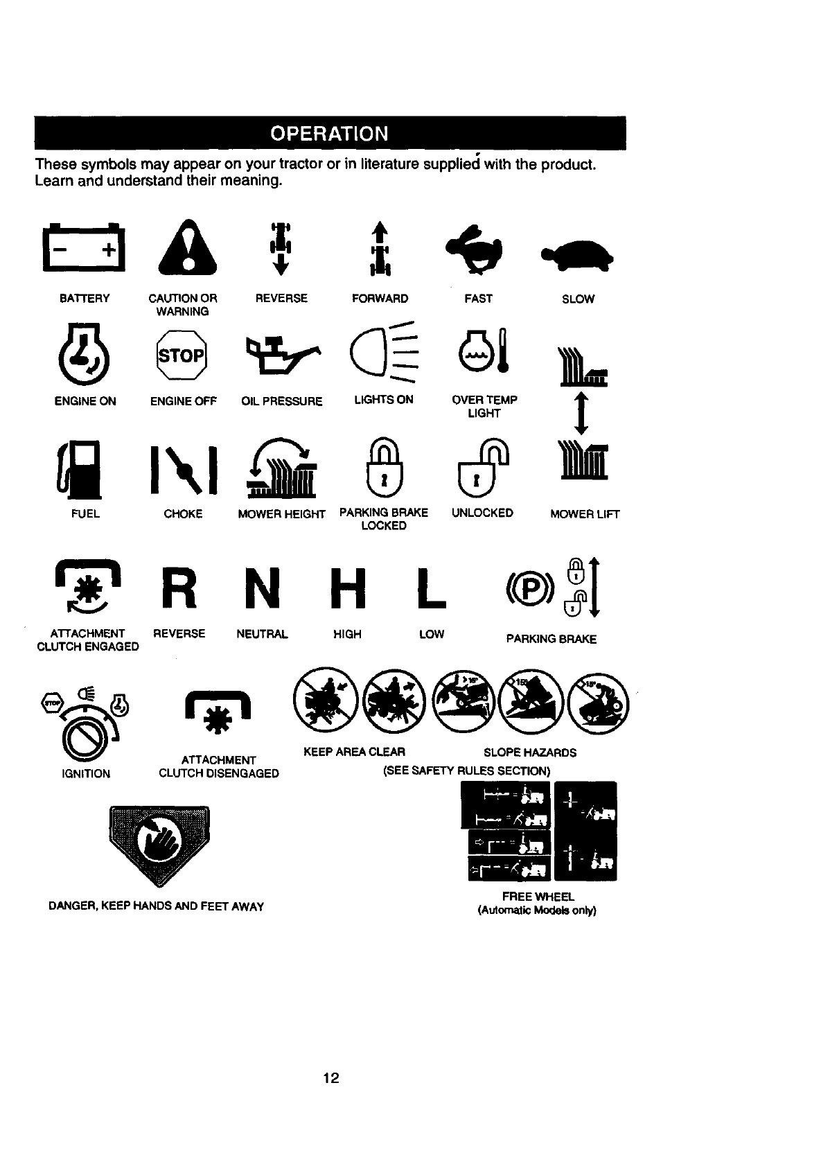
Thesesymbolsmay appear on your tractor or in literature suppliecl with the product.
Learn and understand their meaning.
BATrERY CAUTION OR
WARNING REVERSE FORWARD FAST SLOW
ENGINE ON ENGINE OFF OIL PRESSURE LIGHTS ON OVER TEMP '_
LIGHT
FUEL CHOKE MOWER HEIGHT PARKING BRAKE UNLOCKED MOWER LIFT
LOCKED
R N H L
ATTACHMENT REVERSE NEUTRAL HIGH LOW PARKING BRAKE
CLUTCH ENGAGED
ATTACHMENT KEEP AREA CLEAR SLOPE HAZARDS
IGNITION CLUTCH DISENGAGED (SEE ,_a=FETY RULES SECTION)
DANGER, KEEP HANDS AND FEET AWAY FREEWHEEL
(A_omat_Mode_on_)
12
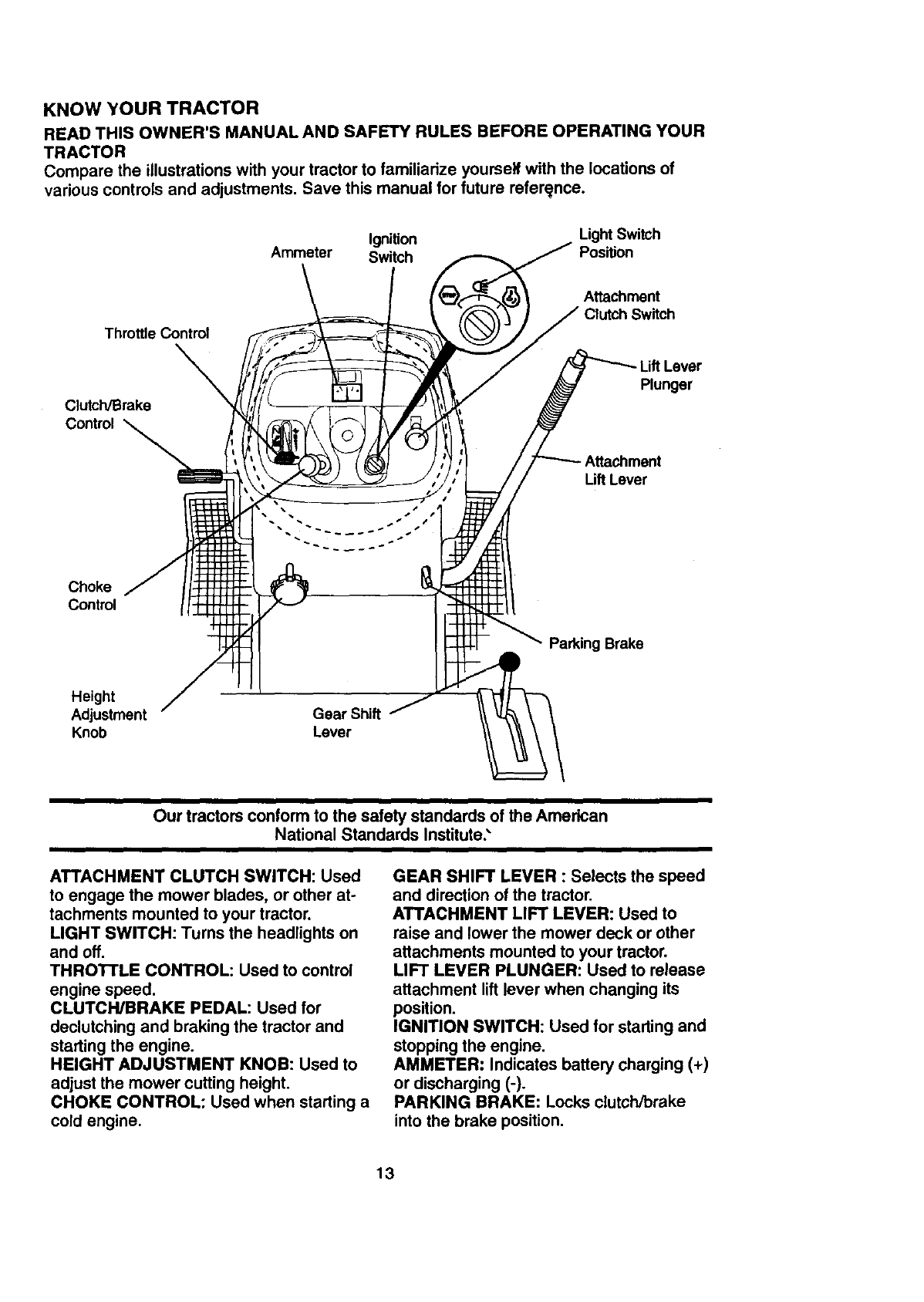
KNOW YOUR TRACTOR
READTHISOWNER'SMANUALANDSAFETYRULESBEFOREOPERATINGYOUR
TRACTOR
Compare the illustrations with your tractor to familiarize yourself with the locations of
various controls and adjustments. Save this manual for future reference.
Ignition Light Switch
Ammeter Switch Position
Throttle Control
\
Clutch/Brake
Control
Attachment
Switch
Plunger
Lift Lever
Choke
Control
Parking Brake
Height
Adjustment Gear Shift
Knob Lever
Our tractors conform to the safety standards of the American
National Standards Institute;
ATTACHMENT CLUTCH SWITCH: Used
to engage the mower blades, or other at-
tachments mounted to your tractor.
LIGHT SWITCH: Turns the headlights on
and off.
THROTTLE CONTROL: Used to control
engine speed.
CLUTCH/BRAKE PEDAL: Used for
declutching and braking the tractor and
starting the engine.
HEIGHT ADJUSTMENT KNOB: Used to
adjust the mower cutting height,
CHOKE CONTROL: Used when starting a
cold engine,
GEAR SHIFT LEVER : Selects the speed
and direction of the tractor.
ATTACHMENT LIFT LEVER: Used to
raise and lower the mower dock or other
attachments mounted to your tractor.
LIFT LEVER PLUNGER: Used to release
attachment lift lever when changing its
position.
IGNITION SWITCH: Used for starting and
stopping the engine.
AMMETER: Indicates battery charging (+)
or discharging (-).
PARKING BRAKE: Locks clutch/brake
into the brake position.
13
II1_ The operationof anytractorcanresultinforeignobjectsthrowninto the I
[-"-_'_- ] eyes, which can result in severe eye damage. Always wear safety glasses I
_or eye shields while operating your tractor or performing any adjustments or
repairs. We recommend a wide vision safety mask over spectacles, or stan-
dard safety glasses.
HOW TO USE YOUR TRACTOR
Your tractor is equipped with an operator
presence sensing switch. When engine is
running, any attempt by the operator to
leave the seat without first setting the
parking brake will shut off the engine.
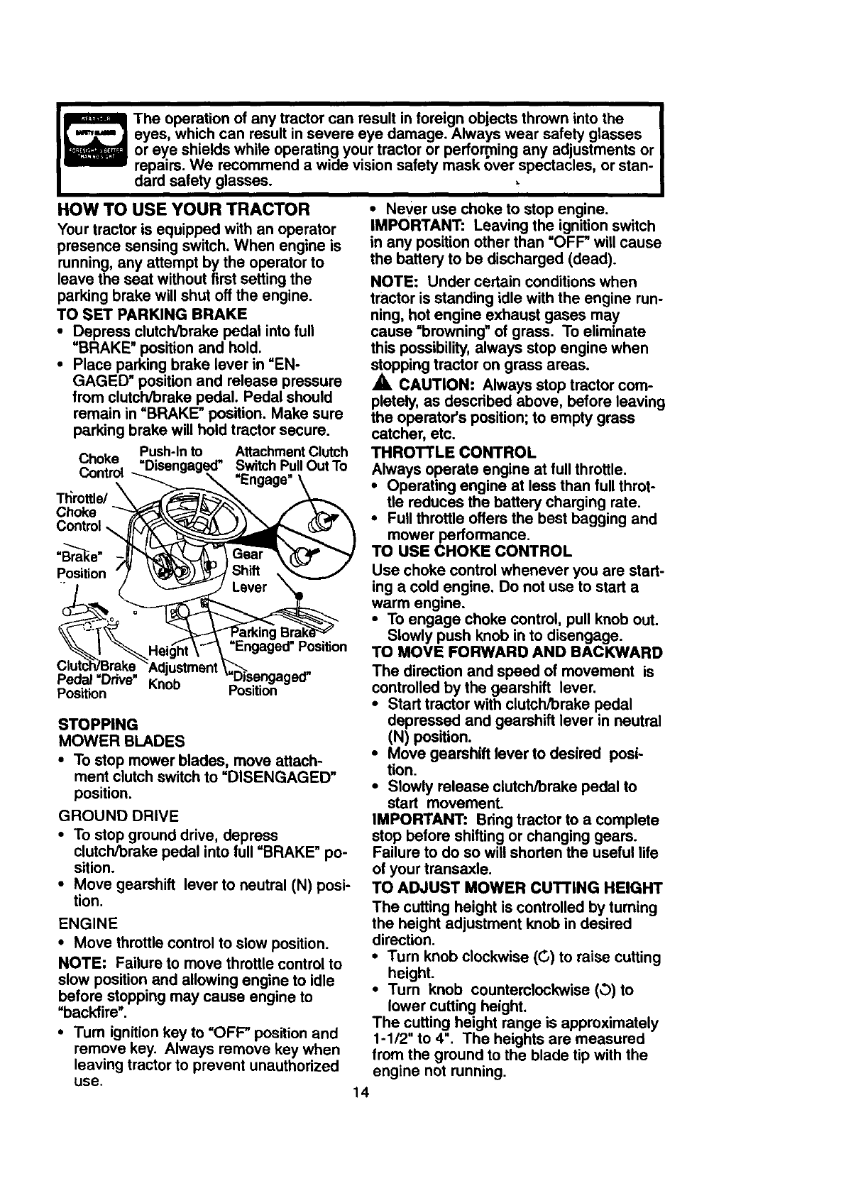
TO SET PARKING BRAKE
• Depress clutch/brake pedal into full
=BRAKE" position and hold.
•Place parking brake lever in =EN-
GAGED" position and release pressure
from clutch/brake pedal. Pedal should
remain in "BRAKE" position. Make sure
parking brake will hold tractor secure.
Push-In to Attachment Clutch
Choke "Disen Switch Pull Out To
Control
Tt_rottls/
Choke
Control
.Br--_a s _
Position
Position
Pedal =Drive" Knob
Position Position
STOPPING
MOWER BLADES
•To stop mower blades, move attach-
ment clutch switch to =DISENGAGED"
position.
GROUND DRIVE
• To stop ground drive, depress
clutch/brake pedal into full "BRAKE" po-
sition.
• Move gearshift lever to neutral (N) posi-
tion.
ENGINE
•Move throttle control to slow position.
NOTE: Failure to move throttle control to
slow position and allowing engine to idle
before stopping may cause engine to
=backfire".
• Turn ignition key to "OFF" position and
remove key. Always remove key when
leaving tractor to prevent unauthorized
use.
•Never use choke to stop engine.
IMPORTANT: Leaving the ignition switch
in any position other than "OFF" will cause
the battery to be discharged (dead).
NOTE: Under certain conditions when
tractor is standing idle with the engine run-
ning, hot engine exhaust gases may
cause "browning" of grass. To eliminate
this possibility, always stop engine when
stopping tractor on grass areas.
_, CAUTION: Always stop tractor com-
pletely, as described above, before leaving
the operator's position; to empty grass
catcher, etc.
THROTTLE CONTROL
Always operate engine at full throttle.
•Operating engine at less than full throt-
tle reduces the battery charging rate.
•Full throttle offers the best bagging and
mower performance.
TO USE CHOKE CONTROL
Use choke control whenever you are start-
ing a cold engine. Do not use to start a
warm engine.
•To engage choke control, pull knob out.
Slowly push knob in to disengage.
TO MOVE FORWARD AND BACKWARD
The direction and speed of movement is
controlled by the gearshift lever.
•Start tractor with clutch/brake pedal
depressed and gearshift lever in neutral
(N) position.
•Move gearshift lever to desired posi-
tion.
•Slowly release clutch/brake pedal to
start movement.
IMPORTANT: Bring tractor to a complete
stop before shifting or changing gears.
Failure to do so will shorten the useful life
of your transaxle.
TO ADJUST MOWER CUTTING HEIGHT
The cutting height is controlled by turning
the height adjustment knob in desired
direction.
•Turn knob clockwise ((3) to raise cutting
height.
•Turn knob counterclockwise (_) to
lower cutting height.
The cutting height range is approximately
1-1/2" to 4". The heights are measured
from the ground to the blade tip with the
engine not running.
14
Theseheightsareapproximateand may
varydependinguponsoil conditions,
heightof grassand typesof grassbeing
mowed.
•The average lawn should be cut to
approximately 2-1/2 inches during the
cool season and to over 3 inches during
hot months. For healthier and better
looking lawns, mow often and after
moderate growth.
• For best cutting performance, grass
over 6 inches in height should be
mowed twice. Make the first cut rela-
tively high; the second to desired height.
TO ADJUST GAUGE WHEELS
Gauge wheels are properly adjusted
when they are slightly off the ground when
mower is at the desired cutting height in
operating position. Gauge wheels then
keep the deck in proper position to help
prevent scalping in most terrain condi-
tions.
•Adjust gauge wheels with tractor on a
fiat level surface.
•Adjust mower to desired cutting height
(See "TO ADJUST MOWER CUTTING
HEIGHT" in the Operation section of
this manual).
•With mower in desired height of cut po-
sition, gauge wheels should be assem-
bled so they are slightly off the ground.
install gauge wheel in appropriate hole
with shoulder bolt, 3/8 washer, and 3/8-
16 Iocknut and tighten securely.
• Repeat for opposite side installing
gauge wheel in same adjustment hole.
Mounting _,
Bracket
3/8-16
Locknut Shoulder Bolt
3/8 Washer Gauge Wheel
TO OPERATE MOWER
Your tractor is equipped with an operator
presence sensing switch. Any attempt by
the operator to leave the seat with the
engine running and the attachment clutch
engaged will shut off the engine.
•Select desired height of cut.
• Lower mower with attachment lift con-
trol.
• Start mower blades by engaging attach-
ment clutch control.
• TO STOP MOWER BLADES - disen-
gage attachment clutch control.
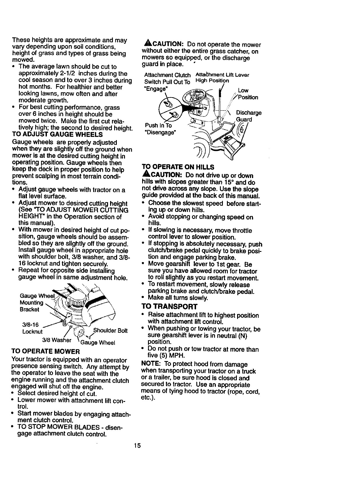
_,CAUTION: Do not operate the mower
without either the entire grass catcher, on
mowers so equipped, or the discharge
guard in place.
Attachment Clutch
Switch Pull Out To
"Enga_
Push InTo"- _>_-_-- ? !
=Disengage" _._d
Atta_:hment Lift Lever
High Position
_/ Low
;:_PosiUon
H
_:_ Discharge
I_J Guard
TO OPERATE ON HILLS
_CAUTION: Do not drive up or down
hills with slopes greater than 15 ° and do
not drive across any slope. Use the slope
guide provided at the back of this manual.
• Choose the slowest speed before start-
ing up or down hills.
•Avoid stopping or changing speed on
hills.
• If slowing is necessary, move throttle
control lever to slower position.
• If stopping is absolutely necessary, push
clutch/breke pedal quickly to brake posi-
tion and engage parking brake.
• Move gearshift lever to 1st gear. Be
sure you have allowed room for tractor
to roll slightly as you restart movement.
• To restart movement, slowly release
parking brake and clutch/brake pedal.
• Make all turns slowly.
TO TRANSPORT
•Raise attachment lift to highest position
with attachment lift control.
•When pushing or towing your tractor, be
sure gearshift lever is in neutral (N)
position.
• Do not push or tow tractor at more than
five (5) MPH.
NOTE: To protect hood from damage
when transporting your tractor on a truck
or a trailer, be sure hood is closed and
secured to tractor. Use an appropriate
means of tying hood to tractor (rope, cord,
etc.).
15
TOWING CARTS AND OTHER
A'rrACHMENTS
Towonlytheattachmentsthatare recom-
mendedbyand complywith specifications
of themanufacturerofyour tractor.Use
commonsensewhentowing.Tooheavyof
a load,whileona slope,is dangerous.
Tirescanlosetractionwiththegroundand
causeyouto losecontrolof yourtractor.
BEFORE STARTING THE ENGINE
CHECKENGINEOIL LEVEL
•The engine in your tractor has been
shipped, from the factory, already filled
with summer weight oil.
•Check engine oil with tractor on level
ground.
•Unthread and remove oil fill cap/dip-
stick; wipe oil off. Reinsert the dipstick
into the tube and rest oil fill cap on the
tube. Do not thread the cap onto the
tube. Remove and read oil level. If nec-
essary, add oil until "FULL" mark on
dipstick is reached. Do not overfill.
•For cold weather operation you should
change oil for easier starting (See "OIL
VISCOSITY CHAR'I" in the
Maintenance section of this manual).
•To change engine oil, see the Customer
Responsibilities section in this manual.
ADD GASOLINE
•Fill fuel tank. Use fresh, clean, regular
unleaded gasoline with a minimum of 87
octane. (Use of leaded gasoline will
increase carbon and lead oxide
deposits and reduce valve life). Do not
mix oil with gasoline. Purchase fuel in
quantities that can be used within 30
days to assure fuel freshness,
IMPORTANT: When operating in tempera-
tures below 32°F(00C), use fresh, clean
winter grade gasoline to help insure good
_/_/weather starting.
ARNING: Experience indicates that
alcohol blended fuels (called gasohol or
using ethanol or methanol) can attract
moisture which leads to separation and
formation of acids during storage. Acidic
gas can damage the fuel system of an
engine while in storage. To avoid engine
problems, the fuel system should be emp-
tied before storage of 30 days or longer.
Drain the gas tank, start the engine and let
it run until the fuel lines and carburetor are
empty. Use fresh fuel next season. See
Storage Instructions for additional informa-
tion. Never use engine or carburetor
cleaner products in the fuel tank or perma-
nent damage may occur.
,_CAUTION: Fill to bottom of gas tank
filler neck. Do not overfill. Wipe off any
spilled oil or fuel. Do not store, spill or use
gasoline near an open flame.
TO START ENGINE
When starting the engine_for the first time
or if the engine has run out of fuel, it will
take extra cranking time to move fuel from
the tank to the engine.
•Sit on seat in operating position,
depress clutch/brake pedal and set
parking brake,
•Place gear shift lever in neutral (N) posi-
tion.
•Move attachment clutch to =DISEN-
GAGED" position.
•Move throttle control to choke position.
NOTE: Before starting, read the warm
and cold starting procedures below.
•Insert key into ignition and turn key
clockwise to =START" position and
release key as soon as engine starts.
Do not run starter continuously for more
than fifteen seconds per minute. If the
engine does not start after several
attempts, move throttle control to fast
position, wait a few minutes and try
again. If engine still does not start,
move the throttle control back to the
choke position and retry.
WARM WEATHER STARTING (50 ° F
AND ABOVE)
•When engine starts, move the throttle
control to the fast position.
•The attachments and ground drive can
now be used. If the engine does not
accept the load, restart the engine and
allow it to warm up for one minute using
the choke as described above.
COLD WEATHER STARTING ( 50 ° F AND
BELOW)
•When engine starts, allow engine to run
with the throttle control in the choke
position until the engine runs roughly,
then move throttle control to fast posi-
tion. This may require an engine warm-
up period from several seconds to sev-
eral minutes, depending on the temper-
ature.
•The attachments can also be used dur-
ing the engine warm-up period.
NOTE: A high altitude (above 3000 feet)
or in cold temperatures (below 32 F) the
carburetor fuel mixture may need to be
adjusted for best engine performance.
See "TO ADJUST CARBURETOR" in the
Service and Adjustments section of this
manual.
16
MOWING TIPS
• Tirechainscannotbe usedwhenthe
mowerhousingisattachedto tractor.
•Mower should be properly leveled for
best mowing performance. See _T'O
LEVEL MOWER HOUSING" in the
Service and Adjustments section of this
manual.
• The left hand side of mower should be
used for trimming.
•Drive so that clippings are discharged
onto the area that has been cut. Have
the cut area to the right of the tractor.
This will result in a more even distribu-
tion of clippings and more uniform cut-
ting.
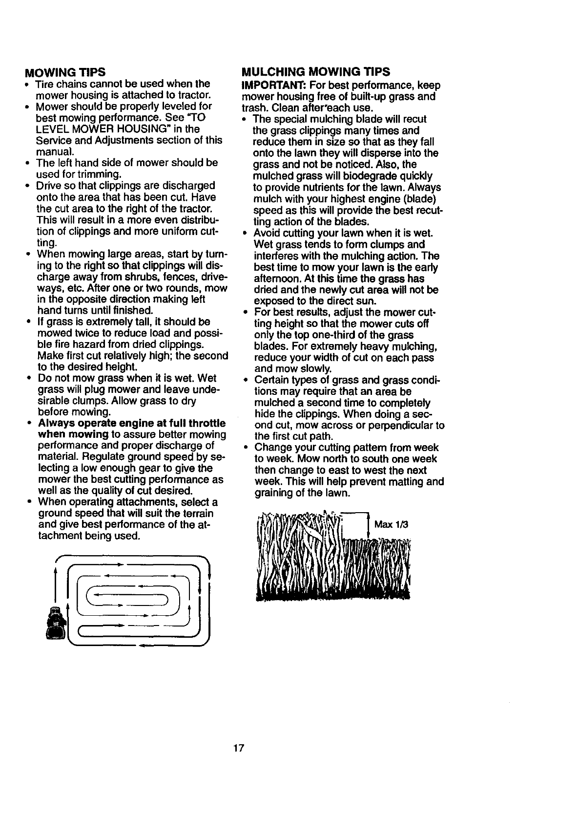
•When mowing large areas, start by turn-
ing to the right so that clippings will dis-
charge away from shrubs, fences, drive-
ways, etc. After one or two rounds, mow
in the opposite direction making left
hand turns until finished.
•If grass is extremely tall, it should be
mowed twice to reduce load and possi-
ble fire hazard from dried clippings.
Make first cut relatively high; the second
to the desired height.
•Do not mow grass when it is wet. Wet
grass will plug mower and leave unde-
sirable clumps. Allow grass to dry
before mowing.
•Always operate engine at full throttle
when mowing to assure better mowing
performance and proper discharge of
material. Regulate ground speed by se-
lecting a low enough gear to give the
mower the best cutting performance as
well as the quality of cut desired.
•When operating attachments, select a
ground speed that will suit the terrain
and give best performance of the at-
tachment being used.
MULCHING MOWING TIPS
IMPORTANT: For best performance, keep
mower housing free of built-up grass and
trash. Clean after'each use.
•The special mulchin.q blade will recut
the grass clippings many times and
reduce them in size so that as they fall
onto the lawn they will disperse into the
grass and not be noticed. Also, the
mulched grass will biodegrade quickly
to provide nutrients for the lawn. Always
mulch with your highest engine (blade)
speed as this will provide the best recut-
ting action of the blades.
•Avoid cutting your lawn when it is wet.
Wet grass tends to form clumps and
interferes with the mulching action. The
best time to mow your lawn is the early
afternoon. At this time the grass has
dried and the newly cut area will not be
exposed to the direct sun.
•For best results, adjust the mower cut-
ting height so that the mower cuts off
only the top one-third of the grass
blades. For extremely heavy mulching,
reduce your width of cut on each pass
and mow slowly.
•Certain types of grass and grass condi-
tions may require that an area be
mulched a second time to completely
hide the clippings. When doing a sec-
ond cut, mow across or perpendicular to
the first cut path.
•Change your cutting pattem from week
to week. Mow north to south one week
then change to east to west the next
week. This will help prevent matting and
graining of the lawn.
17
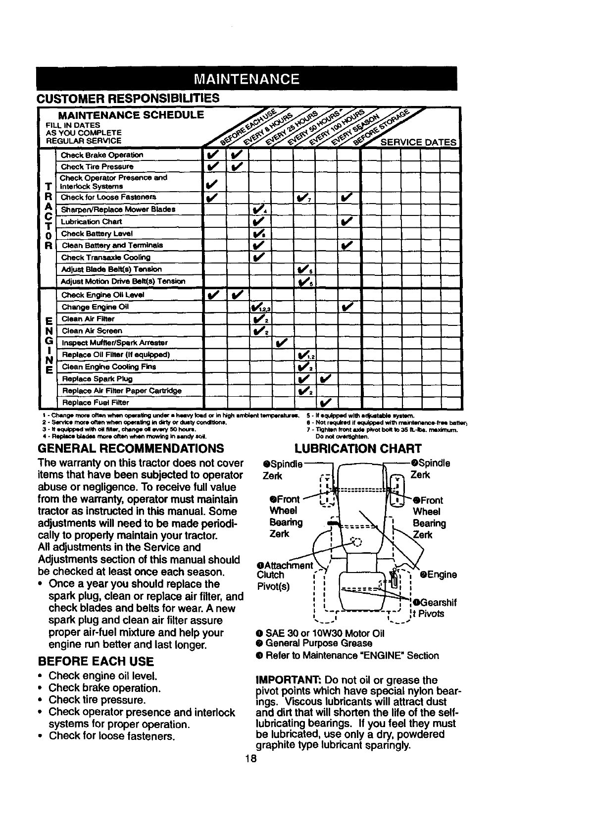
CUSTOMER RESPONSIBILITIES
MAINTENANCE SCHEDULE .,,,,_J_..._,_'./,d_/.._*"
AS YOU COMPLETE
Check Brake Operalion _
Check Tire Pressure
Check Operator Presence and
TInterlock Systems V'
RCheck for Loose Fasteners I_ . I1_'7 I_
She e neplece.owe,Blades
TLubrication Chart I1_
0 Check Battery Level
RClean Battery and Terrnln_ds I_ e
Check Transaxle Coolk_g
Adjust Blade Belt(s) Tension I_s
Adjust Motion Drive Belt(s) Tension
Che_k Engine Oil Level I_ I_
Change Engine Oil _t.=r_
EClean Air Filter
NClean Air Screen
Inspect Muffler/Sped< Attester (l# #
Replace Oil Filter (If equipped) I1_1,_
SClean Engine Cooling Fins I_2
Replace Spark Plug I_ , I_
v',Replace Air Filter Paper Carbidge
Replace Fuel Filter V'
$ - _rnom o_lm wh4m _per_ u_ i h_ told or In hq_h a_rd_ent to_i_, 5 - if equipped with adjust able Ir/stm_.
2-Semite rnme often when c_ers6_l In dlrtyor dusty con41_on=.
3 - tt oquIpp_l with ell filtm, chang* ell every 50 hmx=.
4 - Replace _do_ more o_MI wherl mowk19In lindy soil.
GENERAL RECOMMENDATIONS
The warranty on this tractor does not cover
items that have been subjected to operator
abuse or negligence. To receive full value
from the warranty, operator must maintain
tractor as instructed in this manual. Some
adjustments will need to be made periodi-
cally to properly maintain your tractor.
All adjustments in the Service and
Adjustments section of this manual should
be checked at least once each season.
• Once a year you should replace the
spark plug, clean or replace air filter, and
check blades and belts for wear. A new
spark plug and clean air fitter assure
proper air-fuel mixture and help your
engine run better and last longer.
BEFORE EACH USE
• Check engine oil level
•Check brake operation.
• Check tire pressure.
•Check operator presence and interlock
systems for proper operation.
•Check for loose fasteners.
6-Not required if equipped wi_ _free bstte_
7 * T'_gf-,tmlfror=t axle p_ot bolt to 35 IL-Ibs. maximum.
DO not over6_hten.
LUBRICATION CHART
• Spindle _F-_eSpindle
.Front "_'_ ........ _eFront
Wheel -" 1_Wheel
Beadng ,.===:_ Bearing
Zerk Zerk
@Attachment
Clutch _"
Pivot(s) '_ ,_ '_ _
'OGearshif
I r-" If Pivots
II I
O SAE 30 or 10W30 Motor Oil
• General Purpose Grease
@Refer to Maintenance =ENGINE" Section
IMPORTANT: Do not oil or grease the
pivot points which have special nylon bear-
rags. Viscous lubricants will attract dust
and dirt that will shorten the life of the self-
lubricating bearings. If you feel they must
be lubricated, use only a dry, powdered
graphite type lubricant sparingly.
18
TRACTOR
Alwaysobservesafety ruleswhenper-
forming any maintenance.
BRAKE OPERATION
If tractor requires more than six (6) feet
stopping distance at high speed in highest
gear, then brake must be adjusted. (See
"TO ADJUST BRAKE" in the Service and
Adjustments section of this manual).
TIRES
•Maintain proper air pressure in all tires
(See =PRODUCT SPECIFICATIONS"
section of this manual).
•Keep tires free of gasoline, oil, or insect
control chemicals which can harm rub-
ber.
•Avoid stumps, stones, deep ruts, sharp
objects and other hazards that may
cause tire damage.
NOTE= To seal tire punctures and prevent
flat tires due to slow leaks, tire sealant
may be purchased from your local parts
dealer. Tire sealant also prevents tire dry
rot and corrosion.
OPERATOR PRESENCE SYSTEM
Be sure that operator presence and inter-
lock systems are working properly. If your
tractor does not function as described
below, repair the problem immediately.
•The engine should not start unless the
clutch/brake pedal is fully depressed
and attachment clutch control is in the
disengaged position.
•When the engine is running, any
attempt by the operator to leave the
seat without first setting the parking
brake should shut off the engine.
•When the engine is running and the
attachment clutch is engaged, any
attempt by the operator to leave the
seat should shut off the engine.
• The attachment clutch should never
operate unless the operator is in the
seat.
BLADE CARE
For best results mower blades must be
kept sharp. Replace bent or damaged
blades.
BLADE REMOVAL
•Raise mower to highest position to allow
access to blades.
•Remove hex bolt, lock washer and flat
washer securing blade.
•Install new or resharpened blade with
trailing edge up towards deck as shown.
NOTE: Make sure center hole in blade
aligns with star on mandrel assembly.
•Reassemble hex bolt, lock washer and
flat washer in exact order as shown.
• Tighten bolt securely (27-35 Ft. Lbs.
torque).
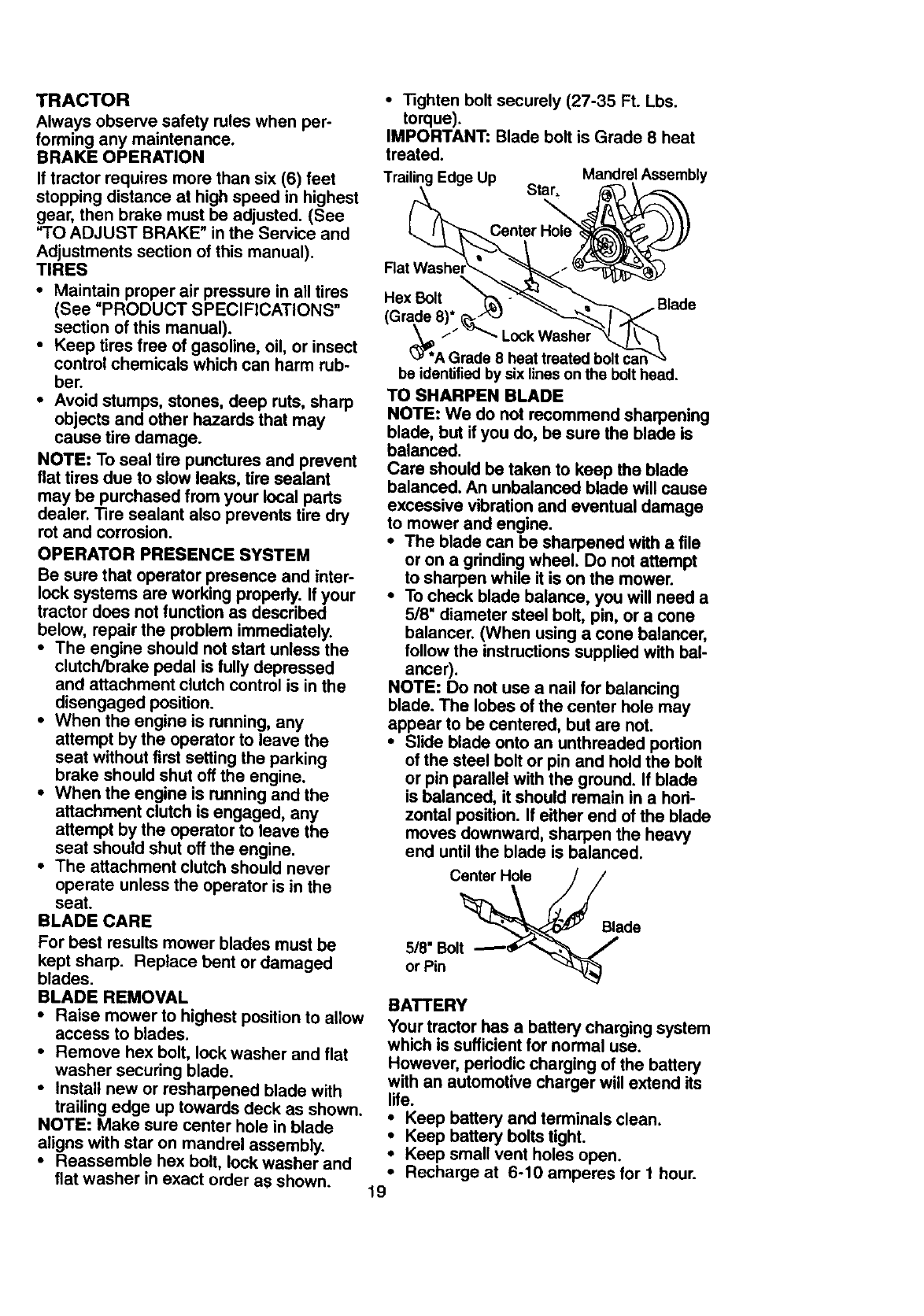
IMPORTANT: Blade bolt is Grade 8 heat
treated.
Trailing Edge Up Mandrel Assembly
Star.
\
\
Hex Bolt •Blade
Lock Wash_
'A Grade8 heattreated
beidentified bysixlinesonthe bolthead.
TO SHARPEN BLADE
NOTE: We do not recommend sharpening
blade, but if you do, be sure the blade is
balanced.
Care should be taken to keep the blade
balanced. An unbalanced blade will cause
excessive vibration and eventual damage
to mower and engine.
•The blade can be sharpened with a file
or on a grinding wheel. Do not attempt
to sharpen while it is on the mower.
•To check blade balance, you will need a
5/8" diameter steel bolt, pin, or a cone
balancer. (When using a cone balancer,
follow the instructionssupplied with bal-
ancer).
NOTE: Do not use a nail for balancing
blade. The lobes of the center hole may
appear to be centered, but are not.
•Slide blade onto an unthreaded portion
of the steel bolt or pin and hold the bolt
or pin parallel with the ground. If blade
is balanced, it should remain in a hori-
zontal position. If either end of the blade
moves downward, sharpen the heavy
end until the blade is balanced.
Ce_erH_e
5/8" Bolt
or Pin
Blade
BATTERY
Your tractor has a battery charging system
which is sufficient for normal use.
However, periodic charging of the battery
with an automotive charger will extend its
life.
•Keep battery and terminals clean.
•Keep battery bolts tight.
•Keep small vent holes open.
•Recharge at 6-10 amperes for 1 hour.
19
NOTE:Theoriginalequipmentbatteryon
yourtractoris maintenancefree.Donot
attemptto openor removecapsor covers.
Addingorcheckinglevelof electrolyteis
notnecessary.
TO CLEANBATTERYANDTERMINALS
Corrosionand dirt on the battery and ter-
minals can cause the battery to =leak"
power.
•Remove terminal guard.
•Disconnect BLACK battery cable first
then RED battery cable and remove
battery from tractor.
•Rinse the battery with plain water and
dry.
•Clean terminals and battery cable ends
with wire brush until bright.
•Coat terminals with grease or petroleum
jelly,
•Reinstall battery (See "REPLACING
BATTERY" in the SERVICE AND
ADJUSTMENTS section of this manu-
al).
V-BELTS
Check V-belts for deterioration and wear
after 100 hours of operation and replace if
necessary. The belts are not adjustable.
Replace belts if they begin to slip from
wear.
TRANSAXLE COOLING
Keep transaxle free from build-ul_'of dirt
• and chaff which can restrict cooling.
ENGINE
LUBRICATION
Only use high quality detergent oil rated
with API service classification SF, SG, or
SH. Select the oil's SAE viscosity grade
according to your expected operating tem-
perature.
NOTE: Although multi-viscosity oils
(5W30, 10W30 etc.) improve starting in
cold weather, these multi-viscosity oils will
result in increased oil consumption when
used above 32°F. Check your engine oil
level more frequently to avoid possible
engine damage from running low on oil.
Change the oil after every 50 hours of
operation or at least once a year if the
tractor is not used for 50 hours in one
year.
Check the crankcase oil level before start-
ing the engine and after each eight (8)
hours of operation. Tighten oil fill cap/dip-
stick securely each time you check the oil
level.
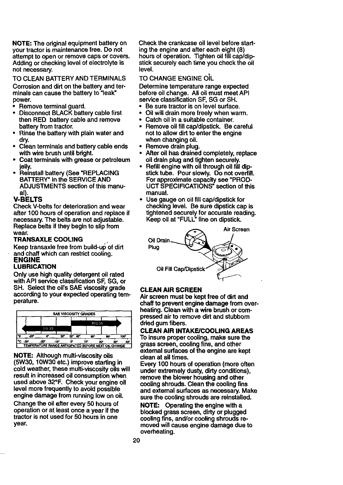
TO CHANGE ENGINE OIL
Determine temperature range expected
before oil change. All oil must meet API
service classification SF, SG or SH.
•Be sure tractor is on level surface.
•Oil will drain more freely when warm.
•Catch oil in a suitable container.
•Remove oil fill cap/dipstick. Be careful
not to allow dirt to enter the engine
when changing oil.
•Remove drain plug.
•After oil has drained completely, replace
oil drain plug and tighten securely.
•Refill engine with oil through oil fill dip-
stick tube. Pour slowly. Do not overfill.
For approximate capacity see "PROD-
UCT SPECIFICATIONS" section of this
manual.
•Use gauge on oil fill cap/dipstick for
checking level. Be sure dipstick cap is
tightened securely for accurate reading.
Keep oil at "FULL" line on dipstick.
/_ Air Screen
Oil Drain___ _
Plug
O I F II Cap/DipsUck/
CLEAN AIR SCREEN
Air screen must be kept free of dirt and
chaff to prevent engine damage from over-
heating. Clean with a wire brush or com-
pressed air to remove dirt and stubborn
dried gum fibers.
CLEAN AIR INTAKE/COOLING AREAS
To insure proper cooling, make sure the
grass screen, cooling fins, and other
external surfaces of the engine are kept
clean at all times.
Every 100 hours of operation (more often
under extremely dusty, dirty conditions),
remove the blower housing and other
cooling shrouds. Clean the cooling fins
and extemal surfaces as necessary. Make
sure the cooling shrouds are reinstalled.
NOTE: Operating the engine with a
blocked grass screen, dirty or plugged
cooling fins, and/or cooling shrouds ra-
moved will cause engine damage due to
overheating.
2O
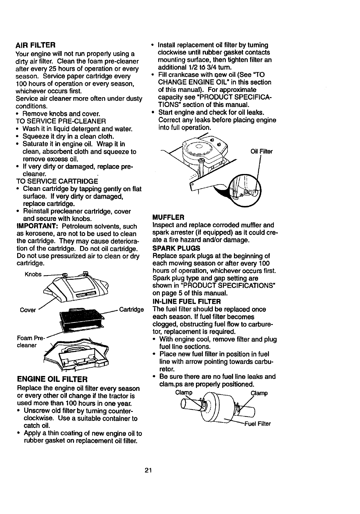
AIR FILTER
Yourengine will not run properly using a
dirty air filter. Clean the foam pre-cleaner
after every 25 hours of operation or every
season. Service paper cartridge every
100 hours of operation or every season,
whichever occurs first.
Service air cleaner more often under dusty
conditions.
• Remove knobs and cover.
TO SERVICE PRE-CLEANER
•Wash it in liquid detergent and water.
•Squeeze it dry in a clean cloth.
•Saturate it in engine oil. Wrap it in
clean, absorbent cloth and squeeze to
remove excess oil.
•If very dirty or damaged, replace pre-
cleaner.
TO SERVICE CARTRIDGE
•Clean cartridge by tapping gently on flat
surface. If very dirty or damaged,
replace cartridge.
•Reinstall precleaner cartridge, cover
and secure with knobs.
IMPORTANT: Petroleum solvents, such
as kerosene, are not to be used to clean
the cartridge. They may cause deteriora-
tion of the cartridge. Do not oil cartridge.
Do not use pressurized air to clean or dry
cartridge.
Cover
Foam Pre_
cleaner
ENGINE OIL FILTER
Replace the engine oilfilter every season
or every other oil change if the tractor is
used more than 100 hours in one year.
• Unscrew old filter by tuming counter-
clockwise. Use a suitable container to
catch oil.
•Apply a thin coating of new engine oil to
rubber gasket on replacement oil filter.
•Install replacement oil filter by turning
clockwise until rubber gasket contacts
mounting surface, then tighten filter an
additional 112 tO 314 turn.
•Fill crankcase with 0ew oil (See "1O
CHANGE ENGINE OIL" in this section
of this manual). For approximate
capacity see =PRODUCT SPECIFICA-
TIONS" section of this manual.
•Start engine and check for oil leaks.
Correct any leaks before placing engine
into full operation.
_Oil Niter
MUFFLER
Inspect and replace corroded muffler and
spark arrester (if equipped) as it could cre-
ate a fire hazard and/or damage.
SPARK PLUGS
Replace spark plugs at the beginning of
each mowing season or after every 100
hours of operation, whichever occurs first.
Spark plug type and gap setting are
shown in =PRODUCT SPECIFICATIONS"
on page 5 of this manual.
IN-LINE FUEL FILTER
The fuel filter should be replaced once
each season. If fuel filter becomes
clogged, obstructing fuel flow to carbure-
tor, replacement is required.
•With engine cool, remove filter and plug
fuel line sections.
•Place new fuel filter in position in fuel
line with arrow pointing towards carbu-
retor.
•Be sure there are no fuel line leaks and
clam.ps are propedy positioned.
21
CLEANING
• Clean engine, battery, seat, finish, etc.
of all foreign matter.
•Keep finished surfaces and wheels free
of all gasoline, oil, etc.
•Protect painted surfaces with automo-
tive type wax.
We do not recommend using a garden
hose to clean your tractor unless the elec-
trical system, muffler, air filter and carbure-
tor are covered to-keep water out. Water
in engine can result in=a shortened engine
life.
A, CAUTION: Before performing any service or adjustments:
•Depress clutch/brake pedal fully and set parking brake.
•Place gearshift lever in neutral (N) position.
•Place attachment clutch in =DISENGAGED" position.
•Tum ignition key =OFP and remove key.
•Make sure the blades and all moving parts have completely stopped.
•Disconnect spark plug wire from spark plug and place wire where it cannot come
in contact with plug.
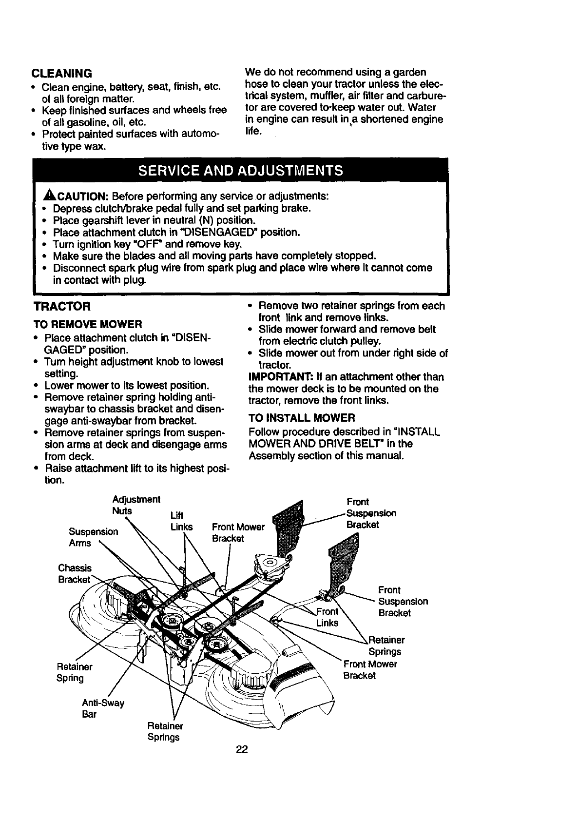
TRACTOR
TO REMOVE MOWER
•Place attachment clutch in =DISEN-
GAGED" position.
•Turn height adjustment knob to lowest
setting.
•Lower mower to its lowest position.
•Remove retainer spring holding anti-
swaybar to chassis bracket and disen-
gage anti-swaybar from bracket.
•Remove retainer springs from suspen-
sion arms at deck and disengage arms
from deck.
•Raise attachment lift to its highest posi-
tion.
•Remove two retainer springs from each
front link and remove links.
•Slide mower forward and remove belt
from electric clutch pulley.
•Slide mower out from under right side of
tractor.
IMPORTANT: If an attachment other than
the mower deck is to be mounted on the
tractor, remove the front links.
TO INSTALL MOWER
Follow procedure described in =INSTALL
MOWER AND DRIVE BELT" in the
Assembly section of this manual.
Adjustment
Nuts
Suspension
Arms
Lift
Links Front Mower
Bracket
Front
Bracket
Chassis
Front
Suspension
Bracket
Retainer
Spring
Anti-Sway
Bar
Springs
Front Mower
Bracket
Retainer
Springs 22
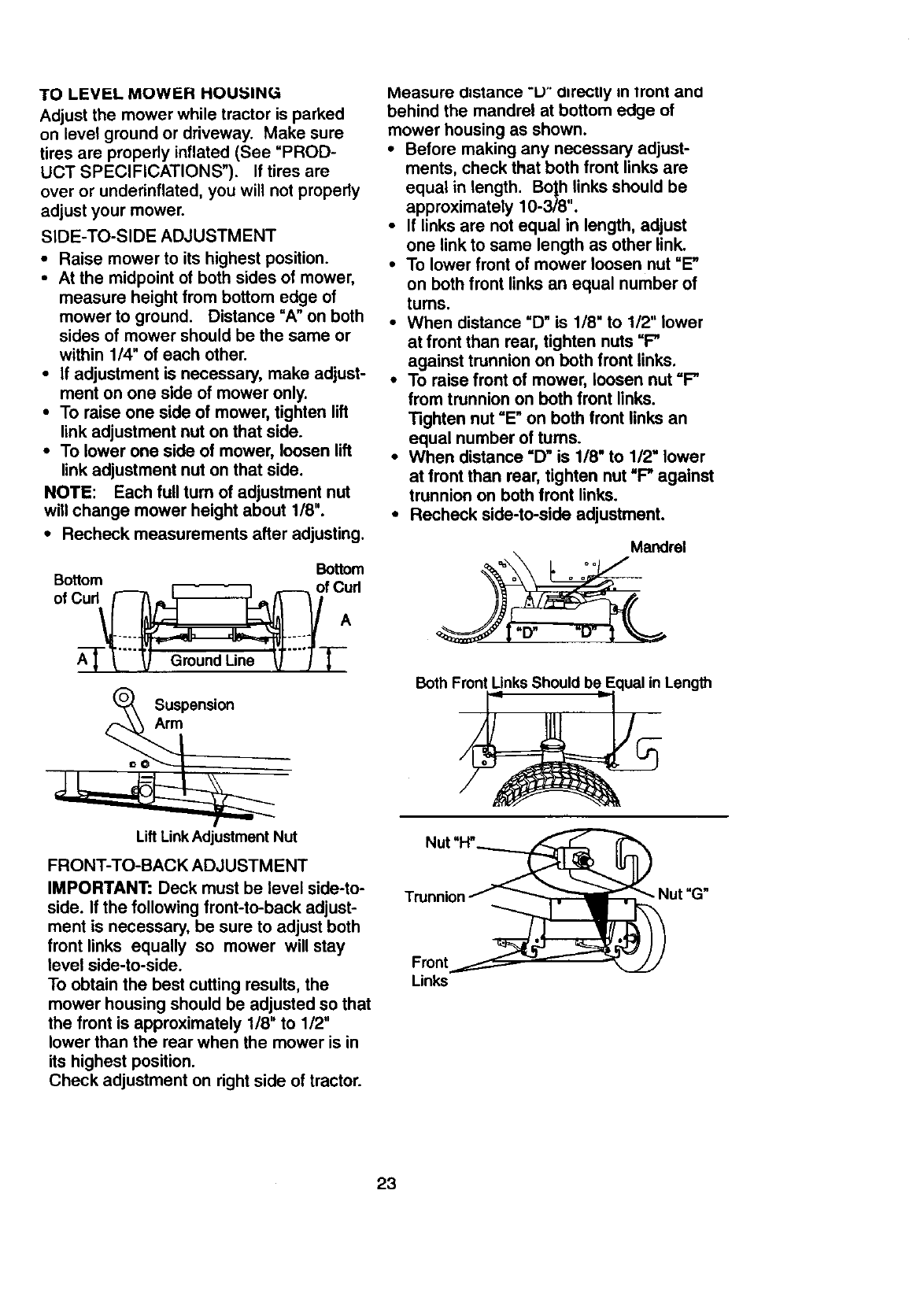
TO LEVEL MOWER HOU;51NG
Adjust the mower while tractor is parked
on level ground or driveway. Make sure
tires are properly inflated (See "PROD-
UCT SPECIFICATIONS"). If tires are
over or underinflated, you will not propedy
adjust your mower.
SIDE-TO-SIDE ADJUSTMENT
•Raise mower to its highest position.
• At the midpoint of both sides of mower,
measure height from bottom edge of
mower to ground. Distance "A" on both
sides of mower should be the same or
within 1/4" of each other.
•If adjustment is necessary, make adjust-
ment on one side of mower only.
•To raise one side of mower, tighten lift
link adjustment nut on that side.
•To lower one side of mower, loosen lift
link adjustment nut on that side.
NOTE: Each full turn of adjustment nut
will change mower height about 1/8".
•Recheck measurements after adjusting.
Bottom
Bottom of Cud
of Cud_ A
Groundun T-7-I-
Measure distance "U" a=recuy m tront ana
behind the mandrel at bottom edge of
mower housing as shown.
•Before making any necessary adjust-
ments, check that both front links are
equal in length. Bo|h links should be
approximately 10-3/8".
•If links are not equal in length, adjust
one link to same length as other link.
•To lower front of mower loosen nut "E"
on both front links an equal number of
tums.
•When distance "D" is 1/8" to 1/2" lower
at front than rear, tighten nuts "F"
against trunnion on both front links.
•To raise front of mower, loosen nut =F"
from trunnion on both front links.
Tighten nut "E" on both front links an
equal number of turns.
•When distance =13"is 1/8" to 1/2" lower
at front than rear, tighten nut "F" against
trunnion on both front links.
•Recheck side-to-side adjustment.
Suspension
Arm
Mandrel
oo a
Both Front Links Should be Equal in Length
Lift Link Adjustment Nut
FRONT-TO-BACK ADJUSTMENT
IMPORTANT: Deck must be level side-to-
side. If the following front-to-back adjust-
ment is necessary, be sure to adjust both
front links equally so mower will stay
level side-to-side.
To obtain the best cutting results, the
mower housing should be adjusted so that
the front is approximately 1/8" to 1/2"
lower than the rear when the mower is in
its highest position.
Check adjustment on right side of tractor.
Links
23
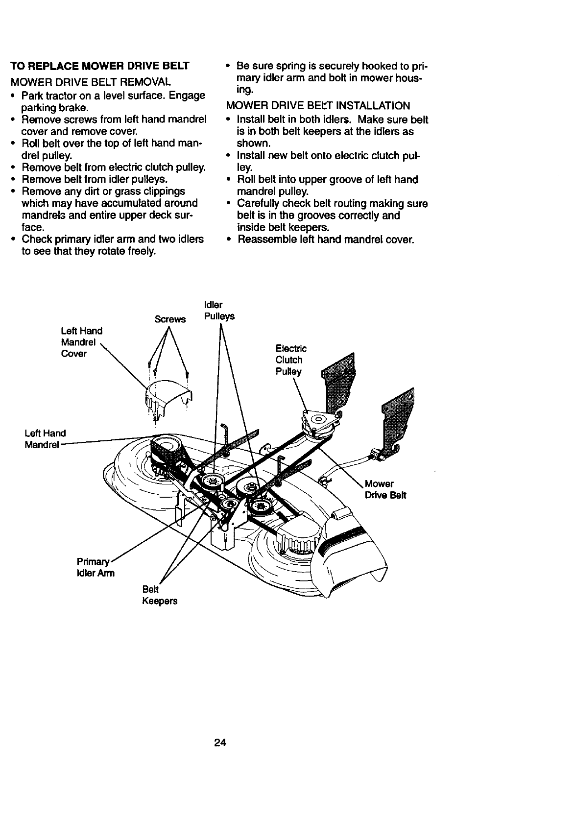
TOREPLACEMOWERDRIVEBELT
MOWER DRIVE BELT REMOVAL
•Park tractor on alevel surface. Engage
parking brake.
•Remove screws from left hand mandrel
cover and remove cover.
•Roll belt over the top of left hand man-
drel pulley.
•Remove belt from electric clutch pulley.
•Remove belt from idler pulleys.
•Remove any dirt or grass clippings
which may have accumulated around
mandrels and entire upper deck sur-
face.
•Check primary idler arm and two idlers
to see that they rotate freely.
•Be sure spring is securely hooked to pri-
mary idler arm and bolt in mower hous-
ing.
MOWER DRIVE BELT INSTALLATION
•Install belt in both idlers. Make sure belt
is in both belt keepers at the idlers as
shown.
•Install new belt onto electric clutch pul-
ley.
•Roll belt into upper groove of left hand
mandrel pulley.
•Carefully check belt routing making sure
belt is in the grooves correctly and
inside belt keepers.
• Reassemble left hand mandrel cover.
Screws
Left Hand
Mandrel
Cover _
Left Hand
Mandrel
Idler
Pulleys
Electric
Clutch
Pulley
Mower
Drive Belt
Pdmary
Idler Arm
Belt
Keepers
24
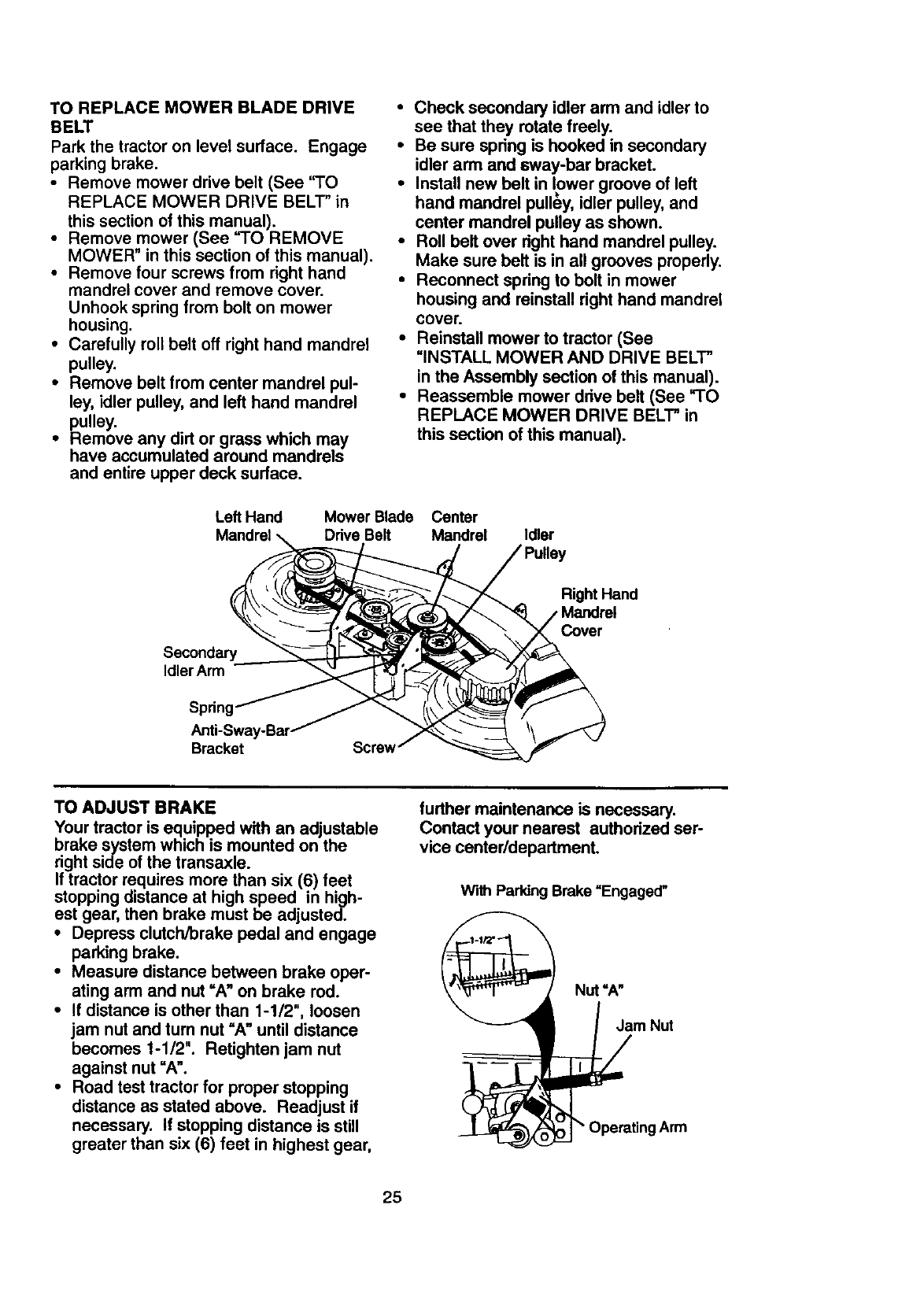
TO REPLACEMOWERBLADEDRIVE
BELT
Parkthetractoronlevelsurface. Engage
parkingbrake.
•Remove mower drive belt (See "TO
REPLACE MOWER DRIVE BELT" in
this section of this manual).
•Remove mower (See ='1"OREMOVE
MOWER" in this section of this manual).
•Remove four screws from right hand
mandrel cover and remove cover.
Unhook spring from bolt on mower
housing.
•Carefully roll belt off right hand mandrel
pulley.
•Remove belt from center mandrel pul-
ley, idler pulley, and left hand mandrel
pulley.
•Remove any dirt or grass which may
have accumulated around mandrels
and entire upper deck surface.
•Check secondary idler arm and idler to
see that they rotate freely.
•Be sure spring is hooked in secondary
idler arm and sway-bar bracket.
•Install new belt in lower groove of left
hand mandrel pulley, idler pulley, and
center mandrel pulley as shown.
•Roll belt over right hand mandrel pulley.
Make sure belt is in all grooves properly.
•Reconnect spring to bolt in mower
housing and reinstall right hand mandrel
cover.
•Reinstall mower to tractor (See
UlNSTALL MOWER AND DRIVE BELT"
in the Assembly section of this manual).
•Reassemble mower ddve belt (See TO
REPLACE MOWER DRIVE BELT" in
this section of this manual).
Left Hand Mower Blade Center
Drive Belt Mandrel Idler
Right Hand
Mandrel
Secondary
IdlerArm
Spring
Bracket Screw
TO ADJUST BRAKE
Your tractor is equipped with an adjustable
brake system which is mounted on the
right side of the transaxle.
If tractor requires more than six (6) feet
stopping distance at high speed in high-
est gear, then brake must be adjusted.
• Depress clutch/brake pedal and engage
parking brake.
•Measure distance between brake oper-
ating arm and nut =A" on brake rod.
• If distance is other than 1-1/2", loosen
jam nut and turn nut "A" until distance
becomes 1-1/2". Retighten jam nut
against nut =A".
•Road test tractor for proper stopping
distance as stated above. Readjust if
necessary. If stopping distance is still
greater than six (6) feet in highest gear,
further maintenance is necessary.
Contact your nearest authorized ser-
vice center/department,
With Parking Brake =Engaged"
Nut =A"
___ | ,/ mNut
_raUng Arm
25
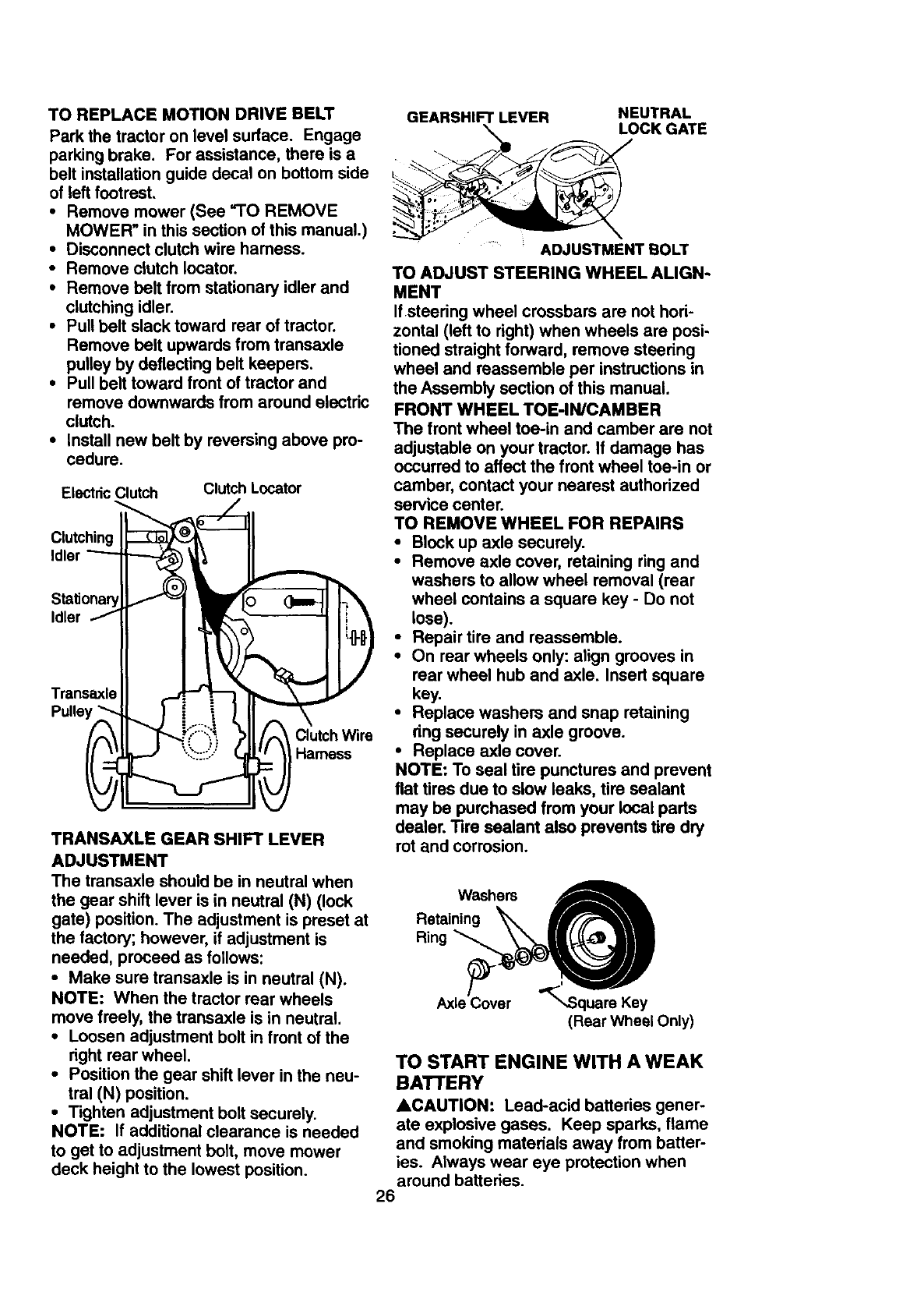
TO REPLACE MOTION DRIVE BELT
Park the tractor on level surface. Engage
parking brake. For assistance, there is a
belt installation guide decal on bottom side
of left footrest.
•Remove mower (See "TO REMOVE
MOWER" in this section of this manual.)
•Disconnect clutch wire harness.
•Remove clutch Iocator.
•Remove belt from stationary idler and
clutching idler.
•Pull belt slack toward rear of tractor.
Remove belt upwards from transaxle
pulley by deflecting belt keepers.
•Pull belt toward front of tractor and
remove downwards from around electric
clutch.
•Install new belt by reversing above pro-
cedure.
Electdc Clutch Clutch Locator
Clutching
Idler
Idler
Trensaxle
Pulley '
Clutch Wire
Harness
TRANSAXLE GEAR SHIFT LEVER
ADJUSTMENT
The transaxle should be in neutral when
the gear shift lever is in neutral (N) (lock
gate) position. The adjustment is preset at
the factory; however, if adjustment is
needed, proceed as follows:
•Make sure transaxle is in neutral (N).
NOTE: When the tractor rear wheels
move freely, the transaxle is in neutral.
•Loosen adjustment bolt in front of the
right rear wheel.
•Position the gear shift lever in the neu-
tral (N) position.
•Tighten adjustment bolt securely.
NOTE: If additional clearance is needed
to get to adjustment bolt, move mower
deck height to the lowest position.
GEARSHIFT LEVER NEUTRAL
LOCK GATE
..... ADJUSTMENT BOLT
TO ADJUST STEERING WHEEL ALIGN-
MENT
Ifsteering wheel crossbars are not hori-
zontal (left to right) when wheels are posi-
tioned straight forward, remove steering
wheel and reassemble per instructions in
the Assembly section of this manual.
FRONT WHEEL TOE-IN/CAMBER
The front wheel toe-in and camber are not
adjustable on your tractor. If damage has
occurred to affect the front wheel toe-in or
camber, contact your nearest authorized
service center.
TO REMOVE WHEEL FOR REPAIRS
•Block up axle securely.
•Remove axle cover, retaining ring and
washers to allow wheel removal (rear
wheel contains a square key - Do not
lose).
•Repair tire and reassemble.
•On rear wheels only: align grooves in
rear wheel hub and axle. Insert square
key.
• Replace washers and snap retaining
ring securely in axle groove.
•Replace axle cover.
NOTE: To seal tire punctures and prevent
flat tires due to slow leaks, tire sealant
may be purchased from your local parts
dealer. Tire sealant also prevents tire dry
rot and corrosion.
Washers
Retaining _
Ring
Axle Cover ",.Square Key
(Rear Wheel Only)
TO START ENGINE WITH A WEAK
BATTERY
ACAUTION: Lead-acid batteries gener-
ate explosive gases. Keep sparks, flame
and smoking materials away from batter-
ies. Always wear eye protection when
around batteries.
26
tf yourbatteryis too weak to start the
engine, it should be recharged. (See
"BA'I-I-ERY" in the MAINTENANCE sec-
tion of this manual).
If =jumper cables" are used for emergency
starting, follow this procedure:
AIMPORTANT: Your tractor Is equiped
with a 12 volt negative grounded system.
The other vehical must also be a 12 volt
negative grounded system. Do not use
your tractor battery to start other vehicals.
TO ATTACH JUMPER CABLES o
• Connect each end of the RED cable to
the POSITIVE (+) terminal of each bat-
tery, taking care not to short against
chassis.
•Connect one end of the BLACK cable to
the NEGATIVE (-) terminal of fully
charged battery.
• Connect the other end of the BLACK
cable to good CHASSIS GROUND,
away from fuel tank and battery.
TO REMOVE CABLES, REVERSE
ORDER -
•BLACK cable first from chassis and
then from the fully charged battery.
•RED cable last from both batteries.
=Positive" (+) "Negative" (-)
L.H. Panel r---_l
Bolt _
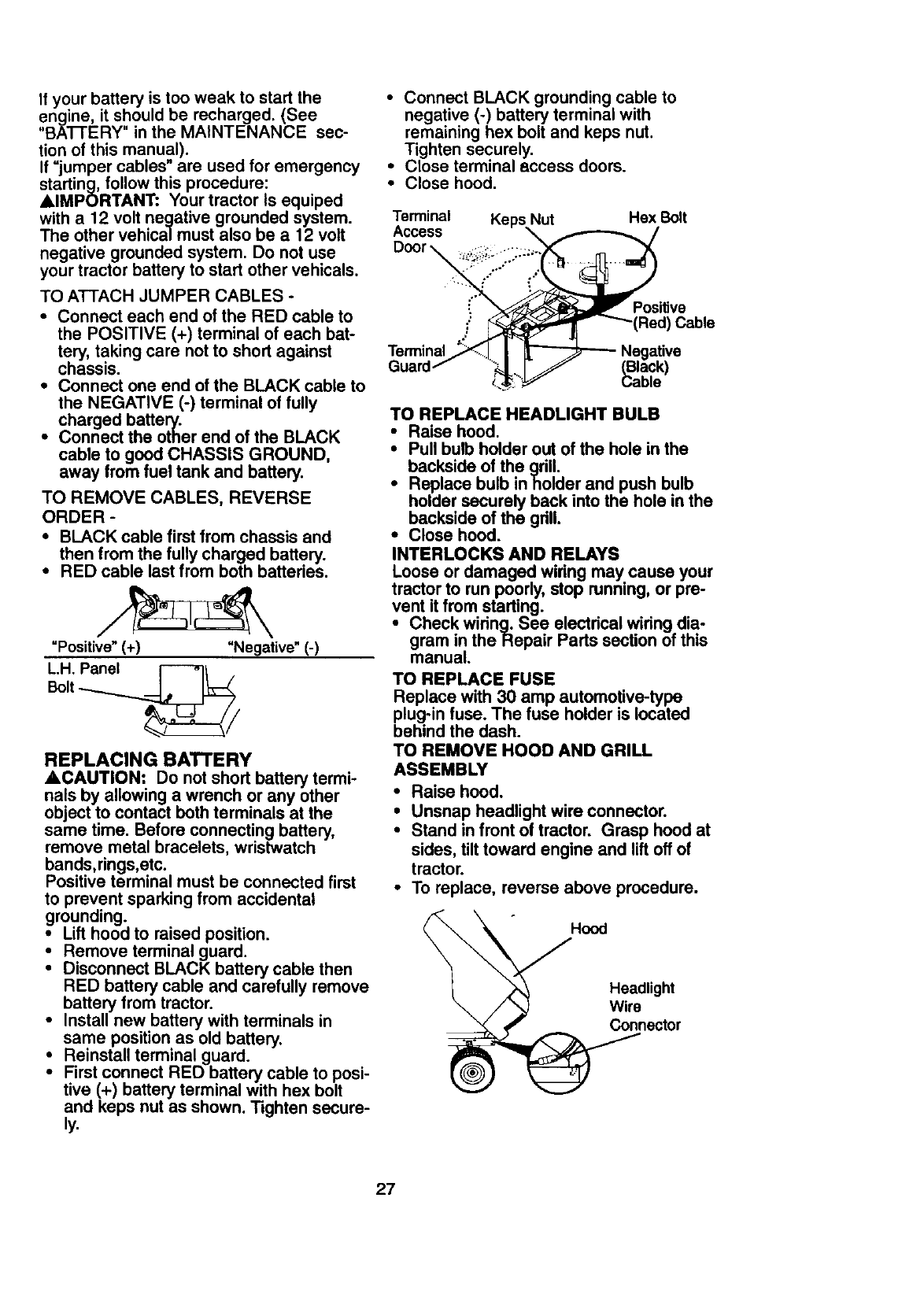
REPLACING BATTERY
ACAUTION: Do not short battery termi-
nals by allowing a wrench or any other
object to contact both terminals at the
same time. Before connecting battery,
remove metal bracelets, wristwatch
bands,rings,etc.
Positive terminal must be connected first
to prevent sparking from accidental
grounding.
•Lifthood to raised position.
•Remove terminal guard.
•Disconnect BLACK battery cable then
RED battery cable and carefully remove
battery from tractor.
•Install new battery with terminals in
same position as old battery.
: Reinstall terminal guard.
Firstconnect RED battery cable to posi-
tive (+) battery terminal with hex bolt
and keps nut as shown. Tighten secure-
ly.
•Connect BLACK grounding cable to
negative (-) battery terminal with
remaining hex bolt and keps nut.
Tighten securely.
•Close terminal access doors.
•Close hood.
Terminal
Access
Door _
Keps Nut Hex Bolt
:Positive
Red) Cable
Terminal Negative
(Black)
Cable
TO REPLACE HEADLIGHT BULB
• Raise hood.
•Pull bulb holder out of the hole in the
backside of the gdll.
•Replace bulb inholder and push bulb
holder securely back into the hole in the
backside of the gdll.
•Close hood.
INTERLOCKS AND RELAYS
Loose or damaged widng may cause your
tractor to run poorly, stop running, or pre-
vent it from starting.
•Check widng. See electdcal widng dia-
gram in theRepair Parts section of this
manual.
TO REPLACE FUSE
Replace with 30 amp automotive-type
plug-in fuse. The fuse holder is located
behind the dash.
TO REMOVE HOOD AND GRILL
ASSEMBLY
• Raise hood.
•Unsnap headlight wire connector.
•Stand in front of tractor. Grasp hood at
sides, tilt toward engine and lift off of
tractor.
•To replace, reverse above procedure.
Headlight
nector
27
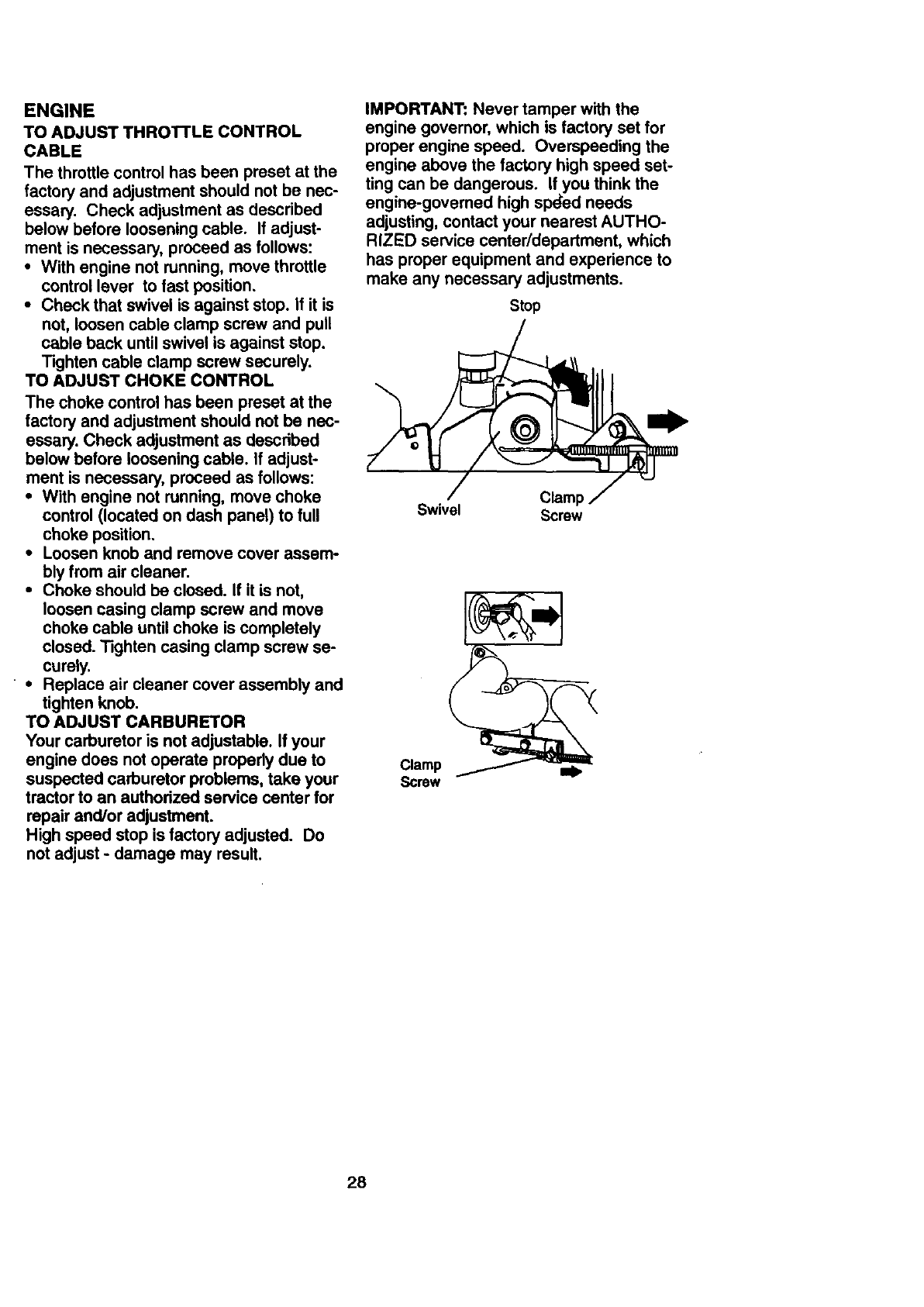
ENGINE
TO ADJUST THROTTLE CONTROL
CABLE
The throttle control has been preset at the
factory and adjustment should not be nec-
essary. Check adjustment as described
below before loosening cable. If adjust-
ment is necessary, proceed as follows:
• With engine not running, move throttle
control lever to fast position.
• Check that swivel is against stop. If it is
not, loosen cable clamp screw and pull
cable back until swivel is against stop.
Tighten cable clamp screw securely.
TO ADJUST CHOKE CONTROL
The choke control has been preset at the
factory and adjustment should not be nec-
essary. Check adjustment as described
below before loosening cable. If adjust-
ment is necessary, proceed as follows:
•With engine not running, move choke
control (located on dash panel) to full
choke position.
•Loosen knob and remove cover assem-
bly from air cleaner.
•Choke should be closed. If it is not,
loosen casing clamp screw and move
choke cable until choke is completely
closed. Tighten casing clamp screw se-
curely.
• • Replace air cleaner cover assembly and
tighten knob.
TO ADJUST CARBURETOR
Your carburetor is not adjustable. If your
engine does not operate propedy due to
suspected carburetor problems, take your
tractor to an authorized service center for
repair and/or adjustment.
High speed stop is factory adjusted. Do
not adjust - damage may result.
IMPORTANT: Never tamper with the
engine govemor, which is factory set for
proper engine speed. Overspeeding the
engine above the factory high speed set-
ting can be dangerous. If you think the
engine-governed high spded needs
adjusting, contact your nearest AUTHO-
RIZED service center/department, which
has proper equipment and experience to
make any necessary adjustments.
Stop
Claml:
Swivel Screw
Clamp
Screw
28
Immediately prepare your tractor for stor-
age at the end of the season or if the trac-
tor will not be used for 30 days or more.
_CAUTION: Never store the tractor with
gasoline in the tank inside a building
where fumes may reach an open flame or
spark. Allow the engine to cool before stor-
ing in any enclosure.
TRACTOR
Remove mower from tractor for winter
storage. This will allow you to clean it thor-
oughly. Remove all dirt, grease, leaves,
etc. Store in a clean, dry area.
•Clean entire tractor (See =CLEANING"
in the Maintenance section of this man-
ual).
•Inspect and replace belts, if necessary
(See belt replacement instructionsin the
Service and Adjustments section of this
manual).
• Lubricate as shown in the Maintenance
section of this manual.
•Be sure that all nuts, bolts and screws
are securely fastened. Inspect moving
parts for damage, breakage and wear.
Replace if necessary.
•Touch up all rusted or chipped paint sur-
faces; sand lightly before painting.
BATTERY
•Fully charge the battery for storage.
•Alter a period of time in storage, battery
may require recharging.
•To help prevent corrosion and power
leakage dudng long pedods of storage,
battery cables should be disconnected
and battery cleaned thoroughly (see
=TO CLEAN BATTERY AND TERMI-
NALS" in the Maintenance section of
this manual).
•Alter cleaning, leave cables disconnect-
ed and place cables where they cannot
come in contact with battery terminals.
•If battery is removed from tractor for
storage, do not store battery directly on
concrete or damp surfaces.
ENGINE
FUEL SYSTEM
IMPORTANT: It is important to prevent
gum deposits from forming in essential
fuel system parts such as carburetor, fuel
filter, fuel hose, or tank during storage.
Also, experience indicates that alcohol
blended fuels (called gasohol or using
ethanol or methanol) can attract moisture
which leads to separatibn and formation of
acids during storage. Acidic gas can dam-
age the fuel system of an engine while in
storage.
•Drain the fuel tank.
•Start the engine and let it run untilthe
fuel lines and carburetor are empty.
•Never use engine or carburetor cleaner
products in the fuel tank or permanent
damage may occur.
•Use fresh fuel next season.
NOTE: Fuel stabilizer is an acceptable
altemative in minimizing the formation of
fuel gum deposits during storage. Add sta-
bilizer to gasoline in fuel tank or storage
container.Always follow the mix ratio
found on stabilizer container. Run engine
at least 10 minutes alter adding stabilizer
to allow the stabilizer to reach the carbure-
tor. Do not drain the gas tank and carbure-
tor if using fuel stabilizer.
ENGINE OIL
Drain oil (with engine warm) and replace
with clean engine oil. (See =ENGINE" in
the Maintenance section of this manual).
CYLINDER(S)
•Remove spark plug(s).
•Pour one ounce of oil through spark plug
hole(s) into cylinder(s).
•Tum ignitionkey to "START" position for
a few seconds to distdbute oil.
• Replace with new spark plug(s).
OTHER
•Do not store gasoline from one season
to another.
•Replace your gasoline can if it starts to
rust. Rust and/or dirt in your gasoline will
cause problems.
•If possible, store your tractor indoors
and cover it to give protection from dust
and dirt.
•Cover your tractor with a suitable protec-
tive cover that does not retain moisture.
Do not use plastic. Plastic cannot
breathe, which allows condensation to
form and cause your tractor to rust.
IMPORTANT: Never cover tractor while
engine and exhaust areas are still warm.
29
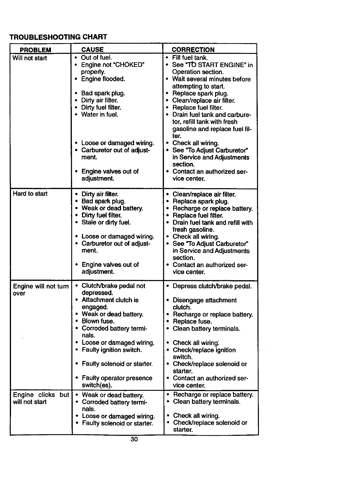
TROUBLESHOOTING CHART
PROBLEM
Will not start
Hard to start
CAUSE
•Out of fuel.
•Engine not'CHOKED"
propedy.
•Engine flooded.
•Bad spark plug. •
•Dirty air filter. •
•Dirty fuel filter. •
•Water in fuel. _•
•Loose or damaged widng.
•Carburetor out of adjust-
ment.
•Engine valves out of
adjustment.
•Dirty air filter.
•Bad spark plug.
•Weak or dead battery.
•Dirty fuel filter.
•Stale or dirty fuel.
•Loose or damaged wiring. •
•Carburetor out of adjust- •
ment.
•Engine valves out of •
adjustment.
•Clutch/brake pedal not
depressed.
•Attachment clutch is
engaged.
•Weak or dead battery.
•Blown fuse.
•Corroded battery termi-
nals.
•Loose or damaged wiring. •
•Faulty ignition switch. •
•Faulty solenoid or starter. •
•Faulty operator presence •
switch(es).
•Weak or dead battery.
Engine will not turn
over
Engine clicks but
will not start •Corroded battery termi-
nals.
•Loose or damaged wiring.
•Faulty solenoid or starter.
CORRECTION
•Fill fuel tank.
•See =TO START ENGINE" in
Operation section.
Wait several minutes before
attempting to start.
Replace spark plug.
Clean/replace air filter.
Replace fuel filter.
Drain fuel tank and carbure-
tor, refill tank with fresh
gasoline and replace fuel fil-
ter.
•Check all wiring.
•See _I'o Adjust Carburetor"
in Service and Adjustments
section.
•Contact an authorized ser-
vice center.
•Clean/replace air filter.
•Replace spark plug.
•Recharge or replace battery.
•Replace fuel filter.
•Drain fuel tank and refill with
fresh gasoline.
Check all widng.
See =To Adjust Carburetor"
in Service and Adjustments
section.
Contact an authorized ser-
vice center.
•Depress clutch/brake pedal.
•Disengage attachment
clutch.
•Recharge or replace battery.
•Replace fuse.
•Clean battery terminals.
Check all wiring_
Check/replace ignition
switch.
Check/replace solenoid or
starter.
Contact an authorized ser-
vice center.
•Recharge or replace battery.
•Clean battery terminals.
Check all wiring.
Check/replace solenoid or
starter.
3O
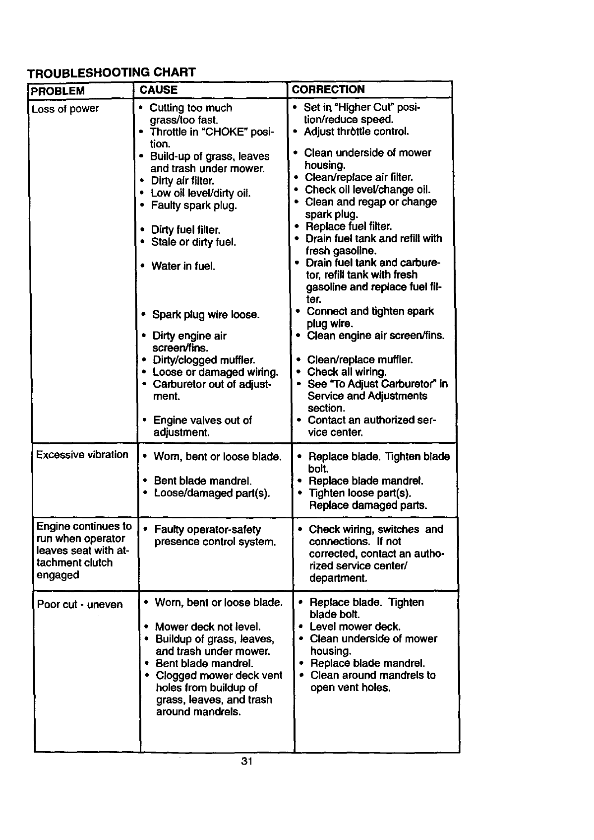
TROUBLESHOOTING CHART
PROBLEM CAUSE
Lossof power • Cuttingtoo much
Excessivevibration
Engine continues to
run when operator
leaves seat with at-
tachment clutch
engaged
Poor cut - uneven
grass/too fast.
• Throttle in _CHOKE" posi-
tion.
•Build-up of grass, leaves
and trash under mower.
•Dirty air filter.
• Low oil level/dirty oil.
•Faulty spark plug.
•Dirty fuel filter.
•Stale or dirty fuel.
• Water in fuel.
• Spark plug wire loose.
•Dirty engine air
screen/fins.
•Dirty/clogged muffler.
•Loose or damaged wiring.
•Carburetor out of adjust-
ment.
•Engine valves out of
adjustment.
•Wom, bent or loose blade.
•Bent blade mandrel.
•Loose/damaged part(s).
• Faulty operator-safety
presence control system.
•Worn, bent or loose blade.
•Mower deck not level.
=• Buildup of grass, leaves,
and trash under mower.
•Bent blade mandrel.
•Clogged mower deck vent
holes from buildup of
grass, leaves, and trash
around mandrels.
CORRECTION
•Set irt =Higher Cut" posi-
tion/reduce speed.
•Adjust thrbttle control.
•Clean underside of mower
housing.
• Clean/replace air filter.
•Check oil level/change oil.
•Clean and regap or change
spark plug.
•Replace fuel filter.
•Drain fuel tank and refill with
fresh gasoline.
•Drain fuel tank and carbure-
tor, refilltank with fresh
gasoline and replace fuel fil-
ter.
•Connect and tighten spark
plug wire.
•Clean engine air screen/fins.
•Clean/replace muffler.
•Check all wiring.
•See "To Adjust Carburetor" in
Service and Adjustments
section.
•Contact an authorized ser-
vice center.
•Replace blade. Tighten blade
bolt.
•Replace blade mandrel.
•Tighten loose part(s).
Replace damaged parts.
•Check widng, switches and
connections. If not
corrected, contact an autho-
rized service center/
department.
•Replace blade. Tighten
blade bolt.
•Level mower deck.
•Clean underside of mower
housing.
•Replace blade mandrel.
•Clean around mandrels to
open vent holes.
•31
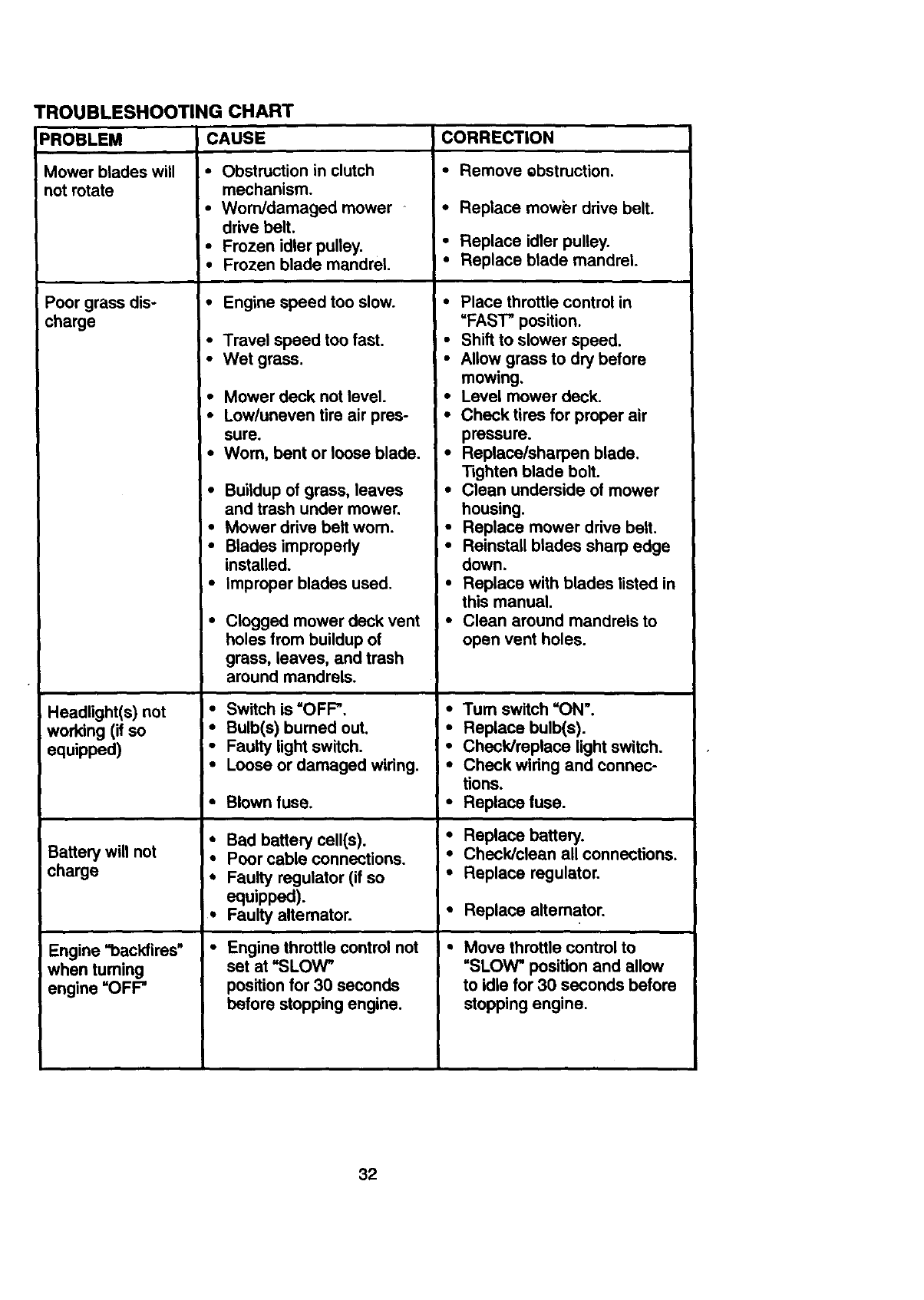
TROUBLESHOOTING CHART
PROBLEM CAUSE
Mower blades will
not rotate
Poor grass dis-
charge
Headlight(s) not
working (if so
equipped)
Battery will not
charge
Engine =backfires"
when turning
engine =OFP
•Obstruction in clutch
mechanism.
•Worn/damaged mower
drive belt.
• Frozen idler pulley.
I•Frozen blade mandrel
•Engine speed too slow.
•Travel speed too fast.
•Wet grass.
•Mower deck not level.
•Low/uneven tire air pres-
sure.
•Worn, bent or loose blade.
•Buildup of grass, leaves
and trash under mower,
•Mower drive belt worn.
•Blades improperly
installed.
•Improper blades used.
• Clogged mower deck vent
holes from buildup of
grass, leaves, and trash
around mandrels.
•Switch is =OFP.
•Bulb(s) bumed out.
•Faulty light switch.
•Loose or damaged wiring.
•Blown fuse.
•Bad battery cell(s).
• Poor cable connections.
• Faulty regulator (if so
equipped).
• Faulty altemator.
i"Engine throttle control not
set at "SLOW_
position for 30 seconds
before stopping engine.
CORRECTION
•Remove ebstruction.
•Replace mower drive belt.
•Replace idler pulley.
•Replace blade mandrel
•Place throttle control in
=FAST" position.
•Shift to slower speed.
•Allow grass to dry before
mowing.
•Level mower deck.
•Check tires for proper air
pressure.
•Replace/sharpen blade.
Tighten blade bolt.
•Clean underside of mower
housing.
•Replace mower drive belt.
•Reinstall blades sharp edge
down.
•Replace with blades listed in
this manual.
•Clean around mandrels to
open vent holes.
•Turn switch =ON'.
•Replace bulb(s).
•Check/replace light switch.
•Check wiring and connec-
tions.
•Replace fuse.
• Replace battery.
•Check/clean all connections.
•Replace regulator.
•Replace alternator.
Move throttle control to
=SLOW"position and allow
to idle for 30 seconds before
stopping engine.
32
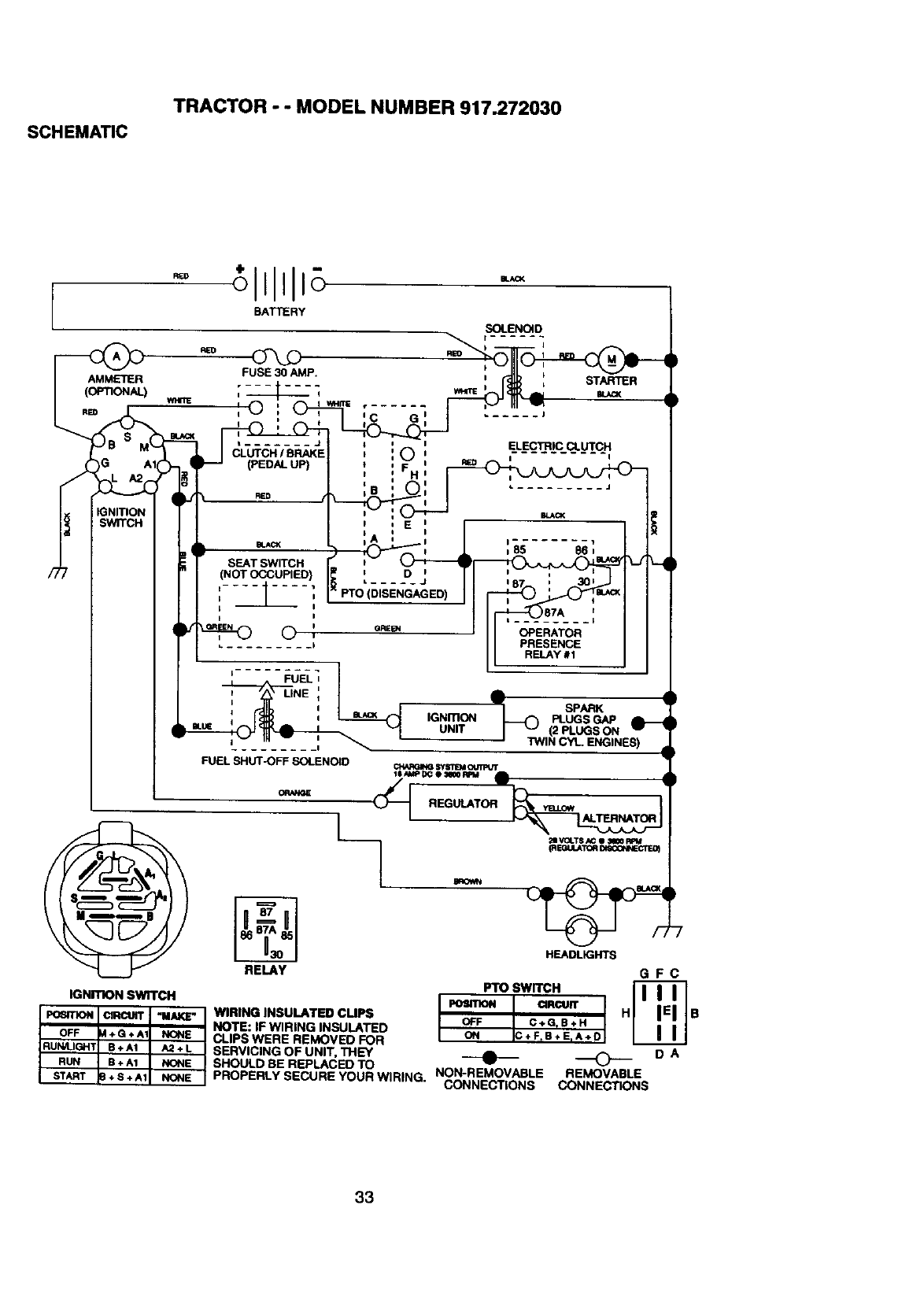
SCHEMATIC
TRACTOR - - MODEL NUMBER 917.272030
AMMETER
(oFnONAL)
RED
STARTER
t _J
CLUTCH /BRAKE
(PEDAL UP)
SEAT SWITCH
(NOT OCCUPIED)
i i
© ',
©ELECTRIC CLUTCH
I
I
*. ......... J
OPERATOR
PRESENCE
RELAY #1
FUELI I
1
I
FUEL SHUT-OFF SOLENOID
A
Vl SPARK
IGNmON _PLUGS GAP
UNIT l _" (2 PLUGS ON
' TWIN CYL ENGINES)
IGNITION SWITCH
POSRK)N I_RCUIT _MAKE"
OFF +G+A1 NONE
RUN/LIGHT E+A1 A2+L
RUN B + A1 NONE
START + S + A1 NONE
RELAY
REGULATOR v_ow
WIRING INSULATED CUPS
NOTE: IF WIRING INSULATED
CLIPS WERE REMOVED FOR
SERVICING OF UNIT, THEY
SHOULD BE REPLACED TO
PROPERLY SECURE YOUR WIRING. NON-REMOVABLE
CONNECTIONS
HEADLIGHTS
GFC
PTO SWITCH
IPOSITION CIRCUIT
OFF C+G_B+H H B
ON C+FtB+ErA÷ D
"0 DA
REMOVABLE
CONNECTIONS
33
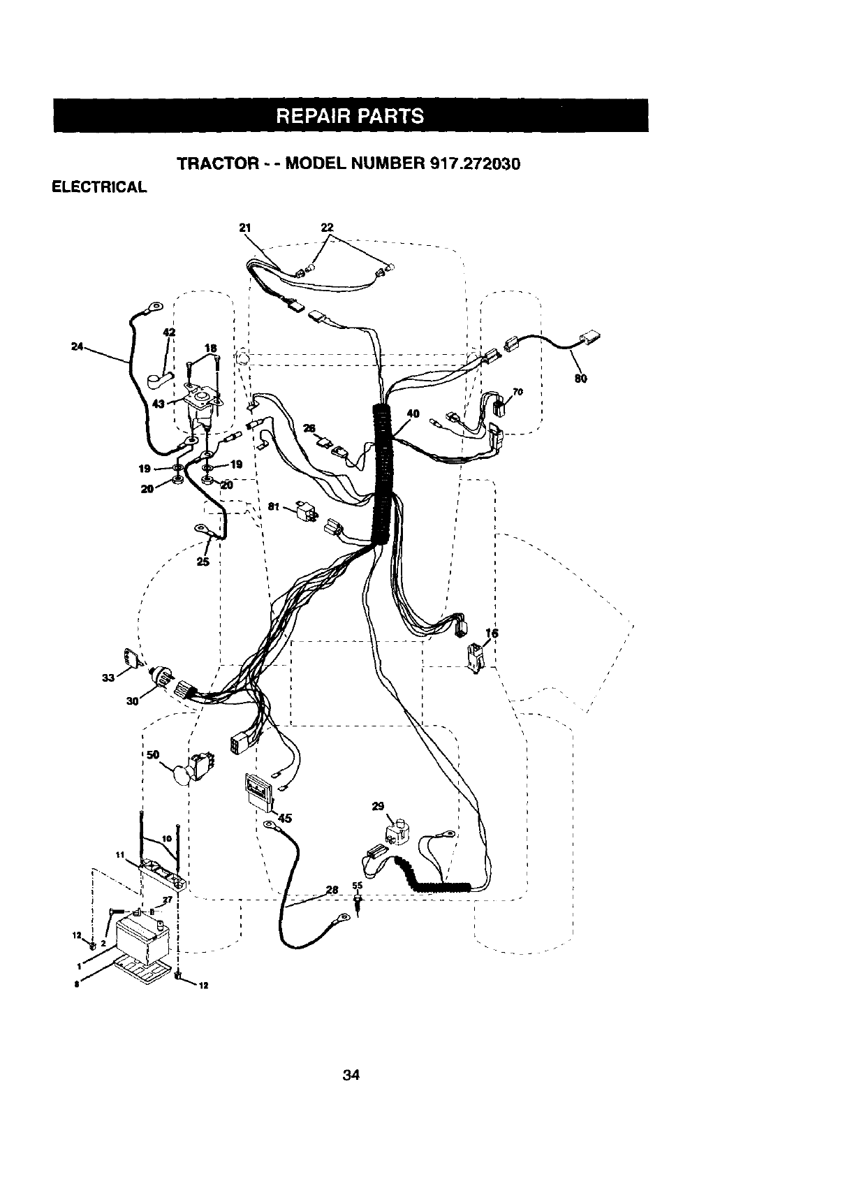
ELECTRICAL
TRACTOR - -MODEL NUMBER 917.272030
21 22
26
i
25
k
I
I
I
I
i
, \
' 80
h
4 I
It
L
I
J
J
34
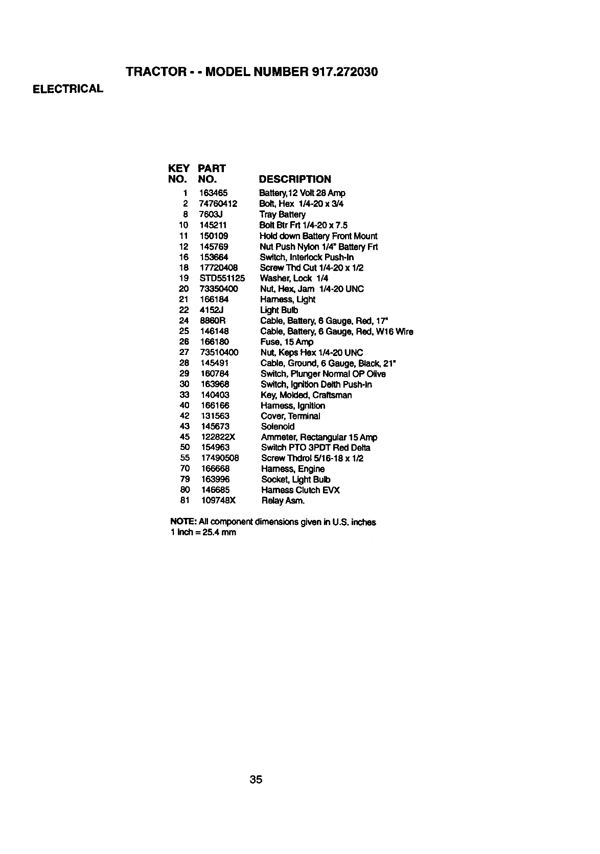
ELECTRICAL
TRACTOR - - MODEL NUMBER 917.272030
KEY PART
NO. NO.
1 163465
2 74760412
8 7603J
10 145211
11 150109
12 145769
16 153664
18 17720408
19 STD551125
20 73350400
21 166184
22 4152J
24 8860R
25 146148
26 166180
27 73510400
28 145491
29 160784
3O 163968
33 140403
40 166166
42 131563
43 145673
45 122822X
50 154963
55 17490508
70 166668
79 163996
80 146685
81 109748X
DESCRIPTION
Battery,12 Volt 28 Amp
Bolt,Hex 1/4-20 x 3/4
Tray Battery
BoltBtr Frt 114-20 x 7.5
Holddown Battery FrontMount
Nut Push Nylon 1/4" Battery Frt
Switch, InterlockPush-in
Screw Thd Cut 1/4-20 x 1/2
Washer, Lock 1/4
Nut, Flex,Jam 1/4-20 UNC
Harness, Light
Light Bulb
Cable, Battery, 6 Gauge, Red, 17'
Cable, Battery, 6 Gauge, Red, W16 Wire
Fuse, 15Amp
Nut, Keps Hex 1/4-20 UNC
Cable, Ground, 6 Gauge, Back, 21"
Switch,Plunger NormalOP Olive
Switch,IgnitionDelth Push-In
Key,Molded, Craftsmen
Hamass, Ignition
Cover,Terminal
Solenoid
Ammeter, Rectangular15 Amp
SwitchPTO 3PDT Red Delta
Screw Thdrol 5/16-18 x 1/2
Harness, Engine
Socket, LightBulb
Hamass Clutch EVX
RelayAsm.
NOTE: Allcomponentdimensionsgivenin U.S. inches
1 Inch = 25.4 mm
35
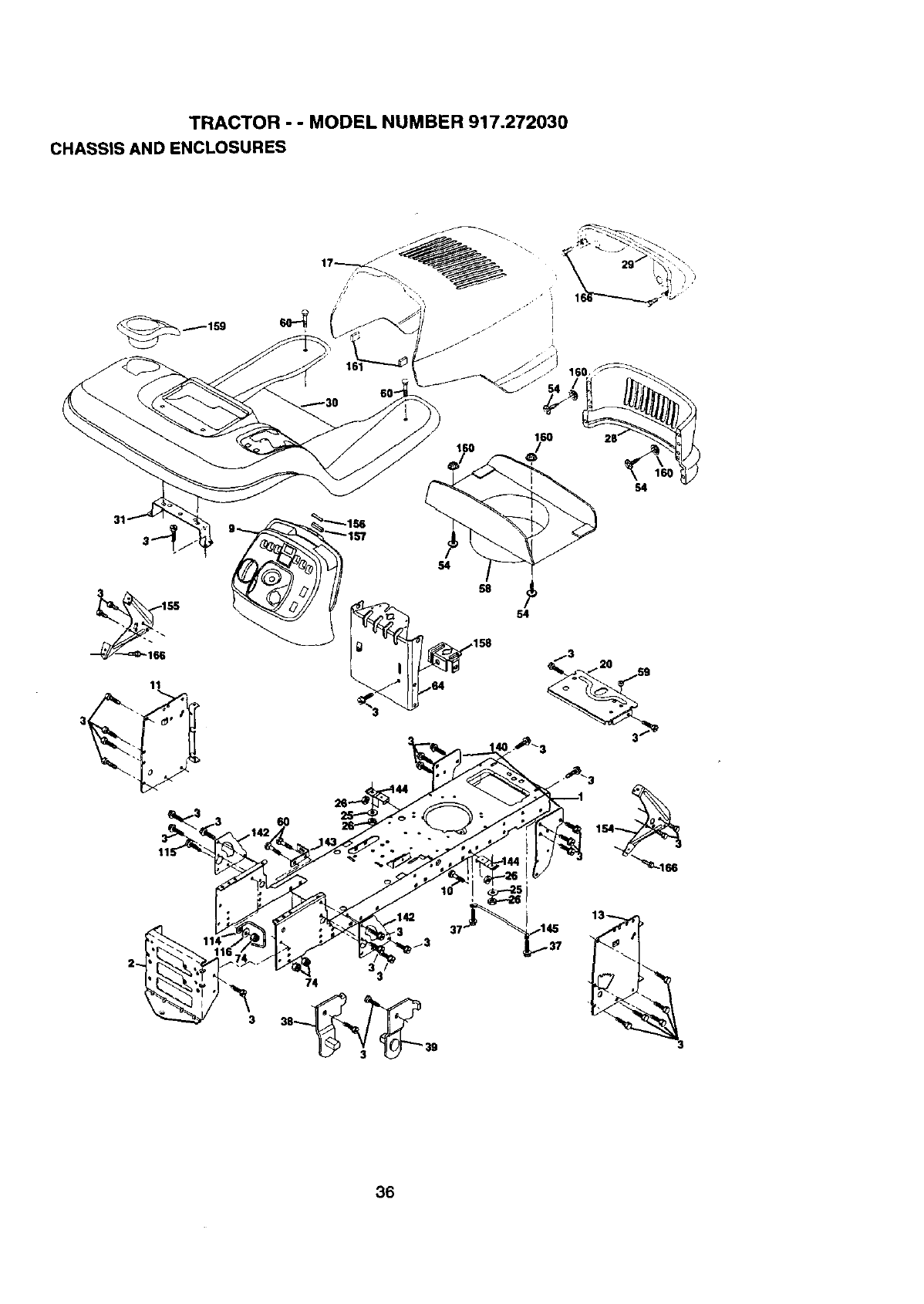
TRACTOR - - MODEL NUMBER 917.272030
CHASSIS AND ENCLOSURES
54
31
55
11
58
158
54
36
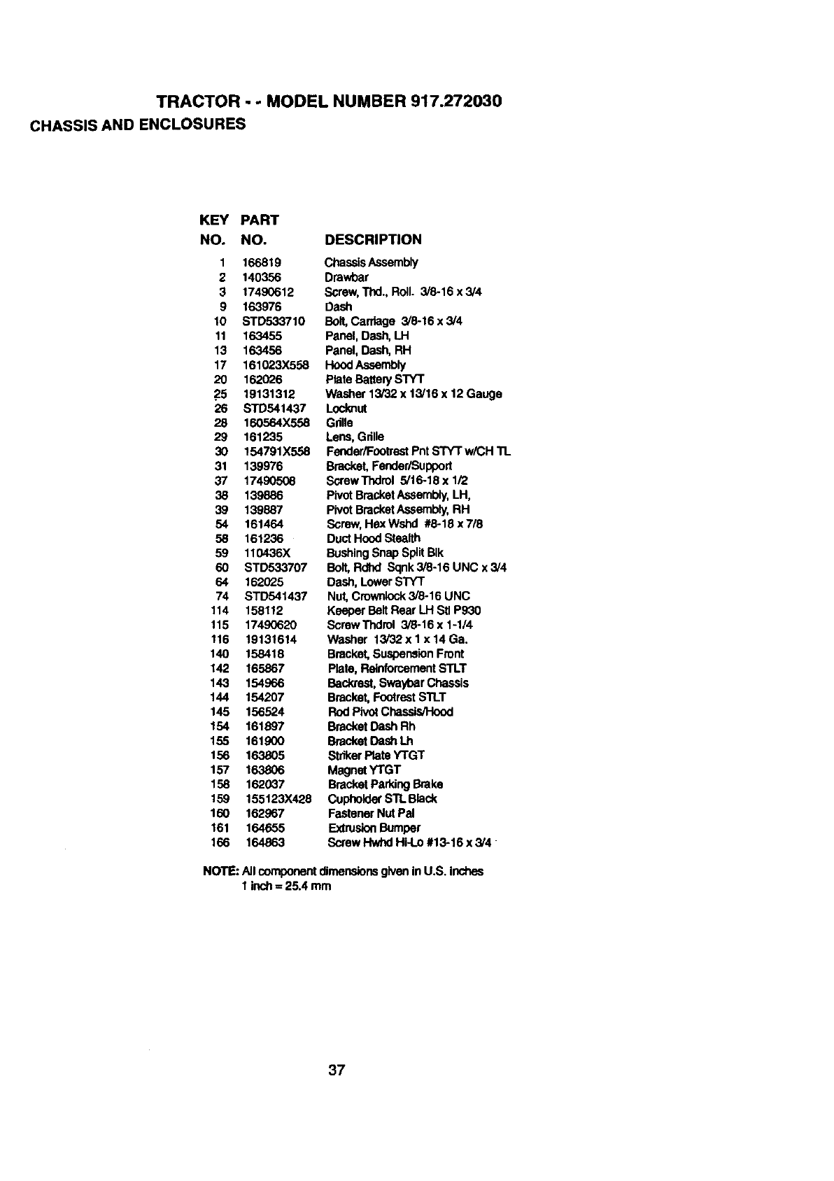
TRACTOR - -MODEL NUMBER 917.272030
CHASSIS AND ENCLOSURES
KEY PART
NO. NO. DESCRIPTION
1 166819 ChassisAssembly
2 140356 Drawbar
3 17490612 Screw,Thd.,RoU. 3/8-16x3/4
9 163976 Dash
10 STD533710 Bolt,Carriage 3/8-16 x 3/4
11 163455 Panel, Dash,LH
13 163456 Panel, Dash, RH
17 161023X558 HoodAssembly
20 162026 Plate BatterySTYT
25 19131312 Washer 13/32 x 13/16 x 12 Gauge
26 STD541437 Locknut
28 160564X558 Grille
29 161235 Lens, Grille
30 154791X558 FenderiFootreetPntSTYT w/CH TL
31 139976 Bracket, Fender/Support
37 17490508 Sc,rewThdrol 5/16-18 x 1/2
38 139886 Pivot BracketAssembly,LH,
39 139887 Pivot BracketAssembly,RH
54 161464 Screw,HexWshd #8-18x7/8
58 161236 DuctHood Stealth
59 110436X BushingSnap SplitBIk
60 STD533707 Bolt,Rdhd Sqnk3i8-16UNCx3/4
64 162025 Dash,Lower STYT
74 STD541437 Nut, Crownlock3/8-16 UNC
114 158112 Keeper BeltRear LH Stl P930
115 17490620 ScrewThdrol 3/8-16x1-1/4
116 19131614 Washer 13i32xlx14Ga.
140 158418 Bracket,SuspensionFront
142 165867 Plate, ReinforcementSTLT
143 154966 Backrest,SwaybarChassis
144 154207 Bracket,Footrest S'R_T
145 156524 Rod PivotChassis/Hood
154 161897 BracketDash Rh
155 161900 BracketDash Lh
156 163805 StdkerPlate YTGT
157 163806 MagnetYTGT
158 162037 BracketParking Brake
159 155123X428 Cupholdef STLBlack
160 162967 Fastener Nut Pal
161 164655 ExtrusionBumper
166 164863 Screw Hwhd Hi-l.o #13-16 x3/4
NOTE: All componentdimeneior_ given in U.S. inches
1 inctt= 25.4 mm
37
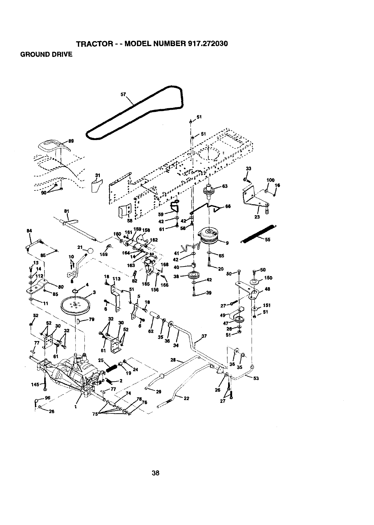
TRACTOR - - MODEL NUMBER 917.272030
GROUND DRIVE
51
38
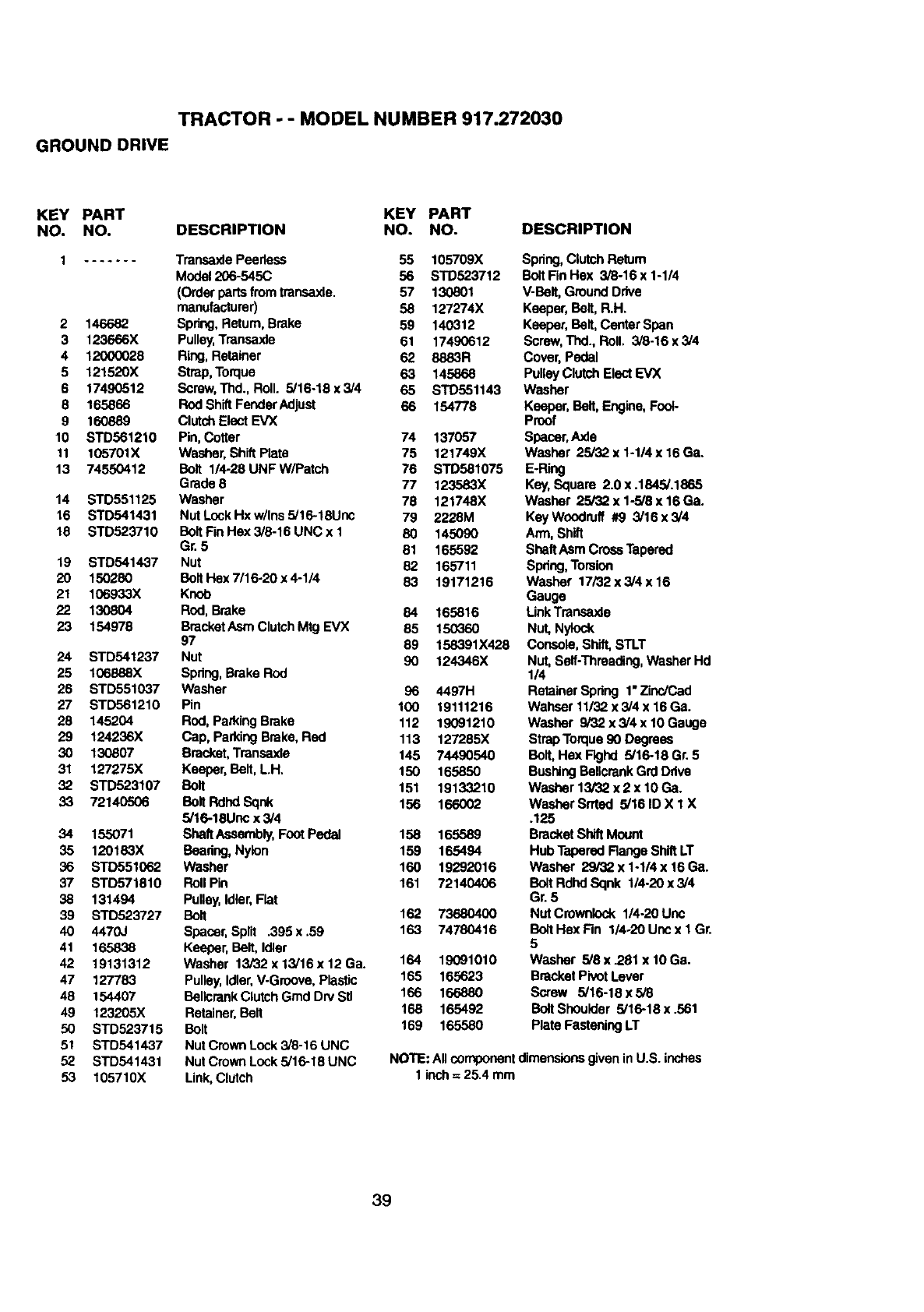
TRACTOR -- MODEL NUMBER 917.272030
GROUND DRIVE
KEY PART KEY PART
NO. NO. DESCRIPTION NO. NO. DESCRIPTION
1....... Transaxle Peedess 55 105709X
Model206-545C 56 STD523712
(Order partsfromtransaxle. 57 130801
manufacturer) 58 127274X
2 146682 Spring, Return, Brake 59 140312
3 123666X Pulley,Transaxfa 61 17490612
4 12000028 Ring, Retainer 62 8883R
5 121520X Strap,Torque 63 145868
6 17490512 Screw,Thd., Roll. 5/16-18 x 3/4 65 STD551143
8 165866 Rod ShiftFenderAdjust 66 154778
9 160889 Clutch Elect EVX
10 STD561210 Pin, Cotter 74 137057
11 105701X Washer, Shift Plate 75 121749X
13 74550412 Bolt 1/4-28UNFW/Patch 76 STD581075
Grade 8 77 123583X
14 STD551125 Washer 78 121748X
16 STD541431 Nut LooKHx w/Ins 5/16-18Unc 79 2228M
18 STD523710 Bolt FinHex 3/8-16 UNC x 1 80 145090
Gr. 5 81 165592
19 STD541437 Nut 82 165711
20 150280 Bolt Hex 7/16-20 x 4-1/4 83 19171216
21 106933X Knob
22 130804 Rod, Brake 84 165816
23 154978 BracketAsm ClutchMtg EVX 85 150360
97 89 158391X428
24 STD541237 Nut 90 124346X
25 106888X Spring, Brake Rod
26 STD551037 Washer 96 4497H
27 STD561210 Pin 100 19111216
28 145204 Rod,Parking Brake 112 19091210
29 124236X Cap, ParkingBrake, Red 113 127285X
30 130807 Bracket,Transaxla 145 74490540
31 127275X Keeper,Belt, LH. 150 165850
32 STD523107 Bolt 151 19133210
33 72140506 Bolt Rdhd Sqnk 156 166002
5/16-18Unc x 3/4
34 155071 SheftAseembly,Foot Pedal 158 165589
35 120183X Beadng, Nyion 159 165494
36 STD551062 Washer 160 19292016
37 STD571810 RollPin 161 72140406
38 131494 Pulley,Idler,Flat
39 STD523727 Bolt 162 73680400
40 4470J Spacer, Split .395 x .59 163 74780416
41 165838 Keeper, Belt, Idler
42 19131312 Washer 13/32 x 13/16x 12 Ga. 164 19091010
47 127783 Pulley,Idler,V-Groove, Plastic 165 165623
48 154407 BellcrankClutchGrad Dry Stl 166 166880
49 123205X Retainer,Belt 168 165492
50 STD523715 Bolt 169 165580
51 STD541437 Nut Crown Lock 3/8-16 UNC
52 STD541431 Nut Crown Lock 3/16-18 UNC
53 105710X Link,Clutch
Spdng,ClutchRetum
Bolt FinHex 3/6-16 x 1-1/4
V-Belt, GroundDrive
Keeper, Belt, R.H.
Keeper, Belt, Center Span
Screw,TIxL, BoIl, 3/8-16 x 3/4
Cover, Pedal
Pulley ClutchElectEVX
Washer
Keeper, Belt, Engine,Foot-
Proof
Spacer,Axle
Washer 25/32 x 1-1/4 x 16 Ga.
E.Ring
Key,Square 2.0 x .1845/.1865
Washer 25/32 x 1-5/8 x 16 Ga.
Key Woodruff #9 3/16x3/4
Arm, Shift
Shelf Asm CrossTapered
Spdng,Tomion
Washer 17/32 x 3/4 x 16
Gauge
LinkTransaxle
Nut, Nylock
Cor_ole, Shift,STLT
Nut, Serf-Threading,WasherHd
1/4
RetainerSpring 1"ZincJCad
Wahser 11/32 x 3/4 x 16 Ga.
Washer 9/32 x 3/4 x 10 Gauge
Strap Torque90 Degrees
BolL Hex Flghd 5/16-18 Gr. 5
BushingBellcrankGrd Ddve
Washer 13/32 x 2 x 10 Ga.
Washer Srrted 5/16 ID X 1 X
.125
Bracket ShiftMount
Hub Tapered Range Shift LT
Washer 29/'32x 1-1/4 x 16 Ga.
Bolt Rdhd Sqnk 114.20x 3/4
Gr. 5
Nut Crownlock 1/4-20 Unc
Bolt Hex Fin 1/4o20Unc x I Gr.
5
Washer 5/8 x.281 x 10 Ga.
Bracket Pivot Lever
Screw 5/16-18 x 5/8
BoltShoulder 5/16-18 x .561
Plate FasteningLT
NOTE: All componentdimensionsgivenin U.S. inches
1 inch= 25.4 mm
39
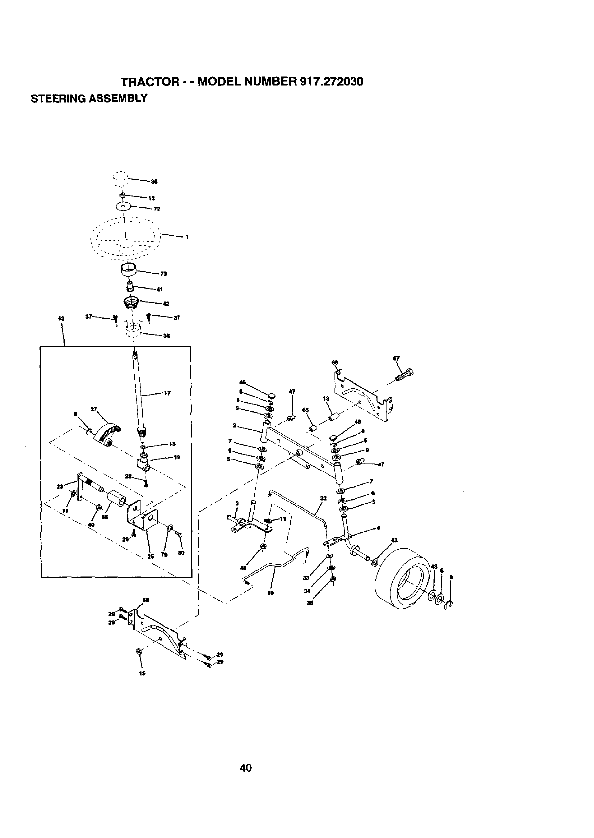
TRACTOR -- MODEL NUMBER 917.272030
STEERING ASSEMBLY
43
L
• J +,
41
---.-._43
117 47
10
68
13
32
43
IS
4O

TRACTOR - - MODEL NUMBER 917.272030
STEERING ASSEMBLY
KEY PART
NO. NO. DESCRIPTION
1 159944X428
2 154427
3 156483
4 157473
5 6266H
6 121748X
7 19272016
8 12000029
9 3366R
10 156438
11 STD551137
• 12 73940800
13 154779
15 73901000
17 156543
18 57079
19 160395
22 165857
23 165851
25 154406
27 136874
29 17490612
32 139929
33 19111216
34 10040500
35 73810500
36 155105
37 152927
38 159946X428
40 STD541537
41 159945
42 163888
43 121749X
46 121232X
47 6855M
62 167905
65 154780
66 154404
67 74781044
68 154429
72 19182411
73 160135
79 19132012
80 74950612
Wheel, Steering
Axle,Asm Front
Spindle,Asm Lh
Spindle,Asm Rh
Beadng, RaceThrustHarden
Washer, 25/32 x 1 5/8 x 16ga
Washer, 27132x 1 1/4 x 16 Ga
Ring,Klip#t5304-75
Bearing,Col StrgBIk
Draglink,ExtendedStamped
Washer, LockHvy HIclSpr 3/6
Nut Hex,Jam Toplock1/2-20 UNF
Beadng, AxleSTLT/GT
Lccl_ut, Flange 5/8-11 UNC
Shaft, Asm Strg
Washer, Thrust 515 x 750 x 033
Support,Shaft
Screw Hex Wshhd Torx
Shaft,Asm Pittman
Bracket,Steering
Gear, Sector
Screw,Thdrol3/8-16x3/4 Ty-tt
Rod,"ReBJ Solid 1975 Manual
Washer 11/32 x 3/4 x 16 Ga.
Washer LockHW HIcl Spr 5/16
Locknut5/16-24 UNF
Bushing,Strg
Screw, TT #10-32 x 5 x 3/8 Range
Insert,Steeflng Wheel
GripcoNut
Adaptor,Wheel Strg
Boot Stealth Steering
Washer, 25/32 x 1-1/4 x 16 Gauge
Cap, SpindleFrTap BIk
Fiffing,Grease
IFut,SteeringAssembly
Spacer,Axle
Bearing, Arm Pittman
Bolt,Rn Hex 5/8-11 UNC x 2-3/4
Axle, Brace
Washer 9/16 ID x 1-1/2 ID 11Ga.Zin
ExtensionSteeringPremium
Washer 13/32 x 1-114x 12 Ga.
Bolt Hex Nylon 3/8-16 x 3/4
NOTE: All componentdimensionsgiven inU.S. inches
1inch = 25.4 mm
41
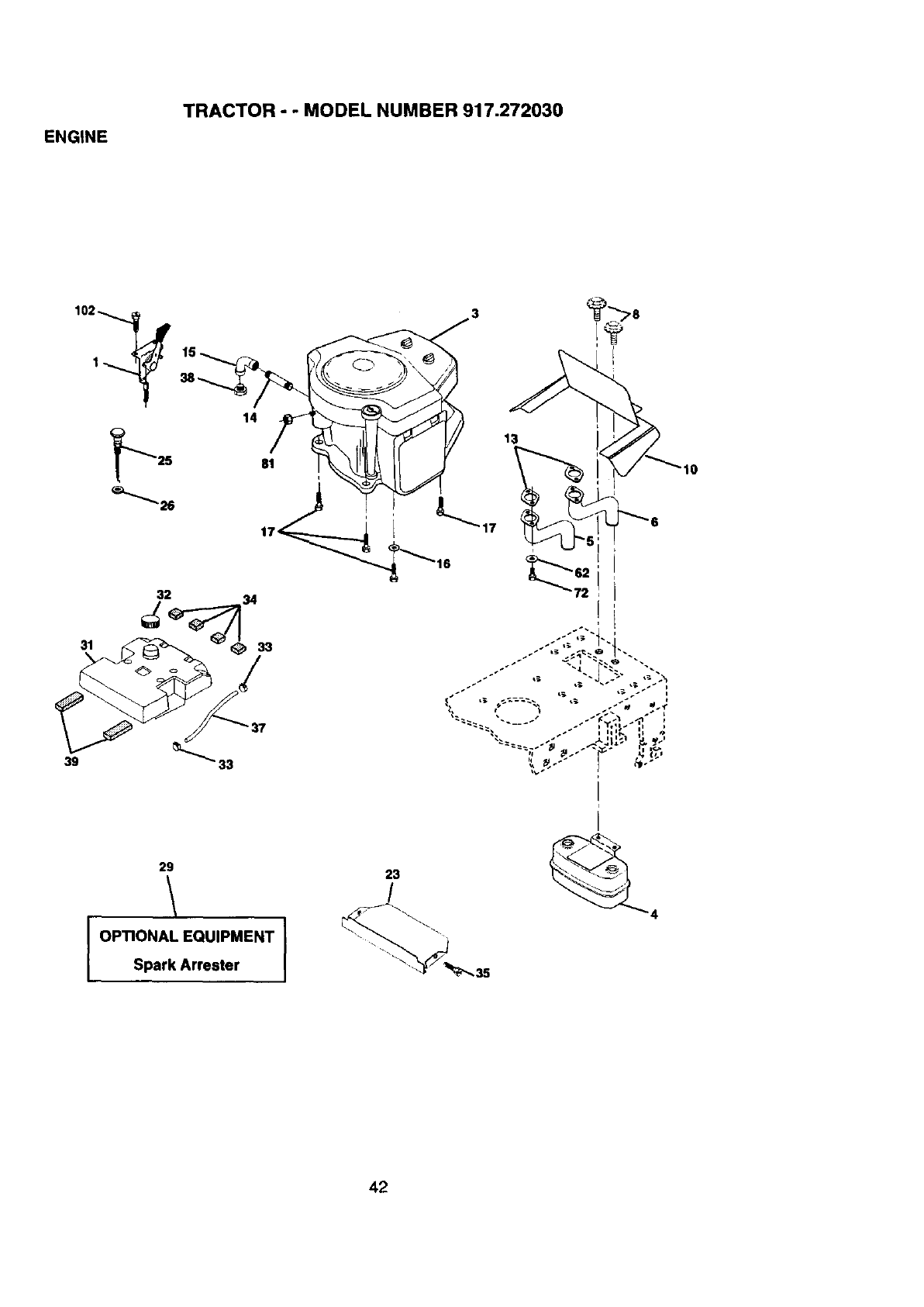
ENGINE
TRACTOR - -MODEL NUMBER 917.272030
39
3
31
14
_25 81 i
32 34
8
13
Ii r. ii t_*
29
OPTIONAL EQUIPMENT
Spark Arrester I
23
/
42
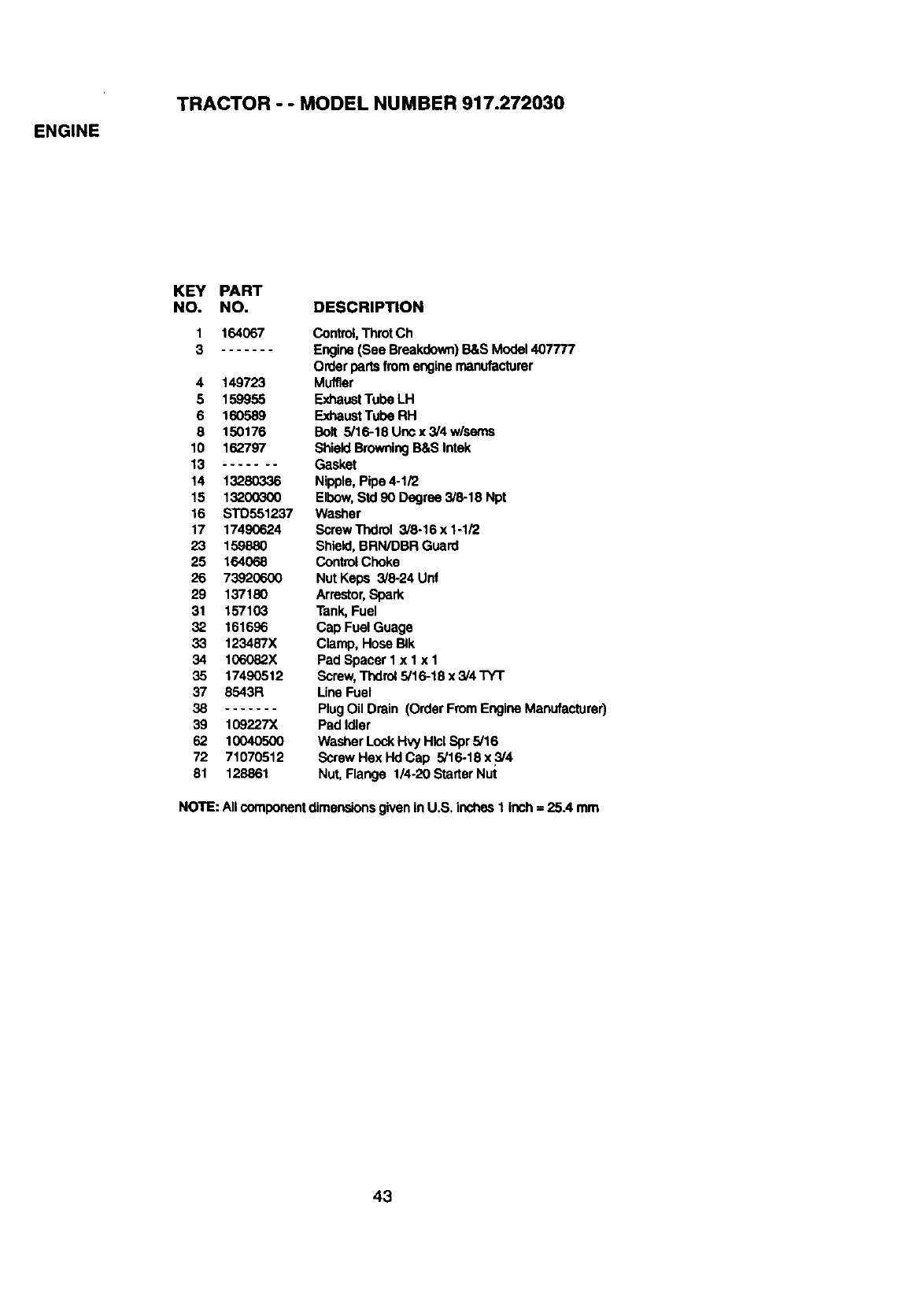
ENGINE
TRACTOR - - MODEL NUMBER 917.272030
KEY PART
NO. NO. DESCRIPTION
1 164067 Control,Throt Ch
3 Engine (See Breakdown)B&S Model 407777
Orderportsfromengine manufacturer
4 149723 Muffler
5 159955 E)d_austTube LH
6 160589 F_)d'_ustTube RH
8 150176 Bolt 5/16-18 Unc x 3/4 w/seres
10 162797 ShieldBrowningB&S Intek
13 ....... Gasket
14 13280336 Nipple, Pipe 4-1/2
15 13200300 Elbow, Std 90 Degree 3/6-18 Npt
16 STD551237 Washer
17 17490624 ScrewThdrol 3/8.16x1-1/2
23 159880 Shield, BRN/DBR Guard
25 164068 Control Choke
26 73920600 Nut Keps 3/6-24 Unf
29 137180 Arrestor,Spark
31 157103 Tank, Fuel
32 161696 Cap Fuel Guage
33 123487X Clamp, Hose BIk
34 106082X Pad Spacer I x I x 1
35 17490512 Screw,Thdrol5/16-18 x5/4 TYT
37 8543R Line Fuel
38 PlugOil Drain (Order FromEngine Manufacturer)
39 109227X Pad Idler
62 10040500 Washer Lock Hvy Hlcl Spr 5/16
72 71070512 ScrewHexHdCap 5/16-18x5/4
81 128861 Nut, Flange 1/4-20 Starter Nut
NOTE: Allcomponentdimensionsgiven inU,S, inches1 inch= 25A mm
43
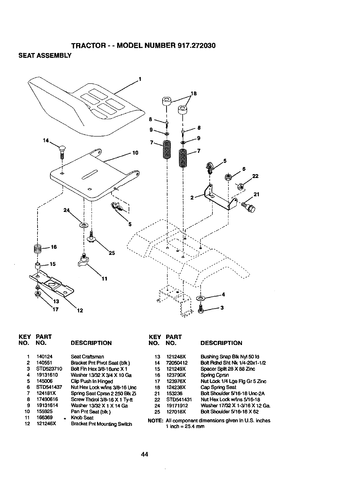
TRACTOR - - MODEL NUMBER 917.272030
SEAT ASSEMBLY
KEY PART
NO. NO.
1 140124
2 140551
3 STD523710
419131610
5 145006
6 STD541437
7 124181X
8 17490616
919131614
10 155925
11 166369
12 121246X
DESCRIPTION KEY PART
NO. NO.
SeatCraftsman 13 121248X
BracketPntPivotSeat (blk) 14 72050412
BoltFinHex 3/8-16unc X 1 15 121249X
Washer 13/32 X 3/4 X 10 Ga 16 123790X
ClipPushIn Hinged 17 123976X
Nut Hex Lockw/Ins3/8-16 Uric 18 124238X
SpnngSeat Cprsn2 250 BIkZi 21 153236
ScrewThdrol3/8-16 X 1Ty-tt 22 STD541431
Washer13/32 X 1 X 14Ga 24 19171912
Pan PntSeat(blk) 25 127016X
. KnobSeat
BracketPntMountingSwitch
DESCRIPTION
BushingSnap BIk Ny150 Id
BoltRdhd ShtNk 1/4-20xl-1/2
Spacer Split28 X 88 Zinc
SpdngCprsn
Nut Lock 114Lge Rg Gr 5 Zinc
capSpr_j seat
Bolt Shoulder 5/16-16 Unc-2A
Nut Hex Lockw/ins5/16-18
Washer 17/32 X 1-3/16 X 12 Ga.
BoltShoulder5/16-18 X 62
NOTE: All componentdimensions given in U.S. inches
1 inch = 25.4 mm
44
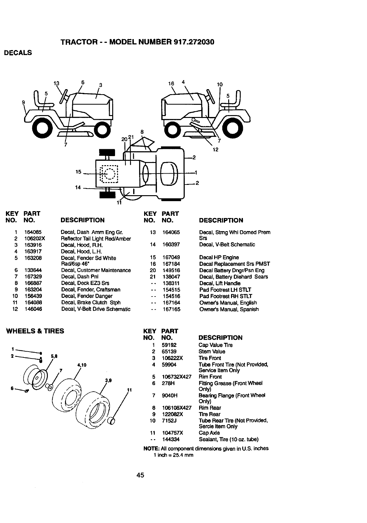
DECALS
TRACTOR - - MODEL NUMBER 917.272030
6 16 4
// 3 10
KEY PART
NO. NO.
1 164085
2 106202X
3 163916
4 163917
5 163208
6 133644
7 167329
8 166887
9 163204
10 156439
11 164088
12 146046
7
KEY PART
DESCRIPTION NO. NO.
Decal, Dash Amm Eng Gr. 13 164065
ReflectorTailLight Red/Amber
Decal, Hood, R.H. 14 160397
Decal, Hood, L.H.
Decal, Fender Sd White 15 167049
Rad/6sp 46" 16 167184
Decal, Customer Maintenance 20 149516
Decal, Dash Pnl 21 138047
Decal, Deck EZ3 Srs -. 138311
Decal, Fender, Craftsman - - 154515
Decal, Fender Danger -- 154516
Decal, Brake Clutch Stph - - 167164
Decal, V-Belt Ddve Schematic - - 167165
7
12
--2
1
_2
DESCRIPTION
Decal, Stmg Whl Domed Prom
Srs
Decal, V-Belt Schematic
Decal HP Engine
Decal ReplacementSrs PMST
Decal BatteryDngr/Psn Eng
Decal, Battery Diehard Sears
Decal, Lift Handle
Pad FootrestLH STLT
Pad FootrestRH STLT
Ownel's Manual, English
Owner's Manual, Spanish
WHEELS & TIRES
2_5,8 4,10
11
KEY PART
NO. NO. DESCRIPTION
1 59192 Cap Value Tire
2 65139 Stem Value
3 106222X "RraFront
4 59904 Tube FrontTire (Not Provided,
Service item Only
5 106732X427 Rim Front
6 278H FitlingGrease (FrontWheal
Only)
7 9040H BearingFlange(FrontWheel
Only)
8 106108X427 Rim Rear
9 122082X "13reRear
10 7152J Tube Rear3]ro (Not Provided,
Seroie Item Only
11 104757X Cap Axle
- - 144334 Sealant, "Rre(10 oz. tube)
NOTE: Allcomponentdimensionsgiven inU.S. inches
1 inch= 25.4 mm
45
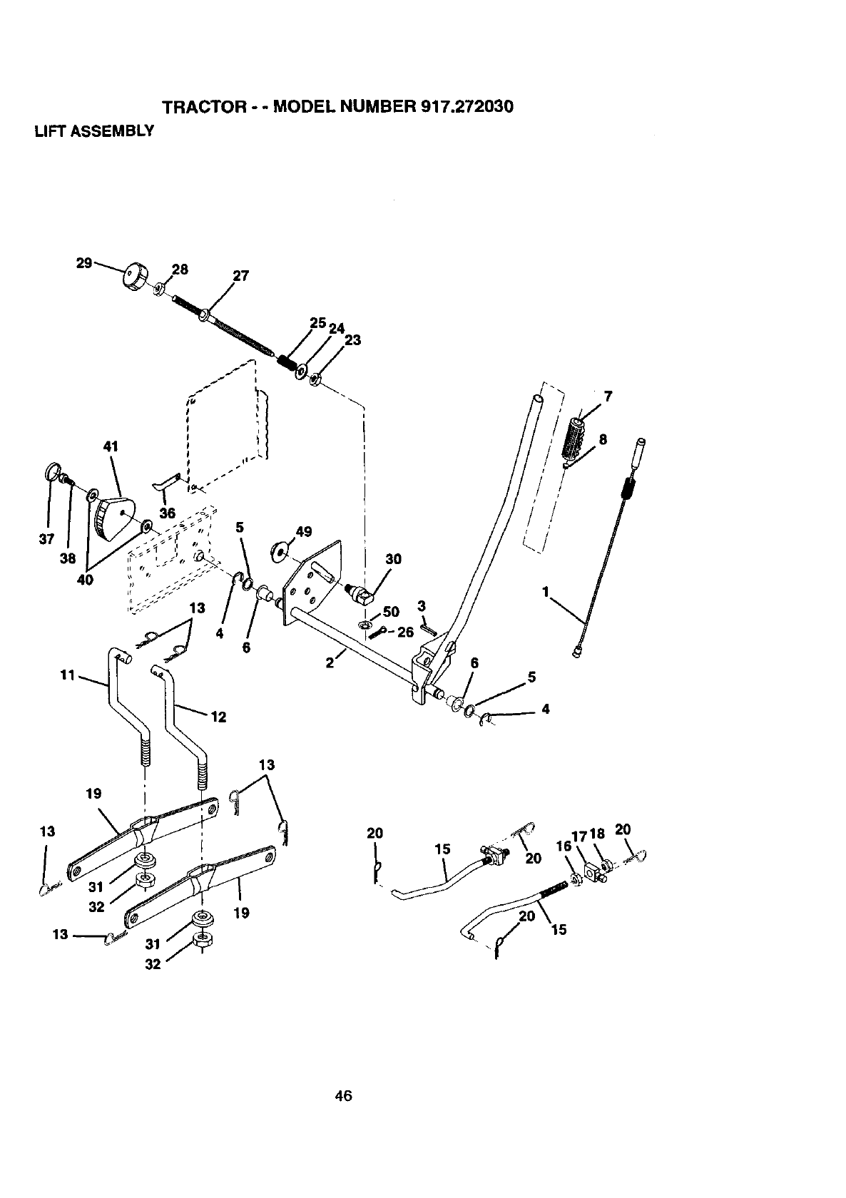
TRACTOR --MODEL NUMBER 917.272030
LIFT ASSEMBLY
37
38
40
11
30
3
19
13
31 _19
32
13
15
20
46
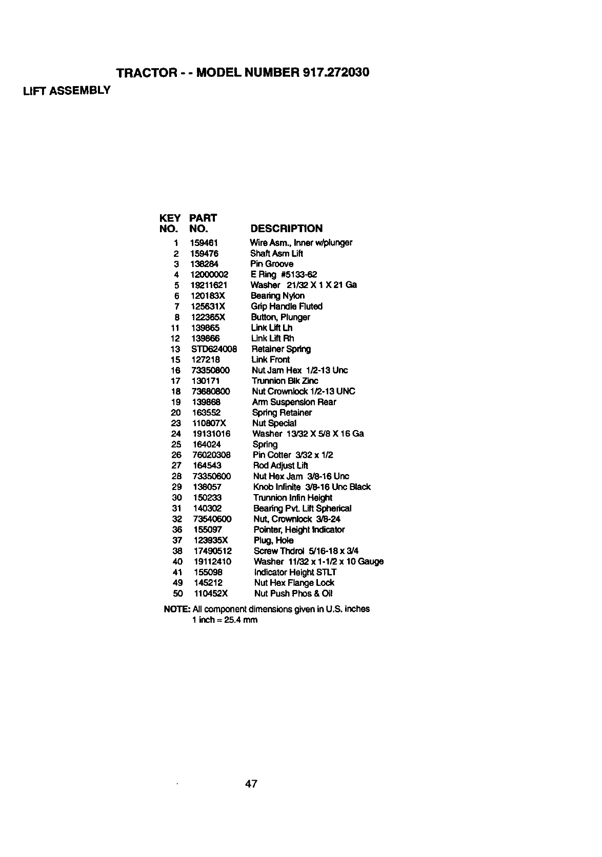
TRACTOR - - MODEL NUMBER 917.272030
LIFT ASSEMBLY
KEY PART
NO. NO. DESCRIPTION
1 159461 Wire Asm., Inner w/plunger
2 159476 ShaftAsm Lift
3 138284 Pin Groove
4 12000002 ERing #5133-62
5 19211621 Washer 21/32X 1 X21 Ga
6 120183X Bearing Nylon
7 125631X Gnp Handle Ruted
8 122365X Button,Plunger
11 139865 Unk Lift Lh
12 139866 Link LiftRh
13 STD624008 Retainer Spring
15 127218 Link Front
16 73350800 Nut Jam Hex 1/2-13 Unc
17 130171 Trunnion BIkZinc
18 73680800 Nut Crownlock1/2-13 UNC
19 139868 Arm SuspensionRear
20 1635.52 SpdngRetainer
23 110807X Nut Special
24 19131016 Washer 13i32X5/8X16Ga
25 164024 Spring
26 76020308 Pin Cotter 3/32 x 1/2
27 164543 Rod Adjust Lift
28 73350600 Nut Hex Jam 3/8-16 Unc
29 138057 Knoblnfinite 3/8-16 Unc Black
30 150233 Trunnion Infln Hek_t
31 1403_Z BearingPvL LiftSphedcal
32 735406o00 Nut, Crownlock 3/8-24
36 155097 Pointer,HeightIndicator
37 123935X Plug,Hole
38 17490512 ScrewThdroi 5/16-18x3/4
40 19112410 Washer 11/32x1-1i2x10Gauge
41 155098 indicatorHeightSTLT
49 145212 Nut Hex Flange Lock
50 110452X Nut Push Phos & Oil
NOTE: All componentdimensionsgivenin U.S. inches
1 inch=25.4 mm
47
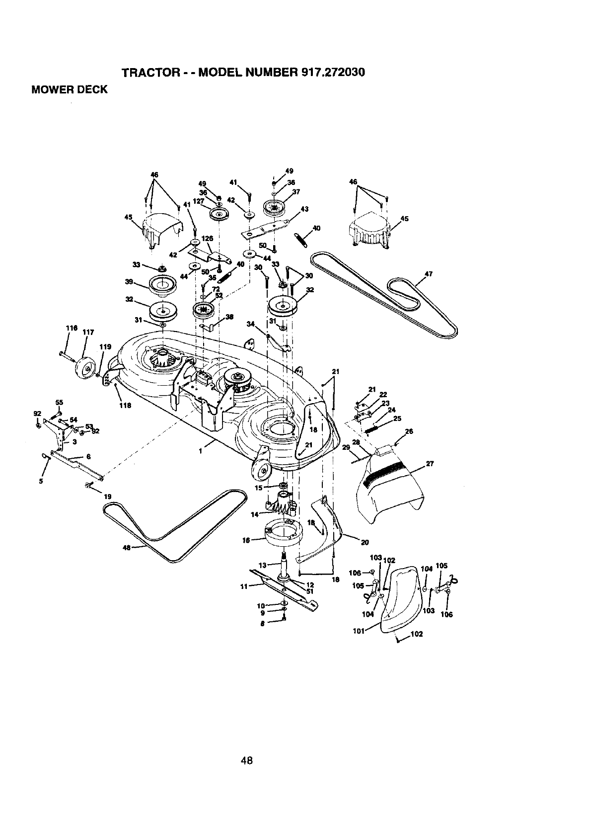
TRACTOR - - MODEL NUMBER 917.272030
MOWER DECK
46
49 41 46
45
\
43
47
116 117
55 118
/
19
21
21
\
48
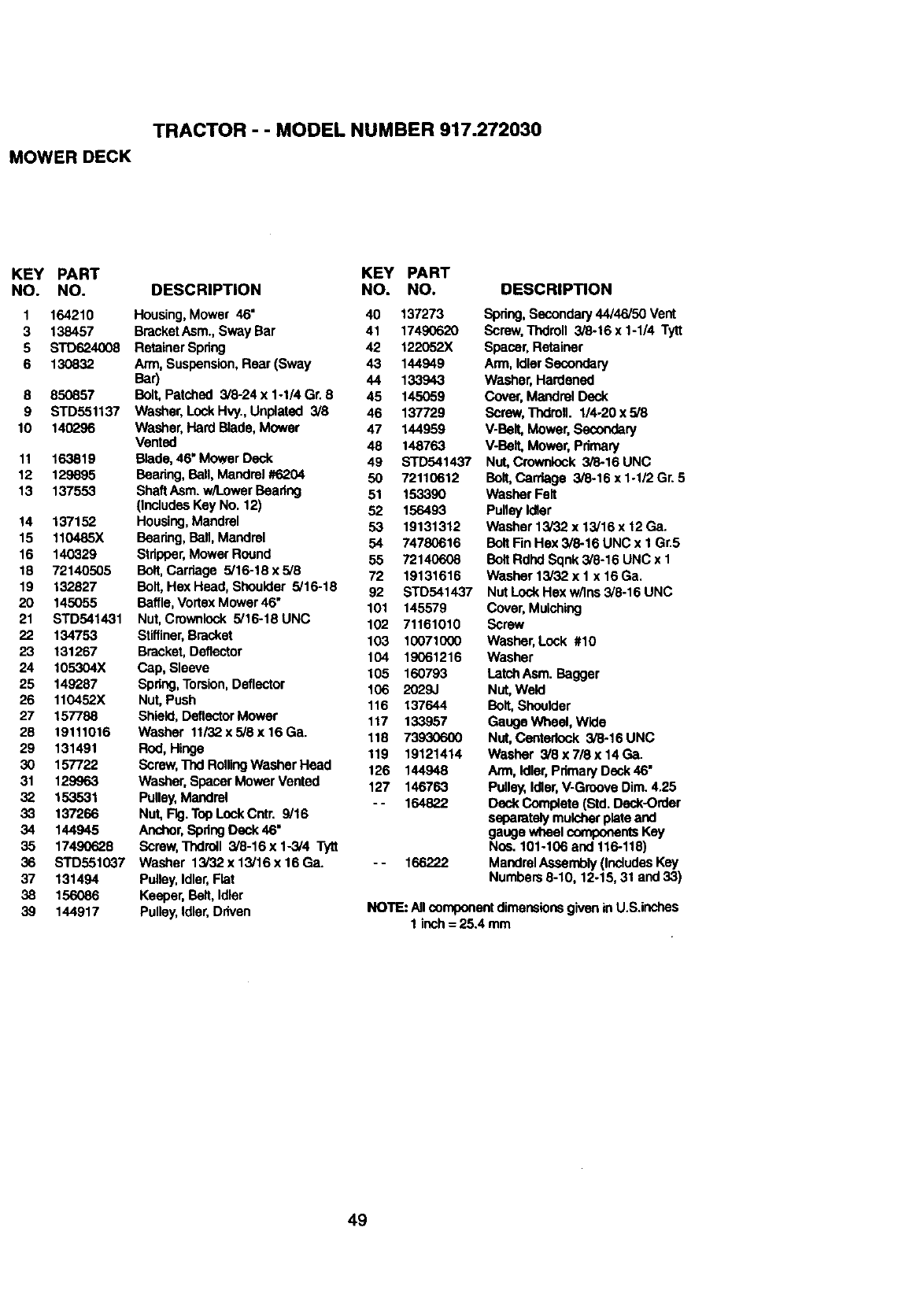
TRACTOR - - MODEL NUMBER 917.272030
MOWER DECK
KEY PART KEY PART
NO. NO. DESCRIPTION NO. NO.
1 164210 Housing,Mower 46" 40 137273
3 138457 BracketAsm.,Sway Bar 41 17490620
5 STD624008 Retainer Spring 42 122052X
6 130832 Arm, Suspension, Rear (Sway 43 144949
Bar) 44 133943
8 850857 Belt, Patched 3/8-24 x 1-1/4 Gr. 8 45 145059
9 STD551137 Washer, Lock Hvy., Unplated 3/8 46 137729
10 140296 Washer,Hard Blade,Mower 47 144959
Vented 48 148763
11 163819 Blade,46" Mower Deck 49 STD541437
12 129895 Baadng, Ball, Mandrel #6204 50 72110612
13 137553 Shaft Asm.w/l_owerBeadng 51 153390
(IncludesKey No. 12) 52 156493
14 137152 Housing,Mandrel 53 19131312
15 110485X Bearing,Ball,Mandrel 54 74780616
16 140329 Stripper,Mower Round 55 72140608
18 72140505 Belt, Carriage 5/16-18 x 5/8 72 19131616
19 132827 Bait, Hex Head, Shoulder 5/16-18 92 STD541437
20 145055 Baffle, VortexMower 46" 101 145579
21 STD541431 Nut, Crownlock 5/16-18UNC 102 71161010
22 134753 Stiffiner,Bracket 103 10071000
23 131267 Bracket, Deflector 104 19061216
24 105304X Cap, Sleeve 105 160793
25 149287 Spdug,Torsion,Deflector 106 2029J
26 110452X Nut, Push 116 137644
27 157788 Shield, DeflectorMower 117 133957
28 19111016 Washer 11/32 x 5/8 x 16 Ga. 118 73930600
29 131491 Rod, Hinge 119 19121414
30 157722 Scraw,Thd RollingWasher Head 126 144948
31 129963 Washer, Spacer Mower Vented 127 146763
32 153531 Pulley,Mandrel - - 164822
33 137266 Nut, Fig.Top Lock Cntr. 9/16
34 144945 Anchor,Spdng Dock 46"
35 17490628 Screw, Thdrctl 3/8-16 x 1-3/4 Tytt
36 STD551037 Washer 13/32x13/16x16Ga. -- 166222
37 131494 Pulley,Idler,Flat
38 156086 Keeper, Belt, Idler
39 144917 Pulley,Idler,Driven
DESCRIPTION
Spdng, Secondary44/46/50 Vent
Screw, Thdroll 3/8-16 x 1-1/4 Tytt
Spacer,Retainer
Arm, IdlerSecondary
Washer,Hardened
Gover,Mandrel Deck
Screw, Thdrctl. I/4-20 x 5/8
V-BelL Mower, Secondary
V-Belt, Mower, Primary
Nut, Crowrdock 3/8-16 UNC
Bait, Carriage 3/8-16 x 1-1/2 Gr. 5
Washer Felt
Pulley Idler
Washer 13/32 x 13/16 x 12 Ga.
Belt FinHex 3/8-16 UNC x 1 Gr.5
Belt Rdhd Sqnk 3/8-16 UNC x 1
Washer 13/32 x 1 x 16Ga.
Nut LockHex w/Ins 3/6-16 UNC
Cover, Mulching
Screw
Washer, Lock #10
Washer
LatchAsm. Bagger
Nut, Weld
Belt, Shoulder
Gauge Wheel, Wide
Nut, Centedock 3/6-16 UNC
Washer 3/8 x 7/8 x 14 Ga.
Ann, Idler,PrimaryDeck 46"
Pulley,Idler,V-GrooveDim. 4.25
Deck Complete (Std. Deck-Order
separately mulcherplate and
gauge wheel componentsKey
Nos. 101-106 and 116-118)
MandrelAssembly(IncludesKey
Numbers 8-10, 12-15, 31 and 33)
NOTE: Allcomponentdimensionsgiven inU.S.inches
1 inch = 25.4 mm
49
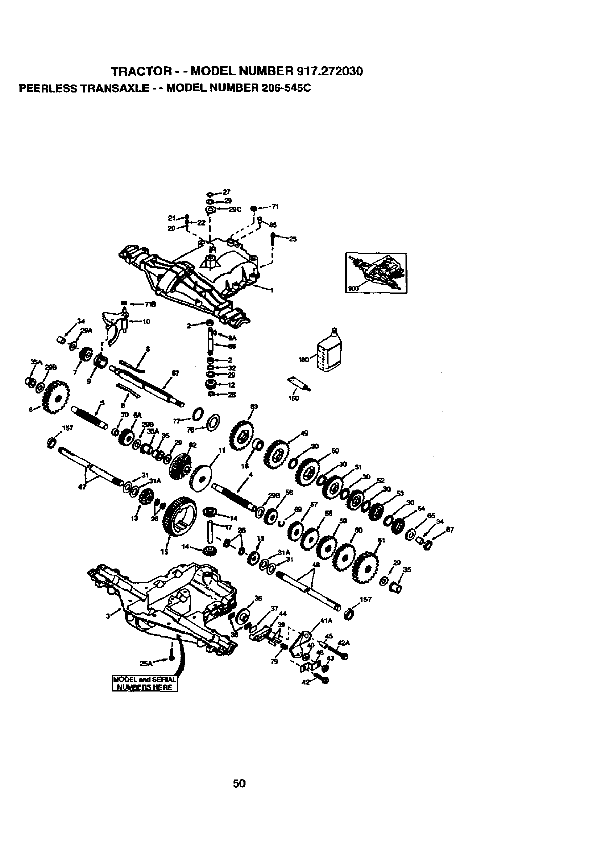
TRACTOR - - MODEL NUMBER 917.272030
PEERLESS TRANSAXLE - - MODEL NUMBER 206-545C
!57
47
8
13
18
157
4S
5O
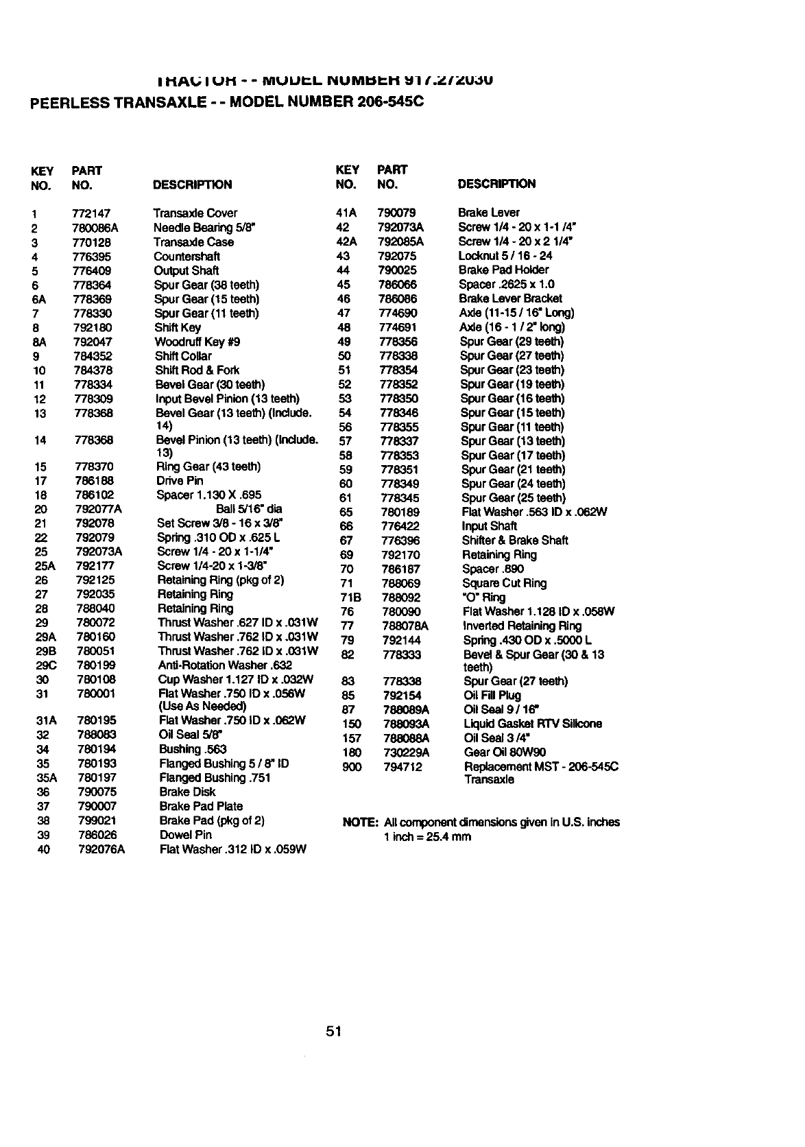
IHAt.; I UI'] - -MUUP..L I_UMI_I"I'I _II._//_U_$U
PEERLESS TRANSAXLE -- MODEL NUMBER 206-545C
KEY PART KEY PART
NO. NO. DESCRIPTION NO. NO.
1 772147 Transaxle Cover 41A 790079
2 780086A Needle Bearing 5/8" 42 792073A
3 770128 Transaxle Caee 42A 7_2085A
4 776395 Countershaft 43 792075
5 776409 Output Shaft 44 790025
6 778364 Spur Gear (38 teeth) 45 786066
6A 778369 Spur Gear (15 teeth) 46 786086
7 778330 SpurGear (11 teeth) 47 774690
8 792180 ShiftKey 48 774691
8A 792047 Woodruff Key #9 49 778356
9 784352 Shift Collar 50 778338
10 784378 ShiftRod & Fork 51 778354
11 778334 Bevei Gear (30 teeth) 52 778352
12 778309 Input Bevel Pinion(13 teeth) 53 778350
13 778368 Bevel Gear (13 teeth) (Include. 54 778346
14) 56 778355
14 778368 Bevel Pinion (13 teeth) (Include. 57 778337
13) 58 778353
15 778370 Ring Gear (43 teeth) 59 778351
17 786188 Drive Pin 60 778349
18 786102 Spacer 1.130 X .695 61 778345
20 792077A Ball5/16" dla 65 780189
21 792078 Set Screw 3/8 - 16 x 3/8" 66 776422
22 792079 Spdng .310 OD x .625 L 67 776396
25 792073A Screw 1/4 -20 x 1-1/4" 69 792170
25A 792177 Screw 1/4-20 x 1-3/8" 70 786187
26 792125 Retaining Ring (pkg of 2) 71 788069
27 792035 Retaining Ring 71B 788092
28 788040 Retaining Ring 76 780090
29 780072 ThrustWasher ,627 ID x .031W 77 788078A
29A 780160 Thrust Washer .762 ID x .031W 79 792144
29B 780051 Thrust Washer .762 ID x .031W 82 778333
29C 780199 Anti-RotationWasher .632
30 780108 Cup Washer 1.127 ID x .032W 83 778338
31 780001 Flat Washer .750 ID x .056W 85 792154
(Use As Needed) 87 788089A
31A 780195 Flat Washer .750 ID x .062W 150 788093A
32 788083 Oil Seal 3/8" 157 788088A
34 780194 Bushing.563 180 730_.29A
35 780193 Ranged Bushing5 /8" ID 900 794712
35A 780197 Flanged Bushing.751
36 790075 Brake Disk
37 790007 Brake Pad Plate
38 799021 Brake Pad (pkgof 2)
39 786026 Dowel Pin
40 792076A FlatWasher .312 ID x .059W
DESCRIPTION
Brake Lever
Screw 1/4 - 20 x 1-1/4"
Screw 1/4- 20 x 2 I/4"
Locknut5116 -24
Brake Pad Holder
Spacer .2625 x 1.0
Brake LeverBracket
Axle(11-15 /16"Long)
Axla(16- I /2" long)
Spur Gear (29 teeth)
Spur Gear (27 teeth)
Spur Gear (23 teeth)
Spur Gear (19 teeth)
Spur Gear (16 teeth)
Spur Gear (15 teeth)
Spur Gear (11 teeth)
Spur Gear (13 teeth)
Spur Gear (17 teeth)
Spur Gear (21 teeth)
Spur Gear (24 teeth)
Spur Gear (25 teeth)
FlatWasher .563 ID x .062W
InputShaft
Shifter& Brake Shaft
Retaining Ring
Spacer .890
Square Cut Ring
"O"Ring
FlatWasher 1,128 ID x .058W
Inverted RetainingRing
Spdng.430 OD x .5000 L
Bevel & SpurGear (30 & 13
teeth)
Spur Gear (27 teeth)
Oil FillPlug
Oil Seal 9 /16"
LiquidGasket RTV Silicone
Oil Seal 3/4"
Gear Oil 80W90
Replacement MST - 206-545C
Transaxle
NOTE: AUcomponentdimensionsgivenin U.S. inches
1 inch= 25A mm
51
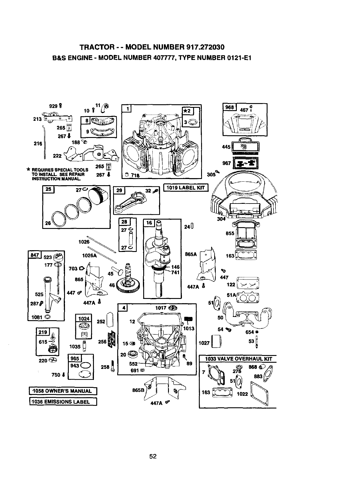
TRACTOR - - MODEL NUMBER 917.272030
B&S ENGINE - MODEL NUMBER 407777, TYPE NUMBER 0121-E1
920_
213_
2161
10 11_._
:>65
267 89
188
222 _
I lJ
710 _
_-J 467_
445
265
,k REQUIRES SPECtAL TOOLS
TO INSTALL. SEE REPAIR 267 8305 _
INSTRUCTION MANUAL
___ 27C'_ 2_32, _11 1019 LABEL KITI,, 304
177_
447 _
447A _122
525 _51A_
287_ 447A _51__
41 1017
ss2- _ _ 00
691
065B_
447A _
1033 VALVE OVERHAUL KIT
1081_ _2521 1
_1035 _2._
220 _ _I"_35_::_I 258
750
[ "1058OWNER'S MANUAL I
11030 EMISSIONS LABEL 1
52
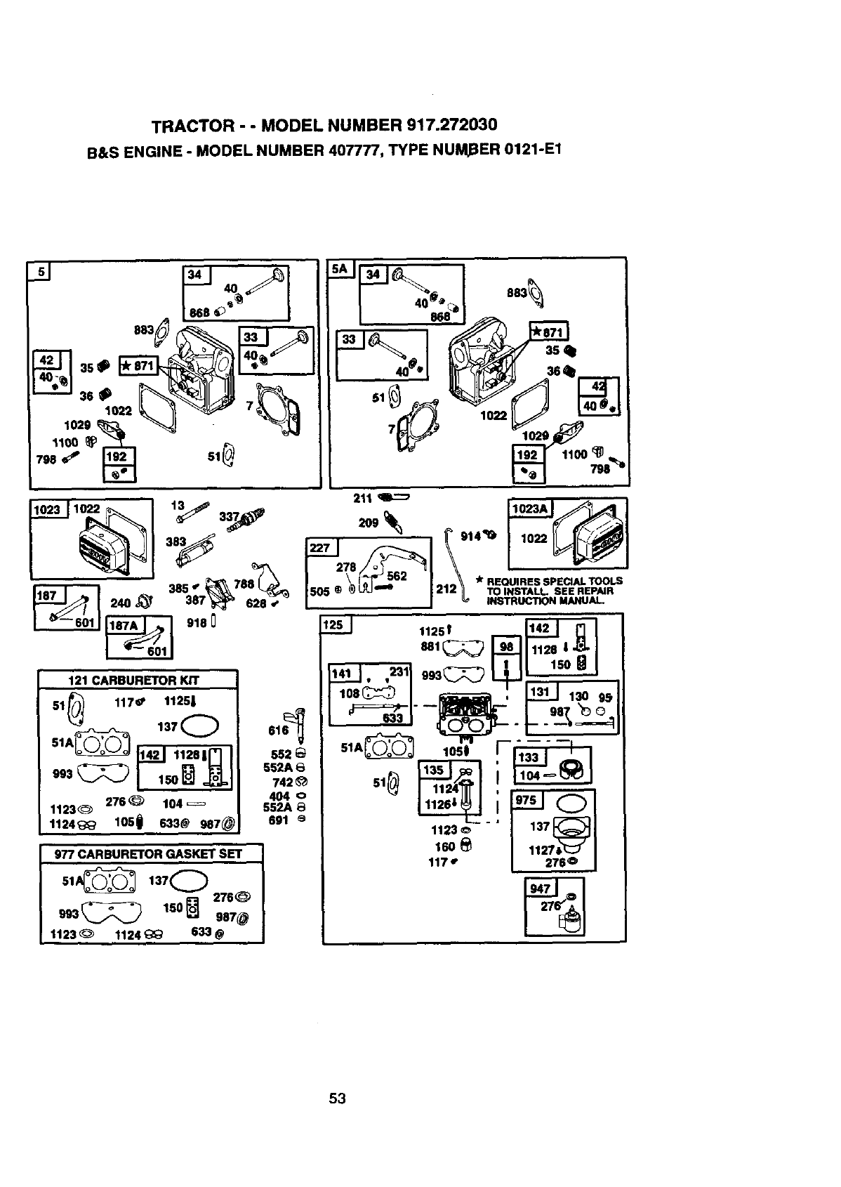
TRACTOR - - MODEL NUMBER 917.272030
B&S ENGINE - MODEL NUMBER 407777, TYPE NUMBER 0121-E1
SAil 34 I_ I 883
I . \_*_r)- 562 I _*REOUIRESSPEClALTOOLS
_240_' 31S3 ISOS_ ''° 1212_L TOINST,LLSEI.EP_UR
/ I INDUCTIONMANUAL.
"-- 601 9180 1251 1125_ _ _
_4_J.._11 9._--r----_l i I_
121CARBURETOR KIT --- "' - - I 1131 J
51Fh/_)J 117# 1125| 108_ I _, 11311 130 95
137 61 _,-- __
33_ 1o4_ ,o40 " _; '-Jcl1123_ S52A 8
1124_;_ 1050 633@ 987@ 691 e1123L__, 137_}1
977 CARBURETOR GASKET SET 160 e1127_ I
1173 2760 I
s,,C_ 13,O .,--%-
.%1
1123 _1124 _633 @
53
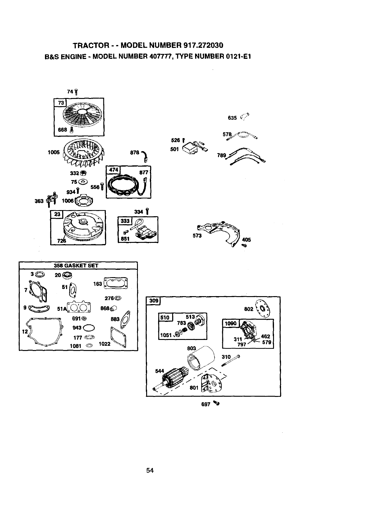
TRACTOR - - MODEL NUMBER 917.272030
B&S ENGINE - MODEL NUMBER 407777, TYPE NUMBER 0121-E1
363
74_
1005 _. 474 8788__
635 _;:r+
526_
_1 9__
78
358 GASKET SET
30
7_ 51_ 163_ 276@
9_ 51_A_ 868_
2_691_ _
1 943
177_
1051 _1022
lsO_S°181_1
462
579311
697
54

TRACTOR - - MODEL NUMBER 917.272030
B&S ENGINE -MODEL NUMBER 407777, TYPE NUMBER 0121-E1
KEY PART
NO. NO.
1690231
2 499585
3 690926
4 690069
5 499587
5A 499595
7 690962
8 499601
9 690937
10 690960
11 690942
12 690945
13 690360
15 690946
16 691046
20 690947
23 691053
24 690974
25 499588
499589
499590
499591
26 499604
499605
499606
499607
27 690975
28 499582
29 499583
32 690976
33 499596
34 499597
35 690963
36 690963
40 690964
42 499586
45 690977
46 690978
48 6g_714
5O 69O948
51 690949
51A 690950
53 690951
54 690953
73 691055
74 691057
75 691056
89 690238
95 690718
98 499802
104 690984
105 690985
108 690986
117 690232
117 690989
121 499811
122 690952
125 499804
130 690993
131 499805
133 499806
KEY PART
DESCRIPTION NO. NO. DESCRIPTION
CylinderAssembly 135 499803 FuehTransferTube
Bushing-Cylinder 137 690994 luGasket-FloatBowl
+SeaI-Oit 141 499807 Choke ShaftKit
Sump-Engins 142 499808 INozzle-Carburetor
Head-Cylinder No. 1 146 94388 Key-'Rming
Head-Cylinder No. 2 150 281767 luGasket-Nozzla
+UGasket-Cylinder Head 160 690996 Retainer-Solenoid
BreatherAssembly 163 691001 +UGasket-Air Cleaner
+Gasket-Breather 177 691031 +O-Ring Seal (Dipetick)
Screw (BreatherAssy.) 187 691050 Line-Fuel (Cut to Required
Tube-Breather Length)
+Gasket-Crankcase 187A 691049 Line-Fuel
Screw (CylinderHead) 188 690960 Screw (ControlBracket)
Plug-Oil Drain 192 690083 Adjuster-RockerArm
Crankshaft 209 690018 Spring-Governor
+SeaI-C_l(PTO Side) 211 690019 Spring-GovernedIdle
Flywheel 212 691020 Link-Throtite
Key-Flywheal 213 691021 Bracket-ChokeControl
PistonAseambly(Std.) 218 691022 Link-Choke
PistonAssembly(.010 =O.S.) 219 394348 Gear-Governor
PistonAssembly(.020"O.S.) 220 690412 Washer (GovernorLever)
PistonAssembly(.030" O.S.) 222 691023 Bracket-Control
Ring Set-Piston (Std.) 227 691048 ControlLever-Governor
Ring Set-Piston (.010 "O.S.) 231 690718 Screw (Choke Valve)
Ring Set-Pieton (.020 "O.S.) 240 691035 Filter-Fudi
Ring Set-Piston (.030 =O.S,) 252 690956 Element-Breather
Lock-PistonPin 256 690957 Retainer-Element
Pin-Piston 258 690308 Screw (Engine Sump)
Rod-Coonecting 265 691024 Claml>-Casing
Screw (ConnectingRod) 267 691044 Screw (CasingClamp)
Valve-Exhaust 276 690997 +lUSealing Washer
Valve-Intake 279 690097 Washer (Gov. Control Lever)
Spnng-Valve(Intake) 287 690960 Screw (DipstickTube)
Spring-Valve(F_xt_ust) 304 691004 Housing-Blower
Retainer-Valve 305 691005 Screw (Blower Housing)
Keeper-Valve 309 691262 Motor-Starter
ValveTappet 310 691263 Bolt-StarterMotor
Cam Sheft 311 691264 BrushSet
ShortBiock 332 690059 Nut (Flywheel)
Manifold-Intake 333 691060 Armatore-Magnsto
+lUGasket-lntake 334 691061 Screw (Armature)
+luGasket-lntake 337 691043 Spark Plug
Stud (Carburetor) 358 499889 Gasket Set
Screw (intakeManifold) 363 691062 Flywheel Puller
Screen-Rotating 383 690966 Wmoch-Spark Plug
Screw (RotatingScreen) 385 65O_60 Screw (Fuel Pump)
Washer (Flywheel) 387 691034 Pump-Fuel
Plug-Oil 404 690442 Washer (Governor Crank)
Screw (ThroftleValve) 405 690960 Screw (Back Plate)
IdleSpeed Kit 445 691007 Fiiter-AirCleanerCartridge
IPin-FloatHinge 447 691003 Screw (AirGuide Cover)
Walve-FloetNeedle 447A 690960 Screw (Air Guide Cover)
Valve-Choke 462 691261 Washer (Starter Cable)
Uet-Main (Standard)
Jet-Main High Altitude) + Includedin GasketSet, Ref. No. 358
CarburetorOverhaul Kit I Inctudedin Gasket Set, Ref. No. 121
Spacer-Carburetor u IncludedinGasket Set, Ref. NO.977
Carburetor U Included inGasket Set, Ref. No. 1033
Valve-Throttle
ThrottleShaftKit NOTE: Allcomponentdimensionsgivenin U.S. inches
Float-Carburetor 1 inch= 25.4 mm
55
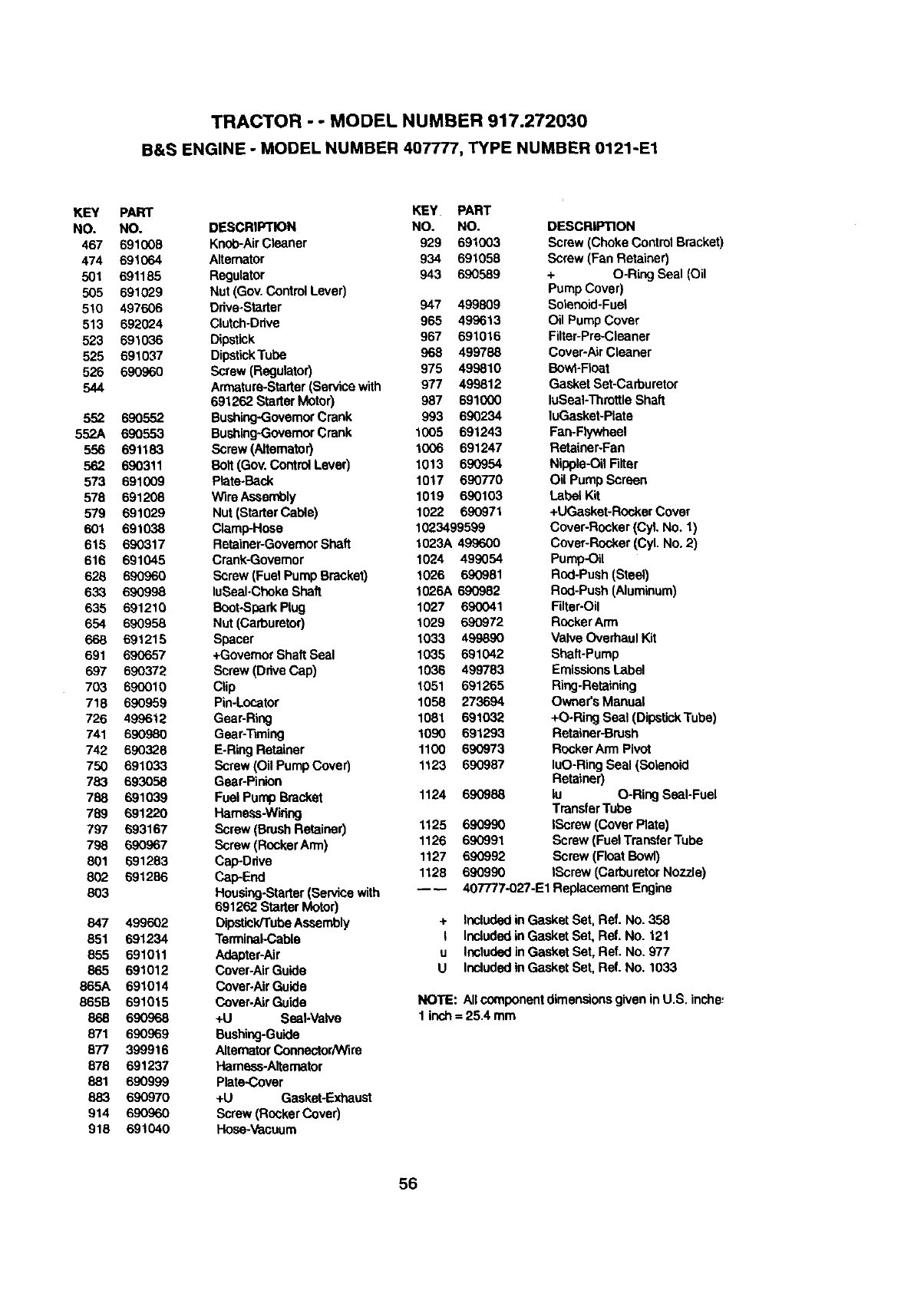
TRACTOR - - MODEL NUMBER 917.272030
B&S ENGINE -MODEL NUMBER 407777, TYPE NUMBER 0121-E1
KEY
NO.
467
474
501
505
510
513
523
525
526
544
552
552A
556
562
573
578
579
601
615
616
628
633
635
654
668
691
697
703
718
726
741
742
750
783
788
789
797
798
801
802
803
847
851
855
865
865A
865B
868
871
877
878
881
883
914
818
PART KEY
NO. DESCRIPTION NO.
691008 Knob-AirCleaner 929
691064 Alternator 934
691185 Regulator 943
691029 Nut (Gov. ControlLever)
497606 Drive.Starter
692024 Clutch-Drive
691036 Dipstick
691037 DipstickTube
690960 Screw (Regulator)
Armature-Starter(Servicewith
691262 StarterMotor)
690552 Bushing-GovemorCrank
690553 Bushing-GovernorCrank
691183 Screw (Altemator)
690311 Bolt (Gov.Control Lever)
691009 Plata.Back
691208 Wire Assembly
691029 Nut (StarterCable)
691038 Clamp-Hose
690317 Retainer-GovernorShaft
691045 Crank-Govemor
690960 Screw (Fuel PumpBracket)
690998 luSeaI-Choke Shaft
691210 Boot*SparkPlug
690958 Nut (Carburetor)
691215 Spacer
690657 +Governor ShaftSeal
690372 Screw (Drive Cap)
69O010 Clip
690959 Pin-Locater
499612 Gear-Ring
690980 Gear-Timing
690328 E-Ring Retainer
691033 Screw (Oil PumpCover)
693058 Gear-Pinion
691039 Fuel Pump Bracket 1124
691220 Plamess-Widng
693167 Screw (BrushRetainer) 1125
690967 Screw (RockerArm) 1126
691283 Cep-Ddve 1127
691286 Cap-End 1128
Housing-Starter(Sen/ice with ----
691262 StarterMotor)
499602 Dipstick/TubeAssembly
691234 TerminaI-Cabla
691011 Adapter-Air
691012 Cover-AirGuide
691014 Cover-Air Guide
691015 Cover-Air Guide
690968 +U Seal-Valve
690969 Bushing-Guide
399916 Alternator Connector/Wire
691237 Hamess-Altemator
690999 Plata-Cover
690970 +U Gasket-Exhaust
690960 Screw (RockerCover)
691040 Hose-Vacuum
PART
NO.
691003
691058
690589
947 499809
965 499613
967 691016
968 499788
975 499810
977 499812
987 691000
993 690234
1005 691243
1006 691247
1013 690954
1017 690770
1019 690103
1022 690971
1023499599
1023A 499600
1024 499054
1026 690981
1026A 690982
1027 690041
1029 690972
1033 499890
1035 691042
1036 499783
1051 691265
1056 273694
1081 691032
1090 691293
1100 690973
1123 690987
DESCRIPTION
Screw (Choke Control Bracket)
Screw (Fan Retainer)
+ O-Ring Seal (Oil
Pump Cover)
Solanoid-Fuel
Oil PumpCover
Filtar-Pre-Cleaner
Cover-AirCleaner
Bowl-Roar
Gasket Set-Carburetor
luSeaI-ThrottleShaft
luGasket-plate
Fan-Flywheel
Retainer-Fan
Nipple-OilFilter
Oil PumpScreen
LabelKit
+UGasket-RockerCover
Cover-Rocker (CyLNo. 1)
Cover-Rocker (CyL No. 2)
Pump-Oil
Rod-Push(Steel)
Rod-Push (Aluminum)
Filter-Oil
RockerArm
Valve Overhaul Kit
Shaft-Pump
EmissionsLabel
Ring-Retaining
Owner's Manual
+O-Ring Seal (DipstickTube)
Retainer-Brush
RockerArm Pivot
luO-RingSeal (Solanoid
Retainer)
690988 lu O-Ring SeeI-Fuel
TransferTube
690990 IScraw (cover Plate)
690991 Screw (Fuel TransferTube
690992 Screw (Float Bowl)
690990 tScrew (CarburetorNozzle)
407777-027-E1 ReplacementEngine
+ IncludedinGasket Set, Ref. No. 358
I IncludedinGasket Set, Ref. No. 121
u IncludedinGasket Set, Ref. No. 977
U IncludedinGasket Set, Ref. No. 1033
NOTE: Allcomponentdimensionsgiven inU.S. inche_
1 inch= 25.4 mm
56

57

58

SUGGESTED GUIDE FOR SIGHTING SLOPES FOR SAFE OPERATION
_r _
SIGHTING "_
ONLY RIDE UP AND DOWN HILL,
NOT ACROSS HILL
ol
_D
15°MAX.
l
I
Operate your Tractor up and down the face of slopes (not I
greater than 15 ), never across the face. Make turns gradu- ]
ally to prevent tipping or loss of control. Exercise extreme
caution when changing direction on slopes.

For in-home major brand repair service:
Call 24 hours a day, 7 days a week
1-800-4-MY-HOME s"(1-800-469-4663)
Para pedir servicio de reparaci6n a domiciUo
1-800-676-5811
In Canada for all your service and parts needs call
Au Canada pour tout le service ou les pibces
1-800-665-4455
For the repair or replacement parts you need:
Call 6 am-11pm CST, 7 days a week
PartsDirectTM
1-800-366-PART (1-800-366-7278)
Para ordenar piezas con entrega adomicilio
1-800-659-7084
For the location of a Sears Parts and Repair Center
in your area:
Call 24 Hours a day, 7 days a week
1-800-488-1222
For information on purchasing a Sears Maintenance
Agreement or to inquire about an existing Agreement:
Call 9 am-5 pm, Monday -Saturday
1-800-827-6655
8EAR8
HomeCentralSM
167164 01.25.99 RH Printedin U.S.A.
