Craftsman 917272061 User Manual LAWN TRACTOR Manuals And Guides 1101584L
User Manual: Craftsman 917272061 917272061 CRAFTSMAN LAWN TRACTOR - Manuals and Guides View the owners manual for your CRAFTSMAN LAWN TRACTOR #917272061. Home:Lawn & Garden Parts:Craftsman Parts:Craftsman LAWN TRACTOR Manual
Open the PDF directly: View PDF ![]() .
.
Page Count: 64

I
RN°
II
16.0 HP
ELECTRIC START
42" MOWER
AUTOMATIC
LAWN TRACTOR
Model No.
917.272061
•Safety
•Assembly
°Operation
•Maintenance
°Repair Parts
CAUTION:
Read and follow all Safety
Rules and Instructions before
operating this equipment.
For answers to your questions
about this product,Call:
1-800-659-5917
Sears Craftsman Help Line
5 am -5 pro, Mon - Sat
Sears, Roebuck and Co., Hoffman Estates, II 60179
Visit our Craftsman website:www.sears,com!craftsman
Warranty...............................................2
SafetyRules.........................................3
ProductSpecJfications..........................6
Assembly..............................................8
Operation............................................11
Maintenance.......................................18
MaintenanceSchedule......................18
ServiceandAdjustments....................23
Storage...............................................29
Troubleshooting.................................30
RepairParts........................................34
PartsOrdering.....................BackCover
LIMITEDTWOYEARWARRANTYONCRAFTSMANRIDINGEQUIPMENTPARTS
Fortwo(2)yearsfromthedateofpurchase,ifthisCraftsmanRidingEquipmentis
maintained,lubricatedandtunedupaccordingtotheinstructionsintheowner's
manual,Searswillrepairorreplace,freeofcharge,anypartsfoundtobedefectivein
materialorworkmanship.Warrantyserviceisavailablefreeofchargebyreturningyour
CraftsmanridingequipmenttoyournearestSearsServiceCenter.In-homewarranty
serviceisavailablebutatripchargewillapply.Thiswarrantyappliesonlywhilethis
productisintheUnitedStates.
ThisWarrantydoesnotcover:
• Expendableitemswhichbecomewornduringnormaluse,suchasblades,spark
plugs,aircleaners,beltsandoilfilters.
• Tirereplacementorrepaircausedbypuncturesfromoutsideobjects,suchas nails,
thorns, stumps, or glass.
•Repairs necessary because of operator abuse, including but not limited to, damage
caused by towing objects beyond the capability of the riding equipment, impacting
objects that bend the frame or crankshaft, or over speeding the engine.
° Repairs necessary because of operator negligence, including but not limited to,
electrical and mechanical damage caused by improper storage, failure to use the
proper grade and amount of engine oil, failure to keep the deck clear of flammable
debris, or the failure to maintain the equipment according to the instructions con-
tained in the owner's manual.
• Engine (fuel system) cleaning or repairs caused by fuel determined to be contami-
nated or oxidized (stale). In general, fuel should be used within thirty (30) days of its
purchase date.
• Riding equipment used for commercial or rental purposes. A product is "used for
commercial purpose" if is used for any purpose other than single family household
dwellings or in usage where profit is made.
LIMITED 90 DAY WARRANTY ON BATTERY
For ninety (90) days from date of purchase, if any battery included with this riding
equipment proves defective in material or workmanship and our testing determines the
battery will not hold a charge, Sears will replace the battery at no charge. Warranty
service is available free of charge by returning your Craftsman riding equipment to
your nearest Sears Service Center. In-home warranty service is available but a trip
charge will apply. This warranty applies only while this product is in the United States.
TO LOCATE THE NEAREST SEARS SERVICE CENTER OR TO SCHEDULE IN-HOME
WARRANTY SERVICE, SIMPLY CONTACT SEARS AT 1-800-4-MY-HOME
This Warranty gives you specific legal rights, and you may also have other rights which
may vary from state to state.
Sears, Roebuck and Co., D/817 WA, Hoffman Estates, IL 60179
2
IMPORTANT:Thiscuttingmachineis capable of amputating hands and feet and
throwing objects. Failure to observe the following safety instructions could result in
serious injury or death.
i. GENERAL OPERATION
•Read, understand,and follow all
instructionsin the manual and on the
machine before starting.
•Only allow responsible adults, who are
familiar with the instructions, to operate
the machine.
•Clear the area of objects such as rocks,
toys, wire, etc., which could be picked
up and thrown by the blade.
•Be sure the area is clear of other people
before mowing. Stop machine if anyone
enters the area.
°Never carry passengers.
• Do not mow in reverse unless absolutely
necessary. Always look down and
behind before and while backing.
• Be aware of the mower discharge
direction and do not point itat anyone.
Do not operate the mower without either
the entire grass catcher or the guard in
place.
•Slow down before turning.
-Never leave a runningmachine
unattended. Always turn off blades, set
parking brake, stop engine, and remove
keys before dismounting.
°Turn off blades when not mowing.
° Stop engine before removing grass
catcher or unclogging chute.
•Mow only in daylight or good artificial
light.
•Do not operate the machine while under
the influence of alcoholor drugs.
°Watch for traffic when operatingnear or
crossing roadways.
•Use extra care when loading or unload-
ing the machine into a trailer or truck.
•Data indicates that operators, age 60
years and above, are involvedin a large
percentage of riding mower-related
injuries. These operators should
evaluate their abiJity to operate the riding
mower safely enough to protect them-
selves and others from serious injury.
•Keep machine free of grass, leaves or
other debris build-up which can touch
hot exhaust /engine parts and bum. DO
not allow the mower deck to plow leaves
or other debris which can cause build-
up to occur. Clean any oil or fuel
spillage before operating or storing the
machine. Allow machine to cool before
storage.
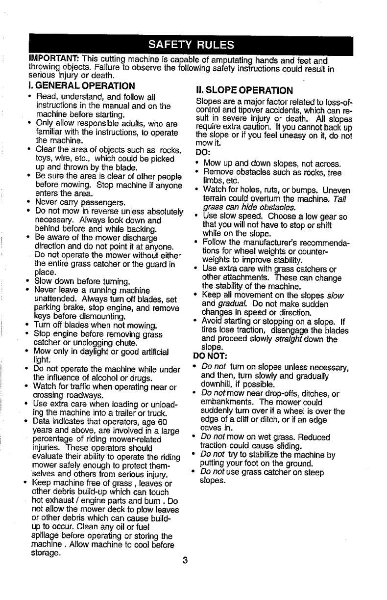
II. SLOPE OPERATION
Slopes are a major factor related to loss-of-
control and tipover accidents, which can re-
sult in severe injury or death. All slopes
require extra caution. If you cannot back up
the slope or if you feel uneasy on it, do not
mow it.
DO:
•Mow up and downslopes, not across.
• Remove obstacles such as rocks, tree
limbs, etc.
•Watch for holes, ruts, or bumps. Uneven
terrain could overturn the machine. Taft
grass can hide obstacles.
°Use slow speed. Choose a low gear so
that you willnot have to stop or shift
while on the slope.
•Follow the manufacturer's recommenda-
tionsfor wheel weights or counter-
weights to improve stability.
°Use extra care with grass catchersor
other attachments. These can change
the stability of the machine.
°Keep all movement on the slopes slow
and gradual Do not make sudden
changes in speed or direction.
•Avoid starting or stopping on a slope. If
tires lose traction, disengage the blades
and proceed slowly straight down the
slope.
DO NOT:
oDo not turn on slopes unless necessary,
and then, turn slowly and gradually
downhill, if possible.
°Do notmow near drop-offs, ditches, or
embankments. The mower could
suddenly turn over if a wheel is over the
edge of a cliff or ditch, or if an edge
caves in+
•Do not mow on wet grass. Reduced
tractioncould cause sliding.
•Do not try to stabilize the machine by
putting your foot on the ground.
•Do not use grass catcher on steep
slopes.
IlLCHILDREN
Tragic accidents can occurif the operator
is not alert to the presence of children.
Children are often attracted to the
machine and the mowing activity. Never
assume that children will remain where
you last saw them.
•Keep children out of the mowing area
and under the watchful care of another
responsible adult.
• Be alert and turn machine off if children
enter the area.
• Before and when backing, look behind
and down for small children.
• Never carry children. They may fall off
and be seriously injured or interfere
with safe machine operation.
° Never allow children to operate the
machine.
• Use extra care when approaching blind
corners, shrubs, trees, or other objects
that may obscure vision.
IV. SERVICE
•Use extra care in handling gasoline
and other fuels. They are flammable
and vapors are explosive.
-Use only an approved container.
-Never remove gas cap or add fuel
with the engine running. Allow
engine to cool before refueling. Do
not smoke.
-Never refuel the machine indoors.
- Never store the machine or fuel
container inside where there is an
open flame, such as a water heater.
• Never run a machine inside a closed
area.
•Keep nuts and bolts, especially blade
attachment bolts, tight and keep
equipment in good condition.
•Never tamper with safety devices.
Check their proper operation regularly,
•Keep machine free of grass, leaves, or
other debris build-up, Clean oil or fuel
spillage. Allow machine to cool before
storing.
• Stop and inspect the equipment if you
strike an object. Repair, if necessary,
before restarting.
•Never make adjustments or repairs
with the engine running.
• Grass catcher components are subject
to wear, damage, and deterioration,
which could expose moving parts or
allow objects to be thrown. Frequently
check components and replace with
manufacturer's recommended parts,
when necessary.
• Mower blades are sharp and can cut.
Wrap the blade(s) or wear gloves, and
use extra caution when servicing them.
•Check brake operation frequently.
Adjust and service as required.
°Be sure the area is clear of other
people before mowing, Stop machine if
anyone enters the area.
•Never carry passengers or children
even with the blades off.
•Do not mow in reverse unless abso-
lutely necessary. Always look down
and behind before and while backing.
°Never carry children. They may fall off
and be seriously injured or interfere
with safe machine operation.
°Keep children out of the mowing area
and under the watchful care of another
responsible adult,
• Be alert and turn machine off if children
enter the area.
•Before and when backing, took behind
and down for small children.
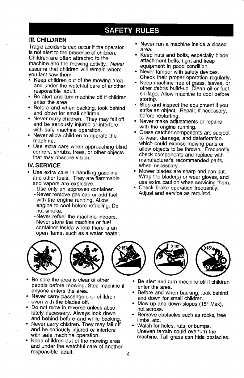
° Mow up and down slopes (15° Max),
not across.
° Remove obstacles such as rocks, tree
limbs, etc.
°Watch for holes, ruts, or bumps,
Uneven terrain could overturn the
machine. Tall grass can hide obstacles.
4
•Use slow speed, Choose a low gear so
that you will not have to stop or shift
while on the slope.
• Avoid starting or stopping on a slope. If
tires lose traction, disengage the
blades and proceed slowly straight
down the slope.
•If machine stops while going uphill,
disengage blades, shift into reverse
and back down slowly.
• Do not turn on slopes unless neces-
sary, and then, turn slowly and gradu-
ally downhill, if possible.
_lbLook for this symbol to point out
important safety precautions. It means
CAUTION!H BECOMEALERT!!! YOUR
SAFETY IS INVOLVED.
CAUTION: In orderto prevent
accidental starting when setting up,
transporting, adjusting or making repairs,
always disconnect spark plug wire and
place wire where it cannot contact spark
plug.
CAUTION: Do not coast down a hill
in neutral, you may lose control of the
tractor.
CAUTION: Tow only the attachments
that are recommended by and comply
with specifications of the manufacturer of
your tractor. Use common sense when
towing. Operate only at the lowest
possible speed when on a slope. Too
heavy of a load, while on a slope, is
dangerous. Tires can lose traction with
the ground and cause you to lose control
of your tractor.
_IbWARNING: Engine exhaust, some of
its constituents, and certain vehicle
components contain or emit chemicals
known to the State of California to cause
cancer and birth defects or other repro-
ductive harm.
_IbWARNING: Battery posts, terminals
and related accessories contain lead and
lead compounds, chemicals known to the
State of California to cause cancer and
birthdefects or other reproductiveharm.
Wash hands after handling.
5
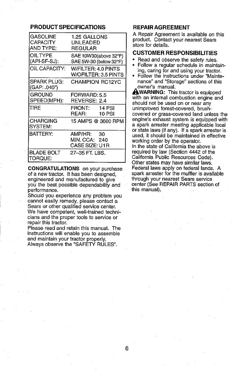
PRODUCT SPECIFICATIONS
GASOLINE 1.25 GALLONS
CAPACITY UNLEADED
AND TYPE: REGULAR
OILTYPE SAE 10W30(above32°i=)
API-SF-SJ): SAE5W-30 (below32°F)
OIL CAPACITY: W/FILTER: 4.0 PINTS
WiOFILTER: 3.5 PINTS
SPARK PLUG: CHAMPION RC12YC
GAP: .040")
GROUND FORWARD: 5.5
SPEED(MPH): REVERSE: 2.4
TIRE FRONT: 14 PSI
REAR: 10 PSI
CHARGING 15 AMPS @ 3600 RPM
SYSTEM:
BATTERY: AMP!HR: 30
MIN. CCA: 240
CASE SIZE: U1 R
BLADE BOLT 27-35 FT. LBS.
TORQUE:
CONGRATULATIONS on your purchase
of a new tractor. It has been designed,
engineered and manufactured to give
you the best possible dependability and
performance.
Should you experience any problem you
cannot easily remedy, please contact a
Sears or other qualified service center.
We have competent, weIFtrained techni-
cians and the proper tools to service or
repair this tractor.
Please read and retain this manual. The
instructions will enable you to assemble
and maintain your tractor properly.
Always observe the "SAFETY RULES%
REPAIR AGREEMENT
A Repair Agreement is available on this
product. Contact your nearest Sears
store for details.
CUSTOMER RESPONSIBILITIES
•Read and observe the safety rules.
° Follow aregular schedule in maintain-
ing, caring for and using your tractor.
•Follow the instructionsunder "Mainte-
nance" and "Storage" sections of this
owner's manual.
,_WARNING: This tractor is equipped
with an internal combustion engine and
should not be used on or near any
unimproved forest-covered, brush-
covered or grass-covered land unless the
engine's exhaust system is equipped with
a spark arrester meeting applicable local
or state laws (if any), If a spark arrester is
used, it should be maintained in effective
working order by the operator.
In the state of California the above is
required by law (Section 4442 of the
California Public Resources Code).
Other states may have similar laws.
Federal laws apply on federal lands. A
spark arrester for the muffler is available
through your nearest Sears service
center (See REPAIR PARTS section of
this manual).
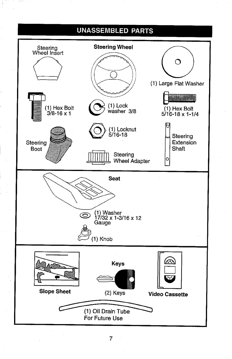
Steering
Wheel Insert
(1) Hex Bolt
3/8-16 x 1
Steerin_
Boot
II,"HII
Steering Wheel
(1) Lockwasher 3/8
(1) Locknut
5/16-18
_ Steering
Wheel Adapter
i
iiiiill ii i
(1) Large Flat Washer
(1) Hex Bolt
5/16-18 x 1-1/4
5
= Steering
Extension
Shaft
o
(1) Washer
@17/32 x 1-3/16 x 12
Gauge
(_(1) Knob
ii ,lll l ii
Slope Sheet
Keys
(2) Keys
,"""llllll
Video Cassette
For Future Use
ill iiiiiiiiiiiiiiiiiillli
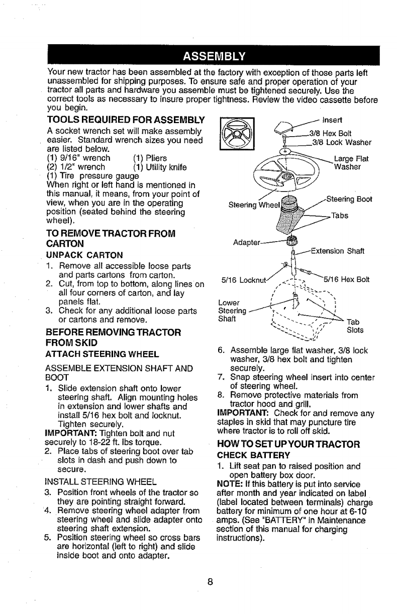
Your new tractor has been assembled at the factory with exception of those parts left
unassembled for shipping purposes. To ensure safe and proper operation of your
tractor all parts and hardware you assemble must be tightened securely. Use the
correct tools as necessary to insure proper tightness. Review the video cassette before
you begin.
TOOLS REQUIRED FOR ASSEMBLY
A socket wrench set will make assembly
easier. Standard wrench sizes you need
are listed below.
(1) 9/16" wrench (1) Pliers
(2) 1/2" wrench (1) Utilityknife
(1) Tire pressure gauge
When right or left hand is mentioned in
this manual, it means, from your point of
view, when you are in the operating
position (seated behind the steering
wheel),
TO REMOVE TRACTOR FROM
CARTON
UNPACK CARTON
1. Remove all accessible loose parts
and parts cartons from carton.
2. Cut, from top to bottom, along lines on
all four corners of carton, and lay
panels flat.
3. Check for any additional loose parts
or cartons and remove.
BEFORE REMOVING TRACTOR
FROM SKID
ATTACH STEERING WHEEL
ASSEMBLE EXTENSION SHAFT AND
BOOT
1. Slide extension shaft onto lower
steering shaft. Align mounting holes
in extension and lower shafts and
install 5/16 hex bolt and Iocknut.
Tighten securely.
IMPORTANT: Tighten bolt and nut
securely to 18-22 ft. Ibs torque.
2. Place tabs of steering boot over tab
slots in dash and push down to
secure.
INSTALL STEERING WHEEL
3. Position front wheels of the tractor so
they are pointing straight forward.
4. Remove steedng wheel adapter from
steering wheel and slide adapter onto
steering shaft extension.
5. Position steering wheel so cross bars
are horizontal (left to right) and slide
inside boot and onto adapter.
Insert
__--_-_ Large Flat
BOOt
SteeringWheel .Tabs
Ada_
//_xtension Shaft
5/16 Locknut/ / _-_._. "5/16 HexBolt
%%
Lower '""
Steering _ ,
Shaft ; ""- Tab
"_:--.. "- -';/i' S_'ots
6. Assemble large flat washer, 3/8 lock
washer, 3/8 hex bolt and tighten
securely.
7. Snap steering wheel insert into center
of steering wheel
8. Remove protective materials from
tractor hood and grill.
IMPORTANT: Check for and remove any
staples in skid that may puncture tire
where tractor is to roll off skid.
HOW TO SET UPYOUR TRACTOR
CHECK BATTERY
1. Lift seat pan to raised positionand
open battery box door.
NOTE: If this battery is put into service
after month and year indicated on label
(label located between terminals) charge
battery for minimum of one hour at 6-10
amps. (See "BA'I-FERY" in Maintenance
section of this manual for charging
instructions).
8
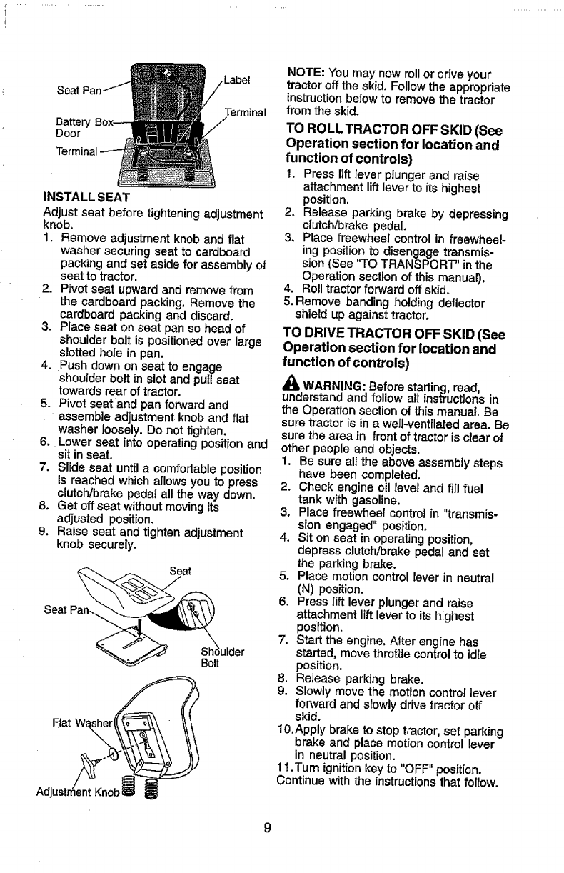
Seat
Label
Terminal
INSTALL SEAT
Adjust seat before tightening adjustment
knob,
1. Remove adjustment knob and flat
washer securing seat to cardboard
packing and set aside for assembly of
seat to tractor.
2. Pivot seat upward and remove from
the cardboard packing. Remove the
cardboard packing and discard.
3. Place seat on seat pan so head of
shoulder bolt is positionedover large
slotted hole in pan.
4. Push down on seat to engage
shoulder bolt in slot and pull seat
towards rear of tractor.
5. pivot seat and pan forward and
assemble adjustment knob and flat
washer loosely. Do not tighten.
6. Lower seat into operating position and
sit in seat.
7. Slide seat until a comfortable position
Is reached which allows you to press
clutch/brake pedal all the way down.
8. Get off seat without moving its
adjusted position.
9. Raise seat and tighten adjustment
knob securely.
Seat
Bolt
Fiat Wa_!
NOTE: You may now roll or drive your
tractor off the skid, Follow the appropriate
instructionbelow to remove the tractor
from the skid.
TO ROLL TRACTOR OFF SKID (See
Operation section for location and
function of controls)
1. Press lift lever pJunger and raise
attachment lift ]ever to its highest
position.
2. Release parking brake by depressing
clutch/brake pedal.
3. Place freewheel control in freewheel-
ing position to disengage transmis-
sion (See 'q'O TRANSPORT" in the
Operation section of this manual),
4. Roll tractor forward off skid.
5. Remove banding holding deflector
shield up against tractor.
TO DRIVE TRACTOR OFF SKID (See
Operation section for location and
function of controls)
,_ WARNING: Before starting,read,
understand and follow all instructions in
the Operation section of this manual. Be
sure tractor is in a well-ventilated area. Be
sure the area in front of tractor is clear of
other people and objects.
1. Be sure all the above assembly steps
have been completed,
2. Check engine oil level and fill fuel
tank with gasoline.
3, Place freewheel control in "transmis-
sion engaged" position.
4. Sit on seat in operating position,
depress clutch/brake pedal and set
the parking brake.
5. Place motion control lever in neutral
(N) position.
6. Press lift lever plunger and raise
attachment liftlever to its highest
position.
7. Start the engine. After engine has
started, move throttle controlto idle
position.
8. Release parking brake.
9. Slowly move the motion control ]ever
forward and slowly drive tractor off
skid.
10.Apply brake to stop tractor, set parking
brake and place motion control lever
in neutral position.
11.Turn ignitionkey to "OFF" position.
Continue with the instructions that follow.
9
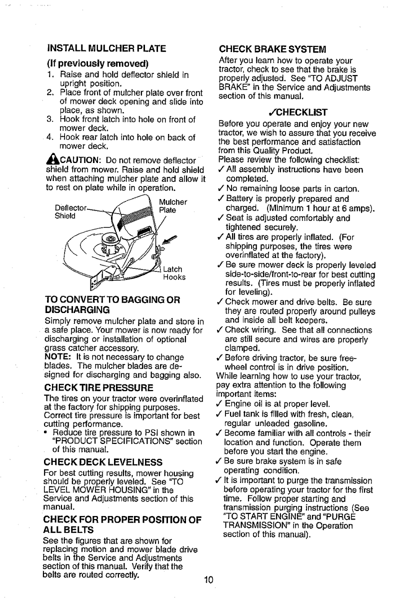
INSTALL MULCHER PLATE
(If previously removed)
1. Raise and hold deflector shield in
upright position.
2. Place front of mulcher plate over front
of mower deck opening and slide into
place, as shown.
3. Hook front latch into hole on front of
mower deck.
4. Hook rear latch into hole on back of
mower deck.
_,CAUTION: Do not remove deflector
shield from mower. Raise and hold shield
when attaching mulcher plate and allow it
to rest on plate whale in operation.
Deflec
Shield
Mulcher
Rate
Latch
Hooks
TO CONVERT TO BAGGING OR
DISCHARGING
Simply remove mulcher plate and store in
a safe place. Your mower is now ready for
discharging or installation of optional
grass catcher accessory.
NOTE." It is not necessary to change
blades, The mulcher blades are de-
signed for discharging and bagging also.
CHECK TIRE PRESSURE
The tires on your tractor were overinflated
at the factory for shipping purposes.
Correct tire pressure is important for best
cutting performance.
•Reduce tire pressure to PSi shown in
"PRODUCT SPECIFICATIONS" section
of this manual.
CHECK DECK LEVELNESS
For best cutting results, mower housing
should be propedy leveled. See "TO
LEVEL MOWER HOUSING" inthe
Service and Adjustments section of this
manual.
CHECK FOR PROPER POSITION OF
ALL BELTS
See the figures that are shown for
replacing motion and mower blade drive
belts inthe Service and Adjustments
section of this manual. Verify that the
belts are muted correctly. 10
CHECK BRAKE SYSTEM
After you learn howto operate your
tractor,check to see that the brake is
properlyadjusted. See "TO ADJUST
BRAKE" in the Service and Adjustments
section of this manual,
,/'CHECKLIST
Before you operate and enjoy your new
tractor, we wish to assure that you receive
the best performance and satisfaction
from this Quality Product,
Please review the following checklist:
v"All assembly instructions have been
completed.
,/No remaining loose parts in carton.
,/Battery is properly prepared and
charged, (Minimum 1 hour at 6 amps).
v" Seat is adjusted comfortably and
tightened securely.
,/All tires are properly inflated. (For
shipping purposes, the tires were
overinflatedat the factory),
JBe sure mower deck is properly leveled
side-to-side!front-to-rear for best cutting
results. (Tires must be properly inftated
for leveling).
,/Check mower and drive belts, Be sure
they are routed properly around pulleys
and inside all belt keepers.
,I Check wiring. See that all connections
are still secure and wires are properly
clamped.
,,,"Before driving tractor, be sure free-
wheel control is in drive position.
While learning how to use your tractor,
pay extra attention to the following
important items:
v" Engine oil is at proper level.
,/Fuel tank is filled with fresh, clean,
regular unleaded gasoline.
,/Become familiar with all controls- their
location and function. Operate them
before you start the engine.
JBe sure brake system is in safe
operating condition.
,/It is importantto purge the transmission
before operating your tractor for the first
time. Follow properstarting and
transmission purging instructions (See
"TO START ENGINE" and "PURGE
TRANSMISSION" anthe Operation
section of this manual).
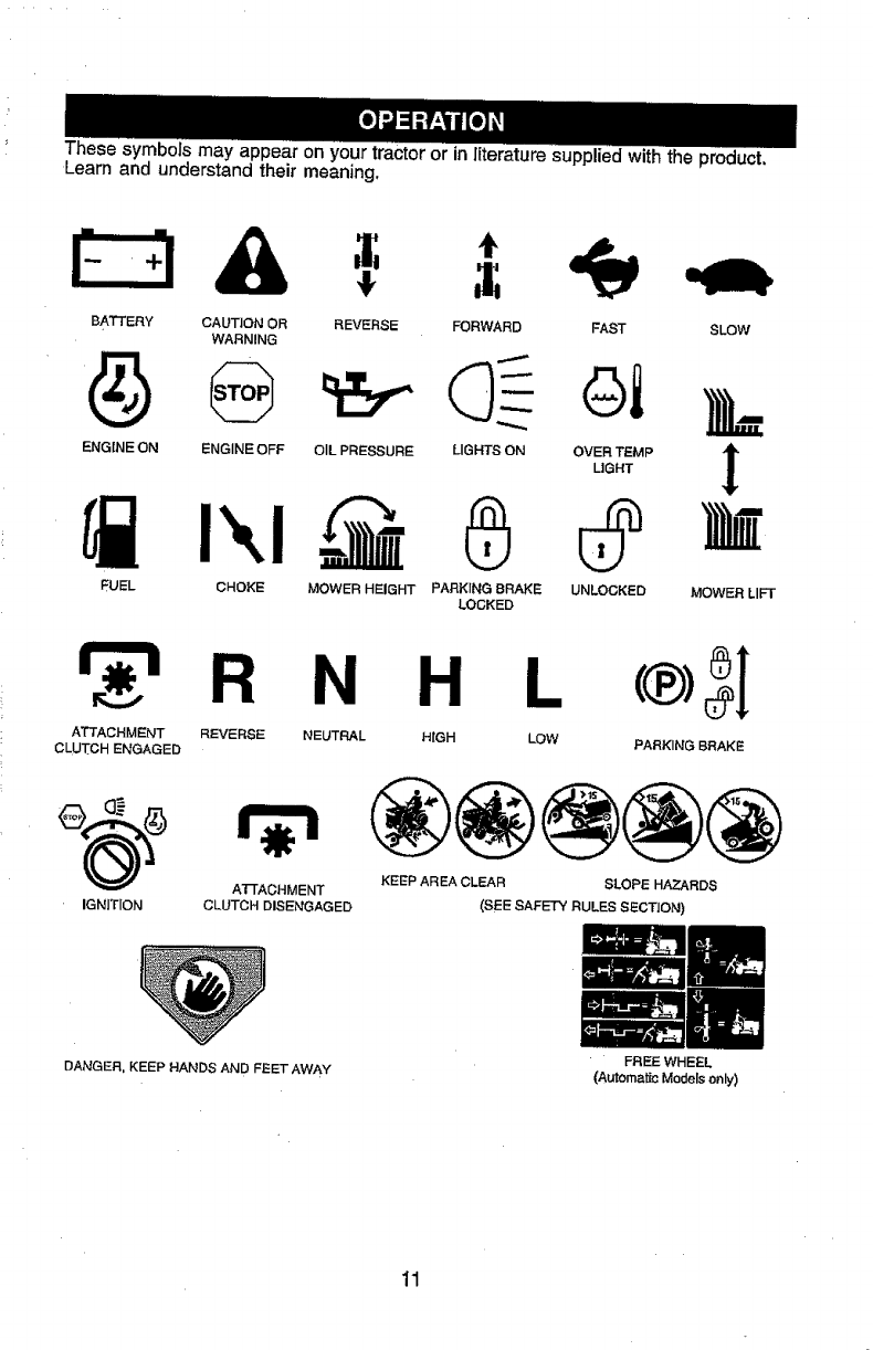
Thesesymbolsmayappearonyourtractororinliteraturesuppliedwiththeproduct.
Learnandunderstandtheirmeaning.
BATTERY CAUTION OR REVERSE FORWARD SLOW
WARNING
ENGINE ON ENGINE OFF OIL PRESSURE LIGHTS ON
FUEL CHOKE MOWER HEIGHT PARKING BRAKE
LOCKED
FAST
Gi
OVER TEMP
LIGHT
UNLOCKED MOWER LIFT
_r_ RNH
ATTACHMENT REVERSE NEUTRAL HIGH
CLUTCH ENGAGED
L_®_I
LOW PARKING BRAKE
A-n'ACHMENT
IGNITION CLUTCH DISENGAGED
KEEP AREA CLEAR SLOPE HAZARDS
(SEE SAFETY RULES SECTION)
DANGER, KEEP HANDS AND FEET AWAY
11
FREE WHEEL
(Automatic Models only)
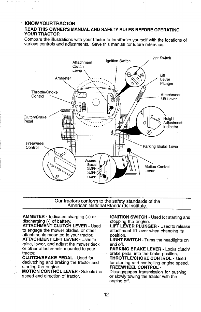
KNOW YOUR TRACTOR
READ THIS OWNER'S MANUAL AND SAFETY RULES BEFORE OPERATING
YOUR TRACTOR
Compare the illustrationswith your tractor to familiarize yourself with the locations of
various controls and adjustments. Save this manual for future reference.
Attachment
Clutch
Ammeter Lever \_
Throttle/Choke
Control
Ignition Switch Light Switch
Lift
jLever
Plunger
Attachment
Lift Lever
CIutch/Brake
Pedal
Freewheel
Control
Height
Adjustment
Indicator
Parking Brake Lever
Motion Control
Lever
Our tractorsconform to the safety standards of the
American National Standards Institute.
AMMETER - Indicates charging (+) or
discharging (-) of battery.
ATTACHMENT CLUTCH LEVER - Used
to engage the mower blades, or other
attachments mounted to your tractor.
ATTACHMENT LIFT LEVER - Used to
raise, lower, and adjust the mower deck
or other attachments mounted to your
tractor.
CLUTCH/BRAKE PEDAL - Used for
deciutching and braking the tractor and
starting the engine.
MOTION CONTROL LEVER - Selects the
speed and direction of tractor.
IGNITION SWITCH - Used for starting and
stopping the engine.
LIFT LEVER PLUNGER - Used to release
attachment lift lever when changing its
position.
LIGHT SWITCH - Turns the headlights on
and off.
PARKING BRAKE LEVER - Locks clutch/
brake pedal into the brake position.
THROTTLE/CHOKE CONTROL- Used
for starting and controlling engine speed.
FREEWHEEL CONTROL-
Disengagages transmission for pushing
or slowly towing the tractor with the
engine off.
12
The operation of any tractor can result in foreign objects thrown into the
eyes, which can result in severe eye damage. Always wear safety
glasses or eye shietds while operating your tractor or performing any
adjustments or repairs. We recommend a wide vision safety mask over
spectacles or standard safety glasses.
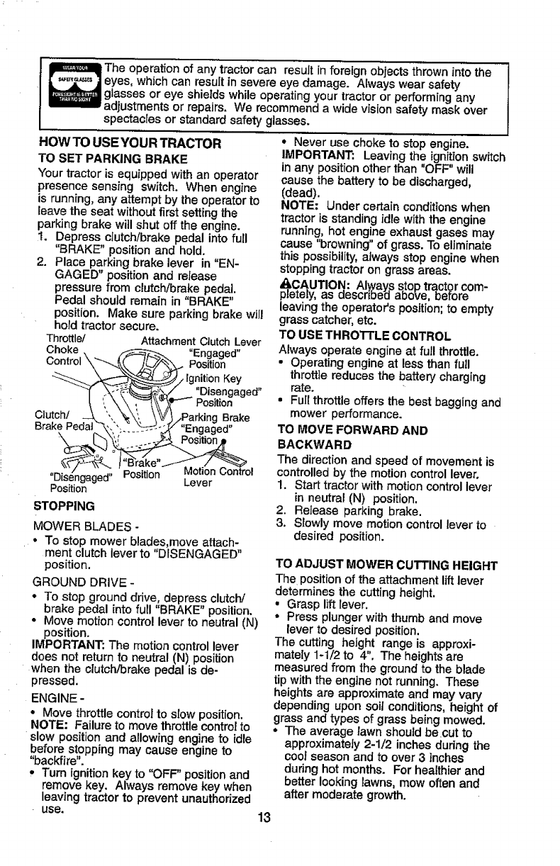
HOW TO USE YOUR TRACTOR
TO SET PARKING BRAKE
Your tractor is equipped with an operator
presence sensing switch. When engine
is running, any attempt by the operator to
leave the seat without firstsetting the
parking brake witl shut off the engine.
1. Depress clutch/brake pedal into full
"BRAKE" position and hold.
2. Place parking brake lever in "EN-
GAGED" position and release
pressure from clutch/brake pedal,
Pedal shoutd remain in "BRAKE"
position. Make sure parking brake will
hold tractor secure.
Throttle/ Attachment Clutch Lever
Choke _ _ "Engaged"
_-___...__ _/Ignition Key
"__'_,_/ "Disengaged"
Clu_" _ ',._'_./.Pa rking Brake
BrakePedat_-. "_"_+__-_-_+_-+:y "Engaged"
_'\ I_,_ _.._:_ Position.+p
"D seng g a" Lever
Position
STOPPING
MOWER BLADES o
• To stop mower blades,move attach-
ment clutch lever to "DISENGAGED"
position.
GROUND DRIVE-
° To stop ground drive, depress clutch/
brake pedal into full "BRAKE" position.
• Move motion control lever to neutral (N)
position.
IMPORTANT: The motion control lever
does not return to neutral (N) position
when the ciutch/brake pedal is de-
pressed.
ENGINE -
• Move throttle control to stow position.
NOTE: Failure to move throttle control to
slow position and allowing engine to idle
before stopping may cause engine to
"backfire".
, Turn ignitionkey to "OFF" position and
remove key. Always remove key when
leaving tractor to prevent unauthorized
use.
°Never use choke to stop engine.
IMPORTANT: Leaving the ignitionswitch
inany position otherthan "OFF" will
cause the battery to be discharged,
(dead).
NOTE: Under certain conditions when
tractor is standing idle with the engine
running, hot engine exhaust gases may
cause "browning" of grass. To eliminate
this possibility, always stop engine when
stopping tractor on grass areas.
A.C.AUTION: AI.waysstop trqctorcom-
pletely, as aescnDea above, oerore
leaving the operator's position; to empty
grass catcher, etc.
TO USE THRO1TLE CONTROL
Always operate engine at full throttle.
• Operating engine at less than full
throttle reduces the battery charging
rate.
• Full throttle offers the best bagging and
mower performance.
TO MOVE FORWARD AND
BACKWARD
The direction and speed of movement is
controlled by the motion control lever.
1. Start tractor with motion control lever
in neutral (N) position,
2. Retease parking brake.
3. Slowly move motion control lever to
desired position.
TO ADJUST MOWER CUTTING HEIGHT
The position of the attachment lift lever
determines the cutting height.
•Grasp lift lever.
° Press plunger with thumb and move
lever to desired position,
The cutting height range is approxi-
mately 1-1/2 to 4". The heights are
measured from the ground to the blade
tip with the engine not running. These
heights are approximate and may vary
depending upon soil conditions, height of
grass and types of grass being mowed.
•The average lawn should becut to
approximately 2-1/2 inches during the
cool season and to over 3 inches
during hot months. For healthier and
better looking lawns, mow often and
after moderate growth.
13
• For best cutting performance, grass
over 6 inches in height should be
mowed twice. Make the first cut
relatively high; the second to desired
height.
TO ADJUST GAUGE WHEELS
Gauge wheels are properly adjusted
when they are slightly off the ground
when mower is at the desired cutting
height in operating position. Gauge
wheels then keep the deck in proper
position to help prevent scalping in most
terrain conditions.
NOTE: Adjust gauge wheels with tractor
on a flat level surface.
1. Adjust mower to desired cutting height
(See "TO ADJUST MOWER CU'F['ING
HEIGHT" in the Operation section of
this manual).
2. With mower in desired height of cut
position, gauge wheels should be
assembled so they are slightly off the
ground. Install gauge wheel in
appropriate hole with shoulder bolt,
3/8 washer, and 3/8-16 Iocknut and
tighten securely.
3. Repeat for opposite side installing
gauge wheel in same adjustment
hole.
3/8-16 "___'%., ""'-x
Bra_'¢_-_'_ _"J" Shoulder
;_z_washer1/_ _J._ .//Bolt
GaugeWheel/ _ ",_eJ"
TO OPERATE MOWER
Your tractor is equipped with an operator
presence sensing switch. Any attempt by
the operator to leave the seat with the
engine running and the attachment
clutch engaged will shut off the engine.
1. Select desired height of cut.
2. Start mower blades by engaging
attachment clutch control.
TO STOP MOWER BLADES -
disengage attachment clutch control.
_J_ CAUTION: Do not operate the
mower without either the entire grass
catcher, on mowers so equipped, or the
deflector shield in place.
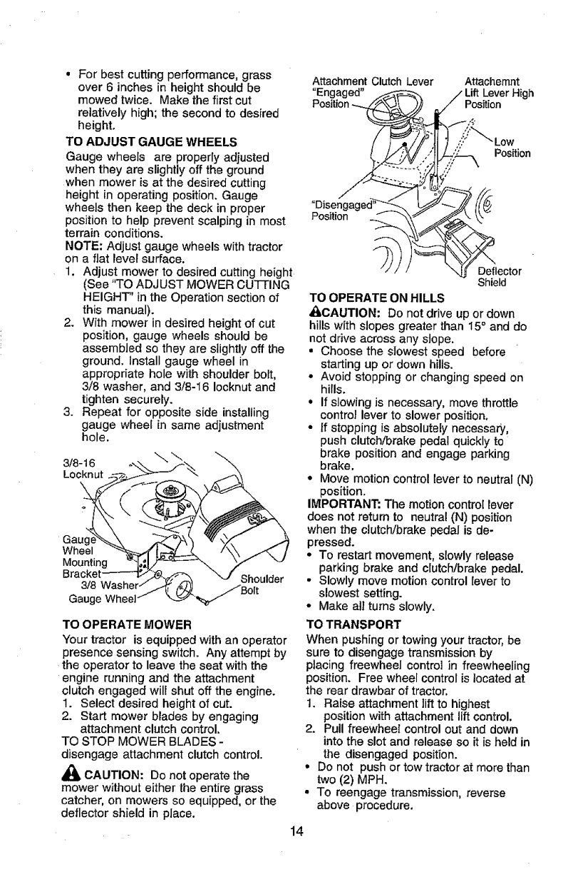
Attachment Clutch Lever Attachemnt
"Engaged" Lever High
Positk Position
Deflector
Shield
TO OPERATE ON HILLS
&CAUTION: Do not drive up or down
hills with slopes greater than 15° and do
not drive across any slope.
•Choose the slowest speed before
starting up or down hills.
•Avoid stopping or changing speed on
hills.
•If slowing is necessary, move throttle
control lever to slower position.
•If stopping is absolutely necessary,
push clutch/brake pedal quickly to
brake position and engage parking
brake.
•Move motion control lever to neutral (N)
position.
IMPORTANT: The motion control lever
does not return to neutral (N) position
when the clutch/brake pedai is de-
pressed.
•To restart movement, slowly release
parking brake and clutch/brake pedal.
•Slowly move motion control lever to
slowest setting.
• Make all turns slowly.
TO TRANSPORT
When pushing or towing your tractor, be
sure to disengage transmission by
placing freewheel control in freewheeling
position. Free wheel control is located at
the rear drawbar of tractor.
1. Raise attachment lift to highest
position with attachment lift control.
2. Pull freewheel control out and down
into the slot and release so it is held in
the disengaged position.
°Do not push or tow tractor at more than
two (2) MPH.
•To reengage transmission, reverse
above procedure.
14
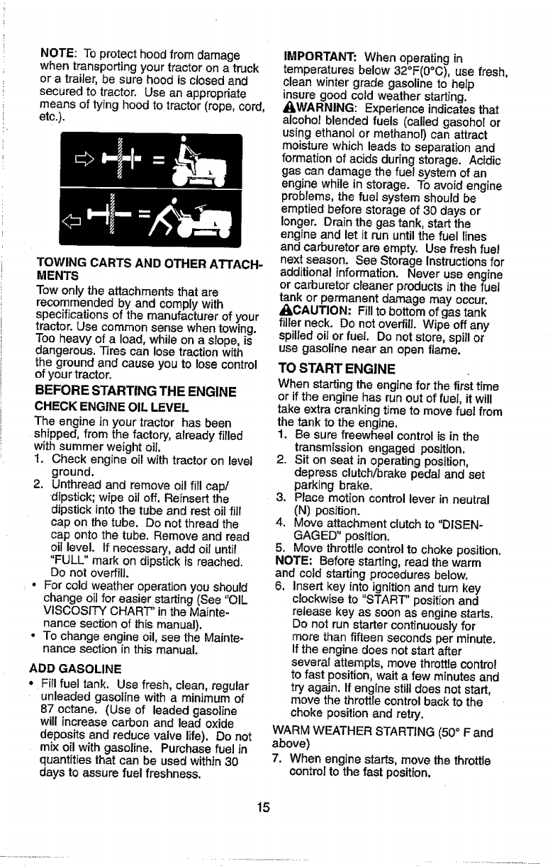
NOTE: To protect hood from damage
when transporting your tractor on a truck
or a trailer, be sure hood is closed and
secured to tractor. Use an appropriate
means of tying hood to tractor (rope, cord,
etc.).
TOWING CARTS AND OTHER ATTACH-
MENTS
Tow only the attachments that are
recommended by and comply with
specifications of the manufacturer of your
tractor. Use common sense when towing.
Too heavy of a load, while on a slope, is
dangerous, -17rescan lose traction with
the ground and cause you to lose control
of your tractor.
BEFORE STARTING THE ENGINE
CHECK ENGINE OIL LEVEL
The engine in your tractor has been
shipped, from the factory, already filled
with summer weight oil.
1. Check engine oil with tractor on level
ground.
2. Unthread and remove oil fill cap/
dipstick; wipe oil off, ReInsert the
dipstick into the tube and rest oilfill
cap on the tube. Do not thread the
cap onto the tube. Remove and read
oil level. If necessary, add oil until
"FULL" mark on dipstick is reached.
Do not overfill.
•For cold weather operation you should
change oilfor easier starting (See "OIL
VISCOSITY CHART" in the Mainte-
nance section of this manual).
•To change engine oil, see the Mainte-
nance section in this manual.
ADD GASOLINE
•Fill fuel tank. Use fresh, clean, regular
unleaded gasoline with a minimum of
87 octane, (Use of leaded gasoline
will increase carbon and lead oxide
deposits and reduce valve life). Do not
mix oil with gasoline, Purchase fuel in
quantities that can be used within 30
days to assure fuel freshness.
IMPORTANT: When operating in
temperatures below 32°F(0°C), use fresh,
clean winter grade gasoline to help
insure good cold weather starting.
AWARNING: Experience indicates that
alcohol blended fuels (called gasohol or
using ethanol or methanol) can attract
moisture which leads to separation and
formation of acids during storage. Acidic
gas can damage the fuel system of an
engine while in storage. To avoid engine
problems,the fuel system should be
emptied before storage of 30 days or
longer. Drain the gas tank, start the
engine and let it run until the fuel lines
and carburetor are empty. Use fresh fuel
next season. See Storage Instructions for
additional information, Never use engine
or carburetorcleaner products in the fuel
tank or permanent damage may occur.
_CAUTION: Fill to bottom of gas tank
filler neck, Do not overfill. Wipe off any
spilled oil or fuel, Do not store, spill or
use gasoline near an open flame.
TO START ENGINE
When starting the engine for the first time
or if the engine has run out of fuel, it will
take extra cranking time to move fuel from
the tank to the engine.
1. Be sure freewheel control is in the
transmission engaged position,
2. Sit on seat in operating position,
depress clutch!brake pedal and set
parking brake.
3. Place motion control lever in neutral
(N) position.
4. Move attachment clutch to "DISEN-
GAGED" position.
5. Move throttle control to choke position.
NOTE; Before starting, read the warm
and cold starting procedures below,
6, Insert key into ignition and turn key
clockwiseto "START" position and
release key as soon as engine starts.
Do not run starter continuously for
more than fifteen seconds per minute.
If the engine does not start after
several attempts, move throttle control
to fast position, wait a few minutes and
try again, If engine still does not start,
move the throttle control back to the
choke position and retry,
WARM WEATHER STARTING (50° F and
above)
7, When engine starts, move the throttle
controlto the fast position.
15
• The attachments and ground drive can
now be used. If the engine does not
accept the load, restart the engine and
allow it to warm up for one minute
using the choke as described above.
COLD WEATHER STARTING ( 50° F and
below)
7. When engine star[s, allow engine to
run with the throttle control in the
choke position until the engine runs
roughly, then move throttle control to
fast position. This may require an
engine warm-up period from several
seconds to several minutes, depend-
ing on the temperature.
AUTOMATIC TRANSMISSION WARM UP
Before driving the unit in cold weather,
the transmission should be warmed up as
follows:
1. Be sure the tractor is on level ground.
2. Place the motion control lever in
neutral. Release the parking brake
and let the clutch/brake slowly return
to operating position.
3. Allow one minute for transmission to
warm up. This can be done during
the engine warm up period.
• The attachments can also be used
during the engine warm-up period after
the transmission has been warmed up.
NOTE: If at a high altitude (above 3000
feet) or in cold temperatures (below 32 F)
the carburetor fuel mixture may need to
be adjusted for best engine performance,
See 'q'O ADJUST CARBURETOR" in the
Service and Adjustments section of this
manual.
PURGE TRANSMISSION
_IlbCAUTION: Never engage or disen-
gage freewheel lever while the engine is
running.
To ensure proper operation and perfor-
mance, it is recommended that the
transmission be purged before operating
tractor for the first time. This procedure will
remove any trapped air inside the
transmission which may have developed
during shipping of your tractor.
IMPORTANT: Should your transmission
require removal for service or replace-
ment, it should be purged after reinstalla-
tion before operating the tractor.
1. Place tractor safely on level surface
with engine off and parking brake set,
2. Disengage transmission by placing
freewheel control in freewheeling
position (See 'q'o TRANSPORT" in
this section of manual).
3. Sitting in the tractor seat, start engine.
After the engine is running, move
throttle control to slow position. With
motion control lever in neutral (N)
position, slowly disengage clutch/
brake pedal.
4. Move motion control lever to full
forward position and hold for five (5)
seconds. Move lever to full reverse
position and hold for five (5) seconds.
Repeat this procedure three (3) times.
NOTE: During this procedure there will be
no movement of ddve wheels. The air is
being removed from hydraulic ddve
system.
5. Move motion control lever to neutral
(N) position. Shut- off engine and set
parking brake.
6. Engage transmission by placing
freewheel control in driving position
(See 'q'O TRANSPORT" in this section
of manual).
7. Sitting in the tractor seat, start engine.
After the engine is running, move
throttle control to half (1/2) speed. With
motion control lever in neutral (N)
position, slowly disengage clutch/
brake pedal.
8. Slowly move motion control lever
forward, after the tractor moves
approximately five (5) feet, slowly
move motion control lever to reverse
position. After the tractor moves
approximately five (5) feet return the
motion control lever to the neutral (N)
position. Repeat this procedure with
the motion control lever three (3)
times.
Your tractor is now purged and now ready
for normal operation.
16
MOWING TIPS
°Mower should be propedy leveled for
best mowing performance. See 'TO
LEVEL MOWER HOUSING" in the
Service and Adjustments section of this
manual.
oThe left hand side of mower should be
used for trimming,
•Drive so that clippings are discharged
onto the area that has been cut. Have
the cut area to the rightof the tractor.
This wilt result in a more even distribu-
tion of clippings and more uniform
cutting,
° When mowing large areas, start by
turning to the right so that clippings will
discharge away from shrubs, fences,
driveways, etc. After one or two
rounds, mow in the opposite direction
making left hand turns until finished.
° If grass is extremely tail, it should be
mowed twice to reduce load and
possible fire hazard from dried clip-
pings. Make first cut relatively high; the
second to the desired height,
•Do not mow grass when it is wet. Wet
grass will plug mower and leave
undesirable clumps. Allow grass to dry
before mowing.
•Always operate engine at full throttle
when mowing to assure better mowing
performance and proper discharge of
material. Regulate ground speed by
selecting a low enough gear to give the
mower cutting performance as we]l as
the quality of cut desired.
• When operating attachments, select a
ground speed that wi]l suit the terrain
and give best performance of the
attachment being used.
MULCHING MOWING TIPS
IMPORTANT: For best performance,
keep mower housing free of built-up
grass and trash. Clean after each use.
• The special mulching blade will recut
the grass clippingsmany times and
reduce them in size so that as they fail
onto the lawn they witl disperse into the
grass and not be noticed. Also, the
mulched grass will biodegrade quickly
to provide nutrients for the lawn,
Always mulch with your highest engine
(blade) speed as this will provide the
best recutting action of the blades.
•Avoid cutting your lawn when it is wet,
Wet grass tends to form clumps and
interferes with the mulching action.
The best time to mow your lawn is the
eady afternoon. At this time the grass
has dried and the newly cut area will
not be exposed to the direct sun.
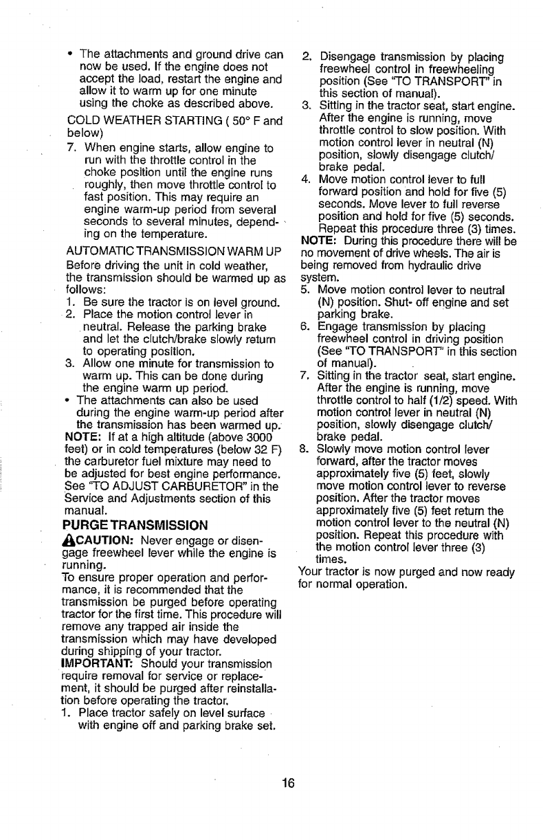
• For best results, adjust the mower
cutting height so that the mower cuts off
only the top one-third of the grass
blades. For extremely heavy mulching,
reduce your width of cut on each pass
and mow slowly,
°Certain types of grass and grass
conditions may require that an area be
mulched a second time to completely
hide the clippings. When doing a
second cut, mow across or perpendicu-
lar to the first cut path.
•Change your cutting pattern from week
to week. Mow north to south one week
then change to east to west the next
week. This wilt help prevent matting
and graining of the lawn.
Max 1/3"
17
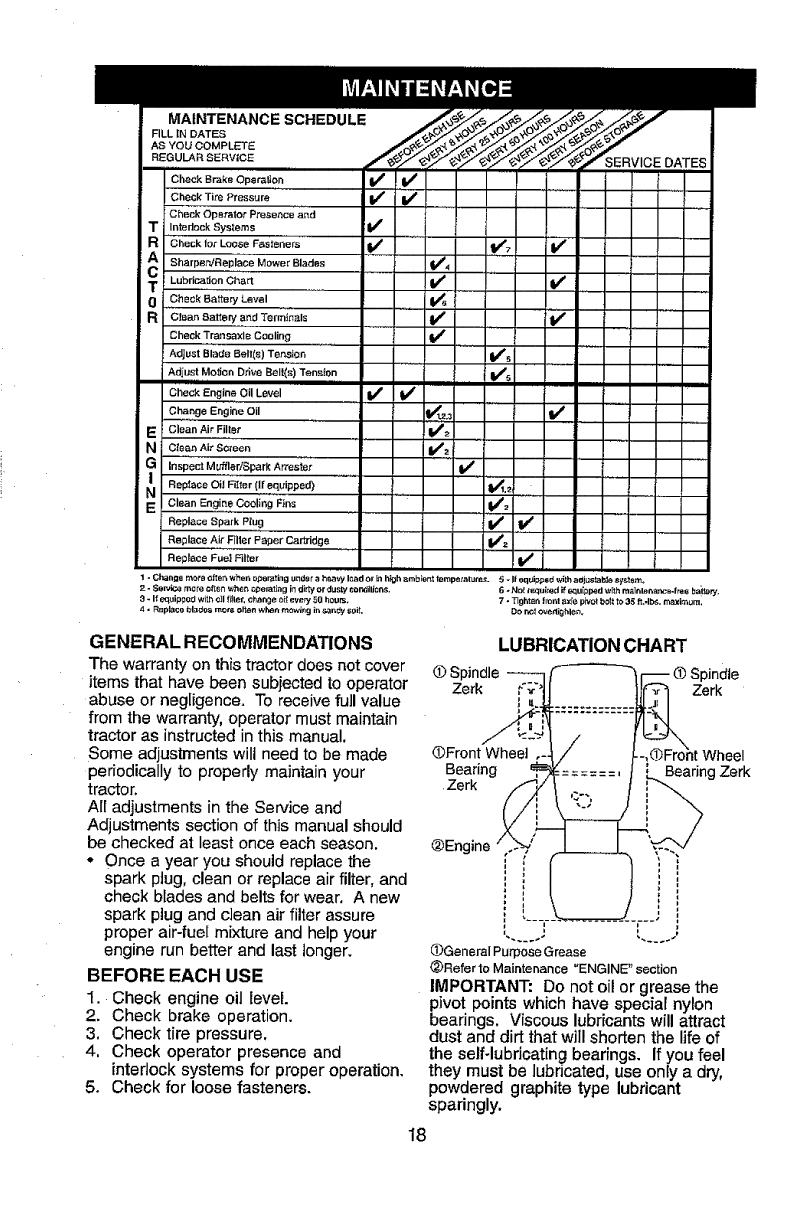
MAINTENANCE SCHEDULE
FILL IN DATES
AS YOU COMPLETE
REGULARSERV|CE SERVICE
Check Brake Operation
Check Tire Pressure If V'
Check Opetater Presence and
T InterlockSysler_s V'
R CheckfoxLooseF,_e_e.e= V' I/7 V'
A Mower Blades _4
Sharpen!Rep, lace
T Lubdca_onC,_rt ...... II/' I/
0Check Battery Level
RCJean Baller¢ and Terrninals , if _ .......
Check T!aneaxle Coaling ........ I_ .....
Adjust Blade Belt(s) Ten.stee V*s
Adjust Me,ion Drive Belt,s) Tension V_s
ilUl nl
Check Engine Oil Level If V'
ch_._0eE,ginooil V',,._ V' =
E Clean Air Fillet' _=
Ni Ctea_ Air Screen V_2 i
|n,p_ au_erlSparkArrest; V'
Replace Oil Filter (I[ equipped) .... _.= .....
Clean Eng!n e Cooling Fins !_z
Replace Spark Plug If tk _
Replace Air Filter Paper Car'_ridge .... V*_
Replace Fuel Filer Vp
,,H .....
1.Changemor_ofteP.whenopemti_gundsraheavyloador_h_mb_e_ttempsxat=_o 5-1teqUJp_Bdwi_haejustabf_t_y_.t_ra,
2- Se_ mo re o_en whet, _perati_g in dir_ or dLIsty _orV3ilJ_n_. 6 *N_I i_3_i_ed if equipped with m_]nl_na._:_-fre8 ba_e_,
8 * If equippe_ with _]I _ill_t. change oil eve_ 58 bourn, 7 * _ghten f_ent axle pivot bolt to 35 _t Ai_, tr_'(im_m,
4 - Replace bl_e= rr_ olin whe_ mo_g in .=_ndy so_L Do r_t _vePJg_l_n_
GENERAL RECOMMENDATIONS
The warranty on thistractordoes not cover
items that have been subjected to operator
abuse or negligence. To receive full value
from the warranty, operator must maintain
tractor as instructed in this manual.
Some adjustments will need to be made
periodically to properly maintain your
tractor.
All adjustments in the Service and
Adjustments section of this manual should
be checked at least once each season.
• Once a year you should replace the
spark plug, clean or replace air filter, and
check blades and belts for wear. A new
spark plug and clean air filter assure
proper air-fuel mixture and help your
engine run better and last longer.
BEFORE EACH USE
1. Check engine oil level.
2. Check brake operation.
3. Check tire pressure.
4. Check operator presence and
interlock systems for proper operation.
5. Check for loose fasteners.
LUBRICATION CHART
Spindle
Zerk Zerk
(£Front Wheel
Bearing
Zerk Bearing Zerk
@Engine
_)General Purpose Grease
(_)Refer to Maintenance "ENGINE" section
IMPORTANT: Do not oil or grease the
pivot points which have special nylon
bearings. Viscous lubricants will attract
dust and dirt that will shorten the life of
the self-lubricating bearings. If you feel
they must be lubricated, use only a dry,
powdered graphite type lubricant
sparingly.
18
TRACTOR
Always observe safety rules when
performing any maintenance.
BRAKE OPERATION
Iftractor requires more than six (6) feet
stopping distance at high speed in
highest gear, then brake must be ad-
justed. (See 'fro ADJUST BRAKE" in the
Service and Adjustments section of this
manual).
TIRES
° Maintain proper air pressure in alt tires
(See "PRODUCT SPECIFICATIONS"
section of this manual).
•Keep tires free of gasoline, oil, or insect
control chemicals which can harm
rubber.
•Avoid stumps, stones, deep ruts, sharp
objects and other hazards that may
cause tire damage.
NOTE: To seal tire punctures and prevent
flat tires due to slow leaks, tire sealant
may be purchased from your local parts
dealer. Tire sealant also prevents tire dry
rot and corrosion.
OPERATOR PRESENCE SYSTEM
Be sure operator presence and interlock
systems are working properly. If your
tractor does not function as described,
repair the problem immediately.
° The engine should not start unless the
brake pedal is fully depressed and
attachement clutch control is in the
disengaged position.
•When the engine is running, any
attempt by the operator to leave the
seat without first setting the parking
brake should shut off the engine.
• When the engine is running and the
attachment clutch is engaged, any
attempt by the operator to leave the
seat should shut off the engine.
• The attachment clutch should never
operate unless the operator is in the
seat.
BLADE CARE
For best results mower blades must be
kept sharp. Replace bent or damaged
blades.
BLADE REMOVAL
1. Raise mower to highest positionto
allow access to blades.
2. Remove hex bolt, lock washer and flat
washer securing blade.
3. Install new or resharpened blade with
trailing edge up towards deck as
shown.
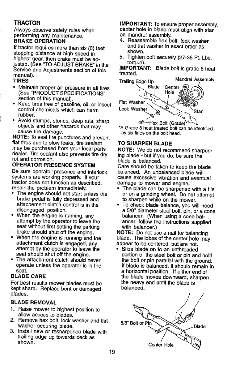
IMPORTANT: To ensure properassembly,
center hole in blade must align with star
on mandrel assembly.
4. Reassemble hex bolt, lockwasher
and flat washer in exact order as
shown.
5. Tighten bolt securely (27-35 Ft. Lbs.
torque).
IMPORTANT: Blade bolt is grade 8 heat
treated. MandrelAssembly
TrailingEdgeUp ._ j
"_. Blade Center ]_'_/'_\
_--Hex Bolt (Grade)*'La'&
*A Grade8 heattreatedbolt canbe identified
by sixlineson the bolt head,
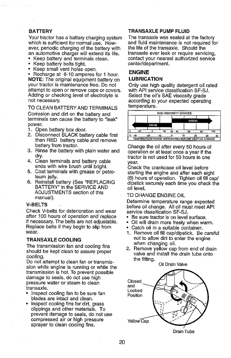
TO SHARPEN BLADE
NOTE: We do not recommend sharpen-
ing blade -but if you do, be sure the
blade is balanced.
Care should be taken to keep the blade
balanced. An unbalanced blade will
cause excessive vibration and eventual
damage to mower and engine.
° The blade can be sharpened with afile
or on a grinding wheel. Do not attempt
to sharpen while on the mower.
•To check blade balance, you will need
a 5/8" diameter steel bolt, pin, or a cone
balancer. (When using a cone bal-
ancer, follow the instructions supplied
with balancer.)
NOTE; Do not use a nail for balancing
blade. The lobes of the center hole may
appear to be centered, but are not.
•Slide blade on to an unthreaded
portion of the steel bolt or pin and hold
the boft or pin parallel with the ground.
If blade is balanced, it should remain in
a horizontal position. If either end of
the blade moves downward, sharpen
the heavy end until the blade is
balanced.
5/8""_B__ e
Center Hole
19
BATTERY
Your tractor has a battery charging system
which is sufficient for normal use. How-
ever, periodic charging of the battery with
an automotive charger will extend its life.
• Keep battery and terminals clean,
° Keep battery bolts tight,
• Keep small vent holes open.
• Recharge at 6-10 amperes for 1 hour.
NOTE: The original equipment battery on
your tractor is maintenance free. Do not
attempt to open or remove caps or covers.
Adding or checking level of electrolyte is
not necessary.
TO CLEAN BATTERY AND TERMINALS
Corrosion and dirt on the battery and
terminals can cause the battery to "leak"
power.
1. Open battery box door,
2. Disconnect BLACK battery cable first
then RED battery cable and remove
battery from tractor.
3. Rinse the battery with plain water and
dry.
4. Clean terminals and battery cable
ends with wire brush until bright.
5. Coat terminals with grease or petro-
leum jelly.
6. Reinstall battery (See "REPLACING
BATTERY" in the SERVICE AND
ADJUSTMENTS section of this
manual).
V-BELTS
Check V-belts for deterJoration and wear
after t00 hours of operation and replace
if necessary. The belts are not adjustable.
Replace belts if they begin to slip from
wear.
TRANSAXLE COOLING
The transmission fan and cooling fins
should be kept clean to assure proper
cooling.
Do not attempt to clean fan or transmis-
sion while engine is running or while the
transmission is hot. To prevent possible
damage to seals, do not use high
pressure water or steam to clean
transaxie.
• Inspect cooling fan to be sure fan
blades are intact and clean.
• Inspect cooling fins for dirt, grass
clippings and other materials. To
prevent damage to seals, do not use
compressed air or high pressure
sprayer to clean cooling fins.
TRANSAXLE PUMP FLUID
The transaxle was sealed at the factory
and fluid maintenance is not required for
the life of the transaxle. Should the
transaxle ever leak or require servicing,
contact your nearest authorized service
center/department.
ENGINE
LUBRICATION
Only use high quality detergent oil rated
with API service classification SF-SJ.
Select the oil's SAE viscosity grade
according to your expected operating
temperature.
Change the oil after every 50 hours of
operation or at least once a year if the
tractor is not used for 50 hours in one
year.
Check the crankcase oil level before
starting the engine and after each eight
(8) hours of operation. Tighten oil fill cap/
dipstick securely each time you check the
oil level.
TO CHANGE ENGINE OIL
Determine temperature range expected
before oil change. All oil must meet API
service classification SF-SJ,
• Be sure tractor is on level surface.
• Oil will drain more freely when warm.
•Catch oil in a suitable container.
1, Remove oil fill cap/dipstick. Be careful
not to allow dirt to enter the engine
when changing oil.
2. Remove yellow cap from end of drain
valve and installthe drain tube onto
the fitting. OilDrainValve
Closed 1
and
Locked
Position
Drain Tube
2O
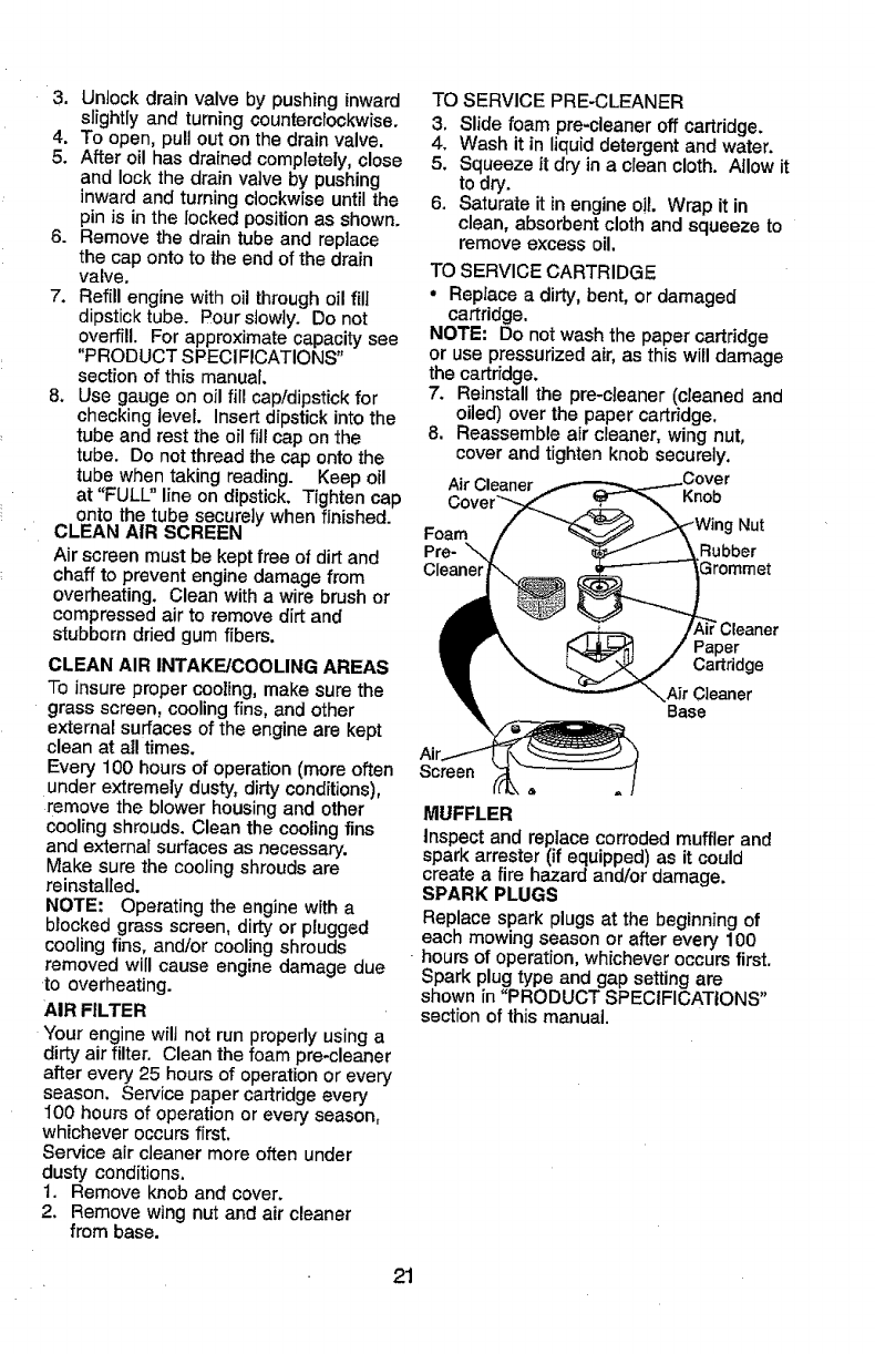
3. Unlock drain valve by pushing inward
slight[y and turning countemlockwise.
4. To open, pull out on the drain valve.
5. After oil has drained completely, close
and lock the drain valve by pushing
inward and turning clockwise until the
pin is in the locked position as shown.
6. Remove the drain tube and replace
the cap onto to the end of the drain
valve,
7. Refill engine with oil through oil fill
dipstick tube. Pour slowly. Do not
overfill. For approximate capacity see
"PRODUCT SPECIFICATIONS"
section of this manual.
8. Use gauge on oil fill cap!dipstick for
checking level. Insert dipstick into the
tube and rest the oil fill cap on the
tube. Do not thread the cap onto the
tube when taking reading. Keep oil
at "FULL" line on dipstick. Tighten cap
onto the tube securely when finished.
CLEAN AIR SCREEN
Air screen mustbe kept free of dirtand
chaff to prevent engine damage from
overheating. Clean with a wire brushor
compressed air to remove dirt and
stubborn dried gum fibers.
CLEAN AIR INTAKE/COOLING AREAS
To insure proper cooling, make sure the
grass screen, coolingfins, and other
external surfaces of the engine are kept
clean at all times.
Every 100 hours of operation (more often
under extremely dusty, dirtyconditions),
remove the blower housing and other
cooling shrouds. Clean the coolingfins
and external surfaces as necessary.
Make sure the coolingshrouds are
reinstalled.
NOTE: Operating the engine with a
blocked grass screen, dirtyor plugged
cooling fins, and/or cooling shrouds
removed will cause engine damage due
to overheating.
AIR FILTER
Your engine wilt not run properly usinga
dirty air filter. Clean the foam pre-cleaner
after every 25 hours of operationor every
season. Service paper cartridge every
lO0 hours of operation or every season,
whichever occursfirst.
Service air cleaner more often under
dusty conditions,
!. Remove knob and cover.
2. Remove wing nut and air cleaner
from base.
21
TO SERVICE PRE-CLEANER
3, Slide foam pre-cleaner off cartridge.
4. Wash it in liquid detergent and water.
5. Squeeze it dry in a clean cloth. Allow it
to dry.
6. Saturate it in engine oil. Wrap it in
clean, absorbent cloth and squeeze to
remove excess oil.
TO SERVICE CARTRIDGE
• Replace a dirty, bent, or damaged
cartridge.
NOTE: Do not wash the paper cartridge
or use pressurized air, as this will damage
the cartridge.
7. Reinstall the pre-cleaner (cleaned and
oiled) over the paper cartridge,
8. Reassemble air cleaner, wing nut,
cover and tighten knob securely.
Air Cleaner Knob
Foam Nut
Preo Rubber
_romrnet
Paper
Cartridge
,,Air Cleaner
Base
Air
Screen
MUFFLER
Inspect and replace corroded muffler and
spark arrester (if equipped) as it could
create a fire hazard and/or damage.
SPARK PLUGS
Replace spark plugs at the beginning of
each mowing season or after every 100
hoursof operation, whichever occursfirst.
Spark plugtype and gap settingare
shown in "PRODUCT SPECIFICATIONS"
section of this manual.
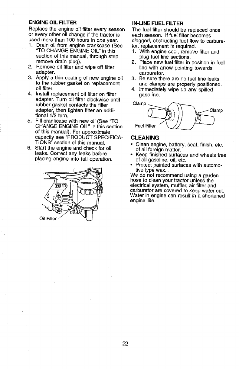
ENGINE OIL FILTER
Replace the engine oil filter every season
or every other oil change ifthe tractor is
used more than 100 hours in one year,
1, Drain oil from engine crankcase (See
"TO CHANGE ENGINE OIL" in this
section of this manual, through step
remove drain plug),
2. Remove oil filter and wipe off filter
adapter.
3. Apply a thin coating of new engine oil
to the rubber gasket on replacement
oil filter.
4. Install replacement oil filter on filter
adapter. Turn oil filter clockwise until
rubber gasket contacts the filter
adapter, then tighten filter an addi-
tional 1/2 turn.
5, Fill crankcase with new oil (See 'q-O
CHANGE ENGINE OIL" in this section
of this manual). For approximate
capacity see "PRODUCT SPECIFICA-
TIONS" section of this manual,
6. Start the engine and check for oil
leaks. Correct any leaks before
placing engine into full operation.
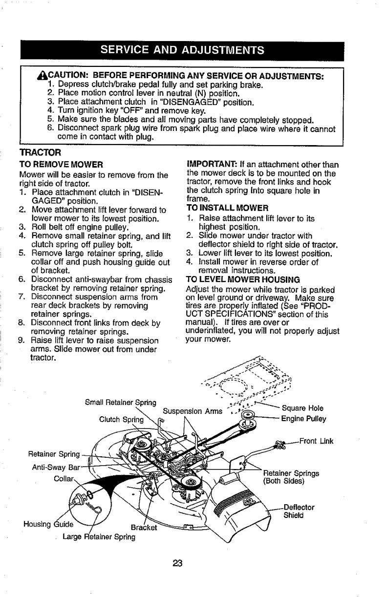
IN-LINE FUEL FILTER
The fuel filter should be replaced once
each season. Iffuel filter becomes
clogged, obstructingfuel flow to carbure-
tor, replacement is required,
1. With engine cool, remove filter and
plug fuel line sections.
2. Place new fuel filter in position in fuel
line with arrow pointing towards
carburetor.
3. Be sure there are no fuel lineleaks
and clamps are properly positioned.
4. Immediately wipe up any spilled
gasoline.
ciarnp_ ..... z'_.
FuelFilter " \...__._
CLEANING
- Clean engine, battery, Seat, finish, etc.
of allforeign matter.
•Keep finished surfaces and wheels free
of all gasoline, oil, etc.
• Protect painted surfaces with automo-
tive type wax.
We do not recommend using agarden
hose to clean your tractor unless the
electrical system, muffler,air filter and
carburetorare covered to keep water out.
Water in engine can result in a shortened
engine life.
22
,_I_CAUTION: BEFORE PERFORMING ANY SERVICE OR ADJUSTMENTS:
1. Depress clutch/brake pedal fully and set parking brake.
2. Place motion controllever in neutral (N) position.
3. Place attachment clutch in "DISENGAGED" position.
4. "rum ignition key "OFF" and remove key.
5. Make sure the blades and alI moving parts have completelystopped.
6. Disconnect spark plug wire from spark plug and place wire where it cannot
come in contact with plug.
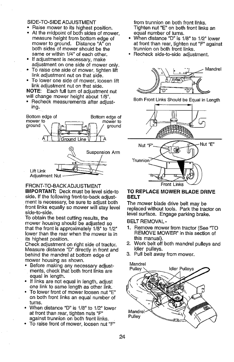
TRACTOR
TO REMOVE MOWER
Mower willbe easier to remove from the
right side of tractor.
1. Place attachment clutch in "DISEN-
GAGED" position.
2. Move attachment lift lever forward to
lower mower to its lowest position.
3. Roll belt off engine pulley.
4. Remove small retainer spring, and lift
clutch spring off pulley bolt.
5. Remove large retainer spring, slide
collar off and push housing guide out
of bracket,
6. Disconnect anti-swaybar from chassis
bracket by removing retainer spring.
7. Disconnect suspension arms from
rear deck brackets by removing
retainer springs.
8. Disconnect front links from deck by
removing retainer springs.
9. Raise lift lever to raise suspension
arms. Slide mower out from under
tractor.
Small Retainer Spring
Clutch S
IMPORTANT: If an attachment other than
the mower deck is to be mounted on the
tractor, remove the front links and hook
the clutch spring Into square hole in
frame,
TO INSTALL MOWER
1, Raise attachment lift lever to its
highest position,
2. Slide mower under tractor with
deflector shield to right side of tractor.
3. Lower lift lever to its lowest position,
4. Install mower in reverse order of
removal instructions.
TO LEVEL MOWER HOUSING
Adjust the mower while tractor is parked
on level ground or driveway. Make sure
tires are properly inflated (See "PROD-
UCT SPECIFICATIONS" section of this
manual). If tires are over or
undefinflated, you will not properly adjust
your mower.
Retainer Sprin!
Anti-Sway
Link
prings
(Both Sides)
Housing Guide
Large _pring
Shield
23
SIDE-TO-SIDE ADJUSTMENT
• Raise mower to its highest position,
• At the midpoint of both sides of mower,
measure height from bottom edge of
mower to ground. Distance "A" on
both sides of mower should be the
same or within 114"of each other.
• If adjustment is necessary, make
adjustment on one side of mower only.
° To raise one side of mower, tighten lift
link adjustment nut on that sider
• To lower one side of mower, loosen lift
link adjustment nut on that side.
NOTE: Each full turn of adjustment nut
will change mower height about 1/8".
° Recheck measurements after adjust-
ingt
Bottomedge of Bottomedgeof
mowerto mower to
ground \_7 ground
A-'l-_'_j Ground Line _"}'-FA
_ion Arm
Lift Link
Adjustment
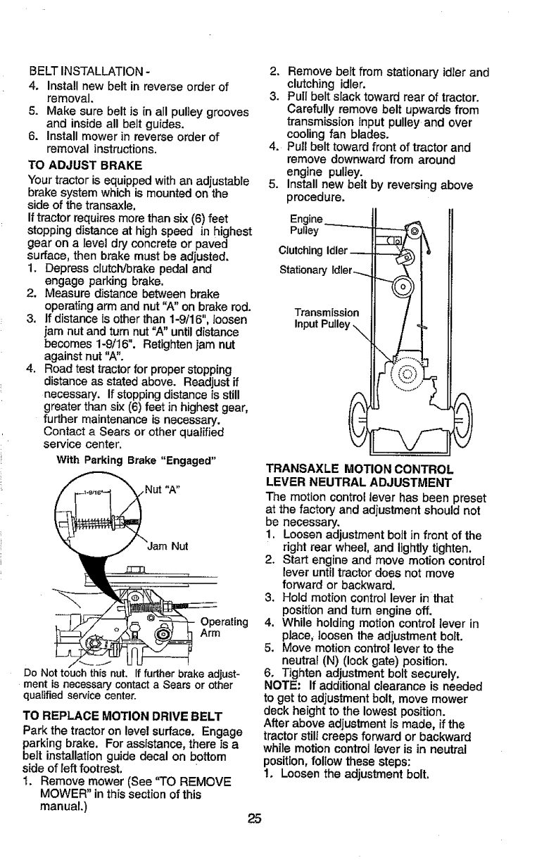
FRONT-TO-BACK ADJUSTMENT
IMPORTANT: Deck must be level side-to
side. If the following front-to-back adjust-
ment is necessary, be sure to adjust both
front links equally so mower will stay level
side-to-side.
To obtain the best cutting results, the
mower housing should be adjusted so
that the front is approximately 1/8" to I/2"
lower than the rear when the mower is in
its highest position.
Check adjustment on right side of tractor.
Measure distance "D" directly in front and
behind the mandrel at bottom edge of
mower housing as shown.
•Before making any necessary adjust-
ments, check that both front links are
equal in length.
• If links are not equal in length, adjust
one link to same length as other link.
• To lower front of mower loosen nut "E"
on both front links an equal number of
turns.
° When distance "D" is 1/8" to 1/2" lower
at front than rear, tighten nuts "F"
against trunnion on both front links.
• To raise front of mower, loosen nut "F';
from trunnion on both front links,
Tighten nut "E" on both front links an
equal number of turns.
° When distance "D" is 1/8" to 1/2" lower
at front than rear, tighten nut "F" against
trunnion on both front links.
° Recheck side-to-side adjustment.
Both Front LinksShouldbe Equal in Length
4_ENJ
TO REPLACE MOWER BLADE DRIVE
BELT
The mower blade drive belt may be
replaced withouttools, Park the tractoron
level surface. Engage parking brake,
BELTREMOVAL-
1. Remove mowerfrom tractor (See "TO
REMOVE MOWER" in thissection of
this manual).
2, Work belt off both mandrel pulleys and
idler pulleys.
3. Pull belt away from mower.
Mandrel
Pulle_
Pulley
24
BELTINSTALLATION-
4, Installnewbeltinreverseorderof
removal.
5. Makesurebeltisinallpulieygrooves
andinsideallbeltguides.
6. Installmowerinreverseorderof
removalinstructions.
TO ADJUST BRAKE
Your tractor is equipped with an adjustable
brake system which is mounted on the
side of the transaxle.
If tractor requires more than six (6) feet
stopping distance at high speed in highest
gear on a level dry concrete or paved
surface, then brake must be adjusted.
1. Depress clutch/brake pedal and
engage parking brake,
2. Measure distance between brake
operating arm and nut 'W' on brake rod.
3. If distance is other than 1-9/16", toosen
jam nut and turn nut "A" until distance
becomes 1-9/16". Retighten jam nut
against nut 'W'.
4, Road test tractor for proper stopping
distance as stated above. Readjust if
necessary, If stopping distance is still
greater than six (6) feet in highest gear,
further maintenance is necessary,
Contact a Sears or other qualified
service center,
With ParkingBrake "Engaged"
Nut
Operating
Arm
Do Not touch this nut. ff further brake adjust-
ment is necessary contact a Sears or other
qualified service center.
TO REPLACE MOTION DRIVE BELT
Park the tractor on level surface, Engage
parkingbrake. For assistance, there is a
belt installation guide decal on bottom
side of left footrest,
1. Remove mower (See "TO REMOVE
MOWER" in this section of this
manual.)
2, Remove belt from stationary idler and
clutching idler.
3, Pull belt slack toward rear of tractor.
Carefully remove belt upwards from
transmission input pulley and over
cooling fan blades.
4. Pull belt toward front of tractor and
remove downward from around
engine pulley.
5. Install new belt by reversing above
procedure,
Engine
Pulley
Clutching Idler
Stationary idler-...
Transmission
Input Pulley ._
TRANSAXLE MOTION CONTROL
LEVER NEUTRAL ADJUSTMENT
The motion controllever has been preset
at the factory and adjustment should not
be necessary,
1. Loosen adjustment bolt in front of the
right rear wheel, and lightly tighten,
2. Start engine and move motion control
lever until tractor does not move
forward or backward.
3, Hold motion controllever in that
position and turn engine off,
4. While holding motion control lever in
place, loosenthe adjustment bolt,
5. Move motion control lever to the
neutral (N) (lock gate) position.
6, Tighten adjustment bolt securely,
NOTE: If additional clearance is needed
to get to adjustment bolt, move mower
deck height to the lowest position.
After above adjustmentis made, ifthe
tractor still creeps forward or backward
while motion control lever is in neutral
position, follow these steps:
1, Loosen the adjustment bolt,
25
2. Move the motion control lever 1/4 to
1/2 inch in the direction it is trying to
creep.
3. Tighten adjustment bolt securely.
4. Start engine and test.
5. If tractor still creeps, repeat above
steps until satisfied.
MotionControl Neutral LockGate
Lever
Bolt
TRANSMISSION REMOVAL/REPLACE-
MENT
Should your transmission require
removal for service or replacement, it
should be purged after reinstallation and
before operating the tractor. See
"PURGE TRANSMISSION" in the
Operation section of this manual.
TO ADJUST STEERING WHEEL ALIGN-
MENT
if steering wheel crossbars are not
horizontal (left to right) when wheels are
positioned straight forward, remove
steering wheel and reassemble per
instructions in the Assembly section of
this manual.
FRONT WHEEL TOE-IN/CAMBER
The front wheet toe-in and camber are
not adjustable on your tractor. If damage
has occurred to affect the front wheel toe-
in or camber, contact a Sears or other
qualified service center.
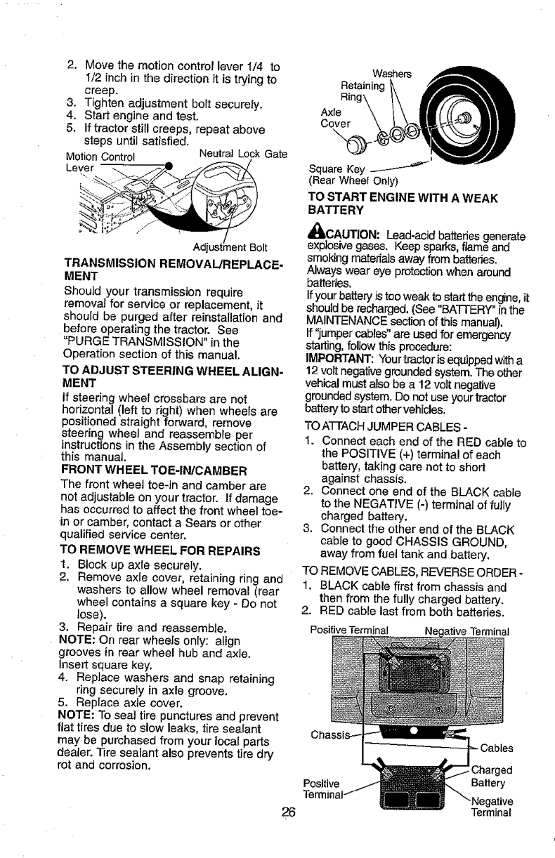
TO REMOVE WHEEL FOR REPAIRS
1. Block up axle securely.
2. Remove axle cover, retaining ring and
washers to allow wheel removal (rear
wheel contains asquare key - Do not
lose).
3. Repair tire and reassemble.
NOTE: On rear wheels only: align
grooves in rear wheel hub and axle.
Insert square key.
4. Replace washers and snap retaining
ring secureIy in axle groove.
5. Replace axle cover.
NOTE: To seal tire punctures and prevent
flat tires due to slow leaks, tire sealant
may be purchased from your local parts
dealer. Tfre sealant also prevents tire dry
rot and corrosion.
Washers
Retaining
R_n
Axle
Cover
,.®
SquareKey
(Rear Wheel Only)
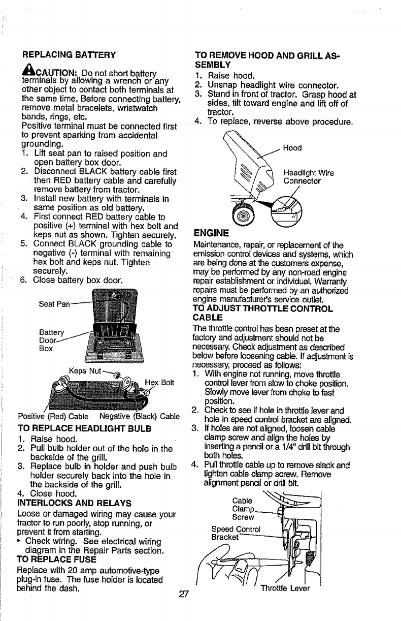
TO START ENGINE WITH A WEAK
BATTERY
x't
41tCA.UTION: Lead-acid batteriesgenerate
explosivegases. Keep sparks, flame &no
smoking materialsaway from batteries.
Always wear eye protection when around
batteries.
ffyour battery is too weak to start the engine,it
should be recharged.(See "BATTERY"inthe
MAINTENANCEsection of this manual).
If "jumpercables" are used for emergency
starting,follow thLsprocedure:
IMPORTANT: Your tractor isequipped witha
12 volt negativegrounded system. The other
vehicalmust also be a 12volt negative
grounded system. Do notuse your tractor
batteryto startother vehicles.
TOATTACHJUMPERCABLES -
1. Connect each end of the RED cable to
the POSITIVE (+) terminal of each
battery, taking care not to short
against chassis.
2. Connect one end of the BLACK cable
to the NEGATIVE (-) terminal of fully
charged battery.
3. Connect the other end of the BLACK
cable to good CHASSIS GROUND,
away from fuel tank and battery.
TO REMOVE CABLES, REVERSEORDER -
1. BLACK cable first from chassis and
then from the fully charged battery.
2. RED cable last from both batteries.
Positive Terminal Terminal
Charged
Battery
26 Terminal
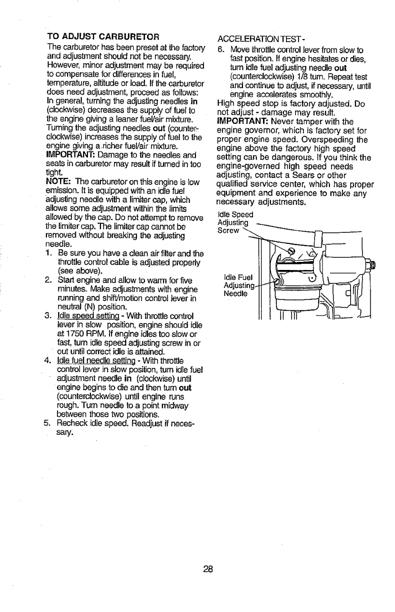
REPLACING BATTERY
_LCAUTION: Do not short battery
terminals by allowing a wrench or any
other objectto contact both terminals at
the same time. Before connecting battery,
remove metal bracelets, wristwatch
bands, rings, etc.
Positive terminal must be connected first
to prevent sparkingfrom accidental
grounding.
1. Lift seat pan to raised position and
open battery box door.
2. Disconnect BLACK battery cable first
then RED battery cable and carefully
remove battery from tractor.
3. Install new battery with terminals in
same position as old battery.
4. First connect RED battery cable to
positive (+) terminal with hex bolt and
keps nut as shown. Tighten securely.
5. Connect BLACK grounding cable to
negative (-) terminal with remaining
hex bolt and keps nut. Tighten
securely.
6. Close battery box door.
Seat
Y
BOX
Keps
Hex Bolt
Positive(Red)Cable Negative (Black)Cable
TO REPLACE HEADLIGHT BULB
1. Raise hood,
2. Pull bulb holder out of the hole in the
backside of the grill
3. Replace bulb in holder and push bulb
holder securely back into the hole in
the backside of the grill.
4. Close hood.
INTERLOCKS AND RELAYS
Loose or damaged wiring may cause your
tractorto run poorly,stop running,or
preventitfrom starting,
•Check wiring. See electrical wiring
diagram in the Repair Parts section.
TO REPLACE FUSE
Replace with20 amp automotive-type
plug-infuse. The fuse holder is located
behind the dash,
TO REMOVE HOOD AND GRILL AS-
SEMBLY
1. Raise hood.
2. Unsnap headlight wire connector.
3. Stand in front of tractor. Grasp hood at
sides, tilt toward engine and liftoff of
tractor.
4. To replace, reverse above procedure,
Hood
HeadlightWire
Connector
27
ENGINE
Maintenance,repair,or replacementof the
emissioncontroldevicesand systems,which
are being done at the Customersexpense,
maybe performedby any non-road engine
repair establishmentor individual,Warranty
repairs must be performed by an authorized
engine manufacturer's service outlet.
TO ADJUST THROTTLE CONTROL
CABLE
The throttle controlhas been preset atthe
factory and adjustmentshould not be
necessary.Check adjustment as described
below before looseningcable. If adjustment is
necessary,proceed as follows:
1. With engine not running, move throttle
controlleverfrom slowto choke position.
Slowly move lever from choke to fast
position.
2. Check to see # hole inthrottle lever and
hole in speed controlbracket are aligned.
3. If holes are not aligned, loosencable
clamp screwand align the holes by
insertinga pencil or a 1/4" drill bit through
bothholes.
4. Pullthro_e cable upto remove slackand
tightencable clamp screw. Remove
alignment pencil or drill bit.
Cab,e _::_ _---'J
Clarnp.____LC{r-'-- _j
Sorow !tT
SpeedControl
Bra/_cket_--_t[r'_ _ i
ThrotUeLever
TOADJUSTCARBURETOR
The carburetor has been preset at the factory
and adjustment should not be necessary.
However,minor adjustment may be required
to compensate for differences in fuel,
temperature, altitudeor load. Ifthe carburetor
does need adjustment, proceed as follows:
In general,turning the adjusting needles in
(clockwise) decreases the supply of fuel to
the enginegiving a leanerfuel/air mixture.
Turningthe adjusting needlesout (counter-
clockwise) increases the supply of fuel to the
engine giving a.richer fueVairmixture.
IMPORTANT. Damage to the needlesand
seats in carburetor may result ifturned in too
tight.
NOTE- The carburetor on this engine is low
emission. It is equipped with an idle fuel
adjusting needle with a limiter cap, which
allows some adjustment within the limits
allowed by the cap. Do not attempt to remove
the limitercap. The limiter cap cannotbe
removed without breaking the adjusting
needle.
1. Be sure you have a clean airfilter and the
throttle control cable isadjusted properly
(see above).
2. Start engine and allow to warm for five
minutes. Make adjustments with engine
running and shift/motion control lever in
neutral (N) position.
3. Idlespeed setting - With throttlecontrol
lever in slow position, engine should idle
at 1750 RPM. If engine idlestoo sbw or
fast,turn idle speed adjusting screw in or
out until correct idleisattained.
4. [die fuel needle setting - With throttle
control lever inslow position,turn idle fuel
adjustment needle in (clockwise) until
engine begins to die and then turn out
(counterclockwise) until engine runs
rough.Turn needle to a point midway
between those two positions.
5. Recheck idte speed. Readjust if neces-
sary.
ACCELERATIONTEST-
6. Move throttle controllever from slowto
fast position. If engine hesitatesor dies,
turn idle fuel adjustingneedle out
(counterclockwise)1/8turn. Repeattest
and continueto adjust, if necessary,until
engine accelerates smoothly.
High speed stop is factory adjusted. Do
not adjust - damage may result.
IMPORTANT: Never tamper with the
engine governor, which is factory set for
proper engine speed. Overspeeding the
engine above the factory high speed
setting can be dangerous. If you think the
engine-governed high speed needs
adjusting, contact a Sears or other
qualified service center, which has proper
equipment and experience to make any
necessary adjustments.
IdleSpeed
Adjusting ....
Screw "_&
IdleFuel
Adjusting. _
Needle
28
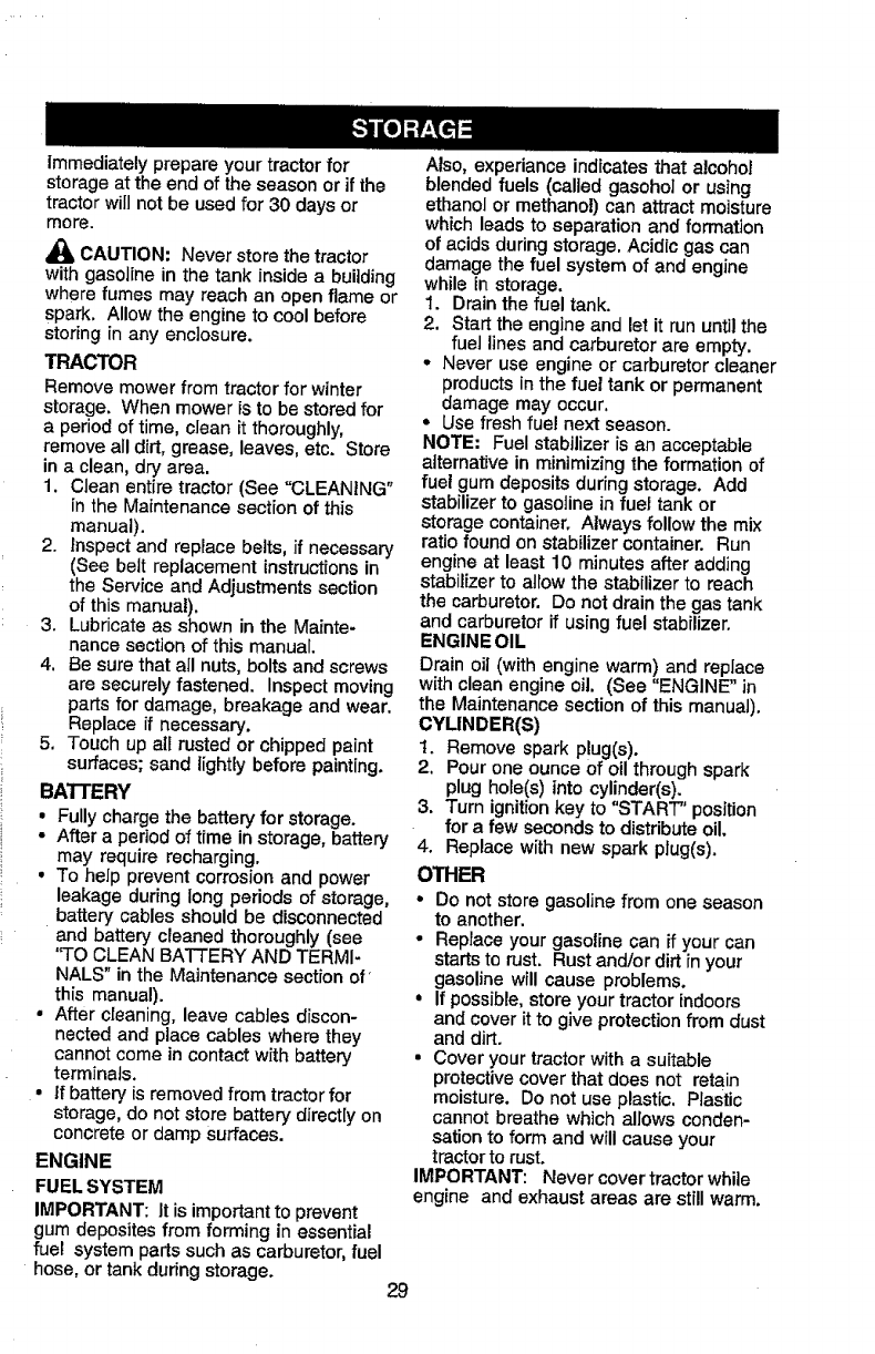
Immediately prepare your tractor for
storage at the end of the season or if the
tractor will not be used for 30 days or
more.
CAUTION: Never store the tractor
with gasoline in the tank inside abuilding
where fumes may reach an open flame or
spark, Allow the engine to cool before
storing in any enclosure.
TRACTOR
Remove mower from tractor for winter
storage. When mower is to be stored for
a period of time, clean it thoroughly,
remove a_ldh'L grease, leaves, etc. Store
in a clean, dry area.
1, Clean entire tractor (See "CLEANING"
in the Maintenance section of this
manual).
2. Inspect and replace belts, if necessary
(See bett replacement instructions in
the Service and Adjustments section
of this manual).
3. Lubricate as shown in the Mainte-
nance section of this manual.
4. Be sure that all nuts, bolts and screws
are securely fastened. Inspect moving
parts for damage, breakage and wear,
Replace if necessary.
5. Touch up all rusted or chipped paint
surfaces; sand lightly before painting.
BATTERY
•Fully charge the battery for storage.
•After a pedod of time in storage, battery
may require recharging.
•To help prevent corrosion and power
leakage during long periods of storage,
battery cables should be disconnected
and battery cleaned thoroughly (see
'qO CLEAN BATTERY AND TERMI-
NALS" in the Maintenance section of'
this manual).
•After cleaning, leave cables discon-
nected and place cables where they
cannot come in contact with battery
terminals.
•If battery is removed from tractor for
storage, do not store battery directly on
concrete or damp surfaces.
ENGINE
FUEL SYSTEM
IMPORTANT: It is importantto prevent
gum deposites from forming in essential
fuel system parts such as carburetor, fuel
hose, or tank during storage.
Also, experianoe indicates that alcohol
blended fuels (called gasohoI or using
ethanol or methano!) can attract moisture
which leads to separation and formation
of acids during storage. Acidic gas can
damage the fuel system of and engine
while in storage.
1. Drain the fuel tank.
2, Start the engine and let it run until the
fuel lines and carburetor are empty,
• Never use engine or carburetor cleaner
products in the fuel tank or permanent
damage may occur,
•Use fresh fuel next season.
NOTE: Fuel stabilizer is an acceptable
alternative in minimizing the formation of
fuel gum deposits during storage, Add
stabilizer to gasoline in fuel tank or
storage container. Always follow the mix
ratio found on stabilizer container. Run
engine at least 10 minutes after adding
stabilizer to allow the stabilizer to reach
the carburetor. Do not drain the gas tank
and carburetor if using fuel stabilizer.
ENGINE OIL
Drain oil (with engine warm) and replace
with clean engine oil. (See "ENGINE" in
the Maintenance section of this manual),
CYLINDER(S)
t. Remove spark p!ug(s).
2, Pour one ounce of oil through spark
plug hole(s) into cylinder(s).
3. Turn ignition key to "START" position
for a few seconds to distribute oil.
4. Replace with new spark plug(s).
OTHER
•Do not store gasoline from one season
to another.
•Replace your gasoline can if your can
starts to rust. Rust and/or dirt in your
gasoline will cause problems.
•if possible,store your tractor indoors
and cover it to give protection from dust
and dirt.
• Cover your tractor with a suitable
protective cover that does not retain
moisture. Do not use plastic, Plastic
cannot breathe which allows conden-
sation to form and will cause your
tractor to rust.
IMPORTANT: Never cover tractor while
engine and exhaust areas are stillwarm.
29
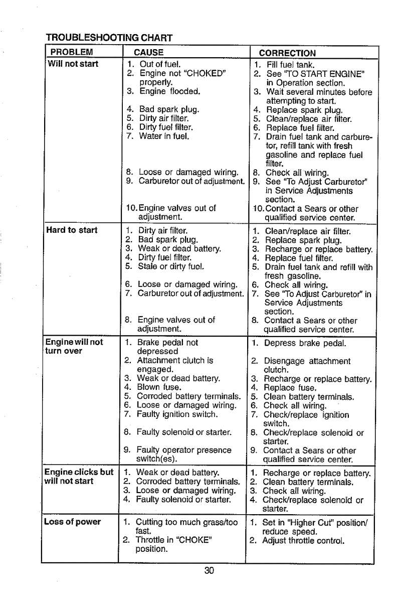
TROUBLESHOOTING CHART
PROBLEM CAUSE
Will not start 1. Out of fuel.
Hard to start
Engi newill not
turn over
Engine clicks but
will not start
Loss of power
2. Engine not "CHOKED"
properly.
3. Engine flooded.
4. Bad spark plug.
5. Dirty air filter.
6. Dirty fuel filter.
7. Water in fuel.
8. Loose or damaged wiring.
9. Carburetor out of adjustment.
10.Engine valves out of
adjustment.
I. Dirty air filter.
2. Bad spark plug.
3. Weak or dead battery.
4. Dirty fuel filter.
5. Stale or dirty fuel.
6. Loose or damaged wiring.
7. Carburetor out of adjustment.
8. Engine valves out of
adjustment.
1. Brake pedal not
depressed
2. Attachment ciutch is
engaged.
3. Weak or dead battery.
4. Blown fuse.
5. Corroded battery terminals.
6. Loose or damaged wiring.
7. Faulty ignition switch,
& Faulty solenoid or starter.
9. Faulty operator presence
switch(es).
I. Weak or dead battery.
2. Corroded battery terminals.
3. Loose or damaged wiring.
4. Faulty solenoid or starter.
1. Cutting too much grass/too
fast,
2. Throttle in "CHOKE"
position.
3O
CORRECTION
1, Fill fuel tank.
2. See "TO START ENGINE"
in Operation section.
3. Wait several minutes before
attempting to start.
4. Replace spark plug,
5. Clean/replace air filter.
6, Replace fuel filter.
7, Drain fuel tank and carbure-
tor, refill tank with fresh
gasoline and replace fuel
filter.
8. Check all wiring.
9. See "To Adjust Carburetor"
in Service Adjustments
section.
10.Contact a Sears or other
qualified service center.
1. Clean/replace air filter.
2. Replace spark plug.
3. Recharge or replace battery.
4. Replace fuel filter.
5. Drain fuel tank and refill with
fresh gasoline.
6. Check all wiring.
7. See '`ToAdjust Carburetor" in
Service Adjustments
section.
8. Contact a Sears or other
qualified service center.
i. Depress brake pedal.
2. Disengage attachment
clutch.
3. Recharge or replace battery.
4. Replace fuse,
5. Clean battery terminals.
6. Check all wiring.
7. Check/replace ignition
switch.
8, Chec]_Jreplace solenoid or
starter.
9. Contact a Sears or other
qualified service center.
1. Recharge or replace battery.
i2. Clean battery terminals.
3. Check all wiring.
4. Check/replace solenoid or
starter.
I. Set in "Higher Cut" position/
reduce speed.
2. Adjust throttle control.
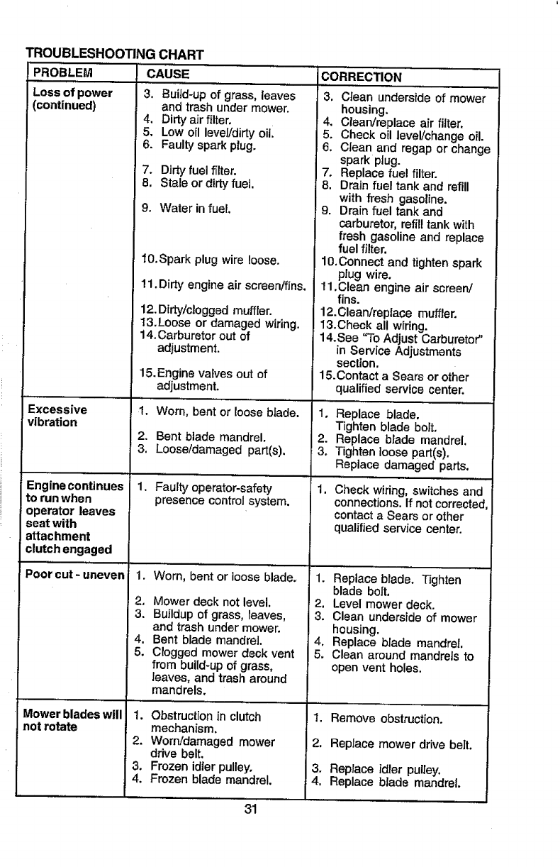
TROUBLESHOOTING CHART
PROBLEM
Loss of power
(continued)
Excessive
vibration
CAUSE
3. Buitd-up of grass, leaves
and trash under mower.
4, Dirty air filter.
5. Low oil level/dirty oill
6. Faulty spark plug.
7. Dirty fuel filter.
8, Stale or dirty fuel.
9. Water in fuel
CORRECTION
i,
3. Clean underside of mower
housing.
4, Clean/replace air filter.
5. Check oil leveVchange oil.
6. Clean and regap or change
spark ptug.
7. Replace fuel filter.
8. Drain fuel tank and refill
with fresh gasoline.
9. Drain fuel tank and
carburetor, refill tank with
fresh gasoline and replace
fuel filter.
lO.Connect and tighten spark
plug wire.
11.Clean engine air screen/
fins.
12.Clean/replace muffler.
13.Check all wiring.
14.See "To Adjust Carburetor"
in Service Adjustments
section,
15.Contact a Sears or other
qualified service center.
1. Replace blade.
Tighten blade bolt,
2. Replace blade mandrel,
3, Tighten loose part(s).
Replace damaged parts,
1, Check wiring, switches and
connections. If not corrected,
contact a Sears or other
qualified service center,
Engine continues
to run when
operator leaves
seat with
attachment
clutch engaged
Poor cut -uneven
Mower blades will
not rotate
lO.Spark plug wire loose.
11.Dirty engine air screen/fins.
12. Dirty/clogged muffler.
13.Loose or damaged wiring.
14.Carburetor out of
adjustment.
15.Engine valves out of
adjustment.
1. Worn, bent or loose blade.
2. Bent blade mandrel.
3, Loose/damaged part(s).
1. Faulty operator-safety
presence control system.
1. Wom, bent or loose blade.
2, Mower deck not level,
3. Buildup of grass, leaves,
and trash under mower.
4. Bent blade mandrel,
5. Clogged mower deck vent
from build-up of grass,
leaves, and trash around
mandrels.
1. Obstruction in clutch
mechanism.
2. Worn/damaged mower
ddve belt.
3. Frozen idler pulley.
4. Frozen blade mandrel.
31
1. Replace blade. Tighten
blade bolt.
2. Level mower deck.
3. Clean underside of mower
housing.
4, Replace blade mandrel,
5. Clean around mandrels to
open vent holes,
1. Remove obstruction.
2, Replace mower drive belt.
3. Replace idler pulley,
4. Replace blade mandrel.
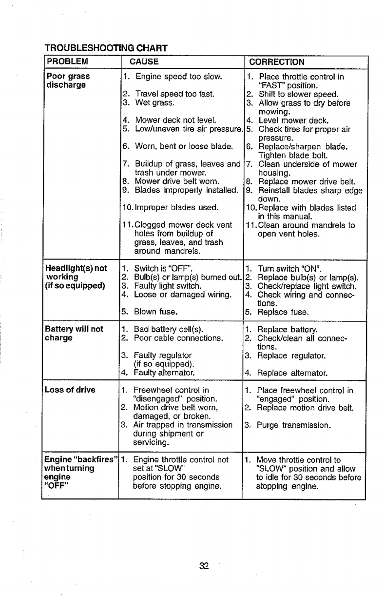
TROUBLESHOOTING CHART
PROBLEM CAUSE
Poor grass 1. Engine speed too slow.
discharge
Headlight(s) not
working
(if SOequipped)
Battery will not
charge
Loss of drive
Engine "backfires"
whenturning
engine
"OFF"
2. Travel speed too fast.
3. Wet grass.
4. Mower deck not level.
5. Low!uneven tire air pressure.
6. Worn, bent or loose blade.
7. Buildup of grass, leaves and
trash under mower.
8. Mower drive belt worn.
9. Blades improperly installed.
10.Improper blades used.
11.Clogged mower deck vent
holes from buildup of
grass, leaves, and trash
around mandrels.
1. Switch is "OFF".
2. Bulb(s) or lamp(s) burned out.
3. Faulty light switch.
4. Loose or damaged wiring.
15. Blown fuse.
1. Bad battery cell(s).
2, Poor cable connections.
3. Faulty regulator
(if so equipped).
4. Faulty alternator.
1. Freewheel control in
"disengaged" position,
2. Motion drive belt worn,
damaged, or broken.
3. Air trapped in transmission
during shipment or
servicing.
1. Engine throttle control not
set at "SLOW"
position for 30 seconds
before stopping engine.
CORRECTION
1. Place throttle control in
"FAST" position.
2. Shift to slower speed.
3. Allow grass to dry before
mowing.
4. Level mower deck.
5. Check tires for proper air
pressure.
6, Replace!sharpen blade.
Tighten blade bolt.
7. Clean underside of mower
housing.
8. Replace mower drive belt.
9. Reinstall blades sharp edge
down.
10, Replace with blades listed
in this manual.
11.Clean around mandrels to
open vent holes.
1. Turn switch "ON".
2. Replace bulb(s) or lamp(s).
3. Check/replace light switch,
4. Check wiring and connec-
tions,
5, Replace fuse.
t. Replace battery.
2. Check/clean all connec-
tions.
3. Replace regulator.
4. Replace alternator.
1. Place freewheel control in
"engaged" position.
2. Replace motion drive belt.
3. Purge transmission.
1. Move throttlecontrol to
"SLOW" position and allow
to idle for 30 seconds before
stopping engine.
32
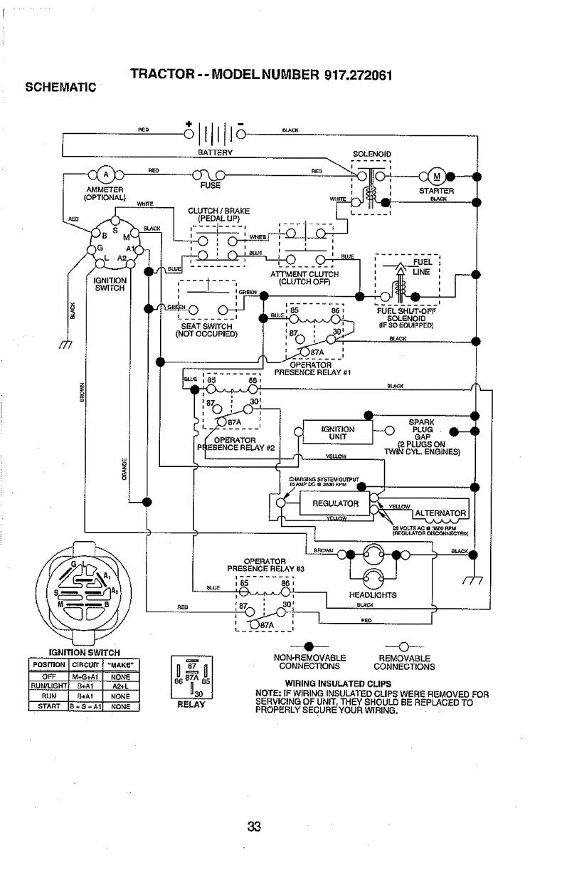
SCHEMATIC TRACTOR-- MODELNUMBER 917.272061
AMMETER
(OPTIONAL)
BATTERY SOLENOID
STARTEER
ATT'MENT CLUTCH
I ........ I
_ _ I G.s_, IlL (CLUTCH OFF)
......... i_wE i
SEAT SWITCH
(NOT OCCUPIED)
• I_ OPERATOR
= ......... PR ESEt'JCE RELAY #1
i85 8B i
FUEL SHUT-OFF
SOLENOID
(IF SO EQUIPPEDI
_L_CK
3PERATOR
ESENCE RELAY #2
REGULATOR
IGNITION SWITCH
.... OFF M÷G÷Ai NONE
IRUN/L[GHT| B÷AI I'_+L I
RUN B+AI I NONE I
I'START IB_-'S÷_JI NONE I RELAY
OPERATOR
PRESENCE RELAY #3
i 85 86 =
HEADLIGHTS
NON-REMOVABLE REMOVABLE
CONNECTIONS CONNECTIONS
WIRING INSULATED CLIPS
NOTE; IF WIRING INSULATED CLIPS WERE REMOVED FOR
SERVICING OF UNIT, THEY SHOULD BE REPLACED TO
PROPERLY SECURE YOUR WIRING.
33
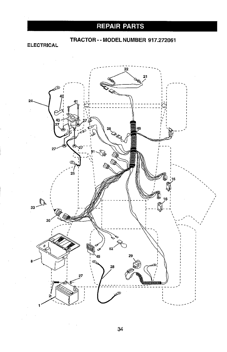
ELECTRICAL TRACTOR -- MODEL NUMBER 917.272061
iz
i
i
=
l i
29
28
i
i
34
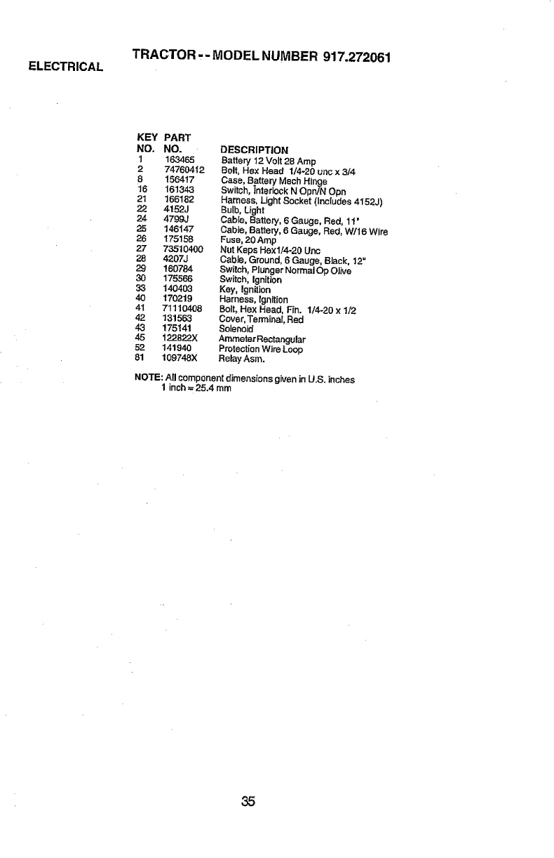
ELECTRICAL TRACTOR.- MODEL NUMBER 917.272061
KEY PART
NO. NO. DESCRIPTION
1163465 Battery 12 Volt 28 Amp
2 74760412 Belt, He× Head 1/4-20 uric x 3/4
8 156417 Case, Battery Mech Hinge
16 161343 Switch, Interlock N Opn/N Opn
21 166182 Harness, Light Socket (Inc{udes 4152,.I)
22 4152J Bulb, Light
24 4799J Cable, Battery, 6G_uge, Red, 11'
25 146147 CabJe, Battery, 6Gauge, Red, W/t 6 Wire
26 175158 Fuse,20Amp
27 73510400 Nut Keps Hexll4-20 Unc
28 4207J Cable, Ground, 6 Gauge, Black, 12"
29 160784 Switch, Plunger Normal Op Olive
30 175566 Switch, Ignition
33 140403 Key, Ignition
40 170219 Harness, Ignition
41 71110408 Bolt, Hex Head, Fin. 1/420 x 1/2
42 131563 Cover, Terminal, Red
43 175141 Solenoid
45 122822X Ammeter Rectangular
52 141940 Protection Wire Loop
81 109748X Relay Asm.
NOTE: All component dimensions given in U.S. inches
1 inch --25.4 mm
35
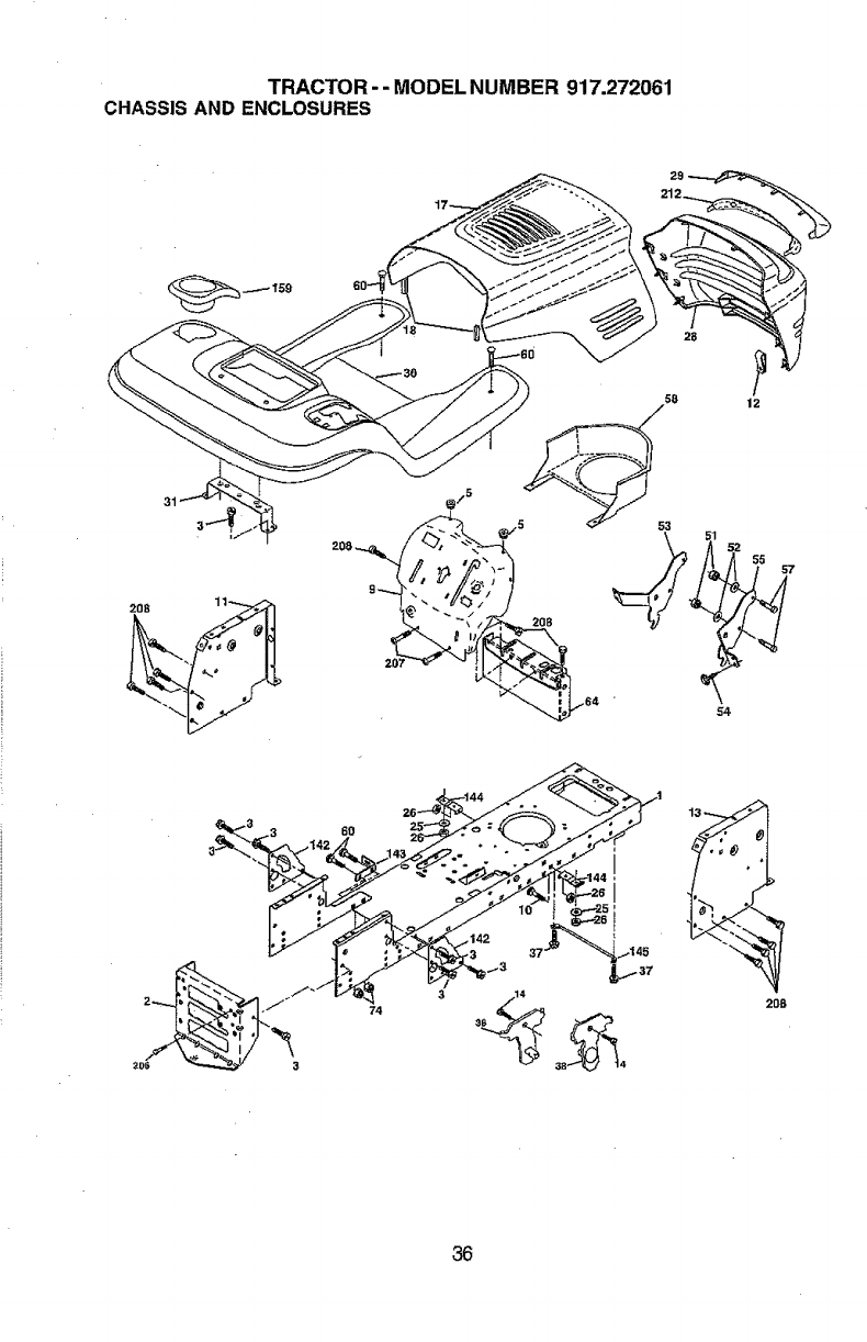
TRACTOR --MODEL NUMBER 917.272061
CHASSIS AND ENCLOSURES
12
57
74
°°i
I
208
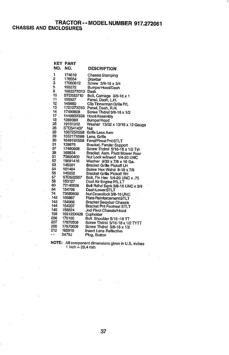
TRACTOR -- MODEL NUMBER 917.272061
CHASSISAND ENCLOSURES
KEY PART
NO. NO. DESCRIPTION
1 174619 Chassis Stamping
2176554 Drawbar
317060612 Screw 3/8-16 x 3/4
5 155272 BumperHood/Dash
9 168337X013 Dash
i0 STD533710 Bolt, Carriage 3/8-16 x 1
11 155927 Panel, Dash, L.H.
12 145660 ClipTlnnerman Grille PtL
13 172107X010 Panel, Dash, R.H,
14 17490808 Screw Thdrol 3/8-16 x 1/2
17 144983X558 HoodAssemb]y
18 126938.)( BumperH0od
25 19131312 Washer 13132 x 13/16 x12 Gauge
26 STD541437 Nut
28 156725)(558 Grille Lens Asm
29 t55217"X599 Lens, Grille
30 164919X558 Fend/Ftrest Pnt STLT
31 139976 Bracket, Fender Support
37 17490508 Screw Thdrol 5/t6-18 x 1/2 Tyt
38 169834 Bracket Asm. Pivot Mower Rear
51 73600400 Nut Lock w/Insert 1/4-20 UNC
52 19091416 Washer 9/32 x 7/6 x16 Ga.
53 145201 Bracket GriUe Pi¢koff LH
54 161464 Screw Hex Wshd 8-18 x 7/8
55 145202 Bracket Grille Piokoif RH
57 STD522507 Bolt, Fin Hex 1/4-20 UNC x .75
58 150127 Duct Air Engine P/L LT
Pc0 72140606 Bolt Rdhd Sqnk 3/8-16 UNC x 3/4
64 154798 Dash LowerSTLT
74 73680600 Nut Crownlook3/8-16 UNC
142 165867 Plate Reinforcement STLT
143 154966 Bracket Swaybar Chassis
144 154207 Bracket Pat Footrest STLT
145 156524 Jod Pivot Chassis/Hood
159 155123)(428 GuphoJder
206 170165 Bolt Shouider5/t6-18TT
207 17670508 Screw Thdrol 5/t6-18 x t/2 TYT]
206 17670608 Screw Thdrol 3/8-16 x 1/2
212 165919 insert Lens Reflective
-5479J Plug, Button
NOTE: AI! component dimensions given in U.S. inches
1 {r_h = 25.4 mm
37
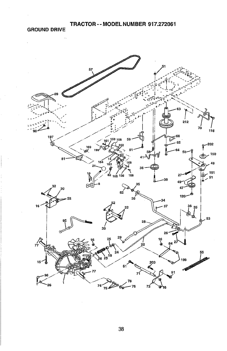
TRACTOR -- MODEL NUMBER 917.272061
GROUNDDRIVE
32
\
156 166
35
62
36
3O
26
22 o84 2
212
7O 116
38
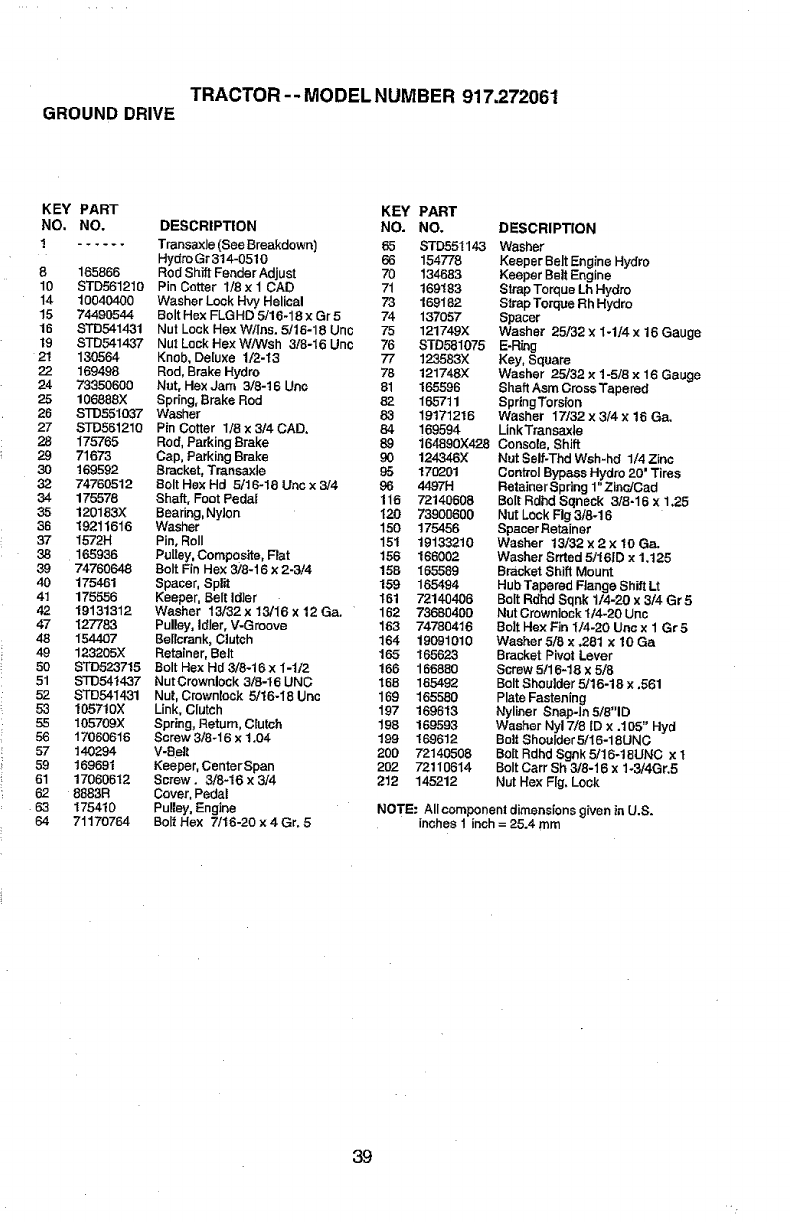
TRACTOR--MODELNUMBER917.272061
GROUNDDRIVE
KEY PART KEY
NO. NO. DESCRIPTION NO.
! ...... Transaxle (See Breakdown) _5
Hydro Gr 314-0510 66
8 165866 Rod Shift Fender Adjust 70
10 STD561210 Pin Cotter 1/8 x 1 CAD 71
14 10040400 Washer Lock Hvy Helical 73
15 74490544 Bolt H_x FLGHD 5/16-18 x Gr5 74
16 STD541431 Nut Lock Hex W/las. 5/18-18 Unc 75
19 STD541437 NutLockHexW!Wsh 3/8-I6Unc 76
2! 130564 Knob, Deluxe 1/2-13 77
22 1694.98 Rod, Brake Hydro 78
24 73350600 Nat, Hex Jam 3/8-16 Unc 81
25 106888X Spring, Brake Rod 82
26 STD551037 Washer 83
27 STD561210 Pin Cotter 1/8 x 314 CAD, 84
28 175765 Rod, Parking Brake 89
29 71673 Cap, Parking Brake 90 124346X
30 169592 Bracket, Transaxte 95 170201
32 74760512 Bolt Hex Hd 5/16-18 Uric x 3/4 96 4497H
34 175578 Shaft, Foot Pedal 116 72140608
35 120183X Bearing, Nylon 120 73900600
36 19211616 Washer 150 1754.56
37 I572H Pin, Roll 151 19133210
38 165936 Pulley, Composite, F_at 156 166002
39 74760648 Bolt Fin Hex 3/8-16 x2-3/4 158 165589
40 175461 Spacer, Split 159 165494
41 175556 Keeper, Belt Idler 161 72140406
42 19131812 Washer 13/32 x 18/16 x12 Ga. 162 73680400
47 127783 Pulley, Idler, V-Groove 183 74780416
48 154407 BeIlcrank, Clutch 164 19091010
49 123205X Retainer, Belt 165 165623
50 STD523715 Bolt Hex Hd 8/8-16 xI-t/2 166 166880
51 STD5414`37 NutCrownlock 3/8-t6 UNC 168 165492
52 S'rD54I,_31 Nut, Crownlack 5/16-18 Uric 169 165580
53 105710X Link, Clutch 197 169613
55 105709X Spring, Return, Clutch 198 169593
56 17060616 Screw3/8-16 x1.04 199 169612
57 140294 V-Belt 200 72140508
59 169691 Keeper, Center Span 202 72110614
61 17060612 Screw. 3/8-16x 3/4 212 145212
62 8883R Cover, Pedal
63 175410 Pulley, Engine
64 71170764 Bait Hex 7/t6-20 x 4 Gr. 5
PART
NO. DESCRIPTION
STD551143 Washer
154778 Keeper Belt Engine Hydro
134683 Keeper Belt Engine
169183 Strap Torque Lh Hydro
169182 Strap Torque Rh Hydro
137057 Spacer
121749X Washer 25/32 ×1-1/4 x 16 Gauge
STD581075 E-R_ng
123583X Key, Square
121748X Washer 25/32 x 1-5/8 x 16 Gauge
165596 Shaft Asm Cross Tapered
165711 SpringTorsion
19171216 Washer 17/32 x3/4 x 16 Ga.
169594 LinkTransaxle
164890X42.8 Console, Shift
Nut Self-Thd Wsh-hd 1/4 Zinc
ControlBypass Hydro 20' Tires
Retainer Spring 1"Zinc/Cad
Bolt Rdhd Sqneck 3/8-16 x 1,25
Nut Lock Fig 3/8-16
Spacer Retainer
Washer 13/32 x 2x 10 Ca.
Washer Srrted 5/16ID x 1.125
Bracket Shift Mount
Hub Tapered FJange Shift Lt
Bolt Rdhd Sqnk 1/4-20 x 3/4 Gr5
Nut Crownlock I/4-20 Uric
Bolt Hex Fin I/4-20 Unc x I Gr 5
Washer 5/8 x .28t x 10 Ga
Bracket Pivot Lever
Screw 5!16-18 x 5/8
Bolt Shoulder 5/16-18 x .561
Plate Fastening
Nyliner Snap-In 5/8"1D
Washer Nyl 7/8 ID x .105" Hyd
Bait ShouIder 5/i6-1 SUNG
Bait Rdhd Sgnk 5/16-18UNC x t
Bolt Cart Sh 3/8-16 x 1-3/4Gr.5
Nut Hex Fig, Lock
NOTE: Allcornponent dimensions given in U.S.
inches 1 inch = 25.4 mm
39
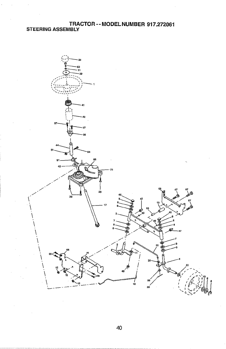
TRACTOR-- MODEL NUMBER 917.272061
STEERINGASSEMBLY
\
\
\
N_'_42
4O
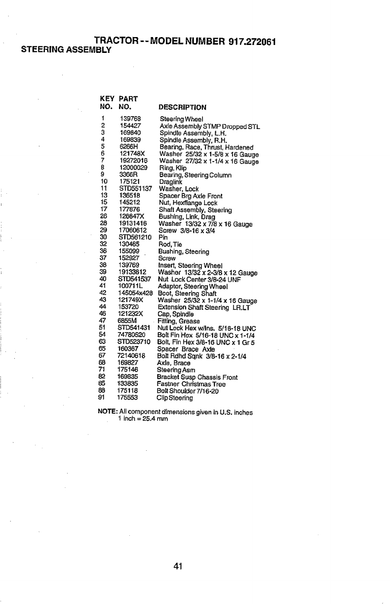
TRACTOR -- MODEL NUMBER 917,272061
STEERINGASSEMBLY
KEY PART
NO. NO. DESCRIPTION
I 139788 Steering Wheel
2 154427 Axle Assembly STMP Dropped STL
3 169840 Spindle Assembly, L.H.
4 169839 Spindle Assembly, R.H.
5 6266H Beadng, Race, Thrust, Hardened
6 12174-8X Washer 25132 x 1_5/8 x 16 Gauge
7 19272016 Washer 27/32 x 1-114x 16 Gauge
8"12000029 Ring, Klip
9 3366R Bearing, Steering Column
10 175121 DragI_nk
11 STD551137 Washer, Lock
13 136518 Spacer Brg Axle Front
15 145212 Nut, Hexftange Lock
t7 177876 Shaft Assemb|y, Steering
26 126847)( Bushing, Link, Drag
2..8 19131416 Washer 13/32 x 718 x 16 Gauge
29 17060612 Screw 3/8-16 x3/4
30 STD561210 Pin
32 130465 Rod, Tie
36 155099 Bushing, Steering
37 152.927 Screw
39 139769 Insert, Steering Wheel
39 19133812 Washer 13/32 x 2-3/B x 12 Gau_e
40 STD541537 Nut Lock Center 3/8-24 UNF
41 100711L Adaptor, Steering Wheel
42 t45054x428 Boot, Steering Shaft
43 121749X Washer 25/32 x 1-ti4 x 16 Gauge
44 153720 Extension Shaft Steering LR.LT
46 12t 232X Cap. Spindle
47 6855M Fitting, Grease
5t STD541431 NutLeek Hexw/ins. 5/t6-18 UNC
54 74780520 Bo[t Fir(Hex 5/16-18 UNC x I-1t4
63 S'1_523710 Bolt, Fin Hex 3f8-16 UNC x 1 Gr5
65 160367 Spacer Brac.e Axle
67 72140618 Boil Rdhd Sqnk 3/6-16x2-I/4
68 169827 Axle, Brace
71 175146 SteeringAsm
82 169835 Bracket Susp Chassis Front
85 133835 Fastner Christmas Tree
88 175118 Bolt Shoulder 7/t 6-20
9t 175553 ClipSteering
NOTE: All componer_tdimensions given in U.S. inches
I inch = 25.4 mm
41
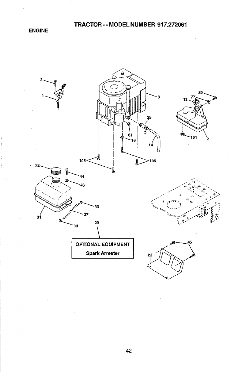
ENGINE TRACTOR -- MODEL NUMBER 917.272061
38
1oo_ i
I OPTZONAL EQUIPMENT
Spark Arrester
80
13 77
42
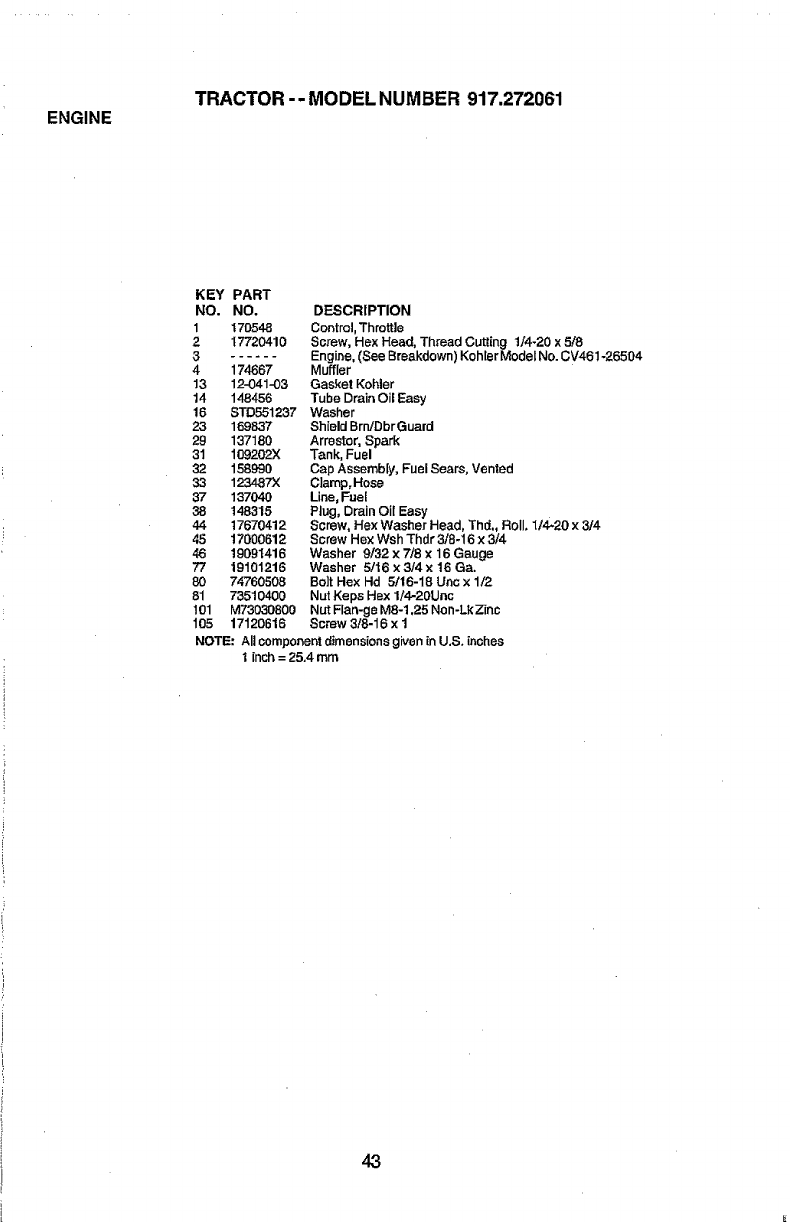
ENGINE TRACTOR-- MODEL NUMBER 917.272061
KEY PART
NO. NO. DF.SCRIPTION
1 170548 Contrel, Throttle
217720410 Screw, Hex Head, Thread Cutting t/4-20 x 5/8
3 Engine, (See Breakdown) Koh[er Model No. CV461-26504
4 174667 Muffler
13 12-041-03 Gasket Kohler
14 146456 Tube Drain Oil Easy
16 STD551237 Washer
23 169837 Shield BrrdDbrGuard
29 137180 Arrestor, Spark
31 109202X Tank, Fuel
32 158990 Cap Assembly, Fuel Sears, Vented
33 123487)( Clamp, Hose
37 137040 Line, Fuel
38 148315 Plug, Drain Oil Easy
44 17670412 Screw, Hex Washer Head, Thd. Roll. 1/4-20 x 3/4
45 17000612 Screw Hex Wsh Thdr 3/8-16 x3/4
46 19091416 Washer 9132 x7/8 x 16 Gauge
77 19101216 Washer 5/16 x3i4x 16 Ca.
80 74760508 Bolt Hex Hd 5116-18 Unc x 1/2
81 73510400 Nut Keps Hex 1/4-20Unc
101 M73030800 Nut Flan-ge M8-1,25 Non-LkZinc
105 17120616 Screw 3/8-16 x I
NOTE: All componentdimensionsgiven in U.S. inches
1 inch = 25.4 mm
43
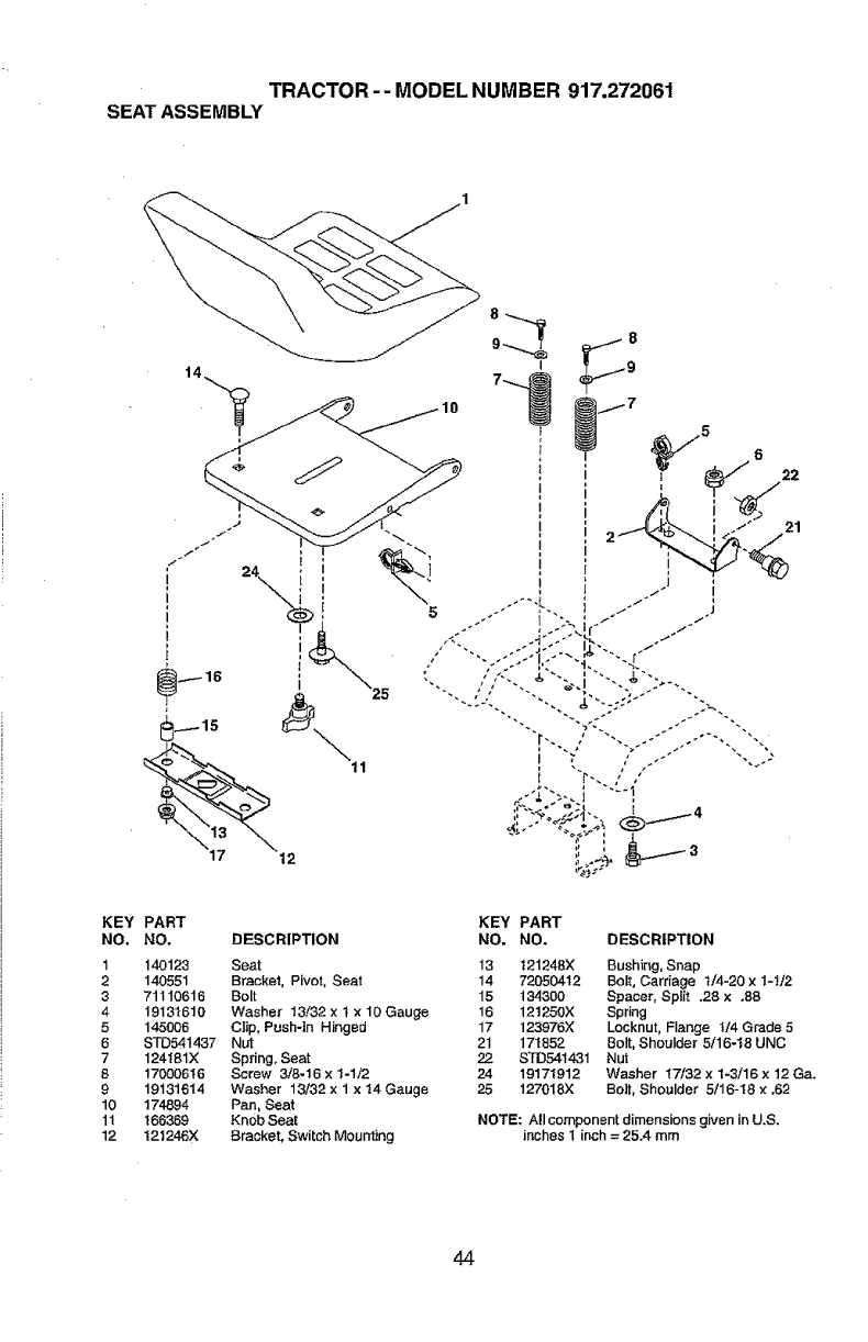
TRACTOR-- MODEL NUMBER 917.272061
SEATASSEMBLY
KEY PART KEY PART
NO. NO. DESCRIPTION NO. NO. DESCRIPTION
1140123 Seat 13 121248× Bushing, Snap
2 140551 Brackel, Pivot, Seat 14 72050412 Bolt, Carriage t14-20 x 1-1t2
3 71110616 Bolt 15 194300 Spacer, Split .28 x .88
4 19131610 Washer 13132 x t x 10 Gauge 16 12t250X Spring
5 145006 C}ip. Push*in HingBd 17 123976X Locknut, Flange 1/4 Grade 5
6 ST05414.37 Nut 21 171852 Bolt, Shoulder 5/16-18 UNC
7 124t81X Spring, Seat 22 sTD5414.31 Nut
8 17000616 Screw 3/8-16 x 1-1/2 24 19171912 Washer 17/32 x 1-3/16 x 12 Ga.
9 19131614 Washer 13132 x 1 x 14 Gauge 25 127018X Belt, Shoulder 5116-18 × .62
10 174894 Pan, Seat
11 166369 Knob Seat NOTE: All component dimensions given in U.S.
12 121246X Bracket, Switch Mounting inches I inch = 25A mm
44
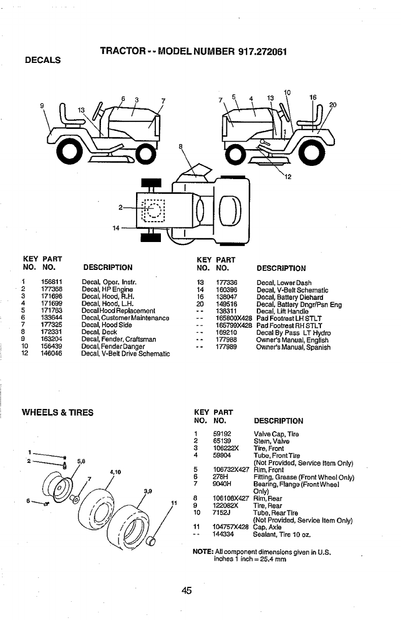
TRACTOR --MODEL NUM BER 917.272061
DECALS
lO
4I3 16
20
12
KEY PART
NO. NO,
1156811
2177368
3171698
4 171699
5171763
6 133644
7177325
8172331
9153204
10 156439
12 146046
DESCRIPTION
Decal, Oper. Instr.
Decal, HP Engine
Decal, Hood, R.H.
Decal, Hood, L.H.
Decal Hood Replacement
Decal, Customer Maintenance
Decal, Hood Side
Decal, Deck
Decal, Fender, Craftsman
Decal, Fender Danger
Decal, V-Belt Drive Schematic
KEY PART
NO. NO. DESCRIPTION
13 177336 Decal, Lower Dash
I4 160396 Decal, V-Belt Schematic
16 138047 Decal, Battery Diehard
20 149516 Decal, Battery DngdPsn Eng
--138311 Decal, Lift Handle
- - 165800X428 Pad Footrest LH STLT
-- 165799;<428 Pad Footrest RH STLT
--169210 Decal By Pass LT Hydro
- - 177988 Owner's Manual, English
--177989 Owner's Manual, Spanish
WHEELS & TIRES
4_10
11
KEY PART
NO, NO, DESCRIPTION
1
2
3
4
5
6
7
8
9
10
11
59192 Valve Cap, Tire
65139 Stem, Valve
106222.5( Tire, Front
59904 Tube, Front Tire
(Not Provided, Service item Only)
106732X427 Rim, Front
276H Fitting,Grease (Front Wheel Only)
9040H Bearing, Flange (Front Wheel
Only)
106108X427 Rim,Rear
122092X Tire, Rear
7152J Tube, Rear Tire
(Not Provided, Service Item Only)
10475TX428 Cap, Axle
144334 Sealant, Tire 10 oz.
NOTE; All component dimensions given in U.S.
inches 1 inch = 25.4 mm
45
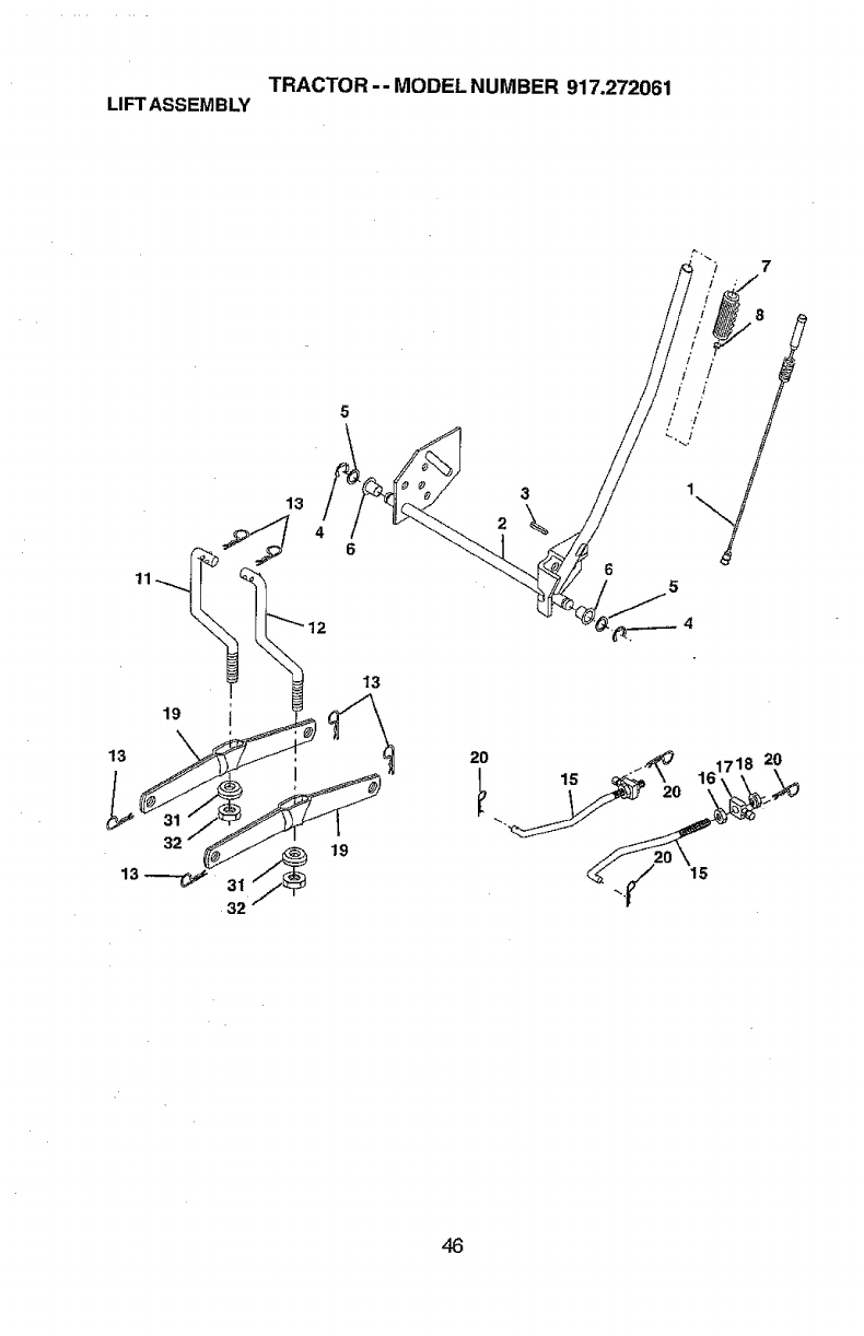
TRACTOR -- MODEL NUMBER 917.272061
LIFTASSEMBLY
13
13
32
13
19
2O
15
46
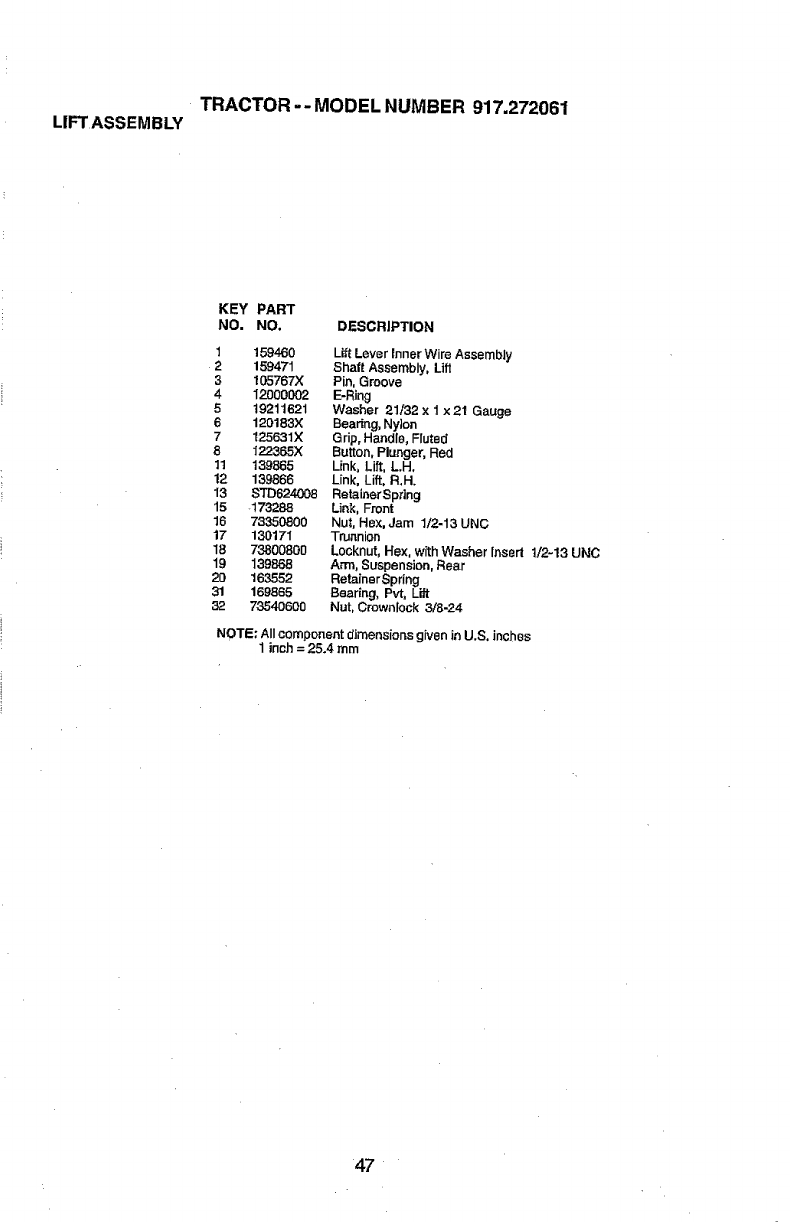
TRACTOR -- MODEL NUMBER 917.272061
LIFT ASSEMBLY
KEY PART
NO. NO. DESCRIPTION
1159460 Lift Lever Inner Wire Assembly
2 159471 Shaft Assembly, Lift
3105767X Pin, Groove
4 12000002 E-Ring
519211621 Washer 21/32 × 1 x 21 Gauge
6 120183X Beadng, Nylon
7125631X Grip, Handle, Fluted
8 122365X Button, Plunger, Red
1t 139865 Link, Lift, L.H,
12 139866 Link, Lift, R.H.
13 STD624008 RetainarSpring
15 -173288 Link, Front
16 73350800 Nut, Hex, Jam 1/2-13 UNC
17 130171 Trunnion
18 73800800 Locknut, Hex, with Washer Insert 1/2-13 UNC
19 139868 Arm, Suspension, Rear
20 163552 RetainerSpring
31 169865 Bearing, Pvt, Lift
32 73540600 Nut, Crownlock 3/8-24
NOTE; All component dimensions given in U.S. inches
1inch = 25.4 mm
47
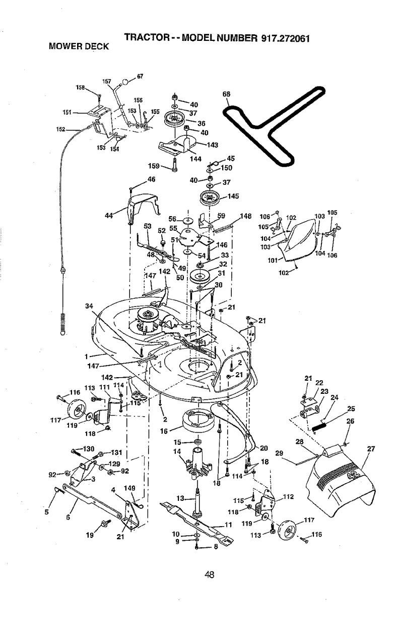
TRACTOR-- MODEL NUMBER 917.272061
MOWER DECK
15R 157 _67
159"..,_,
44 46
._+
11 113 111
118_ '16
I
6
19F 21
144
lo6"1_1o_ _o3_05
105_'. ,///f/_/.1 f 1,._
102 "/_
21 22
24
25
48
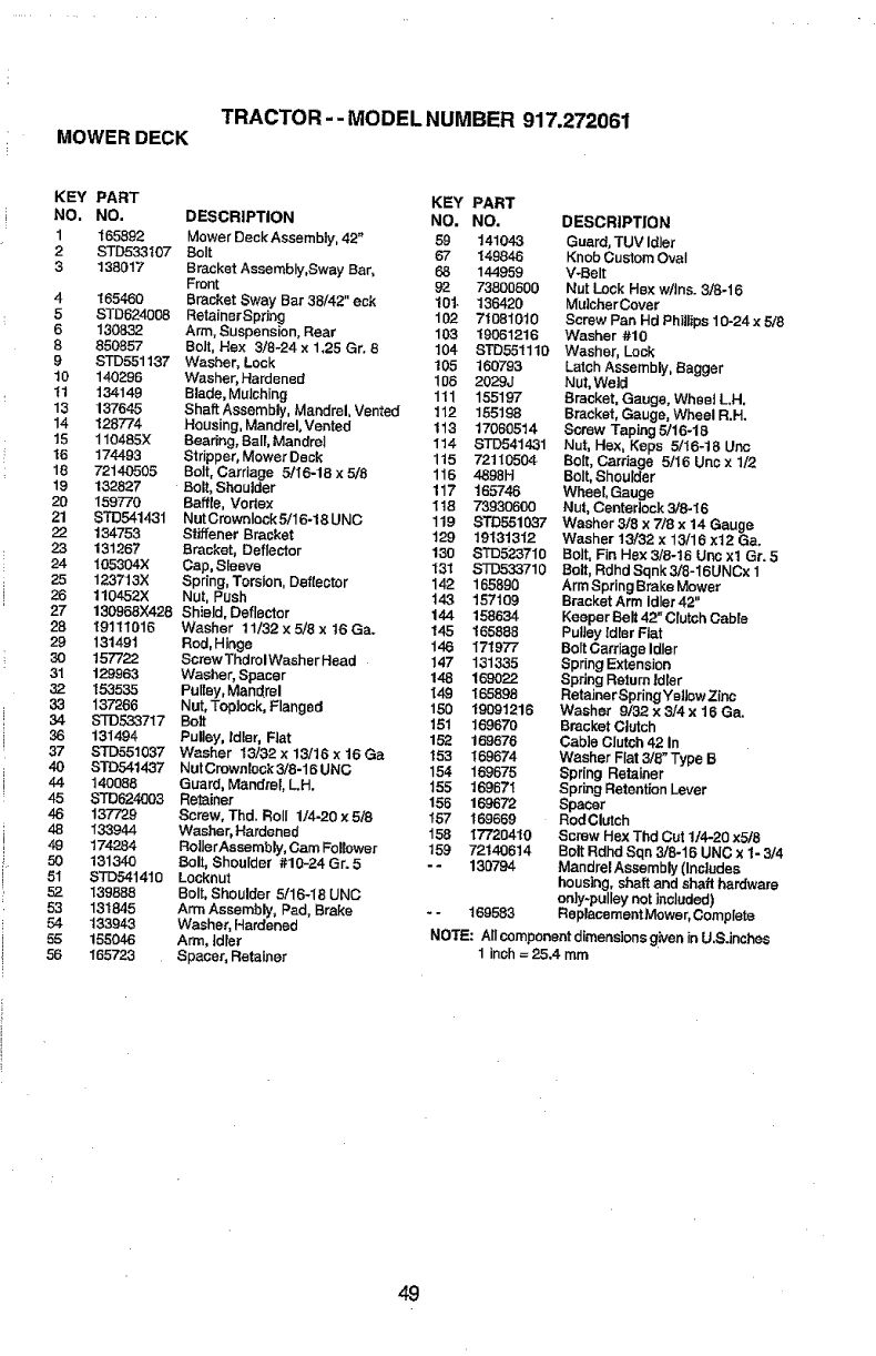
TRACTOR --MODEL NUMBER 917.272061
MOWER DECK
4
5
6
8
9
KEY PART
NO. NO. DESCRIPTION
1 165892 Mower Deck Assembly, 42"
2STD53.3107 Bolt
3 138017 Bracket Assembly,Sway Bar,
Front
165460 Bracket Sway Bar 38/42" eck
STD624008 RetainerSpdng
130832 Arm, Suspension, Rear
850857 Bolt, Hex 3/8-24 x 1,25 Gr. 8
STD551137 Washer, Lock
10 140296 Washer, Hardened
tl 134149 Blade, Mulching
13 13764.5 Shaft Assembly, Mandrel, Vented
14 128774 Housing, Mandrel, Vented
15 110485X Bearing, Belt, Mandrel
16 174493 Stripper, Mower Deck
18 72140505 Bolt, Carriage 5/I6-18 x 5/8
19 132827 Bolt, Shoulder
20 159770 Baffle, Vortex
21 STD5414.31 Nut Crownlock 5/16-18 UNC
22 134753 Stiffener Bracket
23 131267 Bracl{et, Deflector
24 105304X Cap, Sleeve
25 123713X Spring, Torsion, Deflector
26 110452)( Nut, Push
27 130968)(428 Shield, Deflector
28 19111016 Washer 11/32 × 5/8 x t6 Ga.
29 131491 Rod, Hinge
30 157722 Screw ThdrolWasher Head
31 129963 Washer, Spacer
32 153535 Pulley,Mandrel
33 137266 Nut, Topiock, Flanged
34 Sq'D53.3717 Bolt
36 131494 Pulley, tdler, Flat
37 STD551037 Washer 13/32 x 13/16 x 16 Ga
40 STD541437 Nut Crewnlock 3/8-16 UNC
44 140088 Guard, Mandrel, Loll.
45 STD624003 Retair_r
46 137729 Screw, Thd. Roll 1/4-20 x 5/8
48 133944 Washer, Hardened
49 174284 Ro|lerAssembly, Cam Follower
50 131340 Bolt, Shoulder #10-24 Gr. 5
51 STD541410 Looknut
52 139888 Bolt, Shoulder 5/16-18 UNC
53 131845 Arm Assembly, Pad, Brake
54 133943 Washer, Harder_ed
55 155046 Arm, idler
56 165723 Spacer, Retainer
KEY PART
NO. NO. DESCRIPTION
59 141043 Guard, TUV Idler
67 "{49846 Knob Custom Oval
68 144959 V_Belt
92 73800600 Nut Lock HBx w!Jns.3/8-16
101- 13"o420 Mu_cherCovar
102 71081010 Screw Pan Hd Phillips 10-24 x 5/8
103 19061216 Washer #10
104 STD551110 Washer, Lock
105 160793 Latch Assembly, Bagger
106 2029J Nut, We|d
111 155197 Bracket, Gauge, WheelLH,
112 155198 Bracket, G_uge, Wheel R.H.
113 17060514 Screw Taping 5/16-16
114 STD541431 Nut, Hex, Keps 5/16-18 Uec
115 72110504 Bolt, Carriage 5/I6 Uric x 1/2
116 4898H Bolt, Shoulder
117 165746 Wheel, Gauge
118 73930600 Nut, Centertock 3/8-I 6
119 STD551037 Washer3/SxT./8x14Gauge
129 19131312 Washer 13/32 x 13/16 x12 Ga.
130 STD523710 Boit, FinHex3/B-16UncxIGr. 5
131 STD533710 Belt, Rdhd Sqnk 3I8-16UNCx 1
142 165890 Arm Spring Brake Mower
143 157109 BraoketArm Idler42"
144 158634 Keeper Belt 42" Clutch CaMe
14-5 165886 PuUey Id{sr Fiat
146 171977 Bolt Carriage Idler
147 131335 Spring Extension
148 169022 Sprit'_ Return Idler
t49 165898 Retaine r Spring Ye]JowZinc
150 19091216 Washer 9/32x3i4x16Ga.
151 169670 Bracket C|utch
152 169676 Cable Clutch 42 In
t53 169674 Washer Fiat 3/8" Type B
154 169675 Spring Retainer
165 169671 Spring Retention Lever
155 169672 Spacer
I57 169669 RodClutch
158 17720410 Screw Hex Thd Cut 1./4-20 x5t8
159 72140614 Bolt Rdhd Sqn 3/8-16 UNC x 1- 3/4
-- 130794 Mandrel Assembly (Includes
housing, shaft and shaft hardware
only-pulley not included)
-169583 Rep_cement Mowe r,Complete
NOTE: Alloomponent dimens]onsgiverl inU,S.inche$
1 inch=25.4 mm
49
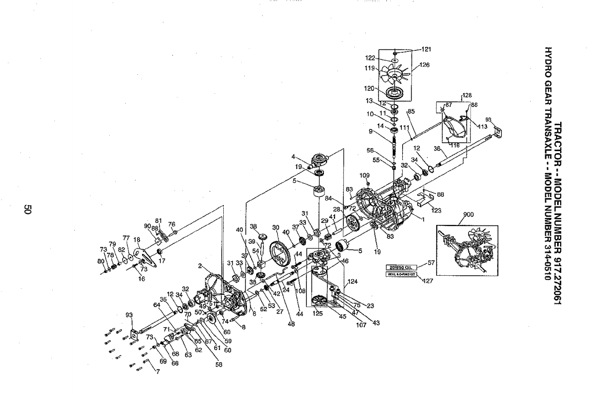
ol
o
81
77
79
73
17
16
351_
64
93
_69 66
60
58
4--,.,
124
119,
120-
10-,
107
14-.
"88
19
_S7
9OO
/..,
,.r
o
Cl
m
3_
m!
mo
Fm
zl-"
C
m
"4
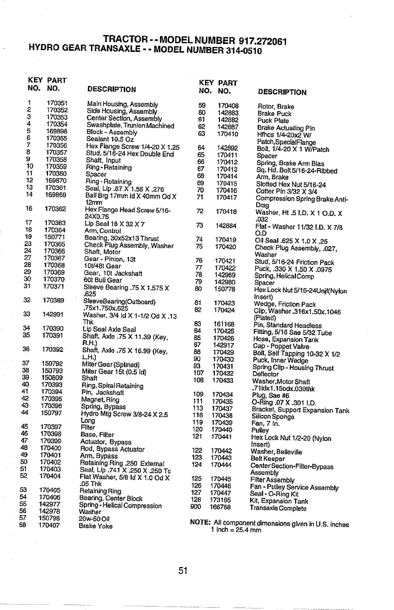
TRACTOR -- MODEL NUMBER 917.272061
HYDRO GEAR TRANSAXLE -- MODEL NUMBER 314-0510
KEY PART KEY PART
NO. NO. DESCRIPTION NO, NO. DESCRIPTION
1170351 Main Housing, Assembly 59 170408 Rotor, Brake
2 170352 Side Housing, Assembly 60 142883 Brake Puck
3 170353 Center Section, Assembly 61 142882 Puck Plate
4170354 Swashplate, TrunJonMachined 62 142887 Brake Actuating Pin
5 159898 Block -Assembly 63 170410 Hfhes 1/4-20x2 W/
6 170355 Seatant 10.50z Patch,SpeeialFlange
7170356 Hex Flange Screw 11420 X 1.25 54 142892 Bolt, lJ4-20 X1 W/Patsh
8 170357 Stud, 5/16-24 Hex Doubts End 65 170411 Spacer
9170358 Shaft, input 66 170412 Spdng, Brake Arm Bias
10 170359 Ring-Retaining 67 170413 Sq, Hd. Bolt 5/16-24-Ribbed
1t 170360 Spacer 68 170414 Arm, Brake
12 169870 Ring-Retaining 69 170415 Slotteri Hex Nut 5/16-24
13 170361 Seat, Up .67 X 1.58 X .2.76 70 170416 Cotter Pin 3/32 X3/4
14 169869 BaI_Brg 17mm ]d X 40ram Od X71 170417 Compression Spring Brake Anti-
12ram Drag
16 170362 Hex Ftange Head Screw5/16- 72 170418 Washer, Ht .5 l,D. X 10.D. X
24X0.75 .032
I7 170363 Lip Seal 18 X 32X7 73 142884 Flat- Washer11/32 LD. X718
16 170364 Arm,Control O.D
19 150771 Bearing, 30x52x13 Thrust 74 170419 Oil Seal .625 X 1.0 X .25
23 170365 Check Plug Assembly, Washer 75 170420 Check Plug Assembly, .027,
24 170366 Shaft, Motor Washer
27 170367 Gear -Pinion, 13t 76 170421 Stud, 5/16-24 Friction Pack
28 170368 10t!48t Gear 77 170422 Puck, .330 X i .50 X.0975
29 170369 Gear, 10t Jackshaft 78 142969 Spring, HelicalComp
30 170370 60t Bull Gear 79 142980 Spacer
31 170371 Sleeve Searing .75 X 1.575 X 80 150778 Hex Lock Nut 5116-24Unjf(Nylon
,625 Insert)
32 170389 SteeveBearing(Outboard) 81 170423 Wedge, Fdction Pack
,75xl.750x.625 82 170424 Clip, Washer ,316x1,50x.1046
33 142991 Washer, 3/4 Id X 1-1/20d X .13 (Plated)
Thk 83 t61168 Pin, Standard Headless
34 170390 Lip Seal Axle Seal 84 170425 Fitting, 5/18 See 5/32 Tube
35 170391 Shaft, Axle.75 X 11,39 (Key, 85 170426 Hose, Expansion Tank
R.H.) 87 142917 Cap -Poppet Valve
36 170392 "Shaft, Axle .75 X 16.99 (Key, 8B 170429 Bolt, SelfTapping 10-32 X 1/2
L.H.) 90 170430 Puok, tnner Wedge
37 150792 Miter Gear (Splinsd) 93 170431 Spdng Clip- Housing Thrust
38 150793 Miter Gear 15t (0,5 ld) I07 170432 Deflector
39 150809 Shaft 108 170433 Washer,Motor Shait
40 170393 Ring, Spiral Retaining .71 idx1.15odx.0301hk
41 170394 Pin, Jackshaft 109 170434 PIug, See #6
42 170395 Magnet, Ring tll 170435 O-Ring .07 X.301 I.D.
43 170396 Spring, Bypass 113 170_37 Bracket, Support Expansion Tank
44 150797 Hyriro Mtg Screw 3/8-24 X2.5 116 170438 Silicon Sponge
Long !19 170439 Fan, 7 In.
4,5 170397 Filter 120 170440 Pulley
46 170398 Base, Filter t21 170441 Hex Lock Nut 1/2-20 (Nyk_rt
47 170399 Actuator, Bypass fnsert)
48 170400 Rod, Bypass Actuator 122 170442 Washer, Belteville
49 170401 Arm, Bypass 123 170443 Belt Keeper
50 170402 Retain{rig Ring .250 _'tema{ i24 170444 CenterSect_n-Fi{ter-Bypass
51 170403 Seal, Lip .741 X .250 X.250 Tc Assembly
52 170404 Flat Washer, 5/8 Id X1.00d X 125 170445 FiIterAssembly
.05 Thk 126 170443 Fan- Pulley Service Assembly
53 170405 Reta_ningRing 127 170447 Seal- O-Ring Kit
54 170406 Bearing, CenterBIock 128 173165 Kit, Expansion Tank
55 142977 Spdng- HelicalCompression 900 166768 Transaxle Complete
56 142978 Washer
57 150798 20w-50Oi_ NOTE: All component dimensions g_ven in U,S. inches
58 170407 Brake Yoke 1 inch = 25.4 mm
51
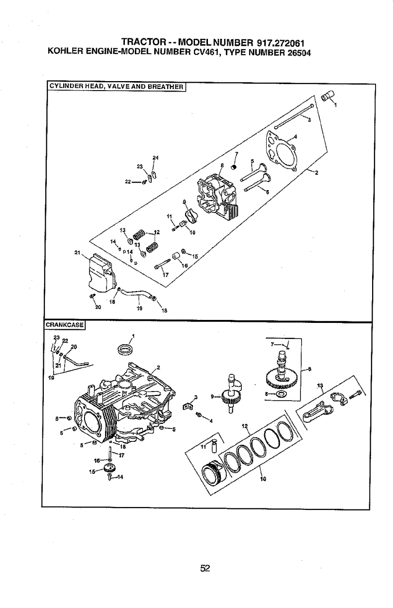
TRACTOR-- MODEL NUMBER 917.272061
KOHLER ENGINE-MODEL NUMBER CV461, TYPE NUMBER 26504
:YLINDER HEAD_ VALVE AND BREATHER I
24
t9
"t8
"17
16_
I
/
52
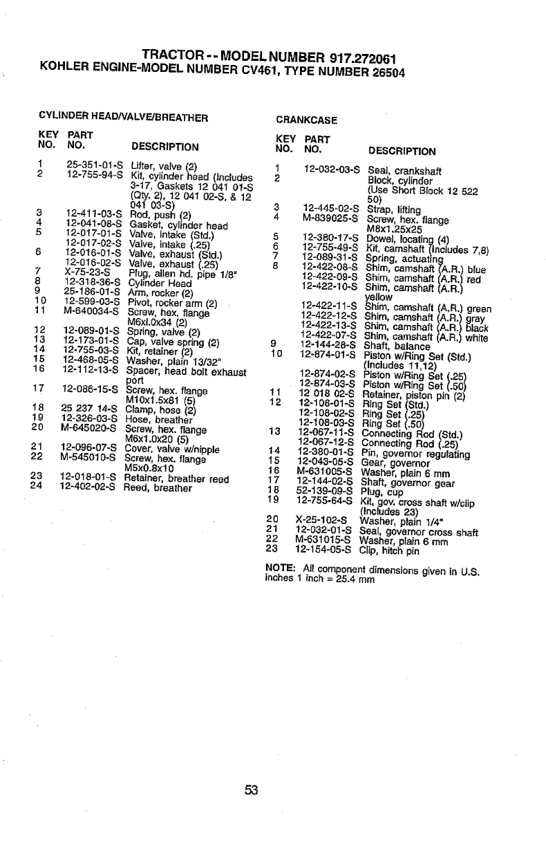
TRACTOR-- MODELNUMBER 917.272061
KOHLERENGINE-MODELNUMBERCV461,TYPE NUMBER26504
CYLINDER HEAD/VA LVF-.JBREATH ER CRANKCASE
KEY PART KEY PART
NO. NO. DESCRIPTION NO. NO. DESCRIPTION
125-351-01-S Litter, valve (2) 1 12-0.32-03-S Seal, crankshaft
2 12-755-94-S Kit, cylinder head (includes 2 Block, cylinder
3-17, Gaskets 12 04I 0/-S (Use Short Block 12 522
(ely, 2), 12 041 02-S, &12 50)
041 0'3-S) 3 12-445-02-8 Strap, lifting
3 I2-41 !-03-S Rod, push (2) 4 M-839025-S Screw, hex. flange
4 12-041-08-S Gasket, cylinder head M8x1,25x25
5 12-017-01-S Valve, intake (Std.) 5 12-380-17-S Dowel locating (4)
12-017-02-S Valve, intake (.25) 6 12-755-49-S Kit, camshaft (Ineudes 7,8)
6 t2-016.01-S Valve, exhaust (Std.) 712-089-31-S Spring, actuating
12-016-02-S Valve, exhaust (.25) 6 12-422-08-S Shim, camshaft (A.R.) blue
7X-75-23-S Plug, alien hd. pipe l/O" 12-422-09-S Shim, camshaft (A.R.) red
8 12-318-36-S Cytinder Head 12-422-10-S Shim, camshaft (A.R.)
9 25-186-01-S Arm, rocker (2) yellow
10 12-599-03-S Pivot, rockerarm (2) I2-422-11-S Shim, camshaft (A.R.) green
11 M-640034-S Screw, he×. flange 12-422-12-S Shim, camshaft (A.Ro) _k
M6x .o×34(27 12-422-t3-ss.Im,camsha,fA.RI
12 12-089-01-S Sprir,,g, valve (2) 12-422-07-S Shim, camshaft, ,A.RI white
13 12-173-01-S Cap, valve spring (2) 9 12-144-28-S Shaft, balance
Piston w/Ring Set (Std.)
14 12-755o03-S Kit, retainer (2) I0 12-874-01-S (Includes 11,12)
15 12-468,05-S Washer, plain 13/32"
16 12-112-13-S Spacer, head bolt exhaust 12-874-02-S Piston wiring Set (,25)
port 12-874-03-S Piston wiring Set (.50)
17 12-086-15-S Screw, hex. flange 11 12 018 02-S Retainer, piston pin (2)
M10xl.Sx81 (5) 12 12-108-0I-S Ring Set (Std.)
18 25 237 14-8 Clamp, hose (2) 12-108-02-8 Ring Set (.25)
19 12-326-03-S Hose, breather 12-108-03-S Ring Set (.50)
20 M-645020-S Screw, hex. flange 13 12-067-!1-S Connecting Rod (Std.)
M6xl.0x20 (5) 12-067-12-S Connecting Rod (.25)
21 12-096-07-S Cover, valve w/nipple 14 I2-380-0t-S Pin, governor regulating
22 M-54501g-S Screw, hex. flange I5 t2-043-05-S Gear, governor
MSx0.Sxt0 16 M-631005-S Washer, plain 6 mm
23 12-018-01-S Retainer, breather reed 17 12-144-02-S Shaft, governor gear
24 12-402-02-S Reed, breather 18 52-139-09-S Plug, cup
19 12-755-64-S Kit, gov. cross shaft w/clip
(Includes 23)
20 X-25-102-S Washer, plain 1/4"
21 12-032-0I-S Seal governor cross shaft
22 M-631015-S Washer, pafn 6 mm
23 12-154-05-S Clip, hitch pin
NOTE: All component dimensions given in U.S,
inches 1 inch =25.4 mm
53
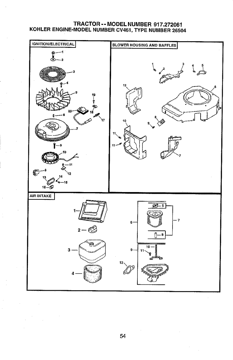
TRACTOR -- MODEL NUMBER 917.272061
KOHLERENGINE-MODELNUMBERCV461,TYPENUMBER26504
fGNITIONtELECTRiCAL I
AIR INTAKE I
BLOWER HOUSING AN[} BAFFLF-_
1o
54
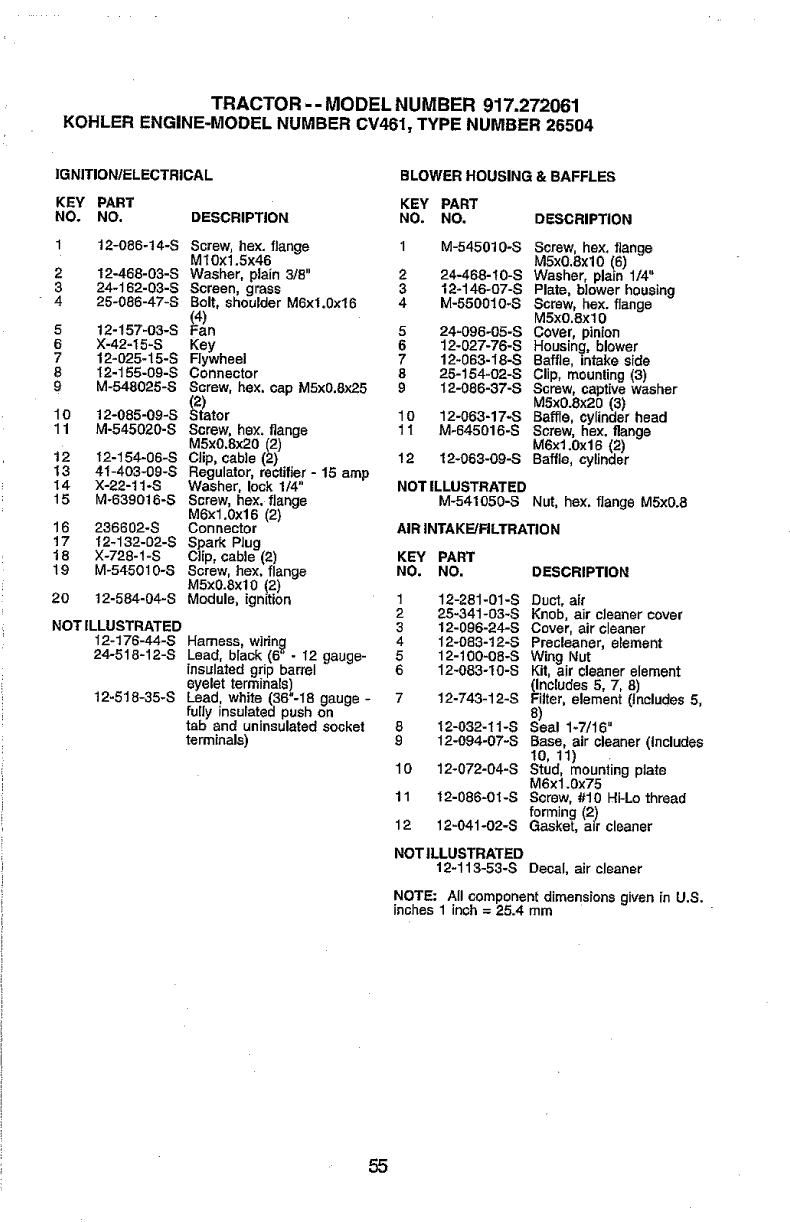
TRACTOR -- MODEL NUMBER 917.272061
KOHLER ENGINE-MODEL NUMBER CV461, TYPE NUMBER 26504
IGNITION/ELECTRICAL BLOWER HOUSING & BAFFLES
KEY PART KEY PART
NO. NO. DESCRIPTION NO. NO, DESCRIPTION
112-086-!4-S Screw, hex. flange
M10x1.5x46
212-468-03-S Washer, plain 3/8"
3 24-162-03-S Screen, grass
4 25-086-47-S Bolt, shoulder M6xt.0x16
512-157-03-S (F4a)n
6X-42-15-S Key .
7 12-025-15-S Flywheel
8 I2-155-09-S Connector
9 M-548025-8 Screw, hex, cap M5x0.8x25
(2)
10 12-085-09-S Stator
11 M-545020-S Screw, hex. flange
M5x0.Sx20 (2)
12 12-154-06-S Clip, cable (2)
13 41-403-09-S Regulator, rectifier - 15 amp
I4 X-22-tt-S Washer, lock 1/4"
15 M-639018-S Screw, he:<. flange
M6x1.0x16 (2)
16 236602-8 Connector
17 I2-132-02-S Spark Plug
18 X-728-1 -S Clip, cable (2)
19 M-545010-S Screw, hex. flange
MSx0.8xl0 (2)
20 12-584-04-8 Module, ignition
NOT ILLUSTRATED
I2-176-44-S Harness, wiring
24-518-12-S Lead, black (6" - I2 gauge-
insulated grip barrel
eyelet terminals)
12-518-35-S Lead, white (36"-18 gauge -
fully insulated push on
tab and uninsulated socket
terminals)
1 M-545010-S Screw, hex. flange
MSx0.8xl0 (6)
2 24-468-I0-S Washer, plain 1/4"
8 12-146-O7-S Plate, blower housing
4 M-550010-S Screw, hex. flange
MSx0.8xl 0
5 24-096-05-S Cover, pinion
6 12_027-76-S Housing, blower
7 12-083-18-S Baffle, intake side
8 25-154.02-S Clip, mounting (3)
9I2-086-37-S Screw, capthte washer
M5x0.8x20 (3)
10 12-063-17-S Baffle, cylinder head
1 t M-645016-S Screw, hex. flange
M6xl.0x16 (2)
12 12-063-09-S Baffle, cylinder
NOTILLUSTRATED
M-541050-S Nut, hex. flange M5xO.8
AIR INTAKE/FILTRATION
KEY PART
NO. NO. DESCRIPTION
1 12-281-01-S Duct, air
225-341-03-S Knob, air cleaner cover
3 12-096-24-S Cover, air cleaner
4 12-083-12-S Precleaner, element
5 12-100-08-S Wing Nut
6 12-083-I0-S Kit, air cleaner element
(Includes 5, 7, 8)
7 12-743-12-S Filter, element (Includes 5,
8)
8 12-032-11-S Seal 1-7116"
912-094-07-S Base, air cleaner (Includes
I0, 11) ,
10 12-072-04-S Stud, mounting plate
M6x1.0x75
11 12-086-0I-S Screw, #10 Hi-Lo thread
forming (2)
12 12-041-02-S Gasket, air cleaner
NOT ILLUSTRATED
12-113-53-S Decal, air cleaner
NOTE: All component dimensions given in U.S.
inches 1 inch = 25.4 mm
55
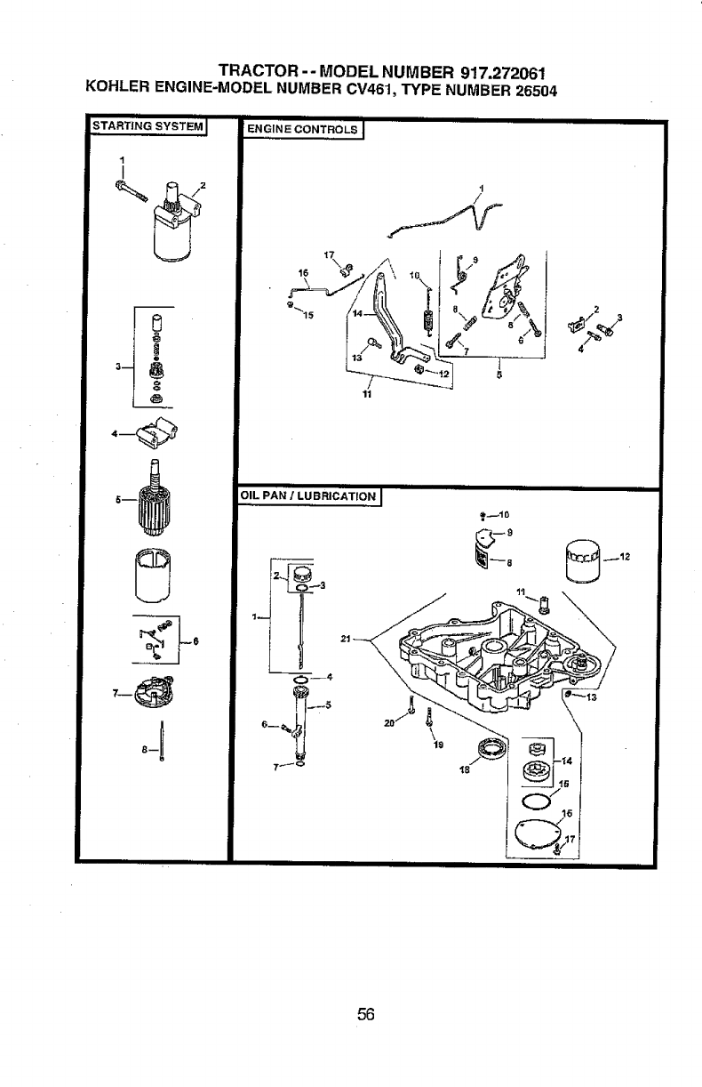
TRACTOR-- MODEL NUMBER 917.272061
KOHLER ENGINE-MODEL NUMBER CV461, TYPE NUMBER 26504
,,,,mm,,ll
STARTfNG SYSTEM I
1
I
!
4
/
11
2
PAN /LU BRICA'I'!ON
O!L
.i-_ _o_'__ _'o
C2_ '
16
.....Q; i
,Hi
56
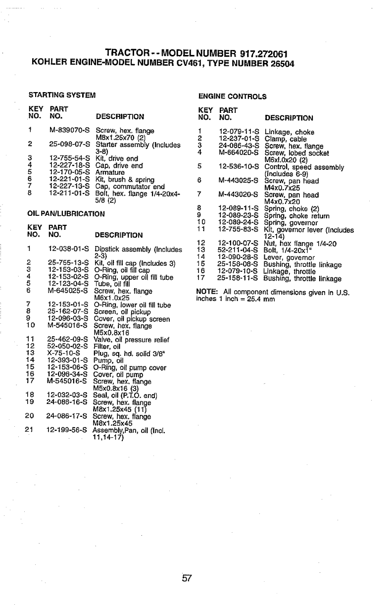
TRACTOR-- MODEL NUMBER 917.272061
KOHLER ENGINE-MODEL NUMBER CV461, TYPE NUMBER 26504
STARTING SYSTEM ENGINE CONTROLS
KEY PART KEY PART
NO. NO. DESCRIPTION NO, NO.
M-839070-S Screw, hex flange 1
MBx1.25X70 (2) 2
25-098-07-S Starter assembly (Includes 3
3-8) 4
12-755-54-S K(t, drive end
12-227-18-S Cap, drive end 5
12-170-05-S Armature
12-221-01-S Kit, brush & spring 6
12-227-13-S Cap, commutator end
12-211-01-S Bolt, hex. flange 1/4-20x4- 7
5/8 (2)
3
4
5
6
7
8
OIL PAN!LUBRICATION
DESCRIPTION
Dipstick assembly (Includes
2-3)
Kit, oil fill cap (Includes 3)
O-Ring, oit fill cap
O-Ring, upper oll fill tube
Tube, oil fill
Screw, hex. flange
M6×1.0x25
O-Ring, lower oil fill tube
Screen, oil pickup
Cover, o(I p{ckup screen
Screw, hex. flange
M5xO.8×l 6
Valve, oil pressure relief
F(Iter0 oil
Plug, sq. hd, solid 3/8"
Pump, oil
O-Ring, oil pump cover
Cover, oil pump
Screw, hex. flange
M5x0.Sx16 (3)
Seal, oil (P.T.O. end)
Screw, hex.flange
M8x1.25x45 111)
Screw, hex. flange
M8x1,25x45
Assembly, Pan, oil (Incl.
11,t4-17)
KEY PART
NO. NO.
1 12_038-01-S
2 25-755-13-S
312-153-03"S
4 12-153-02-S
512-123-04-S
6 M-645025-8
7t 2-t 53-01 -S
8 25-162"07-S
9 12-096-03"8
I 0 M-545016-S
11 25-462-09-S
12 52-050-02-S
!3 X-75-10-S
14 12-393-0t-S
15 12-153 -08 -S
16 12-096-34-S
17 M-545016-S
18 12-032-03-8
19 24-086-16-S
20 24-086-17-8
21 12-199-56-8
8
9
10
11
12
13
14
15
16
17
DESCRIPTION
12-079-11-S Linkage, choke
12-237-01-S Clamp, ¢8,ble
24-086-43-S Screw, hex, flange
M-664020-S Screw, lobed so;3ket
M6xL0x20 (2)
12-536-10-S Control, speed assembly
(Includes 6-9)
M-443025-S Screw, pan head
M4x0,7x25
M-443020-S Screw, pan head
M4x0,7x20
12-089-11-S Spring, choke (2)
12-089-23-S Spring, choke return
12-089-24-S Spring, governor
12-755-83-S Kit, governor lever (Includes
12-14)
t2-100-07-S Nut, he:< flange 1/4-20
52-2tl-04-S Bolt, 1t4-20xl °
12-090-28-S Lever governor
25-158-08-S Bushing, lhrott e linkage
12-079-10-S Linkage, throttle
25-158-!1-S Bushing, throttle linkage
NOTE: All component dimensions given in U.S.
inches 1 inch = 25.4 mm
57
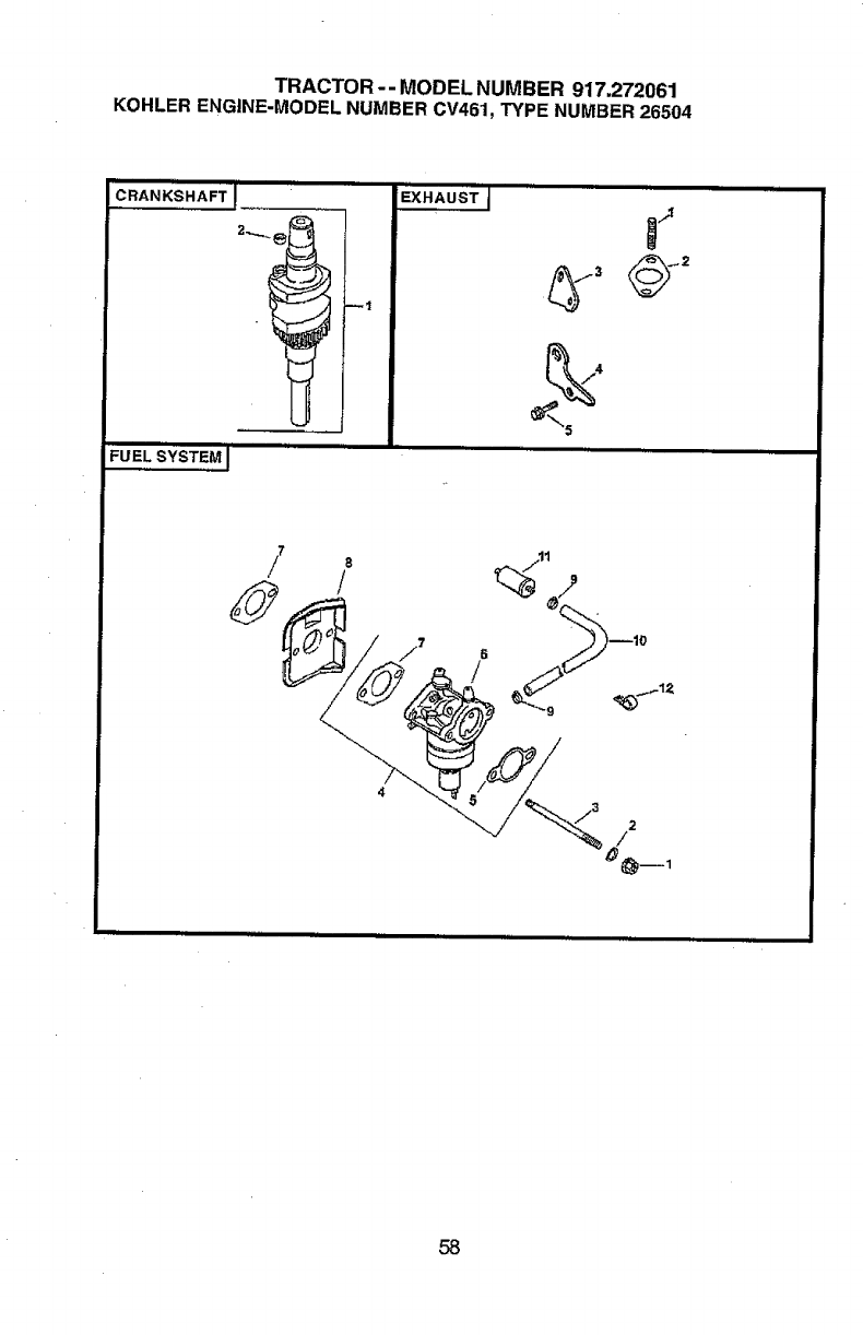
TRACTOR -- MODEL NUMBER 917,272061
KOHLER ENGINE-MODEL NUMBER CV461, TYPE NUMBER 26504
CRANKSHAFTJ
FU_LS_ST_MI
EXHAUST'{
58
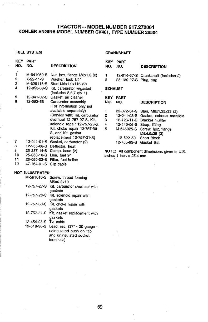
TRACTOR -- MODEL NUMBER 917.272061
KOHLER ENGINE-MODEL NUMBER 0V461, TYPE NUMBER 26504
FUEL SYSTEM CRANKSHAFT
KEY PART KEY PART
NO. NO. DESCRIPTION NO. NO. DESCRIPTION
1'
2
3
4
7
8
9
10
11
12
M-641060-S Nut, hex. flange M6xl.0 (2)
X-22-1 t-S Washer, lock 1/4"
M-629t 16-S Stud M6xl.0x116 (2)
12-853-68-S Kit, carburetor w/gasket
(_ncludes 5,6,7 qty 1)
12-041-02-S Gasket, air cleaner
12-053-68 Carburetor assembly
(For information only not
available separately)
(Service with: Kit, carburetor
overhaul 12 757 27-S, Kit,
solenoid repair 12-757-28-S,
Kit, choke repair 12-757.30-
S, and Kit, gasket
replacement 12-757-31-S)
12-041-01-S Gasket, carburetor (2)
12-265-06-S Deflector, heat
25 237 14-S Clamp, hose (2)
25-353-10-S Line, fuel 9"
25-050-03-S Filter, fuel in-line
47-I54-01-S Clip cable
NOT ILLUSTRATED
M-561010-S Screw, thread forming
M5xO.8xl0
12-757-27-S Kit, carburetor overhaul with
gaskets
I2-757-28-S K_t, solenoid repair with
gaskets
12-757-30-S Kit, choke repair with
gaskets
12-757-31-S Kit, gasket replacement with
gaskets
12-454-03-S Tie cable
12-5t8-36-S Lead, red, (37" - 20 gauge -
uninsulated push on tab
and uninsulated socket
terminals)
112-014-57-S Crankshaft (Includes 2)
225-139-27-S Plug, cup
EXHAUST
KEY PART
NO, NO. DESCRIPTION
125-072-04-S Stud, M8x1.25x33 (2)
212-041-03-S Gasket, exhaust manifold
3 12-126-11-S Bracket muffler
4 12-445-06-S Strap, lifting
5 M-645025-S Screw, hex. flange
MBxL0x25 (2)
12 522 50 Shod Block
t2-755-93-S Gasket Set
NOTE= All component dimensions given in U.S.
inches t inch =25.4 mm
59

60

61

62

SUGGESTED GUIDE FOR SIGHTING SLOPES FOR SAFE OPERATION
"r--
!ONLY RIDE UP AND DOWN HILL,
NOT ACROSS HILL
Operate your Tractor up and down the face of slopes (not
greater than 15 ), never across the face, Make turns gradu-
ally to prevent tipping or loss of control. Exercise extreme
caution when changing direction on slopes.
...... pl ....... L
For repairof majorbrandappliancesinyour own home...
no matter who made it,no matter who sold it[
1-800-4-MY-HOME ¢ Anytime, dayornight
(1-80_) (u.sA.andCanada)
wv,tc,.sears,com vmmt.sears,lm
Forrepairof carrf-inproductslikevacuums,lawn equipment,and
electronics,callfor the nearestSears Partsand Repair Center.
1-800-488-1222 Anytime,dayornight(U.S.A.only)
Forthe replacementparts,accessoriesand owner'smanuals
that you need to do-it-yourself, call Sears PartsDirectSMf
1-800-366-PART 6am.- I1 p.m., 7days aweek
(1-800-366-7278) (U.S.A.only)
www.sears.corWparlsdirect
To purchaseorinquireabouta SearsServiceAgreement
or Sears Maintenance Agreement:
1-800-827-6655 (uos_) 1-800-361-6665 (Ca_da)
7 a.m. - 5 p.m., CST, Mon. - Sat. 9 a.m. - 8 p.moEST0 M - F, 4 p.m. Sat
Pare pedirservicJode mparaci6na
domicilio,ypara ordenarpiezas:
1.888-St.NHOGARsM
(t-888.-784.,6427)
Au Ca_da pour service en frangaJs:
1-800-LE-FOYER ic
vcww.sears.oa
©Sears,Ro_uck andC_
[ AR.s
L"HorneCentral®']
® Registered T_'ademark /T_Trademark /s_ SeTvice Mark of Sears, Roebuck and Co.
® Marca Registrada !TM Marca de F&brica/sMMarca de Servicio de Sears, Roebuck and Co.
MuMarque de commerce /MoMarque d6posE1ede Sears, Roebuck and Co.
177988 Rev. 2 8.21.01 RH/RD Printed in U.S.A.
