Craftsman 917272121 User Manual LAWN TRACTOR Manuals And Guides L0709180
CRAFTSMAN Lawn, Tractor Manual L0709180 CRAFTSMAN Lawn, Tractor Owner's Manual, CRAFTSMAN Lawn, Tractor installation guides
User Manual: Craftsman 917272121 917272121 CRAFTSMAN LAWN TRACTOR - Manuals and Guides View the owners manual for your CRAFTSMAN LAWN TRACTOR #917272121. Home:Lawn & Garden Parts:Craftsman Parts:Craftsman LAWN TRACTOR Manual
Open the PDF directly: View PDF ![]() .
.
Page Count: 64

Owner's Manual
[RRFTSMrlII o
18.5 HP
ELECTRIC START
i" MOWER
AUTOMATIC
LAW "rRACTO
Model No.
917.272121
° Safety
o Assembly
Operation
Maintenance
oRepair Parts
CAUTION: For answers to your questions
about this product, Call:
Read and follow all
Safety Rules and Instructions 1,.800-659-5917
Sears Craftsman Help Line
before operating this equip- s am- 5pro,Mort-Sat
ment.
Sears, Roebuck and Co., Hoffman Estates, IL 60179

Warranty ................................................. 2
Safety Rules ........................................... 2
Product Specifications ........................... 5
Assembly ................................................ 8
Operation .............................................. 12
Maintenance Schedule ......................... 19
Maintenance ......................................... 19
Service and Adjustments ...................... 23
Storage ................................................. 30
Troubleshooting .................................... 31
Repair Parts ......................................... 36
Parts Ordering ....................... Back Cover
LIMITED TWO YEAR WARRANTY ON CRAFTSMAN RIDING EQUIPMENT
For two (2) years from the date of purchase, if this Craftsman Riding Equipment is main-
tained, lubricated and tuned up according to the instructions in the owner's manual,
Sears will repair or replace, free of charge, any parts found to be defective in material or
workmanship.
This Warranty does not cover:
• Expendable items which become worn during normal use, such as blades, spark
plugs, air cleaners, belts, etc.
° Tire replacement or repair caused by punctures from outside objects, such as nails,
thorns, stumps, or glass.
•Repairs necessary because of operator abuse, negligence, improper storage or acci-
dent or the failure to maintain the equipment according to the instructions contained in
the owner's manual.
• Riding equipment used for commercial or rental purposes.
LIMITED 90 DAY WARRANTY ON BATTERY
For ninety (90) days from date of purchase, if any battery included with this riding equip-
ment proves defective in material or workmanship and our testing determines the bat-
tery will not hold a charge, Sears will replace the battery at no charge° in-home warranty
service on your Craftsman riding equipment is available at no charge for 30 days from
the date of purchase. Please contact your nearest service center. After 30 days from the
date of purchase, warranty service is available by taking your Craftsman riding equip-
ment to your nearest Sears Service Center. (In-home warranty service will still be avail-
able after 30 days from the date of purchase but a standard trip charge will apply). This
warranty applies only while this product is in the United States. This Warranty gives you
specific legal rights, and you may also have other rights which may vary from state to
state°
Sears, Roebuck and Co., D/817 WA, Hoffman Estates, IL 60179
GENERAL OPERATION
• Read, understand, and follow all instruc-
tions in the manual and on the machine
before starting.
• Only allow responsible adults, who are
familiar with the instructions, to operate
the machine.
° Clear the area of objects such as rocks,
toys, wire, etc., which could be picked
up and thrown by the blade.
• Be sure the area is clear of other people
before mowing. Stop machine if anyone
enters the area.
•Never carry passengers.
•Do not mow in reverse unless absolute-
ly necessary. Always look down and
behind before and while backing° ...............
• Be aware of the mower discharge direc-
tion and do not point it at anyone. Do
not operate the mower without either
the entire grass catcher or the guard in
place.
•Slow down before turning.
°Never leave a running machine unat-
tended. Always turn off blades, set park-
ing brake, stop engine, and remove
keys before dismounting.

•Turn off blades when not mowing.
• Stop engine before removing grass
catcher or unclogging chute.
o Mow only in daylight or good artificial
light_
° Do not operate the machine while under
the influence of alcohol or drugs.
° Watch for traffic when operating near or
crossing roadways.
° Use extra care when loading or unload-
ing the machine into a trailer or truck.
SLOPE OPERATION
Slopes are a major factor related to loss-
of-control and tipover accidents, which
can result in severe injury or death. All
slopes require extra caution° if you cannot
back up the slope or if you feel uneasy on
it, do not mow it.
DO:
• Mow up and down slopes, not across.
o Remove obstacles such as rocks, tree
limbs, etc.
o Watch for holes, ruts, or bumps. Uneven
terrain could overturn the machine. Tall
grass can hide obstacles_
• Use slow speed. Choose a tow gear so
that you wilt not have to stop or shift
while on the slope.
o Follow the manufacturer's recommen-
dations for wheel weights or counter-
weights to improve stability.
° Use extra care with grass catchers or
other attachments. These can change
the stability of the machine.
, Keep all movement on the slopes slow
and gradual. Do not make sudden
changes in speed or direction.
o Avoid starting or stopping on a slope. If
tires lose traction, disengage the blades
and proceed slowly straight down the
slope.
DO NOT:
°Donot turn or_ s!opes unless necessary,
and then, turn slowly and gradually
downhill, if possible.
,Do not mow near drop-offs, ditches, or
embankments. The mower could sud-
denly turn over if a wheel is over the
edge of a cliff or ditch, or if an edge
caves in.
°Do not mow on wet grass. Reduced
traction could cause sliding.
•Do nottry to stabilize the machine by
putting your foot on the ground.
°Do not use grass catcher on steep
slopes.
CHILDREN
Tragic accidents can occur if the operator
is not alert to the presence of children.
Children are often attracted to the
machine and the mowing activity° Never
assume that children will remain where
you last saw them.
•Keep children out of the mowing area
and under the watchful care of another
responsible adult.
• Be alert and turn machine off if children
enter the area.
° Before and when backing, look behind
and down for small children.
• Never carry children. They may fall off
and be seriously injured or interfere with
safe machine operation.
• Never allow children to operate the
machine.
°Use extra care when approaching blind
corners, shrubs, trees, or other objects
that may obscure vision.
SERVICE
o Use extra care in handling gasoline and
other fuels. They are flammable and
vapors are explosive.
Use only an approved container.
Never remove gas cap or add fuel
with the engine running. Allow en-
gine to coo! before refueling. Do not
smoke.
Never refuel the machine indoors.
Never store the machine or fuel
container inside where there is an
open flame, such as a water heater.
° Never run a machine inside a closed
area.
° Keep nuts and bolts, especially blade
attachment bolts, tight and keep equip-
ment in good condition.
° Never tamper with safety devices, .........
Check their proper operation regularly.
•Keep machine free of grass, leaves, or
other debris build-up. Clean oil or fuel
spillage. Allow machine to cool before
storing.
° Stop and inspect the equipment if you
strike an object. Repair, if necessary,
before restarting.
3

o
o
Never make adjustments or repairs with
the engine running.
Grass catcher components are subject
to wear, damage, and deterioration,
which could expose moving parts or
allow objects to be thrown. Frequently
check components and replace with
manufacturer's recommended parts,
when necessary.
o Mower blades are sharp and can cut.
Wrap the blade(s) or wear gloves, and
use extra caution when servicing them.
° Check brake operation frequently.
Adjust and service as required.
o Be sure the area is clear of other people
before mowing. Stop machine if anyone
enters the area.
• Never carry passengers.
• Do not mow in reverse unless absolute-
ly necessary. Always look down and
behind before and while backing.
° Never carry children_ They may fall off
and be seriously injured or interfere with
safe machine operation.
° Keep children out of the mowing area
and under the watchful care of another
responsible adult.
o Be alert and turn machine off if children
enter the area.
° Before and when backing, look behind
and down for small children.
_,Look for this symbol to point out impor-
tant safety precautions, It means CAU-
TlON!!f BECOME AWARE!!! YOUR SAFE-
TY IS INVOLVED.
_CAUTION: In order to preventacciden-
tal starting when setting up, transporting,
adjustingor making repairs always discon-
nect spark plug wire and place wire where
it cannot contact spark plug.
°Mow up and down slopes (!5 ° Max), not
across°
° Remove obstacles such as rocks, tree
limbs, etc_
° Watch for holes, ruts, or bumps_ Uneven
terrain could overturn the machine. Tall
grass can hide obstacles.
o Use slow speed. Choose a low gear so
that you wilt not have to stop or shift
while on the sloper
° Avoid starting or stopping on a slope, if
tires lose traction, disengage the blades
and proceed slowly straight down the
slope.
°Do not turn on slopes unless necessary,
and then, turn slowly and gradually
downhill, if possible.
,_WARNING: The engine exhaust from
this product contains chemicals known to
the State of California to cause cancer,
birth defects, or other reproductive harm.
4

PRODUCT SPECIFICATIONS
GASOLINE 3.5 GALLONS
CAPACITY UNLEADED
_ND TYPE: REGULAR
OIL TYPE SAE 10W-30
API-SFiSGiSH): (above 32°F)
SAE 5W-30
(below 32°F)
OIL CAPACITY: W/FILTER: 4.2 PINTS
W/O FILTER: 3.7 PINTS
SPARK PLUG: Champion RC12YC
GAP: .040")
GROUND SPEED FORWARD: 0 -4,5
(MPH): REVERSE: 0- 2°0
TIRE PRESSURE: FRONT: 14 PSI
REAR: 10 PSI
CHARGING
SYSTEM: 15 AMPS@ 3600 RPM
BATTERY: AMP/HR: 30
MINoCCA: 280
CASE SIZE: U1R
BLADE BOLT 27-35 FT LBSo
TORQUE:
CONGRATULATIONS on your purchase
of a Craftsman Tractor° It has been
designed, engineered and manufactured
to give you the best possible dependability
and performance.
Should you experience any problem you
cannot easily remedy, please contact your
nearest Sears Authorized Service Center.
We have competent, well-trained techni-
cians and the proper tools to service or
repair this tractor.
Please read and retain this manual. The
instructions will enable you to assemble
and maintain your tractor properly. Always
observe the "SAFETY RULES".
MAINTENANCE AGREEMENT
A Sears Maintenance Agreement is avail.-
able on this product. Contact your nearest
Sears store for details.
CUSTOMER RESPONSIBILITIES
• Read and observe the safety rule&
• Follow a regular schedule in maintain-
ing, caring for and using your tractor.
°Follow the instructions under "Mainte-
nance" and "Storage" sections of this
owner's manual.
_,WARNING" This tractor is equipped
with an internal combustion engine and
should not be used on or near any unim-
proved forest-covered, brush-covered or
grass-covered land unless the engine's
exhaust system is equipped with a spark
arrester meeting applicable local or state
laws (if any). If a spark arrester is used, it
should be maintained in effective working
order by the operator°
In the state of California the above is
required by law (Section 4442 of the
California Public Resources Code). Other
states may have similar taws. Federal
laws apply on federal lands. A spark
arrester for the muffler is available through
your nearest Sears Authorized Service
Center (See REPAIR PARTS section of
this manual).
5

PARTS BAG CONTENTS SHOWN FULL SIZE
('I) Shoulder Bolt
5/16-18
(I) Washer
17/32 x 1-3/16 x 12 Gauge
((1) Knob
, ,, ,,r, ,,r_ '''u''_''
(2) Washers
3/t6 x 3/4 x
(2) screws .-.. (2) Lock
#10 x 5/8 ,_ 1Washers
[_ I #10
(3) Retainer Springs
(Double Loop)
6
,,,,r= II I'

Parts packet separately in carton
Seat
Steermg Wheel
Video
Cassette
Mulcher
Plate
iI
i t
II
I I
I I
t I
I I
h t
Manual Parts Bag
Parts Bag contents not shown full size
©
(2) Shoulder (2) Washers 3/8
Bolts _,) x 7/8 x 14 Ga.
(2) Centerlock @
Nuts
(2) Gauge Wheels
Steering
Wheel Insert
Slope Sheet Steering
Sleeve
_ok
Assemblies
Steering
Sleeve Extension
_(_) Front Link Assemblies _

Your new tractor has been assembled at the factory with exception of those parts left
unassembted for shipping purposes. To ensure safe and proper operation of your tractor
all parts and hardware you assemble must be tightened securely° Use the correct tools
as necessary to insure proper tightness. Review the video cassette before you begin.
TOOLS REQUIRED FOR
ASSEMBLY
A socket wrench set will make assembly
easier. Standard wrench sizes you need
are listed below.
(1) 3/4" wrench
(2) 1/2" wrench
(1) Utility knife
(1)Pliers
(I) 3/4" Socket w!
drive rachet
(1) Phillips Screw-
driver
(t) Tire pressure
gauge
When right or left hand is mentioned in
this manual, it means, from your point of
view, when you are in the operating posi-
tion (seated behind the steering wheel).
TO REMOVE TRACTOR FROM
CARTON
UNPACK CARTON
oRemove all accessible loose parts and
parts boxes from shipping carton (See
page 6).
• Cut, from top to bottom, along lines on
all four corners of shipping carton, and
lay panels flat.
° Remove mower and package materials.
• Check for any additional loose parts or
boxes and remove.
BEFORE ROLLING TRACTOR OFF
SKID
ATTACH STEERING WHEEL
• Remove Iocknut and large flat washer
from steering shaft.
= Position front wheels of the tractor so
they are pointing straight forward.
• Slide the steering sleeve over the steer-
ing shaft.
•Align tabs and press steering sleeve
extension into bottom of steering wheel.
°Position steering wheel so cross bars
are horizontal (left to right) and slide
onto adapter.
° Secure steering wheel to steering shaft
with Iocknut and large flat washer previ-
ously remove& Tighten securely.
°Snap steering wheel insert into center
of steering wheel.
° Remove protective materials from trac-
tor hood and grill.
IMPORTANT: Check for and remove any
staples in skid that may puncture tires
where tractor is to roll off skid.
,Steering
Steering
Wheel Adapter
Steering
Sleeve
/ Extension
Steer ng _ ,._ -. .......
Shaft _[ _5_? .--_Z-.. ,,,
Steenna _t:Z3; _._ ,, / '_
Sleeve kL"_J_ ' ,,',-, , _" /_;
TO ROLL TRACTOR OFF SKID (See
Operation section for location and
function of controls)
o Press lift lever plunger and raise attach-
ment lift lever to its highest position.
oRelease parking brake by depressing
clutch/brake pedal.
°Place freewheel control in freewheeling
position to disengage transmission (See
'q'O TRANSPORT" in the Operation
section of this manual).
° Roll tractor forward off skid.

HOW TO SET UP YOUR TRACTOR
CONNECTBATTERY
° Lift hoodto raisedposition°
° If this batteryis put into service after
monthand year indicated on label (label
located between terminals) charge bat-
tery for minimum of one hour at 6-10
amps, (See "BATTERY" in
MAINTENANCE section of this manual
for charging instructions).
u
:!
Label
INSTALL SEAT
Adjust seat before tightening adjustment
knob°
• Remove cardboard packing on seat pan.
• Place seat on seat pan and assemble
shoulder bolt, Tighten shoulder bolt
securely°
° Assemble adjustment knob and flat
washer loosely. Do not tighten,
• Lower seat into operating position and
sit on seat.
• Slide seat until a comfortable position is
reached which allows you to press
clutch/brake pedal all the way down°
• Get off seat without moving its adjusted
position.
• Raise seat and tighten adjustment knob
securely.
Seat Pan
Seat
Adjustment Knob
Flat Washer
CHECK TIRE PRESSURE
The tires on your tractor were overinflated
at the factory for shipping purposes.
Correct tire pressure is important for best
cutting performance.
o Reduce tire pressure to PSI shown in
"PRODUCT SPECIFICATIONS" on pag_
5 of this manual.
CHECK BRAKE SYSTEM
After you learn how to operate your tractor
check to see that the brake is properly
adjusted. See '%0 ADJUST BRAKE" in the
Service and Adjustments section of this
manual,
INSTALL MOWER AND DRIVE BELT
Be sure tractor is on level surface and
mower suspension arms are raised with
attachment lift control, Engage parking
brake.
• Cut and remove ties securing anti-sway
bar and belts. Swing anti-sway bar to
left side of mower deck.
o Slide mower under tractor with dis-
charge guard to right side of tractor,
9
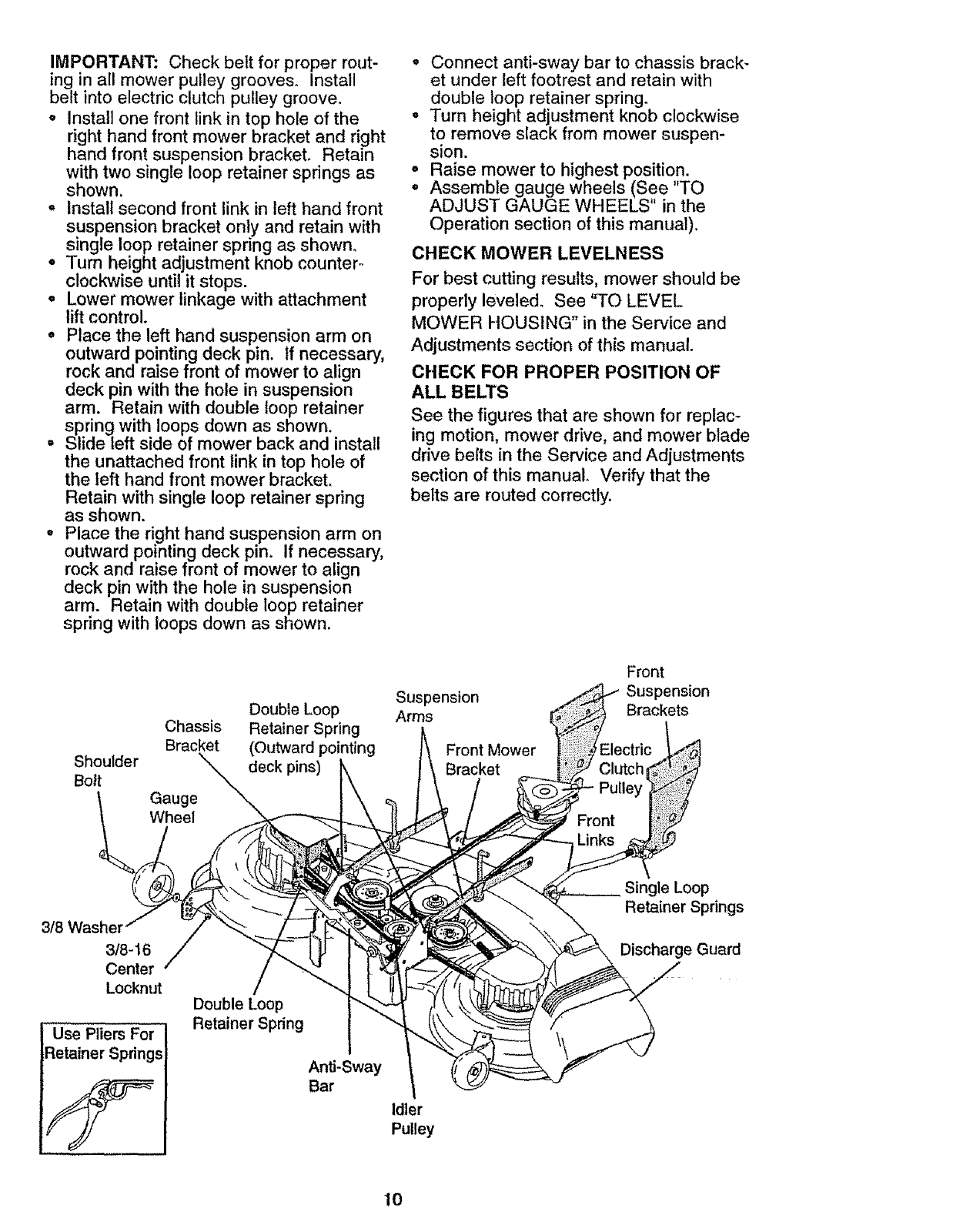
IMPORTANT: Check belt for proper rout-
ing in all mower pulley grooves. Install
belt into electric clutch pulleygroove.
o Installone front link in top hole of the
righthand front mower bracketand right
hand front suspensionbracket. Retain
withtwo single loop retainer springs as
shown,
• Installsecond front link in left handfront
suspensionbracket only and retain with
single loop retainerspring as shown.
° Turn height adjustmentknob counter°
clockwise until it stops.
• Lower mower linkage with attachment
lift control.
• Place the left handsuspension arm on
outward pointing deck pin_ If necessary,
rock and raisefront of mowerto align
deck pin with the hole in suspension
arm. Retain with double loop retainer
spring with loops down as shown.
• Slide left side of mower back and install
the unattachedfront link in top hole of
the left hand front mower bracket.
Retain with single loop retainer spring
as shown.
o Place the right handsuspension arm on
outwardpointing deck pin. if necessary,
rock and raise front of mower to align
deck pin with the hole in suspension
arm. Retainwith double loop retainer
spring with loops down as shown.
° Connect anti-swaybar to chassis brack-
et under left footrest and retain with
double loop retainerspring_
o Turn height adjustmentknob clockwise
to remove slack from mower suspen-
sion.
°Raise mower to highest position.
° Assemble gauge wheels (See TO
ADJUST GAUGE WHEELS in the
Operation section of this manual).
CHECK MOWER LEVELNESS
For best cutting results, mower should be
properly leveled. See 'q-O LEVEL
MOWER HOUSING" in the Service and
Adjustments section of this manual.
CHECK FOR PROPER POSITION OF
ALL BELTS
See the figures that are shown for replac-
ing motion, mower drive, and mower blade
drive belts in the Service and Adjustments
section of this manual. Verify that the
belts are routed correctly.
Doubfe Loop
Chassis Retainer Spring
Bracket (Outward pointing
Shoulder deck pins)
Bolt
Front
Suspension Suspension
Arms Brackets
Front Mower
Bracket
3/8
3/8-16
Center
Locknut
Use Pliers For
Retainer Springs
Double Loop
Retainer Spring
Anti-Sway
Bar
Idler
Pulley
Single Loop
Retainer Springs
Discharge Guard
10

INSTALL MULCHER PLATE
•Install two latch hooks to mulcher plate
using screw, washer, lock washer, and
weld nut as shown°
NOTE: Pre-assemble weld nut to latch
hook by inserting weld nut from the top
with hook pointing down. Tighten hard_
ware securely.
° Raise and hold deflector shield in up-
right position.
° Place front of mulcher plate over front of
mower deck opening and slide into
place, as shown°
°Hook front latch into hole on front of
mower deck.
• Hook rear latch into hole on back of
mower deck.
_CAUTION: Do not remove discharge
guard from mower, Raise and hold guard
when attaching mulcher plate and allow it
to rest on plate while in operation.
TO CONVERT TO BAGGING OR
DISCHARGING
Simply remove mulcher plate and store in
a safe place. Your mower is now ready for
discharging or installation of optional grass
catcher accessory,
NOTE: It is not necessary to change
blades. The mulcher blades are designed
for discharging and bagging also.
Weld Nut
from the To Hook Points
Lock
Washer Latch
Weld Hook
Nut
Latch Nut
Lock
Washer Washer
Mulcher _-----Screw
Plate
v' CHECKLIST
PLEASE REVIEW THE FOLLOWING
CHECKLIST:
t," All assembly instructions have been
completed.
v" No remaining loose parts in carton_
v' Battery is properly prepared and
charged. (Minimum 1 hour at 6 amps).
v' Seat is adjusted comfortably and
tightened securely.
v' All tires are properly inflated. (For
shipping purposes, the tires were
overinflated at the factory).
v' Be sure mower deck is properly leveled
side-to-sideifront-to-rear for best cutting
results. (Tires must be properly inflated
for leveling).
v' Check mower and drive belts, Be sure
they are routed properly around pulleys
and inside all belt keepers.
v' Check wiring. See that all connections
are still secure and wires are properly
clamped.
v' Before driving tractor, be sure free.-
wheel control is in drive position.
WHILE LEARNING HOW TO USE YOUR
TRACTOR, PAY EXTRA ATTENTION TO
THE FOLLOWING IMPORTANT ITEMS:
,/ Engine oil is at proper level.
,I" Fuel tank is filled with fresh, clean,
regular unleaded gasoline.
,/ Become familiar with all controls - their
location and function. Operate them
before you start the engine.
,/ Be sure brake system is in safe operat-
ing condition_
/It is important to purge the transmission
before operating your tractor for the first
time. Follow proper starting and
transmission purging instructions (See
"TO START ENGINE" and "PURGE
TRANSMISSION" in the Operation
section of this manual).
Deflector
Shield
/
Latch
Hooks
11

These symbols may appear on your tractor or in literaturesuppliedwith the product.
[.earn and understandtheir meaning.
4_
BATTERY CAUTION OR REVERSE FORWARD SLOW
WARNING
A
ENGINE ON ENGINE OFF OIL PRESSURE LIGHTS ON T
$
CHOKE MOWER HEIGHT PARKING BRAKE
LOCKED
FUEL
FAST
6i
OVER TEMP
LIGHT
UNLOCKED MOWER LIFT
ATTACHMENT
CLUTCH ENGAGED
IGNITION
REVERSE NEUTRAL HIGH
ATTACHMENT
CLUTCH DISENGAGED
L
LOW PARKING BRAKE
KEEP AREA CLEAR SLOPE HAZARDS
(SEE SAFETY RULES SECTION)
DANGER, KEEP HANDS AND FEET AWAY
HYDROSTATIC FREE WHEEL
(Hydro Models only)
12
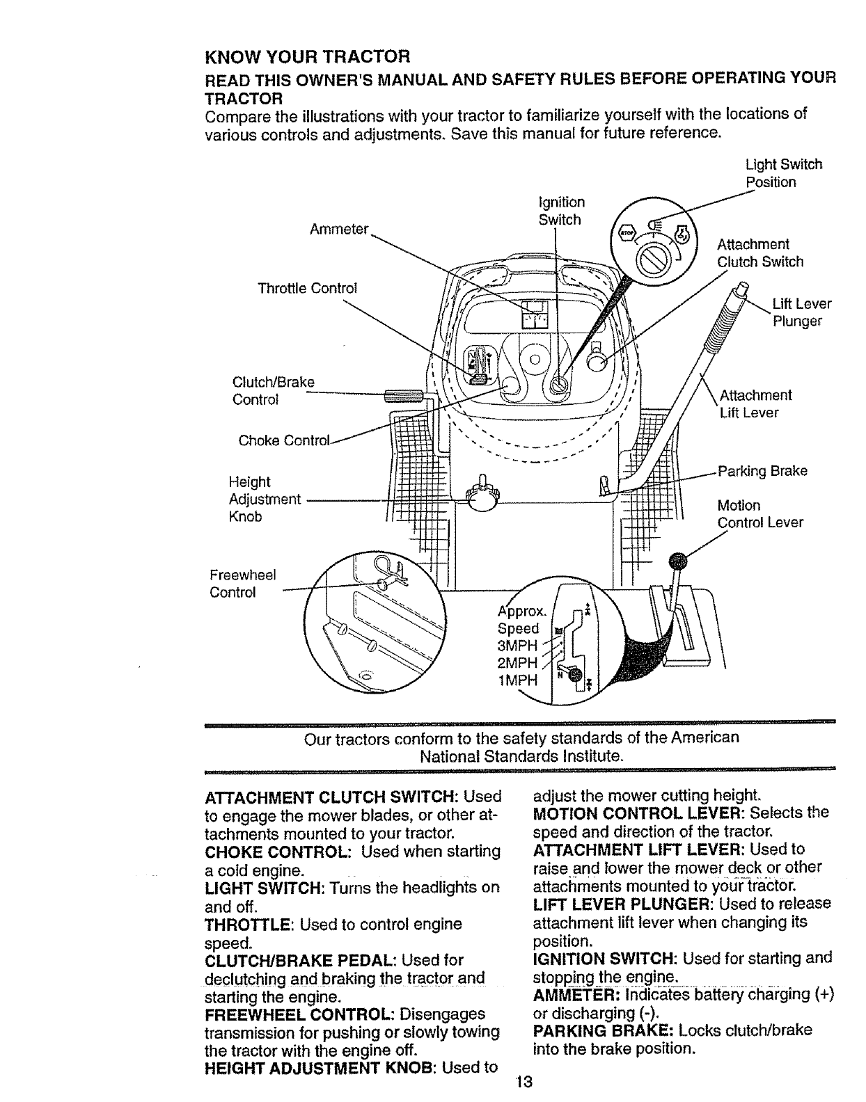
KNOW YOUR TRACTOR
READ THIS OWNER'S MANUAL AND SAFETY RULES BEFORE OPERATING YOUR
TRACTOR
Compare the illustrations with your tractor to familiarize yourself with the locations of
various controls and adjustments. Save this manual for future reference.
Ammeter
Ignition
Switch
Light Switch
Position
Attachment
Clutch Switch
Throttle Control
__ Lift Lever
Plunger
Clutch/Brake
Control
Choke
Height
Adjustment
Knob
Attachment
Lift Lever
Brake
Motion
Control Lever
Freewheel
Control
Speed
3MPH _
2MPH
tMPH
,,, ,, _ , ,,,, ..... _ r,,, " hFP_'' _ ' 'J ' H ...........
Our tractors conform to the safety standards of the American
National Standards Institute.
......................................................... , L i J,i ,,, ,,ll
ATTACHMENT CLUTCH SWITCH: Used
to engage the mower blades, or other at-
tachments mounted to your tractor.
CHOKE CONTROL: Used when starting
a cold engine.
LIGHT SWITCH: Turns the headlights on
and off.
THROTTLE: Used to control engine
speed.
CLUTCH/BRAKE PEDAL: Used for
declutching and braking the tractor and
starting the engine.
FREEWHEEL CONTROL: Disengages
transmission for pushing or slowly towing
the tractor with the engine off.
HEIGHT ADJUSTMENT KNOB: Used to
adjust the mower cutting height.
MOTION CONTROL LEVER: Selects the
speed and direction of the tractor.
ATTACHMENT LIFT LEVER: Used to
raise and lower the mower deck or other
attachments mounted to yodrtra_ct0r.
LIFT LEVER PLUNGER: Used to release
attachment lift lever when changing its
position.
IGNITION SWITCH: Used for starting and
stopping the engine.
AMMEi;ER: Indicates batte_ charging (+)
or discharging (-)°
PARKING BRAKE: Locks clutch/brake
into the brake position.
13

HOW TO USE YOUR TRACTOR
Your tractor is equipped with an operator
presence sensing switch. When engine is
running, any attempt by the operator to
leave the seat without first setting the
parking brake will shut off the engine.
The operation of any tractor can result in foreign objects thrown into the
eyes, which can result in severe eye damage. Always wear safety glasses
or eye shields while operating your tractor or performing any adjustments or
repairs. We recommend a wide vision safety mask over spectacles, or stare
dard safety glasses.
TO SET PARKING BRAKE
o Depress clutch/brake pedal into full
=BRAKE" position and hold.
° Place parking brake lever in "EN-
GAGED" position and release pressure
from clutch/brake pedal. Pedal should
remain in =BRAKE" position. Make sure
parking brake will hold tractor secure.
Throttle Push-In to Attachment Clutch
Control Switch Pull Out To
"Engage"
"Engaged" Position
"Brake"
-Position
Pedal "Drive" "Disengaged"
Position Position
STOPPING
MOWER BLADES
• To stop mower blades, move attach-
ment clutch switch to "DISENGAGED"
position.
GROUND DRIVE -
o To stop ground drive, depress
clutch/brake pedal into full "BRAKE"
position.
=Move motion control lever to neutral (N)
position.
IMPORTANT: The motion control lever
does not return to neutral (N) position
when the clutch/brake pedal is depressed.
ENGINE -
= Move throttle control to slow position.
NOTE: Failure to move throttle control to
slow position and allowing engine to idle
before stopping may cause engine to
"backfire".
, Turn ignition key to "OFF" position and
remove key. Always remove key when
leaving tractor to prevent unauthorized
use,
° Never use choke to stop engine.
IMPORTANT: Leaving the ignition switch
in any position other than "OFF" will cause
the battery to be discharged, (dead).
NOTE: Under certain conditions when
tractor is standing idle with the engine run-
ning, hot engine exhaust gases may
cause "browning" of grass. To eliminate
this possibility, always stop engine when
stopping tractor on grass areas_
,_ CAUTION: Always stop tractor com-
pletely, as described above, before leaving
the operator's position; to empty grass
catcher, etc.
THROTTLE CONTROL
Always operate engine at full throttle.
Operating engine at less than full throt-
i tle reduces the rate.
battery charging
Full throttle offers the best bagging and
mower performance.
CHOKE CONTROL
Use choke control whenever you are start-
ing a cold engine. Do not use to start a
warm engine.
= To engage choke control, pull knob out.
Slowly push knob in to disengage.
TO MOVE FORWARD AND BACKWARD
The direction and speed of movement is
controlled by the motion control lever°
°Start tractor with motion control lever in
neutral (N) position.
°Release parking brake and clutch/brake
.... pedal
° Slowly move motion control lever to
desired position.
NOTE: The effort to move the motion con-
trol lever will reduce after the first few
hours of use. This is normal.
TO ADJUST MOWER CUTTING HEIGHT
The cutting height is controlled by turning
the height adjustment knob in desired
direction.
°Turn knob clockwise (C,) to raise cutting
height.
14

•Turn knob counterclockwise (,.3)to
lower cutting heighL
The cutting height range is approximately
1-1/2" to 4". The heights are measured
from the ground to the blade tip with the
engine not running. These heights are ap-
proximate and may vary depending upon
soil conditions, height of grass and types
of grass being mowed.
o The average lawn should be cut to
approximately 2-1/2 inches during the
cool season and to over 3 inches during
hot months_ For healthier and better
looking lawns, mow often and after
moderate growth_
• For best cutting performance, grass
over 6 inches in height should be
mowed twice° Make the first cut rela-
tively high; the second to desired height.
TO ADJUST GAUGE WHEELS
Gauge wheels are properly adjusted
when they are slightly off the ground when
mower is at the desired cutting height in
operating position. Gauge wheels then
keep the deck in proper position to help
prevent scalping in most terrain condi-
tions.
° Adjust gauge wheels with tractor on a
flat level surface°
°Adjust mower to desired cutting height
(See '%0 ADJUST MOWER CUTTING
HEIGHT" in the Operation section of
this manual).
oWith mower in desired height of cut po-
sition, gauge wheels should be assem-
bled so they are slightly off the ground.
Install gauge wheel in appropriate hole
with shoulder bolt, 3/8 washer, and 3/8-
16 locknut and tighten securely.
o Repeat for opposite side installing
gauge wheel in same adjustment hole.
Gauge Wheel _
Mounting. _---_i-_
Bracket "_,_
3/8-16 (__'t.L"_.._
3/8 Washer_
Gauge Wheel ---"
TO OPERATE MOWER
Your tractor is equipped with an operator
presence sensing switch. Any attempt by
the operator to leave the seat with the
engine running and the attachment clutch
engaged will shut off the engine.
° Select desired height of cut.
• Lower mower with attachment lift con-
trol.
= Start mower blades by engaging attach-
ment clutch control.
° TO STOP MOWER BLADES - disen-
gage attachment clutch control.
Attachment Clutch
Switch Pull Out To
"Enga_ _
Push In To <--_
_Disengage" _ _Y
Attachment Lift Lever
High Position
/Low
;_Position
_'\ Discharge
,_CAUTION: Do not operate the mower
without either the entire grass catcher, on
mowers so equipped, or the discharge
guard in place.
TO OPERATE ON HILLS
_kCAUTION: Do not drive up or down
hills with slopes greater than 15 °and do
not drive across any slope. Use the slope
guide provided at the back of this manual.
• Choose the slowest speed before start-
ing up or down hills.
°Avoid stopping or changing speed on
hills.
o If slowing is necessary, move throttle
control lever to slower position.
° If stopping is absolutely necessary, push
clutchlbrake pedal quickly to brake posi,-
tion and engage parking brake°
° Move motion control lever to neutral (N)
position.
IMPORTANT: The motion control lever
does not return to neutral (N) position
when the clutchlbrake pedal is depressed.
• To restart movement, slowly release
parking brake and clutch/brake pedal.
° Slowly move motion control lever to
slowest setting.
• Make all turns slowly.
TO TRANSPORT
When pushing or towing your tractor, be
sure to disengage transmission _bYp[a£!ng
freewheel control in freewheeling position.
Freewheel control is located at the rear
drawbar of tractor.
15

• Raiseattachmentlift to highestposition
with attachmentlift control.
• Pull freewheelcontrol knob out and hold
in position by inserting retainerspring
into forward hole of control rod.
oDo not push or tow tractor at more than
two (2) MPH.
• To reengage transmission, reverse
above procedure,
NOTE: To protect hood from damage when
transporting your tractor on a truck or a
trailer, be sure hood is closed and secured
to tractor. Use an appropriate means of
tying hood to tractor (rope, cord, etc.).
TOWING CARTS AND OTHER
ATTACHMENTS
Tow only the attachments that are recom-
mended by and comply with specifications
of the manufacturer of your tractor. Use
common sense when towing. Too heavy of
a load, while on a slope, is dangerous.
Tires can lose traction with the ground and
cause you to lose control of your tractor.
BEFORE STARTING THE ENGINE
CHECK ENGINE OIL LEVEL
• The engine in your tractor has been
shipped, from the factory, already filled
with summer weight oil.
°Check engine oil with tractor on level
ground.
•Unthread and remove oil fill cap/dip-
stick; wipe oil off. Reinsert the dipstick
into the tube and rest oil fill cap on the
itube. Do not thread the cap onto the
tube° Remove and read oil level. If nec-
essary, add oil until "FULL" mark on
dipstick is reached. Do not overfill.
For cold weather operation you should
change oil for easier starting (See "OIL
VISCOSITY CHART" in the Customer
: Responsibilities section of this manual).
_ To change engine oil, see the Customer
_ Responsibilities section in this manual.
_DD GASOLINE
•Fill fuel tank. Use fresh, clean, regular
unleaded gasoline with a minimum of 87
octane. (Use of leaded gasoline will
increase carbon and lead oxide
deposits and reduce valve life). Do not
mix oil with gasoline.
Purchase fuel in quantities that can be
used within 30 days to assure fuel fresh
hess.
IMPORTANT: When operating in tempera-
tures below 32 F(0 C), use fresh, clean
winter grade gasoline to help insure good
cold weather starting.
,_kWARNING: Experience indicates that
alcohol blended fuels (called gasohol or
using ethanol or methanol) can attract
moisture which leads to separation and
formation of acids during storage. Acidic
gas can damage the fuel system of an
engine while in storage. To avoid engine
problems, the fuel system should be emp-
tied before storage of 30 days or longer.
Drain the gas tank, start the engine and let
it run until the fuel lines and carburetor are
empty. Use fresh fuel next season. See
Storage Instructions for additional informa-
tion. Never use engine or carburetor
cleaner products in the fuel tank or perma-
nent damage may occur.
,_kCAUTION: Fill to bottom of gas tank
filler neck. Do not overfill. Wipe off any
spilled oil or fuel. Do not store, spill or use
gasoline near an open flame.
TO START ENGINE
When starting the engine for the first time
or if the engine has run out of fuel, it will
take extra cranking time to move fuel from
the tank to the engine.
o Be sure freewheel control is in the
transmission engaged position=
• Sit on seat in operating position,
depress clutch/brake pedal and set
parking brake.
•Place motion control lever in neutral (N)
position.
o Move attachment clutch to "DISEN-
GAGED" position.
o Move throttle control to fast position
° Pull choke control out for a cold engine
start attempt. For a warm engine start
attempt the choke control may not be
needed.
Note: Before starting, read the warm and
cold starting procedures below.
•Insert key into ignition and turn key
clockwise to "START" position and
release key as soon as engine starts.
Do not run starter continuously for more
than fifteen seconds per minute. If the
engine does not start after several
attempts, push choke control in, wait a
few minutes and try again. If engine still
does not start, pull the choke control out
and retry.
16

WARM WEATHERSTARTING(50° F
AND ABOVE)
• When engine starts, slowlypush choke
control in until the engine begins to run
smoothly.If the engine startsto run
roughly,pull the choke control out slight-
ly for a few seconds and then continue
to pushthe control in slowly.
o The attachmentsand grounddrive can
now be used. If the engine does not
accept the load, restart the engine and
allow it to warm upfor one minute using
the choke as described above.
COLDWEATHERSTARTING(50° FAND
BELOW)
• When engine starts, slowly push choke
control in until the engine begins to run
smoothly.Continue to push the choke
control in small steps allowing the
engine to acceptsmall changes in
speed and load, until the choke control
is fully in. If the engine starts to run
roughly,pull the choke control out slight-
ly for a few secondsand then continue
to push the control in slowly,This may
requirean engine warm-up period from
several seconds to several minutes,
depending on the temperature.
AUTOMATICTRANSMISSIONWARM-UP
*Before driving the unit in cold weather,
the transmission should be warmed up
as follows:
,Be sure the tractor is on level ground.
•Place the motion control lever in
neutral. Release the parking brake and
let the clutch/brake slowly return to
operating position_
,Allow one minute for transmission to
warm up. This can be done during the
engine warm up period.
o The attachments can be used during
the engine warm-up period after the
transmission has been warmed up and
may require the choke control be pulled
out slightly.
NOTE:A high altitude (above 3000 feet)
or in cold temperatures (below 32 F) the
carburetor fuel mixture may need to be
adjusted for best engine performance.
See "TO ADJUST CARBURETOR" in the
Service and Adjustments section of this
manual.
PURGE TRANSMISSION
,_CAUTION: Never engage or disen-
gage freewheel lever while the engine is
running.
To ensure proper operation and perfor-
mance, it is recommended that the trans-
mission be purged before operating tractor
for the first timer This procedure will
remove any trapped air inside the trans-
mission which may have developed during
shipping of your tractor.
IMPORTANT: Should your transmission
require removal for service or replace-
ment, it should be purged after reinstalla-
tion before operating the tractor.
,Place tractor safely on level surface with
engine off and par.kin.g brake seL
, Disengage transmlss=on by placing free-
wheel control in freewheeling position
(See '%0 TRANSPORT" in this section
of manual).
• Sitting in the tractor seat, start engine.
After the engine is running, move throt-
tle control to slow position° With motion
control lever in neutral (N) position,
slowly disengage clutch/brake pedal
• Move motion control lever to full forward
position and hold for five (5) seconds.
Move lever to full reverse position and
hold for five (5) seconds. Repeat this
procedure three (3) times.
NOTE: During this procedure there will be
no movement of drive wheels. The air is
being removed from hydraulic drive sys-
tem.
•Move motion control lever to neutral (N)
position. Shut off engine and set parking
brake,
• Engage transmission by placing free-
wheel control in driving position (See
"TO TRANSPORT" in this section of
manual).
• Sitting in the tractor seat, start engine.
After the engine is running, move throt-
tle control to half (1/2) speed. With
motion control lever in neutral (N) posi-
tion, slowly disengage clutch/brake
pedal.
•Slowly move motion control lever for-
ward; after the tractor moves approxi-
mately_five.(5) feet, slowly move motion
control lever to revei:se p_sitioh_After .....
the tractor moves approximately five (5)
feet return the motion control lever to
the neutral (N) position. Repeat this pro-
cedure with the motion control lever
three (3) times.
•Your tractor is now purged and ready for
normal operation.
17

MOWING TIPS
•Tire chains cannot be used when the
mower housing is attached to tractor.
o Mower should be properly leveled for
best mowing performance. See '%0
LEVEL MOWER HOUSING" in the
Service and Adjustments section of this
manual.
° The left hand side of mower should be
used for trimming.
°Drive so that clippings are discharged
onto the area that has been cut. Have
the cut area to the right of the tractor.
This will result in a more even distribu-
tion of clippings and more uniform cut-
ting.
o When mowing large areas, start by turn-
ing to the right so that clippings wilt dis-
charge away from shrubs, fences, drive-
ways, etc. After one or two rounds, mow
in the opposite direction making left
hand turns until finished,
o If grass is extremely tall, it should be
mowed twice to reduce load and possi-
ble fire hazard from dried clippings.
Make first cut relatively high; the second
to the desired height.
• Do not mow grass when it is wet. Wet
grass will plug mower and leave unde-
sirable clumps. Allow grass to dry
before mowing.
oAlways operate engine at full throttle
when mowing to assure better mowing
performance and proper discharge of
material. Regulate ground speed by se-
lecting a low enough gear to give the
mower the best cutting performance as
well as the quality of cut desired.
• When operating attachments, select a
ground speed that will suit the terrain
and give best performance of the at-
tachment being used.
MULCHING MOWING TIPS
IMPORTANT: For best performance, keep
mower housing free of built-up grass and
trash, Clean after each use_
° The special mulching blade will recut
the grass clippings many times and
reduce them in size so that as they fall
onto the lawn they will disperse into the
grass and not be noticed. Also, the
mulched grass will biodegrade quickly
to provide nutrients for the lawn, Always
mulch with your highest engine (blade)
speed as this will provide the best recut-
ting action of the blades,
• Avoid cutting your lawn when it is weL
Wet grass tends to form clumps and
interferes with the mulching action, The
best time to mow your lawn is the early
afternoon. At this time the grass has
dried and the newly cut area will not be
exposed to the direct sun,
o For best results, adjust the mower cut-
ting height so that the mower cuts off
only the top one4hird of the grass
blades. For extremely heavy mulching,
reduce your width of cut on each pass
and mow slowly.
° Certain types of grass and grass condi-
tions may require that an area be
mulched a second time to completely
hide the clippings, When doing a sec-
ond cut, mow across or perpendicular to
the first cut path.
° Change your cutting pattern from week
to week, Mow north to south one week
then change to east to west the next
week. This will help prevent matting and
graining of the lawn.
Max 1/3
18

CUSTOMER RESPONSIBILITIES
i i i illlllllll i i .,i,,..,i .................
sc. o= ,"
REGULAR SERVICE _'_./,_"4_J SERVICE DATES
CheckCheckBrakeOperationTirePressure '' _' _ .....................
Check Operator Presence and
TInterlock Systems
RC'he'ck for Loose Fasteners ........................ _ ............... _7
ASharpen/Replace Mower Blades .......... ' _41 1'I _ "
C Lubrication Chart '"' _ ......
0Check Battery Level , ...... ....... _
RClean Battery and Terminals _ : if ....
Check Transaxle Cooling ....... if ,........
Adjust Blade Belt(s) Tension ......... Ks ......
Adjust Motion Drive Belt(s) Tension .... I[vfs .....
i
Check Engine Oil Level if
Change Engine Oil _.;_,3
ECleanAirF,ter .......... _ ..............
N Clean Air Screen 1_2
GInsp'e'ctMumeriSparkAttester .......... V_
/Replace Oil Filter (}f equipped) _,_
RE Ctean Engine Cooling Fins ........... :
i
i
i
Replace Spark Plug if I_
Re---'placeAir Filter Paper Cartridlg_',,",,' 1##'2
R_eplace Fuel Fiiter , ,, ,u,,ull .........
1 - Change more often when opereUng under a heavy {c_ad or"in high arrbienl tempere_res 5 =If equipped with ad_uetabte system
2*Service mere often when vperaling in d_dy or dusty condigene, 6 - Not required if equipped with maintensnce-free better_
3_ it eq#tpped with oil lilter, change oil every 50 hours
4 -RepIace btedes mere often when mowing in sandy soil
GENERAL RECOMMENDATIONS
The warranty on this tractor does not cover
items that have been subjected to operator
abuse or negligence. To receive full value
from the warranty, operator must maintain
tractor as instructed in this manual. Some
adjustments will need to be made periodi-
cally to properly maintain your tractor.
All adjustments in the Service and
Adjustments section of this manual should
be checked at least once each season.
o Once a year you should replace the
spark plug, clean or replace air filter, and
check blades and belts for wear., A new
spark plug and clean air filter assure
proper air-fuel mixture and help your
engine run better and last longer.
BEFORE EACH USE
°Check engine oil level
• Check blake operation.
- Check tire pressure.
° Check operator presence and interlock
systems for proper operation.
• Check for loose fasteners.
7-T_ghten front axle p_votbott to 35 ff,,-lbs maximum
Do not overtighten
LUBRICATION CHART
@S Spindle
Zerk f_:: Zerk
O Front Wheel
Bearin¢
Front
Wheel
Bearing
Zerk
O Engine,
O
Clutch
or(s)
Piv .j ,.. .,
@ SAE 30 or 10w30 Motor OIL
O General Purpose Grease
O Refer to Maintenance "Engine" Section
IMPORTANT: Do not oil or grease the pivot
points which have special nylon bear-ings.
Viscous lubricants will attract dust and dirt
that will shorten the life of the self-lubricating
bearings. If you feel they must be lubricated,
use only a dry, powdered graphite type lubri-
cant sparingly.
19

TRACTOR
Always observesafety rules when per-
forming any maintenance.
BRAKE OPERATION
If tractor requiresmorethan six (6) feet
stopping distance at highspeed in highest
gear,then brake must be adjusted.(See
=TOADJUST BRAKE" in the Service and
Adjustments section of this manual).
TIRES
oMaintain proper air pressure in all tires
(See "PRODUCT SPECIFICATIONS"
on page 3 of this manual).
° Keep tires free of gasoline, oil, or insect
control chemicals which can harm rub-
ber.
°Avoid stumps, stones, deep ruts, sharp
objects and other hazards that may
cause tire damage.
NOTE: To seal tire punctures and prevent
flat tires due to stow leaks, tire sealant
may be purchased from your local parts
dealer. Tire sealant also prevents tire dry
rot and corrosion.
OPERATOR PRESENCE SYSTEM
Be sure that operator presence and inter-
lock systems are working propedyo If your
tractor does not function as described
below, repair the problem immediately.
° The engine should not start unless the
clutch!brake pedal is fully depressed
and attachment clutch control is in the
disengaged position.
° When the engine is running, any
attempt by the operator to leave the
seat without first setting the parking
brake should shut off the engine,
° When the engine is running and the
attachment clutch is engaged, any
attempt by the operator to leave the
seat should shut off the engine.
• The attachment clutch should never
operate unless the operator is in the
seat.
BLADE CARE
For best resultsmower blades must be
kept sharp. Replace bent or damaged
blades.
BLADE REMOVAL
° Raise mower to highest position to allow
access to blades.
• Remove hex bolt, lock washer and flat
washer securing blade.
,Install new or resharpened blade with
trailing edge up towards deck as shown.
IMPORTANT; To ensure proper assembly,
center hole in blade must align with star
on mandrel assembly.
o Reassemble hex bolt, lock washer and
flat washer in exact order as shown.
° Tighten bolt securely (27-35 Ft. Lbs.
torque).
IMPORTANT: Blade bolt is grade 8 heat
treated.
Trailing
Edge Center
Mandrel
Assembly
Hole
Lock
_- Hex Bolt (Grade 8',
*A Grade 8 heat treated bolt can be
identifiedby six lines on the belt headr
TO SHARPEN BLADE
NOTE: We do not recommend sharpening
blade, but if you do, be sure the blade is
balanced,
Care should be taken to keep the blade
balanced. An unbalanced blade will cause
excessive vibration and eventual damage
to mower and engine.
o The blade can be sharpened with a file
or on a grinding wheel. Do not attempt
to sharpen while it is on the mower.
° To check blade balance, you will need a
5/8" diameter steel bolt, pin, or a cone
balancer. (When using a cone balancer,
follow the instructions supplied with bai-
ancer).
NOTE: Do not use a nail for balancing
blade. The lobes of the center hole may
appear to be centered, but are not.
o Slide blade onto an unthreaded portion
of the steel bolt or pin and hold the bolt
or pin parallel with the ground. If blade
is balanced, it should remain in a hori-
zontal position. If either end of the blade
moves downward, sharpen the heavy
end until the blade is balanced.
Center Hole ./ /
or P=n_
BATTERY
Your tractor has abattery charging system
which is sufficient for normal use.
However, periodic charging of the battery
with an automotive charger will extend its
20 lifeo

- Keep battery and terminals clean.
•Keep battery bolts tight.
°Keep small vent holes open.
° Recharge at 6-10 amperes for 1 hour.
TO CLEAN BATTERY AND TERMINALS
Corrosion and dirt on the battery and ter-
minals can cause the battery to "leak"
power.
°Remove terminal guard.
• Disconnect BLACK battery cable first
then RED battery cable and remove
battery from tractor.
• Rinse the battery with plain water and
dry°
• Clean terminals and battery cable ends
with wire brush until bright.
• Coat terminals with grease or petroleum
jelly°
° Reinstall battery (See "REPLACING
BATTERY" in the SERVICE AND
ADJUSTMENTS section of this manu-
al).
V-BELTS
Check V-beJts for deterioration and wear
after 100 hours of operation and replace if
necessary. The belts are not adjustable.
Replace belts if they begin to slip from
wear.
TRANSAXLE COOLING
The transmission fan and cooling fins
should be kept clean to assure proper
cooling.
Do not attempt to clean fan or transmis-
sion while engine is running or while the
transmission is hot.
° Inspect cooling fan to be sure fan
blades are intact and clean.
° Inspect cooling fins for dirt, grass clip-
pings and other materials. To prevent
damage to seals, do not use com-
pressed air or high pressure sprayer to
clean cooling fins.
TRANSAXLE PUMP FLUID
The transaxle was sealed at the factory
and fluid maintenance is not required for
the life of the transaxle. Should the
transaxle ever leak or require servicing,
contact your nearest authorized service
center.
ENGINE
LUBRICATION
Only use high quality detergent oil rated
with API service classification SF, SG, or
SH° Select the oil's SAE viscosity grade
according to your expected operating tem-
perature_
Change the oil after every 50 hours of
operation or at least once a year if the
tractor is not used for 50 hours in one
year.
Check the crankcase oil level before start-
ing the engine and after each eight (8)
hours of operation° Tighten oil fill cap/dip-
stick securely each time you check the oil
level.
TO CHANGE ENGINE OIL
Determine temperature range expected
before oil change. AII oil must meet API
service classification SF, SG, or SH.
•Be sure tractor is on level surface.
° Oi! will drain more freely when warm.
° Catch oil in a suitable container.
° Remove oil fill cap/dipstick. Be careful
not to allow dirt to enter the engine
when changing oil.
° Remove drain plug,
o After oil has drained completely, replace
oil drain plug and tighten securely_
o Refill engine with oil through oil fill dip-
stick tube. Pour slowly, Do not overfill.
For approximate capacity see "PROD-
UCT SPECIFICATIONS" on page 5 of
this manual.
° Use gauge on oil fill cap/dipstick for
checking level, insert dipstick into the
tube and rest the oil fill cap on the tube.
Do not thread the cap onto the tube
when taking reading. Keep oil at
"FULL" line on dipstick. Tighten cap
onto the tube securely when finished.
N_/__Air Screen
__-,) _ ._, Oil Fiii
Cap/Dipstick
CLEAN AIR SCREEN
Air screen must be kept free of dirt and
chaff to prevent engine damage from over-
heating. Clean with a wire brush or com-
pressed air to remove dirt and stubborn
dried gum fibers.
21

CLEAN AIR INTAKE/COOLING AREAS
To insure proper cooling, make sure the
grass screen, cooling fins, and other
external surfaces of the engine are kept
clean at all times.
Every 100 hours of operation (more often
under extremely dusty, dirty conditions),
remove the blower housing and other
cooling shrouds. Clean the cooling fins
and external surfaces as necessary. Make
sure the cooling shrouds are reinstalled.
NOTE: Operating the engine with a
blocked grass screen, dirty or plugged
cooling fins, and!or cooling shrouds re-
moved will cause engine damage due to
overheating.
AIR FILTER
Your engine will not run properly using a
dirty air filter° Clean the foam pre-cleaner
after every 25 hours of operation or every
season. Service paper cartridge every
100 hours of operation or every season,
whichever occurs first.
Service air cleaner more often under dusty
conditions.
•Loosen knob and remove cover.
TO SERVICE PRE-CLEANER
° Slide foam pre-cleaner off cartridge.
°Wash it in liquid detergent and water.
oSqueeze it dry in a clean cloth. Allow it
to dry.
°Saturate it in engine oil. Wrap it in
clean, absorbent cloth and squeeze to
remove excess oil.
TO SERVICE CARTRIDGE
• Replace a dirty, bent, or damaged car-
tridge.
NOTE: Do not wash the paper cartridge
or use pressurized air, as this will damage
the cartridge°
o Remove nut and cartridge plate.
°Reinstall the pre-cleaner (cleaned and
oiled) over the paper cartridge.
°Check rubber seal for damage and
proper position around stud. Replace if
necessary.
° Reassemble air cleaner, cartridge plate,
and nut.
Reinstall air cleaner cover and secure
by tightening knob.
Foam Cartridge _,
Pre-cle._ __
Cartridg____RuXubb_r
Kno __y Seat
ENGINE OIL FILTER
Reptace the engine oil filer every season
or with every second oil change if the trac-
tor is used more than t00 hours in one
year.
MUFFLER
Inspect and replace corroded muffler and
spark arrester (if equipped) as it could cre-
ate a fire hazard and/or damage°
SPARK PLUGS
Replace spark plugs at the beginning of
each mowing season or after every 100
hours of operation, whichever occurs first.
Spark plug type and gap setting are
shown in "PRODUCT SPECIFICATIONS"
on page 5 of this manual.
IN-LINE FUEL FILTER
The fuel filter should be replaced once
each season. If fuel filter becomes
clogged, obstructing fuel flow to carbure-
tor, replacement is required.
o With engine coot, remove filter and plug
fuel line sections.
• Place new fuel filter in position in fuel
line with arrow pointing towards carbu-
retor.
°Be sure there are no fuel line leaks and
clam.ps are properly positioned.
Cl lampamp _ C
22

CLEANING
• Clean engine, battery, seat, finish, etc,
of all foreign matter,,
• Keep finished surfaces and wheels free
of all gasoline, oil, etc.
• Protect painted surfaces with automo-
tive type wax.
We do not recommend using a garden
hose to clean your tractor unless the elec-
trical system, muffler, air filter and carbure-
tor are covered to keep water out° Water
in engine can result in a shortened engine
lifeo
,&CAUTION: Before performing any service or adjustments:
o Depress clutch/brake pedal fully and set parking brake.
,Place motion control lever in neutral (N) position.
° Place attachment clutch in "DISENGAGED" position.
°Turn ignition key "OFF" and remove key.
o Make sure the blades and al! moving parts have completely stopped.
- Disconnect spark plug wire from spark plug and place wire where it cannot come
in contact with plug.
TRACTOR
TO REMOVE MOWER
o Place attachment clutch in "DISEN-
GAGED" position.
-Turn height adjustment knob to lowest
setting.
*Lower mower to its lowest position.
*Remove retainer spring holding anti-
swaybar to chassis bracket and disen-
gage anti-swaybar from bracket.
° Remove retainer springs from suspen-
sion arms at deck and disengage arms
from deck.
o Raise attachment lift to its highest posi-
tiono
...................... , ,,L,± .......................... ::= --;---
,Remove two retainer springs from each
front link and remove links.
• Slide mower forward and remove belt
from electric clutch pulley.
• Slide mower out from under right side of
tractor.
IMPORTANT: If an attachment other than
the mower deck is to be mounted on the
tractor, remove the front links.
TO INSTALL MOWER
Follow procedure described in "INSTALL
MOWER AND DRIVE BELT* in the
Assembly section of this manual.
Adjustment
Nuts
Suspension
Arms
Lift
Links Front Mower
Bracket
Front
Bracket
Chassis
Bracket_ Front
Suspension
•Bracket
Retainer
Spring
Anti-Sway
Bar
Retainer
Springs
Front Mower
Bracket
Retainer
Springs 23

TO LEVEL MOWER HOUSING
Adjust the mower while tractor is parked
on level ground or driveway. Make sure
tires are properly inflated (See "PROD-
UCT SPECIFICATIONS"). If tires are
over or underinflated, you will not properly
adjust your mower.
SIDE-TO-SIDE ADJUSTMENT
• Raise mower to its highest position.
° At the midpoint of both sides of mower,
measure height from bottom edge of
mower to ground. Distance "A" on both
sides of mower should be the same or
within 1/4" of each other.
° If adjustment is necessary, make adjust-
ment on one side of mower only.
• To raise one side of mower, tighten lift
link adjustment nut on that side.
o To lower one side of mower, Ioose.q lift
link adjustment nut on that side.
NOTE: Each full turn of adjustment nut
will change mower height about 1/8".
° Recheck measurements after adjusting.
Bottom
Bottom f Cud
o,
Suspension
Arm
Lift Link Adjustment Nut
FRONT-TO-BACK ADJUSTMENT
IMPORTANT: Deck must be level side-to-
side° If the following front-to-back adjust._
ment is necessary, be sure to adjust both
front links equally so mower will stay
level side4o-side.
To obtain the best cutting results, the
mower housing should be adjusted so that
the front is approximately 1/8" to 1/2"
lower than the rear when the mower is in
its highest position.
Check adjustment on right side of tractor,
Measure distance "D" directly in front and
behind the mandrel at bottom edge of
mower housing as shown.
° Before making any necessary adjust-
ments, check that both front links are
equal in length. Both links should be
approximately 10-3/8".
° If links are not equal in length, adjust
one link to same length as other link.
o To lower front of mower loosen nut "E"
on both front links an equal number of
turn&
- When distance "D" is 1/8" to 1/2" lower
at front than rear, tighten nuts "F"
against trunnion on both front links.
, To raise front of mower, loosen nut "F"
from trunnion on both front links.
Tighten nut "E" on both front links an
equal number of turns,
° When distance "D" is 1/8" to 1/2" lower
at front than rear, tighten nut "F" against
trunnion on both front links.
° Recheck side-to-side adjustment.
Mandrel
Both Front Links Shoul d be Equal in Length
Nut
Trunnion
Front .....
Links
24

TO REPLACE MOWER DRIVE BELT
MOWER DRIVE BELT REMOVAL
•Park tractor on a level surface. Engage
parking brake.
•Remove screws from left hand mandrel
cover and remove cover.
• Roll belt over the top of left hand man-
drel pulley.
, Remove belt from electric clutch pulley.
• Remove belt from idler pulleys°
°Remove any dirt or grass clippings
which may have accumulated around
mandrels and entire upper deck sur-
face.
o Check primary idler arm and two idlers
to see that they rotate freely°
° Be sure spring is securely hooked to pri-
mary idler arm and bolt in mower hous-
ing.
Left Hand Screws
Mandrel
Cover _
MOWER DRIVE BELT INSTALLATION
•Install belt in both idlers. Make sure belt
is in both belt keepers at the idlers as
shown.
° Install new belt onto electric clutch pul-
ley.
° Roll belt into upper groove of left hand
mandrel putleyo
° Carefully check belt routing making sure
belt is in the grooves correctly and
inside belt keepers.
•Reassemble left hand mandrel cover.
Idler
Pulleys Electric
Clutch
Mower
Drive Belt
Left
Mandrel
Primary Belt
IdlerArm Keepers
25

TO REPLACE MOWER BLADE DRIVE
BELT
Park the tractor on level surface° Engage
parking brake.
• Remove mower drive belt (See 'q-O
REPLACE MOWER DRIVE BELT" in
this section of this manual).
• Remove mower (See "TO REMOVE
MOWER" in this section of this manual).
•Remove four screws from right hand
mandrel cover and remove cover.
Unhook spring from bolt on mower
housing.
°Carefully roll belt off right hand mandrel
pulley.
° Remove belt from center mandrel pul-
ley, idler pulley, and left hand mandrel
pulley.
= Remove any dirt or grass which may
have accumulated around mandrels and
entire upper deck surface.
Left Hand
Mandrel
° Check secondary idler arm and idler to
see that they rotate freely.
o Be sure spring is hooked in secondary
idler arm and sway-bar bracket.
o Install new belt in lower groove of left
hand mandrel pulley, idler pulley, and
center mandrel pulley as shown.
° Roll belt over right hand mandrel pulley°
Make sure belt is in all grooves properly.
• Reconnect spring to bolt in mower
housing and reinstall right hand mandrel
cover.
°Reinstall mower to tractor (See
"INSTALL MOWER AND DRIVE BELT"
in the Assembly section of this manual).
° Reassemble mower drive belt (See "TO
REPLACE MOWER DRIVE BELT" in
this section of this manual).
Mower Blade Center
Drive Belt Mandrel Idler
Secondary
Idler Arm
Spdng
Bracket Screw
TO ADJUST BRAKE
Your tractor is equipped with an adjustable
brake system which is mounted on the
side of the transaxle.
If tractor requires more than six (6) feet
stopping distance at high speed in high-
est gear, then brake must be adjusted.
•Depress clutch/brake pedal and engage
parking brake.
oMeasure distance between brake oper-
ating arm and nut "A" on brake rod.
° If distance is other than 1-9/16", loosen
jam nut and turn nut "A" until distance
becomes 1-9/16". Retighten jam nut
against nut "A".
° Road test tractor for proper stopping
distance as stated above. Readjust if
necessary. If stopping distance is still
greater than six (6) feet in highest gear,
further maintenance is necessary.
Contact your nearest authorized ser-
vice center/department.
TO REPLACE MOTION DRIVE BELT
Right Hand
Mandrel
Cover
With Parking Brake "Engaged"
Jam Nut
Operating
Do Not touch thisnut. If further brake adjust-
ment is necessary contact your nearest autho-
rized service center/department
Park the tractor on level surface. Engage
parking brake_ For assistance, there is a
belt installation guide decal on bottom side
of left footrest.
° Remove mower (See "TO REMOVE
MOWER" in this section of this manual.)
26

o Disconnect clutch wire harness.
•Remove clutch Iocator.
o Remove be!t from stationary idler and
clutching idler.
,Pull belt slack toward rear of tractor.
Carefully remove belt upwards from
transmission input pulley and over cool-
ing fan blades.
o Pull belt toward front of tractor and
remove downwards from around electric
clutch.
- Install new belt by reversing above pro-
cedureo
Electric --_.E.._. .__ Clutch
Clutch I_t Locator
Clutchin_ I
Stati°nary"1-1l I I1"/
Idler I1 !t __
Transrnissio_ IJ Clutch
TO ADJUST MOTION CONTROL LEVER
The motion control lever has been preset
at the factory and adjustment should not
be necessary..
If for any reason the motion control lever
will not hold its position while at a selected
speed, it may be adjusted at the friction
pack located on the right side of transmis-
sion.
° Park tractor on level surface. Stop trac-
tor by turning ignition key to "OFF" posi-
tion, and engage parking brake.
° Adjust motion control lever by tightening
adjustment Iocknut one half (1/2) turn.
NOTE: if for any reason the effort to move
the motion control lever becomes too
excessive, reverse the above adjustment
procedure by loosening Iocknut 1/4 to 1/2
turn.
Road test tractor after adjustment and
repeat procedure if necessary.
TRANSMISSION REMOVAL/REPLACE-
MENT
Should your transmission require removal
for service or replacement, it should be
purged after reinstallation and before
operating the tractor. See "PURGE
TRANSMISSION" in the Operation section
of this manual
TO ADJUST STEERING WHEEL ALIGN-
MENT
If steering wheel crossbars are not hori-
zontal (left to right) when wheels are posi-
tioned straight forward, remove steering
wheel and reassemble per instructions in
the Assembly section of this manual.
r__djustment
ocknut
FRONT WHEEL TOE-IN/CAMBER
The front wheel toeqn and camber are not
adjustable on your tractor, tf damage has
occurred to affect the front wheel toe-in or
camber, contact your nearest authorized
service center.
TO REMOVE WHEEL FOR REPAIRS
•Block up axle securely.
°Remove axle cover, retaining ring and
washers to allow wheel removal (rear
wheel contains a square key - Do not
lose).
° Repair tire and reassemble°
• On rear wheels only: align grooves in
rear whee! hub and axle. Insert square
key.
o Replace washers and snap retaining
ring securely in axle groove.
• Replace axle cover.
NOTE: To seal tire punctures and prevent
flat tires due to slow leaks, tire sealant
may be purchased from your local parts
dealer. Tire sealant also prevents tire dry
rot and corrosion.
Washers
Retaining
Rin(
Axle Cover-J_
Square Ke_ (Rear Wheel Only)
TO START ENGINE WITH A WEAK
BATTERY ..
,&CAUTION: Lead-acid batteries gener-
ate explosive gases. Keep sparks, flame
and smoking materials away from batter-
ie& Always wear eye protection when
around batteries.
If your battery is too weak to sta_ the
engine, it should be recharged. (See
"BATTERY" in the MAINTENANCE sec-
tion of this manual).
27

If"jumper cables" areused for emergency
starting, followthis procedure:
IMPORTANT: Yourtractor is equipped
with a 12 volt negativegroundedsystem.
The othervehicle must also be a t2 volt
negativegrounded system, Do not use
your tractor battery to start other vehicles,
TO ATTACHJUMPER CABLES-
• Connect each end of the RED cable to
the POSITIVE (+) terminal of each bat-
tery,taking care not to short against
chassis_
o Connect one end of the BLACK cable to
the NEGATIVE(-) terminal of fully
charged battery°
• Connectthe other end of the BLACK
cable to good CHASSISGROUND,
away from fuel tank and battery.
TO REMOVECABLES, REVERSE
ORDER-
° BLACKcable first from chassis and
then from the fully chargedbattery.
° RED cable last from bothbatteries.
(_)
REPLACING BATTERY
_kCAUTION: Do not short battery termi-
nals by allowing awrench or any other
object to contact both terminals at the
same time. Before connecting battery,
remove metal bracelets, wristwatch
bands,rings,etc_
Positive terminal must be connected first
to prevent sparking from accidental
grounding.
°Lift hood to raised position.
° Remove terminal guard.
°Disconnect BLACK battery cable then
RED battery cable and carefully remove
battery from tractor°
°Install new battery with terminals in
same position as old battery.
°Reinstall terminal guard.
o First connect RED battery cable to posi-
tive (+) battery terminal with hex bolt
and keps nut a's shown. Tighten secure-
ly.
°Connect BLACK grounding cable to
negative (-) battery terminal with
remaining hex bolt and keps nut.
Tighten securely.
• Close terminal access doors.
° Close hood.
Keps Nut_.._ ,_-_-_
Terminal _,:_1_,[._ _ ._j_HexBolt
Access _::" _ _L L_ ___,,)_
r_. "_-_i::_ "_--.L._ /Positive
,.,,.,v, __(Red) Cable
Terminal :=!
nal-::_ I _ _ Negative
Guard _,_,(Black) Cable
TO REPLACE HEADLIGHT BULB
° Raise hood.
° Pull bulb holder out of the hole in the
backside of the grill.
o Replace bulb in holder and push bulb
holder securely back into the hole in the
backside of the grill,
. Close hood.
INTERLOCKS AND RELAYS
Loose or damaged wiring may cause your
tractor to run poorly, stop running, or pre-
vent it from starting.
oCheck wiring. See electrical wiring dia-
gram in the Repair Parts section of this
manual.
TO REPLACE FUSE
Replace with 30 amp automotive-type
plug-in fuse. The fuse holder is tocated
behind the dash.
TO REMOVE HOOD AND GRILL
ASSEMBLY
°Raise hood.
°Unsnap headlight wire connector°
•Stand in front of tractor. Grasp hood at
sides, tilt toward engine and lift off of
tractor.
° To replace, reverse above procedure_
(_od
Headlight
Wire
Connector
ENGINE
Maintenance, repair, or replacement of the
emission control devices and systems,
which are being done at the customers
expense, may be performed by any non-
road engine repair establishment or indi_
vidual. Warranty repairs must be per-
formed by an authorized engine manufac-
turer's service outlet.
28

TO ADJUST THROTTLECONTROL
CABLE
The throttle control has been presetat the
factory and adjustmentshould not be nec-
essary.Check adjustment as described
below before loosening cable. If adjust-
ment is necessary,proceedas follows:
•With engine not running, move throttle
control lever to fast position_
•Check that speed control lever is
against stop screw. If it is not, loosen
casing clamp screw and pull throttle
cable until lever is against screw,
Tighten clamp screw securely.
Idle :ing Needle
Idle Speed
Screw
Throttle
Control
Cable
Control
Cable
Stop
Screw Clamp Screw
TO ADJUST CHOKE CONTROL
The choke control has been preset at the
factory and adjustment should not be nec-
essary, check adjustment as described
below before loosening cable. If adjust-
ment is necessary, proceed as follows:
•With engine not running, move choke
control (located on dash panel) to full
choke position.
o Remove air cleaner cover, filter and car-
tridge plate to expose carburetor choke
(See "AIR FILTER" in the Customer Re-
sponsibilities section of this manual).
° Choke should be closed. If it is not,
loosen casing clamp screw and move
choke cable until choke is completely
closed. Tighten casing clamp screw se-
curely,
•Reassemble air cleaner.
Closed for Full
Choke
TO ADJUST CARBURETOR
The carburetor has been present at the
factory and adjustment should not be nec-
carburetor does need adjustment, proceec
as follows:
In general, turning the adjusting needles
in (clockwise) decreases the supply of fue
to the engine giving a leaner fuel/air mix-
ture. Turning the adjusting needles out
Icounterctockwise) increases the supply o
uel to the engine giving a richer fuel/air
mixture.
IMPORTANT: Damage to the needles
and the seats in carburetor may result if
screw is turned in too tight,
PRELIMINARY SETTING -
• Be sure you have a clean air filter, and
the throttle control cable is adjusted
properly (see "TO ADJUST THROTTLE
CONTROL CABLE" in the Service and
Adjustments section of this manual).
° With engine off turn idle fuel adjusting
needle in (clockwise) closing it finger
tight and then turn out (counterclock-
wise) 1 turn.
FINAL SETTING -
•Start engine and allow to warm for five
minutes. Make final adjustments with
engine running and shift/motion control
lever in neutral (N) position.
• The high idle is set at the factory and
cannot be adjusted.
• Idle speed setting - With throttle control
lever in slow position, engine should
idle at 1200 RPM. tf engine idles too
slow or fast, turn idle speed adjusting
screw in or out until correct idle is
attained.
• Idle fuel needle setting - With throttle
control lever in slow position, turn idle
fuel adjusting needle in (clockwise) until
engine speed decreases and then turn
out (counterclockwise) approximately
3/4 turn to obtain the best low speed
performance°
•Recheck idle speed. Readjust if neces -
saryo
ACCELERATION TEST -
° Move throttle control lever from slow to
fast position. If engine hesitates or dies,
turn idle fuel adjusting needle out
(counterclockwise) 1/8 turn_ Repeat test
and continue to adjust, if necessary,
until engine accelerates smoothly.
High speed stol_ is factory adjusted. Do
not adjust-damage may result.
IMPORTANT: Never tamper with the
engine governor, which is factory set for
proper engine speed, Overspeeding the
engine above the facory high speed set-
ting can be dangerous. If you think the
engine-governed high speed needs
adjusting, contact your nearest authorized
service center/department, which has
essary. However, minor adjustment may proper equipment and experience to make
be required to compensate for differences any necessary" adjustments.
in fuel, temperature, altitude or load. If the 29

Immediatelyprepareyour tractor for stor-
age at the end of the seasonor if the trac-
tor will not be usedfor 30 days or more.
,_ CAUTION: Never store the tractor with
gasoline in the tank inside a building
where fumes may reach an open flame or
spark. Allow the engine to cool before stor-
ing in any enclosure.
TRACTOR
Remove mower from tractor for winter
storage. This will allow you to clean it thor-
oughly. Remove all dirt, grease, leaves,
etc. Store in a clean, dry area.
° Clean entire tractor (See "CLEANING"
in the Maintenance section of this man-
ual).
• Inspect and replace belts, if necessary
(See belt replacement instructions in the
Service and Adjustments section of this
manual).
, Lubricate as shown in the Maintenance
section of this manual.
• Be sure that all nuts, bolts and screws
are securely fastened. Inspect moving
parts for damage, breakage and wear.
Replace if necessary.
° Touch up all rusted or chipped paint sur-
faces; sand lightly before painting.
BATrERY
° Fully charge the battery for storage.
o After a period of time in storage, battery
may require recharging.
- To help prevent corrosion and power
leakage during long periods of storage,
battery cables should be disconnected
and battery cleaned thoroughly (see
TO CLEAN BATTERY AND TERMI-
NALS" in the Maintenance section of
this manual).
° After cleaning, leave cables disconnect-
ed and place cables where they cannot
come in contact with battery terminals.
If battery is removed from tractor for
storage, do not store battery directly on
concrete or damp surfaces.
•o
ENGINE
FUEL SYSTEM
IMPORTANT: It is important to prevent
gum deposits from forming in essential
fuel system parts such as carburetor, fuel
filter, fuel hose, or tank during storage.
Also, experience indicates that alcohol
blended fuels (called gasohol or using
ethanol or methanol) can attract moisture
which leads to separation and formation of
acids during storage. Acidic gas can dam-
age the fuel system of an engine while in
storage.
. Drain the fuel tank.
• Start the engine and let it run until the
fuel lines and carburetor are empty.
° Never use engine or carburetor cleaner
products in the fuel tank or permanent
damage may occur.
°Use fresh fuel next season.
NOTE: Fuel stabilizer is an acceptable
alternative in minimizing the formation of
fuel gum deposits during storage. Add sta-
bilizer to gasoline in fuel tank or storage
container. Always follow the mix ratio
found on stabilizer container. Run engine
at least 10 minutes after adding stabilizer
to allow the stabilizer to reach the carbure-
tor. Do not drain the gas tank and carbure-
tor if using fuel stabilizer.
ENGINE OIL
Drain oil (with engine warm) and replace
with clean engine oil. (See "ENGINE" in
the Maintenance section of this manual).
CYLINDER (S)
° Remove spark plug(s)o
° Pour one ounce of oil through spark plug
hole(s) into cylinder(s).
° Turn ignition key to "START" position for
a few seconds to distribute oil.
• Replace with new spark plug(s).
OTHER
o Do not store gasoline from one season
to another.
o Replace your gasoline can if it starts to
rust. Rust and/or dirt in your gasoline will
cause problems.
o If possible, store your tractor indoors
and cover it to give protection from dust
and dirt.
- Cover your tractor with a suitable protec-
tive cover that does not retain moisture.
Do not use plastic. Plastic cannot
breathe, which allows condensation to
form and cause your tractor to rust.
IMPORTANT: Never cover tractor while
engine and exhaust areas are still warm.
30

TROUBLESHOOTING CHART
PROBLEM
Will not start
CAUSE CORRECTION
oOut of fuelo
• Engine not "CHOKED" prop-
erly,
•Engine flooded,
• Bad spark plugo
• Dirty air filter°
• Dirty fuel filter.
• Water in fuel.
° Loose or damaged widngo
• Carburetor out of adjustment°
Engine valves out of adjust-
menL
• Fill fuel tank°
• See "TO START ENGINE" in
Operation section.
• Wait several minutes before
attempting to starL
• Replace spark plug.
• Clean/replace air filter.
• Replace fuel filter.
• Drain fuel tank and carburetor,
refill tank with fresh
gasoline and replace fue! filter.
• Check all wiring.
• See "To Adjust Carburetor" in
Service and Adjustments
section.
• Contact an authorized service
center.
Hard to start • Dirty air filter,
• Bad spark plugo
• Weak or dead battery,
•Dirty fuel filter,
•Stale or dirty fuel.
- Loose or damaged wiring.
•Carburetor out of adjustment.
Engine valves out of adjust-
ment,
• Clean/replace air filter.
•Replace spark plug.
° Recharge or replace battery°
• Replace fuel filter°
• Drain fuel tank and reffil with
fresh gasoline.
•Check all wiring°
•See "To Adjust Carburetor" in
Service and Adjustments
section.
• Contact an authorized service
center.
Engine will not turn
ove r
Engine clicks but will
not start
Loss of power
• Clutch/brake pedal not
depressed_
o Attachment clutch is engaged.
• Weak or dead battery.
• Blown fuse.
• Corroded battery terminals.
° Loose or damaged wiring.
° Faulty ignition switch.
• Faulty solenoid or starter.
Faulty operator presence
switch(es).
•Weak or dead battery.
• Corroded battery terminals°
• Depress clutch/brake pedal
•Disengage attachment clutch.
•Recharge or replace battery°
• Replace fuse,
•Clean battery terminals°
•Check all wiring°
•Check/replace ignition switch,
•Check/replace solenoid or
starter.
• Contact an authorized service
center,
• Recharge or replace battery,
• Clean battery terminals.
Loose or damaged widn_j. " .... '. Check all wiring,
Faulty solenoid or starter. •Check/replace solenoid or
• Cutting too much grass/too
fast°
•Throttle in "CHOKE" position.
• Build-up of grass, leaves and
trash under mower.
• Dirty air filter,
• Low oil leve!/dirty oil.
starter.
• Set in "Higher Cut" posi-
tion/reduce speed.
• Adjust throWe control.
• Clean underside of mower
housing.
•Clean/replace air filter.
• Check oil level/change oil.
31

TROUBLESHOOTING CHART
,i
PROBLEM CAUSE
, ,,,u,,,,, ,, ,
Loss of power (cont'd) . Faulty spark plug
•Dirty fuel filter.
oStale or dirty fuel
Water in fuel.
Spark plug wire loose.
°Dirty engine air screen/fins.
• Dirty/clogged muffler°
oLoose or damaged widng.
•Carburetor out of adjustment.
Excessive vibration
Engine continues to •
run when operator
leaves seat with at
tachment clutch
engaged
i ,ll,, =
Poor cut - uneven
Mower blades will not
rotate
i i,,, ,,
• Engine valves out of adjust-
ment.
i i i i,l,,,
o Worn, bent or loose blade.
°Bent blade mandrel.
°Loose/damaged part(s).
Faulty operator-safety pres-
ence control system.
• Worn, bent or loose blade.
o Mower deck not level.
.Buildup of grass, leaves, and
trash under mower.
oBent blade mandrel.
o Clogged mower deck vent
holes from buildup of
grass, leaves, and trash
around mandrels.
llll ,iH,
•Obstruction in clutch mecha-
nism.
• Worn/damaged mower drive
belt,
• Frozen idler pulley,
• Frozen blade mandrel.
CORRECTION
-Clean and regap or change
spark plug.
° Replace fuel filter
• Drain fuel tank and refill with
fresh gasoline.,
• Drain fuel tank and carburetor,
refill tank with fresh gasoline and
replace fuel filter°
• Connect and tighten spark plug
wire°
• Clean engine air screen/fins.
oClean/replace muffler,
•Check all wiring.
° See "To Adjust Carburetor" in
Service and Adjustments
section_
•Contact an authorized service
center.
°Replace blade. "lqghten blade
bolt.
• Replace blade mandrel
=Tighten loose part(s), Replace
damaged parts.
• Check wiring, switches and con-
nections. If not
corrected, contact an authorized
service center/
departmenL
,i I,l,,H,I,JH,JH,IL I , I I, ,, ,, , ,,,
•Replace blade° Tighten blade
bolto
oLevel mower deck
• Clean underside of mower hous-
ing.
• Replace blade mandrel,
•Clean around mandrels to open
vent holes.
i illlll
•Remove obstruction.
• Replace mower ddve belt.
°Replace idler pulley°
• Replace blade mandrel.
Poor grass discharge ° Engine speed too slow.
°Travel speed too fast.
° Wet grass.
• Mower deck not level
° Low/uneven tire air pressure.
•Wom, bent or loose blade.
°Place throttle control in "FAST"
position.
• Shift to slower speed.
• Allow grass to dry before mow-
ing.
• Level mower deck.
• Check tires for proper air pres-
sure.
•Replace/sharpen blade. Tighten
blade bolt.
32
1

TROUBLESHOOTING CHART
,PROBLEM
Poor grass discharge
(cont'd)
Headlight(s) not work
ing (if so equipped)
, t
Battery will not charge
Loss of drive
Engine "backfires"
when turning engine
"OFF"
CAUSE ,,,,,,,, ,,, L Li J* ,uL ,
•Buildup of grass, leaves and
trash under mower.
• Mower drive belt worn.
• Blades improperly installed.
• Improper blades used..
Clogged mower deck vent
holes from buildup of
grass, leaves, and trash
around mandrels.
•Switch is "OFF'.
• Bulb(s) burned out.
• Faulty light switch_
•Loose or damaged wiring.
•Blown fuse.
, ,_u,H _ u Lu_LLILIL,LUJJ,U,,,J
• Bad battery cell(s).
• Poorcabte connections,
• Faulty regulator (if so
equipped)_
• Faulty alternator.
• Freewheel control in "disen-
gaged" position.
•Motion drive belt worn, dam-
aged or broken.
° Air trapped in transmission
during shipment
or servicing.
CORRECTION
o Clean underside of mower
housing.
• Replace mower drive belt.
o Reinstall blades sharp edge
down.
• Replace with blades listed in
this manual°
•Clean around mandrels to open
vent holes.
• Turn switch "ON".
•Replace bulb(s).
° Check/replace light switch.
°Check wiring and connections.
• Replace fuse.
° Replace battery.
° Check/clean all connections.
• Replace regulator.
• Replace alternator.
• Place freewheel control in
"engaged" position.
• Replace motion drive belt.
°Purge transmission°
Engine throttle control not set
at "SLOW" position for 30 sec-
onds before stopping engine.
Move throttle control to "SLOW"
position and allow to idle for 30
seconds before stopping
engine.
33

34

SCHEMATIC
TRACTOR - -MODEL NUMBER 917.272121
BATTERY
f AMMETER
(OPTIONAL) WH_E
)G A_0 I
IGNITION
SWITCH
t
FUSE30 AMP.
, I I
BLACK
SOLENOID
1_ ....
I | STARTER
I|
L_
O SPARK _!
_ IGNITION L_ PLUGSGAP
UNIT I "_, (2PLUGSON v -
TWIN CYL ENGINES) ._
CHARGING SYSTEM OU[PLN-
15 AMP OC O 3600 RPM
BROWN
B_,CK
HEADLIGHTS
GFC
DA
REMOVABLE
CONNECTIONS
-.... FL¥-L";
NE )
l I
BLUE t
FUEL SHUT-OFFSOLENOID
.oT=l 1
YOUR TRACTOR IS
EQUIPPED WITH A SPECIAL
ALTERNATOR SYSTEM.
THE LIGHTS ARE NOT
CONNECTED TO THE
BATTERY, BUT HAVE THEIR
OWN ELECTRICAL SOURCE-
BECAUSE OF THIS, THE
BRIGHTNESS OF THE LIGHTS
WILL CHANGE WITH ENGINE
SPEED. AT IDLE THE LIGHTS
WILL DIM. AS THE ENGINE IS
SPEEDED UP, THE LIGHTS
IGNITION SWITCH WILL BECOME THEIR BRIGHTEST.
POSITIONCIRCUIT "MAKE" WIRING INSULATED CLIPS
OFF _+G+A1, , NONE NOTE: IFWIRING INSULATED
RUNfLIGHTB + A1 A+ Y CLIPS WERE REMOVED FOR
SERVICING OF UNIT, THEY
RUN B ÷A1 NONE SHOULD BE REPLACED TO
START 3+ S + A1 NONE PROPERLY SECURE YOUR WIRING.
87
86 I85
u30
RELAY PTO SWITCH
LZosiT,o.! C,RCUrrI
_;c+Q,8+N l
| ON IC.; F,--.'.'.'.'.'.'.-B+E,-_+DI
00
NON-REMOVABLE
CONNECTIONS
35

ELECTRICAL
TRACTOR -- MODEL NUMBER 917.272121
12
42 _
I
18
7O
40
26
12
36

ELECTRICAL
TRACTOR --MODEL NUMBER 917.272121
KEY PART
NO. NO. DESCRIPTION
t 163465 Battery
2 74760412 Bolt, Hex 1/4-20 x 3/4
8 7603J Tray, Batter./
10 145211 Bolt, BtrFront 1/4-20 x7-1/2
11 150109 Holddown Battery Front Mount
12 145769 Nut, Push NyTon Battery Front 1/4
16 153664 Switch interlock Push-In
18 17720408 Bolt Blk Fin Hex 1/4-20 UNC x 1/2
19 STD551125 Washer, Lock 1/4
20 73350400 Nut, Hex, Jam I/4-20
21 161785 Harness, Light Socket (w/4152J)
22 4152J Light Bulb
24 8860R Cable, Battery
25 146148 Cable, Battery
26 108824X Fuse
27 73510400 NutKeps Hex 1/4-20 Unc
28 145491 Cable, Ground
29 160784 Switch, Seat
30 163968 Switch, Ignition
33 140403 Key, Molded, Craftsman
40 164098 Harness, Ignition
42 131563 Cover, Terminal
43 145673 Solenoid
45 122822X Ammeter Rectangular 15Amp
50 154963 Switch Pro 3 Pdt Red Delta 96
55 17490508 ScrewThdrol 5/16-18 x 1/2
70 157540 Harness Eng Kohl Cv It IPC/PC
80 144685 t_,_U,::.Plamess Clutch Evx
81 109748X Relay Asm
NOTE: All component dimensions given in U.S. inches
1 inch = 25.4 mm
37

TRACTOR - - MODEL NUMBER 917.272121
CHASSIS AND ENCLOSURES
31
155
11
6O
160
54
58
54
b
3
38

TRACTOR -- MODEL NUMBER 917.272121
CHASSISAND ENCLOSURES
KEY PART
NO. NO.
1 160392
2 140356
3 17490612
9 163976
10 STD533710
11 't63455
13 163456
17 161023X558
18 164655
19 17521312
20 162026
25 19131312
26 STD541437
28 160564X558
29 161235
30 154791X558
31 139976
37 17490508
38 139886
39 139887
54 161464
58 161236
59 110436X
60 STD533707
64 162026
74 STD541437
140 158418
t42 156095
143 154966
I44 154207
145 156524
154 161897
t55 161900
156 163805
157 163806
158 162037
159 155123
160 162967
161 164769
DESCRIPTION
Chassis
Drawbar
Screw, Thd,, Roll+ 3/8-16 x 3/4 TypeTT
Dash, Stealth YTGT 2 cyl
Bolt, Carriage 3/8-16 x 1
Panel, Dash, LH
Panel, Dash, RH
Hood Assembly
Extrusion Bumper
Screw Sltd Hex Hd w/PtnWasher
Plate Battery Styt
Washer 13/32 x 13/16x t2 Gauge
Locknut, Hex, wffhInsert 3/8-16 UNC
Grille, MS-558
Lens, Grille
Fender/Footrest
Bracket, Fender/Support
Screw, Thdrol+ 5/16-I8 x t/2 TYT
Pivot Bracket Assembly,LH, Mower,Rear
Pivot Bracket Assembly,RH, Mower, Rear
Screw HexWshd 8+18x 7/8
Duct Hood Stealth
Bushing, Snap, Split
Bolt Rdhd Sqnk 3/8+16UNC x 3/4
Dash Lower STYT
Nut Crownlock 3/8-16 UNC
Bracket Suspension Front
Plate ReinfomementSTLT
Backrest Swaybar Chassis
Bracket Footrest STLT
Rod Pivot Chassis/Hood
Bracket Dash Stealth Rh
Bracket Dash StealthLh
Striker Plate Stealth
Magnet Stealth Ytgt
ParkingBrake Bkrt
Cupholder Stl Blk
Fastner Nutpal
Pinch-Welt Hood
NOTE: All component dimensions given in U.S. inches
1 inch = 25.4 mm
39

GROUND DRIVE
TRACTOR"" MODEL NUMBER 917.272121
100
22
77 26 105 lOO
33
48
150
151
53
4O

TRACTOR -- MODEL NUMBER 917.272121
GROUND DRIVE
KEY PART
NO. NO.
1150071B
2142431
3 143995
8154792
9 160889
10 76020416
16 73800500
18 74780616
19 73800600
20 150280
21 130564
22 145627
23 154978
24 73350600
25 106888X
26 19131316
27 76020412
28 145204
29 124236X
30 130807
32 74760512
33 72140506
34 155071
35 120183X
36 19211616
37 1572H
38 123674X
39 74760644
40 4470J
41 154777
42 19t313t2
47 127783
48 154407
49 123205X
50 74760624
51 73680600
52 73680500
53 t05710X
55 t05709X
56 74760620
57 140294
59 140312
61 17490612
62 8883R
KEY PART
DESCRIPTION NO. NO.
Transaxle Assembly 63 145868
Spring, Return, Brake 65 10040700
Pulley, Transaxle 66 154778
Rod Shift Hydro LT 71 140158
Clutch Elec Evx
Pin Cotter 1/8 x 1 CAD 73 t56347
Nut Lock Hex W/In& 5/16-18
Unc 74 121t99X
BoltFinHex 3/8-16Uncxl 75 12t749X
Gr 5
Nut Lock Hex W/Wsh 3/8-16 76 12000001
Unc 77 123583X
Bolt Hex 7/16-20 x 4-t/4 5 Ga, 78 121748X
Knob, Deluxe 1/2-13
Rod, Brake Hydro 81 156046
Bracket Asm Clutch Mtg Evx
Nut, Hex Jam 3/8-16 Uric 82 123782X
Spring, Brake Rod 83 19171216
Washer 84 161901
Pin Cotter t/8 x 3/4 CAD, 86 71208
Rod, Parking Brake 87 19212016
Cap, Parking Brake 88 12000008
Bracket, Transaxle 89 t58388
Bolt Hex Hd 5/16-18 Unc x 3/4 90 124346X
Bolt Rdhd Sqnk 5/16-18 Unc x 93 142564
3/4 94 t40482
Shaft, Foot Pedal 95 144643
Bearing, Nylon 96 4497H
Washer 97 140469
Pin, Roll
Pulley, Idler, Flat 98 73510600
Bolt 100 19111216
Spacer, Split 102 141322
Keeper, Belt Idler 103 73940800
Washer 13/32 x 13/I6 x 12
Gauge 104 t40156
Pulley, Idler, V-Groove 105 71070516
Beflcrank Clutch Grad Drw Stl 106 74780520
Retainer, Belt
Bolt 144 19111016
Nut Crownlock 3/8-16 UNC 145 74490540
Nut, Crownlock 5/16-18 Unc 146 74490536
Unk, Clutch
Spring, Return, Clutch 147 74490524
Bolt Hex 3/8-16 x 1-1/4
V-Belt, Ground Drive 148 159103
Keeper, Center Span 149 122052X
ScrewThdrol, 3/8-16 x 3/4 150 150935
Ty. "IT 151 19133210
Cover, Pedal
DESCRIPTION
Pulley, Engine
Washer
Keeper Belt Engine Hydro
Strap Torque Lh Hydro
18/20" T
Strap Torque Rh Hydro
18/20" T
Spacer, Split
Washer 25/32 x 14/4 x 16
Gauge
E-Ring
Key, Square
Washer 25/32 x 1-5/8 x 16
Gauge
Shaft Asm. Cross Hydro 20"
Tires
Spring Torsion T/A
Washer 17/32 x 3/4 x 16 Ga
Red, Tie Hydro 20" Tires
Bushing
Washer 21132 x 1-1/4 x 16 Ga..
Ring Klip #5304-62
Console, Shift
Nut Self-Thd Wsh-hd 1/4 Zinc
Line Fuel Hydro 4"
Fan, Hydro 7"
Control Bypass Hydro 20" "fires
Retainer Spring 1" Zinc/Cad
Keeper Bolt Rh Hydro 0750
18/20"
Nut Keps Hex 3/8-16 Unc
Washer 11132x 3/4 x 16 Ga
Washer Bellville o501D x 1 50D
Nut Hex Jam Toptock 1/4-20
Unf
Arm, Control Hydro
Screw Cap Hex 5/16 x 18 x 1
Bolt Fin Hex 5/16-18 Unc x
I-1/4
Washer 11/32 x 5/8 x 16 Ga.
Bolt Hex Flghd 5/16-t8 Gr 5
Bolt Fin Hex 5/16-18 unc x
2-1/4
Bolt Fin Hex 5/1648 unc x
1-1/2
Spacer
Spacer Retainer Pm Mower
Bushing Nylon Collered
Washer 13/32 x 2 x 10 Ga,
NOTE: All component dimensions given inU.& inches
t inch = 25.4 mm
41

TRACTOR - - MODEL NUMBER 917.272121
STEERING ASSEMBLY
62
L '
, ::F-"-_3o
°:::::-!::::.V:., '
k
_73
_42
47
/
/
65
32
34
35
67
68
\13 >
42

TRACTOR -- MODEL NUMBER 917.272121
STEERING ASSEMBLY
KEY PART
NO. NO. DESCRIPTION
1 159944
2154427
3 156483
4 157473
56266H
6 121748X
719272016
8 12000029
9 3366R
10 156438
11 STD55tt37
12 73940800
13 154779
15 73901000
17 156543
18 57079
19 124035X
20 126684X
22 71200410
23 127501
25 154406
27 136874
29 17490612
32 139929
33 19111216
34 STD551131
35 73810500
36 155105
37 152927
38 159946
40 STD541537
4t 159945
42 163888
43 121749X
46 121232X
47 6855M
62 156595
65 154780
66 154404
67 74781044
68 154429
72 19182411
73 160135
Steedng Wheet
Axle Assembly STMP Dropped STL
SpindleAssembly, L°H.
SpindleAssembly, R°H_
Bearing, Race,Thrust, Hardened
Washer 25/32 x 1-5/8 × 16 Gauge
Washer 27/32 x 1-1/4 x I6 Gauge
Ring,Klip
Beadng, Steedng Column
DraglinkExtended Slamped
Washer, Lock
Nut HexJam Toplock 1/2-20 Unf
BeadngAxle STLT/GT
Nut, Lock, Flange 5/8-11 UNC
ShaftAssembly, Steedng
Washer,Thrust .515 x .750 x .033
Support,Shaft
Washer,Shim 1/4 x 5/8 x _062
Screw Hex Socket 1/4-20 x 5/8
Pittman ShaftAssembly
Bracket,Steering
Gear, Sector
Screw,Thd, RoiL 3/8-16 x 3/4
Rod,Tie
Washer 11/32x 3/4 x 16 Gai
Washer Lock Hvy Spro5/16
Locknut 5/16-24 Unf
Bushing,Steering
Screw
Insert,Steedng Wheel
Gripco Nut
Adaptor,Steedng Wheel
Boot, Steedng Shaft
Washer 25/32 x 1-1/4 x 16 Gauge
Cap, Spindle
Fitting, Grease
Kit Steering Asm Service
SpacerAxle
BeadngArm Pittman
Bolt, Fin Hex 5/8-11 UNC x 2-3/4
Axle, Brace
Washer 9/16 Id x 1-1/2Od !1 G Zin
Steedng Sleeve Extension
NOTE: All component dimensions given in U,So inches
1 inch = 25°4 mm
43

ENGINE
TRACTOR - - MODEL NUMBER 917.272121
ii81
17
31
39
32 34
33
29
t OPTIONAL EQUIPMENT I
Spark Arrester
I
/
4
35
44

ENGINE
TRACTOR - - MODEL NUMBER 917.272!21
KEY PART
NO. NO.
I164092
3 ......
4149723
5 146699
6 146700
8 150176
10 146629
13 244341-02
14 13280336
15 13200300
16 STD551237
17 17490624
23 159880
25 164415
26 73920600
29 137180
31 157103
32 161696
33 123487X
34 t06082X
35 17490512
37 8543R
38 .......
39 109227X
81 128861
101 M73030800
102 17151312
DESCRIPTION
Control,Throttle!Choke
Engine, (See Breakdown)Kohler Model No,,CV16S-43512
Muffler,AsmTwin Lo-Tone
PipeExhaust Lh Cv18/20
Pipe Exhaust Rh Cv18/20
Bolt 5/16-18 Unc x 3/4 w/Sems
Shield Heat
Gasket (OrderFrom Engine Mfg)
Nippie, Pipe
Elbow,Standard 90°, 3/8-t8 NPT
Washer, Lock
ScrewThdrol 3/8-16 x 1-1/2 TT
Shield Bm/Dbr Guard
ControlChoke
Nut Keps 3/8-24 Unf
Arrestor, Spark
Tank, Fuel
Cap, Fuel Guage
Clamp, Hose
Pad Spacer
ScrewThdrol 5/16-18 x 3-4 Tyt
Line, Fuel
Plug, Oi! Drain (Order From Engine Manufacturer)
Pad idler
Nut Flange 1/4-20 StarterNut
Nut, FlangeM801,25
ScrewSitd Hex Hd w/PinWasher
NOTE: All component dimensions given in US. inches
1inch = 25.4 mm
45

TRACTOR -- MODEL NUMBER 917.272121
SEAT ASSEMBLY
5
10
KEY PART
NO. NO. DESCRIPTION
1 140123 Seat
2140551 Bracket, Pivot,Seat
3 STD523710 Bolt
4 19131610 _Washer 13/32x I x 10 Gauge
5 145006 Clip, Push-in Hinged
6 STD541437 Nut
7 124181X Spdng, Seat
8 17490616 Screw,Thd., RolL 3/8-16 x 1
9 19131614 Washer 13/32 x I x 14 Gauge
10 !55925 Pan,Seat Emboss QCK Conn_
11 120068X Knob Seat
12 121246X Bracket, Switch Mounting
KEY PART
NO. NO. DESCRIPTION
13 121248X Bushing,Snap
14 72050412 Bolt,Carriage 1/4-20 x 1-1/2
15 134300 Spacer,Split .28 x .88
16 121250X Spdng
17 123976X Locknut,Flange 1/4 Grade5
18 124238X Cap Spring Seat
21 153236 Bolt, Shoulder 5/16-18 UNC
22 STD541431 Nut
24 19171912 Washer t7/32 x t-3/16x 12
Gauge
25 1270t8X Bolt, Shoulder 5/16-18 x .62
NOTE: Allcomponent dimensions given inU.S. inches
1inch = 25.4 mm
46

DECALS
TRACTOR -- MODEL NUMBER 917.272121
21 13 710 21
KEY
NO.
11
PART
NO.
1 164094
2 106202X
3163916
4 163917
5 164088
6 133644
7 163264
8 163203
9 163204
10 156439
1t 142341
15
I4
DESCRIPTION
Decal, Dash, Stealth
Reflector Tail Light
Decal, Hood, R.H.
Decal, Hood, L.H.
Decal Brake Clutch Stealth
Decal, Customer Maintenance
Decal Dash Phi Kohler
Decal, Deck Mower EZ
Decal, Fender, Craftsman
Decal, Fender Danger
Decat, Drawbar Cntrl M_
Hyd Lt
I6
KEY
NO. PART
NO.
12 146046
13 164065
t4 160397
15 158255
16 138047
20 149516
21 163206
-- 138311
-- 154515
-- 154516
*- 165069
-- 165070
12
DESCRIPTION
Decal, V-Belt Drive Schematic
DecalStrg Wheel
Decal, V-Belt Schematic
Decal, HP Engine
Decal, Battery Diehard
Decal, Battery Dngr/Psn Eng
Decal, Fender Side
Decal, Lift Handle
PadFootrest LH STLT
PadFootrest RH STLT
Owner's Manual, English
Owner's Manual, Spanish
WHEELS &TIRES
2___ 5,8 4,10
11
KEY PART
NO. NO. DESCRIPTION
t 59192 Valve Cap, Tire
2 65139 Stem, Valve
3 106222X Tire, Front
4 69904 Tube, FrontTire
(Not Provided, Service Item
Only)
5 t06732X427 Rim, Front
6 278H Fitting, Grease (Front Wheel
Only)
7 9040H Bearing, Flange (Front Wheel
Only)
8 106108X427 Rim, Rear
9 122082X Tire, Rear
10 7152J Tube, RearTire
(Not Provided, Ser'Ace Item
Only)
1t 104757X Cap,Axle
*- 144334 Sealant,Tire 10 oz_
NOTE: Al!componentdimensionsgiven in U_S,inches
1 inch= 25.4 mm
47

TRACTOR --MODEL NUMBER 917.272121
LIFT ASSEMBLY
28 27
37
38
40
41
t
36 5
12
25 2423
49
3O
3
5
19
13
31 _19
32
13
20 1_O 161718 20
48

TRACTOR - - MODEL NUMBER 917.272121
LIFT ASSEMBLY
KEY PART
NO. NO. DESCRIPTION
1 t 59461 Lift Lever Inner Wire Assembly
2 t59476 Shaft Assembly, Lift
3 138284 Pin, Groove
4 12000002 E+Ring
5 19211621 Washer 21/32 x 1 x 21 Gauge
6 120183X Bearing. Nylon
7 125631X Grip, Handle, Fluted
8 122365X Button, Plunger, Red
11 139865 Unk, Lift, L.H.
12 139866 Link, Lift, RH
13 4939M Retainer Spr_ng
15 127218 Link, Front
16 73350800 Nut, Hex, Jam 1/2+13 UNC
17 130171 Trunnion
18 73680800 Nut Crownlock 1/2-13 Unc
19 139868 Arm, Suspension, Rear
20 163552 Retainer Spdng
23 110807X Nut Special
24 19131016 Washer 13/32 x 5/8 x 16 Ga
25 164024 Spring Comp Infinite
26 76020308 Pin Cotter 3/32-1/2
27 164543 Rod Adj Lift Zinc
28 73350600 Nut Hex Jam 3/8-16 unc
29 138057 Knob Infin 3/8-16 unc BIk Sym
30 150233 Trunnion Infin Height
31 140302 Bearing, Pvt, Lift Spherical
32 73540600 Nut, Crownlock 3/8-24
36 155097 Pointer Height Indicator
37 123935X Plug Hole
38 17490512 ScrewThdro_ 5/16-18 x3/4
40 19112410 Washer 11/32 x 1+1/2 x 10 Ga
41 155098 Indicator Height Stlt
49 145212 Nut Hex/Large Lock
50 110452X Nut Push Phes & Oil
NOTE; All component dimensions given in US. inches
tinch = 25+4 mm
49

TRACTOR -- MODEL NUMBER 917.272121
MOWER DECK
116 117
55 118
92 _54
19
103102
10
1_ 103 106
.i 5
21
18
5O

TRACTOR - -MODEL NUMBER 917.272121
MOWER DECK
KEY PART KEY PART
NO. NO. DESCRIPTION NO. NO,
1
3
5
6
t0
11
12
13
14
15
16
18
19
2O
21
22
23
24
25
26
27
28
29
30
31
32
33
34
35
36
37
38
39
t64210 Deck Weldment. 46" 40
138457 Bracket Asm., Sway Bar 41
STD624008 Retainer Spring
130832 Arm, Suspension, Rear
(Sway Bar) 42 122052X
850857 Bolt, Patched 3/8-24 x 1-1/4 43 144949
Gr. 8 44 133943
STD551137 Washer, Lock Hvy., Unplated 45 145059
3/8 46 137729
140296 Washer, Hard Blade, Mower 47 144959
Vented 48 139573
163819 Blade, 3-1N-1, 46" 49 STD541437
129895 Bearing, Bail, Mandrel #6204 50 72110612
137553 Shaft Asm. w/Lower Bearing
(Includes Key No. 12) 51 153390
137t52 Housing, Mandrel 52 156493
110485X Bearing, Bal!, Mandrel 53 19131312
140329 Stripper, Mower Round 54 74780616
STD533106 Bolt, Carriage 5/16-18 x 5/8
132827 Bolt, Hex Head, Shoulder 55 72140608
5/16-18 72 19131616
145055 Baffle, Vortex Mower 46" 92 STD541437
STD541431 Nut, Crownlock 5/16-18 UNC 101 145579
134753 Stiffener, Bracket 102 71161010
131267 Bracket, Deflector 103 STD551t10
I05304X Cap, Steeve 104 19061216
149287 Spdng, Torsion, Deflector 105 160793
1t0452X Nut, Push 106 2029J
t57788 Shield, Deflector Mower 116 137644
19111016 Washer 11/32x5/8x16Ga. 117 133957
131491 Rod, Hinge 118 73930600
I57722 Screw, Thd Rolling Washer 119 19121414
Head 126 144948
129963 Washer, Spacer Mower 127 146763
Vented - - 164882
153531 Pulley, Mandrel
137266 Nut, Fig. Top Lock Cntr. 9/16
144945 Anchor, Spring Deck 46"
17490628 Screw, Thdroll 3/8-16 x t-3/4
Tytt - - 143651
STD551037 Washer 13/32 x 13/16 x
16Ga.
13'1494 Puiley, Idler, Flat
156086 Keeper, Belt, Idler
144917 Pulley, Idter, Driven
DESCRIPTION
137273 Spring, Secondary 44/46/50
Vent
17490620 Screw, Thdmll 3/8-16 x t-1/4
Tytt
Spacer, Retainer
Arm, Idler Secondary
Washer, Hardened
Cover, Mandrel Deck
Screw, Thdroll. 1/4-20 x 5/8
V-Belt, Mower, Secondary
V-Belt, Mower, Primary
Nut, Crownlock 3/8-16 UNC
Bott, Carriage 3/8-16 x 1-1/2
Gro5
Washer Felt
Pulley Idler 46" Prim. Drive
Washer 13/32 x 13/16 x 12 Ga
Bolt Fin Hex 3/8-16 Unc x 1
Gr_.5
Bolt Rdhd Sqnk 3/8_16 Unc x 1
Washer 13/32 x I x 16 Ga
Nut Lock Hex w/Ins 3/8-16 Unc
Cover, Mulching
Screw
Washer, Lock #10
Washer
Latch Asm. Bagger
Nut, Weld
Bolt, Shoulder
Gauge Wheel
Nut, Centeriock 3/8-16 UNC
Washer 3/8 x 7/8 x 14 Gao
Arm, Idler, Primary Deck 46"
Pulley, Idler, V-Groove Dim. 4.25
Mower Service 46" (Standard
Deck - Order separately
mulching and guage wheel com-
ponents Key Nos. 101-t06 and
116-119
Mandrel Asm 44/50 Service
(includes Key Nos° 8-10, 12-15,
31 and 33)
NOTE: All component dimensions given inU.S, inches
1inch= 25A mm
51

TRACTOR -- MODEL NUMBER 917.272121
HYDRO GEAR TRANSAXLE-- MODEL NUMBER 319-0650
58
91
19
23
34 139
26
59
44
17
2B
4
5
"36
35
113
52

TRACTOR - -MODEL NUMBER 917.272121
HYDRO GEAR TRANSAXLE - - MODEL NUMBER 319_0650
KEY PART KEY PART
NO. NO. DESCRIPTION NO. NO.
1 142930 Housing, Lower 43 142884
2 14293! Assembly, Upper Housing 44 150829
3 142932 Seal, Lip 52 142991
4 142928 Ring, Wire Retaining 53 142961
5 142933 Ring, Retaining 56 142963
6 t42934 Bearing, Shaft Bait 58 142964
7 142935 Bearing, Cradle 59 142965
8 I50771 Bearing, Thrust 30 x 52 x 13 62 142966
9 142937 Swashplate, Vadable 63 142967
13 142938 Block, CylinderAssembiy 64 142920
14 142939 Arm, Trunnion 68 142969
t5 142940 Seal, Lip 69 144610
17 142941 Guide, Slot 83 142971
!8 150772 Shaft, Motor 85 150806
t9 150773 Bearing, Thrust 42 x 68 x 16 88 142973
23 142944 Block, CylinderAssembly 89 142974
24 142945 Seal, Lip 10x25x7 90 142975
25 142946 Actuator, Bypass 91 142976
26 150774 Center Section Assembly Kit 92 142977
27 142948 Seal, Lip 26 x 42 x 8 93 142978
28 142949 Ring, Retaining 113 142917
29 142950 Washer 26x35x 1 t14 142918
30 150787 Plate, Bypass 1t9 142980
34 142951 Oil Filter E_ement 134 144607
35 142952 Arm, Bypass 135 144608
36 142953 Ring, Retaining 139 150775
37 142954 Arm, Actuating 140 150776
38 142955 Pin, Actuating
39 150777 Bolt 5/16-24 x 1-3/4 NOTE:
40 150778 Locknut, Hex 5/16-24 UNJC
41 142958 Brake RotodStator Kit
DESCRIPTION
Washer 7/16 x7/8 x .060
Differential Assembly
Washer 3/4 x 1.5 x ..13
Sea! _.75x 1.25 x °250
Shaft, Input
Bolt 1/4-20 x 138
Pin .50D x .43 ID x .750
Arm, Control
Puck, Dampener
Set Screw
Spring
Stud 5116-24
Jackshaft Assembly
Jackshaft
Screw, Cap
Washer 7/16 x I x i/2
SIeeve Bearing
Seal, Wiper
Spring, Block
Washer, Block Thrust
Cap, Vent Assembly
Fitting, O-Ring Assembiy
Spacer
Nut, Castle 5116-24
Pin, Cotter
Spring, Compression
Nut, Hex 5/16-24
All component dimensions given inUS
inches1 inch = 25.4 mm
53

TRACTOR -- MODEL NUMBER 9'17.272121
KOHLER ENGINE-MODEL NUMBER CV18S, TYPE NUMBER PS-61554
CYLINDER HEAD, VALVE AND BREATHER ...........
!r
2-_j
CRANKCASE
6
13 14 !
, 15
_22 w25
25-
_-38373B]
[
I
35
_25
_._-27
_--28
_30
26-_
'1
2
54

TRACTOR -- MODEL NUMBER 917.272121
KOHLER ENGINE-MODEL NUMBER CV18S, TYPE NUMBER PS-61554
IGNITION/ELECTRICAL 7 M-0551016
KEY PART 8 24-063-20
NO. NO. DESCRIPTION 9 24-063414
t0 M-0545010
1 24-162-17 Screen, Grass
2 M.0403025 Screw, Flex, Flange
M4 x 0°7 x 24 (4)
3 X-25-92 Washer, Plain 3/t6 (4)
4 24-112-04 Spacer, Fan (4)
5 24-157-03 Fan
6 M-0639016 Screw, Hex, Flange
M6 x 1o0 x 16 (4)
7 12-112-01 Spacer, Fan (4)
8 24-025-04 Flywheel Assembly
9 X-42-15 Key
10 25-403-03 Rectifier-Regulator
1t 24-086-18 Screw, Phillips (2)
12 236602 Connector, Rectifier-Regulator,
3 Contact
13 t2-132-02 Spark Plug (2)
14 48-154-02 Clip, Cable
15 I2-468-03 Washer, Plain 3t8
16 t2-086-14 Screw, Hex, Flange
M10x1.5x46
17 54-7555.09 Kit, 15 Amp Stator (Includes
#24, #126, #7t Bracket)
18 M-0548025 Screw, Hex, Cap M5 x 08 x 25
(2)
19 X-25-63 Washer, Plain 1/4 (2)
20 X-25-92 Washer, Plain 3/t6 (2)
21 235173 Clip, Cable
22 24-584-0t Module, Ignition (2)
23 M-0545020 Screw, Hex, Flange
M5 x 0.8 x 20 (4)
NOTILLUSTRATED
-- 24-176-12
-- 25-518_8
Harness, Wire
Lead, Black (4", 18 Gauge,
Insulated Gnp Barrel Eyelets)
Decal, Grass Screen
Bracket, Stator Wire
Washer, Lock 114"
BLOWER HOUSING & BAFFLES
-- 24-1t3-18
- - 24-t26-71
- - X-22-11
KEY PART
NO. NO. DESCRIPTION
24-027-20
M-0545016
SM-0645016
24-146-02
M0545020
Housing, Blower
Screw,Hex, Flange
M5 x 0_8x16 (3)
Screw, Hex, Flange
M6x 1:0 x 16 (4)
Plate, Backing, # 2 Side
Screw, Hex, Flange
M5 x 0.8 x20 (2)
1
2
3
5
6
Screw, Hex, Flange M6 x 0.8 x
14
Baffle, Cylinder Barrel, # 2 Side
Baffle, Valley, # 2 Side
Screw, Hex, Flange
M5 x 0.8 x ! 0(2)
11 24.063-23 Baffle, Valley, # 1 Side
12 M-0545016 Screw, Hex, Flange
M5xO8x 16(2)
13 24.063-30 Baffle, Cylinder Barrel, # 1 Side
14 M.0645016 Screw, Hex, Flange
M6 x 1.0 x 16 (2)
15 24-146"08 Plate, Backing, # 1 Side
17 24-112-12 Spacer
18 24d26-44 Bracket, Breather Separator
19 24-445-02 Strap, Breather
20 24-086-27 Screw (2)
NOT ILLUSTRATED
- - 24-100-01 Nut, Plastic (3)
(included with Blower Housing)
- - 24-100-02 Nut, Plastic (2)
(Included with Blower Housing)
--25-139-16 Plug, Button 9116
(included with Blower Housing)
- - 24-113-53 Decal, HP
AIR INTAKE
KEY PART
NO. NO. DESCRIPTION
2 54-755-01 Kit, Knob with Seal
(Includes Key Numbers 3 and 4)
3 25-341-03 Knob, Cover
4 24-153-15 Seal, Knob, Air Cleaner Cover
5 24-096-24 Cover, Air Cleaner
6 t2-100-01 Wing Nut
7 24-032-03 Seal, Air Intake
8 24.096-01 Cover, InnerAir Cleaner
9 24.083-02 Element, Pre_Cleaner
10 47.083.03 Element, Air Cleaner
t3 24-t09-06 Cup, Fuel Spitback
14 24-041-13 Gasket, Fuel Spilback Cup
15 24-094-14 Base, Air Cleaner
16 24-041-14 Gasket, Air Cleaner Base
17 24-164"06 Manifold, Intake
18 24.041"0! Gasket, Intake Manifold (2)
19 M-0651055 Screw M6 x 1.0 x 55 (4)
NOT ILLUSTRATED
-- 12-t13-53 Label, Air Cleaner
NOTE: All componentdimensions given in U.,S.inches
1 inch = 25_4mm
55

TRACTOR -- MODEL NUMBER 917.272121
KOHLER ENGINE-MODEL NUMBER CV18S, TYPE NUMBER PS-61554
IGNITION /ELECTRICAL I ....
_-.3
_--4
23--t 11
\<1_ --,_
20 d0//16
AIR INTAKE I
6 8
__BLOWERHOUSING AND BAFFLES
12
tl
s °o
1"
--8
10
18
56

TRACTOR -- MODEL NUMBER 917.272121
KOHLER ENGINE-MODEL NUMBER CV18S, TYPE NUMBER PS-61554
IGNITION/ELECTRICAL M5 x 0.8 x 20 (2)
7 M-055t016 Screw, Hex, Flange M5x 08 x
KEY PART 14
NO. NO. DESCRIPTION 8 24-063_20 Baffle, Cylinder Barrel, # 2 Side
9 24-063-14 Baffle, Valley, # 2 Side
1 24-162-17 Screen, Grass 10 M-0545010 Screw, Hex, Flange
2 M-0403025 Screw, Hex, Flange M5 x 0.8 x 10 (2)
M4 x 0.7 x 24 (4) 11 24-063-23 Baffle, Valley, # 1 Side
3 X-25-92 Washer, Plain 3/t6 (4) 12 M-0545016 Screw, Hex, Flange
4 24-1t2-04 Spacer, Fan (4) M5 x 0.8 x 16 (2)
5 24-157-03 Fan 13 24-063-30 Baffle, Cylinder Barrel, # t Side
6 M-0639016 Screw, Hex, Flange I4 M-0645016 Screw, Hex, Flange
M6 x 1_0x 16 (4) M6 x 10 x 16 (2)
7 12-112-01 Spacer, Fan(4) 15 24-146-08 Plate, Backing,# 1 Side
8 24-025-04 FlywheelAssembty 17 24-112-12 Spacer
9 X42-15 Key 18 24-126-44 Bracket, Breather Separator
I0 25-403-03 Rectifier-Regulator t9 24.-445-02 Strap, Breather
11 24-086-18 Screw, Phillips (2) 20 24-086-27 Screw (2)
12 236602 Connector, Rectif_er-Regutator, NOT ILLUSTRATED
3 Contact -- 24-100-01 Nut, Plastic (3)
13 12-t32-02 Spark Plug (2) (Included with Blower Housing)
14 48-154-02 Clip, Cable - - 24-100-02 Nut, Plastic (2)
15 12-468-03 Washer, Plain 3/8 (Included with B[owerHcusing)
I6 t2-086-14 Screw, Hex, Flange -- 25-139-16 Plug, Button 9/16
M10 x 1..5x 46 (lncIuded with Blower Housing)
17 54-7555-09 Kit, 15 Amp Stator (Includes --24-113-53 Decal, HP
#24, #126, #71 Bracket)
18 M-0548025 Screw, Hex, Cap M5 x 0 8 x 25
(2) AIR INTAKE
19 X-25-63 Washer, Plain 1/4 (2)
20 X-25-92 Washer, Plain 3/16 (2) KEY PART
21 235173 Clip, Cable NO_ NO, DESCRIPTION
22 24-564-01 Module, Ignition (2)
23 M-0545020 Screw, Hex, Flange 2 54-755-01 Kit, Knob with Seal
M5 x 0.8 x 20 (4) (Includes Key Numbers 3 and 4
NOT It.LUSTRATED 3 25-341-03 Knob, Cover
-* 247176-12 Harness, Wire 4 24-153-15 SeaI, Knob, Air Cleaner Cover
- - 25-518-28 Lead, Black (4", 18 Gauge, 5 24-096-24 Cover, Air Cleaner
Insulated Grip Barrel Eyelets) 6 12-100-01 Wing Nut
- - 24-113-18 Decal, Grass Screen 7 24-032-03 Seal, Air Intake
- - 24-126-71 Bracket, Stator Wire 8 24-096-01 Cover, Inner Air Cleaner
-- X-22-11 Washer, Lock 1/4" 9 24-083-02 Element, Pre-Cieaner
BLOWER HOUSING & BAFFLES 10 47-083-03 Element, Air Cleaner
13 24-109-06 Cup, Fuel Spitback
KEY PART 14 24-041-13 Gasket, Fuel Spitback Cup
NO. NO. DESCRIPTION 15 24-094-14 Base, Air Cleaner
16 24-041-14 Gasket, Air Cleaner Base
1 24-027-20 Housing, Blower 17 24-164-06 Manifold, Intake
2M-0545016 Screw, Hex, Flange 18 24-041_0'1 ..... Gasket, Intake Manifold (2)
MS x 0.8 x16 (3) 19 M-065!055 Screw M6Xlo0X55(4)
3 SM-0645016 Screw, Hex, Flange NOT ILLUSTRATED
M6 x 1.0 x 16 (4) - - 12-113-53 Label, Air Cleaner
5 24-146-02 Plate, Backing, # 2 Side
6 M-0545020 Screw, Hex, Flange NOTE= All component dimensions given in U.S. inches
1 inch = 25.4 mm
57

TRACTOR -- MODEL NUMBER 917.272121
KOHLER ENGINE-MODEL NUMBER CV18S, TYPE NUMBER PS-61554
STARTING SYSTEM J
3
6-
0
o
O
5
/
0
ENGINE CONTROLS
3
14 1
5
58

TRACTOR - -MODEL NUMBER 917.272121
KOHLER ENGINE-MODEL NUMBER CV18S, TYPE NUMBER PS-61554
STARTING SYSTEM
KEY PART
NO, NO.
1 M-0839070
2 M-0839080
3 24-096-05
4 25-098-05
5 12-468-01
6 12-755-54
7 12_227-06
8 12-170-05
9 12-221-0t
10 12-227-13
11 12-211-01
ENGINE CONTROLS
KEY PART
DESCRIPTION NO. NO. DESCRIPTION
OIL PAN/LUBRICATION
KEY PART
NO, NO,
Screw, Hex, Flange
M8 x 1.25 x 70
Screw, Hex, Flange
M8 x 1,25 x 80
Cover, Pinion
StarterAssembly (Includes 6-11)
Washer, Plain 11/32(3)
Kit, Drive End
Cap, Ddve End
Armature
Kit, Brush and Spring
Cap, Commutator End
Bolt, Thru (2)
1 24-199-07
2 X-75-32
3 24-136-01
4 12-050-01
5 52-032-08
6 24-086-17
724-086-16
Xq5-.10
9 24-153-08
10 12-I44-02
11 52_H8-02
t2 24-043-12
13 12-380-01
14 M-0645025
!5 M-0631005
16 24-39308
17 24-123-05
18 24 -162-26
DESCRIPTION
Oil Pan Assembty (IncludesKey
Numbers 10 thru18)
Plug0Hex, Countersunk,
3/8 NPoT,E
Nipple, Oil Filter
Filter, Oil
Sea!,Oil (PTO End)
Screw, Oil Pan M8 x 1.25 x 45
Screw, Oil Pan
M8 x 1.25 x 45 (9)
Plug, Solid, Square Head,
3/8 N_RT_E
O-Ring
Shaft, GovernorGear
Tab, Locking
Kit, Govemor Gear with Pin
(Includes Key Number 13)
Pin, Governor Regulating
Screw M6 x I_0 x 25 (2)
Washer, Plain (2)
Oil Pump Assembly
(Includes17)
Tube, Oil Pickup
Screen, Oil
1SM-0642025 Screw, Hex, Flange
M6 x 1.0 x 25
2 24-090-14 Lever, Govemor
3 M-0641060 Nut, Hex, Flange M6 x 1.0
4 24-089-0t Spring, Linkage
5 25-158-08 Bushing, Linkage Retaining
6 24-079-04 Linkage, "rhmttle
725-158-11 Bushing, Throttle Linkage
824-126-56 Bracket, Control
9 24-089-03 Spring, Choke Retum
10 M-0547050 Locknul, Hex M5 x 0.8
11 SM-0545016 Screw, Hex, Flange
M5x0.8 x 16
12 M-0446030 Nut, Hex M4 x 0.7
13 SM-0645016 Screw, Hex, Flange
M6 x 1.0 x 16 (4)
t4 12-237-01 Clamp, Cable (2)
15 M-0545016 Screw, Hex, Flange
M5 x 08 x 16 (2)
16 24-090-07 Lever, Throttle Actuator
17 24-468-0t Washer (3)
18 24-090-13 Lever, Throttle Control
19 24-090-05 Lever, Choke
20 24-079-05 Linkage, Choke
21 M-0545020 Screw, Hex, Flange
M5 x 08 x 20
22 41-468-03 Washer, Spring 1/4
23 M-0403025 Screw, Hex, Cap
M4 x 0°7 x 25
24 24-089-18 Spring, Govemor
NOT ILLUSTRATED
-_24-089-38 Spring, Throttle Limiter
NOTE: Allcomponentdimensions given inU.S. inches
1inch= 25.4 mm
59

TRACTOR - -MODEL NUMBER 917.272'121
KOHLER ENGINE-MODEL NUMBER CV18S, TYPE NUMBER PS-61554
CRANKSHAFT
2--_
FUELSYSTEM i
2-B
13
6O

TRACTOR --MODEL NUMBER 917.272121
KOHLER ENGINE-MODEL NUMBER CV18S, TYPE NUMBER PS-61554
FUEL SYSTEM
KEY PART
NOo NO.
1 24-853-41
2 244341-15
3 244353-25
4 24-041-14
5 X.426-9
6 24-353433
7M-0641060
8 M-0629095
9 47-154431
10 24-100-01
11 24-393-04
12 244386-12
13 24_353-03
14 25-050-03
NOT ILLUSTRATED
- - 52-353-20
- - 24-757-18
- - 24-757-19
- - 24-757-20
- - 24-757-22
CRANKSHAFT
DESCRIPTION
Kit, Carburetor with Gasket
(Includes Key Numbers 2 thru 4,
I5 and 16)
Gasket, Carburetor
Carburetor Assembly (For
Information Only, Not Available
Separately) (Includes Kits
Shown in Not Illustrated)
Gasket, Air Cleaner Base
Clamp, Hose (6)
Line, Fue!, 10-5/8" (2)
Nut M6 x 1_0(2)
Stud M6 x 1.0 x 95 (2)
Clip, Cable
Nut, Plastic (2)
Pump, Fuel, Pulse
Screw, Hex Cap Head (2)
Line, Fuel, 10-1/2"
Filter, Fuel
Line, Fuel 10"
Kit, Overhaul with Gasket
Kit, Carb Repair with Gasket
Kit, Gasket with Gaskets
Kit, Soleniod with Gaskets
KEY PART
NO. NO.
1 244)14-42
2 52-139439
EXHAUST
KEY PART
NOr NOr
1 24-041-02
2 25-072-04
3 M-0841080
DESCRIPTION
Crankshaft
Plug, Cup
DESCRIPTION
Gasket, Exhaust (2)
Stud MS x t .25 x 33 (4)
Nut, Hex, Flange M8 x 1.25 (4)
NOT ILLUSTRATED
KEY PART
NO. NOo DESCRIPTION
--24-522-62 Short Block
--24-755-03 Gasket Set
RPM Settings: Low Speed: 1150-1650
High Speed: 3200-3400
NOTE: Afl component dimensions given in U..S. inches
1inch = 25.4 mm
61

0
m
I--
<
ILl
ILl
LL,
CO
n-
O
r_
w
0
..J
m
N
CC
0
LU
t_
u
t_
IJJ
r_
r_
r_
j
I
I
/--
I
I
I
I
I
I
I
I
I
62

63

For the repair or replacement parts you need
delivered directly to your home
Call 7 am - 7 pm, 7 days a week
1-800-366=PART
(1-800-366-7278)
Para ordenar piezas con entrega a
domicilio - 1-800-659-7084
For in-house major brand repair service
Call 24 hours a day, 7 days a week
1-800-4-REPAIR
(1-800-473-7274)
Para pedir servicio de reparaciSn a
dornicilio -1-800-676-5811
For the location of a Sears Parts and
Repair Center in your area
Call 24 hours a day, 7 days a week
1-800-488=1222
For information on purchasing a Sears
Maintenance Agreement or to inquire
about an existing Agreement
Call 9 am - 5 pro, Monday-Saturday
1-800=827=6655
When requesting service or ordering
parts, always provide the following
information:
• Product Type •Part Number
°Model Number = Part Description
America's Repair Specialists
165069 7.27°98 REV.2 VB/RD Printed in U.S.A.
