Craftsman 917272130 User Manual LAWN TRACTOR Manuals And Guides L9060055
CRAFTSMAN Lawn, Tractor Manual L9060055 CRAFTSMAN Lawn, Tractor Owner's Manual, CRAFTSMAN Lawn, Tractor installation guides
User Manual: Craftsman 917272130 917272130 CRAFTSMAN LAWN TRACTOR - Manuals and Guides View the owners manual for your CRAFTSMAN LAWN TRACTOR #917272130. Home:Lawn & Garden Parts:Craftsman Parts:Craftsman LAWN TRACTOR Manual
Open the PDF directly: View PDF ![]() .
.
Page Count: 60

Owner's Manual
rRAFTSMAN
20.0 HP
ELECTRIC START
46" MOWER"
6 SPEED TRANSAXLE
LAWN TRACTOR
Model No.
917.272130
• Safety
• Assembly
•Operation
•Maintenance
•Repair Parts
CAUTION:
Read and follow all
Safety Rules and Instructions
before operating this equip-
ment.
For answers to your quest ons
about this product, Call:
1-800-659-5917
Sears Craftsman Help Line
5 am -5 pm, Mon -Sat
Sears, Roebuck and Co., Hoffman Estates; IL 60179
Visit our Craftsman website: www, sears,com/craftsman
Warranty................................................. 2
Safety Rules ............................................ 2
Product Specifications ........................... 5
Assembly.. ........................... ................... 8
Operation .............................................. 12
Maintenance Schedule ......................... 18
Maintenance ......................................... 18
Service and Adjustments ...................... 22
Storage ................................................. 29
Troubleshooting .................................... 30
Repair Parts ......................................... 34
Parts Ordering ....................... Back Cover
LIMITED TWO YEAR WARRANTY ON CRAFTSMAN RIDING EQUIPMENT
For two (2) years from the date of purchase, if this Craftsman Riding Equipment is main-
tained, lubricated and tuned up according to the instructions in the owner's manual,
Sears wilt repair or replace, free of charge, any parts found to be defective in material or
workmanship.
This Warranty does not cover:
•Expendable items which become worn during normal use, such as blades, spark
plugs, air cleaners, belts, etc.
• Tire replacement or repai[ caused by punctures from outside objects, such as nails,
thorns, stumps, or glass.
•Repairs necessary because of operator abuse, negligence, improper storage or acci-
dent or the failure to maintain the equipment according to the instructions contained in
the owner's manual.
• Riding equipment used for]commercial or rental purpose_.
LIMITED 90 DAY WARRANTY ON BATTERY
For ninety (90) days from date of purchase, if any battery included with this riding equip-
ment proves defective in maLerial or workmanship and our testing determines the bat-
tery will not hold a charge, Sears will replace the battery at no charge. In-home warranty
service on your Craftsman riding equipment is available at no charge for 30 days from
the date of purchase. Please contact your nearest service center. After 30 days from the
date of purchase, warranty.service is available by taking your Craftsman riding equip-
ment to your nearest SearsService Center. (In-home warranty service will still be avail-
able after 30 days from the date of purchase but a standard trip charge will apply). This
warranty applies only while this product is in the United States. This Warranty gives you
specific legal rights, and you may also have other rights which may vary from state to
state.
Sears, Roebuck and Co., D/817 WA, Hoffman Estates, IL 60179
GENERAL OPERATION
• Read, understand, and follow all instruc-
tions in the manual and on the machine
before starting. *
• Only allow responsible adults, who are
familiar with the instructions, to operate
the machine.
• Clear the area of objects such as rocks,
toys, wire, etc., which could be picked
up and thrown by the blade.
• Be sure the area is clear of other people
before mowing. Stop machine if anyone
enters the area.
2
• Never carry passengers.
• Do not mow in reverse unless absolute-
ly necessary. Always look down and
behind before and while backing.
• Be aware of the mower discharge direc-
tion and do not point it at anyone. Do
not operate the mower without either
the entire grass catcher or the guard in
place.
• Slow down before turning.
• Never leave a running machine unat-
tended. Always turn off blades, set park-
ing brake, stop engine, and remove
keys before dismounting.
• Turnoff blades when not mowing.
•Stop engine before removing grass
catcher or unclogging chute.
•Mow only in daylight or good artificial
light.
• Do not operate the machine while under
the influence of alcohol or drugs.
• Watch for traffic when operating near or
crossing roadways.
•Use extra care when loading or unload-"
ing the machine into atrailer or truck.
SLOPE OPERATION
Slopes are a major factor related to loss-
of-control and tipover accidents, which
can result in severe injury or death. All
slopes require extra caution. If you cannot
back up the slope or if you feet uneasy on
it, do not mow it.
DO:
• Mow up and down slopes, not across.
• Remove obstacles such as rocks, tree
limbs, etc.
• Watch for holes, ruts, or bumps. Uneven
terrain could overturn the machine. Tall
grass can hide obstacles.
• Use slow speed. Choose a low gear so
that you will not have to stop or shift
while on the slope.
• Follow the manufacturer's recommen-
dations for wheel weights or counter-
weights to improve stability.
•Use extra care with grass catchers or
other attachments. These can change
the stability of the machine.
•Keep all movement on the slopes slow
and gradual. Do not make sudden
changes in speed or direction.
•Avoid starting or stopping on aslope. If
tires lose traction, disengage the blades
and proceed slowly straight down the
slope.
DO NOT:
•Do notturn on slopes unless necessary,
and then, turn slowly and gradually
downhill, if possible.
•Do not mow near drop-offs, ditches, or
embankments. The mower could sud-
denly turn over if a wheel is over the
edge of a cliff or ditch, or if an edge
caves in.
•Do not mow on wet grass. Reduced
traction could cause sliding.
•Do not try to stabilize the machine by
putting your foot on the ground.
•Do not use grass catcher on steep
slopes.
CHILDREN
Tragic accidents can occur if the operator
is not alert to the presence of children.
Children are often attracted to the
machine and the mowing activity. Never
assume that children,will remain where
you last saw them.
• Keep children out of he mowing area
and under the watch'ul care of another
responsible a_dult.
• Be alert and turn machine off if children
enter the area.
• Before and when backing, look behind
and down for small children.
• Never carry children. They may fall off
and be seriously injured or interfere with
safe machine, operation.
• Never allow children to operate the
machine.
• Use extra care when approaching blind
corners, shrubs, trees, or other objects
that may obscure vision.
SERVICE
•Use extra ca_'e in handling gasoline and
other fuels. They are flammable and
vapors are explosive.
Use only .an approved container.
Never remove gas cap or add fuel
with the'engine running. Allow en-
gine to cool before refueling. Do not
smoke.
Never refuel the machine indoors.
Never store the machine or fuel
container inside where there is an
open flame, such as a water heater.
•Never run a machine inside a closed
area.
• Keep nuts and bolts, especially blade
attachment bolts, tight and keep equip-
ment in good Condition.
• Never tamper with safety devices.
Check their proper operation regularly.
• Keep machine free of grass, leaves, or
other debris build-up. Clean oil or fuel
spillage. Allow machine to cool before
storing.
• Stop and inspect the equipment if you
strike an object. Repair, if necessary,
before restarting.
3
• Nevermake adjustments Or repairs with
the engine running.
•Grass catcher components are subject
to wear, damage, and deterioration,
which could expose moving parts or
allow objects to be thrown. Frequently
check components and replace with
manufacturer's recommended parts,
when necessary. "
• Mower blades are sharp and can cut.
Wrap the blade(s) or wear gloves, and
use extra caution when servicing them.
•Check brake operation frequently.
Adjust and service as required. • Be
sure the area is clear of other people
before mowing. Stop machine if anyone
enters the area.
• Never carry passengers•
• Do not mow in reverse unless absolute-
ly necessary. Always Iookdown and
behind before an I while.backing.
• Never carry children. They. may fall off
and be seriously injured or interfere with
safe machine operation. ,.
• Keep children out of the mowing area
and under the wa chful care of another
responsible adult. '
• Be alert and turn machine off if children
enter the area.
• Before and when backing, look behind
and down for small childi'en.
• Mow up and down slopes (15 °Max), not
across.
• Remove obstacles such as rocks, tree
limbs, etc.
•Watch for holes, ruts, or bumps. Uneven
terrain could overturn the machine. Taft
grass can hide obstacles.
•Use slow speed. Choose a low gear so
that you will not have to stop or shift
while on the slope.
•Avoid starting or stopping on a slope. If
tires lose traction, disengage the blades
and proceed slowly straight down the
slope.
•Do notturn on slopes unless necessary,
and then, turn slowly and gradually
downhill, if possible.
_Look for this symbol to point out impor-
tant safety precautions. It means CAU-
TION!!! BECOME AWARE!!! YOUR SAFE-
TY IS INVOLVED.
_,CAUTION: In order to prevent acciden-
tal starting when setting up,;transporting,
adjusting or making repairs always discon-
nect spark plug wire and place wire where
it cannot contact spark pluq.
_WARNING: The engine exhaust from
this product contains chemicals known to
the State of California to cause cancer,
birth defects, or other reproductive harm.
4
PRODUCT SPECIFICATIONS
GASOLINE 3.5 GALLONS
CAPACITY UNLEADED
AND TYPE: REGULAR
OIL TYPE
(API-SF/SG/SH):
OIL CAPACITY:
SAE 30
(above 32°F)
SAE 5W-30
(below 32°F)
W/FILTER_ 3.5 PINTS
W/O RLTER: 3.0 PINTS
SPARK PLUG: Champion RC12YC "
(GAP: .030")
VALVE INTAKE: .004"-.006"
CLEARANCE: EXHAUST: .004"-.006"
GROUND SPEED FORWARD:
(MPH): 1ST 1.2
2ND 1.5
3RD 2.4
4TM 3.5
5TM 4.8
6TM 5.4
REVERSE: 1.5
TIRE PRESSURE: FRONT: 14 PSI
REAR: 10 PSI
CHARGING
SYSTEM: 16 AMPS@3600 RPM
BATTERY: AMP/HR: 30
MIN. CCA:240
CASE SIZE: U1R
BLADE BOLT 27-35 FT. LBS.
TORQUE:
MAINTENANCE AGREEMENT
A Sears Maintenance Agreement is avail-
able on this product. Contact your nearest
Sears store for details.
CUSTOMERRESPONSIBILITIES
•Read and observe the safety rules.
•Follow a regular schedule in maintain-
ing, caring for and using your tractor.
•Follow the instructions under =Mainte-
nance" and "Storage" sections of this
owner's manual.
_WARNING; This tractor is equipped
with an internal combustion engine and
should not be used on or near any unim-
proved forest-covered, brush-covered or
grass-covered :land unless the engine's
exhaust system is equipped with a spark
arrester meeting applicable local or state
laws (if any). If a spark arrester is used, it
should be maintained in effective working
order by the operator.
In the state of California the above is
required by law (Section 4442 of the
California Public Resources Code). Other
states may have similar laws. Federal
laws apply on federal lands. A spark
arrester for the muffler is available through
your nearest Sears Authorized Service
Center (See REPAIR PARTS section of
this manual). :
CONGRATULATIONS on your purchase
of a Craftsman Tractor. It has been
designed, engineered and manufactured
to give you the best possible dependability
and performance.
Should you experience any problem you
cannot easily remedy, please contact your
nearest Sears Authorizod Service Center.
We have competent, well-trained techni-
cians and the proper tools to service or
repair this tractor.
Please read and retain this manual. The
instructions will enable you to assemble
and maintain your tractor prepedy. Always
observe the =SAFETY RULES".
5
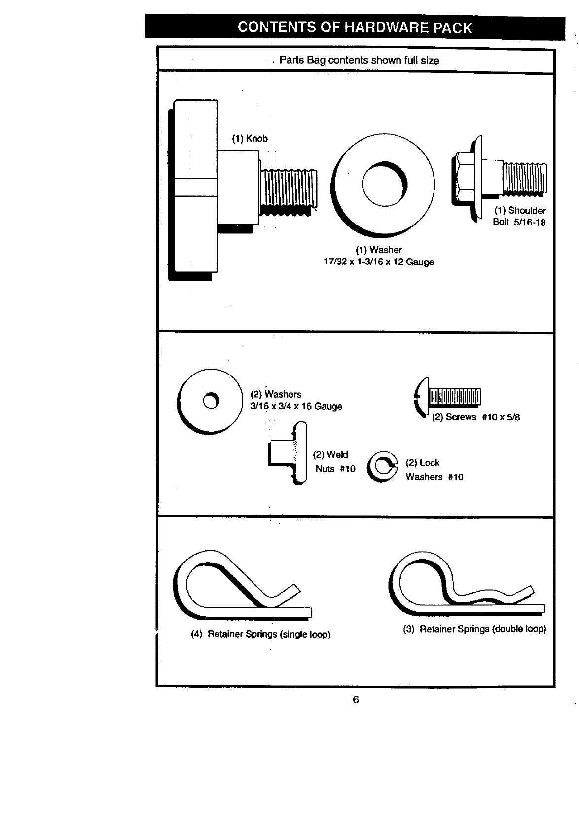
, Parts Bag contents shown full size
(1) Knob
(1) Washer
17/32 x 1-3/16 x 12 Gauge
(1) Shoulder
Bolt 5/16-18
(2) Washers
3/16 x 3/4 x 16 Gauge
(2) Weld
Nuts #10 @
_#10 x 5/8
(2) Lock
Washers #10
(4) Retainer Springs (singleloop) (3) Retainer Spnngs (double loop)
6
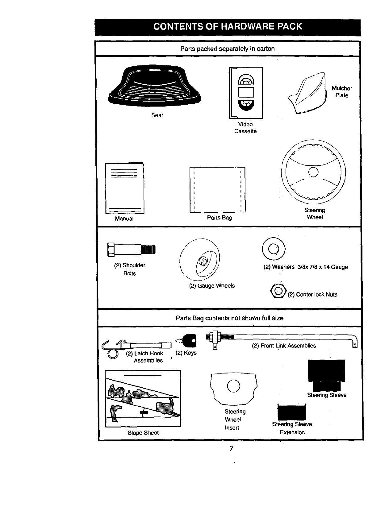
Partspacked separately in carton
Seat
Video
Cassette
Mulcher
Plate
Manual Parts Bag
Steering
Wheel
(2) Shoulder
Bolts
(2) Gauge Wheels
©
(2) Washers 3/8x 7/8 x 14 Gauge
(2) Center lock Nuts
i
Parts Bag contents not shown full size
___(I I I {2)<_Ke_ _l=
2) Latch Hook
Assemblies 0
(2) Front Unk Assemblies
Slope Sheet
Steering
Wheel
Insert
SteeringSleeve
SteeringSleeve
E_ension
7
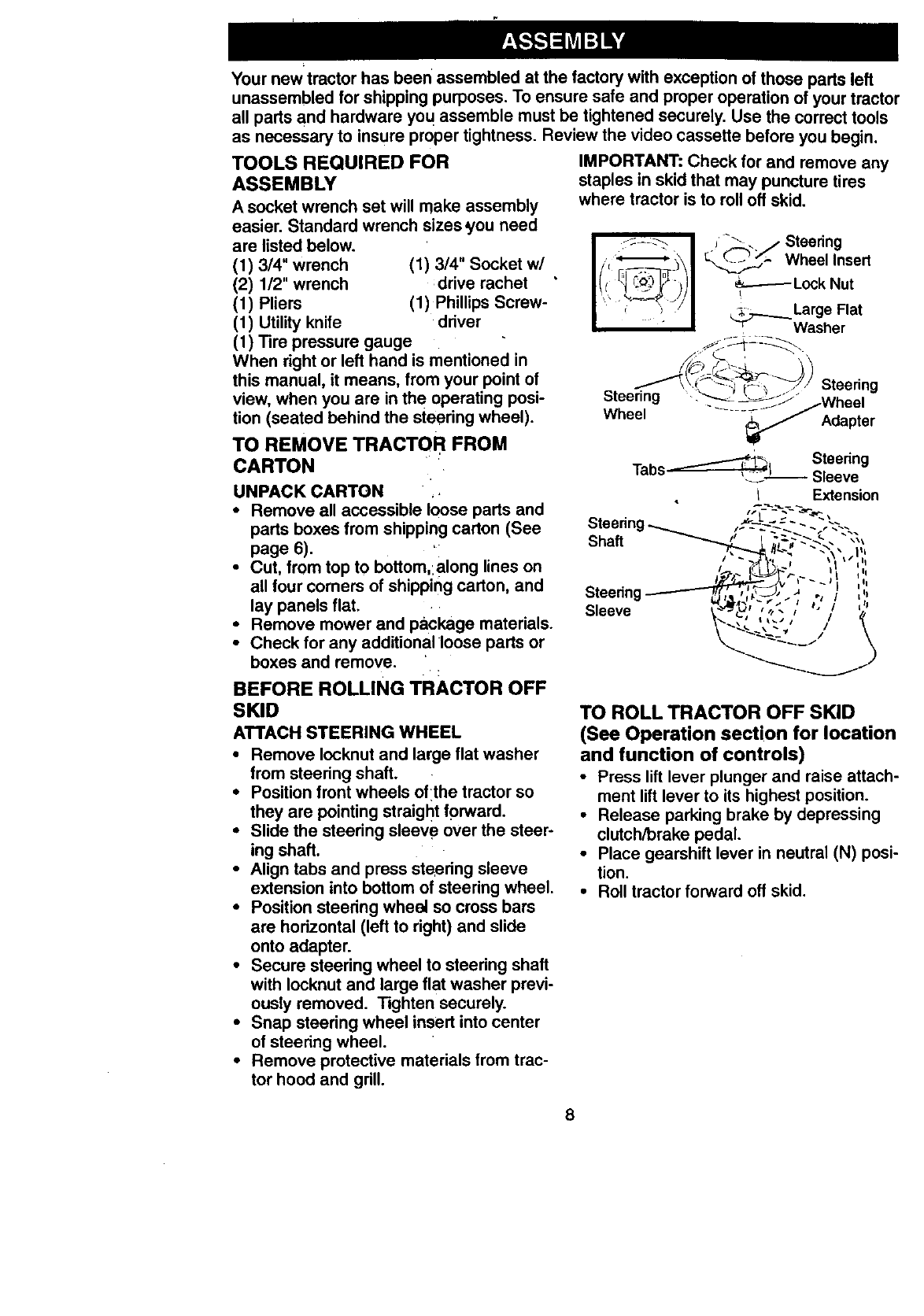
Your newtractor has been assembled at the factory with exception of those parts left
unassembled for shipping purposes. To ensure safe and proper operation of your tractor
all pads and hardware yo u assemble must be tightened securely. Use the correct tools
as necessary to insure proper tightness. Review the video cassette before you begin.
TOOLS REQUIRED FOR
ASSEMBLY
A socket wrench set will make assembly
easier. Standard wrench sizes you need
are listed below.
(1) 3/4" wrench (1) 3/4" Socket w/
(2) 1/2" wrench :drive rachet
(1) Pliers (1) Phillips Screw-
(1) Utility knife driver
(1) Tire pressure gauge
When right or left hand is mentioned in
this manual, it means, from your point of
view, when you are in the operating posi-
tion (seated behind the steering wheel).
TO REMOVE TRACTOR FROM
CARTON
UNPACK CARTON •
•Remove all accessible loose parts and
parts boxes from shipping carton (See
page 6).
•Cut, from top to bottom,:a ong lines on
all four corners of shipping carton and
lay panels flat.
• Remove mower and package materials.
• Check for any additional •loose parts or
boxes and remove.
BEFORE ROLLING TRACTOR OFF
SKID
ATTACH STEERING WHEEL
•Remove Iocknut and large flat washer
from steering shaft.
•Position front wheels oflthe tractor so
they are pointing straight forward.
•Slide the steering sleeve over the steer-
ing shaft.
•Align tabs and press steering sleeve
extension into bottom of steering wheel.
•Position steering wheel so cross bars
are hodzontal (left to dght) and slide
onto adapter.
•Secure steering wheel to steedng shaft
with Iocknut and large flat washer previ-
ously removed. Tighten securely.
•Snap steering wheel insert into center
of steedng wheel.
• Remove protective materials from trac-
tor hood and grill.
IMPORTANT: Check for and remove any
staples in skid that may puncture tires
where tractor is to roll off skid.
",-_-. _ __..- Wheel Insert
E[E-- )
i_Large Flat
Washer
Steering
Steering /Wheel
Wheel _._ Adapter
-_-"_,_L_ Steering
Tabs _o i Sleeve
IExtension
Steerin
Shaft _
Steering
Sleeve
TO ROLL TRACTOR OFF SKID
(See Operation section for location
and function of controls)
•Press lift lever plunger and raise attach-
ment lift lever to its highest position.
•Release parking brake by depressing
clutch/brake pedal.
•Place gearshift lever in neutral (N) posi-
tion.
• Roll tractor forward off skid.
8
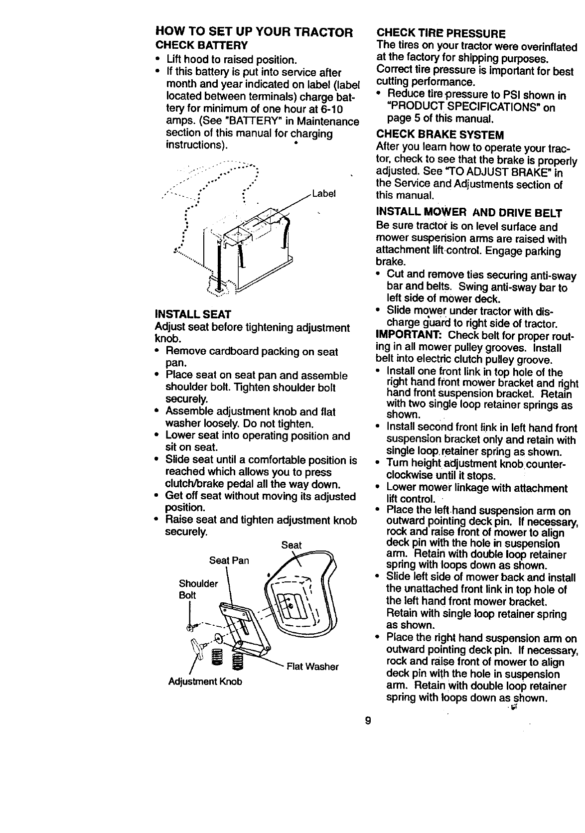
HOW TO SET UP YOUR TRACTOR
CHECKBATTERY
•Lift hood to raised position.
•If this battery is put into service after
month and year indicated on label (label
located between terminals) charge bat-
tery for minimum of one hour at 6-10
amps. (See "BA'I-IERY" in Maintenance
section of this manual for charging
instructions).
..o *
.-= ..,o ..
-.. ::/L_uel,^k
d
%2'
.o I "" i
INSTALL SEAT
Adjust seat before tightening adjustment
knob.
•Remove cardboard packing on seat
pan.
•Place seat on seat pan and assemble
shoulder bolt. Tighten shoulder bolt
securely.
•Assemble adjustment knob and flat
washer loosely. Do not tighten.
•Lower seat into operating position and
sit on seat.
•Slide seat until a comfortable position is
reached which allows you to press
clutch/brake pedal all the way down.
•Get oft seat without moving its adjusted
position.
•Raise seat and tighten adjustment knob
securely.
Sea Pan
Shoulder
Bolt
Adjustment Knob
Seat
Fiat Washer
CHECK TIRE PRESSURE
The tires on your tractor were ovednflated
at the factory for shipping purposes.
Correct tire pressure is importantfor best
cutting performance.
•Reduce tirepressure to PSI shown in
=PRODUCT SPECIFICATIONS" on
page 5 of this manual.
CHECK BRAKE SYSTEM
After you learn how to operate your trac-
tor, check to see that the brake is properl_
adjusted. See "TO ADJUST BRAKE" in
the Service and Adiustments section of
this manual.
INSTALL MOWER AND DRIVE BELT
Be sure tractor is on level surface and
mower suspension arms are raised with
attachment liftcontrel, Engage parking
brake.
•Cut and remove ties securing anti-swa_
bar and belts. Swing anti-sway bar to
left side of mower deck.
•Slide mower under tractor with dis-
charge g'uard to right side of tractor.
IMPORTANT: Check belt for proper rout-
ing in all mower pulley grooves. Install
belt into electric clutch pulley groove.
•install one front link in top hole of the
right hand front mower bracket and righ
hand front suspension bracket. Retain
with two single loop retainer springs as
shown.
•Install second front link in left hand fronl
suspension t)racket only and retain with
single loop, retainer spdng as shown.
•Turn height adjustment knob:counter-
clockwise until it stops,
•Lower mower linkage with attachment
lift control.
• Place the left,hand suspension arm on
outward po!nting deck pin. If necessar_
rock and ranse front of mower to align
deck pin with the hole in suspension
arm. Reta'tn wLth double loop retainer
spring with loops down as shown.
•Slide left side of mower back and install
the unattached front link in top hole of
the left hand front mower bracket.
Retain with single loop retainer spring
as shown.
•Place the right hand suspension arm on
outward pointing deck pin, If necessary
rock and raise front of mower to align
deck pin with the hole in suspension
arm. Retain with double loop retainer
spring with loops down as shown.
9
•Connect anti-sway bar to chassis
bracket under left footrest and retain
with double loop retainer spring.
•Turn height adjustment knob clockwise
to remove slack from mower suspen-
sion.
•Raise mower to highest position.
•Assemble gauge wheels (See "TO
ADJUST GAUGE WHEELS in the
Operation section of this manual).
Shoulder
Bolt
Double Loop
Chassis Retainer Spring
Bracket (Outward pointing
deck pins)
Gauge_
Wheel
3/8
3/8-16
Center
Locknut
Use Pliers For
Retainer Springs
Double Loop
Retainer Spring
Anti-Sway
Bar
CHECK MOWER LEVELNESS
For best cutting results, mower should be
properly leveled. See "TO LEVEL
MOWER HOUSING" in the Service and
Adjustments section of this manual.
CHECK FOR PROPER POSITION OF
ALL BELTS
See the figures that are shown for replac-
ing motion, mower drive, and mower blade
drive belts in the Service and Adjustments
section of this manual. Verify that the
belts are routed correctly. Front
Suspension
Arms Brackets
Front Mower
Idler
Pulley
Single Loop
Retainer Springs
_' _' Discharge Guard
INSTALL MULCHER PLATE Weld Nut
•Install two latch hooks to:mulcher plate from the To
using screw, washer, lock washer, and Lock
weld nut as shown. . Washer
NOTE: Pre-assemble weld :nut to latch Weld
hook by inserting weld nut from the top Nut
with hook pointing down. Tighten hard-
ware securely. ,Latch
•Raise and hold deflector shield in up-
right position. Washer
•Place front of mulcher plate over front of
mower deck opening and slide into
place, as shown. Mulcher 't-----Screw
• Hook front latch into hole;on front of Plate
mower deck.
• Hook rear latch into hole on back of
mower deck.
Hook Points
Latch
Hook
Nut
Lock
Washer
10
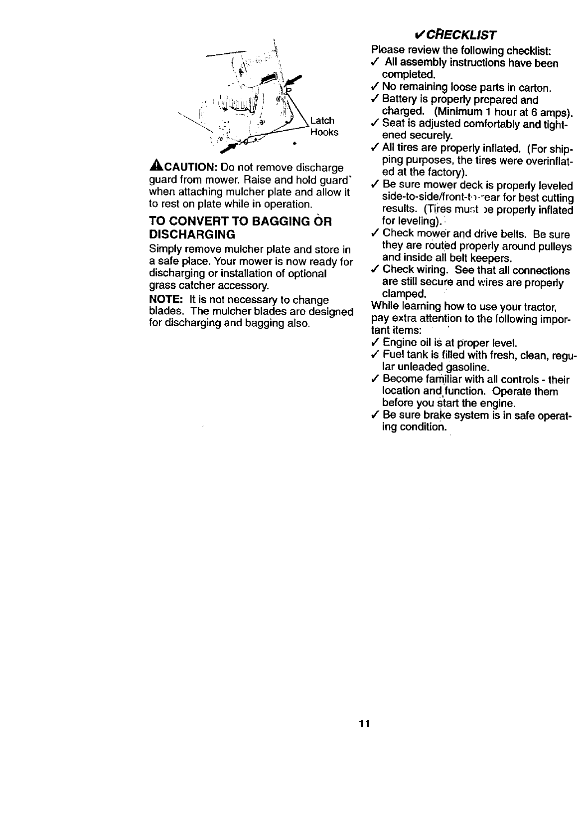
A_.CAUTION: Do not remove discharge
guard from mower. Raise and hold guard"
when attaching mulcher plate and allow it
to rest on plate while in operation.
TO CONVERT TO BAGGING OR
DISCHARGING
Simply remove mulcher plate and store in
asafe place. Your mower is now ready for
discharging or installation of optional
grass catcher accessory.
NOTE: It is not necessary to change
blades. The mulcher blades are designed
for discharging and bagging also.
v"CRECKLIST
Please review the following checklist:
,# All assembly instructions have been
completed.
,/No remaining loose parts in carton.
,/Battery is properly prepared and
charged. (Minimum 1 hour at 6 amps).
4" Seat is adjusted comfortably and tight-
ened securely.
•/" All tires are properly inflated. (For ship-
ping purposes, the tires were overinflat-
ed at the factory).
,! Be sure mower deck is properly leveled
side-to-side/front-t,_-'ear for best cutting
results. (Tires munt )e properly inflated
for leveling).:
,,/Check mower and drive belts. Be sure
they are routed properly around pulleys
and inside all belt keepers.
/Check wiring. See that all connections
are still secure and wires are properly
clamped.
While learning how to use your tractor,
pay extra attention to the following impor-
tant items:
,I Engine oil is at proper level.
,/Fue_ tank is [illed with fresh, clean, regu.
lar unleaded gasoline.
/ Become familiar with all controls - their
location and,function. Operate them
before you start the engine.
/Be sure brake system is in safe operat-
ing condition.
11
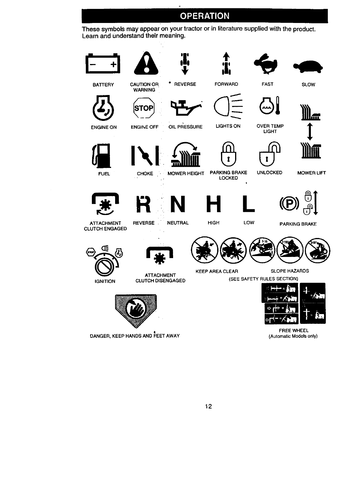
These symbols may appear on your tractor or in literature supplied with the product.
Learn and Understand their meaning.
BATTERY CAUTION OR
WARNING
ENGINE ON ENGINE OFF
•REVERSE FORWARD FAST SLOW
OIL PRESSURE LIGHTS ON OVER TEMP _1_
t
LIGHT
FUEL CHOKE ' MOWER HEIGHT PARKING BRAKE UNLOCKED MOWER LIFT
LOCKED
R
ATTACHMENT
CLUTCH ENGAGED
REVERSE
NHL
NEUTRAL HIGH LOW PARKING BRAKE
(_) _ KEEP AREA CLEAR SLOPE HAZARDS
ATTACHMENT
IGNITION CLUTCH DISENGAGED
J
DANGER, KEEP HANDS AND FEET AWAY
(SEE SAFETY RULES SECTION)
FREE WHEEL
(Automatic Models only)
12
KNOW YOUR TRACTOR
READ THIS OWNER'S MANUAL AND SAFETY RULES BEFORE OPERATING YOUR
TRACTOR
Compare the illustrations with your tractor to familiarize yourself with the locations of
various controls and adjustments. Save this manual for future reference.
Ammeter
Ignition Position
Switch
Throttle
Control
Clutch/Brake
Clutch Switch
Lever
Plunger
Lift Lever
Choke
Control
Height
Adjustment
Knob Gear Shift
Lever
=gBrake
Our tractors conform to the safety standards of the American
National Standards Institute.
ATTACHMENT CLUTCH SWITCH: Used
to engage the mower blades, or other at-
tachments mounted to your tractor.
LIGHT SWITCH: Turns the headlights on
and off.
THROTTLE CONTROL: Used to control
engine speed.
CLUTCH/BRAKE PEDAL: Used for
declutching and braking the tractor and
starting the engine.
HEIGHT ADJUSTMENT KNOB: Used to
adjust the mower cutting height.
CHOKE CONTROL: Used to control
engine speed.
GEAR SHIFT LEVER : Selects the speed
and direction of the tractor.
ATTACHMENT LIFT LEVER: Used to
raise and lower the mower deck or other
attachments mounted to your tractor.
LIFT LEVER PLUNGER: Used to release
attachment lift lever whgn changing its
position.
IGNITION SWITCH: Used for starting and
stopping the engine.
AMMETER: Indicates battery charging (÷)
or discharging (-).
PARKING BRAKE: Locks clutch/brake
into the brake position.
13
Jil! Theoperationof anytractorcan resultinforeignobjectsthrownintothe
I[ =,-£-,, ]eyes, which can result in severe eye damage. A_ays wear safety glasses
IW or eye shields while operating your tractor or penorming any adjustments or
| repairs. We recommend a wide vision sarety mask over spectacles, or stan-
J dard safety glasses.
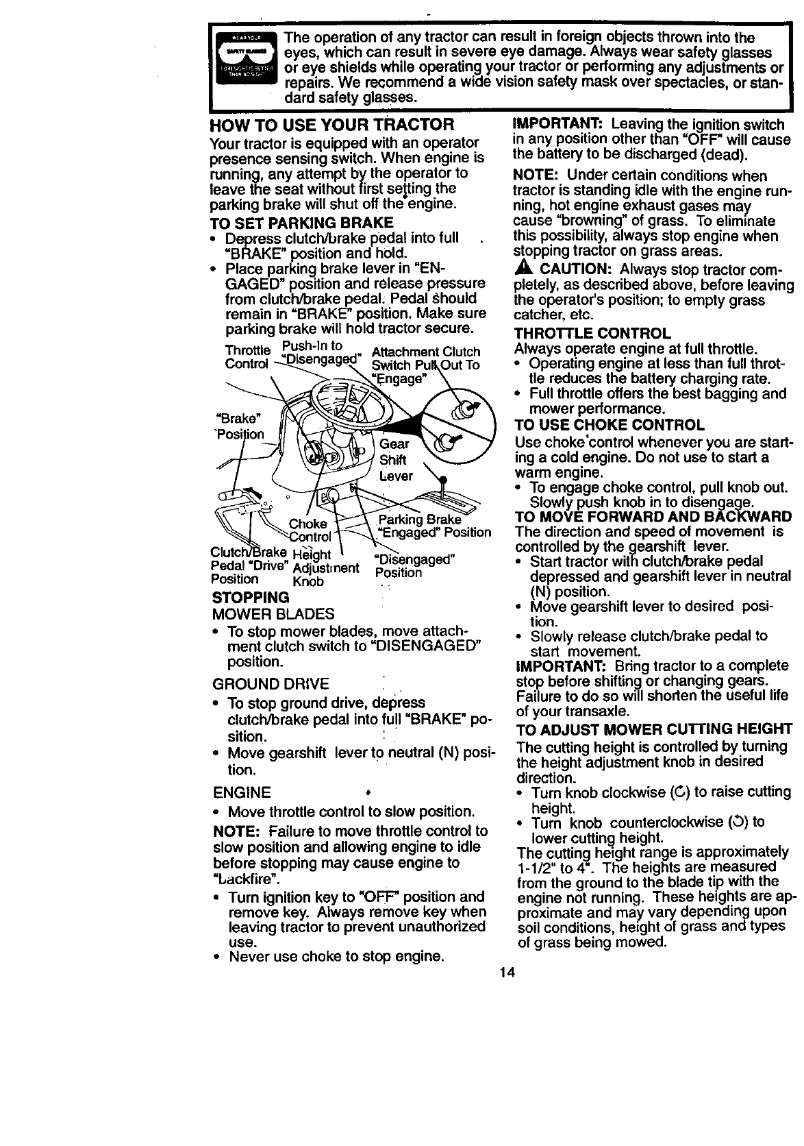
HOW TO USE YOUR TRACTOR
Your tractor is equipped with an operator
presence sensing switch. When engine is
running, any attempt by the operator to
leave the seat without firstsetting the
parking brake will shut off theengine.
TO SET PARKING BRAKE
•Depress clutch/brake pedal into full
"BRAKE" position and hold.
•Place parking brake lever in "EN-
GAGED" position and release pressure
from clutch/brake pedal:Pedal Chould
remain in "BRAKE" position. Make sure
parking brake will hold tractor secure.
Thro Push-In to
tUe ..... Attachment Clutch
Control -.._ngag_. _itch PullOut To
_.__ngaged" Position
Clutc
__rn'€=nf "D_sengaged"
Adjustmem Position
Position Knob .
STOPPING
MOWER BLADES
•To stop mower blades, move attach-
ment clutch switch to "DISENGAGED"
position.
GROUND DRIVE
•To stop ground drive, depress
clutch/brake pedal into fu!l "BRAKE" po-
sition.
•Move gearshift lever to neutral (N) posi-
tion.
ENGINE o
• Move throttle control to slow position.
NOTE: Failure to move throttle control to
slow position and allowing engine to idle
before stopping may cause engine to
"backfire".
•Turn ignition key to "OFF" position and
remove key. Always remove key when
leaving tractor to prevent unauthorized
use.
• Never use choke to stop engine.
IMPORTANT: Leaving the ignition switch
in any position other than "OFF" will cause
the battery to be discharged (dead).
NOTE: Under certain conditions when
tractor is standing idle with the engine run-
ning, hot engine exhaust gases may
cause "browning" of grass. To eliminate
this possibility, always stop engine when
stopping tractor on grass areas.
_, CAUTION: Always stop tractor com-
pletely, as described above, before leaving
the operator's position; to empty grass
catcher, etc.
THRO'n'LE CONTROL
Always operate engine at full throttle.
•Operating engine at less than full throt-
tle reduces the battery charging rate.
•Full throttle offers the best bagging and
mower performance.
TO USE CHOKE CONTROL
Use choke'control whenever you are start-
ing a cold engine. Do not use to start a
warm engine.
•To engage choke control, pull knob out.
Slowly push knob in to disengage.
TO MOVE FORWARD AND BACKWARD
The direction and speed of movement is
controlled by the gearshift lever.
• Start tractor with clutch/brake pedal
depressed and gearshift lever in neutral
(N) position.
• Move gearshift lever to desired posi-
tion.
•Slowly release clutch/brake pedal to
start movement.
IMPORTANT: Bring tractor to a complete
stop before shifting or changing gears.
Failure to do so will shorten the useful life
of your transaxle.
TO ADJUST MOWER CUTrlNG HEIGHT
The cutting height is controlled by turning
the height adjustment knob in desired
direction.
•Turn knob clockwise (G) to raise cutting
height.
•Turn knob counterclockwise (,3)to
lower cutting height.
The cutting height range is approximately
1-1/2" to 4". The heights are measured
from the ground to the blade tip with the
engine not running. These heights are ap-
proximate and may vary depending upon
soil conditions, height of grass and types
of grass being mowed.
14
• The average lawn should be cut to
approximately 2-1/2 inches during the
cool season and to over 3 inches during
hot months. For healthier and better
looking lawns, mow often and after
moderate growth.
• For best cutting performance, grass
over 6 inches in height should be
mowed twice. Make the first cut rela-
tively high; the second to desired height.
TO ADJUST GAUGE WHEELS
Gauge wheels are properly adjusted
when they are slightly off the ground when
mower is at the desired cutting height in
operating position. Gauge wheels then
keep the deck in proper position to" help
prevent scalping in most terrain condi-
tions.
• Adjust gauge wheels with tractor on a
flat level surface.
• Adjust mower to desired cutting height
(See "TO ADJUST MOWER CUTTING
HEIGHT" in the Operation section of
this manual).
•With mower in desired height of cut po-
sition, gauge wheels should be assem-
bled so they are slightly off the ground.
Install gauge wheel in appropriate hole
with shoulder bolt, 3/8 washer, and 3/8-
16 Iocknut and tighten securely.
•Repeat for opposite side installing
gauge wheel in same adjustment hole.
Gaug_
Bracket
3/8-16
Locknut Shoulder Bolt
3/8 Washer Gauge Wheel
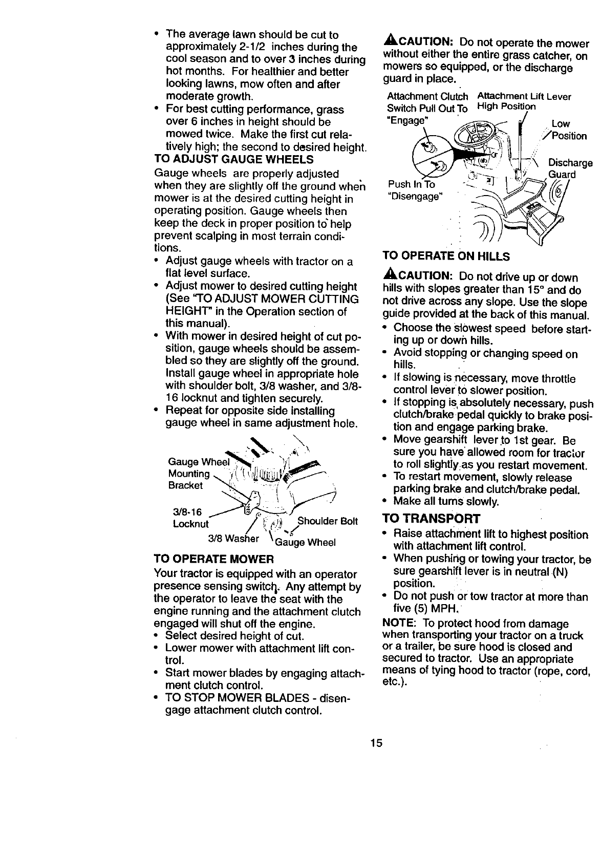
TO OPERATE MOWER
Your tractor is equipped with an operator
presence sensing switcl_, Any attempt by
the operator to leave the seat with the
engine running and the attachment clutch
engaged will shut off the engine.
•Select desired height of cut.
• Lower mower with attachment lift con-
trol.
•Start mower blades by engaging attach-
ment clutch control.
• TO STOP MOWER BLADES - disen-
gage attachment clutch control.
_CAUTION: Do not operate the mower
without either the entire grass catcher, on
mowers so equipped, or the discharge
guard in place.
Attachment Clutch Attachment Lift Lever
Switch Pull Out To High Position
"Engage" Low
_Position
Discharge
Guard
Push In To
"Disengage"
TO OPERATE ON HILLS
,_CAUTION: Do not drive up or down
hills with slopes greater than 15 ° and do
not drive across any slope. Use the slope
guide provided at the back of this manual.
•Choose the slowest speed before start-
ing up or dowh hills.
•Avoid stopping or changing speed on
hills.
•If slowing is necessary, move throttle
control lever •to slower position.
•If stopping is absolutely necessary , pusl
clutch/brakepedal quickly to brake posi.
tion and engage parking brake.
•Move gearshift lever:to 1st gear. Be
sure you have allowed room for tract.or
to roll slightly:as you restart movement.
• To restart movement, slowly release
parking brake and clutch/brake pedal.
•Make all turns slowly.
TO TRANSPORT
• Raise attachment lift to highest position
with attachment lift control.
• When pushing or towing your tractor, be
sure gearshift lever is in neutral (N)
position.
• Do not push or tow tractor at more than
five (5) MPH.
NOTE: To protect hood from damage
when transporting your tractor on a truck
or a trailer, be sure hood is closed and
secured to tractor. Use an appropriate
means of tying hood to tractor (rope, cord,
etc.).
15
TOWING CARTS AND OTHER
ATTACHMENTS
Tow only the attachments that are recom-
mended]by and comply with. specifications
of the manufacturer of your tractor. Use
common sense when towing, Too heavy of
a load, while on a slope, is dangerous.
Tires can lose traction with the ground and
cause you to lose control of your tractor.
BEFORE STARTING THE ENGINE
CHECK ENGINE OIL LEVEL,
•The engine in your tractor has been
shipped, from the factory, already filled
with summer weight oil.
•Check engine oil with tractor on level
ground.
•Unthread and remove oil fill cap/_ip-
stick; wipe oil off. Reinsert the dipstick
into the tube and rest oil fill cap on the
tube. Do not thread the cap onto the
tube. Remove and read oil level. If nec-
essary, add oil until "FULL" mark on
dipstick is reached. Do not overfill.
•For cold weather operation you should
change oil for easier staqing (See "OIL
VISCOSITY CHART" in 1be
Maintenance section of this manual).
•To change engine oil, see the Customer
Responsibilities section iq this manual.
ADD GASOLINE
•Fill fuel tank. Use fresh, clean, regular
unleaded gasoline with aminimum of 87
octane. (Use of leaded gasoline will
increase carbon and lead oxide
deposits and reduce valve life). Do not
mix oil with gasoline. Purchase fuel in
_uantities that can be used within 30
ays to assure fuel freshness.
IMPORTANT: When operating in tempera-
tures below 32°F(0°C), use fresh, clean
winter grade gasoline to he!p insure good
cold weather starting.
,A, WARNING: Experience indicates that
alcohol blended fuels (called gasohol or
using ethanol or methanol) can attract
moisture which leads to separation and
formation of acids dudng storage. Acidic
gas can damage the fuel, system of an
engine while in storage. To avoid engine
problems, the fuel system should be emp-
tied before storage of 30 days or longer.
Drain the gas tank, start the engine and let
it run until the fuel lines and carburetor are
empty. Use fresh fuel next season. See
Storage Instructions for additional informa-
tion. Never use engine or carburetor
cleaner products in the fuel tank or perma-
nent damage may occur.
,ACAUTION" Fill to bottom of gas tank
filler neck. Do not overfill. Wipe off any
spilled oil or fuel. Do not store, spill or use
gasoline near an open flame.
TO START ENGINE
When starting the engine for the first time
or if the engine has run out of fuel, it will
take extra cranking time to move fuel from
the tank to the engine.
•Sit on seat in operating position,
depress clutch/brake pedal and set
parking brake.
•Place gear shift lever in neutral (N) posi-
tion.
•Move attachment clutch to "DISEN-
GAGED" position.
•Move throttle control to choke position.
NOTE: Before starting, read the warm
and cold starting procedures below.
•Insert key into ignition and turn key
clockwise to "START" position and
release key as soon as engine starts.
Do not run starter continuously for more
than fifteen seconds per minute. If the
engine does not start after several
attempts, move throttle control to fast
position, wait a few minutes and try
again. If engine still does not start,
move the throttle control back to the
choke position and retry.
WARM WEATHER STARTING (50 °F
AND ABOVE)
• When engine starts, move the throttle
control to the fast position.
•The attachments and ground drive can
now be used. If the engine does not
accept the load, restart the engine and
allow it to warm up for one minute using
the choke as described above.
COLD WEATHER STARTING ( 50 °FAND
BELOW)
• When engine starts, allow engine to run
with the throttle control in the choke
position until the engine runs roughly.,
then move throttle control to fast posi-
tion. This may require an engine warm-
up period from several seconds to sev-
eral minutes, depending on the temper-
ature.
• The attachments can also be used dur-
ing the engine warm-up period.
NOTE: A high altitude (above 3000 feet)
or in cold temperatures (below 32 F) the
carburetor fuel mixture may need to be
adjusted for best engine performance.
See "TO ADJUST CARBURETOR" in the
Service and Adjustments section of this
manual.
16
MOWING TIPS
• Tirechainscannotbeusedwhenthe
mowerhousingisattachedto tractor.
•Mower should be properly leveled for
best mowing performance. See "TO
LEVEL MOWER HOUSING" in the
Service and Adjustments section of this
manual.
• The left hand side of mower should be
used for trimming. "
• Drive so that clippings are discharged
onto the area that has been cut. Have,
the cut area to the right of the tractor.
This will result in a more even distribu-
tion of clippings and more uniform cut-
ting.
• When mowing large areas, start by turn-
ing to the right so that clippings will dis-
charge away from shrubs, fences, drive-
ways, etc. After one or two rounds, mow
in the opposite direction making left
hand turns until finished.
•If grass is extremely tall, it should be
mowed twice to reduce load and possi-
ble fire hazard from dried clippings.
Make first cut relatively high; the second
to the desired height.
• Do not mow grass when it is wet. Wet
grass will plug mower and leave unde-
sirable clumps. Allow grass to dry
before mowing.
•Always operate engine at full throttle
when mowing to assure better mowing
performance and proper discharge of
material. Regulate ground speed by se-
lecting a low enough gear to give the
mower the best cutting performance as
well as the quality of cut desired.
•When operating attachments, select a
ground speed that will suit the terrain
and give best performance of the at-
tachment being used.
f
MULCHING'MOWING TIPS
IMPORTANT: For best performance, keel
mower housing free of built-up grass and
trash. Clean after each use,
•The special mulching blade will recut
the grass clippings many times and
reduce them in size so that as they fat|
onto the lawn they will disperse into the
grass and not be noticed. Also, the
mulched grass will biodegrade quickly
to provide nutrients for the lawn. Always
mulch with your highest engine (blade)
speed as this will provide the best recut
ting action of the blades.
•Avoid cutting:your lawn when it is wet.
Wet grass tends to form clumps and
interferes v_ith the mulching action. The
best time to mow your lawn is the eady
afternoon. At this time the grass has
dried and the newly cut area will not be
exposed to the direct sun.
• For best results, adjust the mower cut-
ting height so that the mower cuts off
only the top one-third of the grass
blades. For extremely heavy mulching,
reduce your width of cut on each pass
and mow slowly.
• Certain type s of grass and grass condi-
tions may require that an area be
mulched a second time to completely
hide the clipi_ings. When doing a sec-
ond cut, mow across or perpendicular t(
the first cut path.
•Change your.Cutting I_attem from week
to week. Mow north to south one week
then change to east to west the next
week. This Will help prevent matting ant
graining of the lawn.
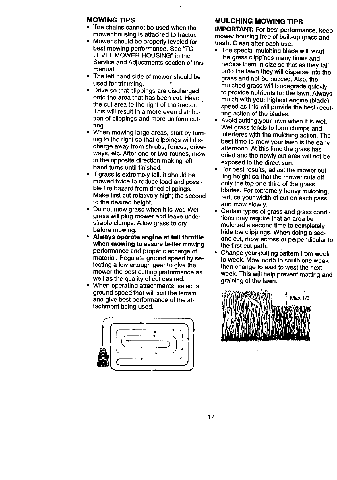
,-_ _ _ ._'r, M,xt,3
17
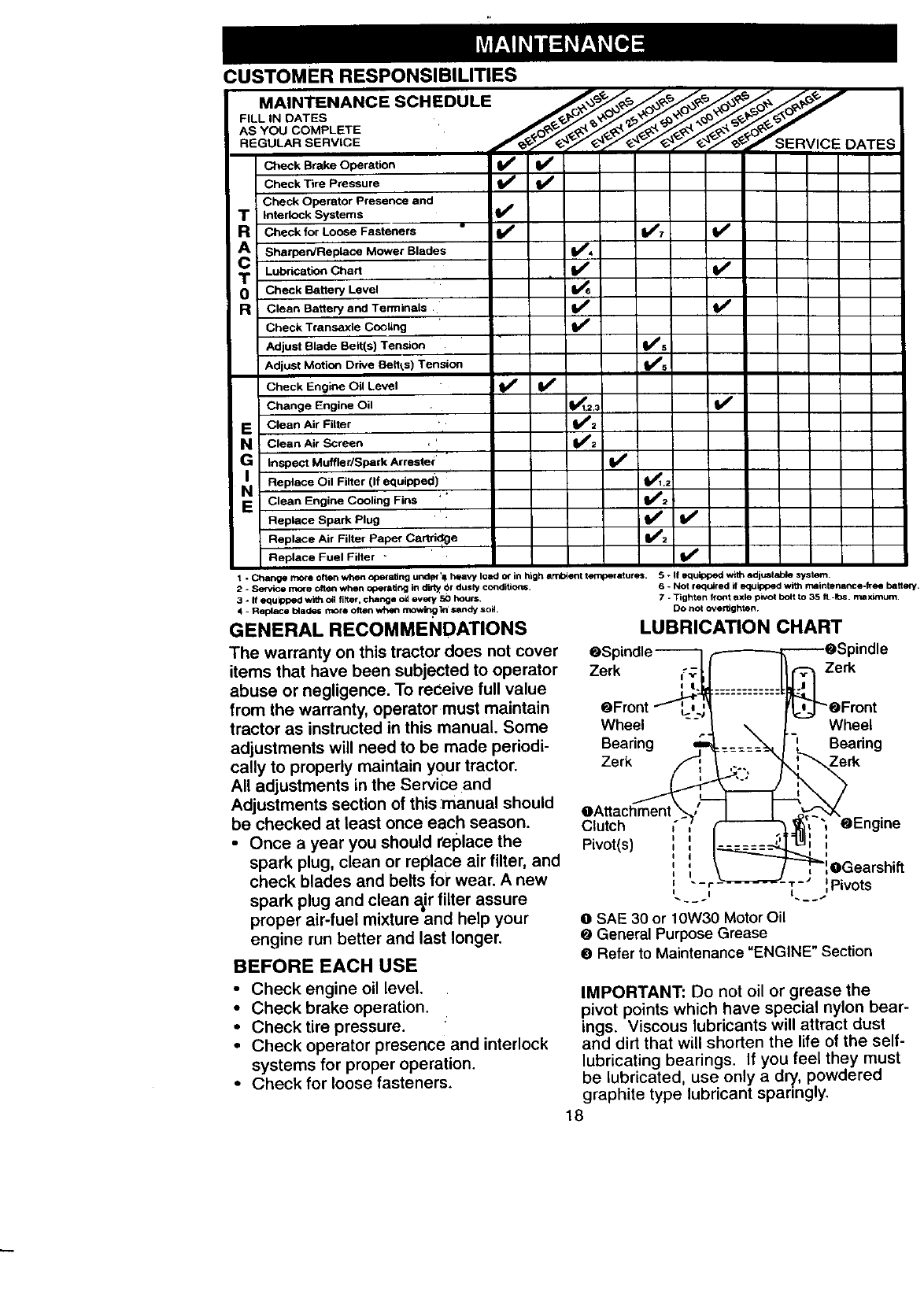
CUSTOMER RESPONSIBILITIES
MAINTENANCESC.'=DU'E
FILL..eATES
AS YOU COMPLETE
REGULAR SERVICE I_ SERVICE DATES
Check Brake Operation _
Check Tire Pressure
Check Operator Presence and
TInterlock Systems
RCheck for Loose Fasteners
A Sharpen/Replace Mower Blades
TLubriCation Chart
0 Check Battery Level
RClean Battery and Terminals
Check Transaxle Cooling
Adjust Blade Belt(s) Tension V*s
Adjust Motion Drive Belt*,s) Tension Ks
Check Engine Oil Level I_ If
Change Engine Oil 1_1_2._
E CleanAirFiger ', _:
N!Clean Air Screen . '
GInspect Muffler/Spark Arrester' "
NI Replace Oil Filter (If equipped) _.2
E Clean Engine Cooling Firm _'_=_2
Replace Spark Plug ' i
Replace Air Filter paper Cartri(_ge
Replace Fuel Filter _ V #
1*C_ mote often when Operating und_"_ heavy load o_ in high ambient tefnperatures. 5 - If equipped with edj,.mt able system.
2-Service more often when opQral_ng in dirty Or dusty conditions. 6 - Not required if equipped with rnalntermnce-fi_ battery.
V', v'
=,i
v'
3*If equipped wi6_ oil fiRer, change oil every _hours.
4-Replace b4ades more often when mowif_ In sandy soil
GENERAL RECOMMENDATIONS
The warranty on this tractoJ"does not cover
items that have been subjected to operator Zerk
abuse or negligence. To receive full value
from the warranty, operator must maintain OFront
tractor as instructed in this manual. Some Wheel
adjustments will need to be made periodi- Bearing
cally to properly maintain your tractor. Zerk
All adjustments in the Service and
Adjustments section of this ;manual should OAttachment
be checked at least once each season. Clutch
•Once ayear you should replace the Pivot(s)
spark plug, clean or replace air filter, and
check blades and belts for wear. A new
spark plug and clean a,ir filter assure
proper air-fuel mixture and help your
engine run better and last longer.
BEFORE EACH USE
•Check engine oil level,
•Check brake operation.
• Checktire pressure.
• Check operator presence and interlock
systems for proper operation.
• Check for loose fasteners.
7-Tighten front axle pivot bolt to 35 It.-Ibs. ma x_lm.
Do not overtighten.
LUBRICATION CHART
Zerk
Wheel
Bearing
Zerk
I
OGearshift
-r-" :Pivots
OSAE 30 or 10W30 Motor Oil
O General Purpose Grease
O Refer to Maintenance "ENGINE" Section
IMPORTANT: Do not oil or grease the
pivot points which have special nylon bear-
ings. Viscous lubricants will attract dust
and dirt that will shorten the life of the self-
lubricating bearings. If you feel they must
be lubricated use only a dry, powdered
graphite type lubricant sparing y.
18
TRACTOR
Always observe safety rules when per-
forming any maintenance.
BRAKE OPERATION
If tractor requires more than six (6) feet
stopping distance at high speed in highest
gear, then brake must be adjusted. (See
"TO ADJUST BRAKE" in the Service and
Adjustments section of this manual).
TIRES
•Maintain proper air pressure in all tires
(See "PRODUCT SPECIFICATIONS"
section of this manual).
•Keep tires free of gasoline, oil, or insect
control chemicals which can harm rub-
ber.
• Avoid stumps, stones, deep ruts', sharp
objects and other hazards that may
cause tire damage.
NOTE: To seal tire punctures and prevent
flat tires due to slow leaks, tire sealant
may be purchased from your local parts
dealer. Tire sealant also prevents tire dry
rot and corrosion.
OPERATOR PRESENCE SYSTEM
Be sure that operator presence and inter-
lock systems are working properly. If your
tractor does not function as described
below, repair the problem immediately.
•The engine should not start unless the
clutch/brake pedal is fully depressed
and attachment clutch control is in the
disengaged position.
• When the engine is running, any
attempt by the operator to leave the
seat without first setting the parking
brake should shut off the engine.
• When the engine is running and the
attachment clutch is engaged, any
attempt by the operator to leave the
seat should shut off the engine.
• The attachment clutch should never
operate unless the operator is in the
seat.
BLADE CARE
For best results mower blades must be
kept sharp. Replace bent or damaged
blades.
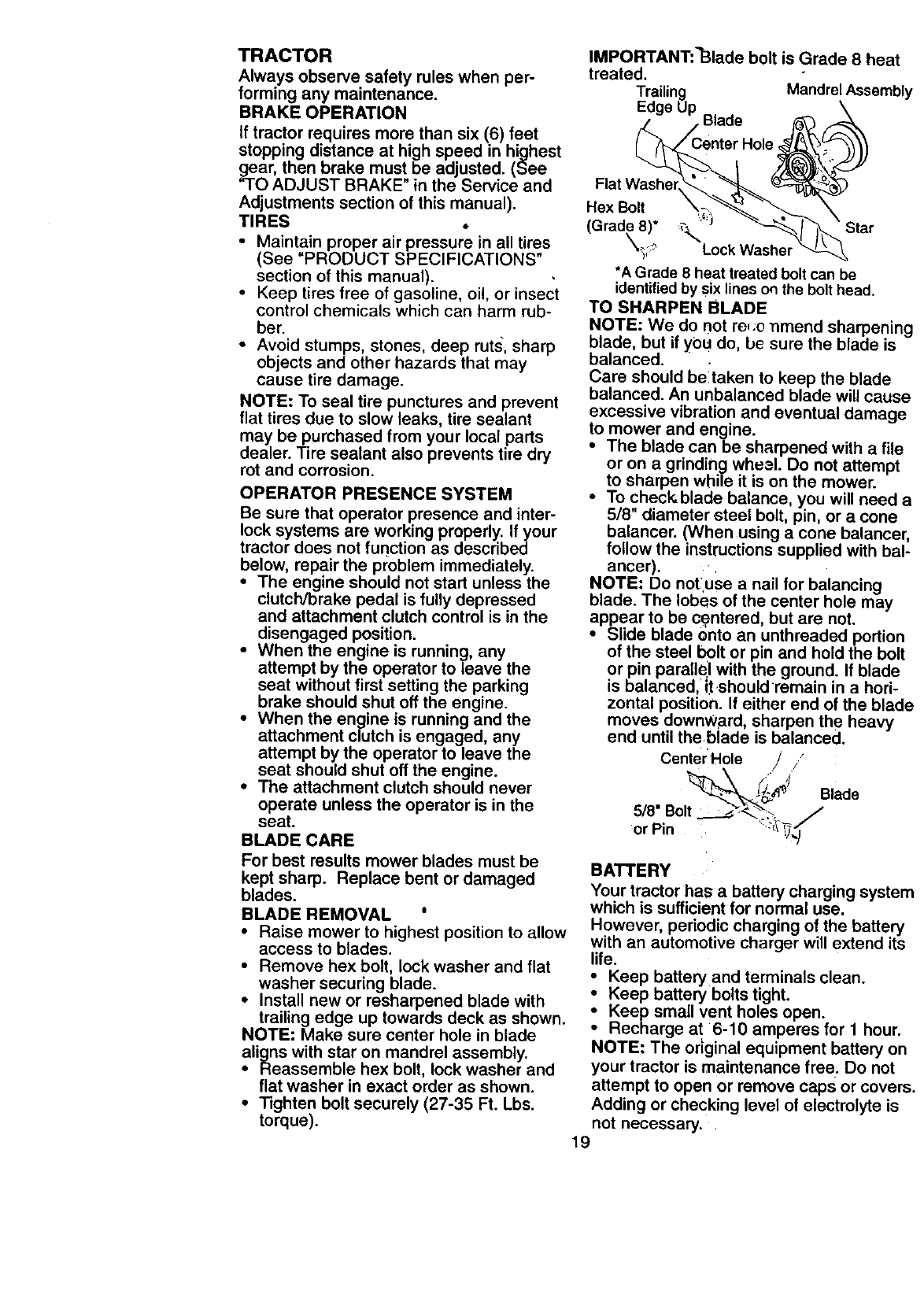
BLADE REMOVAL °
• Raise mower to highest position to allow
access to blades.
• Remove hex bolt, lock washer and flat
washer securing blade.
• Install new or resharpened blade with
trailing edge up towards deck as shown.
NOTE: Make sure center hole in blade
aligns with star on mandrel assembly.
• Reassemble hex bolt, lock washer and
flat washer in exact order as shown.
• Tighten bolt securely (27-35 Ft. Lbs.
torque).
IMPORTANT:"Blade bolt is Grade 8 heat
treated.
Trailing Mandrel Assembly
Edge Up Blade
Flat Washel
Hex Bolt
(Grade 8)i _ '_)
_,_;,_ _:_"Lock Washel
*A Grade 8 heat treated bolt can be
identified by six lines on the bolt head.
TO SHARPEN BLADE
NOTE: We do not re,:o nmend sharpening
blade, but if you do, be sure the blade is
balanced.
Care should be!taken to keep the blade
balanced. An unbalanced blade will cause
excessive vibration and eventual damage
to mower and engine.
• The blade can be sharpened with a file
or on a grinding wheal. Do not attempt
to sharpen while it is on the mower.
• To check, blade balance, you will need a
5/8" diameter steel bolt, pin, or a cone
balancer. (When using a cone balancer,
follow the instructions supplied with bal-
ancer).
NOTE: Do not:use a nail for balancing
blade. The lobes of the center hole may
appear to be c_ntered, but are not.
• Slide blade onto an unthreaded portion
of the steel bolt or pin and hold the bolt
or pin parallel with the ground. If blade
is balanced,i J:t.shouldremain in a hori-
zontal position. If either end of the blade
moves downward, sharpen the heavy
end until the blade is balanced.
Center'Hole /i' B,ade
518" Bolt .__:_-, /
or Pin ....:_\"_,,_"
BATTERY
Your tractor has a battery charging system
which is sufficient for normal use.
However, periodic charging of the battery
with an automotive charger will extend its
life.
•Keep battery and terminals clean.
• Keep battery bolts tight.
:Keep small vent holes open.
Recharge at 6-10 amperes for I hour.
NOTE: The original equipment battery on
your tractor is maintenance free: Do not
attempt to open or remove caps or covers.
Adding or checking level of electrolyte is
not necessary.
19
TO CLEAN BATTERY AND TERMINALS
Corrosion and dirt on the battery and ter-
minals can cause the battery to "leak"
power.
•Remove terminalguard.
•Disconnect BLACK battery cable first
then RED battery cable and remove
battery from tractor.
•Rinse the battery with plain water and
dry.
•Clean terminals and battery cable ends
with wire brush until bdght. •
•Coat terminals with grease or petroleum
jelly.
• Reinstall battery (See "REPLACING
BA'I-I'ERY" in the SERVICE AND
ADJUSTMENTS section of this manu-
al).
V-BELTS
Check V-belts for c;eterioration and wear
after 100 hours of operation and replace if
necessary. The belts are not adjustable.
Replace belts if th_ ybeginto slip from
wear.
TRANSAXLE COOLING :
Keep transaxle free from build-up of dirt
and chaff which can restrict cooling.
ENGINE
LUBRICATION
Only use high quali[y detergent oil rated
with API service classificati0n SF, SG, or
SH. Select the oil's SAE viscosity grade
according to your expecte d operating tem-
perature.
SAE VISCOSITY GRADES
NOTE: Although multi-viscosity oils
(5W30, 10W30 etc.) improve starting in
cold weather, these multi-viscosity oils will
result in increased oil consumPtion when
used above 32°1:. Check your engine oil
level more frequently to avoid possible
engine damage from running low on oil.
Change the oil after every 50 hours of
operation or at least once'a year if the
tractor is not used for 50 hours in one
year.
Check the crankcase oil level before start-
ing the engine and after each eight (8)
hours of operation. Tighten oil fill cap/dip-
stick securely each time you check the oil
level.
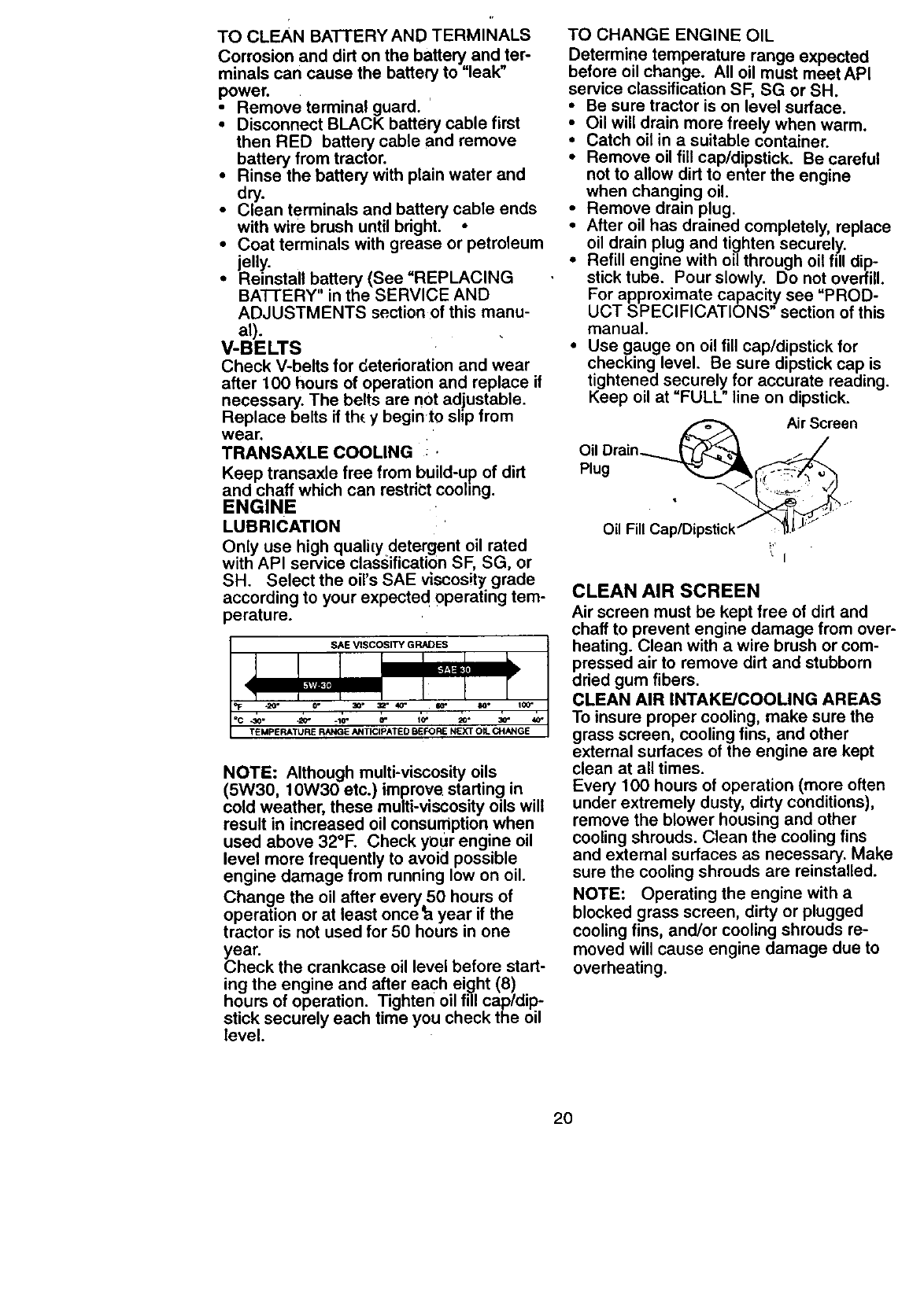
TO CHANGE ENGINE OIL
Determine temperature range expected
before oil change. All oil must meet API
service classification SF, SG or SH.
• Be sure tractor is on level surface.
• Oil will drain more freely when warm.
• Catch oil in a suitable container.
• Remove oil fill cap/dipstick. Be careful
not to allow dirt to enter the engine
when changing oil.
• Remove drain plug.
• After oil has drained completely, replace
oil drain plug and tighten securely..
• Refill engine with oil through oil fill dip-
stick tube. Pour slowly. Do not overfill.
For approximate capacity see "PROD-
UCT SPECIFICATIONS" section of this
manual.
• Use gauge on oil fill cap/dipstick for
checking level. Be sure dipstick cap is
tightened securely for accurate reading.
Keep oil at "FULL" line on dipstick.
h_ Air Screen
Oil Drain.._._'_ _._
Oil Fill Cap/Dipstick /"_J'_
CLEAN AIR SCREEN
Air screen must be kept free of dirt and
chaff to prevent engine damage from over-
heating. Clean with a wire brush or com-
pressed air to remove dirt and stubborn
dried gum fibers.
CLEAN AIR INTAKE/COOLING AREAS
To insure proper cooling, make sure the
grass screen, cooling fins, and other
external surfaces of the engine are kept
clean at all times.
Every 100 hours of operation (more often
under extremely dusty, dirty conditions),
remove the blower housing and other
cooling shrouds. Clean the cooling fins
and external surfaces as necessary. Make
sure the cooling shrouds are reinstalled.
NOTE: Operating the engine with a
blocked grass screen, dirty or plugged
cooling fins, and/or cooling shrouds re-
moved will cause engine damage due to
overheating.
20
AIR FILTER
Your engine will not run properly using a
dirty air filter. Clean the foam pre-cleaner
after every 25 hours of operation or every
season. Service paper cadridge every
100 hours of operation or every season,
whichever occurs first.
Service air cleaner more often under dusty
conditions.
•Remove knobs and cover.
TO SERVICE PRE-CLEANER
• Wash it in liquid detergent and water. ,
•Squeeze it dry in a clean cloth•
• Saturate it in engine oil. Wrap it in
clean, absorbent cloth and squeeze to
remove excess oil.
•If very didy or damaged, replace pre-
cleaner.
TO SERVICE CARTRIDGE
• Clean cadridge by tapping gently on flat
surface. If very didy or damaged,
replace cadridge.
• Reinstall precleaner cadridge, cover
and secure with knobs.
IMPORTANT: Petroleum solvents, such
as kerosene, are not to be used to clean
the cadridge. They may cause deteriora-
tion of the cartridge. Do not oil cadridge.
Do not use pressurized air to clean or dry
cartridge.
Knobs
Ca_ridge
Cover_
Foam Pre-_
ENGINE OIL FILTER
Replace the engine oil filter every season
or every other oil change if the tractor is
used more than 100 hours in one year.
•Unscrew old fitter by turning counter-
clockwise. Use a suitable container to
catch oil.
•Apply a thin coating of new engine oil to
rubber gasket on replacement oil filter.
Install replacement oil filter by turning
clockwise until rubber gasket contacts
mounting surface, then tighten filter an
additional 1/2 to 3/4 turn.
Fill crankcase with new oil (See "TO
CHANGE ENGINE OIL" in this section
of this manual). For approximate
capacity see "PRODUCT SPECIFICA-
TIONS" section of this manual.
Stad engine and check for oil leaks.
Correct any leaks before placing engine
into full operation.
Oil Filter
MUFFLER, :
Inspect and replace corroded muffler and
spark arrester (if equipped) as it could cre
ate a fire hazard and/or damage.
SPARK PLUGS
Replace spark plugs at the beginning of
each mowing season or after every 100
hours of operation, whichever occurs first.
Spark plug type and gap setting are
shown in "PRO, DUCT SPECIFICATIONS"
section of this manual.
IN-LINE FUEL FILTER
The fuel filter should be replaced once
each season. |f fuel filter becomes
clogged, obstructing fuel flow to carbure-
tor, replacement is required.
•With engine cool, remove filter and plu!
fuel line sections.
•Place new fuel filter in position in fuel
line with arrow pointing towards carbu-
retor.
•Be sure there are no fuel line leaks and
ctam.ps are prepedy positioned.
Clamp. /-_--. __ Clamp
-"'_Fuel Filter
21
CLEANING
• Clean engine, battery, seat, finish, etc.
of all foreign matter.
•Keep finished surfaces and wheels free
of all gasoline, oil, etc.
• Protect painted surfaces Withautomo-
tive type wax.
We do not recommend using a garden
hose to clean your tractor unless the elec-
trical system, muffler, air filter and carbure-
tor are covered to keep water out. Water
in engine can result in a shortened engine
life.
_CAUTION: Before performing any service or adjustments:
•Depress clutch/brake pedal fully and set parking brake.
•Place gearshift lever in neutral (N) posi,tion.
•Place attachment clutch in "DISENGAGED" position.
•Turn ignition key "OFI_ and remove key.
•Make sure the blades and all moving parts have completely stopped.
•Disconnect spark plug wire from_spark plug and place wire where it cannot come
in contact with plug.
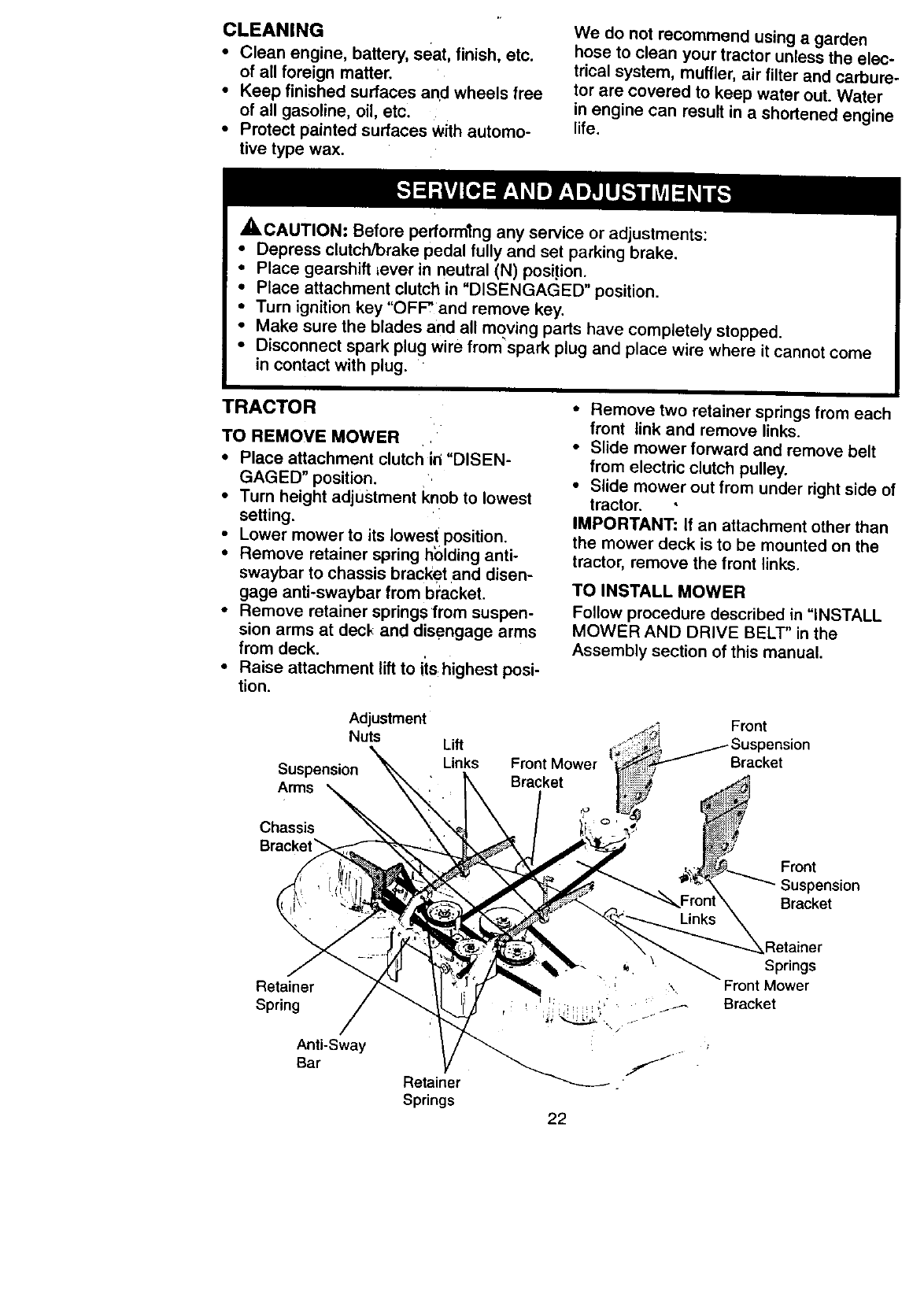
TRACTOR
TO REMOVE MOWER
•Place attachment clutch in "DISEN-
GAGED" position.
•Turn height adjustment knob to lowest
setting.
Lower mower to its Iowes! position.
• Remove retainer spring holding anti-
swaybar to chassis bracket and disen-
gage anti-swaybar from bracket.
• Remove retainer springs from suspen-
sion arms at deck and disengage arms
from deck.
•Raise attachment lift to iis:highest posi-
tion.
• Remove two retainer springs from each
front link and remove links.
•Slide mower forward and remove belt
from electric clutch pulley.
• Slide mower out from under right side of
tractor.
IMPORTANT: If an attachment other than
the mower deck is to be mounted on the
tractor, remove the front links.
TO INSTALL MOWER
Follow procedure described in "INSTALL
MOWER AND DRIVE BELT" in the
Assembly section of this manual.
Adjustment
Nuts
Suspension
Arms
Chassis
Lift
Links Front Mower
Bracket
Front
Bracket
Front
Suspension
Bracket
Retainer
Spring
Anti-Sway
Bar Retainer
Springs 22
Retainer
Springs
Front Mower
Bracket
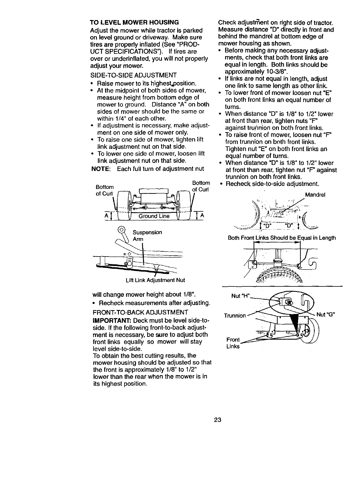
TO LEVEL MOWER HOUSING
Adjust the mower while tractor is parked
on level ground or driveway. Make sure
tiros are properly inflated (See "PROD-
UCT SPECIFICATIONS"). If tiros are
over or underinflated, you will not properly
adjust your mower.
SIDE-TO-SIDE ADJUSTMENT
•Raise mower to its highest,position.
•At the midpoint of both sides of mower,
measure height from bottom edge of
mower to ground. Distance "A" on both
sides of mower should be the same or
within 1/4" of each other.
•If adjustment is necessary, make adjust-
ment on one side of mower only.
•To raise one side of mower, tighten lift
link adjustment nut on that side.
•To lower one side of mower, loosen lift
link adjustment nut on that side.
NOTE: Each full turn of adjustment nut
Bottom
o,O O0 o,cu
Suspension
Arm
Lift Link Adjustment Nut
will change mower height about 1/8".
• Recheck measurements after adjusting.
FRONT-TO-BACK ADJUSTMENT
IMPORTANT: Deck must be level side-to-
side. If the following front-to-back adjust-
ment is necessary, be sure to adjust both
front links equally so mower will stay
level side-to-side.
To obtain the best cutting results, the
mower housing should be adjusted so that
the front is approximately 1/8" to 1/2"
lower than the rear when the mower is in
its highest position.
Check adjustr_ent on right side of tractor.
Measure distance "D" directly in front and
behind the mandrel at bottom edge of
mower housing as shown.
•Before making any necessary adjust-
ments, check that both front links are
equal in length. Both links should be
approximately 10-3/8".
•If links are not equal in length, adjust
one link to same length as other link.
•To lower front of mower loosen nut "E"
on both front links an equal number of
turns.
• When distance "D" is 1/8" to 1/2" lower
at front than I'ear, tighten nuts "F"
against trunnion on both front links.
• To raise frontof mower, loosen nut "P
from trunnion on bnth front links.
Tighten nut "E" on both front links an
equal number of turns.
• When distance "D" is 1/8" to 1/2" lower
at front than rear, tighten nut "P against
trunnion on both front links.
• Recheck side-to-side adjustment.
Mandrel
.... _¢ T"D --b ':f _,t-'
Both Front unks Should beEqual in Length
Nut "H"_
Front_
Links
23
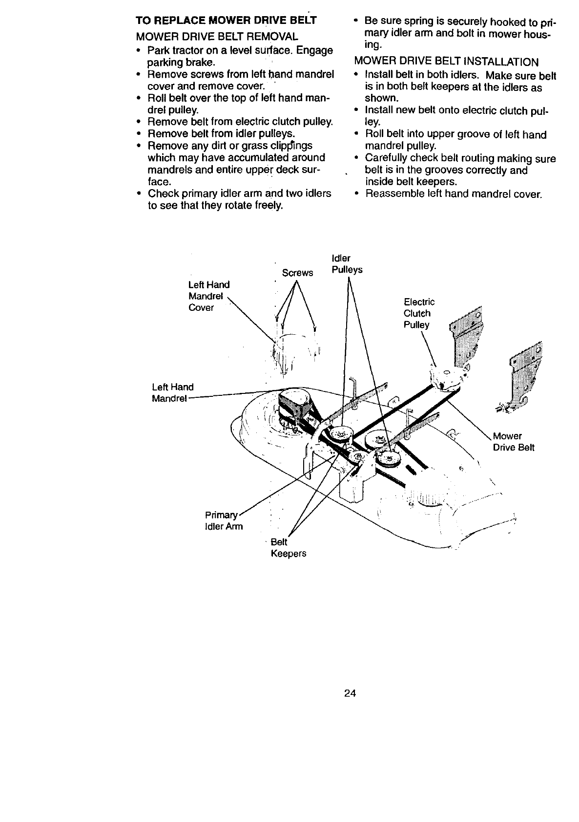
TO REPLACE MOWER DRIVE BEI'T
MOWER DRIVE BELT REMOVAL
•Park tractor on a level surface. Engage
parking brake.
• Remove screws from left band mandrel
cover and remove cover.
• Roll belt over the top of left hand man-
drel pulley.
• Remove belt from electric clutch pulley.
•Remove belt from idler pulleys.
• Remove any dirt or grass clippings
which may have accumulated around
mandrels and entire upper deck sur-
face.
•Check primary idler arm and two idlers
to see that they rotate freely.
•Be sure spring is securely hooked to pri-
mary idler arm and bolt in mower hous-
ing,
MOWER DRIVE BELT INSTALLATION
•Install belt in both idlers. Make sure belt
is in both belt keepers at the idlers as
shown.
°Install new belt onto electric clutch pul-
ley,
•Roll belt into upper groove of left hand
mandrel pulley.
•Carefully check belt routing making sure
belt is in the grooves correctly and
inside belt keepers.
•Reassemble left hand mandrel cover.
Screws
Left Hand
Mandrel \
Cover "
'l_i _ - '_
Left Hand
Mandrel
Idler
Putteys
Electric
Clutch
Pulley
\
Drive Belt
\
",%
Pdma_
IdlerArm
Belt
Keepers
24
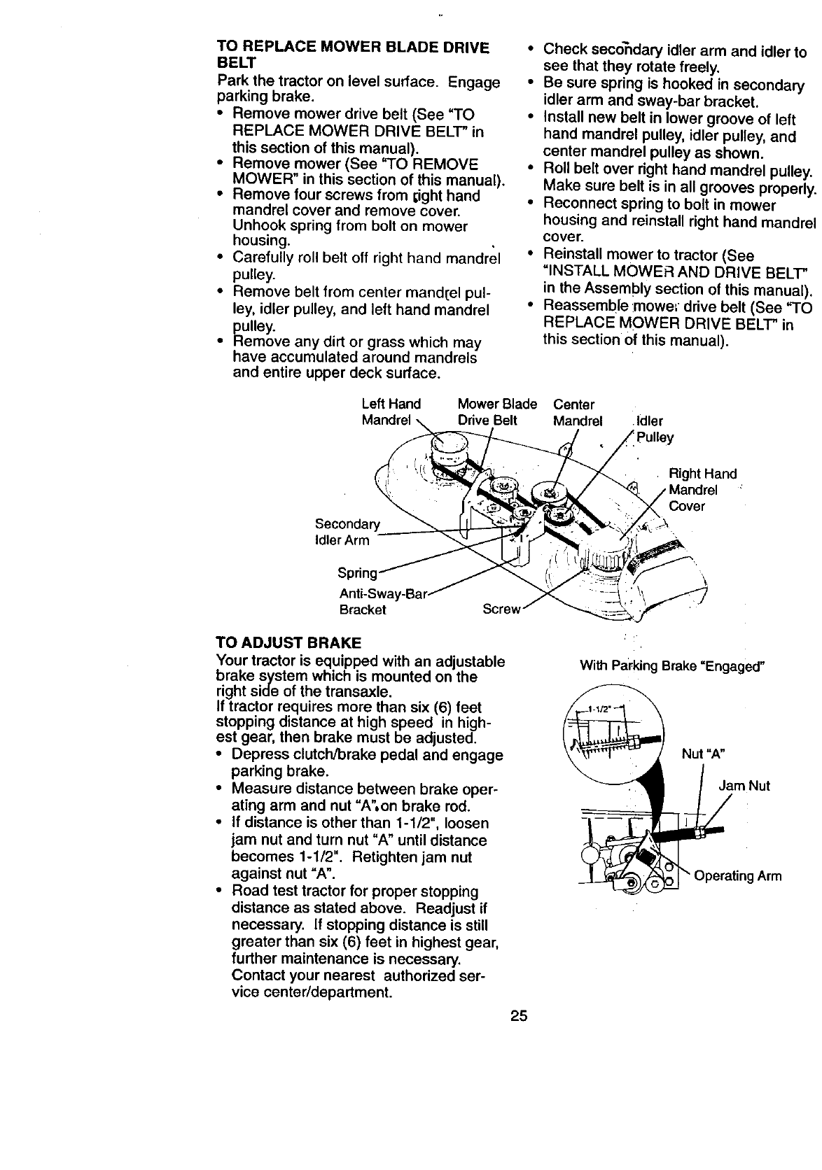
TO REPLACE MOWER BLADE DRIVE
BELT
Park the tractor on level surface. Engage
parking brake.
•Remove mower drive belt (See "TO
REPLACE MOWER DRIVE BELT" in
this section of this manual).
• Remove mower (See "TO REMOVE
MOWER" in this section of this manual).
• Remove four screws from I;ight hand
mandrel cover and remove cover.
Unhook spring from bolt on mower
housing.
• Carefully roll belt off right hand mandrel
pulley.
•Remove belt from center mand[el pul-
ley, idler pulley, and left hand mandrel
pulley.
• Remove any dirt or grass which may
have accumulated around mandrels
and entire upper deck surface.
Check secondary idler arm and idler to
see that they rotate freely.
Be sure spring is hooked in secondary
idler arm and sway-bar bracket.
Install new belt in lower groove of left
hand mandrel pulley, idler pulley, and
center mandrel pulley as shown.
Roll belt over right hand mandrel pulle_
Make sure belt is in all grooves properl
Reconnect spring to bolt in mower
housing and reinstall right hand mandr_
cover.
Reinstatt mower to tractor (See
=INSTALL MOWER AND DRIVE BELT"
in the Assembly section of this manual)
Reassemble :mowe= drive belt (See "TC
REPLACE MOWER DRIVE BELT" in
this section •of this manual).
Left Hand Mower Blade Center
Mandrel Drive Belt Mandrel Idler
pulley
Right Hand
Secondary
Idler Arm
Cover
Bracket Screw
TO ADJUST BRAKE
Your tractor is equipped with an adjustable
brake system which is mounted on the
right side of the transaxle.
If tractor requires more than six (6) feet
stopping distance at high speed in high-
est gear, then brake must be adjusted.
• Depress clutch/brake pedal and engage
parking brake.
•Measure distance between brake oper-
ating arm and nut "A",on brake rod.
•If distance is other than 1-1/2", loosen
jam nut and turn nut "A" until distance
becomes 1-1/2". Retighten jam nut
against nut "A".
• Road test tractor for proper stopping
distance as stated above. Readjust if
necessary. If stopping distance is still
greater than six (6) feet in highest gear,
further maintenance is necessary.
Contact your nearest authorized ser-
vice center/department.
With Parking Brake "Engaged"
Nut "A"
Jam Nut
o_Operating Arm
25
TO REPLACE MOTION DRIVE BI=LT
Park the tractor on level surface. Engage
parking brake. For assistance, there is a
belt installation guide decal on bottom side
of left footrest.
•Remove mower (See =TO REMOVE
MOWER" in this section of this manual.)
•Disconnect clutch wire harness.
•Remove clutch Iocator.
•Remove belt from stationary idler and
clutching idler. .
•Pull belt slack toward rear of tractor.
Remove belt upwards from transaxle
pulley by deflecting belt keepers.
•Pull belt toward front of tractor and
remove downwards from around electric
clutch.
•Install new belt by reversing above pro-
cedure.
Electdc Clutch Locater
Clutching
Transaxle
Pulley
Clutch Wire
Harness
TRANSAXLE GEAR SHIFT LEVER
NEUTRAL
ADJUSTMENT i•
The transaxle should be inlneutral when
the gear shift lever is in neuti'al (N) (lock
gate) position. The adjustment is preset at
the factory; however, if adjustment is
needed, proceed as follows:
•Make sure transaxle is'in neutral (N).
NOTE: When the tractor rear wheels
move freely, the transaxle is in neutral.
• Loosen adjustment bolt in front of the
right rear wheel.
• Position the gear shift lever in the neu-
tral (N) position.
• Tighten adjustment bolt securely.
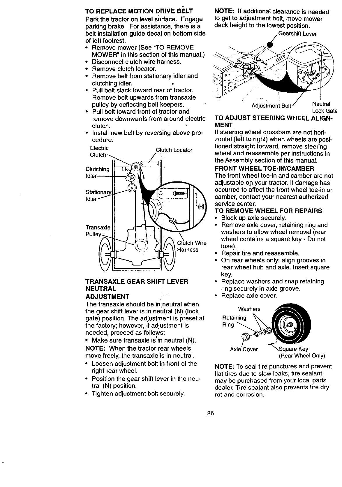
NOTE: If additional clearance is needed
to get to adjustment bolt, move mower
deck height to the lowest position.
Gearshift Lever
Adjustment Neutral
Lock Gate
TO ADJUST STEERING WHEEL ALIGN-
MENT
If steering wheel crossbars are not hori-
zontal (left to right) when wheels are posi-
tioned straight forward, remove steering
wheel and reassemble per instructions in
the Assembly section of this manual.
FRONT WHEEL TOE-IN/CAMBER
The front wheel toe-in and camber are not
adjustable on your tractor. If damage has
occurred to affect the front wheel toe-in or
camber, contact your nearest authorized
service center.
TO REMOVE WHEEL FOR REPAIRS
•Block up axle securely.
•Remove axle cover, retaining ring and
washers to allow wheel removal (rear
wheel contains a square key - Do not
lose).
• Repair tire and reassemble.
• On rear wheels only: align grooves in
rear wheel hub and axle. Insert square
key.
• Replace washers and snap retaining
ring securely in axle groove.
• Replace axle cover.
Washers
Retaining _ _I
Ring
Axle/over _,Square Key
(Rear Wheel Only)
NOTE: To seal tire punctures and prevent
flat tires due to slow leaks, tire sealant
may be purchased from your local parts
dealer. Tire sealant also prevents tire dry
rot and corrosion.
26
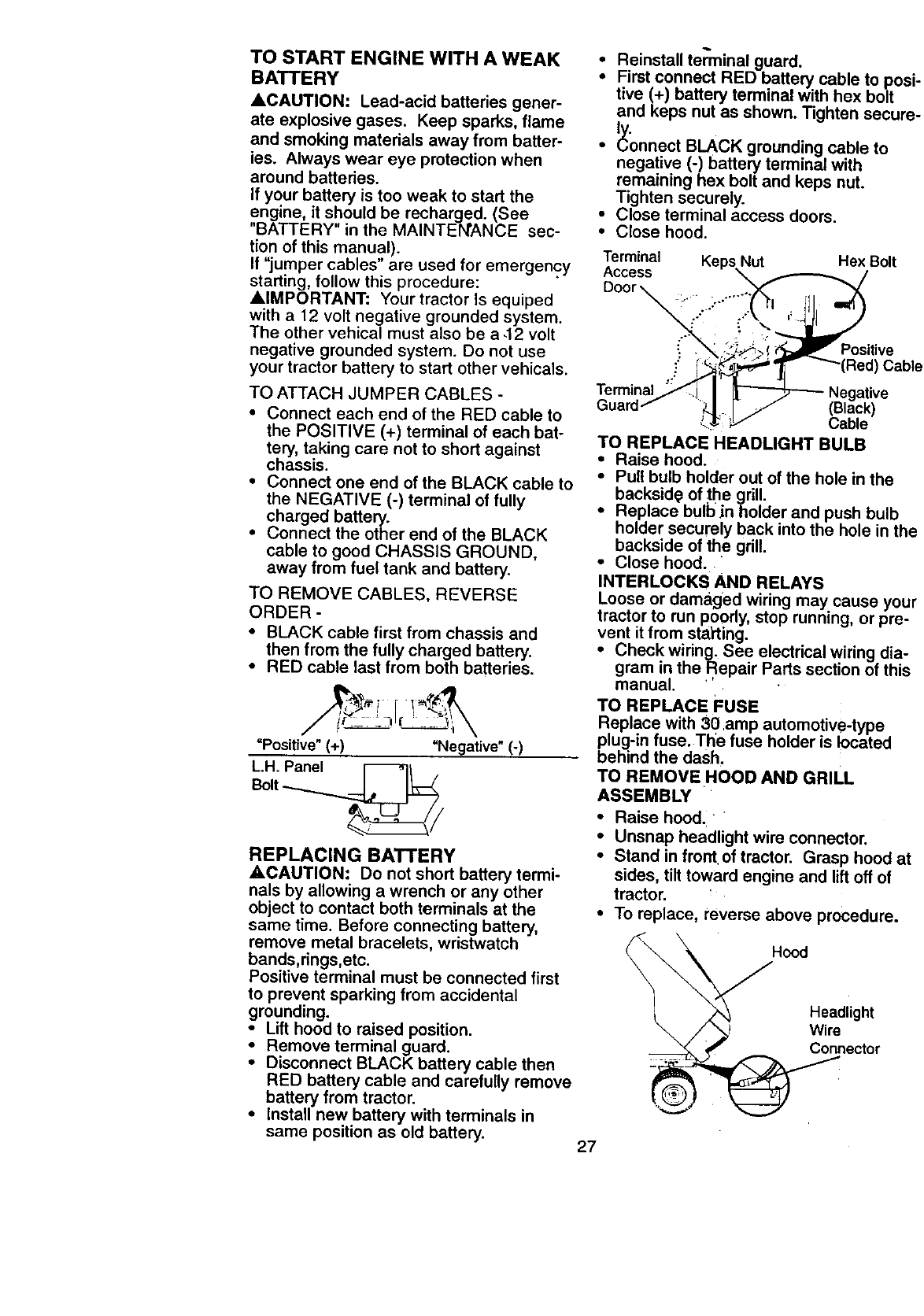
TO START ENGINE WITH A WEAK
BATTERY
&CAUTION: Lead-acid batteries gener-
ate explosive gases. Keep sparks, flame
and smoking materials away from batter-
ies. Always wear eye protection when
around batteries.
If your battery is too weak to start the
engine, it should be recharged. (See
"BATTERY" in the MAINTENANCE sec-
tion of this manual).
If "jumper cables" are used for emergency
starting, follow this procedure:
AIMPORTANT: Your tractor Is equiped
with a 12 volt negative grounded system.
The other vehical must also be a .12 volt
negative grounded system. Do not use
your tractor battery to start other vehicals.
TO ATTACH JUMPER CABLES -
•Connect each end of the RED cable to
the POSITIVE (+) terminal of each bat-
tery, taking care not to short against
chassis.
• Connect one end of the BLACK cable to
the NEGATIVE (-) terminal of fully
charged battery.
• Connect the other end of the BLACK
cable to good CHASSIS GROUND,
away from fuel tank and battery.
TO REMOVE CABLES, REVERSE
ORDER -
•BLACK cable first from chassis and
then from the fully charged battery.
• RED cable last from both batteries.
"Positive"(+) "Negative" (-)
L.H. Panel _/
Bolt _,
REPLACING BATTERY
_CAUTION: Do not short battery termi-
nals by allowing a wrench or any other
object to contact both terminals at the
same time. Before connecting battery,
remove metal bracelets, wristwatch
bands,rings,etc.
Positive terminal must be connected first
to prevent sparking from accidental
grounding.
•Lift hood to raised position.
Remove terminal guard.
Disconnect BLACK battery cable then
RED battery cable and carefully remove
battery from tractor.
• Install new battery with terminals in
same position as old battery.
•Reinstall tenTfinal guard.
•First connect RED battery cable to po,,
twe (+) battery terminal with hex bolt
and keps nut as shown. Tighten secur,
t,,
• _onnect BLACK grounding cable to
negative (-)battery terminal with
remaining hex bolt and keps nut.
Tighten securely.
• Close terminal access doors.
• Close hood.
Terminal Keps Nut
Access
Door
Hex Bolt
Positive
Ca_
Terminal
Guarc Cable
TO REPLACE HEADLIGHT BULB
• Raise hood.
•Pull bulb holder out of the hole in the
backsid_ of the grill.
• Replace bulb jnholder and push bulb
holder securely back into the hole in th,
backside of the grill.
• Close hood.
INTERLOCKS AND RELAYS
Loose or damaged wiring may cause you
tractor to run poorly, stop running, or pre-
vent it from starting.
•Check wiring. See electrical wiring dia-
gram in the Repair Parts section of this
manual. '
TO REPLACE FUSE
Replace with 30 amp automotive-type
plug-in fuse, The fuse holder is located
behind the dash.
TO REMOVE HOOD AND GRILL
ASSEMBLY
• Raise hood.
•Unsnap headlight wire connector.
•Stand in front of tractor. Grasp hood at
sides, tilt toward engine and lift off of
tractor.
•To replace, reverse above procedure.
Hood
Headlight
Connector
27
ENGINE
Maintenance, repair, or replacement of the
emission control devices and systems,
which are being done at the customers
expense may be performed by any non-
road engine repair establishment or ind -
viduaL Warranty repairs must be per-
formed by an authorized engine manufac-
turer's service outlet.
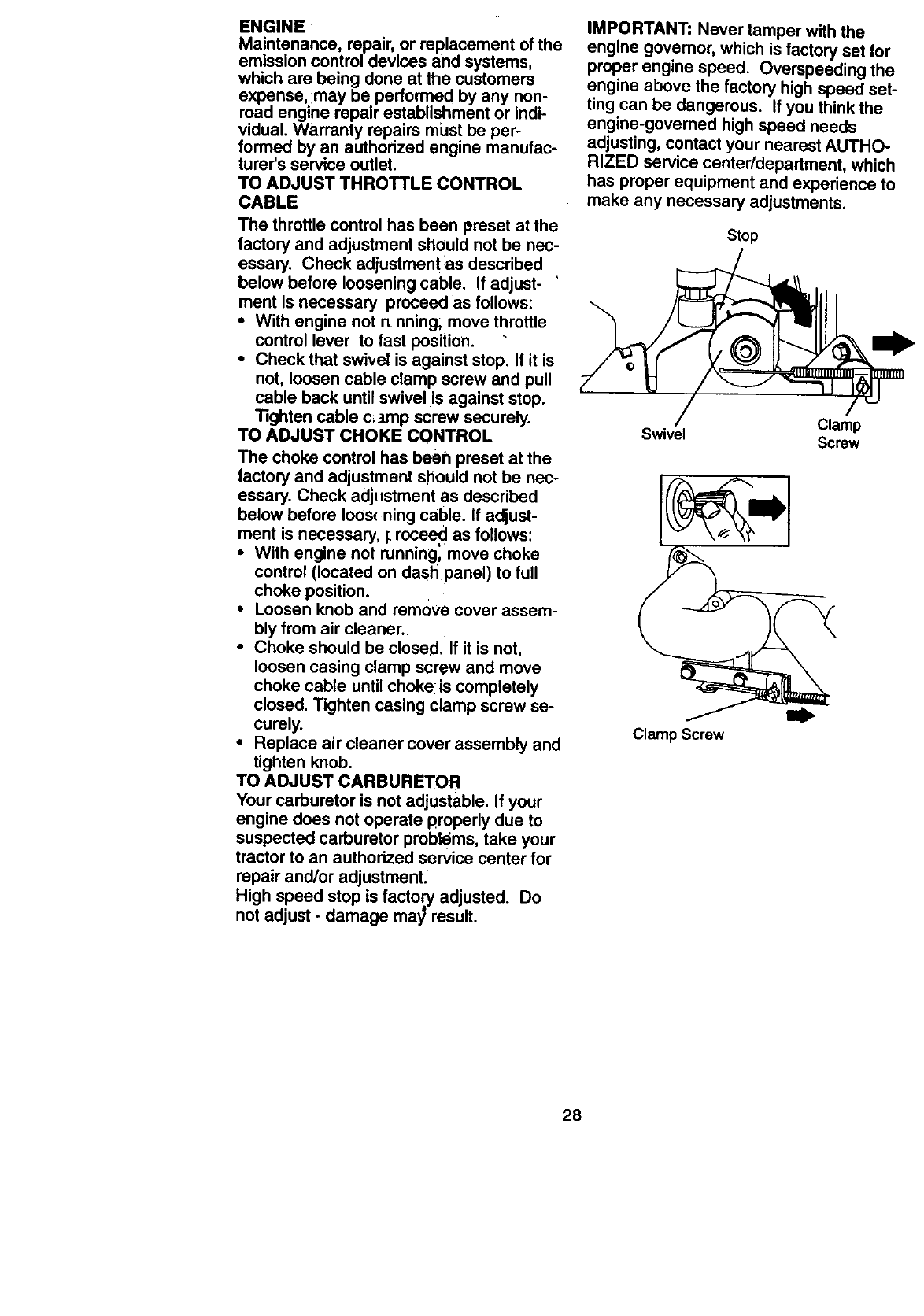
TO ADJUST THROTTLE CONTROL
CABLE
The throttle control has been preset at the
factory and adjustment should not be nec-
essary. Check adjustment as described
below before loosening Cable. If adjust- '
ment is necessary proceed as follows:
•With engine not rLnning; move throttle
control lever to fast position.
•Check that swivel is against stop. If it is
not, loosen cable clamp screw and pull
cable back until swivel is against stop.
Tighten cable c_tmp screw securely.
TO ADJUST CHOKE CONTROL
The choke control has beeh preset at the
factory and adjustment should not be nec-
essary. Check adjustment'as descdbed
below before Ioos_ ning cable. If adjust-
ment is necessary, I_.roceed as follows:
•With engine not running, move choke
control (located on dash panel) to full
choke position.
•Loosen knob and remove cover assem-
bly from air cleaner.
•Choke should be closed. If it is not,
loosen casing clamp screw and move
choke cable untilchoke is completely
closed. Tighten casing clamp screw se-
curely.
•Replace air cleaner cover assembly and
tighten knob.
TO ADJUST CARBURETOR
Your carburetor is not adjustable. If your
engine does not operate properly due to
suspected carburetor probt(_ms, take your
tractor to an authorized service center for
repair and/or adjustment. '
High speed stop is factory adjusted. Do
not adjust - damage may result.
IMPORTANT: Never tamper with the
engine governor, which is factory set for
proper engine speed. Overspeeding the
engine above the factory high speed set-
ting can be dangerous. If you thinkthe
engine-governed high speed needs
adjusting, contact your nearest AUTHO-
RIZED service center/department, which
has proper equipment and experience to
make any necessary adjustments.
Stop
Clamp
Swivel Screw
Clamp Screw
28
Immediately prepare your tractor for stor-
age at the end of the season or if the trac-
tor will not be used for 30 days or more.
_,CAUTION: Never store the tractor with
gasoline in the tank inside a building
where fumes may reach an open flame or
spark. Allow the engine to co.ol before stor-
ing in any enclosure.
TRACTOR
Remove mower from tractor for winter
storage. This will allow you to clean it thor-
oughly. Remove all dirt, grease, leaves,
etc. Store in a clean, dry area.
• Clean entire tractor (See "CLEANING"
in the Maintenance section of this man-
ual).
• Inspect and replace belts, if necessary
(See belt replacement instructions in the
Service and Adjustments section of this
manual):
• Lubricate as shown in the Maintenance
section of this manual.
• Be sure that all nuts, bolts and screws
are securely fastened. Inspect moving
parts for damage, breakage and wear.
Replace if necessary.
• Touch up all rusted or chipped paint sur-
faces; sand lightly before painting.
BATTERY
•Fully charge the battery for storage.
•After a period of time in storage, battery
may require recharging.
•To help prevent corrosion and power
leakage during long periods of storage,
battery cables should be disconnected
and battery cleaned thoroughly (see
"TO CLEAN BATTERY AND TERMI-
NALS" in the Maintenance section of
this manual).
•After cleaning, leave cables disconnect-
ed and place cables where they cannot
come in contact with,battery terminals.
•If battery is removed from tractor for
storage, do not store battery directly on
concrete or damp surfaces.
ENGINE
FUEL SYSTEM
IMPORTANT: It is important to prevent
gum deposits from forming in essential
fuel system parts such as carburetor, fuel
filter, fuel hose, or tank during storage.
Also, experience indicates that alcohol
blended fuels (called gasohol or using
ethanol or methanol) can attract moisture
which leads to separation and formation of
acids during storage. Acidic gas can dam-
age the fuel system of an engine while in
storage.
• Drain the fuel tank.
•Start the engine and let it run until the
fuel lines and carburetor are empty.
• Never use engine or carburetor cleaner
products in the fuel tank or permanent
damage may.occur.
• Use fresh fu_ next season.
NOTE: Fuel stabilizer is an acceptable
alternative in minimizing the formation of
fuel gum deposits during storage. Add sta-
bilizer to gasoline in fuel tank or storage
container. Always follow the mix ratio
found on stabilizer container. Run engine
at least 10 minutes after adding stabilizer
to allow the stabilizer to reach the carbure-
tor. Do not drain'the gas tank and carbure-
tor if using fuel stabilizer.
ENGINE OIL
Drain oil (with engine warm) and replace
with clean eng{ne oil. (See "ENGINE" in
the Maintenance section of this manual).
CYLINDER(S)
•Remove spark plug(s).
•Pour one ounce of oilthrough spark plug
hole(s) into cylinder(s).
•Turn ignition key to =START" position for
a few seconds to distribute oil
•Replace with new spark plug(s).
OTHER :.
• Do not store gasoline from one season
to another.
•Replace your gasoline can if it starts to
rust. Rust and/or dirt in your gasoline will
cause problems.
•If possible, store your tractor indoors
and cover it to give protection from dust
and dirt.
•Cover your tractor with a suitable protec-
tive cover that does t_ot retain moisture.
Do not use plastic. Plastic cannot
breathe, which allows condensation to
form and cause your tractor to rust.
IMPORTANT: Never cover tractor while
engine and exhaust areas are still warm.
29
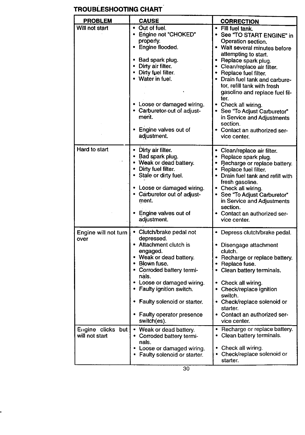
TROUBLESHOOTING CHART'
PROBLEM
Will not start
CAUSE
•Out of fuel.
•Engine not"CHOKED"
pmpedy.
•Engine flooded.
•Bad spark plug.
Hard to start
Engine will not turn
over
E,gine clicks but
will not start
•Dirty air filter.
•Dirty flJel filter.
• Water in fuel.
•Loose or damaged wiring.
• Carburetor_out of adjust-
ment.
•Engine valves out of
adjustment.
• Dirty air filter.
•Bad spark plug.
•Weak or dead battery.
•Dirty fuel filter.
•Stale or dirty fuel.
•LOose or damaged wiring.
• Carburetor out of adjust-
ment.
•Engine valves out of
adjustment.
• Clutch/brake pedal not
depressed.
•Attachment clutch is
engaged.
•Weak or dead battery.
•Blown fuse.
•Corroded battery termi-
nals.
•Loose or damaged wiring.
•Faulty ignition switch.
•Faulty solenoid or starter.
• Faulty operator presence
switch(es).
•Weak or dead battery.
• Corroded battery termi-
nals.
• Loose or damaged wiring.
•Faulty solenoid or starter.
CORRECTION
• Fill fuel tank.
•See "TO START ENGINE" in
Operation section.
•Wait several minutes before
attempting to start.
•Replace spark plug.
•Clean/replace air filter.
•Replace fuel filter.
•Drain fuel tank and carbure-
tor, refill tank with fresh
gasoline and replace fuel fil-
ter.
•Check all wiring.
•See "To Adjust Carburetor"
in Service and Adjustments
section.
•Contact an authorized ser-
vice center.
• Clean/replace air filter.
• Replace spark plug.
•FJecharge or replace battery.
• Replace fuel filter.
•Drain fuel tank and refill with
fresh gasoline.
•Check all wiring.
•See "To Adjust Carburetor"
in Service and Adjustments
section.
•Contact an authorized ser-
vice center.
• Depress clutch/brake pedal.
• Disengage attachment
clutch.
• Recharge or replace battery.
•Replace fuse.
•Clean battery terminals.
•Check all wiring.
• Check/replace ignition
switch.
• Check/replace solenoid or
starter.
• Contact an authorized ser-
vice center.
• Recharge or replace battery.
• Clean battery terminals.
•Check all wiring.
• Check/replace solenoid or
starter.
3O
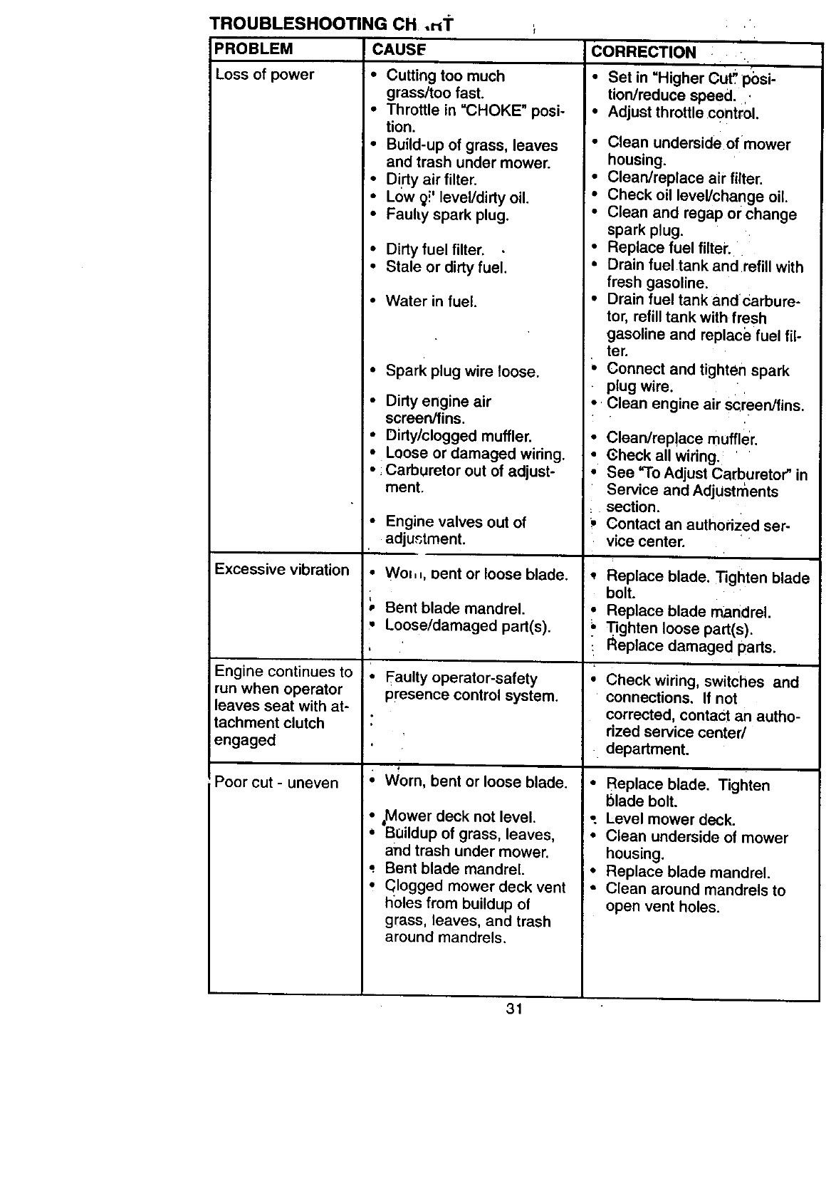
TROUBLESHOOTING CH .r_'r
PROBLEM CAUSE
Loss of power •Cutting too much
grass/too fast.
•Throttle in "CHOKE" posi-
tion.
• Build-up of grass, leaves
and trash under mower.
• Dirty air filter.
•Low 91' level/dirty oil.
•Fauhy spark plug.
•Dirty fuel filter.
•Stale or dirty fuel.
•Water in fuel.
•Spark plug wire loose.
•Dirty engine air
screen/fins.
•Dirty/clogged muffler.
•Loose or damaged wiring.
•Carburetor out of adjust-
ment.
• Engine valves out of
adjustment.
CORRECTION :, .
•Set in Higher Cut! pbsi-
tion/reduce speed...
•Adjust throttle control.
•Clean underside of mower
housing.
•Clean/replace air filter.
•Check oil level/change oil.
•Clean and regap or change
spark plug.
• Replace fuel filter.
•Drain fuel tank and refill with
fresh gasoline.
•Drain fuel tank and Carbure-
tor, refill tank with fresh
gasoline and replace fuel fil-
ter.
_, Connect and tighten spark
•plug wire.
•Clean engine air screen/fins.
•Clean/rep!ace muffler.
•Gheck all wiring.
•See "To Adjust Carburetor" in
Service and AdjUstments
section.
_, Contact an authorized ser-
vice center.
Excessive vibration
Engine continues to
run when operator
leaves seat with at-
tachment clutch
engaged
Poor cut - uneven
• Wo=,=, Dent or loose blade.
pBent blade mandrel.
•Loose/damaged part(s).
!.
! * Faulty operator-safety
presence control system.
•Worn, bent or loose blade.
,Mower deck not level.
*Buildup of grass, leaves,
and trash under mower.
*Bent blade mandrel.
•(;logged mower deck vent
holes from buildup of
grass, leaves, and trash
around mandrels.
Replace blade. Tighten blade
bolt.
• Replace blade mandreL.
•Tighten loose part(s).
• Replace damaged parts.
• Check wiring, switches and
connections. If not
corrected, contact an autho-
rized service center/
department.
•Replace blade. Tighten
blade bolt.
; Level mower deck.
•Clean underside of mower
housing.
• Replace blade mandrel.
• Clean around mandrels to
open vent holes.
31
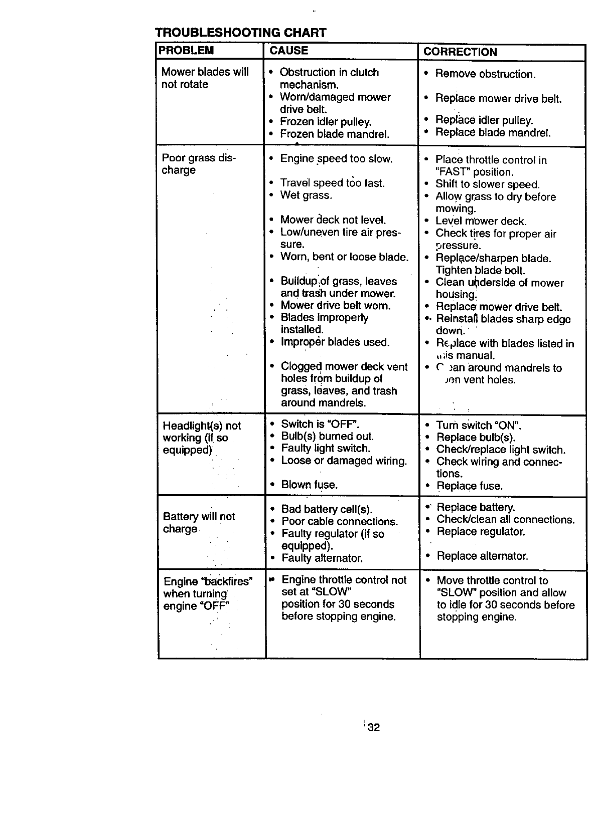
TROUBLESHOOTING CHART
PROBLEM
Mower blades will
not rotate
Poor grass dis-
charge
'i
Headlight(s) not •
working (if so
equipped)
il
Battery wi not o
charge •
Engine =backfires" "
when turning
engine "OFF"
CAUSE
• Obstruction in clutch
mechanism.
•Worn/damaged mower
drive belt.
•Frozen idler pulley.
•Frozen blade mandrel.
4
•Engine speed too slow.
• Travel speed t(_o fast
• Wet grass
•Mower aeck not level.
•Low/uneven tire air pres-
sure.
•Worn, bent or loose blade.
• Buiidup_of grass, leaves
and Va._h under mower.
Mower drive belt worn.
Blades improperly
installed.
Improper blades used.
Clogged mower deck vent
holes frqm buildup of
grass, leaves, and trash
around mandrels.
Switch is =OFF".
Bulb(s) burned out.
Faulty light switch.
Loose or damaged wiring.
Blown fuse.
Bad battery cell(s).
Poor cable connections.
Faulty regulator (if so
equipped).
Faulty alternator.
Engine throttle control not
set at "SLOW"
position for 30 seconds
before stopping engine.
CORRECTION
•Remove obstruction.
•Replace mower drive belt.
• Replace idler pulley.
•Replace blade mandrel.
• Place throttle control in
"FAST" position.
• Shift to slower speed.
•Allowgrass to dry before
mowing.
•Leyel mbwer deck.
•Check t_'es for proper air
oressure.
•Replace/sharpen blade.
Tighten blade bolt.
•Clean u0derside of mower
hoUsing_
•Replace mower drive belt.
•,Reinstal_ blades sharp edge
down.
•R_place with blades listed in
,,;is manual.
•O .'an around mandrels to
P.n vent holes.
•Turn switch "ON".
•Replace bulb(s).
• Check/replace light switch.
*Check wiring and connec-
tions.
• Replace fuse.
• Replace battery.
• Check/clean all connections.
• Replace regulator.
• Replace alternator.
Move throttle control to
"SLOW" position and allow
to idle for 30 seconds before
stopping engine.
_32
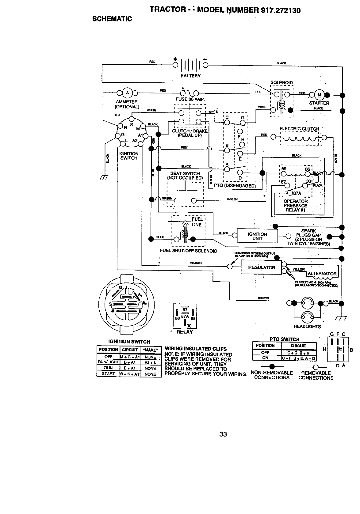
SCHEMATIC
TRACTOR - : MODEL NUMBER 917.272130
AMMETER
(OPTIONAL)
R£0
÷ II-oll
BATTERY
SOLENOID
r
FUSE30AMP,
;---_- -_ *.n_
. ..... |
STARTER
CLUTCH /BRAKE
(PEDAL UP)
ELECTRIC CLUI"CH
REO
I
• ......... J.
SEAT SWITCH
(NOT OCCUPIED)
i=-- I
iI
©:
E
D,J
iFUEL t
iI
I
I i
FUEL SHUT-OFF SOLENOID
,RI-LAy
OPERATOR
PRESENCE
RELAY #1
HEADLIGHTS
GFC
• nosw_c. •.IPOSITION CIRCUIT
OFF C+GIB+H B
ON C+FTS+E_A+D
0DA
REMOVABLE
CONNECTIONS
IGNITION SWITCH
POSITION I I,_IRCUIT "MAKE" WIRING INSULATED CUPS
_lO'l E: IF WIRING INSULATED
OFF ÷ G + A1 NONE CLIPS WERE REMOVED FOR
RUN/LIGHT B+A1 A2+L SERVICING OF UNIT, THEY
RUN B + A1 NONE SHOULD BE REPLACED TO
START + S*A1 NONE . PROPERLY SECURE YOUR WIRING. NON-REMOVABLE
CONNECTIONS
33
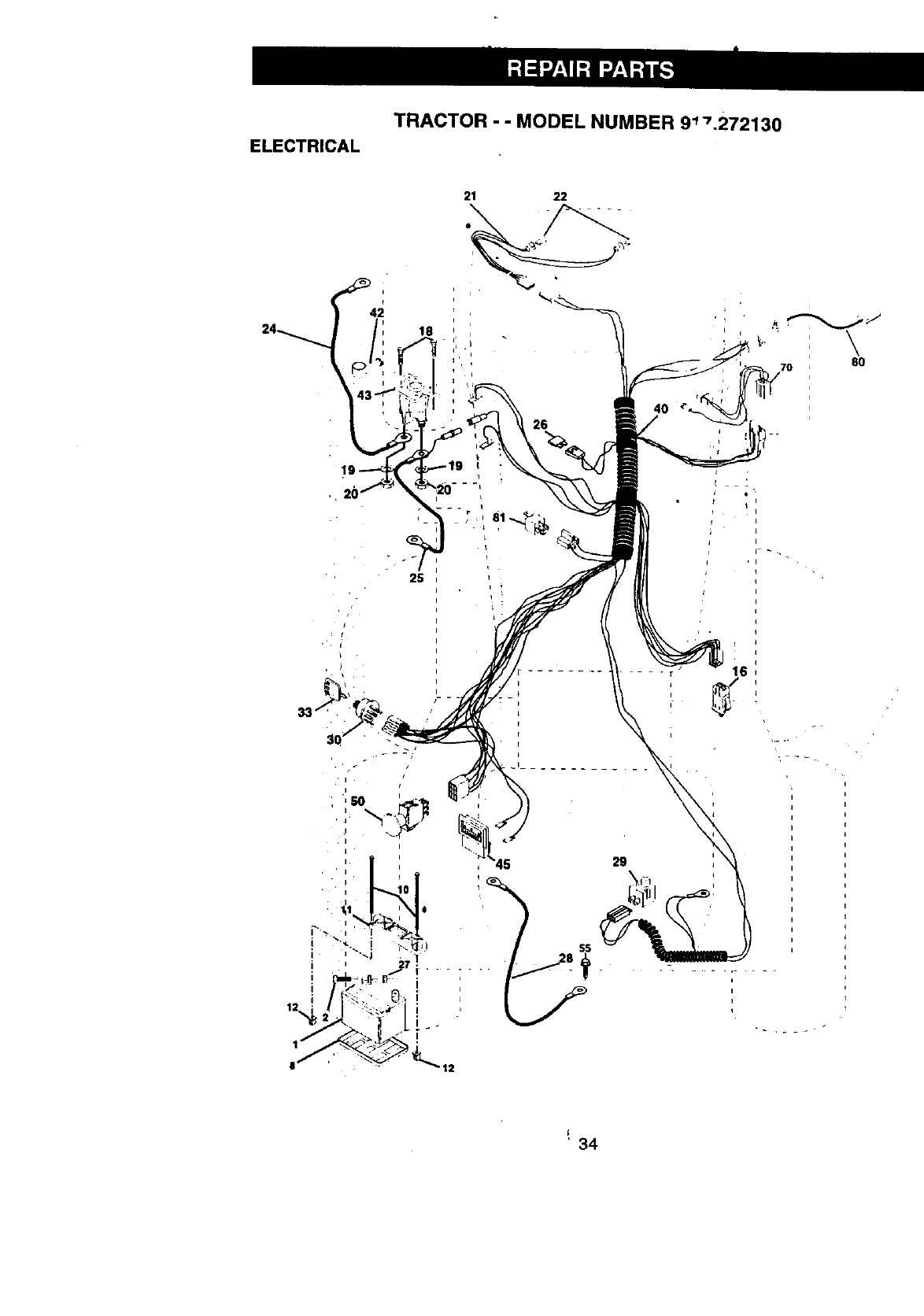
ELECTRICAL TRACTOR - - MODEL NUMBER 9_7.272130
rI
25
21 22
i
i
I
12
40
70 80
29
16
•r- •_,•
I
i
' 34
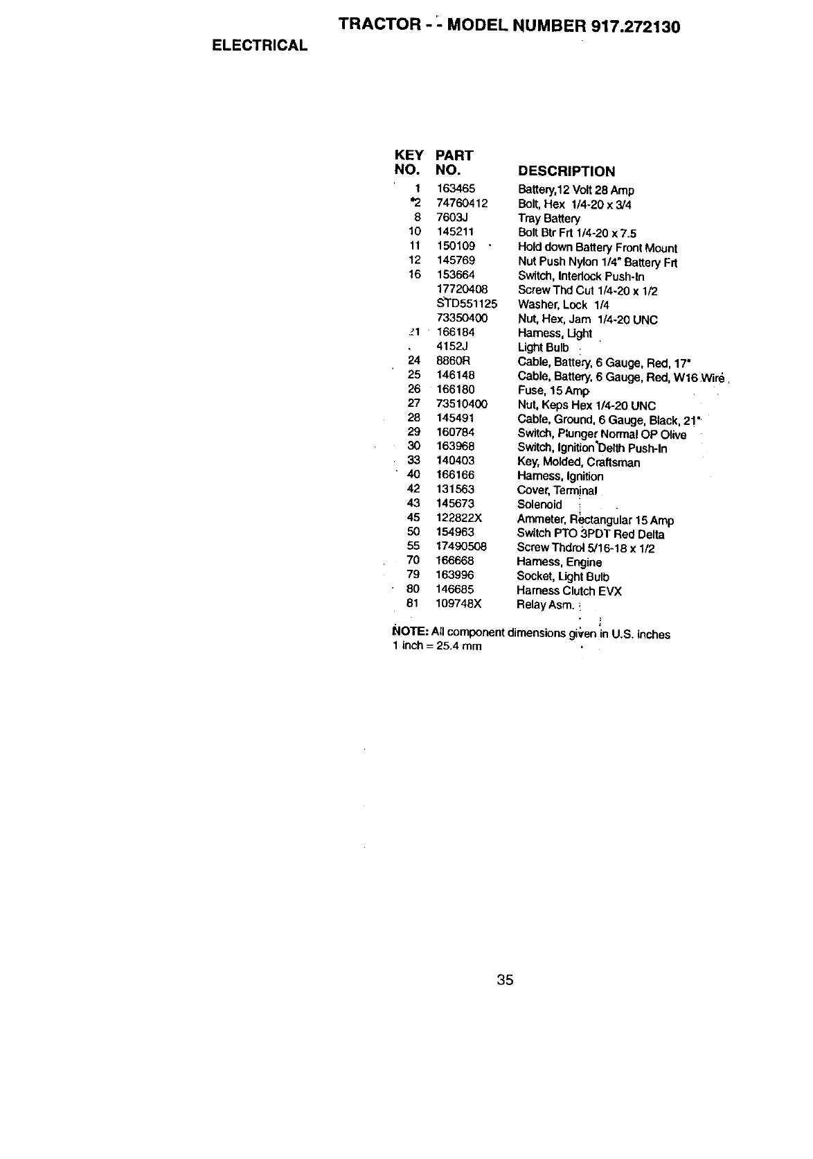
ELECTRICAL
TRACTOR - _-MODEL NUMBER 917.272130
KEY PART
NO. NO. DESCRIPTION
1 163465
"2 74760412
8 7603.1
10 145211
11 150109 "
12 145769
16 153664
17720408
S_rD551125
73350400
_1 166184
4152J
24 8860R
25 146148
26 166180
27 73510400
28 145491
29 160784
30 163£68
33 140403
40 166166
42 131563
43 145673
45 122822X
50 154963
55 17490508
70 166668
79 163996
80 146685
81 109748X
Battery,12Volt28 Amp
Bolt,Hex 1/4-20 x 3/4
Tray Battery
Bolt Btr Frt 114-20x 7.5
Holddown Battery FrontMount
Nut Push Nylon 1/4"Battery Frt
Switch, IntadockPush-In
Screw Thd Cut 1/4-20 x 1/2
Washer, Lock 1/4
Nut, Hex, Jam 1/4-20 UNC
Harness, Ught
LightBulb :
Cable, Battery, 6 Gauge, Red, 17"
Cable, Battery, 6 Gauge, Red, W16 Wire
Fuse, 15 Amp
Nut, Keps Hex 1/4-20 UNC
Cable, Ground,6 Gauge, Black,2!"
Switch, PlungerNormalOP Olive
Switch,Ignition'DelthPush-In
Key,Molded, Craftsman
Harness, Ignition
Cover, Term!na!
Solenoid
Ammeter,R_ctangutar15 Amp
Switch PTO 3PDT Red Delta
Screw Thdrol 5/1@18 x 1/2
Harness, Engine
Socket, Light Bulb
Harness Clutch EVX
Relay Asm, !
NOTE: All component dimensions given in U.S. (riches
1 inch = 25.4 mm
35
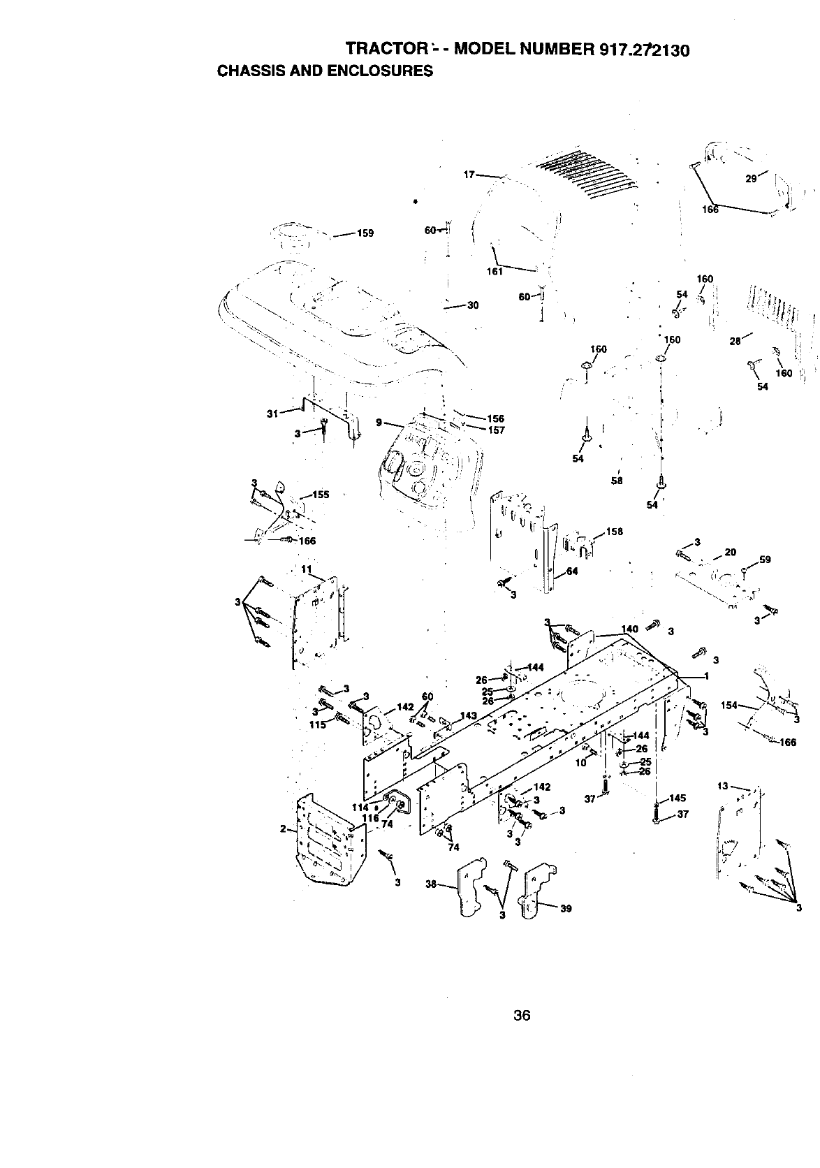
TRACTOR "-- MODEL NUMBER 917.272130
CHASSIS AND ENCLOSURES
17_._
"_-_ -_1s9 eo--;i
-1
160 •
/
54
58
3
3
74 3
3
36
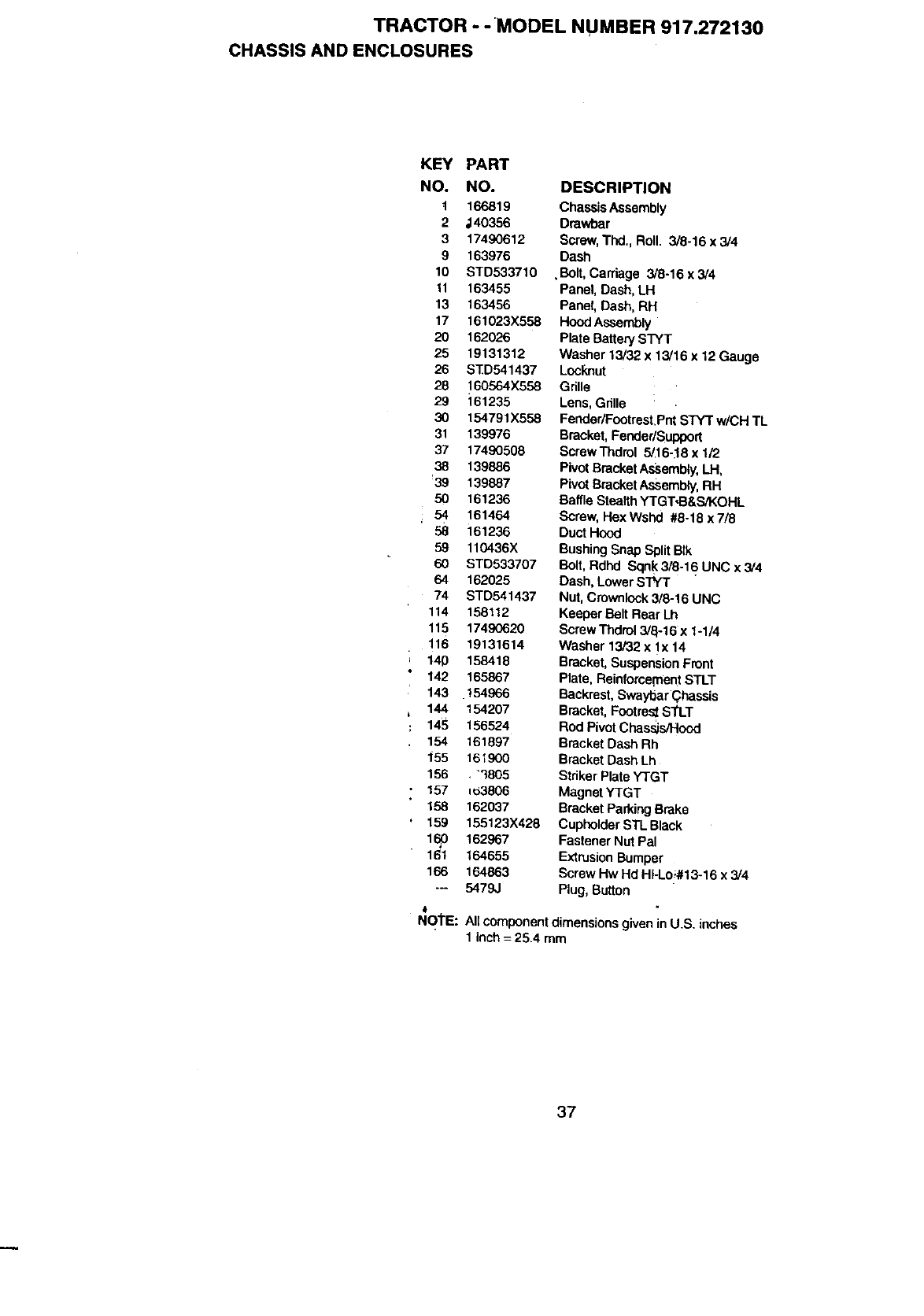
TRACTOR --MODEL NUMBER 917.272130
CHASSIS AND ENCLOSURES
KEY PART
NO. NO. DESCRIPTION
t166819 ChassisAssembly
2 ,140356 Drawbar
3 17490612 Screw,'t'hd., Roll. 3/8-16x3/4
9 163976 Dash
10 STD533710 ,Bolt, Carriage 3/8-16x3/4
11 163455 Panel, Dash, LH
13 163456 Panel, Dash, RH
17 161023X558 HoodAssembly
20 162026 Plate BatterySTYT
25 19131312 Washer 13/32 x13/16 x12 Gauge
26 STD541437 LooP,nut
28 160564X558 Grille
29 161235 Lens,Gnlle :.
30 154791X558 Fender/Footrest.PntSTYT w/CH TL
31 139976 Bracket,Fender/Support
37 17490508 ScrawThdrol 5/16-:18x 1/2
38 139886 PivotBracketAssem_y, LH,
39 139887 PivotBracketAssembly,RH
50 161236 BaffleStealth YTGT'-B&S/KOHL
54 161464 Scraw,HexWshd #8-18x7/8
58 161236 Duct Hood
59 110436X BushingSnap Split Blk
60 STD533707 Bolt,Rdhd Sqnk 3/8-16 UNC x 3/4
64 162025 Dash, Lower STYT
74 STD541437 Nut, Crownlock3/8-16 UNC
114 158112 Keeper Belt Rear Lh
115 17490620 Screw Thdrol3/a-16 x 1-1/4
116 19131614 Washer 13/32 x lx 14
140 158418 Bracket,SuspensionFront
142 165867 Plate, ReinforcementSTLT
143 ,154966 Backrest,Swayt_ar(_hassis
144 154207 Bracket, FootrestSTLT
14_ 156524 Rod PivotChas._s/Hood
154 161897 Bracket Dash Rh
155 161900 B_cket Dash Lh
156 ."3805 Striker PlateYTGT
; 157 =03806 Magnet YTGT
158 162037 Bracket ParkingBrake
159 155123X428 CupholderSTL Black
160 162967 Fastener Nut Pal
161 164655 ExtrusionBumper
166 164863 Screw Hw Hd Hi-Loi#13o16x 3/4
-- 5479J Plug, Button
#
NOI"E: All componentdimensions givenin U.S. inches
1 inch = 26.4 mm
37
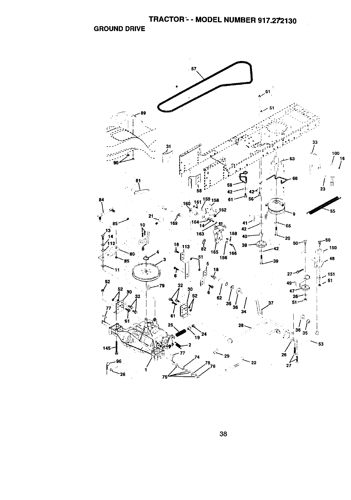
TRACTOR" -MODEL NUMBER 917.27'2130
GROUND DRIVE
38
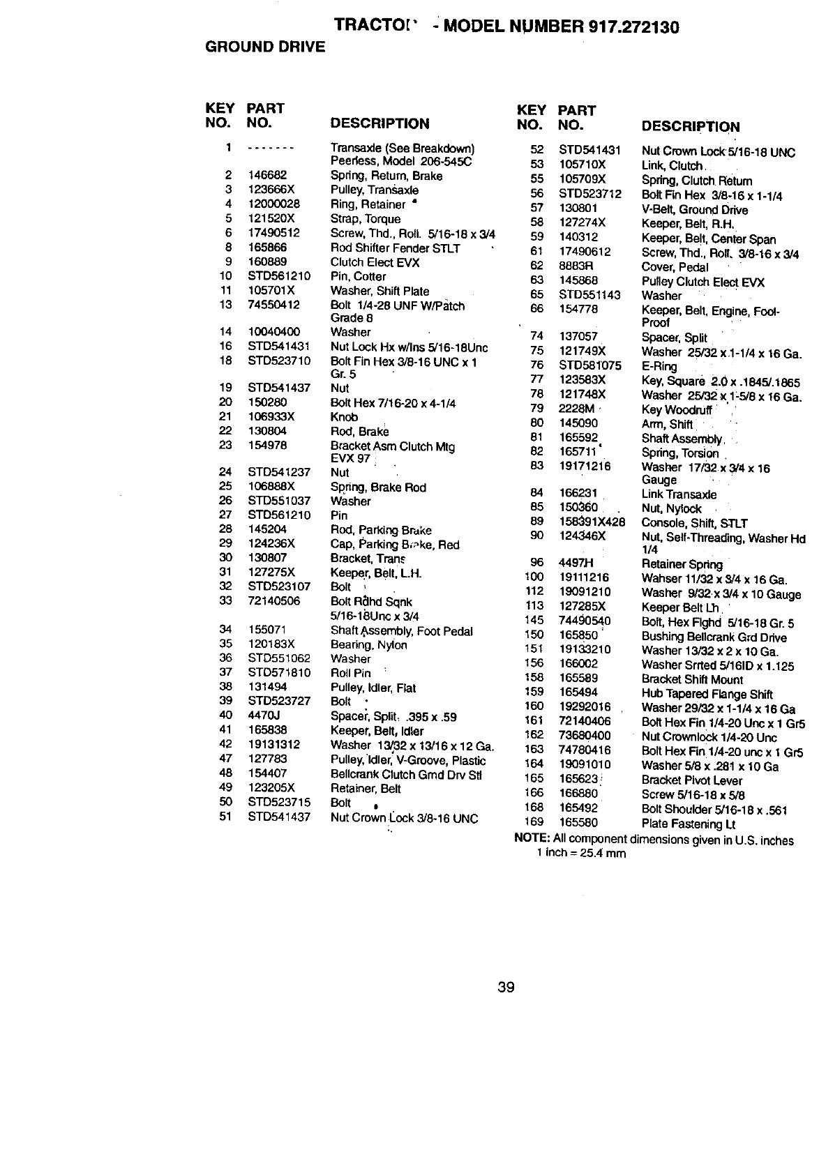
TRACTO[" _MODEL NUMBER 917.272130
GROUND DRIVE
KEY PART KEY PART
NO. NO. DESCRIPTION NO. NO. DESCRIPTIQN
1....... Transaxle (See Breakdown) 52 STD541431
Peerless, Model 206-545(3 53 105710X
2146682 Spring, Return,Brake 55 105709X
3 123666X Pulley, Transaxle 56 STD523712
4t2000028 Ring, Retainer " 57 130801
5121520X Strap, Torque 88 127274X
6 17490512 Screw,Thd., Roll. 5/16-18 x 3/4 59 140312
8165866 Rod Shifter Fender STLT 61 17490612
9 160889 Clutch Elect EVX 62 8883R
10 STD561210 Pin,Cotter 63 145868
11 105701X Washer, Shift Plate 65 STD551143
13 74560412 Bolt 1/4-28 UNF W/Patch 66 154778
Grade 8
14 10040400 Washer 74 137057
16 STD541431 Nut Lock Hxw/Inssi16-18Unc 75 121749X
18 STD523710 Bolt Fin Hex 3/8-16 UNC x 1 76 STD581'075
Gr. 5 77 123583X
19 STD.541437 Nut 78 121748X
20 150280 Bolt Hex 7/16-20 x4-1/4 79 2228M.
21 1OB933X Knob 80 145090
22 130804 Rod, Brake 81 165592
23 154978 BracketAsm Clutch Mtg 82 165711"
EVX 97 1 83 19171216
24 STD541237 Nut
25 106888X Spring, Brake Rod 84 166281
26 STD551037 Washer 85 150360
27 STB561210 Pin 89 158_91X42'8
28 145204 Rod, Parking Brake 90 124346X
29 124236X Cap, Parking Broke,Red
30 130607 Bracket, T_n_ 96 4497_
31 127275X Keeper, Belt, LH. t00 19111216
32 STD623107 Bolt 112 19091210
33 72140506 BoItR_lhd Sqnk 1t3 127285X
5/16-18Unc x 3/4 145 74490540
34 155071 Shaft Sssembly,Foot Pedal 150 165850 '
35 120183X Bearing, Nylon 151 19133210
36 STD551062 Washer 156 166002
37 STO571810 Roll Pin 158 165589
38 131494 Pulley, Idler, Flat 159 165494
39 STD523727 Bolt • 160 19292016
40 4470J Spacer, Sp_it, .395 x.59 161 72140406
41 165838 Keeper, Belt, Idler 162 73680400
42 19131312 Washer 1_32xts/16x12Ga. 163 74780416
47 127783 Pulley,'|dler,V-Graove, Plastic 164 19091010
46 154407 BellcrankClutch Grad Dry Stl 165 165623!
49 123205X Retainer, Belt 166 166880
50 STD523715 Bolt 0 168 165492
51 STD541437 NutCrown Cock3/8-16 UNC 169 165580
Nut Crown L0ck5/16-18 UNC
Unk, CkJtch :
Spring,Clutch Return
Bolt Fin Hex 3/8-16 x 1-1/4
V-Belt, Ground Drive
Keeper, Belt, R.H.
Keeper, Be!t, Center Span
Screw, Thd., RolL 3/8-16 x3/4
Cover, Pedal
Pulley Clutch Elect EVX
Washer
Keeper, Belt, Engine,Fool-
Proof
Spacer, Split
Washer 25/32 x 1-1/4 x 16 Ga.
E-Ring
Key,Square 2.0 x .1845/.1865
Washer 25/32 x1:5/8 x 16 Ga.
Key Woodruff
Arm, Shift
ShaftAssembly, .
Spring,Torsion.
Washer 17/32 x3/4x 16
Gauge
LinkTransaxle
Nut, Nylock
Console, Shift,STLT
Nut, Self-Threading,Washer Hd
1/4
Retainer Spring
Wahser 11/32 x5/4 x16 Ga.
Washer 9/32x 3/4 x10 Gauge
Keeper BeltL_
Bolt, Hex Flghd 5/16-18 Gr. 5
Bushing Be,crank Grd Ddve
Washer 13/32 x 2x 10 Ga.
Washer Srrted 5/161D x 1.125
Bracket ShiftMount
Hub Tapered Flange Shift
Washer 29/32 x 1-1/4 x 16 Ga
Bolt Hex Fin 1/4-20 Uric x I Gr5
Nut Crownlock1/4-20 Unc
BoltHex Fin 1/4-20 uricx I Gr5
Washer 5/8 x .28t x 10 Ga
Bracket Pivot Lever
Screw 5/16-18 x5/8
BoltShoulder 5/16-18 x.561
Plate FasteningLt
NOTE: Allcomponentdimensions given in U.S. inches
1 inch = 25.4 mm
39
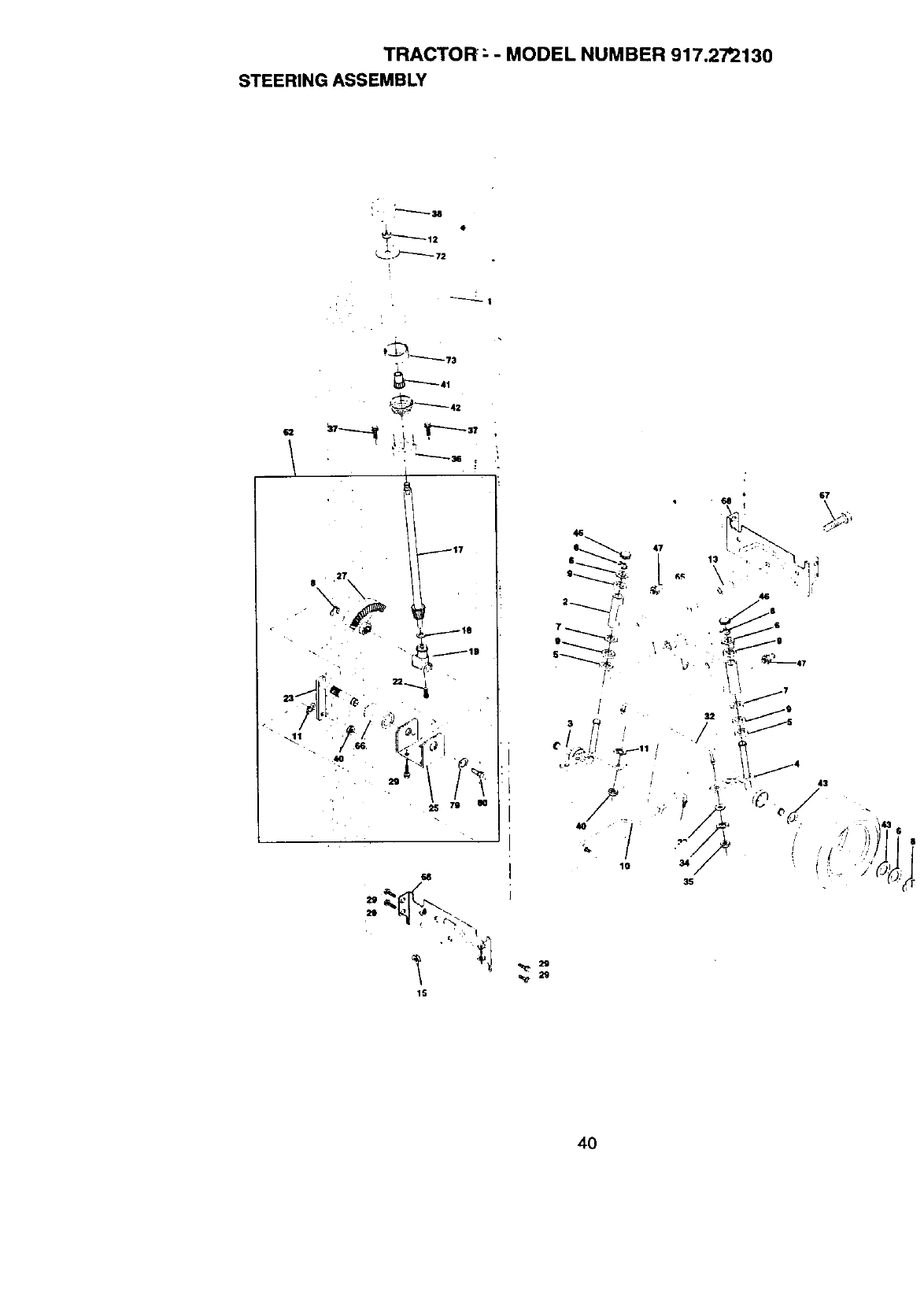
TRACTOR ; -MODEL NUMBER 917.2"/'2130
STEERING ASSEMBLY
"L
27
$\ \
_,,] /J
4O
117
SS
15
2g
4O
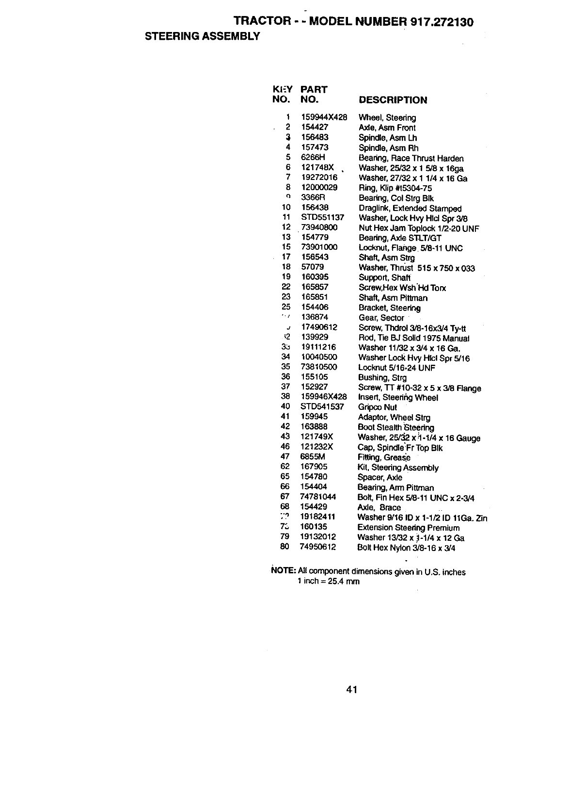
TRACTOR -._MODEL NUMBER 917.272130
STEERING ASSEMBLY
KI-_Y PART
NO. NO.
1 159944X428
2 154427
:_ 156483
4 157473
5 6266H
6 121748X ,
7 19272016
8 12000029
c= 8366R
10 156438
11 STD551137
12 73940800
13 '154779
15 73901000
17 156543
18 57079
19 160395
22 165857
23 165851
25 154406
•_136874
., 17490612
_2 139929
3:J 19111216
34 10040500
35 73810500
36 155105
37 152927
38 159946X428
40 STD541537
41 159945
42 163888
43 121749X
46 121232X
47 6855M
62 167905
65 154780
66 1544O4
67 74781044
68 154429
;'? 19182411
73 160135
79 19132012
80 74950612
DESCRIPTION
Wheel, Steedng
Axle,Asm Front
Spindle,Asm Lh
Spindle,Asm Rh
Bearing, Race ThrustHarden
Washer, 25/32 x 1 518x 16ga
Washer,27/32 x I 1/4 x 16 Ga
Ring, Klip#t5304-75
Bearing,Col Strg BIk
Draglink,ExtendedStamped
Washer, Lock Hvy Hlcl Spr 3/8
Nut Hex Jam Toplock 1/2-20 UNF
Bearing,AxleSTLT/GT
Locknut,Flange. 5/8-11 UNC
Shaft, Asm Strg
Washer,Thrust 515 x 750 x 033
Support,Shaft
Screw,Hex Wsh'Hd Ton(
Shaft,Asm Pittman
Bracket, Steering
Gear, Sector
Screw,Tndrol 3/8-16x3/4 Ty-ft
Rod, ]]e BJ Solid 1975 Manual
Washer 11/32 x 3/4 x 16 Ga,
Washer LockHvy I-IlclSpr 5/16
Locknut5/16.24 UNF
Bushing,Strg
Screw,TT #10-32 x 5 x 3/8 Flange
Insert, SteedhgWheel
Gripee Nut
Adaptor,Wheel Strg
BootStealthSteedng
Washer, 25/_ x_1-1/4x 16 Gauge
Cap, SpindleFrTop BIk
Fitting,Grease
Kit.Steedng Assembly
Spacer,Axle
Bearing,Arm Piftman
Bolt,Fin Hex 5/8-11 UNC x 2-3/4
Axle, Brace
Washer 9/16 ID x 1-1/2 ID 11Ga. Zin
ExtensionSteeringPremium
Washer 13/32 x .:1-1/4x 12 Ga
Bolt Hex Nylon3/8-16 x 3/4
NOTE: Allcomponentdimensionsgiven in U.S. inches
1 inch = 25.4 mm
41
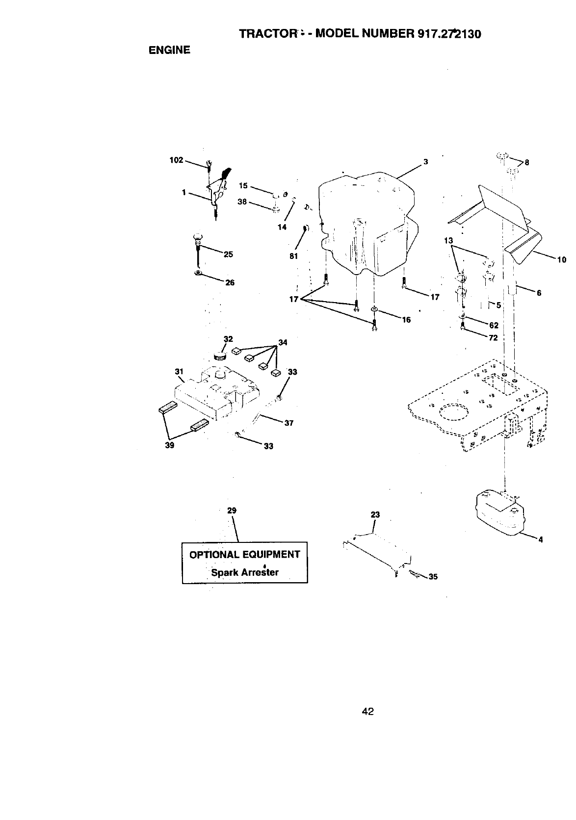
ENGINE
TRACTOR: ; - MODEL NUMBER 917.27'2130
29
OPTIONAL EQUIPMENT
." ii
Spark Arrester
23
/
"_ _'_- 35
4
42
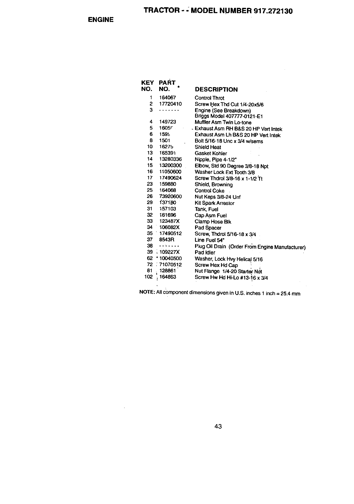
ENGINE
TRACTOR - -MODEL NUMBER 917.272130
KEY PART,
NO. NO.
1164067
217720410
3 .......
4149723
5 1605r
6 1595
81501
10 16,?_75
13 165391
14 132B0336
15 13200300
16 11050600
17 1749(3624
23 159880
25 164068
26 73920600
29 "(371'B0
31 157103
32 161696
33 123487X
34 106082X
35 '17490512
37 8543R
38 o-_. ....
39 _109227X
62 ° 10040500
72 :71070512
81 128861 '
k
102 _164863
DESCRIPTION
Control Throt
Screw _exThd Cut 1/4-20x516
Engine (See Breakdown)
BriggsModel 407777-0121-E1
MufflerAsm Twin Lo-tone
• Exhaust Asm RH B&S 20 HP VealIntek
Exhaust Asm LhB&S 20 HP Vert Intek
Bolt 5/16-18 Uric x 3/4 w/sems
ShieldHeat
Gasket Kohler
Nipple, Pipe 4-1/2"
Elbow,Std 90 Degree 3/8-18 Npt
Washer Lock Ext Tooth3/8
Screw Thdrol3/8-16 x 1-1/2 Tt
Shield, Browning
ContrOlCoke
Nut Keps 3/8-24 Unf
K(tSpark Arrestor
Tank,Fuel
Cap Asm Fuel
Clamp Hose BIk
Pad Spacer
Screw,Thdrol 5/16-18 x 3/4
Line Fuel 54"
Plug Oil Drain (Order From Engine Manufacturer)
Pad Idler
Washer, Lock Hvy Helica!5/16
Screw Hex Hd Cap
Nut Flange 1/4-20 Start_ N_t
Screw Hw Hd Hi-Lo #13-16 x3/4
NOTE: Allcomponentdimensionsgiven in U,S. inches 1 inch = 25.4 mm
43
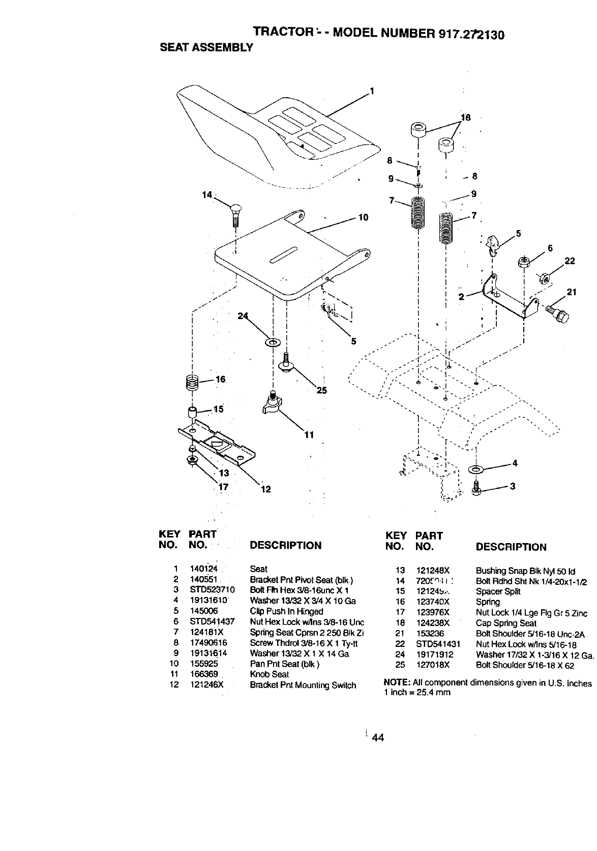
TRACTOR- -MODEL NUMBER 917.272130
SEAT ASSEMBLY
12
11
KEY PART
NO. NO.
1 1401'24
2 140551
3 STD523710
4 19131610
5 145006
6 STD541437
7 124181X
8 17490616
9 1913_614
10 155925
11 166369
12 121246X
KEy PART
DESCRIPTION NO. NO. DESCRIPTION
Seat
BracketPntPivotSeat (blk)
BoltF_ Hex 3/8-16unc X 1
Washer 13/32 X 3/4 X 10 Ga
Clip Push InHinged
Nut Hex Lock w/Ins3/8-16 Uric
SpringSeat Cprsn 2 250 B4kZi
ScrewThdro!3/8-16 X 1 Ty-tt
Washer 13/32 X 1 X 14Ga
Pan Pnt Seat (blk)
Knob Seat
Bracket Pnt Mounting Switch
13 121248X
14 720£_'11;
15 12124_,,.
16 123740X
17 123976X
18 124238X
21 153236
22 STD541431
24 19171912
25 127018X
BushingSnap BIkNy150 Id
BoltRdhd ShtNk 1/4-20x1-1/2
Spacer Spilt
Spdng
Nut Lock 1/4 Lge Fig Gr 5 Zinc
Cap Spring Seat
Bolt Shoulder 5/16-18 Unc-2A
Nut Hex Lock w/ins 5/16-18
Washer 17/32X 1-3/16 X 12 Ga,
BoltShoulder 5/16-18 X 62
NOTE: Allcomponent dimensionsgiven in U.S. inches
1inch = 25.4 mm
'44
DECALS
TRACTOR - -MODEL NU MBER 917.272130
16 4
63 \ 10
KEY PART
NO, NO.
1 164085
2 106202X
3 163916
4 163917
5163208
6 133644
7167330
8 166887
9 163204
10 156439
11 164088
12 146046
KEY PART
DESCRIPTION NO. NO.
Decal, Dash Atom Eng Gr. 13 164065,
Reflector'Tail LightRed/Amber
Decal, Hbod_.R.H 14 160397
Decal, Hood, LH. 15 165399
Decal, Fender Sd White 16 167184
Radi6sp 46" 20 149516
Decal,Customer Maintenance 21 138_47
Decal,'Dash -- 138311
Decal, Deck F..Z3 - - 154515
Decal, Fender, Craftsman - - 1545_16
Decal,iFender Danger -- 168149
Decal,-,Brake Clutch Stph -- 168149
Decal, V-Belt Ddve Schematic
7
12
--2
-1
--2
DESCRIPTION
Decal,Sting WnlDomed
Prem Srs
Decal, V-Belt ,Schematic
Decal, Engine
Decal, Rplc .
Decal Battery Dngr/Psn Eng
Deca_,Battery Diehard Sears
Decal, Uft Handle
Pad FootrestLH STLT
Pad FootrestRH STLT
Owner'sManual,.English
Owner's Manual,Spanish
4,10 .
11
KEY PART
NO. NO. DESCRIPTION
159192 Cap Value 33re
2 65139 Stem Value
3 106222X 13reFront
4 59904 Tube Front'fire (Not Provided,
Service Item Only,'
5106732)(427 P,k'nFront
6 278H 'FittingGrease (Front Wheel
Only)
79o4o1:1 Bearing Flange (Front Wheel
Only)
8106108X427 Rim Rear
9122082X , "13reRear
10 7152J Tube Rear "_re(Not Provided,
SercieItem Only
11 104767X Cap Axle
- - 144334 Sealant, "fire (10 oz. tube)
NOTE: Allcomponentdimensionsgivenin U.S. inches
lm_=25.4mm
45
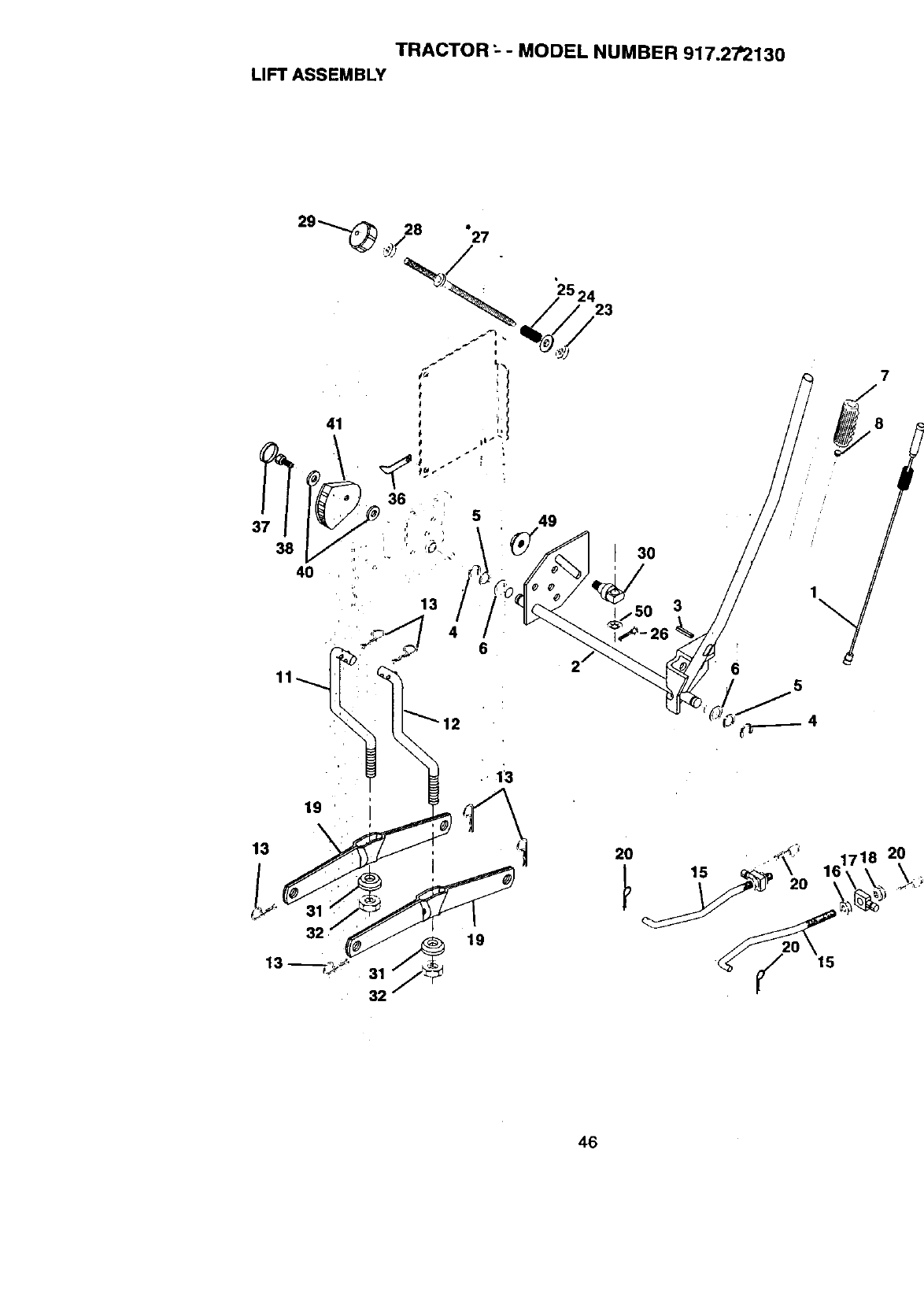
TRACTOR :-- MODEL NUMBER 917.2"/'2130
LIFT ASSEMBLY
,, 13
30
3
13
19
13
19
20
15
46
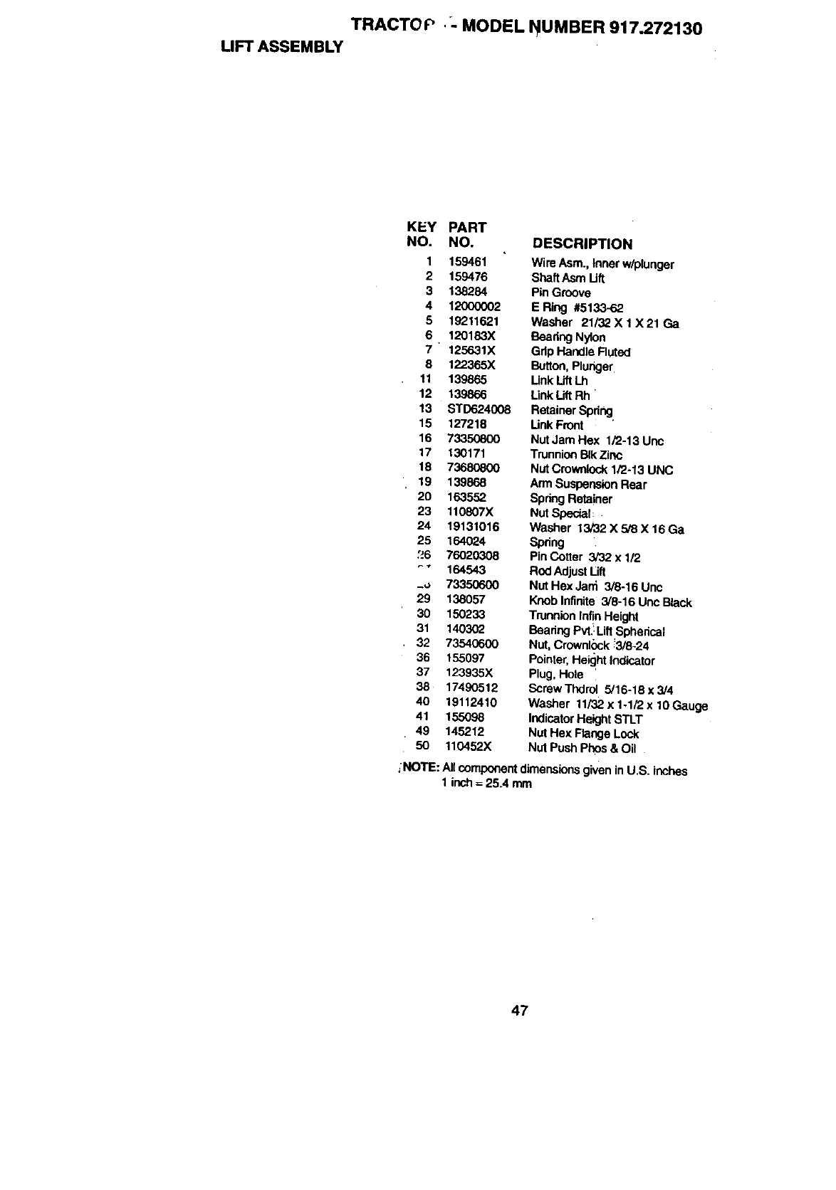
TRACTO P •_. MODEL NUMBER 917.272130
LIFT ASSEMBLY
KEY PART
NO. NO. DESCRIPTION
1 t 59461 Wire Asm., Inner w/plunger
2 159476 ShaftAsm Uft
3 138284 Pin Groove
4 12000002 E Ring #5133-62
5 15211621 Washer 21/32 X 1 X 21 Ga
6 120183X Beadng Nylon
7 125631X Grip Handle Fluted
8 122365X Button Plunger
11 139865 LinkLiftLh
12 139866 Link LiftRh
13 STD624008 RetainerSpdng.
15 127218 Unk Front
16 73350800 Nut Jam Hex 1/2-13 Unc
17 130171 TrunnionBIk Zinc
18 73680800 Nut Crownlock1/2-13 UNC
19 139868 Arm SuspensionRear
20 163552 Spdng Retainer
23 110807X Nut Special:
24 19131016 Washer 13/32 X 5/8 X 16 Ga
25 164524 Spring
:._6 76020308 Pin Cotter 3_32 x 1_
•164543 Rod AdjustLift
_u 73350600 Nut Hex Jani 3/8-16 Unc
29 138057 Knob Infinite 3/8-16 Unc Black
30 150233 TrunnionInfinHeight
31 140302 Beadng Pvt.:LiflSpherical
32 73540600 Nut, Crownlock_3/8-24
36 155097 Pointer,Height Indicator
37 123935X Plug, Hole '
38 17490512 Screw Thdrul 5/16-18 x 3/4
40 19112410 Washer 11/32x 1-1_2x 10Gauge
41 155098 IndicatorHeight STLT
49 145212 Nut Hex Flange Lock
50 110452X Nut Push Phos & Oil
_NOTIE:All componentdimensionsgiven inU.S. inches
1 inch= 25.4 mm
47
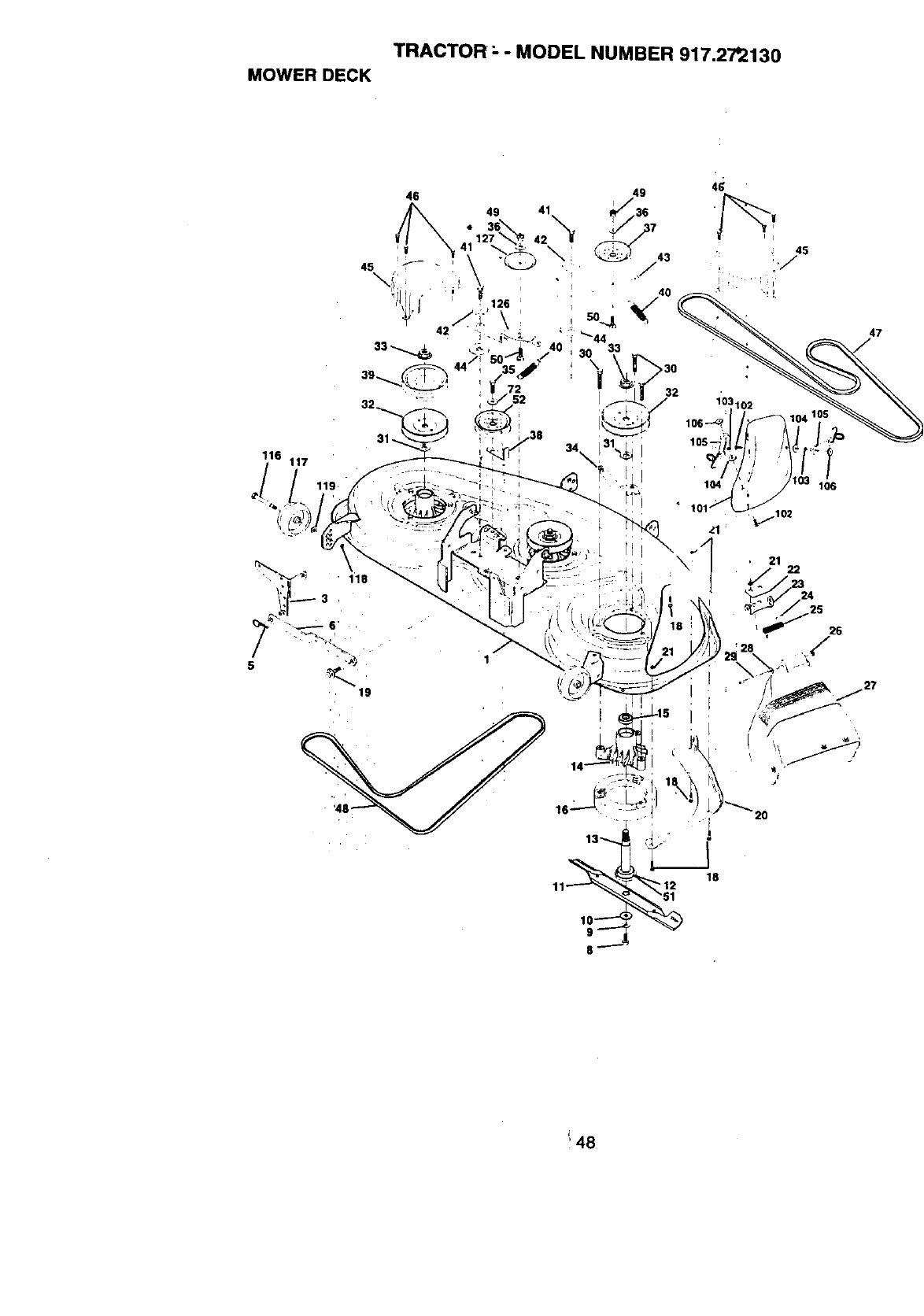
TRACTOR- - MODEL NUMBER 917.27'2130
MOWER DECK
116 117
Jl
46
49 41
8_
21 22
20
47
I
'48
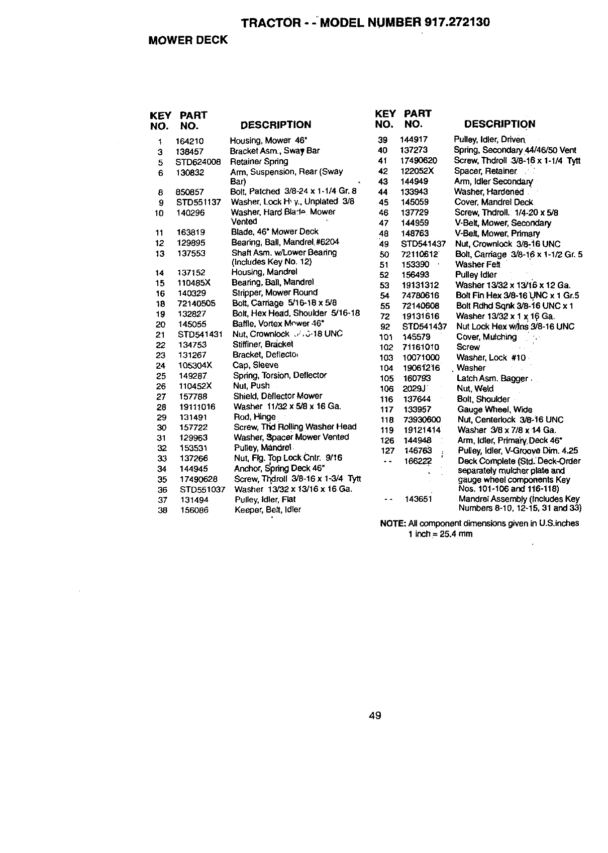
TRACTOR --MODEL NUMBER 917.272130
MOWER DECK
KEY PART
NO. NO.
1 164210
3 138457
5 STD6,?.4008
6130832
8 850857
9 STD551137
10 140296
11 163819
12 129895
13 137553
14 137152
15 110485X
16 14O329
18 72140505
19 132827
20 145055
21 STD541431
22 134753
23 131267
24 105304X
25 149287
26 110452X
27 157788
28 19111016
29 131491
30 157722
31 129963
32 153531
33 137266
34 144945
35 17490628
36 STD551037
37 131494
38 156086
KEY PART
DESCRIPTION NO. NO. DESCRIPTIQN
Housing,Mower 46' 39 144917
BracketAsm., Sway Bar 40 137273
RetainerSpring 41 17490620
Arm, Suspension, Rear (Sway 42 122052X
Bar) ,43 144949
Bolt, Patched 3/8-24 x 1-1/4 Gr. 8 44 133943
Washer, Lock H,y., Unplated 3/8 45 145059
Washer, Hard Bla:'l= Mower 46 137729
Vented 47 144959
Blade,46" Mower Deck 48 148763
Beadng, Ball,Mandrel.#6204 49 STD541437
ShaftAsm. w/Lower Beadng 50 72110612
(IncludesKey No. 12) 51 153390
Housing,Mandrel 52 156493
Bearing,Ball, Mandrel 53 19131312
Stdpper,Mower Round 54 74780616
Bolt,Carriage 5/16-18 x 5/8 55 72140608
Bolt,Hex Head, Shoulder 5/16-18 72 19131616
Baffle,Vortex Mewer 46" 92 STD5414_7
Nut, Crownlock .,,',3-18 UNC 101 145579
Stiffiner,Bracket 102 71161010
Bracket, Deflecto_ 103 10071000
Cap, Sleeve 104 19061216
Spring,Torsion,Deflector 105 160793
Nut, Push 106 2029J
Shield,Deflector Mower 116 137644
Washer 11/32x5/8 x 16 Ga. 117 133957
Rod, Hinge 118 73930600
Screw,Tt_dRol!ingWasher Head 119 19121414
Washer,Spacer Mower Vented 126 144948
Pulley,Mandrel 127 146763
Nut, Fig. Top LockCntr. 9/16 -- 16622_
Anchor, S'pdngDock 46"
Screw,T_roll 3/8-16 x 1-3/4 Tytt
Washer 13/32 x 13/16 x 16Ga.
Pulley,Idler,Flat --143651
Keeper, Belt, Idler
Pulley,Idler,Driven
Spdng,Secondary 44/45/50 Vent
Screw, Thdroll 3/8-16 x 1-1/4 Tytt
Spacer,Retainer '
Ann, IdlerSoc0ndar_
Washer, Hardened
Cover,Mandrel Dec_
Screw, ThdrolL 1/4_20x 5/8
V-Belt, Mower, Secondary
V-Belt, Mower, Pdmery
Nut, Crownlock 3/8-t6 UNC
Bolt, Carriage 3/8-16 x 1-1/2 Gr. 5
Washer Felt
PulleyIdler
Washer 13/32 x 13/1'6x 12 Ga.
Bolt FinHex 3/8-16'1._NCx I Gr.5
Bolt Rdhd Sqnk 3/6.t6 UNC x 1
Washer 13/32 x I x 1_ Ga.
Nut Lock Hex W/Ins3/8-16 UNC
Cover, Mulching ,
Screw
Washer, Lock #10
• Washer
LatchAsm. Bagger.
Nut, Weld
Bolt,Shoulder
Gauge Wheel, Wide
Nut, Centerlock 3/6.t6 UNC
Washer 3/8 x 7/8 x 1AGa.
Arm, Idler,Pdmah/.Deck46"
Pulley, Idler, V-Greoye Dim. 4.25
Deck Complete (Std.iDeck-Order
separately mulehor plate and
gauge wheel componentsKey
Nos. 101-106 and 116-116)
Mandrel Assembly (Includes Key
Numbers 8-10, 12-15,31 and 33)
NOTE: All componentdimensions givenin U.S.inches
1 insh= 25.4 rem
49
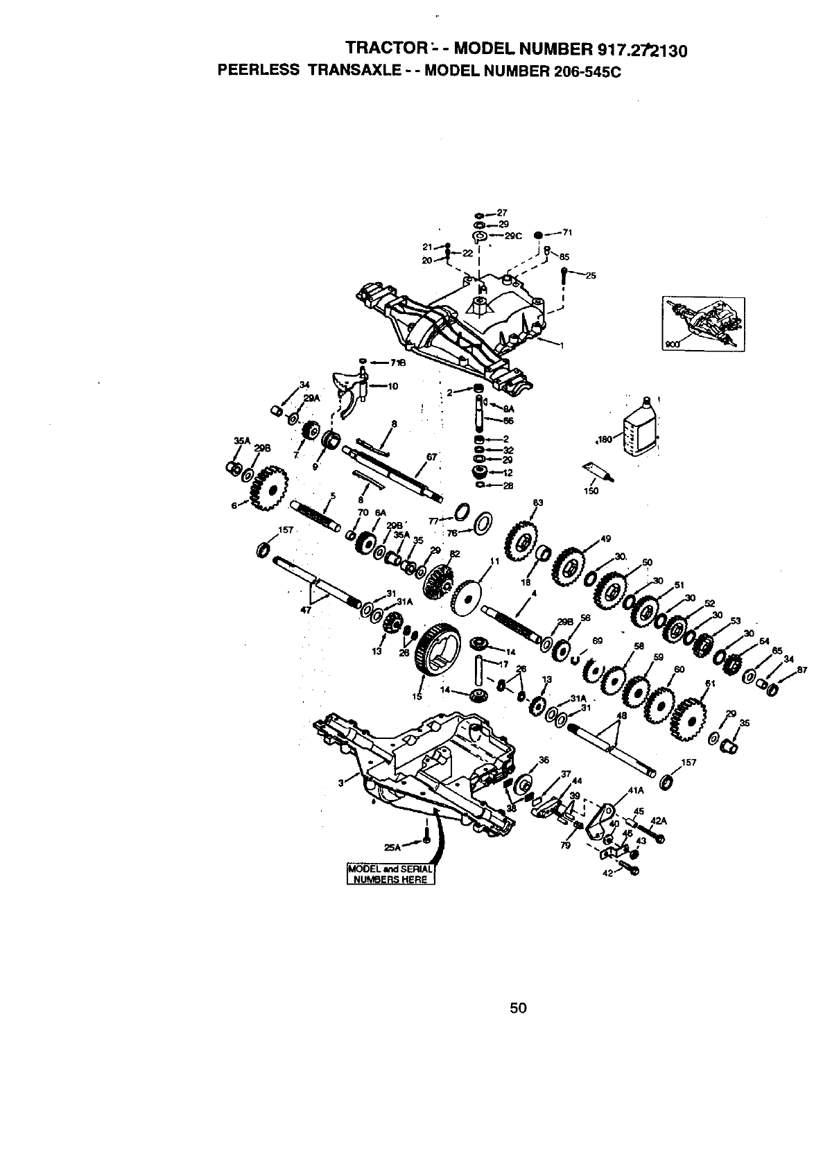
TRACTOR _--MODEL NUMBER 917.272130
PEERLESS TRANSAXLE --MODEL NUMBER 206-545C
157,
47
150
58
29
157
,41A
45
50
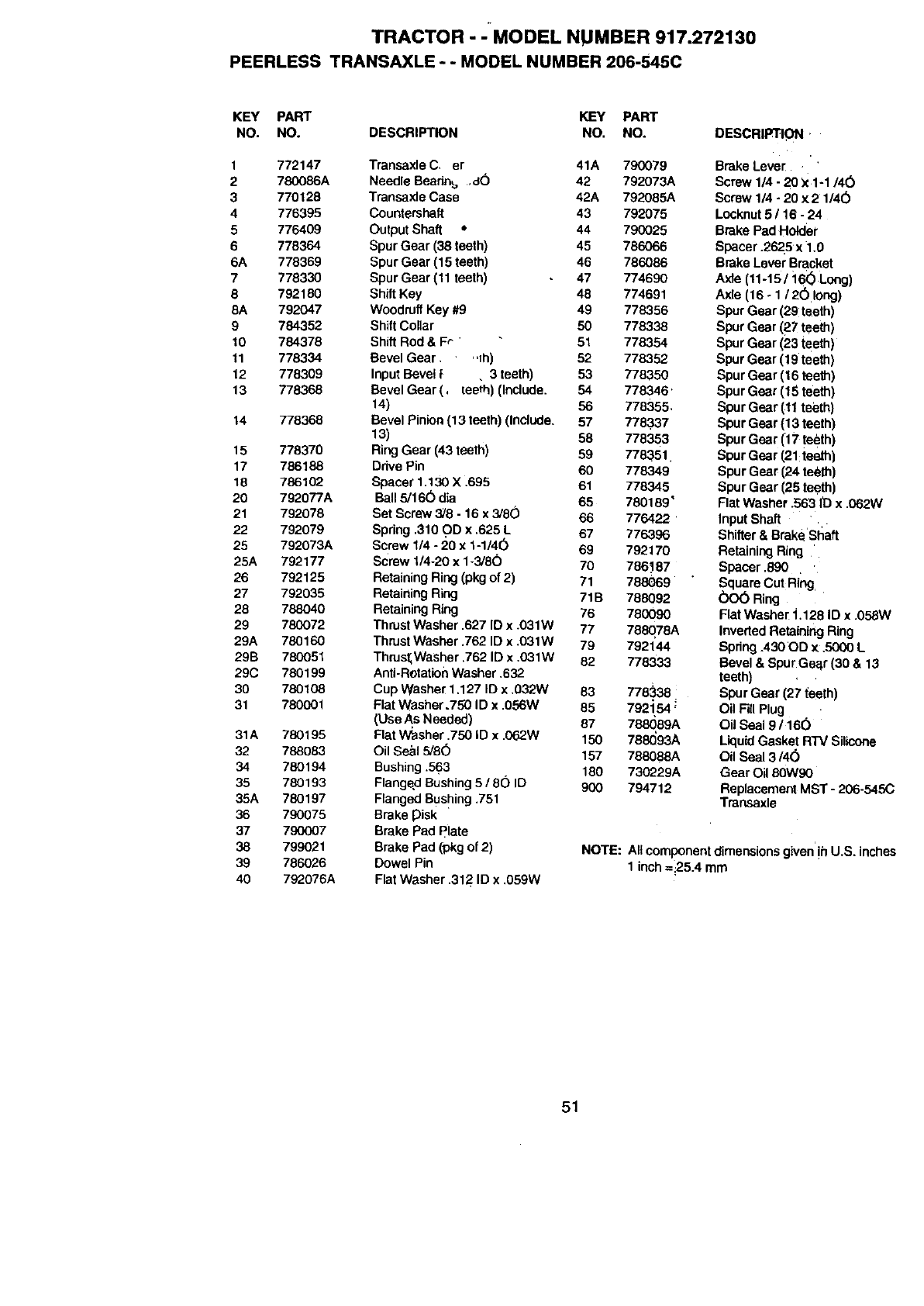
TRACTOR - -MODEL NUMBER 917.272130
PEERLESS TRANSAXLE - - MODEL NUMBER 206-545C
KEY PART KEY PART
NO. NO. DESCRIPTION NO. NO.
1 772147
2 780086A
3 770128
4776395
5776409
6 776364
6A 778369
7 778330
8 792180
8A 782047
9 784352
10 784378
11 778334
12 778309
13 778368
14 778368
15 778370
17 786188
18 786102
20 792077A
21 792078
22 792079
25 792073A
25A 792177
26 792125
27 792035
28 788040
29 780072
29A 780160
29B 780051
29C 780199
30 780108
31 780001
31A 780195
32 788083
34 780194
35 780193
35A 780197
36 790075
37 790007
38 799021
39 786026
40 792076A
Transaxle C, er 41A 790079
Needle Bearth_ ,d() 42 792073A
Transaxle Case 42A 792085A
Countershaft 43 792075
Output Shaft •44 790025
Spur Gear (38 teeth) 45 786066
SpurGear (15 teeth) 46 786086
Spur Gear (11 teeth) 47 774690
ShiftKey 48 774691
WoodruffKey #9 49 778356
ShiftCollar 50 778338
Shift Rod & Fr" " 51 778354
Revel Gear ,,;h) 52 778382
Input Bevel }. 3 teeth) 53 778350
Revel Gear (. [eeth) (Include. 54 778346'
14) 56 778355,
Revel Pinion(13 teeth) (Include. 57 778..337
13) 88 778353
RingGear (43 teeth) 59 778351.
Drive Pin 60 778349
Spacer 1.130 X .695 61 778345
Ball 5/160 dia 65 780189"
Set Screw 3/8 - 16 x 3/60 66 776422
Spdng .310 C)Dx .625 L 67 776396
Screw 1/4 - 20 x 1-1/4(_ 69 792170
Screw 1/4-20 x 1-3/80 70 786'187
Retaining Ring(pkg of 2) 71 788069
Retaining Ring 71B 788092
Retaining Ring 76 780090
ThrustWasher .627 ID x .031W 77 788078A
ThrustWasher .762 ID x .031W 79 792144
ThrustlWaSher.762 ID x .031W 82 778333
Anti-RotationWasher .632
Cup Washer 1.127 ID x .032W 63 778._38
Flat Washer.750 ID x .056W 85 792154 '
(Use As Needed) 87 788089A
Flat Washer .750 ID x .062W 150 788093A
Oil Se_l 5/8(5 157 788088A
Bushing.563 180 730229A
Flanged Bushing5 /80 ID 900 794712
Flanged Bushing.751
Brake pisk
Brake Pad plate
Brake Pad (pkg of 2)
Dowel Pin
Flat Washer .312 ID x .059W
DESCRIPTION,
Brake Lever '
Screw 1/4 - 20 X1-1/4(_
Screw 1/4 - 20 x 2 1/4(_
Locknut5 /16 - 24
Brake Pad Holder
Spacer .2625 x 1.0
Brake Lever Bracket
Axle (11-15/:16_) Long)
Axle (16 oI/2(_ long)
Spur Gear (29 teeth)
Spur Gear (67 teeth)
Spur Gear (23 teeth)
Spur Gear (19 teeth)
Spur Gear (16 teeth)
Spur Gear (15 teeth)
Spur Gear (11teeth)
Spur Gear (13 teeth)
Spur Gear (17 teeth)
Spur Gear (21:teeth)
Spur Gear (24 te_th)
Spur Gear (28 tec:th)
Flat Washer .563 ID x .062W
Input Shaft
Shifter& Brakesl_aft
Retaining Ring
Spacer .890
SquareCut Ring
(_)O_ Ring
Flat Washer i.128 ID x .058W
InvertedRetaining Ring
Spdng.43000 x .5000 L
Bevel & Spur Gec3r(30 & 13
teeth)
Spur Gear (27 _eeth)
Oil FillPlug •
Oil Seal 9 /16(_
LiquidGasket R'W Silicone
Oil Seal 3/4(_
Gear Oil 80W90
ReplacementMST - 206-545C
Tmnsaxle
NOTE: Altcomponentdimensionsgh/en'!hU.S. inches
1 inch =i25.4 mm
51
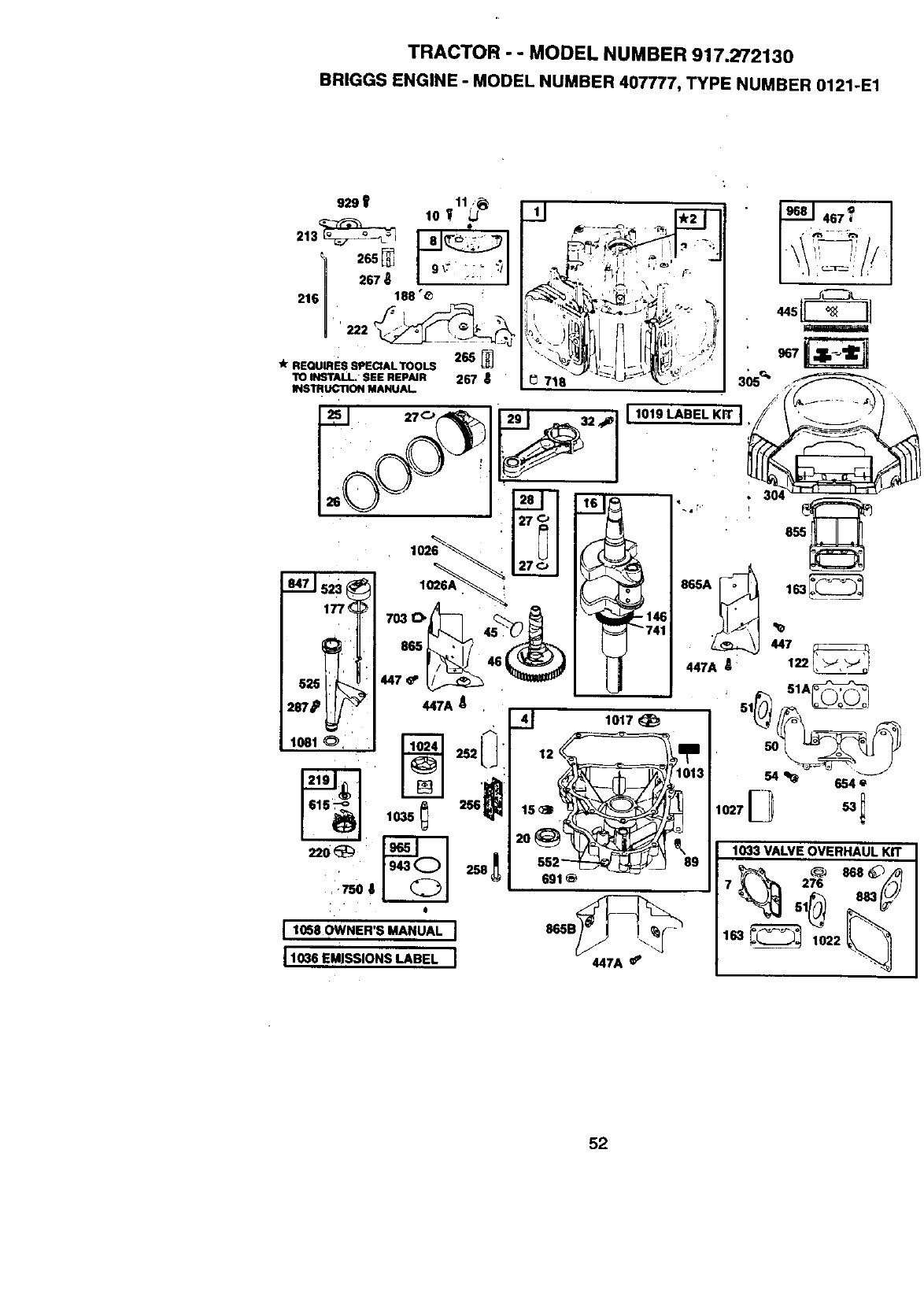
TRACTOR --MODEL NUMBER 917.272130
BRIGGS ENGINE -MODEL NUMBER 407777, TYPE NUMBER 0121-E1
929 _ •
10 11_
213_
267 _ _"
216 188 "_
265
* REQUIRESSPECIALTOOLS
TO INSTALL" SEE REPAIR 267
INSTRUCTIONMANUAL
525 '
287#
1031 O,
447A
75o a
•4
1,038OW.ER'S.AHUALI
11036 EMISSIONS LABEL I
1033 VALVE OVERHAUL KiT
7 276
52
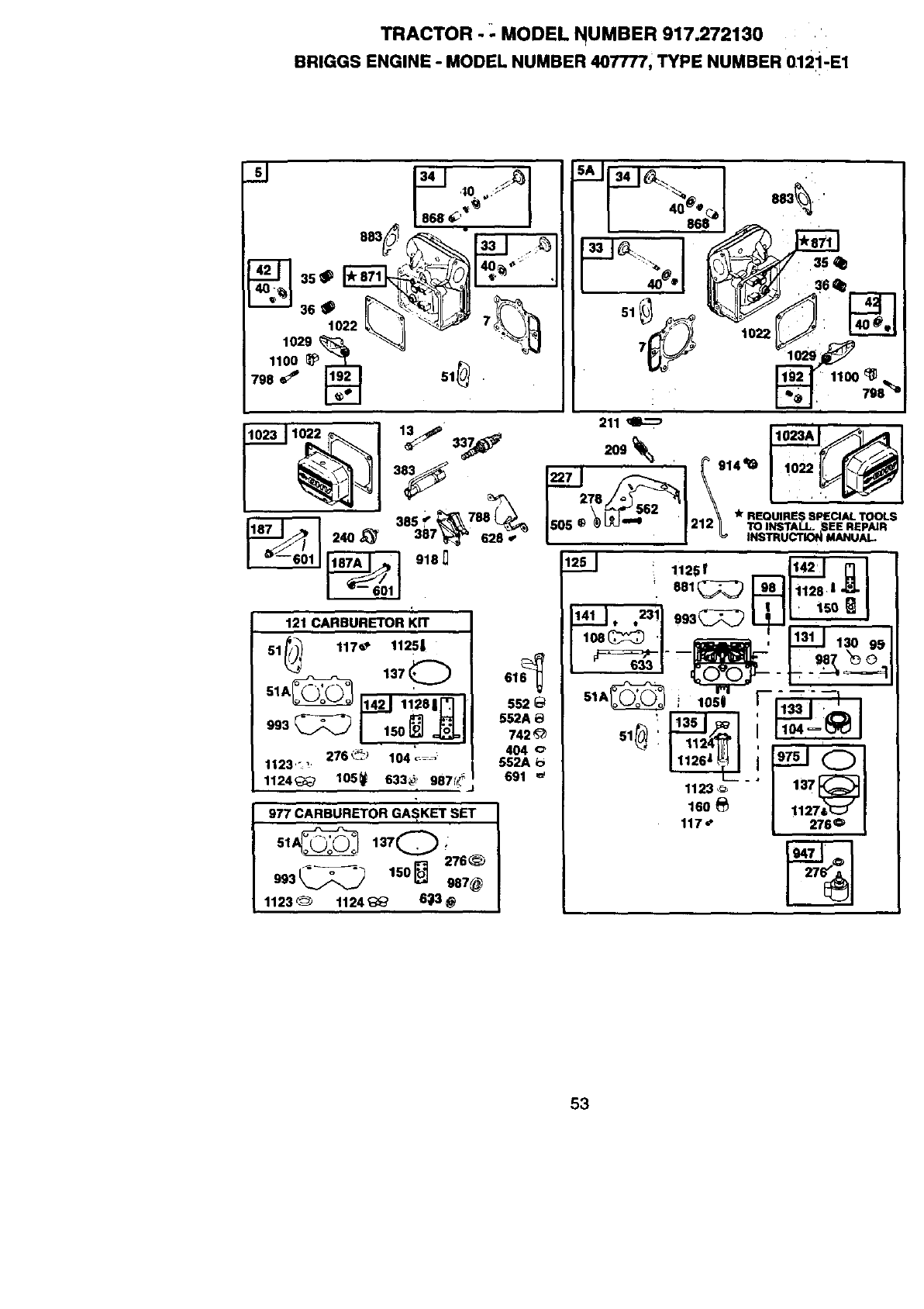
TRACTOR - - MODEL NUMBER 917.272130
BRIGGS ENGINE - MODEL NUMBER 40T777, TYPE NUMBER 012i-E1
s--_I S4I_\_ I
868 _"_ 8
..'zr 3_.__?_ "_ ..
_ "-_ "_ _ _
1029 % "'_ "_--_J
1100 _,...._
1023 1022 13_' 337 211 _1023A
I -++
• 788 'lk REQUIRES SPECIAL TOOLS
303.'_ ,L_ Isos._.... +Sz 1212_ TO,,+rAU+S,E.,,+.,
,.__._124o_ 3.py _=;o r-_______l _ ,.s_u_o,...u.L
__ 918_ 125 ]: 1:8215_ __
121 CARBURETOR KIT 14].__], 23! I993_ I _[ I '_'_ I
108_ ',m 131 130
51/;/_ 117_" 1123, ] _ I 1°8_ 'l.-_i__ 13_ -03
-_-_-_ ,3,ol 01_L____ _mPx',+__t:,:____
SlA_ "+"_'J I °U s+A_ _.T_J,-. --_
.... _ ]142] 11281]'_ II ssm÷ _ i1050 F_
903 "552A @ '
1124_ 105_ 633,_, 9871,_+ ] 691 =' _-• I ...rl "_
:"a 11230 I I01'_+
11_o_ 111271t_1_
'I 117 +, |276 €_
51A_-/_'_')-_ 137_"_ +" I--,--
1123 _1124_ _! _ ]
53
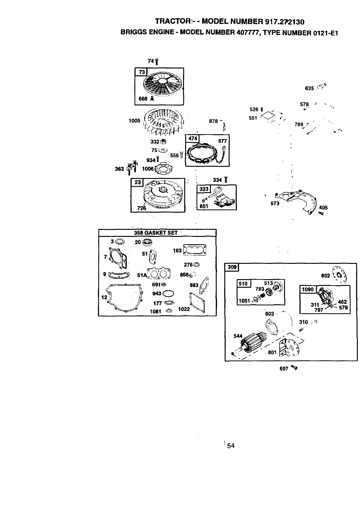
TRACTOR:- - MODEL NUMBER 917.272130
BRIGGS ENGINE - MODEL NUMBER 407777, TYPE NUMBER 0121-E1
74'_
73
__j_a
332® I-_-J- ..I
•334
635 '- "f
578
526 I ff '_, ""
501 _,'._
_'_ 789 _
j:,,
57_405
uv _
r- e
358 GASKET SET
3_ 2o
7_ 51_ 163_276
9_51_ 863_i'_
2_ 691_ 88_
1 943Q
177_
lO8__l°='_JJ
,o.i
513_'_
783 _'_
803 •
.o2 1
311 462
<_ 801
697_
'54
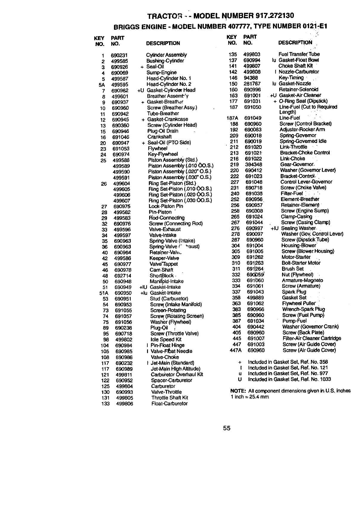
KEY
NO.
TRACTOR -' MODEL NUMBER 917.272130
BRIGGS ENGINE -MODEL NUMBER 407777, TYPE NUMBER 012i-E1
PART KEY
NO. DESCRIPTION NO.
1 690231 CylinderAssembly 135 499803
2 499585 Bushing-Cylinder 137 690994
3 690926 + Seal-Oil 141 499807
4 690069 Sump-Engine 142 499808
5 499587 Head-CylinderNo. I 146 94388
5A 499595 Head-CylinderNO.2 150 281767
7 690962 +U Gasket-CylinderHead 160 690996
8 499601 BreetherAssem_"y 163 691001
9 690937 + Gasket-Breather 177 691031
10 690960 Screw (BreathorAssy.) 187 691050
11 690942 Tube-Breather
12 690945 + Gasket-Crankcase 187A 691049
13 690360 Screw (Cylinder Head) 188 690960
15 690946 Plug-Oil Drain 192 690083
16 691046 Crankshaft 209 690018
20 690947 + Seal-Oil (PTO Side) 211 690019
23 691053 Flywheel 212 691020
24 690974 Key-Flywheet 213 691021
25 499588 PistonAssembly(Std.) 2t6 69_022
499589 PistonAssembly (.010 00.S.) 219 394348
499590 PistonAssembly (.020"O.S,) 220 690412
499591 PistonAsserr_ (.030"O.S.) 222 691023
26 499604 RingSet-Piston(Std,) 227 691048
499605 RingSet-Piston (.010 (_O.S.) 231 690718
499606 RingSet-Piston(.020 00.S.) 240 691035
499607 RingSet-Piston (.030 00.S.) 252 690956
27 690975 Lock-PistonPin 256 690957
28 499582 Pin-Piston "258 690308
29 499583 Rod-Connecting 265 691024
32 690976 Screw (ConnectingRod) 267 69t044
33 499596 Valve-Exhauet 276 69(_97
34 499597 Valve-Intake 278 690097
35 690963 Spring-Valve(Intake) 287 690960
36 690963 Spring-Valve(_ '_aust) 304 691004
40 690964 Retaiber-Valv,_ 305 691005
42 499586 Keeper-Valye 309 691262
45 690977 Valve'Tappet 310 691263
46 690978 CamShaft 311 691"264
48 692714 ShortBIock 332 69_59_
50 690948 Mani_pld-lntake 333 691060
51 690949 +IU Gasket-Intake 334 691061
51A 690950 +lu Gasket-Intake 337 691043
53 690951 Stud(Carburetor) 358 499889
54 690953 Screw ( etake Manifold) 363 691062
73 691055 Screon-Rotating 383 690966
74 691057 Screw (RotatingScreen) 385 690960
75 691056 Washer(Flywheel) 387 691034
89 690238 Plug'Oil _ 404 690442
95 690718 Screw (ThrottleValve) 405 690960
98 499802 Idle Speed Kit 445 691007
104 690984 I Pin-FloatHinge 447 691003
105 690985 I Valve-FltmtNeedle 447A 690960
108 690986 Valve-ChoiCe
117 690232 I Jet-Main (Standard)
117 690989 Jet4vtainHighAltitude)
121 499811 Carbu'retorOverhaulKit
122 690952 Spacer-Carburetor
125 499804 Carburetor
130 690993 Valve:rnrettle
131 499805 ThrottieShaft Kit
133 499806 Float-Carburetor
PART
NO. DESCRIPTION ,'
Fuel Transfel'Tube
lu Gasket-Flaat
Choke Shaft Kit "
I Nozzle-Carburetor
Key-Timing .
lu Gasket*Nozzle
Retainer.Solenoid
+U Gasket-AirCleaner
+ O-Ring Seal (Dipstick)
Line-Fuel(Cut to Required
Length) '
Line-Fuel
Screw (ControlBracket)
Adjuster-RonkerArm
Spring-Governor
Spdng-GovemedIdle
Link-Throttle
Bracket-ChokeControl
Link-Choke
Gear-Governor
Washer (GovernorLever)
Bracket-Contr01,
ControlLever-Go_,emor
Screw (ChokeValve)
Filter-Fuel ,
Element-Breather
Retainer-Elemen,t,
Screw (EngineSump)
Clamp-Casing
Screw (CasingClamp)
+IU Sealing Washer,
Washer(Gov. ControlLever)
Screw (Dipstick Tube)
Housing-Blower
Screw (BlowerHousing)
Motor-Stealer
Bolt-StarterMotol"
BrushSet
Nut (Rywbeet) .
Armature-Magneto
Screw (Armature)
Spark Plug
Gasket Set
FlywbeetPul!er
Wrench.SparkPlug
Screw (Fue! Pump)
Pump-Fuel
Washer(GovernorCrank)
Screw (Back Plate)
Filter*AirCleaner Cartridge
Screw (Air Guide Cover)
Screw (Air Guide Cover)
+ IncludedinGasket Set, Ref. No. 358
I Includedin Gasket Set, Ref. No. 121
u Includedin Gasket Set, Ref. No. 977
U Includedin Gasket Set, Ref. No. 1033
NOTE: All componentdimensionsgivenin U,S. inches
1 inch= 25,4 mm
55
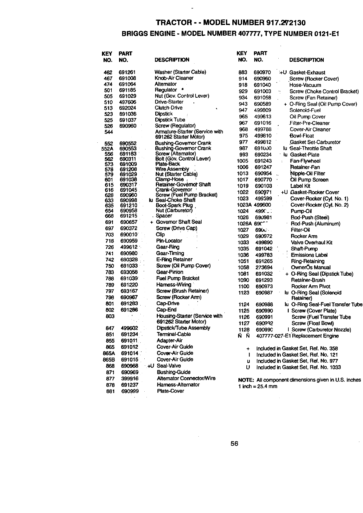
TRACTOR - - MODEL NUMBER 917.2q'2130
BRIGGS ENGINE - MODEL NUMBER 407777, TYPE NUMBER 0121-E1
KEY
NO. PART KEY PART
NO. DESCRIPTION NO. NO. DESCRIPTION
462 691261
467 691008
474 691064
501 691185
505 691029
510 497606
513 692(_4
523 691036
525 691037
526 690960
544
552
552A
556
562
873
578
579
601
615
616
628
6.33
635
654
668
691
697
703
718
726
741
742
750
783
788
788
797
798
801
802
8O3
847
851
855
865
866A
865B
868
871
877
878
881
690552
69O553
691183
690311
6910O9
691208
691029
691038
690317
691045
690960
690998
691210
69O958
691215
690657
690372
69O010'
690959
499612 '
_)980
690328
691O33
693058
691039
691220
693167
890967
691283
691286
499602¸
_1234
_1Qll
_1012
691014
691015
690968
690969
399916
881237
690999
Washer (Stader Cable) 883 690970
Knob-AirCleaner 914 690960
Aitemator 918 691040
Regulator * 929 691003
Nut (Gov. ControlLever) 934 691058
Drive-Starter 943 690589
Clutch-Drive 947 499809
Dipstick
DipstickTube 965 499613
Screw (Regulator) 967 691016
Armatura-Stader(Service with 968 499788
691262 Starter Motor) 975 499810
Bushing-GovernorCrank 977 499812
Bushing-GovernorCrank 987 691U,.)0
Screw (Aitemator) 993 6900234
Bolt(Gov. Contro_Lever) 1905 691243
Plate-Bock
WireAssernbly , 1006 691247
Nut (Starter Cablq) 1013 690954
Clamp-Hose , , 1017 696770
Retainer-Govemo]-Shaft 1019 690103
Crank-Governor :
Screw (Fuel pump Bracket) 1022 696_71
lu Seal-Choke Shaft 1023 499599
Boot.Spark Plug, 1023A 499600
Nut (Carburetor) 1024 499(.
Spacer 1026 690981
+ GovernorShaftSeal 1026A 69("_-
Screw (Drive Cap) 1027 690_;'.
Clip 1029 690972
Pin-Locater 1033 499890
Gear-Ring 1035 691042
Gear-Timing 1036 499783
E-RingRetainer 1051 691265
Screw (Oil Pump Cover) 1058 273694
Gear-Pinion 1081 691032
Fuel Pump Bracket 1096 691293
Hamess.Widng 1100 690973
Screw (BrushRetainer) 1123 690987
Screw (RockerArm)
Cap-Ddve 1124 690988
Cap-End 1125 690996
Housing-Starter(Service with 1126 690991
691262 StarterMotor) 1127 6969q2
Dips_ck/'rubeAssembly 1128 69099C
Terminal*Cable I_1 I_1
Adapter-Air
Cover-AirGuide
Cover-Air Guide
Cover-AirGuide
Seal-Valve
Bushing-Guide
•alternatorConnector/Wire
Hamess-Altemator
Plate-Cover
_-U Gasket-Exhaust
Screw (RockerCover)
Hose-Vacuum
: Screw (ChokeControlBracket)
Screw (Fan Retainer)
+ O-Ring Seal (Oil PumpCover)
Solenoid-Fuel
Oil Pump Cover
.Fiiter-Pre-Cleaner
Cover-AirCleaner
Bowl-Float
,GasketSet-Carburetor
lu "Seal-ThrottleShaft
lu Gasket-Plate
Fan-Flywheel
Retainer-Fan
_lippla-Oil Filter
bil Pump Screen
Label Kit
+U Gasket-Rocker Cover
Cover-Rocker(Cyl. No. 1)
Cover-Rocker(Cyl. No. 2)
Pump-Oil
Rod-Push(Steel)
Rod-Push(Aluminum)
Filter-Oil
RoskerArm
Valve Overhaul Kit
Shaft-Pump
EmissionsLabel
Ring-Retaining
Owfler_)sManual
+ O-Ring Seal (DipstickTube)
Retainer-Brush
RockerArm Pivot
lu O-Ring Seal (Solenoid
Retainer)
lu O-Ring Seal-Fuel TransferTube
IScrew (cover Plate)
Screw (FuelTransferTube
Screw (FloatBowl)
IScrew (CarburetorNozzle)
407777-O27-E1Replacement Engine
+ IncludedinGasket Set, Ref. No. 358
I Includedin Gasket Set, Ref. No. 121
u Includedin Gasket Set, Ref. No. 977
U Includedin Gasket Set, Raf. No. 1033
NOTE: Allcomponentdimensionsgiven inU.S, inches
1 inch= 25.4 mm
56

57

I!58

SUGGESTED GUIDE FOR SIGHTING SLOPES FOR SAFE OPERATION
ONLY RIDE UP AND DOWN HILL,
NOT ACROSS HILL
Operatb your Tractor up a-ridd0wntlle face Ofsldl_es (not I
greater than 15°), never across the face. Make turns gradu-
ally to prevent tipping or loss of control. Exercise extreme |
caution when changing dlrecUon on slopes. I
I

For in-home major brand repair service:
Call 24 hours aday, 7 days a week
1-800-4-MY-H 0 MEsM(1-800-469-4663)
Para pedir serviciode reparaci6n a domicilio
1-800-676-5811
In Canada for all your.service and r ts needs call
Au Canada'pour tout le service _'J les pieces
1-800-665-4455
For the repair or replacement parts ybu need:
Call 6 am-11 pm CST, 7 days a we.ek
PartsDirect s_ q
1-800-366-PART (1-800-_ 2R-7278)
Para ordenar piezas con entrega a domicilio
•1-800-659-7084
For the location of a Sears Parts and Repair Center
, in your area:
Call 24 Hours a day, 7 days aweek
11-800-488-1222
Forinformation on purchasing a SearS Maintenance
Agreement or to inquire about an existing Agreement:
Call 9 am-5 pm, Monday -Saturday
1-800-827-6655
HomeCentralsM
168148 Rev, 1 3.30.99 JH Printed in U.S.A.
