Craftsman 917272140 User Manual LAWN TRACTOR Manuals And Guides 99030709
CRAFTSMAN Lawn, Tractor Manual 99030709 CRAFTSMAN Lawn, Tractor Owner's Manual, CRAFTSMAN Lawn, Tractor installation guides
User Manual: Craftsman 917272140 917272140 CRAFTSMAN LAWN TRACTOR - Manuals and Guides View the owners manual for your CRAFTSMAN LAWN TRACTOR #917272140. Home:Lawn & Garden Parts:Craftsman Parts:Craftsman LAWN TRACTOR Manual
Open the PDF directly: View PDF ![]() .
.
Page Count: 60
Owner's Manual
rRAFTSMAN+
20.0 HP
ELECTRIC START
46" MOWER
AUTOMATIC
LAWN TRACTOR
Model No.
917.272140
•Safety
•Assembly
•Operation
•Maintenance
•Repair Parts
CAUTION:
Read and follow all
Safety Rules and Instructions
before operating this equip-
ment.
For answers to your questions
about this product, Call:
1-800-659-5917
Sears Craftsman Help Line
5 am -5 pm, Mon- Sat
Sears, Roebuck and Co., Hoffman Estates, IL 60179
Visit our Craftsman website: www.sears.com/craftsman
Warranty ................................................. 2
Safety Rules ........................................... 2
Product Specifications ........................... 5
Assembly ................................................ 8
Operation .............................................. 12
Maintenance Schedule ......................... 19
Maintenance ......................................... 19
Service and Adjustments ...................... 23
Storage ................................................. 29
Troubleshooting .................................... 30
Repair Parts ......................................... 34
Parts Ordering ....................... Back Cover
LIMITED TWO YEAR WARRANTY ON CRAFTSMAN RIDING EQUIPMENT
For two -(2) years from the date of purchase, if this Craftsman Riding Equipment is main-
tained, lubricated and tuned up according to the instructions in the owner's manual,
Sears will repair or replace, free of charge, any parts found to be defective in material or
workmanship.
This Warranty does not cover:
• Expendable items which become worn during normal use, such as blades, spark
plugs, air cleaners, belts, etc.
• Tire replacement or repair caused by punctures from outside objects, such as nails,
thorns, stumps, or glass.
•Repairs necessary because of operator abuse, negligence, improper storage or acci-
dent or the failure to maintain the equipment according to the instructions contained in
the owner's manual.
• Riding equipment used for commercial or rental purposes.
LIMITED 90 DAY WARRANTY ON BATTERY
For ninety (90) days from date of purchase, if any battery included with this riding equip-
ment proves defective in material or workmanship and our testing determines the bat-
tery will not hold a charge, Sears will replace the battery at no charge. In-home warranty
service on your Craftsman riding equipment is available at no charge for 30 days from
the date of purchase. Please contact your nearest service center. After 30 days from the
date of purchase, warranty service is available by taking your Craftsman riding equip-
ment to your nearest Sears Service Center. (In-home warranty service will still be avail-
able after 30 days from the date of purchase but a standard trip charge will apply). This
warranty applies only while this product is in the United States. This Warranty gives you
specific legal rights, and you may also have other rights which may vary from state to
state.
Sears, Roebuck and Co., D/817 WA, Hoffman Estates, IL 60179
GENERAL OPERATION
•Read, understand, and follow all instruc-
tions in the manual and on the machine
before starting.
•Only allow responsible adults, who are
familiar with the instructions, to operate
the machine.
•Clear the area of objects such as rocks,
toys, wire, etc., which could be picked
up and thrown by the blade.
•Be sure the area is clear of other people
before mowing. Stop machine if anyone
enters the area.
2
•Never carry passengers.
• Do not mow in reverse unless absolute-
ly necessary. Always look down and
behind before and while backing.
•Be aware of the mower discharge direc-
tion and do not point it at anyone. Do
not operate the mower without either
the entire grass catcher or the guard in
place.
•Slow down before turning.
•Never leave a running machine unat-
tended. Always turn off blades, set park-
ing brake, stop engine, and remove
keys before dismounting.
•Turn off blades when not mowing.
•Stop engine before removing grass
catcher or unclogging chute.
•Mow only in daylight or good artificial
light.
•Do not operate the machine while under
the influence of alcohol or drugs.
•Watch for traffic when operating near or
crossing roadways.
•Use extra care when loading or unload-
ing the machine into a trailer or truck.
SLOPE OPERATION
Slopes are a major factor related to loss-
of-control and tipover accidents, which
can result in severe injury or death. All
slopes require extra caution, if you cannot
back up the slope or if you feel uneasy on
it, do not mow it.
DO:
•Mow up and down slopes, not across.
•Remove obstacles such as rocks, tree
limbs, etc.
•Watch for holes, ruts, or bumps. Uneven
terrain could overturn the machine. Tall
grass can hide obstacles.
•Use slow speed. Choose a low gear so
that you will not have to stop or shift
while on the slope.
•Follow the manufacturer's recommen-
dations for wheel weights or counter-
weights to improve stability.
•Use extra care with grass catchers or
other attachments. These can change
the stability of the machine.
• Keep all movement on the slopes slow
and gradual. Do not make sudden
changes in speed or direction.
•Avoid starting or stopping on a slope. If
tires lose traction, disengage the blades
and proceed slowly straight down the
slope.
DO NOT:
•Do notturn on slopes unless necessary,
and then, turn slowly and gradually
downhill, if possible.
•Do not mow near drop-offs, ditches, or
embankments. The mower could sud-
denly turn over if awheel is over the
edge of a cliff or ditch, or if an edge
caves in.
•Do not mow on wet grass. Reduced
traction could cause sliding.
•Donottrytostabilizethemachineby
putting your foot on the ground.
•Do not use grass catcher on steep
slopes.
CHILDREN
Tragic accidents can occur if the operator
is not alert to the presence of children.
Children are often attracted to the
machine and the mowing activity. Never
assume that children will remain where
you last saw them.
•Keep children out of the mowing area
and under the watchful care of another
responsible adult.
•Be alert and tum machine off if children
enter the area.
•Before and when backing, look behind
and down for small children.
•Never carry children. They may fall off
and be seriously injured or interfere with
safe machine operation.
•Never allow children to operate the
machine.
•Use extra care when approaching blind
corners, shrubs, trees, or other objects
that may obscure vision.
SERVICE
•Use extra care in handling gasoline and
other fuels. They are flammable and
vapors are explosive.
Use only an approved container.
Never remove gas cap or add fuel
with the engine running. Allow en-
gine to cool before refueling. Do not
smoke.
Never refuel the machine indoors.
Never store the machine or fuel
container inside where there is an
open flame, such as a water heater.
•Never run a machine inside a closed
area.
•Keep nuts and bolts, especially blade
attachment belts, tight and keep equip-
ment in good condition.
•Never tamper with safety devices.
Check their proper operation regulady.
•Keep machine free of grass, leaves, or
other debds build-up. Clean oil or fuel
spillage. Allow machine to cool before
storing.
•Stop and inspect the equipment if you
strike an object. Repair, if necessary,
before restarting.
3
• Nevermakeadjustmentsor repairswith
theenginerunning.
•Grass catcher components are subject
to wear, damage, and deterioration,
which could expose moving parts or
allow objects to be thrown. Frequently
check components and replace with
manufacturer's recommended parts,
when necessary.
•Mower blades are sharp and can cut.
Wrap the blade(s) or wear gloves, and
use extra caution when servicing them.
•Check brake operation frequently.
Adjust and service as required.
•Be sure the area is clear of other people
before mowing. Stop machine if anyone
enters the area.
•Never carry passengers.
•Do not mow in reverse unless absolute-
ly necessary. Always look down and
behind before and while backing.
•Never carry children. They may fall off
and be seriously injured or interfere with
safe machine operation.
•Keep children out of the mowing area
and under the watchful care of another
responsible adult.
•Be alert and turn machine off if children
enter the area.
•Before and when backing, look behind
and down for small children.
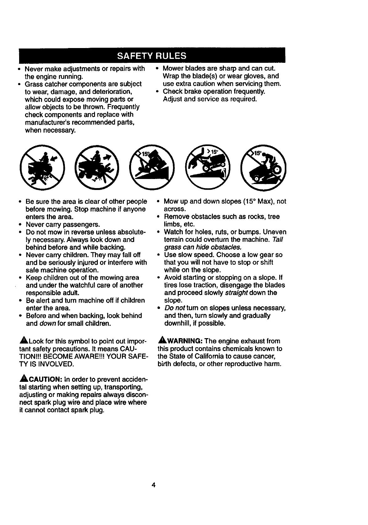
•Mow up and down slopes (15 ° Max), not
across.
•Remove obstacles such as rocks, tree
limbs, etc.
•Watch for holes, ruts, or bumps. Uneven
terrain could overturn the machine. Tall
grass can hide obstacles.
•Use slow speed. Choose a low gear so
that you will not have to stop or shift
while on the slope.
•Avoid starting or stopping on a slope. If
tires lose traction, disengage the blades
and proceed slowly straight down the
slope.
•Do nottum on slopes unless necessary,
and then, turn slowly and gradually
downhill, if possible.
_,Look for this symbol to point out impor-
tant safety precautions. It means CAU-
TION!H BECOME AWARE!!! YOUR SAFE-
TY IS INVOLVED.
_,CAUTION: In order to prevent acciden-
tal starting when setting up, transporting,
adjusting or making repairs always discon-
nect spark plug wire and place wire where
it cannot contact spark plug.
AWARNING: The engine exhaust from
this product contains chemicals known to
the State of California to cause cancer,
birth defects, or other reproductive harm.
4
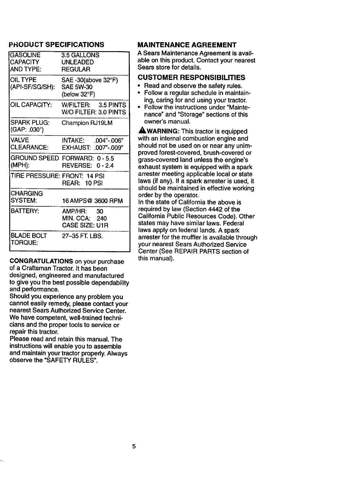
PRODUCT SPECIFICATIONS
GASOLINE 3.5GALLONS
CAPACITY UNLEADED
AND TYPE: REGULAR
:)IL TYPE SAE -30(above 32°F)
API-SF/SG/SH): SAE 5W-30
(below 32°F)
OIL CAPACITY: W/FILTER: 3.5 PINTS
W/O FILTER: 3.0 PINTS
SPARK PLUG: Champion RJ19LM
'GAP: .030")
VALVE INTAKE: .004"-.006"
CLEARANCE: EXHAUST: .00T'-.009"
GROUND SPEED FORWARD: 0 - 5.5
(MPH): REVERSE: 0- 2.4
TIRE PRESSURE: FRONT: 14 PSI
REAR: 10 PSI
CHARGING
SYSTEM: 16AMPS@ 3600 RPM
BATI'ERY: AMP/I-IR: 30
MIN. CCA: 240
CASE SIZE: U1R
BLADE BOLT 27-35 FT. LBS.
,TORQUE:
CONGRATULATIONS on your purchase
of a Craftsman Tractor. It has been
designed, engineered and manufactured
to give you the best possible dependability
and performance.
Should you experience any problem you
cannot easily remedy, please contact your
nearest Sears Authorized Service Center.
We have competent, well-trained techni-
cians and the proper tools to service or
repair this tractor.
Please read and retain this manual. The
instructions will enable you to assemble
and maintain your tractor properly. Always
observe the "SAFETY RULES".
MAINTENANCE AGREEMENT
A Sears Maintenance Agreement is avail-
able on this product. Contact your nearest
Sears store for details.
CUSTOMER RESPONSIBILITIES
• Read and observe the safety rules.
•Follow a regular schedule in maintain-
ing, caring for and using your tractor.
•Follow the instructions under "Mainte-
nance" and "Storage" sections of this
owner's manual.
_,WARNING: This tractor is equipped
with an internal combustion engine and
should not be used on or near any unim-
proved forest-covered, brush-covered or
grass-covered land unless the engine's
exhaust system is equipped with a spark
arrester meeting applicable local or state
laws (if any). If a spark arrester is used, it
should be maintained in effective working
order by the operator.
In the state of California the above is
required by law (Section 4442 of the
California Public Resources Code). Other
states may have similar laws. Federal
laws apply on federal lands. A spark
arrester for the muffler is available through
your nearest Sears Authorized Service
Center (See REPAIR PARTS section of
this manual).
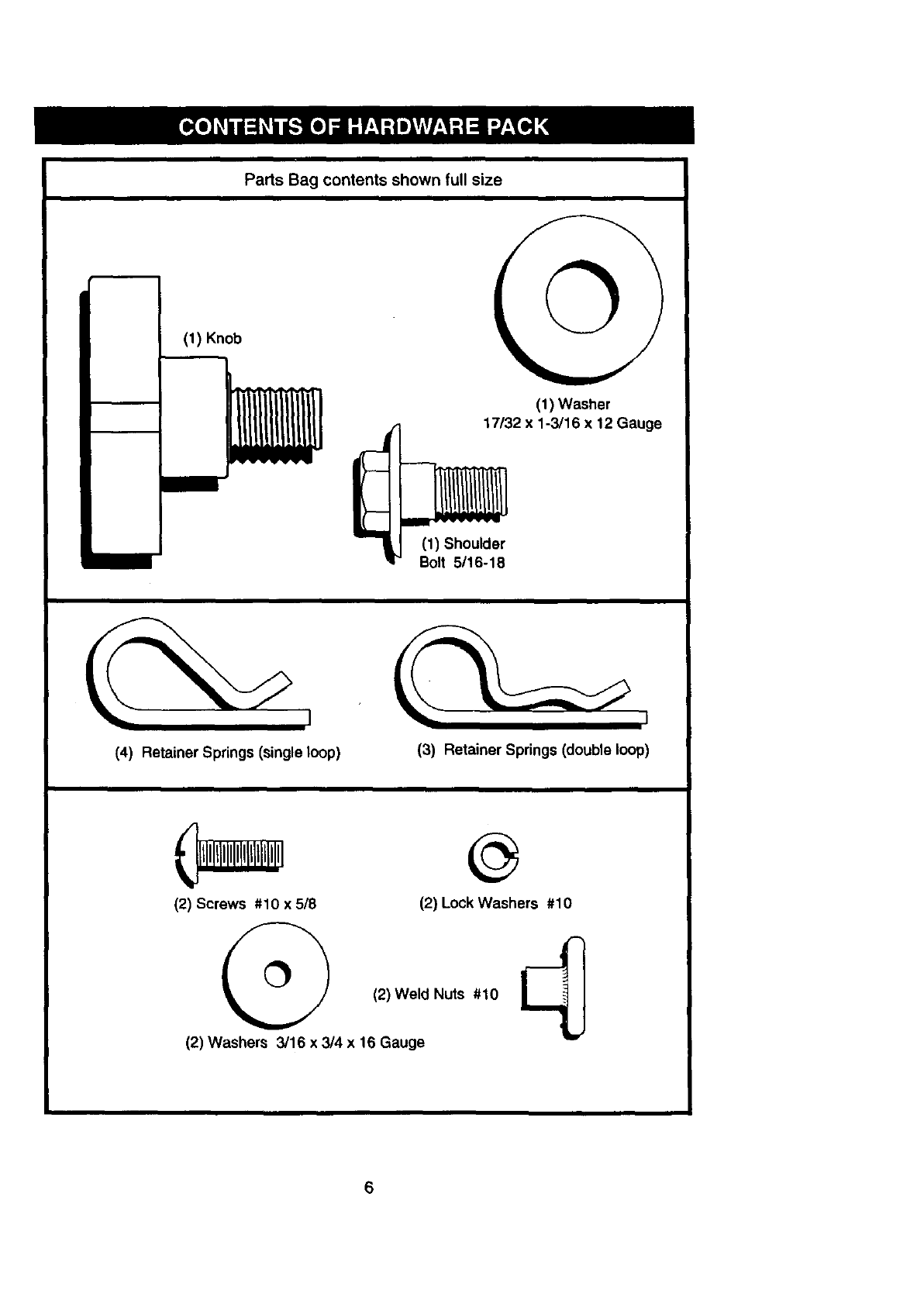
Parts Bag contents shown full size
(1) Knob
(1) Shoulder
Bolt 5/16-18
©
(1) Washer
17/32 x 1-3/16 x 12 Gauge
(4) Retainer Springs (single loop) (3) Retainer Springs (double loop)
(2) Screws #10 x 5/8 (2) Lock Washers #10
(2) Weld Nuts #10
(2) Washers 3/16 x 3/4 x 16 Gauge
6
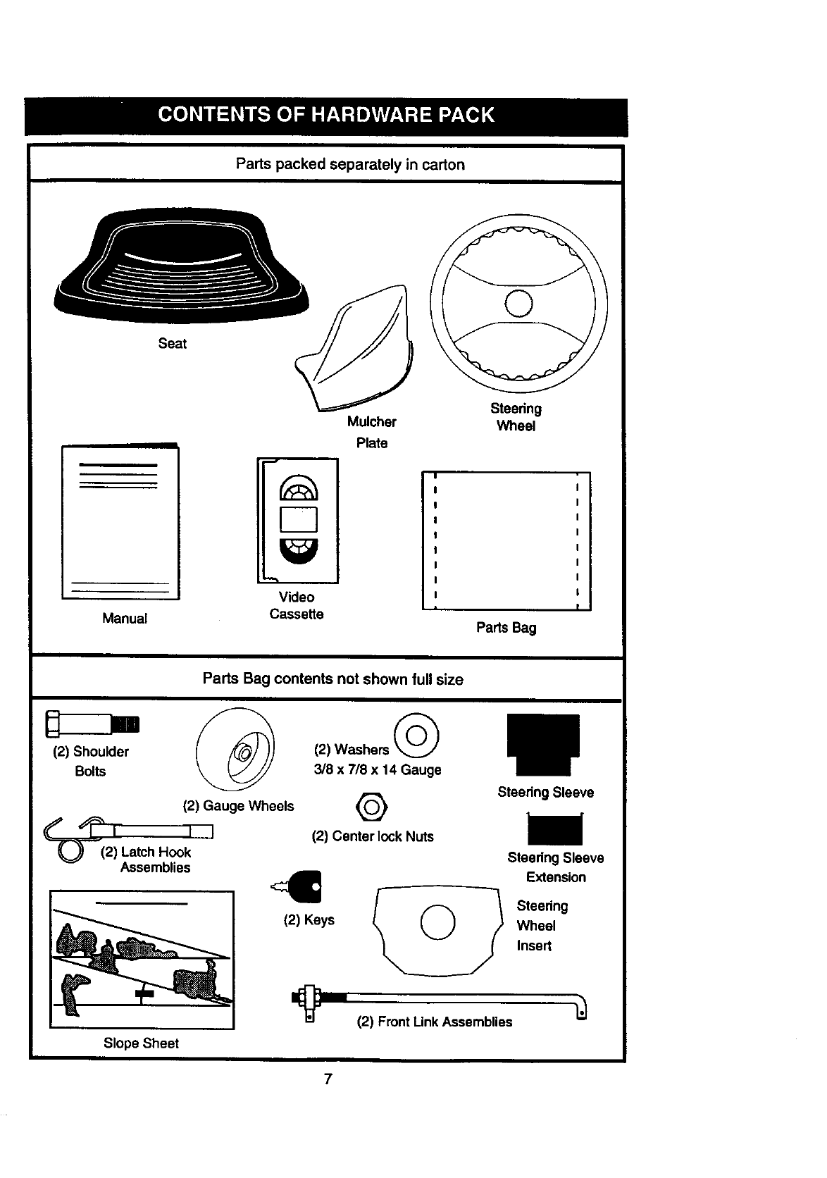
Parts packed separately in carton
Seat
/
Manual
D
Video
Cassette
Mulcher
Plate
Steering
Wheel
i
Pads Bag
Parts Bag contents not shown full size
(2) Shoulder (2) Washers
Bolts 3/8 x 718x 14 Gauge
(2) Gauge Wheels
__I I I
(2) Latch Hook
Assemblies
Slope Sheet
(2) Keys
Q
(2) Center lock Nuts
Stee_ng Sleeve
Steedng Sleeve
E_en_on
_ 0_} Steedng
Wheel
Inse_
(2) Front Link Assemblies
7
Yournewtractorhasbeenassembledat thefactorywithexceptionof thosepartslett
unassembledfor shippingpurposes.Toensuresafeand properoperationof yourtractor
all partsandhardwareyouassemblemustbe tightenedsecurely.Usethe correcttools
asnecessaryto insurepropertightness.Reviewthe videocassettebeforeyoubegin.
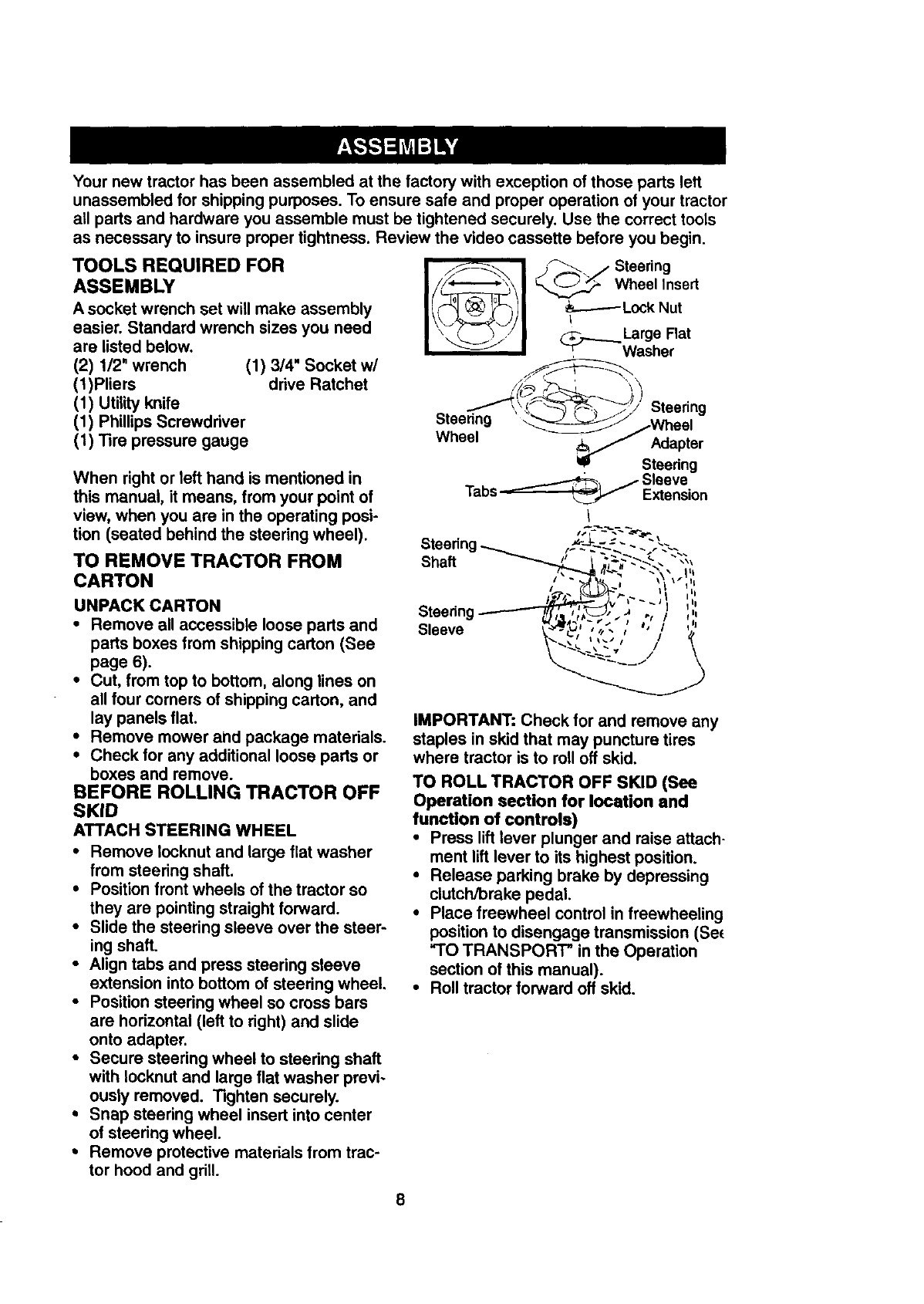
TOOLS REQUIRED FOR
ASSEMBLY
Asocketwrenchset will make assembly
easier. Standard wrench sizes you need
are listed below.
(2) 1/2" wrench (1) 3/4" Socket w/
(1)Pliers drive Ratchet
(1) Utility knife
(1) Phillips Screwdriver
(1) Tire pressure gauge
When right or left hand is mentioned in
this manual, it means, from your point of
view, when you are in the operating posi-
tion (seated behind the steering wheel).
TO REMOVE TRACTOR FROM
CARTON
UNPACK CARTON
•Remove all accessible loose parts and
parts boxes from shipping carton (See
page 6).
• Cut, from top to bottom, along lines on
all four corners of shipping carton, and
lay panels flat.
• Remove mower and package materials.
•Check for any additional loose parts or
boxes and remove.
BEFORE ROLLING TRACTOR OFF
SKID
ATTACH STEERING WHEEL
• Remove Iocknut and large flat washer
from steering shaft.
•Position front wheels of the tractor so
they are pointing straight forward.
•Slide the steering sleeve over the steer-
ing shaft.
•Align tabs and press steering sleeve
extension into bottom of steering wheel,
•Position steering wheel so cress bars
are horizontal (left to dght) and slide
onto adapter.
•Secure steering wheel to steering shaft
with Iocknut and large flat washer previ-
ously removed. Tighten securely.
•Snap steering wheel insert into center
of steedng wheel.
•Remove protective materials from trac-
tor hood and grill.
I> /Steering
Wheellnse"
_--- L_k Nut
Large Flat
_Washer
- .
Steering _-Wheel
Wheel _Adapter
uSteering
_-.--._1 /Sleeve
Tabs _Extension
Shaft
Steering
Sleeve
IMPORTANT: Check for and remove any
staples in skid that may puncture tires
where tractor is to roll off skid.
TO ROLL TRACTOR OFF SKID (See
Operation section for location and
function of controls)
•Press lift lever plunger and raise attach-
ment lift lever to its highest position.
•Release parking brake by depressing
clutch/brake pedal.
•Place freewheel control in freewheeling
position to disengage transmission (Se_
"TO TRANSPORT" in the Operation
section of this manual).
•Roll tractor forward off skid.
HOW TO SET UP YOUR TRACTOR
CONNECTBATTERY
• Lift hoodto raisedposition.
•If this battery is put into service after
month and year indicated on label (label
located between terminals) charge bat-
tery for minimum of one hour at 6-10
amps. (See "BATTERY" in
MAINTENANCE section of this manual
for charging instructions).
Label
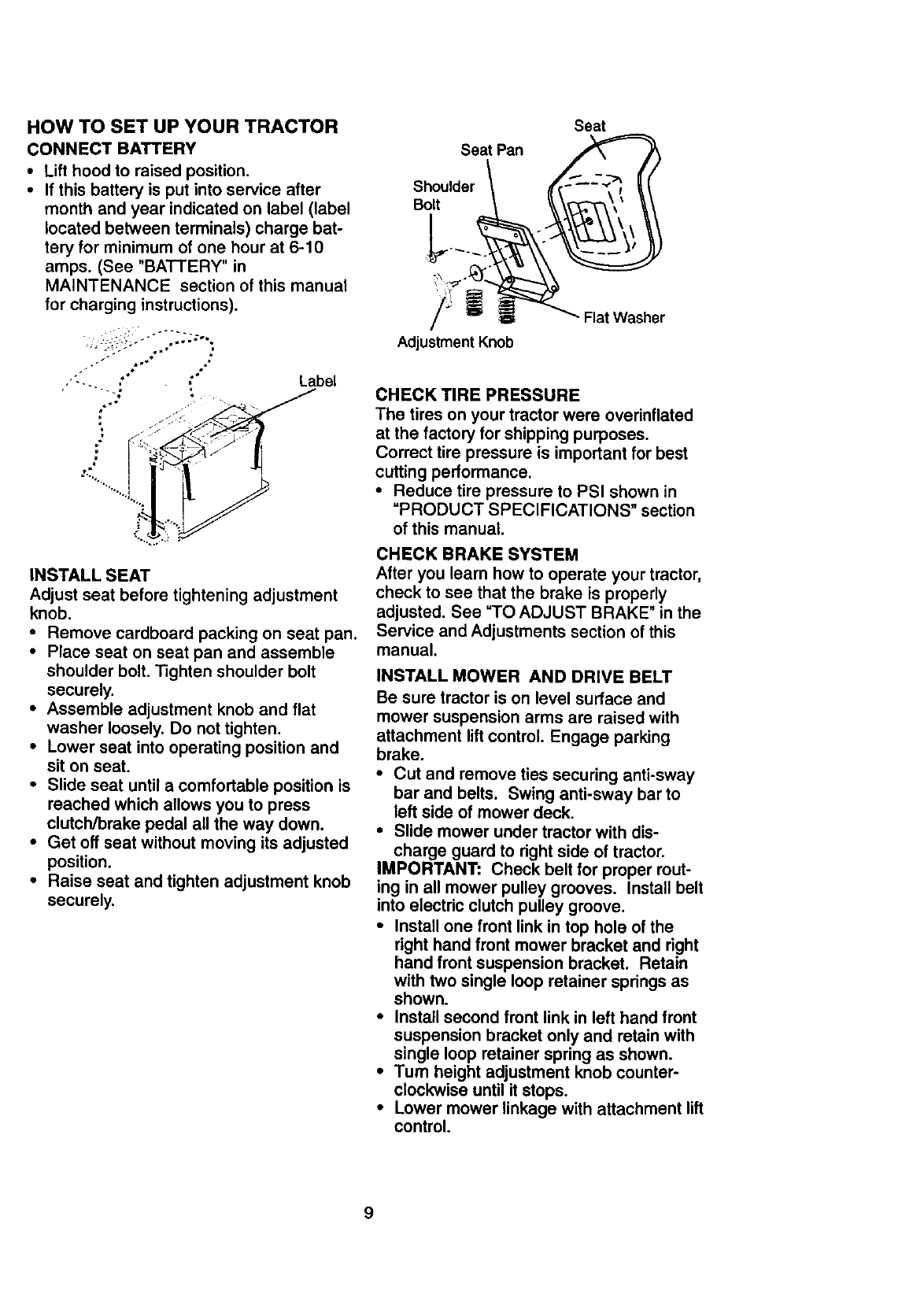
INSTALL SEAT
Adjust seat before tightening adjustment
knob.
•Remove cardboard packing on seat pan.
•Place seat on seat pan and assemble
shoulder bolt. Tighten shoulder bolt
securely.
•Assemble adjustment knob and flat
washer loosely. Do not tighten.
•Lower seat into operating position and
sit on seat,
•Slide seat until a comfortable position is
reached which allows you to press
clutch/brake pedal all the way down.
•Get off seat without moving its adjusted
position.
•Raise seat and tighten adjustment knob
securely,
Seat Pan
Shoulder
Bolt
/
Adjustment Knob
Seat
Flat Washer
CHECK TIRE PRESSURE
The tires on your tractor were overinflated
at the factory for shipping purposes.
Correct tire pressure is important for best
cutting performance.
•Reduce tire pressure to PSI shown in
"PRODUCT SPECIFICATIONS" section
of this manual.
CHECK BRAKE SYSTEM
After you learn how to operate your tractor,
check to see that the brake is properly
adjusted. See "TO ADJUST BRAKE _in the
Service and Adjustments section of this
manual.
INSTALL MOWER AND DRIVE BELT
Be sure tractor is on level surface and
mower suspension arms are raised with
attachment lift control. Engage parking
brake.
•Cut and remove ties securing anti-sway
bar and belts. Swing anti-sway bar to
left side of mower deck.
•Slide mower under tractor with dis-
charge guard to right side of tractor.
IMPORTANT: Check belt for proper rout-
ing in all mower pulley grooves. Install belt
into electric clutch pulley groove.
•Install one front link in top hole of the
right hand front mower bracket and right
hand front suspension bracket. Retain
with two single loop retainer springs as
shown.
•Install second front link in left hand front
suspension bracket only and retain with
single loop retainer spring as shown.
•Tum height adjustment knob counter-
clockwise until it stops.
•Lower mower linkage with attachment lift
control.
9
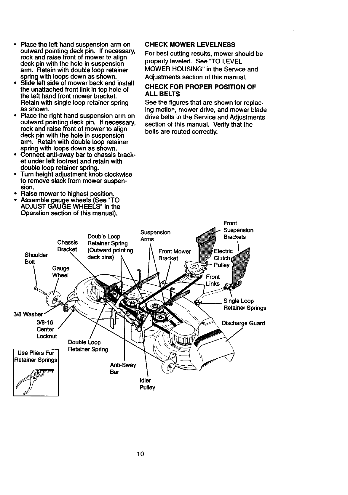
•Place the left hand suspension arm on
outward pointing deck pin. If necessary,
rock and raise front of mower to align
deck pin with the hole in suspension
arm. Retain with double loop retainer
spring with loops down as shown.
•Slide left side of mower back and install
the unattached front link in top hole of
the left hand front mower bracket.
Retain with single loop retainer spring
as shown.
•Place the right hand suspension arm on
outward pointing deck pin. If necessary,
rock and raise front of mower to align
deck pin with the hole in suspension
arm. Retain with double loop retainer
spring with loops down as shown.
•Connect anti-sway bar to chassis brack-
et under left footrest and retain with
double loop retainer spring.
•Turn height adjustment knob clockwise
to remove slack from mower suspen-
sion.
•Raise mower to highest position.
Assemble gauge wheels (See "TO
ADJUST GAUGE WHEELS" in the
Operation section of this manual).
Double Loop
Chassis Retainer Spring
Bracket (Outward pointing
Shoulder deck pins)
Bolt
CHECK MOWER LEVELNESS
For best cutting results, mower should be
properly leveled. See "TO LEVEL
MOWER HOUSING" in the Service and
Adjustments section of this manual.
CHECK FOR PROPER POSITION OF
ALL BELTS
See the figures that are shown for replac-
ing motion, mower drive, and mower blade
drive belts in the Service and Adjustments
section of this manual. Verify that the
belts are routed correctly.
Front
Suspension Suspension
Arms Brackets
Front Mower
Bracket
3/8 Washer
3/8-16
Center
Locknut
Use Pliers For
:_etainerSprings
Double Loop
Retainer Spring
Anti-Sway
Bar
Idler
Pulley
Single Loop
Retainer Springs
Discharge Guard
10
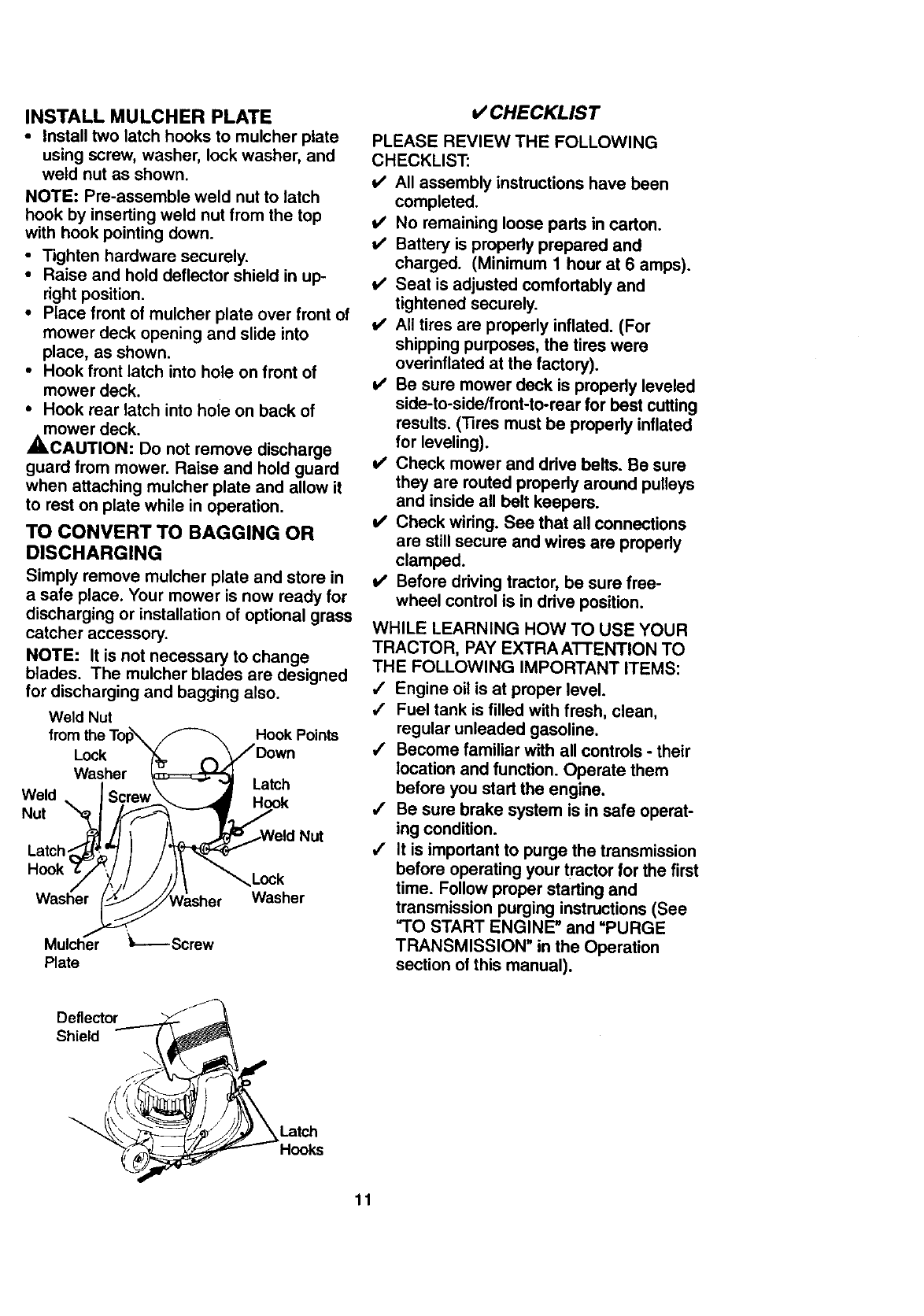
INSTALL MULCHER PLATE
•Install two latch hooks to mulcher plate
using screw, washer, lock washer, and
weld nut as shown.
NOTE: Pre-assemble weld nut to latch
hook by inserting weld nut from the top
with hook pointing down.
•Tighten hardware securely.
•Raise and hold deflector shield in up-
right position.
•Place front of mulcher plate over front of
mower deck opening and slide into
place, as shown.
• Hook front latch into hole on front of
mower deck.
• Hook rear latch into hoie on back of
mower deck.
,ACAUTION: Do not remove discharge
guard from mower. Raise and hold guard
when attaching mulcher plate and allow it
to rest on plate while in operation.
TO CONVERT TO BAGGING OR
DISCHARGING
Simply remove mulcher plate and store in
a safe place. Your mower is now ready for
discharging or installation of optional grass
catcher accessory.
NOTE: It is not necessary to change
blades. The mulchar blades are designed
for discharging and bagging also.
Weld Nut Hook Points
Weld
Nut
Lock
Washer Latch
Hook
Latch
Washer
Mulcher '_-----Screw
Plate
Washer
CHECKLIST
PLEASE REVIEW THE FOLLOWING
CHECKLIST:
v' All assembly instructions have been
completed.
v' No remaining loose parts in carton.
t/ Battery is properly prepared and
charged. (Minimum 1 hour at 6 amps).
t/ Seat is adjusted comfortably and
tightened securely.
_/ All tires are properly inflated. (For
shipping purposes, the tires were
overinflated at the factory).
v' Be sure mower deck is propedy leveled
side-to-side/front-to-rear for best cutting
results. (33res must be properly inflated
for leveling).
v' Check mower and drive belts. Be sure
they are routed propedy around pulleys
and inside all belt keepers.
_' Check wiring. See that all connections
are still secure and wires are propedy
clamped.
v' Before driving tractor, be sure free-
wheel control is in drive position.
WHILE LEARNING HOW TO USE YOUR
TRACTOR, PAY EXTRA ATTENTION TO
THE FOLLOWING IMPORTANT ITEMS:
,/ Engine oil is at proper level.
/Fuel tank is filled with fresh, clean,
regular unleaded gasoline.
,/ Become familiar with all controls -their
location and function. Operate them
before you start the engine.
,/ Be sure brake system is in safe operat-
ing condition.
/It is important to purge the transmission
before operating your tractor for the first
time. Follow proper starting and
transmission purging instructions (See
=TO START ENGINE" and "PURGE
TRANSMISSION" in the Operation
section of this manual).
Deflector
Shield
_Latch
_Hooks
11
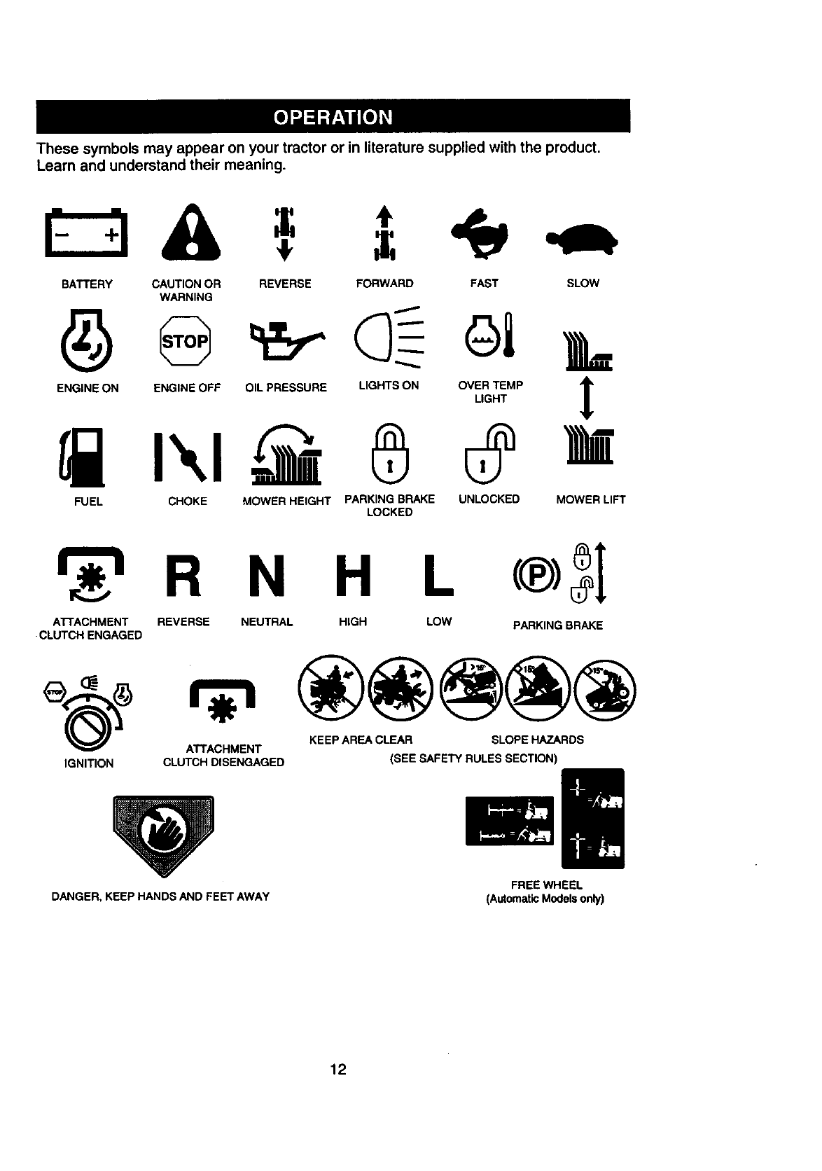
Thesesymbolsmayappearonyourtractoror in literaturesuppliedwiththe product.
Learnandunderstandtheirmeaning.
BATTERY CAUTION OR
WARNING
ENGINE ON ENGINE OFF
REVERSE FORWARD FAST SLOW
OIL PRESSURE LIGHTS ON
®OVER TEMP
LIGHT
FUEL CHOKE MOWER HEIGHT PARKINGBRAKE UNLOCKED
LOCKED MOWER LIFT
R N H L
ATrACHMENT REVERSE NEUTRAL HIGH LOW PARKING BRAKE
•CLUTCH ENGAGED
KEEP AREA CLEAR SLOPE HAZARDS
ATrACHMENT
IGNITION CLUTCH DISENGAGED (SEE SAFETY RULES SECTION)
DANGER, KEEP HANDS AND FEET AWAY FREE WHEEL
(Automatic Models only)
12
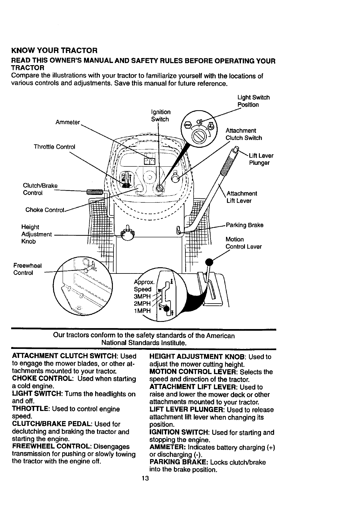
KNOW YOUR TRACTOR
READ THIS OWNER'S MANUAL AND SAFETY RULES BEFORE OPERATING YOUR
TRACTOR
Compare the illustrations with your tractor to familiarize yourself with the locations of
various controls and adjustments. Save this manual for future reference,
Ammeter
Throttle Control
Ignition
Switch
Light Switch
Position
Attachment
Clutch Switch
Lever
Plunger
Clutch/Brake
Control
Choke Control
Attachment
LiftLever
Height Brake
Adjustment
Knob Motion
Control Lever
Freewheel
Control
Our tractors conform to the safety standards of the American
National Standards Institute.
A'n'ACHMENT CLUTCH SWITCH: Used
to engage the mower blades, or other at-
tachments mounted to your tractor.
CHOKE CONTROL: Used when starting
a cold engine.
LIGHT SWITCH: Turns the headlights on
and off.
THROTTLE: Used to control engine
speed.
CLUTCH/BRAKE PEDAL: Used for
declutching and braking the tractor and
starting the engine.
FREEWHEEL CONTROL: Disengages
transmission for pushing or slowly towing
the tractor with the engine off.
HEIGHT ADJUSTMENT KNOB: Used to
adjust the mower cutting height.
MOTION CONTROL LEVER: Selects the
speed and direction of the tractor.
ATTACHMENT LIFT LEVER: Used to
raise and lower the mower deck or other
attachments mounted to your tractor.
LIFT LEVER PLUNGER: Used to release
attachment lift lever when changing its
position.
IGNITION SWITCH: Used for starting and
stopping the engine.
AMMETER: Indicates battery charging (+)
or discharging (-),
PARKING BRAKE: Locks clutch/brake
into the brake position.
13
IIlffi=!_ The operation of any tractor can result in foreign objects thrown into the I
eyes, which can result in severe eye damage. Always wear safety glasses |
or eye shields while operating your tractor or performing any adjustments or |
repairs. We recommend a wide vision safety mask over spectacles, or stan- |
dard safety glasses. I
HOW TO USE YOUR TRACTOR
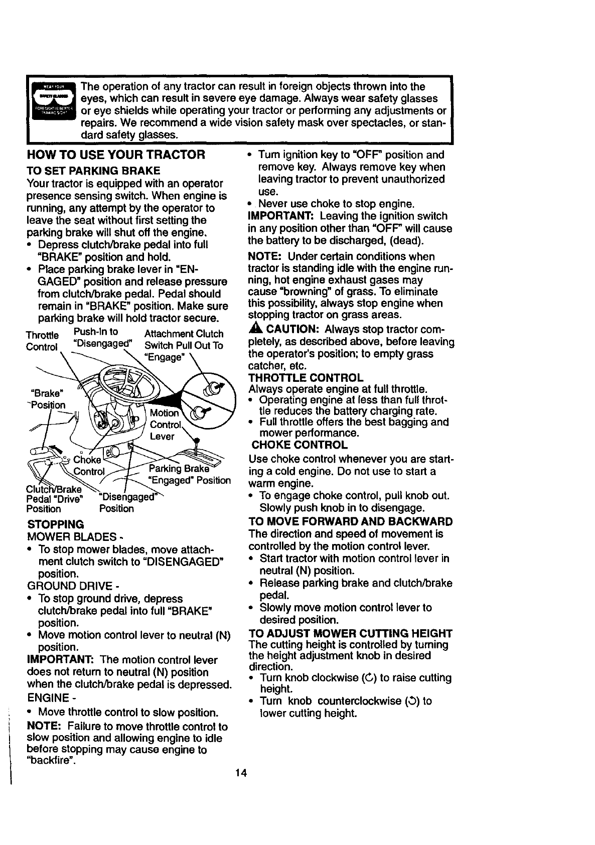
TO SET PARKING BRAKE
Your tractor is equipped with an operator
presence sensing switch. When engine is
running, any attempt by the operator to
leave the seat without first setting the
parking brake will shut off the engine,
• Depress clutch/brake pedal into full
"BRAKE" position and hold.
•Place parking brake lever in =EN-
GAGED" position and release pressure
from clutch/brake pedal. Pedal should
remain in "BRAKE" position. Make sure
parking brake will hold tractor secure.
Throttle Push-In to Attachment Clutch
Control =Disengag_ Switch Pull Out To
=Engage"
"Brake"
"Position
g
=Engaged" Position
Pedal =Ddve"
Position Position
STOPPING
MOWER BLADES -
•To stop mower blades, move attach-
ment clutch switch to =DISENGAGED"
position.
GROUND DRIVE -
•To stop ground drive, depress
clutch/brake pedal into full "BRAKE"
position.
•Move motion control lever to neutral (N)
position.
IMPORTANT: The motion control lever
does not return to neutral (N) position
when the clutch/brake pedal is depressed.
ENGINE -
•Move throttle control to slow position.
NOTE: Failure to move throttle control to
slow position and allowing engine to idle
before stopping may cause engine to
"backfire".
•Tum ignition key to "OFF" position and
remove key. Always remove key when
leaving tractor to prevent unauthorized
use.
•Never use choke to stop engine.
IMPORTANT: Leaving the ignition switch
in any position other than =OFF" will cause
the battery to be discharged, (dead).
NOTE: Under certain conditions when
tractor is standing idle with the engine run-
ning, hot engine exhaust gases may
cause =browning" of grass. To eliminate
this possibility, always stop engine when
stopping tractor on grass areas.
CAUTION: Always stop tractor com-
pletely, as described above, before leaving
the operator's position; to empty grass
catcher, etc.
THROTTLE CONTROL
Always operate engine at full throttle.
•Operating engine at less than full throt-
tle reduces the battery charging rate.
•Full throttle offers the best bagging and
mower performance.
CHOKE CONTROL
Use choke control whenever you are start-
ing a cold engine. Do not use to start a
warm engine.
•To engage choke control, pull knob out.
Slowly push knob in to disengage.
TO MOVE FORWARD AND BACKWARD
The direction and speed of movement is
controlled by the motion control lever.
•Start tractor with motion control lever in
neutral (N) position.
•Release parking brake and clutch/brake
pedal.
•Slowly move motion control lever to
desired position.
TO ADJUST MOWER CUTTING HEIGHT
The cutting height is controlled by turning
the height adjustment knob in desired
direction.
•Turn knob clockwise (C,) to raise cutting
height.
•Turn knob counterclockwise (,3)to
lower cutting height.
14
The cutting height range is approximately
1-1/2" to 4". The heights are measured
from the ground to the blade tip with the
engine not running. These heights are ap-
proximate and may vary depending upon
soil conditions, height of grass and types
of grass being mowed.
•The average lawn should be cut to
approximately 2-1/2 inches during the
cool season and to over 3 inches during
hot months. For healthier and better
looking lawns, mow often and after
moderate growth.
•For best cutting performance, grass
over 6 inches in height should be
mowed twice. Make the first cut rela-
tively high; the second to desired height.
TO ADJUST GAUGE WHEELS
Gauge wheels are properly adjusted
when they are slightly off the ground when
mower is at the desired cutting height in
operating position. Gauge wheels then
keep the deck in proper position to help
prevent scalping in most terrain condi-
tions.
•Adjust gauge wheels with tractor on a
flat level surface.
•Adjust mower to desired cutting height
(See _I'O ADJUST MOWER CUTTING
HEIGHT" in the Operation section of
this manual).
•With mower in desired height of cut po-
sition, gauge wheels should be assem-
bled so they are slightly off the ground.
Install gauge wheel in appropriate hole
with shoulder bolt, 3/8 washer, and 3/8-
16 Iocknut and tighten securely.
•Repeat for opposite side installing
gauge wheel in same adjustment hole.
Gauge Wheel _._
Mounting.,,
Bracket _f/,_
3/8-10
Locknu_
3/8 Washer-----'-_
Gauge Wheel --"" Shoulder Bolt
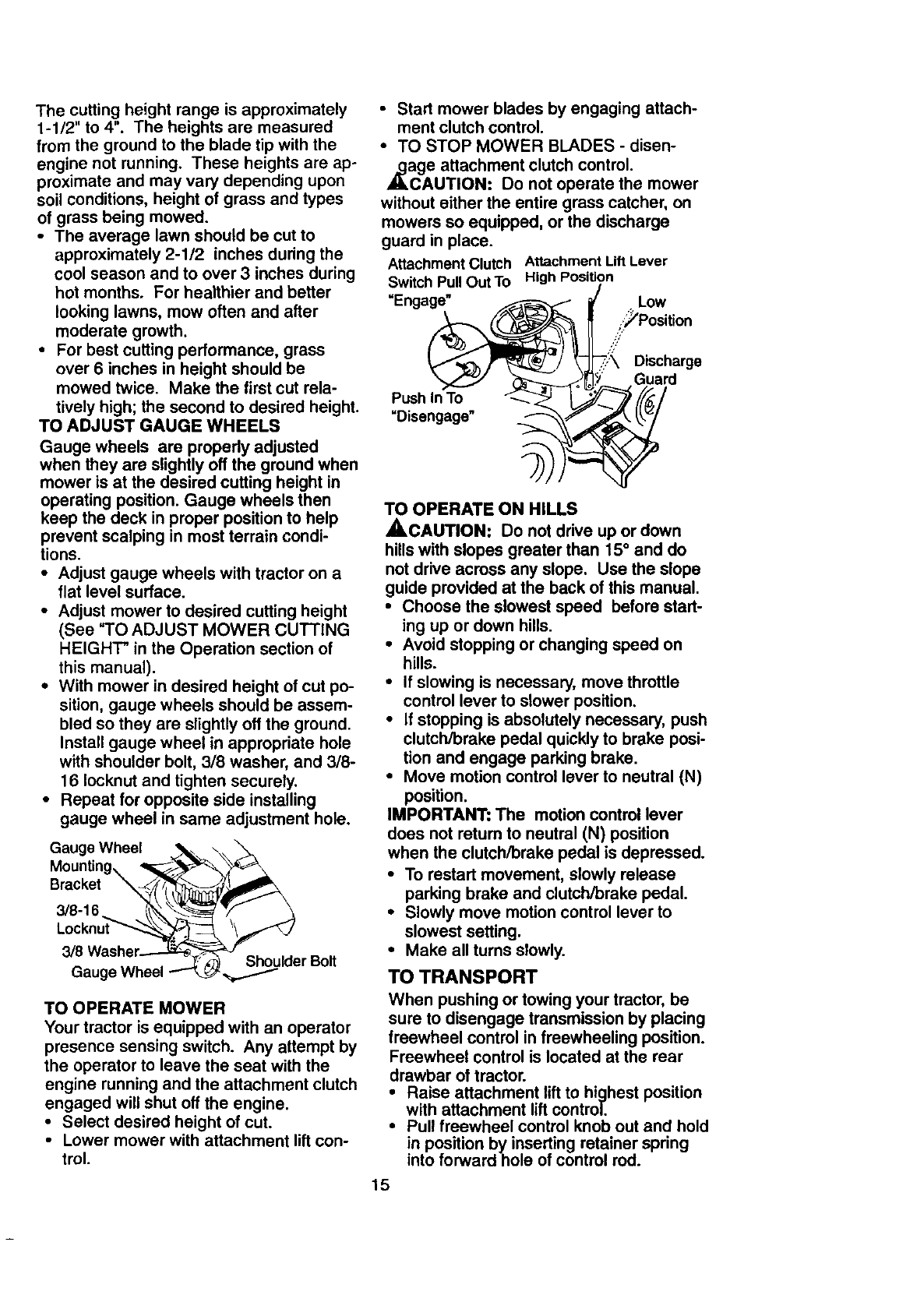
TO OPERATE MOWER
Your tractor is equipped with an operator
presence sensing switch. Any attempt by
the operator to leave the seat with the
engine running and the attachment clutch
engaged will shut off the engine.
•Select desired height of cut.
•Lower mower with attachment lift con-
trol.
•Start mower blades by engaging attach-
ment clutch control.
•TO STOP MOWER BLADES - disen-
,_age attachment clutch control.
CAUTION: Do not operate the mower
without either the entire grass catcher, on
mowers so equipped, or the discharge
guard in place.
Attachment Clutch
Switch Pull Out To
"Engage"
Push In To
=Disengage"
Attachment Lift Lever
High Position
Low
i_Position
S/
,.? Discharge
Guard
TO OPERATE ON HILLS
_,CAUTION: Do not drive up or down
hills with slopes greater than 15° and do
not drive across any slope, Use the slope
guide provided at the back of this manual,
•Choose the slowest speed before start-
ing up or down hills,
•Avoid stopping or changing speed on
hills.
•If slowing is necessary, move throttle
control lever to slower position.
•If stopping is absolutely necessary, push
clutch/brake pedal quickly to brake posi-
tion and engage parking brake,
•Move motion control lever to neutral (N)
position.
IMPORTANT: The motion control lever
does not retum to neutral (N) position
when the clutch/brake pedal is depressed.
•To restart movement, slowly release
parking brake and clutch/brake pedal.
•Slowly move motion control lever to
slowest setting.
•Make all turns slowly.
TO TRANSPORT
When pushing or towing your tractor, be
sure to disengage transmission by placing
freewheel control in freewheeling position.
Freewheel control is located at the rear
drawbar of tractor.
•Raise attachment lift to highest position
with attachment lift control.
•Pull freewheel control knob out and hold
in position by inserting retainer spring
into forward hole of control rod.
15
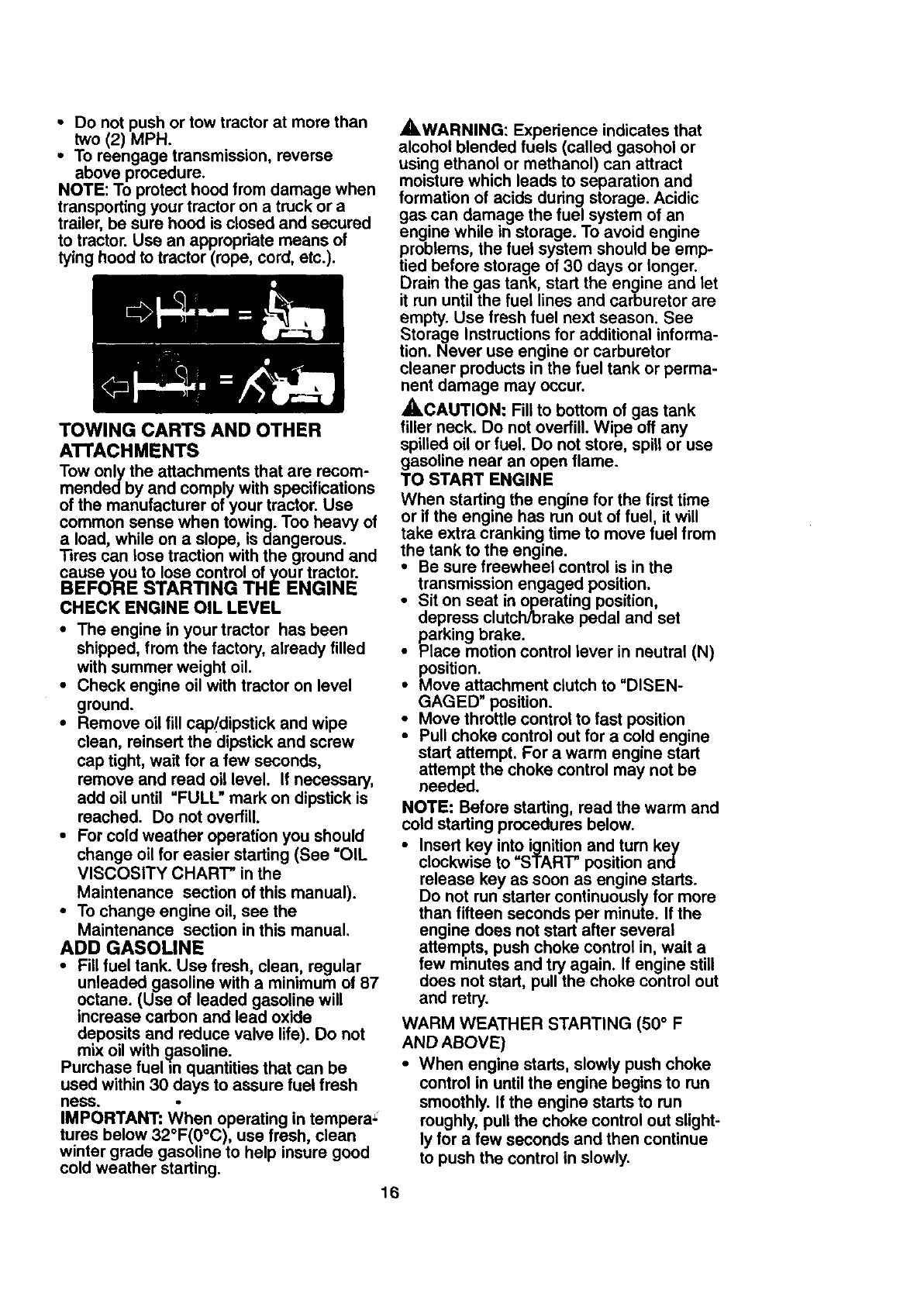
•Do not push or tow tractor at more than
two (2) MPH.
•To reengage transmission, reverse
above procedure.
NOTE: To protect hood from damage when
transporting your tractor on a truck or a
trailer, be sure hood is closed and secured
to tractor. Use an appropriate means of
tying hood to tractor (rope, cord, etc.).
TOWING CARTS AND OTHER
ATrACHMENTS
Tow only the attachments that are recom-
mendedby and comply with specifications
of the manufacturer of your tractor. Use
common sense when towing. Too heavy of
a load, while on a slope, is dangerous.
Tires can lose traction with the ground and
cause you to lose control of your tractor.
BEFORE STARTING THE ENGINE
CHECK ENGINE OIL LEVEL
• The engine in your tractor has been
shipped, from the factory, already filled
with summer weight oil.
•Check engine oil with tractor on level
ground.
•Remove oil fill cap_'dipstick and wipe
clean, reinsert the dipstick and screw
cap tight, wait for a few seconds,
remove and read oil level. If necessary,
add oil until "FULL" mark on dipstick is
reached. Do not overfill.
•For cold weather operation you should
change oil for easier starting (See "OIL
VISCOSITY CHART" in the
Maintenance section of this manual).
•To change engine oil, see the
Maintenance section in this manual.
ADD GASOLINE
•Fill fuel tank. Use fresh, clean, regular
unleaded gasoline with a minimum of 87
octane. (Use of leaded gasoline will
increase carbon and lead oxide
deposits and reduce valve life). Do not
mix oil with _asoline.
Purchase fuel m quantities that can be
used within 30 days to assure fuel fresh
hess.
IMPORTANT: When operating in tempera_
tures below 32°F(0°C), use fresh, clean
winter grade gasoline to help insure good
cold weather starting.
16
_WARNING: Experience indicates that
alcohol blended fuels (called gasohol or
using ethanol or methanol) can attract
moisture which leads to separation and
formation of acids during storage. Acidic
gas can damage the fuel system of an
engine while in storage. To avoid engine
problems, the fuel system should be emp-
tied before storage of 30 days or longer.
Drain the gas tank, start the engine and let
it run until the fuel lines and carburetor are
empty. Use fresh fuel next season. See
Storage Instructions for additional informa-
tion. Never use engine or carburetor
cleaner products in the fuel tank or perma-
nent damage may occur.
,_CAUTION: Fill to bottom of gas tank
filler neck. Do not overfill. Wipe off any
spilled oil or fuel. Do not store, spill or use
gasoline near an open flame.
TO START ENGINE
When starting the engine for the first time
or if the engine has run out of fuel, it will
take extra cranking time to move fuel from
the tank to the engine.
• Be sure freewheel control is in the
transmission engaged position.
•Sit on seat in operating position,
depress clutch/brake pedal and set
parking brake.
•Place motion control lever in neutral (N)
position.
•Move attachment clutch to "DISEN-
GAGED" position.
• Move throttle control to fast position
• Pull choke control out for a cold engine
start attempt. For a warm engine start
attempt the choke control may not be
needed.
NOTE: Before starting, read the warm and
cold starting procedures below.
•Insert key into ignition and turn key
clockwise to =START" position and
release key as soon as engine starts.
Do not run starter continuously for more
than fifteen seconds per minute. If the
engine does not start after several
attempts, push choke control in, wait a
few minutes and try again. If engine still
does not start, pull the choke control out
and retry.
WARM WEATHER STARTING (50 ° F
AND ABOVE)
•When engine starts, slowly push choke
control in until the engine begins to run
smoothly. If the engine starts to run
roughly, pull the choke control out slight-
ly for afew seconds and then continue
to push the control in slowly.
• The attachmentsandgrounddrivecan
nowbe used.Ifthe engine does not
accept the load, restart the engine and
allow it to warm up for one minute using
the choke as described above.
COLD WEATHER STARTING (50 ° F AND
BELOW)
•When engine starts, slowly push choke
control in until the engine begins to run
smoothly. Continue to push the choke
control in small steps allowing the
engine to accept small changes in
speed and load, until the choke control
is fully in. If the engine starts to run
roughly, pull the choke control out slight-
ly for afew seconds and then continue
to push the control in slowly. This may
require an engine warm-up period from
several seconds to several minutes,
depending on the temperature.
AUTOMATIC TRANSMISSION WARM-UP
• Before driving the unit in cold weather,
the transmission should be warmed up
as follows:
•Be sure the tractor is on level
ground.
•Place the motion control lever in
neutral. Release the parking brake
and let the clutch/brake slowly
return to operating position.
•Allow one minute for transmission to
warm up. This can be done during
the engine warm up period.
•The attachments can be used during
the engine warm-up period after the
transmission has been warmed up and
may require the choke control be pulled
out slightly.
NOTE: A high altitude (above 3000 feet)
or in cold temperatures (below 32 F) the
carburetor fuel mixture may need to be
adjusted for best engine performance.
See "TO ADJUST CARBURETOR" in the
Service and Adjustments section of this
manual.
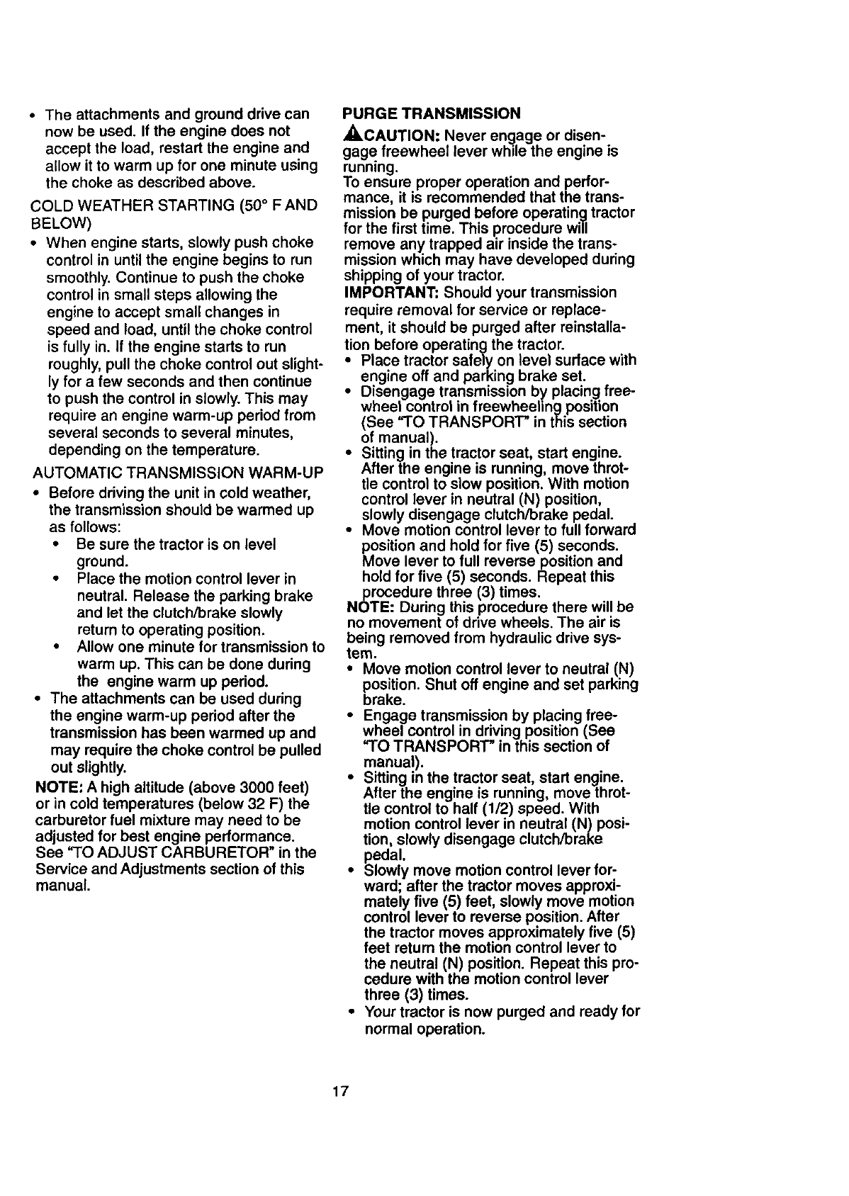
PURGE TRANSMISSION
•ACAUTION: Never en_lage or disen-
gage freewheel lever wh=le the engine is
running.
To ensure proper operation and perfor-
mance, it is recommended that the trans-
mission be purged before operating tractor
for the first time. This procedure will
remove any trapped air inside the trans-
mission which may have developed during
shipping of your tractor.
IMPORTANT: Should your transmission
require removal for service or replace-
ment, it should be purged after reinstalla-
lion before operating the tractor.
• Place tractor safely on level surface with
engine off and parking brake set.
• Disengage transmission by placing free-
wheel control in freewheehng position
(See "TO TRANSPORT" in this section
of manual).
•Sitting in the tractor seat, start engine.
After the engine is running, move throt-
tle control to slow position. With motion
control lever in neutral (N) position,
slowly disengage clutch/brake pedal.
•Move motion control lever to full forward
position and hold for five (5) seconds.
Move lever to full reverse position and
hold for five (5) seconds. Repeat this
procedure three (3) times.
NOTE: During this procedure there will be
no movement of drive wheels. The air is
being removed from hydraulic drive sys-
tem.
• Move motion control lever to neutral (N)
position. Shut off engine and set parking
brake.
• Engage transmission by placing free-
wheel control in driving position (See
"TO TRANSPORT" in this section of
manual).
•Sitting in the tractor seat, start engine.
After the engine is running, move throt-
tle control to half (1/2) speed. With
motion control lever in neutral (N) posi-
tion, slowly disengage clutch/brake
pedal.
•Slowly move motion control lever for-
ward; after the tractor moves approxi-
mately five (5) feet, slowly move motion
control lever to reverse position. After
the tractor moves approximately five (5)
feet return the motion control lever to
the neutral (N) position. Repeat this pro-
cedure with the motion control lever
three (3) times.
•Your tractor is now purged and ready for
normal operation.
17
MOWING TIPS
• Mower should be properly leveled for
best mowing performance. See =TO
LEVEL MOWER HOUSING" in the
Service and Adjustments section of this
manual.
•The left hand side of mower should be
used for trimming.
•Drive so that clippings are discharged
onto the area that has been cut. Have
the cut area to the right of the tractor.
This will result in a more even distribu-
tion of clippings and more uniform cut-
ting.
•When mowing large areas, start by turn-
ing to the right so that clippings will dis-
charge away from shrubs, fences, drive-
ways, etc. After one or two rounds, mow
in the opposite direction making left
hand turns until finished.
•If grass is extremely tall, it should be
mowed twice to reduce load and possi-
ble fire hazard from dried clippings.
Make first cut relatively high; the second
to the desired height.
•Do not mow grass when it is wet. Wet
grass will plug mower and leave unde-
sirable clumps. Allow grass to dry
before mowing.
• Always operate engine at full throttle
when mowing to assure better mowing
performance and proper discharge of
material. Regulate ground speed by se-
lecting a low enough gear to give the
mower the best cutting performance as
well as the quality of cut desired.
•When operating attachments, select a
ground speed that will suit the terrain
and give best performance of the at-
tachment being used.
MULCHING MOWING TIPS
IMPORTANT: For best performance, keep
mower housing free of built-up grass and
trash. Clean after each use.
•The special mulching blade will recut
the grass clippings many times and
reduce them in size so that as they fall
onto the lawn they will disperse into the
grass and not be noticed. Also, the
mulched grass will biodegrade quickly
to provide nutrients for the lawn. Always
mulch with your highest engine (blade)
speed as this will provide the best recut-
ting action of the blades.
•Avoid cutting your lawn when it is wet.
Wet grass tends to form clumps and
interferes with the mulching action. The
best time to mow your lawn is the early
afternoon. At this time the grass has
dried and the newly cut area will not be
exposed to the direct sun.
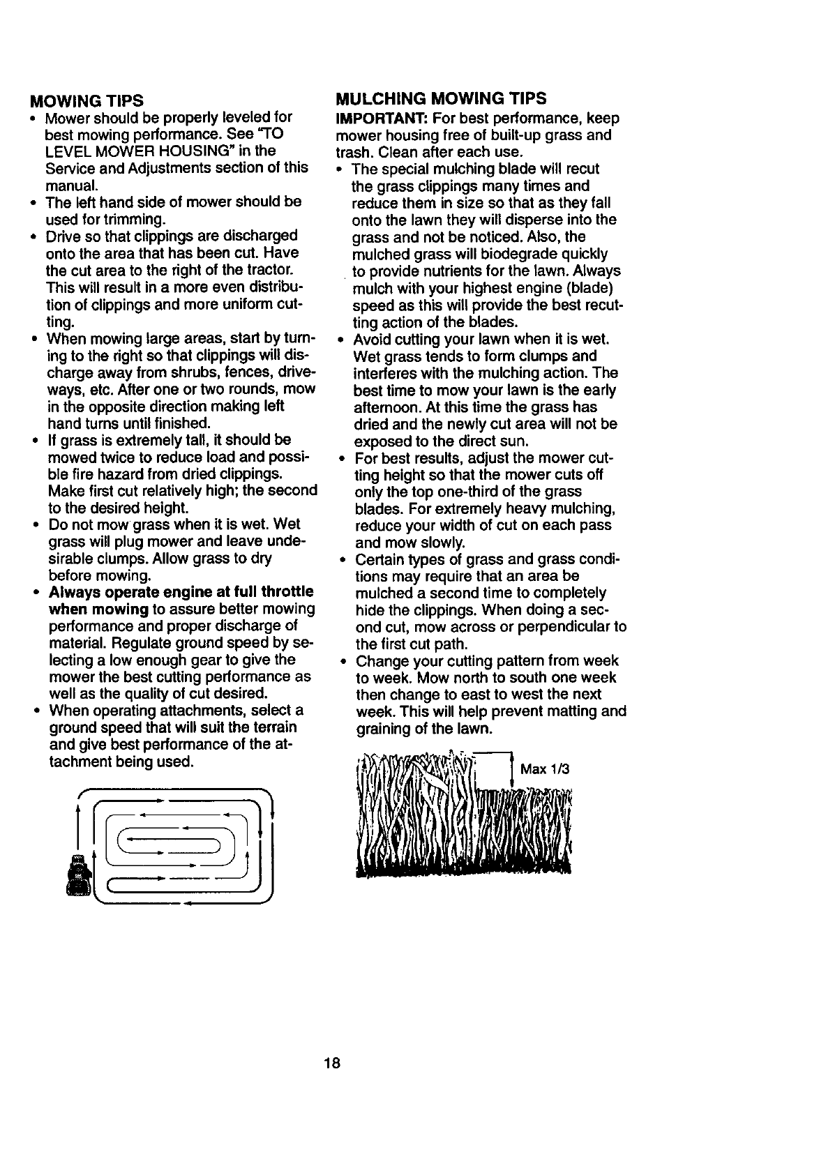
•For best results, adjust the mower cut-
ting height so that the mower cuts off
only the top one-third of the grass
blades. For extremely heavy mulching,
reduce your width of cut on each pass
and mow slowly.
•Certain types of grass and grass condi-
tions may require that an area be
mulched a second time to completely
hide the clippings. When doing a sec-
ond cut, mow across or perpendicular to
the first cut path.
•Change your cutting pattern from week
to week. Mow north to south one week
then change to east to west the next
week. This will help prevent matting and
graining of the lawn.
'_!_K_I_" _Max 1/3
.t _ i ,
18
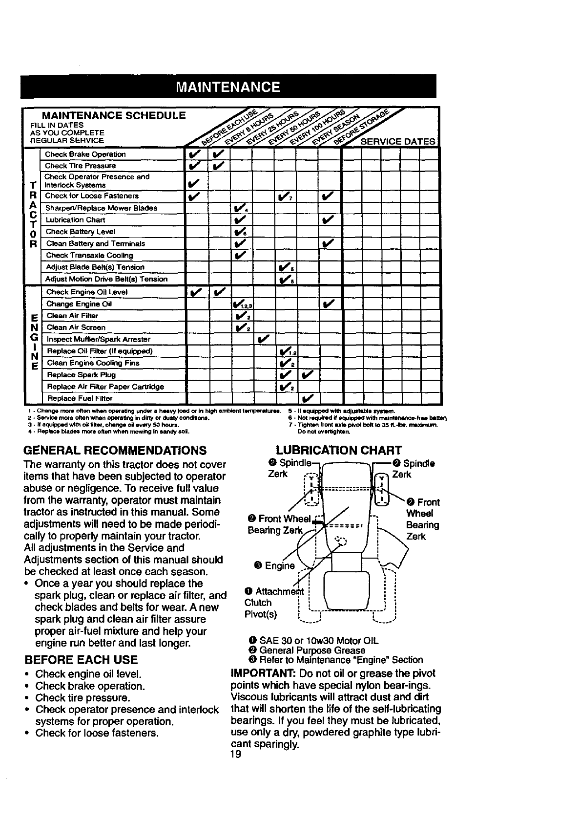
FILL IN DATES
AS YOU COM PL ETE /'_J_'/_-_S E__ _" _RVIREGULAR SERVICE CE DATES
Check Brake Operation _ i I_
Check Tire Pressure ; I_
Check Operator Presence and
RT interlock Systems I_
Check for Loose Fasteners Vw7 If
Sharpen/Replace Mower Blades IV'4
Lubrication Chwt _ li_
oT Check Battery Level
RCioan Battery and Terminals _1_
Check Transaxle Cooling IJ_
Adjust Blade Belt(s) Tension I_s
Adjust Motion Drive Belt(s) Tension Ks
Check Engine Oil Level V' ll_
Change Engine Oil _.2_: V'
EiClean Air Alter
Clean Air Screen
Inspect Muffler/Spark Arrester Ikf
Replace Oil Filter (if equipped) _,s
N Clean Engine C°°ling Fins _2
Replace Spark Plug ll_
Replace Air Filter Paper Cartridge V*a
Replace Fuel Filter I_
1- Change more oftenwhen operaSng under a himWIoedor in highembie_t t=rnperaturu. 5 - If zm_ippedwith adjustable system.
2 - Service more oftenwhen aperaUng in din'yor du=ty conditions. 6 oNot rzquirKI if equippedwt61m=interm_e-lree batte_
3 - _fequlppedw_lt_oil fi#er, change oilevery 50 hour=. 7 - T_hten/ford =xle pivotbolt to 35 ft.*lt_, m=_um.
4 - Replace b/ade_mo_ oftenwhen mowingin sandy soil. DO not overl_lhtOn.
GENERAL RECOMMENDATIONS
The warranty on this tractor does not cover
items that have been subjected to operator
abuse or negligence. To receive full value
from the warranty, operator must maintain
tractor as instructed in this manual. Some O
adjustments will need to be made periodi- E,earin
cally to properly maintain your tractor.
All adjustments in the Service and
Adjustments section of this manual should OEngine
be checked at least once each season.
•Once a year you should replace the
spark plug, clean or replace air filter, and
check blades and belts for wear. A new Clutch
Pivot(s)
spark plug and clean air filter assure
proper air-fuel mixture and help your
engine run better and last longer.
BEFORE EACH USE
•Check engine oil level.
•Check brake operation.
• Check tire pressure.
•Check operator presence and interlock
systems for proper operation.
•Check for loose fasteners.
LUBRICATION CHART
e_
Zerk Zerk
Wheel
Bearing
Zerk
OSAE 30 or 10w30 Motor OIL
OGeneral Purpose Grease
ORefer to Maintenance "Engine" Section
IMPORTANT: Do not oil or grease the pivot
points which have special nylon bear-ings.
Viscous lubricants will attract dust and dirt
that will shorten the life of the self-lubricating
bearings. If you feel they must be lubricated,
use only a dry, powdered graphite type lubri-
cant sparingly.
19
TRACTOR
Alwaysobservesafetyruleswhenper-
formingany maintenance.
BRAKE OPERATION
If tractor requires more than six (6) feet
stopping distance at high speed in highest
gear, then brake must be adjusted. (See
"TO ADJUST BRAKE" in the Service and
Adjustments section of this manual).
TIRES
• Maintain proper air pressure in all tires
(See =PRODUCT SPECIFICATIONS"
section ofthis manual).
•Keep tires free of gasoline, oil, or insect
control chemicals which can harm rub-
ber.
•Avoid stumps, stones, deep ruts, sharp
objects and other hazards that may
cause tire damage.
NOTE: To seal tire punctures and prevent
flat tires due to slow leaks, tire sealant
may be purchased from your local parts
dealer. Tire sealant also prevents tire dry
rot and corrosion.
OPERATOR PRESENCE SYSTEM
Be sure that operator presence and inter-
lock systems are working properly. Ifyour
tractor does not function as described
below, repair the problem immediately.
•The engine should not start unless the
clutch/brake pedal is fully depressed
and attachment clutch control is in the
disengaged position.
•When the engine is running, any
attempt by the operator to leave the
seat without first setting the parking
brake should shut off the engine.
•When the engine is running and the
attachment clutch is engaged, any
attempt by the operator to leave the
seat should shut off the engine.
•The attachment clutch should never
operate unless the operator is in the
seat.
BLADE CARE
For best results mower blades must be
kept sharp. Replace bent or damaged
blades.
BLADE REMOVAL
•Raise mower to highest position to allow
access to blades.
•Remove hex bolt, lock washer and flat
washer securing blade.
•Install new or resharpened blade with
trailing edge up towards deck as shown.
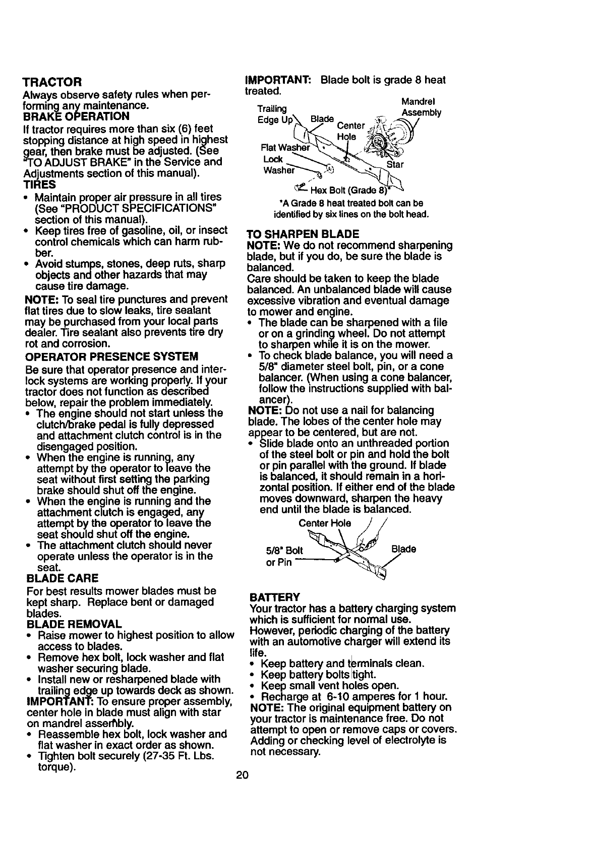
IMPORTANT: To ensure proper assembly,
center hole in blade must align with star
on mandrel assembly.
•Reassemble hex bolt, lock washer and
flat washer in exact order as shown.
• Tighten bolt securely (27-35 Ft. Lbs.
torque).
IMPORTANT:
treated.
Trailing
Edge
FlatWasher
Lock
Blade bolt is grade 8 heat
Mandrel
Assembly
Center
Hole
Star
/
_-- Hex Bolt,
*AGrade 8 heat treatedboltcan be
identifiedby six lineson the bolt head.
TO SHARPEN BLADE
NOTE: We do not recommend sharpening
blade, but if you do, be sure the blade is
balanced.
Care should be taken to keep the blade
balanced. An unbalanced blade will cause
excessive vibration and eventual damage
to mower and engine.
•The blade canbe sharpened with a file
or on a grinding wheel. Do not attempt
to sharpen while it is on the mower.
•To check blade balance, you will need a
5/8" diameter steel bolt, pin, or a cone
balancer. (When using a cone balancer,
follow the instructions supplied with bal-
ancer).
NOTE: Do not use anail for balancing
blade. The lobes of the center hole may
appear to be centered, but are not.
•Slide blade onto an unthreaded portion
of the steel belt or pin and hold the bolt
or pin parallel with the ground. If blade
is balanced, it should remain in a hod-
zontal position. If either end of the blade
moves downward, sharpen the heavy
end until the blade is balanced.
Center Hole
5/8" Bolt Blade
or Pin
BATTERY
Your tractor has a battery charging system
which is sufficient for normal use.
However, periodic charging of the battery
with an automotive charger will extend its
life.
Keep battery and t_erminals clean.
ieep battery bolts tight.
Keep small vent holes open.
•Recharge at 6-10 amperes for 1 hour.
NOTE: The original equipment battery on
your tractor is maintenance free. Do not
attempt to open or remove caps or covers.
Adding or checking level of electrolyte is
not necessary.
20
TO CLEAN BATTERY AND TERMINALS
Corrosion and dirt on the battery and ter-
minals can cause the battery to "leak"
power.
Remove terminal guard.
Disconnect BLACK battery cable first
then RED battery cable and remove
battery from tractor.
• Rinse the battery with plain water and
dry.
• Clean terminals and battery cable ends
with wire brush until bright.
• Coat terminals with grease or petroleum
jelly.
• Reinstall battery (See "REPLACING
BATTERY" in the SERVICE AND
ADJUSTMENTS section of this manu-
al.
V-B_LTS
Check V-belts for deterioration and wear
after 100 hours of operation and replace if
necessary. The belts are not adjustable.
Replace belts if they begin to slip from
wear.
TRANSAXLE COOLING
The transmission fan and cooling fins
should be kept clean to assure proper
cooling.
Do not attempt to clean fan or transmis-
sion while en_]ine is running or while the
transmission _s hot.
•Inspect cooling fan to be sure f_n
blades are intact and clean.
• Inspect cooling fins for dirt, grass clip-
pings and other materials. To prevent
damage to seals, do not use com-
pressed air or high pressure sprayer to
clean cooling fins.
TRANSAXLE PUMP FLUID
The transaxle was sealed at the factory
and fluid maintenance is not required for
the life of the transaxle. Should the
transaxle ever leak or require servicing,
contact your nearest authorized service
center/department.
ENGINE
LUBRICATION
Only use high quality detergent oil rated
with API service classification SF, SG, or
SH. Select the oil's SAE viscosity grade
according to your expected operating tem-
perature.
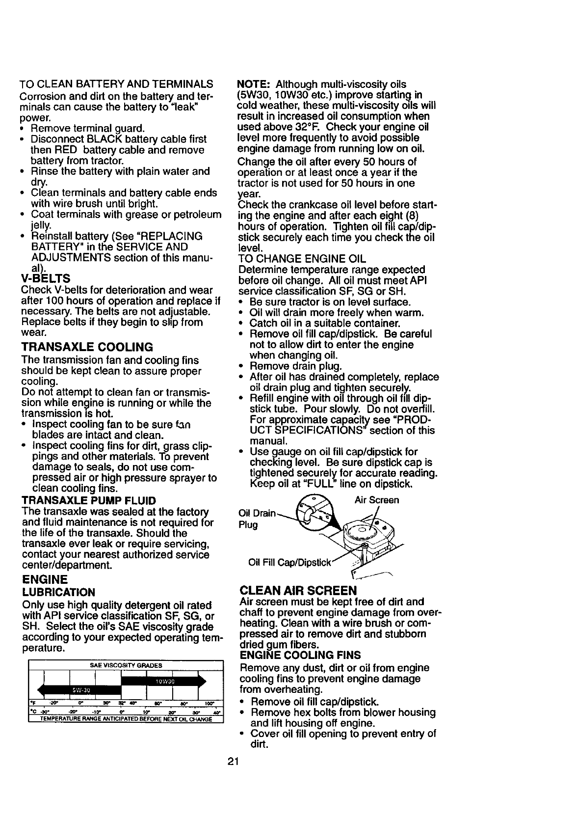
SAE VISCOSITY GRADES
.to" o- 20-
TEMPERATURE RANGE ANTICIPATED BEFORE NEXT CtL CHANGE
NOTE: Although multi-viscosity oils
(5W30, 10W30 etc.) improve starting in
cold weather, these multi-viscosity oils will
result in increased oil consumption when
used above 32°F. Check your engine oil
level more frequently to avoid possible
engine damage from running low on oil.
Change the oil after every 50 hours of
operation or at least once a year if the
tractor is not used for 50 hours in one
_ear.
heck the crankcase oil level before start-
ing the engine and after each eight (8)
hours of operation. Tighten oil fill cap/dip-
stick securely each time you check the oil
level.
TO CHANGE ENGINE OIL
Determine temperature range expected
before oil change. All oil must meet API
service classification SF, SG or SH.
•Be sure tractor is on level surface.
•Oil will drain more freely when warm.
•Catch oil in a suitable container.
•Remove oil fill cap/dipstick. Be careful
not to allow dirt to enter the engine
when changing oil.
•Remove drain plug.
•After oil has drained completely, replace
oil drain plug and tighten securely.
•Refill engine with oil through oil fill dip-
stick tube. Pour slowly. Do not overfill.
For approximate capacity see "PROD-
UCT SPECIFICATIONS" section of this
manual.
•Use gauge on oil fill cap/dipstick for
checking level. Be sure dipstick cap is
tightened securely for accurate reading.
Keep oil at "FULL" line on dipstick.
_Air Screen
Oil Drain.........._--v_ _/_._
Plug _
Oil Fill Cap/Dipstick_ _}_
CLEAN AIR SCREEN
Air screen must be kept free of dirt and
chaff to prevent engine damage from over-
heating. Clean with a wire brush or com-
pressed air to remove dirt and stubborn
dried gum fibers.
ENGINE COOLING FINS
Remove any dust, dirt or oil from engine
cooling fins to prevent engine damage
from overheating.
Remove oil fill cap/dipstick.
Remove hex bolts from blower housing
and lift housing off engine.
•Cover oil fill opening to prevent entry of
dirt.
21
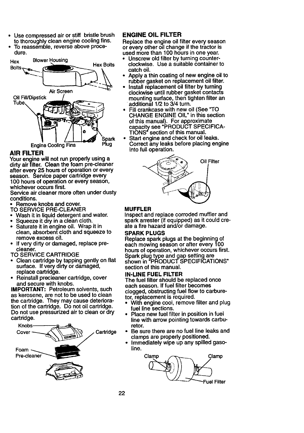
•Use compressed air or stiff bristle brush
to thoroughly clean engine cooling fins.
•To reassemble, reverse above proce-
dure.
Hex Blower Housing
Bolts_.__Hex Bolts
Air Screen
Oil Fill/Dipstick
Tube,
Spark
Engine Cooling Fins Plug
AIR FILTER
Your engine will not run properly using a
dirty airfllter. Clean the foam pre-cleaner
after every 25 hours of operation or every
season. Service paper cartridge every
100 hours of operation or every season,
whichever occurs first.
Service air cleaner more often under dusty
conditions.
• Remove knobs and cover.
TO SERVICE PRE-CLEANER
•Wash it in liquid detergent and water.
Squeeze it dry in a clean cloth.
• Saturate it in engine oil. Wrap it in
clean, absorbent cloth and squeeze to
remove excess oil.
•If very dirty or damaged, replace pre-
cleaner.
TO SERVICE CARTRIDGE
•Clean cartridge by tapping gently on flat
surface. If very dirty or damaged,
replace cartridge.
•Reinstall precleaner cartridge, cover
and secure with knobs.
IMPORTANT: Petroleum solvents, such
as kerosene, are not to be used to clean
the cartridge. They may cause deteriora-
tion of the cartridge. Do not oil cartridge.
Do not use pressurized air to clean or dry
cartridge.
Knobs-
Cover _.__ Cartridge
Foam _
Pre-cleaner
ENGINE OIL FILTER
Replace the engine oil filter every season
or every other oil change if the tractor is
used more than 100 hours in one year.
•Unscrew old filter by turning counter-
clockwise. Use a suitable container to
catch oil.
•Apply a thin coating of new engine oil to
rubber gasket on replacement oil filter.
•Install replacement oil filter by turning
clockwise until rubber gasket contacts
mounting surface, then tighten filter an
additional 1/2 to 3/4 turn.
•Fill crankcase with new oil (See "TO
CHANGE ENGINE OIL" in this section
of this manual). For approximate
capacity see "PRODUCT SPECIFICA-
TIONS" section of this manual.
•Start engine and check for oil leaks.
Correct any leaks before placing engine
into full operation.
ilter
MUFFLER
Inspect and replace corroded muffler and
spark arrester (if equipped) as it could cre-
ate a fire hazard and/or damage.
SPARK PLUGS
Replace spark plugs at the beginning of
each mowing season or after every 100
hours of operation, whichever occurs first.
Spark plug type and gap setting are
shown in "PRODUCT SPECIFICATIONS"
section of this manual.
IN-LINE FUEL FILTER
The fuel filter should be replaced once
each season. If fuel filter becomes
clogged, obstructing fuel flow to carbure-
tor, replacement is required.
•With engine cool, remove filter and plug
fuel line sections.
•Place new fuel filter in position in fuel
line with arrow pointing towards carbu-
retor.
•Be sure there are no fuel line leaks and
clamps are properly positioned.
•Immediately wipe up any spilled gaso-
line.
22
CLEANING
•Clean engine, battery, seat, finish, etc.
of all foreign matter.
•Keep finished surfaces and wheels free
of all gasoline, oil, etc.
•Protect painted surfaces with automo-
tive type wax.
We do not recommend using a garden
hose to clean your tractor unless the elec-
trical system, muffler, air filter and carbure-
tor are covered to keep water out. Water
in engine can result in a shortened engine
life.
_CAUTION: Before performing any service or adjustments:
•Depress clutch/brake pedal fully and set parking brake.
•Place motion control lever in neutral (N) position.
•Place attachment clutch in =DISENGAGED" position.
•Turn ignition key =OFF" and remove key.
•Make sure the blades and all moving parts have completely stopped.
•Disconnect spark plug wire from spark plug and place wire where it cannot come
in contact with plug.
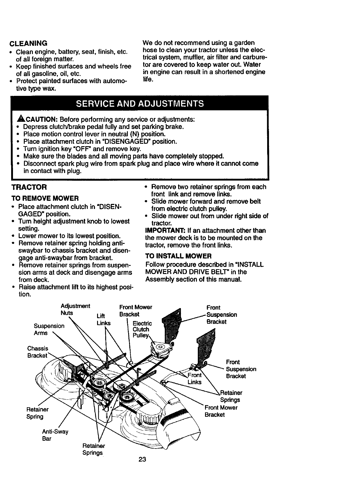
TRACTOR
TO REMOVE MOWER
•Place attachment clutch in "DISEN-
GAGED" position.
•Tum height adjustment knob to lowest
setting.
•Lower mower to its lowest position.
•Remove retainer spring holding anti-
swaybar to chassis bracket and disen-
gage anti-swaybar from bracket.
•Remove retainer spdngs from suspen-
sion arms at deck and disengage arms
from deck.
•Raise attachment lift to its highest posi-
tion.
•Remove two retainer spdngs from each
front link and remove links.
•Slide mower forward and remove belt
from electdc clutch pulley.
•Slide mower out from under dght side of
tractor.
IMPORTANT: If an attachment other than
the mower deck is to be mounted on the
tractor, remove the front links.
TO INSTALL MOWER
Follow procedure descdbed in =INSTALL
MOWER AND DRIVE BELT" in the
Assembly section of this manual.
Adjustment
Nuts
Suspension
Arms
Lift
Links
Front Mower
Bracket
Electric
Clutch
Front
Bracket
Chassis
Bracket_
Retainer
Spring
Anti-Sway
Bar
Front
Suspension
Bracket
-,_Retainer
Spdngs
Bracket
Retainer
Springs 23
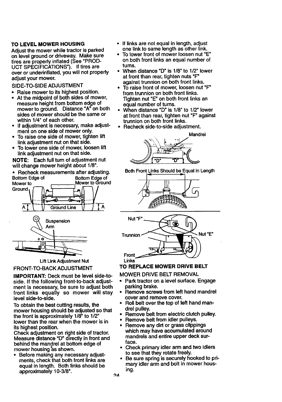
TO LEVEL MOWER HOUSING
Adjust the mower while tractor is parked
on level ground or driveway. Make sure
tires are properly inflated (See =PROD-
UCT SPECIFICATIONS"). If tiros are
over or underinflated, you will not propedy
adjust your mower.
SIDE-TO-SIDE ADJUSTMENT
• Raise mower to its highest position.
• At the midpoint of both sides of mower,
measure height from bottom edge of
mower to ground. Distance "A" on both
sides of mower should be the same or
within 1/4" of each other.
•If adjustment is necessary, make adjust-
ment on one side of mower only.
•To raise one side of mower, tighten lift
link adjustment nut on that side.
• To lower one side of mower, loosen lift
link adjustment nut on that side.
NOTE: Each full turn of adjustment nut
will change mower height about 1/8".
•Recheck measurements after adjusting.
Bottom Edge of Bottom Edge of
Mower to ,_._._._Mower to Ground
Ground _
Suspension
Arm
Lift LinkAdjustment Nut
FRONT-TO-BACK ADJUSTMENT
IMPORTANT: Deck must be level side-to-
side. If the following front-to-back adjust-
ment is necessary, be sure to adjust both
front links equally so mower will stay
level side-to-side.
To obtain the best cutting results, the
mower housing should be adjusted so that
the front is approximately 1/8" to 112"
lower than the rear when the mower is in
its highest position.
Check adjustment on right side of tractor.
Measure distance "D" directly in front and
behind the mandrel at bottom edge of
mower housing "as shown.
•Before making any necessary adjust-
ments, check that both front links are
equal in length. Both links should be
approximately 10-3/8".
•If links are not equal in length, adjust
one link to same length as other link.
•To lower front of mower loosen nut =E"
on both front links an equal number of
tums.
•When distance "D" is 1/8" to 1/2" lower
at front than roar, tighten nuts "P
against trunnion on both front links.
•To raise front of mower, loosen nut "P
from trunnion on both front links.
Tighten nut "E" on both front links an
equal number of turns.
•When distance "D" is 1/8" to 1/2" lower
at front than rear, tighten nut "P against
trunnion on both front links.
•Recheck side-to-side adjustment.
Mandrel
Both F_ Length
Nut =P
Links
TO REPLACE MOWER DRIVE BELT
MOWER DRIVE BELT REMOVAL
•Park tractor on a level surface. Engage
parking brake.
• Remove screws from left hand mandrel
cover and remove cover.
•Roll belt over the top of left hand man-
drel pulley.
•Remove belt from electric clutch pulley.
•Remove belt from idler pulleys.
•Remove any dirt or grass clippings
which may have accumulated around
mandrels and entire upper deck sur-
face.
• Check primary idler arm and two idlers
to see that they rotate freely.
• Be sure spring is securely hooked to pri-
mary idler arm and bolt in mower hous-
ing.
_zt
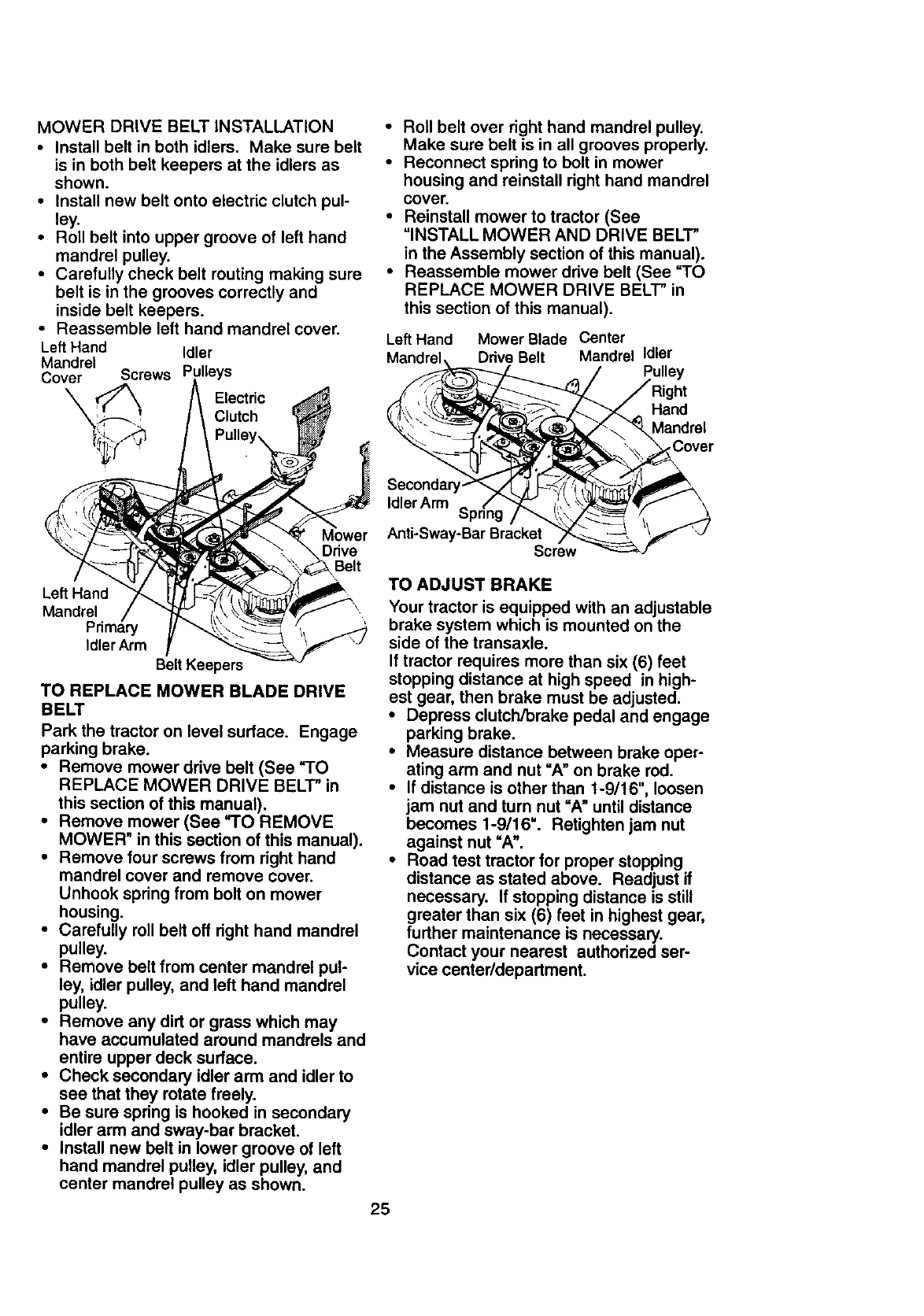
MOWER DRIVE BELT INSTALLATION
• Install belt in both idlers. Make sure belt
is in both belt keepers at the idlers as
shown.
•Install new belt onto electric clutch pul-
ley.
•Roll belt into upper groove of left hand
mandrel pulley.
• Carefully check belt routing making sure
belt is in the grooves correctly and
inside belt keepers.
• Reassemble left hand mandrel cover.
Left Hand Idler
Mandrel ,lleys
Cover Screws
Electric
Mower
Drive
Belt
Left Hand
Mandrel
Primary
Idler Arm
Belt Keepers
TO REPLACE MOWER BLADE DRIVE
BELT
Park the tractor on level surface. Engage
parking brake.
•Remove mower drive belt (See "TO
REPLACE MOWER DRIVE BELT" in
this section of this manual).
• Remove mower (See "TO REMOVE
MOWER" in this section of this manual).
•Remove four screws from right hand
mandrel cover and remove cover.
Unhook spring from bolt on mower
housing.
•Carefully roll belt off right hand mandrel
pulley.
• Remove belt from center mandrel pul-
ley, idler pulley, and left hand mandrel
pulley.
•Remove any dirt or grass which may
have accumulated around mandrels and
entire upper deck surface.
•Check secondary idler arm and idler to
see that they rotate freely.
•Be sure spring is hooked in secondary
idler arm and away-bar bracket.
•Install new belt in lower groove of left
hand mandrel pulley, idler pulley, and
center mandrel pulley as shown.
•Roll belt over right hand mandrel pulley.
Make sure belt is in all grooves properly.
•Reconnect spring to bolt in mower
housing and reinstall right hand mandrel
cover.
•Reinstall mower to tractor (See
"INSTALL MOWER AND DRIVE BELT"
in the Assembly section of this manual).
•Reassemble mower drive belt (See "TO
REPLACE MOWER DRIVE BELT" in
this section of this manual).
25
Left Hand Mower Blade Center
Mandrel, Drive Belt Mandrel Idler
Pulley
Hand
Mandrel
Cover
Secondary
Idler Arm
Anti-Sway-Bar Bracket
Screw
TO ADJUST BRAKE
Your tractor is equipped with an adjustable
brake system which is mounted on the
side of the transaxle.
If tractor requires more than six (6) feet
stopping distance at high speed in high-
est gear, then brake must be adjusted.
•Depress clutch/brake pedal and engage
parking brake.
•Measure distance between brake oper-
ating arm and nut "A" on brake rod.
•If distance is other than 1-9/16", loosen
jam nut and turn nut "A" until distance
becomes 1-9/16". Retighten jam nut
against nut "A".
•Road test tractor for proper stopping
distance as stated above. Readjust if
necessary. If stopping distance is still
greater than six (6) feet in highest gear,
further maintenance is necessary.
Contact your nearest authorized ser-
vice center/department.
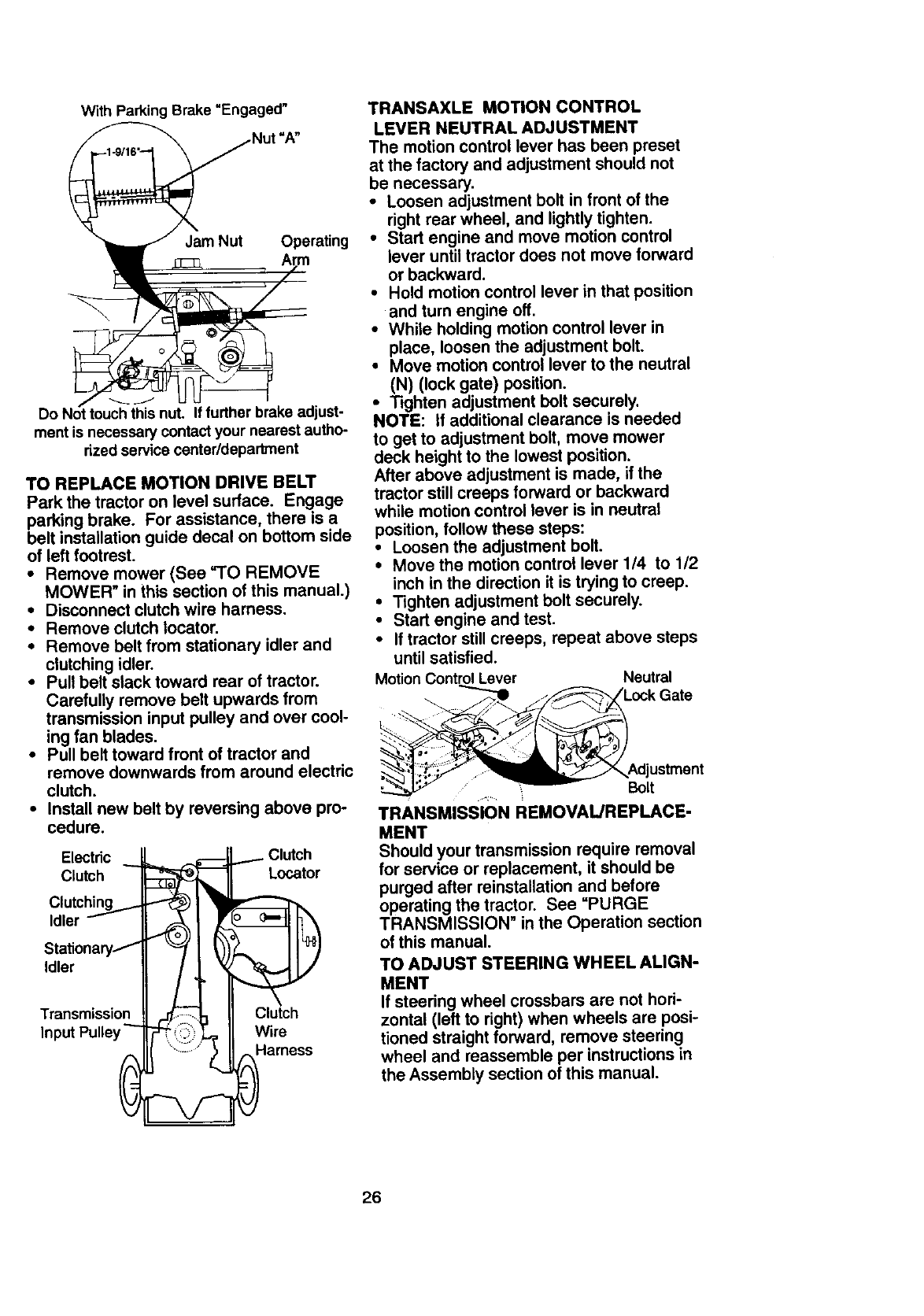
With Parking Brake "Engaged"
"A"
Jam Nut Operating
Do Not touch this nut. If further brake adjust-
ment is necessary contact your nearest autho-
rized service center/department
TO REPLACE MOTION DRIVE BELT
Park the tractor on level surface. Engage
parking brake. For assistance, there is a
belt installationguide decal on bottom side
of left footrest.
•Remove mower (See "TO REMOVE
MOWER" in this section of this manual.)
•Disconnect clutch wire harness.
•Remove clutch Iocator.
•Remove belt from stationary idler and
clutchingidler.
•Pull belt stack toward rear of tractor.
Carefully remove belt upwards from
transmission input pulley and over cool-
ing fan blades.
•Pull belt toward front of tractor and
remove downwards from around electric
clutch.
•Install new belt by reversing above pro-
cedure.
Electric _ __ ,.-.€-- _ Clutch
C,utch ,ocator
Clutching _ I _
Idler _ _ I'!r_ 17"_
sta oa
Transmission _ II Clutch
,nputPu,ey-- II W rr ,,s
TRANSAXLE MOTION CONTROL
LEVER NEUTRAL ADJUSTMENT
The motion control lever has been preset
at the factory and adjustment should not
be necessary.
•Loosen adjustment bolt in front of the
right rear wheel, and lightly tighten.
•Start engine and move motion control
lever until tractor does not move forward
or backward.
•Hold motion control lever in that position
and turn engine off.
•While holding motion control lever in
place, loosen the adjustment bolt.
•Move motion control lever to the neutral
(N) (lock gate) position.
•Tighten adjustment belt securely.
NOTE: If additional clearance is needed
to get to adjustment bolt, move mower
deck height to the lowest position.
After above adjustment is made, if the
tractor still creeps forward or backward
while motion control lever is in neutral
position, follow these steps:
•Loosen the adjustment bolt.
•Move the motion control lever 1/4 to 1/2
inch in the direction it is trying to creep.
•Tighten adjustment bolt securely.
•Start engine and test.
•If tractor still creeps, repeat above steps
until satisfied.
Motion Control Lever Neutral
,= Bolt
TRANSMISSION REMOVAUREPLACE-
MENT
Should your transmission require removal
for service or replacement, it should be
purged after reinstallation and before
operating the tractor. See =PURGE
TRANSMISSION" in the Operation section
of this manual.
TO ADJUST STEERING WHEEL ALIGN-
MENT
If steering wheel crossbars are not hod-
zontal (left to right) when wheels are posi-
tioned straight forward, remove steering
wheel and reassemble per instructions in
the Assembly section of this manual.
26
FRONTWHEELTOE-IN/CAMBER
The front wheel toe-in and camber are not
adjustable on your tractor. If damage has
occurred to affect the front wheel toe-in or
camber, contact your nearest authorized
service center/department.
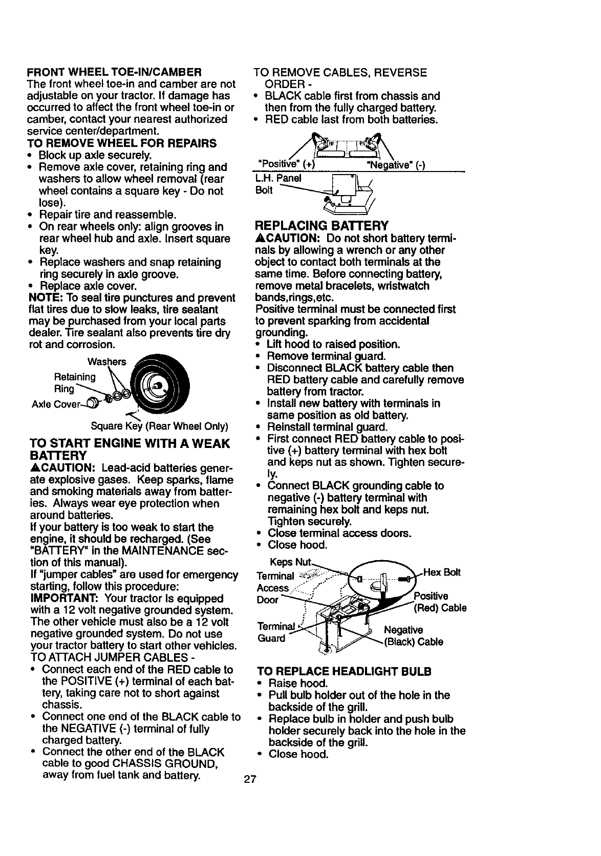
TO REMOVE WHEEL FOR REPAIRS
•Block up axle securely.
•Remove axle cover, retaining ring and
washers to allow wheel removal (rear
wheel contains a square key - Do not
lose).
•Repair tire and reassemble.
•On rear wheels only: align grooves in
rear wheel hub and axle. Insert square
key.
•Replace washers and snap retaining
ring securely in axle groove.
•Replace axle cover.
NOTE: To seal tire punctures and prevent
flat tires due to slow leaks, tire sealant
may be purchased from your local parts
dealer. Tire sealant also prevents tire dry
rot and corrosion.
Washers
Retaining _X_
,x,o Square Key (Rear Wheel Only)
TO START ENGINE WITH A WEAK
BA'B'ERY
ACAUTION: Lead-acid batteries gener-
ate explosive gases. Keep sparks, flame
and smoking materials away from batter-
ies. Always wear eye protection when
around batteries.
If your battery is too weak to start the
engine, it should be recharged. (See
"BATTERY" in the MAINTENANCE sec-
tion of this manual).
If "jumper cables" are used for emergency
starting, follow this procedure:
IMPORTANT: Your tractor Is equipped
with a 12 volt negative grounded system.
The other vehicle must also be a 12 volt
negative grounded system. Do not use
your tractor battery to start other vehicles.
TO ATTACH JUMPER CABLES -
•Connect each end of the RED cable to
the POSITIVE (+) terminal of each bat-
tery, taking care not to short against
chassis.
•Connect one end of the BLACK cable to
the NEGATIVE (-) terminal of fully
charged battery.
•Connect the other end of the BLACK
cable to good CHASSIS GROUND,
TO REMOVE CABLES, REVERSE
ORDER -
•BLACK cable first from chassis and
then from the fully charged battery.
•RED cable last from both battedes.
"Positi_tive" (-)
L.H._el _I I
Bolt
REPLACING BATTERY
ACAUTION: Do not short battery termi-
nals by allowing a wrench or any other
object to contact both terminals at the
same time. Before connecting battery,
remove metal bracelets, wdstwatch
bands, dngs,etc.
Positive terminal must be connected first
to prevent sparking from accidental
grounding.
•Lift hood to raised position.
•Remove terminal guard.
•Disconnect BLACK battery cable then
RED battery cable and carefully remove
battery from tractor.
•Install new battery with terminals in
same position as old battery.
•Reinstall terminal guard.
•First connect RED battery cable to posi-
tive (+) battery terminal with hex bolt
and keps nut as shown. Tighten secure-
ly.
•Connect BLACK grounding cable to
negative (-) battery terminal with
remaining hex bolt and keps nut.
Tighten securely.
•Close terminal access doors.
•Close hood.
Terminal ,.Hex Bolt
Access ,<.'':.;'"
Cable
Terminal
Guard Cable
TO REPLACE HEADLIGHT BULB
•Raise hood.
•Pull bulb holder out of the hole in the
backside of the grill.
•Replace bulb in holder and push bulb
holder securely back into the hole in the
backside of the gdll.
•Close hood.
away from fuel tank and battery. 27
INTERLOCKSAND RELAYS
Looseordamagedwiringmaycauseyour
tractorto run poorly,stoprunning, or pre-
vent it from starting.
•Check wiring. See electrical wiring dia-
gram in the Repair Parts section.
TO REPLACE FUSE
Replace with 30 amp automotive-type
plug-in fuse. The fuse holder is located
behind the dash.
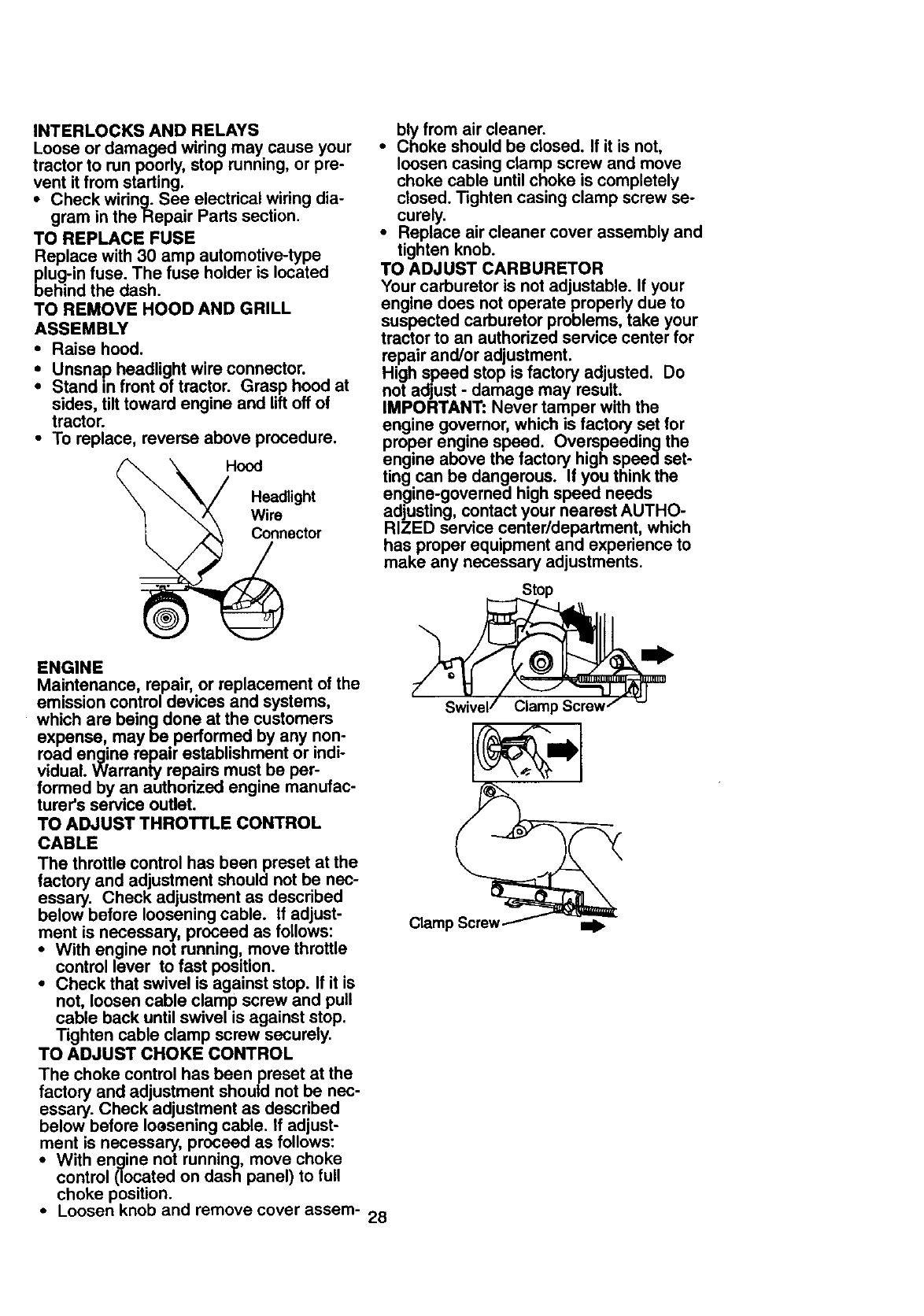
TO REMOVE HOOD AND GRILL
ASSEMBLY
• Raise hood.
•Unsnap headlight wire connector.
Stand in front of tractor. Grasp hood at
sides, tilt toward engine and lift off of
tractor.
•To replace, reverse above procedure.
Hood
_Headlight
"" \/_ Wire
_ _nector
bly from air cleaner.
•Choke should be closed. If it is not,
loosen casing clamp screw and move
choke cable until choke is completely
closed. Tighten casing clamp screw se-
curely.
•Replace air cleaner cover assembly and
tighten knob.
TO ADJUST CARBURETOR
Your carburetor is not adjustable. If your
engine does not operate properly due to
suspected carburetor problems, take your
tractor to an authorized service center for
repair and/or adjustment.
High speed stop is factory adjusted. Do
not adjust - damage may result.
IMPORTANT: Never tamper with the
engine governor, which is factory set for
proper engine speed. Overspeeding the
engine above the factory high speed set-
ting can be dangerous. If you think the
_verned )eed needs
en_ine-g_ high sr
adjusting, contact your nearest AUTHO-
RIZED service center/department, which
has proper equipment and experience to
make any necessary adjustments.
Stop
ENGINE
Maintenance, repair, or replacement of the
emission control devices and systems,
which are being done at the customers
expense, may be performed by any non-
road engine repair establishment or indi-
vidual. Warranty repairs must be per-
formed by an authorized engine manufac-
turer's service outlet.
TO ADJUST THROTTLE CONTROL
CABLE
The throttle control has been preset at the
factory and adjustment should not be nec-
essary. Check adjustment as described
below before loosening cable. If adjust-
ment is necessary, proceed as follows:
•With engine not running, move throttle
control lever to fast position.
•Check that swivel is against stop. If it is
not, loosen cable clamp screw and pull
cable back until swivel is against stop.
Tighten cable clamp screw securely.
TO ADJUST CHOKE CONTROL
The choke control has been preset at the
factory and adjustment should not be nec-
essary. Check adjustment as described
below before Ioasening cable, if adjust-
ment is necessary, proceed as follows:
•With engine not running, move choke
control (located on dash panel) to full
choke position.
•Loosen knob and remove cover assem- 28
Clamp
Clamp Screw
Immediately prepare your tractor for stor-
age at the end of the season or if the trac-
tor will not be used for 30 days or more.
,_,CAUTION: Never store the tractor with
gasoline in the tank inside a building
where fumes may reach an open flame or
spark. Allow the engine to cool before stor-
ing in any enclosure.
TRACTOR
Remove mower from tractor for winter
storage. This will allow you to clean it thor-
oughly. Remove all dirt, grease, leaves,
etc. Store in a clean, dry area.
•Clean entire tractor (See =CLEANING"
in the Maintenance section of this man-
ual).
•Inspect and replace belts, if necessary
(See belt replacement instructions in the
Service and Adjustments section of this
manual).
•Lubricate as shown in the Maintenance
section of this manual.
• Be sure that all nuts, bolts and screws
are securely fastened. Inspect moving
parts for damage, breakage and wear.
Replace if necessary.
•Touch up all rusted or chipped paint sur-
faces; sand lightly before painting.
BATTERY
•Fully charge the battery for storage.
•After a period of time in storage, battery
may require recharging.
• To help prevent corrosion and power
leakage during long periods of storage,
battery cables should be disconnected
and battery cleaned thoroughly (see
=TO CLEAN BATTERY AND TERMI-
NALS" in the Maintenance section of
this manual).
•After cleaning, leave cables disconnect-
ed and place cables where they cannot
come in contact with battery terminals.
•If battery is removed from tractor for
storage, do not store battery directly on
concrete or damp surfaces.
ENGINE
FUEL SYSTEM
IMPORTANT: It is important to prevent
gum deposits from forming in essential
fuel system parts such as carburetor, fuel
filter, fuel hose, or tank during storage.
Also, experience indicates that alcohol
blended fuels (called gasohol or using
ethanol or methanol) can attract moisture
which leads to separation and formation of
acids during storage. Acidic gas can dam-
age the fuel system of an engine while in
storage.
•Drain the fuel tank.
•Start the engine and let it run until the
fuel lines and carburetor are empty.
•Never use engine or carburetor cleaner
products in the fuel tank or permanent
damage may occur.
•Use fresh fuel next season.
NOTE: Fuel stabilizer is an acceptable
alternative in minimizing the formation of
fuel gum deposits during storage. Add sta-
bilizer to gasoline in fuel tank or storage
container. Always follow the mix ratio
found on stabilizer container. Run engine
at least 10 minutes after adding stabilizer
to allow the stabilizer to reach the carbure-
tor. Do not drain the gas tank and carbure-
tor if using fuel stabilizer.
ENGINE OIL
Drain oil (with engine warm) and replace
with clean engine oil. (See =ENGINE" in
the Maintenance section of this manual).
CYLINDER (S)
•Remove spark plug(s).
•Pour one ounce of oil through spark plug
hole(s) into cylinder(s).
•Tum ignition key to "START" position for
a few seconds to distribute oil
•Replace with new spark plug(s).
OTHER
•Do not store gasoline from one season
to another.
•Replace your gasoline can if it starts to
rust. Rust and/or dirt in your gasoline will
cause problems.
•If possible, store your tractor indoors
and cover it to give protection from dust
and dirt.
•Cover your tractor with a suitable protec-
tive cover that does not retain moisture.
Do not use plastic. Plastic cannot
breathe, which allows condensation to
form and cause your tractor to rust.
IMPORTANT: Never cover tractor while
engine and exhaust areas are still warm.
29
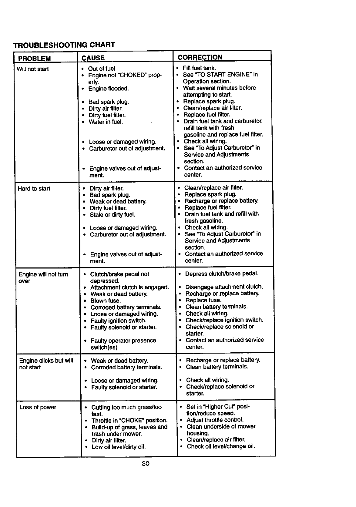
TROUBLESHOOTING CHART
PROBLEM
Will not start
Hard to start
Engine will not turn
over
Engine clicks butwill
not start
Loss of power
CAUSE
•Out of fuel.
•Engine not'CHOKED" prop-
erly.
•Engine flooded.
•Bad spark plug.
•Dirty air filter.
•Dirty fuel filter.
•Water in fuel.
•Loose or damaged widng.
• Carburetor out of adjustment.
•Engine valves out of adjust-
ment.
•Dirty air filter.
•Bad spark plug.
•Weak or dead battery.
•Dirty fuel filter.
•Stale or dirtyfuel.
•Loose or damaged widng.
•Carburetor out of adjustment.
•Engine valves out of adjust-
ment.
•Clutch/brake pedal not
depressed.
•Attachment clutch is engaged.
•Weak or dead battery.
•Blown fuse.
•Corroded battery terminals.
•Loose or damaged widng.
•Faulty ignition switch.
•Faulty solenoid or starter.
•Faulty operator presence
switch(es).
•Weak or dead battery.
•Corroded battery terminals.
• Loose or damaged wiring.
•Faulty solenoid or starter.
•Cutting too much grass/too
fast.
•Throttle in =CHOKE" position.
•Build-up of grass, leaves and
trash under mower.
•Dirty air filter.
• Low oil level/dirtyoil.
CORRECTION
•Fillfuel tank.
•See "TO START ENGINE" in
Operation section.
•Wait several minutes before
attempting to start.
•Replace spark plug.
•Clean/replace air filter.
•Replace fuel filter.
•Drain fuel tank and carburetor,
refilltank with fresh
gasoline and replace fuel filter.
•Check all widng.
•See =ToAdjust Carburetor"in
Service and Adjustments
section.
•Contact an authorized service
center.
•Clean/replace air filter.
•Replace spark plug.
•Recharge or replace battery.
•Replace fuel filter.
•Drain fuel tank and refillwith
fresh gasoline.
•Check all widng.
•See "ToAdjust Carburetor" in
Service and Adjustments
section.
•Contact an authorized service
center.
•Depress clutch/brake pedal.
•Disengage attachment clutch.
•Recharge or replace battery.
•Replace fuse.
•Clean battery terminals.
•Check all wiring.
i• Check/replace ignition switch.
•Check/replace solenoid or
starter.
• Contact an authorized service
center.
•Recharge or replace battery.
• Clean battery terminals.
•Check all wiring.
•Check/replace solenoid or
starter.
•Set in "Higher Cut"posi-
tion/reduce speed.
•Adjust throttle control.
•Clean underside of mower
housing.
•Clean/replace air filter.
•Check oil level/change oil.
30
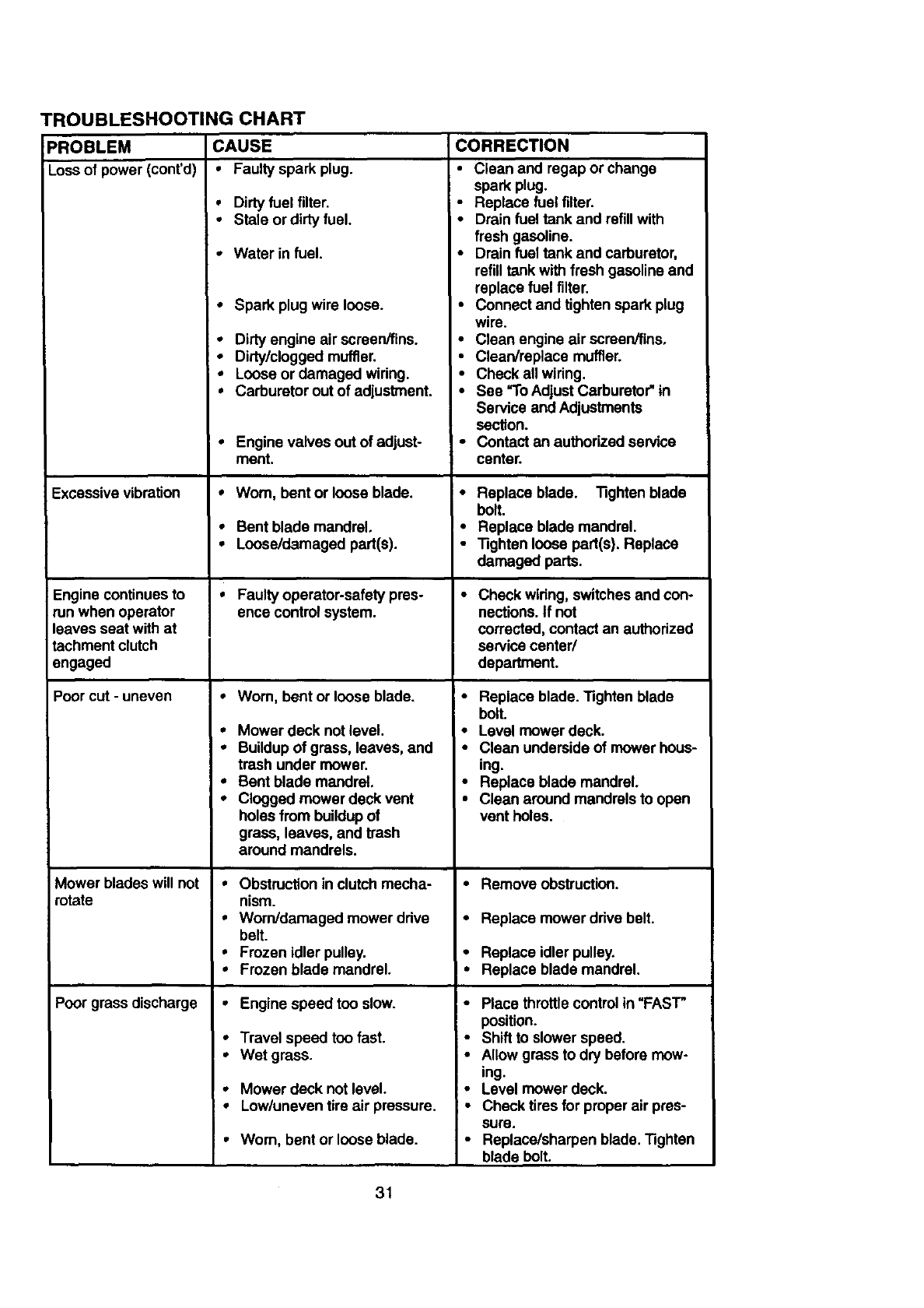
TROUBLESHOOTING CHART
PROBLEM CAUSE CORRECTION
Lossofpower(cont'd) • Faulty spark plug.
Excessive vibration
Engine continues to
run when operator
leaves seat with at
tachment clutch
engaged
Poor cut -uneven
Mower blades will not
rotate
Poor grass discharge
•Dirty fuel filter.
•Stale or dirty fuel.
•Water in fuel.
•Spark plug wire loose.
•Dirty engine air screen/fins.
•Dirty/clogged muffler.
•Loose or damaged wiring.
•Carburetor out of adjustment.
•Engine valves out of adjust-
ment.
•Wom, bent or loose blade.
•Bent blade mandrel.
•Loose/damaged part(s).
•Faulty operator-safety pres-
ence control system.
•Wom, bent or loose blade.
•Mower deck not level.
•Buildup of grass, leaves, and
trash under mower.
• Bent blade mandrel.
•Clogged mower deck vent
holes from buildup of
grass, leaves, and trash
around mandrels.
•Obstruction in clutch mecha-
nism.
•Worn/damaged mower ddve
belt.
•Frozen idler pulley.
•Frozen blade mandrel.
•Engine speed too slow.
•Travel speed too fast.
•Wet grass.
• Mower deck not level.
•Low/uneven tire air pressure.
•Worn, bent or loose blade.
•Clean and regap or change
spark plug.
• Replace fuel filter.
•Drain fuel tank and refillwith
fresh gasoline.
•Drain fuel tank and carburetor,
refilltank with fresh gasoline and
replace fuel filter.
•Connect and tighten spark plug
wire.
•Clean engine air screenfiins.
•Clean/replace muffler.
•Check all wiring.
•See "ToAdjust Carburetor"in
Service and Adjustments
section.
• Contact an authorized service
center.
•Replace blade. Tighten blade
bolt.
!•Replace blade mandrel.
•Tighten loose part(s). Replace
damaged parts.
•Check widng, switches and con-
nections. If not
corrected, contact an authorized
service center/
department.
•Replace blade. Tighten blade
bolt.
•Level mower deck.
•Clean underside of mower hous-
ing.
•Replace blade mandrel.
• Clean around mandrels to open
vent holes.
•Remove obstruction.
•Replace mower drive belt.
•Replace idlerpulley.
•Replace blade mandrel.
•Place throttlecontrol in "FAS'F
position.
•Shift to slower speed.
•Allow grass to dry before mow-
ing.
•Level mower deck.
i* Check tires for proper air pres-
sure.
•Replace/sharpen blade. Tighten
blade bolt.
31
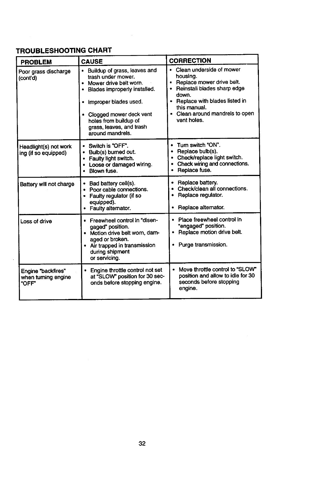
TROUBLESHOOTING CHART
PROBLFM CAUSE
Poor grass discharge • Buildup of grass, leaves and
(cont'd)
Headlight(s) not work
iing (if so equipped)
Battery will not charge
Loss of drive
Engine =backfires"
when fuming engine
"OFP
trash under mower.
•Mower drive belt worn.
•Blades improperly installed.
•Improper blades used.
•Clogged mower deck vent
holes from buildup of
grass, leaves, and trash
around mandrels.
•Switch is "OFP.
• Bulb(s) burned out.
•Faulty light switch.
•Loose or damaged wiring.
•Blownfuss.
•Bad battery cell(s).
•Poor cable connections.
•Faulty regulator (if so
equipped).
•Faulty alternator.
•Freewheel control in "disen-
gaged" position.
•Motion drive belt worn, dam-
aged or broken.
•Air trapped in transmission
during shipment
or servicing.
•Engine throttle controlnot set
at "SLOW" positionfor 30 sec-
onds before stoppingengine.
CORRECTION
• Clean underside of mower
housing.
•Replace mower drive belt.
•Reinstall blades sharp edge
down.
•Replace with blades listed in
this manual.
• Clean around mandrels to open
vent holes.
•Turn switch"ON".
• Replace bulb(s).
•Check/replace light switch.
• Check wiringand connections.
•Replace fuse.
•Replace battery.
•Check/clean all connections.
•Replace regulator.
•Replace altemator.
•Place freewheel control in
=engaged" position.
•Replace motion drive belt.
•Purge transmission.
• Move throttle control to "SLOW"
position and allow to idle for 30
seconds before stopping
engine.
32
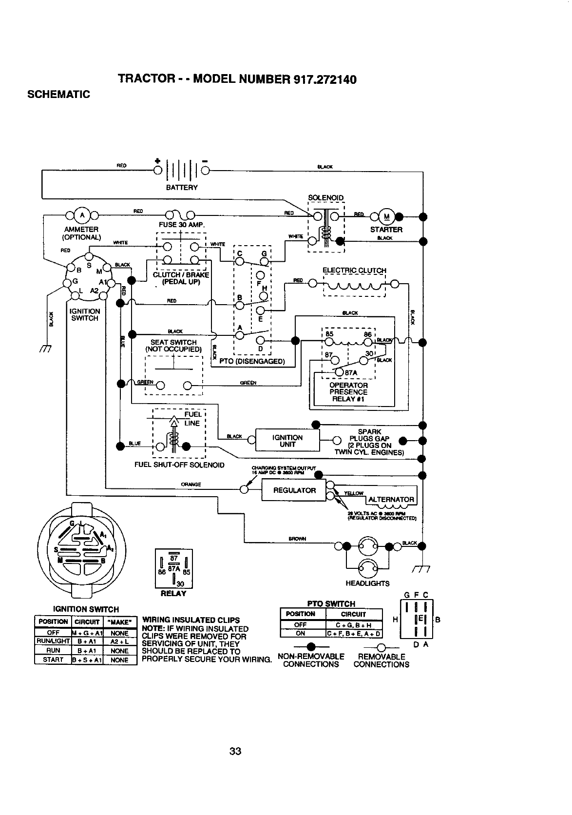
SCHEMATIC
TRACTOR -- MODEL NUMBER 917.272140
AMMETER
(OPTIONAL)
RED
REO
o........ .
FUEL 0
i I
i I
i
I i
I___1
FUEL SHUT-OFF SOLENOID
A •
W•
I_ SPARKIGNITION PLUGS GAP
UNIT I_" (2 PLUGS ON
' TWIN CYL ENGINES)
RELAY
IGNmON SWITCH
POSITION IIRCUIT "MAKE"
OFF +G+A1 NONE
RUN4.IGHT B + A1 A2 + L
RUN B + A1 NONE
START + S + A1 NONE
WIRING INSULATED CLIPS
NOTE: IF WIRING INSULATED
CLIPS WERE REMOVED FOR
SERVICING OF UNIT, THEY
SHOULD BE REPLACED TO
PROPERLY SECURE YOUR WIRING. NON-REMOVABLE
CONNECTIONS
)
-7
GFC
PTO SWITCH HsON C+F,B+ErA+D
0DA
REMOVABLE
CONNECTIONS
33
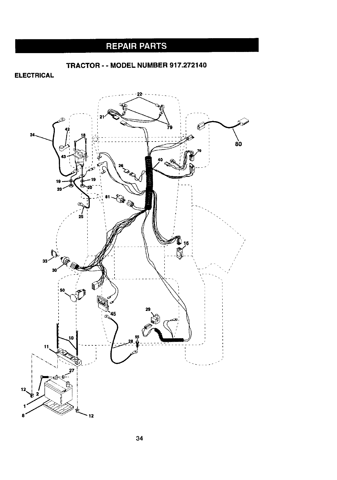
ELECTRICAL
TRACTOR - - MODEL NUMBER 917.272140
79
L
i
\8O
26
I27
i
I
29
16
i
b
8
34
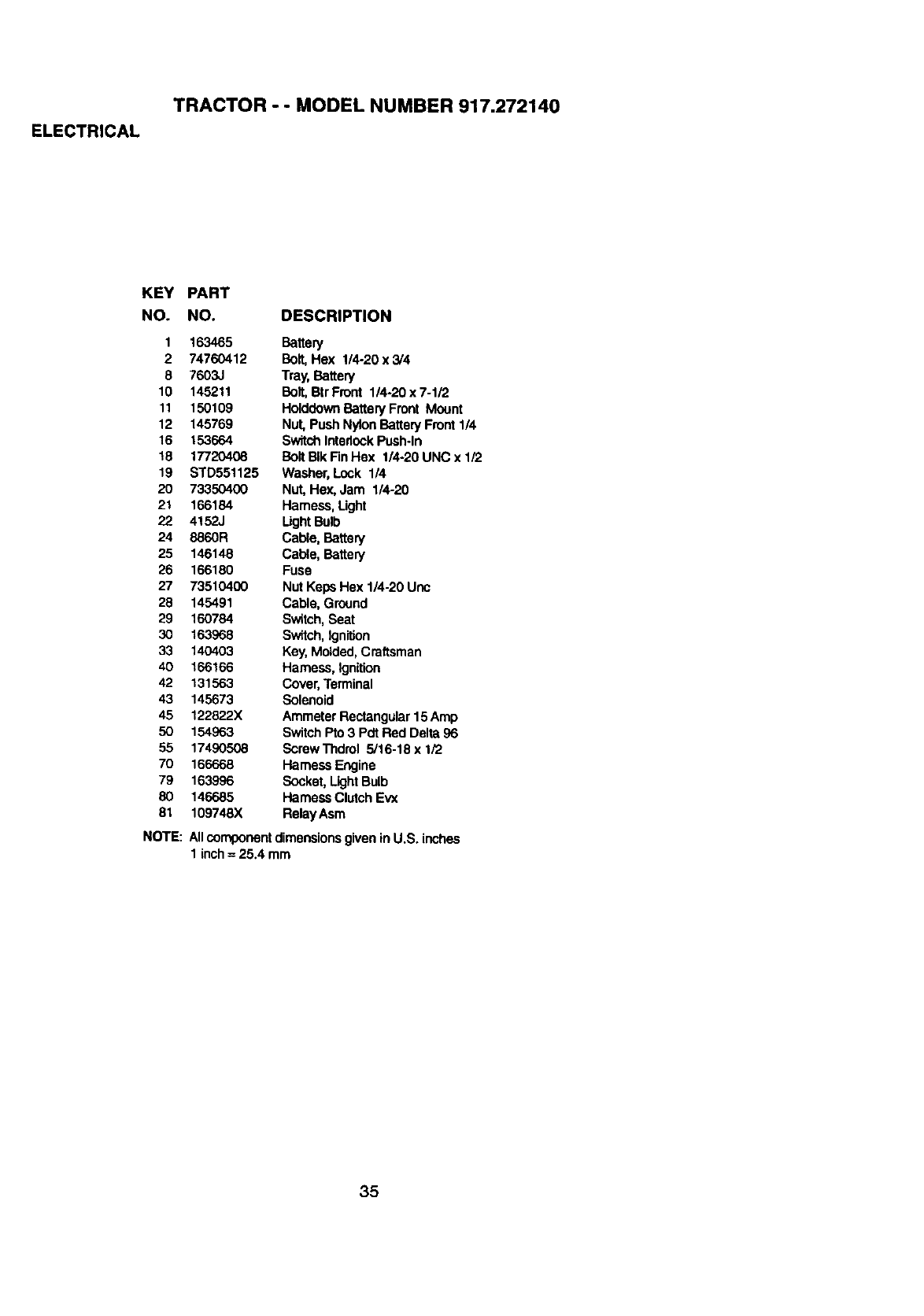
ELECTRICAL
TRACTOR -- MODEL NUMBER 917.272140
KEY PART
NO. NO. DESCRIPTION
1 163465 Battery
2 74760412 Ball, Hex 1/4-20 x 3/4
8 7603J Tray, Battery
10 145211 Ball, BtrFront 1/4-20x7-1/2
11 150109 HolddownBatteryFront Mount
12 145769 Nut, Push NylonBattery Front1/4
16 153664 SwitchInterlockPush-In
!8 17720408 BoltBIk Fin Hex 1/4-20 UNC x 1/2
19 STD551125 Washer, Lock 1/4
20 73350400 Nut, Hex, Jam 1/4-20
21 166184 Harness,Light
22 4152J LightBulb
24 8860R Cable, Battery
25 146148 Cable, Battery
26 166180 Fuse
27 73510400 Nut Keps Hex 1/4-20 Unc
28 145491 Cable, Ground
29 160784 Switch,Seat
30 163968 Switch,Ignition
33 140403 Key, Molded,Craftsman
40 166166 Harness, Ignition
42 131563 Cover,Terminal
43 145673 Solenoid
45 12282.2X Ammeter Rectangular15Amp
50 154963 SwitchPro 3 Pdt Red Delta 96
55 17490508 ScrewThdrol 5/16-18x 1/2
70 166668 Harness Engine
79 163996 Socket,Light Bulb
80 146685 HarnessClutch Evx
81 109748X RelayAsm
NOTE: Allcomponentdimensionsgivenin U.S. inches
1 inch= 25.4 mm
35
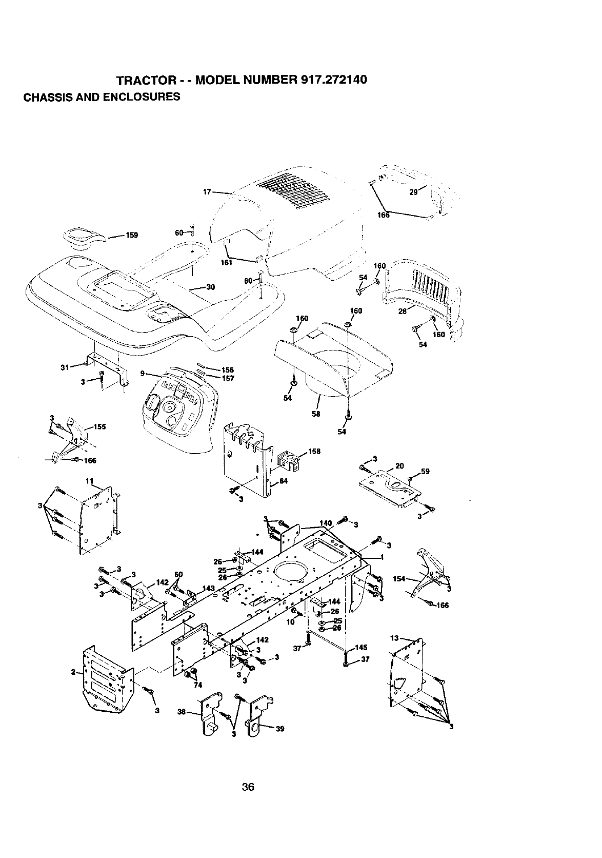
TRACTOR - - MODEL NUMBER 917.272140
CHASSIS AND ENCLOSURES
31
160
160
58
11
3!
154 °
_166
,i3
33
74
36
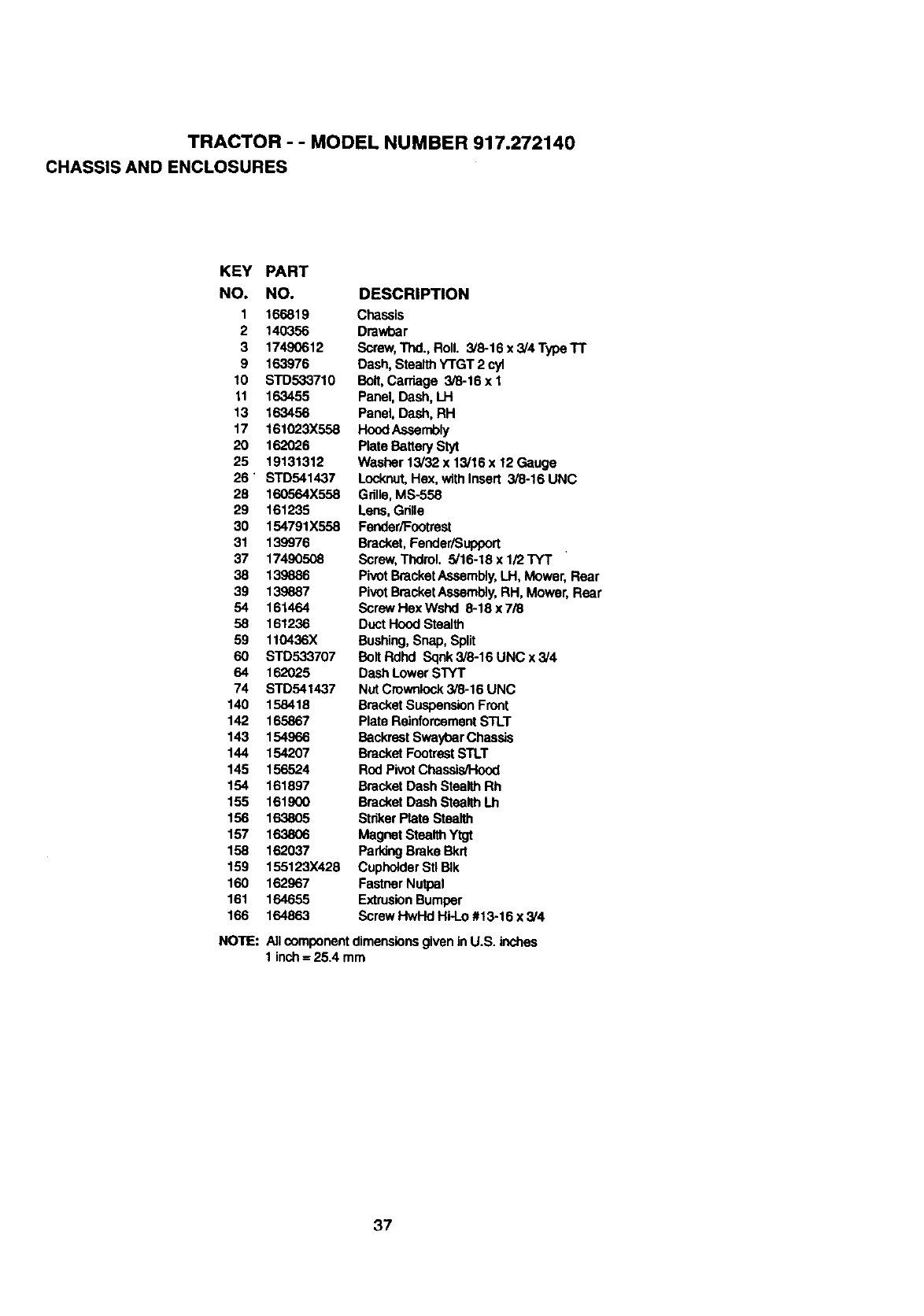
TRACTOR - - MODEL NUMBER 917.272140
CHASSIS AND ENCLOSURES
KEY PART
NO, NO.
1 166819
2 140356
3 17490612
9 163976
t0 STD533710
11 163455
13 163456
17 161023X558
20 162026
25 19131312
26' STD541437
28 160564X558
29 161235
30 154791X558
31 139976
37 17490508
38 139886
39 139887
54 161464
58 161236
59 110436X
60 STD533707
64 162025
74 STD541437
140 158418
142 165867
143 154966
144 154207
145 156524
154 161897
155 161900
156 163805
157 163806
158 162037
159 155123X428
160 162967
161 164655
166 164863
NOTE:
DESCRIPTION
Chassis
Dmwbar
Screw,Thd., Roll. 3/8-16 x 3/4 Type "IT
Dash, Stealth Y'rGT 2 cyl
Bolt,Carriage 3/8-16 x 1
Panel, Dash, LH
Panel, Dash, RH
Hood Assembly
Plate Battery Styt
Washer 13/32 x 13/16 x 12 Gauge
Locknut,Hex, withInsert 3/8-16 UNC
Grille, MS-558
Lens, Grille
Fender/Footrest
Bracket, Fender/Support
Screw, Thdrol. 5/16-18 x 1/2TYT
PivotBracketAssembly,LH, Mower, Rear
PivotBracketAssembly,RH, Mower, Rear
Screw Hex WslxI 8-18 x 7/8
DuctHood Stealth
Bushing,Snap, Split
Bolt Rdhd Sqnk 3/8-16 UNC x 3/4
Dash Lower STYT
Nut Crownlock3/8-16 UNC
Bracket SuspensionFront
Plata ReinforcementSTLT
BackrestSwaybar Chassis
Bracket FootrestSTLT
Rod Pivot Chassis/Hood
Bracket Dash Stealth Rh
Bracket Dash Stealth Lh
Striker Plate Stealth
Magnet Stealth Ytgt
Parking Brake Bkrt
CupholderStl BIk
Fastnsr Nutpal
ExtrusionBumper
Screw HwHd Hi-Lo #13-16 x3/4
Allcomponentdimensionsgivenin U.S. Inches
1 inch=25.4 mm
37
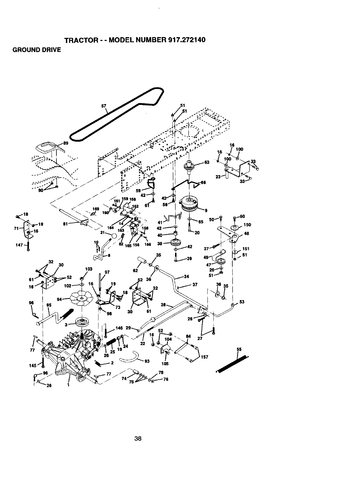
TRACTOR - - MODEL NUMBER 917.272140
GROUND DRIVE
32
61 "52
16
96
103 97
19
3O
62
36
32
51
4'S
47
36 35
I
52
27
22
26
"_:_--- 2 93 105
3B
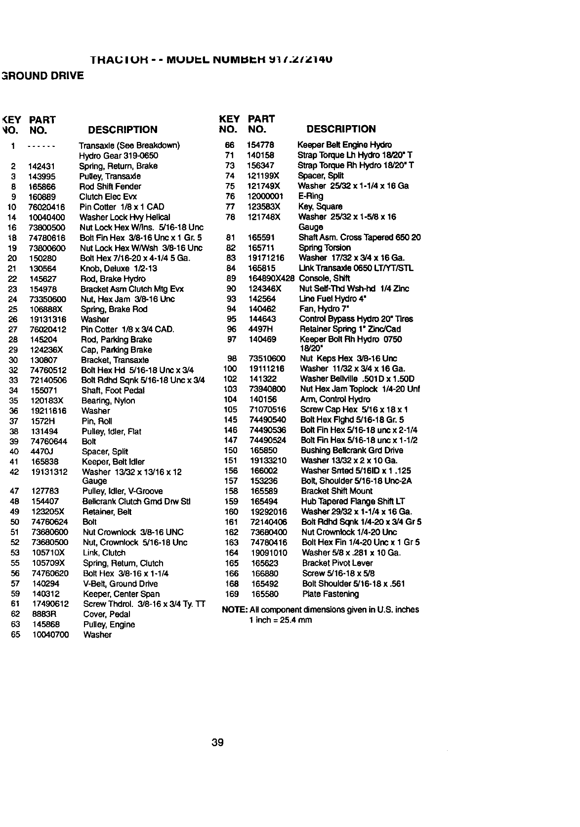
IHAI.; IUH - - MUUI=L NUMI:ilcH _11.ZI_'14U
3ROUND DRIVE
_EY PART KEY PART
_IO. NO. DESCRIPTION NO. NO. DESCRIPTION
1...... Transaxle (See Breakdown) 66 154778
HydroGear 319-0650 71 140158
2 142431 Spdng, Return,Brake 73 156347
3 143995 Pulley,Transaxle 74 121199X
8 165866 Rod Shift Fender 75 121749X
9 160889 ClutchElec Evx 76 12000001
10 76020416 PinCotter 1/8x 1 CAD 77 123583X
14 10040400 Washer Lock Hvy Helical 78 121748X
16 73800500 Nut LockHex W/Ins. 5/16-18 Uoc
18 74780616 BoltFin Hex 3/8-16 Unc x I Gr. 5 81 165591
19 73800600 Nut Lock Hex W/Wsh 3/8-16 Unc 82 165711
20 150280 BoltHexTI16-20x4-1/45Ga. 83 19171216
21 130564 Knob,Deluxe 1/2-13 84 165815
22 145627 ROd,Brake Hydro 89 164890X428
23 154978 BracketAsm ClutchMtg Evx 90 124346X
24 73350600 Nut, Hex Jam 3/8-16 Unc 93 142564
25 106888x Spdng,Brake ROd 94 140462
26 19131316 Washer 95 144643
27 76020412 Pin Cotter 1/8 x 3/4 CAD. 96 4497H
28 145204 ROd,ParkingBrake 97 140469
29 124236X Cap, ParkingBrake
30 130807 Bracket,Transaxte 98 735106(X)
32 74760512 Bolt Hex Hd 5/16-18 Unc x 3/4 100 19111216
33 72140506 Bolt Rdhd Sqnk 5/16-18 Uric x 3/4 102 141322
34 155071 Shaft, Foot Pedal 103 73940800
35 120183X Bearing,Nylon 104 140156
36 19211616 Washer 105 71070516
37 1572H Pin, Roll 145 74490540
38 131494 Pulley,Idler,Rat 146 74490536
39 74760644 Bolt 147 74490524
40 4470J Spacer,Split 150 165850
41 165838 Keeper, BeltIdler 151 19133210
42 19131312 Washer 13/32 x 13/16 x 12 156 166002
Gauge 157 153236
47 127783 Pulley,Idler,V-Groove 158 165589
48 154407 BellcrankClutchGrnd Drw Stl 159 165494
49 123205X Retainer, Belt 160 19292016
50 74760624 Bolt 161 72140406
51 73680600 Nut Crownlock 3/6-16 UNC 162 73680400
52 73680500 Nut, Crownlock 5/16-18 Unc 163 74780416
53 105710X Link,Clutch 164 19091010
55 105709X Spring,Return,Clutch 165 165623
56 74760620 Bolt Hex 3/6-16 x 1-1/4 166 166880
57 140294 V-Belt,Ground Drive 168 165492
59 140312 Keeper, Center Span 169 165580
61 17490612 Screw Thdrol. 3/8-16 x 3/4 Ty.Tr
62 8883R Cover,Pedal
63 145868 Pulley,Engine
65 10040700 Washer
Keeper Bolt EngineHydro
StrapTorque Lh Hydro 18/20" T
Strap Torque Rh Hydro 18/20" T
Spacer,Split
Washer 25/32 x 1-1/4 x 16Ga
E-Ring
Key,Square
Washer 25/32 x 1-5/8 x 16
Gauge
ShaftAsm. Cross Tapered650 20
SpdngTorsion
Washer 17/32 x 3/4 x 16Ga,
LinkTransaxle 0650 LT/YTiSTL
Console,Shift
Nut Self-ThdWsh-hd 114Zinc
Line Fuel Hydro4"
Fan, Hydro7"
ControlBypassHydro20" "nres
RetainerSpdng 1"Zinc/Cad
Keeper Bolt Rh Hydro 0750
18/20"
Nut Keps Hex 3/8.16 Uric
Washer 11/32 x 3/4 x 16 Ga.
Washer Boliville .501D x 1.50D
Nut Hex Jam T_olock 1/4-20 Unf
Arm, ControlHydro
Screw Cap Hex 5/16 x 18 x 1
Bolt He)( Rghd 5/16-18 Gr. 5
Bolt FinHex 5/16-18 un¢x 2-1/4
Bolt FinFlex 5/16-18 uocx 1-1/2
BushingBolicrank Grd Drive
Washer 13/32 x 2 x 10 Ga.
Washer Srrted 5/161D x 1.125
Bolt, Shoulder5/16-18 Uee-2A
BracketShiftMount
Hub TaperedRange Shift LT
Washer29/32 x 1-1/4 x 16Ga.
Bolt Rdhd Sqnk 1/4-20 x 3/4 Gr 5
Nut Crownlock1/4-20 Uoc
BoltHex Fin 1/4-20 Unc x I Gr 5
Washer 5/8 x.281 x 10 Ga.
BracketPivotLever
Screw 5/16o18x5/8
Bolt Shoulder5/16-18 x.561
Plate Fastening
NOTE: All componentdimensionsgiven in U.S. inches
1 inch= 25A mm
39
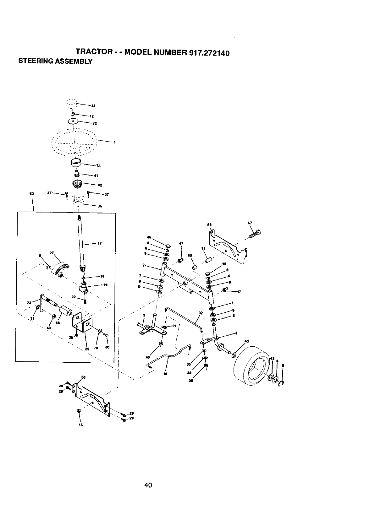
TRACTOR - - MODEL NUMBER 917.272140
STEERING ASSEMBLY
I
i
•j ", '
_ _'_ 73
18
," /),.¸/¸
47
1$
10
611
13
65
67
46
43
4O
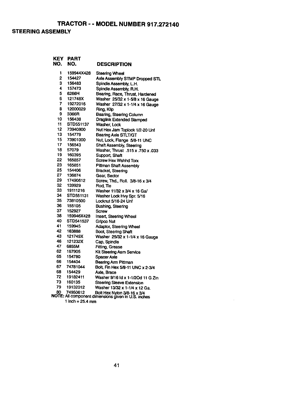
TRACTOR --MODEL NUMBER 917.272140
STEERING ASSEMBLY
KEY PART
NO. NO. DESCRIPTION
1 159944X428 SteedngWheel
2 154427 Axle AssemblySTMP DroppedSTL
3 156483 SpindleAssembly,L.H.
4 157473 SpindleAssembly,R.H.
5 6266H Beadng, Race, Thrust,Hardened
6 121748X Washer 25/32 x1-5/8 x16 Gauge
7 19272016 Washer 27i32x1-1/4x16Gauge
8 12000029 Ring,Klip
9 3366R Bearing,StearingColumn
10 156438 DraglinkExtendedStamped
11 STD551137 Washer, Lock
12 73940800 Nut Hex Jam Toplock1/2-20 Unf
13 154779 BearingAxJeSTLT/GT
15 73901000 Nut, Lock, Range 5/8.11 UNC
17 156543 ShaftAseambly,Steering
18 57079 Washer,Thrust .515 x .750 x .033
19 160395 Support,Shaft
22 165857 Screw Hex Wshnd Ton<
23 165851 PittmanShaftAssembly
25 154406 Bracket, Steering
27 136874 Gear, Sector
29 17490612 Screw,Thd.,Roll. 3/6-16x3/4
32 139929 Rod,"Re
33 19111216 Washer 11/32 x 3/4 x 16 Ga/
34 STD551131 Washer Lock Hvy Spr. 5/16
35 73810500 Locknut5/16-24 Unf
36 155105 Bushing,Steering
37 152927 Screw
38 159946X428 Insert,SteeringWheel
40 STD541537 GripcoNut
41 159945 Adaptor,SteeringWheel
42 163888 Boot,SteeringShaft
43 121749X Washer 25/32 x 1-1/4 x 16 Gauge
46 121232X Cap, Spindle
47 6855M Fitting,Grease
62 167905 Kit SteeringAsm Service
65 154780 SpacerAxle
66 154404 BearingArm Pittman
67 74781044 BOlLFin Hex 5/8-11 UNC x 2-3/4
68 154429 Axle, Brace
72 19182411 Washer 9/16 Id x 1-1/2Od 11G Zin
73 160135 SteeringSleeve Extension
79 19132012 Washer 13/32 x 1-1/4 x 12 Ga.
80 74950612 BoltHex Nylon3/8-16 x 3/4
NOTE: Allcomponentdimensionsgiven in U.S. inches
1 inch= 25.4 mm
41
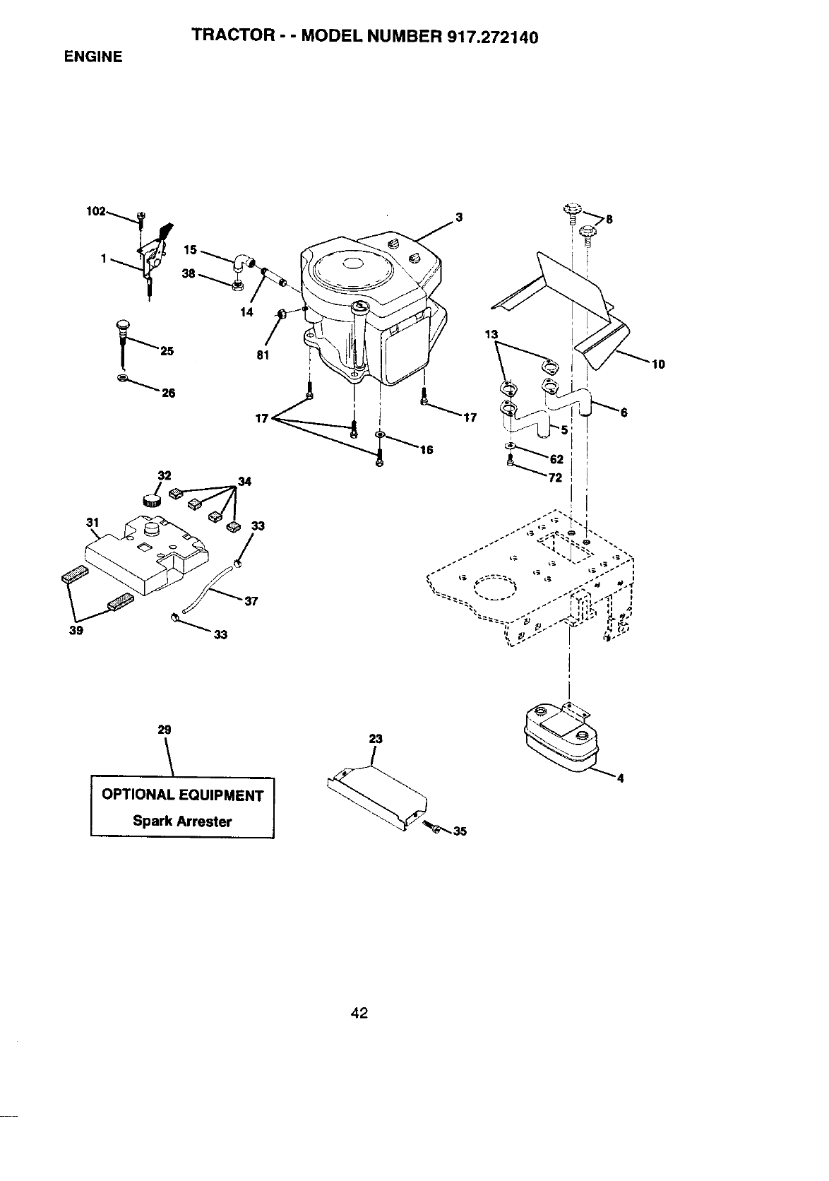
ENGINE TRACTOR - - MODEL NUMBER 917.272140
14
13
29
OPTIONAL EQUIPMENT
Spark Arrester
23
/
4
_35
42
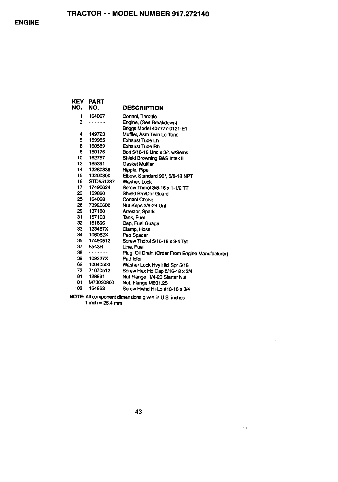
ENGINE
TRACTOR - - MODEL NUMBER 917.272140
KEY PART
NO. NO. DESCRIPTION
1 164067 Control,Throttle
3...... Engine,(See Breakdown)
BriggsModel407777-0121-E1
4 149723 Muffler,Asm Twin Lo-Tone
5 159955 ExhaustTube Lh
6 160589 ExhaustTube Rh
8 150176 Bolt5/16-18 Uric x 3/4 w/Sems
10 162797 ShieldBrowning B&SIntek II
13 165391 Gasket Muffler
14 13280336 Nipple, Pipe
15 13200300 Elbow, Standard 90°, 3/8-18 NPT
16 STD551237 Washer,Lock
17 17490624 Screw Thdrol 3/8-16 x 1.1/2 rl-
23 159880 ShieldBrn/Dbr Guard
25 164068 ControlChoke
26 73920600 Nut Keps 3/6-24 Unf
29 137180 Arrestor,Spark
31 157103 Tank,Fuel
32 161696 Cap, Fuel Guage
33 123487X Clamp, Hose
34 I(To08,?.X Pad Spacer
35 17490512 Screw Thdrol 5/16-18 x 3-4 Tyt
37 8543R Line, Fuel
38 ....... Plug, Oil Drain (Order From EngineManufacturer)
39 109227X Pad Idler
62 10040500 Washer LockHvy HIcl Spr 5/16
72 71070512 Screw Hex Hd Cap 5/16-18 x3/4
81 128861 Nut Flange 1/4-20 Starter Nut
101 M73030800 Nut, Flange M801.25
102 164863 Screw Hwhd Hi-Lo #13-16 x3/4
NOTE: Allcomponentdimensior_ givenin U.S. inches
1 inch= 25.4 mm
43
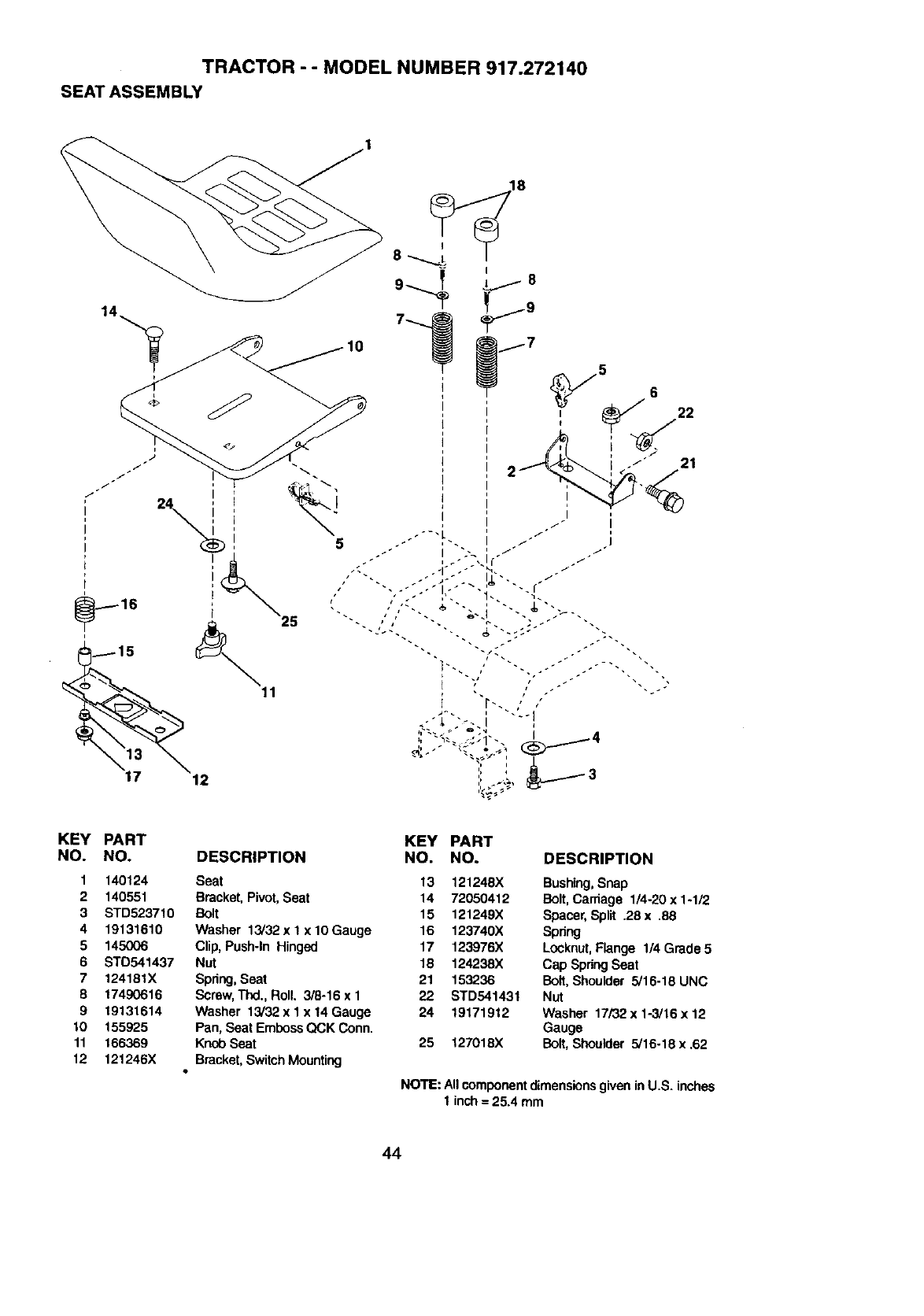
TRACTOR - - MODEL NUMBER 917.272140
SEAT ASSEMBLY
12
21
KEY
NO.
1
2
3
4
5
6
7
8
9
lO
11
12
PART
NO.
140124
140551
STD523710
19131610
145O06
STO541437
124181X
17490616
19131614
155925
166369
121246X
DESCRIPTION
Seat
Bracket, Pivot, Seat
Bolt
Washer 13/32 x 1x 10Gauge
Clip, Push-In Hinged
Nut
Spring,Seat
Screw,Thd., Roll. 3/8-16 x 1
Washer 13/32 x 1 x 14 Gauge
Pan, Seat EmbossQCK Conn.
Knob Seat
Bracket,Switch Mounting
KEY PART
NO. NO, DESCRIPTION
13 121248X Bushing,Snap
14 72050412 Bolt,Carriage 1/4-20 x 1-1/2
15 121249X Spacer,SpSt .28x .88
16 123740X Spnng
17 123976X Locknut,Flange 1/4 Grade 5
18 124238X Cap SpringSeat
21 153236 Bolt, Shoulder 5/16-18 UNC
22 STD541431 Nut
24 19171912 Washer 17/32x 1-3/16x 12
Gauge
25 127018X Bolt,Shoulder 5/16-18 x.62
NOTE: AllcomponentdimensionsgiveninU.S. inches
1 inch = 25.4 mm
44
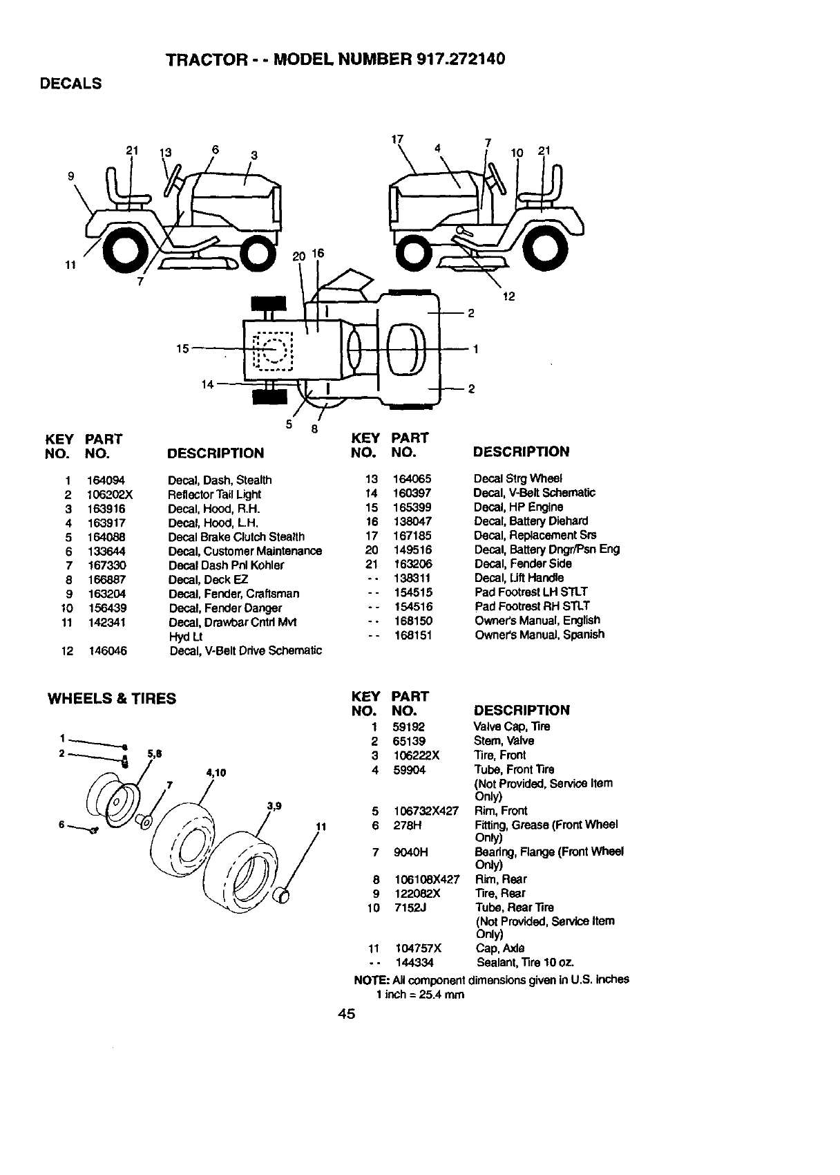
DECALS
TRACTOR --MODEL NUMBER 917.272140
21 13 6 3 17 4721
11 16
12
15
KEY PART
NO. NO.
1 164094
2 106202X
3 163916
4 163917
5 164088
6 133644
7 167330
8 166887
9 163204
10 156439
11 142341
12 146046
5 6
DESCRIPTION
Decal, Dash, Stealth
ReflectorTailLight
Decal, Hood, R.H.
Decal, Hood, L.H.
Decal BrokeClutchStealth
Decal, CustomerMaintenance
Decal Dash Phi Kohler
Decal, Deck EZ
Decal, Fender, Craftsman
Decal, Fender Danger
Decal, Dmwber Cntd Ivh,t
HydLt
Decal, V-BeltDrive Schematic
KEY
NO.
13
14
15
16
17
20
21
PART
NO. DESCRIPTION
164065 Decal Strg Wheel
160397 Decal, V-Belt Schematic
165399 Decal, HP Engine
138047 Decal, Battery Diehard
167185 Decal, Replacement Srs
149516 Decal, Battery Dngr/PsnEng
163206 Decal, Fender Side
138311 Decal, LiftHandle
154515 Pad FootrestLH STLT
154516 Pad FootrestRH STLT
168150 Owner'sManual, English
168151 Owner's Manual,Spanish
74,10
11
KEY PART
NO. NO. DESCRIPTION
1 59192 Valve Cap, Tim
2 65139 Stem, Vaive
3 106222X Tim, Front
4 59904 Tube, FrontTire
(Not Provided,Service Item
Only)
5 106732X427 Rim, Front
6 278H Fitting,Gmaea (FrontWheel
Only)
79040H Baadng, Range (FrontWheel
Orgy)
8 106108X427 Rim, Rear
9 1220&?.X Tire, Rear
10 7152J Tube, RearTire
(Not Provided,Service Item
Only)
11 I04757X Cap, Axle
- - 144334 Sealant, Tire 10 oz.
NOTE: All componentdimensionsgiven inU.S. inches
1 inch= 25.4 mm
45
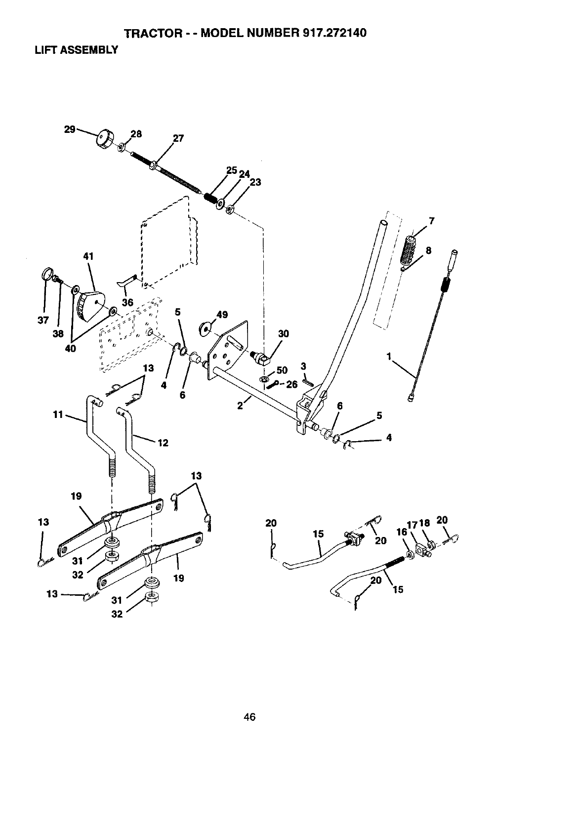
TRACTOR - - MODEL NUMBER 917.272140
LIFT ASSEMBLY
37
38
40
36
5 49
6
3O
3
6
7
,,i/ "8i
5
19
13
32
13
19
20
15
2O
46
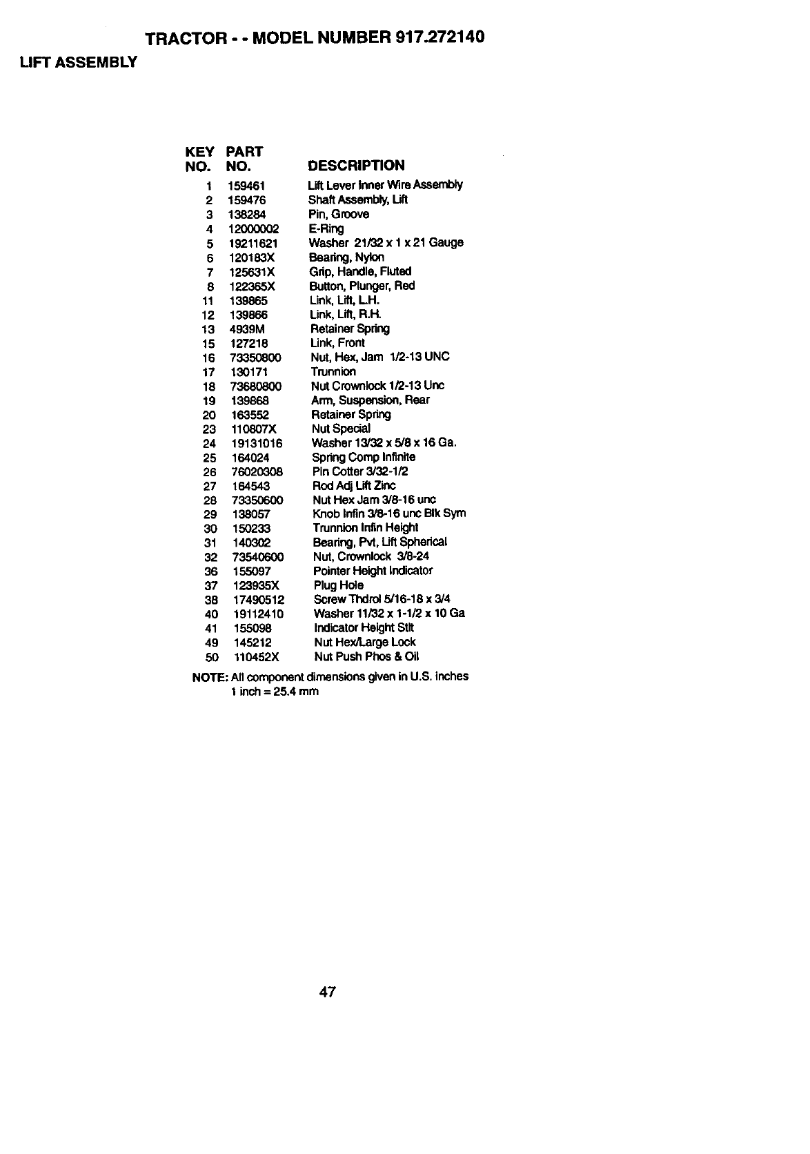
TRACTOR - - MODEL NUMBER 917.272140
LIFT ASSEMBLY
KEY PART
NO. NO. DESCRIPTION
1 159461 LiltLever Inner Wlre Assembly
2 159476 ShaftAssembly,Lift
3 138284 Pin, Groove
4 12000002 E.Ring
5 19211621 Washer 21/32 x 1 x 21 Gauge
6 120183X Beadng, Nylon
7 125631X Grip, Handle, Fluted
8 122365X Button,Plunger,Red
11 139865 Link,Lift, LH.
12 139866 Link,Lift, R.H.
13 4939M RetainerSpdng
15 127218 Link, Front
16 73350800 Nut, Hex, Jam 1/2-13 UNC
17 130171 Trunnion
18 73680800 Nut Crownlock1/2-13 Unc
19 139868 Arm, Suspension,Rear
20 163552 RetainerSpring
23 110807X Nut Special
24 19131016 Washer 13/32 x 5/8 x 16Ga.
25 164024 Spring Comp Infinite
26 76020308 Pin Cotter 3/32-1/2
27 164543 Rod Adj LiftZinc
28 73350600 Nut Hex Jam 3/8-16 unc
29 138057 Knob Infin3/8-16 uncBIk Sym
30 150233 Trunnion InfinHeight
31 140302 Bearing,Pvt, Lift Spherical
32 73540600 Nut, Crownlock 3/8-24
36 155097 PointerHeight Indicator
37 123935X Plug Hole
38 17490512 Screw Thdrol 5/16-18 x 3/4
40 19112410 Washer 11/32 x 1-1/2 x 10 Ga
41 155098 Indicator HeightStlt
49 145212 Nut Hex/Large Lock
50 110452X Nut Push Phos & Oil
NOTE: AllcomponentdimensionsgiveninU.S. inches
1inch= 25.4 mm
47
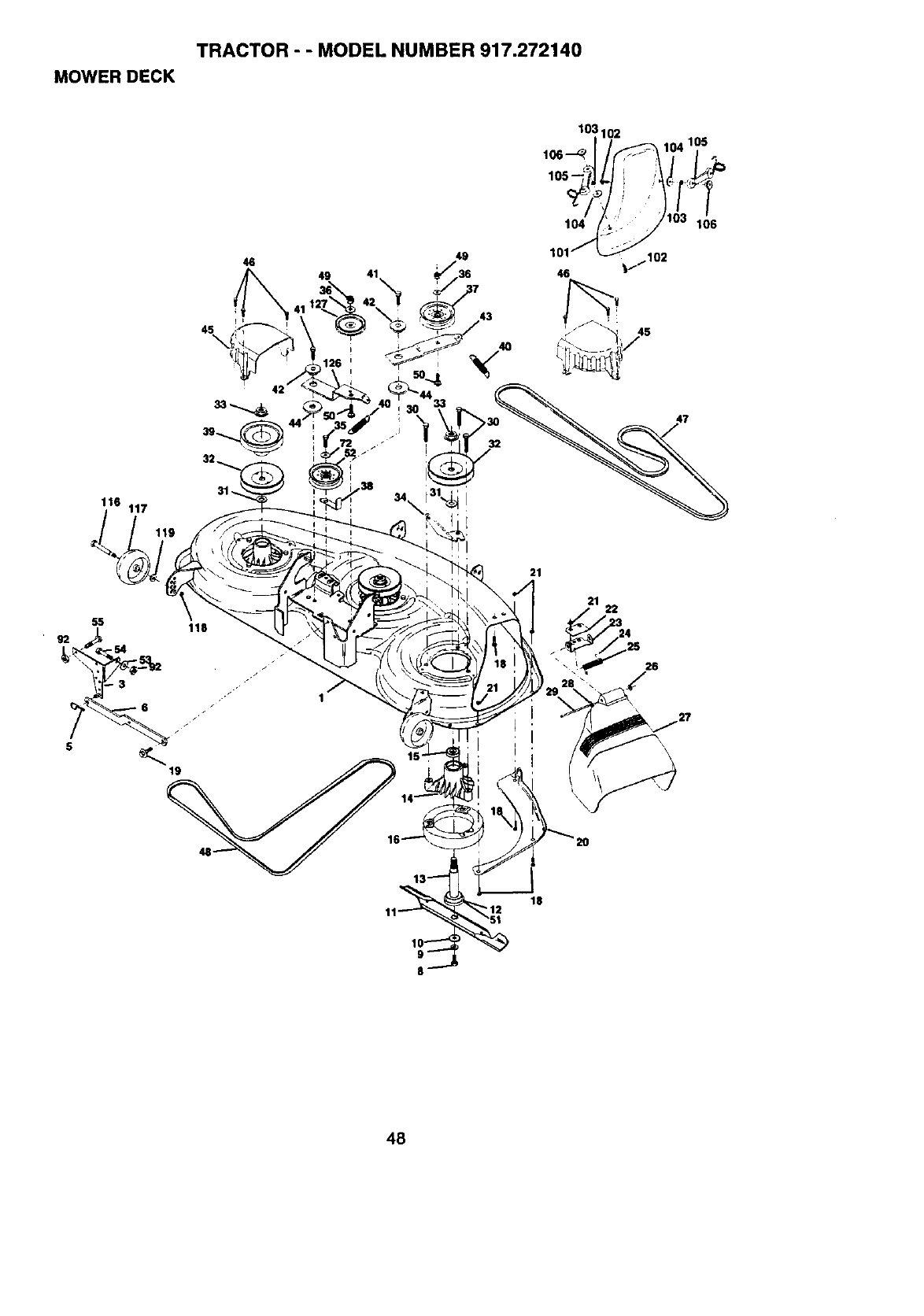
TRACTOR - - MODEL NUMBER 917.272140
MOWER DECK
46
45\
49
116 117
55 118
19
21
21 22
\\
18
48
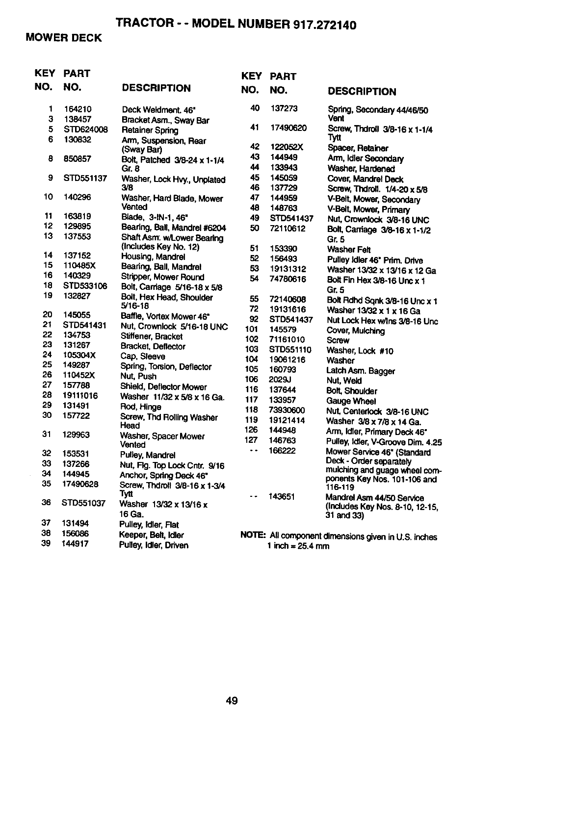
TRACTOR - - MODEL NUMBER 917.272140
MOWER DECK
KEY PART KEY PART
NO. NO. DESCRIPTION NO, NO.
I 164210 Deck Weldmect. 46" 40 137273
3 138457 BracketAsm., Sway Bar 41 17490620
5 STD624008 Retainer Spring
6 130832 Arm, Suspension,Rear 42 122052X
(Sway Bar) 43 144949
6 850857 Bolt, Patched 3/8-24 x 1-1/4
Gr. 8 44 133943
9 STD551137 Washer, Lock Hvy., Unplated 45 145059
3/8 46 137729
10 140296 Washer, Hard Blade, Mower 47 144959
Vented 48 148763
11 163819 Bade, 3-1N-1,46" 49 STD541437
12 129895 Beadng, Ball, Mandrel #6204 50 72110612
13 137553 ShaftAsrrr.w/1.owarBaadng
(IncludesKey No. 12) 51 153390
14 137152 Housing,Mandrel 52 156493
15 110485X Beadng, Ball, Mandrel 53 19131312
16 140329 Stripper,Mower Round 54 74780616
18 STD533106 Bolt,Car'f,age 5/16-18x5/8
19 132827 Bo_t,Hex Head, Shoulder 55 72140608
5/16-18 72 19131616
20 145055 Baffle, VortexMower 46" 92 STD541437
21 STD541431 Nut, Crowntock 5/16-18UNC 101 145579
22 134753 Stiffener, Bracket 102 71161010
23 131267 Bracket, DefleCtor 103 S'rD551110
24 I05304X Cap, Sleeve 104 19061216
25 149287 Spdng,Torsion,Deflector 105 160793
26 110452X Nut, Push 106 2029J
27 157788 Shield, DeflectorMower 116 137644
28 19111016 Washer 11/32x5/8x 16Ga. 117 133957
29 131491 Rod, Hinge 118 73930600
30 157722 Screw,Thd RollingWasher 119 19121414
Head 126 144948
31 129963 Washer, Spacer Mower 127 146763
Vented --166222
32 153531 Pulley,Mandrel
33 137266 Nut, Ftg. Top LockCntr. 9/16
34 144945 Anchor,SpringDeck46"
35 17490628 Screw, Thdroll 3/8-16 x 1-3/4
Tytt - - 143651
36 STD551037 Washer 13/32x13/16x
16 Ga.
37 131494 Pulley,Idler,Flat
38 156086 Keeper, Bait, Idler
39 144917 P_ey, |d_er,Driven
DESCRIPTION
Spdng,Secondely 44/46/50
Vent
Screw,Thdrdll 3/8-16 x 1-1/4
Spacer, Retainer
Ann, IdlerSecoedary
Washer, Hardened
Cover, Mandrel Deck
Screw, ThdrolL 1/4-20 x 5/8
V-Bait,Mower, Secondary
V-Bait,Mower, Priman/
Nut, Crownlock 3/8-16 UNC
Ball Cardage 3/_.16 x 1-1/2
Gr. 5
Washer Felt
Pulley Idler46" Pdm. Drive
Washer 13/32 x 13/16 x 12 Ga
Bolt Fin Hex 3/8-16 Unc x 1
Gr. 5
BoltRdhd Sqnk 5/8-16 Uncx 1
Washer 13/32 x 1 x 16 Ga
Nut Lock Flexw/Ins 3/8-16 Unc
Cover, Mulching
Screw
Washer, Lock #10
Washer
LatchAsm. Bagger
Nut,Weld
Bolt,Shoutder
GaugeWheel
Nut,Centedock 3/8-16 UNC
Washer 3/3 x 7/8 x 14 Ga.
Arm,Idler,Pdmery Deck46"
Pulley,Idler,V-Groove Dim.4.25
Mower Service46" (Standard
Deck-Order separately
muP.,hingend guage whee_com-
ponentsKey Nos. 101-106 and
116-119
Mandrel Aern44/50 Service
(IncludesKey Nos. 8-10, 12-15,
31 and 33)
NOTE: All componentdimensionsgiven in U.S. inches
1 inch= 25.4 mm
49
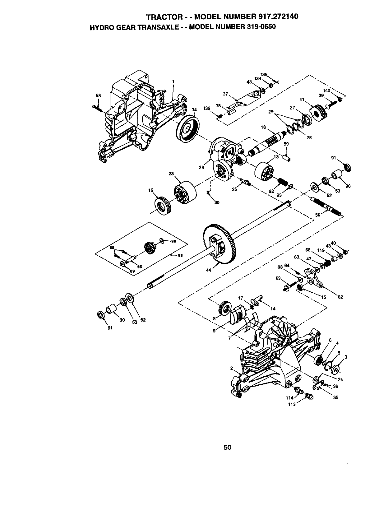
TRACTOR - - MODEL NUMBER 917.272140
HYDRO GEAR TRANSAXLE - - MODEL NUMBER 319-0650
58
23
19
34
41
28
59
91
9O
53
52
44
4
35
5O
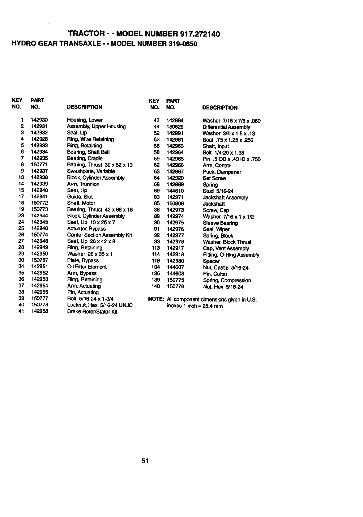
TRACTOR - - MODEL NUMBER 917.272140
HYDRO GEAR TRANSAXIE -- MODEL NUMBER 319-0650
KEY PART KEY PART
NO. NO. DESCRIPTION NO. NO. DESCRIPTION
1 142930 Housing,Lower 43 142884 Washer 7/16 x 7/8 x .060
2 142931 Assembly,Upper Housing 44 150829 DifferentialAssembly
3 142932 Sest, Lip 52 142991 Washer 3/4 x 1.5 x .13
4 142928 Ring,Wire Retaining 53 142961 Seal .75 x 1.25 x .250
5 142933 Ring, Retaining 56 142963 Shaft, Input
6 142934 Bearing,ShaftBall 58 142964 Bolt 1/4-20xl.38
7 142935 Beadng, Cradte 59 142965 Pin .500 x .43 |0 x.750
8 150771 Boadng, Tl_rust 30x52x13 62 142966 Arm,Control
9 142937 Swashplate,Variable 63 142967 Puck, Dampener
13 142938 Block,CylinderAssembly 64 142920 Set Screw
14 142939 Arm,Trunnion 6_ 142969 Spllng
15 142940 Seal, Lip 69 144610 Stud 5/16-24
17 142941 Guide, Slot 83 142971 JackshattAssembly
18 150772 Shaft, Motor 85 150806 Jackshaft
19 150773 Beadng, Thrust 42 x 68 x 16 88 142973 Screw,Cap
23 142944 Block.CylinderAssembly 89 142974 Washer 7/16 x I x 1/2
24 142945 Seal, Lip 10x 25 x 7 90 142975 Sleeve Beadng
25 142946 Act,Jator,Bypass 91 142976 Seal, Wiper
26 150774 CentarSectionAssemblyKlt 92 142977 Spring, Block
27 142948 Seal, Lip 26 x 42 x 8 93 142978 Washer, BlockThrust
28 142949 Ring, Retaining 113 142917 Cap, VentAssembly
29 142950 Washer 26x35x1 114 142918 FKting,O-RIngAssembly
30 150787 Plate, Bypass 119 142980 Spacer
34 142951 OilFitterEtement 134 "t44607 Nut,Castle 5/16-24
35 142952 Arm, Bypass 135 144608 Pin, Cotter
36 142953 Ring, Retaining 139 150775 Spring, Compmssinn
37 142954 Arm, Actuating 140 150776 Nut, Hex 5/16-24
38 142955 Pin, Actuating
39 150777 Bolt 5/16-24xl-3/4 NOTE: AIIcomponentdimensionsglveninU.S.
40 150778 Locknut,Hex 5/16-24 UNJC inches 1 inch = 25.4 mm
41 142958 Brake RotoriStatorKit
51
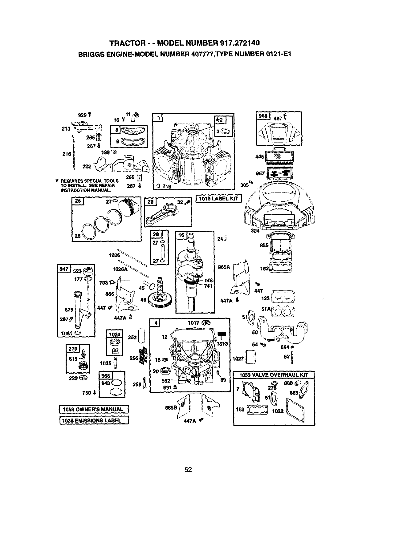
TRACTOR - - MODEL NUMBER 917.272140
BR|GGS ENGINE-MODEL NUMBER 4077Tt_TYPE NUMBER 0121-El
52
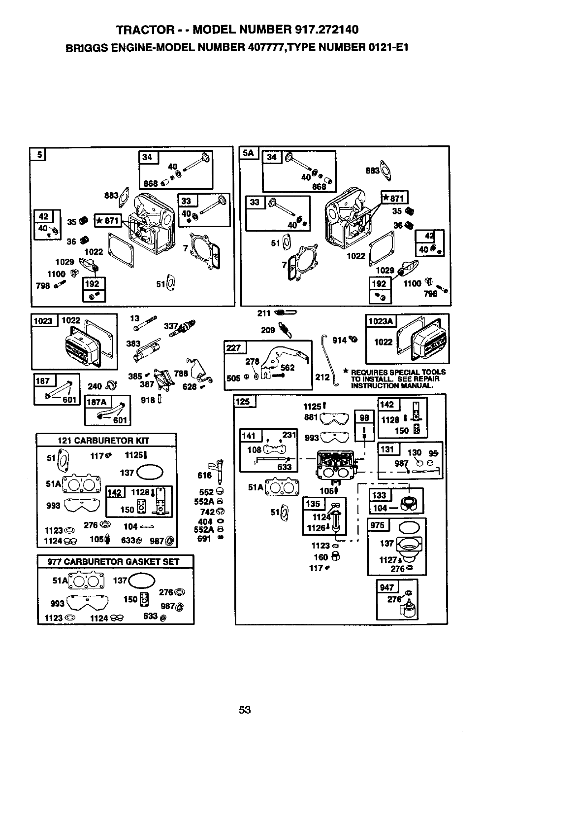
TRACTOR - - MODEL NUMBER 917.272140
BRIGGS ENGINE-MODEL NUMBER 407777,TYPE NUMBER 0121-E1
5._ 868 @°_
51_
211
102311_ 1883538_7_'_"868"28__'_'j27819337_ _1 _91_ I 1022 _1
715o5+_"_--,_z1212_ro.....sE.,,.,..,.
/ I INSTRUCTIONMANUAL
121c,Rsu..onKn 1J!!_1.,=11-3_;_2)
108_:_ I _,11311 130 9J;
51 117_ 11251 6_ "--_- --_J_ - 1"- - 98_ _
51A_ 137@ 61 "--PI--" .---
1128|_ I 552_ 51A_ 1051 rFl_
1123_' 552A
1124'_' 105_ 633@ 987@ 691 ® ....
977 CARBURETOR GASKET SET
137@
-3_2) 150Q27++
857@
1123 _1124 _' 633 @
1123_ '"'
160 _11278[_
117.' 276o
53
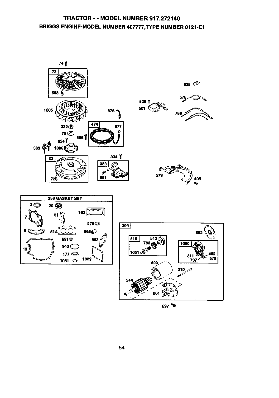
TRACTOR - - MODEL NUMBER 917.272140
BRIGGS ENGINE-MODEL NUMBER 407777,TYPE NUMBER 0121-E1
74_'
1005 _
s2s_
,26_ -_ 15__l
358 GASKET SET
3_ 2o_
276_
g_51_ 858_
691_ 883_ 7s3_
311 _462
737 _579
697
54
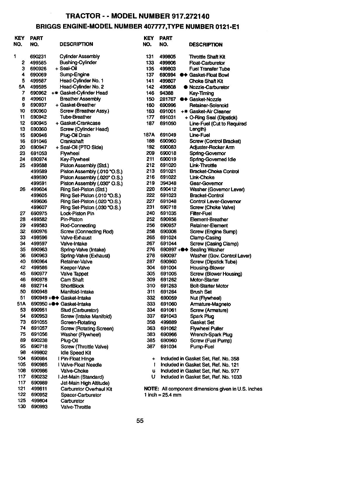
TRACTOR - - MODEL NUMBER 917.272140
BRIGGS ENGINE'MODEL NUMBER 407777,TYPE NUMBER 0121-E1
KEY PART KEY PART
NO. NO. DESCRIPTION NO. NO. DESCRIPTION
1 690231 CylinderAssembly 131
2 499585 Bushing.Cylinder 133
3 690926 + Seal-Oil 135
4 690069 Sump-Engine 137
5 499587 Head-Cylinder No. 1 141
5A 499595 Head-Cylinder No.2 142
7 690962 +-I- Gasket-CylinderHead 146
8 499601 BreatherAssembly 150
9 690937 +Gasket-Breather 160
10 690960 Screw (BreatherAssy.) 163
11 690942 Tube-Breather 177
12 690945 + Gasket-Crankcase 187
13 690360 Screw (CylinderHead)
15 690946 Plug-Oil Drain 187A
16 691046 Crankshaft 188
20 690947 + Seal-Oil (PTO Side) 192
23 691053 Flywheel 209
24 690974 Key-Flywheel 211
25 499588 PisteaAseambly(Std.) 212
499589 PistonAssembly (.010 =O.S.) 213
499590 PistonAssembly (.0_0" O.S,) 216
499591 PistonAssembly(.030" O.S,) 219
26 499604 Ring Set-Pistun (Std.) 220
499605 RingSet-Piston (.010 "O.S.) 222
499606 RingSet-Piston (.020 "O.S.) 227
499607 Ring Set-Piston(.030 "O.S.) 231
27 690975 Lock-PistonPin 240
28 499582 Pin-Piston 252
29 499583 Rod-Connecting 256
32 690976 Screw (Connecting Rod) 258
33 499596 Valve-Exhaust 265
34 499597 Valve-Intake 267
35 690963 Spring.Valve(Intake) 276
36 690963 Spdng-Valve(Exhaust) 278
40 690964 Retainer-Valve 287
42 499586 Keeper-Valve 304
45 690977 Valve Tappet 305
46 690978 Cam Shaft 309
48 692714 ShortBIock 310
50 690948 Manitold-lntake 311
51 690949 +Oe Gasket-Intake 332
51A 690950 +Oe Gasket-Intake 333
53 690951 Stud(Carburetor) 334
54 690953 Screw (Intake Manifold) 337
73 691055 Screan-RotaUng 358
74 691057 Screw (RotatingScreen) 363
75 691056 Washer(Flywheel) 383
89 690238 Plug-Oil 385
95 690718 Screw ('ThrottleValve) 387
98 499802 IdleSpeed Kit
104 690984 I Pin-FloatHinge
105 690985 I Valve-Float Needle
108 690986 Valve-Choke
117 690232 I Jet-Main (Standard)
117 690989 Jet-Main High Altitude)
121 499811 CarburetorOverhaul Kit
122 690952 Spacer-Carburetor
125 499804 Carburetor
130 690993 Valve-Throttle
499805 Throttie Shaft Kit
499806 Float-Carburetor
499803 Fuel TraneterTube
690994 _Gasket-Float Bowl
499807 Choke Shaft Kit
499808 •Nozzle-Carburetor
94388 Key:13ming
281767 _ Gasket-Nozzle
690996 Retainer-Solenoid
691001 +_ Gasket-AirCleaner
691031 + O-Ring Seal (Dipstick)
691050 Line-Fuel (Cut to Required
Length)
691049 Une-Fuel
690960 Screw (ControlBracket)
690083 Adjuster-RockerArm
690018 Spdng-Govemor
690019 Spring-GovernedIdle
691020 Link-Throtlte
691021 Bracket-ChokeControl
691022 Unk-Choka
394348 Gear-Governor
690412 Washer (GovernorLever)
691023 Bracket-Control
691048 ControlLever-Govemor
690718 Screw (ChokeValve)
691035 Filter-Fuel
690956 Element-Breather
690957 Retainer-Element
690308 Screw (EngineSump)
691024 Clamp-Casing
691044 Screw (CasingClamp)
690997 ,tee Sealing Washer
690097 Washer (Gov. ControlLever)
690960 Screw (DipstickTube)
691004 Housing-Blower
691005 Screw (BlowerHousing)
691262 Motor-Starter
691263 Boit-StarterMotor
691264 BrushSet
690059 Nut(Flywheel)
691060 Armature-Magneto
691061 Screw (Armature)
691043 Spark Plug
499889 Gasket Set
691062 FlywheelPuller
690966 Wrench-Spark Plug
690960 Screw (Fuel Pump)
691034 Pump-Fuel
+ Includedin Gasket Set, Ret. No. 358
I Includedin Gasket Set, Ref. No. 121
u InctudodIn Gasket Set, Ref. No. 977
U Inotudodin Gasket Set, Ref. No. 1033
NOTE: Alloompenent dimensionsgiveninU.S. inches
1 inch = 25.4 mm
55
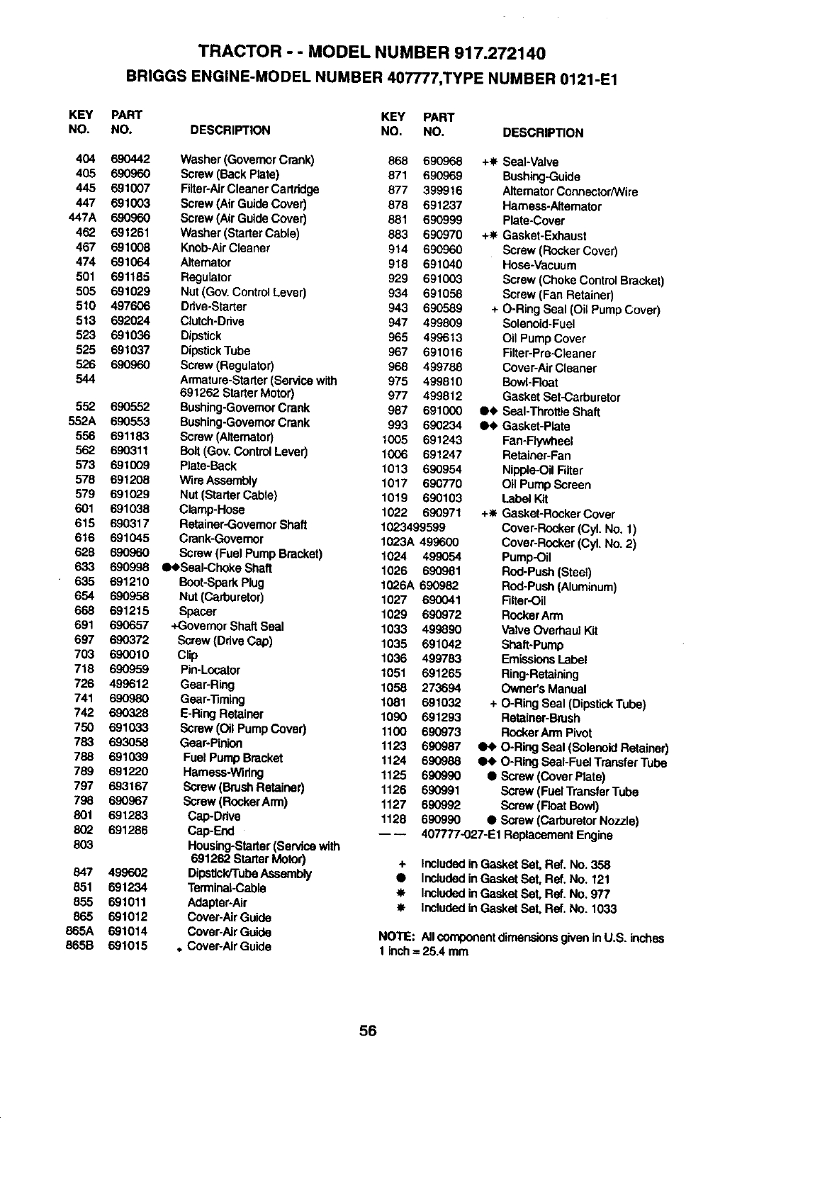
TRACTOR - - MODEL NUMBER 917.272140
BRIGGS ENGINE-MODEL NUMBER 407777,TYPE NUMBER 0121-E1
KEY PART
NO. NO.
404 690442
405 690960
445 691007
447 691003
447A 690960
462 691261
467 691008
474 691064
501 691185
505 691029
510 497606
513 692024
523 691036
525 691037
526 690960
544
552 660552
552A 690553
556 691183
562 690311
573 691009
578 691208
579 691029
601 691038
615 690317
616 691045
628 690960
633 690998
635 691210
654 690958
668 691215
691 690657
697 690372
703 690010
718 690959
726 499612
741 690980
742 690328
750 691033
783 693058
788 691039
789 691220
797 693167
798 690967
801 691283
833 691286
833
847 499602
851 691234
855 691011
865 691012
865A 691014
865B 691015
KEY PART
DESCRIPTION NO. NO. DESCRIPTION
Washer (GovernorCrank) 868 690968
Screw (BackPlate) 871 690969
Filter-AirCleaner Cartridge 877 399916
Screw (Air Guide Cover) 878 691237
Screw (Air Guide Cover) 881 690999
Washer (StarterCable) 883 690970
Knob-AirCleaner 914 690960
Alternator 918 691040
Regulator 929 691003
Nut (Gov. ControlLever) 934 691058
Drive-Starter 943 690589
Clutch-Drive 947 499809
Dipstick 965 499613
DipstickTube 967 691016
Screw (Regulator) 968 499788
Armature-Starter(Service with 975 499810
691262 StarterMotor) 977 499812
Bushing-GovernorCrank 987 691000
Bushing-GovernorCrank 993 690234
Screw (Alternator) 1005 691243
Bolt(Gov. ControlLever) 1006 691247
Plate-Back 1013 690954
Wire Assembly 1017 690770
Nut (StarterCable) 1019 690103
Clamp-Hose 1022 690971
Ratainer-GovernorShaft 1023499599
Crank-Governor 1023A 499600
Screw (Fuel PumpBracket) 1024 499054
•eSeaI-Choke Shaft 1026 690981
Boot-SparkPlug 1026A 690982
Nut (Carburetor) 1027 690041
Spacer 1029 690972
+Governor ShaftSeal 1033 499890
Screw (Drive Cap) 1035 691042
Clip 1036 499783
Pin-Locator 1051 691265
Gear-Ring 1058 273694
Gear-'13ming 1081 691032
E-Ring Retainer 1090 691293
Screw (Oil Pump Cover) 1100 690973
Gear-Pinion 1123 690987
Fuel Pump Bracket 1124 690988
Harness-Wiring 1125 690990
Screw (Brush Retainer) 1126 690991
Screw (RockerArm) 1127 69G992
Cap-Drive 1128 690990
Cap-End _ _
Housing-Starter(Service with
691262 StarterMotor)
Dipstick/TubeAssembly
Terminal-Cable
Adapter.Air
Cover-AirGuide
Cover-AirGuide
. Cover-AirGuide
+_ Seal-Valve
Bushing-Guide
AlternatorConnector/Wire
Harness-Altemator
Plate-Cover
+_ Gasket-Exhaust
Screw (RockerCover)
Hose-Vacuum
Screw (ChokeControl Bracket)
Screw (Fan Retainer)
+ O-Ring Seal (Oil Pump Cover)
Solenoid-Fuel
Oil Pump Cover
Filter-Pre-Cleaner
Cover-Air Cleaner
Bowl-Rear
Gasket Set-Carburetor
•e Seal-ThrottleShaft
•e Gaskat-Plate
Fan-Flywheel
Retainer-Fan
Nipple-OilFilter
Oil PumpScreen
Label Kit
+_ Gaskat-RockerCover
Cover-Rocker(Cyl. No. 1)
Cover-Rocker(CyL No 2)
Pump-Oil
Rod-Push(Steel)
Rod-Push(Aluminum)
Filter-Oil
RockerArm
Valve Ovethaul Kit
Shaft-Pump
EmissionsLabel
Ring-Retaining
Owner's Manual
+ O-Ring Seal (DipstickTube)
Retainer-Brush
RockerArm Pivot
qH_ O-Ring Seal (SolenoidRetainer)
•e O-Ring Seal-Fuel TransferTube
•Screw (Cover Plate)
Screw (FuelTransferTube
Screw (FloatBowl)
• Screw (carburetor Nozzle)
407777-O27-E1 ReplacementEngine
+ Includedin Gasket Set, Ref. No. 358
•Includedin Gasket Set, Ref. No. 121
-_ Includedin Gasket Set, Ret. No. 977
•- Includedin Gasket Set, Ret. No. 1033
NOTE: AllcomponentdimensionsglvoninU.S. inches
1 inch= 25,4 mrn
56

SUGGESTED GUIDE FOR SIGHTING SLOPES FOR SAFE OPERATION
"_
SIGHTING
GUIDE
ONLY RIDE UP AND DOWN HILL,
NOT ACROSS HILL
Ol
-q
I& Operate your Tractor up and down the face of slopes (not I
=
greater than 15°), never across the face. Make turns gradu- I
ally to prevent tipping or loss of control. Exercise extreme
caution when changing direction on slopes.

58

59

For in-home major brand repair service:
Call 24 hours a day, 7 days a week
1-800-4-MY-HO M Es"(1-800-469-4663)
Para pedir servicio de reparaci6n a domicilio
1-800-676-5811
In Canada for all your service and parts needs call
Au Canada pour tout le service ou les pi_ces
1-800-665-4455
For the repair or replacement parts you need:
Call 6 am-llpm CST, 7 days a week
PartsDirect sM
1-800-366-PART (1-800-366-7278)
Para ordenar piezas con entrega a domicilio
1-800-659-7084
For the location of a Sears Parts and Repair Center
in your area:
Call 24 Hours a day, 7 days a week
1-800-488-1222
For information on purchasing a Sears Maintenance
Agreement or to inquire about an existing Agreement:
Call 9 am-5 pro, Monday -Saturday
1-800-827-6655
8EARS
HomeCentral
168150 1.11.99 TR Printed in U.S.A.
