Craftsman 917272242 User Manual LAWN TRACTOR Manuals And Guides L0104098
CRAFTSMAN Lawn, Tractor Manual L0104098 CRAFTSMAN Lawn, Tractor Owner's Manual, CRAFTSMAN Lawn, Tractor installation guides
User Manual: Craftsman 917272242 917272242 CRAFTSMAN LAWN TRACTOR - Manuals and Guides View the owners manual for your CRAFTSMAN LAWN TRACTOR #917272242. Home:Lawn & Garden Parts:Craftsman Parts:Craftsman LAWN TRACTOR Manual
Open the PDF directly: View PDF ![]() .
.
Page Count: 64

Owner's Manual
OCRfiFTSMRN°I
20.0 HP
ELECTRIC START
48" MOWER
AUTOMATIC
LAWN TRACTOR
Model No.
917.272242
• Safety
• Assembly
•Operation
•Maintenance
•Repair Parts
CAUTION:
Read and follow all
Safety Rules and Instructions
before operating this equip-
ment.
For answers to your questions
about this product, Call:
1-800-659-5917
Sears Craftsman Help Line
5 am - 5 pro, Mo_ - Sat
Sears, Roebuck and Co., Hoffman Estates, IL 60179
Visit our Craftsman website: www.sears.conVcraftsman
Warranty ............................................... 2
Safety Rules ......................................... 3
Product Specifications.......................... 6
Assembly .............................................. 8
Operation ............................................ 12
Maintenance Schedule ...................... 18
Maintenance ....................................... 18
Service and Adjustments .................... 22
Storage ............................................... 29
Troubleshooting ................................. 30
Repair Parts........................................ 34
Parts Ordering ..................... Back Cover
LIMITED TWO YEAR WARRANTY ON CRAFTSMAN RIDING EQUIPMENT PARTS
For two (2) years from the date of purchase, if this Craftsman Riding Equipment is
maintained, lubricated and tuned up according to the instructions in the owner's
manual, Sears will repair or replace, free of charge, any parts found to be defective in
material or workmanship. Warranty service is available free of charge by returning
your Craftsman riding equipment to your nearest Sears Service Center. In-home
warranty service is available but a trip charge will apply. This warranty applies only
while this product is in the United States.
This Warranty does not cover:
•Expendable items which become wom during normal use, such as blades, spark
plugs, air cleaners, belts and oil filters.
• Tire replacement or repair caused by punctures from outside objects, such as nails,
thorns, stumps, or glass.
• Repairs necessary because of operator abuse, including but not limited to, damage
caused by towing objects beyond the capability of the riding equipment, impacting
objects that bend the frame or crankshaft, or over speeding the engine.
• Repairs necessary because of operator negligence, including but net limited to,
electdcal and mechanical damage caused by improper storage, failure to use the
proper grade and amount of engine oil, failure to keep the deck clear of flammable
debris, or the failure to maintain the equipment accordingto the instructions
contained in the owner's manual.
• Engine (fuel system) cleaning or repairs caused by fuel determined to be contami-
nated or oxidized (stale). In general, fuel should be used within thirty (30) days of its
purchase date.
•Riding equipment used for commercial or rental purposes. A product is "used for
commercial purpose" if is used for any purpose other than single family household
dwellings or in usage where profit is made.
LIMITED 90 DAY WARRANTY ON BATTERY
For ninety (90) days from date of purchase, if any battery included with this dding
equipment proves defective in material or workmanship and our testing determines
the battery will not hold a charge, Sears will replace the battery at no charge. War-
ranty service is available free of charge by returning your Craftsman riding equipment
to your nearest Sears Service Center. In-home warranty service is available but a trip
charge willapply. This warranty applies only while this product is In the United States.
TO LOCATE THE NEAREST SEARS SERVICE CENTER OR TO SCHEDULE IN-
HOME WARRANTY SERVICE, SIMPLY CONTACT SEARS AT 1-600-4-MY-HOME
This Warranty gives you specific legal dghts, and you may also have other dghts
which may vary from state to state.
Seam, Roebuck and Co., D/817 WA, Hoffi_an Estates, IL 60179
IMPORTANT:Thiscuttingmachineiscapableofamputatinghandsandfontand
throwingobjects.Failuretoobservethefollowingsafetyinstructionscouldresultin
sedousinjuryordeath.
I.GENERALOPERATION
• Read,understand,andfollowall
instructionsinthe manual and on the
machine before starting.
•Only allow responsible adults, who are
familiar with the instructions,to operate
the machine.
• Clear the area of objectssuch as racks,
toys, wire, etc., which could be picked
up and thrown by the blade.
• Be sure the area is dear of other people
before mowing. Stop machine if anyone
enters the area.
•Never carry passengers.
•Do not mow in reverse unless absolutely
necessary. Always look down and
behind before and while backing.
•Be aware of the mower discharge
directionand do not point itat anyone.
Do not operate the mower without either
the entire grass catcher or the guard in
place.
•Slow down before turning.
•Never leave a running machine
unattended. Always tum off blades, set
parking brake, stop engine, and remove
keys before dismounting.
•"rumoff blades when not mowing.
•Stop engine before removinggrass
catcher or uncloggingchute.
•Mow only in daylight or good artificial
lighL
•Do not operate the machine while under
the influenceof alcoholor drugs.
•Watch for trafficwhen operating near or
crossing roadways.
•Use extra care when loading or unload-
ing the machine intoa trailer or truck.
•Data indicates that operators, age 60
years and above, are involved in a large
percentage of dding mower.-rolated
injuries. These operatorsshould
evaluate their abilityto operate the ridleg
mower safely enoughto protectthem-
salves and othersfrom sedous injury.
•Keep machine free of grass, leaves or
other debris build-upwhich can touch
hot exhaust /engine partsand bum. Do
net allow the mower deck to plow leaves
or other debds which can cause build-
upto occur. Clean any oil or fuel
spillage before operatingor storingthe
machine. Allow machine to cool hefere
storage.
II. SLOPE OPERATION
Slopes are a major factor related to loss-of-
control and tipover accidents,which can re-
sult in severe injury or death. All slopes
require exb'acaution. Ifyou cannot beck up
the slope or if you feel uneasy on it, de not
maw it.
DO;
•Mow up and down slopes, net across.
•Remove obstacles such as rocks, tree
limbs,etc.
Watch for holes, ruts, or bumps. Uneven
ten'ain could overturn the machine. Taft
grass can hide obstacles.
Use slow speed. Choose a low gear so
that you will not have to stop orshif_
while on the slope.
Follow the manufacturer's recommenda-
tions for wheel weights or counter-
weights to improvestability.
Use extra care with grass catchersor
other attachments. These can change
the stabilityof the machine.
Keep all movement on the slopes slew
and gradual. Do not make sudden
changes in speed or direction.
Avoid startingor stoppingon a slope. If
tires lose traction, disengage the blades
and proceed slowly straightdown the
slope.
DO NOT:
•Do not turn on slopes unless necessary,
and then, turn slowly and gradually
downhill, if possible.
•Do netmow near drep-offs,ditches,or
embankments. The mower could
suddenlyturn over ifa wheel is over the
edge of a cliffor ditch,or ifan edge
caves in.
•Do not mow on wet grass. Reduced
tractioncould cause sliding.
•Do not try to stabilize the machine by
potting your foot on the ground.
•Do notuse grass catcher on steep
slopes.
II1.CHILDREN
Tragicaccidentscanoccuriftheoperator
isnotalerttothepresenceofchildren.
Childrenareoftenattractedtothe
machineandthemowingactivity.Never
assume that children will ramaln where
you last saw them.
• Keep children out of the mowing area
and under the watchful care of another
responsible adult.
• Be alert and tum machine off if children
enter the area.
• Before and when backing, look behind
and down for small children.
• Never carry children. They may fall off
and be seriously injured or interfere
with safe machine operation.
•Never allow children to operate the
machine.
•Use extra care when approaching blind
corners, shrubs, trees, or other objects
that may obscure vision.
IV. SERVICE
• Use extra care in handling gasoline
and other fuels. They are flammable
and vapors are explosive.
- Use only an approved container.
- Never remove gas cap or add fuel
with the engine running. Allow
engine to cool before refueling. Do
not smoke.
-Never refuel the machine indoors.
- Never store the machine or fuel
container inside where there is an
open flame, such as a water heater.
•Never run a machine inside a closed
area.
•Keep nuts and bolts, especially blade
attachment bolts, tight and keep
equipment in good condition.
•Never tamper with safety devices.
Check their proper operation regularly.
•Keep machine free of grass, leaves, or
other debris build-up. Clean oil or fuel
spillage. Allow machine to cool before
storing.
•Stop and inspectthe equipment if you
strike an object. Repair, if necessary,
before restarting.
•Never make adjustments or repairs
with the engine running.
•Grass catcher components are subject
to wear, damage, and deterioration,
which could expose moving parts or
allow objects to be thrown. Frequently
check components and replace with
manufacturer's recommended parts,
when necessary.
• Mower blades are sharp and can cut.
Wrap the blade(s) or wear gloves, and
use extra caution when servicingthem.
•Check brake operation frequently.
Adjust and service as required.
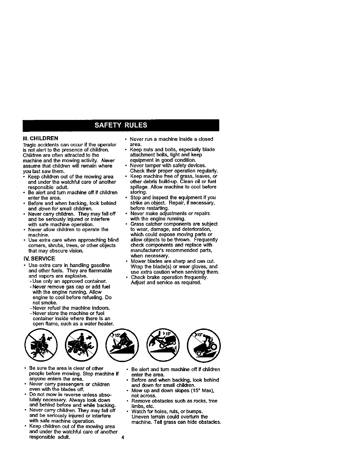
• Be sure the area is clear of other
people before mowing. Stop machine if
anyone enters the area.
•Never carry passengers or children
even with the blades off.
•Do not mow in reverse unless abso-
lutely necessary. Always look down
and behind before and while backing.
•Never carry children. They may fall off
and be seriously injured or interfere
with safe machine operation.
•Keep children out of the mowing area
and under the watchful care of another
responsible adult.
•Be alert and turn machine off if children
enter the area.
•Before and when backing, look behind
and down for small children.
•Mow up and down slopes (15=Max),
not across.
•Remove obstacles such as rocks, free
limbs,etc.
•Watch for holes, ruts, or bumps.
Uneven terrain could overtura the
machine. Tall grass can hide obstacles.
• Useslowspeed. Choose a low gear so
that you will not have to stop or shift
while on the slope.
• Avoid starting or stopping on aslope. If
tires lose traction, disengage the
blades and proceed slowly straight
down the slope.
•If machine stops while going uphill,
disengage blades, shift into reverse
and back down slowly.
•Do not turn on slopes unless neces-
sary, and then, turn slowly and gradu-
ally downhill, if possible.
_lkLook for this symbolto pointout
importantsafety precautions. It means
CAUTIONlll BECOME ALERTIt! YOUR
SAFETY IS INVOLVED.
_CAUTION: In order to prevent
accidental starting when setting up,
transporting, adjusting or making repairs,
always disconnect spark plug wire and
place wire where it cannot contact spark
plug.
_,CAUTION: Do not coast down a hill in
neutral, you may lose controlof the
tractor.
_.CAUTION: Towonly the attachments
that are recommended by and comply
with specifications of the manufacturer of
your tractor. Use common sense when
towing. Operate only at the lowest
possible speed when on a slope. Too
heavy of a load, while on a slope, is
dangerous. Tires can lose traction with
the ground and cause you to lose control
of your tractor.
,_WARNING: Engine exhaust, some of
its constituents, and certain vehicle
components contain or emit chemicals
known to the State of California to cause
cancer and birthdefects or other repro-
ductive harm.
_WARNING: Battery posts, terminals
and related accessories contain lead and
lead compounds, chemicals known to the
State of California to cause cancer and
birth defects or other reproductive harm.
Wash hands after handling.
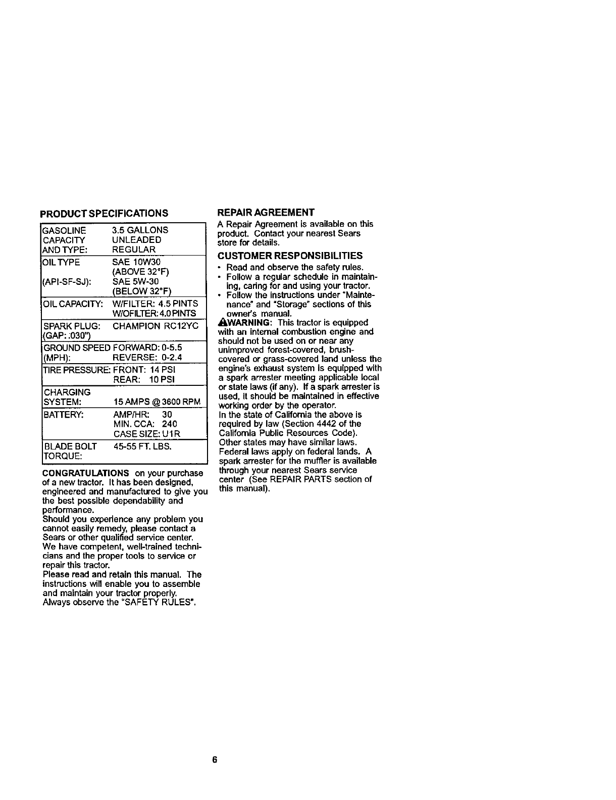
_RODUCT SPECIFICATIONS
-_ASOLINE 3.5 GALLONS
CAPACITY UNLEADED
_ND TYPE: REGULAR
:31LTYPE SAE 10W30
(ABOVE 32°F)
'API-SF-SJ): SAE 5W-30
(BELOW 32°F)
OIL CAPACITY: W/FILTER: 4.5 PINTS
W/OFILTER:4.0PINTS
SPARK PLUG: CHAMPION RC12YC
GAP: :030")
GROUND SPEED FORWARD: 0-5.5
MPH): REVERSE: 0-2.4
TIRE PRESSURE: FRONT: 14 PSI
REAR: 10 PSI
CHARGING
SYSTEM: 15AM PS @ 3600 RPM
BATTERY: AMP/HR: 30
MIN. CCA: 240
CASE SIZE: U1R
BLADE BOLT 45-55 FT. LBS.
TORQUE:
CONGRATULATIONS on your purchase
of a new tractor. It has been designed,
engineered and manufactured to give you
the best possible dependability and
performance.
Should you experience any problem you
cannot easily remedy, please contact a
Sears or other qualified service center.
We have competent, well-trained techni-
cians and the proper tools to service or
repair this tractor.
Please read and retain this manual. The
instructionswill enable you to assemble
and maintain your tractor properly.
Always observe the "SAFETY RULES".
REPAIR AGREEMENT
ARepair Agreement is available on this
product. Contact your nearest Sears
store for details.
CUSTOMER RESPONSIBILITIES
•Read and observe the safety rules.
•Follow a regular schedule in maintain-
ing, cadng for and using your tractor.
•Follow the instructionsunder "Mainte-
nance" and "Storage"sections of this
owner's manual.
_LWARNING: This tractor is equipped
with an internal combustion engine and
should not be used on or near any
unimproved forest-covered, brash-
covered or grass-covered land unless the
engine's exhaust system is equipped with
a spark an'ester meeting applicable local
or state laws (if any). If a spark arrester is
used, it should be maintained in effective
working order by the operator.
In the state of California the above is
required by law (Section 4442 of the
California Public Resources Code).
Other states may have similar laws.
Federal laws apply on federal lands. A
spark arrester for the muffler is available
through your nearest Sears service
center (See REPAIR PARTS section of
this manual).
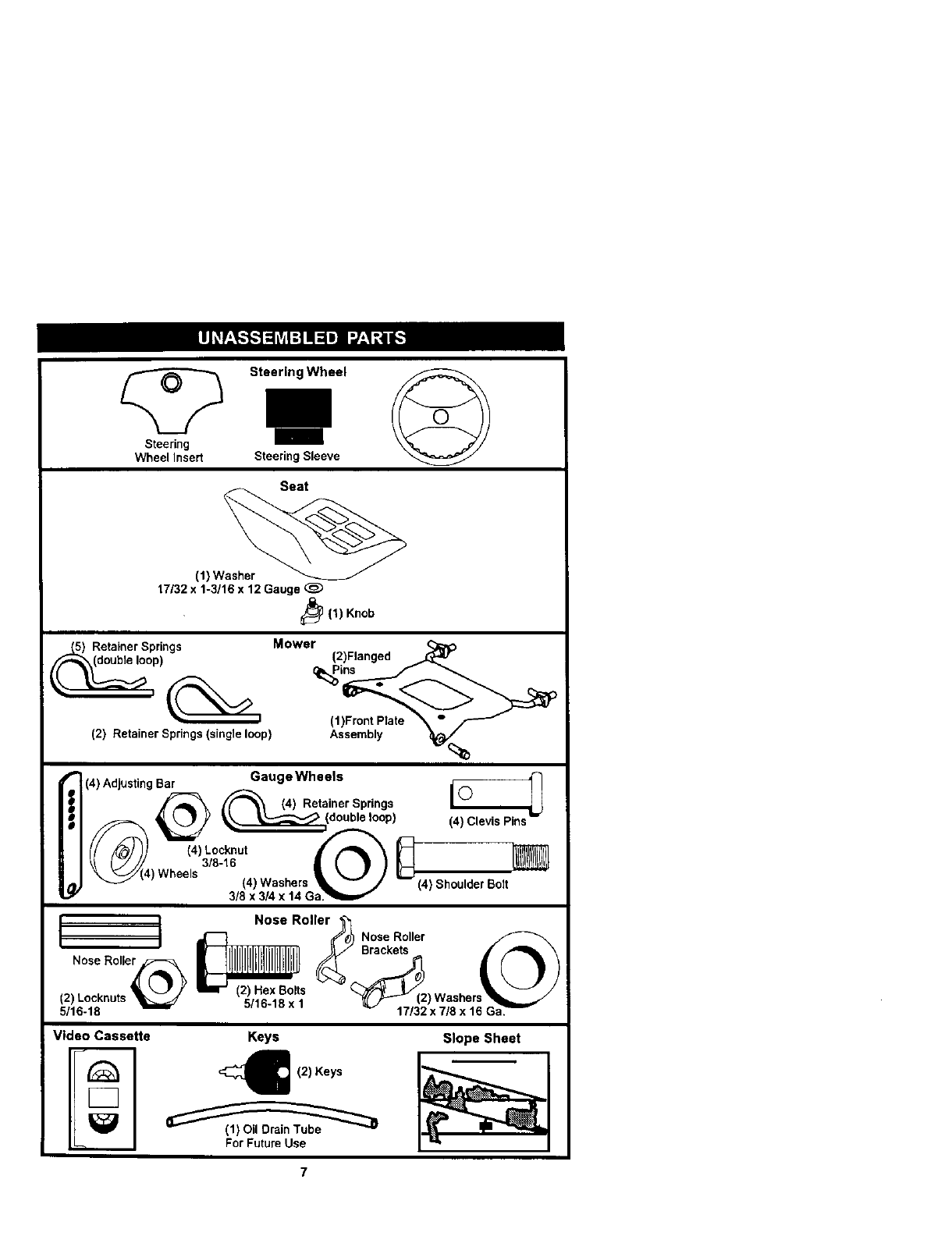
Steering Wheel
Steering
Wheel Insert Steering Sleeve
(l)W_
17132 x 1-3/16 x 12 Gauge
_(1) Knob
Mower
Retainer Springs
)
(2} Retainer Springs (single loop)
(2)Flanged
(1)FrontPlate _"
As,er._ _k_'%
i (4) Adjusting Bar Gauge Wheels
_(4) Retainer Springs
_, L.7 y __(double loop) (4)clevisPins
_a:.t_. €._S.ou,do,Bolt
Nose Roller _j_
-- _'_)! Nose Roller
o o o,,75 /, l l Hbl l H l l ui' I
(2) Locknuts _r (2) Hex Bolts _'_(2" Washers1 • _ /
5/16-18 _ 5/16-18 X 1 _17/3_tJx7/8 x 16
Video Cassette Keys Slope Sheet
For Future Use
7
Your new tractor has been assembled at the factory with exception of those parts left
unassembled for shipping purposes. To ensure safe and proper operation of your
tractor all parts and hardware you assemble must be tightened securely. Use the
correct tools as necessary to insure proper tightness. Review the video cassette before
you begin.
TOOLS REQUIRED FOR ASSEMBLY
A socket wrench set will make assembly
easier. Standard wrench sizes you need
are listed below.
(2) 9/16" wrench (1) 3/4" Socket w/
(1) 1/2" wrench drive ratchet
(1) Utility knife (I) Pliers
(1) Tire pressure gauge
When dght or left hand is mentioned in
this manual, it means, from your point of
view, when you are in the operating
position (seated behind the steering
wheel).
TO REMOVETRACTOR FROM
CARTON
UNPACK CARTON
1. Remove all accessible loose parts
and parts cartons from carton.
2. Cut, from top to bottom, along lines on
all four comers of carton, and lay
panels flat.
3. Remove mower and packing mated-
als.
4. Check for any additional loose parts
or cartons and remove.
BEFORE REMOVINGTRACTOR
FROM SKID
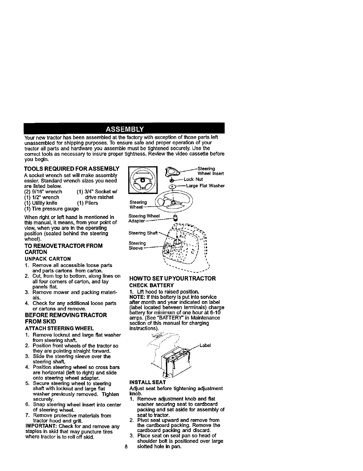
ATTACH STEERING WHEEL
1. Remove Iocknut and large flat washer
from steering shaft.
2, Position front wheels of the tractor so
they are pointing straight forward.
3, Slide the steering sleeve over the
steering shaft.
4. Position steering wheel so cross bars
are horizontal (left to right) and slide
onto ateedng wheel adapter,
5. Secure steering wheel to steedng
shaft with leoknut and large fiat
washer previously removed. Tighten
securely.
6. Snap steering wheel Insert into center
of steedng wheel.
7. Remove protective materials from
tractor hood and grill,
IMPORTANT: Check for and remove any
staples in skid that may puncture tires
where tractor is to roll off skid,
_/Steering
I//"_'\\1 _=_T Whe_lInsert
Nut
__ge Flat Washer
Steering _/ _E_ _) )
SteeringWheel
Adapter--'------_ _
Sleeve ..._ _I.i
HOWTO SET UPYOURTRACTOR
CHECK BATTERY
1. L_ hood to raised position.
NOTE: If this battery is put into service
after month and year indicated on label
(label located between terminals) charge
battery for minimum of one hour at 6-10
amps. (See "BATTERY" in Maintenance
section of this manual for charging
instructions).
-_.._ ,...---:.
.."-'--,,_'_ Label
Y
INSTALL SEAT
Adjust seat before tightening adjustment
knob.
1. Remove adjustment knob and flat
washer seoudng seat to cardboard
packing and set aside for assembly of
seat to tractor.
2. Pivot seat upward and remove from
the cardboard packing. Remove the
cardboard packing and discard,
3. Place seat on seat pan so head of
shoulder bolt is positioned over large
8 slotted hole in pan,
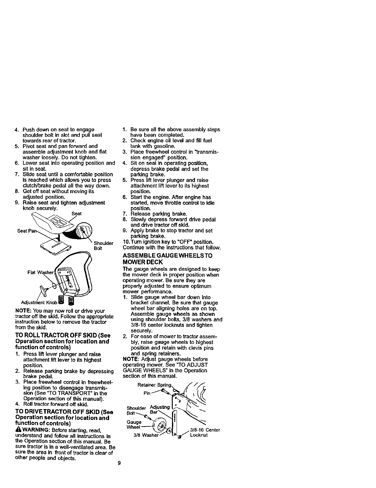
4. Push down on seat to engage
shoulder bolt in slot and pull seat
towards rear of tractor.
5. Pivot seat and pan forward and
assemble adjustment knob and fiat
washer loosely. Do not tighten.
6. Lower seat into operating position and
sit in seat.
7. Slide seat until a comfortable position
is reached which allows you to press
clutch/broke pedal all the way down.
8. Get off seat without moving its
adjusted position.
9. Raise seat and tighten adjustment
knob securely. Seat
Shoulder
Bo_t
Flat
NOTE: You may now roll or drive your
tractor off the skid. Follow the appropdate
instruction below to remove the tractor
from the skid.
TO ROLLTRACTOR OFF SKID (See
Operation section for location and
function of controls)
1. Press lift lever plunger and raise
attachment liftlever to its highest
position.
2. Release parking brake by depressing
brake pedal.
3. Place freewheel control in freewheel-
ing positionto disengage transmis-
sion (See "TO TRANSPORT" in the
Operation section of this manual).
4. Roll tractorforward off skid,
TO DRIVETRACTOR OFF SKID (See
Operation section for location and
function of controls)
A, WARNING: Beforestarting, read,
understand and follow all instructions in
the Operation section of this manual. Be
sure tractor is in a well-ventilated area. Be
sure the area in front of tractor is clear of
other people and objects.
1. Be sure all the above assembly steps
have been completed.
2. Check engine oil level and fill fuel
tank with gasoline.
3. Place freewheel control in "transmis-
sion engaged" position.
4. Sit on seat in operating position,
depress brake pedal and set the
parking brake.
5. Press liftlever plunger and raise
attachment liftlever to its highest
position.
6. Start the engine, After engine has
started, move throttle controlto Idle
position.
7. Release parking brake.
8. Slowly depress forward ddve pedal
and ddve tractor off skid.
9. Apply brake to stop tractor and set
parking brake.
10,Turn ignition key to "OFF" position.
Continue with the instructionsthat follow.
ASSEMBLE GAUGEWHEELSTO
MOWER DECK
The gauge wheels are designed to keep
the mower deck in proper positionwhen
operating mower. Be sure they are
propedy adjusted to ensure optimum
mower performance.
1. Slide gauge wheel bar down into
bracket channel, Be sure that gauge
wheel bar aligning boles are on top.
Assemble gauge wheels as shown
using shoulder bolts, 3/8 washers and
3/8-16 center Iocknutsand tighten
securely.
2. For ease of mower to tractor assem-
bly, raise gauge wheels to highest
position and retain with clevis pins
and spdng retainers.
NOTE: Adjust gauge wheels before
operating mower. See "TO ADJUST
GAUGE WHEELS" in the Operation
section of this manual.
RetainerSpring_ ///__
Pin__._
Shoulder Adiusting_ Ix _.__.
Wheel_,_ I/3/8-16 Center
3/8 Washer/- vL_ Locknut
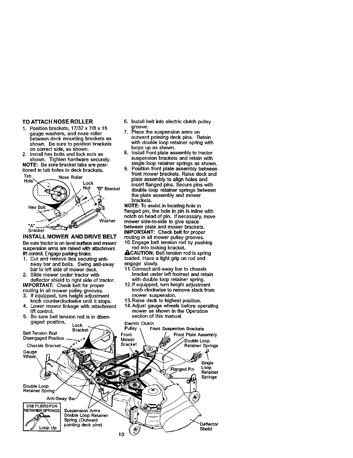
TOATTACHNOSEROLLER
1. Positionbrackets,17/32x 7/8x 16
gaugewashers,andnoseroller
betweendeckmountingbracketsas
shown.Besuretopositionbrackets
oncorrectside,asshown.
2. Installhexboltsandlocknutsas
shown. Tighten hardware securely.
NOTE: Be sure bracket tabs are posi-
tioned in tab holes in deck brackets.
Tab Nose Roller
Hole"_--:':'_'_ \Lock
/_ _.__\\ .Nut "B'_ Bracket
_sher
Bracket
INSTALL MOWER AND DRIVE BELT
Be suretractoris on levelsurfaceand mower
suspension armsare raisedwithattachment
I_ o0ntrol.Engageparkingbrake.
1. Cut and remove ties secudng anti-
sway bar and belts. Swing anti-sway
bar to left side of mower deck.
2. Slide mower under tractor with
deflector shield to right side of tractor.
IMPORTANT: Check belt for proper
routing in all mower pulley grooves.
3. If equipped, turn height adjustment
knob counterclockwise until it stops.
4. Lower mower linkage with attachment
lift control.
5. Be sure belt tension rod is in disen-
gaged position. Lock
Belt Tension Rod
Disengaged
Chassis
Gauge
6. Install belt into electric clutch pulley
groove.
7. Place the suspension arms on
outward pointing deck pins. Retain
with double loop retainer spdng with
loops up as shown.
8. Install front plate assembly to tractor
suspension brackets and retain with
single loop retainer springs as shown.
9. Position front plate assembly between
front mower brackets. Raise deck and
plate assembly to align holes and
insert flanged pins. Secure pins with
double loop retainer spdngs between
the plate assembly and mower
brackets.
NOTE: To assist in locating hole in
flanged pin, the hole in pin is inline with
notch on head of pin. If necessary, move
mower side-to-side to give space
between plate and mower brackets.
IMPORTANT: Check belt for proper
routing in all mower pulley grooves.
10.Engage belt tension rod by pushing
rod into locking bracket.
_iLCAUTION: Belt tension rod is spring
loaded. Have a tight gdp on rod and
engage slowly.
11. Connect anti-sway bar to chassis
bracket under leftfootrest and retain
with double loop retainer spring.
12. If equipped, turn height adjustment
knob clockwise to remove slack from
mower suspension.
13.Raise deck to highest position.
14.Adjust gauge wheels before operating
mower as shown in the Operation
section of this manual.
Etsctde Clutch
Pulley Front Suspention Brackets
Front Front Plate AssembFy
Mower .Double Loop
Bracket
Double Loop
Retainer Spring
Anti-Sway
USEPLIERSFOR
RETAINERSPRINGS Suspension Arms
I/_L_p Double Loop Retainer
Spring (Outward
Up pointing deck pins)
10
Single
Loop
Retainer
Springs
Sheild
CHECKTIRE PRESSURE
The tires on your tractor were ovednfiated
at the factory for shipping purposes.
Correct tire pressure is importantfor best
cutting performance.
• Reduce tire pressure to PSI shown in
=PRODUCT SPECIFICATIONS" section
of this manual.
CHECK DECK LEVELNESS
For best cutting results, mower housing
should be propedy leveled. See "TO
LEVEL MOWER HOUSING" in the
Service and Adjustments section of this
manual.
CHECK FOR PROPER POSITION OF
ALL BELTS
See the figures that are shown for
replacing motion and mower blade drive
belts in the Service and Adjustments
section of thismanual. Verify that the
belts are routed correctly.
CHECK BRAKE SYSTEM
After you learn how to operate your
tractor, check to see that the brake is
properlyadjusted. See "TO ADJUST
BRAKE" in the Service and Adjustments
section of this manual.
_CHECKLIST
BEFORE YOU OPERATE AND ENJOY
YOUR NEW TRACTOR, WE WISH TO
ASSURE THAT YOU RECEIVE THE BEST
PERFORMANCE AND SATISFACTION
FROM THIS QUALITY PRODUCT.
PLEASE REVIEW THE FOLLOWING
CHECKLIST:
,/ All assembly instructionshave been
completed.
,/No remaining loose parts in carton.
J' Battery is propedy prepared and
charged. (Minimum 1 hour at 6 amps).
,/Seat is adjusted comfodably and
tightened securely.
J' All tires are properly inflated. (For
shipping purposes, the tires were
ovednflated at the factory).
,/Be sure mower deck is propedy leveled
side-to-sideifront-to-rear for best catting
results. (Tires must be properly inflated
for leveling).
,/Check mower and ddve belts. Be sure
they are routed propedy around pulleys
and inside all belt keepers.
,/Check widng. See that all connections
ere stillsecure and wires are properly
clamped.
,/Before ddving tractor, be sure free-
wheel control is in ddve position.
WHILE LEARNING HOWTO USEYOUR
TRACTOR, PAY EXTRA ATTENTION TO
THE FOLLOWING IMPORTANT ITEMS:
•/ Engine oil is at proper level.
,/Fuel tank is filled with fresh, clean,
regular unleaded gasoline.
,/Become familiar with all controls - their
location and function. Operate them
before you start the engine.
,/Be sure brake system is in safe
operating condition.
,/It is impcdant to purge the transmission
before operating your tractor for the first
time. Follow proper starting and
transmission purging instructions (See
=TOSTART ENGINE" and "PURGE
TRANSMISSION" in the Operation
section of this manual).
11
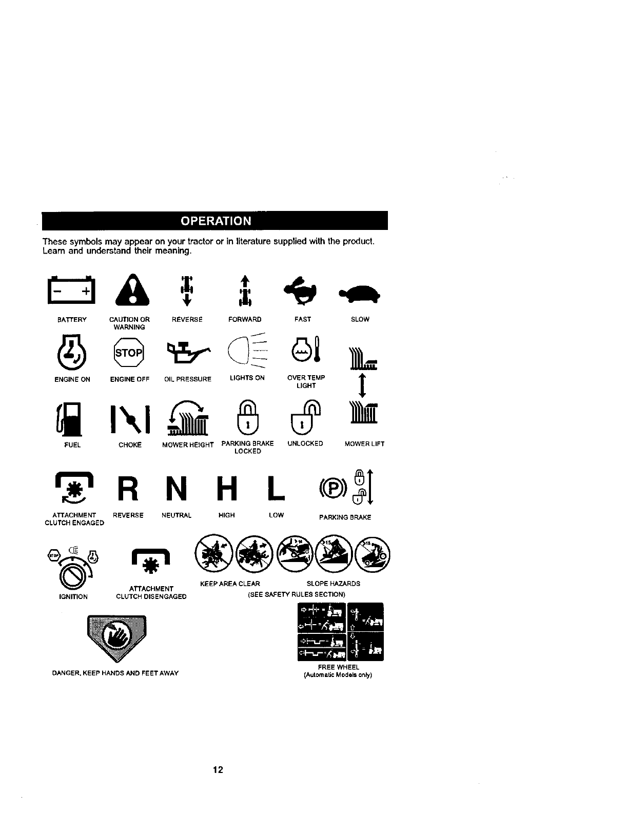
These symbols may appear on your tractor or in literature supplied with the product,
Learn and understand their meaning.
BATTERY CAUTION OR REVERSE FORWARD FAST SLOW
WARNING
ENGINE ON ENGINE OFF OIL PRESSURE LIGHTS ON OVER TEMP
LIGHT t
FUEL CHOKE MOWERHEIGHT PARKING BRAKE UNLOCKED
LOCKED MOWER LIFT
r_'_ R N H L
ATTACHMENT REVERSE NEUTRAL HIGH LOW
CLUTCH ENGAGED
®3[
PARKING BRAKE
IGNITION
KEEP AREA CLEAR SLOPE HAZARDS
ATTACHMENT
CLUTCH DISENGAGED (SEE SAFETY RULES SECTION)
DANGER. KEEP HANDS AND FEET AWAY FREE WHEEL
(Automatic Models only)
12
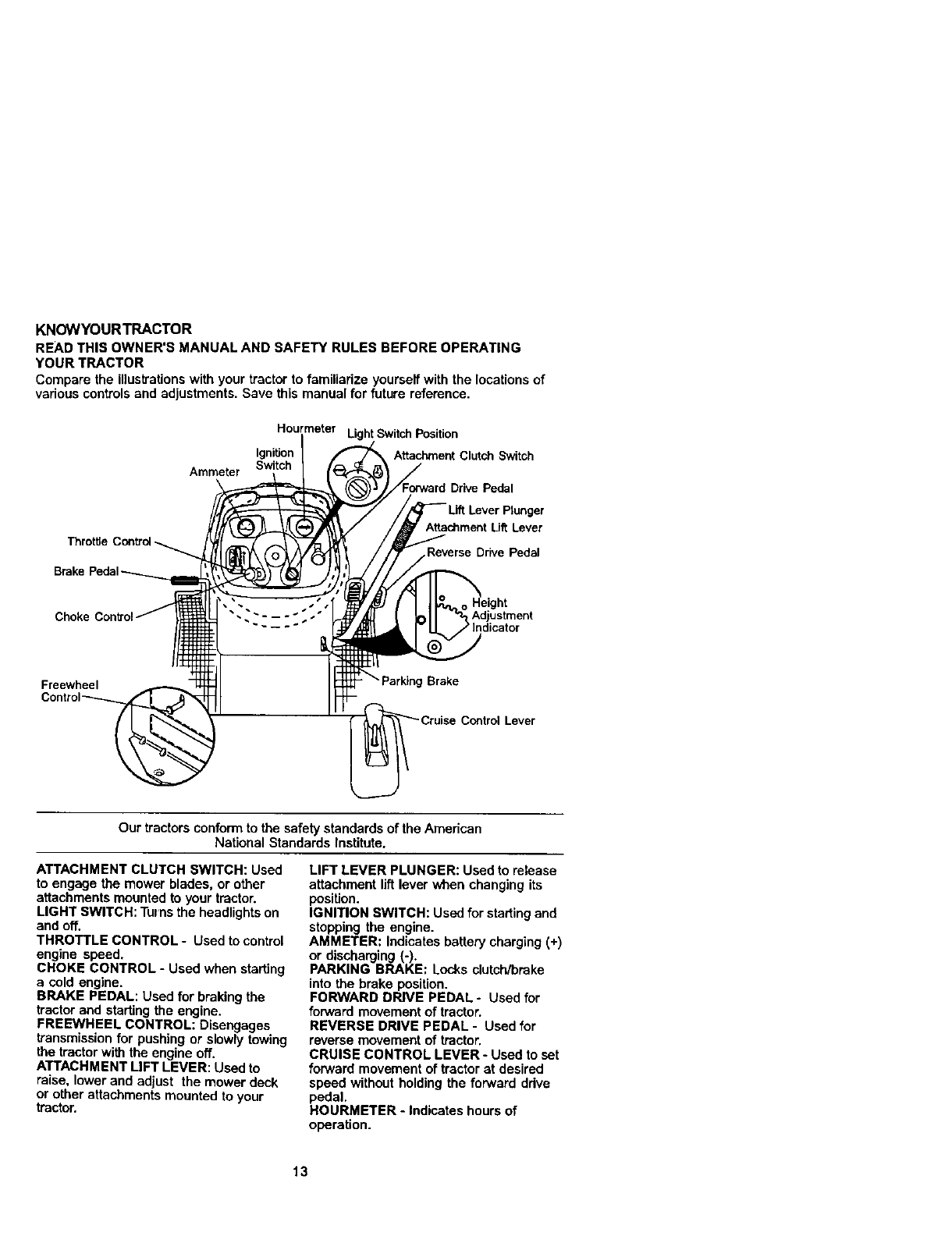
KNOWYOURTRACTOR
READTHISOWNER'SMANUALANDSAFETYRULESBEFOREOPERATING
YOURTRACTOR
Compare the illustrationswith your tractor to familiarize yourself with the locations of
various controls and adjustments. Save this manual for future reference.
Ammeter
Hourmeter Light Switch Position
Ignition Attachment Clutch Switch
Switch
Drive Pedal
Throttle Contro
Brake I
Attachment UffLever
Reverse DrNePedal
Choke • • Ad ustment
~- -- -" indicator
Freewheel Brake
Lever
Our tractors conform to the safety standards of the Amedcan
National Standards Institute.
ATTACHMENT CLUTCH SWITCH: Used
to engage the mower blades, or other
attachments mounted to your tractor.
LIGHT SWITCH: Turnsthe headlights on
and off.
THROTTLE CONTROL - Used to control
engine speed.
CHOKE CONTROL - Used when starting
a cold engine.
BRAKE PEDAL: Used for braking the
tractor and starting the engine.
FREEWHEEL CONTROL: Disengages
transmissionfor pushing or slowly towing
the tractor with the engine off,
ATTACHMENT LIFT LEVER: Used to
raise, lower and adjust the mower deck
or other attachments mounted to your
tractor.
LIFT LEVER PLUNGER: Used to release
attachment liftlever when changing its
position.
IGNITION SWITCH: Used for startingand
stopping the engine.
AMMETER: Indicates battery charging (+)
or discharging (-).
PARKING BRAKE: Locks clutch/brake
into the brake position.
FORWARD DRIVE PEDAL -Used for
forward movement of tractor.
REVERSE DRIVE PEDAL - Used for
reverse movement of tractor,
CRUISE CONTROL LEVER- Used to set
forward movement of tractor at desired
speed without holding the forward ddve
pedal,
HOURMETER - Indicates hours of
operation.
13
Theoperationofany tractor can result in foreign objects thrown into the
eyes, which can result in severe eye damage. Always wear safety glasses
or eye shields while operating your tractor or performing any adjustments
or repairs. We recommend a wide vision safety mask over spectacles, or
standard safety glasses.
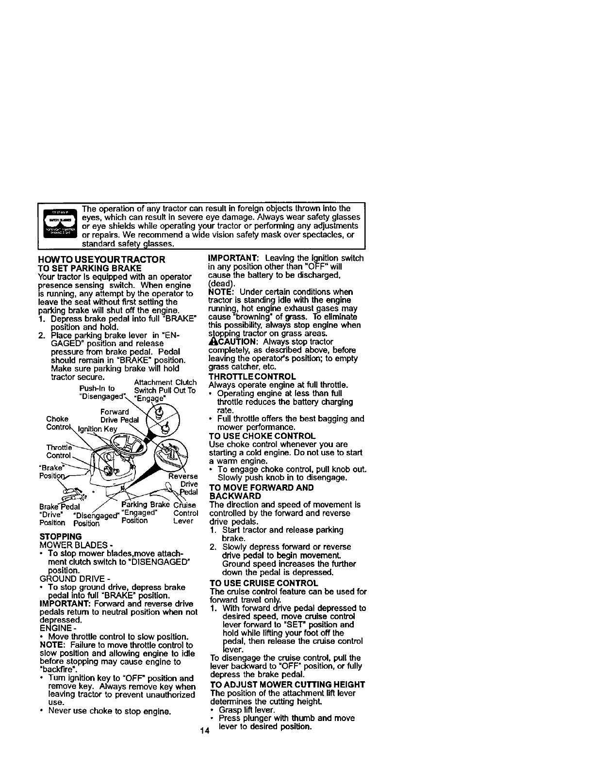
HOWTO USEYOURTRACTOR
TO SET PARKING BRAKE
Your tractor is equipped with an operator
presence sensing switch. When engine
is running,any attempt by the operator to
leave the seat without first setting the
parking brake will shut off the engine.
1. Depress brake pedal into full =BRAKE"
position and hold.
2. Place parking brake lever in "EN-
GAGED" positionand release
pressure from brake pedal. Pedal
should remain in =BRAKE" position.
Make sure parking brake will hold
tractor secure. AttachmentClutch
Push-Into Sv_tchPuffOutTo
"Disengaged_ngag_._
C,oko
Contro__
Disengaged ..
Pc_itJon Position PosttJon Lever
STOPPING
MOWER BLADES -
• To stop mower btades,move attach-
ment clutch switchto "DISENGAGED"
position.
GROUND DRIVE -
• To stop ground drive, depress brake
pedal into full =BRAKE"position.
IMPORTANT: Forward and reverse drive
pedals return to neutral positionwhen not
depressed.
ENGINE-
•Move throttle control to slow position.
NOTE: Failure to move throttle controlto
slow position and allowing engine to idle
before stopping may cause engine to
"backfire'.
•Turn ignition key to =OFF" position and
remove key. Always remove key when
leaving tractor to prevent unauthorized
use.
•Never use choke to stop engine.
IMPORTANT: Leaving the ignitionswitch
in any position other than "OFF" will
cause the battery to be discharged,
Ndead).
OTE: Under certain conditionswhen
tractor is standing idle with the engine
running, hot engine exhaust gases may
cause"browning" of grass. To eliminate
this possibility, always stop engine when
stopping tractor on grass areas.
4_CAUTION: Always stop tractor
completely, as described above, before
leaving the operator's position; to empty
grass catcher, etc.
THROTTLE CONTROL
Always operate engine at full throttle.
• Operating engine at less than full
threttle reduces the battery charging
rate.
•Full throttle offers the best bagging and
mower performance.
TO USE CHOKE CONTROL
Use choke control whenever you are
starting a cold engine. Do not use to start
a warm engine.
• To engage choke control, pull knob out.
Slowly push knob in to disengage.
TO MOVE FORWARD AND
BACKWARD
The direction and speed of movement is
controlled by the forward and reverse
ddve pedals.
1. Start tractor and release parking
brake.
2. Slowly depress forward or reverse
drive pedal to begin movement.
Ground speed increases the further
down the pedal is depressed.
TO USE CRUISE CONTROL
The cruise control feature can be used for
forward travel only.
1. With forward drive pedal depressed to
desired speed, move cruise control
lever forward to "SET" positionand
hold while liftingyour foot off the
pedal, then release the cruise control
lever.
To disengage the cruise control, pull the
lever backward to =OFF" position, or fully
depress the brake pedal.
TO ADJUST MOWER CUTTING HEIGHT
The positionof the attachment lift lever
determines the cutting heighL
•Grasp liftlever.
•Press plunger with thumb and move
14 lever to desired position.
Thecuttingheight range is approxi-
mately 1-1/2 to 4". The heights are
measured from the ground to the blade
tip with the engine not running. These
heights are approximate and may vary
depending upon soil conditions, height of
grass and types of grass being mowed.
• The average lawn should be cut to
approximately 2-1/2 inches dudng the
cool season and to over 3 inches
during hot months. For healthier and
better looking lawns, mow often and
after moderate growth.
• For best cutting performance, grass
over 6 inches in height should be
mowed twice. Make the first cut
relatively high; the second to desired
height.
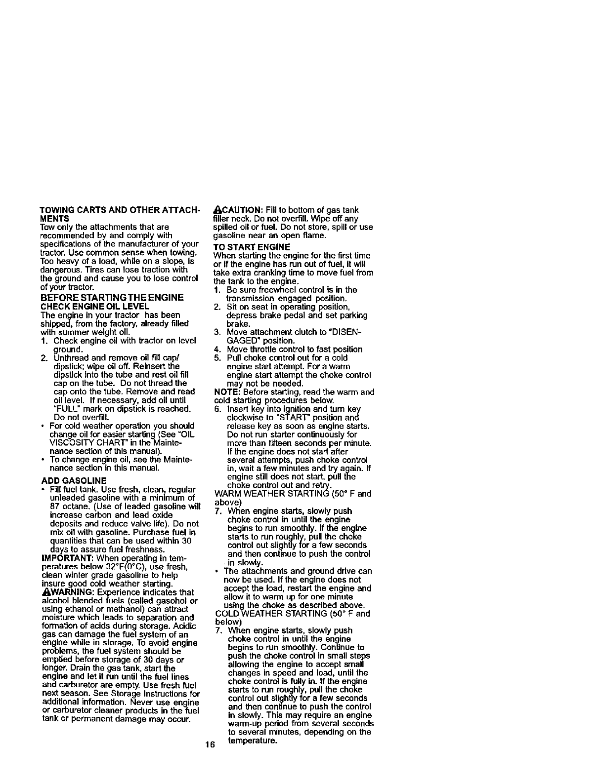
TO ADJUST GAUGE WHEELS
Gauge wheels are properly adjusted
when they are slightlyoff the ground
when mower is at the desired cutting
height in operating position. Gauge
wheels then keep the deck in proper
positionto help prevent scalping in most
terrain conditions.
NOTE: Be sure tractor is on a flat level
surface.
I. Lower mower and adjust mower to
desired cutting height.
2. Remove retainer spdng and clevis pin
which secure each gauge wheel bar.
3. Lower gauge wheels to ground. Raise
gauge wheels slightlyto align holes in
bracket and gauge wheel bar and
insert clevis pin. Gauge wheels
should be slightlyoff the ground.
4. Replace retainer spdng into clevis pin.
5. Be sure all gauge wheels are in the
same setting.
IMPORTANT: Be sure to readjust gauge
wheels if you change the cutting height
of the mowerdeck.
Retainer
Spdn!
TO OPERATE MOWER
Your tractor is equipped with an operator
presence sensing switch. Any attempt by
the operator to leave the seat with the
engine running and the attachment clutch
engaged will shut off the engine.
1. Select desired height of cut.
2. Start mower blades by engaging
attachment clutch control.
15
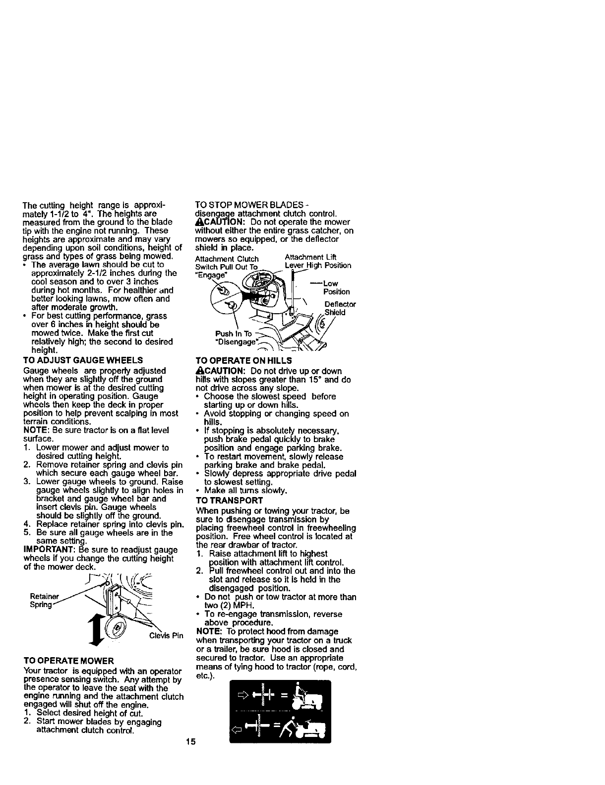
TO STOP MOWER BLADES -
disenqaae attachment clutch control.
_,CA[JI']ON: Do not operate the mower
without either the entire grass catcher, on
mowers so equipped, or the deflector
shield in place.
Attachment Clutch Attachment Lift
Switch Pull OutTo Lever HighPosition
--Low
Position
Deflector
Pushtn To
+Disengage_
TO OPERATE ON HILLS
ACAUTION: Do not drive upor down
hillswith slopes greater than 15 °and do
not drive across any slope.
• Choose the slowest speed before
starting up or down hills.
•Avoid stopping or changing speed on
hills.
• If stopping is absolutely necessary,
push brake pedal quickly to brake
position and engage parking brake.
• To restart movement, slowly release
parking brake and brake pedal.
•Slowly depress appropriate drive pedal
to slowest setting.
• Make all turns slowly.
TO TRANSPORT
When pushing or towing your tractor, be
sure to disengage transmission by
placing freewheel control in freewheeling
position. Free wheel control is located at
the rear drawbar of ltactor.
1. Raise attachment liftto highest
position with attachment lift control.
2. Pull freewheel control out and into the
slot and release so it is held in the
disengaged position.
• Do not push or tow tractor at more than
two (2) MPH.
•To re-engage transmission, reverse
above procedure.
NOTE: To protecthood from damage
when transportingyour tractor on a truck
or a trailer, be sure hood is closed and
secured to tractor. Use an appropriate
means of tying hood to tractor (rope, cord,
etc.).
TOWINGCARTSANDOTHERATtACH-
MENTS
Towonlytheattachmentsthatare
recommendedbyandcomplywith
specificationsofthemanufacturerofyour
tractor.Usecommonsensewhentowing.
Tooheavyofaload,whileonaslope,is
dangerous.Tirescanlosetractionwith
thegroundandcauseyoutolosecontrol
ofyourtractor.
BEFORESTARTINGTHEENGINE
CHECKENGINEOILLEVEL
Theengineinyourtractorhasbeen
shipped,from the factory, already filled
with summer weight oil.
1. Check engine oil with tractor on level
ground.
2. Unthread and remove oil fill cap/
dipstick;wipe oil off. Reinsert the
dipstickinto the tube and rest oil fill
cap on the tube. Do not thread the
cap onto the tube. Remove and read
oil level. If necessary, add oil until
=FULL" mark on dipstick is reached.
Do not overfill.
•For cold weather operation yon should
change oil for easier starting(Sen =OIL
VISCOSITY CHART" inthe Mainte-
nance sectionof this manual).
• To change engine oil, see the Mainte-
nance section in this manual.
ADD GASOLINE
•Fill fuel tank. Use fresh, clean, regular
unleaded gasoline with a minimum of
87 octane. (Use of leaded gasoline will
increase carbon and lead oxide
deposits and reduce valve life). Do not
mixoil with gasoline. Purchase fuel in
quantities that can be used within 30
days to assure fuel freshness.
IMPORTANT: When operating in tem-
peratures below 32°F(0°C), use fresh,
clean winter grade gasoline to help
insure good cold weather starting.
_,WARNING: Experience indicates that
alcohol blended fuels (called gasehol or
using ethanol or methanol) can attract
moisture which leads to separation and
formation of acids during storage. Acidic
gas can damage the fuel system of an
engine while in storage. To avoid engine
problems, the fuel system should be
emptied before storage of 30 days or
longer. Drain the gas tank, start the
engine and let it run untilthe fuel lines
and carburetor are empty. Use fresh fuel
next season. See Storage Instructionsfor
additional information. Never use engine
or carburetor cleaner products in the fuel
tank or permanent damage may occur.
ACAUTION: Fill to bottom of gas tank
filler neck. Do not overfill. Wipe off any
spilled oil or fuel. Do not store, spill or use
gasoline near an open flame.
TO START ENGINE
When starting the engine for the first time
or ifthe engine has run out of fuel, itwill
take extra cranking time to move fuel from
the tank to the engine.
1. Be sure freewheel controlis in the
transmission engaged position.
2. Sit on seat in operating position,
depress brake pedal and set parking
brake.
3. Move attachment clutch to =DISEN-
GAGED" position.
4. Move throttle controlto fast position
5. Pull choke controlout for a cold
engine start attempt. For a warm
engine start attempt the choke control
may not be needed.
NOTE: Before starting, read the warm and
cold starting procedures below.
6. Insert key into ignition and tum key
clockwise to =STAR'I* position and
release key as soon as engine starts.
Do not run starter continuously for
more than fifteen seconds per minute.
If the engine does not start after
several attempts, push choke control
in, wait a few minutes and try again. If
engine stilldoes not start, pull the
choke control out and retry.
WARM WEATHER STARTING (50" F and
above)
7. When engine starts, slowly push
choke control in until the engine
begins to run smoothly. If the engine
starts to run roughly, pull the choke
controlout slightlyfor a few seconds
and then continue to push the control
in slowly.
• The attachments and ground drive can
now be used. If the engine does not
accept the load, restart the engine and
allow it to warm up for one minute
using the choke as described above.
COLDWEATHER STARTING (50°F and
below)
7. When engine starts, slowly push
choke control in until the engine
begins to run smoothly. Continue to
push the choke controlin small steps
allowing the engine to accept small
changes in speed and load, untilthe
choke controt is fully in. If the engine
starts to run roughly, pull the choke
control out slightlyfor a few seconds
and then continue to push the control
in slowly. This may require an engine
warm-up period from several seconds
to several minutes, depending on the
16 temperature.
AUTOMATIC TRANSMISSION WARM UP
Before driving the unit in cold weather,
the transmission should be warmed up as
follows:
1. Be sure the tractor is on level ground.
2. Release the parking brake and let the
brake slowly return to operating
position.
3. Allow one minute for transmission to
warm up. This can be done during the
engine warm up period.
•The attachments can be used dudng
the engine warm-up peded after the
transmission has been warmed up and
may require the choke control be
pulled out slightly.
NOTE: If at a high altitude (above 3000
feet) or in cold temperatures (below 32 F)
the carburetor fuel mixture may need to
be adjusted for best engine perfom]ance.
See "TO ADJUST CARBURETOR in the
Service and Adjustments section of this
manual.
PURGETRANSMISSION
ACAUTION: Never engage or disengage
freewheel lever while the engine is
running.
To ensure proper operation and perfor-
mance, it is recommended that the
transmission be purged before operating
traelor for the first time. This procedure will
remove any trapped air inside the trans-
mission which may have developed during
shipping of your bactor.
IMPORTANT: Should your transmission
require removal for service or replacement,
it should be purged after reiostallation
before operating the tractor.
1. Place tractor safely on level surface
with engine off and parking brake set.
2. Disengage transmission by placing
freewheel control in freewheeling
position(See TO TRANSPORT" in
this section of manual).
3. Sittingin the tractor seat, start engine.
After the engine is running, move
throttle control to slow position.
Disengage parking brake.
4. Depress forward drive pedal to full
forward positionand hold for five (5)
seconds and release pedal. Depress
reverse drive pedal to full reverse
position and hold for five (5) seconds
and release pedal. Repeat this
procedure three (3) times.
NOTE: Dudng this procedure there will be
no movement of drive wheels. The air is
being removed from hydraulic ddve
system.
5. Shut- off engine and set perking
brake.
17
6. Engage transmission by placing
freewheel control in ddving position
(See =TO TRANSPORT" in this section
of manual).
7. Sitting in the tractor seat, start engine.
After the engine is running, move
throttle control to half (1/2) speed.
Disengage parking brake.
8. Drive tractor forward for approximately
five feet then backwards for five feet.
Repeat this ddving procedure three
times.
Your tractor is now purged and now ready
for normal operation.
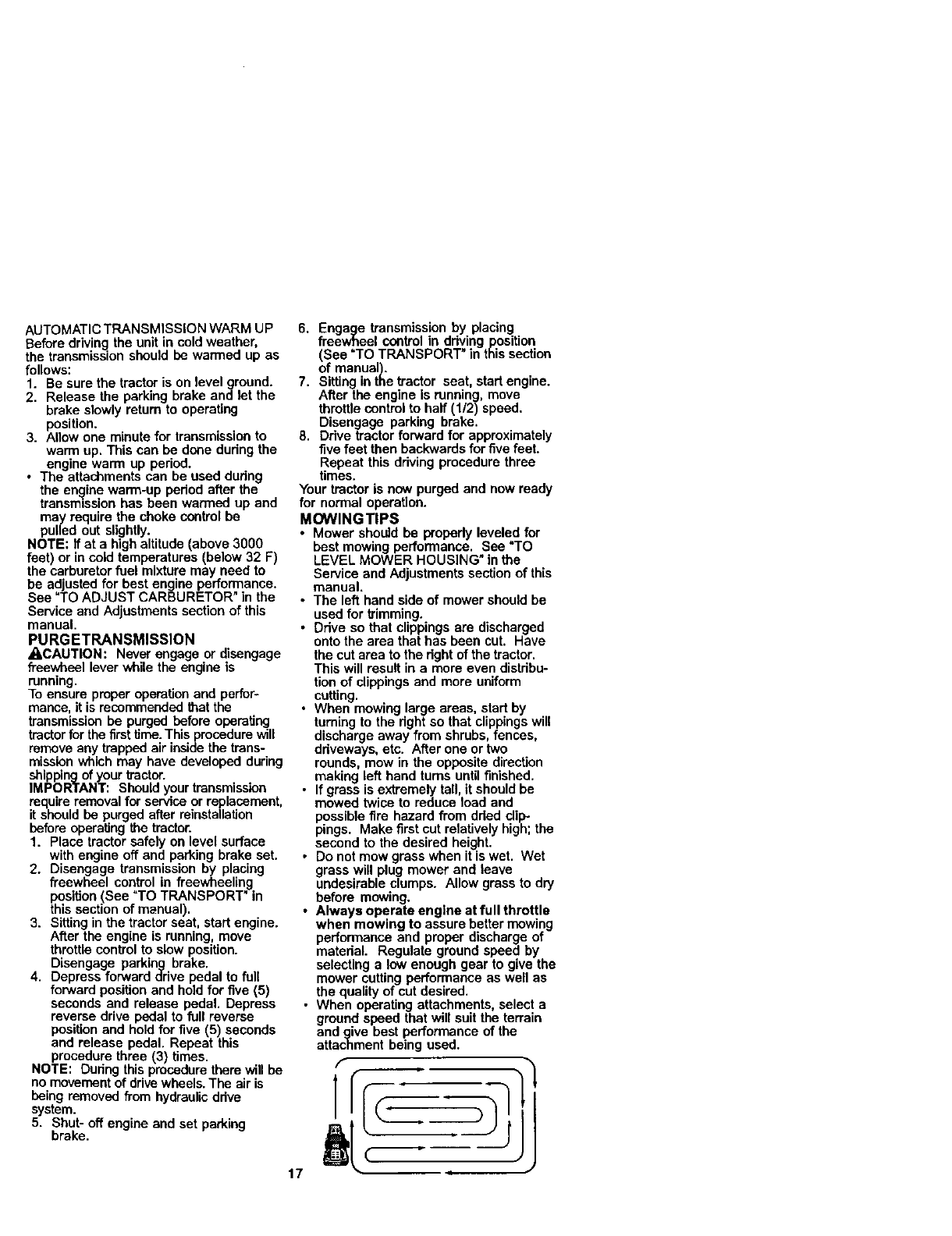
MOWlNGTIPS
• Mower should be propedy leveled for
best mowing performance. See "TO
LEVEL MOWER HOUSING" in the
Service and Adjustments section of this
manual.
• The left hand side of mower should be
used for trimming.
•Ddve so that clippings are discharged
onto the area that has been cut. Have
the cut area to the right of the tractor.
This will result in amore even distribu-
tion of clippings and more uniform
cutting.
• When mowing large areas, start by
turning to the right so that clippings will
discharge away from shrubs, fences,
ddveways, etc. After one or two
rounds, mow in the opposite direction
making left hand turns until finished.
•If grass is extremely tall, it should be
mowed twice to reduce load and
possible fire hazard from dded dip-.
pings. Make first cut relatively high; the
second to the desired height.
• Do not mow grass when it is wet. Wet
grass will plug mower and leave
undesirable clumps. Allow grass to dry
before mowing.
•Always operate engine at full throttle
when mowing to assure better mowing
performance and proper discharge of
material. Regulate ground speed by
selecting a low enough gear to give the
mower cutting performance as well as
the quality of cut desired.
• When operating attachments, select a
ground speed that will suit the terrain
and give best performance of the
attachment being used.
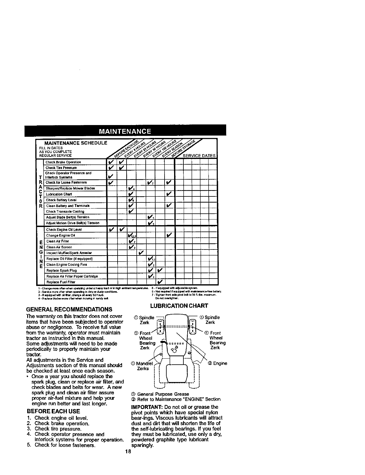
FILL IN DATES
AsYooSe.PL E
Check Brake Operafio_ I1_
CheCl_TirePressure I/ t/_
Check Operator P_esence and
TInte,do_ systems I_
Check10rLooseFasteners I_ 11,/1 II_
ASharpen/Replace Mowe_ Blades (1=/4
L.lxi_tion chad f_ I_
T Check Battee/Level 1_6
R Clean Baltew and Tenl_inals I/' 11_
Check Ttansaxle CoOling (l_
Adlast Blade Belt(s) Tendon ll_
Adj=st Motion DriveBelt(e) Tension _
Check Engine Oil Level I# /
Change Engine Oil _,3 11_
E clean Air Filkar _2
N Ctea nA_*Sueen 1#/2
GInspect Mulfler/Spark Atrest_ Vr
Replace Oil Filter (if equipped) _,2
N Clean Engine Cooling Fins 11_
Repla_ Spark Plug I_ 1_
Replace Air Filter Paper C==rtridoe b/2
Replace Fuel Fitter b/
t. Ch6r_l _onm ot_ wh4m op_all_g ur_,r i h _W Iold _in hlgh a=_ _t I_. 5 - If_lpped v_lh adjum_ ly_ll¢a.
2. S_* mo_ o_1_ _op_a_ng in dire/or 4usty oondltlcn=. 6. Not r_=lred If *qu_ with ma_t,N-_ncr*_n=e bat_.
3. If *_Jipped wi_ oa _K, chang_ ol _60 hoU._. ? -Ti_t_,n _a_t rod* p_ot b_t t_ 35 _,1_ m*_rnum.
GENERAL RECOMMENDATIONS
The warranty on this tractordues not cover
items that have been subjected to operator
abuse or negligence. To receive full value
from the warranty,operator must maintain
tractoras instructedin this manual.
Some adjustmentswill need to be made
periodicallyto properlymaintain your
tractor.
All adjustmentsin the Service and
Adjustments secUonof this manual should
be checked at least once each season.
• Once a year you should replace the
spark plug, clean or replace air filter, and
check blades and belts for wear. A new
spark plug and clean air filter assure
proper air-fuel mixture and help your
engine run better and last longer.
BEFORE EACH USE
1. Check engine oil level.
2. Check brake operation.
3. Check tire pressure.
4. Check operator presence and
intedocksystems for proper operation.
5. Check for loosefasteners.
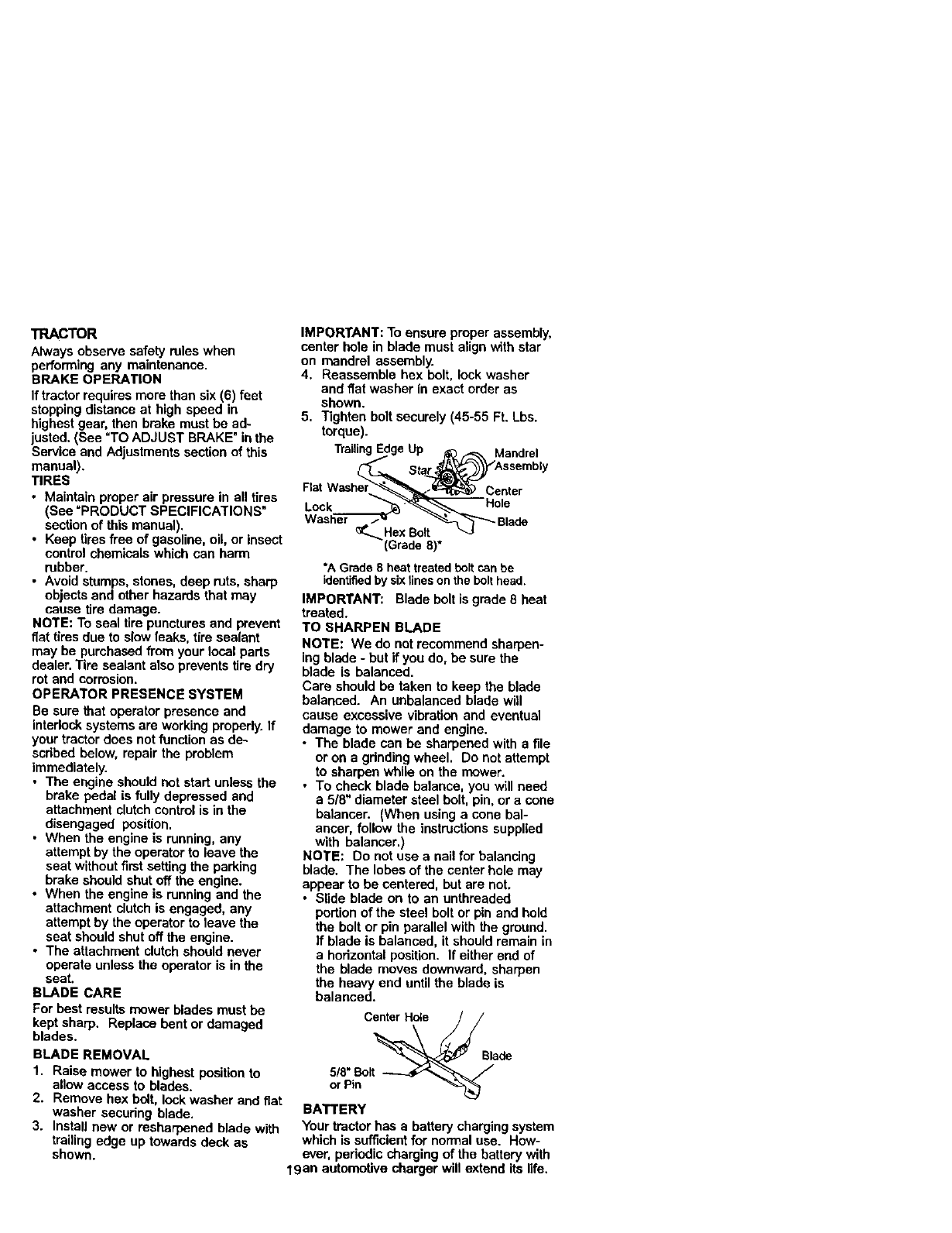
LUBRICATION CHART
Spindle "
Zerk Zerk
Front
Wheel Wheel
Bearing Bearing
Zerk Zerk
Zerks
I
l
l
L....J L._.j
_) General purpose Grease
Refer to Maintenance "ENGINE" Section
IMPORTANT: Do not oil or grease the
pivot points which have special nylon
bear-ings. Viscous lubricants will attract
dust and dirt that will shorten the life of
the self-lubricatinghearings. If you feel
they must be lubricated, use only a dry,
powdered graphite type lubdcant
sparingly.
18
TRACTOR
Always observe safety rules when
performing any maintenance.
BRAKE OPERATION
If tractor requires more than six (6) feet
stoppingdistance at high speed in
highest gear, then brake must be ad-
justed. (See =TOADJUST BRAKE" inthe
Service and Adjustments section of this
manual).
TIRES
• Maintain proper air pressure in all tires
(See _PRODUCT SPECIFICATIONS"
section of this manual).
• Keep tires free of gasoline, oil, or insect
control chemicals which can harm
rubber.
• Avoid stumps, stones, deep ruts, sharp
objects and other hazards that may
cause tire damage.
NOTE: To seal tire punctures and prevent
fiat tires due to slow leaks, tire sealant
may be purchased from your local parts
dealer. Tire sealant also prevents tire dry
rot and corrosion.
OPERATOR PRESENCE SYSTEM
Be sure Mat operator presence and
interlocksystems are working properly. If
your tractor does not function as de.-
scribed below, repair the problem
immediately.
•The engine should not start unless the
brake pedal is fully depressed and
attachment clutch controlis in the
disengaged position.
•When the engine is running,any
attempt by the operator to leave the
seat without first setting the parking
brake should shutoff the engine.
•When the engine is running and the
attachment dutch is engaged, any
attempt by the operator to leave the
seat should shut off the engine.
•The attachment clutch should never
operate unless the operator is in the
seat.
BLADE CARE
For best results mower blades must be
kept sharp. Replace bent or damaged
blades.
BLADE REMOVAL
1. Raise mower to highest positionto
allow access to blades.
2. Remove hex bolt, lock washer and fiat
washer secudng blade.
3. Install new or resharpened blade with
trailing edge up towards deck as
shown.
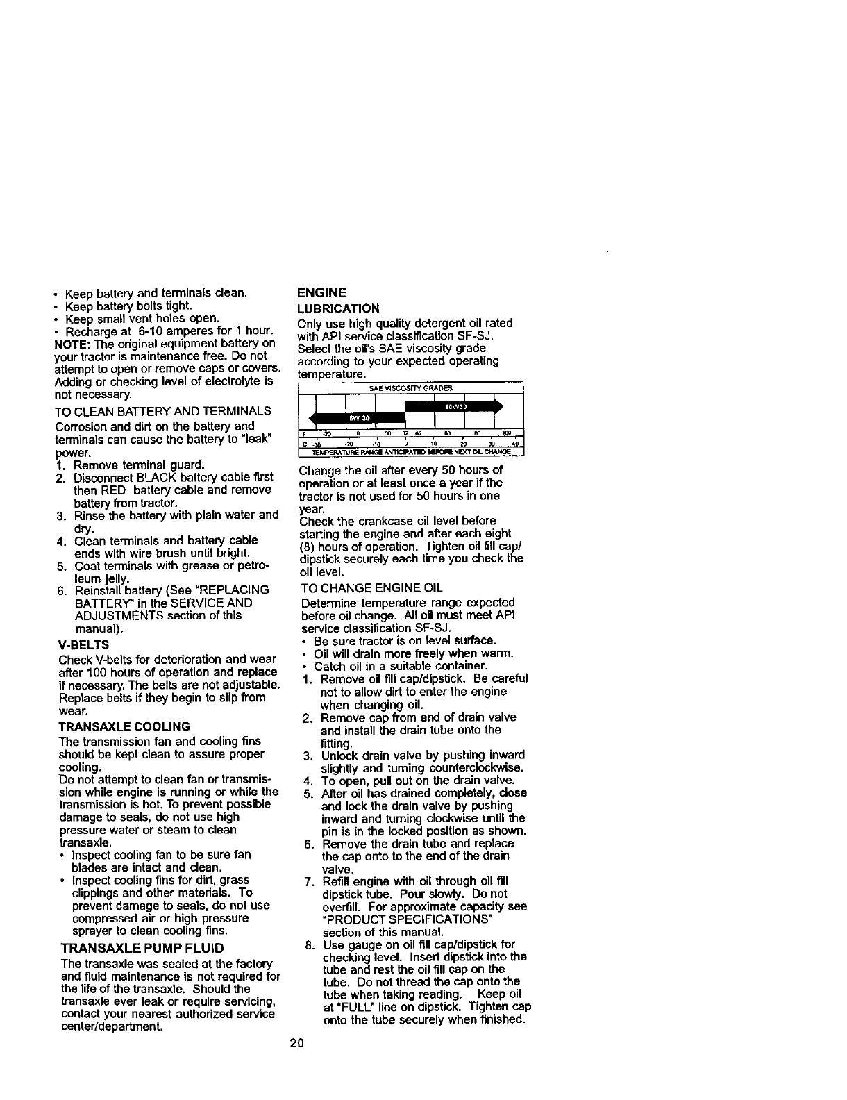
IMPORTANT: To ensure proper assembly,
center hole in blade must align with star
on mandrel assembly.
4. Reassemble hex bolt, lock washer
and flat washer in exact order as
shown.
5. Tighten bolt securely (45-55 Ft. Lbs.
torque).
TrailingEdgeUp ._ _, Mandrel
_Sta_Assembly
Rat Washer __Center
Lock ,__ HOle
Washer _Hex Bolt_-_''Blade
(Grade8)*
*A Grade8 heattreatedboltcan be
identifiedby sixtineson thebolthead.
IMPORTANT: Blade bolt is grade 8 heat
treated.
TO SHARPEN BLADE
NOTE: We do not recommend sharpen-
ing blade - but if you do, be sure the
blade is balanced.
Care should be taken to keep the blade
balanced. An unbalanced blade will
cause excessive vibration and eventual
damage to mower and engine.
• The blade can be sharpened with a file
or on a grindingwheel. Do not attempt
to sharpen while on the mower.
•To check blade balance, you will need
a 5/8" diameter steel bolt, pin, or a cone
balancer. (When using a cone bal-
ancer, follow the instructionssupplied
with balancer.)
NOTE: Do not use a nail for balancing
blade. The lobes of the center hole may
appear to be centered, but are not.
•Slide blade on to an unthreaded
portion of the steel bolt or pin and hold
the bolt or pin parallel with the ground.
If blade is balanced, it should remain in
a horizontal position. If either end of
the blade moves downward, sharpen
the heavy end untilthe blade is
balanced.
Center Hole
_Blade
orPin "_
BATTERY
Your tractor has abattery charging system
which is sufficient for normal use. How-
ever, periodic charging of the battery with
19an automotive charger will extend its life.
•Keep battery and terminals clean.
• Keep battery bolts tight.
•Keep small vent holes open.
• Recharge at 6-10 amperes for 1 hour.
NOTE: The original equipment battery on
your tractor is maintenance tree. Do not
attempt to open or remove caps or covers,
Adding or checking level of electrolyte is
not necessary.
TO CLEAN BATTERY AND TERMINALS
Corrosion and dirt on the battery and
terminals can cause the battery to "leak"
power.
1. Remove terminal guard.
2. Disconnect BLACK battery cable first
then RED battery cable and remove
battery from tractor.
3. Rinse the battery with plain water and
dry.
4. Clean terminals and battery cable
ends with wire brush until bright,
5. Coat terminals with grease or petro-
leum jelly.
6. Reinstall battery (See "REPLACING
BATTERY" in the SERVICE AND
ADJUSTMENTS section of this
manual).
V-BELTS
Check V-belts for deterioration and wear
after 100 hours of operation and replace
if necessary. The belts are not adjustable.
Replace belts if they begin to slip from
wear.
TRANSAXLE COOLING
The transmissionfan and cooling fins
should be kept clean to assure proper
cooling.
Do not attempt to clean fan or transmis-
sion while engine is running or while the
transmissionis hot. To prevent possible
damage to seals, do not use high
pressurewater or steam to clean
transaxle.
•Inspect coolingfan to be sure fan
blades are intact and clean,
•Inspect coolingfins for dirt, grass
clippings and other materials. To
prevent damage to seals, do not use
compressed air or high pressure
sprayer to clean cooling fins,
TRANSAXLE PUMP FLUID
The transaxle was sealed at the factory
and fluid maintenance is not required for
the life of the transaxle, Should the
transaxle ever leak or require servicing,
contact your nearest authorized service
canter/department,
ENGINE
LUBRICATION
Only use high quality detergent oil rated
with API service classification SF-SJ.
Select the oirs SAE viscosity grade
according to your expected operating
temperature.
Change the oil after every 50 hours of
operation or at least once a year ifthe
tractor is not used for 50 hours in one
year.
Check the crankcase dl level before
starting the engine end after each eight
(8) hours of operation. Tighten oil fill cap/
dipsticksecurely each time you check the
oil level.
TO CHANGE ENGINE OIL
Determine temperature range expected
before oil change. All oil must meat API
service classification SF-SJ.
• Be sure tractor is on level surface.
• Oil will drain more freely when warm.
• Catch oil in asuitable container.
1. Remove oil fill cap/dipstick. Be careful
not to allow dirt to enter the engine
when changing oil.
2. Remove cap from end of drain valve
and install the drain tube onto the
fitting.
3. Unlock drain valve by pushing inward
slightly and turning counterclockwise.
4. To open, pull out on the drain valve.
5. After oil has drained completely, close
and lock the drain valve by pushing
inward and turning clockwise until the
pin is in the locked position as shown.
6. Remove the drain tube and replace
the cap onto to the end of the drain
valve.
7. Refill engine with oil through oil fill
dipsticktube. Pour slowly. Do not
overfill. For approximate capacity see
"PRODUCT SPECIFICATIONS"
section of this manual.
8. Use gauge on oil fill cap/dipstick for
checking level. Insert dipstick into the
tube and rest the oil fill cap on the
tube. Do not thread the cap onto the
tube when taking reading. Keep oil
at =FULL" line on dipstick. Tighten cap
onto the tube securely when finished.
20
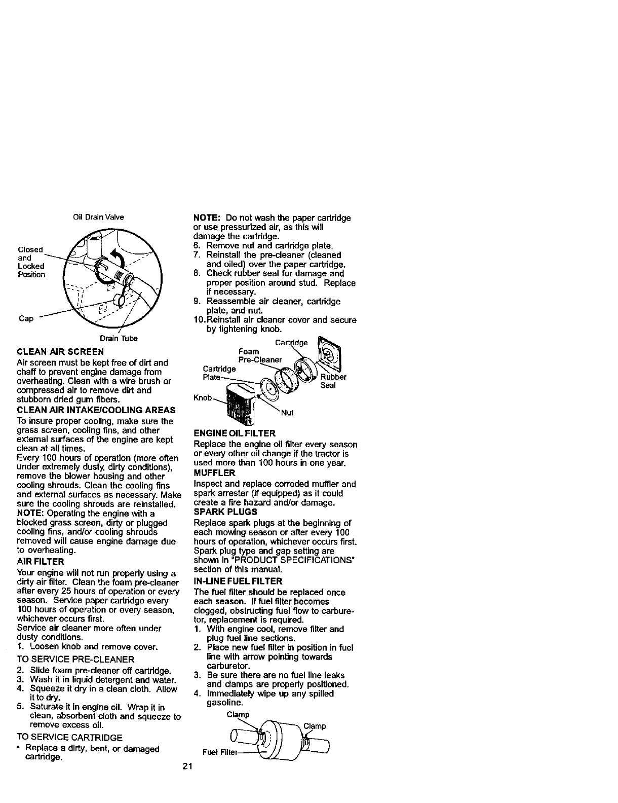
Oil Drain Valve
Closed
and
Locked
Position
Cap
Drain lbbe
CLEAN AIR SCREEN
Air screen must be kept free of dirt and
chaff to prevent engine damage from
overheating. Clean with a wire brush or
compressed air to remove dirt and
stubbem dded gum fibers.
CLEAN AIR INTAKE/COOLING AREAS
To insure proper cooling, make sure the
grass screen, cooling fins, and other
external surfaces of the engine are kept
clean at all times.
Every 100 hours of operation (more often
under extremely dusty, dirty conditions),
remove the blower housing and other
cooling shrouds. Clean the cooling fins
and external surfaces as necessary. Make
sure the cooling shrouds are reinstalled.
NOTE: Operating the engine with a
blocked grass screen, dirty or plugged
cooling fins, and/or cooling shrouds
removed will cause engine damage due
to overheating.
AIR FILTER
Your engine will not run properly using a
dirty air filter. Clean the foam we-cleaner
after every 25 hours of operation or every
season. Service paper cartddge every
100 hours of operation or every season,
whichever occurs first.
Service air cleaner more often under
dusty conditions.
1. Loosen knob and remove cover.
TO SERVICE PRE-CLEANER
2. Slide foam pre-cleaner off cartridge.
3. Wash it in liquid detergent and water.
4. Squeeze it dry in aclean cloth. Allow
it to dry.
5. Saturate it in engine oil. Wrap it in
clean, absorbent cloth and squeeze to
remove excess oil.
TO SERVICE CARTRIDGE
• Replace a dirty, bent, or damaged
cartridge. 21
NOTE: Do not wash the paper cartddge
or use pressurized air, as this will
damage the cartddge.
6. Remove nut and cartridge plate.
7. Reinstall the pra-cleaner (cleaned
and oiled) over the paper cartridge.
8. Check rubber seal for damage and
proper positionaround stud. Replace
if necessary.
9. Reassemble air deaner, cartridge
plate, and nut.
10. Reinstall air cleaner cover and secure
by tightening knob.
Foam
Pre-Cleaner
Ca_ddge
Seal
ENGIN E OIL FILTER
Replace the engine oil filter every season
or every other oil change if the tractor is
used more then 100 hours in one year.
MUFFLER
Inspect and replace corroded muffler and
spark arrester (if equipped) as it could
create afire hazard and/or damage.
SPARK PLUGS
Replace spark plugs at the beginning of
each mowing season or after every 100
hours of operation, whichever occursfirst.
Spark plug type and gap setting are
shown in "PRODUCT SPECIFICATIONS"
section of this manual.
IN-LINE FUEL FILTER
The fuel filter should be replaced once
each season. Iffuel filter becomes
clogged, obstructingfuel flow to carbure-
tor, replacement is required.
1. With engine cool, remove filter and
plug fuel line sections.
2. Place new fuel filter in positionin fuel
line with arrow pointing towards
carburetor.
3. Be sure there are no fuel line leaks
and damps are propedy positioned.
4. Immediately wipe up any spilled
gasoline.
Clamp
FuelFilt_
CLEANING
•Clean engine, batter,!, seat, finish, etc.
of all foreign matter.
•Keep finished surfaces and wheels free
of all gasoline, oil, etc.
• Protect painted surfaces with automo-
tive type wax.
We do not recommend using a garden
hose to clean your tractor unless the
electrical system, muffler,air filter and
carburetor are covered to keep water out.
Water in engine can result in a shortened
engine life.
_CAUTION: BEFORE PERFORMING ANY SERVICE ORADJUSTMENTS:
1. Depress brake pedal fully and set parking brake.
2. Place attachment clutch in =DISENGAGED" position.
3. Turnignition key =OFF" and remove key.
4. Make sure the blades and all moving parts have completely stopped.
5. Disconnect spark plug wire from spark plug and place wire where it cannot
come in contact with plug.
['RACTOR
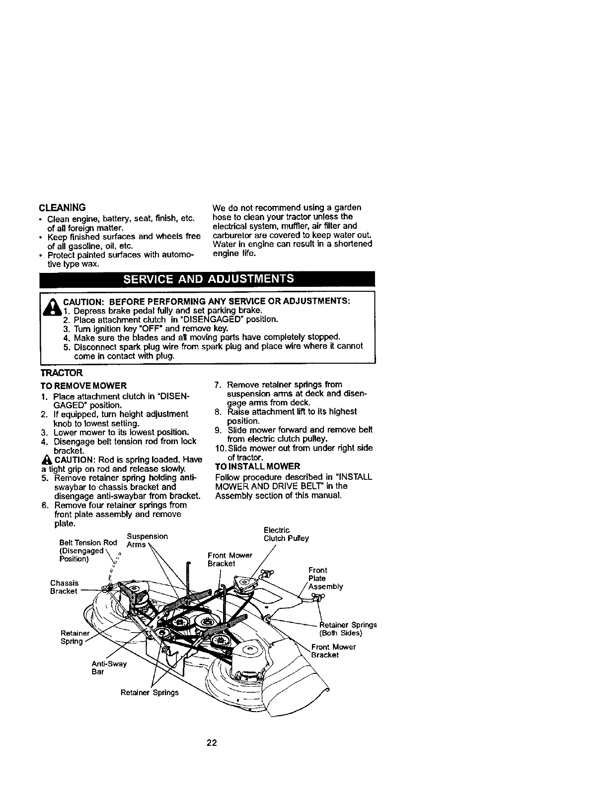
TO REMOVE MOWER
1. Place attachment clutch in =DISEN-
GAGED" position.
2. If equipped, turn height adjustment
knob to lowest setting.
3. Lower mower to its lowest position.
4. Disengage belt tension rod from lock
bracket.
CAUTION: Rod is spring loaded. Have
a tight grip on rod and release slowly.
5. Remove retainer spring holding anti-
swaybar to chassis bracket and
disengage anti-swaybar from bracket.
6. Remove four retainer springsfrom
front plate assembly and remove
plate.
Suspension
BeltTensionRod
(Disengaged\
Position) _,_,
//
Chassis
Bracket
7. Remove retainer springs from
suspension enTtsat deck and disen-
gage arms from deck.
8. Raise attachment lif_to its highest
position.
9. Slide mower forward and remove belt
from electric clutch pulley.
10.Slide mower out from under right side
of tractor.
TO INSTALL MOWER
Follow procedure described in =INSTALL
MOWER AND DRIVE BELT_in the
Assembly section of this manual.
Electric
Clutch Pulley
Front Mower
Bracket Front
Plate
Retainer
Anti-Sway
Bar
Retainer Springs
;prings
(Both Sides)
_Front Mower
Bracket
22
TOLEVEL MOWER HOUSING
Adjust the mower while tractor is parked
on level ground or driveway. Make sure
tires are propedy inflated (See =PROD-
UCT SPECIFICATIONS" sectionof this
manual). If tires are overor
underinflated, you will not propedy adjust
your mower.
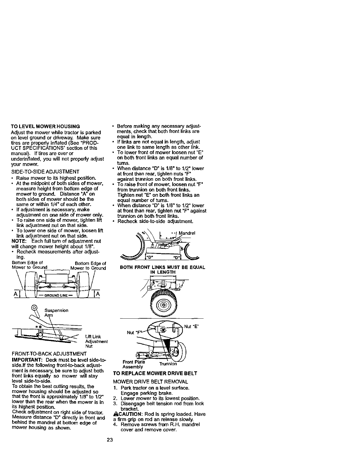
SIDE-TO-SIDE ADJUSTMENT
• Raise mower to its highest position.
•At the midpoint of both sides of mower,
measure height from bottom edge of
mower to ground. Distance =A" on
both sides of mower should be the
same or within 1/4" of each other.
•If adjustment is necessary, make
adjustment on one side of mower only.
•To raise one side of mower, tighten lift
link adjustment nut on that side.
• To lower one side of mower, loosen lift
link adjustment nut on that side.
NOTE: Each full turn of adjustment nut
will change mower height about 1/8".
•Recheck measurements after adjust-
ing.
BottomEdgeof BottomEdgeof
Mower to Ground Mower to Ground
\/
A_Suspensi°n LiftLink
Adjustment
Nut
FRONT-TO-BACK ADJUSTMENT
IMPORTANT: Deck must be level side-to-
side.If the following front-to-back adjust-
ment is necessary, be sure to adjust both
front links equally so mower will stay
level side-to-side.
To obtain the best cutting results, the
mower housing should be adjusted so
that the front is approximately 1/8" to 1/2"
lower than the rear when the mower is in
its highest position.
Check adjustment on right side of tractor.
Measure distance =D"directly in front and
behind the mandrel at bottom edge of
mower housing as shown.
•Before making any necessary adjust-
ments, check that both front links are
equal in length.
•If links are not equal in length, adiust
one link to same length as other link.
•To lower front of mower loosen nut =E"
on both front links an equal number of
turns.
•When distance "D" is 1/8" to 1/2" lower
at front than rear, tighten nuts =F"
against trunnion on both front links.
•To raise front of mower, loosen nut "F"
from trunnion on both front links.
Tighten nut "E"on beth front links an
equal number of turns.
• When distance "D" is 1/8" to 1/2" lower
at front than rear, tighten nut "F" against
trunnion on both front links.
•Recheck side-to-side adjustment.
BOTH FRONT LINKS MUST BE EQUAL
IN LENGTH
Nut "E
Front F Trunnion
Assembly
TO REPLACE MOWER DRIVE BELT
MOWER DRIVE BELT REMOVAL
1. Park tractor on alevel surface.
Engage parking brake.
2. Lower mower to its lowest position.
3. Disengage belt tension rod from lock
bracket.
_CAUTION: Rod is spdng loaded. Have
a firm gdp on rod an release slowly.
4. Remove screws from R.H. mandrel
cover and remove cover.
23
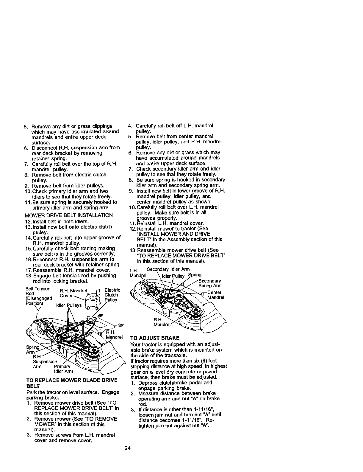
5. Remove any dirt or grass clippings
which may have accumulated around
mandrels and entire upper deck
surface.
6. Disconnect R.H. suspension arm from
rear deck bracket by removing
retainer spring.
7. Carefully roll belt over the top of R.H.
mandrel pulley.
8. Remove belt from electric clutch
pulley.
9. Remove belt from idler pulleys.
10.Check primary idler arm and two
idlers to see that they rotate freely.
11.Be sure spring is securely hooked to
primary idler arm and spring arm.
MOWER DRIVE BELT INSTALLATION
12.Install belt in both idlers.
13.Install new belt onto electric clutch
pulley.
14.Carefully roll belt into upper groove of
R.H. mandrel pulley.
15. Carefully check belt routing making
sure belt is in the grooves correctly.
16.Reconnect R.H. suspension arm to
rear deck bracket with retainer spring.
17.Reassemble R.H. mandrel cover.
18.Engage belt tension rod by pushing
rod into locking bracket.
BeltTension R.H. Mandrel Electric
Rod Cover_Clutch
(Disengaged
Posi_n) Idler
4. Carefully roll belt off LH. mandrel
pulley.
5. Remove belt from center mandrel
pulley, idler pulley, and R.H. mandrel
pulley.
6. Remove any dirt or grass which may
have accumulated around mandrels
and entire upper deck surface.
7. Check secondary idler arm and idler
pulleyto see that they rotate freely.
8. Be sure spring is hooked in secondary
idler arm and secondary spring arm.
9. Installnew belt in lower groove of R.H.
mandrel pulley, idler pulley, and
center mandrel pulley as shown.
10.Carefully roll belt over L.H. mandrel
pulley. Make sure belt is in all
grooves pmpedy.
11.Reinstall L.H. mandrel cover.
12. Reinstall mower to tractor (See
"INSTALL MOWER AND DRIVE
BELT" in the Assembly sectionof this
manual).
13.Reassemble mower drive belt (See
"TO REPLACE MOWER DRIVE BELT"
in this section of this manual).
L.H. Secondary Idler Arm
Mandrel
Spdng Arm
-Center
Mandrel
R.H.
Mandrel
R.H, _"
Suspension
Arm Primary
Idler Arm
TO REPLACE MOWER BLADE DRIVE
BELT
Park the tractoron level surface. Engage
parking brake.
1. Remove mower ddve belt (See "TO
REPLACE MOWER DRIVE BELT" in
this section of this manual).
2. Remove mower (See =TO REMOVE
MOWER" in this section of this
manual).
3. Remove screws from L.H. mandrel
cover and remove cover.
TO ADJUST BRAKE
Your tractor is equipped with an adjust-
able brake system which is mounted on
the side of the transaxle.
If ltactor requires mare than six (6)feet
stoppingdistance at high speed in highest
gear on alevel dry concrete or paved
surface, then brake must he adjusted.
1. Depress clutch/brake pedal and
engage parking brake.
2. Measure distance between brake
operating arm and nut "A" on brake
rod.
3. If distance le other than 1-11/16",
loosen jam nut and turn nut =A" until
distance becomes 1-11/16". Re-
tighten jam nut against nut =A".
24
4. Roadtesttractorfor proper stopping
distance as stated above. Readjust if
necessary. If stopping distance is still
greater than six (6) feet in highest
gear, further maintenance is neces-
sary. Contact your nearest autho-
rized service center/department.
With Parking Brake "Engaged"
g
Arm
Do Not touch this nut. If further brake
adjustment is necessary contact your nearest
authorized service center/deparlrnent
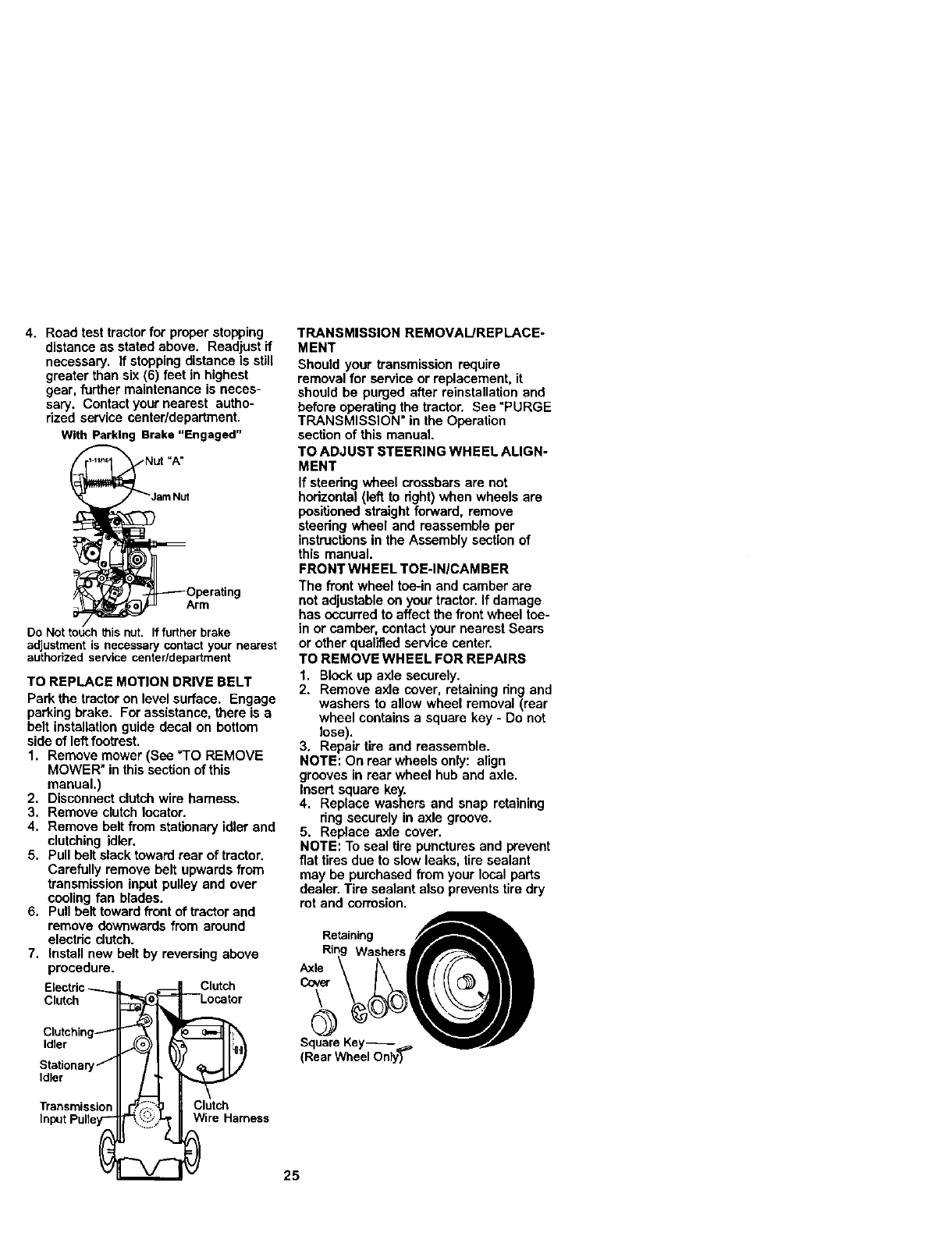
TO REPLACE MOTION DRIVE BELT
Park the tractoron level surface. Engage
parking brake. For assistance, there is a
belt installation guide decal on bottom
side of leftfootrest.
1. Remove mower (See =TO REMOVE
MOWER" in this section of this
manual.)
2. Disconnect clutch wire harness.
3. Remove clutch locater.
4. Remove belt from stationary idler and
clutching idler.
5. Pull belt slack toward rear of tractor.
Carefully remove belt upwards from
transmission input pulley and over
cooling fan blades.
6. Pull belt toward front of tractor and
remove downwards from around
electric clutch.
7. Install new belt by reversing above
procedure.
Electric__
Clutch
Clutching_
Idler
Stationaryj
Idler
Transmission
InputPulley-"
Clutch
"--Locator
Clutch
Wire Harness
TRANSMISSION REMOVAL/REPLACE-
MENT
Should your transmission require
removal for service or replacement, it
should be purged after reinstallation and
before operating the tractor. See "PURGE
TRANSMISSION" in the Operation
section of this manual.
TO ADJUST STEERING WHEEL ALIGN-
MENT
If steedng wheel crossbars are not
hodzontal (left to dght) when wheels are
positioned straight forward, remove
staedng wheel and reassemble per
instructionsin the Assembly section of
this manual.
FRONT WHEEL TOE-IN/CAM BEn
The front wheel toe-in and camber are
not adjustable on your tractor. If damage
has occurred to affect the front wheel toe-
in or camber, contact your nearest Sears
or other qualified service canter.
TO REMOVE WHEEL FOR REPAIRS
1. Blockup axle securely.
2. Remove axle cover, retaining ring and
washers to allow wheel removal (rear
wheel contains a square key - Do not
lose).
3. Repair tire and reassemble.
NOTE: On rear wheels only: align
grooves in rear wheel hub and axle.
Insert square key.
4. Replace washers and snap retaining
ring securely in axle groove.
5. Replace axle cover.
NOTE: To seal tire punctures and prevent
flat tires due to slow leaks, tire sealant
may be purchased from your local parts
dealer. Tire sealant also prevents tire dry
rot and corrosion.
Retaining
Washers
Axle
Cover
\
@
SquareKey--==,
(Rear Wheel Only)
25
TO START ENGINE WITH AWEAK
BATTERY
=_I,CAUTION: Lead-acid batteries
generate explosive gases. Keep sparks,
flame and smoking materials away from
batteries. Always wear eye protection
when around batteries.
If your battery is too weak to start the
engine, it should be recharged. (See
"BATTERY" in the MAINTENANCE
section of this manual).
If =jumpercables" are used for emergency
starting, follow this procedure:
IMPORTANT: Your tractor is equipped
with a 12 volt negative grounded system.
The other vehical must also be a12 volt
negative grounded system. Do not use
your tractor battery to start other vehicles.
TO ATFACHJUMPER CABLES -
1. Connect each end of the RED cable to
the POSITIVE (+) terminal of each
battery, taking care not to short
against chassis.
2. Connect one end of the BLACK cable
to the NEGATIVE (-) terminal of fully
charged battery.
3. Connect the other end of the BLACK
cable to good CHASSIS GROUND,
away from fuel tank and battery.
TO REMOVE CABLES, REVERSE ORDER -
1. BLACK cable first from chassis and
then from the folly charged battery.
2. RED cable last from both battedes.
"Posii_ "Negative"
REPLACING BATTERY
=(kCAUTION: Do not short battery
terminals by allowing a wrench or any
other object to contact both terminals at
the same time. Before connecting battery,
remove metal bracelets, wristwatch
bands, rings, etc.
Positive terminal must be connected first
to prevent sparking from accidental
grounding.
1. Lift hood to raised position.
2. Remove terminal guard.
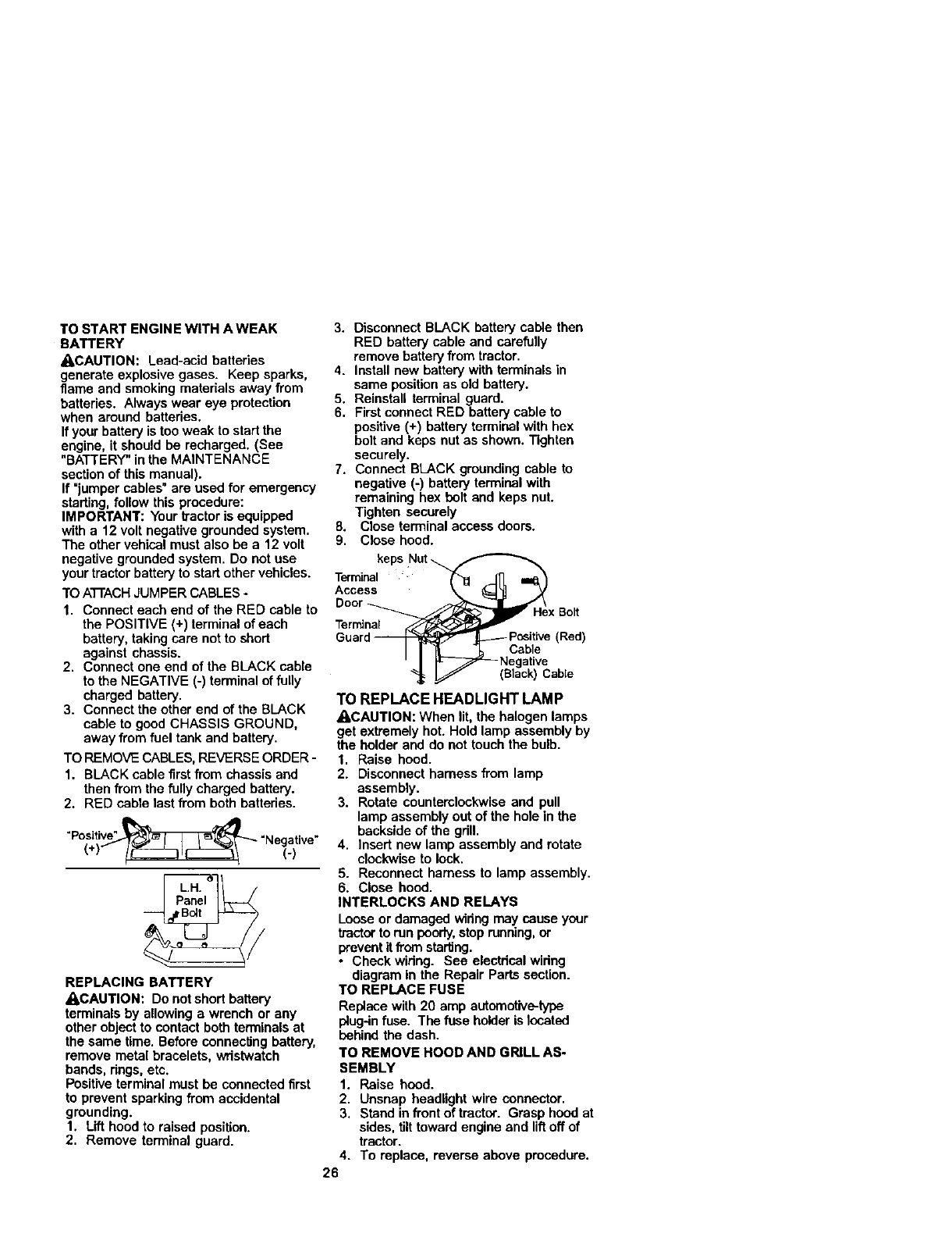
3.
4.
5.
6.
7.
8,
9.
Terminalkeps Nut_(
Access
Door _
Terminal
Guar_
Disconnect BLACK battery cable then
RED battery cable and carefully
remove battery from tractor.
Install new battery with terminals in
same position as old battery.
Reinstall terminal guard.
First connect RED battery cable to
positive (+) battery terminal with hex
bolt and keps nut as shown. Tighten
securely.
Connect BLACK grounding cable to
negative (-) battery terminal with
remaining hex bolt and keps nut.
Tighten securely
Close terminal access doors.
Close hood.
Hex Bolt
(Red)cable
_NC_bliee
(Black) Cable
TO REPLACE HEADLIGHT LAMP
_]LCAUTION: When lit, the halogen lamps
get extremely hot. Hold lamp assembly by
the holder and do not touchthe bulb.
1. Raise hood.
2. Disconnect hamoss from lamp
assembly.
3. Rotate counterclockwise and pull
lamp assembly out of the hole in the
backside of the gdll.
4. Insert new lamp assembly and rotate
clockwise to lock.
5. Reconnect harness to lamp assembly.
6. Close hood.
INTERLOCKS AND RELAYS
Loose or damaged wiring may cause your
tractor to run peedy, stoprunning,or
preventitfrom starting.
•Check wiring. See electdcal widng
diagram in the Repair Parts section.
TO REPLACE FUSE
Replace with 20 amp automotive-type
plug-in fuse. The fuse holder is located
behind the dash.
TO REMOVE HOOD AND GRILL AS-
SEMBLY
1. Raise hood.
2. Unsnap headlight wire connector.
3. Stand in front of tractor. Grasp hood at
sides, tilttoward engine and lift off of
tractor.
4. To replace, reverse above procedure.
26
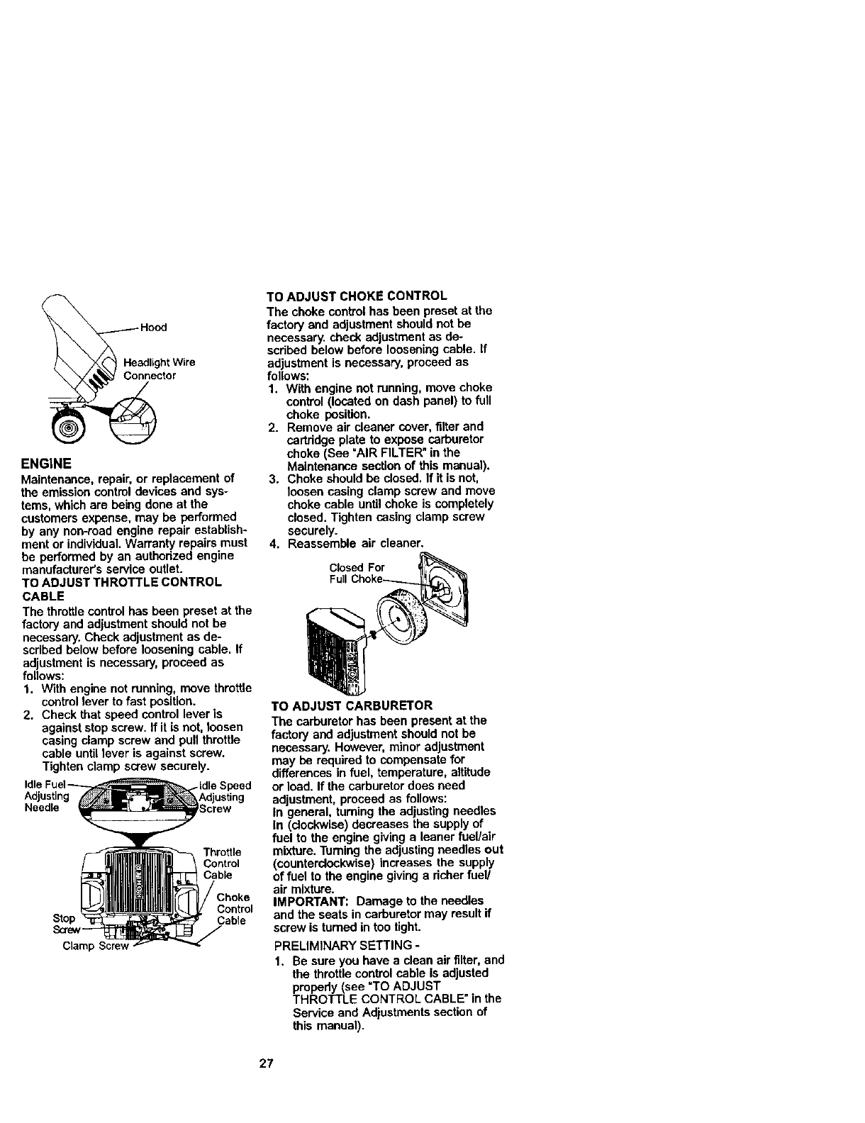
ENGINE
Maintenance, repair, or replacement of
the emission control devices and sys-
tems, which are being done at the
customers expense, may be performed
by any non-road engine repair establish-
ment or individual. Warranty repairs must
be performed by an authorized engine
manufacturer's service outlet.
TO ADJUST THROTTLE CONTROL
CABLE
The throttlecontrol has been preset at the
factory and adjustment should not be
necessary. Check adjustment as de-
scribed below before loosening cable. If
adjustment is necessary, proceed as
follows:
1. With engine not running, move throttle
controllever to fast position.
2. Check that speed control lever is
against stop screw. If it is not, loosen
casing clamp screw and pull throtUe
cable until lever is against screw.
Tighten clamp screw securely.
Adjusting
Needle
Throttle
Control
Cable
Control
Stop Cable
Clamp
TO ADJUST CHOKE CONTROL
The choke control has been preset at the
factory and adjustment should not be
necessary, check adjustment as de--
scribed below before loosening cable. If
adjustment is necessary, proceed as
follows:
1. With engine not running, move choke
control (located on dash panel) to full
choke position.
2. Remove air cleaner cover, filter and
cartridge plate to expose carburetor
choke (See =AIR FILTER"in the
Maintenance section of this manual).
3. Choke should be closed. If it is not,
loosen casing clamp screw and move
choke cable untilchoke is completely
closed. Tighten casing clamp screw
securely.
4. Reassemble air cleaner.
Closed For
Full
TO ADJUST CARBURETOR
The carburetor has been present at the
factory and adjustment should not be
necessary. However, minor adjustment
may be required to compensate for
differences in fuel, temperature, altitude
or load. If the carburetor does need
adjustment, proceed as follows:
In general, turning the adjusting needles
In (clockwise) decreases the supply of
fuel to the engine giving a leaner fuel/air
mixture. Turning the adjusting needles out
(counterclockwise) increases the supply
of fuel to the engine giving a richer fuel/
air mixture.
IMPORTANT: Damage to the needles
and the seats in carburetor may result if
screw is turned in too tight.
PRELIMINARY SETTING -
1. Be sure you have a clean air filter, and
the throttle control cable is adjusted
propedy (see =TO ADJUST
THROll'LEE CONTROL CABLEmin the
Service and Adjustments section of
this manual).
27
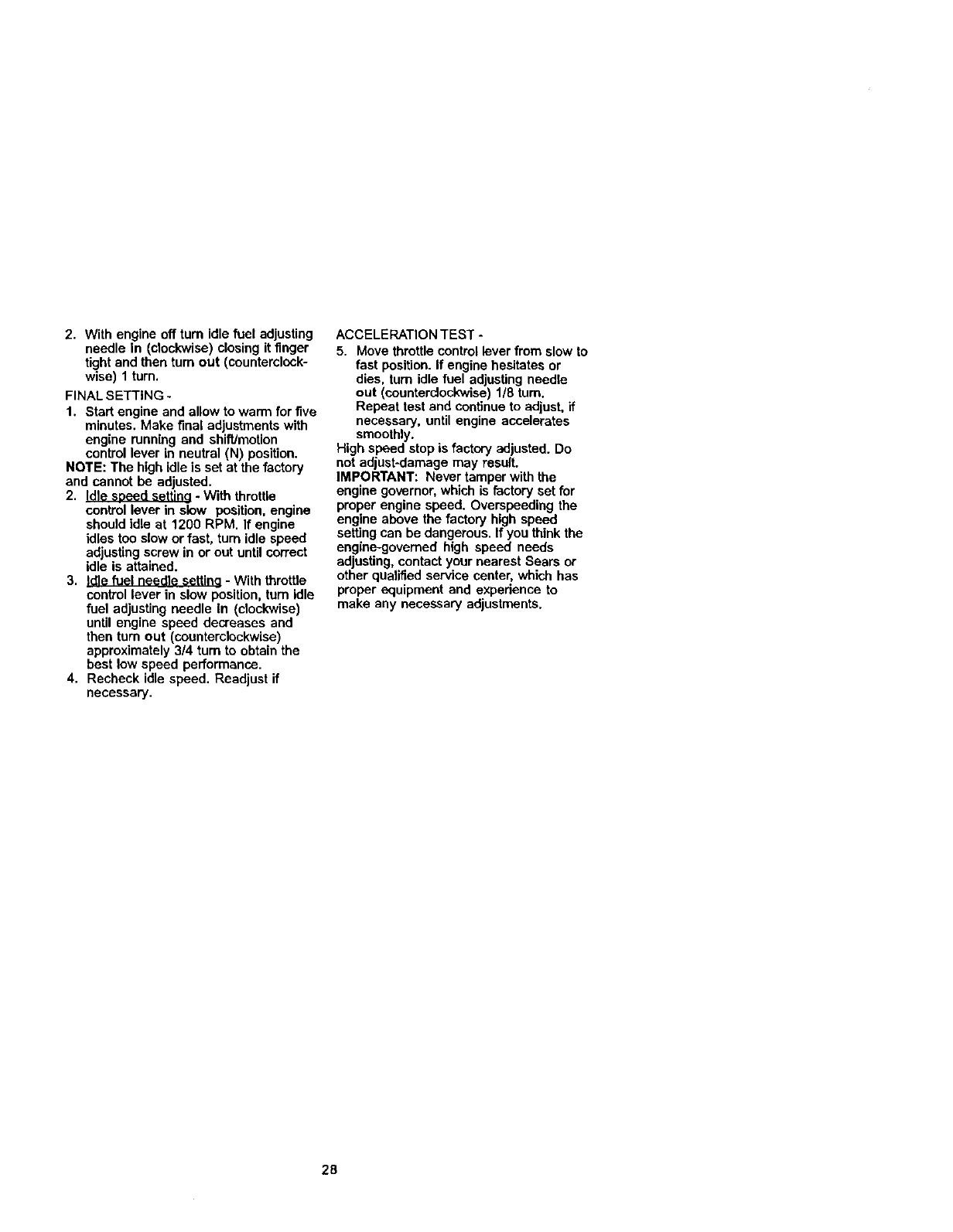
2. Withengineoffturnidlefuel adjusting
needle In (clockwise) closing it finger
tight and then turn out (counterclock-
wise) 1 tum.
FINAL SETTING -
1. Start engine and allow to warm for five
minutes. Make final adjustments with
engine running and shift/motion
control lever in neutral (N) position.
NOTE: The high idle is set at the factory
and cannot be adjusted.
2. Idle seeed setting - With throttle
control lever in slow position, engine
should Idle at 1200 RPM. If engine
idles too slow or fast, turn idle speed
adjusting screw in or out until correct
idle is attained.
3, Idle fuel needle settina - With throttle
control lever in slow position, turn idle
fuel adjusting needle In (clockwise)
until engine speed decreases and
then turn out (counterclockwise)
approximately 3/4 turn to obtain the
best low speed performance.
4. Recheck idle speed. Readjust if
necessary.
ACCELERATION TEST -
5. Move throttle control lever from slow to
fast position. If engine hesitates or
dies, turn idle fuel adjusting needle
out (counterclockwise) 1/8 tum.
Repeat test and continue to adjust, if
necessary, until engine accelerates
smoothly.
High speed stop is factory adjusted. Do
not adjust-damage may result.
IMPORTANT: Never tamper with the
engine governor,which is factory set for
proper engine speed, Overspeeding the
engine above the factory high speed
setting can be dangerous. If you think the
engine-governed high speed needs
adjusting, contact your nearest Sears or
other qualified service center, which has
proper equipment and experience to
make any necessary adjustments.
28
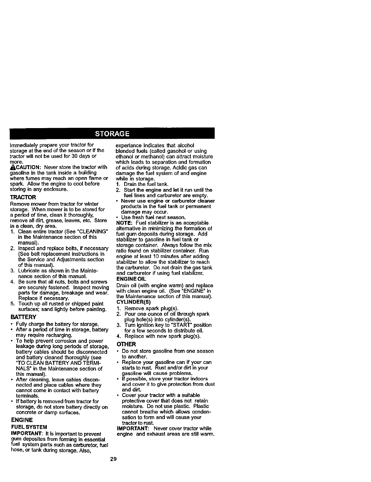
Immediatelyprepare your tractor for
storage at the end of the season or if the
tractor will not be used for 30 days or
more.
_QI,CAUTION: Neverstore the tractor with
gasoline in the tank inside abuilding
where fumes may reach an open flame or
spark. Allow the engine to cool before
storing in any enclosure.
TRACTOR
Remove mower from tractor for winter
storage. V_en mower is to be stored for
a period of time, clean it thoroughly,
remove all dirt, grease, leaves, etc. Store
in a clean, dry area.
1. Clean entire tractor (See =CLEANING"
in the Maintenance section of this
manual).
2. Inspect and replace belts, if necessary
(See belt replacement instructions in
the Service and Adjustments section
of this manual).
3. Lubricate as shown in the Mainte-
nance section of this manual.
4. Be sure that all nuts, bolts and screws
are securely fastened. Inspect moving
parts for damage, breakage and wear.
Replace if necessary.
5. Touch up all rusted or chipped paint
surfaces; sand lightlybefore painting.
BA'I-rERY
• Fully charge the battery for storage.
• After a period of time in storage, battery
may require recharging.
• To help prevent corrosionand power
leakage dudng long periods of storage,
battery cables should be disconnected
and battery cleaned thoroughly (see
=TOCLEAN BATTERYAND TERMI-
NALS" in the Maintenance section of
this manual).
• After cleaning, leave cables discon-
nected and place cables where they
cannot come in contactwith battery
terminals.
• If battery is removed from tractor for
storage, do not store battery directly on
concrete or damp surfaces.
ENGINE
FUEL SYSTEM
IMPORTANT: It is importantto prevent
gum deposites from forming in essential
fuel system parts such as carburetor,fuel
hose, or tank during storage. Also,
experiance indicates that alcohol
blended fuels (called gasohol or using
ethanol or methanol) can attract moisture
which leads to separation and formation
of acids during storage. Acidicgas can
damage the fuel system of and engine
while in storage.
1. Drain the fuel tank.
2. Start the engine and let it run untilthe
fuel lines and carburetor are empty.
•Never use engine or carburetor cleaner
products in the fuel tank or permanent
damage may occur.
•Use fresh fuel next season.
NOTE: Fuel stabilizer is an acceptable
alternative in minimizing the formation of
fuel gum deposits during storage. Add
stabilizer to gasoline in fuel tank or
storage container. Always followthe mix
ratio found on stabilizer container. Run
engine at least 10 minutes after adding
stabilizer to allow the stabilizer to reach
the carburetor. Do not drain the gas tank
and carburetor if using fuel stabilizer.
ENGINE OIL
Drain oil (with engine warm) and replace
with clean engine oil. (See "ENGINE" in
the Maintenance section of this manual).
CYLINDER(S)
1. Remove spark plug(s).
2. Pour one ounce of oil through spark
plug hole(s) into cylinder(s).
3. Turn ignitionkey to =START" position
for a few seconds to distribute oil.
4. Replace with new spark plug(s).
OTHER
•Do not store gasoline from one season
to another.
•Replace your gasoline can if your can
startsto rust. Rust and/or dirtin your
gasoline will cause problems.
•If possible, store your tractor indoors
and cover it to give protectionfrom dust
and dirt.
•Cover your tractor with a suitable
protective cover that does not retain
moisture. Do not use plastic. Plastic
cannot breathe which allows conden-
sation to form and will cause your
tractor to rust.
IMPORTANT: Never cover tractorwhile
engine and exhaust areas are still warm.
29
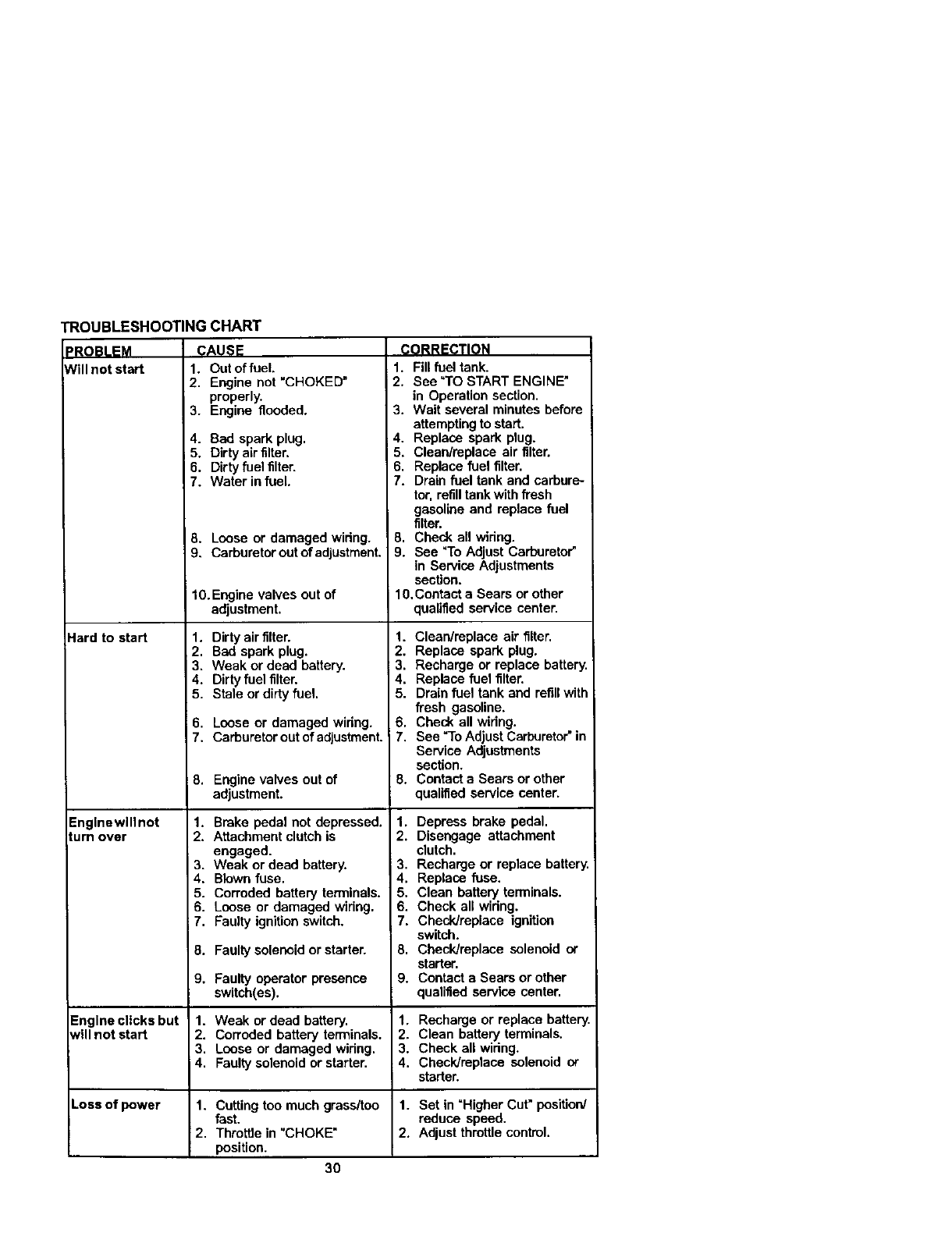
I_OUBLESHOOTING CHART
_RO!_LEM CAUSE
Will not start 1. Out of fuel
2, Engine not "CHOKED"
properly.
3. Engine flooded.
Hard to start
4. Bad spark plug.
i 5. Dirty air filter,
6. Dirty fuel filter.
7. Water in fuel.
8. Loose or damaged widng.
9. Carburetor out of adjustment.
I 0. Engine valves out of
adjustment,
1. Dirty air filter.
2. Bad spark plug,
3. Weak or dead battery.
4. Dirty fuel filter.
5. Stale or dirty fuel.
6. Loose or damaged wiring.
7. Carburetor out of adjustment.
8. Engine valves out of
adjustment.
1. Brake pedal not depressed.
2. Attachment clutch is
engaged.
3. Weak or dead battery.
4. Blown fuse.
5. Corroded battery termlnels.
6. Loose or damaged widng.
7. Faulty ignition switch.
8, Faulty solenoid or starter.
9. Faulty operator presence
switch(es).
Englnewlllnot
tum over
CORRECTION
1. Fill fuel tank.
i 2, See =TO START ENGINE"
in Operation section.
3. Wait several minutes before
attempting to start.
4. Replace spark plug.
5. Clean/replace air filter.
6, Replace fuel filter.
7. Drain fuel tank and carbure-
tor. refilltank with flesh
gasoline and replace fuel
filter.
8. Check all widng.
9. See =ToAdjust Carburetor"
in Service Adjustments
section.
10,Contact e Sears or other
qualified service center.
1. Clean/replace air filter,
2. Replace spark plug.
3, Recharge or replace battery.
4. Replace fuel filter.
5. Drain fuel tank and refillwith
fresh gasoline.
6, Check all widng.
7, See "To Adjust Carburetor"in
Service Adjustments
section.
8. Contact a Sears or other
qualified service center.
1. Depress brake pedal.
2. Disengage attachment
clutch.
3. Recharge or replace battery.
4. Replace fuse.
5. Clean battery terminals.
6. Check all wiring.
7. Check/replace ignition
switch.
8. Check/replace solenoid or
starter.
9. Contact a Sears or other
qualified service center.
Engine clicks but 1. Weak or dead battery, 1. Recharge or replace battery.
t,'ill not start 2. Corroded battery terminals. 2. Clean battery terminals.
3, Loose or damaged widng, 3. Check all widng.
4, Faulty solenoid or starter. 4, Check/replace solenoid or
starter.
Loss of power 1. Cutting too much grass/too 1. Set in "Higher Cut" position/
fast. reduce speed.
2, Throttle in "CHOKE" 2. Adjust throttle control.
position.
3O
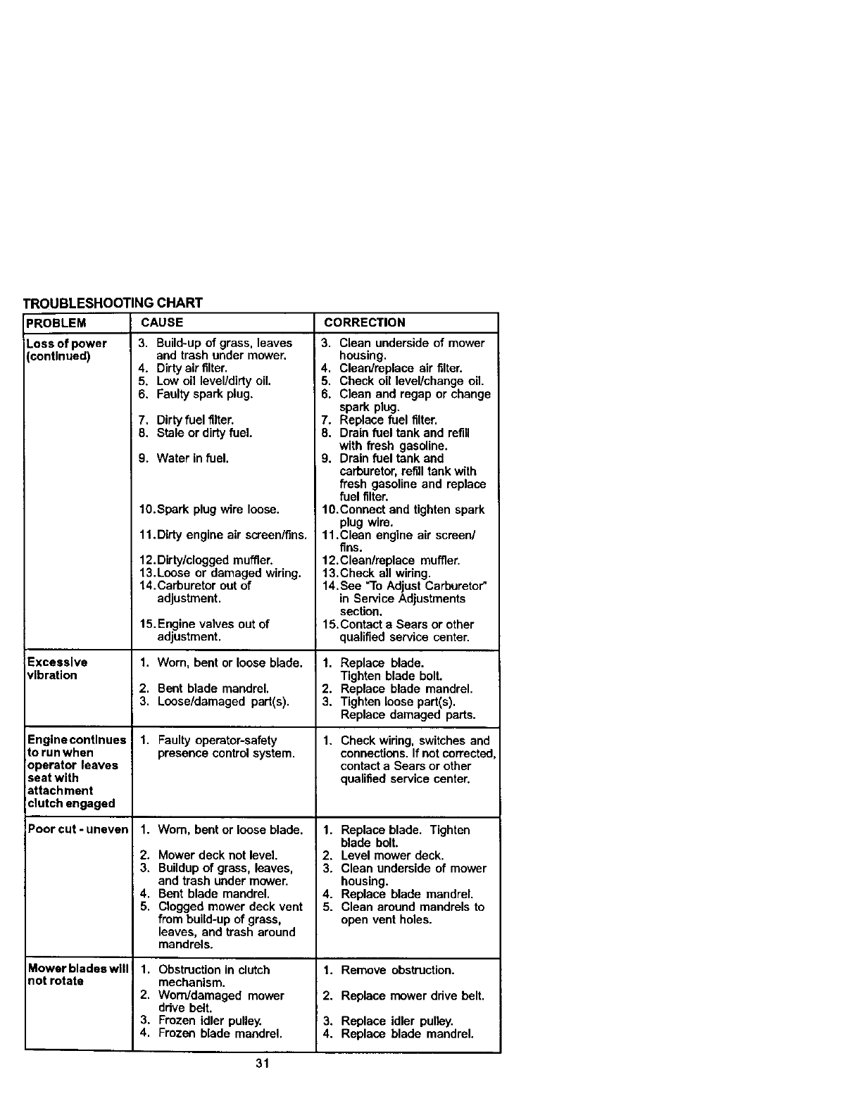
TROUBLESHOOTING CHART
CAUSE CORRECTION
PROBLEM
Loss of power
(continued)
Excessive
vibration
Engine continues
torunwhen
operator leaves
seat with
attachment
clutch engaged
Poorcut-uneven
Mowerbladeswlll
notrotate
3. Build-up of grass, leaves
and trash under mower.
4. Dirty air filter.
5. Low oil level/dirty oil.
6. Faulty spark plug.
7. Dirty fuel filter.
8. Stale or dirtyfuel.
9. Water in fuel.
1O.Spark plug wire loose.
11.Didy engine air screen/fins,
12.Dirty/clogged muffler.
13.Lense or damaged widng.
14.Carburetor out of
adjustment,
15.Engine valves out of
adjustment.
1. Wom, bent or loose blade.
2. Bent blade mandrel,
3, Loose/damaged part(s).
1. Faulty operator-safety
presence control system.
1. Worn, bent or loose blade,
2. Mower deck not level.
3. Buildup of grass, leaves,
and trash under mower.
4. Bent blade mandrel,
5. Clogged mower deck vent
from build-up of grass,
leaves, and trash around
mandrels.
1. Obstruction in clutch
mechanism.
2. Worn/damaged mower
drive belt.
3. Frozen idler pulley.
4. Frozen blade mandrel.
3. Clean underside of mower
housing.
4. Cleardmplece air filter.
5. Check oil level/change oil.
6. Clean and regap or change
spark plug.
7. Replace fuel filter.
8. Drain fuel tank and refill
with fresh gasoline.
9. Drain fuel tank and
carburetor, refilltank with
fresh gasoline and replace
fuel filter.
10.Connect and tighten spark
plug wire.
11.Clean engine air screen/
fins.
12.Clean/replace muffler.
13.Check all widng.
14.See "To Adjust Carburetor"
in Service Adjustments
section.
15,Contact a Sears or other
qualified service center.
1. Replace blade.
Tighten blade bolt.
2. Replace blade mandrel.
3. Tighten loose part(s).
Replace damaged parts.
1. Check wiring, switches and
connections. Ifnot correctec
contact a Sears or other
qualified service center.
1. Replace blade. Tighten
blade bolt.
2. Level mower deck.
3. Clean underside of mower
housing.
4. Replace blade mandrel.
5. Clean around mandrels to
open vent holes.
1. Remove obstruction.
2. Replace mower drive belt,
3. Replace idler pulley.
4. Replace blade mandrel.
31
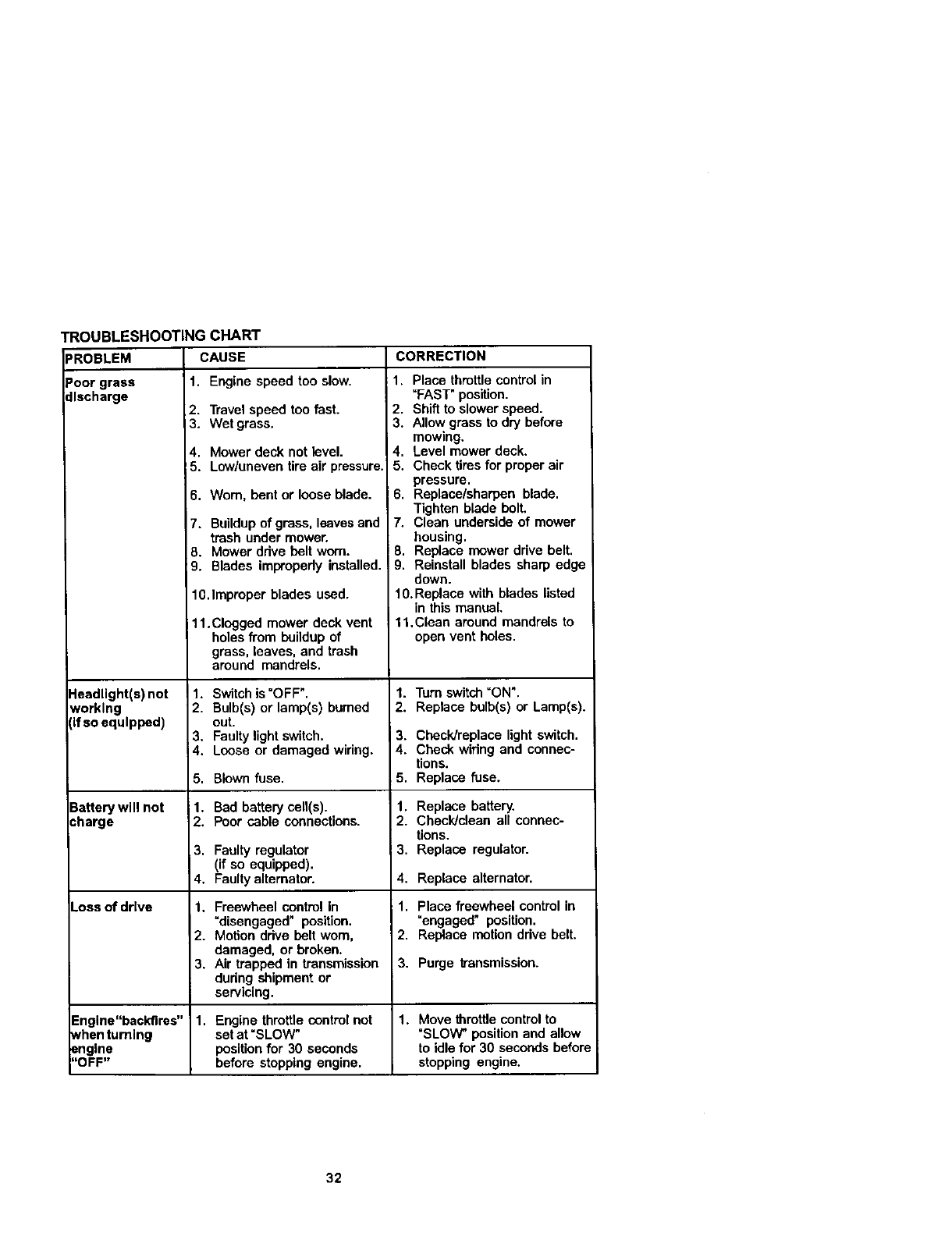
TROUBLESHOOTINGCHART
CAUSE CORRECTION
_ROBLEM
3oor grass
:llscharge
Headlight(s) not
working
If so equipped)
3attery will not
:harge
Loss of drive
1. Engine speed too slow.
2. Travel speed too fast.
3. Wet grass.
4. Mower deck not level.
5. Low/uneven tire air pressure.
6. Worn, bent or loose blade.
7. Buildup of grass, leavesand
trash under mower.
8. Mower ddve belt worn.
9. Blades improperly installed.
10.Improper blades used.
11.Clogged mower deck vent
holes from buildup of
grass, leaves, and trash
around mandrels.
1. Switch is "OFF".
2. Bulb(s) or lamp(s) bumed
out.
3. Faulty light switch.
4. Loose or damaged widng.
5. Blown fuse.
i 1. Bad battery cell(s).
2. Poor cable connections.
3. Faulty regulator
(if so equipped).
4. Faulty alternator.
1. Freewheel control In
"disengaged" position.
2. Motion ddve belt worn,
damaged, or broken.
3. Air trapped in transn_ssion
during shipment or
servicing.
1. Place throttle control in
"FAST" position.
2. Shift to slower speed.
3. Allow grass to dry before
mowing.
4. Level mower deck.
5. Check tires for proper air
pressure.
6. Replace/sharpen blade.
Tighten blade bolt.
7. Clean underside of mower
housing.
8. Replace mower drive belt.
9. Reinstall blades sharp edge
down.
10.Replace with blades listed
in this manual.
11,Clean around mandrels to
open vent holes.
1. Turn switch "ON".
2. Replace bulb(s) or Lamp(s).
3. Checldreplace light switch.
4. Check wiring and connec-
tions.
5. Replace fuse.
1. Replace battery.
2. Checldclean all connec-
tions.
i3. Replace regulator.
4. Replace alternator.
1. Place freewheel control in
"engaged" position.
2. Replace motion ddve belt.
3. Purge lransmission.
Engine"backfires" 1. Engine throttle control not 1. Move throttle control to
when turning set at =SLOW" "SLOW" position and allow
engine positionfor 30 seconds to idle for 30 seconds befor_
"OFF" before stopping engine, stopping engine.
32
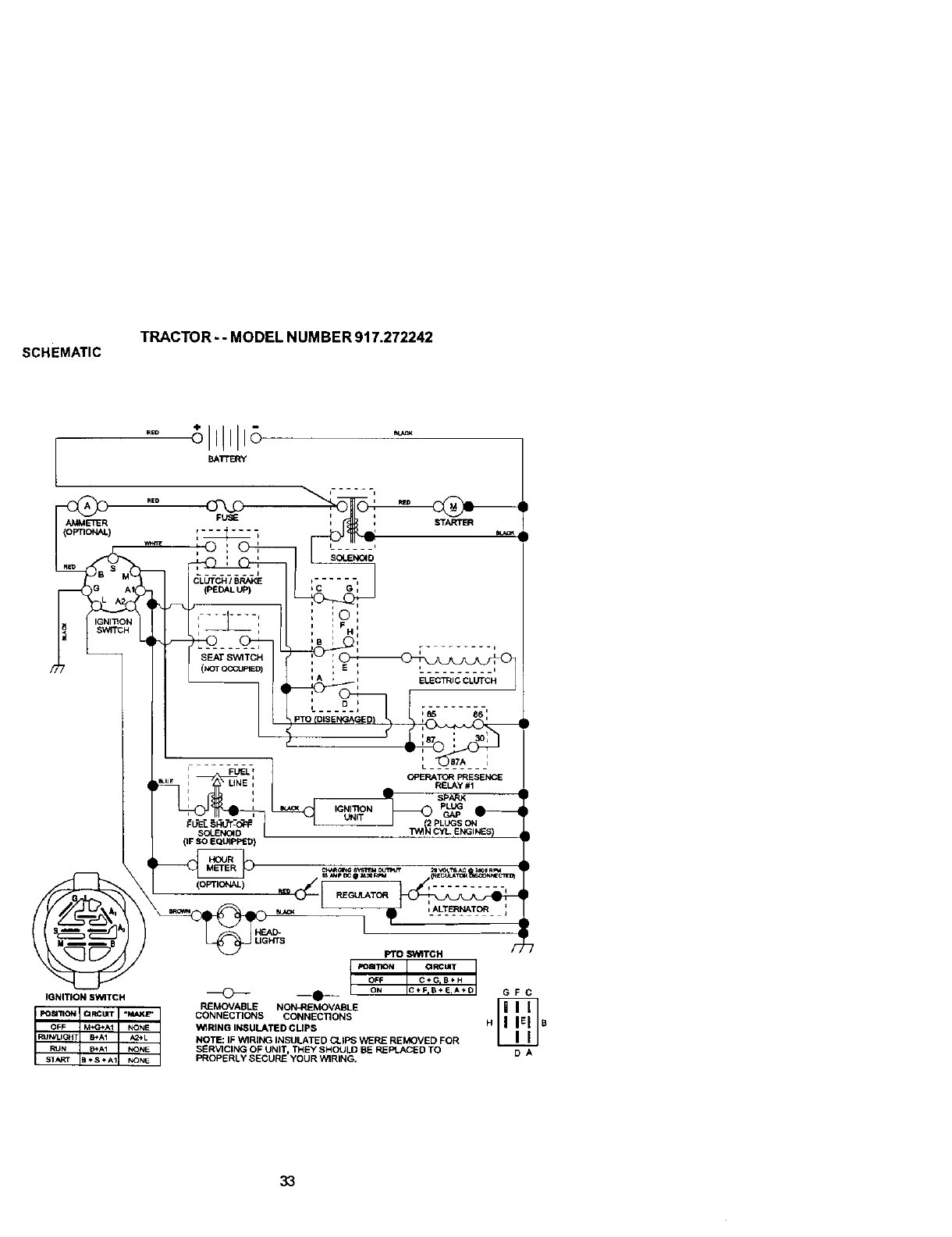
SCHEMATIC TRACTOR- -MODEL NUMBER 917.272242
_TTERY
SEAT SWITCH
(NOTOCCUPIED)
FUEL SHUT-OFF
SOIENC_D
(IF SO EQUIPPED)
IGNITION SWITCH
(OPTIONAL)
HEAD-
UGHTS
IP°sm°N I aRCBT I
OFF C÷G,B_H
_I ON IC÷F.B÷E,A*_I G F C
REMOVABLE NON_qEMOVABLE _
CONNECTIONS CONNECTIONS
WIRING INSULATED CUPS H B
NOTE: IF "_RING INSULATED CLIPS '€_ REMOVED FOR
SERVICING OF UNIT, THEY SHOULD BE NE _I..*_E D TO D A
PROPERLY SECURE YOUR WIRING.
33
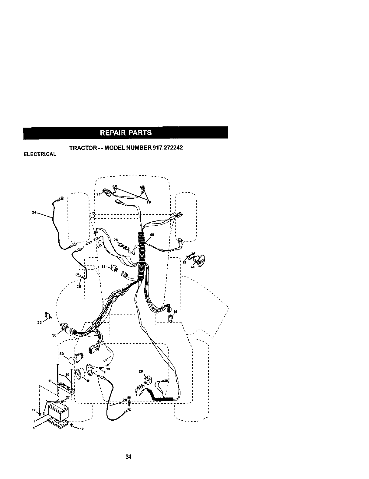
ELECTRICAL TRACTOR - - MODEL NUMBER 917.272242
411
26
\
i t
//
/
___s
i
i
34

ELECTRICAL TRACTOR-- MODEL NUMBER 917.272242
KEY PART
NO. NO. DESCRIPTION
1
2
8
10
11
12
16
21
24
25
26
27
28
29
3O
33
4O
45
46
5O
55
79
81
8_
3O
91
g_Z
93
163465 Battery
74760412 Bolt, Hex 1/4-20 x 3/4
75O3J Tray, Battery
145211 Bdt, Btt Front 114-20 x 7-1/2
150109 Holddown Battery Front Mount
145769 Nut, Push Nylon Battery Front 1/4
153664 Switch Interlock Push-In
175449 Harness, Light
886G_ Cable, Battery
146148 Cable, Battery
175158 Fuse
73510400 Nut Keps Hex 1/4-20 UNC
145491 Cable, Ground
160784 Switch, Seat
175442 Switch, Ignition
175447 Key
178451 Harness, Ignition
175548 Ammeter
175549 Hourmeter
178461 Switch Pro
17490508 Screw Tndrol 5/16-18 x 1/2
175448 Bulband Holder Asm Halogen
109748X Rel Asm
169639 Bra_et Snap-In Houm_eter
176717 Clamp BackAmp Gauge
176730 Washer Lock Amp Gauge
176733 Nut Amp GaL_ge
176732 ClampHourrneter
NOTE: AJlcomponent dimensions given In U.S. inches
1inch = 25.4 rnm
35
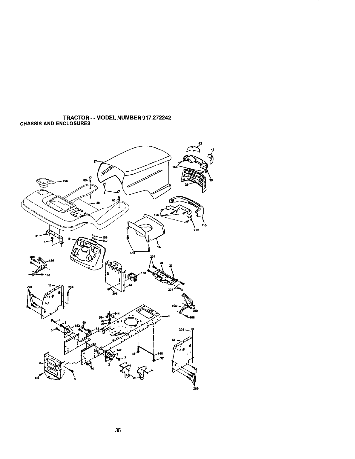
TRACTOR- - MODEL NUMBER 917.272242
CHASSISAND ENCLOSURES
42
29
t65
2119
36
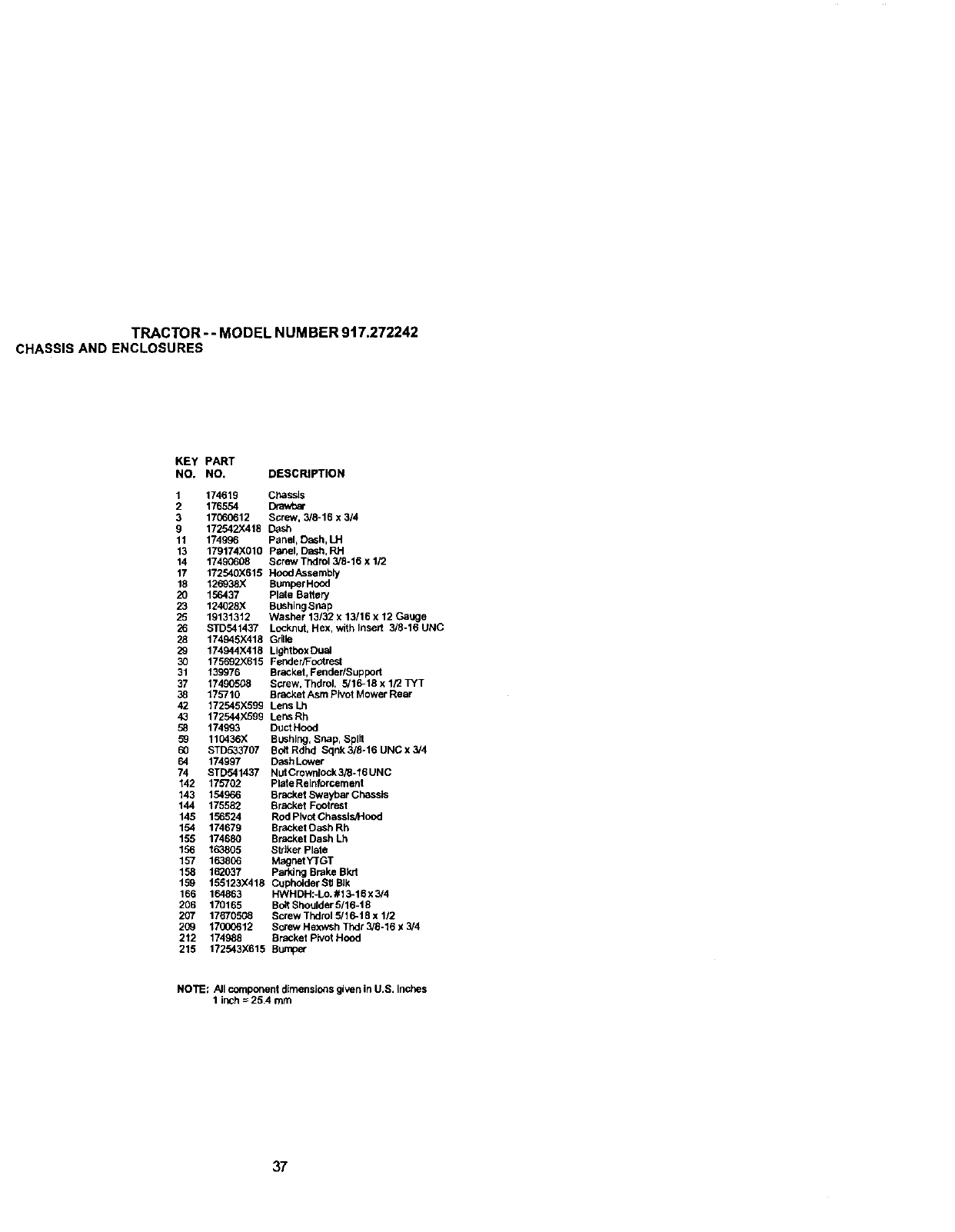
TRACTOR --MODEL NUMBER 917.272242
CHASSISAND ENCLOSURES
KEY PART
NO. NO. DESCRIPTION
1 174619 CP,assls
2 176554
3 17(60612 Screw, 3/8-16 x 314
9 172542X418 Desh
11 174996 Panel, Dash, LH
13 179174X010 Panel, Dash, RH
14 17490608 Screw Tndrol 3/8-16 x 1/2
17 172540)(619 Hood/_sse mbly
18 126938X BUmperHood
20 156437 Plate Battery
23 124028X BUShingsnap
25 19131312 Washer 13/32 x 13/16 x 12 Gauge
26 STD541437 Locknut, Hex, with Insert 3/8o16 UNC
28 174945;<418 Grille
29 174944X418 LightboxDuaJ
30 175692X616 Fender/Footrest
31 139976 BraCket,Fender/Support
37 17490508 Screw, ThdroL 5/16-16 x 1/2 TYT
38 175710 Bracket Asm Pivot Mower Rear
42 172545X599 Lens Lh
43 172544X699 Lens Rh
58 174993 DuctHood
5_ 110436X BLishlug,Snap, Split
60 STD533707 Bott Rdhd Sqnk 3/8-16 UNC x 3/4
64 174997 Dash Lower
74 STD541437 NLItCrownlock 3/8-16 UNC
142 175702 Plate Reinforcement
143 154966 Brackel Swaybar Chessls
144 175582 Bracket Footrest
145 156624 Rod Pivot Chassls_Hood
154 174679 Br_;ket Dash Rh
155 174680 Bracket Dash Lh
156 163805 SViker Plate
157 1638(6 Magnet YTGT
158 162037 Parking Brake BPJ1
159 155123X418 Cupho_derS_JBIk
166 164863 HWHDH:-Lo.#13-16 x 3/4
206 170165 Bolt Shoulder 6/16-t8
207 17670508 Screw Thdlol 5/16-18 x 1/2
209 17000612 Screw Hexwsh Tnd; 3/6-16 x 3/4
212 174988 Bracket PiVot Hood
215 172543X615 Bumper
NOTE; All component dimensions given in U.S. inches
1 inch = 26.4 mrn
37
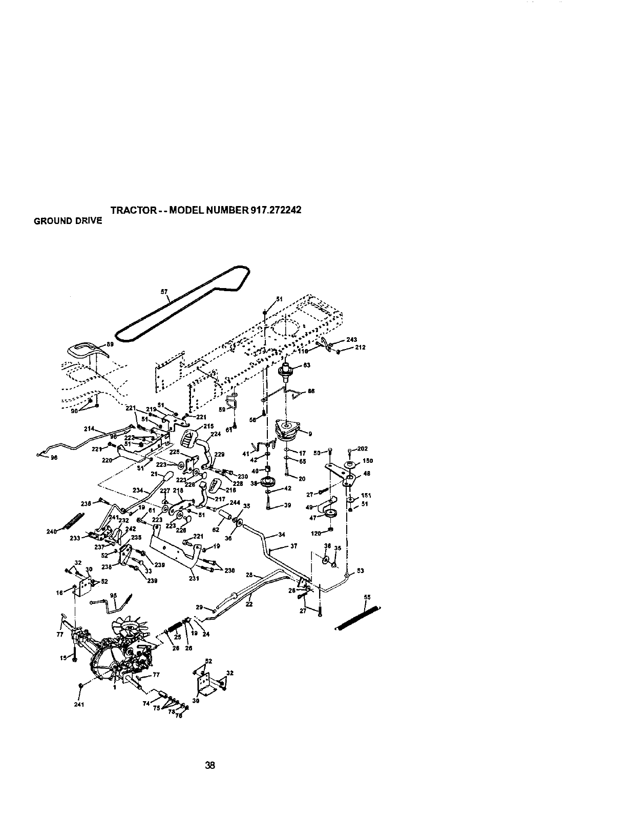
TRACTOR- -MODEL NUMBER 917.272242
GROUNDDRIVE
32
50_ _202
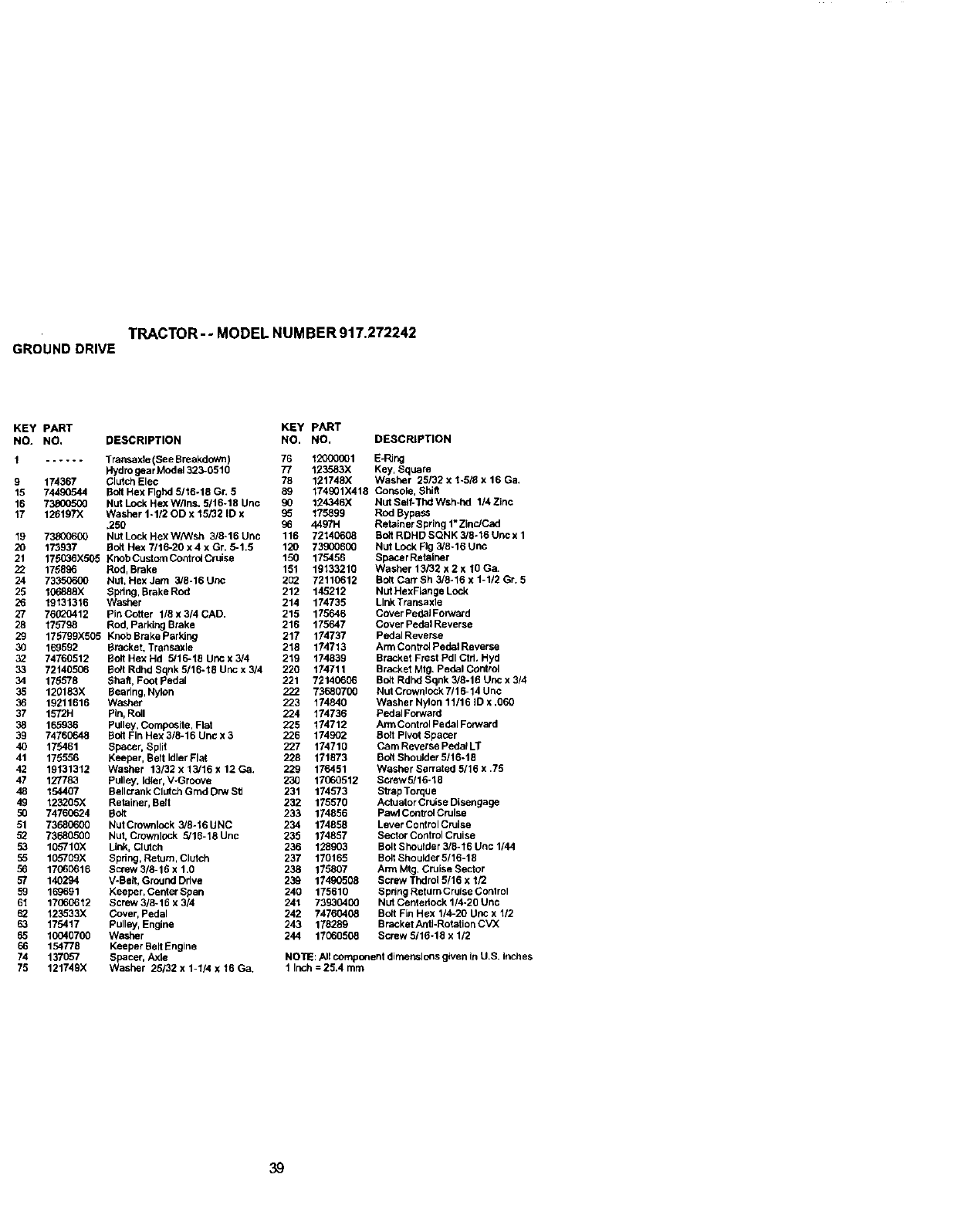
TRACTOR-- MODEL NUMBER 917.272242
GROUNDDRIVE
KEY pART KEY pART
NO. NO, DESCRIPTION NO. NO, DESCRIPTION
1...... Transaxta (See Breakdown) 76 12000001 E-Ring
Hydro gear Mcde1323-0510 77 123583X Key, Square
9 174367 Clutch Elec 78 121748X Washer 25132 x 1-5/_ x 16 Ga.
15 74490544 Bog Hex Flghd 5/t6-18 Gr, 5 89 174901X418 Console, Shift
16 73800500 Nut Lock Hex W/Ins, 5/16-16 Unc 90 124346X Nut Self-Thd Wsh-hd 1/4 Zinc
17 126197X Washer 1-112 OD x 15/32 ID x _5 175899 Rod Bypass
.250 96 4497H Retainer Spring 1"ZinrJCad
19 73800600 NutLockHexW/Wsh 3/6-16Unc 116 72140608 Bo6RDHDSQNK3/6-16Uncx1
20 173937 So6 Hex 7/16-20 x 4 x Gr. 6-1.5 120 73900600 Nut Lock Fig 3/8o16 unc
21 175036X505 KnohCustomControICrulse 150 175456 SpacerRetalner
22 175896 Rod, Brake 151 19133210 Washer 13/32 x 2 x 10 Ga.
24 73350600 Nut, HexJam 3/8-16Unc 252 72110612 BogCarrSh3/6-16xl-1/2Gr. 5
25 10_888X sprlng, BrakeRod 212 145212 Nut HexRangeLock
26 19131316 Washer 214 174735 Link Transaxle
27 76020412 PInCoSer 118x314CAD. 215 175646 CoverPedaIFoPNard
28 175798 Rod, Parking Brake 216 175647 Cover Pedal Reverse
29 175799X505 KnobBrakeParldng 217 174737 PedalReverse
30 169592 Bracket, Transaxle 218 174713 Ann Control Pedal Reverse
32 74760512 Bolt Hex Hd 5/16-18 uric x 3/4 219 174839 Bracket Frest Pdl Ctrl. Hyd
33 72140506 Bc_t Rdhd Sqnk 5/16-18 Unc x 314 220 t74711 Bracket Mtg, Pedal Control
34 175578 shaft, Foot Pedal 221 72140606 Bolt Rdnd Sqnk 3/8-16 Unc x 3/4
35 120183X Bearing, Nylon 222 73680700 Nut Crownlock 7/16-14 Unc
36 19211616 Washer 223 174840 Washer Nylon 11/16 ID x,060
37 1572H Pin, Rdl 224 174736 Pedal Forward
38 165936 Pulley, Composite, Flut 225 174712 Arm Control Pedal Forward
39 74760648 Bog Fin Hex 3/8-16 Unc x 3 226 174902 BoZtPivot Spacer
40 175461 Spacer, Split 227 174710 Cam Reverse PedalLT
41 175556 Keeper, Belt Idler Flat 228 171873 Bo_tShoulder5116-18
42 19131312 Washer 13/32 x 13/16 x 12 Ga. 229 176451 Washer Serrated 5/16 x .75
47 127783 pulley, Idler, V-Groove 230 17060512 Screw 5/16-18
48 154407 Bellcrank Clutch Grnd Dn,'_'Sfl 231 174573 Strap Torque
49 125205X Retainer, Belt 232 175570 Actuator Crulse Disengage
50 74760624 Bch 233 174856 pavA Centre! Cruise
51 73680600 NutCrownlock 3/6-16UNC 234 174858 LeverControlCrulse
52 73680500 Nut, Crownlock 5/16-18 Unc 235 174857 Sector Control Cruise
53 105710X Link, Clutch 236 128903 BChShoulder 3/8-16 Unc 1144
55 105709X Spdng, Return, Clutch 237 170165 Bolt Shoulder 5/16-18
56 17060616 Screw 3/8-16 x 1.0 238 175807 Arm Mtg. Cruise Sector
57 140294 VoBeJt,Ground Ddve 23_ 17490508 Screw Thdrol 5/16 x 1/2
59 169691 Xeepar, Cerder Span 240 175610 Spdng Return Cruise Conlrol
61 17060612 Screw 3/8-16 x 3/4 241 73930400 NUt Centariock 1/4-20 Unc
62 123533X Cover, Pedal 242 74760408 Bo8 Fin Hex 1/4-20 Unc x 1/2
63 175417 Pulley, Engine 243 178289 BracketAn6-RotatienC'v'X
65 10040700 Washer 244 17060508 Screw 5/16-15 x 1/2
66 154778 Keepar BeltEngine
74 137057 Spacer, Axle NOTE: All compcnent dirnep_lo_s given In U.S. Inches
75 121749X Washer 25/32 x 1-114x 16 Ga, 1 Inch = 25.4 mm
39
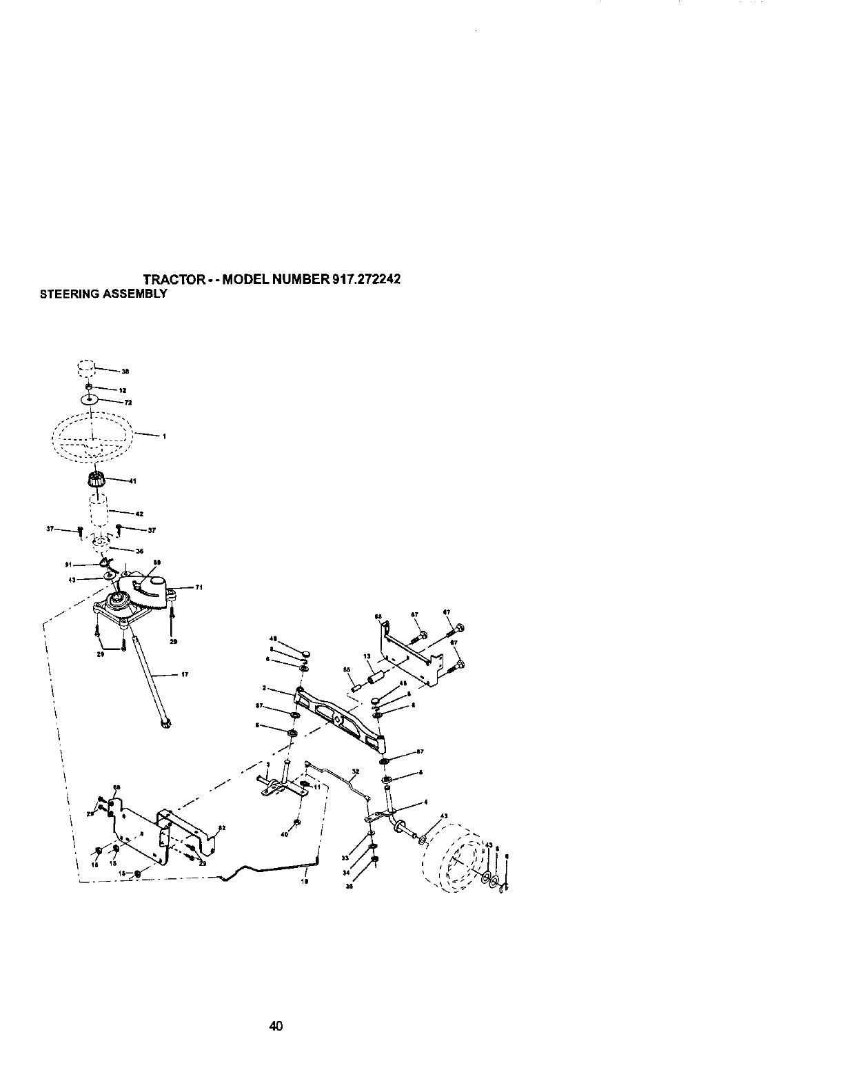
TRACTOR - -MODEL NUMBER 917.272242
STEERINGASSEMBLY
40
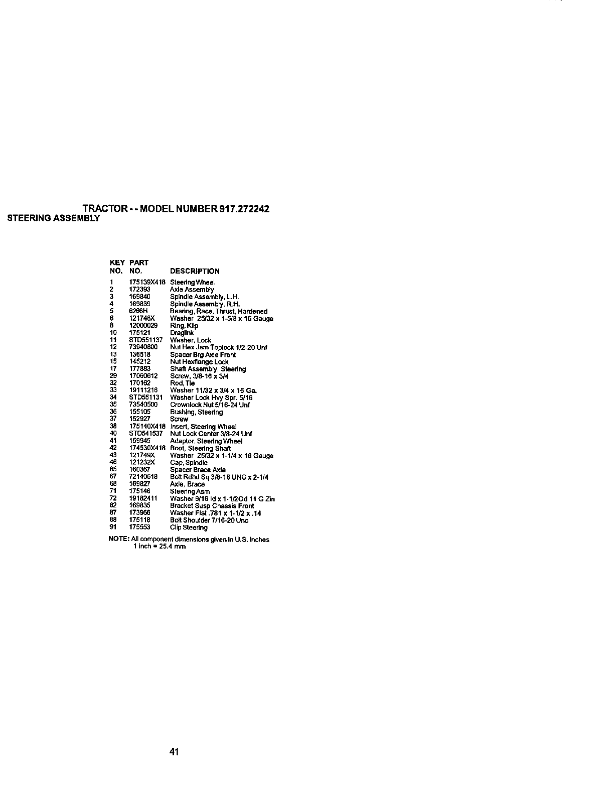
TRACTOR-- MODEL NUMBER 917.272242
STEERINGASSEMBLY
KEY PART
NO. NO. DESCRIPTION
1 175139)(418 Steedng Wheel
2 172393 Axle/_ssembly
3 169840 Spindle Assembly, LH.
4 169839 Spindle Assembly, R.H.
5 6266H Bearing, Race, Thrust, Hardened
6121748X Washer 25/32 x 1-5/8 x 16 GaUge
8 12000029 Ring, KIIp
10 175121 DlaglJnk
11 STD551137 Washer, Lock
12 73949800 Nut Hex Jam Top]ock 112-20 Unf
13 136518 Spacer Brg Axle Front
15 145212 Nut Hex/lange Lock
17 177883 SheR Assembly, Steering
29 17060612 Screw, 3/8-16 x 3/4
32 170182 Rod,Tie
33 19111216 Washer 11/32 x 3/4 x 16 Ga.
34 STD551131 Washer Lock Hvy Spr. 5116
35 73540500 Crownlock Nut 5/16-24 Unf
36 155105 BUShing, Steering
37 152927 Screw
38 175140X418 Insert, Steering Wheel
40 STD541537 Nut Lock Center 3/8-24 Unf
41 159945 Adaptor, Steering Wheel
42 174530X418 Boot, Steering Sha5
43 121749X Washer 25/32 x 1-1/4 x 16 Gauge
46 121232X Cap, Spindle
65 160367 Spacer Brace Axle
67 72140618 Bolt Rdhd Sq 3/8-16 UNC x 2-1/4
68 169827 Axle, Brace
71 175146 Steering Asm
72 19182411 Washer 9/16 Id x 1-1/2Od 11G Zin
82 169835 Bracket Susp Chassis Front
87 173966 Washer Flat .781 x 1-1/2 x .14
88 175118 Bo8 Shoulder 7/16-20 Uric
91 175553 Clip Steering
NOTE: ,aJIcomponent dimensions given in U.S. inches
1 inch = 25.4 mm
41
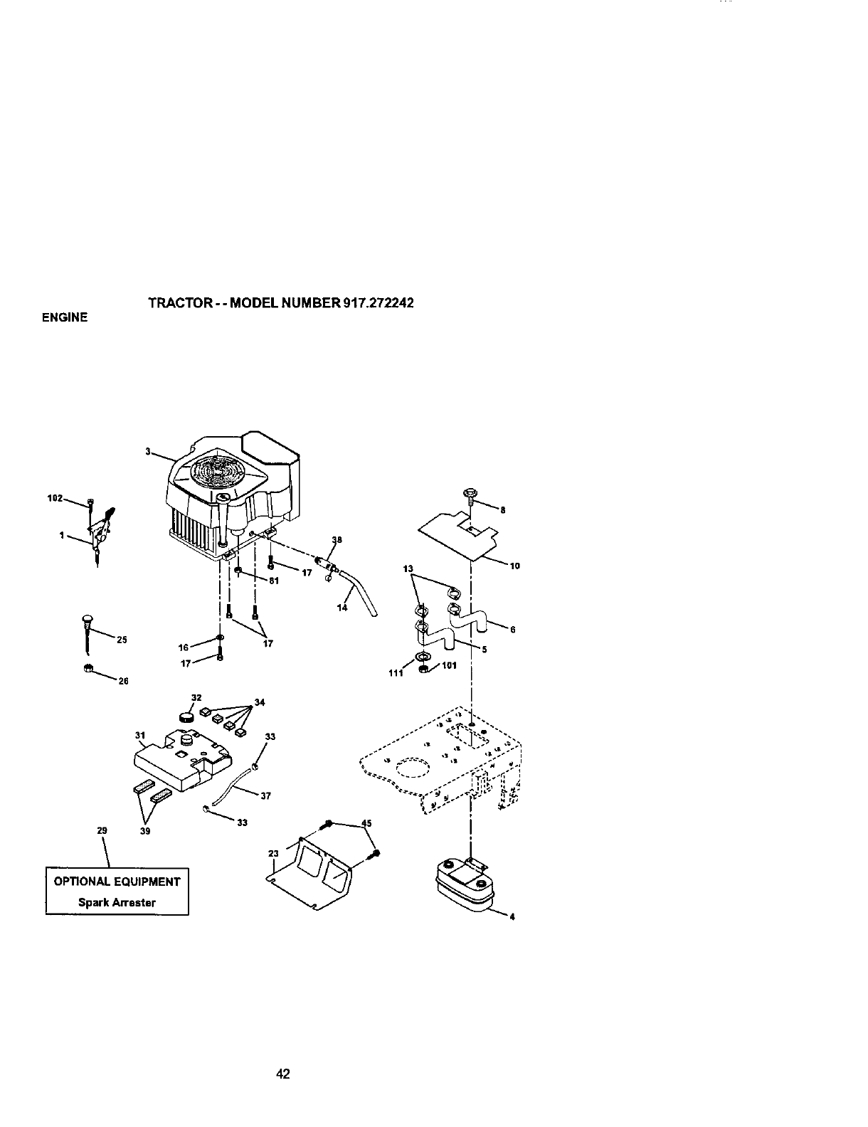
ENGINE TRACTOR- -MODEL NUMBER 917.272242
_---25
29
OPTIONAL EQUIPMENT
Spark Attester
32
42

ENGINE
TRACTOR - - MODEL NUMBER 917.272242
KEY PART
NO. NO. DESCRIPTION
4
5
6
8
10
13
175439X505 ControI,Throtffe
....... Engine, (See Breakdown) Kohler Model Number
CV624-65578
149723 Muffler
146699 Pipe Exhaust Lh
146700 Pipe Exhaust Rh
171877 Bolt 5/16-18 Unc x 3/4
146629 Shield Heat
24-041-02 Gasket Kchler CV18-CV26
(See Engine Breakdown)
14 148456 Tube Drain Oil Easy
16 11050600 Washer, Lock, External Tooth 3/8
17 17490624 Screw Thdrol 3/8-16 x 1-112
23 169837 Shield, Browning IDebds Guard
25 175441X505 Cheke Contrdi
26 73920600 Nut, Keps 3/8-24 UNF
29 137180 Kit, Spark Arrestor
31 157103 TankFuel
32 161696 CapAsmFuel
33 123487X Clamp,Hose
34 106082X Pad, Spacer
37 8543R Line, Fuel
38 148315 Plug Drain Oil Easy
39 109227X Pad. Idler
45 17000612 Screw Hexwsh Thdr 3/8-16 x 3/4
81 73510400 Nut Keps Hex 1/4-20 UNC
101 M73030800 NutFlangeM8-1.25
102 164863 Screw Hwhd H.*Lo #13016 x 3/4
111 10010500 Washer Split
NOTE: All component dimensions given in U.S. Inches
1Inch = 25.4 mm
43
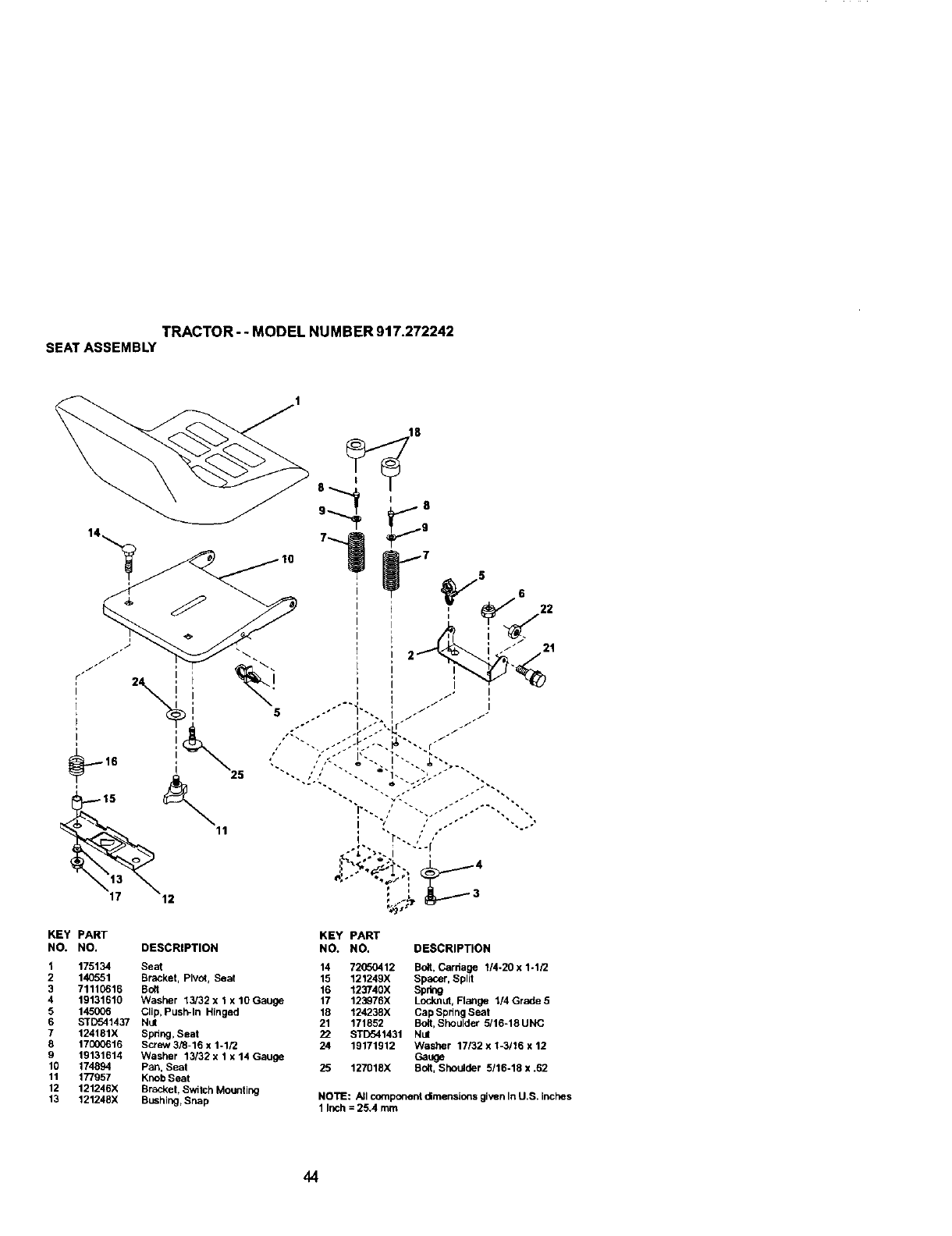
TRACTOR-- MODEL NUMBER 9t7.272242
SEATASSEMBLY
KEY PART KEY PART
NO. NO. DESCRIPTION NO. NO. DESCRIPTION
1 175134 Seat 14 72050412 Bolt, Cardage 1/4-20 x 1-1/2
2 140551 Bracket, Plvut, Seat 15 121249X SpaCer, Split
3 71110615 Bog 16 123740X Spchg
419131610 Washer 13/32 x 1 x 10 Gauge 17 123976X Lock.nut,Flange 1/4 Grade 5
5 145006 Clip, Push-In Hinged 18 124238X Cap Spdng Seat
6 STD541437 Nut 21 171862 Bolt, Shoulder 5/16=18UNC
7 124181X Spring, Seat 22 ST[T341431 Nut
8 17000616 Screw 3/8-16 x 1-1/2 24 19171912 Washer 17132 x 1-3116 x 12
9 19131614 Washer 13132 x 1 x 14 Gauge Gauge
10 174694 Pan, Seat 25 127018X Bolt, Shoulder 5116-18 x .62
11 177957 Knob Seat
12 121246X Bracket, Switch Mounting
13 121248X Bushing, Snap NOTE: .AJlcomponent dimensions given In U.S. inches
1 Inch = 25.4 mm
44
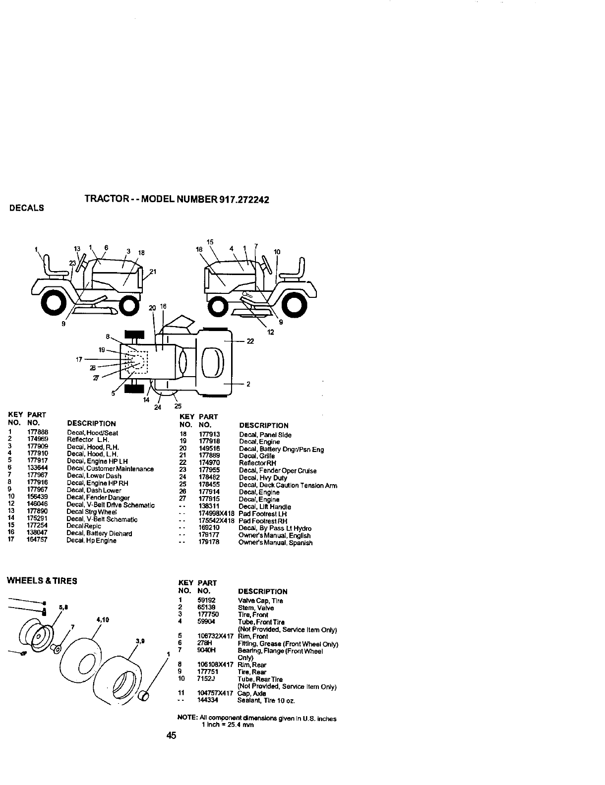
DECALS TRACTOR --MODEL NUMBER 917.272242
13 18
14 24
16
25
KEY PART KEY PART
NO. NO. DESCRIPTION NO. NO.
1 177888 Decal, Hood/Seat 18 177913
2 174969 Reflector L,H, 19 177918
3 177909 Decal, Hood, RH. 20 149516
4 177910 Decal, Hood, LH. 21 177889
5 177917 Decal, Engine Hp LH ZZ 174970
6 133644 Decal, Customer Maintenance 23 177955
7 177967 Decal, Lower Dash 24 178482
8 177916 Decal, Engine Hp RH 25 178455
9 177967 Decal, Dash Lower 26 177914
10 156439 Decal, Fender Danger 27 17-I915
12 146046 Decal, V-Belt Drive Schematic - - 138311
13 177890 Decal Strg Wheel -- 174998X418
14 175291 Decal, V-Belt Schematic --175542X419
15 177254 Decal Replc -* 169210
16 138047 Decal, Baite_, Diehard -o 179177
17 164757 Decal, Hp Engine -- 179178
15
18 710
\
9
12
DESCRIPTION
Decal, Panel Side
Decal, Engine
Decal, Ba6ery Dngr/Psn En9
Decal, Gdlle
Rellector RH
Decal, Fender Oper Cruise
DecaJ, Hvy Duty
Decal, Deck Caution Tension Arm
Decal, Engine
Decal, Engine
Decal, Lilt Handle
Pad Footrest LH
Pad Footrest RH
DecaJ, By Pass Lt Hydro
Owner's Manual, English
Owner's Manual, Spanish
WHEELS &TIRES KEY PART
NO. NO.
159192
3177750
5_
5 106732X417
/,9 1 278H
7_
177751
10 7152J
11 104757X417
- - 144334
DESCRIPTION
Valve Cap, Tire
Stem, VaNe
TJre,Front
Tube, Front Tire
(Not provided, Service Item Only)
Rim, Front
Fitting, Grease (Front Wheel Only)
Seadng, Flange {Front Wheel
Only)
RJm,R_ar
Tire, Rear
Tube, RearTire
(Not provided, Service Item Only)
Cap, Axle
Sealant, I-Ire 10 oz.
NOTE: All component dJrnenslonsgiven In U,S. inches
1 inch =25,4 mm
45
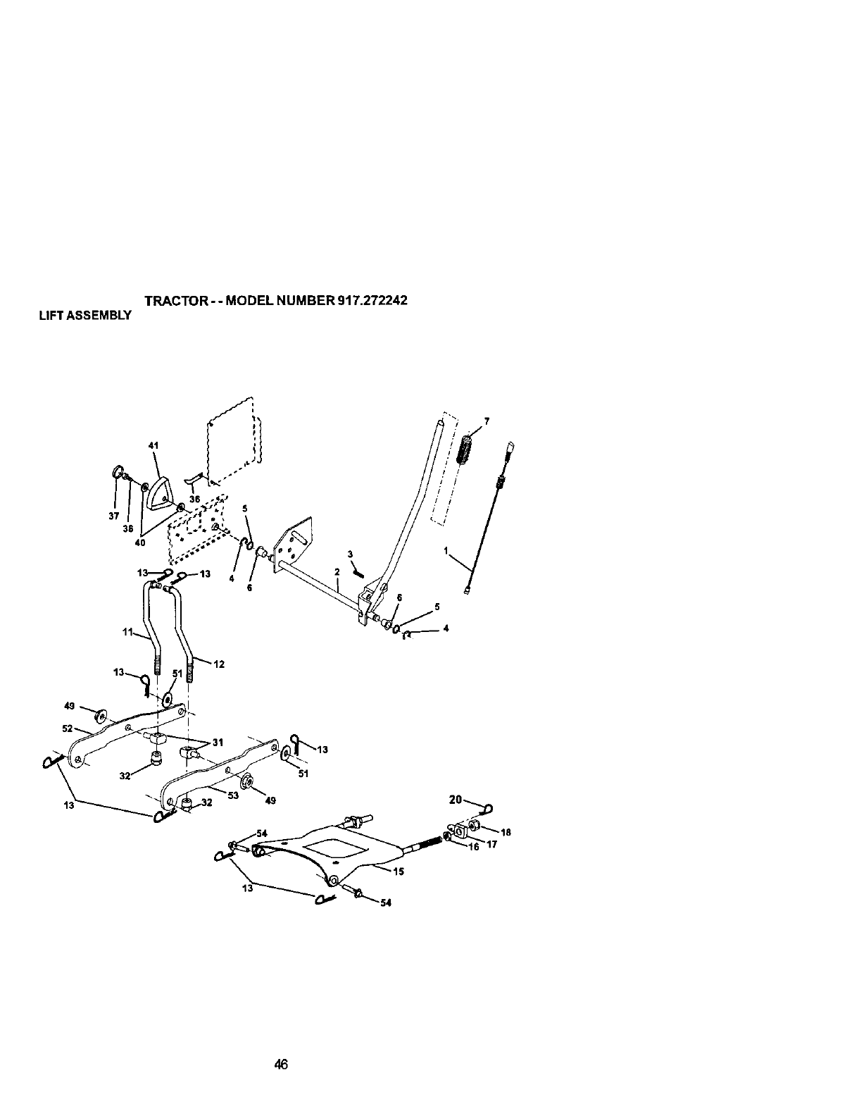
TRACTOR--MODELNUMBER917.272242
LIFTASSEMBLY
41
37
38
4O
46

TRACTOR --MODEL NUMBER 917.272242
LIFTASSEMBLY
KEY PART
NO. NO. DESCRIPTION
1176263 PJungerAsSembly
2 159479 Shaft Assembly, Uft
3 178981 Pin, Groove
4 12000002 E-RJUg
5 19211621 Washer 21132 x 1 x 21 Gauge
6 120183X Bearing, Nylon
7 175830 Gdp, Handle, Fluted
11 175370 Link, Lift, LH.
12 175371 Link, Lift, R.H.
t3 493,._M Retainer Spdng
15 175562 Plate Asrn Suspension Frc_t
16 73350800 Nut Jam Hex 1/2-13 Unc
17 175689 Trunnion Front Susp.
18 73800800 NUt Lock w/Wsh 1/2-13 Unc
20 163652 Retalnar Spdng
31 176205 Trunion Sups. Ann.
32 175994 Nut Lift Link 7/16-20
36 155097 Pointer Height Indicator
37 123935)( Plug Ho_e
38 17060516 Screw 5/16-18 x 1
40 19112410 Washer 11132 x 1-1/2 x 10 Ga
41 155098 Indic_tor Height S9t
49 145212 Nut Hex/Large Lock
51 19171416 Washer 17/32 x 7/8 x 16 Ga.
52 175378 Arm Suspension Rear LH
53 175802 Arm Suspension Rear RH
54 175560 PinFlange
NOTE: Aircomponent d_menslons g_venin U.S. inches
I inch = 25.4 mm
47
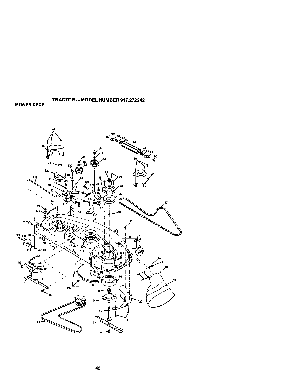
TRACTOR--MODEL NUMBER 917.272242
MOWERDECK
46
32_
112
I
21 '
10
48
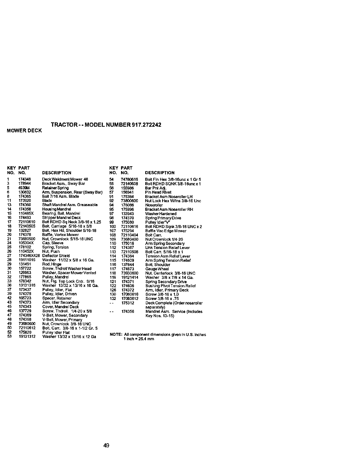
TRACTOR- -MODEL NUMBER 917.272242
MOWERDECK
KEY PART KEY PART
NO. NO. DESCRIPTION NO. NO. DESCRIPTION
1 174348 DeckWeldrnent Mower 48 54 74780616 Bolt Fin Hex 3/8-16unc x 1 Gr 5
3 178944 Bracket Asm,, Sway Bar 55 72146608 Bolt RDHD SQNK 316-18unc x 1
5 4939M Ret=UnerSpdng 56 155986 Bar PUt Adj.
6 130832 Arm, Suspension, Rear (Sway Bar) 57 156941 Pin Head Rivet
8 174365 Bolt 7/16 Asm. Blade 91 175384 Bracket Asm Noseroller LH
11 173920 Blade 92 73800600 Nut Lock Hex W/Ins 3/6-16 Unc
13 174360 Shaft Mandrel Asm. Greaseable 94 176_66 Noseroi_er
14 174358 Housing Mandrel 95 175996 Bracket Asm Noseroller RH
15 110485X Beadng, Ball, Mandrel 97 133943 Washer Hardaned
16 174493 Strlpper Mandrel Deck 98 174370 Spdng Pdmary Ddve
17 72110610 Bo8 RDHD Sq Neck 318-16 x 1.25 99 175080 Pulley Idler"V_
18 72140505 Bo_t,Carriage 5/16-18 x 5/8 100 72110616 Bolt RDHD Sqnk 3/8-18 UNC x 2
19 132827 Bolt, Hex Hd, Shoulder 5/16-18 107 175294 Baffle Vac Edge Mower
20 174378 Battle, Vodex Mower 108 72110404 Bolt Carr.
21 73680500 Nut, Crownlock 5/16-t8 UNC 109 73680400 Nut Crownlock 1/4-20
24 105304X Cap, Sleeve 110 175016 Arm Spring Secondary
25 178102 Spring,Torsion 112 174387 Link Tension Rehef Lever
26 110452X Nut, PUSh 113 72110508 Bolt CarT. 5/16-18 x 1
27 174346)(428 DefleutorShield 114 174384 TensionAsmReliefLever
28 19111016 Washer 11/32xS/8x16Ga. 115 174609 ArmSpdngTensionRellef
29 131491 Rod,Hinge 116 137644 Bolt, Shoulder
30 157722 Screw, Thdroll Washar Head 117 174873 GaugeWheel
31 129963 Washar, SpacerMowerVented 118 73930600 Nut, Centedock 3/8-16UNC
32 177865 Pulley, Mandrel 119 19121414 Washer 3/8 x 7/8 x 14 Ga.
33 178342 Nut, Fig. Top Lock Cntr. 9/16 121 174371 Spring SecondaryDdve
36 19131316 Washer 13/32 x 13/16 x 16 Ca. 122 174606 Bushing Pivot Tension Relief
37 173437 Pulley, Idler, Flat 126 174372 Arm, Idler, Primary Deck
39 174375 Pulley, Idler, Driven 130 17060616 Screw 3/8-16 x 1.0
42 165723 Spacer, Retatner 132 17(60612 Bcrew316-16x.75
43 174373 Arm, Idler Secondary - - 175312 Deck Complete (Ordar noseroller
45 174343 Cover, Mandrel Deck separately)
46 137729 Screw, ThdrolL 1/4o20 x 5/8 - - 174356 Mandrel Asm. Service (Includes
47 174369 V-Belt, Mower, Secondary Key Nos. 13-15)
48 174368 V-BOlt, Mower, Primary
49 73680600 Nut, Crownlock 3/8-16 UNC
50 72110612 Bolt, Carr. 3/8-16 x %1/2 Gr, 5
52 175820 Pulley Idler Flat NOTE: AJIcomponent dimensions glen In U,S. inches
53 19131312 Washer 13132 x 13116 x 12 Ga 1 inch = 25.4 mm
49
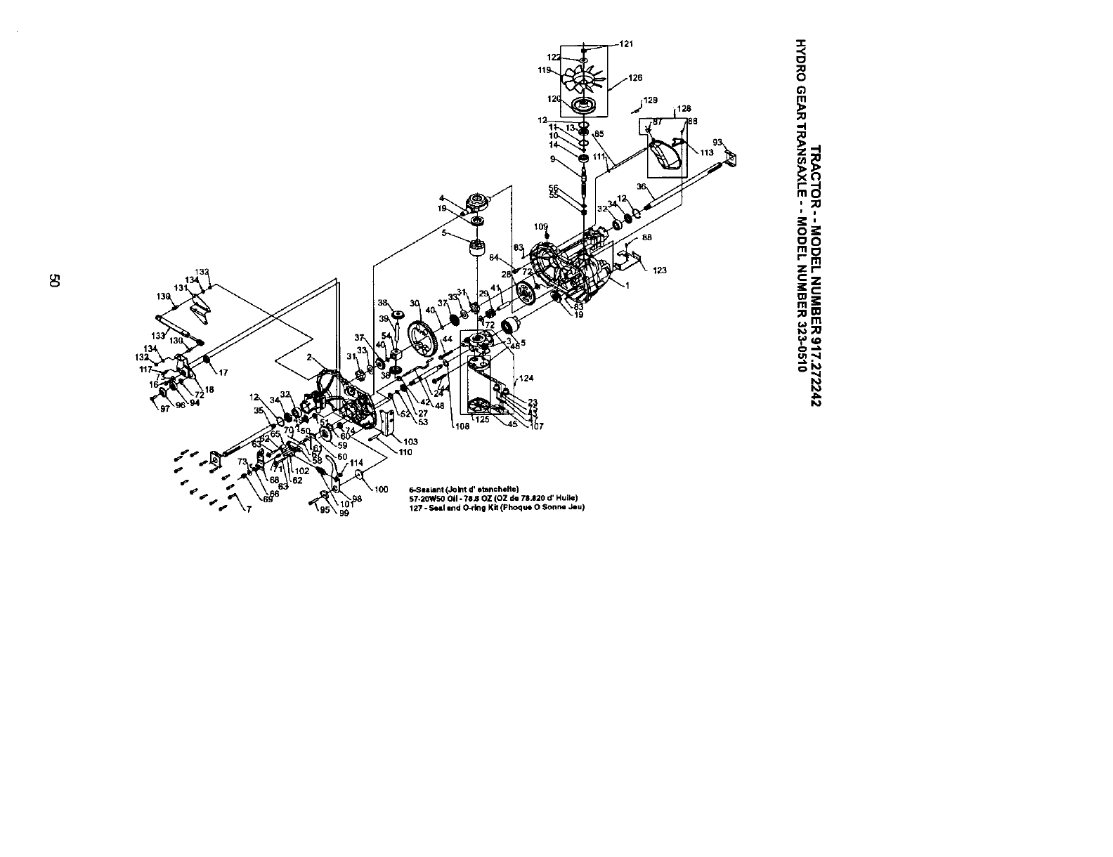
6-Sealant (Joint d' etahchelle)
57-2QWSQOil - ?SJ_ OZ (OZ de 78.820 d' Hulle)
127 -Seal end O_klg Kit (Phoque 0 SonM Jeu)
._129
88
123
128
:I:
,.<
0
0
m
;0
-4
ii
o_
oo
zr-
_m
t_.M
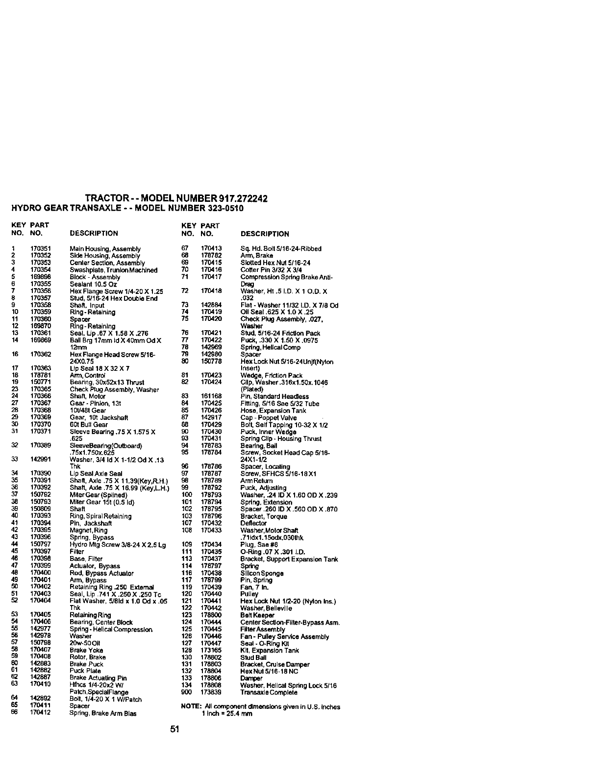
TRACTOR- -MODEL NUMBER 917.272242
HYDRO GEARTRANSAXLE--MODEL NUMBER 323-0510
KEY pART KEY PART
NO. NO. DESCRIPTION NO. NO. DESCRIPTION
1 170351 Main Housing+Assernbly 67 170413 Sq. Hd.Bolt5116-24-Ribbed
2 170352 Side Housing, Assembly 68 178782 Arm, Brake
3 170353 Center Section, Assembly 69 170416 Slotted Hex Nut 5/16-24
4 170354 Swashplate, Trunlon Machined 70 170416 Cotter Pin 3132 X 3/4
5 169898 Block - Assembly 71 170417 Compression Spdng Brake Anti-
6 170355 Sealant 10.50z Drag
7 170356 Hex Flange Screw 1/4-20 X 1.25 72 170418 Washer, Ht .5 I.D. X 1 O.D. X
8 170357 Stud, 5/16-24 Hex Double End .032
9 170358 Shaft, Input 73 142884 Flat - Washer 11132 I.D. X 718 Od
10 170369 Ring -Retaining 74 170419 Oil Seal .625 X 1.0 X .26
11 170360 Spacer 75 170420 Check Ptog Assernbty, .027,
12 169870 Ring-Retaining Washer
13 170361 Seal, Up .67 X 1.68 X .276 76 170421 Stud, 5/16-24 Fri_on Pack
14 169869 Ball Brg 17turn Id X 40rnm Od X 77 170422 Pu_<, .330 X 1.50 X .0975
1;b_n 78 142969 Spring, HellcalComp
16 170362 Hex Flange Heed Screw 5/16- 79 142980 Spacer
24X0.75 80 150776 Hex Lock Nut 5/16-24Unjf(Nylon
17 170363 Lip Seal 18 X 32 X 7 Insert)
18 178781 Arm, Control 61 170423 Wedge, Friction Pack
19 150771 Bearing, 30x52x13 Thrust 82 170424 Clip, Washer .316x1.50x. 1046
23 170365 Check Plug Assembly, Washer (Ptated)
24 170366 Shell, Motor 83 161168 Pin, Standard Headless
27 170367 Gear - Pinion, 13t 84 170425 Fitting, 5/16 Sae 5/32 Tube
28 170368 10U48t Gear 85 170426 Hose, Expansion Tank
29 170369 Gear, 10t Jackshaft 87 142917 Cap -Poppet Valve
30 170370 60t Bull Gear 88 170429 Bolt, Self Tapping 10-32 X 1/2
31 170371 Sleeve Bearing .75 X 1.575 X 90 170430 Puck, Inner Wedge
.625 93 170431 Spring Clip -Housing Thrust
32 170389 SleeveBeaflng(Outboard) 94 178783 Bearing, Ball
.75x1.750x.625 96 178784 Screw, Socket Head Cap 5116-
33 142991 Washer, 3/4 Id X 1-1/2 Gd X ,13 24X1-1/2
Thk 96 178786 Spacer, Locating
34 170390 Lip Seal Axle Seal 97 178787 Screw,SFHCS 5/16-18 X1
35 170391 Bhatt, Axle .75 X 11.39(Key,R.H.) 96 178789 Arm Return
36 170392 Shaft, Axle .75 X 16.99 (Key,LH.) 96 176792 Puck, Adjusting
37 150792 MiterGear (Splined) 100 178793 Washer, .24 ]D X 1.60 OD X .239
38 150793 Miter Gear 15t (0.5 Id) 101 178794 Spring, Extension
39 150809 Shaft 102 178795 Spacer .360 ID X.560 OD X .870
40 170393 Ring, Spiral Retalnlng 103 178796 Bracket, Torque
41 170394 Pin, Jacksheft 107 170432 Deflector
42 170395 Magnet,Ring 108 170433 Washer,Motor Shaft
43 170396 Spring, Bypass .711dx1.15odx.030thk
44 150797 Hydro Mtg Screw 318-24 X 2.5 Lg 109 170434 Plug, Sae #6
45 170397 Filter 111 170435 O-Ring .07 X .301 I.D.
46 179696 Base, Filter 113 170437 Bracket, Support Expansion Tank
47 179696 Actuator, Bypass 114 178797 Spring
48 170400 Rod, Bypass Actuator 116 170438 SIIIconSponge
46 170401 Arm, Bypass 117 178796 Pin, Spring
50 170402 Retaining Ring .250 Externol 119 170439 Fan, 7 In.
51 170403 Seal, Lip .741 X .250 X .250 Tc 120 170440 Pulley
52 170404 Fiat Washer, 5/81d x 1.60d x .05 121 170441 Hex Lock Nut 1/2-20 (Nylon Ins.)
Thk 122 170442 Washer, Bellevllle
53 170405 RetainingRing 123 178800 Bed Keeper
54 170406 Bearing, Center Block 124 170444 Center Sec_on-FIher-Bypass Asrn.
55 142977 Spring -HelicalCompression 125 170445 Filter Assembly
56 142978 Washer 126 170446 Fan -Pulley Service Assembly
57 150768 20w-50 Oil 127 170447 Seal - O-Ring Kit
58 170407 Brake Yoke 128 173165 Kit, Expansion Tank
59 170408 Rotor, Brake 130 178802 Stud Ball
60 142883 Brake Puck t31 178803 Bracket, Cruise Damper
61 142882 Puck Ptate 132 178804 HexNut 5/16-18 NC
62 142887 Brake Actuating Pin 133 178806 Damper
63 170410 Hthcs 1/4-20x2 WI 134 178808 Washer, Helical Spring Lock 5116
Patch,SpeclalFlange 900 173839 Transaxle Ccmplete
64 142892 Bolt, 1/4-20 X 1 W/Patch
65 170411 Spacer NOTE: All component dimensions given In U.S. Inches
66 170412 Spring, Brake Arm Bias 1 Inch = 25.4 rnm
51
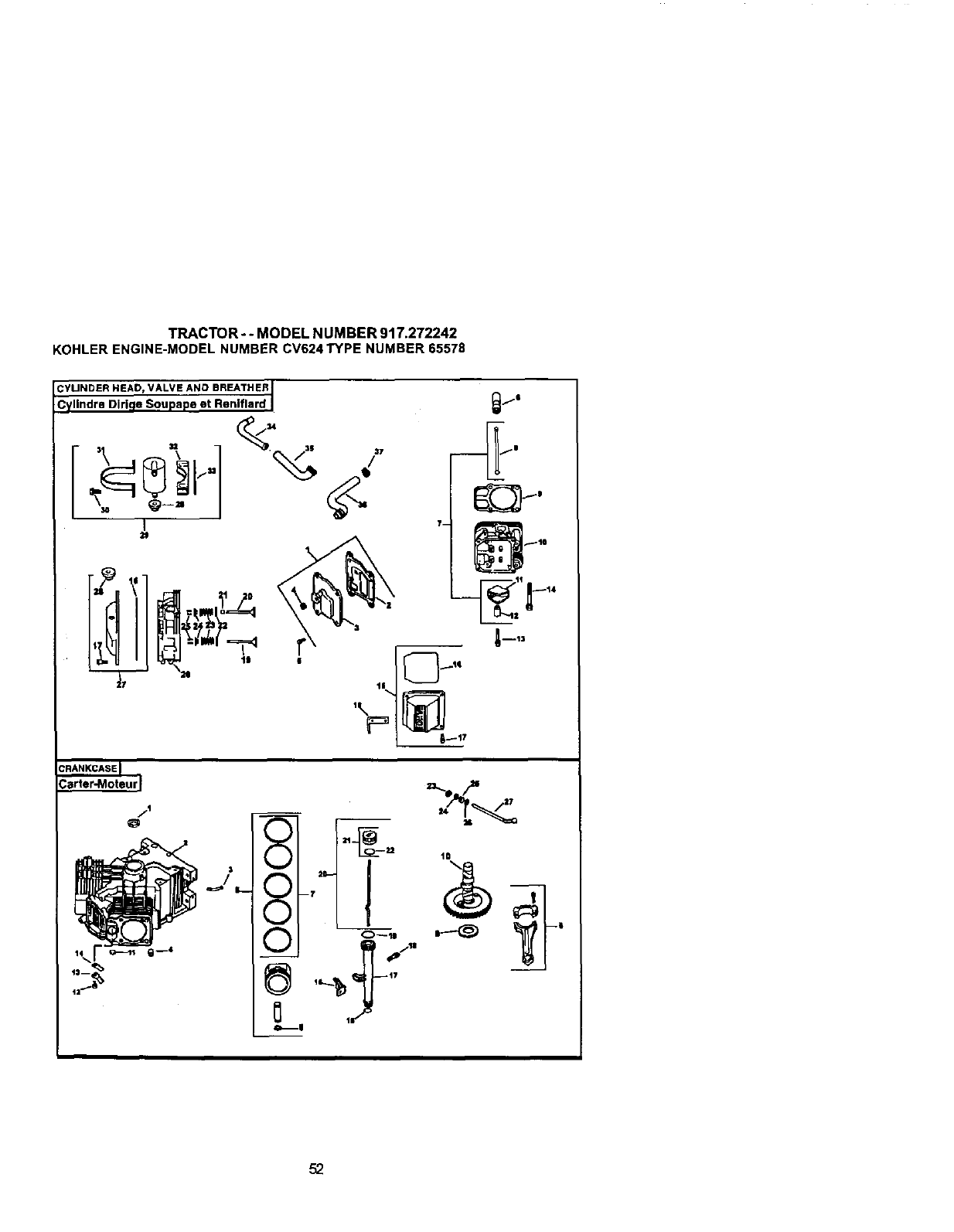
TRACTOR-- MODELNUMBER917.272242
KOHLERENGINE-MODELNUMBERCV624TYPENUMBER65578
Q
_8
52
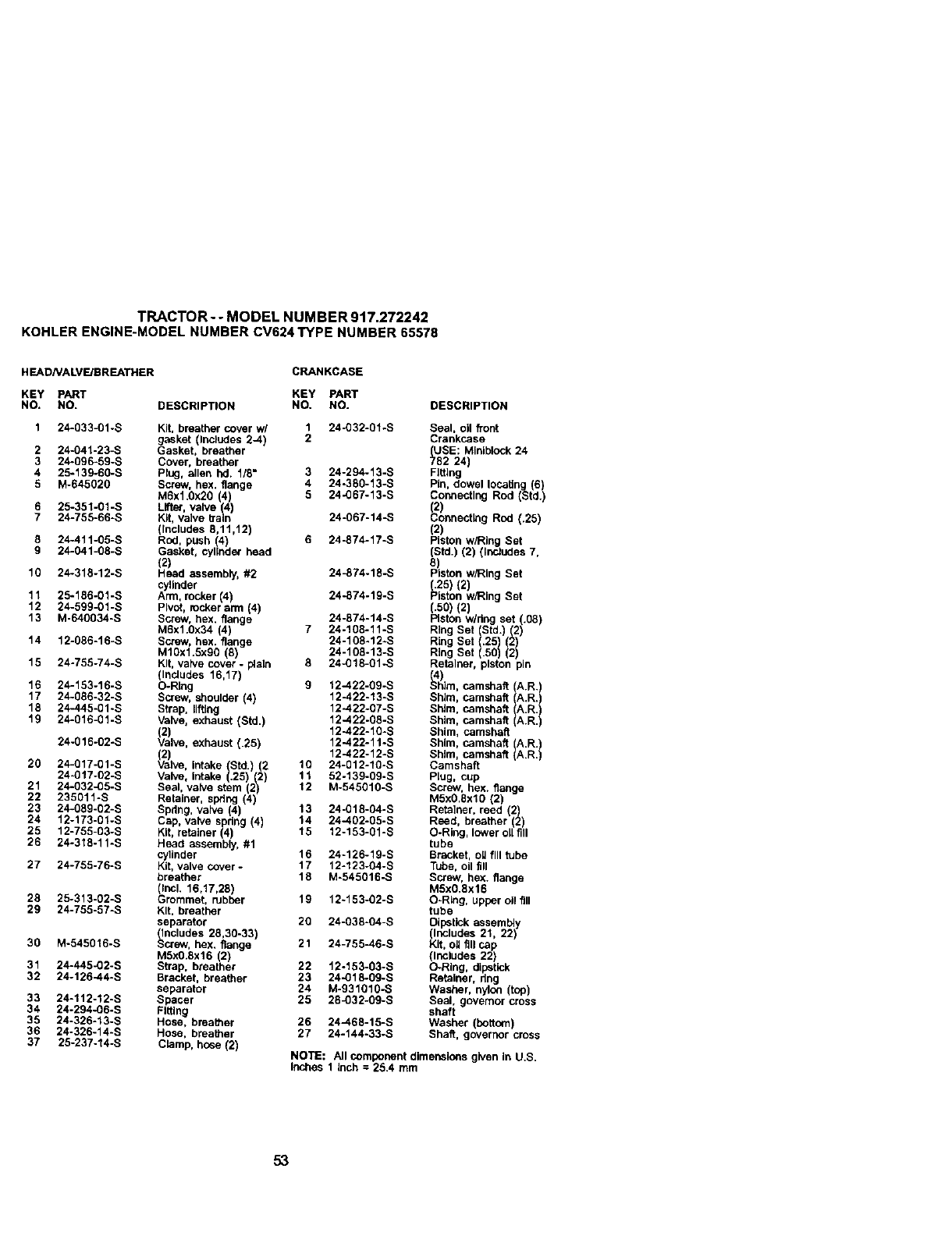
TRACTOR--MODEL NUMBER 917.272242
KOHLERENGINE-MODELNUMBERCV624TYPE NUMBER65578
H EADNALVF.JEREATHER CRANKCASE
KEY PART KEY PART
NO. NO. DESCRIPTION NO. NO. DESCRIPTION
2
3
4
5
10
11
12
13
14
15
16
17
18
19
20
21
22
23
24
25
26
27
28
29
30
31
32
24-033-01-S Kit, breather cover w/ 1 24-032-01.S Seal, oil front
gasket (Inctades 2-4) 2 Crankcase
24-041-23-S Gasket, breather (USE: Miniblock 24
24-696-59-S Cover, breather 782 24)
25-139-60-S Plug, allen hd. 1/8" 3 24-294-13-S Fgtthg
M-64502g Screw, hex. flange 4 24-380-13-S pin, dowel locating (6)
M6xl.Ox20 (4) 6 24-067-13-S Connecting Rod (Std.)
25-351-01-S LlfteF, valve 4 _2)
24-755-66-S K, vave b'a n 24-067-14-S _.onnect_g Rod (.25)
(thcludes 6,11,12) (2)
24-411-65-S Rod, push (4) 6 24-874-17-S Piston w/Ring Set
24-041-68-S Gasket, cylinder head (Std.) (2) (thcludes 7,
(2) 6
24*318-12-S Head assembly, #2 24_74-18-S Pson w/Ring Set
cylinder (.25) (2)
25-186-01-S Arm, rocker 4) 24-874-19-S Piston w/Ring Set
24-59g-01-S P rot, rocker ann (4) (.60) (2)
M-640634-S Screw, hex. flange 24-674-14-S Piston w/ring set (.08)
M6x1.Ox34 (4) 7 24-166-11-S Ring Set (Std.) (2)
12-086-16-S Screw, hex. flange 24-168.12..S Ring Set (.25 (2
MlOxl.6x90 (6) 24-105-13-S Rng Se .56 2
24-755-74-S Kit, valve cover -plain 8 24-016-01-S Retainer, piston pin
(Includes 16,17) (4)
24-153-16-S O-Ring 9 12-422-09-S Shim, camshaR ()A.R.
24-086-32-S Screw, shoulder (4) 12-422-13-S Shim, camshaft (A.R.)
24-445-gl-S Strap, lifting 12-422-07-S Shim, camshaft A.R.
24-616-01-S Valve, exhaust (Std,) 12-422-06-S Shim, camshaft A.R.
(2) 12-422-10-S Shim, camshaft
24-016-02-S Valve, exhaust (.25) 12-422-11.S Shim, camshaft A.R.)
(2) 12-422-12-S Shim, camshaft A.R.)
24-017-01-S Valve, intake (Std.) (2 16 24-012-10-S Camshaft
24-017-02-S Valve, Intake (.25) (2) 1/ 52-139-69-S Plug, cup
24-032_5-S Seal, valve stem 2) 12 M-545010-S Screw, hex. flange
235011-S Reaner, spring 4 M5x0.8xl0 (2)
24-089-02-S Spdng, valve (4) 13 24-018-04-S Retather, reed 2)
12-173-61-S Cap, valve spdng (4) 14 24-402-05-S Reed, breather 2
12-755-03-S Kit, retainer (4) 15 12-153-01 *S O-Ring, lower oil fill
24-318-11-S Head assembly, #1 tube
cylinder 16 24-126-19-S Bracket, ou fill tube
24-755-76-S Kit, valve cover -17 12-123-04-S Tube, oil fill
breather 18 M-545016-S Screw, hex. flange
(Incl. 16,17,28) MSx0.8x16
25-313-02-S Grommet, rubber 19 12~153-02-S O-Ring, upper oil fill
24-755-57-S Kit. breather tube
separator 20 24-038-04-S Dipstick assembly
_ncludes 28,30-33) (Includes 21, 22)
M-545616-S _crew, hex. flange 21 24-755-46-S Kit, oH fill cap
M6x0.6x16 (2) (Includes 22)
24-445-02-S Strap, breather 22 12-153-03-S O-Ring, dipstick
24-126-44-S Bracket, breather 23 24-018-09-S Retainer. dng
separator 24 M-931010-S Washer, nylon (top)
24-112-12-S Spacer 25 284)32-09-S Seal, governor cross
24-294-06-S Fitting shaft
24-326-13-S Hose. breather 26 24-468-15-S Washer (bottom)
24-326-14-S Hose, breather 27 24-144-33-S Shaft, governor cross
25-237-14-S Clamp, hose (2) NOTE: All component dimensions given in U.S.
Inches 1 inch : 25.4 mm
33
34
35
36
37
53
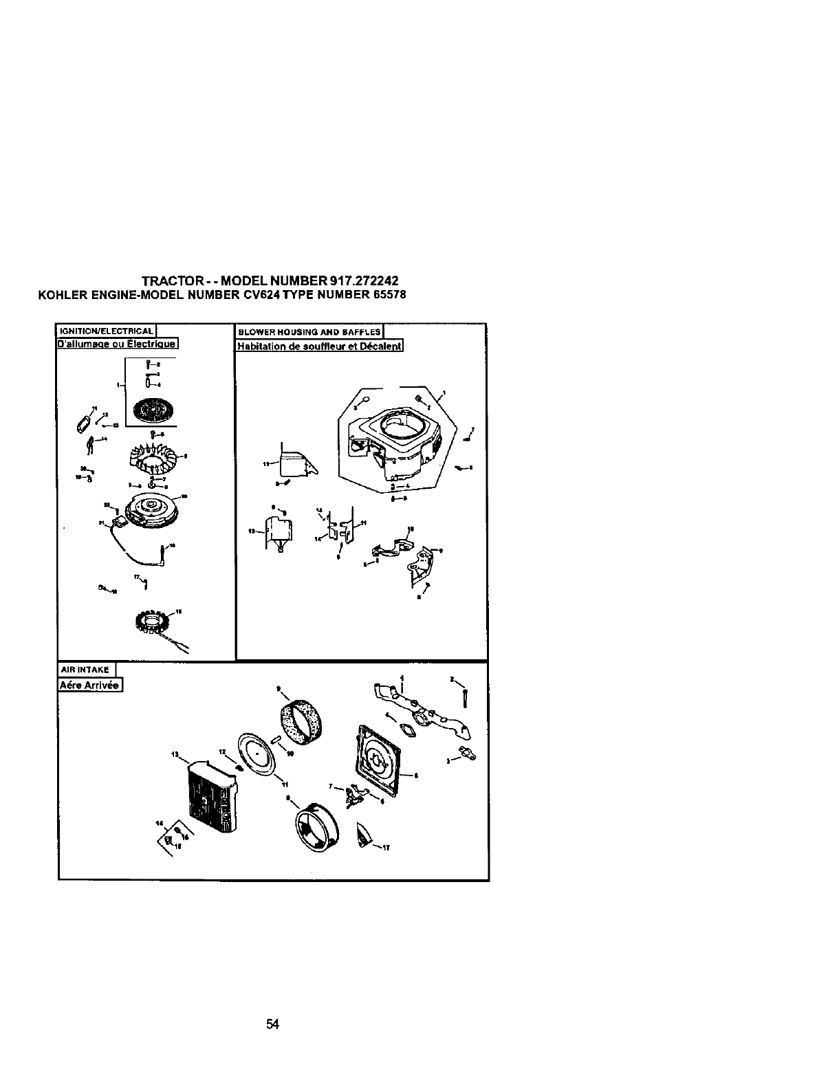
TRACTOR--MODEL NUMBER 917.272242
KOHLERENGINE-MODELNUMBER CV624TYPE NUMBER65578
IGNITION/ELECTRICAL I
allumaqe ou Electriouel
f-,
d _oQ
I
SLOWER HOUSING AND BAFFLES I
Habitation de souffleur et D_calenll
i
1|
54
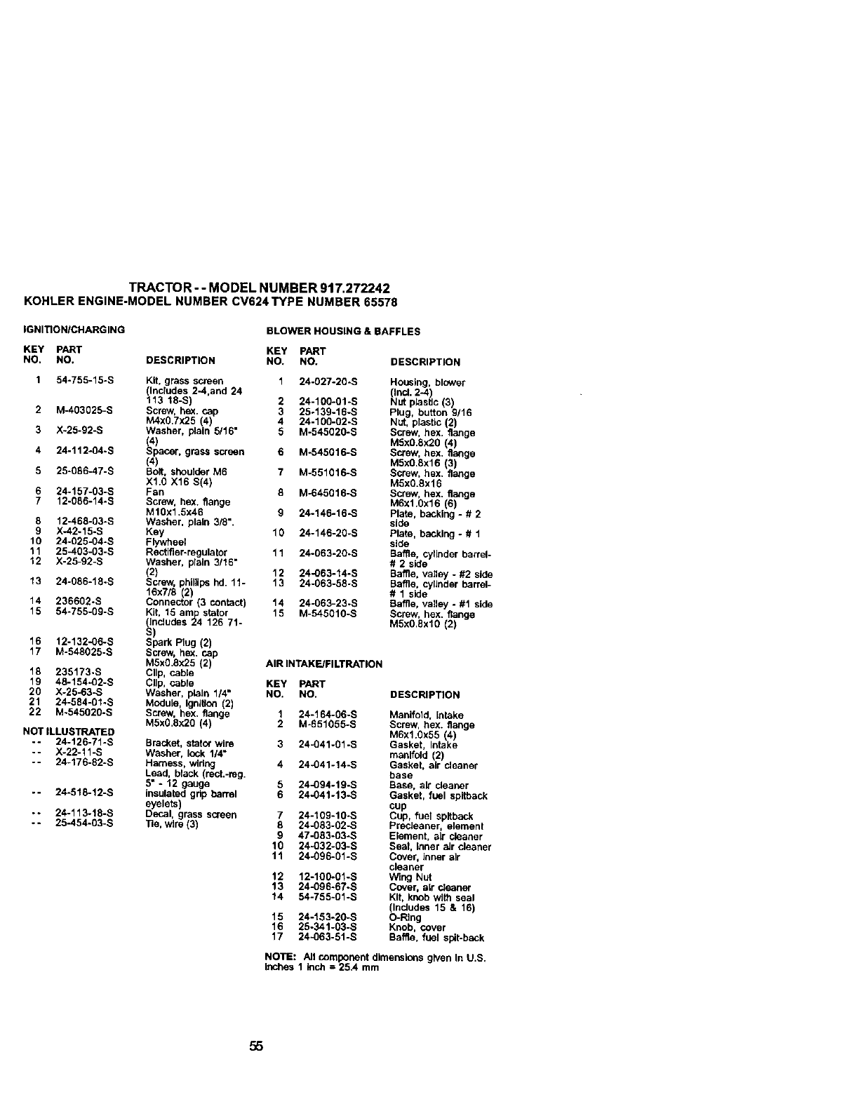
TRACTOR - - MODEL NUMBER 917.272242
KOHLERENGINE-MODELNUMBERCV624TYPE NUMBER65578
IGNITION/CHARGING BLOWER HOUSING & BAFFLES
KEY PART KEY PART
NO. NO. DESCRIPTION NO. NO.
1 54-755-15-S Kit, grass screen 124-027-20-S
llncludes 2-4,and 24
13 18-S) 2 24-100-01-S
2 M-403025-S Screw, he)(. cap 3 25-139-16-S
M4X0,7X25 (4) 4 24-100-02-S
3 X-25-92-S Washer, plain 5/16" 5 M-545020-S
(4)
4 24-112-04.S Spacer, grass screen 6 M-545016-S
(4)
5 25-066-47-S Bolt, shoulder M6 7 M-551016-S
X1.0 X16 S(4)
6 24-157-03-S Fan 8 M-645016-S
7 12-086-14-S Screw, hex. flange
MI0x1.5x46 9 24-146-16-S
8 12-468-g3-s Washer, plain 3/8".
9 X-42-15-S Key 10 24-146-20-S
1O 24-025-04-S Flywhee_
11 25-403-03-S Rectifier-regulater 11 24-063-20-S
12 X-25-92-S Washer, plain 3/16"
(2) 12 24-063-14-S
13 24-086-18-S Screw, phillips hd. 11 -13 24-063-58-S
16x7/8 2
14 236602-S Connecor 3 contact) 14 24-063-23-S
15 54-755-09-S KR, 16 amlp stator 15 M-545010-S
(Includes 24 126 71-
S)
16 12-132-06-S Spark Plug (2)
17 M-548025-S Screw, he;<. cap
M5xO.8x25 (2) AIR INTAKE/FILTRATION
18 235173-S Clip, cabla
19 48-154-02-S Clip, cabre KEY PART
20 X-25-63-S Washer, plain 1/4" NO. NO. DESCRIPTION
21 24-584-01-S Module, ignRlen (2)
22 M~545020-S Screw, hex. flange 1 24-164-06-S
M5x0.Sx2g (4) 2 M-651055-S
NOT ILLUSTRATED
- - 24-126-71-S Bracket, slato_"wire 3 24-041-01 -S
-- X-22-11-S Washer, lock 1/4"
-- 24-176-82-S Harness, wiring 4 24-041-14-S
Lead, black (rect.-reg.
5" - 12 gauge 5 24_94-19-S
-- 24-518-12-S insulated grip barrel 6 24-041-13-S
eyelets)
-- 24-113-18-S Decal, grass screen 7 24-109-10.S
-- 25-454-03-S Tie, Wire (3) 8 24-083-02-S
9 47-083-03-S
10 24-O32-03-S
11 24-096-01-S
12 12-100-01-S
13 24-096-67-S
14 54-755-01-S
15 24-153-20-S
16 25-341-03-S
17 24-063-51-S
DESCRIPTION
Housing, blower
(Incl. 2-4
Nut plastte 3
Plug, button 9/16
Nut, plastic (2)
Screw, hex. flange
MSx0.Sx20 (4)
Screw, hex. flange
MSx0.8x16 (3)
Screw, hex. flange
M5xg.Sx16
Screw, bax. flange
M6xl.0x16 (6)
Plate, backing - # 2
side
Plate, backing. # 1
side
Baffle, eyfinder barrel-
# 2 side
Baffle, valley -#2 side
Baffle, cylinder barrel-
# 1 side
Baffle, valley -#1 side
Screw, hex. flange
M5x0.6xl0 (2)
Manfiold, intake
Screw, hex. flange
M6x1.0x55 (4)
Gasket, Intake
manifold (2)
Gasket, air cleaner
base
Base, air cleaner
Gasket, fuel spitback
cup
Cup, fuel spltback
PrecJeaner, element
Etsment, air cleaner
Seal, Inner aJr cleaner
Cover, Inner air
cleaner
Wing Nut
Cover, air c_eaner
Kit, knob with seal
(Indudss 15 & 16)
O-RIng
Knob, cover
Baffle. fuel spit-back
NOTE: All component dimensions given In U.S.
inches 1 inch = 25.4 mm
55
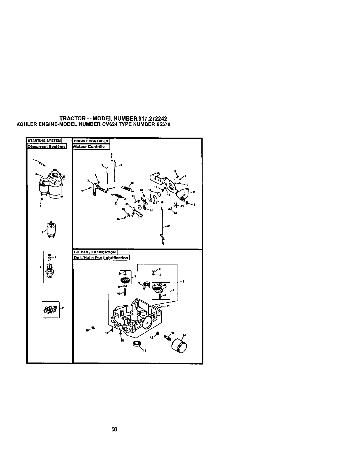
TRACTOR- - MODEL NUMBER 917.272242
KOHLERENGINE-MODELNUMBERCV624 TYPE NUMBER 65578
STARTING SYSTEM [
[_marrant Svst_me I
!
3
O
ENGtNE CONTROLS
Aoteur ContrSle
_2T
I
DIL PAN /LUBRICATION [
De L'Hulle Pan Lubrifieation J
I# z
.-Q O., _'
56
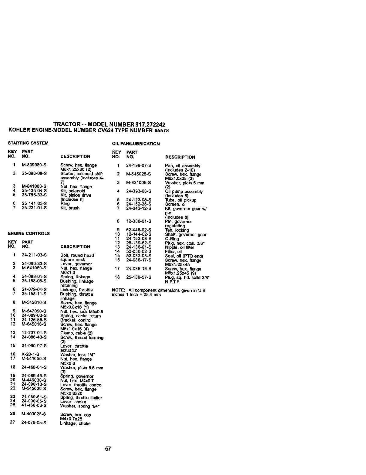
TRACTOR --MODEL NUMBER 917.272242
KOHLERENGINE-MODELNUMBER CV624TYPE NUMBER65578
STARTING SYSTEM
KEY PART
NO. NO.
1 M-539080-S
2 25-09 fl.08-S
3 M-841080-S
425-435-04-S
5 25-755-33-S
6 25 141 O5-S
7 25-221.01-S
ENGINE CONTROLS
KEY PART
NO. NO.
124-211.03-S
2 24.090-33-S
3 M-64106g-s
4 24-089.01-S
5 25-158-08-S
6 24-079.04-S
7 25-158-11-S
8 M-545016-S
9 M-547050-S
1g24.089.03-S
11 24-126-56-S
12 M-645016-S
13 12-237-01 -S
14 24-086-43-S
15 24-090-07-S
16 X-20-1-S
17 M-541050-S
18 24-468.01-S
19 24-089-45-S
20 M-446030-S
21 24-090-13-S
22 M-545020-S
23 24.089-51-S
24 24.090-05-S
25 41-468-03-S
26 M.403025-S
27 24-079-05-S
OIL PAN/LUBRICATION
KEY PART
DESCRIPTION NO. NO. DESCRIPTION
Screw, hex. flange 1 24-199-g7-s
M8x1.25x80 (2)
Starter, solenoid shift 2 M-645025-S
assembly (Inc;udes 4-
7) 3 M-031005-S
Nut, hex. flange
Kit. solenoid 4 24-393-08-S
Kg, pinion drive
(Includes 6) 5 24-123-05-S
Ring 6 24-162-26-S
Kit, brush 7 24-043-12-S
DESCRIPTION
Bolt, round head
square neck
Lever, govemor
NUt, hex. flange
M6x1.0
Spring, linkage
Bushing, linkage
retaining
Linkage, throttle
Bushing, throtlte
linkage
Screw, hex. flange
M5x0.8x16 (1)
NUt, hex. took M5xO.8
Spdng, choke return
Bracket, control
Screw, hex. flange
M6x1.0x16 4)
Clamp, cable 2)
Screw, thread forming
(2)
Lever, throttle
actuator
Washer, lock 1/4"
Nut, hex. flange
M5x0.8
Washer, piain 5.5 mm
_3p)rlag, governor
NUt, hex. M4XO.7
Lever, throttle conb'ol
Screw, hex. flange
M5xO.8x2O
Spdng, throtBe limfler
Lever, choke
Washer, sprthg 1/4"
Screw, he_(. cap
M4xO.7x25
Linkage, choke
12-380-01-S
9 52-448-02-S
10 12-144-02-S
11 24-153-08-S
12 25-139-62-S
13 24-136.01-S
14 52-050.02-S
15 52.032.0g-s
16 24-086-17-S
17 24.086-16-S
18 25-139-57-S
Pan. bll assembly
_ncludes 2-10)
crew, hex. flange
M6xl.Ox25 (2)
Washer, plain 6 mm
(2)
Olt pump assembly
(Includes 5)
Tube, oil pickup
Screen, oil
Kit, governor gear w/
8)
Pin, governor
regulating
Tab, locking
Shaft, governor gear
O-Ring
Plug, hex. ctsk. 3/8"
Nipple, oll filter
Filter, oil
Seal, oil (PTO end)
Screw, he:<. flange
M8xl.25x45
Screw, hex. flange
M8x1.25x45 (9)
Plug, sq. hd. solid 3/8"
N.RT.F.
NOTE: All component dimensions given In U.S.
inches 1 inch = 25.4 mm
57
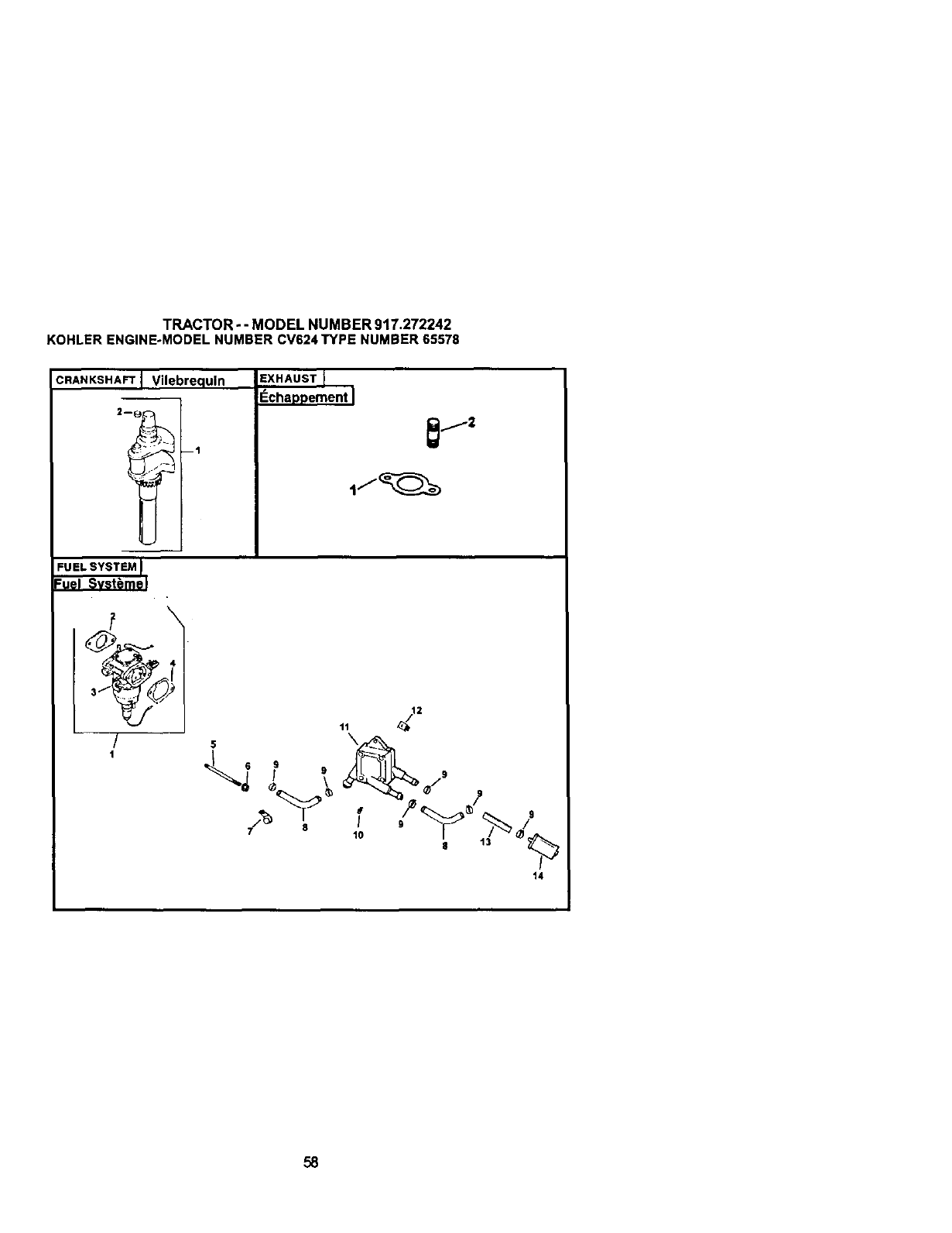
TRACTOR--MODEL NUMBER 917.272242
KOHLERENGINE-MODELNUMBER CV624TYPE NUMBER65578
CRANKSHAFT Vilebrequln
ml
EXHAUST
_chappement I
_j2
FUEL SYSTEM I
Fuel Svst_me J
--7 t
/v
t4
58
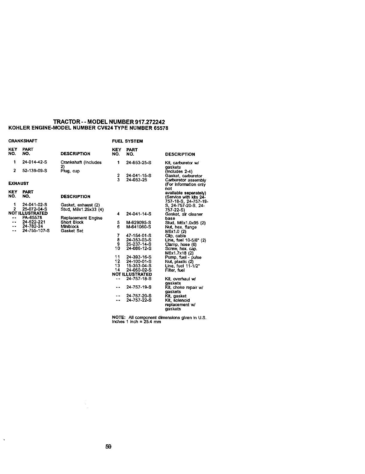
TRACTOR-- MODEL NUMBER 917.272242
KOHLERENGINE-MODELNUMBERCV624TYPE NUMBER 65578
CRANKSHAFT
KEY PART
NO, NO,
1 24-014-42-S
2 52-139-09-S
EXHAUST
KEY PART
NO. NO.
1 24-041-02-S
2 25-072-04-S
NOT ILLUSTRATED
-- PA-65578
-- 24-522-221
-- 24-782-24
-- 24-755-107-S
FUEL SYSTEM
KEY PART
DESCRIPTION NO. NO.
Crankshaft (Includes 1 24-853-25-S
2)
Plug, cup 2 24-041-15-S
3 24-053-25
DESCRIPTION
Gasket. exhaust (2)
Stud. MSx1.25x33 (4) 4 24-041-14-S
Replacement Engine
Short Block 5 M-629095-S
Mlnlblock 6 M-641060-S
Gasket Set
7 47-154-01.S
8 24-353-03-S
9 25-237-14-S
10 24-086-12-S
11 24-393-16-S
12 24-100-01-S
13 15-353-04-S
14 24_50-02-S
NOT ILLUSTRATED
-- 24-757-18-S
-- 24-757-19-S
-- 24-757-20-S
-- 24-757-22-S
DESCRIPTION
Kit. carburetorw/
askets
_nutud_ 2-4)
Gasket, carburetor
Carburetor a._embly
(For infraction only
not
available separately
(Service _th k,s 24-
757-18-S, 24-757-19-
S, 24-757-20-S, 24-
757-22-S)
Gasket, air ciean_"
base
Stud, M6x1.0x95 (2)
NUt, hex. flange
M6xl.0 (2)
Clip, cebte
Line, fuel 111-5/8"(2)
Clamp, hose (6)
Screw, hex. cap.
M6x1.7x18 !2)is e
Pump. fuel
Nut. plastic (2)
Line. fuel 11-1/2"
Filter,fuel
Kit, overhaul w/
askets
,_t, choke repairw/
gaskets
Kit, gasket
Kit, solenoid
replacementw/
gaskets
NOTE: All component dimensions given in U.S.
inches 1 inch = 25.4 mm
59

6O

61


SUGGESTED GUIDE FOR SIGHTING SLOPES FOR SAFE OPERATION
GUIDE
ONLY RIDE UP AND DOWN HILL,
NOT ACROSS HiLL
I p_ Operate your Tractor up and down the face of slopes (not
greater than 15 ), never across the face. Make turns gradu-
ally to prevent tipping or loss of control. Exercise extreme
caution when changing direction on slopes.. .......................

For repairof major brandappliancesinyour own home...
nomatterwhomade it,nomatterwhosold
Forrepairof carry-inproductslikevacuums,lawnequipment,and
electronics,callfor thenearestSears Pads and RepairCenter.
1-800-488-1222 ,_ny_me,dayo_r_Jt(U.SA_
Forthe repbcementparts,accessoriesandowner'smanuals
thatyouneedtodo-it-yourself,callSears PartsDirect-_]
1-800-366-PART
(1-8oo-366-7278) 6a_m.-11p.m. 7daysaweek
_J.S_.only)
www.sears.com@atsdrect
To purchaseor inquireabouta SearsServiceAgreement
orSearsMaintenanceAgreement:
1-800-827-6655 (U.S.A.) 1-800-361-6665 (Canada)
7a.m.- 5p.m.,CST,M_rL - Sat. 9 a.m.- 8 p.rn.EST, M - F,4 p.m. Sat.
Parapedrse_,idode reparaci_ a
dornidlio,y paraordonarpiezas:
1-888-SU-HOGAR_
®Registered Trademark I "nJTrademark /s_ Service Mark of Sears, Roebuck and Co.
©Marca Registrada ITM Marca de F_brica IsMMarca de Servtcio de Sears, Roebuck and Co.
McMarque de commerce /k_)Marque d&p_6e de Sears, Roebuck and Co.
179177 3.22.01 TR Pdntedin U.S.A.
