Craftsman 917272962 User Manual TRACTOR Manuals And Guides L0101121
CRAFTSMAN Lawn, Tractor Manual L0101121 CRAFTSMAN Lawn, Tractor Owner's Manual, CRAFTSMAN Lawn, Tractor installation guides
User Manual: Craftsman 917272962 917272962 CRAFTSMAN TRACTOR - Manuals and Guides View the owners manual for your CRAFTSMAN TRACTOR #917272962. Home:Lawn & Garden Parts:Craftsman Parts:Craftsman TRACTOR Manual
Open the PDF directly: View PDF ![]() .
.
Page Count: 68
Owner's Manual
JCRRFTSMIIN"I
20.0 HP
ELECTRIC START
46" MOWER
AUTOMATIC
GARDEN TRACTOR
Model No.
917.272962
• Safety
• Assembly
• Operation
• Maintenance
•Repair Parts
This product has a low emission engine which operates
differently from previously built engines. Before you start the
engine, read and understand this Owner's Manual.
CAUTION:
Read and follow all Safety
Rules and Instructions before
operating this equipment.
Foranswerstoyourquestions
aboutthisproduct,Call:
1-800-659-5917
Seers Craftsman Help Line
5 am - 5 pm, Mon -Sat
Sears, Roebuck and Co., Hoffman Estates, II 60179
Visit our Craftsman website:www.sears.com/craftsman
Warranty............................................... 2
Safety Rules ......................................... 3
ProductSpecifications..........................6
Assembly.............................................. 8
Operation............................................ 12
Maintenance....................................... 19
Maintenance Schedule...................... 19
Serviceand Adjustments....................23
Storage ............................................... 31
Troubleshooting.................................32
Repair Parts........................................36
Parts Ordedng ..................... Back Cover
LIMITEDTWO YEARWARRANTY ON CRAFTSMAN RIDING EQUIPMENT PAF_I'S
For two(2) years from the date of purchase,if thisCraftsmanRidingEquipmentis
maintained,lubricatedand tuned up accordingto the instructionsin the owner's
manual,Sears willrepairor replace,free of charge, any partsfound to be defectivein
matedalorworkmanship.Warrantyserviceis availablefree of charge by takingyour
Craftsmanridingequipmentto your nearestSears ServiceCenter. In-homewarranty
serviceis availablebut a tdp charge will apply.This warrantyappliesonlywhile this
productis inthe UnitedStates.
ThisWarrantydoesnot cover:.
• Expendableitemswhich becomeworn duringnormaluse, suchas blades,spark
plugs,air cleaners,belts and oilfilters.
•Tire replacementor repaircausedby puncturesfrom outsideobjects,suchas nails,
thorns,stumps,or glass.
•Repairsnecessarybecauseof operatorabuse, includingbut not limitedto, damage
causedby towingobjectsbeyondthe capabilityof the ddingequipment,impacting
objectsthat bendthe frame or crankshaft,or overspeedingthe engine.
•Repairsnecessarybecause of operatornegligence,includingbut not limitedto,
electricaland mechanicaldamage causedby improperstorage,failure to use the
propergrade and amount of engineoil,failure to keep the deck clearof flammable
debds,orthe failure to maintainthe equipmentaccordingto the instructionscon-
tained in the owner's manual.
•Engine(fuel system)cleaningor repairscaused by fuel determinedto be contami-
natedor oxidized(stale). In general,fuel shouldbe used withinthirty(30) days of its
purchasedate.
•Ridingequipmentused for commercialor rentalpurposes.
LIMITED 90 DAYWARRANTY ON BATTERY
For ninety(90) days from date of pumhase,if any batteryincludedwith thisdding
equipmentprovesdefectivein matadalor workmanshipand our testingdetermines the
batterywill notholda charge,Sears will replacethe batteryat no charge.Warranty
serviceis availablefree of charge by takingyour Craftsmanddingequipmentto your
nearestSears ServiceCenter. In-homewarrantyservice is availablebuta tdp charge
will apply.This warrantyappliesonlywhile this productis in the UnitedStates.
TO LOCATE THE NEAREST SEARS SERVICE CENTER OR TO SCHEDULE IN-HOME
WARRANTY SERVICE, SIMPLY CONTACT SEARS AT 1-800-4-MY-HOME
This Warrantygivesyou specificlegal dghts, and you may alsohave other dghts which
mayvaryfrom stateto state.
Sears, Roebuck and Co., D/817 WA, Hoffman Estates, IL 60179
IMPORTANT:Thiscuttingmachneiscapableofamputatinghandsandfeet and
throwing objects. Failure to observe the following safety instruCtionscould result in
sedous injury or death.
I. GENERAL OPERATION
• Read, understand, and follow all
instructions in the manual and on the
machine before starting.
• Only allow responsible adults, who are
familiar with the instructions, to operate
the machine.
•Clear the area of objects such as
rocks, toys, wire, etc., which could be
picked up and thrown by the blade,
•Be sure the area is clear of other
peopla before mowing. Stop machine
if anyone enters the area.
•Never carry passengers.
•Do not mow in reverse unless abso-
lutely necessary. Always look down
and behind before and while backing.
•Be aware of the mower discharge
direction and do not point _t at anyone,
Do not operate the mower without
either the entire grass catcher or the
guard inplace.
•Slow down before turning.
•Never leave arunning machine
unattended. Always tum off blades, set
parking brake stop engine, and
remove keys before dismount ng.
•Tum off blades when not mowing,
•Stop engine before removing grass
catcher or unclogging chute.
•Mow only in daylight or good artificial
light.
•Do not operate the machine while
under the influence of alcohol or drugs.
•Watch for traffic when operating near or
crossing roadways.
• Use extra care when loading or
unloading the machine into a trailer or
truck.
•Data indicates that operators, age 60
years and above, are involved in a
large percentage of dding mower-
related in odes. These operators
should evaluate the r ability to operate
the dding mower safely enough to
protect themselves and others from
serious injury.
Iio SLOPE OPERATION
Slopes are a ma'lor factor related to lass-of-
control and tipover accidents, which can
result in severe injury or death. All slopes
require extra caution. Ifyou cannot back up
the slope or if you feel uneasy on it, do not
mow it.
DO:
Mow up and down slopes, not across.
Remove obstacles such as rocks, tree
limbs, etc.
•Watch for holes, ruts, or bumps.
Uneven terrain could overturn the
machine. Tall grass can hide obstacles.
•Use slow speed. Choose a low gear
so that you will nOthave to stop or shift
while on the slope.
•Follow the manufacturer's recommen-
dations for wheel weights or counter-
weights to improve stability.
•Use extra care with grass catchers or
other attachments. These can change
the stability of the machine.
•Keep all movement on the slopes slow
and gradual. Do not make sudden
changes in speed or direction.
• Avoid starting or stopping on a slope. If
tires lose traction, disengage the
blades and proceed slowly straight
down the slope.
DO NOT:
•Do not turn on slopes unless neceso
sery and then, turn slowly and gradu-
ally downhill, if poss b e.
•Do not mow near drop-offs, ditches, or
embankments. The mower could
suddenly turn over if a wheel is over
the edge of a cliff or ditch, or if an edge
caves in.
•Do not mow on wet grass. Reduced
traction could cause sliding,
•Do not try to stabilize the machine by
putting your foot on the ground,
•Do not use grass catcher on steep
slopes.
3
Ill. CHILDREN
Tragic accidents can occur if the operator
is not alert to the presence of children.
Children are often attracted to the
machine and the mowing activity, Never
assume that children will remain where
you last saw them.
•Keep children out of the mowing area
and under the watchful care of another
responsible adult.
•Be alert and tum machine off if children
enter the area.
•Before and when backing, look behind
and down for small children.
•Never carry children. They may fail off
and be seriously injured or interfere
with safe machine operation.
•Never allow children to operate the
machine.
•Use extra care when approaching blind
corners, shrubs, trees, or other objects
that may obscure vision,
IV. SERVICE
•Use extra care in handling gasoline
and other fuels. They are flammable
and vapors are explosive.
-Use only an approved container.
-Never remove gas cap or add fuel
with the engine running. Allow
engine to cool before refueling. Do
not smoke.
-Never refuel the machine indoors.
-Never store the machine or fuel
container inside where there is an
open flame, such as a water heater.
•Never run amachineinsidea closed
area.
•Keep nutsand bolts,especiallyblade
attachmentbotts,tightand keep
equipmentin good condition.
•Nevertamperwithsafetydevices.
Check their properoperationregularly.
•Keep machinefree of grass, leaves,or
other debrisbuild*up.Clean oil or fuel
spillage.Allowmachineto cool before
stodng.
•Stop and inspectthe equipmentif you
stdkean object. Repair,if necessary,
before restarting.
•Never make adjustments or repairs
withthe engine running.
•Grass catchercomponentsare subject
to wear, damage, and deterioration,
whichcouldexposemovingpartsor
allow objectsto be thrown. Frequently
check componentsand replace with
manufacturer'srecommendedparts,
when necessary.
•Mower bladesare sharp and can cut.
Wrap the blade(s) or wear gloves,and
usa extra cautionwhenservicingthem.
•Check brake operationfrequently.
Adjustand serviceas required.
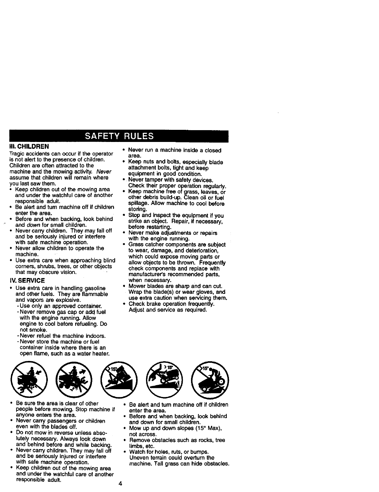
•Be sure the area is clear of other * Be alert and tom machine off if children
people before mowing. Stop machine if
anyone enters the area.
•Never carry passengers or children
even withthe blades off.
•Do not mow in reverse unless abso-
lutely necessary. Always look down
and behind before and while backing.
• Never carry children. They may fall off
and be seriously injured or interfere
with safe machine operation.
•Keep children out of the mowing area
and under the watchful care of another
responsible adult.
enter the area.
•Before and when backing, look behind
and down for small children.
•Mow up and down slopes (15 °Max),
not across.
•Remove obstacles such as rocks, tree
limbs, etc.
• Watch for holes, ruts, or bumps.
Uneven terrain could overturn the
machine. Tall grass can hide obstacles.
4
•Use slowspeed. Choose a lowgear so
that youwillnothave to stopor shift
while on the slope.
•Avoidstartingorstoppingona slope. If
tireslose traction,disengagethe
blades and proceedslowlystraight
downthe slope.
•If machinestopswhile going uphill,
disengageblades,shiftinto reverse
and back downslowly.
•Do nottum onslopes unlessneces-
sary, andthen, turn slowlyand gradu-
ally downhill,if possible.
_]lL,Lookfor thissymbolto pointout
importantsafetyprecautions.It means
CAUTIONtt! BECOMEALERTTt!YOUR
SAFETY IS INVOLVED.
_b CAUTION: In orderto prevent
accidentalstartingwhensetting up,
transporting,adjusting or makingrepairs,
always disconnectspark plugwire and
placewire where it cannotcontactspark
plug.
_, CALITION: Do notcoast downa hill
in neutral,you may losecontrolof the
tractor.
_CAUTION: Towonlythe attachments
that are recommendedby and comply
withspecificationsof the manufacturerof
yourtractor.Use commonsense when
towing.Operateonlyat the lowest
possiblespeed when on a slope. Too
heavy of a load,while ona slope,is
dangerous.Tires can losetractionwith
the groundand cause you to losecontrol
of yourtractor.
_bWARNING: Engineexhaust,some of
its constituents,and certainvehicle
componentscontainor emit chemicals
knownto the Stateof Californiato cause
cancerand birthdefectsor otherrepro-
ductiveharm.
_bWARNING: Batteryposts,terminals
and relatedaccessoriescontainlead and
lead compounds,chemicalsknownto the
State of Californiato cause cancerand
birthdefectsorother reproductiveharm.
Wash hands after handling.
PRODUCT SPECIFICATIONS
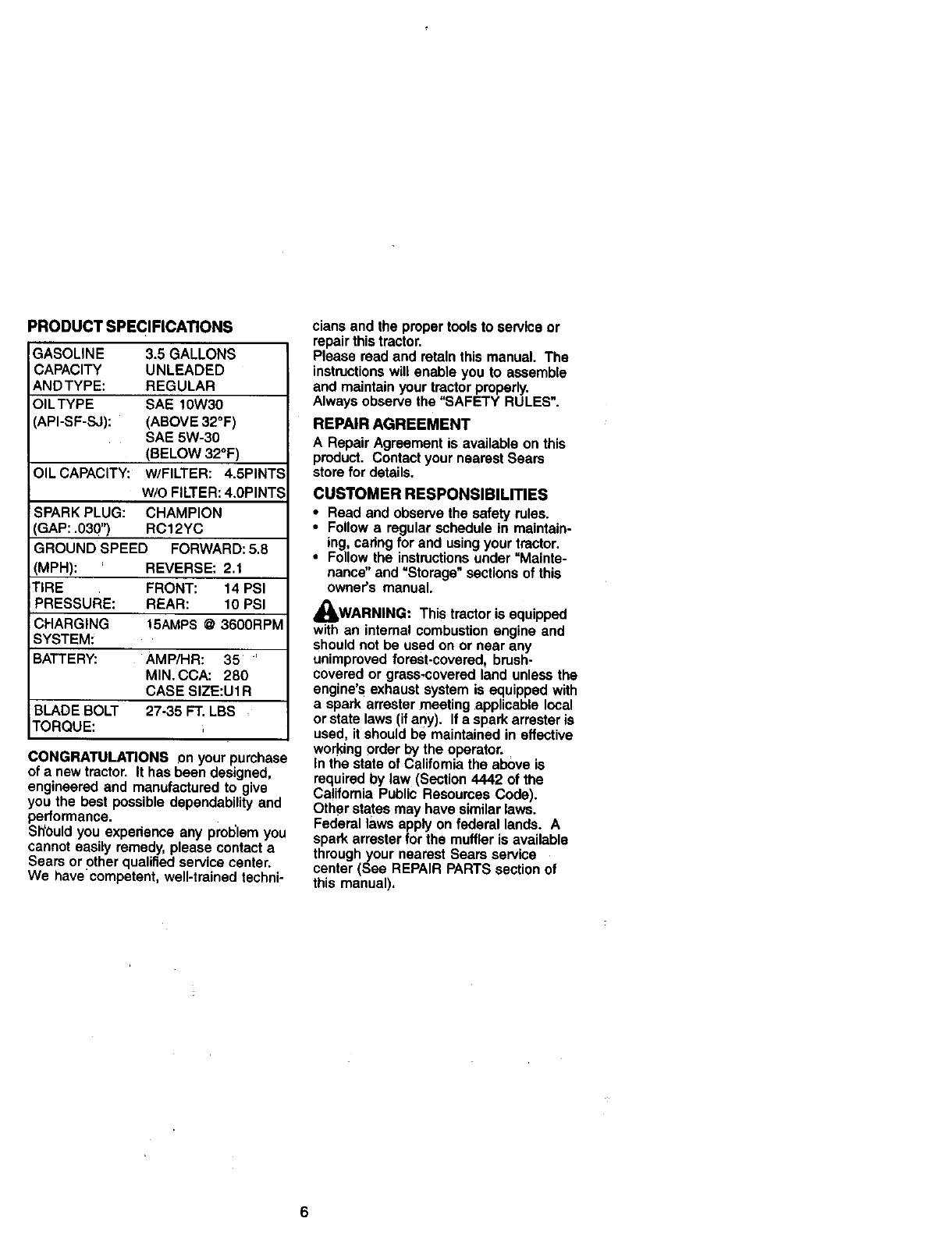
GASOLINE 3.5 GALLONS
CAPACITY UNLEADED
ANDTYPE: REGULAR
OILTYPE SAE 10W30
API-SF-SJ): (ABOVE 32°F)
SAE 5W-30
(BELOW 32°F)
OILCAPACITY: w/FILTER: 4.5PINTE
W/O FILTER: 4.0PINT:
SPARK PLUG: CHAMPION
IGAP: .030") RC12YC
GROUND SPEED FORWARD: 5.8
(MPH): REVERSE: 2.1
TIRE FRONT: 14 PSI
PRESSURE: REAR: 10 PSI
CHARGING t5AMPS @ 3600RPM
SYSTEM:
BATTERY: AMP/HR: 35
MIN. CCA: 280
CASE SIZE:U1R
BLADE BOLT 27-35 FT. LBS
TORQUE:
CONGRATULATIONS _n your purchase
of a newtractor. It hasbeen designed,
engineeredand manufacturedto give
you the best possibledependabilityand
performance.
ShOuldyou experienceany pret_lemyou
cannoteasilyremedy,pleasecontacta
Sears or otherqualifiedservicecenter.
We have competent,well-trainedtechni-
clansand the propertoolsto serviceor
repairthistractor.
Please readand retainthis manual. The
instructionswill enable you to assemble
and maintainyour tractorproperly.
Alwaysobservethe "SAFETY RULES".
REPAIR AGREEMENT
A RepairAgreementis availableon this
product. ContactyournearestSears
storefor details.
CUSTOMER RESPONSIBILITIES
• Read and observethe safety rules.
•Followa regularschedulein maintain-
ing, caringfor and usingyour tractor.
• Followthe instructionsunder "Mainte-
nance"and =Storage"sectionsof this
owner's manual.
WARNING: This tractoris equipped
with an internalcombustionengineand
shouldnotbe used on or near any
unimprovedforest-covered_brush.
covered or grass,coveredland unlessthe
engine'sexhaustsystemis equippedwith
a sparkarrestermeetingapplicablelocal
or statelaws (ifany). Ifa sparkarresteris
used, it shouldbe maintainedin effective
workingorderby the operator.
Inthe stateof Californiathe aboveis
requiredby law (Section4442 of the
Ca!ifomia PublicResourcesCode).
Otherstatesmay have similarlaws.
Federallaws applyon federal lands. A
sparkarresterfor the muffleris available
throughyour nearestSears service
center(See REPAIRPARTSsectionof
this manual).
6
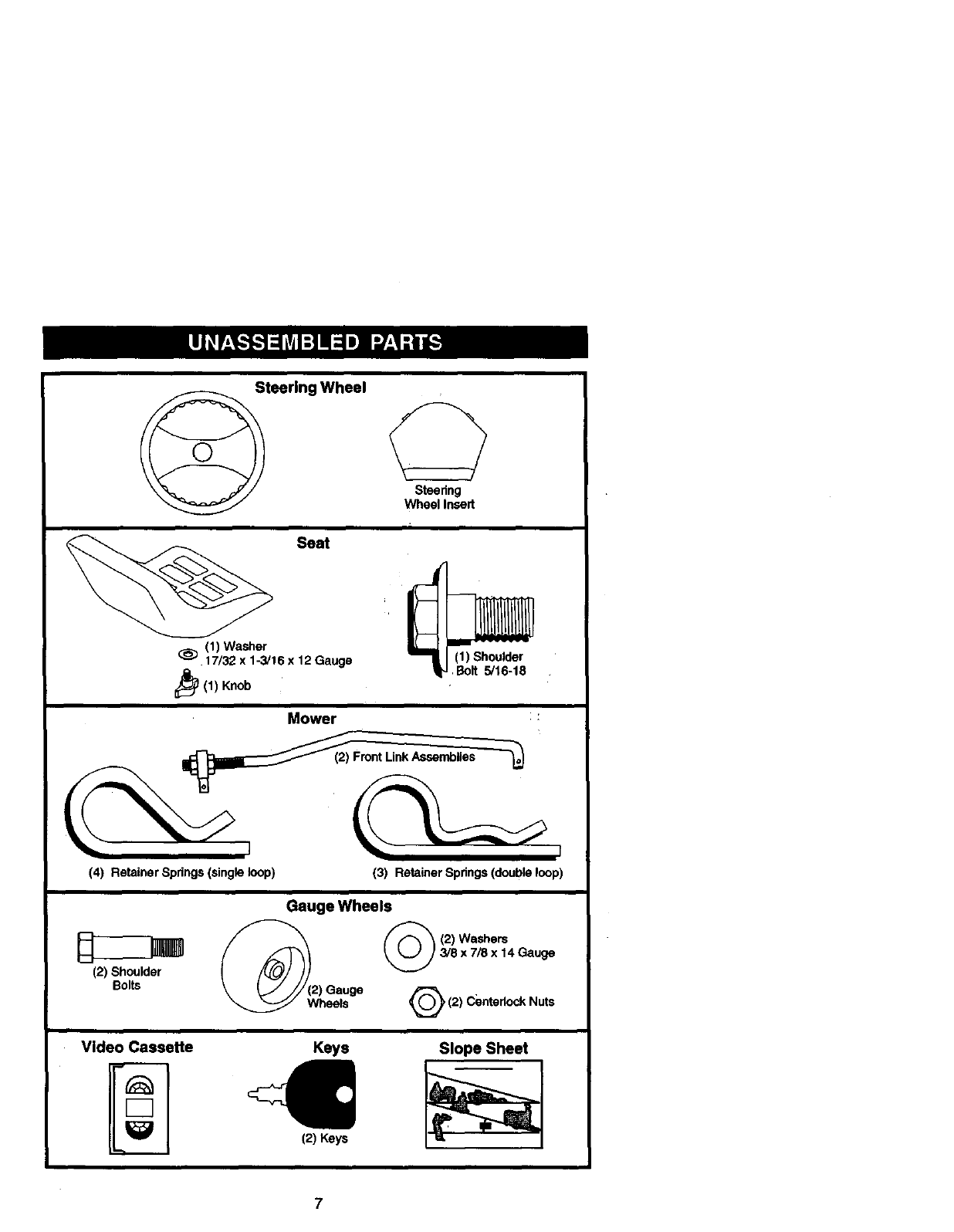
SteeringWheel 0
Steering
Wheel Insert
Seat
(1) Washer
17/32 x 1-3/16 x 12 Gauge (1) Shoulder
Bolt 5/16-18
(1) Knob
IMower :
(4) Retainer Spdngs (single loop) (3) Retainer Spdngs (double loop)
(2) Shoulder
Bolts
Gauge Wheels
_( (/_ (2) Washers
_j) 3/8 x 7/8 x 14 Gauge
Video Cassette Keys
(2) Keys
Slope Sheet
7
Your new tractor has been assembled at the factory with exception of those parts left
unassembled for shipping purposes. To ensure safe and proper operation of your
tractor all parts and hardware you assemble must be tightened securely. Use the
correct tools as necessary to insure proper tightness.
TOOLS REQUIRED FOR ASSEMBLY
A socket wrench set will make assembly
easier. Standard wrench sizes are listed.
(1) 9/16" wrench (1) Pliers
(1) 1/2=wrench (1) Utility knife
(1) 3/4" socket with
drive ratchet
(1) Tire pressure ga0ge
When right or left hand is mentioned in
this manual, it means when you are in the
operating position (seated behind the
steering wheel).
TO REMOVETRACTOR FROM
CARTON
UNPACK CARTON
1. Remove all accessible loose parts
and parts cartons from carton.
2. Cut, from top to bottom, along lines on
all four corners of carton, and lay
panels flat.
3. Remove mower and packing materi-
als.
4. Check for any additional loose pads
or cartons and remove.
BEFORE REMOVINGTRACTOR
FROM SKID
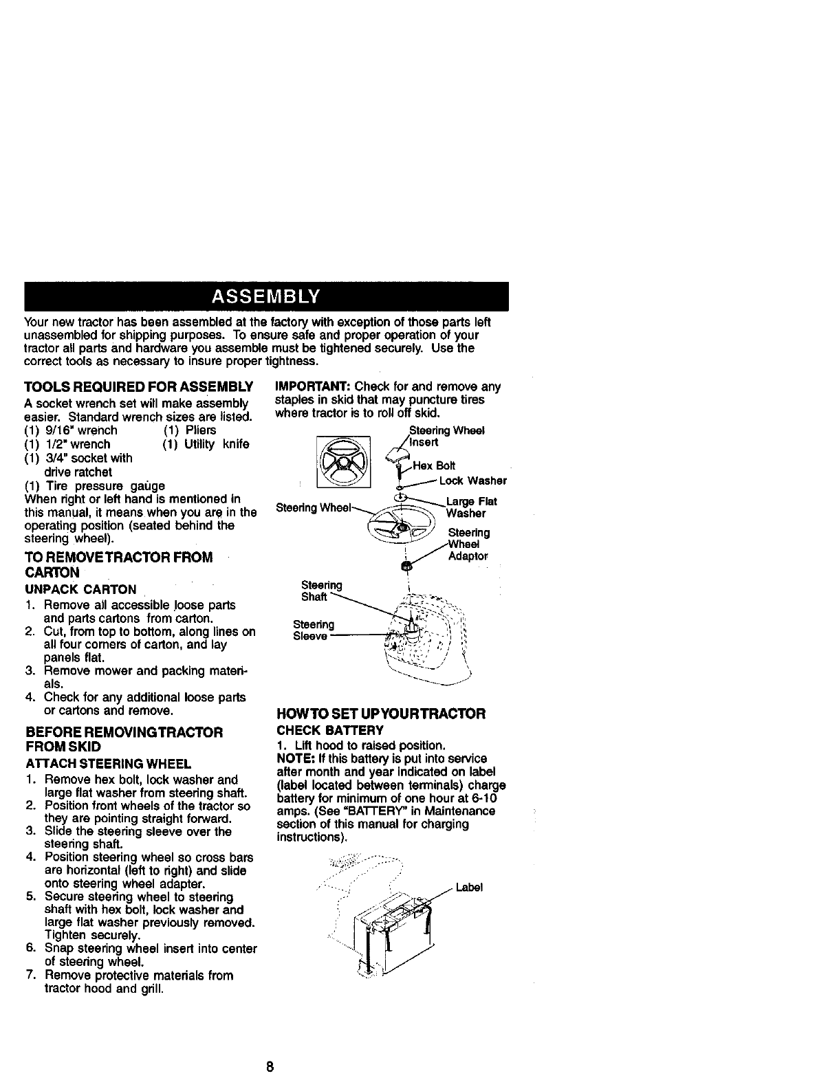
ATTACH STEERING WHEEL
1. Remove hex bolt, lock washer and
large flat washer from steering shaft.
2. Position front wheels of the tractor so
they are pointing straight forward.
3. Slide the steering sleeve over the
steering shaft.
4. Position steering wheel so cross bars
are horizontal (left to right) and slide
onto steering wheel adapter.
5. Secure steering wheel to steering
shaft with hex bolt, lock washer and
large flat washer previously removed.
Tighten securely.
6. Snap steering wheel insert into center
of steering wheel.
7. Remove protective materials from
tractor hood and grill.
IMPORTANT: Check for and remove any
staples in skid that may puncture tires
where tractor is to roll off skid.
SteeringWheel
"_Hex Bolt
Lock Washer
SteedngWhee,_La_ F'a'
\_-_:;'J Steering
_Wheel
i_ Adaptor
Steering
Stesnng ,'_"_1%, ',,",;'
Sleeve- ,'_t_: ";"-- 'I I,',
HOWTO SET UPYOURTRACTOR
CHECK BATTERY
1. Lifthoodto raisedposition.
NOTE: If thisbatteryis putintoservice
after monthand year indicatedon label
(label located between terminals)charge
batteryfor minimumof one hourat 6-10
amps.(See "BA'n'ERY"inMaintenance
sectionof thismanualfor charging
instructions).
•......,; _Label
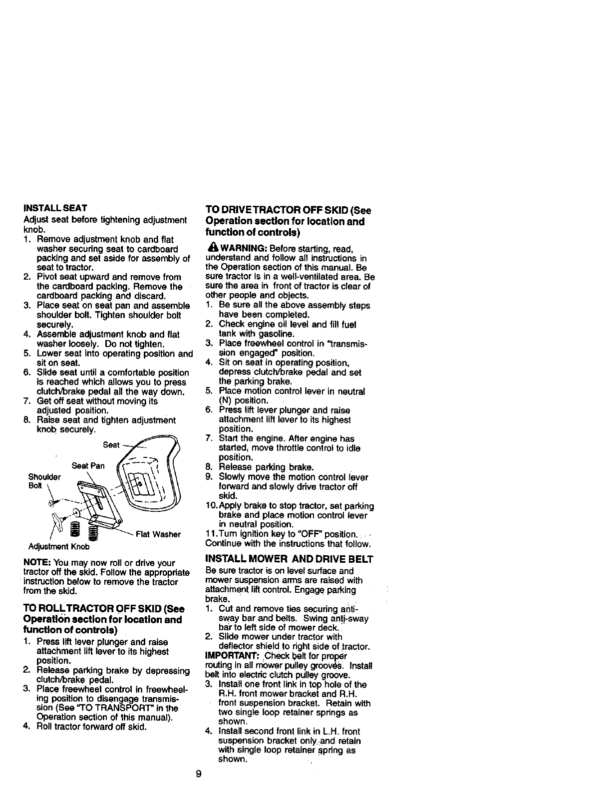
INSTALLSEAT
Adjustseatbeforetighteningadjustment
knob.
1. Removeadjustmentknobandflat
washersecuringseattocardboard
packingandsetasideforassemblyof
seattotractor.
2. Pivotseatupwardandremovefrom
thecardboardpacking.Removethe
cardboardpackinganddiscard.
3. Placeseatonseatpanandassemble
shoulderbolt.Tightenshoulderboll
securely.
4. Assembleadjustmentknobandflat
washerloosely.Donottighten.
5. Lowerseatintooperatingpositionand
sitonseat.
6. Slideseatuntilacomfortableposition
isreachedwhichallowsyoutopress
clutch/brakepedalallthewaydown.
7. Getoffseatwithoutmovingits
adjustedposition.
8. Raiseseatandtightenadjustment
knobsecurely.
Seat_
Shoulder SeatPa\ n _._, /
AdjustmentKnob
NOTE: You may now roll or drive your
tractor off the skid. Follow the appropdate
instruction below to remove the tractor
from the skid.
TO ROLLTRACTOR OFF SKID (See
Operatk)n section for location and
function of controls)
1. Press lift lever plunger and raise
attachment liftlever to its highest
position.
2. Release parking brake by depressing
clutch/brake pedal.
3. Place freewheel control in freewheel-
ing position to disengage transmis-
sion (See "TO TRANSPORT" in the
Operation section of this manual),
4. Roll tractor forward off skid.
TO DRIVETRACTOR OFF SKID (See
Operation section for location and
function of controls)
WARNING: Before starting, read,
understand and follow all instructions in
the Operation section of this manual. Be
sure tractor is in a well-ventilated area. Be
sure the area in front of tractor is clear of
other people and objects.
1, Be sure all the above assembly steps
have been completed.
2. Check engine oil level and fill fuel
tank with gasoline.
3. Place freewheel control in "transmis-
sion engaged" position.
4. Sit on seat in operating position,
depress clutch/brake pedal and set
the parking brake.
5. Place motion control lever in neutral
(N) position.
6. Press lift lever plunger and raise
attachment lift lever to its highest
position.
7, Start the engine. After engine has
started, move throttle control to idle
position.
8. Release parking brake.
9. Slowly move the motion control lever
forward and slowly drive tractor off
skid.
10.Apply brake to stop tractor, set parking
brake and place motion control lever
in neutral position.
11.Tum ignition key to =OFF" position,:
Continue with the instructions that follow,
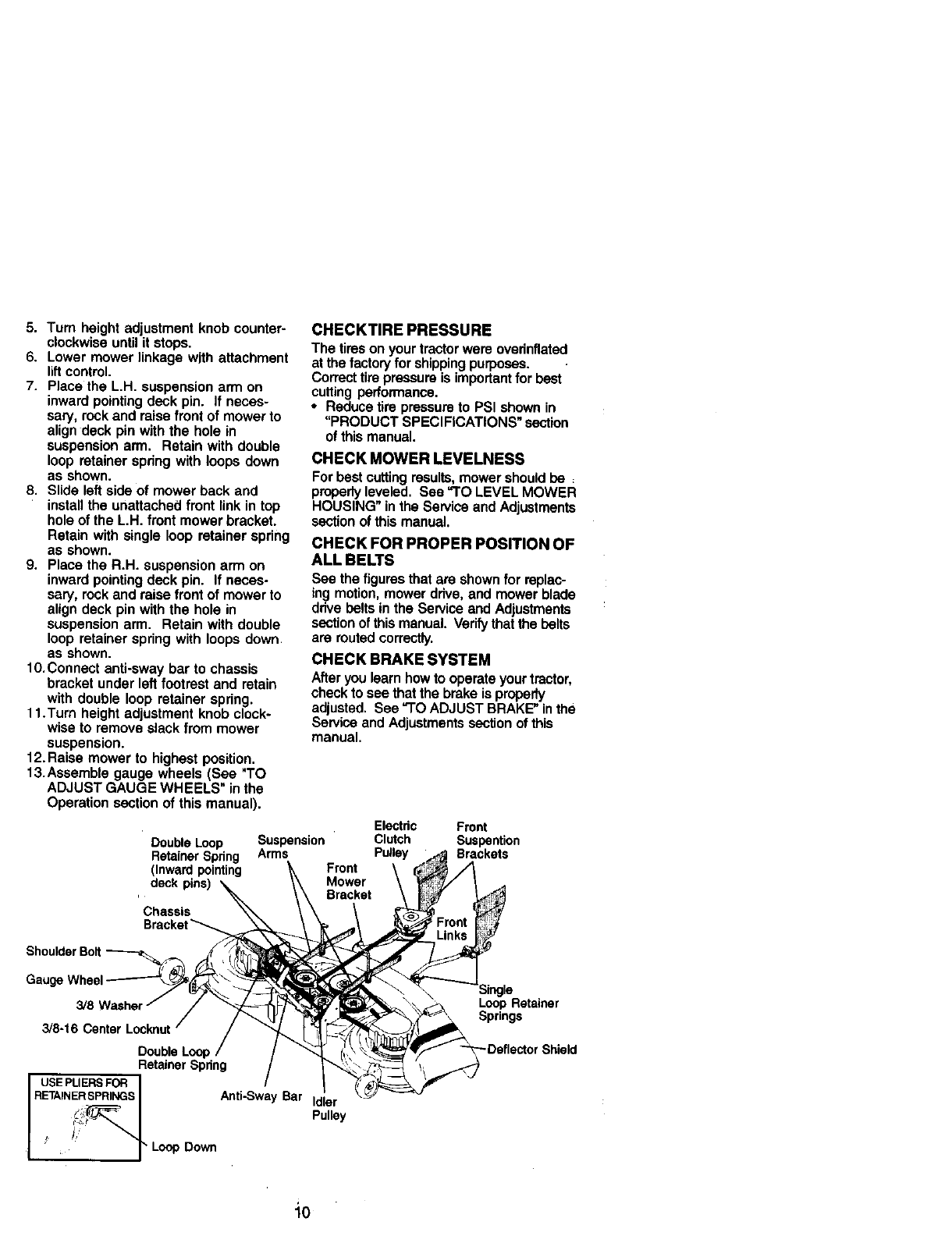
INSTALL MOWER AND DRIVE BELT
Be sure tractor is on level surface and
mower suspension arms are raised with
attachment lift control. Engage parking
brake.
1. Cut and remove ties securing anti-
sway bar and belts. Swing an!i,sway
bar to left side of mower deck.
2. Slide mower under tractor with
deflector shield to fight side of tractor.
IMPORTANT: Check belt for proper
routing in all mower pulley gmove`=_,install
belt into electric clutch pulley groove.
3. install one front link in top hole of the
R.H. front mower bracket and R.H.
front suspension bracket. Retain with
two single loop retainer springs as
shown.
4. install second front link in LH. front
suspension bracket only and retain
with single loop retainer _;pdng as
shown.
5. Tum height adjustment knob counter-
clockwise until it stops,
6. Lower mower linkage with attachment
liftcontrol.
7. Place the L.PL suspension arm on
inward pointing deck pin. If neces-
sary, reck and raise front of mower to
align deck pin with the hole in
suspension arm, Retain with double
loop retainer spring with loops down
as shown.
8. Slide left side of mower back and
install the unattached front link in top
hole of the L.H. front mower bracket,
Retain with single loop retainer spring
as shown.
9, Place the R.H. suspension arm on
inward pointing deck pin. if neces-
sary, rock and raise front of mower to
align deck pin with the hole in
suspension arm. Retain with double
loop retainer spring with loops down
as shown.
10.Connect anti-sway bar to chassis
bracket under left footrest and retain
with double loop retainer spring.
11.Turn height adjustment knob clock-
wise to remove slack from mower
suspension.
12. Raise mower to highest position.
13.Assemble gauge wheels (See *TO
ADJUST GAUGE WHEELS" in the
Operation section of this manual).
Double Loop
Retainer Spring
(Inward pointing
deck pins)
Chassis
Bracket_
Shoulder Bolt
GaugeWheel
3/8-1_
Double Loo_
Retainer Spring
USEPLIERSFOR I
RETAINERSPRINGSS_NGSI Anti-Sway Bar
_ /_ _ Loop Down
/
CHECKTIRE PRESSURE
The tires on your tractor were ovednflated
at the factory for shipping purposes.
Correct tire pressure is importantfor best
cutting performance.
• Reduce tire pressure to PSI shown in
"PRODUCT SPECIFICATIONS" section
of this manual.
CHECK MOWER LEVELNESS
For best cutting results, mower should be
propedy leveled. See "TO LEVEL MOWER
HOUSING" in the Service and Adjustments
section of this manual.
CHECK FOR PROPER POSITION OF
ALL BELTS
See the fk:jul"esthat are shown for replec-
ing motion, mower drive, and mower blade
drive belts in the Service and Adjustments
sectionof this manual. Verify that the belts
are routed correctly.
CHECK BRAKE SYSTEM
After you learn how to operate your tractor,
check to see that the brake is properly
adjusted. See "TO ADJUST BRAKE" in the
Service and Adjustments section of this
manual.
Electric Front
Suspension Clutch Suspention
Arms Pulley Brackets
Front
Mower
Bracket
Loop Retainer
Springs
Pulley
"10
t/CHECKLIST
Beforeyou operate and enjoy your hew
tractor,we wishto assurethat you receive
the best performanceand satisfaction
from thisQualityProduct.
Please reviewthe following checklist:
./'All assemblyinstructionshave been
completed.
,/'No remaininglooseparts incarton.
,/Battery is properlyprepared and
charged. (Minimum1 hourat 6 amps).
v"Seat is adjustedcomfortablyand
tightenedsecurely.
.,fAll tiresare propedyinflated. (For
shippingpurposes,the tireswere
ovednflatedat the factory).
v'Be sure mowerdeck is properlyleveled
side-to-side/front-to-rearfor best cutting
results. (Tires mustbe propedyinflated
for leveling).
v'Check mowerandddve belts. Be sure
they are routedpropedyaroundpulleys
and insideall belt keepers.
.,/Check widng. See that all connections
are stillsecure and wiresare propedy
clamped.
v"Beforedrivingtractor,be surefree-
wheel controlis in drive position.
While learninghowto use yourtractor,
pay extra attentionto the following
importantitems:
V" Engineoilis at properlevel.
V"Fueltank is filled withfresh, Clean,
regular unleaded gasoline.
v"Becomefamiliar with all controls- their
locationand function. Operate them
beforeyoustart the engine.
v'Be surebrake systemis insafe
operatingcondition.
-,/It is importantto purgethe transmission
beforeoperatingyourtractorfor the first
time. Followproperstartingand
transmissionpurginginstructions(See
"TO START ENGINE"and "PURGE
TRANSMISSION" in the Operation
sectionof this manual).
11
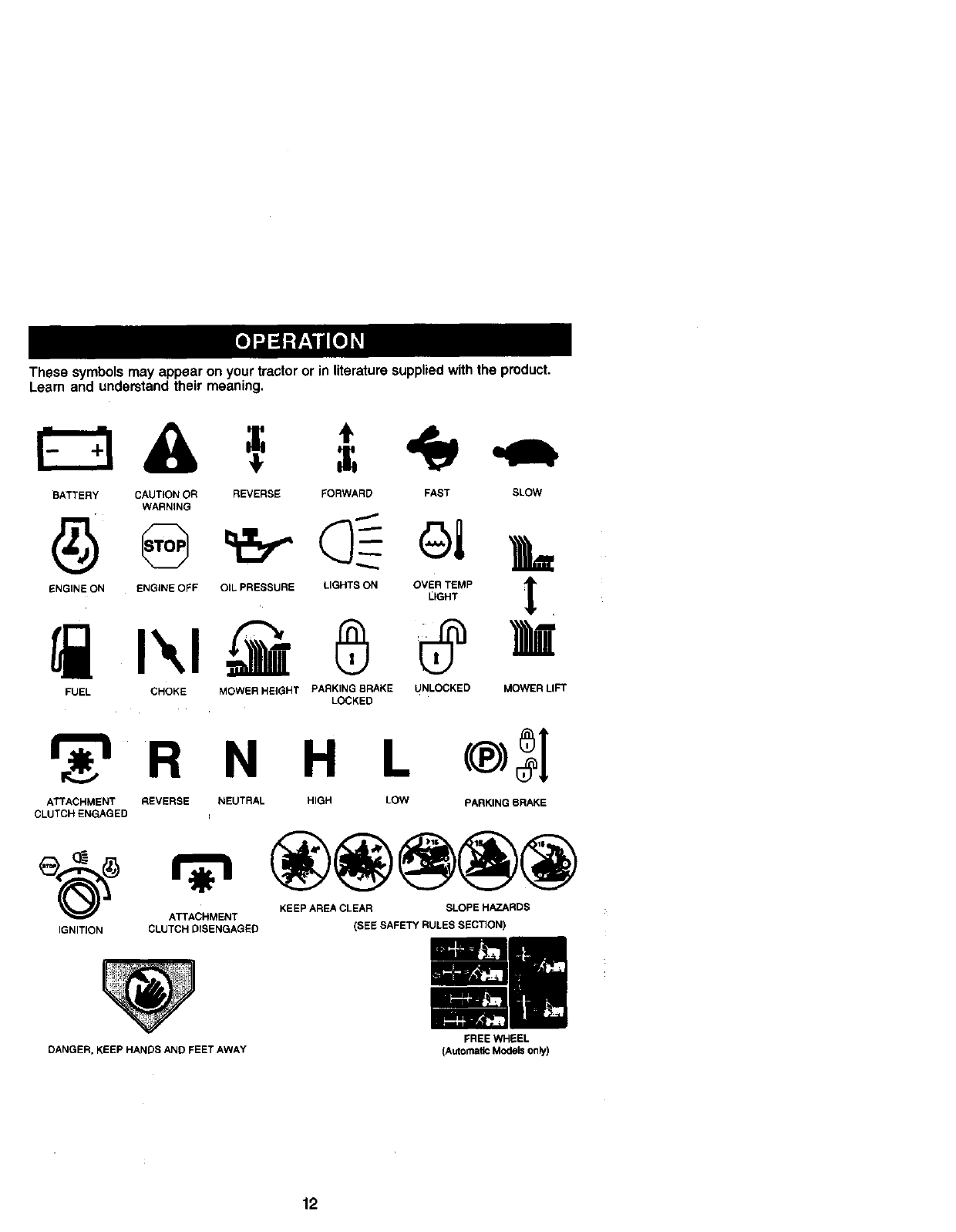
Thesesymbolsmayappearonyourtractororinliteraturesuppliedwiththeproduct.
Learnandunderstandtheirmeaning,
BATTERY CAUTION OR
WARNING
REVERSE FORWARD FAST SLOW
A
ENGINE ON ENGINE OFF OIL PRESSURE LIGHTS ON OVER TEMP 3r
LIGHT
FUEL CHOKE MOWER HEIGHT PARKING BRAKE UNLOCKED MOWER LIFT
LOCKED
R N H L
ATTACHMENT REVERSE NEUTRAL HIGH LOW PARKING BRAKE
CLUTCH ENGAGED =
KEEP AREA CLEAR SLOPE HAZARDS
ATTACHMENT
IGNITION CLUTCH DISENGAGED (SEE SAFETY RULES SECTION)
DANGER, KEEP HANDS ANO FEET AWAY
12
FREE WHEEL
(Automatic Models only)
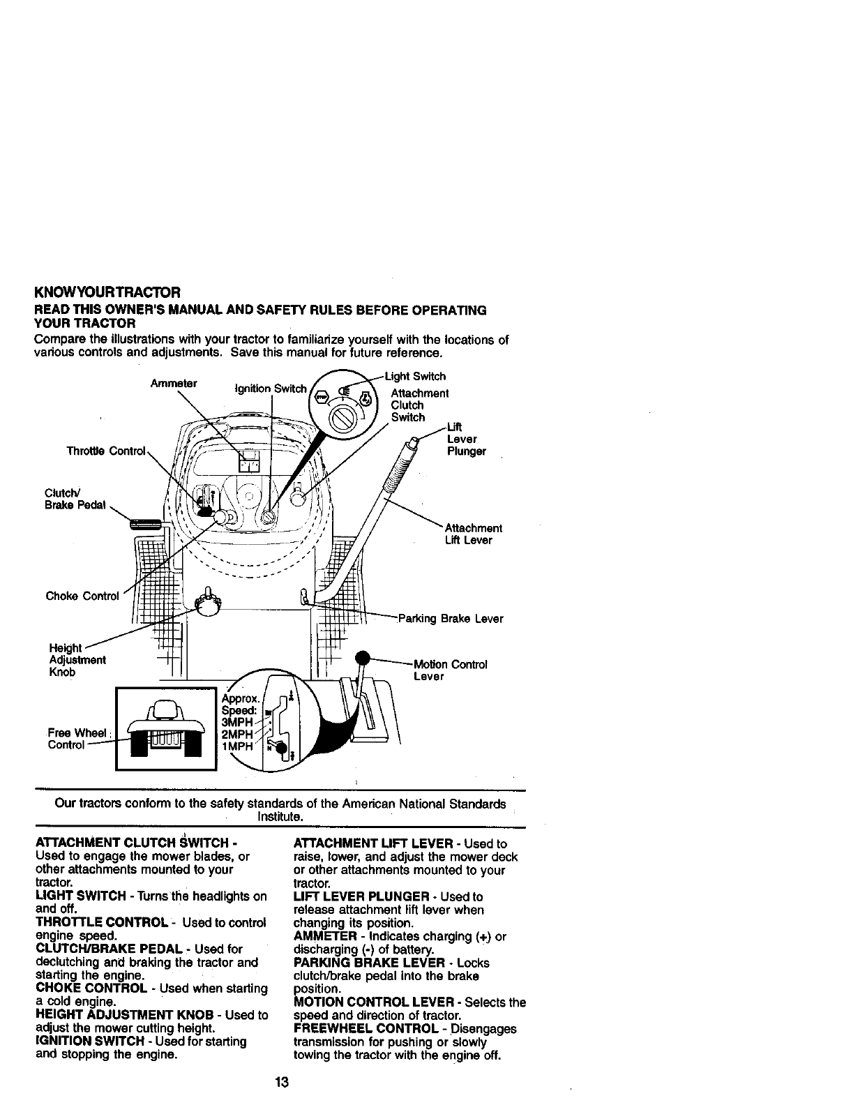
KNOWYOURTRACTOR
READ THIS OWNER'S MANUAL AND SAFETY RULES BEFORE OPERATING
YOUR TRACTOR
Comparethe illustrationswithyour tractorto familiarizeyourselfwiththe locationsof
vadouscontrolsand adjustments. Save thismanualfor future reference.
Throffie
Ammeter Ignition Switch Attachment
Clutch
Switch
Lever
Plunger
Clutch/
'Attachment
Lift Lever
Brake Lever
Adjustment
Knob Lever
Free Wheel
Our tractors conform to the safety standards of the American National Standards
Institute.
A'rrACHMENT CLUTCH SWITCH -
Used to engage the mower blades, or
other attachments mounted to your
tractor.
LIGHT SWITCH -Turns the headlights on
and off.
THRO'n'LE CONTROL -Used to control
engine speed.
CLUTCH/BRAKE PEDAL -Used for
declutching an_l braking the tractor and
starting the engine.
CHOKE CONTROL -Used when starting
a cold engine.
HEIGHT ADJUSTMENT KNOB -Used to
adjust the mower cutting height.
IGNITION SWITCH - Used for starting
and stopping the engine.
ATTACHMENT LIFT LEVER - Used to
raise, lower, and adjust the mower deck
or other attachments mounted to your
tractor.
LIFT LEVER PLUNGER - Used to
release attachment lift lever when
changing its position.
AMMETER - Indicates charging (+) or
discharging (-) of battery.
PARKING BRAKE LEVER -Locks
clutch/brake pedal into the brake
position.
MOTION CONTROL LEVER - Selects the
speed and direction of tractor.
FREEWHEEL CONTROL - Disengages
transmission for pushing or slowly
towing the tractor with the engine off.
13
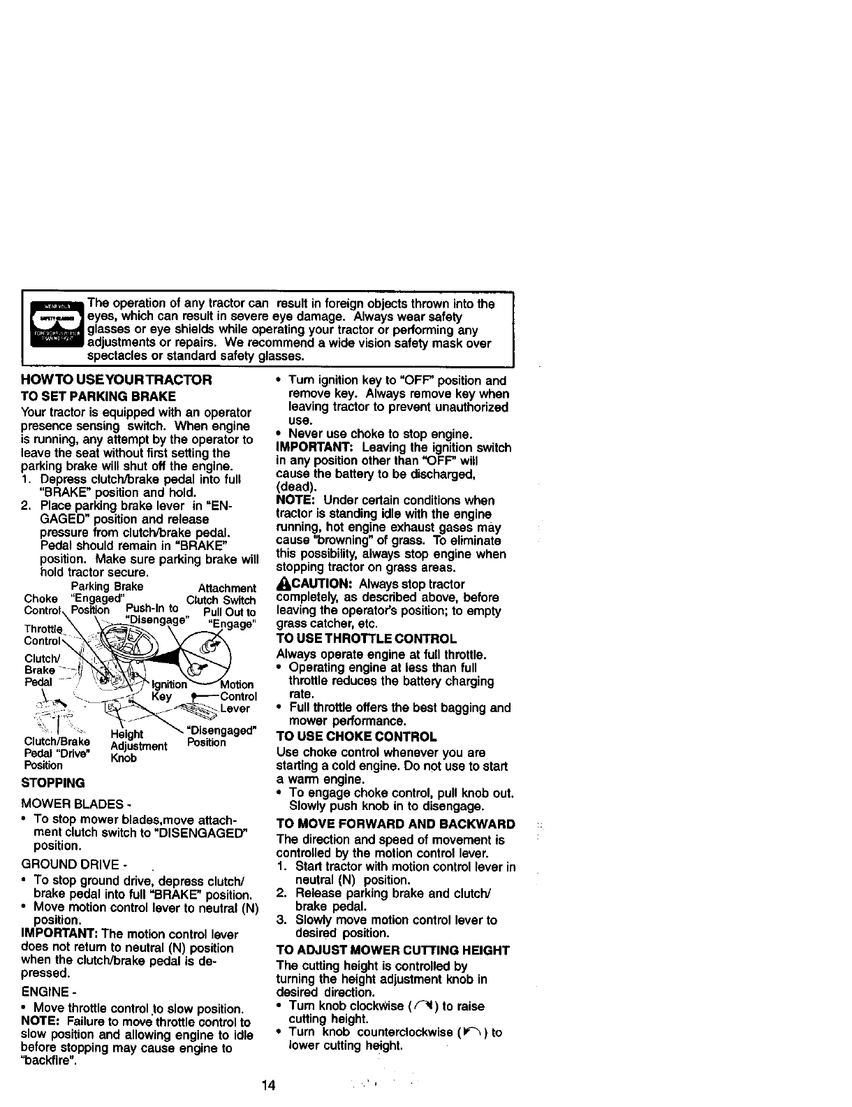
The operation of any tractor can result in foreign objects thrown into the
eyes, which can result in severe eye damage. Always wear safety
glasses or eye shields while operating your tractor or performing any
adjustments or rapairs. We recommend a wide vision safety mask over
spectacles or standard safety glasses.
HOWTO USEYOURTRACTOR
TO SET PARKING BRAKE
Your tractor is equipped with an operator
presence sensing switch. When engine
is running, any attempt by the operator to
leave the seat without first setting the
parking brake will shut off the engine.
1. Depress clutch/brake pedal into full
"BRAKE" position and hold.
2. Place parking brake lever in "EN-
GAGED" position and release
pressure from clutch/brake pedal.
Pedal should remain in =BRAKE"
position. Make sure parking brake will
hold tractor secure.
ParkingBrake Attachment
"En "
Choke gaged ClutchSwRch
Control-,Position Push-Into Pull Out to
\\ __ "Disengage" ,Enna,.,e.
Throttle____--_._ •.,....-._'='
C°ntr°l"__L _
clutc
Brake-_::_j _ _" "_
Pedal- _',lgffltion_Motion
_ _ -_ Key s-----Control
':_-I H_eioht-_ "Disengaged"
Clutch/Brake AdiH_trn_ fPosition
Pedal "Odve" _n;-b-'''-n"
Position
STOPPING
MOWER BLADES -
•To stop mower bledaa,move attach-
ment clutch switch to "DISENGAGED"
position.
GROUND DRIVE -
•To stop ground ddvel depress clutch/
brake pedal into full "BRAKE" position.
•Move motion control lever to neutral (N)
position.
IMPORTANT: The motion control lover
does not return to neutral (N) position
when the clutch/brake pedal is de-
pressed.
ENGINE -
•Move throttle control to slow position.
NOTE: Failure to move'throttle control to
slow position and allowing engine to idle
before stopping may cause engine to
"backfire".
•Turn ignition key to "OFF" position and
remove key. Always remove key when
leaving tractor to prevent unauthorized
use.
•Never use choke to stop engine.
IMPORTANT: Leaving the ignition switch
in any position other than "OFF" will
cause the battery to be discharged,
(dead).
NOTE: Under certain conditions when
tractor is standing idle with the engine
running, hot engine exhaust gases may
cause "browning" of grass. To eliminate
this possibility, always stop engine when
stopping tractor on grass areas.
_kCAUTION: Always stop tractor
completely, as described above, before
leaving the operator's position; to empty
grass catcher, etc.
TO USE THROTTLE CONTROL
Always operate engine at full throttle.
• Operating engine at less than full
throttle reduces the battery charging
rate.
•Full throttle offers the best bagging and
mower performance.
TO USE CHOKE CONTROL
Usa choke control whenever you are
starting a cold engine. Do not usa to start
a warm engine.
•To engage choke control, pull knob out.
Slowly push knob in to disengage.
TO MOVE FORWARD AND BACKWARD
The direction and speed of movement is
controlled by the motion control lever.
1. Start tractor with motion control lever in
neutral (N) position.
2. Release parking brake and clutch/
brake pedal.
3. Slowly move motion control lever to
desired position.
TO ADJUST MOWER CU'FFING HEIGHT
The cutting height is controlled by
turning the height adjustment knob in
desired direction.
•Turn knob clockwise ( F'I ) to raise
cutting height.
•Turn knob counterclockwise (1_)to
lower cutting height.
4 ,'
The cutting height range is approximately
1-1/2" to 4-1/2", The heights are mea-
sured from the ground to the blade tip
with the engine not running. These
heights are approximate and may vary
depending upon soil conditions, height of
grass and types of grass being mowed.
•The average lawn should be cut to
approximately 2-1/2 inches during the
cool season and to over 3 inches
during hot months. For healthier and
better looking lawns, mow often and
after moderate growth.
•For best cutting performance, grass
over 6 inches in height should be
mowed twice, Make the first cut
relatively high; the second to desired
height.
TO ADJUST GAUGE WHEELS
Gauge wheels are properly adjusted
when they are slightly off the ground
when mower is at the desired cutting
height in operating position. Gauge
wheels then keep the deck in proper
position to help prevent scalping in most
terrain conditions.
NOTE: Adjust gauge wheels with tractor
on a flat level surface.
!, Adjust mower to desired cutting height
(See 'I"O ADJUST MOWER CUTTING
HEIGHT" in the Operation section of
this manual).
2, With mower in desired height of cut
position, gauge wheels should be
assembled so they are slightly off the
ground. Install gauge wheel in
appropdate hole with shoulder bolt, 3/
8 washer, and 3/8-16 Iocknut and
tighten securely.
3. Repeat for opposite side installing
gauge wheel in same adjustment
hole.
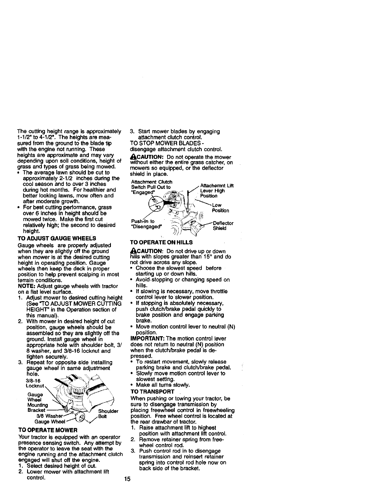
3/8-16
Locknut
Gauge ',
Wheel
Mounting
Gauge
TO OPERATE MOWER
Your tractor is equipped with an operator
presence sensing switch. Any attempt by
the operator to leave the seat with the
engine running and the attachment clutch
engaged will shut off the engine.
1. Select desired height of cut.
2. Lower mower with attachment lift
control.
3. Start mower blades by engaging
attachment clutch control.
TO STOP MOWER BLADES -
disengage attachment clutch control.
_kCAUTION: Do not operate the mower
without either the entire grass catcher, on
mowers so equipped, or the deflector
shield in place.
AttachmentClutch
P o AttachemntLift
Switch ullOut t i.
_En-a-ed" f._ - _ Lever High
U U_a._._ (_ _Position
_- _-_?_.___ .. Position
/ -_ _ LJ_ 7,'1_
Push-In to -_-_::[_'._._Deflector
Disengaged" _', '_0_ '_'- Shield
,
TO OPERATE ON HILLS
_ICAUTION: Do not ddve up or down
hills with slopes greater than 15° and do
not ddve across any slope.
• Choose the slowest speed before
starting up or down hills.
•Avoidstopping or changing speed on
hills.
•If slowing is necessary, move throttle
control lever to slower position.
•If stopping is absolutely necessary,
push clutch/brake pedal quickly to
brake position and engage parking
brake.
•Move motion control lever to neutral (N)
position.
IMPORTANT: The motion control lever
does not ratum to neutral (N) position
when the clutch/brake pedal is de-
pressed.
•To restart movement, slowly release
parking brake and clutch/brake pedal.
•Slowly move motion control lever to
slowest setting.
•Make all turns slowly.
TO TRANSPORT
When pushing or towing your tractor, be
sure to disengage transmission by
placing freewheel control in freewheeling
position. Free wheel control is located at
the rear drawbar of tractor.
1. Raise attachment lift to highest
position with attachment lift control.
2. Remove retainer spring from free-
wheel control rod.
3. Push control rod in to disengage
transmission and reinsed retainer
spdng into control rod hole now on
back side of the bracket.
15
• Donotpushortowtractoratmorethan
two(2)MPH.
• Toreengagetransmission,reverse
aboveprocedure.
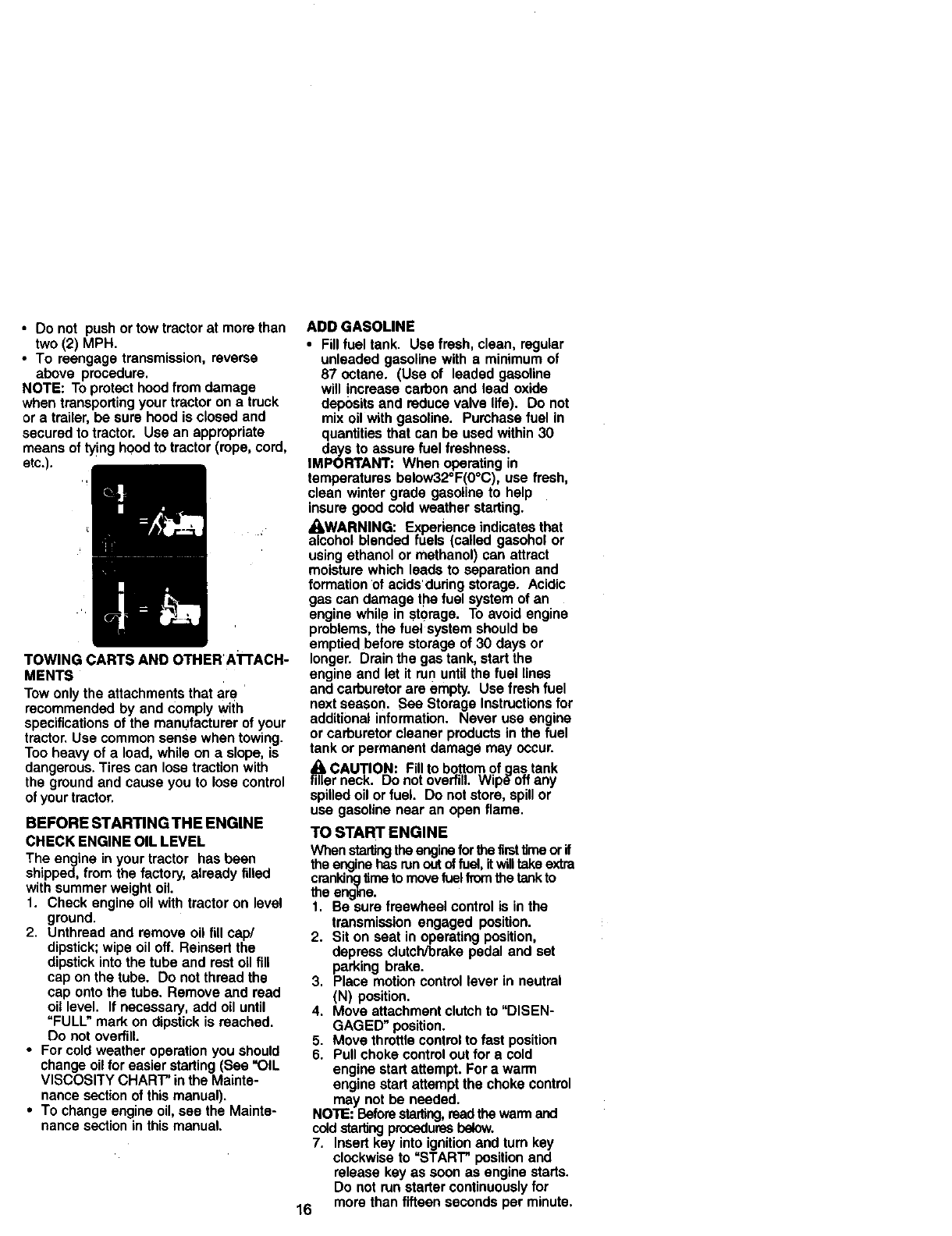
NOTE:Topmtocthoodfrom damage
whentransportingyour tractorona truck
or a trailer,be surehood is closedand
securedto tractor. Use an appropriate
means of tyinghoodto tractor(rope,cord,
etc.).
TOWING CARTS AND OTHERA'I-rACH-
MENTS
Tow only the attachments that are
recommended by and comply wiih
specifications of the manufacturer of your
tractor, Use common sense when towing.
Too heavy of a load, while on a slope, is
dangerous. Tires can lose traction with
the ground and cause you to lose control
of your tractor.
BEFORE STARTINGTHE ENGINE
CHECK ENGINE OIL LEVEL
The engine in your tractor has been
shipped, from the factory, already tilled
with summer weight oil.
1. Check engine oil with tractor on level
ground.
2. Unthread and remove oil fill cap/
dipstick; wipe oil off, Reinsert the
dipstick into the tube and rest oil fill
cap on the tube. Do not thread the
cap onto the tube. Remove and read
oil level. If necessary, add oil until
"FULL" mark on dipstick is reached.
Do not overfill.
•For cold weather operation you should
change oil for easier starting (See "OIL
VISCOSITY CHART" in the Mainte-
nance section of this manual).
•To change engine oil, see the Mainte-
nance section in this manual.
ADD GASOLINE
•Fillfuel tank. Use fresh, clean, regular
unleaded gasolinewith a minimumof
87 octane. (Use of leaded gasoline
will increasecarbonand lead oxide
depositsand reduce valve life). Do not
mix oil withgasoline. Pumhasefuel in
quantitiesthat can be usedwithin30
daysto assurefuelfreshness.
IMPORTANT: When operatingin
temperaturesbelow32°F(0°C), use fresh,
clean wintergrade gasolineto help
insuregoodcold weatherstarting.
_kWARNING: Experienceindicatesthat
alcoholblendedfuels (called gasonolor
usingethanolor methanol)can attract
moisturewhich leadsto separationand
formationof acidsdudngstorage. Acidic
gas can damagethe fuel systemof an
enginewhile in storage. Toavoid engine
problems,the fuel systemshouldbe
emptiedbefore storageof 30 days or
longer. Drainthe gastank, startthe
engineand let it run untilthe fuel lines
and carburetorare empty. Use fresh fuel
next season. See Storage Instructionsfor
additionalinformation. Never use engine
or carburetorcleaner productsinthe fuel
tank or permanentdamage may occur.
CAUTION: Fillto bottomofaas tank
filter neck. Do notoverfill.Wip_'offany
spilledoil orfuel. Do notstore,spillor
use gasolinenear an open flame.
TO START ENGINE
Whenstartingtheenginefor thefirsttimeorif
theenginehas runoutoffus_,itwilltakeextra
crankincjtimeto movefuelfromthetankto
the engine.
1. Be sure freewheel controlis inthe
transmissionengaged position.
2. Sit on seat in operatingposition,
depressclutch/brakepedal and set
parkingbrake.
3. Place motioncontrollever in neutral
(N) position.
4. Move attachmentclutchto "DISEN-
GAGED" position.
5. Movethrottlecontrolto fast position
6. Pull chokecontroloutfor a cold
enginestartattempt.For a warm
enginestartattemptthe chokecontrol
may notbe needed.
NOTE:Beforestarting,readthewarmand
coldstaringproceduresbelow.
7. Insertkey intoignitionand turn key
clockwiseto "START" positionand
releasekey as soon as enginestarts.
Do not run startercontinuouslyfor
16 morethanfifteensecondsper minute,
if the engine does not start after
several attempts, push choke control
in, wait a few minutes and try again. If
engine still does not start, pull the
choke control out and retry.
WARM WEATHER STARTING (50° F and
above)
8. When engine starts, slowly push
choke control in until the engine
begins to run smoothly. If the engine
starts to run roughly, pull the choke
control out slightly for afew seconds
and then continue to push the control
in slowly.
•The attachmentsand ground drivecan
now be used. If the enginedoes not accept
the load, restartthe engine and allowit to
warm up for one minute usingthe choke
as describedabove.
COLD WEATHER STARTING (50° F and
below)
8. When engine starts, slowly push
choke control in until the engine
begins to run smoothly. Continue to
push the choke control in small steps
allowing the engine to accept small
changes in speed and load, until the
choke control is fully in. If the engine
starts to run roughly, pull the choke
control out slightly for afew seconds
and then continue to push the control
in slowly. This may require an engine
warm-up period from several seconds
to several minutes, depending on the
temperature.
AUTOMATIC TRANSMISSION WARM UP
Before driving the unit in cold weather,
the transmission should be warmed up as
follows:
1. Be sure the tractor is on level ground.
2. Place the motion control lever in
neutral. Release the parking brake
and let the clutch/brake slowly return
to operating position.
3. Allow one minute for transmission to
warm up. This can be done during the
engine warm up period.
• The attachments can be used during
the en_line warm-up period after the
transmission has been warmed up and
may require the choke control be
putl=e,dout slightly.
,NOTE, If at a high altitude (above 3000
feet) or in cold temperatures (below 32 F)
the carburetor fuel mixture may need to
be adjusted for best engine performance.
See =TO ADJUST CARBURETOR" in the
Service and Adjustments section of this
manual.
PURGETRANSMISSION
_,CAUTION: Never engage or dlsengage
freewheel lever while the engine is running.
To ensure proper operation and perfor-
manGe, it is recommended that the trans-
mission be purged before operating tractor
for the firsttime. This procedure will remove
any trapped air inside the transmission
which may have developed during ship-
ping of your tractor.
IMPORTANT: Should your transmission
require removal for service or replacement,
it should be purged after reinstaitation
before operating the tractor.
f. Place tractor safely on level surface
with engine off and parking brake set.
2. Disengage transmission by placing
freewheel control in freewheeling
position (See =TO TRANSPORT" in this
section of manual).
3. Sitting in the tractor seat, start engine.
After the engine is running, move
throttle control to slow position. With
motion control lever in neutral (N)
position, slowly disengage clutch/
brake pedal.
4. Move motion control lever to full
forward position and hold for five (5)
seconds. Move lever to full reverse
position and hold for five (5) seconds.
Repeat this procedure three (3) times.
NOTE: During this procedure there will be
no movement of drive wheels. The air is
being removed from hydraulic drive system.
5. Move motion control lever to neutral
(N) position. Shut- off engine and set
parking brake.
6. Engage transmission by placing _,
freewheel control in driving position
(See =TO TRANSPORT" in this section
of manual).
7. Sitting in the tractor seat, start engine.
After the engine is running, move
throttle control to half (1/2) speed. With
motion control lever in neutral (N)
position, slowly disengage clutch/
brake pedal.
8. Slowly move motion control lever
forward, after the tractor moves
approximately five (5) feet, slowly
move motion control lever to reverse
position. After the tractor moves
approximately five (5) feet return the
motion control lever to the neutral (N)
position. Repeat this procedure with
the motion control lever three (3) times.
Your tractor is now purged and now ready
for normal operation.
17
MOWINGTIPS
•Tire chains cannot be used when the
mower housing is attached to tractor.
•Mower should be propedy leveled for
best mowing performance. See "TO
LEVEL MOWER HOUSING" in the
Service and Adjustments section of this
manual.
•The left hand side of mower should be
used for trimming.
•Drive so that clippings are discharged
onto the area that has been cut. Have
the cut area to the right of the tractor.
This will result in a more even distribu-
tion of clippings and more uniform
cutting.
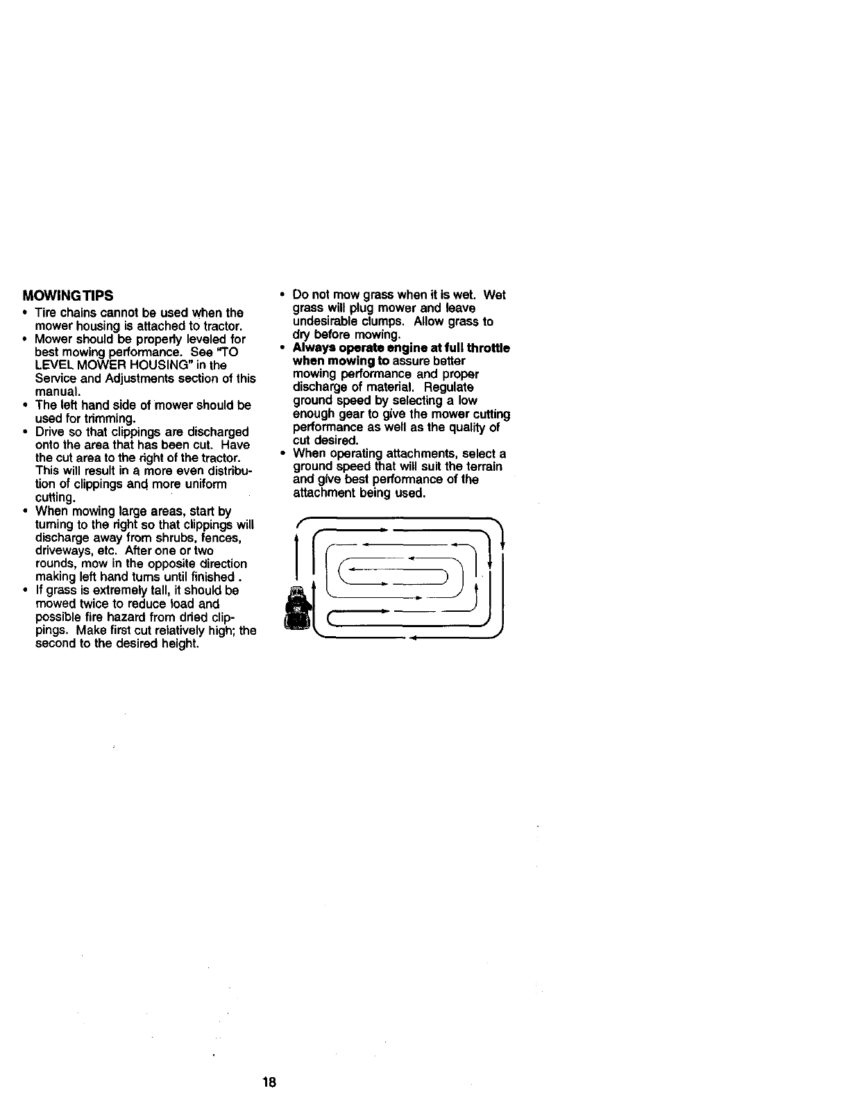
•When mowing large areas, start by
turning to the dght so that clippings will
discharge away from shrubs, fences,
driveways, etc. After one or two
rounds, mow in the opposite direction
making left hand turns until finished.
•If grass is extremely tall, it should be
mowed twice to reduce load and
possible fire hazard from dried clip-
pings. Make first cut relatively high; the
second to the desired height.
•Do notmow grasswhenit is wet. Wet
grass will plugmowerand leave
undesirableclumps. Allowgrassto
dry before mowing.
• Always operate engine at full throttle
when mowingto assurebetter
mowingperformanceand proper
dischargeof material. Regulate
groundspeed by selectinga low
enough gearto givethe mowercutting
performanceas well as the qualityof
cut desired.
•When operatingattachments,selecta
groundspeed that willsuitthe terrain
and give best performanceof the
attachment beingused.
f
l
JJ
18
GENERAL RECOMMENDATIONS
The warranty on this tractor does net cover
items that have been subjected to operator
abuse or negligence. To receive full value
from the warranty, operator must maintain
tractor as instructed in this manual.
Some adjustments will need to be made
periodically to properly maintain your
tractor.
All adjustments in the Service and
Adjustments section of this manual should
be checked at least once each season.
•Once a year you should replace the
spark plug, clean or replace air filter, and
check blades and belts for wear. A new
spark plug and clean air filter assure
proper air-fuel mixture and help your
engine run better and last longer.
BEFORE EACH USE
1. Check engine oil level.
2. Check brake operation.
3. Check tire pressure.
4. Check operator presence and
interlock systems for proper operation.
5. Check for loose fasteners.
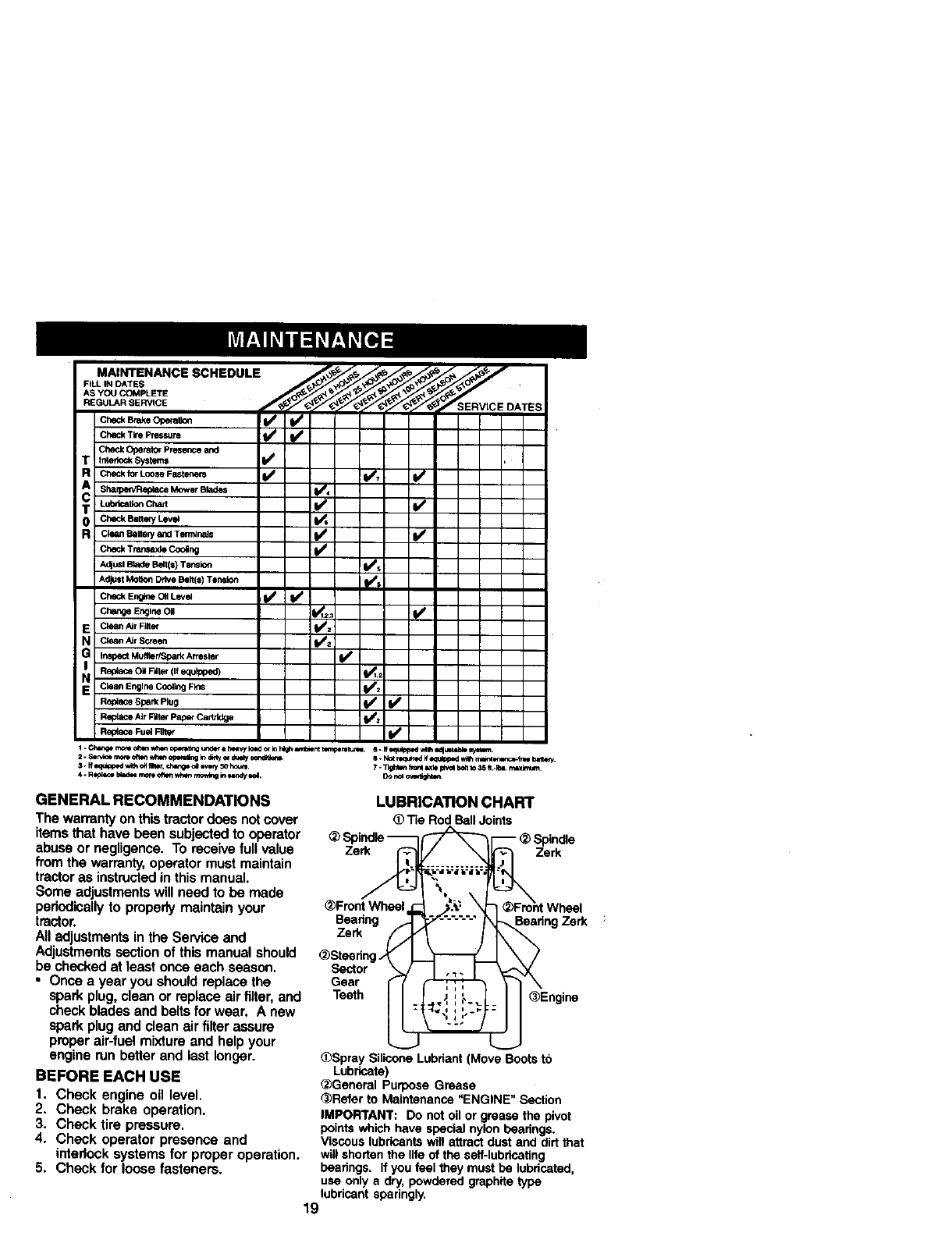
LUBRICATION CHART
Tie Rod BallJoints
Zerk Zerk
_)Front Wheel
Bearing
Zerk
_)Steedn
Sector
Gear
Teeth
Zerk
(_Spray Silicone Lubriant (Move Boots to
Lubricate)
®General Purpose Grease
_)Refer to Maintenance "ENGINE" Section
IMPORTANT: Do not oil or grease the pivot
points which have special nylon beadngs.
Viscous lubricants will attract dust and dirt that
will shorten the life of the seit-lubdcating
peadngs. If you feel they must be lubriceted,
use only a dry, powdered graphite type
lubricant sparingly.
19
TRACTOR
Always observe safety rules when
performing any maintenance.
BRAKE OPERATION
If tractor requires more than six (6) fast
stopping distance at high speed in
highest gear, then brake must be ad-
justed. (See "TO ADJUST BRAKE" in the
Service and Adjustments section of this
manual).
TIRES
• Maintain proper air pressure in all tires
(See =PRODUCT SPECIFICATIONS"
section of this manual).
•Keep tires free of gasoline, oil, or insect
control chemicals which can harm
rubber.
•Avoid stumps, stones, deep ruts, sharp
objects and other hazards that may
cause tire damage.
NOTE: To seal tire punctures and prevent
flat tires due to slow leaks, tire sealant
may be pumhased from your local parts
dealer. Tire sealant also prevents tire dry
rot and corrosion.
OPERATOR PRESENCE SYSTEM
Be sure operator presence and interlock
systems are working propedy. If your
tractor does not function as dsscdbed,
repair the problem immediately.
•The engine should not start unless the
clutch/brake pedal is fully depressed
and attachment clutch control is in the
disengaged position.
•When the engine is running, any
attempt by the operator to leave the
seat without first setting the parking
brake should shut off the engine.
•When the engine is running and the
attachment clutch is engaged, any
attempt by the operator to leave the
seat should shut off the engine.
• The attachment clutch should never
operate unless the operator is in the
seat.
BLADE CARE
For best _'esults mower blades must be
kept sharp. Replace bent or damaged
blades.
BLADE REMOVAL
1. Raise mower to highest position to
allow access to blades.
2. Remove hex bolt, lock washer and flat
washer securing blade.
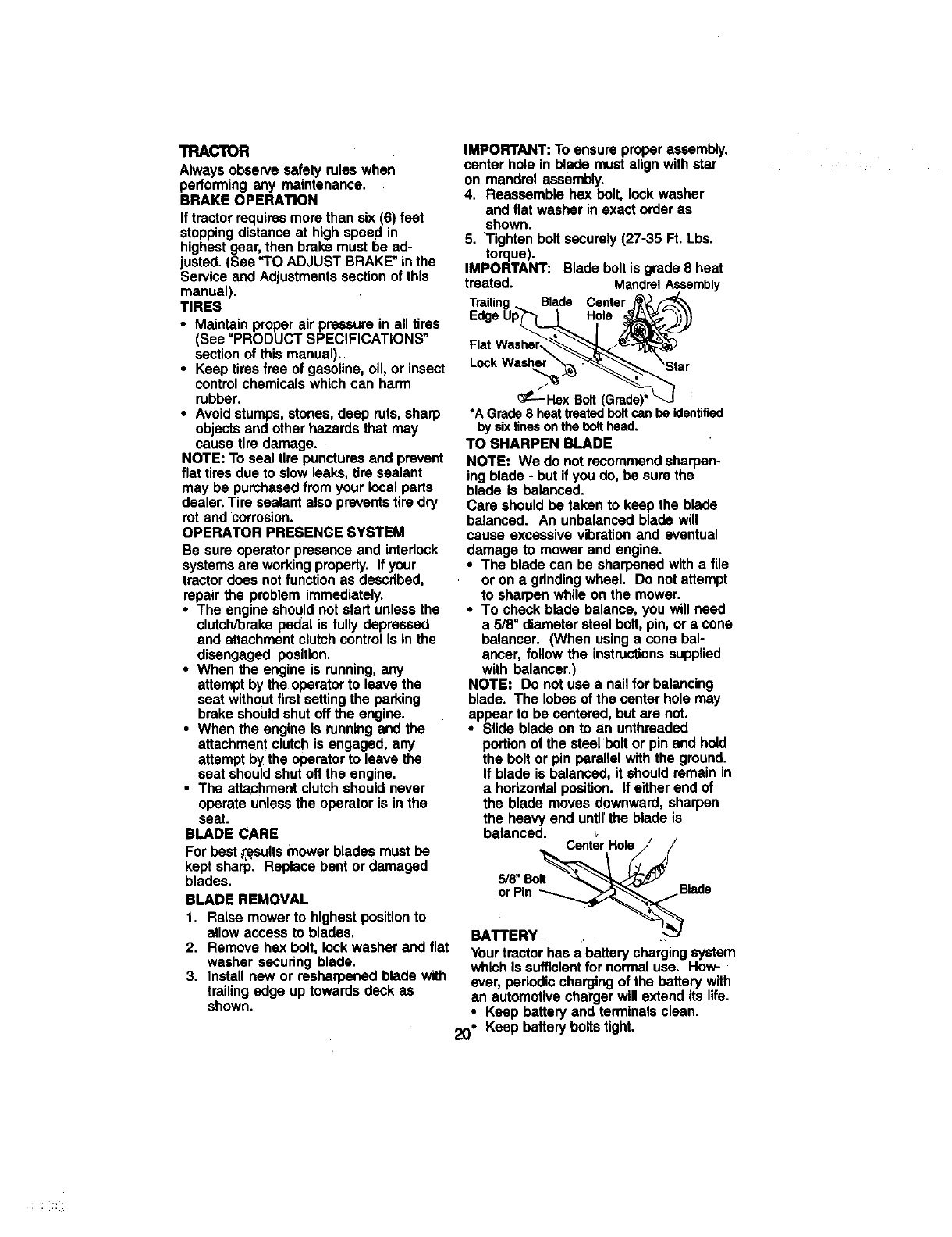
3. Install new or resharpened blade with
trailing edge up towards deck as
shown.
IMPORTANT: Toensure properassembly,
centerhole in blade must align withstar
on mandrelassembly.
4. Reassemble hex bolt,lockwasher
and flat washer inexact orderas
shown.
5. 'Tightenboltsecurely(27-35 Ft. Lbs.
torque).
IMPORTANT: Bladeboltis grade 8 heat
treated. MandrelAssembly
Blade Center
EdgeUp Hole
Lock Washer
f
_---Hex Bolt (Grade)
*A Grade8 heattreated boltcan be identified
by sixlinesonthe bolthead.
TO SHARPEN BLADE
NOTE: We do not recommend sharpen-
ing blade -but ifyou do, be sure the
blade is balanced.
Care should be taken to keep the blade
balanced. An unbalanced blade will
cause excessive vibration and eventual
damage to mower and engine.
•The blade can be sharpened with a file
or on a gdnding wheel. Do not attempt
to sharpen while on the mower.
•To check blade balance, you will need
a 5/8" diameter steel bolt, pin, or a cone
balancer. (When using a cone bal-
ancer, follow the instructions supplied
with balancer.)
NOTE: Do not use a nail for balancing
blade. The lobes of the center hole may
appear to be centered, but are not.
•Slide blade on to an unthreaded
portion of the steel bolt or pin and hold
the bolt or pin parallel with the ground.
If blade is balanced, it should remain in
a hodzontal position. If either end of
the blade moves downward, sharpen
the heaw end until the blade is
v
balanced. Center Hole
5,'8"Bolt Blade
BATTERY
Yourtractorhas a batterychargingsystem
whichis sufficientfor normaluse. How-
ever, periodic chargingof the batterywith
an automotivechargerwill extendits life.
•Keep batteryand terminalsclean.
20" Keep batteryboltstight.
• Keep small vent holes open.
• Recharge at 6-10 amperes forI hour,
NOTE; The originalequipment batteryon
yourtractorismaintenance free,Do not
attempt to open or remove caps or covers.
Adding or checking level of electrolyte is
not necessary.
TO CLEAN BATTERY AND TERMINALS
Corrosion and dirt on the battery and
terminals can cause the battery to "leak"
power.
1. Remove terminal guard.
2. Disconnect BLACK battery cable first
then RED battery cable and remove
battery from tractor.
3. Rinse the battery with plain water and
dry.
4. Clean terminals and battery cable
ends with wire brush until bright.
5. Coat terminals with grease or petro-
leum jelly.
6. Reinstall battery (See =REPLACING
BATTERY" in the SERVICE AND
ADJUSTMENTS section of this
manual).
V-BELTS
Check V-belts for deterioration and wear
after 100 hours of operation and replace
if necessary. The belts are not adjustable.
Replace belts ifthey begin to slip from
wear.
TRANSAXLE COOLING
The transmission fan and cooling fins
should be kept clean to assure proper
cooling.
Do not attempt to clean fan or transmis-
sion while engine is running or while the
transmission is hot. To prevent possible
damage to seals, do not use high
pressure water or steam to clean
transaxle.
•Inspect cooling fan to be sure fan
blades are intact and clean.
•Inspect cooling fins for dirt, grass
clippings and other materials. To
prevent damage to seals, do not use
compressed air or high pressure
sprayer to clean cooling fins.
TRANSAXLE PUMP FLUID
The transaxle was sealed at the factory
and fluid maintenance is not required for
the life of the transaxle, Should the
transexle ever leak or require servicing,
contact your nearest authodzed service
center/department.
ENGINE
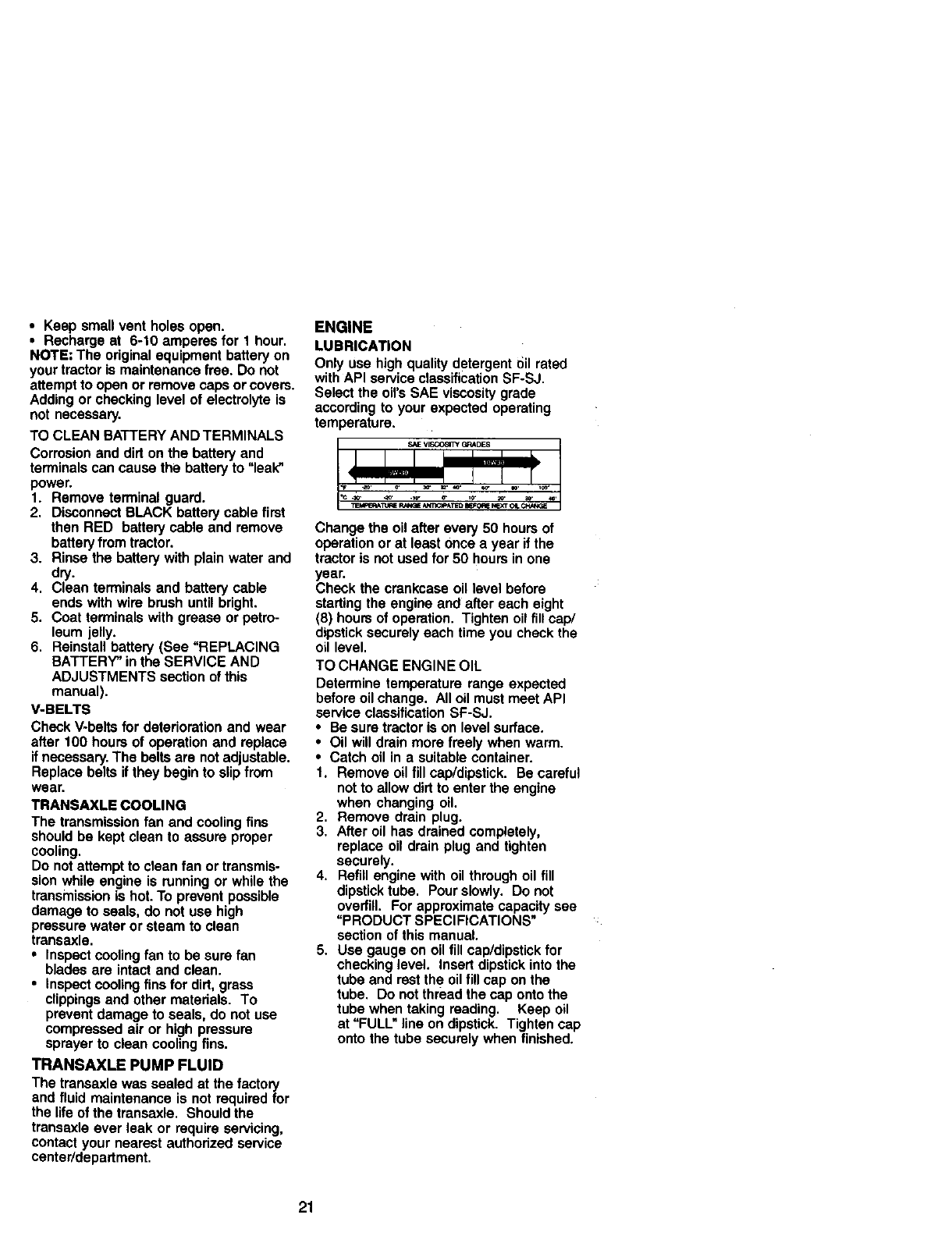
LUBRICATION
Only use high quality detergent oil rated
with API service classification SF-SJ.
Select the oil's SAE viscosity grade
according to your expected operating
temperature.
Change the oil after every 50 hours of
operation or at least once a year if the
tractor is not used for 50 hours in one
year.
Check the crankcase oil level before
starting the engine and after each eight
(8) hours of operation. Tighten oil fill cap/
dipstick securely each time you check the
oil level.
TO CHANGE ENGINE OIL
Determine temperature range expected
before oil change. All oil must meet API
service classification SF-SJ.
•Be sure tractor is on level surface.
•Oil will drain more freely when warm.
•Catch oil in a suitable container.
1. Remove oil fill cap/dipstick. Be careful
not to allow dirt to enter the engine
when changing oil,
2. Remove drain plug.
3, After oil has drained completely,
replace oil drain plug and tighten
securely.
4. Refill engine with oil through oil fill
dipstick tube. Pour slowly. Do not
overfill. For approximate capacity see
=PRODUCT SPECIFICATIONS*
section of this manual.
5. Use gauge on oil fill cap/dipstick for
checking level. Insert dipstick into the
tube and rest the oil fill cap on the
tube. Do not thread the cap onto the
tube when taking reading. Keep oil
at =FULL" line on dipstick. Tighten cap
onto the tube securely when finished.
21
Dipstick
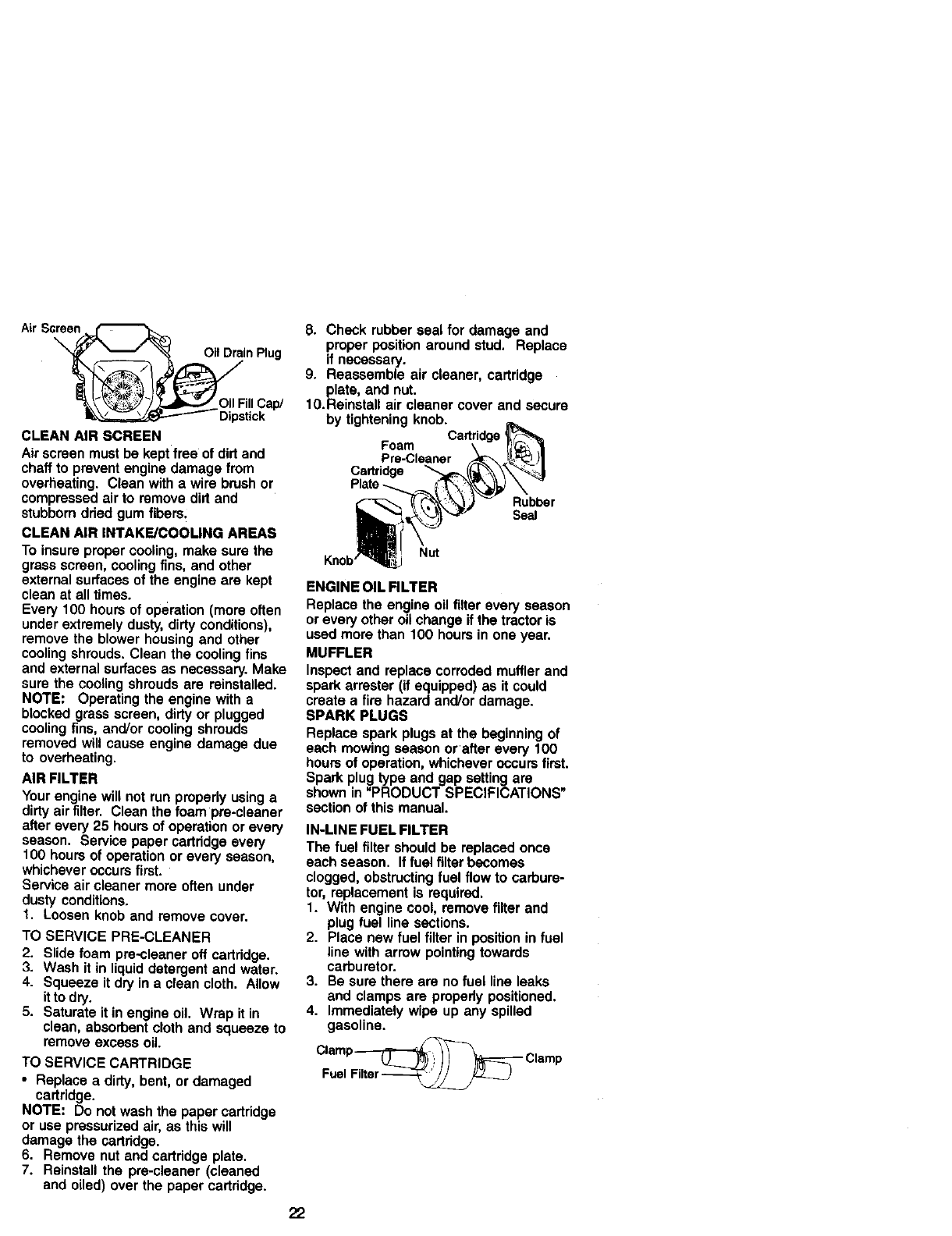
CLEAN AIR SCREEN
Air screen must be kept free of dirt and
chaff to prevent engine damage from
overheating. Clean with awire brush or
compressed air to remove dirt and
stubborn dded gum fibem;
CLEAN A|R INTAKE/COOLING AREAS
To insure proper cooling, make sure the
grass screen, cooling fins, and other
external surfaces of the engine are kept
clean at all times.
Every 100 hours of operation (more often
under extremely dusty, dirty conditions),
remove the blower housing and other
cooling shrouds. Clean the cooling fins
and external surfaces as necessary. Make
sure the cooling shrouds are reinstalled.
NOTE: Operating the engine with a
blocked grass screen, dirty or plugged
cooling fins, and/or cooling shrouds
removed will cause engine damage due
to overheating.
AIR FILTER
Your engine will P_otrun property usinga
dirty air filter. Clean the foam pre-cleaner
after every 25 hours of operation or every
season. Service paper c_rtddge every
100 hours of operation or every season,
whichever occurs first.
Service air cleaner more often under
dusty conditions.
1. Loosen knob and remove cover.
TO SERVICE PRE-CLEANER
2. Slide foam pre.,cleaner off cartridge.
3. Wash it in liquid detergent and water.
4. Squeeze it dry in a clean cloth. Allow
itto dry.
5. Saturate itin engine oil Wrap it in
clean, absorbent cloth and squeeze to
remove excess oil.
TO SERVICE CARTRIDGE
•Replace a dirty, bent, or damaged
cartridge.
NOTE: Do not wash the paper cartridge
or use pressurized air, as this will
damage the cartridge.
6. Remove nut and cartridge plate.
7. Reinstall the pre-cleaner (cleaned
and oiled) over the paper cartridge.
8. Check rubber seal for damage and
proper position around stud. Replace
if neceesary.
9. Reassemble air cleaner, cartridge
plate, and not.
10.Reinstall air cleaner cover and secure
by tightening knob.Cartridge
Foam
Pre-Cleaner
Cartridge
22
Rubber
Se=
Nut
ENGINE OIL RLTER
Replace the engine oil filter every season
or every other oil change if the tractor is
used more than 100 hours in one year.
MUFFLER
Inspect and replace corroded muffler and
spark arrester (if equipped) as it could
create a fire hazard and/or damage.
SPARK PLUGS
Replace spark plugs at the beginning of
each mowing season or after every 100
hours of operation, whichever occurs first.
Spark plug type and gap setting are
shown in =PRODUCT SPECIFICATIONS"
section of this manual.
IN-LINE FUEL FILTER
The fuel filter should be replaced once
each season. If fuel filter becomes
clogged, obstructing fuel flow to carbure-
tor, replacement is required.
1. With engine cool, remove filter and
plug fuel line sections.
2. Place new fuel filter in position in fuel
line with arrow pointing towards
carburetor.
3. Be sure there are no fuel line leaks
and clamps are propedy positioned,
4. Immediately wipe up any spilled
gasoline.
Clamp_Clamp
Fuel Filter
CLEANING _,
•Clean engine, battery, _;eat, finish, etc.
of all for'sign matter.
•Keep finished surfaces and wheels free
of all gasoline, oil, etc.
•Protect painted surfaces with automo-
tive type wax.
We do not recommend using a garden
hose to clean your tractor unless the
electrical system, muffler, air filter and
carburetor are covered to keep water out.
Water in engine can result in a shortened
engine life.
,_kCAUTION: BEFORE PERFORMING ANY SERVICE OR ADJUSTMENTS:
1_ Depress clutch/brake pedal fully and set parking brake.
• Place motion control lever in neutral (N)position.
3. Place attachment clutch in "DISENGAGED" position.
4. Turn ignition key "OFF" and remove key•
5. Make sure the blades and all moving parts have completely stopped.
6. Disconnect spark plug wire from spark plug and place wire wher e it cannot com
in contact with pluQ.
TRACTOR
TO REMOVE MOWER
1. Place attachment clutch in =DISEN-
GAGED" position.
2. Turn height adjustment knob to lowest
setting.
3. Lower mower to its lowest position.
4. Remove retainer spring holding anti-
swaybar to chassis bracket and
disengage anti-swaybar from bracket.
5. Remove retainer springs from
suspension arms at deck and disen-
gage arms from deck.
6. Raise attachment lift to its highest
position.
7. Remove two retainer springs from
each front link and remove links.
8. Slide mower forward and remove belt
from electric clutch pulley.
9. Slide mower out from under right side
of tractor.
IMPORTANT: If an attachment other than
the mower deck is to be mounted on the
tractor, remove the front links.
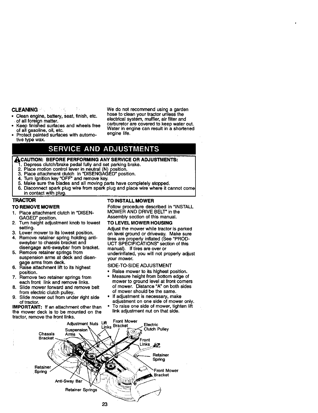
AdjustmentNuts Lift Front Mower
Links Bracket
TO INSTALL MOWER
Follow procedure described in "INSTALL
MOWER AND DRIVE BELT" in the
Assembly section of this manual.
TO LEVEL MOWER HOUSING
Adjust the mower while tractor is parked
on level ground or driveway. Make sure
tires are properly inflated (See "PROD-
UCT SPECIFICATIONS" section of this
manual). Iftires are over or
underinflated, you will not properly adjust
your mower•
SIDE-TO-SIDE ADJUSTMENT
•Raise mower to its highest position.
•Measure height from bottom edge of
mower to ground level at front comers
of mower. Distance "A" on both sides
of mower should be the same•
•If adjustment is necessary, make
adjustment on one side of mower only.
•To raise one side of mower, tighten lift
link adjustment nut on that side.
Electric
Chassis Arms
Bracket _.
Retainer
.Spdng
Anti-Sway Bal
Retainer Spring.=
Retainer
Spnng
Mower
Bracket
23
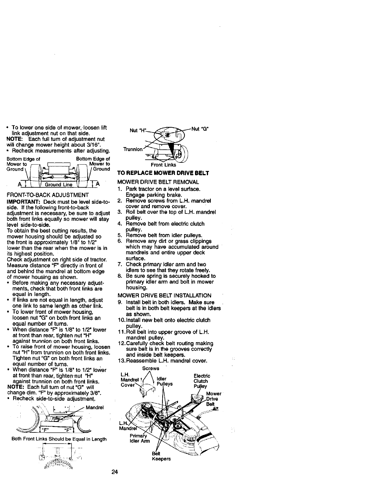
•To lower one side of mower,.Ioosen lift
link adjustment nut on that side.
NOTE: Each full turn of adjustment nut
will change mower height about 3/16".
•Recheck measurements after adjusting.
BottomEdge of BottomEdge of
Mowerto _[_ZZZZZ_ _Mowerto
Gr°und _l _I__V GrOund
Groun Uno
FRONT-TO-BACK ADJUSTMENT
IMPORTANT: Deck must be level side-to-
side. If the following front-to-back
adjustment is necessary, be sure to adjust
both front links equally so mower will stay
level side-to-side.
To obtain the best cutting results, the
mower housing should be adjusted so
the front is approximately 1/8" to 1/2"
lower than the rear when the mower is in
its highest position.
Check adjustment on right side of tractor.
Measure distance "F" directly in front of
and behind the mandrel at bottom edge
of mower housing as shown.
•Before making any necessary adjust-
ments, check that both front links are
equal in length.
•If links are not equal in length, adjust
one link to same length as other link.
•To lower front of mower housing,
loosen nut "(3" on both front links an
equal number of turns.
•When distance "F" is 1/8" to 1/2" lower
at front than rear, tighten nut "H"
against trunnion on both front links.
•To raise front of mower housing, loosen
nut "H" from trunnion on both front links.
Tighten nut "G" on both front links an
equal number of turns.
•When distance =F" is 1/8" to 1/2" Io_,er
at front than rear, tighten-nut "H"
against trunnion on both front links.
NOTE: Each full turn of nut "G" will
change dim. "F" by approximately 3/8".
• Recheck side-to*side adjustment.
Nut "H_ Nut
Trunni0n/_
Front Links
"G"
TO REPLACE MOWER DRIVE BELT
MOWER DRIVE BELT REMOVAL
1. Park tractor on a level surface.
Engage parking brake.
2. Remove screws from L.H. mandrel
cover and remove cover.
3. Roll belt over the top of L.H. mandrel
pulley.
4. Remove belt from electric clutch
pulley.
5. Remove belt from idler pulleys.
6. Remove any dirt or grass clippings
which may have accumulated around
mandrels and entire upper deck
surface.
7. Check primary idler arm and two
idlers to see that they rotate freely.
8. Be sure spring is securely hooked to
primary idler arm and bolt in mower
housing.
MOWER DRIVE BELT INSTALLATION
9. Install belt in both idlers. Make sure
belt is in both belt keepers at the idlers
as shown.
10. Install new belt onto electdc clutch
pulley.
11.Roll belt into upper groove of L.H.
mandrel pulley.
12.Carefully check belt routing making
sure belt is in the grooves correctly
and inside belt keepers.
13.Reassemble L.H. mandrel cover.
Electdc
Clutch
Mower
,=F_
BothFrontLinksShouldbe Equal in Length Idler Arm
24
Keepe_
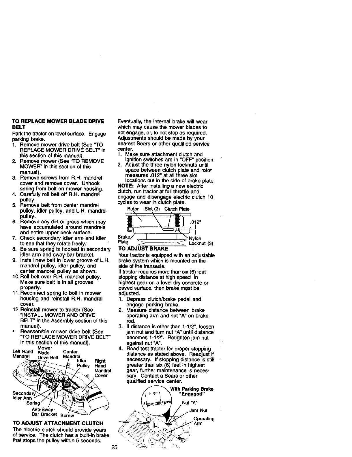
TO REPLACE MOWER BLADE DRIVE
BELT
Park the tractor on level surface. Engage
parking brake.
1. Remove mower ddve belt (See "TO
REPLACE MOWER DRIVE BELT" in
this section of this manual).
2. Remove mower (See "TO REMOVE
MOWER" in this section of this
manual).
3. Remove screws from R.H. mandrel
cover and remove cover. Unhook
spring from bolt on mower housing.
4. Carefully roll belt off R.H. mandrel
pulley.
5. Remove belt from center mandrel
pulley, idler pulley, and L.H. mandrel
pulley.
6. Remove any dirt or grass which may
have accumulated around mandrels
and entire upper deck surface.
7. Check secondary idler arm and idler J
to see that they rotate freely.
8. Be sure spdng is hooked in secondary
idler arm and sway-bar bracket.
9. Install new belt in lower groove of L.H.
mandrel pulley, idler pulley, and
center mandrel pulley as shown.
10.Roll belt over R.H. mandrel pulley.
Make sure belt is in all grooves
properly.
11. Reconnect spring to bolt in mower
housing and reinstall R.H. mandrel
cover,
12. Reinstall mower to tractor (See
"INSTALL MOWER AND DRIVE
BELT" in the Assembly section of this
manual).
•Reassemble mower ddve belt (See
"TO REPLACE MOWER DRIVE BELT"
in this section of this manual).
Mower
Left Hand Blade Center
Mandrel Drive Belt Mandrel
Idler Right
Hand
Mandrel
Cover
Idler Arm
Anti-Sway-
Bar Bracket
TO ADJUST ATTACHMENT CLUTCH
The electdc clutch should provide years
of service. The clutch has a built-in brake
that stops the pulley within 5 seconds. 25
Eventually, the internal brake will wear
which may cause the mower blades to
not engage, or, to not stop as required.
Adjustments should be made by your
nearest Sears or other qualified service
center.
t. Make sure attachment clutch and
ignition switches are in =OFF" position.
2. Adjust the three nylon Iocknuts until
space between clutch plate and rotor
measures .012" at all three slot
locations cut in the side of brake plate.
NOTE: After installing a new electdc
clutch, run tractor at full throttle and
engage and disengage electdc clutch 10
cycles to wear in clutch plate.
Rotor Slot (3) ClutchPlate
- I
e. ake/ II \Nylon
t'laze _Locknut(3)
TO ADJUST BRAKE
Your tractor is equipped with an adjustable
brake system which is mounted on the
side of the transaxle.
If tractor requires more than six (6) feet
stopping distance at high speed in
highest gear on a level dry concrete or
paved surface, then brake m_mtbe
adjusted.
1. Depress clutch/brake pedal and
engage parking brake.
2. Measure distance between brake
operating arm and nut "A" on brake
rod.
3. If distance is other than 1-1/2", loosen
jam nut and turn nut =A"until distance
becomes 1-1/2". Rstighten jam nut
against nut =A".
4. Road test tractor for proper stopping
distance as stated above. Readjust if
necessary. If stopping distance is still
greater than six (6) feet in highest
gear, further maintenance is neces-
sary. Contact a Sears or other
qualified service center.
With Parking Brake
"Engaged"
Nut "A"
_. Ja_p: autting
\/Arm
C --41
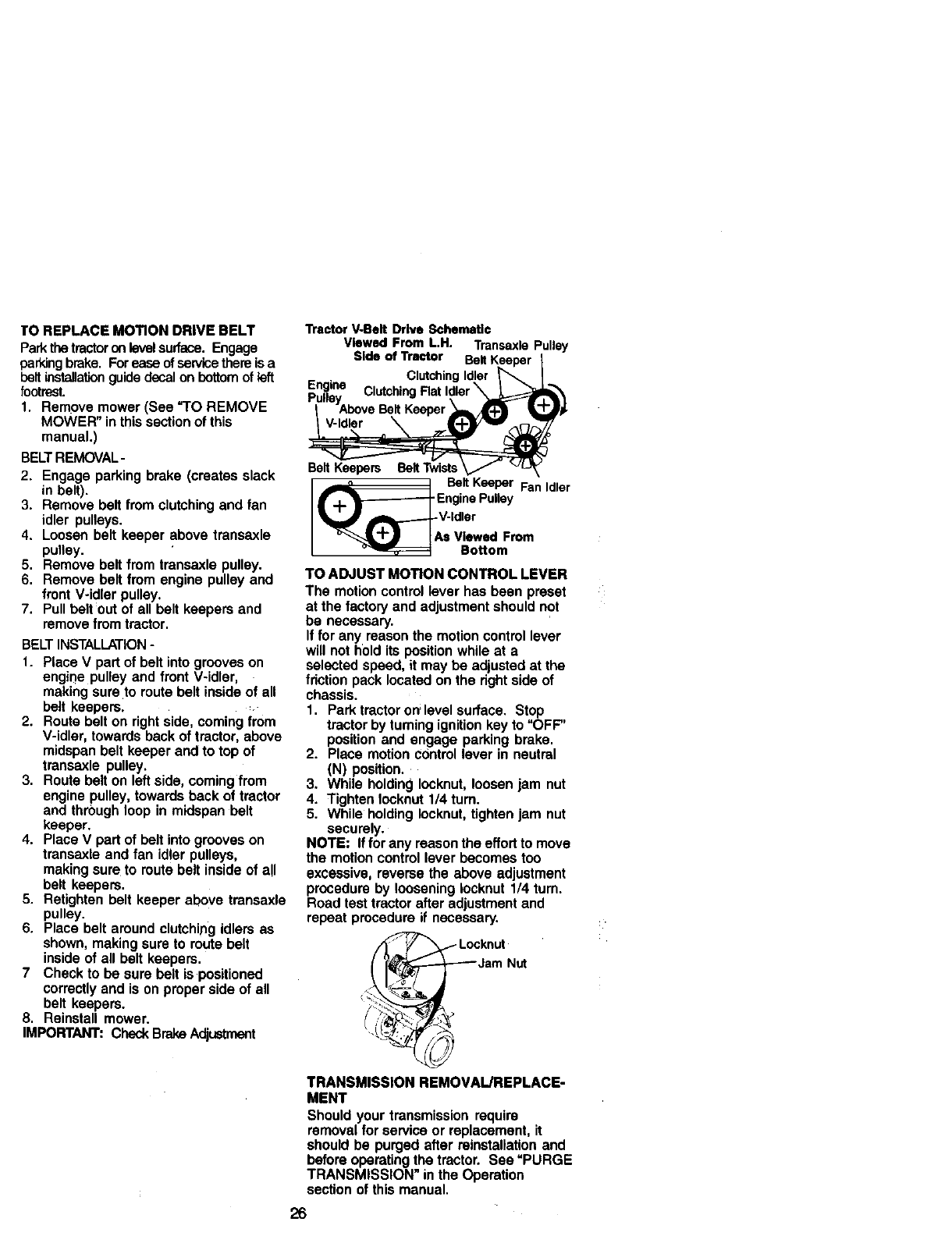
TO REPLACE MOTION DRIVE BELT
Park thetractoron levelsurface. Engage
parking brake. For ease of servicethere is a
beltinstallationguide decal on bottomof left
footrest.
1. Remove mower (See "TO REMOVE
MOWER" in this section of this
manual.)
BELTREMOVAL-
2. Engage parking brake (creates slack
in belt).
3. Remove belt from clutching and fan
idler pulleys.
4. Loosen belt keeper above transaxle
pulley.
5. Remove belt from transaxle pulley.
6. Remove belt from engine pulley and
front V-idler pulley.
7. Pull belt out of all belt keepers and
remove from tractor.
BELT INSTALLATION -
1. Place V part of belt into grooves on
engine pulley and front V-idler,
making sure to route belt inside of all
belt keepers.
2. Route belt on right side, coming from
V-idler, towards back of tractor, above
midspan belt keeper and to top of
transaxle pulley.
3. Route belt on left side, coming from
engine pulley, towards back of tractor
and through loop in midspan belt
keeper.
4. Place V part of belt into grooves on
transaxle and fan idler pulleys,
making sure to route belt inside of a!l
belt keepers.
5. Retightan belt keeper above transaxle
pulley.
6. Place belt around clutching idlers as
shown, making sure to route belt
inside of all belt keepers.
7 Check to be sure belt is positioned
correctly and is on proper side of all
belt keepers.
8. Reinstall mower.
IMPORTANT: Check Brake Adjustment
Tractor V-Belt Drive Schematic
Viewed From L.H. Transaxle Pulley
Side of Tractor
Clutching Idle
Eng.ins Clutching Rat Idler \
_'ulleYAbove Belt
V-Idler
Belt Keepers Belt Twists
] Belt Keeper Fan Idler
_r'_.-_- Engine Pulley
V _[_ v'ldler
_-_._ !AS Viewed From
Bottom
TO ADJUST MOTION CONTROL LEVER
The motion control lever has been preset
at the factory and adjustment should not
be necessary.
If for any reason the motion control lever
will not h01d its position while at a
selected speed, it may be adjusted at the
friction pack located on the dght side of
chassis.
1. Park tractor on level surface. Stop
tractor by turning ignition key to "OFF"
position and engage parking brake.
2. Place motion control lever in neutral
(N) position.
3. While holding Iocknut, loosen jam nut
4. Tighten Iocknut 1/4 turn.
5. While holding Iocknut, tighten jam nut
securely.
NOTE= If for any reason the effort to move
the motion control lever becomes too
excessive, reverse the above adjustment
procedure by loosening Iocknut 1/4 turn.
Road test tractor after adjustment and
repeat procedure if necessary.
TRANSMISSION REMOVAL/REPLACE-
MENT
Should your transmission require
removal for service or replacement, it
should be purged after rainstallation and
before operating the tractor. See =PURGE
TRANSMISSION" in the Operation
section of this manual.
26
TO ADJUST STEER NGWREEL AL GN-
MENT
If steering wheel crossbars are not
horizontal {left to right) when wheels are
positioned straight forward, remove
steering wheet and reassemble per
instructions in the Assembly section of
this manual.
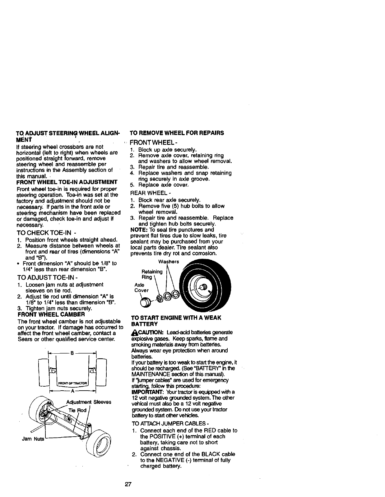
FRONT WHEEL TOE-IN ADJUSTMENT
Front wheel toe-in is required for proper
steering operation. Toe-in was set at the
factory and adjustment should not be
necessary. If parts in the front axle or
steering mechanism have been replaced
or damaged, check toe-in and adjust if
necessary.
TO CHECK TOE-IN -
1. Position front wheels straight ahead.
2. Measure distance between wheels at
front and rear of tires (dimensions "A"
and "B").
• Front dimension "A" should be 1/8" to
1/4" less than rear dimension =B".
TO ADJUST TOE-IN -
1. Loosenjam nutsat adjustment
sleeveson tie rod.
2. Adjusttie roduntildimension"A" is
1/8"to 1/4" less thandimension"B",
3. Tightenjam nutssecurely.
FRONT WHEEL CAMBER
The front wheel camberis not adjustable
onyourtractor, If damagehas occurredto
affectthe front wheelcamber,contacta
Sears or otherqualifiedservicecenter.
Sleeves
Jam Nuts
TO REMOVE WHEEL FOR REPAIRS
FRONTWHEEL-
1. Block up axle securely.
2. Remove axle cover, retaining ring
and washers to allow wheel removal.
3. Repair tire and reassemble.
4. Replace washers and snap retaining
ring securely in axle groove.
5. Replace axle cover.
REAR WHEEL -
t. Block rear axle securely.
2. Remove five (5) hub bolts to allow
wheel removal.
3. Repair tire and reassemble. Replace
and tighten hub bolts securely.
NOTE: To seal tire punctures and
prevent flat tires due to slow leaks, tire
sealant may be purchased from your
local parts dealer. Tire sealant also
prevents tire dry rot and corrosion.
Washers
Retaining _ A_.
Ring\ I\ _r__'_l,I
Axle \ I\II( ((_%'_ Ill
TO START ENGINE WITH A WEAK
BA'n'ERY
4_CAUTION: Lead-acid batteriesgenerate
explosivegases. Keep sparks, flame and
smekJngmaterialsaway from batteries.
Always wear eye protectionwhen around
batteries.
Ifyour battery is too weak to startthe engine, it
shouldbe recharged.(See =BATTERY"in the
MAINTENANCE ssc_on of this manual).
If'_umper cables"are used for emergency
starting,follow thisprocedure:
IMPORTANT: Yourtractoris equipped witha
12 volt negativegroundedsystem.The other
vehical must also be a 12 volt negative
groundedsystem. Do not useyour tractor
batteryto startother vehicles.
TO ATTACHJUMPER CABLES -
1. Connect each end of the RED cable to
the POSITIVE (+) terminal of each
battery, taking care not to short
against chassis.
2. Connect one end of the BLACK cable
to the NEGATIVE (-) terminal of fully
charged battery.
27
_. Connect the other end of the BLACK
cable to good CHASSIS GROUND,
away from fuel tank and battery.
;O REMOVE CABLES, REVERSE ORDER -
I. BLACK cable first from chassis and
then from the fully charged battery.
_.. RED cable last from both battedes.
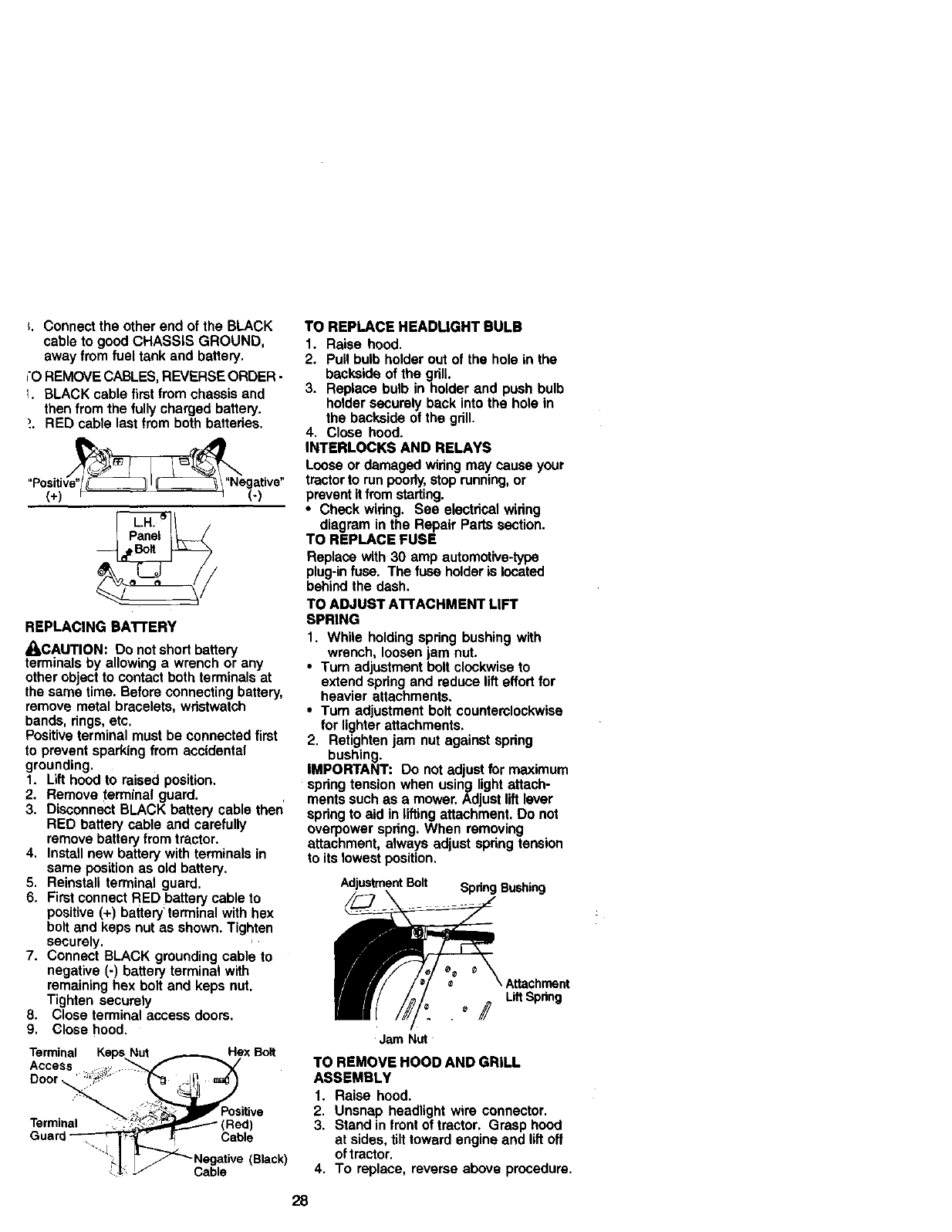
REPLACING BA'rrERY
•I=CAUTION: Do not short battery
terminals by allowing a wrench or any
other object to contact both terminals at
the same time. Before connecting battery,
remove metal bracelets, wdstwatch
bands, rings, etc.
Positive terminal must be connected first
to prevent sparking from accidental
grounding.
1. Lift hood to raised position.
2. Remove terminal guard.
3. Disconnect BLACK battery cable then'
RED battery cable and carefully
remove battery from tractor.
4. Install new battery with terminals in
same position as old battery.
5. Reinstall terminal guard.
6. First connect RED battery cable to
positive (+) battery' terminal with hex
bolt and keps nut as shown. Tighten
securely.
7. Connect BLACK grounding cable to
negative (-) battery terminal with
remaining hex bolt and keps nut.
Tighten securely
8. Close terminal access doors.
9. Close hood,
Terminal Keps Nut _FlexBolt
Access .... _:, _,_
Terminal __"_ (Red)
Guard_ Cabe
.J
TO REPLACE HEADUGHT BULB
1. Raise hood.
2. Pull bulb holder out of the hole in the
backside of the grill
3. Replace bulb in holder and push bulb
holder securely back into the hole in
the backside of the gdll.
4, Close hood.
INTERLOCKS AND RELAYS
Loose or damaged widng may cause your
tractor to run poorly, stop running, or
prevent itfrom starting.
•Check wiring. See electrical wiring
diagram in the Repair Parts section.
TO REPLACE FUSE
Replace with 30 amp automotive-type
plug-in fuse. The fuse holder is located
behind the dash.
TO ADJUST A'rrACHMENT LIFT
SPRING
1. While holding spring bushing with
wrench, loosen jam nut.
•Turn adjustment bolt clockwise to
extend spring and reduce lift effort for
heavier attachments.
•Turn adjustment bolt countemlockwise
for lighter attachments.
2. Retighten jam nut against spdng
bushing.
IMPORTANT: Do not adjust for maximum
spring tension when using light attach-
ments such as a mower. Adjust lift lever
spdng to aid in lifting attachment. Do not
overpower spdng. When removing
attachment, always adjust spdng tension
to its lowest position,
Adjustment Bolt Spring Bushing
LiftSpring
°//
Jam Nut
TO REMOVE HOOD AND GRILL
ASSEMBLY
1. Raise hood.
2. Unsnap headlight wire connector.
3. Stand in front of tractor. Grasp hood
at sides, tilt toward engine and lift off
of tractor.
4. To replace, reverse above procedure.
28
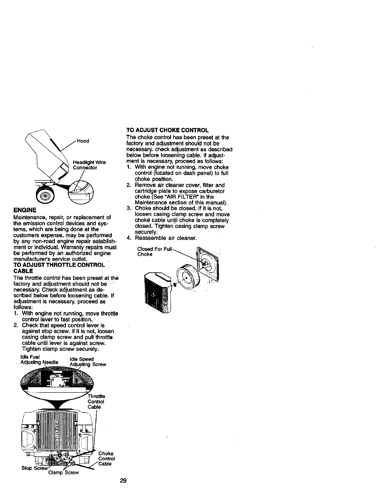
HeadligM Wire
Connector
ENGINE
Maintenance, repair, or replacement of
the emission control devices and sys-
tems, which are being done at the
customers expense, may be performed
by any non-read engine repair establish-
ment or individual. Warranty repairs must
be performed by an authorized engine
manufacturer's service outlet.
TO ADJUST THROTTLE CONTROL
CABLE
The throttle control has been preset at the
factory and adjustment should not be
necesSary. Check adjustment as de-
scribed below before loosening cable, if
adjustment is necessary, proceed as
follows:
1. With engine not running, move throttle
control lever to fast position.
2. Check that speed control lever is
against stop screw. If it is not, loosen
casing clamp screw and pull throttle
cable until lever is against screw.
Tighten clamp screw securely.
IdleFuel Idle Speed
Needle Screw
TO ADJUST CHOKE CONTROL
The choke control has been preset at the
factory and adjustment should not be
necessary, check adjustment as described
below before loosening cable. If adjust-
ment is necessary, proceed as follows:
1. With engine not running, move choke
control (loCated on dash panel) to full
choke position.
2. Remove air cleaner cover, filter and
cartridge plate to expose carburetor
choke (See "AIR FILTER" in the
Maintenance section of this manual).
3. Choke should be closed. If it is not,
loosen casing clamp screw and move
choke_cable until choke is completely
closed. Tighten casing clamp screw
securely.
4. Reassemble air cleaner.
Closed For Full_
Choke
r'hrettle
Control
Cable
Stop
Choke
Control
Clamp _crew
29
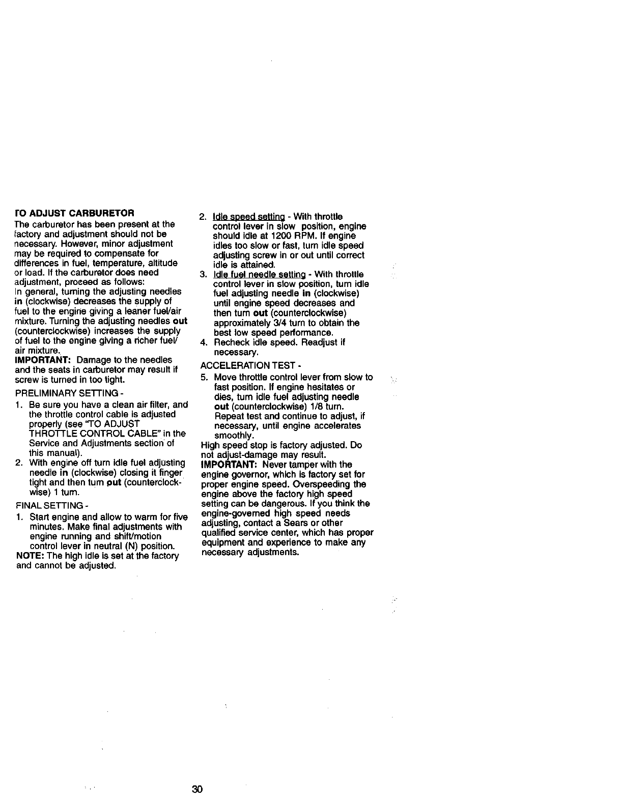
ro ADJUST CARBURETOR
The carburetor has been present at the
_actory and adjustment should not be
necessary. However, minor adjustment
may be required to compensate for
differences in fuel, temperature, altitude
or load. If the carburetor does need
adjustment, proceed as follows:
In general, turning the adjusting needles
in (clockwise) decreases the supply of
fuel to the engine giving a leaner fuel/air
mixture. Turning the adjusting needles out
(counterclockwise) increases the supply
of fuel to the engine giving a dcher fuel/
air mixture.
IMPORTANT: Damage to the needles
and the seats in carburetor may result if
screw is turned in too tight.
PRELIMINARY SETI'ING -
1. Be sure you have aclean air filter, and
the throttle control cable is adjusted
properly (see "TO ADJUST
THROTTLE CONTROL CABLE" in the
Service and Adjustments section of
this manual).
2. With engine off turn idle fuel adjusting
needle in (clockwise) closing it finger
tight and then tum _ut (counterclock-
wise) 1 turn.
FINAL SETTING -
1. Start engine and allow to warm for five
minutes. Make final adjustments with
engine running and shiff/motion
control lever in neutral (N) position.
NOTE: The high idle is set at the factory
and cannot be adjusted.
2. Idle speed settina - With throttle
control lever in slow position, engine
should idle at 1200 RPM. If engine
idles too slow or fast, turn idle speed
adjusting screw in or out until correct
idle is attained.
3. Idle fuel needle setting - With throttle
control lever in slow position, turn idle
fuel adjusting needle in (clockwise)
until engine speed decreases and
then rum out (counterclockwise)
approximately 3/4 turn to obtain the
best low speed performance.
4. Recheck idle speed. Readjust if
necessary.
ACCELERATION TEST -
5. Move throttle control lever from slow to
fast position. If engine hesitates or
dies, tum idle fuel adjusting needle
out (counterclockwise) 1/8 turn.
Repeat test and continue to adjust, if
necessary, until engine accelerates
smoothly.
High speed stop is factory adjusted. Do
not adjust-damage may result.
IMPORTANT: Never tamper with the
engine governor, which is factory set for
proper engine speed. Overspeeding the
engine above the factory high speed
setting can be dangerous. If you think the
engine-governed high speed needs
adjusting, contact a Sears or other
qualified service center, which has proper
equipment and experience to make any
necessary adjustments.
'" 30
Immediately prepare your tractor for
storage at the end of the season or if the
tractor will not be used for 30 days or
more.
•l, CAUTION: Never store the tractor with
gasoline in the tank inside a building
where fumes may reach an open flame or
spark. Allow the engine to cool before
storing in any enclosure.
TRACTOR
Remove mower from tractor for winter
storage. When mower is to be stored for
aperiod of time, clean it thoroughly,
remove all dirt, grease, leaves, etc. Store
in a clean, dry area.
t. Clean entire tractor (See "CLEANING"
in the Maintenance section of this
manual).
2. Inspect and replace belts, if necessary
(See belt replacement instructions in
the Service and Adjustments section
of this manual).
3. Lubdcate as shown in the Mainte-
nance section of this manual.
4. Be sure that all nuts, bolts and screws
are securely fastened. Inspect moving
parts for damage, breakage and wear.
Replace if necessary.
5. Touch up all rusted or chipped paint
surfaces; sand lightly before painting.
BATTERY
•Fully charge the battery for storage.
•After a pedod of time in storage, battery
may require recharging.
•To help prevent corrosion and power
leakage dudng long perinds of storage,
battery cables should be disconnected
and battery cleaned thoroughly (see
"TO CLEAN BATTERY AND TERMI-
NALS" in the Maintenance section of
this manual).
•After cleaning, leave cables discon-
nected and place cables where they
cannot come in contact with battery
terminals.
•If battery is removed from tractor for
storage, do not store battery directly on
concrete or damp surfaces.
ENGINE
FUEL SYSTEM
IMPORTANT: It is important to prevent
gum deposites from forming in essential
fuel system parts such as carburetor, fuel
hose, or tank dudng storage.
Also, expedance indicates that alcohol
blended fuels (called gasohol or using
ethanol or methanol) can attract moisture
which leads to separation and formation
of acids during storage. Acidic gas can
damage the fuel system of and engine
while in storage.
1. Drain the fuel tank.
2. Start the engine and let it run until the
fuel lines and carburetor are empty.
•Never use engine or carburetor cleaner
products in the fuel tank or permanent
damage may occur.
•Use fresh fuel next season.
NOTE: Fuel stabilizer is an acceptable
alternative in minimizing the formation of
fuel gum deposits during storage. Add
stabilizer to gasoline in fuel tank or
storage container. Always follow the mix
ratio found on stabilizer container. Run
engine at least 10 minutes after adding
stabilizer to allow the stabilizer to reach
the carburetor. Do not drain the gas tank
and carburetor if using fuel stabilizer.
ENGINE OIL
Drain oil (with engine warm) and replace
with clean engine oil. (See "ENGINE" in
the Maintenance section of this manual).
CYLINDER(S)
1. Remove spark plug(s).
2. Pour one ounce of oil through spark
plug hole(s) into cylinder(s),
3. Turn ignition key to "START" position
for afew seconds to distribute oil.
4. Replace with new spark plug(s).
OTHER
•Do not store gasoline from one season
to another.
•Replace your gasoline can if your can
starts to rust. Rust and/or did in your
gasoline will cause problems.
•If possible, store your tractor indoors
and cover it to give protection from dust
and dirt.
• Cover your tractor with asuitable
protective cover that does not retain
moisture. Do not use plastic. Plastic
cannot breathe which allows conden-
sation to form and will cause your
tractor to rust.
IMPORTANT: Never cover tractor while
engine and exhaust areas are still warm.
31
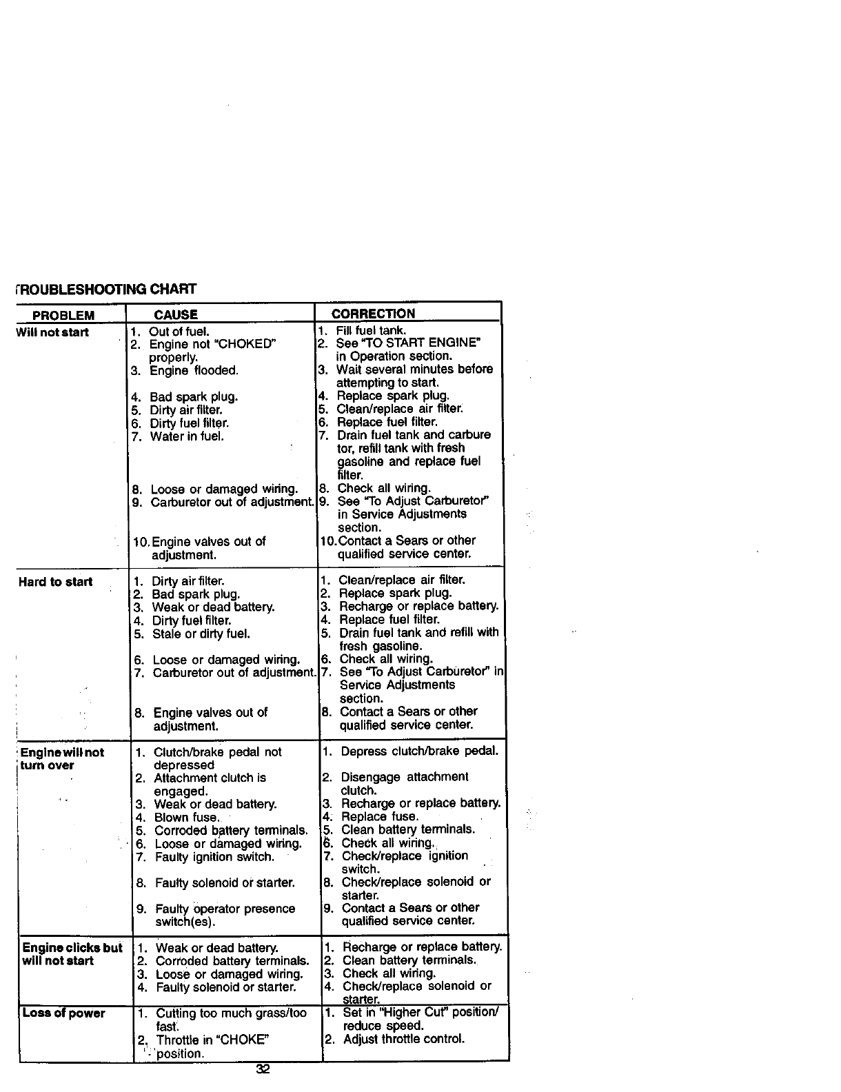
tROUBLESHOOTING CHART
PROBLEM
Will not start
Hard to start
Englnewill not
turn over
Engine clicks but
will not start
Loss of power
CAUSE
I. Out of fuel.
2. Engine not "CHOKED"
properly.
3. Engine flooded.
4. Bad spark plug.
5. Dirty air filter.
6. Dirty fuel filter.
7. Water in fuel.
8. Loose or damaged widng.
9. Carburetor out of adjustment.
10. Engine valves out of
adjustment.
1. Dirty air filter.
2. Bad spark plug.
3. Weak or dead battery.
4. Dirty fuel filter.
5. Stale or dirty fuel.
6. Loose or damaged widng.
7. Carburetor out of adjustment.
8. Enginevalves outof
adjustment.
1. Clutch/brake pedal not
depressed
2. Attachment clutch is
engaged.
3. Weak or dead battery.
4. Blown fuse.
5. Corroded bpttery terminals.
• 6. Loose or damaged widng.
7. Faulty ignition switch.
8. Faulty solenoid or starter.
9. Faultyoperatorpresence
switch(es).
1. Weak or dead battery.
2. Corroded battery terminals.
3. Loose or damaged wiring.
4. Faulty solenoid or starter.
1. Cutting toomuch grass/too
fast:
2 Throttlein "CHOKE"
': positon. 32
CORRECTION
1. Fill fuel tank.
2. See "TO START ENGINE"
in Operation section.
3. Wait several minutes before
attempting to start.
4. Replace spark plug.
5. Clean/replace air filter.
6. Replace fuel filter.
7. Drain fuel tank and carbure
tor, refilltank with fresh
gasoline and replace fuel
filter.
8. Check all wiring.
9. See "To Adjust Carburetor"
in Service Adjustments
section.
t0.Contact a Sears or other
qualified service center.
1. Cleardmplace air filter.
2. Replace spark plug.
3, Recharge or replace battery.
4. Replace fuel filter.
5. Drain fuel tank and refill with
fresh gasoline.
6. Check all wiring.
7. See "To Adjust Carburetor" in
Service Adjustments
section.
8. Contact a Sears or other
qualified service center.
1. Depress clutch/brake pedal.
2. Disengage attachment
clutch.
3. Recharge or replace battery.
4: Replace fuse.
5. Clean battery terminals.
6. CheCk al! widng.
7. Check/replace ignition
switch,
8. Check/replace solenoid or
starter.
). Contact a Sears or other
qualified service center.
1. Recharge or replace battery.
2. Clean battery terminals.
3. Check all widng.
4. Check/replacesolenoidor
starter.
1. Set in "Higher Cut"position/
reduce speed.
2. Adjustthrottlecontrol.
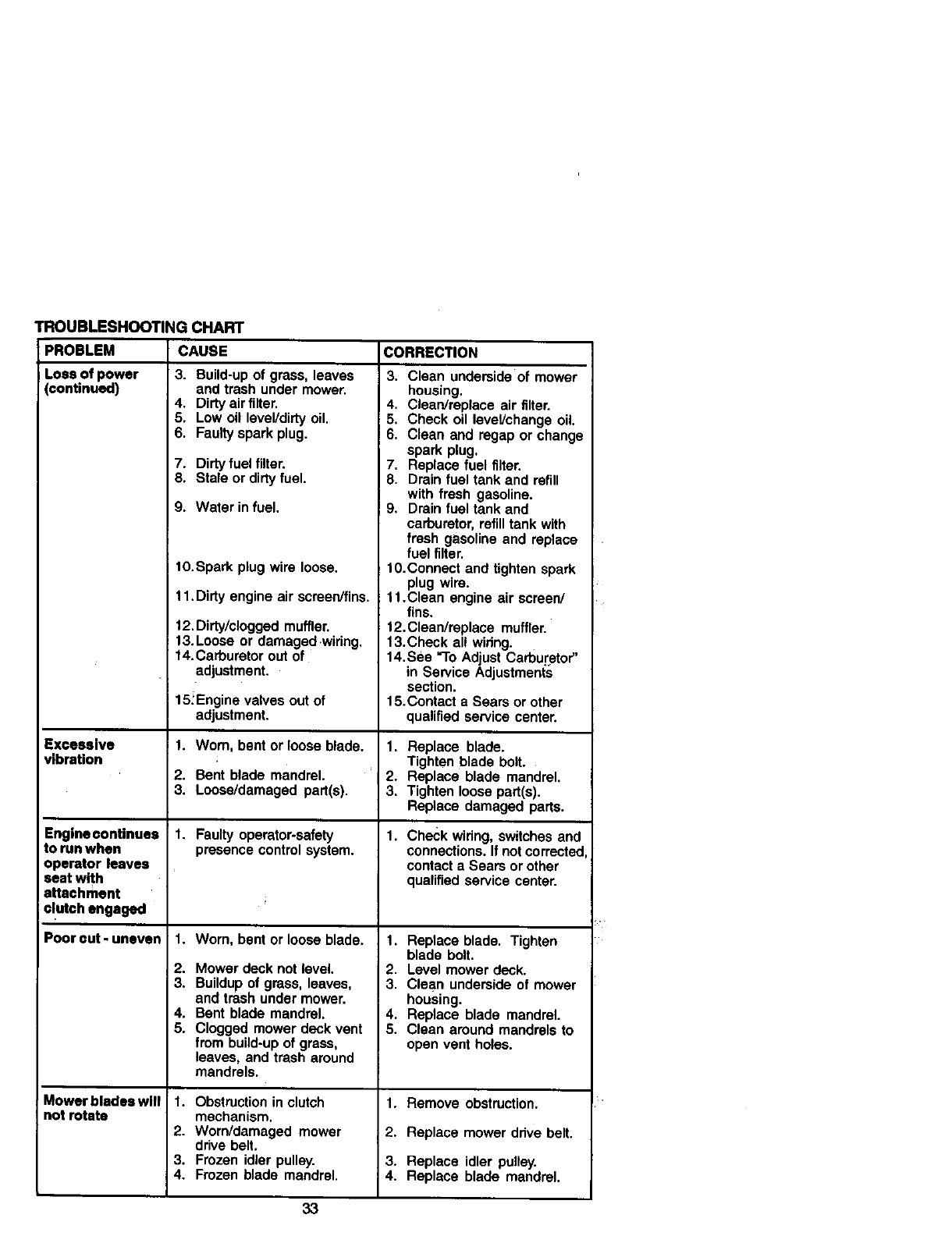
TROUBLESHOOTING CHART
CAUSE CORRECTION
3. Build-up of grass, leaves
and trash under mower.
4. Dirty air filter.
5. Low oil level/dirty oil.
6. Faulty spark plug.
PROBLEM
Loss of power
(continued)
Excessive
vibration
Engine oontinues
to run when
operator leaves
seat with
attachment
o!utch engaged
Poorout-uneven
Mowerblades will
not rotate
7. Dirty fuel filter.
8. Stale or dirty fuel.
9. Water in fuel.
lO.Spark plug wire loose.
11. Dirty engine air screen/fins.
12. Dirty/clogged muffler.
13. Loose or damage dwiring,
14.Carburetor out of
adjustment.
15_Enginevalves outof
adjustment.
1. Worn, bent or loose blade.
2. Bent blade mandrel.
3. Loose/damaged part(s).
1. Faultyoperator-safety
presencecontrolsystem.
1. Wom, bent orloose blade.
2. Mower deck not level.
3, Buildupof grass, leaves,
and trashundermower.
4. Bent blade mandrel.
5. Cloggedmowerdeck vent
from build-upof grass,
leaves, and trash around
mandrels.
1. Obstruction in clutch
mechanism.
2. Worn/damaged mower
drive belt.
3. Frozen idler pulley.
4. Frozen blade mandrel.
3. Clean underside of mower
housing.
4. Clean/replace air filter.
5. Check oil level/change oil.
6. Clean and regap or change
spark plug.
7. Replace fuel filter.
8. Drain fuel tank and refill
with fresh gasoline.
9. Drain fuel tank and
carburetor, refill tank with
fresh gasoline and replace
fuel filter.
10.Connect and tighten spark
plug wire.
11.Clean engine air screen/
fins.
12. Clean/replace muffler.
13.Check all wiring.
14. See _1"oAdjust Carburetor"
in Service Adjustments
section.
15.Contact a Sears or other
qualified service center.
1. Replace blade.
Tightenblade bolt.
2. Replace blade mandrel.
3. Tighten loosepart(s).
Replace damaged parts.
1. Checkwidng, switchesand
connections.If notcorrected
contacta Sears or other
qualifiedservice center.
1. Replace blade. Tighten
blade bolt.
2. Level mower deck.
3. Clean underside of mower
housing.
4. Replace blade mandrel.
5. Clean around mandrels to
open vent holes.
1. Remove obstruction.
2. Replace mower drive belt.
3. Replace idler pulley.
4. Replace blade mandrel.
33
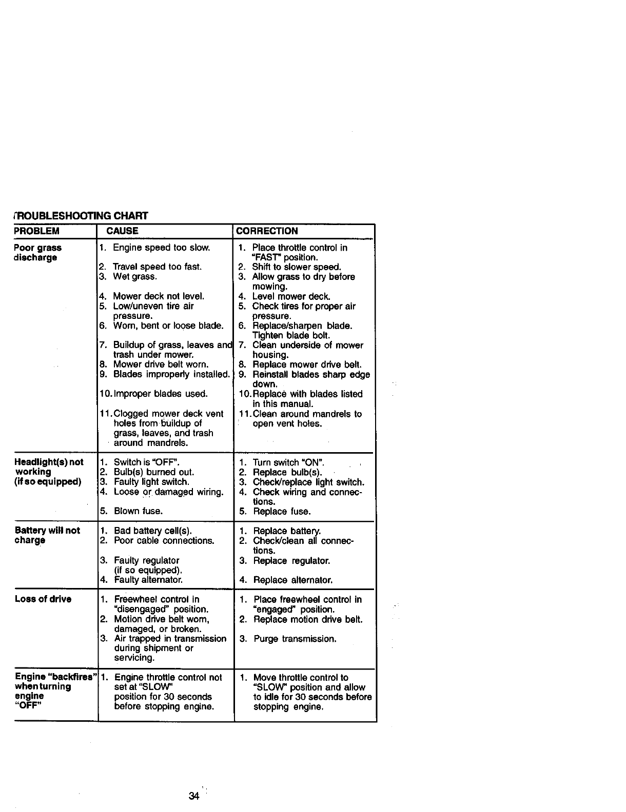
;'ROUBLESHOOTINGCHART
CAUSEPROBLEM
Poor grass
_ischarge
Headlight(s) not
working
(if so equipped)
1. Engine speed too slow.
2. Travel speed too fast.
3. Wet grass.
4. Mower deck not level.
5. Low/uneventire air
pressure.
6. Worn, bent or looseblade.
i7. Buildupof grass, leaves ant
trash undermower.
E3.Mower drivebelt worn.
9. Blades improperlyinstalled.
10. Improperblades used.
11.Clogged mower deck vent
holes from buildup of
grass, leaves, and trash
around mandrels.
1. Switchis"OFF".
2. Bulb(s)bumed out.
3, Faultylightswitch.
4. Looseor damaged widng.
5. Blown fuse.
Battery will not
charge
3.
4.
Loss of drive 1.
2.
3.
Engine "backfires" 1.
whenturning
engine
"OFF"
1, Bad batterycell(s).
2. Poor cable connections.
Faulty regulator
(if so equipped).
Faultyalternator.
Freewheel control in
=disengaged" position.
Motion ddve belt wom,
damaged, or broken.
Air trapped in transmission
dudng shipment or
servicing.
CORRECTION
1. Place throttlecontrolin
=FAST"position.
2. Shiftto slowerspeed.
3. Allowgrassto drybefore
mowing.
4. Levelmowerdeck.
5. Checktires for properair
pressure.
6. Replace/sharpenblade.
Tighten blade bolt.
7. Clean undersideof mower
housing.
8. Replace mowerdrive belt.
9. Reinstallblades sharp edge
down.
10.Replace with blades listed
in thismanual.
11.Clean aroundmandrelsto
open vent holes.
1. Turn switch "ON".
2. Replace bulb(s).
3. ChecWreplace light switch.
4. Check widng and connec-
tions.
5, Replace fuse.
1. Replace battery.
2. Check/clean all connec-
tions.
3. Replace regulator.
4. Replace alternaton
1. Place freewheel controlin
"engaged" position.
2. Replace motiondrive belt.
3. Purge transmission,
Engine throttle control not 1. Move throttle control to
set at "SLOW" "SLOW _ position and allow
position for 30 seconds to idle for 30 seconds before
before stopping engine, stopping engine,
34
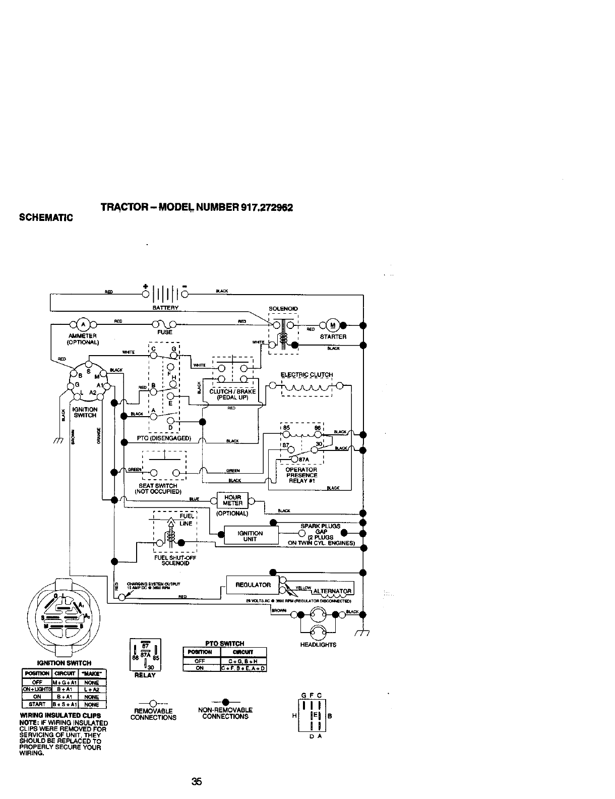
SCHEMATIC TRACTOR - MODEl. NUMBER 917,272962
I
AMMETER
(OPTIONAL)
)EEl
3
3NITIO_
tWITCH
IGNmoNSWITCH
WIRING IN6ULATED CUPS
NOTE: IF WIRING INSULATED
CLIPS WERE REMOVED FOR
SERVICING OF UNIT, THEY
SHOULD BE REPLACED TO
PROPERLY SECURE YOUR
WIRING.
RELAY
PTO SWITCH HEADLIGHTS
CIRCWR
ON C+F,B_E_A+D
OFF C+GIB÷H
GFC
o-.-
REMOVABLE NON-REMOVABLE
CONNECTIONS CONNECTIONS H B
DA
35
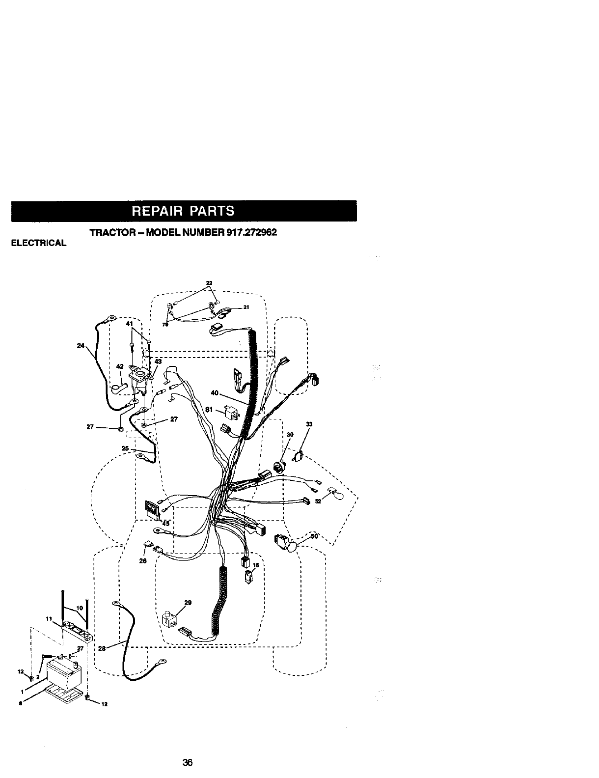
TRACTOR - MODEL NUMBER 917.272962
ELECTRICAL
11
i
29
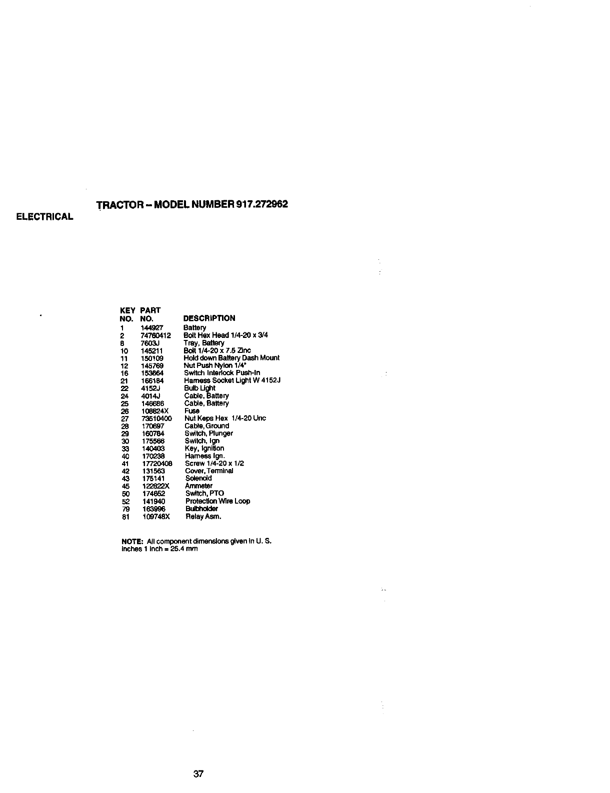
ELECTRICAL TRACTOR - MODEL NUMBER 917.272962
KEY PART
NO. NO, DESCRIPTION
1 144927 Battery
2 74760412 Bolt Hex Head 1/4-20 x 3/4
8 7603J Tray, Battery
10 145211 Bolt 1/4-20 x 7.5 Zinc
11 150109 Hold down Battery Dash Mount
12 145769 Nut Push Nylon 1/4"
16 153664 Switch Interlock Push-In
21 166184 Hamess Socket Light W 4152J
22 4152J Bulb Light
24 4014J Cable, Battery
25 146686 Cable, Battery
26 10e824X Fuse
27 73510400 Nut Keps Hex 1/4-20 Unc
28 170697 Cable, Ground
29 160784 Switch, Plunger
30 175566 Switch, Ign
33 140403 Key, ignition
40 17(]_38 Harness Ign.
41 17720408 Screw 1/4-20 x 1/2
42 131563 Cover, Terminal
43 175141 Solenoid
45 1_-_822X Ammeter
50 174662 Switch, PTO
52 141940 Protection Wire Loop
79 163996 Bulbholder
81 109748X Relay Asm.
NOTE: All component dimensions given in U. S.
inches I inch =25.4 mm
37
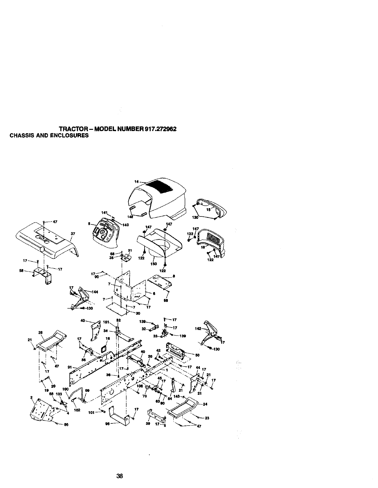
TRACTOR- MODELNUMBER917.272962
CHASSISANDENCLOSURES
17 144
47
122
43
2 t7
17
7
_130
38
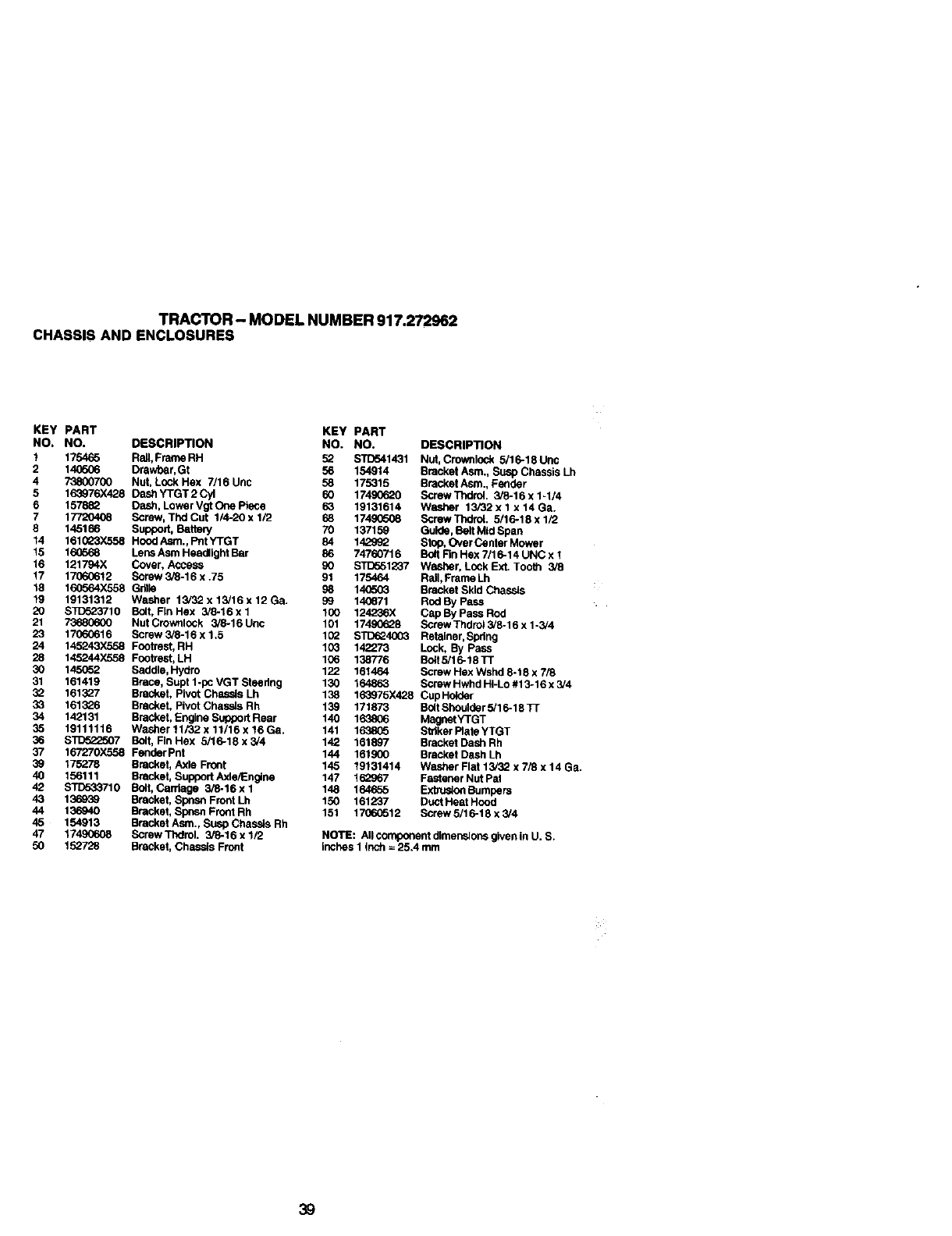
TRACTOR - MODEL NUMBER 917.272962
CHASSIS AND ENCLOSURES
KEY PART KEY
NO, NO. DESCRIPTION NO.
1175465 Rdll, Fran_ RH 52
2 14_506 Drawbar, Gt 56
4 73800700 NOt, Lock Hex 7/16 Uric 58
5 163976X428 Dash YTGT 2 Cyl 60
6 157832 Dash, Lower Vgt One Piece 63
7 17720408 Screw, Thd Cut 1/4-20 x 1/2 68
8 145166 Support, Battery 70
14 161_23X568 Hood Asm., P!lt YTGT 84
15 16(T_68 Lens Asm Headlight Bar 86
16 121794X Cover, Access 90
17 17060612 Screw 3/8-16 x .75 91
18 160994X558 Grille 99
19 19131312 Washer 13/32 x 13/16 x 12 Ga. 99
20 $1_523710 Bolt, FInHex 3/8-16xl 100
21 73680600 NOt Crownlock 3/8-16 Unc 101
23 17060616 Scraw 3/8-16 x 1.5 102
24 145243X558 Footrast, RH 103
28 145244X558 Footrest, LH 199
30 145052 Saddle, Hydro 122
31 161419 Brace, Supt 1-pc VGT Steedng 130
32 161327 Bracket, Pivot Chassis Lh 138
33 161326 Bracket, Pivot ChassLs Rh 139
34 142131 Bracket, Engine Support Rear 140
35 19111116 Washer 11/32 x 11/16 x 16 Ga. 141
36 STD322507 Bolt' FIn Hex 5/16-18x3/4 142
37 167270X558 Fender Pnt 144
39 175278 Bracket, Axle Front 145
40 156111 Bracket, S uppor t Axle/Englne 147
42 STD533710 Bolt, Carriage 3/_-16xl 148
43 136939 Bracket, Spnsn Front Lh 150
44 136940 Bracket, Spnsn Front Rh 151
45 154913 Bracket Asm., Susp Chassis Rh
47 17490608 Screw Ttx:lml. 3/8-16 x 1/2
50 152728 Bracket, Chassis Front
PART
NO. DESCRIPTION
STD541431 Not, Crownlock 6/16-18Unc
154914 Bracket Asm., Susp Chassis Lh
175315 Bracket Asm., Fender
17490620 Screw Thdrdl. 3/8-16 x 1-1N
19131614 Washer 13/32 x 1 x 14 Ga.
17490608 Scraw Thdrot. 5/16-18 x 1/_2
137159 Guide, Belt Mid Span
142992 Step, Over Center Mower
74760716 Bo4tRn Hex 7/16-14 UNC x 1
STD551237 Washer, Lock Ext. Too_ 3/8
175464 Rail, Frame Lh
140503 Bracket Skid Chassis
140871 Rod By Pass
124236X Cap By Pass Rod
17490628 Screw Thdrol 3/8-16 x 1-3/4
STD324993 Retainer, Spring
142273 Lock, By Pass
138776 Bdlt 5/16-18 TT
161464 Screw Hex Wshd 8-18 x 7/8
164863 Screw Hwhd HI-Lo #13-16 x3/4
163975X428 Cup Holder
171873 Bdlt Shoulder 5/16-18 Tr
163806 MagnetYTGT
1638C5 Striker Plate YTGT
161897 Bracket Dash Rh
161900 Bracket Dash Lh
19131414 Washer Flat 13/32 x 7/8 x 14 Ga.
132967 Fastener Nut Pal
164655 Extrusion Bumpers
161237 Duct Heat Hood
1706(3512 Screw 5/16-18 x 3/4
NOTE: AIIcomponentdimensionsglvenin U. S.
inches1 inch=25.4 mm
39
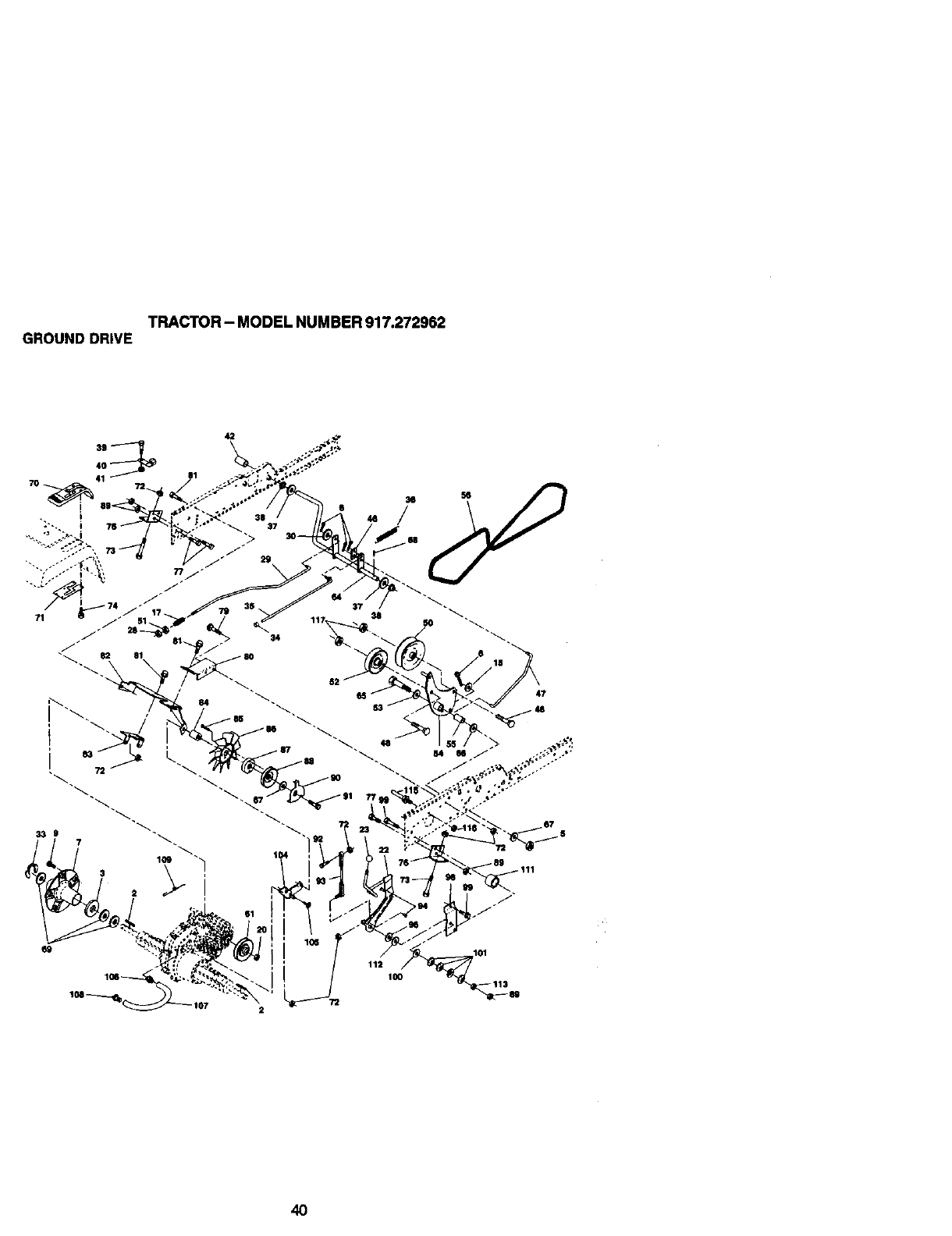
TRACTOR - MODEL NUMBER 917.272962
GROUND DRIVE
4O
41
I
11
61
47
72
112
IO0
ri01
4O
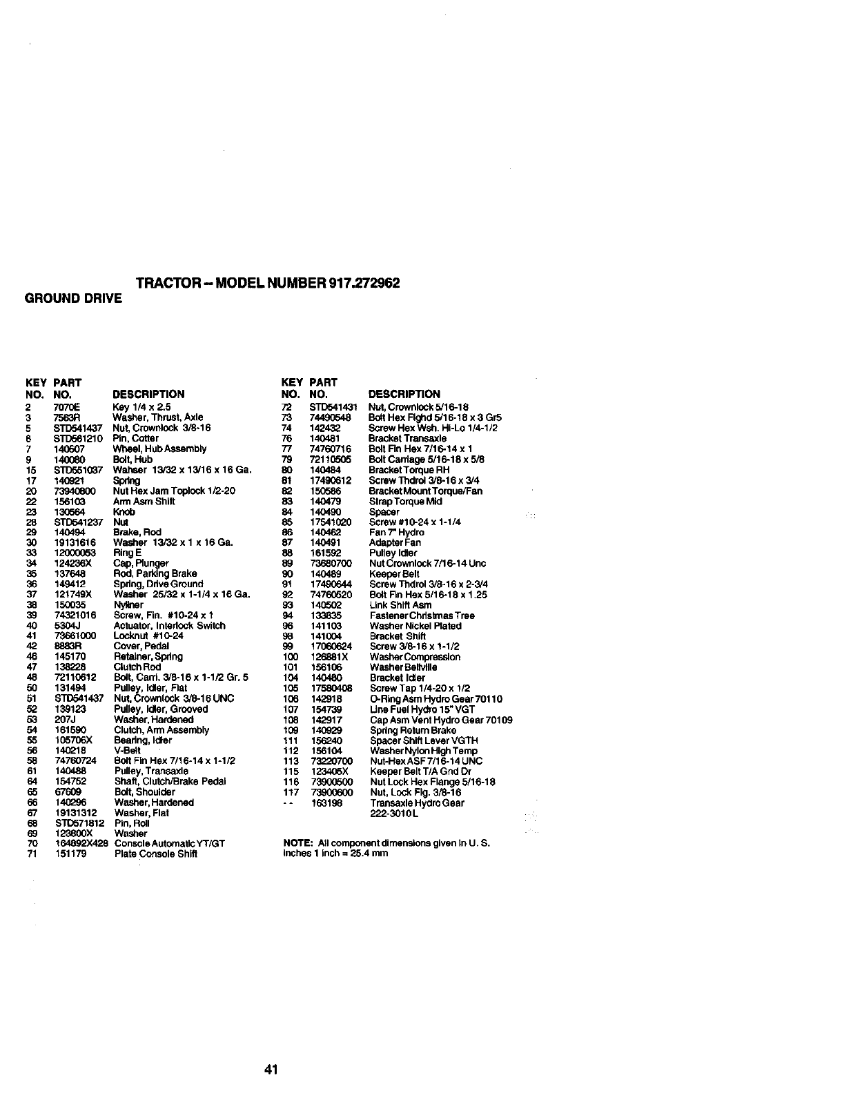
TRACTOR - MODEL NUMBER 917.272962
GROUND DRIVE
KEY PART KEY PART
NO. NO. DESCRIPTION NO. NO.
2 7070E Key 1/4 x 2.5 72 s'r[To41431
3 7563R Washer, Thrust, Axle 73 7449(_48
5 STD541437 Nut, Crownlock 3/8.16 74 142432
6 S_1210 Pin, Cotter 76 140481
7 140507 Wheel, Hub Assembiy 77 74760716
9 140(_0 Bolt, Hub 79 7211(To05
15 S'RTo510G7 Wahser 13i32x13!16x16Ga. 80 140484
17 140921 Spring 81 17490612
20 73940600 Nut Hex Jam Toplock 1/2-20 82 150586
22 15610_ Arm Asm Shift 83 140479
23 13(T_64 Knob 84 140490
28 STD541237 NUt 85 17541020
29 140494 Brake, Rod 55 140462
30 19131616 Washer 13/32x I x 16Ga. 87 140491
33 12000(_63 RingE 88 161592
34 124236X Cap, Plunger 89 73680700
35 137648 Rod, Parking Brake 90 140489
36 149412 Spdng, Ddve Ground 91 17490644
37 121749X Washer 25/32 x 1-1/4 x 16 Ga. 92 7476_20
38 150035 Nyllner 93 14(T_G2
39 74321016 Screw, Fin. #10-24 x 194 133835
40 5304J Actuator, Intedock Switch 96 14110G
41 73661000 Locknut #10-24 98 141004
42 8553R Cover, Pedal 99 17060624
46 145170 Rete_ner, Spdng 100 126881X
47 138228 Clutch ROd 101 156106
48 72110612 Bolt, Can1, 3/6.16 x 1-1/3 Gr. 5 104 140480
50 131494 Pulley, Idler, Flat 105 17580408
51 ST[To41437 Nut, Crowrtlock 3/6.16UNC 106 142918
52 139123 Pulley, Idler, Grooved 107 154739
53 207J Washer, Hardenod 108 142917
54 161590 Clutch, Arm Assembly 109 140929
55 155706X Beadng, Idler 111 15_40
56 14(_18 VoBOlt 112 156104
58 74760724 Bolt Fin Hex 7/16.14 x1-112 113 _700
61 140488 Pulley, Transaxle 115 123405X
64 154752 ShaH, Clutch/Brake Pedal 116 7390(To00
65 67609 Bolt, Shoulder 1t7 73900600
66 140L:_5 Washer, Hardened - - 16319_
67 19131312 Washer, Flat
68 STD571812 Pin, Roll
69 123800X Washer
70 164892X428 Console Autornatlc YT/GT
71 151179 Plate Console Shift
DESCRIPTION
Nut, Crownlock 5/16-18
Bolt Hex Flghd 5/16.18 x 3 Gr5
Screw Hex Wsh. HI-Lo 1/4-1/2
Bracket Transaxle
Bolt Rn Hex 7/16-14 x 1
Bolt Carriage 5/1 6-18 x 5/8
Bracket Torque RH
Screw Thdrol 3/6-16 x3/4
Bracket Mount Torque/Fan
StrapTorque Mid
Spacer
Screw #10-24 x 1-1/4
Fan 7"Hydro
Adapter Fan
Pulley Idler
Nut Crownlock 7/1 6-14 Unc
Keeper Belt
Screw Thdrol 3/8-16 x 2-3/4
Bolt Fin Hex 6/16-16 x 1.25
Link Shift Asm
Fastener Chdstmas Tree
washer Nickel Plated
Bracket Shift
Screw 3/6.16 x 1-1/2
Washor Compression
Washer Bellvllle
Bracket Idler
Screw Tap 1/4.20 x 1/2
O-Ring Asm Hydro Gear 70110
Line Fuel Hydro 15" VGT
Cap Asm Vent Hydro Gear 70109
Spring Return Brake
Spacer Shift Lever VGTH
Washer Nylon Higtl Temp
Nut-HexASF 7/16.14 UNC
Keeper Belt T/A GOd Or
Nut Lock Hex Flange 5/16-18
Nut, Lock Fig. 3/6.16
Transaxle Hydro Gear
222-3010L
NOTE: All component dimensions given In U. S.
inches 1 inch = 25.4 mm
41
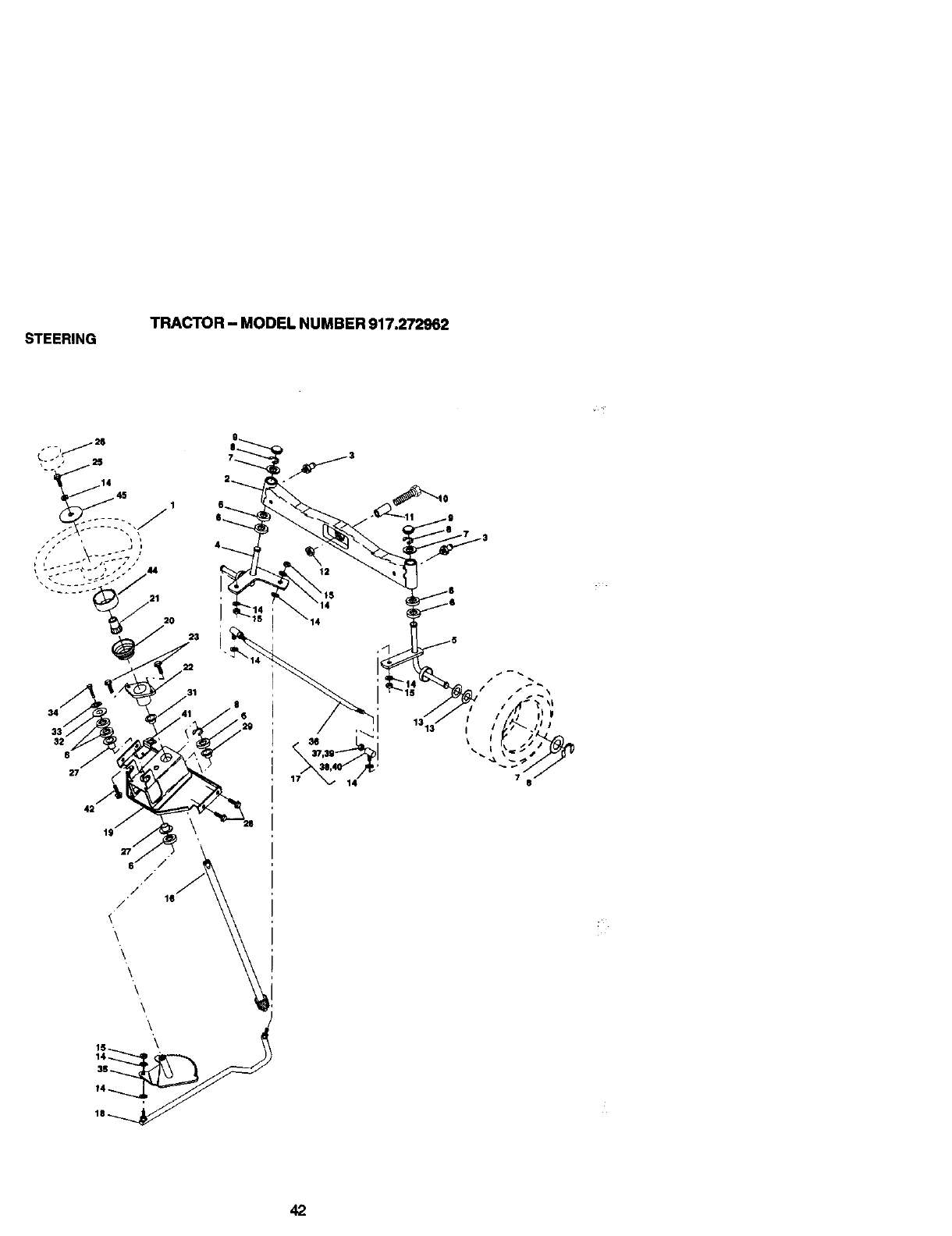
STEERING TRACTOR - MODEL NUMBER 917.272962
34
32
6
27
19
31
16
17
42
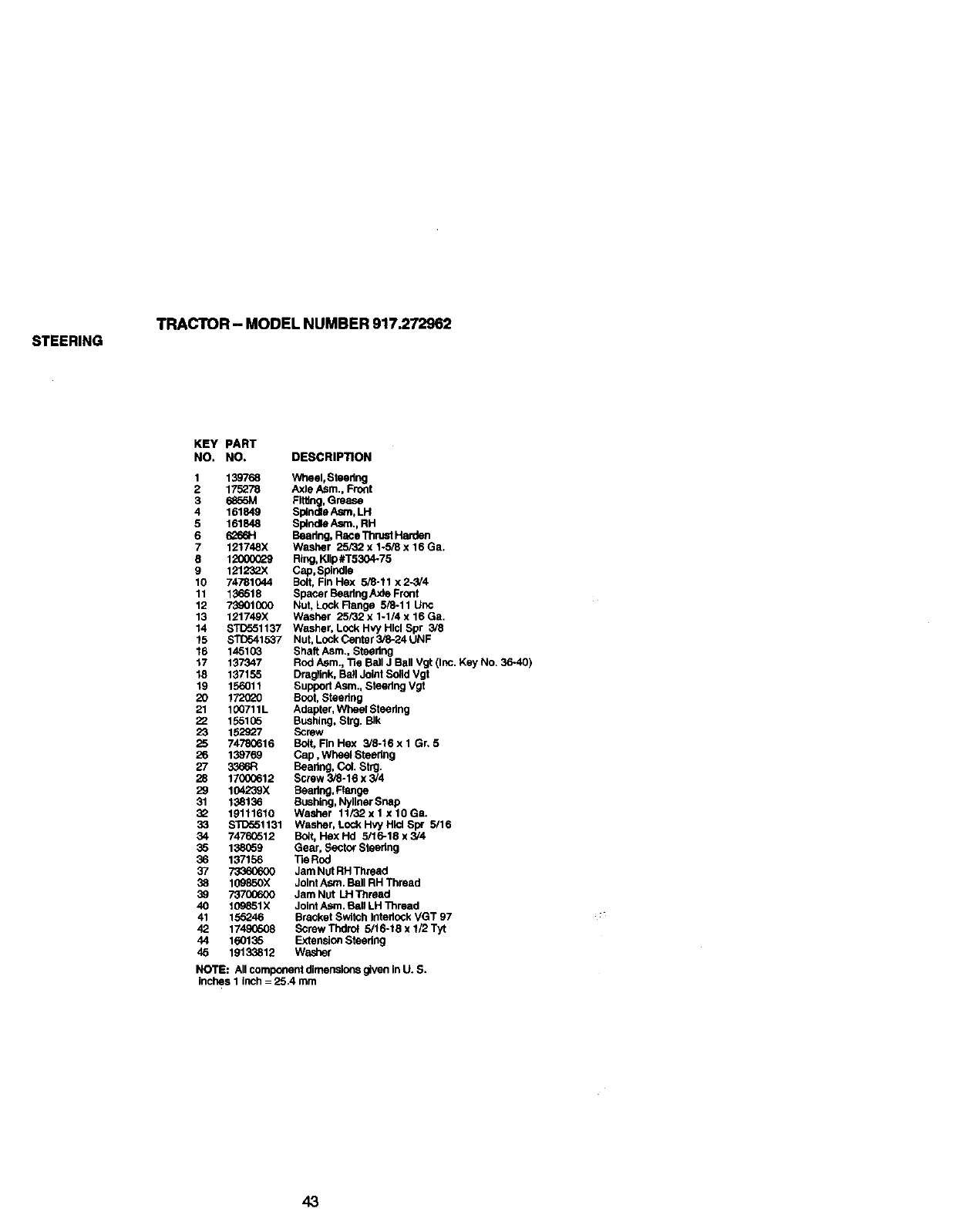
STEERING TRACTOR - MODEL NUMBER 917.272962
KEY PART
NO, NO. DESCRIPTION
1 139768 Wheel, Steedng
2 175278 Axle Asm., Front
3 6855M FWdng, Grease
4 161849 Splndle Asm, LH
5 161848 Sptndte Asnt., RH
6 6_6H Beadng, Race Thrust Harden
7 121748X Washer 25/32 x 1.5/8 x 16 Ga.
8 1L_60(_9 Ring, KIIp#T5304-75
9 1212"-2"-2"-2"-2"-2"-2_XCap, Splndhi
10 74781044 Bolt, Fin Hex 5/8-11 x 2-3/4
11 136518 Spacer Beadng/L_e Front
12 73_01000 Nut, Lock Range 5/8-11 Unc
13 121749X Washer 25/32 x 1-1/4 x 16 Ga.
14 STD551137 Washer, Lock Hvy Hlcl Spr 3/8
15 STD541537 Nut, LoCk Center 3/8-24 UNF
16 145103 Shaft Asm., Steedng
17 137347 Rod Asm., Tie Ball J Ball Vgt (Inc. Key No. 36-40)
18 137155 Draglink, Ball Joint Solid Vgt
19 156011 Support Asm., Steedng Vgt
20 172020 Boot, Steedng
21 100711L Adapter, Wheel Steedng
22 155105 BuShing, Strg. Blk
23 152927 Screw
25 74780616 Boft, FIn Hex 3/8-16x 1Gn5
26 139769 Cap, Wheel Steering
27 3366R Beadng, Col. Strg.
28 17000612 Screw 3_-16 x 3/4
29 104239X Beadng, Range
31 138136 Bushing, Nyllner Snap
32 19111610 Washer 11/32 x 1 x 10 Ga.
33 STD551131 Washer, Lock Hvy Hlol Bpr 5/16
34 74760512 Bait, Hex Hd 5/16-18 x 3/4
35 138059 Gear, Sector Steedng
36 137156 Tie Rod
37 73360600 Jam Nut RH Thread
38 109850X Joint Asm. Ball RH Thread
39 73700600 Jam Nut LH Thread
40 109851X Joint Asm. Ball LH Thread
41 155246 Bracket Switch Intedock VGT 97
42 174S0508 Screw Thdrol 5/16-18 x 1/2 Tyt
44 160135 Extension Steedng
45 19133812 Washer
NOTE: AllcomponentdimensionsgivenInU. S.
inches1 inch=25.4 mm
43
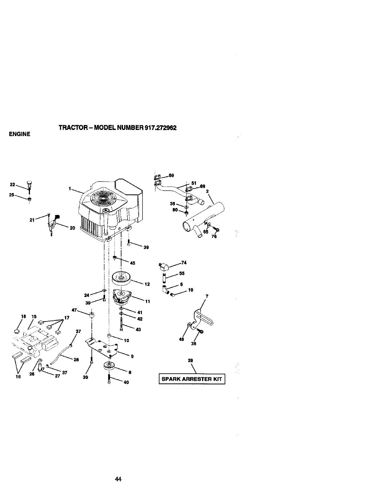
ENGINE TRACTOR - MODEL NUMBER 917.272962
18 15 17 47,.._
/i
37 13
_j74
js
7
48 38
26 ' 37
16 39 8
29
\
[SPARK ARRESTER KIT J
44
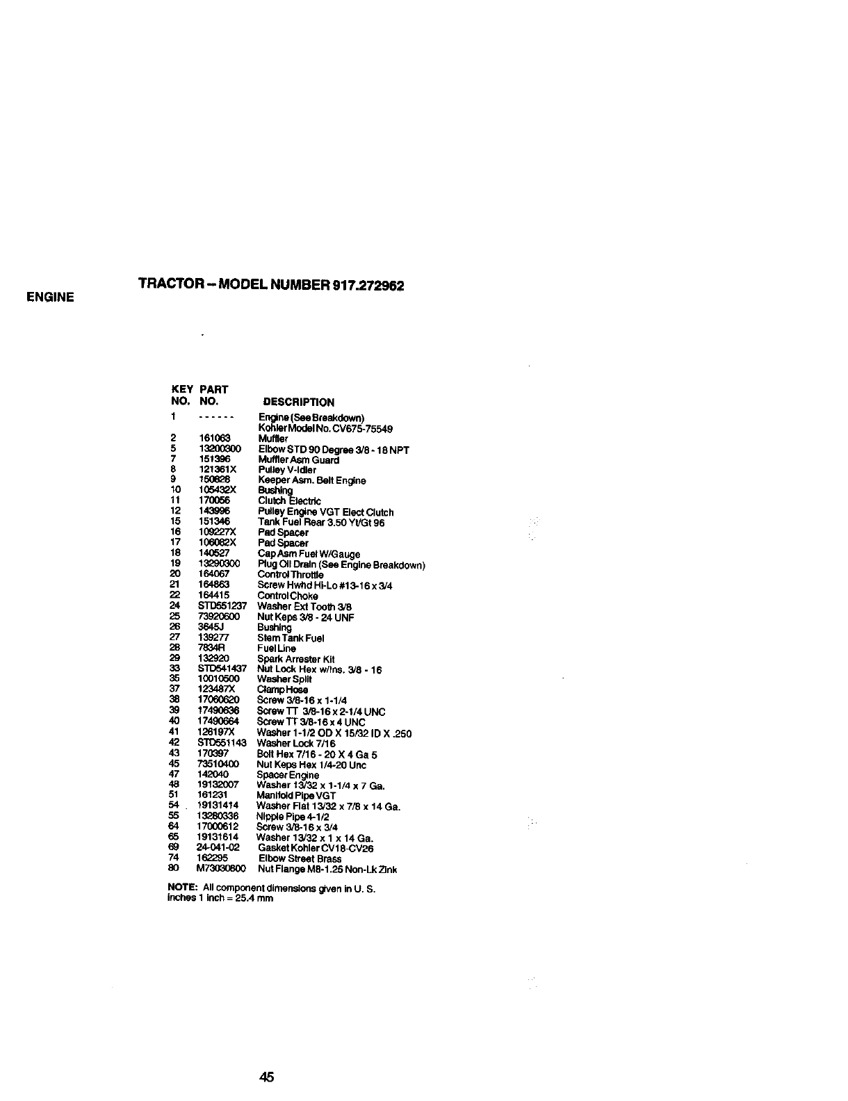
ENGINE TRACTOR - MODEL NUMBER 917.272962
KEY PART
NO, NO. DESCRIPTION
1 Engine (See Breakdown)
Kohler Model No. CV675-7554g
2 161063 Muffler
5 13_00_00 Elbow STD 90 Degree 3/8-18 NPT
7 151386 MuffierAsm Guard
8 121361X Pulley V-Idler
9 150628 Keeper Asm. Belt Eng4ne
10 1054_X Bushing
11 170056 Clutch Electric
12 143g_6 Pulley En_ne VGT EI6ct Clutch
15 151346 Tenk Fuel Rear 3.50 YI/Gt 96
16 109227X Pad Spacer
17 1060_ZX Pad Spacer
18 140527 Cap Asm Fuel W/Gauge
19 1_90300 Rug OII Drain (See Engine Breakdown)
20 164067 Contro4Throffie
21 164863 Screw Hwhd HI-Lo #13-16 x 3/4
22 164415 ControlCboke
24 S'1_551237 Washer Ext Tooth 3/8
25 73920600 Nut Kep_ 3_ - 24 UNF
26 3645J Bushing
27 139277 Stem Tank Fuel
28 7834R FuelUne
29 132920 Spark Arrester Kit
33 STD541437 Nut Lock Hex w/Ins, 3/8 -16
35 10010500 Washer Split
37 123487X C_ampH(:6e
38 17060620 Screw 3/8-16 x %1/4
39 1749(_36 Screw Tr 3/8-16 x 2.1/4 UNC
40 17490664 Screw TT 3/8-16 x 4 UNC
41 126197X Washer 1-1/20D X 15/32 ID X ,250
42 _1143 Washer Lcck 7/16
43 170397 Bolt Hex 7/16 - 20 X 4 Ga 5
45 73510400 Nut Kepe Hex 1/4-20 Unc
47 142040 Specer Engine
48 19132007 Washer 13/32 x 1-1/4 x 7Ga.
51 161231 Manlfold Pipe VGT
54 19131414 Washer Rat 13/32 x 7/8 x 14 Ga,
55 13280336 Nipple Pipe 4-1/2
64 17000612 Screw 3/8-16 x 3/4
65 19131614 Washer 13/32 x I x 14 Ga.
69 24-041-02 Gasket Kohler CV18-CV26
74 162295 Elbow Street Brass
80 M_ Nut Flange M8-1.25 Non-Lk 2]nk
NOTE: All component dimensions given in U. S,
inches 1 inch = 25.4 mm
45
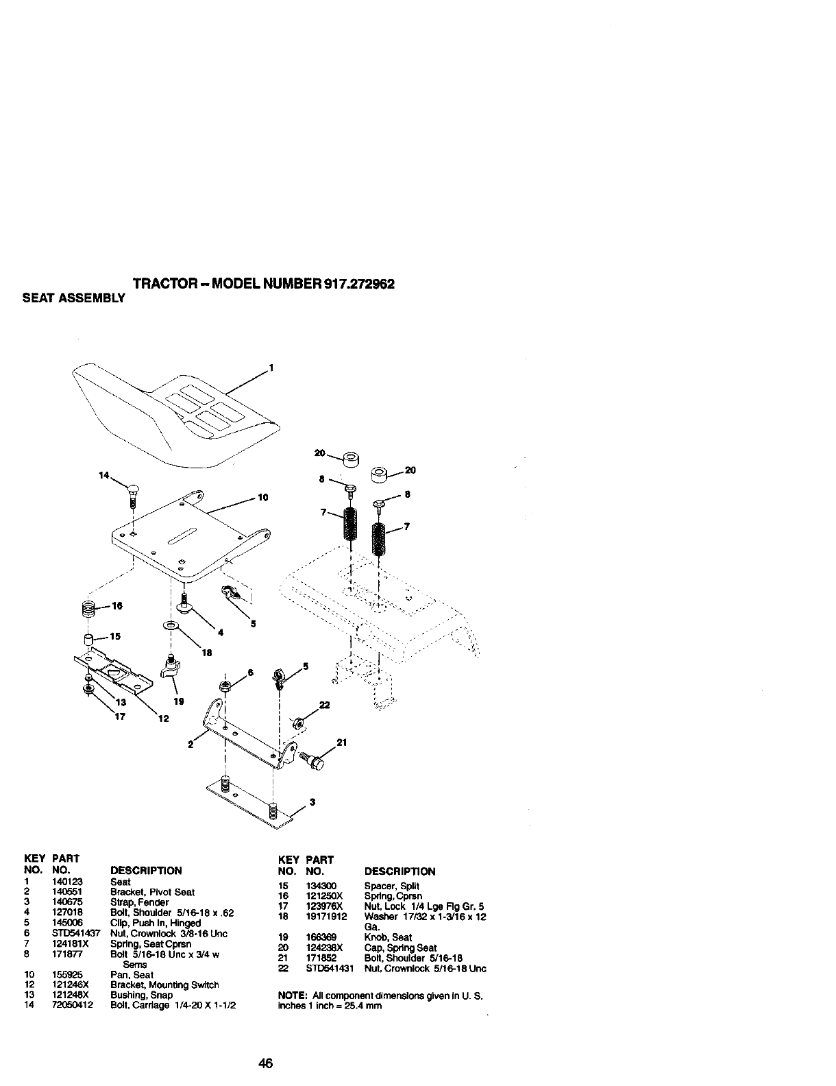
TRACTOR- MODELNUMBER917.272962
SEATASSEMBLY
8
KEY PART
NO. NO.
1 14O123
2 14(}551
3 140675
4 127018
5 145O06
6 STD541437
7 124181X
8 171877
10 155925
12 121246X
13 121248X
14 72(_O412
DESCRIPTION
Seat
Bracket, Pivot Seat
Strap, Fender
Bolt, Shoulder 5/16-18 x .62
Clip, Push In, Hinged
Nut, Crowolock 3/8-16 UriC
Spring, Seat Cprsn
Bolt 5/16-18 Unc x 3/4 w
Seres
Pan, Seat
Bracket, Mounting Switch
Bushing, Snap
Bolt, Cardage 1/4-20 X 1-1/2
KEY PART
NO, NO. DESCRIPTION
15 134300 Spacer, Split
16 121250X Spring, Cprsn
17 123976X Nut, Lock 1/4 Lge Rg Gr. 5
18 19171912 Washer 17/32 x 1-3/16 x 12
Ga.
19 166369 Knob, Seat
20 124238X Cap, Spring Seat
21 171852 Bolt, Bhoolder 5/16-18
22 $1_o41431 Nut, Crownlock 5/16-18 Unc
NOTE: All component dimensions given In U. B.
inches 1 inch =25.4 mm
46
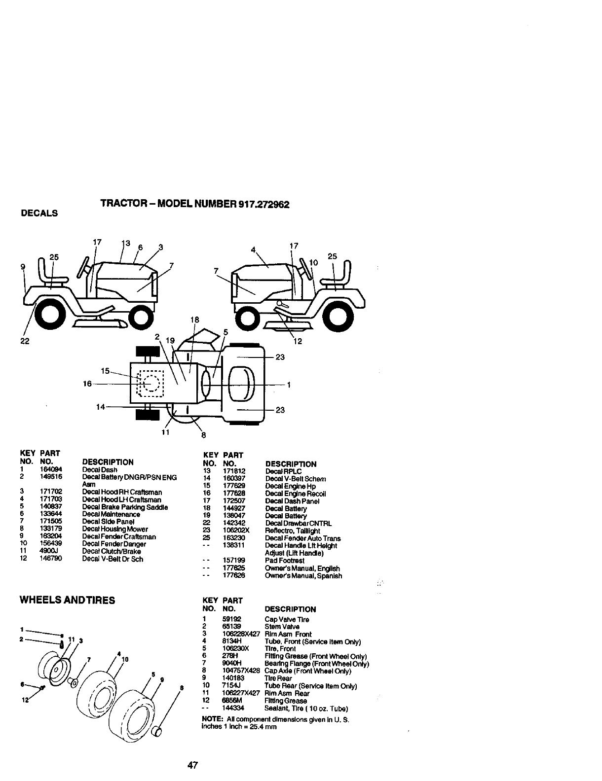
DECALS TRACTOR - MODEL NUMBER 917.272962
17 17
25
22
18
12
KEY PART
NO. NO.
1 164094
2 149516
3 171702
4 1717O3
5 140837
6 133644
7 171505
8133179
g 1632O4
10 156439
11 4900J
12 146790
I
11
DESCRIPTION
DecalDash
DecalBatteryDNGR/PSNENG
Asm
DecalHoodRHCraftsman
DecalHoodLHCralteman
DecalBrake ParkingSaddle
DecstMaintenance
DecalSide Panel
DecalHouelngMower
DecalFenberCrafteman
DecelFenberDanger
DecalClutch/Brake
DecalV-BeltDr Sch
WHEELS ANDTIRES
9
$
8
KEY PART
NO. NO. DESCRIPTION
13 171812 Decst RPLC
14 160_7 Decal V-Belt Schem
15 1776_ Decel Engine Hp
16 177628 Oecel Engine Recoil
17 172507 Dasel Dash Panel
18 144927 Decal Battery
19 138047 Decal Battery
22 142342 Dasal Drav/oarCNTRL
23 10620_ Rshectro, Taillight
25 163230 Decal Fender Auto Trans
- - 138311 Decal Handle Lft Height
Adjust (Lift Handle)
- - 157199 Pad Footrest
-- 1776_5 Owner's Man ual, Englrih
- - 177626 Owner's Manual, Spanish
KEY PART
NO. NO. DESCRIPTION
1 591g_ Cap Vrive Tire
2 65139 Stem Valve
3 106228X427 RimAsm Front
4 8134H Tube, Front (Service Item Only)
5 10_L_30X Tim, Front
6 278H Fitting Grease (Front Wheel Only)
7 9040H Beadng Range (Front Wheel Only)
8 104757X428 Cap Axle (Frc_t Wheel Only)
9 140183 ]Ire Rasr
10 7154J Tube Rear (Sendce Item Only)
11 106227X427 RimAsm Rear
12 6856M Firing Greese
- - 144334 Sealant, "nre ( 10 oz, Tube)
NOTE: All component dlmer'_dons g;ven in U. S.
inches I Inch = 25.4 mm
47
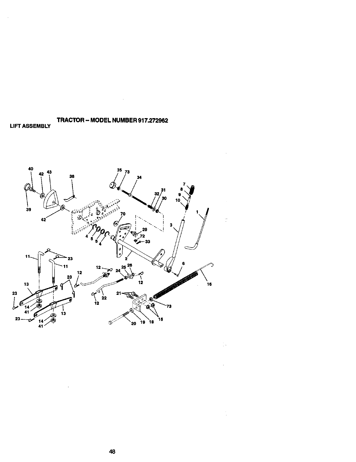
TRACTOR-MODEL NUMBER 917.272962
LIFTASSEMBLY
4O 43 38
15
20 19 18
16
48
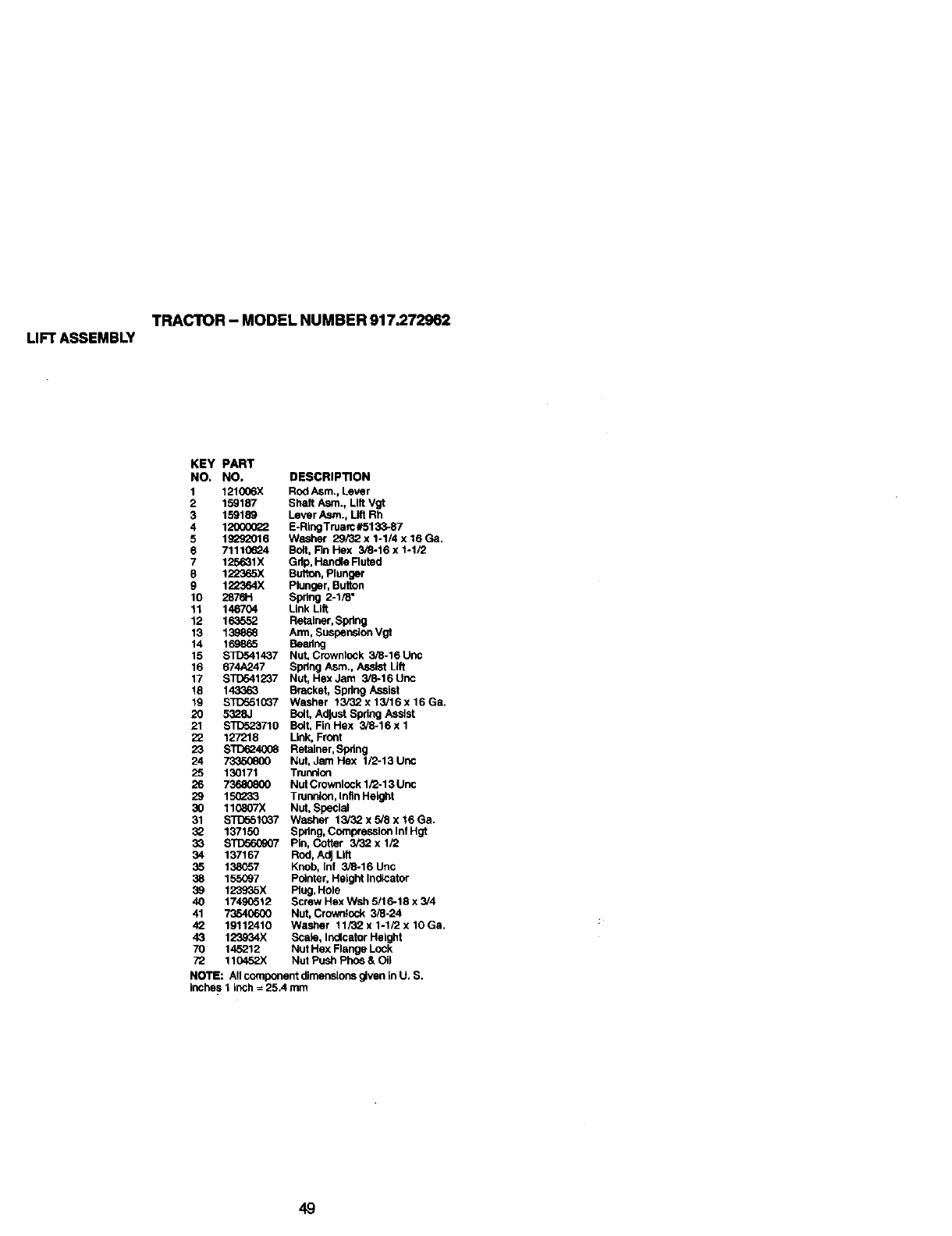
TRACTOR - MODEL NUMBER 917.272962
LIFT ASSEMBLY
KEY PART
NO. NO, DESCRIPTION
1 121006X Rod Asm., Lever
2 159187 Shalt Asm., Lift Vgt
3 159189 Lever Asm., Lift Rh
4 1_ E-RingTruarc#5133-87
5 19292016 Washer 29/32 x 1-1/4 x 16 Ga,
6 71110624 Bolt, Fin Hex 3/8-16 x 1-1/2
7 125631X Gdp, Handis Rutod
8 1;_65X Button, Plunger
9 1_o364X Plunger, Button
10 2876H Spring 2-1/8"
11 146704 Link Lilt
12 163552 Retainer, Spdng
13 139868 Arm, Suspension Vgt
14 169865 Beshng
15 $1I)541437 Nut, Crowoiock 3/8-16Unc
16 674A247 Spring Asm., Assist Lift
17 STD541237 Nut, Hex Jam 3/8-16 Unc
18 143363 Bracket, Spdng Assist
19 STD551037 Washer 13/:32x13/16x16Ga.
20 5328J BolLAdjust Spdng Assist
21 ST[To23710 Boit, FinHex 3/8-16xl
22 127218 Link, Front
23 s'rDi_4_X]8 Retainer, Spring
24 73350800 Nut, Jam Hex 1/2-13 Unc
25 130171 Trunoicn
26 73680800 Nut Crownlock 1/2-13 Unc
29 150233 Trunnion, Infln Height
30 110807X Nut, Special
31 s'rD561037 Washer 13J32x3iSx16Ga,
32 137150 Spring, Compression Inf Hgt
33 STD560907 Pin, Cotter 3/32 x 1/2
34 137167 Rod, AdJLilt
35 138057 Knob, Inf 3/8-16 Unc
38 155O97 Pointer, Height Indicator
39 123935X Rug, Hole
40 17490512 Screw Hex Wsh 5/16-18 x 3/4
41 73540600 Nut, Crowntock 3/8-24
42 19112410 Washer 11/32 x 1-1/2 x 10 Ga,
43 123934X Scais, Indicator Height
70 145212 Nut Hex Flange Lock
72 110452X Nut Push Pho_ & Oil
NOTE: All componentdimensionsgivenInU, S,
inches1 inch= 25.4 mm
49
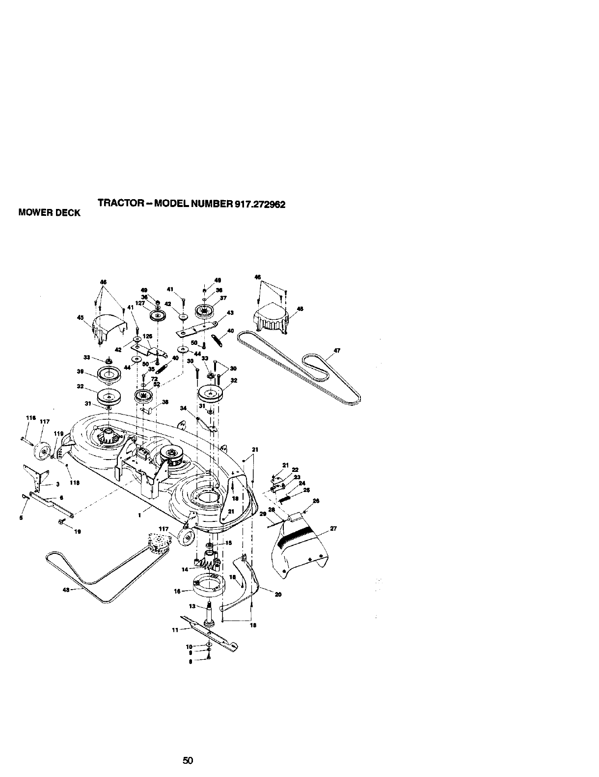
TRACTOR - MODEL NUMBER 917.272962
MOWER DECK
45\
46
O41 \
49
36
46
42
39_
47
116 117
19 117
21
26
j27
13_
18
50
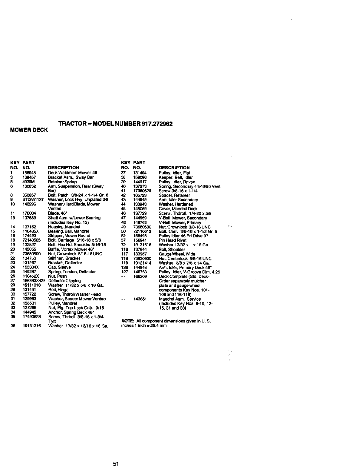
TRACTOR - MODEL NUMBER 917.272962
MOWER DECK
KEY PART KEY PART
NO. NO. DESCRIPTION NO. NO.
1 156948 Deck Weldment Mower 46 37 131494
3 138457 Bracket Asm., Sway Bar 38 156086
5 4939M Retainer Spdng 39 144917
6 130832 Arm, Suspension, Rear (Sway 40 137273
Bar) 41 17060620
8 850857 Bolt, Patch 3_-24 x 1-1/4 Gr. 8 42 165723
9 $11To51137 Washer, Lock Hvy. Unplatad 3/8 43 144949
10 1402S6 Washer, Hard Blade, Mower 44 133943
Vented 45 145059
11 176084 Blade, 46" 46 137729
13 137553 Shaft Asm. w/Lower Beating 47 144959
(Includes Key No. 12) 48 148763
14 137152 Housing.Mandrel 49 73680600
15 110485X Baadng, Ball, Mandrel 50 72110612
16 174493 Stripper, Mower Round 52 156493
18 72140505 Bolt, Cardage 5/16-18 x 5/8 57 156941
19 132827 Bolt, Hex Hd, Shoulder 5/16-18 72 19131616
20 145(T_5 Baffle, Vortex Mower 46" 116 137644
21 _Nut, Crownlock 5/16-18UNC 117 133_57
22 134753 S_ffiner, Bracket 118 73930600
23 131267 Bracket, Deflector 119 19121414
24 1(_0304X Cap, Sleeve 126 144948
25 149"287 Spdng, Torsion, Deflector 127 146763
26 110452X Nut, Push - - 166_79
27 166883)(428 Deflector CEipplng
28 19111016 Washer 11/32 x 5/8 x 16 Ga,
29 131491 Rnd, Hl_je
30 157722 Screw, Thdrdll Washer Head
31 129963 Washer, Spacer Mower Vented - - 143651
3_ 153531 Pulley, Mandrel
33 137266 Nut, Fig. Top Lnck Cntr. 9/16
34 144945 Anchor, Spdng Deck 46"
35 17490628 Screw, Thciroll 3/8-16 x 1-3/4
Tytt
36 19131316 Washer 15/32 x 13/16 x 16 Ga.
DESCRIPTION
Pulley, Idler, Flat
Keeper, Bait, Idler
Pulley, Idler, Driven
Spring, Secondary 44/46/50 Vent
Screw 3/8-16 x 1-1/4
Spacer, Retainer
Arm, Idler Secondary
Washer, Hardened
Cover, Mandrel Deck
Screw, Thdrdll. 1/4-20 x 5/8
V-Belt, Mower, Secondary
V-Belt, Mower, Primary
Nut, Crownlock 3/8-16 UNC
Bolt, Carr. 3/8-16 x 1-1/2 Gr. 5
Pulley Idler 46 Pd Ddve 97
Pin Head Rivet
Washer 13/32 x 1 x 16 Ga.
Bo/t, Shoulder
Gange Wheel,Wide
Nut, Centedock 3/8-16 UNC
Washer 3/8 x 7/8 x 14 Ga.
Arm, Idler, Pdmary Deck 46"
Pulley, Idler, V-Groove Dim. 4.25
Deck Completa (Std, Deck*
Order separately mulcher
plate and gauge wheel
components Key Nos. 101-
106and 116-118)
Mandrel Arm. Service
(Includes Key Nos. 8-10, 12-
15,31 and 33)
NOTE: Atlcomponentdlmenstor_g4venIn U.S.
inchesI inch=25.4 mm
51
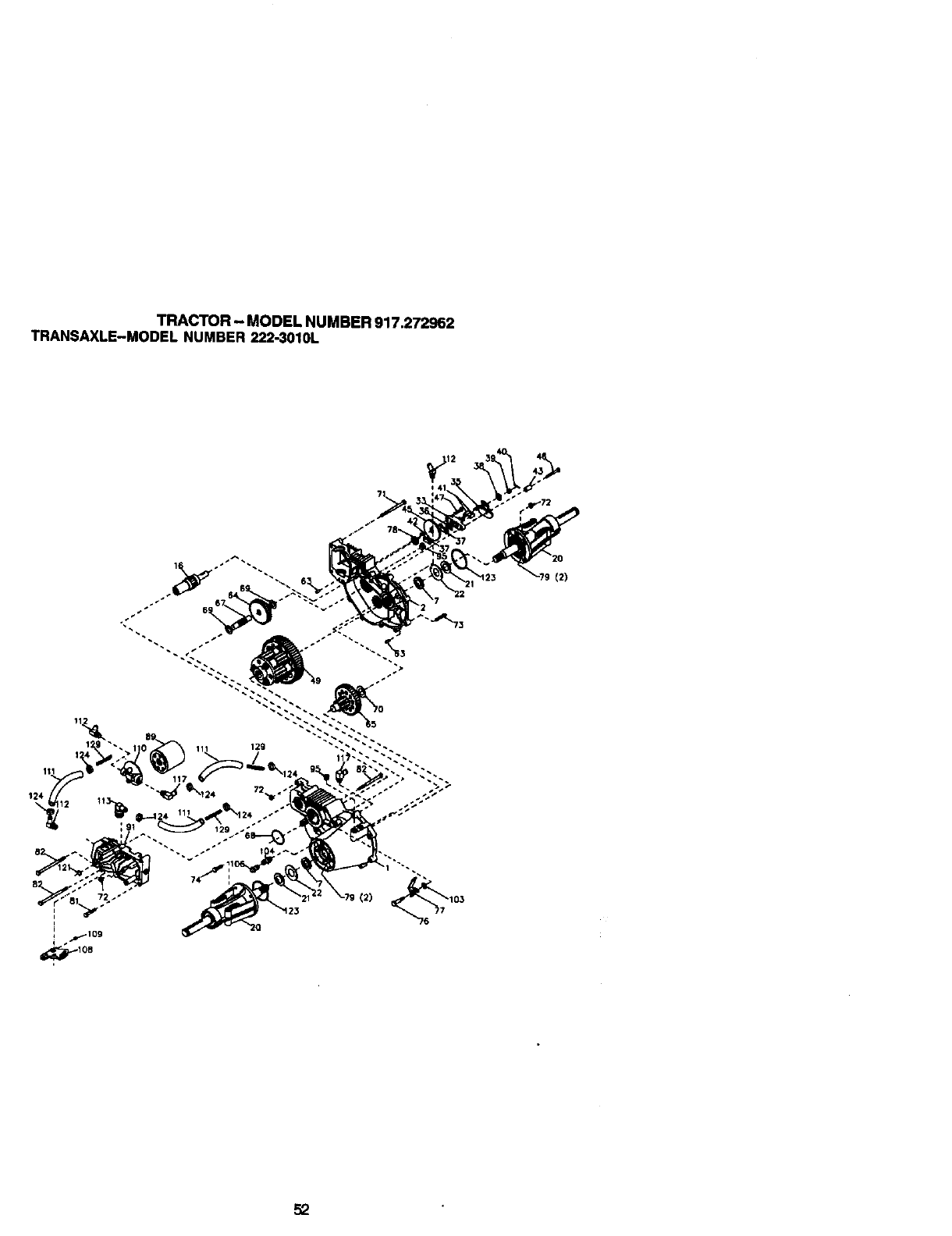
TRACTOR - MODEL NUMBER 917.272962
TRANSAXLE-MODEL NUMBER 222-3010L
129 • _ •
151
(2)
52
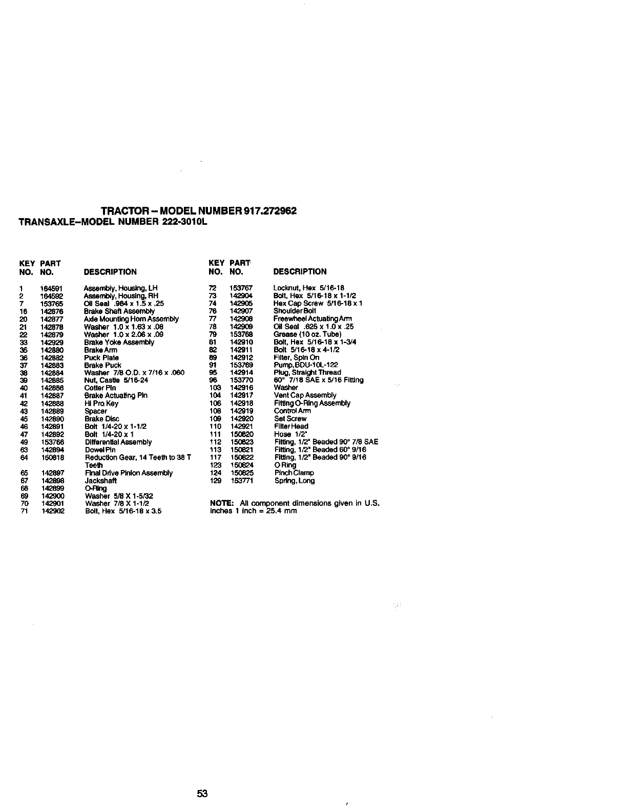
TRACTOR - MODEL NUMBER 917.272962
TRANSAXLE-MODEL NUMBER 222-3010L
KEY PART KEY PART
NO. NO. DESCRIPTION NO. NO.
1 164591 Assembly, Housing, LH
2 164592 Aseefnbly, Housing, RH
7 153765 Oil Seal .984 x 1.5 x .25
16 142876 Brake Shaft Assembly
20 142877 Axle Mounting Hom Assemb;y
21 142878 Washer 1,0 x 1.63 x .08
22 142879 Washer 1.0 x 2.06 x .09
33 142929 Brake Yoke Assembly
35 142880 BrakeArm
36 142882 Puck Plate
37 142883 Brake Puck
38 142884 Washer 7/80.D. x 7/16 x .060
39 142885 Nut, Castie 5/16-24
40 142886 Cotter Pin
41 142887 Brake Actuating Pin
42 142888 HI Pro Key
43 142889 Spacer
45 142890 Brake Disc
46 142891 Bod 1/4-20 x 1-1/2
47 142892 Bolt 1/4-20 x 1
49 153766 Differential Assembly
63 142894 DowalFin
64 150618 Reduction Gear, 14 Teeth to 38 T
Teeth
6_5 142897 Final Ddve Pinion Assembly
67 142898 Jackshaft
68 142899 O-P_g
69 142900 Washer 5/8 X 1-5/32
70 142901 Washer 7/8 X 1-1/2
71 142902 Bolt, Hex 5/16-t8 x 3.5
DESCRIPTION
72 153767 Looknut, Hex 5116-18
73 142904 Bolt, Hex 5116-18 x 1-I/2
74 142905 Hex Cap Screw 5/16-18 x 1
76 142g07 Shoulder Bolt
77 1429_8 Freewheel Actuating Arm
78 142909 Oil Seal .625 x 1.0 x .25
79 153768 Grease {10 oz. Tube)
81 142910 Bolt, Hex 5/16-18 x 1-3/4
82 142911 Bolt 5/16-18 x 4.1/2
89 142912 Frier, Spin On
91 153769 Pump, BDU-10L-122
S5 142914 Plug, Straight Thread
96 153770 60 °7/18 SAE x 5/16 Fitting
103 142916 Washer
104 142917 Vent Cap Assembly
106 142918 Fitting O-Ring Assembly
108 142919 Control Arm
109 142920 SetScrew
110 142921 Fllter Head
111 150820 Hose 1/2"
112 1506_3 Fitting, 1/2" Beaded 90 ° 7/8 SAE
113 150821 Fitting, 1/2' Beaded 60 °9/16
117 150622 Fitting, 1/2" Beaded 90 °9/16
123 15_624 ORIng
124 15_625 Pinch Clamp
129 153771 Spring, Long
NOTE: All component dimensions given in U.S.
inches 1 Inch = 25.4 mm
53
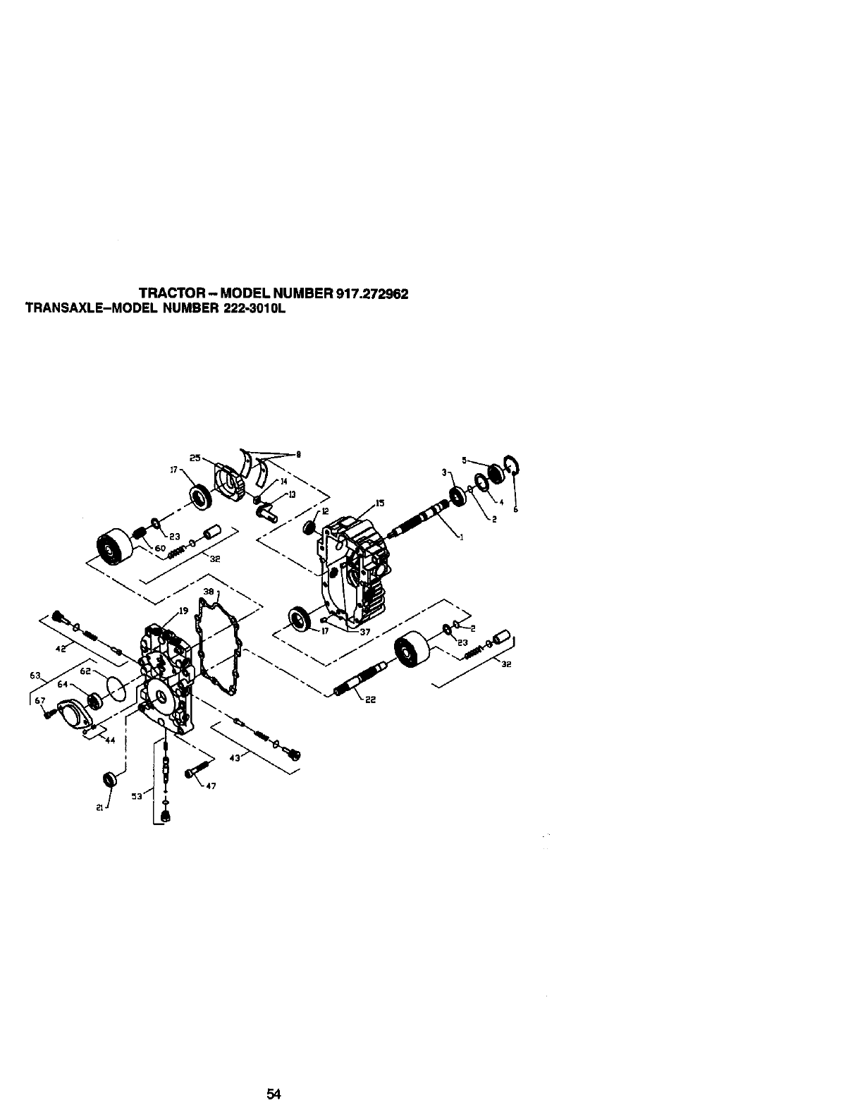
TRACTOR - MODEL NUMBER 917.272962
TRANSAXLE-MODEL NUMBER 222-3010L
54
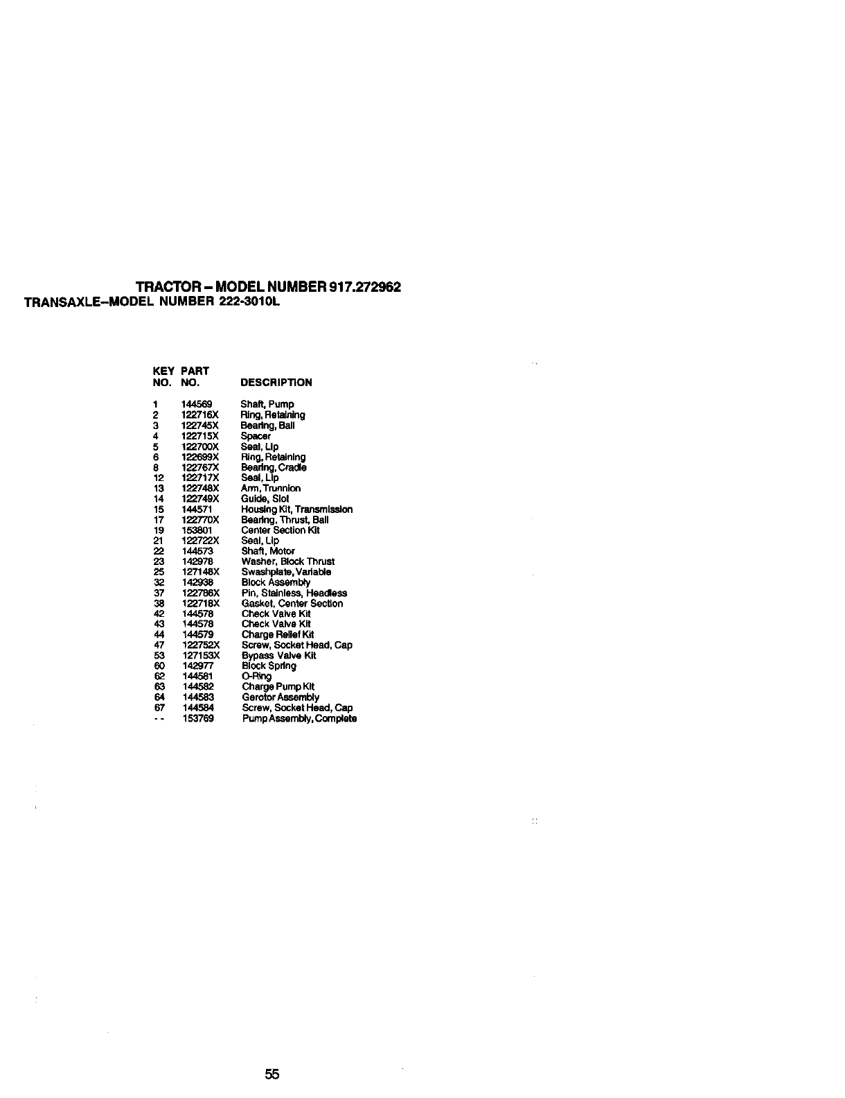
TRACTOR- MODELNUMBER917.272962
TRANSAXLE-MODELNUMBER222-3010L
KEY PART
NO. NO. DESCRIPTION
1 144569 Shaft, Pump
2 122716X Ring, Retaining
3 122745X Beadng, Ball
4 122715X Spacer
5 122700X Seal, Lip
6 122539X Ring, Retaining
8 12_/67X Beadng, Cradle
12 122717X Seal, Lip
13 1_748X Arm,Trunnion
14 1_°749X Guide, Slot
15 144571 Housing Kit, Transrnisedon
17 122770X Beadng, Thrust, Ball
19 153801 Center Section Kit
21 122722X Seal. Lip
22 144573 Shaft, Motor
23 142978 Washer, Block Thrust
25 127148X Swashplata, Vadable
3_ 142938 Block Asssmb_y
37 122753X Pin, Stainless, Headless
38 122718X Gasket, Center Section
42 144578 Check Valve Kit
43 144578 Check Valve Kit
44 144579 Charge Relief Kit
47 122753X Screw, Socket Head, Cap
53 127153X Bypass Valve Kit
60 142977 Block Spring
53 144581
63 144582 Charge Pump Kit
64 144583 Gerotor Assembly
67 144584 Screw, Socket Head, Cap
-. 153769 Pump Assembly, Comp4ete
55
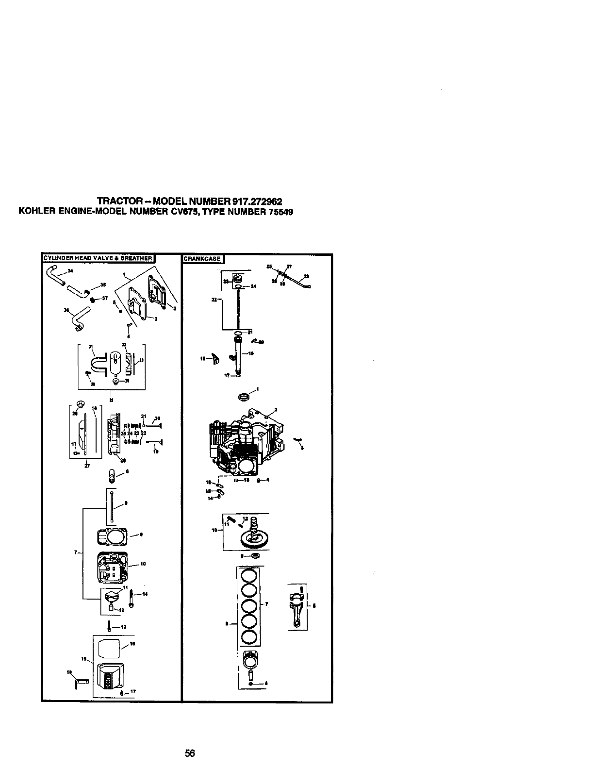
TRACTOR - MODEL NUMBER 917.272962
KOHLER ENGINE-MODEL NUMBER CV675, TYPE NUMBER 75549
56
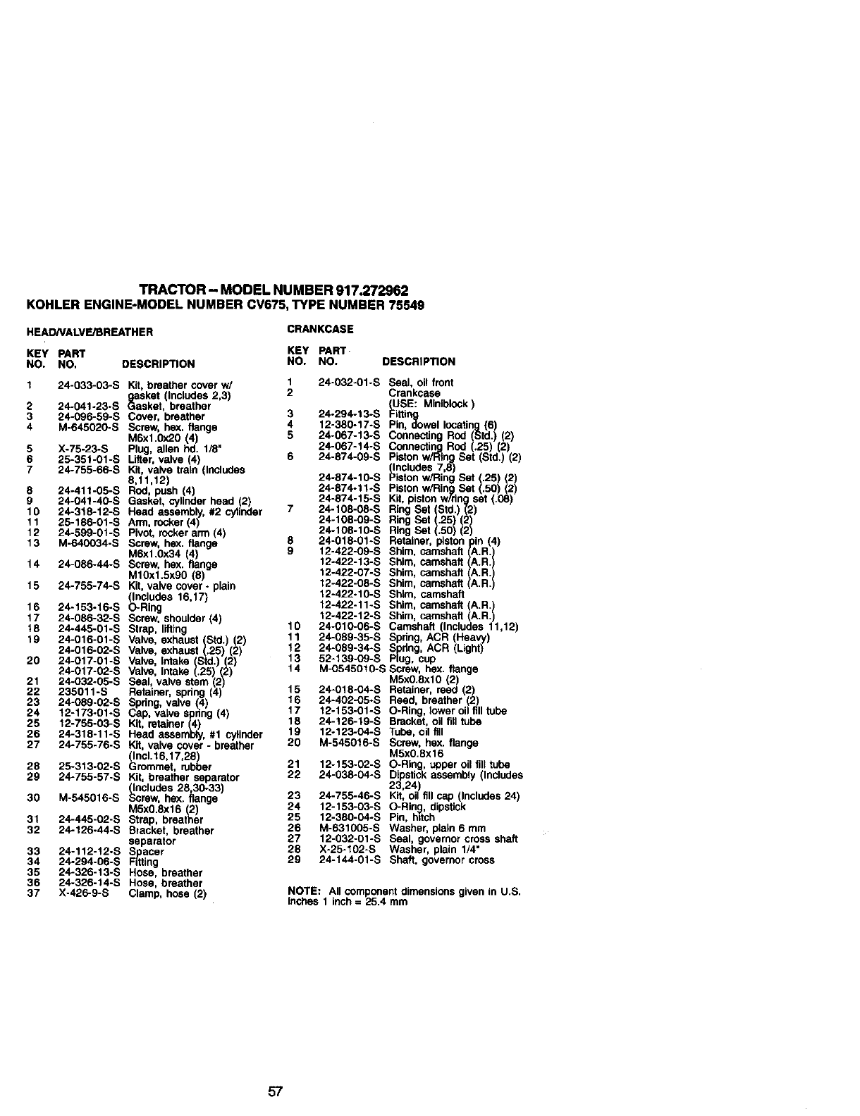
TRACTOR - MODEL NUMBER 917.272962
KOHLER ENGINE-MODEL NUMBER CV675, TYPE NUMBER 75549
HEAONALVE/BREATHER CRANKCASE
KEY PART KEY PART
NO. NO. DESCRIPTION NO. NO. DESCRIP_ON
1 24-033-03-S Kit, breather cover w/ 1 24-032-01-S Seal, oil front
gasket (Includes 2,3) 2 Crankcase
2 24-041-23-S Gasket, breather (USE: MInlblock
3 24-096-59-S Cover, breather 3 24-294-13-S Fitftng
4 M-645020-S Screw, hex. flange 4 12-380.17-S Pin, dowel locating (6)
M6xl.0x20 (4) 5 24-067-13-S Connecting Rod (Std.) (2)
5 X-75-23-S Plug, allen hd. 1/8" 24-067-14-S Connecting Rod (.25) (2)
6 25-351-01-S Lifter, valve (4) 6 24-874-09-S Piston w/Ring Set (Std.) (2)
7 24-755-66-S Kit, valve train (Includes (Includes 7,8)
8,11,12) 24-874-10-S PiStonw/Ring Set (.25) (2)
8 24-411-05-9 ROd, push (4) 24-874-11-S PLstonw/Ring Set (.50) (2)
0 24-041-40-S Gasket, cylinder head (2) 24-874-15-S Kit, piston w/dng set (.08)
10 24-318-12-S Head assembly, #2 cytinder 7 24-108-08-S Ring Set (Std.) (2)
11 25-186-01-S Arm, rocker (4) 24-108-09-S Ring Set (.25) (2)
12 24-599-01-S Pivot, rocker arm (4) 24-108-10-S Ring Set (.50) (2)
13 M-640034-S Screw, hex. flange 8 24-018-01-S Retainer, pistonpin (4)
M6x1.0x34 4) 9 12-422-00-S Shim, camshaft IA.R.I
14 24-086-44-S Screw, hex. range 12-422-13-S Shim, camshaft ,..,.R.
.10x15xoo(5) 124229shimcamshoft
15 24-755-74-S Kit, valve cover -plain 12-422-08-S Shim, camshaft i i
12-422-10.9 Sh_m,camshaft
(Includes 16,17)
16 24-153-16-S O-Ring 12-422-11-S Shim, camshaft (A.R.
12-422-12-S Shim, camshaft (A.R.
17 24-086-32-S Screw, shoulder (4) 10 24-010-06-S Camshaft (Includes 11,12)
18 24-445-01-S Strap, lifting
19 24-016-01-S Valve, exhaust (Std.) (2) 11 24-08g-35-S Spring, ACR (Heavy)
24-016-02-S Valve, exhaust (.25) (2) t2 24-089-34-9 9pdng, ACR (Light)
20 24-017-01-9 Valve, intake Std. (2) 13 52-139-O9-S Plug, cup
24-017-02-S Valve, intake (.25) (2) 14 M-0545010-S Screw, hex. flange
21 24-O32-05-S Seal, valve stem (2) MSxO.8xl0 (2)
22 235011-S Retainer, spdng (4) 15 24-018-04-S Retainer, reed (2)
23 24-089-02-S Spdng, valve (4 16 24-402-05-S Reed, breather (2)
24 12-173-01-S Cap, valve spring (4) 17 12-153-01-S O-Ring, lower oil filltube
25 12-755-03-S Kit, retainer (4) 18 24-126-19-S Bracket, oil fill tube
26 24-318-11-S Head assembly, #1 cylinder 19 12-123-04-S Tube, oil fill
27 24-755-76-S Kit, valve cover -breather 20 M-545016-S Screw, he)(. flange
(Incl.l 6,17,28) M5x0.8x16
28 25-313-02-S Grommet, rubber 21 12-153-02-S O-Ring, upper oil fill tube
29 24-755-57-S Kit, breather separator 22 24-038-04-S Dipstick assembly (Includes
(Includes 28,30-33) 23,24)
30 M-545016-S Screw, hex. flange 23 24-755-46-S Kit, oil fill cap (Includes 24)
M5x0.8x16 (2) 24 12-153-03-S O-Ring, dipstick
31 24-445-02-S Strap, breather 25 12-380-04-S Pin, hitch
32 24-120.44-S Bracket, breather 26 M-631005-S Washer, plain 6 mm
separator 27 12-032-01-S Seal, governor cross sftaft
33 24-112-12-S Spacer 28 X-25-102-S Washer, plain 1/4"
34 24-294-06-S Fdting 29 24-144-01-S Shaft, governor cross
35 24-326-13-S Hose, breather
36 24-326-14-S Hose, breather
37 X-426-9-S Clamp, hose (2) NOTE: All component dimensions given in U.S.
inches 1 inch = 25.4 mm
57
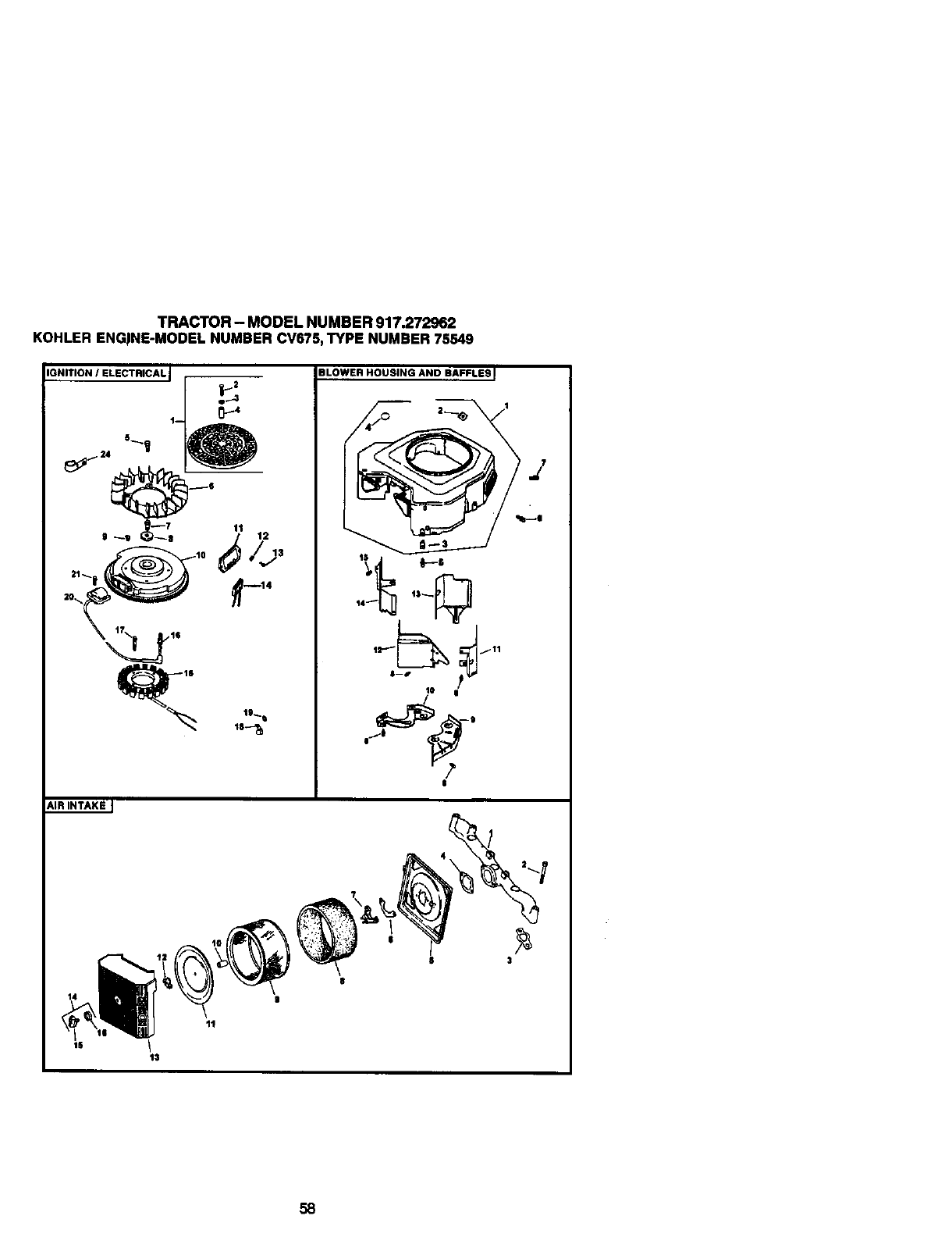
TRACTOR - MODEL NUMBER 917.272962
KOHLER ENGiNE-MODEL NUMBER CV675,TYPE NUMBER 75549
IGNITION /ELECTRICAL I
e.._l
1--
BLOWER HOUSING ANO BAFFLES
l.,b_o
8--0
t0 e'
/
I
AIR INTAKE J
13
8 3
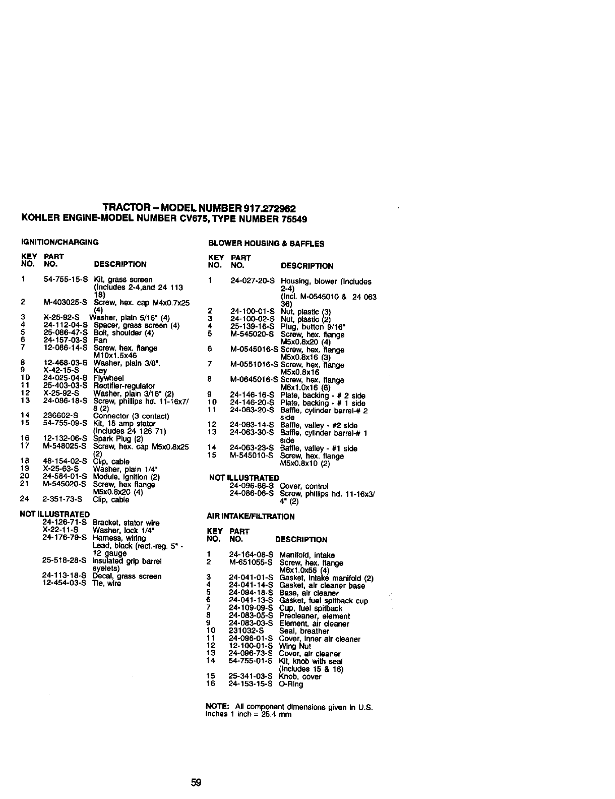
TRACTOR - MODEL NUMBER 917.272962
KOHLER ENGINE-MODEL NUMBER CV675, TYPE NUMBER 75549
IGNITION/CHARGING BLOWER HOUSING & BAFFLES
KEY PART KEY PART
NO. NO. DESCRIPTION NO, NO. DESCRIPTION
1 54-755-15-S Kit, grass screen 1 24-027-20-S Housing, blower (Includes
(Includes 2-4,and 24 113 2-4
18) (Inc. M-0545010 & 24 063
2 Mo403025-S Screw, hex. cap M4x0.7x25 36)
(4) 2 24-100-01-S Nut, plastic (3)
3 ;<-25-92-S Washer, plain 5/16" (4) 3 24-100-02-S Nut, plastic (2)
4 24-112-04-S Spacer, grass ssreen (4) 4 25-139-16-S Plug, button 9/16"
5 25-086-47-S Bolt, shoulder (4) 5 M-545920-S Screw, hex, flange
6 24-157-03-S Fan MSx0.8x20 (4)
7 12-086-14-S Screw, hox, flange 6 M-0545016-S Screw, hex. flange
M1Ox1.5x46 M5xO.8xf 6 (3)
8 12-468-03-S Washer, plain 3/6". 7M-0551016-S Screw, hex, flange
9 X-42-15-S Key M5xO.8x16
10 24-025-04-S Flywheel 8 M-0645016-S Screw, hex, flange
11 25-403-03-S Rsctifler-regulator M6x1.0x16 (6)
12 X-25-92-S Washer, plain 3/16" (2) 9 24-146-16-S Plate, bacldng - #2side
13 24-086-18-S Screw, phillips hd. 11-f6x7/ 10 24-146-20-S Plate, backing - #1 side
8 (2") 11 24-063-20-S Baffle, cylinder barter-# 2
14 236602-S Connector (3 contact) side
15 54-755-09-S Kit, 15 am)p stator 12 24-063-14-S Baffle, valley - #2 side
_lncludes 24 128 71) 13 24-063-30-S Baffle, cylinder barrel-# 1
16 12-132-06-S Spark Plug (2) side
17 M-548025-S Screw, hex. cap M5x0.8x25 14 24-063-23-S Baffle, valley - #1 side
15 M-545010-S Screw, hox. flange
18 48-154-02-S lip, cable M5x0.8xlO (2)
19 X-25-63-S Washer, plain 1/4"
20 24-584-01-S Module, ignition (2) HOT ILLUSTRATED
21 M-545020-S Screw, hex flange 24-096-66-S Cover, control
MSx0.8x20 (4) 24-086-06-S Screw, phillips hd. 11-16x3/
24 2-351-73-S Clip, cable 4' (2)
NOT ILLUSTRATED
24-126-71-S Bracket, stator wire
X-22-11-S Washer, lock !/4"
24-176-79-S Harness, wiring
Lead, black (rect.-rng. 5" -
12 gauge
25-518-28-S insulated grip barrel
eyelets)
24-113-18-S Oecat, gross screen
12-454-03-S Tie, wire
AIR INTAKE/FILTRATION
KEY PART
NO. NO. DESCRIPTION
1 24-164-06-S Manifold, intake
2 M-651055-S Screw, hex, flange
M6xf.0x65 (4)
3 24-041-01-S Gasket, intake manifotd (2)
4 24-041-14-S Gasket, air cleaner base
5 24-094-18-S Base, air cleaner
6 24-041-13-S Gasket, fuel spithack cup
7 24-109*09-S Cup, fuel spitback
8 24-083-05-S precleaner, element
9 24-063-03-S Element, air cleaner
10 231032-S Seal, breather
11 24-096-01-S Cover, Inner air cleaner
12 12-100-01-S Wing Nul
13 24-096-73-S Cover, air cleaner
14 54-755-01-S Kit, knob with seal
(Includes 15 & 16)
15 25-341-03-S Knob, cover
16 24-153-15-S O-Ring
NOTE: All component dimensions given In U.S.
inches 1inch = 25.4 mm
59
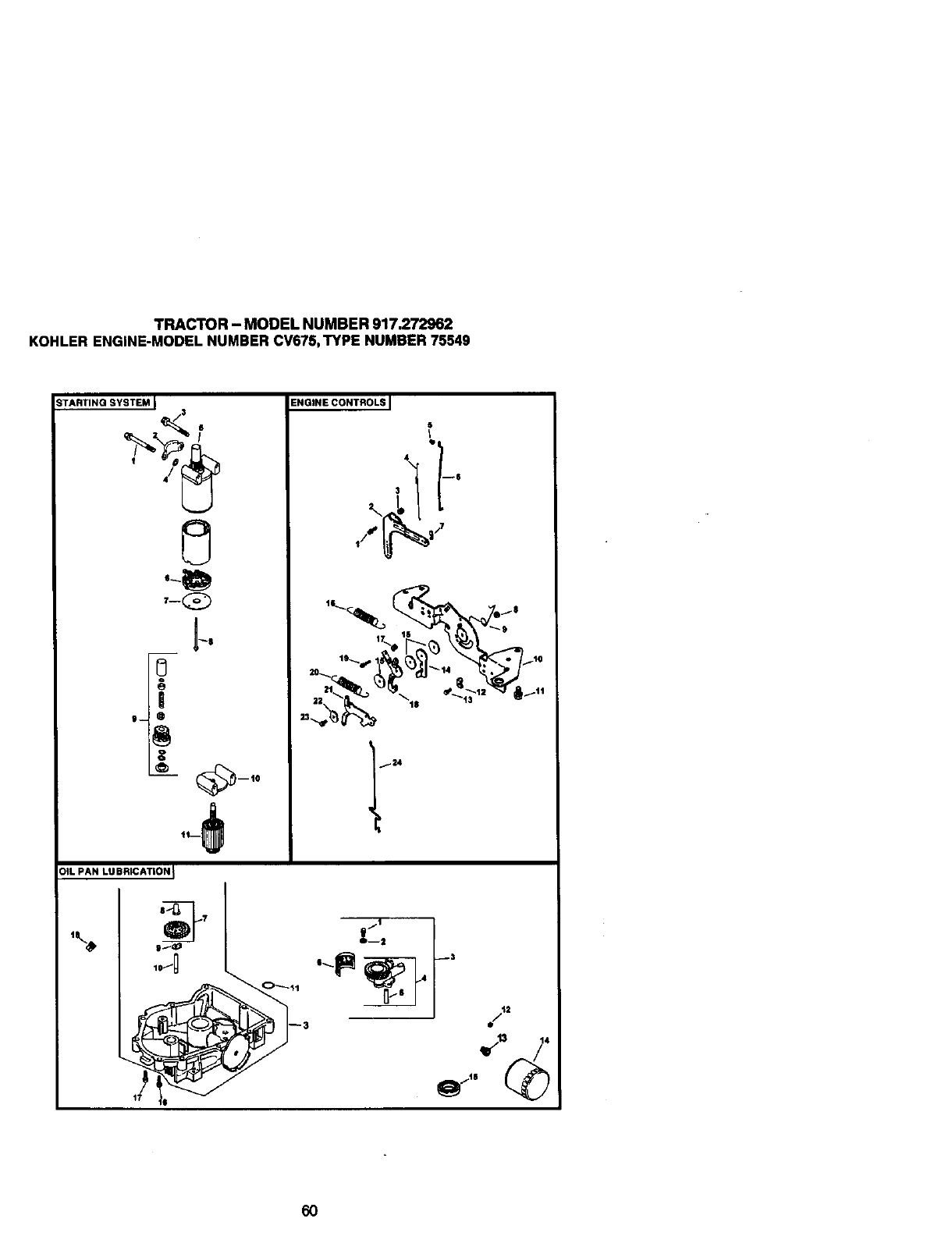
TRACTOR- MODELNUMBER917.272962
KOHLERENGINE-MODELNUMBERCV675,TYPENUMBER75549
TARTING SYSTEM I4.
0
T--Q
_8
0
i
ENGINE CONTROLS I
5
I
16_17_ li__,_e_ $
'_24
qb
I
OIL PAN LUBRICATION I
10/D
jl
60
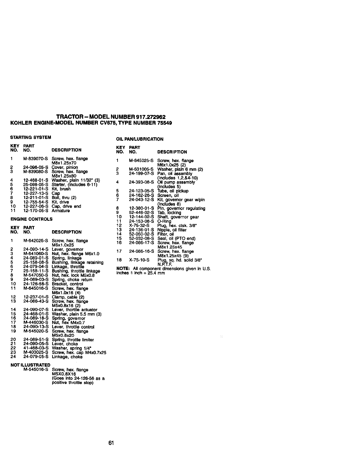
TRACTOR- MODELNUMBER917.272962
KOHLERENGINE-MODELNUMBERCV675,TYPENUMBER75549
s'rARTtNG sYSTI=M
KEY pART
NO. NO. DESCRiPTiON
I M-839070.S Screw, hex, |te_Ige
M8xl,25x70
24°G90.06-S Cover, pinion
3 MSx] ,,_ox
-466-01-S washer, plain 11F32_(3)
4 12=_oA_5-S Starter, (Inckides 6-11)
7 12.227-13-S Cap
8 12-2tl-01-S BOlt,thru (2)
9 12-755-54"S K_t,drive
10 12.227-06-S Cap, drive ar_
11 12.170-06-S Armature
ENGINE cONTROLS
KEY pART
NO. NO. DESCRIPTION
2
3
4
5
6
7
5
9
M-642025-S Screw, hex. flange
M6xt .0x25
4 090-14 S Lever, governor
2 - " ='ut hex fk_wJeM6xl 0
M-641060-S r4 _linka e'
.089.01.S Spnng g
224158.08. s Bush_, I!n.ka_.eretaining
54 079.04-5 Linkage, tr_ro_ ,,-_._,=
-"-- 4. _ n.shino throma .,.'=_
26-1.':>B-.-'_ "z,Tz _kick MSx0.8
M-547050"_ r_u=,..- _,__,. --*-m
2,-o..03-s
_6- 6-S Bre.ckez,comro
10 24-1__ 5 It_ e
M.645016-S Screw, hex,,.ng
12 12-237-01 -S I
24-086-43-S Screw, r_ ,,,'_P
13 M5x0,axl 8 (2)
4 090 07-S Lever, thorttle actuator
14 _,_468"01-S Washer, pt_tn5.5 mm (3_
15
16 24-089-16-S Spdng, governor
_7 M.446030-S Nut, hex M4x0,7
24°090-13-S Lever, thr_t_ control
_8 M.545020.S Screw, he)(, flange
19 M5xO,ax20
24_089-51-S Spdng, throttk_tk_lter
20 24.090.05-S Leve_ch°kr_rtg 114"
21 1.468-06-S Was , sp
22 41'_3026-S Screw, hex, cap MAxO.7x25
23 _4-'_'79-06-S L{nkage, choke
24
NOT iLLUSTRATED
M-545016-S Screw, hex. flange
MSX0.BX16
(Goes into 24.126-56 as a
positive throttle stop)
OIL pAN/LUBRtGA_ON
KE_ pART
NO, NO. DESCRIPTION
1 M.645026-S Screw, heX. flange
Mgx1.0x25 (2)
M-631006-S Washer, pl_d_6 mm (2)
24-199-G7-S p¢_, oil assambty
(Inoludes 1,2,&4-10)
4 24-393/06-S Oil pump aSSembly
(inol,._des5)
5 24.123-05-S Tube eli p_kup
6_4.162-26-S Screen, on ,_,.
7 24+043-12-S Kit, ,gOv=em°r gear w,v,-
IncluQee o_
12.380-01-S _n, governor reg_et_
2-446-02-S Tab, |ocking
8 52.144.02. S shaft, governor gear
,%
_1 24.153-08-S O-Rk_g .
X.76-32-S Pt_g hex. ctsk. 3/8
2 24.;36-01-S Nipple, air fitter
13
14 52.050-02-S Filter,oil
15 52.032-06-S Seal oil (PTO end)
16 24.086-17-S ScreW, hex. ftenge
MSx1.25x45
17 24-086-16"S Screw, .h_x45ft_r_
M8X1.25X ( ) ,
18 X-75-10-S p_U_,sq. hd. solid 3/8
N,P,T.F
NOTE: Ail _t dimensions gven in U.S,
_ches 1 inch =25.4 mm
61
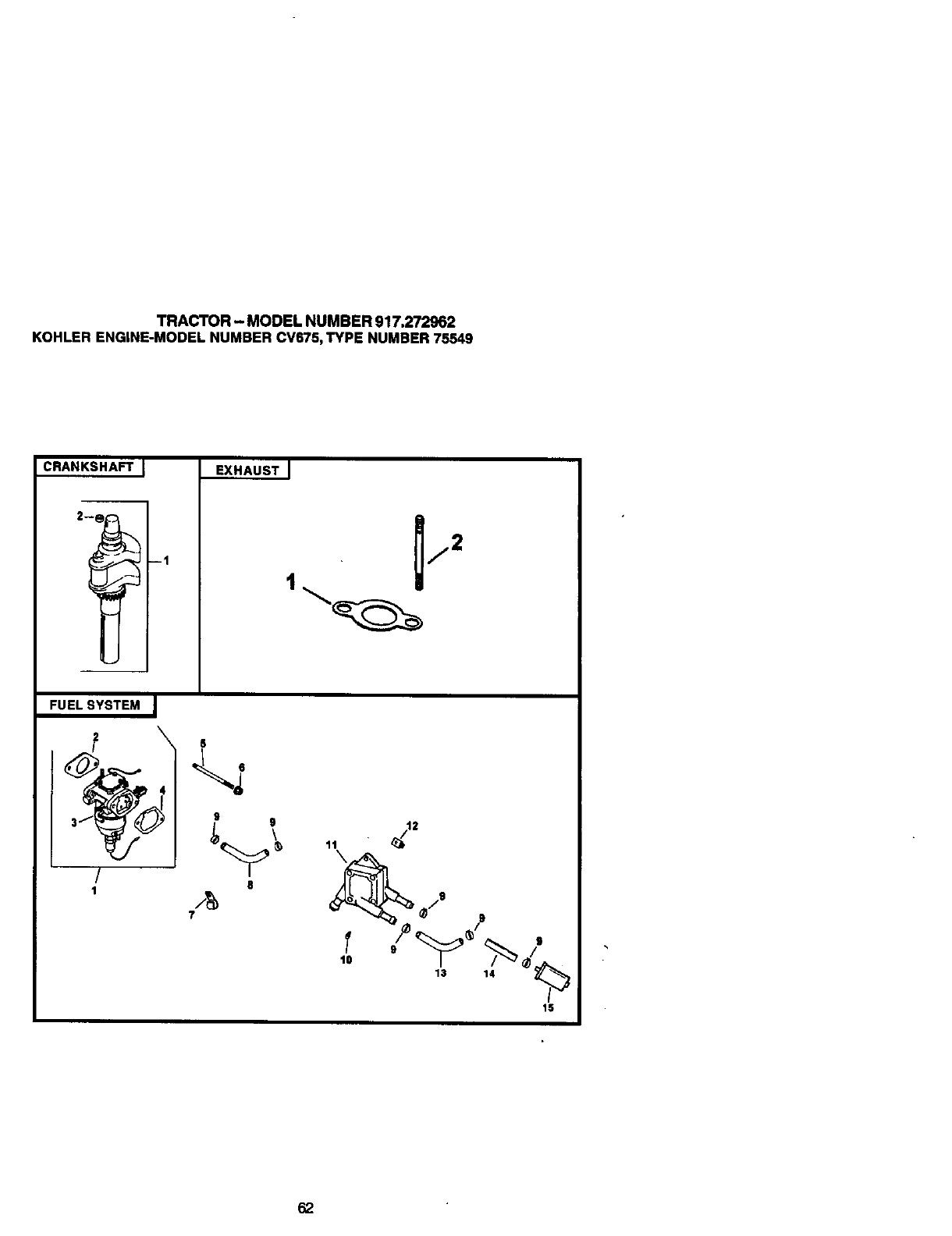
TRACTOR - MODEL NUMBER 917.272962
KOHLER ENGINE-MODEL NUMBER CV675,TYPE NUMBER 75549
EXHAUST I
FUEL SYSTEM
!
18
/g
7
\
9
10
13 14
15
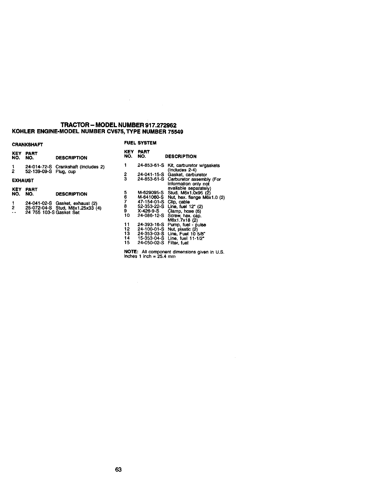
TRACTOR - MODEL NUMBER 917.272962
KOHLER ENGINE-MODEL NUMBER CV675,TYPE NUMBER 75549
CRANKSHAFT FUEL SYSTEM
KEY PART KEY PART
NO. NO, DESCRIPTION NO. NO. DESCRIP_ON
1 24-014-72-S Crankshaft (Includes 2) 1 24-853-61-S
2 52-139-09-S Plug, cup 2 24-041-15-S
EXHAUST 3 24-853-61-S
KEY PART
NO. NO. DESCRIPTION 5 M-629095-S
6 M-641060-S
124-041-02-S Gasket, exhaust (2) 7 47-154-01-S
2 25-072-04-S Stud, M8x1,25x33 (4) 8 52-353-22-S
-- 24 755 103-S Gasket Set 9 X-426-9-S
10 24-086-12-S
11 24-393-16-S
12 24-100-01-S
13 24-353-03-S
14 15-353-04-S
15
Kit, carburetor w/gaskets
(Includes 2-4)
Gasket, carburetor
Carburetor assembly (For
information only not
available separately)
Stud, M6xl.0x95 (2)
Nut, hex. flange M6xl.O (2)
Clip, cable
Line, fuel 12" (2)
Clamp, hose (6)
Screw, hex. cap.
M6x1.7x18 (2)
Pump, fuel - pulse
Nut, plastic (2
Lne, Fue 10 5/8"
Line, fuel 11-1/2"
24-050-02-S Filter, fuel
NOTE: All component dimensions given in U.S.
Inches 1 inch =25.4 mm
63

64

65

66
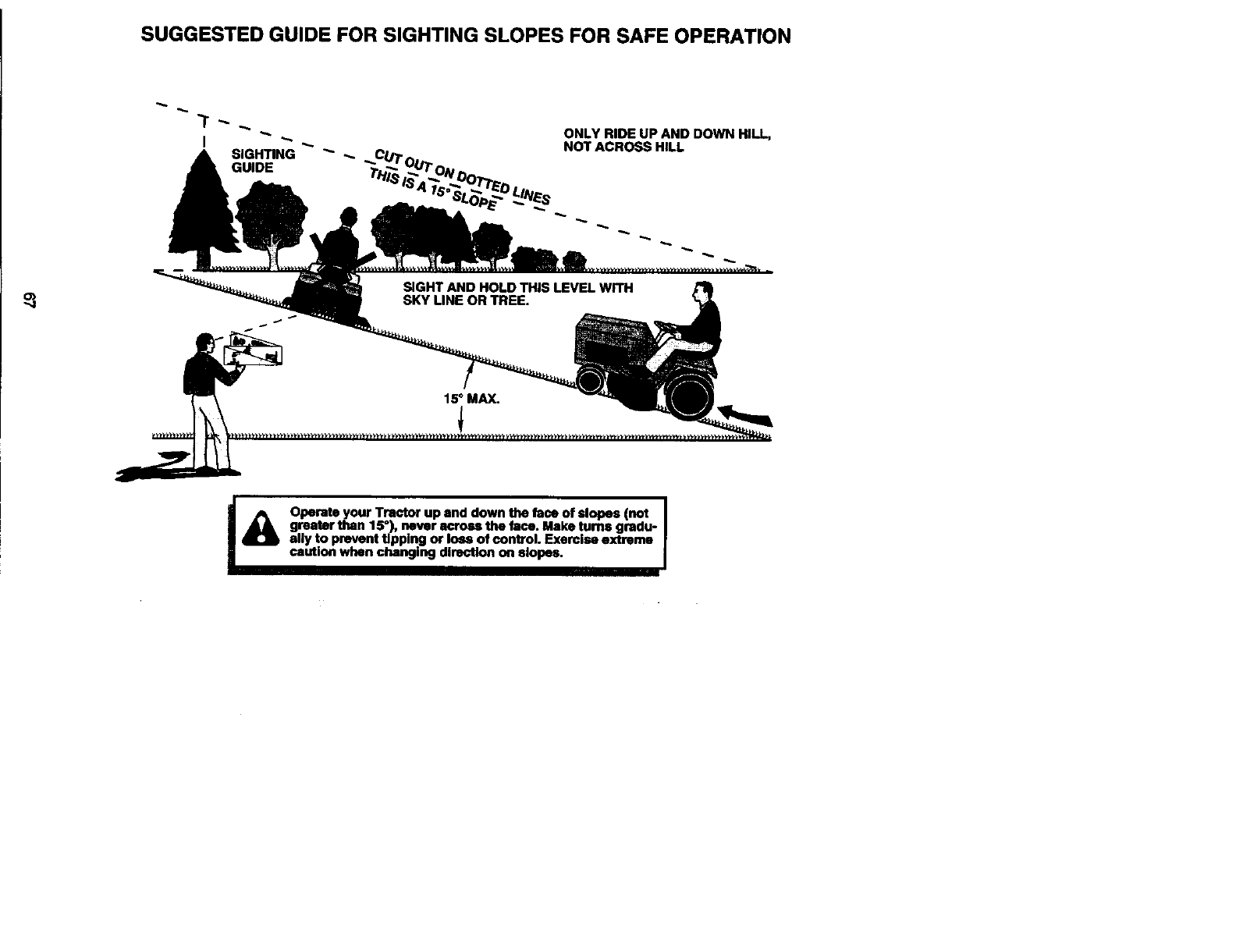
SUGGESTED GUIDE FOR SIGHTING SLOPES FOR SAFE OPERATION
SIGHTING "_
GUIDE
ONLY RIDE UP AND DOWN HILL,
NOT ACROSS HILL
I_ Operate your Tractor up and down the face of slopes (not I
I
greater than 15°), never across the face. Make turns gradu- r
ally to prevent Upping or Ioes of control. Exercise extreme
caution when changing direction on slopes.

Get it fixed, at your home or ours!
For repair of major brand appliances In your own home...
no matter who made it, no matter who sold it!
1-800-4-MY-HeM Es. An_._.dayornight
(1-800-469-4663)
ww_._si_,com
To bring in products such as vacuums,
lawn equipment and electronics for repair, call for
the location of your nearest Seers Parts & Repair Center.
1-800-488-1222 A_ln_,dayor.ioht
www.sears.com
For the replacement parts, accessories and owner's manuals
that you need to do-it-yourself, call Sears PerteDIrectSM!
1-800-366-PART earn- 11p.m. CST,
(1-800-366-7278) 7 daysa week
www.sears.com/partsdlrect
To purchase or inquire about a Sears Service Agreement:
1-800-827-6655
7a.rn.- 5 p.m.CST,Men.- Sat.
Para pedir servic_ode reparaci6n a domicilio, Au Canada pourservice an franP,,als:
y para ordenarplezas con entrega a domicifio: 1-877-LE-FOYER =*
(1-877-533-6937)
1"888"SU'HOGAR ='
(1-888-784-6427)
®R isteredTrademark /_.M_sdemark of Sears, Roebud( and CO.
/_a.r_ Registrada /TM Marca de .C_odcade Sears, Roebuck snd Co.
177625 12.5.00 RD Pdnted in U.S.A.
