Craftsman 917273011 User Manual 20 HP ELECTRIC START 6 SPEED 46 GARDEN TRACTOR Manuals And Guides 98080209
CRAFTSMAN Lawn, Tractor Manual 98080209 CRAFTSMAN Lawn, Tractor Owner's Manual, CRAFTSMAN Lawn, Tractor installation guides
User Manual: Craftsman 917273011 917273011 CRAFTSMAN 20 HP ELECTRIC START 6 SPEED 46 GARDEN TRACTOR - Manuals and Guides View the owners manual for your CRAFTSMAN 20 HP ELECTRIC START 6 SPEED 46 GARDEN TRACTOR #917273011. Home:Lawn & Garden Parts:Craftsman Parts:Craftsman 20 HP ELECTRIC START 6 SPEED 46 GARDEN TRACTOR Manual
Open the PDF directly: View PDF ![]() .
.
Page Count: 64
Owner's Manual
£RaFTSMgN
20.0 HP
ELECTRIC STAR-l:
46" MOWER
6 SPEED
GARDEN TRACTQR
Model No.
917;.273011
•Safety
•Assembly
•Operation
•Maintenance
-, Repair Parts
CAUTION:
Read and follow all
Safety Rules and Instructions
before operating this equip-
ment.
For answers to your questions
about this product, Call:
1-800-659-5917
Sears Craftsman Help Line
5 am -5 pm, Mon -Sat
Sears, Roebuck and Co., Hoffman Estates, IL 60179
....2
Safe_!Sul_s:::_....'...-7.':._..-_.,_.... .......... "........ 2
Prod_Specificat!ons ........................... 5
Assembly.,,L.J.L ...................................... 8
Opefa_... .................................... 12
IV_enance Schedule .............. ........... 19
Maintenance ......................................... 19
Service and Adjustments ...................... 23
Storag--'_................................................. 31
Troubleshooting .................................... 32
Repair Parts ......................................... 35
.Pandering ....................... Back Cover
-.,..
LIMITED TWO YEAR WARRANTY ON CRAFTSMAN RIBING EQUIPMENT
For _ (2) years from the date of purchase, if this Craftsman Riding Equipment is main-
tai_td; Jubdcated and tuned up according to the instructions in the owner's manual,
Sea_s Will repair or replace, free of charge, any parts found to be defective in material or
workmanship.
This Warranty does not cover:.
• Expendableitemswhich become worn during normal use, such as blades, spark
plugs, air cleaners, belts, etc.
• Tire replacement or repair caused by punctures from outside objects, such as nails,
thorns, stumps, or glass.
•Repairs necessary because of operator abuse, negligence, improper storage or acci-
dent or the failure to maintain the equipment according to the instructions contained in
the owner's manual.
• Riding equipment used for commercial or rental purposes.
LIMITED 90 DAY WARRANTY ON BATTERY
For ninety (90) days from date of purchase, if any battery included with this riding equip-
ment proves defective in material or workmanship and our testing determines the bat-
tery will not hold a charge, Sears will replace the battery at no charge. In-home warranty
service on your Craftsman riding equipment is available at no charge for 30 days from
the date of purchase. Please contact your nearest service center. After 30 days from the
date of purchase, warranty service is available by taking your Craftsman riding equip-
ment to your nearest Sears Service Center. (In-home warranty service will still be avail-
able after 30 days from the date of purchase but a standard trip charge will apply)_ This
warranty applies only while this product is in the United States. This Warranty gives you
specific legal rights, and you may also have other rights which may vary from state to
state.
Sears, Roebuck and Co., D/817 WA, Hoffman Estates, IL 60179
GENERAL OPERATI0_I
•Read, understand, and follow all instruc-
tions in the manual and on the machine
before starting.
• Only allow responsible adults, who are
familiar with the instructions, to operate
the machine.
• Clear the area of objects such as rocks,
toys, wire, etc., which could be picked
up and thrown by the blade.
•B_esu_bthe a_a is clear of other people
before mowing. Stop machine if anyone
enters the area.
2
•Never carry passengers.
• Do not mow in reverse unless absolute-
ly necessary. Always look down and
behind before and while backing.
•Be aware of the mower discharge direc-
tion and do not point it at anyone. Do
not operate the mower without either
•the entire grass catcher or the guard in
place.
•Slow down before tuming.
•Never leave a running machine unat-
tended. Always turn oft blades, set park-
ing brake, stop engine, and remove
keys before dismounting.
•Tum off blades when not mowing.
•Stop engine before removing grass
catcher or unclogging chute.
•Mow only in daylight or good artificial
light.
•Do not operate the machine while under
the influence of alcohol or drugs.
•Watch for traffic when operating near or
crossing roadways.
• Use extra care when loading or unload-
ing the machine into a trailer or truck.
SLOPE OPERATION
Slopes are a major factor related to loss-
of-control and tipover accidents, which
can result in severe injury or death. All
slopes require extra caution. If you cannot
backup the slope-or if you feel uneasy on
it, do not mow it.
DO:
•Mow up and down slopes, not across.
•Remove obstacles such as rocks, tree
limbs, etc.
•Watch for holes, ruts, or bumps. Uneven
terrain could overturn the machine. Tall
grass can hide obstacles.
•Use slow speed. Choose a low gear so
that you will not have to stop or shift
while on the slope.
•Follow the manufacturer's recommen-
dations for wheel weights or counter-
weights to improve stability.
_, Use extra care with grass catchers or
other attachments. These can change
the stability of the machine.
•Keep all movement on the slopes slow
and gradual. Do not make sudden
changes in speed or direction.
•Avoid starting or stopping on a slope. If
tires lose traction; disengage the blades
and proceed slowly straight down the
slope.
DO NOT:
• Do not tum on slopes unless necessary,
and then, tum slowly and gradually
downhill, if possible.
•Do not mow near drop-offs, ditches, or
embankments. The mower could sud-
denly tum over if a wheel is over the
edge of a cliff or ditch, or if an edge
caves in.
• Do not mow on wet grass. Reduced
-- _n ceuld cause sliding.
•Do nottry to stabilizethe machine by
puttingyour foot on the ground.
•Do not use grass catcher on•steep
slopes.
CHILDREN
Tragic accidents can occur if the operator
is not alert to the presence of children.
Children are often attracted to the
machine and the mowing activity. Never
assume that children will remain where
you last saw them.
• Keep children out of the mowing area
and under the watchful care of another
responsible adult.
•Be alert and tum machine off if children
enter the area.
•Before and when backing, look behind
and down for small children.
•Never carry children. They may fall off
and be seriously injured or interfere with
safe machine operation.
•Never allow children to operate the
machine.•
•Use extra care when approaching blind
comers, shrubs, trees, or other objects
that may obscure vision.
SERVICE
•Use extra care in handling gasoline and
other fuels. They are flammable and
vapors are explosive.
- Use only an approved container.
- Never remove gas cap or add fuel
with the engine running. Allow en-
gine to cool before refueling. Do not
smoke."
- Never refuel the machine indoors.
- Never store the machine or fuel
container inside where there is an
open flame, such as a water heater.
• Never run a machine inside a closed
area.
•Keep nuts and bolts, especially blade
attachment bolts, tight and keep equip-
ment in good condition.
•Never tamper with safety devices.
Check their proper operation regularly.
•Keep machine free of grass, leaves, or
other debris build-up. Clean oil or fuel
spillage. Allow machine to cool before
storing.
•Stop and inspect the equipment if you
strike an object. Repair, if necessary,
3
before restarting.
•Never make adjustments or repairs with
theengine running.
• Grass catcher components are subject
to wear, damage, and deterioration,
which could expose moving parts or
allow objects to be thrown. Frequently
check components and replace with
•Be sure the area is clear of.other people
before_m___owi_ng._S_topmachine if anyone
enters the.area.
•Never carry passengers.
• Do not mow in reverse unless absolute-
ly necessary. Always look down and
behind before and while backing.
•Never carry children. They may fall off
and be seriously injured or interfere with
safe machine operation.
•Keep children out of the mowing area
and under the watchful care of another
responsible adult.
•Be alert and tum machine off if children
enter the area.
•Before and when backing, look behind
and down for small children.
,_Look for this symbol to point out impor-
tant safety precautions. It means CAU-
TION!!! BECOME AWARE!!! YOUR SAFE-
TY IS INVOLVED.
-_CAUTION: In order tO prevent acciden-
tal starting when setting up, transporting,
adjusting or making repairs always discon-
nect spark plug wire and place wire where
it cannot contact spark plug.
manufacturer's recommended parts,
when necessary.
•Mower blades are sharp and can cut.
Wrap the blade(s) or wear gloves, and
use extra caution when servicing them.
•Check brake operation frequently.
Adjust and service as required.
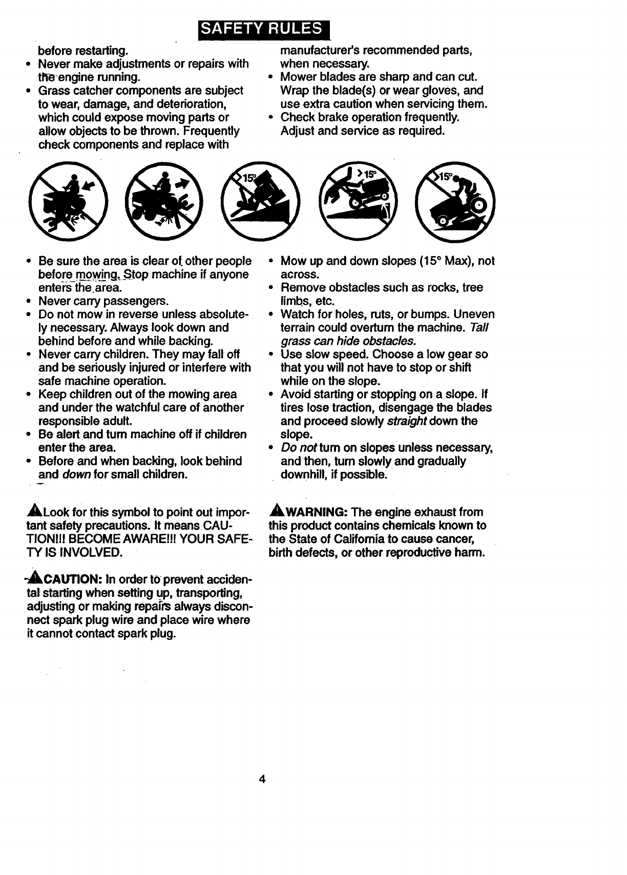
•Mow up and down slopes (15° Max), not
across.
•Remove obstacles such as rocks, tree
limbs, etc.
•Watch for holes, ruts, or bumps. Uneven
terrain could overtum the machine. Tall
grass can hide obstacles.
•Use slow speed. Choose a low gear so
that you will not have to stop or shift
while on the slope.
•Avoid starting or stopping on a slope. If
tires lose traction, disengage the blades
and proceed slowly straight down the
slope.
° Do nottum on slopesunless necessary,
and then, tum slowly and gradually
downhill, if possible.
,_WARNING: The engine exhaust from
this product contains chemicals known to
the State of Califomia to cause cancer,
birth defects, or other reproductive harm.
4
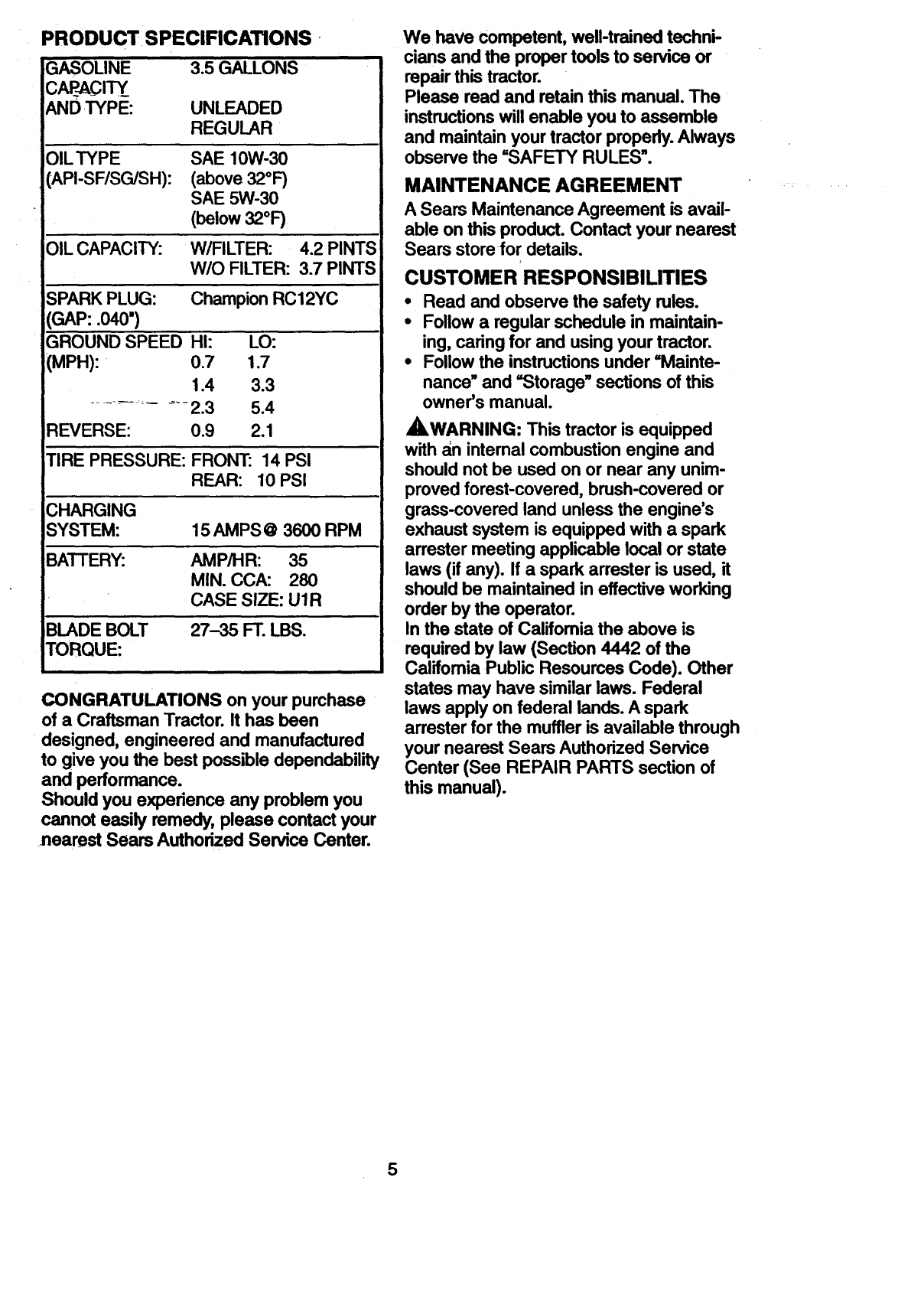
PRODUCT. SPECIFICATIONS-
GASOLINE
c crrY._ 3.5 GALLONS
UNLEADED
REGULAR
OILTYPE
(API-SF/SG/SH):
SAE 10W-30
(above32°1)
SAE 5W-30
(below32°1)
OIL CAPACITY: W/FILTER: 4.2 PINTS
W/O FILTER: 3.7 PINTS
iSPARK PLUG: Champion RC12YC
(GAP: .040")
GROUND SPEED HI:
I(MPH): 0.7
1.4
LO:
1.7
3.3
5.4
2.1
TIRE PRESSURE: FRONT: 14 PSI
REAR: 10 PSI
CHARGING
SYSTEM:
BATTERY:
15 AMPS @ 3600 RPM
AMP/HR: 35
MIN. CCA: 280
CASE SIZE: U1R
BLADE BOLT 27-35 FT. LBS.
CONGRATULATIONS on your purchase
of a Craftsman Tractor. It has been
designed, engineered and manufactured
to give you the best possible dependability
and performance.
Shouldyou experience any problem you
cannot easily remedy, please contact your
nearest Sears Authorized Service Center.
We have competent, well-trained techni-
cians and the proper tools to service or
repair this tractor.
Please read and retain this manual. The
instructions will enable you to assemble
and maintain your tractor properly. Always
observe the =SAFETY RULES".
MAINTENANCE AGREEMENT
ASears Maintenance Agreement is avail-
able on this product. Contact your nearest
Sears storefor details.
CUSTOMER RESPONSIBILITIES
• Read and observe the safety rules.
•Follow a regular schedule in maintain-
ing, caring for and using your tractor.
• Follow the instructions under =Mainte-
nance" and "Storage" sections of this
owner's manual.
_I_WARNING: This tractor is equipped
with ;_n internal combustion engine and
should not be used on or near any unim-
proved forest-covered, brush-covered or
grass-covered land unless the engine's
exhaust system is equipped with a spark
arrester meeting applicable local or state
laws (if any). If a spark arrester is used, it
should be maintained in effective working
order by the operator.
In the state of California the above is
required by law (Section 4442 of the
Califomia Public Resources Code). Other
states may have similar laws. Federal
laws apply on federal lands. A spark
arrester for the muffler is available through
your nearest Sears Authorized Service
Center (See REPAIR PARTS section of
this manual).
5
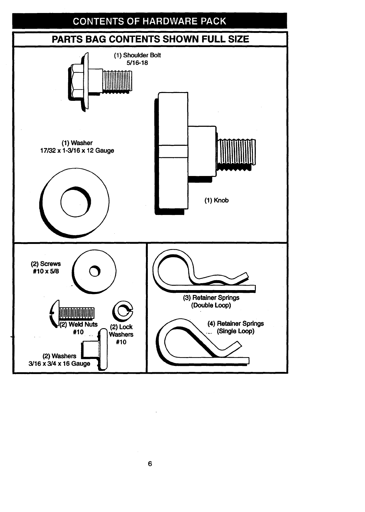
PARTS BAG CONTENTS SHOWN FULL SIZE
((1) Shoulder Bolt
'J 5/16-18
'iiiiiii"
(1) Washer
17/32 x 1-3/16 x 12 Gauge
I(1) Knob
I
1_ _uts @ ___RSe°_P_ingeSr Spdngs
,.,wo_.°oI_
3/16 x3/4 x 16 Gauge ! I
6
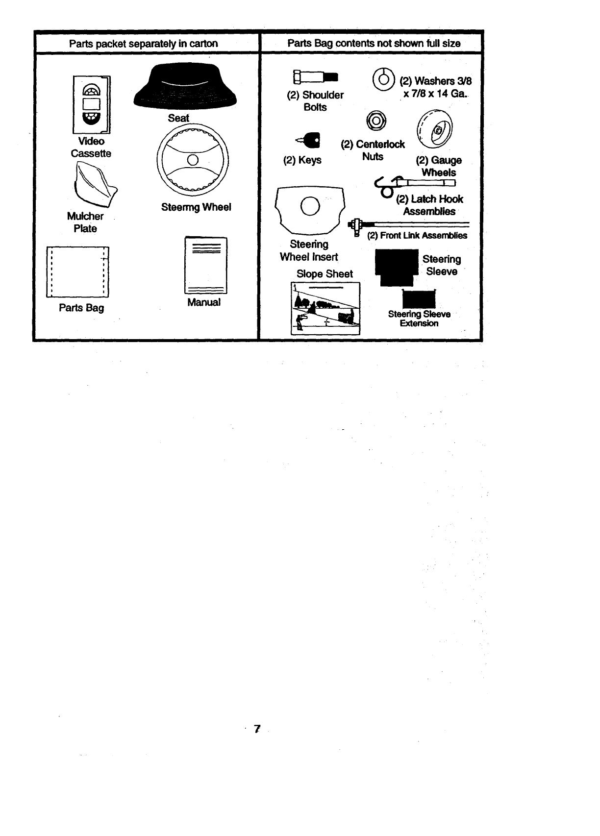
Parts packet separately in carton
!;
I
Video
Cassette
Mulcher
Plate H
i
Pads Bag
Seat
Steering Wheel
Manual
il I
Parts Bag contents not shown full size
(2) Shoulder
Bolts
(2) Keys
Steering
Wheel Insert
Slope Sheet
(_(2) Washers 3/8
x 7/8 x 14 Ga.,
(2) Centedock
Nuts (2) Gauge
W11eels
t" -?, tl
U(2)LatchHook
Assemblies
'p"
(2) FrontUnk Assemblies
Steering
Sleeve "
SteedngSleeve
Extension
7
Yournew tractor has been assembledat the factory with exception of those parts left
unassem_bledfor shipping purposes. To ensure safe and proper operation of your tractor
all parts and hardware you assemble must be tightened securely. Use the correct tools
as necessary to insure proper tightness. Review the video cassette before you begin.
TOOLS REQUIRED FOR
ASSEMBLY
A socket wrench set will make assembly
easier. Standard wrench sizes you need
are listed below.
(1) 9/16" wrench
(1) 1/2" wrench
(1) Utility knife
(1)Pliers
(1) 3/4" Socket w/
drive rachet
(1) Phillips Screw-
driver
(1) "i3repressure
gauge
When right or left hand is mentioned in
this manu_,,it-means, from your point of
view, when you are in the operating posi-
tion (seated behind the steering wheel).
TO REMOVE TRACTOR FROM
CARTON
UNPACK CARTON
•Remove all accessible loose parts and
parts boxes from shipping carton (See
page 6).
•Cut, from top to bottom, along lines on
all four comers of shipping carton, and
lay panels flat.
•Remove mower and package materials.
•Check for any additional loose parts or
_boxes and remove.
BEFORE ROLLING TRACTOR OFF
SKID
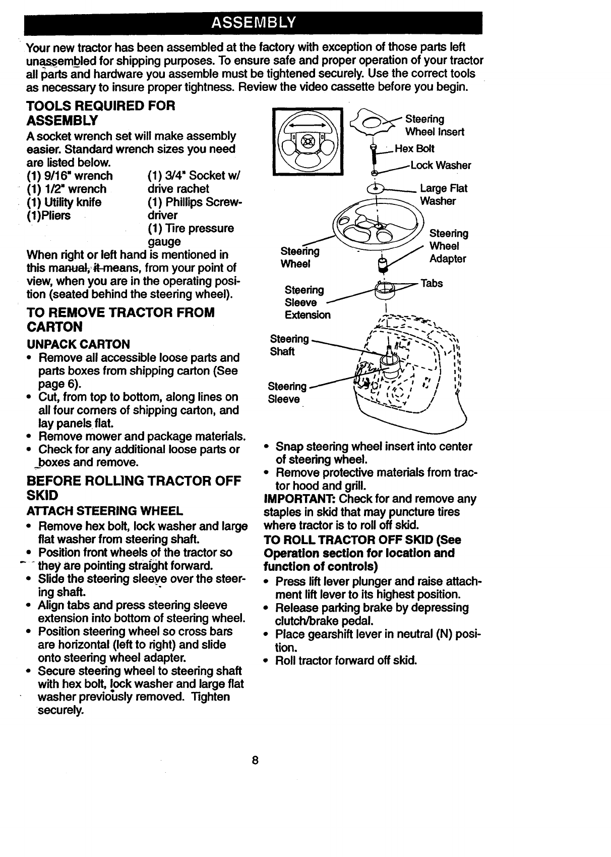
ATTACH STEERING WHEEL
• Remove hex bolt, lock washer and large
fiat washer from steering shaft.
•Position front wheels of the tractor so
-they are pointing straight forward.
•Slide the steering sleeye over the steer-
ing shaft.
• Align tabs and press steering sleeve
extension into bottom of steering wheel.
•Position steering wheel so cross bars
are horizontal (left to right) and slide
onto steering wheel adapter.
•Secure steering wheel to steering shaft
with hex bolt, lock washer and large flat
washer previously removed. Tighten
securely.
Wheel Insert
2_Hex Bolt
_Lock Washer
Large Flat
Washer
__..__/ Steering
Stee_na _/Wheel
_AdapterWheel
Steering_Tabs
Sleeve I
Extension Ir
Steering
Sleeve
•Snap steering wheel insert into center
of steering wheel.
•Remove protective materials from trac-
tor hood and grill.
IMPORTANT: Check for and remove any
staples in skid that may puncture tires
where tractor is to roll off skid.
TO ROLL TRACTOR OFF SKID (See
Operation section for location and
function of controls)
•Press lift lever plunger and raise attach-
ment lift lever to its highest position.
•Release parking brake by depressing
clutch/brake pedal.
•Place gearshift lever in neutral (N) posi-
tion.
•Roll tractor forward off skid.
8
HOWTO SET UP YOUR TRACTOR
CHECK BATTERY
• Lift hood to raisedposition.
• lf_-hisbattery is put into service after
month and year indicated on label (label
located between terminals) charge bat-
tery for minimum of one hour at 6-10
amps. (See "BATTERY" in MAINTE-
NANCE section of this manual for charg-
ing instructions).
• ii-'"-
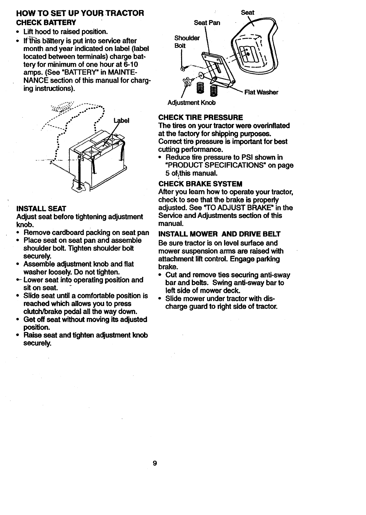
INSTALL SEAT
Adjust seat before tightening adjustment
knob.
•Remove cardboard packing on seat pan
•Place seat on seat pan and assemble
shoulder bolt. Tighten shoulder bolt
securely.
•Assemble adjustment knob and fiat
washer loosely. Do not tighten.
Lower seat into operating position and
sit on seat. -
•Slide seat until a comfortable position is
reached which allows you to press
clutch/brake pedal all the way down.
•Get off seat without moving its adjusted
position.
•Raise seat and tighten adjustment knob
securely.
L
Seat Pan
Shoulder
Bolt
Seat
\
Adjustment Knob
Rat Washer
CHECK TIRE PRESSURE
The tires on your tractor were overinflated
at the factory for shipping puq)oses.
Correct tire pressure is important for best
cutting performance.
•Reduce tire pressure to PSI shown in
=PRODUCT SPECIFICATIONS" on page
5 of;this manual.
CHECK BRAKE SYSTEM
After you leam how to operate your tractor,
check to see that the brake is propady
adjusted. See =TO ADJUST BRAKE" in the
Service and Adjustments section of this
manual.
INSTALL MOWER AND DRIVE BELT
Be sure tractor is on level surface and
mower suspensionarms are raised with
attachment lilt control. Engage parking
brake.
•Cut and remove ties securing anti-sway
bar and belts. Swing anti-sway bar to
leftside of mower deck.
•Slide mower under tractorwith dis-
charge guardto rightsideof tractor.
9
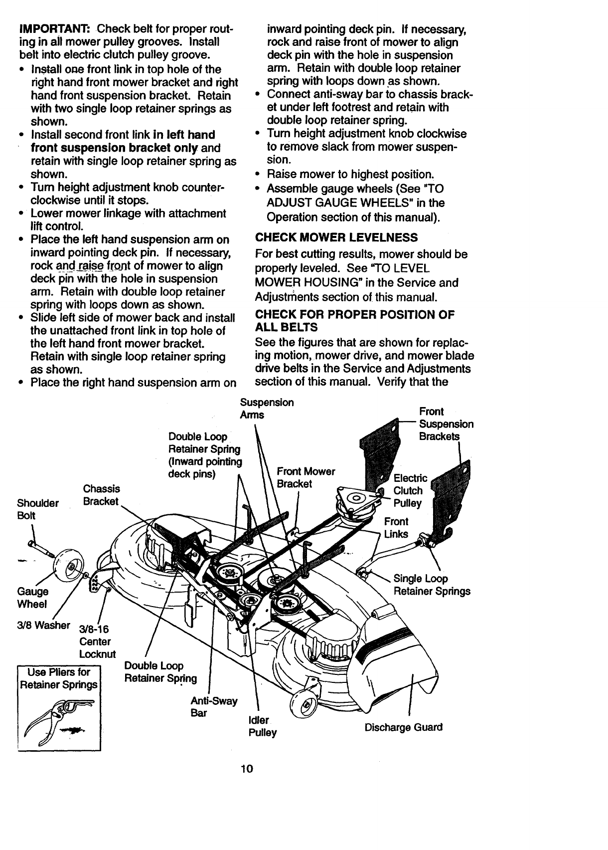
IMPORTANT: Check belt for proper rout-
ing in all mower pulley grooves. Install
belt into electric clutch pulley groove.
• Install one front link in top hole of the
right hand front mower bracket and right
hand front suspension bracket. Retain
with two single loop retainer springs as
shown.
•Install second front link in left hand
front suspension bracket only and
retain with single loop retainer spring as
shown.
•Tum height adjustment knob counter-
clockwise until it stops.
• Lower mower linkage with attachment
lift control.
•Place the left hand suspension arm on
inward pointing deck pin. If necessary,
rock and r._aisefront of mower to align
deck pin with the hole in suspension
arm. Retain with double loop retainer
spring with loops down as shown.
•Slide left side of mower back and install
the unattached front link in top hole of
the left hand front mower bracket.
Retain with single loop retainer spring
as shown.
°Place the right hand suspension arm on
Shoulder
BoR
Chassis
Bracket
Double Loop
Retainer Spring
(Inward pointing
deck pins)
inward pointing deck pin. If necessary,
rock and raise front of mower to align
deck pin with the hole in suspension
arm. Retain with double loop retainer
spring with loops down as shown.
Connect anti-sway bar to chassis brack-
et under left footrest and retain with
double loop retainer spring.
Tum height adjustment knob clockwise
to remove slack from mower suspen-
sion.
Raise mower to highest position.
Assemble gauge wheels (See "TO
ADJUST GAUGE WHEELS" in the
Operation section of this manual).
CHECK MOWER LEVELNESS
For best cutting results, mower should be
properly leveled. See =TO LEVEL
MOWER HOUSING" in the Service and
Adjustrnents section of this manual.
CHECK FOR PROPER POSITION OF
ALL BELTS
See the figures that are shown for replac-
ing motion, mower drive, and mower blade
drive belts in the Service and Adjustments
section of this manual. Verify that the
Suspension
Arms Front
Suspension
Brackets
Front Mower
Bracket Electric
Clutch
Front
Gauge
Wheel
3/8 Washer 3/8-16
Center
Locknut
Use Pliersfor
Retainer Springs
4r_
Double Loop
Retainer Spri.'ng
Anti-Sway
Bar Idler
Pulley
Single Loop
Retainer Spdngs
Discharge Guard
10
belts are muted correctly.
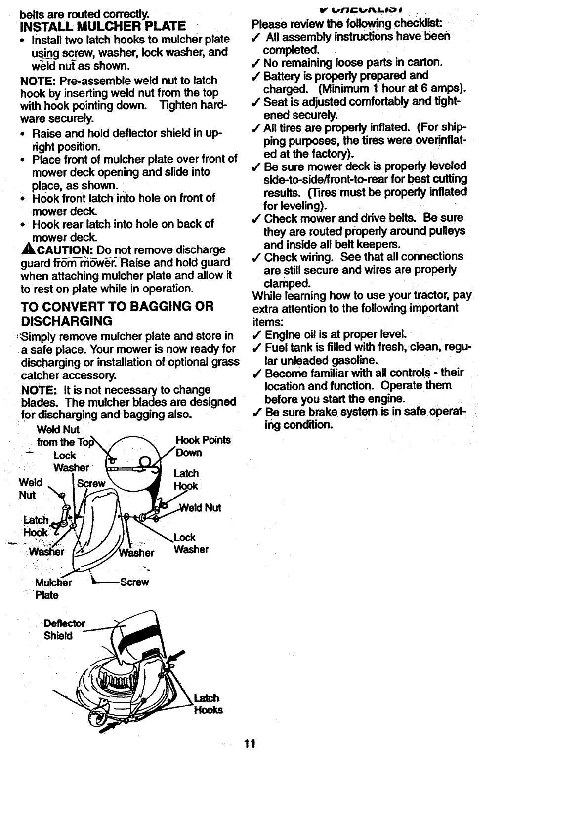
INSTALL MULCHER PLATE
•Install two latch hooks to mulcher plate
u_g screw, washer, lock washer, and
weld nut as shown.
NOTE: Pre-assemble weld nut to latch
hook by inserting weld nut from the top
with hook pointing down. Tighten hard-
ware securely.
.Raise and hold deflector shield in up
right position.
•Place front of mulcher plate over front of
mower deck opening and slide into
place, as shown.
•Hook front latch ir_tohole on front of
mower deck.
-Hook rear latch into hole on back of
mower deck.
ACAUTION: Do not remove discharge
guard fP6m-m_w_-r. Raise and hold guard
when attaching mulcher plate and allow it
to rest on plate while in operation.
TO CONVERT TO BAGGING OR
DISCHARGING
:_Simply remove mulcher plate and store in
a safe place. Your mower is now ready for
discharging or installation of optional grass
catcher accessory.
NOTE: It is not necessary to change
:blades. The mulcher blades are designed
:for discharging and bagging also.
Weld Nut HookPoints
Weld
Nut
Latch
Hook
Nut
Please review the fonowi'ng checklist:
/All assembly instructions have been
completed.
4" No remaining loose parts in carton.
4' Battery is properly prepared and
charged. (Minimum 1 hour at 6 amps).
4' Seat is adjusted comfortably and tight-
ened securely.
/All tires are propedy inflated. (For ship
ping purposes, the tires wereoverinflat-
ed at the factory).
/Be sure mower deck is properly leveled
side-to-side/front-to-rear for best cutting
results. (Tires must be properly inflated
for leveling).
/Check mower and drive belts. Be sure
they are routed properly around pulleys
and inside all belt keepers.
,/Check wiring. See that all connections
are still secure and wires are propedy
clamped.
While learning how to use your tractor, pay
extra attention to the following important
items:
4' Engine oil is at proper level.
,/Fuel tank is filled with fresh, clean, regu-
lar unleaded gasoline.
,/Become familiar with all controls -their
location and function. Operate them
•before you start the engine.
/Be sure brake system is in safe operat-
ing condition.
• Mulcher
Plate
,Lock
Washer
Deflector
Shield
Latch
Hooks
- 11
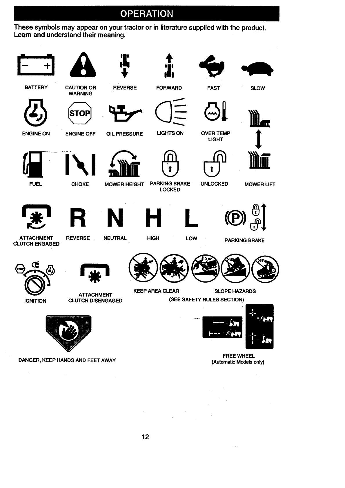
These symbols may appear onyour tractoror in literature supplied with the product.
Learn and understand their meaning.
E3A .=
BATTERY CAUTION OR REVERSE FORWARD FAST SLOW
WARNING
ENGINE ON ENGINE OFF OIL PRESSURE LIGHTS ON OVER TEMP '_
LIGHT !
FUEL CHOKE MOWER HEIGHT PARKING BRAKE UNLOCKED MOWER LIFT
LOCKED
N H L
ATTACHMENT REVERSE . NEUTRAL HIGH LOW
CLUTCH ENGAGED
_(_ AI-I'ACHMENT
IGNITION CLUTCH DISENGAGED
PARKING BRAKE
KEEP AREA CLEAR SLOPE HAZARDS
(SEE SAFETY RULES SECTION)
DANGER, KEEP HANDS AND FEET AWAY FREE WHEEL
(Automatic Models only)
12
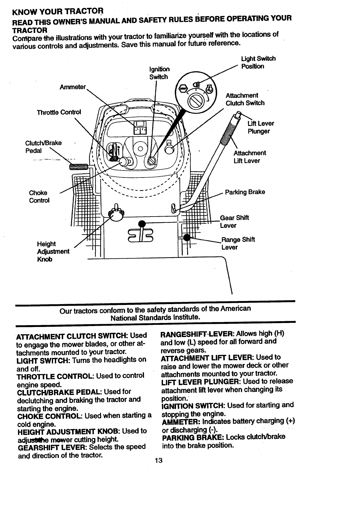
KNOW YOUR TRACTOR
READ THIS OWNER'S MANUAL AND sAFETY RULES BEFORE OPERATING YOUR
TRACTOR
Corr_pare-the illustrations with your tractor to familiarize yourseft with the locations of
various controls and adjustments. Save this manual for future reference.
Ammeter
Throttle Control
Ignition
Switch
Ught Switch
Position
Attachment
Clutch Switch
Clutch/Brake
Pedal
Lift Lever
Plunger
Attachment
Uft Lever
Choke
Control
Height
Adjustment
Knob
Parking Brake
Gear Shift
Lever
Shift
Lever
Our tractors conform to the safety standards of the American
National Standards Institute.
I
ATTACHMENT CLUTCH SWITCH: Used
to engage the mower blades, or other at-
tachments mounted to your tractor.
MGHT SWITCH: Tums the headlights on
and off.
THROTTLE CONTROL: Used to control
engine speed.
CLUTCH/BRAKE PEDAL: Used for
declutching and braking the tractor and
starting the engine.
CHOKE CONTROL: Used when starting a
cold engine.
HEIGHT ADJUSTMENT KNOB: Used to
adjusllltte mower cutting height.
GEARSHIFT LEVER: Selects the speed
and direction of the tractor.
RANGESHIFT-LEVER: Allows high (H)
and low (L) speed for all forward and
reverse gears.
ATTACHMENT LIFT LEVER: Used to
raise and lower the mower deck or other
attachments mounted to your tractor.
LIFT LEVER PLUNGER: Used to release
attachment lift lever when changing its
position.
IGNITION SWITCH: Used for starting and
stopping the engine.
AMMETER: Indicates battery charging (+)
or discharging (-).
PARKING BRAKE: Locks clutch/brake
into the brake position.
13
The operation of anytractor can result inforeign objects thrown into the
eyes, which can result in severe eye damage. Always wear safety glasses
-or eye shields while operating your tractor or performing any adjustments or
repairs. We recommend a wide vision safety mask over spectacles, or stan-
dard safety glasses.
HOW TO USE YOUR TRACTOR
Your tractor is equipped with an operator
presence sensing switch. When engine is
running, any attempt by the operator to
leave the seat without first setting the
parking brake will shut off the engine.
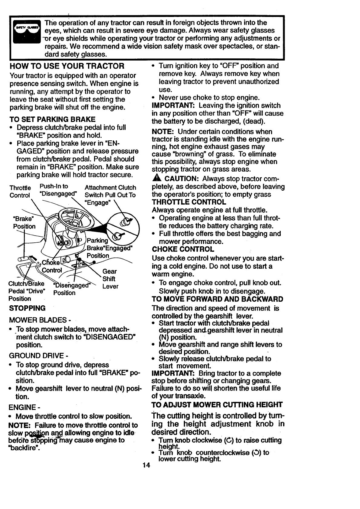
TO SET PARKING BRAKE
•Depress clutch/brake pedal into full
=BRAKE" position and hold.
•Place parking brake lever in =EN-
GAGED" position and release pressure
from clutch/brake pedal. Pedal should
remain in =BRAKE" position. Make sure
parking brake will hold tractor secure.
Throttle Push-In to Attachment Clutch
Control Switch Pull Out To
=Engage"
=Brake"
Position
Position
Gear
Pedal =Ddve"
Position
STOPPING
)isengag Lever
Position
MOWER BLADES-
•To stopmower blades,=move attach-
ment clutchswitchto =DISENGAGED"
position.
GROUND DRIVE -
•To stop ground drive, depress
clutch/brake pedal into full =BRAKE" po-
sition.
•Move gearshift lever to neutral (N) posi-
tion.
ENGINE -
•Move throttle control to slow position.
NOTE: Failure to move throttle control to
slow I_n a_.. allowing engine to idle
befdi'e st6ppin_j may cause engine to
=backfire'.
•Turn ignition key to =OFF-"position and
remove key. Always remove key when
leaving tractor to prevent unauthorized
use.
•Never use choke to stop engine.
IMPORTANT: Leaving the ignition switch
in any position other than =OFF-"will cause
the battery to be discharged, (dead).
NOTE: Under certain conditions when
tractor is standing idle with the engine run-
ning, hot engine exhaust gases may
cause =browning" of grass. To eliminate
this possibility, always stop engine when
stopping tractor on grass areas.
CAUTION: Always stop tractor com-
pletely, as described above, before leaving
the operator's position; to empty grass
THROTTLE CONTROL
Always operate engine at full throttle.
•Operating engine at less than full throb
tie reduces the battery charging rate.
•Full throttle offers the best bagging and
mower performance.
CHOKE CONTROL
Use choke control whenever you are start-
ing a cold engine. Do not use to start a
warm engine.
•To engage choke control, pull knob out.
Slowly push knob in to disengage.
TO MOVE FORWARD AND BACKWARD
The direction and speed of movement is
controlled by the gearshift lever.
•Start tractor with clutch/brake pedal
depressed and-gearshift lever in neutral
(N)position.
•Move gearshift and range shift levers to
desired position.
•Slowly release clutch/brake pedal to
start movement.
IMPORTANT: Bring tractor to a complete
stop before shifting or changing gears.
Failure to do so wil! shorten the useful life
of your transaxle.
TO ADJUST MOWER CUTTING HEIGHT
The cutting height is controlled by turn-
ing the height adjustment knob in
desired direction.
•Turn knob clockwise (__.,)to raise cutting
height.
•Turn knob counterclockwise (_) to
lower cutting heighL
14
The cutting height range is approximately
1-1/2"to 4-1/2". The heights are mea-
sured from the groundto the bladetip with
the engine not running. These heightsare
approximateand may vary depending
upon soil conditions,height of grass and
types of grass beingmowed.
•The average lawn should be cut to
approximately 2-1/2 inches during the
cool season and to over 3 inches during
hot months. For healthier and better
looking lawns, mow often and after
moderate growth.
•For best cuffing performance, grass
over 6 inches in height should be
mowed twice. Make the first cut rela-
tively high; the second to desired height.
TO ADJUST GAUGE WHEELS
Gauge wheels are properly adjusted
when they are slightly off the ground when
mow(_t fs_t'ttle _-dsired cutting height in
operating position. Gauge wheels then
keep the deck in proper position to help
prevent scalping in most terrain condi-
tions.
•Adjust gauge wheels with tractor on a
flat level surface.
•Adjust mower to desired cutting height
(See "TO ADJUST MOWER CUTTING
HEIGHT" in the Operation section of
this manual).
•With mower in desired height of cut po-
sition, gauge wheels should be assem-
bled so they are slightly off the ground.
Install gauge wheel in appropriate hole
with shoulder belt, 3/8 washer, and 3/8-
i6 Iocknut and tighten securely.
•Repeat for opposite side installing
gauge wheel in same adjustment hole.
Gauge
Mounting
Bracket
3/8-16
Locknut Shoulder Bolt
3/8 Washer Gauge Wheel
TO OPERATE MOWER
Your tractor is equipped with an operator
...presence sensing switch. Any attempt by
the operator to leave the seat with the
engine running and the attachment clutch
engaged wig shut off the engine,
¶ _ d_ed height of cut.
-" Lower mower with attachment liftcontrol
•:szan mower Dlaaes Dy engagmngiltt_ll,;ll-
ment clutch control. .....
•TO STOP MOWER BLADES -disen-
ge attachment dutch control.
AUTION: Do not operate the mower
without either the entire grass catcher, on
mowers so equipped, or the discharge
guard in place.
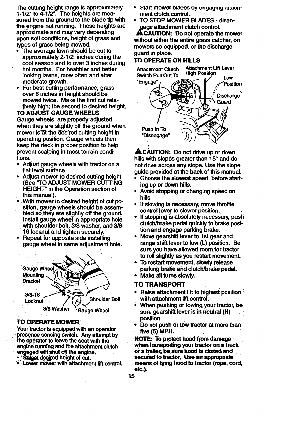
TO OPERATE ON HILLS
Attachment Clutch
Switch Pull Out To
"Engage"
Attachment Uft Lever
High PositiOn Low
.'.-P"Position
..'/
i.'.:"Di,_t_rge"
Guard
Push In To
"Disengage"
r
ACAUTION: Do not drive up or down
hills with slopes greater than 15 ° and do
not drive across any slope. Use the slope
guide provided at the back of this manual.
•Choose the slowest speed before start-
ing up or down hills.
•Avoid stopping or changing speed on
hills.
•If slowing is necessary, move-throttle
control lever to slower position.
•If stopping is absolutely necessary,, push
clutcll/brake pedal quickly to brake posi-
tion and engage parking-brake.
•Move gearshift lever to 1st gear and
range shift lever to low (L) position. Be
sure you have alloWed room for.tractor
to roll slightly as you restart movement.
• To restart movement, slowly release
parking brake and clutcli/brake pedal.
•Make all turns slowly.
TO TRANSPORT
•Raise attachment lift to highest position
with attachment lift control.
•When pushing or towing your tractor, be
sure gearshift lever is in neutral (N)
position. •
• Do not push or tow tractor at more than
five (5) MPH.
NOTE: To protect hood from damage
when transpoltifl9 your tractor on a truck .
or a trailer, be,sum hood is dosed and
secured to tractor. Use an appropriate
moans oftyinghoodtotractor(rope,cord. 0
etc.).
15
ATTACHMENTS
Tow onlythe attachmentsthat are recom-
mended by and complywith specifications
ofthe-manufacturerof your tractor.Use
commonsense when towing.Too heavy of
a load, while on a slope, is dangerous.
Tires can lose tractionwith the groundand
cause you to lose controlof yourtractor.
•BEFORE STARTING THE ENGINE
CHECK ENGINE OIL LEVEL
• The engine in your tractor has been
shipped, from the factory, already filled
with summer weight oil.
• Check engine oil with tractor on level
ground.
• Unthread and remove oil fillcap/dip
stick; wipe oil off. Reinsert the dipstick
into the tube and rest oil fill cap on the
tube/D_'n0-t ti_'readthe cap onto the
tube. Remove and read oil level. If nec-
essary, add oil until =FULL" mark on
dipstick is reached. Do not overfill.
•For cold weather operation you should
change oil for easier starting (See =OIL
VISCOSITY CHART" in the Customer
Responsibilities section of this manual).
•To change engine oil, see the Customer
Responsibilities section in this manual.
ADD GASOLINE
•Fill fuel tank. Use fresh, clean, regular
•unleaded gasoline with a minimum of 87
octane. (Use of leaded gasoline will
increase carbon and lead oxide
deposits and reduce valve life). Do not
mix oil with gasoline. Purchase fuel in
quantities that can be used within 30
days to assure fuel freshness.
IMPORTANT: When operating in tempera-
tures below32°F(0°C), use fresh, clean
..winter grade gasoline to help insure good
,_dAweather starting.
RNING: Experience indicates that
alcohol blended fuels (called gasohol or
using ethanol or methanol) can attract
moisture which leads to separation and
formation of acids during storage. Acidic
gas can damage the fuel system of an
engine while in storage. To avoid engine
problems, the fuel system should be emp-
tied before stora,(]e of 30 days or longer.
Drain the gas tank, start the engine and let
it run until the fuel lines and carburetor are
empty.i_,fres_fuel next season. See
Stor_'ge-I_tmct_ns for additional
,,.u,, ,,*-,uusm.i_uvur use engine or
carburetor cleanerproducts in the fuel
k or permanent damage may occur.
CAUTION: Fill to bottom of gas tank
filler neck. Do not overfill. Wipe off any
spilled oil or fuel. Do not store, spill or use
gasoline near an open flame.
TO START ENGINE
When startingthe engine for the firsttime
or if the engine has run out offuel, it will
take extra crankingtime to move fuel from
the tank to the engine.
•Sit on seat in operating position,
depress clutch/brakepedal and set
parking brake.
•Place gear shift lever in neutral (N)
position.
•Move attachment clutchto =DISEN-
GAGED" position.
•Move throttlecontrolto fast position
•Pull choke control out for a cold engine
start attempt. For a warm engine start
attempt the choke control may not be
needed.
NOTE: Before starting, read the warm and
cold starting procedures below.
•Insert key into ignition and tum key
clockwise to "START" position and
release key as soon as engine starts.
Do not run starter continuously for more
than fifteen seconds per minute. If the
engine does not start after several
attempts, push choke control in, wait a
few minutes and try again. If engine still
does not start, pull the choke control out
and retry.
WARM WEATHER STARTING (50 ° F
AND ABOVE)
•When engine starts, slowly push choke
control in until the engine begins to run
smoothly. If the_engine starts to run
roughly, pullthe choke control out slight-
ly for a few seconds and then continue
to push the control in slowly.
•The attachments and ground drive can
now be used. If the engine does not
accept the load, restart the engine and
allow it to warm up for one minute using
the choke as described above.
16
engineto accept small changes in ....
speed and load, until the choke control
is fully in. If the engine startsto run
r0u--ghly,-pullthe choke control out slight-
ly for afew seconds and then continue
to pushthe control in slowly.This may
requirean engine warm-up period from
several seconds to several minutes,
depending on the temperature.
•The attachments can be used during
the engine warm-up periodand may
requirethe choke controlbe pulled out
slightly.
NOTE: A high altitude (above 3000 feet)
or in cold temperatures (below 32 F) the
carburetor fuel mixture may need to be
adjusted for best engine performance.
See =TOADJUST CARBURETOR" in the
Service andAdjustments section of this
manual.
MOWING TIPS
• Tire chains cannot he used when the
mower housing is attached to tractor.
•Mower should he properly leveled for
best mowing performance. See =TO
LEVEL MOWER HOUSING" in the
Service and Adjustments section of this
manual.
• The left hand side of mower should he
used for trimming.
• Drive so that clippings are discharged
onto the area that has been cut. Have
-the cut area to the right of the tractor.
This will result in a more even distribu-
tion of clippings and more uniform cut-
ting.
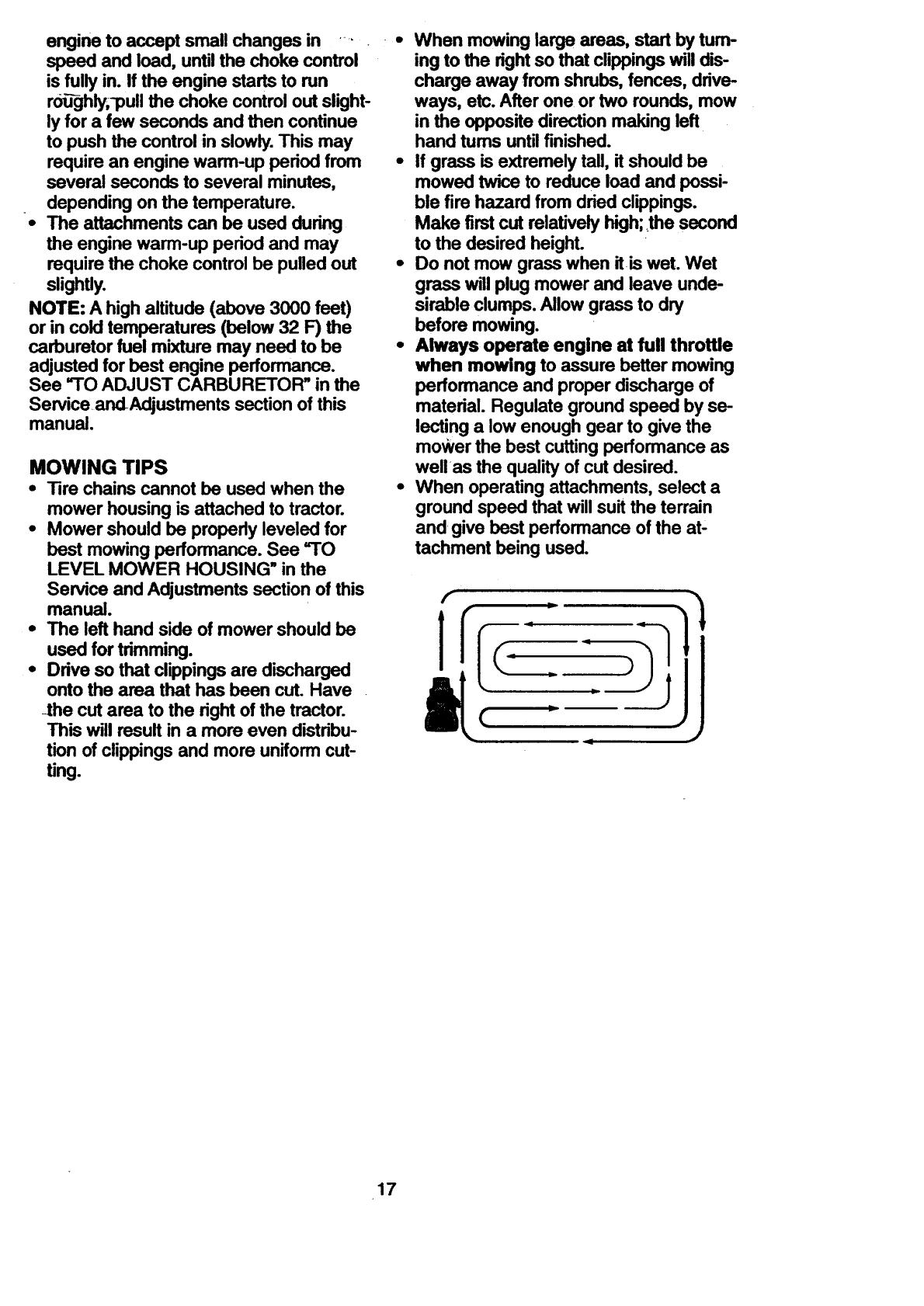
L • When mowing large areas, start by tum-
ing to the right so that clippings will dis-
charge away from shrubs, fences, drive-
ways, etc. After one or two rounds, mow
in the opposite direction making left
hand tums until finished.
•If grass is extremely tall, it should be
mowed twice to reduce load and possi-
ble fire hazard from dried clippings.
Make first cut relatively high;_thesecond
to the desired height.
•Do not mow grass when it is wet. Wet
grass will plug mower and leave unde-
sirable clumps. Allow grass to dry
before mowing.
• Always operate engine at full throttle
when mowing to assure better mowing
performance and proper discharge of
material. Regulate ground speed by se-
lecting a low enough gear to give the
mower the best cutting performance as
wellas the quality of cut desired.
•When operating attachments, select a
ground speed that will suit the terrain
and give best performance of the at-
tachment being used.
17
MULCHING MOWING TIPS
IMPORTANT:For best performance,keep
mower_housing free of built-up grass and
trash_ Clean after each use.
•The special mulching blade will recut
the grass clippings many times and
reduce them in size so that as they fall
onto the lawn they will disperse into the
grass and not be noticed. Also, the
mulched grass will biodegrade quickly
to provide nutrients for the lawn. Always
mulch with your highest engine (blade)
speed as this will provide the best recut-
ting action of the blades.
•Avoid cutting your lawn when it is wet.
Wet grass tends to form clumps and
interferes with the mulching action. The
best time to mow your lawn is the early
afternoo-n.-Atthi_ ][me the grass has
dried and the newly cut area will not be
exposed to the direct sun.
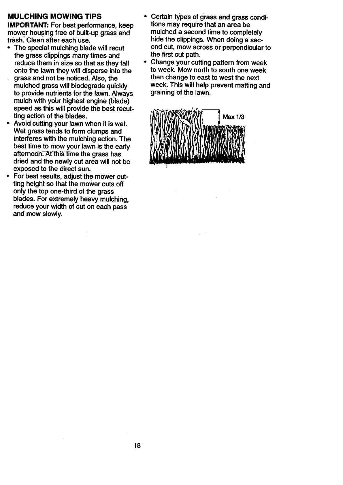
•For best results, adjust the mower cut-
ting height so that the mower cuts off
only the top one-third of the grass
blades. For extremely heavy mulching,
reduce your width of cut on each pass
and mow slowly.
•Certain types of grass and grass condi-
tions may require that an area be
mulched a second time to completely
hide the clippings. When doing a sec-
ond cut, mow across or perpendicular to
the first cut path.
• Change your cutting pattern from week
to week. Mow north to south one week
then change to east to west the next
week. This will help prevent matting and
graining of the lawn.
18
CUSTOMER RESPONSIBILrFIES
FILL IN DATES
AS YOU COMPLETE '_.4._'_ _.._x_'_ 'r
CheckBrakeC_,n,t_n V" V"
CheckTn Pressure l/ V'
Check Operator Presence and
RT Inter_o_s,_n_s IV'
c .ck ,oo. F=t re iv' v', v"
T L.b_,=_onChart v"
O Check Battery Level
Rczeen Battery and TerreinaLs/Redlarge v" v"
Check Trensaxle Cooling v"
Adjust Blade Belt(s) Tension v's J
Adjust Motion Drive Belt(s) Tension v's
Check Engine Oil Lev:el v" v"
Chi_g-e EK-gine_O+l I_,, v"
RE Clean Air Filter v'=
Clean Air Screen v'= +_
Inspect Mufflar/Spark Arrester v"
Replace Oil Filter (If equipped) _.2
M
_.. Clean Engine Cooling Fins v'=
Replace Spark Plug v"
Replace Air Filter Paper Cartridge v'=
Replace Fuel Filter v"
1- Change morn often when operaUng under a heavy load or Inhlgh Sntlent _tu_=.
2 - Sendce more ohen when opendS_ In dirty or dusty condltiors.
3 - nequlpped wtth olt rdte,r. change dl every 50 hours.
4 - _blMes more olin when mowinO in randy soil
GENERAL RECOMMENDATIONS
The warranty on this tractor does not cover
items that have been subjected to operator
abuse or negligence. To receive full value
from the warranty, operator must maintain
tractor as instructed in this manual. Some
adjustments will need to be made periodi-
cally to properly maintain your tractor.
All adjustments in the Service and
Adjustments section of this manualshould
be checked at least once each season.
• Once a year you should replace the
spark plug, clean or replace air filter, and
check blades and belts for wear. A new
spark plug and clean air filter assure
proper air-fuel mixture and help your
engine run better and last longer.
BEFORE EACH USE
• Check engine oil level.
. Check brake operation.
•Check tim pressure.
s- n equk)pedwnhadJum_ Wm._
a - NotmquVed_ =quk)p_wUh_betWy
7 - _front axle pivot bolt to 3S It.4b=. _
Donot_
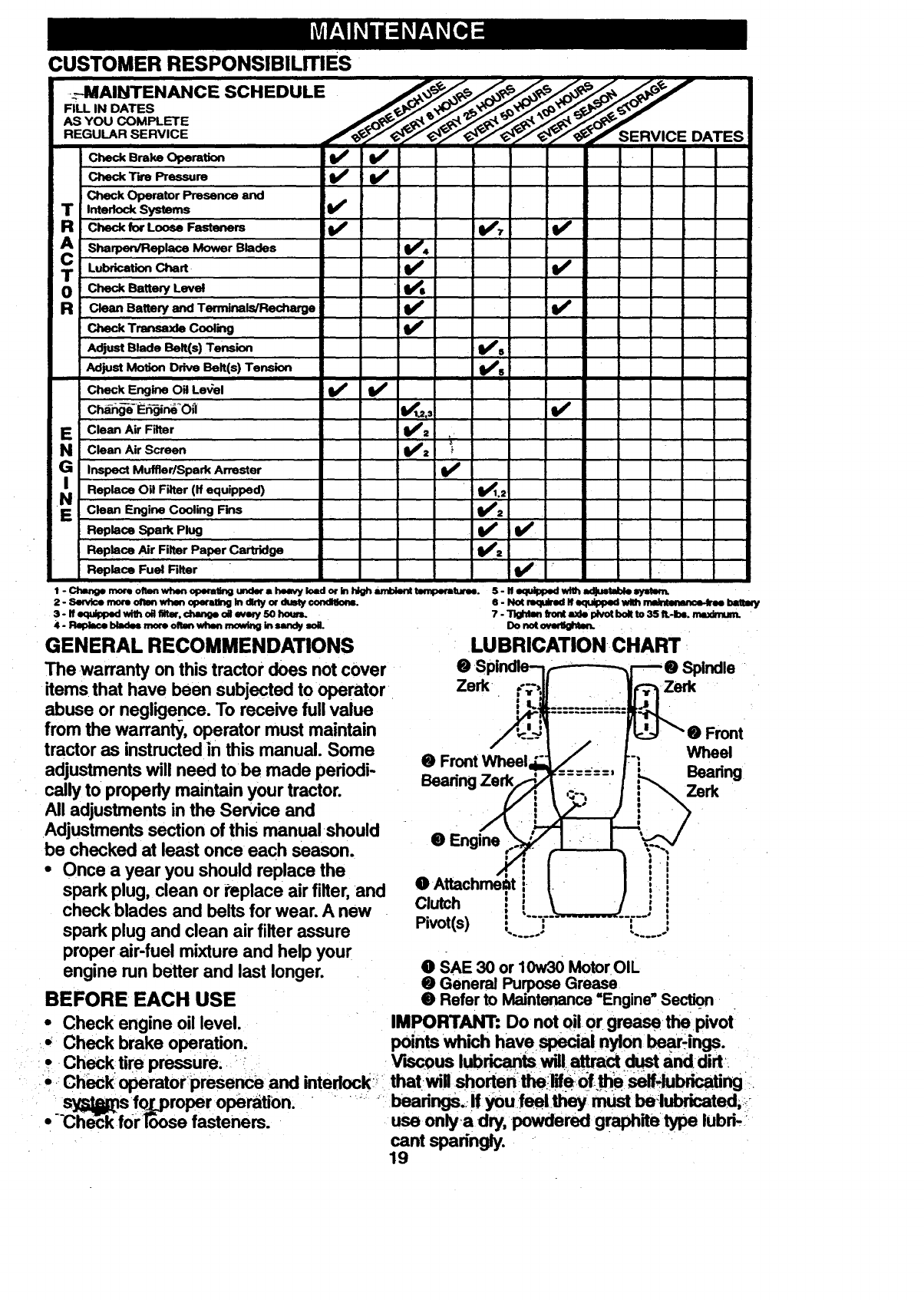
LUBRICATION CHART
Zerk Zerk
@ Front Wheel
Front
Wheel
Beadng
Zerk
@Engine
Clutch i
Pivot(s) : :
@SAE 30 or 10w30 Motor OIL
ee General Purpose Grease
Refer to Maintenance "Engine" Section
iMPORTANT: Do not oil or grease +the pivot
points which have special nylon _-ings.
V'mcous lubricants will+attraCt dust+and dirt
'+ Check operatorpresence and intedock _! thatwill shortentheilifeof+. elself!lubdcating _
"syT_sfox_proper operation. • " "_ : beadngs,..!f you.feeltheymust belubdcated+.-+
• -Che_k forloose fasteners, use onlya dry, .powdered graphite type lubri-:
cant sparingly.
19
Always observesafety rules when per-
forming any maintenance.
BRAKE OPERATION
If tra_-tbr re-quiresmore than six (6) feet
stopping distance at high speed in highest
gear, then brake must be adjusted. (See
=1-OADJUST BRAKE" in the Service and
Adjustments section of this manual).
TIRES
•Maintain proper air pressure in all tires
(See =PRODUCT SPECIFICATIONS"
on page 3 of this manual).
•Keep tires free of gasoline, 0il, or insect
control chemicals which can harm rub-
ber.
•Avoid stumps, stones, deep ruts, sharp
objects and other hazards that may
cause tire damage.
NOTE: To seal tire punctures and prevent
flat tires due to slow leaks, tire sealant
may be purchased from your local parts
dealer. Tire sealant also prevents tire dry
rot and corrosion.
OPERATOR PRESENCE SYSTEM
Be sure that operator presence and inter-
lock systems are working properly. If your
tractor does not function as described
below, repair the problem immediately.
•The engine should not start unless the
clutch/brake pedal is fully depressed
and attachment clutch control is in the
disengaged position.
•When the engineis running, any
attemptby the operator to leave the
seat without first setting the parking
brake should shut off the engine.
•When the engine is running and the
attachment clutch is engaged, any
attempt by the operator to leave the
peat should shut off the engine.
•Theattachment clutch should never
operate unless the operator is in the
_seat.
BLADE CARE
For best results mower blades must be
kept sharp. Replace bent or damaged
blades.
BLADE REMOVAL
•Raise mower to highest position to allow
access to blades.
•Remove hex bolt, lock washer and flat
washer securingblade.
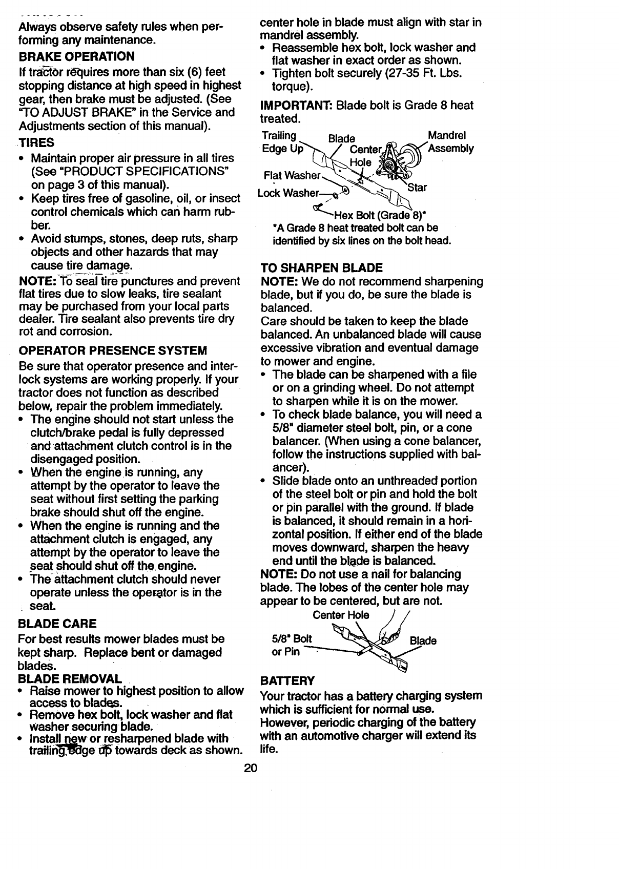
•InstallLn_w or resharpened blade with
trailin_ge t_ towards deck as shown.
center hole in blade must align with star in
mandrel assembly.
•Reassemble hex bolt, lock washer and
flat washer in exact order as shown.
•Tighten bolt securely (27-35 Ft. Lbs.
torque).
IMPORTANT: Blade bolt is Grade 8 heat
treated.
Trailing Blade Mandrel
Edge U_ Cente_Assembly
Rat Washer__'_1_^.
Was e:. ' tar
_"Hex Bolt (Grade 8)*
*A Grade 8 heat treated boltcan be
identifiedby sixlineson the bolthead.
TO SHARPEN BLADE
NOTE: We do not recommend sharpening
blade, but if you do, be sure the blade is
balanced.
Care should be taken to keep the blade
balanced. An unbalanced blade will cause
excessive vibration and eventual damage
to mower and engine.
•The blade can be sharpened with a file
or on a grinding wheel. Do not attempt
to sharpen while it is on the mower.
•To check blade balance, you will need a
5/8 =diameter steel bolt, pin, or a cone
balancer. (When using a cone balancer,
follow the instructions supplied with bal-
ancer).
•Slide blade onto an unthreaded portion
of the steel bolt or pin and hold the bolt
or pin parallel with the ground. If blade
is balanced, it should remain in a hori-
zontal position. If either end of the blade
moves downward, sharpen the heavy
end until the b[ode is balanced.
NOTE: Do not use a nail for balancing
blade. The lobes of the center hole may
appear to be centered, but are not.
Center Hole
5/8" Bolt Blade
or Pin
BATTERY
Your tractor has a battery charging system
which is sufficient for normal use.
However. periodic charging of the battery
with an automotive charger will extend its
life.
20
•Keep battery and terminals clean.
•Keep battery bolts tight.
•Keep small vent holes open.
•Recharge at 6-10 amPeres for 1 hour.
TO CLEAN BATTERY AND TERMINALS
P
Corrosion and dirt on the battery and ter-
minals can cause the battery to =leak"
power.
•Remove terminal guard.
•Disconnect BLACK battery cable first
then RED battery cable and remove
battery from tractor.
•Rinse the battery with plain water and
dry.
•Clean terminals and battery cable ends
with wire brush until bright.
•Coat terminals with grease or petroleum
jelly.
•Reinstall battery (See =REPLACING
BATTERY'in the MAINTENANCE sec-
tion of this manual).
V-BELTS
Check V-belts for deterioration and wear
after 100 hours of operation and replace if
necessary. The belts are not adjustable.
Replace belts if they begin to slip from
wear.
TRANSAXLE COOLING
Keep transaxle free from build-up.of dirt
and chaff which can restrict cooling.
CHECK TRANSAXLE OIL LEVEL
•Blo(_kup rear axle securely.
•Remove left rear wheel by removing
_hub bolts.
•Remove filler plug from transaxle. Oil
level must be even with plug threads. If
necessary, fill with SAE 30 motor oil,
API SF, SG or SH. Replace filler plug.
•Reassemble wheel to hub.
Transaxle
ENGINE
LUBRICATION
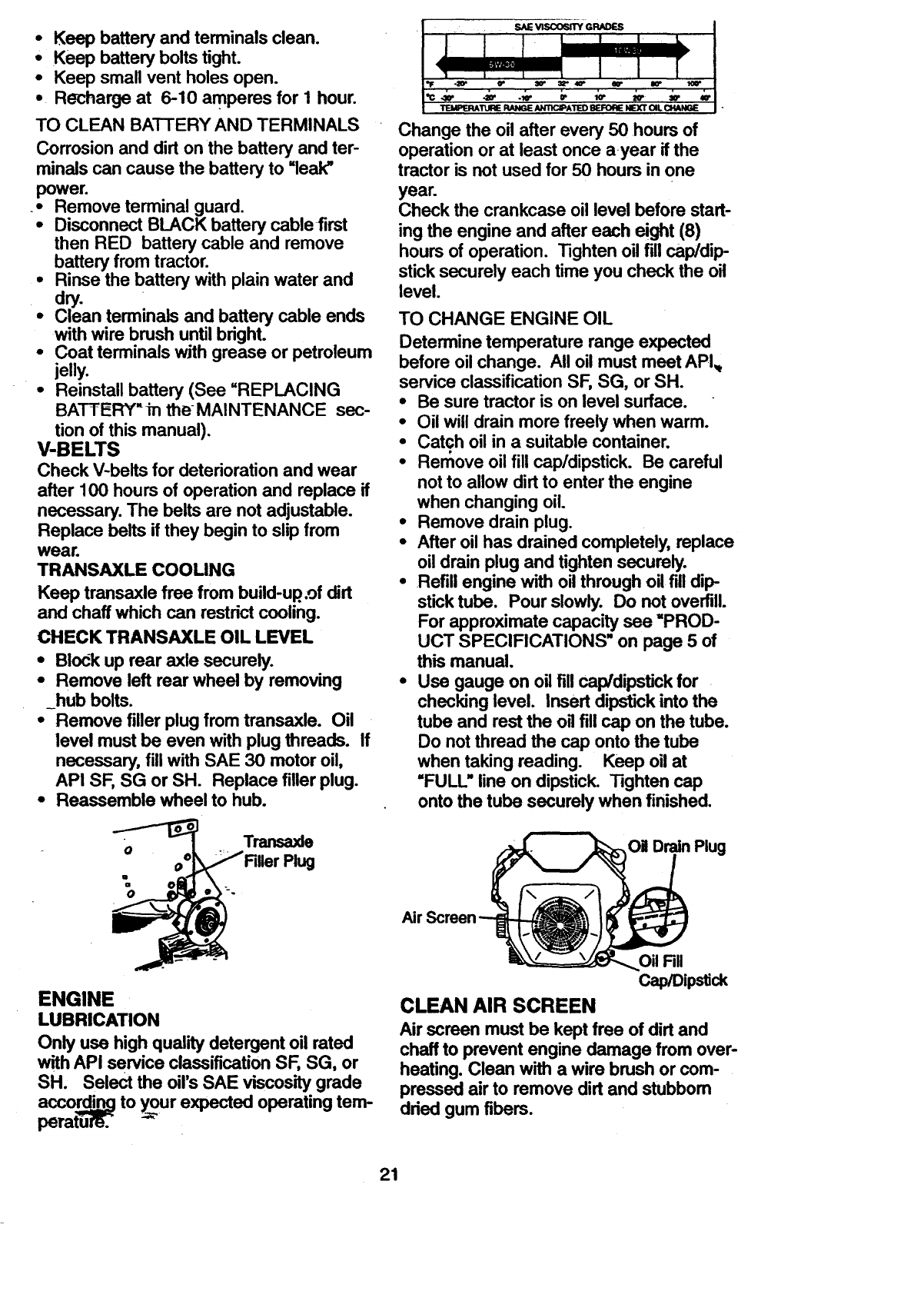
Only use high quality detergent oil rated
with API service classification SF, SG, or
SH. Select the oil's SAE viscosity grade
accordi_.__qgto y..ourexpected operating tem-
perature, r
•s_ vmoos_GP_S
< ira= _,
=IF o_ CP 3r 32" 40DeS" _
Te_e_T_eFU_,e,,am_ATeOe_oRemx'rO,LC_NGe
Change the oil after every 50 hours of
operation or at least once ayear if the
tractor is not used for 50 hours in one
year.
Check the crankcase oil level before start-
ing the engine and after each eight (8)
hours of operation. Tighten oil fill cap/dip
stick securely each time you check the oil
level.
TO CHANGE ENGINE OIL
Determine temperature range expected
before oil change. All oil must meet API_
service classification SF, SG, or SH.
•Be sure tractor is on level surface.
•Oil will drain more freely when warm.
•Catch oil in a suitable container.
•Remove oil fill cap/dipstick. Be careful
not to allow dirt to enter the engine
when changing oil.
•Remove drain plug.
•After oil has drained completely, replace
oil drain plug and tighten securely.
•Refill engine with oil through oil fill dip-
stick tube. Pour slowly. Do not overfill.
For approximate capacity see =PROD-
UCT SPECIFICATIONS" on page 5 of
this manual.
•Use gauge on oil fill cap/dipstick for
checking level. Insert dipstick into the
tube and rest the oil fill cap on the tube.
Do not thread the cap onto the tube
when taking reading. Keep oil at
"FULL" line on dipstick. Tighten cap
onto the tube securely when finished.
Oil DrainPlug
Air Screen
Oil Fill
Cap/Dipstick
CLEAN AIR SCREEN
Air screen must be kept free of dirt and
chaff to prevent engine damage from over-
heating. Clean with a wire brush or com-
pressed air to remove dirt and stubbom
dried gum fibers.
21
CLEAN AIR INTAKE/COOLINGAREAS
To insure proper cooling, makesure the
grass screen,cooling fins, and other
external surfacesof the engine are kept
clean at all times.
Every 100 hours of operation (more often
under extremelydusty, dirty conditions),
removethe blower housing and other
cooling shrouds. Cleanthe cooling fins
and externalsurfaces as necessary.Make
sure the cooling shrouds are reinstalled.
NOTE: Operatingthe engine with a
blockedgrassscreen, dirty or plugged
cooling fins, and/or cooling shrouds re-
moved will cause engine damagedue to
overheating.
AIR FILTER
Yourengine will not run properly using a
dirty airfilter, _€lean the foam pre-cleaner
after every 25 hours of operation or every
season. Service paper cartridge every
100 hours of operation or every season,
whichever occurs first.
Service air cleaner more often under dusty
conditions.
•Loosen knob and remove cover.
TO SERVICE PRE-CLEANER
•Slide foam pre-cleaner off cartridge.
•Wash it in liquid detergent and water.
•Squeeze it dry in a clean cloth. Allow it
todry.
•Saturate it in engine oil. Wrap it in
clean, absorbent cloth and squeeze to
-remove excess oil.
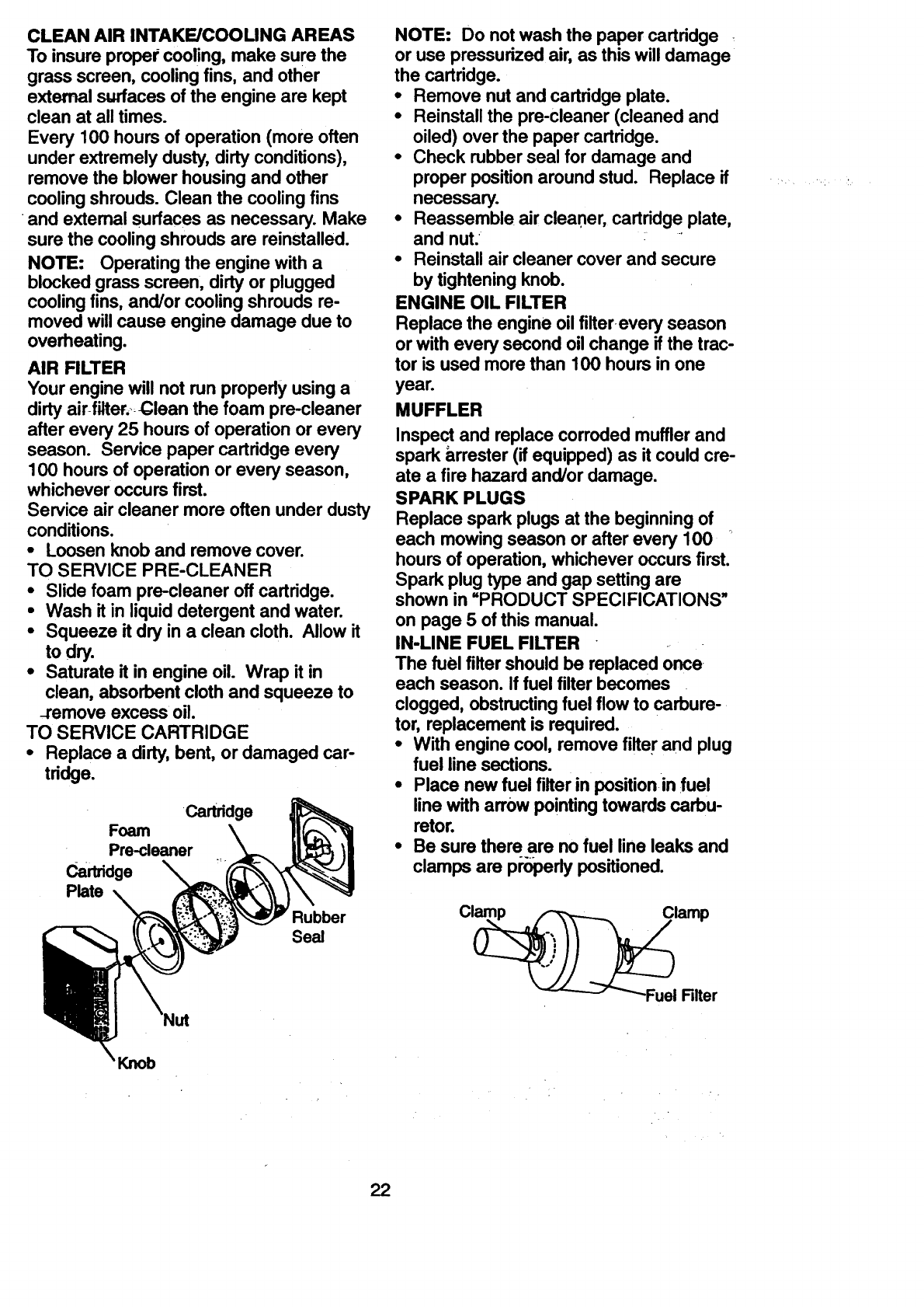
TO SERVICE CARTRIDGE
•Replace a dirty, bent, or damaged car-
tridge.
Cartridge
Foam
Pre-cleaner
Cartridge
Plate
Rubber
Seal
NOTE: Do not wash the paper cartridge
or use pressurized air, as this will damage
the cartridge.
•Remove nut and cartridge plate.
•Reinstall the pre-cleaner (cleaned and
oiled) over the paper cartridge.
•Check rubber seal for damage and
proper position around stud. Replace if
necessary.
•Reassemble air cleaner, cartridge plate,
and nut.
•Reinstall air cleaner cover and secure
by tightening knob.
ENGINE OIL FILTER
Replace the engine oil filterevery season
or with every second oil change if the trac-
tor is used more than 100 hours in one
year.
MUFFLER
Inspectand replace corrodedmuffler and
spark arrester (ifequipped) as it couldcre-
ate a fire hazard and/or damage.
SPARK PLUGS
Replace spark plugs at the beginningof
each mowingseason or after every 100
hours of operation,whichever occurs first.
Spark plugtype and gap settingare
shown in =PRODUCT SPECIFICATIONS"
on page 5 ofthis manual.
IN-LINE FUEL FILTER
The fuel filter shouldbe replaced once
each season. If fuel filter becomes
clogged, obstructingfuel flow to carbure-
tor, replacement is required.
•With engine cool, remove filter and plug
fuel line sections.
•Place new fuel filterin positionin fuel
line with arrow pointingtowards carbu-
retor.
•Be sure there are no fuel line leaks and
clamps are pl'_perlypositioned.
Clamp
Filter
Knob
22
CLEANING
•Clean engine, battery, seat, finish, etc.
of all foreign matter.
•Keep finished surfaces and wheels free
of all gasoline, oil, etc.
•Protect painted surfaces with automo-
tive type wax.
we ao no[ [eGOIIIIIII_IlU u.._il ly i= tJ_lU_l I
hose t0_clean your tractor unless the elec-
trical system, muffler, air filter and carbure:
tor are covered to keep water out. Water
in engine can result in a shortened engine
life.
,ACAUTION: Before performing any service or adjustments:
•Depress clutch/brake pedal fully and set parking brake.
•Place gearshift lever in neutral (N) position.
•Place attachment clutch in =DISENGAGED" position.
•Turn ignition key =OFF" and remove key.
•Make sure the blades and all moving parts have completely stopped.
•Disconnect spark plug wire from spark plug and place wire where it cannot come
in contact with plug.
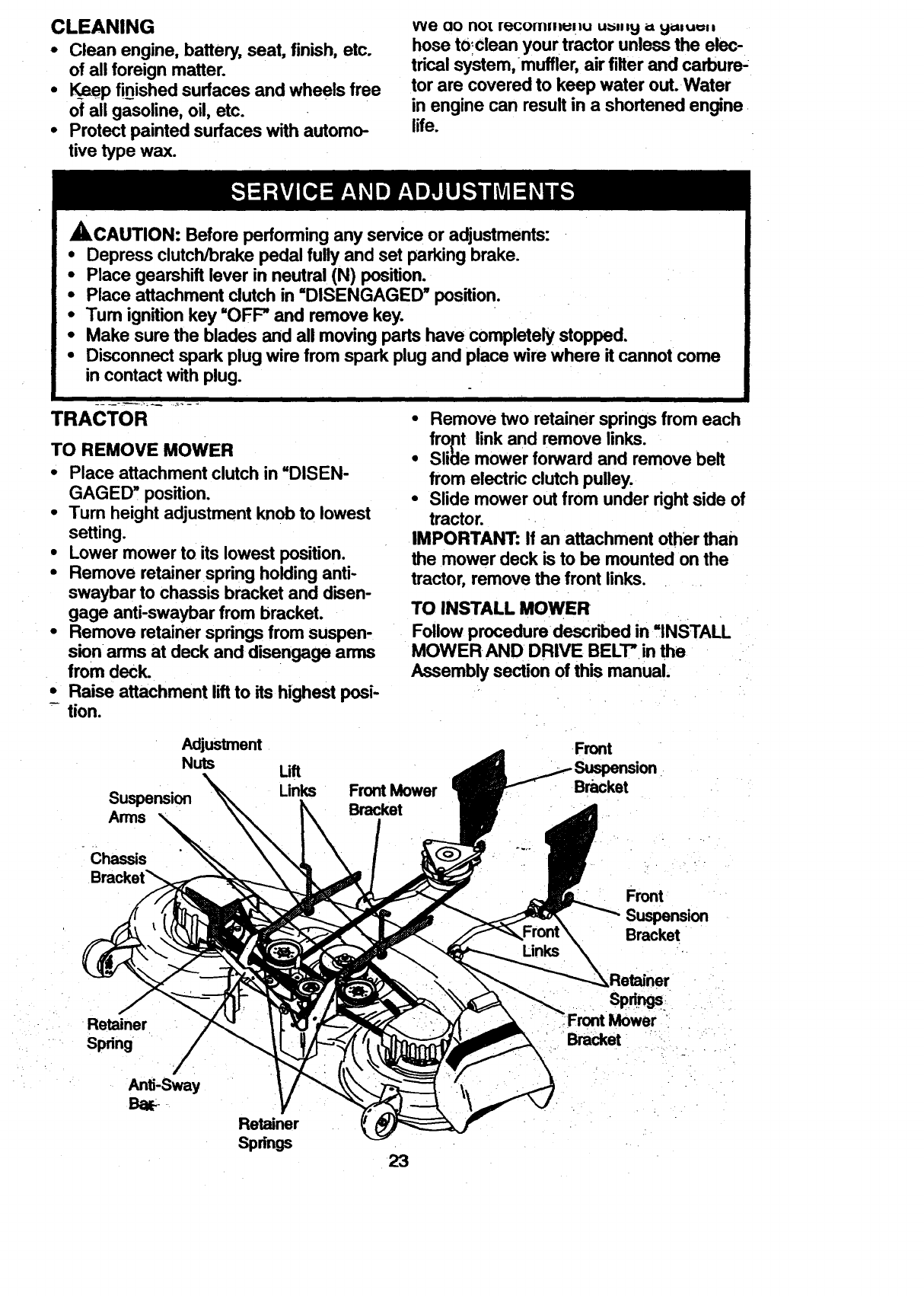
TRACTOR
TO REMOVE MOWER
•Place attachment clutch in =DISEN-
GAGED! position.
•Turn height adjustment knob to lowest
setting.
•Lower mower to its lowest position.
•Remove retainer spring holding anti-
swaybar to chassis bracket and disen-
gage anti-swaybar from bracket.
•Remove retainer springs from suspen-
sion arms at deck and disengage arms
from deck.
•Raise attachment lift to its highest posi-
- tion.
•Remove two retainer springs from each
fropt link and remove links.
•Sli_le mower forward and remove belt
from electric clutch pulley.
•Slide mower out from under right side of
tractor.
IMPORTANT: If an attachment other than
the mower deck is to be mounted on the
tractor, remove the front links.
TO INSTALL MOWER
Follow procedure described in ,,INSTALL
MOWER AND DRWE BELT" in the
Assembly section of this manual.
Adjustment
Nuts
Suspension
Arms
Front Mower
Bracket
Front
Bracket
-Chas=s
Bracket_
Links
Front
Suspension
Bracket
Retainer
Spring
Anti-Sway
Ba_
Retainer
Spdngs 23
sp .gs:
Front Mower
Bracket
TO LEVEL MOWER HOUSING
Adjust the mower while tractor is parked
on level ground or driveway. Makesure
tiresare properlyinflated (See =PROD-
UCT SPECIFICATIONS"). If tires are
over or underinflated, you will not properly
adjust your mower.
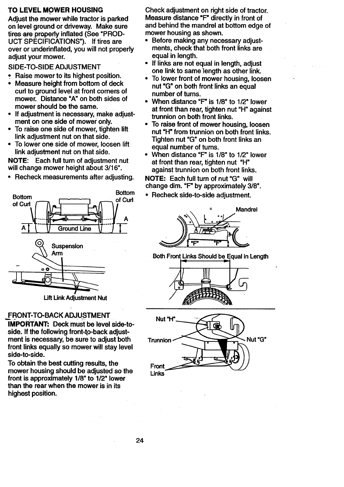
SIDE-TO-SIDE ADJUSTMENT
•. Raise mower to its highest position.
•Measure height from bottom of deck
cud to ground level at front comers of
mower. Distance =A" on both sides of
mower should be the same.
•If adjustment is necessary, make adjust-
ment on one side of mower only.
•To raise one side of mower, tighten lift
link adjustment nut on that side.
•To lower one side of mower, loosen lift
link adjustment nut on that side.
NOTE: Each full tum of adjustment nut
will change mower height about 3/16".
•Recheck measurements after adjusting.
Bottom Bottom
of Curl _I I _ofCurl
Check adjustment on right side of tractor.
Measure distance "P directly in front of
and behind the mandrel at bottom edge of
mower housing as shown.
•Before making any necessary adjust-
ments, check that both front links are
equal in length.
•If links are not equal in length, adjust
one link to same length as other link.
•To lower front of mower housing, loosen
nut "G" on both front links an equal
number of turns.
•When distance "P is 1/8" to 1/2" lower
at front than rear, tighten nut =H" against
trunnion on both front links.
•To raise front of mower housing, loosen
nut "H" from trunnion on both front links.
Tighten nut =G" on both front links an
equal number of tums.
•When distance =P is 1/8" to 1/2" lower
at front than rear, tighten nut "H"
against trunnion on both front links.
NOTE: Each full turn of nut "G" will
change dim. "P by approximately 3/8".
•Recheck side-to-side adjustment.
°Mandrel
Suspension
Arm
Uft Unk Adjustment Nut
FRONT-TO-BACK ADJUSTMENT
IMPORTANT: Deck must be level side-to-
side. If the following front-to-back adjust-
ment is necessary, besure to adjust both
front links equally so mower will stay level
side-to-side.
To obtain the best cutting results, the
mower housing should be adjusted so the
front is approximately 1/8" to 1/2" lower
than the rear •when the mower is in its
highest position.
Both FrontUnks Shouldbe Equal in Length
Trunnion Nut =G"
Front
Unks
24
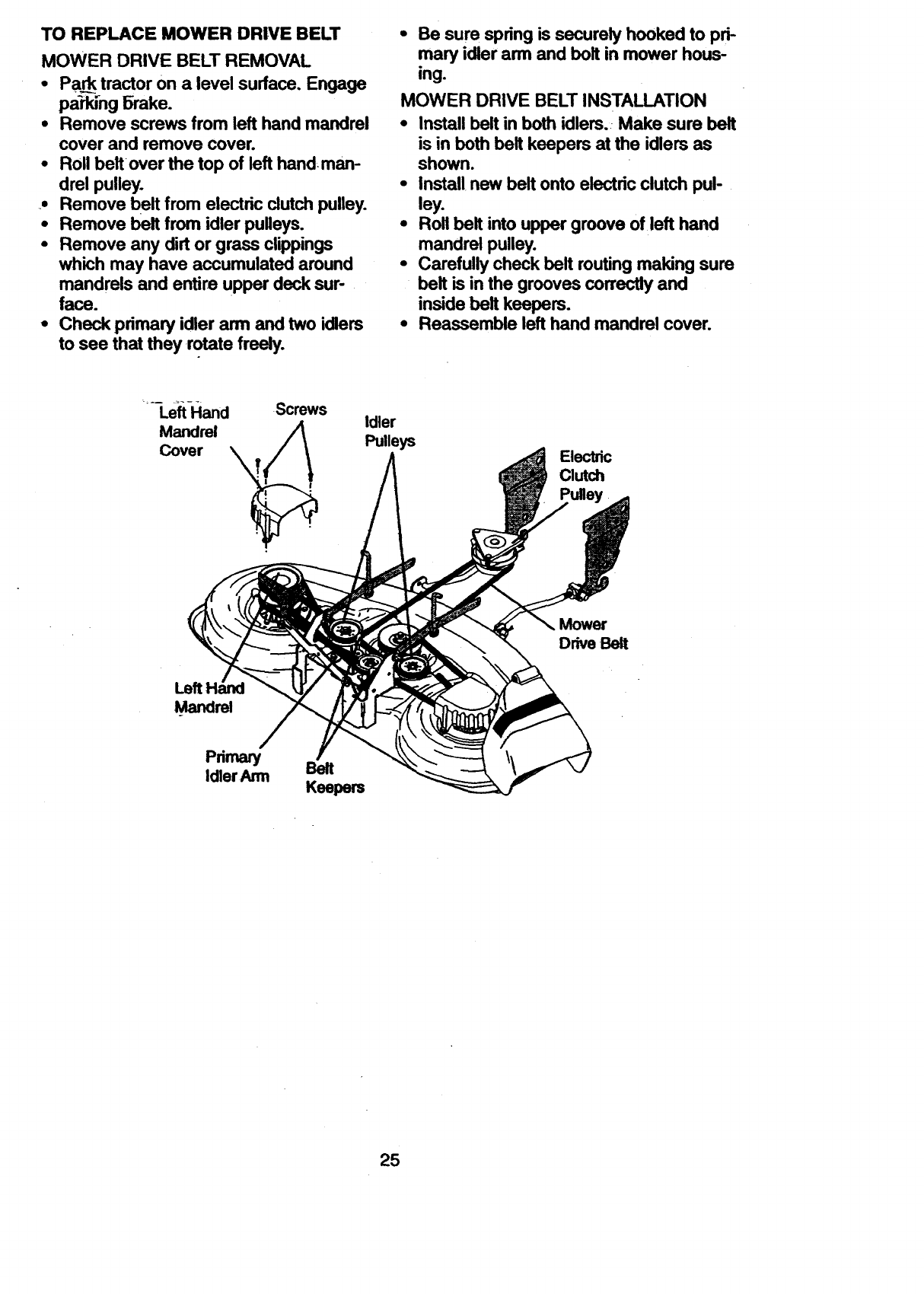
TO REPLACE MOWERDRIVE BELT
MOWER DRIVE BELT REMOVAL
•Pa_ tractor on a level surface. Engage
pa'rkJ_ngBrake.
•Remove screws from left hand mandrel
cover and remove cover.
•Roll beltover the top of left hand man-
drel pulley.
• Remove belt from electric clutch pulley.
• Remove belt from idler pulleys.
•Remove any dirt or grass clippings
which may have accumulated around
mandrels and entire upper deck sur-
face.
•Check primary idler arm and two idlers
to see that they rotate freely.
•Be sure spring is securely hooked to pd-
mary idler arm and bolt in mower hous-
ing.
MOWER DRIVE BELT INSTALLATION
•Install belt in both idlers. Make sure belt
is in both belt keepers at the idlers as
shown.
•Install new belt onto electric clutch pul-
ley.
•Roll belt into upper groove of left hand
mandrel pulley.
•Carefully check belt routing making sure
belt is in the grooves correctly and
inside belt keepers.
•Reassemble left hand mandrel cover.
LeftHand
Mandrel
Cover
Screws Idler
Pulleys Electric
Clutch
Mower
Drive Belt
Mandrel
Primary
Idler Arm Belt
Keepers
25
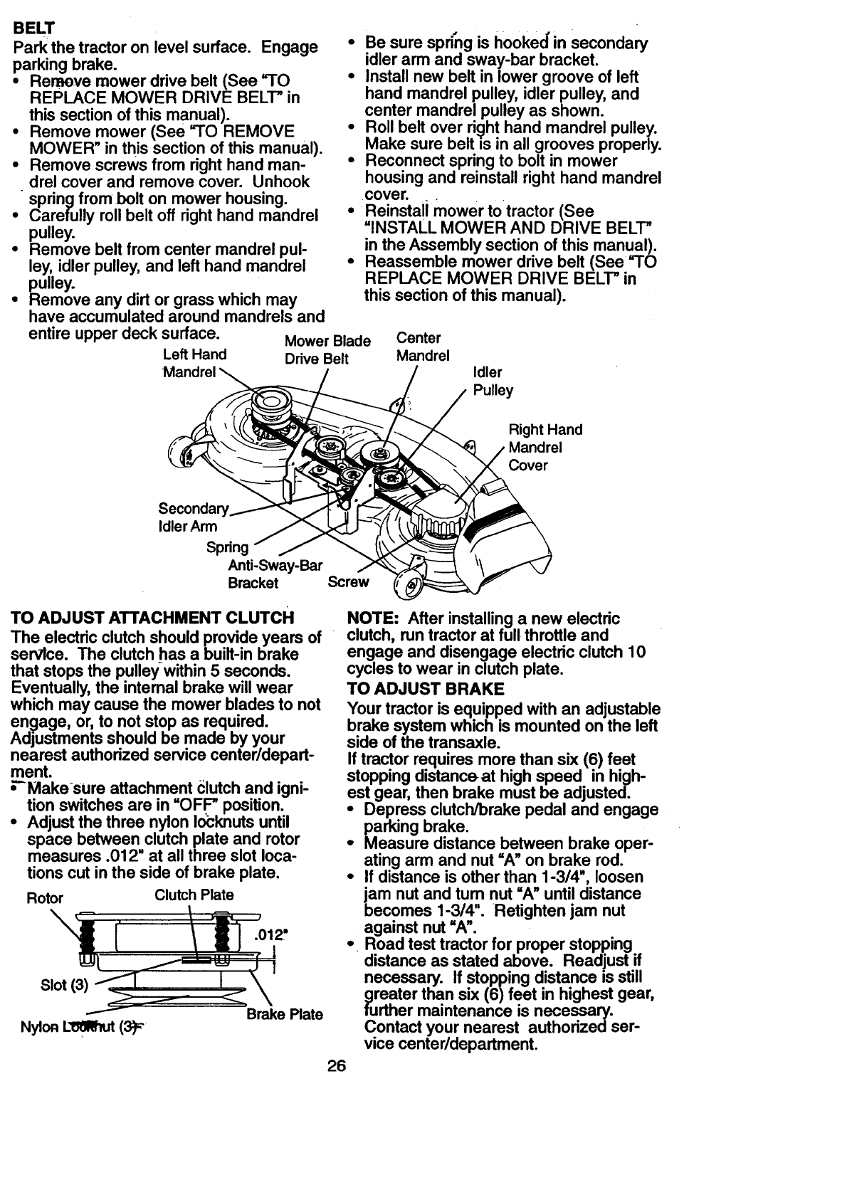
BELT
Park the tractor on level surface. Engage
parkingbrake.
•Remove mower drive belt (See 9-0
REPLACE MOWER DRIVE BELT" in
this section of this manual).
• Remove mower (See =TO REMOVE
MOWER" in this section of this manual).
•Remove screws from right hand man- "
drel cover and remove cover. Unhook
spring from bolt on mower housing.
•Carefully roll belt off right hand mandrel
pulley.
•Remove belt from center mandrel pul-
ley, idler pulley, and left hand mandrel
pulley.
•Remove any dirt or grass which may
have accumulated around mandrels and
entire upper deck surface. Mower Blade
Left Hand Drive Belt
Mandrel
•Be sure sprrng is hooked"in secondary
idler arm and sway-bar bracket.
•Install new belt in lower groove of left
hand mandrel pulley, idler pulley, and
center mandrel pulley as shown.
Roll belt over right hand mandrel pulley.
Make sure belt is in all grooves properly.
Reconnect spring to bolt in mower
housing and reinstall right hand mandrel
cove r.
•Reinstali mower totractor (See
=INSTALL MOWER AND DRIVE BELT"
in the Assembly section of this manual).
•Reassemble mower drive belt (See =TO
REPLACE MOWER DRIVE BELT" in
this section of this manual).
Center
Mandrel Idler
Pulley
Right Hand
Mandrel
Cover
Idler Arm
Spring
Anti-Sway-Bar
Bracket Screw
TO ADJUST ATTACHMENT CLUTCH
The electric clutch should provide years of
servlce. The clutch has a built-in brake
that stops the pulley-within 5 seconds.
Eventually, the intemal brake will wear
which may cause the mower blades to not
engage, or, to not stop as required.
Adjustments should be made by your
nearest authorized service center/depart-
ment.
_Makesure attachment clutch and igni-
tion switches are in =OFP position.
•Adjust the three nylon Io_knuts until
space between clutch plate and rotor
measures .012" at all three slot loca-
tions cut in the side of brake plate.
Rotor Clutch Plate
.012,
Brake Plate
26
NOTE: After installing a new electric
clutch, run tractor at full throttle and
engage and disengage electric clutch 10
cycles to wear in clutch plate.
TO ADJUST BRAKE
Your tractor is equipped with an adjustable
brake system which is mounted on the left
side of the transaxle.
If tractor requires more than six (6) feet
stopping distanceat high speed in high-
est gear, then brake must be adjusted.
•Depress clutch/brake pedal and engage
parking brake.
• Measure distance between brake oper-
ating arm and nut "A" on brake rod.
•If distance is other than 1-3/4", loosen
jam nut and tum nut =A" until distance
becomes 1-3/4". Retighten jam nut
against nut =A".
•Road test tractor for proper stopping
distance as stated above. Readjust if
necessary. If stopping distance is still
greater than six (6)feet in highest gear,
further maintenance is necessary.
Contact your nearest authorizedser-
vice center/department.
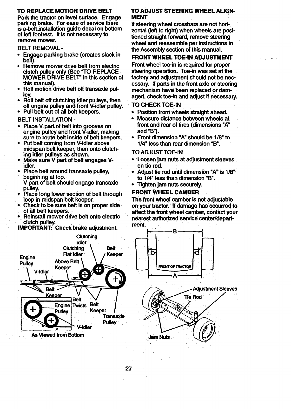
TO REPLACE MOTION DRIVE BELT
Park the tractor on level surface. Engage
parking brake. For ease of service there
isa-beltJnstallation guide decal on bottom
of left footrest. It is not necessaryto
remove mower.
BELT REMOVAL-
•Engage parking brake (creates slack in
belt).
•Remove mower drive belt from electdc
clutch pulley only (See "TO REPLACE
MOWER DRIVE BELT" in this section of
this manual).
• Roll motion drive belt off transaxle pul-
ley.
• Flog belt off clutching, idler p.u!__ys+.t.h,en.
off engine pulley ana rront v-lomr pu.uy.
•Pull belt out ofall belt keepers.
BELT INSTALLATION -
•Place-Vpart.of.belt into grooves on
engine pulley and front V-idler, making
sure to route belt inside of belt keepers.
•Put belt coming from V-idler above
midspan belt keeper, then onto clutch-
ing idler pulleys as shown.
•Make sure V part of belt engages V-
idler.
•Place belt around transaxle pulley,
beginning at top.
V part of belt should engage transaxle
pulley.
0 Place long lower section of belt through
loop in miclspan belt keeper.
•Check to be Sure belt is on proper side
of all beltkeepers.
•Reinstall mower drive belt onto electric
clutch pulley.
IMPORTANT: Check brake adjustment.
Engine
Pulley
Clutching
Idler
Clutching
Rat Idler
-Above Belt
Belt
TO ADJUST STEERING WHEEL AUGN-
MENT
If steering wheel crossbars are not hori-
zontal (left to right) when wheels are posi-
tioned straight forward, remove steering
wheel and reassemble per instructions in
the Assembly section of this manual.
FRONT WHEEL TOE-IN ADJUSTMENT ...........................
Front wheel toe-in is required for proper
steering operation. Toe-in was set atthe
factory and adjustment should not be nec-
essary. If parts in the front axle or steering
mechanism have been replaced or dam-
aged, check toe-in and adjust if necessary.
TO CHECK TOE-IN
•Position front wheels straight ahead.
•Measure distance between wheels at
front and rear of tires (dimensions "A"
and "B").
•Front dimension =A" should be 1/8" to
114"less than rear dimension "B".
TO ADJUST TOE-IN
• Loosen jam nuts at adjustment sleeves
on tie rod.
•Adjust tie rod until dimension "A'ls 1/8"
to 1/4" less than dimension "B'.
•Tighten jam nuts securely.
FRONT WHEEL CAMBER
The front wheel camber is not adjustable
on your tractor.. If damage has occurred to
affect the front wheel .camber, contact your
nearest authorized service center/depart-
ment.
_1
= B --I
"A"_j
Belt
Belt
Twists Belt
Keeper
Transaxle
Pulley
V-Idler
As Viewed from Bottom JamNuts
Sleeves
27
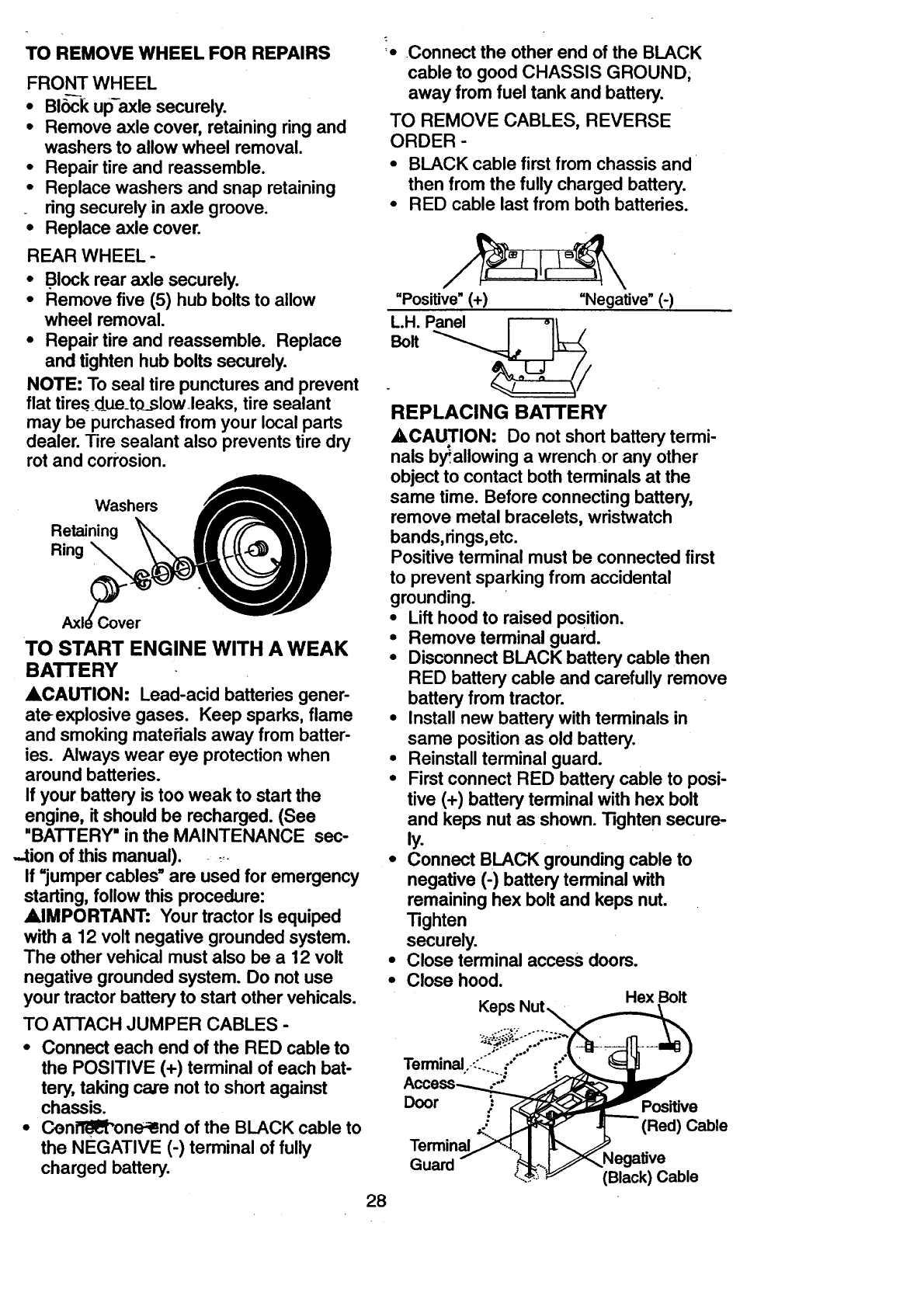
TO REMOVEWHEEL FOR REPAIRS
FRONT WHEEL
• Blbck up-axle securely.
• Remove axle cover, retaining ring and
washers to allow wheel removal.
• Repair tire and reassemble.
• Replace washers and snap retaining
ring securely in axle groove.
• Replace axle cover.
REAR WHEEL -
•Block rear axle securely.
•Remove five (5) hub bolts to allow
wheel removal.
•Repair tire and reassemble. Replace
and tighten hub bolts securely.
NOTE: To seal tire punctures and prevent
flat tiresdue_to_slow.leaks, tire sealant
may be purchased from your local parts
dealer. Tire sealant also prevents tire dry
rot and corrosion.
Washers
Retaining
Ring _
Cover
TO START ENGINE WITH A WEAK
BATTERY
ACAUTION: Lead-acid batteries gener-
ate explosive gases. Keep sparks, flame
and smoking matei'ials away from batter-
ies. Always wear eye protection when
around batteries.
If your battery is too weak to start the
engine, it should be recharged. (See
"BATTERY" in the MAINTENANCE sec-
-tion of this manual). _
If =jumper cables" are used for emergency
starting, follow this procedure:
AIMPORTANT: Your tractor Is equiped
with a 12 volt negative grounded system.
The other vehical must also be a 12 volt
negative grounded system. Do not use
your tractor battery to start other vehicals.
TO ATTACH JUMPER CABLES -
•Connect each end of the RED cable to
the POSITIVE (+) terminal of each bat-
tery, taking care not to short against
chassis.
•Cen_ne-_nd of the BLACK cable to
the NEGATIVE (-) terminal of fully
charged battery.
_- Connect the other end of the BLACK
cable to good CHASSIS GROUND,
away from fuel tank and battery.
TO REMOVE CABLES, REVERSE
ORDER -
• BLACK cable first from chassis and
then from the fully charged battery.
• RED cable last from both batteries.
"Positive" (+) =Negative"(-)
"'""
REPLACING BATTERY
A, CAUTION: Do not short battery termi-
nals byallowing awrench or any other
object to contact both terminals at the
same time. Before connecting battery,
remove metal bracelets, wristwatch
bands, rings,etc.
Positive terminal must be connected first
to prevent sparking from accidental
grounding.
•Lift hood to raised position.
•Remove terminal guard.
•Disconnect BLACK battery cable then
RED battery cable and carefully remove
battery from tractor.
•Install new battery with terminals in
same position as old battery.
•Reinstall terminal guard.
•First connect RED battery cable to posi-
tive (+) battery terminal with hex bolt
and keps nut as shown. Tighten secure-
ly.
• Connect BLACK grounding cable to
negative (-) battery terminal with
remaining hex bolt and keps nut.
Tighten
securely.
•Close terminal access doors.
•Close hood. Hex Bolt
Keps
28
Door ,Positive
(Red) Cable
Terminal
Guard (Black) Cable
TO REPLACE HEADLIGHT BULB
•;Raise hood.
• Pull bulb holder out of the hole in the
backside of the grill.
•Rdplace-bulb in holder and push bulb
holder securely back into the hole in the
backside of the grill.
•Close hood.
INTERLOCKS AND RELAYS
Loose or damaged wiring maycause your
tractor to run poody, stop running, or pre-
vent it from starting.
•Check wiring. See electrical wiring dia-
gram in the Repair Parts section of this
manual.
TO REPLACE FUSE
Replace with 30 amp automotive-type
plug-in fuse. The fuse holder is located
behind t_h_._das_h......
formed by an authorized engine manufac-
turer's service outlet.
TO REMOVE HOOD AND GRILL
ASSEMBLY
•Raise hood.
• Unsnap headlight wire connector.
• Stand in front of tractor. Grasp hood at
sides, tilt toward engine and lift off of
tractor.
•To replace, reverse above procedure.
Hood
Headlight
Wire
Connector
ENGINE
Maintenance, repair, or replacement of the
emission control devices and systems,
which are being done at the customers
expense, may be performed by any non-
road engine repair establishment or indi-
vidual. Warranty repairs must be per-
formed by an authorized engine manufac-
turer's service outlet.
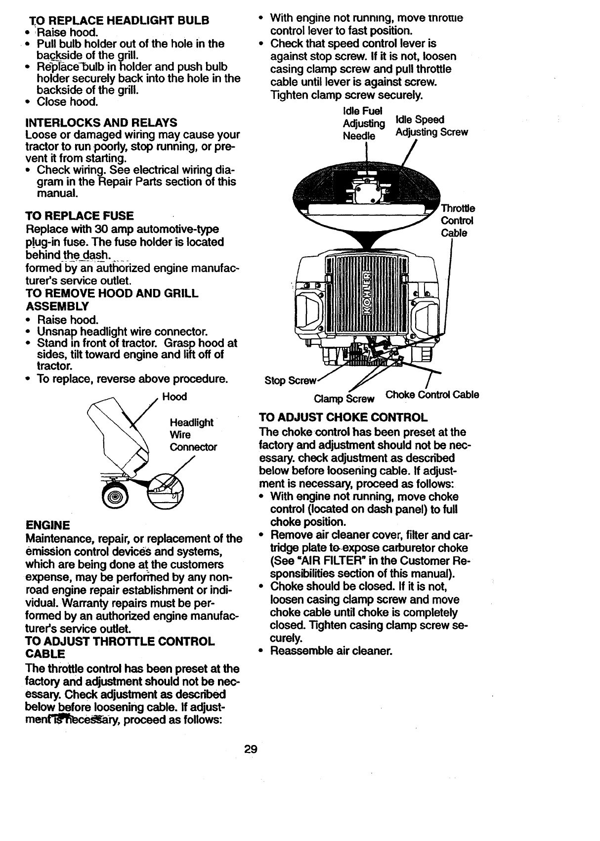
TO ADJUST THROTTLE CONTROL
CABLE
The throttle control has been preset at the
factory and adjustment should not be nec-
essary. Check adjustment as described
below before loosening cable. If adjust-
ment_i"_eS_,ary, proceed as follows:
With engine not running, move mrotzle
control lever to fast position.
Check that speed control lever is
against stop screw. If it is not, loosen
casing clamp screw and pull throttle
cable until lever is against screw.
Tighten clamp screw securely.
Idle Fuel
Adjusting Idle Speed
Needle AdjustingScrew
Control
Cable
Stop
Clamp Screw Choke Control Cable
TO ADJUST CHOKE CONTROL
The choke control has been preset at the
factory and adjustment should not be nec-
essary, check adjustment as described
below before loosening cable. If adjust-
ment is necessary, proceed as follows:
•With engine not running, move choke
control (located on dash panel) to full
choke position.
•Remove air cleaner cover, filter and car-
tridge plate toexpose carburetor choke
(See =AIR RLTER tin the Customer Re-
sponsibilities section of this manual).
•Choke should be closed. If it is not,
loosen casing clamp screw and move
choke cable until choke is completely
closed. Tighten casing clamp screw se-
curely.
•Reassemble air cleaner.
29
FINAL SETTING -
•Start engine and allow to warm for five
minutes. Make final adjustments with
engi[__ running and shift/motion control
lever in neutral (N) position.
• The high idle is set at the factory and
cannot be adjusted.
•Idle speed setting -With throttle control
lever in slow position, engine should
•idle at 1200 RPM. If engine idles too
slow or fast, turn idle speed adjusting
screw in or out until correct idle is
attained.
•Idle fuel needle setting -With throttle
control lever in slow position, tum idle
fuel adjusting needle in (clockwise) until
engine speed decreases and then turn
out (counterclockwise) approximately
3/4 turn to obtain the best low speed
performah_-e_ ........
• Recheck idle speed.-Readjust if neces-
sary.
ACCELERATION TEST -
•Move throttle control lever from slow to
fast position. If engine hesitates or dies,
tum idle fuel adjusting needle out
(counterclockwise) 1/8 tum. Repeat test
and continue to adjust, if necessary,
until engine accelerates smoothly.
High speed stop is factory adjusted. Do
not adjust-damage may result.
IMPORTANT: Never tamper with the
engine govemor, which is factoryset for
proper engine speed. Overspeeding the
engine above the facory high speed set-
ting can be dangerous. If you think the
engine-governed high speed needs
adjusting, contact your nearest authorized
service center/department, which has
proper equipment and experience to make
any necessary adjustments.
30
Imr'3ediatelyprepareyour tractor for stor-
ag_ at th_ end of the season or if the trac-
tor will not be used for 30 days or more.
,A CAUTION: Never store the tractor with
gasoline in the tank inside a building
where fumes may reach an open flame or
spark. Allow the engine to cool before stor-
ing in any enclosure.
TRACTOR
Remove mower from tractor for winter
storage. This will allow you to clean it thor-
oughly. Remove all dirt, grease, leaves,
etc. Store in a clean, dry area.
•Clean entire tractor (See =CLEANING"
in the Maintenance section of this man-
ual). - ..........
•Inspect and replace belts, if necessary
(See belt replacement instructions in the
Service and Adjustments section of this
manual).
•Lubricate as shown in the Maintenance
section of this manual.
•Be sure that all nuts, bolts and screws
are securely fastened. Inspect moving
parts for damage, breakage and wear.
Replace if necessary.
•Touch up all rusted or chipped paint sur-
faces; sand lightly before painting.
BATTERY
•Fully charge the battery for storage.
-• After aperiod of time in storage, battery
may require r_echarging.
•To help prevent corrosion and power
leakage during long periods of storage,
battery cables should be disconnected
and battery cleaned thoroughly (see
=TO CLEAN BATTERY AND TERMI-
NALS" in the Maintenance section of
this manual).
•After cleaning, leave cables disconnect-
ed and place cables where they cannot
come in contact with battery terminals.
•If battery is removed from tractor for
storage, do not store battery directly on
concrete or damp surfaces.
•ENGINE
FUEL SYSTEM
•_:IMPORTANT: It is important to prevent
gum deposits from forming in essential
]ue],_l_6te_arts such as carburetor, fuel
filter, fuel h_e, or tank during storage.
Also, experience indicates that alcohol
blended fuels (called gasohol or using
ethanol or methanol) can attract moisture
which leads to separation and formation of
acids during storage. Acidic gas can dam-
age the fuel system of an engine while in
storage.
• Drain thefuel tank.
•Start the engine and let it run until the
fuel lines and carburetor are empty.
• Never use engine or carburetor cleaner
products in the fuel tank or permanent
damage may occur.
•Use fresh fuel next season.
NOTE: Fuel stabilizer is an acceptable
alternative in minimizing the formation of
fuel gum deposits during storage. Add sta-
bilizer to gasoline in fuel tank or storage
container. Always follow the mix ratio
found on stabilizer container. Run engine
at least 10 minutes after adding stabilizer
to allow the stabilizer to reach the carbure-
tor. Do not drain the gas tank and carbure-
tor if using fuel stabilizer.
ENGINE OIL
Drain oil (with engine warm) and replace
with clean engine oil. (See "ENGINE" in
the Maintenance section of this manual).
CYLINDER(S)
•Remove spark plug(s).
•Pour one ounce of oil through spark plug
hole(s) into cylinder(s).
•Turn ignition key to =STAR'I_' position for
a few second,.F,to distribute oil.
•Replace with new spark plug(s).
OTHER
•Do not stOregasoline from one season
to another.
•Replace your gasoline can if it starts to
rust. Rust and/or dirt in your gasoline will
cause problems.
•If possible, store your tractor indoors
and cover it to give protection from dust
and dirt.
•Cover your tractor with a suitable protec-
tive cover that does not retain moisture.
Donot use plastic. Plastic cannot - -
breathe; which allows condensation to
form and cause your tractor to rust. _
IMPORTANT: Never cover tractor while :
engine and exhaust areas are still warm.
31
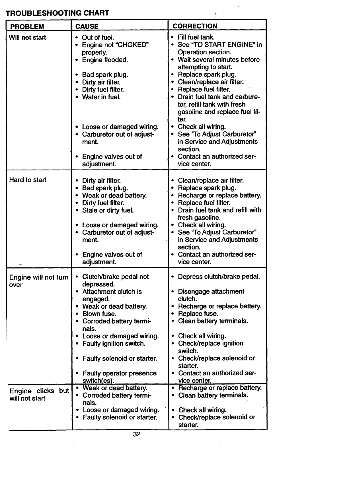
TROUBLESHOOTING CHART •
PROBLEM
Will not start
CAUSE
•Out of fuel.
•Engine not =CHOKED"
properly.
• Engine flooded.
Hard to start
Engine will not turn
over
Engine clicks but
will not start
•Bad spark plug.
•Dirty air filter.
•Dirty fuel filter.
•Water in fuel.
Loose or damaged wiring.
Carburetor out of adjust-
ment.
Enginevalves out of
adjustment.
•Dirty air filter.
•Bad spark plug.
•Weak or dead battery.
•Dirty fuel filter.
•Stale or dirty fuel.
•Loose or damaged wiring.
•Carburetor out of adjust-
ment.
•Enginevalves out of
adjustment.
• Clutch/brake pedal not
depressed.
•Attachment clutch is
engaged.
•Weak or dead battery.
•Blown fuse.
•Corroded battery termi-
nals.
•Loose or damaged wiring.
•Faulty ignition switch.
•Faulty solenoid or starter.
•Faulty operator presence
switch(es).
•Weak or dead battery.
•Corroded battery termi-
nals.
•Loose or damaged wiring.
•Faulty solenoid or starter.
CORRECTION
•Fill fuel tank.
•See "TO START ENGINE" in
Operation section.
•Wait several minutes before
attempting to start.
•Replace spark plug.
•Clean/replace air filter.
•Replace fuel filter.
•Drain fuel tank and carbure-
tor, refill tank with fresh
gasoline and replace fuel fil-
ter.
•Check all wiring.
•See =ToAdjust Carburetor"
in Service and Adjustments
section.
•Contact an authorized ser-
vice center.
•Clean/replace air filter.
• Replace spark plug.
• Recharge or replace battery.
•Replace fuel filter.
• Drain fuel tank and refill with
fresh gasoline.
•Check all wiring.
•See "To Adjust Carburetor'
in Service and Adjustments
section.
•Contact an authorized ser-
vice center.
•Depress clutch/brake pedal.
•Disengage attachment
clutch.
•Recharge or replace battery.
•Replace fuse.
•Clean battery terminals.
•Check all wiring.
•Check/replace ignition
switch.
•Check/replace solenoid or
starter.
•Contact an authorized ser-
vice center. •
•Recharge or replace battery.
•Clean battery terminals.
•Check all wiring.
•Check/replace solenoid or
starter.
32
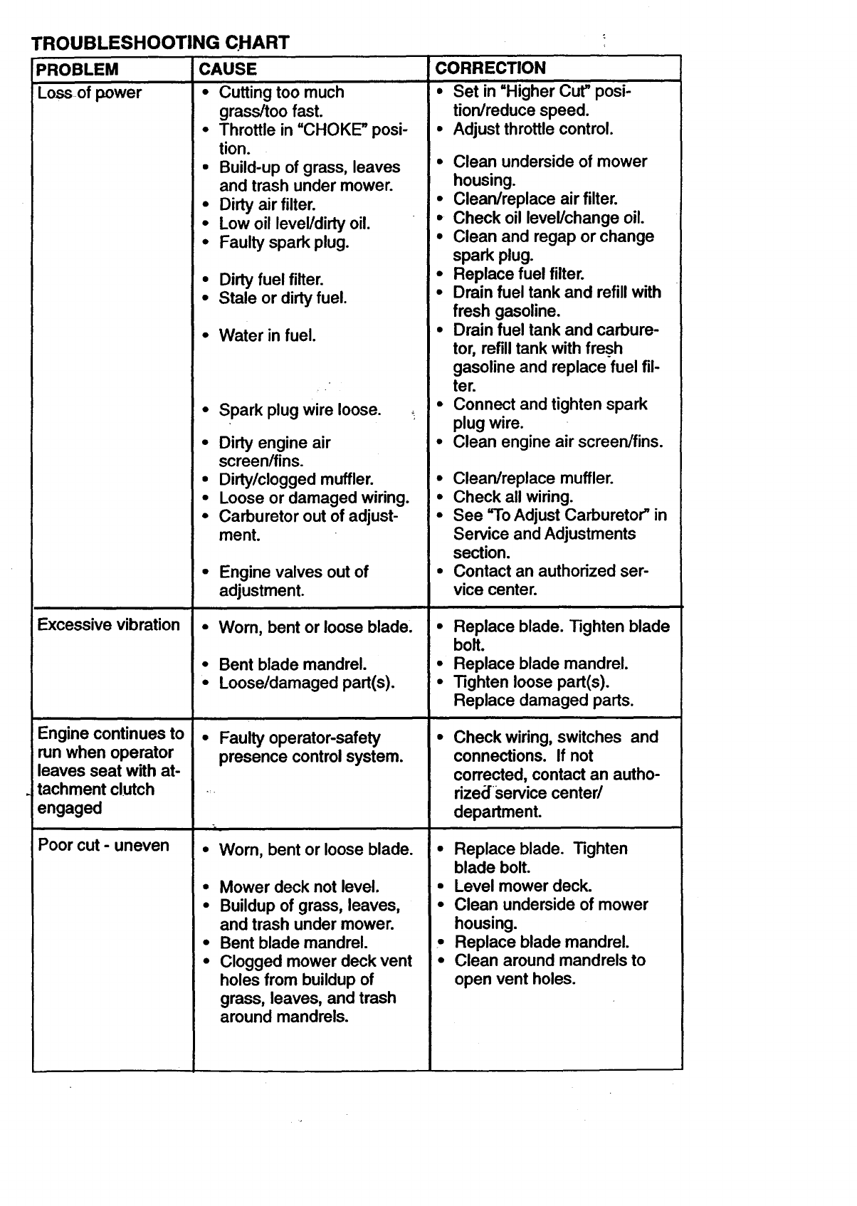
TROUBLESHOOTING CHART
PROBLEM
Loss of power
CAUSE
• Cutting too much
grass/too fast.
•Throttle in "CHOKE" posi-
tion.
• Build-up of grass, leaves
and trash under mower.
• Dirty air filter.
•Low oil level/dirty oil.
• Faulty spark plug.
•Dirty fuel filter.
•Stale or dirty fuel.
Water in fuel.
Spark plug wire loose.
Dirty engine air
screen/fins.
Dirty/clogged muffler.
Excessive vibration
Engine continues to
run when operator
leaves seat with at-
tachment clutch
engaged
Poor cut - uneven
•Loose or damaged wiring.
•Carburetor out of adjust-
ment.
•Engine valves out of
adjustment.
•Worn, bent or loose blade.
•Bent blade mandrel.
•Loose/damaged part(s).
• Faulty operator-safety
presence controlsystem.
"r
•Wom, bent or loose blade.
•Mower deck not level.
•Buildup of grass, leaves,
and trash under mower.
•Bent blade mandrel.
•Clogged mower deck vent
holes from buildup of
grass, leaves, and trash
around mandrels.
CORRECTION
•Set in "Higher Cut" posi-
tion/reduce speed.
•Adjust throttle control.
•Clean underside of mower
housing.
• Clean/replace air filter.
•Check oil level/change oil.
•Clean and regap or change
spark plug.
•Replace fuel filter.
•Drain fuel tank and refill with
fresh gasoline.
•Drain fuel tank and carbure-
tor, refill tank with fresh
gasoline and replace fuel fil-
ter.
•Connect and tighten spark
plug wire.
•Clean engine air screen/fins.
• Clean/replace muffler.
•Check all wiring.
•See =ToAdjust Carburetor" in
Service and Adjustments
section.
•Contact an authorized ser-
vice center.
•Replace blade. Tighten blade
bolt.
•Replace blade mandrel.
•Tighten loose part(s).
Replace damaged parts.
Check wiring, switches and
connections. If not
corrected, contact an autho-
rized service canted
department.
• Replace blade. Tighten
blade bolt.
•Level mower deck.
•Clean underside of mower
housing.
•Replace blade mandrel.
•Clean around mandrels to
open vent holes.
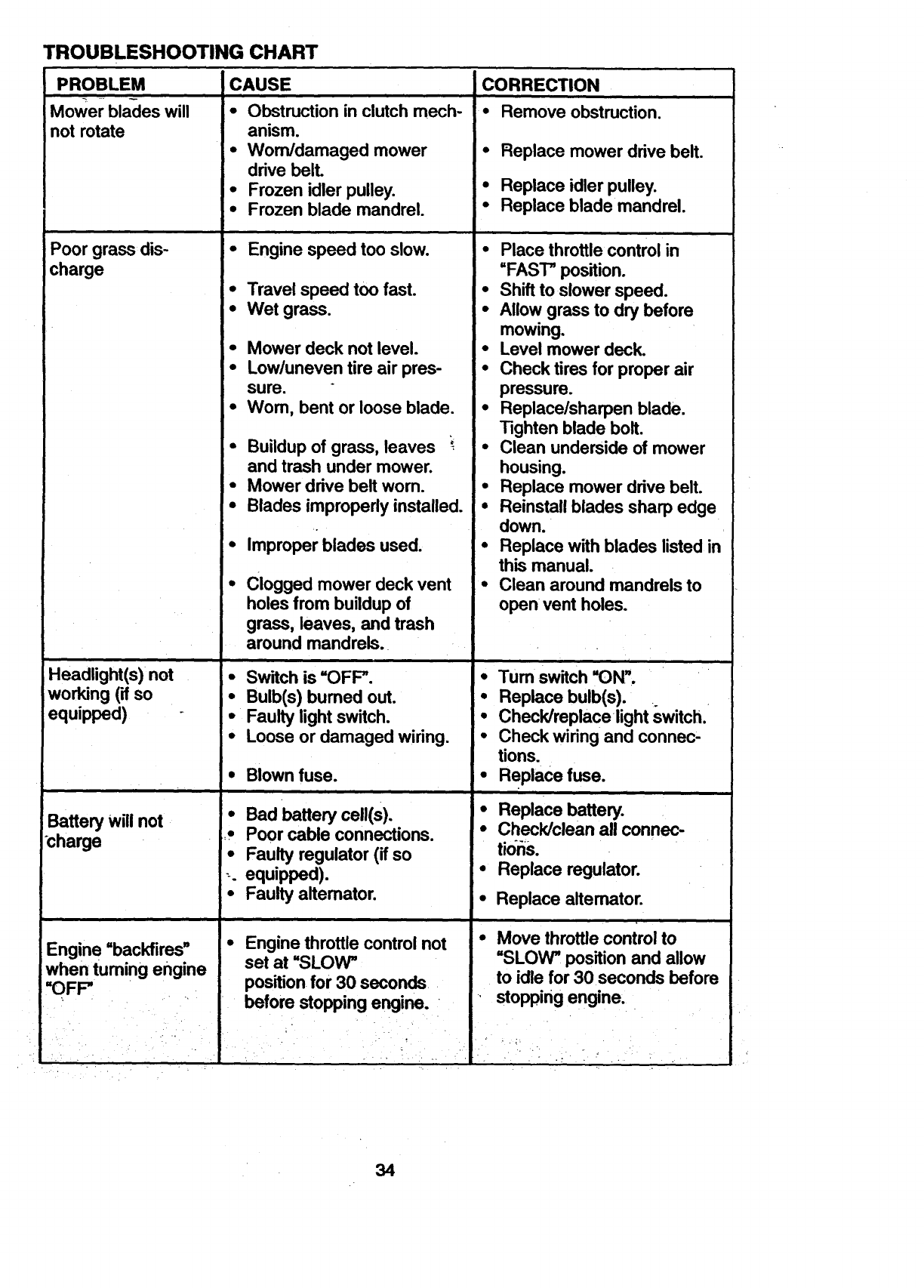
TROUBLESHOOTING CHART
PROBLEM
Mower blades will
not rotate
Poor grass dis-
charge
Headlight(s) not
working (if so
equipped)
Battery Will not
charge
Engine =backfires"
when turning engine
=OFF"
-,- .
CAUSE
• Obstruction in clutch mech-
anism.
• Worn/damaged mower
drive belt.
•Frozen idler pulley.
•Frozen blade mandrel.
i i
•Engine speed too slow.
• Travel speed too fast.
• Wet grass.
•Mower deck not level.
•Low/uneven tire air pres-
sure.
•Wom, bent or loose blade.
•Buildup of grass, leaves '
and trash under mower.
•Mower drive belt worn.
•Blades improperly installed.
Improper blades used.
Clogged mower deck vent
holes from buildup of
grass, leaves, and trash
around mandrels.
•Switch is "OFF".
• Bulb(s) burned out.
• Faulty light switch.
•Loose or damaged wiring.
Blown fuse.
•Bad battery cell(s).
,Poor cable connections.
•Faulty regulator (if so
;. equipped).
•Faulty altemator.
•Engine throttle control not
set at "SLOW"
position for 30 seconds
before stopping engine.
CORRECTION
• Remove obstruction.
•Replace mower drive belt.
•Replace idler pulley.
•Replace blade mandrel.
•Place throttle control in
=FAST" position.
•Shift to slower speed.
•Allow grass to dry before
mowing.
• Level mower deck.
•Check tires for proper air
pressure.
• Replace/sharpen blade.
Tighten blade bolt.
•Clean underside of mower
housing.
•Replace mower drive belt.
• Reinstall blades sharp edge
down. _
•Replace with blades listed in
this manual.
•Clean around mandrels to
open vent holes.
• Turn switch =ON".
• Replace bulb(s).
• Check/replacelight switch.
•Check wiringand connec-
tions.
•Replace fuse.
•Replace battery.
•Check/clean all connec-
tideS.
• Replace regulator.
•Replace altemator.
•Move throttle control to
=SLOW" position and allow
to idle for 30 seconds before
stopping engine.
., • . ;.
m
34
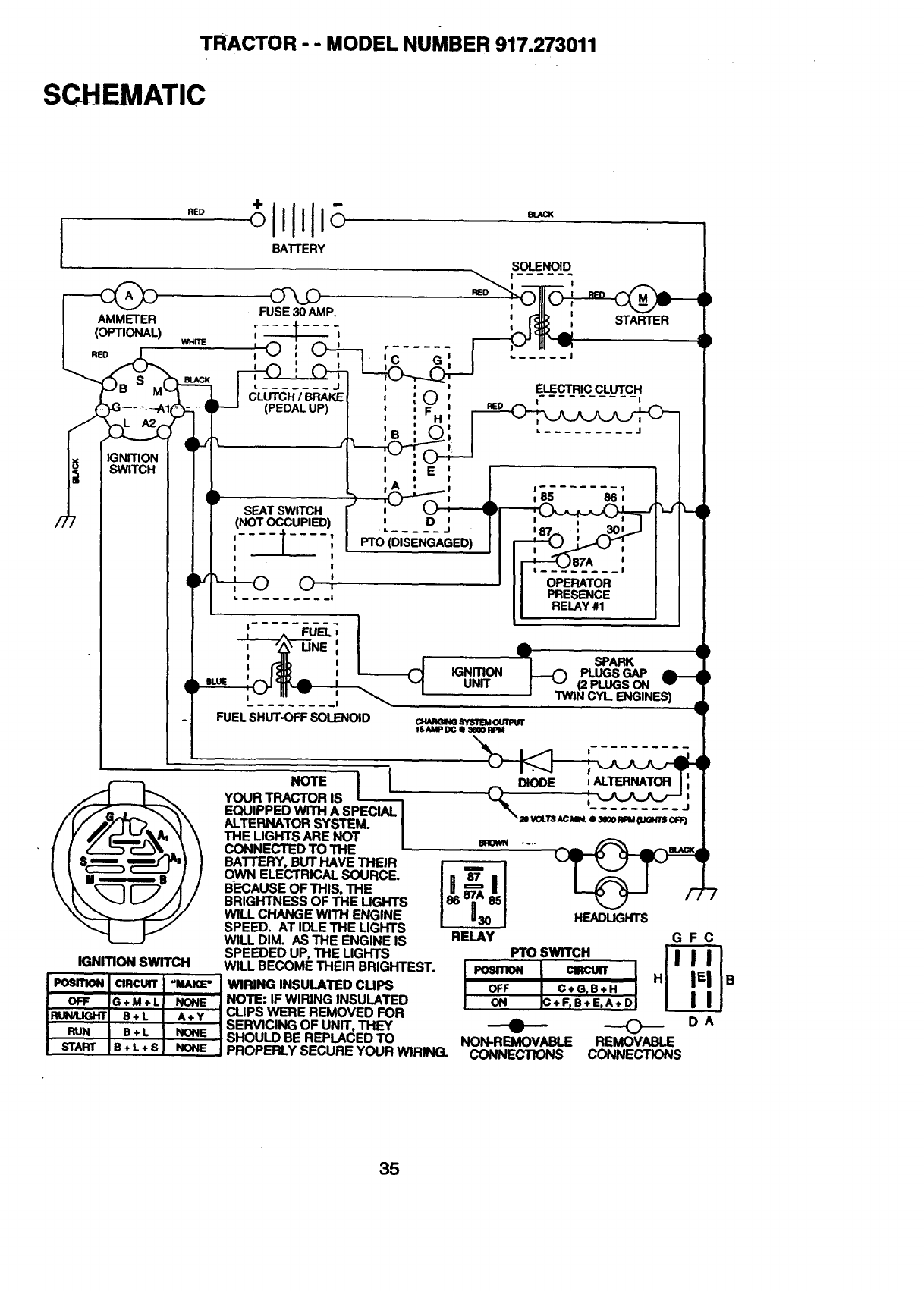
TRACTOR -- MODEL NUMBER 917.273011
SCHEMATIC
I
/7
RED
BATTERY
)
K_NmON
SWITCH
YOUR TRACTOR IS
EQUIPPED WITH A SPECIAL I
ALTERNATOR SYSTEM. I
THE LIGHTS ARE NOT I
CONNECTED TO THE--
BATTERY, BUT HAVE THEIR
OWN ELECTRICAL SOURCE.
BECAUSE OF THIS, THE
BRIGHTNESS OF THE LIGHTS
WILL CHANGE WITH ENGINE
SPEED. AT IDLE THE LIGHTS
WILL DIM. AS THE ENGINE IS
SPEEDED UP, THE LIGHTS
SOLENOID
| ...... !
I !
,jSTARTER
IGNmON SWITCH WILL BECOME THEIR BRIGHTEST.
A
,=,
(_ SPARK
-- IGNmON _PLUGSGAP
UNIT I "" (2 PLUGSON v •
' TWIN CYL ENGINES) .,
CI._R(aNGSYSlrEMou1rPu1r
ISAMP DG e 3_0 RPM
D-_,-
RELAY
HEADLIGHTS
Fro SWITCH
w°. -=- I
OFF C+G.B+H I
ON +F_B+E,A+DJ
!_°" I="c_'I"_ IWIRINGINSULATEDCUPS
OFF IG+M+LJ NONE JNOTE: IFWlRING INSULATED
RUI_UGHTI B÷ L I^+y Jcups WERE REMOVED FOR
I I ISERVICING OF UNIT, THEY
RUN IB+L INONE ISHOULD BE REPLACED TO
START IB+ L ÷ S I NONE JPROPERLY SECURE YOUR WIRING. NON-REMOVABLE
CONNECTIONS
GFC
----0---- OA
REMOVABLE
CONNECTIONS
35
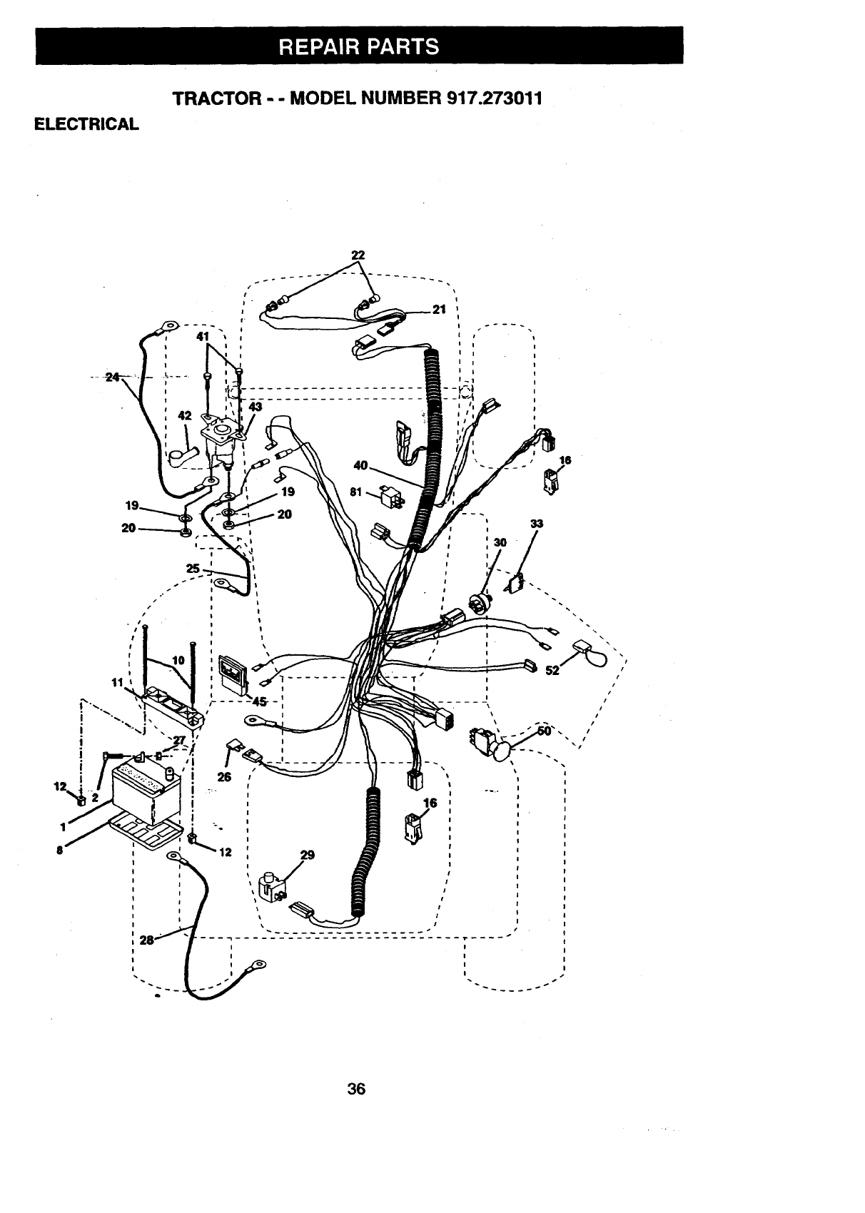
ELECTRICAL
TRACTOR - - MODEL NUMBER 917.273011
22
I
i p
I I !
i I !
J i I
t_l I
i
I
2O
l
\7
_ it t
I
j t
36
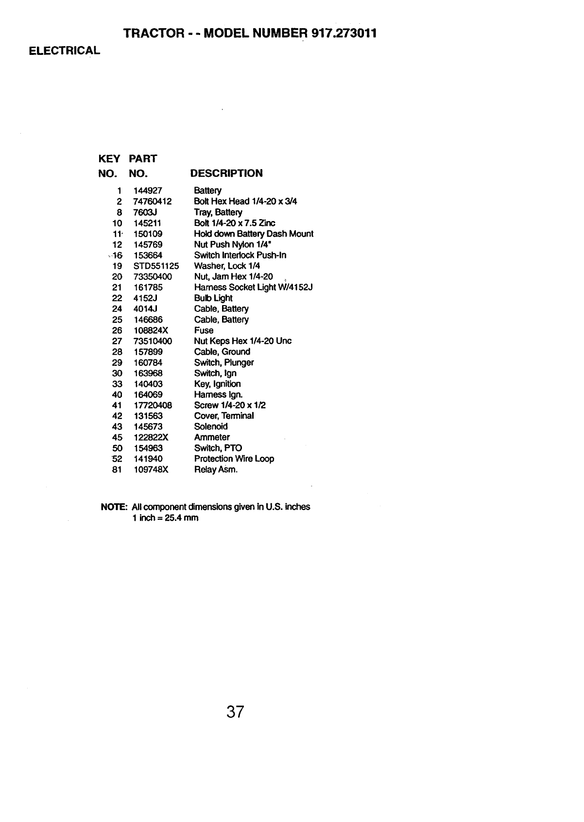
ELECTRICAL
TRACTOR -- MODEL NUMBER 917.273011
KEY
NO.
PART
NO. DESCRIPTION
1 144927 Battery
2 74760412 Bolt Hex Head 1/4-20 x 3/4
8 7603J Tray, Battery
10 145211 Bolt 114-20 x 7.5 Zinc
11- 150109 Hold down Battery Dash Mount
12 145769 Nut Push Nylon 114"
_,16 153664 Switch Interlock Push-in
19 STD551125 Washer, Lock 1/4
20 73350400 Nut, Jam Hex 1/4-20
21 161785 Harness Socket Light VV/4152J
22 4152J Bulb Light
24 4014J Cable, Battery
25 146686 Cable, Battery
26 108824X Fuse
27 73510400 Nut Keps Hex 1/4-20 Unc
28 157899 Cable, Ground
29 160784 Switch, Plunger
30 163968 Switch, Ign
33 140403 Key, Ignition
40 164069 Harness Ign.
41 17720408 Screw 114-20 x 1/2
42 131563 Cover, Terminal
43 145673 Solenoid
45 122822X Ammeter
50 154963 Switch, PTO
52 141940 Protection Wire Loop
81 109748X RelayAsm.
NOTE: AllcomponentdimensionsgiveninU.S. inches
1 inch= 25.4 mm
37
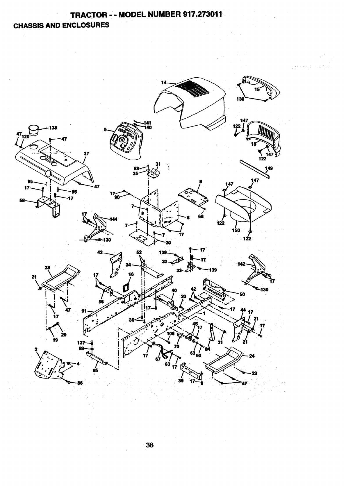
TRACTOR -- MODEL NUMBER 917.273011
CHASSIS AND ENCLOSURES
21_28 "
. 17
19
2
\
17 16
56
17
M
147
122
122
122
15
42
44 17
"::..-_. 21_17
38
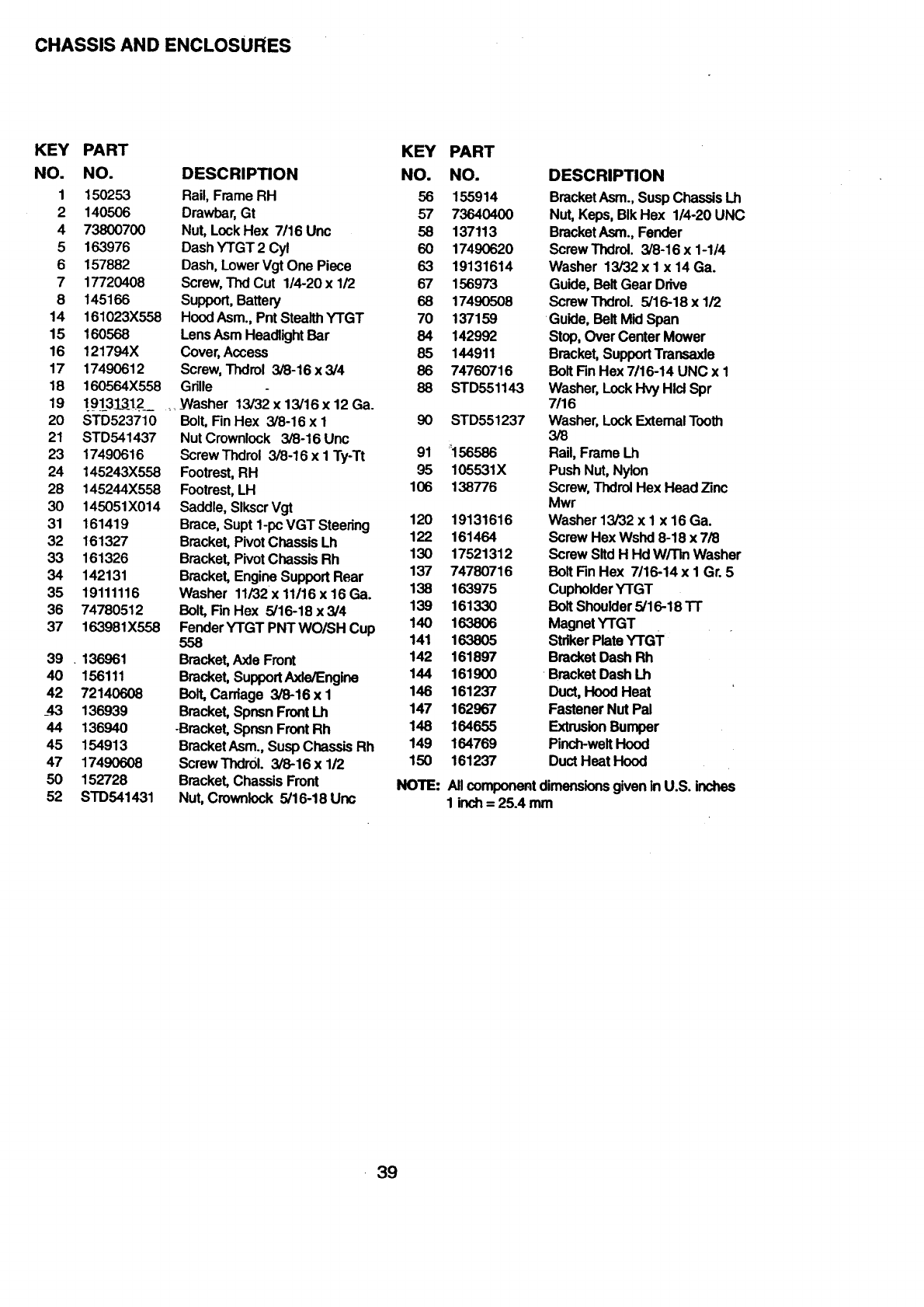
CHASSISANDENCLOSURES
KEY PART
NO. NO.
1 150253
2 140506
4 73800700
5 163976
6 157882
7 17720408
8 145166
14 161023X558
15 160568
16 121794X
17 17490612
18 160564X558
19 191_313_12_
20 STD523710
21 STD541437
23 17490616
24 145243X558
28 145244X558
30 145051X014
31 161419
32 161327
33 161326
34 142131
35 19111116
36 74780512
37 163981X558
39 . 136961
40 156111
42 72140608
_43 136939
44 136940
45 154913
47 17490608
50 152728
52 STD541431
KEY
DESCRIPTION NO.
Rail, Frame RH 56
Drawbar, Gt 57
Nut, Lock Hex 7116 Unc 58
Dash YTGT 2 Cyl 60
Dash, Lower Vgt One Piece 63
Screw, Thd Cut 1/4-20 x 1/2 67
Support, Battery 68
Hood Asm., Pnt Stealth YTGT 70
Lens Asm Headlight Bar 84
Cover, Access 85
Screw, Thdrol 3/6-16 x 3/4 86
Grille 88
,_Washer 13/32 x 13/16 x 12 Ga.
Bolt, Fin Hex 3/8-16 x I 90
Nut Crownlock 3/8-16 Unc
Screw Thdrol 3/8-16 x 1 Ty-Tt 91
Footrest, RH 95
Footrest, LH 106
Saddle, Slkscr Vgt
Brace, Supt 1-pc VGT Steering 120
Bracket, Pivot Chassis Lh 122
Bracket, Pivot Chassis Rh 130
Bracket, Engine Support Rear 137
Washer 11/32 x 11/16 x 16 Ga. 138
Bolt, Fin Hex 5/16-18 x3/4 139
Fender YTGT PNT WO/SH Cup 140
558 141
Bracket, Axle Front 142
Bracket, Support Axle/Engine 144
Bolt, Carriage 3/8-16 x I 146
Bracket, Spnsn Front Lh 147
-Bracket, Spnsn Front Rh 146
Bracket Asm., Susp Chassis Rh 149
ScrewThdr01. 3/8-16 x 112 150
Bracket, Chassis Front NOTE:
Nut, Cmwnlock 5/16-18 Unc
PART
NO.
155914
73640400
137113
17490620
19131614
156973
17490508
137159
142992
144911
74760716
ST D551143
STD551237
_156566
105531X
138776
19131616
161464
17521312
74780716
163975
161330
163806
163805
161897
161900
161237
162967
164655
164769
161237
DESCRIPTION
Bracket Asm., Susp Chassis Lh
Nut, Keps, BIk Hex 1/4-20 UNC
Bracket Asm., Fender
ScrewThdrol. 3/8-16 x 1-1/4
Washer 13/32 x I x 14 Ga.
Guide, Belt Gear Drive
ScrewThdrol. 5/16-18 x 1/2
Guide, Belt Mid Span
Stop, Over Center Mower
Bracket, Support Transaxle
Bolt Fin Hex 7/16-14 UNC x 1
Washer, Lock Hvy Hid Spr
7/16
Washer, Lock Extemal Tooth
3/8
Rail, Frame Lh
Push Nut, Nylon
Screw, Thdrol Hex Head Zinc
Mwr
Washer 13/32 x I x 16 Ga.
Screw Hex Wshd 8-18 x 7/8
Screw Sltd H Hd W/TIn Washer
Bolt Fin Hex 7/16-14 x I Gr. 5
Cuphoider YTGT
Bolt Shoulder 5/16-18 TT
Magnet YTGT
Striker Plate YTGT
Bracket Dash Rh
•Bracket Dash Lh
Duct, Hood Heat
Fastener Nut Pal
Extrusion Bumper
Pinch-welt Hood
Duct Heat Hood
AllcomponeRtdimensionsgivenin U.S. inches
1 inch= 25.4 mm
39
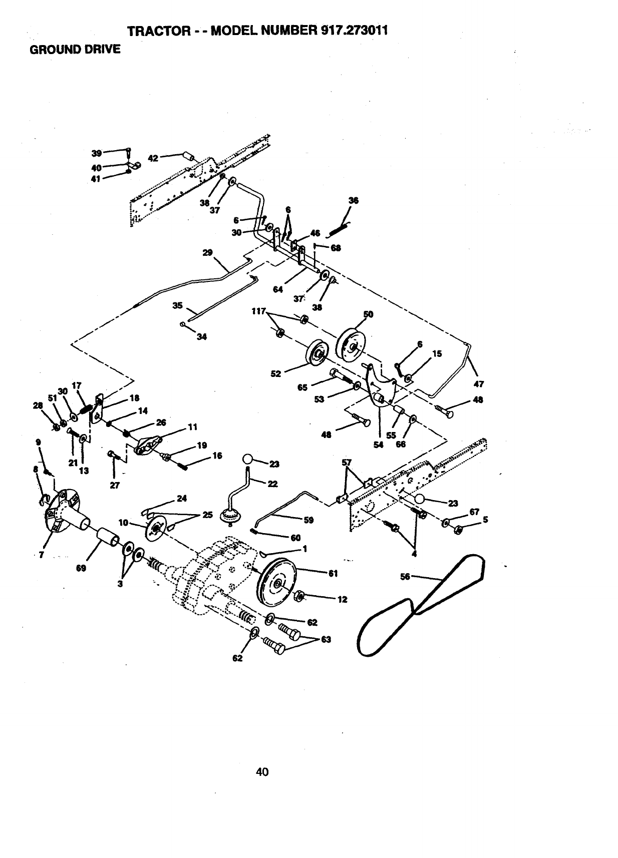
TRACTOR -- MODEL NUMBER 917.273011
GROUND DRIVE
g
12
62
40
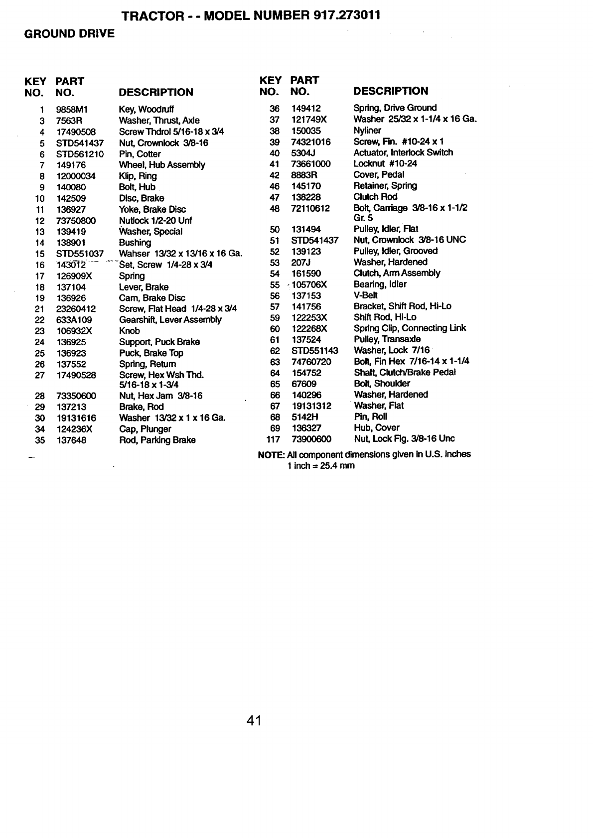
TRACTOR -- MODEL NUMBER 917.273011
GROUND DRIVE
KEY PART KEY PART
NO. NO. DESCRIPTION NO. NO.
1 9858M1 Key, Woodruff 36 149412
3 7563R Washer, Thrust, Axle 37 121749X
4 17490508 ScrewThdrol 5/16-18 x 3/4 38 150035
5 STD541437 Nut, Crownlock 3/8-16 39 74321016
6 STD561210 Pin, Cotter 40 5304J
7149176 Wheel, Hub Assembly 41 73661000
812000034 Klip, Ring 42 8883R
9 140080 Bolt' Hub 46 145170
10 142509 Disc, Brake 47 138228
11 136927 Yoke, Brake Disc 46 72110612
12 73750800 Nutlock 1/2-20 Unf
13 139419 Washer, Special 50 131494
14 138901 Bushing 51 STD541437
15 STD551037 Wahser 13/32 x 13/16 x 16 Ga. 52 139123
16 1430_12........ Set, Screw 1/4-28 x 3/4 53 207J
17 126909X Spring 54 161590
18 137104 Lever, Brake 55 _105706X
19 136926 Cam, Brake Disc 56 137153
21 23260412 Screw, Rat Head 1/4-28 x 3/4 57 141756
22 633A109 Gearshift, Lever Assembly 59 122253X
23 106932X Knob 60 122268X
24 136925 Support, Puck Brake 61 137524
25 136923 Puck, Brake Top 62 STD551143
26 137552 Spring, Return 63 74760720
27 17490528 Screw, Hex Wsh Thd. 64 154752
5/16-18 x 1-3/4 65 67609
28 73350600 Nut' Hex Jam 3/8-16 66 140296
29 137213 Brake, Rod 67 19131312
30 19131616 Washer 13/32xl x16Ga. 68 5142H
34 124236X Cap, Plunger 69 136327
35 137648 Rod, Parking Brake 117 73900600
DESCRIPTION
Spring, Drive Ground
Washer 25/32 x 1-1/4 x 16 Ga.
Nyliner
Screw, Rn. #10-24 x 1
Actuator, Interlock Switch
Locknut #10-24
Cover, Pedal
Retainer, Spdng
Clutch Rod
Bolt, Carriage 3/8-16 x 1-1/2
Gr. 5
Pulley, Idler, Flat
Nut, Crownlock 3/8-16 UNC
Pulley, Idler, Grooved
Washer, Hardened
Clutch, Arm Assembly
Bearing, Idler
V-Belt
Bracket, Shift ROd, Hi-Lo
Shift Rod, Hi-Lo
Spring Clip, Connecting Link
Pulley, Transaxle
Washer, Lock 7116
Bolt, Fin Hex 7/16-14 x 1-1/4
Shaft, Clutch/Brake Pedal
BolL Shoulder
Washer, Hardened
Washer, Flat
Pin, Roll
Hub, Cover
Nut, Lock Rg. 3/8-16 Unc
NOTE: All component dimensions given in U.S. inches
1 inch = 25.4 mm
41
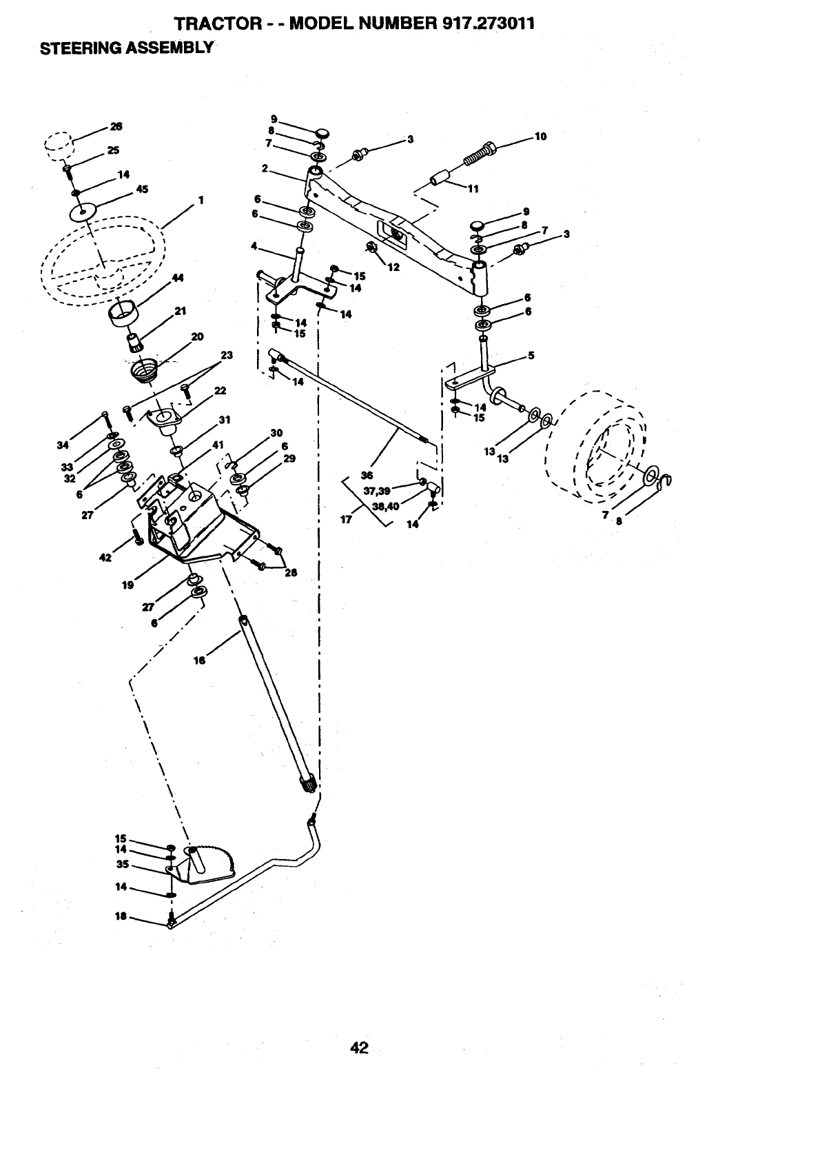
TRACTOR -- MODEL NUMBER 917.273011
STEERING ASSEMBLY
32
6
19
6' /
/
/
16
22
31
!
\
\
\
"\
!
\
\
42
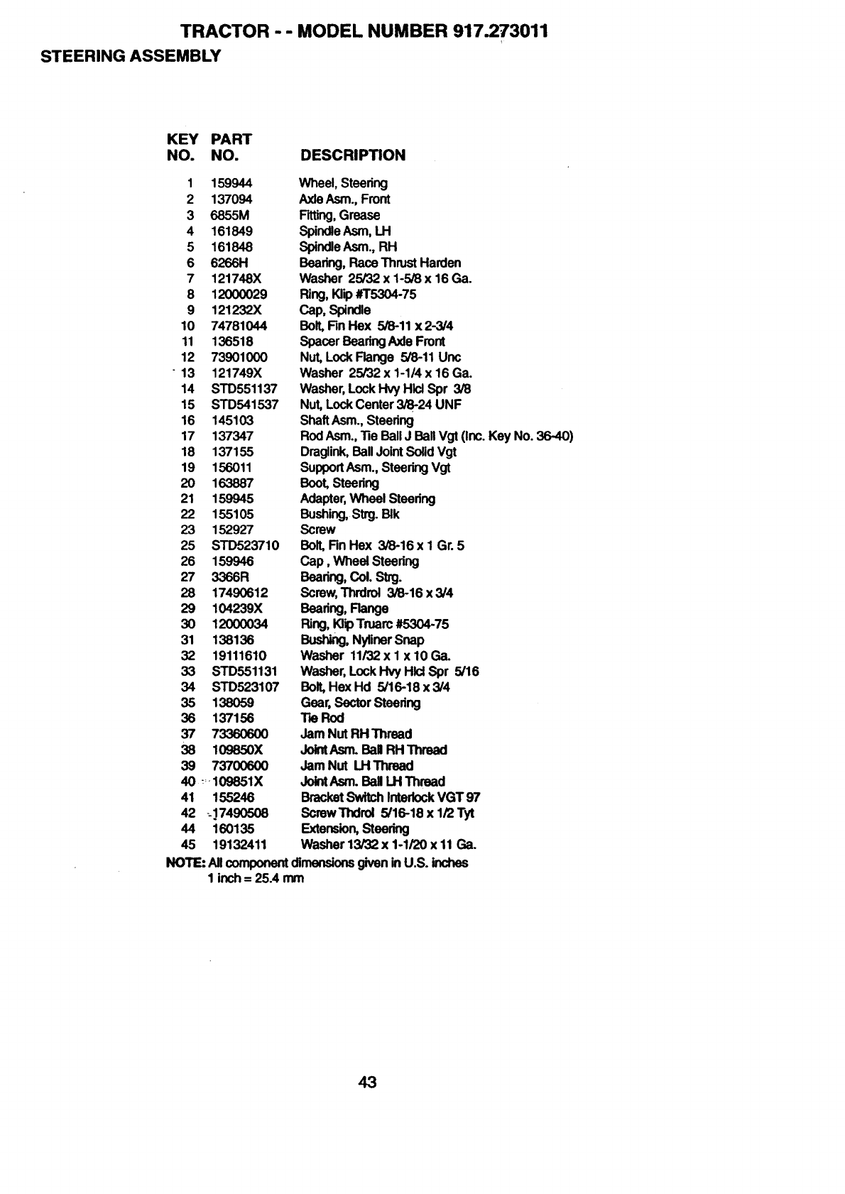
TRACTOR -- MODEL NUMBER 917.273011
STEERING ASSEMBLY
KEY PART
NO. NO. DESCRIPTION
1 159944
2 137094
3 6855M
4 161849
5 161848
6 6266H
7 121748X
8 12(X)0029
9 121232X
10 74781044
11 136518
12 73901000
- 13 121749X
14 STD551137
15 STD541537
16 145103
17 137347
18 137155
19 156011
20 163887
21 159945
22 155105
23 152927
25 STD523710
26 159946
27 3366R
28 17490612
29 104239X
30 12000034
31 138136
32 19111610
33 STD551131
34 STD523107
35 138059
38 137156
37 73360600
38 109850X
39 737OO6O0
40 _109851X
41 155246
42 --17490508
44 160135
45 19132411
Wheel, Stearing
Axle Asm., Front
F'_ng, Grease
Sl_n_e Asm,LH
Spindle Asm., RH
Bearing, Race Thrust Harden
Washer 25/32 x 1-5/8 x 16 Ga.
Ring, Klip #T5304-75
Cap, Spindle
Boll Rn Hex 5/8-11 x 2-3/4
Spacer Bearing Axle Front
Nut, Lock Flange 5/8-11 Unc
Washer 25/32 x 1-1/4 x 16 Ga.
Washer, Lock Hvy Hlcl Spr 3/8
Nut, Lock Center 3/8-24 UNF
Shaft Asm., Steedng
Rod Asm., "ReBall J Ball Vgt (Inc. Key No. 36-40)
Draglink, Ball Joint Solid Vgt
SupportAsm.,SteeringVgt
Boot, Steering
Adapter, Wheal Stearing
Bushing, Strg. BIk
Screw
BoIl Fin Hex 3/8-16 x I Gr. 5
Cap, Wheel Steering
Bearing,CoO.Strg.
Screw, Thrdroi 3/8-16 x 3/4
Bearing,Range
Ring, KlipTruarc #5304-75
Bushing, Nyflnar Snap
Washer 11/32 x 1 x 10 Ga.
Washer, Lock Hvy Hlci Spr 5/16
BoIl Hex Hd 5/16-18 x 3/4
Gear, Sector Steadng
.Re Rod
Jam Nut RH Thread
JointAsm. BaH RH Thread
Jam Nut LH Thread
Joint Asm. Ball I.H Thread
Bracket Switch Interlock VGT 97
ScrewThdrol 5/16-18 x 1/2Tyt
Extension,Steering
Washer 13/32 x 1-1/20 x 11 Ga.
NOTE:AllcomponentdimensionsgiveninU.S. inches
1 inch= 25A mm
43
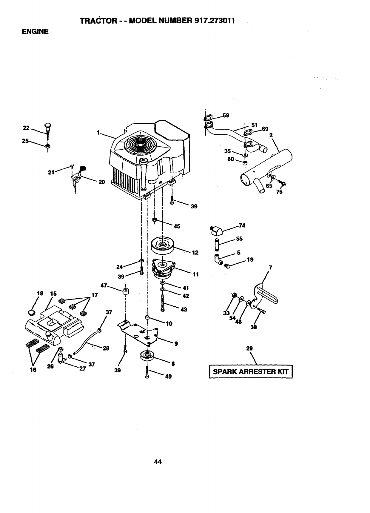
ENGINE
TRACTOR - - MODEL NUMBER 917.273011
25
21
18 15
26
16 37
20
I
i
I
I
i-
!
3
I
37
39
42
7
9
8
29
\
ISPARK ARRESTER KIT I
4_
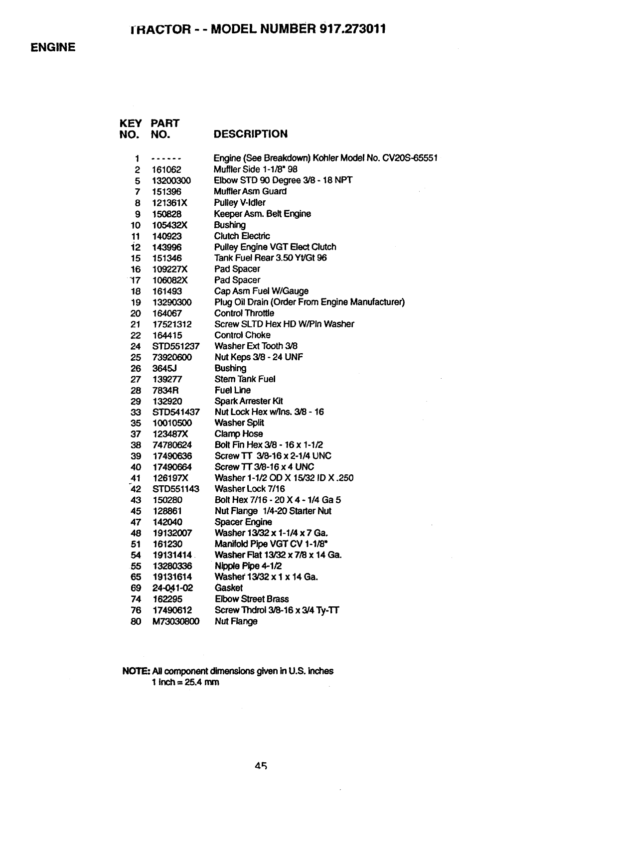
ENGINE
IHACTOR --MODEL NUMBER 917.273011
KEY PART
NO. NO. DESCRIPTION
2 161062
5 13200300
7 151396
8 121361X
9 150828
10 105432X
11 140923
i2 143996
15 151346
16 109227)(
-17 106082X
18 161493
19 13290300
20 164067
21 17521312
22 164415
24 STD551237
25 73920600
26 3645J
27 139277
28 7834R
29 132920
33 STD541437
35 10010500
37 123487X
38 74780624
39 17490636
40 1749O664
41 126197X
_42 STD551143
43 150280
45 128861
47 142040
48 19132007
51 161230
54 19131414
55 13280336
65 19131614
69 24-0_1-02
74 162295
76 17490612
80 M73030800
Engine(See Breakdown)KohlerModelNo. CV20S-65551
MufflerSide 1-1/8"98
ElbowSTD 90 Degree3/8 - 18 NPT
MufflerAsm Guard
PulleyV-Idler
KeeperAsm.BeltEngine
Bushing
ClutchElectdc
PulleyEngineVGT ElectClutch
TankFuelRear3.50 Yt/Gt96
Pad Spacer
Pad Spacer
CapAsmFuelW/Gauge
PlugOilDrain(OrderFromEngineManufacturer)
ControlThrotUe
ScrewSLTDHex HD W/PinWasher
ControlChoke
WasherExtTooth3/8
NutKeps3/8 - 24 UNF
Bushing
StemTankFuel
Fuel Line
SparkArresterKit
NutLock Hex w/Ins.3/8 - 16
WasherSplit
ClampHose
BoltFinHex 3/8 - 16x 1-1/2
Screw'N" 3/8-16 x 2-1/4 UNC
Screw TT 3/8-16 x4 UNC
Washer1-1/20D X 15/32 ID X .250
WasherLock7/16
Bolt Hex 7/16 - 20 X 4 - 1/4 Ga 5
NUtFlange 1/4-20StarterNut
SpacerEngine
Washer13/32 x 1-1/4x 7 Ga.
ManifoldPipeVGT CV 1-1/8"
WasherFlat13/32x 7/8 x 14 Ga,
NipplePipe4-1/2
Washer13/32 x I x 14 Ga.
Gasket
ElbowStreetBrass
ScrewThdml3/8-16 x 3/4 Ty-'l-I"
NUtFlange
NOTE:AllcomponentdimensionsgiveninU.S. inches
1 inch= 25.4 mm
LL_
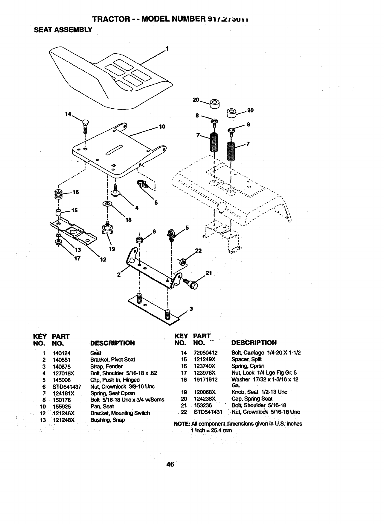
TRACTOR - -MODEL NUMBER 91-t.zl_u,,
SEAT ASSEMBLY
KEY PART
NO. NO. DESCRIPTION
1 140124 _14
2 140551 Bracket, PivotSeat 15
3 - 140675 Strap, Fender 16
4 127018)( Bolt, Shoulder 5/16-18 x .62 17
5 145006 Clip, Push In, Hinged 18
6 STD541437 Nut, Crowrdock 3/8-16 Uric
7 124181X Spring, Seat Cprsn 19
8 150176 Bolt 5/16-18Uncx3/4w/Sems 20
10 155925. Pan, Seat 21
-12 .12!246x Bracket, Mounting Switch .22
13. 121248X Bushing, Snap
KEY PART
NO. NO. """ DESCRIPTION
72050412
121249X
123740X
123976X
19171912
120068X
124238X
153236
STD541431
Bolt, Carriage 1/4-20 X 1-1/2
spacer,spilt
,Spring,Cprsn
Nut, Lock 1/4 Lge Fig Gr. 5
Washer 17/32 x 1-3/16 x 12
Ga.
Knob, Seat 1/2-13 Uric
Cap, Spring Seat
Bolt, Shoulder 5/16-18
Nut, Crownlock 5/16-18 Uric
NOTE:AllcomponentdimensionsgiveninU.S. inches
I inch= 25.4 mm
46
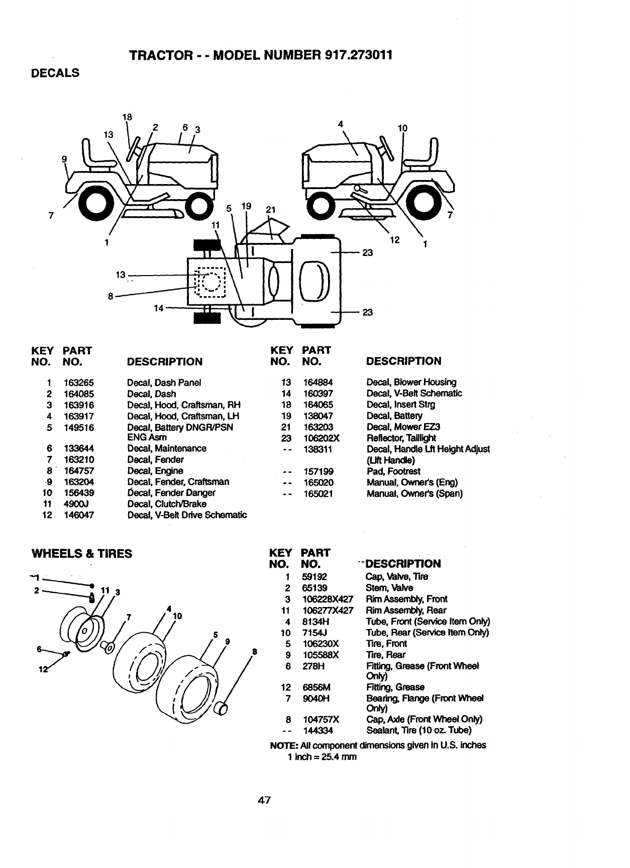
DECALS
TRACTOR - - MODEL NUMBER 917.273011
13
18
6 3
21
10
7
12 1
13
8
14
KEY
NO.
1
2
3
4
5
6
7
8
9
lO
11
12
PART
NO.
163265
164O85
163916
163917
149516
133644
163210
164757
163204
156439
4900J
146047
DESCRIPTION
Decal, DashPanel
Decal, Dash
Decal, Hood,Craftsman,RH
Decal, Hood,Craftsman,LH
Decal, BatteryDNGR/PSN
ENG Asm
Decal, Maintenance
Decal, Fender
Decal, Engine
Decal, Fender,Craftsman
I_ecal,FenderDanger
Decal, Clutch/Broke
Decal, V-BeltDriveSchematic
KEY
NO.
13
14
18
19
21
23
.°
PART
NO. DESCRIPTION
164884 Decal, Blower Housing
160397 Decal, V-BaR Schematic
164065 Decal, Insert Strg
138047 Decal, Battery
163203 Decal, Mower EZ3
106202X Reflector,Taillight
138311 Decal, Handle Lit Height Adjust
(uftHand_)
157199 Pad, Footrest
165020 Manual, Owners (Eng)
165021 Manual, Owner's (Span)
WHEELS & TIRES
3
7410
8
KEY PART
NO. NO. "-DESCRIPTION
1 59192 Cap, Valve,'lim
2 65139 Stem, Valve
3 106228X427 Rim Assembly, Front
11 106277X427 Rim Assembly, Rear
4 8134H Tube, Front (Service Item Only)
10 7154J Tube, Rear (Service Item Only)
5 106230X "13m,Front
9 105588X Tire, Rear
6 278H Fitting, Grease (Front Wheel
Orgy)
12 6856M Fitting, Grease
7 9040H Bearing, Flange (Front Wheel
only)
8 104757X Cap, Axle (Front Wheel Only)
- - 144334 Sealant,'fim (10 oz. Tube)
NOTE: All component dimensions given in U.S. inches
1 inch = 25.4 mm
47
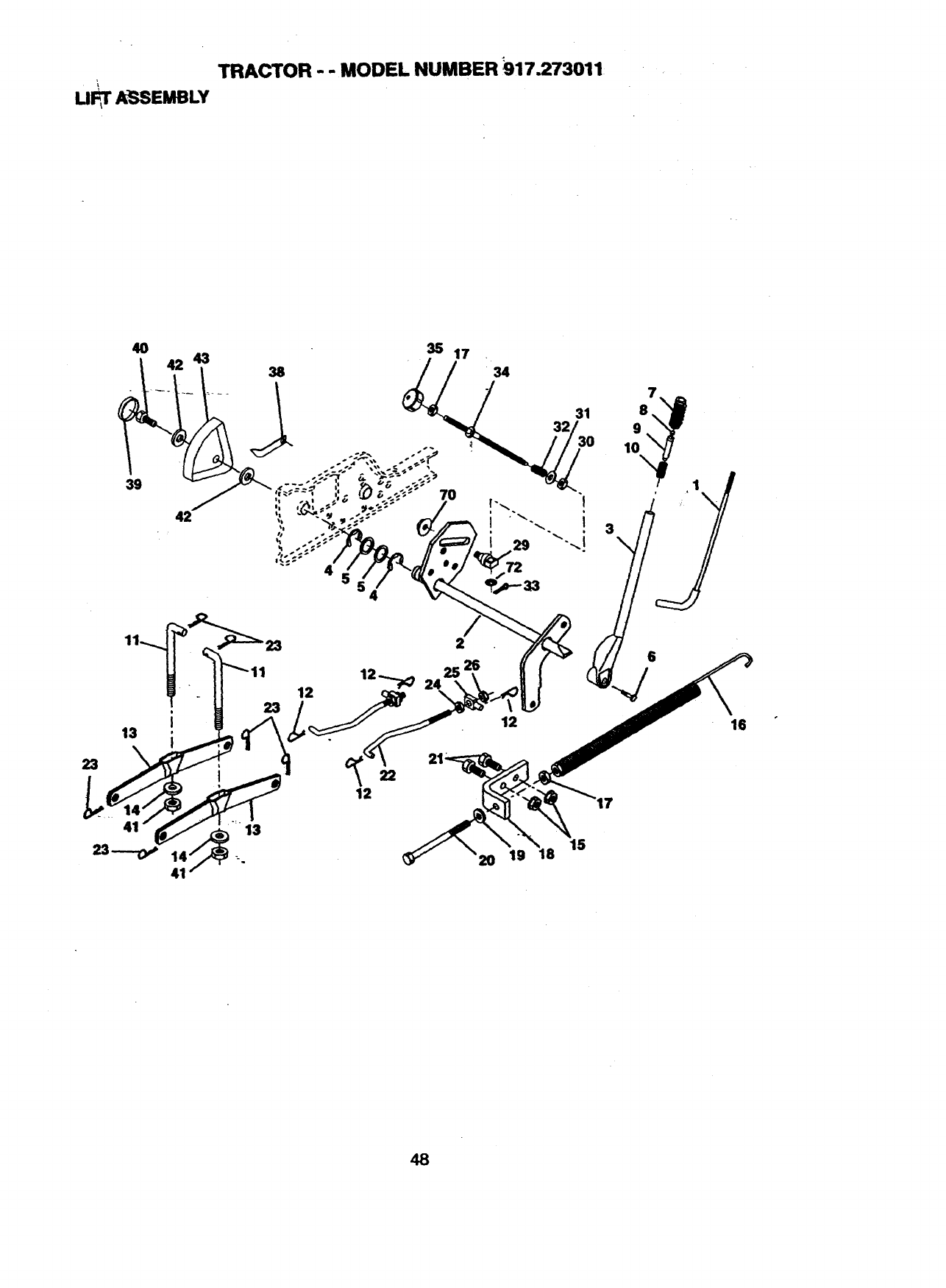
TRACTOR - - MODEL NUMBER i)17.273011
u_rASSeMeLY
4O
39
13
23
43 35 17
38 34
31 8,
32 9
-- _10
48
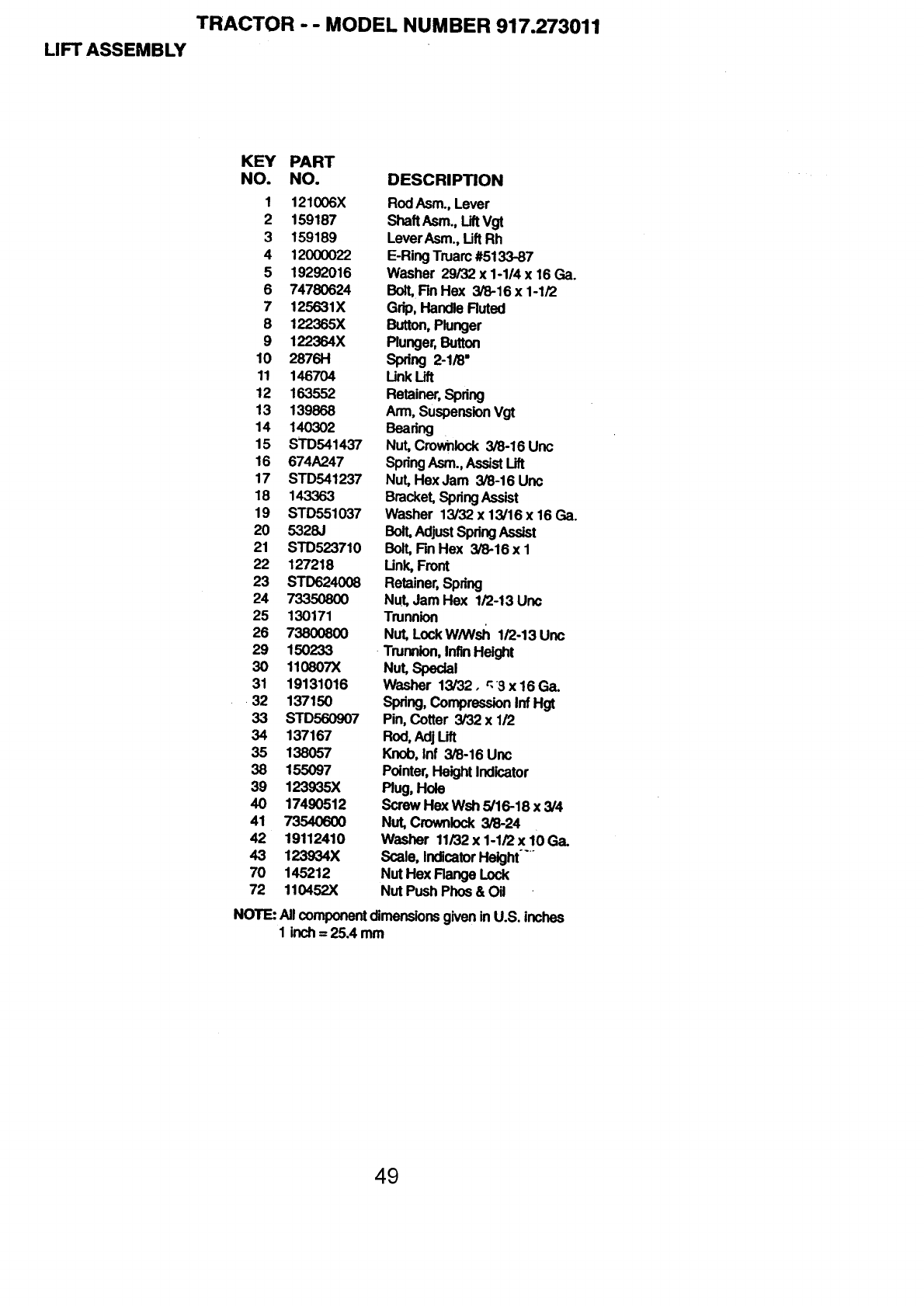
TRACTOR - - MODEL NUMBER 917.273011
LIFT ASSEMBLY
KEY PART
NO. NO. DESCRIPTION
1 121006X RodAsm.,Lever
2 159187 ShaftAsm.,LiftVgt
3 159189 LeverAsm.,LiftRh
4 12000022 E-RingTruarc#5133-87
5 19292016 Washer 29/32 x 1-1/4 x 16 Ga.
6 74780624 Bolt,Rn Hex 3/8-16 x 1-1/2
7 125631X Grip,HandleFluted
8122365X Button,Plunger
9 122364X Plunger,Button
10 2876H Spdng 2-1/8"
11 146704 Unk Lift
12 163552 Retainer,Spring
13 139868 Arm,SuspensionVgt
14 140302 Beating
15 STD541437 Nut, Crownlock3/8-16 Unc
16 674A247 SpringAsm.,AssistLift
17 STD541237 Nut, HexJam 3/8-16 Uric
18 143363 Bracket,SpdngAssist
19 STD551037 Washer 13/32x13/16x16Ga.
20 5328J Bolt,AdjustSpringAssist
21 STD523710 Bolt,Fin Hex 3/8-16 x 1
22 127218 Unk, Front
23 STD624008 Retainer,Spring
24 73350800 Nut,Jam Hex 1/2-13 Unc
25 130171 Trunnion
26 73800800 Nut,Lock W/Wsh 1/2-13 Unc
29 150233 -Trunnion,InflnHeight
30 110807X Nut,Special
31 19131016 Washer 13/32. r,3x16Ga.
•32 137150 Spdng,CompressionInfHgt
33 STD560907 Pin,Cotter 3/32 x 1/2
34 137167 Rod,Adj Lift
35 138057 Knob,Inf 3/6-16 Unc
38 155097 Pointer,HeightIndicator
39 123935X Plug,Hole
40 17490512 ScrewHe)(Wsh 5/16-18 x 3/4
41 73540600 Nut,Crownlock3/8-24
42 19112410 Washer 11/32x 1-1/2x 10 Ga.
43 123934X Scale,IndicatorHeight
70 145212 NutHex FlangeLock
72 110452X NutPushPhos& Oil
NOTE:All componentdimensionsgiveninU.S. inches
1 inch= 25.4 mm
49
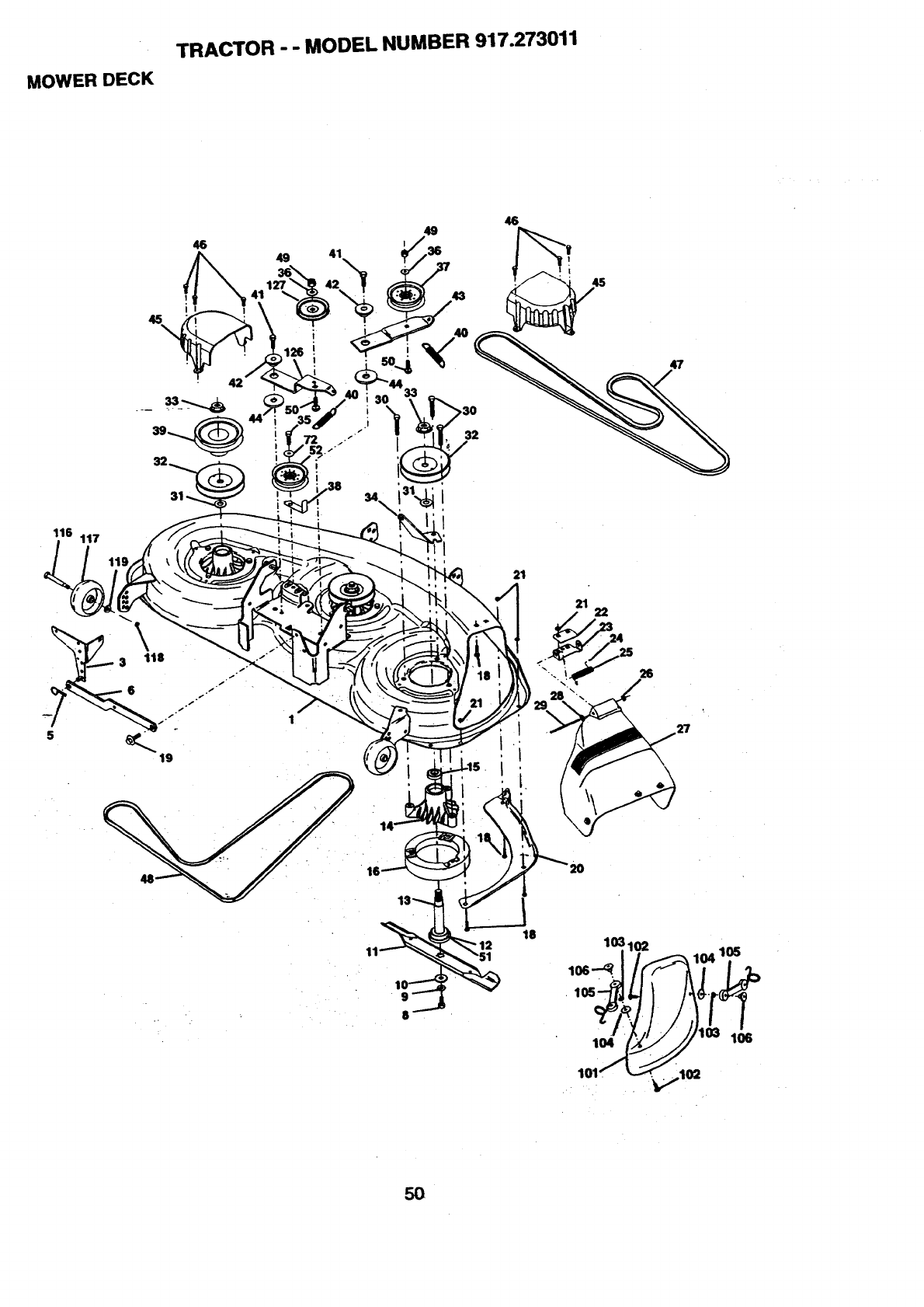
TRACTOR - - MODEL NUMBER 917.273011
MOWER DECK
116 117
49
I
32
i
19
1
21
511
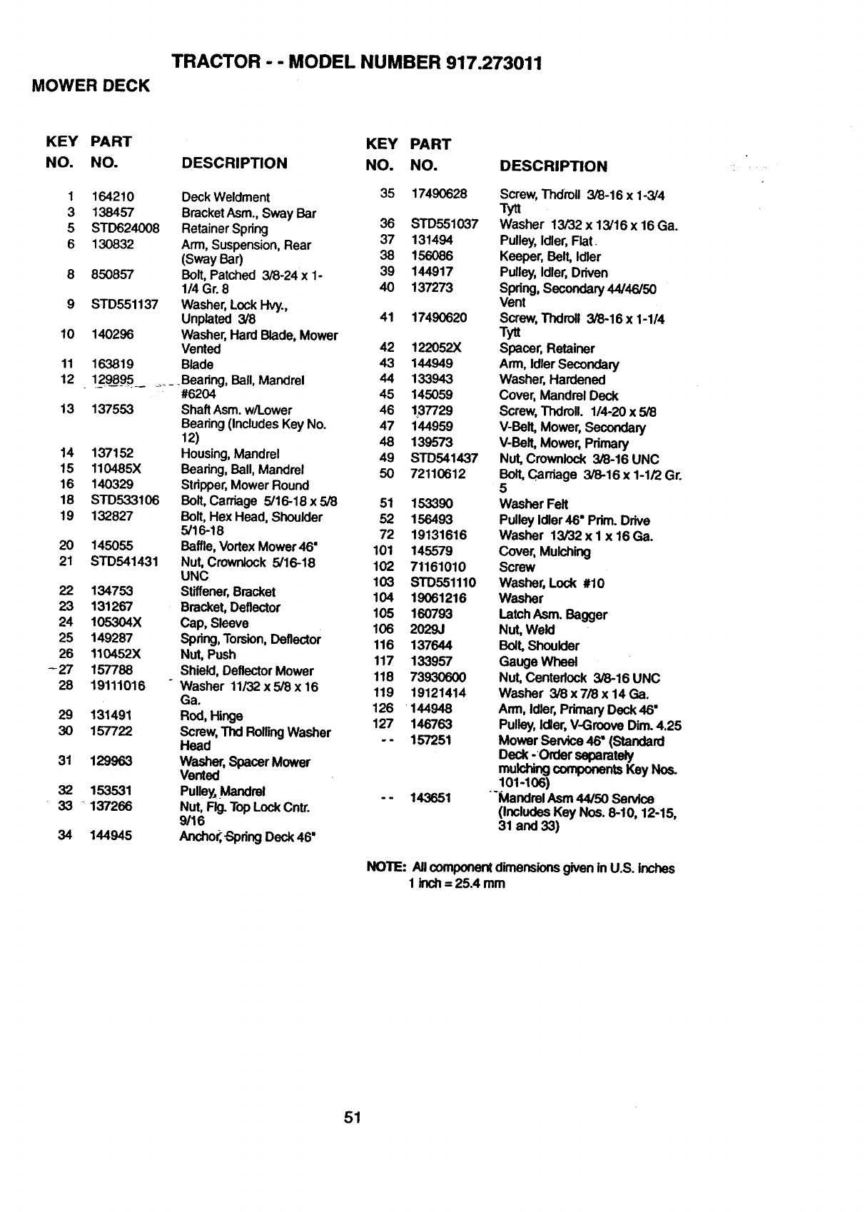
TRACTOR -- MODEL NUMBER 917.273011
MOWER DECK
KEY PART KEY PART
NO. NO. DESCRIPTION NO. NO.
1 164210 Deck Weldment 35 17490628
3 138457 Bracket Asm., Sway Bar
5 STD624008 Retainer Spring 36 STD551037
6 130832 Arm, Suspension, Rear 37 131494
(Sway Bar) 38 156086
8 850857 Bolt, Patched 3/8-24x 1- 39 144917
1/4 Gr. 8 40 137273
9 STD551137 Washer, Lock Hvy.,
Unplated 3/8 41 17490620
10 140296 Washer, Hard Blade, Mower
Vented 42 122052X
11 163819 Blade 43 144949
12 1298_95....... Bearing, Ball, Mandrel 44 133943
#6204 45 145059
13 137553 Shaft Asm. w/Lower 46 137729
Bearing (Includes Key No. 47 144959
12) 48 139573
14 137152 Housing, Mandrel 49 STD541437
15 110485X Bearing, Ball, Mandrel 50 72110612
16 140329 Stripper, Mower Round
18 STD533106 Bolt, Carriage 5/16-18 x 5/8 51 153390
19 132827 Bolt, Hex Head, Shoulder 52 156493
5/16-18 72 19131616
20 145055 Baffle, Vortex Mower46" 101 145579
21 STD541431 Nut, Crownlock 5/16-18 102 71161010
UNC 103 STD551110
22 134753 Stiffener, Bracket 104 19061216
23 131267 Bracket, Deflector 105 160793
24 105304X Cap, Sleeve 106 2029J
25 149287 Spring, Torsion, Deflector 116 137644
26 110452X Nut, Push 117 133957
-27 157788 Shield, Deflector Mower 118 73930600
28 19111016 Washer 11/32 x 518 x16 119 19121414
Ga.
29 131491 Rod, Hinge 126 144948
127 146763
30 157722 Screw, Thd Roiling Washer
Head -- 157251
31 129963 Washer, Spacer Mower
Vented
32 153531 Pulle_.Mandrel -- 143651
33 _ 137266 Nut, FI_ Top Lock Cntr.
9116
34 144945 Anchor--Spring Deck 46"
DESCRIPTION
Screw, Thdroll 3/8-16 x 1-3/4
Tytt
Washer 13/32 x 13/16 x 16 Ga.
Pulley, Idler, Flat.
Keeper, Belt, Idler
Pulley, Idler, Driven
Spring, Secondary 44/46/50
Vent
Screw, Thdroll 3/8-16 x 1-1/4
Tytt
Spacer, Retainer
Arm, Idler Secondary
Washer, Hardened
Cover, Mandrel Deck
Screw, TIxIrell. 114-20 x 5/8
V-BelLMower,Secondary
V-Belt, Mower, Primary
Nut, Crownlock 3/8-16 UNC
Bolt, Carriage 3/8-16 x 1-1/2 Gr.
5
Washer Felt
Pulley Idler 46" Prim. Drive
Washer 13/32 x I x 16 Ga.
Cover,Mulching
Screw
Washer, Lock #10
Washer
Latch Asm. Bagger
Nut, Weld
Bolt, Shoulder
Gauge Wheel
Nut, Centedock 3/8-16 UNC
Washer 3/8 x 7/8 x 14 Ga.
Arm, Idler, Primary Deck 46"
Pulley, Idler, V-Groove Dim. 4.25
Mower Service 46" (Standard
Deck -Order separately
mulching components Key Nos.
101-106)
"'Mandrel Asm 44/50 Sen4ce
(Includes Key Nos. 8-10, 12-15,
31 and 33)
NOTE: AllcomponentdimensionsgiveninU.S. inches
1 inch= 25.4 mm
51

TRANSAXLE
TRACTOR--- MODEL NUMBER 917.273011
15
14
74 70 73 _,30
92 93°
41-_4S
......9a
25 24
52
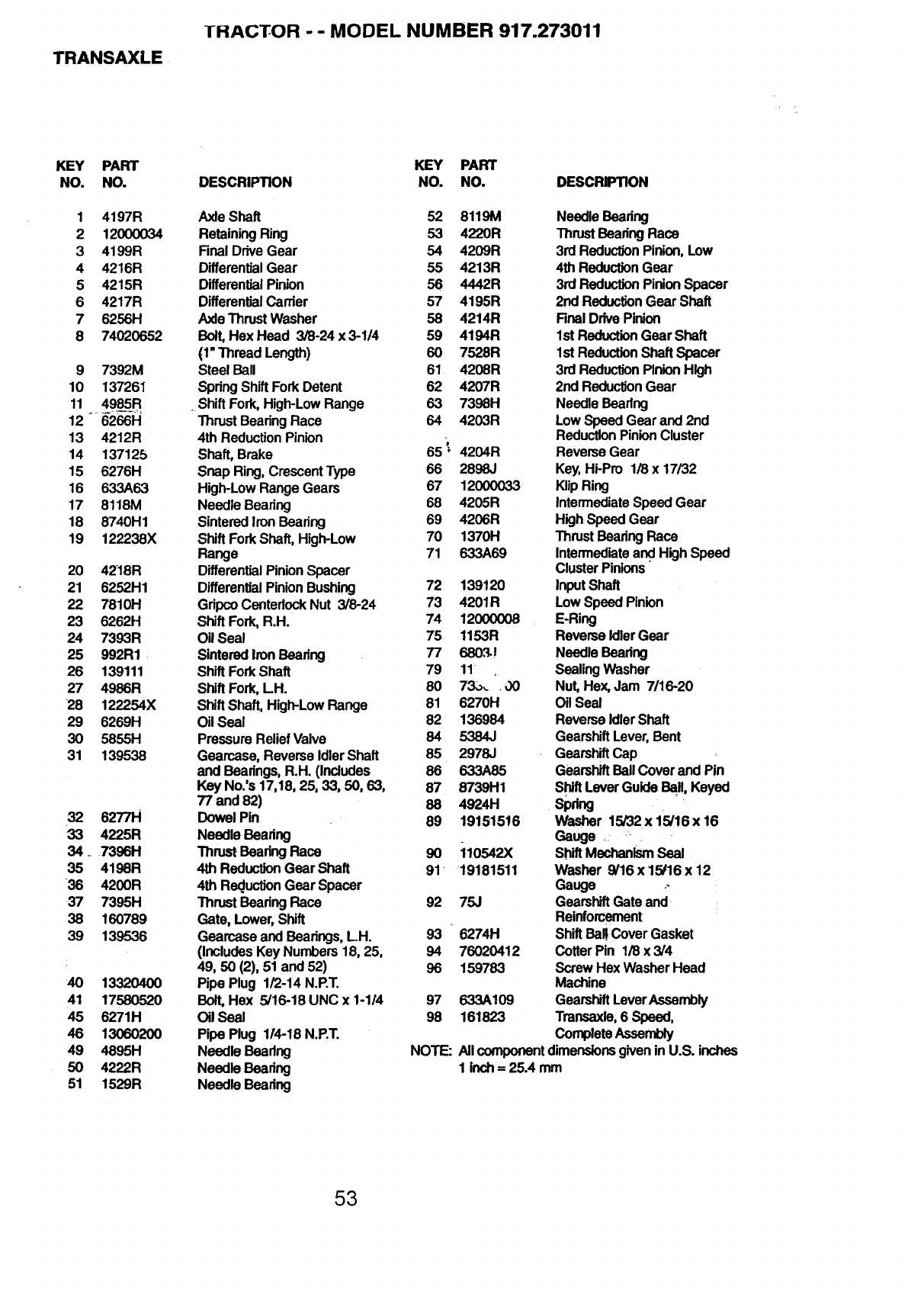
TRANSAXLE
THACTOR --MODEL NUMBER 917.273011
KEY PART
NO. NO.
1 4197R
2 12(X)0034
3 4199R
4 4216R
5 4215R
6 4217R
7 6256H
8 74020652
9 7392M
10 13726I
11 4985R
12 6266H
13 4212R
14 137125
15 6276H
16 633A63
17 8118M
18 8740H1
19 122238X
20 4218R
21 6252H1
22 7810H
23 6262H
24 7393R
25 992R1
26 139111
27 4986R
28 122254X
29 6269H
30 5855H
31 139538
32 6277H
33 4225R
34_ 7396H
35 4198R
36 4200R
37 7395H
38 160789
39 139536
40 13320400
41 17580520
45 6271H
46 13060200
49 4895H
50 4222R
51 1529R
KEY PART
DESCRIPTION NO. NO.
AxleShaft
RetainingRing
FinalDriveGear
DifferentialGear
DifferentialPinion
DifferentialCarder
AxleThrustWasher
Bolt,Hex Head 3/8-24 x 3-1/4
(1"Thread Length)
SteelBall
SpringShiftForkDetent
. ShiftFork,High-LowRange
Thrust BearingRace
4th ReductionPinion
Shaft,Brake
Snap Ring,CrescentType
High-LowRangeGears
Needle Bearing
SinteredIronBearing
ShiftForkShaft,High-Low
Range
DifferentialPinionSpacer
DifferentialPinionBushing
GdpcoCentedockNut 3/8-24
ShiftFork,R.H.
OilSeal
SinteredIronBearing
ShiftForkShaft
ShiftFork,LH.
ShiftShaft,High-LowRange
OilSeal
PressureReliefValve
Gearcase,ReverseIdlerShaft
andBearings,R.H. (Includes
Key No.'s17,18, 25, 33, 50, 63,
77 and 82)
DowelPin
Needle Bearing
Thrust Bearing Race
4th ReductionGear Shaft
4th ReductionGear Spacer
Thrust Bearing Race
Gate, Lower,Shift
GearcaseandBearings, L.H.
(IncludesKeyNumbers16, 25,
49, 50 (2), 51 and52)
Pipe Plug 1/2-14 NoRT.
Bolt,Hex 5/16-18 UNC x 1-1/4
OilSeal
Pipe Plug 114-18N.P.T.
Needle Bearing
Needle Bearing
Needle Bearing
DESCRIPTION
52 8119M Needle Bearing
53 4220R Thrust Bearing Race
54 4209R 3rd Reduclion Pinion, Low
55 4213R 4th Reduction Gear
56 4442R 3rd Reduction Pinion Spacer
57 4195R 2nd Reduction Gear Shaft
58 4214R Rnal Drive Pinion
59 4194R 1st Reduction Gear Shaft
60 7528R 1st Reduction Shaft Spacer
61 4208R 3rd Reduction Pinion High
62 4207R 2nd Reduction Gear
63 7398H Needle Bearing
64 4203R Low Speed Gear and 2nd
; Reduction Pinion Cluster
65 =4204R Reverse Gear
66 2898J Key, Hi-Pro 1/8 x 17/32
67 12000033 Klip Ring
68 4205R Intermediate Speed Gear
69 4206R High Speed Gear
70 1370H Thrust Bearing Race
71 633A69 Intermediate and High Speed
Cluster Pinions'
72 139120 Input Shaft
73 4201R Low Speed Pinion
74 12000008 E-Ring
75 1153R Reverse Idler Gear
77 680.'].! Needle Bearing
79 11 Sealing Washer
80 7304 "00 Nut, Hex, Jam 7/16-20
81 6270H Oil Seal
82 135984 Reverse Idler Shaft
64 5384J Gearshift Lever, Bent
85 2978J Gearshift Cap
86 633A85 Gearshift Ball Cover and Pin
87 8739H1 Shift Lever Guide BaH,Keyed
88 4924H Spdng
89 19151516 Washer 15/32 x15/16 x16
Gauge .: _
9o 110542x ShiftMechanismSeal
91 19181511 Washer 9/16 x 15/16 x 12
Gauge .-
92 75J Gearshift Gate and
Reinforcement
93 6274H Shift Bal!Cover Gasket
94 76020412 Cotter Pin 1/8 x 3/4
96 159763 Screw Hex Washer Head
Machine
97 633A109 Gearshift Lever Assembly
98 161823 Transaxle, 6 Speed,
CompaetaAssernUy
NOTE: All component dimensions given in U.S. inches
1 inch =25.4 mm
53
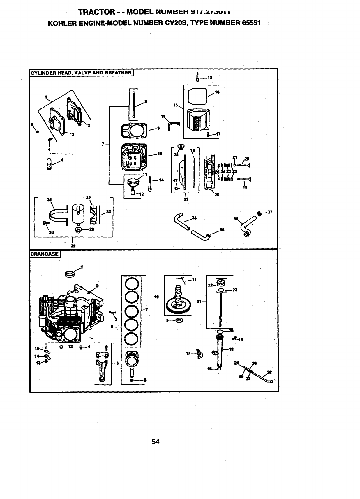
TRACTOR - -MODEL NUMI:II::I-i u i i .i_lou:,
KOHLER ENGINE-MODEL NUMBER CV20S, TYPE NUMBER •65551
CYLINDER HEAD, VALVE AND BREATHER
--13
CRANCASEJ
27
V •
v
V
A
54
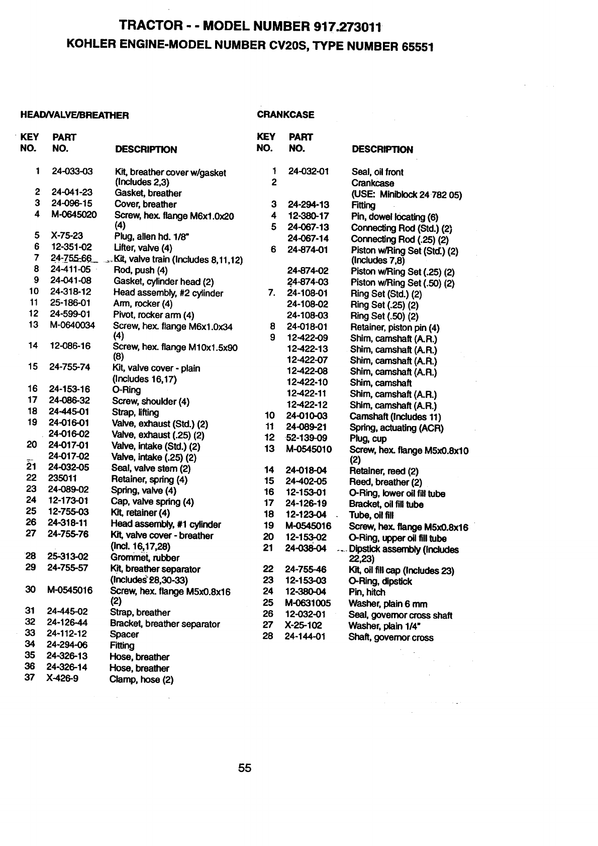
TRACTOR - - MODEL NUMBER 917.273011
KOHLER ENGINE-MODEL NUMBER CV20S, TYPE NUMBER 65551
HEAD/VALVE/BREATHER
KEY PART
NO. NO. DESCRIPTION
2
3
4
5
6
7
8
9
10
11
12
13
14
15
16
17
18
19
20
21
22
23
24
25
26
27
28
29
3O
31
32
33
34
35
36
37
24-033-03 Kit, breather cover w/gasket
(Includes 2,3)
24-041-23 Gasket, breather
24-096-15 Cover, breather
M-0645020 Screw, hex. flange M6xl.0x20
(4)
X-75-23 Plug, alien hd. 1/8"
12-351-02 Ufter, valve (4)
24-755:66_ ....Kit, valve train (Includes 8,11,12)
24-411-05 Rod, push (4)
24-O41-08
24-318-12
25-186-01
24-599-01
M-0640034
12-086-16
24-755-74
24-153-16
24-086-32
24-445-01
24-016-01
24-016-02
24-017-01
24-017-02
24-032-05
235011
24-089-02
12-173-01
12-755-03
24-318-11
24-755-76
25-313-02
24-755-57
M-0545016
24-445-02
24-126-44
24-112-12
24-294-O6
24-326-13
24-326-14
X-426-9
Gasket, cylinder head (2)
Head assembly, #2 cylinder
Arm, rocker (4)
Pivot, rocker arm (4)
Screw, hex. flange M6x1.0x34
(4)
Screw, hex. flange M10xl.5x90
(8)
Kit,valve cover -plain
(Includes 16,17)
O-Ring
Screw, shoulder (4)
Strap, lifting
Valve, exhaust (Std.) (2)
Valve, exhaust (.25) (2)
Valve, intake (Std.) (2)
Valve, intake (.25) (2)
Seal, valve stem (2)
Retainer, spring (4)
Spring, valve (4)
Cap, valve spring (4)
lot, retainer (4)
Head assembly, #1 cylinder
Kit,valve cover -breather
(Incl. 16_17,28)
Grommet, rubber
Kit,breather separator
(Includes£8,30-33)
Screw, hex. flange M5x0.8x16
(2)
Strap, breather
Bracket, breather separator
Spacer
F_ng
Hose, breather
Hose, breather
Clamp,hose(2)
CRANKCASE
KEY PART
NO. NO. DESCRIPTION
1 24-032-01
2
3 24-294-13
4 12-380-17
5 24-067-13
24-067-14
6 24-874-01
24-874-02
2.4-874-03
7. 24-108-01
24-108-02
24-10803
8 24-018-01
9 12-422-09
12-422-13
12-422-07
12-422-08
12-422-10
12-422-11
12-422-12
10 24-010-03
11 24-089-21
12 ,52-139-09
13 M-0545010
14 24-018-04
15 24-402-05
16 12-153-O1
17 24-126-19
18 12-123-04
19 M-0545016
20 12-153-02
21 24-038-04
22 24-755-46
23 12-153-03
24 12-380-04
25 M-0631005
26 12-032-01
27 )(-25-102
28 24-144-01
Seal, oil front
Crankcase
(USE: Min_lock 24782 05)
Fitting
Pin, dowel locating (6)
Connecting Rod (Std.) (2)
Connecting Rod (.25) (2)
Piston w/Ring Set (Std.) (2)
(Includes7,8)
Piston w/Ring Set (.25) (2)
Piston w/Ring Set (.50) (2)
Ring Set (Std.) (2)
Ring Set (.25) (2)
Ring Set (.50) (2)
Retainer, piston pin (4)
Shim, camshaft (A.R.)
Shim, camshaft (A.R.)
Shim, camshaft (A.R.)
Shim, camshaft (A.R.)
Shim, camshaft
Shim, camshaft (A.R.)
Shim, camshaft (A.R.)
Camshaft (Includes 11)
Spring, actuating (ACR)
Plug, cup
Screw, hex. flange M5x0.8xl0
(2)
Retainer, reed (2)
Reed, breather (2)
O-Ring, lower oil fill tube
Bracket, oil fill tube
Tube, oil fill
Screw, hey,. flange M5xO.Sx16
O-Ring, upper oil filltube
....O_ost_kassemUy(Includas
22_3)
Kit,o, fi, cap (Includes23)
O-Ring, dipstick
Pin, hitch
Washer, plain 6 mm
Seal, governor cross shaft
Washer,plain1/4"
Shaft, governor cross
55
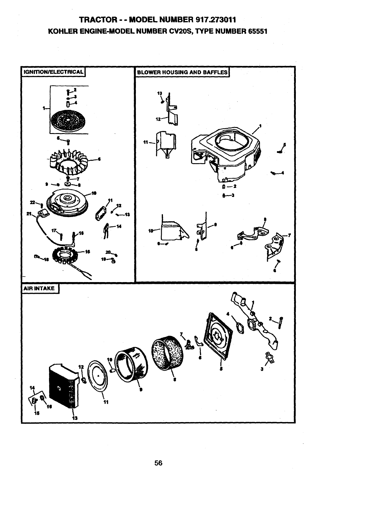
TRACTOR - - MODEL NUMBER 917.273011
KOHLER ENGINE-MODEL NUMBER CV20S, TYPE NUMBER 65551
IGNmONIELECTRICAL
l1_2
e...-,$
, 0_
IG)
BLOWER HOUSING AND BAFFLES I
13
_F---3
I
14
16 \
13
11
56
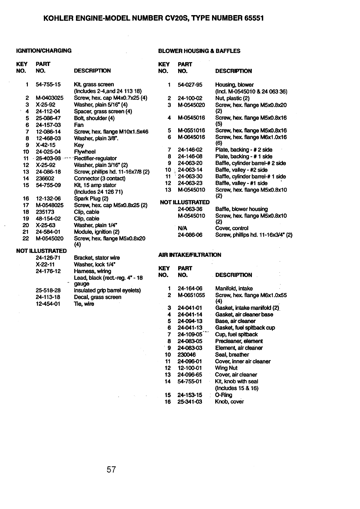
KOHLER ENGINE-MODELNUMBER CV20S,TYPE NUMBER65551
IGNmON/CHARGING
KEY PART
NO. NO.
1 54-755-15
2 M-0403025
3 X-25-92
4 24-112-04
5 25-086-47
6 24-157-03
7 12-086-14
8 12-468-03
9 X-42-15
10 24-025-04
11 -25-403-0-3 ......
12 X-25-92
13 24-086-18
14 236602
15 54-755-09
16 12-132-06
17 M-0548025
18 235173
19 48-154-02
20 X-25-63
21 24-584-01
22 M-0545020
NOT ILLUSTRATED
24-126-71
X-22-11
24-176-12
25-518-28
24-113-18
12-454-01
BLOWER HOUSING & BAFFLES
KEY PART
DESCRIPTION NO. NO. DESCRIPTION
Kit, grass screen 1 54-027-95
(Includes 2-4,and 24 113 18)
Screw, hex. cap M4x0.7x25 (4) 2 24-100-02
Washer, plain 5/16" (4) 3 M-0545020
Spacer, grass screen (4)
Bolt, shoulder (4) 4 M-0545016
Fan
Screw, hex. flange M10xl.5x46 5 M-0551016
Washer, plain 3/8". 6 M-0645016
Key
Flywheel 7 24-146-02
Rectifier-regulator 8 24-146-08
Washer, plain 3/16" (2) 9 24-063-20
Screw, phillipshal. 11-16x7/8 (2) 10 .. 24-063-14
Connector (3 contact) 11 _24-063-30
WJt,15 amp stator 12 24-063-23
(Includes 24 126 71) 13 M-0545010
Spark Plug (2) NOT ILLUSTRATED
Screw, hex. cap M5x0.8x25 (2) 24-063-36
Clip, cable
Clip, cable M-0545010
Washer, plain 114" N/A
Module, ign'dJon(2) 24-086-06
Screw, hex. flange M5x0.8x20
(4)
Bracket,statorwire
Washer,lock114"
Harness,widng
Lead, black(recL-reg.4"- 18
gauge
insulatedgripbarreleyelets)
Decal,grassscreen
Tie, wire
Housing, blower
(Ind. M-05450i0 & 24 063 36)
Nut, plastic (2)
Screw, hex. flange M5xO.8x20
(2)
Screw, hex. flange M5x0.8x16
(5)
Screw, he_ flange M5xO.8x16
Screw, hex. flange M6x1.0x16
(6)
Plate, backing - # 2 side
Plate, backing - # 1 side
Baffle, cylinder barrel-# 2 side
Baffle, valley - #2 side
Baffle, cylinder barrel-# 1 side
Baffle, valley - #1 side
Screw, hex. flange M5xO.8xl0
(2)
Baffle, blower housing
Screw, hex. flange M5x0.8xl0
(2)
Cover, control
Screw, phillipshd. 11-16x3/4" (2)
AIR IN'rAKE/RLTRATION
KEY PART
NO. NO. DESCRIPTION .
1 24-164-06
2 M-0651055
3 24-041-01
4 24-041-14
5 24-094-13
6 24-041-13
7 24-109-05 ....
8 24-083-05
• 9 24-083-03
10 23OO46
11 24-O96-01
12 12-100-01
13 24-096-65
14 54-755-01
15 24-153-15 :
16 25-341-03
Manifold, intake
Screw, he_ flange M6x1.0x55
(4)
Gasket, intake manifold (2)i
Gasket, air cleaner base
Base, air cleaner
Gasket, fuel spitback cup
Cup, fuel spitback
Pracleaner, element
Element, air cleaner
Seal, breather
Cover, inner air cleaner
Wing Nut
Cover, air cleaner
Kit, knob with seal
(Includes 15 & 16)
O-Ring
Knob, cover
57
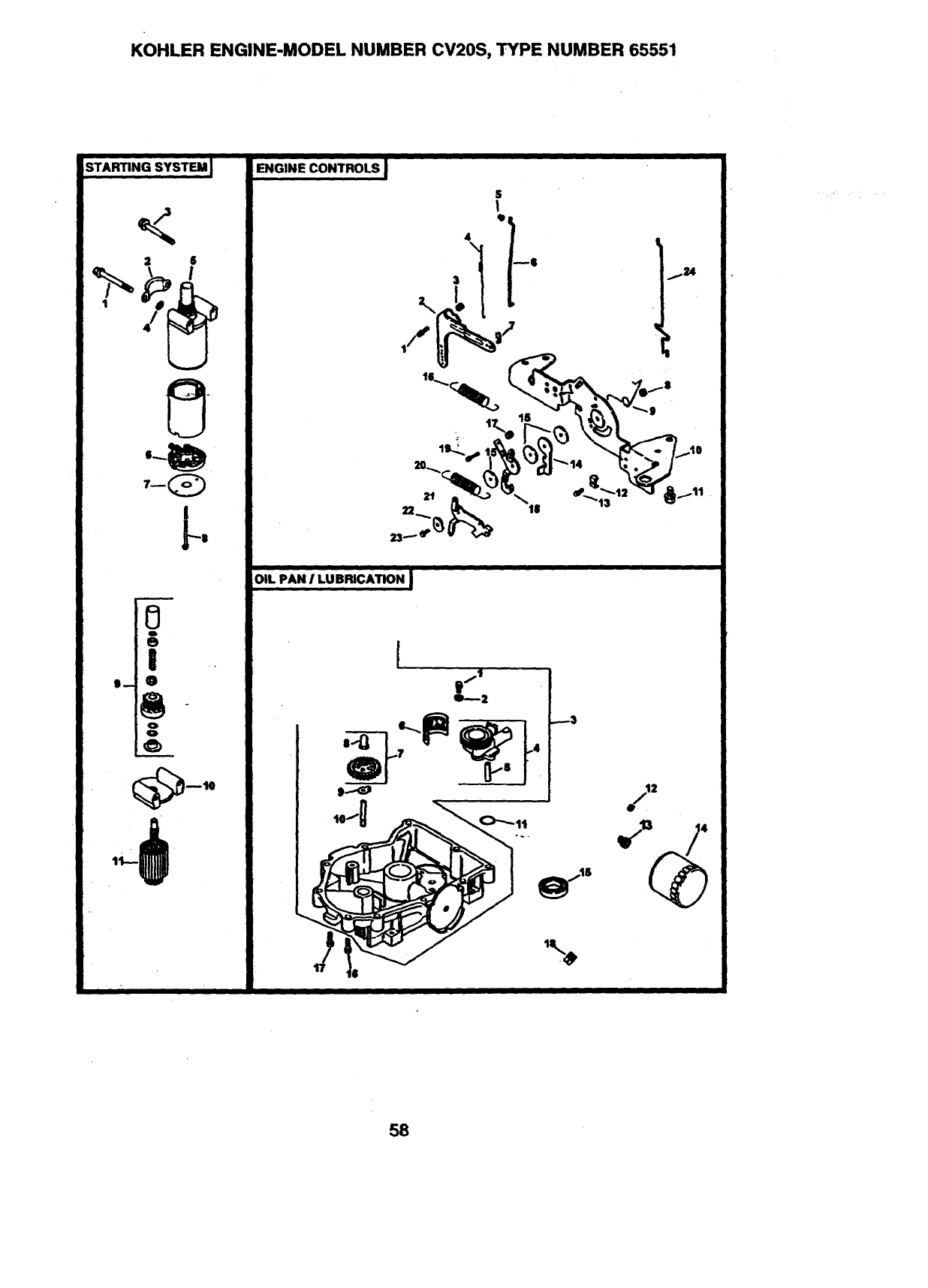
KOHLER ENGINE-MODEL NUMBER CV20S, TYPE NUMBER 65551
I
STARTING SYSTEM IENGINE CONTROLS J
OIL PAN ILUBRICATION J
1_--2
---3
2
4
58
TRACTOR --MODEL NUMBER 917.273011
KOHLER ENGINE-MODEL NUMBER CV20S, TYPE NUMBER 65551
STARTING SYSTEM
KEY PART
NO. NO.
1 M-0839070
2 24-096-05
3 M-O839080
4 12-468-01
5 25-098-05
6 12-221-01
7 12-227-13
8 12-211-01
9 12-755-54
10 .12,227-06-
11 12-170-05
ENGINE CONTROLS
KEY PART
NO. NO.
1 SM-0642025
2 24-090-14
3 M-0641060
4 24-089-01
5 25-158-08
6 24-079-04
7 25-158-11
8 M-0547050
9 24-089-03
-10 24-126-56
11 M-0645016 -
12 12-237-01
13 M-0545016
14 24-090-07
15 24-468-01
16 24-089-18
17 M-0446030
18 24-090-13
19 M-0545020
20 24-089-38
21 24-090-05
22 41-468-03
23 M-0403025
24 24-079-05
DESCRIPTION
Screw, hex. flange MSx1.25x70
Cover, pinion
Screw, hex. flange M8x1.25x80
Washer, plain 11/32" (3)
Starter, (includes 6-11)
Kit,brush
Cap
Bolt,thru (2)
Kit,drive
_--Cap, drive end
Armature
DESCRIPTION
Screw,hex.flangeM6x1.0x25
Lever, govemor
Nut, hex. flange M6xl.0
Spring, linkage
Bushing, linkage retaining
Unkage, throttle
Bushing, throtfla linkage
Nut, hex. lock M5x0.8
Spring, throttle
Bracket, control
Screw, hex. flange M6x1.0x16
(4)
Clamp, cable (2)
Screw_hex. flange M5xO.8x16
(3)
Lever, thorttie actuator
Washer, plain 5.5 rnm (3)
Spring,.govemor
Nut, hex M4x0.7
Lever, throttle control
Screw,hex. flange M5x0.8x20
Spring, throttle limiter
Lever, choke
Washer, spdng 1/4"
Screw, hex. cap M4x0.7x25
Unkage, choke
OIL PAN/LUBRICATION
KEY PART
NO. NO. DESCRIPTION
2
3
4
5
6
7
8
9
10
11
12
13
14
15
16
17
18
M-0645025
M-0631005
24-199-07
24-393-08
24-123-05
24-162-26
24-043-12
12-380-01
_52-448-02
!12-144-02
24-153-08
X-75-32
24-136-01
52-05O-O2
52-032-08
24-086-17
24-086-16
X-75-10
Screw, hex. flange M6x1.0x25
(2)
Washer, plain 6 mm (2)
Pan, oil assembly
(Includes 1,2, & 4-10)
Oil pump assembly (Includes 5)
Tube, oil pickup
Screen, oil
I_ governorgearw/pin
(Includes 8)
Pin, gevemor regulating
Tab, locking
Shaft, governor gear
O-Ring
Plug, hex. _._;. 3/8"
Nipple, oil filter
Rlter, oil
Seal, oil (PTO end)
Screw, hex. flange M8x1.25x45
Screw, hex. flange M8x1.25x45
(9)
Plug, sq. hd. solid 3/8" N.P.T.R
59
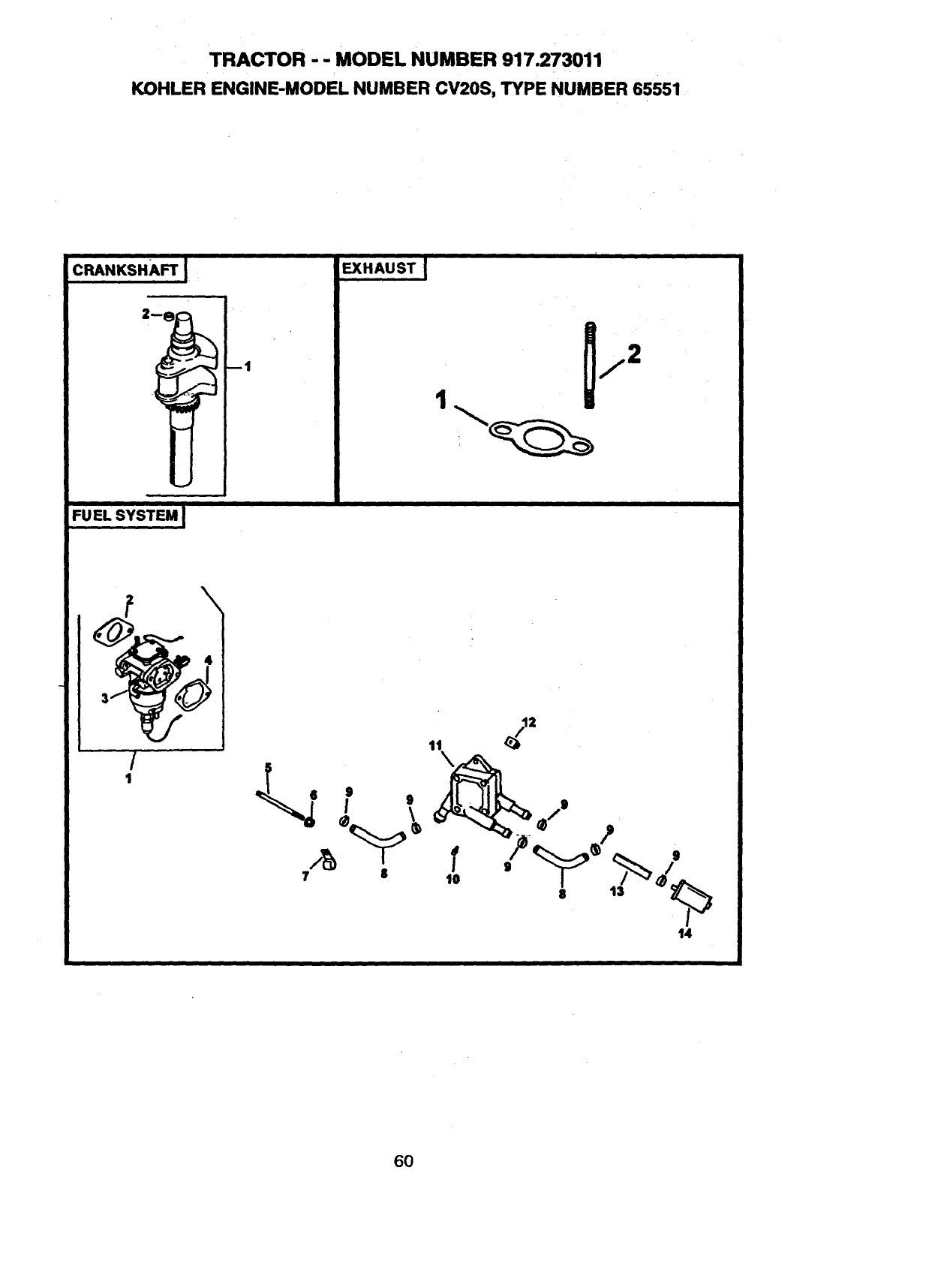
TRACTOR - - MODEL NUMBER 917.273011
KOHLER ENGINE-MODEL NUMBER CV20S, TYPE NUMBER 65551
I
CRANKSHAFT I.
2 1
FU EL SYSTEM !
i i
EXHAUST I
/
1
14
6O
KOHLER ENGINE-MODEI_ NUMBER CV20S, TYPE NUMBER 65551
CRANKSHAFT
KEY PART
NO. NO.
1 24-014-72
2 52-139-09
EXHAUST
KEY PART
NO. NO.
1 24-041-02
2 25-072-04
24-522-16
24-782-05
24-755-03
DESCRIPTION
Crankshaft(Includes2)
Plug, cup
DESCRIPTION
Gasket, exhaust (2)
Stud, M8x1.25x33 (4)
Short Block
Miniblock
Gasket Set
FUEL SYSTEM
KEY PART
NO. NO.
1 24-853-25
2 24-041-15
3
4 24-041-14
5 M-0629095
6 M-0641060
7 47-154-01
8_. 24-353-03
9 X-426-9
10 24-086-12
11 24-393-04
12 24-100-01
13 25-353-03
14 24-050-02
NOT ILLUSTRATED
24-757-18
24-757-19
24-757-20
24-757-22
DESCRIPTION
Kit, carburetor w/gaskets
(Includes 2-4)
Gasket, cad_umtor
Carburetor assembly
(For information only not
available separately)
(Includes 24 757 18, 24-053-25,
24-757-19, 24-757-20, 24-757-
22)
Gasket, air cleaner base
Stud, M6x1.0x95 (2)
Nut, hex. flange M6xl.0 (2)
Clip, cable
Line, fuel 10-5/8" (2)
Clamp, hose (6)
Screw, hex. cap. M6x1.7x18 (2)
Pump, fuel - pulse
Nut, plastic (2)
Line, fuel 13-1/2"
Filter,fuel
Kit, overhaul wlgaskets
Kit, choke repair w/gaskets
Kit, gasket
Kit, solenoid replacement w/gas-
kets
61

62

SUGGESTED GUIDE FOR SIGHTING SLOPES FOR SAFE OPERATION
SIGHTING
GUIDE
ONLY RIDE UP AND DOWN HILL,
NOT ACROSS HILL
SIGHT AND HOLD THIS LEVEL WITH
SKY LINE OR TREE.
15" MAX.
/_ Operate your Tractor up and down the face of slopes (not
greater than 15 '), never across the face. Make turns gradu-
ally to prevent tipping or loss of control. Exercise extreme
caution when changing direction on slopes.

For the repair or replacement parts you need
delivered directly to your home
Call 7 am - 7 pm, 7 days a week
1-800-366-PART
(1-800-366-7278)
Para ordenar piezas con entrega a
domicilio -1-800-659-7084
For in-house major brand repair service
Call 24 hours a day, 7 days a week
1-800-4-REPAIR
(1-800-473-7274) .
Para pedir servicio de reparaci6n a
domicilio - 1-800-676-5811
For the location of a Sears Parts and
Repair Center in your area
Call 24 hours a day, 7 days a week
1-800-488-1222
For information on purchasing a Sears
Maintenance Agreement or to inquire
_about an existing Agreement
Call 9 am - 5 pm, Monday-Saturday
1-800-827-6655
nBaimm 1
mmnunnnu
When requesting service or ordering
parts, always provide the following
information:
•Product Type •Part Number
•Model Number •Part Description
SEARS
Amenca's Repair Speciat_sts
165020 7.24.98 Rev. 3 RD/SJ/RD Printed in U.S.A.
