Craftsman 917273021 User Manual TRACTOR Manuals And Guides 98100083
CRAFTSMAN Lawn, Tractor Manual 98100083 CRAFTSMAN Lawn, Tractor Owner's Manual, CRAFTSMAN Lawn, Tractor installation guides
User Manual: Craftsman 917273021 917273021 CRAFTSMAN TRACTOR - Manuals and Guides View the owners manual for your CRAFTSMAN TRACTOR #917273021. Home:Lawn & Garden Parts:Craftsman Parts:Craftsman TRACTOR Manual
Open the PDF directly: View PDF ![]() .
.
Page Count: 68
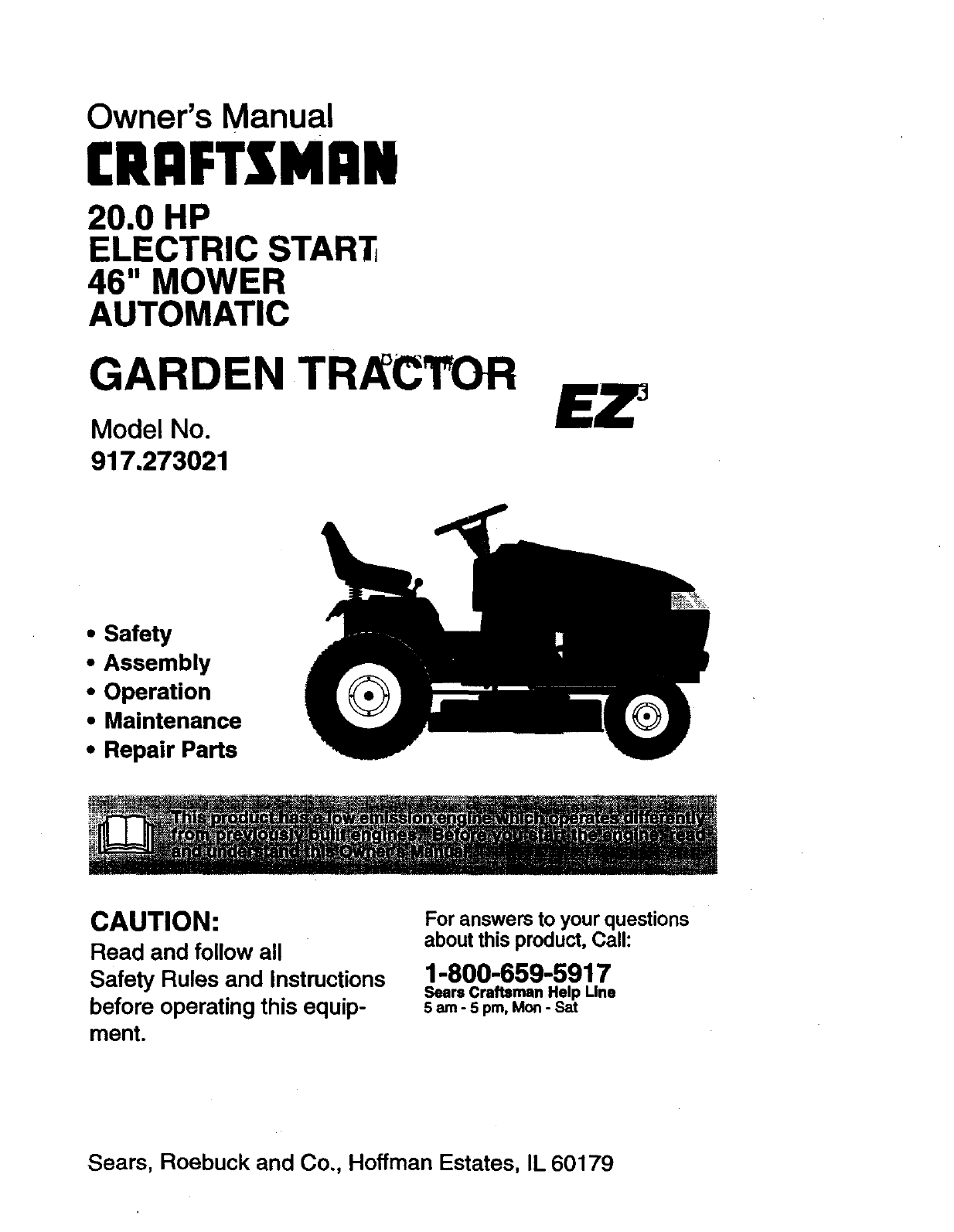
Owner's Manual
CnnFTSivina
20.0 HP
ELECTRIC STAR7
46" MOWER
AUTOMATIC
GARDEN TRA C
Model No.
917.273021
• Safety
• Assembly
• Operation
•Maintenance
• Repair Parts
CAUTION:
Read and follow all
Safety Rules and Instructions
before operating this equip-
ment.
For answers to your questions
about this product,Call:
1-800-659-5917
Sears Craftsman Help Line
5 am -5 pm, Mort - Sat
Sears, Roebuck and Co., Hoffman Estates, IL 60179
Warranty ................................................. 2
Safety Rules ........................................... 2
Product Specifications ........................... 5
Assembly ................................................ 8
Operation .............................................. 12
Maintenance Schedule ......................... 19
Maintenance ......................................... 19
Service and Adjustments...................... 23
Storage ................................................. 31
Troubleshooting.................................... 32
Repair Parts ......................................... 36
Parts Ordering ............... ........ Back Cover
LIMITED TWO YEAR WARRANTY ON CRAFTSMAN RIDING EQUIPMENT
•For two (2) years from the date of purchase, if this Craftsman Riding Equipment is main-
tained, lubricated and tuned up according to the instructions in the owner's manual,
Sears will repair or replace, free of charge, any parts found to be defective in material or
workmanship.
This Warranty does not cover:.
• Expendable items which become wom during normal use, such as blades, spark
plugs, air cleaners, belts, etc.
•Tire replacement or repair caused by punctures from outside objects, such as nails,
thoms, stumps, or glass.
•Repairs necessary because of operator abuse, negligence, improper storage or acci-
dent or the failure to maintain the equipment according to the instructions contained in
the owner's manual.
•Riding equipment used for commercial or rental purposes.
LIMITED 90 DAY WARRANTY ON BATTERY
For ninety (90) days from date of pumhase, if any battery included with this riding equip-
ment proves defective in material or workmanship and our testing determines the bat-
tery will not hold a charge, Sears will replace the battery at no charge. In-home warranty
service on your Craftsman riding equipment is available at no charge for 30 days from
the date of purchase. Please contact your nearest service center. After 30 days from the
date of purchase, warranty service is available by taking your Craftsman riding equip-
ment to your nearest Sears Service Center. (In-home warranty service will still be avail-
able after 30 days from thedate of purchase but a standard trip charge will apply). This
warranty applies only while this product is inthe United States. This Warranty gives you
specific legal rights,and you may also have other dghts which may vary from state to
state.
Sears, Roebuck and Co., D/817 WA, Hoffman Estates, IL 60179
GENERAL OPERATION
•Read, understand, and follow all instruc-
tions in the manual and on the machine
before starting.
•Only allow responsible adults, who are
familiar with the instructions,to operate
the machine.
•Clear the area of objects such as rocks,
toys, wire, etc., which could be picked
up and thrown by the blade.
•Be sure the area is clear of other people
befOr_ mowing. Stop machine if anyone
enters the area.
2
•Never carry passengers.
•Do not mow in reverse unless absolute-
ly necessary. Always look down.and
behind before and while backing:
•Be aware of the mower discharge direc-
tion and do not point it at anyone. Do
not operate the mower without either
the entire grass catcher or the guard in
place.
•Slow down before tuming.
•Never leave arunning machine unat-
tended. Always turn off blades, set park-
ing brake, stop engine, and remove
keys before dismounting.
•Tum off blades when not mowing.
•Stop engine before removing grass
catcher or unclogging chute.
•Mow only in daylight or good artificial
light.
•Do not operate the machine while under
the influence of alcohol or drugs.
•Watch for traffic when operating near or
crossing roadways.
•Use extra care when loading or unload-
ing the machine into a trailer or truck.
SLOPE OPERATION
Slopes are a major factor related to Ioss-
of-contrel and tipover accidents, which
can result in severe injury or death. All
slopes require extra caution. If you cannot
back up the slope or if you feel uneasy on
it, do not mow it.
DO:
•Mow up and down slopes, not across.
• Remove obstacles such as rocks, tree
limbs, etc.
•Watch for holes, ruts, or bumps. Uneven
terrain could overturn the machine. Tall
grass can hide obstacles.
•Use slow speed. Choose a low gear so
that you will not have to stop or shift
while on the slope.
•Follow the manufacturer's recommen-
dations for wheel weights or counter-
weights to improve stability.
•Use extra care with grass catchers or
other attachments. These can change
the stability of the machine.
•Keep all movement on the slopes slow
and gradual. Do not make sudden
changes in speed or direction.
•Avoid starting or stopping on aslope. If
tires lose traction, disengage the blades
and proceed slowly straight down the
slope.
DO NOT:
•Do nottum on slopes unless necessary,
and then, tum slowly and gradually
downhill, if possible.
•Do not mow near drop-offs, ditches, or
embankments. The mower could sud-
denly turn over if a wheel is over the
edge of a cliffor ditch, or if an edge
caves in.
•Do-not mow on wet grass. Reduced
traction could cause sliding.
•Do nottry to stabilize the machine by
puttingyour foot on the ground.
•Do not use grass catcher on steep
slopes.
CHILDREN
Tragic accidents can occur if the operator
is not alert to the presence of children.
Children are often attracted to the
machine and the mowing activity. Never
assume that children will remain where
you last saw them.
•Keep children out of the mowing area
and under the watchful care of another
responsible adulL
•Be alert and tum machine off if children
enter the area.
•Before and when backing, look behind
and down for small children.
•Never carry children. They may fall off
and be seriously injured or interfere with
safe machine operation.
•Never allow children to operate the
machine.
•Use extra care when approaching blind
comers, shrubs, trees, or other objects
that may obscure vision.
SERVICE
•Use extra care in handling gasoline and
other fuels. They are flammable and
vapors are explosive.
Use only an approved container.
Never remove gas cap or add fuel
with the engine running. Allow en-
gine to cool before refueling. Do not
smoke.
Never refuel the machine indoors.
Never store the machine or fuel
container inside where there is an
open flame, such as a water heater.
•Never run a machine inside a closed
area.
•Keep nuts and bolts, especially blade
attachment bolts, tight and keep equip-
ment in good condition.
_Never tamper with safety devices.
Check their proper operation regularly.
Keep machine free of grass, leaves, or
other debris build-up. Clean oil or fuel
spillage. Allow machine to cool before
'storing.
•Stop and inspect the equipment if you
strike an object. Repair, if necessary,
before restarting.
3
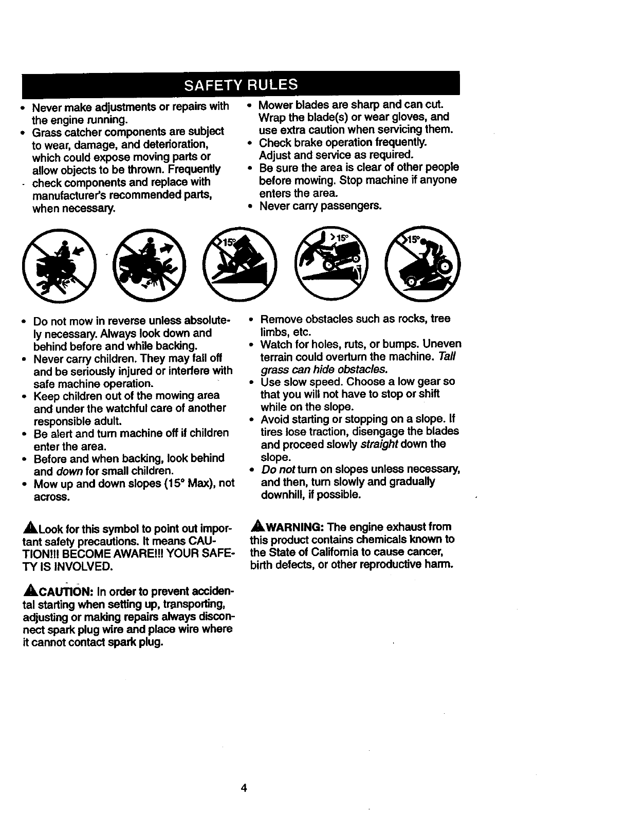
•Never make adjustments or repairs with
the engine running.
•Grass catcher components are subject
to wear, damage, and deterioration,
which could expose moving pads or
allow objects to be thrown. Frequently
- check components and replace with
manufacturer's recommended pads,
when necessary.
•Mower blades are sharp and can cut.
Wrap the blade(s) or wear gloves, and
use extra caution when servicing them.
•Check brake operation frequently.
Adjust and service as required.
•Be sure the area is clear of other people
before mowing. Stop machine if anyone
enters the area.
•Never carry passengers.
•Do not mow in reverse unless absolute-
ly necessary. Always look down and
behind before and while backing.
•Never carry children. They may fall off
and be seriously injured or interfere with
safe machine operation.
•Keep children out of the mowing area
and under the watchful care of another
responsible adult.
•Be alert and tum machine off if children
enter the area.
•Before and when backing, look behind
and down for small children.
•Mow up and down slopes (15 ° Max), not
across.
•Remove obstacles such as rocks, tree
limbs, etc.
•Watch for holes, ruts, or bumps. Uneven
terrain could overtum the machine. Tall
grass can hide obstacles.
•Use slow speed. Choose a low gear so
that you will not have to stop or shift
while on the slope.
•Avoid starting or stopping on aslope. If
tires lose traction, disengage the blades
and proceed slowly straight down the
slope.
• Donottumonslopesunlessnecessary,
and then, tum slowly and gradually
downhill, if possible.
_,Look for this symbol to point out impor-
tant safety precautions. It means CAU-
TION!!! BECOME AWARE!!! YOUR SAFE-
TY IS INVOLVED.
AcAuTION: In order to prevent acciden-
tal startingwhen setting up, tr-dnsporting,
adjusting or making repairs always discon-
nect spark plug wire and place wire where
it cannot contact spark plug.
,_WARNING: The engine exhaust from
this product contains chemicals known to
the State of Califomia to cause cancer,
birth defects, or other reproductive harm.
4
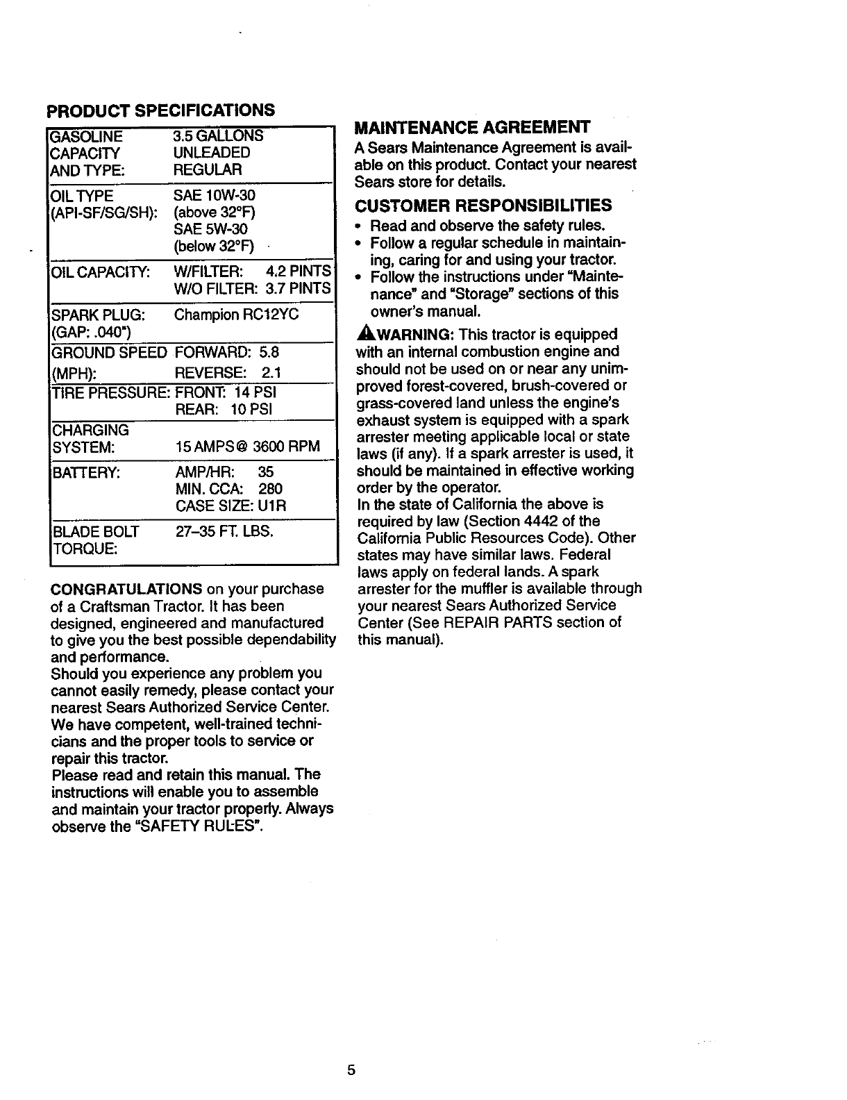
PRODUCT SPECIFICATIONS
3ASOLINE :3.5 GALLONS
3APACITY UNLEADED
_,ND TYPE: REGULAR
OIL TYPE SAE 10W-30
API-SF/SG/SH): (above 32°F)
SAE 5W-30
(below 32°F")
_ILCAPACITY: W/FILTER: 4,2 PINTS
W/O FILTER: 3.7 PINTS
SPARK PLUG: Champion RC12YC
GAP: .040")
GROUND SPEED FORWARD: 5.8
MPH): REVERSE: 2.1
TIRE PRESSURE: FRONT: 14 PSI
REAR: 10 PSI
CHARGING
SYSTEM: 15 AMPS@ 3600 RPM
BATTERY: AMP/HR: 35
MIN. CCA: 280
CASE SIZE: U1R
BLADE BOLT 27-35 FT. LBS.
TORQUE:
CONGRATULATIONS on your purchase
of a Craftsman Tractor. It has been
designed, engineered and manufactured
to give you the best possible dependability
and performance.
Should you experience any problem you
cannot easily remedy, please contact your
nearest Sears Authorized Service Center.
We have competent, well-trained techni-
cians and the proper tools to service or
repair this tractor.
Please read and retain this manual. The
instructions will enable you to assemble
and maintain your tractor properly. Always
observe the "SAFETY RULES".
MAINTENANCE AGREEMENT
A Sears Maintenance Agreement is avail-
able on this product. Contact your nearest
Sears store for details.
CUSTOMER RESPONSIBILITIES
•Read and observe the safety rules.
•Follow a regular schedule in maintain-
ing, caring for and using your tractor.
•Follow the instructions under =Mainte-
nance" and =Storage" sections of this
owner's manual.
,AWARNING: This tractor is equipped
with an internal combustion engine and
should not be used on or near any unim-
proved forest-covered, brush-covered or
grass-covered land unless the engine's
exhaust system is equipped with a spark
arrester meeting applicable local or state
laws (if any). If a spark arrester is used, it
should be maintained in effective working
order by the operator.
In the state of California the above is
required by law (Section 4442 of the
California Public Resources Code). Other
states may have similar laws. Federal
laws apply on federal lands. A spark
arrester for the muffler is available through
your nearest Sears Authorized Service
Center (See REPAIR PARTS section of
this manual).
5
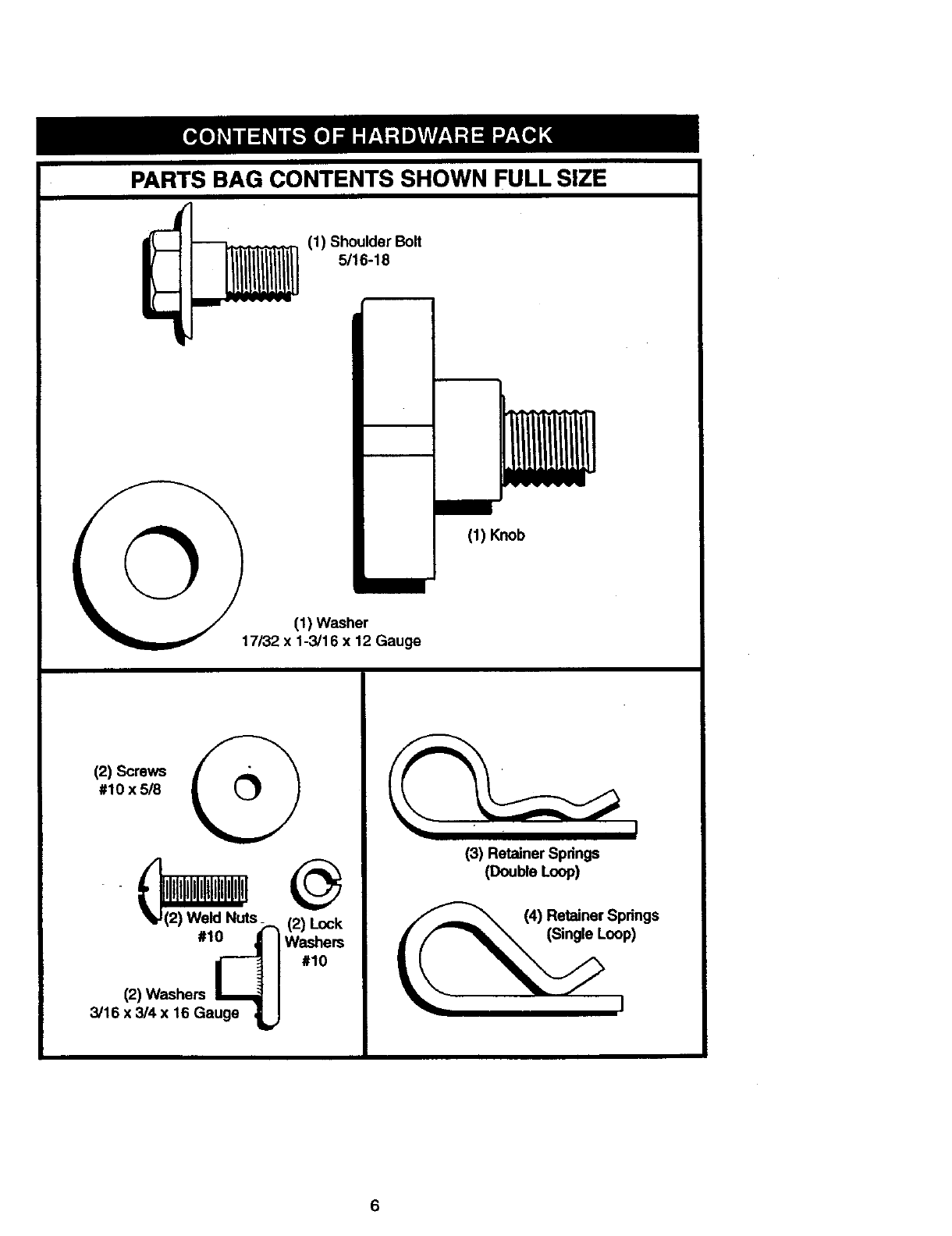
PARTS BAG CONTENTS SHOWN FULL SIZE
(1) Shoulder Bolt
15/16-18
I
(1) Washer
17/32 x 1-3/16 x 12 Gauge
(1) Knob
(2) Screws
#10 x 5/8 t
(2) Weld Nuts_ (2) Lock
#1_ Washers#10
(2) Washers
3/16 x 3/4 x 16 Gauge _w
(3) Retainer Spdngs
(Double Loop)
/I_"_ (4) Retainer Springs
(Single Loop)
6
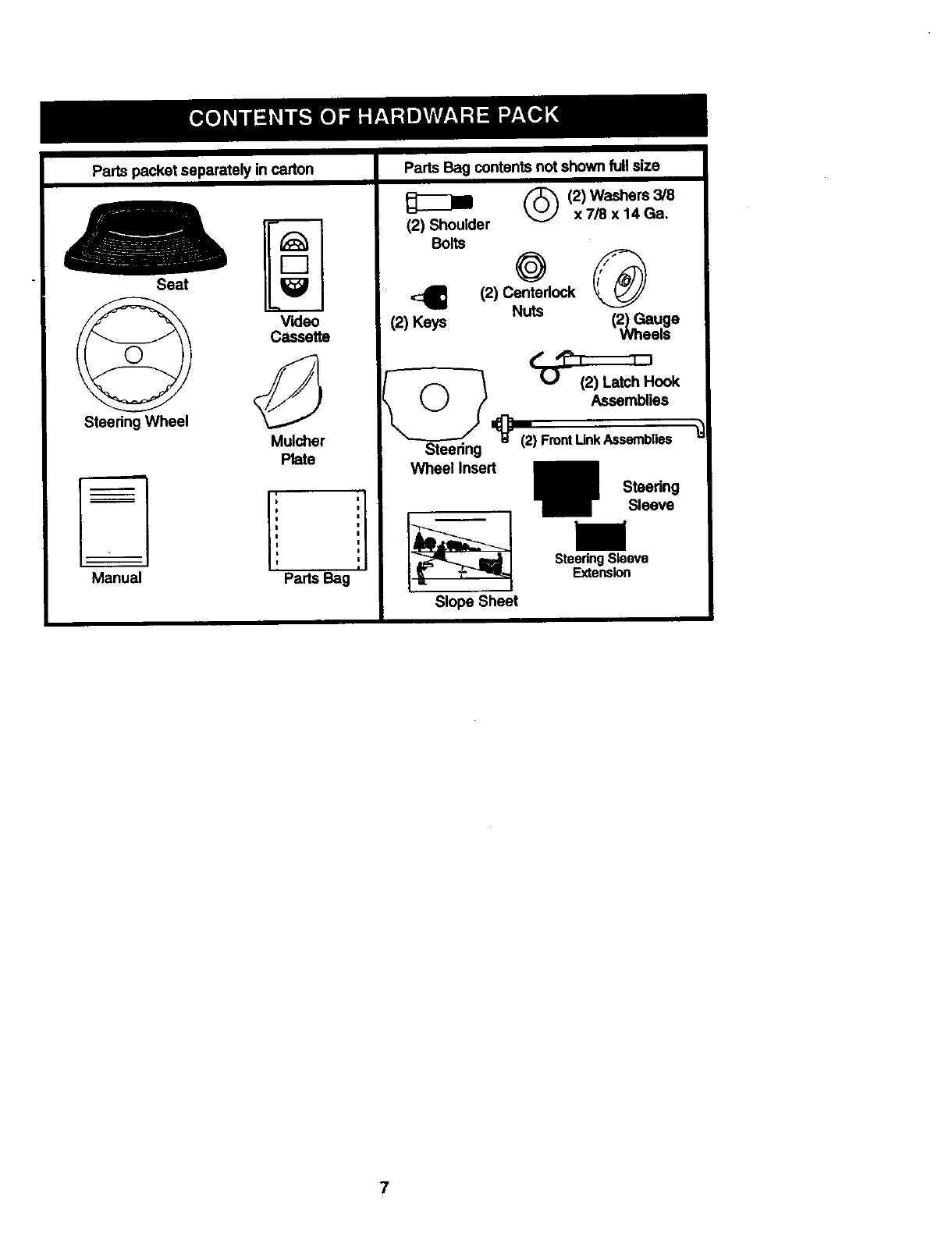
Partspacketseparatelyincarton
Seat
Steering Wheel
Mulcher
Video
Cassette
Plate
Manual Parts Bag
Parts Bag contents not shown full size
(_(2) Washers 3/8
(2) Shoulder x 7/8 x 14 Ga.
Bolts +®
<:_ 12) Centerlock
(2) Keys Nuts (2) Gauge
Wheels
Steedng
U (2) Latch Hook
Assemblies
_(2) FrontLinkAssemblies
Wheellnsed
Slope Sheet
Steedng
Sleeve
Steedng Sleeve
Extension
7
Yournewtractorhas beenassembledatthe factorywithexceptionof thosepartsleft
unassembledfor shippingpurposes.Toensuresafeandproperoperationof yourtractor
all partsand hardwareyouassemblemustbe tightenedsecurely.Usethecorrecttools
as necessaryto insurepropertightness.Reviewthe videocassettebeforeyoubegin.
TOOLS REQUIRED FOR
ASSEMBLY
-A socketwrenchsetwill makeassembly
easier. Standard wrench sizes you need
are listed below.
(1) 9/16" wrench (1) 3/4" Socket w/
(1) 112" wrench drive rachet
(1)Pliers (1) Phillips Screw-
(1) Utility knife driver
(1) Tire pressure gauge
When right or left hand is mentioned in
this manual, it means, from your point of
view, when you are in the operating posi-
tion (seated behind the steering wheel).
TO REMOVE TRACTOR FROM
CARTON
UNPACK CARTON
• Remove all accessible loose parts and
parts boxes from shipping carton (See
page 6).
•Cut, from top to bottom, along lines on
all four corners of shipping carton, and
lay panels flat.
•Remove mower and package materials.
•Check for any additional loose parts or
boxes and remove.
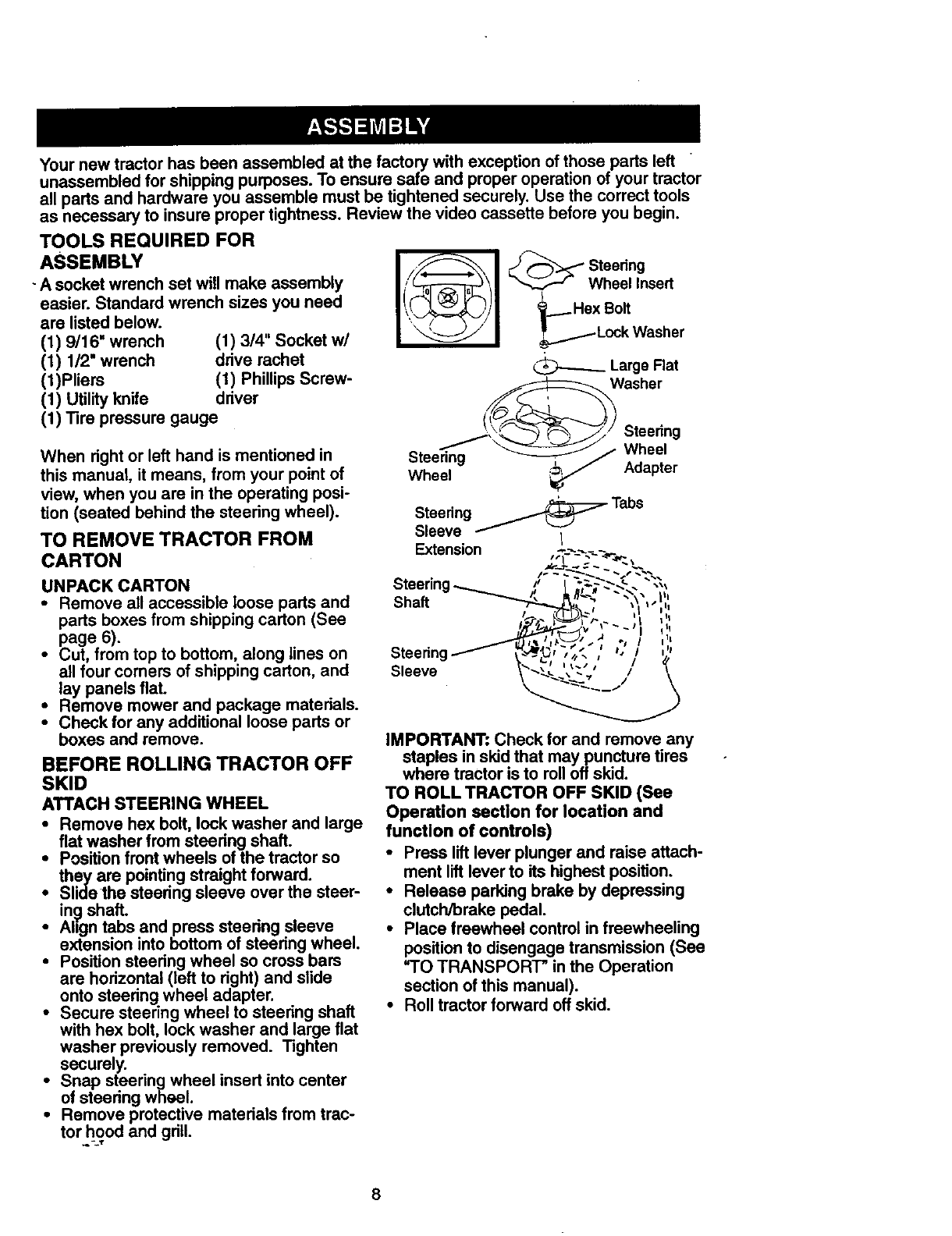
BEFORE ROLLING TRACTOR OFF
SKID
ATTACH STEERING WHEEL
• Remove hex bolt, lock washer and large
flat washer from steering shaft.
•Position front wheels of the tractor so
they are pointing straight forward.
• Slidethe steering sleeve over the steer-
in_]shaft.
•Align tabs and press steering sleeve
extension into bottom of steering wheel.
•Position steering wheel so cross bars
are horizontal (left to right) and slide
onto steering wheel adapter.
•Secure steering wheel to steering shaft
with hex bolt, lock washer and large flat
washer previously removed. Tighten
securely.
•Snap steering wheel insert into center
of steering wheel.
•Remove protective materials from trac-
tor hood and grill.
Steering
Wheel
_Steedng
Wheel Insert
Hex Bolt
Lock Washer
Large Flat
Washer
Wheel
Adapter
IMPORTANT: Check for and remove any
staples in skid that may puncture tires
where tractor is to roll off skid.
TO ROLL TRACTOR OFF SKID (See
Operation section for location and
function of controls)
• Press lift lever plunger and raise attach-
ment lift lever to its highest position.
•Release parking brake by depressing
clutch/brake pedal.
•Place freewheel control in freewheeling
position to disengage transmission (See
"TO TRANSPORT" in the Operation
section of this manual).
•Roll tractor forward off skid.
8
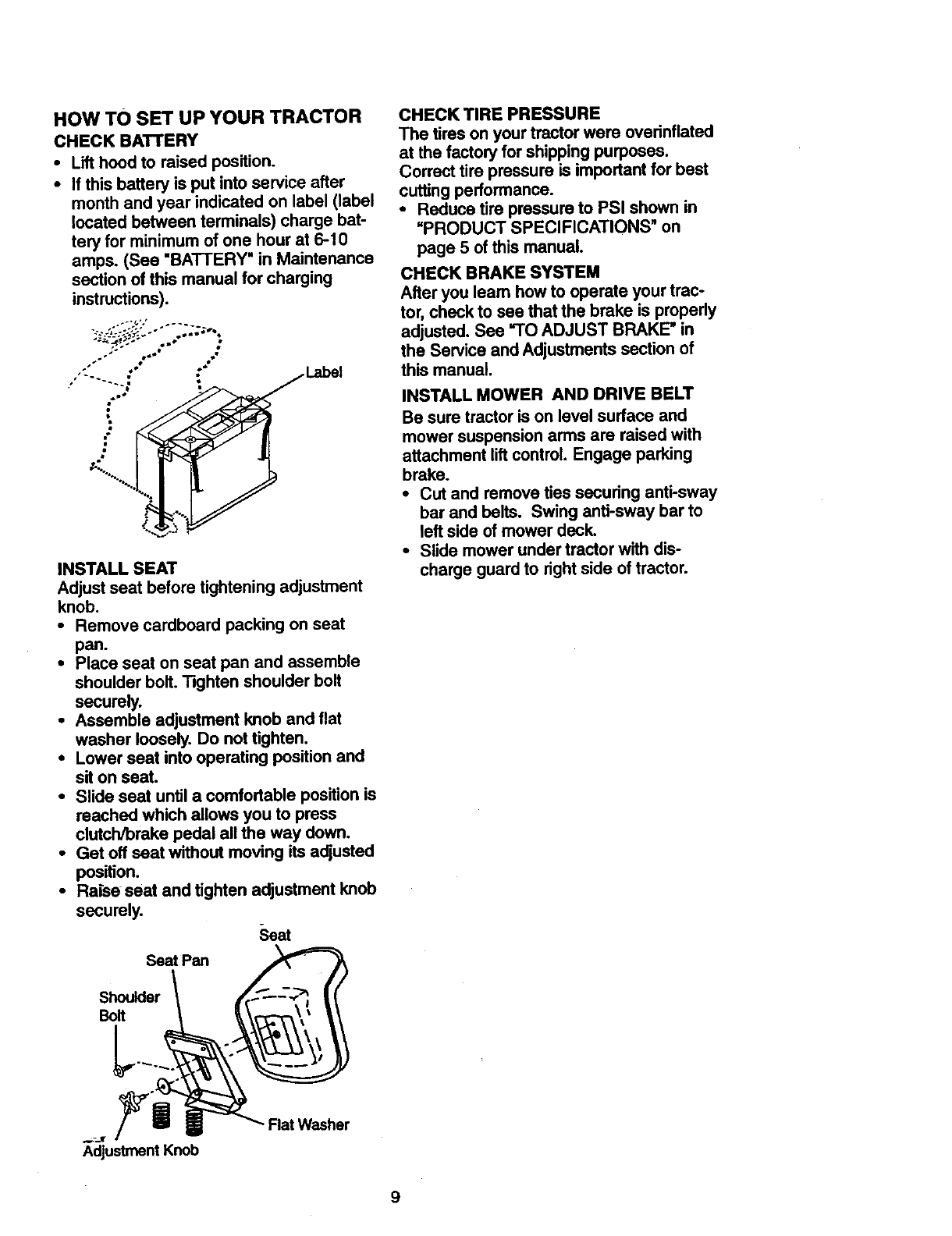
HOW TO SET UP YOUR TRACTOR
CHECK BATTERY
• Lifthood to raised position.
• If this battery is put into service after
month and year indicated on label (label
located between terminals) charge bat-
tery for minimum of one hour at 6-10
amps. (See "BATTERY" in Maintenance
section of this manual for charging
instructions).
INSTALL SEAT
Adjust seat before tightening adjustment
knob.
•Remove cardboard packing on seat
pan.
•Place seat on seat pan and assemble
shoulder bolt. Tighten shoulder bolt
securely.
•Assemble adjustment knob and flat
washer loosely. Do not tighten.
•Lower seat into operating position and
sit on seat.
•Slide seat until a comfortable position is
reached which allows you to press
clutch/brake pedal all the way down.
•Get off seat without moving its adjusted
position.
•Raise seat and tighten adjustment knob
securely,
Seat
Seat Pan
Shoulder
Bolt
CHECK TIRE PRESSURE
The tires on your tractor were overinflated
at the factory for shipping purposes.
Correct tire pressure is important for best
cuffing performance.
•Reduce tire pressure to PSI shown in
_PRODUCT SPECIFICATIONS" on
page 5 ofthis manual.
CHECK BRAKE SYSTEM
After you learn how to operate your trac-
tor, check to see that the brake is properly
adjusted. See =TOADJUST BRAKE" in
the Service and Adjustments section of
this manual.
INSTALL MOWER AND DRIVE BELT
Be sure tractor is on level surface and
mower suspension arms are raised with
attachment lift control. Engage parking
brake.
•Cut and remove ties securing anti-sway
bar and belts. Swing anti-sway bar to
left side of mower deck.
•Slide mower under tractor with dis-
charge guard to right side of tractor.
Rat Washer
9
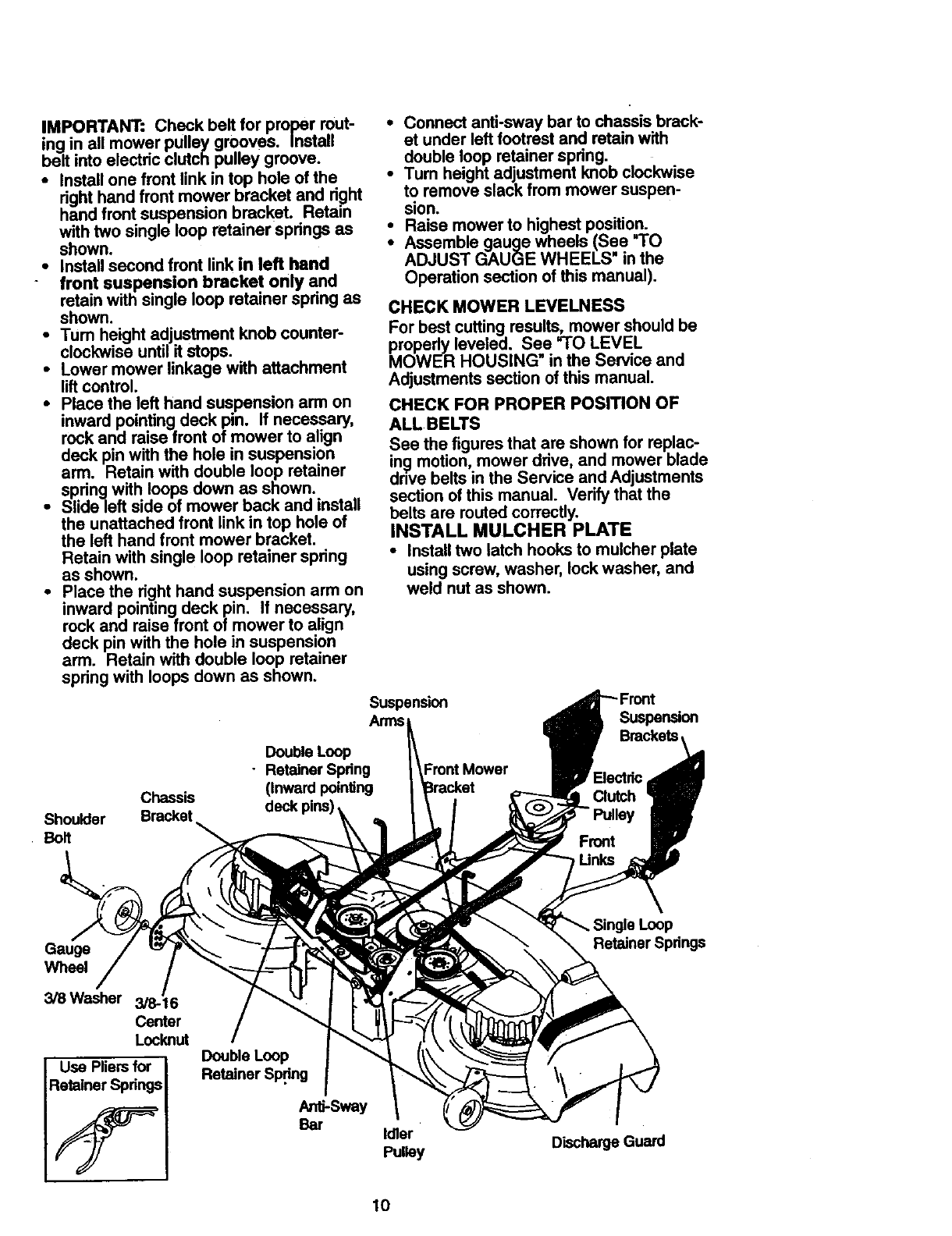
IMPORTANT:Checkbellfor properrout-
ingin all mowerpulleygrooves. Install
bellintoelectricclutchpulleygroove.
•Install one front link in top hole of the
right hand front mower bracket and right
hand front suspension bracket. Retain
with two single loop retainer springs as
shown.
•Install second front link in left hand
front suspension bracket only and
retain with single loop retainer spdng as
shown.
•Tum height adjustment knob counter-
clockwise until it stops.
•Lower mower linkage with attachment
lift control.
•Place the left hand suspension arm on
inward pointing deck pin. If necessary,
rock and raise front of mower to align
deck pin with the hole in suspension
arm. Retain with double loop retainer
spring with loops down as shown.
•Slide left side of mower back and install
the unattached front link in top hole of
the left hand front mower bracket.
Retain with single loop retainer spring
as shown.
•Place the right hand suspension arm on
inward pointing deck pin. If necessary,
rock and raise front of mower to align
deck pin with the hole in suspension
arm. Retain with double loop retainer
spring with loops down as shown.
Chassis
Shoulder Bracket
•Boa
Double Loop
•Retainer Spring
(Inward pointing
deck p_ns)
•Connect anti-sway bar to chassis brack-
et under left footrest and retain with
double loop retainer spring.
•Turn height adjustment knob clockwise
to remove slack from mower suspen-
sion.
Raise mower to highest position.
Assemble gauge wheels (See "TO
ADJUST GAUGE WHEELS in the
Operation section of this manual).
CHECK MOWER LEVELNESS
For best cutting results, mower should be
properly leveled. See =TO LEVEL
MOWER HOUSING" in the Service and
Adjustments section of this manual.
CHECK FOR PROPER POSITION OF
ALL BELTS
See the figures that are shown for replac-
ing] motion, mower drive, and mower blade
drive belts in the Service and Adjustments
section of this manual. Verify that the
belts are routed correctly.
INSTALL MULCHER PLATE
•Install two latch hooks to mulcher plate
using screw, washer, lock washer, and
weld nut as shown.
Suspension
Arms Suspension
Front Mower
Gauge
Wheel
3/8 Washer 3/8-16
Center
Locknut
Use Pliers for
Retainer Springs
Double Loop
Retainer Sp.dng
Anti-Sway
Bar Idler
Pulley
Retainer Springs
DLschargeGuard
10
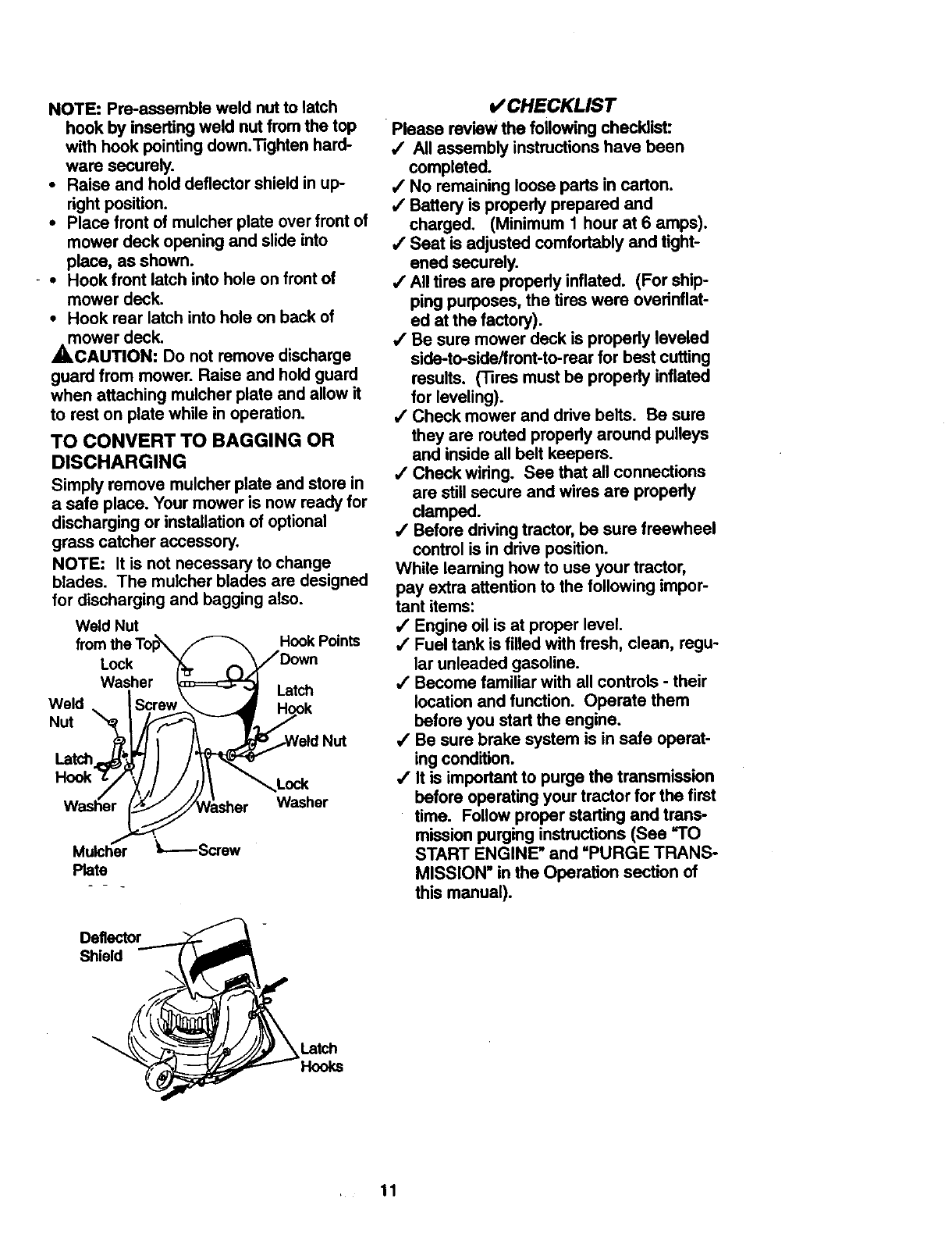
NOTE:Pre-assembleweldnutto latch
hookbyinsertingweldnutfromthetop
withhookpointingdown.Tightenhard-
waresecurely.
•Raise and hold deflector shield in up-
right position.
•Place front of mulcher plate over front of
mower deck opening and slide into
place, as shown.
-•Hook front latch into hole on front of
mower deck.
•Hook rear latch into hole on back of
mower deck.
,_CAUTION: Do not remove discharge
guard from mower. Raise and hold guard
when attaching mulcher plate and allow it
to rest on plate while in operation.
TO CONVERT TO BAGGING OR
DISCHARGING
Simply remove mulcher plate and store in
a safe place. Your mower is now ready for
discharging or installation of optional
grass catcher accessory.
NOTE: It is not necessary to change
blades. The mulcher blades are designed
for discharging and bagging also.
Weld Nut Hook Points
Lock
Washer
Weld Latch
Nut
Latch
Lock
Washer
Mulcher '_,-----Screw
Plate
Deflector
Shield
*/CHECKLIST
Please review the following checklist:
•/All assembly instructions have been
completed.
,/No remaining loose parts in carton.
,/Battery is properly prepared and
charged. (Minimum 1 hour at 6 amps).
/Seat is adjusted comfortably and tight-
ened securely.
/All tires are properly inflated. (For ship-
ping purposes, the tires were overinflat-
ed at the factory).
,/Be sure mower deck is propedy leveled
side-to-side/front-to-rear for best cuffing
results. ('13res must be propedy inflated
for leveling).
•/Check mower and drive belts. Be sure
they are routed propedy around pulleys
and inside all belt keepers.
,/Check wiring. See that all connections
are still secure and wires are propedy
clamped.
,/Before ddving tractor, be sure freewheel
control is in drive position.
While leaming how to use your tractor,
pay extra attention to the following impor-
tant items:
,/Engine oil is at proper level.
•/Fuel tank is filled with fresh, clean, regu-
lar unleaded gasoline.
•(Become familiar with all controls -their
location and function. Operate them
before you start the engine.
•/Be sure brake system is in safe operat-
ing condition.
,/It is important to purge the transmission
before operating your tractor for the first
time. Follow proper starting and trans-
mission purging instructions (See "TO
START ENGINE" and =PURGE TRANS-
MISSION" in the Operation section of
this manual).
, 11
Thesesymbolsmay appearonyour tractoror inliteraturesuppliedwiththe product.
Learnandunderstandtheirmeaning.
BATTERY CAUTIONOR REVERSE FORWARD FAST SLOW
WARNING
A
ENGINE ON ENGINE OFF OIL PRESSURE LIGHTS ON OVEL]RGTI_EMP T
FUEL CHOKE MOWER HEIGHT PARKING BRAKE UNLOCKED MOWER LIFT
LOCKED
ATTACHMENT REVERSE NEUTRAL HIGH LOW PARKING BRAKE
CLUTCH ENGAGED
KEEP AREA CLEAR SLOPE HAZARDS
ATTACHMENT
IGNITION CLUTCH DISENGAGED (SEE SAFETY RULES SECTION)
DANGER, KEEP HANDS AND FEET AWAY
FREE WHEEL
(AutomaticModelsonly)
12
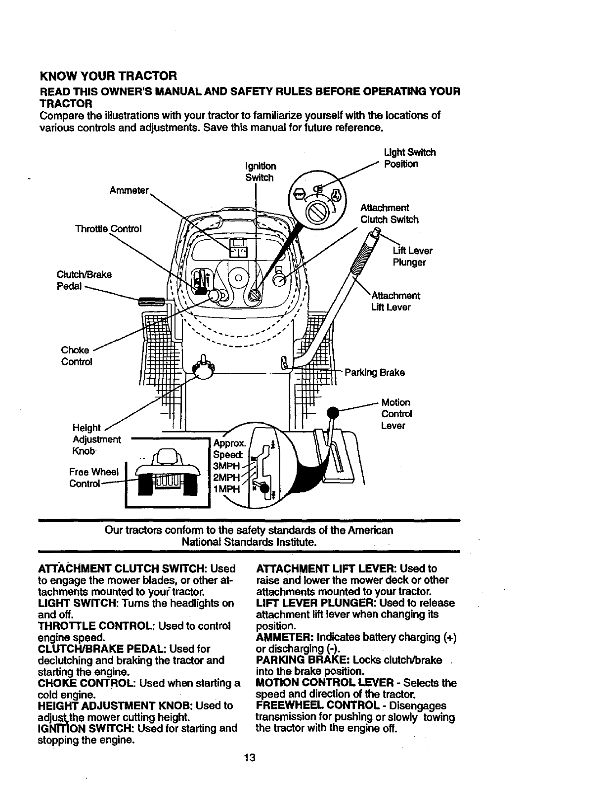
KNOW YOUR TRACTOR
READTHISOWNER'SMANUALANDSAFETYRULESBEFOREOPERATINGYOUR
TRACTOR
Comparethe illustrationswith yourtractorto familiarizeyourselfwiththe locationsof
variouscontrolsand adjustments.Savethismanualfor future reference.
Ignition
Switch
UghtSw h
Position
Throttle Control
Clutch/Brake
Peda
Attechment
Clutch Switch
Uft Lever
Plunger
LiftLever
Chokq
Control
-Parking Brake
Height
Adjustment
Knob
Free Wheel
Motion
Control
Lever
Our tractors conform to the safety standards of the Amedcan
National Standards Institute.
AI"I'ACHMENT CLUTCH SWITCH: Used
to engage the mower blades, or other at-
tachments mounted to youftractor.
LIGHT SWITCH: Turns the headlights on
and off.
THRO'I-rLE CONTROL: Used to control
engine speed.
CLUTCH/BRAKE PEDAL: Used for
declutching and braking the tractor and
starting the engine.
CHOKE CONTROL: used when starting a
cold engine.
HEIGHT ADJUSTMENT KNOB: Used to
adjust, the mower cutting height.
IGNITION SWITCH: Used for starting and
stopping the engine.
ATTACHMENT LIFT LEVER: Used to
raise and lower the mower deck or other
attachments mounted to your tractor.
LIFT LEVER PLUNGER: Used to release
attachment lift lever when changing its
position.
AMMETER: Indicates battery charging (+)
or discharging (-).
PARKING BRAKE: Locks clutch/brake
into the brake position.
MOTION CONTROL LEVER -Selects the
speed and direction of the tractor.
FREEWHEEL CONTROL -Disengages
transmission for pushing or slowly towing
the tractor with the engine off.
13
Theoperationof anytractorcan resultinforeignobjectsthrownintothe
eyes,whichcan resultinsevereeyedamage.Alwayswearsafetyglasses
or eyeshieldswhileoperatingyourtractoror performing any adjustments or
repairs. We recommend a wide vision safety mask over spectacles, or stan-
dard safety glasses.
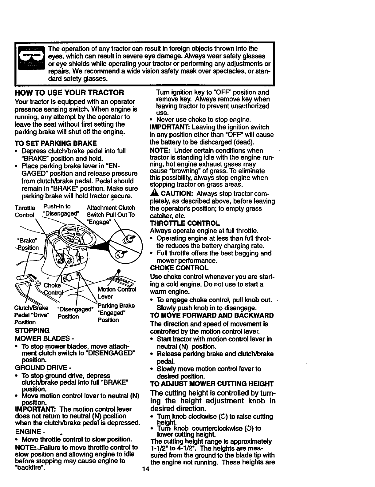
HOW TO USE YOUR TRACTOR
Your tractor is equipped with an operator
.presence sensing switch. When engine is
running, any attempt by the operatorto
leave the seat without first settingthe
parking brake will shut offthe engine.
TO SET PARKING BRAKE
•Depress clutch/brake pedal into full
=BRAKE" position and hold,
•Place parking brake lever in =EN-
GAGED" positionand release pressure
from clutch/brake pedal. Pedal should
remain in =BRAKE" position. Make sure
parking brake will hold tractor _.secure.
Throttle Push-In to Attachment Clutch
Control "Disengaged" Switch Pull Out To
---__ Engage
Clutch/B"_ake -ni_=_=n=_r, "Parking Brake
Position Position
STOPPING
MOWER BLADES -
•To stop mower blades, move attach-
mont clutch switch to =DISENGAGED"
position.
GROUND DRIVE -
•To stop ground drive, depress,
clutchroreke pedal into full BRAKE"
position.
•Move motion control lever to neutral (N)
position.
IMPORTANT: The motion control lever
does not retum to neutral (N) position
when the clutch/brake pedal ksdepressed.
ENGINE -
•Move throttle'control to slow position.
NOT "P.:_.F-allure to move throttle control to
slow position and allowing engine to idle
before stopping may cause engine to
"backfire'.
Tum ignition key to "OFF" position and
remove key. Always remove key when
leaving tractor to prevent unauthodzed
use.
•Never use choke to stop engine.
IMPORTANT: Leaving the ignition switch
in any position other than =OFF" will cause
the battery to be dishcarged (dead).
NOTE: Under certain conditions when
tractor is standing idle with the engine run-
ning, hot engine exhaust gases may
cause "browning" of grass. To eliminate
this possibility, always stop engine when
stopping tractor on grass areas.
ACAUTION: Always stop tractor com-
pletely, as descdbed above, before leaving
the operator's position; to empty grass
catcher, etc.
THRO'n'LE CONTROL
Always operate engine at full throttle.
•Operating engine at less than full throt-
tle reduces the battery charging rate.
•Full throttle offers the best bagging and
mower performance.
CHOKE CONTROL
Use choke control whenever you are start-
ing a cold engine. Do not use to start a
warm engine.
•To engage choke control, pull knob out..
Slowly push knob in to disengage.
TO MOVE FORWARD AND BACKWARD
The direction and speed of movement is
controlled by the motion control lever.
•Start tractor with motion control lever in
neutral (N) position.
•Release parking brake and clutch_rake
pedal.
•Slowly move motion control lever to
desired position.
TO ADJUST MOWER CUTTING HEIGHT
The cutting height is controlled by turn-
ing the height adjustment knob in
desired direction.
•Tum knob clockwise (0) to raise cutting
•/urn Knoe counterclockwise (0)to
lower cutting height.
The cutting height range is approximately
1-1/2" to 4-1/2". The heights are mea-
sured from the ground to the blade tip with
the engine not running. These heights are
14
approximateandmayvarydepending
uponsoilconditions,heightof grassand
typesof grassbeingmowed.
•The average lawn should be cut to
approximately 2-1/2 Inches during the
cool season and to over 3 inches during
hot months. For healthier and better
looking lawns, mow often and after
moderate growth.
•For best cutting performance, grass
over 6 inches in height should be
mowed twice. Make the first cut rela-
tively high; the second to desired height.
TO ADJUST GAUGE WHEELS
Gauge wheels are properly adjusted
when they are slightly off the ground when
mower is at the desired cutting height in
operating position. Gauge wheels then
keep the deck in proper position to help
prevent scalping in most terrain condi-
tions.
•Adjust gauge wheels with tractor on a
flat level surface.
•Adjust mower to desired cutting height
(See =TO ADJUST MOWER CUFFING
HEIGHT" in the Operation section of
this manual).
•With mower in desired height of cut po-
sition, gauge wheels should be assem-
bled so they are slightly off the ground.
Install gauge wheel in appropriate hole
with shoulder bolt, 3/8 washer, and 3/8-
16 Iocknut and tighten securely.
•Repeat for opposite side installing
gauge wheel in same adjustment hole.
Mounting
Bracket
,_CAUTION: Do not operate the mower
without either the entire grass catcher, on
mowers so equipped, or the discharge
guard in place.
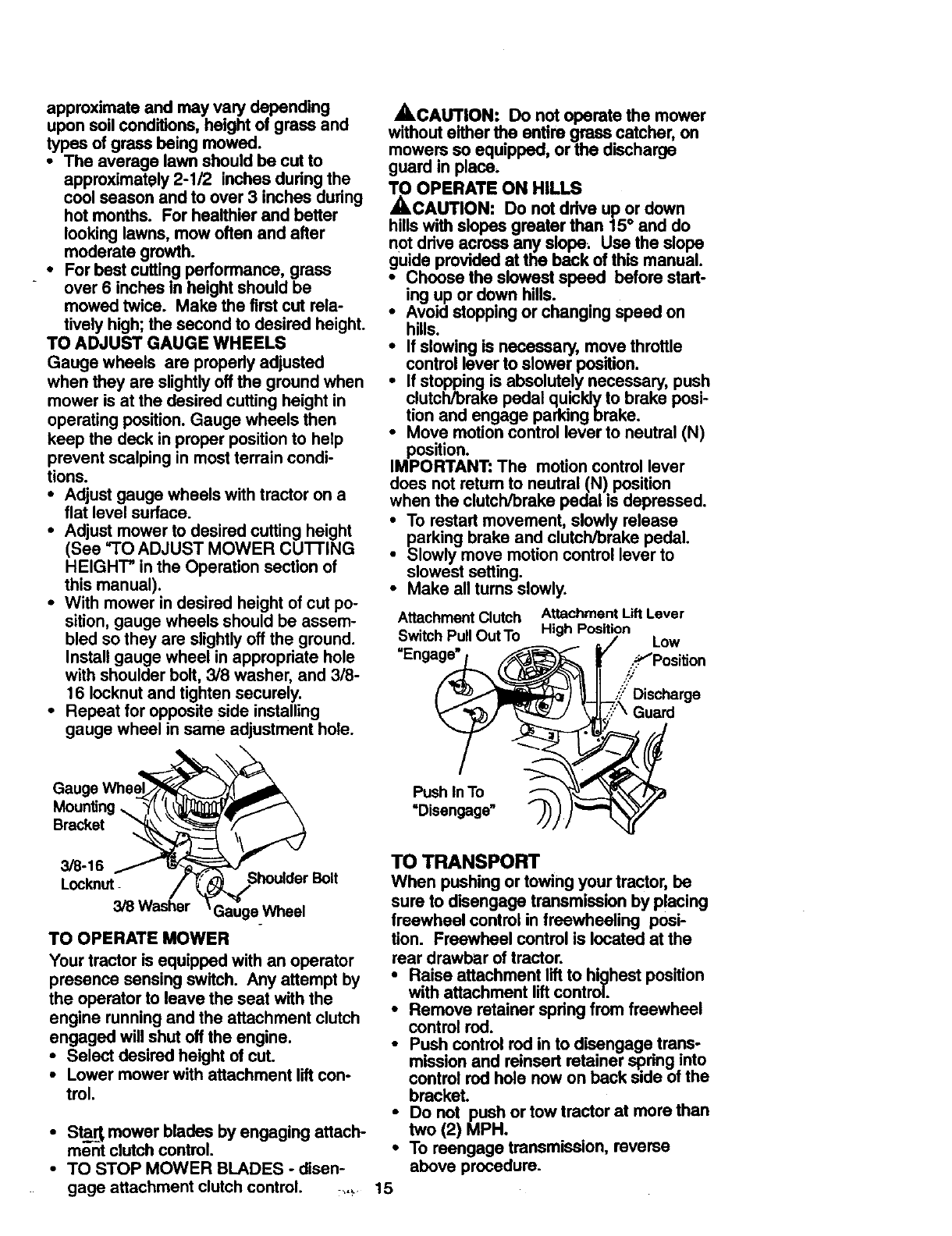
TO OPERATE ON HILLS
_,CAUTION: Do not drive up or down
hillswith slopes greater than 15° and do
not drive across any slope; Use the slope
guide provided at the back of this manual
•Choose the slowest speed beTorestart-
ing up or down hills.
•Avoid stopping or changing speed on
hills.
i•lf slowing is necessary, move throttle
control lever to slower possion.
If stoppingis absolutely necessary, push
clutch/brake pedal quicklyto brake posi-
tion and engage parldng brake.
Move motion control lever to neutral (N)
position.
IMPORTANT: The motion control lever
does not return to neutral (N) position
when the clutch/brake pedal is depressed.
i o restad movement, slowlyrelease
parking brake and clutch/brake pedal.
Slowly move motton control lever to
slowest setting.
Make all turns slowly.
Attachment Clutch
Switch Pull Out To
1-'- 4
Push In To _-_
"Disengage" "_) )_
Attachment Lift Lever
High Position
/Low
:-_'Position
// Discharge
7'\ Guard
3/8-16
Locknut Shoulder Bolt
3/8 Washer 'Gauge Wheel
TO OPERATE MOWER
Your tractor is equipped with an operator
presence sensing switch. Any attempt by
the operator to leave the seat with the
engine running and the attachment clutch
engaged will shut off the engine.
•Select desired height of cut.
•Lower mower with attachment liftcon-
troi.
•S_ mower blades by engaging attach-
mer_ crutchcontrol.
•TO STOP MOWER BLADES -disen-
gage attachment clutch control.
TO TRANSPORT
When pushing or towing your tractor, be
sure to disengage transmission by placing
freewheel control in freewheeling posi-
tion. Freewheel control is located at the
rear drawhar of tractor.
•Raise attachment lift to highest position
with attachment lift control.
•Remove retainer spdng from freewheel
control rod.
•Push control rod in to disengage trans-
mission and reinsert retainer spdng into
control rod hole now on back side of the
bracket.
•Do not push or tow tractor at more than
two (2) MPHo . .
•To reengage transmission, reverse
above procedure;
..... 15
NOTE: To protect hood from damage
when transporting your tractor on a truck
or a trailer, be sure hood is closed and
secured to tractor. Use an appropriate
means of tying hood to tractor (rope, cord,
etc.).
TOWING CARTS AND OTHER
A'I-rACHMENTS
Tow only the attachments that are recom-
mendedby and comply with specifications
of the manufacturer of your tractor. Use
common sense when towing. Too heavy of
a load, while on a slope, is dangerous.
Tires can lose traction with the ground and
cause you to lose control of your tractor.
BEFORE STARTING THE ENGINE
CHECK ENGINE OIL LEVEL
iThe engine in your tractor has been
shipped, from the factory, already filled
with summer weight oil.
Check engine oil with tractor on level
ground.
• Unthread and remove oil fill cap/dip
stick; wipe oil off. Reinsert the dipstick
into the tube and rest oil fill cap on the
tube. Do not thread the cap onto the
tube. Remove and read oil level. If nec-
essary, add oil until =FULL" mark on
dipstick is reached. Do not overfill.
•For cold weather operation you should
change oil for easier starting (See =OIL
VISCOSITY CHART" in the Customer
Responsibilities section of this manual).
•To change engine oil, see the Customer
Responsibilities section in this manual.
ADD GASOLINE
•Fill fuel tank. Use fresh, clean, regular
unleaded gasoline with a minimum of 87
octane, (Use of leaded gasoline will
increase carbon and lead oxide
deposits and reduce valve life). Do not
_Tx oil with gasoline. Purchase fuel in
quantities that can be used within 30
days to assure fuel freshness.
16
IMPORTANT: When operating in tempera-
tures below 32°F(0°C), use fresh, clean
winter grade gasoline to help insure good
_d weather starting.
WARNING: Experience indicates that
alcohol blended fuels (called gasohol or
usingethanol or methanol) can attract
moisture which leads to separation and
formation of acids duringstorage. Acidic
gas can damage the fuel system of an
engine while in storage. To avoid engine
problems, the fuel system should be emp-
tied before storage of 30 days or longer.
Drain the gas tank, start the engine and let
it run until the fuel lines and carburetor are
empty. Use fresh fuel next season. See
Storage Instructionsfor additional
information. Never use engine or
carburetor cleaner productsin the fuel
_k or permanent damage may occur.
CAUTION: Fillto bottom of gas tank
filler neck. Do not overfill. Wipe off any
spilled oil or fuel. Do notstore, spill or use
gasoline near an open flame.
TO START ENGINE
When startingthe engine for the firsttime
or if the engine has run out of fuel, it will
take extra cranking time to move fuel from
the tank to the engine.
•Be sure freewheel controlis in the
transmissionengaged position.
•Sit on seat in operating position,
depress clutch/brake pedal and set
parking brake.
•Place motion control lever in neutral (N)
position.
•Move attachment clutch to =DISEN-
GAGED" position.
•Move throttle controlto fast position
•Pull choke controlout for a cold engine
start attempt. For a warm engine start
attempt the choke control may not be
needed.
NOTE: Before starting, read the warm and
cold starting procedures below.
•Insert key into ignition and tum key
clockwise to =START" position and
release key as soon as engine starts.
Do not run starter continuously for more
than fifteen seconds per minute. If the
engine does not start after several
attempts, push choke control in, wait a
few minutes and try again. If engine still
does not start, pull the choke control out
and retry.
WARM WEATHER STARTING (50 ° F
AND ABOVE)
•When engine starts, slowly push choke
control in until the engine begins to run
smoothly. If the engine starts to run
roughly, pull the choke control out slight-
ly for a few seconds and then continue
to push the control in slowly.
•The attachments and ground drive can
now be used. If the engine does not
accept the load, restart the engine and
allow it to warm up for one minute using
the choke as described above.
COLD WEATHER STARTING (50 ° FAND
BELOW)
•When engine starts, slowly push choke
control in until the engine begins to run
smoothly. Continue to push the choke
control in small steps allowing the
engine to accept small changes in
speed and load, until the choke control
is fully in. If the engine starts to run
roughly, pull the choke control out slight-
ly for afew seconds and then continue
to push the control in slowly. This may
require an engine warm-up period from
several seconds to several minutes,
depending on the temperature.
AUTOMATIC TRANSMISSION WARM-UP
•Before driving the unit in cold weather,
the transmission should be warmed up
as follows:
•Be sure the tractor is on level ground.
•Place the motion control lever in neu-
tral. Release the parking brake and
let the clutch/brake slowly return to
operating position.
•Allow one minute for transmission to
warm up. This can be done dudng the
engine warm up period.
•The-attachments can be used during
the engine warm-up period after the
transmission has been warmed up and
may require the choke control be pulled
out slightly.
NOTE: Ahigh altitude (above 3000 feet)
or in cold temperatures (below 32 F) the
carburetor fuel mixture may need to be
adjusted for best engine performance.
See "TO ADJUST CARBURETOR" in the
Service and Adjustments section of this
manual.
,.==-.jr
PURGE TRANSMISSION
_,CAUTION: Never engage or disen-
gage freewheel lever while the engine is
running.
To ensure proper operation and perfor-
mance, it is recommended that the trans-
mission be purged before operating tractor
for the firsttime. This procedure will
remove any trapped air inside the trans-
mission which may have developed during
shipping of your tractor.
IMPORTANT: Should your transmission
require removeal for service or replace-
ment, it should be purged after reinstalla-
tion before operating the tractor.
•Place tractor safely on level surface with
•engine off and parking brake set.
Disengage transmission by placing free-
wheel control in freewheeling position
(See =TOTRANSPORT" in this section
of manual).
•Sitting in the tractor seat, start engine.
After the engine is running, move throt-
tle controlto slow position.With motion
controllever in neutral (N) position,
slowly disengage clutch/brake pedal.
•Move motion control lever to full forward
_,lositionand hold for five (5) seconds.
eve lever to full reverse position and
hold for five (5) seconds. Repeat this
procedure three (3) times.
NOTE: During this procedure there will be
no movement of drive wheels. The air is
being removed from hydraulic drive sys-
tem.
•Move motion control lever to neutral (N)
position. Shut oft engine and set parking
brake.
•Engage transmission by placing free-
whee/control in driving position(See
=TOTRANSPORT" in this section of
manual).
•Sitting in the tractor seat, start engine.
After the engine is running,move throt-
tle controlto half (1/2) speed. With
motion control lever in neutral (N)posi-
tion, slowly disengage clutch/brake
pedal.
•Slow_ move motion control lever for-
ward, after the tractor moves approxi-
mately five (5) feet, slowly move motion
control lever to reverse position.After
the tractor moves approximately five (5)
feet return the motion controllever to
the neutral (N) position. Repeat this pro-
cedure with the motion controllever
three (3) times.
•Your tractor is now purged and now
ready for normal operation.
17
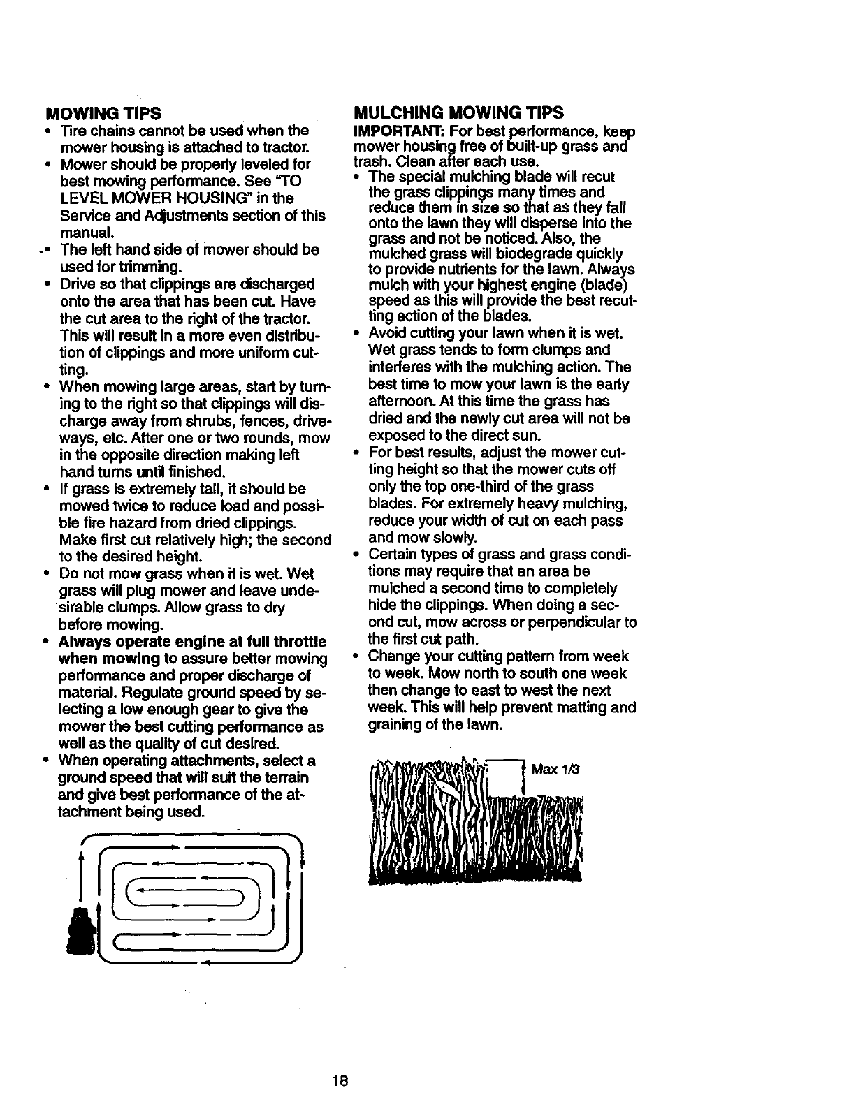
MOWING TIPS
• Tirechainscannotbeusedwhenthe
mowerhousingis attachedto tractor.
•Mower should be properly leveled for
best mowing performance. See "TO
LEVEL MOWER HOUSING" in the
Service and Adjustments section of this
manual.
-= The left hand side of mower should be
used for trimming.
•Ddve so that clippings are discharged
onto the area that has been cut. Have
the cut area to the right of the tractor.
This will result in a more even distribu-
tion of clippings and more uniform cut-
ting.
•When mowing large areas, start by turn-
ing to the right so that clippings will dis-
charge away from shrubs, fences, drive-
ways, etc. After one or two rounds, mow
in the opposite direction making left
hand turns until finished.
•If grass is extremely tall, it should be
mowed twice to reduce load and possi-
ble fire hazard from dried clippings.
Make first cut relatively high; the second
to the desired height.
•Do not mow grass when it is wet. Wet
grass will plug mower and leave unde-
sirable clumps. Allow grass to dry
before mowing.
•Always operate engine at full throttle
when mowing to assure better mowing
performance and proper discharge of
matedal. Regulate ground speed by se-
lecting a low enough gear to give the
mower the best cutting performance as
well as the quality of cut desired°
•When operating attachments, select a
ground speed that will suit the terrain
and give best performance of the at-
tachment being used.
f
1J
MULCHING MOWING TIPS
IMPORTANT: For best performance, keep
mower housing free of built-up grass and
trash. Clean after each use.
•The special mulching blade will recut
the grass clippin_s many times and
reduce them in size so that as they fall
onto the lawn they will disperse into the
grass and not be noticed. Also, the
mulched grass will biodegrade quickly
to provide nutrients for the lawn. Always
mulch with your highest engine (blade)
speed as this will provide the best recut-
ting action of the blades.
•Avoid cuffing your lawn when it is wet.
Wet grass tends to form clumps and
interferes with the mulching action. The
best time to mow your lawn is the eady
aftemoon. At this time the grass has
dried and the newly cut area will not be
exposed to the direct sun.
•For best results, adjust the mower cut-
ting height so that the mower cuts off
only the top one-third of the grass
blades. For extremely heavy mulching,
reduce your width of cut on each pass
and mow slowly.
•Certain types of grass and grass condi-
tions may require that an area be
mulched asecond time to completely
hide the clippings. When doing a sec-
ond cut, mow across or perpendicular to
the first cut path.
•Change your cutting pattem from week
to week. Mow north to south one week
then change to east to west the next
week. This will help prevent matting and
graining of the lawn.
18
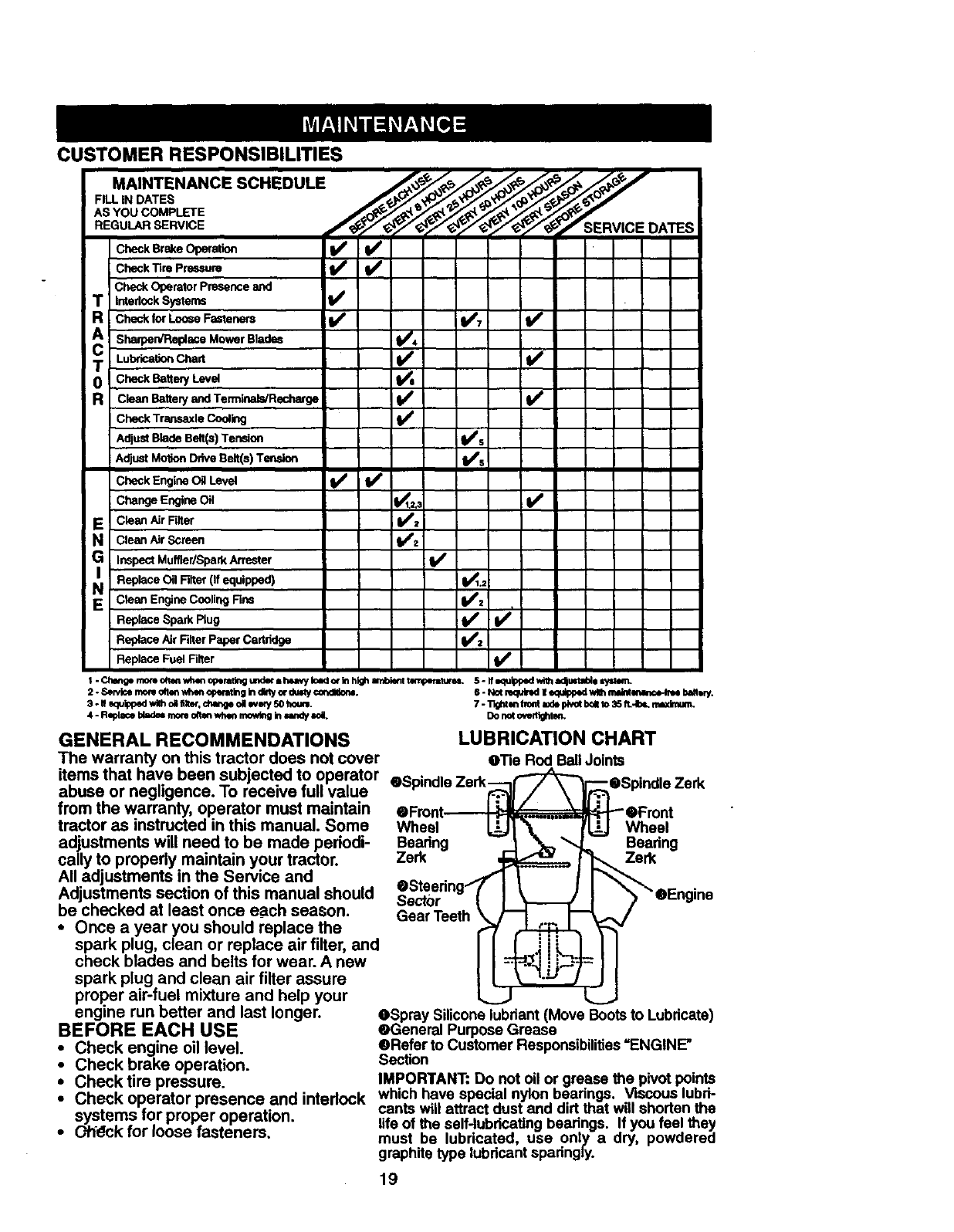
CUSTOMER RESPONSIBILITIES
.A,.T .A.CESC"EOUL
FILL iN DATES _e_'_'_. _'_r'_. o_ _,€_'_,d_"l_ .Yo,_
,eYou o.p E _SERVICE DATES
REGULAR SERVICE aS- _p_,/ _-,r:/_,_ _.4_/,_
Check Brake Operation
Check Tira Pra_sure _ _
Check Operator Presence and
T Interlock Systems I_'
R CheckforLooseFasteners V' 1_7 ll/
CAS_n_,_.o., elad_ i"
TLubdcalionChart
0 Check BatteryLevel
R Cleon Batteryand Terminels/Recharge t/#
Check Tronsaxle Cooling I_ /
Adjust Blade Belt(s) Tension kl's
Adjust MolJonDrive BeER(s)Tension II_s
Check Engine Oil Level I_ I/'
ChangeE,_r_Oil _,_ V'
E CleanAir RERer t,_/_;
N Clean Air Screen t/
G Inspect Muffler/Spark Attester
Replace Oil RERef(If equipped) li_l.:
EN Clean Engine Cooling Fins v',
Replace Spark Plug I_ i/
v',
Replace Air Filter Paper Cartridge
Replace Fuel Filter ll_
I - Chenge mo_ o_en w4_moperatingunderi heavy loadof _'1highambienttemp. 5 - ff equippedw_hadjustabklsyslem.
2 - Servicen_ oilen whenopecatlngIn dittyor"dm4y¢_litkx_. 6 - Not I_lnKI | equipped'_'1 nl_lleniltce-lnle bldt_y.
3. #equippedwllh oi Ill.r, d_nge ol i_y 50 hour. 7 -"nlinten boer a_depb_ b_ to 35 ft..Ixk n_mm_.
4 - Rq_e blad_ mo_ o_en when mow_o in_ndy _i. Do r_ o_mghte_
GENERAL RECOMMENDATIONS LUBRICATION CHART
The warranty on this tractor does not cover eTie Rod Ball Joints
items that have been subjected to operator eSpindle Zerk------I _ _eSpindle Zerk
abuse or negligence. To receive full value I.'1
from the warranty, operator must maintain eFront-------{-_ ._=,=,=,=,=,=,=,i__eFmnt
tractor as instructed in this manual. Some Wheel _ _ rw Wheel
adjustments will need to be made periodi- Bearing __ Bearing
cally to properly maintain your tractor. Zerk _-,,_ Zerk
All adjustments in the Service and eSteering-_' __ _ I"_"
Adjustments section of this manual should Sector |eEngine
%
Gear Teeth \
:
be checked at least once each season.
• Once a year you should replace the
spark plug, clean or replace air filter, and
check blades and belts for wear. A new
spark plug and clean air filter assure
proper air-fuel mixture and help your
engine run better and last longer.
BEFORE EACH USE
-4 k--
•Check engine oil level.
Check brake operation.
OSprey Silicone lubriant (Move Boots to Lubricats)
eGeneral Purpose Grease
@Refer to Customer Responsibilities=ENGINE"
Section
iCheck tire pressure. IMPORTANT: Do not oil or grease the pivot points
Check operator presence and intedock which have special nylon bearings. Viscous lubd-
systems for proper operation, cants will attract dust and dirt that will shorten the
life of the self-lubricating bearings. If you feel they
C_-dck for loose fasteners, must be lubricated, use only a dry, powdered
graphite type lubricant sparingly.
19
TRACTOR
Always observe safety rules when per-
forming any maintenance.
BRAKE OPERATION
If tractor requires more than six (6) feet
stopping distance at high speed in highest
gear, then brake must be adjusted. (See
"TO ADJUST BRAKE" in the Service and
. Adjustments section of this manual).
TIRES
• Maintain proper air pressure in all tires
(See "PRODUCT SPECIFICATIONS"
on page 5of this manual).
•Keep tires free of gasoline, oil, or insect
control chemicals which can harm rub-
ber.
•Avoid stumps, stones, deep ruts, sharp
objects and other hazards that may
cause tire damage.
NOTE: To seal tire punctures and prevent
flat tires due to slow leaks, tire sealant
may be purchased from your local parts
dealer. Tire sealant also prevents tire dry
rot and corrosion.
OPERATOR PRESENCE SYSTEM
Be sure operator presence and interlock
systems are working properly. If your trac-
tor does not function as described below,
repair the problem immediately.
•The engine should not start unless the
clutch/brake pedal is fully depressed
and attachment clutch control is in the
disengaged position.
•When the engine is running, any
attempt by the operator to leave the
seat withoutfirst setting the parking
brake should shut off the engine.
•When the engine is running and the
attachment clutch is engaged, any
attempt by the operator to leave the
seat should shut off the engine.
•The attachment clutch should never
operate unless the operator is in the
seat.
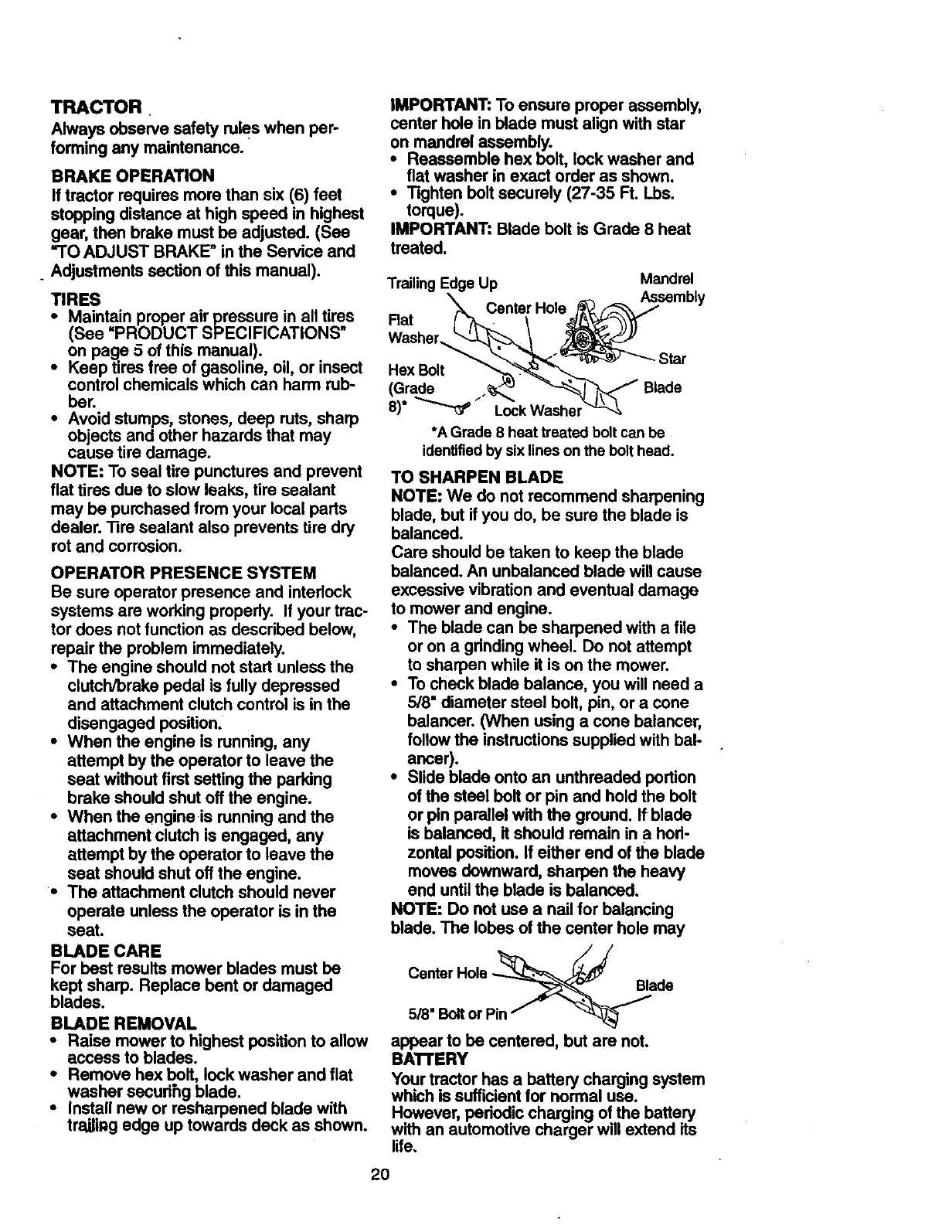
BLADE CARE
For best results mower blades must be
kept sharp. Replace bent or damaged
blades,
BLADE REMOVAL
• Raise mower to highest position to allow
access to blades.
•Remove hex belt, lock washer and flat
washer secudhg blade.
•Install new or resharpened blade with
trailing edge up towards deck as shown.
IMPORTANT: To ensure proper assembly,
center hole in blade must align with star
on mandrel assembly.
•Reassemble hex bolt, lock washer and
flat washer in exact order as shown.
•Tighten bolt securely (27-35 Ft. Lbs.
torque).
IMPORTANT: Blade bolt is Grade 8 heat
treated.
Trailing Edge Up Mandrel
Center Hok Assembly
Rat
Washer,
Star
*A Grade 8 heat treated bolt can be
identified by six lines on the bolt head.
TO SHARPEN BLADE
NOTE: We do not recommend sharpening
blade, but if you do, be sure the blade is
balanced.
Care should be taken to keep the blade
balanced. An unbalanced blade will cause
excessive vibration and eventual damage
to mower and engine.
•The blade can be sharpened with a file
or on a gdnding wheel. Do not attempt
to sharpen while it is on the mower.
•To check blade balance, you will need a
5/8" diameter steel bolt, pin, or acone
balancer. (When using a cone balancer,
follow the instructions supplied with bal-
ancer).
•Slide blade onto an unthreaded portion
of the steel bolt or pin and hold the bolt
or pin parallel with the ground, if blade
is balanced, it should remain in a hod-
zontal position. If either end of the blade
moves downward, sharpen the heavy
end until the blade is balanced.
NOTE: Do not use a nail for balancing
blade. The lobes of the center hole may
Blade
5/8" Bolt or Pin
appear to be centered, but are not.
BA'n'ERY
Your tractor has a battery charging system
wh=ch is sufficient for normal use.
However, pedodic charging of the battery
with an automotive charger will extend its
life.
20
*Keep battery and terminals clean.
Keep battery bolts tight.
Keep small vent holes open.
Recharge at 6-10 amperes for 1 hour.
TO CLEAN BATrERYAND TERMINALS
Corrosion and dirt on the battery and ter-
minals can cause the battery to =leak"
power.
•Remove terminal guard.
•Disconnect BLACK battery cable first
then RED battery cable and remove
battery from tractor.
•Rinse the battery with plain water and
dry.
•Clean terminals and battery cable ends
with wire brush until bright.
•Coat terminals with grease or petroleum
jelly.
•Reinstall battery (See =REPLACING
BATTERY" in the SERVICE AND
ADJUSTMENTS section of this manu-
al).
V-BELTS
Check V-belts for deterioration and wear
after 100 hours of operation and replace if
necessary. The belts are not adjustable.
Replace belts if they begin to slip from
wear.
TRANSAXLE COOLING
The transmission fan and cooling fins
should be kept clean to assure proper
cooling.
Do not attempt to clean fan or transmis-
sion while engine is running or while the
transmission is hot.
•Inspect cooling fan to be sure fan
blades are intact and clean.
•Inspect cooling fins for dirt, grass clip-
pings and other materials. To prevent
damage to seals, do not use com-
pressed air or high pressure sprayer to
clean cooling fins.
TRANSAXLE PUMP FLUID
The transaxle was sealed at the factory
and fluid maintenance is not required for
the life of the transaxle. Should the
transaxle ever leak or require servicing,
contact your nearest authorized service
center/department.
ENGINE
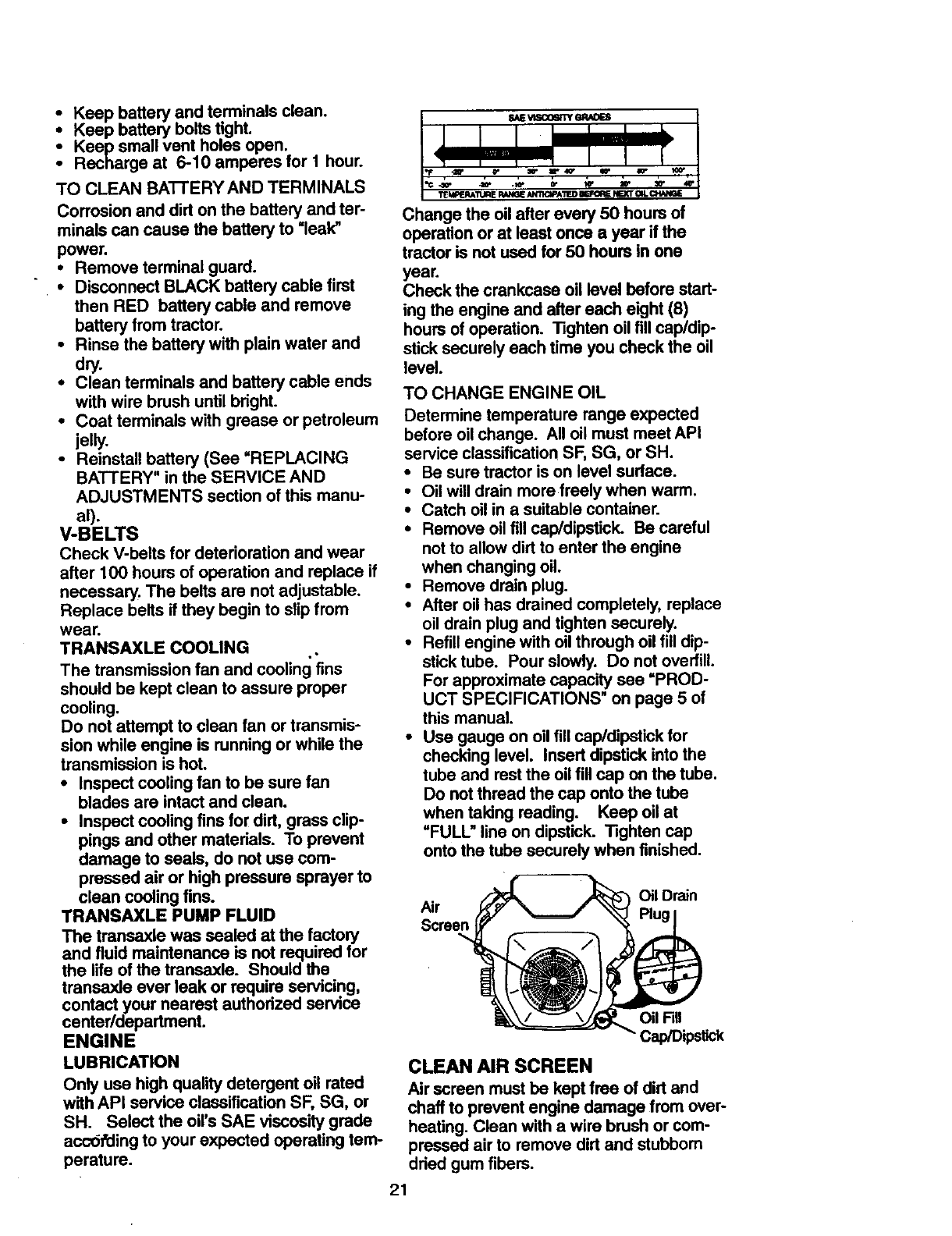
LUBRICATION
Only use high quality detergent oil rated
with API service classification SF, SG, or
SH. Select the oil's SAE viscosity grade
according to your expected operating tam-
perature.
T[MFF.RA'PJRE RkW_ ANTICIPA_T_D8_ORE NEXT_t. C_kN_E
Change the oil after avery 50 hours of
operation or at least once ayear if the
tractor is not used for 50 hours in one
year.
Check the crankcase oil level before start-
ing the engine and after each eight (8)
hours of operation. Tighten oil fill cap/dip-
stick securely each time you check the oil
level.
TO CHANGE ENGINE OIL
Determine temperature range expected
before oil change. All oil must meet API
service classification SF, SG, or SH.
•Be sure tractor is on level surface.
•Oil will drain more freely when warm.
•Catch oil in a suitable container.
•Remove oil fill cap/dipstick. Be careful
not to allow dirt to enter the engine
when changing oil.
•Remove drain plug.
•After oil has drained completely, replace
oil drain plug and tighten securely.
•Refill engine with oil through oil fill dip-
stick tube. Pour slowly• Do not overfill.
For approximate capacity see =PROD-
UCT SPECIFICATIONS" on page 5 of
this manual.
•Use gauge on oil fill cap/dipstick for
checking level. Insert dipstick into the
tube and rest the oil fill cap on the tube.
Do not thread the cap onto the tube
when taking reading. Keep oil at
=FULL" line on dipstick. Tighten cap
onto the tube securely when finished.
Air
Screen
Oil Drain
Oil Fill
Cap/Dipstick
CLEAN AIR SCREEN
Air screen must be kept free of dirt and
chaff to prevent engine damage from over-
heating. Clean with a wire brush or com-
pressed air to remove dirt and stubborn
dried gum fibers.
21
CLEAN AIR INTAKE/COOLING AREAS
To insure proper cooling, make sure the
grass screen, coolingfins, and other
extemal surfaces of the engine are kept
clean at all times.
Every 100 hours of operation (more often
under extremely dusty,dirty conditions),
remove the blower housing and other
. cooling shrouds. Clean the cooling fins
and external surfaces as necessary. Make
sure the coolingshrouds are reinstalled.
NOTE: Operating the engine with a
blocked grass screen, dirtyor plugged
coolingfins, and/or coolingshrouds re-
moved will cause engine damage due to
overheating.
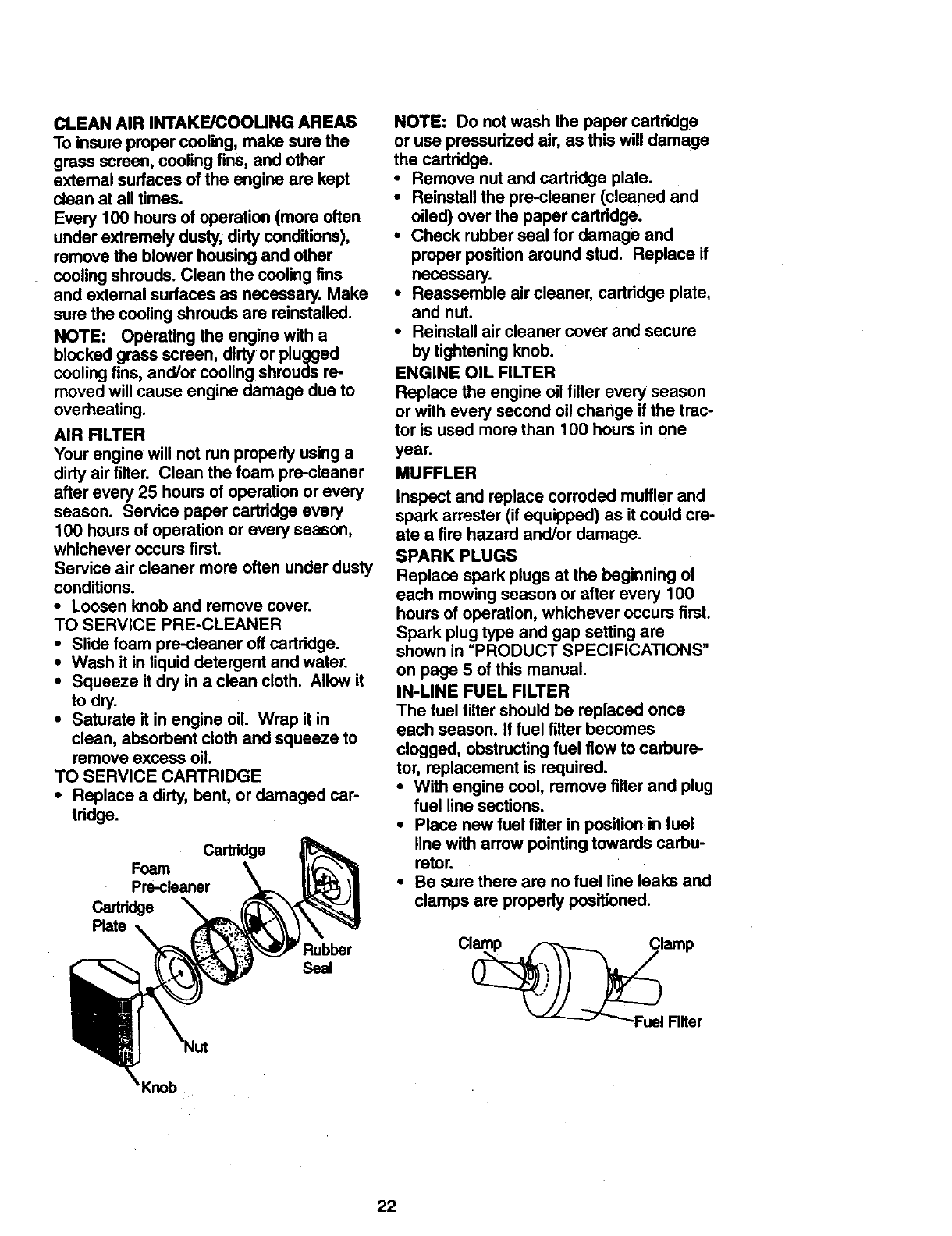
AIR FILTER
Your engine will not run pmpedy using a
dirty air filter. Clean the foam pre-cleaner
after every 25 hours of operation or every
season. Service paper cartridge every
100 hours of operation or every season,
whichever occurs first.
Service air cleaner more often under dusty
conditions.
•Loosen knob and remove cover.
TO SERVICE PRE-CLEANER
•Slide foam pre-cleaner off cadridge.
•Wash it in liquid detergent and water.
•Squeeze it dry in a clean cloth. Allow it
to dry.
•Saturate it in engine oil. Wrap it in
clean, absorbent cloth and squeeze to
remove excess oil.
TO SERVICE CARTRIDGE
•Replace a dirty, bent, or damaged car-
tridge.
Cartridge
Foam
Pre-cleaner
Cartridge
Plate
Rubber
Seal
NOTE: Do notwash the paper cartridge
or use pressurized air, as this will damage
the cadddge.
•Remove nut and cartddge plate.
•Reinstall the pre-cleaner (cleaned and
oiled) over the paper cartddge.
•Check rubber seal for damage and
proper positionaround stud. Replace if
necessary.
• Reassemble air cleaner, cartridge plate,
and nut.
•Reinstall air cleaner cover and secure
by tightening knob.
ENGINE OIL FILTER
Replace the engine oilfilter every season
or with every second oil change if the trac-
tor is used more than 100 hours in one
year.
MUFFLER
Inspect and replace corroded muffler and
spark arrester (ifequipped) as it could cre-
ate a fire hazard and/or damage.
SPARK PLUGS
Replace spark plugs at the beginning of
each mowing season or after every 100
hours of operation, whichever occurs first.
Spark plug type and gap setting are
shown in "PRODUCT SPECIFICATIONS"
on page 5 ofthis manual.
IN-LINE FUEL FILTER
The fuel filter should be replaced once
each season. If fuel filter becomes
clogged, obstructingfuel flow to carbure-
tor, replacement is required.
•With engine cool, remove filter and plug
fuel line sections.
•Place new fuel filter in position in fuel
line with arrow pointing towards carbu-
retor.
•Be sure there are no fuel line leaks and
clamps are properly positioned.
22
CLEANING
Clean engine, battery, seat, finish, etc.
iof all matter.
foreign
Keep finished surfaces and wheels free
of all gasoline, oil, etc.
•Protect painted surfaces with automo-
tive type wax.
We do not recommend using a garden
hose to clean your tractor unless the elec-
trical system, muffler, air filter and carbure-
tor are covered to keep water out. Water
in engine can result in a shortened engine
life.
_.CAUTION: Before performing any service or adjustments:
•Depress clutch/brake pedal fully and set parking brake.
•Place motion control lever in neutral (N) position.
•Place attachment clutch in "DISENGAGED" position.
Turn ignitionkey =OFP and remove key.
Make sure the blades and all moving parts have completely stopped.
Disconnect spark plug wire from spark plug and place wire where it cannot come
in contact with plug.
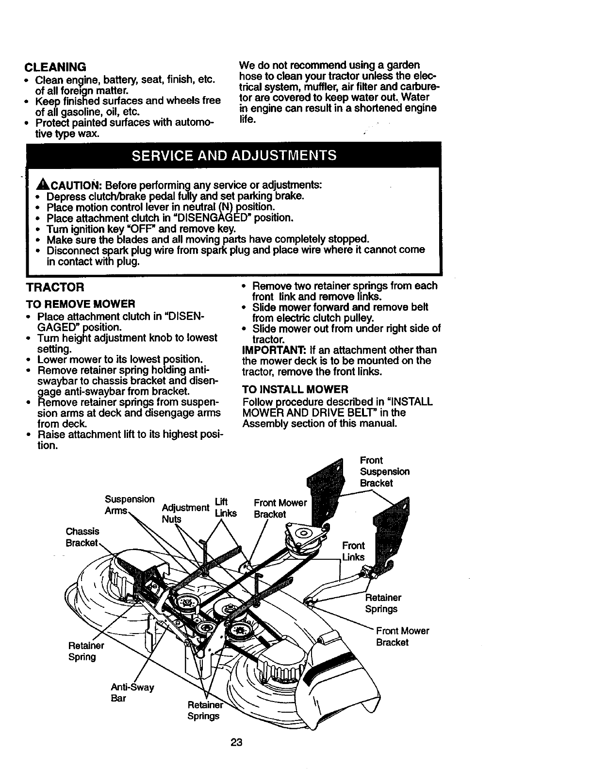
TRACTOR
TO REMOVE MOWER
•Place attachment clutch in =DISEN-
GAGED" position.
•Turn height adjustment knob to lowest
setting.
•Lower mower to its lowest position.
•Remove retainer spring holding anti-
swaybar to chassis bracket and disen-
gage anti-swaybar from bracket.
•Remove retainer springs from suspen-
sion arms at deck and disengage arms
from deck.
•Raise attachment lift to its highest posi-
tion.
Chassis
Suspension Adjustment
Nuts
Lift
Unks
• Remove two retainer spdngs from each
front link and remove links.
•Slide mower forward and remove belt
from electric clutch pulley.
•Slide mower out from under right side of
tractor.
IMPORTANT: If an attachment other than
the mower deck is to be mounted on the
tractor, remove the front links.
TO INSTALL MOWER
Follow procedure described in =INSTALL
MOWER AND DRIVE BELT" in the
Assembly section of this manual.
Front Mowei
Bracket
Front
Suspension
Bracket
Retainer
Springs
Retainer
Spring
Bracket
Anti-Sway
Bar
Springs
23
TO LEVELMOWERHOUSING
Adjustthemowerwhiletractoris parked
onlevelgroundor driveway.Makesure
tiresarepropedyinflated(See=PROD-
UCT SPECIFICATIONS'). If tires are
over or undednflated, you will not propedy
adjust your mower.
SIDE-TO-SIDE ADJUSTMENT
:Raise mower to its highest position.
.Measure height frombottom of deck
curl to ground level at front corners of
mower. Distance =A" on both sides of
mower should be the same.
•If adjustment is necessary, make adjust-
ment on one side of mower only.
•To raise one side of mower, tighten lift
link adjustment nut on that side.
•To lower one side of mower, loosen lift
link adjustment nut on that side.
NOTE: Each full turn of adjustment nut
will change mower height about 3/16".
•Recheck measurements after adjusting.
Bottom
oBf¢_° dm_f Curl
A
Suspension
Arm
LiftLink Adjustment Nut
FRONT-TO-BACK ADJUSTMENT
IMPORTANT: Deck must be level side-to-
side. If the following front-to-back adjust-
ment is necessary, be sure to adjust both
front links equally so mower will stay level
side-to-side.
To obtain the best cutting results, the
mower housing should be adjusted so the
front is approximately 1/8" to 1/2" lower
than the rear when the mower is in its
highest position.
Check adjustment on d_ht side of tractor.
Measure distance =P directly in front of
and behind the mandrel at bottom edge of
mower housing as shown.
•Before making any necessary adjust-
ments, check that both front links are
equal in length.
•If links are not equal in length, adjust
one link to same length as other link.
•To lower front of mower housing, loosen
nut =G" on both front links an equal
number of tums.
•When distance "P is 1/8" to 1/2" lower
at front than rear, tighten nut =H" against
trunnion on both front links.
•To raise front of mower housing, loosen
nut H from trunnion on both front links.
"13ghtennut "G" on both front links an
equal number of tums.
•When distance =P is 1/8" to 1/2" lower
at front than rear, tighten nut "H"
against trunnion on both front links.
NOTE: Each full tum of nut "G" will
change dim. =P by approximately 3/8".
•Recheck side-to-side adjustment.
24
Mandrel
Both Fron__,= =' Length
Nut =H"-__
Unks _
TO REPLACE MOWER DRIVE BELT
MOWER DRIVE BELT REMOVAL
•Park tractor on a level surface. Engage
parking brake.
•Remove screws from left hand mandrel
cover and remove cover.
•Roll belt over the top of left hand man-
drel pulley.
•Remove belt from electdc clutch pulley.
•Remove belt from idler pulleys.
•Remove any dirt or grass clippings
which may have accumulated around
mandrels and entire upper deck sur-
face.
• Check pdmary idler arm and two idlers
to see that they rotate freely.
• Be sure spdng is securely hooked to pd-
mary idler arm and bolt in mower hous-
ing.
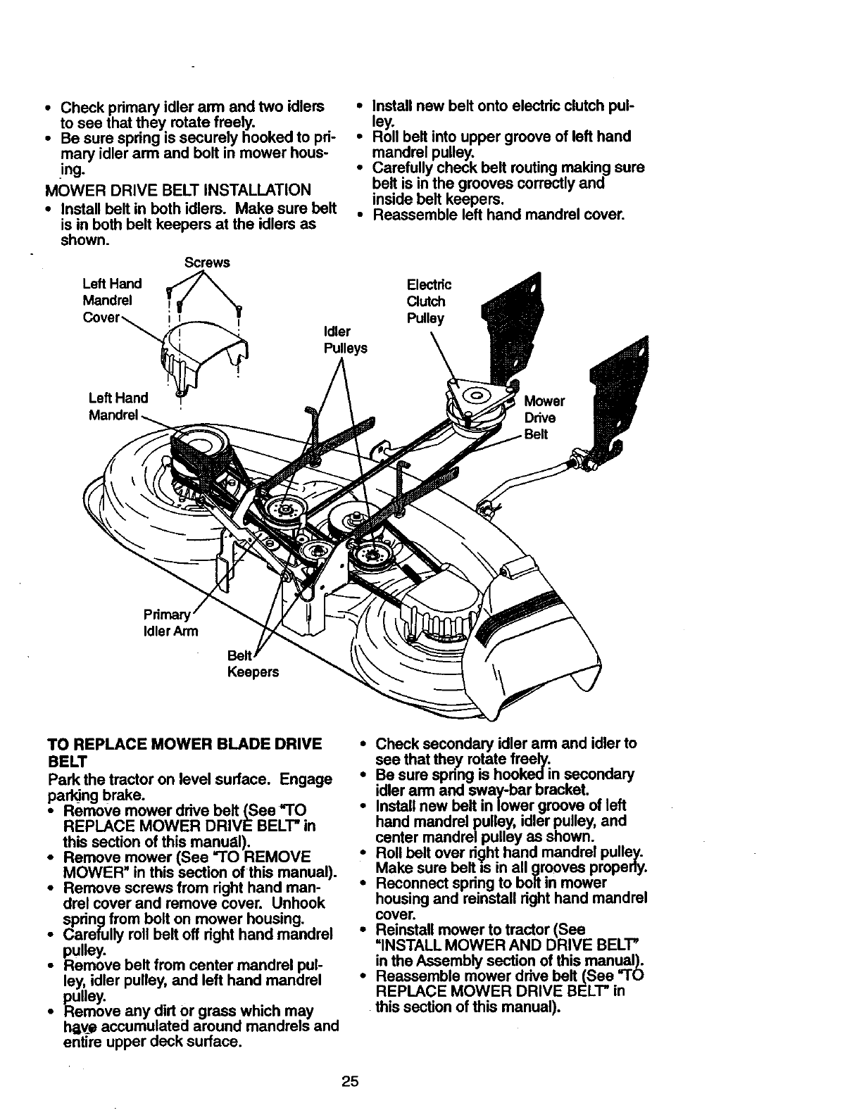
Check primary idler arm and two idlers
_to that rotate freely.
they
see
Be sure spring is securely hooked to pri-
mary idler arm and bolt in mower hous-
ing.
MOWER DRIVE BELT INSTALLATION
•Install belt in both idlers. Make sure belt
is in both belt keepers at the idlers as
shown.
Screws
Left Hand
Mandrel
•Install new belt onto electric clutch pul-
• _il belt into upper groove of left hand
mandrel pulley.
•Carefully check belt routing making sure
belt is in the grooves correctly and
inside belt keepers.
•Reassemble left hand mandrel cover.
Electdc
Clutch
Pulley
Idler
Pulleys
Pdmary
Idler Arm
Keepers
TO REPLACE MOWER BLADE DRIVE
BELT
Park the tractor on level surface. Engage
parking brake.
•Remove mower drive belt (See "TO
REPLACE MOWER DRIVE BELT" in
this section of this manu_ll).
•Remove mower (See "TO REMOVE
MOWER" in this section of this manual).
•Remove screws from right hand man-
drel cover and remove cover. Unhook
springfrom bolt on mower housing.
•Carefully roll belt off right hand mandrel
pulley.
•Remove belt from center mandrel pul-
ley, idler pulley, and left hand mandrel
pulley.
•Remove any dirt or grass which may
hav=eaccumulated around mandrels and
entire upper deck surface.
•Check secondary idler arm and idler to
see that they rotate freely.
•Be sure spnng is hooked in secondary
idler arm and sway-bar bracket.
•Install new belt in lower groove of left
hand mandrel pulley, idler pulley, and
center mandrel pulley as shown.
Roll belt over right hand mandrel pulley.
iMake sure ,s grooves properly.
belt in all
Reconnect spring to bolt in mower
housing and reinstall right hand mandrel
cover.
•Reinstall mower to tractor (See
=INSTALL MOWER AND DRIVE BELT"
in the Assembly section of this manual).
•Reassemble mower drive belt(See "TO
REPLACE MOWER DRIVE BELT" in
this section of this manual).
25
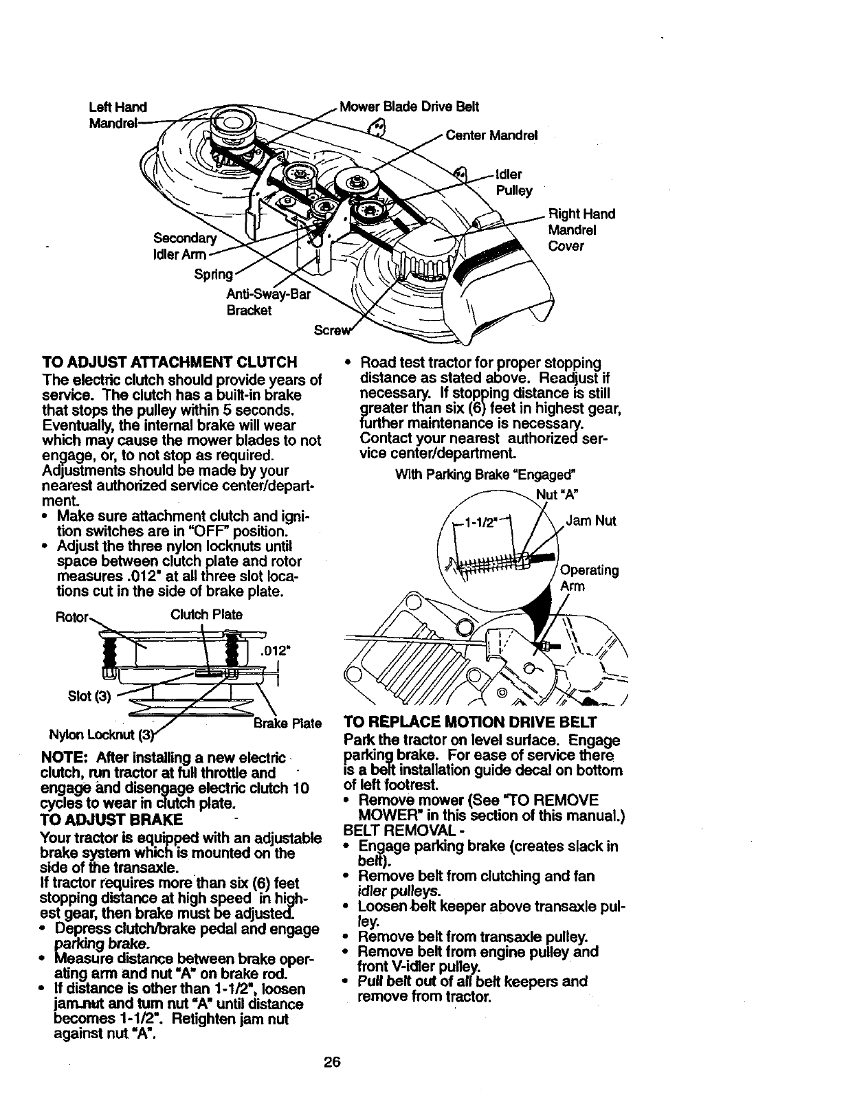
Left Hand Blade Drive Belt
/landrel
IdlerArm
S
Pulley
Right Hand
Mandrel
Cover
Bracket
TO ADJUST ATTACHMENT CLUTCH
The electdc clutch should provide years of
service. The clutch has a built-in brake
that stops the pulley within 5 seconds.
Eventually, the internal brake will wear
which may cause the mower blades to not
engage or, to not stop as required.
Adjustments shou d be made by your
•Road test tractor for proper stopping
distance as stated above. Readjust if
necessary. If .stopping distance is still
greater than six (6) feet in highest gear,
further mamtenance is necessary.
Contact your nearest authorized ser-
vice canter/department.
With Parking Brake "Engaged'
nearest authorized service center/depart- F_'------_ Nut "A"
merit.
•Make sure attachment clutch end igni- (_1,._/"-1"1/2"_ / _,Jam Nut
tion switches are in =OFF" position.
•Adjust the three nylon Iocknuts until
space between clutch plate and rotor \_'_'_:_-_-_ /Operating
Rotor.,.__measures.012" at all th.ree slot Ioca- _A_ z_mh
tions cut in the side of brake plate.
Clutch Plate
_=_r_ol 2.
"y" P,a,,TOR=P CEMOT,ONDRIVE.ELT
Nyton Park the tractor on level surface. Engage
NOTE: After installing a new electric paddngbrake. For ease of service there
is abelt installation guide decal on bottom
clutch, run tractor at full throttle and
engage _nd di.se.ngega electric clutch 10
cycles to wear m clutch plate.
TO ADJUST BRAKE
Your tractor is equipped with an adjustable
brake system which is mounted on the
side of the transaxle.
If tractor requires more than six (6) feet
stopping distance at high speed in high-
est gear, then brake must be adjusted.
•Depress clutclVlorake pedal end engage
parking brake. . .
•Measure distarme t)etween OraKe oper-
ating arm and nut A" on brake rod.
• If distance is other than 1-1/2", loosen
jam.rod end turn nut "A" until distance
becomes 1-1/2". Retighten iam nut
against nut =A'.
of left footrest.
• Remove mower (See _'O REMOVE
MOWER" in this section of this manual.)
BELT REMOVAL -
•Engage parking brake (creates slack in
belt).
•Remove belt from clutching and fan
idler pulleys.
•Loosen t_elt keeper above transaxle pul-
ley.
: Remove belt from trensayJe pulley.
Remove belt from engine pulley and
front V-idler pulley.
•Pull belt out of all belt keepers and
remove from tractor.
26
BELT INSTALLATION o
• Place V part of belt intogrooves on
engine pulley and front V-idler, making
sure to route belt inside of all belt keep-
ers.
•Route belt on right side, coming from V-
idler, towards back of tractor, above
midspan belt keeper and to top of
transaxle pulley.
•Route belt on left side, coming from
engine pulley, towards back of tractor
and through loop in midspan belt keep-
er.
• Place V part of belt into grooves on
transaxle and fan idler pulleys, making
sure to route belt inside of all belt keep-
ers.
•Retighten belt keeper above transaxle
pulley.
•Place belt around clutching idlers as
shown, making sure to route belt inside
of all belt keepers.
•Check to be sure belt is positioned cor-
rectly and is on proper side of all belt
keepers.
•Reinstall mower.
IMPORTANT: Chock brake adjustment.
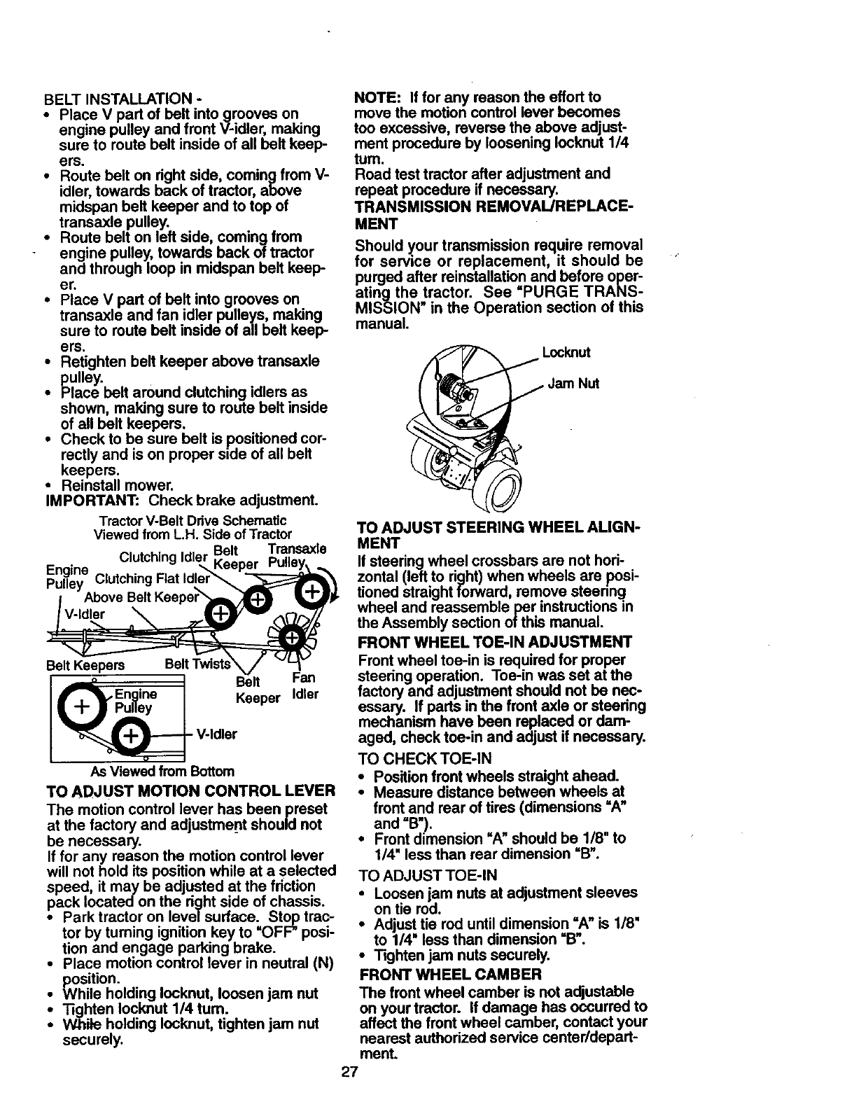
Tractor V-Belt Drive Schematic
Viewed frorn L.H. Side of Tractor
•Belt Transaxle
Clutching Idler Keeper
Engine Clutching Rat Idler"_
Pulley
Belt Keepers JBelt Fan
_Engine | Keeper Idler
_V-Idler
AsViewedfromBottom
TO ADJUST MOTION CONTROL LEVER
The motion control lever has been preset
st the factory and adjustment should not
be necessary.
If for any reason the motion control lever
will not hold its position while at a selected
speed, it may be adjusted at the friction
pack located on the right side of chassis.
•Park tractor on level surface. Stop trac-
tor by turning ignition key to =OFF" posi-
tion and engage parking brake•
•Place motion control lever in neutral (N)
position•
•While holding Iocknut, loosen jam nut
Tighten Iocknut 1/4 turn.
While holding Iocknut, tighten jam nut
securely.
NOTE: If for any reason the effort to
move the motion control lever becomes
too excessive, reverse the above adjust-
ment procedure by loosening Iocknut 114
tlJm.
Road test tractor after adjustment and
repeat procedure if necessary.
TRANSMISSION REMOVAL/REPLACE-
MENT
Should y.ourtransmission require removal
for service or replacement, it should be
purged after reinstallation and before oper-
atingthe tractor. See =PURGE TRANS-
MISSION _in the Operation section of this
manual.
Locknut
TO ADJUST STEERING WHEEL ALIGN-
MENT
If steering wheel crossbars are not hori-
zontal (left to right) when wheels are posi-
tioned straight forward, remove steering
wheel and reassemble pe r instructions in
the Assembly section of this manual•
FRONT WHEEL TOE-IN ADJUSTMENT
Frontwheel toe-in is required for proper
steering operation. Toe-in was set at the
factory and adjustment should not be nec-
essary. If parts in the front axle or steering
mechanism have been replaced or dam-
aged, check toe-in and adjust if necessary.
TO CHECK TOE-IN
•Positionfront wheels straightahead.
•Measure distance between wheels at
front and rear of tires (dimensions =An
and =B').
•Front dimension =A_ should be 1/8" to
1/4" leas than rear dimension =B_.
TO ADJUST TOE-IN
•Loosen jam nuts at adjustment sleeves
on tie rod.
•Adjust tie rod untildimension =A" is 1/8"
to 1/4" less than dimension =B".
•Tighten jam nuts securely.
FRONT WHEEL CAMBER
The front wheel camber is not adjustable
on your tractor. If damage has occurred to
affect the front wheel camber, contact your
nearest authorized service center/depart-
ment.
27
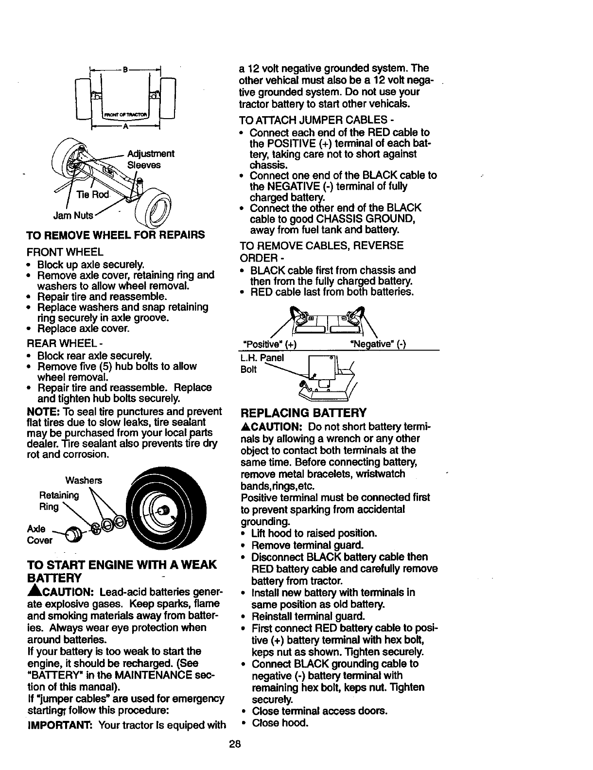
Sleeves
Jam Nuts.
TO REMOVE WHEEL FOR REPAIRS
FRONT WHEEL
•Block up axle securely.
•Remove axle cover, retaining ringand
washers to allow wheel removal
•Repair tire and reassemble.
•Replace washers and snap retaining
ring securely in axle groove.
•Replace axle cover.
REAR WHEEL -
•Block rear axle securely.
•Remove five (5) hub bolts to allow
wheel removal.
•Repair tire and reassemble. Replace
and tighten hub bolts securely.
NOTE; To seal tire punctures and prevent
flat tires due to slow leaks, tire sealant
may be purchased from your local parts
dealer. Tire sealant also prevents tire dry
rot and corrosion.
Washers
Retaining _ f_r_'_i,
TO START ENGINE WITH A WEAK
BATTERY
ACAUTION: Lead-acid batteries gener-
ate explosive gases. Keep sparks, flame
and smoking materials away from batter-
ies. Always wear eye protection when
around battedes.
If your battery is too weak to start the
engine, it should be recharged. (See
"BA'I-I'ERY" in the MAINTENANCE sec-
tion of this manoal).
If "jumper cables" are used for emergency
starting? follow this procedure:
IMPORTANT: Your tractor Is equiped with
a 12 volt negative grounded system. The
other vehical must also be a 12 volt nega-
tive grounded system. Do not use your
tractor battery to start other vehicals.
TO ATTACH JUMPER CABLES -
•Connect each end of the RED cable to
the POSITIVE (+) terminal of each bat-
tery, taking care not to short against
chassis.
•Connect one end of the BLACK cable to
the NEGATIVE (-) terminal of fully
charged battery.
•Connect the other end of the BLACK
cable to good CHASSIS GROUND,
away from fuel tank and battery.
TO REMOVE CABLES, REVERSE
ORDER -
•BLACK cable first from chassis and
then from the fully charged battery.
•RED cable last from both batteries.
=Positive" (+) =Negative" (-)
Bolt
REPLACING BA'I-I'ERY
ACAUTION: Do not short battery termi-
nals by allowing awrench or any other
object to contact both terminals at the
same time. Before connecting battery,
remove metal bracelets, wdstwatch
bands, rings,etc.
Positive terminal must be connected first
to prevent sparking from accidental
grounding.
•Lift hood to raised position.
•Remove terminal guard.
•Disconnect BLACK battery cable then
RED battery cable and carefully remove
battery from tractor.
• Install new battery with terminals in
same position as old battery.
• Reinstall terminal guard.
•First connect RED battery cable to posi-
tive (+) battery terminal with hex bolt,
keps nut as shown. Tighten securely.
•Connect BLACK grounding cable to
negative (-) battery terminal with
remaining hex bolt, keps nut. Tighten
securely.
•Close terminal access doors.
•Close hoed.
28
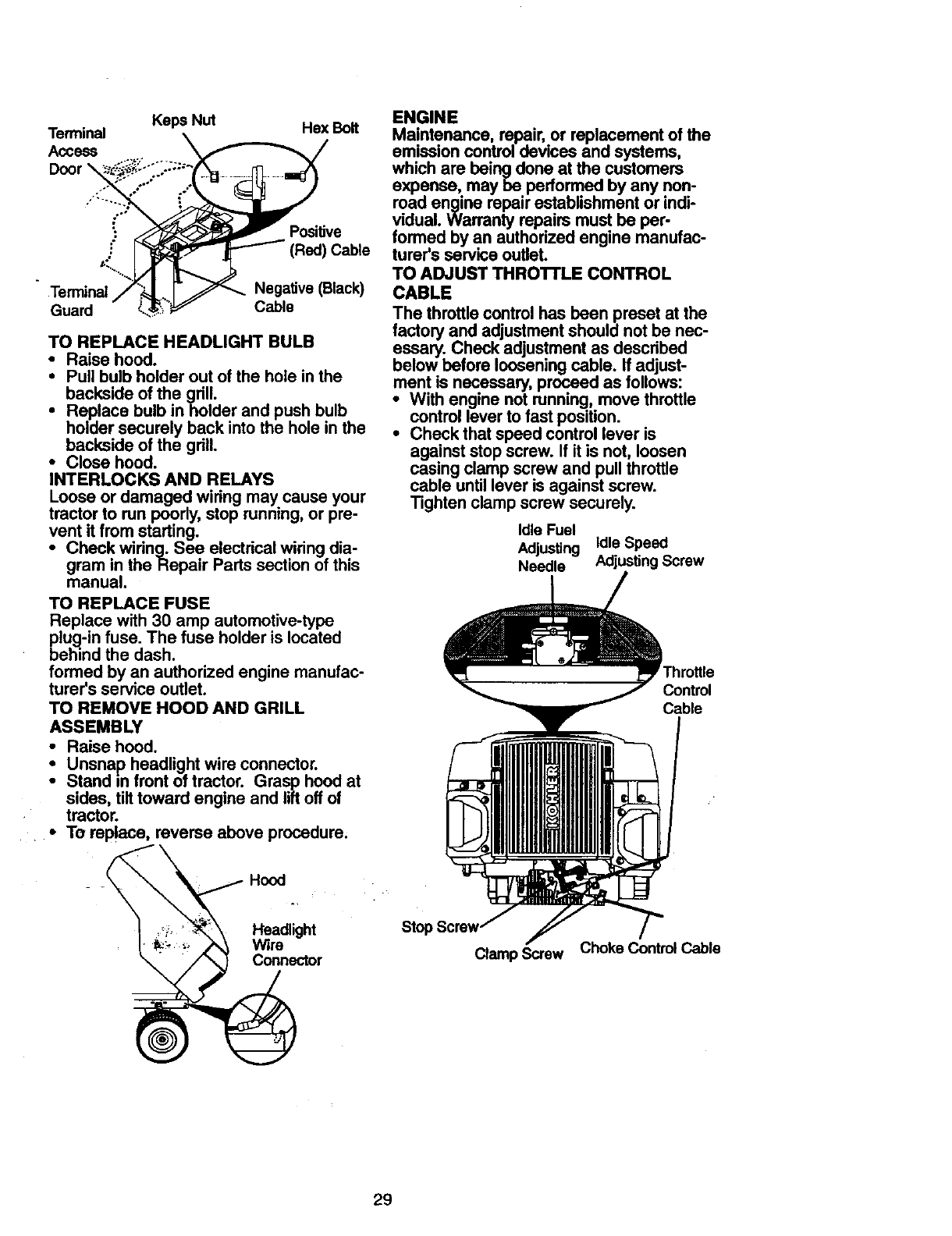
Terminel
Access
Keps Nut Hex Bolt
'. Positive
" Cable
Terminal Negative (Black)
Guard Cable
TO REPLACE HEADLIGHT BULB
•Raise hood.
•Pull bulb holder out of the hole in the
backside of the grill
•Replace bulb inholder and push bulb
holder securely back into the hole in the
backside of the grill.
•Close hood.
INTERLOCKS AND RELAYS
Loose or damaged wiring may cause your
tractor to run poorly, stop running, or pre-
vent it from starting.
•Check wiring. See electrical wiring dia-
gram in theRepair Parts section of this
manual.
TO REPLACE FUSE
Replace with 30 amp automotive-type
plug-in fuse. The fuse holder is located
behind the dash.
formed by an authorized engine manufac-
turar's service outlet.
TO REMOVE HOOD AND GRILL
ASSEMBLY
•Raise hood.
•Unsnap headlight wire connector.
Stand in front of tractor. Grasp hood at
sides, tilt toward engine and lift off of
tractor.
•To replace, reverse above procedure;
ENGINE
Maintenance, repair,or replacement of the
emission control devices and systems,
which are being done at the customers
expense, may be performed by any non-
road engine repair establishment or indi-
vidual. Warranty repairs must be per-
formed by an authorized engine manufac-
turar's service outlet.
TO ADJUST THRO'R'LE CONTROL
CABLE
The throttle control has been preset at the
factory and adjustment should not be nec-
essary. Check adjus!ment as described
below before loosening cable. If adjust-
ment is necessary, proceed as follows:
•With engine not running, move throttle
control lever to fast position.
•Check that speed control lever is
against stop screw. If it is not, loosen
casing clamp screw and pull throttle
cable until lever is against screw.
Tighten clamp screw securely.
Idle Fuel
Adjusting Idle Speed
Needle Adjusting Screw
Control
Cable
Hood
Headlight
Wire
Connector
StOl
Clamp Screw Choke Control Cable
29
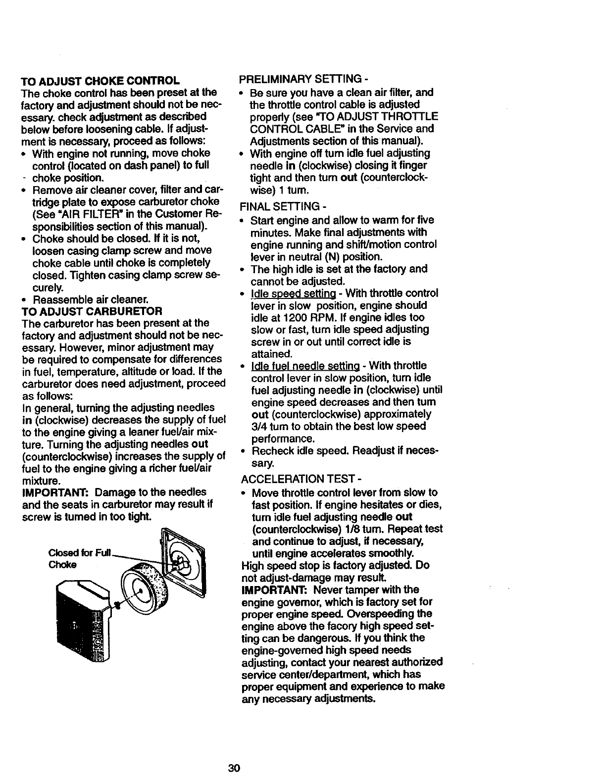
TO ADJUST CHOKE CONTROL
The choke control has been preset at the
factory and adjustment should not be nec-
essary, check adjustment as described
below before loosening cable. If adjust-
ment is necessary, proceed as follows:
• With engine not running, move choke
control (located on dash panel) to full
- choke position.
• Remove air cleaner cover, filterand car-
tridge plate to expose carburetor choke
(See =AIR FILTER" in the Customer Re-
sponsibilitiessection of this manual).
• Choke should be closed. If it isnot,
loosen casing clamp screw and move
choke cable until choke is completely
closed. Tighten casing clamp screw se-
curely.
• Reassemble air cleaner.
TO ADJUST CARBURETOR
The carburetor has been present at the
factory and adjustment should not be nec-
essary. However, minor adjustment may
be required to compensate for differences
in fuel, temperature, altitudeor load. If the
carburetor does need adjustment, proceed
as follows:
In general, tuming the adjusting needles
in (clockwise) decreases the supply of fuel
to the engine giving aleaner fuel/air mix-
ture. Turning the adjusting needles out
(counterclockwise) increases the supply of
fuel to the engine giving a richer fuel/air
mixture.
IMPORTANT: Damage to the needles
and the seats in carburetor may result if
screw is turned intoo tight.
Choke
PRELIMINARY SETTING -
•Be sure you have a clean air filter, and
the throttle control cable is adjusted
properly (see "TO ADJUST THRO'I-ILE
CONTROL CABLE" in the Service and
Adjustments section of this manual).
• With engine off tum idle fuel adjusting
needle in (clockwise) closing it finger
tight and then turn out (counterclock-
wise) 1 tum.
FINAL SETTING -
• Start engine and allow to warm for five
minutes. Make final adjustments with
engine running and shift/motion control
lever in neutral (N) position.
• The high idle is set at the factory and
cannot be adjusted.
•Idle soeed settino - With throttle control
lever in slow position, engine should
idle at 1200 RPM. If engine idles too
slow or fast, turn idle speed adjusting
screw in or out until correct idle is
attained.
•Idle fuel needle settin(] -With throttle
control lever in slow position, tum idle
fuel adjusting needle in (clockwise) until
engine speed decreases and then tum
out (counterclockwise) approximately
3/4 turn to obtain the best low speed
performance.
•Recheck idle speed. Readjust if neces-
sary.
ACCELERATION TEST -
•Move throttle control lever from slow to
fast position. If engine hesitates or dies,
tum idle fuel adjusting needle out
(countemlockwise) 1/8 tum. Repeat test
and continue to adjust, if necessary,
until engine accelerates smoothly.
High speed stop is factory adjusted. Do
not adjust-damage may resulL
IMPORTANT: Never tamper with the
engine governor, which is factory set for
proper engine speed. Overspeeding the
engine above the facory high speed set-
ting can be dangerous. If yo u think the
engine-govemed high speed needs
adjusting, contact your nearest authorized
service center/department, which has
proper equipment and experience to make
any necessary adjustments.
30
Immediately prepare your tractor for stor-
age at the end of the season or if the trac-
tor will not be used for 30 days or more.
AcAUTION: Never store the tractorwith
gasoline in the tank inside a building
where fumes may reach an open flame or
spark. Allow the engine to cool before stor-
ing in any enclosure.
TRACTOR
Remove mower from tractor for winter
storage. This will allow you to clean it thor-
oughly. Remove all dirt, grease, leaves,
etc. Store in a clean, dry area.
• Clean entire tractor (See "CLEANING"
in the Maintenance section of this man-
ual).
•Inspect and replace belts, if necessary
(See belt replacement instructions in the
Service and Adjustments section of this
manual).
•Lubdcate as shown in the Maintenance
section of this manual.
•Be sure that all nuts, bolts and screws
are securely fastened. Inspect moving
parts for damage, breakage and wear.
Replace if necessary.
•Touch up all rusted or chipped paint sur-
faces; sand lightly before painting.
BATTERY
•Fully charge the battery for storage.
•After a period of time in storage, battery
may require recharging.
•To help prevent corrosion and power
leakage dudng long pedods of storage,
battery cables should be disconnected
and battery cleaned thoroughly (see
='1"0 CLEAN BATTERY AND TERMI-
NALS" in the Maintenance section of
thismanual).
•After cleaning, leave cables disconnect-
ed and place cables where they cannot
come in contact with battery terminals.
•If battery is removed from tractor for
storage, do not store battery directly on
concrete or damp surfaces.
ENGINE
FUEL SYSTEM
IMPORTANT: It is important to prevent
gum deposits from forming in essential
fuel system parts such as carburetor, fuel
filter,,_Juelhose, or tank dudng storage.
Also, expodence indicates that alcohol
blended fuels (called gasohol or using
ethanol or methanol) can attract moisture
which leads to separation and formation of
acids during storage. Acidic gas can dam-
age the fuel system of an engine while in
storage.
•Drain the fuel tank.
•Start the engine and let it run until the
fuel lines and carburetor are empty.
•Never use engine or carburetor cleaner
products in the fuel tank or permanent
damage may occur.
•Use fresh fuel next season.
NOTE: Fuel stabilizer is an acceptable
altemative in minimizing the formation of
fuel gum deposits during storage. Add sta-
bilizer to gasoline in fuel tank or storage
container. Always follow the mix ratio
found on stabilizer container. Run engine
at least 10 minutes after adding stabilizer
to allow the stabilizer to reach the carbure-
tor. Do not drain the gas tank and carbure-
tor if using fuel stabilizer.
ENGINE OIL
Drain oil (with engine warm) and replace
with clean engine oil. (See "ENGINE" in
the Maintenance section of this manual).
CYLINDERS
•Remove spark plug(s).
•Pour one ounce of oil through spark plug
hole(s) into cylinder(s).
•Turn ignitionkey to "START" positionfor
afew seconds to distribute oil.
•Replace with new spark plug(s).
OTHER
•Do not store gasoline from one season
to another.
•Replace your gasoline can if it starts to
rust. Rust and/or dirt in your gasoline will
cause problems.
•If possible, store your tractor indoors
and cover it to give protection from dust
and dirt.
•Cover your tractor with asuitable protec-
tive cover that does not retain moisture.
Do not use plastic. Plastic cannot
breathe, which allows condensation to
form and cause your tractor to rust.
IMPORTANT: Never cover tractor while
engine and exhaust areas are still warm.
31
TROUBLESHOOTING CHART
PROBLEM CAUSE CORRECTION
Will not start
Hard to start
Engine will not tum
over
Engine dicks butwill
not start
• Out of fuel.
•Engine not =CHOKED" prop-
erty.
• Engine flooded.
•Bad spark plug.
•Dirty air filter.
•Dirty fuel filter.
•Water in fuel.
Loose or damaged wiring. I•
Carburetor out of adjustment. •
Engine valves out of adjust- •
ment.
Dirty air filter. •
Bad spark plug,
Weak or dead battery. •
Dirty fuel filter. •
Stale or dirty fuel. •
Loose or damaged widng.
Carburetor out of adjustment. •
Engine valves out of adjust- •
ment.
Clutch/brake pedal not
depressed.
Attachment clutch is engaged. •
Weak or dead battery. •
Blownfuse. •
Corroded battery terminals.
Loose or damaged widng. •
Faulty ignitionswitch.
Faulty solenoid or starter. •
Faulty operator presence
switch(es).
Weak or dead battery. •
Corroded battery terminals.
Loose or damaged widng. •
Faulty solenoid or starter.
•Fill fuel tank.
• See =TO START ENGINE" in
Operation section.
Wait several minutes before
attempting to start.
Replace spark plug.
Clean/replace air filter.
Replace fuel filter.
Drain fuel tank and carburetor,
refilltank with fresh
gasoline and replace fuel filter.
Check all widng.
See "ToAdjustCarburetor"in
Service and Adjustments
sect_n.
Contact an authorized service
center.
Clean/replace air filter.
Replace spark plug.
Recharge or replace battery.
Replace fuel tilter.
Drain fuel tank and refillwith
fresh gasoline.
Check all widng.
See "ToAdjust Carburetor" in
Service andAdjustments
section.
Contact an authorized service
center.
Depress clutch/brake pedal.
Disengage attachment clutch.
Recharge or replace battery.
Replace fuse.
Clean battery terminals.
Check all widng.
Check/replace ignitionswitch.
Check/replace solenoid or
starter.
Contact an authodzed service
center.
Recharge or replace battery.
Clean batteryterminals.
Check all widng.
Check/replace solenoidor
stader.
32
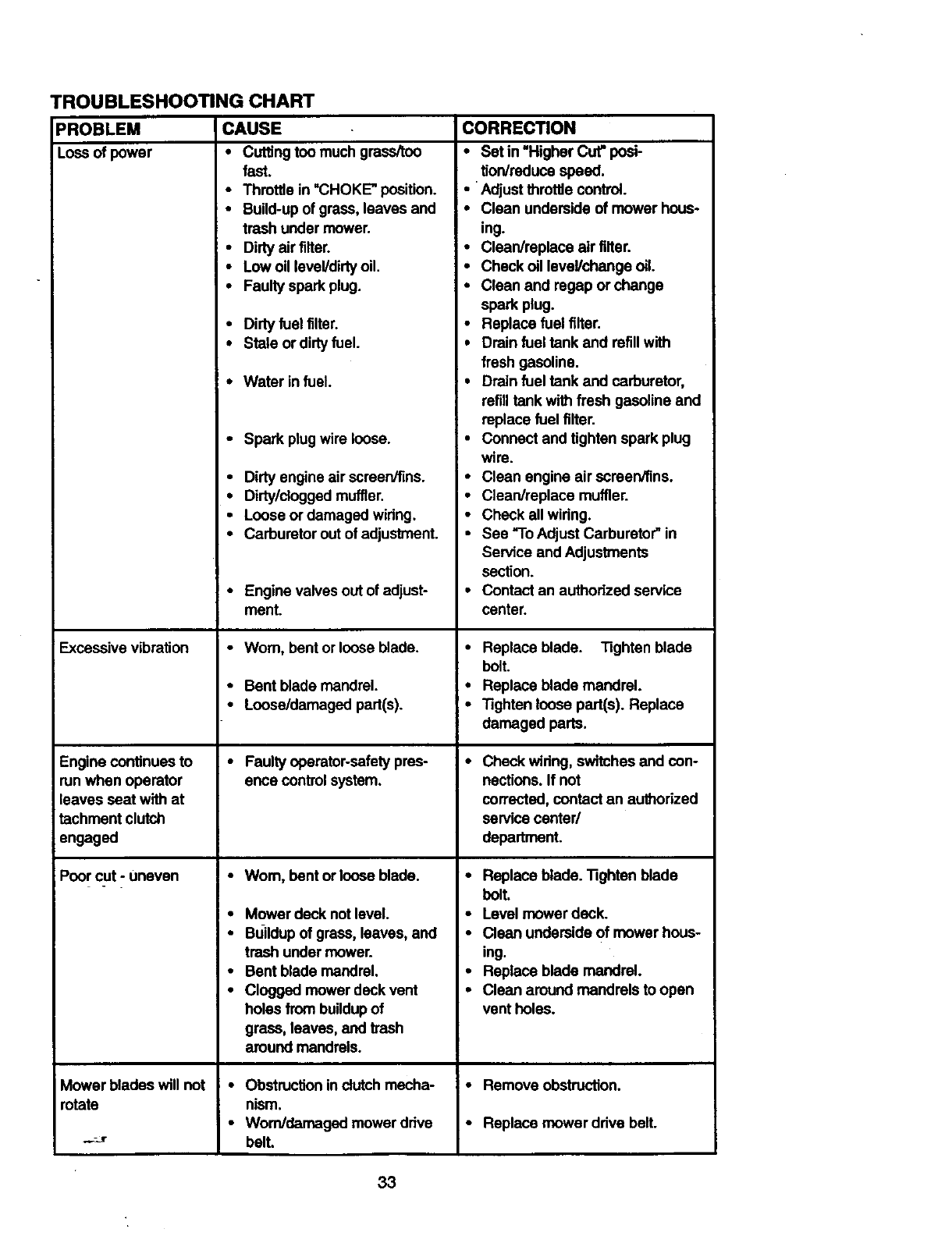
TROUBLESHOOTING CHART
PROBLEM
Lossofpower
CAUSE
• Cuffing too much gres_oo
fast.
• Throttle in =CHOKE" position.
•Build-up of grass, leaves and
trash under mower.
•Dirty air filler.
•Low oil level/dirtyoil.
•Faulty sparkplug.
•Dirty fuel filter.
•Stale or dirty fuel.
•Water in fuel.
Excessive vibration
Engine continues to
run when operator
leaves seat with at
tachmant clutch
engaged
Poor cut - uneven
Mower blades will not
rotate
•Spark plugwire loose.
Dirty engine air scmervlins. •
Dirty/clogged muffler.
Loose or damaged widng.
Carburetor out of adjustment. ,
CORRECTION
•Set in "HigherCut" posi-
fion/reduce speed.
•Adjustthrottlecontrol.
•Clean underside of mower hous-
ing.
•Clean/replace air filler.
•Check oil level/change oil.
•Clean and regap or change
spark plug.
•Replace fuel filter.
•Drain fuel tank and refillwith
fresh gasoline.
•Drain fuel tank and carburetor,
refilltank with fresh gasoline and
replece fuel filter.
•Connect and tighten spark plug
wire.
Clean engine air screanifins.
Clean/replace muffler.
Check all widng.
See "ToAdjust Carburetor" in
Service and Adjustments
section.
•Contact an authorized service
center.
•Engine valves out of adjust-
ment.
•Wom, bent or loose blade.
•Bent blade mandrel.
•Loose/damaged part(s).
Faulty operator-safety pres-
ence control system.
Worn, bent or loose blade.
Mower deck not level.
BLlildupof grass, leaves, and
trash under mower.
Bent blade mandrel.
Clogged mower deck vent
holes from buildupof
grass, leaves, and trash
around mandrels.
•Obstructionindutch mecha-
nism.
•Worn/damaged mower ddve
belt.
•Replace blade. Tighten blade
bolt.
•Replace blade mandrel.
•Tighten loose part(s). Replace
damaged parts.
Check widng, switches and con-
nections. If not
corrected, contact an authorized
service center/
department.
•Replace blade. Tighten blade
bolt.
•Level mower deck.
•Clean underside of mower hous-
ing.
•Replace blade mandrel.
•Clean around mandrels to open
vent holes.
I " Remove obstruction.
•Replace mower ddve belt.
33
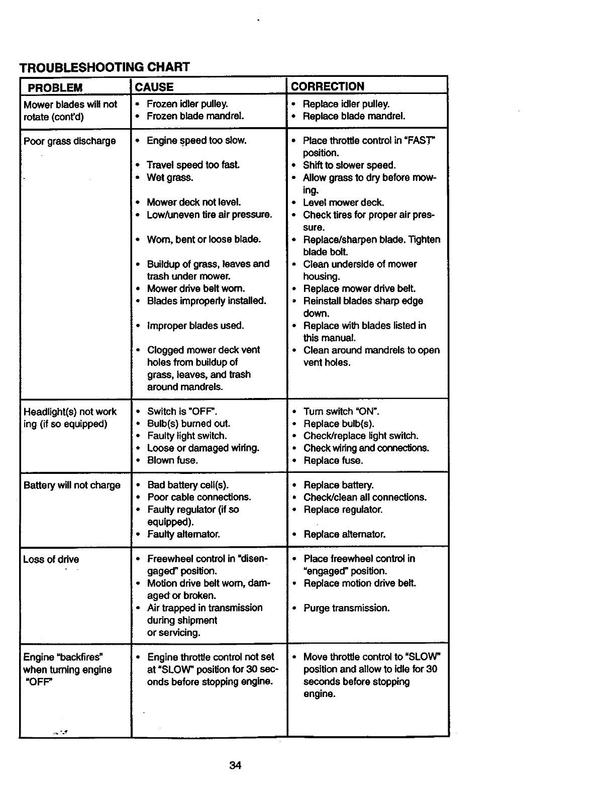
TROUBLESHOOTING CHART
PROBLEM CAUSE CORRECTION
Mowerbladeswillnot • Frozenidlerpulley. • Replaceidlerpulley.
rotate(cont'd) •Frozen blade mandrel. •Replace blade mandrel.
Poor grass discharge •Engine speed too slow,
Headlight(s) not work
ing (if so equipped)
Battery will not charge
Loss of drive
Engine =backfires"
when turning engine
"OFF"
•Travel speed too fast.
•Wet grass.
•Mower deck not level.
•Lowluneven tire air pressure.
•Worn, bent or loose blade.
•Buildup of grass, leaves and
trash under mower.
•Mower drive belt wom.
•Blades improperlyinstalled.
•Improper blades used.
•Clogged mower deck vent
holes from buildupof
grass, leaves, and trash
around mandrels.
•Switch is "OFF".
•Bulb(s) burned out.
•Faulty light switch.
•Loose or damaged wiring.
•Blown fuse.
•Bad battery cell(s).
• Poor cable connections.
•Faulty regulator (if so
equipped).
•Faulty altamator'
•Freewheel controlin "disen-
gaged_position.
•Motion drive belt worn, dam-
aged or broken.
•Air trapped in transmission
during shipment
or servicing.
•Engine throttle controlnot set
at =SLOW" positionfor 30 sec-
onds before stopping engine.
•Place throttle control in =FAST"
position.
•Shift to slower speed.
•Allow grass to dry before mow-
ing.
•Levai mower deck.
•Check tires for proper air pres-
sure.
•Replace/sharpen blade. "13ghten
blade bolt.
•Clean underside of mower
housing.
•Replace mower drive belt.
•Reinstall blades sharp edge
down,
•Replace with blades listed in
this manual.
•Clean around mandrels to open
vent holes.
•Turn switch "ON".
• Replace bulb(s).
• Check/replace light switch.
•Checkwiring and connecSons.
•Replace fuse.
•Replace battery.
•Check/clean all connections.
•Replace regulator,
•Replace alternator.
•Place freewheel controlin
"engaged" position.
•Replace motion drive belt.
•Purge transmission.
•Move throttle control to =SLOW"
position and allow to idle for 30
seconds before stopping
engine.
34
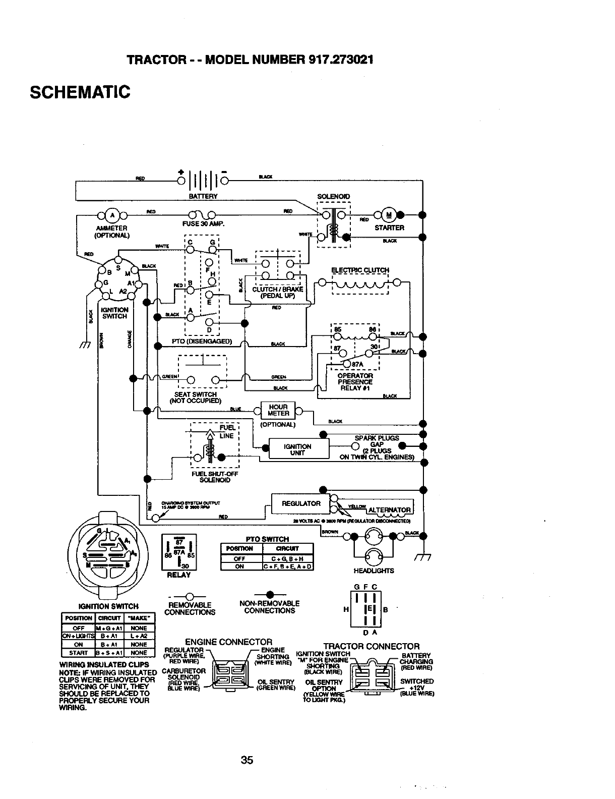
TRACTOR - - MODEL NUMBER 917.273021
SCHEMATIC
RED o'llllll_
BATrlERY SOLENOID
35
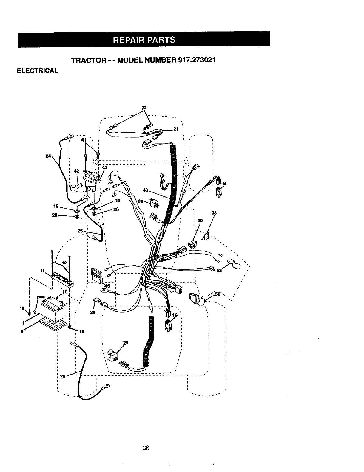
ELECTRICAL
TRACTOR - - MODEL NUMBER 917.273021
" i,,l;'_,_ .................. |--i'_i,_ i
26
i
t
¢
I
',_'t---_ .......................... ;....
¢1
i t
38
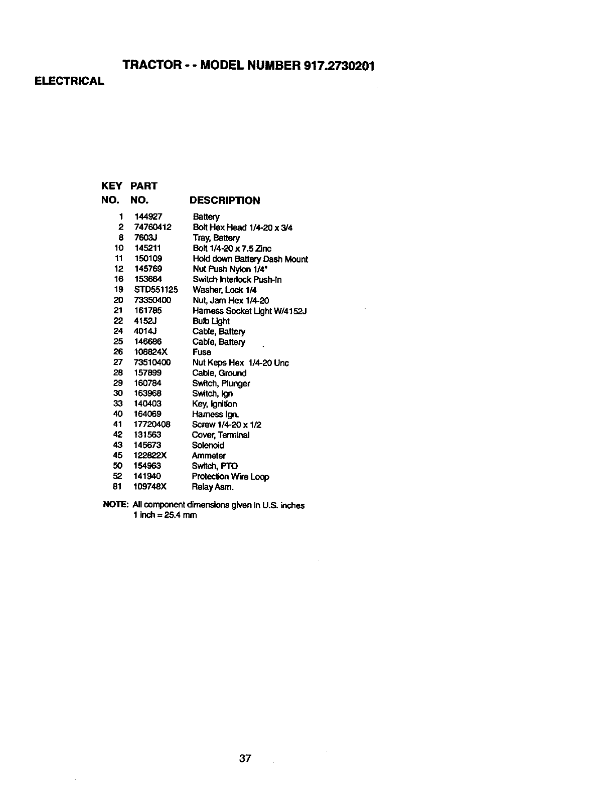
ELECTRICAL
TRACTOR - - MODEL NUMBER 917.2730201
KEY PART
NO. NO. DESCRIPTION
1 144927 Battery
2 74760412 Bolt Hex Head 1/4-20 x 3/4
8 7603J Tray,Battery
10 145211 Bolt 1/4-20 x 7.5 Zinc
11 150109 Holddown Battery Dash Mount
12 145769 Nut Push Nylon 1/4"
16 153664 SwitchInterlockPush-In
19 STD551125 Washer,Lock 1/4
20 73350400 Nut, Jam Hex 1/4-20
21 161785 Hamess Socket LightW/4152J
22 4152J BulbLight
24 4014J Cable, Battery
25 146686 Cable, Battery
26 108824X Fuse
27 73510400 Nut Keps Hex 1/4-20 Unc
28 157899 Cable, Ground
29 160784 Switch,Plunger
30 163968 Switch,Ign
33 140403 Key, Ignition
40 164069 Harness Ign.
41 17720408 Screw 1/4-20 x 1/2
42 131563 Cover,Terminal
43 145673 Solenoid
45 122822X Ammeter
50 154963 Switch,PTO
52 141940 Protec_onWire Loop
81 109748X RelayAsm.
NOTE: Allcomponentdimensionsgiven inU.S. inches
1 inch= 25.4 mm
37
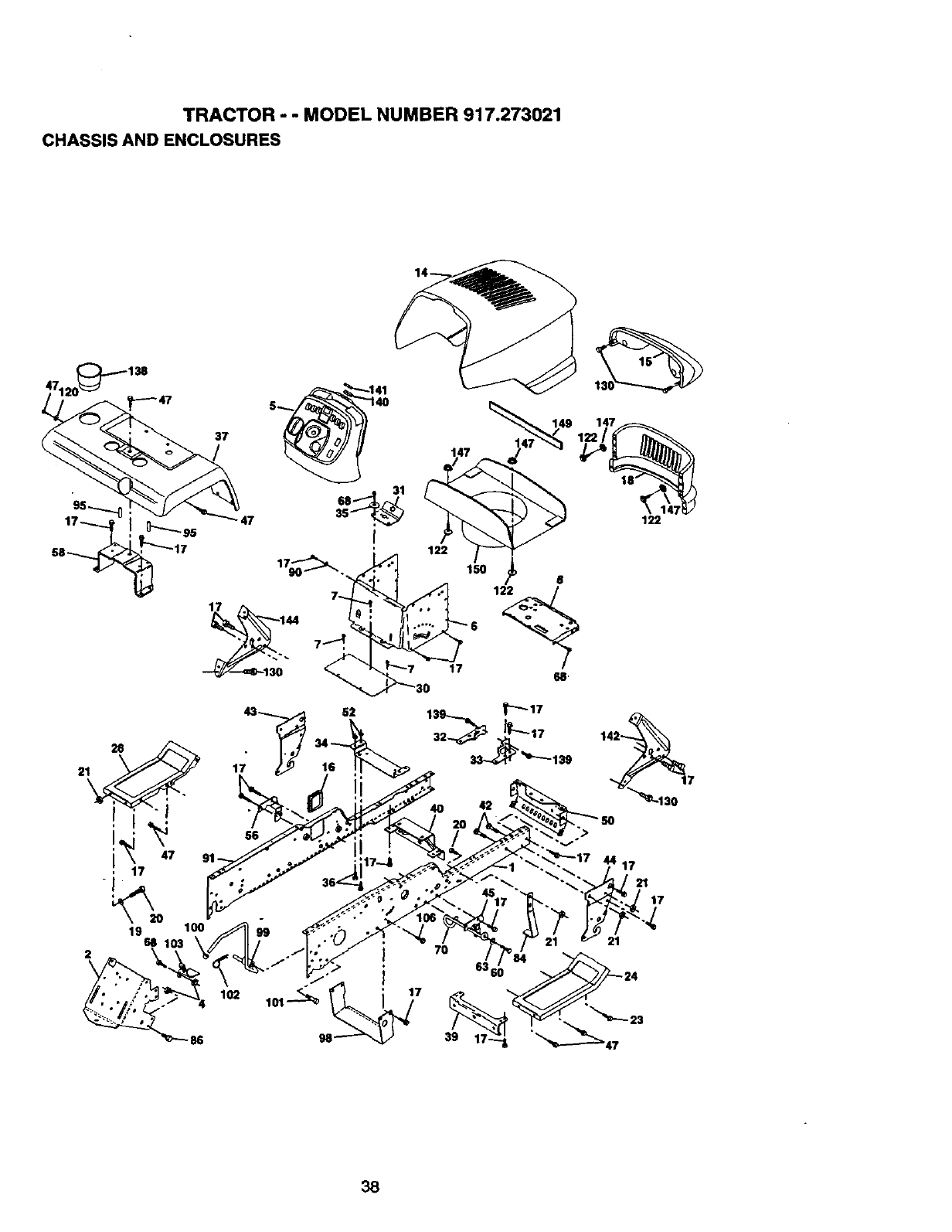
TRACTOR o- MODEL NUMBER 917.273021
CHASSIS AND ENCLOSURES
0----_...95
19 100
86
17 144
52
17
102
147 1"4_7 1/49
17 68
122
42
17
38
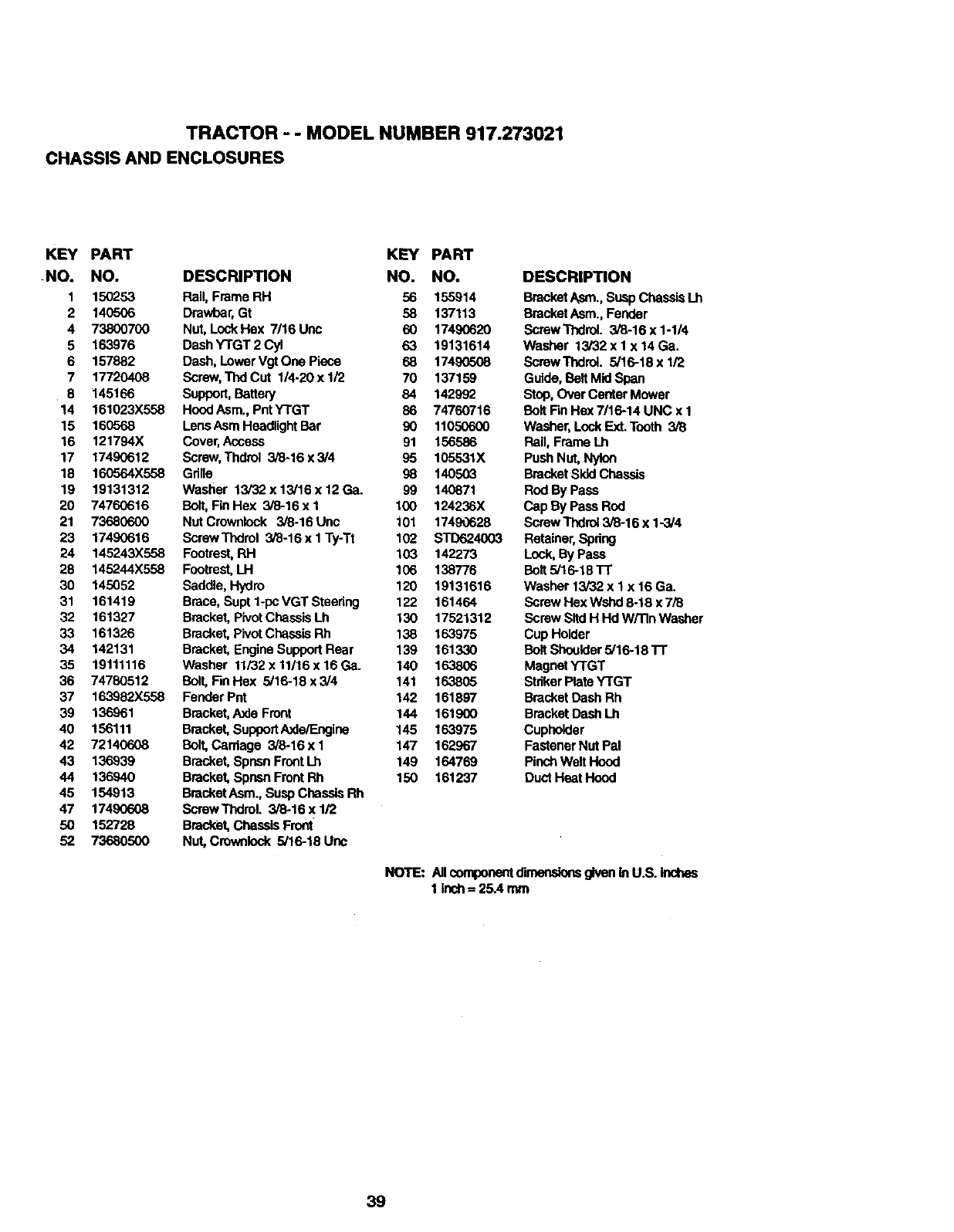
TRACTOR --MODEL NUMBER 917.273021
CHASSIS AND ENCLOSURES
KEY PART KEY PART
-NO. NO. DESCRIPTION NO. NO.
1 150253 Rail, Frame RH 56 155914
2 140506 Drawbar,Gt 58 137113
4 73800700 Nut, LockHex 7/16 Uric 60 17490620
5 163976 DashYTGT2Cyl 63 19131614
6 157882 oash, LowerVgtOnePiece 68 17490508
7 17720408 Screw,ThdCut 1/4-20xl/2 70 137159
8 145166 Support,Battery 84 142992
14 161023X558 HoodAsm.,PntYTGT 86 74760716
15 160568 Lens Asm HeadlightBar 90 11050600
16 121794X Cover,Access 91 156586
17 17490612 Screw,Thdrol 3/8-16x3/4 95 105531X
18 160564X558 Grille 98 140503
19 19131312 Washer 13/32x 13/16x 12Ga. 99 140871
20 74760616 Bolt,Fin Hex 3/8-16 x I 100 124236X
21 73680600 Nut Crowntock 3/8-16 Uric 161 17490628
23 17490616 ScrewThdrol 3/8-16 x I Ty-Tt 102 STD624003
24 145243)(558 Footrest,RH 103 142273
28 145244X558 Footrest,LH 106 138776
30 145052 Saddle, Hydro 120 19131616
31 161419 Brace, Suptl-pcVGTStaedng 122 161464
32 161327 Bracket, PivotChassis Lh 130 17521312
33 161326 Bracket, PivotChassis Rh 138 163975
34 142131 Bracket, Engine Support Rear 139 161330
35 19111116 Washer 11/32x11/16x 16Ga. 140 163806
36 74780512 Bolt`Fin Hex 5/16-18x3/4 141 163805
37 163982X558 FenderPnt 142 161897
39 136961 Bracket,Axle Front 144 161900
40 156111 Bracket, SupportAx_e/Engine 145 163975
42 72140608 Bolt, Cardage 3/8-16 x 1 147 162967
43 136939 Bracket, Spnsn FrontLh 149 164769
44 136940 Bracket, Spnsn Front P.h 150 161237
45 154913 BracketAsm, Susp Chassis Rh
47 17490608 ScrewThdrol. 3/6-16xl/2
50 152728 Bracket, Chassis Front
52 73680500 Nut, Crownlock 5/16-18 Unc
DESCRIPTION
BracketAsm., Susp Chassis Lh
Bracket Asm.,Fender
Screw Thdrol. 3/8-16 x 1-114
Washer 13/32 x I x 14Ga.
ScrewThdrol. 5/16-18x 1/2
Guide, Belt Mid Span
Stop, Over Center Mower
Bolt Fin Hex 7/16-14 UNC x 1
Washer, Lock Ext. Tooth 3/8
Rail, Frame Lh
Push Nut, Nylon
BracketSlddChassis
Rod By Pass
Cap By Pass Rod
Screw "t'hdrol3/8-16 x 1-3/4
Retainer,Spring
Lock,By Pass
BOlt5/16-18"1"I"
Washer 13/32 x 1 x 16 Ga.
Screw Hex Wshd 6-18 x 7/8
Screw Sltd H Hd W/TIn Washer
Cup Holder
Bolt Shoulder5/16-18 1-1"
MagnetYTGT
Stdker PtataY'£GT
BracketDash Rh
Bracket Dash Lh
Cup_der
Fastener Nut Pal
PinchWelt Hood
Duct Heat Hood
NOTE: Allcomponentdimendop.sgivenInU.S.inches
linch =25A mm
39
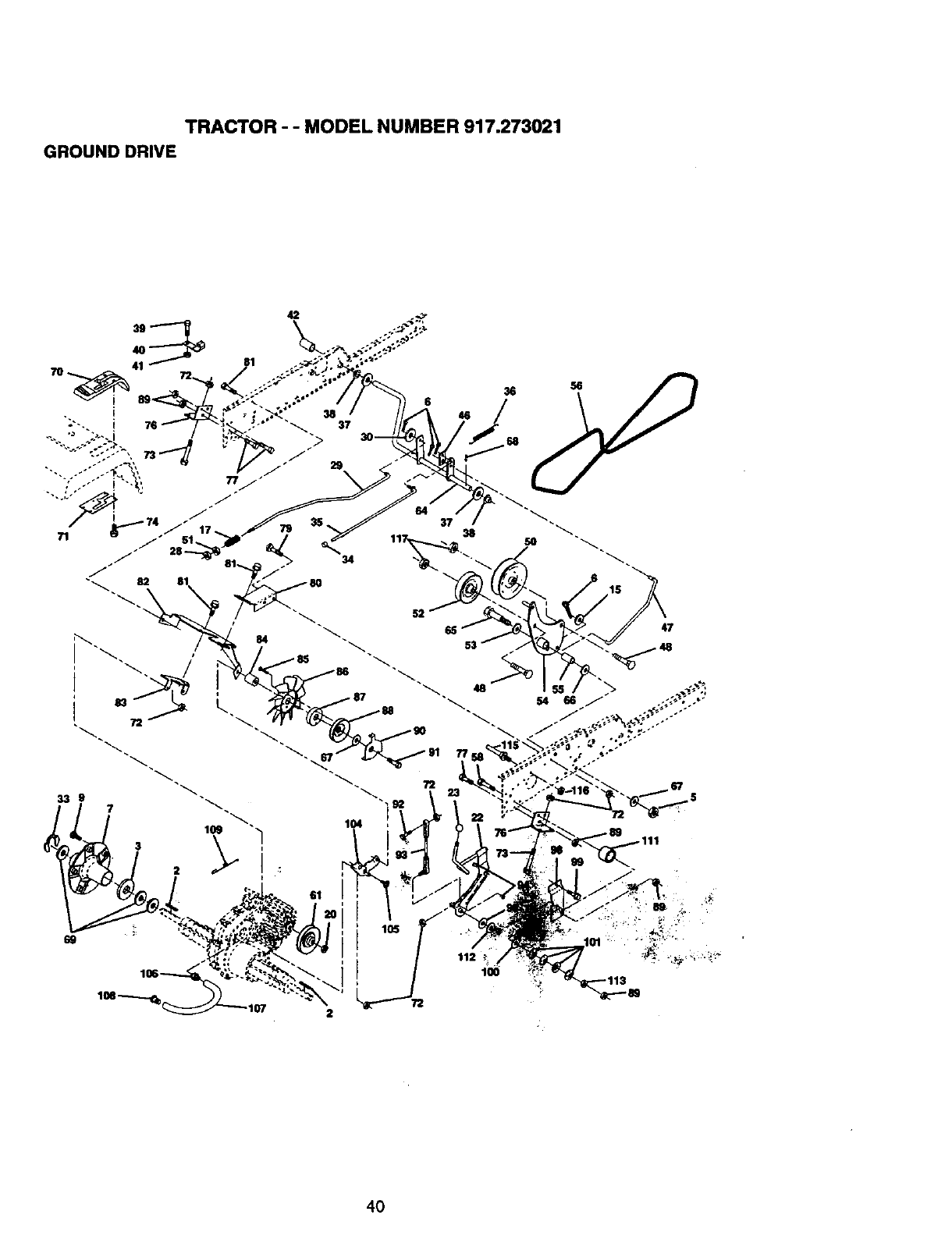
TRACTOR - - MODEL NUMBER 917.273021
GROUND DRIVE
1
33 9 7
3
2
109
46
47
53
48
.111
4O
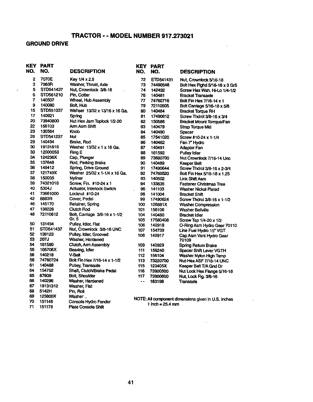
TRACTOR - - MODEL NUMBER 917.273021
GROUND DRIVE
KEY PART KEY PART
NO. NO. DESCRIPTION NO. NO.
2 7070E Key 114x 2.5 72 STD541431
3 7563R Washer, Thrust,Axle 73 74490548
5 8TD541437 Nut, Crownlock 3/8-16 74 142432
6 STD561210 Pin, Cotter 76 140481
7 140507 Wheel, HubAssembly 77 74760716
9 140080 Bolt,Hub 79 72110505
15 STD551037 Wahser 13/32x13/16x16Ga. 80 140484
17 140921 Spdng 81 17490612
20 73940800 Nut Hex Jam Topidck1/2-20 82 150586
22 156103 Arm Asm Shift 83 140479
23 130564 Knob 84 140490
28 STD541237 Nut 85 17541020
29 140494 Brake, Rod 86 140462
30 19131616 Washer 13/32xl x16Ga. 87 140491
33 12000053 Ring E 88 161592
34 124236X Cap, Plunger 89 73680700
35 137648 Rod, ParkingBroke 90 140489
36 149412 Spdng, DriveGround 91 17490644
37 121749X Washer 25/32 x 1-1/4 x 16 Ga. 92 74760.520
38 150035 Nyliner 93 140502
39 74321016 Screw, Fin. #10-24 x I 94 133835
40 5304J Actuator,InterlockSwitch 96 141103
41 73661000 Locknut #1024 98 141004
42 8883R Cover, Pedal 99 17490624
46 145170 Retainer,Spdng 100 126881X
47 138228 ClutchRod 101 156106
48 72110612 Bolt, Carriage 3/6-16 x 1-1/2 104 140480
Gr. 5 105 17580408
50 131494 Pulley, Idler,Flat 106 142918
51 STD541437 Nut, Crewnlock 3/8-16 UNC 107 154739
52 139123 Pulley,Idler,Grooved 108 142917
53 207J Washer, Hardened
54 161590 Clutctt,ArmAasembly 109 140929
55 105706X Beadng, Idler 111 156240
56 140218 V-Belt 112 156104
58 74760724 Bolt FinHex 7/16-14 x 1-1/2 113 73220700
61 140488 Putley,Transaxle 115 123405X
64 154752 Shaft, Clutch/BrakePedal 116 73900500
65 67609 Bolt, Shoulder 117 73900600
66 140296 Washer, Hardened - - 163198
67 19131312 Washer, Flat
68 5142H Pin, Roll
69 123800X Washer _
70 151146 Console Hydro Fender
71 151179 plate Console Shift
DESCRIPTION
Nut, Crovmlock5/16-18
BoltHex Flghd5/16-18 x 3 Gr5
Screw Hex Wsh. Hi-Lo 1/4-1/2
BracketTrensa_de
BoltFin Hex 7/16-14 x 1
Bolt Carriage 5/16-18 x 5/8
BracketTorqueRH
ScrewThdrol3/6-16 x 3/4
BracketMountTorrquelFan
Strap TorqueMid
Spacer
Screw #10-24 x 1-1/4
Fan 7" Hydro
Adapter Fan
PulleyIdler
NutCrownlock7/16-14 Unc
Keeper Belt
Screw "rhdrol3/8-16 x 2-3/4
Bolt FinHex 5/16-18 x 1.25
Unk Shift Asm
Fastener ChristmasTree
Washer Nickel Plated
BracketShift
Screw ThdroI3/6-16 x 1-1/2
Washer Compression
Washer Bollville
BracketIdler
Screw Tap 1/4-20 x 1/2
O-Ring Asm HydroGear 70110
Line Fuel Hydro15" VGT
CapAsm Vent HydroGear
70109
Spdng ReturnBrake
Spacer ShiftLever VGTH
Washer Nylon HighTemp
Nut-Hex ASF 7/16-14 UNC
Keeper BeltT/AGnd Dr
Nut Lock Hex Flange 5/16-18
Nut, Lock Fig.3/8-16
Transaxle
NOTE: All componentdimensionsgivenin U.S. inches
I inch= 25.4 rnrn
41
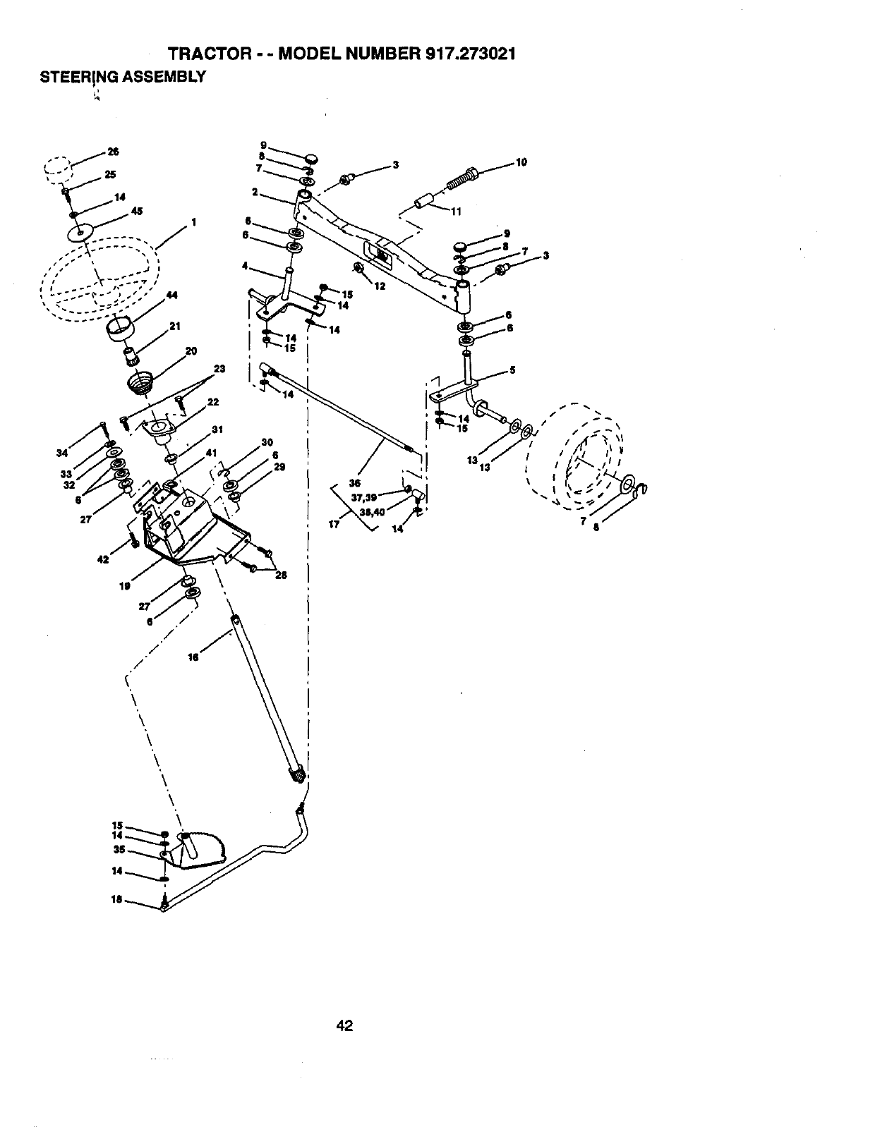
TRACTOR - - MODEL NUMBER 917.273021
STEERING ASSEMBLY
22
31
34
32
1S
1313, I / // _11
42
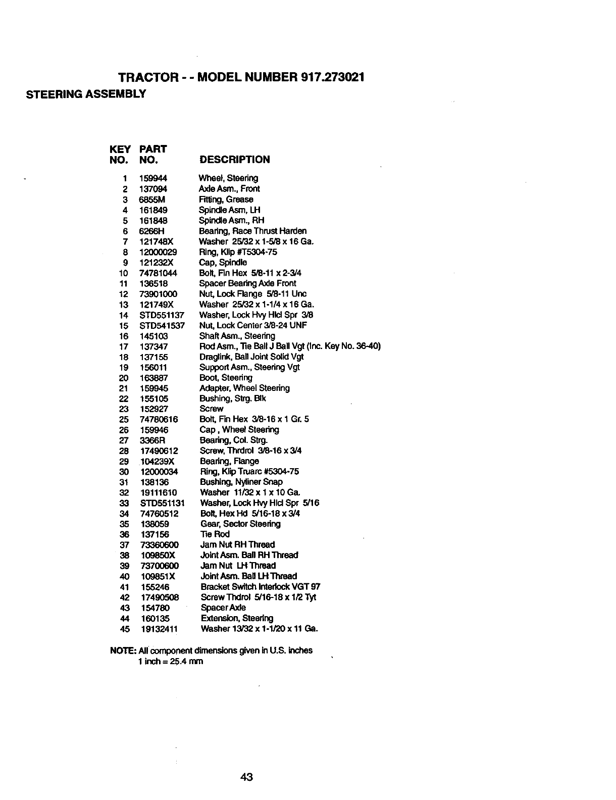
TRACTOR - - MODEL NUMBER 917.273021
STEERING ASSEMBLY
KEY PART
NO. NO. DESCRIPTION
1 159944
2 137094
3 6855M
4 161849
5 161848
6 6266H
7 121748X
8 12000029
9 121232X
10 74781044
11 136518
12 73901000
13 121749X
14 STD551137
15 STD541537
16 145103
17 137347
18 137155
19 156011
20 163887
21 159945
22 155105
23 152927
25 74780616
26 159946
27 3366R
28 17490612
29 104239X
30 12000034
31 138136
32 19111610
33 STD551131
34 74760512
35 138059
36 137156
37 73360600
38 1098,50X
39 73700600
40 109851X
41 155246
42 17490608
43 154780
44 160135
45 19132411
Wheal, Steering
AxleAsm., Front
Fitting,Grease
SpindleAsm, LH
SpindleAsm., RH
Beating, Race ThrustHarden
Washer 25/32 x 1-5/8 x 16 Ga.
Ring,Knp#T5304.75
Cap, Spindle
Bolt,Fin Hex 5/8-11 x 2-3/4
Spacer BearingAxle Front
Nut, Lock Flange 5/8-11 Unc
Washer 25/32 x 1-1/4 x 16 Ga.
Washer, LockHvy Hlcl Spr 3/8
Nut, Lock Center 3/8-24 UNF
ShaftAsm., Steering
RodAsm, "lie BellJ Bell Vgt (Inc. Key No. 36-40
Dragllnk,Ball JointSolid Vgt
SupportAsm., SteedngVgt
Boot,Steering
Adapter,Wheel Steering
Bushing,Strg. BIk
Screw
Bolt, FinHex 3/8-16 x I Gr. 5
Cap, Wheal Steadng
Beadng, Col. Strg.
Screw,Thrdrol 3/8-16 x 3/4
Bearing,Flange
Ring,KlipTruam #5304-75
Bushing,NylicerSnap
Washer 11/32 x I x 10 Ga.
Washer, LockI-IvyHlclSpr 5/16
Bolt, Hex Hd 5/16-18 x 3/4
Gear, SectorSteering
Tie ROd
Jam Nut RH Thread
JointAsm. Bell RH Thread
Jam NUt LH Thread
JointAsm. Bell LH Thread
BracketSwitch InterlockVGT 97
ScrewThdrol 5/16-18 x 1/2Tyt
SpacerAxfe
Extension,Steering
Washer 13/32 x 1-1/20 x 11 Ga.
NOTE: All componentdimensionsgiven inU.S. inches
1inch =25A mm
43
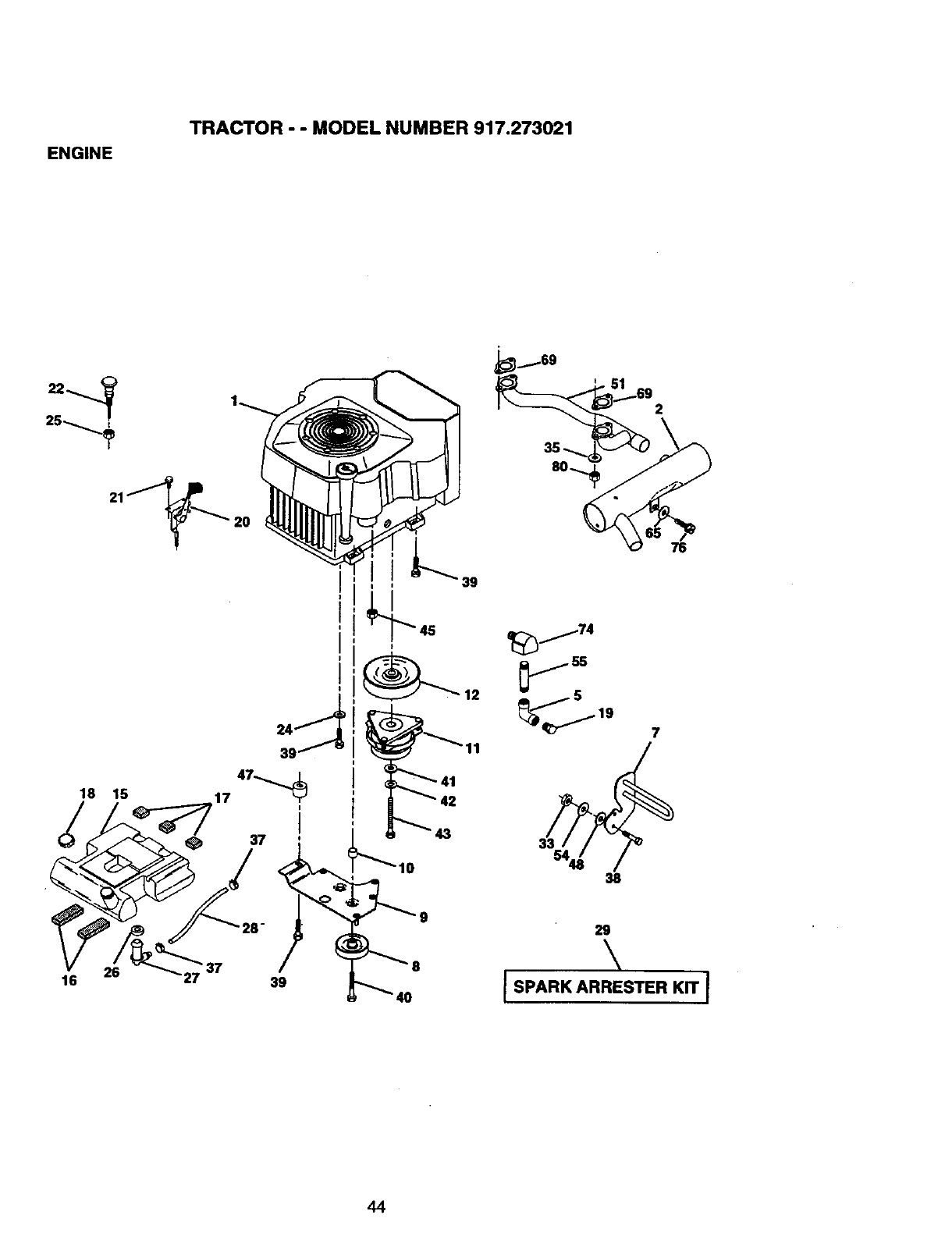
ENGINE
TRACTOR - - MODEL NUMBER 917.273021
25
21 "__ 20
18 15 17 47_,_
39
÷°
42
0
76
_j74
js
_ 4_""" 19 7
38
29
\
ISPARK ARRESTER KIT I
44
ENGINE
TRACTOR - - MODEL NUMBER 917.273021
KEY PART
NO. NO. DESCRIPTION
1 ......
2 161062
5 13200300
7 151396
8 121361X
9150828
10 105432X
11 140923
12 143996
15 151346
16 109227X
17 106082X
18 161493
19 13290300
20 164067
21 17521312
22 164415
24 STD551237
25 73920600
26 3645J
27 139277
28 7834R
29 132920
33 STD541437
35 10010500
37 123487X
38 74780624
39 17490636
40 17490664
41 126197X
42 STD551143
43 150280
45 128861
47 142040
48 19132007
51 161230
54 19131414
55 13280336
65 19131614
69 24-041-02
74 162295
76 17490612
80 M73030800
L
Engine (See Breakdown)
KohlerModel No. CV20S-65551
MufflerSide 1-1/8"98
Elbow STD 90 Degree 3/8 -18 NPT
MufflerAsm Guard
Pulley V-Idler
Keeper Asm. Belt Engine
Bushing
ClutchElactdc
Pulley Engine VGT ElectClutch
Tank Fuel Rear 3.50 Yt/Gt 96
Pad Spacer
Pad Spacer
Cap Asm FuelW/Gauge
Plug Oil Drain (Order FromEngine Manufacturer)
ControlThrottle
Screw SLTD Hex HD W/PIn Washer
ControlChoke
Washer Ext Tooth3/8
Nut Keps 3/8.24 UNF
Bushing
Stem Tank Fuel
Fuel Une
SparkArrestar Kit
Nut Lock Hex w/Ins. 3/8 -16
Washer Split
Clamp Hose
Bolt Fin Hex 3/8 -16 x 1-1/2
Screw'lT 3/8-16 x 2-1/4 UNC
Screw'l-r 3/8-16 x 4 UNC
Washer 1-1/20D X 15/32 ID X .250
Washer Lock 7116
Bolt Hex 7/16 -20 X 4 -1/4 Ga 5
Nut Range 1/4-20 StarterNut
Spacer Engine
Washer 13/32 x 1-1/4 x 7 Ga.
ManifoldPipeVGT CV 1-1/8"
Washer Flat 13/32 x 7/8 x 14 Ga.
Nipple Pipe 4-1/2
Washer 13/32 x 1 x 14 Ga.
Gasket KohlerCV18-CV26
Elbow Street Brass
Screw Thdrol3/8-16 x 3/4 Ty-'l-r
Nut Range M8-1.25 Non-LkZInk
NOTE: Allcomponentdimensionsgivenin U.S. inches
1 inch= 25A mm
45
TRACTOR - - MODEL NUMBER 917.273021
SEAT ASSEMBLY
19
12
21
KEY
NO.
1
2
3
4
5
6
7
8
10
12
13
PART
NO.
14O124
140551
140675
127018X
145O06
STD541437
124181X
150176
155925
121246X
121248X
DESCRIPTION
Seat
Bracket, PivotSeat
Strap, Fender
Bolt,Shoulder 5/16-18 x .62
Clip, Push In, Hinged
Nut, Crownlock 3/8-16 Unc
Spring,Seat Cprsn
Bolt 5/16-18 Unc x 3/4 wPSems
Pan, Seat
Bracket, MounlJngSwitch
Bushing,Snap
KEY
NO. PART
NO. DESCRIPTION
14 72050412 Bolt,Carriage 1/4-20X1-1/2
15 121249X Spacer, Split
16 123740X Spdng, Cprsn
17 123976X Nut, Lock 1/4 Lge Fig Gr. 5
18 19171912 Washer 17/32 x1-3/16 x12
Ga.
19 120068X Knob, Seat 1/2-13 Unc
20 124238X Cap, SpringSeat
21 153236 Bolt, Shoulder 5/16-18
22 STD541431 Nut, Crownlock 5/16-18 Unc
NOTE: All componentdimer_sionsgivenin U.S. inches
1 inch=25A mm
46
DECALS
TRACTOR - - MODEL NUMBER 917.273021
18 17 4 17 10
KEY PART
NO. NO.
1 164094
2 149516
3 163916
4 163917
5140837
6 133644
7 164757
8 164884
9 163204
10 156439
11 4900J
12 146790
11
KEY PART
DESCRIPTION NO. NO.
Decal, Dash 14 160397
Decal, Battery DNGR/PSN 16 163203
ENG Asm 17 163265
Decal, Hood, Craftsman, RH 18 164065
Decal, Hood, Craftsman,LH 19 138047
Decal, Brake ParkingSaddle 22 142342
Decal, Maintenance 23 106202X
Decal, Eng LrgSm Koh Pro 20 25 163230
Tw - - 138311
Decal, BlowerHsng Kohl
Decal, Fender,Craftsman - - 157199
Decal, Fender Banger -- 165018
Decal, Clutch_mke -- 165019
Decal, V-Belt DriveSchematic
12
DESCRIPTION
Decal, V-BeltSchematic
Decal, Mower EZ3
Decal, Dash Panel
Decal, Insert Strg
Decal, Battery
Decal, DrawbarCNTRL
Reflector,Taillight
Decal, FendAutoTrans
Decal, Handle LftHeight Adjust
(uftHand_)
Pad, Footrest
Manual,Owner's(Eng)
Manual,Owner's(Span)
WHEELS & TIRES
4- lO
59
8
KEY PART
NO. NO. DESCRIPTION
1 59192 Cap, Valve,Tire
2 65139 Stem, Valve
3 106228X427 RimAssembly,Front
11 106277X427 RimAssembly,Rear
4 8134H Tube, Front (SendceItem Orgy)
10 7154J Tube, Rear (BandceItem Only)
5 106230X Tire, Front
9 105588X Tim, Rear
6 278H Fltling,Grease (FrontWheel
Only)
12 6856M Flt_g, Groase
7 9040H Baadng, Flange(F_nt Wheel
Only)
8 104757X Cap,/r_de (FrontWheel Only)
-- 144334 Sealant,"l'we(10 oz. Tube)
NOTE:AAeocnponantd_,oonsloosglveninU.S. _es
1Inch: 25A mm
47
TRACTOR - - MODEL NUMBER 917.273021
LIFT ASSEMBLY
40 43 35 17
39
38 34
31
2
23
2O
22
12
15
19 18
7
#1j
3
6
48
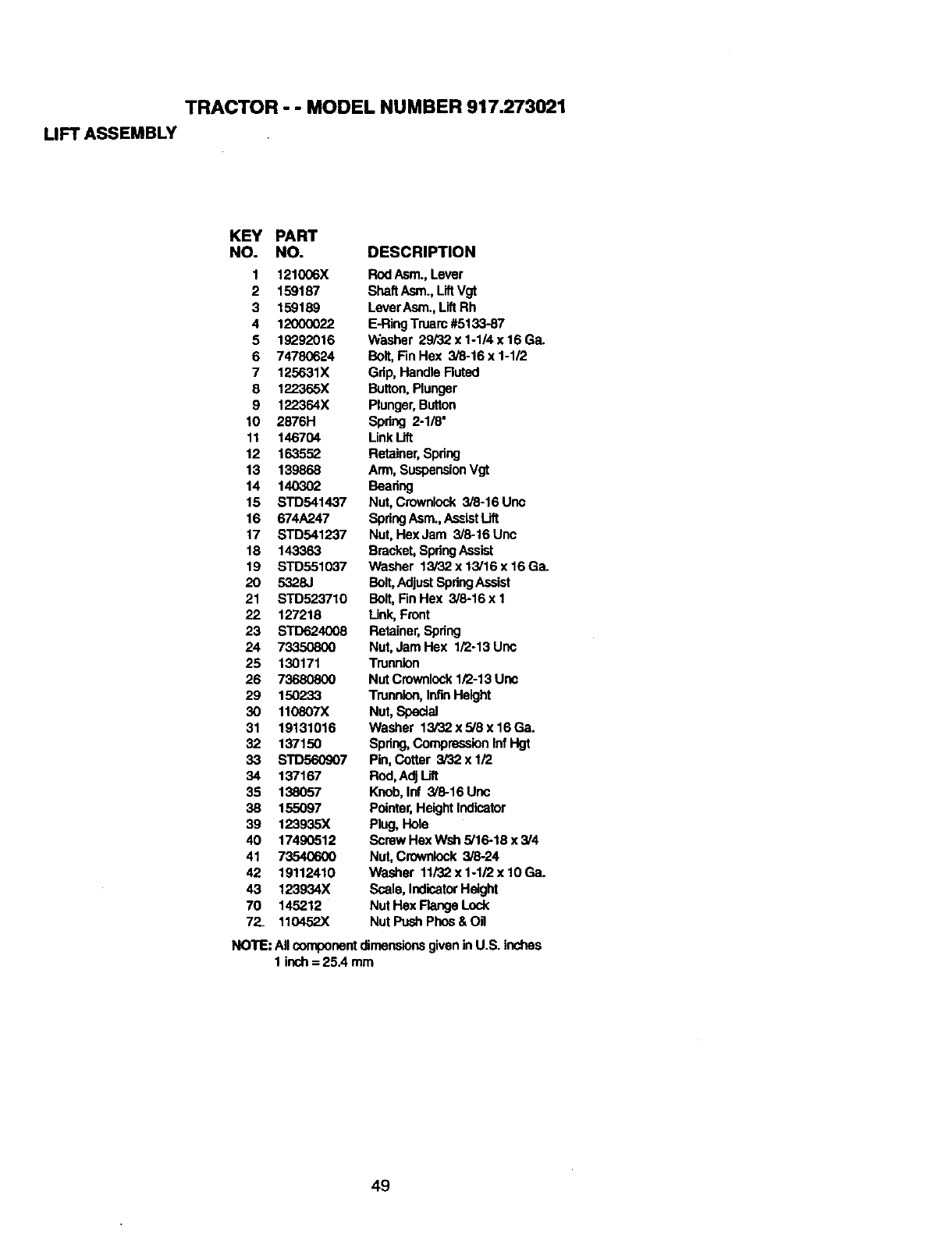
TRACTOR - - MODEL NUMBER 917.273021
LIFT ASSEMBLY
KEY PART
NO. NO. DESCRIPTION
1 121006X RodAsm., Lever
2 159187 ShaftAsm., LiftVgt
3 159189 LeverAsm., LiftRh
4 12000022 E-RingTruarc#5133-87
5 19292016 Washer 29i32x1-1/4x16Ga.
6 74780624 Bolt,FinHex 3/8-16x1-1/2
7 125631X Gdp, Handle Rutad
8 122365X Button,Plunger
9 122364X Plunger,Button
10 2876H Spdng 2-1/8"
11 146704 LinkLift
12 163552 Retainer,Spdng
13 139868 Arm, SuspensionVgt
14 140302 Bearing
15 STD541437 Nut, Crownlock 3/8-16 Unc
16 674A,?.47 SpdngAsm.,As.sistLift
17 STD541237 Nut, Hex Jam 3/8-16 Unc
18 143363 Bracket,SpdngAssist
19 STD551037 Washer 13/32x13/16x16Ga.
20 5328J Bolt,AdjustSpdngAssist
21 STD523710 Bolt, FinHex 3/8-16 x 1
22 127218 Link, Front
23 STD624008 Retainer,Spdng
24 73350800 Nut, Jam Hex 1/2-13 Unc
25 130171 Trunnion
26 73680800 Nut Crownlock1/2-13 Unc
29 150233 Trunnion,InfinHeight
30 1108073( Nut, Special
31 19131016 Washer 13i32xS/8x16Ga.
32 137150 Spdng,CompressionInfHgt
33 STD560907 Pin, Cotter 3/32 x 1/2
34 137167 Rod, Adj Lilt
35 138057 Knob, lnf 3/8-16Unc
38 155097 Pointer,Height Indicator
39 123935X Plug, Hole
40 17490512 Screw Hex WSh 5/16-18 x 3/4
41 73540600 Nut, Crowniock 3/8-24
42 19112410 Washer 11/32 x 1-1/2 x 10 Ga.
43 123934X Scale, IndicatorHeight
70 145212 Nut FlexFlangeLock
72 110452X Nut Push Phos& OI1
NOTE: Alloomponent dimensionsgiveninU.S. inches
1 inch= 25.4 mm
49
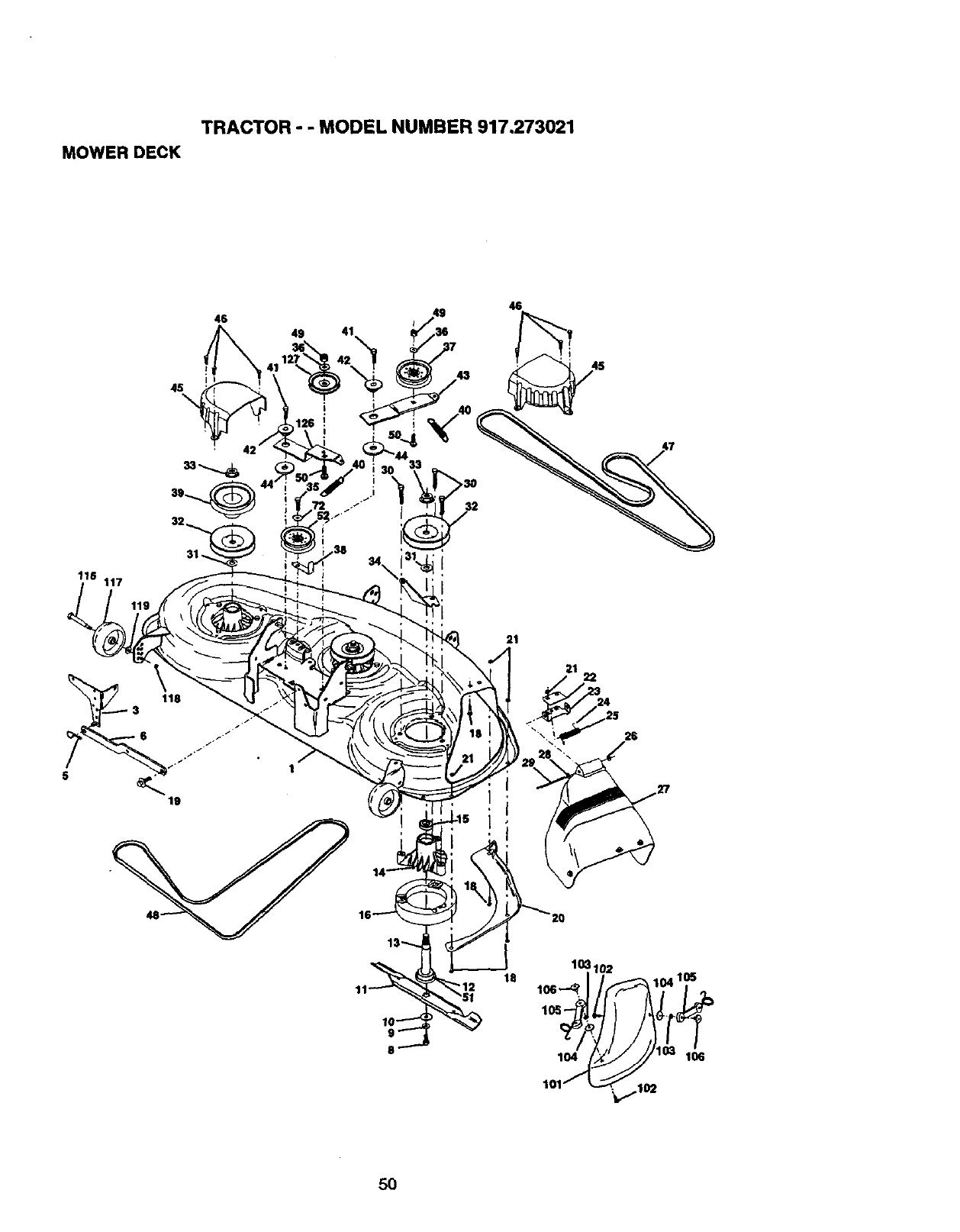
TRACTOR - - MODEL NUMBER 917.273021
MOWER DECK
46
49
46
I
4S\
I
118 117
I
32
E
i
21 22
103102 105
18 106'-'_ 104
5O
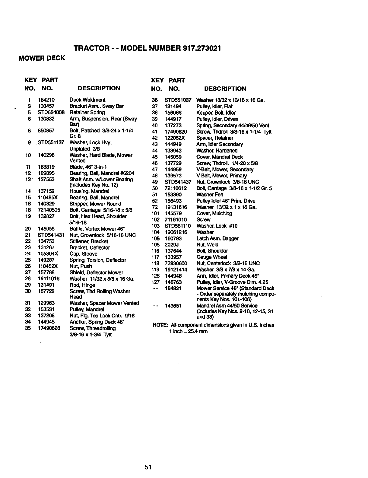
TRACTOR - - MODEL NUMBER 917.273021
MOWER DECK
KEY PART KEY PART
NO. NO. DESCRIPTION NO. NO.
1 164210 Deck Weldment 36 STD5510_7
3 138457 BracketAsm., Sway Bar 37 131494
5 STD624008 Retainer Spring 38 156086
6 130832 Arm, Suspension,Rear (Sway 39 144917
Bar) 40 137273
8 850857 Bolt,Patched 3/8-24 x 1-1/4 41 17490620
Gr. 8 42 122052X
9 STD551137 Washer, Lock I-Ivy., 43 144949
Unplated 3/8 44 133943
10 140296 Washer, Hard Blade, Mower 45 145059
Vented 46 137729
11 163819 Blade, 46" 3-in-1 47 144959
12 129895 Beadng, Ball, Mandrel #6204 48 139573
13 137553 ShaftAsm. w/LowerBeadng 49 STD541437
(includesKey No. 12) 50 72110612
14 137152 Housing, Mandrel 51 153390
15 110485X Beadng, Ball,Mandrel 52 156493
16 140329 Stripper,Mower Round 72 19131616
18 72140505 Bolt, Carriage 5/16-18x5/8 101 145579
19 132827 Bolt, Hex Head, Shoulder 102 71161010
5/16-18 103 STD551110
20 145055 Baffle, Vortex Mower 46" 104 19061216
21 STD541431 Nut, Crowntock 5/16-18 UNC
22 134753 Stiffener,Bracket 105 160793
106 2029J
23 131267 Bracket, Deflector 116 137644
24 105304X Cap, Sleeve 117 133957
25 149287 Spring, Torsion,Deflector 118 73930600
26 110452X Nut, Push 119 19121414
27 157788 Shield, Deflector Mower 126 144948
28 19111016 Washer 11r32x5/8x16Ga.
29 131491 Rod, Hinge 127 146763
- - 164821
30 157722 Screw, Thd RollingWasher
Head
31 129963 Washer, Spacer Mower Vented - - 143651
32 153531 Pulley,Mandrel
33 137266 Nut, Fig. Tap LockCntr. 9/16
34 144945 Anchor,Spring Deck46"
35 17490628 Screw,Threadmlling
3/8-16 x 1-3/4 Tytt
DESCRIPTION
Washer 13/32 x 13/16 x 16 Ga.
Pulley,Idler,Flat
Keeper, Bait, Idler
Pulley,Idler,Ddven
Spdng,Secondary44/46/50 Vent
Screw,'Rldrofl 3/6-16x 1-1/4 Tytt
Spacer, Retainer
Arm, IdlerSecondary
Washer,Hardened
Cover, Mandrel Deck
Screw,Thdroll. 1/4-20 x 5/8
V-Belt, Mower,Secondary
V-Belt, Mower,Pdmary
Nut,Crownlock 3/8-16 UNC
Bolt, Carriage 3/8-16 x 1-1/2 Gr. 5
Washer Felt
PulleyIdler 46" Prim. Drive
Washer 13/32 x I x 16 Ga.
Cover, Mulching
Screw
Washer, Lock #10
Washer
LatchAsm. Ba_r
Nut, Weld
Bolt,Shoulder
GaugeWheal
NUt,Centerlock 3/8-16 UNC
Washer 3i8 x 7/8 x 14 Gao
Ann, Idler,Pdmary Deck46"
Pulley,Idler,V-Groove Dim. 4.25
Mower Service46" (StandardDeck
- Orderseparatelymulchingcompo-
nentsKey Nos. 101-106)
MandrelAsrn44/50 Sen/Ice
(Indudea Key Nea. 6-10, 12-15, 31
and 33)
NO'rE: Afl componentdimensionsgivenIn U.S. inches
1 inch= 25.4 mm
51
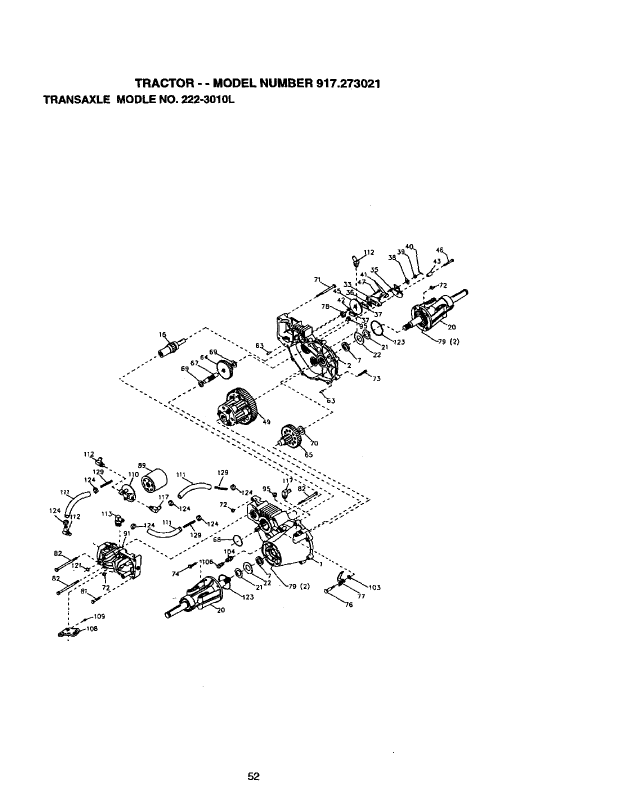
TRACTOR - - MODEL NUMBER 917.273021
TRANSAXLE MODLE NO. 222-3010L
52
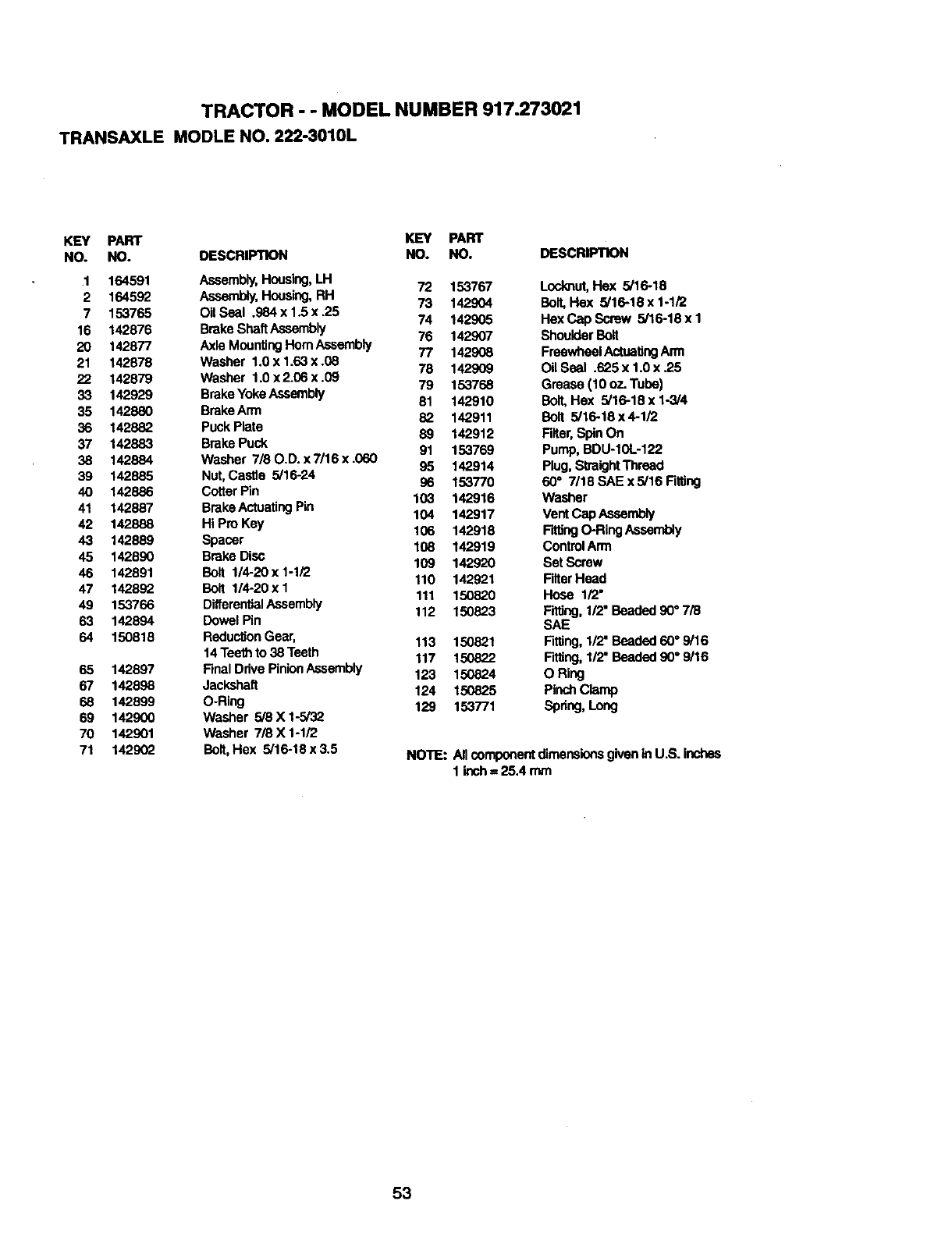
TRACTOR - - MODEL NUMBER 917.273021
TRANSAXLE MODLE NO. 222-3010L
KEY PART KEY PART
NO. NO. DESCRIPTION NO- NO-
1 164591 Assembly,Housing,LH 72 153767
2 164592 Assembly,Housing,RH 73 142904
7 153765 OilSeal .984 x 1.5 x .25 74 142905
16 142876 BrakeShaftAssembly 76 142907
20 142877 Axle MountingHorn Assembly 77 142908
21 142878 Washer 1.0 x 1.63 x .08 78 142909
22 142879 Washer 1.0 x 2.06 x .09 79 153768
33 142929 BrakeYokeAssembly 81 142910
35 142880 BrakeArm 82 142911
36 142882 PuckPlate 89 142912
37 142883 Brake Puck 91 153769
38 142884 Washer 7/80.D. x 7/16 x .060 95 142914
39 142885 Nut, Castle 5/16-24 96 153770
40 142886 Cotter Pin 103 142916
41 142887 BrakeActuatingPin 104 142917
42 142888 Hi Pro Key 106 142918
43 142889 Spacer 108 142919
45 142890 Broke Disc 109 142920
46 142891 Bolt 114-20x 1-1/2 110 142921
47 142892 Bolt 1/4-20 x I 111 150820
49 153766 DifferentlelAssembly 112 150823
63 142894 Dowel Pin
64 150818 Reduc_onGear, 113 150821
14 Teethto 38 Teeth 117 150822
65 142897 Final Drive PinionAssembly 123 150824
67 142898 Jackshaft 124 150825
68 142899 O-Ring 129 153771
69 142900 Washer 5/8 X 1-5/32
70 142901 Washer 7/8 X 1-1/2
71 142902 Bolt, Hex 5/16-18 x 3.5
DESCRIPTION
Locl_ut, Hex 5/16-18
Bolt, Hex 5/16-18 x 1-1/2
Hex Cap Screw 5/16-18 x 1
Shoulder Bolt
FreewheelActuatingArm
Oil Seal .625 x 1.0 x .25
Grease (10 oz. Tube)
Bolt, Hex 5/16-18 x 1-3/4
Bolt 5/16-18 x4-1/2
Filter,Spin On
Pump, BDU-10L-122
Plug, StraightThread
60°7/18 SAE x 5/16 Fitting
Washer
Vent Cap Assembly
FittingO-Ring Asse_
ControlArm
Set Screw
FilterHead
Hose 1/2"
Fiffing,1/2" Beaded 90°7/8
SAE
Fitting, 1/2" Beaded 60°9/16
Fitting,1/2" Beaded 90°9/16
O Ring
PinchClamp
Spring, Long
NOTE: AllcomponentdimensionsgiveninU.S. inches
1 inch-- 25.4 rnm
53
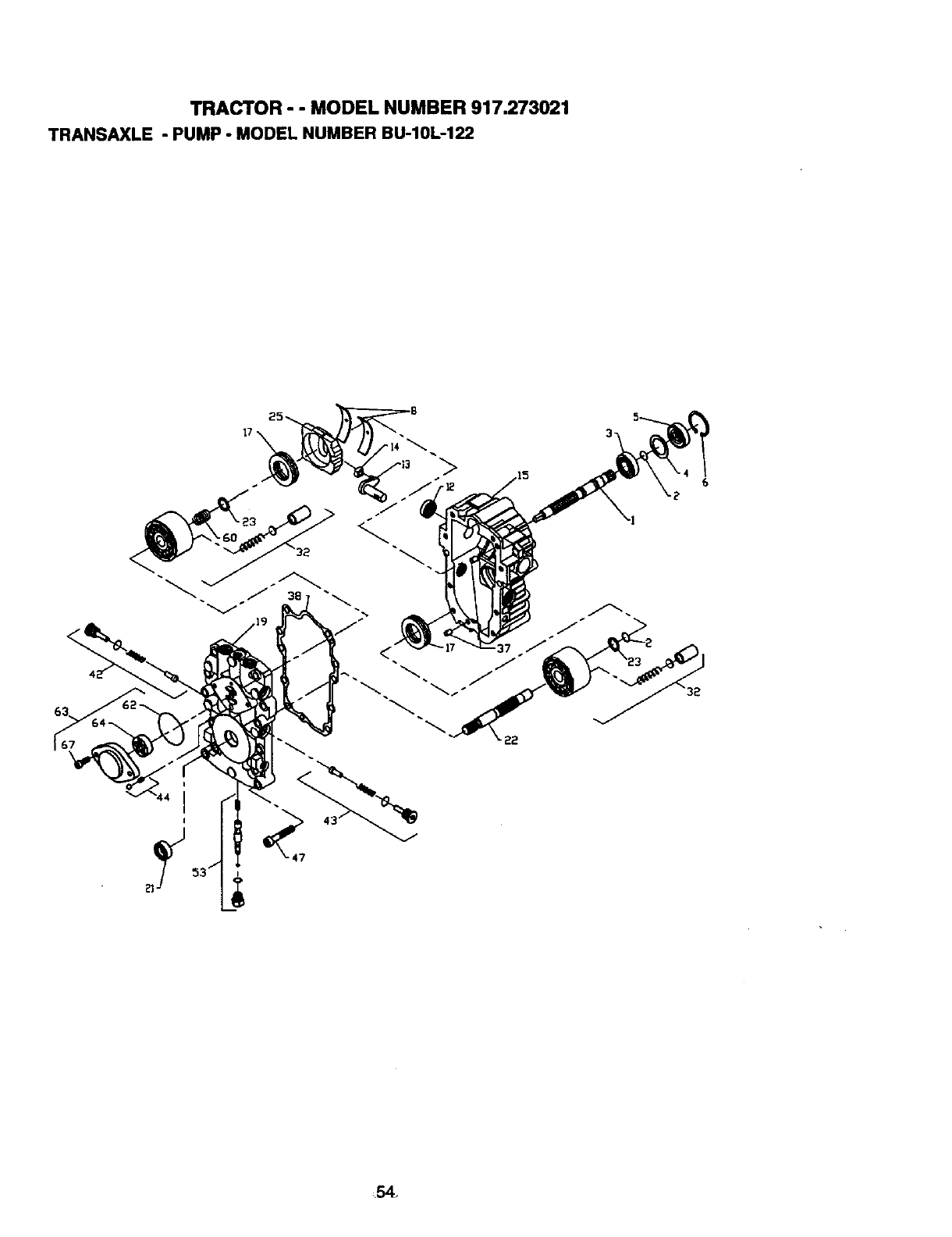
TRACTOR - - MODEL NUMBER 917.273021
TRANSAXLE - PUMP -MODEL NUMBER BU-10L-122
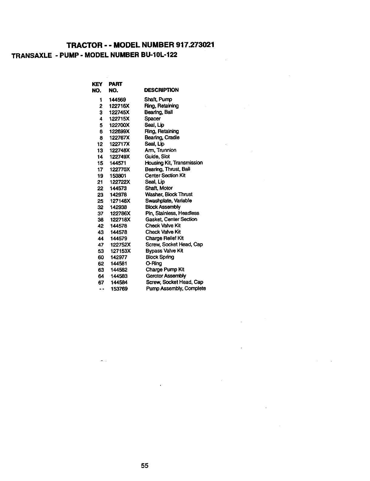
TRACTOR - - MODEL NUMBER 917.273021
TRANSAXLE - PUMP - MODEL NUMBER BU-10L-122
KEY PART
NO. NO. DESCRIPTION
1 144569 Shaft, Pump
2 122716X Ring,Retaining
3 122745X Beadng, Ball
4 122715X Spacer
5 122700X Seal, Lip
6 122699X Ring, Retaining
8 122767X Bearing,Cradle
12 122717X Seal, Lip
13 122748X Arm, Trunnion
14 122749X Guide,Slot
15 144571 HousingKit,Transmission
17 122770X Bearing,Thrust,Ball
19 153801 Center SectionKit
21 122722X Seal, Lip
22 144573 Shaft, Motor
23 142978 Washer, BlockThrust
25 127148X Swashplate,Vadabte
32 142938 BlockAssembly
37 122786X Pin, Stainless,Headless
38 122718X Gasket, Center Section
42 144578 Check Valve Kit
43 144578 CheckValve Kit
44 144579 Charge Relief Kit
47 122752X Screw, SocketHead, Cap
53 127153X BypassValve Kit
60 142977 BlockSpdng
62 144581 O-Ring
63 144582 Charge Pump Kit
64 144583 Gemtor Assembly
67 144584 Screw, SocketHead, Cap
- - 153769 PumpAssembly,Complete
55
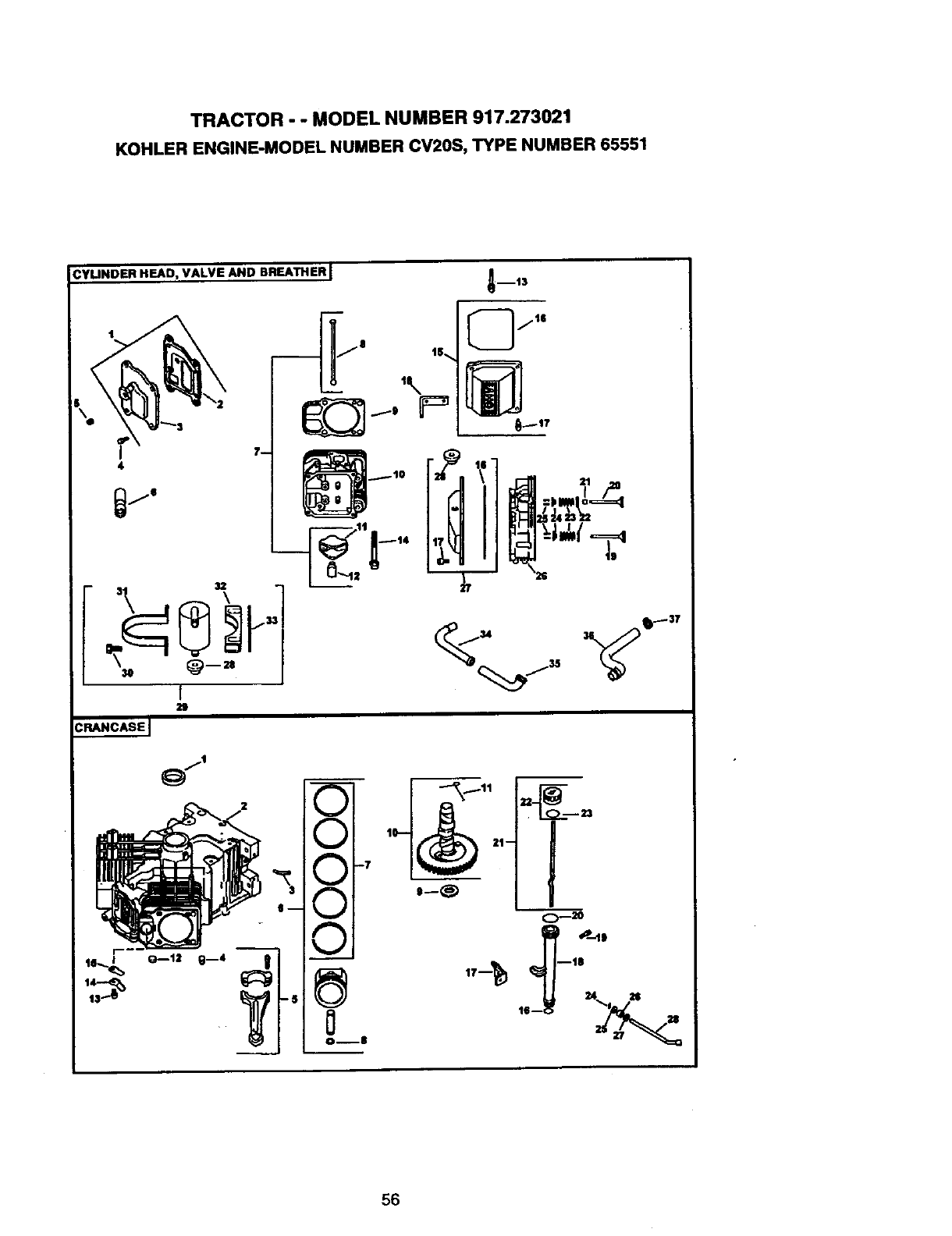
TRACTOR - - MODEL NUMBER 917.273021
KOHLER ENGINE-MODEL NUMBER CV20S, TYPE NUMBER 65551
CYUNDER HEAD, VALVE AND BREATHER J
J 7--
4
1
29
CRANCASE_.J
"_,.,S r
I 7
A ! C_--20
56
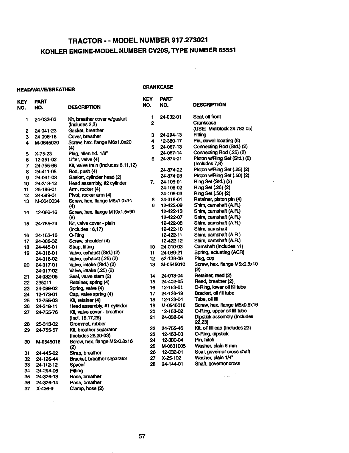
TRACTOR - -MODEL NUMBER 917.273021
KOHLER ENGINE-MODEL NUMBER CV26S, TYPE NUMBER 65551
HEAD/VALVE/BREATHER
KEY PART
NO. NO.
CRANKCASE
1 24-033-03
2 24-041-23
3 24-096-15
4 M-0645020
5X-75-23
6 12-351-02
7 24-755-66
8 24-411-05
9 24-041-08
10 24-318-12
11 25-186-01
12 24-599-01
13 M-0640034
14 12-086-16
15 24_56-74
16 24-153-16
17 24-086-32
18 24-445-01
19 24-016-O1
24-016-02
20 24-017-01
24-017-02
21 24-032-05
22 235011
23 24-089-O2
24 12-17301
25 12-755-03
28 24-318-11
27 24-755-76
28 25-313-02
29 24-755-57
30 M-0545016
31 24-445-02
32 24-126-44
33 24-112-12
34 24-294-06
35 24-326-13
36 24-326-14
37 X-426`9
KEY PART
DESCRIPTION NO. NO, DESCRIPTION
breathercoverw/gasket 1 24-032-01
(Includes2,3) 2
Gasket, breather
Cover,breather 3 24-294-13
Screw,hex.flange M6xl.0x20 4 12-380-17
(4) 5 24-067-13
Plug, aUenhd. I/8" 24-067-14
Lifter,valve(4) 6 24-874-01
Kit,valve train (Includes8,11,12)
Rod,push (4) 24-374-02
Gasket,cylinderhead (2) 24-874.03
Head assembly,#2 cylinder 7. 24-108-01
Ann, rocker(4) 24-108-02
Pivot,rockerarm (4) 24-10803
Screw,hex.flange M6xl.0x34 8 24-018-01
(4) 9 12-422-09
Screw,hex. flange M10x1.5x90 12-422-13
(8) 12-422-07
Kit,valve cover -plain 12-422-08
(Includes 16,17) 12-422-10
O-Ring 12-422oll
Screw,shoulder (4) 12-422-12
Strap, lifting 10 24-010-03
Valve,exhaust (Std.) (2) 11 24-089-21
Valve, exhaust (.25) (2) 12 52-13909
Valve, intake(Std.) (2) 13 M-0545010
Valve,intake (.25) (2)
Seal, valvestem (2) 14 24-018-04
Retainer,spdng(4) 15 24-402-05
Spdng,valve (4) 16 12-153.01
Cap, valve spring(4) 17 24-126-19
rstalner(4) 18 12-123.04
Head _, #1 cyf_der 19 M-0545016
valve cover- breather 20 12-153-.02
(Incl. 16,17,28) 21 24-038-04
Grommet,rubber
WJt,breatherseparator 22 24-756-46
(Includes28j30-33) 23 12-153-03
Screw,hex.flange M5xO.8x16 24 12-380-04
(2) 25 M-0631005
Slmp, breather 26 12-032-01
Bracket, breatherseparator 27 X-26-10_
Space=; 28 24-144-01
F_ng
Hose, breather
Hose, brestber
C_.m,hoea(2)
Seal, oil front
Crankcase
(USE: MIniblock24 782 05)
F_g
Pin, dowel locating(6)
ConnectingRod (Std.) (2)
Coonec_ngRod(`25)(2)
Pistonw/Ring Set (Std.) (2)
(Includes7,8)
P_on w/Ring Set (.25) (2)
Pistonw/Ring Set (.50) (2)
RingSet (Std.) (2)
RingSet (,25) (2)
Ring Set (`50) (2)
Retainer,pistonpin (4)
Shim, camshaft(A.R.)
Shim, camshaft(A.R.)
Shim, camshaft(A.R.)
Shim, camshaft(A.R.)
Shim,camshaft
Shim,camshaft (A.R.)
Shim,camshaft (A.R.)
Camshaft (Inc_des11)
Spdng, actuating(ACR)
Plug, cup
Screw, bex. flange M5xO.8xl0
(2)
Retainer, reed(2)
Reed, breather(2)
O-Ring,loweroil fill tube
Bracket,oil tilltube
Tube, oilfill
Screw, _ flange MSxO.Sx16
O-Ring, upper oilfil tube
Dipstickasean_d_y(Includes
22,23)
Kit,oil tillcap (Includes23)
O-Ring, dipstick
Pin, hitch
Washer, plain8 mm
Seal, govamorcross shaft
Washer, I_ain 1/4"
Shaft, governorcross
57
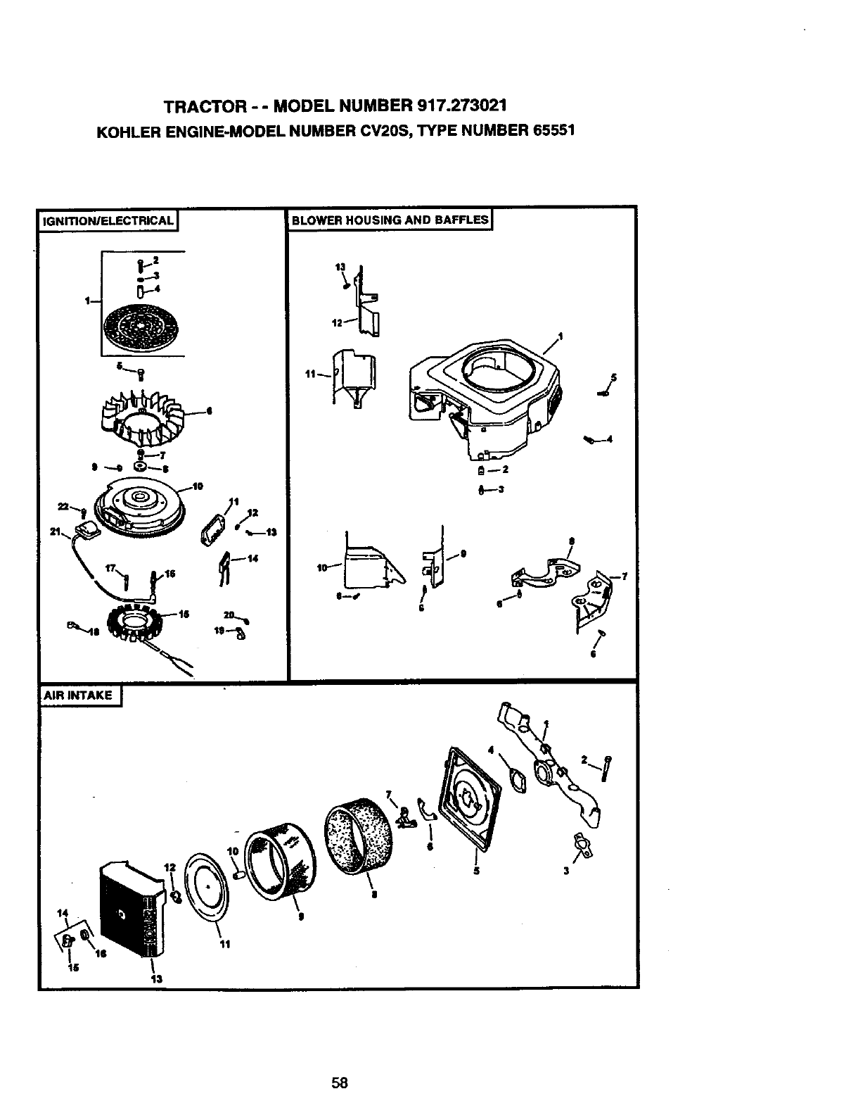
TRACTOR - - MODEL NUMBER 917.273021
KOHLER ENGINE-MODEL NUMBER CV20S, TYPE NUMBER 65551
IGNmONIELECTRICALI
e....3
AIR INTAKE I
3LOWER HOUSING AND BAFFLES I
e,_2
tl t4 7
s--o, 6 E
',I-
s
$
11
3
58
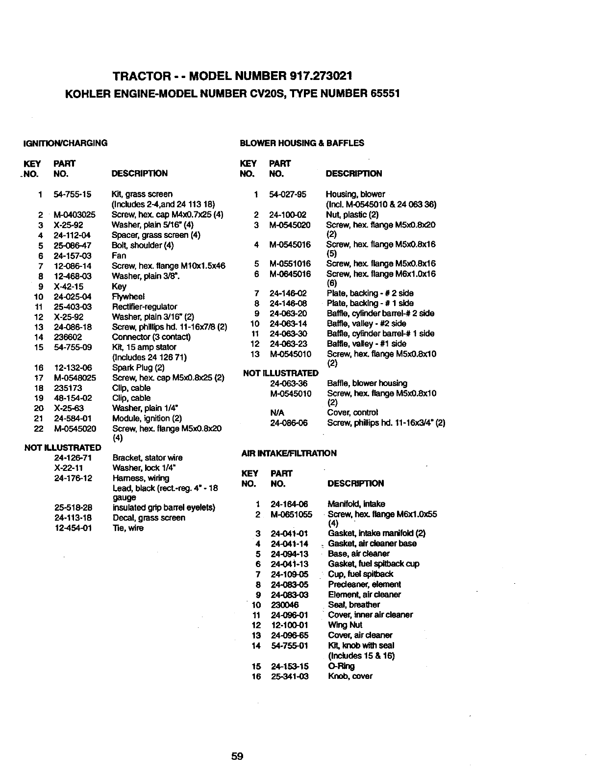
TRACTOR - - MODEL NUMBER 917.273021
KOHLER ENGINE-MODEL NUMBER CV20S, TYPE NUMBER 65551
IGNITION/CHARGING
KEY PART
.NO. NO.
154-755-15
2 M-0403025
3 X-25-92
4 24-112-04
5 25-086-47
6 24-15703
7 12-086-14
8 12-468-03
9 X-42-15
10 24-025-04
11 2540303
12 X-25.92
13 24-086-18
14 236602
15 54-755-09
16 12-132-06
17 M-0548025
18 235173
19 46-154-02
20 X-25-63
21 24-584-01
22 M-0545020
NOT ILLUSTRATED
24-126-71
X-22-11
24-176-12
25-518-28
24-113-18
12-454-01
BLOWER HOUSING & BAFFLES
KEY PART
DESCRIPTION NO. NO. DESCRIPTION
Kit,grass screen 1 54-027-95
(Includes2-4,and 24 113 18)
Screw,hex. cap M4xO.7x25(4) 2 24-10002
Washer, plain 5/16" (4) 3 M-0545020
Spacer,grass screen (4)
Bolt,shoulder (4) 4 M-0545016
Fan
Screw, hex. flange M10x1.5x46 5 M-0551016
Washer,plain 3/8". 6 M-0645016
Key
Flywheel 7 24-146-02
Rectifier-regulator 8 24-146-08
Washer, plain3/16" (2) 9 24-063-20
Screw, phillipshd. 11-16x7/8 (2) 10 24-063-14
Connector(3 contact) 11 24-063-30
Kit, 15 amp statcr 12 24-063-23
(Includes24 126 71) 13 M-0545010
Spark Plug (2)
Screw, hex.cap MSx0.8x25 (2)
Clip, cable
Clip, cable
Washer, plain 1/4" N/A
Module, ignition(2) 24-086-06
Screw, hex. flange M5xO.8x20
(4)
Housing,blower
(Incl. M-0545010 & 24 063 36)
Nut, plastic(2)
Screw,hex. flange M5xO.8x20
(2)
Screw, hex. flange M5x0.8x16
(s)
Screw,hex. flange M5xO.8x16
Screw, hex. flange M6x1.0x16
(6)
Plate, backing- #2 side
Plate, backing- # 1 side
Baffle,cylinderbarrel-# 2 side
Baffle,valley - #2 side
Baffle, cylinderbarrel-# 1 side
Baffle, valley - #1 side
Screw, hex. flange M5xO.8xl0
(2)
NOT ILLUSTRATED
24-063-36 Baffle, blowerhousing
M-0545010 Screw,hex. flange M5xO.8xl0
(2)
Cover, control
Screw,phillipshd. 11-16x3/4" (2)
Bracket, stator wire AIR IN'FAKFJFILTRATION
Washer, lock 1/4" KEY PART
Hamess, wiring NO. NO.
Lead, black (rect.-reg. 4"-18
gauge
insulatedgrip babel eyelets) 1 24-164-06
2 M-0651055
Decal, grassscreen
"Ne,wire 3 24-041-01
4 24041-14
5 24-094-13
6 24-041-13
7 24-109-05
8 24-O83-O5
9 24-083-03
10 23OO46
11 24-096-01
12 12-100-01
13 24-096-65
14 54-755-01
DESCRIPTION
15 24-153-15
16 25-341-03
Manifold,intake
Screw, he:<.flange M6x1.0x55
(4)
Gasket, intake manifold(2)
Gasket, airc_eanerbase
Base, air cleaner
Gasket, fuel spltbackcup
Cup, fuel spltback
Predeaner, element
Element, air cleaner
Seal, breather
Cover, innerair cleaner
w_g Nut
Cover, aircleaner
Kit,knobwithseal
(includes15 & 16)
o-P,_g
Knob, cover
59
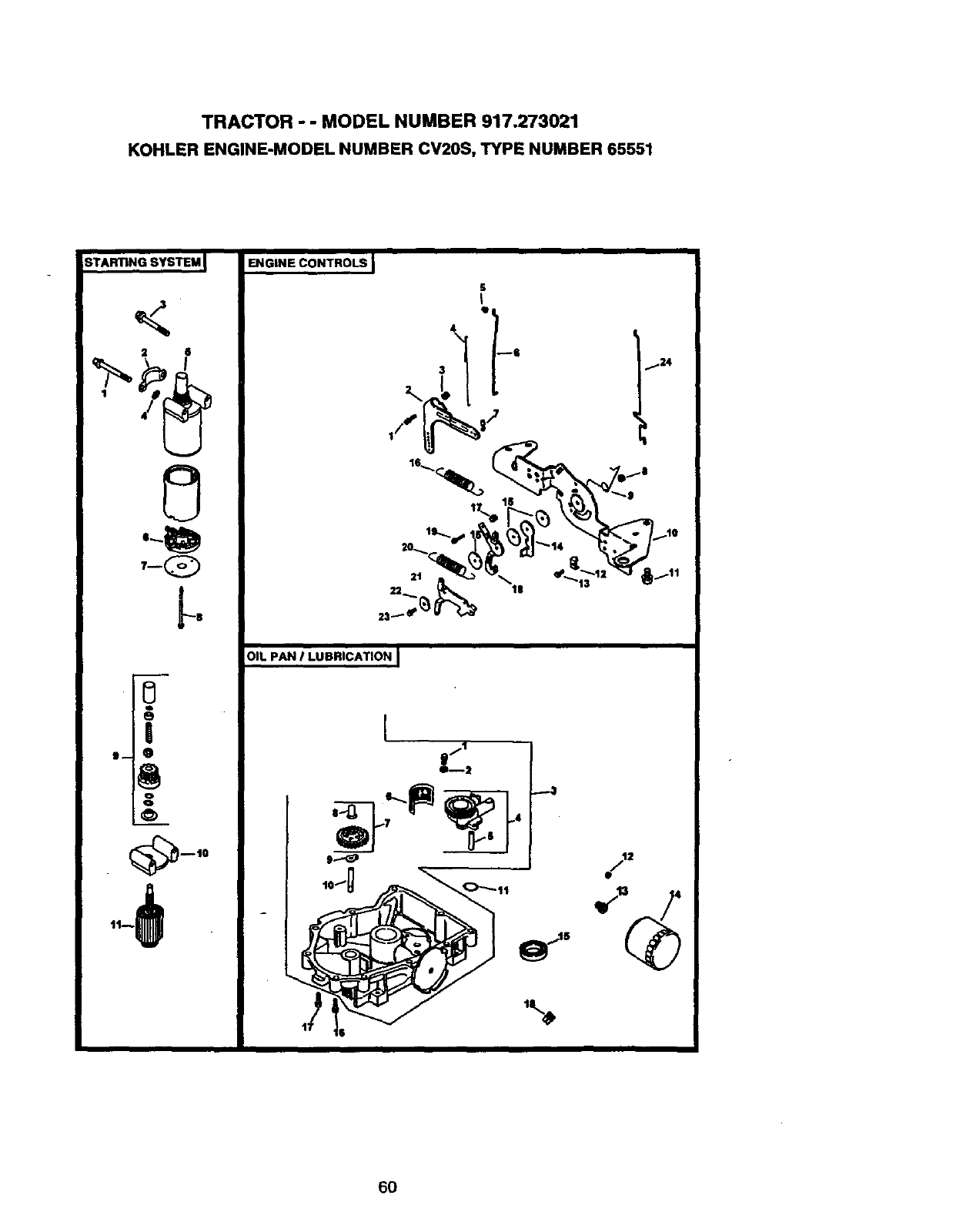
TRACTOR - - MODEL NUMBER 917.273021
KOHLER ENGINE-MODEL NUMBER CV2OS, TYPE NUMBER 65551
STARTING SYSTEM I
<,
ENGINE CONTROLS
S
I
4
3_Q 124
DIL pAN ILUBRICATION I
Ifl
Z--,
_3
2
6O
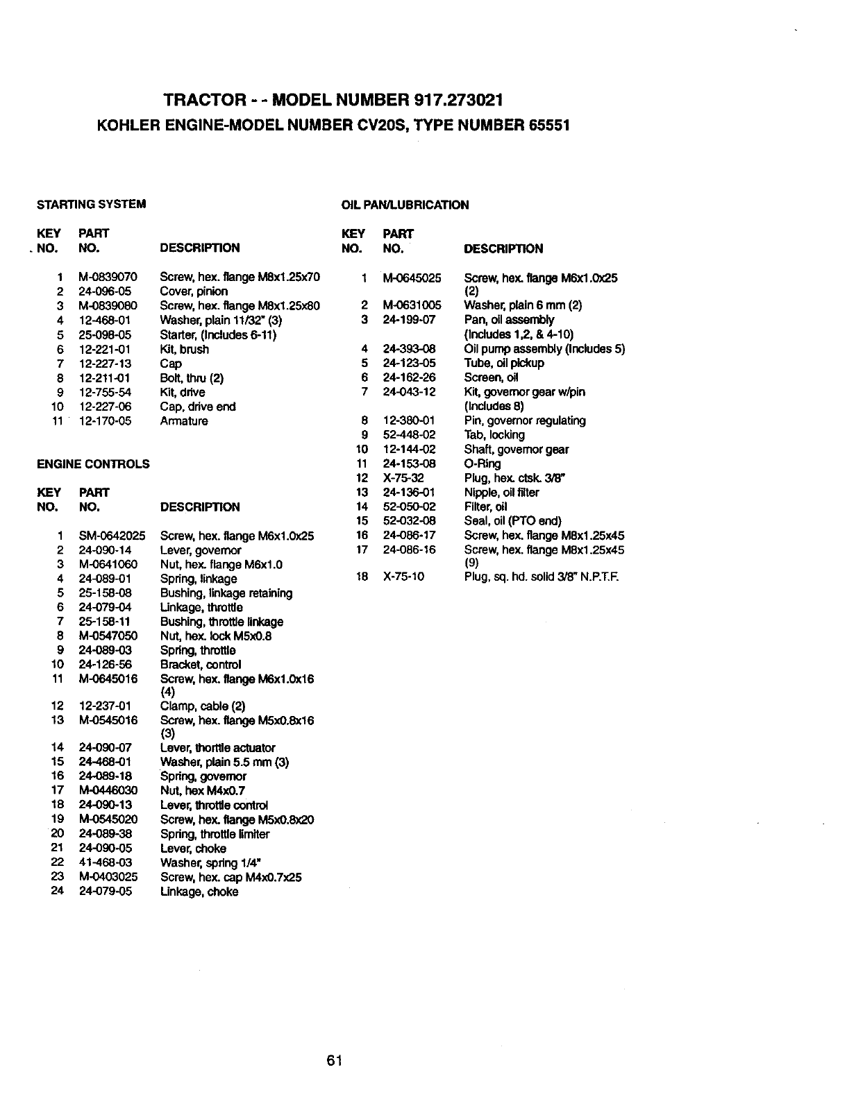
TRACTOR --MODEL NUMBER 917.273021
KOHLER ENGINE-MODEL NUMBER CV20S, TYPE NUMBER 65551
STARTING SYSTEM
KEY PART
.NO. NO.
1 M-0839070
2 24-096-05
3 M-0839080
4 12-468-01
5 25-098-05
6 12-221-01
7 12-227o13
8 12-211-01
9 12-755-54
10 12-227-06
11 12-170-05
ENGINE CONTROLS
KEY PART
NO. NO.
1SM-0642025
2 24-090-14
3M-0641(_o0
4 24-089-01
5 25-158-08
6 24-079-04
7 25-158-11
8 M-0547050
9 24-089-03
10 24-126-56
11 M-0645016
12 12-237-01
13 M-0545016
14 24-090-07
15 24-468-01
16 24089-18
17 M-0446030
18 24-090-13
19 M-0545020
20 24-089-38
21 24-090-05
22 41-468-03
23 M-0403025
24 24-079-05
OIL PAN/LUBRICATION
KEY PART
DESCRIPTION NO. NO.
Screw,hex. flange M8x1.25x70
Cover,pinion
Screw, hex. flange M8x1.25x80
Washer,plain 11/32" (3)
Starter,(Includes6-11)
Kit,brush
Cap
Bolt, thin (2)
Kit,dnve
Cap, driveend
Armature
DESCRIPTION
Screw,hex. flange M6x1.Ox25
Lever, governor
Nut, hex. flange M6xl.0
Spring, linkage
Bushing,linkage retaining
Linkage, throttle
Bushing,throttlelinkage
Nut, flex. lockM5x0.8
Spring, thmttla
Bracket, control
Screw,hex. flange M6x1.0x16
(4)
Clamp, cable (2)
Screw,hex. flange M5xO.8x16
(3)
Lever, thontle actuator
Washer, plain 5.5 mm (3)
Spring, govemor
Nut, hax M4x0.7
Lever, throttlecontrol
Screw,hex. flange M5x0.8x20
Spring, thmttla limiter
Lever, choke
Washer, spring1/4"
Screw, hex.cap M4xO.7x25
Linkage, choke
DESCRIPTION
1
2
3
4
5
6
7
8
9
10
11
12
13
14
15
16
17
18
M-0645025
M-0631005
24-199-07
24-393-08
24-12305
24-162-26
24-043-12
12-380-01
52-448-02
12-144-02
24-153-08
X-75-32
24-136-01
52-05002
52-032-08
24-086-17
24-086-16
X-75-10
Screw, heY,.flange M6x1.0x25
(2)
Washer,plain 6 mm (2)
Pan, oilassembly
(Includes1,2, & 4-10)
Oil pump assembly (Includes5)
Tube, oilpickup
Screen, oil
Kit,governorgear w/pin
(Includes8)
Pin, governorregulating
Tab, locking
Shaft, governorgear
O-Ring
Plug, hex.ctsk.3/8"
Nipple, oilfilter
Filter,oil
Seal, oil (PTO end)
Screw, hex. flange M8x1.25x45
Screw,hex. flange MSx1.25x45
(9)
Plug, sq. hal.solid3/8_N.P.T.F.
61
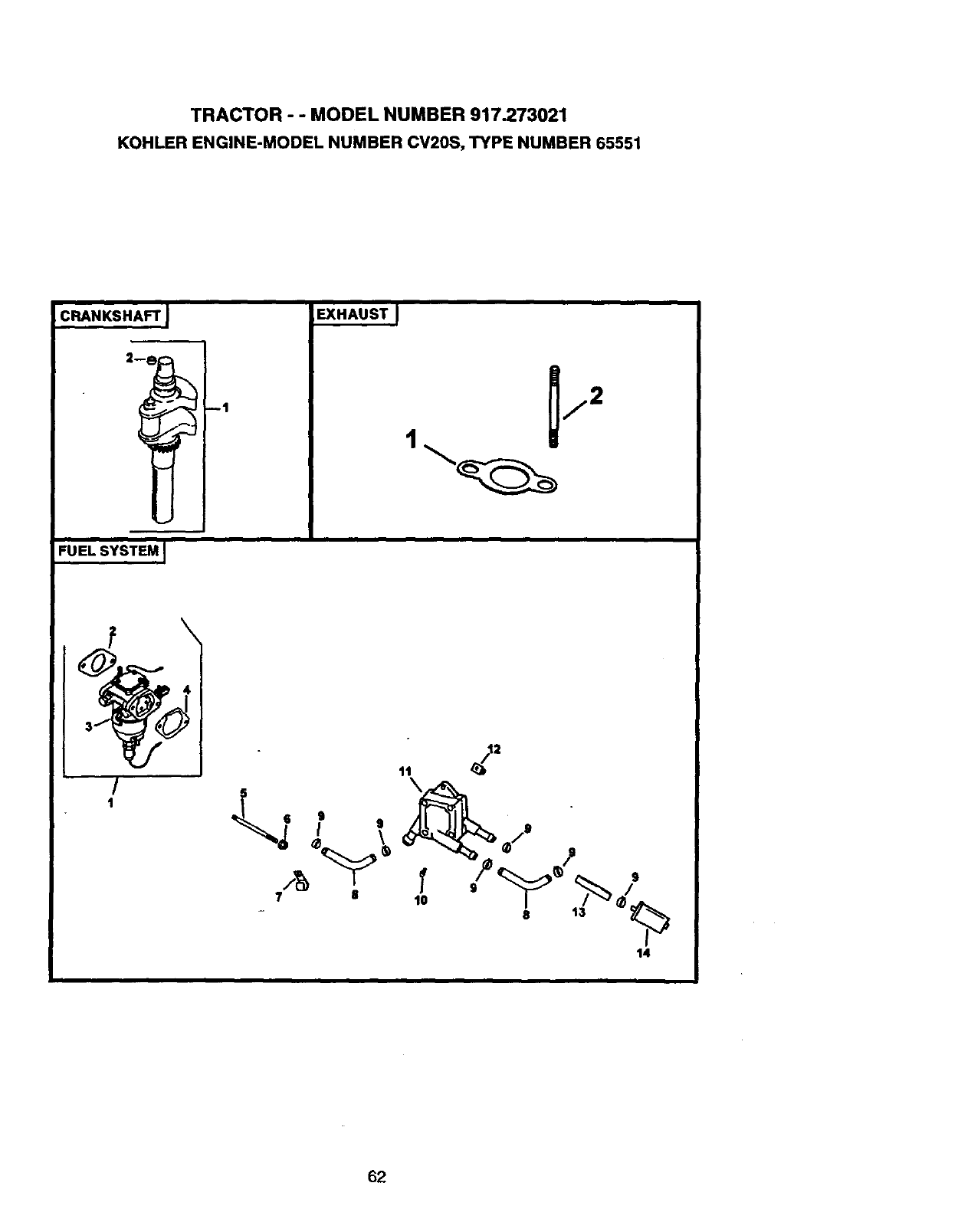
TRACTOR --MODEL NUMBER 917.273021
KOHLER ENGINE-MODEL NUMBER CV2OS, TYPE NUMBER 65551
CRANKSHAFT]
FUE'SVST_I
EXHAUST I
1
/
1
14
62
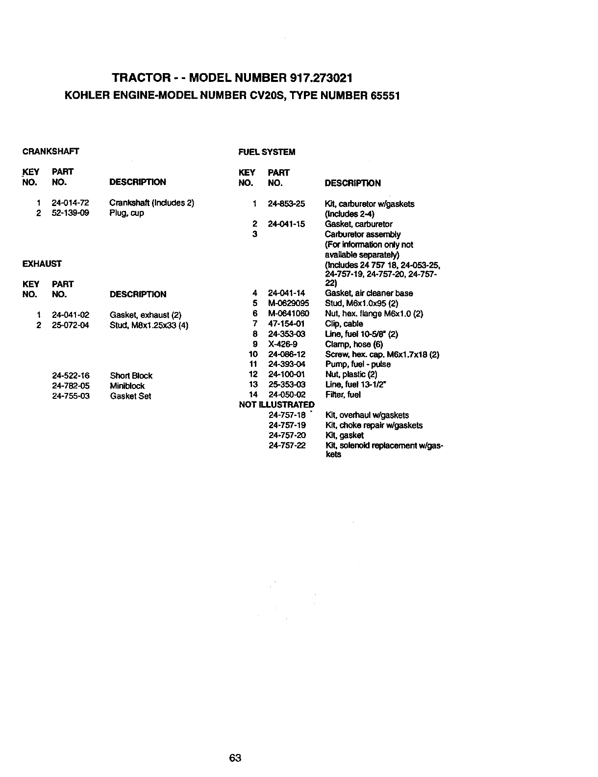
TRACTOR - - MODEL NUMBER 917.273021
KOHLER ENGINE-MODEL NUMBER CV20S, TYPE NUMBER 65551
CRANKSHAFT
KEY PART
NO. NO.
1 24-014-72
2 52-139-09
EXHAUST
KEY PART
NO. NO.
1 24-041-02
2 25-072-04
24-522-16
24-782-05
24-755-03
FUEL SYSTEM
KEY PART
DESCRIPTION NO. NO.
Crankshaft(Includes2) 1 24-853-25
Plug, cup 2 24-O41-15
3
DESCRIPTION 4 24-041-14
5 M-0629095
Gasket, exhaust(2) 6 M-0641060
Stud, M8x1.25x33 (4) 7 47-154-01
8 24-353-03
9 X-426-9
10 24-o86-12
11 24-393-04
Shod Block 12 24-100-01
Miniblock 13 25-353-03
Gasket Set 14 24-050-02
NOT ILLUSTRATED
24-757-18 "
24-757-19
24-757.20
24-757-22
DESCRIPTION
carburetorw/gaskets
(Indudas 2-4)
Gasket, carburetor
Carburetorassembly
(For infomlationonlynot
availableseparately)
(Includes24 757 18, 24-053-25,
24-757-19, 24-757-20, 24-757-
22)
Gasket, air cleaner base
Stud, M6x1.0x95 (2)
Nut, hex.flange M6x1.0 (2)
Clip, cable
Une, fuel 10-5/8" (2)
Clamp, hose (6)
Screw, hex.cap. M6xl.7x18 (2)
Pump, fuel-pulse
Nut, plastic(2)
Line, fuel 13-1/2'
Filter,fuel
Kit,overhaulw/gaskets
Kit,chokerepairw/gaskets
Kit,gasket
Kit,solenoidreplacementw/gas-
kets
63

SUGGESTED GUIDE FOR SIGHTING SLOPES FOR SAFE OPERATION
ONLY RIDE UP AND DOWN HILL,
NOT ACROSS HILL
03
4_
I_ Operate your Tractor up and down the face of slopes (not I
I
greater then 15°), never across the face. Make turns gradu-
ally to prevent tipping or loss of control. Exercise extreme
caution when changing direction on slopes.
'hi

65

66

67

For the repair or replacement pads you need
delivered directly to your home
Call 7 am - 7 pm, 7 days a week
1-800-366-PART
(1-800-366-7278)
Para ordenar piezas con entrega a
domlcilio -1-800-659-7084
For in--house major brand repair service
Call 24 hours a day, 7 days a week
1-800-4-REPAIR
(1-800-473-7274)
Para pedir servicio de reparaci6n a
domicilio- 1-800-676-5811
For the location of a Sears Parts and
Repair Center in your area
Call 24 hours aday, 7 days a week
1-800-488-1222
For information on purchasing a Sears
Maintenance Agreement or to inquire
about an existing Agreement
Call 9 am - 5 pm, Monday-Saturday
1-800-827-6655
When requesting service or ordering
pads, always provide the following
information:
•Product Type •Part Number
•Model Number •Part Description SEAR8
Amenca's Repair Specialists
165018 Rev, 5 8.10.98 RDFI'WRH/SV Printed in U.S.A.
