Craftsman 917273042 User Manual TRACTOR Manuals And Guides 98100086
CRAFTSMAN Lawn, Tractor Manual 98100086 CRAFTSMAN Lawn, Tractor Owner's Manual, CRAFTSMAN Lawn, Tractor installation guides
User Manual: Craftsman 917273042 917273042 CRAFTSMAN TRACTOR - Manuals and Guides View the owners manual for your CRAFTSMAN TRACTOR #917273042. Home:Lawn & Garden Parts:Craftsman Parts:Craftsman TRACTOR Manual
Open the PDF directly: View PDF ![]() .
.
Page Count: 64
Owner's Manual
£RI:IFTSMI
20.0 HP
ELECTRIC STAi:_
46" MOWER
AUTOMATIC
GARDEN TRAL 34:I
Model No.
917.273042
* Safety
• Assembly
•Operation
•Maintenance
•Repair Parts
CAUTION:
Read and follow all
Safety Rules and Instructions
before operating this equip-
ment.
For answers to your questions
about this product, Call:
1-800-659-5917
Sears Craftsman Help Une
5 am - 5 pm, Mon- Sat
Sears, Roebuck and Co., Hoffman Estates, IL 60179
Warranty ................................................. 2
Safety Rules ........................................... 2
Product Specifications ........... ,............... 5
/_sembly,_: ........... _................................ 8
Oj:_ration .............................................. 12
M'a'lntenanceSchedule ......................... 19
Maintanance ......................................... 19
Service and Adjustments...................... 23
Storage ................................................. 31
Troubleshooting.................................... 32
Repair Parts ......................................... 36
Parts Ordedng ....................... Beck Cover
LIMITED TWO YEAR WARRANTY ON CRAFTSMAN RIDING EQUIPMENT
For two (2) years from the date of pumhase, if this Craftsman Riding Equipment is main-
tained, lubdcatod and tuned up accordingto the instructionsin the owner's manual,
Sears will repair or replace, free of charge, any parts found to be defective in material or
workmanship.
This Warranty does not cover.
• Expendable items which become worn during normal use, such as blades, spark
plugs, air cleaners, belts, etc.
•Tire replacement or repair caused by punctures from outside objects, such as nails,
thoms, stumps, or glass.
•Repairs necessary because ofoperator abuse, negligence, improper storage or acci-
dent or the failure to maintain the equipment according to the instructionscontained in
the owner's manual.
•Riding equipment used for commercial or rental purposes.
LIMITED 90 DAY WARRANTY ON BATTERY
For ninety (90) days from date of purchase, if any battery included with this riding equip-
ment proves defective in material or workmanship and our testing determines the bat-
tery will not hold a charge, Sears will replace the battery at no charge. In-home warranty
service on your Craftsman ridingequipment is available at no charge for 30 days from
the date of purchase. Please contact your nearest service center. After 30 days from the
date of pumhase, warranty service is available by taking your Craftsman ridingequip-
ment to your nearest Sears Service Center. (In-home warranty sew'mewill still be avail-
able after 30 days from the date of purchase but a standard trip charge will apply). This
warranty applies only while this product is in the United States. This Warranty gives you
specific legal rights, and you may also have other rights which may vary from state to
state.
Sears, Roebuck and Co., D/817 WA, Hoffman Estates, IL 60179
=
GENERAL OPERATION
•Read, understand, and follow all instruc-
tions in the manual and on the machine
before starting.
•Only allow responsible adults, who are
familiar with the instructions,to operate
the machine.
•Clear the area of objects such as rocks,
toys, wire, etc., which could be picked
up and thrown by the blade.
•Be sine the area is clear of other people
before mowing. Stop machine if anyone
enters the area.
•Never carry passengers.
•Do not mow in reverse unless absolute-
ly necessary.Always look down and
behind before and while backing.
•Be aware of the mower discharge direc-
tion and do not point it at anyone. Do
not operate the mower without either
the entire grass catcher or the guard in
place.
•Slow down before tuming.
• Never leave a running machine unat-
tended. Always turn offblades, set park-
ing brake, stop engine, and remove
keys before dismounting.
2

• Tum off blades when not mowing.
•Stop engine before removing grass
catcher or unclogging chute.
•Mow only in daylight or good artificial
light.
•Do not operate the machine while under
the influence of alcohol or drugs.
•Watch for trafficwhen operating near or
crossing roadways.
•Use extra care when loading or unload-
ing the machine into a trailer or truck.
SLOPE OPERATION
Slopes are a major factor related to loss-
of-control and tipover accidents, which
can result in severe injury or death. All
slopes require extra caution. If you cannot
back up the slope or if you feel uneasy on
it, do not mow it.
DO:
•Mow up and down slopes, not across.
•Remove obstacles such as rocks, tree
limbs, etc.
•Watch for holes, ruts, or bumps. Uneven
terrain could overturn the machine. Tall
grass can hide obstacles.
•Use slow speed. Choose a low gear so
that you will not have to stop or shift
while on the slope.
•Follow the manufacturer's recommen-
dations for wheel weights or counter-
weights to improve stability.
•Use extra care with grass catchers or
other attachments. These can change
the stability of the machine.
•Keep all movement on the slopes slow
and gradual. Do not make sudden
changes in speed or direction.
•Avoid starting or stopping on a slope. If
tires lose traction, disengage the blades
and proceed slowly straight down the
slope.
DO NOT:
•Do not turn on slopes unless necessary,
and then, turn slowly and gradually
downhill, if possible.
•Do not mow near drop-offs, ditches, or
embankments. The mower could sud-
denly turn over if a wheel is over the
edge of a cliff or ditch, or if an edge
caves in.
•Do._t mow on wet grass. Reduced
traction could cause sliding.
•Do nottry to stabilize the machine by
puttingyour foot on the ground.
•Do not use grass catcher on steep
slopes.
CHILDREN
Tragic accidents can occur if the operator
is not alert tO the presence of children.
Children are often attracted to the
machine and the mowing activity. Never
assume that children will remain where
you last saw them.
•Keep children out of the mowing area
and under the watchful care of another
responsible adult.
•Be alert and tum machine off if children
enter the area.
•Before and when backing, look behind
and down for small children.
•Never carry children. They may fall off
and be seriously injured or interfere with
safe machine operation.
•Never allow children to operate the
machine.
•Use extra care when approaching blind
comers, shrubs, trees, or other objects
that may obscure vision.
SERVICE
•Use extra care in handling gasoline and
other fuels. They are flammable and
vapors are explosive.
Use only an approved container.
Never remove gas cap or add fuel
with the engine running. Allow en-
gine to cool before refueling. Do not
smoke.
Never refuel the machine indoors.
Never store the machine or fuel
container inside where there is an
open flame, such as a water heater.
•Never run a machine inside a closed
area.
•Keep nuts and bolts, especially blade
attachment bolts, tight and keep equip-
ment in good condition.
•Never tamper with safety devices.
Check their proper operation regularly.
•Keep machine free of grass, leaves, or
other debris build-up. Clean oil or fuel
spillage. Allow machine to cool before
storing.
•Stop and inspect the equipment if you
stdke an object. Repair, if necessary,
before restarting.
3
•Never make adjustments or repairs with
the engine running.
•Grass catcher components are subject
to wear, damage, and detedoraUon,
which could expose movingparts or
allow objects to be thrown. Frequently
check components and replace with
manufacturer's recommended parts,
when necessary.
•Mower blades are sharp and can cut.
Wrap the blade(s) or wear gloves, and
use extra caution when servicing them.
•Check brake operation frequently.
Adjust and service as required.
•Be sure the area is clear of other people
before mowing. Stop machine if anyone
enters the area.
•Never carry passengers.
•Do not mow in reverse unless absolute-
ly necessary. Always look down and
behind before and while backing.
•Never carry children. They may fall off
and be seriously injured or interfere with
safe machine operation.
•Keep children out of the mowing area
and under the watchful care of another
responsible adult.
•Be alert and turn machine off if children
enter the area.
•Before and when backing, look behind
and down for small children.
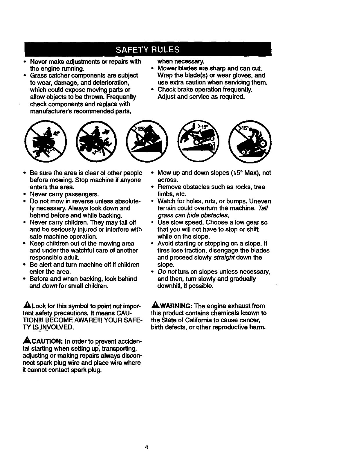
•Mow up and down slopes (15 ° Max), not
across.
•Remove obstacles such as rocks, tree
limbs, etc.
•Watch for holes, ruts, or bumps. Uneven
terrain could overturn the machine. Tall
grass can hide obstacles.
•Use slow speed. Choose a low gear so
that you will not have to stop or shift
while on the slope.
•Avoid starting or stopping on aslope. If
tires lose traction, disengage the blades
and proceed slowly straight down the
slope.
•Do not turnon slopes unless necessary,
and then, turn slowly and gradually
downhill, if possible.
,ALook for this symbol to point out impor-
tant safety precautions. It means CAU-
TION!!! BECOME AWARE!!! YOUR SAFE-
TY IS iNVOLVED.
_CAUTION: In order to prevent acciden-
tal starting when setting up, transporting,
adjusting or making repairs always discon-
nect spark plug wire and place wire where
it cannot contact spark plug.
_WARNING: The engine exhaust from
this product contains chemicals known to
the State of California to cause cancer,
birth defects, or other reproductive harm.
4
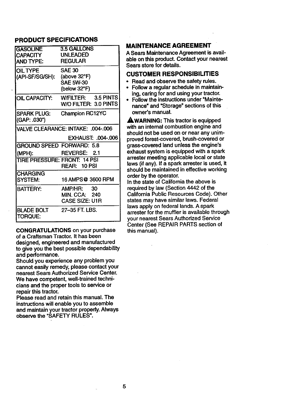
PRODUCT SPECIFICATIONS
GASOLINE 3.5 GALLONS
CAPACITY UNLEADED
AND TYPE: REGULAR
)ILTYPE SAE 3O
_,PI-SF/SG/SH): (above 32°F)
SAE 5W-30
(below 32°F)
OIL CAPACITY: W/FILTER: 3.5 PINTS
W/O FILTER: 3.0 PINTS
SPARK PLUG: Champion RC12YC
GAP: .030")
ALVE CLEARANCE: INTAKE: .004-.006
EXHAUST: .004-.006
GROUND SPEED FORWARD: 5.8
(MPH): REVERSE: 2.1
TIRE PRESSURE: FRONT: 14 PSI
REAR: 10 PSI
CHARGING
SYSTEM: 16 AMPS @3600 RPM
BATTERY: AMP/HR: 30
MIN. CCA: 240
CASE SIZE: U1R
BLADE BOLT 27-35 FT. LBS.
TORQUE:
CONGRATULATIONS on your purchase
of a Craftsman Tractor. It has been
designed, engineered and manufactured
to give you the best possible dependability
and performance.
Should you experience any problem you
cannot easily remedy, please contact your
nearest Sears Authorized Service Center.
We have competent, well-trained techni-
cians and the proper tools to service or
repair this tractor.
Please read and retain this manual. The
instructions will enable you to assemble
and maintain your tractor properly. Always
observe the "SAFETY RULES".
MAINTENANCE AGREEMENT
A Sears Maintenance Agreement is avail-
able on this product. Contact your nearest
Sears store for details.
CUSTOMER RESPONSIBILITIES
•Read and observe the safety rules.
•Follow a regular schedule in maintain-
ing, caring for and using your tractor.
•Follow the instructions under =Mainte-
nance" and =Storage" sections of this
owner's manual.
_,WARNING: This tractor is equipped
with an intemal combustion engine and
should not be used on or near any unim-
proved forest-covered, brush-covered or
grass-covered land unless the engine's
exhaust system is equipped with a spark
arrester meeting applicable local or state
laws (if any). If a spark arrester is used, it
should be maintained in effective working
order by the operator.
In the state of California the above is
required by law (Section 4442 of the
California Public Resources Code). Other
states may have similar laws. Federal
laws apply on federal lands. A spark
arrester for the muffler is available through
your nearest Sears Authorized Service
Center (See REPAIR PARTS section of
this manual).
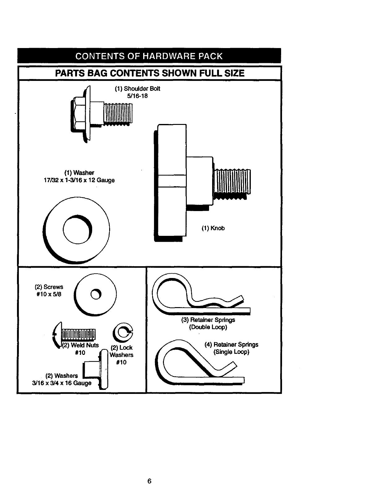
PARTS BAG CONTENTS SHOWN FULL SIZE
•(1) Shoulder Bolt
5/16-18
(1) Washer
17/32 x 1-3/16 x 12 Gauge
(1) Knob
(2) Screws
#10 x 5/8 i
A,
(2) Weld Nuts ,-. (2) Lock
#1_ Washersi . #1o
(2) Washers L_
3/16 x 3/4 x 16 Gauge _,..,
(3) Retainer Springs
(Double Loop)
(4) Retainer Springs
6
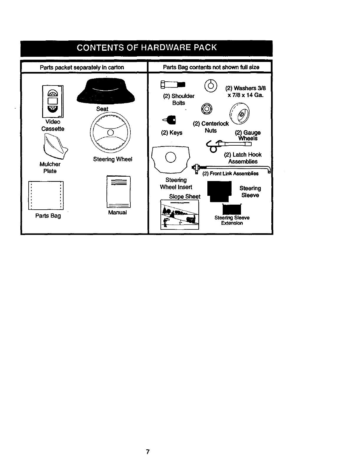
Parts packet separately in carton Parts Bag contents not shown full size
DSeat
Video
Cassette
Steering Wheel
Mulcher
Plate
Parts Bag
--...__
Manual
(_ (2) Washers 3/8
(2) Shoulder x 718 x 14 Ga.
Bolts
(2) Centerlock
(2) Keys Nuts (2) Gauge
Wheels
r''1% ,,
F(_ "_ _(2)Latch Hook
\ _ /Assemblies
t"'--_ z_(2) FrontLinkAseemblies
Steering
Wheel Insert Steering
Slope Sheet Sleeve
SteeringSleeve
Extension
7
Yournewtractorhasbeenassembledat the factorywithexceptionof thosepartsleft
unassembledfor shippingpurposes.Toensuresafeand properoperationofyourtractor
all partsand hardwareyouassemblemustbe tightenedsecurely.Usethe corr,ecttools
as necessaryto insurepropertightness.Reviewthevieeocassetteoeloreyouoegin.
TOOLS REQUIRED FOR
ASSEMBLY
- A socket wrench set will make assembly
easier. Standard wrench sizes you need
are listed below.
(1) 9/16" wrench (1) 3/4" Socket w/
(1) 1/2" wrench drive ratchet
(1) Utility knife (1) Phillips Screw-
(1)Pliers driver
(1) Tire pressure gauge
When right or left hand is mentioned in
this manual, it means, from your point of
view, when you are in the operating posi-
tion (seated behind the steering wheel).
TO REMOVE TRACTOR FROM
CARTON
UNPACK CARTON
• Remove all accessible loose parts and
parts boxes from shipping carton (See
page 6).
•Cut, from top to bottom, along lines on
all four comers of shipping carton, and
lay panels flat.
• Remove mower and package materials.
•Check for any additional loose parts or
boxes and remove.
BEFORE ROLLING TRACTOR OFF
SKID
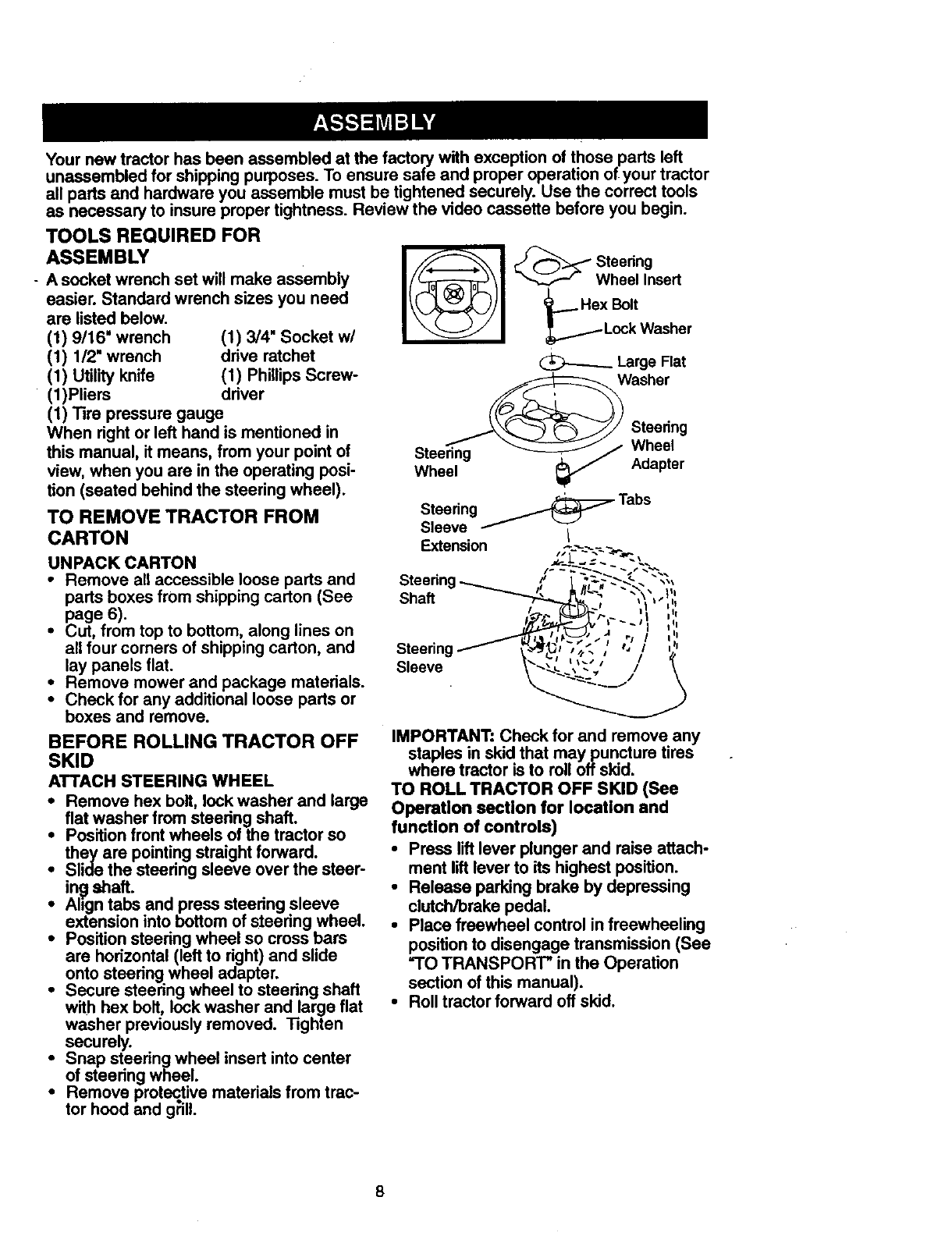
ATTACH STEERING WHEEL
• Remove hex bolt, lock washer and large
fiat washer from steering shaft.
•Position front wheels of the tractor so
they are pointing straight forward.
•Slide the steering sleeve over the steer-
Jn_ shaft.
•Align tabs and press steering sleeve
extension into bottom of steering wheel.
•Position steering wheel so cross bars
are horizontal (left to right) and slide
onto steering wheel adapter.
•Secure steering wheel to steering shaft
with hex bolt, lock washer and large flat
washer previously removed. Tighten
securely.
•Snap steering wheel insert into center
of steering wheel.
•Remove protective materials from trac-
tor hood and g_ill.
I l *een0
Wheel Insert
__._ Hex Bolt
Lock Washer
_Large Flat
Washer
Steering
Steering Wheel
Wheel Adapter
Steering _Tabs
Sleeve I
Extension
%\**
Shaft
Steering
Sleeve
IMPORTANT: Check for and remove any
staples in skid that maypuncture tires
where tractor is to roll offskid.
TO ROLL TRACTOR OFF SKID (See
Operation section for location and
function of controls)
•Press lift lever plunger and raise attach-
ment lift lever to its highest position.
•Release parking brake by depressing
clutch/brake pedal.
•Place freewheel control in freewheeling
position to disengage transmission (See
"TO TRANSPORT" in the Operation
section of this manual).
•Roll tractor forward off skid.
8
HOW TO SET UP YOUR TRACTOR
CHECKBATTERY
• Lifthoodto raisedposition
•If this battery is put into service after
month and year indicated on label (label
located between terminals) charge bat
tery for minimum of one hour at 6-10
amps. (See "BATTERY' in MAINTE-
NANCE section of this manual for charg-
ing instructions).
.o't.'I .. *..
=I
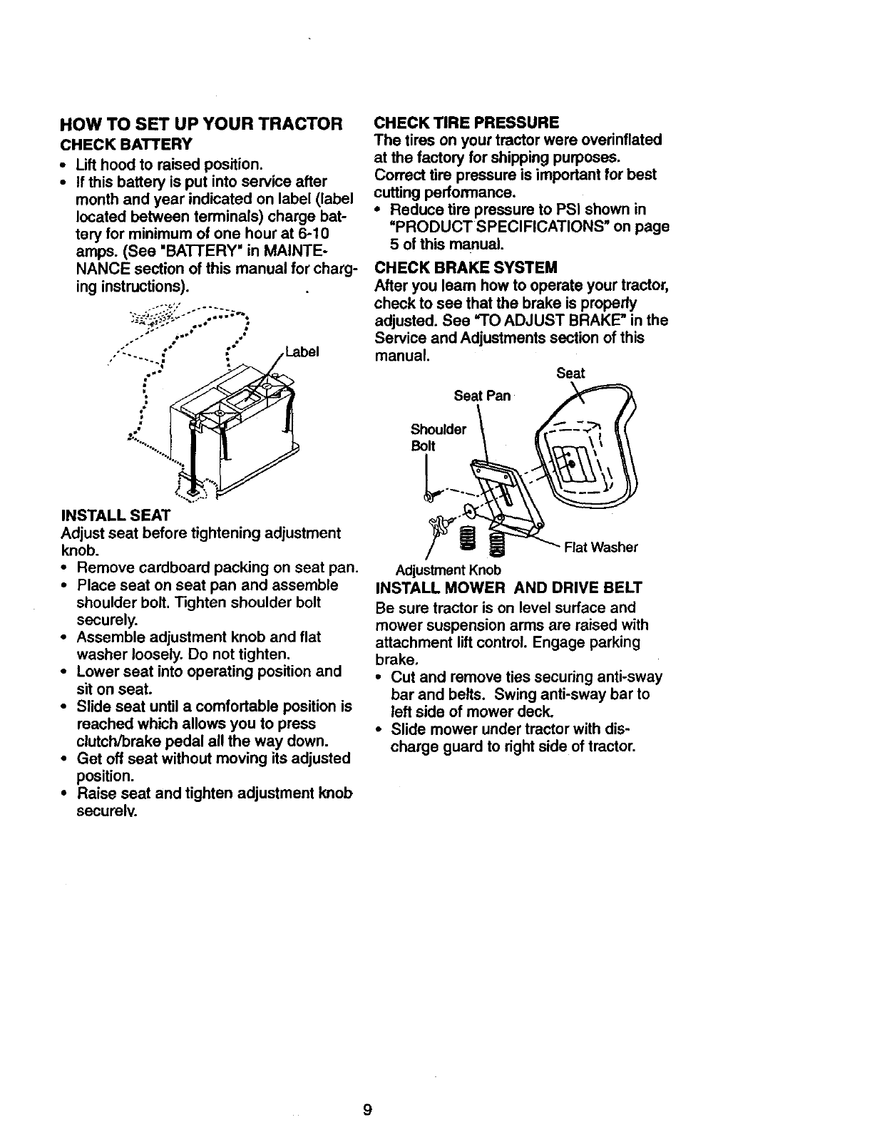
INSTALL SEAT
Adjust seat before tightening adjustment
knob.
•Remove cardboard packing on seat pan.
•Place seat on seat pan and assemble
shoulder bolt. Tighten shoulder bolt
securely.
•Assemble adjustment knob and flat
washer loosely. Do not tighten.
•Lower seat into operating position and
sit on seat.
•Slide seat until a comfortable position is
roached which allows you to press
clutch/brake pedal all the way down.
•Get off seat without moving its adjusted
position.
•Raise seat and tighten adjustment knob
securelv.
CHECK TIRE PRESSURE
The tires on your tractor were overinflated
at the factory for shipping purposes.
Correct tire pressure is important for best
cutting performance.
• Reduce tire pressure to PSI shown in
"PRODUCT SPECIFICATIONS" on page
5 of this manual.
CHECK BRAKE SYSTEM
After you leam how to operate your tractor,
check to see that the brake is properly
adjusted. See "TO ADJUST BRAKE" in the
Service and Adjustments section of this
manual.
Seat
Seat Pan
Shoulder
Bolt
Flat Washer
Adjustment Knob
INSTALL MOWER AND DRIVE BELT
Be sure tractor is on level surface and
mower suspension arms are raised with
attachment lift control. Engage parking
brake.
• Cut and remove ties securing anti-sway
bar and belts. Swing anti-sway bar to
left side of mower deck.
•Slide mower under tractor with dis-
charge guard to right side of tractor.
9
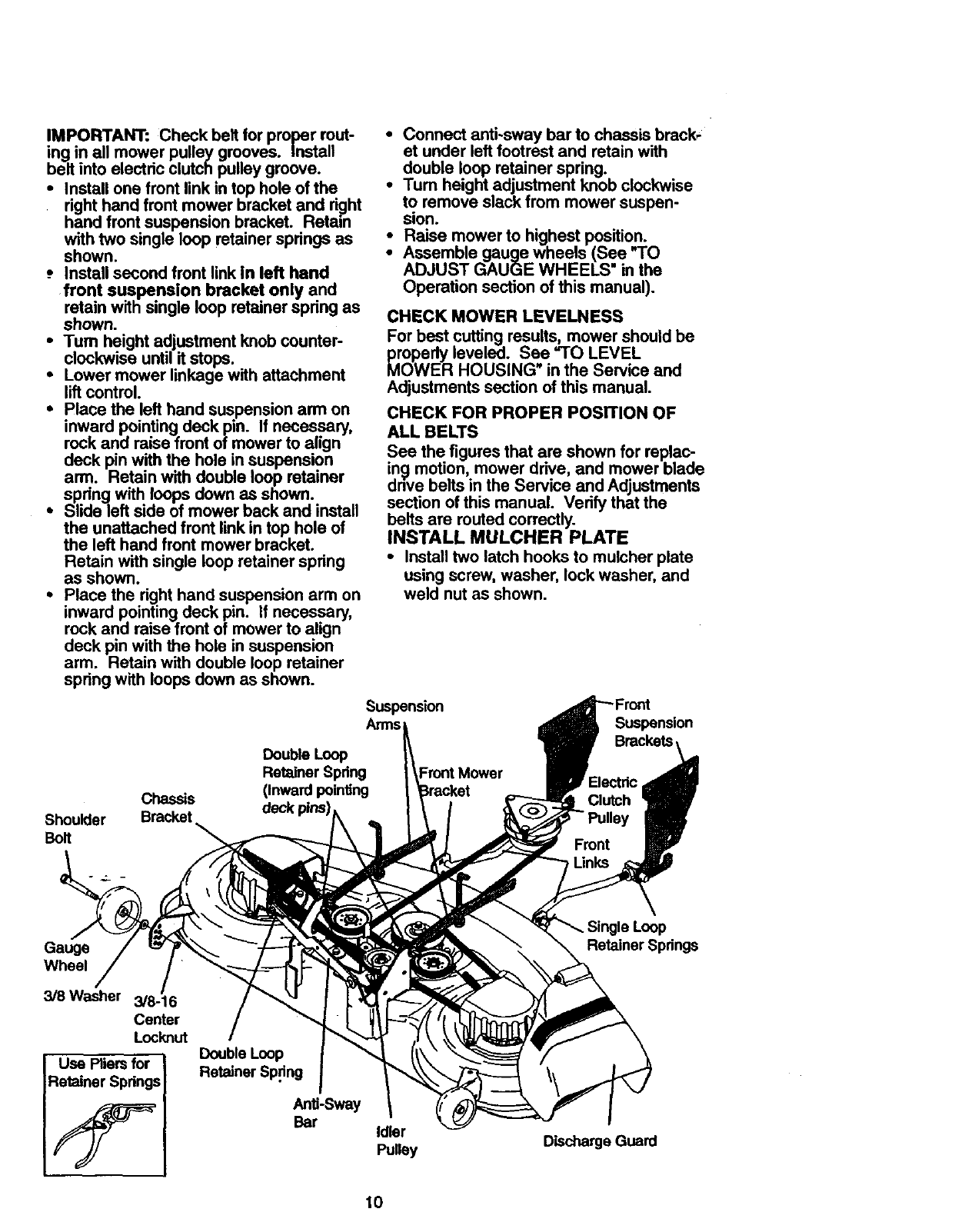
IMPORTANT:Checkbeltfor properrout-
ing in all mowerpulleygrooves. Install
beltinto electricclutchpulleygroove.
•Install one front link in top hole of the
right hand front mower bracket and d_ht
hand front suspension bracket. Retain
with two single loop retainer springa as
shown.
-. Install second front link in left hand
front suspension bracket only and
retain with single loop retainer spring as
shown.
•Turn height adjustment knob counter-
clockwise until it stops.
•Lower mower linkage with attachment
lift control.
• Place the left hand suspension arm on
inward pointing deck pin. If necessary,
rock and raise front of mower to align
deck pin with the hole in suspension
arm. Retain with double loop retainer
spring with loops down as shown.
• Slide left side of mower back and install
the unattached front link in top hole of
the left hand front mower bracket.
Retain with single loop retainer spring
as shown.
•Place the right hand suspension arm on
inward pointing deck pin. If necessary,
rock and raise front of mower to align
deck pin with the hole in suspension
arm. Retain with double loop retainer
spring with loops down as shown.
Chassis
Shoulder Bracket
BoR
•Connect anti-sway bar to chassis brack,
et under left footrest and retain with
double loop retainer spring.
•Tum height adjustment knob clockwise
to remove slack from mower suspen-
sion.
•Raise mower to highest position.
Assemble gauge wheels (See "TO
ADJUST GAUGE WHEELS" in the
Operation section of this manual).
CHECK MOWER LEVELNESS
For best cutting results, mower should be
properly leveled. See =TO LEVEL
MOWER HOUSING in the Service and
Adjustments section of this manual.
CHECK FOR PROPER POSITION OF
ALL BELTS
See the figures that are shown for replac-
ing motion, mower drive, and mower blade
drive belts in the Service and Adjustments
section of this manual. Verify that the
belts are routed correctly.
INSTALL MULCHER PLATE
•Install two latch hooks to mulcher plate
using screw, washer, lock washer, and
weld nut as shown.
Suspension -'root
Arms Suspension
Double Loop
Retainer Spdng
(Inward pointing
_eckpins)
FrontMower
Gauge
Wheel
3/8 Washer 3/8-16
Center
Locknut
Use Pliers for
Retainer Springs
Double Loop
Retainer Sp_ng
Idler
Pulley Discharge Guard
Loop
Retainer Springs
10
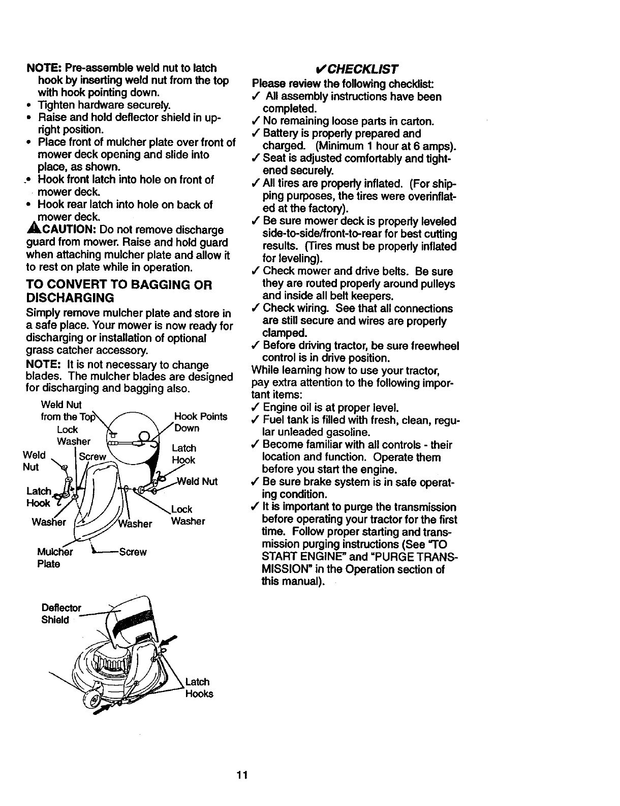
NOTE:Pre-assembleweld nutto latch
hookby insertingweldnutfromthetop
withhookpointingdown.
•Tighten hardware securely.
• Raise and hold deflector shield in up-
right position.
•Place front of mulcher plate over front of
mower deck opening and slide into
place, as shown.
.• Hook front latch into hole on front of
mower deck.
•Hook rear latch into hole on back of
mower deck.
_.CAUTION: Do not remove discharge
guard from mower. Raise and hold guard
when attaching mulcher plate and allow it
to rest on plate while in operation.
TO CONVERT TO BAGGING OR
DISCHARGING
Simply remove mulcher plate and store in
a safe place. Your mower is now ready for
discharging or installation of optional
grass catcher accessory.
NOTE: It is not necessary to change
blades. The mulcher blades are designed
for discharging and bagging also.
Weld Nut Hook Points
Lock
Washer Latch
Weld Hook
Nut
Nut
Latch
Lock
Washer
Mulcher _=-----Screw
Plate
Deflector
Shield
CHECKLIST
Please review the following checklist:
,/ All assembly instructions have been
completed.
/No remaining loose parts in carton.
/Battery is properly prepared and
charged. (Minimum 1 hour at 6 amps).
/Seat is adjusted comfortably and tight-
ened securely.
/All tires are properly inflated. (For ship-
ping purposes, the tires were overinflat-
ed at the factory).
,/Be sure mower deck is properly leveled
side-to-side/front-to-rear for best cutting
results. (Tires must be properly inflated
for leveling).
/Check mower and drive belts. Be sure
they are routed properly around pulleys
and inside all belt keepers.
,/Check wiring. See that all connections
are still secure and wires are propedy
clamped.
4' Before driving tractor, be sure freewheel
control is in drive position.
While learning how to use your tractor,
pay extra attention to the following impor-
tant items:
•/Engine oil is at proper level.
•/ Fuel tank is filled with fresh, clean, regu-
lar unleaded gasoline.
,/Become familiar with all controls -their
location and function. Operate them
before you start the engine.
,/Be sure brake system is in safe operat-
ing condition.
,/It is important to purge the transmission
before operating your tractor for the first
time. Follow proper starting and trans-
mission purging instructions (See "TO
START ENGINE" and =PURGE TRANS-
MISSION" in the Operation section of
this manual).
Latch
11
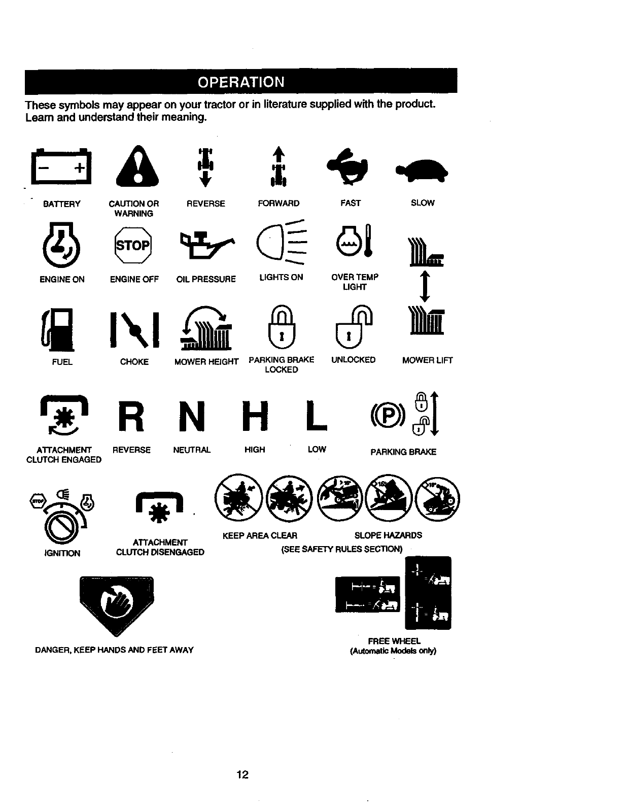
Thesesymbolsmayappearonyourtractoror in literaturesuppliedwiththeproduct.
Learnandunderstandtheirmeaning.
BATTERY CAUTION OR REVERSE FORWARD FAST SLOW
WARNING
FUEL CHOKE MOWER HEIGHT PARKING BRAKE UNLOCKED MOWER LIFT
LOCKED
N H L
ATTACHMENT REVERSE NEUTRAL HIGH LOW PARKING BRAKE
CLUTCH ENGAGED
ATTACHMENT KEEP AREA CLEAR SLOPE HAZARDS
IGNmON CLUTCH DISENGAGED (SEE SAFETY RULES SECTION)
DANGER, KEEP HANDS AND FEET AWAY
FREE WHEEL
(AutomaticModelsone/)
12
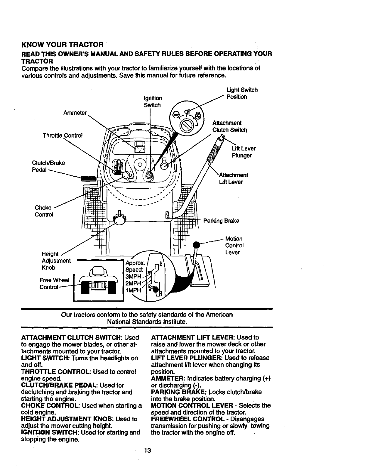
KNOW YOUR TRACTOR
READTHISOWNER'SMANUALANDSAFETYRULESBEFOREOPERATINGYOUR
TRACTOR
Comparethe illustrationswithyourtractorto familiarizeyourselfwiththe locationsof
variouscontrolsandadjustments.Savethismanualfor future reference.
Ignition
Switch
Ught Switch
Position
Throttle Control
Clutch/Brake
Attachment
Clutch Switch,
Lift Lever
Plunger
Lift Lever
Choke
Control
- Parking Brake
Height
Adjustment
Knob
Free Wheel
Control
Lever
Our tractors conform to the safety standards of the American
National Standards Institute.
I
ATTACHMENT CLUTCH SWITCH: Used
to engage the mower blades, or other at-
tachments mounted to your tractor.
LIGHT SWITCH: Tums the headlights on
and off.
THROTTLE CONTROL: Used to control
engine speed.
CLUTCH/BRAKE PEDAL: Used for
declutching and braking the tractor and
starting the engine.
CHOKE CONTROL: Used when starting a
cold engine.
HEIGHT ADJUSTMENT KNOB: Used to
adjust the mower cutting height.
IGNIT4ON SWITCH: Used for starting and
stopping the engine.
ATTACHMENT LIFT LEVER: Used to
raise and lower the mower deck or other
attachments mounted to your tractor.
LIFT LEVER PLUNGER: Used to release
attachment lift lever when changing its
position.
AMMETER: Indicates battery charging (+)
or discharging (-).
PARKING BRAKE: Locks clutch/brake
into the brake position.
MOTION CONTROL LEVER -Selects the
speed and direction of the tractor.
FREEWHEEL CONTROL -Disengages
transmission for pushing or slowly towing
the tractor with the engine off,
13
The operation of any tractor can result in foreign objects thrown into the
eyes, which can result in severe eye damage. Always wear safety glasses
or eye shields while operating your tractor or performing any adjustments or
repairs. We recommend a wide vision safety mask over spectacles, or stan-
dard safety glasses.
HOW TO USE YOUR TRACTOR
Your tractor is equipped with an operator
presence sensing switch. When engine is
running, any attempt by the operator to
leave the seat without first setting the
parking brake will shut off the engine.
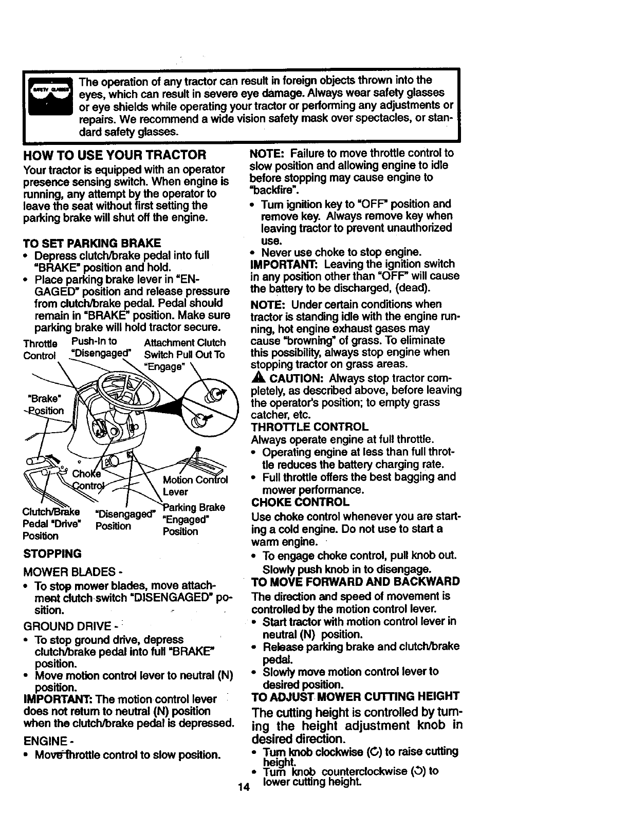
TO SET PARKING BRAKE
•Depress clutch/brake pedal into full
=BRAKE" positionand hold.
•Place parking brake lever in =EN-
GAGED" position and release pressure
from clutch/brake pedal. Pedal should
remain in =BRAKE" position. Make sure
parking brake will hold tractorsecure.
Throttle Push-lnto AttachmentClutch
Control "Disengaged" Switch Pull Out To
_ "Engage_
Clutc_e =ni_,=._=n,=rr"'Parking Brake
Pedal=Drive. p_(_,_._i'o__''" "Engaged"
Posilion Position
STOPPING
MOWER BLADES -
• To stop mower blades, move attach-
merit clutchswitch "DISENGAGED" po-
sition.
GROUND DRIVE - :
•To stop ground drive, depress
clutch/brake pedal into full =BRAKE"
position.
•Move motion control lever to neutral (N)
position.
IMPORTANT: The motion control lever
does not retum to neutral (N) position
when the clutch/brake pedal is depressed.
ENGINE -
NOTE: Failure to move throttle controlto
slow position and allowing engine to idle
before stopping may cause engine to
"backfire'.
•Tum ignitionkey to =OFF" position and
remove key. Always remove key when
leavingtractor to prevent unauthorized
use.
•Never use choke to stop engine.
IMPORTANT: Leaving the ignitionswitch
in any positionother than =OFF" will cause
the battery to be discharged, (dead).
NOTE: Under certain conditions when
tractor is standing idle with the engine run-
ning, hot engine exhaust gases may
cause "browning"of grass. To eliminate
this possibility,always stop engine when
stoppingtractor on grass areas.
_, CAUTION.'- Always stop tractor com-
pletely,as described above, before leaving
the operator's position;to empty grass
catcher, etc.
THROTTLE CONTROL
Always operate engine at full throttle.
•Operating engine at less than fullthrot-
tle reduces the battery charging rate.
•Full throttleoffers the best bagging and
mower performance.
CHOKE CONTROL
Use choke controlwhenever you are start-
ing a coldengine. Do not use to start a
warm engine.
•To engage choke control, pull knob out.
Slowly push knob in to disengage.
TO MOVE FORWARD AND BACKWARD
The direction and speed of movement is
controlled by the motion control lever.
•Start tractor withmotion control lever in
neutral (N) position.
•Release parking brake and clutch/brake
padS.
•Slowly move motion control lever to
desired position.
TO ADJUST MOWER CUTTING HEIGHT
The cutting height is controlled by tum-
ing the height adjustment knob in
desired direction.
•Mov-th_hrottle control to slow Position. •Tum lamb clockwise (C,) to raise cutting
height.
• lum knob counterclockwise (0) to
14 lower cuffing heighL
The cuttingheightrangeis approximately
1-1/2" to 4-1/2". The heights are mea-
sured from the ground to the blade tip with
the engine not running. These heights are
approximate and may vary depending
upon soil conditions, height of grass and
types of grass being mowed.
•The average lawn should be cut to
approximately 2.112 inches during the
cool season and to over 3 inches during
hot months. For healthier and better
looking lawns, mow often and after
moderate growth.
•For best cutting performance, grass
over 6 inches in height should be
mowed twice. Make the first cut rela-
tively high; the second to desired height.
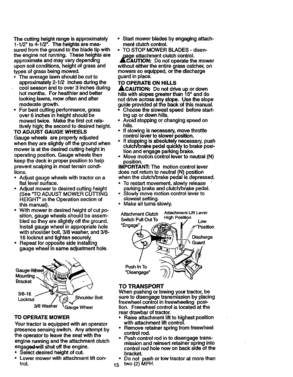
TO ADJUST GAUGE WHEELS
Gauge wheels are property adjusted
when they are slightly off the ground when
mower is at the desired cutting height in
operating position. Gauge wheels then
keep the deck in proper position to help
prevent scalping in most terrain condi-
tions.
•Adjust gauge wheels with tractor on a
flat level surface.
•Adjust mower to desired cutting height
(See _'TO ADJUST MOWER CUTTING
HEIGHT _in the Operation section of
this manual).
•With mower in desired height of cut po-
sition, gauge wheels should be assem-
bled so they are slightly off the ground.
Install gauge wheel in appropriate hole
with shoulder belt, 3/8 washer, and 3/8-
16 Iocknut and tighten securely.
•Repeat for opposite side installing
gauge wheel in same adjustment hole.
Mounting ,_
Bracket
3/8-16
Lockout Shoulder Bolt
3/8 Washer Gauge Wheel
TO OPERATE MOWER
Your tractor is equipped with an operator
presence sensing switch. Any attempt by
the operator to leave the seat with the
engine running and the attachment clutch
engaged-_vill shut off the engine.
•Select desired height of cut.
•Lower mower with attachment lift con-
trol.
• Start mower blades by engaging attach-
ment clutch control.
•TO STOP MOWER BLADES -disen-
,_gA e attachment clutch control.
UTION: Do not operate the mower
without either the entire grass catcher, on
mowers so equipped, or the discharge
guard in place.
TO OPERATE ON HILLS
,_CAUTION:. Do not drive up or down
hills with slopes greater than 15° and do
not drive across any slope. Use the slope
guide provided at the back of this manual.
•Choose the slowest speed before start-
ing up or down hills.
•Avoid stopping or changing speed on
hills.
•If slowing is necessary, move throttle
control lever to slower position.
if stoppingis absolutely necessary, push
clutch/brake pedal quicldy to brake posi-
tion and engage parking brake.
Move motion control lever to neutral (N)
position.
IMPORTANT: The motion control lever
does not retum to neutral (N) position
when the clutch/brake pedal is depressed.
io restart movement, slowly release
parking brake and clutch/brake pedal.
Slowly move motion control lever to
slowest setting.
•Make all tums slowly.
Attachment Clutch
Switch Pull Out To
=Engage"
Push In To_ _'_
=Disengage" "-_;)=
Attachment Lift Lever
High Position
/Low
,..._Positlon
/:/Discharge
3'\ Guard
TO TRANSPORT
t;
When pushing or towing your tractor, be
sure to disengage transmission by placing
freewheel control in freewheeling posi-
tion. Freewheel control is located at the
rear drawbar of tractor.
•Raise attachment lift to highest position
with attachment lift control.
•Remove retainer spring from freewheel
control rod.
• Push control rod in to disengage trans-
mission and reinsert retainer spring into
control rod hole now on back side of the
bracket.
Do not push or tow tractor at more than
two (2) MPH.
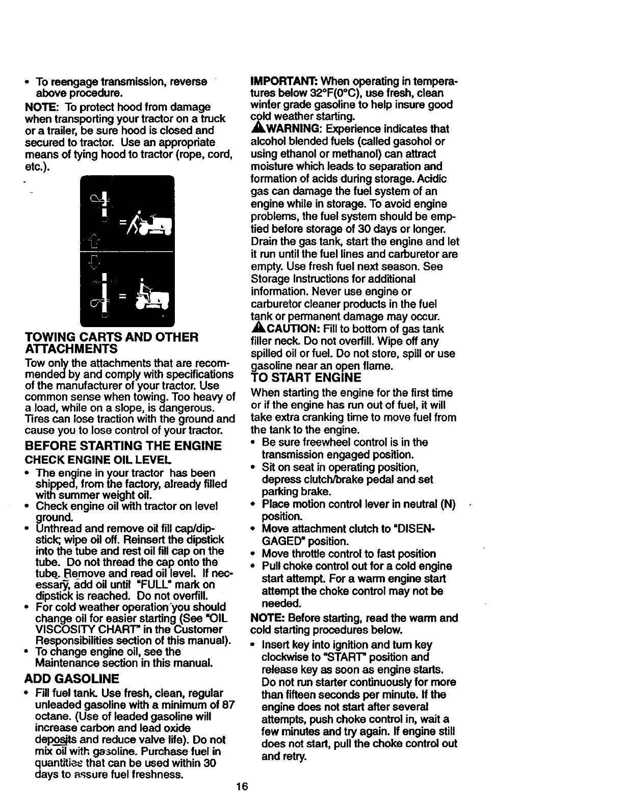
•To reengage transmission, reverse
above procedure.
NOTE: To protect hood from damage
when transporting your tractor on a truck
or a trailer, be sure hood is closed and
secured to tractor. Use an appropriate
means of tying hood to tractor (rope, cord,
etc.).
TOWING CARTS AND OTHER
ATTACHMENTS
Tow only the attachments that are recom-
mendedby and comply with specifications
of the manufacturer of your tractor. Use
common sense when towing. Too heavy of
a load, while on a slope, is dangerous.
Tires can lose traction with the ground and
cause you to lose control of your tractor.
BEFORE STARTING THE ENGINE
CHECK ENGINE OIL LEVEL
•The engine in your tractor has been
shipped, from the factory, already filled
with summer weight oil.
•Check engine oil with tractor on level
ground.
•Unthread and remove oil fillcap/dip-
stick; wipe oil off. Reinsert the dipstick
into the tube and rest oilfill cap on the
tube. Do not thread the cap onto the
tube. Be_moveand read oil level. If nec-
essary, add oil until =FULL" mark on
dipstick is reached. Do not overfill.
•For cold weather operationyou should
change oil for easier starting (See "OIL
VISCOSITY CHART* in the Customer
Responsibilities section of this manual).
•To change engine oil, see the
Maintenance section in this manual.
ADD GASOLINE
• Fill fuel tank. Use fresh, clean, regular
unleaded gasoline with a minimum of 87
octane. (Use of leaded gasoline will
increase carbofl and lead oxide
de_ and reduce valve life). Do not
mix oil with ge_oline. Purchase fuel in
quantiti_._ that can be used within 30
days to _sure fuel freshness. 16
IMPORTANT: When operating in tempera-
tures below 32°F(0°C), use fresh, clean
winter grade gasoline to help insure good
,_dNAweather starting.
RNING: Expedence indicates that
alcohol blended fuels (called gasohol or
using ethanol or methanol) can attract
moisture which leads to separation and
formation of acids dudng storage. Acidic
gas can damage the fuel system of an
engine while in storage. To avoid engine
problems, the fuel system should be emp-
tied before storage of 30 days or longer.
Drain the gas tank, start the engine and let
it run until the fuel lines and carburetor are
empty. Use fresh fuel next season. See
Storage Instructions for additional
information. Never use engine or
carburetor cleaner products in the fuel
_k or permanent damage may occur.
CAUTION: Fill to bottom of gas tank
filler neck. Do not overfill. Wipe off any
spilled oil or fuel. Do not store, spill or use
gasoline near an open flame.
TO START ENGINE
When starting the engine for the first time
or if the engine has run out of fuel, it will
take extra cranking time to move fuel from
the tank to the engine.
•Be sure freewheel control is in the
transmission engaged position.
•Sit on seat in operating position,
depress clutch/brake pedal and set
parking brake.
•Place motion control lever in neutral (N)
position.
•Move attachment clutch to =DISEN-
GAGED" position.
°Move throttle control to fast position
•Pull choke control out for a cold engine
start attempt. For a warm engine start
attempt the choke control may not be
needed.
NOTE: Before starting, read the warm and
cold starting procedures below.
•Insert key into ignitionand tum key
clockwise to =STAR'F positionand
release key as soon as engine starts.
Do not run starter continuouslyfor more
than fifteen seconds per minute. If the
engine does notstart after several
attempts, push choke control in, walt a
few minutes and try again. If engine still
does not start, pull the choke control out
and retry.
WARM WEATHER STARTING (50 °F
AND ABOVE)
•When engine starts, slowly push choke
control in until the engine begins to run
smoothly. If the engine starts to run
roughly, pull the choke control out slight-
ly for afew seconds and then continue
to push the control in slowly.
•The attachments and ground drive can
now be used. If the engine does not
accept the load, restart the engine and
allow it to warm up for one minute using
the choke as described above.
COLD WEATHER STARTING (50 ° FAND
BELOW)
• When engine starts, slowly push choke
control in until the engine begins to run
smoothly. Continue to push the choke
control in small steps allowing the
engine to accept small changes in
speed and load, until the choke control
is fully in. If the engine starts to run
roughly, pull the choke control out slight-
ly for afew seconds and then continue
to push the control in slowly. This may
require an engine warm-up period from
several seconds to several minutes,
depending on the temperature.
AUTOMATIC TRANSMISSION WARM-UP
• Before driving the unit in cold weather,
the transmission should be warmed up
as follows:
• Be sure the tractor is on level ground.
• Place the motion control lever in neu-
tral. Release the parking brake and
let the clutch/brake slowly return to
operating position.
•Allow one minute for transmission to
warm up. This can be done during the
engine warm up period.
•The attachments can be used during
the engine warm-up period after the
transmission has been warmed up and
may require the choke control be pulled
out slightly.
NOTE: Ahigh altitude (above 3000 feet)
or in cold temperatures (below 32 F) the
carburetor fuel mixture may need to be
adjusted for best engine performance.
See "TO ADJUST CARBURETOR" in the
Service and Adjustments section of this
manual.
PURGE TRANSMISSION
ACAUTION: Never engage or disen-
gage freewheel lever while the engine is
running.
To ensure proper operation and perfor-
mance, it is recommended that the trans-
mission be purged before operating tractor
for the first time. This procedure will
remove any trapped air inside the trans-
mission which may have developed during
shippingof your tractor.
IMPORTANT: Should our transmission
require removal for service or replace-
ment, it should be purged after reinstalla-
tion before operating the tractor.
•Place tractor safely on level surface with
engine off and parking brake set.
•Disengage transmission by placing free-
wheel control in freewheeling position
(See "TO TRANSPORT" in this section
of manual).
•Sitting in the tractor seat, start engine.
After the engine is running, move throt-
tle control to slow position. With motion
control lever in neutral (N) position,
slowly disengage clutch/brake pedal.
•Move motion control lever to full forward
position and hold for five (5) seconds.
Move lever to full reverse position and
hold for five (5) seconds. Repeat this
procedure three (3) times.
NOTE: During this procedure there will be
no movement of drive wheels. The air is
being removed from hydraulic drive sys-
tem.
•Move motion control lever to neutral (N)
position. Shut off engine and set parking
brake.
•Engage transmission by placing free-
whee/control in driving position (See
"TO TRANSPORT" in this section of
manual).
•Sitting in the tractor seat, start engine.
After the engine is running, move throt-
tle control to half (1/2) speed. With
motion control lever in neutral (N) posi-
tion, slowly disengage clutch/brake
pedal.
•Slowly move motion control lever for-
ward; after the tractor moves approxi-
mately five (5) feet, slowly move motion
control lever to reverse position. After
the tractor moves approximately five (5)
feet return the motion control lever to
the neutral (N) position. Repeat this pro-
cedure with the motion control lever
three (3) times.
•Your tractor is now purged and now
ready for normal operation.
17
MOWING TIPS
• Tire chains cannot be used when the
mower housing is attached to tractor.
•Mower should be properly leveled for
best mowing performance. See =TO
LEVEL MOWER HOUSING" in the
Service and Adjustments section of this
manual.
•The left hand side of mower should be
used for trimming.
,; Drive so that clippings are discharged
onto the area that has been cut. Have
the cut area to the right of the tractor.
This will result in a more even distribu-
tion of clippings and more uniform cut-
ting.
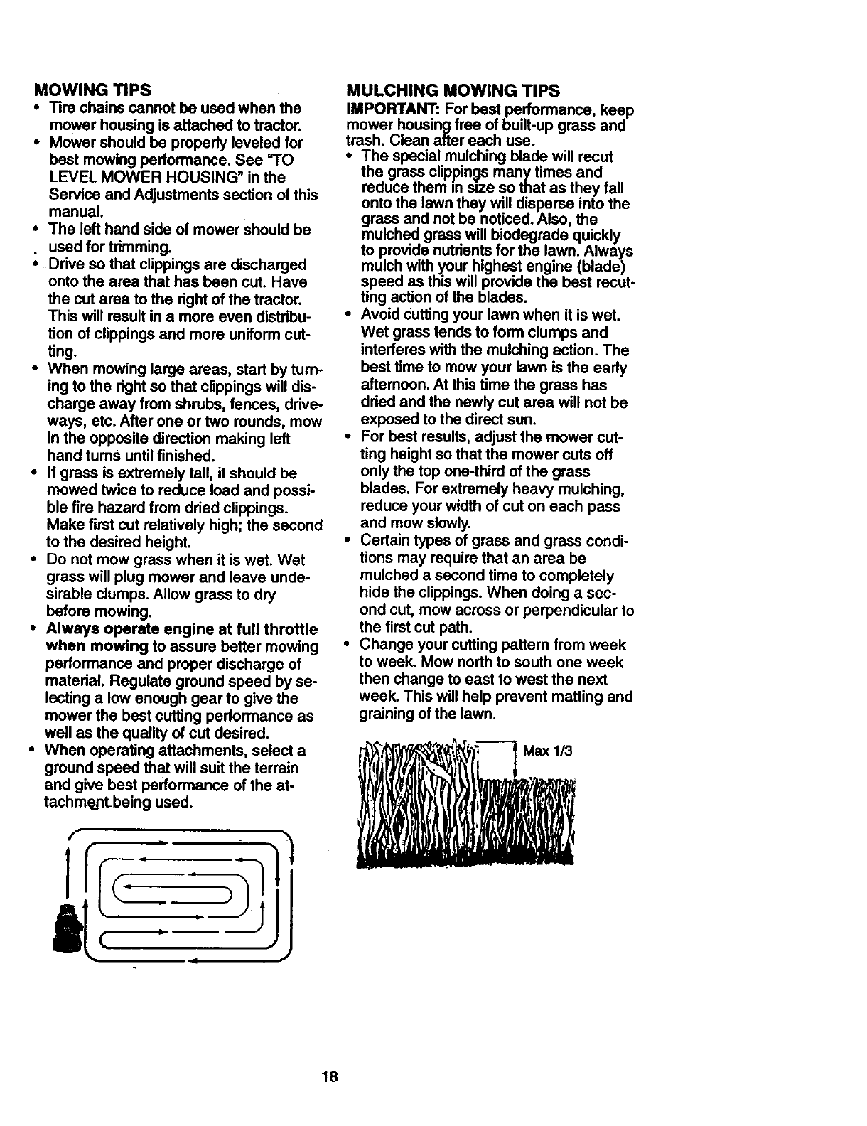
•When mowing large areas, start by turn-
ing to the right so that clippings will dis-
charge away from shrubs, fences, drive-
ways, etc. After one or two rounds, mow
in the opposite direction making left
hand turnS until finished.
•If grass is extremely tall, it should be
mowed twice to reduce load and possi-
ble fire hazard from dried clippings.
Make first cut relatively high; the second
to the desired height.
•Do not mow grass when it is wet. Wet
grass will plug mower and leave unde-
sirable clumps. Allow grass to dry
before mowing.
•Always operate engine at full throttle
when mowing to assure better mowing
performance and proper discharge of
material. Regulate ground speed by se-
lecting a low enough gear to give the
mower the best cutting performance as
well as the quality of cut desired.
•When operating attachments, select a
ground speed that will suit the terrain
and give best performance of the at-
tachm_LnLbeing used.
MULCHING MOWING TIPS
IMPORTANT: For best performance, keep
mower housing free of built-up grass and
trash. Clean after each use.
•The special mulching blade will recut
the grass clippings many times and
reduce them in size so that as they fall
onto the lawn they will disperse into the
grass and not be noticed. Also, the
mulched grass will biodegrade quickly
to provide nutrients for the lawn. Always
mulch with your highest engine (blade)
speed as this will provide the best recut-
ting action of the blades.
•Avoid cutting your lawn when it is wet.
Wet grass tends to form clumps and
interferes with the mulching action. The
best time to mow your lawn is the early
afternoon. At this time the grass has
dried and the newly cut area will not be
exposed to the direct sun.
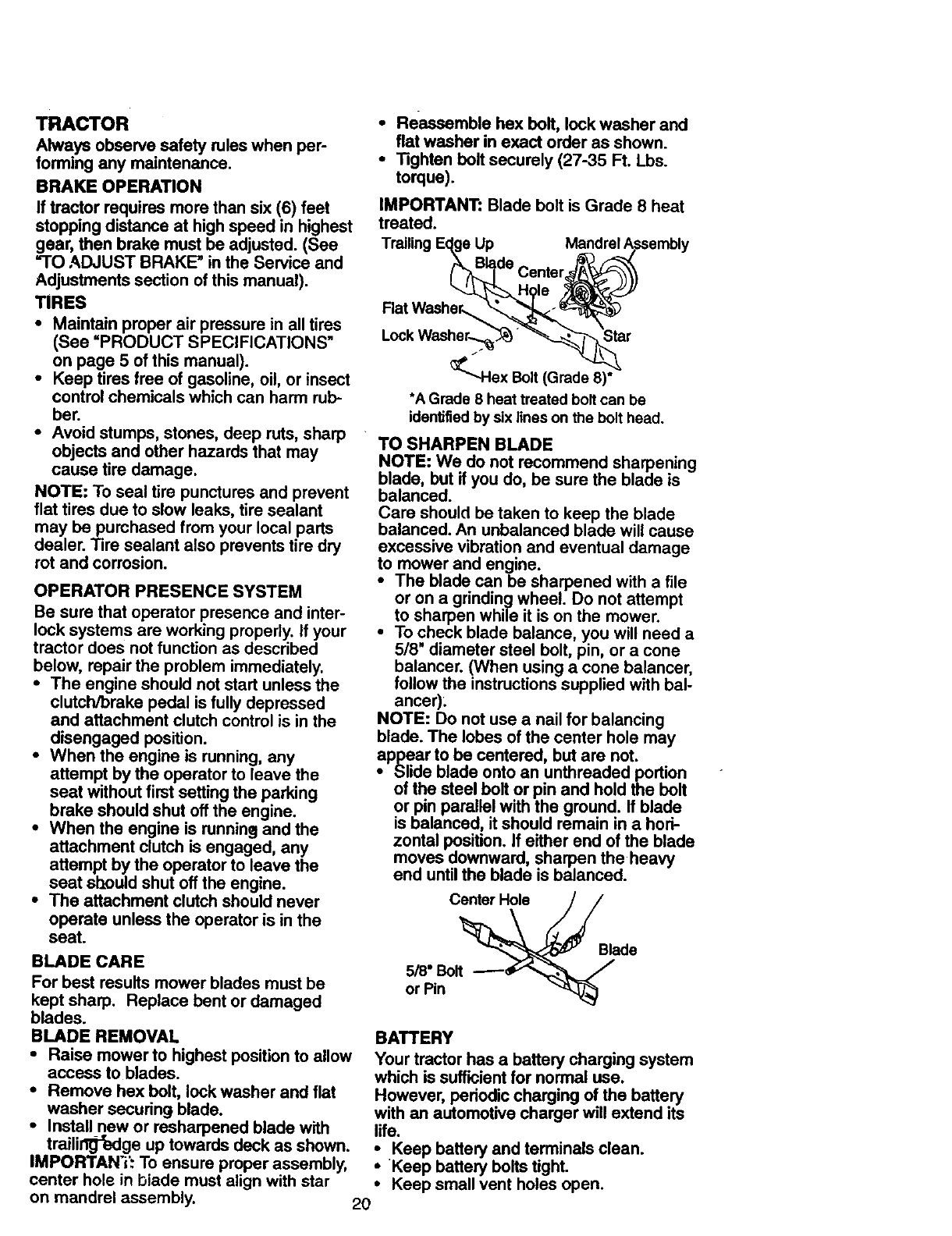
•For best results, adjust the mower cut-
ting height so that the mower cuts off
only the top one-third of the grass
blades. For extremely heavy mulching,
reduce your width of cut on each pass
and mow slowly.
•Certain types of grass and grass condi-
tions may require that an area be
mulched a second time to completely
hide the clippings. When doing a sec-
ond cut, mow across or perpendicular to
the first cut path.
•Change your cutting pattern from week
to week. Mow north to south one week
then change to east to west the next
week. This will help prevent matting and
graining of the lawn.
18

CUSTOMER RESPONSIBILITIES
REGULARSERVICE .,_",_-',t_"_-"._'_'_'/_4_'_t"_"_"",_"S ERVICEDATES
Check Brake Operation
CheckTire Prassura _k_' _
Check Operator Presence and
T =ntedockSystems V f
RCheckfor LooseF_oners Vr I/, l/
T LubdcaUonChart
0 CheckBatteryLevel
RckJon Battery and Terminals I_
Check Traneaxle Cooling I_
Adjust Blade Belt(s) Tension Q_s
Adjust Motion Drive Belt(s) Tension I_s
Check Engine Oil Level li_ il_
Change Engine Oil I_,a 91_
E CleanAirRlter _
N c_aonAir Screen
Inspect Muffler/Spark Arrester V'
Replace Oil Filter (ff equipped) ._
N clean Engine Cooling Rns
Replace Spark Plug _
Replace Air Filter Paper Cartridge 1_2
Replace Fuel Filter ll_
1- Qlange motoofllft whenoperatingrinds"a he_ loadof in hlghan.kierdlen_erldgres. 5 -If oqtltppodwnh ad_ustablllyil_.
2 - Servicemorooftenwhenoperafi_ i_ dley or duslyco_<:=loes. 6 - N_ raqu_,d R=quipp_ with malntmonce-lreeI_tory.
3 - If equlpFodwllhoa filter,¢ha,_e oil eve*y50 hours. 7 - T_ht _from=xle ift_otbel Io 34;It-be. maodmum.
4 - Replace biedesmorne4t_,,_m mowingInsandy soil Do nol ovodighten.
GENERAL RECOMMENDATIONS LUBRICATION CHART
The warranty on this tractor does not cover eTie Rod Ball Joints
items that have been subjected to operator eSpindle _N_ _ _--_,S
abuse or negligence. To receive full value pindle Zerk
from the warranty, operator must maintain eFmnt_ _ _ eFront
tractor as instructed in this manual. Some Wheel -=U_JI"t r-W Wheel
adjustments will need to be made pedodi- Bearing -A _ _ L-- Bearing
cally to properly maintain your tractor. Zerk ._ _ _1,,,_ Zerk
All adjustn_ents in the Service and eSteedng_l _ J _1 _-- .
Adjustments section of this manual should Sector - _ I_I_ _P_ngme
be checked at least once each season. Gear Teeth _ _
• Once a year you should replace the
spark plug, clean or replace air filter, and [_t _ _i _
check blades and belts for wear. A new
spark plug and clean air filter assure
pro.per air-fuel mixture and help your
engine run better and last longer. OSpray Silicone lubriant(Move Boots to Lubdcate)
BEFORE EACH USE eGeneral Purpose Grease
•Check engine oil level. @Refer to Customer Responsibilities"ENGINE"
• Check brake operation. Section
iCheck tire pressure. IMPORTANT: Do not oil or grease the pivot points
Check operator presence and intedock which have special nylon beadngs. Viscous lubd-
sysjg_!_s for proper operation, cants will attract dust and dirt that will shorten the
Check for loose fasteners, life of the self-lubricating bearings. If you feel they
must be lubdcated, use only a dry, powdered
graphite type lubdcant sparingly.
19
TRACTOR
Alwaysobservesafetyruleswhenper-
forminganymaintenance.
BRAKEOPERATION
If tractorrequiresmorethansix (6)feet
stoppingdistanceat highspeedin highest
gear,thenbrakemustbeadjusted.(See
=TO ADJUST BRAKE" in the Service and
Adjustments section of this manual).
TIRES
•Maintain proper air pressure in all tires
(See =PRODUCT SPECIFICATIONS"
on page 5 of this manual).
•Keep tires free of gasoline, oil, or insect
control chemicals which can harm rub-
ber.
• Avoid stumps, stones, deep ruts, sharp
objects and other hazards that may
cause tire damage.
NOTE: To seal tire punctures and prevent
flat tires due to slow leaks, tire sealant
may be purchased from your local parts
dealer. Tire sealant also prevents tire dry
rot and corrosion.
OPERATOR PRESENCE SYSTEM
Be sure that operator presence and inter-
lock systems are working properly. If your
tractor does not function as described
below, repair the problem immediately.
•The engine should not start unless the
clutch/brake pedal is fully depressed
and attachment clutch control is in the
disengaged position.
•When the engine is running, any
attempt by the operator to leave the
seat without first setting the parking
brake should shut off the engine.
•When the engine is running and the
attachment clutch is engaged, any
attempt by the operator to leave the
seat should shut off the engine.
•The attachment dutch should never
operate unless the operator is in the
seat.
BLADE CARE
For best results mower blades must be
kept sharp. Replace bent or damaged
blades.
BLADE REMOVAL
• Raise mower to highest position to allow
access to blades.
•Remove hex bolt, lock washer and flat
washer securing blade.
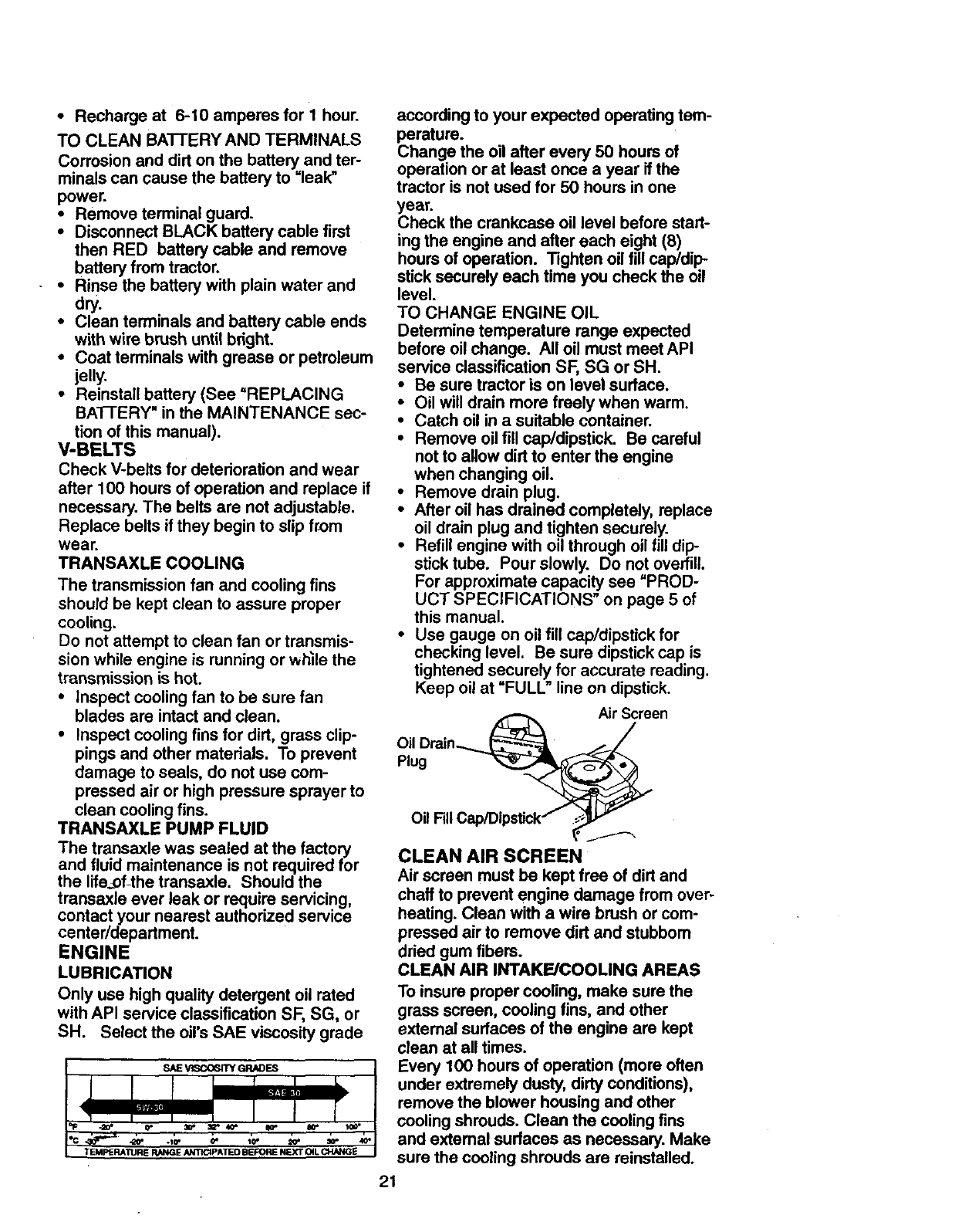
•Install new or rasharpened blade with
trailirlt_'edge up towards deck as shown.
IMPORTANT: To ensure proper assembly,
center hole in blade must align with star
•Reassemble hex bolt, lock washer and
flat washer in exact order as shown.
• Tighten bolt securely (27-35 Ft. Lbs.
torque).
IMPORTANT: Blade bolt is Grade 8 heat
treated.
Trailing Ec_gsUp Mandrel Assembly
(_Bl_de Center_
_Hgle /_J/
•_"-.Hex Bolt (Grade 8)*
•A Grade 8 heat treated bolt can be
identifiedby six lines on the bolt head.
TO SHARPEN BLADE
NOTE: We do not recommend sharpening
blade, but if you do, be sure the blade is
balanced.
Care should be taken to keep the blade
balanced. An unbalanced blade will cause
excessive vibration and eventual damage
to mower and engine.
•The blade canbe sharpened with a file
or on a grinding wheel. Do not attempt
to sharpen while it is on the mower.
•To check blade balance, you will need a
5/8" diameter steel bolt, pin, or a cone
balancer. (When using a cone balancer,
follow the instructions supplied with bal-
ancer).
NOTE: Do not use a nail for balancing
blade. The lobes of the center hole may
appear to be centered, but are not.
•Slide blade onto an unthreaded portion
of the steel bolt or pin and hold the bolt
or pin parallel with the ground. If blade
is balanced, it should remain in a hori-
zontal position. If either end of the blade
moves downward, sharpen the heavy
end until the blade is balanced.
Center Hole
5/8" Bolt
or Pin
Blade
BATTERY
Your tractor has a battery charging system
which is sufficient for normal use.
However, periodic charging of the battery
with an automotive charger will extend its
life.
• Keep battery and terminals clean.
•Keep battery bolts tight.
• Keep small vent holes open.
on mandrel assembly. 2O
•Recharge at 6-10 amperes for I hour.
TO CLEAN BATI'ERY AND TERMINALS
Corrosion and dirt on the battery and ter-
minals can cause the battery to =leak"
power.
•Remove terminal guard.
•Disconnect BLACK battery cable first
then RED battery cable and remove
battery from tractor.
•Rinse the battery with plainwater and
dry.
•Clean terminals and battery cable ends
with wire brush until bright,
•Coat terminals with grease or petroleum
jelly,
•Reinstall battery (See =REPLACING
BAI-rERY" in the MAINTENANCE sec-
tion of this manual).
V-BELTS
Check V-belts for deterioration and wear
after 100 hours of operation and replace if
necessary. The belts are not adjustable,
Replace belts if they begin to slip from
wear.
TRANSAXLE COOLING
The transmission fan and cooling fins
should be kept clean to assure proper
cooling.
Do not attempt to clean fan or transmis-
sion while engine is running or wh_le the
transmission is hot.
• inspect cooling fan to be sure fan
blades are intact and clean.
• Inspect cooling fins for dirt, grass clip-
pings and other materials. To prevent
damage to seals, do not use com-
pressed air or high pressure sprayer to
clean cooling fins.
TRANSAXLE PUMP FLUID
The transaxle was sealed at the factory
and fluid maintenance is not required for
the life_of-the transaxle. Should the
transaxle ever leak or require servicing,
contact your nearest authorized service
center/department.
ENGINE
LUBRICATION
Only use high quality detergent oil rated
with API service classification SF, SG, or
SH. Select the oil's SAE viscosity grade
6* 10' _o"
TEMPERATURE RANGE ANTICIPATED BEFORE NEXT OiL CHANGE
according to your expected operating tem-
perature.
Change the oil after every 50 hours of
operation or at least once a year if the
tractor is not used for 50 hours in one
year.
Check the crankcase oil level before start-
ing the engine and after each eight (8)
hours of operation. Tighten oil fill cap/dip-
stick securely each time you check the oil
level.
TO CHANGE ENGINE OIL
Determine temperature range expected
before oil change. All oil must moot API
service classification SF, SG or SH.
•Be sure tractor is on level surface.
•Oil will drain more freely when warm.
•Catch oil in a suitable container.
•Remove oil fill cap/dipstick. Be careful
not to allow dirt to enter the engine
when changing oil.
•Remove drain plug.
•After oil has drained completely, replace
oil drain plug and tighten securely.
•Refill engine with oil through oil fill dip-
stick tube. Pour slowly. Do not overfill.
For approximate capacity see "PROD-
UCT SPECIFICATIONS" on page 5 of
this manual.
•Use gauge on oil fill cap/dipstick for
checking level. Be sure dipstick cap is
tightened securely for accurate reading.
Keep oil at "FULL" line on dipstick.
Air Screen
Oil Drain_ _
Plug _
Oil FillCap/Dips_ck f _P"
CLEAN AIR SCREEN
Air screen must be kept free of dirt and
chaff to prevent engine damage from over-
heating. Clean with a wire brush or com-
pressed air to remove dirt and stubborn
dried gum fibers.
CLEAN AIR INTAKE/COOLING AREAS
To insure proper cooling, make sure the
grass screen, cooling fins, and other
external surfaces of the engine are kept
clean at all times.
Every 100 hours of operation (more often
under extremely dusty, dirty conditions),
remove the blower housing and other
cooling shrouds. Clean the cooling fins
and external surfaces as necessary. Make
sure the cooling shrouds are reinstalled.
21
NOTE: Operatingthe enginewitha
blockedgrassscreen,dirtyorplugged
coolingfins, and/orcoolingshroudsre-
movedwillcauseenginedamagedueto
overheating.
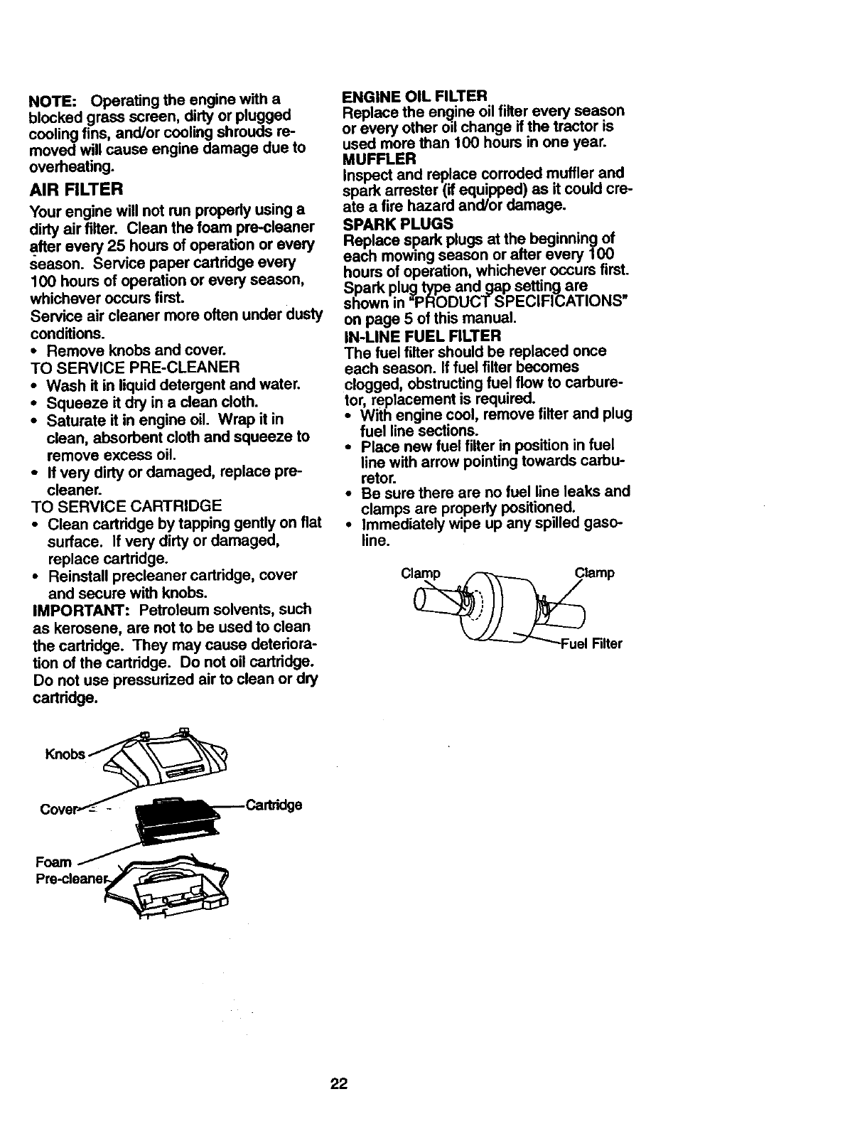
AIR FILTER
Yourenginewill notrunproperlyusinga
dirtyairfilter. Cleanthefoampre-cleaner
afterevery25 hoursof operationorevery
season. Servicepapercartridge every
100 hours of operation or every season,
whichever occurs first.
Service air cleaner more often under dusty
conditions.
•Remove knobs and cover.
TO SERVICE PRE-CLEANER
•Wash it in liquid detergent and water.
•Squeeze it dry in a clean cloth.
•Saturate it in engine oil. Wrap it in
clean, absorbent cloth and squeeze to
remove excess oil.
•If very dirty or damaged, replace pre-
cleaner.
TO SERVICE CARTRIDGE
•Clean cartridge by tapping gently on flat
surface. If very dirty or damaged,
replace cartridge.
•Reinstall precleaner cartridge, cover
and secure with knobs.
IMPORTANT: Petroleum solvents, such
as kerosene, are not to be used to clean
the cartridge. They may cause deteriora-
tion of the cartridge. Do not oil cartridge.
Do not use pressurized air to clean or dry
cartridge.
ENGINE OIL FILTER
Replace the en_line oil filter every season
or every other od change if the tractor is
used more than 100 hours in one year.
MUFFLER
Inspect and replace corroded muffler and
spark arrester (if equipped) as it could cre-
ate a fire hazard and/or damage.
SPARK PLUGS
Replacesparkplugs at the beginning of
each mowing season or after every 100
hours of operation, whichever occurs first.
Spark plug type andgap setting are
shown in "PRODUCTSPECIFICATIONS"
on page 5 of this manual.
IN-LINE FUEL RLTER
The fuel filter should be replaced once
each season. If fuel tilter becomes
clogged, obstructing fuel flow to carbure-
tor, replacement is required.
•With engine cool, remove filter and plug
fuel line sections.
•Place new fuel filter in position in fuel
line with arrow pointing towards carbu-
retor.
•Be sure there are no fuel line leaks and
clamps are properly positioned.
•Immediately w_pe up any spilled gaso-
line.
Cove_r_-__--_Cartridg e
22
CLEANING
•Clean engine, battery, seat, finish, etc.
of all foreign matter.
•Keep finished surfaces and wheels free
of all gasoline, oil, etc.
•Protect painted surfaces with automo-
tive type wax.
We do not recommend using a garden
hose to clean your tractor unless the elec-
trical system, muffler, air filter and carbure-
tor are covered to keep water out. Water
in engine can result in a shortened engine
life.
_CAUTION: Before performing any service or adjustments:
•Depress clutch/brake pedal fully and set parking brake.
•Place motion control lever in neutral (N)position.
•Place attachment clutch in uDISENGAGED" position.
Turn ignition key "OFF" and remove key.
Make sure moving parts completely stopped.
the blades and all have
Disconnect spark plug wire from spark plug and place wire where it cannot come
in contact with plug.
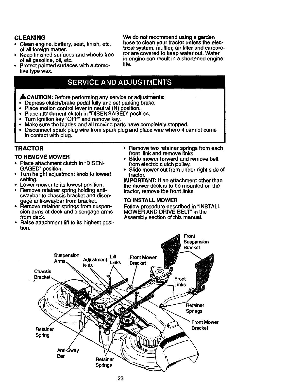
TRACTOR
TO REMOVE MOWER
•Place attachment clutch in "DISEN-
GAGED" position.
•Turn height adjustment knob to lowest
setting.
•Lower mower to its lowest position.
Remove retainer spring holding anti-
swaybar to chassis bracket and disen-
gage anti-swaybar from bracket.
•Remove retainer springs from suspen-
sion arms at deck and disengage arms
from deck.
•Raise attachment lift to its highest posi-
tion.
Chassis
•Remove two retainer springs from each
front link and remove links.
•Slide mower forward and remove belt
from electdc clutch pulley.
•Slide mower out from under right side of
tractor.
IMPORTANT: If an attachment other than
the mower deck is to be mounted on the
tractor, remove the front links.
TO INSTALL MOWER
Follow procedure described in =INSTALL
MOWER AND DRIVE BELT" in the
Assembly section of this manual.
Suspension Adjustment Lift Front Mower
Unks Bracket
Nuts
Front nsion
Bracket
Retainer
Spring
Retainer
Springs
Front Mower
Bracket
Anti-Sway
Bar Retainer
Springs
23
TOLEVELMOWERHOUSING
Adjust the mower while tractor is parked
on level ground or driveway. Make sure
tires are properly inflated (See "PROD-
UCT SPECIFICATIONS'). if tires are
over or underinflated, you will not properly
adjust your mower.
SIDE-TO-SIDE ADJUSTMENT
•Raise mower to its highest position.
•Measure height from bottom of deck
curl to ground level at front comers of
mower. Distance =A" on both sides of
mower should be the same.
•If adjustment is necessary, make adjust-
ment on one side of mower only.
•To raise one side of mower, tighten lift
link adjustment nut on that side.
•To lower one side of mower, loosen lift
link adjustment nut on that side.
NOTE: Each full tum of adjustment nut
will change mower height about 3/16".
•Recheck measurements after adjusting.
Bottom
Bottom of Cud
o,
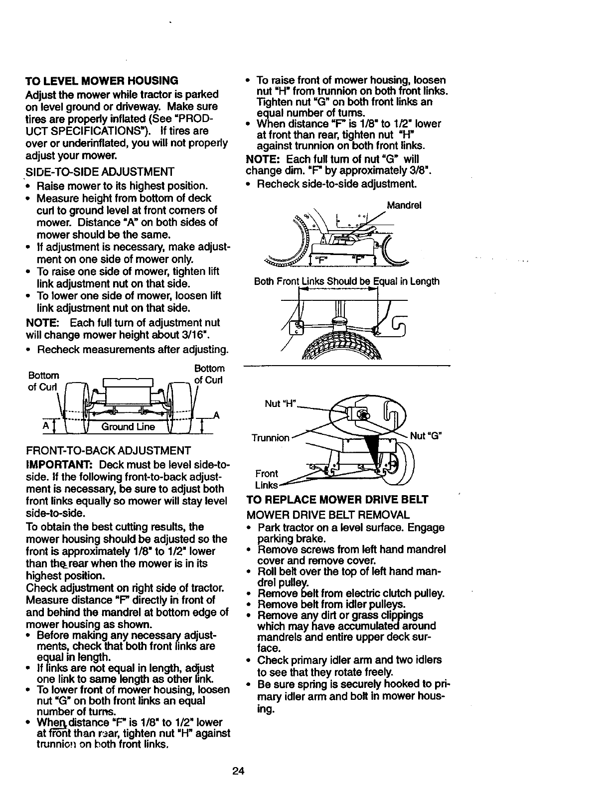
FRONT-TO-BACK ADJUSTMENT
IMPORTANT: Deck must be level side-to-
side. If the following front-to-back adjust-
ment is necessary, be sure to adjust both
front links equally so mower will stay level
side-to-side.
To obtain the best cutting results, the
mower housing should be adjusted so the
front is approximately 1/8" to 1/2" lower
than th_rear when the mower is in its
highest position.
Check adjustment on right side of tractor.
Measure distance "F" directly in front of
and behind the mandrel at bottom edge of
mower housing as shown.
•Before making any necessary adjust-
ments, check that beth front links are
equal in length.
i f/inks are not equal in length, adjust
one link to same length as other link.
To lower front of mower housing, loosen
nut =G" on both front links an equal
number of turns.
•Wher_distance =F" is 1/8" to 1/2" lower
at rfT6-ntthan r3ar, tighten nut =H" against
trunnio_ on both front links.
•To raise front of mower housing, loosen
nut "H" from trunnion on both front links.
Tighten nut "G" on both front links an
equal number of tums.
•When distance "F" is 1/8" to 1/2" lower
at front than rear, tighten nut "H"
against trunnion on both front links.
NOTE: Each full turn of nut =G" will
change dim. =F" by approximately 3/8".
•Recheck side-to-side adjustment.
Mandrel
Both F_
Length
Nut =H"_
Trunnion _ _ Nut "G"
ron
Links._-------
TO REPLACE MOWER DRIVE BELT
MOWER DRIVE BELT REMOVAL
•Park tractor on a level surface. Engage
parking brake.
•Remove screws from left hand mandrel
cover and remove cover.
•Roll belt over the top of left hand man-
drel pulley.
•Remove belt from electric clutch pulley.
Remove belt from idler pulleys.
Remove any dirt or grass clippings
which may have accumulated around
mandrels and entire upper deck sur-
face.
Check primary idler arm and two idlers
to see that they rotate freely.
•Be sure spring is securely hooked to pri-
mary idler arm and bolt in mower hous-
ing.
24
•Check primary idler arm and two idlers
to see that they rotate freely.
•Be sure spring is securely hooked to pri-
mary idler arm and bolt in mower hous-
ing.
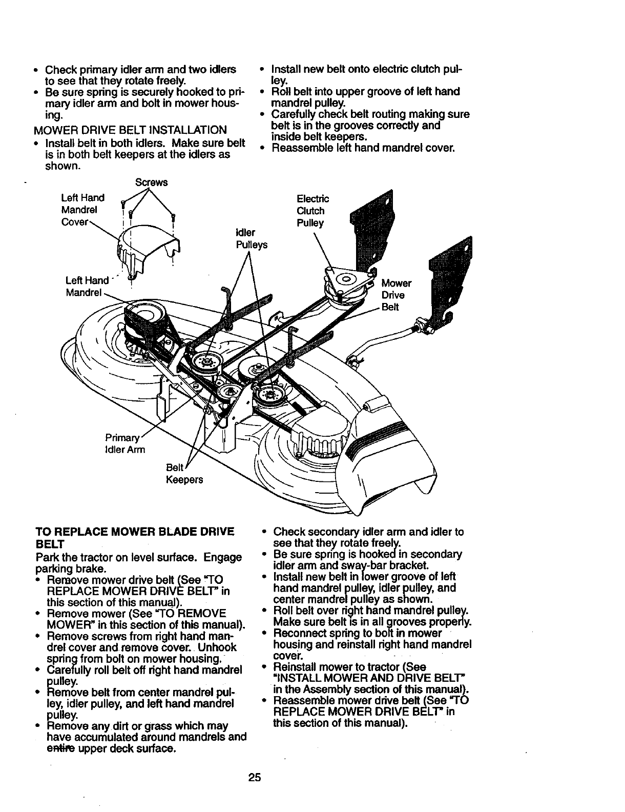
MOWER DRIVE BELT INSTALLATION
•Install belt in both idlers. Make sure belt
is in both belt keepers at the idlem as
shown.
Screws
Left Hand
Mandrel
Cover ,_
Left Hand "_
•Install new belt onto electric clutch pul-
ley.
•Roll belt into upper groove of left hand
mandrel pulley.
•CarefuUy check belt routing making sure
belt is in the grooves correctly and
inside belt keepers.
•Reassemble left hand mandrel cover.
Electdc
Clutch
Pulley
Idler
Pulleys
IdlerArm
Keepers
TO REPLACE MOWER BLADE DRIVE
BELT
Park the tractor on level surface. Engage
parking brake.
•Remove mower drive belt (See =TO
REPLACE MOWER DRIVE BELT" in
this section of this manu_).
•Remove mower (See =TO REMOVE
MOWER" in this section of this manual),
•Remove screws from right hand man-
drel cover and remove cover. Unhook
spring from bolt on mower housing.
•Carefully roll belt off right hand mandrel
pulley.
•Hemove belt from center mandrel pul-
ley, idler pulley, and left hand mandrel
pulley. . .
•Remove any dirt or grass wnicn may
have accumulated around mandrels and
eR_,e upper deck surface.
iheck secondary idler arm and idler to
see that they rotate freely.
Be sure spring is hookedin secondary
idler arm and sway-bar bracket.
Install new belt in lower groove of left
hand mandrel pulley, idler pulley, and
center mandre/pulley as shown.
Roll belt over ri.c)hthand mandrel pulley.
_Make belt in all properly.
sure IS grooves
Reconnect spring to bolt in mower . .
hous!ng and reinstall right hand manare=
cover,
•Reinstall mower to tractor (See
"INSTALL MOWER AND DRIVE BELT"
in the Assembly section of this menu.eel).:
•Reassemble mower drive belt(See -iu
REPLACE MOWER DRIVE BELT" in
this section of this manual).
25
LeftHand Belt
Pulley
Secondar
Spdn!
Anti-Sway-Bar
Bracket
Mandrel
Cover
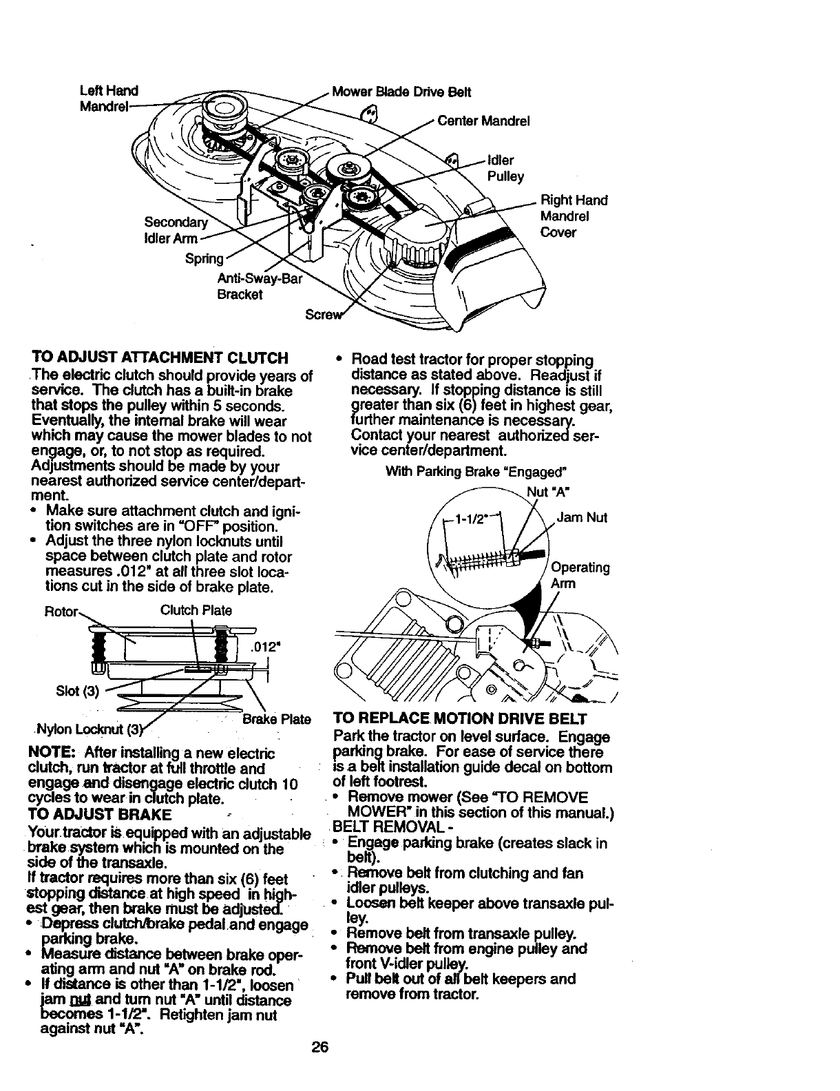
TO ADJUST ATTACHMENT CLUTCH
.The electric clutch should provide years of
service. The clutch has a built-in brake
that stops the pulley within 5 seconds.
Eventually, the internal brake will wear
which may cause the mower blades to not
engage, or, to not stop as required.
Adjustments should be made by your
nearest authorized service center/depart-
ment.
•Make sure attachment clutch and igni-
tion switches are in "OFF" position.
•Adjust the three nylon Iocknuts until
space between clutch plate and rotor
measures .012" at all three slot loca-
tions cut in the side of brake plate.
Rotor,__ Clutch Plate
F01=
Slot(3)_ _..../ I ,X
Nylon Locknut (3F Brake Plate
NOTE: After installing a new electric
clutch, run tractor at full throttle and
•Road test tractor for proper stopping
distance as stated above. Readjust if
necessary. If stopping distance is still
greater than six (6)feet in highest gear,
further maintenance is necessary.
Contact your nearest authorizedser-
vice canter/department.
With Parking Brake "Engaged"
Nut "A"
Jam Nut
)perating
Arm
engage.and disengage electric clutch 10
cycles to wear in clutch plate.
TO REPLACE MOTION DRIVE BELT
Park the tractor on level surface. Engage
Psaarkingbrake. For ease of service there
belt installation guide decal on bottom
of left footrest.
•Remove mower (See "TO REMOVE
TO ADJUST BRAKE .MOWER" in this section of this manual.)
Your tractor is equipped with an adjustable BELT REMOVAL-
brake system which is mounted on the :° i_. ge parking brake (creates slack in
side of the transexle. °Remove belt from clutching and fan
ff tractor requires more than six (6) feet "
stopping distance at high speed in high-
est gear, then brake must be adjustedT..
•Depress clutch_reke pedal and engage
•parking brake.
Measure distance between brake oper-
ating arm and nut "A" on brake rod.
• If distance is other than I-1/2", loosen
_1]_ and tum nut "A" until distance
omes 1-1/2". Retighten jam nut
against nut "A'.
idler pulleys.
Loosen belt keeper above transaxle pul-
_Ymove belt from transaxle pulley.
Remove belt from engine pulley and
front V-idler pulley.
Pull belt out of all belt keepers and
remove from tractor.
26
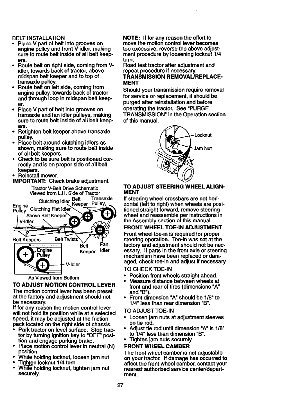
BELT INSTALLATION
•Place V part of bolt into grooves on
engine pulley and front V-idler, making
sure to route belt inside of all bolt keep-
ers.
•Route belt on right side, coming from V-
idler, towards back of tractor, above
midspan belt keeper and to top of
transaxle pulley.
.• Route belt on left side, coming from
engine pulley, towards back of tractor
and through loop in midspan belt keep
er.
•Place V part of bolt into grooves on
transaxle and fan idler pulleys, making
sure to route bolt inside of all belt keep-
ers.
•Retighten belt keeper above transaxle
pulley.
•Place belt around clutching idlers as
shown, making sure to route belt inside
of all belt keepers.
•Check to be sure bolt is positioned cor-
rectly and is on proper side of all belt
keepers.
•Reinstall mower.
IMPORTANT: Chock brake adjustment.
TractorV-Belt Ddve Schematic
Viewed from L.H. Side of Tractor
• Belt Transaxle
Engine Clutching Idler Keeper
Pulley Clutching Rat Idler_
Above Belt
Belt Keepers JBelt Fan
f,_ Engine / Kee_r Idler
_J_p_- V-d er
As Viewed from Bottom
TO ADJUST MOTION CONTROL LEVER
The motion control lever has been preset
at the factory and adjustment should not
be necessary.
If for any reason the motion control lever
will not hold its position while at a selected
speed, it may be adjusted at the friction
pack located on the right side of chassis.
•Park tractor on leve| surface. Stop trac-
tor by turning ignition key to "OFP posi-
tion and engage parking brake.
•Place motion control lever in neutral (N)
position.
ihile holding Iocknut, loosen jam nut
Tight¢n Iocknut 1/4 tum.
Whi-ileholding Iocknut, tighten jam nut
securely.
NOTE: If for any reason the effort to
move the motion control lever becomes
too excessive, reverse the above adjust-
ment procedure by loosening Iocknut 1/4
turn.
Road test tractor after adjustment and
repeat procedure if necessary.
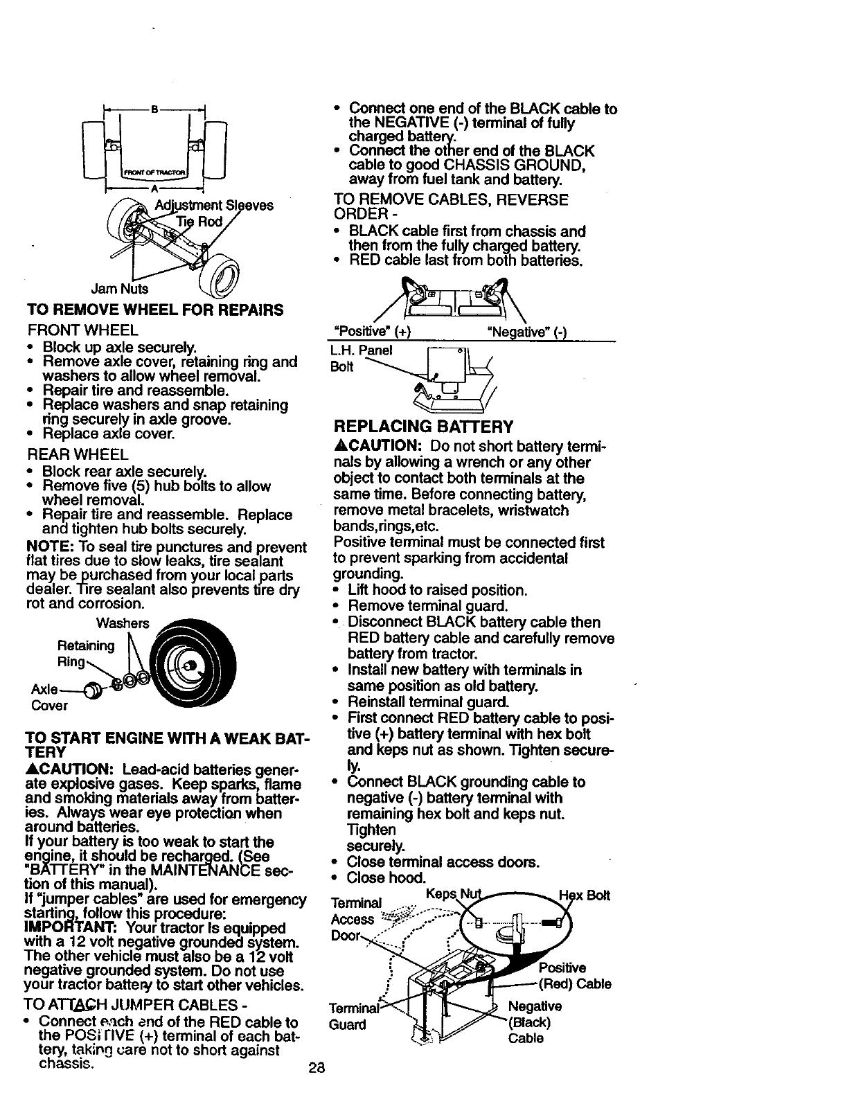
TRANSMISSION REMOVAL/REPLACE-
MENT
Should your transmission require removal
for service or. replacement, it should be
purged after reinstallation and before
operating the tractor. See =PURGE
TRANSMISSION" in the Operation section
of this manual.
Locknut
_"._Jam Nut
TO ADJUST STEERING WHEEL ALIGN-
MENT
If steering wheel crossbars are not hori-
zontal (left to right) when wheels are posi-
tioned straight ronsard, remove steering.
wheel and reassemble per instructions in
the Assembly section of this manual.
FRONT WHEEL TOE-IN ADJUSTMENT
Front wheel toe-in is required for proper
steering operation. Toe-in was set at the
factory and adjustment should not be nec-
essary. If parts in the front axle or steering
mechanism have been replaced or dam-
aged, chock toe-in and adjust if necessary.
TO CHECK TOE-IN
•Position front wheels straight ahead.
•Measure distance between wheels at
front and rear of tires (dimensions =A"
and =B').
•Front dimension "A" should be 1/8" to
1/4" less than rear dimension =B'.
TO ADJUST TOE-IN
• Loosen jam nuts at adjustment sleeves
on tie rod.
• Adjust tie rod until dimension =A" is 1/8"
to 1/4" less than dimension "B".
•Tighten jam nuts securely.
FRONT WHEEL CAMBER
The front wheel camber is not adjustable
on your tractor. If damage has occurred to
affect the front wheel camber, contact your
nearest authorized service center/depart-
ment.
27
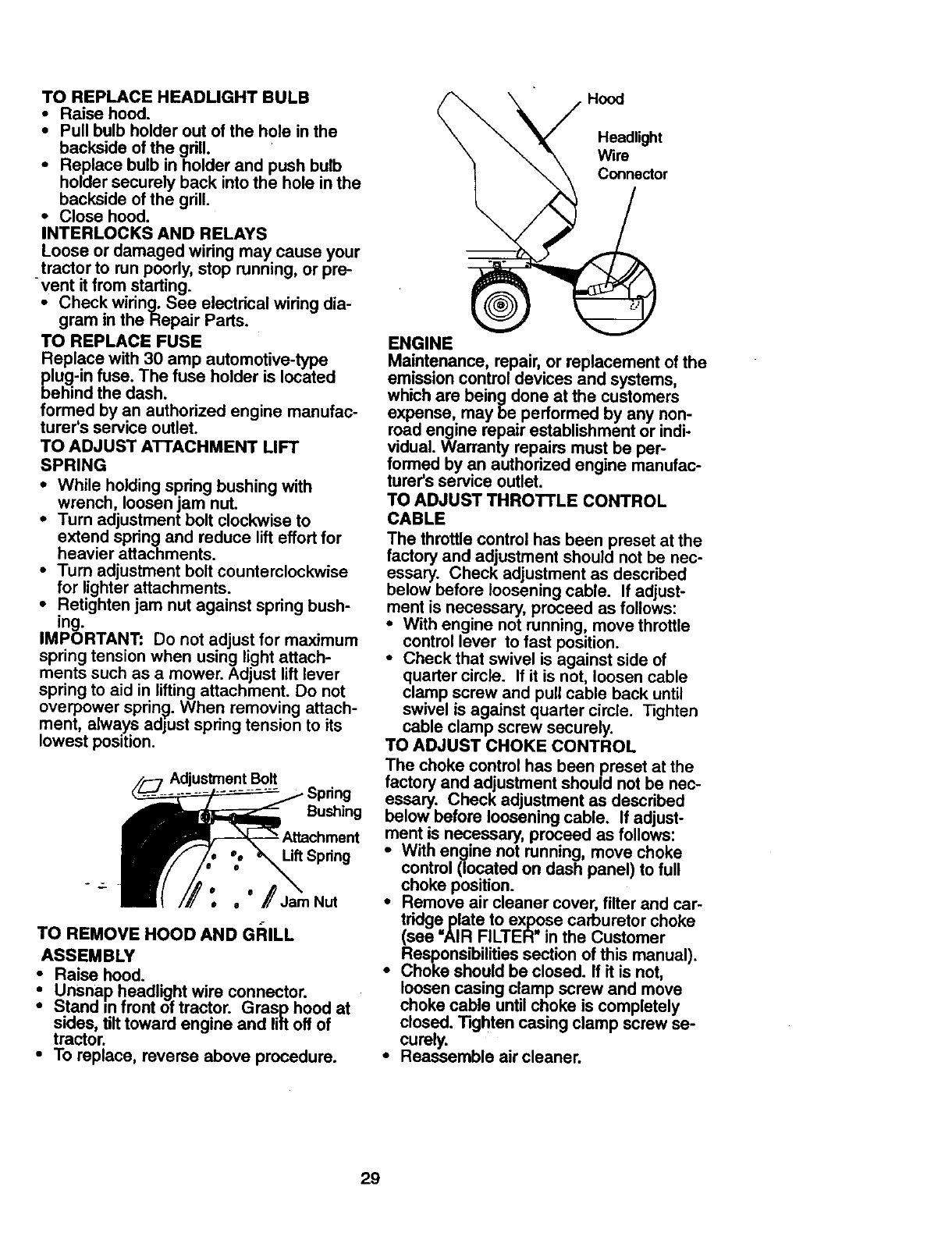
AdjustmentSleeves
JamNuts
TO REMOVE WHEEL FOR REPAIRS
FRONT WHEEL
Block up axle securely.
Remove axle cover, retaining ring and
washers to allow wheel removal.
_- Repair tire and reassemble.
Replace washers and snap retaining
nng securely in axle groove.
•Replace axle cover.
REAR WHEEL
Block rear axle securely.
Remove five (5) hub bolts to allow
wheel removal.
•Repair tire and reassemble. Replace
and tighten hub bolts securely.
NOTE: To seal tire punctures and prevent
flat tires due to slow leaks, tire sealant
cm,eaY be purchased from your local parts
aler. Tire sealant also prevents tire dry
rot and corrosion.
TO START ENGINE WITH A WEAK BAT-
TERY
ACAUTION: Lead-acid batteries gener-
ate explosive gases. Keep sparks, flame
and smoking materials away from batter-
ies. Always wear eye protection when
around batteries.
If your battery is too weak to start the
engine, it should be recharged. (See
"BA'n'ERY" in the MAINTENANCE sec-
tion of this manual).
If =jumper cables" are used for emergency
starting, follow this procedure:
IMPORTANT: Your tractor Is equipped
with a 12 volt negative grounded system.
The other vehicle must also be a 12 volt
negative grounded system. Do not use
your tractor battery to start other vehicles.
TO ATT2k_H JUMPER CABLES -
•Connect e,_ch and of the RED cable to
the POS; rIVE (+) terminal of each bat-
tery, takin0 care not to short against
chassis.
• Connect one end of the BLACK cable to
the NEGATIVE (-) terminal of fully
charged battery.
•Connect the other end of the BLACK
cable to good CHASSIS GROUND
away from fue tank and battery.
TO REMOVE CABLES, REVERSE
ORDER -
•BLACK cable first from chassis and
then from the fully charged battery.
•RED cable last from both battedes.
"Positive" (+) "Negative" (-)
BoltL'H"P_
REPLACING BATTERY
ACAUTION: Do not short battery termi-
nals by allowing a wrench or any other
object to contact both terminals at the
same time. Before connecting battery,
remove metal bracelets, wristwatch
bands,rings,etc.
Positive terminal must be connected first
to prevent sparking from accidental
grounding.
•Lift hood to raised position.
• Remove terminal guard.
•Disconnect BLACK battery cable then
RED battery cable and carefully remove
battery from tractor.
•Install new battery with terminals in
same position as old battery.
•Reinstall terminal guard.
•First connect RED battery cable to posi-
tive (+) battery terminal with hex bolt
and keps nut as shown. Tighten secure-
ly.
•Connect BLACK grounding cable to
negative (-) battery terminal with
remaining hex bolt and keps nut.
"13ghten
securely.
• Close terminal access doors.
•Close hood.
Terminal
Access
Door,%
Positive
Cable
Guard Negative
Black)
Cable
28
TO REPLACEHEADLIGHTBULB
•Raise hood.
•Pull bulb holder out of the hole in the
backside of the gdll.
•Replace bulb in holder and push bulb
holder securely back into the hole in the
backside of the grill.
• Close hood.
INTERLOCKS AND RELAYS
Loose or damaged wiring may cause your
tractor to run poody, stop running, or pre-
-vent it from starting.
•Check wiring. See electrical wiring dia-
gram in the Repair Parts.
TO REPLACE FUSE
Replace with 30 amp automotive-type
plug-in fuse. The fuse holder is located
behind the dash.
formed by an authorized engine manufac-
turer's service outlet.
TO ADJUST ATI'ACHMENT LIFT
SPRING
•While holding spring bushing with
wrench, loosen jam nut.
•Turn adjustment bolt clockwise to
extend springand reduce lift effort for
heavier attachments.
•Turn adjustment bolt counterclockwise
for lighter attachments.
•Retighten jam nut against spring bush-
in a..
IMPORTANT: Do not adjust for maximum
spring tension when using light attach-
ments such as a mower. Adjust lift lever
spring to aid in lifting attachment. Do not
overpower spring. When removing attach-
ment, always adjust spring tension to its
lowest position.
Adjustment Bolt
Bushing
_.ttachment
Lift Spdng
e
• • Jam Nut
TO REMOVE HOOD AND GI_ILL
ASSEMBLY
•Raise hood.
:Unsn.ap headlight wire connector.
Stand m front of tractor. Grasp hoed at
sides, tilt toward engine and lift off of
tractor.
•To replace, reverse above procedure.
Hood
Headlight
Wire
Connector
ENGINE
Maintenance, repair,or replacement of the
emission controldevices and systems,
which are being done at the customers
expense, may be performed by any non-
road engine repair establishment or indi-
vidual. Warranty repairs must be per-
formed by an authorized engine manufac-
tureCsservice outlet.
TO ADJUST THROTTLE CONTROL
CABLE
The throttle control has been preset at the
factory and adjustment should not be nec-
essary. Check adjustment as described
below before loosening cable. If adjust-
ment is necessary, proceed as follows:
•With engine not running, move throttle
control lever to fast position.
•Check that swivel is against side of
quarter circle. If it is not, loosen cable
clamp screw and pull cable back until
swivel is against quarter circle. Tighten
cable clamp screw securely.
TO ADJUST CHOKE CONTROL
The choke control has been preset at the
factory and adjustment should not be nec-
essary. Check adjustment as described
below before loosening cable. If adjust-
ment is necessary, proceed as follows:
•With engine not running, move choke
control (located on dash panel) to full
choke position.
•Remove air cleaner cover, filter and car-
tridge plate to expose carburetor choke
(see "AIR FILTER" in the Customer
Responsibilities section of this manual).
•Choke should be closed. If it is not,
loosen casing clamp screw and move
choke cable until choke is completely
closed. _ghten casing clamp screw se-
curely.
•Reassemble air cleaner.
29
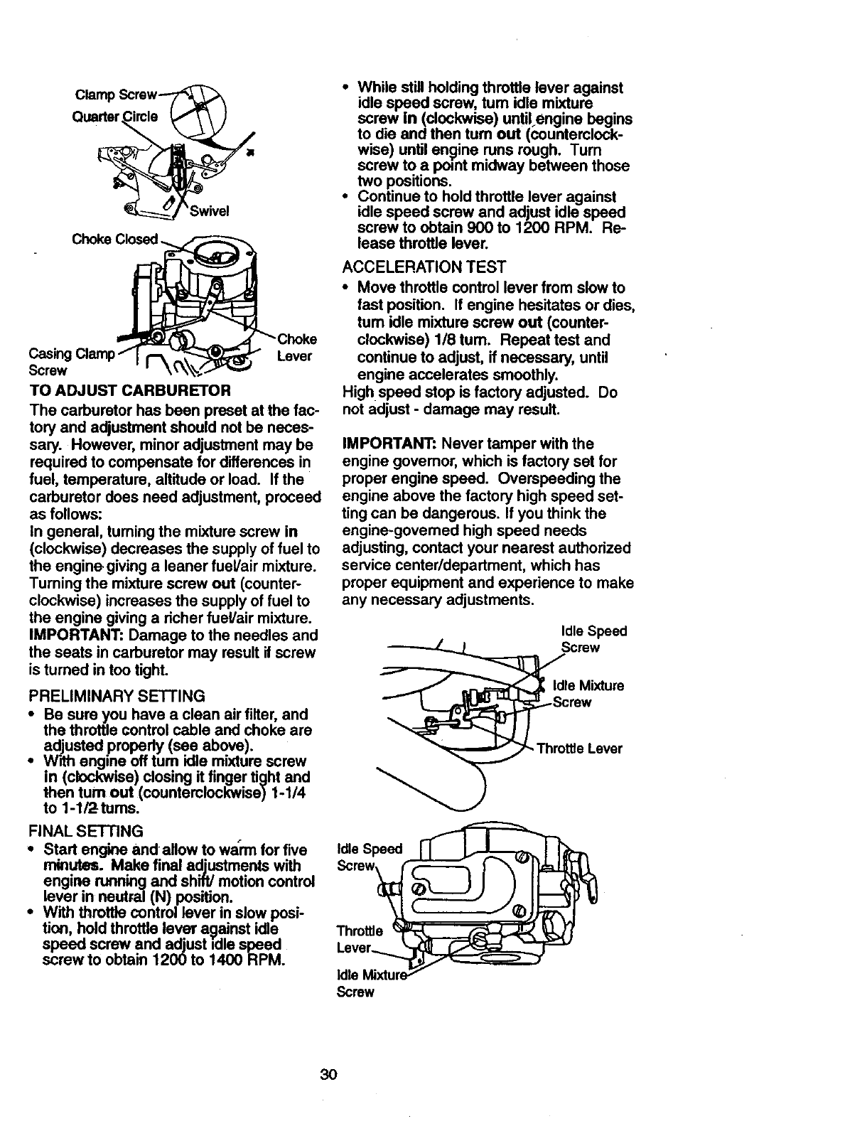
ClampScrew-_
Quarter.CircleLI"_ \ I
Lever
Screw
TO ADJUST CARBURETOR
The carburetor has been preset at the fac-
tory and adjustment should not be neces-
sary. However, minor adjustment may be
required to compensate for differences in
fuel, temperature, altitude or load. If the
carburetor does need adjustment, proceed
as follows:
In general, tuming the mixture screw in
(clockwise) decreases the supply of fuel to
the engine giving a leaner fuel/air mixture.
Turning the mixture screw out (counter-
clockwise) increases the supply of fuel to
the engine giving a richer fuel/air mixture.
IMPORTANT: Damage to the needles and
the seats in carburetor may result if screw
is turned in too tight.
PRELIMINARY SETTING
•Be sure you have a clean air filter, and
the throttle control cable and choke are
adjusted properly (see above).
•With engine off turn idle mixture screw
in (clockwise) closing it finger tight and
then turn out (counterclockwise) 1-1/4
to 1-1/2tums.
FINAL SETTING
•Start angme andallow to warm for five
minutes. Make final adjustments with
engine running and shift/motion control
lever in neutral (N) position.
•With throttle control lever in slow posi-
tion, hold throttle lever against idle
speed screw and adjust idle speed
screwto obtain 1200 to 1400 RPM.
•While still holding throttle lever against
idle speed screw, tum idle mixture
screw in(clockwise) until.engine begins
to die and then turn out (counterclock-
wise) until engine runs rough. Turn
screw to a point midway between those
two positions.
•Continue to hold throttle lever against
idle speed screw and adjust idle speed
screw to obtain 900 to 1200 RPM. Re-
lease throttle lever.
ACCELERATION TEST
• Move throttle control lever from slow to
fast position. If engine hesitates or dies,
turn idle mixture screw out (counter-
clockwise) 1/8 tum. Repeat test and
continue to adjust, if necessary, until
engine accelerates smoothly.
High speed stop is factory adjusted. Do
not adjust - damage may result.
IMPORTANT: Never tamper with the
engine governor, which is factory set for
proper engine speed. Overspeeding the
engine above the factory high speed set-
ting can be dangerous. If you think the
engine-govemed high speed needs
adjusting, contact your nearest authorized
service center/department, which has
proper equipment and experience to make
any necessary adjustments.
Idle Speed
Screw
_ldle Mixture
._Screw
Throttle Lever
Idle Speed
Throttle
Screw
3O
Immediately prepare your tractor for stor-
age at the end of the season or if the trac-
tor will not be used for 30 days or more.
,_CAUTION: Never store the tractor with
gasoline in the tank inside abuilding
where fumes may reach an open flame or
spark. Allow the engine to cool before stor-
ing in any enclosure.
TRACTOR
Remove mower from tractor for winter
storage. This will allow you to clean it thor-
oughly. Remove all dirt, grease, leaves,
etc. Store in a clean, dry area.
•Clean entire tractor (See =CLEANING"
in the Maintenance section of this man-
ual).
•Inspect and replace belts, if necessary
(See belt replacement instructions in the
Service and Adjustments section of this
manual).
•Lubricate as shown in the Maintenance
section of this manual.
•Be sure that all nuts, bolls and screws
are securely fastened. Inspect moving
parts for damage, breakage and wear.
Replace if necessary.
•Touch up all rusted or chipped paint sur-
faces; sand lightly before painting.
BATTERY
•Fully charge the battery for storage.
•After a period of time in storage, battery
may require recharging.
•To help prevent corrosion and power
leakage during long periods of storage,
battery cables should be disconnected
and battery cleaned thoroughly (see
=TO CLEAN BATTERY AND TERMI-
NALS"_in=the Maintenance section of
this manual).
•After cleaning, leave cableSdisconnect-
ed and place cables where they cannot
come in contact with battery terminals.
•If battery is removed from tractor for
storage, do not store battery directly on
concrete or damp surfaces.
ENGINE
FUEL SYSTEM
IMPORTANT: It is important to prevent
gum deposits from forming in essential
fuel system parts such as carburetor, fuel
filter, fuel hose, or tank during storage.
Also, experience indicates that alcohol
blended fuels (called gasohol or using
ethanol or methanol) can attract moisture
which leads to separation and formation of
acids during storage. Acidic gas can dam-
age the fuel system of an engine while in
storage.
•Drain the fuel tank.
•Start the engine and let it run until the
fuel lines and carburetor are empty.
•Never use engine or carburetor cleaner
products in the fuel tank or permanent
damage may occur.
•Use fresh fuel next season.
NOTE: Fuel stabilizer is an acceptable
altamative in minimizing the formation of
fuel gum deposits during storage. Add sta-
bilizer to gasoline in fuel tank or storage
container. Always follow the mix ratio
found on stabilizer container. Run engine
at least 10 minutes after adding stabilizer
to allow the stabilizer to reach the carbure-
tor. Do not drain the gas tank and carbure-
tor if using fuel stabilizer.
ENGINE OIL
Drain oil (with engine warm) and replace
with clean engine oil. (See =ENGINE" in
the Maintenance section of this manual).
CYLINDER(S)
•Remove spark plug(s).
•Pour one ounce of oil through spark plug
hole(s) into cylinder(s).
•Turn ignition key to =START:'. position for
a few seconds to distribute oil.
•Replace with new spark plug(s).
OTHER
•Do not store gasoline from one season
to another.
•Replace your gasoline can if it starts to
rust. Rust and/or dirt in your gasoline will
cause problems.
•If possible, store your tractor indoors
and cover it to give protection from dust
and dirt.
•Cover your tractor with a suitable protec-
tive cover that does not retain moisture.
Do not use plastic. Plastic cannot
breathe, which allows condensation to
form and cause your tractor to rust.
IMPORTANT: Never cover tractor while
engine and exhaust areas are still warm.
31
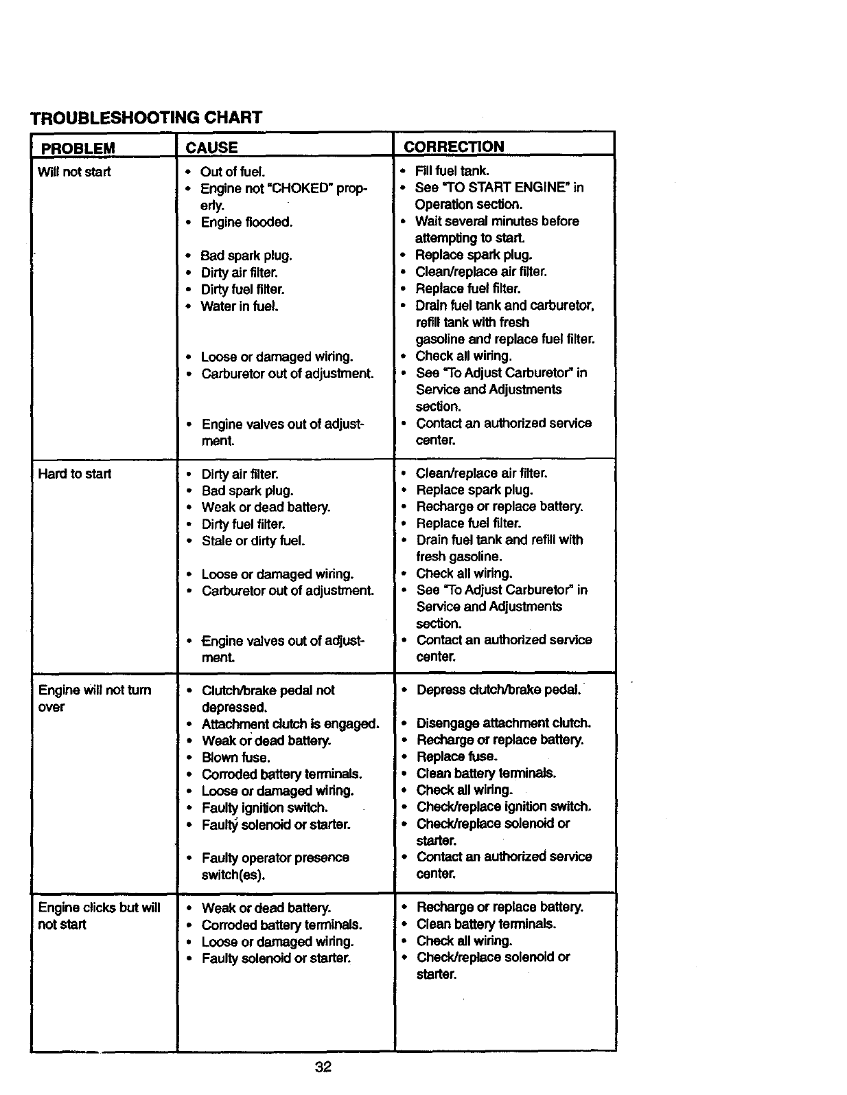
TROUBLESHOOTING CHART
PROBLEM CAUSE
Will notstart
Hard to start
Engine will notturn
over
Engine clicks but will
not start
CORRECTION
•Out of fuel.
•Engine not =CHOKED" prop- *
erly.
•Engine flooded.
•Bad spark plug. *
•Dirty air filter. *
•Dirty fuel filter. •
•Water in fuel. *
•Loose or damaged wiring. •
•Carburetor out of adjustment, •
•Engine valves out of adjust- I *
ment. I
•Dirty air filter.
• Bad spark plug.
•Weak or dead battery.
•Dirty fuel filter. •
-Stale or dirty fuel. *
•Loose or damaged wiring. ' *
•Carburetor out of adjustment. •
•Engine valves out of adjust- •
menL
• Clutch/brake pedal not •
depressed.
•Attachment dutch is engaged. •
•Weak or dead battery. *
•Blown fuse. *
•Corroded battery terminals.
•Loose or damaged wiring. •
•Faulty ignifionswitch. •
•Fault_ solenoidor starter.
•Faulty operator presence *
switch(es).
•Weak or dead battery. •
•Corroded battsryterminais. *
•Loose or damaged widng. °
•Faulty solenoidor starter. *
32
Fillfuel tank.
See =TOSTART ENGINE" in
Operation secfion.
Wait several minutes before
attempting to start.
Replace spark plug.
Clean/replace air filter.
Replace fuel filter.
Drain fuel tank and carburetor,
refilltank with fresh
gasoline and replace fuel filter.
Check all wiring.
See =ToAdjust Carburetor" in
Service and Adjustments
section.
Contact an authorized service
center.
Clean/replace air filter.
Replace spark plug.
Recharge or replace battery.
Replace fuel filter.
Drain fuel tank and refill with
fresh gasoline.
Check all wiring.
See =ToAdjust Carburetor"in
Service and Adjustments
section.
Contact an authorized service
center.
Depress dutch/brake pedal.
Disengage attachment clulch.
Recharge or replace battery.
Replace fuse.
Clean battery terminals.
Check all wiring.
Check/replace ignition switch.
Check/replace solenoid or
starter.
Contact an authorized service
center.
Recharge or replace battery.
Clean battery terminals.
Check ell wiring.
Check/reptace solenoid or
starter.
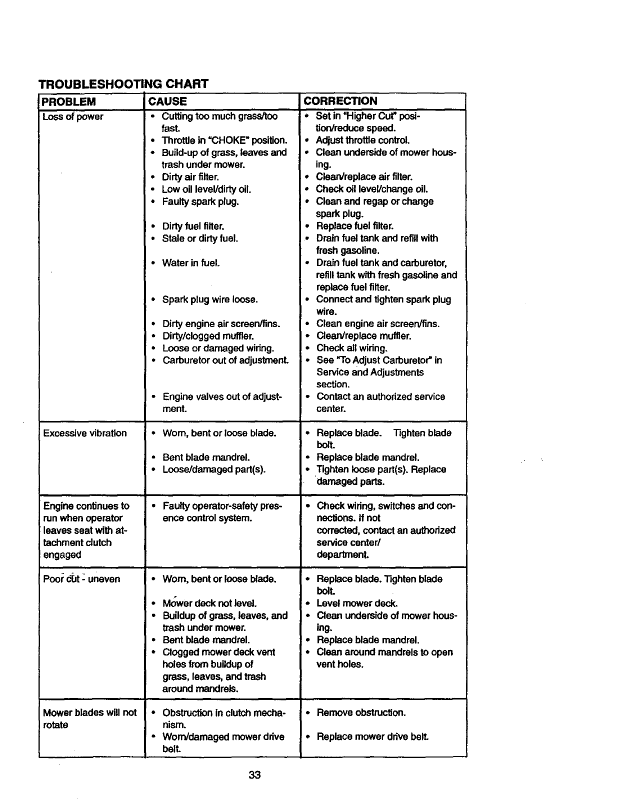
PROBLEM
Loss of power
TROUBLESHOOTING CHART
CAUSE
• Cuffing too much grass/too
fasL
•Throttle in "CHOKE" position.
•Build-up of grass, leaves and
CORRECTION
•Set in "Higher Cut" posi-
tion/reduce speed.
•Adjust throttle control.
•Clean underside of mower hous-
trash under mower.
•Dirty air tilter.
• Low oil leveVdirtyoil.
•Faulty spark plug.
•Dirty fuel filter.
•Stale or dirty fuel.
• Water in fuel.
•Spark plug wire loose.
•Dirty engine air screen/fins.
•Dirty/clogged muffler.
•Loose or damaged wiring.
ing.
*Clean/replace air filter.
•Check oil leveVchange oil.
•Clean and regap or change
spark plug.
•Replace fuel tilter.
•Drain fuel tank and refillwith
fresh gasoline.
•Drain fuel tank and carburetor,
refilltank with fresh gasoline and
replace fuel filter.
•Connect and tighten spark plug
wire.
•Clean engine air screen/fins.
•Clean/replace muffler.
•Check all widng.
Excessive vibration
Engine continues to
run when operator
leaves seat with at-
tachment clutch
engaged
Poor diJt- uneven
Mower blades will not
rotate
Carburetor out of adjustmenL
Engine valves out of adjust-
ment.
Worn, bent or loose blade.
Bent blade mandrel.
Loose/damaged part(s).
Faulty operator-safety pres-
ence control system.
•Worn, bent or loose blade.
•Ivlowerdeck not level.
•Buildup of grass, leaves, and
trash under mower.
•Bent blade mandrel.
•Clogged mower deck vent
holes from buildup of
grass, leaves, and trash
around rnandmls,
•Obstruction in clutch mecha-
nism.
•Wom/damaged mower drive
bell
•See "To Adjust Carburetor" in
Service and Adjustments
section.
•Contact an authorized service
center.
•Replace blade. Tighten blade
bolt.
•Replace blade mandrel.
•Tighten loose part(s). Replace
damaged parts.
•Check widng, switchesand con-
nections. If not
corrected, contact an authorized
service center/
departmenL
• Replace blade. Tighten blade
bolt.
•Level mower deck.
•Clean underside of mower hous-
ing.
•Replace blade mandrel.
•Clean around mandrels to open
vent holes.
•Remove obstruction.
• Replace mower drive belt.
33
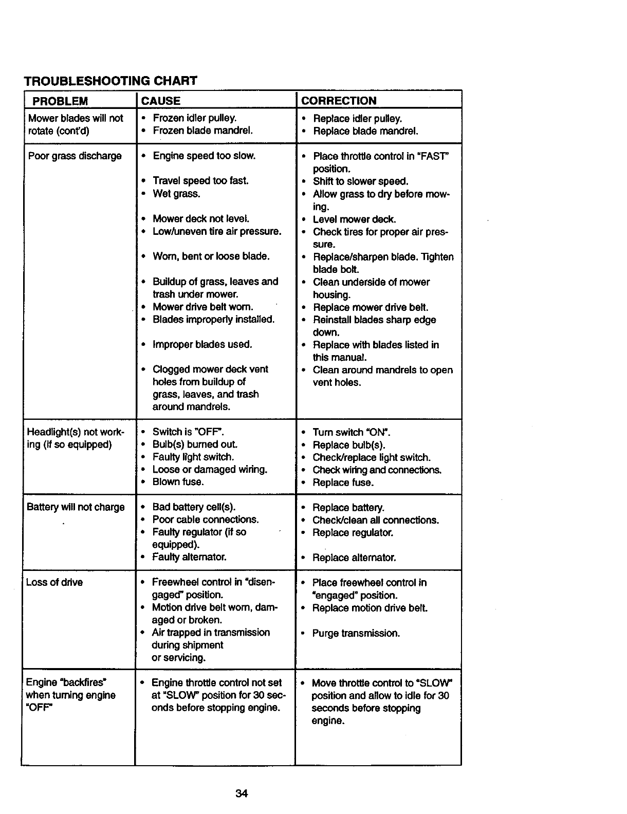
TROUBLESHOOTING CHART
PROBLEM
Mower blades will not
rotate (cont'd)
Poor grass discharge
Headlight(s) not work-
iing (if so equipped)
Battery will not charge
Loss ofdrive
Engine =backfires"
when turning engine
"OFF"
CAUSE
• Frozen idler pulley.
•Frozen blade mandrel.
•Engine speed too slow.
• Travel speed too fast.
•Wet grass.
•Mowerdeck not level.
•Low/uneven tire air pressure.
•Wom, bent or loose blade.
• Buildupof grass, leaves and
trash under mower.
•Mower ddve belt wom.
•Blades improperly installed.
•Improper blades used.
•Clogged mower deck vent
holes from buildup of
grass, leaves, and trash
around mandrels.
•Switch is "OFF".
•Bulb(s) burned out.
• Faulty light switch.
•Loose or damaged wiring.
•Blown fuse.
• Bad batterycell(s).
• Poor cable connections.
•Faulty regulator (if so
equipped).
•Faulty altemator.
•Freewheel control in =disen-
gaged" position.
•Motion ddve belt worn, dam-
aged or broken.
I- Air trapped in transmission
dudng shipment
or servicing.
•Engine throttle control not set
at "SLOW" positionfor 30 sec-
onds before stopping engine.
CORRECTION
• Replace idlerpulley.
•Replace blade mandrel.
•Place throttlecontrol in =FAST"
position.
•Shift to slower speed.
•Allow grass to dry before mow-
ing.
•Level mower deck.
•Checktires for properalr pres-
sure.
•Replace/sharpen blade. tighten
blade bolt.
•Clean underside of mower
housing.
•Replace mowerddve belt.
•Reinstall blades sharp edge
down.
•Replace with blades listed in
this manual.
•Clean around mandrels to open
vent holes.
•Turn switch "ON'.
•Replace bulb(s).
•Check/replace lightswitch.
•Check wiringand connections.
•Replace fuse.
•Replace battery.
•Check/clean all connections.
•Replace regulator.
•Replace alternator.
•Place freewheel control in
"engaged" position.
•Replace motion ddve belt.
•Purge transmission.
•Move throttle controlto "SLOW"
position and allow to idle for 30
seconds before stopping
engine.
34
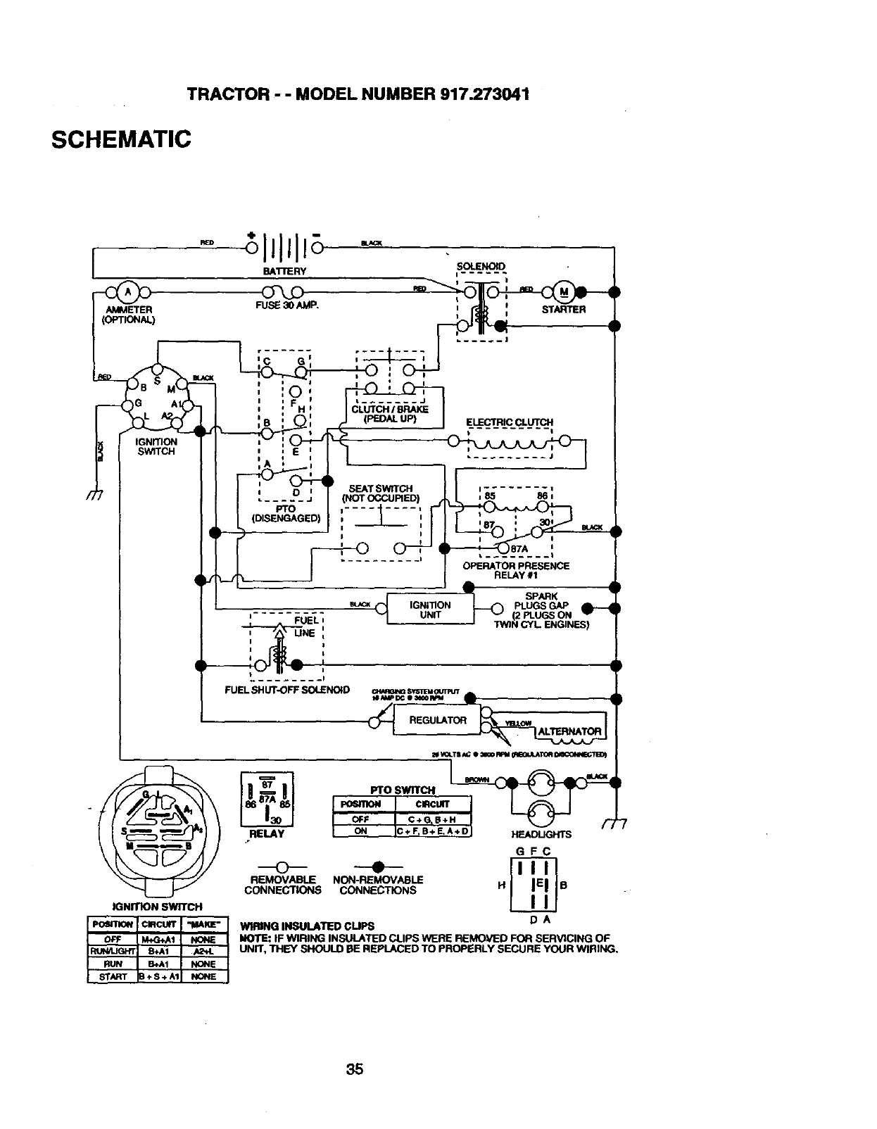
TRACTOR -- MODEL NUMBER 917.273041
SCHEMATIC
RED
IBAITERY
IGNITION SWITCH
It SEATSWtTCH
.... D_j (NOTOCCUPIED)
PTO _........ ,
SOLENOID
i..... .
iSTARTLER
I
..... J
FUELt
iUNE
Ii
........ I
FUELSHUT-OFFSOLENOID
RELAY
ELECTRICCLUTCH
,_ 861
I I
OPERATORPRESENCE
RELAy#1
_) SPARK
IGNITION PLUGSGAP
UNIT (2 PLUGS ON
' "PNINCYL. ENGINES)
Cm,RSINGSy'&"Fk_C_JTR_r
(_ REGULATOR
_CIRCUITH_/_
OFF C+O_B+
ON C+ FIB+ E,A+D HEADLIGHTS
GFC
REMOVABLE NON-REMOVABLE
CONNECTIONS CONNECTIONS HR
W_IING INSULATED CUPS D A
NOTE: IF WIRING INSULATED CLIPS WERE REMOVED FOR SERVICING OF
UNIT, THEY SHOULD RE REPLACED TO PROPE_RLYSECURE YOUR WIRING.
35
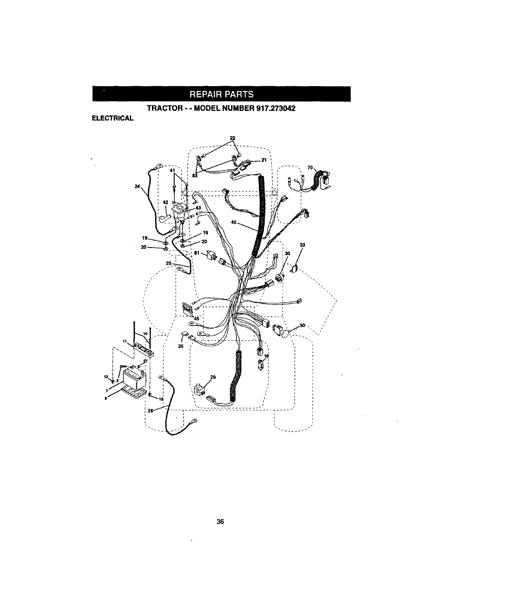
TRACTOR ,.- MODEL NUMBER 917.273042
ELECTRICAL
22
11
36
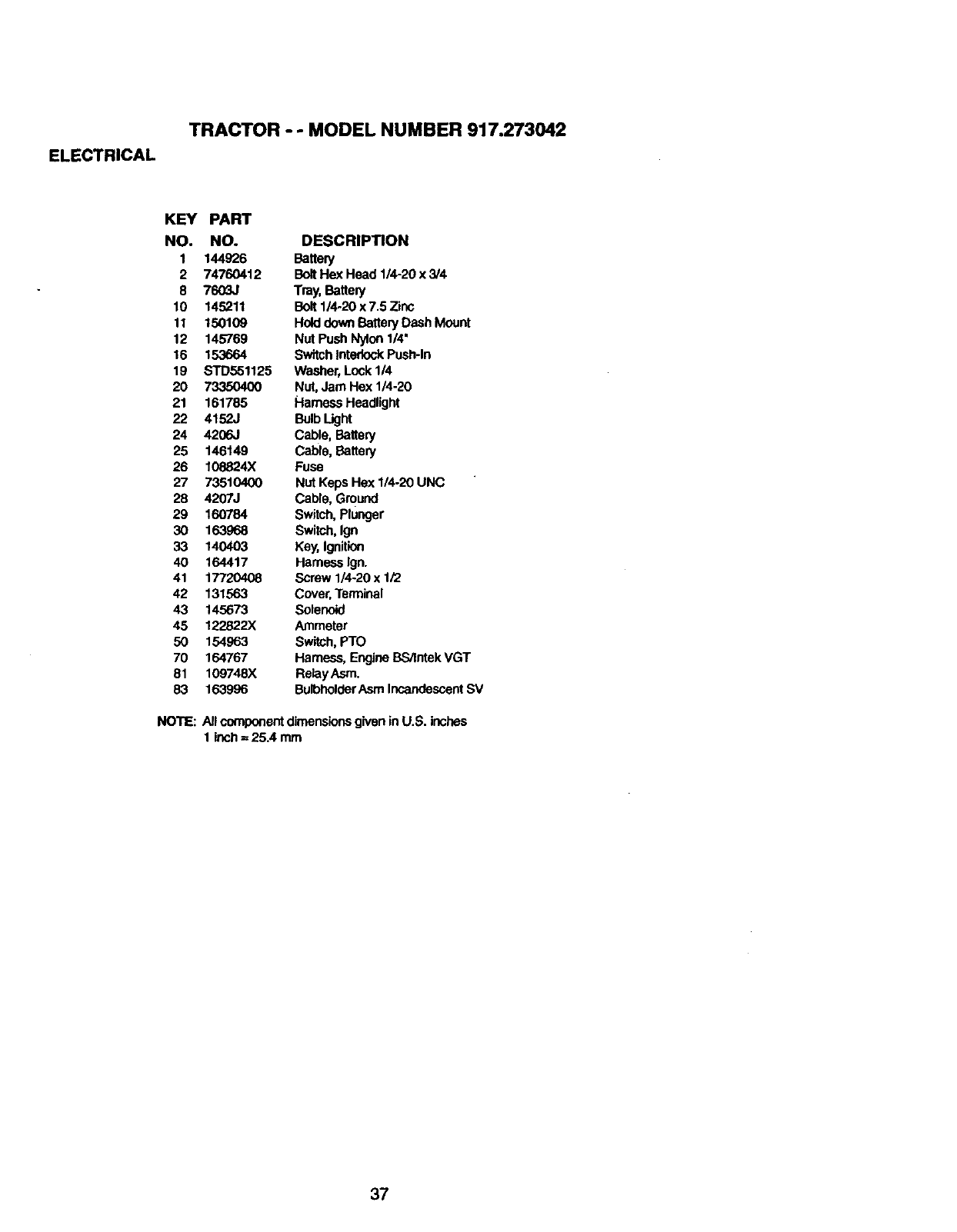
ELECTRICAL
TRACTOR - - MODEL NUMBER 917.273042
KEY PART
NO. NO. DESCRIPTION
1 144926 Battery
2 74760412 BoltHex Head 114-20x 3/4
8 7603J Tray, Buttery
10 145211 Bolt 1/4.20 x 7.5 Zinc
11 150109 Hold downBattery Dash Mount
12 145769 Nut Push Nylon1/4'
16 153664 SwitchInterlockPush-In
19 STD551125 Washer,Lock 114
20 73350400 Nut, Jam Hex 1/4.20
21 161785 Hameas Headlight
22 4152J Bulb Light
24 4206.1 Cable, Battery
25 146149 Cable, Buttery
26 108824X Fuse
27 73510400 Nut Keps Hex 1/4-20 UNC
28 4207J Cable, Ground
29 160784 Switch,Plunger
30 163968 Switch, Ign
33 140403 Key, Ignition
40 164417 Harness Ign.
41 17720408 Screw 1/4.20 x 1/2
42 131563 Cover,Terminal
43 145673 Solenoid
45 122822X Ammeter
50 154963 Switch, PTO
70 164767 Hamess, Engine BS/IntekVGT
81 109748X RelayAsm.
83 163996 BulbholderAsm IncandescentSV
NOTE: Allcomponentdimensionsgivenin U.S. inches
1 inch= 25.4 mm
37
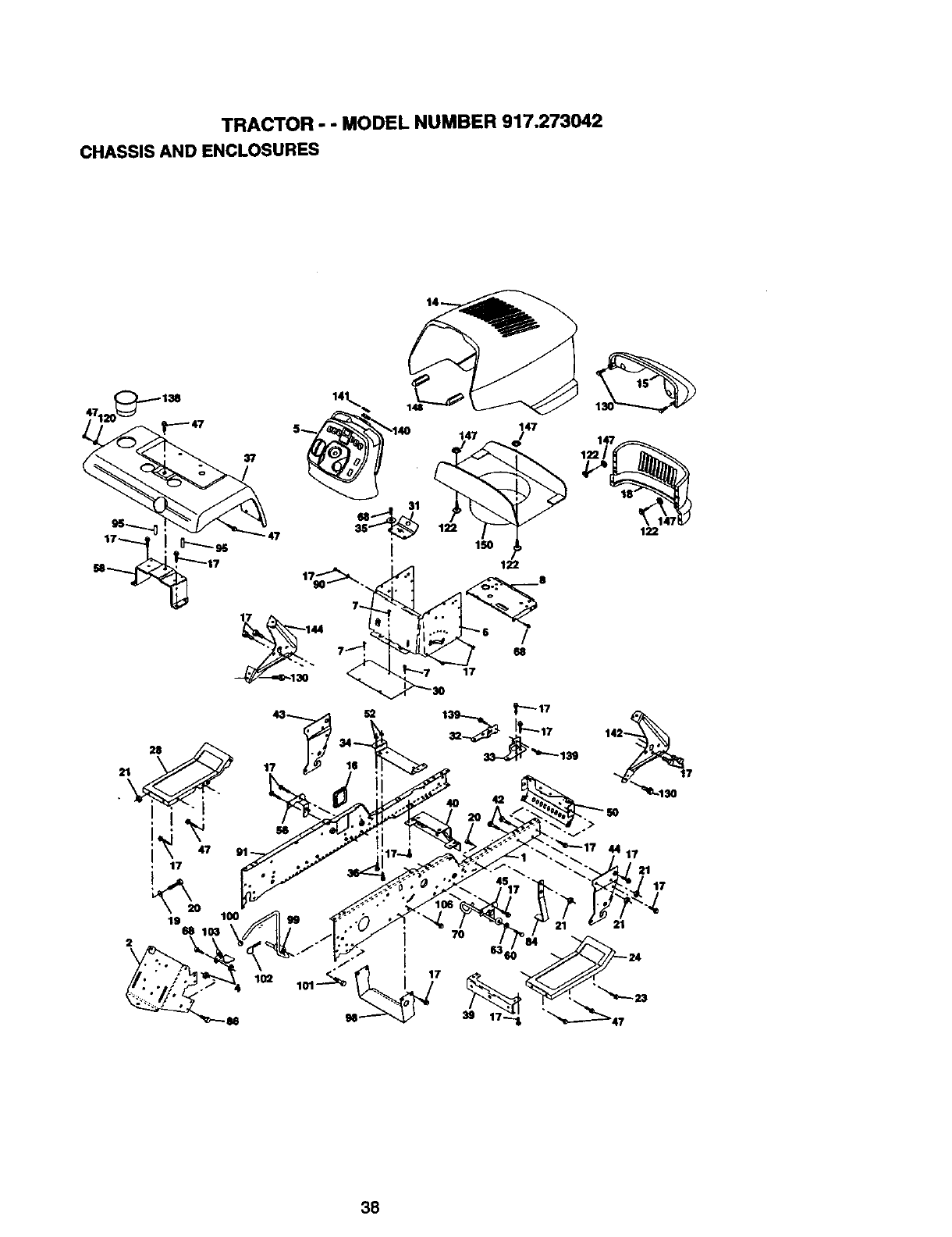
TRACTOR -- MODEL NUMBER 917.273042
CHASSIS AND ENCLOSURES
38
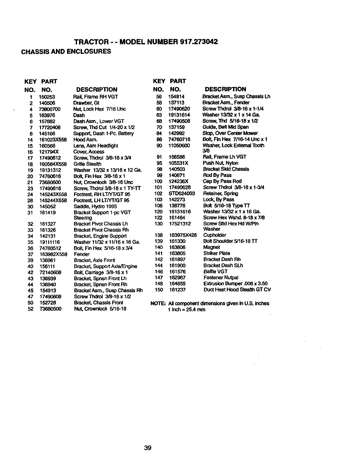
TRACTOR - - MODEL NUMBER 917.273042
CHASSIS AND ENCLOSURES
KEY PART KEY PART
NO. NO. DESCRIPTION NO. NO.
1 150253 Rail, Frame RH VGT 56 154914
2 140506 Drawbar,Gt 58 137113
4 738(X)700 Nut, LockHex 7/16Unc 60 17490620
5 163976 Dash 63 19131614
6 157882 DashAsm., LowerVGT 68 17490508
7 177204_ Screw,ThdCut 1/4-20xl/2 70 137159
8 145166 Support,Dash 1-Pc.Battery 84 142992
14 161023X558 HoodAsm. 86 74760716
15 160568 Lene,Asm Headlight 90 11050600
16 121794X Cover,/_cass
17 17490612 Surew, Thdrol 3/6-16x3/4 91 156586
18 160564X558 Grille Stealth 95 105531X
19 19131312 Washer 13/32 x 13/16 x 12 Ca. 86 140503
20 74760616 BolLFinHex 3/8-16xl 99 140871
21 73680600 Nut, Crownlock 3i8-16 Unc 100 124236X
23 17490616 Screw,Thdrol 3/6-16 x 1 TY-TT 101 17490628
24 145243X558 Footrest,RH LT/YT/GT 95 102 STD624003
28 145244X558 Footrest,LH LT/YT/GT 95 103 142273
30 145052 Saddle, Hydro 1995 106 138776
31 161419 Bracketsupport 1-pcVGT 120 19131616
Steedng 122 161464
32 161327 BracketPivot ChassisLh 130 17521312
33 161326 BracketPivot Chassis Rh
34 142131 Bracket, Engine Support 138 163975X428
35 19111116 Washer 11/32x11/16x 16Ga. 139 161330
36 74780512 Bolt, FinHex 5/16-18x3/4 140 163806
37 163982X558 Fender 141 163805
39 136961 Bracket,Axle Front 142 161897
40 156111 Bracket, SupportAxle/Engine 144 161900
42 72140608 Bolt, Carriage 3/8-16 x 1 146 161576
43 136939 Bracket, Spnsn FrontLh 147 162967
44 136940 Bracket, Spnsn FrontRh 148 164655
45 154913 BracketAsm., Susp Chassis Rh 150 161237
47 17490608 ScrewThdro_ 3/8-16xl/2
50 152729 Bracket, Chassis Front
52 73680500 Nut, Crownlock 5/16-18
DESCRIPTION
Blacket Asm., Susp Chassis Lh
BracketAsm., Fender
Screw Thdrol 3/8-16 x 1-1/4
Washer 13/32 X 1 x 14 Ga.
Screw, Thd 5/16-18 x 1/2
Guide, Belt Mid Span
Stop, Over Center Mower
Bon, Fin Hex 7/16-14 Uric x 1
Washer, Lock ExtemalTooth
3/8
Rail, Frame Lh VGT
Push Nut, Nytoo
Bracket SkidChassis
RodByPass
CapByPassRod
ScrewThdrol 3/8-16 x 1-3/4
Retainer,Spdng
Lock,By Pass
Bolt 5/16-18 Type TT
Washer 13/32 x I x 16 Ga.
Screw Hex Wshd. 8-18 x 7/8
Screw Sltd Hex Hd W/PIn
Washer
Cupheider
BoltShoulder 5/16-18 l-r
Magnet
Stdker Plate
Bracket Dash Rh
Bracket Dash SLh
Baffle VGT
Fastener Nutpal
ExtrusionBumper .006 x 3.50
Duct Heat Hood Stealth GTCV
NOTE: Allcomponentdimsr_oos givenin U.S. inches
1inch = 25A mm
39
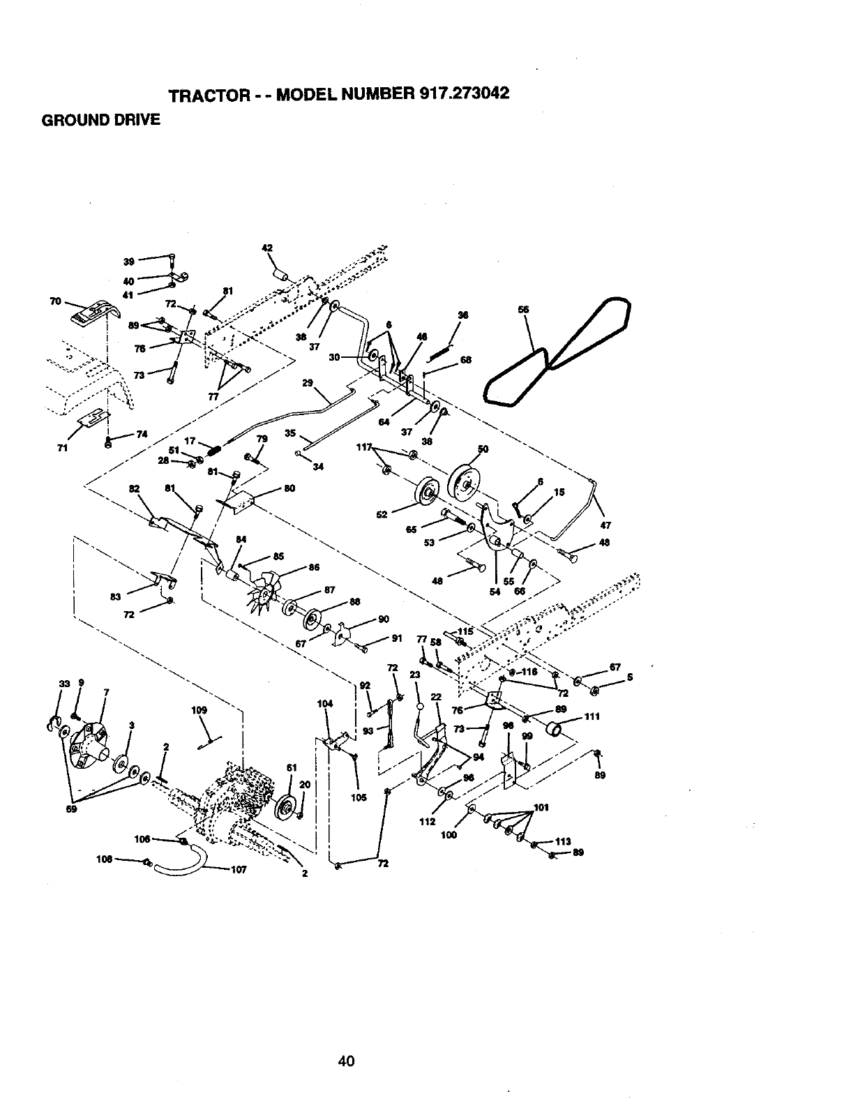
TRACTOR - - MODEL NUMBER 917.273042
GROUNDDRIVE
42
46
47
112 100
72
40
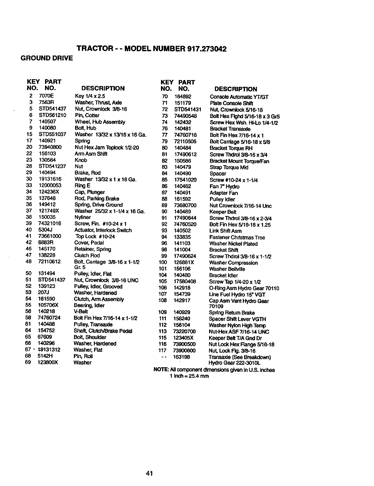
TRACTOR -- MODEL NUMBER 917.273042
GROUND DRIVE
KEY PART KEY PART
NO. NO. DESCRIPTION NO. NO.
2 7070E Key 1/4 x 2.5 70 164892
3 7563R Washer,Thrust,AxJe 71 151179
5 STD541437 Nut, Crownicck 3/8-16 72 STD541431
6 STD561210 Pin, Cotter 73 74490548
7 140507 Wheel, Hub Assembly 74 142432
9 140080 Bolt,Hub 76 140481
15 STD551037 Washer 13i32x13/16x16Ga. 77 74760716
17 140921 Spdng 79 72110505
20 73940800 Nut Hex Jam Taplock1/2-20 80 140484
22 156103 ArmAsmShltt 81 17490612
23 130564 Knob 82 150586
28 STD541237 Nut 83 140479
29 140494 Brake, Rod 84 140490
30 19131616 Washer 13/32x 1 x16Ga. 85 17541020
33 12(XX)053 RingE 86 140462
34 124236X Cap, Plunger 87 140491
35 137648 Rod, ParkingBrake 88 161592
36 149412 Spring, Drive Ground 89 73680700
37 121749X Washer 25/32x1-1/4x16Ga. 90 140489
38 150035 Nyliner 91 17490644
39 74321016 Screw, Fin. #10-24 x 1 92 74760520
40 5304J Actuator,InterlockSwitch 93 140502
41 73661000 Top Lock #10-24 94 133835
42 8883R Cover, Pedal 96 141103
45 145170 Retainer,Spdng 98 141004
47 138228 Clutch Rod 99 17490624
48 72110612 Bolt, Carriage 3/8-16 x 1-1/2 100 126881X
Gr. 5 101 156106
50 131494 Pulley,Idler, Flat 104 140480
51 STD541437 Nut, Crownicck 3/8-16 UNC 105 17580408
52 139123 Pulley,Idler,Grooved 106 142918
53 207J Washer, Hardened 107 154739
54 161590 Clutch,Ann Assembly 108 142917
55 105706X Bearing, Idler
56 140218 V-Belt 109 140929
58 74760724 Bolt Fin Hex 7/16-14 x 1-1/2 111 156240
61 140488 Puney,Transaxle 112 156104
64 154752 Shaft, ClutctvBrakePedal 113 73220700
65 67609 Bolt,Shoulder 115 123405X
66 140296 Washer, Hardened 116 73900500
67 - /9131312 Washer, Rat 117 73900600
68 5142H Pin, Roll -- 163198
89 123800X Washer
DESCRIPTION
ConsoleAutomaticYT/GT
Plate Console Shift
Nut, Crownicck5/16-18
Bolt Hex Flghd5/16-18 x 3 Gr5
Screw Hex Wsh. Hi-Lo 1/4-1/2
BracketTransaxle
BoltFin Hax 7116-14x I
BoltCordage 5/16-18 x 5/8
BracketTorqueRH
Screw "l_:Iral3/8-18 x 3/4
BracketMountTorque/Fan
StrapTorqueMid
Spacer
Screw #10-24 x 1-1/4
Fen 7" Hydro
AdapterFan
Pulley Idler
Nut Crownlock7/16-14 Unc
Keeper Belt
Screw Thdrol3/8-16 x 2-3/4
Bolt Fin Hex 5/16-18 x 1.25
LinkShiftAsm
FastenerChristmasTree
Washer Nickel Plated
BracketShift
Screw Tl'_rol 3/8-16 x 1-1/2
WasherCompression
WasherBelMne
BracketIdler
ScrewTap 1/4-20 x 1/2
O-Ring Asm Hydro Gear 70110
Line Fuel Hydro 15"VGT
CapAsm Vent HydroGear
70109
Spring ReturnBrake
Spacer ShiftLeverVGTH
Washer NylonHigh Temp
Nut-Hex ASF 7/16-14 UNC
Keeper BeltT/A Gnd Dr
Nut Lock Hex Range 5/16-18
NuL Lock Rg. 3/8-16
Transaxle(See Breakdown)
HydroGear 222-3010L
NOTE: Allcomponentdimensionsgivenin U.S. inches
1 inch= 25.4 mm
41
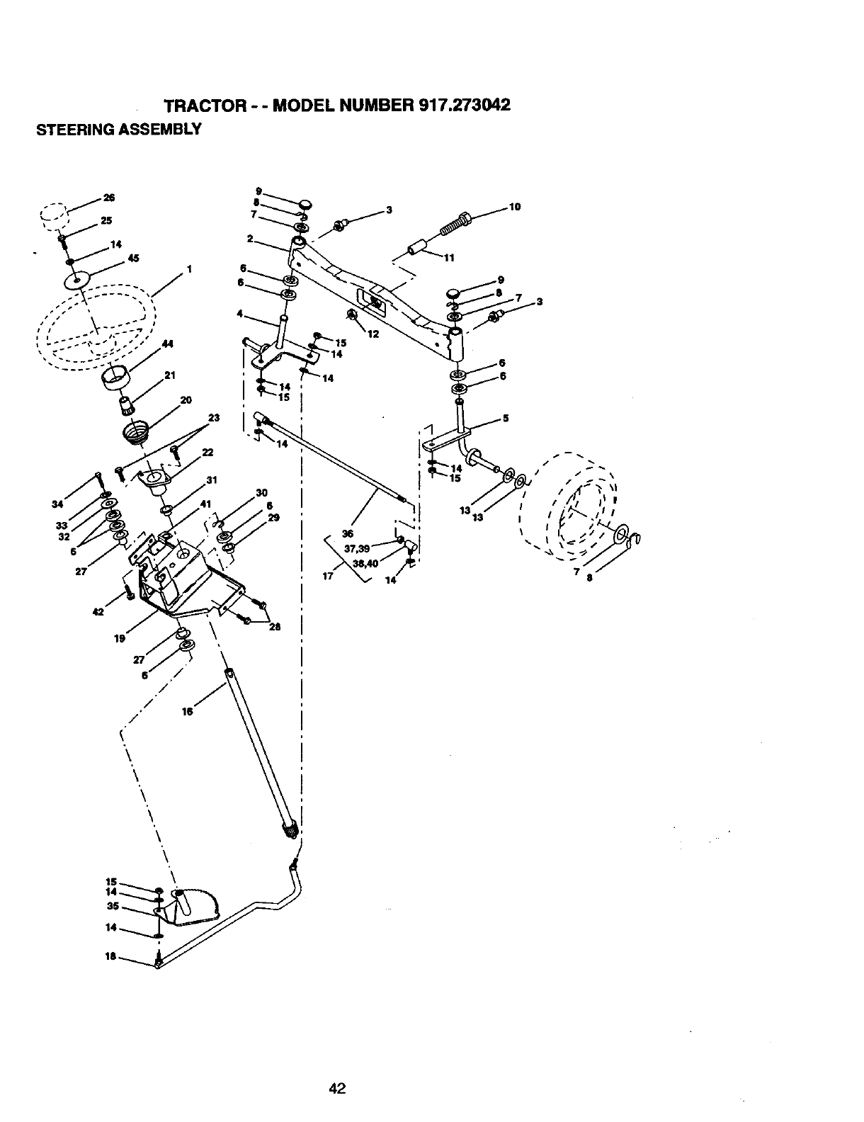
TRACTOR - - MODEL NUMBER 917.273042
STEERINGASSEMBLY
••_ • )
•--_ I
21 '
2O
23
34
32
6
22
19
It,/,¢ iII
42
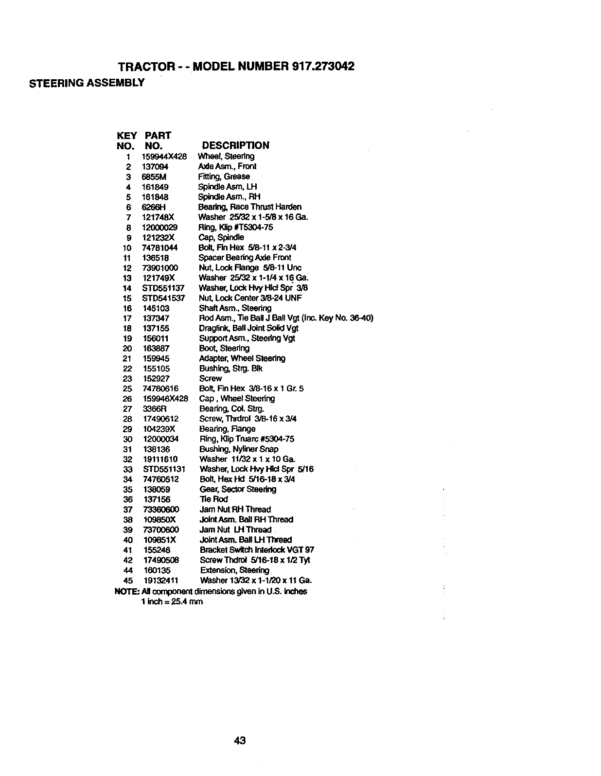
TRACTOR - - MODEL NUMBER 917.273042
STEERING ASSEMBLY
KEY PART
NO. NO.
I 159944X428
2 137094
3 6855M
4 101849
5 161848
6 6266H
7 121748X
8 12000029
9 121232X
10 74781044
11 136518
12 73901000
13 121749X
14 STD55t137
15 STD541537
16 145103
17 137347
18 137155
19 156011
20 163887
21 159945
22 155105
23 152927
25 74780616
26 159946X428
27 3366R
28 17490612
29 104239X
30 12000034
31 138136
32 19111610
33 STD551131
34 74760512
35 138059
36 137156
37 7336O6OO
38 1(_)850X
39 73700600
40 109651X
41 155246
42 17490508
44 160135
45 19132411
DESCRIPTION
Wheel, Steering
AxleAsm., Front
Fitting, Grease
SpindleAsm, LH
SpindleAsm., RH
Bearing,Race ThrustHarden
Washer 25/32 x 1-5/8 x 16Ga.
Ring,K]ip#T5304-75
Cap, Spindle
Bolt,Rn Hex 5/8-11 x2-3/4
Spacer Baadng AxleFront
Nut, Lock Flange 5/8-11 Unc
Washer 25/32 x 1-1/4 x 16 Ga.
Washer, LockHvy HJclSpr 3/8
Nut, LockCenter 3/8-24 UNF
ShaftAsm., Steering
Rod Asm., "ReBall J BallVgt (Ir_ Key No. 36-40)
Draglink,BallJointSolidVgt
SupportAsm., SteedngVgt
Boot,Steering
Adapter,Wheel Steedng
Bushing,Strg. BIk
Screw
Bolt,F3nHex 3/8-16 x 1 Gr. 5
Cap, Wheel Steering
Bearing,Coi.S_g.
Screw,Thrdrol 3/8-16 x 3/4
Beadng,Flange
Ring, KlipTruarc#5304-75
Bushing,NylinerSnap
Washer 11/32x I x 10 Ga.
Washer,LockHvy Hld Spr 5/16
Bolt, Hex Hd 5/16-18 x 3/4
Gear, SectorSteering
"heRod
Jam NUtRH Thread
JointAsm. Ball RH Thread
Jam NUt LH Tlvead
JointAsm. Ball LH Thread
BracketSwitch InterlockVGT 97
Screw Tt_roi 5/16-18 x 1/2 Tyt
Extension,Steering
Washer 13/32 x 1-1/20 x 11Ga.
NOTE: Allcomponentdimensionsgivenin U.S. inches
1 inch = 25A mm
43
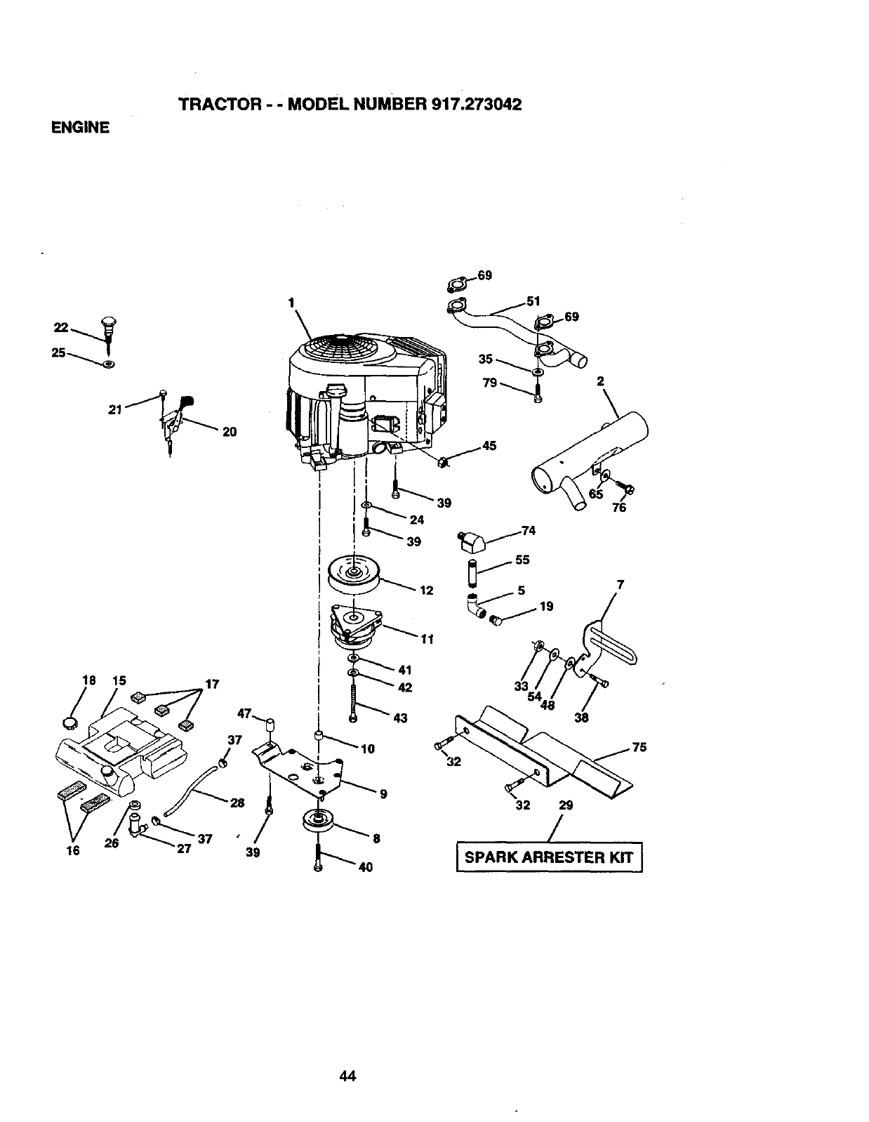
ENGINE
TRACTOR - - MODEL NUMBER 917.273042
20
2
18 15 17
37
26
16 39
39
39
76
32 29
/
44
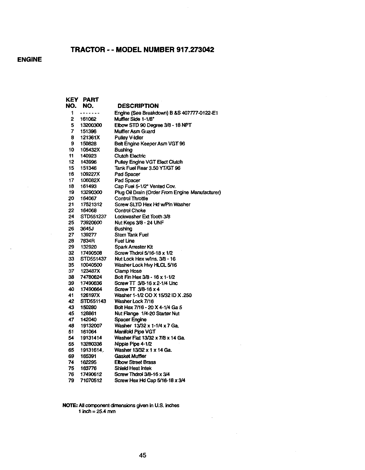
ENGINE
TRACTOR - - MODEL NUMBER 917.273042
KEY PART
NO. NO.
I .......
2 161062
5 13200300
7 151396
8 121361X
9 150828
10 105432X
11 140923
12 1439S6
15 151346
16 109227X
17 106082X
18 161493
19 13290300
20 164067
21 17521312
22 164068
24 STD551237
25 73920600
26 3645J
27 139277
28 7834R
29 132920
32 17490508
33 STD551437
35 10040500
37 123487X
38 74780624
39 17490636
40 17490664
41 126197X
42 STD551143
43 150280
45 128861
47 142040
48 19132007
51 161064
54 19131414
55 13280336
65 191316147
69 165391
74 162295
75 163776
76 1749O612
79 71070512
DESCRIPTION
Engine (See Breakdown)B &S40TF/7-0122-E1
MufflerSide 1-1/8"
Elbow STD 90 Degree 3/8 -18 NPT
MulflerAsm Guard
PulleyV-Idler
Belt Engine KeeperAsmVGT 96
Bushing
ClutchElectric
Pulley Engine VGT Elect Clutch
Tank Fuel Rear 3.50 YT/GT 96
Pad Spacer
Pad Spacer
Cap Fuel 5-1/2" VentedCov.
Plug Oil Drain(Order FromEngine Manufacturer)
ControlThrottle
Screw SLTD Hex Hd w/Pin Washer
ControlChoke
LockwasherExt Tooth3/8
Nut Keps 3/8 - 24 UNF
Bushing
Stem TankFuel
Fuel Une
SparkArresterKit
Screw Thdrol5/16-18 x 1/2
Nut Lock Hex w/Ins. 3/8 -16
Washer LockHvy HLCL 5/16
Clamp Hose
Bolt FinHex 3/8 -16x 1-1/2
Screw Tr 3/8-16 x 2-1/4 Uric
Screw'l-I" 3/8-16 x 4
Washer 1-1/20D X 15/32 ID X .250
Washer Lock7/16
Belt Hex 7/16 -20 X 4-1/4 Ga 5
Nut Flange 114-20StarterNut
Spacer Engine
Washer 13/32 x 1-1/4 x 7 Ga.
ManifoldPipe VGT
Washer Flat 13/32 x 7/8 x 14 Ga.
Nipple Pipe4-1/2
Washer 13/82 x I x 14Ga+
Gasket Muffler
ElbowStreet Brass
ShieldHeat intek
Screw TIxIrol3/8-16 x 3/4
Screw Hex Hd Cap 5/16-16 x3/4
NOTE: Allcomponentdimensionsgiven inU.S. inches
1 inch= 25.4 rein
45
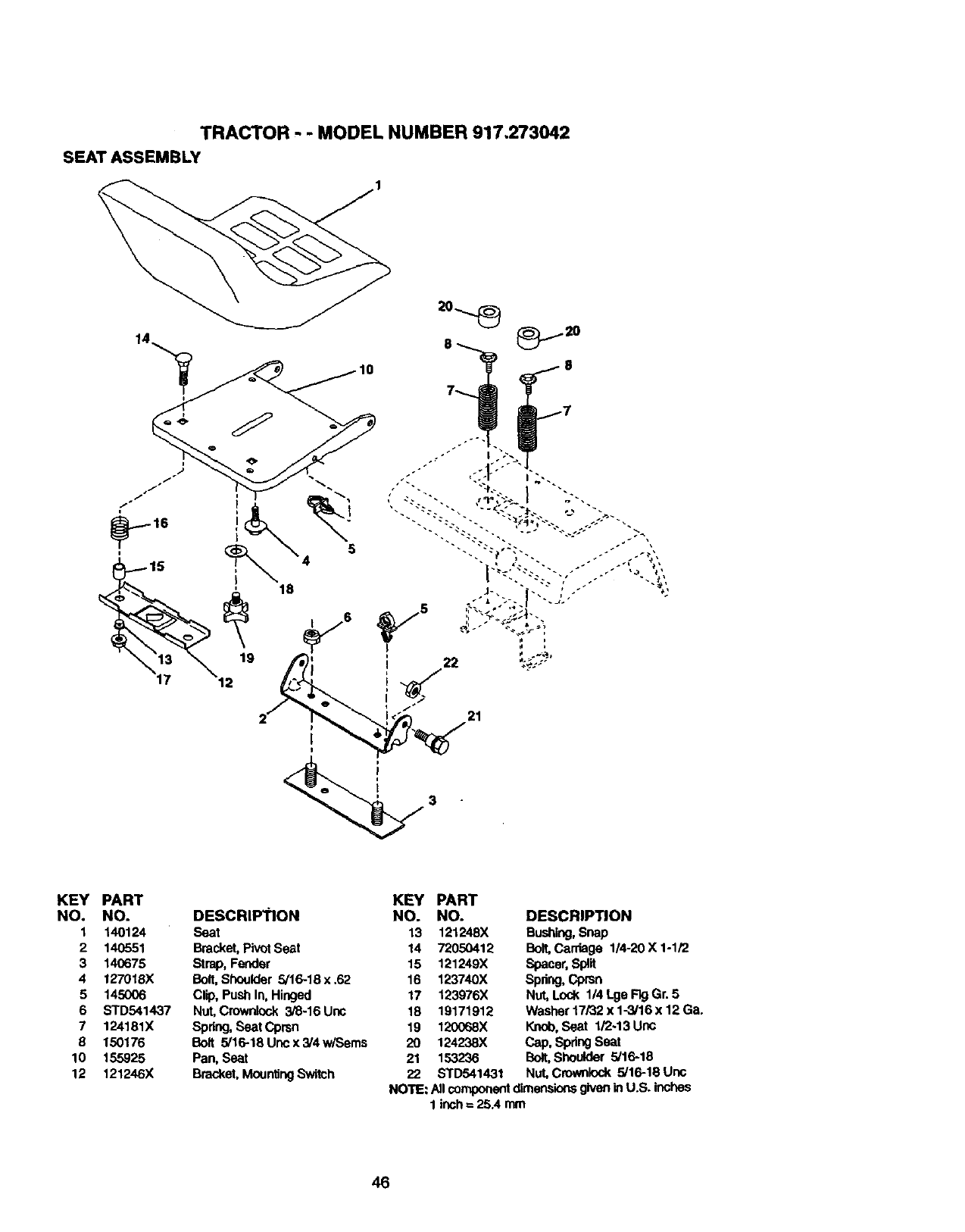
TRACTOR - - MODEL NUMBER 917,273042
SEAT ASSEMBLY
KEY PART KEY PART
NO. NO. DESCRII:_'ION NO. NO.
I 140124 Seat 13 121248X
2 140551 Bracket, Pivot Seat 14 72050412
3 140675 Strap, Fender 15 121249X
4 127018X Bolt,Shoulder 5/16-18 x .62 16 123740X
5 145006 Clip, Push In, Hinged 17 123976X
6 STD541437 Nut, Crownlcok 3/6-16 Unc 18 19171912
7 124181X Spring,Seat Cprsn 19 120068X
8 150176 Bolt 5/16-18Uncx3/4wiSems 20 124238X
10 155925 Pan, Seat 21 1532"36
12 121246X Bracket, MountingSwitch 22 STD541431
DESCRIPTION
Bushing,Snap
Bolt, Carriage 1/4-20 X 1-1/2
Spacer,Split
Spdng,Cprsn
Nut, Lock I14 Lge Fk3Gr. 5
Washer 17/32 x 1-3/16 x 12 Ga.
Knob, Seat 1/2-13 Unc
Cap, SpringSeat
Bclt,Shoulder 5/16-18
Nut, Crownlock 5/16-18 Unc
NOTE: NI componentdimensionsgiveninU.S. inches
1 inch= 25A mm
46
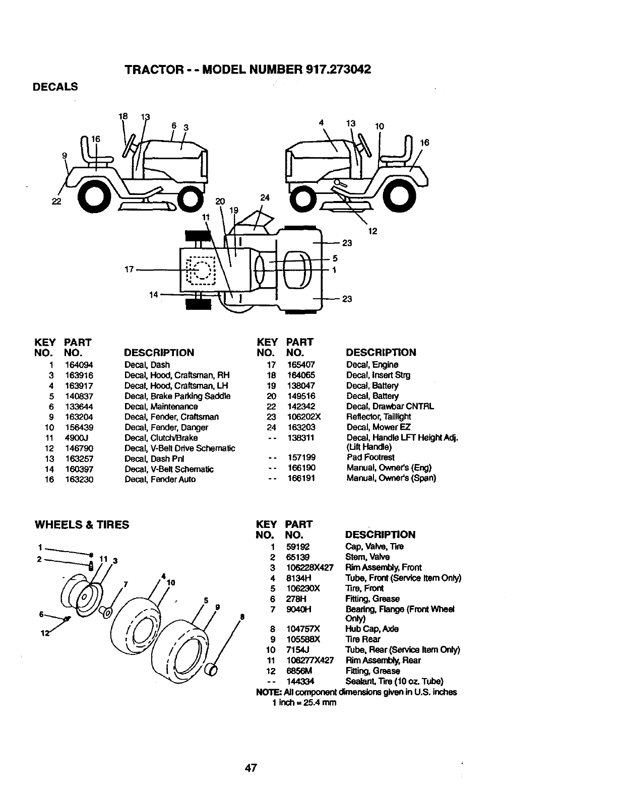
DECALS
TRACTOR - -MODEL NUMBER 917.273042
22
18
17
11
2O 24
4
5
1
13
12
--23
10
16
KEY PART
NO. NO.
1 164094
3 163916
4 163917
5 140837
6 133644
9 163204
10 156439
11 4900J
12 146790
13 163257
14 160397
16 163230
KEY PART
DESCRIPTION NO. NO.
Decal, Dash 17 165407
Decal. Hood, Craftsman, RH 18 164065
Decal, Hood, Craftsman,LH 19 138047
Decal, Brake ParkingSaddle 20 149516
Decal, Maintenance 22 142342
Decal, Fender,Craftsman 23 1G6202X
Decal, Fender, Danger 24 163203
Decal, Clutch/Brake - - 138311
Decal, V-BeltDdve Schematic
Decal, Dash Phi - - 157199
Decal, V-BeltSchematic - - 166190
Decal, FenderAuto -- 166191
DESCRIPTION
Decal, Engine
Decal, Insert Strg
Decal, BatteTy
Decal, Battery
Decal, DrawbarCNTRL
Reflector,Taillight
Decal, Mower EZ
Decal, Handle LFT HeightAdj.
(uftHandte)
Pad Footrest
Manual, Owner's(Eng)
Manual,Owner's (Span)
WHEELS & TIRES
3
410
KEY PART
NO. NO. DESCRIPTION
1 59192 Cap, Valve, Tin)
2 65139 Stem, Valve
3 106228X427 RimAssembly,Front
4 8134H Tube, Front(Service Item Only)
5106230X Tire, Front
6 278H F_ng, Grease
7 90401-1 Bearing,Flange(FrontWheel
only)
8 104757X Hub Cap, Axle
9 105588)( Tire Rear
10 7154J Tube, Rear (san'ice Item Only)
11 106277X427 RimAssembly,Rear
12 6856191 F_ng, Grease
- - 144334 Sealant, Tire (10 oz. Tube)
NOTE: AJIcomponentdimensionsgivenin U.S. inches
1 insh=25.4 mm
47
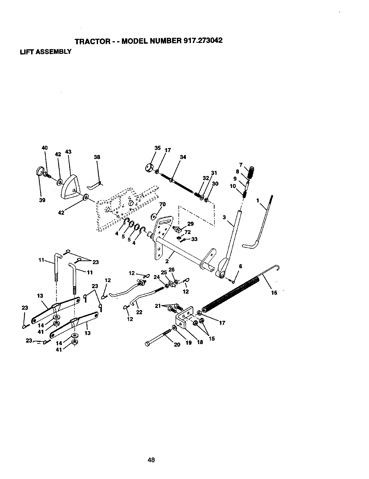
TRACTOR - - MODEL NUMBER 917.273042
LIFTASSEMBLY
4O
39
43 38
4 72
"_1123
12
23
I
13
23 _,
48
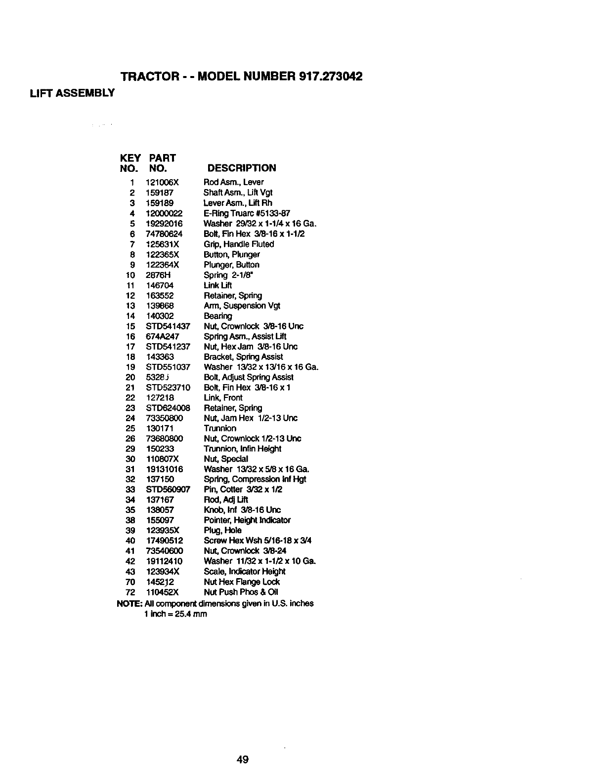
TRACTOR - - MODEL NUMBER 917.273042
LIFT ASSEMBLY
KEY PART
NO. NO. DESCRIPTION
1 121006X RodAsm., Lever
2 159187 SheftAsm., Uft Vgt
3 159189 LeverAsm., LiftRh
4 12000022 E-RingTruarc #5133-87
5 19292016 Washer 29/32x1-1/4x16Ga.
6 74780624 Bolt,FinHex 3/8-16 x 1-1/2
7125631X Grip, Handle Ruted
8 122365X Button,Plunger
9 122364X Plunger,Button
10 2876H Spring 2-1/8"
11 146704 LinkLift
12 163552 Retainer,Spdng
13 139868 Arm, SuspensionVgt
14 140302 Beadng
15 STD541437 Nut, Crownlock 3/8-16 Unc
16 674A247 SpringAsm., AssistLift
17 STD541237 Nut, HexJam 3/8-16Unc
18 143363 Bracket, SpringAssist
19 STD551037 Washer 13/32 x 13/16x 16Ga.
20 5328J Bolt, AdjustSpringAssist
21 STD523710 Bolt, Fin Hex 3/8-16 x 1
22 127218 Unk, Front
23 STD624008 Retainer,Spring
24 73350800 Nut, Jam Hex 1/2-13 Uric
25 130171 Trunnion
26 73680800 Nut, Crownlcok1/2-13 Uric
29 150233 Trunnion,InfinHeight
30 110807X Nut, Special
31 19131016 Washer 13/32x5i8x16Ga.
32 137150 Spring, CompressionInfHgt
33 STD560907 Pin, Cotter 3/32x 1/2
34 137167 Rnd,AdjUft
35 138057 Knob, lnf 3/8-16Unc
38 155097 Pointer,HeightIndicator
39 123935X Plug, Hole
40 17490512 Borew Hex Wsh 5/16-18 x3/4
41 73540600 Nut, C_ 3/8-24
42 19112410 Washer 11i32x1-1!2x10Ga.
43 123934X Scale, IndicatorHeight
70 1452.12 NUtHex FlangeLock
72 110452X NUtPush Phos& Oil
NOTE: Allcomponentdimeneionsgiven in U.S. inches
1 inch= 25.4 mm
49
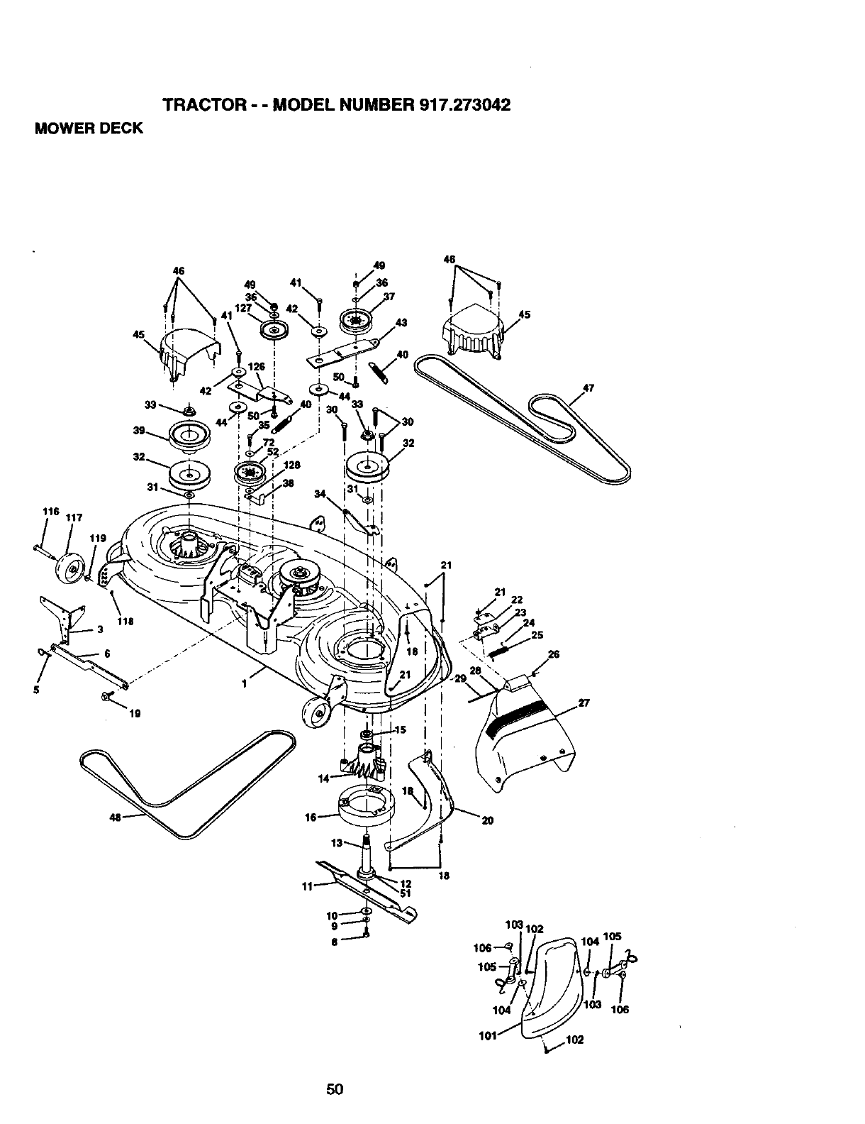
TRACTOR - - MODEL NUMBER 917.273042
MOWERDECK
46
49
46
45
>30
32
118 117
21
21 22
5O
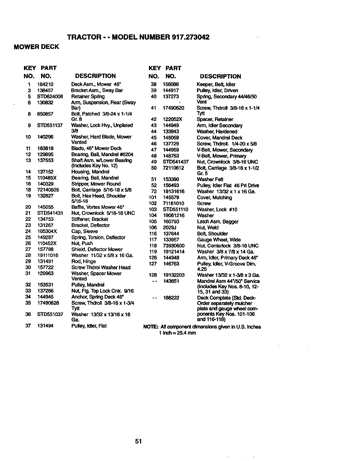
TRACTOR - - MODEL NUMBER 917.273042
MOWER DECK
KEY PART
NO. NO.
1 164210
3 138457
5 STD624008
6 130832
8 85O857
9 STD551137
10 140296
11 163819
12 129895
13 137553
14 137152
15 110485X
16 140329
18 72140505
19 132827
20 145055
21 STD541431
22 134753
23 131267
24 105304X
25 149287
26 110452X
27 157788
28 19111016
29 131491
30 157722
31 129963
32 153531
33 137266
34 144945
35 17490628
36 STD551037
37 131494
KEY PART
DESCRIPTION NO. NO.
DeckAsm., Mower 46" 38 156_86
BmcketAsm., Sway Bar 39 144917
RetainerSpring 40 137273
Ann, Suspension,Rear (Sway
Bar) 41 17490620
Bolt,Patched 3/8-24 x 1-1/4
Gr. 8 42 122052X
Washer, LockHW., Unplated 43 144949
3/8 44 133943
Washer, Hard Blade,Mower 45 145059
Vented 46 137729
Blade, 46" Mower Deck 47 144959
Bearing,Ball, Mandrel #6204 48 148763
ShaftAsm. w/Lower Bearing 49 STD541437
(IncludesKey No. 12) 50 72110612
Housing, Mandrel
Bearing,Ball,Mandrel 51 153390
Stripper,Mower Round 52 156493
Bolt,Carriage 5/16-18 x 5/8 72 19131616
Bolt, Hex Head, Shoulder 101 145579
5/16-18 102 71161010
Baftle,VortexMower 46" 103 STD551110
Nut, Crownlock 5/16-18 UNC 104 19061216
Stiffener,Bracket 105 160793
Bracket,Deflector 106 2029J
Cap, Sleeve 116 137644
Spdng,Torsion,Deflector 117 133957
Nut, Push 118 73930600
Shield,DeflectorMower 119 19121414
Washer 11/32xS/8x16Ga. 126 144948
Rod,Hinge 127 146763
Screw ThdrotWasher Head
Washer, Spacer Mower 128 19132203
Vented -- 143651
Pulley,Mandrel
Nut, Rg.Top Lock Cnl_. 9/16
Anchor,Spdng Deck 46" -- 166222
Screw, Thdroll 3/8-16 x 1-3/4
Tytt
Washer 13/32 x 13/16 x 16
Ga.
Pulley,Idler,Flat
DESCRIPTION
Keeper, Belt, Idler
Pulley, Idler,Driven
Spdng, Secondary44/46/50
Vent
Screw, Thdroll 3/8-16 x 1-1/4
Tytt
Spacer, Retainer
Arm, IdlerSecondary
Washer, Hardenod
Cover,Mandrel Deck
Screw,Thdroll. 1/4-20 x 5/8
V-Belt, Mower, Secondary
V-Belt, Mower, Primary
Nut, Crownlock 3/8-16 UNC
Boft,Carhage 3/8-16 x 1-1/2
Gr. 5
Washer Felt
Pulley,Idler Fiat 46 Pd Drive
Washer 13/32 x 1 x 16 Ga.
Cover, Mulching
Screw
Washer, Lock #10
Washer
LatchAsm. Bagger
Nut, Weld
Bolt, Shoulder
Gauge Wheel, Wide
Nut, Centedock 3/8-16 UNC
Washer 3/8 x 7/8 x 14 Ga.
Arm, Ioler, Pdmary Denk46"
Pulley, Idler, V-Groove Dim.
4.25
Washer 13/32 x 1-3/8 x 3 Ga.
MandrelAsm 44"/50" Sewlce
(IncludesKey Nos. 6-10, 12-
15, 31 and 33)
Deck Complete (Std. Dock-
Order separately mulcher
plate and gauge wheelcom-
ponents Key Nos. 101-106
and 116-118)
NOTE:AircomponentdimensionsgivenInU.S.Inches
1 ioch= 25.4mm
51
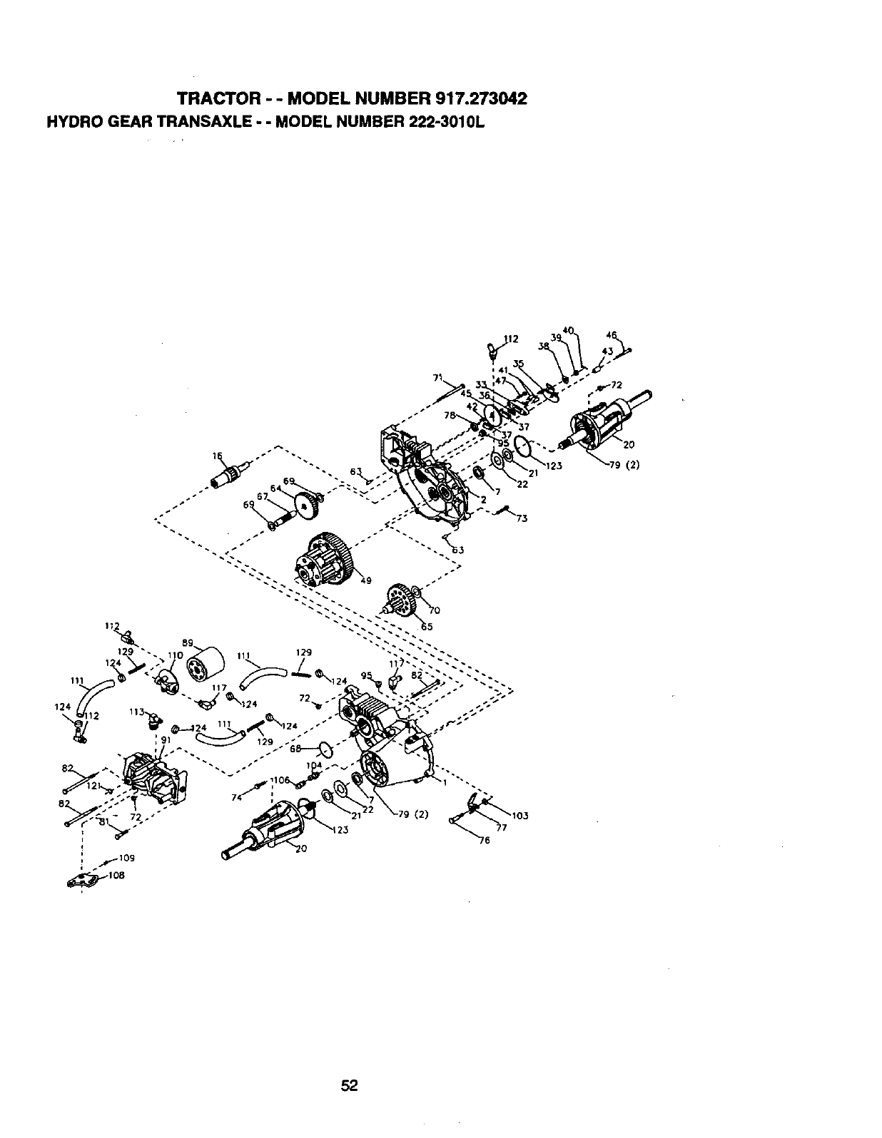
TRACTOR "' MODEL NUMBER 917.273042
HYDRO GEAR TRANSAXLE "" MODEL NUMBER 222-3010L
52
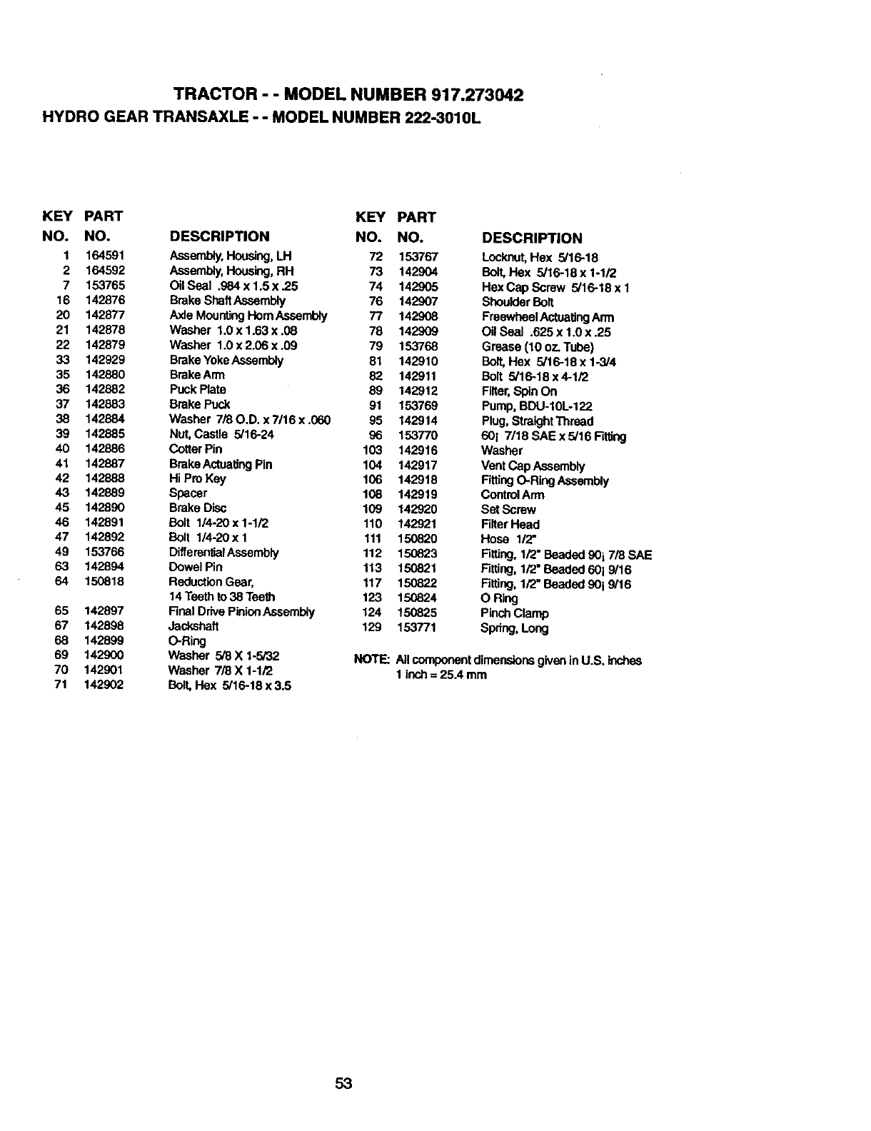
TRACTOR - - MODEL NUMBER 917.273042
HYDRO GEAR TRANSAXLE - - MODEL NUMBER 222..3010L
KEY PART KEY PART
NO. NO. DESCRIPTION NO. NO.
1 164591 Assembly,Housing,LH 72 153767
2 164592 Assembly,Housing,RH 73 142904
7 153765 Oil Seal .984 x 1.5 x .25 74 142905
16 142876 BrakeShaftAseambly 76 142907
20 142677 Axle MountingHomAssembly 77 142908
21 142878 Washer 1.0 x 1.63 x .08 78 142909
22 142879 Washer 1.0 x 2.06 x .09 79 153768
33 142929 BrakeYokeAssembly 81 142910
35 142880 BrakeArm 82 142911
36 142882 Puck Plate 89 142912
37 142883 Brake Puck 91 153769
38 142884 Washer 7/80.D. x 7/16 x .060 95 142914
39 142885 Nut, Castle 5/16-24 96 153770
40 142886 CotterPin 103 142916
41 142887 BrakeActuatJngPin 104 142917
42 142888 Hi Pro Key 106 142918
43 142889 Spacer 108 142919
45 142890 Brake Disc 109 142920
46 142891 Bolt 1/4-20 x 1-1/2 110 142921
47 142892 Bolt 1/4-20 x I 111 150820
49 153766 DifferentlalAseambly 112 150823
63 142894 Dowel Pin 113 150821
64 1.50818 ReductionGear, 117 150822
14 Teethto 38 Tee_ 123 156824
65 142897 Flnal Drive PinionAssembly 124 150825
67 142898 Jackshaft 129 153771
68 142899 O-Ring
69 142900 Washer 5/8X 1-5/32 NOTE:
70 142901 Washer 7/8 X 1-1/2
71 142902 Bott,Hex 5/16-18x3.5
DESCRIPTION
Lockout,Hex 5/16-18
Bolt,Hex 5/16-18 x 1-1/2
Hex Cap Screw 5/16-18 x 1
Shoulder Bolt
Freewheel ActuatingArm
Oil Seal .625 x 1.0 x .25
Grease (10 oz. Tube)
Bolt,F!ex 5/16-18 x 1-3/4
Bolt 5/16-18 x4-1/2
Filter,Spin On
Pump, BDU-10L-122
Plug, StraightThread
601 7/18 SAE x 5/16 Firdng
Washer
Vent Cap Assembly
FittingO-Ring Assembly
ControlArm
Set Screw
FilterHead
Hose 1/2"
RUing, 1/2" Beaded90 i 7/8 SAE
Fitting, 1/2"Beaded 601 9/16
Fitting, 1/2" Beaded 90 i 9/16
O Ring
PinchClamp
Spdng, Long
Allcomponentdimensionsgivenin U.S. Inchea
1 inch= 25A mm
53
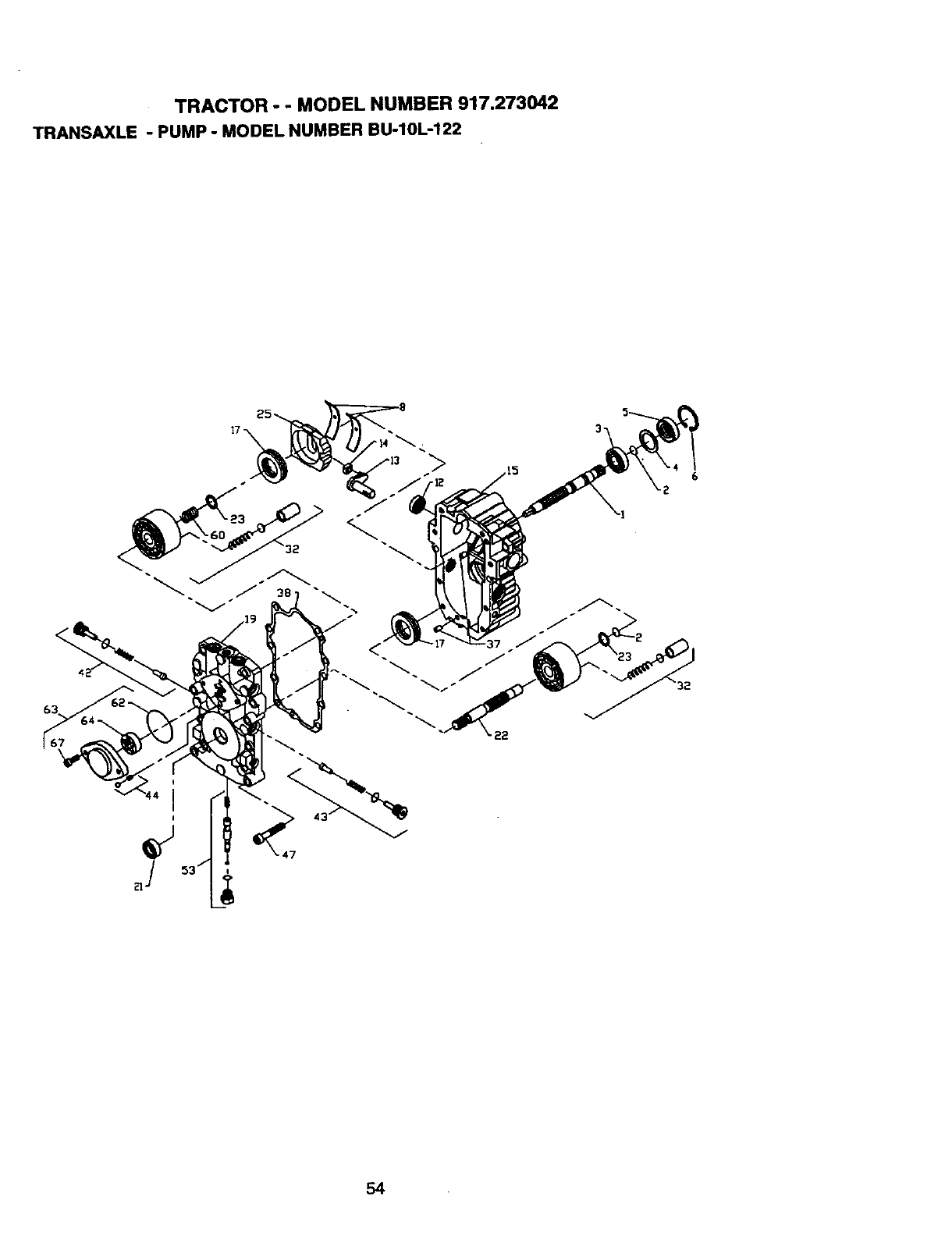
TRACTOR -- MODEL NUMBER 917.273042
TRANSAXLE - PUMP - MODEL NUMBER BU-10L-122
54
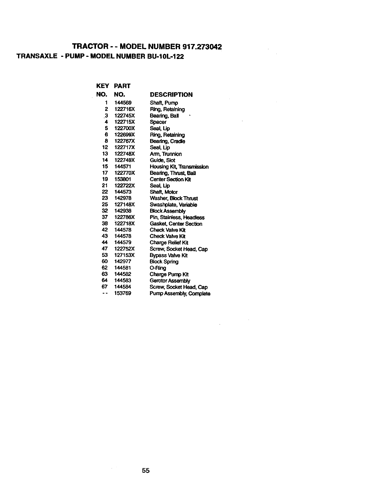
TRACTOR - - MODEL NUMBER 917.273042
TRANSAXLE -PUMP -MODEL NUMBER BU-10L-122
KEY PART
NO. NO. DESCRIPTION
1 144569 Shaft, Pump
2 122716X Ring, Retaining
3 122745X Beadng, Ball
4 122715)( Spacer
5 122700X Seal, Up
6 122699X Ring. Retaining
8 122767X Beadng, Cradle
12 122717X Seal, Lip
13 122748X Arm,Trunnion
14 122749X Guide, Slot
15 144571 Housing_Transmission
17 122770X Bearing,Theist, Bali
19 153801 Center SectionKit
21 122722X Seal, Up
22 144573 Shaft, Motor
23 142978 Washer,BlockThrust
25 127148X Swashplate,Variable
32 142938 BlockAseambly
37 122786X Pin, Stainless,Headless
38 122718X Gasket, Center Sec_on
42 144578 Check ValveKit
43 144578 Check Valve Kit
44 144579 Charge ReliefKit
47 122752X Screw,SocketHead, Cap
53 127153X BypassValve Kit
60 142977 BlockSpring
62 144581 O-Ring
63 144582 Charge Pump K'_
64 144583 GerotorAssembly
67 144584 Screw,SocketHead, Cap
- - 153769 PumpAssembly,Complete
55
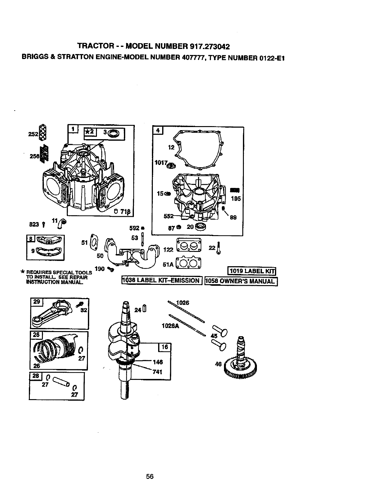
TRACTOR - - MODEL NUMBER 917.273042
BRIGGS & STRATTON ENGINE-MODEL NUMBER 407777, TYPE NUMBER 0122-E1
823T 11_
"k REQUIRES SPECLALTOOLS 190 110
TO INSTALL. SEE REPAIR
INSTRUCTION MANUAL.
41
87Q 20_
_9_J 51_ 83 _l:_t_ 22_
IIII195
\89
11019 LABEL Kl'rI
ll_SLA._L_-EMJSS'ONI_058OWNER'S._.Aq
26 46
56
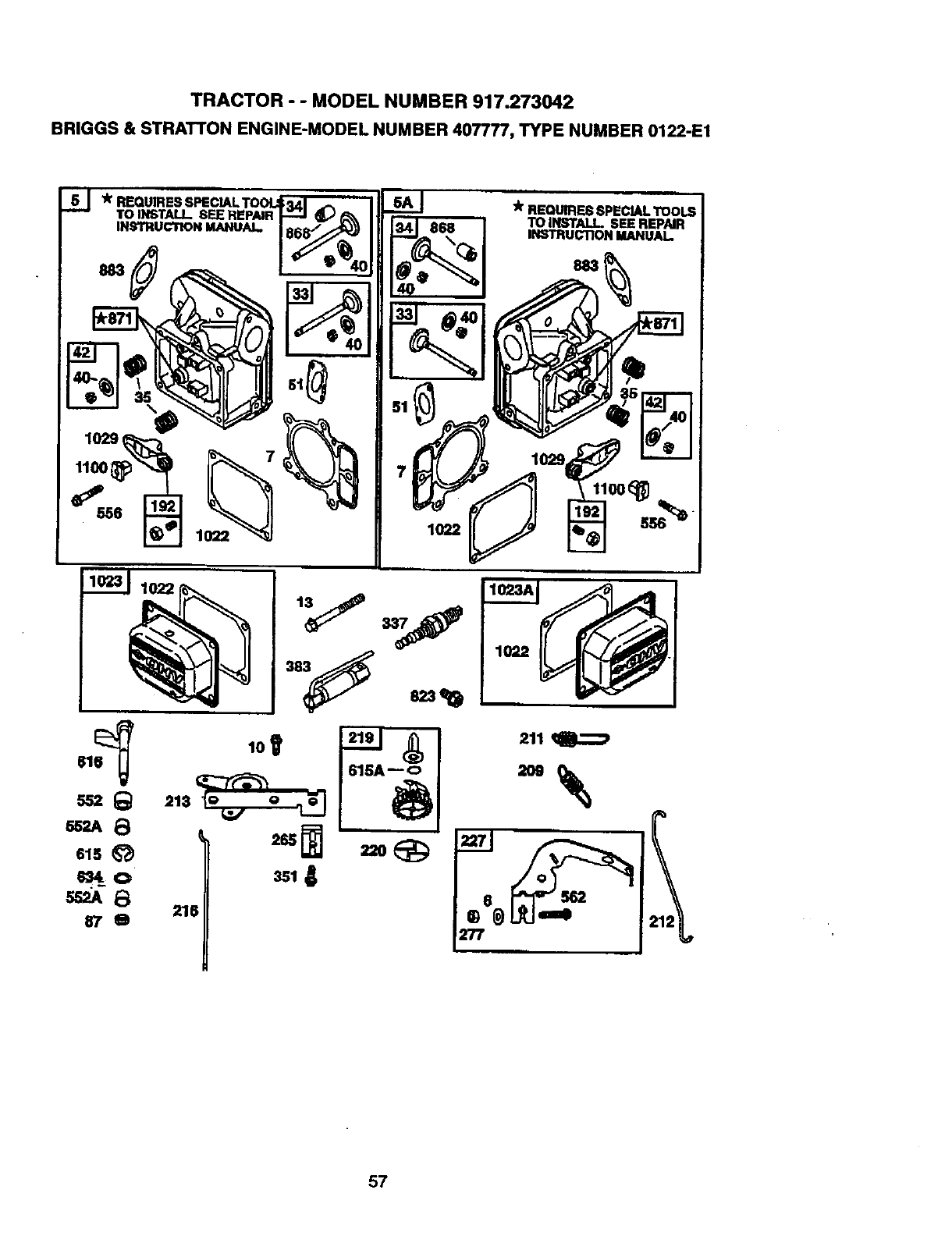
TRACTOR - -MODEL NUMBER 917.273042
BRIGGS & STRATTON ENGINE-MODEL NUMBER 407777, TYPE NUMBER 0122-E1
*REQUIRES SPECIAL TOOU
TO INSTALL SEE REPAIR _ iIl___l *_?_,_%_o_,_
_II1_ n _._o.,_u_
IH-gTHU_II_N MANUAL,
1022
57
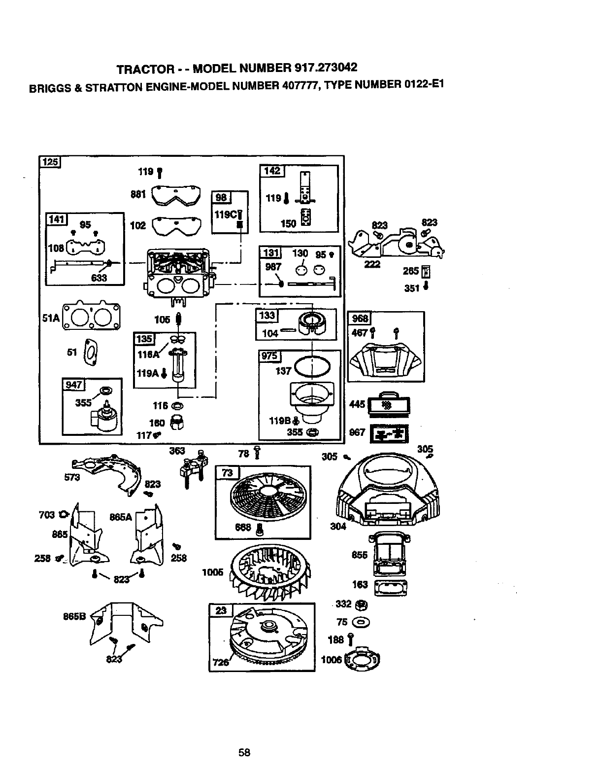
TRACTOR - - MODEL NUMBER 917.273042
BRIGGS & STRATTON ENGINE-MODEL NUMBER 407777, TYPE NUMBER 0122-E1
mIt
222
823 823
I-.,,rz_,..'l ioo+ 'Ira
865B,
3Sl I
3O5
,o
58
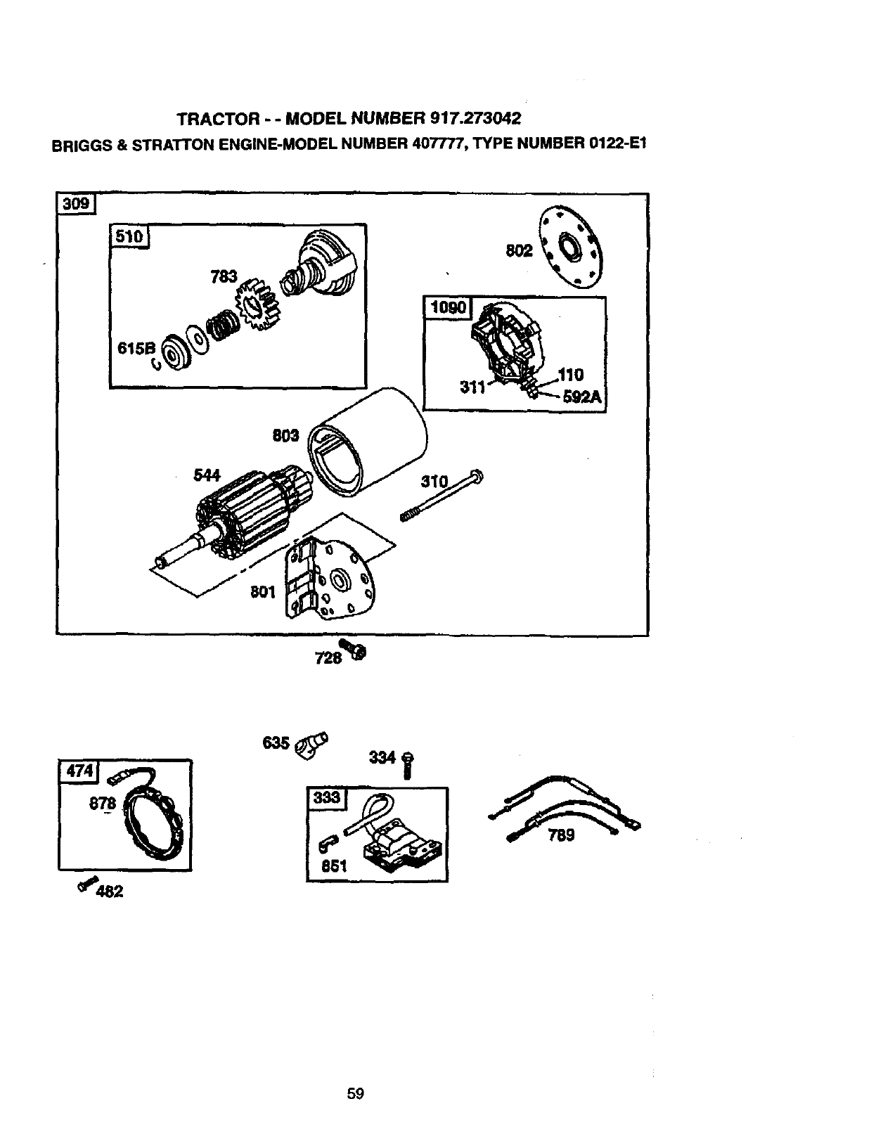
TRACTOR -- MODEL NUMBER 917.273042
BRIGGS & STRATTON ENGINE-MODEL NUMBER 407777, TYPE NUMBER 0122-E1
544
783
803
801
_482
59
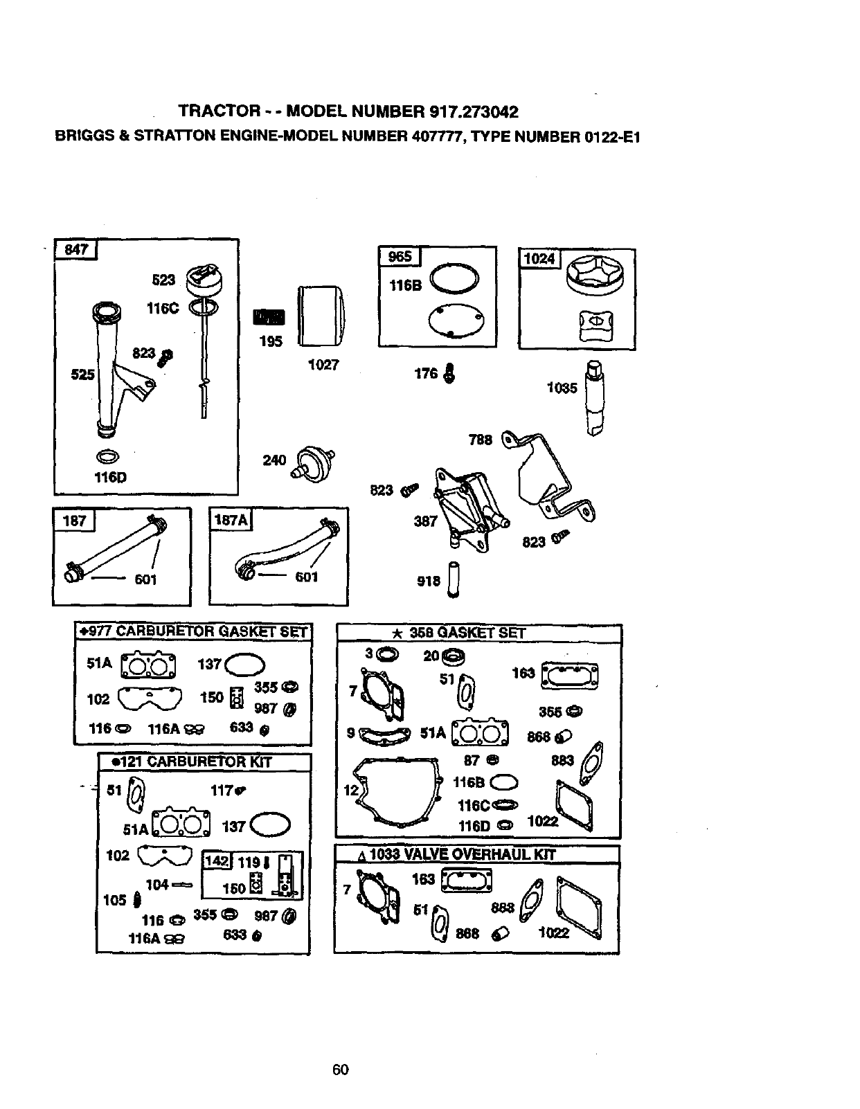
TRACTOR - - MODEL NUMBER 917.273042
BRIGGS& STRA'R'ONENGINE-MODELNUMBER407777,TYPENUMBER0122-E1
525
O
116D
116C
195
i"4,977CARBURETOR GASKET BET
51A_ 137 0
355 O
102 _150_ 987@
116_ 116A_' 633 •
e121 CARBURETOR KIT
51 _117f
51_AL_ 137Q
lO2_ _.s I _ I
1050 104= 'SO L_ ,__ I
116_ 355_ 987_
116A _;_ 633 @
116B Q
%
788
.23 _
387
823
-k 368 GASKET SET
30 2o_
12_ tiriDC_ 1022_
,_1033"VALVE OVERHAUL KIT I
r
Sl _888
_ses
6O
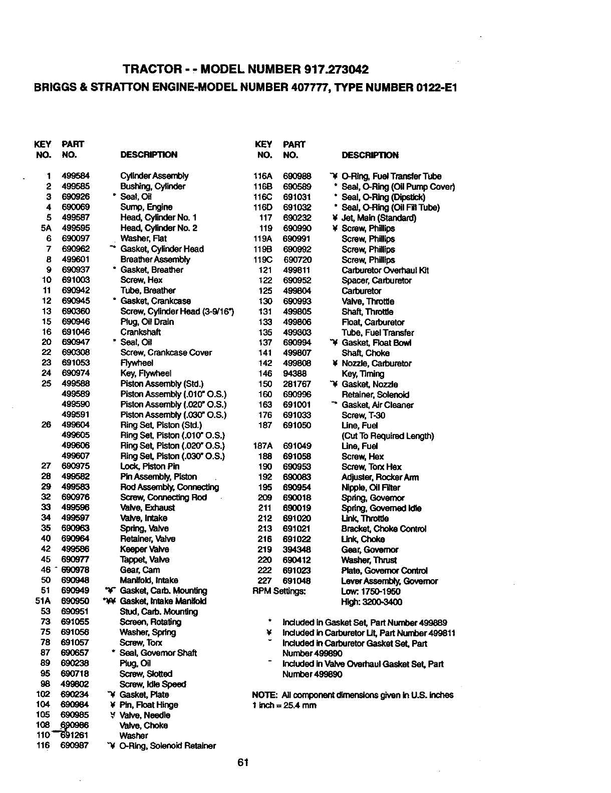
TRACTOR - - MODEL NUMBER 917.273042
BRIGGS & STRATrON ENGINE-MODEL NUMBER 407777, TYPE NUMBER 0122-E1
KEY PART KEY PART
NO. NO. DESCRIPTION NO. NO. DESCRIPTION
1 499584 CylinderAssembly 116A 690988 "4 O-Ring, FuelTransferTube
2 499585 Bushing,Cylinder 116B 690589 * Seal, O-Ring (Og Pump Cover)
3 690926 * Seal, Oil 116C 691031 * Seal, O-Ring (DipsUck)
4 690069 Sump, Engine 116D 691032 " Seal, O-Ring (Oil FilITube)
5 499587 Head, CylinderNo. 1 117 690232 ¥Jet, Main (Standard)
5A 499595 Head, CylinderNo. 2 119 690990 ¥Screw,Phillips
6 690097 Washer, Rat 119A 690991 Screw, Phillips
7 690962 "" Gasket,CylinderHead 119B 690992 Screw, Phillips
8 499601 BreatherAssembly 119C 690720 Screw, Phillips
9 690937 °Gasket, Breather 121 499811 CarburetorOverhaul Kit
10 691003 Screw, Hax 122 690952 Spacer,Carburetor
11 690942 Tube, Breather 125 499804 Carburetor
12 690945 ° Gasket, Crankcase 130 690993 Valve,Throttle
13 690360 Screw, CylinderHead (3-9/16") 131 499805 Shaft,Throttle
15 690946 Plug, Oil Drain 133 499806 Roat, Carburetor
16 691046 Crankshaft 135 499803 Tube, FuelTransfer
20 690947 ° Seal, Oil 137 690994 _Gasket, FloatBowl
22 690308 Screw, Crankcase Cover 141 499807 Shaft, Choke
23 691053 Flywheel 142 499808 ¥Nozzle, Carburetor
24 690974 Key,Rywheel 146 94388 Key,_ming
25 499588 PistonAssembly (Std.) 150 281767 "-4 Gasket, Nozzle
499589 PistonAssembly (.010"O.S.) 160 690996 Retainer,Solenoid
499590 PistonAssembly(.020"O.S.) 163 691001 _" Gasket,AJrCleaner
499591 PistonAssembly (.030"O.S.) 176 691033 Screw, T-30
26 499604 Ring Set, Piston(Std.) 187 691050 Line, Fuel
499605 RingSet, Piston(.010"O.S.) (CutTo RequiredLength)
499606 RingSet, Piston(.020"O.S.) 187A 691049 Une, Fuel
499607 RingSeL Piston(.030"O.S.) 188 691058 Screw, Hex
27 690975 Lock,PistonPin 190 690953 Screw, TorxHex
28 499582 PinAssembly,Piston 192 6,90083 Adjustor,RockerArm
29 499583 RodAsasmb_y,Coneacting 195 690954 Nlpple,OilFdtor
32 690976 Screw,ConnectingRod 209 690018 Spdng, Governor
33 499596 Valve, Exhaust 211 690019 Spring, GovernedIdle
34 499597 Valve, Intake 212 691020 Unk, Throttle
35 690963 Spring, Valve 213 691021 Bracket,Choke Control
40 690964 Retainer,Valve 216 691022 Link, Choke
42 499586 Keeper Valve 219 394348 Gear, Governor
45 690977 Tappet, Valve 220 690412 Washer,Tlvuet
46 - 690978 Gear, Cam 222 691023 Plata, GovernorControl
50 690948 Manifold,Intake 227 691048 LeverAseambly,Governor
51 690949 "¥" Gasket, Carb. MounlJng RPM Settings: Low:.1750-1950
51A 690950 _Gasket, IntakeManifold H'_h: 3200-3400
53 690951 Stud,Cad). Mounting
73 691055 Screen, RotaUng induded inGasket Set, Part Number499889
75 691056 Washer,Spring ¥ includedinCarburetorUt,PartNumber499811
78 691057 Screw, Too( Includedin Carburetor Gasket Set, Part
87 690657 * Seal, GovernorShaft Number499690
89 690238 Plug, Og Includedin Valve Oved_aulGasket Set, Part
95 690718 Screw,Slotted Number499890
98 499602 Sorew,ldta Speed
102 690234 "4 Gasket, Plate NOTE: Allcom__givenl_U.S.ind_es
104 690984 ¥Pin, FloatHinge 1 inch=25.4mm
105 690985 _ Valve, Nead_e
108 6_986 Valve, Choke
110 _'6-91261 Washer
116 690987 "4 O-Ring,SolenoidRetainer
61
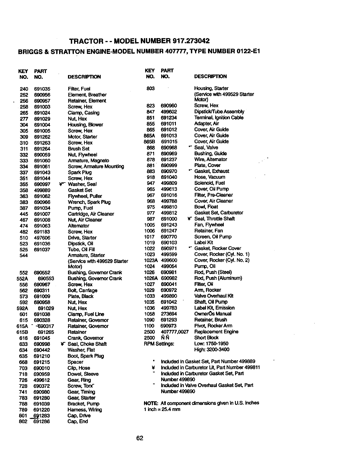
TRACTOR - - MODEL NUMBER 917.273042
BRIGGS & STRATTON ENGINE-MODEL NUMBER 407777, TYPE NUMBER 0122-E1
KEY PART KEY PART
NO. NO. DESCRIPTION NO. NO. DESCRIPTION
240 691035
252 690956
256 690957
258 691003
265 691024
277 691029
304 691004
305 691005
309 691262
310 691263
311 691264
332 690059
333 691060
334 691061
337 691043
351 691044
355 690997
358 499889
363 691062
383 69O966
387 691034
445 691007
467 691008
474 691063
482 691183
510 497606
523 691036
525 691037
544
552 690552
552A 690553
556 69(7967
562 690311
573 691009
592 690958
592A 691029
601 691038
615 690328
615A - -_.q0317
615B 691265
616 691045
633 69O998
634 690442
635 691210
668 691215
703 690010
718 690959
726 499612
728 690372
741 690980
783 691280
788 691039
789 691220
801 _.66_1283
802 691286
Fdter,Fuel 80_ Housing,Starter
Element, Breather (Service with499529 Starter
Retainer, Element Metor)
Screw, Hex 823 690960 Screw,Hex
Clamp, Casing 847 499602 Dipsltck/TubeAssembly
Nut, Hex 851 691234 Terminal,IgnitionCable
Housing, Blower 855 691011 Adepter,Air
Screw, He)( 865 691012 Cover,AirGuide
Motor, Starter 865A 691013 Cover, Air Guide
Screw, Hex 865B 691015 Cover, Air Guide
BrushSet 868 690968 "- Seal, Valve
Nut, Flywheel 871 690969 Bushing,Guide
Armatura, Magneto 878• 691237 Wire, Alternator
Screw, Armature Mounting 881 690999 Plate, Cover
Spark Plug 883 690970 "- Casket, Exhaust
Screw, Hex 918 691040 Hose,Vacuum
_'- Washer, Seal 947 499809 Solenoid,Fuel
Gasket Set 965 499e13 Cover, OUPump
Flywheel, Puller 967 691016 Filter,Pre-Cleanar
Wrench, Spark Ping 9_8 499788 Cover, AirCleaner
Pump, Fuel 975 499810 Bowl,Float
Cartridge,Air Cleaner 977 499812 Casket Set, Carburetor
Nut, AirCleacer 987 691000 _- SeaI, ThrottleShaft
Alternator 1005 691243 Fan, Flywheel
Screw, Hex 1006 691247 Retainer,Fan
Ddve, Starter 1017 690770 Screen, Oil Pump
Dipstick,Oil 1019 690103 LabelKit
Tube, Oil Fill 1022 690971 "- Casket, RockerCover
Armature,Starter 1023 499599 Cover, Rocker(Cyl. No. 1)
(Service with499529 Starter 1023A 499600 Cover, Rocker(CyLNo, 2)
Motor) 1024 499_54 Pump, Oil
Bushing,GovernorCrank 1026 690981 Rod, Push (Stea_)
Bushing,Governor Crank 1026A 690982 ROd,Push (Aiuminum)
Screw, Hex 1027 690041 Filter,Oil
Bolt,Carriage 1029 690972 Arm, Rocker
Plate, Black 1033 499890 Valve OverhaulKit
Nut, Hex 1035 691042 Shaft, Oil Pump
Nut, Hex 1036 499783 LabelKit,Emission
Clamp, Fuel Une 1058 273694 Ownar_ Manual
Retainer, Governor 1090 691293 Retainer,Brush
Retainer, Governor 1100 690973 Pivot, RockerArm
Retainer 2500 407777,0027 Replacement Engine
Crank, Governor 2500 I_11_1 Short Block
Seal, Choke Shaft RPM Settings: Low:.1750-1950
Washer, Rat High: 32(X)-3400
Boot, Spark Plug
Spacer Includedin Gasket Set, Part Number499889
Clip, Hose ¥Includedin CarburetorLit,Part Number 499811
Dowel, Sleeve Includedin CarburetorCasket Set, Part
Gear, Ring Number 499890
Screw, Torx" Includedin Valve Overhaul Gasket Set, Part
Gear, "timing Number 499890
Gear, Starter
Bracket, Pump NOTE: Allcomponentdimensionsgivenin U.S. inches
Hamuss, Wiring 1 inch=25.4 mm
Cap, Drive
Cap, End
62
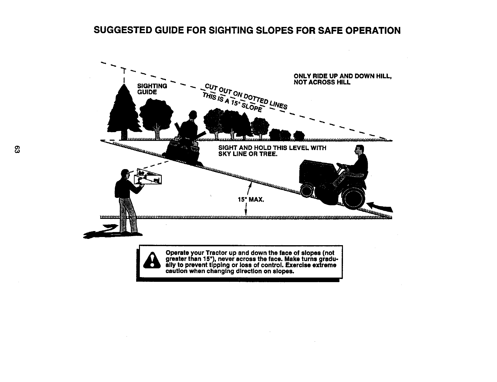
SUGGESTED GUIDE FOR SIGHTING SLOPES FOR SAFE OPERATION
,,.,,,,
ONLY RIDE UP AND DOWN HILL,
NOT ACROSS HILL
15" MAX.
I_1) Operate your Tractor up and down the face of slopes (not I
I
greater than 15"), never across the face. Make turns gradu- I
ally to prevent tipping or loss of control. Exercise extreme
caution when changing direction on slopes.
For the repair or replacement parts you ne_ed
delivered directly to your home
Call 7 am - 7 pm, 7 days a week
1-800-366-PART
(1-800-366-7278)
Para ordenar plezas con entrega a
domicilio - 1-800-659-7084
For in-house major brand repair service
Call 24 hours a day, 7 days a week
1-800-4-REPAIR
(1-800-473-7274)
Para pedir servicio de reparaci6n a
domicllio- 1-800-676-5811
For the location of a Sears Parts and
Repair Center in your area
Call 24 hours aday, 7 days a week
1-800-488-1222
For information on purchasing a Sears
Maintenance Agreement or to inquire
about an existing Agreement
Call 9 am - 5 pm, Monday-Saturday
1-800-827-6655
When requesting service or ordering
parts, always provide the following
information:
•Product Type •Part Number
•Model Number •Part Description
Illiml
H||H|H
SEARS
Amenca's Repair Speciat_sts
166190 9.2.98 RD Printed in U.S.A.
