Craftsman 917273201 User Manual 24 HP ELECTRIC START 46 MOWER AUTOMATIC GARDEN TR Manuals And Guides 99040593
CRAFTSMAN Lawn, Tractor Manual 99040593 CRAFTSMAN Lawn, Tractor Owner's Manual, CRAFTSMAN Lawn, Tractor installation guides
User Manual: Craftsman 917273201 917273201 CRAFTSMAN 24 HP ELECTRIC START 46 MOWER AUTOMATIC GARDEN TR - Manuals and Guides View the owners manual for your CRAFTSMAN 24 HP ELECTRIC START 46 MOWER AUTOMATIC GARDEN TR #917273201. Home:Lawn & Garden Parts:Craftsman Parts:Craftsman 24 HP ELECTRIC START 46 MOWER AUTOMATIC GARDEN TR Manual
Open the PDF directly: View PDF ![]() .
.
Page Count: 68

Owner's Manual
[RAFTXMI:IN
24.0 HP
ELECTRIC START
46" MOWER
AUTOMATIC
GARDEN TRACTOR
Model No.
917.273201
•Safety
•Assembly
•Operation
•Maintenance
•Repair Parts
CAUTION:
Read and follow all
Safety Rules and Instructions
before operating this equip-
ment.
For answers to your questions
about this product, Call:
1-800-659-5917
Sears Craftsman Help Line
5 am -5pm, Mon -Sat
Sears, Roebuck ar=d Co., Hoffman Estates, IL 60179
Visit our Craftsman website: www.sears.com/craftsman
Warranty ................................................. 2
Safety Rules ........................................... 2
Product Specifications ........................... 5
Assembly ................................................ 8
Operation ............................ ,... .............. 12
Maintenance Schedule .......................... 19
Maintenance ......................................... 19
Service and Adjustments ...................... 23
Storage ................................................. 31
Troubleshooting .................................... 32
Repair Parts ......................................... 36
Parts Ordering ....................... Back Cover
LIMITED TWO YEAR WARRANTY ON CRAFTSMAN RIDING EQUIPMENT
For two (2) years from the date of purchase, if this Craftsman Riding Equipment is main-
tained, lubricated and tuned up according to the instructions in the owner's manual,
Sears will repair or replace, free of charge, any parts found to be defective in matedal or
workmanship.
This Warranty does not cover:
•Expendable items which become worn during normal use, such as blades, spark
plugs, air cleaners, belts, etc.
• Tire replacement or repair caused by punctures from outside objects, such as nails,
thorns, stumps, or glass.
• Repairs necessary because of operator abuse, negligence, improper storage or acci-
dent or the failure to maintain the equipment according to the instructions contained in
the owner's manual.
• Riding equipment used for commercial or rental purposes.
LIMITED 90 DAY WARRANTY ON BATTERY
For ninety (90) days from date of purchase, if any battery included with this riding equip-
ment proves defective in material or workmanship and our testing determines the bat-
tery will not hold a charge, Sears will replace the battery at no charge. In-home warranty
service on your Craftsman riding equipment is available at no charge for 30 days from
the date of purchase. Please contact your nearest service center. After 30 days from the
date of purchase, warranty service is available by taking your Craftsman riding equip-
ment to your nearest Sears Service Center. (In-home warranty service will still be avail-
able after 30 days from the date of purchase but a standard trip charge will apply). This
warranty applies only while this product is in the United States. This Warranty gives you
specific legal rights, and you may also have other rights which may vary from state to
state. -_
Sears, Roebuck and Co., D/817 WA, Hoffman Estates, IL 60179
GENERAL OPERATION
• Read, understand, and follow all instruc-
tions in the manual and on the machine
before starting.
•Only allow responsible adults, who are
familiar with the instructions, to operate
the machine.
• Clear the area of objects such as rocks,
toys, wire, etc., which could be picked
up and thrown by'the blade.
• Be sure the area is clear of other people
before mowing. Stop machine if anyone
enters the area.
2
Never carry passengers.
Do not mow in reverse unless absolute-
ly necessary. Always look down and
behind before and while backing.
Be aware of the mower discharge direc-
tion and do not point it at anyone. Do
not operate the mower without either
the entire grass catcher or the guard in
place.
Slow down before turning.
Never leave a running machine unat-
tended. Always turn off blades, set park-
ing brake, stop engine, and remove
keys before dismounting.

• Turnoffbladeswhen not mowing.
• Stop engine before removing grass
catcher or unclogging chute.
• Mow only in daylight or good artificial
light.
• Do not operate the machine while under
the influence of alcohol or drugs.
• Watch for traffic when operating near or
crossing roadways.
• Use extra care when loading or unload-
ing the machine into a trailer or truck.
SLOPE OPERATION
Slopes are amajor factor related to loss-
of-control and tipover accidents, which
can result in severe injury or death. All
slopes require extra caution. If you cannot
back up the slope or if you feel uneasy on
it, do not mow it.
DO:
•Mow up and down slopes, not across.
•Remove obstacles such as rocks, tree
limbs, etc.
•Watch for holes, ruts, or bumps. Uneven
terrain could overturn the machine. Tall
grass can hide obstacles.
•Use slow speed. Choose a low gear so
that you will not have to stop or shift
while on the slope.
• Follow the manufacturer's recommen-
dations for wheel weights or counter-
weights to improve stability.
•Use extra care with grass catchers or
other attachments. These can change
the stability of the machine.
•Keep all movement on the slopes slow
and gradual. Do not make sudden
changes in speed or direction.
• Avoid starting or stopping on a slope. If
tires lose traction, disengage the blades
and proceed slowly straight down the
slope.
DO NOT:
•Do notturn on slopes unless necessary,
and then, turn slowly and gradually
downhill, if possible.
•Do notmow near drop-offs, ditches, or
embankments. The mower could sud-
denly turn over if a wheel is over the
edge of a-cliff or ditch, or if an edge
caves in.
•Do not mow on wet grass. Reduced
traction c_uld cause sliding.
•Do not try to stabilize the machine by
putting your foot on the ground.
•Do not use grass catcher on steep
slopes.
CHILDREN
Tragic accidents can occur if the operator
is not alert to the presence of children.
Children are often attracted to the
machine and the mowing activity. Never
assume that children will remain where
you last saw them.
•Keep children out of the mowing area
and under the watchful care of another
responsible adult.
•Be alert and turn machine off if children
enter the area.
•Before and when backing, look behind
and down for small children.
•Never carry children. They may fall off
and be seriously injured or interfere with
safe machine operation.
•Never allow children to operate the
machine.
• Use extra care when approaching blind
corners, shrubs, trees, or other objects
that may obscure vision.
SERVICE
•Use extra care in handling gasoline and
other fuels. They are flammable and
vapors are explosive.
Use only an approved container.
Never remove gas cap or add fuel
with the engine running. Allow en-
gine to cool before refueling. Do not
smoke.
Never refuel the machine indoors.
Never store the machine or fuel
container inside where there is an
open flame, such as a water heater.
•Never run a machine inside a closed
area.
•Keep nuts and bolts, especially blade
attachment bolts, tight and keep equip-
ment in good condition.
•Never tamper with safety devices.
Check their proper operation regularly.
•Keep machine free of grass, leaves, or
other debris build-up. Clean oil or fuel
spillage. Allow machine to cool before
storing.
•Stop and inspect the equipment if you
strike an object. Repair, if necessary,
before restarting.
3

Never make adjustments or repairs with
the engine running.
Grass catcher components are subject
to wear, damage, and deterioration,
which could expose moving parts or
allow objects to be thrown. Frequently
check components and replace with
manufacturer's recommended parts,
when necessary.
•Mower blades are sharp and can cut.
Wrap the blade(s) or wear gloves, and
use extra caution when servicing them.
• Check brake operation frequently.
Adjust and service as required.
• Be sure the area is clear of other people
before mowing. Stop machine if anyone
enters the area.
• Never carry passengers.
• Do not mow in reverse unless absolute-
ly necessary. Always look down and
behind before and while backing.
• Never carry children. They may fall off
and be seriously injured or interfere with
safe machine operation.
• Keep children out of the mowing area
and under the watchful care of another
responsible adult.
• Be alert and turn machine off if children
enter the area.
• Before and when backing, look behind
and down for small children.
• Mow up and down slopes (15 ° Max), not
across.
•Remove obstacles such as rocks, tree
limbs, etc.
•Watch for holes, ruts, or bumps. Uneven
terrain could overtum the machine. Tall
grass can hide obstacles.
•Use slow speed. Choose a low gear so
that you will not have to stop or shift
while on the slope.
•Avoid starting or stopping on a slope. If
tires lose traction, disengage the blades
and proceed slowly straight down the
slope.
• Do notturn on slopes unless necessary,
and then, turn slowly and gradually
downhill, if possible.
,_Look for this symbol to point out impor-
tant safety precautions. It means CAU-
TION!!! BECOME AWARE!!! YOUR SAFE-
TY IS INVOLVED.
A.CAUTION: In order to prevent acciden-
tal starting when setting up, transporting,
adjusting or making repairs always discon-
nect spark plug wire and place wire where
it cannot contact spark plug.
_,WARNING: The engine exhaust from
this product contains chemicals known to
the State of California to cause cancer,
birth defects, or other reproductive harm.
4

PRODUCT SPECIFICATIONS
HORSEPOWER 24.0
_ASOLINE 3.5 GALLONS
;APACITY UNLEADED
,ND TYPE: REGULAR
OIL TYPE SAE 10W-30
(API-SF/SG/SH): (above 32°F)
SAE 5W-30
(below 32°F)
OIL CAPACITY: W/FILTER: 4.2 PINTS
W/O FILTER: 3.7 PINTS
SPARK PLUG: Champion RC12YC
3AP: .030")
VALVE NOT ADJUSTABLE
CLEARANCE:
GROUND SPEED FORWARD: 5.8
IMPH): REVERSE: 2.1
TIRE PRESSURE: FRONT: 14 PSI
REAR: 10 PSI
3HARGING
SYSTEM: 15 AMPS @ 3600 RPM
E3AI-IERY: AMP/HR: 35
MIN. CCA: 280
CASE SIZE: U1R
BLADE BOLT 27-35 FT. LBS.
TORQUE:
CONGRATULATIONS on your purchase
of a Craftsman Tractor. It has been
designed, engineered and manufactured
to give you the best possible dependability
and performance.
Should you experience any problem you
cannot easily remedy, please contact your
nearest Sears Authorized Service Center.
We have competent, well-trained techni-
cians and the proper tools to service or
repair this tractor.
Please read and retain this manual. The
instructions will enable you to assemble
and maintain your tractor properly. Always
observe the "SAFETY RULES".
MAINTENANCE AGREEMENT
A Sears Maintenance Agreement is avail-
able on this product. Contact your nearest
Sears store for details.
CUSTOMER RESPONSIBILITIES
•Read and observe the safety rules.
•Follow a regular schedule in maintain-
ing, caring for and using your tractor.
•Follow the instructions under "Mainte-
nance" and "Storage" sections of this
owner's manual.
_WARNING: This tractor is equipped
with an internal combustion engine and
should not be used on or near any unim-
proved forest-covered, brush-covered or
grass-covered land unless the engine's
exhaust system is equipped with a spark
arrester meeting applicable local or state
laws (if any). If a spark arrester is used, it
should be maintained in effective working
order by the operator.
In the state of California the above is
required by law (Section 4442 of the
California Public Resources Code). Other
states may have similar laws. Federal
laws apply on federal lands. A spark
arrester for the muffler is available through
your nearest Sears Authorized Service
Center (See REPAIR PARTS section of
this manual).
5

Parts Bag contents shown full size
_J
(1) Shoulder
Bolt 5/16-18 _
(1) Washer _ /
17/32 x 1-3/16 x 12 Gauge _li= J
(1) Knob
(4) Retainer Springs (single loop)
(3) Retainer Springs (double loop)
(2) Screws #10 x 5/8
(2) Washers
3116x3/4 x
16 Gauge
(2) Lock Washers #10
(2) Weld Nuts #10
6

Partspackedseparatelyincarton
Seat
Video
Cassette
lie
Manual
Steering
Wheel
=
Parts Bag
Parts Bag contents not shown full size
I I I
2) LatchHook
Assemblies
(4) Washers
3/8 x 3/4 x 14 Ga.
(4) Shoulder Bolts
(_(4) Wheels
(Optional)
(4)
(4) Retainer Springs
(4) Locknuts
3/8-16
(4) Clevis Pins
Slope Sheet
Steering Sleeve
Steering Sleeve
Extension
(2) Front Link Assemblies
Steering
Wheel Insert
7

Your new tractor has been assembled at the factory with exception of those parts left
unassembled for shipping purposes. To ensure safe and proper operation of your tractor
a parts and hardware you assemble must be tightened securely. Use the correct tools
as necessary to insure proper tightness. Review the video cassette before you begin.
TOOLS REQUIRED FOR
ASSEMBLY
A socket wrench set will make assembly
easier. Standard wrench sizes you need
are listed below.
(1) 9/16" wrench (1) 3/4" Socket w/
(1)Pliers drive ratchet
(1) 1/2" wrench (1) Phillips Screw-
(1) Utility knife driver
(t) Tire pressure gauge
When right or left hand is mentioned in
this manual, it means, from your point of
view, when you are in the operating posi-
tion (seated behind the steedng wheel).
TO REMOVE TRACTOR FROM
CARTON
UNPACK CARTON
•Remove all accessible loose parts and
parts boxes from shipping carton (See
pages 6).
•Cut, from top to bottom, along lines on
all four corners of shipping carton, and
lay panels flat.
Remove mower and packing materials.
Check for any additional loose parts or
boxes and remove.
BEFORE ROLLING TRACTOR OFF
SKID
ATTACH STEERING WHEEL
• Remove hex bolt, lock washer and large
flat washer from steering shaft.
• Position front wheels of the tractor so
they are pointing straight forward.
_lide the steering sleeve over the steer-in_ shaft.
Align tabs and press steering sleeve
extension into bottom of steering wheel.
•Position steering wheel so cross bars
are horizontal (left to right) and slide
onto steering wheel adapter.
•Secure steering wheel to steering shaft
with hex bolt, lock washer and large flat
washer previously removed. Tighten
securely.
•Snap steedng wheel insert into center
of steering wheel.
•Remove protective materials from trac-
tor hood and grill.
IMPORTANT: Check for and remove any
staples in skid that may puncture tires
where tractor is to roll offskid.
Steering
Sleeve
TO ROLL TRACTOR OFF SKID
(See Operation section for location
and function of controls)
•Press lift lever plunger and raise attach-
ment lift lever to its highest position.
•Release parking brake by depressing
clutch/brake pedal.
•Place freewheel control in freewheeling
position to disengage transmission (See
"TO TRANSPORT" in the Operation
section of this manual).
•Roll tractor forward off skid.
•Remove ties from V-belts.
HOW TO SET UP YOUR TRACTOR
CHECK BATTERY
•Lift hood to raised position.
•if this battery is put into service after
month and year indicated on label (label
located between terminals) charge bat-
tery for minimum of one hour at 6-10
amps. (See "BATTERY" in Maintenance
section of this manual for charging
instructions).
"8

. ++÷++_
•-+•- .+
-+ •
.s,t +- / k I
,, ..... : : /_aue,
+°+" i+; _ .
:>2
INSTALL SEAT
Adjust seat before tightening adjustment
knob.
•Remove cardboard packing on seat
pan.
•Place seat on seat pan and assemble
shoulder bolt. Tighten shoulder bolt
securely.
• Assemble adjustment knob and flat
washer loosely. Do not tighten.
•Lower seat into operating position and
sit on seat.
•Slide seat until a comfortable position is
reached which allows you to press
clutch/brake pedal all the way down.
•Get off seat without moving its adjusted
position.
• Raise seat and tighten adjustment knob
securely.
Seat
Seat Pan
Shoulder
Bolt
Adjustment _:+._-_
Knob Flat Washer
CHECK TIRE PRESSURE
The tires on your tractor were overinflated
at the factory for shipping purposes.
Correct tire pressure is important for best
cutting performance.
•Reduce tire pressure to PSi shown in
"PRODUCT SPECIFICATIONS" section
of this manual
CHECK BRAKE SYSTEM
After you learn how to operate your trac-
tor, check to see that the brake is properly
adjusted. See "TO ADJUST BRAKE" in
the Service and Adjustments section of
this manual.
ASSEMBLE GAUGE WHEELS TO
MOWER DECK
The gauge wheels are designed to keep
the mower deck in proper position when
operating mower. Be sure they are proper-
ly adjusted to ensure optimum mower per-
formance.
•Slide gauge wheel bar down into brack-
et channel, Be sure that gauge wheel
bar aligning holes are on top. Assemble
gauge wheels as shown using shoulder
bolts, 3/8 washers and 3/8-16 center
Iocknuts and tighten securely.
•For ease of mower to tractor assembly,
raise gauge wheels to highest position
and retain with clevis pins and spring
retainers.
•Adjust gauge wheels before operating
mower. See "TO ADJUST GAUGE
WHEELS" in the Operation section of
this manual. Retainer
Shoulder
Bolt
PinJ .
Adjusting
Bar
Gauge
Wheel
3/8 Washer 3/8-16 Center
Locknut
9

INSTALL MOWER AND DRIVE BELT
Be sure tractor is on level surface and
mower suspension arms are raised with
attachment lift control (see Know Your
Tractor in the Operation section). Engage
parking brake.
•Cut and remove ties securing anti-sway
bar and belts. Swing anti-sway bar to
left side of mower deck.
•Slide mower under tractor with dis-
charge guard to right side of tractor.
IMPORTANT: Check belt for proper rout-
ing in all mower pulley grooves. Install
belt into electric clutch pulley groove.
•Install one front link in top hole of the
left hand front mower bracket and left
hand front suspension bracket. Retain
with two single loop retainer springs as
shown.
•Install second front link in right hand
front suspension bracket only and retain
with single loop retainer spring as
shown.
•Slide right side of mower back and
install link in top hole of right hand front
mower bracket. Retain with single loop
retainer spring as shown.
•Turn height adjustment knob counter-
clockwise until it stops.
•Lower mower linkage with attachment
lift control.
DOUBLE LOOP
RETAINER Suspension
SPRING (Inward Arms
pointing deck pins)
Chassis Bracket
•Place the suspension arms on inward
pointing deck pins If necessary, rock
and raise front of mower to align deck
pins with the holes in suspension arms.
Retain with double loop retainer spring
with loops down as shown.
• Connect anti-sway bar to chassis brack-
et under left footrest and retain with
double loop retainer spring.
• Turn height adjustment knob clockwise
to remove slack from mower suspen-
sion.
• Raise deck to highest position.
• Adjust gauge wheels before operating
mower as shown in the Operation sec-
tion of this manual.
CHECK MOWER LEVELNESS
For best cutting results, mower should be
properly leveled. See "TO LEVEL
MOWER HOUSING" in the Service and
Adjustments section of this manual.
CHECK FOR PROPER POSITION OF
ALL BELTS
See the figures that are shown for replac-
ing motion, mower drive, and mower blade
drive belts in the Service and Adjustments
section of this manual. Verify that the
belts are routed correctly.
Front
Brackets
Front Mower
Bracket
Gauge
Wheel
\
Double Loop
Retainer Spring
Anti-Sway Bar
Use Pliers For
Retainer Springs Idler Pulley
Spnngs
Discharge
Guard
10

INSTALL MULCHER PLATE
•Install two latch hooks to mulcher plate
using screw, washer, lock washer, and
weld nut as shown.
NOTE: Pre-assemble weld nut to latch
hook by inserting weld nut from the top
with hook pointing down.
•Tighten hardware securely.
•Raise and hold deflector shield in up-
right position.
•Place front of mulcher plate over front of
mower deck opening and slide into
place, as shown.
•Hook front latch into hole on front of
mower deck.
•Hook roar latch into hole on back of
mower deck.
_CAUTION: Do not remove discharge
guard from mower. Raise and hold guard
when attaching mulcher plate and allow it
to rest on plate while in operation.
TO CONVERT TO BAGGING OR
DISCHARGING
Simply remove mulcher plate and store in
asafe place. Your mower is now ready for
discharging or installation of optional
grass catcher accessory.
NOTE: It is not necessary to change
blades. The mulcher blades are designed
for discharging and bagging also.
Weld Nut
from the "Pc
Lock Hook Points
Weld Nut
Latch Latch
Plate _1-Screw
Deflector
Shield
Weld
Nut
Lock Washer
v"CHECKLIST
Please review the following checklist:
/All assembly instructions have been
completed.
,/No remaining loose parts in carton.
,/Battery is properly prepared and
charged. (Minimum 1 hour at 6 amps).
,I Seat is adjusted comfortably and tight-
ened securely.
,/All tires are properly inflated. (For ship-
ping purposes, the tires were overinflat-
ed at the factory).
,/Be sure mower deck is properly leveled
side-to-side/front-to-rear for best cutting
results. (Tires must be properly inflated
for leveling).
,/Check mower and drive belts. Be sure
they are routed properly around pulleys
and inside all belt keepers.
,/Check wiring. See that all connections
are still secure and wires are properly
clamped.
4" Before driving tractor, be sure freewheel
control is in drive position.
While learning how to use your tractor,
pay extra attention to the following impor-
tant items:
,/" Engine oil is at proper level.
Fuel tank is filled with fresh, clean, regu-
lar unleaded gasoline.
,/Become familiar with all controls - their
location and function. Operate them
before you start the engine.
•/Be sure brake system is in safe operat-
ing condition.
,/it is important to purge the transmission
before operating your tractor for the first
time. Follow proper starting and trans-
mission purging instructions (See "TO
START ENGINE" and "PURGE TRANS-
MISSION" in the Operation section of
this manual).
Hooks
11

These symbols may appear on your tractor or in literature supplied with the product.
Learn and understand their meaning.
I- ;I
BATTERY CAUTION OR REVERSE FORWARD FAST SLOW
WARNING
ENGINE ON ENGINE OFF OIL PRESSURE CLUTCH LIGHTS ON OVER TEMP
LIGHT
FUEL
CHOKE MOWER HEIGHT DIFFERENTIAL PARKING BRAKE UNLOCKED
REVERSE NEUTRAL HIGH LOW PARKING BRAKE
MOWER LIFT
ATTACHMENT
CLUTCH ENGAGED CLUTCH DISENGAGED
ATTACHMENT KEEP AREA CLEAR SLOPE HAZARDS
(SEE SAFETY RULES SECTION)
DANGER, KEEP HANDS AND FEET AWAY IGNITION FREE WHEEL
(Automatic Models only)
12

KNOW YOUR TRACTOR
READ THIS OWNER'S MANUAL AND SAFETY RULES BEFORE OPERATING YOUR
TRACTOR
Compare the illustrations with your tractor to familiarize yourself with the locations of
various controls and adjustments. Save this manual for future reference,
Throttle Control
Hourmeter
Ignition
Switch
Light Switch
Position
Attachment
Clutch Switch
Clutch/Brake
Pedal
Lift Lever
Plunger
Lift Lever
Choke
Control
Height
Adjustment
Knob
Free Wheel
Motion
Control
Lever
Our tractors conform to the safety standards of the American
National Standards Institute.
ATTACHMENT CLUTCH SWITCH: Used
to engage the mower blades, or other at-
tachments mounted to your tractor.
LIGHT SWITCH: Turns the headlights on
and off.
THROTTLE CONTROL: Used to control
engine speed.
CLUTCH/BRAKE PEDAL: Used for
declutching and braking the tractor and
starting the engine.
CHOKE CONTROL: Used when starting a
cold engine.
HEIGHT ADJUSTMENT KNOB: Used to
adjust the mower cutting height.
IGNITION SWITCH: Used for starting and
stopping the engine.
ATTACHMENT LIFT LEVER: Used to
raise and lower the mower deck or other
attachments mounted to your tractor.
LIFT LEVER PLUNGER: Used to release
attachment lift lever when changing its
position,
AMMETER: Indicates battery charging (+)
or discharging (-).
PARKING BRAKE: Locks clutch/brake
into the brake position.
MOTION CONTROL LEVER - Selects the
speed and direction of the tractor.
FREEWHEEL CONTROL - Disengages
transmission for pushing or slowly towing
the tractor with the engine off.
HOURMETER - Indicates hours of opera-
tion -
13

The operation of any tractor can result in foreign objects thrown into the I
eyes, which can result in severe eye damage. Always wear safety glasses |
or eye shields while operating your tractor or performing any adjustments or |
repairs. We recommend a wide vision safety mask over spectacles, or stan-|
dard safety glasses. I
HOW TO USE YOUR TRACTOR
TO SET PARKING BRAKE
Your tractor is equipped with an operator
presence sensing switch. When engine is
running, any attempt by the operator to
leave the seat without first setting the
parking brake will shut off the engine.
•Depress clutch/brake pedal into full
"BRAKE" position and hold.
•Place parking brake lever in "EN-
GAGED" position and release pressure
from clutch/brake pedal. Pedal should
remain in "BRAKE" position. Make sure
parking brake will hold tractor secure.
Throttle Push-In to Attachment Clutch
Control "Disengage Switch Pull Out To
"Engage"
"Brake"
Lever
Brake
"Disengaged" "Engaged"
Pedal"Ddve" Position
Posi_on Posi_on
STOPPING
MOWER BLADES -
• To stop mower blades, move attach-
ment clutch switch to "DISENGAGED"
position.
GROUND DRIVE-
•To stop ground drive, depress
clutch/brake pedal into full "BRAKE"
position.
•Move motion control lever to neutral (N)
position.
IMPORTANT: The motion control lever
does not return to neutral (N) position
when the clutch/brake pedal is depressed.
ENGINE -
• Move throttle control to slow position.
NOTE: Failure to move throttle control to
slow position and allowing engine to idle
before stopping may cause engine to -
"backfire".
•Turn ignition key to "OFF" position and
remove key. Always remove key when
leaving tractor to prevent unauthorized
use.
•Never use choke to stop engine.
IMPORTANT: Leaving the ignition switch
in any position other than OFF" will cause
the battery to be discharged (dead).
NOTE: Under certain conditions when
tractor is standing idle with the engine run-
ning, hot engine exhaust gases may
cause "browning" of grass. To eliminate
this possibility, always stop engine when
stopping tractor on grass areas.
,_, CAUTION: Always stop tractor com-
pletely, as described above, before leaving
the operator's position; to empty grass
catcher, etc.
THROTTLE CONTROL
Always operate engine at full throttle.
•Operating engine at less than full throt-
tle reduces the battery charging rate.
•Full throttle offers the best mower per-
forrnance.
CHOKE CONTROL
Use choke control whenever you are start-
ing a cold engine. Do not use to start a
warm engine.
• To engage choke control, pull knob out.
Slowly push knob in to disengage.
TO MOVE FORWARD AND BACKWARD
The direction and speed of movement is
controlled by the motion control lever.
•Start tractor with motion control lever in
neutral (N) position,
•Release parking brake and clutch/brake
pedal.
•Slowly move motion control lever to
desired position.
TO ADJUST MOWER CUTTING HEIGHT
The cutting height is controlled by turn-
ing the height adjustment knob in
desired direction.
• Turn knob clockwise (G) to raise cutting
height.
• Turn knob counterclockwise (,.3)to
lower cutting height.
The cutting height range is approximately
1-1/2" to 4-1/2". The heights are mea-
sured from the ground to the blade tip with
the engine not running. These heights are
approximate and may vary depending
upon soil conditions, height of grass and
types of grass being mowed.
14

• The averagelawn should be cut to
approximately 2-1/2 inches during the
cool season and to over 3 inches during
hot months. For healthier and better
looking lawns, mow often and after
moderate growth.
•For best cutting performance, grass
over 6 inches in height should be
mowed twice. Make the first cut rela-
tively high; the second to desired height.
TO ADJUST GAUGE WHEELS
Gauge wheels are properly adjusted
when they are slightly off the ground when
mower is at the desired cutting height in
operating position. Gauge wheels then
keep the deck in proper position to help
prevent scalping in most terrain condi-
tions.
•Be sure tractor is on a flat level surface.
• Lower mower and adjust mower to
desired cutting height.
•Remove retainer spring and clevis pin
which secure each gauge wheel bar.
•Lower gauge wheels to ground. Raise
gauge wheels slightly to align holes in
bracket and gauge wheel bar and insert
clevis pin. Gauge wheels should be
slightly off the ground.
•Replace retainer spring into clevis pin.
Retainer
spring
ClEvis
._-.-. Pin
IMPORTANT: Be sure to readjust gauge
wheels if you change the cutting height of
the mower deck.
TO OPERATE MOWER
Your tractor is equipped with an operator
presence sensing switch. Any attempt by
the operator to leave the seat with the
engine running and the attachment clutch
engaged will shut off the engine.
• Select desired height of cut.
•Lower mower with attachment lift con-
trol.
•Start mower blades by enga_]ing attach-
, ment clutch control.
•TO STOP MOWER BLADES - disen-
gage attachment clutch control.
,_CAUTION: Do not operate the mower
without either the entire grass catcher, on
mowers so equipped, or the discharge
guard in place.
TO OPERATE ON HILLS
_CAUTION: Do not drive up or down
hills with slopes greater than 15 °and do
not drive across any slope.
•Choose the slowest speed before start-
ing up or down hills.
•Avoid stopping or changing speed on
hills.
•If slowing is necessary, move throttle
control lever to slower position.
i f stopping is absolutely necessary, push
clutch/brake pedal quickly to brake posi-
tion and engage parking brake.
Move motion control lever to neutral (N)
position.
IMPORTANT: The motion control lever
does not return to neutral (N) position
when the clutch/brake pedal is depressed.
•To restart movement, slowly release
parking brake and clutch/brake pedal.
•Slowly move motion control lever to
slowest setting.
• Make all turns slowly.
Attachment Clutch
Switch Pull Out To
"Engage"
Push In TO -"Z_, __
"Disengage" f_) )_'
Attachment Lift Lever
High Position
/LOW
JPosition
_Discharge
\ Guard
TO TRANSPORT
When pushing or towing your tractor, be
sure to disengage transmission by placing
freewheel control in freewheeling posi-
tion. Freewheel control is located at the
rear drawbar of tractor.
•Raise attachment lift to highest position
with attachment lift control.
•Remove retainer spring from freewheel
control rod.
•Push control rod in to disengage trans-
mission and reinsert retainer spring into
control rod hole now on back side of the
bracket.
• Do not push or tow tractor at more than
two (2) MPH.
• To reengage transmission, reverse
above procedure.
15

NOTE: To protect hood from damage
when transporting your tractor on a truck
or a trailer, be sure hood is closed and
secured to tractor. Use an appropriate
means of tying hood to tractor (rope, cord,
etc.).
TOWING CARTS AND OTHER
ATTACHMENTS
Tow only the attachments that are recom-
mended by and comply with specifications
of the manufacturer of your tractor. Use
common sense when towing. Too heavy of
a load, while on a slope, is dangerous.
Tires can lose traction with the ground and
cause you to lose control of your tractor.
BEFORE STARTING THE ENGINE
CHECK ENGINE OIL LEVEL
•The engine in your tractor has been
shipped, from the factory, already filled
with summer weight oil.
•Check engine oil with tractor on level
ground.
•Unthread and remove oil fill cap/dip-
stick; wipe oil off. Reinsert the dipstick
into the tube_and rest oil fill cap on the
tube. Do not thread the cap onto the
tube. Remove and read oil level. If nec-
essary, add oil until "FULL" mark on
dipstick is reached. Do not overfill.
•For cold weather operation you should
change oil for easier starting (See =OIL
VISCOSITY CHART" in the
Maintenance section of this manual).
•To change engine oil, see the
Maintenance section in this manual.
ADD GASOLINE
• Fill fuel tank. Use fresh, clean, regular
unleaded gasoline with a minimum of 87
octane. (Use of leaded gasoline will
increase carbon and lead oxide
deposits and reduce valve life). Do not
mix oil with gasoline. Purchase fuel in
quantities that can be used within 30
days to assL)re fuel freshness.
IMPORTANT: When operating in tempera-
tures below 32°F(0°C), use fresh, clean
winter grade gasoline to help insure good
Zd weather starting.
WARNING: Experience indicates that
alcohol blended fuels (called gasohol or
using ethanol or methanol) can attract
moisture which leads to separation and
formation of acids during storage. Acidic
gas can damage the fuel system of an
engine while in storage. To avoid engine
problems, the fuel system should be emp-
tied before storage of 30 days or longer.
Drain the gas tank, start the engine and let
it run until the fuel lines and carburetor are
empty. Use fresh fuel next season. See
Storage Instructions for additional
information. Never use engine or
carburetor cleaner products in the fuel
t_k or permonent damage may occur.
CAUTION: Fill to bottom of gas tank
filler neck. Do not overfill. Wipe off any
spilled oil or fuel. Do not store, spill or use
gasoline near an open flame.
TO START ENGINE
When starting the engine for the first time
or if the engine has run out of fuel, it will
take extra cranking time to move fuel from
the tank to the engine.
• Be sure freewheel control is in the
transmission engaged position.
• Sit on seat in operating position,
depress clutch/brake pedal and set
parking brake.
°Place motion control lever in neutral (N)
position.
• Move attachment clutch to "DISEN-
GAGED" position.
• Move throttle control to fast position
• Pull choke control out for a cold engine
start attempt. For a warm engine start
attempt the choke control may not be
needed.
NOTE: Before starting, read the warm and
cold starting procedures below.
•Insert key into ignition and turn key
clockwise to "START" position and
release key as soon as engine starts.
Do not run starter continuously for more
than fifteen seconds per minute. If the
engine does not start after several
attempts, push choke control in, wait a
few minutes and try again. If engine still
does not start, pull the choke control out
and retry.
16

WARM WEATHER STARTING (50" F
AND ABOVE)
•When engine starts, slowly push choke
control in until the engine begins to run
smoothly. If the engine starts to run
roughly, pull the choke control out slight-
ly for a few seconds and then continue
to push the control in slowly.
• The attachments and ground drive can
now be used. If the engine does not
accept the load, restart the engine and
allow it to warm up for one minute using
the choke as described above.
COLD WEATHER STARTING (50 ° F AND
BELOW)
• When engine starts, slowly push choke
control in until the engine begins to run
smoothly. Continue to push the choke
control in small steps allowing the
engine to accept small changes in
speed and load, until the choke control
is fully in. If the engine starts to run
roughly, pull the choke control out slight-
ly for a few seconds and then continue
to push the control in slowly. This may
require an engine warm-up period from
several seconds to several minutes,
depending on the temperature.
AUTOMATIC TRANSMISSION WARM-UP
•Before driving the unit in cold weather,
the transmission should be warmed up
as follows:
• Be sure the tractor is on level ground.
• Place the motion control lever in neu-
tral. Release the parking brake and
let the clutch/brake slowly return to
operating p6sition.
• Allow one minute for transmission to
warm up. This can be done during the
engine warm up period.
• The attachments can be used during
the engine warm-up period after the
transmission has been warmed up and
may require the choke control be pulled
out slightly.
NOTE: A high altitude (above 3000 feet)
or in cold temperatures (below 32 F) the
carburetor fuel mixture may need to be
adjusted for best engine performance.
See "TO ADJUST CARBURETOR" in the
Service and AdjLjstments section of this
manual.
PURGE TRANSMISSION
_,CAUTION: Never engage or disen-
gage freewheel lever while the engine is
running.
To ensure proper operation and perfor-
mance, it is recommended that the trans-
mission be purged before operating tractor
for the first time. This procedure will
remove any trapped air inside the trans-
mission which may have developed during
shipping of your tractor.
IMPORTANT: Should your transmission
require removeal for service or replace-
ment, it should be purged after reinstalla-
tion before operating the tractor.
•Place tractor safely on level surface with
engine off and parking brake set.
•Disengage transmission by placing free-
wheel control in freewheeling position
(See "TO TRANSPORT" in this section
of manual).
•Sitting in the tractor seat, start engine.
After the engine is running, move throt-
tle control to slow position. With motion
control lever in neutral (N) position,
slowly disengage clutch/brake pedal.
•Move motion control lever to full forward
position and hold for five (5) seconds.
Move lever to full reverse position and
hold for five (5) seconds. Repeat this
procedure three (3) times.
NOTE: During this procedure there will be
no movement of drive wheels. The air is
being removed from hydraulic drive sys-
tem.
Move motion control lever to neutral (N)
position. Shut off engine and set parking
brake.
Engage transmission by placing free-
wheel control in driving position (See
"TO TRANSPORT" in this section of
manual).
Sitting in the tractor seat, start engine.
After the engine is running, move throt-
tle control to half (1/2) speed. With
motion control lever in neutral (N) posi-
tion, slowly disengage clutch/brake
pedal.
Slowly move motion control lever for-
ward; after the tractor moves approxi-
mately five (5) feet, slowly move motion
control lever to reverse position. After
the tractor moves approximately five (5)
feet return the motion control lever to
the neutral (N) position. Repeat this pro-
cedure with the motion control lever
three (3) times.
Your tractor is now purged and now
ready for normal operation.
17

MOWING TIPS
• Tire chains cannot be used when the
mower housing is attached to tractor.
•Mower should be properly leveled for
best mowing performance. See "TO
LEVEL MOWER HOUSING" in the
Service and Adjustments section of this
manual.
•The left hand side of mower should be
used for trimming.
•Drive so that clippings are discharged
onto the area that has been cut. Have
the cut area to the right of the tractor.
This will result in a more even distribu-
tion of clippings and more uniform cut-
ting.
• When mowing large areas, start by turn-
ing to the right so that clippings will dis-
charge away from shrubs, fences, drive-
ways, etc. After one or two rounds, mow
in the opposite direction making left
hand turns until finished.
• If grass is extremely tall, it should be
mowed twice to reduce load and possi-
ble fire hazard from dried clippings.
Make first cut relatively high; the second
to the desired height.
•Do not mow grass when it is wet. Wet
grass will plug mower and leave unde-
sirable clumps. Allow grass to dry
before mowing.
•Always operate engine at full throttle
when mowing to assure better mowing
performance and proper discharge of
material. Regulate ground speed by se-
lecting a low enough gear to give the
mower the best cutting performance as
well as the quality of cut desired.
•When operating attachments, select a
ground speed that will suit the terrain
and give best performance of the at-
tachment being used.
MULCHING MOWING TIPS
IMPORTANT: For best performance,
keep mower housing free of built-up grass
and trash. Clean after each use.
•The special mulching blade will recut
the grass clippings many times and
reduce them in size so that as they fall
onto the lawn they will disperse into the
grass and not be noticed. Also, the
mulched grass will biodegrade quickly
to provide nutrients for the lawn.
Always mulch with your highest engine
(blade) speed as this will provide the
best recutting action of the blades.
•Avoid cutting your lawn when it is wet.
Wet grass tends to form clumps and
interferes with the mulching action. The
best time to mow your lawn is the early
afternoon. At this time the grass has
dried and the newly cut area will not be
exposed to the direct sun.
•For best results, adjust the mower cut-
ting height so that the mower cuts off
only the top one-third of the grass
blades. For extremely heavy mulching,
reduce your width of cut on each pass
and mow slowly.
•Certain types of grass and grass condi-
tions may require that an area be
mulched a second time to completely
hide the clippings. When doing a sec-
ond cut, mow across or perpendicular to
the first cut path.
•Change your cutting pattern from week
to week. Mow north to south one week
then change to east to west the next
week. This will help prevent matting
and graining of the lawn.
l_i_l_'_--] Max 1/3
18

CUSTOMER RESPONSIBILITIES
.A,.TE...CESC.EOU'E
FiLL IN DATES
As COMPLETE
REGU RSERVICE Y Y Y , SERVlCE DATES
Check Brake Operation _ _.#
Check Tire Pressure
Check Operator Presence and
TInterlockSystems ;I//
RCheck for Loose Fasteners I1_ V.7 !V.
CA Sharpen/Replace Mower Blades _/4
TLubrication Chart V'
0 Check Battery Level
RClean Battery and Terminals V. V.
Check Transaxle Cooling If
Adjust Blade Belt(s) Tension l_s
I Adjust Motion Odve Belt(s) Tension V's
Check Engine Oil Level If V*
Change Engine Oil I_t_,: V'
E Clean Air Fitter _V':
NClean Air Screen
iV'
GI Inspect MuffiedSpark Arrester
N Replace Oil Filter (If equipped) It_l,_
Clean Engine Cooling Fins V.=
Replace Spark Plug _2 V.
Replace Air Filter Paper Cartridge
Replace Fuel Filter V.
1-Ch_gernorec_enwhenoperatingunderaheavyloadorinhighambienltemperalures. 5-1fequ_ppedwithadjustablesystem,
2-Service more often when operating in dirty or dusty cortdifmns, 6 - Not required if equipped with maintenanceJree b_ery.
3 - If equippedwith oil fiiflr, change ci_ever/50 hours, 7 -T'_htan Iront axle pivotbolt to35 ft.-Ibs,max=mum.
4-Replace blades moreo_en wh_ mow_g in sandysoil. Do no_ov=rifghte_.
GENERAL RECOMMENDATIONS LUBRICATION CHART
O_e Rod Ball Joints
The warranty on this tractor does not cover
items that have been subjected to operator
abuse or negligence. To receive full value eSpindle Zerk --
from the warranty, operator must maintain
tractor as instructed in this manual. Some F eSpindle Zerk
-/----Y_ /
adjustments will need to be made periodi- eFront [_- /_ /- eFront
cally to properly maintain your tractor. Wheel _1_.'-; __-__;:__-_'k._'.3_ Wheel
All adjustments in the Service and Bearing _ "_,_-'_._J Bearing
Adjustments section of this manualshould Zerk l _',-. _ Zerk
be checked at least once each season. _Steering I __"_ .Engine\
•Once a year you should replace the Sector :_//
spark plug clean or replace air filter and GearTeeth /
check bla_es and be ts for wear. A new
spark plug and clean air filter assure
proper air-fuel mixture and help your
engine run better and last longer.
BEFORE EACH USE
:Check engine oil level. _.
Check brake operation.
oCheck tire pressure. OSpray Silicone lubriant (Move Boots to Lubricate)
Check operator presence and interlock _General Purpose Grease
systems for proper operation, eRefer to Maintenance ENGINE Section
Check for loose fasteners.
IMPORTANT: Do not oil or grease the pivot
points which have special, nylon bearings.
Viscous lubricants will attract dust and dirt that
will shorten the life of the self-lubricating bear-
ings. If you feel they must be lubricated, use
only a dry, powdered graphite type lubricant
sparingly.
19

TRACTOR
Alwaysobservesafetyruleswhenper-
forming any maintenance.
BRAKE OPERATION
If tractor requires more than six (6) feet
stopping distance at high speed in highest
gear, then brake must be adjusted. (See
"TO ADJUST BRAKE" in the Service and
Adjustments section of this manual).
TIRES
•Maintain proper air pressure in all tires
(See "PRODUCT SPECIFICATIONS"
section of this manual).
•Keep tires free of gasoline, oil, or insect
control chemicals which can harm rub-
ber.
•Avoid stumps, stones, deep ruts, sharp
objects and other hazards that may
cause tire damage.
NOTE: To seal tire punctures and prevent
flat tires due to slow leaks, tire sealant
may be purchased from your local parts
dealer. Tire sealant also prevents tire dry
rot and corrosion.
OPERATOR PRESENCE SYSTEM
Be sure that operator presence and inter-
lock systems are working properly. If your
tractor does not function as described
below, repair the problem immediately.
• The engine should not start unless the
clutch/brake pedal is fully depressed
and attachment clutch control is in the
disengaged position.
•When the engine is running, any
attempt by the operator to leave the
seat without first setting the parking
brake should shut off the engine.
•When the engine is running and the
attachment clutch is engaged, any
attempt by the operator to leave the
seat should shut off the engine.
•The attachment clutch should never
operate unless the operator is in the
seat.
BLADE CARE
For best results mower blades must be
kept sharp. Replace bent or damaged
blades.
BLADE REMOVAL
•Raise mower to highest position to allow
access to blades.
•Remove hex bolt, lock washer and flat
washer securing blade.
•Install new or resharpened blade with
trailing edge up towards deck as shown.
IMPORTANT: To ensure proper assembly,
center hole in blade must align with star
on mandrel assembly.
•Reassemble hex bolt, lock washer and
flat washer in exact order as shown.
• Tighten bolt securely (27-35 Ft. Lbs.
torque).
Edge Blade Mandrel
Flat Washer,
Hex Bolt
(Grade 8)* 7, ;'_
\_, Star
*A Grade 8 heat treated bolt can be
identified by six lines on the belt head.
IMPORTANT: Blade bolt is Grade 8 heat
treated.
TO SHARPEN BLADE
NOTE: We do not recommend sharpening
blade, but if you do, be sure the blade is
balanced.
Care should be taken to keep the blade
balanced. An unbalanced blade will cause
excessive vibration and eventual damage
to mower and engine.
•The blade can be sharpened with a file
or on a grinding wheel. Do not attempt
to sharpen while it is on the mower.
•To check blade balance, you will need a
5/8" diameter steel bolt, pin, or a cone
balancer. (When using a cone balancer,
follow the instructions supplied with bal-
ancer).
NOTE: Do not use a nail for balancing
blade. The lobes of the center hole may
appear to be centered, but are not.
• Slide blade onto an unthreaded portion
of the steel bolt or pin and hold the bolt
or pin parallel with the ground. If blade
is balanced, it should remain in ahod-
zontal position. If either end of the blade
moves downward, sharpen the heavy
end until the blade is balanced.
Center Hole .'
5/8"Bolt _Blade
or Pin _ _,'_
BATTERY
Your tractor has a battery charging system
which is sufficient for normal use.
However, pedodic charging of the battery
with an automotive charger will extend its
life.
• Keep battery and terminals clean.
•Keep battery bolts tight.
•Keep small vent holes open.
Recharge at 6-10 amperes for 1 hour.
NOTE: The original equipment battery on
your tractor is maintenance free. Do not
attempt to open or remove caps or covers.
Adding or checking level of electrolyte is
not necessary.
20

TO CLEAN BATTERY AND TERMINALS
Corrosion and dirt on the battery and ter-
minals can cause the battery to "leak"
power.
• Remove terminal guard.
•Disconnect BLACK battery cable first
then RED battery cable and remove
battery from tractor.
•Rinse the battery with plain water and
dry.
• Clean terminals and battery cable ends
with wire brush until bright.
•Coat terminals with grease Or petroleum
jelly.
•Reinstall battery (See "REPLACING
BATTERY in the SERVICE AND
ADJUSTMENTS section of this manu-
.al).
V BELTS
Check V-belts for deterioration and wear
after 100 hours of operation and replace if
necessary. The belts are not adjustable.
Replace belts if they begin to slip from
wear.
TRANSAXLE COOLING
The transmission fan and cooling fins
should be kept clean to assure proper
cooling.
Do not attempt to clean fan or transmis-
sion while engine is running or while the
transmission is hot.
•Inspect cooling fan to be sure f._n
blades are intact and clean.
•Inspect cooling fins for dirt, grass clip-
pings and other materials. To prevent
damage to seals, do not use com-
pressed air or high pressure sprayer to
clean cooling fins.
TRANSAXLE PUMP FLUID
The transaxle was sealed at the factory
and fluid maintenance is not required for
the life of the transaxle. Should the
transaxie ever leak or require servicing,
contact your nearest authorized service
center/department.
ENGINE
LUBRICATION
Only use high quality detergent oil rated
with API service classification SF, SG, or
SH. Select the oil's SAE viscosity grade
according to your expected operating tem-
perature.
Change the oil after every 50 hours of
operation or at least once a year if the
tractor is not used for 50 hours in one
year.
Check the crankcase oil level before start-
ing the engine and after each eight (8)
hours of operation. Tighten oil fill cap/dip-
stick securely each time you check the oil
level.
TO CHANGE ENGINE OIL
Determine temperature range expected
before oil change. All oil must meet API
service classification SF, SG, or SH.
•Be sure tractor is on level surface.
• Oil will drain more freely when warm.
•Catch oil in a suitable container.
•Remove oil fill cap/dipstick. Be careful
not to allow dirt to enter the engine
when changing oil.
•Remove drain plug.
•After oil has drained completely, replace
oil drain plug and tighten securely.
•Refill engine with oil through oil fill dip-
stick tube. Pour slowly. Do not overfill.
For approximate capacity see "PROD-
UCT SPECIFICATIONS" section of this
manual.
•Use gauge on oil fill cap/dipstick for
checking level. Insert dipstick into the
tube and rest the oil fill cap on the tube.
Do not thread the cap onto the tube
when taking reading. Keep oil at
"FULL" line on dipstick. Tighten cap
onto the tube securely when finished.
Oil Drain Plug
•Oil Fill
Air Screen Cap/Dipstick
CLEAN AIR SCREEN
Air screen must be kept free of dirt and
chaff to prevent engine damage from over-
heating. Clean with a wire brush or com-
pressed air to remove dirt and stubborn
dried gum fibers.
21

CLEAN AIR INTAKE/COOLING AREAS
To insure proper cooling, make sure the
grass screen, cooling fins, and other
external surfaces of the engine are kept
clean at all times.
Every 100 hours of operation (more often
under extremely dusty, dirty conditions),
remove the blower housing and other
cooling shrouds. Clean the cooling fins
and external surfaces as necessary. Make
sure the cooling shrouds are reinstalled.
NOTE: Operating the engine with a
blocked grass screen, dirty or plugged
cooling fins, and/or cooling shrouds re-
moved will cause engine damage due to
overheating.
AIR FILTER
Your engine will not run properly using a
dirty air filter. Clean the foam pre-cleaner
after every 25 hours of operation or every
season. Service paper cartridge every
100 hours of operation or every season,
whichever occurs first.
Service air cleaner more often under dusty
conditions.
•Loosen knob and remove cover.
TO SERVICE PRE-CLEANER
Slide foam pre-cleaner off cartridge.
Wash it in liquid detergent and water.
•Squeeze it dry in a clean cloth. Allow it
to dry.
•Saturate it in engine oil. Wrap it in
clean, absorbent cloth and squeeze to
remove excess oil.
TO SERVICE CARTRIDGE
•Replace a dirty, bent, or damaged car-
tridge.
Cartridge
Foam
Pre-cleaner
Cartridge
Plate
Rubber
Seal
Nut
Knob
NOTE: Do not wash the paper cartridge
or use pressurized air, as this will dam-
age the cartridge.
•Remove nut and cartridge plate.
•Reinstall the pre-cleaner (cleaned and
oiled) over the paper cartridge.
•Check rubber seal for damage and
proper position around stud. Replace if
necessary.
•Reassemble air cleaner, cartridge plate,
and nut.
•Reinstall air cleaner cover and secure
by tightening knob.
ENGINE OIL FILTER
Replace the engine oil filter every season
or with every second oil change if the trac-
tor is used more than 100 hours in one
year.
MUFFLER
Inspect and replace corroded muffler and
spark arrester (if equipped) as it could cre-
ate a fire hazard and/or damage.
SPARK PLUGS
Replace spark plugs at the beginning of
each mowing season or after every 100
hours of operation, whichever occurs first.
Spark plug type and gap setting are
shown in "PRODUCT SPECIFICATIONS"
section of this manual.
IN-LINE FUEL FILTER
The fuel filter should be replaced once
each season. If fuel filter becomes
clogged, obstructing fuel flow to carbure-
tor, replacement is required.
•With engine cool, remove filter and plug
fuel line sections.
•Place new fuel filter in position in fuel
line with arrow pointing towards carbu-
retor.
•Be sure there are no fuel line leaks and
clamps are propedy positioned.
•Immediately wipe up any spilled gaso-
line.
CLEANING
iClean engine, battery, seat, finish, etc.
of all foreign matter.
Keep finished surfaces and wheels free
of all gasoline, oil, etc.
•Protect painted surfaces with automo-
tive type wax.
We do not recommend using a garden
hose to clean your tractor unless the elec-
trical system, muffler, air filter and carbure-
tor are covered to keep water out. Water
in engine can result in a shortened engine
life.
22

,_CAUTION: Before performing any service or adjustments:
•Depress clutch/brake pedal fully and set parking brake.
Place motion control lever in neutral (N) position.
Place attachment clutch in DISENGAGED position.
•Turn ignition key =OFF" and remove key.
Make sure the blades and all moving parts have completely stopped.
Disconnect spark plug wire from spark plug and place wire where it cannot come
in contact with plug.
TRACTOR
TO REMOVE MOWER
•Place attachment clutch in uDISEN-
GAGED" position.
•Turn height adjustment knob to lowest
setting.
•Lower mower to its lowest position,
•Remove retainer spdng holding anti-
swaybar to chassis bracket and disen-
gage anti-swaybar from bracket.
•Remove retainer spdngs from suspen-
sion arms at deck and disengage arms
from deck.
•Raise attachment lift to its highest posi-
tion.
Adjustment
Nuts
Suspension
Arms
Lift
Links
Chassis
Bracket
•Remove two retainer springs from each
front link and remove links.
•Slide mower forward and remove belt
from electdc clutch pulley.
•Slide mower out from under right side of
tractor.
IMPORTANT: If an attachment other than
the mower deck is to be mounted on the
tractor, remove the front links.
TO INSTALL MOWER
Follow procedure described in =INSTALL
MOWER AND DRIVE BELT" in the
Assembly section of this manual.
Front
Front Mower
Bracket
Retainer
Spring
Retaine
Springs
Front Mower
Anti-Sway
Bar Retainer
Springs
23

TOLEVELMOWERHOUSING
Adjustthe mowerwhiletractoris parked
onlevelgroundor driveway.Makesure
tiresareproperlyinflated(See"PROD-
UCT SPECIFICATIONS"). If tires are
over or underinflated, you will not properly
adjust your mower.
SIDE-TO-SIDE ADJUSTMENT
•Raise mower to its highest position.
•Measure height from bottom of deck
cud to ground level at front corners of
mower. Distance "A" on both sides of
mower should be the same.
•If adjustment is necessary, make adjust-
ment on one side of mower only.
•To raise one side of mower, tighten lift
link adjustment nut on that side.
•To lower one side of mower, loosen lift
link adjustment nut on that side.
NOTE: Each full turn of adjustment nut
will change mower height about 3/16";
•Recheck measurements after adjusting.
Bottom Edge of Bottom Edge of
Mower to _ _ _ Mower to
FRONT-TO-BACK ADJUSTMENT
IMPORTANT: Deck must be level side-to-
side. If the following front-to-back adjust-
ment is necessary, be sure to adjust both
front links equally so mower will stay level
side-to-side.
To obtain the best cutting results, the
mower housing should be adjusted so the
front is approximately 1/8" to 1/2" lower
than the rear when the mower is in its
highest position.
Check adjustment on right side of tractor.
Measure distance "P directly in front of
and behind the mandrel at bottom edge of
mower housing as shown.
• Before making any necessary adjust-
ments, check that both front links are
equal in length.
•If links are not equal in length, adjust
one link to same length as other link.
•To lower front of mower housing, loosen
nut "G" on both front links an equal
number of turns.
•When distance "P is 1/8" to 1/2" lower
at front than rear, tighten nut "H" against
trunnion on both front links.
•To raise front of mower housing, loosen
nut "H" from trunnion on both front links.
Tighten nut "G" on both front links an
equal number of turns.
•When distance =P is 118" to 1/2" lower
at front than rear, tighten nut "H"
against trunnion on both front links.
NOTE: Each full turn of nut "G" will
change dim. =P by approximately 3/8".
•Recheck side-to-side adjustment.
Mandrel
\
Both Front Links Should be Equal in Length
Nut "H"_
Trunnion/- _
)
"_ Nut "G"
TO REPLACE MOWER DRIVE BELT
MOWER DRIVE BELT REMOVAL
•Park tractor on alevel suffade. Engage
parking brake.
•Remove screws from left hand mandrel
cover and remove cover.
•Roll belt over the top of left hand man-
drel pulley.
•Remove belt from electric clutch pulley.
•Remove belt from idler pulleys.
•Remove any dirt or grass clippings
which may have accumulated around
mandrels and entire upper deck sur-
face.
•Check primary idler arm and two idlers
to see that they rotate freely.
•Be sure spring is securely hooked to pri-
mary idler arm and belt in mower hous-
_ing.
24
MOWER DRIVE BELT INSTALLATION
•Install belt in both idlers. Make sure belt
is in both belt keepem at the idlers as
shown.
•Install new belt onto electric clutch pul-
ley.
Screws
Left Hand
Mandrel
Cover _= '
Idler
Pulleys
•Roll belt into upper groove of left hand
mandrel pulley.
•Carefully check belt routing making sure
belt is in the grooves correctly and
inside belt keepers.
•Reassemble left hand mandrel cover.
Mower
Ddve Belt
Left Hand
Mandrel
Pdmary
Idler Arm Belt
Keepers
TO REPLACE MOWER BLADE DRIVE
BELT
Park the tractor on level surface. Engage
parking brake.
• Remove mower drive belt (See =TO
REPLACE MOWER DRIVE BELT" in
this section of this manual).
•Remove mower (See =TO REMOVE
MOWER" in this section of this manual),
•Remove screws from R,H. mandrel
cover and remove cover. Unhook
spring from bolt on mower housing.
•Carefully roll belt off R,H. mandrel pul-
ley.
•Remove belt from center mandrel pul-
ley, idler pulley, and L.H. mandrel pulley.
•Remove any dirt or grass which may
have accumulated around mandrels and
entire upper deck surface.
Check secondary_-idler arm and idler to
see that they rotate freely.
Be sure spring is hooked in secondary
idler arm and sway-bar bracket.
Install new belt in lower groove of L.H.
mandrel pulley, idler pulley, and center
mandrel pulley as shown.
Roll belt over R.H. mandrel pulley.
Make sure belt is in all grooves properly.
Reconnect spring to bolt in mower
housing and reinstall R.H. mandrel
cover.
Reinstall mower to tractor (See
"tNSTALL MOWER AND DRIVE BELT"
in the Assembly section of this manual).
Reassemble mower drive belt (See =TO
REPLACE MOWER DRIVE BELT" in
this section of this manual).
25

Left Hand
Mandrel
Mower Blade
Drive Belt
Secondary
IdlerArm
"Mandrel Idler
Pulley
Right Hand
Mandrel
Cover
Spring
Anti-Sway-Bar Bracket Screw
TO ADJUST ATTACHMENT CLUTCH
The electric clutch should provide years of
service. The clutch has a built-in brake
that stops the pulley within 5 seconds.
Eventually, the intemal brake will wear
which may cause the mower blades to not
engage, or, to not stop as required.
Adjustments should be made by your
nearest authorized service center/depart-
ment.
•Make sure attachment clutch and igni-
tion switches are in "OFF' position.
•Adjust the three nylon Iocknuts until
space between clutch plate and rotor
measures .012" at all three slot loca-
tions cut in the side of brake plate.
NOTE: After installing a new electric
clutch, run tractor at full throttle and
engage and disengage electric clutch 10
cycles to wear in clutch plate.
Slot (3) Clutch Plata
Rotor ,-- -_ ;
Locknut_t j "_ "_'_ Brake
(3) >_.. Plate
TO ADJUST BRAKE
Your tractor is equipped with an adjustable
brake system which is mounted on the
side of the transaxle.
If tractor requires more than six (6) feet
stopping distance at high speed in high-
est gear, then brake must be adjusted.
•Depress clutch/brake pedal and engage
parking brake.
•Measure distance between brake oper-
ating arm and nut =A" on brake rod.
•If distance is other than 1-1/2", loosen
jam nut and turn nut =A" until distance
becomes 1-1/2 _. Retighten jam nut
against nut "A".
•Road test tractor for proper stopping
distance as stated above. Readjust if
necessary. If stopping distance is still
_Feater than six (6)feet in highest gear,
turther maintenance is necessary.
Contact your nearest authorized ser-
vice center/department.
With Parking
Brake
=Engaged"
26
TO REPLACE MOTION DRIVE BELT
Park the tractor on level surface. Engage
parking brake. For ease of service there
is a belt installation guide decal on bottom
of left footrest.
• Remove mower (See "TO REMOVE
MOWER" in this section of this manual.)
BELT REMOVAL-
• Engage parking brake (creates slack in
belt).
• Remove belt from clutching and fan
idler pulleys.
• Loosen belt keeper above trensaxle pul-
• Remove belt from transaxle pulley.
•Remove belt from engine pulley and
front V-idler pulley.
• Pull belt out of all belt keepers and
remove from tractor.
BELT INSTALLATION -
• Place V part of belt into grooves on
engine pulley and front V-idler, making
sure to route belt inside of all belt keep-
ers.
• Route belt on right side, coming from V-
idler, towards back of tractor, above
midspan belt keeper and to top of
transaxle pulley.
• Route belt on left side, coming from
engine pulley, towards back of tractor
and through loop in midspan belt keep-
er.
• Place V part of belt into grooves on
_ansaxle and fan idler pulleys, making
dure to route belt inside of all belt keep-
ers.

•Retighten belt keeper above transaxle
pulley.
• Place belt around clutching idlers as
shown, making sure to route belt inside
of all belt keepers.
•Check to be sure belt is positioned cor-
rectly and is on proper side of all belt
keepers.
• Reinstall mower.
IMPORTANT: Check brake adjustment.
Tractor V-Belt Drive Schematic
Viewed from L.H. Side of Tractor
•Belt Transaxle
Clutching Idler_,_,Keeper
Engine Clutching Flat Idler_
Pulley
Belt Keepers IBelt Fan
Keeper Idler
V Idler
As Viewed from Bottom
TO ADJUST MOTION CONTROL LEVER
The motion control lever has been preset
at the factory and adjustment should not
be necessary.
If for any reason the motion control lever
will not hold its position while at a selected
speed, it may be adjusted at the friction
pack Iocatedon the right side of chassis.
• Park tractor on level surface. Stop trac-
tor by turning ignition key to "OFF" posi-
tion and engage parking brake.
• Place motion control lever in neutral (N)
position.
While holding Iocknut, loosen jam nut
Tighten Iocknut 114 turn.
While holding Iocknut, tighten jam nut
securely.
NOTE: If for any reason the effort to
move the motion control lever becomes
too excessive, reverse the above adjust-
ment procedure by loosening Iocknut 114
turn.
Road test tractor after adjustment and
repeat procedure if necessary.
_ocknut
i
TRANSMISSION REMOVAL/REPLACE-
MENT
Should your transmission require removal
for service or replacement, it should be
purged after reinstallation and before
operating the tractor. See =PURGE
TRANSMISSION" in the Operation section
of this manual.
TO ADJUST STEERING WHEEL ALIGN-
MENT
If steering wheel crossbars are not hori-
zontal (left to right) when wheels are posi-
tioned straight forward, remove steering
wheel and reassemble per instructions in
the Assembly section of this manual.
FRONT WHEEL TOE-IN ADJUSTMENT
Front wheel toe-in is required for proper
steering operation. Toe-in was set at the
factory and adjustment should not be nec-
essary. If parts in the front axle or steering
mechanism have been replaced or dam-
aged, check toe-in and adjust if necessary.
TO CHECK TOE-IN
•Position front wheels straight ahead.
•Measure distance between wheels at
front and rear of tires (dimensions =A"
and =B").
•Front dimension "A" should be 1/8" to
1/4" less than rear dimension "B".
TO ADJUST TOE-IN
•Loosen jam nuts at adjustment sleeves
on tie rod.
•Adjust tie rod until dimension =A" is 1/8"
to 1/4" less than dimension "B".
•Tighten jam nuts securely.
FRONT WHEEL CAMBER
The front wheel camber is not adjustable
on your tractor. If damage has occurred to
affect the front wheel camber, contact your
nearest authorized service center/depart-
ment.
t_._ _ Adjustment
. i/_'_ Sleeves
I/(/,::-1
Jam Nuts '_
27

TO REMOVEWHEELFORREPAIRS
FRONT WHEEL
• Block up axle securely.
• Remove axle cover, retaining ring and
washers to allow wheel removal.
• Repair tire and reassemble.
• Replace washers and snap retaining
ring securely in axle groove.
• Replace axle cover.
REAR WHEEL -
Block rear axle securely.
Remove f_,ve (5) hub bolts to allow
wheel removal.
• Repair tire and reassemble. Replace
and tighten hub bolts securely.
NOTE= To seal tire punctures and prevent
flat tires due to slow leaks, tire sealant
may be purchased from your local parts
dealer. Tire sealant also prevents tire dry
rot and corrosion.
Washers
Ring
Axle
Cover
TO START ENGINE WITH A WEAK BAT-
TERY
ACAUTION: Lead-acid batteries gener-
ate explosive gases. Keep sparks, flame
and smoking materials away from batter-
ies. Always wear eye protection when
around batteries.
If your battery is too weak to start the
engine, it should be recharged, (See
"BATTERY" in the MAINTENANCE sec-
tion of this manual).
If =jumper cables" are used for emergency
starting, follow this procedure:
IMPORTANT: Your tractor Is equiped with
a 12 volt negative grounded system. The
other vehical must also be a 12 volt nega-
tive grounded system. Do not use your
tractor battery to start other vehicles.
TO REMOVE CABLES, REVERSE
ORDER -
• BLACK cable first from chassis and
then from the fully charged battery.
•RED cable last from both batteries.
"Positive_._k.___ _=._L "Negative"
,.-,o,1\
REPLACING BATTERY
4=CAUTION: Do not short battery termi-
nals by allowing a wrench or any other
object to contact both terminals at the
same time. Before connecting battery,
remove metal bracelets, wristwatch
bands,rings,etc.
Positive terminal must be connected first
to prevent sparking from accidental
grounding.
•Lift hood to raised position.
Remove terminal guard.
Disconnect BLACK battery cable then
RED battery cable and carefully remove
battery from tractor.
•Install new battery with terminals in
same position as old battery.
Reinstall terminal guard.
First connect RED battery cable to posi-
tive (+) battery terminal with hex bolt
and keps nut as shown. Tighten secure-
_onnect BLACK grounding cable
•to
negative (-) battery terminal with
remaining hex bolt and keps nut.
Tighten securely.
•Close terminal access doors.
•Close hood.
Terminal
Access
Door_
TO ATTACH JUMPER CABLES -
•Connect each end of the RED cable to ..o
the POSITIVE (+) terminal of each bat-
tery, taking care not to short against
chassis. _.".....
•Connect one end of the BLACK cable to
the NEGATIVE (-) terminal of fully Guard
charged battery.
•Connect the other end of:the BLACK
cable to good CHASSIS _IROUND,
away from fuel tank and Ibattery.
;Nut Hex Bolt
Positive
(Red) Cable
(Black)
Cable
28

TOREPLACEHEADLIGHTBULB
•Raise hood.
•Pull bulb holder out of the hole in the
backside of the grill.
•Replace bulb in holder and push bulb
holder securely back into the hole in the
backside of the grill.
•Close hood.
INTERLOCKS AND RELAYS
Loose or damaged wiring may cause your
tractor to run poorly, stop running, or pre-
vent it from starting.
• Check wiring. See electrical wiring dia-
gram in the Repair Parts section.
TO REPLACE FUSE
Replace with 30 amp automotive-type
plug-in fuse. The fuse holder is located
behind the dash.
TO ADJUST ATTACHMENT LIFT
SPRING
•While holding spring bushing with
wrench, loosen jam nut.
• Turn adjustment bolt clockwise to
extend spring and reduce lift effort for
heavier attachments.
•Turn adjustment bolt counterclockwise
for lighter attachments.
•Retighten jam nut against spring bush-
ing.
IMPORTANT: Do not adjust for maximum
spring tension when using light attach-
ments such as a mower. Adjust lift lever
spring to aid in lifting attachment. Do not
overpower spring. When removing attach-
ment, always adjust spring tension to its
lowest position.
Jam Nut Spring
Bolt
Attachment
Lift Spring
TO REMOVE HOOD AND GRILL
ASSEMBLY
•Raise hood.
Unsnap headlight wire connector.
Stand in front of tractor. Grasp hood at
sides, tilt toward engine and lift off of
tractor.
•To replace, reverse above procedure.
Hood
Headlight
Wire
Connector
ENGINE
Maintenance, repair, or replacement of the
emission control devices and systems,
which are being done at the customers
expense, may be performed by any non-
road engine repair establishment or indi-
vidual. Warranty repairs must be per-
formed by an authorized engine manufac-
turer's service outlet.
TO ADJUST THROTTLE CONTROL
CABLE
The throttle control has been preset at the
factory and adjustment should not be nec-
essary. Check adjustment as described
below before loosening cable. If adjust-
ment is necessary, proceed as follows:
• With engine not running, move throttle
control lever to fast position.
•Check that speed control lever is
against stop screw. If it is not, loosen
casing clamp screw and pull throttle
cable until lever is against screw.
Tighten clamp screw securely.
Needle Idle
Speed
AdjusUng
Screw
Stop Throttle
Screw Control
Cable
Clamp Screw
Choke
Control
Cable
29

TOADJUSTCHOKECONTROL
Thechokecontrolhasbeenpresetat the
factory and adjustment should not be nec-
essary, check adjustment as described
below before loosening cable. If adjust-
ment is necessary, proceed as follows:
•With engine not running, move choke
control (located on dash panel) to full
choke position.
•Remove air cleaner cover, filter and car-
tridge plate to expose carburetor choke
(See "AIR FILTER" in the Customer Re-
sponsibilities section of this manual).
• Choke should be closed. If it is not,
loosen casing clamp screw and move
choke cable until choke is completely
closed. 13ghten casing clamp screw se-
curely.
•Reassemble air cleaner.
Closed for
TO ADJUSTCARBURETOR
The carburetor has been present at the
factory and adjustment should not be nec-
essary. However, minor adjustment may
be required to compensate for differences
in fuel, temperature, altitude or load. If the
carburetor does need adjustment, proceed
_asfollows:
In general, turning the adjusting needles
in (clockwise) decreases the supply of fuel
to the engine giving a leaner fuel/air mix-
ture. Tuming the adjusting needles out
(counterclockwise) increases the supply of
fuel to the engine giving a richer fuel/air
mixture.
IMPORTANT: Damage to the needles
and the seats in carburetor may result if
screw is turned in too tight.
PRELIMINARY SETTING -
•Be sure you have a clean air filter, and
the throttle control cable is adjusted
properly (see "TO ADJUST THROTTLE
CONTROL CABLE" in the Service and
Adjustments section of this manual).
With engine off turn idle fuel adjusting
needle in (clockwise) closing it finger
tight and then tum out (counterclock-
wise) 1 turn.
FINAL SETTING -
•Start engine and allow to warm for five
minutes. Make final adjustments with
engine running and shift/motion control
lever in neutral (N) position.
•The high idle is set at the factory and
cannot be adjusted.
• Idle soeed settina - With throttle control
lever in slow position, engine should
idle at 1200 RPM. If engine idles too
slow or fast, turn idle speed adjusting
screw in or out until correct idle is
attained.
•Idle fuel needle setting - With throttle
control lever in slow position, turn idle
fuel adjusting needle in (clockwise) until
engine speed decreases and then tum
out (counterclockwise) approximately
3/4 turn to obtain the best low speed
performance.
•Recheck idle speed. Readjust if neces-
sary.
ACCELERATION TEST -
•Move throttle control lever from slow to
fast position. If engine hesitates or dies,
turn idle fuel adjusting needle out
(counterclockwise) 1/8 turn. Repeat test
and continue to adjust, if necessary,
until engine accelerates smoothly.
High speed stop is factory adjusted. Do
not adjust-damage may result.
IMPORTANT: Never tamper with the
engine governor, which is factory set for
proper engine speed. Overspeeding the
engine above the facory high speed set-
ting can be dangerous. If you think the
engine-govemed high speed needs
adjusting, contact your nearest authorized
service center/department, which has
proper equipment and experience _o make
any necessary adjustments.
3O

Immediately prepare your tractor for stor-
age at the end of the season or if the trac-
tor will not be used for 30 days or more.
_.CAUTION: Never store the tractor with
gasoline in the tank inside a building
where fumes may reach an open flame or
spark. Allow the engine to cool before stor-
ing in any enclosure.
TRACTOR
Remove mower from tractor for winter
storage. This will allow you to clean it thor-
oughly. Remove all dirt, grease, leaves,
etc. Store in a clean, dry area.
• Clean entire tractor (See "CLEANING"
in the Maintenance section of this man-
ual).
•Inspect and replace belts, if necessary
(See belt replacement instructions in the
Service and Adjustments section of this
manual).
• Lubricate as shown in the Maintenance
section of this manual.
• Be sure that all nuts, bolts and screws
are securely fastened. Inspect moving
parts for damage, breakage and wear.
Replace if necessary.
• Touch up all rusted or chipped paint sur-
faces; sand tightly before painting.
BATTERY
• Fully charge the battery for storage.
• After a period of time in storage, battery
may require recharging.
• To help prevent corrosion and power
leakage during long periods of storage,
battery cables should be disconnected
and battery cleaned thoroughly (see
"TO CLEAN BATTERY AND TERMI-
NALS" in the Maintenance section of
this manual).
• After cleaning, leave cables disconnect-
ed and place cables where they cannot
come in contact with battery terminals.
• If battery is removed from tractor for
storage, do not store battery directly on
concrete or damp surfaces.
ENGINE
FUEL SYSTEM
IMPORTANT: It is important to prevent
gum deposits from forming in essential
fuel system parts such as carburetor, fuel
filter, fuel hose, or tank during storage.
Also, experience indicates that alcohol
blended fuels (called gasohol or using
ethanol or methanol) can attract moisture
which leads to separation and formation of
acids during storage. Acidic gas can dam-
age the fuel system of an engine while in
storage.
• Drain the fuel tank.
• Start the engine and let it run until the
fuel lines and carburetor are empty.
• Never use engine or carburetor cleaner
products in the fuel tank or permanent
damage may occur.
• Use fresh fuel next season.
NOTE: Fuel stabilizer is an acceptable
alternative in minimizing the formation of
fuel gum deposits during storage. Add sta-
bilizer to gasoline in fuel tank or storage
container. A_ways follow the mix ratio
found on stabilizer container. Run engine
at least 10 minutes after adding stabilizer
to allow the stabilizer to reach the carbure-
tor. Do not drain the gas tank and carbure-
tor if using fuel stabilizer.
ENGINE OIL
Drain oil (with engine warm) and replace
with clean engine oil. (See "ENGINE" in
the Maintenance section of this manual).
CYLINDER(S)
•Remove spark plug(s).
•Pour one ounce of oil through spark plug
hole(s) into cylinder(s).
•Turn ignition key to "START" position for
afew seconds to distribute oil.
•Replace with new spark plug(s).
OTHER
• Do not store gasoline from one season
to another.
•Replace your gasoline can if it starts to
rust. Rust and/or dirt in your gasoline will
cause problems.
•If possible, store your tractor indoors
and cover it to give protection from dust
and dirt.
• Cover your tractor with a suitable protec-
tive cover that does not retain moisture.
Do not use plastic. Plastic cannot
breathe, which allows condensation to
form and cause your tractor to rust.,
IMPORTANT: Never cover tractor while
engine and exhaust areas are still warm.
31

TROUBLESHOOTING CHART
PROBLEM
Will not start
CAUSE
•Out of fueL.
•Engine not"CHOKED" prop-
erly.
•Engine flooded.
• Bad spark plug.
• Dirty air filter.
•Dirty fuel tilter.
•Water in fuel.
Hard to start
Engine will not turn
over
Engine clicks but will
not start
•Loose or damaged wiring.
•Carburetor out of adjustment.
• Engine valves out of adjust-
ment.
• Dirty air filter.
•Bad spark plug.
•Weak or dead battery.
•Dirty fuel filter.
•Stale or dirty fuel.
• Loose or damaged wiring.
• Carburetor out of adjustment.
•Engine valves out of adjust-
ment.
• Clutch/brake pedal not
depressed.
• Attachment clutch is engaged.
•Weak or dead battery.
•Blown fuse.
•Corroded battery terminals.
•Loose or damaged wiring.
•Faulty ignitionswitch.
•Faulty solenoidor starter.
•Faulty operator presence
switch(es).
•Weak or dead battery.
• Corroded battery terminals.
• Loose or damaged wiring.
• Faulty solenoid or starter.
CORRECTION
• Fill fuel tank.
•See "TO START ENGINE" in
Operation section.
•Wait several minutes before
attempting to start.
• Replace spark plug.
• Clean/replace air filter.
• Replace fuel filter.
• Drain fuel tank and carburetor,
refill tank with fresh
gasoline and replace fuel filter.
• Check all widng.
• See "ToAdjust Carburetor' in
Service and Adjustments
section.
• Contact an authorized service
center.
• Clean/replace air tilter.
• Replace spark plug.
• Recharge or replace battery.
•Replace fuel filter.
• Drain fuel tank and refillwith
fresh gasoline.
•Check all widng.
•See "To Adjust Carburetor' in
Service and Adjustments
section.
•Contact an authorized service
center.
•Depress clutch/brake pedal.
• Disengage attachment clutch.
•Recharge or replace battery.
I"Replace fuse.
• Clean battery terminals.
I. Check all wiring.
•Check/replace ignitionswitch.
•Check/replace solenoid or
starter.
•Contact an authodzed service
center.
• Recharge or replace battery,
• Clean battery terminals.
• Check all wiring.
• Check/replace solenoid or
starter.
32

TROUBLESHOOTING CHART
CAUSE
•Cutting too much grass/too
fast.
•Throttle in "CHOKE" position.
•Build-up of grass, leaves and
trash under mower.
• Dirty airfiltar.
•Low oil ieveVdirty oil.
• Faulty spark plug.
•Dirty fuel filter.
•Stale or dirty fuel.
PROBLEM
Loss of power
Excessive vibration
Engine continues to
run when operator
leaves seat with at
tachment clutch
engaged
Poor cut - uneven
Mower blades will not
rotate
•Water in fuel.
•Spark plug wire loose.
• Dirty engine air screen/fins.
• Didy/clogged muffler.
• Loose or damaged wiring.
• Carburetor out of adjustment.
• Engine valves out of adjust-
ment.
• Worn, bent or loose blade.
•Bent blade mandrel.
• Loose/damaged part(s).
• Faulty operator-safety pres-
ence control system.
•Worn, bent or loose blade.
• Mower deck not level.
•Buildup of grass, leaves, and
trash under mower.
•Bent blade mandrel.
•Clogged mower deck vent
holes from buildup of
grass, leaves, and trash
around mandrels.
• Obstruction in clutch mecha-
nism.
•Worn/damaged mower drive
belt.
CORRECTION
• Set in "Higher Cut" posi-
tion/reduce speed.
• Adjust throttle control.
•Clean underside of mower hous-
ing.
•Clean/replace air filter.
•Check oil level/change oil.
•Clean and regap or change
spark plug.
•Replace fuel filter.
•Drain fuel tank and refill with
fresh gasoline.
•Drain fuel tank and carburetor,
refilltank with fresh gasoline and
replace fuel filter.
•Connect and tighten spark plug
wire.
•Clean engine air screen/fins.
Clean/replace muffler.
•Check all wiring.
•See "ToAdjust Carburetor" in
Service and Adjustments
section.
•Contact an authorized service
center.
• Replace blade. Tighten blade
bolt.
• Replace blade mandrel.
• Tighten loose part(s). Replace
damaged parts.
• Check wiring, switches and con-
nections. If not
corrected, cdntact an authorized
service center/
department.
• Replace blade. "nghtenblade
bolt.
• Level mower deck.
•Clean underside of mower hous-
ing.
•Replace blade mandrel.
•Clean around mandrels to open
vent holes.
•Remove obstruction.
•Replace mower drive belt.
I
33

TROUBLESHOOTII_ _CHART
PROBLEM CAUSE CORRECTION
Mower blades will not , • Frozen idler pulley. *Replace idler pulley.
rotate (cont'd) =Frozen blade mandrel, •Replace blade mandrel.
Poor grass discharge Engine speed too slow.
Headlight(s) not work
ing (if so equipped)
Battery will not charge
Loss of drive
Engine =backfires"
when turning engine
=OFF"
i•
i:
i •
Travel speed too fast.
Wet grass.
Mower deck not level.
Low/uneven tire air pressure.
Worn, bent or loose blade,
Buildupof grass, leaves and
trash under mower.
Mower drive belt worn.
Blades improperly installed.
Improper blades used.
Clogged mower deck vent
holes from buildup of
grass, leaves, and trash
around mandrels.
•Switch is "OFF".
i•Bulb(s) bumed out.
• Faulty light switch.
•Loose or damaged widng.
I ° Blown fuse.
i1
I.
i"
=•
Bad battery cell(s). •
Poor cable connections.
Faulty regulator (if so *
equipped).
Faulty alternator. •
Freewheel control in =disen- *
gaged" position.
Motion drive belt worn, dam- •
aged or broken.
Air trapped intransmission .
during shipment
or servicing.
Engine throttle control not set
at =SLOW" positionfor 30 sec-
onds before stoppingengine.
• Place throttle control in =FAST"
position.
•Shiftto slower speed.
•Allow grass to dry before mow-
ing.
•Level mower deck.
•Check tires for proper air pres-
sure.
•bladeReplacelsharpanbott,blade. "nghten
•Clean underside of mower
housing.
•Replace mower drive belt.
• Reinstall blades sharp edge
down.
•Replace with blades listed in
this manual.
•Clean around mandrels to open
vent holes.
• Tum switch =ON".
•Replace bulb(s).
• Check/replace lightswitch.
•Checkwidng and connecUons.
•Replace fuse.
Replace battery.
Check/clean all connections.
Replace regulator.
Replace altamator.
Place freewheel control in
=engaged" position.
Replace motion drive belt.
Purge transmission.
•Move throttle control to =SLOW"
positionand allow to idle for 30
seconds before stopping
engine.
34

SCHEMATIC
TRACTOR - - MODEL NUMBER 917.273201
BATTERY SOLENOID
FUEL _(OPTIONAL)
i
t
-........ I
FUEL SHUT'OFF
SOLENOID
SPARK PLUGS
GAP
2 PLUGS
GFC
RH)
RELAY
IGNmON SWITCH REMOVABLE NON-REMOVABLE
..CONNECTIONS CONNECTIONS H B
ENGINE CONNECTOR
.............. TRACTOR CONNECTOR
nc,_u_ _1,.._,_ _=._,._._c IGNITION SWITCH BATTERY
,,uRgE. HO°T,NG
RED WIRE) (WHITE WIRE) M FOR ENGINE CHARGING
WIRING INSULATED CLIPS (RED WIRE)
NOTE: IF WIRING INSULATED CARBURETOR )
CUPSWE.ERE_OVEOPORSOLENO'O___Lo O_N_:_,_
EDW_RE. OIL SENTRY OIL SENTRY SWITCHED
SERVICING OF UNIT, THEY _UE WIRE) REEN WIRE)
SHOULD BE REPLACED TO _owOwlRE RE)o_L_(HTPKG.)
PROPERLY SECURE YOUR
WIRING,
35

ELECTRICAL
TRACTOR --MODEL NUMBER 917.273201
43
20
16
36

ELECTRICAL
TRACTOR --MODEL NUMBER 917.273201
KEY PART
NO. NO. DESCRIPTION
1 144927 Battery
2 74760412 Bolt Hex Head 1/4-20 x 3/4
8 7603J Tray, Battery
10 145211 Bolt 1/4-20 x 7.5 Zioc
11 150109 Holddown Battery Dash Mount
12 145769 Nut Push Nylon 1/4"
16 153664 SwitchInterlockPush-In
19 10090400 WesherLock 1/4
20 73350400 NutJam Hex 1/2-20 UNC
21 166184 Harness Socket Lightw/4152J
22 4152J BulbUght
24 4014J Battery4 Ga. 22" Red
25 146686 Battery Red 4 Ga. w/16 Wire
26 198824X Fuse
28 157899 Cable, Ground
27 73510400 Nut, Keps Hex 1/4-20 UNC
29 160784 Switch, Plunger
30 163968 Switch, Ign
33 140403 Key,Ignition
40 166176 Harness Ign.
41 17720408 ScrewThd Cut 1/4-20 x 1/2 TY23
42 131563 Cover Terminal
43 145673 Solenoid
45 122822X Ammeter
46 110940X Meter, Hour
47 164881 Screw
50 154963 Switch, PTO
81 109748X Relay Asrn.
83 163996 Socket, LightBulb
NOTE: Allcomponentdimensionsgiven in U.S. inches
1 inch= 25.4 mm
37

TRACTOR - - MODEL NUMBER 917.273201
CHASSIS AND ENCLOSURES
21 ,_//z_ f¢' 17
7 91
7
19 100
68
2
52
38

TRACTOR --MODEL NUMBER 917.273201
CHASSIS AND ENCLOSURES
KEY PART KEY PART
NO. NO. DESCRIPTION NO. NO. DESCRIPTION
1150253 Rail, Frame RH VGT 52 STD541431 Nut, Crownlock 5/16-18
2 140506 Drawbar, Gt 56 154914 Bracket Asm., Susp Chassis Lh
473800700 Nut, Lock Hex 7/16 Unc 58 137113 Bracket Asm., Fender
5 163976 Dash 60 17490620 ScrewThdrol 3/8-16 x 1-1/4
6 157882 DashAsm.,LowerVGT 63 19131614 Washer13i32xlx14Ga.
717720408 Screw,Thd Cut 1/4-20 x 1/2 68 17490508 Screw,Thd 5/16-18 x 1/2
8 145166 Support,Dash 1-Pc. Battery 70 137159 Guide, Belt MidSpan
14 161023X558 Hood Asm., Pnt 84 142992 Stop, Over Center Mower
15 160568 Lens,Asm Headlight 86 74760716 Bolt,Fin Hex 7/16-14 Unc x 1
16 121794X Cover, Access 90 STD551237 Washer, Lock Extamal Tooth
17 17490612 Screw,Thdrol 3,/8-16x3/4 3/8
18 160564X558 Gdlle 91 156586 Rail, Frame Lh VGT
19 19131312 Washer 13/32 x 13/16 x 12 Ga. 95 105531X Push Not, Nylon
20 STD523710 Bolt, Fin Hex 3/8-16 x I 98 140503 BracketSkid Chassis
21 STD541437 Nut, Crownlock 3/8.16 Unc 99 140871 Rod By Pass
23 17490616 Screw,Thdrol 3/8-16 x 1 TY-'I-r 100 124236X Cap By Pass Rod
24 145243X558 Footrest, RH LT/YT/GT 95 101 17490628 Screw Thdrol 3/8-16 x 1-3/4
28 145244X558 Footrest,LH LT/Y'T/GT 95 102 STD624003 Retainer,Spring
30 145052 Saddle, Hydro 1995 103 142273 Lock,By Pass
31 161419 BracketSuppoortl-poVGT 106 138776 Bolt 5i16-18Type'l-r
Steering 120 19131616 Washer 13/32 x 1 x 16 Ga.
32 161327 Bracket PivotChassis Lh 122 !61464 Screw Hex Wshd 8-18 x 7/8
33 161326 Bracket PivotChassis Rh 130 164863 Screw HWHD Hi-Lo
34 142131 Bracket, Engine Support #13-16x3/4
35 19111116 Washer 11/32 x 11/16 x 16Ga. 138 163975X428 Cupholder
36 74780512 Bolt,FinHex 5/16-18x3/4 139 161330 BoltShouider5/16-18"l-r
37 163982X558 FenderPnt W/S.W/Cup 140 163806 MagnetY'T/GT
39 136961 Bracket,Axle Front 141 163805 StrikerPlate YT/GT
40 156111 Bracket, SupportAxle/Engine 142 161897 Bracket Dash Rh
42 STD533710 Bolt, Carriage 3/8-16x 1 144 161900 Bracket DashLh
43 136939 Bracket, Spnsn Front Lh 147 162967 Fastner Nut Pal
44 136940 Bracket, Spnsn Front Rh 148 164655 ExtrusionBumper
45 154913 BracketAsm.,SuspChassis Rh 150 161237 Duct Heat Hood
47 17490608 Screw Thdrol 3/8-16 x 112 NOTE: All componentdimensionsgiven in U.S. inches
50 152728 Bracket, Chassis Front 1 inch = 25.4 mm
39

TRACTOR - - MODEL NUMBER 917.273201
GROUND DRIVE
71
72
105
112
100
4O

TRACTOR --MODEL NUMBER 917.273201
GROUND DRIVE
KEY PART KEY PART
NO. NO. DESCRIPTION NO. NO. DESCRIPTION
27070E Key 1/4x2.5 71 151179
37563R Washer,Thrust,Axle 72 STD541431
5 STD541437 Nut, Crownlock 3/8-16 73 74490548
6STD561210 Pin, Cotter 74 142432
7 140507 Wheel, Hub Assembly 76 140481
9 140080 Bolt, Hub 77 74760716
15 STB551037 Wahser 13/32x13/16x16Ga. 79 72110505
17 140921 Spdng 80 140484
20 73940800 Nut Hex Jam Toploek 1/2-20 81 17490612
22 156103 Arm Asm Shift 82 150586
23 130564 Knob 83 140479
28 STD541237 Nut 84 140490
29 140494 Brake, Rod 85 17541020
30 19131616 Washer 13/32x 1 x 16Ga. 86 140462
33 12000053 RingE 87 140491
34 124236X Cap, Plunger 88 161592
35 137648 Rod, ParkingBrake 89 73680700
36 149412 Spdng, Drive GrOund 90 140489
37 121749X Washer 25,/32x 1-1/4 x 16 Ga. 91 17490644
38 150035 Nyliner 92 74760520
39 74321016 Screw, Fin. #10-24 x I 93 140502
40 5304J Actuator,InterlockSwitch 94 133835
41 73661000 Top Lock #10-24 96 141103
42 8883R Cover, Pedal 98 141004
46 145170 Retainer, Spdng 99 17490624
47 138228 ClutchRod 100 126881X
48 72110612 Bolt, Carriage 3/8-16x 1-1/2 101 156106
Gr. 5 104 140480
50 131494 Pulley, Idler,Flat 105 17580408
51 STD541437 Nut, Crownlock 3/8-16 UNC 106 142918
52 139123 Pulley,Idler,Grooved 107 154739
53 207J Washer,Hardened 108 142917
54 161590 Clutch, ArmAssembly
55 105706X Bearing, Idler 109 140929
56 140218 V-Belt 111 156240
58 74760724 Bolt FinHex7/16-14x 1-1/2 112 156104
61 140488 Pulley, Transaxle 113 73220700
64 154752 Shaft, Clutdn/Bmke Pedal 115 123405X
65 67609 Bolt, Shou_ler 116 73900500
66 140296 Washer, Hardened 117 73900600
67 19131312 Washer, Fiat -- 163198
68 5142H Pin, Roll
69 123800X Washer
70 164892X428 Console Shift Auto
Plate Console Shift
Nut, Crownlock 5/16-18
Bolt Hex Flghd 5/16-18 x 3Gr5
Screw Hex Wsh. Hi-Lo 1/4-1/2
Bracket Transaxle
Bolt Fin Hex 7/16-14 x 1
Bolt Carriage 5/16-18 x 5/8
Bracket Torque RH
Screw Thdml 3/8-16 x 3/4
Bracket Mount Torrque/Fan
Strap Torque Mid
Spacer
Screw #10-24 x I-1/4
Fan 7" Hydro
Adapter Fan
Pulley Idler
Nut Crownlock 7/16-14 Uric
Keeper Belt
Screw Thdrol 3/8-16 x 2-3/4
Bolt Fin Hex 5/16-18 x 1.25
Link ShiftAsm
Fastener ChristmasTree
Washer Nickel Plated
BracketShift
Scraw Thdml 3/8-16 x 1-1/2
Washer Compression
Washer Bellville
Bracket Idler
ScrewTap 1/4-20 x 1/2
O-Ring Asm Hydro Gear 70110
Line Fuel Hydro 15" VGT
Cap Asm Vent Hydro Gear
70109
Spdng ReturnBrake
Spacer ShiftLever VGTH
Washer Nylon High Temp
Nut-HexASF 7116-14 UNC
Keeper BeltT/A Gnd Dr
Nut LockHex Flange 5/16-19
Nut, Lock Fig. 3/8-16
Transaxle (See Breakdown)
Hydro Gear 222-3010L
NOTE: All componentdimensions given in U.S. inches
1inch=25.4 mm
41

TRACTOR - - MODEL NUMBER 917.273201
STEERING ASSEMBLY
23
34
32
27
42
22
19
27
6/"
/"
/16
/
'\\
78
42

TRACTOR - - MODEL NUMBER 917.273201
STEERING ASSEMBLY
KEY PART
NO. NO. DESCRIPTION
1 159944X428
2 137094
3 6&55M
4 161849
5 161848
6 6266H
7 121748X
8 12000029
9 121232X
10 74781044
11 136518
12 73901000
13 121749X
14 STD551137
15 STD541537
16 145103
17 137347
18 137155
19 156011
20 163887
21 159945
22 155105
23 152927
25 STD523710
26 159946X428
27 3366R
28 17490612
29 104239X
30 12000034
31 138136
32 19111610
33 STD551131
34 STD523107
35 138059
36 137156
37 73360600
38 109850X
39 73700600
40 109851X
41 155246
42 17490508
44 160135
45 19132411
Wheel, Steering
AxleAsm., Front
Fitting,Grease
SpindleAsm, LH
SpindleAsm., RH
Bearing, Race Thrust Harden
Washer 25/32 x I-5/8 x 16 Ga.
Ring,Klip #T5304-75
Cap, Spindle
Bolt,FmHex 5/8-11 x 2-3/4
Spacer Baaring Axle Front
Nut, Lock Range 5/8-11 Unc
Washer 25/32 x 1-1/4 x 16 Ga.
Washer, Lock Hvy H]clSpr 3/8
Nut, Lock Canter 3/8-24 UNF
ShaftAsm., Steedng
Rod Asm., 33eBall J Ball Vgt (Inc. Key No. 36-40)
Draglink,Ball Joint Solid Vgt
SupportAsm., SteeringVgt
Boot, Steedng
Adapter, Wheel Steering
Bashing, Strg. BIk
Screw
Bolt, Fin Hex 3/6`16 x I Gr. 5
Cap, Wheel Steering
Baaring, Col. Strg.
Screw,Thrdrol 3/8-16 x 3/4
Beadng, Range
Ring,KlipTmarc #5304-75
Bushing,Nyliner Snap
Washer 11/32 x 1 x 10 Ga.
Washer, Lock Hvy Hlcl Spr 5/16
Bait, He)( Hd 5/16-18 x 3/4
Gear, SectorSteering
Re Rod
Jam Nut RH Thread
JointAsm. Ball RH Thread
Jam Nut LH Thread
JointAsm. Ball LH Thread
Bracket SwitchInterlockVGT 97
Screw Thdml 5/16-18 x 1/2 Tyt
Extension,Steering
Washer 13/32 x 1-1/20 x 11Ga.
. NOTE: All componentdimensionsgiven in U.S. ir_ches
1 inch- 25.4 mm
43

ENGINE
TRACTOR -- MODEL NUMBER 917.273201
22 Q
21 __ 20
18 15 17 47-..._
16 26 27 39
_....._69
2
64
29
\
ISPARK ARRESTER KIT I
44

ENGINE
TRACTOR -- MODEL NUMBER 917.273201
KEY PART
NO. NO. DESCRIPTION
1....... Engine (See Breakdown) KohlerCV23S-75518
2161063 Muffler
513200300 Elbow STD 90 Degree 3_ -18 NPT
7151396 MufflerAsm Guard
8 121361X Pulley V-Idler
9 150828 Belt Engine Keeper Asm VGT 96
10 105432X Bushing
11 140923 ClutchElectric
12 143996 Pulley Engine VGT Elect Clutch
15 151346 Tank Fuel Rear 3.50 YT/GT 96
16 109227X Pad Spacer
17 106082X Pad Spacer
18 161493 Cap Fuel 5-1/2" Vented Coy.
19 13290300 Plug Oil Drain (Order From Engine Manufacturer)
20 164067 ControlThrottle
21 164863 Screw HWHD Hi-Lo #13-16 x 3/4
22 164415 ControlChoke
24 STD551237 Leakwasher Ext Tooth3/8
25 73920600 Nut Keps 3/8 - 24 UNF
26 3645J Bushing
27 139277 Stem Tank Fuel
28 7834R Fuel Line
29 132920 SparkArrasterKit
33 STD551437 Nut Lock Hex w/ins, 3/8 -16
35 10010500 Washer Split
37 123487X Clamp Hose
38 74780624 Bolt FinHex 3/8 -16 x 1-1/2
39 17490636 Screw'lT 3i8-16x2-1/4Unc
40 17490664 Screwl-I" 3/8-16x4
41 126197X Washer 1-1/20D X 15/32 ID X .250
42 10040700 WasherLock 7/16
43 150280 BoltHex 7/16 -20 X 4- 1/4 Ga 5
45 128861 Nut Flange 1/4-20
47 142040 Spacer Engine
48 19132007 Washer 13/32x1-1/4x7Ga.
51 161231 ManifoldVGT
54 19131414 Washer Flat 13/32 x 7/8 x 14 Ga.
55 13280336 Nipple Pipe 4-1/2
64 17490612 ScrewThdrol 3/8-16 x 3/4TY-TT
65 19131614 Washer 13/32 x I x 14 Ga.
69 24-O41-02 Gasket KohiorCV18-CV26
74 162295 ElbowStreet Brass
78 164323 MufflerSide VGT
80 M73030800 Nut Flange M8-1.25
NOTE: Allcomponentdimensionsgiven inU.S. inches
1 inch = 25.4 mm
45

TRACTOR - - MODEL NUMBER 917.273201
SEAT ASSEMBLY
_16 I
KEY PART KEY PART
NO. NO. DESCRIPTION NO. NO. DESCRIPTION
1 140124 Seat 14 72050412 Bolt,Carriage 1/4-20 X1-1/2
2 140551 Bracket, Pivot Seat 15 121249X Spacer, Split
3 140675 Strap, Fender 16 123740X Spring,Cprsn
4 127018X Bolt,Shoulder 5/16-18 x .62 17 123976X Nut, Lock 1/4 Lge FigGr. 5
5 145006 Clip, Pushln, Hinged 18 19171912 Washer 17/32x 1-3/16x 12
6 STD541437 Nut, Crownlock 3/8-16 Unc Ga.
7 124181X Spdng, Seat Cprsn 19 166369 Knob, Seat
8 150176 Bolt 5/16-18 Unc x 3/4 w/Sems 20 124238X Cap, SpringSeat
10 155925 Pan, Seat 21 153236 Bolt,Shoulder 5/16-18
12 121246X Bracket, MountingSwitch 22 STD541431 Nut, Crownlock 5/16-18 Unc
13 121248X Bushing,Snap !
NOTE: Allcomponentdimensionsgiven inU.S. inches
1 inch = 25.4 mm
46

DECALS
TRACTOR - - MODEL NUMBER 917.273201
18 13 4 13 10
6 3
19
11
17
19
12
23
2
15
KEY
NO, PART
NO.
1 164096
2 164759
3 163916
4 163917
5 140837
6 133644
7 164884
8 166887
9 142342
10 15643g
11 4900J
12 146790
13 163267
KEY PART
DESCRIPTION NO. NO.
Decal, Dash Stlth 14 160397
Decal, Engine 15 167186
Decal, Hood, Craftsman, RH 16 163204
Decal, Hood, Craftsman, LH 17 149516
Decal, Brake ParldngSaddle 1B 164065
Deca_,Maintenance 19 138047
Decal, Blower Hsng 23 106202X
Decal, Deck EZ3 24 163230
Decal, ControlMovement -. 138311
Decal, Fender, Danger
Decal, Clutch/BraKe - - 157199
Decal, V-BeNDrive Schematic . - 169143
Decal, Dash - - 169144
WHEELS & TIRES
4
710
59
DESCRIPTION
Decal, V-BeltSchemalJc
Decal, Rplc
Decal, Fender
Decal, Btn/Dngr/Psn Eng.
Decal, InsertStrg
Decal, Bettety
Reflector,Taillight
Decal, Fender Sd. Wht Auto
Decal, Handle LFT Hieght Adj.
(Lift Handle)
Pad Footrest
Manual, Owner's (Eng)
Manual, Owner*s(Span)
KEY PART
NO. NO. DESCRIPTION
1
2
3
4
5
6
7
8
9
10
11
12
..
59192 Cap, Valve, Toe
65139 Stem, Valve
148736X427 Rim Assembly,Front
8134H Tube, Front(Service Item Only)
148741 Tire, Fm_
278H Fitting,Grease
9040H Beating, Flange (FrontWheel
Orgy)
104757X Hub Cap, Axle
151607 Tire Rear
7154J Tube, Rear (Sewice Item Only)
148738X427 RimAssembly, Rear
6856M Fitt_, Grease
144334 Sealant, Mrs (10 oz. Tube)
NOTE: Allcomponentdimensionsgiven inU.S. inches
1 inch = 25A mm
47

TRACTOR -- MODEL NUMBER 917.273201
LIFT ASSEMBLY
40 43 35 17
39
38 34
7
9
10
1\
I
13 I
22
12
12
15
20 19 18
16
48

TRACTOR - - MODEL NUMBER 917.273201
LIFT ASSEMBLY
KEY PART
NO. NO. DESCRIPTION
1121006X Rod Asm., Lever
2 159187 ShaftAsm., UftVgt
3 159189 LeverAsm.,Lift Rh
412000022 E-RingTruarc #513387
5 19292016 Washer 29/32x1-1/4x16Ga.
6 74780624 Bolt,Fin Hex 3/8-16 x 1-1/2
7 125631X Grip, Handle Fluted
8 122365X Button,Plunger
9 122364X Plunger,Button
10 2876H Spring 2-1/8"
11 146704 LinkLift
12 163552 Retainer, Spdng
13 139868 Arm, SuspensionVgt
14 140302 Beadng
15 STD541437 Nut, Crowrdock 3/8.16Unc
16 674A247 SpringAsm., AssistLift
17 STD541237 Nut, HexJam 3/8-16 Uric
18 143363 Bracket, SpdngAssist
19 STD551037 Washer 13/32x13/16x16Ga.
20 5328J Bolt,AdjustSpringAssist
21 STD523710 Bolt, Fin Hex 3/8.16 x 1
22 127218 Link,Front
23 STD624008 Retainer,Spdng
24 73350800 Nut, Jam Hex 1/2-13 Unc
25 130171 Trunnion
26 73800800 Nut, Lock W/V_/sh1/2-13 Unc
29 150233 Trunnion,InflnHeight
30 110807X Nut, Special
31 19131016 Washer 13/32xS/Sx16Ga.
32 137150 Spdng, CompressionInl Hgt
33 76020308 Pin, Cotter 3/32 x 1/2
34 137167 Rod, Adj Lift
35 138057 Knob, lnf 3/8-16Unc
38 155097 Pointer, Height Indicator
39 123935X Plug, Hole
40 17490512 Screw Hex Wsh 5/16-18 x 3/4
41 73540600 Nut, Crownlock 3/8-24
42 19112410 Washer 11F32x1-1/2x10Ga.
43 123934X Scale, IndicatorHeight
70 145212 Nut Hex Flange Lock
72 110452X Nut Push Phos & Oil
NOTE: Allcomponentdimensionsgiven in U.S. inches
1 inch = 25A mm
49
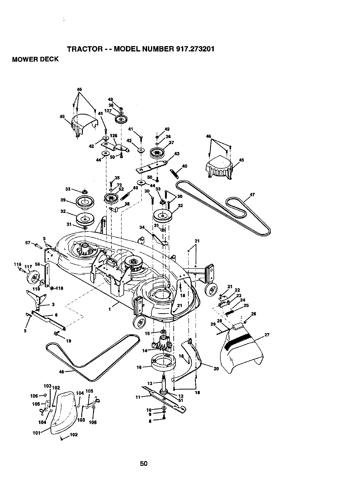
TRACTOR - - MODEL NUMBER 917.273201
MOWER DECK
46
4g
45\
46
21
116
22
18
5O

MOWER DECK
KEY PART
NO. NO.
1 164811
3 138457
5 4939M
6 130832
8 85O857
9 STD551137
10 140296
11 163819
12 129895
13 137553
14 137152
15 110485X
16 140329
18 72140505
19 132827
20 145055
21 73680500
22 134753
23 131267
24 105304X
25 149287
26 110452X
27 157788
28 19111016
29 131491
30 157722
31 129963
32 153531
33 137266
34 144945
35 17490628
36 19131316
37 131494
38 156086
39 144917
TRACTOR --MODEL NUMBER 917.273201
KEY PART
DESCRIPTION NO. NO. DESCRIPTION
DeckWeldment Mower 46 40 137273
BracketAsm. Sway Bar
Retainer Spring 41 17490620
Arm, Suspension,Rear (Sway
Bar) 42 122952X
Ball Patched 3/8-24 x 1-1/4 43 144949
Gr. 8 44 133943
Washer, Lock Hvy., Unplated 45 145059
3/8 46 137729
Washer, Hard Blade,Mower 47 144959
Vented 48 148763
Blade, 46" 49 73680600
Beadng, Ball, Mandrel #6204 50 72110612
ShaftAsm. w/Lower Bearing
(includesKey No. 12) 51 153390
Housing,Mandrel 52 156493
Bearing,Ball,Mandrel 56 155986X505
Stripper,Mower Round
Bait, Carriage 5/16-18 x 5/8 57 156941
Boil Hex Head, Shoulder 72 19131616
5/16-18 101 145579
Baffle, Vodex Mower 46" 102 71161010
Nut, Crownlock 5/16-18 UNC
Stltfiner,Bracket 103 10071000
Bracket, Deflector 104 19061216
Cap, Sleeve 105 160793
Spring, Torsion,Deflector 106 2029J
Nut, Push 116 137644
Shield, DeflectorMower 117 133957
Washer 11/32 x 5/8 x 16 Ga. 118 73930600
Rod, Hinge 119 19121414
Screw,ThdrollWasher Head 126 144948
Washer, Spacer Mower 127 146763
Vented
Pulley,Mandrel - - 166211
Hut, Fig. Top Lock Cntr. 9/16
Anchor,Spring Deck 46"
Screw. Thdrolt 3/8-16 x 1-3/4
Tytt
Washer 13/32 x 13/16 x 16 -- 143651
Ga.
Pulley,Idler,Flat
Keeper,Belt, Idler
Pulley,Idler,Driven
Spring, Secondary44/45/50
Vent
Screw, Thdroll 3/8-16 x 1-1/4
Tytt
Spacer, Retainer
Ann, IdlerSecondary
Washer, Hardened
Cover,Mandrel Dock
Screw, Thdroll. 1/4-20 x 5/8
V-BelL Mower, SecoP.dary
V-Belt, Mower, Primary
Nut, Crownlock 3/8-16 UNC
Bolt,Carriage 3/6-16 x 1-1/2
Gr. 5
Washer, Felt
Pulley Idler 46 Pri Drive 97
Bar. PnLAdjustingWheel
Guage
Pin Head Rivet
Washer 13/32 x 1 x 16 Ga.
Cover Mulcher
ScrewTruss Hd Phil
10-24 x 5/8
Washer Lock#10
Washer #10
LatchAsm
Nut Weld
Bolt, Shoulder
Gauge Wheel, Wide
Nut, Centeriock 3/8-16 UNC
Washer 3/8 x 7/8 x 14 Ga.
Arm, Idler, Primary Deck46"
Pulley,Idler,V-Groove Dim.
4.25
Deck Complete (Std. Deck-
Order separately mulcher
plate and gauge wheel com-
ponsntsKey Nos. 101-106
and 116-'118)
Mandrel_sm. Service
(IncludesKey Nos. 6-10, 12-
15, 31 and 33)
NOTE: All componentdimensionsgiveninU.S. inches
1 inch= 25.4 mm
51

TRACTOR --MODEL NUMBER 917.273201
HYDRO GEAR TRANSAXLE --MODEL NUMBER 222-3010L
20
(2)
52

TRACTOR - - MODEL NUMBER 917.273201
HYDROGEARTRANSAXLE- - MODELNUMBER222-3010L
KEY PART KEY PART
NO. NO. DESCRIPTION NO. NO. DESCRIPTION
1 164591 Assembly,Housing,LH 72 153767
2 164592 Assembly,Housing,RH 73 142904
7153765 Oil Seal .984 x 1.5 x .25 74 142905
16 142876 BrakeShaftAssembly 76 142907
20 142877 Axle MountingHorn Assembly 77 142908
21 142878 Washer 1.0 x 1.63 x .08 78 142909
22 142879 Washer 1.0 x 2.06 x .09 79 153768
33 142929 Brake YokeAssembly 81 142910
35 142880 BrakeArm 82 142911
36 142882 Puck Plate 89 142912
37 142883 Brake Puck 91 153769
38 142884 Washer 7/80.D. x 7/16 x .06o0 95 142914
39 142885 Nut, Castle 5/16-24 g6 153770
40 142886 Cotter PEn 103 142916
41 142887 Brake ActuatingPin 104 142917
42 142888 Hi Pro Key 106 142918
43 142889 Spacer 108 142919
45 142890 Brake Disc 109 142920
46 142891 BOR 1/4-20x 1-1/2 110 142921
47 142892 Bolt 1/4-20 x I 111 150820
49 153766 DifferentialAssembly 112 150823
63 142894 Dowel Pin
64 150818 ReductionGear, 113 150821
14 Teeth to 38 Teeth 117 150822
65 142897 FinaEDdve PinionAssembly 123 150824
67 142898 Jack.shaft 124 150825
68 142899 O-Ring 129 153771
69 142900 Washer 5/8 X 1-5/32
70 142901 Washer 7/8 X 1-1/2
71 142902 Bolt, Hex 5/16-18x3.5
Locknut,Hex 5/16-18
Bolt,Hex 5/16-18 x 1-1/2
Hex Cap Screw 5/16-18 x 1
Shoulder Bolt
Freewheel ActuatingArm
Oil Seal .625 x 1.0 x .25
Grease (10 oz. Tube)
Bolt,Hex 5/16-18 x 1-3/4
Bolt 5/16-18 x 4-1/2
Filter,SpinOn
Pomp, BDU-10L-122
Plug, StraightThread
60" 7/18 SAE x 5/16 Fiffing
Washer
Vent Cap Assembly
FittingO-Ring Assembly
ControlArm
Set Screw
Filter Head
Hose 1/2"
Fiffing, 1/2` Beaded 90" 7/8
SAE
F_ng, 1/2"Beaded 60" 9/16
F_ng, 1/2" Beaded 90" 9/16
O Ring
PinchClamp
Spring,Long
NOTE: Allcomponentdimensionsgiven in U,S. inches
1 inch= 25.4 mm
53

TRACTOR --MODEL NUMBER 917.273201
TRANSAXLE -PUMP -MODEL NUMBER BU-10L-122
6
_47 43
54

TRACTOR - - MODEL NUMBER 917.273201
TRANSAXLE - PUMP - MODEL NUMBER BU-10L-122
KEY PART
NO. NO. DESCRIPTION
1 144569 Shaft, Pump
2 122716X Ring, Retaining
3 122745X Beadng, Ball
4 122715X Spacer
5 122700X Seal, Lip
6 122699X Fling,Retaining
8 122767X Bearing,Cradle
12 122717X Seal, Lip
13 122748X Arm,Trunnion
14 122749X Guide, Slot
15 144571 HousingKit, Transmission
17 122770X Beadng, Thrust, Bell
19 153801 Center Sec_on Kit
21 122722X Seal, Lip
22 144573 Shaft, Motor
23 142978 Washer, BlockTtvust
25 127148X Swashplata, Variable
32 142938 Biock Assembly
37 122786X Pin, Stainless,Headless
38 122718X Gasket, Center Section
42 144578 Check Valve Kit
43 144578 Check Valve Kit
44 144579 Charge Relief Kit
47 122752X Screw, Socket Head, Cap
53 127153X BypassValve Kit
60 142977 BlockSpring
62 144581 O-Ring
63 144582 Charge Pump Kit
64 144583 GerotorAssembly
67 144584 Screw, Socket Head, Cap
- - 153769 PumpAssembly,Complete
55

TRACTOR - -MODEL NUMBER 917.273201
KOHLER ENGINE-MODEL NUMBER CV22S, TYPE NUMBER 75518
CYUNDER HEAD VALVE &BREATHER
4
I
_2 242322
/8
7- _'_t0
15..,
P
,
O--TJ
,T-J
ts-%.
14..-8
0 _,
0-' _rp_'
,-0 I
,0
0--|
56
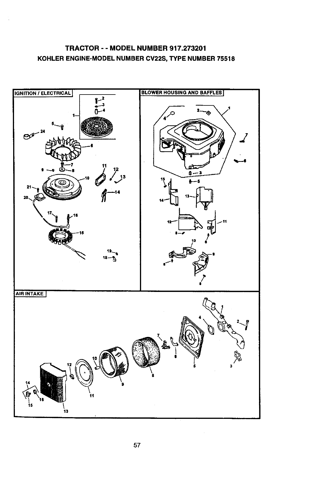
TRACTOR --MODEL NUMBER 917.273201
KOHLER ENGINE-MODEL NUMBER CV22S, TYPE NUMBER 75518
;NITION IELECTRICAL I
AIR INTAKE I
BLOWER HOUSING AND BAFFLES I
J
14
15
13
\11
8
9
$
3
57

TRACTOR - - MODEL NUMBER 917.273201
KOHLER ENGINE-MODEL NUMBER CV22S, TYPE NUMBER 75518
ITARTING SYSTEM i
4/
S
I
l
9-- @
OIL PAN LUBRICATIONJ
_8
ENGINE CONTROLS J
5
t
1/4_ _/7
16.... @_-8
1% g/1
Om2
/12
• 13 t4
,*Y /
e- @

TRACTOR -- MODEL NUMBER 917.273201
KOHLER ENGINE-MODEL NUMBER CV22S, TYPE NUMBER 75518
CRANKSHAFT I
--1
EXHAUST I
1
FUEL SYSTEM I
/
1
11
i' .r
10
14
59

TRACTOR - - MODEL NUMBER 917.273201
KOHLERENGINE-MODELNUMBERCV22S,TYPENUMBER75518
HEAD/VALVE/BREATHER
KEY PART
NO. NO. DESCRIPTION
1. 24-033-03-S
2. 24041-23-S
3. 24-096-59-S
4. M-645020-S
5. X-75-23-S
6. 25-351-01-S
7. 24-755-66-S
8. 24-411-05-S
9. 24-041-40-S
10. 24-318-12-S
11. 25-186-01-S
12. 24-599-01-S
13. M-640034-S
14. 24-086-44-S
15. 24-755-74-S
16. 24-153-16-S
17, 24-086-32-S
18. 24-445-01-S
19. 24-016-O1-S
24-016-02-S
20. 24-017-01-S
24-017-02-S
21. 24-032-05-S
22. 235011-S
23. 24-089-02-S
24. 12-173-01-S
25. 12-755-03-S
26. 24-318-11-S
27. 24-755-76-S
28, 25-313-02-S
29. 24-755-57-S
30. M-545016-S
31. 24-445-02-S
32. 24-126-44-S
33. 24-112-12-S
34. 24-294-06-S
35. 24-326-13-S
36. 24-326-14-S
37. X-426-9-S
Kit,breathercover wlgasket
(Includes2,3)
Gasket, breather
Cover, breather
Screw, hex. flange M6xl.0x20
(4)
Plug, allen nd. 1/8"
Lifter,valve (4)
Kit,valve train(Includes
8,11,12)
Rod, push (4)
Gasket, cylinderhead (2)
Head assembly, #2 cylinder
Arm, rocker(4)
Pivot, rockerarm (4)
Screw, hex.flange M6x1.0x34
(4)
Screw, hax. flange M10x1.5x90
(8)
Kit,valve cover -plain
(Includes 16,17)
O-Ring
Screw, shoulder(4)
Strap, lifting
Valve, exhaust (Std.) (2)
Valve, exhaust (25) (2)
Valve, intake (Std.) (2)
Valve, intake (.25) (2)
Seal, valve stem (2)
Retainer,spring(4)
Spdng,valve (4)
Cap, valve spring(4)
Kit,retainer (4)
Head assembly,#1 cylinder
Kit, valve cover - breather
(Inci,16,17,28)
Grommet, rubber
Kit,breather separator
(includes28,3033)
Screw, hex. flange M5x0.8x16
(2)
Strap, breather
Bracket,breather separator
Spacer
Fitting
Hose, breather
Hose, breather
Clamp, hose (2)
CRANKCASE
KEY PART
NO. NO. DESCRIPTION
1. 24-O32-01-S Seal, oil front
2. Crankcase
(USE: Miniblock)
3. 24.294-13-S Fitting
4. 12-380-17-S Pin, dowel locating (6)
5. 24-067-13-S ConnectingRod (Std.) (2)
24-067-14-S ConnectingRod (.25) (2)
6. 24-874-09-S Pistonw/Ring Set (Std.) (2)
(Includes7,8)
24-874-10-S Pistonw/Ring Set (.25) (2)
24-874-11-S Pistonw/Ring Set (.50) (2)
24-874-15-S Kit,pistonw/ring set (.08)
7, 24-108-08-S Ring Set (Std.) (2)
24-108-09-S Ring Set (.25) (2)
24-108-10-S Ring Set (.50) (2)
8. 24-018-O1-S Retainer,pistonpin (4)
9. 12-422-09-S Shim, camshaft(A.R.)
12-422-13-S Shim,camshaft(A.R.)
12-422-07-S Shim,camshaft(A.R,)
12-422-08-S Shim,camshaft (A.R.)
12-422-10-S Shim,camshaft
12-422-11-S Shim,camshaft (A.R.)
12-422-12-S Shim,camshaft (A.R.)
10, 24-010-06-S Camshaft(Includes 11,12)
11. 24.O89-35-S Spdng,ACR (Heavy)
12. 24-089-34-S Spring,ACR (Light)
13. 52-139-O9-S Plug, cup
14. M-O545010-S Screw, hex. flange M5x0.SxlO
(2)
15. 24-018-04-S Retainer,reed (2)
16. 24-402-05-S Reed, breather (2)
17. 12-153-01-S O-Ring, lower oilfill tube
18. 24-126-19-S Bracket, oilfilltube
19. 12-123-04-S Tube, oil fill
20. M-545016-S Screw, heY..flange MSxO.8xl6
21. 12-153-02-S O-Ring, upperoil filltube
22. 24-038-04-S Dipstickassembly (includes
23,24)
23. 24-755-46-S Kit, oil fillcap (Includes 24)
24, 12-153-03-S O-Ring, dips_k
25. 12-380-04-S Pin, hitch
26. M-631005-S Washer, plain 6 mm
27. 12-032-o1-S Seal, governorcrossshaft
28. X-25-102-S Washer, plain 1/4"
29. 24-144-01-S Shaft, governorcross
NOTE: All componentdimensionsgiveninU.S.
inches 1 inch= 25.4 mm
60

TRACTOR - - MODEL NUMBER 917.273201
KOHLER ENGINE-MODEL NUMBER CV22S, TYPE NUMBER 75518
IGNmON/CHARGING
KEY PART
NO. NO. DESCRIPTION
1. 54-755o15-S
2. M.403025-S
3. X-25-92-S
4. 24-112-04-S
5. 25-086-47-S
6. 24-157-03-S
7. 12-086-14-S
8. 12.468-O3-S
9. X-42-15-S
10. 24-025-11-S
11. 25-403-03-S
12. X-25-92-S
13. 24-086-18-S
14. 236602-S
15. 54-755-09-S
16. 12-132-06-S
17. M-548025-S
18. 48-154-O2-S
19. X-25-63-S
20. 24-584-01-S
21. M-545020-S
24. 2-351-73-S
Kit,grass screen
(Includes2-4,aud 24 113 18)
Screw,hex. cap M4x0.7x25 (4)
Washer, plain 5/16" (4)
Spacer,grass screen (4)
Bolt,shoulder (4)
Fan
Screw,hox. flange M10x1.5x46
Washer,plain 3/8".
Key
Flywheel
Rectifier-regulator
Washer,plain 3/16" (2)
Screw,phillipshd. 11-16x7/8 (2
Connector(3 contact)
Kit, 15 amp stator
(IncludeS24 126 71)
Spark Plug (2)
Screw,hex. cap MSx0.8x25 (2)
Clip,cable
Washer, plain 1/4"
Module, ignition(2)
Screw, hexflange
M5xO.8x20(4)
Clip,cable
NOT ILLUSTRATED
24-126-71-S
X-22-11-S
24-176-12-S
25-518-28-S
24-113-18-S
12-454-01-S
X-468-1 -S
Bracket, statorwire
Washer,lock 1/4"
Harness,wiring
Lead, black (recL-reg.4" -18
gauge
insulatedgdp barrel eyelets)
Decal, grass screen
"Re,wire
"Re,cable (3)
BLOWER ROUSING & BAFFLES
KEY PART
NO. NO. DESCRIPTION
I.
2.
3.
24-027-20-S
24-100-01-S
24-100-02-S
Housing,blower
(Includes2-4)
(Incl.M-0545010 & 24 063 36)
Nut, plastic(3)
Nut, plastic(2)
4. 25-139-16-S Plug, button9/16"
5. M-567020-S Screw, hex. flange M5x0,8x20
(4)
6. M-0545016-S Screw, hex. flange M5x0.Sx16
(3)
7, M-0551016-S Scmw, hex.flangeM5x0.8x16
8. M-0645016-S Screw,hex. flange M6xl.0x16
(6)
9. 24-146-16-S Plate, backing- #2 side
10. 24-146-20-S Plate, backing - # 1 side
11. 24-063-20-S Baffle,cylinderbarrel-# 2 side
12. 24-063-14-S Baffle,valley- #2 side
13. 24-063-30-S BaBe, cylinderbarrel-# 1 side
14. 24-063-23-S Baffle, valley -#1 side
15. M-545010-S Screw, hex.tlangaMSx0.8xl0
(2)
NOT ILLUSTRATED
24-096-66-S Cover, control
24-086-06-S Screw,phillips hd. 11-16x3/4" (2
AIR INTAKE/FILTRATION
KEY PART
NO. NO. DESCRIPTION
1. 24-164-06-S Manifold,intake
2. M-651055-S Screw, hex.flange M6x1.0x55
(4)
3. 24-041-01-S Gasket, intakemanifold(2)
4. 24-041-14-S Gasket, air cleaner base
5. 24-094-18-S Base, air cleaner
6, 24-041-13-S Gasket, fuel spitbackcup
7. 24-109-09-S Cup, fuel spitback
8. 24-083-05-S Precleaner, element
9. 24-O83-03-S Element, air cleaner
10. 230046-S Seal, breather
11. 24-096-01-S Cover, inner air cleaner
12. 12-100-01-S Wk_j Nut
13. 24-096-65-S Cover,air cleaner
14. 54-755-01-S Kit,knobwithseal
(Inciodes 15 & 16)
15. 25-341-03-S Knob, cover
16. 24.153-15-S O-Ring
NOTE: All component dimensionsgivenin U.S.
thcbea 1 inch =25.4 mm
61

TRACTOR - - MODEL NUMBER 917.273201
KOHLER ENGINE-MODEL NUMBER CV22S, TYPE NUMBER 75518
STARTING SYSTEM
KEY PART
NO. NO. DESCRIPTION
1. M-0839070-S Screw, hex.flange MBx1.25x70
2. 24-096-05-S Cover, pinion
3. M-0839080-S Screw, hex. flange M8x1.25x80
4. 12-468-01-S Washer, plain 11/32"(3)
5. 25-096-05-S Starter,(Includes6-11)
6. 12-221-01-S Kit,brush
7. 12-227-13-S Cap
8. 12-211-01-S Bolt,thru (2)
9. 12-755-54-S Kit,drive
10. 12-227-06-S Cap, driveend
11. 12-170-05-S Armature
ENGINE CONTROLS
KEY PART
NO. NO. DESCRIPTION
1. M-642026-S Screw, hex. flange M6x1.0x25
2. 24-090-14-S Lever, govemor
3. M-641060-S Nut, hex.flange M6xl.0
4. 24-089-01-S Spring,linkage
5. 25-158-06-S Bushing,linkage retaining
6. 24-079-04-S Linkage, throttle
7. 25-158-11-S Bushing, throttlelinkage
8. M-547050-S Nut, he:(. lockM5xO.8
9. 24-089-03-S Spring,choke mtum
10. 24-126-56-S Bracket,control
11. M-645016-S Screw, hex. flange M6x1.0x16
(4)
12. 12-237-O1-S Clamp, cable (2)
13. 24-O86-43-S Screw, hex. flange M5xO.8x16
(2)
14. 24-090-07-S Lever, thorttleactuator
15. 24-468-01-S Washer, plain 5;5 mm (3)
16. 24-08g-15-S Spring, governor
17. M-446030-S Nut, hex M4xO.7
18. 24-090-13-S Lever,throttlecontrol
19. M-545020-S Screw, hex. flange M5xO.8x20
20. 24-089-38-S Spring,throttle limiter
21. 24-090-05-S Lever,choke
22. 41-466-03-S Washer, spring1/4"
23. M-403025-S Screw,hex. cap M4xO.7x25
24. 24-079-05-S Linkage, choke
NOT ILLUSTRATED
M-545016-S Screw, hex. llange M5X0.8X16
(Goes into 24-126-56 as a
positivethrottle stop)
OIL PAN/LUBRICATION
KEY PART
NO. NO. DESCRIPTION
1. M-645026-S Screw, hex. flange M6x1.0x25
(2)
2. M-631006-S Washer, plain 6 mm (2)
3. 24-199-07-S Pan, oil assembly
(Includes 1,2,&4-10)
4. 24-393-06-S Oil pump assembly (Includes5)
5. 24-123-05-S Tube, oil pickup
6. 24-162-26-S Screen, oil
7. 24-043-12-S Kit,govemorgearw/pin
(Includes8)
8. 12-380-01-S Pin, governor regulating
9. 52-448-02-S Tab, locking
10. 12-144-O2-S Shaft,govemor gear
11. 24-153-06-S O-Ring
12. X-75-32-S Plug, hex. ctsk. 3/8"
13. 24-136-01-S Nipple, oil filter
14. 52-050-02-S Filter,oil
15. 52-032-06-S Seal, oil (PTO end)
16. 24-086-17-S Screw, hex.flange M8x1.25x45
17. 24-086-16-S Screw, hsx.flange M8x1.25x45
(9)
18. X-75-10-S Plug, sq. hd. solid3/8" N.P.T.F.
NOTE: All component dimensionsgiven inU.S.
inches 1 inch= 25.4 mm
62

TRACTOR - - MODEL NUMBER 917.273201
KOHLER ENGINE-MODEL NUMBER CV22S, TYPE NUMBER 75518
CRANKSHAFT
KEY PART
NO. NO.
I. 24-014.72-S
2. 52-139-09-S
EXHAUST
KEY PART
NO. NO.
1. 24-041-02-S
2. 25-072-04-S
-- 24522 16
-- 24 78205-S
-- 24 75503-S
DESCRIPTION
Crankshaft(includes 2)
Plug, cup
DESCRIPTION
Gasket, exhaust (2)
Stud, M8x1.25x33 (4)
ShortBlock
Miniblock
Gasket Set
FUEL SYSTEM
KEY PART
NO. NO. DESCRIPTION
1.
2.
3.
5°
6.
7.
8.
9.
10.
11.
12.
13.
14.
24-853-25-S
24.041-15-S
o.
M-0629095-S
M-0641060-S
47-154-01-S
24-353-03-S
X-426-9-S
24.086-12-S
24-393-04-S
24.100-01-S
25-353-03-S
24-050-02-S
Kit,carburetorw/gaskets
(Includes2-4)
Gasket, carburetor
Carburetorassembly (For infor-
mationonly not
availableseparately)
(Includes24-757-18,
24-053-25 24-757-19, 24-757-
20, 24-757-22)
Stud,M6xt.0x95 (2)
Nut, hex. flange M6xl.0 (2)
Clip, cable
Line, fuel 10-,5/8"(2)
Clamp, hose (6)
Screw,he:<.cap. M6x1.7x18 (2)
Pump, fuel - pulse
Nut, plastic(2)
Line, fuel 13-1/2"
Filter,fuel
NOT ILLUSTRATED
24.757-18-S
24-757-19-S
24-757-20-S
24-757-22-S
Kit,overhaul w/gaskets
Kit,choke repairw/gaskets
Kit,gasket
Kit,solenoidreplacement
w/gaskets
NOTE: All componentdimensionsgiven in U.S.
inches 1 inch = 25.4 mm
63

64

65

66

SUGGESTED GUIDE FOR SIGHTING SLOPES FOR SAFE OPERATION
ONLY RIDE UP AND DOWN HILL,
NOT ACROSS HILL
O_
.,,j
I
Operate your Tractor up and down the face of slopes (not ]
greater than 15 ), never across the face. Make turns gradu- I
ally to prevent tipping or loss of control. Exercise extreme
caution when changing direction on slopes.

For in-home major brand repair service:
Call 24 hours aday, 7 days a week
1-800-4-MY-HO M EsM(1-800-469-4663)
Para pedir servicio de reparaci6n a domicilio
1-800-676-5811
In Canada for all your service and parts needs call
Au Canada pour tout le service ou les pi_ces
1-800-665-4455
For the repair or replacement parts you need:
Call 6 am-11pm CST, 7 days _ week
PartsDirect
1-800-366-PART (1-800-366-7278)
Para ordenar piezas con entrega a domicilio
1-800-659-7084
For the location of a Sears Parts and Repair Center
in your area:
Call 24 Hours a day, 7 days a week
1-800-488-1222
For information on purchasing a Sears Maintenance
Agreement or to inquire about an existing Agreement:
Call 9 am-5 pro, Monday -Saturday
1-800-827-6655
• •
HomeCentralsM
169143 02.22.99 RH Printed in U.S.A.
