Craftsman 917273421 User Manual LAWN TRACTOR Manuals And Guides 99040585
CRAFTSMAN Lawn, Tractor Manual 99040585 CRAFTSMAN Lawn, Tractor Owner's Manual, CRAFTSMAN Lawn, Tractor installation guides
User Manual: Craftsman 917273421 917273421 CRAFTSMAN LAWN TRACTOR - Manuals and Guides View the owners manual for your CRAFTSMAN LAWN TRACTOR #917273421. Home:Lawn & Garden Parts:Craftsman Parts:Craftsman LAWN TRACTOR Manual
Open the PDF directly: View PDF ![]() .
.
Page Count: 64
Owner's Manual
CRI:IFTSMI:IN"
18 HP
ELECTRIC START
46" MOWER
AUTOMATIC
LAWN TRACTOR
Model No.
917.273421
• Safety
• Assembly
• Operation
• Maintenance
•Repair Parts
CAUTION:
Read and follow all
Safety Rules and Instructions
before operating this equip-
ment.
For answers to your questions
about this product, Call:
1-800-659-5917
Sears Craftsman Help Line
5 am -5 pm, Mon -Sat
Seam, Roebuck and Co., Hoffman Estates, IL 60179
Visitour Craftsmanwebsite:www.sears.com/craftsman
Warranty ................................................. 2
Safety Rules ......:.................................... 2
Product Specifications ........................... 5
Assembly............. ................................... 8
Operation .............................................. 13
Maintenance Schedule ......................... 20
Maintenance ......................................... 20
Service _andAdjustments...................... 24
Storage ................................................. 31
Troubleshooting.................................... 32
Repair Parts ......................................... 36
Parts Ordering ....................... Back Cover
LIMITED TWO YEAR WARRANTY ON CRAFTSMAN RIDING EQUIPMENT
For two (2) years from the date of purchase, if this Craftsman Riding Equipment is main-
tained, lubricated and tuned up according to the instructionsin the owner's manual,
Sears will repair or replace, free of charge, any parts found to be defective in material or
workmanship.
This Warranty does not cover:
• Expendable items which become worn during normal use, such as blades, spark
plugs, air cleaners, belts, etc.
•"13rereplacement or repair caused by punctures from outside objects, such as nails,
thorns, stumps, or glass.
• Repairs necessary because of operator abuse, negligence, improper storage or acci-
dent or the failure to maintain the equipment according to the instructions contained in
the owner's manual.
•Riding equipment used for commemial or rental purposes.
LIMITED 90 DAY WARRANTY ON BATTERY
For ninety (90) days from date of purchase, if any battery included with this ridingequip-
ment proves defective in material or workmanship and our testing determines the bat-
tery will not hold a charge, Sears will replace the battery at no charge. In-home warranty
service on your Craftsman dding equipment is available at no charge for 30 days from
the date of purchase. Please contact your nearest service center. After 30 days from the
date of purchase, warranty service is available by taking your Craftsman dding equip-
ment to your nearest Sears Service Center. (In-home warranty service will still be avail-
able after 30 days from the date of purchase but a standard trip charge will apply). This
warranty applies only while this product is in the United States. This Warranty gives you
specific legal dghts, and you may also have other rights which may vary from state to
state.
Sears, Roebuck and Co., D/817 WA, Hoffman Estates, IL 60179
GENERAL OPERATION
•Read, understand, and follow all instruc-
tions in the manual and on the machine
before starting.
• Only allow responsible adults, who are
familiar with the instructions, to operate
the machine.
•Clear the area of objects such as rocks,
toys, wire, etc., which could be picked
up and thrown by the blade.
•Be sure the area is clear of other people
before mowing. Stop machine if anyone
enters the area.
•Never carry passengers.
•Do not mow in reverse unless absolute-
ly necessary. Always look down and
behind before and while backing.
•Be aware of the mower discharge direc-
tion and do not point it at anyone. Do
not operate the mower without either
_heentire grass catcher or the guard in
Race.
S_w down before turning.
Ne_er leave a running machine unat-
tenSted.Always turn off blades, set park-
ing b_ake, stop engine, and remove
keys before dismounting.
2
•Turn off blades when not mowing.
•Stop engine before removing grass
catcher or unclogging chute.
•Mow only in daylight or good artificial
light.
•Do not operate the machine while under
the influence of alcohol or drugs.
•Watch for traffic when operating near or
crossing roadways.
•Use extra care when loading or unload-
ing the machine into atrailer or truck.
SLOPE OPERATION
Slopes are a major factor related to loss-
of-control and tipover accidents, which
can result in severe !njury or death. All
slopes require extra caution. If you cannot
back up the slope or if you feel uneasy on
it, do not mow it.
DO:
•Mow up and down slopes, not across.
•Remove obstacles such as rocks, tree
limbs, etc.
•Watch for holes, ruts, or bumps. Uneven
terrain could overturn the machine. Tall
grass can hide obstacles.
• Use slow speed. Choose a low gear so
that you will not have to stop or shift
while on the slope.
•Follow the manufacturer's recommen-
dations for wheel weights or counter-
weights to improve stability.
•Use extra care with grass catchers or
other attachments. These can change
the stability of the machine.
•Keep all movement on the slopes slow
and gradual. Do not make sudden
changes in speed or direction.
•Avoid starting or stopping on a slope. If
tires lose traction, disengage the blades
and proceed slowly straight down the
slope.
DO NOT:
• Do notturn on slopes unless necessary,
and then, turn slowly and gradually
downhill, if possible.
•Do not mow near drop-offs, ditches, or
embankments. The mower could sud-
denly turn over if a wheel is over the
edge of a cliffor ditch, or if an edge
caves in.
•Do not mow on wet grass. Reduced
traction could cause sliding.
=
•Do nottry to stabilize the machine by
puttingyour foot on the ground.
•Do not use grass catcher on steep
slopes.
CHILDREN
Tragic accidents can occur if the operator
is not alert to the presence of children.
Children are often attracted to the
machine and the mowing activity. Never
assume that children will remain where
you last saw them.
•Keep children out of the mowing area
and under the watchful care of another
responsible adult.
•Be aled and tum machine off if children
enter the area.
•Before and when backing, look behind
and down for small children.
•Never carry children. They may fall off
and be senously injured or interfere with
safe machine operation.
•Never allow children to operate the
machine.
•Use extra care when approaching blind
comers, shrubs, trees, or other objects
that may obscure vision.
SERVICE
•Use extra care in handling gasoline and
other fuels. They are flammable and
vapors are explosive_
Use only an approved container.
Never remove gas cap or add fuel
with the engine running.Allow en-
gine to cool before refueling. Do not
smoke.
Never refuel the machine indoors.
Never store the machine or fuel
container inside where there is an
open flame, such as a water heater.
•Never run a machine inside a closed
area.
•Keep nuts and bolts, especially blade
attachment bolts, tight and keep equip-
ment in good condition.
•Never tamper with safety devices.
Check their proper operation regulady.
•Keep machine free of grass, leaves, or
other debris build-up. Clean oil or fuel
spillage. Allow machine to cool before
storing.
•Stop and inspect the equipment if you
strike an object. Repair, if necessary,
before restading.
3
• Never make adjustments or repairs with
the engine running.
•Grass catcher components are subject
to wear, damage, and deterioration,
which could expose moving parts or
allow objects to be thrown. Frequently
check components and replace with
manufacturer's recommended parts,
when necessary.
•Mower blades are shsrp and can cut.
Wrap the blade(s) or wear gloves, and
use extra caution when servicing them.
•Check brake operation frequently.
Adjust and service as required.
•Be sure the area is clear of other people °MoW up and down slopes (15° Max), not
before mowing. Stop machine if anyone
enters the area.
°Never carry passengers.
•Do not mow in reverse unless absolute-
ly necessary. Always look down and
behind before and while backing.
•Never carry children. They may fall off
and be sedously injured or interfere with
safe machine operation.
•Keep children out of the mowing area
and under the watchful care of another
responsible adult.
•Be alert and turn machine off if children
enter the area.
•Before and when backing, look behind
and down for small children.
across.
•Remove obstacles such as recks, tree
limbs, etc.
•Watch for holes, ruts, or bumps. Uneven
terrain could overturn the machine. Tall
grass can hide obstacles.
•Usa slow speed. Choose a low gear so
that you will not have to stop or shift
while on the slope.
• Avoid starting or stopping on a slope. If
tires lose traction, disengage the blades
and proceed slowly straight down the
slope.
• Donottumonslopesunlessnecessary,
and then, tum slowly and gradually
downhill, if possible.
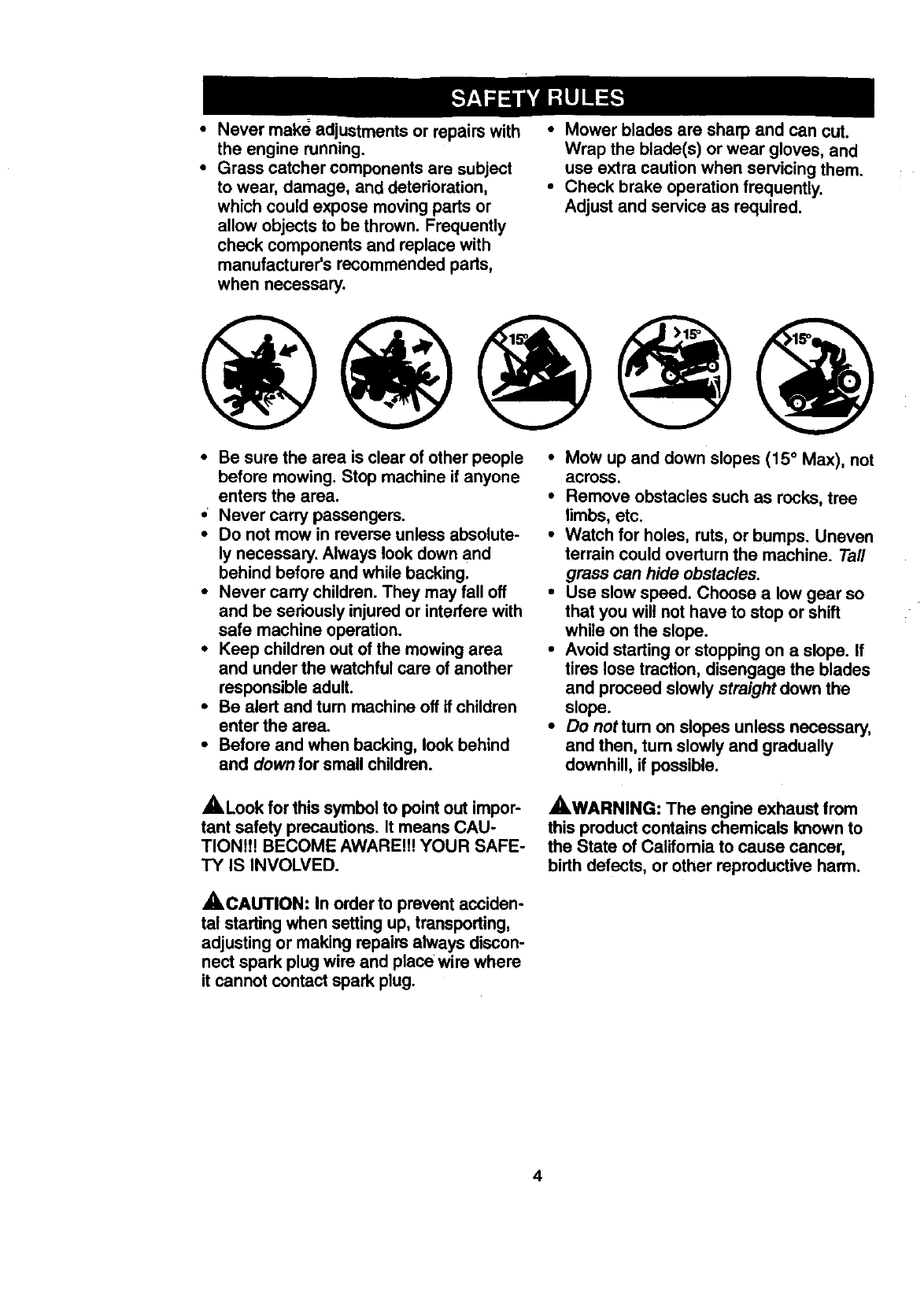
ALook for this symbol to point out impor-
tant safety precautions. It means CAU-
TION!!! BECOME AWARE!f! YOUR SAFE-
TY IS INVOLVED.
AWARNING: The engine exhaust from
this product contains chemicals known to
the State of Califomia to cause cancer,
birth defects, or other reproductive harm.
_CAUTION: In order to prevent acciden-
tal starting when setting up, transporting,
adjusting or making repairs always discon-
nect spark plug wire and place wire where
it cannot contact spark plug.
4
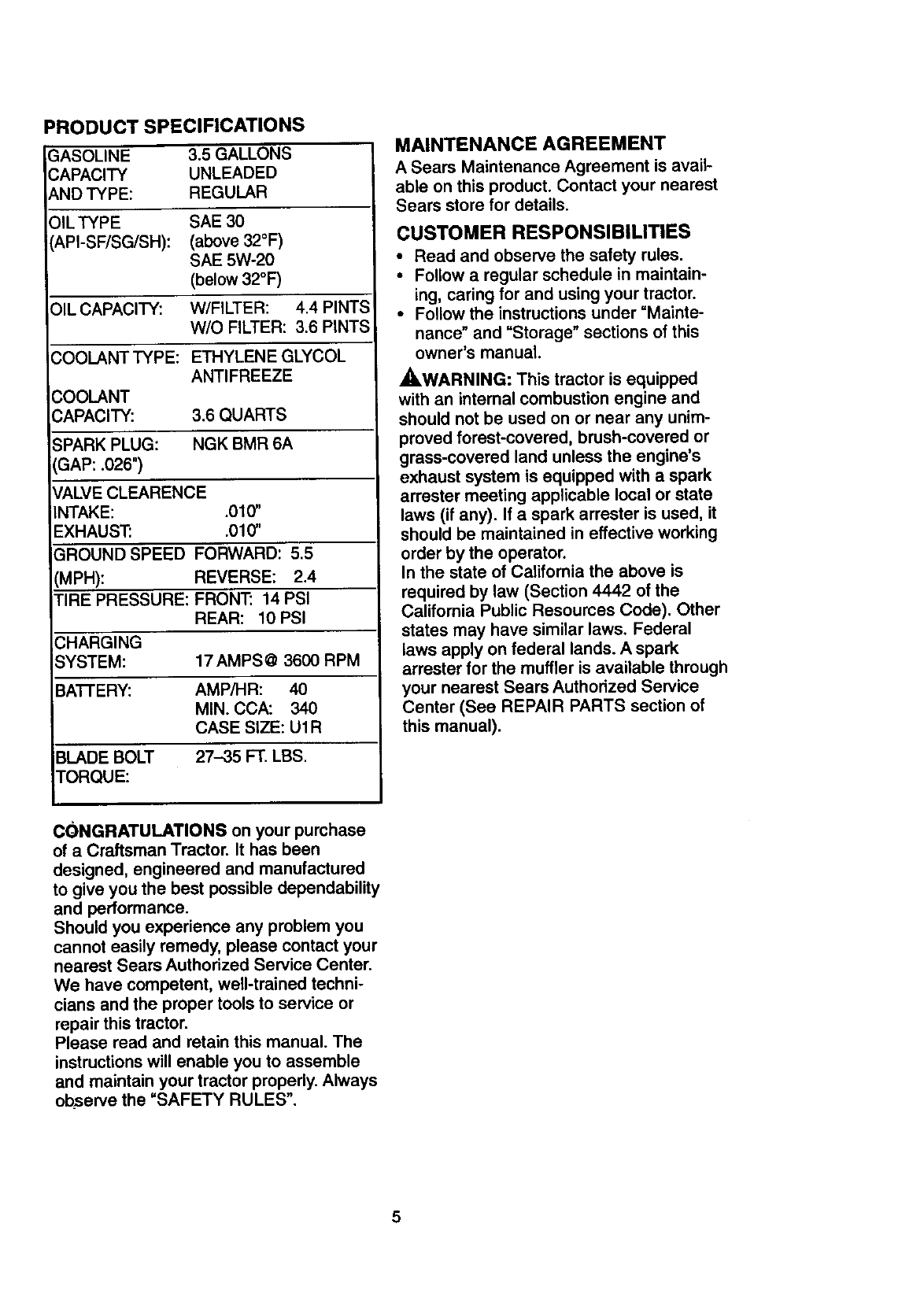
PRODUCT SPECIFICATIONS
3ASOLINE 3.5GALLONS
3APACITY UNLEADED
AND TYPE: REGULAR
OlLTYPE SAE 30
API-SF/SG/SH): (above 32°F)
SAE 5W-20
(below 32°F)
OIL CAPACITY: W/FILTER: 4.4 PINTS
W/O FILTER: 3.6 PINTS
COOLANT TYPE: ETHYLENE GLYCOL
ANTIFREEZE
COOLANT
CAPACITY: 3.6 QUARTS
SPARK PLUG: NGK BMR 6A
GAP: .026")
_/ALVE CLEARENCE
INTAKE: .010"
EXHAUST: .010"
GROUND SPEED FORWARD: 5.5
(MPH): REVERSE: 2.4
TIRE PRESSURE: FRONT: 14 PSI
REAR: 10 PSI
CHARGING
SYSTEM: 17 AMPS @3600 RPM
BA'I-I'ERY: AMP/HR: 40
MIN. CCA: 340
CASE SIZE: U1R
BLADE BOLT 27-35 FT. LBS.
TORQUE:
MAINTENANCE AGREEMENT
A Sears Maintenance Agreement is avail-
able on this product. Contact your nearest
Sears store for details.
CUSTOMER RESPONSIBILITIES
•Read and observe the safety rules.
•Follow a regular schedule in maintain-
ing, caring for and using your tractor.
•Follow the instructions under "Mainte-
nance" and "Storage" sections of this
owner's manual.
_,WARNING: This tractor is equipped
with an internal combustion engine and
should not be used on or near any unim-
proved forest-covered, brush-covered or
grass-covered land unless the engine's
exhaust system is equipped with a spark
arrester meeting applicable local or state
laws (if any). If a spark arrester is used, it
should be maintained in effective working
order by the operator.
In the state of California the above is
required by law (Section 4442 of the
California Public Resources Code). Other
states may have similar laws. Federal
laws apply on federal lands. A spark
arrester for the muffler is available through
your nearest Sears Authorized Service
Center (See REPAIR PARTS section of
this manual).
CONGRATULATIONS on your purchase
of a Craftsman Tractor. It has been
designed, engineered and manufactured
to give you the best possible dependability
and performance.
Should you experience any problem you
cannot easily remedy, please contact your
nearest Sears Authorized Service Center.
We have competent, well-trained techni-
cians and the proper tools to service or
repair this tractor.
Please read and retain this manual. The
instructions will enable you to assemble
and maintain your tractor properly. Always
observe the =SAFETY RULES".
5
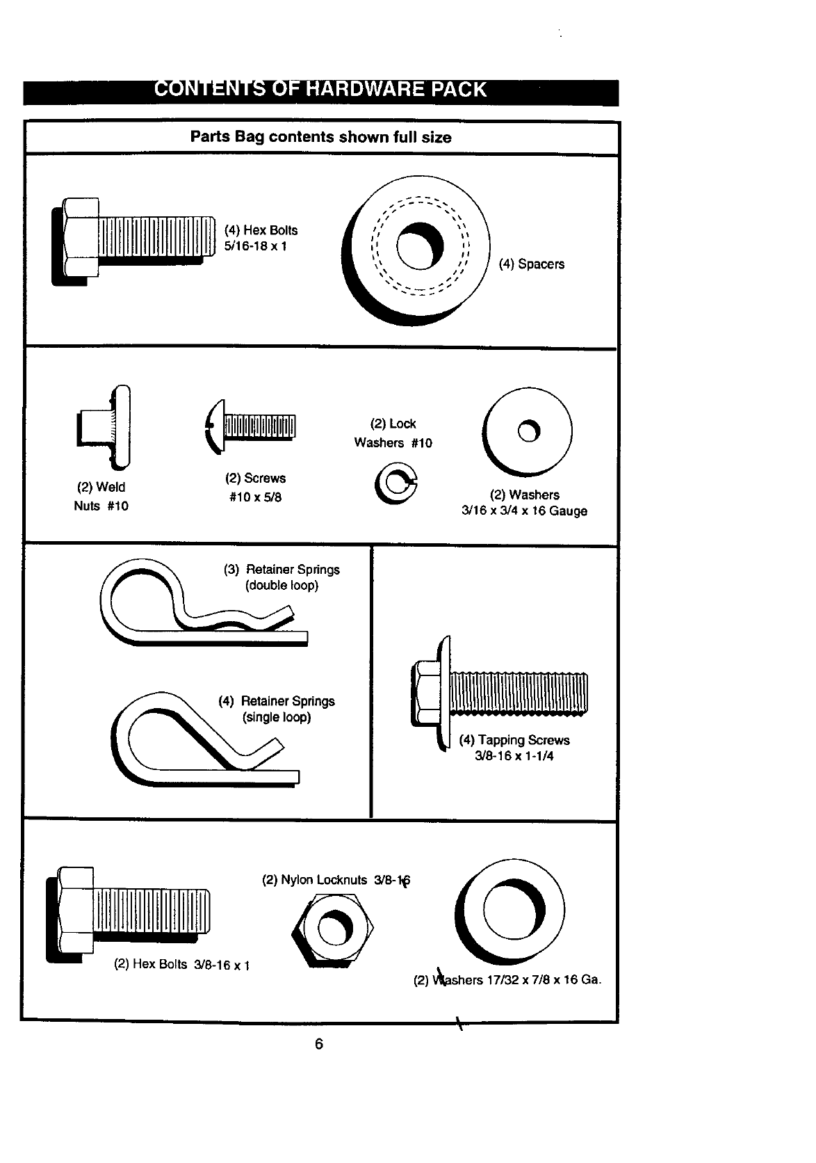
Parts Bag contents shown full size
(4) Hex Bolts
5/16-18 x I
(4) Spacers
(2) Weld
Nuts #10
J, _(2) Lock
I Washers #10 tO'
(2) Screws
#10 x 5/8 (2) Washers
3/16 x 3/4 x16 Gauge
o(3) Retainer Springs
(4) Retainer Springs
(single loop)
3/8-16 x 1-1/4
1]
(2) Hex Bolts 3/8-16 x 1
(2) Nylon Locknuts 3/8-1_ if_ ._h _
(2) V_shers 17/32 x 7/8 x 16 Ga.
\
6
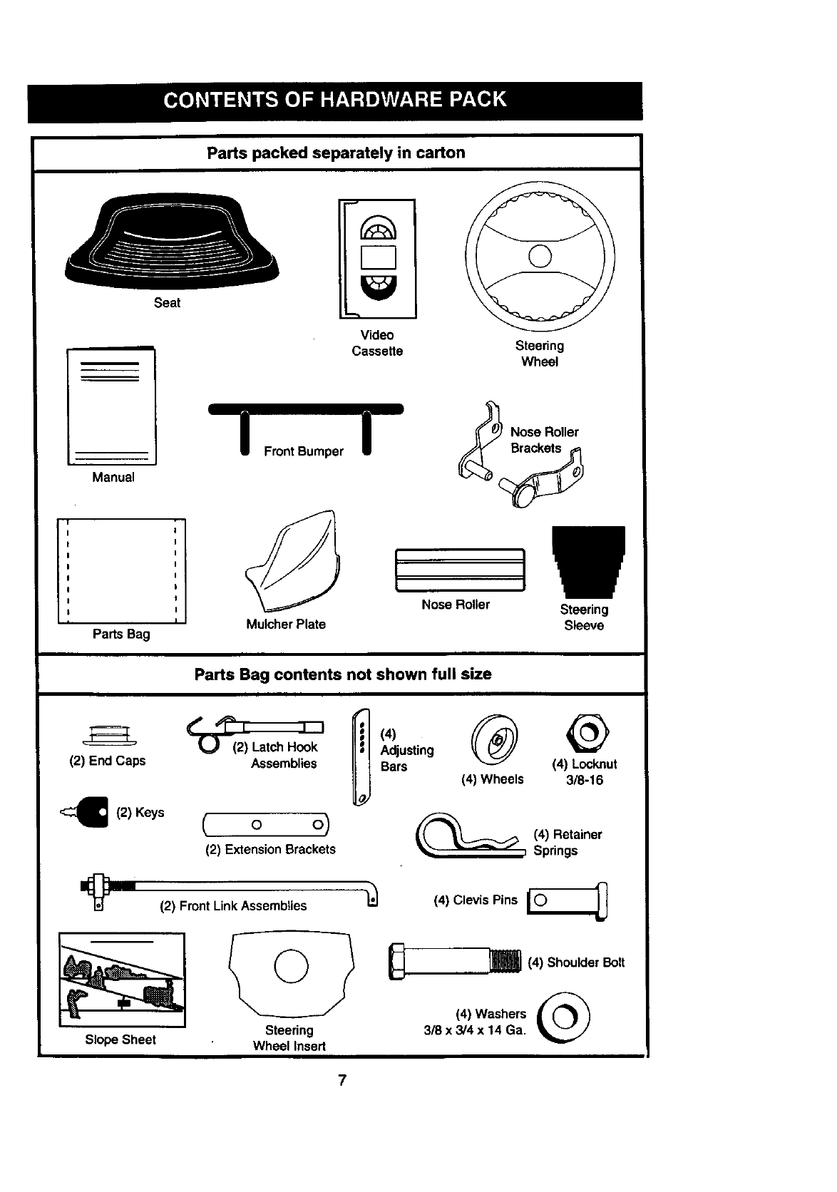
Seat
Parts packed separately in carton
F-7
Video
Cassette Steering
Wheel
Manual
Parts Bag
IFront Bumper
Mulcher Plate
INose Roller
Nose Roller
Parts Bag contents not shown full size
(2) End Caps
'_(2) Keys
Slope Sheet
Assemblies
( o o)
(2) Extension Brackets
(4)
Adjusting
Bars
(2) Front Link Assemblies
Steering
Wheel Insert
Steering
Sleeve
(4) Locknut
(4) Wheels 3/8-16
(4) Retainer
Springs
(4) Clevis Pins [_
I(4) Shoulder Bolt
(4) Washers
3/8x 3/4x 14 Ga.
7
Your new tractor has been assembled at the factory with exception of those parts left
unassembted for shippingpurposes. To ensure safe and proper operation of your tractor
all parts and hardware you assemble must be tightened securely: Use the correct tools
as necessary to msure proper tightness. Review the vioeo casse_e eerore you oegin.
TOOLS REQUIRED FOR
ASSEMBLY
A socket wrench set will make assembly
easier. Standard wrench sizes you need
are listed below.
2) 9/16" wrench (1) 3/4" Socket w/
t)Pliers drive rachet
1) 1/2 wrench (1) Phillips Screw-
(1) Utility knife driver
(1) "13repressure gauge
When right or left hand is mentioned in
this manual, it means, from your point of
view, when you are in the operating posi-
tion (seated behind the steering wheel).
TO REMOVE TRACTOR FROM
CARTON
UNPACK CARTON
•Remove all accessible loose parts and
parts boxes from shipping carton (See
page 6).
•Cut, from top to bottom, along lines on
all four comers of shipping carton, and
lay panels flat.
•Remove mower and package materials.
•Check for any additional loose parts or
boxes and remove.
BEFORE ROLLING TRACTOR OFF
SKID
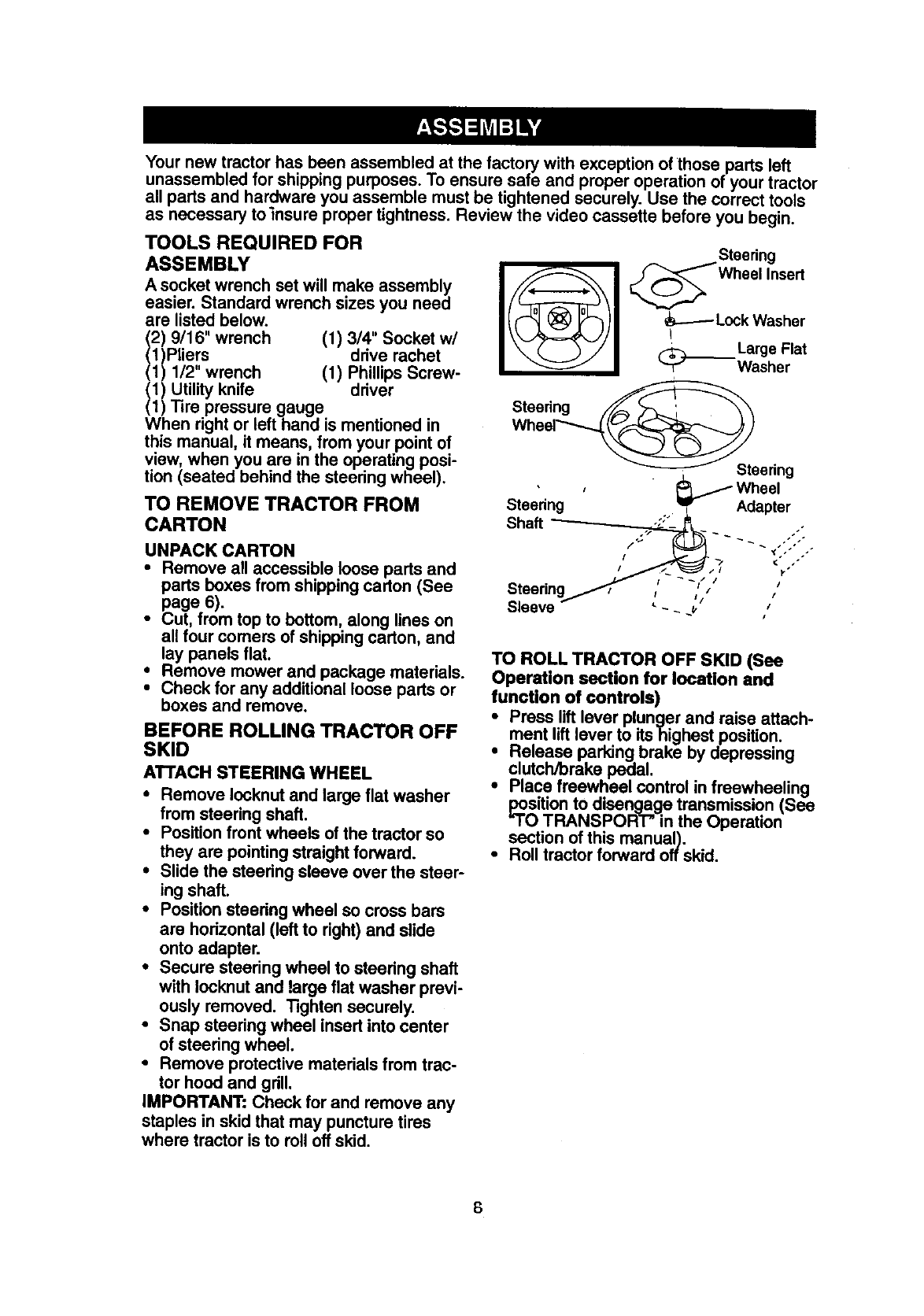
ATTACH STEERING WHEEL
•Remove locknut and large flat washer
from steering shaft.
•Positionfront wheels of the tractor so
they are pointingstraight forward.
• Slide the steering sleeve over the steer-
ing shaft.
•Positionsteering wheel so cross bars
are hodzontal (left to right) and slide
onto adapter.
•Secure steering wheel to steering shaft
with Iocknut and large flat washer previ-
ously removed. Tighten securely.
•Snap steering wheel insert into center
of steedng wheel.
•Remove protective materials from trac-
tor hood and grill,
IMPORTANT: Check for and remove any
staples in skid that may puncture tires
where tractor is to roll off skid.
Steering
_Wheel Insed
_Lock Washer
Large Flat
_--Washer
Steering
Wheel_stSteedng
•, _ Wheel
Steering__ Adapter
Shaft
if _/ ¢" ."
Steering /"
Sleeve _. u ,i
TO ROLL TRACTOR OFF SKID (See
Operation section for location and
function of controls)
iPress lift lever plunger and raise attach-
ment lift lever to its highest position.
Release parking brake by depressing
clutch/brake pedal.
•Place freewheel control in freewheeling
_oSition to disengage transmission (See
TRANSPORT" in the Operation
section of this manual).
•Roll tractor forward off skid.
8
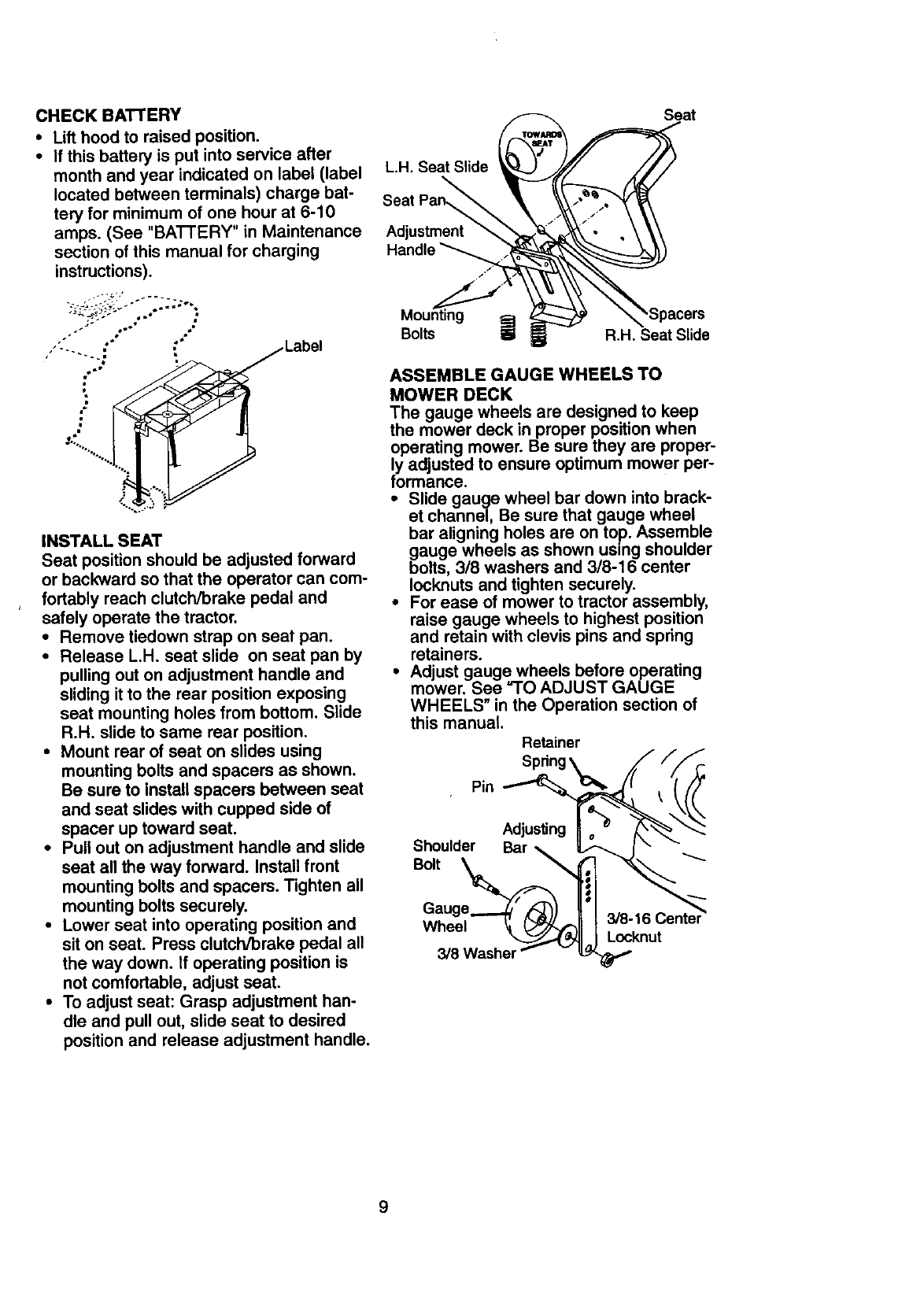
CHECK BATTERY
•Lift hood to raised position.
•If this battery is put into service after
month and year indicated on label (label
located between terminals) charge bat-
tery for minimum of one hour at 6-10
amps. (See "BATTERY" in Maintenance
section of this manual for charging
instructions).
._ ol •
INSTALL SEAT
Seat position should be adjusted forward
or backward so that the operator can com-
fortably reach clutch/brake pedal and
safely operate the tractor.
•Remove tiedown strap on seat pan.
•Release L,H. seat slide on seat pan by
pulling out on adjustment handle and
sliding it to the rear position exposing
seat mounting holes from bottom. Slide
R.H. slide to same rear position.
•Mount rear of seat on slides using
mounting bolts and spacers as shown.
Be sure to install spacers between seat
and seat slides with cupped side of
spacer up toward seat.
•Pull out on adjustment handle and slide
seat all the way forward. Install front
mounting bolts and spacers. Tighten all
mounting bolts securely.
•Lower seat into operating position and
sit on seat. Press clutch/brake pedal all
the way down. tf operating position is
not comfortable, adjust seat.
•To adjust seat: Grasp adjustment han-
dle and pull out, slide seat to desired
position and release adjustment handle.
Seat
L.H. Seat Slide
Seat Pan,
Adjustment
,Spacers
=a
Bolts ii R.H. Seat Slide
ASSEMBLE GAUGE WHEELS TO
MOWER DECK
The gauge wheels are designed to keep
the mower deck in proper position when
operating mower. Be sure they are proper-
ly adjusted to ensure optimum mower per-
formance.
•Slide gauge wheel bar down into brack-
et channel, Be sure that gauge wheel
bar aligning holes are on top. Assemble
gauge wheels as shown using shoulder
bolts, 3/8 washers and 3/8-16 center
Iocknuts and tighten securely.
•For ease of mower to tractor assembly,
raise gauge wheels to highest position
and retain with clevis pins and spring
retainers.
•Adjust gauge wheels before operating
mower. See "1"O ADJUST GAUGE
WHEELS" in the Operation section of
this manual.
Retainer
Pin
9
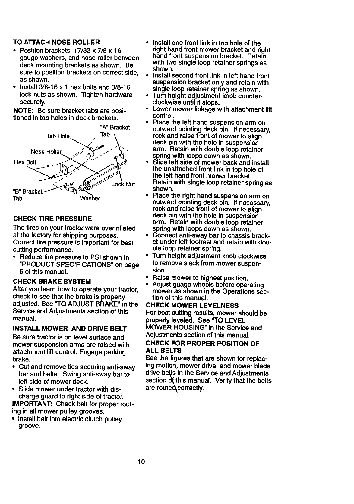
TOATTACHNOSEROLLER
•Position brackets, 17/32 x 7/8 x 16
gauge washers, and nose roller between
deck mounting brackets as shown. Be
sure to position brackets on correct side,
as shown.
•Install 3/8-16 x Ihex bolts and 3/8-16
lock nuts as shown. Tighten hardware
securely.
NOTE: Be sure bracket tabs are posi-
tioned in tab holes in deck brackets.
"A" Bracket
Tab Hole Tab \
Nose Roller _:_' "J' "_'_
<._ _ Lock Nut
"B" Bracketf "
Tab Washer
CHECK TIRE PRESSURE
The tires on your tractor were overinflated
at the factory for shipping purposes.
Correct tire pressure is impodant for best
cutting performance.
•Reduce tire pressure to PSI shown in
=PRODUCT SPECIFICATIONS" on page
5 of this manual.
CHECK BRAKE SYSTEM
After you leam how to operate your tractor,
check to see that the brake is properly
adjusted. See =TO ADJUST BRAKE" in the
Service and Adjustments section of this
manual.
INSTALL MOWER AND DRIVE BELT
Be sure tractor is on level surface and
mower suspension arms are raised with
attachment lift control, Engage parking
brake.
•Cut and remove ties securing anti-sway
bar and belts, Swing anti-sway bar to
left side of mower deck.
•Slide mower under tractor with dis-
charge guard to right side of tractor.
IMPORTANT: Check belt for proper rout-
ing in all mower pulley grooves.
•Install belt into electric clutch pulley
groove.
•Install one front link in top hole of the
right hand front mower bracket and right
hand front suspension bracket. Retain
with two single loop retainer springs as
shown.
•Install second front link in left hand front
suspension bracket only and retain with
single loop retainer spring as shown.
•Turn height adjustment knob counter-
clockwise until it stops.
•Lower mower linkage with attachment lift
control.
•Place the left hand suspension arm on
outward pointing deck pin. If necessary,
rock and raise front of mower to align
deck pin with the hole in suspension
arm. Retain with double loop retainer
spring with loops down as shown.
•Slide left side of mower back and install
the unattached front link in top hole of
the left hand front mower bracket.
Retain with single loop retainer spring as
shown.
•Place the right hand suspension arm on
outward pointing deck pin. If necessary,
rock and raise front of mower to align
deck pin with the hole in suspension
arm. Retain with double loop retainer
spring with loops down as shown.
•Connect anti-sway bar to chassis brack-
et under left footrest and retain with dou-
ble loop retainer spring.
•Turn height adjustment knob clockwise
to remove slack from mower suspen-
sion.
Raise mower to highest position.
Adjust guage wheels before operating
mower as shown in the Operations sec-
tion of this manual.
CHECK MOWER LEVELNESS
For best cutting results, mower should be
properly leveled. See =TO LEVEL
MOWER HOUSING" in the Service and
Adjustments section of this manual.
CHECK FOR PROPER POSITION OF
ALL BELTS
See the figures that are shown for replac-
ing motion, mower drive, and mower blade
drive be_s in the Service and Adjustments
section o_ this manual. Verify that the belts
are route_correctly.
10
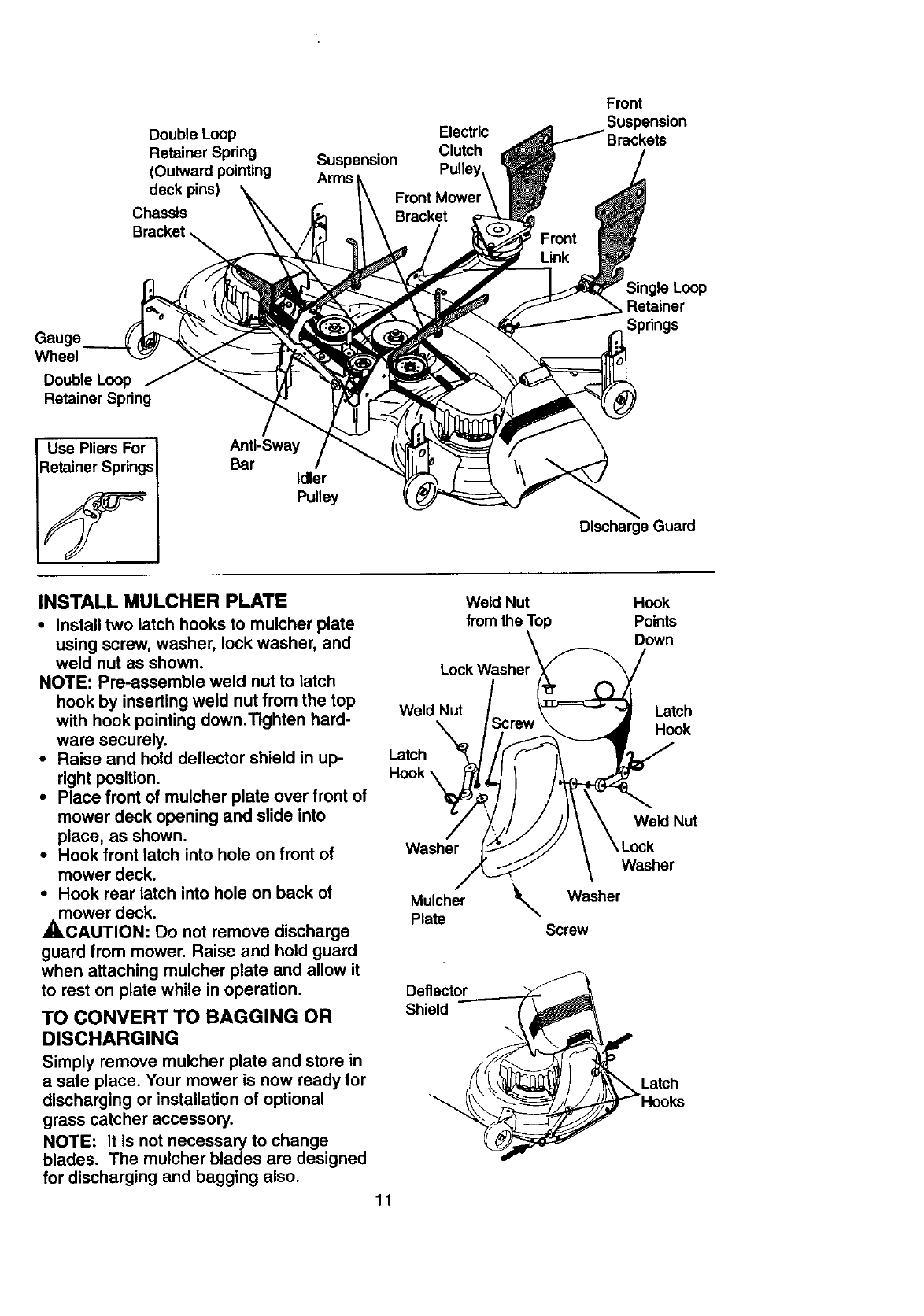
Double Loop
Retainer Spring
(Outward pointing
deck pins)
Chassis
Bracket
Suspension
Arms
Electric
Clutch
Front
Suspension
Gauge
Wheel
DoubleLoop
Retainer Spring
le Loop
Retainer
Springs
Use Pliers For
Retainer Springs
Anti-Sway
Bar Idler
Pulley
Discharge Guard
INSTALL MULCHER PLATE
• Install two latch hooks to mulcher plate
using screw, washer, lock washer, and
weld nut as shown.
NOTE: Pre-assemble weld nut to latch
hook by inserting weld nut from the top
with hook pointing down.'13ghten hard-
ware securely.
• Raise and hold deflector shield in up-
right position.
•Place front of mulcher plate over front of
mower deck opening and slide into
place, as shown.
•Hook front latch into hole on front of
mower deck.
•Hook rear latch into hole on back of
mower deck.
_,CAUTION: Do not remove discharge
guard from mower. Raise and hold guard
when attaching mulcher plate and allow it
to rest on plate while in operation.
TO CONVERT TO BAGGING OR
DISCHARGING
Simply remove mulcher plate and store in
a safe place. Your mower is now ready for
discharging or installation of optional
grass catcher accessory.
NOTE: It is not necessary to change
blades. The mulcher blades are designed
for discharging and bagging also.
Weld Nut Hook
from the Top Points
Down
Lock Washer __ /
Weld Nut ., _ ' Latch
\_crew _...._4 Hook
Nut
Washer _J"/,/// \ \Lock
/_ \ Washer
MlU/ther _ Washer
Screw
Deflector__.___,___
Shield (
f-
LHato_C;s
11
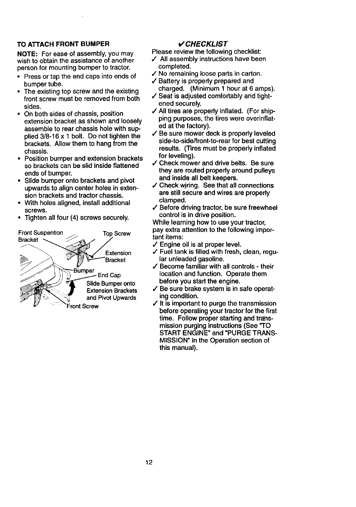
TOATTACHFRONTBUMPER
NOTE: For ease of assembly, you may
wish to obtain the assistance of another
person for mounting bumper to tractor.
•Press or tap the end caps into ends of
bumper tube.
•The existing top screw and the existing
front screw must be removed from both
sides.
•On both sides of chassis, position
extension bracket as shown and loosely
assemble to rear chassis hole with sup-
plied 3/8-16 x 1 bolt. Do not tighten the
brackets. Allow them to hang from the
chassis.
•Position bumper and extension brackets
so brackets can be slid inside flattened
ends of bumper.
•Slide bumper onto brackets and pivot
upwards to align center holes in exten-
sion brackets and tractor chassis.
•With holes aligned, install additional
screws.
•Tighten all four (4) screws securely.
Front Suspention _Screw
Bracket
\ Extension
-Bumper Cap
Slide Bumper onto
Extension Brackets
\'_ and Pivot Upwards
CHECKLIST
Please review the following checklist:
,I All assembly instructions have been
completed.
,I No remaining loose parts in carton.
,/Battery is properly prepared and
charged. (Minimum 1 hour at 6 amps).
,I Seat is adjusted comfortably and tight-
ened securely.
,/All tires are properly inflated. (For ship-
ping purposes, the tires were overinflat-
ed at the factory).
/Be sure mower deck is properly leveled
side-to-side/front-to-rear for best cutting
results. (Tires must be properly inflated
for leveling).
,/Check mower and drive belts. Be sure
they are routed properly around pulleys
and inside all belt keepers.
/Check wiring. See that all connections
are still secure and wires are properly
clamped.
4' Before driving tractor, be sure freewheel
control is in drive position.
While learning how to use your tractor,
pay extra attention to the following impor-
tant items:
,/Engine oil is at proper level.
,/Fuel tank is filled with fresh, clean, regu-
lar unleaded gasoline.
/Become familiar with all controls - their
location and function. Operate them
before you start the engine.
/Be sure brake system is in safe operat-
ing condition.
/It is important to purge the transmission
before operating your tractor for the first
time. Follow proper starting and tra_s-
mission purging instructions (See "TO
START ENGINE" and "PURGE TRANS-
MISSION" in the Operation section of
this manual).
12
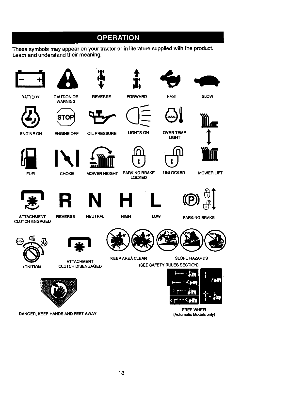
These symbols may appear on your tractor or in literature supplied with the product.
Learn and understand their meaning.
BATTERY CAUTION OR REVERSE FORWARD FAST SLOW
WARNING
FUEL CHOKE MOWER HEIGHT PARKING BRAKE UNLOCKED MOWER LIFT
LOCKED
R N H L
ATTACHMENT REVERSE NEUTRAL HIGH LOW PARKING BRAKE
CLUTCH ENGAGED
KEEP AREA CLEAR SLOPE HAZARDS
ATTACHMENT
IGNITION CLUTCH DISENGAGED (SEE SAFETY RULES SECTION)
DANGER, KEEP HANDS AND FEET AWAY FREE WHEEL
(AutomaticModelsonly)
13
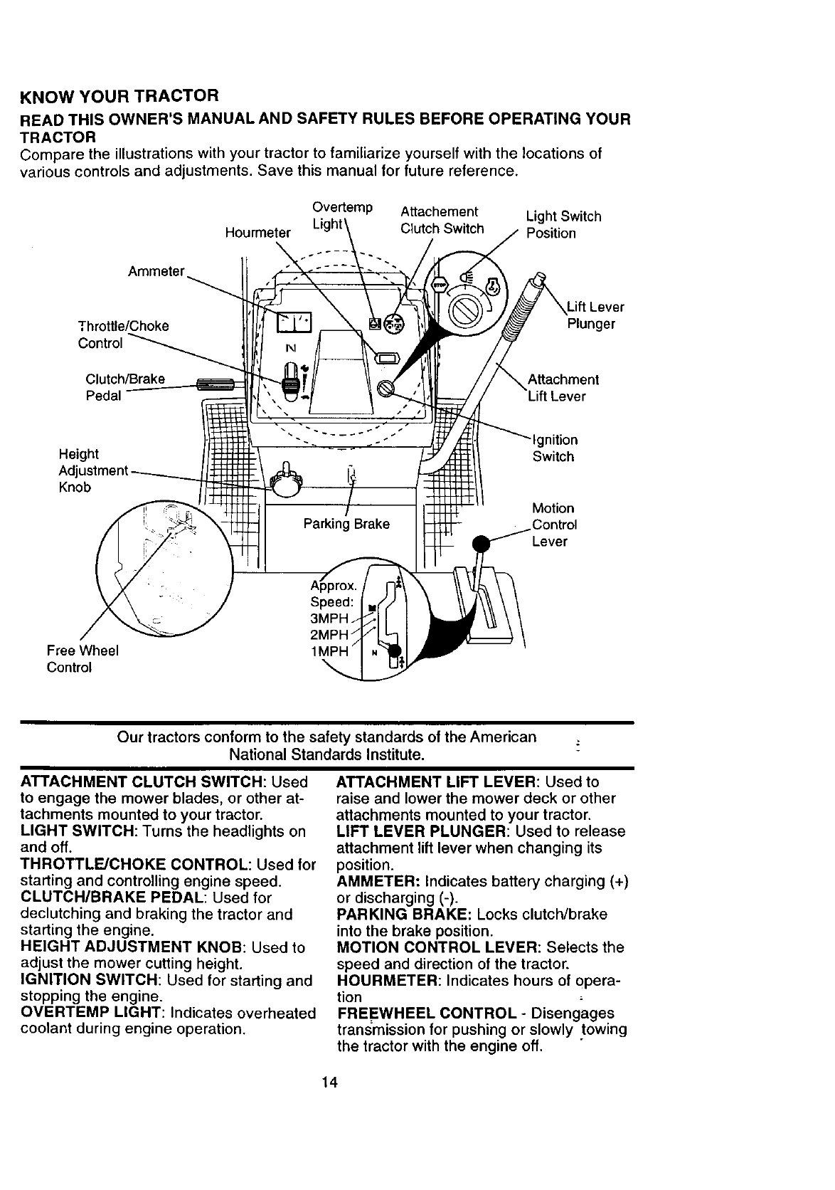
KNOW YOUR TRACTOR
READTHISOWNER'SMANUALAND SAFETYRULESBEFOREOPERATINGYOUR
TRACTOR
Compare the illustrations with your tractor to familiarize yourself with the locations of
various controls and adjustments. Save this manual for future reference.
Ammeter
Overtemp Attachement Light Switch
Hourmeter Clutch Switch Position
Throttle/Choke
Control
.ift Lever
Plunger
Clutch/Brake Attachment
Pedal
Height
Knob
gnition
Switch
Motion
Control
Lever
Free Wheel
Control
Our tractors conform to the safety standards of the American ;
National Standards Institute.
ATTACHMENT CLUTCH SWITCH: Used
to engage the mower blades, or other at-
tachments mounted to your tractor.
LIGHT SWITCH: Turns the headlights on
and off.
THROTTLE/CHOKE CONTROL: Used for
starting and controlling engine speed.
CLUTCH/BRAKE PEDAL: Used for
declutching and braking the tractor and
starting the engine.
HEIGHT ADJUSTMENT KNOB: Used to
adjust the mower cutting height.
IGNITION SWITCH: Used for starting and
stopping the engine.
OVERTEMP LIGHT: Indicates overheated
coolant during engine operation.
ATTACHMENT LIFT LEVER: Used to
raise and lower the mower deck or other
attachments mounted to your tractor.
LIFT LEVER PLUNGER: Used to release
attachment lift lever when changing its
position.
AMMETER: Indicates battery charging (+)
or discharging (-).
PARKING BRAKE: Locks clutch/brake
into the brake position.
MOTION CONTROL LEVER: Selects the
speed and direction of the tractor.
HOURMETER: Indicates hours of opera-
tion
FREEWHEEL CONTROL - Disengages
transmission for pushing or slowly towing
the tractor with the engine off.
14
The operationof anytractorcanresultinforeignobjectsthrowninto the
eyes, which can result in severe eye damage. Always wear safety glasses
or eye shields while operating your tractor or performing any adjustments or
repairs. We recommend a wide vision safety mask over spectacles, or stan-
dard safety glasses.
HOW TO USE YOUR TRACTOR
Your tractor is equipped with an operator
presence sensing switch. When engine is
running, any attempt by the operator to
leave the seat without first setting the
parking brake will shut off the engine.
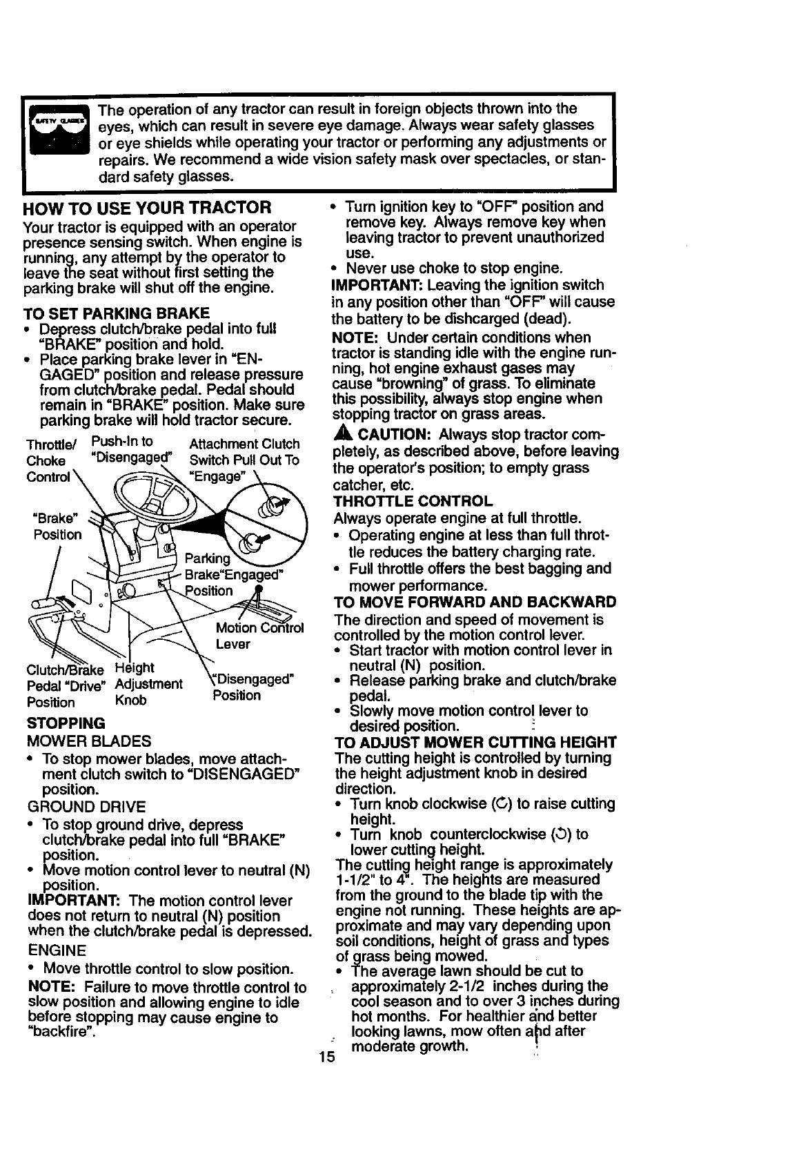
TO SET PARKING BRAKE
•Depress clutch/brake pedal into full
=BRAKE" position and hold.
•Place parking brake lever in "EN-
GAGED" position and release pressure
from clutch/brake pedal. Pedal should
remain in =BRAKE" position. Make sure
parking brake will hold tractor secure.
Throttle/ Push-In to Attachment Clutch
Choke Switch Pull Out To
"Engage"
"Brake"
Portion
•Brake"Engaged"
Lever
Pedal"Ddve" Adjustment
PosRion Knob PosiUon
STOPPING
MOWER BLADES
•To stop mower blades, move attach-
ment clutch switch to =DISENGAGED"
position.
GROUND DRIVE
•To stop ground drive, depress
clutch/brake pedal into full =BRAKE"
position.
•Move motion control lever to neutral (N)
position.
IMPORTANT: The motion control lever
does not return to neutral (N) position
when the clutch/brake pedal is depressed.
ENGINE
•Move throttle control to slow position.
NOTE: Failure to move throttle control to
slow position and allowing engine to idle
before stopping may cause engine to
=backfire".
• Turn ignition key to "OFF" position and
remove key. Always remove key when
leaving tractor to prevent unauthorized
use.
•Never use choke to stop engine.
IMPORTANT: Leaving the ignition switch
in any position other than =OFF" will cause
the battery to be dishcarged (dead).
NOTE: Under certain conditions when
tractor is standing idle with the engine run-
ning, hot engine exhaust gases may
cause =browning" of grass. To eliminate
this possibility, always stop engine when
stopping tractor on grass areas.
_, CAUTION: Always stop tractor com-
pletely, as described above, before leaving
the operator's position; to empty grass
catcher, etc.
THROTTLE CONTROL
Always operate engine at full throttle.
•Operating engine at less than full throt-
tle reduces the battery charging rate.
•Full throttle offers the best bagging and
mower performance.
TO MOVE FORWARD AND BACKWARD
The direction and speed of movement is
controlled by the motion control lever.
•Start tractor with motion control lever in
neutral (N) position.
•Release parking brake and clutch/brake
pedal.
•Slowly move motion control lever to
desired position.
TO ADJUST MOWER CuI-rlNG HEIGHT
The cutting height is controlled by turning
the height adjustment knob in desired
direction.
•Turn knob clockwise (G) to raise cutting
height.
•Turn knob counterclockwise (,b)to
lower cutting height.
The cutting height range is approximately
1-1/2" to 4". The heights are measured
from the ground to the blade tip with the
engine not running. These heights are ap-
proximate and may vary depending upon
soil conditions, height of grass and types
of grass being mowed.
•The average lawn should be cut to
approximately 2-1/2 inches during the
cool season and to over 3 inches during
hot months. For healthier _nd better
looking lawns, mow often a_d after
15 moderate growth.
•For best cutting performance, grass
over 6 inches in height shouldbe
mowed twice. Make the first cut rela-
tively high; the second to desired height.
TO ADJUST GAUGE WHEELS
Gauge wheels are properly adjusted
when they are slightly off the ground when
mower is at the desired cutting height in
operating position. Gauge wheels then
keep the deck in proper position to help
prevent scalping in most terrain condi-
tions.
•Be sure tractor is on a flat level surface,
• Lower mower and adjust mower to
desired cutting height.
• Remove retainer spring and clevis pin
which secure each gauge wheel bar.
•Lower gauge wheels to ground. Raise
gauge wheels slightly to align holes in
bracket and gauge wheel bar and insert
clevis pin. Gauge wheels should be
slightly off the ground.
• Replace retainer spring into clevis pin.
IMPORTANT: Be sure to readjust gauge
wheels if you change the cutting height of
the mower deck.
Retainer
spring
Clevis
,__-: Pin
TO OPERATE MOWER
Your tractor is equipped with an operator
presence sensing switch. Any attempt by
the operator to leave the seat with the
engine running and the attachment clutch
engaged will shut off the engine.
•Select desired height of cut.
•Lower mower with attachment lift con-
trol.
•Start mower blades by engaging attach-
ment clutch control.
•TO STOP MOWER BLADES - disen-
,_age attachment clutch control.
CAUTION: Do not operate the mower
without either the entire grass catcher, on
mowers so equipped, or the discharge
guard in place.
TO OPERATE ON HILLS
,A.CAUTION: Do not drive up or down
hills with slopes greater than 15 ° and do
not drive across any slope. Use the slope
guide provided at the back of this manual.
• Choose the slowest speed before start-
ing up or down hills.
•Avoid stopping or changing speed on
hills.
• If slowing is necessary, move throttle
control lever to slower position.
•If stopping is absolutely necessary, push
clutch/brake pedal quickly to brake posi-
tion and engage parking brake.
• Move motion control lever to neutral (N)
position.
IMPORTANT; The motion control lever
does not return to neutral (N) position
when the clutch/brake pedal is depressed.
i o restart movement, slowly release
parking brake and clutch/brake pedal.
Slowly move motion control lever to
slowest setting.
• Make all turns slowly.
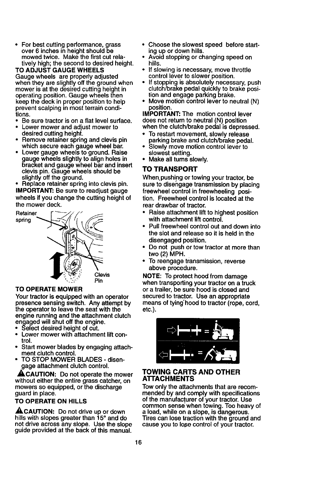
TO TRANSPORT
When, pushing or towing your tractor, be
sure to disengage transmission by placing
freewheel control in freewheeling posi-
tion. Freewheel control is located at the
rear drawbar of tractor.
• Raise attachment lift to highest position
with attachment lift control.
• Pull freewheel control out and down into
the slot and release so it is held in the
disengaged position.
• Do not push or tow tractor at more than
two (2) MPH.
• To reengage transmission, reverse
above procedure.
NOTE: To protect hood from damage
when transporting your tractor on atruck
or a trailer, be sure hood is closed and
secured to traqtor. Use an appropriate
means of tying-hood to tractor (rope, cord,
etc.).
TOWING CARTS AND OTHER
ATTACHMENTS
Tow only the attachments that are recom-
mended by and comply with specifications
of the manufacturer of your tractor, Use
common sense when towing. Too heavy of
a load, while on a slope, is dangerous.
Tires can lose t_action with the ground and
cause you to Io_e control of your tractor.
16
•BEFOBE STARTING THE ENGINE
CHECK ENGINE OIL LEVEL
iThe engine in your tractor has been
shipped, from the factory, already filled
with summer weight oi1.
Check engine oil with tractor on level
ground.
•Unthread and remove oil fill cap/dip-
stick;wipe oil off. Reinsert the dipstick
into the tube and rest oil fill cap on the
tube. Do not thread the cap onto the
tube. Remove and read oil level. If nec-
essary, add oil until =FULL" mark on
dipstick is reached. Do not overfill.
•For cold weather operation you should
change oil for easier starting (See uOIL
VISCOSITY CHAR'T" in the Customer
Responsibilities section of this manual).
•To change engine oil, see the Customer
Responsibilities section in this manual.
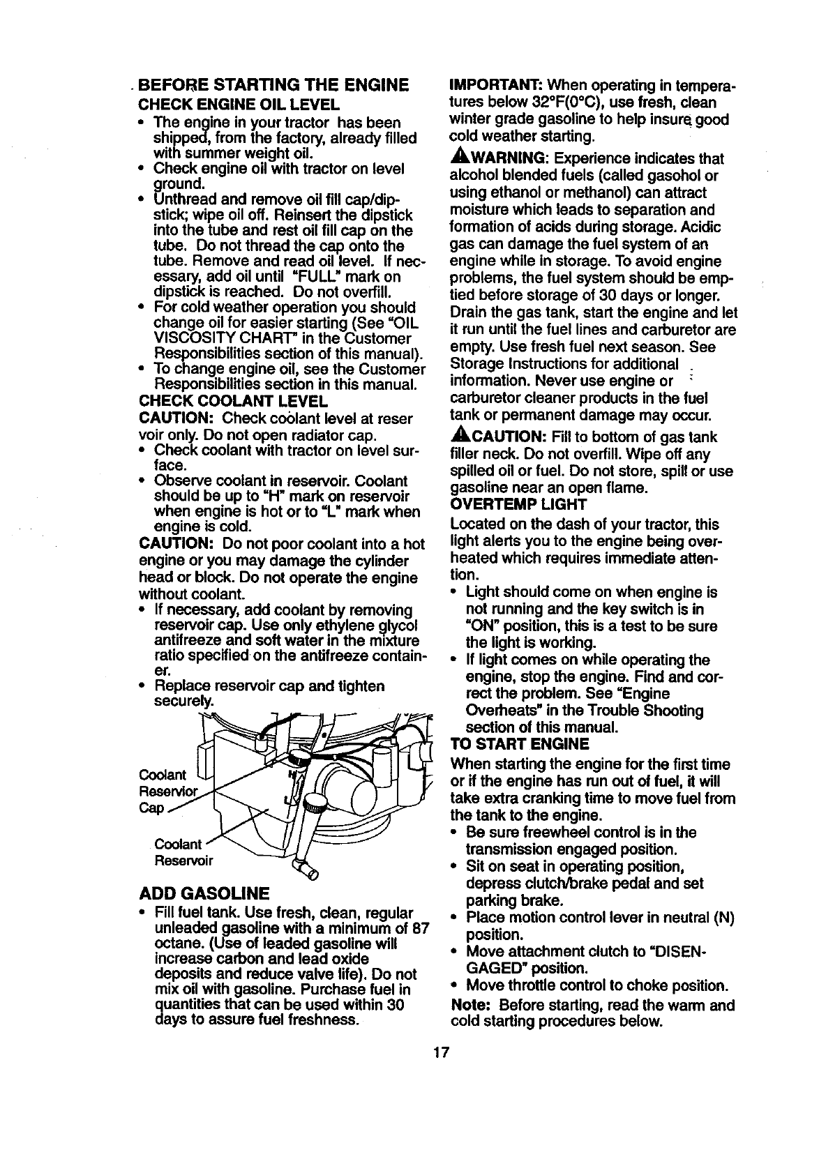
CHECK COOLANT LEVEL
CAUTION: Check coolant level at reser
voir only. Do not open radiator cap.
•Check coolant with tractor on level sur-
face.
•Observe coolant in reservoir. Coolant
should be up to =H"mark on reservoir
when engine is hot or to =L" mark when
engine is cold.
CAUTION: Do not poor coolant into a hot
engine or you may damage the cylinder
head or block. Do not operate the engine
without coolant.
•If necessary, add coolant by removing
reservoir cap. Use only ethylene 91ycol
antifreeze and soft water in the mexture
ratio specified on the antifreeze contain-
er.
•Replace reservoir cap and tighten
securely.
Coolant
Car
Reservoir
ADD GASOUNE
•Fillfuel tank. Use fresh, clean, regular
unleaded gasoline with a minimum of 87
octane. (Use of leaded gasoline will
increase carbon and lead oxide
deposits and reduce valve life). Do not
mix oil with gasoline. Purchase fuel in
quantities that can be used within 30
days to assure fuel freshness.
IMPORTANT: When operating in tempera-
tures below 32°F(0°C), use fresh, clean
winter grade gasoline to help insure_good
cold weather starting.
_,WARNING: Experience indicates that
alcohol blended fuels (called gasohol or
using ethanol or methanol) can attract
moisture which leads to separation and
formation of acids dudng storage. Acidic
gas can damage the fuel system of an
engine while in storage. To avoid engine
problems, the fuel system should be emp-
tied before storage of 30 days or longer.
Drain the gas tank, start the engine and let
it run until the fuel lines and carburetor are
empty. Use fresh fuel next season. See
Storage Instructionsfor additional
information. Never use engine or
carburetor cleaner products in the fuel
tank or permanent damage may occur.
A.CAUTION: Fillto bottom of gas tank
filler neck. Do not overfill.Wipe off any
spilled oil or fuel. Do not store, spillor use
gasoline near an open flame.
OVERTEMP LIGHT
Located on the dash of your tractor,this
light alerts you to the engine being over-
heated which requires immediate atten-
tion.
•Light should come on when engine is
not running and the key switch is in
=ON" position, this is a test to be sure
the light is working.
•If light comes on while operating the
engine, stop the engine. Find and cor-
rect the problem. See =Engine
Overheats" in the Trouble Shooting
section of this manual.
TO START ENGINE
When starting the engine for the firsttime
or if the engine has run out of fuel, it will
take extra cranking time to move fuel from
the tank to the engine.
•Be sure freewheel control is in the
transmission engaged position.
•Sit on seat in operating position,
depress clutch/brake pedal and set
parking brake.
•Place motion control lever in neutral (N)
position.
•Move attachment clutch to =DISEN-
GAGED" position.
•Move throttle control to choke position.
Note: Before starting, read the warm and
cold starting procedures below.
17
•Insert key into ignition and turn key
clockwise to =START" position and
release key as soon as engine starts.
Do not run starter continuously for more
than fifteen seconds per minute. If the
engine does not start after several
attempts, move throttle control to fast
position, wait a few minutes and try
again. If engine still does not start,
move the throttle control back to the
choke position and retry.
WARM WEATHER STARTING (50 ° F
AND ABOVE)
• When engine starts, move the throttle
control to the fast position.
•The attachments and ground drive can
now be used. If the engine does not
accept the load, restart the engine and
allow it to warm up for one minute using
the choke as described above.
COLD WEATHER STARTING ( 50 ° F AND
BELOW)
•When engine starts, allow engine to run
with the throttle control in the choke
position until the engine runs roughly,
then move throttle control to fast posi-
tion. This may require an engine warm-
up pedod from several seconds to sev-
eral minutes, depending on the temper-
ature.
AUTOMATIC TRANSMISSION WARM-UP
• Before ddving the unit in cold weather,
the transmission should be warmed up
as follows:
•Be sure the tractor is on level
ground.
•Place the motion control lever in
neutral. Release the parking brake
and let the clutch/brake slowly return
to operating position.
•Allow one minute for transmission to
warm up. This can be done during
the engine warm up pedod.
•The attachments can also be used dur-
ing the engine warm-up pedod after the
transmission has been warmed up.
NOTE: A high altitude (above 3000 feet)
or in cold temperatures (below 32 F) the
carburetor fuel mixture may need to be
adjusted for best engine performance.
See "TO ADJUST CARBURETOR" in the
Service and Adjustmentssection of this
manual.*
PURGE TRANSMISSION ._
,ACAUTION: Never engage or disen-
gage freewheel lever while the engine is
running,
To ensure proper operation and perfor-
mance, it is recommended that the trans-
mission be purged before operating tractor
for the first time. This procedure will
remove any trapped air inside the trans-
mission which may have developed during
shipping of your tractor.
IMPORTANT: Should your transmission
require removeal for service or replace-
ment, it should be purged after reinstalla-
tion before operating the tractor.
iPlace tractor safely on level surface withengine off and parking brake set.
Disengage transmissmn by placing free-
wheel control in freewheeling position
(See =TOTRANSPORT" in this section
of manual).
•Sitting in the tractor seat, start engine.
After the engine is running, move throt-
tle control to slow position. With motion
control lever in neutral (N) position,
slowly disengage clutch/brake pedal.
•Move motion control lever to full forward
positionand hold for five (5) seconds.
Move lever to full reverse position and
hold for five (5) seconds. Repeat this
procedure three (3) times.
NOTE: Dudng this procedure there will be
no movement of drive wheels. The air is
being removed from hydraulic drive sys-
tem.
•Move motion control lever to neutral (N)
position. Shut off engine and set parking
brake.
•Engage transmission by placing free-
whee/control in ddving position (See
"TO TRANSPORT" in this section of
manual).
•Sitting in the tractor seat, start engine.
After the engine is running, move throt-
tle control to half (1/2) speed. With
motion control lever in neutral (N) posi-
tion, slowly disengage clutch/brake
pedal.
•Slowly move motion control lever for-
ward; after the tractor moves approxi-
mately five (5) feet, slowly move motion
control lever to reverse position. After
the tractor moves approximately five (5)
feet return the motion control lever to
the neutral (N) position. Repeat this pro-
cedure with the motion control lever
three (3) times.
•Your tractor is now purged and now
ready for normal operation.
_18
MOWING TIPS
•Tire chains cannot be used when the
mower housing is attached to tractor.
•Mower should be propedy leveled for
best mowing performance. See "TO
LEVEL MOWER HOUSING" in the
Service and Adjustments section of this
manual.
• The left hand side of mower should be
used for trimming.
• Drive so that clippings are discharged
onto the area that has been cut. Have
the cut area to the right of the tractor.
This will result in a more even distribu-
tion of clippings and more uniform cut-
ting.
•When mowing large areas, start by turn-
ing to the right so that clippings will dis-
charge away from shrubs, fences, drive-
ways, etc. After one or two rounds, mow
in the opposite direction making left
hand turns until finished.
•If grass is extremely tall, it should be
mowed twice to reduce load and possi-
ble fire hazard from dried clippings.
Make first cut relatively high; the second
to the desired height.
•Do not mow grass when it is wet. Wet
grass will plug mower and leave unde-
sirable clumps. Allow grass to dry
before mowing.
•Always operate engine at full throttle
when mowing to assure better mowing
performance and proper discharge of
matedal. Regulate ground speed by se-
lecting a low enough gear to give the
mower the best cutting performance as
well as the quality of cut desired.
•When operating attachments, select a
ground speed that will suit the terrain
and give best performance of the at-
tachment being used.
MULCHING MOWING TIPS
IMPORTANT: For best performance, keep
mower housing free of built-up grass and
trash. Clean after each use.
•The special mulching blade will recut
the grass clippings many times and
reduce them in size so that as they fall
onto the lawn they will disperse into the
grass and not be noticed. Also, the
mulched grass will biodegrade quickly
to provide nutdents for the lawn. Always
mulch with your highest engine (blade)
speed as this will provide the best recut-
ting action of the blades.
•Avoid cutting your lawn when it is wet.
Wet grass tends to form clumps and
interferes with the mulching action. The
best time to mow your lawn is the early
afternoon. At this time the grass has
dried and the newly cut area will not be
exposed to the direct sun.
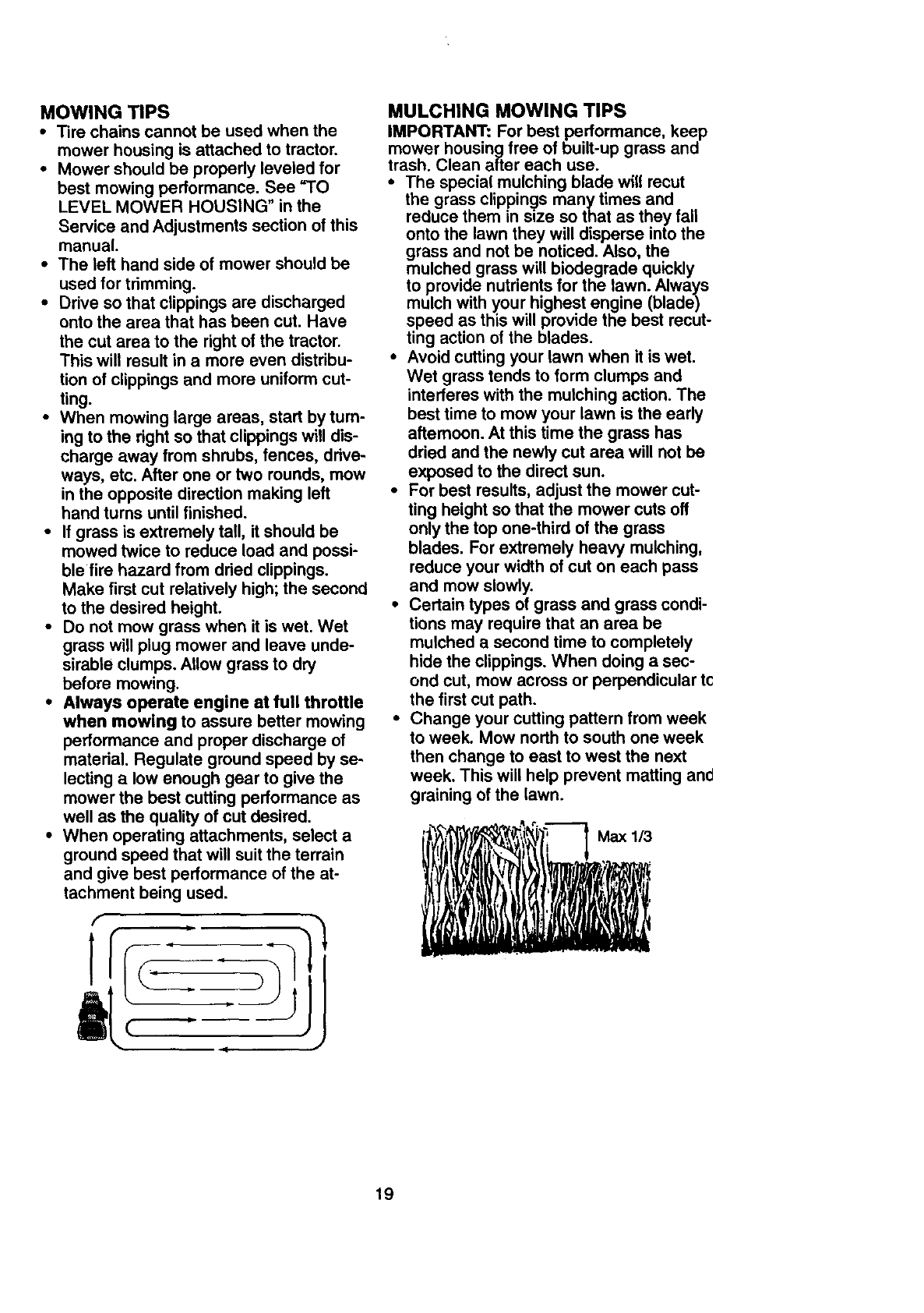
•For best results, adjust the mower cut-
ting height so that the mower cuts off
only the top one-third of the grass
blades. For extremely heavy mulching,
reduce your width of cut on each pass
and mow slowly.
•Certain types of grass and grass condi-
tions may require that an area be
mulched a second time to completely
hide the clippings. When doing asec-
ond cut, mow across or perpendicular tc
the first cut path.
•Change your cutting pattern from week
to week. Mow north to south one week
then change to east to west the next
week. This will help prevent matting and
graining of the lawn.
19
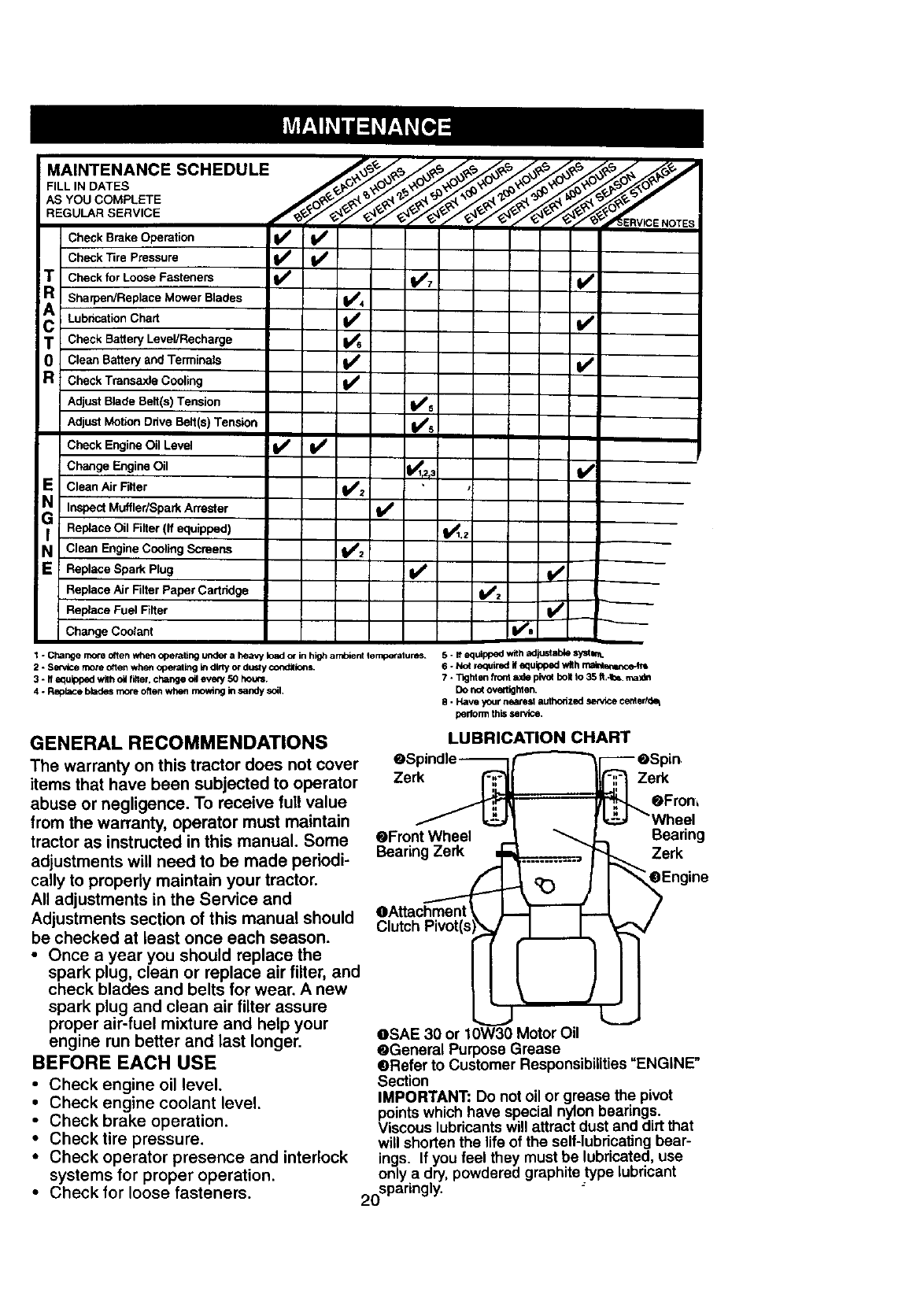
MAINTENANCE SCHEDULE _/._,,_ _o/o__ ,o/o_o_ _,_,_/_,_j,1
FILL IN DATES _ _._,_
YOOCOMPLETE
REGULAR SERVICE
Check Brake Operation _
Check Tire pressure
!T Check for LoOse Fasteners V / VP7 V'
R Sharpen/Replace Mower Blades
Lobhcation Chart
C Check Battery Level/Recharge
0 Clean Battery and Terminals Vp
RCheck Transaxle Cooling I_
Adjust Blade Belt(s) Tension V's
Adiust Mo6on DriveBe_t(s)Tension V/s
Check Engine Oil Level iV / V'
Change Engine Oil _,3
E Clean Air Filter 1_'2
Inspect Muffler/Spark Arraster V'
GI Replace Oil Filter(If eo_pped) f_.z i
NClean Engine Cooling Screens f#=
; Replace Spark Plug I_
Replace Air Filter Paper Cartridge 11_2
Replace Fuel FiNer _"_" --
Change Cnelant I_e
5 - eequippedwith adkLstabiesy_h-..
1. Cl_nge more onenwhen operaling undera heavy load_in higharr_ent _emp_atums- 6. Nc_required #equi_oed with _
2 - Se_ce more oftenwhe_ operaling k_dir_ or dustycond_ions.
3. ff equippedwith oi filler, change c# every 50 hour. 7. T_hten frontaxle pivo_bolt to 35 _,-t_. max_
DO_ovet'_t_en.
4-Replaceb_es more oftenwhen rnow_ngin sandysoil. 8 - Have your neamsl authorized servicecented_
penorm tPlisset, ice.
GENERAL RECOMMENDATIONS
The warranty on this tractor does not cover
items that have been subjected to operator
abuse or negligence. To receive full value
from the warranty, operator must maintain
tractor as instructed in this manual. Some
adjustments will need to be made periodi-
cally to properly maintain your tractor.
All adjustments in the Service and
Adjustments section of this manual should
be checked at least once each season.
•Once a year you should replace the
spark plug, clean or replace air filter, and
check blades and belts for wear. A new
spark plug and clean air filter assure
proper air-fuel mixture and help your
engine run better and last longer.
BEFORE EACH USE
•Check engine oil level.
•Check engine coolant level.
•Check brake operation.
•Check tire pressure.
•Check operator presence and interlock
systems for proper operation.
• Check for loose fasteners.
LUBRICATION CHART
Zerk Zerk
Vheel
eFront Wheel Bearing
Bearing Zerk Zerk
Clutch Pivot(s
oSAE 30 or 10W30 Motor Oil
@General Purpose Grease
@Refer to Customer Responsibilities "ENGtNE"
Section
MPORTANT: Do not oil or grease the pivot
points wh ch have special nylon bearings.
Viscous lubricantswill attract dust and drt that
will shorten the life of the self-lubricating bear-
ings. If you feel they must be lubricated, use
only a dry, powdered graphite type lubricant
20spadngly"
TRACTOR
Always observe safety rules when per-
forming any maintenance.
BRAKE OPERATION
If tractor requires more than six (6) feet
stopping distance at high speed in highest
gear, then brake must be adjusted. (See
"TO ADJUST BRAKE" in the Service and
Adjustments section of this manual).
TIRES
• Maintain proper air pressure in all tires
(See =PRODUCT SPECIFICATIONS"
on page 5 of this manual).
• Keep tires free of gasoline, oil, or insect
control chemicals which can harm rub-
ber.
•Avoid stumps, stones, deep ruts, sharp
objects and other hazards that may
cause tire damage.
NOTE: To seal tire punctures and prevent
flat tires due to slow leaks, tire sealant
may be purchased from your local parts
dealer. Tire sealant also prevents tire dry
rot and corrosion.
OPERATOR PRESENCE SYSTEM
Be sure that operator presence and inter-
lock systems are working properly. Ifyour
tractor does not function as described
below, repair the problem immediately.
•The engine should not start unless the
clutch/brake pedal is fully depressed
and attachment clutch control is in the
disengaged position.
•When the engine is running, any
attempt by the operator to leave the
seat without first setting the parking
brake should shut off the engine.
ihen the engine is running and the
attachment clutch is engaged, any
attempt by the operator to leave the
seat should shut off the engine.
The attachment clutch should never
operate unless the operator is in the
seat.
BLADE CARE
For best results mower blades must be
kept sharp. Replace bent or damaged
blades.
BLADE REMOVAL
•Raise mower to highest position to allow
access to blades.
•Remove hex bolt, lock washer and flat
washer securing blade.
•Install new or resharpened blade with
trailing edge up towards deck as shown.
IMPORTANT: To ensure proper assembly,
center hole in blade must align with star
on mandrel assembly.
• Reassemble hex bolt, lock washer and
fiat washer in exact order as shown.
• Tighten bolt securely (27-35 Ft. Lbs.
torque).
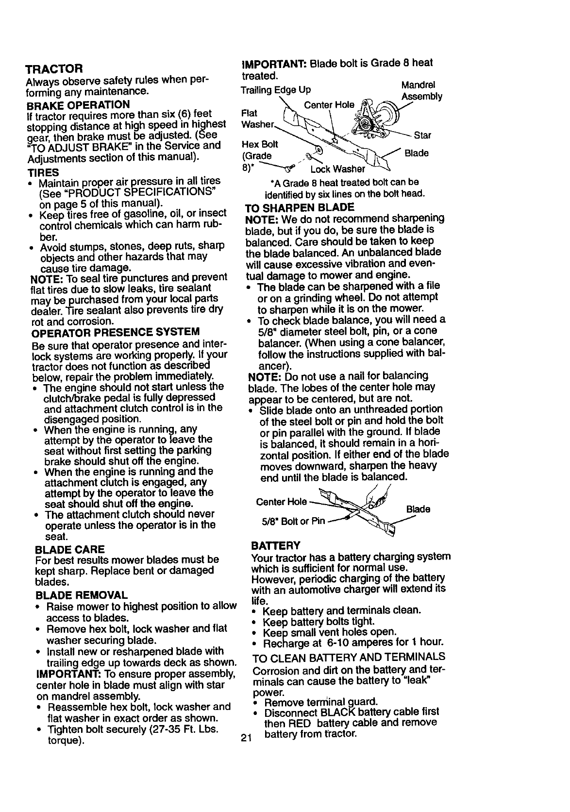
IMPORTANT: Blade bolt is Grade 8 heat
treated.
Trailing Edge Up Mandrel
Assembly
Center Hole
Flat
Washer.... Star
Hex Bolt
(Grade ._,,_
8)* _Lock Washel
*A Grade 8 heat treated bolt can be
identified by six lines on the bolt head.
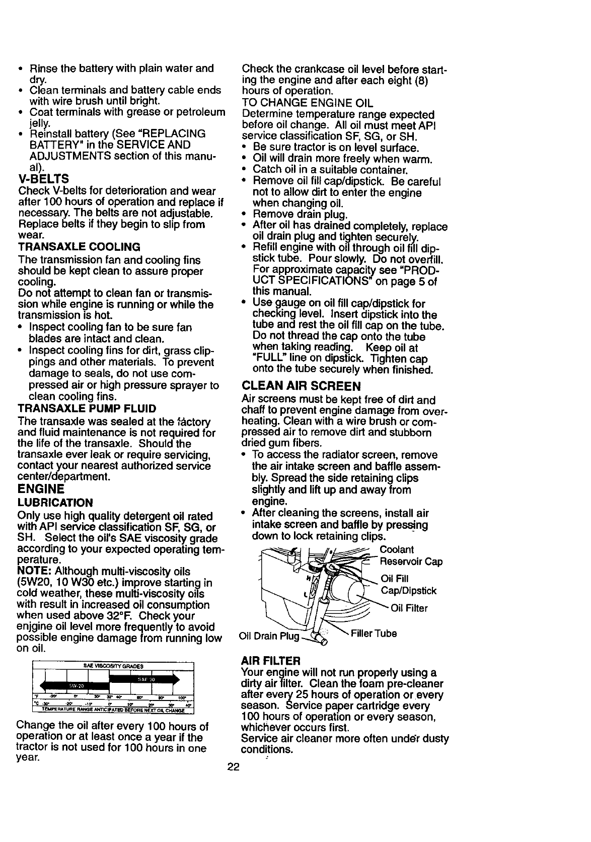
TO SHARPEN BLADE
NOTE: We do not recommend sharpening
blade, but if you do, be sure the blade is
balanced. Care should be taken to keep
the blade balanced. An unbalanced blade
will cause excessive vibration and even-
tual damage to mower and engine.
•The blade can be sharpened with a file
or on a grinding wheel. Do not attempt
to sharpen while it is on the mower.
•To check blade balance, you will need a
5/8" diameter steel bolt, pin, or a cone
batancer. (When using a cone balancer,
follow the instructions supplied with bal-
ancer).
NOTE: Do not use a nail for balancing
blade. The lobes of the center hole may
appear to be centered, but are not.
•Slide blade onto an unthreaded portion
of the steel bolt or pin and hold the bolt
or pin parallel with the ground. If blade
is balanced, it should remain in a hori-
zontal position. If either end of the blade
moves downward, sharpen the heavy
end until the blade is balanced.
Center
5/8" Bolt or Pin
Blade
BATTERY
Your tractor has a battery charging system
which is sufficient for normal use.
However, periodic charging of the battery
with an automotive charger will extend its
life.
ieep batteryand terminalsclean.
Keep batteryboltstight.
Keep smallventholesopen.
Recharge at 6-10amperes forI hour.
TO CLEAN BATI'ERY AND TERMINALS
Corrosionand dirton thebatteryand ter-
minalscan cause thebatteryto=leak"
power.
Remove terminal guard.
Disconnect BLACK battery cable first
then RED battery cable and remove
21 battery from fractor.
• Rinse the battery with plain water and
dry.
• Clean terminals and battery cable ends
with wire brush until bright.
• Coat terminals with grease or petroleum
jelly.
• Reinstall battery (See REPLACING
BATTERY" in the SERVICE AND
ADJUSTMENTS section of this manu-
al).
V-BELTS
Check V-belts for deterioration and wear
after 100 hours of operation and replace if
necessary. The belts are not adjustable.
Replace belts if they begin to slip from
wear.
TRANSAXLE COOLING
The transmission fan and cooling fins
should be kept clean to assure proper
cooling.
Do not attempt to clean fan or transmis-
sion while engine is running or while the
transmission is hot.
•Inspect cooling fan to be sure fan
blades are intact and clean.
•Inspect cooling fins for dirt, grass clip-
pings and other materials. To prevent
damage to seals, do not use com-
pressed air or high pressure sprayer to
clean cooling fins.
TRANSAXLE PUMP FLUID
The transaxle was sealed at the factory
and fluid maintenance is not required for
the life of the transaxle. Should the
transaxle ever leak or require servicing,
contact your nearest authorized service
center/department.
ENGINE
LUBRICATION
Only use high quality detergent oil rated
with API service classification SF, SG, or
SH. Select the oil's SAE viscosity grade
according to your expected operating tem-
perature.
NOTE: Although multi-viscosity oils
(5W20, 10 W30 etc.) improve startin 9in
cold weather, these multi-viscosity oils
with result in increased oil consumption
when used above 32°1=. Check your
enjgine oil level more frequently to avoid
possible engine damage from running low
on oil.
TEMPERATURE RANGE ANTICIPATEO BEFORE NEXT ON, CK;_IGE
Change the oil after every 100 hours of
operation or at least once a year if the
tractor is not used for 100 hours in one
year.
Check the crankcase oil level before start-
ing the engine and after each eight (8)
hours of operation.
TO CHANGE ENGINE OIL
Determine temperature range expected
before oil change. All oil must meet API
service classification SF, SG, or SH.
•Be sure tractor is on level surface.
• Oil will drain more freely when warm.
• Catch oil in a suitable container.
• Remove oil fill cap/dipstick. Be careful
not to allow dirt to enter the engine
when changing oil.
• Remove drain plug.
• After oil has drained completely, replace
oil drain plug and tighten securely..,
• Refill engine with oil through oil fill dip-
stick tube. Pour slowly. Do not overfill.
For approximate capacity see "PROD-
UCT SPECIFICATIONS" on page 5 of
this manual.
• Use gauge on oil fill cap/dipstick for
checking level, Insert dipstick into the
tube and rest the oil fill cap on the tube.
Do not thread the cap onto the tube
when ta,king reading. Keep oil at
FULL line on dipstick. Tighten cap
onto the tube securely when finished.
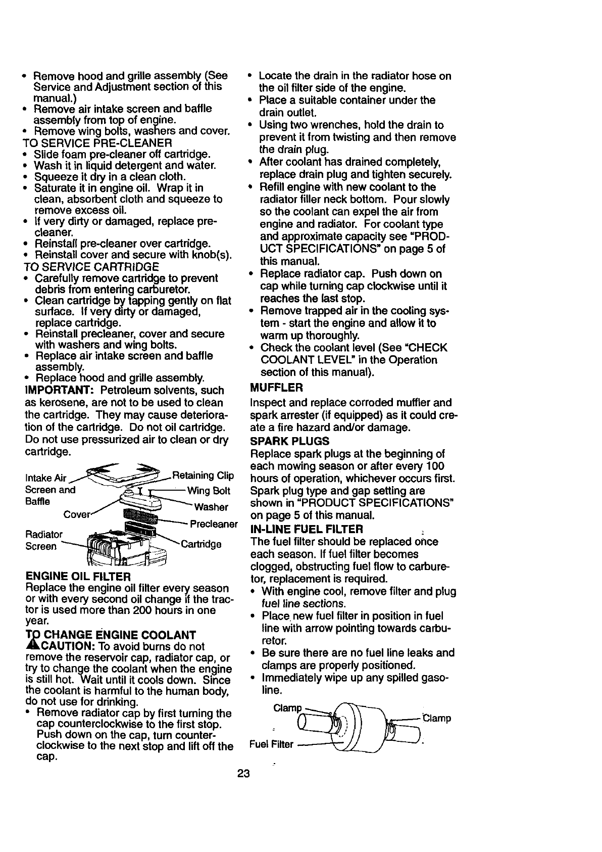
CLEAN AIR SCREEN
Air screens must be kept free of dirt and
chaff to prevent engine damage from over-
heating. Clean with a wire brush or com-
pressed air to remove dirt and stubborn
dried gum fibers.
•To access the radiator screen, remove
the air intake screen and baffle assem-
bly. Spread the side retaining clips
slightly and lift up and away from
engine.
•After cleaning the screens, install air
intake screen and baffle by pressi'ng
down to lock retaining clips.
Coolant
Oil Fill
Oil Drain ube
AIR FILTER
Your engine will not run properly using a
dirty air filter. Clean the foam pre-cleaner
after every 25 hours of operation or every
season. Service paper cartddge every
100 hours of operation or every season,
whichever occurs first.
Service air cleaner more often unddr dusty
conditions.
22
• Remove hood and grille assembly (See
Service and Adjustment section of this
manual.)
•Remove air intake screen and baffle
assembly from top of engine.
•Remove wing bolts, washers and cover.
TO SERVICE PRE-CLEANER
•Slide foam pre-cleaner off cartridge.
•Wash it in liquid detergent and water.
•Squeeze it dry in a clean cloth.
•Saturate it in engine oil. Wrap it in
clean, absorbent cloth and squeeze to
remove excess oil.
•If very dirty or damaged, replace pre-
cleaner.
Reinstall pre-cleaner over cartridge.
Reinstall cover and secure with knob(s).
TO SERVICE CARTRIDGE
_Carefully remove cartridge to prevent
debris from entering carburetor.
Clean cartridge b_/tapping gently on flat
surface. If very dirty or damaged,
replace cartridge.
•Reinstall precteaner, cover and secure
with washers and wing bolts.
•Replace air intake screen and baffle
assembly.
•Replace hood and grille assembly.
IMPORTANT: Petroleum solvents, such
as kerosene, are not to be used to clean
the cartridge. They may cause deteriora-
tion of the cartridge. Do not oil cartridge.
Do not use pressurized air to clean or dry
cartridge.
Intake _Retaining Clip
Screen and Bolt
Baffle
Precleaner
Radiator
Screen ge
ENGINE OIL FILTER
Replace the engine oil filter every season
or with every second oil change if the trac-
tor is used more than 200 hours in one
year.
_CHANGE ENGINE COOLANT
CAUTION: To avoid burns do not
remove the reservoir cap, radiator cap, or
try to change the coolant when the engine
is still hot. Wait until it cools down. Since
the coolant is harmful to the human body,
do not use for drinking.
• Remove radiator cap by first turning the
cap counterclockwise to the first stop.
Push down on the cap, turn counter-
clockwise to the next stop and lift off the
cap.
•Locate the drain in the radiator hose on
the oil filter side ofthe engine.
•Place a suitable container under the
drain outlet.
•Using two wrenches, hold the drain to
prevent it from twisting and then remove
the drain plug.
* After coolant has drained completely,
replace drain plug and tighten securely.
•Refill engine with new coolant to the
radiator filler neck bottom. Pour slowly
so the coolant can expel the air from
engine and radiator. For coolant type
and approximate capacity see =PROD-
UCT SPECIFICATIONS" on page 5 of
this manual.
•Replace radiator cap. Push down on
cap while turning cap clockwise until it
reaches the last stop.
•Remove trapped air in the cooling sys-
tem - start the engine and allow it to
warm up thoroughly.
• Checkthe coolant level (See "CHECK
COOLANT LEVEL" in the Operation
section of this manual).
MUFFLER
Inspect and replace corroded muffler and
spark arrester (if equipped) as it could cre-
ate a fire hazard and/or damage.
SPARK PLUGS
Replace spark plugsat the beginning of
each mowing season or after every 100
hours of operation, whichever occurs first.
Spark plug type and gap setting are
shown in "PRODUCT SPECIFICATIONS"
on page 5 of this manual.
IN-LINE FUEL FILTER
The fuel filter should be replaced of_ce
each season. If fuel filter becomes
clogged, obstructingfuel flow to carbure-
tor, replacement is required.
•With engine cool, remove filter and plug
fuel line sections.
• Placenew fuel filter in position in fuel
line with arrow pointing towards carbu-
retor.
•Be sure there are no fuel line leaks and
clamps are properly positioned.
•Immediately wipe up any spilled gaso-
line.
Clam_ Clamp
Fuel Filter _ _ :
23
CLEANING
•Clean engine, battery, seat, finish, etc.
of all foreign matter.
• Keep finished surfaces and wheels free
of all gasoline, oil, etc.
•Protect painted surfaces with automo-
tive type wax.
We do not recommend using a garden
hose to clean your tractor unless the elec-
trical system, muffler, air filter and carbure-
tor are covered to keep water out. Water
in engine can result in a shortened engine
life.
,_CAUTION: Before performing any service or adjustments:
• Depress clutch/brake pedal fully and set parking brake.
•Place motion control lever in neutral (N) position.
• Place attachment clutch in "DISENGAGED" position.
• Turn ignition key "OFF" and remove key.
• Make sure the blades and all moving parts have completely stopped.
• Disconnect spark plug wire from spark plug and place wire where it cannot come
in contact with plug.
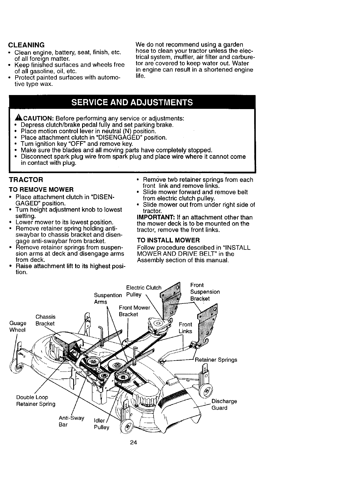
TRACTOR
TO REMOVE MOWER
• Place attachment clutch in "DISEN-
GAGED" position.
• Turn height adjustment knob to lowest
setting.
• Lower mower to its lowest position.
•Remove retainer spring holding anti-
swaybar to chassis bracket and disen-
gage anti-swaybar from bracket.
• Remove retainer springs from suspen-
sion arms at deck and disengage arms
from deck.
•Raise attachment lift to its highest posi-
tion.
• RemOve twb retainer springs from each
front link and remove links.
• Slide mower forward and remove belt
from electric clutch pulley.
• Slide mower out from under right side of
tractor.
IMPORTANT: If an attachment other than
the mower deck is to be mounted on the
tractor, remove the front links.
TO INSTALL MOWER
Follow procedure described in "INSTALL
MOWER AND DRIVE BELT" in the
Assembly section of this manual.
Chassis
Guage Bracket
Wheel
Electric Clutch
Suspention Pulley \
Arms \
Front Mower
Bracket
Front
Suspension
Bracl_et
Retainer Springs
Double Loop
Retainer Spring
Anti-Sway
Bar Idler
Pulley
Discharge
24
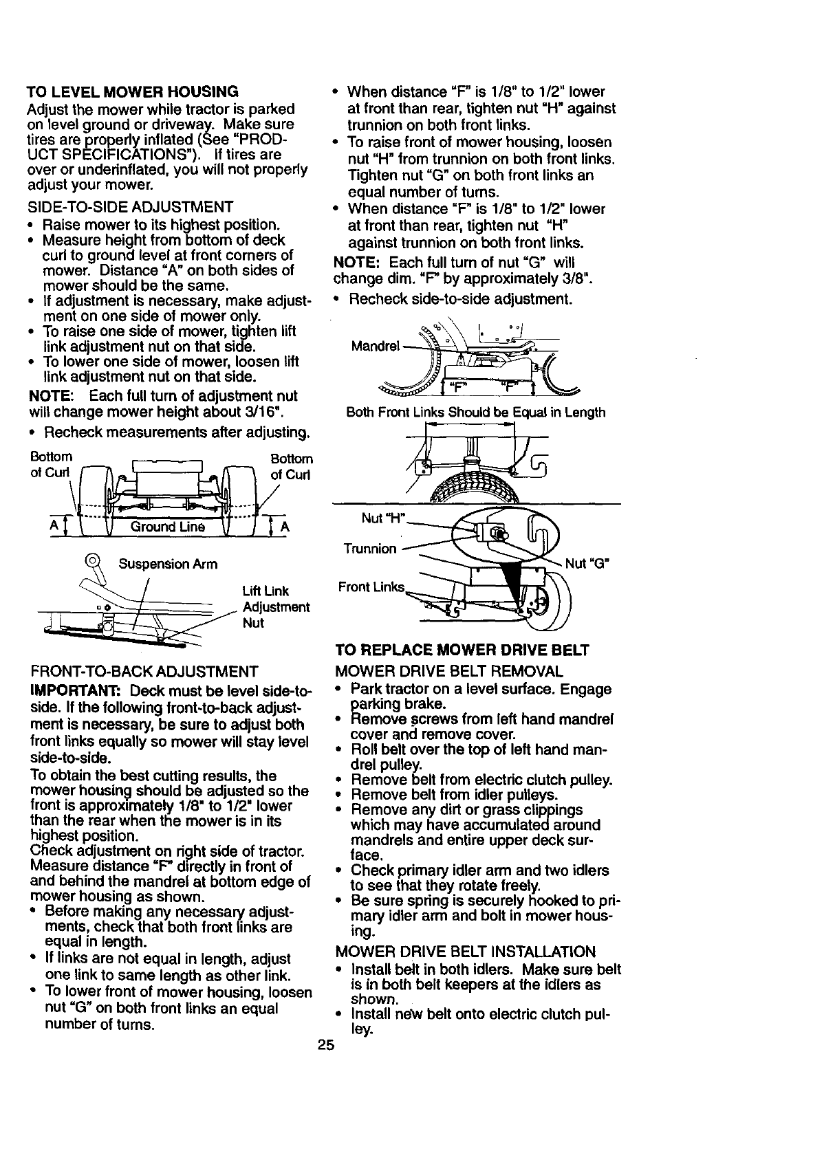
TO LEVEL MOWER HOUSING
Adjust the mower while tractor is parked
on level ground or driveway. Make sure
tires are properly inflated (See "PROD-
UCT SPECIFICATIONS"). If tires are
over or undefinflated, you will not properly
adjust your mower.
SIDE-TO-SIDE ADJUSTMENT
• Raise mower to its highest position.
•Measure height from bottom of deck
curl to ground level at front corners of
mower. Distance "A" on both sides of
mower should be the same.
•If adjustment is necessary, make adjust-
ment on one side of mower only.
•To raise one side of mower, tighten lift
link adjustment nut on that side.
•To lower one side of mower, loosen lift
link adjustment nut on that side.
NOTE: Each full turn ofadjustment nut
will change mower height about 3/16".
•Recheck measurements after adjusting.
Bottom Bottom
o,
A-_r_'"" _ GmundUne _""J-'_
m Lift Link
_djustment
Nut
FRONT-TO-BACK ADJUSTMENT
IMPORTANT: Deck must be level side-to-
side. If the following front-to-back adjust-
ment is necessary, be sure to adjust both
front links equally so mower will stay level
side-to-side.
To obtain the best cutting results, the
mower housing should be adjusted so the
front is approx=mately 1/8" to 1/2" lower
than the rear when the mower is in its
highest position.
Check adjustment on d_]ht side of tractor.
Measure distance "F" directly in front of
and behind the mandrel at bottom edge of
mower housing as shown.
• Before making any necessary adjust-
ments, check that both front links are
equal in length.
• If links are not equal in length, adjust
one link to same length as other link.
•To lower front of mower housing, loosen
nut =G" on both front links an equal
number of turns.
•When distance =F" is 1/8" to 1/2" lower
at front than rear, tighten nut "H" against
trunnion on both front links.
•To raise front of mower housing, loosen
nut "H" from trunnion on both front links.
Tighten nut "G" on both front links an
equal number of turns.
•When distance "F" is 1/8" to 1/2" lower
at front than rear, tighten nut "H"
against trunnion on both front links.
NOTE: Each full turn of nut "G" will
change dim. "F" by approximately 3/8".
•Recheck side-to-side adjustment.
|r" r | L
Both Front Links Should be Equal in Length
Nut "H"____'_
Trunnion X_Nu t "G"
Front Links_
TO REPLACE MOWER DRIVE BELT
MOWER DRIVE BELT REMOVAL
•Park tractor on a level surface. Engage
parking brake.
•Remove screws from left hand mandrel
cover and remove cover.
•Roll belt over the top of left hand man-
drel pulley.
•Remove belt from electdc clutch pulley.
•Remove belt from idler pulleys.
•Remove any dirt or grass clippings
which may have accumulated around
mandrels and entire upper deck sur-
face.
•Check primary idler arm and two idlers
to see that they rotate freely.
•Be sure spdng is securely hooked to pri-
mary idler arm and bolt in mower hous-
ing.
MOWER DRIVE BELT INSTALLATION
•Install be_t in both idlers. Make sure belt
is in both belt keepers at the idlers as
shown.
•Install new belt onto electric clutch pul-
ley.
25
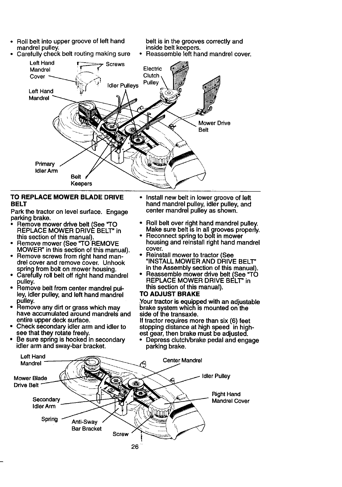
• Roll belt into upper groove of left hand
mandrel pulley.
• Carefully check belt routing making sure
Left Hand _ Screws
Mandrel , ._-.._
Cover
Idler Pulleys
Left Hand
Mandrel
belt is in the grooves correctly and
inside belt keepers.
•Reassemble left hand mandrel cover.
Electric
Clutch
Pulley
Mower Odve
Belt
Primary
IdlerArm Belt
Keepers
TO REPLACE MOWER BLADE DRIVE
BELT
Park the tractor on level surface. Engage
parking brake.
• Remove mower drive belt (See "TO
REPLACE MOWER DRIVE BELT" in
this section of this manual).
• Remove mower (See "TO REMOVE
MOWER" in this section of this manual).
• Remove screws from right hand man-
drel cover and remove cover. Unhook
spring from bolt on mower housing.
• Carefully roll belt off right hand mandrel
pulley.
•Hemove belt from center mandrel pul-
ley, idler pulley, and left hand mandrel
pulley.
• Remove any dirt or grass which may
have accumulated around mandrels and
entire upper deck surface.
• Check secondary idler arm and idler to
see that they rotate freely.
• Be sure spring is hookedin secondary
idler arm and sway-bar bracket.
Left Hand
Mandrel
Mower Blade
Drive Belt
Secondary
Idler Arm
Spring Anti-Sway
Bar Bracket Screw
•Install new belt in lower groove of left
hand mandrel pulley, idler pulley, and
center mandrel pulley as shown.
•Roll belt over right hand mandrel pulley.
Make sure belt ts in all grooves properly.
• Reconnect spring to bolt in mower
housing and reinstall right hand mandrel
cover.
• Reinstall mower to tractor (See
"INSTALL MOWER AND DRIVE BELT"
in the Assembly section of this manual).
• Reassemble mower drive belt (See "TO
REPLACE MOWER DRIVE BELT" in
this section of this manual).
TO ADJUST BRAKE
Your tractor is equipped with an adjustable
brake system which is mounted on the
side of the transaxle.
If tractor requires more than six (6) feet
stopping distance at high speed in high-
est gear, then brake must be adjusted.
• Depress clutch/brake pedal and engage
parking brake.
Center Mandrel
Idler Pulley
Right Hand
Mandrel Cover
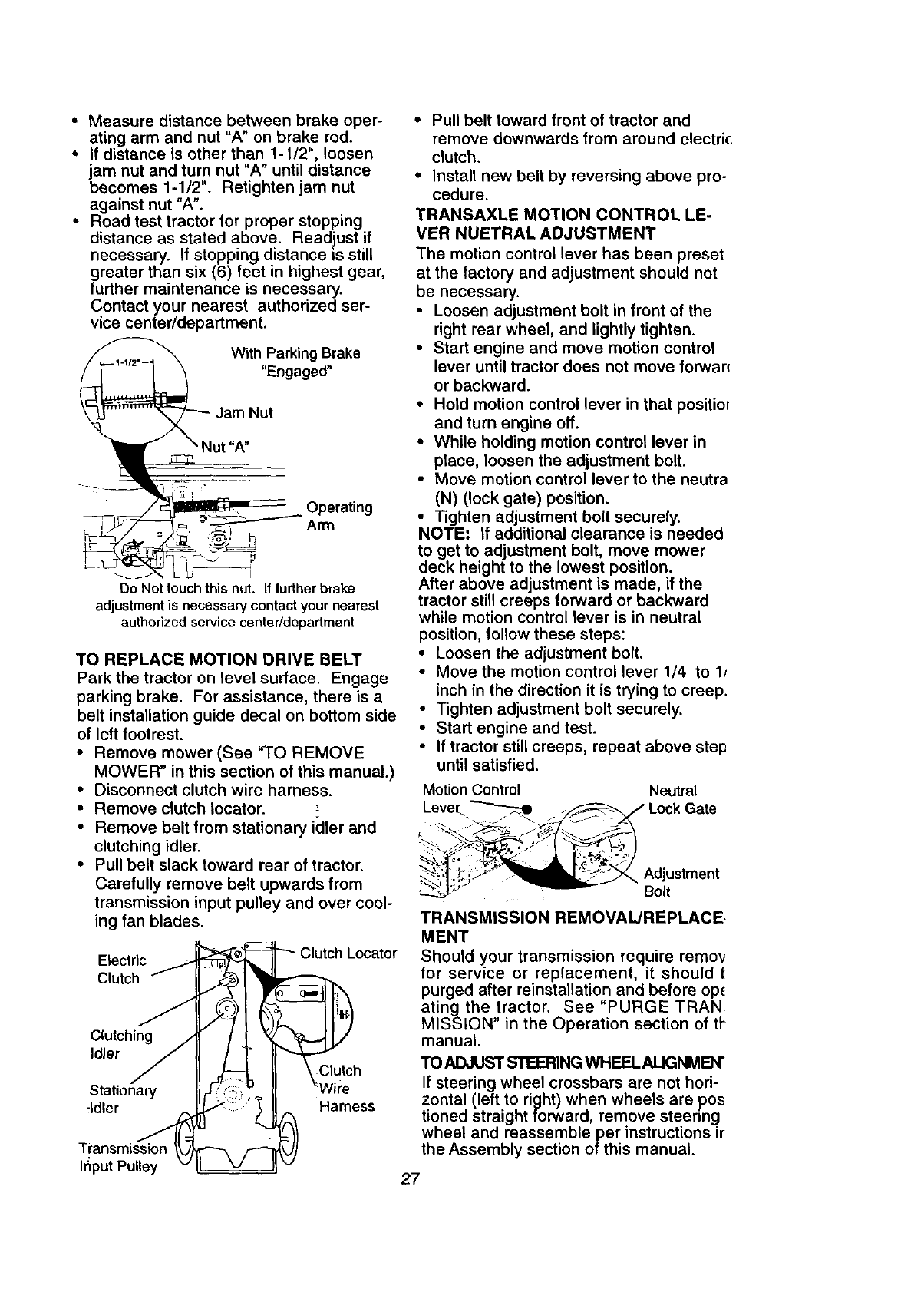
•Measure distance between brake oper-
ating arm and nut "A" on brake rod.
•If distance is other than 1-1/2", loosen
jam nut and turn nut "A" until distance
becomes 1-1/2". Retighten jam nut
against nut "A".
• Road test tractor for proper stopping
distance as stated above. Readjust if
necessary. If stopping distance is still
greater than six (6) feet in highest gear,
further maintenance is necessary.
Contact your nearest authorized ser-
vice center/department.
_Nut ,AWithParking Brake
"Engaged"
Jam Nut
_ Operating
_--._-_J_ __ Arm
Do Not touch this nut. If turther brake
adjustment is necessary contact your nearest
authorized service center/department
TO REPLACE MOTION DRIVE BELT
Park the tractor on level surface. Engage
parking brake. For assistance, there is a
belt installation guide decal on bottom side
of left footrest.
• Remove mower (See "TO REMOVE
MOWER" in this section of this manual.)
• Disconnect clutch wire harness.
• Remove clutch Iocator. -"
• Remove belt from stationary icller and
clutching idler.
• Pull belt slack toward rear of tractor.
Carefully remove belt upwards from
transmission input pulley and over cool-
ing fan blades.
Electric
Clutch
Idler Clutch
Stationary
_ldler Harness
Transmission
Ifiput Pulley
• Pull belt toward front of tractor and
remove downwards from around electric
clutch.
• Install new belt by reversing above pro-
cedure.
TRANSAXLE MOTION CONTROL LE-
VER NUETRAL ADJUSTMENT
The motion control lever has been preset
at the factory and adjustment should not
be necessary.
• Loosen adjustment bolt in front of the
right rear wheel, and lightly tighten.
• Start engine and move motion control
lever until tractor does not move forwar(
or backward.
• Hold motion control lever in that positiol
and turn engine off.
• While holding motion control lever in
place, loosen the adjustment bolt.
• Move motion control lever to the neutra
(N) (lock gate) position.
• Tighten adjustment bolt securely.
NOTE: If additional clearance is needed
to get to adjustment bolt, move mower
deck height to the lowest position.
After above adjustment is made, if the
tractor still creeps forward or backward
while motion control lever is in neutral
position, follow these steps:
• Loosen the adjustment bolt.
• Move the motion control lever 1/4 to lJ
inch in the direction it is trying to creep.
• Tighten adjustment bolt securely.
• Start engine and test.
• If tractor still creeps, repeat above step
until satisfied.
Motion Control Neutral
Level
Adjustment
Bolt
TRANSMISSION REMOVAL/REPLACE-
MENT
Should your transmission require remov
for service or replacement, it should t
purged after reinstallation and before op_
ating the tractor, See "PURGE TRAN
MISSION" in the Operation section of tl-
manual.
TO ADJUST STEERING WHEELALIGNMEN"
If steering wheel crossbars are not hori-
zontal (left to right) when wheels are pos
tioned straight forward, remove steering
wheel and reassemble per instructions ir
the Assembly section of this manual.
27
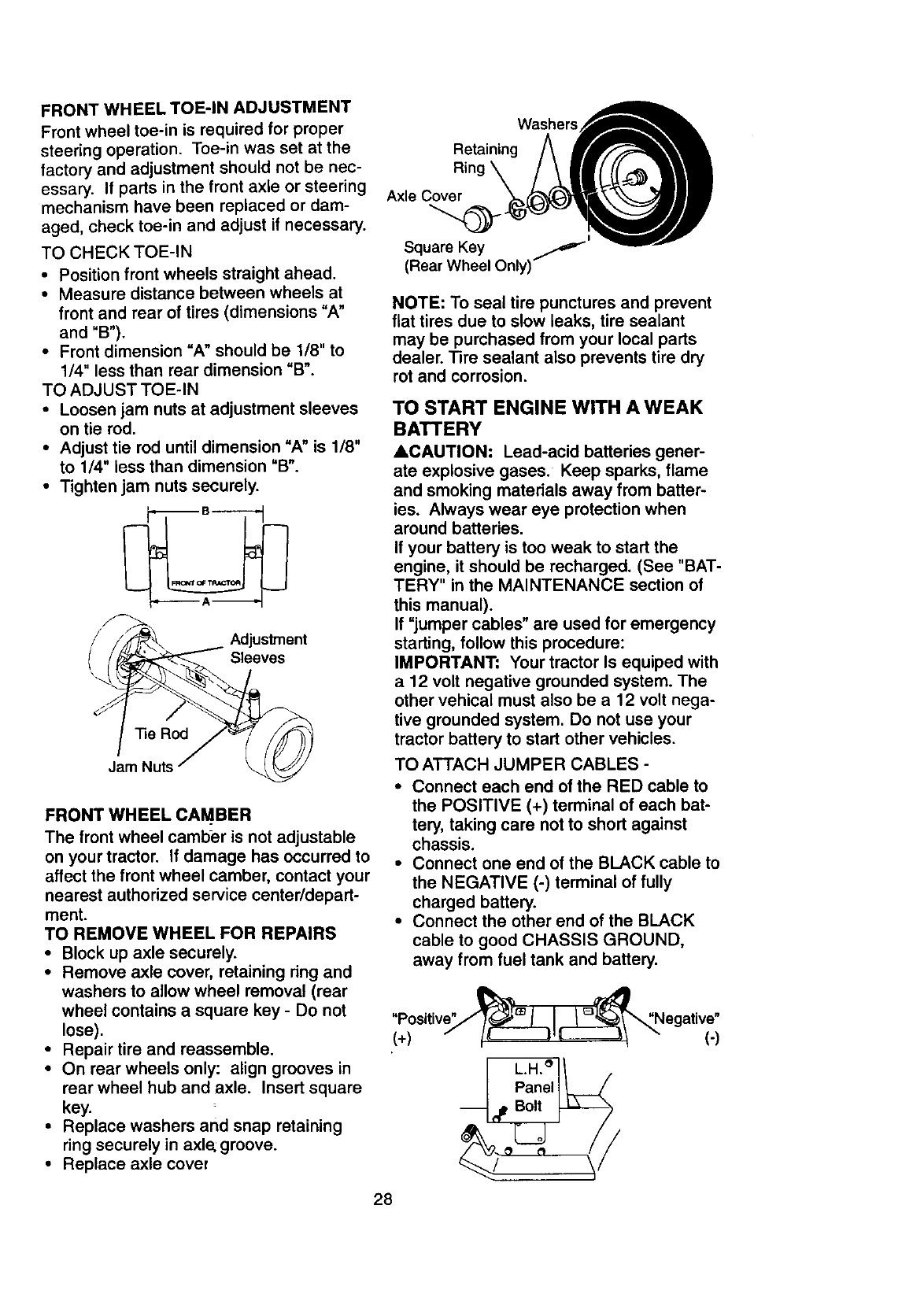
FRONT WHEEL TOE-IN ADJUSTMENT
Front wheel toe-in is required for proper
steering operation. Toe-in was set at the
factory and adjustment should not be nec-
essary. If parts in the front axle or steering
mechanism have been replaced or dam-
aged, check toe-in and adjust if necessary.
TO CHECK TOE-IN
•Position front wheels straight ahead.
•Measure distance between wheels at
front and rear of tires (dimensions "A"
and "B").
• Front dimension "A" should be 1/8" to
1/4" less than rear dimension =B".
TO ADJUST TOE-IN
•Loosen jam nuts at adjustment sleeves
on tie red.
•Adjust tie red until dimension "A" is 1/8"
to 1/4" less than dimension "B".
•Tighten jam nuts securely.
_Adius ent
/_ Sleeves
Jam Nuts" _._
FRONT WHEEL CAMBER
The front wheel camber is not adjustable
on your tractor. If damage has occurred to
affect the front wheel camber, contact your
nearest authorized service center/depart-
ment.
TO REMOVE WHEEL FOR REPAIRS
•Block up axle securely.
•Remove axle cover, retaining ring and
washers to allow wheel removal (rear
wheel contains a square key -Do not
lose).
•Repair tire and reassemble.
•On rear wheels only: align grooves in
rear wheel hub and axle. Insert square
key.
•Replace washers and snap retaining
ring securely in axle: groove.
•Replace axle cover
Washers_
Retaining A f__'_
Riog\ / .11¢ .111
Square Key
(Rear Wheel Only)--
NOTE: To seal tire punctures and prevent
flat tires due to slow leaks, tire sealant
may be purchased from your local parts
dealer. Tire sealant also prevents tire dry
rot and corrosion.
28
TO START ENGINE WITH A WEAK
BATTERY
ACAUTION: Lead-acid batteries gener-
ate explosive gases. Keep sparks, flame
and smoking matedals away from batter-
ies. Always wear eye protection when
around batteries.
If your battery is too weak to start the
engine, it should be recharged. (See "BAT-
TERY" in the MAINTENANCE section of
this manual).
If "jumper cables" are used for emergency
starting, follow this procedure:
IMPORTANT: Your tractor Is equiped with
a 12 volt negative grounded system. The
other vehical must also be a 12 volt nega-
tive grounded system. Do not use your
tractor battery to start other vehicles.
TO ATTACH JUMPER CABLES -
•Connect each end of the RED cable to
the POSITIVE (+) terminal of each bat-
tery, taking care not to short against
chassis.
•Connect one end of the BLACK cable to
the NEGATIVE (-) terminal of fully
charged battery.
•Connect the other end of the BLACK
cable to good CHASSIS GROUND,
away from fuel tank and battery.
"Positive"___"Negative"
(*) "" (')
[ LaHne/I___
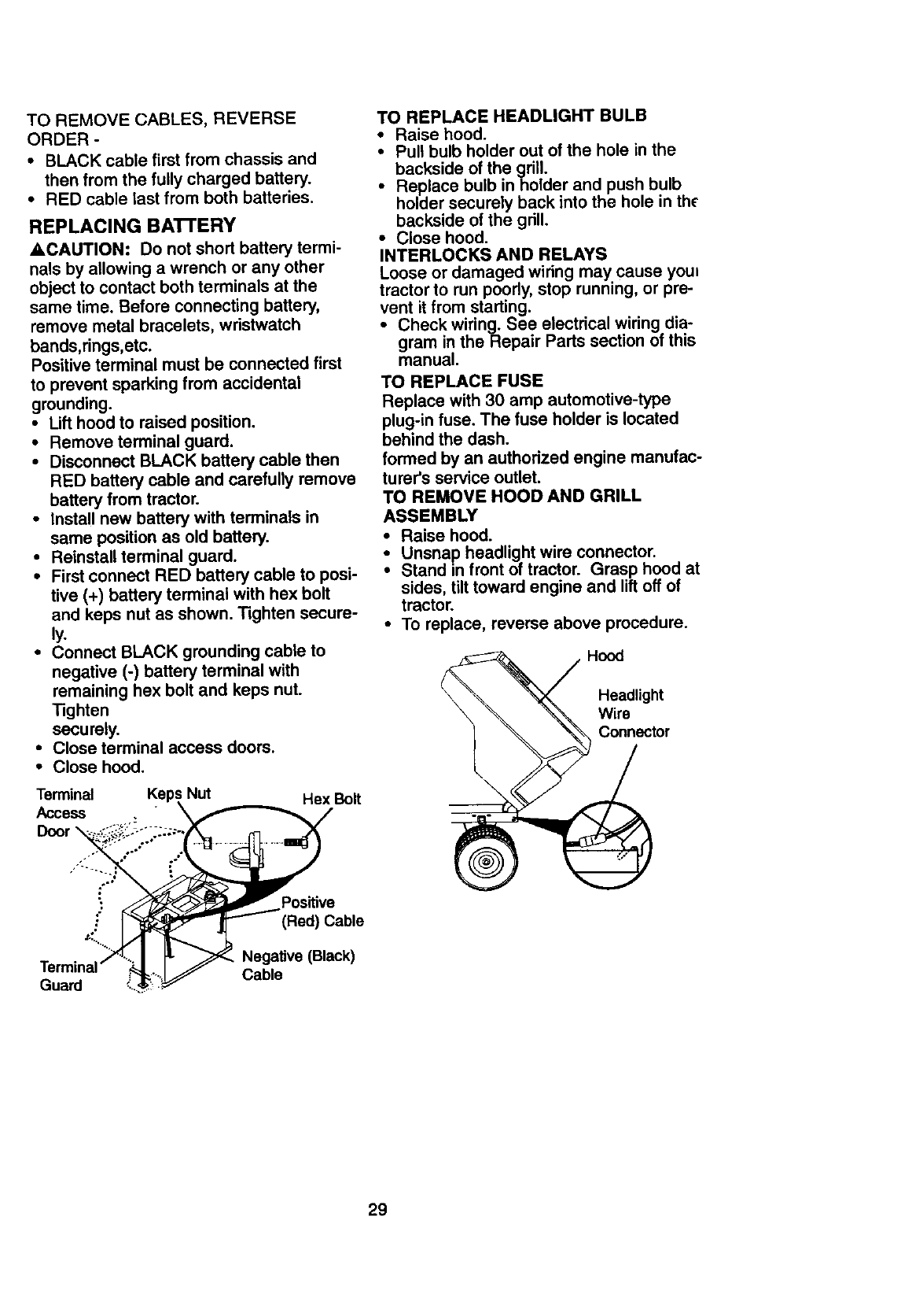
TO REMOVECABLES,REVERSE
ORDER-
•BLACK cable first from chassis and
then from the fully charged battery.
• RED cable last from both batteries.
REPLACING BA'n'ERY
&CAUTION: Do not short battery termi-
nals by allowing a wrench or any other
object to contact both terminals at the
same time. Before connecting battery,
remove metal bracelets, wristwatch
bands,rings,etc.
Positive terminal must be connected first
to prevent sparking from accidental
grounding.
•Lift hood to raised position.
•Remove terminal guard.
•Disconnect BLACK battery cable then
RED battery cable and carefully remove
battery from tractor.
•Install new battery with terminals in
same position as old battery.
•Reinstall terminal guard.
•First connect RED battery cable to posi-
tive (+) battery terminal with hex bolt
and keps nut as shown. Tighten secure-
ly.
•Connect BLACK grounding cable to
negative (-) battery terminal with
remaining hex bolt and keps nut.
Tighten
securely.
• Close terminal access doors.
•Close hood.
Terminal Keps Nut Hex Bolt
Access \
TO REPLACE HEADLIGHT BULB
•Raise hood.
•Pull bulb holder out of the hole in the
backside of the grill.
•Replace bulb in holder and push bulb
holder securely back into the hole in the
backside of the grill.
• Close hood.
INTERLOCKS AND RELAYS
Loose or damaged wiring may.cause youl
tractor to run poorly, stop running, or pre-
vent it from starting.
• Check wiring. See electrical wiring dia-
gram in the Repair Parts section of this
manual.
TO REPLACE FUSE
Replace with 30 amp automotive-type
plug-in fuse. The fuse holder is located
behind the dash.
formed by an authorized engine manufac-
turer's service outlet.
TO REMOVE HOOD AND GRILL
ASSEMBLY
• Raise hood.
Unsnap headlight wire connector.
Stand in front of tractor. Grasp hood at
sides, tilt toward engine and lift off of
tractor.
•To replace, reverse above procedure.
Hood
Headlight
Wire
Connector
Guard
Positive
(Red) Cable
Negative (Black)
Cable
29
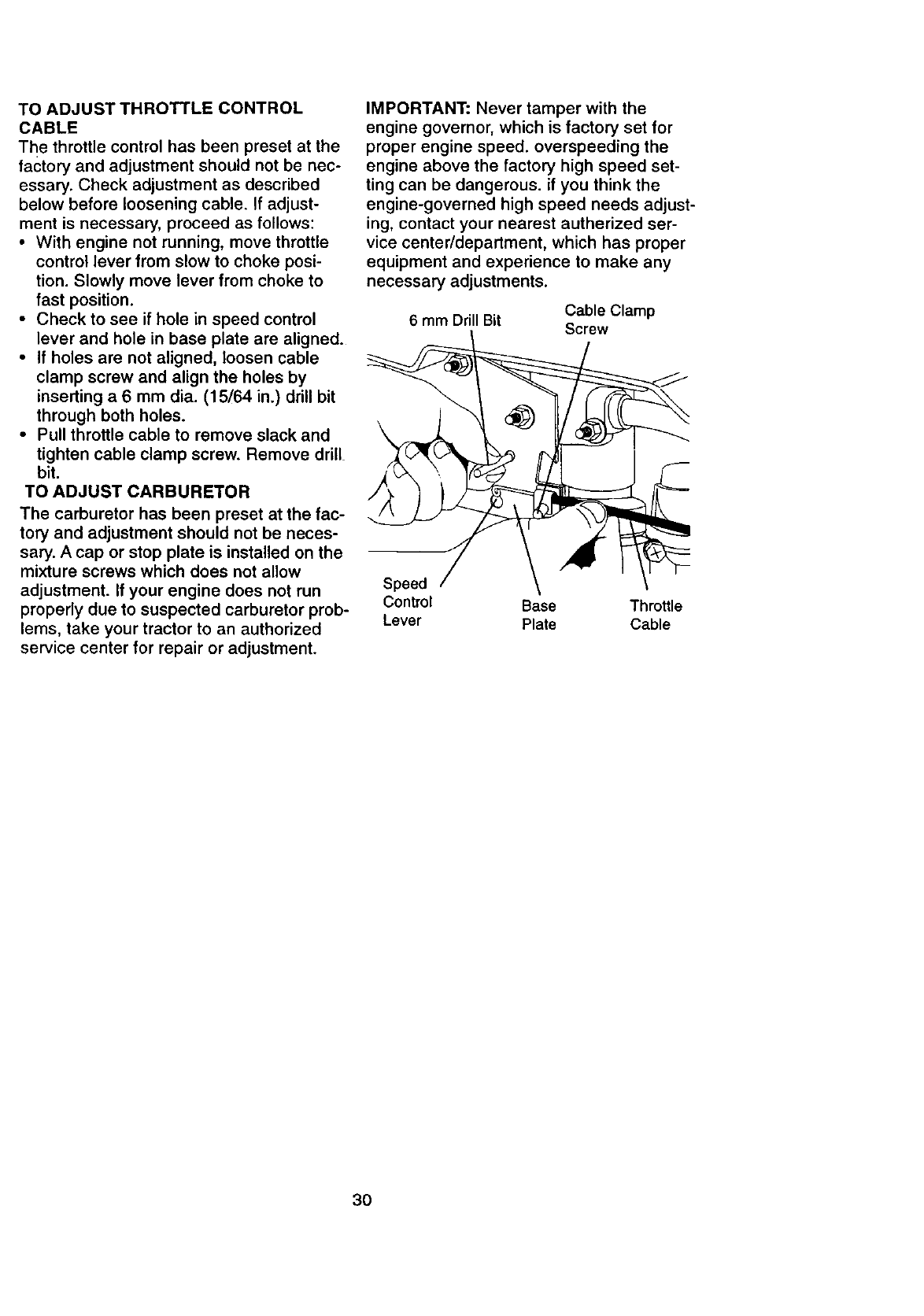
TOADJUSTTHROTTLECONTROL
CABLE
Thethrottlecontrolhasbeenpresetatthe
factory and adjustment should not be nec-
essary. Check adjustment as described
below before loosening cable. If adjust-
ment is necessary, proceed as follows:
•With engine not running, move throttle
control lever from slow to choke posi-
tion. Slowly move lever from choke to
fast position.
•Check to see if hole in speed control
lever and hole in base plate are aligned.
•If holes are not aligned, loosen cable
clamp screw and align the holes by
inserting a 6 mm dia. (15/64 in.) drill bit
through both holes.
• Pull throttle cable to remove slack and
tighten cable clamp screw. Remove drill
bit.
TO ADJUST CARBURETOR
The carburetor has been preset at the fac-
tory and adjustment should not be neces-
sary. A cap or stop plate is installed on the
mixture screws which does not allow
adjustment. If your engine does not run
properly due to suspected carburetor prob-
lems, take your tractor to an authorized
service center for repair or adjustment.
IMPORTANT: Never tamper with the
engine governor, which is factory set for
proper engine speed, overspeeding the
engine above the factory high speed set-
ting can be dangerous, if you think the
engine-governed high speed needs adjust-
ing, contact your nearest autherized ser-
vice center/department, which has proper
equipment and experience to make any
necessary adjustments.
6mm Drill Bit Cable Clamp
Screw
Speed
Control Base Throttle
Lever Plate Cable
3O
Immediately prepare your tractor for stor-
age at the end of the season or if the trac-
tor will not be used for 30 days or more.
,_CAUTION: Never store the tractor with
gasoline in the tank inside abuilding
where fumes may reach an open flame or
spark. Allow the engine to cool before stor-
ing in any enclosure.
TRACTOR
Remove mower from tractor for winter
storage. This will allow you to clean it thor-
oughly. Remove all dirt, grease, leaves,
etc. Store in aclean, dry area.
• Clean entire tractor (See =CLEANING"
in the Maintenance section of this man-
ual).
•Inspect and replace belts, if necessary
(See belt replacement instructions in the
Service and Adjustments section of this
manual).
•Lubricate as shown in the Maintenance
section of this manual.
•Be sure that all nuts, bolts and screws
are securely fastened. Inspect moving
parts for damage, breakage and wear.
Replace if necessary.
•Touch up all rusted or chipped paint sur-
faces; sand lightly before painting.
BA'I-rERY
•Fully charge the battery for storage.
•After a period of time in storage, battery
may require recharging.
•To help prevent corrosion and power
leakage during long periods of storage,
battery cables should be disconnected
and battery cleaned thoroughly (see
=TO CLEAN BATTERY AND TERMI-
NALS" in the Maintenance section of
this manual).
•After cleaning, leave cables disconnect-
ed and place cables where they cannot
come in contact with battery terminals.
• If battery is removed from tractor for
storage, do not store battery directly on
concrete or damp surfaces.
ENGINE
FUEL SYSTEM
IMPORTANT: It is important to prevent
gum deposits from forming in essential
fuel system parts such as carburetor, fuel
filter, fuel hose, or tank during storage.
Also, experience indicates that alcohol
blended fuels (called gasohol or using
ethanol or methanol) can attract moisture
which leads to separation and formation of
acids during storage. Acidic gas can dam-
age the fuel system of an engine while in
storage.
• Drain the fuel tank.
•Start the engine and let it run until the
fuel lines and carburetor are empty.
•Never use engine or carburetor cleaner
products in the fuel tank or permanent
damage may occur.
• Use fresh fuel next season.
NOTE: Fuel stabilizer is an acceptable
alternative in minimizing the formation of
fuel gum deposits during storage. Add sta-
bilizer to gasoline in fuel tank or storage
container. Always follow the mix ratio
found on stabilizer container. Run engine
at least 10 minutes after adding stabilizer
to allow the stabilizer to reach the carbure-
tor. Do not drain the gas tank and carbure-
tor if using fuel stabilizer.
ENGINE OIL
Drain oil (with engine warm) and replace
with clean engine oil. (See "ENGINE" in
the Maintenance section of this manual).
CYLINDER(S)
•Remove spark plug(s).
•Pour one ounce of oil through spark plug
hole(s) into cylinder(s).
•Turn ignition key to "START" position for
afew seconds to distribute oil.
•Replace with new spark plug(s).
OTHER
•Do not store gasoline from one season
to another.
•Replace your gasoline can if it starts to
rust. Rust and/or dirt in your gasoline will
cause problems.
•If possible, store your tractor indoors
and cover it to give protection from dust
and dirt.
•Cover your tractor with asuitable protec-
tive cover that does not retain moisture.
Do not use plastic. Plastic cannot
breathe, which allows condensation to
form and cause your tractor to rust.
IMPORTANT: Never cover tractor while
engine and exhaust areas are still warm.
31
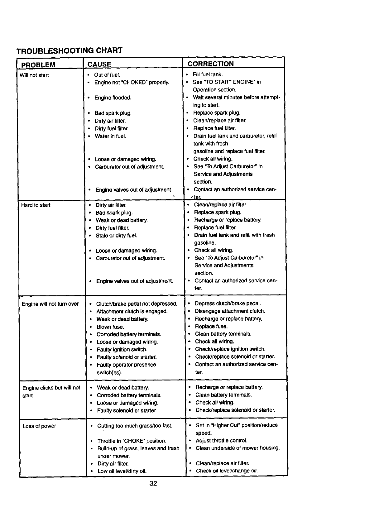
TROUBLESHOOTING CHART
PROBLEM CAUSE
Will notstart • Outoffuel.
•Engine not "CHOKED" propedy.
CORRECTION
•Fill fuel tank.
•See "TO START ENGINE" in
Operation section.
•Engine flooded.
•Bad spark plug.
•Dirtyair filter.
Dirty fuel filter,
Water in fuel.
•Loose ordamaged wiring.
I•Wait several minutes before attempt-
ing to start.
• Replace spark plug.
•Clean/replace airfilter.
•Replace fuel filter,
• Drain fuel tank and carburetor, refill
tank withfresh
gasoline and replace fuel filter,
•Check all wiring.
Hard to start
Engine will not turn over
I
I Engine clicks but will not
start
Loss of power
•Carburetorout of adjustment.
• Engine valves out of adjustment.
•Dirty air filter.
• Bad spark plug,
•Weak or dead battery.
•Dirty fuel filter.
•Stale or dirtyfuel.
•Loose or damaged widng,
•Carburetorout of adjustment.
• Engine valves out of adjustment.
•Clutch_rake pedal not depressed.
•Attachment clutch is engaged.
•Weak or dead battery,
•Blownfuse.
• Corroded battery terminals.
Loose or damaged wiring.
•Faulty ignitionswitch.
•Faulty solenoid or starter.
Faulty operator presence
switch(es).
•Weak or dead battery.
•Corroded battery terminals.
•Loose or damaged wiring.
•Faulty solenoidor starter.
• Cutting too much grass/too fast.
•Throttle in "CHOKE" position.
•Build-up of grass, leaves and trash
under mower.
•Dirty air filter.
•Lowoil leveVdirtyoiL
•See "To Adjust Carburetor" in
Service and Adjustments
section.
•Contact an authorized service can-
, tar.
•Clean/replace air filter,
•Replace spark plug.
•Recharge or replace battery,
•Replace fuel filter.
•Drain fuel tank and refillwith fresh
gasoline.
•Check all widng.
•See "To AdjustCarburetor" in
Service andAdjustments
section.
' • Contact an authodzed service cen-
ter.
I
I•Depress clutch/brake pedal.
• Disengage attachment clutch.
•Recharge or replace battery.
•Replace fuse.
•Clean battery terminals.
•Check all widng.
•Check/replace ignitionswitch.
•Checldreplece solenoidor starter.
•Contact an authorized service can-
ten
•Recharge or replace battery.
•Clean battery terminals.
•Check all wiring.
•ChecWreplace solenoid or starter.
•Set in 'l-'ligher Cut" position/reduce
speed.
•Adjust throttlecontrol.
•Clean underside of mower housing.
• Clean/replace air filter.
•Check oil level/change oil.
32
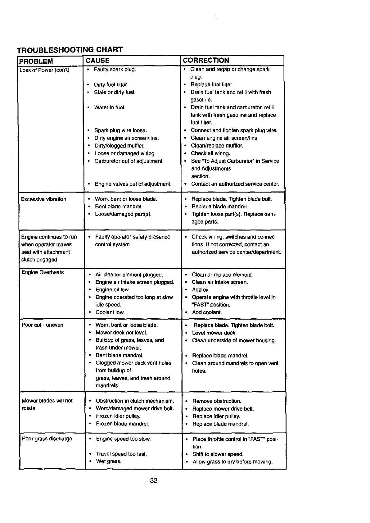
PROBLEM
Lossof Power (oon't)
"ROUBLESHOOTING CHART
CAUSE
•Faulty spark plug.
• Oirty fuel filter.
• Stale or dirty fuel.
•Waterin fuel.
Excessive vibration
Engine continuesto run
when operator leaves
seat with attachment
clutch engaged
Engine Overheats
Poor cut- uneven
Mower blades will not
otate
Poorgrass discharge
Spark plugwire loose.
Dirty engine air scraen/fins.
• Dirty/clogged muffler.
•Loose or damaged wiring.
•Carburetor out of adjustment,
•Engine valves out of adjustment. •
•Worn, bent or loose blade. •
•Bent blade mandrel.
•Loose/damaged part(s).
•Faulty operator-safety presence
controlsystem.
•Air cleaner element plugged.
•Engine air intake screen plugged. •
•Engine oil low. •
•Engine operated too longat slow •
idlespeed.
•Coolant low. •
•Worn, bent or loose blade.
•Mower deck not level. , •
•Buildup of grass, leaves, and •
trash under mower.
•Bent blade mandrel. I °
•Clogged mowerdeck vent holes •
frombuildup of
grass, leaves, and trash around
mandrels.
•Obstruction inclutch mechanism.
•Worn/damaged mowerddve belt.
•Frozen idlerpulley.
•Frozen blade mandrel.
Engine speed too slow.
•Travel speed too fast.
•Wet grass.
CORRECTION
•Clean and regap orchange spark
plug.
•Replace fuel filter,
•Drain fuel tank and refillwithfresh
gasoline.
Drain fuel tank and carburetor, refill
tank withfresh gasoline and replace
fuel filter.
Connect and tighten spark plug wire.
Clean engine air screen/fins.
Clean/replace muffler.
Check all wiring.
See "To Adjust Carburetor"in Service
and Adjustments
section.
Contact an authorized service center.
Replace blade, 33ghtenblade bolt.
Replace blade mandrel.
"Sghtenloose part(s). Replace dam-
aged parts.
Check wiring, switches and connec-
tions. If not corrected, contact an
authorized service center/department.
Clean or replace element.
Clean air intake screen.
Add oil.
Operate engine withthrottle level in
"FAST" position,
Add coolant.
Replace blade. 11ghten blade holt.
Level mower deck,
Clean underside of mower housing.
Replace blade mandrel.
Clean around mandrels to open vent
holes.
•Remove obstruction.
•Replace mower ddve belt.
•Replace idlerpulley.
•Replace blade mandrel.
Place throttle controlin "FAST"posi-
tion.
•Bhiff to slower speed.
•Allow grass to dry before mowing.
33
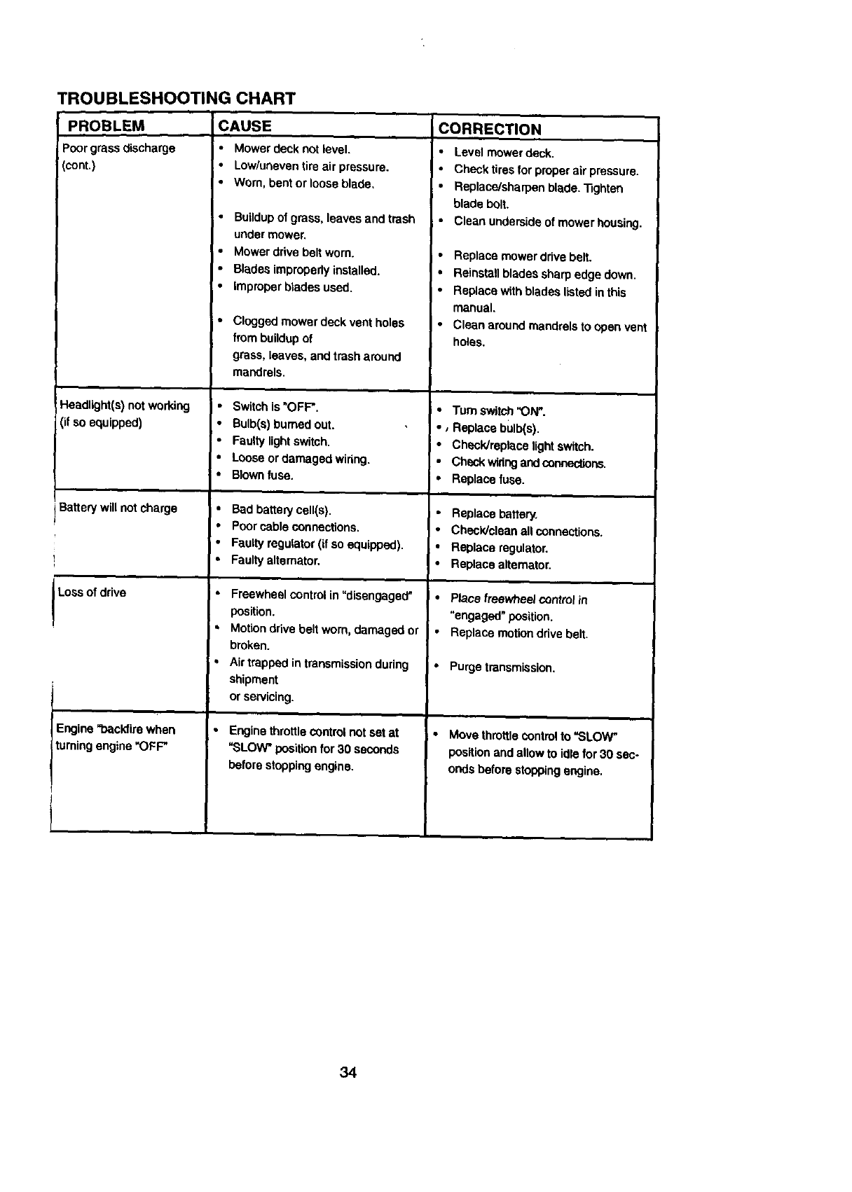
TROUBLESHOOTING CHART
CAUSE CORRECTION
PROBLEM
Poorgrassc_scharge
cont.)
Headlight(s)not working
(if soequipped)
Battery will not charge
Loss of drwe
Engine "backfirewhen
turning engine "OFF"
i.
Mower deck not level.
Low/uneven tire air pressure.
Worn. bent or loose blade,
•Buildupof grass, leaves and trash
under mower.
•Mower drive belt worn.
•Blades improperly installed.
•Improper blades used.
•Clngged mower deck vent holes
from bui|dup of
grass, leaves, and trash around
mandrels.
•Switch is "OFF".
Bulb(s) burned out.
Faulty lightswitch.
I° Loose or damaged widng.
! • BLOWNfuse.
•Bad battery cell(s).
•Poor cable connections.
•Faulty regulator (if so equipped).
•Faulty alternator.
•Freewhe_ contr_ in%isangags_"
position.
=MotiOndrive belt worn, damaged or
broken.
•Air trapped in transmissiondudng
shipment
or servicing.
• Engine throttlecontrolnot set at
"SLOW" position for 30 seconds
before stoppingengine.
•Level m_owerdeck.
•Check tiresfor proper air pressure.
•Replace/sharpen blade. "Sghten
blade bolt.
•Clean underside of mower housing.
i•Replace mower drive belt.
I"Reinstall blades sharp edge down.
•Replace with blades listedin this
manual,
•Clean around mandrels to open vent
holes.
•Turn switch"ON".
•,Replace bulb(s).
•Check/replace light switch.
• Check widng andconnections.
•Replace fuse.
Replace battery.
•Check/clean allconnections.
•Replace regulator.
•Replace alternator.
•Place freewheel controlin
"engaged" position.
Replace mo_on drive belt.
Purge transmission.
•Move throttlecontrolto =SLOW"
positionand allow to idle for 30 sec-
onds before stoppingengine.
34
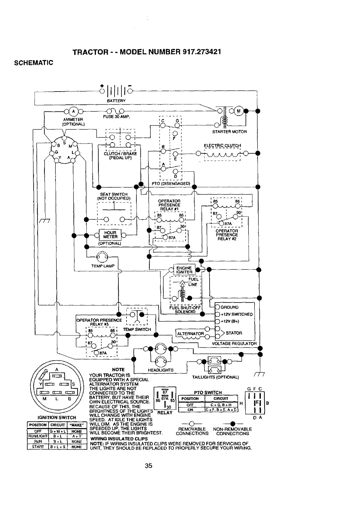
SCHEMATIC
TRACTOR -- MODEL NUMBER 917.273421
[BATTERY
AMMETER
(OPTIONAL)
L ....... J
CLUTCH /BRAKE
(PEDAL UP) E
D
PTO_(DISENGAGED)
STARTER MOTOR
ELECTRIC CLUTCH-i
SEAT SWITCH
(NOT OCCUPIE[
(OPTIONAL)
i
OPERATOR I85 86 t
PRESENCE
RELAY #1
it
85 86
_f
OPERATOR
PRESENCE
RELAY #2
TEMP LAMP
RELAY */,3
85 86 , TEMP SWITCH
)
FUEL SHUT-OFF ! GROUND /
SOLENOID +12V SWITCHED 4
I +12V (B+)
STATOR J
VOLTAGE%LATOR!
/HEABUGHTS _ _ /'_
NOTE
YOURTRACTORIS
IGNITION SWITCH
EQUIPPED WITH A SPECIAL
ALTERNATOR SYSTEM.
THE UGHTS ARE NOT
CONNECTED TO THE
BATTERY, BUT HAVE THEIR
OWN ELECTRICAL SOURCE.
BECAUSE OF THIS, THE
BRIGHTNESS OF THE LIGHT5
WILL CHANGE WITH ENGINE
SPEED. AT IDLE THE UGHTS
TAILLIGHTS (OPTIONAL)
RELAY
GFC
PTO SWITCH 1
POSITION CIRCUIT
OFF C+G,B+H R B
ON C+_+ D
DA
PoErI'ION CIRCUIT "MAKE" WILL DIM, AS THE ENGINE IS _
SPEEDED UP, THE LIGHTS REMOVABLE NON-REMOVABLE
OFF _ * M + L NONE WILL BECOME THEIR BRIGHTEST. CONNECTIONS CONNECTIONS
RUN,'LIGFR B+L A+Y WIRING INSULATED CLIPS
PUN S+ L NONE NOTE: IF WIRING INSULATED CLIPS WERE REMOVED FOR SERVICING OF
START B + L ÷S NONE UNIT, THEY SHOULD BE REPLACED TO PROPERLY SECURE YOUR WIRING.
35
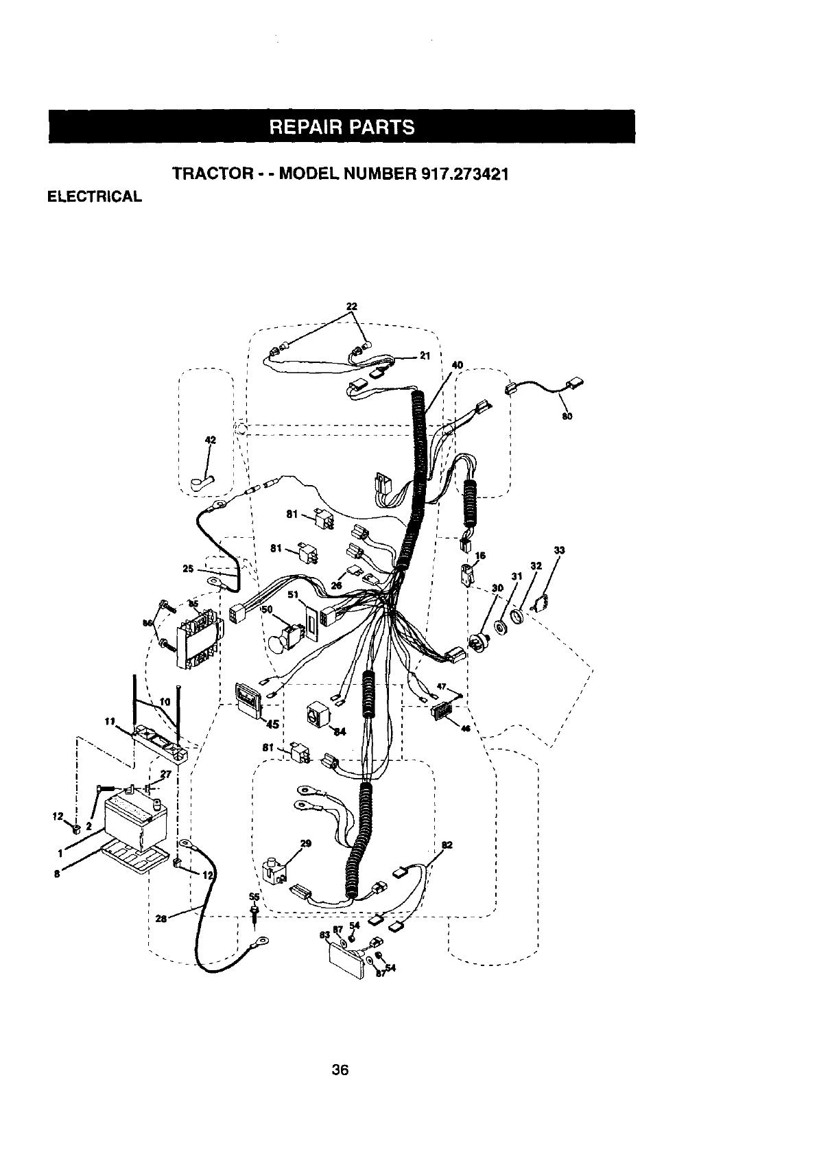
ELECTRICAL
TRACTOR - -MODEL NUMBER 917.273421
22
i
36
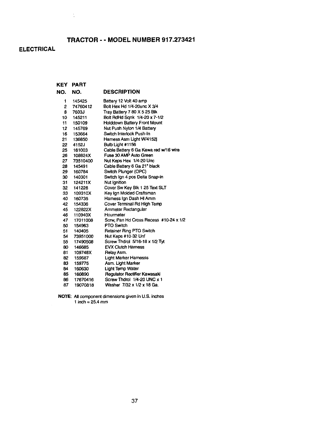
ELECTRICAL
TRACTOR --MODEL NUMBER 917.273421
KEY
NO.
1
2
6
10
11
12
16
21
22
25
26
27
2B
29
3O
31
32
33
40
42
45
46
47
5O
51
54
55
80
81
82
83
84
85
86
87
NOTE:
PART
NO. DESCRIPTION
145425
74760412
7603J
145211
150109
145769
153664
136850
4152J
161003
108824X
73510400
145491
160784
140301
124211X
141226
109310X
160735
154336
122822X
110940X
17011008
154963
140405
73951000
17490508
146685
109748X
159687
159775
160630
160890
17670416
19070818
Battery 12 Volt40 amp
Bolt Hex Hd 1/4-20unc X 3/4
Tray Battery 7 80 X 5 25 BIk
Bait RdHd Sqnk 1/4-20 x 7-1/2
HolddownBatteryFront Mount
Nut Push Nylon 1/4 Battery
SwitchIntadockPush-In
Hamess Asm Ught W/4152j
BulbLight#1156
Cable Battery 6 Ga Kawa red w/16 wire
Fuse 30 AMP AutoGreen
Nut Kaps Hex 1/4-20 Unc
Cable Battery 6 Ga 21• black
SwitchPlunger(OPC)
Switchign 4 pos Delta Snap-in
Nut Ignition
Cover Sw Key BIk 1 25 Text SLT
Key Ign MoldedCraftsman
Harness IgnDash HIAtom
Cover TerminalRd High Temp
Ammeter Rectangular
Hourmeter
SCPN,Pan Hd Cross Recess #10-24 x 112
PTO Switch
RetainerRing PTO Switch
Nut Keps #10-32 Unf
ScrewThdrol 5/16-18 x 1/2 Tyt
EVX ClutchHamess
Relay Asm.
Light MarkerHamesss
Asm. Light Marker
LightTemp Water
Regulator RectWJerKawasaki
Screw Thdrol 1/4-20 UNC x I
Washer 7F32x 1/2 x 18 Ga.
All componentdimensionsgivenin U,S. inches
1inch =25.4 mm
37
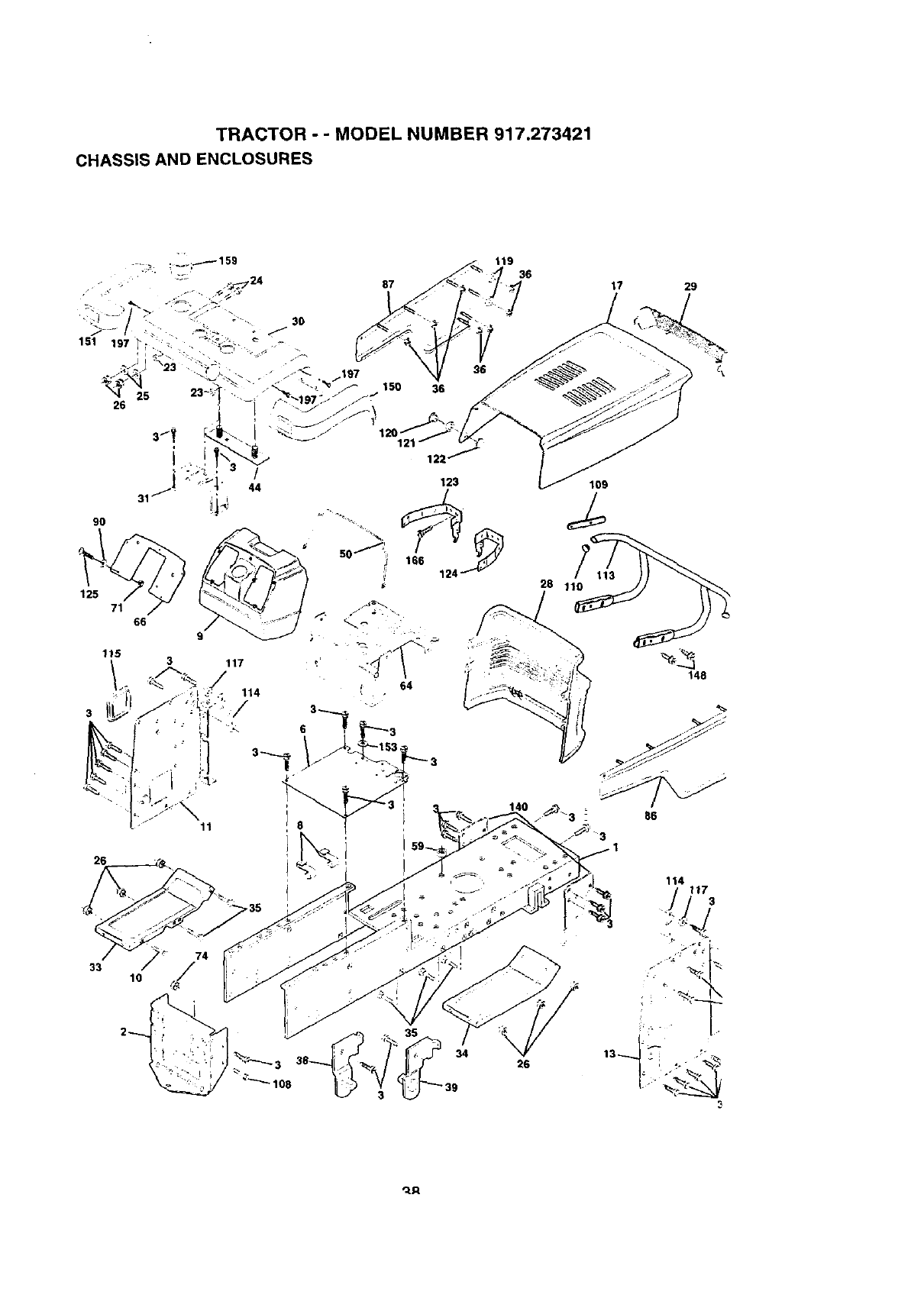
TRACTOR - - MODEL NUMBER 917.273421
CHASSIS AND ENCLOSURES
125
71 66
9O
87
150 36
64
119 36
26
33 10
17 29
109
28 110
148
_R
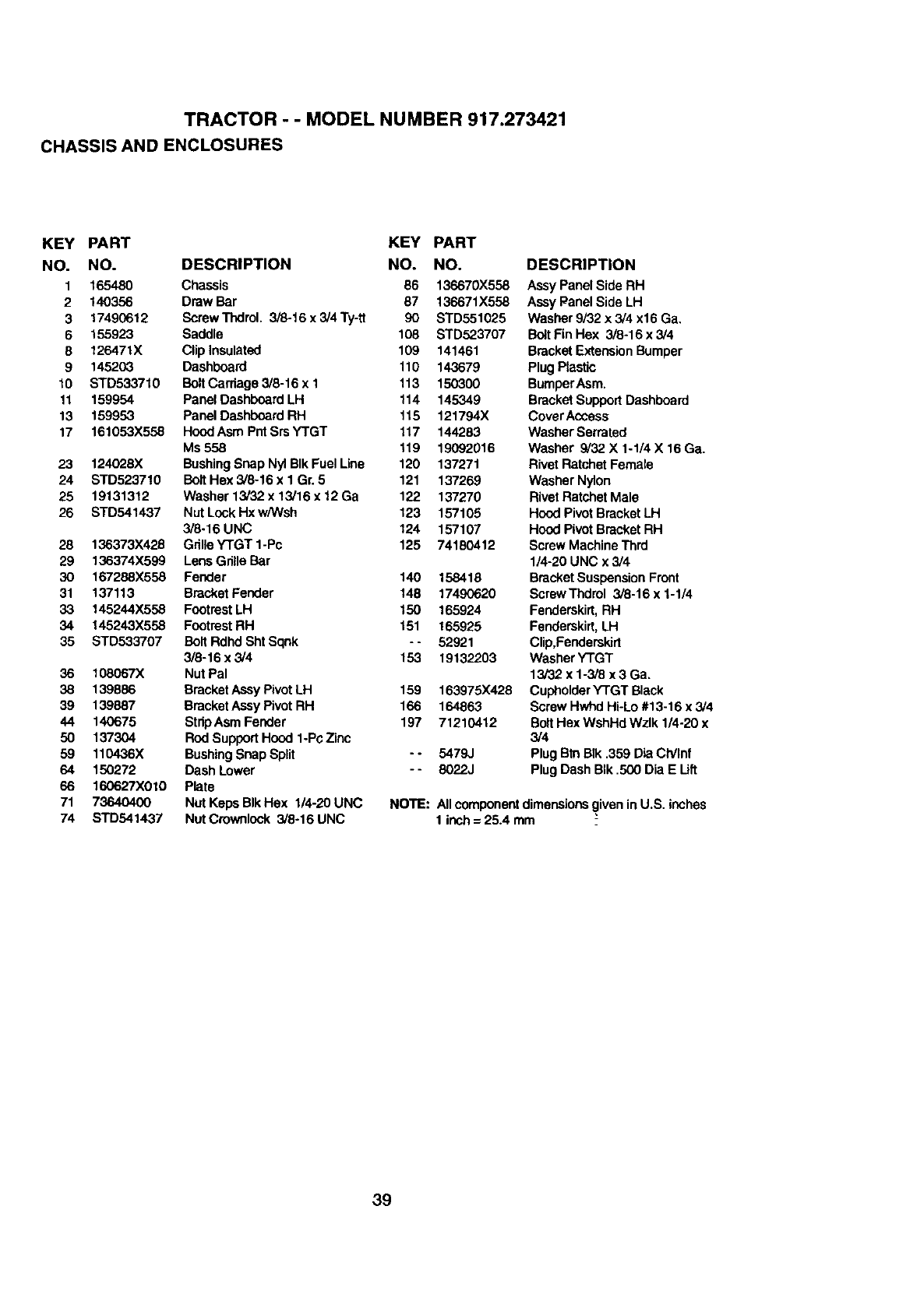
TRACTOR - - MODEL NUMBER 917.273421
CHASSIS AND ENCLOSURES
KEY PART KEY PART
NO. NO. DESCRIPTION NO. NO.
1165480 Chassis 86 136670X558
2140356 Drew Bar 87 136671X558
3 17490612 ScrewTndrol. 3/8-16x3!4Ty-ft 90 STD551025
6 155923 Saddle 108 STD523707
8 126471X Cliplnsulated 109 141461
9 145203 Dashboard 110 143679
10 STD533710 BoltCarriage 3/8-16 x1 113 150300
11 159954 Panel DashboardLH 114 145349
13 159953 PaneIDashboard RH 115 121794X
17 161053X558 HoodAsm PntSrsYTGT 117 144283
Ms558 !19 19092016
23 124028X BushingSnap Nyl BIk Fuel Line 120 137271
24 STD523710 BoltHex 3/8-16 x 1 Gr. 5 121 137269
25 19131312 Washer 13/32 x 13,'16x 12Ga 122 137270
26 STD541437 Nut Lock Hx w/Wsh 123 157105
3/8-16 UNC 124 157107
28 136373X426 Grille YTGT 1-Pc 125 74180412
29 136374X599 Lens Gdtle Bar
30 167288X558 Fender 140 158418
31 137113 Bracket Fender 148 17490620
33 145244X558 FootrestLH 150 165924
34 145243X558 FootrestRH 151 165925
35 STD533707 Bolt Rdhd Sht Sqnk - - 52921
3/8-16 x 3/4 153 19132203
36 108067X Nut Pal
38 139886 BracketAssy PivotLH 159 163975X428
39 139887 BracketAssy Pivot RH 166 164863
44 140675 StripAsm Fender 197 71210412
50 137304 Rod Support Hood 1-Pc Zinc
59 110436X BushingSnap Split - - 5479J
64 150272 Dash Lower - - 8022J
66 160627X010 Plate
71 73640400 Nut Keps BIk Hex 1/4-20 UNC NOTE:
74 STD541437 NutCrownlock 3/8-16 UNC
DESCRIPTION
Assy Panel Side RH
Assy Panel Side LH
Washer 9i32 x 3/4 x16 Ga.
Bo_tFin Hex 3/8-16 x 3/4
BracketExtensionBumper
Plug Plastic
BumperAsm.
Bracket SupportDashboard
Cover Access
Washer Serrated
Washer 3/32 X1-1/4 X 16 Ga.
Rivet Ratchet Female
Washer Nylon
Rivet Ratchet Male
Hood Pivot BracketLH
Hood Pivot BracketRH
Screw MachineThrd
1/4-20 UNC x 3/4
BracketSuspensionFront
ScrewThdrol 3/8-16 x 1-1/4
Fenderskirt,RH
Fenderskirt,LH
Clip,Fenderskirt
WasherYTGT
13/32 x 1-3/8 x 3 Ga.
CupholderY'rGT Black
Screw Hwhd Hi-Lo #13-16 x 3/4
Bolt Has WshHd Wzlk 1/4-20 x
3/4
Plug BtnBik .359 Bia CtYlnf
Plug Dash BIk .500 Dia E Lift
Allcomponentdimensionsgiven in U.S. inches
1 inch= 25.4 mm
39
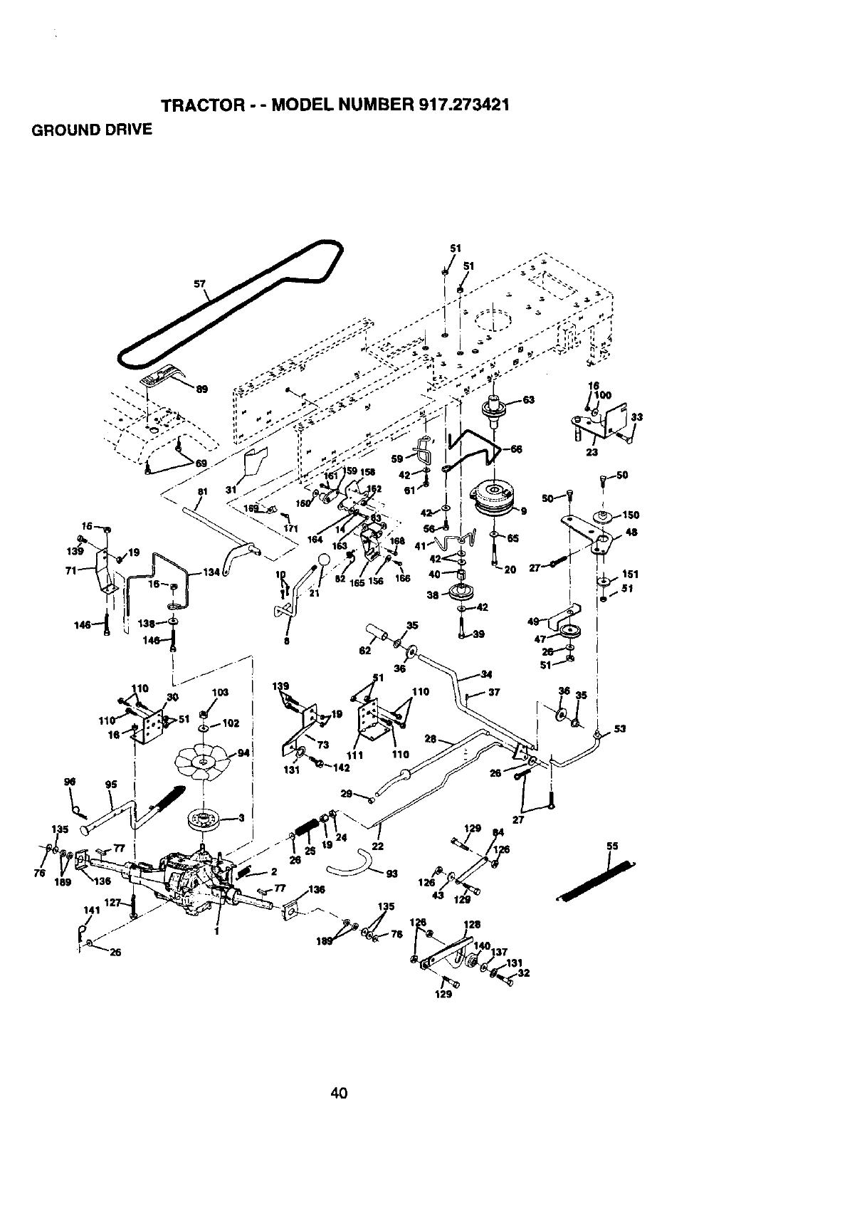
TRACTOR - - MODEL NUMBER 917.273421
GROUND DRIVE
189
/_..
27
93 1
135
1 128
1 76
31
129
4O
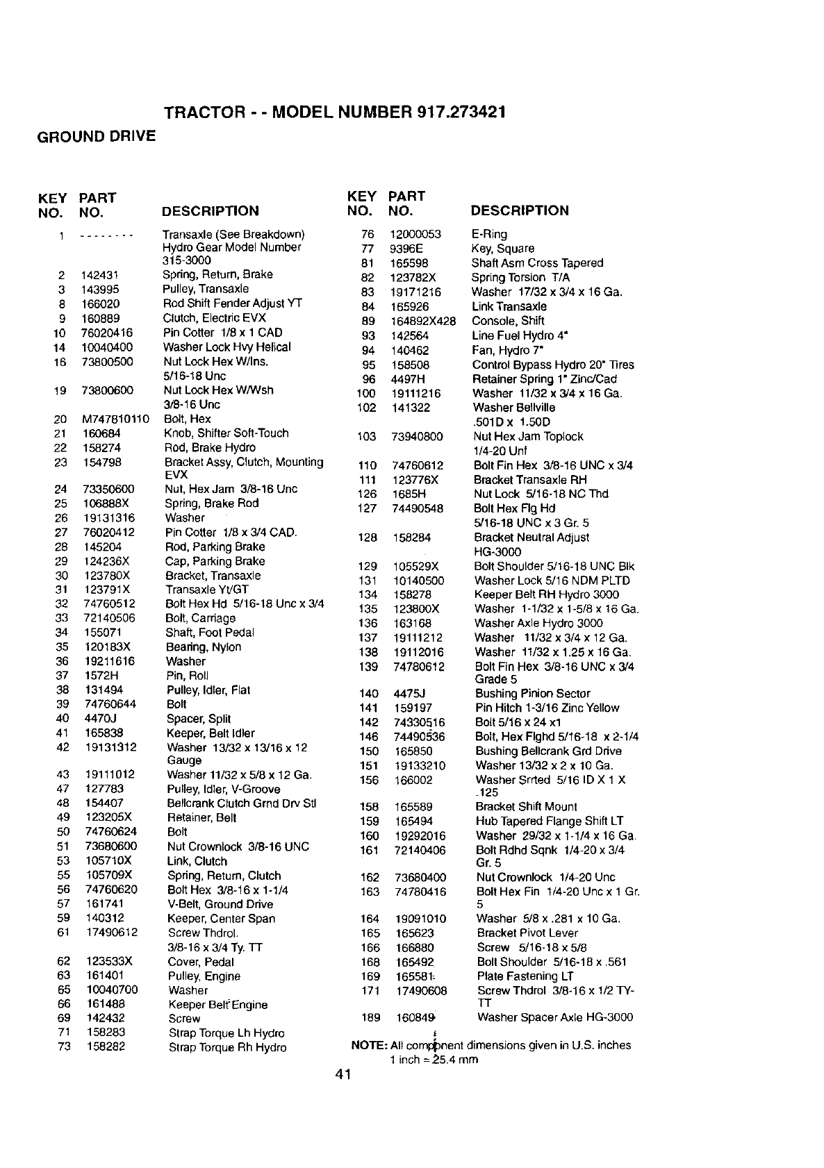
TRACTOR - - MODEL NUMBER 917.273421
GROUND DRIVE
KEY PART KEY PART
NO. NO. DESCRIPTION NO. NO.
1 ........ Transaxle(See Breakdown) 76 12000053
HydroGear Model Number 77 9396E
315-3000 81 165598
2 142431 Spdng, Return, Brake 82 123782X
3 143995 Pulley,Transaxle 83 19171216
8 166020 Rod Shift Fender Adjust Y3" 84 165926
9 160889 Clutch, Electric EVX 89 164892X428
10 76020416 Pin Cotter 1/8 x 1 CAD 93 142564
14 10040400 Washer Lock Hvy Helical 94 140462
16 73800500 Nut Lock Hex W/Ins. 95 158508
5/16-18 Uric 96 4497H
19 73800600 Nut Lock Hex W/Wsh 100 19111216
3/8-16 Unc 102 141322
20 M747810110 Bolt, Hex
21 160684 Knob, Shifter Soft-Touch 103 73940800
22 158274 Rod, Brake Hydro
23 154798 Bracket Assy, Clutch, Mounting 110 74760612
EVX 111 123776X
24 73350600 Nut, HexJam 3/8-16 Uric 126 1685H
25 106888X Spring, Brake Rod 127 74490548
26 19131316 Washer
27 76020412 Pin Cotter 1/6 x 3/4 CAD. 128 158284
28 145204 Rod, Parking Brake
29 124236X Cap, Parking Brake 129 105529X
30 123780X Bracket, Trensaxle 131 10140500
31 123791X Transaxle Yt]GT 134 158278
32 74760512 Bolt Hex Hd 5/16-18 Uric x 3/4 135 123800X
33 72140506 Bolt, Carriage 136 163168
34 155071 Shaft, Foot Pedal 137 19111212
35 120183X Bearing, Nylon 138 19112016
36 19211616 Washer 139 74780612
37 1572H Pin, Roll
38 131494 Pulley, Idler,Flat 140 4475,1
39 74760644 Bolt 141 159197
40 4470J Spacer, Split 142 74330516
41 165838 Keeper, Belt Idler 146 74490536
42 19131312 Washer 13/82 x 13/16x 12 150 165850
Gauge 151 19133210
43 19111012 Washer 11/32 x 5/8 x 12 Ga. 156 166002
47 127783 Pulley, Idler, V-Groove
48 154407 BellcrankClutch Grnd DrY Stl 156 165589
49 123205X Retainer, Belt 159 165494
50 74760624 Bolt 160 19292016
51 73680600 Nut Crownlock 3/8-16 UNC 161 72140406
53 105710X Link, Clutch
55 105709X Spring, Return, Clutch 162 73680400
56 74760620 Bolt Hex 3/8-16x 1-1/4 163 74780416
57 161741 V-Belt, Ground Ddve
59 140312 Keeper, Center Span 164 19091010
61 17490612 Scraw Thdrol. 165 165623
3/8-16 x 3/4 Ty. TI- 166 166880
62 123533X Cover, Pedal 168 165492
63 161401 Pulley, Engine 169 165581:
65 10040700 Washer 171 17490608
66 161488 Keeper Belt"Engine
69 142432 Screw 189 160849.
71 158283 Strap TorqueLh Hydro
73 158282 Strap Torque Rh Hydro
DESCRIPTION
E-Ring
Key, Square
Shaft Asm Cross Tapered
Spring Torsion T/A
Washer 17/32 x 3/4 x 16 Ga.
Link Transaxle
Console, Shift
Line Fuel Hydro 4"
Fan, Hydro 7"
Control Bypass Hydro 20" 33res
Retainer Spring 1" Zinc!Cad
Washer 11/32 x 3/4 x 16 Ga.
Washer Bellville
.501D x t.50D
Nut Hex Jam Toplock
1/4-20 Unf
Bolt Fin Hex 3/8-16 UNC x 3/4
Bracket Transaxle RH
Nut Lock 5/16-18 NC Thd
Bolt Hex Fig Hd
5/16-18 UNC x 3 Gr. 5
Bracket Neutral Adjust
HG-3000
Bolt Shoulder 5/16-18 UNC BIk
Washer Lock 5/16 NDM PLTD
Keeper Belt RH Hydro 3000
Washer 1-1/32 x 1-5/8 x 16 Ga.
Washer Axle Hydro 3000
Washer 11/32 x 3/4 x 12 Ga.
Washer 11/82 x 1.25 x 16 Ga.
Bolt Fin Hex 3/8-16 UNC x 3/4
Grade 5
BushingPinionSector
Pin Hitch 1-3/16 Zinc Yellow
Bolt 5/16 x 24 xl
Bolt, Hex Flghd 5/16-18 x 2-1/4
Bushing Bellcrank Grd Drive
Washer 13/82 x 2 x 10 Ga.
Washer Srrted 5/16 ID X 1 X
.125
Bracket Shift Mount
Hub Tapered Flange Shift LT
Washer 29/32 x 1-1/4 x 16 Ga.
Bolt Rdhd Sqnk 1/4-20 x 3/4
Gr. 5
Nut Crownlock 1/4-20 Unc
Bolt Hex Fin 1/4-20 Unc x 1 Gr.
5
Washer 5/8 x .281 x 10 Ga.
Bracket Pivot Lever
Screw 5/16-18 x 5/8
Bolt Shoulder 5/16-18 x .561
Plate Fastening LT
ScrewThdrol 3/6-16 x 1/2 TY-
TT
Washer Spacer Axle HG-3000
NOTE: All component dimensionsgiven inU.S. inches
1 inch =2.5.4 mm
41
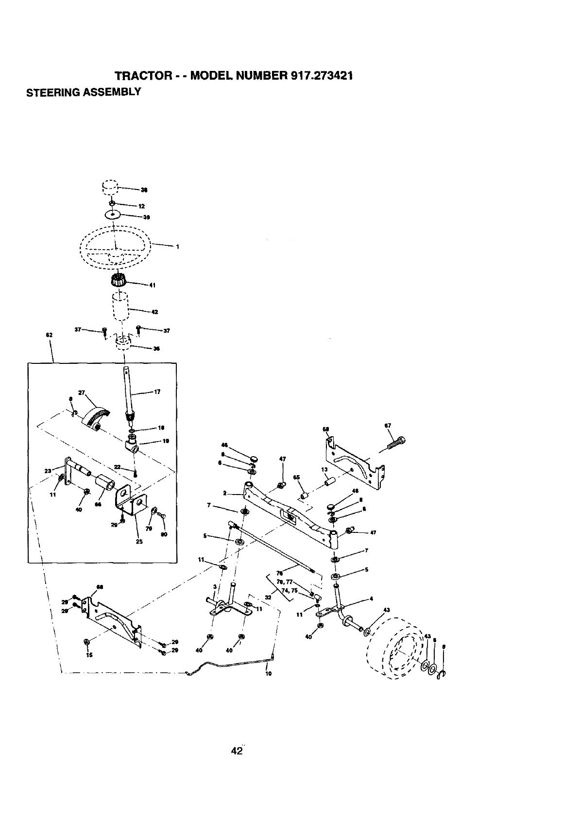
TRACTOR - - MODEL NUMBER 917.273421
STEERING ASSEMBLY
L)
,.-","------u
._ ..... t.. j1
) ..... ---- F
• ". L J .." 14
)
I •
I 7 "
42
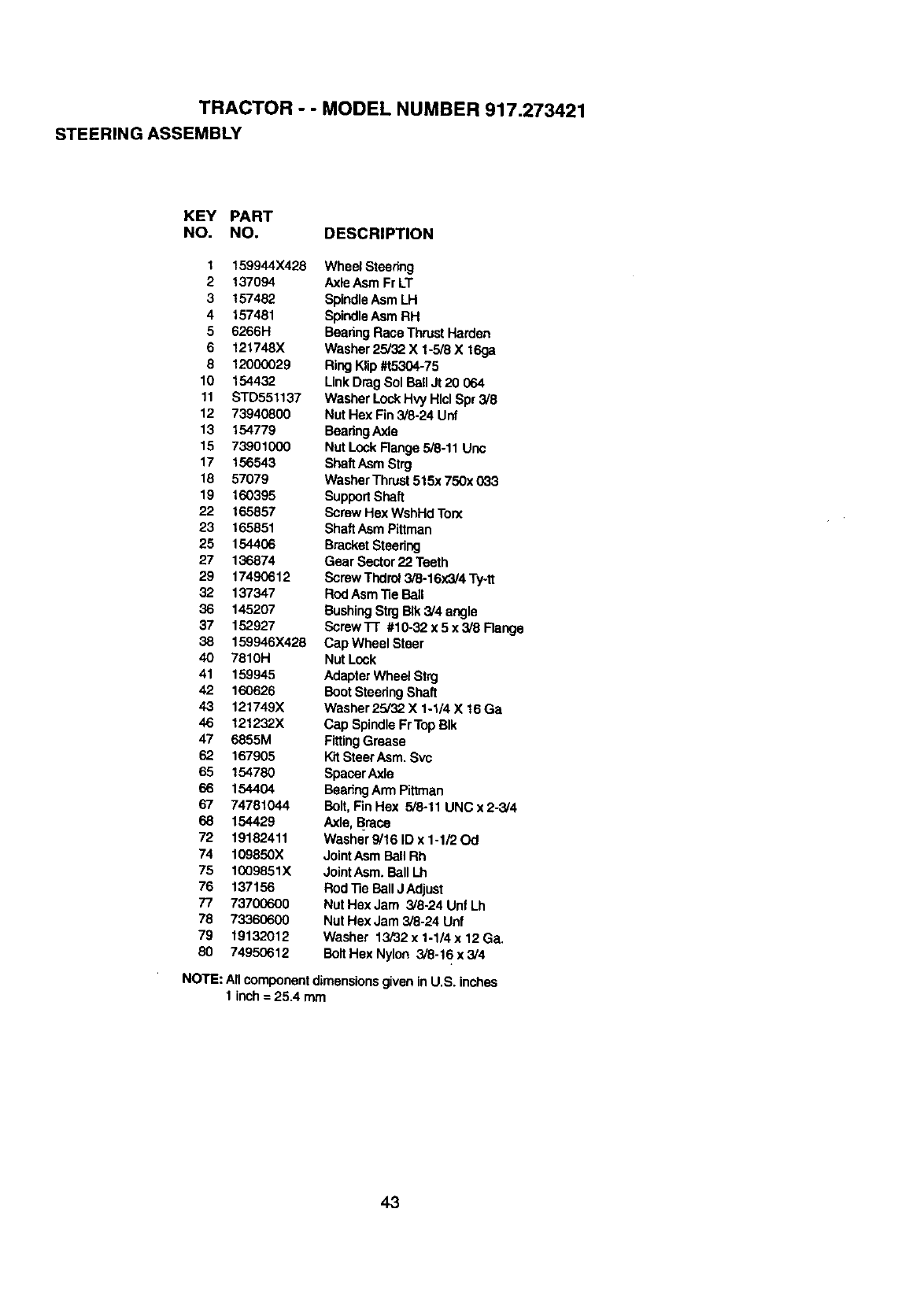
TRACTOR --MODEL NUMBER 917.273421
STEERING ASSEMBLY
KEY PART
NO. NO. DESCRIPTION
1 159944X428 Wheel Steadng
2 137094 AxleAsm Fr LT
3157482 SpindleAsm LH
4 157481 SpindleAsm RH
5 6266H BearingRace Thrust Harden
6 121748X Washer25/32 X1-5/8 X 16ga
8 12000029 Ring Klip#t5304-75
10 154432 Link Drag Sol BallJt 20 064
11 STD551137 Washer LockHv'j Hlcl Spr 3/8
12 73940800 Nut Hex Fin3/8-24 Unf
13 154779 BaadngAxle
15 73901000 Nut Lock Range 5/8-11 Unc
17 156543 ShaftAsm Strg
18 57079 WasherThrust515;<750x 033
19 160395 SupportShaft
22 165857 Screw Hex WshHd Torx
23 165851 ShaftAsm Pittman
25 154406 BracketSteedng
27 136874 Gear Sector 22 Teeth
29 17490612 Screw Thdrol3/8-16x3/4 Ty-tt
32 137347 Rod AsmTie Ball
36 145207 BushingStrgBIk 3/4 angle
37 152927 ScrewTr #10-32x5x3/8Range
38 159946X428 Cap Wheel Steer
40 7810H Nut Lock
41 159945 Adapter Wheel Strg
42 160626 BootSteedng Shaft
43 121749X Washer25/32 X 1-1/4 X 16Ga
46 121232X Cap SpindleFrTop BIk
47 6855M FittingGrease
62 167905 Kit SteerAsm. Svc
65 154780 Spacer Axle
66 154404 BeadngArm Pittman
67 74781044 Bolt, FinHex 5/8.11 UNC x 2-3/4
68 154429 Axle, Brace
72 19182411 Washer 9/16 ID x 1-1/20d
74 109850X JointAsm Ball Rh
75 1009851X JointAsm. BallLh
76 137156 ROd"13aBall J Adjust
77 73700600 Nut Hex Jam 3/8.24 Unf Lh
78 73360600 Nut Hex Jam 3/8-24 Unf
79 19132012 Washer 13/32 x 1-1/4 x 12 Ga.
80 74950612 Bolt Hex Nylon 3/8-16x3/4
NOTE: All componentdimensionsgiven inU.S. inches
1 inch= 25.4 mm
43
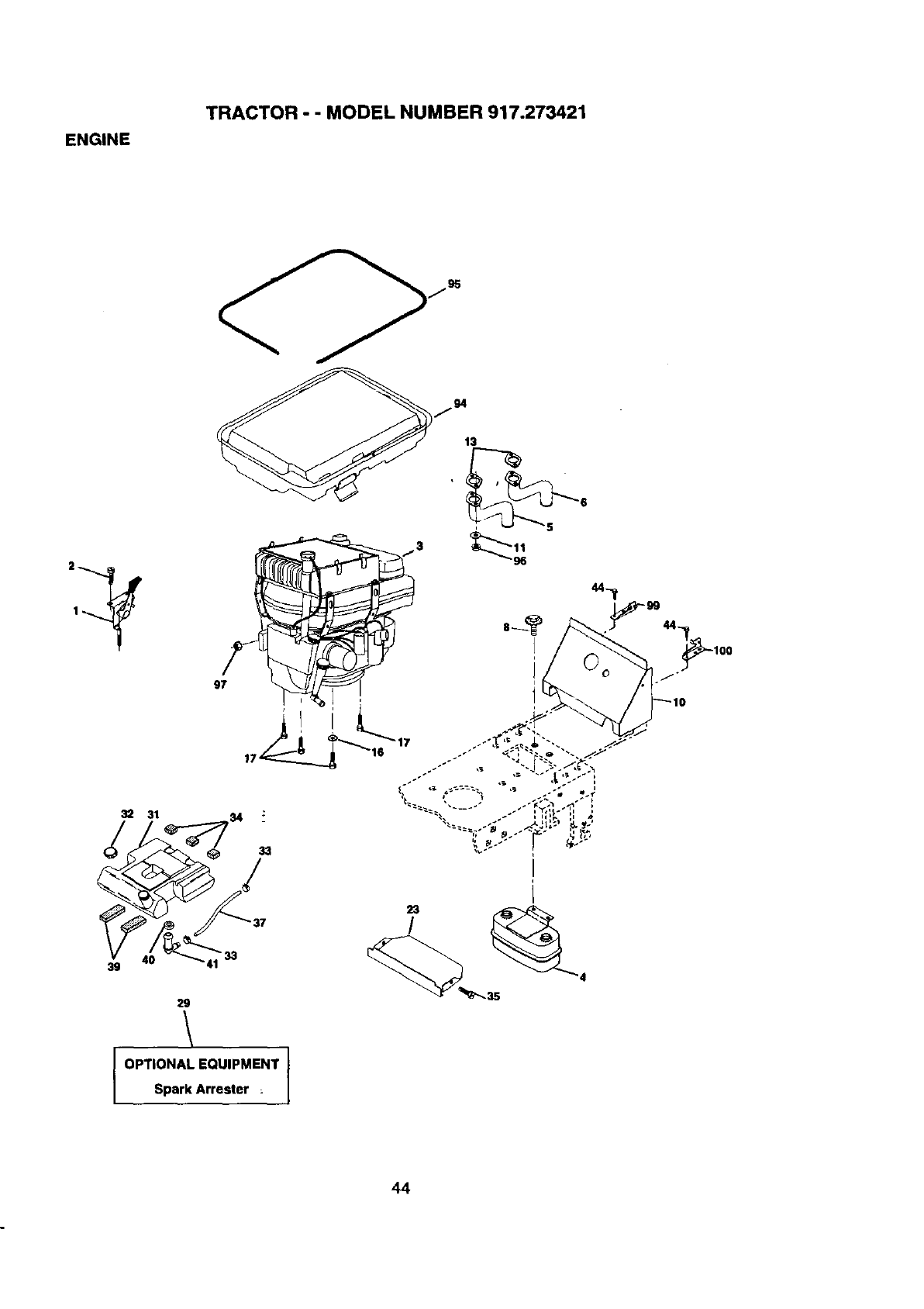
ENGINE
TRACTOR - - MODEL NUMBER 917.273421
32 31
j95
13
5
97
40 "33
39
29
OPTIONAL EQUIPMENT
Spark Arrester :
44
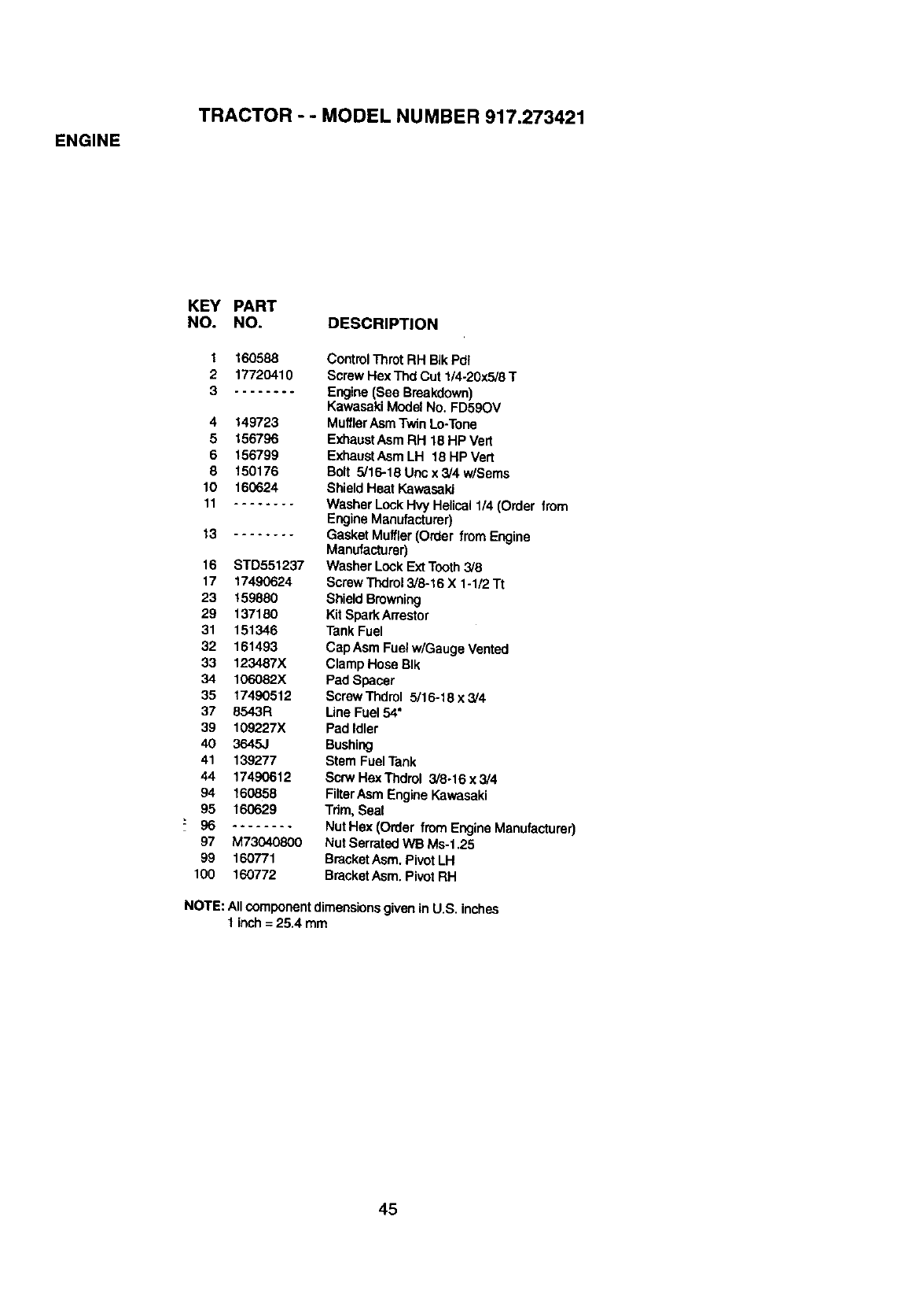
ENGINE
TRACTOR - - MODEL NUMBER 917.273421
KEY PART
NO. NO. DESCRIPTION
1160588
2 17720410
3....... .
4 149723
5'L56796
6 156799
8 150176
10 160624
11 ........
_3 ........
16 STD551237
17 17490624
23 159880
29 137180
31 151346
32 161493
33 123487X
34 106082X
35 17490512
37 8543R
39 109227X
40 3645J
41 139277
44 17490612
94 160858
95 160629
97 M73040800
99 160771
100 160772
Control Throt RH BIkPdl
Screw Hex Thd Cut 1/4-20x5/8 T
Engine (See Breakdown)
Kawasaki Model No. FD59OV
MufflerAsm Twin Lo-Tone
Exhaust Asm RH 1B HP Vert
ExhaustAsm LH 18 HP Vert
Bolt 5/16-18 Uric x 3/4 w/Sems
Sl'_eldHeat Kawasaki
Washer Lock Hvy Helical 1/4 (Order from
Engine Manufacturer)
Gasket Muffler (Order from Engine
Manufacturer)
Washer Lock Ext Tooth3/8
ScrewThdrol3/8-16 X 1-1/2 "It
ShieldBrowning
Kit SparkArrestor
Tank Fuel
Cap Asm Fuel w/Gauge Vented
Clamp Hose BIk
Pad Spacer
Screw Thdrol 5/16-18 x 3/4
Line Fuel 54"
Pad Idler
Bushing
Stem Fuel Tank
Scrw t-lexTl_lrol 3/8-15 x 3/4
FilterAsm Engine Kawasaki
Trim, Seal
NutHex (Order from Engine Manufacturer)
Nut Serrated WB Ms-1.25
BracketAsm. Pivot LH
BracketAsm. Ph,'olRH
NOTE: Allcomponentdimensionsgivenin U.S. inches
tinch= 25.4 mm
45
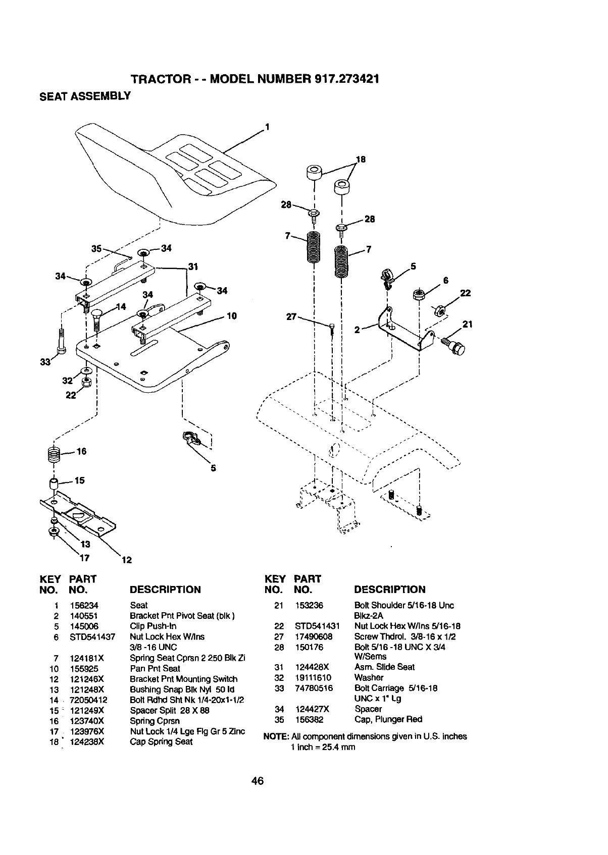
TRACTOR - - MODEL NUMBER 917.273421
SEAT ASSEMBLY
31
10
KEY PART
NO. NO.
1 156234
2 140551
5 145006
6 STD541437
7124181X
10 155925
12 121246X
13 121248X
14 72050412
15 121249X
16 123740X
17 123976X
15" 124235X
DESCRIPTION
Seat
Bracket Pnt Pivot Seat (blk)
Clip Push-In
Nut Lock Hex W/Ins
3/8 -16 UNC
Spdng Seat Cprsn 2 250 BIkZi
Pan Pnt Seat
Bracket Pnt MountingSwitch
BushingSnap BIk Nyl 50 Id
Bolt Rdhd ShtNk 1/4-20x1-1/2
Spacer Split 28 X 88
Spring Cprsn
Nat Lock 1/4 Lge Fig Gr 5 Zinc
Cap Spring Seat
5
21
KEY
NO. PART
NO. DESCRIPTION
21 15,3236 Boit Shoulder 5/16-18 Unc
Blkz-2A
22 STD541431 Nut Lock Hex W/Ins 5/16-18
27 17490608 ScrewThdrol. 3/8-16 x 1/2
28 150176 Bolt5/16 -18 UNC X 3/4
W/Sems
31 124428X Asm. Slide Seat
32 19111610 Washer
33 74780516 BoltCarriage 5/16-18
UNCx 1"Lg
34 124427X Spacer
35 156382 Cap, PlungerRed
NOTE: All component dimensions givenin U.S. inches
1 inch =25.4 mm
46
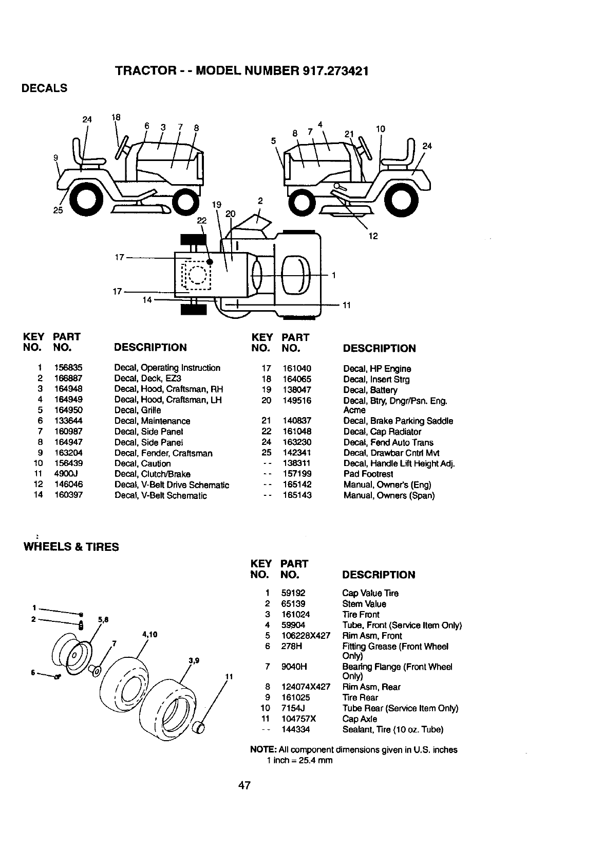
DECALS
TRACTOR --MODEL NUMBER 917.273421
24 18 4
6 3 7 8 6710
24
25
17
17 14'
19 2
12
1
11
KEY
NO.
1
2
3
4
5
6
7
8
9
10
11
12
14
PART
NO.
156835
166887
164948
164949
164950
133644
160987
164947
163204
156439
4900J
146046
160397
KEY PART
DESCRIPTION NO. NO.
Decal, Operating Instruction 17 161040
Decal, Deck, EZ3 18 164065
Decal, Hood, Craftsman, RH 19 138047
Decal, Hood, Craftsman, LH 20 149516
Decal, Gdtle
Decal, Maintenance 21 140837
Decal, Side Panel 22 161048
Decal, Side Panel 24 163230
Decal, Fender,Craftsman 25 142341
Decal, Caution - - 138311
Decal, Clutch/Brake - -157199
Decal, V-Be_tDriveSchematic - - 165142
Decal, V-Belt Schematic - - 165143
DESCRIPTION
Decal, HP Engine
Decal, InsertStrg
Decal, Battery
Decal, Btry,Dngr/Psn. Eng.
Acme
Decal, Brake Parking Saddle
Decal, Cap Radiator
Decal, FendAuto Trans
Decal, Dra'wbarCntfl Mvt
Decal, Handle Lift HeightAdj.
Pad Footrest
Manual, Owner's (Eng)
Manual, Owners (Span)
WHEELS & TIRES
4,10
KEY
NO.
1
2
3
4
5
6
11
8
9
10
11
PART
NO. DESCRIPTION
59192 Cap Value Tire
65139 Stem Value
161024 Tire Front
59904 T_oe, Front (Service item Only)
106228X427 RimAsm, Front
278H FittingGrease (FrontWheel
Only)
9040H Bearing Flange (FrontWheel
Only)
124074X427 Rim ASm,Rear
161025 _ra Rear
7154J Tube Rear (Service Item Only)
104757X Cap Axle
144334 Sealant, Tire (10 oz. Tube)
NOTE: All componentdimensionsgiven inU.S. inches
1 inch = 25.4 mm
47
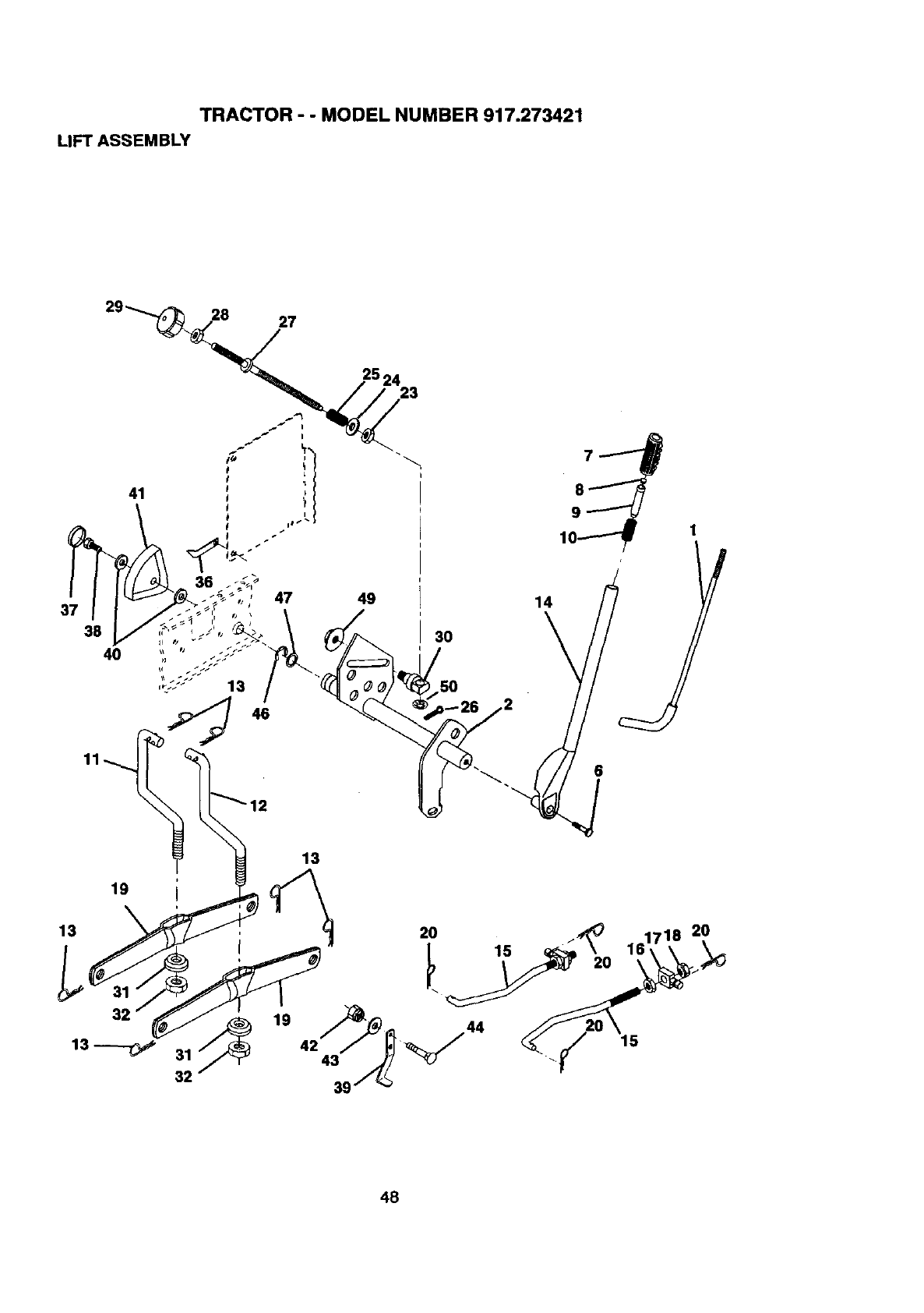
TRACTOR - - MODEL NUMBER 917.273421
LIFT ASSEMBLY
28 27
37
38
13
47
46
13
32
13_ 31_
32
19
42 43
39
2524 23
49
30
14
1
6
20
48
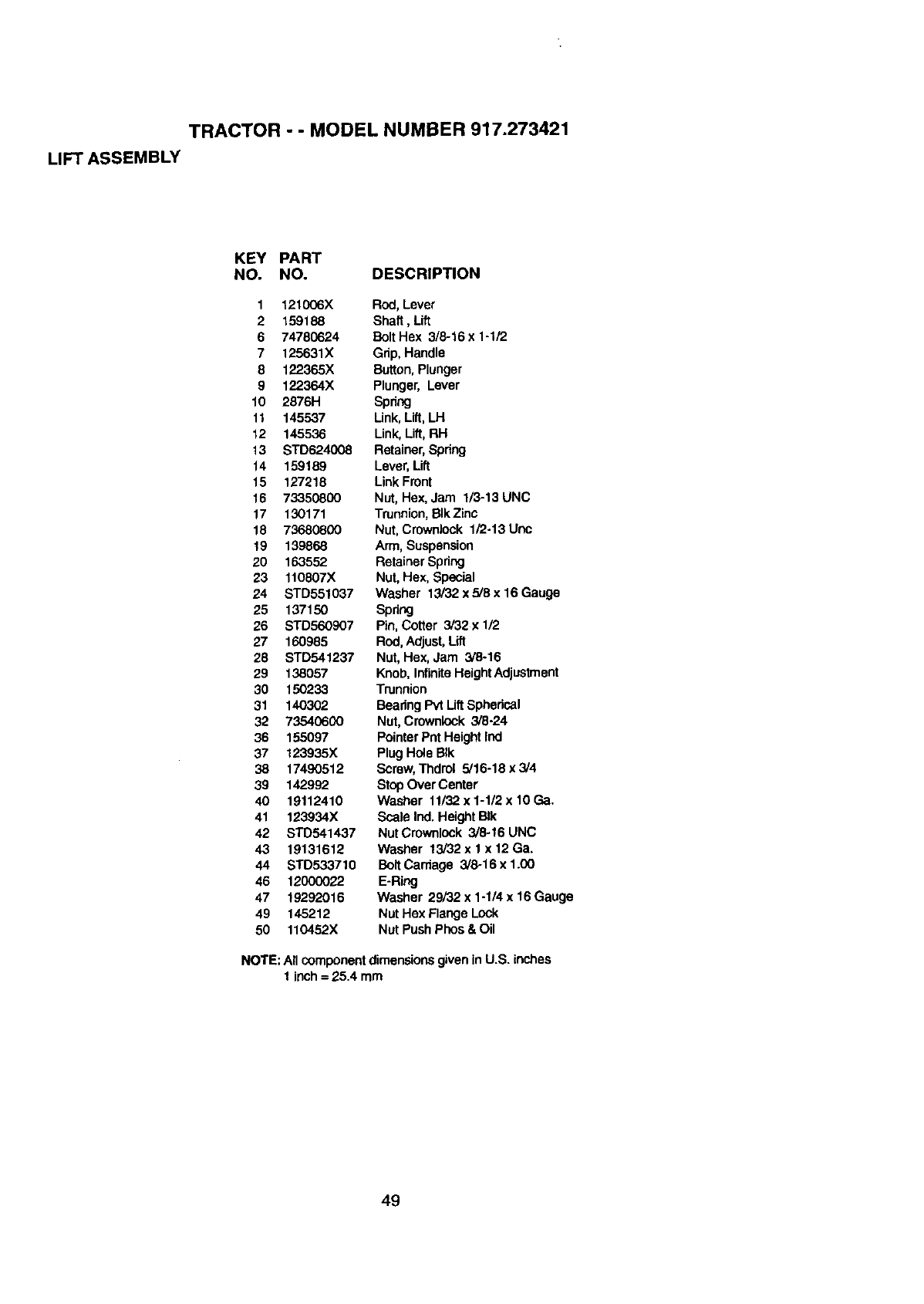
TRACTOR --MODEL NUMBER 917.273421
LIFT ASSEMBLY
KEY PART
NO. NO. DESCRIPTION
1121006X Rod, Lever
2159188 Shaft, Lift
6 74780624 Bolt Hex 3/8-16 x 1-1/2
7 125631X Grip, Handle
8 122365X Button,Plunger
9 122364X Plunger, Lever
10 2878H Spdng
11 145537 Link, Lift, LH
12 145536 Link, Lift, RH
13 STD624008 Retainer, Spring
14 159189 Lever, Lift
15 127218 Link Front
16 73350800 Nut, Hex, Jam 1/3-13 UNC
17 130171 Trunnion,BIkZinc
18 73680800 Nut, Crownlock 1/2-13 Uric
19 139868 Arm, Suspension
20 163552 Retainer Spring
23 110807X Nut, Hex, Special
24 STD551037 Washer 13/32 x 5,,8x 16 Gauge
25 137150 Spring
26 STD560907 Pin, Cotter 3/32x 1/2
27 160985 Rod, Adjust, Lift
28 STD541237 Nut, Hex, Jam 3/8-16
29 138057 Knob, Infinite HeightAdjus_ent
30 150233 Trunnion
31 140302 Bearing Pvt Uft Spherical
32 73540600 Nut, Crownlock 3/8-24
36 155097 Pointer Pnt Height Ind
37 123935X Plug Ho4eBIk
38 17490512 Scmw, Thdrol 5,'16-18x3/4
39 142992 StopOver Center
40 19112410 Washer 11132x1-112xlOGa,
41 123934X Scale Ind. Height BIk
42 STD541437 Nut Crownlock 3/8-16 UNC
43 19131612 Washer 13/32 x 1 x 12 Ga.
44 STD533710 BoltCardage 3/8-16 x 1.(30
46 12000022 E-Ring
47 19292016 Washer 29/32 x1-1/4 x16 Gauge
49 145212 Nut Hex Flange Lock
50 110452X Nut PushPhos & Oil
NOTE: All componentdimensionsgiven inU.S. inches
1inch = 25.4 mm
49
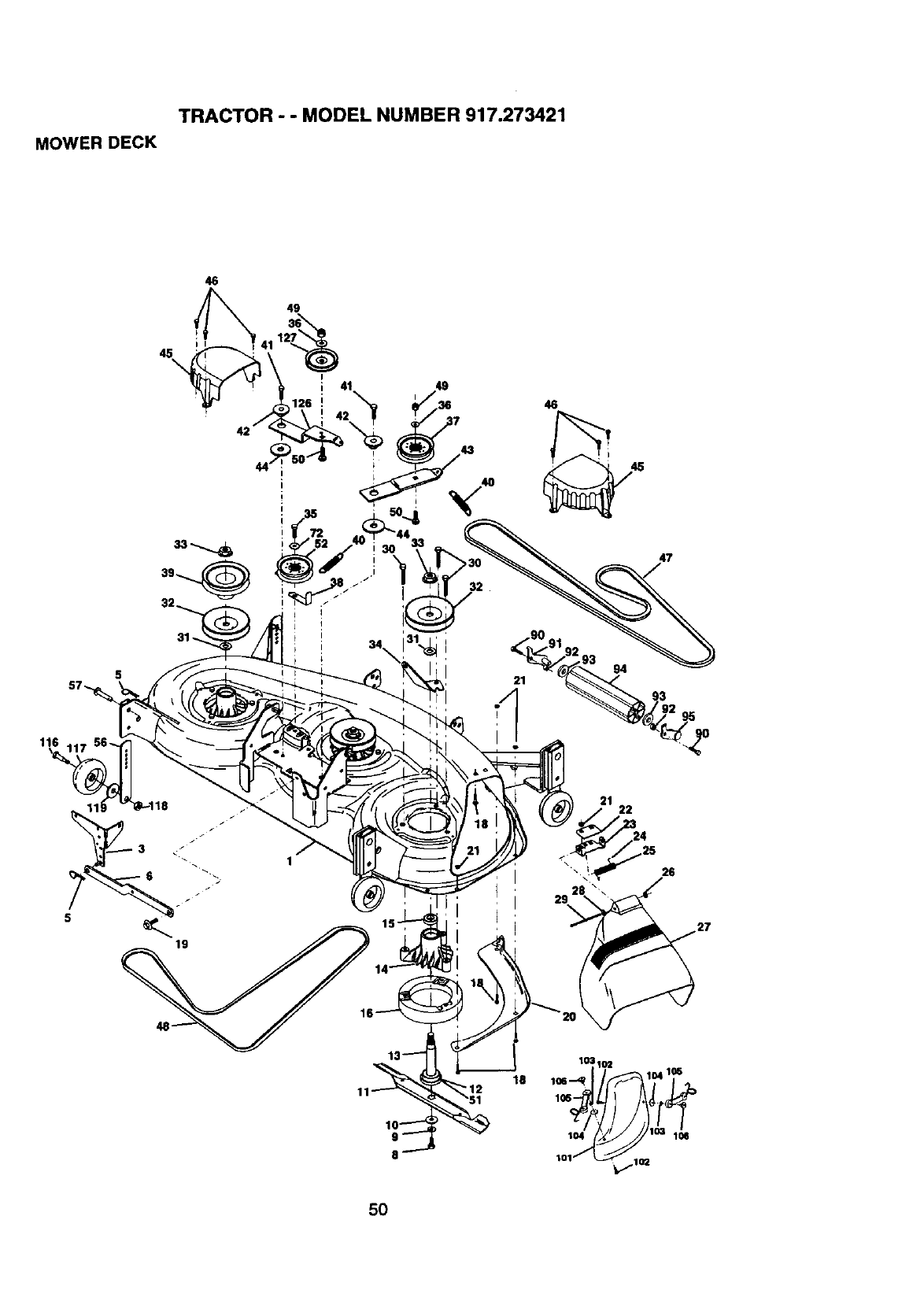
TRACTOR - - MODEL NUMBER 917.273421
MOWER DECK
46
45\
49
13%
126 i41 i49 7 46
42
47
31 -.
116
95
19
22
26
103192
18 11oe-4_ 1°4ms
lOl
5O
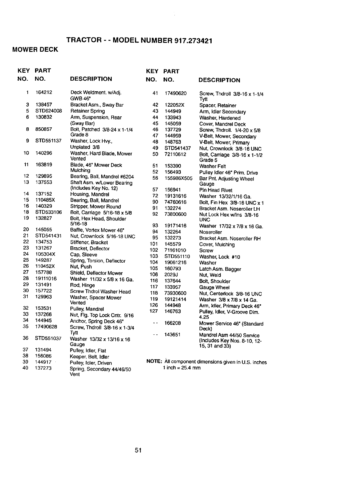
TRACTOR - -MODEL NUMBER 917.273421
MOWER DECK
KEY PART KEY PART
NO. NO. DESCRIPTION NO. NO.
3
5
6
8
9
10
11
t2
13
14
15
16
18
19
20
21
22
23
24
25
26
27
28
29
30
31
32
33
34
35
36
37
38
39
4O
164212 Deck Weldment. w/Adj. 41 17490620
GWB 46"
138457 Bracket Asm., Sway Bar 42 122052X
STD624008 Retainer Spring 43 144949
130832 Arm, Suspension, Rear 44 133943
(Sway Bar) 45 145059
850857 Bolt, Patched 3/8-24 x 1-1/4 46 137729
Grade 8 47 144959
STD551137 Washer, Lock Hvy., 48 148763
Unplated 3/8 49 STD541437
140296 Washer, Hard Blade, Mower 50 72110612
Vented
163819 Blade, 46" Mower Dock 51 153390
Mulching 52 156493
129895 Bearing, Ball, Mandrel#6204 56 155986X505
137553 Shaft Asm. w/Lower Bearing
(Includes Key No. t2) 57 156941
137152 Housing, Mandrel 72 19131616
110485X Bearing, Ball, Mandrel 90 74760616
140329 Stripper, Mower Round 91 132274
STD533106 Bolt, Cardage 5/16-18 x 5.i8 92 73800600
132827 Bolt, Hex Head, Shoulder
5/16-18 93 19171416
145055 Baffle, Vortex Mower46" 94 132264
STD541431 Nut, Crownlock 5/16-18 UNC 95 132273
134753 Stiffener, Bracket 101 145579
131267 Bracket, Deflector 102 71161010
t05304X Cap, Sleeve 103 STD551110
149287 Spring, Torsion, Deflector 104 19061216
110452X Nut, Push 105 160793
157788 Shield, Deflector Mower 106 2029J
19111016 Washer 11/32x 5/8 x 16 Ga. 116 137644
131491 Rod, Hinge 117 133957
157722 Screw Thdrol Washer Head 118 73930600
129963 Washer, Spacer Mower 119 19121414
Vented 126 144948
153531 Pulley, Mandrel 127 146763
137266 Nut, Fig. Top Lock Cntr. 9/16
144945 Anchor, Spring Deck46* -- 166208
17490628 Screw, Thdroll 3/8-16 x 1-3/4
Tytt - - 143651
STD551037 Washer 13/32 x 13/16 x 16
Gauge
131494 Pulley, Idler, Flat
156086 Keeper, Belt, Idler
144917 Pulley,Idler,Driven
137273 Spring, Secondary 44/46/50
Vent
DESCRIPTION
Screw, Thdroll 3/8-16 x 1-1/4
Tytt
Spacer, Retainer
Arm, Idler Secondary
Washer, Hardened
Cover, Mandrel Deck
Screw, Thdroll. 1/4-20 x 5/8
V-Belt, Mower, Secondary
V-Belt, Mower, Pdmary
Nut, Crownlock 3/8-16 UNC
Bolt, Carriage 3/8-16 x 1-1/2
Grade 5
Washer Felt
Pulley Idler 46" Pdm. Drive
Bar Pnt. Adjusting Wheel
Gauge
Pin Head Rivet
Washer 13/32/1/16 Ga.
Bolt, Fin Hex 3/8-16 UNC x 1
Bracket Asm. Noseroller LH
Nut Lock Hex w/Ins 3/8-16
UNC
Washer 17/32 x 7/8 x 16 Ga.
Noseroller
Bracket Asm. Noseroller RH
Cover, Mulching
Screw
Washer, Lock #10
Washer
Latch Asm. Bagger
Nut, Weld
Bolt, Shoulder
Gauge Wheel
Nut, Centedock 3/8-16 UNC
Washer 3/8 x 7/8 x 14 Ga.
Arm, Idler, Pdmary Deck 46"
Pulley, Idler, V-Groove Dim.
4.25
Mower Service 46" (Standard
Deck)
Mandrel Asm 44/50 Service
(Includes Key Nos. 8-10, 12-
15, 31 and 33)
NOTE: Allcomponent dimensions given in U.S. inches
1 inch = 25.4 mm
51
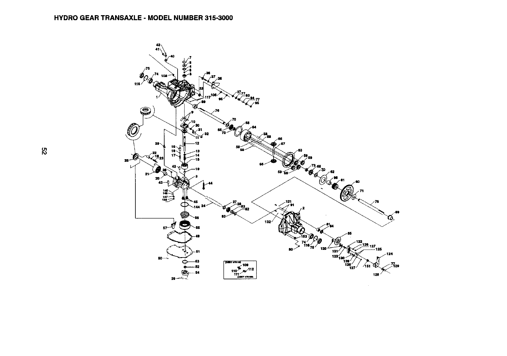
HYDRO GEAR TRANSAXLE - MODEL NUMBER 315-3000
oi

TRACTOR --MODEL NUMBER 917.273421
HYDRO GEAR TRANSAXLE -MODEL NUMBER 315-3000
KEY PART KEY PART
NO. NO. DESCRIPTION NO. NO. DESCRIPTION
KEY PART
NO. NO. DESCRIPTION
ol
1 161122 Main housingassembly .44 150797 Screw
2161123 RH housingassembly 49 161135 Gasket,lower
3161124 Center sectionaseembly 50 161136 Scraw-selftapping
4 161125 Spacer 51 161137 Lowercover
5 142932 Seal-lip 52 161138 Gerotorassembly
6 142928 Wire retainingring 53 144581 O-ring
7142933 Retainingring 54 161139 Gerotorcover
8 142934 Ball bearing 55 161140 Filter
9142935 Cradle bearing 56 161141 Charge manifold
10 142937 Variable swashplate 57 161142 Retainer,motorbearing
11 150771 Thrustbearing30 x 52 x 13 58 161143 Pin, carrier
12 161126 Inputshaft 59 161144 15t planet gear
13 142978 Blockthrust washer 60 161145 67t spurgear
14 142977 Block spring 61 161146 21 toothsun gear
15 142938 1Ococylindarblockassembly 62 161147 Planetthrustplate
21 142944 10occylinderblockassembly 63 161148 51t ringgear
24 161127 Output(motor)shaft 64 161149 Planetarycarrier
25 150773 Thrustbearing 42 x 68 x 16 65 161150 Miter gear.diff. (splined)
26 161128 Controlarm 66 161151 Mitergear, diff.
27 161129 Spacer 67 161152 Shaft,differential
"28 161130 16t piniongear 68 161153 Diff.thrustplate
29 161131 Capscrew, M6x 1-22 70 161154 Washer
30 142941 Slot guide 71 161155 Washer
31 161132 Trunnionarm 73 161156 Hexjam nut, 5/8-18
32 161133 Trunnionbushing 75 161157 Seal, 1"lDx2.0472xO.375
33 142940 Lipseal 76 161158 Shaft,axle
36 161134 5/16-24stud 77 142884 Washer
37 142967 Puck, friction 79 150801 Gasket material
38 150787 Bypass plate 80 161159 Torxhead screw,5/16-18
39 142946 Bypass actuator 81 161160 Needle bearing(SCE1412)
40 142945 Lipseal 82 161161 Washer
41 142952 Bypass arm 83 161162 Retainingring
42 142953 Retaining ring 84 161163 Lipseal (.8751.D. x 1.30.D.x.25)
_.'*.t lZ[_QRK Pin 85 161164 Brake disk
93 142969 Spring, friction pack
94 142980 Spacer, frictionpack
95 142957 Hex lock nut5/16-24
96 161165 Sleeve bearing
97 150798 OiE
106 161166 Spacer, trunnion
109 142918 Fitting-O ringassembly
111 142917 Cap-vent assembly
116 161167 Retaining ring
117 161168 Std hdlspin
120 142883 Puck, brake
122 161169 Brake yoke
123 161170 Bolt,square head
124 161171 Arm, brake
125 142887 Pins,brake
126 161172 Lockwasher, 1/4
127 161173 Nut, 1/4-20
128 142885 Nut, castle
129 142886 Cotter pin
130 161174 Spacer
131 142882 Puck plate
138 161175 Screw
139 161176 Washer, 7/80D x .2651D x.125
THK
144 161177 O ring,2.864 ID 0.070 THK
145 161178 Charge reliefspring
146 161179 Ball
147 161180 Plate, relief
151 161181 Comp. spring, brake anti-drag
153 142914 Plug, straightthread
NOTE: Allcomponentdimensions given in U.S. inches
1 inch= 25.4 mm
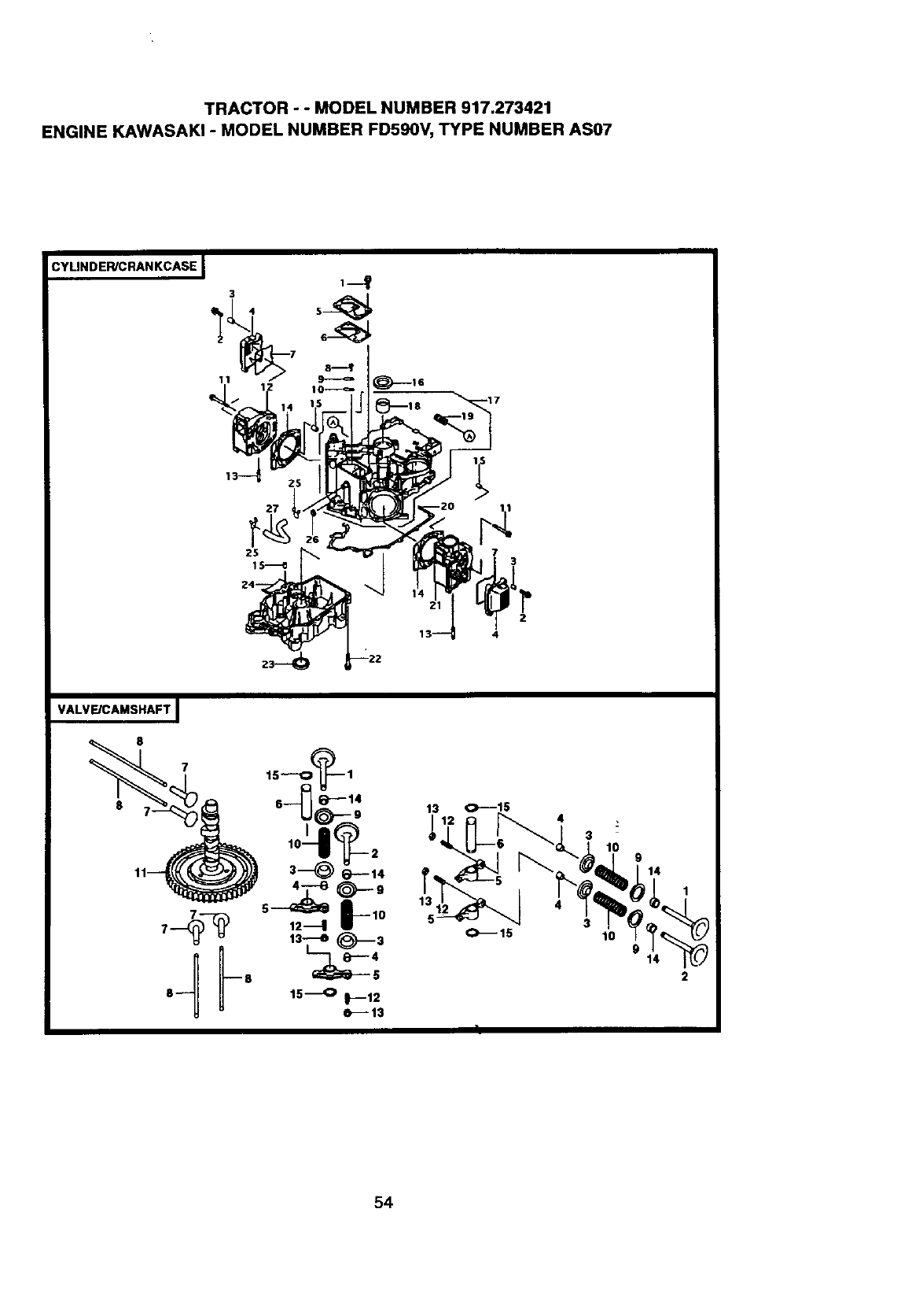
TRACTOR - - MODEL NUMBER 917.273421
ENGINE KAWASAK! - MODEL NUMBER FD590V, TYPE NUMBER AS07
CYLINDEWCRANKCASE I1--t
27
73
2
4
VALVE/CAMSHAFT I
13 O---15
_L_J_O'---_'_ 10 914
_'-_ "-4 _ r'O_,"_
9 14 "_
2
54

TRACTOR--MODEL NUMBER 917.273421
ENGINE KAWASAKI -MODEL NUMBER FD590V, TYPE NUMBER AS07
CYLINDER/CRANKCASE VALVE/CAMSHAFT
KEY PART KEY PART
NO. NO. DESCRIPTION NO. NO.
1 130B0816 Bolt.Flanged 1 12004-2106
2 130130625 Bolt-Flanged 2 12005-2094
3 92143-2010 Collar 3 12009-2067
4 11022-2056 Case-Rocker 4 12011-2056
5 14024-2109 Cover 5 12016-2056
6 11060-2074 Gasket 6 12020-2059
7 11060-2332 Gasket, RockerCase 7 12032-2064
8 92009-2308 Screw 8 13116-2057
9 13183-2120 Plate 9 39108-2057
10 16126-2146 Valve 10 49078-2071
11 130G0865 Bolt-Flanged 11 49118-2063
12 11008-2066 Head-Comp.Cylinder 12 92009-1109
13 92004-2141 Stud 13 92015-1137
14 11004-2098 Gasket-Head 14 92049-2109
15 92043-1037 Pin 15 480J1200
16 92049-2110 Seal-Oil
17 49120-6070 Crankcase-Comp
18 92141-2110 Bearing-Plane
19 59071-2079 Joint
20 11060-2284 Gasket,Crankcase Cover
21 11008-6005 Head-comp-Cylinder
22 130G0845 Bolt-Flanged
23 92049-2112 Seal-Oil
24 49015-6200 Cover-Crankcase
25 92170-2002 Clamp
26 92049-2097 Seal-Oil
27 92190-2145 Tube
DESCRIPTION
Valve-Intake
Valve-Exhaust
Retainer-ValveSpring
Collet
Arm-Rocker
Shaft-Rocker
Tappet
Rod-Push
Retainer-Spring
Spring-EngineValve
Camshaft-Comp
Screw
Nut
Seal-Oil
Circlip
55
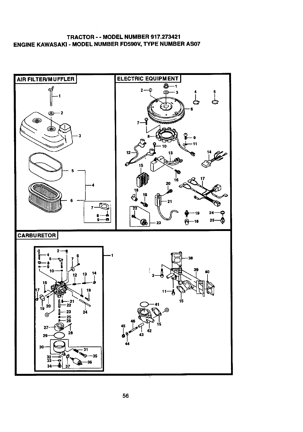
TRACTOR- - MODELNUMBER917.273421
ENGINEKAWASAKI-MODEL NUMBER FD590V, TYPE NUMBER AS07
AIR FILTER/M U FFLER J
CARBU RETOR J
B4
ELECTRIC EQUIPM ENT I
2---_ _---3 4 5
13
3
15
C_--41
,5,__ 15
42
44
56

TRACTOR- - MODEL NUMBER 917.273421
ENGINE KAWASAKI -MODEL NUMBER FD590V, TYPE NUMBER AS07
AIR FILTER/MUFFLER CARBURETOR
KEY PART KEY PART
NO. NO. DESCRIPTION NO. NO. DESCRIPTION
1 92150-2004 Bolt
2 92022-1545 Washer
3 11011-2193 Case-Air Filter
4 11029-2001 Elament-Assy-AirFilter
5 11013-2114 Element-AirfFilter
6 11013-2115 Element-AirFUter
7 11060-2079 Gasket-Mufflrt
8 461F0600 Washer-Sprfng
9 311G0600 Nut-Hex
ELECTRIC EQUIPMENT
DESCRIPTION
KEY PART
NO. NO.
1 92015-2167 Nut
2 510A5100 Key-Woodruff
3 92022-2245 Washer
4 92072-1195 Band
5 92072-2003 Bond
6 21193-2148 FlywheeI-Assy
7 92009-2273 Screw
6 59031-2122 Coil-Charging
9 214B0510 Screw-Pan
10 225B0414 Screw-Pan-WSP-CROS
11 92037-2208 Clamp
12 59026-2054 Coil-Pulsing
13 21119-2120 Igniter
14 26030-2234 Harness
15 21066-2070 Regulator-Voltage
16 130B0614 Bolt-Ranged
17 26030-2246 Hamess
18 21130-2060 Cap-Spa,k-Plug
19 92070-2060 PlugSpark,BMR6A
(NGK),BOlid
20 130B0520 Bolt-Flanged
21 21121-2083 Coil-Ignition
22 241B0406 Screw-Pan-WP
23 27010-2170 Switch
24 11009-2766 Gasket
25 27010-2181 Switch
1 15003-2620 Carburetor-Assy
2 92064-2102 Jet-Pilot #37.5
3 130B0645 Bolt-Flanged
4 16041-2235 Shaft-Carburetor
5 16041-2170 Shaft-Carburetor, Throttl
6 92009-2080 Screw
7 16025-2192 Valve-Throttle#145
8 92027-2004 Collar
9 92027-2003 Collar
10 92093-2002 Seal
11 130B0620 Bolt-Flaeged
12 92081-2009 Spring
13 16014-2075 Borew-Pilot Air
14 39076-2053 Umitar
15 11060-2076 Gasket,intake Pipe
16 16035-2062 Jet-Air #1.3
17 92009-2081 Screw
18 214130414 Screw-Pan
19 16126-2147 Valve,Choke
20 16035-2055 Jet-Air #1.0
21 16030-2076 Valve-Float
22 49121-2100 Nozzle-Main #18A
23 49121-2101 Nozzle-Main #18A
24 92191-2018 Tube
25 49123-2015 Holder-Main Jet
26 92063-2305 Jet-Main #112.5
27 16031-2065 Float
28 92043-2006 Pin
29 11009-2024 Gasket
:30 16020-2135 Chamber-Float
31 92144-2174 Spring
32 92055-2148 O Ring
33 11009-2769 Gasket
34 92150-2250 Bolt
35 92009-2025 Screw
36 21186-2009 Solenoid
37 92022-2231 Washer
38 11060-2077 Gasket
39 59076-2053 Manifold-Intake
40 11060-2078 Gasket
41 670B3036 O Ring
42 16060-2127 Pipe-Intake
43 92143-2011 Collar
44 92022-2373 Washer 6.2 x 15 x 1.2
45 92015-1193 Nut
46 172G0695 Bolt-Stud
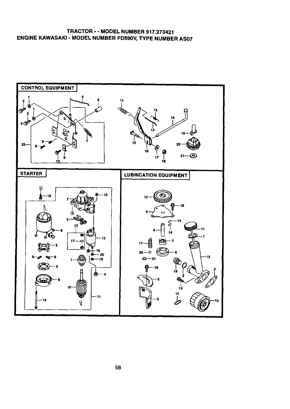
TRACTOR - - MODEL NUMBER 917.273421
ENGINE KAWASAK! -MODEL NUMBER FD590V, TYPE NUMBER AS07
45
9
1o
STARTER J
11
II
LUBRICATION EQUIPM ENT I
58
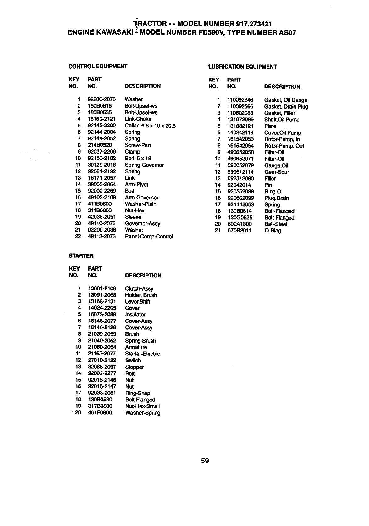
;iRACTOR - - NUMBER 917.273421
MODEL
ENGINE KAWASAKI ;MODEL NUMBER FD590V, TYPE NUMBER AS07
CONTROL EQUIPMENT LUBRICATION EQUIPMENT
KEY PART KEY PART
NO. NO. DESCRIPTION NO. NO.
1 92200-2070 Washer 1 110092346
2 180B0616 Bolt-Upset-ws 2 110092566
3 180B0635 Bolt-Upset-ws 3 1106_2083
4 16169-2121 Unk-Choke 4 131072099
5 92143-2200 Collar 6.8 x 10 x 20.5 5 131832121
6 92144-2004 Spdng 6 140242113
7 92144-2052 Spring 7 161542053
8 214B0520 Screw-Pan 8 161542054
9 92037-2209 Clamp 9 490652058
10 92150-2182 Bolt 5x18 10 490652071
11 39129-2018 Spring-Governor 11 520052079
12 92081-2192 Spdn_ 12 590512114
13 16171-2057 Unk 13 592312080
14 39003-2064 Arm-Pivot 14 92042014
15 92002-2269 Bolt 15 920552086
16 49103-2108 Arm-Governor 16 920662099
17 411B0600 Washer-Plain 17 921442053
18 311B0600 Nut-Hex 18 130B0614
19 4L:_)36-2051 Sleeve 19 130G0625
20 49110-2073 Governor-Assy 20 600A1300
21 92200-2036 Washer 21 670B2011
22 49113-2073 PaneI-Comp-Control
DESCRIPTION
Gasket, Oil Gauge
Gasket, Drain Ping
Gasket, Filler
Shaft.Oil Pump
Plate
Cover,Oil Pump
Rotor-Pump,In
Rotor-Pump,Out
Filter-Oil
Filter-Oil
Gauge,Oil
Gear-Spur
Filler
Pin
Ring-O
Plug,Drein
Spdng
Bolt-Flanged
Bolt-Ranged
BalI-Steet
O Ring
STARTER
KEY PART
NO. NO. DESCRIPTION
1 13081-2108 Clutch-Assy
2 13091-2068 Holder, Brash
3 13168-2131 Lever,Shift
4 14024-2205 Cover
5 16073-2098 Insulator
6 16146-2077 Cover-Assy
7 16146-2128 Cover-Assy
8 21039-2059 Brush
9 21040-2052 Spring-Brush
10 21080-2054 Armature
11 21163-2077 Starter-Electric
12 27010-2122 Switch
13 32085-2097 Stopper
14 92002-2277 Bolt
15 92015-2146 NUt
16 92015-2147 Nut
17 92033-2081 Ring-Snap
18 130B0830 Bolt-Flanged
19 317B0800 Nut-Hex-Small
• 20 461F0800 Washer-Spring
59
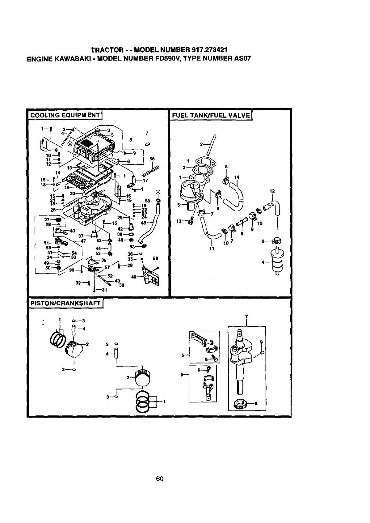
TRACTOR - - MODEL NUMBER 917.273421
ENGINE KAWASAKI - MODEL NUMBER FD590V, TYPE NUMBER AS07
EQUIPM ENT I
COOLING
1---t 7
!
FU EL TAN KJFU EL VALV E
8
14
11
12
PISTON/CRANKSHAFT I
:1 0----3
3_
L
7
Ii
6O
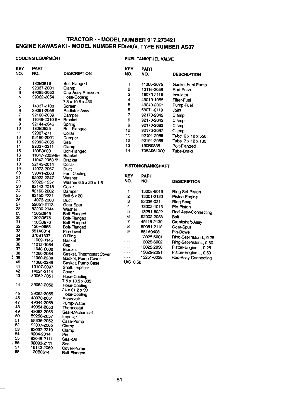
TRACTOR - - MODEL NUMBER 917.273421
ENGINE KAWASAKI - MODEL NUMBER FD590V, TYPE NUMBER AS07
COOLING EQUIPMENT FUEL TANK/FUEL VALVE
KEY PART KEY PART
NO. NO. DESCRIPTION NO. NO. DESCRIPTION
1130B0816
292037-2001
3 49085-2052
439062-2054
5 14037-2108
6 39061-2068
7 92160-2039
811046-2010-9H
9 92144-2346
10 130B0825
11 92027-271
12 92160-2001
13 92093-2085
14 92037-2211
15 130B0620
16 11047-2059-9H
17 11047-2058-9H
18 92143-2014
19 14073-2067
20 59041-2063
21 92022-2247
22 92022-1557
23 92143-2013
24 92160-2002
25 92150-2231
26 14073-2068
27 59051-2113
28 92200-2044
29 130G0645
30 130G0675
31 130G0870
32 130H0665
33 551A0314
34 670B1507
35 11009-1145
36 11012-1084
37 11046-2008
38 11060-2084
!39 11060-2288
40 11060-2289
41 13107-2097
42 14024-2114
43 39062-2051
44 39062-2052
45 39062-2055
46 43078-2051
47 49044-2058
48 49054-2053
49 49063-2056
50 59256-2057
51 59336-2052
52 92037-2065
53 92037-2210
54 9204-2014
55 92049-2111
56 92093-2111
57 16142-2069
58 130130614
Bolt-Flanged 1 11060-2075
Clamp 2 13116-2058
Cap-Assy-Pressera 3 16073-2116
Hose-Cooling
7.5 x 10.5 x 460 4 49019-1055
Screen 5 49040-2061
Radiator-Assy 6 59071-2119
Damper 7 92170-2042
Bracket 8 92170-2043
Spdng 9 92170-2082
Bolt-Flanged 10 92170-2097
Collar 11 92191-2056
Damper
Seal 12 92191-2059
Clamp 13 130B0835
Bolt-Flanged 14 705A061000
Bracket
Bracket
Collar PISTON/CRANKSHAFT
Duct
Fan, Cooling
Washer KEY PART
Washer 6,5 x 20 x 1,6 NO. NO.
Collar
Damper 1 13008-6016
Bolt 6 x 20 2 13001-2123
Duct 3 92036-021
Gear-Spur 4 13002-1013
Washer 5 13251-6022
Bolt-Flanged
Bolt-Flanged 6 92002-2053
Bolt-Flangod 7 49119-2130
Bolt-Flanged 8 59051-2112
Pin-dowel 9 551A0408
O Ring - - - 13025-6001
Gasket - - - 13025-6002
Cap - - - 13029-2090
Bracket
Gasket, Thermostat Cover - - - 13029-2091
Gasket, Pump Cover - - - 13251-6026
Gasket, Pump Case U/S--0.50
Shaft, Impeller
Cover
Hose-Cooling
7.5 x 13.5 x 305
Hose-Cooling
24 x 31.2 x 90
Hose-Cooling
Reservoir
Pump-Water
Thermostat
Seal-Mechanical
Impeller
Case-Pump
Clamp
Clamp
Pin
Seal-Oil
Seal
Cover-Pump
Bolt-Flanged
Gasket,Fuel Pump
Rod-Push
Insulator
Filter-Fuel
Pump-Fuel
Joint
Clamp
Clamp
Clamp
Clamp
Tube 6x 10x550
Tube 7x 12x130
Bolt-Flanged
Tube-Braid
DESCRIPTION
Ring-Set-Piston
Piston-Engine
Ring-Snap
Pin-Piston
Rod-Assy-Connecting
Bolt
Crankshaft-Assy
Gear-Spur
Pin-Dowel
Ring-Set-PistonL, 0.25
Ring-Set-PistonL,0.50
Piston-EngineL, 0.25
Piston-EngineL, 0.50
Rod-Assy-Connecting
61

62
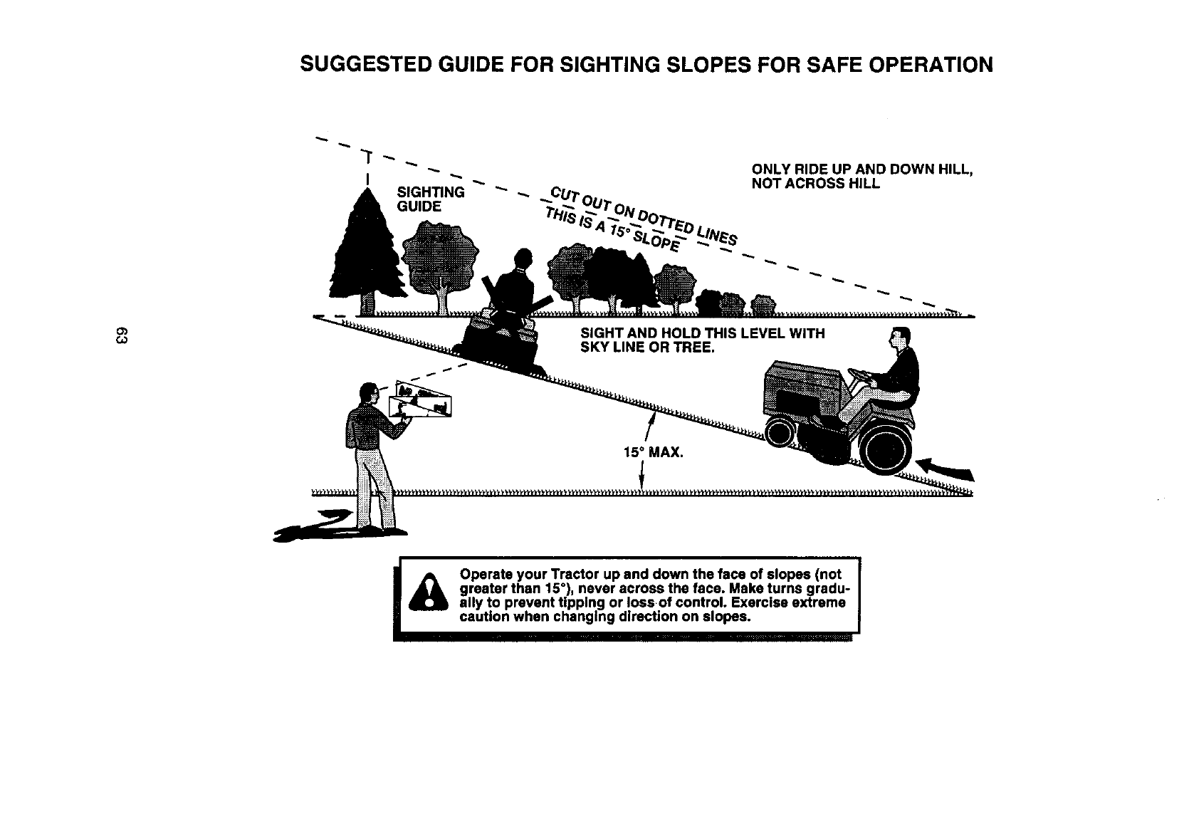
SUGGESTED GUIDE FOR SIGHTING SLOPES FOR SAFE OPERATION
_T _ ONLY RIDE UP AND DOWN HILL,
NOT ACROSS HILL
c_
G_
iA Operate your Tractor up and down the face of slopes (not
greater than 15°), never across the face. Make turns gradu-
ally to prevent tipping or loss of control. Exercise extreme
caution when changing direction on slopes.

For in-home major brand repair service:
Call 24 hours a day, 7 days a week
1-800-4-MY-HOME sM(1-800-469-4663)
Para pedir servicio de reparaci6n a domicUio
1-800-676-5811
In Canada for all your service and parts needs call
Au Canada pour tout le service ou les pi_ces
1-800-665-4455
For the repair or replacement parts you need:
Call 6 am-11 pm CST, 7 ,days a week
PartsDirects"
1-800-366-PART (1-800-366-7278)
Para ordenar piezas con entrega a domicilio
1-800-659-7084
For the location of a Sears Parts and Repair Center
in your area:
Call 24 Hours a day, 7 days a week
1-800-488-1222
For information on purchasing a Sears Maintenance
Agreement or to inquire about an existing Agreement:
Call 9 am-5 pm, Monday -Saturday
1-800-827-6655
SEAR8
HomeCentralsM
165142 Rev. 3 2.19.99 RH Printed in U.S.A.
