Craftsman 917274951 User Manual LAWN TRACTOR Manuals And Guides L0104115
CRAFTSMAN Lawn, Tractor Manual L0104115 CRAFTSMAN Lawn, Tractor Owner's Manual, CRAFTSMAN Lawn, Tractor installation guides
User Manual: Craftsman 917274951 917274951 CRAFTSMAN LAWN TRACTOR - Manuals and Guides View the owners manual for your CRAFTSMAN LAWN TRACTOR #917274951. Home:Lawn & Garden Parts:Craftsman Parts:Craftsman LAWN TRACTOR Manual
Open the PDF directly: View PDF ![]() .
.
Page Count: 60
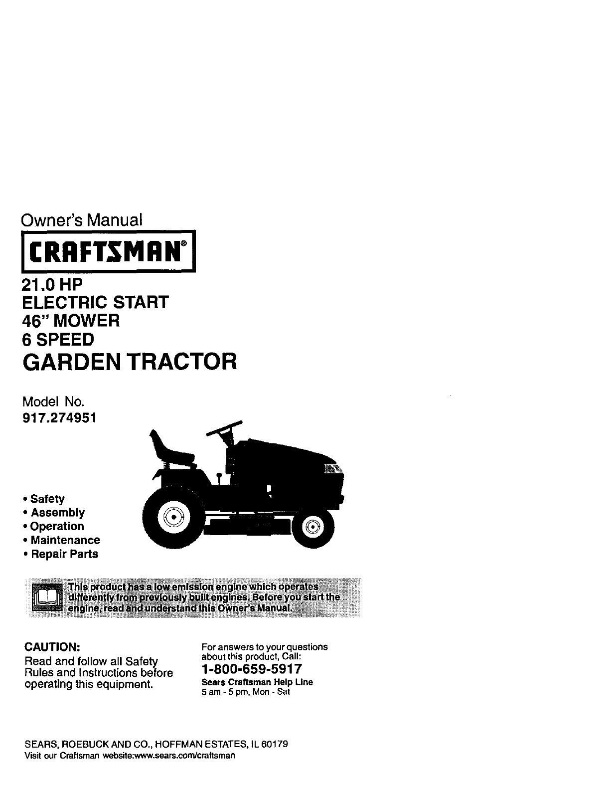
Owner's Manual
JCRRFTSMIIN°I
21.0 HP
ELECTRIC START
46" MOWER
6 SPEED
GARDEN TRACTOR
Model No.
917.274951
•Safety
•Assembly
•Operation
•Maintenance
•Repair Parts
CAUTION:
Read and follow all Safety
Rules and Instructions before
operating this equipment.
For answers to your questions
about this product,Call:
1-800-659-5917
Sears Craftsman Help Line
5 am -5 pro, Mon- Sat
SEARS, ROEBUCK AND CO., HOFFMAN ESTATES, IL 60179
Visit our Craftsmanwebsite:www.sears,conYcraftsman
Warranty ............................................... 2
Safety Rules ......................................... 3
Product Specifications .......................... 6
Assembly .............................................. 8
Operation ............................................ 12
Maintenance Schedule ...................... 18
Maintenance ....................................... 18
Service and Adjustments .................... 22
Storage ............................................... 29
Troubleshooting ................................. 30
Repair Parts ........................................ 34
Parts Ordering ..................... Back Cover
LIMITED TWOYEAR WARRANTY ON CRAFTSMAN RIDING EQUIPMENT PARTS
For two (2) years from the date of purchase, if this Craftsman Riding Equipment is
maintained, lubricated and tuned up according to the instructions in the owner's
manual, Sears will repair or replace, free of charge, any parts found to be defective in
material or workmanship. Warranty service is available free of charge by retuming your
Craftsman riding equipment to your nearest Sears Service Center. In-home warranty
service is available but a trip charge will apply. This warranty applies only while this
product is in the United States.
This Warranty does not cover:
• Expendable items which become worn during normal use, such as blades, spark
plugs, air cleaners, belts and oil filters.
• Tire replacement or repair caused by punctures from outside objects, such as nails,
thorns, stumps, or glass.
• Repairs necessary because of operator abuse, including but not limited to, damage
caused by towing objects beyond the capability of the riding equipment, impacting
objects that bend the frame or crankshaft, or over speeding the engine.
• Repairs necessary because of operator negligence, including but not limited to,
electrical and mechanical damage caused by improper storage, failure to use the
proper grade and amount of engine oil, failure to keep the deck clear of flammable
debris, or the failure to maintain the equipment according to the instructions con-
tained in the owner's manual.
• Engine (fuel system) cleaning or repairs caused by fuel determined to be contami-
nated or oxidized (stale). In general, tuel should be used within thirty (30) days of its
purchase date.
• Riding equipment used for commercial or rental purposes. A product is "used for
commercial purpose" it is used for any purpose other than single family household
dwellings or in usage where profit is made.
LIMITED 90 DAY WARRANTY ON BA'I-FERY
For ninety (90) days from date of purchase, if any battery included with this riding
equipment proves defective in material or workmanship and our testing determines the
battery will not hold a charge, Sears will replace the battery at no charge. Warranty
service is available free of charge by returning your Craftsman riding equipment to
your nearest Sears Service Center. In-home warranty service is available but a trip
charge will apply. This warranty applies only while this product is in the United States.
TO LOCATETHE NEAREST SEARS SERVICE CENTER OR TO SCHEDULE IN-HOME
WARRANTY SERVICE, SIMPLY CONTACT SEARS AT 1-800-4-MY-HOME
This Warranty gives you specific legal rights, and you may also have other rights which
may vary tram state to state.
Sears, Roebuck and Co., D/817 WA, Hoffman Estates, IL 60179
IMPORTANT:Th s cutting roach ne s capable of amputating hands and feet and
throwingob ects. Failure to observe the following safety instructions could result in
serious injury or death,
I. GENERAL OPERATION
•Read, understand, and follow al_
instructionsin the manual and on the
machine before starting.
•Only allow responsibleadults, who are
familiar withthe instructions,to operate
the machine.
•Clear the area of objectssuch as rocks,
toys, wire, etc., which could be picked
up and thrown by the blade.
•Be sure the area is clear of other people
before mowing. Stop machine if anyone
enters the area.
Never carry passengers.
Do not mow in reverse unless absolutely
necessary. Always took down and
behind before and while backing.
• Be aware of the mower discharge
direction and do not point it at anyone.
Do not operate the mower without either
the entire grass catcher or the guard in
place.
• Slow down before turning.
• Never leave arunning machine
unattended. Always turn off blades, set
parking brake, stop engine, and remove
keys before dismounting.
* Turn off blades when not mowing.
*Stop engine before removing grass
catcher or uncl_jging chute.
•Mow only in daylight or good artificial
light.
*Do not operate the machine while under
the influence of alcohol or drugs.
• Watch for traffic when operating near or
crossing roadways,
• Use extra care when loading or unload-
ing the machine into a trailer or truck.
• Data indicates that operators, age 60
years and above, are involved in a large
p_rcentage of dding mower-related
iniudes. These operatorsshould
evaluate their abilityto operate the nding
mower safely enoughto protectthem-
selves and others from serious injury.
• Keep machine free of grass, leaves or
other debds build-up which can touch
hot exhaust / engine parts and bum. DO
not allow the mower deck to plow leaves
or other dabriswhich can cause build-
up to occur. Clean any oilor fuel
spillage before operating or storingthe
machine. Allow machine to cool before
storage. 3
II. SLOPE OPERATION
Slopes are a major factor related to loss-of-
controland tipever accidents, which can re-
sult in severe inury or death. All slopes
require extra caution, f you cannot back up
the slope or ifyou feel uneasy on it, do not
mow it.
DO:
•Mow up and down slopes, not across.
•Remove obstaclessuch as rocks, tree
limbs, etc.
•Watch for ho_es,ruts,or bumps. Uneven
terrain could overturn the machine. Taft
grass can hide obstacles.
•Use slow speed. Choose a low gear so
that you will not have to stop or shift
while on the slope.
•Follow the manufacturer's recommenda-
tions for wheel weights or counter-
weights to improvestability.
• Use extra care with grass catchers or
other attachments. These can change
the stability of the machine.
• Keep all movement on the slopes slow
and gradual Do not make sudden
changes in speed or direction.
• Avoid starting or stopping on a slope. If
tires lose traction, disengage the b_edes
and proceed slowly straightdown the
slope.
DO NOT:
•DO not turn on slopes unless necessary,
and then, turn slowly and gradually
downhill, if poasible.
•Do not mow near drop-ofts,ditches, or
embankments. The mower could
suddenly turn over if a wheel is over the
edge of acliff orditch, or if an edge
caves in.
•DO not mow on wet grass. Reduced
traction could cause sliding.
•DOnot try to stabilize the machine by
puttingyour foot on the ground.
• DOnot use grass catcher on steep
slopes.
IlLCHILDREN
Tragic accidentscan occur if the operator
is not alert to the presence of children.
Children are often attracted to the
machine and the mowing activity. Never
assume that children will remain where
you last saw them.
• Keep children out of the mowing area
and under the watchful care of another
responsible adult.
•Be alert and turn machine off if children
enter the area,
• Before and when backing, look behind
and down for small children.
• Never carry children. They may feb off
and be seriously injured or interfere
with safe machine operation.
•Never allow children to operate the
machine,
•Use extra care when approaching blind
corners, shrubs, trees, or other objects
that may obscure vision.
IV. SERVICE
•Use extra care in handling gasoline
and other fuers. They are flammable
and vapors are explosive.
-Use only an approved container.
-Never remove gas cap or add fuel
with the engine running. Allow
engine to cool before refueling. Do
not smoke.
-Never refuel the machine indoors.
- Never store the machine or fuel
container inside where there is an
open flame, such as a water heater.
•Never run a machine inside a closed
area.
• Keep nuts and bolts, especially blade
attachment bolts, tight and keep
equipment in good condition.
•Never tamper with safety devices.
Check thenr proper operation regularly.
• Keep machine free of grass, leaves, or
other debris build-up. Clean oil or fuel
spillage. Allow machine to cool before
stodng.
• Stop and inspect the equipment if you
strike an object. Repair, if necessary,
before restarting.
• Never make adjustments or repairs
with the engine running.
•Grass catcher components are subject
to wear, damage, and deterioration,
which could expose moving parts or
allow objects to be thrown. Frequently
check components and replace with
manufacturer's recommended pads,
when necessary.
• Mower blades are sharp and can cut.
Wrap the blade(s) or wear gloves, and
usa extra caution when servicingthem.
• Check brake operation frequently.
Adjust and service as required,
•Be sure the area is clear of other
people before mowing. Stop machine if
anyone enters the area.
• Never carry passengers or children
even with the blades off.
•Do not mow in reverse unless abso-
lutely necessary. Always look down
and behind before and while backing.
• Never carry children. They may fall off
and be seriously injured or intedere
with safe machine operation.
• Keep children out of the mowing area
and under the watchful care of another
responsible adult.
•Be alert and turn machine off ifchildren
enter the area.
• Before and when backing, Icok behind
and down for small children.
• Mow up and down slopes (15°Max),
not across.
• Remove obstacles such as rooks,tree
limbs, etc.
• Watch for holes, ruts, or bumps.
Uneven terrain could ovedum the
machine. Tall grass can hide obstacles.
4
• Use slow speed. Choose alow gear so
that you will not have to stop or shift
while on the slope.
• Avoid starting or stopping on a slope. If
tires lose traction, disengage the
blades and proceed slowly straight
down the slope.
• If machine stops while going uphill,
disengage blades, shift into reverse
and back down slowly.
•Do not turn on slopes unless neces-
sary, and then, turn slowly and gradu-
ally downhill, if possible.
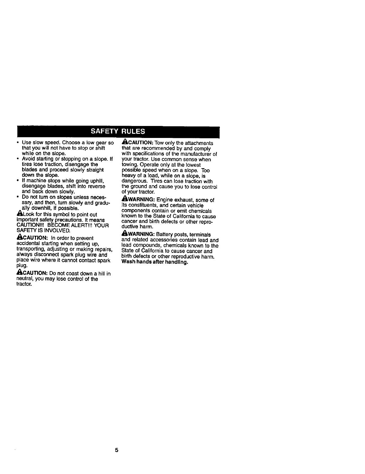
J_Look for this symbol to point out
importantsafety precautions. It means
CAUTIONI!! BECOMEALERT!!! YOUR
SAFETY IS INVOLVED.
_QLCAUTION: In order to prevent
accidental starting when setting up,
transporting, adjusting or making repairs,
always disconnect spark plug wire and
place wire where itcannot contact spark
plug.
_,CAUTION: Do not coast down a hill in
neutral, you may lose controlof the
tractor.
_CAUTION: Tow only the attachments
that are recommended by and comply
with specifications of the manufacturer of
your tractor. Use common sense when
towing. Operate only at the lowest
possible speed when on a slope. Too
heavy of a load, while on a slope, is
dangerous. Tires can lose traction with
the ground and cause you to lose control
of your tractor.
/LWARNING: Engine exhaust, some of
its constituents, and certain vehicle
components contain or emit chemicals
known to the State of California to cause
cancer and birth defects or other repro-
ductive harm.
/kWARNING: Battery posts, terminals
and related accessories contain lead and
lead compounds, chemicals known to the
State of California to cause cancer and
birthdefects or other reproductive harm.
Wash hands after handling.
5
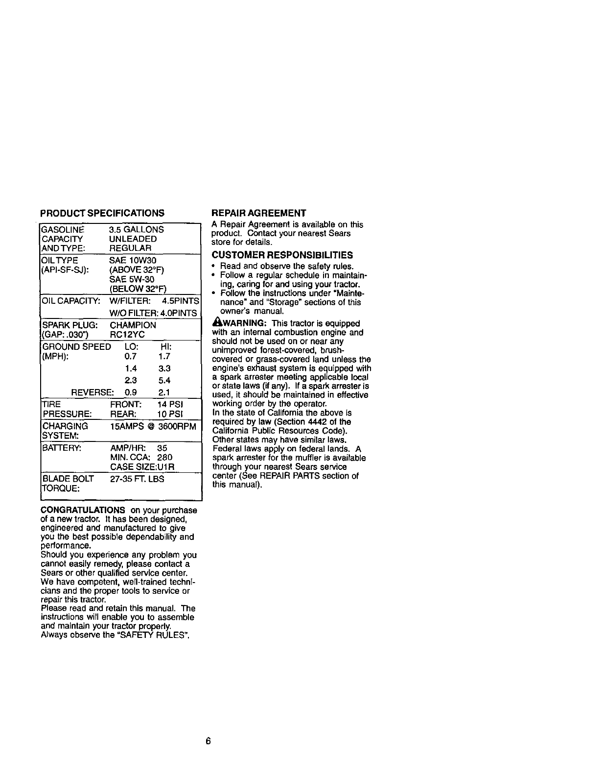
PRODUCT SPECIFICATIONS
3ASOLINE 3.5 GALLONS
CAPACITY UNLEADED
ANDTYPE: REGULAR
DILTYPE SAE 10W30
',API-SF-SJ): (ABOVE 32°F)
SAE 5W-30
(BELOW 32°F)
OIL CAPACITY: W/FILTER: 4.5PINTS
W/O FILTER: 4.0PINTS
SPARK PLUG: CHAMPION
GAP: .030") RC12YC
GROUND SPEED LO: HI:
(MPH): 0.7 1.7
1.4 3.3
2.3 5.4
REVERSE: 0.9 2.1
TIRE FRONT: 14 PSI
PRESSURE: REAR: 10 PSI
CHARGING 15AMPS @3600RPM
SYSTEM:
BATi'E RY: AMP/HR: 35
MIN. CCA: 280
CASE SIZE:U1R
BLADE BOLT 27-35 FT. LBS
TORQUE:
CONGRATULATIONS on your purchase
of a new tractor. It has been designed,
engineered and manufactured to give
you the best possible dependability and
performance.
Should you experience any problem you
cannot easily remedy, please contact a
Sears or other qualified service center.
We have competent, wen-trained techni-
cians and the proper tools to service or
repair this tractor.
Please read and retain this manual. The
instructionswirl enable you to assemble
and maintain your tractor properly.
Always observe the "SAFETY RULES".
REPAIR AGREEMENT
A Repair Agreement is available on this
product. Contact your nearest Sears
store for details.
CUSTOMER RESPONSIBILITIES
• Read and observe the safety rules.
• Follow a regular schedule in maintain-
ing, caring for and using your tractor.
•Follow the instructions under =Mainte-
nance" and "Storage" sections of this
owner's manual.
_I, WARNING: This tractor is equipped
with an internal combustion engine and
should not be used on or near any
unimproved forest-covered, brush-
covered or grass-covered land unless the
engine's exhaust system is equipped with
aspark errester meeting applicable local
or state laws (if any). If a spark arrester is
used, it should be maintained in effective
working order by the operator.
In the state of California the above is
required by law (Section 4442 of the
California Public Resources Code).
Other states may have similarlaws.
Federal laws apply on federal lands. A
spark arrester for the muffler is available
through your nearest Sears service
center (See REPAIR PARTS section of
this manual).
Steering Wheel
Steedng
Wheel Insert Steedng Sleeve
Seat
(1) Washer
17/32 x 1-3/16 x 12 Gauge
_(1) Knob
(5) etainer Springs
(double loop)
(2) etainer Spdngs
(single loop)
Mower
(2)Flanged
( 1)Front Plate
Assembly
Gauge Wheels
)Shoulder Bolts
12)Centedock Nuts
_ I Y// (2)
"_,,_/(2) Wheels 3/8 x3/4 x 14 Ga
Video Cassette
Slope Sheet
For Future Use I AI_'_
Keys
(2) Keys
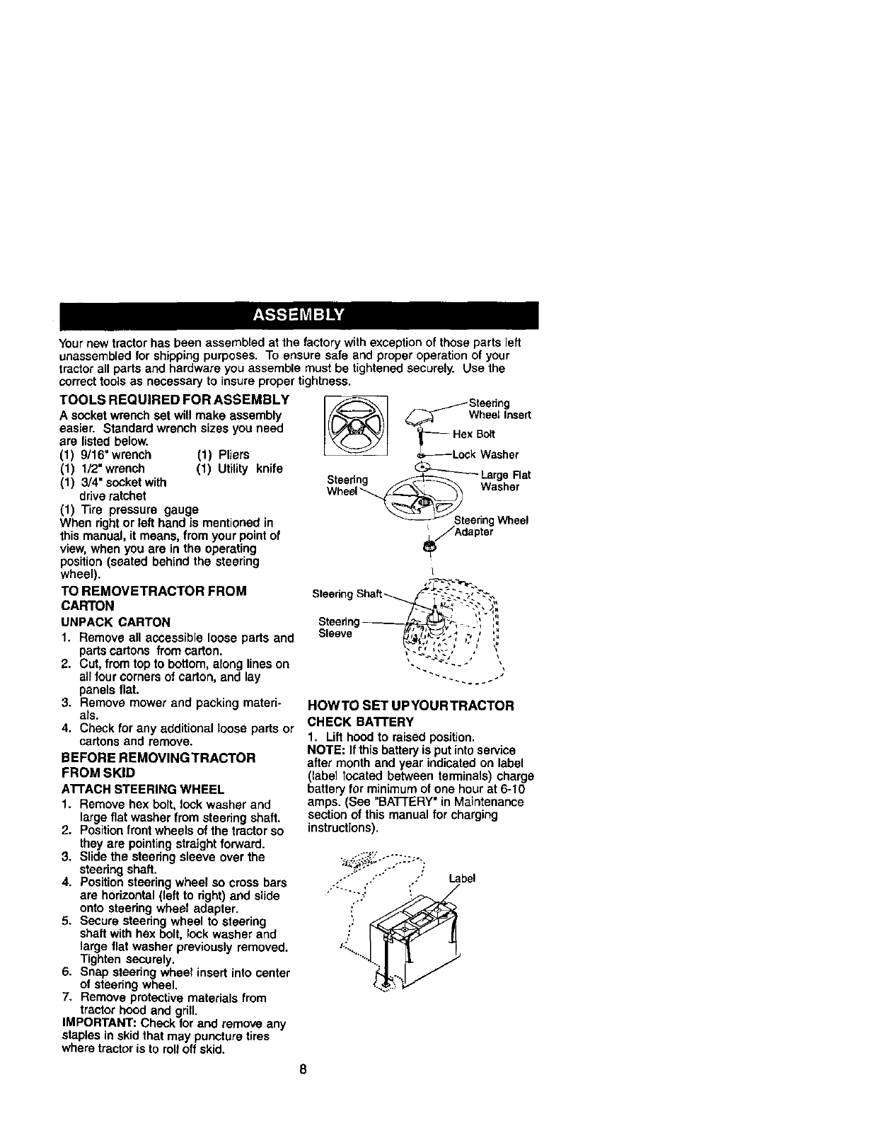
Your new tractor has been assembled at the factory with exception of those parts left
unassembled for shipping purposes. To ensure safe and proper operation of your
tractor all parts and hardware you assemble must be tightened securely. Use the
correct tools as necessary to insure proper tightness.
TOOLS REQUIRED FOR ASSEMBLY
Asocket wrench set will make assembly
easier. Standard wrench sizes you need
are listed below.
(1) 9/16"wrench (t) Pliers
(1) 1/2"wrench (1) UtiUty knife
(1) 3/4" socket with
drive ratchet
(1) Tire pressure gauge
When right or left hand is mentioned in
this manual, it means, from your point of
view, when you are in the operating
position (seated behind the steering
wheel).
TO REMOVETRACTOR FROM
CARTON
UNPACK CARTON
1. Remove all accessible loose parts and
parts cartons from carton.
2. Cut, from top to bottom, along lines on
all four comers of carton, and lay
panels flat.
3. Remove mower and packing materi-
als.
4. Check for any additional loose parts or
cartons and remove.
BEFORE REMOVINGTRACTOR
FROM SKID
ATFACH STEERING WHEEL
1. Remove hex bolt, look washer and
large flat washer from steering shaft.
2. Position front wheels of the tractor so
they are pointing straight forward.
3. Slide the steering sleeve over the
steering shaft•
4. Position steering wheel so cross bars
are horizontal (left to right) and slide
onto steering wheel adapter.
5. Secure steering wheel to steering
shaft with hex bolt, lock washer and
large flat washer previously removed.
Tighten securely.
6. Snap steering wheel insert into center
of steering wheel.
7. Remove protective materials from
tractor hood and grill.
IMPORTANT: Check for and remove any
staples in skid that may puncture tires
where tractor is to roll off skid.
_/_] _ /Steedng
_Wheel Insert
lr--.e.so.,
_Lock Washer
Steering LargeRat
Washer
Wheel
_JAdapte_
L
Steering Shaft-_ F--.:.." ;, -".-.-..
,,
v-- N
Sleeve /_,,'_7:_'L__, . ., ., ,,,
HOWTO SET UPYOURTRACTOR
CHECK BA'n'ERY
1. Lift hood to raised position.
NOTE: If this battery is put into service
after month end year indicated on label
(label located between terminals) charge
battery for minimum of one hour at 6-10
amps. (See "BATI'ERY" in Maintenance
section of this manual for charging
instructions).
Label
8
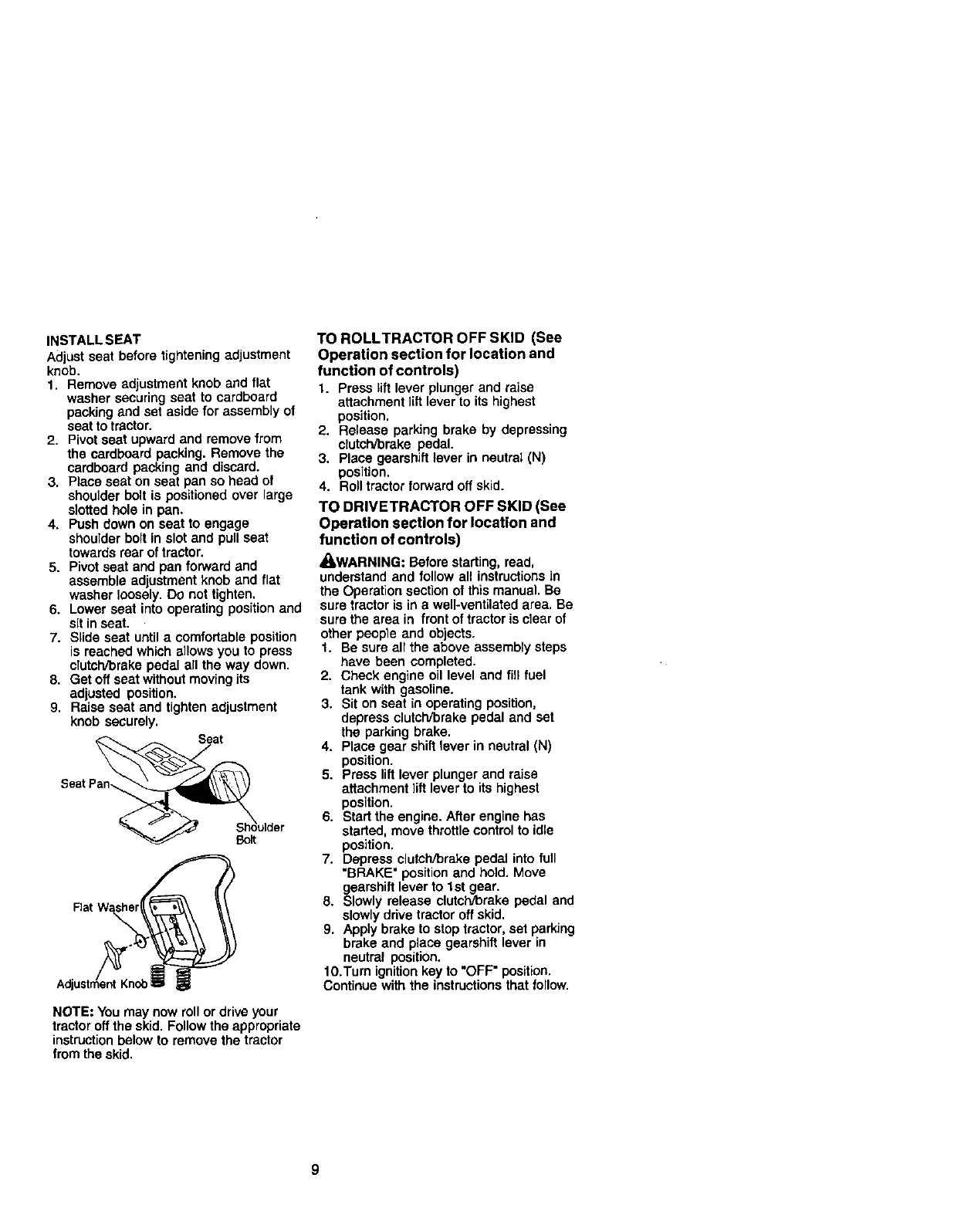
INSTALL SEAT
Adjust seat before tightening adjustment
knob.
1. Remove adjustment knob and flat
washer securing seat to cardboard
packing and set aside for assembly of
seat to tractor.
2. Pivot seat upward and remove from
the cardboard packing. Remove the
cardboard packing and discard.
3. Place seat on seat pan so head of
shoulder bolt is positioned over large
slotted hole in pan.
4. Push down on seat to engage
shoulder bolt in slot and pull seat
towards rear of tractor.
5. Pivot seat and pan forward and
assemble adjustment knob and flat
washer loosely. DO not tighten.
6. Lower seat into operating position and
sit in seat.
7. Slide seat until a comfortable position
is reached which allows you to press
clutcWbrake pedal all the way down.
8. Get off seat without moving its
adjusted position.
9. Raise seat and tighten adjustment
knob securely.
Seat
NOTE: You may now roll or drive your
tractor off the skid. Follow the appropriate
instructionbelow to remove the tractor
from the skid.
TO ROLLTRACTOR OFF SKID (See
Operation section for location and
function of controls)
1. Press lift lever plunger and raise
attachment lift lever to its highest
position.
2. Release parking brake by depressing
clutch/brake pedal.
3. Place gearshift lever in neutrat (N)
position.
4. Roll tractor forward off skid.
TO DRIVETRACTOR OFF SKID (See
Operation section for location and
function of controls)
_I=WARNING: Before starting, read,
understand and follow all instructions in
the Operation section of this manual. Be
sure tractor is in a well-ventilated area. Be
sure the area in front of tractor is clear of
other people and objects.
t. Be sure all the above assembly steps
have been completed.
2. Check engine oil level and fill fuel
tank with gasoline.
3. Sit on seat in operating position,
depress clutch/brake pedal and set
the parking brake.
4. Place gear shift lever in neutral (N)
position.
5. Press lift lever plunger and raise
attachment lift lever to its highest
position.
6. Start the engine. After engine has
started, move throttle control to idle
position.
7. Depress clutch/brake pedal into full
"BRAKE" position and hold. Move
gearshift lever to 1st gear.
8. Slowly release clutch/brake pedal and
slowly drive tractor off skid.
9. Apply brake to stop tractor, set parking
brake and place gearshift lever in
neutral position.
lO.Tum ignition key to "OFF" position.
Continue with the instructions that follow.
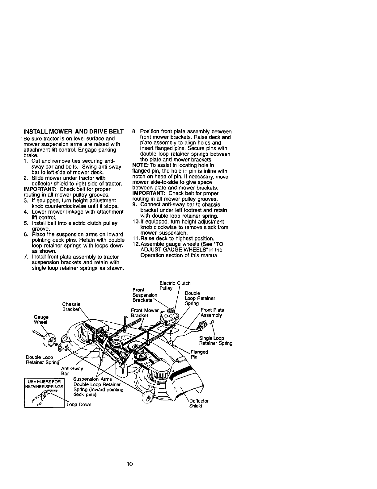
INSTALL MOWER AND DRIVE BELT
Be sure tractor is on level surface and
mower suspension arms are raised with
attachment lift control. Engage parking
brake.
1. Cut and remove ties securing anti-
sway bar and belts. Swing anti-sway
bar to left side of mower deck.
2. Slide mower under tractor with
deflector shield to right side of tractor.
IMPORTANT: Check belt for proper
routing in all mower pulley grooves.
3. If equipped, turn height adjustment
knob counterclockwise until it stops.
4. Lower mower linkage with attachment
lift control.
5. Install belt into electric clutch pulley
groove.
6. Place the suspension arms on inward
pointing deck pins. Retain with double
loop retainer spdngs with loops down
as shown.
7. Installfront plata assembly to tractor
suspension brackets and retain with
single loop retainer springs as shown.
Chassis
Gauge
Wheel
8. Position front plate assembly between
front mower brackets• Raise deck and
plate assembly to align holes and
insert flanged pins. Secure pins with
double loop retainer springs between
the plate and mower brackets.
NOTE: To assist in locating hole in
flanged pin, the hole in pin is inline with
notch on head of pin. If necessary, move
mower side-to-side to give space
between plate and mower brackets.
IMPORTANT: Check belt for proper
routing in all mower pulley grooves.
9. Connect anti-sway bar to chassis
bracket under left footrest and retain
with double loop retainer spring.
10. If equipped, turn height adjustment
knob clockwise to remove slack from
mower suspension.
11. Raise deck to highest position•
12.Assemble gauge wheels (See "TO
ADJUST GAUGE WHEELS" in the
Operation section of this manua
Electdc Clutch
Front Pulley
Suspension Double
Brackets _Loop Retainer
Spring
Front Mower Front Plate
Bracket
DoubleLoop
RetainerSpring
Anti-Sway
Bar Suspens=on
USE PLIERS FOR DoubleLoopRetame
Spring(Inwardpointing
RETAINER SPRINGS . . .
dockp,nsl
• _ I LoopDown
Single Loop
Retainer Spring
Pin
,eflector
Shield
10
CHECK TIRE PRESSURE
The tires onyour tractorwere overinflated
at the factoryfor shippingpurposes.
Correct tire pressure is impodantfor best
cutting performance.
• Reduce tire pressure to PSI shown in
"PRODUCT SPECIFICATIONS" section
of this manual.
CHECK MOWER LEVELNESS
For best cuttingresults, mowershould be
pmpedy leveled. See "TO LEVEL MOWER
HOUSING" in the Service and Adjustments
sectionof this manual.
CHECK FOR PROPER POSITION OF ALL
BELTS
See the figures that are shown for replac-
ing motion, mower drive, and mower blade
drive belts in the Service and Adjustments
sectionof this manual. Verifythat the belts
are routedcorrectly,
CHECK BRAKE SYSTEM
After you learn how to operate your tractor,
check to see that the brake is pmpedy
adjusted. See "TO ADJUST BRAKE" in the
Service and Adjustmentssectionof this
manual.
V"CHECKLIST
Before you operate and enjoy your new
tractor, we wish to assure that you
receive the best performance and
satisfaction from this quality product.
Pieaee review the following checklist:
/" All assembly instructions have been
completed.
,/No remaining loose parts in carton.
/Battery is propedy prepared and
charged.(Minimum 1hour at 6 amps).
,/Seat is adjusted comfortably and
tightened securely.
,/All tires are properly inflated. (For
shipping purposes, the tires were
ovednflated at the factory).
,/Be sure mower deck is pmpedy
leveled side-to-side/front-to-rear for
best cutting results. (Tires must be
propedy inflated for leveling).
,/Check mower and drive belts. Be
sure they are routed properly around
pulleys and inside all belt keepers.
,/Check wiring. See that aUconnec-
tions are stillsecure and wires are
properly clamped.
While learning how to use your tractor,
pay extra attention to the following
important items:
,/'Engine oil is at proper level.
/Fuel tank is filled with fresh, clean,
regular unleaded gasoline.
,,/Become familiar with all controls -
their location and function. Operate
them before you start the engine.
,/Be sure brake system is in safe
operating condition.
11
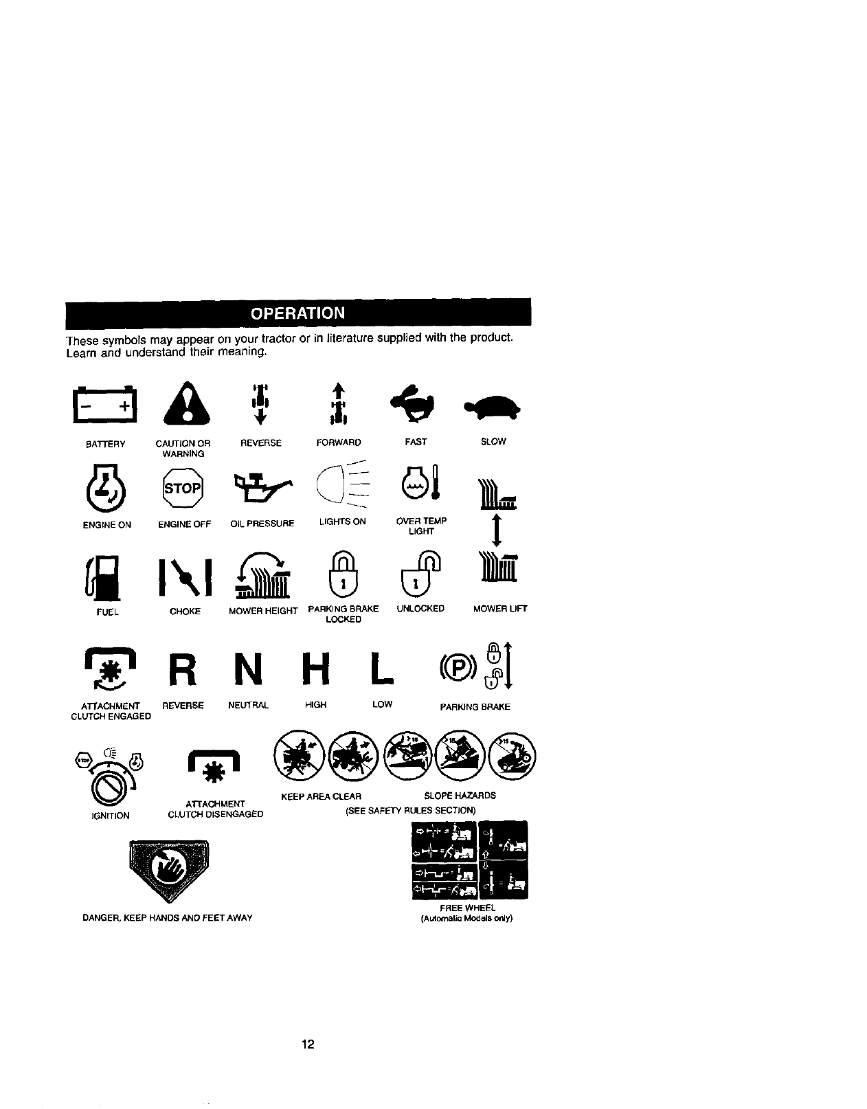
These symbols may appear on your tractor or in literature supplied with the product.
Learn and understand their meaning.
BATrERY CAUTION OR REVERSE FORWARD FAST SLOW
WARNING
ENGINE ON ENGINE OFF OiL PRESSURE LIGHTS ON OVER TEMP
LIGHT
FUEL CHOKE MOWER HEIGHT PARKING BRAKE UNLOCKED
LOCKED
!
MOWERLI_
r_'l R N H L
ATTACHMENT REVERSE NEUTRAL HIGH LOW PARKING BRAKE
CLUTCH ENGAGED
_(_) ATEACHMENT
IGNITION CLUTCH DISENGAGED
DANGER, KEEP HANDS AND FEET AWAY
KEEP AREA CLEAR SLOPE HAZARDS
(SEE SAFk-FY RULES SECTJON)
FREE WHEEL
(Automatic Models o_y)
12
KNOWYOURTRACTOR
READ THIS OWNER'S MANUAL AND SAFETY RULES BEFORE OPERATING
YOUR TRACTOR
Compare the illustrationswith your tractor to familiarize yourself with the locations of
various controls and adjustments. Save this manual for future reference.
Switch
Ignition
Switch Position
ThrotUe Control
Attachment
Switch
ClutcWBrake
Plunger
Attachment
Lift Lever
Control Brake
Heigt /_
Adjustment
Knob /
Gear Shift Lever \3Shift Lever
Our tractors conform to the safety standards of the
American National Standards Institute.
A't-rACHMENT CLUTCH SWITCH: Used
to engage the mower blades, or other
attachments mounted to your tractor.
LIGHT SWITCH: Turnsthe headlights on
and off.
THROI"rLE CONTROL: Used to control
engine speed.
CLUTCH/BRAKE PEDAL: Used for
declutching and braking the tractor and
starting the engine.
CHOKE CONTROL: Used when starting a
cold engine.
HEIGHT ADJUSTMENT KNOB: Used to
adjust the mower cutting height.
GEARSHIFT LEVER: Selects the speed
and directionof the tractor.
RANGESHIFT LEVER: Allows high (H)
and low (L) speed for all forward and
reverse gears.
ATTACHMENT LIFT LEVER: Used to
raise and lower the mower deck or other
attachments mounted to your tractor.
LIFT LEVER PLUNGER: Used to release
attachment liftlever when changing its
position.
IGNITION SWITCH: Used for starting and
stopping the engine.
AMMETER: Indicates battery charging (+)
or discharging (-).
PARKING BRAKE: Locks clutch/brake
into the brake position.
13
The operation of any tractor can resultin foreign objects thrown into
the eyes, which can result in severe eye damage. Always wear safety
glasses or eye shields while operating your tractor or performing any
adjustments or repairs. We recommend a wide vision safety mask
over spectacles or standard safety glasses.
HOWTO USEYOURTRACTOR
TO SET PARKING BRAKE
Yourtractor is equipped with an operator
presence sensing switch. When engine
is running, any attempt by the operator to
leave the seat without first setting the
parking brake witl shut off the engine.
1. Depress clutch/brake pedal into full
"BRAKE" position and held.
2. Place parking brake lever in "EN-
GAGED" position and release
pressure from clutch/brake pedal.
Pedal should remain in "BRAKE"
position. Make sure parking brake will
hold tractor secure. Attachment
Clutch Switch
Push-In to Pull OutTo
Throttie _ "Dise a
Control__Chok_..._ _ g_d" "Engage"
"Brake" _
Gear Brake
Clutch/BrakeAdjustrnen _nm =Engaged"
Pobal=Drive"Knob Lever ..
Position "Dis aged" Pos_t_on
Position
STOPPING
MOWER BLADES -
•To stop mower blades,move attach-
ment clutch switch to "DISENGAGED"
position.
GROUND DRIVE -
•To stop ground drive, depress dutch/
brake pedal into full "BRAKE" position.
• Move gearshift lever to neutral (N)
position.
ENGINE -
•Move throttle control to slow position.
NOTE: Failure to move throttle control to
slow position and allowing engine to idle
before stopping may cause engine to
"backfire".
• Turn ignition key to "OFF" position and
remove key. Always remove key when
leaving tractor to prevent unauthorized
use.
,, Never use choke to stop engine.
IMPORTANT: Leaving the ignition switch
in any position other than "OFF•will
cause the battery to be discharged,
(dead).
NOTE: Under certain conditions when
tractor is standing idle with the engine
running, hot engine exhaust gases may
cause "browning" of grass. To eliminate
this possibility,always stop engine when
stopping tractor on grass areas.
-_CAUTION: Always stop tractor
completely, as described above, before
leaving the operator's position; to empty
grass catcher, etc.
TO USE THRO'R'LE CONTROL
Always operate engine at full throttle.
• Operating engine at less than full
throttle reduces the battery charging
rate.
•Full throttle offers the best bagging and
mower performance.
CHOKE CONTROL
Use choke control whenever you are
starting a cold engine, Do not use to start
a warm engine.
• To engage choke control, pull knob out.
Slowly push knob in to disengage.
TO MOVE FORWARD AND BACKWARD
The direction and speed of movement is
controlled by the gearshift lever.
1. Start tractor with clutch/brake pedal
depressed and gearshift lever in
neutral (N) position.
2. Move gearshift and range shift levers
to desired position.
3. Slowly release clutch/brake pedal to
start movement.
IMPORTANT: Bringtractor to acomplete
stop before shiftingor changing gears,
Failura to do so willshorten the useful life
of your transaxle.
TO ADJUST MOWER CU'I-rlNG HEIGHT
The cutting height is controlled by turning
the height adjustment knob in desired
direction.
•Turn knob clockwise ((_) to raise
cutting height,
•Turn knob counterclockwise (P_)to
lower cutting height.
14
The cutting height range is approximately
1-1/2" to 4-1/2". The heights are mea-
sured from the ground to the blade tip with
the engine not running. These heights are
approximate and may vary depending
upon soil conditions, height of grass and
types of grass being mowed.
•The average lawn should be cut to
approximately 2-1/2 inches during the
cool season and to over 3 inches
during hot months. For healthier and
better looking lawns, mow often and
after moderato growth.
•For best cutting performance, grass
over 6 inches in height should be
mowed twice. Make the first cut
relatively high; the second to desired
height.
TO ADJUST GAUGE WHEELS
Gauge wheels are properly adjusted
when they are slightlyoff the ground
when mower is at the desired cutting
height in operating position. Gauge
wheels then keep the deck in proper
position to help prevent scalping in most
terrain conditions.
NOTE: Adjust gauge wheels with tractor
on a flat level surface.
1. Adjust mower to desired cutting height
(See "TO ADJUST MOWER CU'I-rlNG
HEIGHT" in the Operation sectionof
this manual).
2. With mower in desired height of cut
position, gauge wheels should be
assembled so they are slightly off the
ground. Install gauge wheel in
appropriate hole with shoulder bolt,
3/8 washer, and 3/8-16 Iocknut and
tighten securely.
3. Repeat for opposite side installing
gauge wheel in same adjustment
hole.
Goo0eWh ,
Mounting Y/ _\_,_/_w_-_
Bracket_ /(\\ _'v_ \
3/8-16 _:._,_, _ \_
Locknut_] _ '\_"f\/
3/8 Washer---__-_ v.p_ _Shoulder
GaugeWheel-----------_. -_:_,_/Bolt
TO OPERATE MOWER
Your tractor is equipped with an operator
presence sensing switch. Any attempt by
the operator to leave the seat with the
engine running and the attachment
clutch engaged will shut off the engine.
1. Select desired height of cut.
2. Lower mower with attachment lift
control.
3. Start mower blades by engaging
attachment clutch control.
TO STOP MOWER BLADES -
disengage attachment clutch control.
_CAUTION: Do not operate the mower
without either the entire grass catcher, on
mowers so equipped, or the deflector
shield in place.
AttachmentClutch
SwitchPull Out To
"Disengage" _\_
AttachmentUft
/Lever High
#Position
_4=_r--- Deflector
TO OPERATE ON HILLS
_kCAUTION: Do not drive up or down
hills with slopes greater than 15° and do
not drive across any slope. Use the slope
guide provided at the back of this manual.
•Choose the slowest speed before
starting up or down hills.
•Avoid stopping or changing speed on
hills.
•If slowing is necessary, move throttle
control lever to slower position.
•If stopping is absolutely necessary,
push clutch/brake pedal quickly to
brake position and engage parking
brake.
•Move gearshift lever to 1st gear and
range shift lever to low (L) position. Be
sure you have allowed room for tractor
to roll slightlyas you restart movement.
•To restart movement, slowly release
parking brake and clutch/brake pedal.
•Make all turns slowly.
TO TRANSPORT
•Raise attachment lift to highest position
with attachment lift control.
• When pushing or towing your tractor,
be sure gearshift lever =sin neutral (N)
position,
•Do not push or tow tractor at more than
five (5) MPH.
NOTE: To protect hood from damage
when transportingyour tractor on a truck
or atrailer, be sure hood is closed and
secured to tractor. Use an appropriate
means of tying hood to tractor (rope, cord,
15etc,).
TOWINGCARTSANDOTHERA'FrACH-
MENTS
Towonlytheattachmentsthatare
recommendedbyandcomplywith
specificationsofthemanufacturerofyour
tractor.Usecommonsensewhentowing.
Tooheavyofaload, while on aslope, is
dangerous. Tires can lose traction with
the ground and cause you to lose control
of yourtractor.
BEFORE STARTINGTHE ENGINE
CHECK ENGINE OIL LEVEL
The engine in your tractor has been
shipped, from the factory, already filled
with summer weight oil.
1. Check engine oil with tractor on level
ground.
2. Unthread and remove oil fill cap/
dipstick; wipe oil off. Reinsert the
dipstick into the tube and rest oil fill
cap on the tube. Do not thread the
cap onto the tube. Remove and read
oil level If necessary, add oil until
"FULL" mark on dipstick is reached.
Do not overfill.
•For cold weather operation you should
change oil for easier starting (See "OIL
VISCOSITY CHART" in the Mainte-
nance sectionof this manual).
•To change engine oil, see the Mainte-
nance section in this manual.
ADD GASOLINE
•Fill fuel tank. Use fresh, clean, regular
unleaded gasoline with a minimum of
87 octane. (Use of leaded gasoline
will increase carbon and lead oxide
deposits and reduce valve life). Do not
mix oil with gasoline. Purchase fuel in
quantities that can be used within 30
days to assure fuel freshness.
IMPORTANT: When operating in
temperatures below 32°F(0°C), use fresh,
dean winter grade gasoline to help
insure good cold weather starting.
AWARNING: Experience indicates that
alcohol blended fuels (called gasohol or
using ethanol or methanol) can attract
moisture which leads to separation and
formation of acids duringstorage. Acidic
gas can damage the fuel system of an
engine while in storage. To avoid engine
problems, the fuel system should be
emptied before storage of 30 days or
longer. Drain the gas tank, start the
engine and let it run until the fuel lines
and carburetor are empty. Use fresh fuel
next season. See Storage Instructionsfor
additional information. Never use engine
or carburetor cleaner products in the fuel
tank or permanent damage may occur.
_CAUTION: Fill to bottom of gas tank
filler neck. Do not overfill Wipe off any
spilled oil or fuel. Do not store, spill or
use gasoline near an open flame.
TO START ENGINE
When starting the engine for the first time
or if the engine has run out of fuel, it will
take extra cranking time to move fuel from
the tank to the engine.
1. Sit on seat in operating position,
depress clutch/brake pedal and set
parking brake.
2. Place gear shift lever in neutral (N)
position.
3. Move attachment clutch to "DISEN-
GAGED" position.
4. Move throttle control to fast position
5. Pull choke control out for a cold
engine start attempt. For a warm
engine start attempt the choke control
may not be needed.
NOTE; Before starting, read the warm and
cold starting procedures below.
6. Insert key into ignition and turn key
clockwise to "START" position and
release key as soon as engine starts.
Do not run starter continuously for
more than fifteen seconds per minute.
If the engine does not start after
several attempts, push choke control
in, wait a few minutes and try again. If
engine still does not start, pull the
choke control out and retry.
16
WARM WEATHER STARTING (50 ° F and
above)
7. When engine starts, slowly push
choke control in until the engine
begins to run smoothly. If the engine
starts to run roughly, pull the choke
control out slightly for a few seconds
and then continue to push the control
in slowly.
•The attachments and ground drive can
now be used. if the engine does not
accept the load, restart the engine and
allow Ltto warm up for one minute
using the choke as described above.
COLD WEATHER STARTING (50 °F and
below)
7. When engine starts, slowly push
choke control in until the engine
begins to run smoothly. Continue to
push the choke control in small steps
allowing the engine to accept small
changes in speed and load, until the
choke control is fully in. 1!the engine
starts to run roughly, pull the choke
control out slightly for a few seconds
and then continue to push the control
in slowly. This may require an engine
warm-up period from several seconds
to several minutes, depending on the
temperature.
• The attachments can be used during
the engine warm-up period and may
require the choke contrel be pulled out
slightly.
NOTE: if at a high altitude (above 3000
feet) or in cold temperatures (below 32 F)
the carburetor fuel mixture may need to
be adjusted for best engineperformance.
See "TO ADJUST CARBURETOR" in the
Service and Adjustments section of this
manual.
MOWINGTIPS
•Tire chains cannot be used when the
mower housing is attached to tractor.
•Mower should be properly leveled for
best mowing performance. See "TO
LEVEL MOWER HOUSING" in the
Service and Adjustments section of this
manual.
• The left hand side of mower should be
used for trimming.
•Drive so that c_ippingsare discharged
onto the area that has been cut. Have
the cut area to the right of the tractor.
This will result in a more even distribu-
tion of clippings and more uniform
cutting.
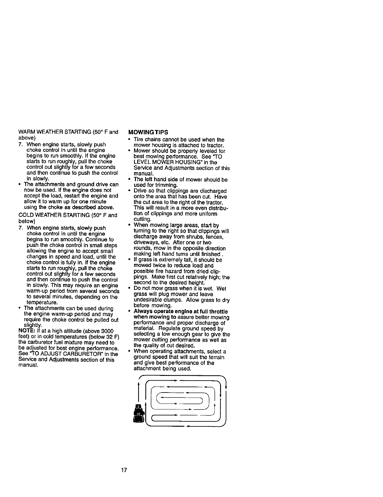
• When mowing large areas, start by
turning to the right so that clippingswill
discharge away from shrubs, fences,
ddveways, etc. After one or two
rounds, mow in the opposite direction
making left hand turns until finished.
• If grass is extremely tall, itshould be
mowed twice to reduce load and
possible fire hazard from dried clip-
pings. Make first cut relatively high; the
second to the desired height.
• DOnot mow grass when it is wet. Wet
grass will plug mower and leave
undesirable clumps. Allow grass to dry
before mowing.
•Always operate engine at full throttle
when mowing to assure better mowing
performance and proper discharge of
material, Regulate ground speed by
selecting e. low enough gear to give the
mower cutting performance as well as
the quality of cut desired.
• When operating attachments, select a
ground speed that will suit the terrain
and give best pedormance of the
attachment being used.
'
a
17
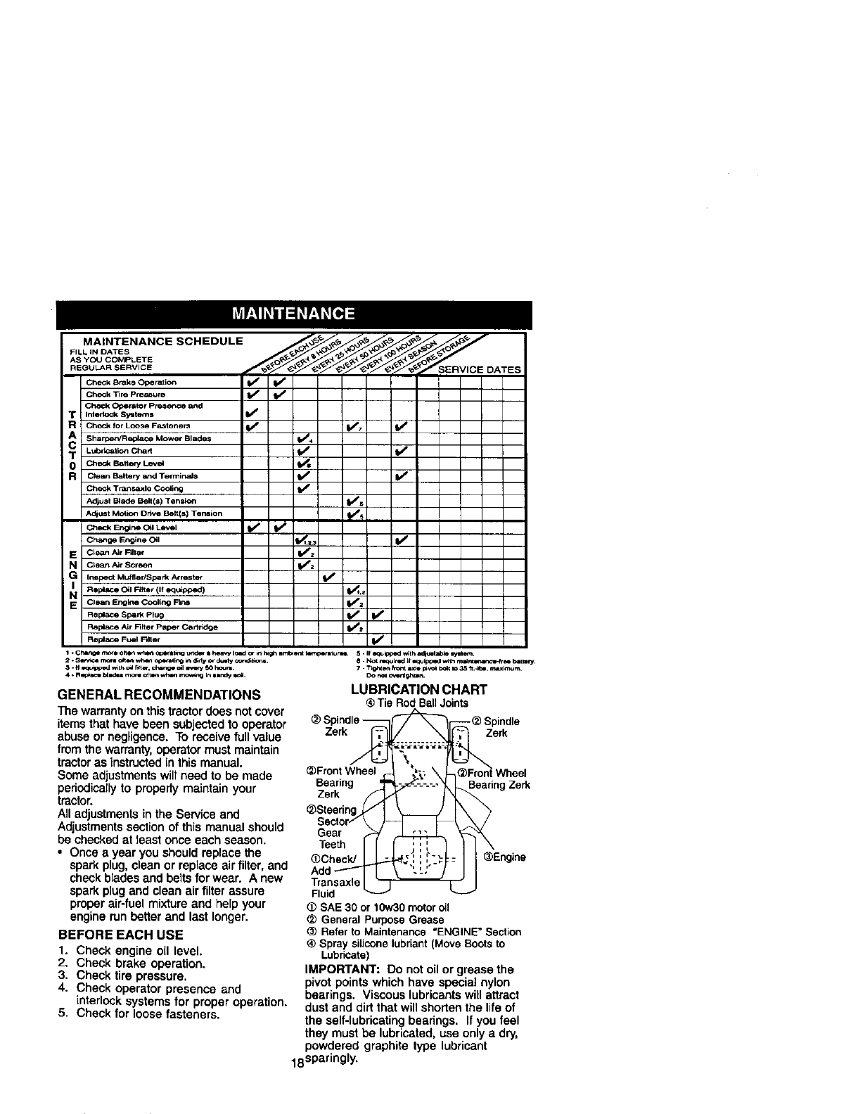
MAINTENANCE SCHEDULE _ _ _._ _ _
FLLNOATEO
AS yOU COMPLETE
REGULAR SERVICE ___,_SERVICE DATES
CheCk Brake Operation If (I_
Ch_k "13ro pre_ute If
Check Operator pr_e_'_e* and
t_ntedockSyste*ns I_'
R Check for LOOSe FaSteners ik/ 1_7
A Sharpen/Repla_ _Mower Blad_ V' 4
T u,b,_=,o_c_ V" =/
0 Check Bakery Level t_o
R Clean Balten/&rid TermiP, Js _ V_
Check Transaxle Co_iP_j f_
A(r_ust Egade Bell(s) Tension _s
l_djust Motion Drive Belt(s) Termion _s
ChockEr'_r_C_JLevel t/ IVp
Change Engine Oil I1_=_,3 V'
E Clean Air F'_ter I_z
N Qean AirScreen I/z
IG Inspect Muffler/Spark Atrester
Repl_ CNI Filter (If equipped) _lj
EN Clean Enolna Cooling Fins If 2 I
Replace Spark Plug If I_
Replavce Air Filter Paper Cartridge I_ !
Replace Fuel Rlter ll_
I - Cha_ rho_ ft 0 f1_1 w_l_ Qc4_sUng tJfldor I;'4[,a'*'/IC, Sd or m r_gh arn_erlt _rllur_ _. II i,_ zq_oed wilh a_lJt aa_e _l/Bt_lm_.
GENERAL RECOMMENDATIONS
The warranty on thistractor does not cover
itemsthat have been subjected to operator
abuse or negligence. To receive full value
from the warranty, operator must maintain
tractoras instructedin this manual.
Some adjustments will need to be made
periodicallyto properly maintain your
tractor.
Alladjustments in the Service and
Adjustmentssectionof this manual should
be checked at least once each season.
•Once a year you should replace the
spark plug,clean or replace air filter, and
check blades and belts for wear. A new
spark plug and clean air filter assure
proper air-fuel mixture and help your
engine run petter and last longer.
BEFORE EACH USE
1. Check engine oil level.
2. Check brake operation.
3. Check tire pressure.
4. Check operator presence and
interlock systems for proper operation.
5. Check for loose fasteners.
6. N_ _ired _f eq= liplped _lh mwn_r_-Fr 0e bl_ t-_.
7 - Tt_tt _n b_nt It Je [C_VOl _t to 3_ ft.*_e r_zxlmur_
Do r_ ovendghten.
LUBRICATION CHART
®Tie Rod BallJoints
_) Spindle-- _ _(_ Spindle
Zerk_ ............ _e_
\
_Front Wheel "" "X__Front Wheel
Bearingzerk_"-_-_'-'-'1 3eadngZerk
_Steedng_ I
Sector/\i-
Gear ,_
TeethII J'k
Transaxle
Fluid
(I) SAE 30 or 10w30motoro_1
_) GeneralPurposeGrease
_) Referto Maintenance"ENGINE" Section
®Spraysiliconelubriant(MoveBootsto
Lubricate)
IMPORTANT: Do not oil or grease the
pivot points which have special nylon
bearings. Viscous lubricants will attract
dust and dirtthat will shorten the life of
the self-lubricating bearings. If you feel
they must be lubricated, use only a dry,
powdered graphite type lubricant
18sparingly.
TRACTOR
Alwaysobservesafetyruleswhen
performinganymaintenance.
BRAKE OPERATION
If tractor requires more than six (6) feet
stopping distance at high speed in
highest gear, then brake must be ad-
justed. (See "TO ADJUST BRAKE" in the
Service and Adjustments section of this
manual).
TIRES
•Maintain proper air pressure in all tires
(See "PRODUCT SPECIFICATIONS"
section of this manual).
•Keep tires free of gasoline, oil, or insect
control chemicals which can harm
rubber.
•Avoid stumps, stones, deep ruts, sharp
objects and other hazards that may
cause tire damage.
NOTE: To seat tire punctures and prevent
fiat tires due to slow leaks, tire sealant
may be purchased from your local parts
dealer. Tire sealant also prevents tire dry
rot and corrosion.
OPERATOR PRESENCE SYSTEM
Be sure operator presence and interlock
systems are working properly. If your
tractor does not function as described,
repair the problem immediately.
•The engine should not start unless the
clutch/brake pedal is fully depressed
and attachement clutch control is in the
disengaged position.
•When the engine is running, any
attempt by the operator to leave the
seat without first setting the parking
brake should shut off the engine.
•When the engine is running and the
attachment clutch is engaged, any
attempt by the operator to leave the
seat should shut off the engine.
•The attachment clutch should never
operate unless the operator is in the
seat.
BLADE CARE
For best results mower blades must be
kept sharp. Replace bent or damaged
blades.
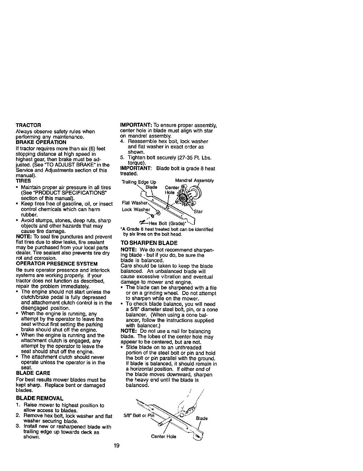
BLADE REMOVAL
1. Raise mower to highest position to
allowaccess to blades.
2. Remove hex bolt, lock washer and flat
washer secudng blade.
3. Install new or resharpened blade with
trailing edge up towards deck as
shown.
IMPORTANT: To ensure proper assembly,
center hole in blade must align with star
on mandrel assembly.
4. Reassemble hex boil, lock washer
and flat washer in exact order as
shown.
5. Tighten bolt securely (27-35 Ft. Lbs.
torque).
IMPORTANT: Blade bolt is grade 8 heat
treated.
Trailing Edge Up
Lock Washe
_-----Hex Bolt (Grade)'
*A Grade 8 heat treated bolt can be identified
by six lines on the bolt head.
TO SHARPEN BLADE
NOTE: We do not recommend sharpen-
ing blade -but ifyou do, be sure the
blade is balancad.
Care should be taken to keep the b_ede
balanced. An unbalanced blade will
cause excessive vibration and eventual
damage to mower and engine.
•The blade can be sharpened with a file
or on agrindingwheel. Do not attempt
to sharpen while on the mower.
•To check blade balance, you will need
a5/8" diameter steel bolt, pin, or acone
balancer. (When using a cone bal-
ancer, follow the instructionssupplied
with balancer.)
NOTE: Do not use anail for balancing
blade. The lobes of the center hole may
appear to be centered, but are not.
•Slide blade on to an unthreaded
portion of the steel bolt or pin and hold
the bolt or pin parallel with the ground,
If blade is balanced, it should remain in
a horizontal position. If either end of
the blade moves downward, sharpen
the heavy end until the blade is
balanced. /
/
/
CenterHole
19
BA'n'ERY
Your tractor has abattery charging system
which is sufficient for normal use. How-
ever, periodic charging of the battery with
an automotive charger will extend its life.
•Keep battery and terminals clean.
• Keep battery bolts tight.
• Keep small vent holes open.
•Recharge at 6-10 amperes for 1 hour.
NOTE: The original equipment battery on
your tractor is maintenance free. Do not
attempt to open or remove caps or covers.
Adding or checking level of electrolyte is
not necessary,
TO CLEAN BA'I-rERY ANDTERMINALS
Corrosion and dirt on the battery and
terminals can cause the battery to "leak"
power.
1. Remove terminal guard,
2. Disconnect BLACK battery cable first
then RED battery cable and remove
battery from tractor.
3. Rinse the battery with plain water and
dry,
4. Clean terminals and battery cable
ends with wire brush until bright.
5. Coat terminals with grease or petro-
leum jelly.
6. Reinstall battery (See =REPLACING
BA'I-I'ERY" in the SERVICE AND
ADJUSTMENTS section of this
manual).
V-BELTS
Check V-belts for deterioration and wear
after 100 hours of operation and replace
if necessary. The belts are not adjustable.
Replace belts if they begin to slip from
wear.
TRANSAXLE COOLING
Keep transaxle free from build-up of dirt
and chaff which can restrict cooling.
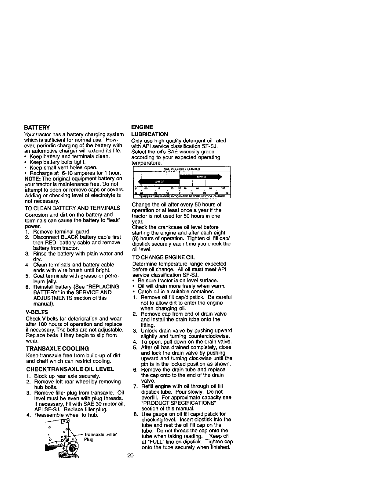
CHECKTRANSAXLE OIL LEVEL
1. Block up rear axle securely.
2. Remove left rear wheel by removing
hub bolts.
3. Remove filler plug from transaxle. Oil
level must be even with plug threads.
If necessary, fill with SAE 30 motor oil,
API SF-SJ. Replace filler plug.
4. Reassemble wheel to hub.
oPlug
ENGINE
LUBRICATION
Only use high quality detergent oil rated
with API service classification SF-SJ,
Select the oil's SAE viscosity grade
according to your expected operating
temperature.
SKEV_SCO31TYGRACES
Change the oil after every 50 hours of
operation or at least once ayear if the
tractor is not used for 50 hours in one
year.
Check the crankcase oil level before
starting the engine and after each eight
(8) hours of operation. Tighten oil fill cap/
dipstick securely each time you check the
oil level
TO CHANGE ENGINE OIL
Determine temperature range expected
before oil change. All oil must meet API
service classification SF-SJ.
• Be sure tractor is on level surface.
• Oil will drain more freely when warm.
• Catch oil in a suitable container.
1. Remove oil fill cap/dipstick. Be careful
not to allow dirt to enter the engine
when changing oil.
2. Remove cap from end of drain valve
and install the drain tube onto the
fitting.
3. Unlock drain valve by pushing upward
slightly and turning counterclockwise.
4. To open, pull down on the drain valve.
5. After oil has drained completely, close
and lock the drain valve by pushing
upward and turning clockwise until the
pin is in the locked position as shown.
6. Remove the drain tube and replace
the cap onto to the end of the drain
valve.
7. Refill engine with oil through oil fill
dipstick tube. Pour slowly. Do not
overfill. For approximate capacity see
"PRODUCT SPECIFICATIONS"
section of this manual.
8. Use gauge on oil fill cap/dipstick for
checking level. Insert dipstick into the
tube and rest the oil fill cap on the
tube. De not thread the cap onto the
tube when taking reading. Keep oi_
at "FULL" line on dipstick. Tighten cap
onto the tube securely when finished.
2O
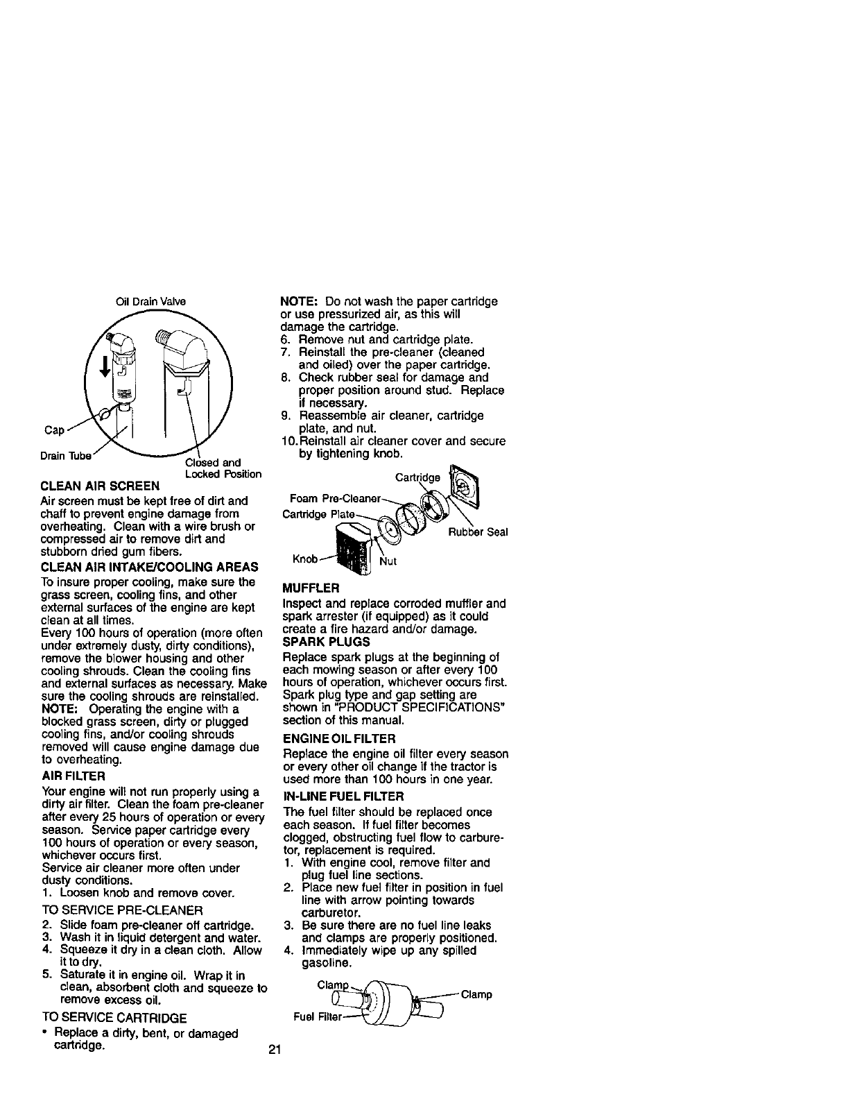
cap
DrainTube/
Oil Drain Valve
Cl _sedand
LockedPosition
CLEAN AIR SCREEN
Air screen must be kept free of dirt and
chaff to prevent engine damage from
overheating. Clean with a wire brush or
compressed air to remove dirtand
stubborn dried gum fibers.
CLEAN AIR INTAKE/COOLING AREAS
To insure proper cooling, make sure the
grass screen, cooling fins, and other
external surfaces of the engine are kept
clean at all times.
Every 100 hours of operation (more often
under extremely dusty, dirty conditions),
remove the blower housing and other
cooling shrouds. Clean the cooling fins
and external surfaces as necessary. Make
sure the cooling shrouds are reinstalled.
NOTE: Operating the engine with a
blocked grass screen, dirty or plugged
cooling fins, and/or cooling shrouds
removed will cause engine damage due
to overheating.
AIR FILTER
Your engine will not run properly using a
dirty air filter. Clean the foam pre-cleaner
after every 25 hours of operation or every
season. Service paper cartridge every
100 hours of operation or every season,
whichever occurs first.
Service air cleaner more often under
dusty conditions.
1. Loosen knob and remove cover.
TO SERVICE PRE-CLEANER
2. Slide foam pre-cleaner off cartridge.
3. Wash it in liquid detergent and water.
4. Squeeze it dry in a clean cloth. Allow
it to dry.
5. Saturate it in engine oil. Wrap it in
clean, absorbent cloth and squeeze to
remove excess oil.
TO SERVICE CARTRIDGE
• Replace adirty, bent, or damaged
cartddge. 21
NOTE: Do not wash the paper cartridge
or use pressurized air, as this will
damage the cartridge.
6. Remove nut and cartridge plate.
7. Reinstall the pre-cleaner (cleaned
and oiled) over the paper cartridge.
8. Check rubber seal for damage and
proper position around stud. Replace
if necessary.
9. Reassemble air cleaner, cartridge
plate, and nut.
10.Reinstall air cleaner cover and secure
by tightening knob.
Rubber Seal
Nut
MUFFLER
Inspect and replace corroded muffler and
spark arrester (if equipped) as it could
create a fire hazard and/or damage.
SPARK PLUGS
Replace spark plugs at the beginning of
each mowing season or after every 100
hours of operation, whichever occurs first.
Spark plug type and gap setting are
shown in "PRODUCT SPECIFICATIONS"
section of this manual.
ENGINE OIL FILTER
Replace the engine oil filter every season
or every other oil change if the tractor is
used more than 100 hours in one year.
IN-LINE FUEL FILTER
The fuel filter should be replaced once
each season. If fuet filter becomes
clogged, obstructingfuel flow to carbure-
tor, replacement is required.
1. With engine cool, remove filter and
plug fuel line sections.
2. Place new fuel filter in positionin fuel
line with arrow pointingtowards
carburetor.
3. Be sure there are no fuel line leaks
and clamps are properly positioned.
4. Immediately wipe up any spilled
gasoline.
Cl_ Clamp
Fuel Filter_
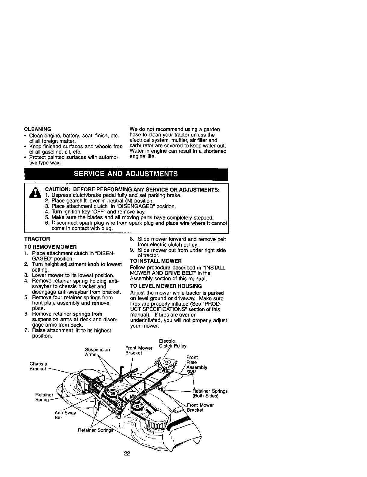
CLEANING
•Clean engine, battery, seat, finish, etc.
of all foreign matter.
•Keep finished surfaces and wheels free
of all gasoline, oil, etc.
• Protect painted surfaces with automo-
tive type wax.
We do not recommend using a garden
hose to clean your tractor unless the
electrical system, muffler, air filter and
carburetor are covered to keep water out.
Water in engine can result in a shortened
engine life.
&CAUTION: BEFORE PERFORMING ANY SERVICE OR ADJUSTMENTS:
1. Depress clutch/brake pedal fully and set parking brake,
2. Place gearshift lever in neutral (N) position.
3, Place attachment clutch in "DISENGAGED" position.
4, Turn ignition key "OFF" and remove key,
5. Make sure the blades and all moving parts have completely stopped.
6. Disconnect spark plug wire from spark plug and place wire where it cannot
come in contact with plug.
TRACTOR
TO REMOVE MOWER
1. Place attachment clutch in "DISEN-
GAGED" position.
2. Turn height adjustment knob to lowest
setting.
3. Lower mower to its lowest position.
4. Remove retainer spring holding anti-
swaybar to chassis bracket and
disengage anti-swaybar from bracket.
5. Remove four retainer springs from
front plate assembly and remove
plate.
6. Remove retainer springs from
suspension arms at deck and disen-
gage arms from deck.
7. Raise attachment lift to its highest
position.
Suspension
Arms
Chassis
8. Slide mower forward and remove belt
from electric clutch pulley.
9. Slide mower out from under right side
of tractor.
TO INSTALL MOWER
Follow procedure described in "INSTALL
MOWER AND DRIVE BELT" in the
Assembly section of this manual.
TO LEVEL MOWER HOUSING
Adjust the mower while tractor is parked
on level ground or driveway. Make sure
tires are properly inflated (See "PROD-
UCT SPECIFICATIONS" section of this
manual). If tires are over or
underinflated, you will not properly adjust
your mower.
Electric
Front Mower Clutch Pulley
Bracket Front
Plate
Retainer
Sprin!
Anti-Sway
Bar
Retainer S
Retainer Springs
(Both Sides)
22
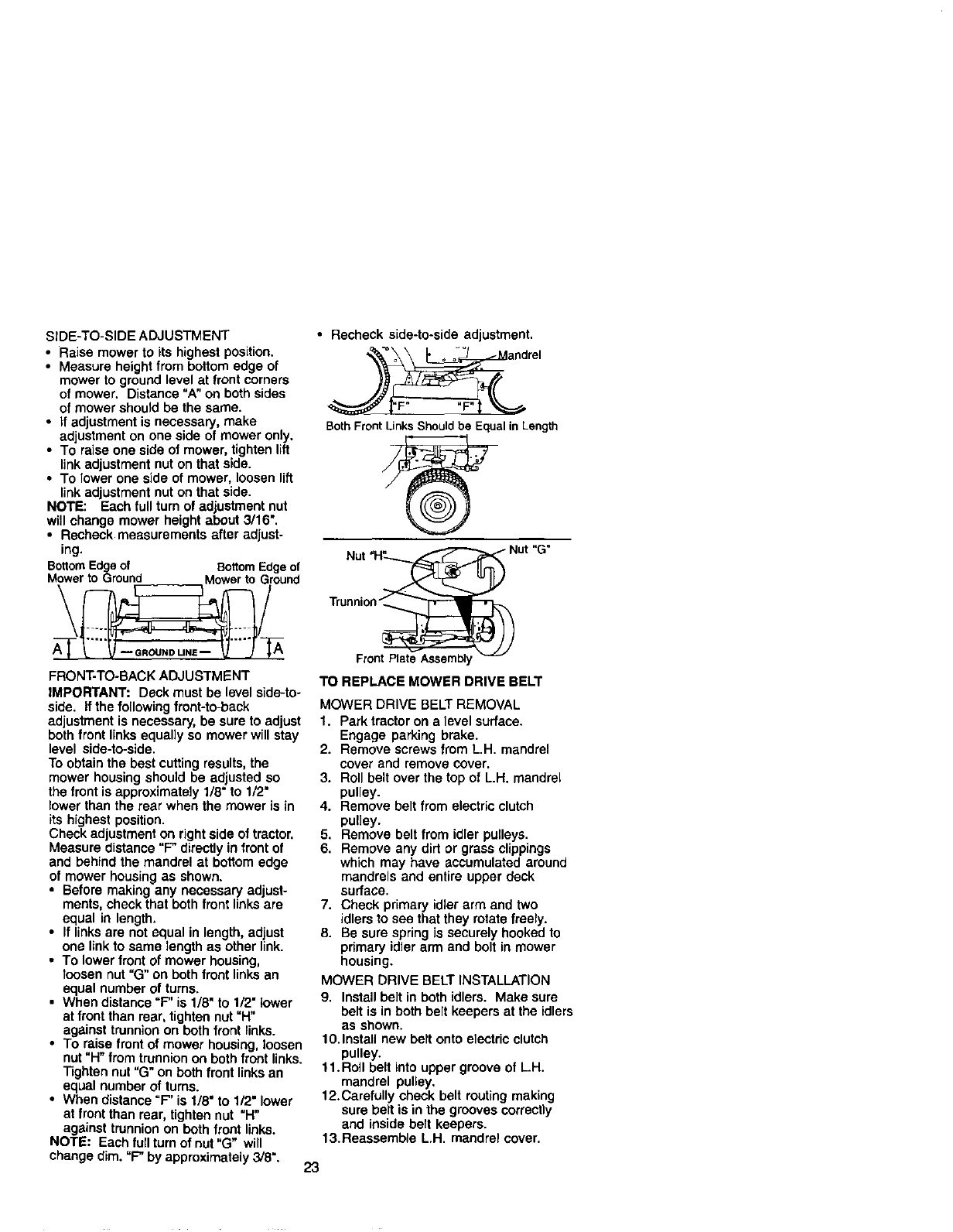
SIDE-TO-SIDE ADJUSTMENT
•Raise mower to its highest position.
• Measure height from bottom edge of
mower to ground level at front corners
of mower. Distance "A" on both sides
of mower should be the same.
• If adjustment is necessary, make
adjustment on one side of mower only.
• To raise one side of mower, tighten lift
link adjustment nut on that side.
• To lower one side of mower, loosen lift
link adjustment nut on that side.
NOTE: Each lull turn of adjustment nut
will change mower height about 3/16".
• Recheck measurements after adjust-
ing.
BottomEdgeof BottomEdgeof
Mowerto Ground Mowerto Ground
\/
FRONT-TO-BACK ADJUSTMENT
IMPORTANT: Deck must be level side-to-
side. If the following front-to-back
adjustment is necessary, be sure to adjust
both front links equally so mower will stay
level side-to-side.
To obtain the best cutting results, the
mower housing should be adjusted so
the front is approximately 1/8" to 1/2"
lower than the rear when the mower is in
its highest position.
Check adjustment on right side of tractor,
Measure distance "F" directly in front of
and behind the mandrel at bottom edge
of mower housing as shown.
•Before making any necessary adjust-
ments, check that both front links are
equal in length,
•If links are not equal in length, adjust
one link to same length as other link.
•To lower front of mower housing,
loosen nut "G"on both front links an
equal number of turns.
•When distance "F" is 1/8" to 112"lower
at front than rear, tighten nut "H"
against trunnion on both front links.
•To raise front of mower housing, loosen
nut "H"from trunnion on both front links.
Tighten nut "G" on both front links an
equal number of rums.
•When distance =F" is 1/8" to 1/2" lower
at front than rear, tighten nut "H"
against trunnion on both front links.
NOTE: Each full turn of nut "G" will
change dim. "F" by approximately 3/8".
• Recheck side-to-side adjustment.
BothFrontLinksShouldbe EqualinLength
Nut "H_-__ Nut "G"
TO REPLACE MOWER DRIVE BELT
MOWER DRIVE BELT REMOVAL
1. Park tractor on a level surface.
Engage parking brake.
2. Remove screws from L.H. mandrel
cover and remove cover.
3. Roll belt over the top of L.H. mandrel
pulley.
4. Remove belt from electric clutch
pulley.
5. Remove belt from idler pulleys.
6. Remove any dirt or grass clippings
which may have accumulated around
mandrels and entire upper deck
surface.
7. Check primary idler arm and two
idlers to see that they rotate freely.
8. Be sure spring is securely hooked to
primary idler arm and bolt in mower
housing.
MOWER DRIVE BELT INSTALLATION
9. Install belt in both idlers. Make sure
belt is in both belt keepers at the idlers
as shown.
10. Install new belt onto electric clutch
pulley.
11. Roll belt into upper groove of L.H.
mandrel pulley,
12.Carefully check belt routing making
sure belt is in the grooves correctly
and inside belt keepers.
13.Reassemble L.H. mandrel cover.
23
_Screws Electric
i_eaftnd_LeftHand Idler ClutChpulley
Man_rel_ Mandrel Mower
_ Drive
Cove
Left Hand Mower Center
Mandrel Blade Mandrel
Mandrel
Cover
Mower
Drive
Belt Belt
Keepers
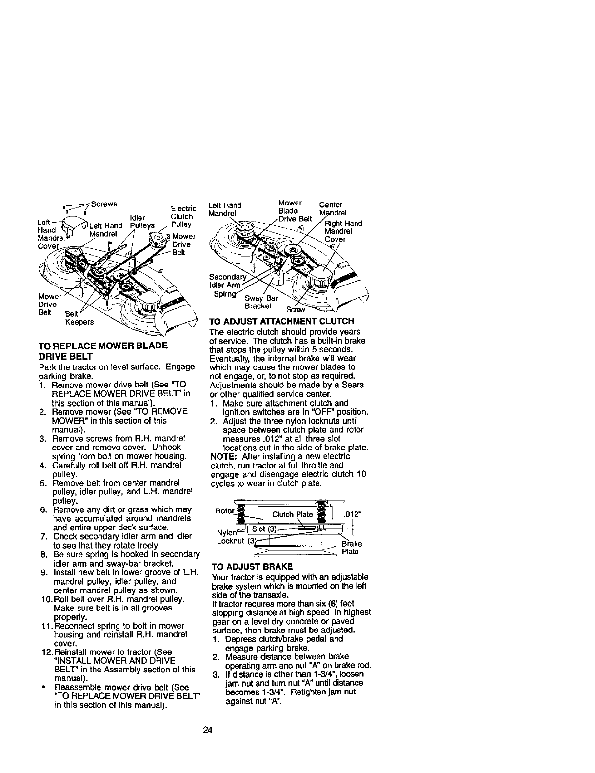
TO REPLACE MOWER BLADE
DRIVE BELT
Park the tractor on level surface. Engage
parking brake.
1. Remove mower drive belt (See "TO
REPLACE MOWER DRIVE BELT" in
this section of this manual).
2. Remove mower (See "TO REMOVE
MOWER" in this section of this
manual).
3. Remove screws from R.H. mandrel
cover and remove cover. Unhook
spring from bolt on mower housing.
4. Carefully roll belt off R.H. mandrel
pulley.
5. Remove belt from center mandrel
pulley, idler pulley, and L.H. mandrel
pulley.
6. Remove any dirt or grass which may
have accumulated around mandrels
and entire upper deck surface.
7. Check secondary idler arm and idler
to see that they rotate freely.
8. Be sure spring is hooked in secondary
idler arm and sway-bar bracket.
9. Install new belt in bowergroove of L.H.
mandrel pulley, idler pulley, and
center mandrel pulley as shown.
10.Roll belt over R.H. mandrel pulley.
Make sure belt is in all grooves
properly.
11.Reconnect spring to bolt in mower
housing and reinstall R.H. mandrel
cover.
12. Reinstall mower to tractor (See
"INSTALL MOWER AND DRIVE
BELT" in the Assembly section of this
manual).
•Reassemble mower drive belt (See
"TO REPLACE MOWER DRIVE BELT"
in this section of this manual).
Idler Arm \
Sway Bar
Bracket
TO ADJUST A'I-rACHMENT CLUTCH
The electdc clutch should provide years
of service, The clutch has abuilt-in brake
that stops the pulley within 5 seconds,
Eventually, the internal brake will wear
which may cause the mower blades to
not engage, or, to not stop as required.
Adjustments should be made by a Sears
or other qualified service center.
1. Make sure attachment clutch and
ignition switches are in "OFF" position.
2. Adjust the three nylon Iocknuts until
space between clutch plate and rotor
measures .012" at all three slot
Iooations cut in the side of brake ptate.
NOTE: After installing a new electric
clutch, run tractor at fullthrottle and
engage and disengage electric clutch 10
cycles to wear in clutch plate.
°oto;4LL c,utchP,atet --:ot2"
Nylon_ l
Locknut(3)'-"'T'- IB'rake
_Plate
TO ADJUST BRAKE
Yourtractor is equipped with an adjustable
brake system which is mounted on the left
side of the transaxle.
If tractor requiresmore than six(6) feet
stoppingdistance at high speed in highest
gear on a level dry concrete or paved
surface, then brake must be adjusted.
1. Depress clutchYorakepedal and
engage parking brake.
2. Measure distance between brake
operatingarm and nut "A" on brake rod.
3. If distance is other than 1-3/4", loosen
jam nut and turn nut =A"untildistance
becomes 1-3/4". Retighten jam nut
against nut "A".
24
4. Road test tractor for proper stopping
distance as stated above. Readjust if
necessary. If stopping distance is still
greater than six (6) feet in highest gear,
further maintenance is necessary.
Contact a Sears or other qualified
service center.
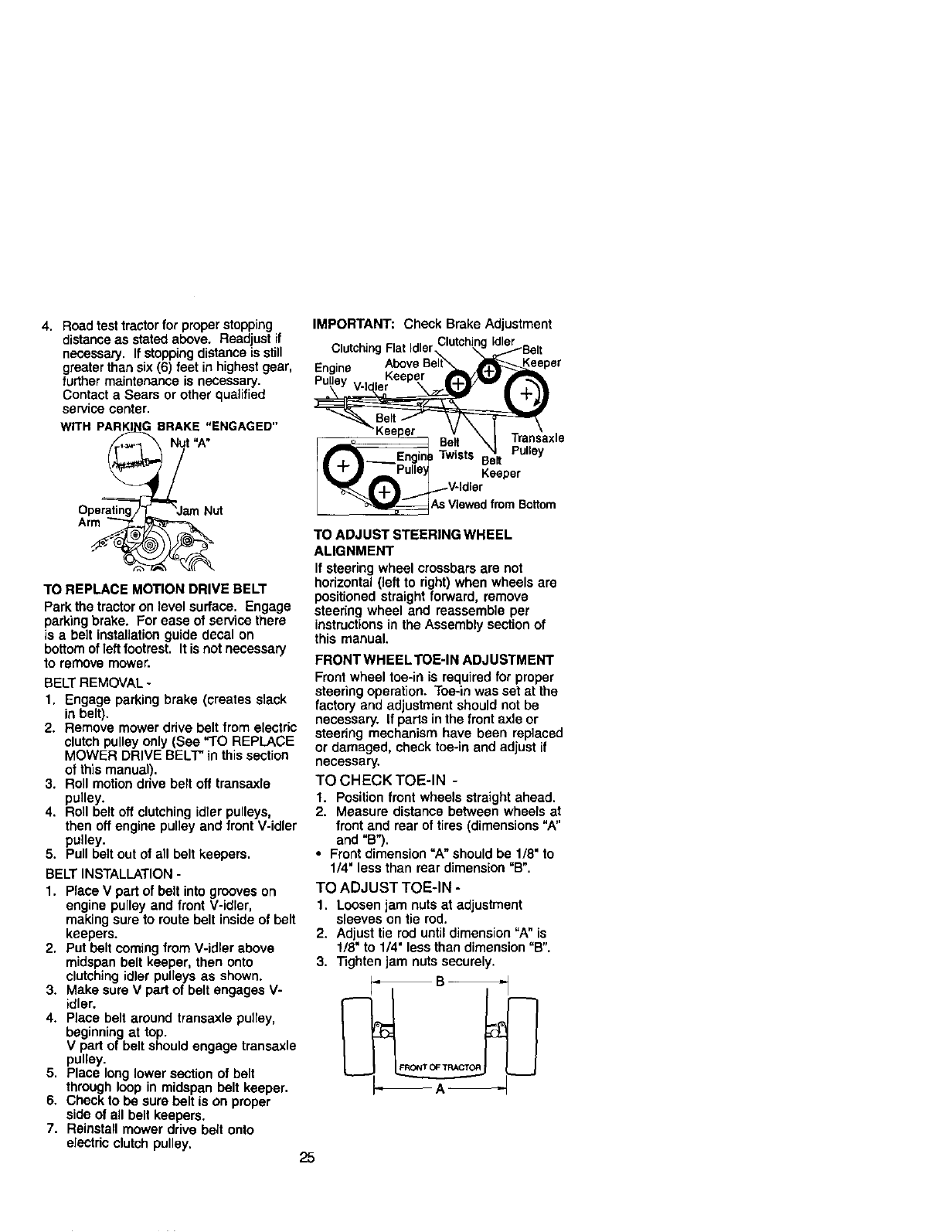
WITH PARKI BRAKE "ENGAGED"
Nut "A"
Operatin
Arm
TO REPLACE MOTION DRIVE BELT
Park the tractor on level surface, Engage
parking brake. For ease of service there
is a belt installationguide decal on
bottom of left footrest, It is not necessary
to remove mower.
BELT REMOVAL -
1. Engage parking brake (creates slack
in belt).
2. Remove mower drive belt from electric
clutch pulley only (See "TO REPLACE
MOWER DRIVE BELT" in this section
of this manual).
3. Roll motion drive belt off transaxle
pulley.
4. Roll belt off clutching idler pulleys,
then off engine pulley and front V-idler
pulley.
5. Pull belt out of all belt keepers.
BELT INSTALLATION -
1. Place V part of belt into grooves on
engine pulley and front V-idler,
making sure to route belt inside of belt
keepers.
2. Put belt coming from V-idler above
midspan belt keeper, then onto
clutching idler pulleys as shown.
3. Make sure V part of belt engages V-
idler.
4. Place belt around transaxle pulley,
beginning at top.
V part of belt should engage transaxle
pulley.
5. Place long lower section of belt
through loop in midspan belt keeper.
6. Check to be sure belt is on proper
side of all belt keepers.
7. Reinstall mower drive belt onto
electdc clutch pulley.
IMPORTANT: Check Brake Adjustment
Clutching Flat Idler,
Engine Above
Transaxle
Belt Pulley
Twists Belt
Keeper
I from Bottom
TO ADJUST STEERING WHEEL
ALIGNMENT
If steering wheel crossbars are not
horizontal (left to right) when wheels are
positioned straight forward, remove
steering wheel and reassemble per
instructionsin the Assembly section of
this manual.
FRONTWHEELTOE-IN ADJUSTMENT
Front wheel toe-in is required for proper
steering operation. Toe-in was set at the
factory and adjustment should not be
necessary. If parts in the front axle or
steedng mechanism have been replaced
or damaged, check toe-in and adjust if
necessary.
TO CHECK TOE-IN -
1. Position front wheels straight ahead.
2. Measure distance between wheels at
front and rear of tires (dimensions "A"
and "B").
•Front dimension =A" should be 1/8" to
1/4' less than rear dimension "B".
TO ADJUST TOE-IN -
1. Loosen jam nuts at adjustment
sleeves on tie rod.
2. Adjust tie rod until dimension "A" is
1/8" to 1/4" less than dimension "B".
3. Tighten jam nuts securely.
25
FRONT WHEEL CAMBER
The front wheel camber is not adjustable
on your tractor. If damage has occurred to
affect the front wheel camber, contact a
Sears or other qualified service center.
TO REMOVEWHEEL FOR REPAIRS
FRONT WHEEL -
1. Block up axle securely.
2. Remove axle cover, retaining ring and
washers to allow wheel removal.
3. Repair tire and reassemble.
4. Replace washers and snap retaining
ring securely in axle groove.
5. Replace axle cover.
REAR WHEEL -
1. Block rear axle securely.
2. Remove five (5) hub bolts to allow
wheel removal.
3. Repair tire and reassemble. Replace
and tighten hub bolts securely.
NOTE: To seal tire punctures and prevent
flat tires due to slow leaks, tire sealant
may be purchased from your local parts
dealer. Tire sealant also prevents tire dry
rot and corrosion.
RetainingWashers
g'o vor\
TO START ENGINEWlTH AWEAK
BATTERY
• I,CAUTION: Lead-acid batteries
generate explosive gases. Keep sparks,
flame and smoking materials away from
batteries. Always wear eye protection
when around batteries.
If your battery is too weak to start the
engine, it should be recharged. (See
"BATTERY = in the MAINTENANCE
section of this manual).
If "jumper cables" are used for emergency
starting, follow this procedure:
IMPORTANT: Your tractor is equipped
with a 12 volt negative grounded system.
The other vehical must also be a 12 volt
negative grounded system. Do not use
your tractor battery to start other vehicles.
TO ATTACH JUMPER CABLES -
1. Connect each end of the RED cable to
the POSITIVE (+) terminal of each
battery, taking care not to short
against chassis.
2. Connect one end of the BLACK cable
to the NEGATIVE (-) terminal of fully
charged battery.
3. Connect the other end of the BLACK
cable to good CHASSIS GROUND,
away from fuel tank and battery.
TO REMOVE CABLES, REVERSE
ORDER -
1. BLACK cable first from chassis and
then from the fully charged battery.
2. RED cable last from both batteries.
REPLACING BATTERY
_I_CAUTION: Do not short battery
terminals by allowing a wrench or any
other object to contact both terminals at
the same time, Before connecting battery,
remove metal bracelets, wristwatch
bands, rings, etc.
Positive terminal must be connected first
to prevent sparking from accidental
grounding.
1. Lift hood to raised position.
2. Remove terminal guard.
3. Disconnect BLACK battery cable then
RED battery cable and carefully
remove battery from tractor.
4. install new battery with terminals in
same position as old battery.
5. Reinstall terminal guard.
6. First connect RED battery cable to
positive (+) battery terminal with hex
bolt and keps nut as shown. Tighten
securely.
26
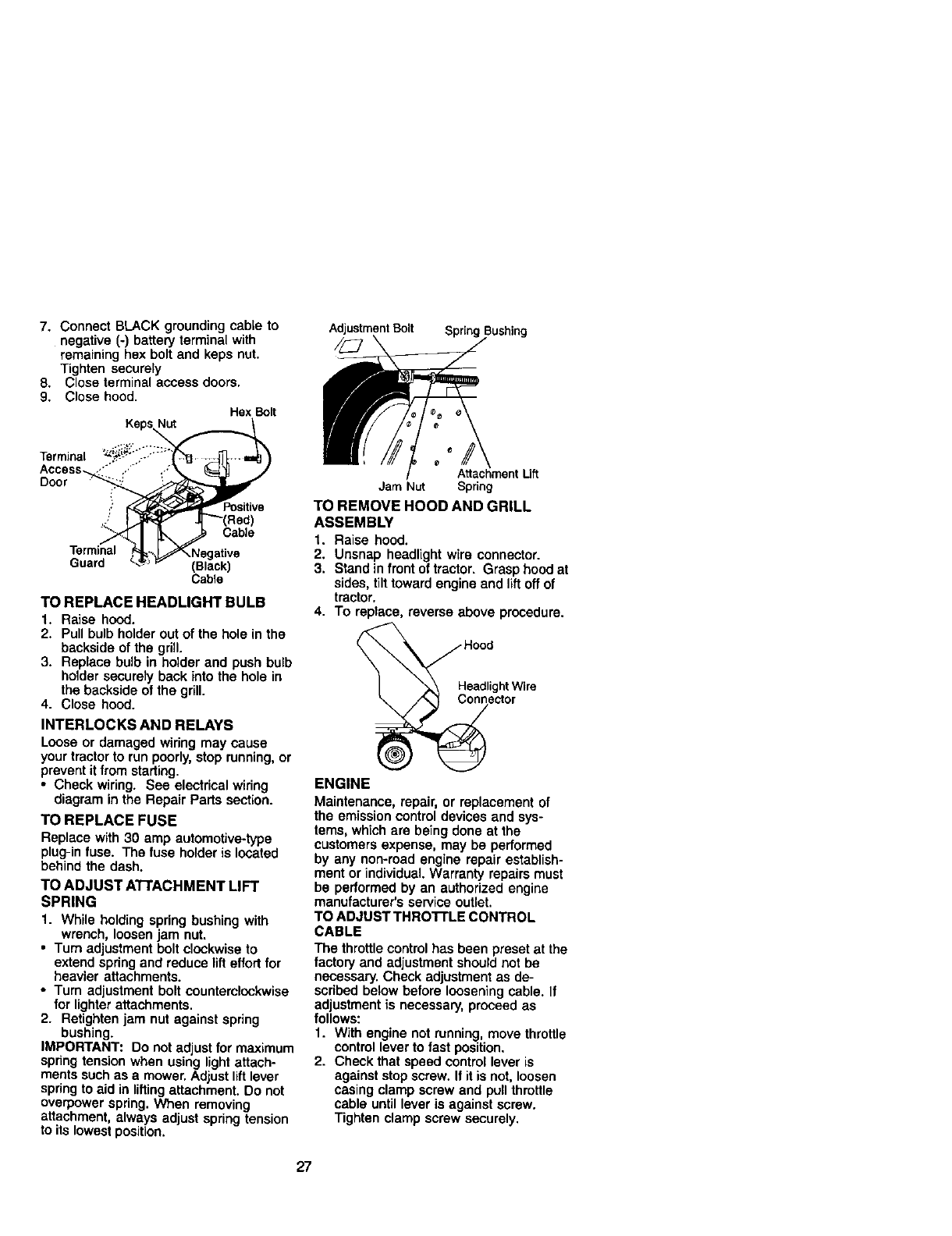
7. Connect BLACK grounding cable to
negative (-) battery terminal with
remaining hex bolt and keps nut.
Tighten securely
8. Close terminal access doors.
9. Close hood. Hex Bolt
Keps
Adjustment Bolt Spring
Terminal
Access._, S /- ./
Door :_
Positive
Terminal
Guard (Black)
Cable
TO REPLACE HEADLIGHT BULB
1. Raise hood.
2. Pull bulb holder out of the hole in the
backside of the grill.
3. Replace bulb in holder and push bulb
holder securely back into the hole in
the backside of the grill.
4. Close hood.
INTERLOCKS AND RELAYS
Loose or damaged wiring may cause
your tractor to run poorly, stop running, or
prevent it from starting.
•Check wiring. See electrical wiring
diagram in the Repair Parts section.
TO REPLACE FUSE
Replace with 30 amp automotive-type
plug-in fuse. The fuse holder is located
behind the dash.
TO ADJUST ATrACHM ENT LIFT
SPRING
1. While holding spring bushing with
wrench, loosen jam nut.
• Turn adjustment bolt clockwise to
extend spdng and reduce lifteffort for
heavier attachments.
• Turn adjustment bolt counterclockwise
for lighter attachments.
2. Retighten jam nut against spring
bushing.
IMPORTANT: Do not adjust for maximum
spring tension when using light attach-
ments such as a mower. Adjust lift lever
spdng to aid in liffingattachment. Do not
overpower spring. When removing
attachment, always adjust spring tension
to its lowestposition.
Attachment Lift
Jam Nut Spring
TO REMOVE ROOD AND GRILL
ASSEMBLY
1. Raise hood.
2. Unsnap headlight wire connector.
3. Stand in front of tractor. Grasp hood at
sides, tilttoward engine and liftoff of
tractor.
4. To replace, reverse above procedure.
inector
ENGINE
Maintenance, repair, or replacement of
the emission control devices and sys-
tems, which are being done at the
customers expense, may be performed
by any non-road engine repair establish-
ment or individual. Warranty repairs must
be performed by an authorized engine
manufacturer's service outlet.
TO ADJUST THRO'rrLE CONTROL
CABLE
The throttle controlhas been preset at the
factory and adjustment should not be
necessary. Check adjustment as de-
scribed below before loosening cable. If
adjustment is necessary, proceed as
follows:
1. With engine not running, move throttle
control lever to fast position.
2. Check that speed control lever is
against stop screw. If it is not, loosen
casing clamp screw and pull throttle
cable until lever is against screw.
Tighten clamp screw securely.
27
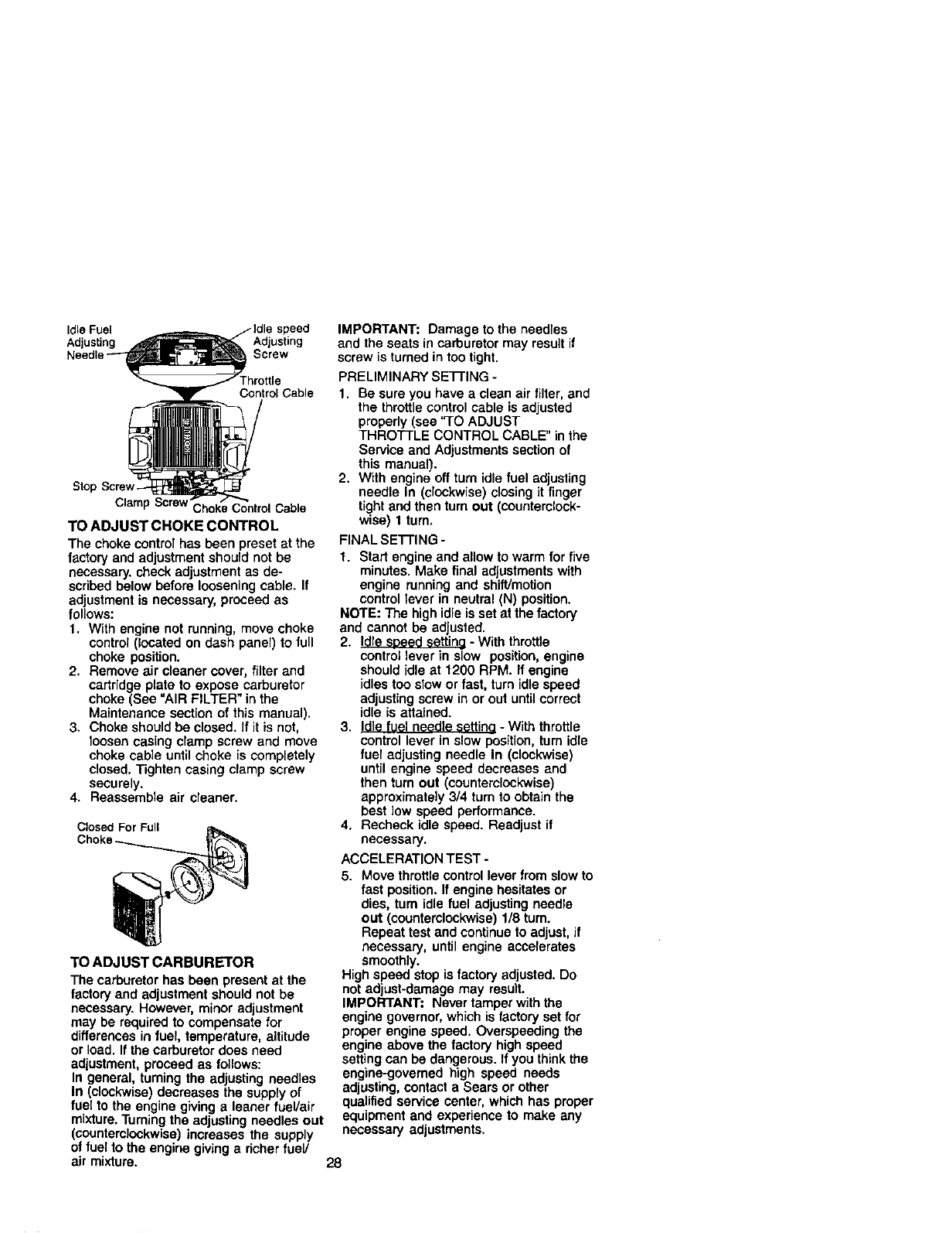
Idle Fuel
Adjusting Screw
Control Cable
Clamp ScrewChoke Control Cable
TO ADJUST CHOKE CONTROL
The choke control has been preset at the
factory and adjustment should not be
necessary, check adjustment as de-
scribed below before loosening cable. If
adjustment is necessary, proceed as
follows:
1. With engine not running, move choke
control (located on dash panel) to full
choke position.
2. Remove air cleaner cover, filter and
cartridge plate to expose carburetor
choke (See "AIR FILTER" in the
Maintenance section of this manual).
3. Choke should be closed. If it is not,
loosen casing clamp screw and move
choke cable until choke is completely
closed. Tighten casing clamp screw
securely.
4. Reassemble air cleaner.
Closed For Full
TO ADJUST CARBURETOR
The carburetor has been present at the
factory and adjustment should not be
necessary. However, minor adjustment
may be required to compensate for
differences in fuel, temperature, altitude
or load. If the carburetor does need
adjustment, proceed as follows:
In general, turning the adjusting needles
In (clockwise) decreases the supply of
fuel to the engine giving a leaner fuel/air
mixture. Turningthe adjusting needles out
(countemlockwise) increases the supply
of fuel to the engine giving a richer fue!/
air mixture.
IMPORTANT: Damage to the needles
and the seats in carburetor may result if
screw is turned in too tight.
PRELIMINARY SETI'ING -
1. Be sure you have a clean air filter, and
the throttle controlcable is adjusted
properly (see "TO ADJUST
THROTTLE CONTROL CABLE" in the
Service and Adjustments section of
this manual).
2. With engine off turn idle fuel adjusting
needle In (clockwise) closing it finger
tight and then turn out (counterclocK-
wise) 1 turn,
FINAL SETI'ING -
1. Start engine and allow to warm for five
minutes. Make final adjustments with
engine running and shift/motion
control lever in neutral (N) position.
NOTE: The high idle is set at the factory
and cannot be adjusted.
2. Idle sDeeU settine - With throttle
control lever in slow position, engine
should idle at 1200 RPM. If engine
idles too slow or fast, turn idle speed
adjusting screw in or out until correct
idle is attained.
3. Idle fuel needle settino - With throttle
control lever in slow position, turn idle
fuer adjusting needle In (clockwise)
until engine speed decreases and
then turn out (counterclockwise)
approximately 3/4 turn to obtain the
best low speed performance.
4. Recheck idle speed. Readjust if
necessary.
ACCELERATION TEST -
5. Move throttle control lever from slow to
fast position. If engine hesitates or
dies, turn idle fuel adjusting needle
out (counterclockwise) 1/8 turn.
Repeat test and continue to adjust, if
necessary, until engine accelerates
smoothly.
High speed stop is factory adjusted. Do
not adjust-damage may result.
IMPORTANT: Never tamper with the
engine governor, which is factory set for
proper engine speed. Overspeeding the
engine above the factory high speed
setting can be dangerous. If you think the
engine-governed high speed needs
adjusting, contact a Sears or other
qualified service center, which has proper
equipment and experience to make any
necessary adjustments.
28
Immediately prepare your tractor for
storage at the end of the season or if the
tractor will not be used for 30 days or
more.
_1=CAUTION: Never store the tractor with
gasoline in the tank inside a building
where fumes may reach an open flame or
spark. Allow the engine to cool before
storing in any enclosure.
TRACTOR
Remove mower from tractor for winter
storage. When mower is to be stored for
a period of time, clean it thoroughly,
remove all dirt, grease, leaves, etc. Store
in a clean, dry area.
1. Clean entire tractor (See "CLEANING"
in the Maintenance section of this
manual).
2. Inspect and replace belts, if necessary
(See belt replacement instructions in
the Service and Adjustments section
of this manual).
3. Lubricate as shown in the Mainte-
nance section of this manual.
4. Be sure that all nuts, boltsand screws
are securely fastened. Inspect moving
parts for damage, breakage and wear.
Replace if necessary.
5. Touch up all rusted or chipped paint
surfaces; sand lightly before painting.
BA'n'ERY
•Fully charge the battery for storage.
•After a period of time in storage, battery
may require recharging.
•To help prevent corrosion and power
leakage during long periods of storage,
battery cables should be disconnected
and battery creaned thoroughly (see
"TO CLEAN BATTERY AND TERMI-
NALS" in the Maintenance section of
this manual).
•After cleaning, leave cables discon-
nected and place cables where they
cannot come in contact with battery
terminals.
•If battery is removed from tractor for
storage, do not store battery directly on
concrete or damp surfaces.
ENGINE
FUEL SYSTEM
IMPORTANT: It is importantto prevent
gum deposites from forming in essential
fuel system parts such as carburetor, fuel
hose, or tank during storage. Also,
expedance indicates that alcohol
blended fuels (called gasohol or using
ethanol or methanol) can attract moisture
which leads to separation and formation
of acids during storage. Acidic gas can
damage the fuel system of and engine
while in storage.
1. Drain the fuel tank.
2. Start the engine and let it run until the
fuel lines and carburetor are empty.
•Never use engine or carburetor cleaner
products in the fuel tank or permanent
damage may occur.
• Use fresh fuel next season.
NOTE: Fuel stabilizer is an acceptable
alternative in minimizing the formation of
fuel gum deposits during storage. Add
stabilizer to gasoline in fuel tank or
storage container. Always follow the mix
ratio found on stabilizer container. Run
engine at least 10 minutes after adding
stabilizer to allow the stabilizer to reach
the carburetor. Do not drain the gas tank
and carburetor if using fuel stabilizer.
ENGINE OIL
Drain oil (with engine warm) and replace
with clean engine oil. (See "ENGINE" in
the Maintenance section of this manual).
CYLINDER(S)
1. Remove spark plug(s).
2. Pour one ounce of oil through spark
plug hole(s) into cylinder(s).
3. Turn ignition key to "START" position
for a few seconds to distribute0il.
4. Replace with new spark plug(s).
OTHER
•Do not store gasoline from one season
to another.
•Replace your gasoline can if your can
starts to rust. Rust and/or dirt in your
gasoline will cause problems.
•If possible, storeyour tractor indoors
and cover it to give protectionfrom dust
and dirt.
•Cover your tractor with asuitable
protective cover that does not retain
moisture. Do not use plastic. Plastic
cannot breathe which allows conden-
sation to form and will cause your
tractor to rust.
IMPORTANT: Never cover tractor while
engine and exhaust areas are still warm.
29
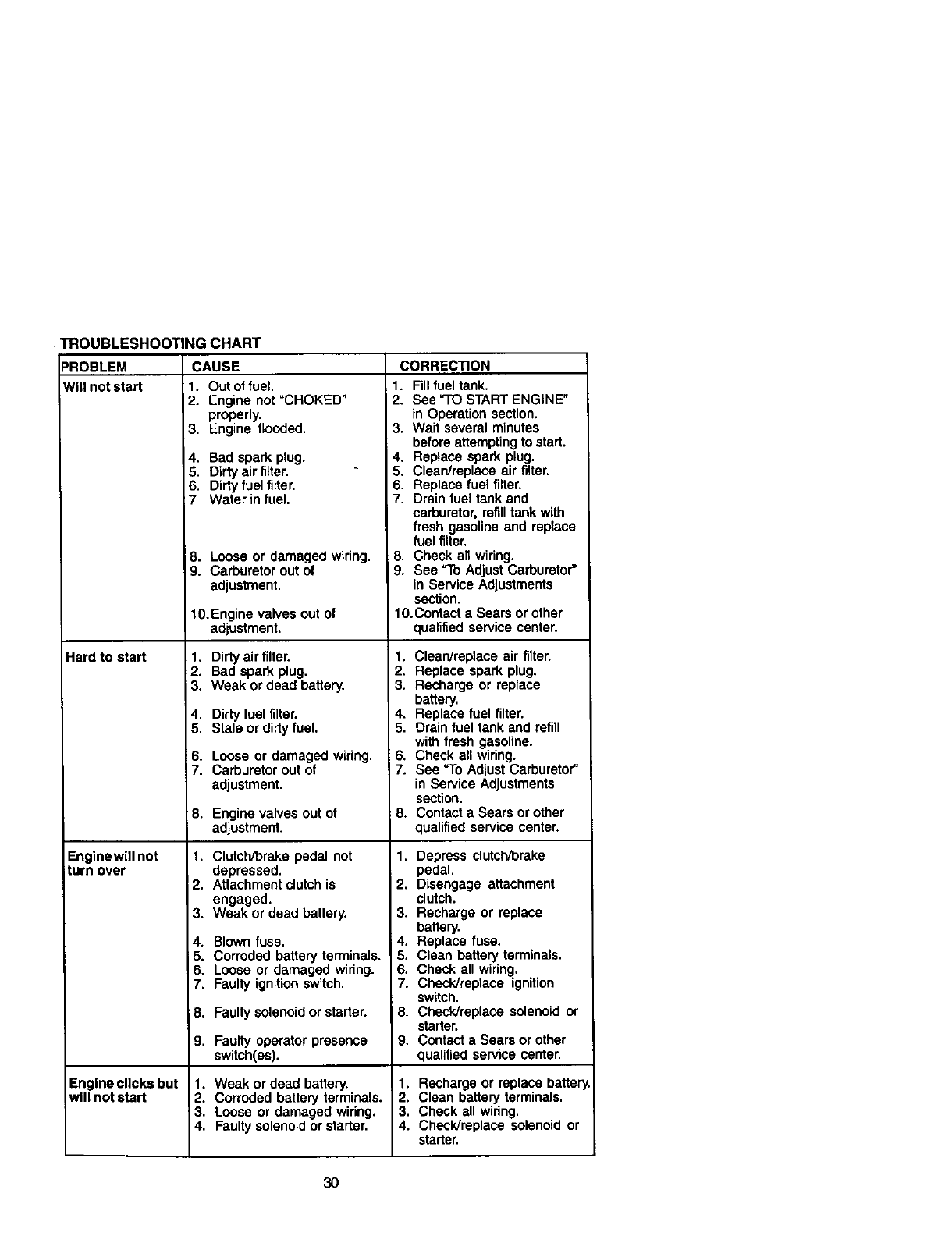
TROUBLESHOOTING CHART
=ROBLEM CAUSE
Will not start 1. Out of fuel,
Hard to start
Englnewill not
turn over
2. Engine not "CHOKED"
properly.
3. Engine flooded.
4. Bad spark plug.
5. Dirty air filter.
6. Dirty fuel filter.
:7 Water in fuel.
8. Loose or damaged wiring.
9. Carburetor out of
adjustment.
10. Engine valves out of
adjustment.
1. Dirty air filter.
2. Bad spark plug.
3. Weak or dead battery.
4. Dirty fuel filter.
5. Stale or dirty fuel.
6. Loose or damaged wiring.
7. Carburetor out of
adjustment.
8. Engine valves out of
adjustment.
1. Clutch/brake pedal not
depressed.
2. Attachment clutch is
engaged.
3. Weak or dead battery.
4. Blown fuse.
5. Corroded battery terminals.
6. Loose or damaged wiring.
7. Faulty ignition switch.
; 8. Faulty solenoid or starter.
9. Faulty operator presence
switch(es).
1. Weak or dead battery.
2. Corroded battery terminals.
3. Loose or damaged wiring.
4. Faulty solenoid or starter.
Engine clicks but
will not start
CORRECTION
1. Fill fuel tank.
2. See"TO START ENGINE"
in Operation section,
3. Wait several minutes
before attempting to start.
4. Replace spark plug.
5. Clean/replace air filter.
6. Replace fuel filter.
7. Drain fuel tank and
carburetor, refill tank with
fresh gasoline and replace
fuel filter.
8. Check all widng.
9. See "To Adjust Carburetor"
in Service Adjustments
section.
10.Contact a Sears or other
qualified service center.
1. Clean/replace air filter.
2. Replace spark plug.
3. Recharge or replace
battery.
4. Replace fuel filter.
5. Drain fuel tank end refill
with fresh gasoline.
6. Check all wiring.
7. See "To Adjust Carburetor"
in Service Adjustments
section.
8. Contact aSears or other
qualified service center.
1. Depress clutch/brake
pedal.
2. Disengage attachment
clutch.
3. Recharge or replace
battery.
i 4. Replace fuse,
5. Clean battery terminals.
6. Check all wiring.
7. Check/replace ignition
switch.
8. Check/replace solenoid or
starter.
9. Contact a Sears or other
qualified service center.
1. Recharge or replace battery
2. Clean battery terminals.
3. Check all wiring.
4. Check/replace solenoid or
starter.
30
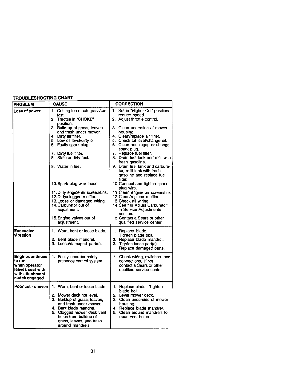
TROUBLESHOOTING CHART
PROBLEM CAUSE CORRECTION
Loss of power 1. Cutting too much grass/too
Excessive
_lbration
Englnecontlnues
_orun
Nhen operator
leaves seat with
Nith attachment
¢lutch engaged
Poor cut-uneven
fast,
2. Throttle in "CHOKE"
position.
3. Build-up of grass, leaves
and trash under mower,
4. Dirty air filter.
5. Low oil level/didy oil.
6, Faulty spark plug.
7. Dirty fuel filter.
8. Stale or dirty fuel.
9. Water in fuel.
10.Spark plug wire loose.
11. Dirty engine air screen/fins.
12. Dirty/clogged muffler.
13.Loose or damaged wiring.
14.Carburetor out of
adjustment.
15.Engine valves out of
adjustment.
1. Worn, bent or loose blade.
2. Bent blade mandrel,
3. Loose/damaged part(s).
1. Faulty operator-safety
presence controlsystem.
1, Worn, bent or loose blade.
2. Mower deck not level.
3, Buildupof grass, leaves,
and trash under mower.
4. Bent blade mandrel.
5. Clogged mower deck vent
holes from buildup of
grass, leaves, and trash
around mandrels.
1. Set in "Higher Cut" position/
reduce speed.
2. Adjust throttle control.
I3. Clean underside of mower
housing.
4. Clean/replace air filter.
5. Check oil level/change oil.
6. Clean and regap or change
spark plug.
7. Replace fuel filter.
8. Drain fuel tank and refill with
fresh gasoline.
9. Drain fuel tank and carbure-
tor, refill tank with fresh
gasoline and replace fuel
filter.
1O.Connect and tighten spark
plug wire.
11.Clean engine air screen/fins
12.Clean/replace muffler.
13.Check all wiring.
14.See "To Adjust Carburetor"
in Service Adjustments
section.
15.Contact a Sears or other
qualified service center.
1. Replace blade.
Tighten blade bolt.
2. Replace blade mandrel.
3. T_ghten loose part(s).
Replace damaged pads.
1. Check wiring, switches and
connections. If not
contact a Sears or other
qualified service center.
1, Replace blade. Tighten
blade bolt.
2, Level mower deck.
3. Clean underside of mower
housing.
4. Replace blade mandrel.
5. Clean around mandrels to
open vent holes,
31
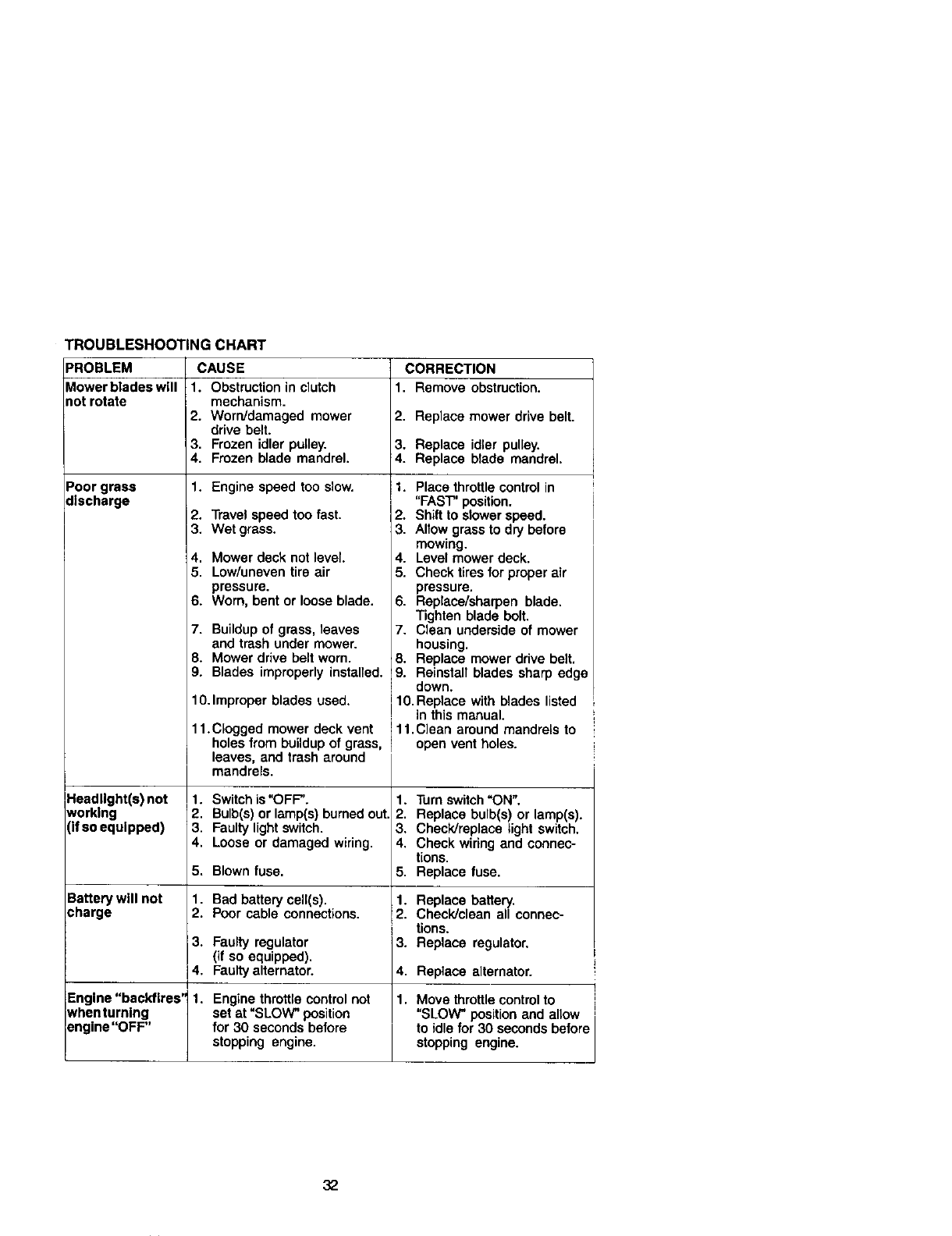
TROUBLESHOOTING CHART
PROBLEM CAUSE CORRECTION
_1owerbladesw[ll 1. Obstruction in clutch 1. Remove obstruction.
rot rotate mechanism.
2. Worn/damaged mower 2. Replace mower drive belt.
drive belt.
3. Frozen idler pulley. 3. Replace idler pulley.
4. Frozen blade mandrel. 4. Replace blade mandrel.
Poor grass 1. Engine speed too slow.
discharge
Headlight(s) not
working
(if so equipped)
Battery will not
charge
2. Travel speed too fast.
3. Wet grass.
4. Mower deck notlevel.
5. Low/uneven tire air
pressure.
6. Worn, bent or loose blade.
7. Buildup of grass, leaves
and trash under mower.
8. Mower drive belt worn.
9. Blades improperly installed.
10.Improper blades used.
11.Clogged mower deck vent
holes from buildup of grass,
leaves, and trash around
mandrels.
1. Switch is "OFF".
2. Bulb(s) or lamp(s) burned out.
3. Faulty light switch.
4. Loose or damaged wiring.
5. Blown fuse.
1. Bad battery cell(s).
2. Poor cable connections.
1. Place throttle control in
"FAST" position.
2. Shift to slower speed.
3. Allow grass to dry before
mowing.
4. Level mower deck.
5. Check tires for proper air
pressure.
6. Replace/sharpen blade.
Tighten blade bolt.
7. Clean underside of mower
housing.
8. Replace mower drive belt.
'9. Reinstall blades sharp edge
down.
I1O.Replace with blades listed
in this manual.
11.Clean around mandrels to
open vent holes.
1.
2.
3.
4.
5.
1.
2.
3.
4.
1.
Turn switch"ON".
Replace bulb(s) or lamp(s).
Check]replace light switch.
Check wiring and connec-
tions.
Replace fuse.
Replace battery.
Check]clean all connec-
tions.
Replace regulator,
3. Faulty regulator
(if so equipped).
4. Faulty alternator. Replace alternator.
Engine"backfires' 1. Engine throttle control not Move throttle control to
whenturnlng set at "SLOW" position "SLOW" position and allow
engine "OFF" for 30 seconds before to idle for 30 seconds before
stopping engine, stopping engine.
32
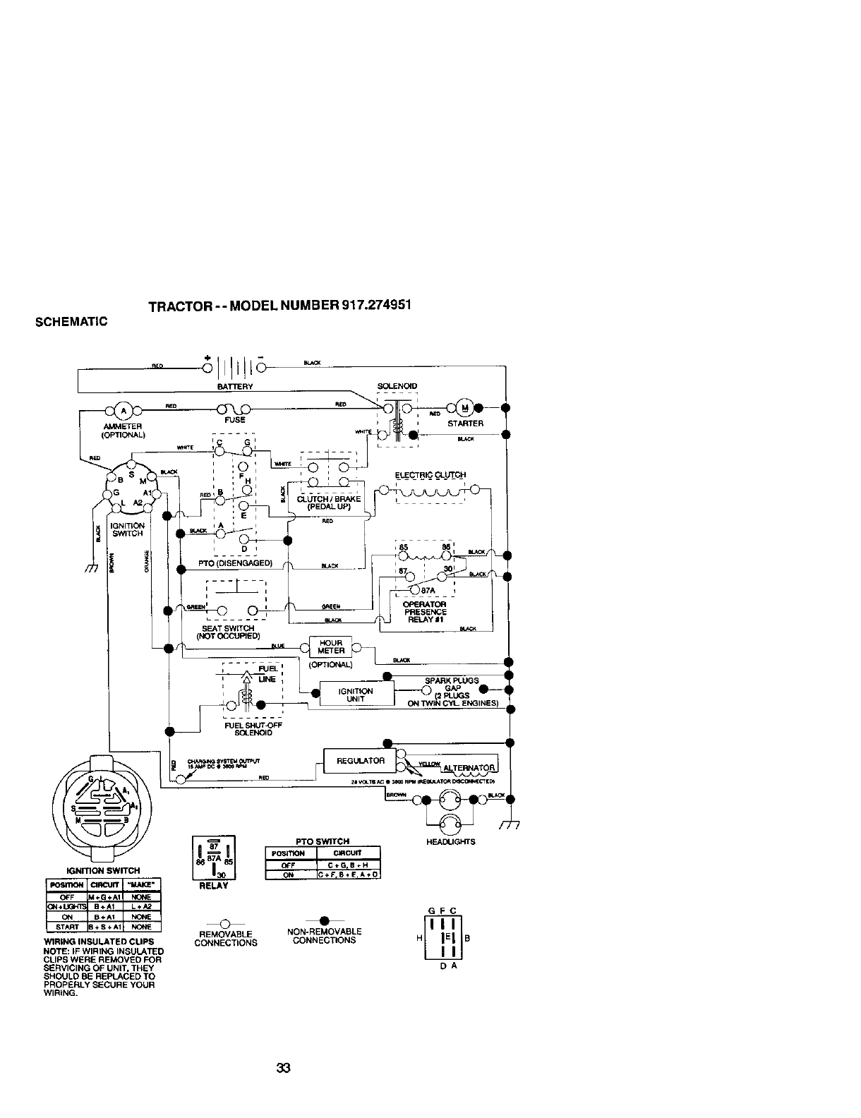
SCHEMATIC
TRACTOR -- MODEL NUMBER 917.274951
I
IGNITION SWITCH
WIRING INSULATED CUPS
NOTE: IF WIRING INSULATED
CLIPS WERE REMOVED FOR
SERVICING OF UNIT, THEY
SHOULD BE REPLACED TO
PROPERLY SECURE YOUR
WIRING.
BATTERy SOLENO4D
FUSE _', STARTER
-
', _ _ _ '-ELECTRIC CLUTCH
iDi
PTO (DISENGAGED)
i
i
L .......
SEAT SWITCH
(NOT C_,CUPIE D) muc
RELAY
FUEL SHUT_)FF
SOLENOID
•i
_85 861 mJ_
r 87A i
PRESENCE
METER
ASPARK FI.UGS
,GN,_,O_"_ _s e---
UNIT 2
• ON T,NIN CYL ENGINES
GFC
REMOVABLE NON-REMOVABLE
CONNECTIONS CONNECTIONS H B
DA
33
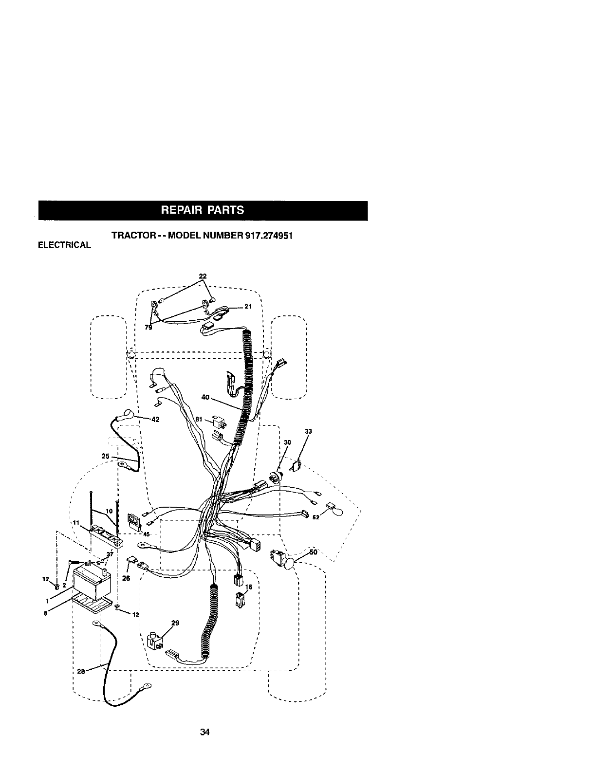
ELECTRICAL TRACTOR --MODEL NUMBER 917.274951
22
/
I_l
33
:34

ELECTRICAL TRACTOR -- MODEL NUMBER 917.274951
KEY PART
NO. NO. DESCRIPTION
1 144,927 Battery
2 74760412 Bolt Hex Head 1/4-20 x 3/4
8 7603J Tray, Battery
10 145211 Bolt 1/4-20 x 7,5 Zinc
11 150109 Hold down Battery Dash Mount
12 145769 Nut Push Nylon 1/4"
16 153664 Switch Interlock Push-In
21 166184 Harness Socket Light W/4152J
22 4152J Bulb Light
25 150755 Cable, Battery
26 108824X Fuse
27 73510400 Nut Keps Hex 1/4-20 Unc
28 170697 Cable, Ground
29 160784 Switch, Plunger
30 175566 Switch, lgn
33 140403 Key, Ignition
40 17(_38 Harness Ign.
42 154336 Cover, Termini
45 122822X Ammeter
50 174652 Switch, PTO
52 141940 Protection Wire Loop
79 163996 Bulbhok:lerAsm. Incandescent
81 109748X Relay Asm.
NOTE: All component dimensions given in U.S. inches
1 inch = 25.4 mm
35
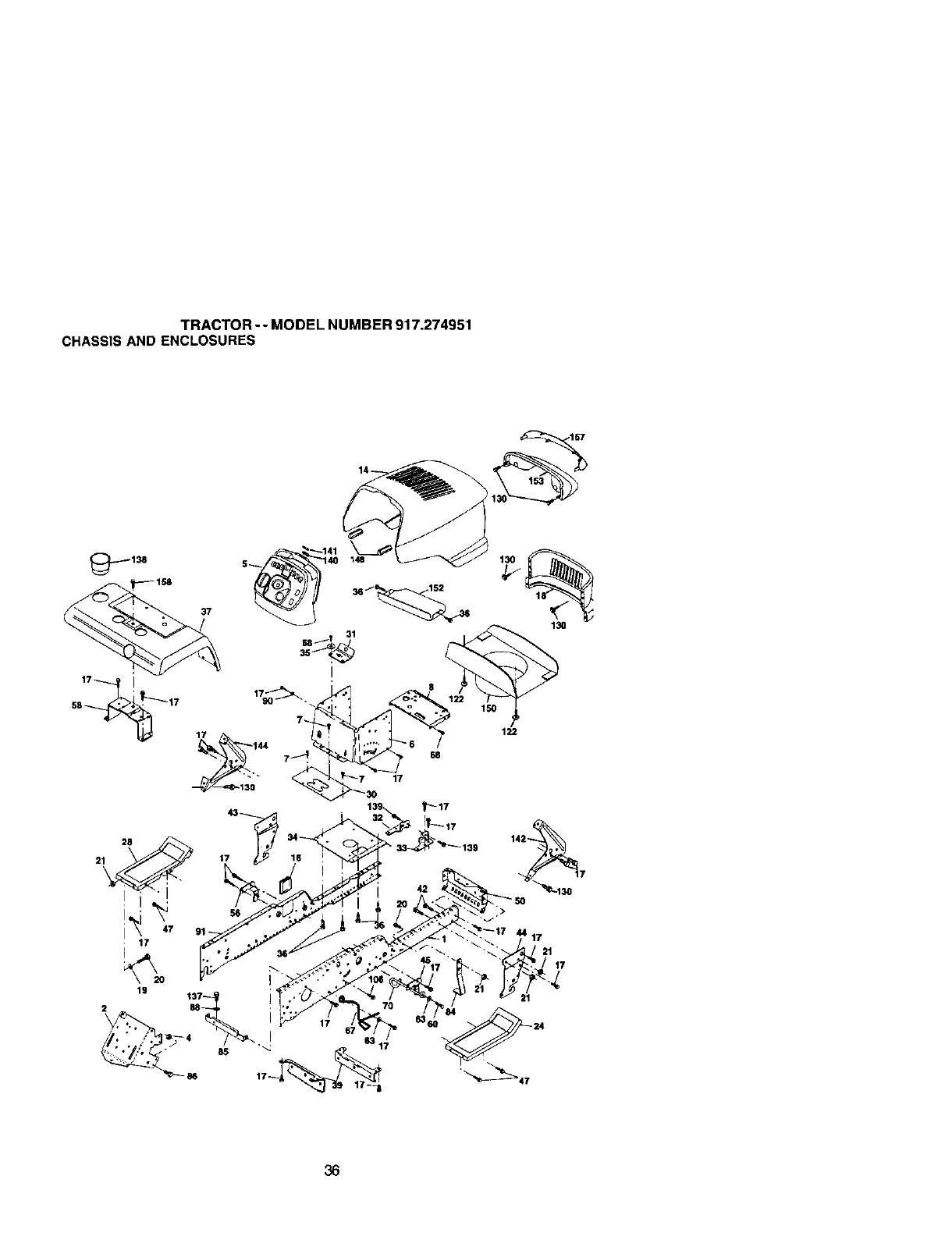
TRACTOR -- MODEL NUMBER 917.274951
CHASSIS AND ENCLOSURES
36

TRACTOR -- MODEL NUMBER 917.274951
CHASSISAND ENCLOSURES
KEY PART KEY PART
NO, NO. DESCRIPTION NO. NO, DESCRIPTION
1 175465 Rail, Frame RH 50 175476 Bracket, Chassis Front
2 175282 D_wb_,G1 56 154614 _et Asm., S_sp Ch_s_'_ Lh
4 73680700 Nut, Crownlock Hex 7/16-14UNC 58 175315 B_cket Asm., Fender
5 163976X428 Dash YTGT 2 Cyl 60 17G60620 Screw 3/8-16 x 1-1/4
6 157882 Dash, Lower Vgt One Piece 63 19131514 WaSher 13/32 x 1 x 14 Ga.
7 177'20406 Screw, Thd Cut 1/4-20 x 1/2 67 156973 Guide, Belt Gear Drive
8 145166 Suppod, Bettery 68 174905(_ Screw "l_droL 5/16-18 x 1/2
14 175259)(558 Rood Asm., Pnt Stealth YTGT 70 177679 Keeper, Belt
16 161841 Lens LH 84 142992 Stop, Over Center Mower
16 121794X Cover, Access 85 144911 Bracket, Supporl Transaxle
17 17060612 Screw 86 74760716 Belt Fin Hex 7/16-14 UNC x 1
18 174515X558 Grille 88 STD551143 WaSher, Lock Hvy Hlcl Spr 7/16
19 19131312 Washer 13/32x13/16x12 Ga. 91 175464 Rail, Frame Lh
20 S]_523710 Belt, FinHex 3/6-15xl 106 1758_20 Screw, ThdmlHexHeadZincMwr
21 STD541437 NutCrownlock 3/8-16Unc 122 161464 ScrewHexWshd6-18x7/8
24 145243X558 Footrest, RH 130 164863 ScrewHWHDHI-Lo#13*16X3/4
25 161842 LensRH 137 74780715 Bolt Fin Hex 7/16-14 xl Gr. 5
28 145244X558 Footrest, LH 139 171873 BoltShouider5/16-18TT
30 145051)(014 S_,ddte,Stkscr Vgt "_40 "_63806 M._3r_etYTGT
31 161419 Brace, Supt 1-pc VGT Strg 141 163805 Striker Plate YTGT
32 161327 Bracket, Pivot Chassis Lh 142 1618_7 Bracket Dash Rh
33 161326 Bracket, Pivot Chassis Rh 144 161900 Bracket Oash Lh
34 177015 Plate Asm 148 164655 Extrusion Bumper
35 19111116 Washer 11/32x11/16x16Ga. 150 161237 D,.JctHeatHood
36 17060512 Screw 5_16-16 x 3/4 152 177956 S_ietd Browning
37 167285X558 Fender 153 161235 Lensasm
39 175276 Bracket, Axle Front 158 1767(To08 ScrewThdrol 3/6-16 x 1/2
42 72140608 Belt, Carriage 3/6-16xl 160 17060508 Screw 3/16-18 x1/2
43 136939 Bracket, Spnsn Front Lh
44 136940 Bracket, Spnsn Front Rh
45 154913 Bracket Asm., Susp Chassis Rh NOTE: A_compor_ent_met_sio_s 9h,en _U.S. i_:;hes
47 17490608 Screw Thdrol. 3/6-16 x 1/2 1 inch=25.4 mm
37
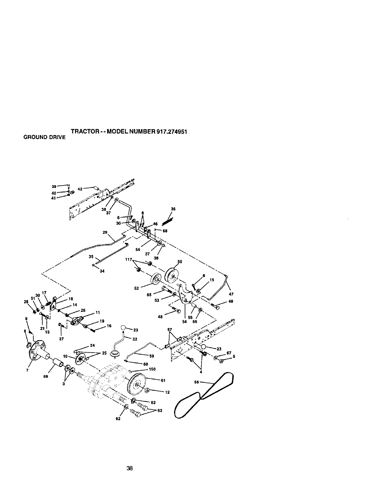
TRACTOR--MODEL NUMBER 917.274951
GROUND DRIVE
28
9
47
27
69 4
_, 12
62
38

TRACTOR-- MODEL NUMBER 917.274951
GROUND DRIVE
KEY PART KEY PART
NO. NO. DESCRIPTION NO. NO. DESCRIPTION
1 9858M1' Key, Woodruff 37 121749X Washer 25/32 x1-1/4 x 16 Ga.
3 7563R WaSher, Thrust, Axle 38 150035 Ny_ner
4 174g_o06 Screw Thdro_5/16-18 x 3/4 39 74321016 Screw, Fin. #10-24 x 1
5 STD5414.T/ Nut, Crownlock 3/8-16 40 178575 Actuator, Irdedock Switch
6 $1_561210 Pin, Cotter 41 73931060 Locknut #10-24
7 149176 Wheel, Hub Assembly 42 8883R Cover, Pedal
812000034 Klip, Ring 46 145170 Retainer, Spdng
9 140080 Bott, Hub 47 138228 Clutch ROd
10 142509 Disc, Drake 48 72110612 Bolt, Cart. 3/8-16 x 1-1/2 Gr. 5
11 136927 Yoke, Brake Disc 50 131494 Pulley, Idler, Flat
12 73750800 Nutlock 1/2-20 Unf 51 STC541437 NUt, Crewnlock 3/8-16 UNC
13 139419 Washer, Special 52 139123 Pulley, Idler, Grooved
14 138901 Bushing 53 207J Washer, Hardened
15 STB5510_7 Washer 13/3,?.xl3/16 x 16 Ga. 54 161590 Clutch, Arm Assembly
16 143012 Set, Screw 1/4-28 x 3/4 55 1C5706X Beadng, Idler
17 126_O9X Sprig 56 137153 V-Bett
18 137104 Lever, Brake 57 141756 Bracket, Shift ROd, Hi-Lo
19 136_26 Cam, Brake Disc 59 122_53X Shift Red, H_-Lo
21 23260412 Screw, Flat Head 1/4-28 x 3/4 60 122268X Spring Clip, Connecting Link
22 633A1G9 Gearshift, Lever Assembly 61 137524 Pulley, Transaxle
23 106932)( Knob 62 STD551143 Washer, Lock 7/16
24 136925 Support, Puck Drake 63 74760720 Bolt, Fin Hex 7/16-14 x 1-1/4
25 136923 Puck, Brake Top 64 154752 Shaft, Clutch/Brake Pedal
26 137552 Spdng, Return 65 67609 Bolt, Shoulder
27 17490528 Screw, Hex Wsh Thd. 66 140296 Washer, Hardened
5/16-18 x 1-3/4 67 19131312 Washer, Flat
28 73350600 NUt, Hex dam 3/8-16 68 5142H Pin, Roll
29 137213 Brake, Rod 69 136,327 Hub, Cover
30 19131616 Washer 13/32 x 1 x 16 Ga. 117 739006G0 Nut, Lock Fig. 3/8-16 Unc
34 71673 Cap, Plunger
35 137648 ROd, Parking Brake NOTE: All compo_3nt dimensions given in U.S. inches
36 149412 Spring, Drive Ground 1 inch =25A mm
39
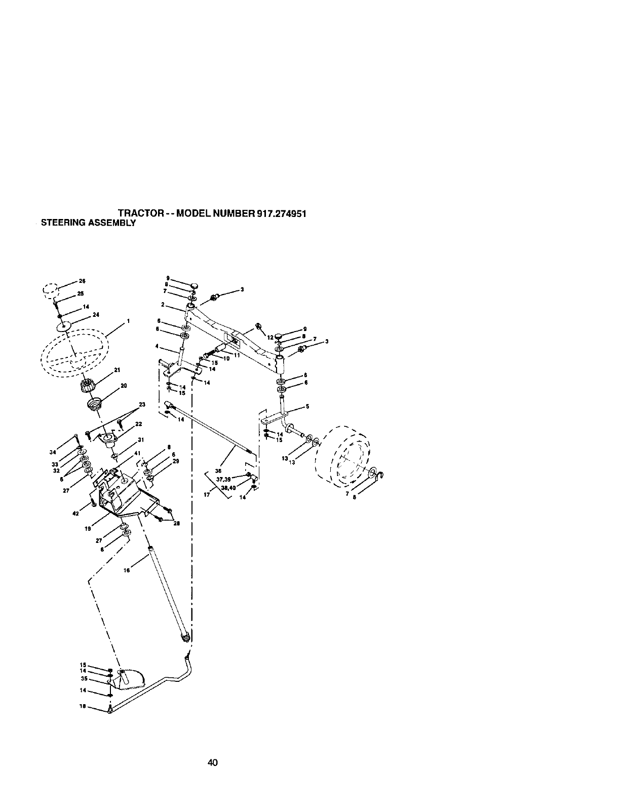
TRACTOR- - MODEL NUMBER 917.274951
STEERINGASSEMBLY
4O

TRACTOR -- MODEL NUMBER 917.274951
STEERINGASSEMBLY
KEY PART
NO. NO. DESCRIPTION
1 139768 Wheel, Steering
2 178557 Axle Asm., Front
3 6855 Fitting, Grease
4 161849 Spindle Asm, LH
5 161848 Spindle Asm., RH
6 62_6H Bearing, Race Thrust Harden
7 121748X Washer 25/32 x 1-5/8 x 16 Ga.
8 1'2(J(_029 Ring, Klip #T5304-75
9 121232X Cap, Spindle
10 74781044 Boll, Fin Hex 5/8-11 x 2-3/4
11 136518 Spacer Beating Axle Front
12 73901(_0 Nut, Lock F_ange 5/8-11 Unc
13 121749X Washer 25/32 x 1-1/4 x 16 Ga.
14 STD551137 Washer, LockHvyHlclSpr 3/8
15 STD541537 Nut, Lock Center 3/6-24 UN F
16 145103 Shaft Asm., Steedng
17 137347 Rod Asm., Tie Ball J Bait Vgt (Inc. Key No. 36-40)
18 175572 Drngliok, EeJI Joint Solid Vgt
19 156011 Suppod Asm., Steering Vgt
20 172020 Boot, Sleedng
21 1CO711L Adapter, Whee_Steedng
22 155105 Bushing, Sty. BIk
23 152927 Screw
24 19133812 Wa.sher 13/32 x 2-3/8 x 12 Ga.
25 STD523710 Belt, FinHex 3/6-16xl Gr. 5
26 139769 Cap, Wheel Steedng
27 3366R Bearing, Col. Str 9.
28 170(_612 Screw 3/6-16 x 3/4
29 104239X Beadng, Range
31 138136 Bushiog, Nyfiner Snap
32 19111610 Washer 11/32x 1 x 10Ga.
33 s'r_.551131 Washer, Lock Hvy Hi(:] Spr 5/16
34 7478B512 Bott, Fin Hex Hd 5/16-18 x 3/4
35 138059 Gear, Sector Steedn 9
36 137156 i3e Rod
37 73360600 Jam Nut RH Thread
38 1_J850X Joint Asm. Ball RH Thread
39 73700600 Jam Nut LH Thread
40 109851X Joint Asm. Ball LH Thread
41 155246 Bracket Switch Interlock VGT 97
42 17490508 Screw Thdrol 5i16-18xl/2Tyt
NOTE: All component dimensions given in U.S. inches
1 inch = 25.4 mm
41
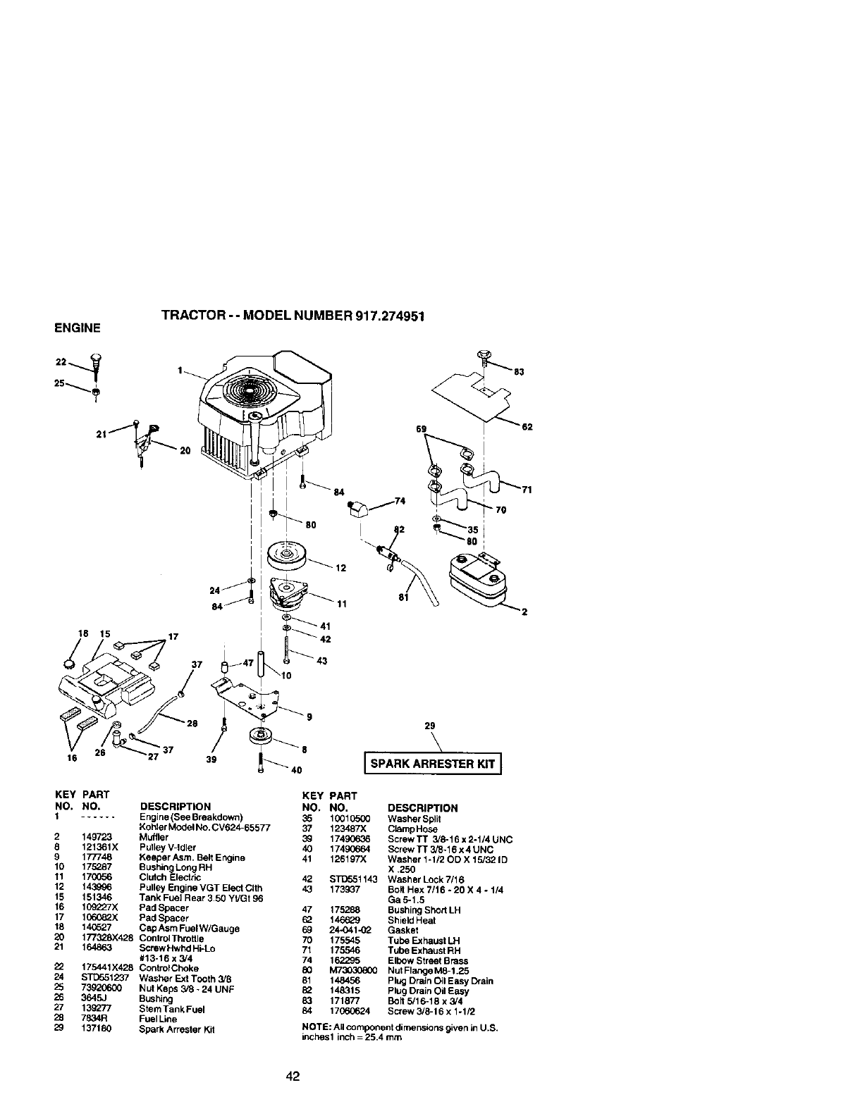
ENGINE
25
TRACTOR -- MODEL NUMBER 917.274951
18 15 17
81
37
16 39 8
KEY PART
NO. NO. DESCRIPTION
1...... Engine (See Breakdown)
Kohler Model No. CV624-65577
2 149723 Muffler
8 121361X PuTleyV-Idler
9 177748 Keeper Asm. Belt Engine
10 175287 Bushing Long RH
11 17(_56 Clutch Electrk:
12 143996 Pulley Engine VGT Elect Clth
15 151346 Tank Fuel Rear 3.50 YVGt 96
16 109"_7X Pad Spacer
17 1(36082X Pad Spacer
18 14_27 Cap Asm FuelW/Gauge
20 177328X428 Control Throttle
21 164863 Screw Hwhd Hi-Lo
#13-16 x 3/4
22 175441)(428 Contrut Choke
24 ST0551237 Washer Exl Tooth 3/8
25 73920600 Nut Keps 3/8 - 24 UNF
26 3645J Bushing
27 139277 Stem Tank Fuel
28 7834R Fuel Line
29 137180 Spark Arrester Kit
29
\
SPARK ARRESTER KIT J
KEY PART
NO, NO. DESCRIPTION
35 10010500 Washer Split
37 123487X ClampHose
3_ 17490636 Screw TT 3/8-16 x 2-1/4 UNC
40 17490664 Screw TT 3/8-16 x 4 UNC
41 126197)( Washer 1-1/2 OD X 15/32 ID
X .250
42 STD551143 Washer Lock 7/16
43 173937 Bolt Hex 7/16 -20 X 4 -1/4
Ga5-1.5
47 175288 Bushing Shod LH
69 1466_9 Shield Heat
69 24-041-02 Gasket
70 175545 Tube Exhaust LH
71 175546 Tube Exhaust RH
74 16,_x35 Elbow Street Brass
80 M73030800 Nut RangeMS-1.25
81 148456 Plug Drain Oil Easy Drain
69 148315 Plug Drain Oil Easy
83 171877 Bolt 5/16-18 x 3/4
84 17(;60624 Screw 3/8-16 x 1-1/2
NOTE: All component dimensions given in U.S.
inches 1 inch = 25.4 mm
42
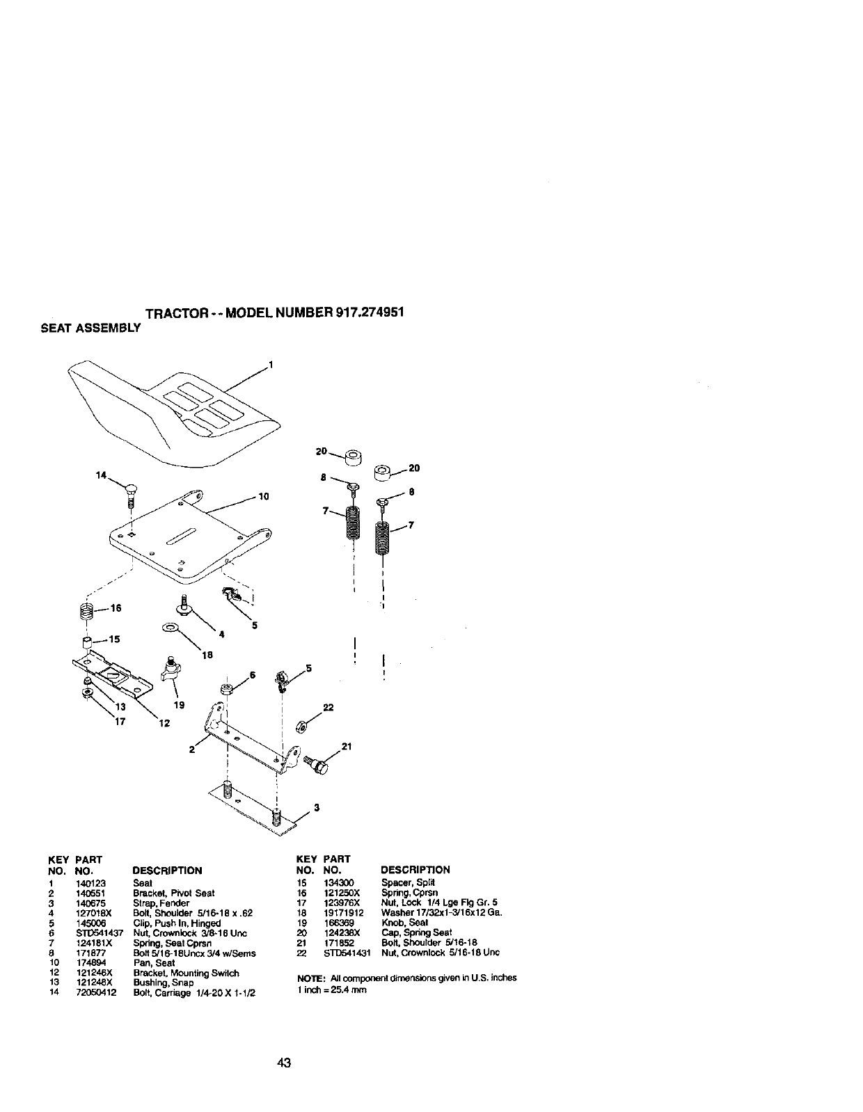
TRACTOR o* MODEL NUMBER 917.274951
SEATASSEMBLY
16
11 12
KEY PART
NO. NO.
t 140123
2140551
3 140675
4 127018X
5 14_
6 $11To41437
7124181X
9 171877
10 174894
12 121246X
13 121248X
14 72050412
5
I
i22
I
21
8_ _,_,_ 20
8
7
DESCRIPTION
Seat
Bracket, Pivot Seat
Strap, Fender
Bolt, Shoulder 5/16-18 x .62
CJip. Push In, Hinged
Nut, Crownlock 3/8-16 Uric
Spring, Seal Cprsn
Se9 5/16-18Uncx 3/4 w/Seres
Pan, Seat
Bracket, Mounting Switch
Bushing, Snap
Bott, Carriage 1/4o20X 1-1/2
KEY PART
NO. NO. DESCRIPTION
15 134300 Spacer, Split
16 121250X Spring, Cprsn
17 123976X Nut. LOCk 1/4 Lge Fkj Gr. 5
18 18171912 Washer 17/32x 1-3,'16x 12 Ga.
19 166369 Knob, Seat
20 124238X Cap, Spring Seat
21 171852 Bog. Shoulder 5/16-18
22 STD541431 Nut.Crownlock 5/16.18Unc
NO'hE: All comp_snt d_n'_nsionsgiven inU.S, inches
1inch =25.4 mm
43
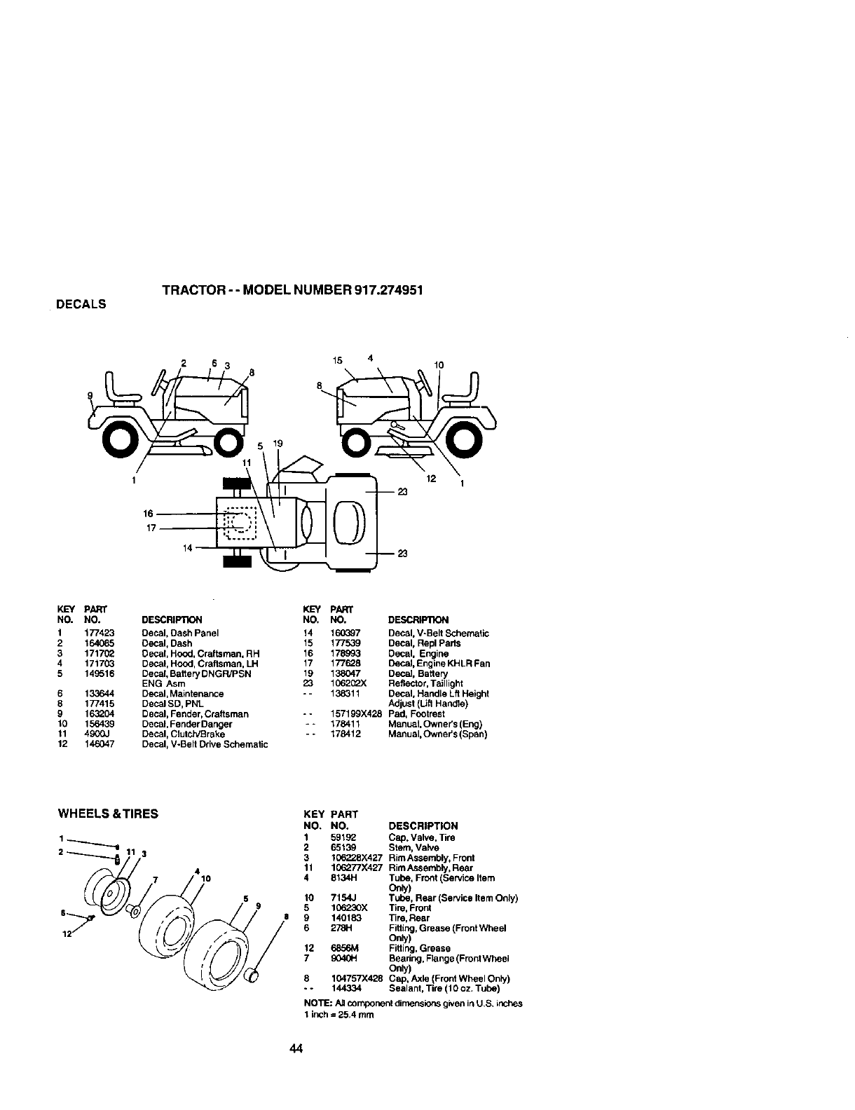
DECALS TRACTOR --MODEL NUMBER 917.274951
2
519
15
8
10
1
16
17
12 1
KEY PARr
NO. NO.
1 177423
2164_85
3 1717(_
4 171703
5 149516
6 133644
8 177415
9 163204
10 156439
11 4900J
12 146047
I_'Y PART
DESCRIPTION NO. NO. DESCRIPllON
Decal, Dash Panel 14 160397 Decal, V-Belt Schematic
Decal, Dash 15 177539 Decal, Rapl Parts
Decal, Hood, Craftsman, RH 16 178993 Decal, Engine
Decal, Hood, Craftsman, LH 17 177628 Decal, Engine KHLR Fan
Decal, Battery DNGPJPSN 19 138047 Decal, Battery
ENG Asm 23 1062__X Reflector, Taillight
Decal, Maintenance - - 138311 Decal, Handle Lft Height
Decal SD, PNL Adjust (LJr1Handle)
Decal, Fender, Craftsman -- 157199)(428 Pad, Footrest
Decal, Fender Danger -* 178411 Manual, Owner's (Eng)
Decal, Clutch/Brake -•178412 Manual,Owner's (Span)
Decal, V-Belt Drive Schematic
WHEELS&TIRES
410
KEY PART
NO. NO. DESCRIPTION
1 59192 Cap. Valve, Tire
2 65139 Stem, Valve
3 106228X427 Rim Assembly. Front
11 106277X427 Rim Assembly, Rear
4 8134H Tube, Fro_t (Service Item
Only)
10 7154J Tube. Rear (Service Item Only)
5 166230X Tire, Front
9 140183 Tire,Rear
6 2781-1 Fitting, Grease (Front Wheel
Only)
12 6856M Fitting, Grease
7 904_H Beadng, Range (Front Wheel
Only)
8 t 04757X428 Cap, Axle (Front Wheel Only)
--144334 Sealant, Tire (10 oz. Tube)
NOTE: Allcomponent dimensions given inU,S, inches
1inch =25.4 mm
44
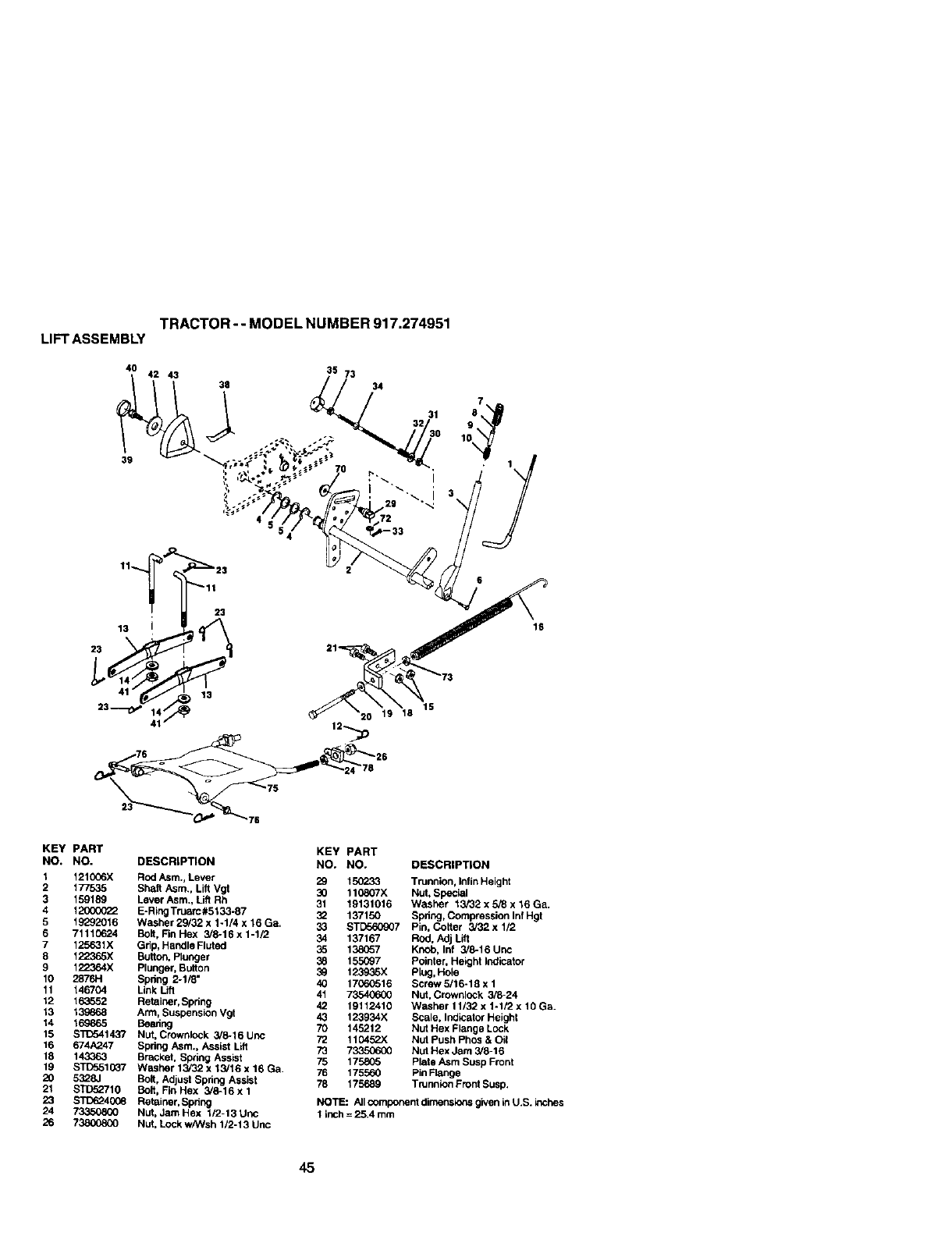
TRACTOR --MODEL NUMBER 917.274951
LIFTASSEMBLY
40 42 43 38 35 73
31 8
9
10
15
16
KEY PART
NO. NO.
1 1210C6X
2 177535
3 159189
412OOOO22
5 19292016
6 71110624
7 125631X
8 122365X
9 122364X
10 2876H
11 146704
12 163552
13 139868
14 169865
15 STE_41437
15 674A247
18 143363
19 STDS,51(X37
20 5328J
21 STD52710
23 STD624008
24 733508(_
26 73800800
KEY PART
DESCRIPTION NO. NO. DESCRIPTION
Rod Asm., Lever 29 150233 Trunnion, InfinHeight
Shaft Asm., Lift Vgt 30 110807X Nut, Special
Lever Asm., Litt Rh 31 19131016 Washer 13/32 x 5/8 x 16 Ga.
E-RingTruarc#5133-87 32 137150 Spdng, Compression Inf Hgt
Washer29/32xl-1/4x16Ga. 33 STD560907 Pin, Cotter 3/32xl/2
Bolt, Fin Hex 3/8-16 x 1-1/2 34 137167 Rod, Adj Lift
Grip, Handle Fluted 35 138057 Knob, Inf 3/8-16 Unc
Button, Plurpger 38 155(_7 Pointer, Height Indicator
Plunger, Button 39 123935X Plug, Hole
Spdng 2-1/8" 40 17060516 Sci'ew 5/16-18 x 1
Link Lift 41 7_ Nut, Crownlock 3/8-24
Retainer, Spring 42 19112410 Washer 11/32 x 1-1/2 x 10 Ga.
Arm, Suspension Vgt 43 123934X SCale, Ind_cato,"Height
Bearing 70 145212 Nut Hex Flange Lock
Nut, Crownlock 3/8-16 Unc 72 110452X NUt Push Phos & Oil
Spring Asm., Assist Lift 73 7_ Nut Hex Jam 3/6-16
Bracket, Spring Assist 75 175805 Plate Asm Susp Front
Washer 13/32 x 13/16 x 16 Ga. 76 1755,50 Pin Flange
Bolt, Adjust Spring Assist 78 175689 Trunnion Front Susp.
Belt, Fin Hex 3/8-16 x 1
Retainer, Spdng NOTE: All component dimensionsgiven in U.S. inches
Nut, Jam Hex 1/2-13 Unc 1inch= 254 mm
Nut, Lock wPAlsh1/2-13 Uric
45
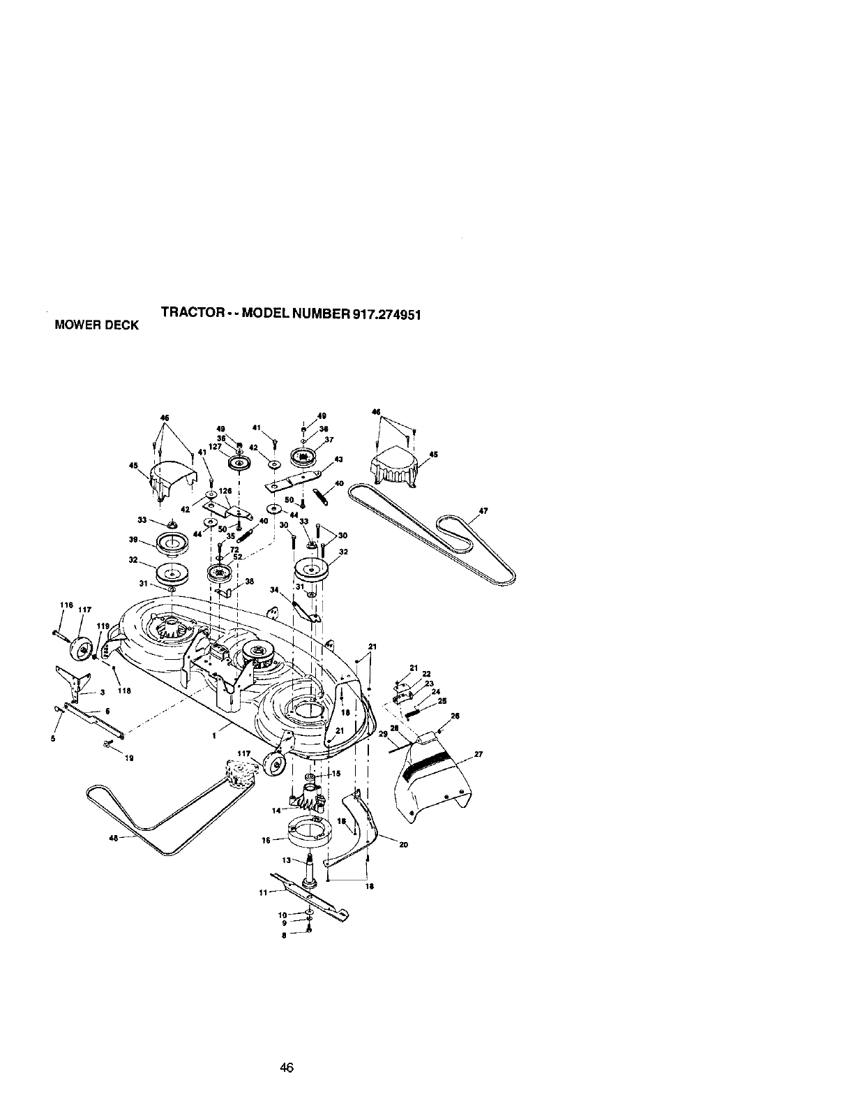
TRACTOR--MODEL NUMBER 917.274951
MOWERDECK
49 41
4S
16 117
47
__3 118
19
1
117
21
22
26
46

TRACTOR-- MODEL NUMBER 917.274951
MOWERDECK
KEY PART KEY PART
NO, NO. DESCRIPTION NO. NO,
1 156948 Deck Weldment 34 144945
3 138457 Bracket Asm., Sway Bar 35 17490628
5 STD624008 Retainer Spdng 36 STD5510_7
6 130632 Arm, Suspenslan, Rear (Sway 37 131494
sad 3s 1560_
8 850857 Bolt, Patched 3/8-24 x 1-1/4 39 144917
Gr. 8 40 137273
9 STD551137 Washer, Lock Hvy., Unplatnd 3/8 41 17060620
10 14(_96 Washer, Hard Blade, Mower 42 165723
Vented 43 144949
11 176084 Blade 44 133943
13 137553 Shaft Asm. w/Lower Beadng 45 145059
14 137152 Housing, Mandrel 46 137729
15 110485X Bearing, Bell, Mandrel 47 144959
19 174493 Stripper, Mower 48 148763
18 STD533166 Bolt, Carriage 5/16-18 x 5/8 49 $3_D541437
19 132827 Bolt, Hex Heed, Shoulder 50 72110612
5/16-18
20 145055 Baffle, Vortax Mower 46" 52 156493
21 STD541431 Nnt, Crownlock 5/16-18 UNC 72 19131616
22 134753 Stiffener, Bracket 116 137644
23 131267 Bracket, Deflector 117 133957
24 105304X Cap, Sleeve 118 73930600
25 149287 Spdng, Torsion, Deflactor 119 19121414
26 110452X Nut, Push 126 144948
27 166883)(428 BeflectorClipping 127 146763
28 19111016 Washer 11/32 x 5/8 x 16 Ga. -- 166209
29 131491 Rod,Hinge --143651
30 157722 Screw, Thd Rolling Washer Hd
31 1'29963 Washer, Spacer Mower Vented
3_ 153531 Pulley,Mandrel
33 178342 Nut, Fig. Top Lock Cntr. 9/16
DESCRIPTION
Anchor, Spring Deck 46"
Screw, 3/8-16 x 1-3/4
Washer 13132 x13/16 x 16 Ga.
Pullay, Idtar, F_at
Keeper, Belt, Idler
Pulley, Idler, Ddven
Spdng, Beconda_ 44/46/50 Vent
Screw 3/8-16 x 1-1,4
Spacer, Retainer
Arm, Idler Secondary
Washer, Hardened
Cover, Mandrel Deck
Screw, Thdroll. 1/4-20 x 5/8
V-Belt, Mower, Secondary
V-Belt, Mower, Pdmary
Nut, Crownlock 3/8-16 UNC
Bolt, Cardage 3/8-16x 1-1/2
Gr. 5
Pulley Idler 49" Phm. Ddve
Washer 13,'32 x 1 x 16 Ga.
Bolt,Shoulder
GaugeWheel
Nut, Centedock 3/8-16 UNC
Washer 3/8 x 7/8 x 14 Ga.
Arm, Idler, Pdmary Deck 46"
Pulley, Idler, V-Groove Dim. 4.25
Replacement Mower Complate
Mandrel Asm 44/50 Sen/ice
(InrJudes Key Nos. 8-10, 13-15,
31 and 33)
NOTE: All component dimensions given in U.S. inches
1 inch = 25.4 mm
47
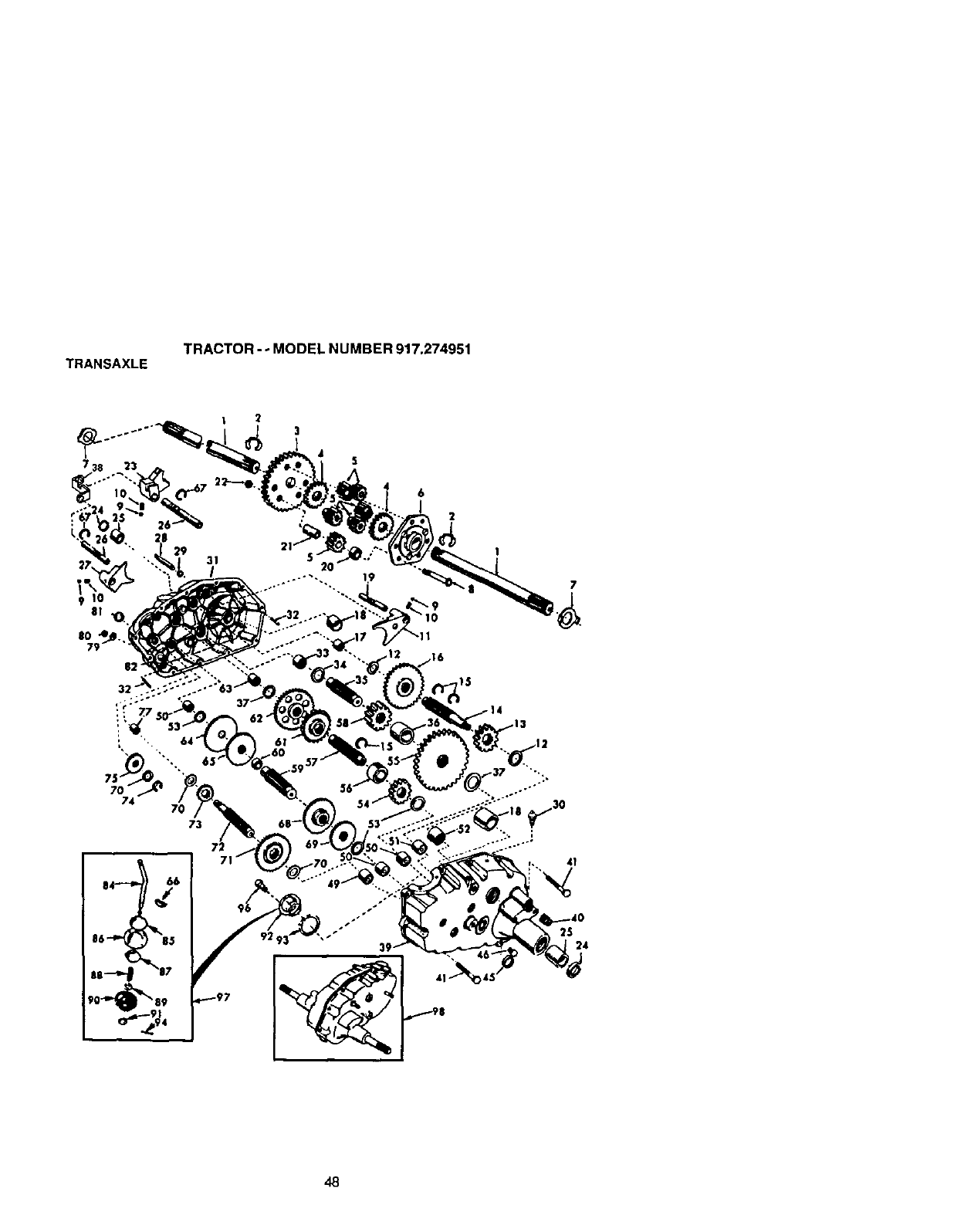
TRANSAXLE TRACTOR - - MODEL NUMBER 917.274951
73
72
86 85
Ji 7
3
5
6
:3
I
15
25 34
48
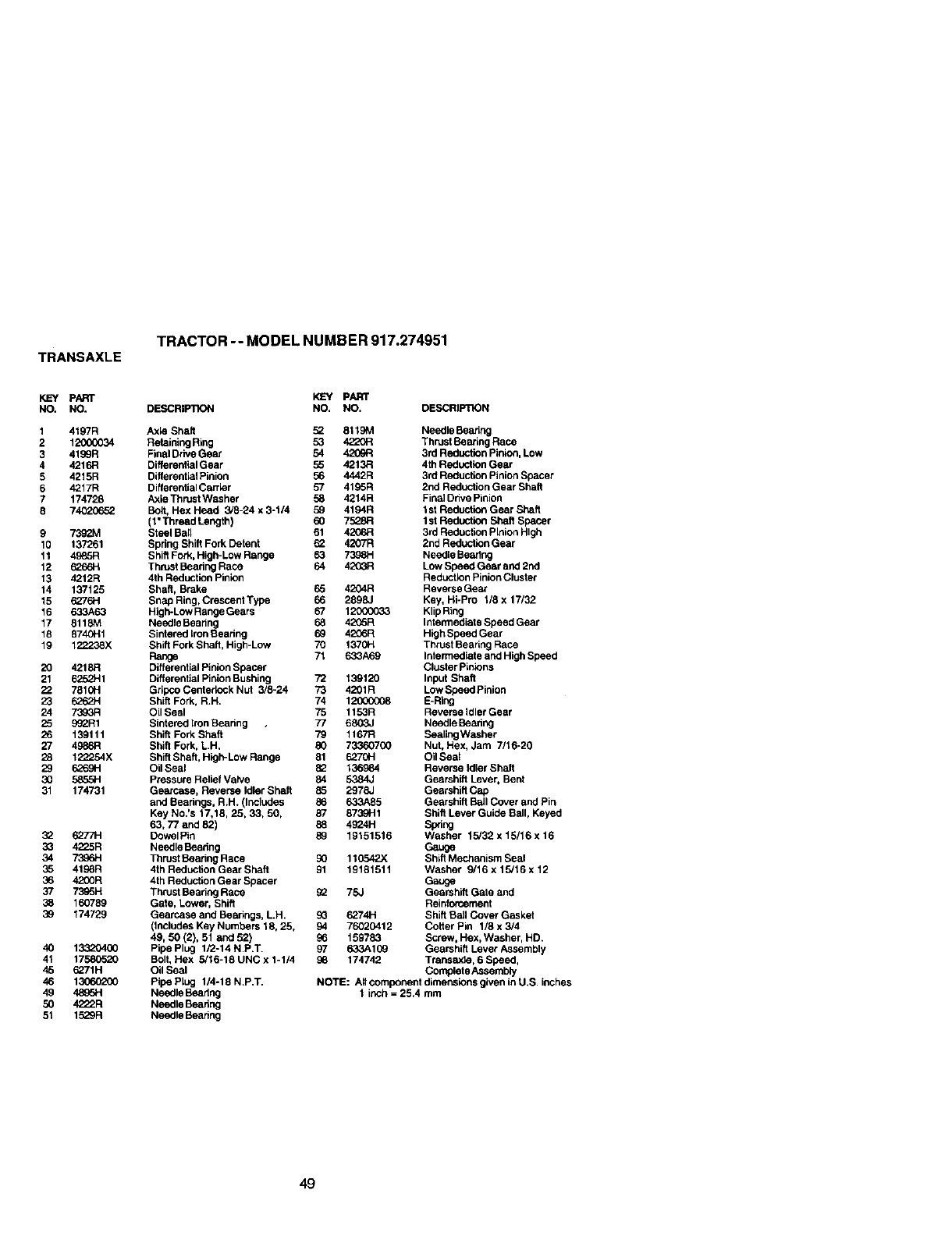
TRANSAXLE
TRACTOR -- MODEL NUMBER 917.274951
KEY PART
NO. NO.
1 4197R
21'2_XX_34
3 4199R
44216R
5 4215R
64217R
7 174728
8 74020652
97392M
10 137261
11 4985R
12 6266H
13 4212R
14 137125
15 6276H
16 &33A63
17 8118M
18 8740H1
19 12223OX
20 4218,=1
21 6252H1
22 7819H
23 6262H
24 7393R
25 _R1
26 139111
27 4966R
28 122254X
29 626911
3O 5855H
31 174731
32 6277H
33 4225R
34 73O6H
35 4198R
36 4200R
37 7395H
38 160789
39 174729
40 13320400
41 17586520
45 6271H
46 1306O200
49 48_5H
50 4222R
51 1529R
KEY PART
DESCRtP'nON NO. NO. DESCRIWRON
Axle Shaft 52 8119M Needle Beanng
Retaining Ring 53 4220R Thrust Beating Race
Final Drive Gear 54 4209R 3rd Reduction pinion. Low
Differential Gear 55 4213,=1 4th Reductlen Gear
Differential Pinion 56 4442R 3rd Reduction Pinion Spacer
Differengal Carrier 57 4195R 2nd Reduction Gear Shaft
Axle Thrust Washer 58 4214R Final Dhve Pinion
Bolt, Hex Head 3/8-24 x 3-114 59 4194R 1st Reduction Gear Shaft
(1"Thread Length) 60 7528,9 I st Reductioq Shaft Spacer
Steel Bail 61 4208R 3rd ReduclJonPinion High
Spdng Shift Fork Detent _4207R 2nd Reduction Gear
ShiftFork, High-Low Range 63 7398H Needle Bearing
Thrust Beanng Race 64 4203R Low Speed Gear and 2nd
4th Reduction Pinion Reduction Pinion Cluster
Shaft, Brake 65 4204R Reverse Gear
Snap Ring, CrescentType 66 2898-1 Key, Hi-Pro 1/8 x 17/32
High-Low RangeGears 67 1200C033 KlipRing
Needle Beadng 68 42_5R Intermediate Speed Gear
Sintered Iron Searing 69 4206R High Speed Gear
Shift Fork Shaft, High-Low 70 1370H ThrUstBearing Race
Range 71 633A69 Intermediate and High Speed
Differential Pinion Spacer Cluster Pinions
Differential Pinion Bushing 72 139120 Input Shaft
Gripco Centedock Nut 3/8-24 73 4201R Low Speed Pinion
Shift Fork. R.H. 74 12(_O008 E-Ring
Oil Seal 75 1153R Reverse Idler Gear
Sintered Iron Bearing 77 6803.1 Needle Bearing
Shift Fork Shaft 79 1167R SealingWasher
Shift Fork, L.H. 80 733607G0 Nut. Hex, Jam 7/16-20
Shift Shaft, High-Low Range 81 6270H Oil Sea_
Oil Seal 82 136984 Reverse Idler Shaft
Pressure Relief Vatve 84 5384J Gearshift Lever. Bent
Gearcase, Reverse Idler Shaft 85 2978J Gearshift Cap
and Bearings. R.H. (Includes 86 633A85 Gearshift Ball Cover and Pin
Key No.'s 17.18, 25.33, 50, 87 873OH1 Shift Lever Guide Sail, Keyed
63,77 and 82) 88 4924H Spring
Dowel Pin 89 19151516 Washer 15/32 x 15/16 x 16
Needle Beadng Gauge
Thrust Searing Race 90 110542X Shift Mechanism Seal
4th Reduction Gear Shaft 91 19181511 Washer 9/16 x 15/16 x 12
4th Reduction Gear Spacer Gauge
Thrust Bearing Race _75,) Gearshift Gate and
Gate, Lower, Shift Reinforcement
Gearcase and Bearings, LH. 9G 6274H Shift Bail Cover Gasket
(Includes Key Numbers 18, 25, 94 76020412 Cotter Pin 1/8 x3/4
49, 50 (2), 51 and 52) 96 159783 Screw, Hex, Washer, HD.
Pipe Plug 1/2-14 N.P.T. 97 633109 Gearshift Lever Assembly
Bolt, Hex 5/16-18 UNC x 1-1/4 96 174742 Trans_de, 6 Speed,
Oil Seal Complete Assembly
PipaPlug 1/4-18 N.P.T. NOTE: AIIcompanentdimensionsgivenidU.S, inches
Needle Bearing 1 inch =25.4 mm
Needle Bearing
Needle Bearing
49
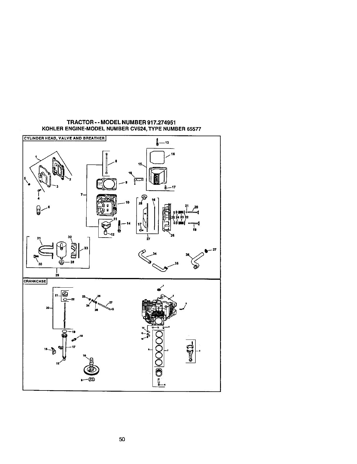
TRACTOR- °MODEL NUMBER 917.274951
KOHLERENGINE-MODELNUMBERCV624,TYPE NUMBER65577
CYLINDER HEAD, VALVE AND BREATHER I
_m13
4
7w
°i[_/''
-- t5...
I
2g
O_10
6 Ii
7t
0
/
5O
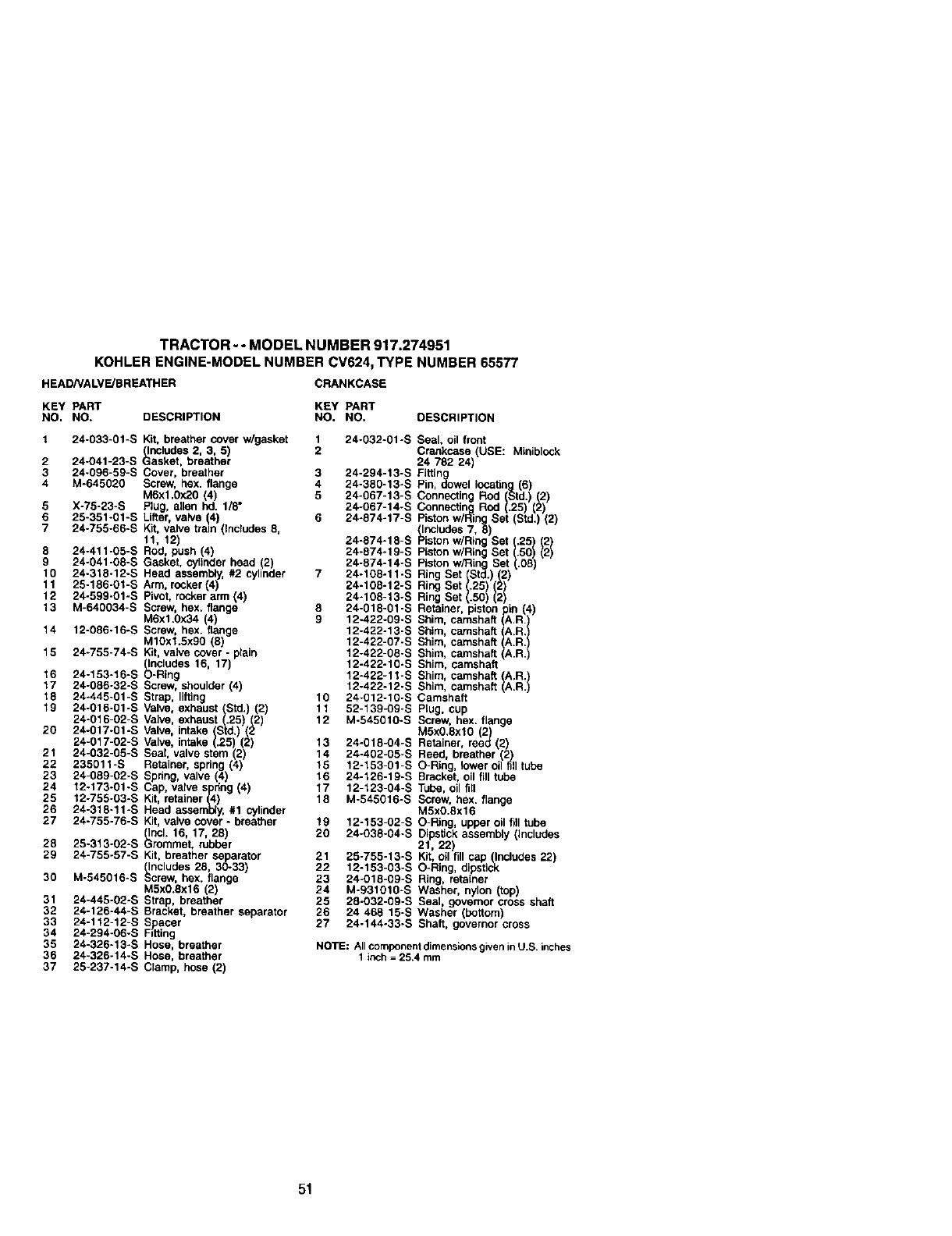
TRACTOR-- MODELNUMBER917.274951
KOHLER ENGINE-MODEL NUMBER CV624, TYPE NUMBER 65577
HEADNALVE/BREATHER CRANKCASE
KEY PART KEY PART
NO. NO. DESCRIPTION NO. NO. DESCRIPTION
1 24-033-01-S Kit, breather cover w/gasket 1 24-032-01-S Seal, oil front
(Includes 2, 3, 5) 2 Crankcase (USE: Miniblock
2 24-O41-23-S Gasket, breather 24 782 24)
3 24-096-59-S Cover, breather 3 24-294-13-S Fittin
4 M-645020 Screw, hex. flange 4 24-380-13-S Pin, _owel IocaUn
M6xl.0x20 (4) 5 24-067-13-S
5 X-75-23-S Plug, allen hd. 1/8" 24-067-14-S
6 25-351-01-S Lifter valve 14) 6 24-874-17-S ncludas 7,
7 24-755-66-S Kit, valve train ( ncudes 8, 24-874-15-S
., ,2)
8 24-411-05-S Rod, push (4) 24-874-19-S
9 24-041-08-S Gasket, cylinder head (2) 24-874-14-S
10 24-318-12-S Head assembly, #2 cylinder 7 24-108-11-S Ring !
11 25-186-01-S Arm, rocker (4)
12 24-599-01-S Pivot, rocker arm (4)
13 M-640034-S Screw, hex. flange 8 24-0
M6x1.0X34 4) 9 12-422-09-S St_m,
14 12-086-16-S Screw hex. flange 12-422-13-S Shim, camshaft
MlOxl.5x90 (8 12-422-07-S Shim, camshaft
15 24-755-74-S Kit, valve cover -plain 12-422-08-S Shim, camshaft
(Includes 16, 17) 12-422-10-S Shim, camshaft
16 24-153-16-S O-Ring 12-422-11-S Shim, camshaft (A.R.)
17 24-086-32-S Screw, shoulder (4) 12-422-12-S Shim, camshaft (A.R.)
18 24-445-01-S Strap, lifting 10 24-012-10-S Camshaft
19 24-016-01-S Valve, exhaust (Std.) (2) 11 52-139-09-S Plug, cup
Screw, hex. flange
24-016-02-S Valve, exhaust (.25)(2) 12 M-545010-S M5xO.Sxl0 (2)
20 24-017-01-S Valve intake (Std.) (2
24-017-02-S Valve intake (.25 (2) 13 24-018-04-S Retainer, reed (2)
21 24-032-05-S Seal valve stem 2) 14 24-402-05-S Reed breather 2
22 235011-S Retainer, spring (4) 15 12-153-01-S O-Ring, lower oil fill tube
23 24-089-02-S Spdng, valve (4) 16 24-126-19-S Bracket, oil fit) tube
24 12-173-01-S Cap, valve spring (4) 17 12-123-04-S Tube, oil fill
25 12-755-03-S Kit, retainer (4) 18 M-545016-S Screw, hex. flange
26 24-318-11-S Head assembly, #1 cytindm M5xO.Sx16
27 24-755-76-S Kit, valve cover -breather 19 12-153-02-S O-Ring, upper oil fill tube
(Incl. 16, 17, 28) 20 24-038-04-S Dipstick assembly (includes
28 25-313-02-S Grommet, rubber 21, 22)
29 24-755-57-S Kit, breather separator 21 25-755-13-S Kit, oil fill cap _lnclubes 22)
(Includes 28, 30-33) 22 12-153-03-S O-Ring, dipsticK
30 M-545016-S Screw, hex. flange 23 24-018-09-S Ring, retainer
24 M-931010-S Washer, nylon (top)
M5x0.SX16 (2)
31 24-445-02-S Strap, breather 25 28-032-09-S Seal gevemor cross shaft
32 24-126-44-S Bracket, breather separator 26 24 468 15-S Washer (bottom
33 24-1_2-12-S Spacer 27 24-144-33-S Shaft, governor cross
34 24-294-06-S Fdting
35 24-326-13-S Hose, breather NOTE: AIIcomponent dimensionsgivenin U,S. inches
36 24-326-14-S Hose, breather 1 inch = 25.4 mm
37 25-237-14-S Clamp, hose (2)
51
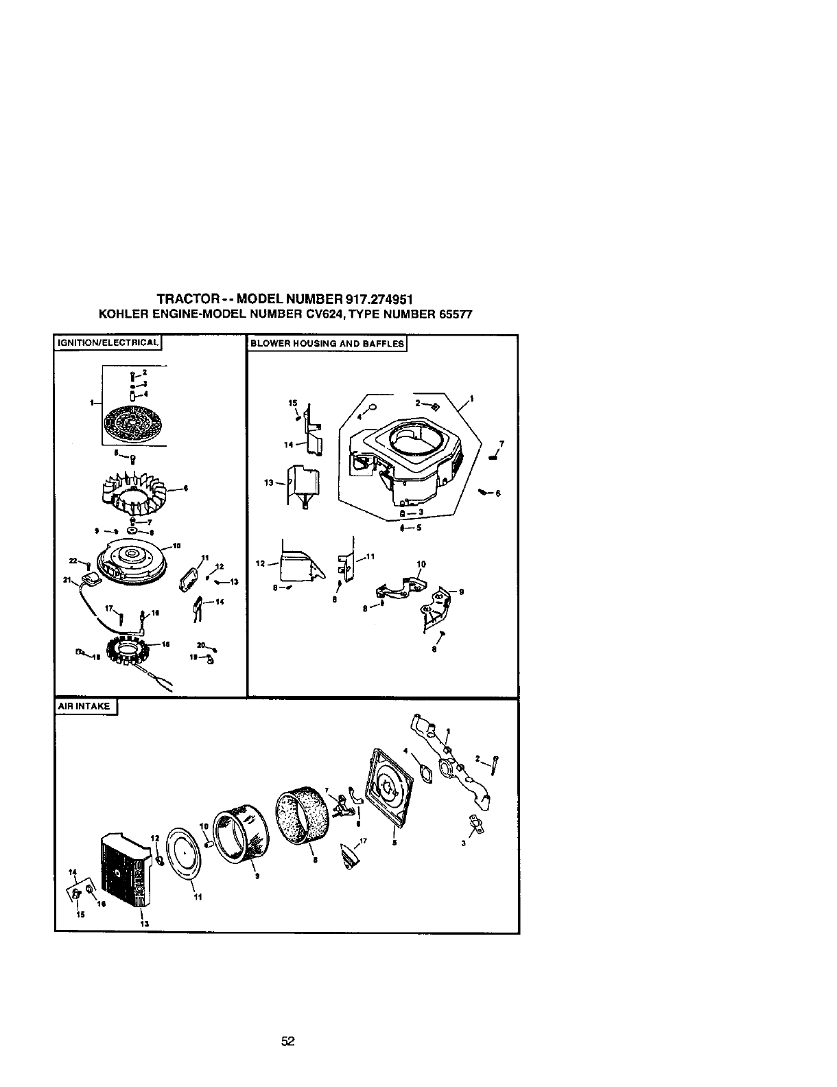
TRACTOR-- MODEL NUMBER 917.274951
KOHLERENGINE-MODELNUMBER CV624,TYPE NUMBER 65577
IGNITIONIELECTRICAL
_2
e.-1
p-,
1-
°_- t
AIR INTAKE J
BLOWER HOUSING AND BAFFLES I
d!---s
3--*" ,1_ 9
8
1
/_,-o
13
52
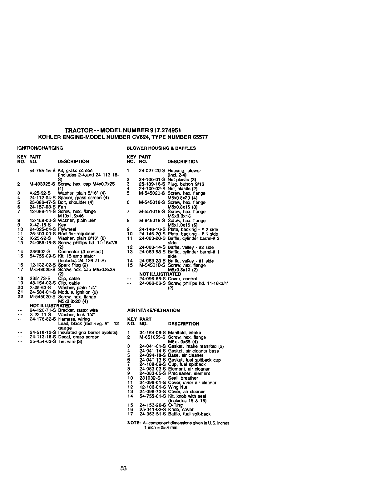
TRACTOR --MODEL NUMBER 917.274951
KOHLERENGINE-MODELNUMBER CV624,TYPE NUMBER65577
IGNITION/CHARGING BLOWER HOUSING & BAFFLES
KEY PART KEY PART
NO. NO. DESCRIPTION NO. NO. DESCRIPTION
Housing, blower
1 54-755-15-S Kit, grass screen 1 24-027-20-S (Incl. 2-4)
_nciudes 2-4,and 24 113 18-
) 2 24-100-01-S Nut plasflc (3)
2 M-403025-S Screw, hox. cap M4x0.Tx25 3 25-139-16-S Plug, button 9/16
(V_a 4 24-100-02-S Nut, plastic (2)
3 X-25-92-S shor, p_n 5/16" (4) 5 M-545020-S Screw, hex. flange
4 24-112-04-S Spacer, grass screen (4) M5x0.8x20 (4)
5 25-086-47-S Bolt, shoulder (4) 6 M-545016-S Screw, hex. flange
6 24-157-03-S Fan M5x0.8x16 (3
7 12-086-14-S Screw, hex. flange 7 M-551016-S Screw, hex. fange
M10x1.5x46 M5x0.flx15
8 12-468-03-S Washer, plain 3/8" 8 M-645016-S Screw, hex. flange
9 X-42-15-S Key M6x1.0x16 (5)
10 24-625-04-S Flywheel 9 24-146-16-S Plate, backing - # 2 side
11 25-403-03-S Rectifier-regulator ,10 24-146-20-S Plate, backing- It 1 side
12 X-25-92-S Washer, plain 3/16 (2) 11 24-063-26-S Baffle, cylinder barrel-# 2
13 24-086-t8-S Screw, phillips hd, 11-16x7/8 side
(2) 12 24-063-14-S Baffle, valley - #2 side
J4 236602-S Connector (3 contact) 13 24-663-58-S Baffle, cylinder barrel-# 1
15 54-755-09-S Kit, 15 amp starer side
(Includes 24 126 71*S) 14 24-063-23-S Baffle, valley - #1 side
16 12-132-02-S Spark Plug (2) 15 M-545010-S Screw, hex. flange
17 M-548025-S Screw, hex. cap M5x0.8x25 M5x0.8xl0 (2)
NOT iLLUSTRATED
18 235173-S lip, cable -- 24-096-66-S Cover, control
19 48-154-02-S Clip, cable -- 24-085-06-S Screw, phillips hd. 11-16x3/4"
20 X-25-63-S Washer, plain 1/4" (2)
21 24-584-01-S Module, ignition (2)
22 M-545020-S Screw, hex. flange
M5x0.8x20 (4)
NOT ILLUSTRATED
-- 24-126-71-S Bracket, stator wire AIR INTAKE/FILTRATION
-- X-22-11-S Washer, !ock 1/4"
-- 24-176-82-S Harness, wiring KEY PART
Lead, black (rect.-reg. 5" -12 NO. NO. DESCRIPTION
gau g_e
-- 24-518-12-S Insulated grip barrel eyelets) 1 24-164-06-S Manifold, intake
-- 24-113-18-S Decal, grass screen 2 M-651055-S Screw, hex. flange
-- 25-454*03-S Tie, wire (3) M6x1.0x55 (4)
3 24-041-01-S Gasket, intake manifold (2)
4 24-041-14-S Gasket, air cleaner base
5 24-094-18oS Base, air cleaner
6 24-041-13-S Gasket, fuel spltback cup
7 24-109-09°S Cup, fuel spltback
8 24-083-03-S Element, air cleaner
9 24-053-05°S Precleanar, element
10 231032-S Seal, breather
11 24-096-01-S Cover, inner air cleaner
12 12-100-01oS Wing Nut
13 24-096-73-S Cover, air cleaner
14 54-755-01-S Kit, knob with seal
(Includes 15 & 16
15 24-153-20-S O-Rng
16 25-341-03-S Knob, cover
17 24-063-51-S Baffle, fuel spit-back
NOTE: All component dimensions given in U.S. inches
1 inch = 25.4 mm
53
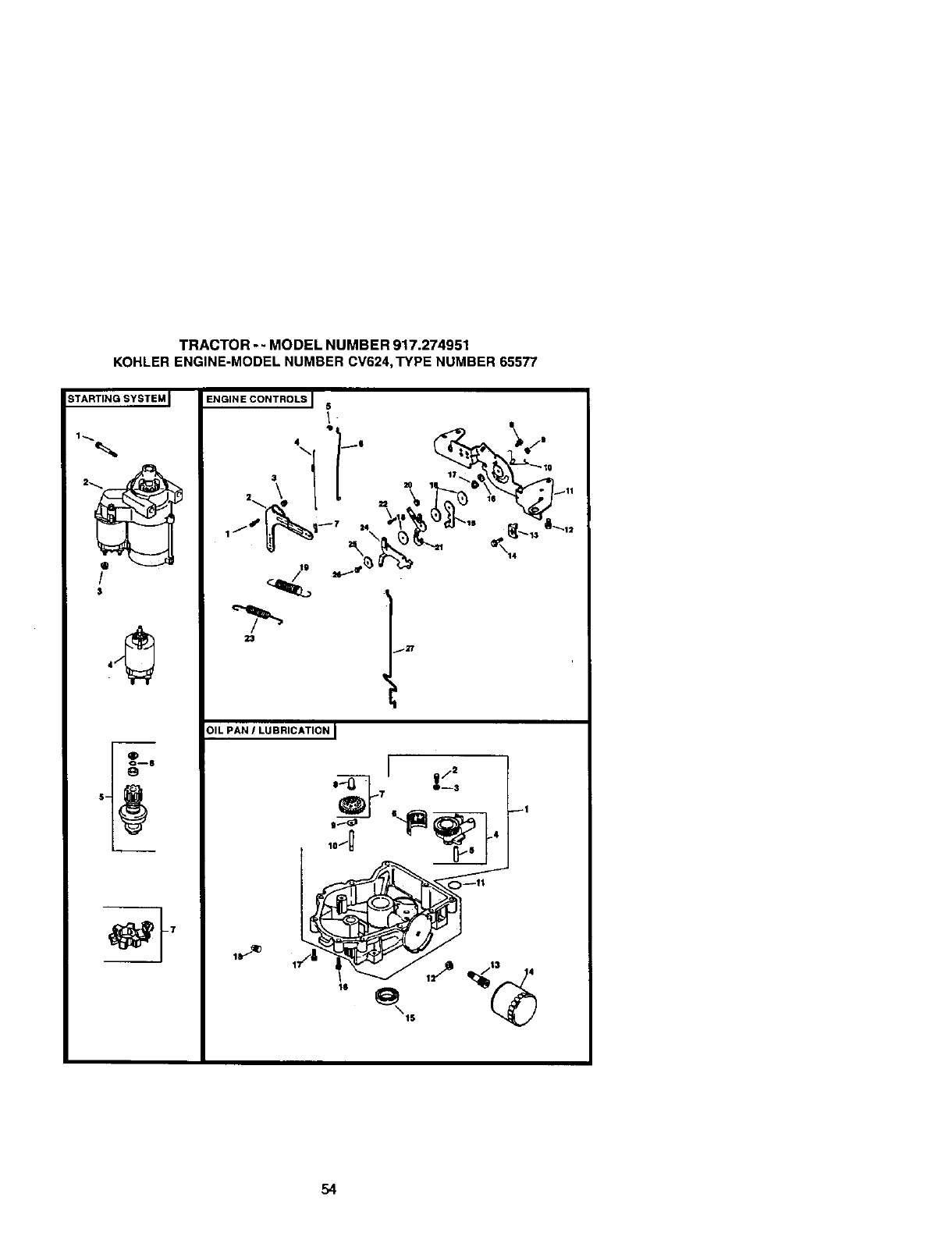
TRACTOR -- MODEL NUMBER 917.274951
KOHLER ENGINE-MODEL NUMBER CV624,TYPE NUMBER 65577
STARTING SYSTEM I
/
$
23
_27
OIL PAN /LUBRICATION I
.-_L,[ z";
OF -,
10_ 4
54
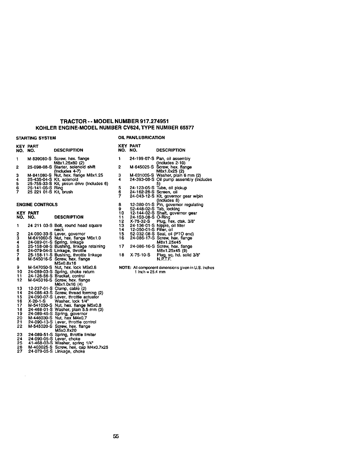
TRACTOR -- MODEL NUMBER 917.274951
KOHLERENGINE-MOBELNUMBER CV624,TYPE NUMBER 65577
STAR_NGSYSTEM OIL PAN/LU BRICATION
KEY PART KEY PART
NO. NO. DESCRIPTION NO. NO. DESCRIPTION
1M-839080-S Screw, hex. flange
Mex1.25xe0 (2)
2 25-098-08-S Starter, solenoid shift
_lndudes 4-7)
3 M-841080-S Nut, hex. flange M8x1.25
4 25-435-04-S Kit, solenoid
5 25-755-33-S Kit, pirdon drive (InCludes 6)
6 25-141-05-S Ring
7 25 221 01-S Kit, brush
ENGINE CONTROLS
KEY PART
NO, NO. DESCRIPTION
1 24 211 03-S Bolt, round head square
neck
2 24-090o33-S Lever, governor
3 M-641060-S Nut, hex. flange M6xl.0
4 24-089-01-S Spring linkage
5 25-15E-OE-S BtJshing, Iinka_e retaining
6 24-079-g4-s Linkage, throttle
7 25-158-11-S BushJng, uthrottle linkage
8 M-545016-S Screw, hex. range
M5x0.8x16
9 M-547050-S Nut, hex. lock MSx0.8
10 24-089-03-S Spring, choke return
11 24-126-56-S Bracket, control
12 M-645016-S Screw, hex. flange
M6x1.0x16 (4)
13 12-237-01-S Clamp, cable (2
14 24-086-43-S Screw, thread forming _2)
15 24-090-07-S Lever, throttle actuator
16 X-20-1-S Washer, lock 1/4"
17 M-541050-S Nut hex. flange M5x0.8
18 24-468-01-S Washer, plain 5.5 mm 3)
lg 24-08g-45-S Spring, governor
20 M-446030-S Nut, hex M4x0.7
21 24-09g-13oS Lever, throttte control
22 M-545020-S Screw, hex. flange
M5x0.8x20
23 24-08g-51-S Spdng, throttle limiter
24 24-g90-05-S Lever, choke
25 41-468-03-S Washer, spring 1/4"
26 M-403025-S Screw, hex. cap M4x0.Tx25
27 24-079-05-S Linkage, choke
124-199-07-S Pan, oil assembly
(Includes 2-10)
2 M-645025-S Screw, hex. flange
MExl.0:'25 (2)
3 M-631005-S Washer plain 6 mm 2
4 24.393-08°S Oil pump assembly (Includes
5)
5 24o123-05oS Tube, oil pickup
6 24.162-26-S Screen, oil
724-043-12-S =Kit, governor gear w/pin
(Inctudes 8)
8 12-380-01oS Pin, governor regulating
52-448-02-S Tab, locking
0 12-144-02-S Shaft, governor gear
11 24-153-08-S O-Ring
12 X-75-32-S Plug, _ex. ctsk. 3/8"
13 24-136-gl-S Nipple, oil filter
14 12-050°01-S Filter, oil
15 52-032-08-S Seal, oil (PTO end)
16 24-086-17-S Screw, hex. flange
M8xl.25x45
17 24-086-16-S Screw, hex, flange
M8x1.25x45 (g)
18 X-75-10-S N.P_.RPlu,sq. hd. solid a!8"
NOTE: All component dimensions given in U.S. inches
1 inch = 25.4 mm
55
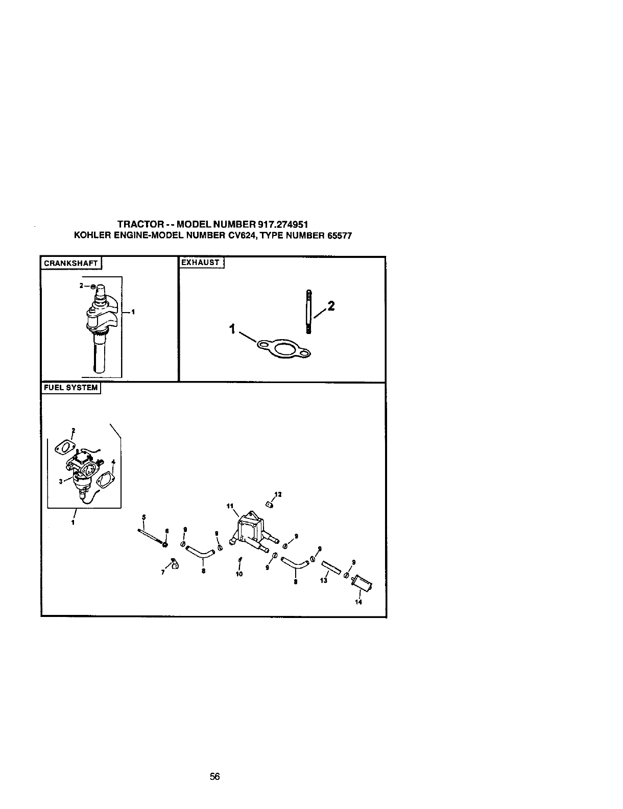
TRACTOR -- MODEL NUMBER 917.274951
KOHLER ENGINE-MODEL NUMBER CV624, TYPE NUMBER 65577
CRANKSHAFT J
--t
EXHAUST I
j2
1
FUELSYSTEM I
/
1
14
56
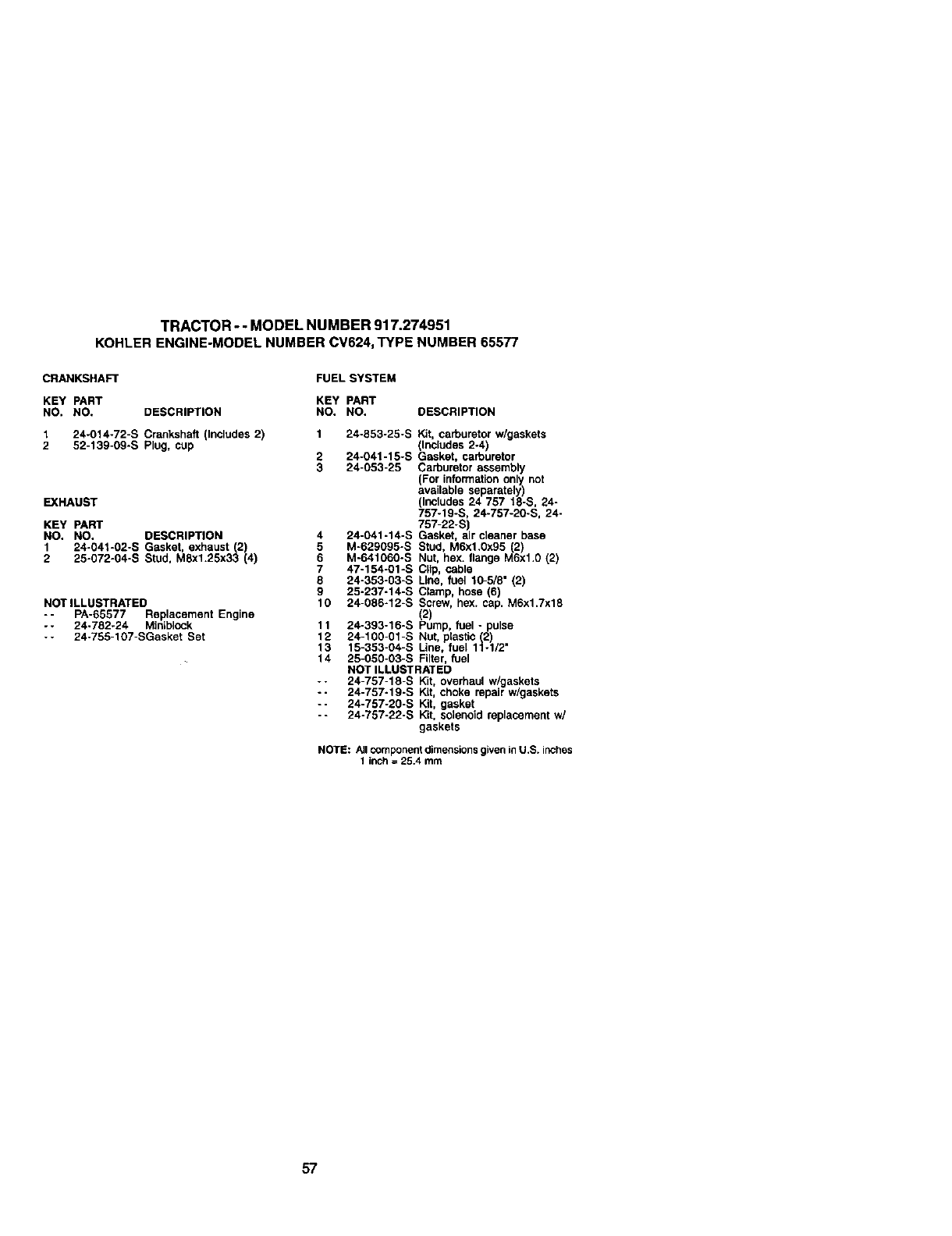
TRACTOR-- MODEL NUMBER 917.274951
KOHLERENGINE-MODELNUMBERCV624,TYPE NUMBER 65577
CRANKSHAFT
KEY PART
NO. NO. DESCRIPTION
1 24-014-72-S C_nksha_(Includes 2)
2 52-139-09-S Plug, cup
EXHAUST
KEY PART
NO. NO. DESCRIPTION
1 24-041-02-S Gasket, exhaust (2)
2 25-072-04-S Stud, M8xl.25x33 (4)
NOT ILLUSTRATED
-- PA-65577 Replacement Engine
-- 24-782-24 Miniblock
-- 24-755-107-SGasket Set
FUEL SYSTEM
KEY PART
NO. NO. DESCRIPTION
1 24-853-25oS Kit, carburetor w/gaskets
(Includes 2-4)
2 24o041-15-S Gasket, carburetor
3 24-053-25 Carburetor assembly
For information only not
ava abe separate y
(Includes 24 757 18-S, 24-
757-19-S, 24-757-20-S, 24-
757-22-S)
4 24-041-14-S Gasket, air cleaner base
5 M°629095-S Stud, M6x1.0)(95 (2)
6 M-641060oS Nut, hex. flange M6xl.0 (2)
7 47-154-01-S Clip, cable
8 24-353-03-S Line, fuel 10-5/8" (2)
9 25-237-14-S Clamp, hose (6)
10 24-086-12-S Screw, hex. cap. M6x1.7x18
2
11 24-393-16-S Pump, uel - pulse
12 24-100.01-S Nut, plastic (2)
13 15-353-04-S Line, fuel 11-1/2"
14 25-050-03-S Filter, fuel
NOT ILLUSTRATED
-- 24-757-18-S Kit, overhaul w/gaskets
-- 24-757-19-S Kit, choke repair w/gaskets
-- 24-757-20-S Kit, gasket
- - 24-757-22-S Kit, solenoid replacement w/
gaskets
NOTE: All component dimensions given in U.S. itches
1 inch = 25.4 mm
57


SUGGESTED GUIDE FOR SIGHTING SLOPES FOR SAFE OPERATION
SIGHTING _ _. CU T
GUIDE T/./_.-S
ONLY RIDE UP AND DOWN HILL,
NOT ACROSS HILL
Operate your Trector up and down the face of slopes (not I
greater than 15 ), never across the face. Make turns gradu-
ally to prevent tipping or loss of control. Exercise extreme
caution when changing direction on slopes.
For repairof major brand appliancesinyour own home...
nomatter who made it, nomatter who sold
1-800-4-MY-HOME _Any_me,day_ night
(1-800_ (U.S.A.andCanada
•www_e_i*_com W_w.seell,ca
For repairof carry-inproducts like vacuums,lawn equipment,and
electrenics,caJlforthe nearestSearsParts and RepairCenter,
1-800-486-1222 Any_rne,daycrr_l__.SA orgy)
V_NW.S_ItZ_n
Forthe replacementparts, accessoriesandowner'smanuals
that you need to do-it-yourse_f,call Seam PartsDirect6"!
1-800-366-PART 6 a.rn.- 11 p.m., 7days aweek
0-_o-3_-727s) (u.s_.o,_y)
www.seam_:x_dsdi_ct
To purchaseorinquireabout a Sears ServiceAgreement
or Sears MaintenanceAgreement:
1-800-827-6655 (u.s_.) 1-800-361-6665 (Canada)
7 a.m.- 5 p.m.,CST, Mort.- Sat. 9 aJ_ -8 p.m.EST, M- F,4 p.m. SaL
parape_rse_ciodereparaci6na
demiciio, yparaordenarpiezas:
1-888-SU,.HOGARs_
AuCanadapeurserv_ enfr_'x;_:
1-800-LE-FOYERac
WWW.SC_tS.Ca
©See_ P_ebu_andC_
®Registered Trademark /"raTrademark /su Service Mark of Sears, Roebuck and Co.
®Marca Registrada /"rMMarc_ de F&brica /s_ Marca de Servicio de Sears, Roebuck and Co.
MCMarque de commerce /MeMarque ddpos_e de Sears, Roebuck and Co.
178411 3.20.01 TR Printed in U.S.A.
