Craftsman 917275011 User Manual LAWN TRACTOR Manuals And Guides L0103114
CRAFTSMAN Lawn, Tractor Manual L0103114 CRAFTSMAN Lawn, Tractor Owner's Manual, CRAFTSMAN Lawn, Tractor installation guides
User Manual: Craftsman 917275011 917275011 CRAFTSMAN LAWN TRACTOR - Manuals and Guides View the owners manual for your CRAFTSMAN LAWN TRACTOR #917275011. Home:Lawn & Garden Parts:Craftsman Parts:Craftsman LAWN TRACTOR Manual
Open the PDF directly: View PDF ![]() .
.
Page Count: 60
Owner's Manual
ICRAFTSMAWI
23.0 HP
ELECTRIC START
48" MOWER
6 SPEED
GARDEN TRACTOR
Model No.
917.275011
•Safety
•Assembly
•Operation
•Maintenance
•Repair Parts
CAUTION:
Read and follow all Safety
Rules and Instructions before
operating this equipment.
For answersto your questions
about this product,Call:
1-800-659-5917
Sears CraftsmanHelp Line
5 am- 5 pm, Mon- Sat
SEARS, ROEBUCK AND CO., HOFFMAN ESTATES, IL 60179
Visit our Craftsman website:www.sears.com/craftsman
Warranty ............................................... 2
Safety Rules ......................................... 3
Product Specifications .......................... 6
Assembly .............................................. 8
Operation ............................................ 12
Maintenance Schedule ...................... 16
Maintenance ....................................... 18
Service and Adjustments.................... 22
Storage ............................................... 29
Troubleshooting ................................. 30
Repair Parts........................................ 34
Parts Ordedng ..................... Back Cover
LIMITED TWO YEAR WARRANTY ON CRAFTSMAN RIDING EQUIPMENT PARTS
For two (2) years from the date of purchase, if this Craftsman Riding Equipment is
maintained, lubricated and tuned up according to the instructionsin the owner's
manual, Sears will repair or replace, free of charge, any partsfound to be defective in
matedal or workmanship. Warranty service is available free of charge by returningyour
Craftsman riding equipment to your nearest Sears Service Center. In-home warranty
service is available but a trip charge will apply. This warranty applies only while this
product is in the United States.
This Warranty does not cover:
•Expendable items which become worn during normal use, such as blades, spark
plugs, air cleaners, pelts and oil filters.
•Tire replacement or repair caused by punctures from outside objects, such as nails,
thorns, stumps, or glass.
• Repairs necessary because of operator abuse, including but not limited to, damage
caused by towing objects beyond the capability of the dding equipment, impacting
objects that bend the frame or crankshaft, or over speeding the engine.
•Repairs necessary because of operator negligence, including but net limited to,
electdcal and mechanical damage caused by improper storage, failure to use the
proper grade and amount of engine oil, failure to keep the deck clear of flammable
debds, or the failure to maintain the equipment according to the instructionscon-
tained in the owner's manual.
•Engine (fuel system) cleaning or repairs caused by fuel determined to be contami-
nated or oxidized (stale). In general, fuel should be used within thirty (30) days of its
purchase date.
• Riding equipment used for commercial or rental purposes. Aproduct is "used for
commercial purpose" if is used for any purpose other than single family household
dwellings or in usage where profit is made.
LIMITED 90 DAY WARRANTY ON BATTERY
For ninety (90) days from date of purchase, if any battery included with this dding
equipment proves defective in matedal or workmanship and our testing determines the
battery will not hold a charge, Sears will replace the battery at no charge. Warranty
service is available free of charge by returning your Craftsman ddlag equipment to
your nearest Sears Service Center. In-home warranty service is available but atrip
charge will apply. This warranty applies only while this product is in the United States.
TO LOCATE THE NEAREST SEARS SERVICE CENTER OR TO SCHEDULE IN-HOME
WARRANTY SERVICE, SIMPLY CONTACT SEARS AT 1-800--4-MY-HOME
This Warranty gives you specific legal rights, and you may also have other rightswhich
may vary from state to state.
Sears, Roebuck and Co., D/817 WA, Hoffman Estates, IL 60179
IMPORTANT:ThiscuttingmachineIscapableofamputaUnghandsandfeetand
throwing objects. Failure to observe the followingsafety instructionscould result in
sedous injuryor death.
I. GENERAL OPERATION
•Read, understand, and follow all
lestruetions in the manual and on the
machine before starting.
•Only/.allow responsible adults, who are
famdiarwith the Instructions, to operate
the machine.
•Clear the area of objects such as
rocks, toys, wire, etc., which could be
picked up and thrown by the blade.
•Be sure the area is clear of other
people before mowing. Stop machine
ifanyone enters the area,
Never carry passengers.
Do not mow in reverse unless abso-
lutely necessary, Always look down
and behind before and while backing.
•Be aware of the mower discharge
directionand do not point it at anyone.
Do not operate the mower without
either the entire grass catcher or the
guard in place.
•Slow down before turning.
•Never leave a running machine
unattended. Always turn off blades, set
parking brake, stop engine, and
remove keys before dismounting.
•Turn off blades when not mowing.
Stop engine before removing grass
icatcher or unclog_ng chute.
Mow only in daylight or good artificial
light.
•Do not operate the machine while
under the influence of alcohol or drugs.
•Watch for traffic when operating near or
crossing roadways.
•Use extra care when loading or
unloading the machine into a trailer or
truck.
•Data indicates that operators, age 60
years and above, are involved in a
large percentage of dding mower-
related inudee. These operators
shou d eva uate the r abil ty to operate
the dding mower safely enough to
protect themselves and others from
sedous injury.
•Keep machine free of grass, leaves or
other debds build-up which can touch
hot exhaust /engine parts and bum.
Do not allow the mower deck to plow
leaves or other debds which can cause
build-up to occur. Clean any oil or fuel
spillage before operating or stodng the
machine. Allow machine to cool before
storage.
II. SLOPE OPERATION
Slopes are a major factor related to loss-
of-control and tipover accidents, which
can result in severe injury or death. All
slopes require extra caution. Ifyou
cannot back upthe slope or if you feel
uneasy on it, do not mow it.
DO:
•Mow up and down slopes, not across.
• Remove obstacles such as rocks, tree
limbs, etc.
Watch for holes, ruts, orbumps.
Uneven terrain could overturn the
machine. Tall grass can hide obstacles.
Use slow speed. Choose a low gear
so that you will not have to stop or shift
while on the slope.
Follow the manufacturer's recommen-
dations for wheel weights or counter-
weights to improve stability.
Use extra care with grass catchers or
other attachments. These can change
the stability of the machine.
Keep all movement on the slopes slow
and gradual. Do not make sudden
changes in speed or direction.
Avoid starting or stopping on a slope. If
tires lose traction, disengage the
blades and proceed slowly straight
down the slope.
DO NOT:
•Do not turn on slopes unless neces-
sary, and then, turn slowly and gradu-
ally downhill, if possible.
•Do not mow near drop-offs, ditches, or
embankments. The mower could
suddenly turn over if a wheel is over
the edge ofa cliffor ditch, or if an edge
caves in,
•Do not mow on wet grass. Reduced
traction could cause sUding.
•Do not try to stabilize the machine by
putting your foot on the ground.
•Do not use grass catcher on steep
slopes.
3
III. CHILDREN
Tragic accidents can occur if the operator
is not alert to the presence of children.
Children are often attracted to the
machine and the mowing activity. Never
assume that children will remain where
you last saw them.
• Keep children out of the mowing area
and under the watchful care of another
responsible adult.
• Be alert and turn machine off ifchildren
enter the area.
•Before and when backing, look behind
and down for small children.
•Never carry children. They may fall off
and be seriously injured or interfere
with safe machine operation.
•Never allow children to operate the
machine.
•Use extra care when approaching blind
corners, shrubs,trees, or other objects
that may obscure vision.
IV. SERVICE
•Usa extra care in handling gasoline
and other fuels. They are flammable
and vapors are explosive.
- Use only an approved container.
-Never remove gas cap or add fuel
with the engine running. Allow
engine to cool before refueling. Do
not smoke.
- Never refuel the machine indoors.
- Never store the machine or fuel
container inside where there is an
open flame, such as awater heater.
• Never run a machine inside a closed
area.
• Keep nuts and bolts, especially blade
attachment bolts, tight and keep
equipment in good condition.
•Never tamper with safety devices.
Check their proper operation regulady.
•Keep machine free of grass, leaves, or
other debds build-up. Clean oil or fuel
spillage. Allow machine to cool before
storing.
•Stop and inspect the equipment if you
strike an object. Repair, if necessary.
before restarting.
•Never make adjustments or repairs
with the engine running.
•Grass catcher components are subject
to wear, damage, and detedoration,
which could expose moving parts or
allow obiects to be thrown. Frequently
check components and replace with
manufacturer's recommended parts,
when necessary.
•Mower blades are sharp and can cut.
Wrap the blade(s) or wear gloves, and
use extra caution when servicing them.
•Check brake operation frequently.
Adjustand service as required.
•Be sure the area is clear of other
people before mowing. Stop machine if
anyone enters the area.
• Never carry passengers or children
even with the blades off.
•Do not mow in reverse unless abso-
lutely necessary. Always look down
and behind before and while backing.
•Never carry children. They may fall off
and be seriously injured or interfere
with safe machine operation.
•Keep children out of the mowing area
and under the watchful care of another
responsible adult.
•Be alert and tum machine off if children
enter the area.
•Before and when backing, look behind
and down for small children.
•Mow up and down slopes (15°Max),
not across.
•Remove obstacles such as rocks, tree
limbs,etc.
•Watch for holes, ruts, or bumps.
Uneven terrain could overture the
machine. Tall grass can hide obstacles.
4

• Use slow speed. Choose alow gear so
that you will not have to stop or shift
while on the slope.
• Avoid starting or stopping on a slope. If
tires lose traction, disengage the
blades and proceed slowly straight
down the slope.
•If machine stops while going uphill,
disengage blades, shift into reverse
and back down slowly.
•Do not turn on slopes unless neces-
sary, and then, turn slowly and gradu-
ally downhill, if possible.
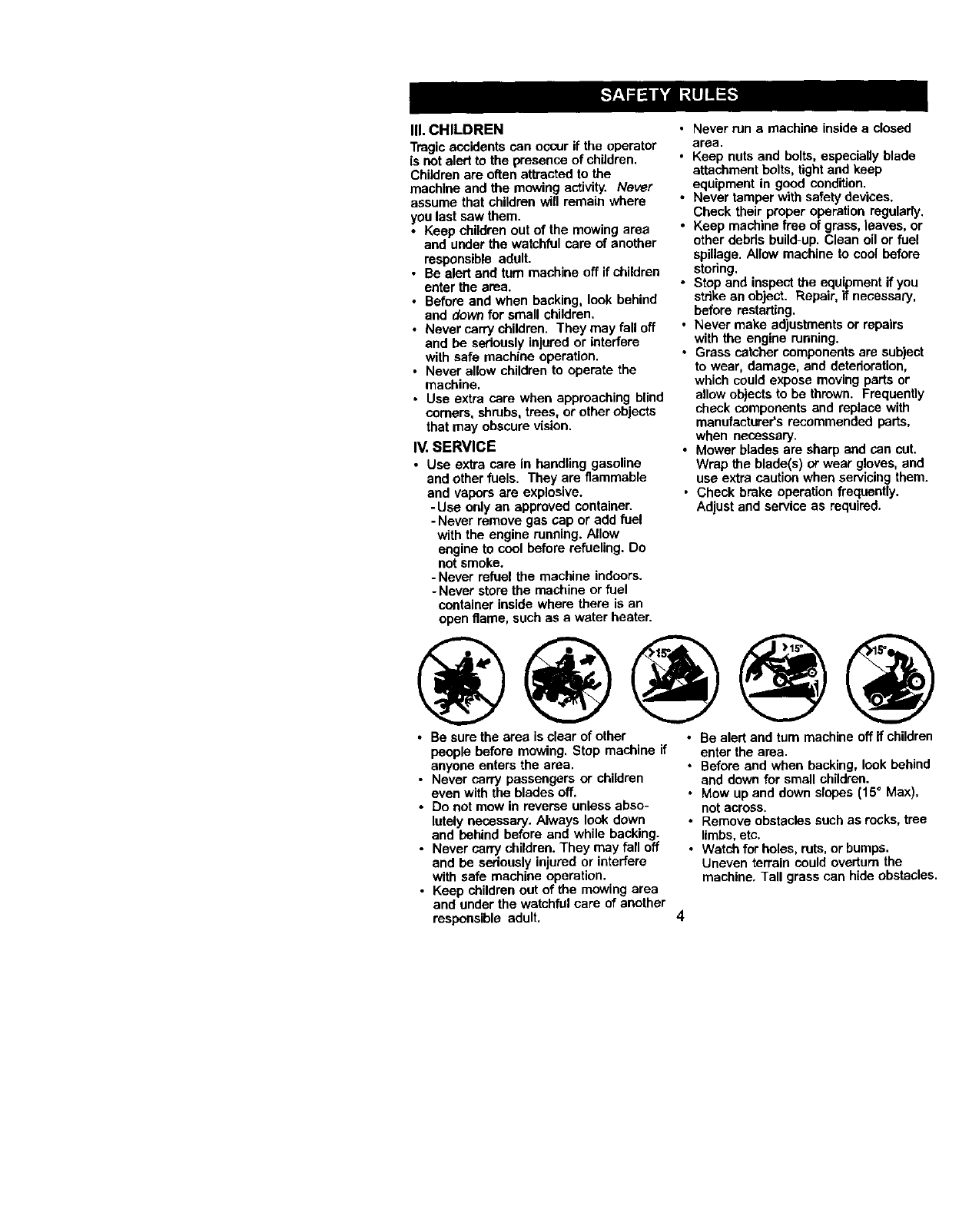
-&Look for this symbol to point out
importantsafety precautions, it means
CAUTIONII! BECOME ALERTlll YOUR
SAFETY IS INVOLVED.
ACAUTION: In order to prevent acci-
dental starting when setting up, trans-
porting,adjusting or making repairs,
always disconnect spark plug wire and
place wire where it cannot contact spark
plug.
ACAUTION: Do not coast down e hill in
neutral, you may lose control of the
tractor.
&CAUTION: Tow only the attachments
that are recommended by and comply
with specificationsof the manufacturer of
your tractor. Use common sense when
towing. Operate only at the lowest
possible speed when on a slope. Too
heavy of a load, while on aslope, is
dangerous. Tires can lose traction with
the ground and cause you to lose control
of your tractor.
&WARNING: Engine exhaust, some of its
constituents, and certain vehicle compo-
nents contain or emit chemicals known to
the State of California to cause cancer
end birth defects or other reproductive
harm.
,_WARNING: Battery posts, terminals and
related accessories contain lead and
lead compounds, chemicals known to the
State of California to cause cancer and
birth defects or other reproductive harm.
Wash hands after handling.
5
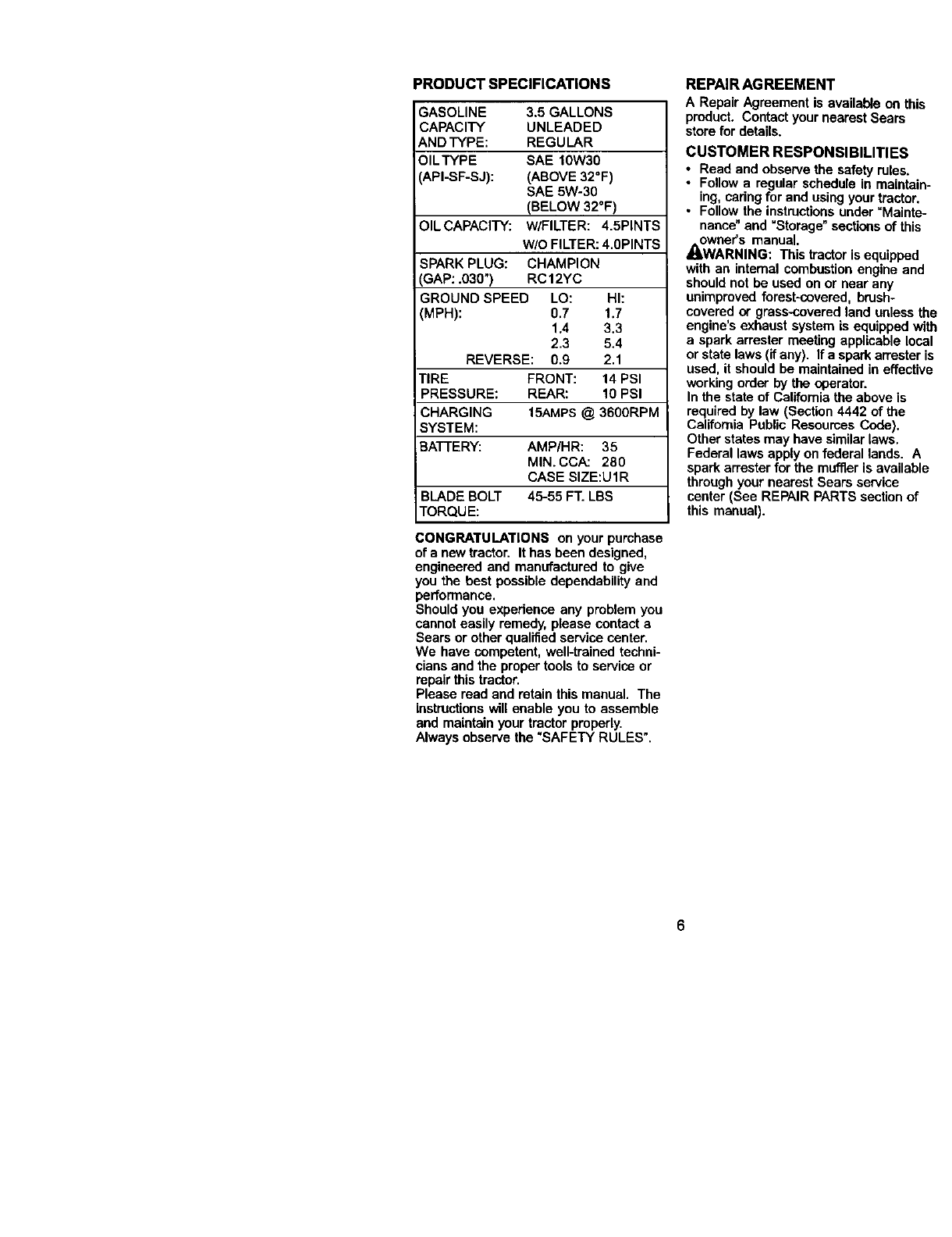
PRODUCT SPECIFICATIONS
GASOLINE 3.5 GALLONS
CAPACITY UNLEADED
AND TYPE: REGULAR
OILTYPE SAE 10W30
API-SF-SJ): (ABOVE 32°F)
SAE 5W-30
(BELOW 32°F)
OIL CAPACITY: W/FILTER: 4.5PINTS
w/o FILTER: 4.0PINTS
SPARK PLUG: CHAMPION
GAP: .030") RC12YC
GROUND SPEED LO: HI:
(MPH): 0.7 1.7
1,4 3.3
2.3 5.4
REVERSE: 0.9 2.1
TIRE FRONT: 14 PSI
PRESSURE: REAR: 10 PSI
CHARGING 15AMPS @ 3600RPM
SYSTEM:
BATTERY: AMP/HR: 35
MIN. CCA: 280
CASE SIZE:U1R
BLADE BOLT 45-55 FT. LBS
TORQUE:
CONGRATULATIONS on your purchase
of a new tractor. It has been designed,
engineered and manufactured to give
you the best possible dependability and
performance.
Should you experience any problem you
cannot easily remedy, please contact a
Sears or other qualified service center.
We have competent, well-trained techni-
cians and the proper tools to service or
repair this tractor.
Please read and retain this manual. The
instructionswill enable you to assemble
and maintainyour tractor properly.
Always observe the "SAFETY RULES".
REPAIR AGREEMENT
A Repair Agreement is available on this
product. Contact your nearest Sears
store for details.
CUSTOMER RESPONSIBILITIES
•Read and observe the safety rules.
• Follow a regular schedule in maintain-
ing, cadng for and using your tractor.
•Follow the instructionsunder "Mainte-
nance" and "Storage" sections of this
owner's manual.
_I_WARNING: This tractor is equipped
with an internal combustion engine and
should not be used on or near any
unimproved forest-covered, brush-
covered or grass-covered land unless the
engine's exhaust system is equipped with
a spark arrester meeting applicable local
or state laws (if any). If a spark arrester is
used, it should be maintained in effective
working order by the operator.
In the state of California the above is
required by law (Section 4442 of the
California Public Resources Code).
Other states may have similarlaws.
Federal laws apply on federal lands. A
spark an'ester for the muffler is available
through your nearest Sears service
center (See REPAIR PARTS section of
this manual).
6
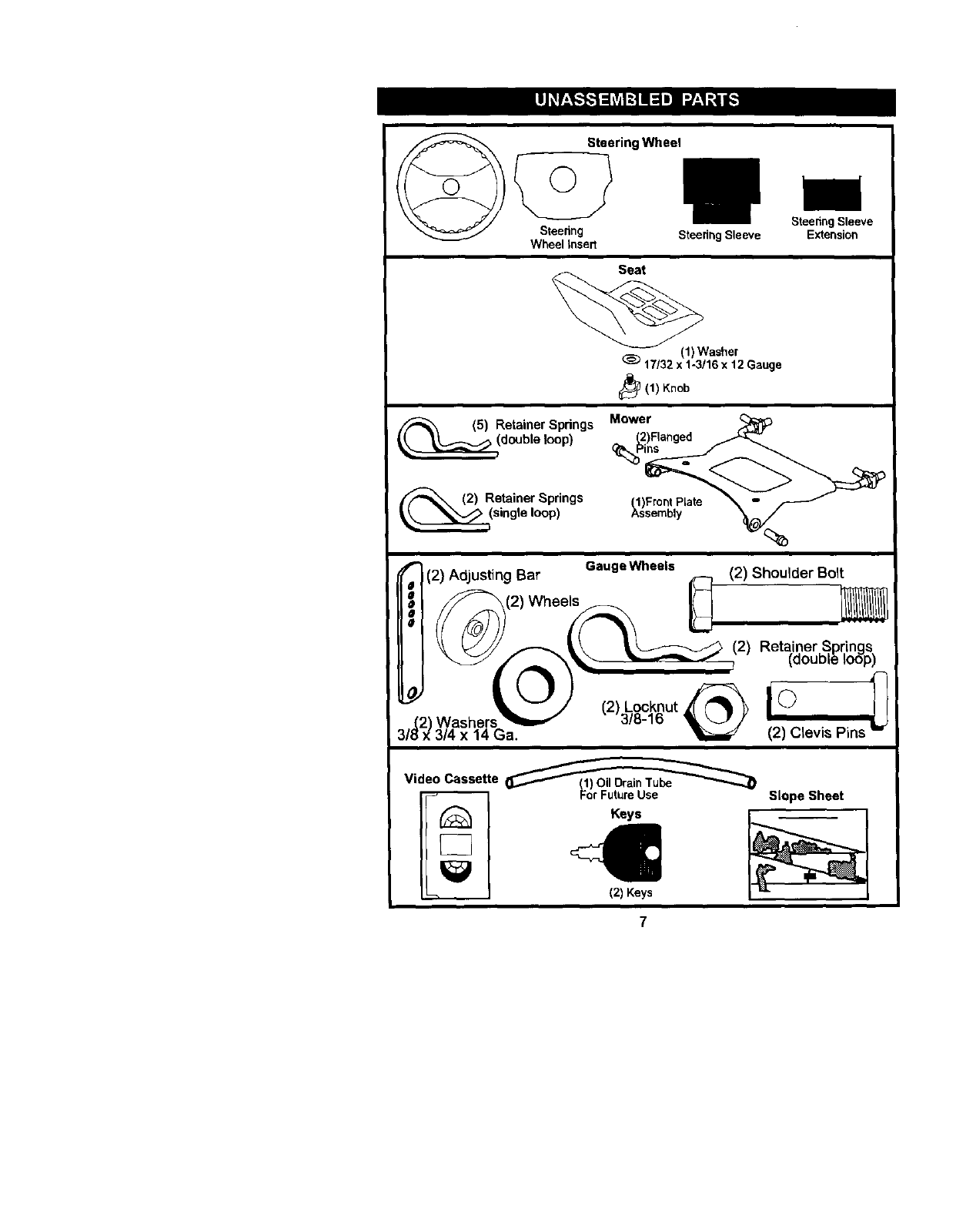
Steering Wheel
Steenng Steedng Sleeve
Wheel Insert
Steering Sleeve
Extension
Seat
(1) Washer
17/32 x 1-3/16 x 12 Gauge
_(1) Knob
(5) Retainer Springs
double loop)
Retainer Spdngs
single loop)
Mower ,_
(2)Flanged
(1)Freer PLate _-
Assembly
f (2) Adjusting Bar GaugeWheels _ (2) Shoulder Bolt
0
_ (2) Wheels _ _
\_ f_k__(2)Reta, iner Springs
(OOUDlelOOp)
iO) i°
,,_2)vy,ash ers _==,I 3/8-16 _J ,)" !
;/_ x _/4 x ]4 _a. _ (2) Clevis Pins "_
Video Casse_e_
Slope Sheet
Keys I
/2) Keys
7
Your new tractor has been assembled at the factory with exception of those parts left
unassambled for shipping purposes. To ensure safe and proper operation of your
tractor all parts and hardware yea assemble must be tightened securely. Use the
correcttools as necessary to insure proper tightness. Review the video cassette before
you begin.
TOOLS REQUIRED FOR ASSEMBLY
A socket wrench set will make assembly
easier. Standard wrench sizes you need
are listed below.
(1) 9/16"wrench (1) Pliers
(1) 1/2"wrench (1) Utility knife
(1) 3/4" socket with
drive ratchet
(1) Tire pressure gauge
When rightor left hand is mentioned in
this manual, it means, from your point of
view, when you are in the operating
position (seated behind the steering
wheel).
TO REMOVETRACTOR FROM
CARTON
UNPACK CARTON
1. Remove all accessible loose parts
and parts cartons from carton.
2. Cut, from top to bottom, along lines on
all four comers of carton, and lay
panels fiat.
3. Remove mower and packing materi-
als.
4. Check for any additional loose parts
or cartons and remove.
BEFORE REMOVING TRACTOR
FROM SKID
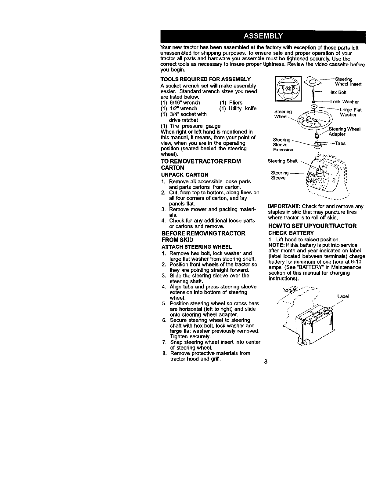
ATTACH STEERING WHEEL
1. Remove hex bolt, lock washer and
large fiat washer from steering shaft.
2. Position front wheels of the tractor so
they are pointing straight forward.
3. Slide the steedng sleeve over the
steedng shaft.
4. Align tabs and press steering sleeve
extension into bottom of steering
wheel.
5. Position steedng wheel so cross bars
are horizontal (left to dght) and slide
onto steedng wheel adapter.
6. Secure steedng wheel to steedng
shaft with hex bolt, lock washer and
large fiat washer previously removed.
Tighten securely.
7. Snap steedng wheel insert into center
of steering wheel.
8. Remove protective matedals from
tractor hood and grill.
_ _'_ Steering
___..-_ Wheel Insert
_F:_2't asher
Steering _ Large Flat
Wheel__ Washer
Steering_ _ Tabs
Sleeve
Extension
SteeringShaft _-"_..'_._ _._-"._
• J _ -n
Steer/3 i_ 1 =.
Sleeve _;,_i'_._-J:'._,_?/,,".
IMPORTANT: Check for and remove any
staples in skid that may puncturetires
where tractor is to roll off skid.
HOWTO SET UPYOURTRACTOR
CHECK BATTERY
1. Lift hood to raised position•
NOTE: Ifthis battery is put into service
after month and year indicated on label
(label located between terminals) charge
battery for minimum of one hourat 6-10
amps. (See "BATTERY" in Maintenance
section of this manual for charging
instructions).
Label
""'::'ii::i'''..:..._.,_':..'_
8
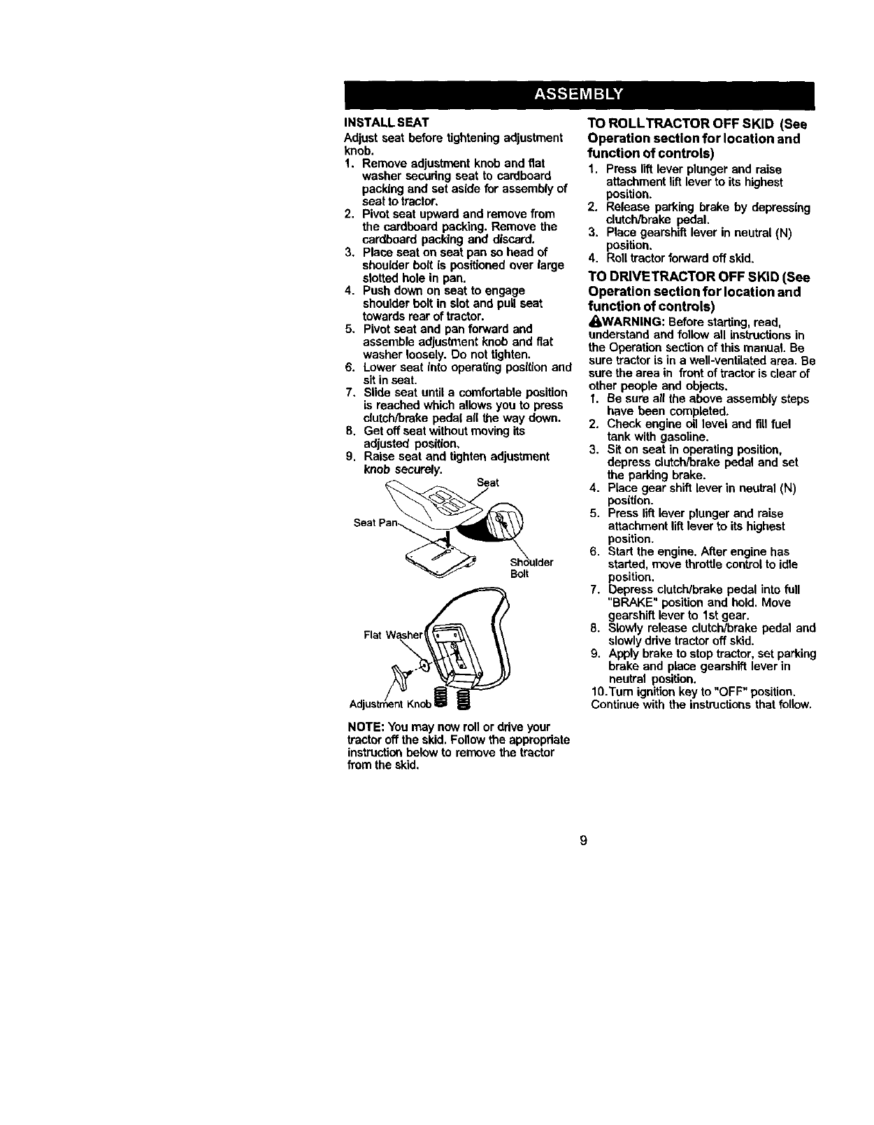
INSTALL SEAT
Adjust seat before tightening adjustment
knob.
1. Remove adjustment knob and fiat
washer securing seat to cardboard
packing and set aside for assembly of
seat to tractor,
2. Pivot seat upward and remove from
the cardboard packing. Remove the
cardboard packing and discard.
3. Place seat on seat pan so head of
shoulder boll is positioned over large
slotted hole in pan.
4. Push down on seat to engage
shoulder bolt in slot and pull seat
towards rear of tractor.
5. Pivot seat and pan forward and
assemble adjustment knob end fiat
washer loosely. Do not tighten.
6. Lower seat into opera_ng position and
sit in seat.
7. Slide seat until a comfortable position
is reached which allows you to press
clutch/brake peda( al( the way down.
8. Get off seat withoutmoving its
adjusted position,
9. Raise seat and tighten adjustment
knob securely. Seat
Bolt
NOTE: You may now roll or ddve your
tractor off the skid. Follow the appropriate
instructionbelow to remove the tractor
from the skid.
TO ROLLTRACTOR OFF SKID (See
Operation section for location end
function of controls)
1. Press liftlever plunger and raise
attachment lift lever to its highest
position.
2. Release parking brake by depressing
clutch/brake pedal.
3. Place gearshift lever in neutral iN)
position.
4. Roll tractor forward off skid.
TO DRIVETRACTOR OFF SKID (See
Operation section for location and
function of controls)
_,WARNING: Before starting, read,
understand and follow all instructionsin
the Operation sectionof this manual. Be
sure tractor is in a well-ventilated area. Be
sure the area in front of tractor is clear of
other people and objects.
I. Be sure all the above assembly steps
have been completed.
2. Check engine oil level and fill fuel
tank with gasoline.
3. Sit on seat in operating position,
depress clutch/brake pedal and set
the parking brake.
4. Place gear shift lever in neutral (N)
position.
5. Press lift lever plunger and raise
attachment liR lever to its highest
position.
6. Start the engine. After engine has
started, move throttle control to idle
position.
7. Depress clutch/brake pedal into full
"BRAKE" position and bold. Move
gearshift lever to 1st gear.
8. Slowly release clutch/brake pedal and
slowly drive tractor off skid.
9. Apply brake to stop tractor, set parking
brake and place gearshift lever in
neutral position.
10.'rum ignition key to "OFF" position.
Continue with the instructionsthat follow.
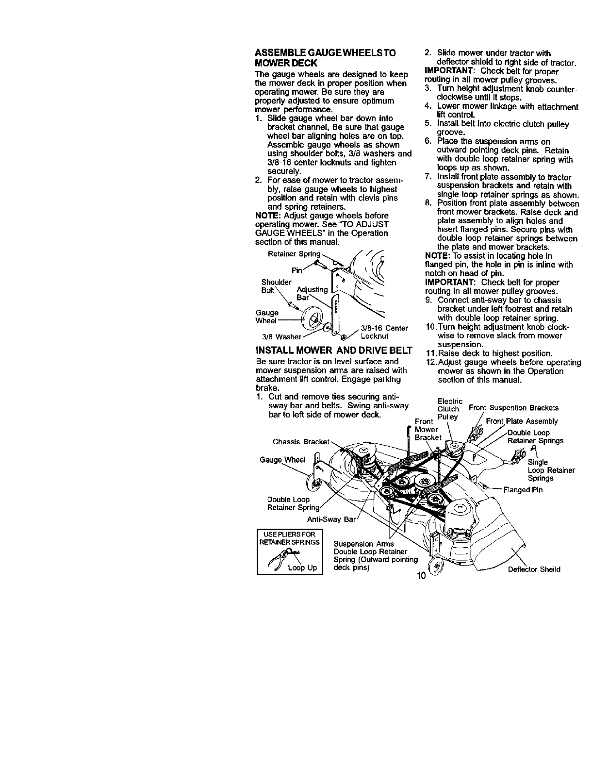
ASSEMBLE GAUGEWHEELSTO
MOWER DECK
The gauge wheels are designed to keep
the mower deck in proper position when
operating mower. Be sure they are
propedy adjusted to ensure optimum
mo,*ver penormaoce.
1. Slide gauge wheel bar down into
bracket channel, Be sure that gauge
wheel bar aligning holes ate on top.
Assemb_ gauge wheels as shown
using shoulder hoRs, 3/8 washers and
3/8-16 center leeknuts and tighten
securely.
2. Forease of mower to tractor assem-
bly raise gauge wheels to highest
positionand retain with clevs p ns
and spdng retainers.
NOTE: Adjust gauge wheels before
operating mower. See "TO ADJUST
GAUGE WHEELS" in the Operation
section of this manual.
Shoulder
Gauge
3/eWash( Locknut
INSTALL MOWER AND DRIVE BELT
Be sure tractor is on level surface and
mower suspension arms are raised with
attachment llftcontrol. Engage parking
brake.
1. Cut and remove ties securir_:Janti-
sway bar and belts, Swing anti-sway
bar to left side of mower deck.
Chassi
Gauge
2. Slide mower under tractor with
deflectorshield to right side of tra
IMPORTANT'. Check belt for proper
routing in all mower pulley grooves.
3. Turn height adjustment knob cou
clockwiseuntil it stops.
4. Lower mower linkage with attach
liftcontrol.
5. Install belt into electric clutch pulh
groove.
6. Place the suspension arms on
outward pointing deck pins. Reta
with double loop retainer spdngv
loops up as shown.
7. Installfront plate assembly to trac
suspension brackets and retain
single loop retainer spdngs as sh
8. Position front plate assembly bet_
front mower brackets. Raise deck
plate assembly to align holes an(
insertflanged pins. Secure pins
double loop retainer spdngs betv
the plate and mower brackets.
NOTE: To assist in lecating hole in
flanged pin, the hole in pin is ioline
notchon head of pin.
IMPORTANT: Check belt for proper
ro,_ing in all mower polley grooves.
9. Connect anti-sway bar to chassL,
bracket under left footrest and re1
with double loop retainer spdng.
lO.Turn height adjustment knob clc,
wise to remove slack from mowe
suspension.
11.Raise deck to highest position.
12.Ad)ust gaage wheels before op_
mower as shown in the Operatio
section of this manual.
Electric
Clutch
Front Pulley
' Mower
Front Suspention Brackets
}late Assembly
Loop
RetainerSpring=
Loop Retz
Springs
Double Loop
Retainer Spring
Anti-Sway Bar /
USE PUERS FOR I
RETAINER _:_:_RINGS
_p Up
SuspensionArms
DoubleLoopRetainer
Spring(Outwardpointing
deck pins) 10 _heild
CHECKTIRE PRESSURE
The tires on your tractor were overinflated
at the factory for shipping purposes.
Correct tire pressure is important for best
. cutting performance.
•Reduce tire pressure to PSI shown in
=PRODUCT SPECIFICATIONS" section
of this manual.
CHECK MOWER LEVELNESS
For best cutting results, mower should be
propedy leveled. See =TO LEVEL
MOWER HOUSING" in the Service and
Adjustments section of this manual.
CHECK FOR PROPER POSITION OF
ALL BELTS
See the figures that are shown for
replacing motion, mower drive, and
mower blade ddve belts in the Service
and Adjustments section of this manual.
Verify that the belts are routed correctly.
CHECK BRAKE SYSTEM
After you learn how to operate your
tractor, check to see that the brake is
propedy adjusted. See "TO ADJUST
BRAKE" in the Service and Adjustments
section of this manual.
MCHECKLIST
Before you operate and enjoy your new
tractor, we wishto assure that you receive
the best performance and satisfaction
from this quality product.
Please review the following checklist:
,/ All assembly instructions have been
completed.
J" No remaining loose parts in carton.
•/Battery is properly prepared and
charged. (Minimum 1 hour at 6 amps).
,/Seat is adjusted comfortably and
tightened securely.
,/All tires are properly inflated. (For
shipping purposes, the tires were
ovednflated at the factory).
/Be sure mower deck is propedy leveled
side-to-side/front-to-rear for best cutting
results. (Tires must be propedy inflated
for leveling).
JCheck mower and drive belts. Be sure
they are routed properly around pulleys
and inside all belt keepers.
J' Check wiring. See that all connections
are still secure and wires are properly
clamped.
While learning how to use your tractor,
pay extra attention to the following
important items:
•/ Engine oil is at proper level.
,/Fuel tank is filled with fresh, clean,
regular unleaded gasoline.
,/Become familiar with all controls - their
location and function. Operate them
before you start the engine.
,/Be sure brake system is in safe operat-
ing condition.
11
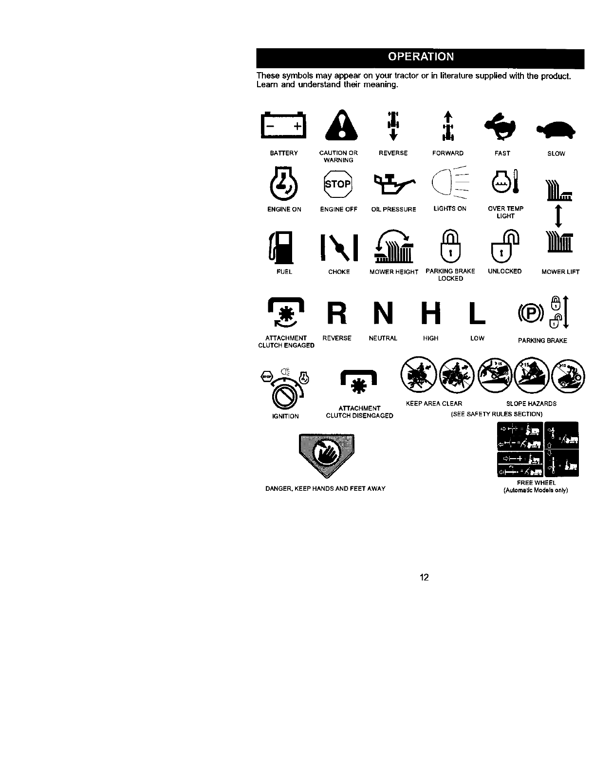
These symbols may appear on your tractor or in literature supplied with the product
Learn and understand their meaning.
BA'rFERY CAUTION OR REVERSE FORWARD FAST SLOW
WARNING
ENGINE ON ENGINE OFF OIL PRESSURE LIGHTS ON OVER TEMP
LIGHT
® O
FUEL CHOKE MOWER HEIGHT PARKING BRAKE UNLOCKED
LOCKED
!
MOWER LIFT
r_'= R N H L
ATTACHMENT REVERSE NEUTRAL HIGH LOW PARKING BRAKE
CLUTCH ENGAGED
ATTACHMENT KEEP AREA CLEAR SLOPE HAZARDS
IGNITION CLUTCH DISENGAGED (SEE SAFETY RULES SECTION)
DANGER. KEEP HANDS AND FEET AWAY FREE WHEEL
(AutomaUcModelsonly)
12
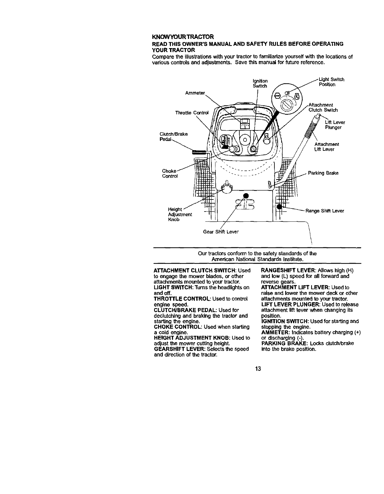
KNOWYOURTRACTOR
READ THIS OWNER'S MANUAL AND SAFETY RULES BEFORE OPERATING
YOUR TRACTOR
Compare the illustrationswith your tractor tofamiliadze yourseff with the locations of
vadous controls and adjustments. Save this manual for future reference.
Ignition Switch
Switch Position
Ammeter
Attachment
Throttle Control Switch
Clutch/Brake
Plunger
Attachment
Lift Lever
Contml Brake
Height
Adjustment
Knob
e Shift Lever
Gear Shift Lever
Our tractorsconformto the safety standards of the
Amedcan National Standards Institute.
ATTACHMENT CLUTCH SWITCH: Used
to engage the mower blades, or other
attachments mounted to your tractor,
LIGHT SWITCH: Turnsthe headlights on
and off.
THROTTLE CONTROL: Used to control
engine speed.
CLUTCH/BRAKE PEDAL: Used for
declutchingand braking the tractor and
starting the engine.
CHOKE CONTROL: Used when starting
acold engine.
HEIGHT ADJUSTMENT KNOB: Used to
adjust the mower cutting height,
GEARSHIFT LEVER: Selects the speed
and direction of the tractor.
RANGESHIFT LEVER: Allows high(H)
and low (L) speed for all forward and
reverse gears.
ATTACHMENT LIFT LEVER: Used to
raise and lower the mower deck or other
attachments mounted to your tractor.
LIFT LEVER PLUNGER: Used to release
attachment lift lever when changing its
position.
IGNITION SWITCH: Used for starting and
stopping the engine.
AMMETER: Indicates battery charging (+)
or discharging (-).
PARKING BRAKE: Locks clutch/brake
into the brake position.
13
The operation of any tractor can result in foreign objects thrown into the
eyes, which can result in severe eye damage. Always wear safety
glasses or eye shields while operating your tractor or performingany
adjustments or repairs. We recommend a wide visionsafety mask over
spectacles or standard safety glasses.
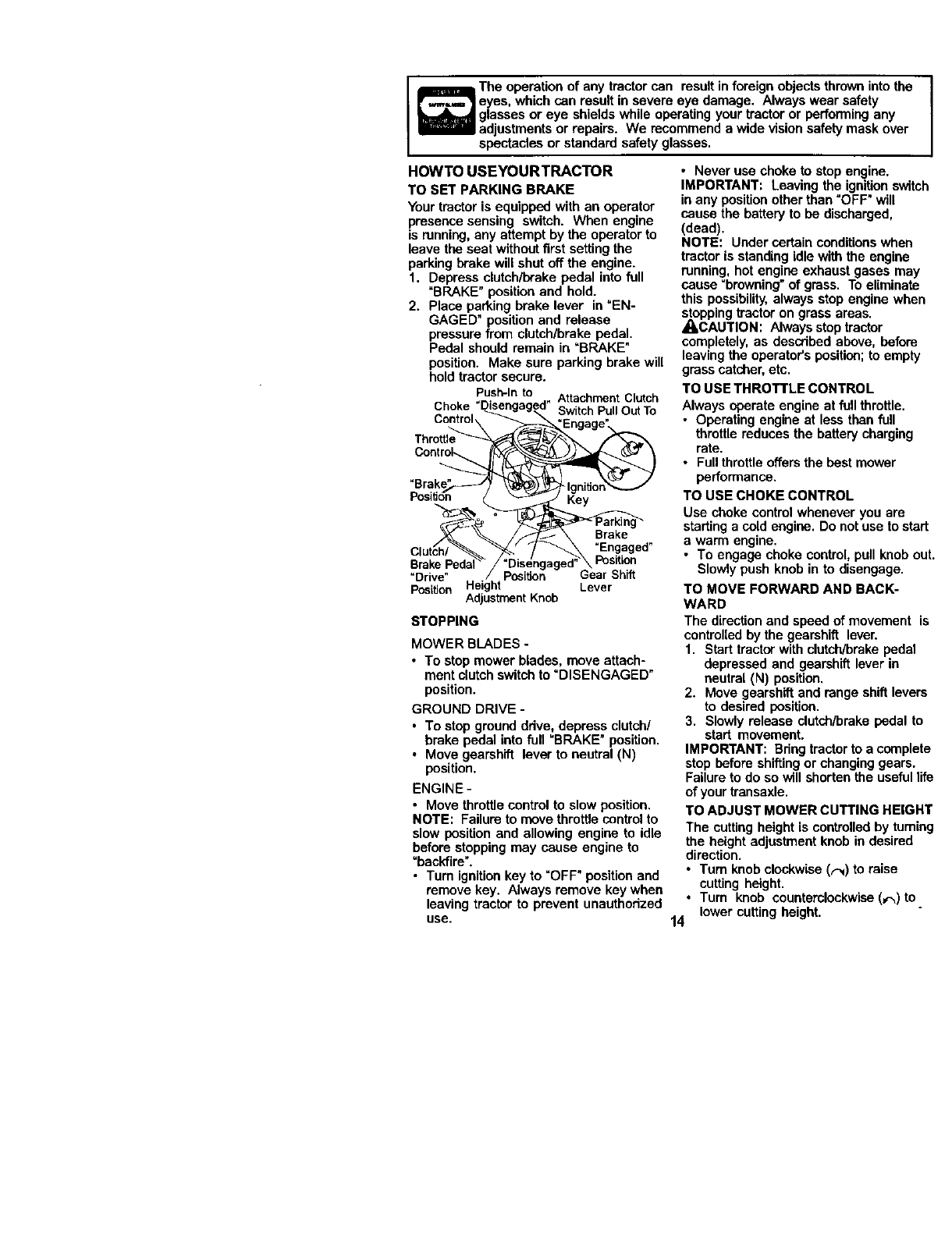
HOWTO USEYOURTRACTOR
TO SET PARKING BRAKE
Your tractor is equipped with an operator
presence sensing switch. When engine
is running,any attempt by the operator to
leave the seat without first setting the
parking brake will shut off the engine.
1. Depress clutch/brake pedal into full
=BRAKE"position and hold.
2. Place parking brake lever in "EN-
GAGED" positionand release
pressure from clutch/brake pedal.
Pedal should remain in =BRAKE"
position. Make sure parking brake will
hold tractor secure.
Push-Into AttachmentClutch
Choke "SwitchPullOutTo
Control,
Key
Brake
=Engaged"
BrakePeda Position
=Drive" Position Gear Shift
PosiUon Lever
AdjustmentKnob
STOPPING
MOWER BLADES -
•To stop mower blades, move attach-
ment clutch switch to =DISENGAGED"
position.
GROUND DRIVE -
• To stop ground ddve, depress clutch/
brake pedal into full =BRAKE" position.
• Move gearshift lever to neutral (N)
position.
ENGINE -
•Move throttle control to slow position.
NOTE: Failure to move throttle control to
slow position and allowing engine to idle
before stopping may cause engine to
"backfire".
• Turn ignition key to =OFF" position and
remove key. Always remove key when
leaving tractor to prevent unauthodzed
use.
•Never use choke to stop engine.
IMPORTANT: Leaving the ignitionswitch
in any positionother than =OFF" will
cause the battery to be discharged,
(dead).
NOTE'. Under certain conditions when
tractor is standing idle with the engine
running, hot engine exhaust gases may
cause "browning" of grass. To eliminate
this possibility, always stop engine when
stoppingtractor on grass areas.
_CAUTION: Always stop tractor
completely, as described above, before
leaving the operator's position; to empty
grass catcher, etc.
TO USE THROTTLE CONTROL
Always operate engine at full throttle.
•Operating engine at less than full
throttle reduces the battery charging
rate.
• Full throttle offers the best mower
performance.
TO USE CHOKE CONTROL
Use choke controlwhenever you are
startinga cold engine. Do not use to start
a warm engine.
•To engage choke control, pull knob out.
Slowly push knob in to disengage.
TO MOVE FORWARD AND BACK-
WARD
The direction and speed of movement is
controlled by the gearshift lever.
1. Start tractor with clutch/brake pedal
depressed and gearshift lever in
neutral (N) position.
2. Move gearshift and range shift levers
to desired position.
3. Slowly release clutch/brake pedal to
start movement.
IMPORTANT: Bdng tractor to a complete
stop before shiftingor changing gears.
Failure to do so will shorten the useful life
of your transaxle.
TO ADJUST MOWER CUTTING HEIGHT
The cutting height is controlled by taming
the height adjustment knob in desired
direction.
•Tum knob clockwise (_) to raise
cutting height.
•Turn knob counterclockwise(_)to.
lower cutting height.
14
Thecuttingheight range is approximately
1-112"to 4-112". The heights are mea-
sured from the ground to the blade tip
with the engine not running. These
heights are approximate and may vary
depending upon soil conditions, height of
grass and types of grass being mowed.
• The average lawn should be cut to
approximately 2-1/2 inches during the
cool season and to over 3 inches
during hot months. For healthier and
better looking lawns, mow often and
after moderate growth.
• For best cutting performance, grass
over 6 inches in height should be
mowed twice. Make the first cut
relatively high; the second to desired
height.
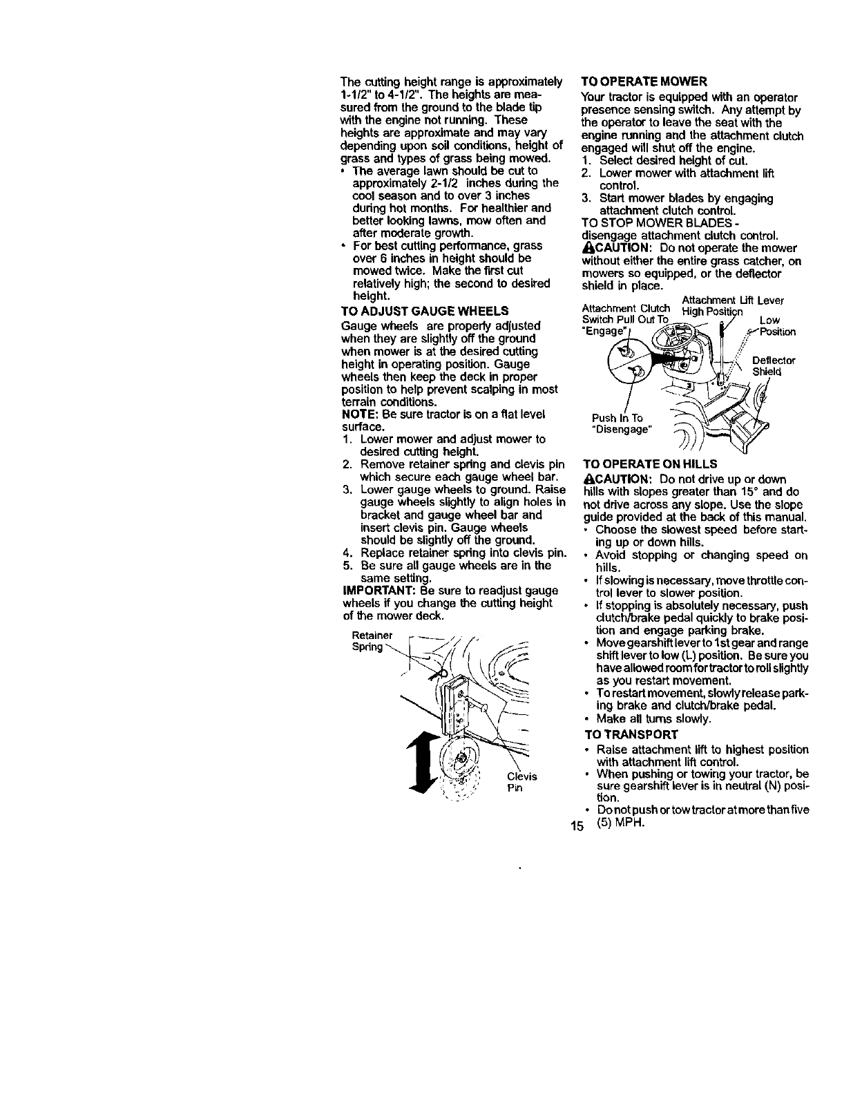
TO ADJUST GAUGE WHEELS
Gauge wheels are properly adjusted
when they are slightly off the ground
when mower is at the desired cutting
height in operating position. Gauge
wheels then keep the deck in proper
position to help prevent scalping in most
terrain conditions.
NOTE: Be sure tractor is on a flat level
surface.
1. Lower mower and adjust mower to
desired cutting height.
2. Remove retainer spdng and clevis pin
which secure each gauge wheel bar.
3. Lower gauge wheels to ground. Raise
gauge wheels slightlyto align holes in
bracket and gauge wheel bar and
insert clevis pin. Gauge wheels
should be slightlyoff the ground.
4. Replace retainer spdng into clevis pin.
5. Be sure all gauge wheels are in the
same setting.
IMPORTANT: Be sure to readjust gauge
wheels if you change the cutting height
of the mower deck.
Retainer 1,
Spring "_
TO OPERATE MOWER
Your tractor is equipped with an operator
presence sensing switch. Any attempt by
the operator to leave the seat with the
engine running and the attachment clutch
engaged will shut off the engine.
1. Select desired height of cut.
2. Lower mower with attachment lift
control.
3. Start mower blades by engaging
attachment clutch control.
TO STOP MOWER BLADES -
disengage attachment clutch control.
_CAU'rlON: Do not operate the mower
without either the entire grass catcher, on
mowers so equipped, or the deflector
shield in place. AttachmentLiftLever
"Enga_ /.::_;/'_'/P°siti°n
Deflector
y
TO OPERATE ON HILLS
_ICAUTION: Do net drive up or down
hillswith slopes greater than 15° and do
not drive across any slope. Use the slope
guide provided at the back of this manual.
•Choose the slowest speed before start-
ing up or down hills.
• Avoid stopping or changing speed on
hills.
• Ifslowing isnecessery, move thretUecon-
trol lever to slower position.
• Ifstopping is absolutely necessary, push
clutch/brake pedal quickly to brake posi-
tion and engage parking brake.
• Move gearshiftlever to 1stgear and range
shift lever to low(L) position. Be sure you
haveallowed teem fortractorto rollslightly
as you restart movement.
•Torestart movement, slowlyrelease park-
ing brake and clutch/brake pedal.
•Make all tunis slowly.
TO TRANSPORT
•Raise attachment lift to highest position
with attachment liftcontrol.
•When pushing or towing your tractor, be
sure gearshift lever is in neutral (hi) posi-
tion.
•Doeel pushortow tractoratmore thanfive
15 (5) MPH.

NOTE:Toprotecthoodfromdamage
whentransportingyourtractoronatruck
oratrailer,besurehoodisclosedand
secured to tractor. Use an appropriate
means of tying hood to tractor (rope, cord,
etc.).
TOWING CARTS AND OTHER ATTACH-
MENTS
Towonly the attachments that are
recommended by and comply with
specificationsof the manufacturer of your
tractor. Use common sense when towing.
Too heavy of a load, while on a slope, is
dangerous. Tires can lose traction with
the ground and cause you to lose control
of your tractor.
BEFORE STARTING THE ENGINE
CHECK ENGINE OIL LEVEL
The engine in your tractor has been
shipped, from the factory, already filled
with summer weight oil.
1, Check engine oil with tractor on level
ground.
2. Unthroad and remove oil fill cap/
dipstick;wipe oil off. Reinsert the
dipstick into the tube and rest oil fill
cap on the tube. Do not thread the
cap onto the tube. Remove and read
oil level. If necessary, add oil until
"FULL" mark on dipstick is reached.
Do not overfill.
•For cold weather operation you should
change oil for easier starting(See "OIL
VISCOSITY CHART" in the Mainte-
nance section of thismanual).
• To change engine oil, see the Mainte-
nance sectionin this manual.
ADD GASOLINE
• Fill fuel tank. Use fresh, clean, regular
unleaded gasoline with a minimum of
87 octane. (Use of leaded gasoline
will increase carbon and lead oxide
deposits and reduce valve life). Do not
mix oil with gasoline. Purchase fuel in
quantitiesthat can be used within 30
days to assure fuel freshness,
IMPORTANT: When operating in
temperatures below 32°F(0°C), use fresh,
clean winter grade gasoline to help
insure good cold weather starting.
_I,WARNING: Experience indicates that
alcohol blended fuels (called gasohol or
using ethanol or methanol) can attract
moisturewhich leads to separation and
formation of acids dudng storage. Acidic
gas can damage the fuel system of an
engine while in storage. To avoid engine
problems, the fuel system should be
emptied before storage of 30 days or
longer. Drain the gas tank, start the
engine and let it run untilthe fuel lines
and carburetor are empty. Use fresh fuel
next season. See Storage Instructionsfor
additional information. Never use engine
or carbumter cleaner productsin the fuel
tank or permanent damage may occur.
_,CAUTION: Fill to bottomof gas tank
fillerneck. Do not overfill. Wipe offany
spilled oil or fuel. Do not store, spillor
use gasoline near an open flame.
TO START ENGINE
When staring the enginefor thefirst_me or if
theenginehasmn cut offuel, itwil takeextra
orankir_ f_meto move fuelfrom the tankto
eng=ne.
1. Sit on seat in operating position,
depress clutch/brake pedal and set
perking brake.
2. Place gear shift lever in neutral (N)
position.
3. Move attachment clutch to "DISEN-
GAGED" position.
4. Move throttle control to fast position
5. Pull choke controlout for a cold
engine start attempt. For a warm
engine start attempt the choke control
may not be needed.
NOTE: Beforestarting,readthe warmand
coldstaring procadumsbelow.
6. Insert key into ignition and turn key
clockwiseto "START" position and
release key as soon as engine starts.
Do not run starter continuouslyfor
more than fifteen seconds per minute.
If the engine does not start after
several attempts, push choke control
in, wait a few minutes end try again. If
engine still does not start, pull the
choke controlout and retry.
WARM WEATHER STARTING (50°F and
above)
7. When engine starts, slowly push
choke control in until the engine
begins to run smoothly.If the engine
starts to run roughly, pull the choke
control out slightlyfor a few seconds
and then continue to push the control
in slowly.
16
• The attachments and ground drive can
now be used. If the engine does not
accept the load, restart the engine and
allow it to warm up for one minute
using the choke as described above.
COLD WEATHER STARTING (50° F and
below)
7, When engine starts, slowly push
choke control in until the engine
begins to run smoothly. ConlJnueto
push the choke control in small steps
allowing the engine to accept small
changes in speed and load, until the
choke controlis fully in. if the engine
startsto run roughly,pull the choke
control out slightlyfor a few seconds
and then continue to push the control
in slowly. This may require an engine
warm-up period from several seconds
to several minutes, depending on the
temperature.
• The attachments can be used during
the engine warm-up pedod and may
require the choke control be pulled out
slightly.
NOTE: If at a high altitude (above 3000
feet) or in cold temperatures (below 32 F)
the carburetorfuel mixture may need to
be adjusted for best engine performance.
See "TO ADJUST CARBURETOR" in the
Service and Adjustments section of this
manual.
MOWINGTIPS
• Tire chains cannot be used when the
mower housingis attached to tractor.
•Mower should be propedy leveled for
best mowing performance. See "TO
LEVEL MOWER HOUSING" in the
Service and Adjustments section of this
manual.
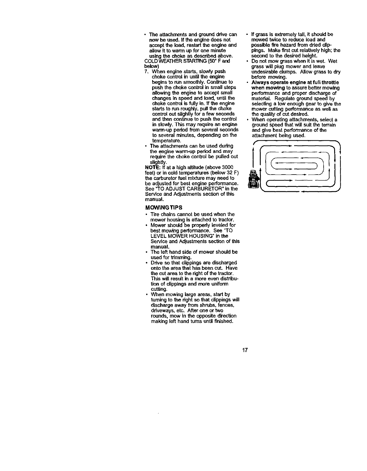
•The left hand side of mower should be
used for trimming.
•Drive so that clippings are discharged
onto the area that has been cut. Have
the cut area to the right of the tractor.
This will result in a mere even distribu-
tion of clippingsand more uniform
cuffing.
•When mowing large areas, start by
turning to the dght so that clippingswill
discharge away from shrubs, fences,
driveways, etc. After one ortwo
rounds, mow in the opposite direction
making left hand turns until finished.
•If grass is extremely tall, it should be
mowed twice to reduce load and
possible fire hazard from dded clip-
pings. Make firstcut relatively high; the
second to the desired height.
•De not mow grass when it is wet. Wet
grass will plug mower and leave
undesirable clumps. Allow grass to dry
before mowing.
• Always operate engine at full throttle
when mowing to assure better mowing
performance and proper discharge of
matedaL Regulate ground speed by
selecting a low enough gear to give the
mower cutting performance as well as
the quality of cut desired.
•When operating attachments, select a
ground speed that will suit the terrain
and give best performance of the
attachment being used.
17
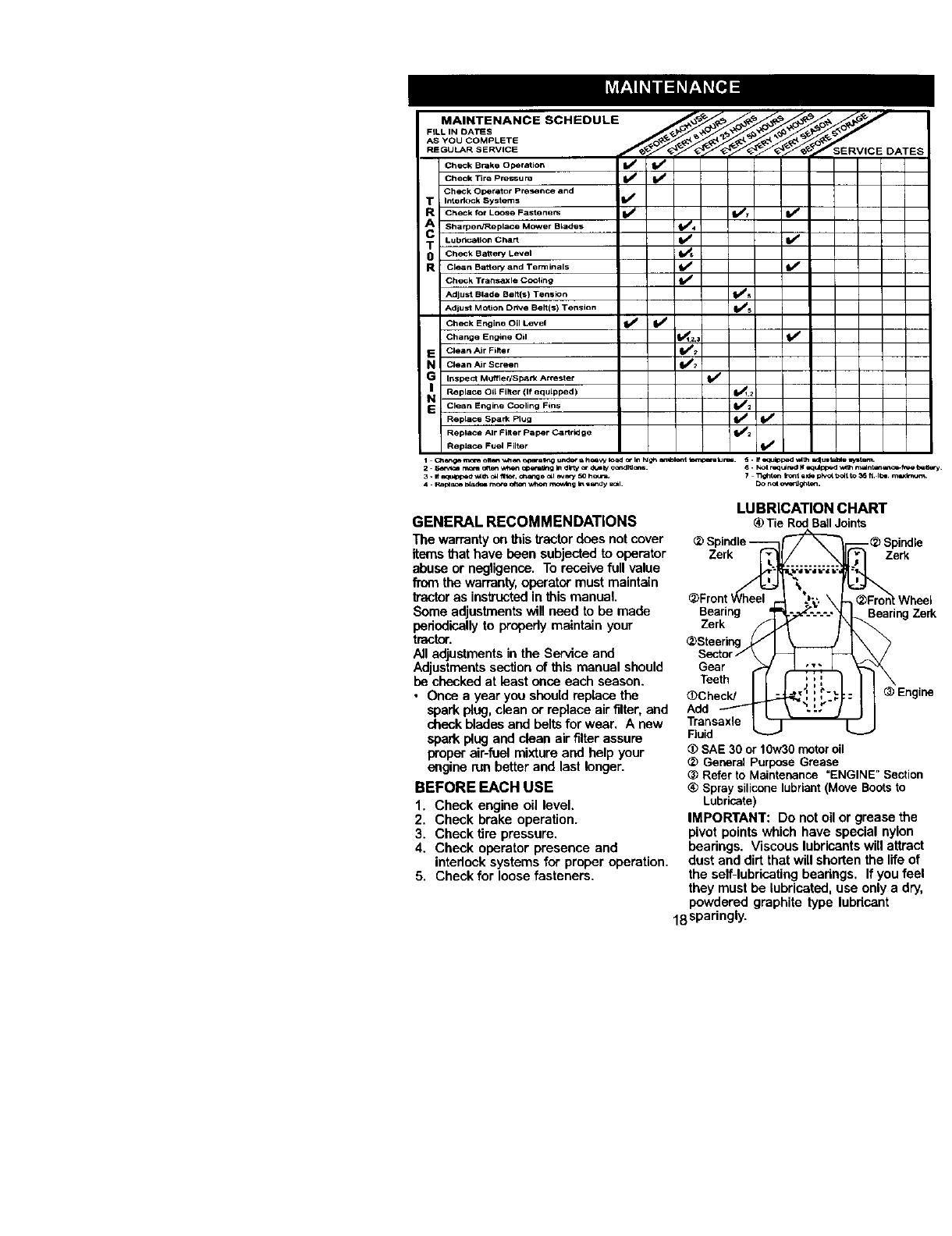
MAINTENANCE SCHEDULE
FILL IN DATES
AS YOU COMPLETE
REGULAR SERVICE _ERVICE DATES
Check Brake operation V' V p
Check Tire pl'e'l_su ra I_
Check Operator PreSence and
T Intell ock Systems if
R Check for Lcose Fasteners _ 11/7 Vf
A Sharped/Rapist 8Mower Blades II_' 4
TLubrication Chart V' I_
0 Check Battery Level
R Cle_, n Bakery and Terminals _
Ch_k TransaXle Cooling if
Adjust Blade Belt{s) Tension (l_s
Adjust Motion Drtve Belt(s) Tension tl/5
Check Engine Oil LeVel _i (i_
Change Engine Oil _1,2,_
EiClean Air Filter _
a Clean Air Screen _2
G Insl_Ct Mufflec/sl_rk Affestef
NI Replace Oil Filter (if equipped )1_1.2
EClean _ngina Cooling Fins Ibm2
Reptace spark Plug _I_'
Replace Air Filter paper C_,rtrldge e_/2
ReplaCe Fuel Filter q_/
GENERAL RECOMMENDATIONS
The warranty on thistractor does not cover
itemsthat have been subjected to operator
abuse or negligence. To receive fullvalue
fromthe warranty,operator must maintain
Vactoras instructedin this manual.
Some adjustmentswill need to be made
periodicallyto properlymaintain your
tractor.
All adjustments in the Service and
Adjustmentssection of this manusI should
be checked at least once each season.
• Once a year you should replace the
spark plug,clean or replace air filter, and
cheek blades and belts for wear. Anew
spark plug and clean air filter assure
proper air-fuel mixture and help your
engine run better and last longer.
BEFORE EACH USE
1. Check engine oil level.
2. Check brake operation.
3. Check tire pressure.
4. Check operator presence and
intedocksystems for proper operation.
5. Check for loose fasteners.
Zerk
Bearing
Zerk
Gear
Teeth
<_ChecW
Add
Transaxle
Fluid
LUBRICATION CHART
Tie RodBallJoints
@Spindle
............ Z_rk
BearingZerk
,.---,r =r-,.-;-,
_:::: ;-:_.
\--- /
SAE30 or 10w30motoroil
<_GeneralPurposeGrease
(_ Referto Maintenance"ENGINE"Section
<_Spraysiliconelubriant(MoveBootsto
Lubricate)
IMPORTANT: Do not oil or grease the
pivot points which have special nylon
bearings. Viscous lubricantswill attract
dust and dirt that will shorten the llfe of
the self-lubricatingbearings. If you feel
they must be lubricated, use only a dry,
powdered graphite type lubdcant
18sparingly.
TRACTOR
Always observe safety rules when
performing any maintenance.
BRAKE OPERATION
If tractor requires more than six (6) feet
stoppingdistance at high speed in
highest gear, then brake must be ad-
justed. (See "TO ADJUST BRAKE" inthe
Service and Adjustments section of this
manual).
TIRES
• Maintain proper air pressure in all tires
(See =PRODUCT SPECIFICATIONS"
section of this manual).
• Keep tires free of gasoline, oil, or insect
control chemicals which can harm
rubber.
• Avoid stumps, stones, deep rets, sharp
objects and other hazards that may
cause tire damage.
NOTE: To seal tire punctures and prevent
fiat tires due to slow leaks, tire sealant
may be purchased from your local parts
dealer. Tire sealant also prevents tire dry
rot and corrosion.
OPERATOR PRESENCE SYSTEM
Be sure operator presence and interlock
systems are working propedy. If your
tractor does not function as descdbed,
repair the problem immediately.
•The engine should not start unless the
clutch/brake pedal is fully depressed
and attachement clutch control is in the
disengaged position.
• When the engine is running, any
attempt by the operator to leave the
seat without first setting the parking
brake should shut off the engine.
•When the engine is running and the
attachment clutch is engaged, any
attempt by the operator to leave the
seat should shut off the engine.
• The attachment clutch should never
operate unless the operator is in the
seat.
BLADE CARE
For best results mower blades must be
kept sharp. Replace bent or damaged
b(ades.
BLADE REMOVAL
1. Raise mower to highest positionto
allow access to blades.
2. Remove bex bolt, lock washer and fiat
washer securing blade.
3, Install new or resharpened blade with
trailing edge up towards deck as
shown,
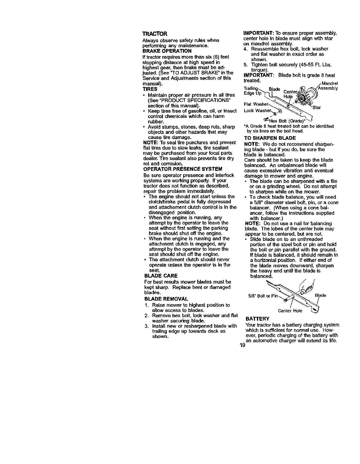
IMPORTANT: To ensure proper assembly,
center hole in blade must align with star
on mandre( assembly.
4. Reassemble hex bolt, lock washer
and fiat washer in exact order as
shown,
5. Tighten belt securely (45-55 Ft. Lbs.
torque).
IMPORTANT: Blade bolt is grade 8heat
treated. /Mandrel
Trailin9-_. Blade _ _/Assembly
Edge Up'_ I Center_L_\\\
Fat
*A Grade8 heat treated boltcan be identified
by six lines onthe bolt head.
TO SHARPEN BLADE
NOTE: We do not recommend shaq_en-
ing blade * but if you do, be sure the
blade is balanced.
Care should be taken to keep the blade
balanced. An unbalanced blade will
cause excessive vibration and eventual
damage to mower and engine.
•The blade can be sharpened with afile
or on a gdnding wheel. Do not attempt
to sharpen while on the mower,
•To check blade balanca, you will need
a 5/8" diameter steel bolt, pin, or a cone
belancar. (When using a cone bal-
ancer, follow the instructions supplied
with balancer,)
NOTE: Do not use a nail for balancing
blade. The lobes of the center hole may
appear to be centered, bet are not.
•Slide blade on to an unthreaded
portion of the steel bolt or pin and hold
the bolt or pin parallel with the ground.
If blade is balanced, it should remain in
ahorizontal position. If either end of
the blade moves downward, sharpen
the heavy end untilthe blade is
balanced.
5/8"Bolt de
Center Hole L_
BATTERY
Yourtractor has abattery chargingsystem
which is sufficient for normal use, How-
ever, periodic charging of the battery with
an automotive charger will extend its life.
19
•Keep battery and terminals dean.
•Keep battery bollstight.
•Keep small vent holes open,
•Recharge at 6-10 amperes for 1 hour.
NOTE: The originalequipment battery on
your tractoris maintenance free, Do not
attemptto open or remove caps or covers.
Adding or checldng levelof electrolyteis
not necessary.
TO CLEAN BATTERY AND TERMINALS
Corrceionand dirton the battery and
terminals can cause _le battery to "leak"
power.
1. Remove terminal guard.
2. DisconnectBLACK battery cable first
then RED battery cable and remove
battery fromtractor.
3. Rinse the battery with plain water and
dry.
4. Clean tenninals and battery cable ends
with wire brushuntil bright,
5. Coat terminals with grease or petro-
leum jelly.
6. Reinstall battery (Sen =REPLACING
BATTERY" in the SERVICE AND
ADJUSTMENTS section of this
manual).
V-BELTS
Check V-belts for detedorationand wear
after 100 hoursof operation and replace if
necessary.The belts are not adjustable,
Replace belts ifthey begin to slipfrom
wear.
TRANSAXLE COOLING
Keep trensaxle fren from build-upof dirt
and chaff which can restrictcooling.
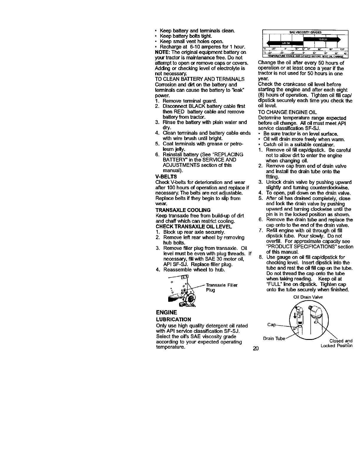
CHECK TRANSAXLE OIL LEVEL
1. Blockup rear axle securely.
2. Remove left rear wheel by removing
hub bolts.
3. Remove fillerplug from transaxle. Oil
levelmust be even with plugthreads. If
necessary,fillwith SAE 30 motor oil.
API SF-SJ. Replace fillerplug.
4. Reassemble wheel to hub.
,__ piT_jsaxleFiller
ENGINE
LUBRICATION
Only use high quality detergent oil rated
with API service classificationSF-SJ,
Select the oil's SAE viscositygrade
according to your expected operating
temperature, 2O
Change the oil after every 50 hours of
operation or at least once a year ifthe
tractor is not used for 50 hours in one
year.
Check the crankcase oil level before
starting the engine and after each eight
(8) hours of operation. Tighten oilfill cap/
dipsticksecurely each time you check the
oil level.
TO CHANGE ENGINE OIL
Determine temperature range expected
before oil change. All oil mustmeet API
service classificationSF-SJ.
• Be suretractor is on level surface,
•Oil willdrain more frenly when warm,
• Catch oil in a suitable container.
1. Remove oil fillcap/dipstick. Be careful
not to allowdirt to enter the engine
when changing oil,
2, Remove sap from end of drain valve
and installthe drain tube onto the
fitting.
3. Unlock drain valve by pushingupward
slightlyand turning counterclockwise.
4, To open, pulldown on the drain valve.
5, After oil has drained completely,dose
and lock the drain valve by pushing
upward and turningclockwiseuntil the
pin is in the lockedpositionas shown,
6. Remove the drain tube and replace the
cap onto to the end of the drainvalve.
7. Refill engine with oil through oil fill
dipsticktube. Pour slowly. Do not
overfill. For approximatecapacitysee
"PRODUCT SPECIFICATIONS" section
of this manual.
8. Use gauge onoil fill cap/dipstick for
checking level. Insert dipstickinto the
tube and rest the oil fillcap on the tube.
Do notthread the cap nato the tube
when taldngreading. Keep oil at
=FULL" lineon dipstick. Tightennap
onto the tube securelywhen finished,
Oil DrainValve
Drain Tube and
Locked Position
CLEAN AIR SCREEN
Air screen must be kept free of dirt and
chaff to prevent engine damage from
overheating. Clean with a wire brush or
compressed air to remove dirt and
stubbom dried gum fibers.
CLEAN AIR INTAKEICOOLING AREAS
To insure proper cooling, make sure the
grass screen, cooling fins, and other
external surfaces of the engine are kept
clean at all times.
Every 100 hours of operation (more often
under extremely dusty, dirty conditions),
remove the blower housing and other
cooling shrouds. Clean the cooUng fins
and external surfaces as necessary.
Make sure the cooling shrouds are
reinstalled.
NOTE: Operating the engine with a
blocked grass screen, dirty or plugged
cooling fins, and/or cooling shrouds
removed will cause engine damage due
to overheating.
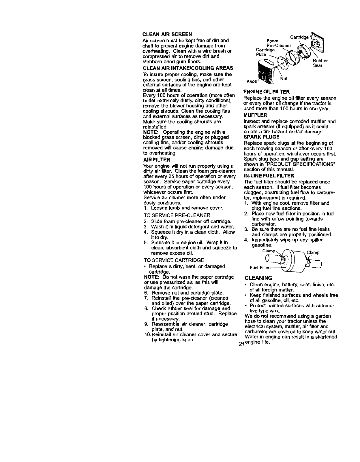
AIR FILTER
Your engine will not run properly using a
dirty air filter. Clean the foam pre-deaner
after every 25 hours of operation or every
season. Service paper cartridge every
100 hours of operation or even/season,
whichever occurs first.
Service air cleaner more often under
dusty conditions.
1. Loosen knob and remove cover.
TO SERVICE PRE-CLEANER
2. Slide foam pre-cleaner off cartridge.
3. Wash it in liquid detergent and water.
4. Squeeze it dry in a clean cloth. Allow
itto dry.
5. Saturate it in engine oil Wrap it in
clean, absorbent cloth and squeeze to
remove excess oil.
TO SERVICE CARTRIDGE
•Replace a dirty, bent, or damaged
cartridge.
NOTE: Do not wash the paper cartridge
or use pressurized air, as this will
damage the cartridge.
6. Remove nut and cartridge plate.
7. Reinstall the pre-cfeaner (cleaned
and oiled) over the paper cartddge.
8. Check rubber seal for damage and
proper position around stud. Replace
if necessary.
9. Reassemble air cleaner, cartddge
plate, and nut.
10, Reinstall air cleaner cover and secure
Foam
Pre-Cleaner
Cartridge
Rubber
Seal
Nut
Knob
ENGINE OIL FILTER
Replace the engine oil filter every season
or every other oil change if the tractor is
used more than 100 hours in one year.
MUFFLER
Inspect and replace corroded muffler and
spark attester (if equipped) as it could
create afire hazard andlor damage.
SPARK PLUGS
Replace spark plugs at the beginning of
each mowing season or after every 100
hours of operation, whichever occurs first.
Spark plug type and gap setting are
shown in "PRODUCT SPECIFICATIONS"
section of this manual.
IN-LINE FUEL FILTER
The fuel filter should be replaced once
each season. If fuel filter becomes
dogged, obstructingfuel flow to carbure-
tor, replacement is required.
1. With engine cool, remove filter and
plug fuel line sections.
2. Place new fuel filter in position in fuel
line with arrow pointing towards
carburetor.
3. Be sure there are no fuel line leaks
and clamps are properly positioned.
4. Immediately wipe up any spilled
gasoline.
CLEANING
•Clean engine, battery, seat, finish, etc.
of allforeign matter.
• Keep finished surfaces and wheels free
of all gasoline, oil, etc.
•Protect painted surfaces with automo-
tive type wax.
We do not recommend using a garden
hose to clean your tractor unless the
electrical system, muffler, air filter and
carburetor are covered to keep water out.
Water in engine can result in ashortened
by tightening knob. 21 engine life.
_L CAUTION: BEFORE PERFORMING ANY SERVICE OR ADJUSTMENTS:
1. Depress clutch/brake pedal fully and set parking brake,
2. Place gearshift lever in neutral (N) position,
3. Place attachment clutch in "DISENGAGED" position.
4, Turn ignitionkey "OFF" and remove key.
5, Make sure the blades and aU moving parts have completely stopped.
6. Disconnect spark plug wire from spark plug and place wire where it cannot
come in contact with plug.
1RACTOR
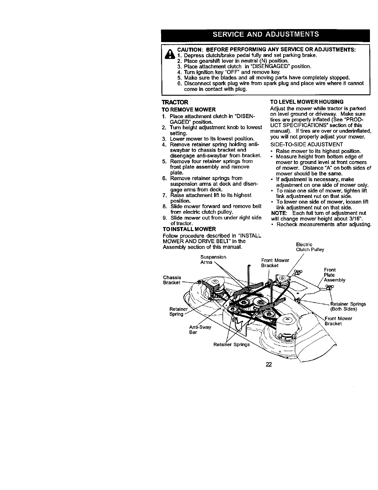
TO REMOVE MOWER
1. Place attachment clutch in "DISEN-
GAGED" position.
2. Tum height adjustment knob to lowest
setting.
3. Lower mower to its lowest position.
4, Remove retainer spdng holding anti-
swaybar to chassis bracket and
disengage anti-swaybar from bracket.
5. Remove four retainer springsfrom
front plate assembly and remove
plate.
6. Remove retainer spdngs from
suspension arms at deck and disen-
gage arms from deck,
7, Raise attachment liftto its highest
position.
8. Slide mower forward and remove belt
from elecb'icclutch pulley.
9. Slide mower out from under dght side
of tractor.
TO INSTALL MOWER
Follow procedure described in "INSTALL
MOWER AND DRIVE BELT" in the
Assembly section of this manual,
Suspension
Chassis
TO LEVEL MOWER HOUSING
Adjust the mower while tractor is parked
on level ground or driveway, Make sure
tires are propedy inflated (See =PROD-
UCT SPECIFICATIONS" sectionof this
manual). Iftires are over or undednflated,
you will not properlyadjust your mower,
SIDE-TO-SIDE ADJUSTMENT
•Raise mower to its highest position,
•Measure height from bottom edge of
mower to ground level at front comers
of mower, Distance "A" on both sides of
mower should be the same.
•If adjustment is necessary, make
adjustment on one side of mower only,
•To raise one side of mower, tighten lift
linkadjustment nut on that side.
•To lower one side of mower, loosen lift
linkadjustment nut on that side.
NOTE: Each full tum of adjustment nut
will change mower height about 3/16",
•Recheck measurements after adjusting,
Electric
Clutch Pulley
Front Mower
Bracket Front
Plate
Retainer
Spnn
Anti-Sway
Bar
Retainer Springs
Bracket
22
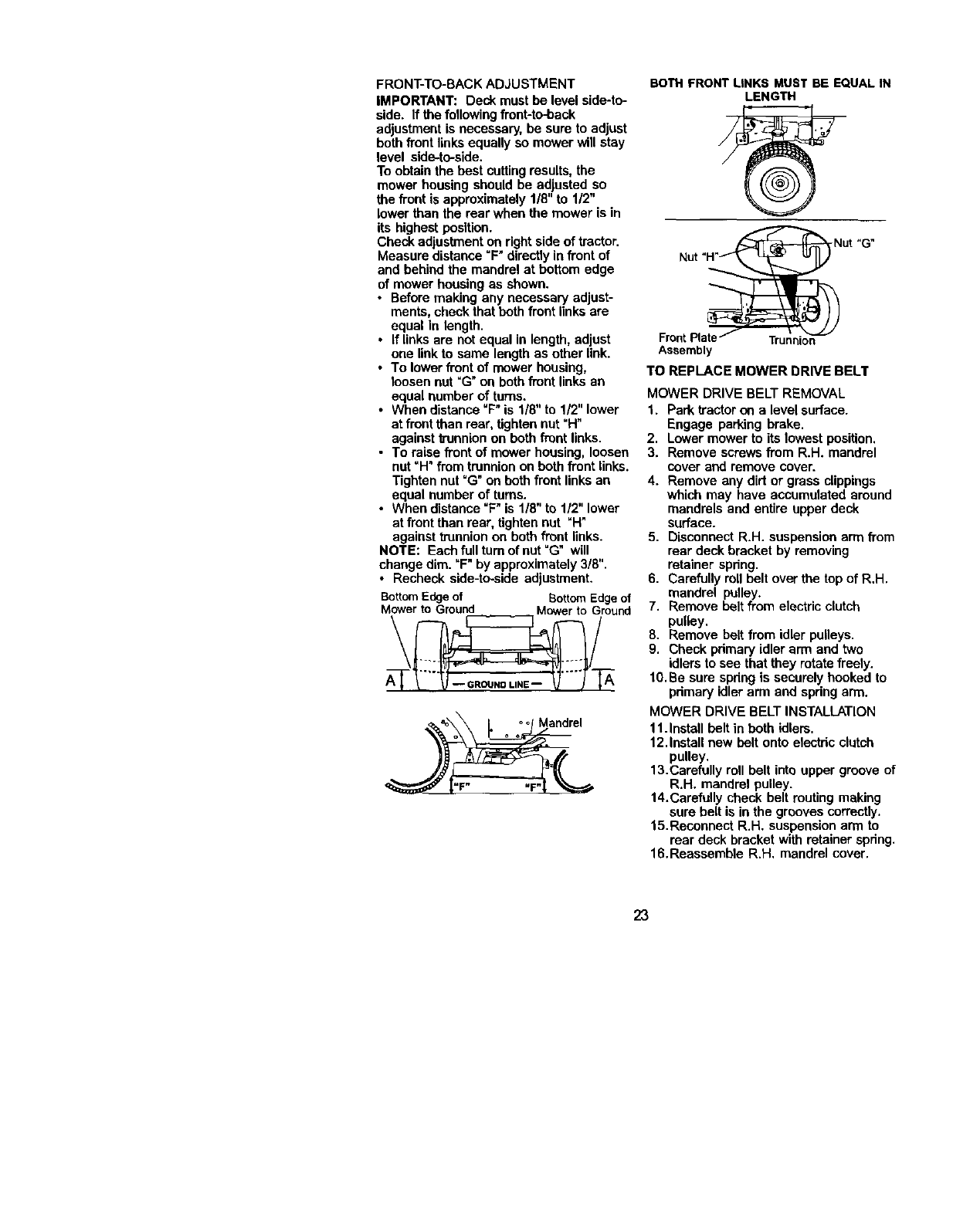
FRONT-TO-BACK ADJUSTMENT
IMPORTANT: Deck mustbe levelside-to-
side. If the followingfront-to-back
adjustment is necessary, be sure to adjust
both front links equally so mower will stay
level side-to-side.
Toobtain the best cutting results, the
mower housing should be adjusted so
the front is approximately 1/8" to 1/2"
lower than the rear when the mower is in
its highest position.
Check adjustment on right side of tractor.
Measure distance "F" directly in front of
and behind the mandrel at bottom edge
of mower housing as shown.
• Before making any necessary adjust-
ments, check that beth front links are
equal in length.
•If linksare not equal in length, adjust
one linkto same lengthas other link.
•To lower front of mower housing,
loosen nut "(3" on both front links an
equal number of turns.
•When distance "F" is 1/8" to 1/2" lower
at front than rear, tighten nut "H"
against trunnlen on beth front links.
• To raise front of mower housing, loosen
nut "H" from trunnion on beth front links.
Tighten nut =G" on both front linksan
equal number of turns.
•When distance "F" is 1/8" to 1/2" lower
at front than rear, tighten nut "H"
against trunnion on both front links.
NOTE: Each full turn of nut "G" will
change dim. "F"by approximately 3/8".
•Recheck side-to-side adjustment.
BottomEdgeof Bottom Edgeof
Mowerto Ground Mowerto Ground
<__\_ / o_/ Mandrel
o o _,
BOTH FRONT LINKS MUST BE EQUAL IN
LENGTH
Front |Trunnion
Assembly
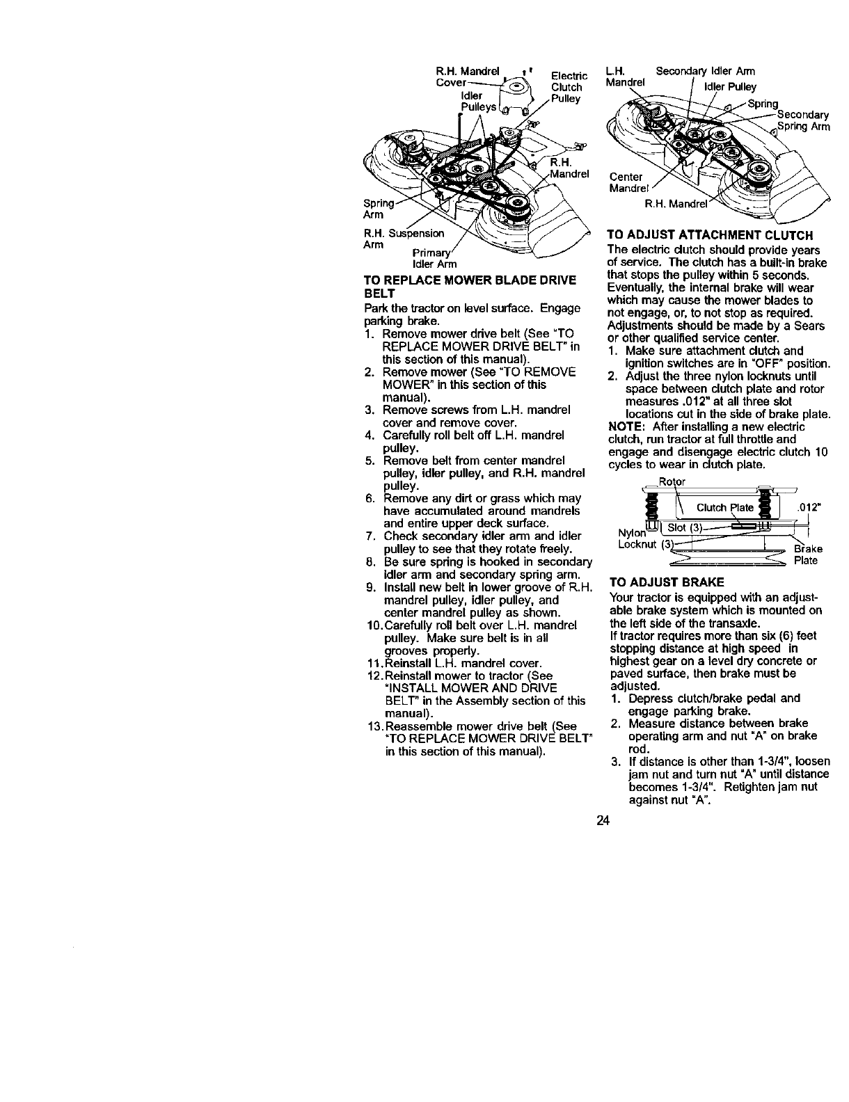
TO REPLACE MOWER DRIVE BELT
MOWER DRIVE BELT REMOVAL
1. Park tractor on a level surface.
Engage parking brake.
2. Lower mower to its lowest position.
3. Remove screws from R.H. mandrel
cover and remove cover.
4. Remove any dirt or grass clippings
which may have accumulated around
mandrels and entire upper deck
surface.
5, Disconnect R.H. suspension arm from
rear deck bracket by removing
retainer spdng,
6, Carefully roll belt over the top of R,H.
mandrel pulley.
7. Remove belt from electric clutch
pulley,
8. Remove belt from idler pulleys,
9. Check pdmary idler arm and two
idlers to see that they rotate freely.
10.Be sure spdng is securely hooked to
pdmary idlerarm and spdng arm.
MOWER DRIVE BELT INSTALLATION
11.Install belt in beth idlers,
12,Install new belt onto electdc clutch
pulley,
13.Carefully roll belt into upper groove of
R.H. mandrel pulley.
14.Carefully check belt routing making
sure belt is in the grooves correctly.
15,Reconnect R.H. suspension arm to
rear deck bracket with retainer spdng.
16.Reassamble R.H, mandrel cover.
23
R.H. Mandrel v I Electric
Clutch
Idler .Pulley
Spring.
Arm
R.H. Suspension
Arm
Idler Arrn
TO REPLACE MOWER BLADE DRIVE
BELT
Park the tractoron level surface. Engage
parking brake.
1. Remove mower ddve belt (See "TO
REPLACE MOWER DRIVE BELT" in
this section of this manual).
2. Remove mower (See "TO REMOVE
MOWER" in this section of this
manual).
3. Remove screws from L.H. mandrel
cover and remove cover.
4. Carefully roll belt off L.H. mandrel
pulley.
5. Remove belt from center mandrel
pulley, idler pulley, and R.H. mandrel
pulley.
6. Remove any dirt or grass which may
have accumulated around mandrels
and entire upper deck surface.
7. Check secondary idler arm and idler
pulley to see that they rotate freely.
8. Be sure spdng is hooked in secondary
idler arm and secondary spring arm.
9. Install new belt in lower groove of R.H.
mandrel pulley, idler pulley, and
center mandrel pulley as shown.
10.Carefully roll belt over L.H. mandrel
pulley. Make sure belt is in all
grooves properly.
11.Reinstall L.H. mandrel cover.
12.Reinstall mower to tractor (See
"INSTALL MOWER AND DRIVE
BELT" in the Assembly section of this
manual).
13. Reassemble mower drive belt (See
"TO REPLACE MOWER DRIVE BELT"
in this section of this manual).
L.H. Secondar/ Idler Arm
Mandrel Idler Pulley
Center
R.H, Mandr_
TO ADJUST ATTACHMENT CLUTCH
The electdc dutch should provide years
of service. The clutch has a built-inbrake
that stops the pulleywithin 5 seconds.
Eventually, the internal brake will wear
which may cause the mower blades to
not engage, or, to not stop as required.
Adjustments should he made by a Sears
or other qualified service center.
1. Make sure attachment clutch and
ignitionswitches are in "OFF" position.
2. Adjust the three nylon Iocknotsuntil
space between clutch plate end rotor
measures .012" at all three slot
locationscut in the side of brake plate.
NOTE: After installinga new electric
clutch, run tractor at full throttle and
engage and disengage electdc clutch 10
cycles to wear in clutch plate.
! t\ c'utchP'atell 012"
Nylon_ Slot 3)_
Locknu 3 _ Brake
_Plate
TO ADJUST BRAKE
Yourtractor is equipped with an adjust-
able brake system which is mounted on
the left side of the transaxle.
If tractor requires more than six (6) feet
stoppingdistance at high speed in
highest gear on alevel dry concrete or
paved surface, then brake must be
adjusted.
1. Depress clutch/brake pedal and
engage parking brake.
2. Measure distance between brake
operating arm and nut "A" on brake
rod.
3. If distance is other than 1-3/4", loosen
jam nut and turn nut "A" untildistance
becomes 1-3/4". Retightenjam nut
against nut "A".
24
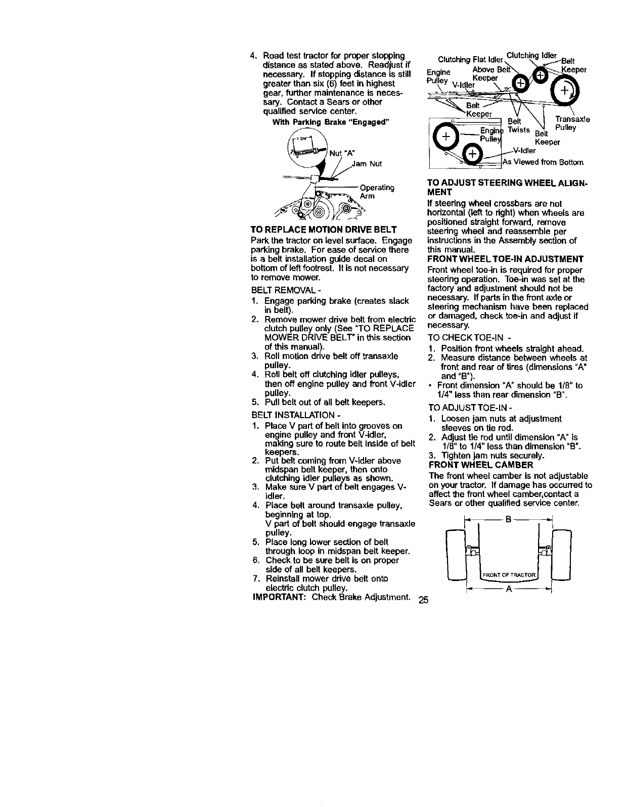
4. Road test tractor for proper stooPing
distance as stated above. Readjust if
necessary. If stopping distance is still
greater than six (6) feet in highest
gear, further maintenance is neces-
sary. Contact a Sears or other
qualified service center.
With Parking Brake"Engaged"
Nut "A"
Nut
Operating
Arm
TO REPLACE MOTION DRIVE BELT
Park the tractor on level surface, Engage
parking brake, For ease of service there
is abelt installationguide decal on
bottomof leftfootrest, It is not necessary
to remove mower,
BELT REMOVAL -
1. Engage parking brake (creates slack
in belt).
2. Remove mower ddve belt from electdc
clutch pulley only (See "TO REPLACE
MOWER DRIVE BELT" in this section
of this manual).
3. Roll motion ddve belt off transaxle
pulley.
4. Roll belt off clutching idler pulleys,
then off engine pulley and front V-idler
pulley.
5. Pull belt out of all belt keepers.
BELT INSTALLATION -
1. Place V part of belt into grooves on
engine pulley and front V-idler,
making sure to route belt inside of belt
keepers.
2. Put belt coming from V-idler above
midspan belt keeper, then onto
clutching idler pulleys as shown.
3. Make sureV part of belt engages V-
idler.
4. Place belt around transaxle pulley,
beginning at top.
V part of belt should engage transaxle
pulley.
5. Place long lower section of belt
through loop in midspan belt keeper.
6. Check to be sure belt is on proper
side of all belt keepers.
7. Reinstall mower ddve belt onto
electde clutch pulley.
IMPORTANT: Check Brake Adjustment. 25
ClutchingFlatidlerrh, ,a==,,,_,.tchi_..gI_.._Be ff
a" e AboveBelt'___ _eeper
EnJn Keeper
Belt \ I Transaxle
Twisst Befit Pulley
Keeper
V-Idler
_AS V_ledIK_r_ rBottom
TO ADJUST STEERING WHEEL ALIGN-
MENT
If steedng wheel crossbars are not
bedzontal (left to dght) when wheels are
positioned straight forward, remove
steedng wheel and reassemble per
instructionsin the Assembly section of
this manual.
FRONT WHEEL TOE-IN ADJUSTMENT
Front wheel tee-in is required for proper
steedng operation. Toe-in was set at the
factory and adjustment should not be
necessary. If parts in the front axle or
steedng mechanism have been replaced
or damaged, check toe-in and adjust if
necessary.
TO CHECKTOE-IN -
1. Position front wheels straight ahead.
2. Measure distance between wheels at
front and rear of tires (dimensions"A"
and °B").
• Front dimension "A" should be 1/8" to
1/4" less than rear dimension =B".
TO ADJUST TOE-IN -
1. Loosen jam nuts at adjustment
sleeves on tie rod.
2, Adjust tie rod until dimension "A" is
1/8" to 1/4" less than dimension=B".
3. Tighten jam nuts securely.
FRONT WHEEL CAMBER
The front wheel camber is not adjustable
onyour tractor. If damage has occurred to
affect the front wheel camber,contact a
Sears or other qualified service center.
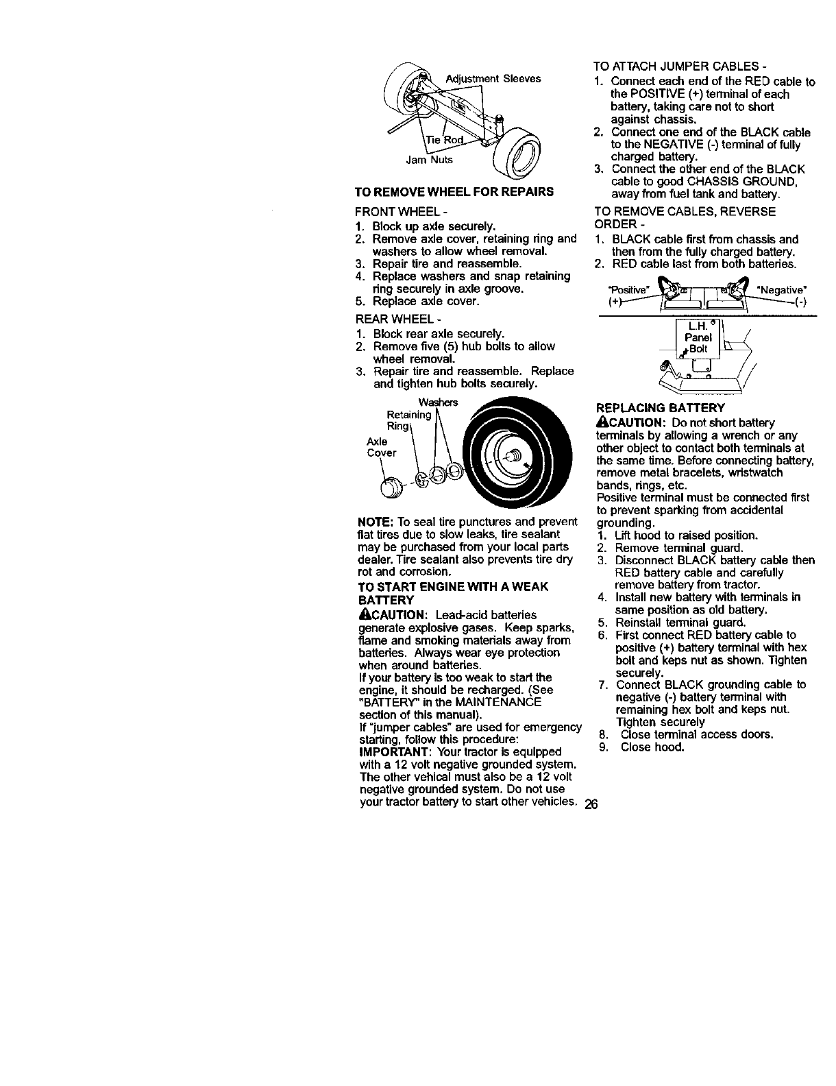
TOREMOVEWHEELFORREPAIRS
FRONT WHEEL-
1. Block up axle securely.
2. Remove axle cover, retaining ring and
washers to allow wheel removal.
3. Repair tire and reassemble.
4. Replace washers and snap retaining
ring securely in axle groove.
5. Replace axle cover.
REAR WHEEL -
1. Block rear axle securely.
2. Remove five (5) hub bolts to allow
wheel removal.
3. Repair tire and reassemble. Replace
and tighten hub bolts securely.
Washers
Retaining_
Axle
co;
NOTE: To seal tire punctures and prevent
fiat tiresdue to slow leaks, tire sealant
may be purchased from your local parts
dealer. Tire sealant also preventstire dry
rot and corrosion.
TO START ENGINE WITH A WEAK
BATTERY
ACAUTION: Lead-acid batteries
generate explosive gases. Keep sparks,
flame and smoking materials away from
batteries. Always wear eye protection
when around battedes.
If your battery is tee weak to start the
engine, it should be recharged. (See
"BATTERY" in the MAINTENANCE
sectionof this manual).
If "jumper cables" are used for emergency
starting, follow this procedure:
IMPORTANT: Your tractor is equipped
with a 12 volt negative grounded system.
The other vehical must also be a 12 volt
negative grounded system. Do not use
your tractor battery to start other vehicles. 26
TO ATTACH JUMPER CABLES -
1. Connect each end of the RED cable to
the POSITIVE (+) terminal of each
battery, taking care not to short
against chassis.
2. Connect one end of the BLACK cable
to the NEGATIVE (-) terminal of fully
charged battery.
3. Connect the other end of the BLACK
cable to good CHASSIS GROUND,
away from fuel tank and battery.
TO REMOVE CABLES, REVERSE
ORDER -
1. BLACK cable first from chassis and
then from the fully charged battery.
2, RED cable last from both batteries.
"Positive"_ "Negative"
(.)/-- )
REPLACING BATTERY
_CAUTION: Do not short battery
terminals by allowing a wrench or any
other object to contact both terminals at
the same time. Before connecting battery,
remove metal bracelets, wristwatch
bands, rings,etc.
Positive terminal must be connected first
to prevent sparking from accidental
grounding.
1. Lift hood to raised position.
2. Remove terminal guard.
3. Disconnect BLACK battery cable then
RED battery cable and carefully
remove battery from tractor.
4. Install new battery with terminals in
same position as old battery.
5. Reinstall terminal guard.
6. First connect RED battery cable to
positive (+) battery terminal with hex
bolt and keps nut as shown. Tighten
securely.
7. Connect BLACK grounding cable to
negative (-) battery terminal with
remaining hex bolt and keps nut.
Tighten securely
8. Close terminal access doors.
9. Close hood.
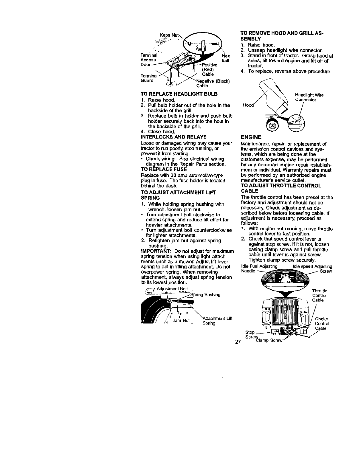
Terminal Hex
Access Bolt
Guard
-Positive
(Red)
Cabte
Cable
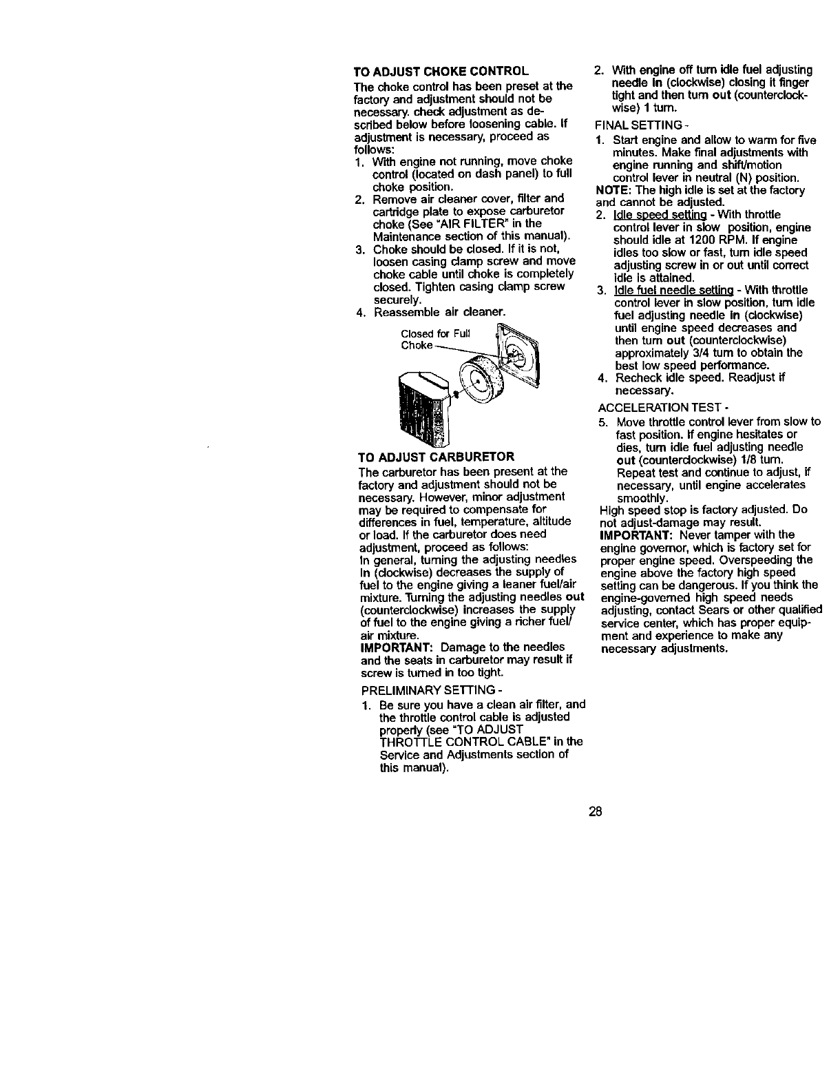
TO REMOVE HOOD AND GRILL AS-
SEMBLY
1. Raise hood.
2. Unsnap headlight wire connector.
3. Stand in front of tractor. Grasp hood at
sides, itlt toward engine and lift off of
tractor,
4. To replace, reverse above procedure,
TO REPLACE HEADLIGHT BULB
1. Raise hood.
2. Pull bulb holder out of the hole in the
backside of the gdll.
3. Replace bulb in holder and push bulb
holder securely back into the hole in
the backside of the grill.
4. Close hood.
INTERLOCKS AND RELAYS
Loose or damaged wiring may cause your
tractorto run poorly,stoprunning, or
preventitfrom starling.
• Check wiring. See electrical wiring
diagram in the Repair Parts section.
TO REPLACE FUSE
Replace with 30 amp automotive-type
plugqnfuse. The fuse holder is located
behind the dash.
TO ADJUST ATTACHMENT LIFT
SPRING
1. While holding spring bushing with
wrench, loosen jam nut.
• Turn adjustment bolt clockwise to
extend spring and reduce lift effort for
heavier attachments.
•Turn adjustment bolt counterclockwise
for lighter attachments.
2. Retighten jam nut against spring
bushing.
IMPORTANT: Do not adjust for maximum
spring tension when using lightattach-
ments such as a mower. Adjust lift lever
spring to aid in lifting attachment. Do not
overpower spring. When removing
attachment, always adjust spring tension
to its lowestposition.
_ Bushing
_/ /_ ......... - Spring
27
Headlight Wire
Connector
ENGINE
Maintenance, repair, or replacement of
the emission control devices and sys-
tems, which are being done at the
customers expense, may be performed
by any non-ruad engine repair establish-
ment or individual.Warranty repairs must
be performed by an authorized engine
manufacturer's service outlet.
TO ADJUST THROTTLE CONTROL
CABLE
The throttle control has been preset at the
factory and adjustment should not be
necessary. Check adjustment as de-
scribed below before loosening cable. If
adjustment is necessary, proceed as
follows:
1. With engine not running, move throttle
control lever to fast position,
2. Check that speed controllever is
against stop screw. If it is not, loosen
casing clamp screw and pull throttle
cab(e unti(lever is against screw.
Tighten clamp screw securely.
IdleFuelAdjusting IdlespeedAdjusting
Throttle
Control
Cable
Stop
Scre_laml:
;hoke
Control
Cable
TO ADJUST CHOKE CONTROL
The choke control has been preset at the
factory end adjustment should not be
necessary, check adjustment as de-
scribed below before loosening cable, If
adjustment is necessary, proceed as
follows:
1. With engine not running, move choke
control (located on dash panel) to full
choke position.
2. Remove air cleaner cover, f_lterand
cartridge plate to expose carburetor
choke (See "AIR FILTER" in the
Maintenance section of this manual).
3. Choke should be closed. If it is not,
loosen casing clamp screw and move
choke cable untilchoke is completely
closed. Tighten casing clamp screw
securely,
4. Reassemble air cleaner.
Closed for FuLl
TO ADJUST CARBURETOR
The carburetor has been present at the
factory and adjustment should not be
necessary. However, minor adjustment
may be required to compensate for
differences in fuel, temperature, altitude
or load. If the carburetor does need
adjustment, proceed as follows:
In general, turning the adjusting needles
In (clockwise)decreases the supply of
fuel to the engine giving a leaner fuel/air
mixture.Turningthe adjusting needles out
(counterclockwise) increases the supp(y
of fuel to the engine giving a richer fuel/
air mixture.
IMPORTANT: Damage to the needles
and the seats in carburetor may result if
screw is turned in too tight.
PRELIMINARY SE'I-rlNG -
1. Be sure you have aclean air filter, and
the throttle control cable is adjusted
propedy (see "TO ADJUST
THROTTLE CONTROL CABLE" in the
Service and Adjustments section of
this manual).
2. With engine off turn Idle fuel adjusting
needle In (clockwise) closingit finger
tightand then turn out (countercl_-'k-
wise) 1 tam.
FINAL SETTING-
1. Start engine and allow to warm for fiv
minutes. Make final adjustments with
engine running and shift/motion
controllever in neutral (N) position.
NOTE: The high idle is set at the factory
and cannot be adjusted.
2. Idle seeed settino -With throttle
controllever in slow position, engine
should idle at 1200 RPM. If engine
idles too slow or fast, tam idle speed
adjusting screw in or out until correct
idle is attained.
3. Idle fuel needle setting - With throttle
controllever in slow position, turn idk
fuel adjusting needle in (clockwise)
until engine speed decreases and
then tum out (counterclockwise)
approximately 3/4 turn to obtain the
best low speed performance.
4, Recheck idle speed. Readjust if
necessary,
ACCELERATION TEST -
5. Move throttle controllever from slow I
fast position. If engine hesitates or
dies, turn idle fuel adjusting needle
out (counterclockwise) 1/8 turn.
Repeat test and continue to adjust,if
necessary, until engine accelerates
smoothly.
High speed step is factory adjusted. Do
not adjust-damage may result.
IMPORTANT: Never tamper with the
engine governor, which is factory set foT
proper engine speed. Overspeeding the
engine above the factory high speed
setting can be dangerous. If you think tr
engine-governed high speed needs
adjusting, contact Sears or other qualifi
service center, which has proper equip-
ment and experience to make any
necessary adjustments.
28
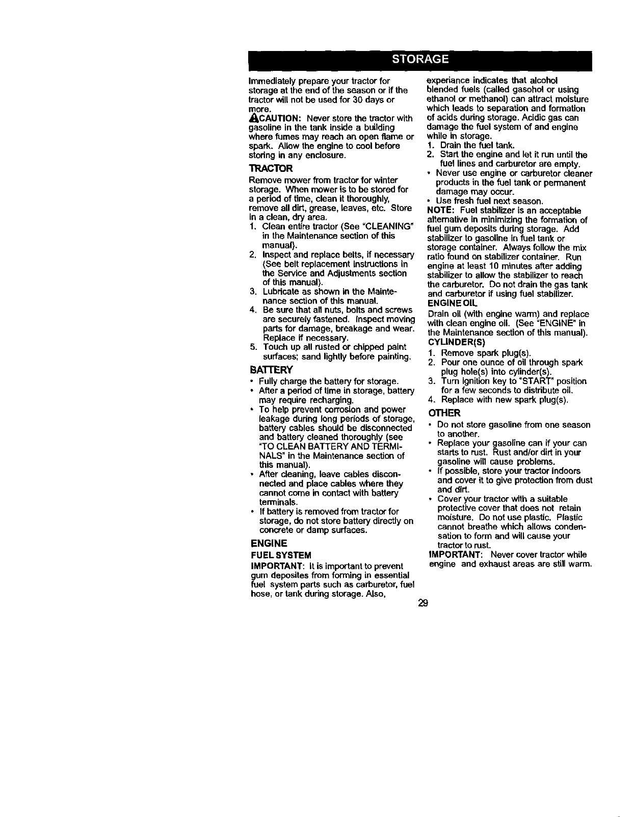
Immediately prepare your tractor for
storage at the end ofthe season or if the
tractor will not be used for 30 days or
more.
_,CAUTION: Never store the tractor with
gasoline in the tank inside a building
where fumes may reach an open flame or
spark. Allow the engine to cool before
stodng in any enclosure.
TRACTOR
Remove mower from tractorfor winter
storage. When mower is to be stored for
a period of time, clean it thoroughly,
remove all dirt, grease, leaves, etc. Store
in a clean, dry area.
1. Clean entire tractor (See "CLEANING"
in the Maintenance section of this
manual).
2. Inspect and replace belts, if necessary
(See belt replacement instructionsin
the Service and Adjustments section
of this manual).
3. Lubricate as shown in the Mainte-
nance sectionof this manual.
4. Be sure that all nuts, bolts and screws
are securely fastened, inspect mov{ng
parts for damage, breakage and wear.
Replace if necessary,
5. Touch up all rested or chipped paint
surfaces; sand lightly before painting.
BAI-I'ERY
•Fully charge the battery for storage.
• After a pedod of time in storage, battery
may require recharging.
•To help prevent corrosion and power
leakage dudng long pedods of storage,
battery cables should be disconnected
and battery cleaned thoroughly (see
=TOCLEAN BATTERY AND TERMI-
NALS" in the Maintenance section of
this manual).
•After cleaning, leave cables discon-
nected and place cables where they
cannot come in contactwith battery
terminals.
• If battery is removed from tractor for
storage, do not store battery directly on
concrete or damp surfaces.
ENGINE
FUEL SYSTEM
IMPORTANT: it is importantto prevent
gum depesitas from forming in essential
fuel system parts such as carburetor,fuel
hose, or tank during storage. Also,
expedance indicates that alcohol
blended fuels (called gasohol or using
ethanol or methanol) can attract moisture
which leads to separation and formation
of acids dudng storage, Acidic gas can
damage the fuel system of and engine
while in storage.
1. Drain the fuel tank.
2. Start the engine and let it run untilthe
fuel lines and carburetor are empty.
• Never use engine or carburetor cleaner
products in the fuel tank or permanent
damage may occur.
•Use fresh fuel next season,
NOTE: Fuel stabilizer is an acceptable
alternative in minimizing the formation of
fuel gum deposits during storage. Add
stabilizer to gasoline in fuel tank or
storage container. Always follow the mix
ratio found on stabilizer container. Run
engine at least 10 minutes after adding
stabilizer to allow the stabilizer to reach
the carburetor. Do not drain the gas tank
and carburetor if using fuel stabilizer.
ENGINE OIL
Drain oil (with engine warm) and replace
with clean engine oil. (See =ENGINE" in
the Maintenance sectionof this manual).
CYLINDER(S)
1. Remove spark plug(s),
2, Pour one ounce of nil through spark
plug hole(s) into cylinder(s).
3. Tum ignitionkey to "START" position
for a few seconds to distribute oil.
4. Replace with new spark plug(s),
OTHER
•Do not store gasoline from one season
to another.
• Replace your gasoline can if your can
starts to rust. Rust and/or dirt in your
gasoline will cause problems.
• If possible, store your tractor indoors
and cover it to give protection from dust
and dirt.
• Cover your tractor with a suitable
protective cover that does not retain
moisture. Do not use plastic. Plastic
cannot breathe which allows conden-
sation to form end willcause your
tractor to rest.
IMPORTANT: Never cover tractor while
engine and exhaust areas are still warm.
29
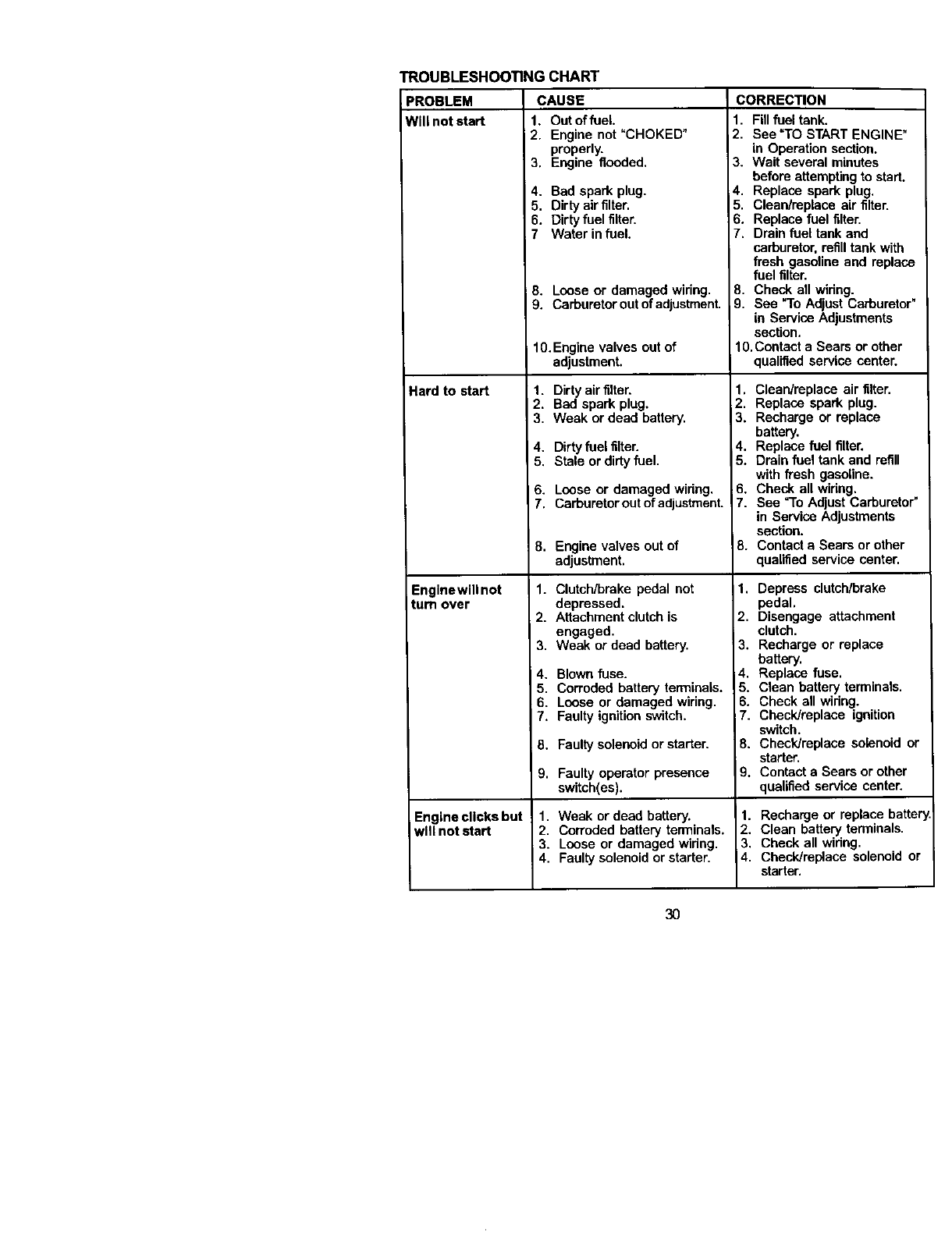
TROUBLESHOOTING CHART
)ROBLEM CAUSE
Will not start 1. Out of fuel
Hard to start
Enginewill not
turn over
2. Engine not "CHOKED"
properly.
3. Engine flooded.
4. Bad spark plug.
5. Dirty air filter.
6. Dirty fuel filter.
7 Water infuel.
8. Loose or damaged wiring.
9. Carburetor out of adjustment.
10.Engine valves out of
adjustment.
1. Dirty air filter.
2. Bad spark plug,
3. Weak or dead battery.
4. Dirtyfuel filter.
5. Stale or dirty fuel.
6. Loose or damaged widng.
7. Carburetor out of adjustment.
8. Engine valves out of
adjustment.
1. Clutch/brake pedal not
depressed.
2. Attachment clutch is
engaged,
3, Weak or dead battery,
4. Blown fuse.
5, Corroded battery terminals.
6. Loose or damaged wiring,
7, Faulty ignitionswitch.
8. Faulty solenoidor starter.
9, Faulty operator presence
switch(es).
1. Weak or dead battery.
2. Corroded battery terminals,
3. Loose or damaged widng.
4. Faulty solenoid or starter.
Engine clicks but
will not start
CORRECTION
1. Fill fuel tank.
2. See "TO START ENGINE"
in Operation section,
3. Wait several minutes
before attemptingto start.
4. Replace spark plug.
5. Clean/replace air filter.
6. Replace fuel filter.
7. Drain fuel tank and
carburetor, refill tank with
fresh gasoline and replace
fuel filter.
8. Check all widng.
9. See "To Adjust Carburetor"
in Service Adjustments
section.
10.Contact a Sears or other
qualified service center.
1. Clean/replace air filter.
2. Replace spark plug.
3. Recharge or replace
battery.
4. Replace fuel filter.
5, Drain fuel tank and refill
with fTesh gasoline.
6. Check all widng.
7. See "To Adjust Carburetor"
in Service Adjustments
section.
8. Contact aSears or other
qualified service center.
1. Depress clutch/brake
pedal.
2. Disengage attachment
clutch.
3. Recharge or replace
battery.
4. Replace fuse.
5. Clean battery terminals.
6. Check all widng.
7. Check/replace ignition
switch.
8. Check/replace solenoid or
starter.
9. Contact aSears or other
qualified service center.
1. Recharge or replace batter
2. Clean battery terminals.
3. Check all widng.
4. Check/replace solenoid or
starter.
30
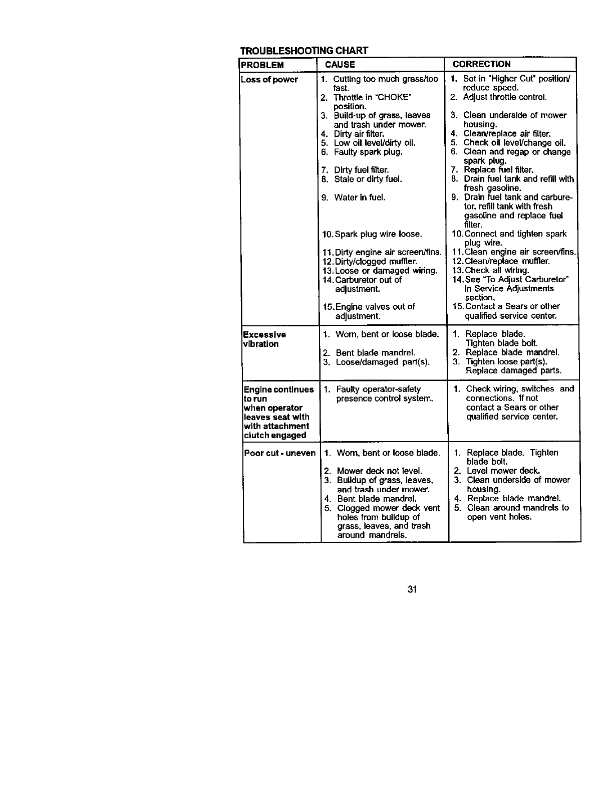
TROUBLESHOOTING CHART
PROBLEM CAUSE CORRECTION
Loss of power 11. Cuttingtoo much grass/too
Excessive
vibration
Engine continues
Lorun
Nhen operator
leaves seat with
Nith attachment
¢lutch engaged
Poorcut-uneven
fast.
2. Throttle in =CHOKE"
position.
3. Build-up of grass, leaves
and trash under mower.
4. Dirty air filter.
5, Low oil level/dirty oil.
6, Faulty spark plug.
7. Dirtyfuel filter,
8. Stale or dirtyfuel.
9. Water in fuel.
10,Spark plug wire loose.
11,Dirty engine air screen/fins,
12.Dirty/clogged muffler.
13,Loose or damaged widng,
14.Carburetor out of
adjustment.
15.Engine valves out of
adjustment.
1, Wom, bent or loose blade.
2. Bent blade mandrel.
3, Loose/damaged part(s).
i1. Faulty operator-safety
presence controlsystem.
1. Worn, bent or loose blade
2. Mower deck not level.
3, Buildup of grass, leaves,
and trash under mower.
4. Bent blade mandrel,
5. Clogged mower deck vent
holes from buildupof
grass, leaves, and trash
around mandrels.
1. Set in "Higher Cut"position/
reduce speed.
2. Adjust throttle control.
3, Clean underside of mower
housing.
4. Clean/replace air filter.
5. Check oil level/change oil.
6, Clean and regap or change
spark plug,
7. Replace fuel filter.
8. Drain fuel tank and refill with
fresh gasoline.
9, Drain fuel tank and carbure-
tor, refill tank with fresh
gasoline and replace fuel
filter,
10.Connect and tighten spark
plug wire.
11.Clean engine air screen/fins.
12. Clean/replece muffler.
13.Check all widng.
14.See "To Adjust Carburetor"
in Service Adjustments
section.
15.Contact a Sears or other
qualified service center.
1. Replace blade.
Tighten blade bolt.
2. Replace blade mandrel.
3. Tighten loose part(s).
Replace damaged parts.
1. Check wiring, switches and
connections. If not
contact a Sears or other
qualified service center.
1. Replace blade. Tighten
blade bolt.
2. Level mower deck.
3, Clean underside of mower
housing.
4. Replace blade mandrel.
5. Clean around mandrels to
open vent holes,
31
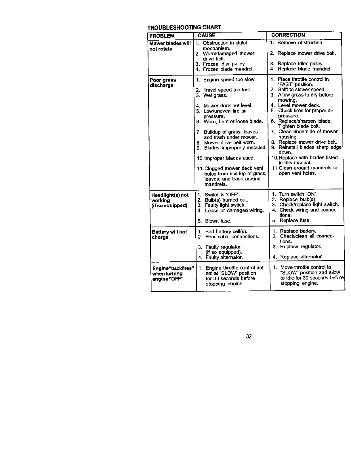
TROUBLESHOOTING CHART
CAUSE CORRECTION
1. Remove obstruction.
3ROBLEM
Mower blades will
not rotate
Poor grass
discharge
Headlight(s) not
working
(If so equipped)
Battery will not
charge
Engine"beddlres"
whenturnlng
engine"OFF"
1. Obstruction in clutch
mechanism.
2. Worn/damaged mower
drive belt.
3. Frozen idler pulley.
4. Frozen blade mandrel.
1. Engine speed too slow.
2. Travel speed too fast.
3, Wet grass.
4. Mower deck not level.
5, Low/uneven tire air
pressure.
6. Worn, bent or loose blade.
7. Buildup of grass, leaves
and trash under mower.
8. Mower drive belt worn.
9. Blades improperly installed.
lO.Improper blades used.
11.Clogged mower deck vent
holes from buildup of grass,
leaves, and trash around
mandrels.
1. Switch is "OFF".
2. Bulb(s) burned out.
3. Faulty light switch.
4. Loose or damaged wiring.
5. Blown fuse.
1. Bed battery cell(s).
2. Poor cable connections,
3. Faulty regulator
(if so equipped).
4. Faulty alternator.
1. Engine throttle control not
set at =SLOW" position
for 30 seconds before
stopping engine.
2. Replace mower ddve belt.
3. Replace idler pulley,
4. Replace blade mandrel.
1. Place throttle control in
_FAST" position.
2. Shift to slower speed.
3. Allow grass to dry before
mowing.
4. Level mower deck.
5. Check tires for proper air
pressure.
6. Replace/sharpen blade.
Tighten blade bolt.
7. Clean underside of mower
housing.
8. Replace mower ddve belt.
9. Reinstall blades sharp edge
down.
10.Replace with blades listed
in this manual.
11.Clean around mandrels to
open vent holes.
1. Turn switch "ON".
2. Replace bulb(s).
3. Check/replace light switch.
4. Check widng and connec-
tions.
5. Replace fuse.
1. Replace battery.
2. Check/clean all connec-
tions.
3. Replace regulator.
4. Replace alternator.
1. Move throttle controlto
=SLOW" positionand allow
to idle for 30 seconds before
stopping engine.
32
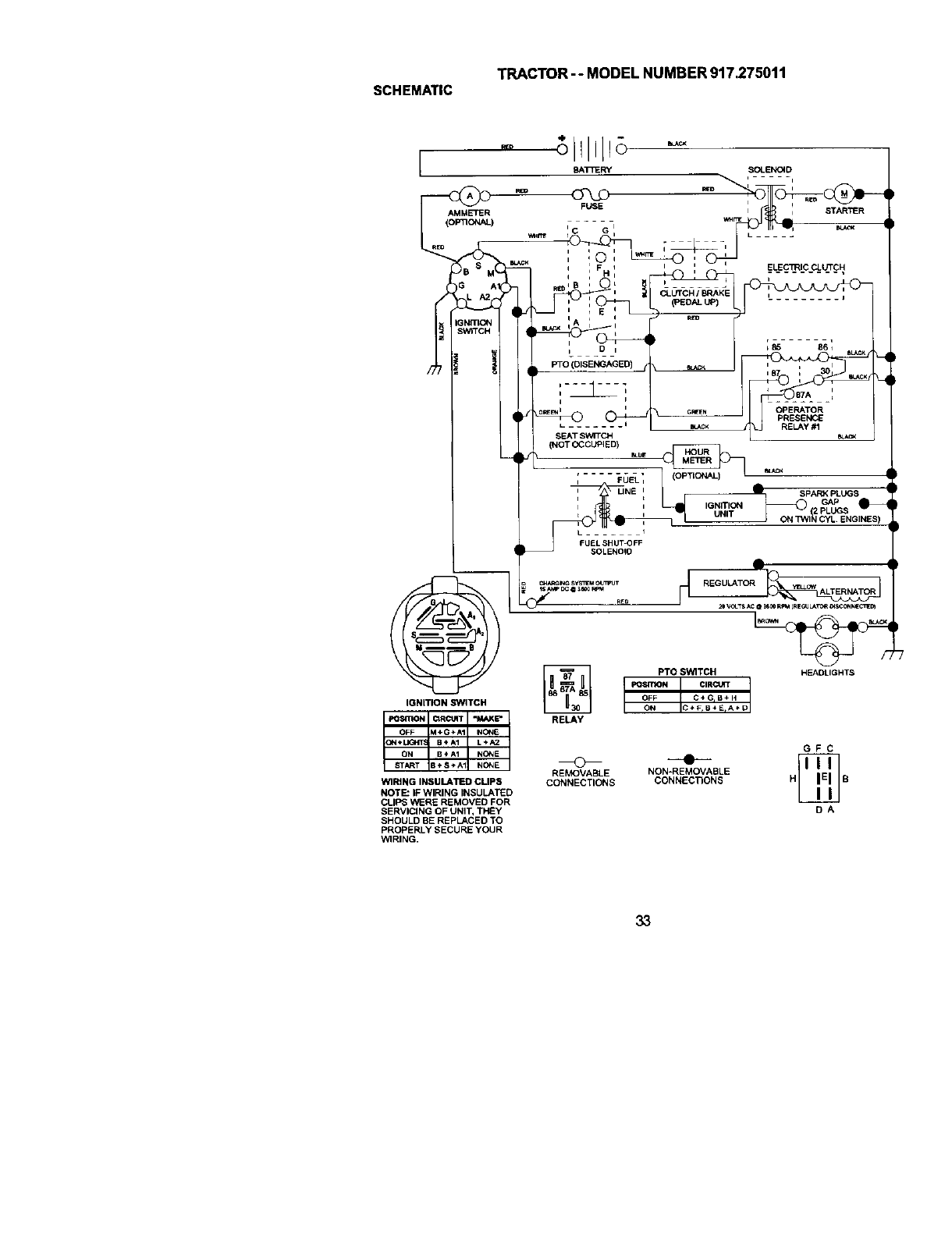
TRACTOR--MODELNUMBER917.275011
SCHEMATIC
AMMETER
(OP_ONAL)
)BS_
G
SNmC_
IGNITION SWITCH
WIRING INSULATED CUPS
NOTE" IF WIRING INSULATED
CLIPS WERE REMOVED FOR
SERVICING OF UNIT, THEY
SHOULD BE REPLACED TO
PROPERLY SECURE YOUR
WIRING.
- _illlL_8 -
_T_ERy SOLEF,IO_D
m_u_=_-. I_r1_ I ,m= STARTER
i G I ILkJ- III I1_1 ECJ,C_
/
I _ FIIELECTRIC CLUTCH
,, H, ;" ........ •
'd CLUTCH IBRAKE ,
_--40_04_-q _ [ .........
tDn _85 86_
PTO(DISENGAGED) _ n _ I
...............
1 ,_, _
'.,_Y_ow_'_--- _.EOE_
(NOT OCCUPIED)
_" SPAR:< PLUGS
FUEL SHUT OFF
FU_,_,OFF
RELAY
GFC
REMOVABLE NON-REMOVABLE
CONNECTIONS CONNECTIONS H B
DA
33
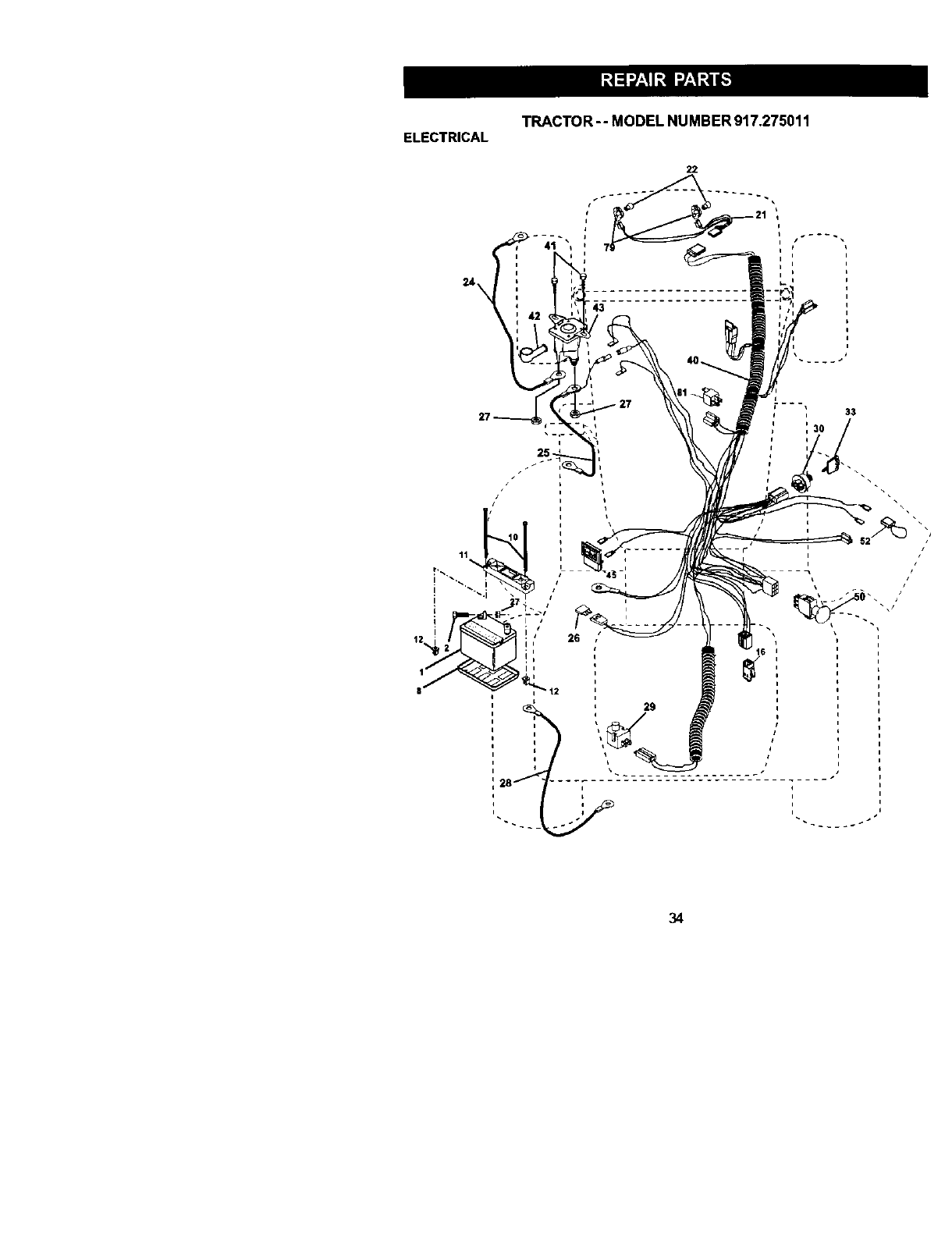
ELECTRICAL TRACTOR -- MODEL NUMBER 917.275011
22
11
I
Ii'
i'
26
34

TRACTOR- oMODEL NUMBER 917.275011
ELECTRICAL
KEY PART
NO, NO. DESCRIPTION
1 144927 Battery
2 74760412 Bolt Hex Head 1/4-20 x 3/4
8 7603J Tray, Battery
10 145211 Bolt 1/4-20 x 7.5 Zinc
11 150109 Hold down Battery Dash Mount
12 145769 Nut Push Nylon 1/4"
16 153664 Switch Interlock Push-In
21 166184 Harness Socket Light W/4152J
Z2 4152J Bulb Light
24 4014J Cable, Battery
25 146686 Cable, Battery
26 108824X Fuse
27 73510400 Nut Keps Hex 1/4÷20 Unc
28 170697 Cable,Ground
29 160784 Switch, Ptunger
30 175566 Switch, Ign
33 140403 Key, ignition
40 170238 Harness Ign.
41 17720408 Screw Thd Cut 1/4-20 x 1/2
42 154336 Cover, Terminal
43 175141 Sotenoid
45 122822X Ammeter
50 174652 Switch, PTO
52 141940 protection Wire Loop
79 163996 Bulbholder Asm. incan descent
81 109748X Relay Asm.
NOTE: All component dimensions given LnU.S. Lnches
1 inch =25.4 mm
35
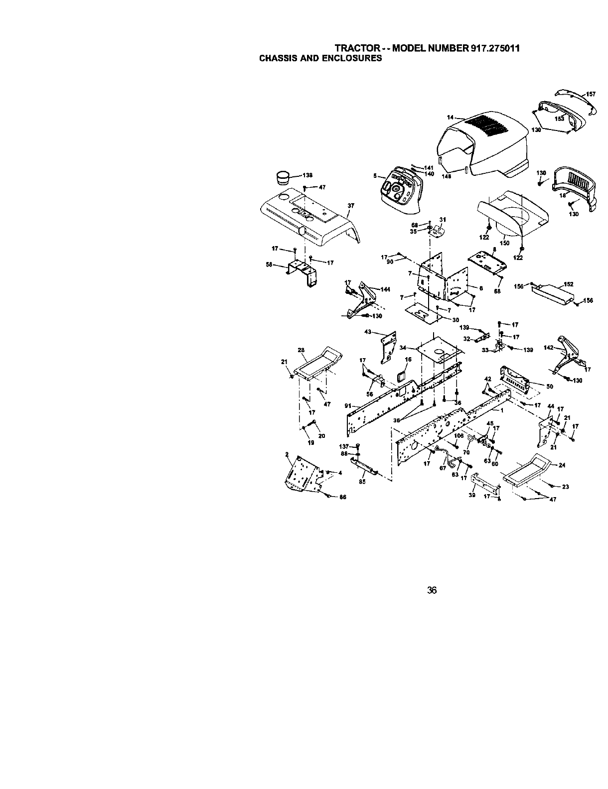
TRACTOR--MODEL NUMBER 917.275011
CHASSISAND ENCLOSURES
45
36

TRACTOR--MODELNUMBER917.275011
CHASSISANDENCLOSURES
KEY PART KEY PART
NO, NO. DESCRIPTION NO. NO.
1 175465 RUIl,Frame RH 56 176016
2 175282 Drawbar, Gt 58 175315
4 73680700 Nut, CrownlGckHex 7/16-14UNC 60 17490620
5163976)(428 Dash YTGT 2 Cyt 63 19131614
6 157882 Dash, Lower Vgt One piece 67 156973
7 17720408 Screw, Thd Cut 1/4-20 x 1/2 68 17490508
8 145166 Support, Baitery 70 177679
14 175259X558 Hood AXm 85 144911
16 12t794X Cover, Access 86 74760716
17 17000612 Screw 88 STD551143
18 174515X558 Gdtle 90 $10551237
19 19131312 Washer 13/32x13/16x12 Ga, 91 175464
21 STD541437 NutCrownlock 3/8-16Unc 106 138776
23 17060616 SCl_W 3/_-16 xl.5 122 161464
24 145243X558 Footrest, RH 130 164863
28 145244X558 Footrest, LH 137 74780716
30 145051X014 Saddle, Slkscr Vgt 138 163975X428
32 161327 Bracket, Pivot Chassis Lh 139 171873
33 161326 Bracket, Pivot Chassis Rh 140 163806
34 177018 Plate Asm Engine Chassis 141 163865
35 19111116 Washer 11/32xll116x16Ga. 142 161897
36 17060512 Screw 5116-18 x 3/4 144 1619(30
37 167286X558 Fender 148 164655
39 175278 Bracket, Axle Front 150 161237
42 72140608 Buit, Carriage 3/8-16 x 1 152 177956
43 136939 Bracket, Spnsn Front Lh 153 160568
44 136940 Bracket, Spnsn Front Rh 156 17066512
45 176018 Bracket Chassis 157 161840
47 17670668 Screw Thdrol. 3/8-16 x 1/2
50 175476 Bracket, Chassis Front
DESCRIPTION
Bracket Asrn., Susp Chassis Lh
Bracket Asm. Fender
Screw Thdrui. 3/_-16 x 1-1/4
Washer 13132 x 1 x 14 Ga.
Guide, Belt Gear Drive
ScrewThdroL 5/16-18 x 1/2
Belt Keeper VGT Ground Drive
Br_:ket, Support Transaxle
Bolt Fin Hex 7116-14 UNC x 1
Washer, Lock Hvy Hlct Spr 7/16
Washer, Lock External Tooth 3/8
Rail, Frame Lh
Screw, Thdrol Hex Head Zinc Mwr
Screw Hex Wshd 8-18 x 7/8
Screw HWHD Hi-Lo #13-16 x 3/4
Bolt Fin Hex 7116-14 xl Gr. 5
Cuphuider YTGT
Bolt Shoulder 5/16-18 TT
Magnnt YTGT
Striker Plate YTGT
Bracket Dash Rh
Bracket Dash Lh
Extrusion Bumper
Duct Heat Hood
Shield Browning
Lens Asm Headlight Bar
Screw 9/16-18 x 3/4
Lens Bar
NOTE: Allcomponent dimensions given tn U.S. Irmches
1Inch = 25.4 mm
37
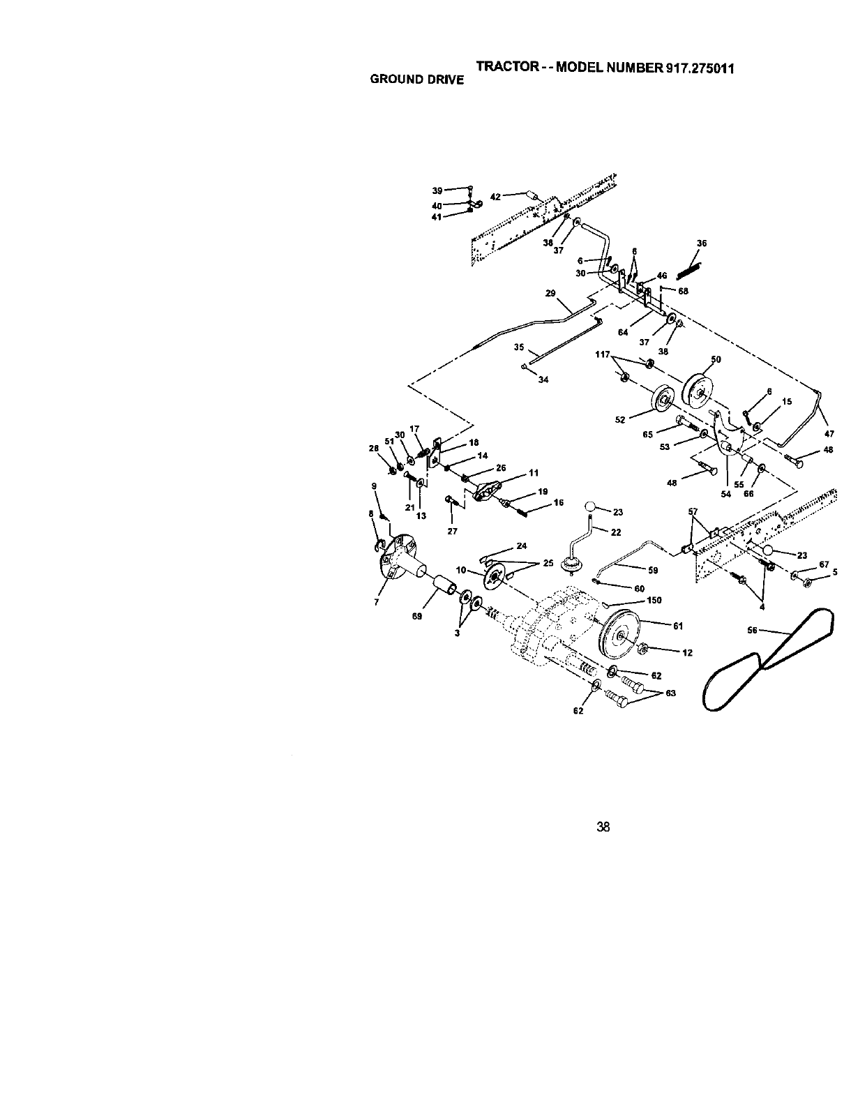
TRACTOR--MODEL NUMBER 917.275011
GROUNDDRIVE
39
28 5
%
36
37 6
38

TRACTOR- -MODEL NUMBER 917.275011
GROUNDDRIVE
KEY PART KEY PART
NO. NO. DESCRIPTION NO. NO. DESCRIPTION
3 7563R Washer, Thrust, Axle 38 150035 Nyllner
4 17490508 Screw Thdrol 5/16.18 x3/4 39 74321016 screw, Fin. #10-24 x 1
5 STD541437 Nut, Crownlock 3/8-16 40 5364J Actuator, latedock Switch
6 STD561216 Pin, Cotter 41 73_1000 Nut, Centedock#10*24
7 149176 Wheel, Hub Assembly 42 8883R Cover, Pedal
8 12000034 Klip, Ring 46 145170 Retainer, Spring
9 140080 Bo6, Hub 47 138229 Clutch Rod
10 142509 Disc, Brake 48 72110612 Bolt, Cart, 3/8-16 x 1-1/2 Gr. 9
11 136927 Yoke, Brake Disc 50 131494 Pulley, tdter, Flat
12 73750800 NuitCCk1/2-20 Unf 51 STD541437 Nut, Crowatock 3./6.16 GNC
13 139419 Washer, SpeCial 52 139123 Pulley, Idler, Grooved
14 138901 BUShing 53 297J Washer, Hardened
15 STD551037 Washer 13/32x13/16 x 16 Ga, 54 161590 Clutch, ArmAssembly
16 143012 Set, Screw 1/4-28 x 3/4 55 105706X Beadng, Idler
17 126909X Spdng 56 137153 V-Bed
18 137104 Lever, Brake 57 141756 Bracket, Shift Rod, Hi-Lo
19 136926 Cam, Brake Disc 59 12_253X Shift Rod, Hi-Lo
21 23260412 Screw, Flat Head 1/4-28 x 3/4 60 122268X Spdng Clip, COnnecting Link
22 633A109 Gearshift, Lever Assembly 61 137524 Pulley, Transaxle
23 106932X Knob 62 STI)551143 Washer, Lcck 7/16
24 136925 Suppod, puck Brake 63 74760720 Bolt, Fin Hex 7/16-14 x 1-1/4
25 136923 puck, Brake Top 64 154752 Shaft, Clutch/Brake Pedel
26 137552 Spring, Return 65 67609 Bo6, Shoulder
27 17490528 Screw, Hex Wsh Thd. 66 140296 Washer, Hardened
5/16-18 x 1-3/4 67 19131312 Washer, Flat
28 73350600 Nut, Hex ,Jam 3/8-16 68 5142H Pin, Roll
29 137213 Brake, Rod 69 136327 Hub,Cover
30 19131616 Washer 13132xlx16Ga. 117 73_)0600 Nut, LockFIg, 3/8-16Unc
34 71673 Cap, Plunger 150 9858M1 Key, Woodruff
35 137648 Rod, Parking Brake
36 149412 Spring, Drive Ground NOTE: All componentdimensions given in U.S, inches
37 121749X Washer 25/32 x1-1/4 x 16 Ga, 1 inch = 25,4 mm
39
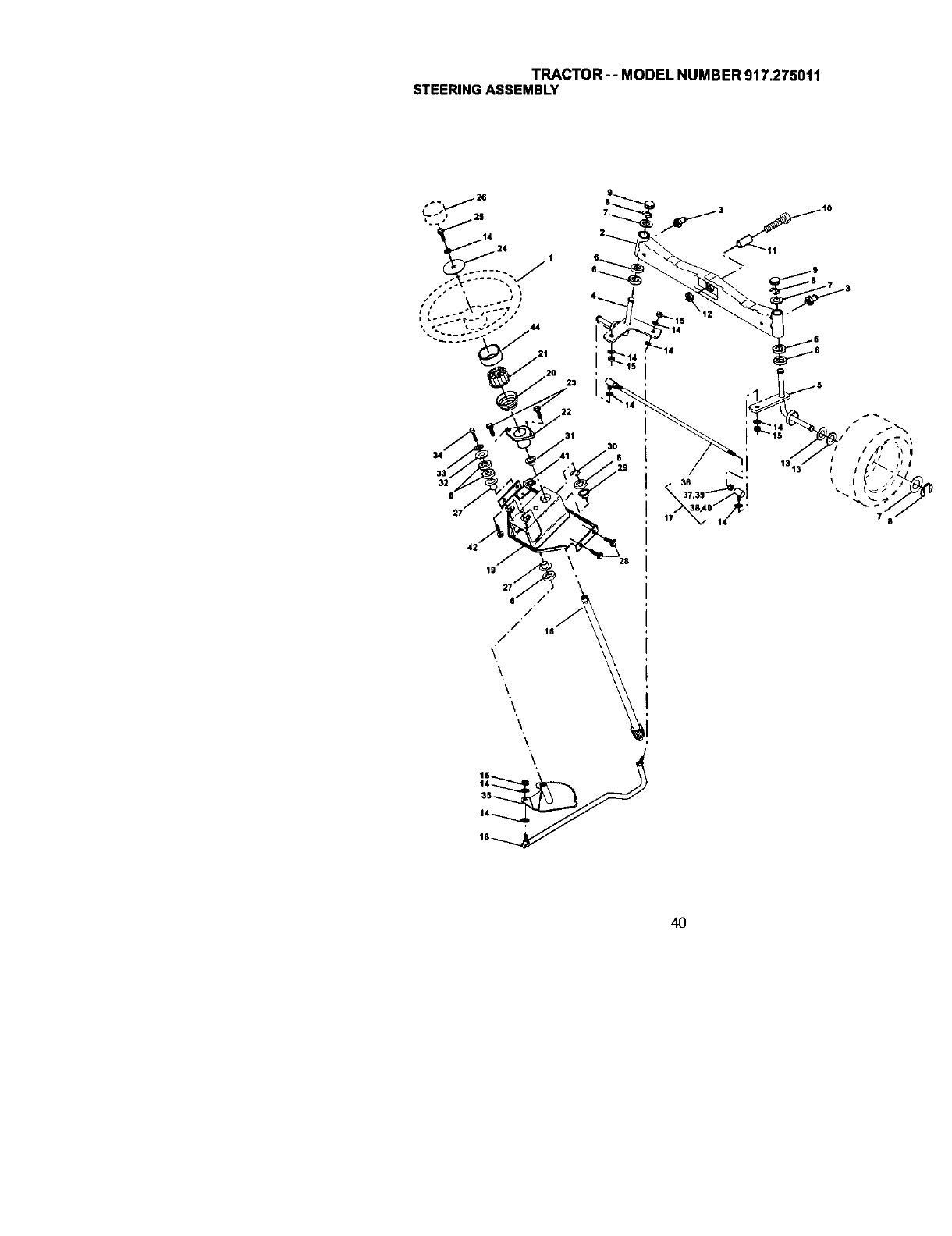
TRACTOR-- MODEL NUMBER 917.275011
STEERINGASSEMBLY
34
32
27
40

TRACTOR-- MODELNUMBER917.275011
STEERINGASSEMBLY
KEY PART
NO. NO. DESCRIPTION
1 159944X428 Wheel, Steedng
2 137094 Axle Asm., Front
3 6855M Fitting, Grease
4 151849 Spindle Asm, LH
5 161848 Spindle Asm., RH
6_66H Beadng, Race Thrust Harden
7 121748X Washer 25132 x 1-5/8 x 16 Ga.
8 12000029 P3ng,Kllp#T5304-75
9 121232X Cap, Spindle
10 74781044 Bo_t,Fin Hex 5/8-11 x 2-3/4
11 136518 Spacer Bearing AXle Front
12 73901000 Nut, Lock FLange 5/8-11 Unc
t3 12t749X Washer 25132 x 1-1/4 x 16 Ga.
t4 STD551137 Washer, LockHvyHIdSpr 3/8
15 STD541537 Nut, Lock Center 3/8-24 UNF
16 145103 Shaft Asm,, Steering
17 137347 Rod Axm., Tie Batl J Ball Vgt (Inc, Key No. 36-46)
18 175572 Draglink, Vgt
19 156011 Support Asm., Steering Vgt
20 163887X428 Boot, Steering
21 159945 Adapter, Wheel Steering
22 155105 Bushing, Strg. BIk
23 15_927 Screw
25 STD523710 Bolt, Fin Hex 3/8-16 x 1 Gr. 5
26 159946X428 Cap, Wheel Steering
27 3366R Beadng, Col. Strg.
28 17000612 Screw 318-16 x 314
29 104239X Beahng, Flange
31 138136 Bushing, Nyliner Snap
32 19111610 Washer 11/32 x 1 x 10 Ga.
33 STD551131 Washer, Lock Hvy Hlcl Spr 5/16
34 S]_523107 Boit, HexHd 5/16-18x3/4
35 138059 Gear, Sector Steering
36 137156 Tie Rod
37 73360_00 Jam NUt RH Thread
38 109850X Joint Asm. Ball RH Thread
39 73706600 Jam Nut LH Thread
40 109851X Joint Asm. Ball LH Thread
41 155246 Bracket Sw_tch Interlock VGT 97
42 17490508 Screw Thdroi 5/16-18 x 1/2 Tyt
44 166135X428 Extension, Steedng
45 19132411 Washer 13/32 x 1-1/20 x 11 Ga,
NOTE: All component dimensions given LnU.S. inches
1 inch = 25.4 mm
41
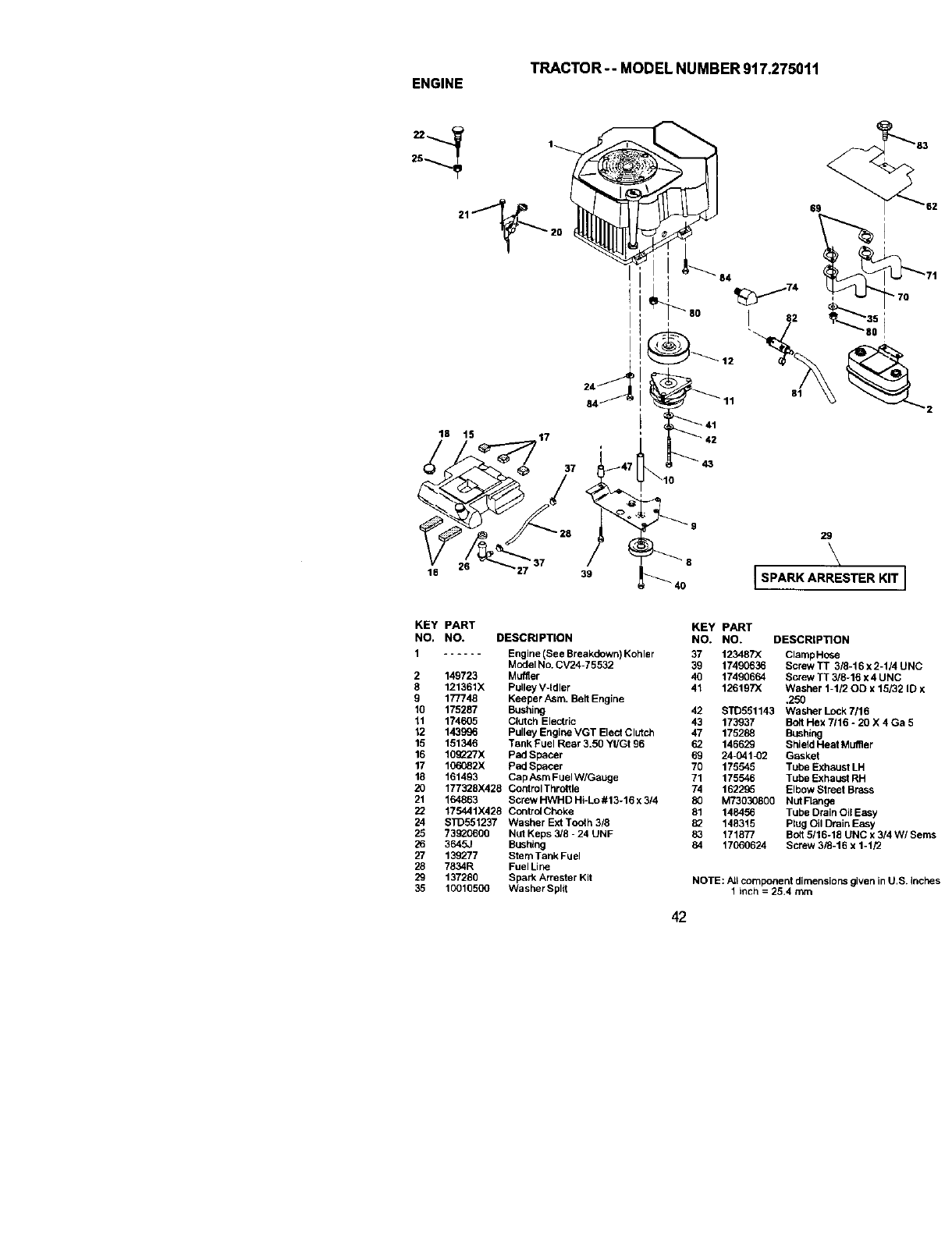
TRACTOR-- MODEL NUMBER 917.275011
ENGINE
25
18 t5 17
37
84
69
81 _2
16 27 39 8
29
\
I SPARK ARRESTER KIT I
KEY PART
NO. NO. DESCRIPTION
1...... Engine (See Breakdown) Kohler
Model No. CV24-75532
2 149723 Muffler
8 121361X Pulley V-Idler
9 177748 Keeper Asm. Belt Engine
10 175287 Bushing
11 174605 Clutch Electric
12 143996 Pulley Engine VGT Elect Clutch
15 151346 Tank Fuel Rear 3.50 Yt/Gt 96
16 10_Ti'X pad Spacer
17 106082X Pad Spacer
18 161493 Cap h.smFuel W/Gauge
20 177328X428 Control Throttle
21 164863 Screw HWHD Hi-Lo#13-16 x 3/4
22 175441)(426 Control Choke
24 9TD551237 Washer Ext Tooth 3/6
25 73920600 Nut Keps 3/8 -24 UNF
26 3645J Bushing
27 139277 Stem Tank Fuel
26 T834R Fuel Line
29 137280 Spark Arrester Kit
35 10010500 Washer Spl_t
KEY PART
NO. NO. DESCRIPTION
37 123487X ClampHose
39 17490636 Screw TT 3/8-16 x2-1/4 UNC
40 17490664 Screw TT 3/8-16 x 4 UNC
41 126197X Washer 1-1/2 OD x15/32 ID x
,250
42 STD551143 Washer Lock 7/16
43 173937 Bolt Hex 7116 *20 X 4 Ga 5
47 175288 Bushing
62 146629 Shield Heat Mugler
69 24-041_)2 Gasket
70 175545 Tube Exhaust LH
71 175546 Tuhe Exhaust RH
74 162285 Elbow Street Brass
80 M73030600 Nut Flange
81 148456 Tube Drain Oil Easy
82 148315 Plug Oil Drain Easy
83 171877 Bolt5/16-18 UNC x 3/4 W/Serns
84 17060624 Screw 3/8-16 x 1-1/2
NOTE: AJtcomponent dimensions given in U.S. inches
1 inch = 25.4 mm
42
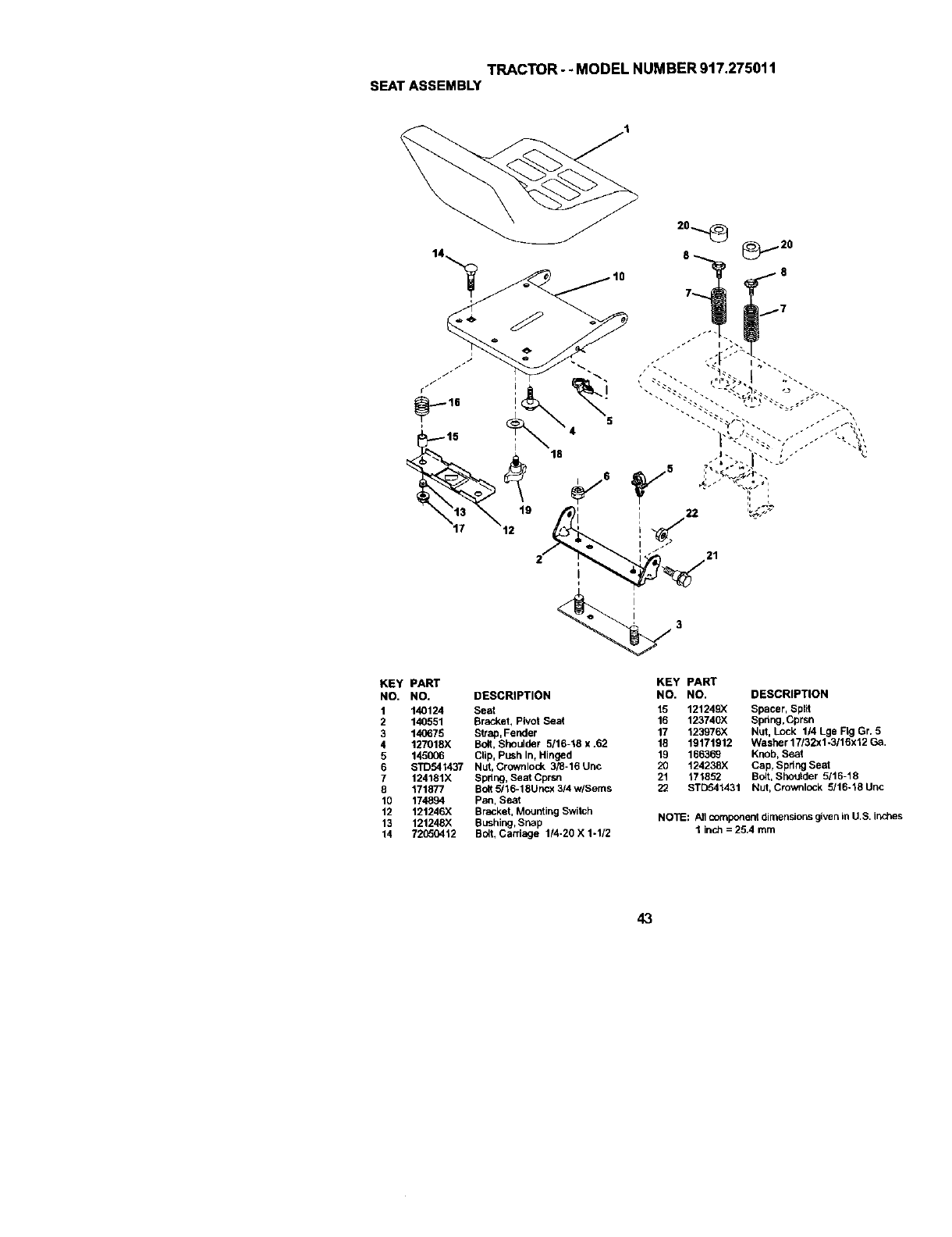
TRACTOR-- MODEL NUMBER 917.275011
SEATASSEMBLY
KEY PART KEY PART
NO. NO. DESCRIPTION NO. NO. DESCRIPTION
1 140124 Seat 15 121249X Spacer, SpI_t
2 140551 Bracket, Pivot Seat 16 123740X Spring,Cprsn
3 14(_75 Strap, Fender 17 123976X Nut, Lock 1/4 Lge Fig Gr. 5
4 127018X Bolt, Shoulder 5/16-18 x .62 18 19171912 Washer 17/32x1-3/16x12 Ga.
5 145006 Clip, Push In, Hinged 19 166369 Knob, Seat
6 STD541437 Nut, Crownlock 3/_-16 Unc 20 124238X Cap, Spring Seal
7 124181X Spring, Seat Cprsn 21 171852 Bolt, Shoulder 5/16-18
8 171877 BoltS/16-18Uncx3/4w/Sems 22 STD541431 Nut, Crownlock 5/16-18Unc
10 174894 pan, Seat
12 121246X Bracket, Mounting Switch
13 121248X Bushing, Snap NOTE: A]I component dimensions given in U,S, inches
14 72(]50412 Bolt, Carriage 1/4-20 X 1-1/2 1 indl = 25,4 mm
43
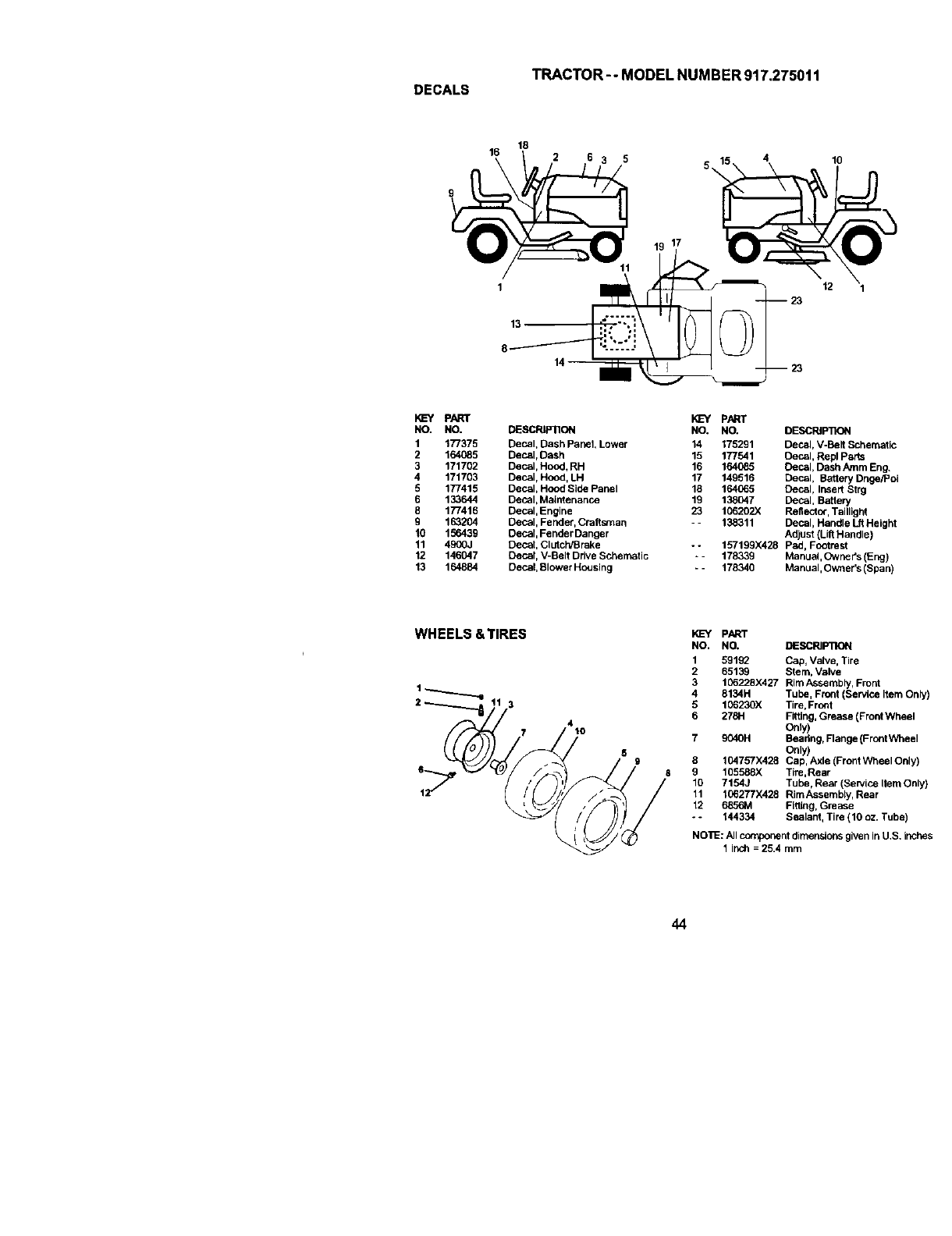
TRACTOR--MODEL NUMBER 917.275011
DECALS
18
16
13
2 6 3
17
10
12 1
I_=Y PART
NO. NO.
1 177375
2 164085
3 171702
4 171703
5 177415
6 133644
8 177416
9 163204
10 156439
11 4900J
12 146047
13 164884
PN_T
DESCRIP11ON NO. NO.
Decal, Dash Panel, Lower 14 175291
Decal, Dash 15 177541
Decal, Hood, RH 16 164085
Decal, Hood, LH 17 149516
Decal, Hood Side Panel 18 164065
Decal,Maintenance 19 138047
Decat, Engine 23 106202X
Decal, Fender, Craftsman -- 138311
Decal, Fender Danger
Decal, Clutch/Brake - -157199)(428
Decal, V-Belt Drive Schematic * -178339
Decal, Blower Housing - -178340
DESCRIP]](_
Decal, V-Belt Schematic
Decal, Repl Parts
Decal, Dash Amrn Eng.
Decal, Battery Dnge/Poi
Decal, Insert Strg
Decal, Battery
Reflect(x, Taillight
Decal, Handle Ltt Height
Adjust (Lift Handle)
pad, Footrest
Manual, Owner's (Eng)
Manual, Owner's (Span)
WHEELS &TIRES
3
7410
8
9
10
11
12
o*
PART
NO. NO. DESCRIPTION
159192 Cap, Valve, Tire
2 65139 Stern, Valve
3 106228X427 Rim Assembly, Front
4 8134H Tube, Front (SerVice Item Only)
5 106230X Tire, Front
6 278H Fitting, Grease (Front Wheel
Only)
9040H Bearing, Flange (Front Wheel
Only)
104757X428 Cap, Axle (Front Wheel Only)
105588)( Tire,Rear
7154J Tube, Rear (Service Item Only)
106277)(428 Rim Assembly, Rear
6856M FittLng,Grease
144334 Sealant, Tire (10 oz. Tube)
NO'I_: Allcomponent dimensionsgiven In U.S. inches
1 inch = 25.4 rnm
44
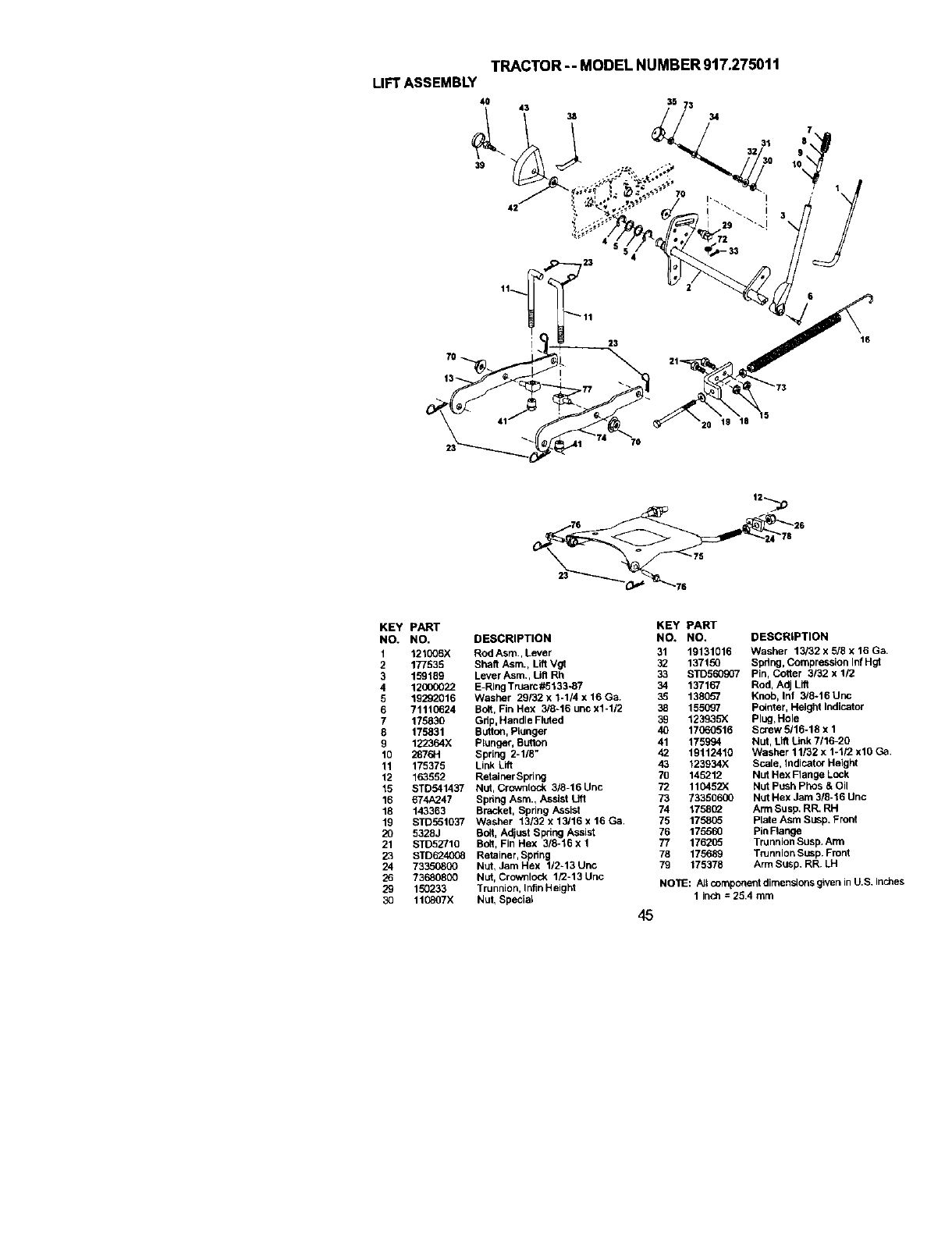
TRACTOR-- MODEL NUMBER 917.275011
LIFTASSEMBLY
4O
39
35 73 34
7
1
23
7O
_020_19 18
76 _'26
KEY PART
NO. NO.
1 121006X
2177535
3 159189
4 12000022
5 19292016
6 71110624
7 175830
8 175831
9 122364X
10 287614
11 175375
12 163552
15 STD541437
16 674A247
18 143363
19 STD551037
20 5328J
21 STD52710
23 STDf_t4008
24 73350800
26 73680800
29 150233
30 110807X
DESCRIPTION
Rod Asm., Lever 31
Shefl Asm., Lift Vgt 32
Lever Asm., Utl Rh 33
E-Ring Truarc#5133-87 34 137167
Washer 29132 x 1-114x 16 Ga. 35 138057
Bolt, Fin Hex 3/8-16 unc x1-1/2 38 155097
Grip, Handle Fluted 39 123935)(
Button, Plunger 40 17060516
Plunger, Sutton 41 175994
Spring 2-1/8" 42 19112410
Link Lift 43 123934X
Retainer Spring 70 145212
Nut, Crowstock 3/8-16 Unc 72 110452X
Sphng Asm., Assist Lift 73 73350600
Bracket, Spring Assist 74 1758(_
Washer 13/32 x 13/16 x 16 Ca. 75 175805
Bolt, Adjust Spring Assist 76 175560
BO6, Fin Hex 3/8-16 x 1 77 176205
Retainer, Spring 78 175689
Nut, Jam Hex 1/2-13 Unc 79 175378
Nut, Crownlock 1/2-13 Unc
Trunnion, Infin Height
Nut, Special
KEY PART
NO. NO. DESCRIPTION
19131016 Washer 13/32 x 5/8 x 16 Ga.
137150 Spdng, Compression In/Hgt
STD560907 Pin, Cotter 3132 x 1/2
Rod, Adj Lift
Knob, Inf 3/8-16 Unc
pointer, Height Indicator
Plug,Hole
Screw 5116-18 x 1
Nut, Lift Unk 7/16-20
Washer 11/32 x 1-1/2 xl0 Ca.
Scale, Indicator Height
Nut Hex Flange Lock
Nut push Phes &Oil
Nut Hex Jam 3/8-16 Unc
Arm Susp. RR. RH
Plate Asm Susp. Front
PinFlange
Trunnion Susp. Arm
Trunnion Susp. Front
Arm Susp. RR. LH
NOTE: All componentdimensions given in U.S. inches
1 inch = 25.4 turn
45
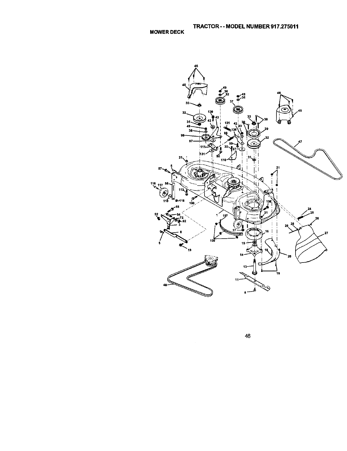
TRACTOR- - MODEL NUMBER 917.275011
MOWERDECK
46
45
,16
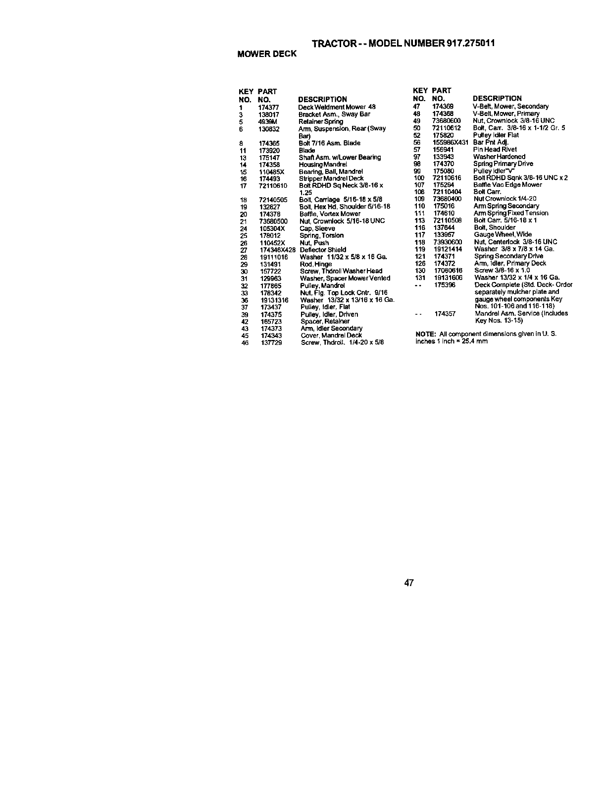
TRACTOR -- MODEL NUMBER 917.27501 t
MOWERDECK
KEY PART KEY PART
NO. NO. DESCRIPTION NO. NO.
1 174377 Deck Weldment Mower 48 47 174369
3 138017 Bracket Asm., Sway Bar 48 174368
5 4939M Retainer Spdng 49 73680600
6 130832 Arm, Suspension, Rear (Sway 50 72110612
Bar) 52 17582O
8 174365 Bolt 7/16 Asm. Blade 56 155986X431
11 173920 Blade 57 156941
13 175147 Shaft Asm. w/Lower Baarlng 97 133943
14 174358 HousingMandrel 98 174370
15 110485X Beadng, Ball, Mandrel 99 175080
16 174493 Strlppar Mandrel Deck 100 72110616
17 72110610 Bo6 RDHD Sq Neck 3/8-16 x 107 175294
1.25 108 72110404
18 72140505 Bolt, Carriage 5116-18 x 5/8 109 73680400
19 132827 Bolt, Hex Hd, Shoulder 5/16-18 110 175016
20 174378 Baffle, Vosex Mower 111 174610
21 73680500 Nut, Crownlock 5/16-18 UNC 113 72110508
24 105304X Cap, Slaeve 116 137644
25 178012 Spring,Torsion 117 133957
26 110452X Nut, Push 116 73930600
27 174346)(428 DellectorShlald 119 19121414
28 19111016 Washer 11132xS/Sx16Oa. 121 174371
29 131491 Rnd,Hinge 126 174372
30 157722 Scl_w, Thdmll Washer Head 130 17060616
31 129963 Washer, Spacer Mower Vented 131 19131606
32 177865 Pullay, Mandrel - - 175396
33 176342 Nut, Fig, Top Lock Cntr. 9/16
36 19131316 Washer t3/32 x 13/16 x 16 Ca.
37 173437 PuIlay, Idler, Flat
39 174375 Pulley, Idler, Driven - - 174357
42 165723 Spacer, Retainer
43 174373 Arm, Idler Secondary
45 174343 Cover, Mandrel Deck
46 137729 Screw, ThdrolL 1/4-20 x 5/8
DESCRIPTION
V-Belt, Mower, Secondary
V-Belt, Mower, Primary
Nut, Crownlock 3/8-16 UNC
Bolt, Carr. 318-16 x 1-1/2 Gr. 5
Pulley Idler Flat
Bar Pnt Adj.
Pin Head Rivet
Washer Hardened
Spdng Pdmary Ddve
Pulley Idlar"_P
Bolt RDHD Sqnk 3/8-16 UNC x2
Baffle Vac Edge Mower
Bolt Carr.
NUtCrownlock 1/4-20
Arm Spring Secondary
Arm Spring Fixed Tension
Bolt Cart. 5/16-18 x 1
Bolt,Shoulder
GaUge Wheel, Wide
Nut, Centeriock 3/8-16 UNC
Washer 318 x 7/8 x 14 Ga.
Spring Secondary Drive
Arm, Idler, Pdrnary Deck
Screw 318-16 x 1.0
Washer 13/32 x 114 x 16 Ga.
Deck Complete (Std. Deck- Order
separately mulcher plate and
gauge wheel components Key
Nos. 101-106 and 116-118)
Mandrel Asm. Service (Includes
Key Nos. 13-15)
NOTE: All component dimenslorhsgiven inU. S.
inches Iinch =26.4 mm
47
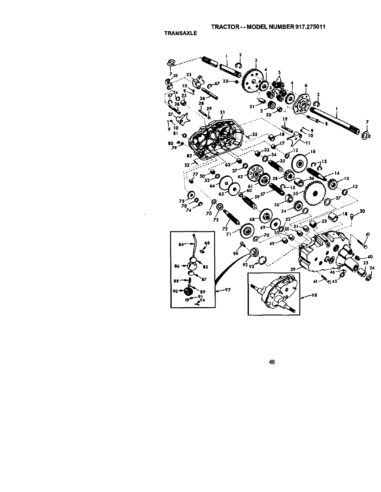
TRACTOR- - MODEL NUMBER 917.275011
TRANSAXLE
6
2
73
72
7
48
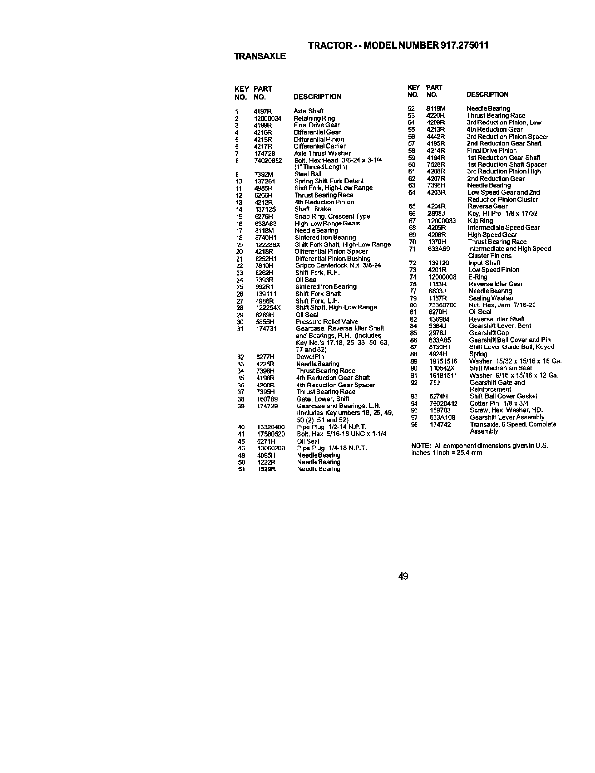
TRACTOR-- MODELNUMBER917.275011
TRANSAXLE
KEY PART
NO. NO.
1 4197R
2 12_)0034
3 4199R
4 4216R
5 4215R
6 4217R
7 174728
8 74(_0652
9 73_M
10 137261
11 498,_
12 1_66H
13 4212R
14 137129
15 6276H
16 633A63
17 8118M
18 8740H1
19 122238X
20 4218R
21 6252H1
22 781GH
23 6262H
24 7393R
25 992R1
26 139111
27 49_R
28 122254X
29 6269H
3O 5855H
31 174731
32 62T/H
33 422.5_
34 7336H
35 4136R
36 4200R
37 7336H
38 160789
39 174729
40 13320400
41 17580520
45 6271H
46 13(60200
49 4895H
50 4222R
51 1529R
DESCRIPTION
PART
NO. NO. DESCRIPTION
Axle Shaft 52 8119M Needle Bearing
Retaining Ring 53 4220R Thrust Bearing Race
Final Drive Gear 54 42(]9R 3rd Reduction Pinion, Low
D_erentialGear 55 4213R 4th Reduction Gear
Differential Pinion 36 4442R 3rd Reduction Piaion Spacer
Differential Carrier 57 4195R 2nd Reduction Gear Shaft
Axle Thrdet Washer 58 4214R Final Drive Pinion
Bolt, Hex Head 3/8-24 x 3-114 59 4194R let Reduction Gear Shaft
(l"ThreedLength) 60 7528R 1st Reduction Shaft Spacer
Steel Bail 61 4236R 3rd Reduction Pinion High
Spdng Shift Fork Detent _4207R 2nd Reduction Gear
Sh_ Fork, High-Low Range 63 7398H Needle Beadeg
Thrust Beadng Race 64 4203R Low Speed Gear and 2nd
4111Reduction Pinion Reduction Pinion Cluster
Shaft, Brake 65 4204R Reverse Gear
Snap Ring, Crescent Type 36 2898J Kay, HI-Pro 1/8 x 17/82
High-Low Range Gears 67 12000033 KlipRing
NeedleBeadng 68 4205R Infermediate Speed Gear
Sintered IronBearing 69 4236R High Speed Gear
Shdt Fork Shaft, High-Low Range 70 1370H Thrust Searing Race
Differential Plaion Spacer 71 633A69 Ictermediate and HighSpeed
Differential Pinion Bushing Cluster Pinions
Gdpco Centerlock Nut 3/8-24 72 139120 Input Shaft
Shift Fork, R.H. 73 4201R LowSpeedPinion
Oil Seal 74 1_ E-Ring
SInfered Iron Beadng 75 1153R Reverse Idler Gear
Shift Fork Shaft 77 6803J Needle Beadng
Shift Fork, L.H. 79 1167R SeaiingWasher
ShiftShaft, High-Low Range 80 73360700 Nut, Hex, Jam 7116-20
Oil Seal 81 6270H OII Seal
Pressure Retief Valve 82 136984 Reverse Idler Shaft
Gearcase, Reverse Idler Shaft 84 5384J Gearshift Lever, Bent
and Beahngs, R.H, (Includes 85 2978J GearshiftGep
Key No.'s 17,18, 25, 33, 50, 63, 86 633A85 Gearshift Ball Cover and Pin
77 and 82) 87 8739H1 Shift Lever Guide Ball, Keyed
Dowai Pin 88 4£_4H Spring
NeedleBearing 8_ 19151516 Washer 15/32 x 15/16 x 16 Ga.
Thrust Beadng Race 90 1105473( Shift Mechanism Seal
4th Reduction Gear Shaft 91 19181511 Washer 9/18 x 15116 x 12 Ge.
4th Reduction Gear Spacer 92 753 Gearshift Gate and
Thrust Bearing Race Reinforcement
Gate, Lower, Shift 93 6274H Shift Ball Cover Gasket
Gearcase and Bearings, LH. 94 76020412 Cotter Pin 1/8 x 3/4
(Includes Key umbers 18, 25, 49, 36 159783 Screw, Hex, Washer, HD.
50 (2), 51 and 52) 97 633A169 Gearshift Lever Assembly
Pipe Plug 112-14 N.P,T. 98 174742 Transaxle, 6 Speed, Complete
Bolt, Hex 5/16-18 UNC x 1-1/4 Assembly
Oil Seal
Pipe Plug 1/4-18 N.P,T, NOTE: All component dimensions given in U.S.
Needle Beadng inches 1 inch =25.4 mm
Needle Beadng
Needle Bearing
49
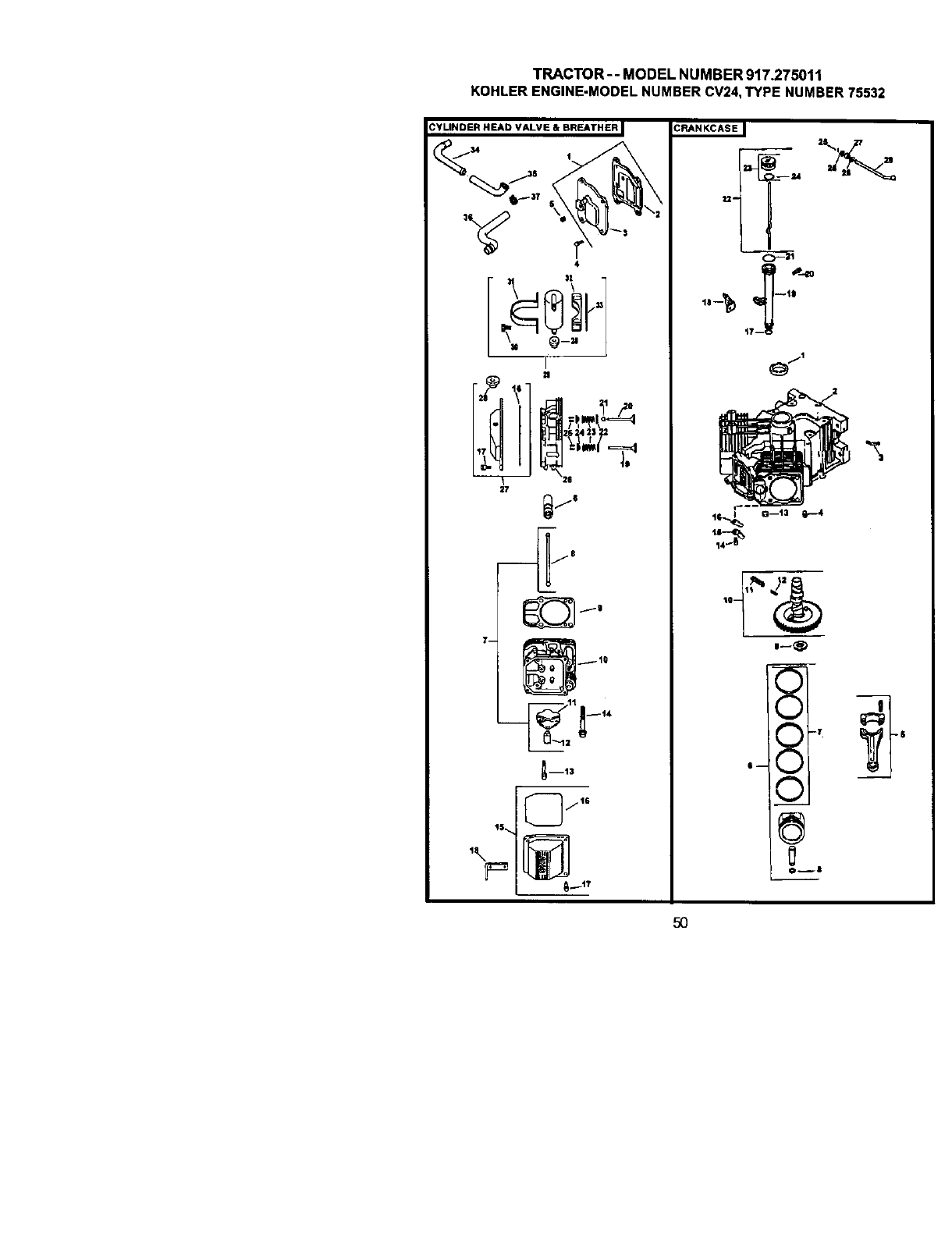
TRACTOR--MODELNUMBER917.275011
KOHLERENGINE-MODELNUMBERCV24,TYPENUMBER75532

TRACTOR--MODELNUMBER917.275911
KOHLERENGINE-MODELNUMBERCV24,TYPENUMBER75532
R EADNALVFJ BREATHER CRANKCASE
KEY PART KEY pART
NO. NO. DESCRIPTION NO, NO. DESCRIPTION
1. 24-03g-03-S Kit, breather cover w/gaskot 1. 24-032-01-S Seal oil front
(tnuludes 2,3) 2. Crankcase
2. 24.041-23-S Gasket, breather (USE: Miulblock)
3. 24-096-59-S Cover, breather 3. 24-294-13-S Fitting
4. M-645020-S Screw, hex. flange 4. 12-380-17-S Pin. dowel tocaflng (6)
M6xl.Ox2O (4) 5. 24-g67-13-S Connecting Rod (_td.) (2)
5. X-75-23-S Plu_. arian hd. 1/8" 24-067-14-S Connectin_ ROd (.25) (2)
6. 25-351-gl-S Lifter, valve (4) 6. 24-874-09-S Piston w/Ring Sot Std. (2)
7, 24-755-66-S Kit, valve train (Includes (Includes 7,8)
8,11,12) 24-874-10-S Piston w/Ring Set (.25) (2)
8, 24-411-05-S Rod, push (4) 24-,874-11-S piston w/Ring Set (.50) (2)
9. 24-041-40-S Gasket, cy_oder head (2) 24-874-15-S Kit, piston w/ring set (.08)
10. 24-31B-'_2-S Head aSSembly, #2 c¥_lwde_ 7. 24-10_,-08-S _.k_g Set (Std.} (2}
11. 25-186-01-S Arm, rocker(4) 24-108-g9-S Ring Set (.25) (2)
12. 24-599-0%S Pivot, rockeraml (4) 24-108-10-S Ring Set .50 (2)
13. M-640034-S Screw, hex. flange 8, 24-018-01-S Retainer, pison pn 4
Shim, camshaft/\.R./
M6xl.gx34 (4) 9. 12-422-09-S
14, 24-086-44-S Screw, hex. flange 12-422-13-S Shim, camshaft A.R.
M1Oxl.5xg0 (8) 12-422-07-S Shim, camshaft A.R.
15. 24-755-74-S Kit, valve cover -plain 12-422-g8-s Shim, camshaft (A.R.)
(iedudes 16.17) 12-422-10-S Shim, camshaft
16. 24-153-16-S O-Ring 12-422-11-S Bhim, camshaft(A.R.)
17. 24-g86-32-S Screw, shoulder (4) 12-422-12-S Shim, camshaft (A.R.)
18. 24-445-01-S Strap. lifting 10. 24-01g-06-S Camshaft (Includes 11,12)
19, 24-016-01-S Valve, exhaust (Std.) (2) 11. 24-089-35-S Spdng, ACR (Heavy)
24-016-02-S Valve, e_haust (.25) (2) 12. 24.089-34-S Spring, ACR(Light)
20. 24-O17-O1-S VaNe, intake (Std.) (2) 13. 52-139-09-S Ptug, cup
24-017-02-S Valve, intake .25) 2 14. M-0545010-S Screw, hex. flange
21. 24-032-05-S Seal, valve stern (2) M5x0.8xl0 (2)
22. 235_)'_'_-S Re_ther, sprig (4} 15. 24.Q18-04-S Reta_er, reed (`2}
23. 24-089°02-S Spdng, valve (4) 16. 24-402-05-S Reed, breather (2)
24. 12-173-gl-S Cap, valve spdng (4) 17. 12-t53-01-S O-Ring, tower oil filltube
25. 12-755-03-S Kit retainer 4 18. 24-126-19-S Bracket, oll fill tube
26. 24-318-11-S Head assembly, #1cyiinder 19. 12*123-04-S Tube, oilfill
27. 24-755-76-S Kit, valve cover- breather 20. M-545016-S Screw, hex. flange
(Inc1.16,17,28) M5xO.Bx16
28 25-313-02-S Grommet, rubber 21. 12-153-g2-s O-Ring, upper oil flU tube
29. 24-755.57-S Kit, breather separator 22. 24-038-04-S Dipstick assembly (Includes
(includes 28,30-33) 23,24)
30. M-545016-S Screw, hex. flange 23. 24-755-46-S Kit, oil fill cap (includes 24)
M5xO.8x16 (2) 24. 12-153-03-S O-Ring, dipstick
31. 24-445-02-S Strap, breather 25. 12-380-04-S Pin, hitch
32. 24-t26-44-S Bracket, breather separator 26. M-631005-S Washer, plain 6mm
33. 24-112-12-S Spacer 27. 12-032-01-S Seal, governor cross shaft
34. 24-294-06-S Fitting 28. X-25-102-S Washer, p_ln 1/4"
35. 24-326-13-S Hose, breather 29. 24-144-gl-S Shaft, governor cross
36 24-326-14-S _ose, breather
37. X-426-9-S Cl_mp, hose (2) NOTE; All component dimensions given InU.8.
inches 1 inch = 254 mm
51
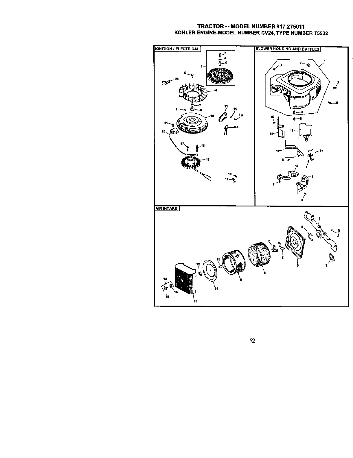
TRACTOR-- MODEL NUMBER 917.275011
KOHLERENGINE-MODELNUMBERCV24,TYPE NUMBER 75532
IGNITION IELECTRICAL I pz
,,.---1
t-
9_9 _,_7 11 12
BLOWER HOUSING AND BAFFLES I
/'
lil'_
14_
la 8
/
_ _-o
|
ift
AIR INTAKE J
is I13
52
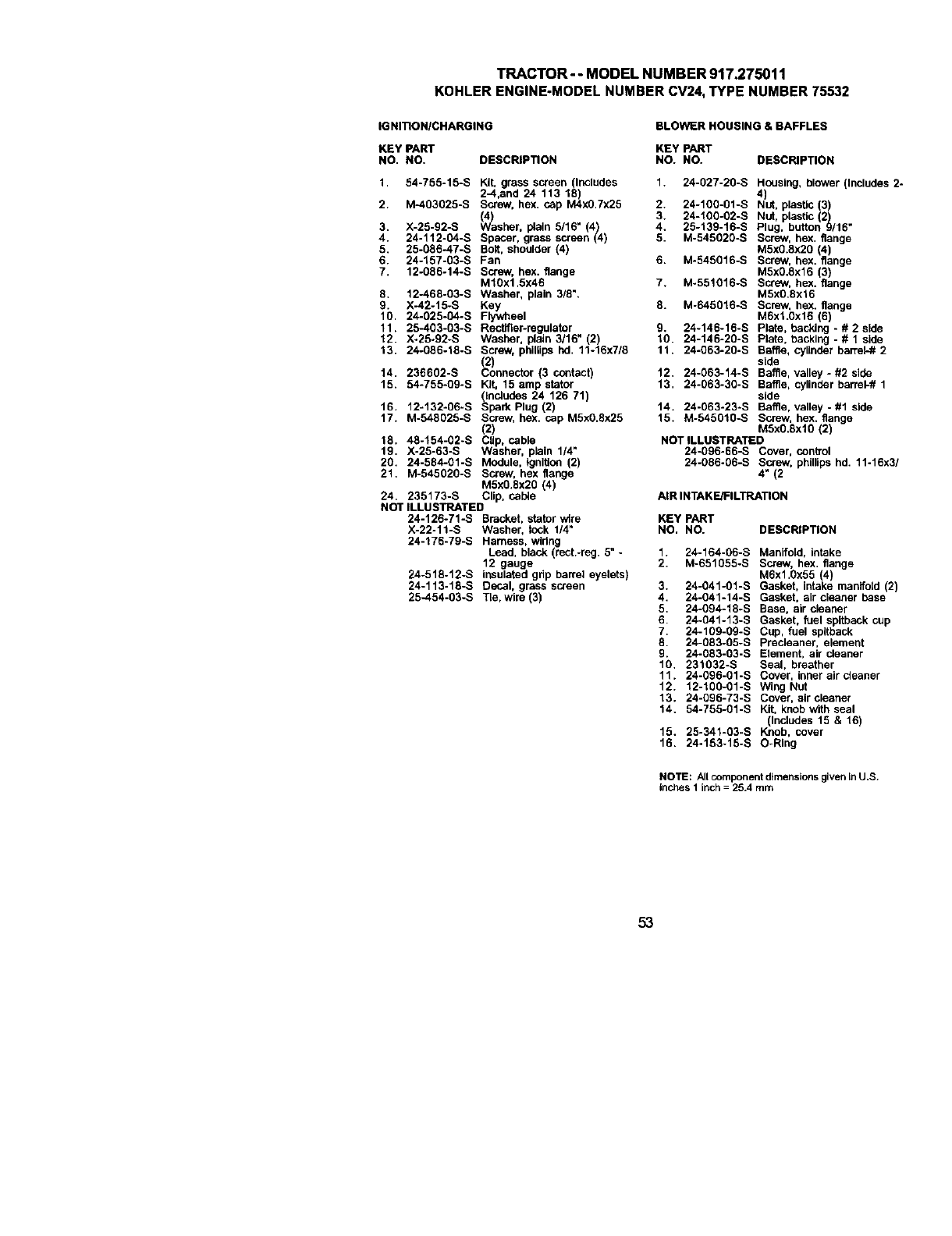
TRACTOR--MODELNUMBER917.275011
KOHLERENGINE.MODELNUMBERCV24,TYPENUMBER75532
IG NITIONICHARGING BLOWER HOUSING & BAFFLES
KEY PART KEY PART
NO. NO. DESCRIPTION NO. NO. DESCRIPTION
1. 54-755o15-S Kit grass screen _lncludes 1. 24-027-20-S Housing, blower (Includes 2
2--4,a_d 24 113 18 4)
2. M-403025-S Screw, hex. cap M4xO.7x25 2. 24-100-01-S Nut, plastic (3)
(/4_ 3. 24-100-02-S Nut, plastic (2)
3. X-25-g2-s _/asher, plain 5/16" (4) 4. 25-139-16-S Plug. button 9/16"
4. 24-112*04-S Spacer, grass screen (4) 5. M-545020-S Screw, hex, flange
5. 25-086-47-S Bolt, shoulder (4) M5x0.8x20 (4)
6. 24-'_57-B3-S Fan 6. M-545(3'_6-S Screw, hex. flange
7. 12-086-14-S Screw, hex. flange M5xO.Sx16 (3)
M10x1.5x46 7. M-551016-S Screw, hex. flange
8. 12-468-03-S Washer, plain 318". M5x0.8x16
X-42-15-S Ke=y= 8. M-645016-S Screw, hex. flange
19_) 24-025-04-S eel M6xl.0x16 (6)
r ly',NH
11. 25-403-03-S Rectifier-regulator g. 24o146-16-S Plate, backing -# 2 side
12. X-25-92-S Washer, plain 3/16" (2) 10. 24o146-20-S Plate, backing - # 1 side
13. 24-g86-18-S Screw, phillips hd. 11-16x7/8 11. 24o063-20-S Baffle, cylinder barrel-# 2
2) side
14. 236602-S Connecor (3 contact) 12. 24÷063-14-S Baffle, valley- #2 side
15. 54-755-Q9-S Kit, 15 amp stator 13. 24÷063-30-S Baffle, cylinder barrel-# 1
(includes 24 126 71) side
16. 12-132-06-S Spark Plug (2) 14. 24-063-23-S Baffle, valley - #1 side
17. M-548025-S Screw, hex. cap M5x0.Sx25 15. M-545010-S Screw, hex. flange
(2) M5xO.SxlO (2)
18. 48-154-02-S Clip, cable NOT ILLUSTRATED
19. X-25-63-S Washer, plein 114" 24-Q96-66-S Cover, control
20. 24-584-01-S Module, tgnflion (2) 24-086-06-S Screw, phillips hd. 11-16x3
21. M-545020-S Screw, hex flange 4" (2
M5xO.Sx2O (4)
24. 235173-S Clip, cable AIRINTAKE/IFILTRATION
NOT ILLUSTRATED
24-126-71-S BraCket, s_ator w_re KE'/PART
X-22-11-S Washer, lock 1/4" NO. NO. DESCRIPTION
24-176-79-S Harness, wiring
Lead, black (rect.-reg. 5" - 1. 24-164-06-S ManifoLd, intake
12 gauge 2 M-651055-S Screw, hex flange
24-518-12-S insulated grip barrel eyelets) M6x1,0x55 (4)
24-113-18-S DeCal, grass screen 3. 24-041-01-S Gasket, intake manifold (2)
25-454-03-S Tie, wire (3) 4. 24-041-14-S Gasket, air cleaner base
5. 24-094-18-S Base, air cleaner
6. 24-041-13-S Gasket, fuel spltback cup
7. 24-109-09-S Cup, fuel spltback
8. 24-Q83-Q5-S Precleaner, element
9. 24-083-03-S Element, air deaner
10, 231032-S Seal, breather
11. 24-096-01-S Cover, inner air cleaner
12. 12-100-01-S Wing Nut
13. 24-096-73-S Cover, aircleaner
14. 54-755-_1-S Kit, knob w_fh seat
(Includes 15 & 16)
15. 25-341-03-S Knob, cover
16. 24-153-15-S O-Ring
NOTE: All component dimensions given In U.S.
inches t inch = 25.4 mm
53
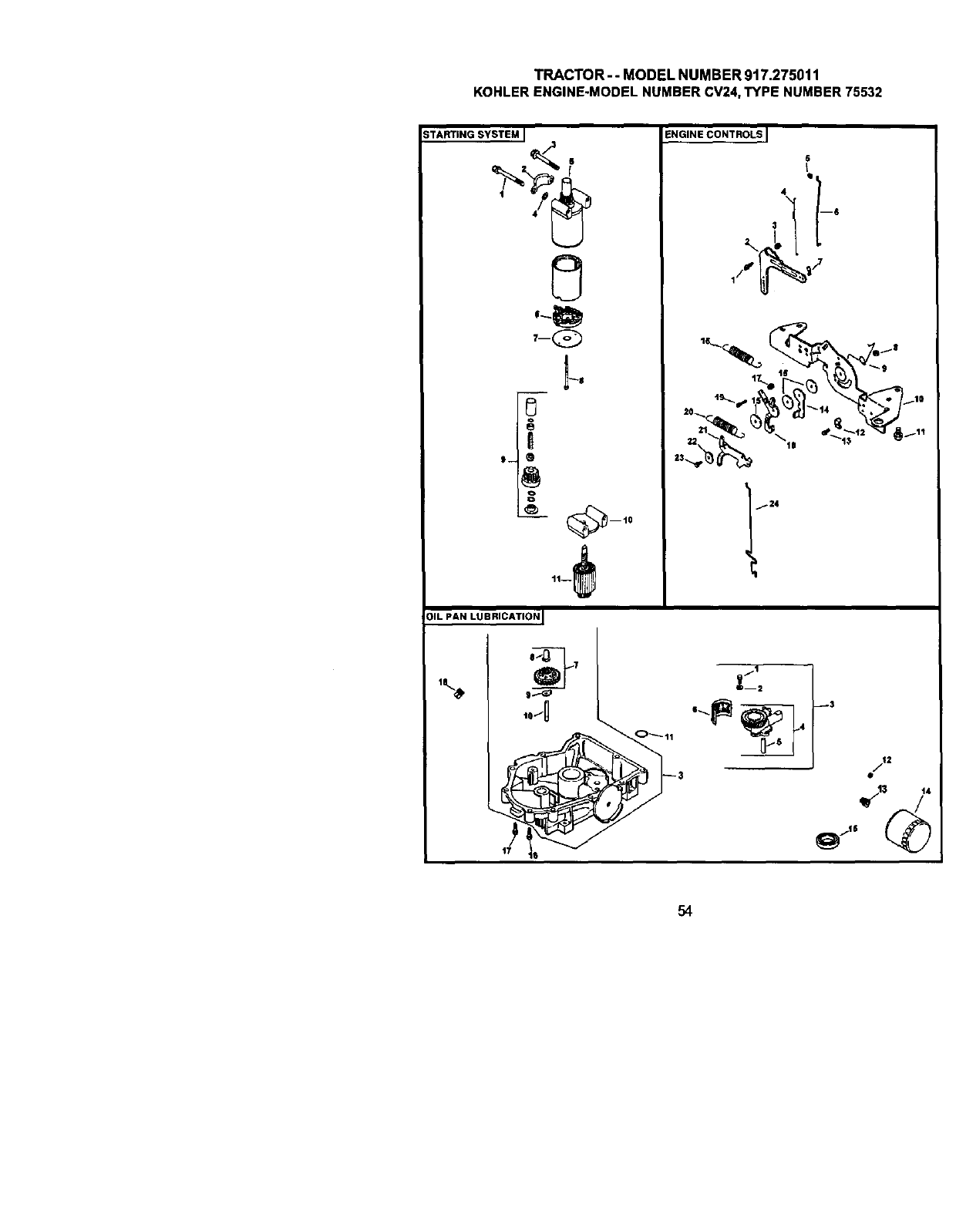
TRACTOR-- MODEL NUMBER 9t7.275011
KOHLERENGINE-MODELNUMBERCV24,TYPE NUMBER 75532
STARTING SYSTEM I
[3
A
I-- 0
ENGINE CONTROLS I
6
OIL PAN LUBRICATION I
54
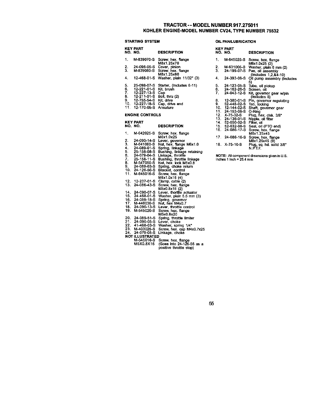
TRACTOR--MODEL NUMBER 917.275011
KOHLERENGINE-MODELNUMBER CV24,TYPE NUMBER75532
STARTING SYSTEM
KEY PART
NO. NO.
t. M-839070-S
2. 24-096-05-S
3. M-539080-S
4. 12-468-01-S
DESCRIPTION
screw, hex. flange
M8x1.25x70
Dover, pinion
SCrew, hex. flange
M8x1,25x80
Washer. plain 11/32" (3)
5. 25-098-07-S Starter, (Includes 6-11)
6. 12-221-01-S Kit, brush
7 12-227-13-S Cap
8 12-211-01-S Bolt, thru (2)
g. 12-755-54-S Kit, ddve
IQ. 12-227-18-S Cap, drive end
11 12-170-05-S Armature
ENGINECONTROLS
KEY PART
NO, NO. DESCRIPTION
1. M-542025-S Screw, hex, flange
M6x1.0x25
2 24-090-14-S Lever, govemor
3. M-541060-S Nut, hex, flange M6xlfl
4 24-089-01-S Spdng, linkage
5 25-158-08-S Bushing, linkage retaining
6. 24_079-04-S Linkage, throttle
7. 25-158-11-S Bushing, throttla linkage
8. M-547050-S Nut, hex. leck M5X0.8
9. 24-089-03-S 5pdng, choke return
10. 24-126-56-S Bracket, control
11. M-645016-S Screw, hex. flange
M6x1.0x16 (4)
12. 12-237-01-S Clamp, cable (2)
13. 24-086-43-S Screw, hex. flange
MSx0.Sxl 6 (2)
14. 24-590-07-S Lever, thodtle actuator
15. 24-468-01-S Washer, plain 5.5 mm (3)
16. 24-g89-18-S Spring, governor
17. M-446030-S Nut, hex M4x0.7
18. 24-g90-13-S Lever, throttta control
19. M-545020-S Screw. hex. flange
M5x0,8x20
20. 24-089-51-S Spdng, throttle limger
21. 24-090-05-S Lever, choke
22. 4"1-468-03-S Washer, spr_g 114"
23. M-403025-S Screw, hex. cap M4X0.7X25
24. 24-079-05-S Linkage, choke
NOT ILLU S'nRATED
M-545016-S Screw, hex. flange
M5X0.8X16 (Goes into 24-126-56 as a
positive throttle stop)
OIL PAN/LUBRICATION
KEY pART
NO. NO. DESCRIPTION
2.
3
4.
5,
6.
7,
8.
9,
10.
11.
12.
13.
14.
15.
16.
17.
18.
M.645025-S Screw, hex. flange
M6x1.Ox25 (2
M-631005-S Washer, plan 6 mm 2
24-199-07-S Pan, cll assem_y
Includes 1,2,&4-10)
24-393-08-S Oil pump assembly Includ(
24.123-05.S Tube, oil pickup
24-162-26-S Screen, oil
24-043-12*S Kit, governor gear w/pin
(Includes 8)
12-380-gl-S Pin, ovemor regutatlng
52-448-02-S Tab, _ing
12-144-02-S Shaft, governor gear
24-153-08-S O-Ring
X-75-32-S Plug, hex. ctsk. 3/8"
24-136-01-S Nippie, cll filter
52-050-02-S Fi_e_, o_
52-032-08-S Seal, oil (PTO end)
24-086-17-S Screw, hex. flange
M8x1.25x45
24-086-16-S Screw, hex. flange
MSx1.25x45 (9)
X-75-10-S Plug, sq. hd. solid 3/8"
N.F_T.F.
NOTE: All component dimensions given in US
inches I inch =25.4 mm
55
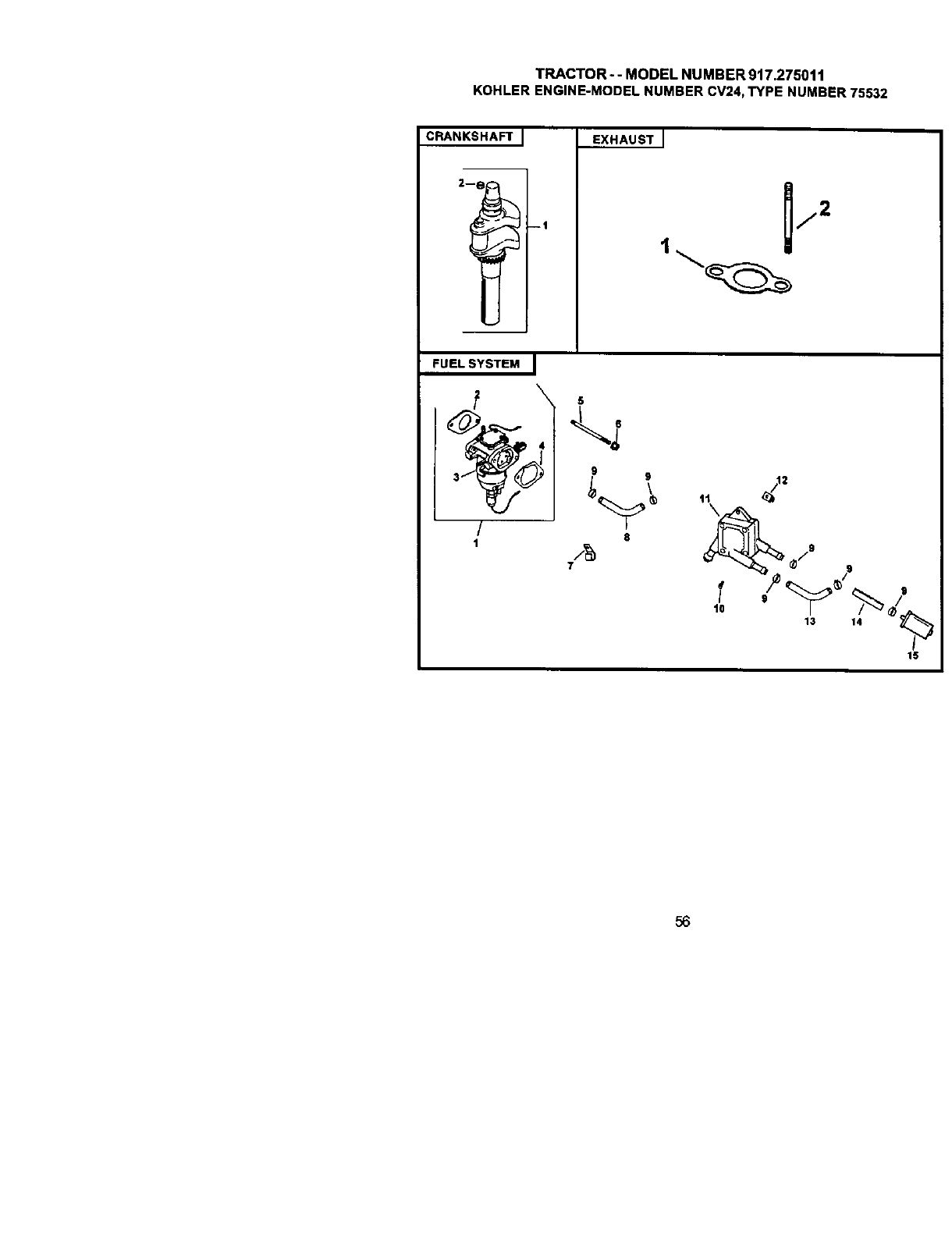
TRACTOR--MODEL NUMBER 917.275011
KOHLERENGINE-MODELNUMBER CV24,TYPE NUMBER 75532
CRANKSHAFT I
--1
EXHAUST J
FUELSYSTEM I
/
18
7
9
\
13
56
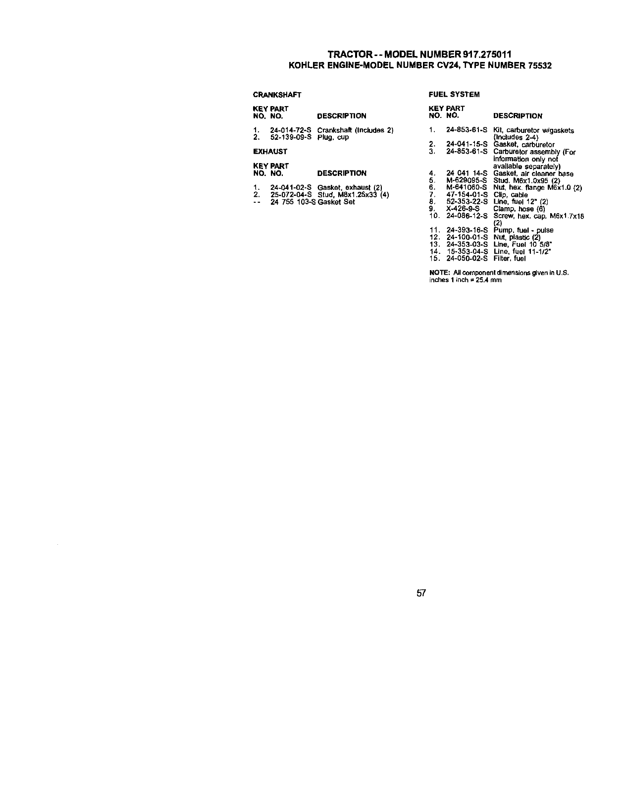
TRACTOR-- MODELNUMBER9t7.275011
KOHLERENGINE-MODELNUMBERCV24,TYPENUMBER75532
CRANKSHAFT
KI_y PART
NO. NO, DESCRIPTION
1, 24-014-72-S Crankshaft (Includes 2)
2, 52-13g-09-S Plug, cup
EXHAUST
KEY PART
NO. NO. DESCRIPTION
1. 24-041-02-S Gasket, exhaust(2)
2. 25-072-04-S Stud, MSx1.25x33 (4)
-- 24 755 lg3-SGasket Set
FUEL SYSTEM
KEY PART
NO. NO. DESCRIPTION
1, 24-853-61-S Kit, carburetor w/gaskets
(Includes 2-4)
2. 24-041-15-S Gasket, carburetor
3. 24-853.61-S Carburetor assembly (For
information only not
available separately)
4, 24 041 14-S Gasket, air cleaner base
5, M-629095-S Stud, M6x1.0x95 (2)
6, Mo641060-S Nut, hex. flange M6xl.0 (2)
7. 47-154-01-S Clip. Cable
8, 52-353-22-S Line. fuel 12" (2)
9, X-426-9-S Clamp, base (6)
10. 24-086-12-S Screw, hex. Cap. M6x1.7x18
(2)
11, 24-393-16-S Pump. fuel- pulse
12. 24-100-01-S Nut, plastic (2)
13. 24-353-03-S Line, Fuel 10 5/B"
14. 15-353-04-S Line, fuel 11-1/2"
15. 24-050-02-S Filter, fUel
NOTE: PJIcomponent dimensions given in U.S.
inches 1 inch =25.4 turn
57

58
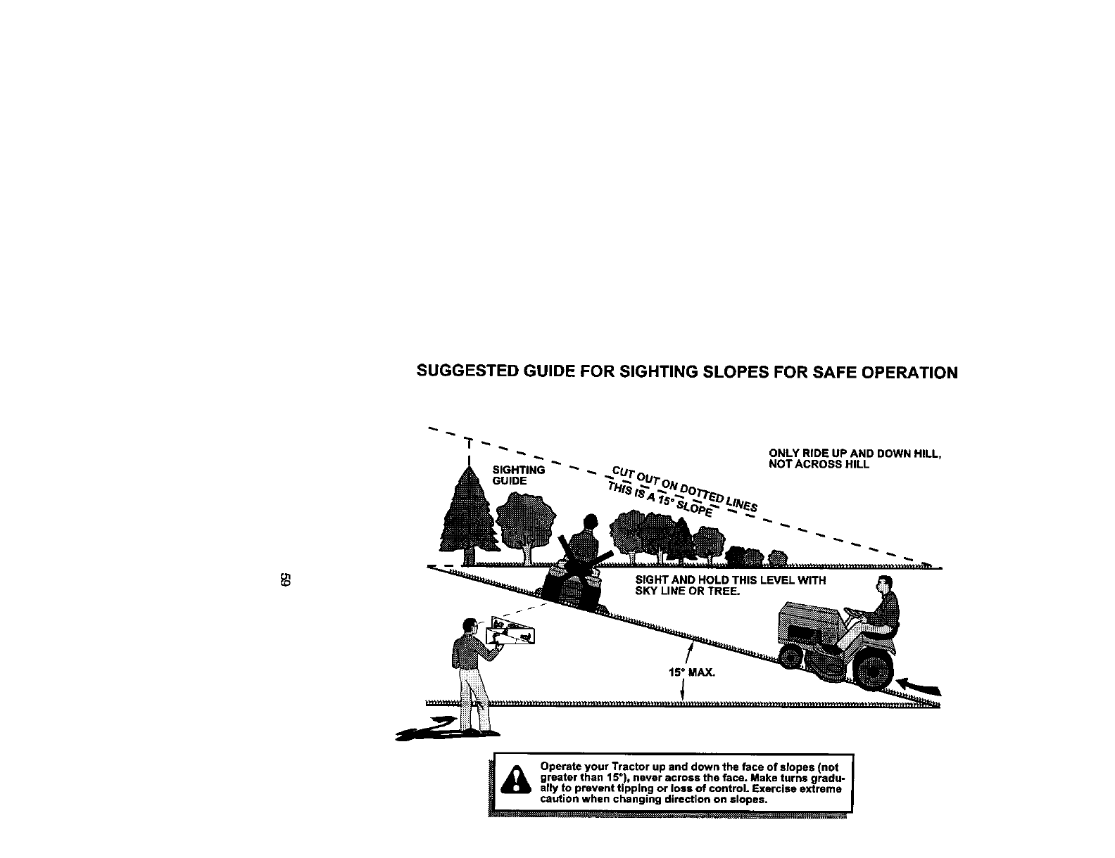
SUGGESTED GUIDE FOR SIGHTING SLOPES FOR SAFE OPERATION
GUIDE
ONLY RIDE UP AND DOWN HILL,
NOT ACROSS HILL
.a_ Operate your Tractor up and down the face of slopes (not I
greater than 15"), never acrossthe face. Make turns gradu- I
a ally to prevent tipping or loss of control. Exercise extreme |
Wcaution when changing direction on slopes. I
For rep_r of carry-in pmd_ts tike vacuums, lawn equipment, and
electronics, callfor the nearest Sears Parts and Repair Center.
1-800-488-1222 Anyane,dayorn_ht(U.S.A.c_/)
For the replacement parts, accessories and owner's manuals
that you need to do-R-yourself,call Sears PartsDirect_l
1-800-366-PART calm.-11 psn.,7_a_
(1-80e.,._-72-is) (u.,s_.on_)
w,_N.seam--conVpattsdlmct
To purchase or inquireabout a Sears Service Agreement
or Sears Maintenance Agreement:
1-800-827-6655 (U.SA) 1-800-361-6665 (Canada)
7a.m.-Sp,m.,CST, Mon.-Sat. 9 a.m. - 8 p.m. EST, M - F, 4 p.m. Sat.
Parapedirsewldodemparad_aAuCanadapour_ en_
dornk_o, y para orde_ar pleza_ 1-800-LE-FOVER Mc
1-S88-SU-HOGAR_(1-800-533_7)
_:: (I_88-784-6427) www.sears_.a
@ Registered Trademark /TM Trademark /sM Service Mark of Sears. Roebuck and Co.
®M_rca Regisvada /TM Marcel de F& brica / su Ma_ca de Servlcio d_ Nears. Ro_buck and C:o
_: Marque de commerce /Me Marque d_posbe de Sears. Roebuck and CO.
178339 2.12.01 TR Printed in U.S.A.
