Craftsman 917276350 User Manual GARDEN TRACTOR Manuals And Guides L0503432
CRAFTSMAN Lawn, Tractor Manual L0503432 CRAFTSMAN Lawn, Tractor Owner's Manual, CRAFTSMAN Lawn, Tractor installation guides
User Manual: Craftsman 917276350 917276350 CRAFTSMAN GARDEN TRACTOR - Manuals and Guides View the owners manual for your CRAFTSMAN GARDEN TRACTOR #917276350. Home:Lawn & Garden Parts:Craftsman Parts:Craftsman GARDEN TRACTOR Manual
Open the PDF directly: View PDF ![]() .
.
Page Count: 60

Owner's Manual
[RRFTSMIIN°
GARDEN TRACTOR
25.0 HP, 48" Mower
Electric Start
6 Speed Transaxle
Model No.
917.276350
This product has a low emission engine which operates
_]]1 differently from previously built engines. Before start the
you
engine, read and understand this Owner's Manual.
IMPORTANT:
Read and follow all Safety
Rules and Instructions before
operating this equipment.
For answers to your questions
about this product, Call:
1-800-659-5917
Sears Craftsman Help Line
5 am - 5 pm, Mon- Sat
SEARS, ROEBUCK AND CO., HOFFMAN ESTATES, IL 60179 U.S.A.
Visit our Craftsman website:www.sears.com/craftsman
Warranty ................................................ 2
Safety Rules .......................................... 3
Product Specifications ........................... 5
Assembly/Pre-Operation ....................... 7
Operation ............................................... 9
Maintenance Schedule ........................ 15
Maintenance ........................................ 15
Service and Adjustments ..................... 19
Storage ................................................ 27
Troubleshooting ................................... 28
Repair Parts ......................................... 32
Sears Service ........................ Back Cover
LIMITED WARRANTY ON CRAFTSMAN RIDING EQUIPMENT
For two (2) years from the date of purchase, if this Craftsman Riding Equipment is
maintained, lubricated and tuned up according to the instructions in the owner's manual,
Sears will repair or replace free of charge any parts that are found to be defective in
material or workmanship according to the guidelines of coverage listed below. Sears will
also provide free labor for these applicable warranted parts for the two full years. During
the first 30 days of purchase, there will be no charges to service the product at your
home for issues covered by this warranty. (See exclusions below). For your conve-
nience, IN HOME warranty service will still be available after the first 30 days of pur-
chase, but a trip charge will apply. This charge will be waived if the Craftsman product is
dropped off at an authorized Sears location. For the nearest authorized Sears location,
please call 1-800-4-MY-HOME®. This warranty applies only while this product is within
the United States.
This Warranty does not cover:
• Expendable items which become worn during normal use, including but not limited to
blades, spark plugs, air cleaners, belts, and oil filters.
• Standard Maintenance Servicing, oil changes, or tune-ups
• Tire replacement or repair caused by punctures from outside objects, such as nails,
thorns, stumps, or glass.
• Repairs necessary because of operator abuse, including but not limited to, damage
caused by towing objects beyond the capability of the riding equipment, impacting
objects that bend the frame or crankshaft, or over-speeding the engine.
• Repairs necessary because of operator negligence, including but not limited to, elec-
trical and mechanical damage caused by improper storage, failure to use the proper
grade and amount of engine oil, failure to keep the deck clear of flammable debris,
or failure to maintain the equipment according to the instructions contained in the
owner's manual.
• Engine (fuel system) cleaning or repairs caused by fuel determined to be contami-
nated or oxidized (stale). In general, fuel should be used within 30 days of its pur-
chase date.
• Normal deterioration and wear of the exterior finishes, or product label replacement.
• Riding equipment used for commercial or rental purposes.
LIMITED WARRANTY ON BATTERY
For ninety (90) days from date of purchase, if any battery included with this riding equip-
ment proves defective in material or workmanship and our testing determines the battery
will not hold a charge, Sears will replace the battery at no charge. During the first 30
days of purchase, there will be no charges to replace the battery at your HOME. After
the first 30 days, for your convenience, IN-HOME warranty service will still be avail-
able but a trip charge will apply. This charge will be waived if the Craftsman product is
dropped off at an authorized Sears location. For the nearest authorized Sears location,
please call 1-800-4-MY-HOME®.
This battery warranty applies only while this product is within the United States.
This warranty gives you specific legal rights, and you may also have other rights, which
vary, from state to state.
Sears, Roebuck and Co.,Dept.817WA, Hoffman Estates, IL 60179
2
IMPORTANT: This cutting machine is capable of amputating hands and feet and throw-
ing objects. Failure to observe the following safety instructions could result in serious
injury or death.
WARNING: In order to prevent ac-
cidental starting when setting up, trans-
porting, adjusting or making repairs,
always disconnect spark plug wire and
place wire where it cannot contact spark
plug.
WARNING: Do not coast down a
hill in neutral, you may lose control of the
tractor.
WARNING: Tow only the attachments
that are recommended by and comply with
specifications of the manufacturer of your
tractor. Use common sense when towing.
Operate only at the lowest possible speed
when on a slope. Too heavy of a load,
while on a slope, is dangerous. Tires can
lose traction with the ground and cause
you to lose control of your tractor.
WARNING: Engine exhaust, some
of its constituents, and certain vehicle
components contain or emit chemicals
known to the State of California to cause
cancer and birth defects or other reproduc-
tive harm.
WARNING: Battery posts, terminals
and related accessories contain lead and
lead compounds, chemicals known to the
State of California to cause cancer and
birth defects or other reproductive harm.
Wash hands after handling.
I. GENERAL OPERATION
• Read, understand, and follow all
instructions on the machine and in the
manual before starting.
• Do not put hands or feet near rotating
parts or under the machine. Keep clear
of the discharge opening at all times.
• Only allow responsible adults, who are
familiar with the instructions, to operate
the machine.
• Clear the area of objects such as
rocks, toys, wire, etc., which could be
picked up and thrown by the blades.
• Be sure the area is clear of bystand-
ers before operating. Stop machine if
anyone enters the area.
• Never carry passengers.
3
• Do not mow in reverse unless abso-
lutely necessary. Always look down
and behind before and while backing.
• Never direct discharged material
toward anyone. Avoid discharging
material against a wall or obstruction.
Material may ricochet back toward the
operator. Stop the blades when cross-
ing gravel surfaces.
• Do not operate machine without the
entire grass catcher, discharge guard,
or other safety devices in place and
working.
• Slow down before turning.
• Never leave a running machine
unattended. Always turn off blades,
set parking brake, stop engine, and
remove keys before dismounting.
• Disengage blades when not mowing.
Shut off engine and wait for all parts to
come to a complete stop before clean-
ing the machine, removing the grass
catcher, or unclogging the discharge
guard.
• Operate machine only in daylight or
good artificial light.
• Do not operate the machine while
under the influence of alcohol or drugs.
• Watch for traffic when operating near
or crossing roadways.
• Use extra care when loading or unload-
ing the machine into a trailer or truck.
• Always wear eye protection when oper-
ating machine.
• Data indicates that operators, age 60
years and above, are involved in a
large percentage of riding mower-re-
lated injuries. These operators should
evaluate their ability to operate the
riding mower safely enough to protect
themselves and others from serious
injury.
• Follow the manufacturer's recommen-
dation for wheel weights or counter-
weights.
• Keep machine free of grass, leaves or
other debris build-up which can touch
hot exhaust /engine parts and burn.
Do not allow the mower deck to plow
leaves or other debris which can cause
build-up to occur. Clean any oil or fuel
spillage before operating or storing the
machine. Allow machine to cool before
storage.
I1.SLOPE OPERATION
Slopesarea majorfactor relatedto lossof
control and tip-overaccidents,whichcan
resultin severeinjuryor death. Opera-
tion on all slopes requiresextra caution. If
you cannot back up the slope or if you feel
uneasy on it, do not mow it.
• Mow up and down slopes, not across.
• Watch for holes, ruts, bumps, rocks, or
other hidden objects. Uneven terrain
could overturn the machine. Tall grass
can hide obstacles.
• Choose a low ground speed so that
you will not have to stop or shift while
on the slope.
• Do not mow on wet grass. Tires may
lose traction.
Always keep the machine in gear when
going down slopes. Do not shift to
neutral and coast downhill.
• Avoid starting, stopping, or turning on
a slope. If the tires lose traction, dis-
engage the blades and proceed slowly
straight down the slope.
• Keep all movement on the slopes slow
and gradual. Do not make sudden
changes in speed or direction, which
could cause the machine to roll over.
• Use extra care while operating ma-
chine with grass catchers or other at-
tachments; they can affect the stability
of the machine. Do no use on steep
slopes.
• Do not try to stabilize the machine by
putting your foot on the ground.
• Do not mow near drop-offs, ditches,
or embankments. The machine could
suddenly roll over if a wheel is over the
edge or if the edge caves in.
III. CHILDREN
Tragic accidents can occur if the operator
is not alert to the presence of children.
Children are often attracted to the machine
and the mowing activity. Never assume
that children will remain where you last
saw them.
• Keep children out of the mowing area
and in the watchful care of a respon-
sible adult other than the operator.
•Be alert and turn machine off if a child
enters the area.
• Before and while backing, look behind
and down for small children.
• Never carry children, even with the
blades shut off. They may fall off and
be seriously injured or interfere with
safe machine operation. Children who
have been given rides in the past may
suddenly appear in the mowing area
for another ride and be run over or
backed over by the machine.
• Never allow children to operate the
machine.
• Use extra care when approaching blind
corners, shrubs, trees, or other objects
that may block your view of a child.
IV. TOWING
• Tow only with a machine that has a
hitch designed for towing. Do not at-
tach towed equipment except at the
hitch point.
• Follow the manufacturer's recommen-
dation for weight limits for towed equip-
ment and towing on slopes.
• Never allow children or others in or on
towed equipment.
• On slopes, the weight of the towed
equipment may cause loss of traction
and loss of control.
• Travel slowly and allow extra distance
to stop.
V. SERVICE
SAFE HANDLING OF GASOLINE
To avoid personal injury or property
damage, use extreme care in handling
gasoline. Gasoline is extremely flammable
and the vapors are explosive.
• Extinguish all cigarettes, cigars, pipes,
and other sources of ignition.
•Use only approved gasoline container.
• Never remove gas cap or add fuel with
the engine running. Allow engine to
cool before refueling.
• Never fuel the machine indoors.
• Never store the machine or fuel con-
tainer where there is an open flame,
spark, or pilot light such as on a water
heater or other appliances.
•Never fill containers inside a vehicle
or on a truck or trailer bed with plastic
liner. Always place containers on the
ground away from your vehicle when
filling.
• Removegas-poweredequipmentfrom
the truckor trailerand refuelit on the
ground.If this is not possible,then
refuel suchequipmentwith a portable
container,ratherthanfrom a gasoline
dispensernozzle.
• Keepthe nozzlein contactwiththe rim
of the fuel tank or containeropeningat
all times until fuelingis complete.Do
not usea nozzlelock-opendevice.
• If fuel is spilledon clothing,change
clothingimmediately.
• Neveroverfillfuel tank.Replacegas
capand tighten securely.
GENERAL SERVICE
•Never operate machine in a closed
area.
•Keep all nuts and bolts tight to be sure
the equipment is in safe working condi-
tion.
• Never tamper with safety devices.
Check their proper operation regularly.
• Keep machine free of grass, leaves, or
other debris build-up. Clean oil or fuel
spillage and remove any fuel-soaked
debris. Allow machine to cool before
storing.
• If you strike a foreign object, stop and
inspect the machine. Repair, if neces-
sary, before restarting.
• Never make any adjustments or repairs
with the engine running.
• Check grass catcher components and
the discharge guard frequently and
replace with manufacturer's recom-
mended parts, when necessary.
• Mower blades are sharp. Wrap the
blade or wear gloves, and use extra
caution when servicing them.
• Check brake operation frequently. Ad-
just and service as required.
• Maintain or replace safety and instruc-
tion labels, as necessary.
• Be sure the area is clear of bystand-
ers before operating. Stop machine if
anyone enters the area.
• Never carry passengers.
• Do not mow in reverse unless abso-
lutely necessary. Always look down
and behind before and while backing.
• Never carry children, even with the
blades shut off. They may fall off and
be seriously injured or interfere with
safe machine operation. Children who
have been given rides in the past may
suddenly appear in the mowing area
for another ride and be run over or
backed over by the machine.
• Keep children out of the mowing area
and in the watchful care of a respon-
sible adult other than the operator.
• Be alert and turn machine off if a child
enters the area.
• Before and while backing, look behind
and down for small children.
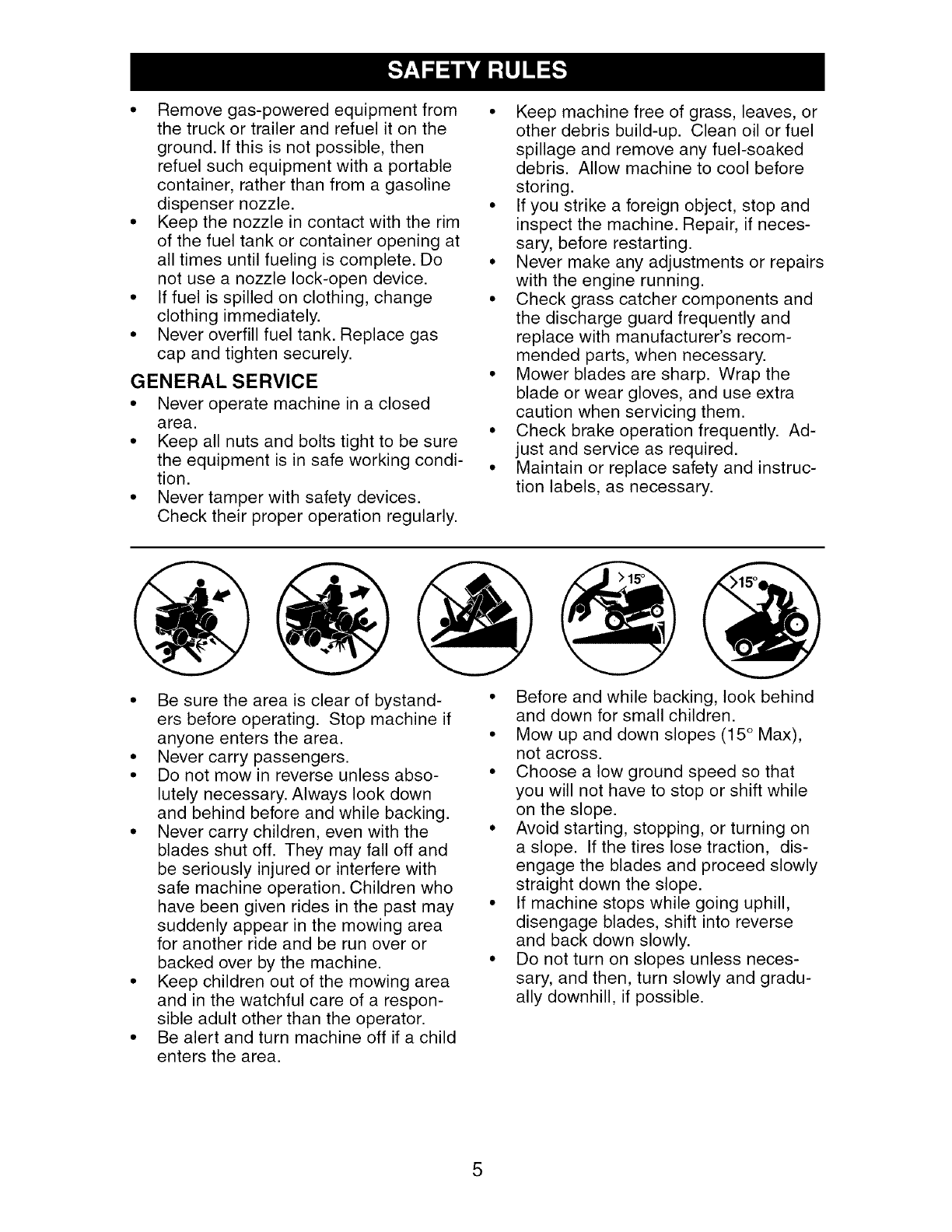
• Mow up and down slopes (15 ° Max),
not across.
• Choose a low ground speed so that
you will not have to stop or shift while
on the slope.
• Avoid starting, stopping, or turning on
a slope. If the tires lose traction, dis-
engage the blades and proceed slowly
straight down the slope.
• If machine stops while going uphill,
disengage blades, shift into reverse
and back down slowly.
• Do not turn on slopes unless neces-
sary, and then, turn slowly and gradu-
ally downhill, if possible.
5
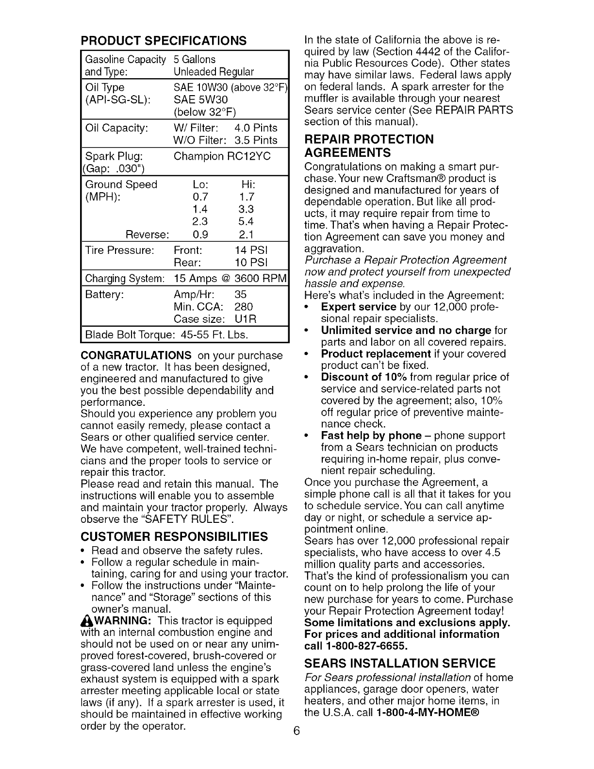
PRODUCT SPECIFICATIONS
Gasoline Capacity 5 Gallons
and Type: Unleaded Regular
Oil Type SAE 10W30 (above 32°F
(API-SG-SL): SAE 5W30
(below 32°F)
Oil Capacity: W/Filter: 4.0 Pints
W/O Filter: 3.5 Pints
Spark Plug: Champion RC12YC
(Gap: .030")
Ground Speed
(MPH):
Lo: Hi:
0.7 1.7
1.4 3.3
2.3 5.4
Reverse: 0.9 2.1
Tire Pressure: Front: 14 PSI
Rear: 10 PSI
Charging System: 15 Amps @ 3600 RPM
Battery: Amp/Hr: 35
Min. CCA: 280
Case size: U1R
Blade Bolt Torque: 45-55 Ft. Lbs.
CONGRATULATIONS on your purchase
of a new tractor. It has been designed,
engineered and manufactured to give
you the best possible dependability and
performance.
Should you experience any problem you
cannot easily remedy, please contact a
Sears or other qualified service center.
We have competent, well-trained techni-
cians and the proper tools to service or
repair this tractor.
Please read and retain this manual. The
instructions will enable you to assemble
and maintain your tractor properly. Always
observe the "SAFETY RULES".
CUSTOMER RESPONSIBILITIES
• Read and observe the safety rules.
• Follow a regular schedule in main-
taining, caring for and using your tractor.
• Follow the instructions under "Mainte-
nance" and "Storage" sections of this
owner's manual.
,_WARNING: This tractor is equipped
with an internal combustion engine and
should not be used on or near any unim-
proved forest-covered, brush-covered or
grass-covered land unless the engine's
exhaust system is equipped with a spark
arrester meeting applicable local or state
laws (if any). If a spark arrester is used, it
should be maintained in effective working
order by the operator.
In the state of California the above is re-
quired by law (Section 4442 of the Califor-
nia Public Resources Code). Other states
may have similar laws. Federal laws apply
on federal lands. A spark arrester for the
muffler is available through your nearest
Sears service center (See REPAIR PARTS
section of this manual).
REPAIR PROTECTION
AGREEMENTS
Congratulations on making a smart pur-
chase. Your new Craftsman® product is
designed and manufactured for years of
dependable operation. But like all prod-
ucts, it may require repair from time to
time. That's when having a Repair Protec-
tion Agreement can save you money and
aggravation.
Purchase a Repair Protection Agreement
now and protect yourself from unexpected
hassle and expense.
Here's what's included in the Agreement:
•Expert service by our 12,000 profe-
sional repair specialists.
•Unlimited service and no charge for
parts and labor on all covered repairs.
•Product replacement if your covered
product can't be fixed.
• Discount of 10% from regular price of
service and service-related parts not
covered by the agreement; also, 10%
off regular price of preventive mainte-
nance check.
• Fast help by phone- phone support
from a Sears technician on products
requiring in-home repair, plus conve-
nient repair scheduling.
Once you purchase the Agreement, a
simple phone call is all that it takes for you
to schedule service. You can call anytime
day or night, or schedule a service ap-
pointment online.
Sears has over 12,000 professional repair
specialists, who have access to over 4.5
million quality parts and accessories.
That's the kind of professionalism you can
count on to help prolong the life of your
new purchase for years to come. Purchase
your Repair Protection Agreement today!
Some limitations and exclusions apply.
For prices and additional information
call 1-800-827-6655.
SEARS INSTALLATION SERVICE
For Sears professional installation of home
appliances, garage door openers, water
heaters, and other major home items, in
the U.S.A. call 1-800-4-MY-HOME®
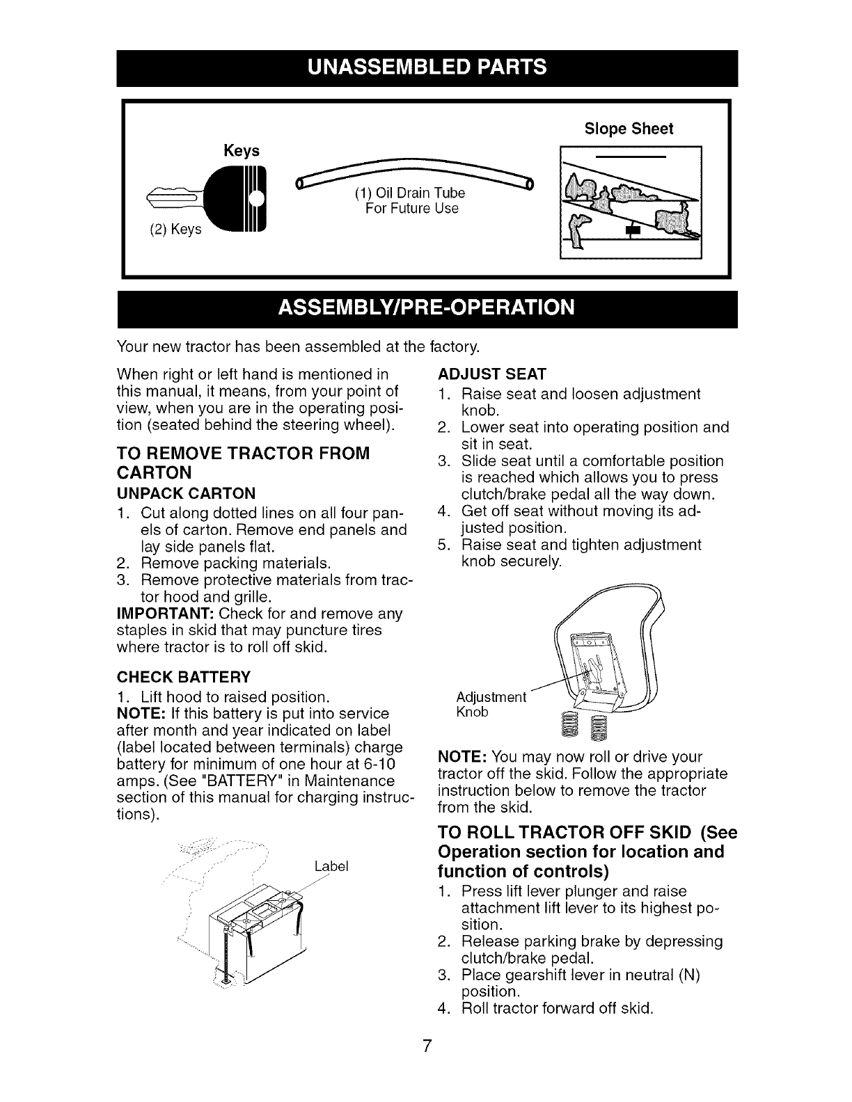
Keys
Slope Sheet
(2) Keys
(1) Oil Drain Tube
For Future Use
Your new tractor has been assembled at the factory.
When right or left hand is mentioned in
this manual, it means, from your point of
view, when you are in the operating posi-
tion (seated behind the steering wheel).
TO REMOVE TRACTOR FROM
CARTON
UNPACK CARTON
1. Cut along dotted lines on all four pan-
els of carton. Remove end panels and
lay side panels flat.
2. Remove packing materials.
3. Remove protective materials from trac-
tor hood and grille.
IMPORTANT: Check for and remove any
staples in skid that may puncture tires
where tractor is to roll off skid.
CHECK BATTERY
1. Lift hood to raised position.
NOTE: If this battery is put into service
after month and year indicated on label
(label located between terminals) charge
battery for minimum of one hour at 6-10
amps. (See "BATTERY" in Maintenance
section of this manual for charging instruc-
tions).
Label
ADJUST SEAT
1. Raise seat and loosen adjustment
knob.
2. Lower seat into operating position and
sit in seat.
3. Slide seat until a comfortable position
is reached which allows you to press
clutch/brake pedal all the way down.
4. Get off seat without moving its ad-
justed position.
5. Raise seat and tighten adjustment
knob securely.
Adjustment
Knob
NOTE: You may now roll or drive your
tractor off the skid. Follow the appropriate
instruction below to remove the tractor
from the skid.
TO ROLL TRACTOR OFF SKID (See
Operation section for location and
function of controls)
1. Press lift lever plunger and raise
attachment lift lever to its highest po-
sition.
2. Release parking brake by depressing
clutch/brake pedal.
3. Place gearshift lever in neutral (N)
position.
4. Roll tractor forward off skid.
7
TO DRIVE TRACTOR OFF SKID
(See Operation section for location
and function of controls)
_L,WARNING: Before starting, read, un-
derstand and follow all instructions in the
Operation section of this manual. Be sure
tractor is in a well-ventilated area. Be sure
the area in front of tractor is clear of other
people and objects.
1. Be sure all the above assembly steps
have been completed.
2. Check engine oil level and fill fuel tank
with gasoline.
3. Sit on seat in operating position,
depress clutch/brake pedal and set the
parking brake.
4. Place gear shift lever in neutral (N)
position.
5. Press lift lever plunger and raise
attachment lift lever to its highest posi-
tion.
6. Start the engine. After engine has
started, move throttle control to idle
position.
7. Depress clutch/brake pedal into full
"BRAKE" position and hold. Move
gearshift lever to 1st gear.
8. Slowly release clutch/brake pedal and
slowly drive tractor off skid.
9. Apply brake to stop tractor, set park-
ing brake and place gearshift lever in
neutral position.
10. Turn ignition key to "STOP" position.
Continue with the instructions that follow.
CHECK TIRE PRESSURE
The tires on your tractor were overinflated
at the factory for shipping purposes. Cor-
rect tire pressure is important for best
cutting performance.
•Reduce tire pressure to PSI shown in
"PRODUCT SPECIFICATIONS" section
of this manual.
CHECK DECK LEVELNESS
For best cutting results, mower hous-
ing should be properly leveled. See "TO
LEVEL MOWER HOUSING" in the Service
and Adjustments section of this manual.
CHECK FOR PROPER POSITION
OF ALL BELTS
See the figures that are shown for replac-
ing motion and mower blade drive belts
in the Service and Adjustments section
of this manual. Verify that the belts are
routed correctly.
CHECK BRAKE SYSTEM
After you learn how to operate your trac-
tor, check to see that the brake is properly
adjusted. See "TO ADJUST BRAKE" in
the Service and Adjustments section of
this manual.
,/CHECKLIST
Before you operate your new tractor, we
wish to assure that you receive the best
performance and satisfaction from this
Quality Product.
Please review the following checklist:
,/All assembly instructions have been
completed.
,/No remaining loose parts in carton.
,/Battery is properly prepared and
charged. (Minimum 1 hour at 6 amps).
,/Seat is adjusted comfortably and tight-
ened securely.
,/All tires are properly inflated. (For ship-
ping purposes, the tires were overin-
flated at the factory).
,/Be sure mower deck is properly leveled
side-to-side/front-to-rear for best cutting
results. (Tires must be properly inflated
for leveling).
,/Check mower and drive belts. Be sure
they are routed properly around pulleys
and inside all belt keepers.
,/Check wiring. See that all connections
are still secure and wires are properly
clamped.
While learning how to use your tractor, pay
extra attention to the following important
items:
,/Engine oil is at proper level.
,/Fuel tank is filled with fresh, clean, regu-
lar unleaded gasoline.
,/Become familiar with all controls, their
location and function. Operate them
before you start the engine.
,/Be sure brake system is in safe operat-
ing condition.
,/Be sure Operator Presence System
and Reverse Operation System (ROS)
are working properly (See the Opera-
tion and Maintenance sections in this
manual).
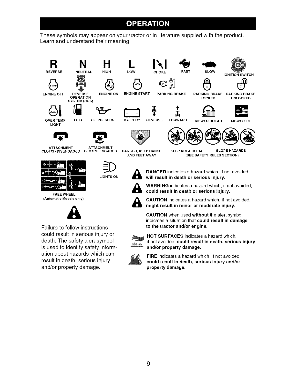
Thesesymbols mayappearon yourtractor or in literaturesuppliedwiththe product.
Learnand understandtheir meaning.
R N H I",1
REVERSE NEUTRAL HIGH LOW CHOKE FAST
ENGINE OFF REVERSE ENGINE ON ENGINE START PARKING BRAKE
OPERATION
SYSTEM (ROS)
oi
OVER TEMP
LIGHT
SLOW IGNITION SWITCH
PARKING BRAKE PARKING BRAKE
LOCKED UNLOCKED
t
FUEL OIL PRESSURE BATTERY REVERSE FORWARD MOWER HEIGHT MOWER LIFT
m
ATTACHMENT ATTACHMENT
CLUTCH DISENGAGED CLUTCH ENGAGED
LIGHTS ON
FREE WHEEL
(Automatic Models only)
&
Failure to follow instructions
could result in serious injury or
death. The safety alert symbol
is used to identify safety inform-
ation about hazards which can
result in death, serious injury
and/or property damage.
DANGER, KEEP HANDS
AND FEET AWAY
®@@@@
KEEP AREA CLEAR SLOPE HAZARDS
(SEE SAFETY RULES SECTION)
&
&
DANGER indicates a hazard which, if not avoided,
will result in death or serious injury.
WARNING indicates a hazard which, if not avoided,
could result in death or serious injury.
CAUTION indicates a hazard which, if not avoided,
might result in minor or moderate injury.
CAUTION when used without the alert symbol,
indicates a situation that could result in damage
to the tractor and/or engine.
HOT SURFACES indicatesa hazard which,
if not avoided, could result in death, serious injury
and/or property damage.
FIRE indicates a hazard which, if not avoided,
could result in death, serious injury and/or
property damage.
9
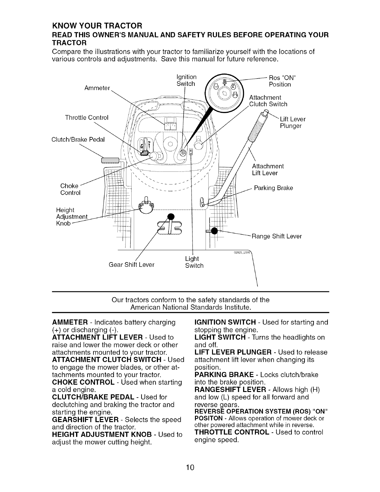
KNOW YOUR TRACTOR
READ THIS OWNER'S MANUAL AND SAFETY RULES BEFORE OPERATING YOUR
TRACTOR
Compare the illustrations with your tractor to familiarize yourself with the locations of
various controls and adjustments. Save this manual for future reference.
Ammeter
Throttle Control
Clutch/Brake Pedal_'_
Ignition Ros "ON"
Switch Position
Attachment
Clutch Switch
Plunger
Attachment
Lift Lever
Choke Parking Brake
Control
Height
Adjustment
Range Shift Lever
Light
Gear Shift Lever Switch
02825 LSW1
Our tractors conform to the safety standards of the
American National Standards Institute.
AMMETER - Indicates battery charging
(+) or discharging (-).
ATTACHMENT LIFT LEVER - Used to
raise and lower the mower deck or other
attachments mounted to your tractor.
ATTACHMENT CLUTCH SWITCH - Used
to engage the mower blades, or other at-
tachments mounted to your tractor.
CHOKE CONTROL - Used when starting
a cold engine.
CLUTCH/BRAKE PEDAL - Used for
declutching and braking the tractor and
starting the engine.
GEARSHIFT LEVER - Selects the speed
and direction of the tractor.
HEIGHT ADJUSTMENT KNOB - Used to
adjust the mower cutting height.
IGNITION SWITCH - Used for starting and
stopping the engine.
LIGHT SWITCH - Turns the headlights on
and off.
LIFT LEVER PLUNGER - Used to release
attachment lift lever when changing its
position.
PARKING BRAKE - Locks clutch/brake
into the brake position.
RANGESHIFT LEVER - Allows high (H)
and low (L) speed for all forward and
reverse gears.
REVERSE OPERATION SYSTEM (ROS) "ON"
POSITON - Allows operation of mower deck or
other powered attachment while in reverse.
THROTTLE CONTROL - Used to control
engine speed.
10
The operation of any tractor can result in foreign objects thrown into the
eyes, which can result in severe eye damage. Always wear safety glasses
or eye shields while operating your tractor or performing any adjustments
or repairs. We recommend standard safety glasses or a wide vision safety
mask worn over spectacles.
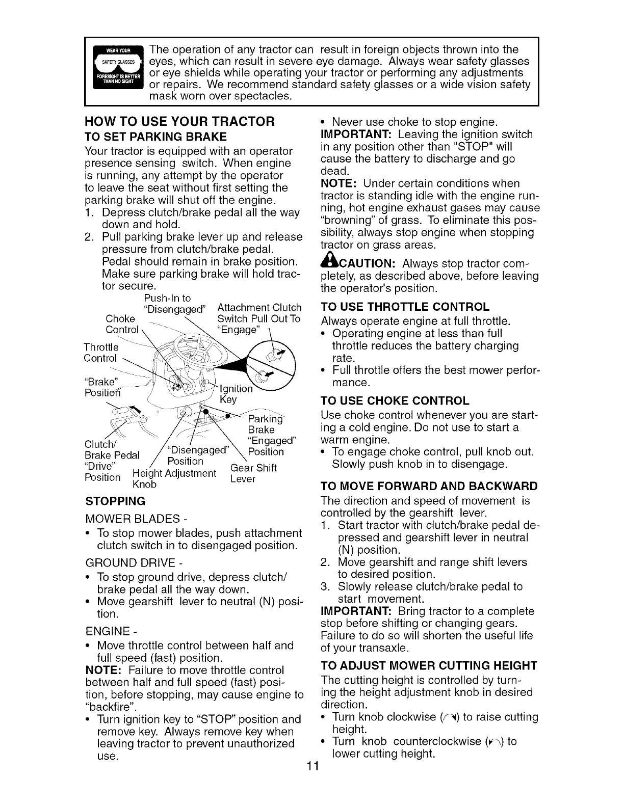
HOW TO USE YOUR TRACTOR
TO SET PARKING BRAKE
Your tractor is equipped with an operator
presence sensing switch. When engine
is running, any attempt by the operator
to leave the seat without first setting the
parking brake will shut off the engine.
1. Depress clutch/brake pedal all the way
down and hold.
2. Pull parking brake lever up and release
pressure from clutch/brake pedal.
Pedal should remain in brake position.
Make sure parking brake will hold trac-
tor secure.
Push-In to
"Disengaged" Attachment Clutch
Choke Switch Pull Out To
Control "Engage"
Throttle
Control
"Brake" nitior
\/
_ ,,. _- Key
.+-;_:--;-:.:::_ _7_ <_ Parking"
_+ \_ _z)_:'_ X Brake
Clutch/ _,,_=_2/ ........ ,,_ "Engaged"
BrakePedal /pUo'S_ngnagea_P°siti°n
Drive /..... Gear Shift
Position Height Adjustment Lever
Knob
STOPPING
MOWER BLADES -
• To stop mower blades, push attachment
clutch switch in to disengaged position.
GROUND DRIVE -
• To stop ground drive, depress clutch/
brake pedal all the way down.
• Move gearshift lever to neutral (N) posi-
tion.
ENGINE -
• Move throttle control between half and
full speed (fast) position.
NOTE: Failure to move throttle control
between half and full speed (fast) posi-
tion, before stopping, may cause engine to
"backfire".
• Turn ignition key to "STOP" position and
remove key. Always remove key when
leaving tractor to prevent unauthorized
use.
• Never use choke to stop engine.
IMPORTANT: Leaving the ignition switch
in any position other than "STOP" will
cause the battery to discharge and go
dead.
NOTE: Under certain conditions when
tractor is standing idle with the engine run-
ning, hot engine exhaust gases may cause
"browning" of grass. To eliminate this pos-
sibility, always stop engine when stopping
tractor on grass areas.
_CAUTION: Always stop tractor com-
pletely, as described above, before leaving
the operator's position.
TO USE THROTTLE CONTROL
Always operate engine at full throttle.
• Operating engine at less than full
throttle reduces the battery charging
rate.
• Full throttle offers the best mower perfor-
mance.
TO USE CHOKE CONTROL
Use choke control whenever you are start-
ing a cold engine. Do not use to start a
warm engine.
• To engage choke control, pull knob out.
Slowly push knob in to disengage.
11
TO MOVE FORWARD AND BACKWARD
The direction and speed of movement is
controlled by the gearshift lever.
1. Start tractor with clutch/brake pedal de-
pressed and gearshift lever in neutral
(N) position.
2. Move gearshift and range shift levers
to desired position.
3. Slowly release clutch/brake pedal to
start movement.
IMPORTANT: Bring tractor to a complete
stop before shifting or changing gears.
Failure to do so will shorten the useful life
of your transaxle.
TO ADJUST MOWER CUTTING HEIGHT
The cutting height is controlled by turn-
ing the height adjustment knob in desired
direction.
• Turn knob clockwise (_) to raise cutting
height.
• Turn knob counterclockwise (_-_) to
lower cutting height.
The cuttingheight rangeis approximately
1-1/2"to 4-1/2". The heightsare mea-
suredfrom the groundto the bladetip with
the engine not running. These heights
areapproximateand mayvary depending
uponsoil conditions,heightof grassand
types of grassbeingmowed.
• The averagelawnshouldbecut to
approximately2-1/2 inchesduringthe
cool seasonand to over3 inchesduring
hot months. For healthierand better
looking lawns,mowoften and after
moderategrowth.
• For bestcutting performance,grassover
6 inchesin heightshouldbe mowed
twice. Makethe first cut relativelyhigh;
the secondto desiredheight.
TO ADJUST GAUGE WHEELS
Gauge wheels are properly adjusted
when they are slightly off the ground when
mower is at the desired cutting height in
operating position. Gauge wheels then
keep the deck in proper position to help
prevent scalping in most terrain conditions.
NOTE: Be sure tractor is on a flat level
surface.
1. Lower mower and adjust mower to de-
sired cutting height(See "TO ADJUST
MOWER CUTTING HEIGHT" in this
section of manual).
2. Remove retainer spring and clevis pin
which secure each gauge wheel bar.
3. Lower gauge wheels to ground. Raise
gauge wheels slightly to align holes
in bracket and gauge wheel bar and
insert clevis pin. Gauge wheels should
be slightly off the ground.
4. Replace retainer spring into clevis pin.
5. Be sure all gauge wheels are in the
same setting.
IMPORTANT: Be sure to readjust gauge
wheels if you change the cutting height
of the mower deck.
Retainer
Clevis
Pin
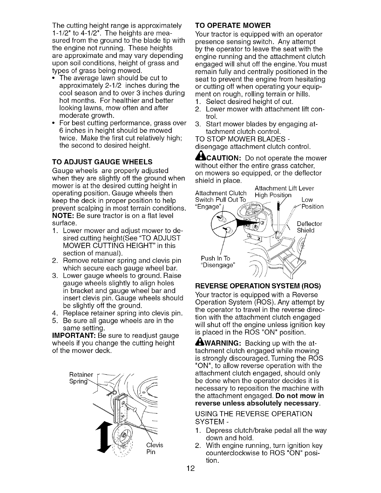
TO OPERATE MOWER
Your tractor is equipped with an operator
presence sensing switch. Any attempt
by the operator to leave the seat with the
engine running and the attachment clutch
engaged will shut off the engine. You must
remain fully and centrally positioned in the
seat to prevent the engine from hesitating
or cutting off when operating your equip-
ment on rough, rolling terrain or hills.
1. Select desired height of cut.
2. Lower mower with attachment lift con-
trol.
3. Start mower blades by engaging at-
tachment clutch control.
TO STOP MOWER BLADES -
disengage attachment clutch control.
CAUTION: Do not operate the mower
without either the entire grass catcher,
on mowers so equipped, or the deflector
shield in place. Attachment Lift Lever
Attachment Clutch High Positi
Switch Pull Out To Low
"Engage" x_"Position
,;," Deflector
Shield
Push In To
"Disengage"
REVERSE OPERATION SYSTEM (ROS)
Your tractor is equipped with a Reverse
Operation System (ROS). Any attempt by
the operator to travel in the reverse direc-
tion with the attachment clutch engaged
will shut off the engine unless ignition key
is placed in the ROS "ON" position.
,_,WARNING: Backing up with the at-
tachment clutch engaged while mowing
is strongly discouraged. Turning the ROS
"ON", to allow reverse operation with the
attachment clutch engaged, should only
be done when the operator decides it is
necessary to reposition the machine with
the attachment engaged. Do not mow in
reverse unless absolutely necessary.
USING THE REVERSE OPERATION
SYSTEM -
1. Depress clutch/brake pedal all the way
down and hold.
2. With engine running, turn ignition key
counterclockwise to ROS "ON" posi-
tion.
12
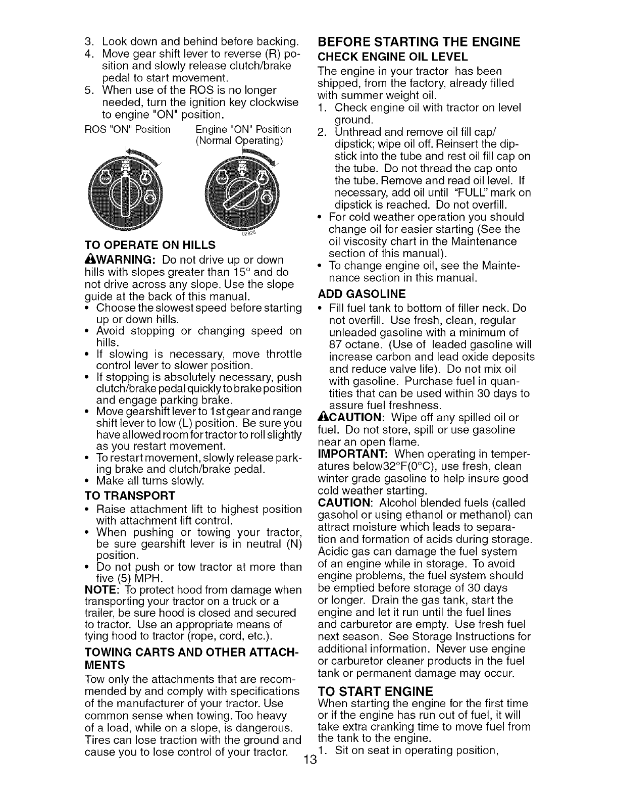
ROS "ON" Position
3. Look down and behind before backing.
4. Move gear shift lever to reverse (R) po-
sition and slowly release clutch/brake
pedal to start movement.
5. When use of the ROS is no longer
needed, turn the ignition key clockwise
to engine "ON" position.
Engine "ON" Position
(Normal Operating)
TO OPERATE ON HILLS
AWARNING: Do not drive up or down
hills with slopes greater than 15 ° and do
not drive across any slope. Use the slope
guide at the back of this manual.
•Choose the slowest speed before starting
up or down hills.
•Avoid stopping or changing speed on
hills.
•If slowing is necessary, move throttle
control lever to slower position.
• If stopping is absolutely necessary, push
clutch/brake pedal quickly to brake position
and engage parking brake.
• Move gearshift lever to lstgearand range
shift lever to low (L) position. Be sure you
have allowed room for tractor to roll slightly
as you restart movement.
• To restart movement, slowly release park-
ing brake and clutch/brake pedal.
•Make all turns slowly.
TO TRANSPORT
• Raise attachment lift to highest position
with attachment lift control.
• When pushing or towing your tractor,
be sure gearshift lever is in neutral (N)
position.
•Do not push or tow tractor at more than
five (5) MPH.
NOTE: To protect hood from damage when
transporting your tractor on a truck or a
trailer, be sure hood is closed and secured
to tractor. Use an appropriate means of
tying hood to tractor (rope, cord, etc.).
TOWING CARTS AND OTHER ATTACH-
MENTS
Tow only the attachments that are recom-
mended by and comply with specifications
of the manufacturer of your tractor. Use
common sense when towing. Too heaw
of a load, while on a slope, is dangerous.
Tires can lose traction with the ground and
BEFORE STARTING THE ENGINE
CHECK ENGINE OIL LEVEL
The engine in your tractor has been
shipped, from the factory, already filled
with summer weight oil.
1. Check engine oil with tractor on level
ground.
2. Unthread and remove oil fill cap/
dipstick; wipe oil off. Reinsert the dip-
stick into the tube and rest oil fill cap on
the tube. Do not thread the cap onto
the tube. Remove and read oil level. If
necessary, add oil until "FULl" mark on
dipstick is reached. Do not overfill.
• For cold weather operation you should
change oil for easier starting (See the
oil viscosity chart in the Maintenance
section of this manual).
•To change engine oil, see the Mainte-
nance section in this manual.
ADD GASOLINE
• Fill fuel tank to bottom of filler neck. Do
not overfill. Use fresh, clean, regular
unleaded gasoline with a minimum of
87 octane. (Use of leaded gasoline will
increase carbon and lead oxide deposits
and reduce valve life). Do not mix oil
with gasoline. Purchase fuel in quan-
tities that can be used within 30 days to
assure fuel freshness.
_i, CAUTION: Wipe off any spilled oil or
fuel. Do not store, spill or use gasoline
near an open flame.
IMPORTANT: When operating in temper-
atures below32°F(0°C), use fresh, clean
winter grade gasoline to help insure good
cold weather starting.
CAUTION: Alcohol blended fuels (called
gasohol or using ethanol or methanol) can
attract moisture which leads to separa-
tion and formation of acids during storage.
Acidic gas can damage the fuel system
of an engine while in storage. To avoid
engine problems, the fuel system should
be emptied before storage of 30 days
or longer. Drain the gas tank, start the
engine and let it run until the fuel lines
and carburetor are empty. Use fresh fuel
next season. See Storage Instructions for
additional information. Never use engine
or carburetor cleaner products in the fuel
tank or permanent damage may occur.
TO START ENGINE
When starting the engine for the first time
or if the engine has run out of fuel, it will
take extra cranking time to move fuel from
the tank to the engine.
1. Sit on seat in operating position,
cause you to lose control of your tractor. 13
depressclutch/brakepedaland set
parkingbrake.
2. Place gearshift leverin neutral(N)
position.
3. Moveattachmentclutch to disengaged
position.
4. Movethrottlecontrol to fast position
5. Pull chokecontrol outfor a cold engine
startattempt.Fora warmengine start
attemptthe chokecontrol maynot be
needed.
NOTE:Beforestarting, readthe warm and
cold startingproceduresbelow.
6. Insert keyinto ignitionand turn key
clockwiseto start positionand release
keyas soonas engine starts.Do
not runstarter continuouslyfor more
thanfifteensecondsper minute.If the
enginedoes not start after several
attempts,pushchoke controlin, wait
a few minutesand try again.If engine
stilldoes notstart, pull the chokecon-
trol out and retry.
WARMWEATHERSTARTING(50° F and
above)
7. Whenengine starts, slowlypushchoke
controlin until the engine beginsto
runsmoothly.If the engine startsto
run roughly,pull the chokecontrol out
slightlyfor a fewsecondsand then
continueto pushthe control in slowly.
• The attachmentsand grounddrivecan
now be used.Ifthe enginedoes not
acceptthe load, restartthe engine and
allowit to warm upfor one minuteusing
the choke as describedabove.
COLDWEATHERSTARTING(50° F and
below)
7. Whenengine starts,slowly pushchoke
controlin until the engine beginsto run
smoothly.Continueto pushthe choke
controlin small stepsallowingthe en-
gineto acceptsmall changesin speed
and load, until the chokecontrol is fully
in. Ifthe enginestartsto runroughly,
pullthe choke controlout slightlyfor a
fewsecondsand thencontinueto push
the control inslowly.This may re-
quirean enginewarm-upperiodfrom
severalsecondsto severalminutes,
dependingon the temperature.
• The attachmentscan be usedduring
the enginewarm-upperiodand may
requirethe choke control bepulled out
slightly.
NOTE: If at a high altitude(above3000
feet) or in cold temperatures(below32 F)
the carburetorfuel mixturemay needto
be adjustedfor best engineperformance.
See"TOADJUSTCARBURETOR"inthe
Service andAdjustmentssectionof this
manual.
MOWING TIPS
• Tire chains cannot be used when the
mower housing is attached to tractor.
• Mower should be properly leveled for
best mowing performance. See "TO
LEVEL MOWER HOUSING" in the
Service and Adjustments section of this
manual.
• The left hand side of mower should be
used for trimming.
• Drive so that clippings are discharged
onto the area that has already been
cut. Have the cut area to the right of
the tractor. This will result in a more
even distribution of clippings and more
uniform cutting.
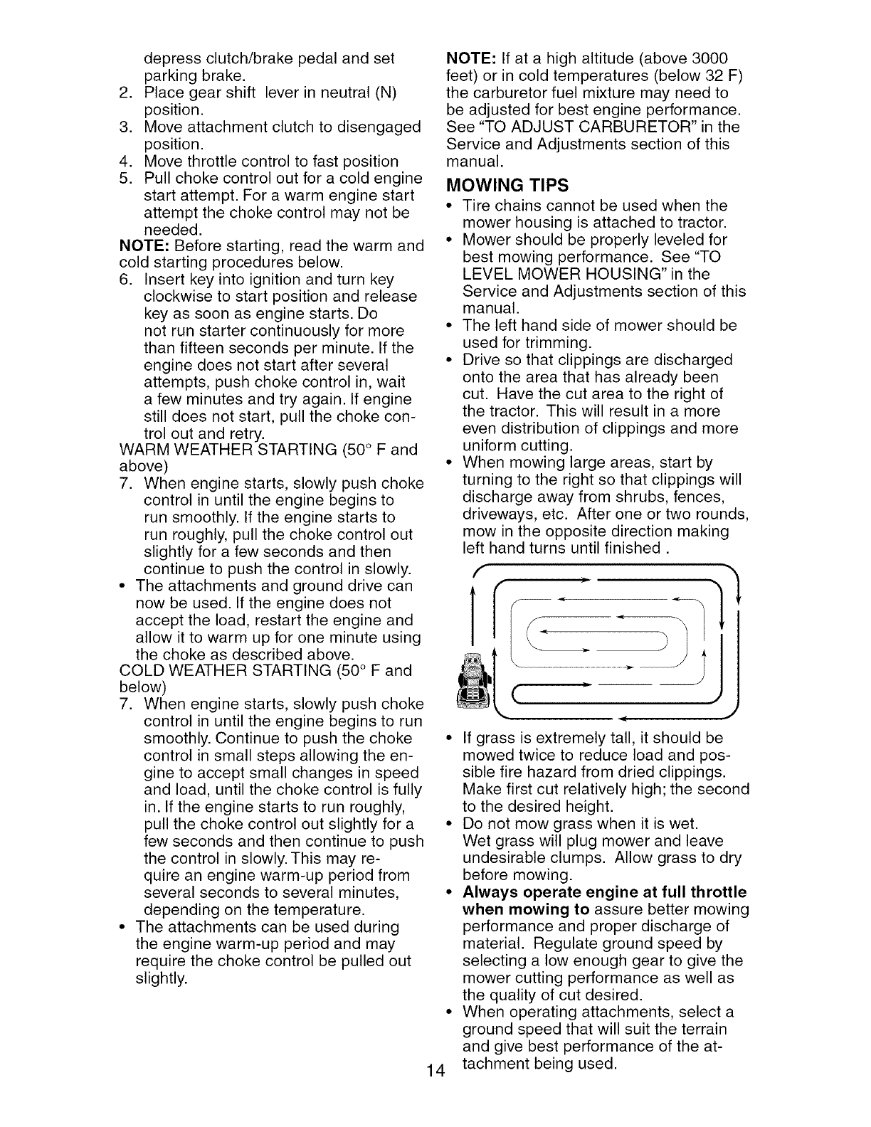
• When mowing large areas, start by
turning to the right so that clippings will
discharge away from shrubs, fences,
driveways, etc. After one or two rounds,
mow in the opposite direction making
left hand turns until finished.
]1,
( .,
14
• If grass is extremely tall, it should be
mowed twice to reduce load and pos-
sible fire hazard from dried clippings.
Make first cut relatively high; the second
to the desired height.
• Do not mow grass when it is wet.
Wet grass will plug mower and leave
undesirable clumps. Allow grass to dry
before mowing.
• Always operate engine at full throttle
when mowing to assure better mowing
performance and proper discharge of
material. Regulate ground speed by
selecting a low enough gear to give the
mower cutting performance as well as
the quality of cut desired.
• When operating attachments, select a
ground speed that will suit the terrain
and give best performance of the at-
tachment being used.
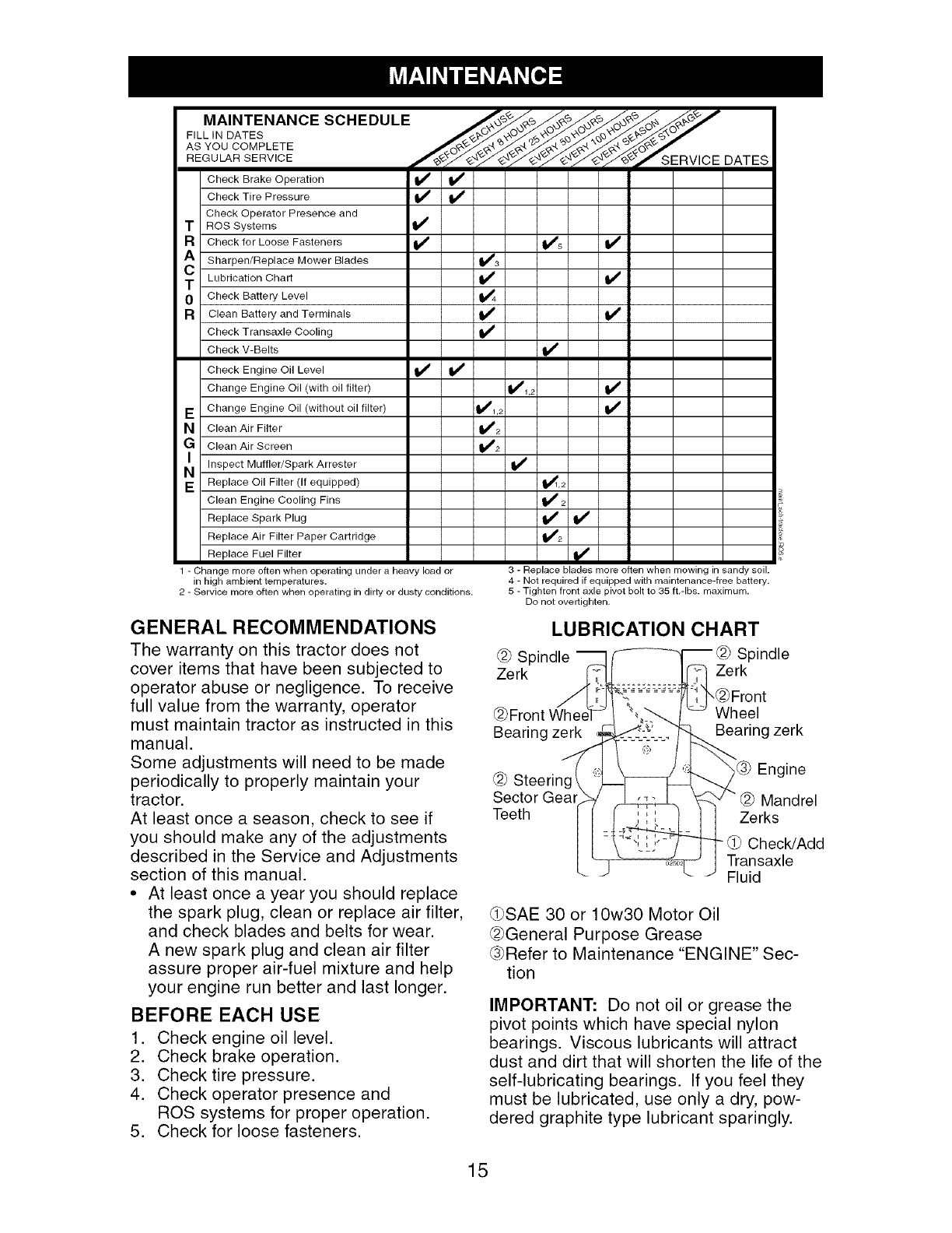
FILL, O TES
ASYOOOOMPLETEf ZERV'OE
REGULAR SERVICE DATES
Check Brake Operation _
Check Tire Pressure
Check Operator Presence and
T ROS Systems
R Check for Loose Fasteners _ II_s
Sharpen/Replace Mower Blades I_s
T Lubrication Chart I_
0Check Battery Level _4
R Clean Battery and Terminals I_ I_
Check Transaxle Cooling If
Check V-Belts I_
Check Engine Oil Level If
Change Engine Oil (with oil filter) 11_1,2
E Change Engine Oil (without oil filter) q1_1,2
N Clean Air Filter _2
G Clean Air Screen 1_2
N_ Inspect Muffler/Spark Arrester
E Replace Oil Filter (If equipped) _,2
Clean Engine Cooling Fins _ 2
Replace Spark Plug I_
Replace Air Filter Paper Cartridge 1_2
Replace Fuel Filter
1 - Change more often when operating under a heavy load or
in high ambient temperatures.
2 - Service more often when operating in dirty or dusty conditions.
3 - Replace blades more often when mowing in sandy soil.
4 - Not required if equipped with maintenance-free battery,
5 - Tighten front axle pivot bolt to 35 ft,-Ibs, maximum,
Do not overtighten,
GENERAL RECOMMENDATIONS
The warranty on this tractor does not
cover items that have been subjected to
operator abuse or negligence. To receive
full value from the warranty, operator
must maintain tractor as instructed in this
manual.
Some adjustments will need to be made
periodically to properly maintain your
tractor.
At least once a season, check to see if
you should make any of the adjustments
described in the Service and Adjustments
section of this manual.
• At least once a year you should replace
the spark plug, clean or replace air filter,
and check blades and belts for wear.
A new spark plug and clean air filter
assure proper air-fuel mixture and help
your engine run better and last longer.
BEFORE EACH USE
1. Check engine oil level.
2. Check brake operation.
3. Check tire pressure.
4. Check operator presence and
ROS systems for proper operation.
5. Check for loose fasteners.
LUBRICATION CHART
@ Spindle
Zerk
@Front Whe_
Bearing zerk
Spindle
Zerk
_Front
Wheel
Bearing zerk
@ Steerinc
Sector Gear
Teeth
Engine
@ Mandrel
Zerks
- _ Check/Add
Transaxle
Fluid
_SAE 30 or 10w30 Motor Oil
@General Purpose Grease
@Refer to Maintenance "ENGINE" Sec-
tion
IMPORTANT: Do not oil or grease the
pivot points which have special nylon
bearings. Viscous lubricants will attract
dust and dirt that will shorten the life of the
self-lubricating bearings. If you feel they
must be lubricated, use only a dry, pow-
dered graphite type lubricant sparingly.
15
TRACTOR
Always observe safety rules when per-
forming any maintenance.
BRAKE OPERATION
If tractor requires more than five (5) feet to
stop at highest speed in highest gear on a
level, dry concrete or paved surface, then
brake must be checked and adjusted. (See
"TO ADJUST BRAKE" in the Service and
Adjustments section of this manual).
TIRES
•Maintain proper air pressure in all tires
(See "PRODUCT SPECIFICATIONS"
section of this manual).
•Keep tires free of gasoline, oil, or insect
control chemicals which can harm rub-
ber.
• Avoid stumps, stones, deep ruts, sharp
objects and other hazards that may
cause tire damage.
NOTE: To seal tire punctures and prevent
flat tires due to slow leaks, tire sealant
may be purchased from your local parts
dealer. Tire sealant also prevents tire dry
rot and corrosion.
OPERATOR PRESENCE SYSTEM AND
REVERSE OPERATION SYSTEM (ROS)
Be sure operator presence and reverse
operation systems are working properly. If
your tractor does not function as de-
scribed, repair the problem immediately.
• The engine should not start unless the
brake pedal is fully depressed, and the
attachment clutch control is in the disen-
gaged position.
CHECK OPERATOR PRESENCE
SYSTEM
• When the engine is running, any at-
tempt by the operator to leave the seat
without first setting the parking brake
should shut off the engine.
• When the engine is running and the
attachment clutch is engaged, any at-
tempt by the operator to leave the seat
should shut off the engine.
• The attachment clutch should never op-
erate unless the operator is in the seat.
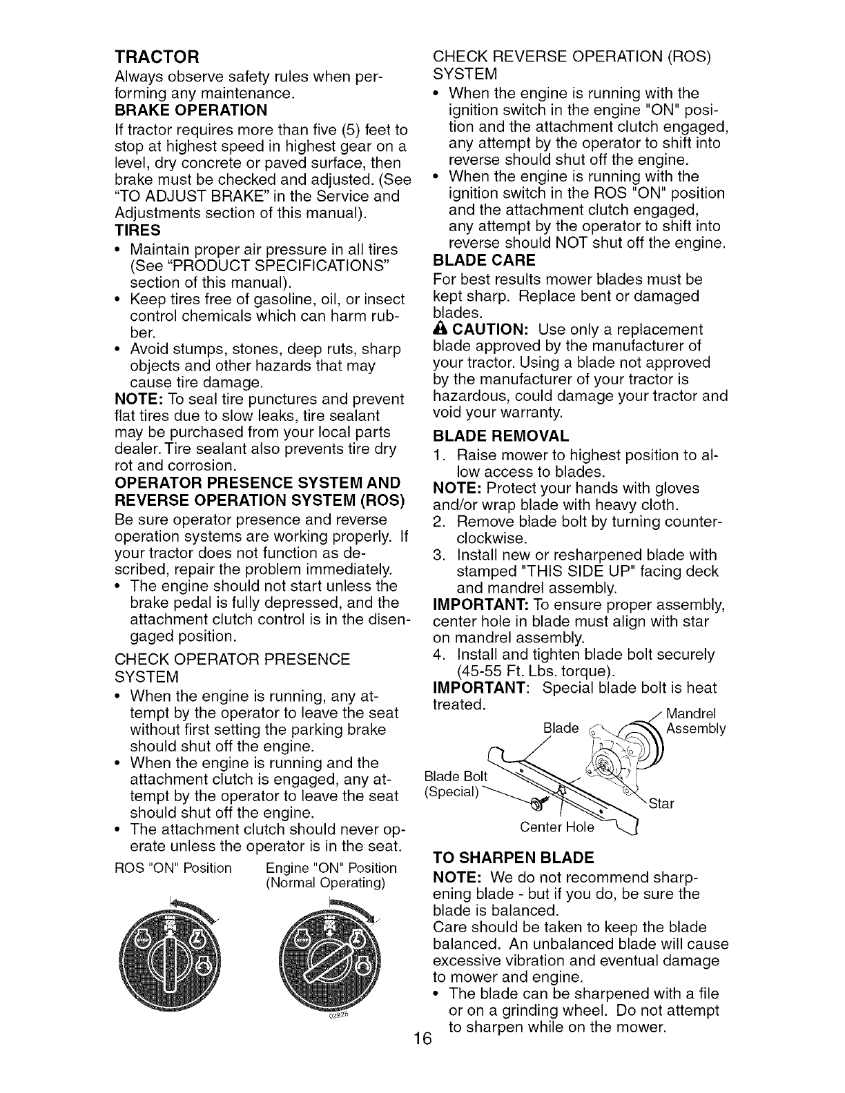
ROS "ON" Position Engine "ON" Position
(Normal Operating)
CHECK REVERSE OPERATION (ROS)
SYSTEM
• When the engine is running with the
ignition switch in the engine "ON" posi-
tion and the attachment clutch engaged,
any attempt by the operator to shift into
reverse should shut off the engine.
• When the engine is running with the
ignition switch in the ROS "ON" position
and the attachment clutch engaged,
any attempt by the operator to shift into
reverse should NOT shut off the engine.
BLADE CARE
For best results mower blades must be
kept sharp. Replace bent or damaged
blades.
A CAUTION: Use only a replacement
blade approved by the manufacturer of
your tractor. Using a blade not approved
by the manufacturer of your tractor is
hazardous, could damage your tractor and
void your warranty.
BLADE REMOVAL
1. Raise mower to highest position to al-
low access to blades.
NOTE: Protect your hands with gloves
and/or wrap blade with heavy cloth.
2. Remove blade bolt by turning counter-
clockwise.
3. Install new or resharpened blade with
stamped "THIS SIDE UP" facing deck
and mandrel assembly.
IMPORTANT: To ensure proper assembly,
center hole in blade must align with star
on mandrel assembly.
4. Install and tighten blade bolt securely
(45-55 Ft. Lbs. torque).
IMPORTANT: Special blade bolt is heat
treated. Mandrel
Blade Assembly
Blade Bolt
Center Hole
TO SHARPEN BLADE
NOTE: We do not recommend sharp-
ening blade - but if you do, be sure the
blade is balanced.
Care should be taken to keep the blade
balanced. An unbalanced blade will cause
excessive vibration and eventual damage
to mower and engine.
• The blade can be sharpened with a file
or on a grinding wheel. Do not attempt
to sharpen while on the mower.
16
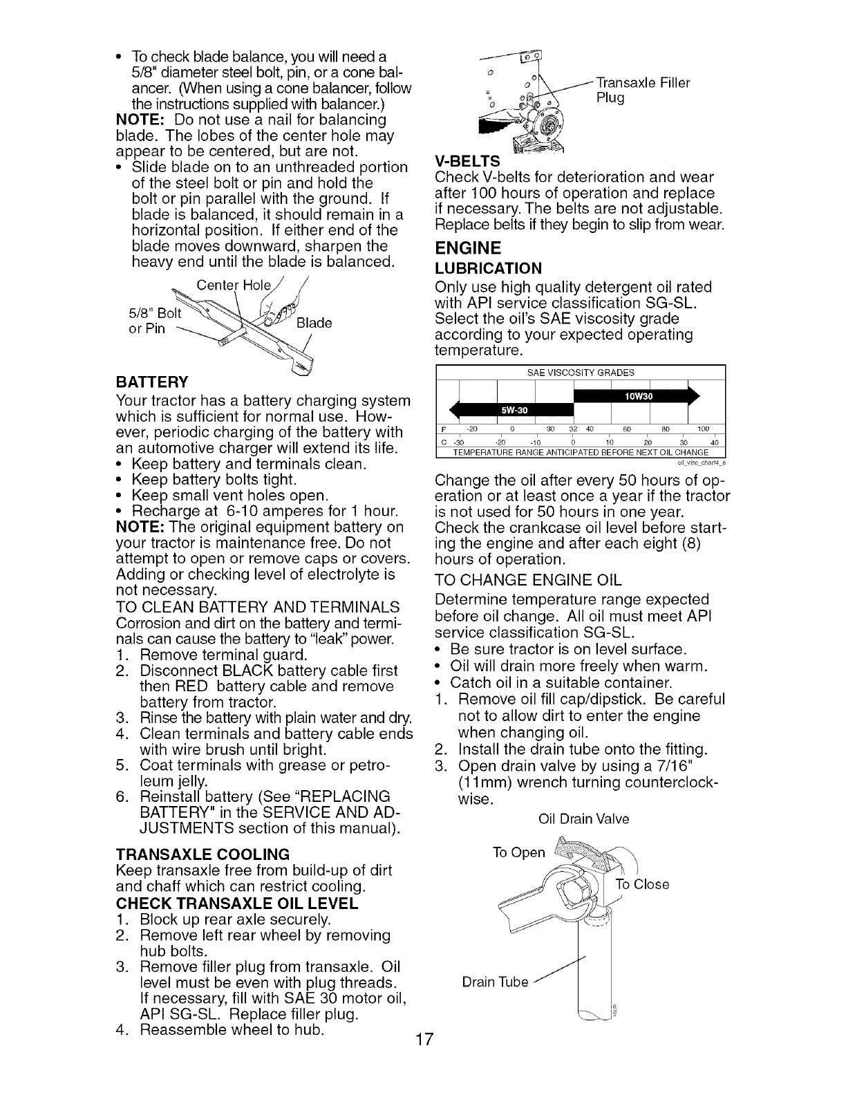
• Tocheckbladebalance,youwillneeda
5/8"diametersteelbolt,pin,or aconebal-
ancer.(Whenusingaconebalancer,follow
theinstructionssuppliedwithbalancer.)
NOTE: Donot use a nailfor balancing
blade. The lobes of the centerhole may
appearto be centered,butare not.
• Slide bladeon to an unthreadedportion
of the steelboltor pin and hold the
bolt or pin parallelwiththe ground. If
bladeis balanced,it shouldremainina
horizontalposition. If either end of the
blademovesdownward,sharpenthe
heavyend untilthe bladeis balanced.
CenterHole/ /
or Pin "_a
BATTERY
Your tractor has a battery charging system
which is sufficient for normal use. How-
ever, periodic charging of the battery with
an automotive charger will extend its life.
• Keep battery and terminals clean.
• Keep battery bolts tight.
• Keep small vent holes open.
• Recharge at 6-10 amperes for 1 hour.
NOTE: The original equipment battery on
your tractor is maintenance free. Do not
attempt to open or remove caps or covers.
Adding or checking level of electrolyte is
not necessary.
TO CLEAN BATTERY AND TERMINALS
Corrosion and dirt on the battery and termi-
nals can cause the battery to "leak" power.
1. Remove terminal guard.
2. Disconnect BLACK battery cable first
then RED battery cable and remove
battery from tractor.
3. Rinse the battery with plain water and dry.
4. Clean terminals and battery cable ends
with wire brush until bright.
5. Coat terminals with grease or petro-
leum jelly.
6. Reinstall battery (See "REPLACING
BATTERY" in the SERVICE AND AD-
JUSTMENTS section of this manual).
TRANSAXLE COOLING
Keep transaxle free from build-up of dirt
and chaff which can restrict cooling.
CHECK TRANSAXLE OIL LEVEL
1. Block up rear axle securely.
2. Remove left rear wheel by removing
hub bolts.
3. Remove filler plug from transaxle. Oil
level must be even with plug threads.
If necessary, fill with SAE 30 motor oil,
API SG-SL. Replace filler plug.
4. Reassemble wheel to hub. 17
G
@i_- ransaxle Filler
Plug
V-BELTS
Check V-belts for deterioration and wear
after 100 hours of operation and replace
if necessary. The belts are not adjustable.
Replace belts if they begin to slip from wear.
ENGINE
LUBRICATION
Only use high quality detergent oil rated
with API service classification SG-SL.
Select the oil's SAE viscosity grade
according to your expected operating
temperature.
SAE VISCOSITY GRADES
F-20 0 30 32 40 60 80 100
TEMPERATURE RANGE ANTICIPATED BEFORE NEXT OIL CHANGE
OH vJsccha_4 e
Change the oil after every 50 hours of op-
eration or at least once a year if the tractor
is not used for 50 hours in one year.
Check the crankcase oil level before start-
ing the engine and after each eight (8)
hours of operation.
TO CHANGE ENGINE OIL
Determine temperature range expected
before oil change. All oil must meet API
service classification SG-SL.
• Be sure tractor is on level surface.
• Oil will drain more freely when warm.
• Catch oil in a suitable container.
1. Remove oil fill cap/dipstick. Be careful
not to allow dirt to enter the engine
when changing oil.
2. Install the drain tube onto the fitting.
3. Open drain valve by using a 7/16"
(11 mm) wrench turning counterclock-
wise.
Oil Drain Valve
To Open
To Close
Drain Tube
4. After oil has drained completely, close
the drain valve turning clockwise. Use
the 7/16" (11 mm) wrench to apply
a small amount of torque to keep it
closed. Do not over tighten.
5. Remove the drain tube and store in a
safe place.
6. Refill engine with oil through oil fill dip-
stick tube. Pour slowly. Do not overfill.
For approximate capacity see "PROD-
UCT SPECIFICATIONS" section of this
manual.
7. Use gauge on oil fill cap/dipstick for
checking level. Insert dipstick into
the tube and rest the oil fill cap on the
tube. Do not thread the cap onto the
tube when taking reading. Keep oil
at "FULl" line on dipstick. Tighten cap
onto the tube securely when finished.
ENGINE OIL FILTER
Replace the engine oil filter every season
or every other oil change if the tractor is
used more than 100 hours in one year.
AIR FILTER
Your engine will not run properly using a
dirty air filter. Clean the foam pre-cleaner
after every 25 hours of operation or every
season. Service paper cartridge every
100 hours of operation or every season,
whichever occurs first.
Service air cleaner more often under dusty
conditions.
1. Loosen knob and remove cover.
TO SERVICE PRE-CLEANER
2. Slide foam pre-cleaner off cartridge.
3. Wash it in liquid detergent and water.
4. Squeeze it dry in a clean cloth. Allow it
to dry.
5. Saturate it in engine oil. Wrap it in
clean, absorbent cloth and squeeze to
remove excess oil.
TO SERVICE CARTRIDGE
• Replace a dirty, bent, or damaged car-
tridge.
NOTE: Do not wash the paper cartridge
or use pressurized air, as this will damage
the cartridge.
1. Remove nut and cartridge plate.
2. Reinstall the pre-cleaner (cleaned and
oiled) over the paper cartridge.
3. Check rubber seal for damage and
proper position around stud. Replace
if necessary.
4. Reassemble air cleaner, cartridge
plate, and nut.
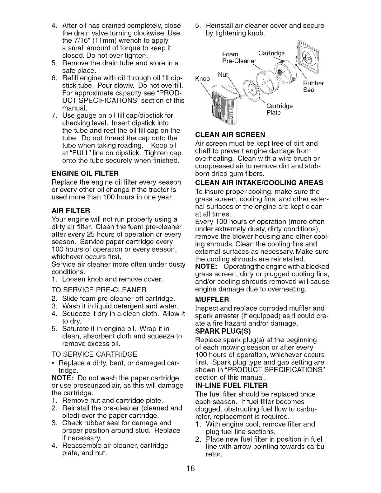
5. Reinstall air cleaner cover and secure
by tightening knob.
Foam Cartridge
Pre-Cleaner
Knob Nut\
Cartridge
Plate
Rubber
Seal
CLEAN AIR SCREEN
Air screen must be kept free of dirt and
chaff to prevent engine damage from
overheating. Clean with a wire brush or
compressed air to remove dirt and stub-
born dried gum fibers.
CLEAN AIR INTAKE/COOLING AREAS
To insure proper cooling, make sure the
grass screen, cooling fins, and other exter-
nal surfaces of the engine are kept clean
at all times.
Every 100 hours of operation (more often
under extremely dusty, dirty conditions),
remove the blower housing and other cool-
ing shrouds. Clean the cooling fins and
external surfaces as necessary. Make sure
the cooling shrouds are reinstalled.
NOTE: Operating the engine with a blocked
grass screen, dirty or plugged cooling fins,
and/or cooling shrouds removed will cause
engine damage due to overheating.
MUFFLER
Inspect and replace corroded muffler and
spark arrester (if equipped) as it could cre-
ate a fire hazard and/or damage.
SPARK PLUG(S)
Replace spark plug(s) at the beginning
of each mowing season or after every
100 hours of operation, whichever occurs
first. Spark plug type and gap setting are
shown in "PRODUCT SPECIFICATIONS"
section of this manual.
IN-LINE FUEL FILTER
The fuel filter should be replaced once
each season. If fuel filter becomes
clogged, obstructing fuel flow to carbu-
retor, replacement is required.
1. With engine cool, remove filter and
plug fuel line sections.
2. Place new fuel filter in position in fuel
line with arrow pointing towards carbu-
retor.
18
3. Be sure there are no fuel line leaks
and clamps are properly positioned.
4. Immediately wipe up any spilled gaso-
line.
Clamp Clamp
Fuel Filter-
CLEANING
• Clean engine, battery, seat, finish, etc.
of all foreign matter.
• Keep finished surfaces and wheels free
of all gasoline, oil, etc.
• Protect painted surfaces with auto-
motive type wax.
We do not recommend using a garden
hose or pressure washer to clean your
tractor unless the engine and transmis-
sion are covered to keep water out. Water
in engine or transmission will shorten the
useful life of your tractor. Use compressed
air or a leaf blower to remove grass,
leaves and trash from tractor and mower.
&WARNING: TO AVOID SERIOUS INJURY, BEFORE PERFORMING ANY SER-
VICE OR ADJUSTMENTS:
1. Depress clutch/brake pedal fully and set parking brake.
2. Place gearshift lever in neutral (N) position.
3. Place attachment clutch in "DISENGAGED" position.
4. Turn ignition key to "STOP" and remove key.
5. Make sure the blades and all moving parts have completely stopped.
6. Disconnect spark plug wire from spark plug and place wire where it cannot
come in contact with plug.
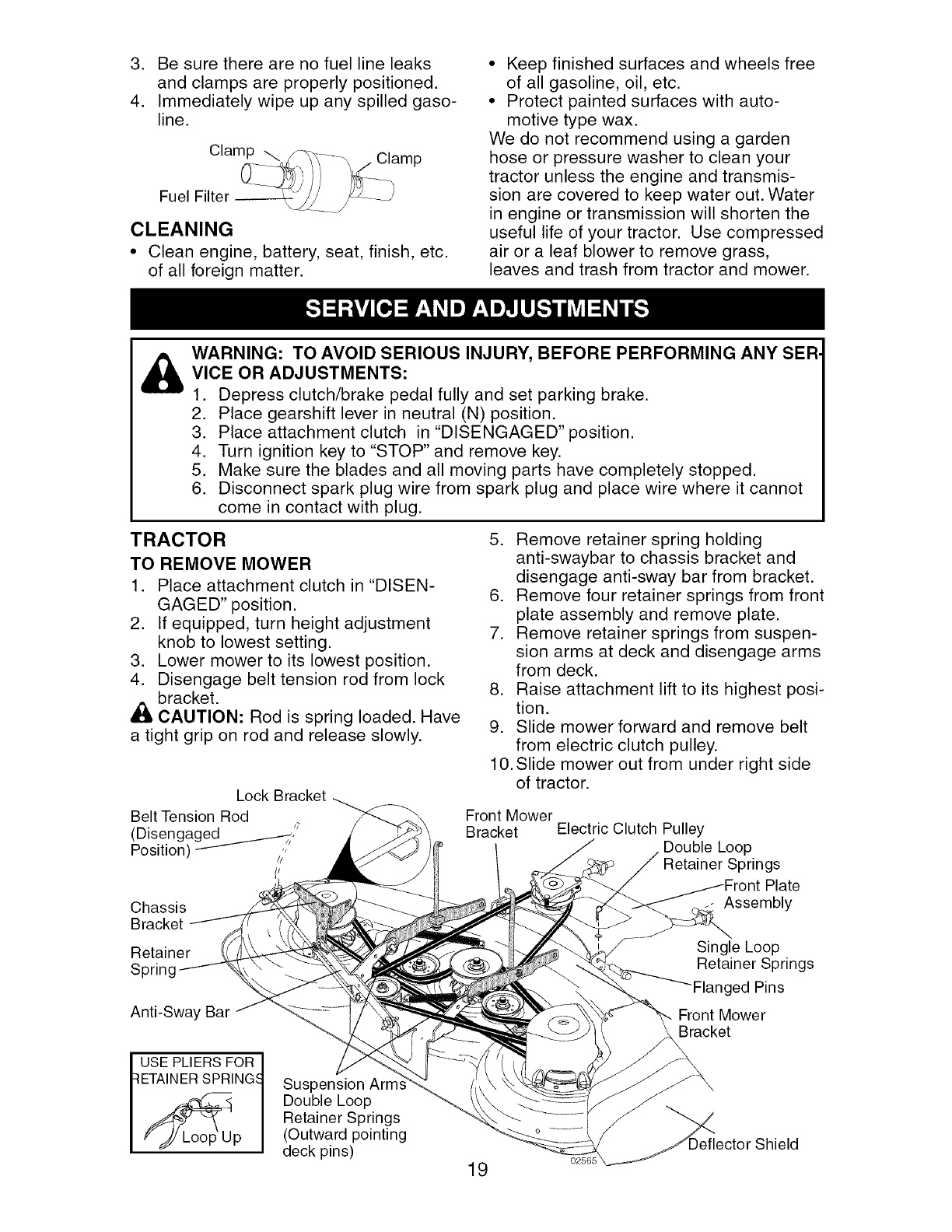
TRACTOR
TO REMOVE MOWER
1. Place attachment clutch in "DISEN-
GAGED" position.
2. If equipped, turn height adjustment
knob to lowest setting.
3. Lower mower to its lowest position.
4. Disengage belt tension rod from lock
bracket.
_L CAUTION: Rod is spring loaded. Have
a tight grip on rod and release slowly.
Lock Bracket
Belt Tension Rod
(Disengaged ...______--_/
Position) 1/
Chassis
Bracket
Retainer
Spring
Anti-Sway Bar
5. Remove retainer spring holding
anti-swaybar to chassis bracket and
disengage anti-sway bar from bracket.
6. Remove four retainer springs from front
plate assembly and remove plate.
7. Remove retainer springs from suspen-
sion arms at deck and disengage arms
from deck.
8. Raise attachment lift to its highest posi-
tion.
9. Slide mower forward and remove belt
from electric clutch pulley.
10. Slide mower out from under right side
of tractor.
Front Mower
Bracket Electric Clutch Pulley
Double Loop
Retainer Springs
Plate
-Assembly
Single Loop
Retainer Springs
-Flanged Pins
Front Mower
Bracket
USE PLIERS FOR
RETAINER SPRING, _ Suspension Arm
Double Loop
Retainer Springs
(Outward pointing
deck pins) 19
--- ector Shteld_
TO INSTALLMOWER
Besure tractoris on levelsurfaceand
mowersuspensionarmsare raisedwith
attachmentlift control.Engageparking
brake.
1. Swinganti-swaybar to left side of
mowerdeck.
2. Slidemower undertractor with deflec-
tor shieldto rightside of tractor.
IMPORTANT: Checkbeltfor properrout-
ing in all mowerpulleygrooves.
3. If equipped, turn height adjustment
knob counterclockwise until it stops.
4. Lower mower linkage with attachment
lift control.
5. Be sure belt tension rod is in disen-
gaged position.
6. Install belt into electric clutch pulley
groove.
7. Place the suspension arms on outward
pointing deck pins. Retain with double
loop retainer spring with loops up as
shown.
8. Install front plate assembly to tractor
suspension brackets and retain with
single loop retainer springs as shown.
9. Position front plate assembly between
front mower brackets. Raise deck and
plate assembly to align holes and
insert flanged pins. Secure pins with
double loop retainer springs between
the plate assembly and mower brack-
ets.
NOTE: To assist in locating hole in flanged
pin, the hole in pin is inline with notch on
head of pin. If necessary, move mower
side-to-side to give space between plate
and mower brackets.
IMPORTANT: Check belt for proper rout-
ing in all mower pulley grooves.
10. Engage belt tension rod by pushing rod
into locking bracket.
ACAUTION: Belt tension rod is spring
loaded. Have a tight grip on rod and en-
gage slowly.
11. Connect anti-sway bar to chassis
bracket under left footrest and retain
with double loop retainer spring.
12. If equipped, turn height adjustment
knob clockwise to remove slack from
mower suspension.
13. Raise deck to highest position.
TO LEVEL MOWER HOUSING
Adjust the mower while tractor is parked
on level ground or driveway. Make sure
tires are properly inflated (See "PROD-
UCT SPECIFICATIONS" section of this
manual). If tires are over or underinflated,
you will not properly adjust your mower.
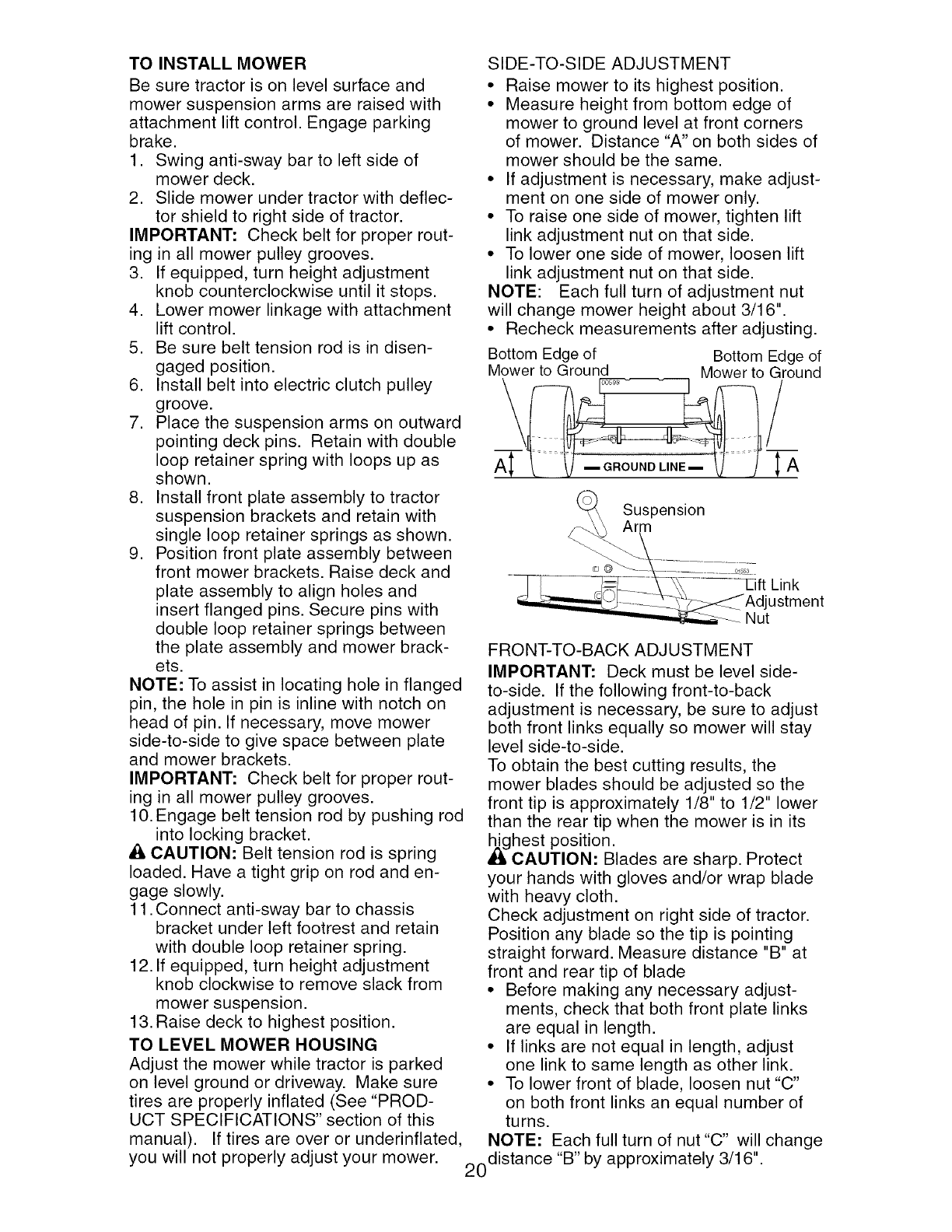
SIDE-TO-SIDE ADJUSTMENT
• Raise mower to its highest position.
• Measure height from bottom edge of
mower to ground level at front corners
of mower. Distance "A" on both sides of
mower should be the same.
• If adjustment is necessary, make adjust-
ment on one side of mower only.
• To raise one side of mower, tighten lift
link adjustment nut on that side.
• To lower one side of mower, loosen lift
link adjustment nut on that side.
NOTE: Each full turn of adjustment nut
will change mower height about 3/16".
• Recheck measurements after adjusting.
Bottom Edge of Bottom Edge of
Mower to Ground Mower to Ground
Suspension
Arm
Link
Adjustment
Nut
FRONT-TO-BACK ADJUSTMENT
IMPORTANT: Deck must be level side-
to-side. If the following front-to-back
adjustment is necessary, be sure to adjust
both front links equally so mower will stay
level side-to-side.
To obtain the best cutting results, the
mower blades should be adjusted so the
front tip is approximately 1/8" to 1/2" lower
than the rear tip when the mower is in its
,_ghest position.
CAUTION: Blades are sharp. Protect
your hands with gloves and/or wrap blade
with heavy cloth.
Check adjustment on right side of tractor.
Position any blade so the tip is pointing
straight forward. Measure distance "B" at
front and rear tip of blade
• Before making any necessary adjust-
ments, check that both front plate links
are equal in length.
• If links are not equal in length, adjust
one link to same length as other link.
• To lower front of blade, loosen nut "C"
on both front links an equal number of
turns.
NOTE: Each full turn of nut"C" will change
20distance "B" by approximately 3/16".
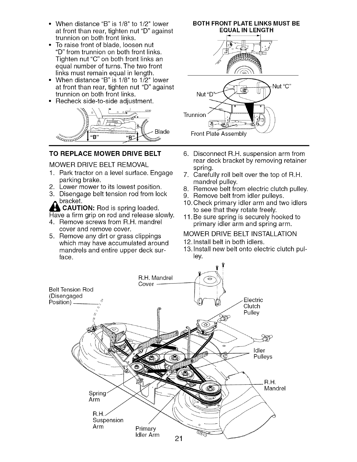
• Whendistance"B" is 1/8"to 1/2" lower
at front than rear,tightennut "D" against
trunnion on both front links.
• To raise front of blade, loosen nut
"D" from trunnion on both front links.
Tighten nut "C" on both front links an
equal number of turns. The two front
links must remain equal in length.
• When distance "B" is 1/8" to 1/2" lower
at front than rear, tighten nut "D" against
trunnion on both front links.
• Recheck side-to-side adjustment.
_ ___C,_- Blade
_;y |"B" 'i'_
BOTH FRONT PLATE LINKS MUST BE
EQUAL IN LENGTH
Nut
Trunnion
Front Plate Assembly
TO REPLACE MOWER DRIVE BELT
MOWER DRIVE BELT REMOVAL
1. Park tractor on a level surface. Engage
parking brake.
2. Lower mower to its lowest position.
3. Disengage belt tension rod from lock
bracket.
CAUTION: Rod is spring loaded.
Have a firm grip on rod and release slowly.
4. Remove screws from R.H. mandrel
cover and remove cover.
5. Remove any dirt or grass clippings
which may have accumulated around
mandrels and entire upper deck sur-
face.
Belt Tension Rod
(Disengaged
Position) ,7
,j
//
6. Disconnect R.H. suspension arm from
rear deck bracket by removing retainer
spring.
7. Carefully roll belt over the top of R.H.
mandrel pulley.
8. Remove belt from electric clutch pulley.
9. Remove belt from idler pulleys.
10. Check primary idler arm and two idlers
to see that they rotate freely.
11. Be sure spring is securely hooked to
primary idler arm and spring arm.
MOWER DRIVE BELT INSTALLATION
12. Install belt in both idlers.
13. Install new belt onto electric clutch pul-
ley.
R.H. Mandrel __
Cover _
Clutch
Pulley
Idler
Pulleys
Spring
Arm
B.a,
Mandrel
Suspension
Arm Primary
Idler Arm 21
14.Carefullyroll belt intoupper grooveof
R.H.mandrelpulley.
15.Carefullycheckbelt routingmaking
surebelt is in the groovescorrectly.
16.ReconnectR.H.suspensionarm to
reardeckbracketwith retainerspring.
17.ReassembleR.H. mandrelcover.
18.Engagebelttension rodby pushing rod
intolockingbracket.
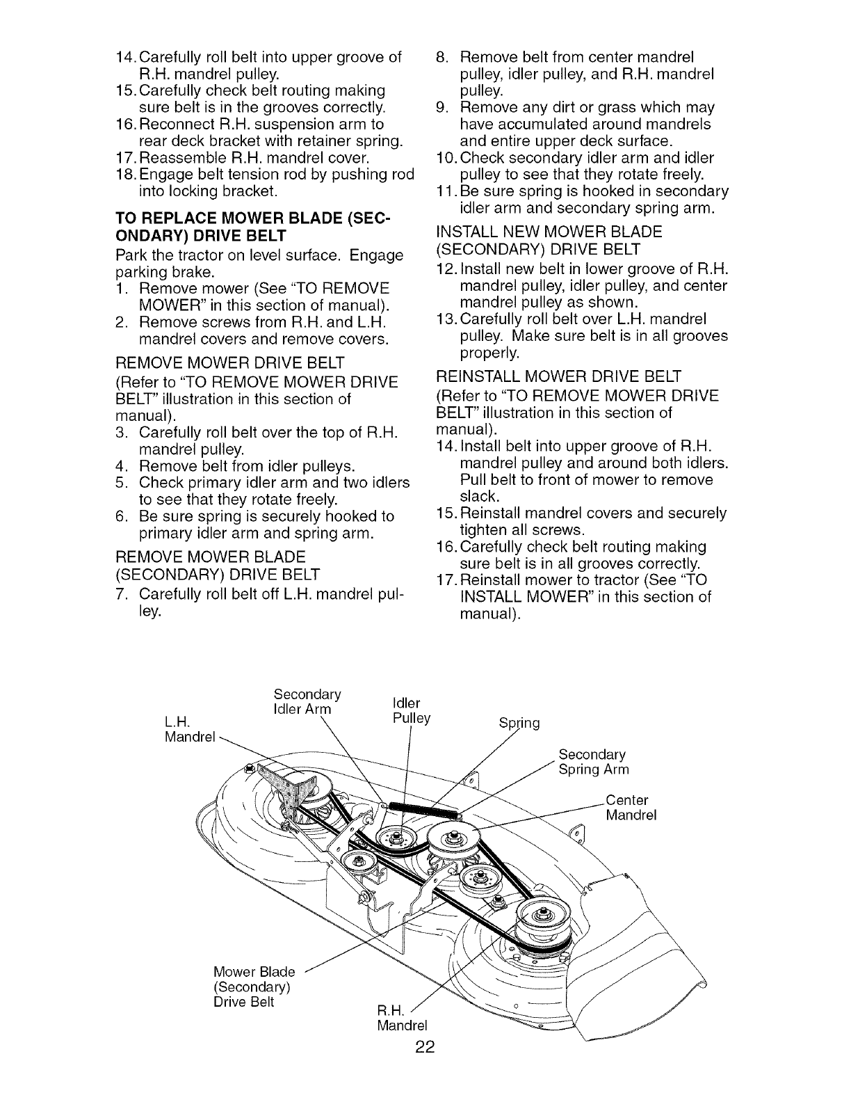
TO REPLACE MOWER BLADE (SEC-
ONDARY) DRIVE BELT
Park the tractor on level surface. Engage
parking brake.
1. Remove mower (See "TO REMOVE
MOWER" in this section of manual).
2. Remove screws from R.H. and L.H.
mandrel covers and remove covers.
REMOVE MOWER DRIVE BELT
(Refer to "TO REMOVE MOWER DRIVE
BELT" illustration in this section of
manual).
3. Carefully roll belt over the top of R.H.
mandrel pulley.
4. Remove belt from idler pulleys.
5. Check primary idler arm and two idlers
to see that they rotate freely.
6. Be sure spring is securely hooked to
primary idler arm and spring arm.
REMOVE MOWER BLADE
(SECONDARY) DRIVE BELT
7. Carefully roll belt off L.H. mandrel pul-
ley.
8. Remove belt from center mandrel
pulley, idler pulley, and R.H. mandrel
pulley.
9. Remove any dirt or grass which may
have accumulated around mandrels
and entire upper deck surface.
10. Check secondary idler arm and idler
pulley to see that they rotate freely.
11. Be sure spring is hooked in secondary
idler arm and secondary spring arm.
INSTALL NEW MOWER BLADE
(SECONDARY) DRIVE BELT
12. Install new belt in lower groove of R.H.
mandrel pulley, idler pulley, and center
mandrel pulley as shown.
13. Carefully roll belt over L.H. mandrel
pulley. Make sure belt is in all grooves
properly.
REINSTALL MOWER DRIVE BELT
(Refer to "TO REMOVE MOWER DRIVE
BELT" illustration in this section of
manual).
14. Install belt into upper groove of R.H.
mandrel pulley and around both idlers.
Pull belt to front of mower to remove
slack.
15. Reinstall mandrel covers and securely
tighten all screws.
16. Carefully check belt routing making
sure belt is in all grooves correctly.
17. Reinstall mower to tractor (See "TO
INSTALL MOWER" in this section of
manual).
L.a.
Mandrel
Secondary
Idler Arm Idler
Pulley Sp ling
Secondary
Spring Arm
.Center
Mandrel
Mower Blade
(Secondary)
Drive Belt B.a.
Mandrel
22
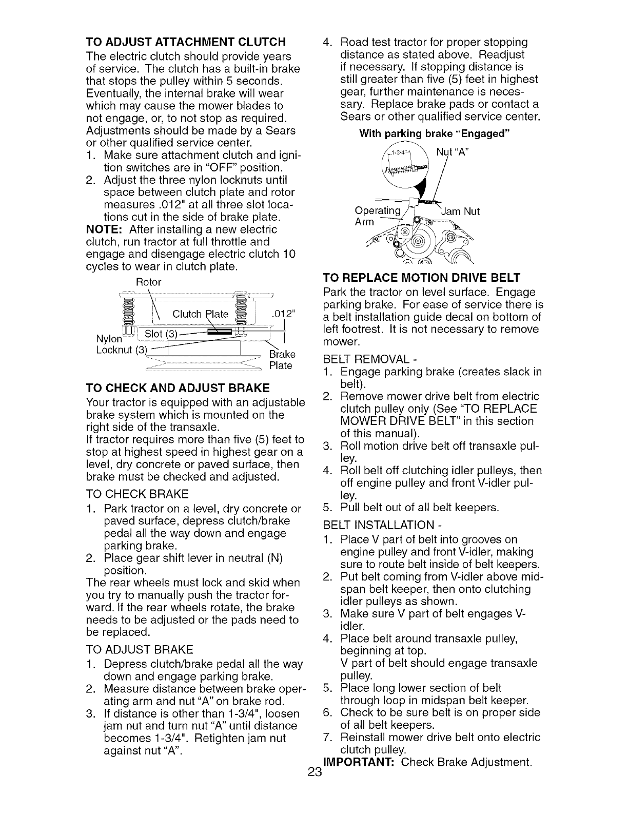
TO ADJUST ATTACHMENT CLUTCH
The electric clutch should provide years
of service. The clutch has a built-in brake
that stops the pulley within 5 seconds.
Eventually, the internal brake will wear
which may cause the mower blades to
not engage, or, to not stop as required.
Adjustments should be made by a Sears
or other qualified service center.
1. Make sure attachment clutch and igni-
tion switches are in "OFF" position.
2. Adjust the three nylon Iocknuts until
space between clutch plate and rotor
measures .012" at all three slot loca-
tions cut in the side of brake plate.
NOTE: After installing a new electric
clutch, run tractor at full throttle and
engage and disengage electric clutch 10
cycles to wear in clutch plate.
Rotor
Nylor
Locknut
.012"
1
1
......_:......................................................................................._:_i Plate
TO CHECK AND ADJUST BRAKE
Your tractor is equipped with an adjustable
brake system which is mounted on the
right side of the transaxle.
If tractor requires more than five (5) feet to
stop at highest speed in highest gear on a
level, dry concrete or paved surface, then
brake must be checked and adjusted.
TO CHECK BRAKE
1. Park tractor on a level, dry concrete or
paved surface, depress clutch/brake
pedal all the way down and engage
parking brake.
2. Place gear shift lever in neutral (N)
position.
The rear wheels must lock and skid when
you try to manually push the tractor for-
ward. If the rear wheels rotate, the brake
needs to be adjusted or the pads need to
be replaced.
TO ADJUST BRAKE
1. Depress clutch/brake pedal all the way
down and engage parking brake.
2. Measure distance between brake oper-
ating arm and nut "A" on brake rod.
3. If distance is other than 1-3/4", loosen
jam nut and turn nut "A" until distance
becomes 1-3/4". Retighten jam nut
against nut "A".
,Road test tractor for proper stopping
distance as stated above. Readjust
if necessary. If stopping distance is
still greater than five (5) feet in highest
gear, further maintenance is neces-
sary. Replace brake pads or contact a
Sears or other qualified service center.
With parking brake "Engaged"
Nut "A"
Operating Nut
Arm
TO REPLACE MOTION DRIVE BELT
Park the tractor on level surface. Engage
parking brake. For ease of service there is
a belt installation guide decal on bottom of
left footrest. It is not necessary to remove
mower.
BELT REMOVAL -
1. Engage parking brake (creates slack in
belt).
2. Remove mower drive belt from electric
clutch pulley only (See "TO REPLACE
MOWER DRIVE BELT" in this section
of this manual).
3. Roll motion drive belt off transaxle pul-
ley.
4. Roll belt off clutching idler pulleys, then
off engine pulley and front V-idler pul-
ley.
5. Pull belt out of all belt keepers.
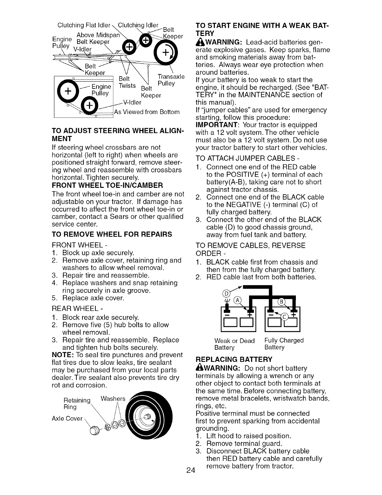
BELT INSTALLATION -
1. Place V part of belt into grooves on
engine pulley and front V-idler, making
sure to route belt inside of belt keepers.
2. Put belt coming from V-idler above mid-
span belt keeper, then onto clutching
idler pulleys as shown.
3. Make sure V part of belt engages V-
idler.
4. Place belt around transaxle pulley,
beginning at top.
V part of belt should engage transaxle
pulley.
5. Place long lower section of belt
through loop in midspan belt keeper.
6. Check to be sure belt is on proper side
of all belt keepers.
7. Reinstall mower drive belt onto electric
clutch pulley.
IMPORTANT: Check Brake Adjustment.
23
Clutching Flat
Above Mids
Engine Belt Kee
Pulley V-Idler
Clutchin(
eper
Keeper _ ,
o /ransaxle
Belt
_-i._ Engine I Twists Belt Pulley
Pulley I Keeper
"q__..._{..}.} ._.i_ V-IdIer
_As Viewed from Bottom
TO ADJUST STEERING WHEEL ALIGN-
MENT
If steering wheel crossbars are not
horizontal (left to right) when wheels are
positioned straight forward, remove steer-
ing wheel and reassemble with crossbars
horizontal. Tighten securely.
FRONT WHEEL TOE-IN/CAMBER
The front wheel toe-in and camber are not
adjustable on your tractor. If damage has
occurred to affect the front wheel toe-in or
camber, contact a Sears or other qualified
service center.
TO REMOVE WHEEL FOR REPAIRS
FRONT WHEEL -
1. Block up axle securely.
2. Remove axle cover, retaining ring and
washers to allow wheel removal.
3. Repair tire and reassemble.
4. Replace washers and snap retaining
ring securely in axle groove.
5. Replace axle cover.
REAR WHEEL -
1. Block rear axle securely.
2. Remove five (5) hub bolts to allow
wheel removal.
3. Repair tire and reassemble. Replace
and tighten hub bolts securely.
NOTE: To seal tire punctures and prevent
flat tires due to slow leaks, tire sealant
may be purchased from your local parts
dealer. Tire sealant also prevents tire dry
rot and corrosion.
Retaining Washers
Ring
TO START ENGINE WITH A WEAK BAT-
TERY
_k, WARNING: Lead-acid batteries gen-
erate explosive gases. Keep sparks, flame
and smoking materials away from bat-
teries. Always wear eye protection when
around batteries.
If your battery is too weak to start the
engine, it should be recharged. (See "BAT-
TERY" in the MAINTENANCE section of
this manual).
If "jumper cables" are used for emergency
starting, follow this procedure:
IMPORTANT: Your tractor is equipped
with a 12 volt system. The other vehicle
must also be a 12 volt system. Do not use
your tractor battery to start other vehicles.
TO ATTACH JUMPER CABLES -
1. Connect one end of the RED cable
to the POSITIVE (+) terminal of each
battery(A-B), taking care not to short
against tractor chassis.
2. Connect one end of the BLACK cable
to the NEGATIVE (-) terminal (C) of
fully charged battery.
3. Connect the other end of the BLACK
cable (D) to good chassis ground,
away from fuel tank and battery.
TO REMOVE CABLES, REVERSE
ORDER -
1. BLACK cable first from chassis and
then from the fully charged battery.
2. RED cable last from both batteries.
Weak or Dead Fully Charged
Battery Battery
,
24
REPLACING BATTERY
_ILWARNING: Do not short battery
terminals by allowing a wrench or any
other object to contact both terminals at
the same time. Before connecting battery,
remove metal bracelets, wristwatch bands,
rings, etc.
Positive terminal must be connected
first to prevent sparking from accidental
grounding.
1. Lift hood to raised position.
2. Remove terminal guard.
Disconnect BLACK battery cable
then RED battery cable and carefully
remove battery from tractor.
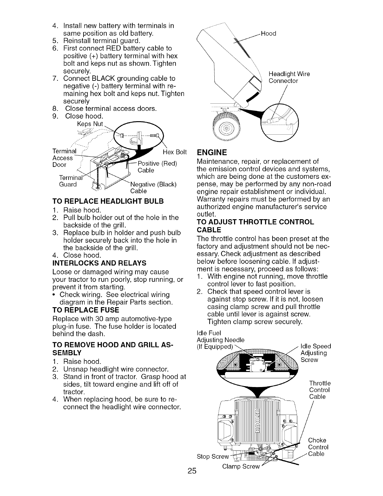
4. Install new batterywithterminalsin
samepositionas old battery.
5. Reinstallterminalguard.
6. First connectRED battery cableto
positive(+) batteryterminalwith hex
boltand kepsnut as shown.Tighten
securely.
7. ConnectBLACKgroundingcableto
negative(-) batteryterminalwith re-
maininghexboltand kepsnut.Tighten
securely
8. Closeterminalaccessdoors.
9. Closehood.
Keps,Nut___
Termin_ _-;:" _""-_ex Bolt
Access _ _
Door _ '_"_Positive (Red)
Termi_i_ _ Cable
Guard _ " "Ne.gatlve (Black)
............_ Cable
TO REPLACE HEADLIGHT BULB
1. Raise hood.
2. Pull bulb holder out of the hole in the
backside of the grill.
3. Replace bulb in holder and push bulb
holder securely back into the hole in
the backside of the grill.
4. Close hood.
INTERLOCKS AND RELAYS
Loose or damaged wiring may cause
your tractor to run poorly, stop running, or
prevent it from starting.
• Check wiring. See electrical wiring
diagram in the Repair Parts section.
TO REPLACE FUSE
Replace with 30 amp automotive-type
plug-in fuse. The fuse holder is located
behind the dash.
TO REMOVE HOOD AND GRILL AS-
SEMBLY
1. Raise hood.
2. Unsnap headlight wire connector.
3. Stand in front of tractor. Grasp hood at
sides, tilt toward engine and lift off of
tractor.
4. When replacing hood, be sure to re-
connect the headlight wire connector.
",, Headlight Wire
Connector
ENGINE
Maintenance, repair, or replacement of
the emission control devices and systems,
which are being done at the customers ex-
pense, may be performed by any non-road
engine repair establishment or individual.
Warranty repairs must be performed by an
authorized engine manufacturer's service
outlet.
TO ADJUST THROTTLE CONTROL
CABLE
The throttle control has been preset at the
factory and adjustment should not be nec-
essary. Check adjustment as described
below before loosening cable. If adjust-
ment is necessary, proceed as follows:
1. With engine not running, move throttle
control lever to fast position.
2. Check that speed control lever is
against stop screw. If it is not, loosen
casing clamp screw and pull throttle
cable until lever is against screw.
Tighten clamp screw securely.
Idle Fuel
Adjusting Needle
(If Idle Speed
Adjusting
Screw
Throttle
Control
Cable
Stop Screw
25 Clam_p Screw
Choke
Control
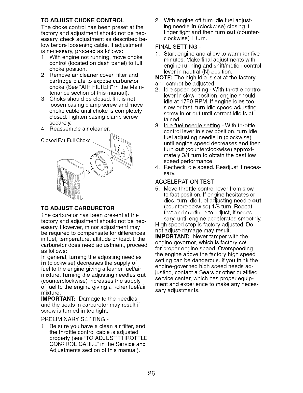
TO ADJUST CHOKE CONTROL
The choke control has been preset at the
factory and adjustment should not be nec-
essary, check adjustment as described be-
low before loosening cable. If adjustment
is necessary, proceed as follows:
1. With engine not running, move choke
control (located on dash panel) to full
choke position.
2. Remove air cleaner cover, filter and
cartridge plate to expose carburetor
choke (See "AIR FILTER" in the Main-
tenance section of this manual).
3. Choke should be closed. If it is not,
loosen casing clamp screw and move
choke cable until choke is completely
closed. Tighten casing clamp screw
securely.
4. Reassemble air cleaner.
Closed
TO ADJUST CARBURETOR
The carburetor has been present at the
factory and adjustment should not be nec-
essary. However, minor adjustment may
be required to compensate for differences
in fuel, temperature, altitude or load. If the
carburetor does need adjustment, proceed
as follows:
In general, turning the adjusting needles
in (clockwise) decreases the supply of
fuel to the engine giving a leaner fuel/air
mixture. Turning the adjusting needles out
(counterclockwise) increases the supply
of fuel to the engine giving a richer fuel/air
mixture.
IMPORTANT: Damage to the needles
and the seats in carburetor may result if
screw is turned in too tight.
PRELIMINARY SETTING -
1. Be sure you have a clean air filter, and
the throttle control cable is adjusted
properly (see "TO ADJUST THROTTLE
CONTROL CABLE" in the Service and
Adjustments section of this manual).
,With engine off turn idle fuel adjust-
ing needle in (clockwise) closing it
finger tight and then turn out (counter-
clockwise) 1 turn.
FINAL SETTING -
1. Start engine and allow to warm for five
minutes. Make final adjustments with
engine running and shift/motion control
lever in neutral (N) position.
NOTE: The high idle is set at the factory
and cannot be adjusted.
2. Idle speed setting - With throttle control
lever in slow position, engine should
idle at 1750 RPM. If engine idles too
slow or fast, turn idle speed adjusting
screw in or out until correct idle is at-
tained.
3. Idle fuel needle setting - With throttle
control lever in slow position, turn idle
fuel adjusting needle in (clockwise)
until engine speed decreases and then
turn out (counterclockwise) approxi-
mately 3/4 turn to obtain the best low
speed performance.
4. Recheck idle speed. Readjust if neces-
sary.
ACCELERATION TEST -
5. Move throttle control lever from slow
to fast position. If engine hesitates or
dies, turn idle fuel adjusting needle out
(counterclockwise) 1/8 turn. Repeat
test and continue to adjust, if neces-
sary, until engine accelerates smoothly.
High speed stop is factory adjusted. Do
not adjust-damage may result.
IMPORTANT: Never tamper with the
engine governor, which is factory set
for proper engine speed. Overspeeding
the engine above the factory high speed
setting can be dangerous. If you think the
engine-governed high speed needs ad-
justing, contact a Sears or other qualified
service center, which has proper equip-
ment and experience to make any neces-
sary adjustments.
26
Immediately prepare your tractor for stor-
age at the end of the season or if the trac-
will not be used for 30 days or more.
WARNING: Never store the tractor
with gasoline in the tank inside a building
where fumes may reach an open flame
or spark. Allow the engine to cool before
storing in any enclosure.
TRACTOR
Remove mower from tractor for winter
storage. When mower is to be stored for a
period of time, clean it thoroughly, remove
all dirt, grease, leaves, etc. Store in a
clean, dry area.
1. Clean entire tractor (See "CLEANING"
in the Maintenance section of this
manual).
2. Inspect and replace belts, if necessary
(See belt replacement instructions in
the Service and Adjustments section of
this manual).
3. Lubricate as shown in the Maintenance
section of this manual.
4. Be sure that all nuts, bolts and screws
are securely fastened. Inspect moving
parts for damage, breakage and wear.
Replace if necessary.
5. Touch up all rusted or chipped paint
surfaces; sand lightly before painting.
BATTERY
• Fully charge the battery for storage.
• After a period of time in storage, battery
may require recharging.
• To help prevent corrosion and power
leakage during long periods of storage,
battery cables should be disconnected
and battery cleaned thoroughly (see "TO
CLEAN BATTERY AND TERMINALS" in
the Maintenance section of this manual).
• After cleaning, leave cables discon-
nected and place cables where they
cannot come in contact with battery
terminals.
• If battery is removed from tractor for
storage, do not store battery directly on
concrete or damp surfaces.
ENGINE
FUEL SYSTEM
IMPORTANT: It is important to prevent
gum deposits from forming in essential
fuel system parts such as carburetor, fuel
hose, or tank during storage. Also, alcohol
blended fuels (called gasohol or using
ethanol or methanol) can attract moisture
which leads to separation and formation of
acids during storage. Acidic gas can dam-
age the fuel system of an engine while in
storage.
• Empty the fuel tank by starting the en-
gine and letting it run until the fuel lines
and carburetor are empty.
• Never use engine or carburetor cleaner
products in the fuel tank or permanent
damage may occur.
• Use fresh fuel next season.
NOTE: Fuel stabilizer is an acceptable
alternative in minimizing the formation of
fuel gum deposits during storage. Add
stabilizer to gasoline in fuel tank or stor-
age container. Always follow the mix ratio
found on stabilizer container. Run engine
at least 10 minutes after adding stabilizer
to allow the stabilizer to reach the carbure-
tor. Do not empty the gas tank and carbu-
retor if using fuel stabilizer.
ENGINE OIL
Drain oil (with engine warm) and replace
with clean engine oil. (See "ENGINE" in
the Maintenance section of this manual).
CYLINDER(S)
1. Remove spark plug(s).
2. Pour one ounce of oil through spark
plug hole(s) into cylinder(s).
3. Turn ignition key to start position for a
few seconds to distribute oil.
4. Replace with new spark plug(s).
OTHER
•Do not store gasoline from one season
to another.
• Replace your gasoline can if your can
starts to rust. Rust and/or dirt in your
gasoline will cause problems.
•If possible, store your tractor indoors
and cover it to give protection from dust
and dirt.
• Cover your tractor with a suitable pro-
tective cover that does not retain mois-
ture. Do not use plastic. Plastic cannot
breathe which allows condensation to
form and will cause your tractor to rust.
IMPORTANT: Never cover tractor while
engine and exhaust areas are still warm.
27
TROUBLESHOOTING CHART:
See appropriate section in manual unless directed to Sears service center
PROBLEM
Will not start
Hard to start
Engine will not
turn over
Engine clicks but
will not start
CAUSE CORRECTION
1. Out of fuel.
2. Engine not "CHOKED"
properly.
3. Engine flooded.
4. Bad spark plug.
5. Dirty air filter.
6. Dirty fuel filter.
7 Water in fuel.
8. Loose or damaged wiring.
9. Carburetor out of adjustment.
10. Engine valves out of
adjustment.
1. Dirty air filter.
2. Bad spark plug.
3. Weak or dead battery.
4. Dirty fuel filter.
5. Stale or dirty fuel.
6. Loose or damaged wiring.
7. Carburetor out of adjustment.
8. Engine valves out of
adjustment.
1. Clutch/brake pedal not
depressed.
2. Attachment clutch is
engaged.
3. Weak or dead battery.
4. Blown fuse.
5. Corroded battery terminals.
6. Loose or damaged wiring.
7. Faulty ignition switch.
8. Faulty solenoid or starter.
9. Faulty operator presence
switch(es).
1. Weak or dead battery.
2. Corroded battery terminals.
3. Loose or damaged wiring.
4. Faulty solenoid or starter.
1. Fill fuel tank.
2. See "TO START ENGINE"
in Operation section.
3. Wait several minutes
before attempting to start.
4. Replace spark plug.
5. Clean/replace air filter.
6. Replace fuel filter.
7. Empty fuel tank and
carburetor, refill tank with
fresh gasoline and replace
fuel filter.
8. Check all wiring.
9. See "To Adjust Carburetor"
in Service and Adjustments
section.
10. Contact a Sears or other
qualified service center.
1. Clean/replace air filter.
2. Replace spark plug.
3. Recharge or replace
battery.
4. Replace fuel filter.
5. Empty fuel tank and refill tank
with fresh, clean gasoline.
6. Check all wiring.
7. See "To Adjust Carburetor"
in Service and Adjustments
section.
8. Contact a Sears or other
qualified service center.
1. Depress clutch/brake
pedal.
2. Disengage attachment
clutch.
3. Recharge or replace
battery.
4. Replace fuse.
5. Clean battery terminals.
6. Check all wiring.
7. Check/replace ignition
switch.
8. Check/replace solenoid or
starter.
9. Contact a Sears or other
qualified service center.
1. Recharge or replace battery.
2. Clean battery terminals.
3. Check all wiring.
4. Check/replace solenoid or
starter.
28
TROUBLESHOOTING CHART:
See appropriate section in manual unless directed to Sears service center
PROBLEM CAUSE CORRECTION
1. Cutting too much grass/too
fast.
2. Throttle in "CHOKE" position.
3. Build-up of grass, leaves
and trash under mower.
4. Dirty air filter.
5. Low oil level/dirty oil.
6. Faulty spark plug.
7. Dirty fuel filter.
8. Stale or dirty fuel.
9. Water in fuel.
Loss of power
Excessive
vibration
Engine dies when
tractor is shifted
into reverse
Engine continues
to run when oper-
ator leaves seat
with attachement
clutch engaged
10. Spark plug wire loose.
11. Dirty engine air screen/fins.
12. Dirty/clogged muffler.
13. Loose or damaged wiring.
14. Carburetor out of
adjustment.
15. Engine valves out of
adjustment.
1. Worn, bent or loose blade.
2. Bent blade mandrel.
3. Loose/damaged part(s).
,
,
Reverse operation system
(ROS) is not "ON" while
mower or other attachment
is engaged.
Faulty operator-safety
presence control system.
,
2.
3.
4.
5.
Worn, bent or loose blade.
Mower deck not level.
Buildup of grass, leaves,
and trash under mower.
Bent blade mandrel.
Clogged mower deck vent
holes from buildup of
grass, leaves, and trash
around mandrels.
Poor cut - uneven
1. Raise cutting height/reduce
speed.
2. Adjust throttle control.
3. Clean underside of mower
housing.
4. Clean/replace air filter.
5. Check oil level/change oil.
6. Clean and regap or change
spark plug.
7. Replace fuel filter.
8. Empty fuel tank and refill tank
with fresh, clean gasoline.
9. Empty fuel tank and carbure-
tor, refill tank with fresh gaso
line and replace fuel filter.
10. Connect and tighten spark
plug wire.
11. Clean engine air screen/fins.
12. Clean/replace muffler.
13. Check all wiring.
14. See "To Adjust Carburetor"
in Service and Adjustments
section.
15. Contact a Sears or other
qualified service center.
1. Replace blade.
Tighten blade bolt.
2. Contact a Sears or other
qualified service center.
3. Tighten loose part(s).
Replace damaged parts.
1. Turn ignition key to
ROS "ON" position.
See Operation section.
1. Check wiring, switches and
connections. If not contact
a Sears or other with quali-
fied service center.
1. Replace blade. Tighten
blade bolt.
2. Level mower deck.
3. Clean underside of mower
housing.
4. Contact a Sears or other
qualified service center.
5. Clean around mandrels to
open vent holes.
29
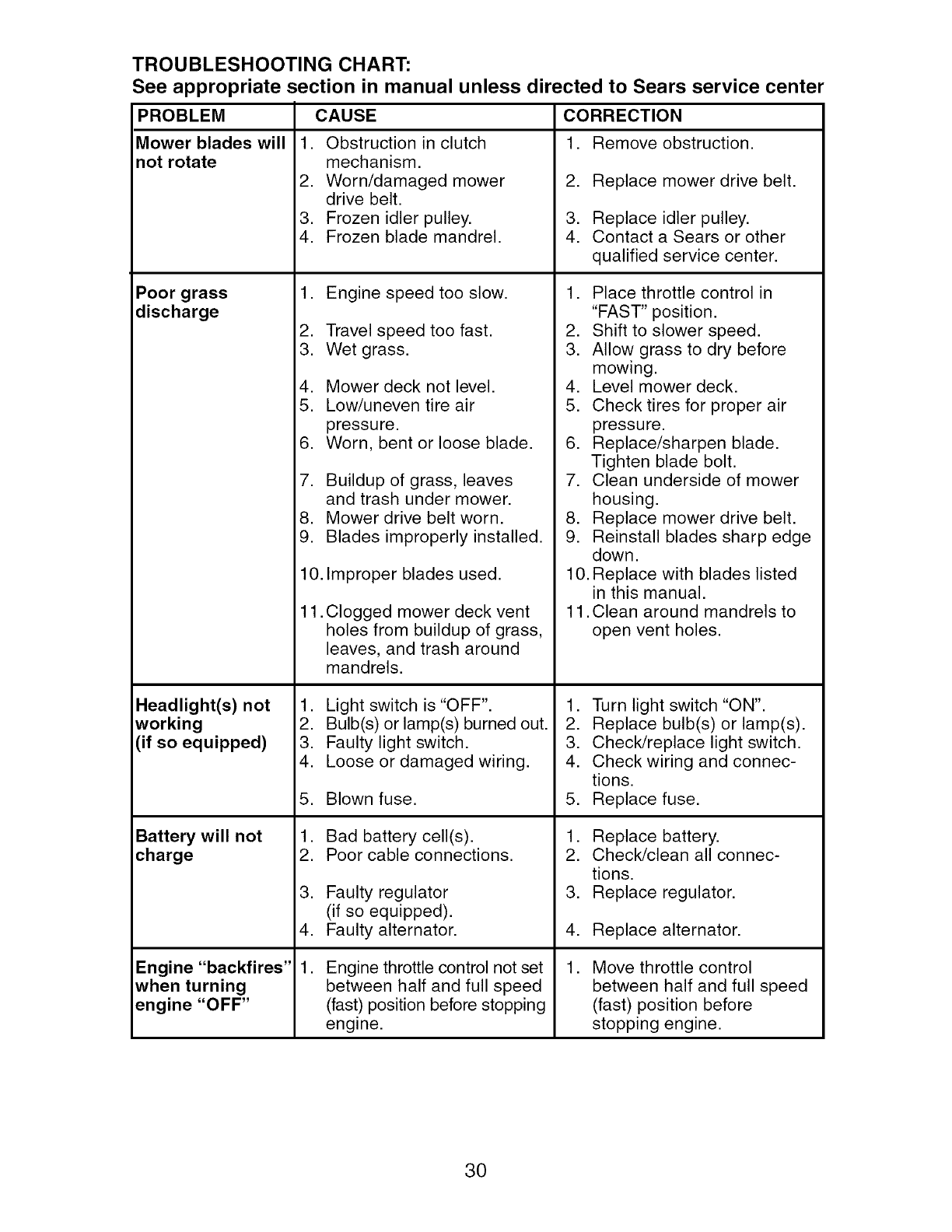
TROUBLESHOOTING CHART:
See appropriate section in manual unless directed to Sears service center
PROBLEM CAUSE CORRECTION
1. Remove obstruction.Mower blades will
not rotate
Poor grass
discharge
Headlight(s) not
working
(if so equipped)
Battery will not
charge
Engine "backfires"
when turning
engine "OFF"
1. Obstruction in clutch
mechanism.
2. Worn/damaged mower
drive belt.
3. Frozen idler pulley.
4. Frozen blade mandrel.
1. Engine speed too slow.
2. Travel speed too fast.
3. Wet grass.
4. Mower deck not level.
5. Low/uneven tire air
pressure.
6. Worn, bent or loose blade.
,
8.
9.
10.
Buildup of grass, leaves
and trash under mower.
Mower drive belt worn.
Blades improperly installed.
Improper blades used.
11. Clogged mower deck vent
holes from buildup of grass,
leaves, and trash around
mandrels.
1. Light switch is "OFF".
2. Bulb(s) or lamp(s) burned out.
3. Faulty light switch.
4. Loose or damaged wiring.
5. Blown fuse.
1. Bad battery cell(s).
2. Poor cable connections.
3. Faulty regulator
(if so equipped).
4. Faulty alternator.
,Engine throttle control not set
between half and full speed
(fast) position before stopping
engine.
2. Replace mower drive belt.
3. Replace idler pulley.
4. Contact a Sears or other
qualified service center.
1. Place throttle control in
"FAST" position.
2. Shift to slower speed.
3. Allow grass to dry before
mowing.
4. Level mower deck.
5. Check tires for proper air
pressure.
6. Replace/sharpen blade.
Tighten blade bolt.
7. Clean underside of mower
housing.
8. Replace mower drive belt.
9. Reinstall blades sharp edge
down.
10. Replace with blades listed
in this manual.
11. Clean around mandrels to
open vent holes.
1. Turn light switch "ON".
2. Replace bulb(s) or lamp(s).
3. Check/replace light switch.
4. Check wiring and connec-
tions.
5. Replace fuse.
1. Replace battery.
2. Check/clean all connec-
tions.
3. Replace regulator.
4. Replace alternator.
,Move throttle control
between half and full speed
(fast) position before
stopping engine.
30
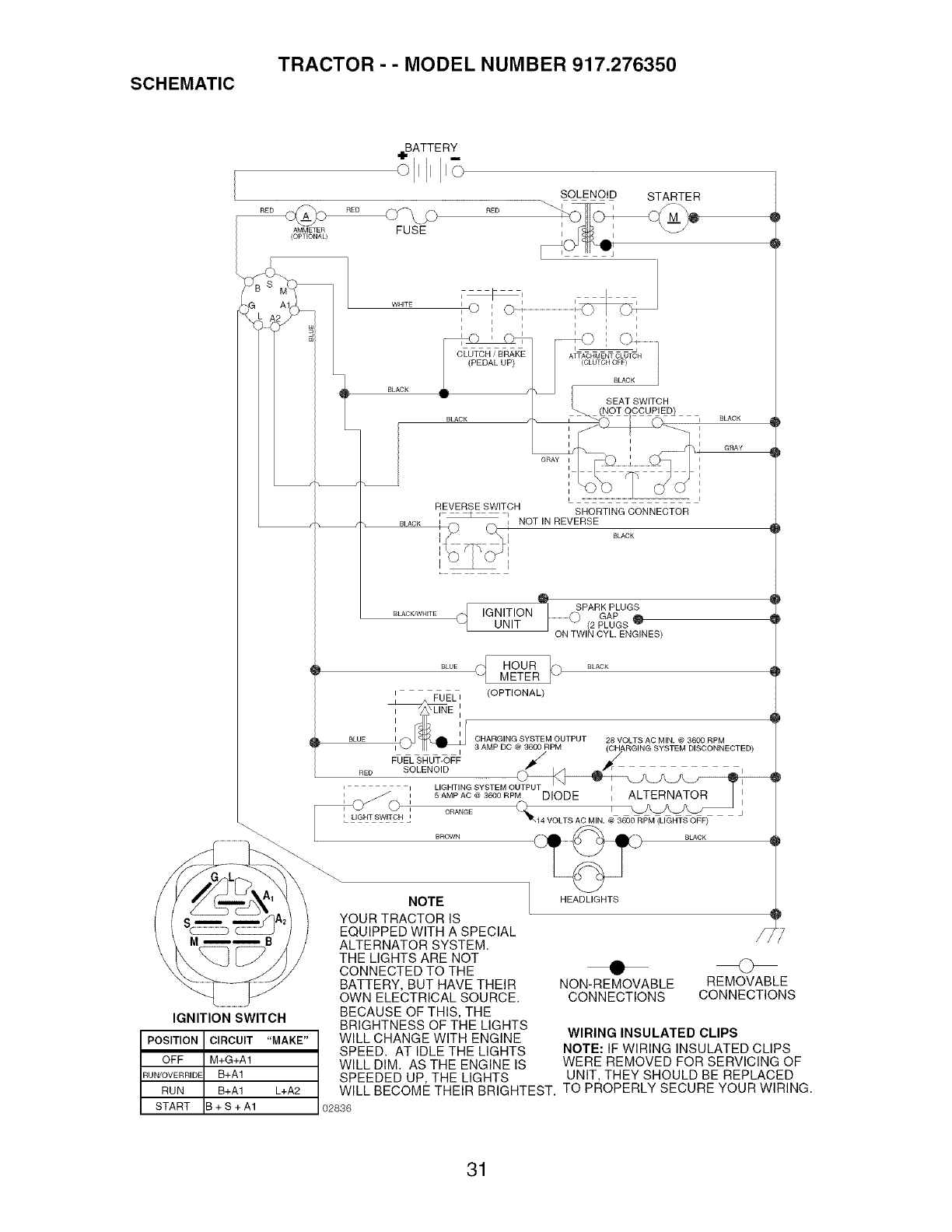
SCHEMATIC TRACTOR - - MODEL NUMBER 917.276350
BATTERY
RED RED
AMMETER FUSE
(OPTIONAL)
SOLENOID STARTER
i i i i i
i
i i i i i
CLUTCH /BRAI(E
(PEDAL UP)
I
BLACK
GRAY
REVERSE SWITCH
F _ _ i SHORTING CONNECTOR
NOT IN REVERSE
BLACK
IGNITION SWITCH
POSITION CIRCUIT "MAKE"
OFF M+G+A1
RUN/OVERRIDE B+A1
RUN B+A1 L+A2
START B + S + A1
i SPARK PLUGS
IGNITION .......................0GAP O
UNIT (2 PLUGS
ON TWIN CYL. ENGINES)
q
8CUE HOUR
METER
(OPTIONAL)
BLUE
RED
I I
i
ON i
NOTE
YOUR TRACTOR IS
EQUIPPED WITH A SPECIAL
ALTERNATOR SYSTEM.
THE LIGHTS ARE NOT
CONNECTED TO THE
BATTERY, BUT HAVE THEIR
OWN ELECTRICAL SOURCE.
BECAUSE OF THIS, THE
BRIGHTNESS OF THE LIGHTS
WILL CHANGE WITH ENGINE
SPEED. AT IDLE THE LIGHTS
WILL DIM. AS THE ENGINE IS
CHARGING SYSTEM OUTPUT 28 VOLTS AC MIN. @ 3600 RPM
3 AMP DC @ 3600 RPM (CHARGING SYSTEM DISCONNECTED)
FUEL SHUT-OFF _/
SOLENOID J'N_J'L_J
LIGHTING SYSTEM OUTPUT
5 AMP AC @ 3600 RPM DIODE ALTERNATOR
ORANGE (_ I X._k._ j
"_14 VOLTS AC MIN. @ 3600 RPM (LIGHTS OFF)
HEADLIGHTS
• C>
NON-REMOVABLE REMOVABLE
CONNECTIONS CONNECTIONS
WIRING INSULATED CLIPS
NOTE: IF WIRING INSULATED CLIPS
WERE REMOVED FOR SERVICING OF
UNIT, THEY SHOULD BE REPLACED
SPEEDED UP, THE LIGHTS
WILL BECOME THEIR BRIGHTEST. TO PROPERLY SECURE YOUR WIRING.
02836
31
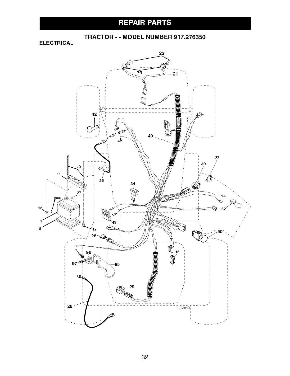
ELECTRICAL
TRACTOR - - MODEL NUMBER 917.276350
I
I
I
I
34
33
/12
\
/
96
I
\
\
\\\\\
\\
\\
J
52 ,'
/
/
/
/
/
\\ i i
\
32

ELECTRICAL
TRACTOR - - MODEL NUMBER 917.276350
KEY PART
NO. NO. DESCRIPTION
1 144927 Battery
2 74760412 Bolt Hex Head 1/4-20 x 3/4
8 7603J Tray, Battery
10 145211 Bolt 1/4-20 x 7.5 Zinc
11 150109 Hold down Battery Dash Mount
12 145769 Nut Push Nylon 1/4"
16 176138 Switch Interlock Push-In
21 175688 Harness Socket Light W/4152J
22 4152J Bulb Light
25 185456 Cable, Battery
26 108824X Fuse
27 73510400 Nut Keps Hex 1/4-20 uric
28 170697 Cable, Ground
29 192749 Switch, Seat
30 193350 Switch, Ign
33 140403 Key, Ignition
34 110712X Switch Light /Reset
40 193394 Harness Ign.
42 154336 Cover, Terminal
45 122822X Ammeter
50 174652 Switch, PTO
52 141940 Protection Wire Loop
79 175242 Bulbholder Asm. Incan Descent
95 193666 Bracket ROS
96 104445X Switch Interlock
97 170488 Screw Hex Wsh Stl #10-24 x .50
NOTE: All component dimensions given in U.S. inches
1 inch = 25.4 mm
33

TRACTOR - - MODEL NUMBER 917.276350
CHASSIS AND ENCLOSURES
161
47
_20
19
2 88
86
chassis-stealth II 5-vgt
158
37
368_31
138
J
56
91
17 67
-4
85
148
167
122
156
17
32 ,_172
45 17
63 50/
63 17
153
130
18
130
15o /
122
142
_130
5O
17
34
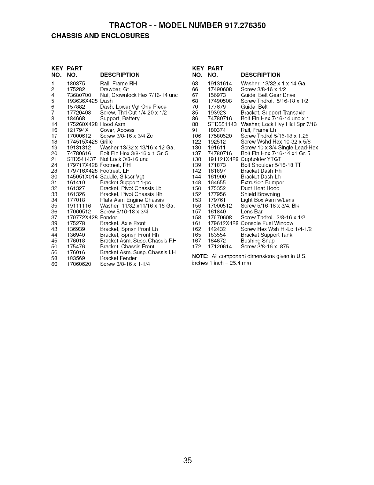
TRACTOR - - MODEL NUMBER 917.276350
CHASSIS AND ENCLOSURES
KEY PART KEY
NO. NO. DESCRIPTION NO.
1 180375 Rail, Frame RH 63
2 175282 Drawbar, Gt 66
4 73680700 Nut, Crownlock Hex 7/16-14 unc 67
5 193636X428 Dash 68
6 157882 Dash, Lower Vgt One Piece 70
7 17720408 Screw, Thd Cut 1/4-20 x 1/2 85
8 184668 Support, Battery 86
14 175260X428 Hood Asm 88
16 121794X Cover, Access 91
17 17000612 Screw 3/8-16 x 3/4 Zc 106
18 174515X428 Grille 122
19 19131312 Washer 13/32 x 13/16 x 12 Ga. 130
20 74780616 Bolt Fin Hex 3/8-16 x 1 Gr. 5 137
21 STD541437 Nut Lock 3/8-16 unc 138
24 179717X428 Footrest, RH 139
28 179716X428 Footrest, LH 142
30 145051X014 Saddle, SIkscr Vgt 144
31 161419 Bracket Support 1-pc 148
32 161327 Bracket, Pivot Chassis Lh 150
33 161326 Bracket, Pivot Chassis Rh 152
34 177018 Plate Asm Engine Chassis 153
35 19111116 Washer 11/32 x11/16 x 16 Ga. 156
36 17060512 Screw 5/16-18 x 3/4 157
37 179772X428 Fender 158
39 175278 Bracket, Axle Front 161
43 136939 Bracket, Spnsn Front Lh 162
44 136940 Bracket, Spnsn Front Rh 165
45 176018 Bracket Asm. Susp. Chassis RH 167
50 175476 Bracket, Chassis Front 172
56 176016 Bracket Asm. Susp. Chassis LH
58 183569 Bracket Fender
60 17060620 Screw 3/8-16 x 1-1/4
PART
NO.
19131614
17490608
156973
17490508
177679
193923
74780716
STD551143
180374
17580520
192512
191611
74780716
DESCRIPTION
Washer 13/32 x 1 x 14 Ga.
Screw 3/8-16 x 1/2
Guide, Belt Gear Drive
Screw Thdrol. 5/16-18 x 1/2
Guide, Belt
Bracket, Support Transaxle
Bolt Fin Hex 7/16-14 uric x 1
Washer, Lock Hvy HIcl Spr 7/16
Rail, Frame Lh
Screw Thdrol 5/16-18 x 1.25
Screw Wshd Hex 10-32 x 5/8
Screw 10 x 3/4 Single Lead-Hex
Bolt Fin Hex 7/16-14 xl Gr. 5
191121X428 Cupholder YTGT
171873 Bolt Shoulder 5/16-18 TT
161897 Bracket Dash Rh
161900 Bracket Dash Lh
164655 Extrusion Bumper
175352 Duct Heat Hood
177956 Shield Browning
179761 Light Box Asm w/Lens
17000512 Screw 5/16-18 x 3/4. BIk
161840 Lens Bar
17670608 Screw Thdrol. 3/8-16 x 1/2
179612X428 Console Fuel Window
142432 Screw Hex Wsh Hi-Lo 1/4-1/2
183554 Bracket Support Tank
184672 Bushing Snap
17120614 Screw 3/8-16 x .875
NOTE: All component dimensions given in U.S.
inches 1 inch = 25.4 mm
35
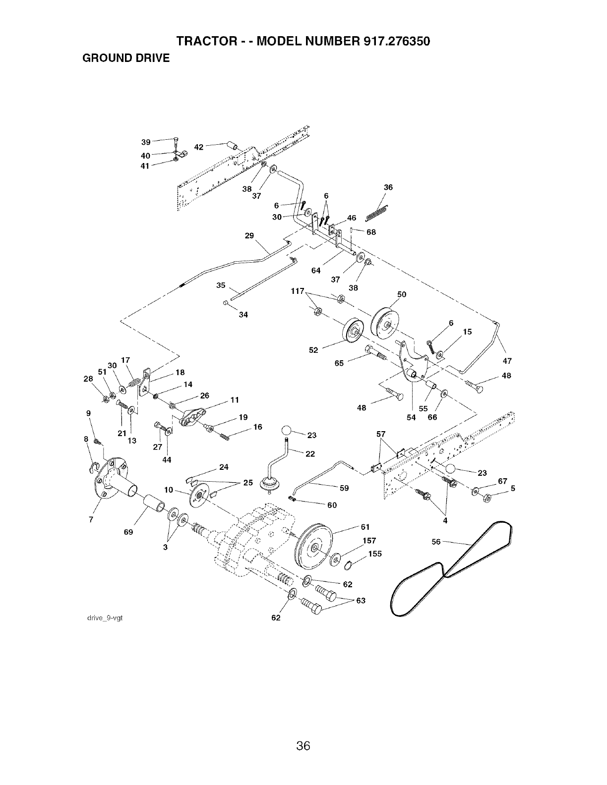
TRACTOR - - MODEL NUMBER 917.276350
GROUND DRIVE
30
51
28\
9
7
69
44
48
24
54
57
157
155
62
66
15
47
23
drive 9=vgt 62
36
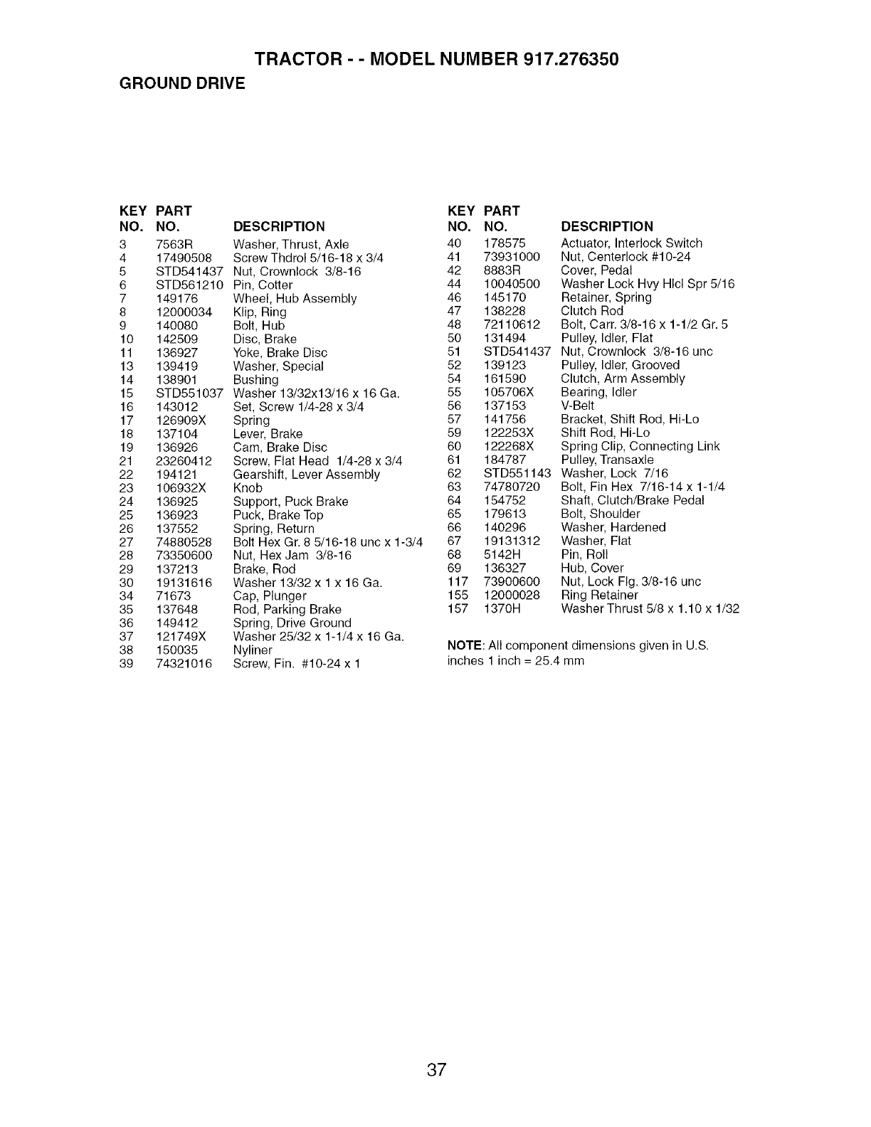
TRACTOR - - MODEL NUMBER 917.276350
GROUND DRIVE
KEY PART KEY PART
NO. NO. DESCRIPTION NO. NO.
3 7563R Washer, Thrust, Axle 40 178575
4 17490508 Screw Thdrol 5/16-18 x 3/4 41 73931000
5 STD541437 Nut, Crownlock 3/8-16 42 8883R
6 STD561210 Pin, Cotter 44 10040500
7 149176 Wheel, Hub Assembly 46 145170
8 12000034 Klip, Ring 47 138228
9 140080 Bolt, Hub 48 72110612
10 142509 Disc, Brake 50 131494
11 136927 Yoke, Brake Disc 51 STD541437
13 139419 Washer, Special 52 139123
14 138901 Bushing 54 161590
15 STD551037 Washer 13/32x13/16 x 16 Ga. 55 105706X
16 143012 Set, Screw 1/4-28 x 3/4 56 137153
17 126909X Spring 57 141756
18 137104 Lever, Brake 59 122253X
19 136926 Cam, Brake Disc 60 122268X
21 23260412 Screw, Fiat Head 1/4-28 x 3/4 61 184787
22 194121 Gearshift, Lever Assembly 62 STD551143
23 106932X Knob 63 74780720
24 136925 Support, Puck Brake 64 154752
25 136923 Puck, Brake Top 65 179613
26 137552 Spring, Return 66 140296
27 74880528 Bolt Hex Gr. 8 5/16-18 unc x 1-3/4 67 19131312
28 73350600 Nut, Hex Jam 3/8-16 68 5142H
29 137213 Brake, Rod 69 136327
30 19131616 Washer 13/32 x 1 x 16 Ga. 117 73900600
34 71673 Cap, Plunger 155 12000028
35 137648 Rod, Parking Brake 157 1370H
36 149412 Spring, Drive Ground
37 121749X Washer 25/32 x 1-1/4 x 16 Ga.
38 150035 Nyliner
39 74321016 Screw, Fin. #10-24 x 1
DESCRIPTION
Actuator, Interlock Switch
Nut, Centerlock #10-24
Cover, Pedal
Washer Lock Hvy Hlcl Spr 5/16
Retainer, Spring
Clutch Rod
Bolt, Carr. 3/8-16 x 1-1/2 Gr. 5
Pulley, Idler, Flat
Nut, Crownlock 3/8-16 uric
Pulley, Idler, Grooved
Clutch, Arm Assembly
Bearing, Idler
V-Belt
Bracket, Shift Rod, Hi-Lo
Shift Rod, Hi-Lo
Spring Clip, Connecting Link
Pulley, Transaxle
Washer, Lock 7/16
Bolt, Fin Hex 7/16-14 x 1-1/4
Shaft, Clutch/Brake Pedal
Bolt, Shoulder
Washer, Hardened
Washer, Flat
Pin, Roll
Hub, Cover
Nut, Lock Fig. 3/8-16 unc
Ring Retainer
Washer Thrust 5/8 x 1.10 x 1/32
NOTE: All component dimensions given in U.S.
inches 1 inch = 25.4 mm
37
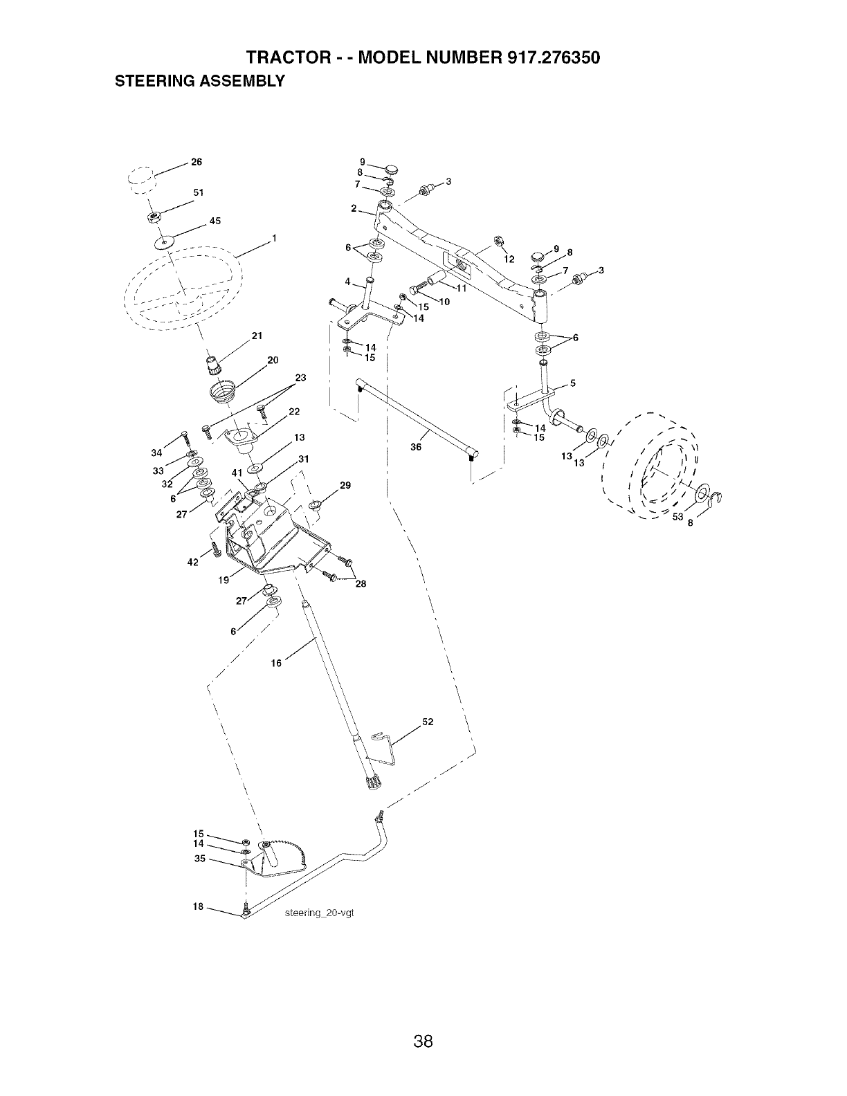
TRACTOR - - MODEL NUMBER 917.276350
STEERING ASSEMBLY
34
33
32
6
23
22
13
31
29
28
36
\
\
IJ
15
1313
/i
/'_ \1
I I i I II
II /ll
k I
\ I
_ 53 8
18_ steering 20-vgt
52
/
J
38

TRACTOR - - MODEL NUMBER 917.276350
STEERING ASSEMBLY
KEY PART
NO. NO.
1 186093X428
2 178557
3 183226
4 161849
5 161848
6 6266H
7 121748X
8 12000029
9 184946X505
10 74781044
11 136518
12 73901000
13 121749X
14 STD551137
15 73540600
16 186814
18 175572
19 156011
20 163887X428
21 186737
22 155105
23 152927
26 186095X428
27 3366R
28 17000612
29 104239X
31 138136
32 19111610
33 STD551131
34 74780512
35 187039
36 186799
41 155246
42 17490508
45 19183812
51 73940800
52 175553
53 188967
DESCRIPTION
Wheel, Steering
Axle Asm., Front
Fitting, Grease
Spindle Asm., LH
Spindle Asm., RH
Bearing, Race Thrust Harden
Washer 25/32 x 1-5/8 x 16 Ga.
Ring, Klip #T5304-75
Cap, Spindle
Bolt, Fin Hex 5/8-11 x 2-3/4
Spacer Bearing Axle Front
Nut, Lock Flange 5/8-11 unc
Washer 25/32 x 1-1/4 x 16 Ga.
Washer, Lock Hvy I-IIcl Spr 3/8
Nut, Crown Lock 3/8-24 unf
Shaft Asm., Steering
Draglink, Vgt
Support Asm., Steering Vgt
Boot, Steering
Adapter, Wheel Steering
Bushing, Strg. BIk
Screw
Insert, Wheel Steering
Bearing, Col. Strg.
Screw 3/8-16 x 3/4
Bearing, Flange
Bushing, Nyliner Snap
Washer 11/32xlx10Ga.
Washer, Lock Hvy HIcl Spr 5/16
Bolt, Hex Hd 5/16-18 x 3/4
Gear, Sector Steering
Tie Rod
Bracket Switch Interlock VGT 97
ScrewThdrol 5/16-18 x 1/2Tyt
Washer 9/16 x 2-3/8 x 12 Ga.
Nut Hex Jam Toplock 1/2-20 unf
Clip Steering
Washer Hardened .793 x 1.637 x .060
NOTE: All component dimensions given in U.S. inches
1 inch = 25.4 mm
39
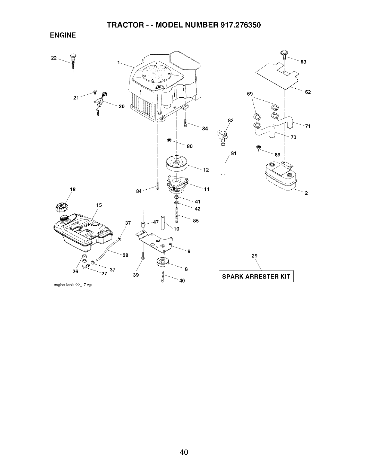
ENGINE
TRACTOR - - MODEL NUMBER 917.276350
37
26 27
engine-kohler22 17-vgt
84
39
84
80
i
12
11
i
42
85
82
29
\\ \\/
SPARK ARRESTER KIT I
J
40
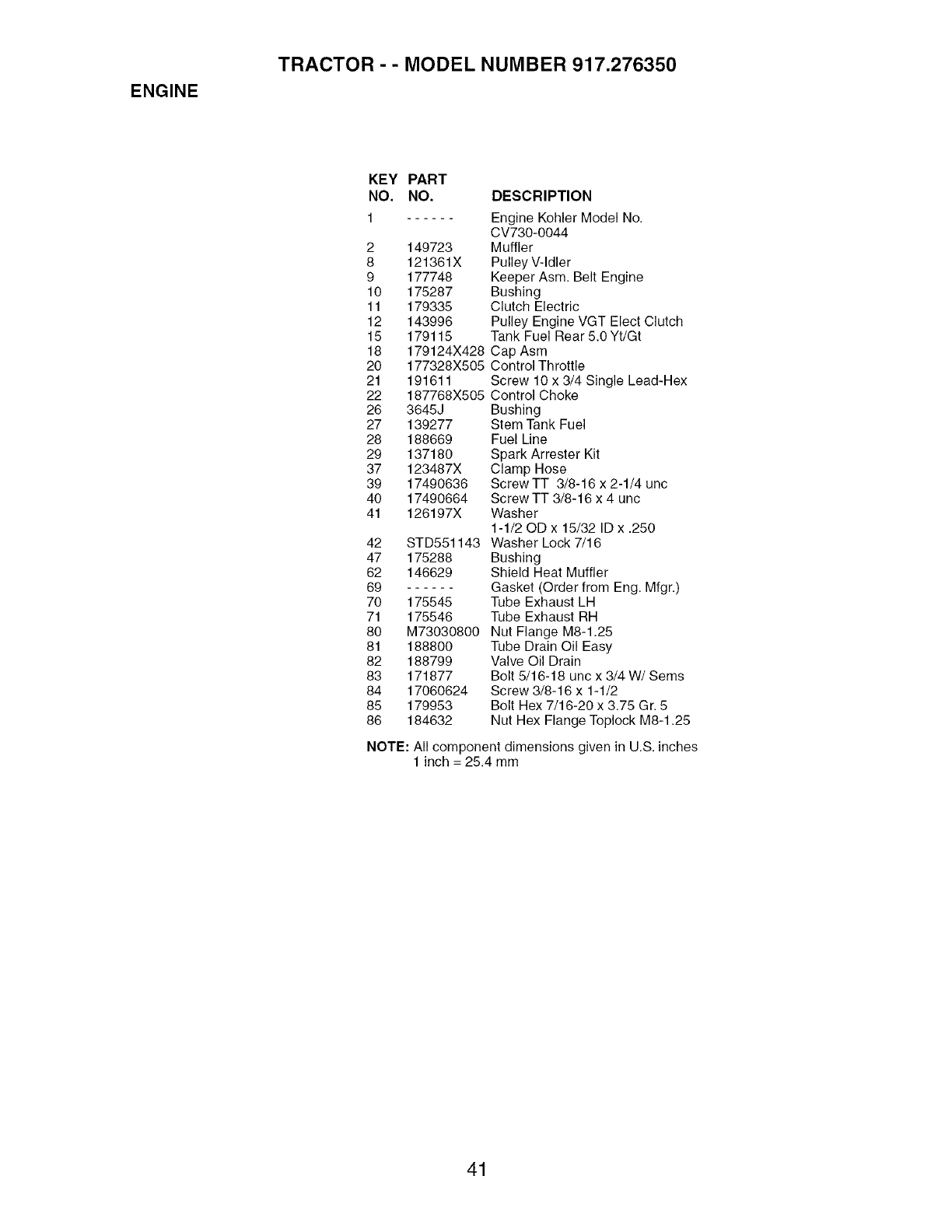
ENGINE
TRACTOR - - MODEL NUMBER 917.276350
KEY PART
NO. NO. DESCRIPTION
1 Engine Kohler Model No.
CV730-0044
2 149723 Muffler
8 121361X Pulley V-Idler
9 177748 Keeper Asm. Belt Engine
10 175287 Bushing
11 179335 Clutch Electric
12 143996 Pulley Engine VGT Elect Clutch
15 179115 Tank Fuel Rear 5.0 Yt/Gt
18 179124X428 Cap Asm
20 177328X505 Control Throttle
21 191611 Screw 10 x 3/4 Single Lead-Hex
22 187768X505 Control Choke
26 3645J Bushing
27 139277 Stem Tank Fuel
28 188669 Fuel Line
29 137180 Spark Arrester Kit
37 123487X Clamp Hose
39 17490636 Screw TT 3/8-16 x 2-1/4 unc
40 17490664 Screw TT 3/8-16 x 4 unc
41 126197X Washer
1-1/20D x 15/32 ID x .250
42 STD551143 Washer Lock 7/16
47 175288 Bushing
62 146629 Shield Heat Muffler
69 Gasket (Order from Eng. Mfgr.)
70 175545 Tube Exhaust LH
71 175546 Tube Exhaust RH
80 M73030800 Nut Flange M8-1.25
81 188800 Tube Drain Oil Easy
82 188799 Valve Oil Drain
83 171877 Bolt 5/16-18 unc x 3/4 W/Seres
84 17060624 Screw 3/8-16 x 1-1/2
85 179953 Bolt Hex 7/16-20 x 3.75 Gr. 5
86 184632 Nut Hex Flange Toplock M8-1.25
NOTE: All component dimensions given in U.S. inches
1 inch = 25.4 mm
41
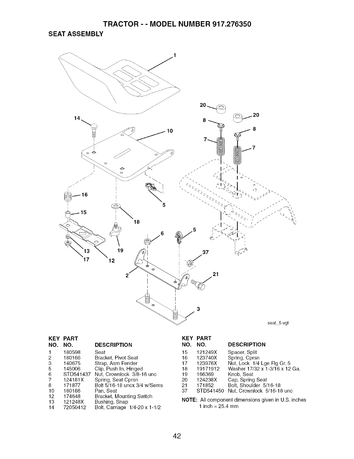
TRACTOR - - MODEL NUMBER 917.276350
SEAT ASSEMBLY
\\
10
18
\
5
17 12
19
6
I
I
37
J
21
I
I
seat 5-vgt
KEY PART
NO. NO.
1 180598
2 180166
3 140675
5 145006
6 STD541437
7 124181X
8 171877
10 180186
12 174648
13 121248X
14 72050412
DESCRIPTION
Seat
Bracket, Pivot Seat
Strap, Asm Fender
Clip, Push In, Hinged
Nut, Crownlock 3/8-16 unc
Spring, Seat Cprsn
Bolt 5/16-18 uncx 3/4 w/Sems
Pan, Seat
Bracket, Mounting Switch
Bushing, Snap
Bolt, Carriage 1/4-20 x 1-1/2
KEY PART
NO. NO. DESCRIPTION
15 121249X Spacer, Split
16 123740X Spring, Cprsn
17 123976X Nut, Lock 1/4 Lge Fig Gr. 5
18 19171912 Washer 17/32 x 1-3/16 x 12 Ga.
19 166369 Knob, Seat
20 124238X Cap, Spring Seat
21 171852 Bolt, Shoulder 5/16-18
37 STD541450 Nut, Crownlock 5/16-18 unc
NOTE: All component dimensions given in U.S. inches
1 inch = 25.4 mm
42
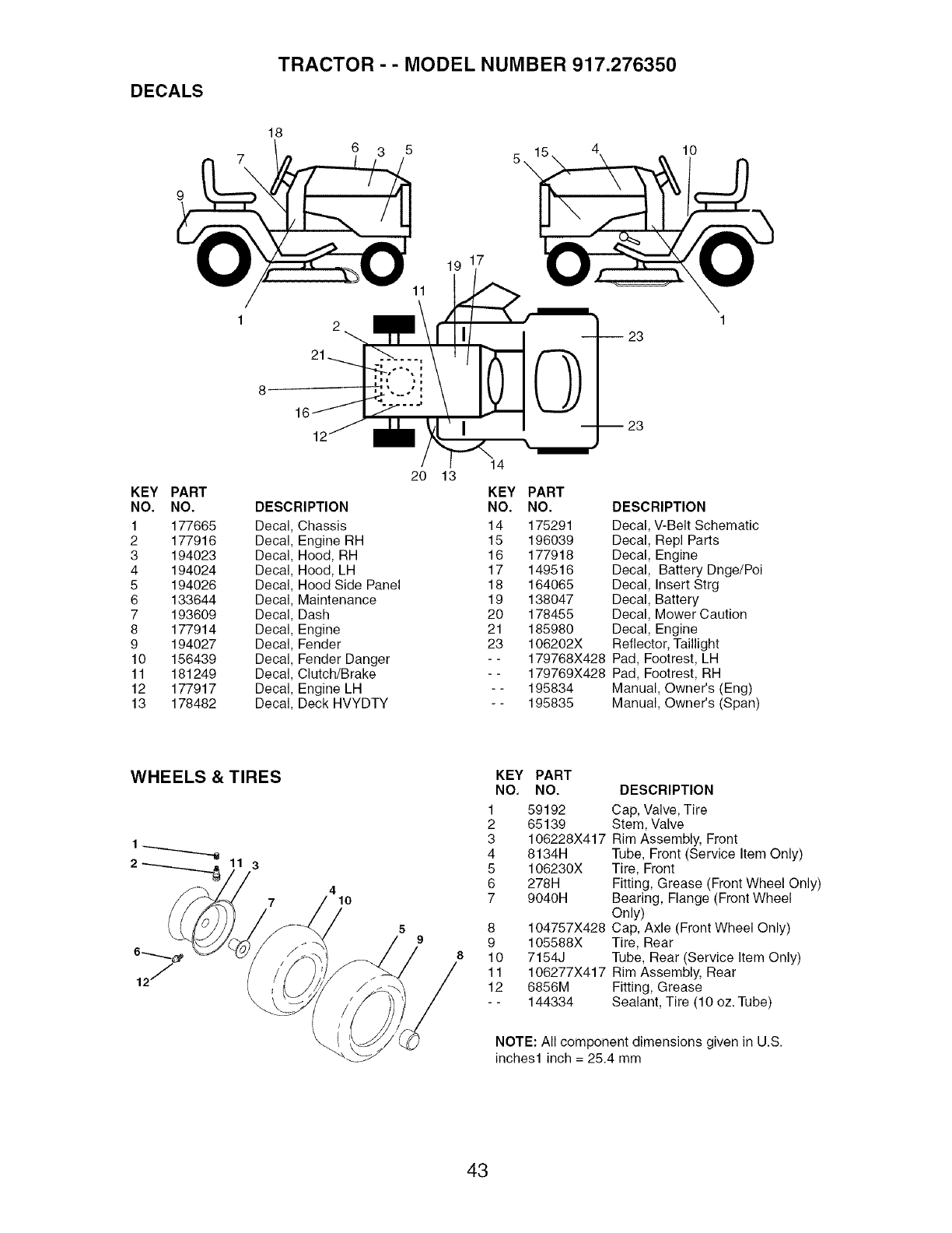
DECALS
TRACTOR - - MODEL NUMBER 917.276350
18
11
19 17
23
10
8
KEY PART
NO. NO.
1 177665
2 177916
3 194023
4 194024
5 194026
6 133644
7 193609
8 177914
9 194027
10 156439
11 181249
12 177917
13 178482
DESCRIPTION
Decal Chassis
Decal Engine RH
Decal Hood, RH
Decal Hood, LH
Decal Hood Side Panel
Decal Maintenance
Decal Dash
Decal Engine
Decal Fender
Decal Fender Danger
Decal Clutch/Brake
Decal Engine LH
Decal Deck HVYDTY
2O 13 14
KEY
NO.
14
15
16
17
18
19
2O
21
23
PART
NO. DESCRIPTION
175291 Decal, V-Belt Schematic
196039 Decal, Repl Parts
177918 Decal, Engine
149516 Decal, Battery Dnge/Poi
164065 Decal, Insert Strg
138047 Decal, Battery
178455 Decal, Mower Caution
185980 Decal, Engine
106202X Reflector, Taillight
179768X428 Pad, Footrest, LH
179769X428 Pad, Footrest, RH
195834 Manual, Owner's (Eng)
195835 Manual, Owner's (Span)
WHEELS & TIRES
1
3
410
\\
KEY
NO.
1
2
3
4
5
6
7
8
9
8 10
11
12
PART
NO. DESCRIPTION
59192 Cap, Valve, Tire
65139 Stem, Valve
106228X417 Rim Assembly, Front
8134H Tube, Front (Service Item Only)
106230X Tire, Front
278H Fitting, Grease (Front Wheel Only)
9040H Bearing, Flange (Front Wheel
Only)
104757X428 Cap, Axle (Front Wheel Only)
105588X Tire, Rear
7154J Tube, Rear (Service Item Only)
106277X417 Rim Assembly, Rear
6856M Fitting, Grease
144334 Sealant, Tire (10 oz. Tube)
NOTE: All component dimensions given in U.S.
inches1 inch = 25.4 mm
43
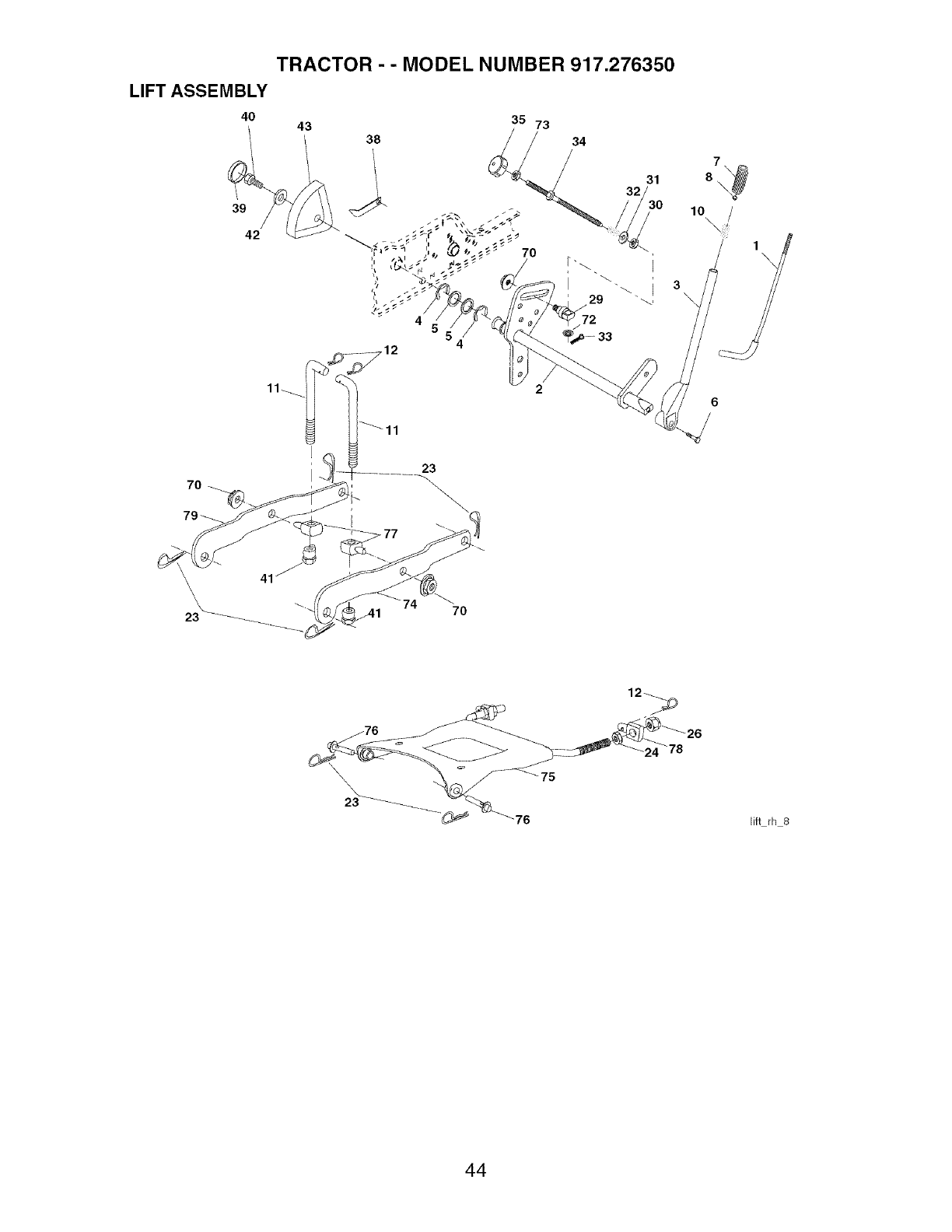
LIFT ASSEMBLY
40
39
42
70
TRACTOR - - MODEL NUMBER 917.276350
43 38
i
11\_
\\\
7
1o /
70
12_
lift rh 8
44

TRACTOR - - MODEL NUMBER 917.276350
LIFT ASSEMBLY
KEY PART
NO. NO. DESCRIPTION
1 121006X Rod Asm., Lever
2 180045 Shaft Asm., Lift Vgt
3 159189 Lever Asm., Lift Rh
4 12000022 E-Ring Truarc #5133-87
5 19292016 Washer 29/32 x 1-1/4 x 16 Ga.
6 71110624 Bolt, Fin Hex 3/8-16 uric x1-1/2
7 175830 Grip, Handle Fluted
8 175831X505 Button, Plunger
10 183894 Spring 0.62 OD x 2.125
11 175375 Link Lift
12 163552 Retainer Spring
23 STD624008 Retainer, Spring
24 73350800 Nut, Jam Hex 1/2-13 uric
26 73680800 Nut, Crownlock 1/2-13 unc
29 150233 Trunnion, Infin Height
30 110807X Nut, Special
31 19131016 Washer 13/32 x 5/8 x 16 Ga.
32 137150 Spring, Compression Inf Hgt
33 STD560907 Pin, Cotter 3/32 x 1/2
34 137167 Rod, Adj Lift
35 138057 Knob, Inf 3/8-16 uric
38 155097 Pointer, Height Indicator
39 123935X Plug, Hole
40 17060516 Screw 5/16-18 x 1
41 175994 Nut, Lift Link 7/16-20
42 19112410 Washer 11/32 x 1-1/2 x 10 Ga.
43 123934X Scale, Indicator Height
70 145212 Nut Hex Flange Lock
72 110452X Nut Push Phos & Oil
73 73350600 Nut Hex Jam 3/8-16 unc
74 175802 Arm Susp. RR. RH
75 175805 Plate Asm Susp. Front
76 175560 Pin Flange
77 176205 Trunnion Susp. Arm
78 175689 Trunnion Susp. Front
79 175378 Arm Susp. RR. LH
NOTE: All component dimensions given in U.S.
inches 1 inch = 25.4 mm
45
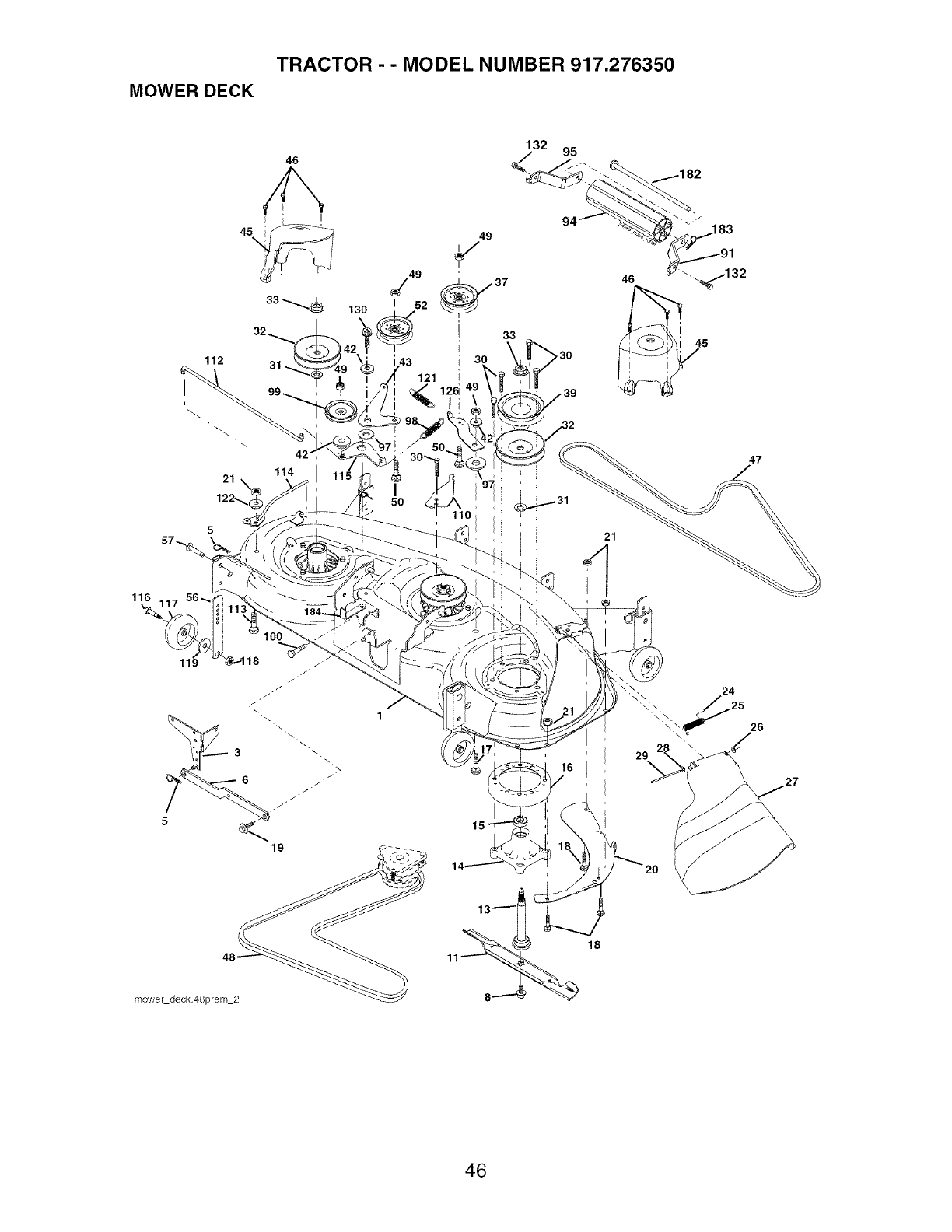
TRACTOR - - MODEL NUMBER 917.276350
MOWER DECK
46
132 95
33 _;_ 130
112 31
114
21
122,
5
116 _
\_117 56.
49
I
121
>30
110
47
119 J
1
J
J
mower deck48prem 2
16
18
29
26
46
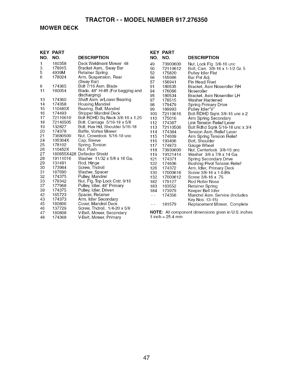
TRACTOR - - MODEL NUMBER 917.276350
MOWER DECK
KEY PART KEY PART
NO. NO. DESCRIPTION NO. NO.
1 180358 Deck Weldment Mower 48 49 73900600
3 178915 Bracket Asm., Sway Bar 50 72110612
5 4939M Retainer Spring 52 175820
6 178024 Arm, Suspension, Rear 56 155986
(Sway Bar) 57 156941
8 174365 Bolt 7/16 Asm. Blade 91 180535
11 180054 Blade, 48" Hi-lift (For bagging and 94 176066
discharging) 95 180534
13 174360 Shaft Asm. w/Lower Bearing 97 178515
14 174358 Housing Mandrel 98 179479
15 110485X Bearing, Ball, Mandrel 99 189993
16 174493 Stripper Mandrel Deck 100 72110616
17 72110610 Bolt RDHD Sq Neck 3/8-16 x1.25 110 175016
18 72140505 Bolt, Carriage 5/16-18 x 5/8 112 174387
19 132827 Bolt, Hex Hd, Shoulder 5/16-18 113 72110506
20 174378 Baffle, Vortex Mower 114 174384
21 73680500 Nut, Crownlock 5/16-18 unc 115 174609
24 105304X Cap, Sleeve 116 193406
25 178102 Spring, Torsion 117 174873
26 110452X Nut, Push 118 73930600
27 180655X428 Deflector Shield 119 19121414
28 19111016 Washer 11/32 x 5/8 x 16 Ga. 121 174371
29 131491 Rod, Hinge 122 174606
30 173984 Screw, Thdroll 126 174372
31 187690 Washer, Spacer 130 17000616
32 174375 Pulley, Mandrel 132 17000612
33 178342 Nut, Fig. Top Lock Cntr. 9/16 182 179127
37 177968 Pulley, Idler, 48" Primary 183 163552
39 174375 Pulley, Idler, Driven 184 173979
42 165723 Spacer, Retainer - - 174356
43 174373 Arm, Idler Secondary
45 180806 Cover, Mandrel Deck - - 181579
46 137729 Screw, Thdroll. 1/4-20 x 5/8
47 180808 V-Belt, Mower, Secondary
48 174368 V-Belt, Mower, Primary
DESCRIPTION
Nut, Lock Fig 3/8-16 unc
Bolt, Carr. 3/8-16 x 1-1/2 Gr. 5
Pulley Idler Flat
Bar Pnt Adj.
Pin Head Rivet
Bracket, Asm Noseroller RH
Noseroller
Bracket, Asm Noseroller LH
Washer Hardened
Spring Primary Drive
Pulley Idler"V"
Bolt RDHD Sqnk 3/8-16 unc x 2
Arm Spring Secondary
Link Tension Relief Lever
Bolt Rdhd Sqnk 5/16-18 unc x 3/4
Tension Asm. Relief Lever
Arm Spring Tension Relief
Bolt, Shoulder
Gauge Wheel
Nut, Centerlock 3/8-16 unc
Washer 3/8 x 7/8 x 14 Ga.
Spring Secondary Drive
Bushing Pivot Tension Relief
Arm, Idler, Primary Deck
Screw 3/8-16 x 1.0.BIk
Screw 3/8-16 x .75
Rod Roller Nose
Retainer Spring
Keeper Belt Idler
Mandrel Asm. Service (Includes
Key Nos. 13-15)
Replacement Mower, Complete
NOTE: All component dimensions given in U.S. inches
1 inch = 25.4 mm
47
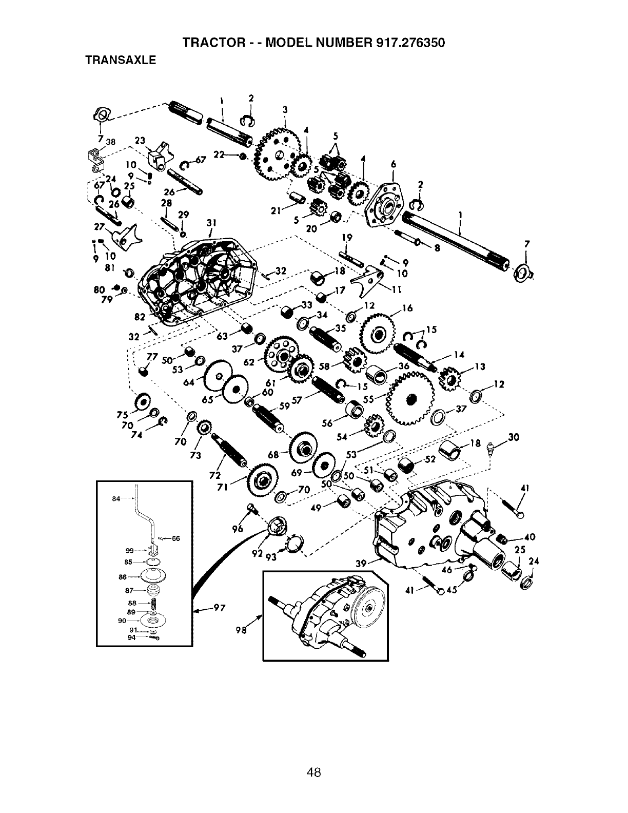
TRANSAXLE
TRACTOR - - MODEL NUMBER 917.276350
46
1
73
84.
_ _'--66
85 _0
87_
88 _
90 _
91_,_._
94_o
,15
14
3
7
25
24
48
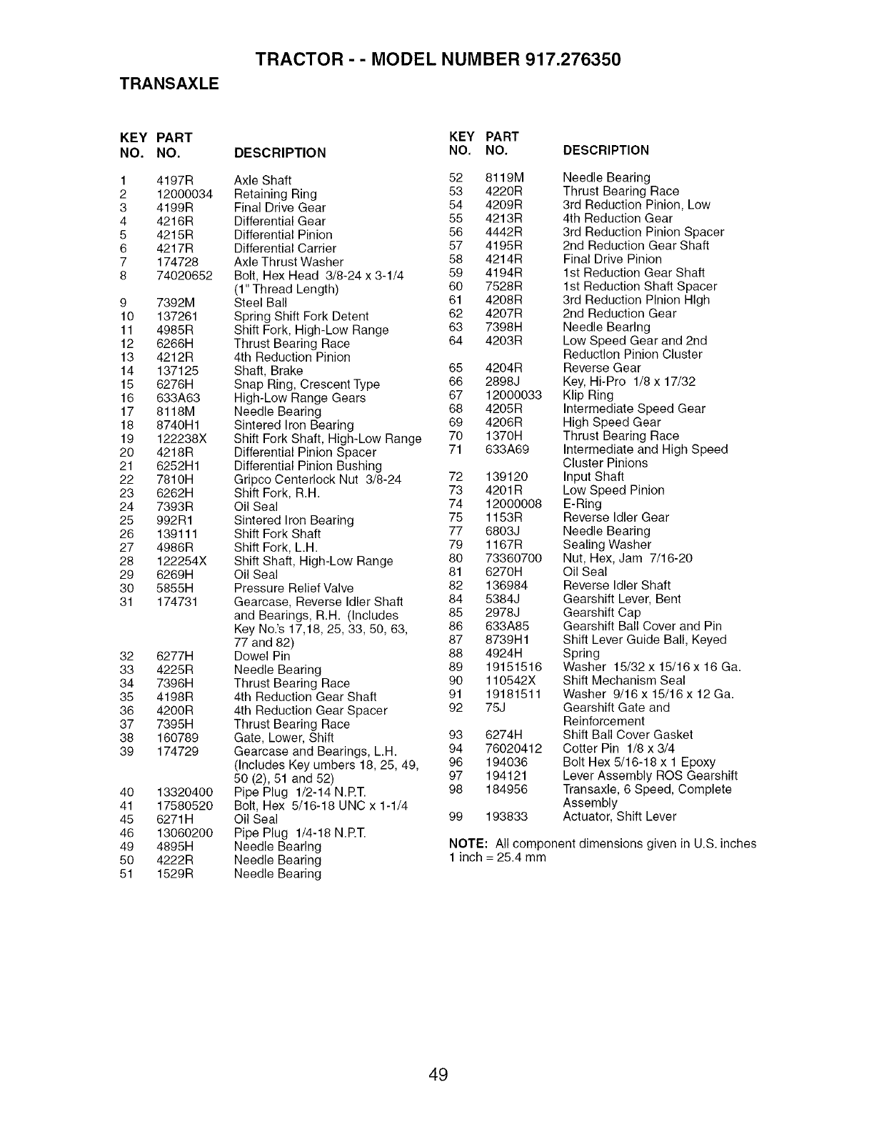
TRANSAXLE
TRACTOR - - MODEL NUMBER 917.276350
KEY PART
NO. NO.
1 4197R
2 12000034
3 4199R
4 4216R
5 4215R
6 4217R
7 174728
8 74020652
9 7392M
10 137261
11 4985R
12 6266H
13 4212R
14 137125
15 6276H
16 633A63
17 8118M
18 8740H1
19 122238X
20 4218R
21 6252H1
22 7810H
23 6262H
24 7393R
25 992R1
26 139111
27 4986R
28 122254X
29 6269H
30 5855H
31 174731
32 6277H
33 4225R
34 7396H
35 4198R
36 4200R
37 7395H
38 160789
39 174729
40 13320400
41 17580520
45 6271H
46 13060200
49 4895H
50 4222R
51 1529R
KEY PART
DESCRIPTION NO. NO. DESCRIPTION
Axle Shaft 52 8119M
Retaining Ring 53 4220R
Final Drive Gear 54 4209R
Differential Gear 55 4213R
Differential Pinion 56 4442R
Differential Carrier 57 4195R
Axle Thrust Washer 58 4214R
Bolt, Hex Head 3/8-24 x 3-1/4 59 4194R
(1" Thread Length) 60 7528R
Steel Ball 61 4208R
Spring Shift Fork Detent 62 4207R
Shift Fork, High-Low Range 63 7398H
Thrust Bearing Race 64 4203R
4th Reduction Pinion
Shaft, Brake 65 4204R
Snap Ring, Crescent Type 66 2898J
High-Low Range Gears 67 12000033
Needle Bearing 68 4205R
Sintered Iron Bearing 69 4206R
Shift Fork Shaft, High-Low Range 70 1370H
Differential Pinion Spacer 71 633A69
Differential Pinion Bushing
Gripco Centerlock Nut 3/8-24 72 139120
Shift Fork, R.H. 73 4201R
Oil Seal 74 12000008
Sintered Iron Bearing 75 1153R
Shift Fork Shaft 77 6803J
Shift Fork, L.H. 79 1167R
Shift Shaft, High-Low Range 80 73360700
Oil Seal 81 6270H
Pressure Relief Valve 82 136984
Gearcase, Reverse Idler Shaft 84 5384J
and Bearings, R.H. (Includes 85 2978J
Key No.'s 17,18, 25, 33, 50, 63, 86 633A85
77 and 82) 87 8739H1
Dowel Pin 88 4924H
Needle Bearing 89 19151516
Thrust Bearing Race 90 110542X
4th Reduction Gear Shaft 91 19181511
4th Reduction Gear Spacer 92 75J
Thrust Bearing Race
Gate, Lower, Shift 93 6274H
Gearcase and Bearings, L.H. 94 76020412
(Includes Key umbers 18, 25, 49, 96 194036
50 (2), 51 and 52) 97 194121
Pipe Plug 1/2-14 N.ET. 98 184956
Bolt, Hex 5/16-18 UNC x 1-1/4
Oil Seal 99 193833
Pipe Plug 1/4-18 N.ET.
Needle Bearing
Needle Bearing
Needle Bearing
Needle Bearing
Thrust Bearing Race
3rd Reduction Pinion, Low
4th Reduction Gear
3rd Reduction Pinion Spacer
2nd Reduction Gear Shaft
Final Drive Pinion
1st Reduction Gear Shaft
1st Reduction Shaft Spacer
3rd Reduction Pinion High
2nd Reduction Gear
Needle Bearing
Low Speed Gear and 2nd
Reduction Pinion Cluster
Reverse Gear
Key, Hi-Pro 1/8 x 17/32
Klip Ring
Intermediate Speed Gear
High Speed Gear
Thrust Bearing Race
Intermediate and High Speed
Cluster Pinions
Input Shaft
Low Speed Pinion
E-Ring
Reverse Idler Gear
Needle Bearing
Sealing Washer
Nut, Hex, Jam 7/16-20
Oil Seal
Reverse Idler Shaft
Gearshift Lever, Bent
Gearshift Cap
Gearshift Ball Cover and Pin
Shift Lever Guide Ball, Keyed
Spring
Washer 15/32 x 15/16x 16 Ga.
Shift Mechanism Seal
Washer 9/16 x 15/16 x 12 Ga.
Gearshift Gate and
Reinforcement
Shift Ball Cover Gasket
Cotter Pin 1/8 x 3/4
Bolt Hex 5/16-18 x 1 Epoxy
Lever Assembly ROS Gearshift
Transaxle, 6 Speed, Complete
Assembly
Actuator, Shift Lever
NOTE: All component dimensions given in U.S. inches
1 inch = 25.4 mm
49
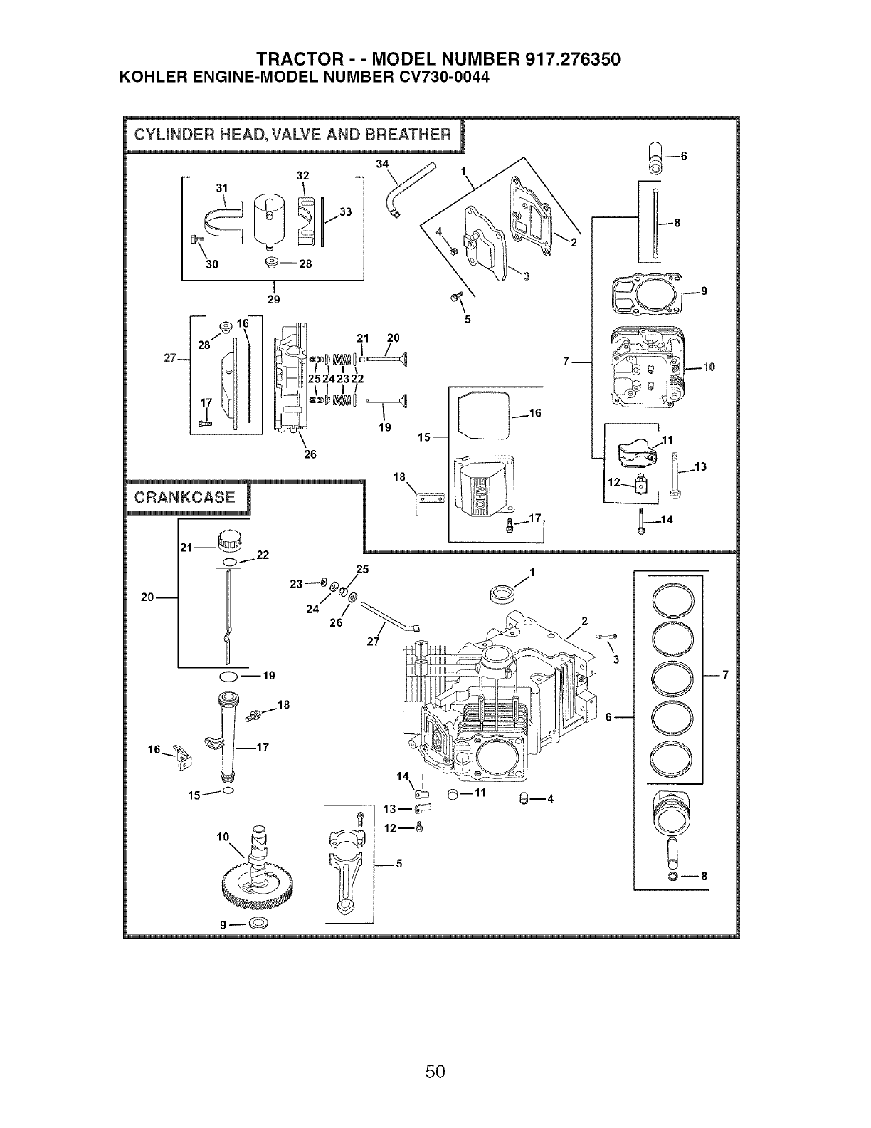
TRACTOR - - MODEL NUMBER 917.276350
KOHLER ENGINE-MODEL NUMBER CV730-0044
CYLINDER HEAD, VALVE AND BREATHER I
27--
32
4
\ ,... 3
5
31 /
30 _--28
17 _
I
29
15 m
_8
CRANKCASE
21 001- 22
21 20
II I\
25 24 23 22
II I/
__ 19
"_6
18
"_1171
7m
-12_._!113
20 m
25
O--11 Gin4
0
0
0
0
0
4
--7
50

TRACTOR - - MODEL NUMBER 917.276350
KOHLER ENGINE-MODEL NUMBER CV730-0044
HEAD/VAWE/BREATHER CRANKCASE
KEY PART KEY PART
NO. NO. DESCRIPTION NO. NO. DESCRIPTION
1. 24-033-03-S Kit, breather cover w/gasket
(Includes 2, 3)
2. 24-041-51-S Gasket, breather
3. 24-096-87-S Cover, breather
4. M-645020-S Screw, hex. flange M6xl.0x20
(4)
5. 25 139 60-S Plug, hex. ctsk. 1/8"
6. 25-351-01-S Lifter, valve (4)
7. 24-755-66-S Kit, valve train (Includes 8, 11,
12)
8. 24-411-05-S Rod, push (4)
9. 24-841-03-S Kit, cylinder head gasket (2)
(Includes 13) 7.
10. 24-318-72-S Head assembly, #2 cylinder
11. 25-186-01-S Arm, rocker (4)
12. 24-599-01-S Pivot, rocker arm (4) 8.
13. 12 086 16-S Screw, hex. flange 9.
M10x1.5x90 (8)
14. 66-086-07-S Screw, hex. flange M6x1.0x34
(4)
15. 24-755-141-S Kit, valve cover- plain
(Includes 16,17)
16. 24-153-28-S O-Ring
17. M-651030-S Screw, hex. flange M6x1.0x30 10.
(4) 11.
18. 24-445-01-S Strap, lifting 12.
19. 24-016-01-S Valve, exhaust (Std.) (2)
24-016-02-S Valve, exhaust (.25) (2) 13.
20. 24-017-01-S Valve, intake (Std.) (2) 14.
24-017-02-S Valve, intake (.25) (2) 15.
21. 66-032-05-S Seal, valve stem (2) 16.
22. 235011-S Retainer, spring (4) 17.
23. 24-089-02-S Spring, valve (4) 18.
24. 12-173-01-S Cap, valve spring (4) 19.
25. 12-755-03-S Kit, retainer (4) 20.
26. 24-318-69-S Head assembly, #1 cylinder
27. 24-755-142-S Kit, valve cover- breather 21.
(Includes 16,17,29) 22.
28. 25-313-03-S Grommet, rubber 23.
29. 24-755-57-S Kit, breather separator 24.
(Includes 29,31-34) 25.
30. M-545016-S Screw, hex. flange M5x0.8x16 26.
(2) 27.
31. 24-445-02-S Strap, breather
32. 24-126-44-S Bracket, breather separator
33. 24-112-12-S Spacer
34. 24-326-74-S Hose, breather
NOTILLUSTRATED
24755147-S Kit, cylinderheadhardware
1. 24-032-01-S Seal, front oil
2. Crankcase (USE: Miniblock 24
782 14)
3. 24-294-13-S Fitting
4. 24-380-13-S Pin, locating (6)
5. 24-067-13-S Connecting Rod (Std.) (2)
24-067-14-SConnecting Rod (.25) (2)
6. 24-874-08-S Piston w/Ring Set (Std.) (2)
24-874-16-S
24-874-20-S
24-874-21-S
24-108-05-S
24-108-06-S
24-108-07-S
24-018-01-S
12-422-09-S
12-422-13-S
12-422-07-S
12-422-08-S
12-422-10-S
12-422-11-S
12-422-12-S
24-012-16-S
52-139-09-S
M-545010-S
24-018-04-S
24-402-05-S
12-153-01-S
24-126-19-S
12-123-04-S
M-545016-S
12-153-02-S
24-038-04-S
24-755-46-S
25 153 02-S
24-018-09-S
M-931010-S
28-032-09-S
24-468-15-S
24-144-38-S
(Includes 7, 8)
Piston w/Ring Set (.08)
Piston w/Ring Set (.25)
Piston w/Ring Set (.50)
Ring Set (Std. & .08) (2)
Ring Set (.25)
Ring Set (.50)
Retainer, piston pin (4)
Shim, camshaft (A.R.)
Shim, camshaft (A.R.)
Shim, camshaft (A.R.)
Shim, camshaft (A.R.)
Shim, camshaft
Shim, camshaft (A.R.)
Shim, camshaft (A.R.)
Camshaft
Plug, cup
Screw, hex. flange M5x0.8xl0
(2)
Retainer, reed (2)
Reed, breather (2)
O-Ring, lower oil fill tube
Bracket, oil fill tube
Tube, oil fill
Screw, hex. flange M5x0.8x16
O-Ring, upper oil fill tube
Dipstick assembly (Includes
21,22)
Kit, oil fill cap (Includes 22)
O-Ring, dipstick
Ring, retainer
Washer, nylon (top)
Seal, governor cross shaft
Washer (bottom)
Shaft, governor cross
NOTE: All component dimensions given in U.S.
inches 1 inch : 25.4 mm
51
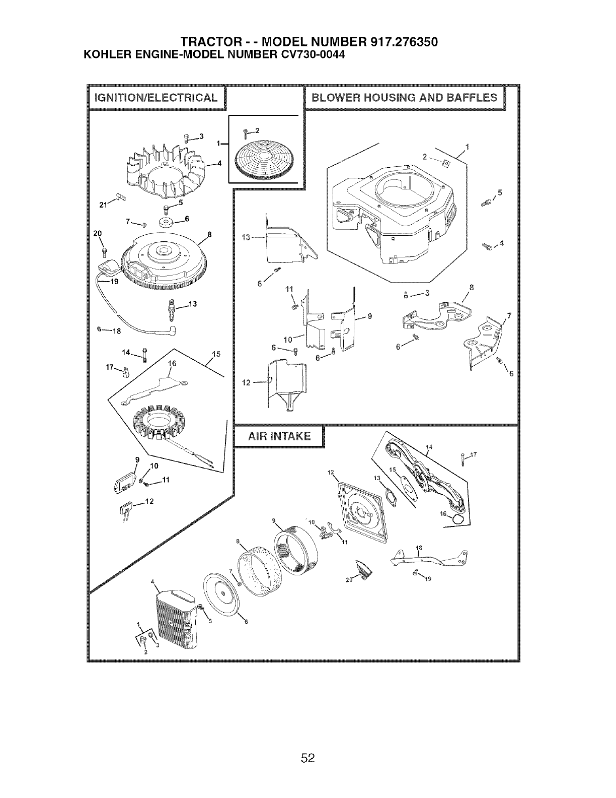
TRACTOR - - MODEL NUMBER 917.276350
KOHLER ENGINE-MODEL NUMBER CV730-0044
2_ _
6/
_j3
2
52
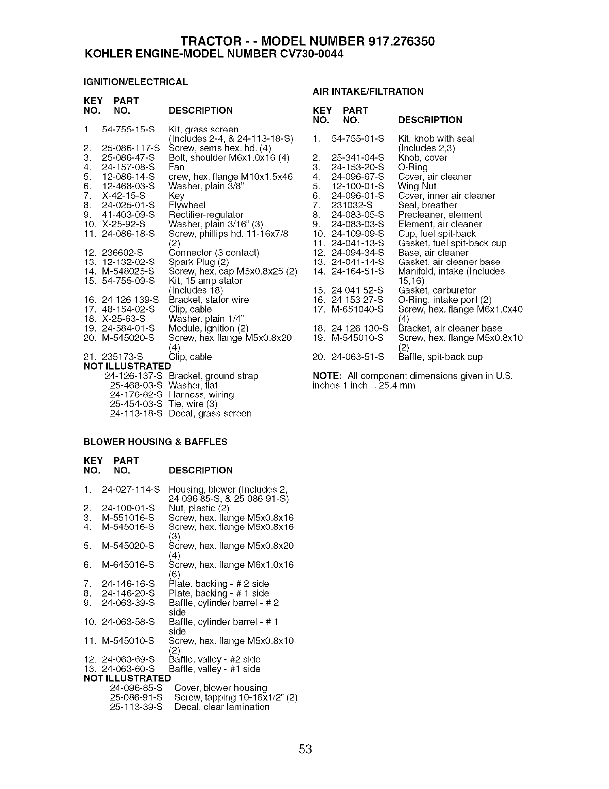
TRACTOR - - MODEL NUMBER 917.276350
KOHLER ENGINE-MODEL NUMBER CV730-0044
IGNITION/ELECTRICAL
KEY PART
NO. NO.
AIR INTAKE/FILTRATION
DESCRIPTION KEY PART
NO. NO.
1. 54-755-15-S Kit, grass screen
(Includes 2-4, & 24-113-18-S) 1. 54-755-01-S
2. 25-086-117-S Screw, semshex, hd.(4)
3. 25-086-47-S Bolt, shoulder M6x1.0x16 (4) 2. 25-341-04-S
4. 24-157-08-S Fan 3. 24-153-20-S
5. 12-086-14-S crew, hex. flange M10x1.5x46 4. 24-096-67-S
6. 12-468-03-S Washer, plain 3/8" 5. 12-100-01-S
7. X-42-15-S Key 6. 24-096-01-S
8. 24-025-01-S Flywheel 7. 231032-S
9. 41-403-09-S Rectifier-regulator 8. 24-083-05-S
10. X-25-92-S Washer, plain 3/16" (3) 9. 24-083-03-S
11. 24-086-18-S Screw, phillips hd. 11-16x7/8 10. 24-109-09-S
(2) 11. 24-041-13-S
12. 236602-S Connector (3 contact) 12. 24-094-34-S
13. 12-132-02-S Spark Plug (2) 13. 24-041-14-S
14. M-548025-S Screw, hex. cap M5x0.8x25 (2) 14. 24-164-51-S
15. 54-755-09-S Kit, 15 amp stator
(Includes 18) 15. 24 041 52-S
16. 24 126 139-S Bracket, statorwire 16. 24 153 27-S
17. 48-154-02-S Clip, cable 17. M-651040-S
18. X-25-63-S Washer, plain 1/4"
19. 24-584-01-S Module, ignition (2) 18. 24 126 130-S
20. M-545020-S Screw, hex flange M5x0.8x20 19. M-545010-S
(4)
21. 235173-S Clip, cable
NOT ILLUSTRATED
24-126-137-S Bracket, ground strap
25-468-03-S Washer, flat
24-176-82-S Harness, wiring
25-454-03-S Tie, wire (3)
24-113-18-S Decal, grass screen
DESCRIPTION
20. 24-063-51-S
Kit, knob with seal
(Includes 2,3)
Knob, cover
O-Ring
Cover, air cleaner
Wing Nut
Cover, inner air cleaner
Seal, breather
Precleaner, element
Element, air cleaner
Cup, fuel spit-back
Gasket, fuel spit-back cup
Base, air cleaner
Gasket, air cleaner base
Manifold, intake (Includes
15,16)
Gasket, carburetor
O-Ring, intake port (2)
Screw, hex. flange M6x1.0x40
(4)
Bracket, air cleaner base
Screw, hex. flange M5x0.8xl 0
(2)
Baffle, spit-back cup
NOTE: All component dimensions given in U,S,
inches 1 inch = 25.4 mm
BLOWER HOUSING & BAFFLES
KEY PART
NO. NO. DESCRIPTION
1. 24-027-114-S
2. 24-100-01-S
3. M-551016-S
4. M-545016-S
5. M-545020-S
6. M-645016-S
7. 24-146-16-S
8. 24-146-20-S
9. 24-063-39-S
10. 24-063-58-S
11. M-545010-S
12. 24-063-69-S
13. 24-063-60-S
NOT ILLUSTRATED
24-096-85-S
25-086-91-S
25-113-39-S
Housing, blower (Includes 2,
24 096 85-S, & 25 086 91-S)
Nut, plastic (2)
Screw, hex. flange M5x0.8x16
Screw, hex. flange M5x0.8x16
(3)
Screw, hex. flange M5x0.8x20
(4)
Screw, hex. flange M6x1.0x16
(6)
Plate, backing - # 2 side
Plate, backing - # 1 side
Baffle, cylinder barrel - # 2
side
Baffle, cylinder barrel - # 1
side
Screw, hex. flange M5x0.8xl0
(2)
Baffle, valley - #2 side
Baffle, valley - #1 side
Cover, blower housing
Screw, tapping 10-16xl/2" (2)
Decal, clear lamination
53
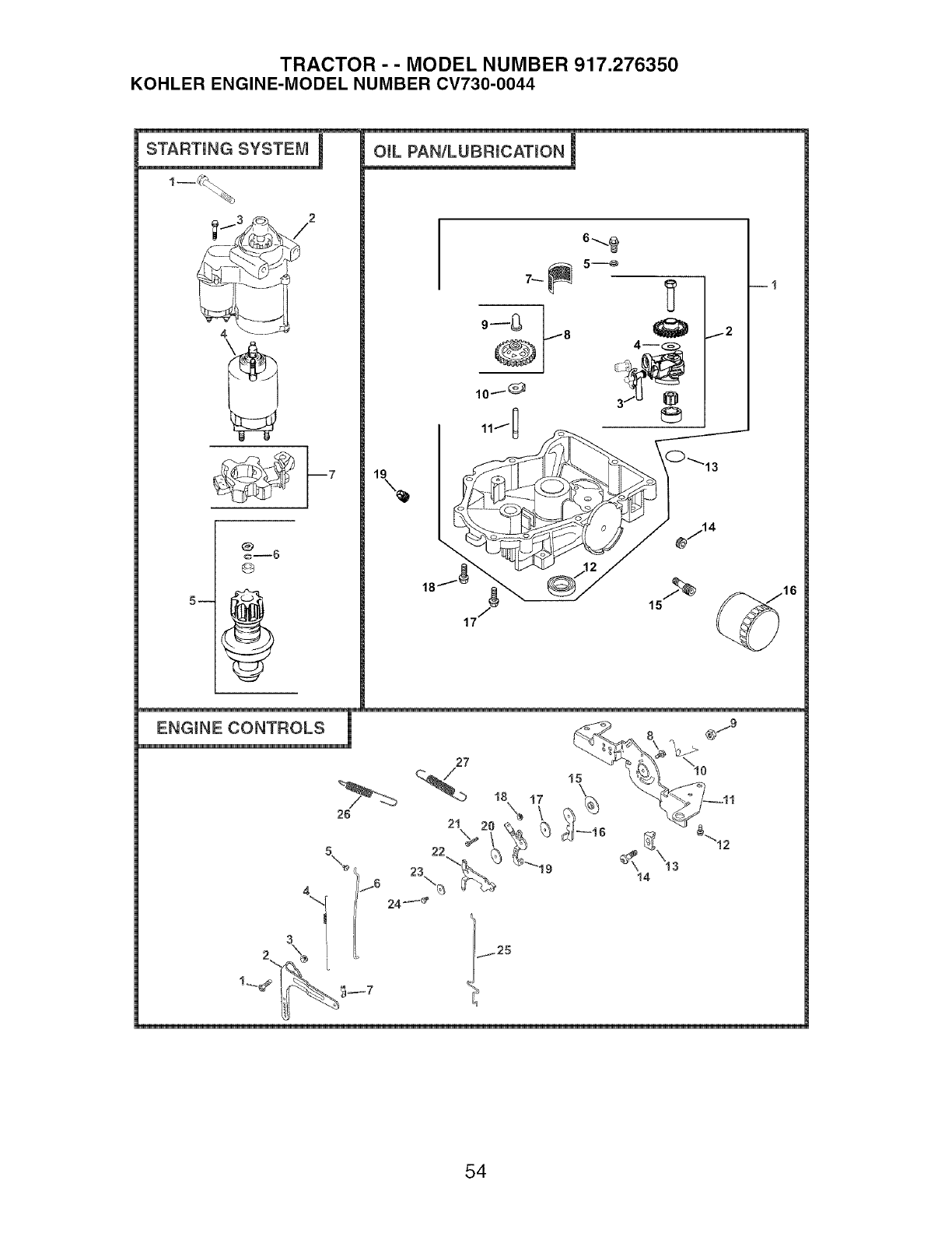
TRACTOR - - MODEL NUMBER 917.276350
KOHLER ENGINE-MODEL NUMBER CV730-0044
m
®
24_
54

TRACTOR - - MODEL NUMBER 917.276350
KOHLER ENGINE-MODEL NUMBER CV730-0044
STARTING SYSTEM OIL PAN/LUBRICATION
KEY PART KEY PART
NO. NO. DESCRIPTION NO. NO.
1. M-839080-S Screw, hex. flange
M8x1.25x80 (2)
2. 25-098-09-S Starter, solenoid shift (In-
cludes 3-7)
3. 25 086 113-S Screw, external torx hd.(3)
4. 25-435-05-S Kit, solenoid (Includes 3)
5. 25-755-33-S Kit, pinion drive (Includes 6)
6. 25-141-05-S Ring
7. 25-221-01-S Kit, brush
ENGINE CONTROLS
DESCRIPTION
KEY PART
NO. NO.
Bolt, round head square neck
Lever, governor
Nut, hex. flange M6x1.0
Spring, linkage
Bushing, linkage retaining
Linkage, throttle
Bushing, throttle linkage
Screw, hex. flange M5x0.8x16
Nut, hex. lock M5x0.8
Spring, choke return
Bracket, control
Screw, hex. flange M6x1.0x16
(4)
Clamp, cable (2)
Screw, hex. flange M5x0.8x16
(2)
Spacer
Lever, throttle actuator
Washer, plain
Nut, hex M4x0.7
Lever, throttle control
Washer, plain 5.5 mm (3)
Screw, hex. flange M5x0.8x20
Lever, choke
Washer, spring 1/4"
Screw, hex. cap M4x0.7x25
Linkage, choke
Spring, throttle limiter
Spring, governor
1. 24 211 03-S
2. 24-090-33-S
3. M-641060-S
4. 24-089-01 -S
5. 25-158-08-S
6. 24-079-04-S
7. 25-158-11-S
8. M-545016-S
9. M-547050-S
10. 24-089-03-S
11. 24-126-56-S
12. M-645016-S
13. 12-237-01-S
14. 24-086-43-S
15. 24-112-27-S
16. 24-090-47-S
17. 24-468-20-S
18. M-446030-S
19. 24-090-13-S
20. 24-468-01-S
21. M-545020-S
22. 24-090-05-S
23. 41-468-03-S
24. M-403025-S
25. 24-079-22-S
26. 24-089-55-S
27. 24-089-25-S
DESCRIPTION
1. 24-199-07-S Pan assembly, oil
(Includes 2-11)
2. 24-393-37-S Oil pump assembly (Includes
3,4)
3. 24-381-11-S Tube, oil pickup
4. 24 153 01-S O-Ring, oil pump
5. M-631005-S Washer, plain 6 mm (2)
6. M-645025-S Screw, hex. flange M6x1.0x25
(2)
7. 24-162-26-S Screen, oil
8. 24-043-12-S Kit, governor gear w/pin
(Includes 9)
9. 12-380-01-S Pin, governor regulating
10. 24-448-02-S Tab, locking
11. 12-144-02-S Shaft, governor gear
12. 52-032-08-S Seal, oil (PTO end)
13. 24-153-08-S O-Ring
14. 25-139-62-S Plug, hex. ctsk. 3/8"
15. 24-136-01-S Nipple, oil filter
16. 52-050-02-S Filter, oil
17. 24-086-17-S Screw, hex. flange
M8x1.25x45
18. 24-086-16-S Screw, hex. flange
M8x1.25x45 (9)
19. 25-139-57-S Plug, sq. hd. solid 3/8" N.RT.R
NOTE: All component dimensions given in U.S.
inches 1 inch = 25.4 mm
55
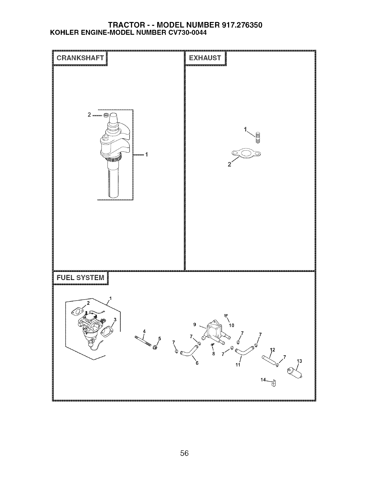
TRACTOR - - MODEL NUMBER 917.276350
KOHLER ENGINE-MODEL NUMBER CV730-0044
CRANKSHAFT ! EXHAUST !
FUEL SYSTEM I
5 7\ 7
6 11 13
14..g
56

TRACTOR - - MODEL NUMBER 917.276350
KOHLER ENGINE-MODEL NUMBER CV730-0044
CRANKSHAFT
KEY PART
NO. NO. DESCRIPTION
1, 24-014-72-S Crankshaft (Includes 2)
2. 52-139-09-S Plug, cup
EXHAUST
KEY PART
NO. NO. DESCRIPTION
1, 24-041-49-S Gasket, exhaust (2)
2. 25-072-04-S Stud, M8x1,25x33 (4)
- - 24-522-332 Short Block
- - 24-782-23 Miniblock
-- 24-755-113-S GasketSet
FUEL SYSTEM
KEY PART
NO. NO. DESCRIPTION
1, 24-853-102-S Kit, carburetor w/gaskets
(Includes 2,3)
2, 24-041-52-S Gasket, carburetor
3. 24 041 14-S Gasket, air cleaner base
4, M-629095-S Stud, M6x1.0x95 (2)
5, M-641060-S Nut, hex. flange M6xl,0 (2)
6. 25-353-03-S Line, fuel 14"
7, 25-237-14-S Clamp, hose (6)
8, 24-086-12-S Screw, hex. cap. M6x1.7x18
(2)
9. 24-393-16-S Pump, fuel - pulse
10, 24-100-01-S Nut, plastic (2)
11. 24-353-12-S Line, fuel 11"
12, 15-353-04-S Line, fuel 11-1/2"
13. 24-050-10-S Filter, fuel
14, 47-154-01-S Clip, cable
NOT ILLUSTRATED
- - 24 234 02-S Bowl, float
- - 24 757 18-S Kit, overhaul
- - 24 757 19-S Kit, choke repair
- - 24 757 20-S Kit, gasket
- - 24 757 22-S Kit, fuel shutdown solenoid
NOTE: All component dimensions given in U,S.
inches 1 inch : 25,4 mm
57

58

SUGGESTED GUIDE FOR SIGHTING SLOPES FOR SAFE OPERATION
O1
LO
ONLY RIDE UP AND DOWN HILL,
NOT ACROSS HILL
15 DEGREES MAX.
_ARNING: To avoid serious injury, operate your tractor up and
down the face of slopes, never across the face. Do not mow
slopes greater than 15 degrees. Make turns gradually to prevent
tipping or loss of control. Exercise extreme caution when
changing direction on slopes.

iHHHH
iHHHH
iHHHH
iHHHH
iHHHH
iiiiiiiiiiiiiiiiii
Your Home
For repair - in your home - of all major brand appliances,
lawn and garden equipment, or heating and cooling systems,
no matter who made it, no matter who sold it!
For the replacement parts, accessories and
owner's manuals that you need to do-it=yourself.
For Sears professional installation of home appliances
and items like garage door openers and water heaters.
1=800=4=MY=HOME ® Anytime, day or night
(1-800-469-4663) (U.S.A. and Canada)
www.sears.com www,sears.ca
Our Home
For repair of carry-in products like vacuums, lawn equipment,
and electronics, call or go on-line for the nearest
Sears Parts and Repair Center.
1-800-488-1222 Anytime, day or night (U.S.A. only)
www.sears.com
_%!!!!!!!ii!
iiiiiiiiiiiiiiiiiiii
iiiiiiiiiiiiiiiiiiii
iiiiiiiiiiiiiiiiiiii
iiiiiiiiiiiiiiiiiiii
iiiiiiiiiiiiiiiiiiii
iiiiiiiiiiiiiiiiiiii
iiiiiiiiiiiiiiiiiiii
iiiiiiiiiiiiiiiiiiii
iiiiiiiiiiiiii_;ii:_ii_ii_ii_ii_i
HHHHHHHH_
iiiiiiiiiiiiiiiiiii
To purchase a protection agreement (U.S.A.)
or maintenance agreement (Canada) on a product serviced by Sears:
1°800°827°6655 (U.S.A.) t o800o361 °6665 (Canada)
Para pedir servicio de reparaci6n
a domicilio, y para ordenar piezas:
1-888_U-HOG_ sM
(1-888-78445427)
Au Canada pour service en franccais:
I=800=LE=FOYER Mc
(1=800=533=6937)
www,sears.ca
02410
© Sears, Roebuck and Co.
® Registered Trademark /TMTrademark /SMService Mark of Sears, Roebuck and Co.
® Marca Registrada /TMMarca de Fabrica /SMMarca de Servicio de Sears, Roebuck and Co.
MCMarque de commerce /MDMarque d6pos6e de Sears, Roebuck and Co.
195834 Rev. 1 03.21.05 TR Printed in U.S.A.
