Craftsman 917288600 User Manual TRACTOR Manuals And Guides L0807368
CRAFTSMAN Lawn, Tractor Manual L0807368 CRAFTSMAN Lawn, Tractor Owner's Manual, CRAFTSMAN Lawn, Tractor installation guides
User Manual: Craftsman 917288600 917288600 CRAFTSMAN TRACTOR - Manuals and Guides View the owners manual for your CRAFTSMAN TRACTOR #917288600. Home:Lawn & Garden Parts:Craftsman Parts:Craftsman TRACTOR Manual
Open the PDF directly: View PDF ![]() .
.
Page Count: 72

Operator's Manual
JCRIIFTSMI N°J
GARDEN TRACTOR
26.0 HR* 54" Mower
Electric Start
Automatic Transmission
Model No.
917.28860
• Espar_ol, p. 36
This product has a low emission engine which operates
[_]]] differently from previously built engines. Before start the
you
engine, read and understand this Owner's Manual.
IMPORTANT:
Read and follow all Safety
Rules and Instructions before
operating this equipment.
For answers to your questions
about this product, Call:
1-800-659-5917
Sears Craftsman Help Line
5 am -5 pm, Mort -Sat
SEARS, ROEBUCK AND CO., HOFFMAN ESTATES, IL 60179 U.S.A.
Visit our Craftsman website:www.sears.com/craftsman *As rated by the engine manufacturer

Warranty ................................................ 2
Safety Rules .......................................... 3
Product Specifications ........................... 6
Assembly/Pre-Operation ....................... 8
Operation ............................................. 12
Maintenance Schedule ........................ 19
Maintenance ........................................ 19
Service and Adjustments ..................... 24
Storage ................................................ 30
Troubleshooting ................................... 31
Sears Service ........................ Back Cover
CRAFTSMAN LIMITED WARRANTY
TWO YEARS ON TRACTOR
When operated and maintained according to all supplied instructions, if this tractor fails
due to a defect in material or workmanship within two years from the date or purchase,
call 1-800-4-MY-HOME® to arrange for free repair.
During the first year of purchase, there will be no charge for warranty service in your home.
For your convenience, in-home warranty service will still be available after the first year
of purchase, but a trip charge will apply. This charge will be waived if you transport the
tractor to an authorized Craftsman drop-off location. For the nearest authorized location,
call 1-800-4-MY-HOME®.
90 DAYS ON BA'B'ERY
For ninety (90) days from date of purchase, if the battery included with this tractor is
defective in material or workmanship (our testing proves it will not hold a charge), it will be
replaced free of charge in your home.
This warranty covers ONLY defects in material and workmanship. Sears will NOT pay for:
Expendable items that become worn during normal use, including but not limited to
blades, spark plugs, air cleaners, belts, and oil filters.
Standard maintenance servicing, oil changes, or tune-ups.
Tire replacement or repair caused by punctures from outside objects, such as nails,
thorns, stumps, or glass.
Tire or wheel replacement or repair resulting from normal wear, accident, or improper
operation or maintenance.
Repairs necessary because of operator abuse, including but not limited to damage
caused by towing objects beyond the capability of the tractor, impacting objects that
bend the frame or crankshaft, or over-speeding the engine.
Repairs necessary because of operator negligence, including but not limited to, electrical
and mechanical damage caused by improper storage, failure to use the proper grade
and amount of engine oil, failure to keep the deck clear of flammable debris, or failure
to maintain the equipment according to the instructions contained in the operator's
manual.
Engine (fuel system) cleaning or repairs caused by fuel determined to be contaminated or
oxidized (stale). In general, fuel should be used within 30 days of its purchase date.
Normal deterioration and wear of the exterior finishes, or product label replacement.
All tractor and battery warranty coverage is void if this product is ever used for
commercial or rental purposes.
This warranty applies only while this product is within the United States.
This warranty gives you specific legal rights, and you may also have other rights which
vary from state to state.
Sears, Roebuck and Co., Hoffman Estates, IL 60179
2
_DANGER: This cutting machine is capable of amputating hands and feet and
throwing objects. Failure to observe the following safety instructions could result
in serious injury or death,
A_,WARNING: In order to prevent ac-
cidental starting when setting up, trans-
porting, adjusting or making repairs, always
disconnect spark plug wire and place
wire where it cannot contact spark plug.
_,WARNING: Do not coast down a hill in
neutral, you may lose control of the tractor.
_,WARNING: Tow only the attachments
that are recommended by and comply
with specifications of the manufacturer of
your tractor. Use common sense when
towing. Operate only at the lowest pos-
sible speed when on a slope. Too heavy
of a load, while on a slope, is dangerous.
Tires can lose traction with the ground and
cause you to lose control of your tractor.
_IbWARNING: Engine exhaust, some of
its constituents, and certain vehicle com-
ponents contain or emit chemicals known
to the State of California to cause cancer
and birth defects or other reproductive harm.
,_WARNING: Battery posts, terminals
and related accessories contain lead and
lead compounds, chemicals known to
the State of California to cause cancer
and birth defects or other reproductive
harm. Wash hands after handling.
I. GENERAL OPERATION
Read, understand, and fol-
low all instructions on the machine
and in the manual before starting.
• Do not put hands or feet near rotating
parts or under the machine. Keep clear
of the discharge opening at all times.
• Only allow responsible adults,
who are familiar with the instruc-
tions, to operate the machine.
• Clear the area of objects such as
rocks, toys, wire, etc., which could be
picked up and thrown by the blades.
• Be sure the area is clear of by-
standers before operating. Stop
machine if anyone enters the area.
• Never carry passengers.
• Do not mow in reverse unless abso-
lutely necessary. Always look down
and behind before and while backing.
• Never direct discharged material toward
anyone. Avoid discharging material
against awall or obstruction. Material may
ricochet back toward the operator. Stop
the bladeswhen crossing gravel surfaces.
• Do not operate machine without the
entire grass catcher, discharge guard, or
other safety devices in place and working.
• Slow down before turning.
• Never leave a running machine unat-
tended. Always turn off blades, set
parking brake, stop engine, and re-
move keys before dismounting.
• Disengage blades when not mowing.
Shut off engine and wait for all parts to
come to a complete stop before clean-
ing the machine, removing the grass
catcher, or unclogging the discharge guard.
• Operate machine only in daylight or good
artificial light.
• Do not operate the machine while un-
der the influence of alcohol or drugs.
• Watch for traffic when operating near or
crossing roadways.
• Use extra care when loading or unload-
ing the machine into a trailer or truck.
• Always wear eye protection when operat-
ing machine.
• Data indicates that operators, age 60
years and above, are involved in a
large percentage of riding mower-re-
lated injuries. These operators should
evaluate their ability to operate the riding
mower safely enough to protect them-
selves and others from serious injury.
• Follow the manufacturer's recommenda-
tion for wheel weights or counterweights.
• Keep machine free of grass, leaves or
other debris build-up which can touch
hot exhaust/engine parts and burn. Do
not allow the mower to plow leaves or
other debris which can cause build-up
to occur. Clean any oil or fuel spillage
before operating or storing the ma-
chine. Allow machine to cool before
storage.
3
II. SLOPE OPERATION
Slopes are a major factor related to loss of
control and tip-over accidents, which can
result in severe injury or death. Operation
on all slopes requires extra caution. If you
can not back up the slope or if you feel uneasy
on it, do not mow it.
•Mow up and down slopes, not across.
• Watch for holes, ruts, bumps, rocks, or
other hidden objects. Uneven terrain could
overturn the machine. Tall grass can hide
obstacles.
•Choose alowground speed sothat you will
not have to stop or shift while on the slope.
• Do not mow on wet grass. Tires may lose
traction. Always keep the machine in gear
when going down slopes. Do not shift to
neutral and coast downhill.
• Avoid starting, stopping, or turning on a
slope. Ifthetires Iosetraction, disengage
the blades and proceed slowly straight
down the slope.
• Keep all movement on the slopes slowand
gradual. Do not make sudden changes
in speed or direction, which could cause
the machine to roll over.
• Use extra care while operating machine
with grass catchers or other attachments;
they can affectthe stability of the machine.
Do no use on steep slopes.
• Do not try to stabilize the machine by put-
ting your foot on the ground.
• Do not mow near drop-offs, ditches, or
embankments. The machine could sud-
denly roll over if a wheel is over the edge
or if the edge caves in.
III. CHILDREN
Tragic accidents can occur if the operator is
not alert to the presence of children. Chil-
dren are often attracted to the machine and
the mowing activity. Never assume that chil-
dren will remain where you last saw them.
• Keep children out of the mowing area and
in the watchful care of a responsible adult
other than the operator.
• Be alert and turn machine off if a child
enters the area.
• Before and while backing, look behind and
down for small children.
• Never carry children, even with the blades
shutoff. They may fall offand be seriously
injured or interfere with safe machine
operation. Children who have been given
rides in the past may suddenly appear in
the mowing area for another ride and be run
over or backed over by the machine. 4
Neverallowchildrentooperatethemachine.
Use extra care when approaching blind
corners, shrubs, trees, or other objects
that may block your view of a child.
IV. TOWING
• Tow only with a machine that has a hitch
designed for towing. Do not attach towed
equipment except at the hitch point.
• Follow the manufacturer's recommenda-
tion for weight limits for towed equipment
and towing on slopes.
• Never allow children or others in or on
towed equipment.
• On slopes,theweig htofthetowed equipment
maycause loss oftraction and Iossofcontrol.
• Travelslowly and allowextradistancetostop.
V. SERVICE
SAFE HANDLING OF GASOLINE
To avoid personal injury or property dam-
age, use extreme care in handling gasoline.
Gasoline is extremely flammable and the
vapors are explosive.
• Extinguish all cigarettes, cigars, pipes,
and other sources of ignition.
• Use only approved gasoline container.
• Never remove gas cap or add fuel with
the engine running. Allow engine to cool
before refueling.
• Never fuel the machine indoors.
• Never store the machine or fuel container
where there is an open flame, spark, or
pilot light such as on a water heater or
other appliances.
• Never fill containers inside a vehicle or
on a truck or trailer bed with plastic liner.
Always place containers on the ground
away from your vehicle when filling.
• Remove gas-powered equipment from the
truck or trailer and refuel it on the ground.
If this is not possible, then refuel such
equipment with a portable container, rather
than from a gasoline dispenser nozzle.
• Keep the nozzle in contact with the rim of
the fuel tank or container opening at all
times until fueling is complete. Do not use
a nozzle lock-open device.
• If fuel is spilled on clothing, change cloth-
ing immediately.
• Never overfill fuel tank. Replace gas cap
and tighten securely.
GENERAL SERVICE
• Never operate machine in a closed area.
• Keep all nuts and bolts tight to be sure the
equipment is in safe working condition.
• Never tamper with safety devices. Check
their proper operation regularly.
• Keep machine free of grass, leaves, or
other debris build-up. Clean oil or fuelspill-
age and remove any fuel-soaked debris.
Allow machine to cool before storing.
• If you strike a foreign object, stop and
inspect the machine. Repair, if necessary,
before restarting.
• Never make any adjustments or repairs
with the engine running.
• Check grass catcher components and the
discharge guard frequently and replace
with manufacturer's recommended parts,
when necessary.
• Mower blades are sharp. Wrap the blade or
wear gloves, and use extra caution when
servicing them.
• Check brake operation frequently. Adjust
and service as required.
• Maintain or replace safety and instruction
labels, as necessary.
• Be sure the area is clear of bystanders
before operating. Stop machine if anyone
enters the area.
• Never carry passengers.
• Do not mow in reverse unless absolutely
necessary. Always look down and behind
before and while backing.
• Never carry children, even with the blades
shut off. They may fall off and be seriously
injured or interfere with safe machine
operation. Children who have been given
rides in the past may suddenly appear in
the mowing area for another ride and be
run over or backed over by the machine.
• Keep children out of the mowing area and
in the watchful care of a responsible adult
other than the operator.
• Be alert and turn machine off if a child
enters the area.
• Before and while backing, look behind and
down for small children.
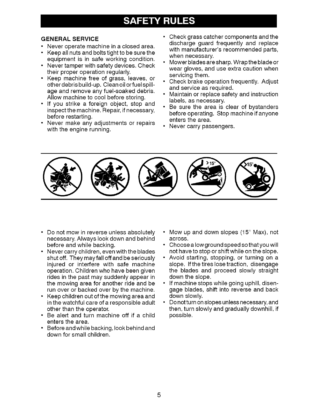
• Mow up and down slopes (15 ° Max), not
across,
• Choose a Iowground speed sothatyou will
not have to stop or shift while on the slope.
• Avoid starting, stopping, or turning on a
slope. If the tires lose traction, disengage
the blades and proceed slowly straight
down the slope.
• If machine stops while going uphill, disen-
gage blades, shift into reverse and back
down slowly.
• Do not turn on slopes unless necessary, and
then, turn slowly and gradually downhill, if
possible.
5
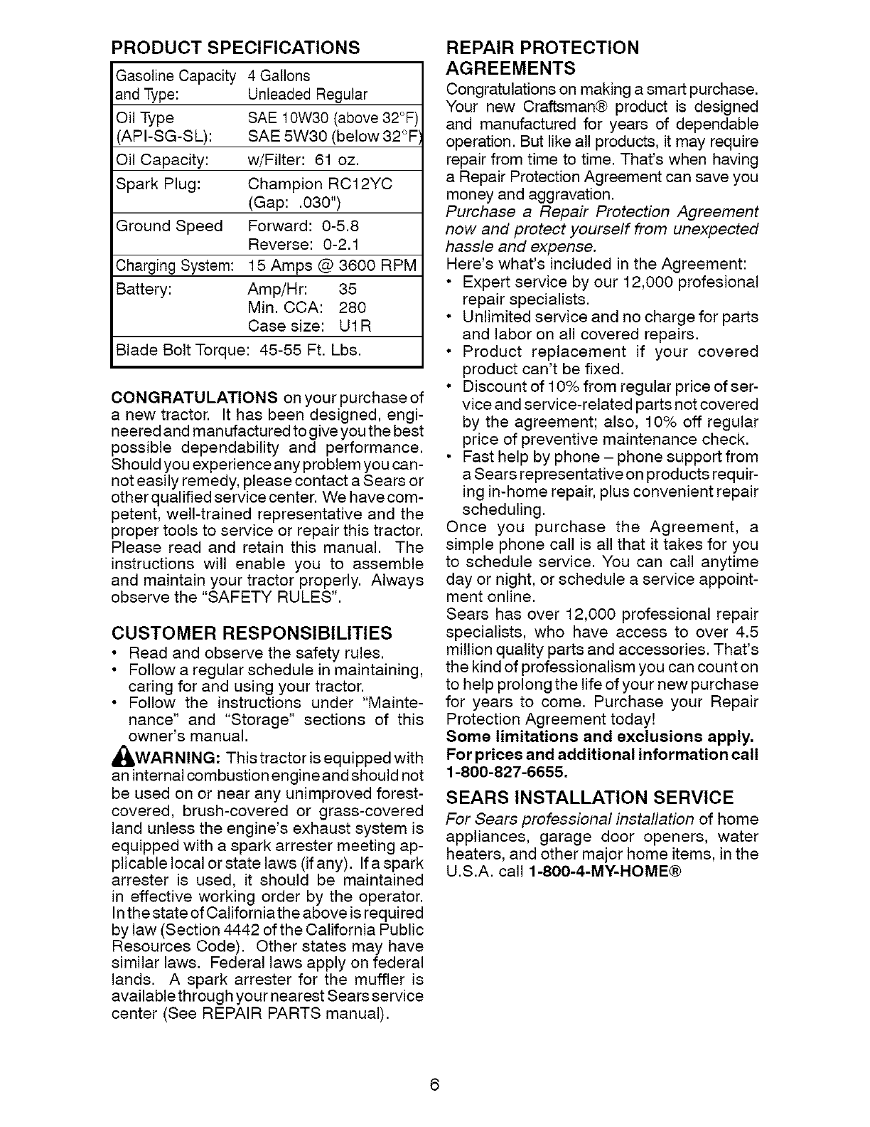
PRODUCT SPECIFICATIONS
Gasoline Capacity 4 Gallons
and Type: Unleaded Regular
Oil Type SAE 10W30 (above 32°F)
'API-SG-SL): SAE 5W30 (below 32°F
Oil Capacity: w/Filter: 61 oz.
Spark Plug: Champion RC12YC
(Gap: .030")
Ground Speed Forward: 0-5.8
Reverse: 0-2.1
Charging System: 15 Amps @ 3600 RPM
Battery: Amp/Hr: 35
Min. CCA: 280
Case size: U1R
Blade Bolt Torque: 45-55 Ft. Lbs.
CONGRATULATIONS on your purchase of
a new tractor. It has been designed, engi-
neered and man ufactured to give you the best
possible dependability and performance.
Should you experience any problem you can-
not easily remedy, please contact a Sears or
other qualified service center. We have com-
petent, well-trained representative and the
proper tools to service or repair this tractor.
Please read and retain this manual. The
instructions will enable you to assemble
and maintain your tractor properly. Always
observe the "SAFETY RULES".
CUSTOMER RESPONSIBILITIES
• Read and observe the safety rules.
• Follow a regular schedule in maintaining,
caring for and using your tractor.
• Follow the instructions under "Mainte-
nance" and "Storage" sections of this
owner's manual.
_,WARNING: This tractor is equipped with
an internal combustion engine and should not
be used on or near any unimproved forest-
covered, brush-covered or grass-covered
land unless the engine's exhaust system is
equipped with a spark arrester meeting ap-
plicable local or state laws (if any). If a spark
arrester is used, it should be maintained
in effective working order by the operator.
In the state of California the above is req ui red
by law (Section 4442 of the California Public
Resources Code). Other states may have
similar laws. Federal laws apply on federal
lands. A spark arrester for the muffler is
available through your nearest Sears service
center (See REPAIR PARTS manual).
REPAIR PROTECTION
AGREEMENTS
Congratulations on making a smart purchase.
Your new Craftsman@ product is designed
and manufactured for years of dependable
operation. But like all products, it may require
repair from time to time. That's when having
a Repair Protection Agreement can save you
money and aggravation.
Purchase a Repair Protection Agreement
now and protect yourself from unexpected
hassle and expense.
Here's what's included in the Agreement:
Expert service by our 12,000 profesional
repair specialists.
Unlimited service and no charge for parts
and labor on all covered repairs.
Product replacement if your covered
product can't be fixed.
Discount of 10% from regular price of ser-
vice and service-related parts not covered
by the agreement; also, 10% off regular
price of preventive maintenance check.
Fast help by phone - phone support from
a Sears representative on products requir-
ing in-home repair, plus convenient repair
scheduling.
Once you purchase the Agreement, a
simple phone call is all that it takes for you
to schedule service. You can call anytime
day or night, or schedule a service appoint-
ment online.
Sears has over 12,000 professional repair
specialists, who have access to over 4.5
million quality parts and accessories. That's
the kind of professionalism you can count on
to help prolong the life of your new purchase
for years to come. Purchase your Repair
Protection Agreement today!
Some limitations and exclusions apply.
For prices and additional information call
1-800-827-6655.
SEARS INSTALLATION SERVICE
For Sears professional installation of home
appliances, garage door openers, water
heaters, and other major home items, in the
U.S.A. call 1-800-4-MY-HOME@
6
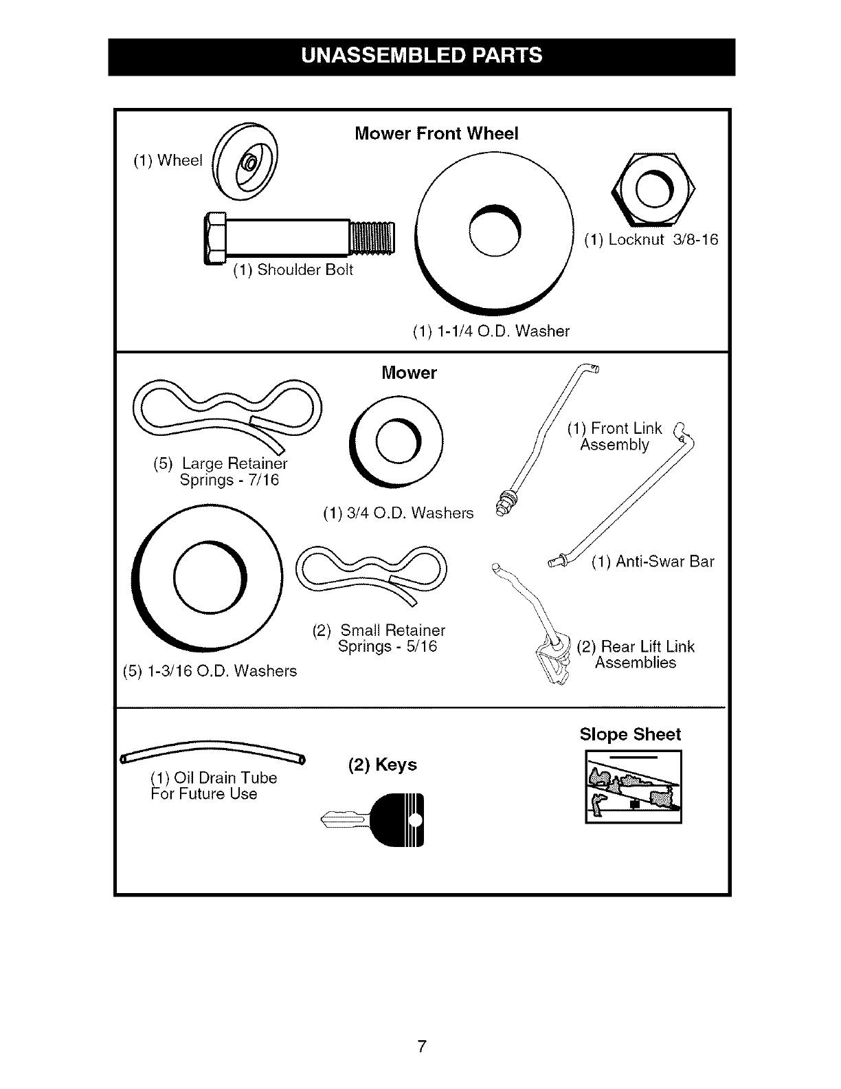
(1) Wheel
D
Mower Front Wheel
(1) Shoulder Bolt
(1) 1-1/40.D. Washer
(1) Locknut 3/8-16
Mower
(1) 3/40.D. Washers
(2) Small Retainer
Springs- 5/16
(5) 1-3/16 O.D. Washers
_ (_1 _srOnt Link
embly
(1) Anti-Swar Bar
(2) Rear Lift Link
Assemblies
(1) Oil Drain Tube
For Future Use
(2) Keys
Slope Sheet
7
Your new tractor has been assembled at the factory with the exception of those parts left
unassembled for shipping purposes.
TOOLS REQUIRED FOR
ASSEMBLY
A socket wrench set will make assembly
easier. Standard wrench sizes you need
are listed below.
(1) 3/4" wrench (1) Pliers
(1) 9/16" wrench (1) Utility knife
(1) Tire pressure gauge
When right or left hand is mentioned in this
manual, it means, from your point of view,
when you are in the operating position (seat-
ed behind the steering wheel).
TO REMOVE TRACTOR FROM
CARTON
UNPACK CARTON
1. Remove all accessible loose parts and
parts cartons from carton.
2. Cut along dashed lines on all four panels
of carton. Remove end panels and lay
side panels flat.
3. Remove mower and packing materials.
4. Check for any additional loose aprts or
cartons and remove.
CHECK BATTERY
1. Lift hood to raised position.
NOTE: If this battery is put into service after
month and year indicated on label (L) (label
is located between terminals) charge battery
for minimum of one hour at 6-10 amps. (See
"BA'i-I-ERY" in Maintenance section of this
manual for charging instructions).
f
ADJUST SEAT
1. Sit in seat.
2. Lift up adjustment lever (A) and slide seat
until a comfortable position is reached
which allows you to press clutch/brake
pedal all the way down.
3. Release lever to lock seat in position.
NOTE: You may now roll your tractor off the
skid. Followthe appropriate instruction below
to remove the tractor from the skid.
WARNING: Before starting, read, un-
derstand and follow all instructions in the
Operation section of this manual. Be sure
tractor is in a well-ventilated area. Be sure
the area in front of tractor is clear of other
people and objects.
TO ROLL TRACTOR OFF SKID
(See Operation section for location
and function of controls)
1. Raise attachment lift lever to its highest
position.
2. Release parking brake by depressing
brake pedal.
3. Place freewheel control in "transmission
disengaged position" (See "TO TRANS-
PORT" in the Operation section of this
manual).
4. Roll tractor forward off skid.
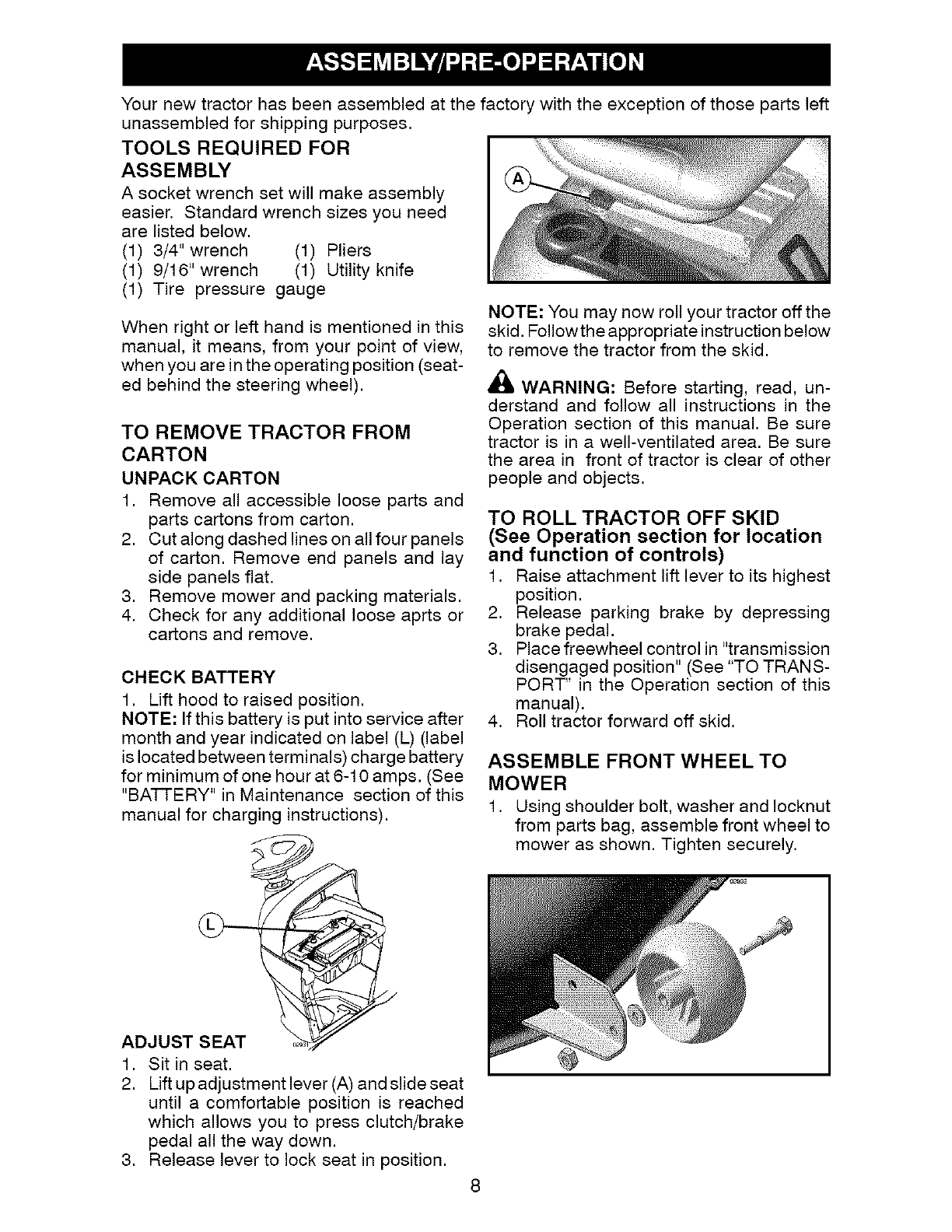
ASSEMBLE FRONT WHEEL TO
MOWER
1. Using shoulder bolt, washer and Iocknut
from parts bag, assemble front wheel to
mower as shown. Tighten securely.
8
INSTALL MOWER AND DRIVE
BELT
See MOWERAND DRIVE BELTASSEMBLY
Supplement Sheet for additional guidance
on this assembly.
Be sure tractor is on level surface and engage
parking brake.
1. Lower attachment lift lever to its lowest
position.
CAUTION: Lift lever is spring loaded.
Have a tight grip on lift lever, lower it slowly
and engage in lowest position.
2. Turn steering wheel to the left as far as it
will go and position mower on right side of
tractor with deflector shield to the right.
3. Remove plastic tie securing belt, bring
belt forward and check belt for proper
routing in all mower pulley grooves.
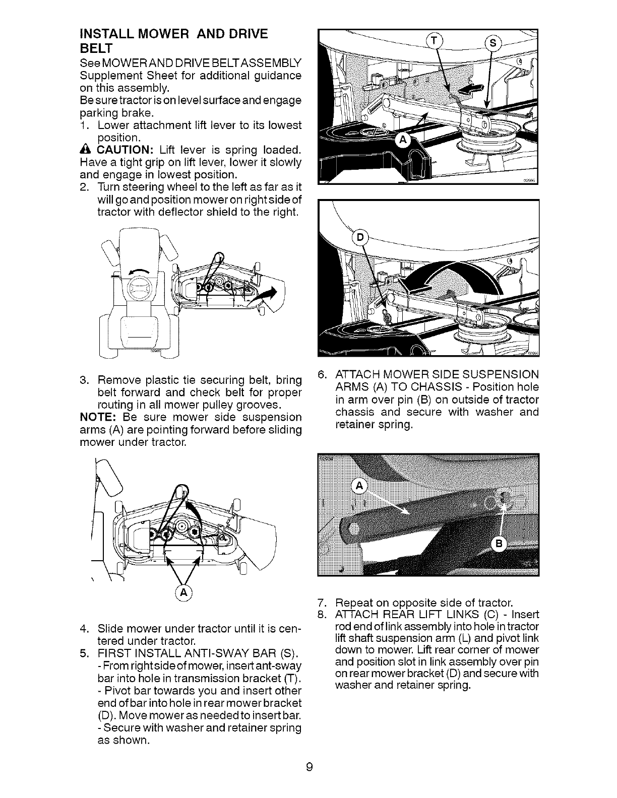
NOTE: Be sure mower side suspension
arms (A) are pointing forward before sliding
mower under tractor.
6. ATTACH MOWER SIDE SUSPENSION
ARMS (A) TO CHASSIS - Position hole
in arm over pin (B) on outside of tractor
chassis and secure with washer and
retainer spring.
4. Slide mower under tractor until it is cen-
tered under tractor.
5. FIRST INSTALL ANTI-SWAY BAR (S).
- From rightsideof mower, insert ant-sway
bar into hole in transmission bracket (T).
- Pivot bar towards you and insert other
end of bar into hole in rear mower bracket
(D). Move mower as needed to insert bar.
- Secure with washer and retainer spring
as shown.
7. Repeat on opposite side of tractor.
8. A-Ft-ACH REAR LIFT LINKS (C) - Insert
rod end of link assembly into hole in tractor
lift shaft suspension arm (L) and pivot link
down to mower. Lift rear corner of mower
and position slot in link assembly over pin
on rear mower bracket (D) and secure with
washer and retainer spring.
9
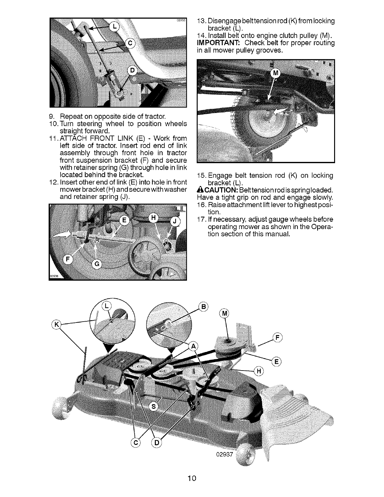
13.Disengagebelttensionrod(K)fromlocking
bracket(L).
14.Installbeltontoengineclutchpulley(M).
IMPORTANT: Check beltfor properrouting
in all mowerpulleygrooves.
9. Repeaton oppositesideof tractor.
10.Turn steering wheel to positionwheels
straightforward.
11.AFfACH FRONTLINK (E) - Work from
left side of tractor.Insert rod end of link
assembly through front hole in tractor
front suspensionbracket(F) and secure
withretainerspring(G)throughholeinlink
locatedbehindthe bracket.
12.Insertotherendof link(E)intoholeinfront
mowerbracket(H)andsecurewithwasher
and retainerspring(J).
15.Engage belt tension rod (K) on locking
_ bracket(L).
CAUTION:Belttensionrodisspringloaded.
Havea tight grip on rod and engageslowly.
16.Raiseattachmentliftleverto highestposi-
tion.
17.If necessary,adjustgaugewheelsbefore
operatingmoweras showninthe Opera-
tion sectionof this manual.
02937
10
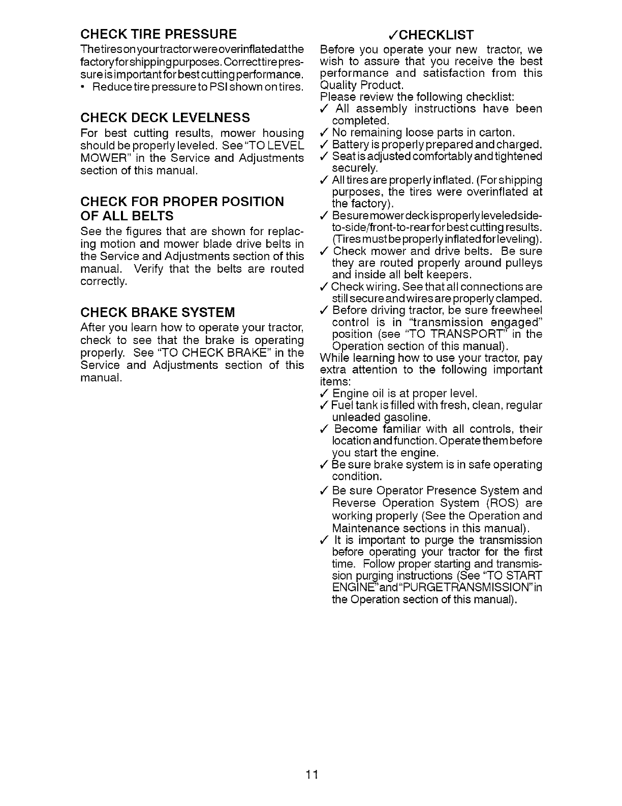
CHECKTIREPRESSURE
Thetireson yourtractorwereoverinflated atthe
factoryforshipping purposes. Correcttire pres-
sure is important for bestcutting performance.
• Reducetire pressureto PSI shown ontires.
CHECK DECKLEVELNESS
For best cutting results, mower housing
should be properly leveled. See "TO LEVEL
MOWER" in the Service and Adjustments
section of this manual.
CHECK FOR PROPER POSITION
OF ALL BELTS
See the figures that are shown for replac-
ing motion and mower blade drive belts in
the Service and Adjustments section of this
manual. Verify that the belts are routed
correctly.
CHECK BRAKESYSTEM
After you learn how to operate your tractor,
check to see that the brake is operating
properly. See "TO CHECK BRAKE" in the
Service and Adjustments section of this
manual.
JCHECKLIST
Before you operate your new tractor, we
wish to assure that you receive the best
performance and satisfaction from this
Quality Product.
Please review the following checklist:
,/ All assembly instructions have been
completed.
,/No remaining loose parts in carton.
,/Battery is properly prepared and charged.
,/Seat is adjusted comfortably and tightened
securely.
¢" All tires are properly inflated. (For shipping
purposes, the tires were overinflated at
the factory).
,/Besure mower deckis properlyleveledside-
to-side/front-to-rear for best cutting results.
(Tires must be properly inflated forleveling).
¢ Check mower and drive belts. Be sure
they are routed properly around pulleys
and inside all belt keepers.
,/Check wiring. See that all connections are
still secure and wires are properly clamped.
,/Before driving tractor, be sure freewheel
control is in "transmission engaged"
position (see "TO TRANSPORT" in the
Operation section of this manual).
While learning how to use your tractor, pay
extra attention to the following important
items:
,/Engine oil is at proper level.
,/Fuel tank is filled with fresh, clean, regular
unleaded gasoline.
,/ Become familiar with all controls, their
location and function. Operate them before
you start the engine.
,/Be sure brake system is in safe operating
condition.
,/
,/
Be sure Operator Presence System and
Reverse Operation System (ROS) are
working properly (See the Operation and
Maintenance sections in this manual).
It is important to purge the transmission
before operating your tractor for the first
time. Follow proper starting and transmis-
sion purging instructions (See "TO START
ENGINE'and"PURGETRANSMISSlON'in
the Operation section of this manual).
11
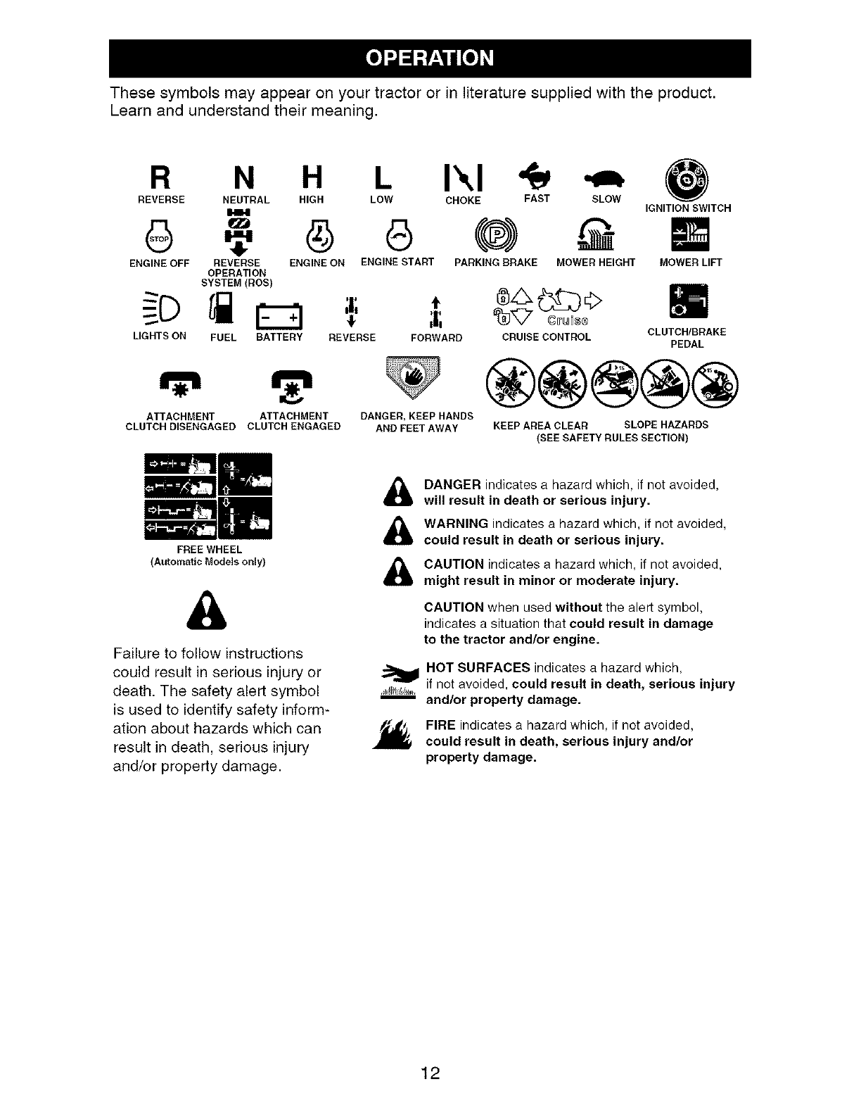
These symbols may appear on your tractor or in literaturesuppliedwith the product.
Learn and understandtheir meaning.
R N H L I\1
REVERSE NEUTRAL HIGH LOW CHOKE FAST SLOW
6
ENGINE OFF PARKING DRAKE MOWER HEIGHT
IGNITION SWITCH
REVERSE ENGINE ON ENGINE START
OPERATION
SYSTEM(DOS) ,,
LIGHTS ON FUEL BATTERY REVERSE FORWARD CRUISE CONTROL CLUTCH/BRAKE
PEDAL
MOWER LIFT
m
ATTACHMENT
CLUTCH DISENGAGED
ATTACHMENT
CLUTCH ENGAGED
FREE WHEEL
{Automatic Modelsonly)
DANGER, KEEP HANDS
AND FEETAWAY KEEP AREA CLEAR SLOPE HAZARDS
(SEE SAFETY RULES SECTION)
&
Failure to follow instructions
could result in serious injury or
death, The safety alert symbol
is used to identify safety inform-
ation about hazards which can
result in death, serious injury
and/or property damage,
DANGER indicates a hazard which, if not avoided,
will result in death or serious injury.
WARNING indicates a hazard which, if not avoided,
could result in death or serious injury.
,_l_I{l/lll_lll.,
n
CAUTION indicates a hazard which, if not avoided,
might result in minor or moderate injury.
CAUTION when used without the alert symbol,
indicates a situation that could result in damage
to the tractor and/or engine.
HOT SURFACES indicates a hazard which,
if not avoided, could result in death, serious injury
and/or property damage.
FIRE indicates a hazard which, if not avoided,
could result in death, serious injury and/or
property damage.
12
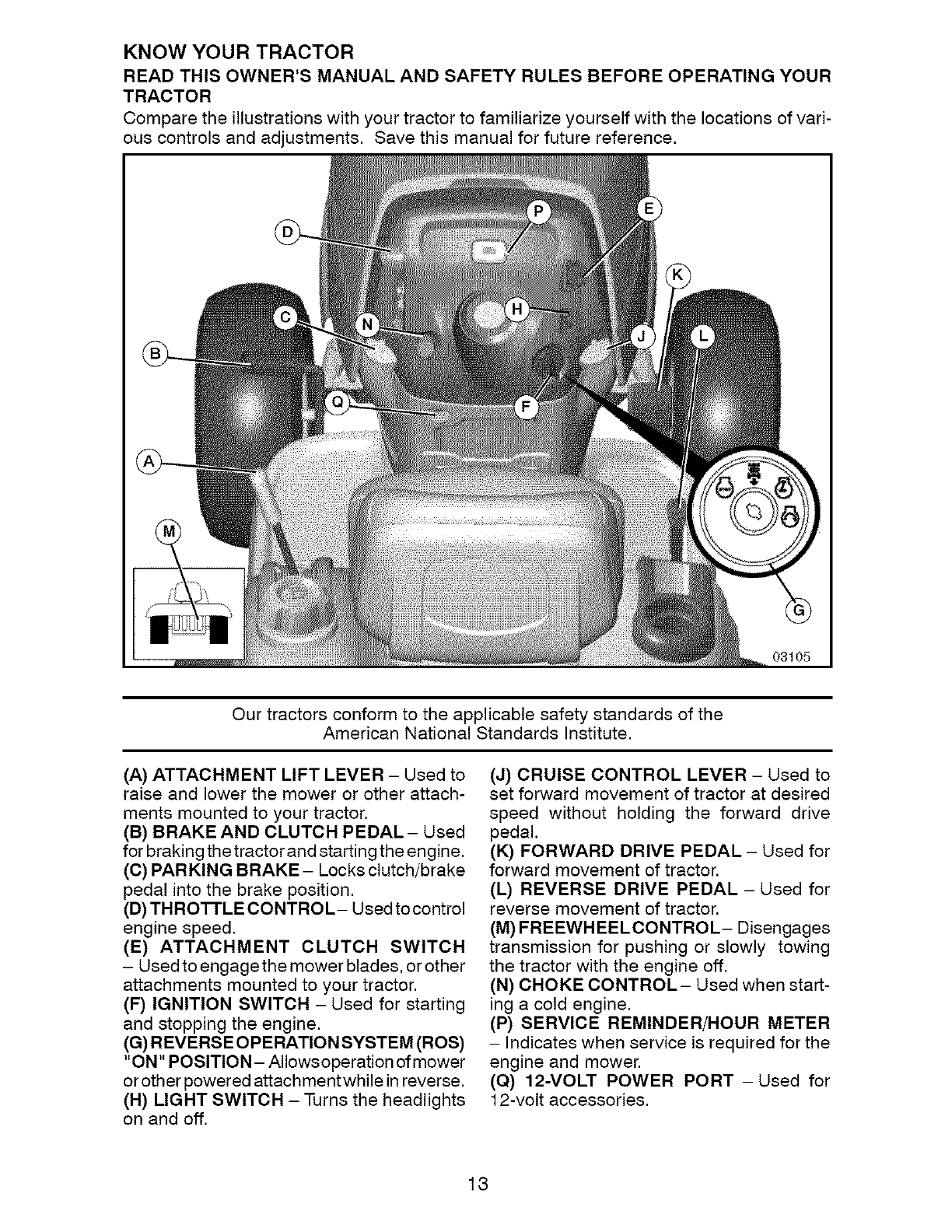
KNOW YOUR TRACTOR
READ THIS OWNER'S MANUAL AND SAFETY RULES BEFORE OPERATING YOUR
TRACTOR
Compare the illustrations with your tractor to familiarize yourself with the locations of vari-
ous controls and adjustments. Save this manual for future reference.
03105
Our tractors conform to the applicable safety standards of the
American National Standards Institute.
(A) ATTACHMENT LIFT LEVER - Used to
raise and lower the mower or other attach-
ments mounted to your tractor.
(B) BRAKE AND CLUTCH PEDAL- Used
for braking the tractor and starting the engine.
(C) PARKING BRAKE - Locks clutch/brake
pedal into the brake position.
(D) TH RO'I-FLE CONTRO L- Used to control
engine speed.
(E) ATTACHMENT CLUTCH SWITCH
- Used to engage the mower blades, or other
attachments mounted to your tractor.
(F) IGNITION SWITCH - Used for starting
and stopping the engine.
(G) REVERS E OPERATION SYSTEM (ROS)
"ON" POSITION- AIIowsoperation of mower
or other powered attachment while in reverse.
(H) LIGHT SWITCH - Turns the headlights
on and off.
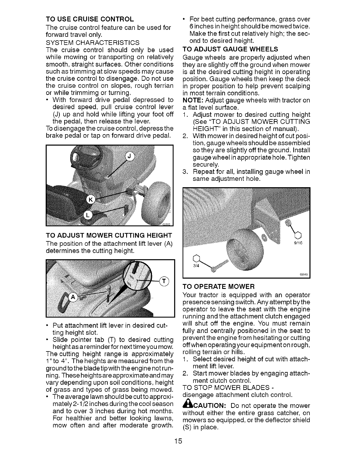
(J) CRUISE CONTROL LEVER - Used to
set forward movement of tractor at desired
speed without holding the forward drive
pedal.
(K) FORWARD DRIVE PEDAL - Used for
forward movement of tractor.
(L) REVERSE DRIVE PEDAL - Used for
reverse movement of tractor.
(M) FREEWHEELCONTROL- Disengages
transmission for pushing or slowly towing
the tractor with the engine off.
(N) CHOKE CONTROL- Used when start-
ing a cold engine.
(P) SERVICE REMINDER/HOUR METER
- Indicates when service is required for the
engine and mower.
(Q) 12-VOLT POWER PORT -Used for
12-volt accessories.
13
The operation of anytractor can resultin foreign objects thrown into the
eyes, which can result in severe eye damage. Always wear safety glasses
or eye shieldswhile operating your tractoror performingany adjustments
or repairs. We recommendstandard safety glasses or a wide vision safety
maskworn over spectacles.
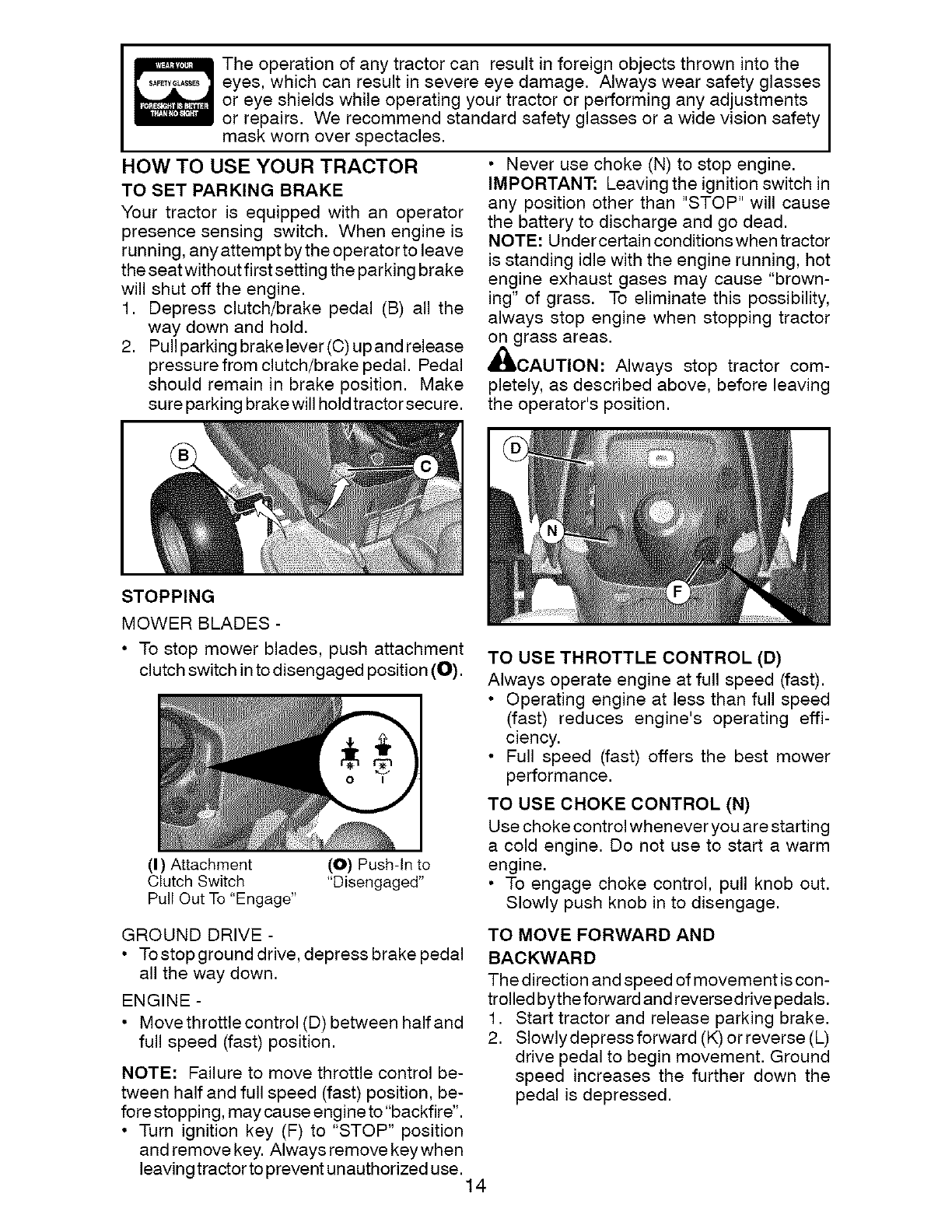
HOW TO USE YOUR TRACTOR
TO SET PARKING BRAKE
Your tractor is equipped with an operator
presence sensing switch. When engine is
running, anyattempt by the operator to leave
the seat without first setting the parking brake
will shut off the engine.
1. Depress clutch/brake pedal (B) all the
way down and hold.
2. Pull parking brake lever (C) up and release
pressure from clutch/brake pedal. Pedal
should remain in brake position. Make
sure parking brake will hold tractor secure.
Never use choke (N) to stop engine.
IMPORTANT: Leaving the ignition switch in
any position other than "STOP" will cause
the battery to discharge and go dead.
NOTE: Undercertain conditions when tractor
is standing idle with the engine running, hot
engine exhaust gases may cause "brown-
ing" of grass. To eliminate this possibility,
always stop engine when stopping tractor
on grass areas.
,_,CAUTION: Always stop tractor com-
pletely, as described above, before leaving
the operator's position.
STOPPING
MOWER BLADES -
• To stop mower blades, push attachment
clutch switch in to disengaged position (O).
(I) Attachment
Clutch Switch
Pull Out To "Engage"
(O) Push-In to
"Disengaged"
GROUND DRIVE -
• Tostopground drive, depress brake pedal
all the way down.
ENGINE -
• Move throttle control (D) between half and
full speed (fast) position.
NOTE: Failure to move throttle control be-
tween half and full speed (fast) position, be-
fore stopping, may cause engine to "backfire".
• Turn ignition key (F) to "STOP" position
and remove key. Always remove keywhen
leaving tractor to prevent unauthorized use. 14
TO USE THROTTLE CONTROL (D)
Always operate engine at full speed (fast).
Operating engine at less than full speed
(fast) reduces engine's operating effi-
ciency.
Full speed (fast) offers the best mower
performance.
TO USE CHOKE CONTROL (N)
Use choke control whenever you are starting
a cold engine. Do not use to start a warm
engine.
• To engage choke control, pull knob out.
Slowly push knob in to disengage.
TO MOVE FORWARD AND
BACKWARD
The direction and speed of movement is con-
trolled bytheforward and reversedrive pedals.
1. Start tractor and release parking brake.
2. Slowly depress forward (K) or reverse (L)
drive pedal to begin movement. Ground
speed increases the further down the
pedal is depressed.
TO USE CRUISE CONTROL
The cruise control feature can be used for
forward travel only.
SYSTEM CHARACTERISTICS
The cruise control should only be used
while mowing or transporting on relatively
smooth, straight surfaces. Other conditions
such as trimming at slow speeds may cause
the cruise control to disengage. Do not use
the cruise control on slopes, rough terrian
or while trimmimg or turning.
• With forward drive pedal depressed to
desired speed, pull cruise control lever
(J) up and hold while lifting your foot off
the pedal, then release the lever.
To disengage the cruise control, depress the
brake pedal or tap on forward drive pedal.
• For best cutting performance, grass over
6 inches in height should be mowed twice.
Make the first cut relatively high; the sec-
ond to desired height.
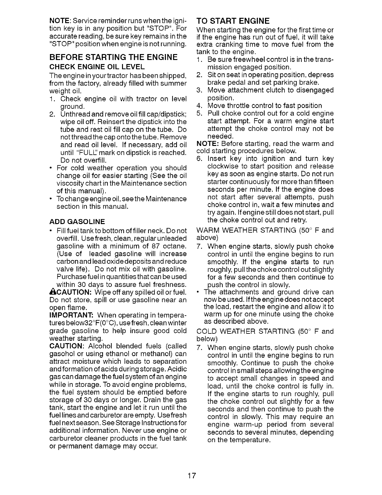
TO ADJUST GAUGE WHEELS
Gauge wheels are properly adjusted when
they are slightly off the ground when mower
is at the desired cutting height in operating
position. Gauge wheels then keep the deck
in proper position to help prevent scalping
in most terrain conditions.
NOTE: Adjust gauge wheels with tractor on
a flat level surface.
1. Adjust mower to desired cutting height
(See "TO ADJUST MOWER CUTTING
HEIGHT" in this section of manual).
2. With mower in desired height of cut posi-
tion, gauge wheels should be assembled
so they are slightly off the ground. Install
gauge wheel in appropriate hole. Tighten
securely.
3. Repeat for all, installing gauge wheel in
same adjustment hole.
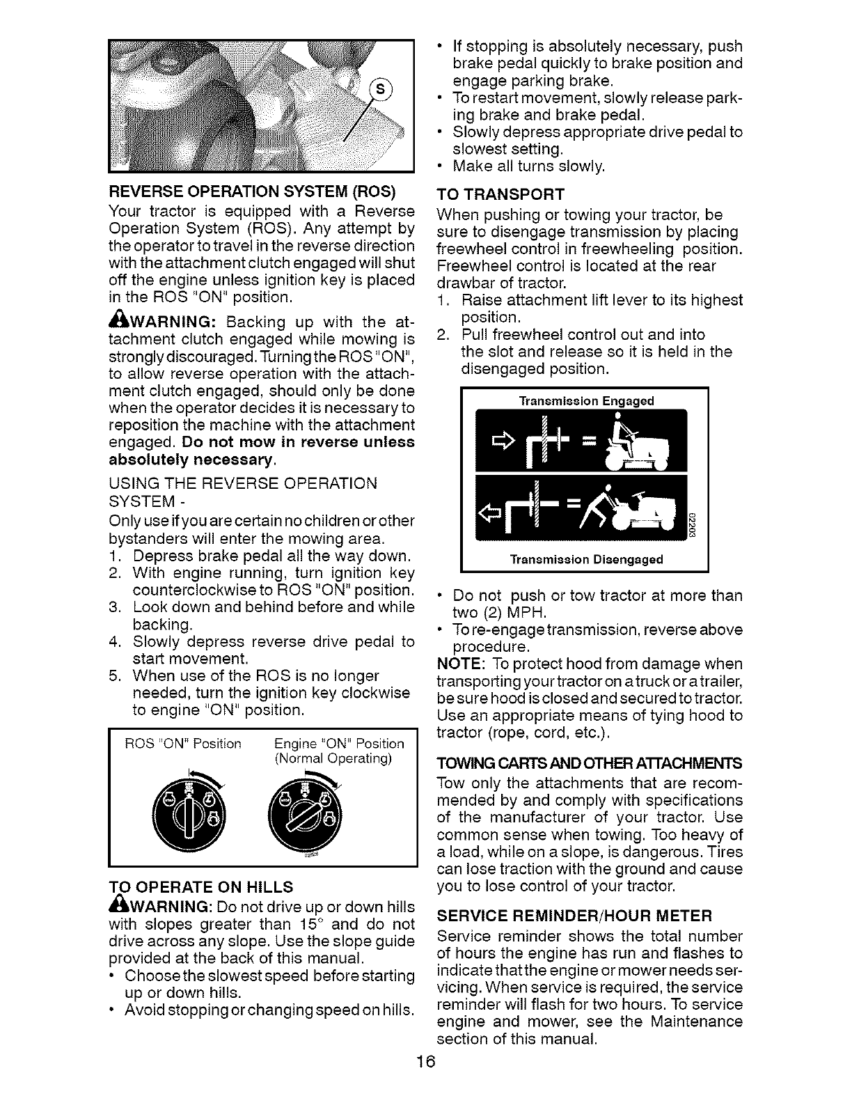
TO ADJUST MOWER CUTTING HEIGHT
The position of the attachment lift lever (A)
determines the cutting height.
• Put attachment lift lever in desired cut-
ting height slot.
• Slide pointer tab (T) to desired cutting
height as a reminder for nexttimeyou mow.
The cutting height range is approximately
1"to 4". The heights are measured from the
ground to the bladetipwith the engine not run-
ning. These heights are approximate and may
vary depending upon soil conditions, height
of grass and types of grass being mowed.
• The average lawn should be cutto approxi-
mately 2-1/2 inches during the cool season
and to over 3 inches during hot months.
For healthier and better looking lawns,
mow often and after moderate growth.
TO OPERATE MOWER
Your tractor is equipped with an operator
presence sensing switch. Any attempt by the
operator to leave the seat with the engine
running and the attachment clutch engaged
will shut off the engine. You must remain
fully and centrally positioned in the seat to
prevent the engine from hesitating or cutting
offwhen operating your equipment on rough,
rolling terrain or hills.
1. Select desired height of cut with attach-
ment lift lever.
2. Start mower blades by engaging attach-
ment clutch control.
TO STOP MOWER BLADES -
disengage attachment clutch control.
_,CAUTION: Do not operate the mower
without either the entire grass catcher, on
mowers so equipped, or the deflector shield
(S) in place.
15
If stopping is absolutely necessary,push
brake pedalquicklyto brake positionand
engage parkingbrake.
• Torestartmovement,slowlyreleasepark-
ing brake and brake pedal.
• Slowlydepressappropriatedrive pedalto
slowest setting.
Make all turns slowly.
REVERSE OPERATION SYSTEM (ROS)
Your tractor is equipped with a Reverse
Operation System (ROS). Any attempt by
the operator to travel in the reverse direction
with the attachment clutch engaged will shut
off the engine unless ignition key is placed
in the ROS "ON" position.
_IbWARNING: Backing up with the at-
tachment clutch engaged while mowing is
stronglydiscouraged. Turning the ROS "ON",
to allow reverse operation with the attach-
ment clutch engaged, should only be done
when the operator decides it is necessary to
reposition the machine with the attachment
engaged. Do not mow in reverse unless
absolutely necessary.
USING THE REVERSE OPERATION
SYSTEM -
Only use if you are certain no children or other
bystanders will enter the mowing area.
1. Depress brake pedal all the way down.
2. With engine running, turn ignition key
counterclockwise to ROS "ON" position.
3. Look down and behind before and while
backing.
4. Slowly depress reverse drive pedal to
start movement.
5. When use of the ROS is no longer
needed, turn the ignition key clockwise
to engine "ON" position.
ROS "ON" Position Engine "ON" Position
(Normal Operating)
TO OPERATE ON HILLS
_IbWARNING: Do not drive up or down hills
with slopes greater than 15 ° and do not
drive across any slope. Use the slope guide
provided at the back of this manual.
• Choosethe slowest speed before starting
up or down hills.
• Avoid stopping or changing speed on hills.
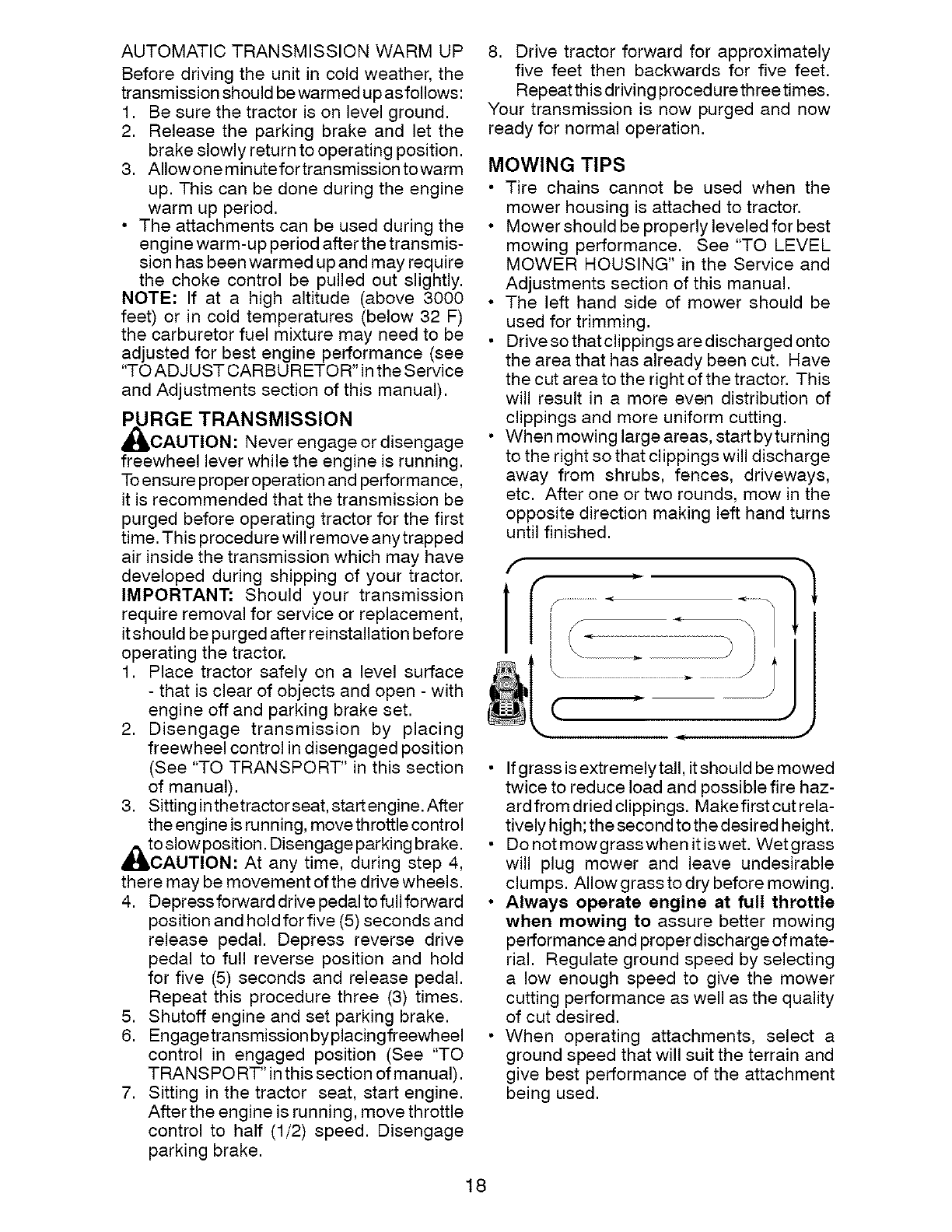
TO TRANSPORT
When pushing or towing your tractor, be
sure to disengage transmission by placing
freewheel control in freewheeling position.
Freewheel control is located at the rear
drawbar of tractor.
1. Raise attachment lift lever to its highest
position.
2. Pull freewheel control out and into
the slot and release so it is held in the
disengaged position.
Transmission Engaged
Transmission Diaengaged
Do not push or tow tractor at more than
two (2) MPH.
• To re-engage transmission, reverse above
procedure.
NOTE: To protect hood from damage when
transporting you r tractor on a truck or a trailer,
be sure hood is closed and secured to tractor.
Use an appropriate means of tying hood to
tractor (rope, cord, etc.).
TOWING CARTS AND OTHER ATrACHMENTS
Tow only the attachments that are recom-
mended by and comply with specifications
of the manufacturer of your tractor. Use
common sense when towing. Too heavy of
a load, while on a slope, is dangerous. Tires
can lose traction with the ground and cause
you to lose control of your tractor.
SERVICE REMINDER/HOUR METER
Service reminder shows the total number
of hours the engine has run and flashes to
indicate thatthe engine or mower needs ser-
vicing. When service is required, the service
reminder will flash for two hours. To service
engine and mower, see the Maintenance
section of this manual.
16
NOTE: Service reminder runs when the igni-
tion key is in any position but "STOP". For
accurate reading, be sure key remains in the
"STOP" position when engine is not running.
BEFORE STARTING THE ENGINE
CHECK ENGINE OIL LEVEL
The engine in your tractor has been shipped,
from the factory, already filled with summer
weight oil.
1. Check engine oil with tractor on level
ground.
2. Unthread and remove oil fill cap/dipstick;
wipe oil off. Reinsert the dipstick into the
tube and rest oil fill cap on the tube. Do
not thread the cap onto the tube. Remove
and read oil level. If necessary, add oil
until "FULl" mark on dipstick is reached.
Do not overfill.
• For cold weather operation you should
change oil for easier starting (See the oil
viscosity chart in the Maintenance section
of this manual).
• To change engine oil, seethe Maintenance
section in this manual.
ADD GASOLINE
• Fill fuel tank to bottom of filler neck. Do not
overfill. Usefresh, clean, regular unleaded
gasoline with a minimum of 87 octane.
(Use of leaded gasoline will increase
carbon and lead oxide deposits and reduce
valve life). Do not mix oil with gasoline.
Purchase fuel in quantities that can be used
within 30 days to assure fuel freshness.
ACAUTION: Wipe off any spilled oil or fuel.
Do not store, spill or use gasoline near an
open flame.
IMPORTANT: When operating in tempera-
tures below32°F(0°C), use fresh, clean winter
grade gasoline to help insure good cold
weather starting.
CAUTION: Alcohol blended fuels (called
gasohol or using ethanol or methanol) can
attract moisture which leads to separation
and formation of acids during storage. Acidic
gas can damage the fuel system of an engine
while in storage. To avoid engine problems,
the fuel system should be emptied before
storage of 30 days or longer. Drain the gas
tank, start the engine and let it run until the
fuel lines and carburetor are empty. Usefresh
fuel next season. See Storage Instructions for
additional information. Never use engine or
carburetor cleaner products in the fuel tank
or permanent damage may occur.
TO START ENGINE
When starting the engine for the first time or
if the engine has run out of fuel, it will take
extra cranking time to move fuel from the
tank to the engine.
1. Be sure freewheel control is in thetrans-
mission engaged position.
2. Sit on seat in operating position, depress
brake pedal and set parking brake.
3. Move attachment clutch to disengaged
position.
4. Move throttle control to fast position
5. Pull choke control out for a cold engine
start attempt. For a warm engine start
attempt the choke control may not be
needed.
NOTE: Before starting, read the warm and
cold starting procedures below.
6. Insert key into ignition and turn key
clockwise to start position and release
key as soon as engine starts. Do not run
starter continuously for more than fifteen
seconds per minute. If the engine does
not start after several attempts, push
choke control in, wait a few minutes and
try again. If engine still does not start, pull
the choke control out and retry.
WARM WEATHER STARTING (50 ° F and
above)
7. When engine starts, slowly push choke
control in until the engine begins to run
smoothly. If the engine starts to run
roughly, pull the choke control out slightly
for a few seconds and then continue to
push the control in slowly.
• The attachments and ground drive can
now be used. If the engine does not accept
the load, restart the engine and allow itto
warm up for one minute using the choke
as described above.
COLD WEATHER STARTING (50 ° F and
below)
7. When engine starts, slowly push choke
control in until the engine begins to run
smoothly. Continue to push the choke
control in small steps allowing the engine
to accept small changes in speed and
load, until the choke control is fully in.
If the engine starts to run roughly, pull
the choke control out slightly for a few
seconds and then continue to push the
control in slowly. This may require an
engine warm-up period from several
seconds to several minutes, depending
on the temperature.
17
AUTOMATIC TRANSMISSION WARM UP
Before driving the unit in cold weather, the
transmission should be warmed up as follows:
1. Be sure the tractor is on level ground.
2. Release the parking brake and let the
brake slowly return to operating position.
3. AIIowone minute for transmission towarm
up. This can be done during the engine
warm up period.
• The attachments can be used during the
engine warm-up period after the transmis-
sion has been warmed up and may require
the choke control be pulled out slightly.
NOTE: If at a high altitude (above 3000
feet) or in cold temperatures (below 32 F)
the carburetor fuel mixture may need to be
adjusted for best engine performance (see
"TO ADJUST CARBU RETOR" in the Service
and Adjustments section of this manual).
_RGE TRANSMISSION
CAUTION: Never engage or disengage •
freewheel lever while the engine is running.
To ensure proper operation and performance,
it is recommended that the transmission be
purged before operating tractor for the first
time. This procedure will remove any trapped
air inside the transmission which may have f
developed during shipping of your tractor.
IMPORTANT: Should your transmission t
require removal for service or replacement, /
it should be purged after reinstallation before
operating the tractor.
1. Place tractor safely on a level surface
- that is clear of objects and open - with
engine off and parking brake set.
2. Disengage transmission by placing
freewheel control in disengaged position
(See "TO TRANSPORT" in this section
of manual).
3. Sitting in thetractor seat, start engine. After
the engine is running, move throttle control
_to slow position. Disengage parking brake.
AUTION: At any time, during step 4,
there may be movement of the drive wheels.
4. Depressforwarddrivepedaltofullforward °
position and hold for five (5) seconds and
release pedal. Depress reverse drive
pedal to full reverse position and hold
for five (5) seconds and release pedal.
Repeat this procedure three (3) times.
5. Shutoff engine and set parking brake.
6. Engagetransmissionbyplacingfreewheel •
control in engaged position (See "TO
TRANS PORT" in this section of manual).
7. Sitting in the tractor seat, start engine.
After the engine is running, move throttle
control to half (1/2) speed. Disengage
parking brake.
8. Drive tractor forward for approximately
five feet then backwards for five feet.
Repeat this driving procedure three times.
Your transmission is now purged and now
ready for normal operation.
MOWING TIPS
Tire chains cannot be used when the
mower housing is attached to tractor.
Mower should be properly leveled for best
mowing performance. See "TO LEVEL
MOWER HOUSING" in the Service and
Adjustments section of this manual.
The left hand side of mower should be
used for trimming.
Drive so that clippings are discharged onto
the area that has already been cut. Have
the cut area to the right of the tractor. This
will result in a more even distribution of
clippings and more uniform cutting.
When mowing large areas, start by turning
to the right so that clippings will discharge
away from shrubs, fences, driveways,
etc. After one or two rounds, mow in the
opposite direction making left hand turns
until finished.
J
If grass is extremely tall, it should be mowed
twice to reduce load and possible fire haz-
ard from dried clippings. Makefirstcut rela-
tively high; the second to the desired height.
Do not mowgrasswhen it iswet. Wet grass
will plug mower and leave undesirable
clumps. Allow grass to dry before mowing.
Always operate engine at full throttle
when mowing to assure better mowing
performance and proper discharge of mate-
rial. Regulate ground speed by selecting
a low enough speed to give the mower
cutting performance as well as the quality
of cut desired.
When operating attachments, select a
ground speed that will suit the terrain and
give best performance of the attachment
being used.
18
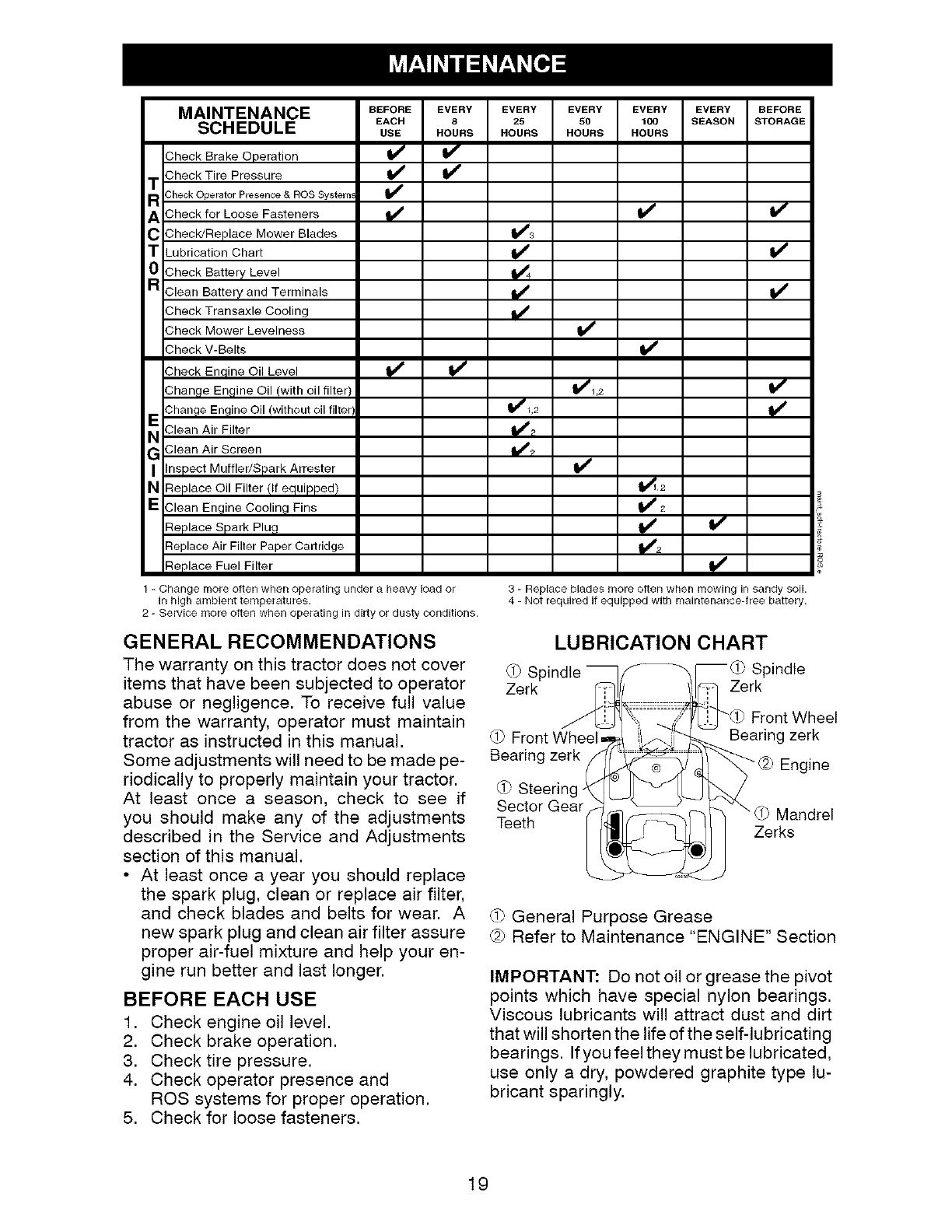
MAINTENANCE BEFORE EVERY EVERY EVERY EVERY EVERY BEFORE
EACH 8 25 50 100 REASON STORAGE
SCHEDULE USE HOURS HOURS HOURS HOURS
Check Brake Operation
Check Tire Pressure
T
R3heck Operator Presence & ROS System_
ACheck for Loose Fasteners
C Check/Replace Mower Blades
TLubrication Chart
0Check Battery Level
aClean Battery and Terminals
Check Transaxle Cooling
Check Mower Levelness v'
v'
Check V-Belts
Check Enqine Oil Level
Change Engine Oil (with oil filter)
Change Engine Oil/without oil filtel
_ Clean Air Filter
GClean Air Screen
I inspect Muffler/Spark Arrester
N Replace Oil Filter (If equipped)
E Clean Engine Cooling Fins
Replace Spark Plug
Replace Air Filter Paper Cartridge
_1,2
v"
Replace Fuel Filter
1-Change more often when operating under a heavy load or
in high ambient temperatures.
2 - SerVice more often when operating in dirty or dusty conditions.
v"
v"
3 - Replace blades more often when mowing in sandy soil.
4 - Not required if equipped with maintenance-tree battery.
GENERAL RECOMMENDATIONS
The warranty on this tractor does not cover
items that have been subjected to operator
abuse or negligence. To receive full value
from the warranty, operator must maintain
tractor as instructed in this manual.
Some adjustments will need to be made pe-
riodically to properly maintain your tractor.
At least once a season, check to see if
you should make any of the adjustments
described in the Service and Adjustments
section of this manual.
•At least once a year you should replace
the spark plug, clean or replace air filter,
and check blades and belts for wear. A
new spark plug and clean air filter assure
proper air-fuel mixture and help your en-
gine run better and last longer.
BEFORE EACH USE
1. Check engine oil level.
2. Check brake operation.
3. Check tire pressure.
4. Check operator presence and
ROS systems for proper operation.
5. Check for loose fasteners.
LUBRICATION CHART
_0 Spindle __[_ Spindle
Zerk _ _ Zerk
(i_ FrontWheelm2_ [j;.."_ Bearingzerk
Bearing zerk _U_/_ 1/ _2_ Engine
_f) Steering __
Sector Gear. _ _ _ \ .......
Teeth (_]f-7_"_-_ uJ IVlanerel
. _ Zerks
_.i?General Purpose Grease
@ Refer to Maintenance "ENGINE" Section
IMPORTANT: Do not oil or grease the pivot
points which have special nylon bearings.
Viscous lubricants will attract dust and dirt
that will shorten the life of the self-lubricating
bearings. If you feel they must be lubricated,
use only a dry, powdered graphite type lu-
bricant sparingly.
19
TRACTOR
Alwaysobservesafetyruleswhenperforming
any maintenance.
BRAKE OPERATION
If tractor requires more than five (5) feet to
stop at highest speed in highest gear on a
level, dry concrete or paved surface, then
brake must be serviced. (See "TO CHECK
BRAKE" in the Service and Adjustments
section of this manual).
TIRES
• Maintain proper air pressure in all tires
(See PSI on tires).
• Keep tires free of gasoline, oil, or insect
control chemicals which can harm rubber.
• Avoid stumps, stones, deep ruts, sharp
objects and other hazards that may cause
tire damage.
NOTE: To seal tire punctures and prevent flat
tires dueto slow leaks, tire sealant may be pur-
chased from your local parts dealer. Tire seal-
ant also prevents tire dry rot and corrosion.
OPERATOR PRESENCE SYSTEM AND
REVERSE OPERATION SYSTEM (ROS)
Be sure operator presence and reverse
operation systems are working properly. If
your tractor does not function as described,
repair the problem immediately.
• The engine should notstart unlessthe brake
pedal isfullydepressed, and theattachment
clutch control is in the disengaged position.
CHECK OPERATOR PRESENCE SYSTEM
• When the engine is running, any attempt
by the operator to leave the seat without
first setting the parking brake should shut
off the engine.
• When the engine is running and the at-
tachment clutch is engaged, any attempt
by the operator to leave the seat should
shut off the engine.
• The attachment clutch should never oper-
ate unless the operator is in the seat.
CHECK REVERSE OPERATION (ROS)
SYSTEM
• Whentheengineis running with the ignition
switch in the engine "ON" position and the
attachment clutch engaged, any attempt
by the operator to shift into reverse should
shut off the engine.
• Whentheengineis running with the ignition
switch in the ROS "ON" position and the
attachment clutch engaged, any attempt
by the operator to shift into reverse should
NOT shut off the engine. 2O
BLADE CARE
For best results mower blades must be sharp.
Replace worn, bent or damaged blades.
ACAUTION: Use only a replacement blade
approved by the man ufactu rer of you r tractor.
Using a blade not approved by the manu-
facturer of your tractor is hazardous, could
damage your tractor and void your warranty.
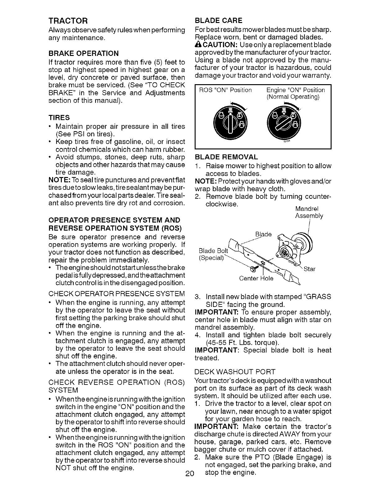
ROS "ON" Position Engine "ON" Position
(Normal Operating)
BLADE REMOVAL
1. Raise mower to highest position to allow
access to blades.
NOTE: Protect your hands with gloves and/or
wrap blade with heavy cloth.
2. Remove blade bolt by turning counter-
clockwise. Mandrel
Assembly
Blade
Blade
(Special)_
Center Hole
3. Install new blade with stamped "GRASS
SIDE" facing the ground.
IMPORTANT: To ensure proper assembly,
center hole in blade must align with star on
mandrel assembly.
4. Install and tighten blade bolt securely
(45-55 Ft. Lbs. torque).
IMPORTANT: Special blade bolt is heat
treated.
DECK WASHOUT PORT
Your tractor's deck is equipped with a washout
port on its surface as part of its deck wash
system. It should be utilized after each use.
1. Drive the tractor to a level, clear spot on
your lawn, near enough to a water spigot
for your garden hose to reach.
IMPORTANT: Make certain the tractor's
discharge chute is directed AWAY from your
house, garage, parked cars, etc. Remove
bagger chute or mulch cover if attached.
2. Make sure the PTO (Blade Engage) is
not engaged, set the parking brake, and
stop the engine.
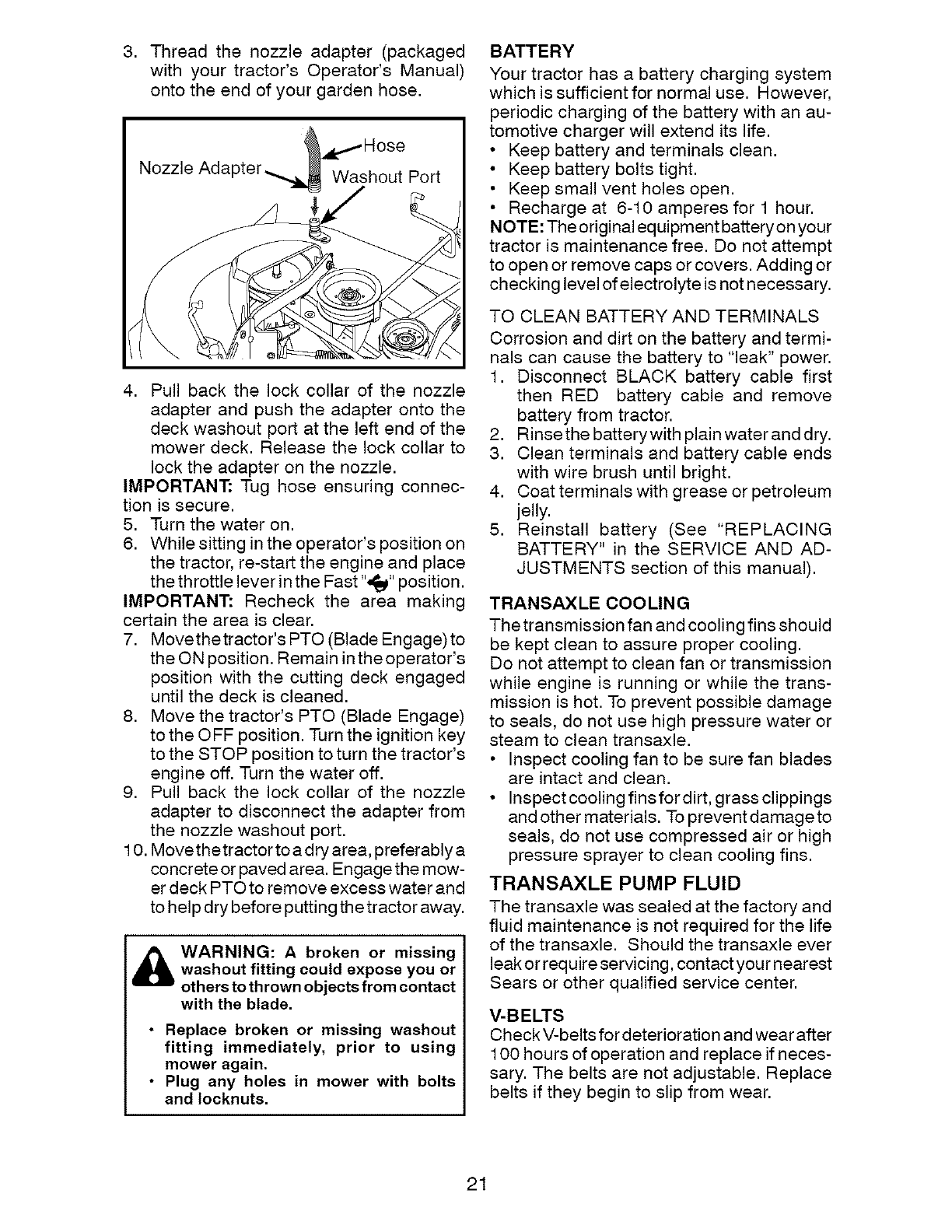
3. Thread the nozzle adapter (packaged
with your tractor's Operator's Manual)
onto the end of your garden hose.
Nozzle Ada Washout Port
4. Pull back the lock collar of the nozzle
adapter and push the adapter onto the
deck washout port at the left end of the
mower deck. Release the lock collar to
lock the adapter on the nozzle.
IMPORTANT: Tug hose ensuring connec-
tion is secure.
5. Turn the water on.
6. While sitting in the operator's position on
the tractor, re-start the engine and place
the throttle lever inthe Fast ",_j_" position.
IMPORTANT: Recheck the area making
certain the area is clear.
7. Movethe tractor's PTO (Blade Engage) to
the ON position. Remain in the operator's
position with the cutting deck engaged
until the deck is cleaned.
8. Move the tractor's PTO (Blade Engage)
to the OFF position. Turn the ignition key
to the STOP position to turn the tractor's
engine off. Turn the water off.
9. Pull back the lock collar of the nozzle
adapter to disconnect the adapter from
the nozzle washout port.
10. Movethetractor to a dry area, preferably a
concrete or paved area. Engage the mow-
er deck PTO to remove excess water and
to help dry before putting the tractor away.
WARNING: Abroken or missing
washout fitting could expose you or
others to th rown objects from contact
with the blade.
• Replace broken or missing washout
fitting immediately, prior to using
mower again.
•Plug any holes in mower with bolts
and Iocknuts.
BATTERY
Your tractor has a battery charging system
which is sufficient for normal use. However,
periodic charging of the battery with an au-
tomotive charger will extend its life.
• Keep battery and terminals clean.
• Keep battery bolts tight.
• Keep small vent holes open.
• Recharge at 6-10 amperes for 1 hour.
NOTE: The original equipment battery on your
tractor is maintenance free. Do not attempt
to open or remove caps or covers. Adding or
checking level of electrolyte is not necessary.
TO CLEAN BATTERY AND TERMINALS
Corrosion and dirt on the battery and termi-
nals can cause the battery to "leak" power.
1. Disconnect BLACK battery cable first
then RED battery cable and remove
battery from tractor.
2. Rinsethe batterywith plain water and dry.
3. Clean terminals and battery cable ends
with wire brush until bright.
4. Coatterminals with grease or petroleum
jelly.
5. Reinstall battery (See "REPLACING
BATTERY" in the SERVICE AND AD-
JUSTMENTS section of this manual).
TRANSAXLE COOLING
The transmission fan and cooling fins should
be kept clean to assure proper cooling.
Do not attempt to clean fan or transmission
while engine is running or while the trans-
mission is hot. To prevent possible damage
to seals, do not use high pressure water or
steam to clean transaxle.
• Inspect cooling fan to be sure fan blades
are intact and clean.
• Inspectcooling finsfordirt, grass clippings
and other materials. To prevent damageto
seals, do not use compressed air or high
pressure sprayer to clean cooling fins.
TRANSAXLE PUMP FLUID
The transaxle was sealed at the factory and
fluid maintenance is not required for the life
of the transaxle. Should the transaxle ever
leak or require servicing, contact your nearest
Sears or other qualified service center.
V-BELTS
Check V-belts for deterioration and wear after
100 hours of operation and replace if neces-
sary. The belts are not adjustable. Replace
belts if they begin to slip from wear.
21
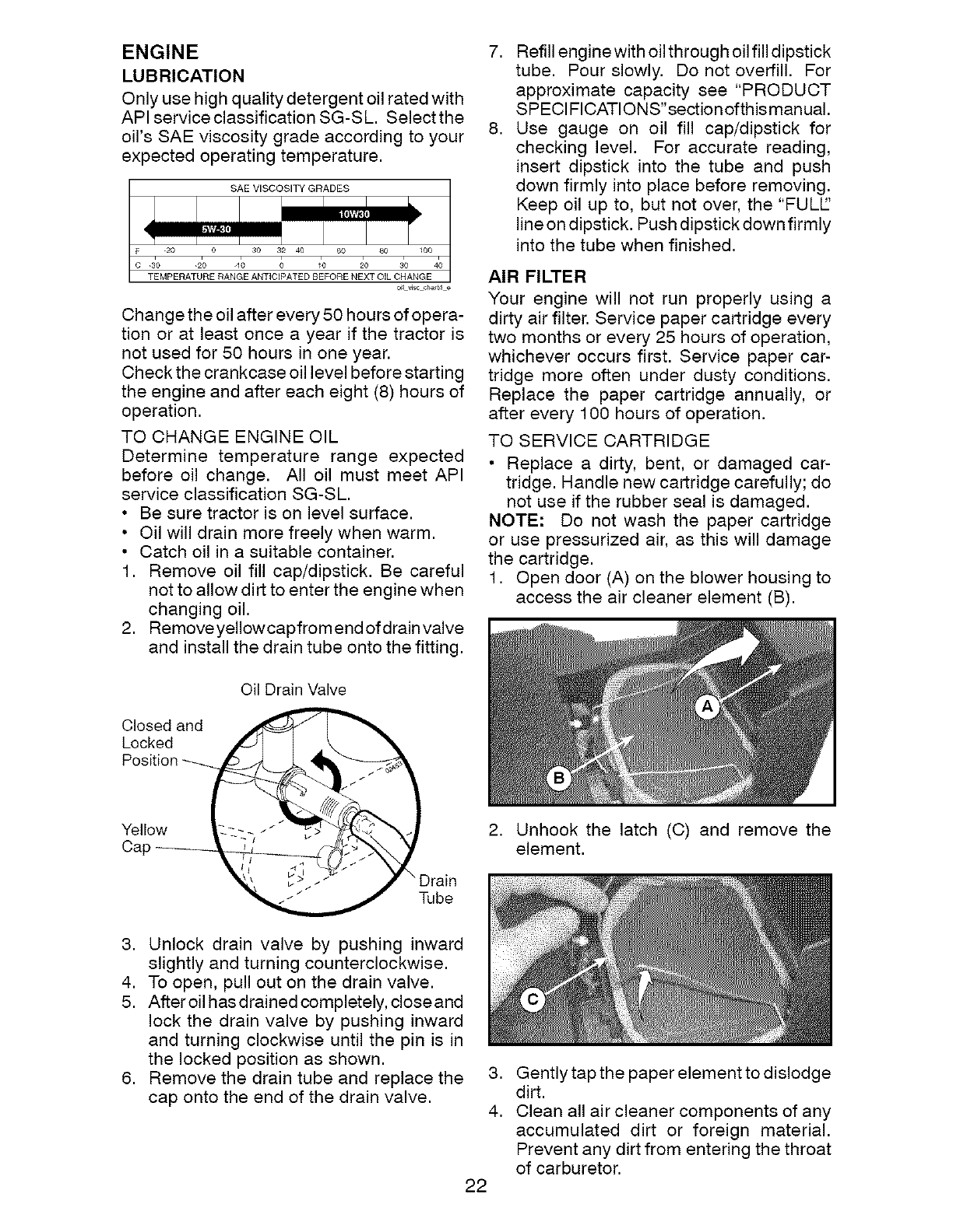
ENGINE 7.
LUBRICATION
Onlyusehighqualitydetergentoil ratedwith
APIserviceclassificationSG-SL. Selectthe
oil's SAE viscosity grade according to your 8.
expectedoperating temperature.
SAE VISCOSITY GRADES
F
TEMPERATURE RANGE ANTICIPATED BEFORE NEXT OIL CHANGE
o_1_lscch_rt4e
Change the oil after every 50 hours of opera-
tion or at least once a year if the tractor is
not used for 50 hours in one year.
Check the crankcase oil level before starting
the engine and after each eight (8) hours of
operation.
TO CHANGE ENGINE OIL
Determine temperature range expected
before oil change. All oil must meet API
service classification SG-SL.
• Be sure tractor is on level surface.
• Oil will drain more freely when warm.
• Catch oil in a suitable container.
1. Remove oil fill cap/dipstick. Be careful
not to allow dirt to enter the engine when
changing oil.
2. Remove yellowcapfrom end of drain valve
and install the drain tube onto the fitting.
Refill engine with oil through oil fill dipstick
tube. Pour slowly. Do not overfill. For
approximate capacity see "PRODUCT
SPECl FICATIONS"section of this manual.
Use gauge on oil fill cap/dipstick for
checking level. For accurate reading,
insert dipstick into the tube and push
down firmly into place before removing.
Keep oil up to, but not over, the "FULE'
line on dipstick. Push dipstick down firmly
into the tube when finished.
AIR FILTER
Your engine will not run properly using a
dirty air filter. Service paper cartridge every
two months or every 25 hours of operation,
whichever occurs first. Service paper car-
tridge more often under dusty conditions.
Replace the paper cartridge annually, or
after every 100 hours of operation.
TO SERVICE CARTRIDGE
Replace a dirty, bent, or damaged car-
tridge. Handle new cartridge carefully; do
not use if the rubber seal is damaged.
NOTE: Do not wash the paper cartridge
or use pressurized air, as this will damage
the cartridge.
1. Open door (A) on the blower housing to
access the air cleaner element (B).
Closed and
Locked
Oil Drain Valve
Yellow
CaF
\ Drain
Tube
2. Unhook the latch (C) and remove the
element.
3. Unlock drain valve by pushing inward
slightly and turning counterclockwise.
4. To open, pull out on the drain valve.
5. After oil has drained completely, close and
lock the drain valve by pushing inward
and turning clockwise until the pin is in
the locked position as shown.
6. Remove the drain tube and replace the
cap onto the end of the drain valve.
22
,
4.
Gently tap the paper element to dislodge
dirt.
Clean all air cleaner components of any
accumulated dirt or foreign material.
Prevent any dirt from entering the throat
of carburetor.
5. Install cleaned or new element on the
base and secure with latch.
6. Closeand latchthe door.
CLEAN AIR SCREEN
Air screen must be kept free of dirt and chaff
to prevent engine damage from overheating.
Clean with awire brush or compressed airto
remove dirt and stubborn dried gum fibers.
CLEAN AIR INTAKE/COOLING AREAS
To insure proper cooling, make sure the
grass screen, cooling fins, and other exter-
nal surfaces of the engine are kept clean
at all times.
Every 100 hours of operation (more often
under extremely dusty, dirty conditions),
removethe blower housing and other cooling
shrouds. Clean the cooling fins and external
surfaces as necessary. Make sure the cooling
shrouds are reinstalled.
NOTE: Operating the engine with a blocked
grass screen, dirty or plugged cooling fins,
and/or cooling shrouds removed will cause
engine damage due to overheating.
MUFFLER
Inspect and replace corroded muffler and
spark arrester (if equipped) as it could create
a fire hazard and/or damage.
SPARK PLUG(S)
Replace spark plug(s) at the beginning of
each mowing season or after every 100
hours of operation, whichever occurs first.
Spark plug type and gap setting are shown
in "PRODUCT SPECIFICATIONS" section
of this manual.
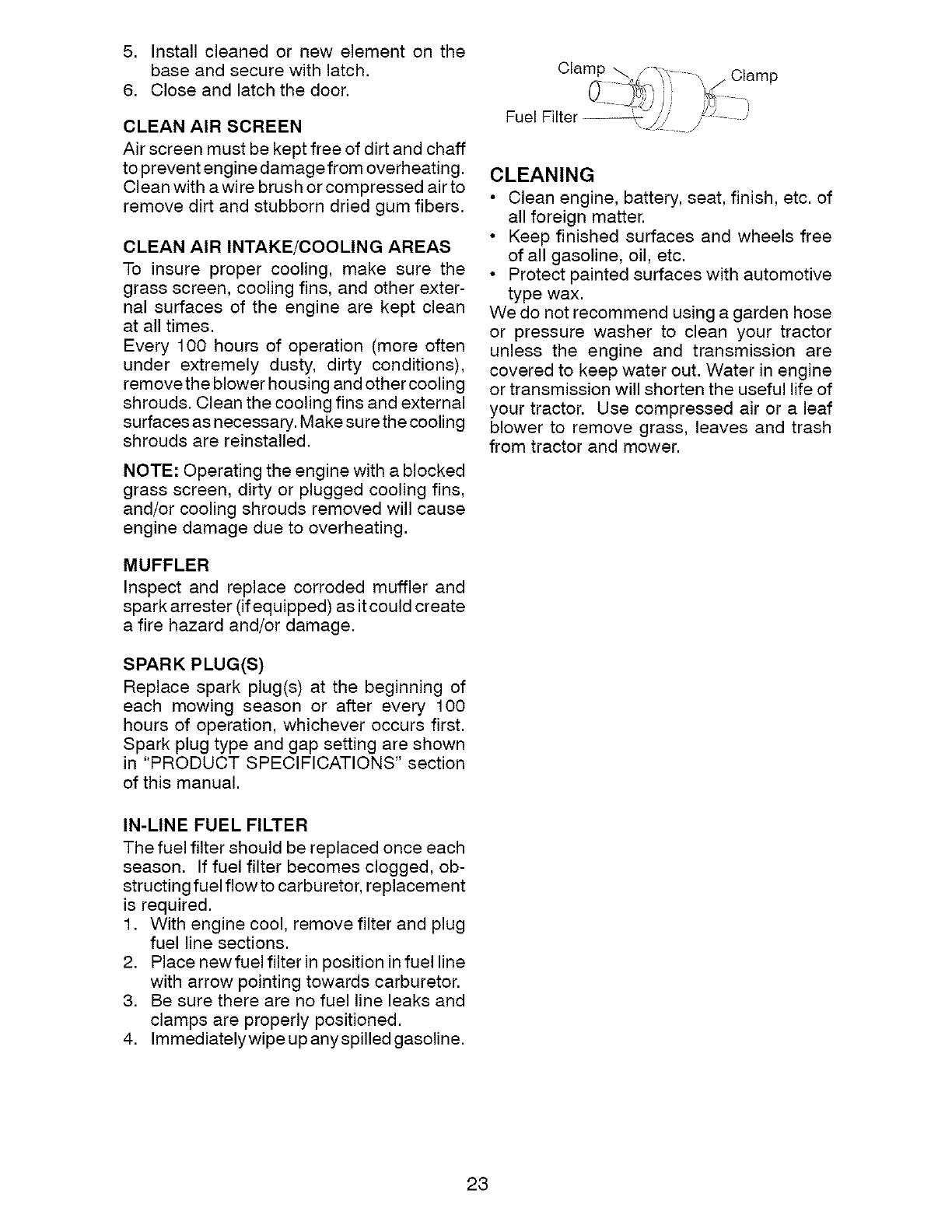
Clan_p ,[x_ Clamp
Fuel Filter _'// \ _J J J
CLEANING
• Clean engine, battery, seat, finish, etc. of
all foreign matter.
• Keep finished surfaces and wheels free
of all gasoline, oil, etc.
• Protect painted surfaces with automotive
type wax.
We do not recommend using a garden hose
or pressure washer to clean your tractor
unless the engine and transmission are
covered to keep water out. Water in engine
or transmission will shorten the useful life of
your tractor. Use compressed air or a leaf
blower to remove grass, leaves and trash
from tractor and mower.
IN-LINE FUEL FILTER
The fuel filter should be replaced once each
season. If fuel filter becomes clogged, ob-
structing fuel flow to carburetor, replacement
is required.
1. With engine cool, remove filter and plug
fuel line sections.
2. Place newfuel filter in position in fuel line
with arrow pointing towards carburetor.
3. Be sure there are no fuel line leaks and
clamps are properly positioned.
4. Immediately wipe up any spilled gasoline.
23
WARNING: TO AVOID SERIOUS INJURY, BEFORE PERFORMING ANYSERVICE OR ADJUSTMENTS:
1. Depress brake pedal fully and set parking brake.
2. Place attachment clutch in "DISENGAGED" position.
3. Turn ignition key to "STOP" and remove key.
4. Make sure the blades and all moving parts have completely stopped.
5. Disconnect spark plug wire from spark plug and place wire where it cannot
come in contact with plug.
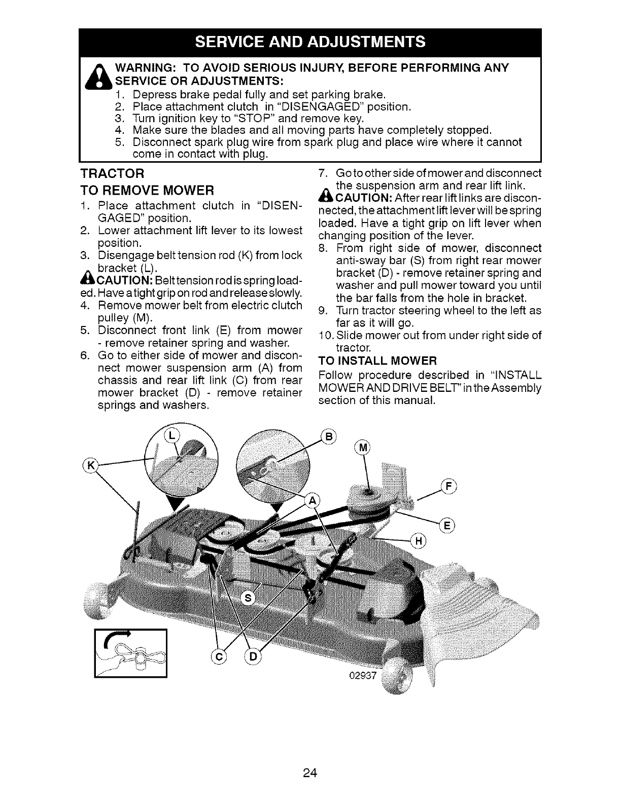
TRACTOR
TO REMOVE MOWER
1. Place attachment clutch in "DISEN-
GAGED" position.
2. Lower attachment lift lever to its lowest
position.
3. Disengage belttension rod (K) from lock
_ bracket (L).
CAUTION: Belt tension rod is spring load-
ed. Have atight grip on rod and release slowly.
4. Remove mower belt from electric clutch
pulley (M).
5. Disconnect front link (E) from mower
- remove retainer spring and washer.
6. Go to either side of mower and discon-
nect mower suspension arm (A) from
chassis and rear lift link (C) from rear
mower bracket (D) - remove retainer
springs and washers.
7. Goto other side of mower and disconnect
_the suspension arm and rear lift link.
CAUTION: After rear lift links are discon-
nected, the attachment lift lever will be spring
loaded. Have a tight grip on lift lever when
changing position of the lever.
8. From right side of mower, disconnect
anti-sway bar (S) from right rear mower
bracket (D) - remove retainer spring and
washer and pull mower toward you until
the bar falls from the hole in bracket.
9. Turn tractor steering wheel to the left as
far as it will go.
10. Slide mower out from under right side of
tractor.
TO INSTALL MOWER
Follow procedure described in "INSTALL
MOWER AND DRIVE BELT"in theAssembly
section of this manual.
02937
24
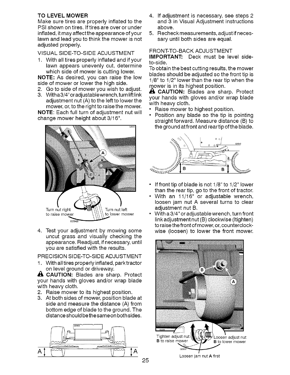
TO LEVEL MOWER
Make sure tires are properly inflatedto the
PSIshownontires. Iftires areoveror under
inflated,itmayaffecttheappearanceof your
lawn and lead youto think the mower is not
adjusted properly.
VISUAL SIDE-TO-SIDE ADJUSTMENT
1. With all tires properly inflated and if your
lawn appears unevenly cut, determine
which side of mower is cutting lower.
NOTE: As desired, you can raise the low
side of mower or lower the high side.
2. Go to side of mower you wish to adjust.
3. Witha3/4"oradjustablewrench,turnliftlink
adjustment nut (A) to the left to lower the
mower, or, to the right to raise the mower.
NOTE: Each full turn of adjustment nut will
change mower height about 3/16".
Turn nut right Turn nut left
to raise mower to lower mower
4. Test your adjustment by mowing some
uncut grass and visually checking the
appearance. Readjust, if necessary, until
you are satisfied with the results.
PRECISION SIDE-TO-SIDE ADJUSTMENT
1. With all tires properly inflated, park tractor
on level ground or driveway.
_IL CAUTION: Blades are sharp. Protect
your hands with gloves and/or wrap blade
with heavy cloth.
2. Raise mower to its highest position.
3. At both sides of mower, position blade at
side and measure the distance (A) from
bottom edge of blade to the ground. The
distance should bethesameon both sides.
4. If adjustment is necessary, see steps 2
and 3 in Visual Adjustment instructions
above.
5. Recheck measurements, adjust if neces-
sary until both sides are equal.
FRONT-TO-BACK ADJUSTMENT
IMPORTANT: Deck must be level side-
to-side.
To obtain the best cutting results, the mower
blades should be adjusted so the front tip is
1/8" to 1/2" lower than the rear tip when the
mower is in its highest position.
CAUTION: Blades are sharp. Protect
your hands with gloves and/or wrap blade
with heavy cloth.
• Raise mower to highest position.
• Position any blade so the tip is pointing
straight forward. Measure distance (B) to
the ground at front and rear tip of the blade.
B B
• If front tip of blade is not 1/8" to 1/2" lower
than the rear tip, go to the front of tractor.
• With an 11/16" or adjustable wrench,
loosen jam nut A several turns to clear
adjustment nut B.
• With a 3/4" or adjustablewrench, turn front
link adjustment nut (B) clockwise (Itighten)
to raise the front of mower, or,counterclock-
wise (loosen) to lower the front mower.
25
Tighten adjust nut
B to raise mower Loosen adjust nut
B to lower mower
Loosen jam nut A first
NOTE: Each full turn of the adjustment nut
will change mower height about 1/8".
• Recheck measurements, adjust if neces-
sary until front tip of blade is 1/8" to 1/2"
lower than the rear tip.
• Hold adjustment nut in position with wrench
and tighten jam nut securely against ad-
justment nut.
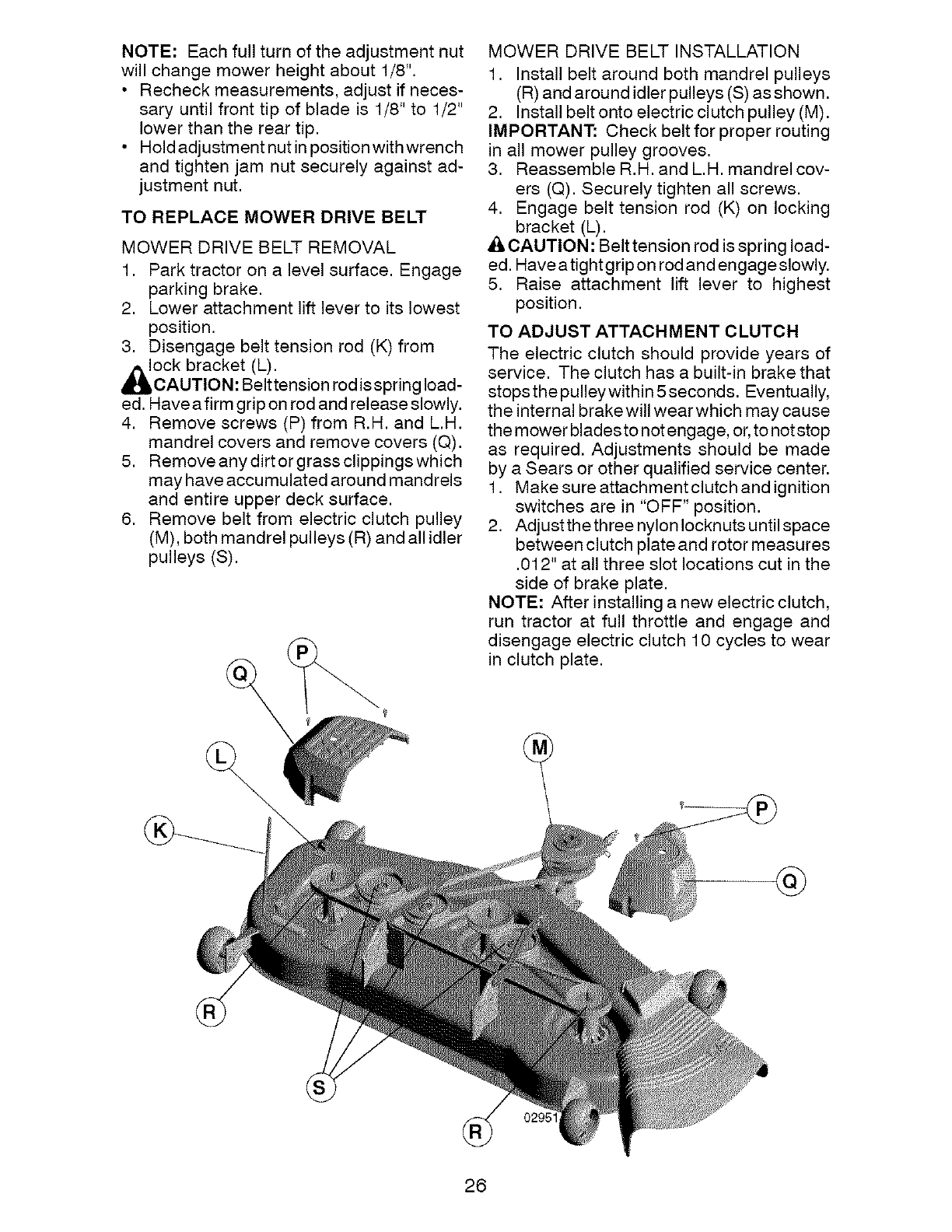
TO REPLACE MOWER DRIVE BELT
MOWER DRIVE BELT REMOVAL
1. Park tractor on a level surface. Engage
parking brake.
2. Lower attachment lift lever to its lowest
position.
3. Disengage belt tension rod (K) from
_l_OCk bracket (L).
CAUTION: Belttension rod is spring load-
ed. Have a firm grip on rod and release slowly.
4. Remove screws (P) from R.H. and L.H.
mandrel covers and remove covers (Q).
5. Remove any dirt or grass clippings which
may have accumulated around mandrels
and entire upper deck surface.
6. Remove belt from electric clutch pulley
(M), both mandrel pulleys (R) and all idler
pulleys (S).
MOWER DRIVE BELT INSTALLATION
1. Install belt around both mandrel pulleys
(R) and around idler pulleys (S) as shown.
2. Install belt onto electric clutch pulley (M).
IMPORTANT: Check belt for proper routing
in all mower pulley grooves.
3. Reassemble R.H. and L.H. mandrel cov-
ers (Q). Securely tighten all screws.
4. Engage belt tension rod (K) on locking
bracket (L).
& CAUTION: Belt tension rod is spring load-
ed. Have a tight g rip on rod and engage slowly.
5. Raise attachment lift lever to highest
position.
TO ADJUST ATTACHMENT CLUTCH
The electric clutch should provide years of
service. The clutch has a built-in brake that
stops the pulley within 5 seconds. Eventually,
the internal brakewill wear which may cause
the mower blades to not engage, or, to not stop
as required. Adjustments should be made
by a Sears or other qualified service center.
1. Make sure attachmentclutch and ignition
switches are in "OFF" position.
2. Adjust the three nylon Iocknuts until space
between clutch plate and rotor measures
.012" at all three slot locations cut in the
side of brake plate.
NOTE: After installing a new electric clutch,
run tractor at full throttle and engage and
disengage electric clutch 10 cycles to wear
in clutch plate.
@
02951
26
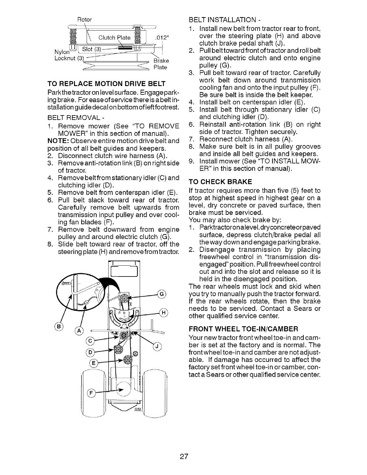
Rotor
_\, ,_ .
L_ Clutch Plate _ _] .012
hooknut(3! I " ake
4, Plate
TO REPLACE MOTION DRIVE BELT
Parkthetractor on level surface. Engagepark-
ing brake. For easeofservicethereisabeltin-
stallation guide decal on bottom of left footrest.
BELT REMOVAL -
1. Remove mower (See "TO REMOVE
MOWER" in this section of manual).
NOTE: Observe entire motion drive belt and
position of all belt guides and keepers.
2. Disconnect clutch wire harness (A).
3. Removeanti-rotation link (B) on rightside
of tractor.
4. Remove beltfrom stationary idler (C) and
clutching idler (D).
5. Remove belt from centerspan idler (E).
6. Pull belt slack toward rear of tractor.
Carefully remove belt upwards from
transmission input pulley and over cool-
ing fan blades (F).
7. Remove belt downward from engine
pulley and around electric clutch (G).
8. Slide belt toward rear of tractor, off the
steering plate (H) and remove from tractor.
BELT INSTALLATION -
1. Install new belt from tractor rear to front,
over the steering plate (H) and above
clutch brake pedal shaft (J).
2. Pull belt toward front of tractor and roll belt
around electric clutch and onto engine
pulley (G).
3. Pull belt toward rear of tractor. Carefully
work belt down around transmission
cooling fan and onto the input pulley (F).
Be sure belt is inside the belt keeper.
4. Install belt on centerspan idler (E).
5. Install belt through stationary idler (C)
and clutching idler (D).
6. Reinstall anti-rotation link (B) on right
side of tractor. Tighten securely.
7. Reconnect clutch harness (A).
8. Make sure belt is in all pulley grooves
and inside all belt guides and keepers.
9. Install mower (See "TO INSTALL MOW-
ER" in this section of manual).
TO CHECK BRAKE
If tractor requires more than five (5) feet to
stop at highest speed in highest gear on a
level, dry concrete or paved surface, then
brake must be serviced.
You may also check brake by:
1. Parktractoronalevel,dryconcreteor paved
surface, depress clutch/brake pedal all
the way down and engage parking brake.
2. Disengage transmission by placing
freewheel control in "transmission dis-
engaged" position. Pull freewheel control
out and into the slot and release so it is
held in the disengaged position.
The rear wheels must lock and skid when
you try to manually push the tractor forward.
If the rear wheels rotate, then the brake
needs to be serviced. Contact a Sears or
other qualified service center.
FRONT WHEEL TOE-IN/CAMBER
Your new tractor front wheel toe-in and cam-
ber is set at the factory and is normal. The
frontwheel toe-in and camber are not adjust-
able. If damage has occurred to affect the
factory set front wheel toe-in or camber, con-
tact a Sears or other qualified service center.
27
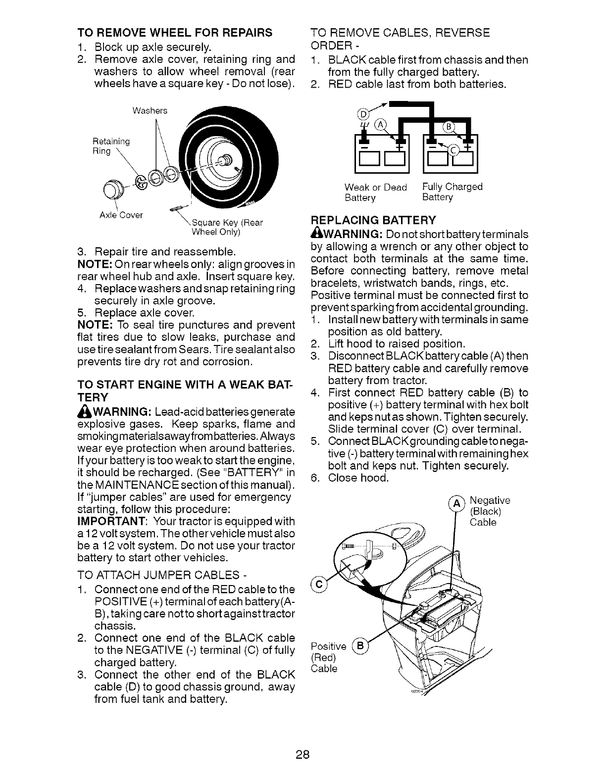
TO REMOVE WHEEL FOR REPAIRS
,
2. Block up axle securely.
Remove axle cover, retaining ring and
washers to allow wheel removal (rear
wheels have a square key - Do not lose).
TO REMOVE CABLES, REVERSE
ORDER -
1. BLACK cable first from chassis and then
from the fully charged battery.
2. RED cable last from both batteries.
Washers
Retaining
Ring \
Axle Cover \Square Key (Rear
Wheel Only)
3. Repair tire and reassemble.
NOTE: On rear wheels only: align grooves in
rear wheel hub and axle. Insert square key.
4. Replacewashers and snap retaining ring
securely in axle groove.
5. Replace axle cover.
NOTE: To seal tire punctures and prevent
flat tires due to slow leaks, purchase and
use tire sealant from Sears. Tire sealant also
prevents tire dry rot and corrosion.
TO START ENGINE WITH A WEAK BAT-
TERY
_WARNING: Lead-acid batteriesgenerate
explosive gases. Keep sparks, flame and
smoking materialsawayfrom batteries. Always
wear eye protection when around batteries.
If your battery is too weak to start the engine,
it should be recharged. (See "BATTERY" in
the MAINTENANCE section of this manual).
If "jumper cables" are used for emergency
starting, follow this procedure:
IMPORTANT: Your tractor is equipped with
a 12 volt system. The other vehicle must also
be a 12 volt system. Do not use your tractor
battery to start other vehicles.
TO ATTACH JUMPER CABLES -
1. Connectone end of the REDcabletothe
POSITIVE (+) terminal of each battery(A-
B), taking care notto short against tractor
chassis.
2. Connect one end of the BLACK cable
to the NEGATIVE (-) terminal (C) of fully
charged battery.
3. Connect the other end of the BLACK
cable (D) to good chassis ground, away
from fuel tank and battery.
Weak or Dead Fully Charged
Battery Battery
REPLACING BA'I-FE RY
_WARNING: Do not short battery terminals
by allowing a wrench or any other object to
contact both terminals at the same time.
Before connecting battery, remove metal
bracelets, wristwatch bands, rings, etc.
Positive terminal must be connected first to
prevent sparking from accidental grounding.
1. Install new battery with terminals in same
position as old battery.
2. Lift hood to raised position.
3. Disconnect BLACK battery cable (A) then
RED battery cable and carefully remove
battery from tractor.
4. First connect RED battery cable (B) to
positive (+) battery terminal with hex bolt
and keps nutas shown. Tighten securely.
Slide terminal cover (C) over terminal.
5. Connect BLACKgrounding cableto nega-
tive (-) battery terminal with remaining hex
bolt and keps nut. Tighten securely.
6. Close hood.
_ Negative
(Black)
Cable
Positive
(Red)
Cable
28
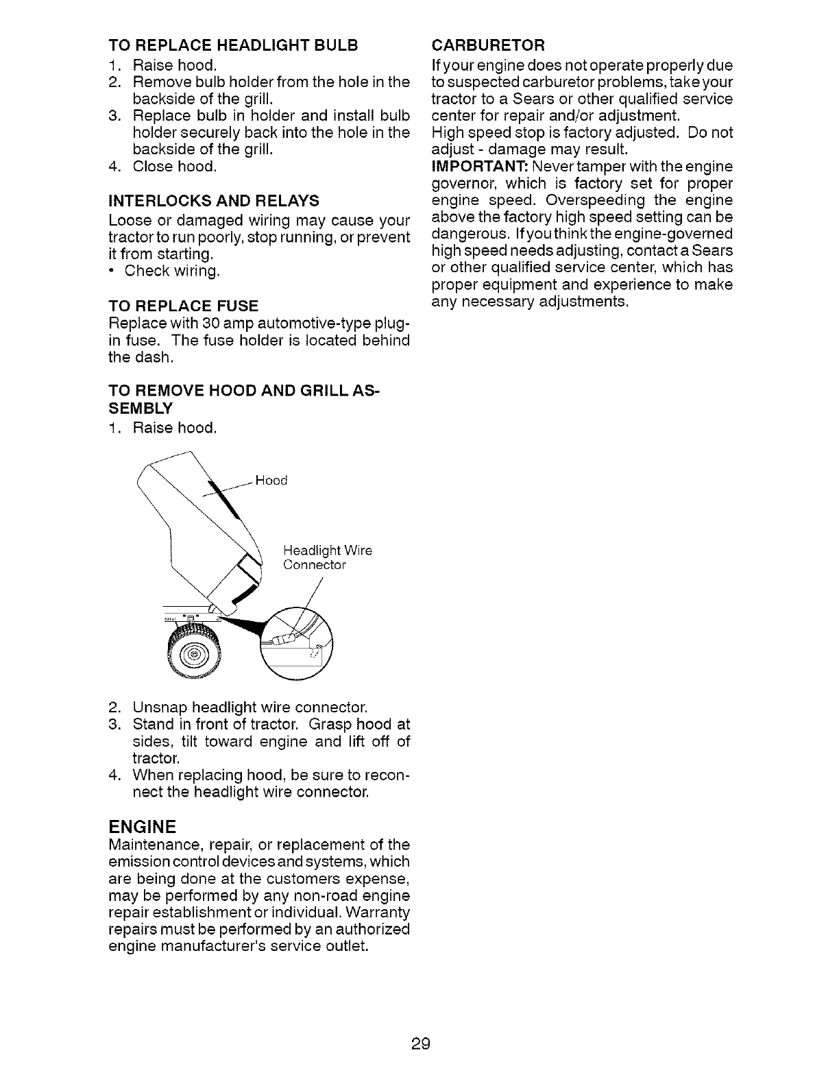
TO REPLACE HEADLIGHT BULB
1. Raise hood.
2. Remove bulb holder from the hole in the
backside of the grill.
3. Replace bulb in holder and install bulb
holder securely back into the hole in the
backside of the grill.
4. Close hood.
INTERLOCKS AND RELAYS
Loose or damaged wiring may cause your
tractor to run poorly, stop running, or prevent
it from starting.
• Check wiring.
TO REPLACE FUSE
Replace with 30 amp automotive-type plug-
in fuse. The fuse holder is located behind
the dash.
TO REMOVE HOOD AND GRILL AS-
SEMBLY
1. Raise hood.
CARBURETOR
If your engine does not operate properly due
to suspected carburetor problems, take your
tractor to a Sears or other qualified service
center for repair and/or adjustment.
High speed stop is factory adjusted. Do not
adjust - damage may result.
IMPORTANT: Never tamper with the engine
governor, which is factory set for proper
engine speed. Overspeeding the engine
above the factory high speed setting can be
dangerous. If you think the engine-governed
high speed needs adjusting, contact a Sears
or other qualified service center, which has
proper equipment and experience to make
any necessary adjustments.
Headlight Wire
Connector
2. Unsnap headlight wire connector.
3. Stand in front of tractor. Grasp hood at
sides, tilt toward engine and lift off of
tractor.
4. When replacing hood, be sure to recon-
nect the headlight wire connector.
ENGINE
Maintenance, repair, or replacement of the
emission control devices and systems, which
are being done at the customers expense,
may be performed by any non-road engine
repair establishment or individual. Warranty
repairs must be performed by an authorized
engine manufacturer's service outlet.
29
Immediatelyprepareyourtractorfor storage
at the end of the seasonor if the tractor will
_/be usedfor 30 days or more.
ARNING: Never store the tractor with
gasolinein the tank insidea buildingwhere
fumes may reach an open flame or spark.
Allow the engine to cool before storing in
any enclosure.
TRACTOR
When tractor is to be stored for a period
of time, clean it thoroughly, remove all dirt,
grease, leaves, etc. Store in aclean, dry area.
1. Clean entiretractor (See"CLEANING"in
the Maintenance section of this manual).
2. Inspectand replacebelts, ifnecessary(See
belt replacementinstructionsintheService
and Adjustments section of this manual).
3. Lubricate as shown in the Maintenance
section of this manual.
4. Be sure that all nuts, bolts and screws
are securely fastened. Inspect moving
parts for damage, breakage and wear.
Replace if necessary.
5. Touch up all rusted or chipped paint
surfaces; sand lightly before painting.
BATTERY
• Fully charge the battery for storage.
• After a period of time in storage, battery
may require recharging.
• To help prevent corrosion and power
leakage during long periods of storage,
battery cables should be disconnected
and battery cleaned thoroughly (see "TO
CLEAN BATTERY AND TERMINALS" in
the Maintenance section of this manual).
• After cleaning, leave cables disconnected
and place cables where they cannot
come in contact with battery terminals.
• If battery is removed from tractor for
storage, do not store battery directly on
concrete or damp surfaces.
ENGINE
FUELSYSTEM
IMPORTANT: It is important to prevent gum
deposits from forming in essential fuel sys-
tem parts such as carburetor, fuel hose, or
tank during storage. Also, alcohol blended
fuels (called gasohol or using ethanol or
methanol) can attract moisture which leads
to separation and formation of acids during
storage. Acidic gas can damage the fuel
system of an engine while in storage.
• Empty the fuel tank by starting the engine
and letting it run until the fuel lines and
carburetor are empty.
• Never use engine or carburetor cleaner
products in the fuel tank or permanent
damage may occur.
• Use fresh fuel next season.
NOTE: Fuel stabilizer is an acceptable al-
ternative in minimizing the formation of fuel
gum deposits during storage. Add stabilizer
to gasoline in fuel tank or storage container.
Always follow the mix ratio found on stabilizer
container. Run engine at least 10 minutes
after adding stabilizer to allow the stabilizer to
reach the carburetor. Do not empty the gas
tank and carburetor if using fuel stabilizer.
ENGINE OIL
Drain oil (with engine warm) and replace
with clean engine oil. (See "ENGINE" in the
Maintenance section of this manual).
CYLINDER(S)
1. Remove spark plug(s).
2. Pour one ounce of oil through spark
plug hole(s) into cylinder(s).
3. Turn ignition key to start position for a
few seconds to distribute oil.
4. Replace with new spark plug(s).
OTHER
• Do not store gasoline from one season
to another.
• Replace your gasoline can if your can
starts to rust. Rust and/or dirt in your
gasoline will cause problems.
• If possible, store your tractor indoors and
cover itto give protection from dust and dirt.
• Cover your tractor with a suitable protec-
tive cover that does not retain moisture.
Do not use plastic. Plastic cannot breathe
which allows condensation to form and
will cause your tractor to rust.
IMPORTANT: Never cover tractor while
engine and exhaust areas are still warm.
30
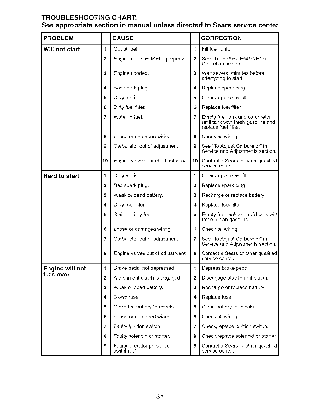
TROUBLESHOOTING CHART:
See appropriate section in manual unless directed to Sears service center
CAUSE CORRECTION
1Out of fuel. 1Fill fuel tank.
2 Engine not"CHOKED" properly. 2 See "TO START ENGINE" in
Operation section.
3 Engine flooded. 3 Wait several minutes before
attempting to start.
4 Bad spark plug. 4 Replace spark plug.
5 Dirty air filter. 5 Clean/replace air filter.
6 Dirty fuel filter. 6 Replace fuel filter.
7 Water in fuel. 7 Empty fuel tank and carburetor,
refill tank with fresh gasoline and
replace fuel filter.
8Loose or damaged wiring. 8Check all wiring.
9 Carburetor out of adjustment. 9 See "To Adjust Carburetor" in
Service and Adjustments section.
10 Engine valves out of adjustment. 10 Contact a Sears or other qualified
service center.
1 Dirty air filter. 1 Clean/replace air filter.
2 Bad spark plug. 2 Replace spark plug.
3 Weak or dead battery. 3 Recharge or replace battery.
4 Dirty fuet filter. 4 Replace fuet filter.
5 Stale or dirty fuel. 5 Empty fuel tank and refill tank with
fresh, clean gasoline.
6Loose or damaged wiring. 6Check all wiring.
7 Carburetor out of adjustment. 7 See "To Adjust Carburetor" in
Service and Adjustments section.
8 Engine valves out of adjustment. 8 Contact a Sears or other qualified
service center.
1 Brake pedal not depressed. 1 Depress brake pedal.
2 Attachment clutch is engaged. 2 Disengage attachment clutch.
3 Weak or dead battery. 3 Recharge or replace battery.
4 Blown fuse. 4 Replace fuse.
5 Corroded battery terminals. 5 Clean battery terminals.
6 Loose or damaged wiring. 6 Check all wiring.
PROBLEM
Will not start
Hard to start
Engine will not
turn over
7Faulty ignition switch.
8Faulty solenoid or starter.
9 Faulty operator presence
switch(as).
7 Check/replace ignition switch.
8 Check/replace solenoid or starter.
9 Contact a Sears or other qualified
service center.
31
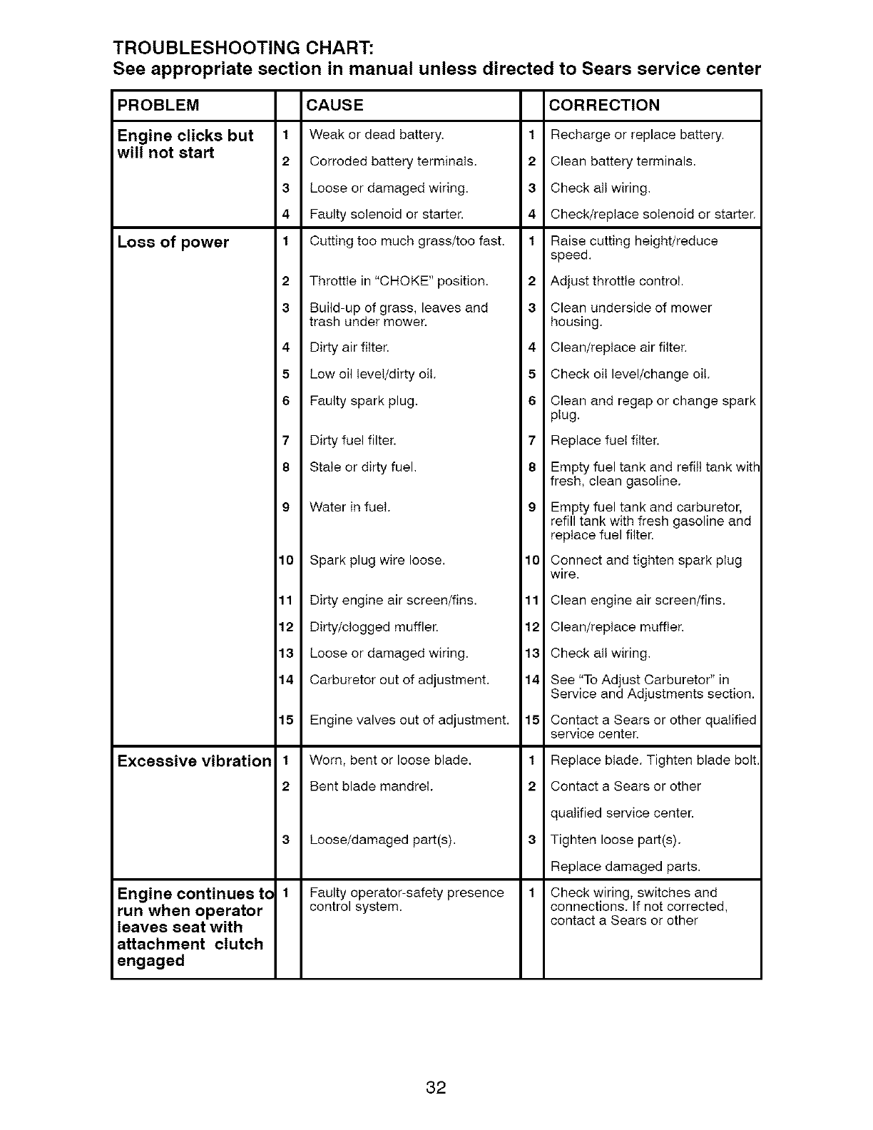
TROUBLESHOOTING CHART:
See appropriate section in manual unless directed to Sears service center
CAUSE
1 Weak or dead battery.
2 Corroded battery terminals.
3 Loose or damaged wiring.
4 Faulty solenoid or starter.
1 Cutting too much grass/too fast.
2 Throttle in "CHOKE" position.
3 Build-up of grass, leaves and
trash under mower.
4 Dirty air filter.
5 Low oil level/dirty oil.
6 Faulty spark plug.
7 Dirty fuel filter.
8 Stale or dirty fuel.
9 Water in fuel.
10 Spark plug wire loose.
11 Dirty engine air screen/fins.
12 Dirty/clogged muffler.
13 Loose or damaged wiring.
14 Carburetor out of adjustment.
15 Engine valves out of adjustment.
1 Worn, bent or loose blade.
2 Bent blade mandrel.
3 Loose/damaged part(s).
1 Faulty operator-safety presence
control system.
PROBLEM
Engine clicks but
will not start
Loss of power
Excessive vibration
Engine continues tc
run when operator
leaves seat with
attachment clutch
engaged
CORRECTION
1 Recharge or replace battery.
2 Clean battery terminals.
3 Check attwiring.
4 Check/replace solenoid or starter.
1 Raise cutting height/reduce
speed.
2 Adjust throttle control.
3 Clean underside of mower
housing.
4 Clean/replace air filter.
5 Check oil level/change oil.
6 Clean and regap or change spark
plug.
7 Replace fuel filter.
8Empty fuel tank and refill tank with
fresh, clean gasoline.
9 Empty fuel tank and carburetor,
refill tank with fresh gasoline and
replace fuel filter.
10 Connect and tighten spark plug
wire.
11 Clean engine air screen/fins.
12 Clean/replace muffler.
13 Check all wiring.
14 See "To Adjust Carburetor" in
Service and Adjustments section.
15 Contact a Sears or other qualified
service center.
1 Replace blade. Tighten blade bolt
2 Contact a Sears or other
qualified service center.
3 Tighten loose part(s).
Replace damaged parts.
1 Check wiring, switches and
connections. If not corrected,
contact a Sears or other
32
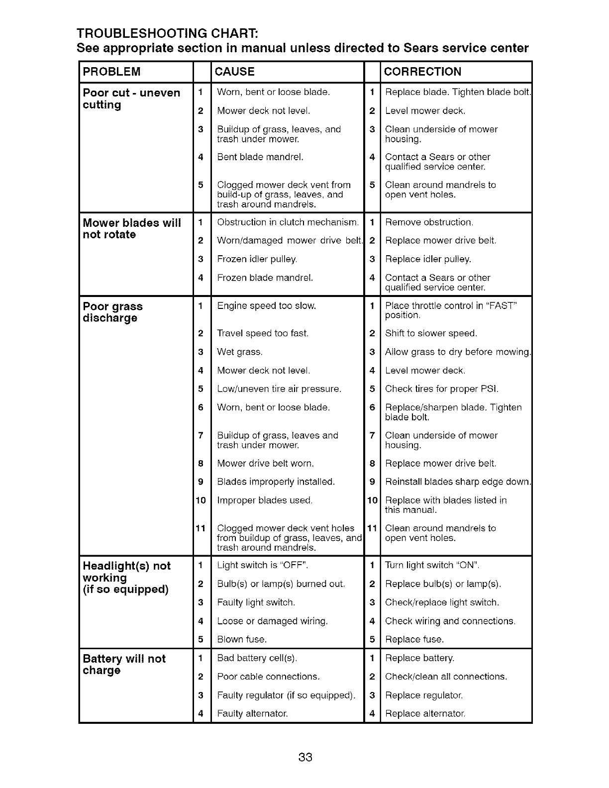
TROUBLESHOOTING CHART:
See appropriate section in manual unless directed
PROBLEM
Poor cut - uneven
cutting
Mower blades will
not rotate
Poor grass
discharge
Headlight(s) not
working
(if so equipped)
Battery will not
charge
to Sears service center
CAUSE
1Worn, bent or loose blade.
2 Mower deck not level.
3 Buildup of grass, leaves, and
trash under mower.
4 Bent blade mandrel.
5Clogged mower deck vent from
build-up of grass, leaves, and
trash around mandrels.
1 Obstruction in clutch mechanism.
2 Worn/damaged mower drive belt
3 Frozen idler pulley.
4 Frozen blade mandrel.
1 Engine speed too slow.
CORRECTION
1 Replace blade. Tighten blade bolt.
2 Level mower deck.
3Clean underside of mower
housing.
4 Contact a Sears or other
qualified service center.
5 Clean around mandrels to
open vent holes.
1 Remove obstruction.
2 Replace mower drive belt.
3Replace idler pulley.
4 Contact a Sears or other
qualified service center.
1 Place throttle control in "FAST"
position.
2Travel speed too fast.
3Wet grass.
4Mower deck not level.
2Shift to slower speed.
3Allow grass to dry before mowing.
4 Level mower deck.
5 Low/uneven tire air pressure.
6 Worn, bent or loose blade.
7 Buildup of grass, leaves and
trash under mower.
8 Mower drive belt worn.
9 Blades improperly installed.
10 Improper blades used.
11 Clogged mower deck vent holes
from buildup of grass, leaves, and
trash around mandrels.
1 Light switch is "OFF".
2 Bulb(s) or tamp(s) burned out.
3 Faulty light switch.
4 Loose or damaged wiring.
5 Blown fuse.
1 Bad battery cell(s).
2 Poor cable connections.
3 Faulty regulator (if so equipped).
4 Faulty alternator.
5Check tires for proper PSI.
6 Replace/sharpen blade. Tighten
blade bolt.
7 Clean underside of mower
housing.
8 Replace mower drive belt.
9 Reinstall blades sharp edge down.
10 Replace with blades listed in
this manual.
11 Clean around mandrels to
open vent holes.
1Turn light switch "ON".
2Replace bulb(s) or tamp(s).
3Check/replace light switch.
4 Check wiring and connections.
5 Replace fuse.
1 Replace battery.
2 Check/clean att connections.
3Replace regulator.
4 Replace alternator.
33

TROUBLESHOOTING CHART:
See appropriate section in manual unless directed to Sears service center
PROBLEM CAUSE CORRECTION
Loss of drive 1
2
Freewheel control in "disengaged"
position.
Motion drive belt worn, damaged,
or broken.
1 Place freewheetcontrot in
"engaged" position.
2 Replace motion drive belt.
3 Air trapped in transmission 3 Purge transmission.
during shipment or servicing.
Engine "backfires" 1 Engine throttle control not sel 1 Move throtttecontrot between
when turning between half and fult speed (fast) half and full speed (fast) position
engine "OFF" position before stopping engine, before stopping engine.
Engine dies when
tractor is shifted
into reverse
1 Reverse operation system (ROS)
is not "ON" while mower or other
attachment is engaged.
1 Turn ignition key to ROS "ON"
position. See Operation section.
NEED MORE HELP?
You3_ find the answer and more on managemyhomeo¢om - for free!
Find this and all your other product manuats online.
Get answers from our team of home experts.
• Get a personatized maintenance plan for your home.
34
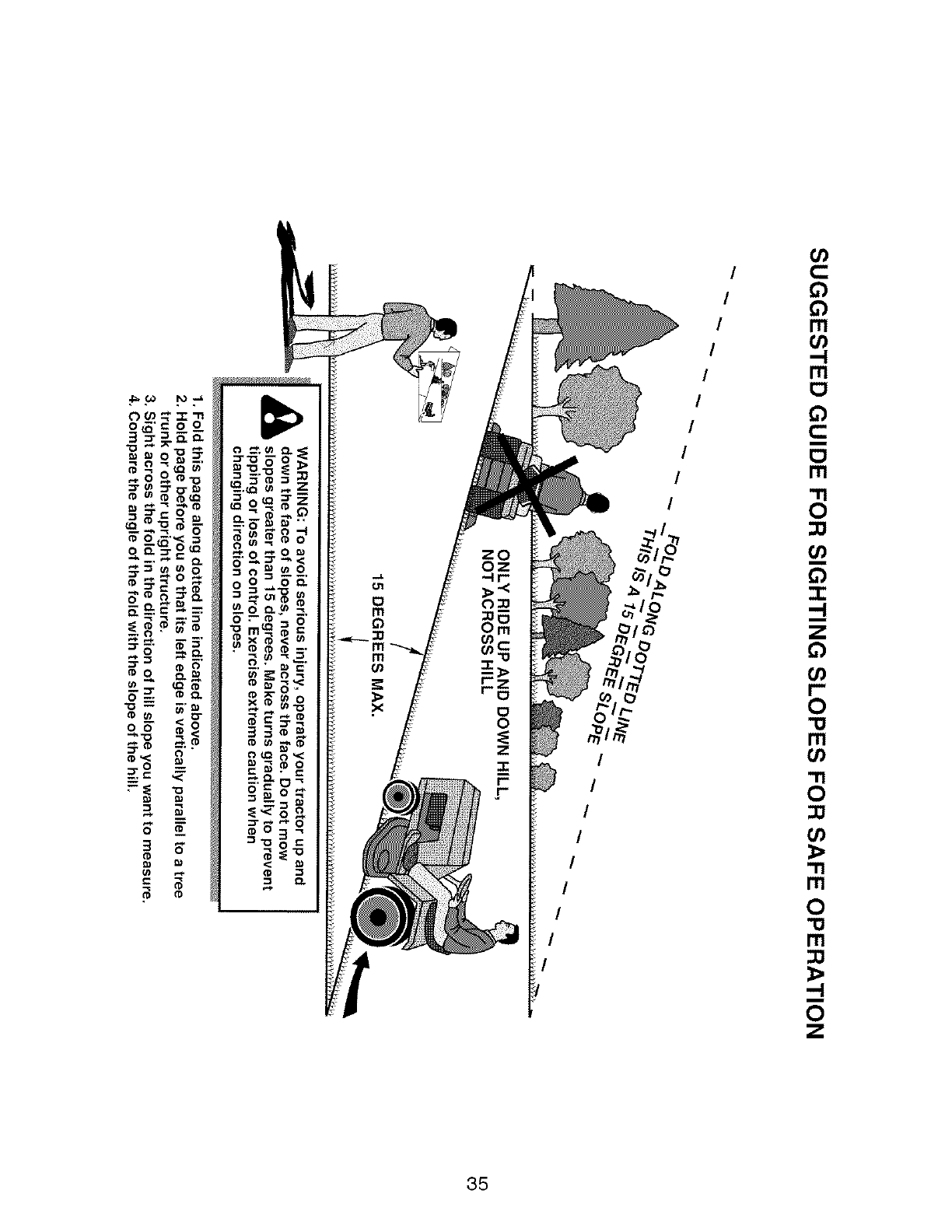
o_'=o o
0"_ LQ_
• • OLQ
_ _O
O_. :_ 0 U_
_._._ _
_ _._ _'_
(I) 0 003
o_ _<g
(0_< o3
_=.g
oo3
I
I
I
I
I
g
I
I
I
I
I
I
I
I
I
0
m
o
Z
35
Garantia ....................................................... 36
Reglas de Seguridad ................................... 37
Especificaciones del Producto ..................... 40
Montaje/Pre Operaci6n ................................ 42
Operaci6n .................................................... 46
Mantenimiento ............................................. 54
GARANTiA LIMITADA DE CRAFTSMAN
DOS ANOS PARA TRACTORES
Programa de Mantenimiento ....................... 54
Servicio y Ajustes ........................................ 59
Almacenamiento .......................................... 65
Identificaci6n de Problemas ........................ 66
Servicio Sears ................................ Contratapa
Si opera y mantiene este tractor segOn todas las instrucciones provistas, y este deja de funcionar
debido a defectos del material o de la mano de obra dentro de los dos afros posteriores a la fecha de
compra, comuniquese al 1-800-4-MY-HOME_} para obtener una reparaci6n sin cargo.
Durante el primer a6o a partir de la fecha de compra, no incurrir& en gastos ocasionados por el
servicio de garant[a a domicilio. Para su conveniencia, el servicio de garant[a a domicilio aQn estar&
disponible luego del primer afro a partir de la fecha de compra, pero se aplicar&n gastos de traslado.
Si usted transporta el tractor a un lugar de entrega autorizado de Craftsman, estos gastos se
cancelar&n. Para Iocalizar el lugar autorizado m&s cercano, comuniquese al 1-800-4-MY-HOME(_R_.
90 DiAS PARA BATERiAS
Si la bateria que se incluye con este tractor resulta defectuosa en los materiales o en la mano de obra
(nuestras pruebas demuestran que no mantiene la carga) dentro de los 90 (noventa) dias a partir de
la fecha de compra, ser& reemplazada a domicilio sin cargo.
Esta garanfia SOLO cubre los defectos en los materiales yen la mano de obra. Sears NO pagar& por:
Los art[culos prescindibles que se desgastan con el uso normal, que incluyen, entre otros: hojas,
bujias, limpiadores de aire, correas y filtros de aire.
El servicio de mantenimiento est&ndar, cambios de aceite o puestas a punto.
El reemplazo ni la reparaci6n de neum&ticos debido alas pinchaduras provocadas pot objetos
exteriores como clavos, espinas, tocones o vidrios.
El reemplazo ni la reparaci6n de neum&ticos o ruedas debido al uso normal, accidente u operaci6n
y mantenimiento incorrectos.
Las reparaciones necesarias debido al abuso pot parte del operador, que incluyen, entre otros:
daffos causados pot el remolque de objetos que sobrepasen la capacidad del tractor, por el im-
pacto de objetos que doblen la estructura o el cig_ehal, o pot el exceso de velocidad del motor.
Las reparaciones necesarias debido a la negligencia del operador, que incluyen, entre otros:
daffos el6ctricos o causados pot el medio ambiente debido al almacenamiento inapropiado, la no
utilizaci6n de la cantidad ni el grado adecuado de aceite para el motor, la acumulaci6n de basura
inflamable en la plataforma, o la falta de mantenimiento del equipo seg6n las instrucciones que
se encuentran en el manual del operador.
La limpieza del motor (sistema de combustible) ni las reparaciones debido a combustible consid-
erado contaminado u oxidado (viejo). En general, el combustible debe usarse dentro de los 30
dias a partir de la fecha de compra.
El deterioro y uso normal de los acabados exteriores ni el reemplazo de la etiqueta del producto.
Si alguna vez, este tractor se utiliza con fines comerciales o de alquiler, toda la cobertura de la
garantia del tractor y de la bater[a ser& nula.
Esta garantia se aplica Onicamente mientras el producto permanezca dentro de los Estados
Unidos.
Esta garantia le otorga derechos legales especificos yes posible que usted goce de otros derechos
que varian de estado en estado.
Sears, Roebuck and Co., Hoffman Estates, IL 60179
36
_I_PELIGRO: Esta Maquina cortadora es capaz de amputar las manosy los pies y de lanzar
objetos, si no ss observan las instrucciones de ssguridad siguientss ss pueden producir
lesiones graves o la muerte.
_IADVERTENCIA: Siempre desconecte el alam-
bre de la bujia y p6ngalo donde no pueda entrar
en contacto con la bujia, para evitar el arranque
por accidente, durante la preparaci6n, el trans-
porte, el ajuste o cuando se hacen reparaciones.
_ADVERTENClA: No avance cuesta abajo a pun-
to muerto ya que podria perder el control del tractor.
_ADVERTENClA: Remolque solamente
los accesorios recomendados y conformes a
las caracteristicas indicadas por el fabricante
de su tractor. Tenga cuidado y prudencia al
utilizar el tractor. Cuando se encuentre en un
declive, oper utilizando exclusivamente la ve-
Iocidad m&s baja. En case de un declive una
carga excesiva podria resultar peligrosa. Los
neum&ticos pueden perder la tracci6n con el
suelo y hacerle perder el control de su tractor.
_ADVERTENCIA: El tubo de escape del motor,
algunos de sus constituyentes y algunos com-
ponentes del vehiculo contienen o desprenden
productos quimicos conocidos en el Estado de
California como causa de c&ncer y defectos
al nacimiento u otros da_ios reproductivos.
_ADVERTENClA: Los bornes, terminales y
accesorios relativos de la bateria contienen
plomo o compuestos de plomo, productos
quimicos conocidos en el Estado de Cali-
fornia come causa de c&ncer y defectos al
nacimiento u otros daSos reproductivos. La-
var las manos despues de manipularlos.
I, FUNClONAMIENTO GENERAL
•Leer, entender y seguir todas las instrucciones so-
bre la m&quina y en el manual antes de empezar.
•No poner las manes o los pies cerca de par-
tes giratorias o debajo de la m&quina, man-
tener siempre limpia la abertura de descarga.
• Permitir el funcionamiento de la m&quina sSIo a
adultos que tengan familiaridad con las instruc-
clones.
• Limpiar el &rea de objetos como piedras,
juguetes, cables, etc. que pueden ser re-
cogidos y disparados con las cuchillas.
• Asegurarse de que el &rea est6 libre de
otras personas antes de ponerla en march&
Parar la m&quina si alguien entra en el &rea.
• Nunca Ilevar pasajeros.
• No cortar marcha atr&s al no ser absolu-
tamente necesario. Mirar siempre aba-
joy delante mientras se precede atr&s.
• Nunca dirigir el material descargado hacia
nadie. Evitar descargar material contra
paredes u obstrucciones. El material podria
rebotar hacia el operador. Parar las cuchil-
las cuando se pasan superficies de grava.
• No hacer funcionar lamb, quina sin el captador
de hierba entera, la protecci6n de descarga u
otros dispositivos de seguridad en su lugar y
en buenas condiciones. 37
• Ralentizar antes de girar.
• Nunca dejar una m&quina encendida sin vigi-
lancia. Apagar siempre las cuchillas, poner el
freno de estacionamiento, parar el motor, y
quitar las Ilaves antes de bajar.
• Desconectar las cuchillas cuando no se corta.
Apagar el motor y esperar que todas las partes
esten completamente paradas antes de limpiar
la m&quina, quitar el captador de hierba, o
desatascar la protecci6n de descarga.
• Hacer funcionar la m&quina s61o con la luz del
dia o luz artificial buena.
• No hacer funcionar la m&quina estando bajo
los efectos de alcohol o droga.
•Poner atenci6n al trafico cuando se opera cerca
de calles o se cruzan.
• Poner la m&xima atenci6n al cargar o descar-
gar la m&quina en una caravana o cami6n.
• Llevar siempre gafas de protecci6n cuando se
hace funcionar la maquina.
• Los datos indican que los operadores a partir
de los 60 a_ios estan afectados por un gran
porcentaje de heridas relativas a la conducci6n
del cortacesped. Estos operadores tendrian
que evaluar su habilidad de hacer funcionar
el cortac_sped de modo Io bastante seguro
para proteger a si mismos y a otras personas
de heridas graves.
• Seguir las recomendaciones del fabricante
para los pesos y contrapesos de las ruedas.
• Mantener la m&quina libre de hierba, hojas
u otros escombros que pueden tocar el
tubo de escape /partes del motor calientes
y quemarse. No permitir que el puente del
cortac6sped cargue hojas u otros residuos
que pueden causar acumulaciones. Limpiar
toda salpicadura de aceite o carburante antes
de hacer operaciones sobre la maquina o
guardarla. Dejarla enfriar antes de guardarla.
II. FUNClONAMIENTO EN PENDIENTES
Las pendientes son el mayor factor de acciden-
tes relativos a la p6rdida de control y vuelco,
que pueden causar severas heridas o muerte.
El funcionamiento en pendientes requiere una
atenci6n extra. Si no es posible hacer marcha
atr&s en una pendiente o si te sientes incomodo,
no la cortes.
• Cortar hacia arriba y abajo de una pendiente,
no de modo horizontal.
• Poner atenciones a los hoyos, las raices, los
bultos, las piedras u otros objetos escondidos.
El terreno irregular puede volcar la m&quina.
La hierba alta puede esconder obst&culos.
• Escoger una velocidad de marcha baja de
modo que no sea necesario pararse o cambiar
estando en una pendiente.
• Nocortarlahierbamojada.Lasruedaspueden
perdertracci6n.
Ponersiempreuna marchacuandose est&
enpendientes.Noponerenpuntomuertoe ir
cuestaabajo.
• Evitararrancar,pararseogirarenunapendien-
te.Silasruedaspierdentracci6n,desconectar
lascuchillasy procederdespaciocuestaabajo
enlapendiente.
• Mantenertodo los movimientosen las pen-
dienteslentosy gradual.No hacercambios
repentinosde velocidado direcci6n,ya que
puedencausarelescapedela m&quina.
• Ponerlamaximaatenci6ncuandolam&quina
funcionacon captadoresde hierbau otros
dispositivosenganchados;puedenafectarla
estabilidaddelamaquina.No usarenpendi-
entesempinados.
• Nointentarestabilizarlam&quinaponiendoel
pieenelterreno.
• Nocortarcercadebajadas,cunetasy orillas.
Lasmaquinapuedevolcarseimprovisamente
si unaruedaest&enelbordeo sehunde.
II1.NINOS
Si el operador no pone atenci6n a la presencia
de los nihos pueden ocurrir accidentes tr&gicos.
Los niSos a menudo est&n atraidos por la m&-
quina y las actividad de cortar. No dar por hecho
de que los niSos se queden adonde estaban la
51tima vez que los vistes.
• Mantener los ni_ios fuera del b,rea de corte y
vigilades por un adulto responsable que no sea
el operador.
• Estar alerta y apagar la m&quina si un niSos
entra en el &rea.
• Antes y durante la marcha atr&s, mirar adelante
y abajo para ver si hay ni_ios peque_ios.
• Nunca Ilevar niSos, incluso si hay las cuchillas
apagadas. Podrian caer y herirse seriamente
e interferir con el funcionamiento seguro de la
m&quina, los niSos que se han Ilevado prec-
edentemente pueden aparecer de pronto en el
&rea de corte por otro paseo y ser atropellados
o tumbados por la m&quina.
• Nunca dejar que los nii_os manipulen la m&-
quina.
• Tenet el m&ximo cuidado cuando se acerca
a cantos ciegos, arbustos, &rboles u otros
objetos que pueden impedir la vista de ni_ios.
IV. REMOLQUE
• Remolcar s61o con una m&quina que tenga un
gancho diseSado para remolcar. Enganchar el
equipo o remolcar s61o en el punto dispuesto
al efecte.
• Seguir las recomendaciones del productor con
respecto a los limites del equipo por remolcar
y el remolque en pendientes.
• Nunca permitir que niSos u otras personas
est6n dentro del equipo por remolcar.
• En pendientes, el peso del equipo remolcado
puede causar la p6rdida de tracci6n y la p6r-
dida de control.
• Viajar despacio y dejar m&s distancia para
frenar.
V. SERVIClO
MANIPULAClON SEGURA DE LA GASOMNA
Para evitar heridas personales o daSos alas
cosas, porter el m&ximo cuidado a la hera de ma-
nipular la gasolina. La gasolina es extremamente
inflamable y los vapores son explosivos.
• Apagar todos los cigarrillos, cigarros, pipas y
otras fuentes de ignici6n.
• Usar s61o contenedores para gasolina aproba-
dos.
• Nunca quitar el tap6n de la gasolina o a_adir
carburante con el motor en marcha, dejar
enfriar el motor antes del abastecimiento de
la gasolina.
• Nunca abastecer la m&quina al interior de un
local.
• Nunca guardar la maquina o el contenedor
del carburante donde haya una llama abierta,
chispas o una luz piloto como un calentador
de agua u otros dispositivos.
• Nunca Ilenar los contenedores al interior de
un vehiculo o en una caravana o cami6n
recubiertos con un forro de pl&stico. Colocar
siempre los contenedores en el terreno lejos
del vehiculo cuando se esta Ilenando.
• Quitar el equipo de gas del cami6n o caravana
y abastecedo en el terreno. Si no es posible,
abastecer dicho equipo con un contenedor
port&til, mas bien que de un surtidor de gaso-
lina.
• Mantener la boquilla a contacto del borde
del dep6sito de carburante o la abertura del
contenedor durante toda la operaci6n de
abastecimiento. No utilizar un dispositivo con
boquilla cerrada-abierta.
• Si se vierte carburante sobre la ropa, cambi-
arse la ropa inmediatamente.
• Nunca Ilenar el dep6sito m&s de Io debido.
Volver a colocar el tap6n del gas y cerrar de
modo firme.
OPERAClONES DE SERVIClO GENERALES
• Nunca hacer funcionar la m&quina en un &rea
cerrada.
• Mantener todas las tuercas y pernos apretados
para asegurarse de que trabaja en condiciones
seguras.
• Nunca modificar los dispositivos de seguridad.
Controlar su correcto funcionamiento regular-
mente.
38
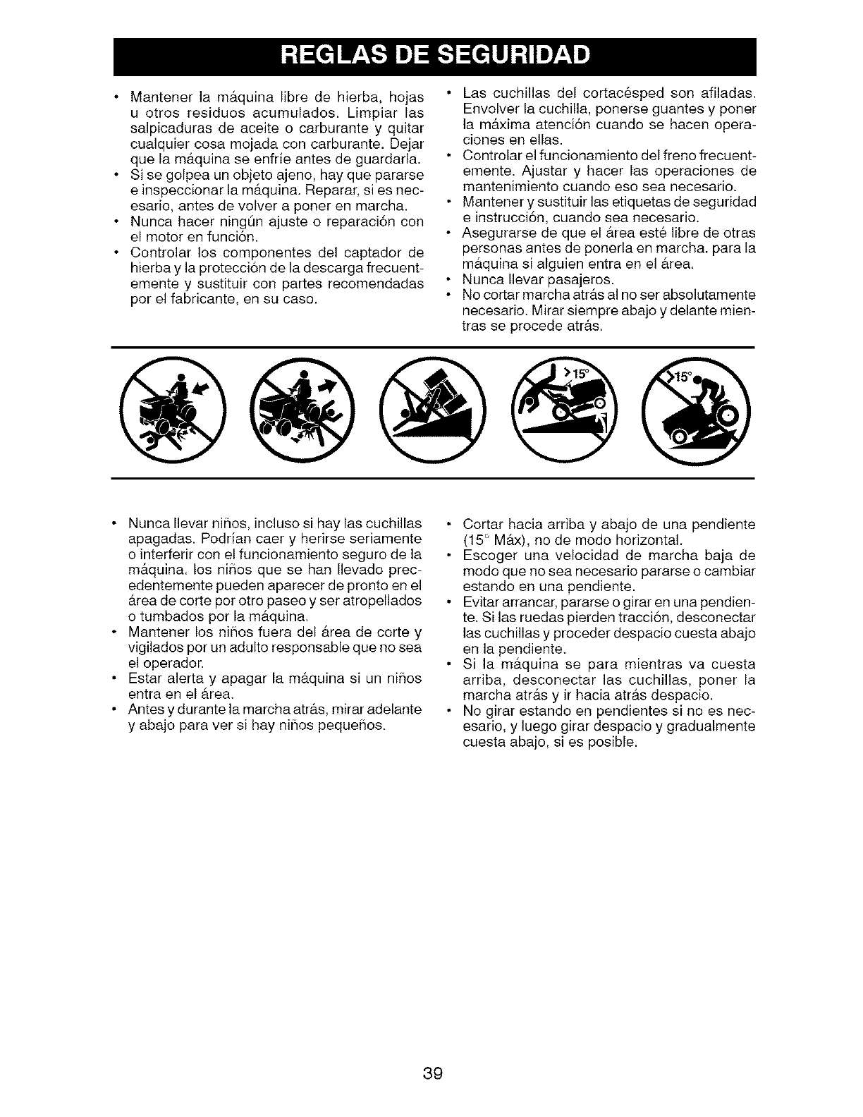
Mantener la m#,quina libre de hierba, hojas
u otros residues acumulados. Limpiar las
salpicaduras de aceite o carburante y quitar
cualquier cosa mojada con carburante. Dejar
que la m&quina se enfrie antes de guardarla.
Si se golpea un objeto ajeno, hay que pararse
e inspeccionar la m&quina. Reparar, si es nec-
esario, antes de volver a porter en marcha.
Nunca hacer ningOn ajuste o reparaci6n con
el motor en funci6n.
Controlar los componentes del captador de
hierba y la protecci6n de la descarga frecuent-
emente y sustituir con partes recomendadas
por el fabricante, en su caso.
Las cuchillas del cortac&sped son afiladas.
Envolver la cuchilla, ponerse guantes y poner
la m&xima atenci6n cuando se hacen opera-
clones en elias.
•Controlar el funcionamiento del freno frecuent-
emente. Ajustar y hacer las operaciones de
mantenimiento ouando eso sea necesario.
Mantener y sustituir las etiquetas de seguridad
e instrucci6n, cuando sea necesario.
• Asegurarse de que el b,rea est6 libre de otras
personas antes de ponerla en marcha, para la
maquina si alguien entra en el &tea.
• Nunca Ilevar pasajeros.
• No cortar marcha atr_ts al no set absolutamente
necesario. Mirar siempre abajo y delante mien-
tras se procede atr#.s.
• Nunca Ilevar ni_ios, incluso si hay las cuchillas
apagadas. Podrian caer y herirse seriamente
o interferir con el funcionamiento seguro de la
m&quina, los niSos que se hart Ilevado prec-
edentemente pueden aparecer de pronto en el
_trea de corte pot otro paseo y set atropellados
o tumbados per la m_tquina.
• Mantener los ni_ios fuera del area de corte y
vigilados pot un adulto responsable que no sea
el operador.
• Estar alerta y apagar la m_tquina si un ni_os
entra en el _.rea.
• Antes y durante la marcha atr_.s, mirar adelante
y abajo para ver si hay ni_os peque_ios.
Cortar hacia arriba y abajo de una pendiente
(15 ° M_x), no de modo horizontal.
Escoger una velocidad de marcha baja de
modo que no sea necesario pararse o cambiar
estando en una pendiente.
Evitar arrancar, pararse o girar en una pendien-
te. Si las ruedas pierden tracci6n, desconectar
las cuchillas y proceder despacio cuesta abajo
en la pendiente.
Si la m#,quina se para mientras va cuesta
arriba, desconectar las cuchillas, poner la
marcha atrb,s y ir hacia atras despacio.
No girar estando en pendientes si no es nec-
esario, y luego girar despacio y gradualmente
cuesta abajo, si es posible.
39
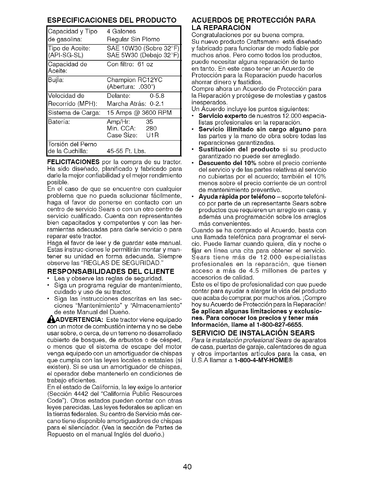
ESPECIFICACIONES DEL PRODUCTO
Capacidad y Tipo 4 Galones
de gasolina: Regular Sin Plomo
Tipo de Aceite: SAE 10W30 (Sobre 32_F)
AP!-SG-SL) SAE 5W30 (Debajo 32 F)
Capacidad de Con filtro: 61 oz
Aceite:
Bujla: Champion RC12YC
(Abertura: .O3O")
Velocidad de Delante: 0-5.8
Recorrido (MPH): Marcha Atr&s: 0-2,1
Sistema de Carga: 15 Amps @ 3600 RPM
Bateria: Amp/Hr: 35
Min, CCA: 280
Case Size: U1R
Torsi6n del Perno
de la Cuchilla: 45-55 Ft. Lbs,
FE/IClTAClONES per la compra de su tractor.
Ha side dise_iado, planificado y fabricado para
darle la mejor confiabilidad y el mejor rendimiento
posible.
En el caso de que se encuentre con cualquier
problema que no pueda solucionar f&cilmente,
haga el favor de ponerse en contacto con un
centro de servicio Sears o con un otro centro de
servicio cualificado. Cuenta con representantes
bien capacitados y competentes y con las her-
ramientas adecuadas para darle servicio o para
reparar este tractor.
Haga el favor de leer y de guardar este manual.
Estas instruc-ciones le permitir&n montar y man-
tener su unidad en forma adecuada. Siempre
observe las "REGLAS DE SEGURIDAD."
RESPONSABIMDADES DEL CLIENTE
• Lea y observe las reglas de seguridad.
• Siga un programa regular de mantenimiento,
cuidado y uso de su tractor.
• Siga las instrucciones descritas en las sec-
clones "Mantenimiento" y '_Jmacenamiento"
de este Manual del Due_io.
_ADVERTENClA: Este tractor viene equipado
con un motor de combusti6n intema y no se debe
usar sobre, o cerca, de un terreno no desarrollado
cubierto de bosques, de arbustos o de cesped,
o menos que el sistema de escape del motor
venga equipado con un amortiguador de chispas
que cumpla con las leyes locales o estatales (si
existen). Si se usa un amortiguador de chispas,
el operador debe mantenerlo en condiciones de
trabajo eficientes.
En el estado de California, la ley exige Io anterior
(Secci6n 4442 del "California Public Resources
Code"). Otros estados pueden contar con otras
leyes parecidas. Las leyes federales se aplican en
la tierras federales. Su centro de Servicio m&s cer-
cano tiene disponible amortiguadores de chispas
para el silenciador. (Vea la secci6n de Partes de
Repuesto en el manual Ingles del dueiio.)
ACUERDOS DE PROTECClON PARA
LA REPARAClON
Congratulaciones por su buena compra.
Su nuevo producto Craftsman,_R>estb, diseSado
y fabricado para funcionar de modo fiable por
muchos aSos. Pero como todos los productos,
puede necesitar alguna reparaci6n de tanto
en tanto. En este caso tener un Acuerdo de
Protecci6n para la Reparaci6n puede hacerles
ahorrar dinero y fastidios.
Compre ahora un Acuerdo de Protecci6n para
la Reparaci6n y prot6gese de molestias y gastos
inesperados.
Un Acuerdo incluye los puntos siguientes:
• Servicio experto de nuestros 12.000 especia-
listas profesionales en la reparaci6n.
•Servieio ilimitado sin cargo alguno para
las partes y la mane de obra sobre todas las
reparaciones garantizadas.
• Suetitucion del producto si su producto
garantizado no puede ser arreglado.
• Deecuento de110% sobre el precio corriente
del servicio y de las partes relativas al servicio
no cubiertas per el acuerdo; tambien el 10%
menos sobre el precio corriente de un control
de mantenimiento preventivo.
• Ayuda rapida pot telefono- soporte telef6ni-
co por parte de un representante Sears sobre
productos que requieren un arreglo en casa, y
adem&s una programaci6n sobre los arreglos
m&s convenientes.
Cuando se ha comprado el Acuerdo, basta con
una Ilamada telef6nica para programar el servi-
cio. Puede Ilamar cuande quiera, diay noche o
fijar en linea una cita para obtener el servicio.
Sears tiene m&s de 12.000 especialistas
profesionales en la reparaci6n, que tienen
acceso a m&s de 4.5 millones de partes y
accesorios de calidad.
Este es el tipo de profesionalidad con que puede
contar para ayudar a alargar la vida del producto
que acaba de comprar, por muchos ai_os, iCompre
hoy su Acuerdo de Protecci6n para la Reparaci6n!
Se aplican algunae limitaeionee y exelueio-
nes. Para conocer Ice precios y tenet mae
Informacion, llame al 1-800-827-6655.
SERVIClO DE INSTALAClON SEARS
Para la instalacidn profesional Sears de aparatos
de casa, puertas de garaje, calentadores de agua
y otros importantes articulos para la casa, en
U.S.A Ilamar a 1-800-4-MY-HOME®
4O
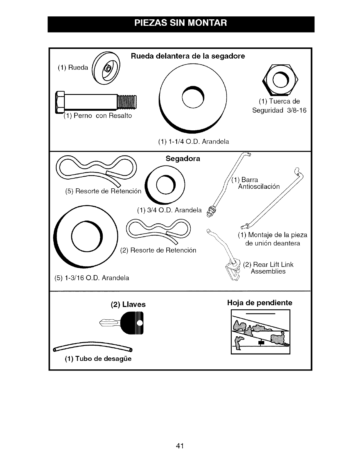
(1) Rueda (_
m
1) Perno con Resalto
Rueda delantera de la segadore
(1) 1-1/40.D. Arandela
@
(1) Tuerca de
Seguridad 3/8-16
.or/Barra
(5) Resorte de Retenci6n Antioscilaci6n
(1) 3/40.D. Arandela
©(2) Resorte de Retenci6n
(5) 1-3/16 O.D. Arandela
__(1) Montaje de la pieza
de uni6n deantera
(2) Rear Lift Link
Assemblies
(2) Llaves Hoja de pendiente
(1) Tubo de desag_e
41

Su tractor nuevo ha side montado en la f&brica con la excepci6n de aquellas partes que no se han
montado por razones de envio.
Cuando en este manual se mencionan los t6rminos
"mano derecha" o "mano izquierda" se refiere a
cuando usted se encuentra en la posici6n de oper-
aci6n (sentado/a detr&s del volante de direcci6n).
HERRAMIENTAS NECESARIAS PARA
EL MONTAJE
Un juego de Ilaves de tubo facilitar& el montaje.
A continuaci6n se enumeran los tamahos de
las Ilaves est&ndar.
(1) Llave de 3/4" (1) Medidor de pre-
(1) Llave de 9/16" si6n de las Ilantas
(1) Pinzas
(1) Cuchillo para todo uso
PARA REMOVER EL TRACTOR DE
LA CAJA DE CARTON
DESEMPAQUE LA CAJA DE CARTON
1. Remueva todas las partes sueltas que esten
accesibles, y las cajas de partes, de la caja
de cart6n grande.
2. Cortar a Io largo de las lineas de puntos en
todos los cuatro paneles de cart6n. Remover
los paneles de cierre y aplanar los paneles
laterales.
3. Remueva la segadora y los materiales del
embalage.
4. Revise si hay partes sueltas adicionales o
cart6n y remu6valas.
VERIFIQUE LA BATERIA
1. Levante el asiento a la posici6n elevada
AVlSO: Si esta bateria esta utilizada despu6s
del mes y a5o indicado sobre la etiqueta (L) (la
etiqueta que se encuentra entre los terminales),
cargue la bateria por un minimo de una hora a
6-10 amps. (Vea "Bateria" en la secci6n de Man-
tenimento de este manual).
AVlSO: Ahora puede rodar su tractor fuera de la
corredera. Siga las siguientes instrucciones para
remover el tractor de la corredera.
_ADVERTENCIA: Antes de empezar, leer, en-
tender y seguir todas las instrucciones presentes
en la secci6n de Operaciones de este manual.
Asegurarse que el tractor est6 en un &rea bien
ventilada. Asegurarse que la zona delante del
tractor est& Iibre de otras personas y objetos.
PARA HACER RODAR EL TRACTOR
FUERA DE LA CORREDERA (Yea la sec-
cibn de la operacibn para la localidad y
la funcibn de los controles)
1. Levante la palanca de levantamiento del ac-
cesorio a su posici6n m#.s alta.
2. Suelte el freno de estacionamiento presion-
ando el pedal del freno.
3. Ponga el control de la rueda libre en la
posici6n de giro libre para desenganchar la
transmisi6n. (Vea "PARA TRANSPORTAR"
en la secci6n de Operaci6n de este manual).
4. Haga rodar el tractor hacia delante fuera de
la corredera.
MONTE RUEDA DELATENTERA DE LA
SEGADORA
1. Utilizando un bul6n curvo, una arandela y
una tuerca de sujecion, fije la rueda delantera
de la cortadora, como se ilustra en la figura.
AjOstela bien.
AJUSTE EL ASIENTO
1. Si6ntese sobre el asiento.
2. Levante la palanca del ajuste (A) hacia arriba
y mueva el asiento hasta que alcance una
posici6n c6moda que le permita presionar com-
pletamente sobre el pedal del embragueffreno.
3. Desconecte la palanca para trabar el asiento
ell la posici6n.
42
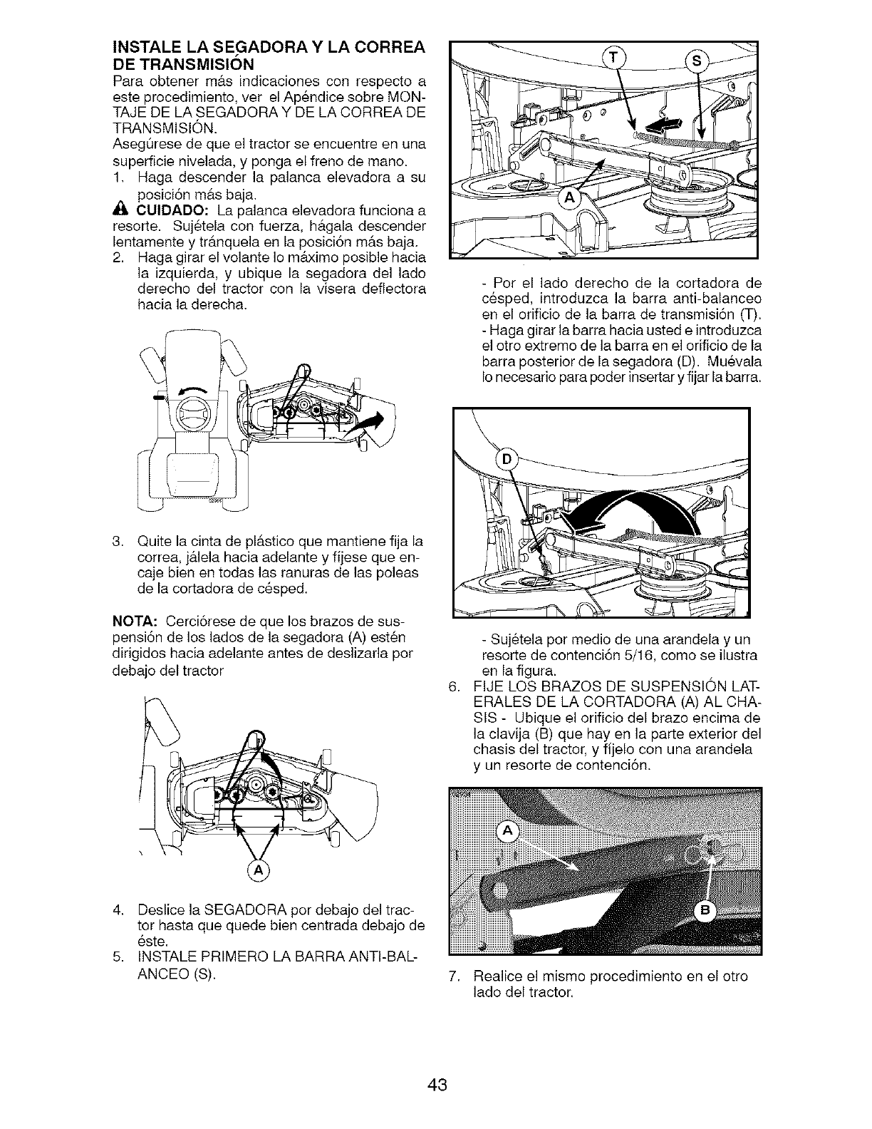
INSTALE LA SEGADORA Y LA CORREA
DE TRANSMISlON
Para obtener m&s indicaciones con respecto a
este procedimiento, ver el Ap6ndice sobre MON-
TAJE DE LA SEGADORA Y DE LA CORREA DE
TRANSMISION.
AsegSrese de que el tractor se encuentre en una
superficie nivelada, y ponga el freno de mano.
1. Haga descender la palanca elevadora a su
posici6n m&s baja.
_, CUIDADO: La palanca elevadora funciona a
resorte. Suj6tela con fuerza, h&gala descender
lentamente y tr&nquela en la posici6n m&s baja.
2. Haga girar el volante Io m&ximo posible hacia
la izquierda, y ubique la segadora del lado
derecho del tractor con la visera deflectora
hacia la derecha.
3, Quite la cinta de pl&stico que mantiene fija la
correa, j_.lela hacia adelante y fijese que en-
caje bien en todas las ranuras de las poleas
de la cortadora de c6sped.
NOTA: Cerci6rese de que los brazos de sus-
pensi6n de los lados de la segadora (A) est6n
dirigidos hacia adelante antes de deslizarla por
debajo del tractor
- Per el lade derecho de la cortadora de
c6sped, introduzca la barra anti-balanceo
en el orificio de la barra de transmisi6n (T).
- Haga girar la barra hacia usted e introduzca
el otro extremo de la barra en el orificio de la
barra posterior de la segadora (D). Muevala
Io necesario para poder insertar y fijar la barra.
6.
- Suj&tela per medio de una arandela y un
resorte de contenci6n 5/16, como se ilustra
en la figura.
FIJE LOS BRAZOS DE SUSPENSION LAT-
ERALES DE LA CORTADORA (A) AL CHA-
StS- Ubique el orificio del braze encima de
la clavija (B) que hay en la parte exterior del
chasis del tractor, y fijelo con una arandela
y un resorte de contenci6n.
4. Deslice la SEGAD©RA per debajo del trac-
tor hasta que quede bien centrada debajo de
este.
5. INSTALE PRIMERO LA BARRA ANTI-BAL-
ANCEO (S). 7. Realice el mismo procedimiento en el otto
lado del tractor.
43
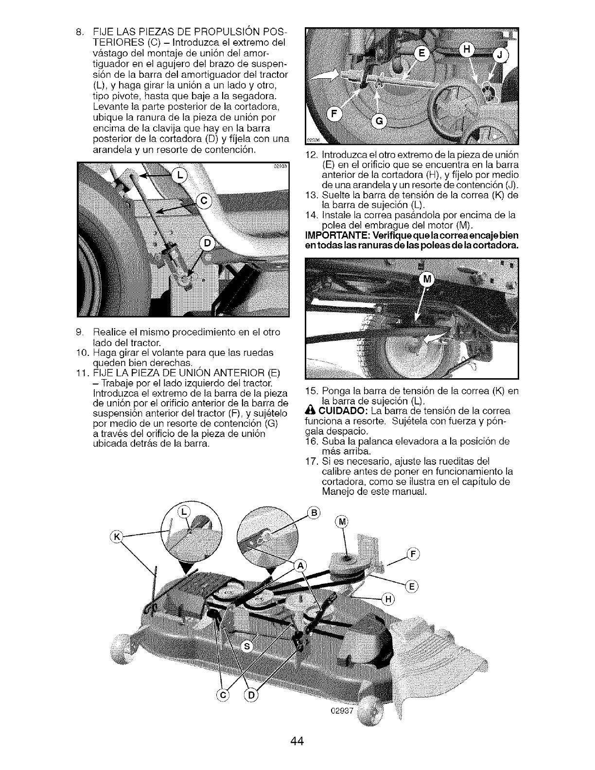
8. FIJE LAS PIEZAS DE PROPULSION POS-
TERIORES (C) - Introduzca el extremo del
v#.stago del montaje de uni6n del amor-
tiguador en el agujero del brazo de suspen-
si6n de la barra del amortiguador del tractor
(L), y haga girar la uni6n a un lado y otro,
tipo pivote, hasta que baje a la segadora.
Levante la parte posterior de la cortadora,
ubique la ranura de la pieza de uni6n pot
encima de la clavija que hay en la barra
posterior de la cortadora (D) y fijela con una
arandela y un resorte de contenci6n. 12. Introduzca el otro extremo de la pieza de uni6n
(E) en el orificio que se encuentra en la barra
anterior de la cortadora (H), y fijelo pot medio
de una arandela y un resorte de contenci6n (J).
13. Suelte la barra de tensi6n de la correa (K) de
la barra de sujeci6n (L).
14. Instale la correa pas_tndola por encima de la
polea del embrague del motor (M).
IMPORTANTE: Verifique que laeorrea encaje bien
en todas las ranuras de las poleas de la cortadora.
9. Realice el mismo procedimiento en el otro
lado del tractor.
10. Haga girar el volante para que las ruedas
queden bien derechas.
11. FIJE LA PIEZA DE UNION ANTERIOR (E)
- Trabaje por el lado izquierdo del tractor.
Introduzca el extremo de la barra de la pieza
de uni6n pot el orificio anterior de la barra de
suspensi6n anterior del tractor (F), y suj6telo
por medio de un resorte de contenci6n (G)
a trav6s del orificio de la pieza de uni6n
ubicada detr_.s de la barra.
15. Ponga la barra de tensi6n de la correa (K) en
la barra de sujeci6n (L).
CUIDADO: La barra de tensi6n de la correa
funciona a resorte. Suj6tela con fuerza y p6n-
gala despacio.
16. Suba la palanca elevadora a la posici6n de
mas arriba.
17. Si es necesario, ajuste las rueditas del
calibre antes de poner en funcionamiento la
cortadora, como se ilustra en el capitulo de
Manejo de este manual.
02937
44
REVISION DE LA PRESION DE LAS
LLANTAS
Las Ilantas en su unidad fueron infladas de-
masiado en la f&brica por razones de envio. La
presi6n de las Ilantas correctas es importante
para obtener el mejor rendimiento en el corte.
• Reduzca la presi6n de los neum&ticos a la PSi
que se indica en estos.
REVISION DE LA NIVELACION DEL
CONJUNTO
Para obtener los mejores resultados en el corte, la
caja de la segadora tiene que estar nivelada en la
forma adecuada. Vea "PARA NIVELAR LA CAJA
DE LA SEGADOR/_' en la secci6n de Servicio y
Ajustes de este manual.
REVISION DE LA POSICION ADECUA-
DA DE TODAS LAS CORREAS
Yea las figuras que aparecen para cambiar las
correas de impulsi6n de la cuchilla de la sega-
dora y de movimiento en la secci6n de Servicio y
Ajustes de este manual. Verifique que las correas
slgan su paso correcto.
REVISION DEL SISTEMA DE FRENOS
Una vez que usted haya aprendido a manejar su
tractor, verifique que el freno funcione correcta-
mente. Vet "PARA VERIFICAR Sl FUNCIONA
BIEN EL FRENO" en el capitulo de servicio y
ajustes de este manual.
,/LISTA DE REVISION
Antes de operar y de disfrutar de su tractor nuevo,
le deseamos que reciba el mejor rendimiento y la
mayor satisfaccion de este producto de calidad.
Haga el favor de revisar la lista a continuacion:
,/Se han completado todas las instrucciones de
montaje.
,/ No quedan partes sueltas en la caja de
cart6n.
,/ La bateria est#. preparada y cargada en forma
adecuada.
,/ El asiento ha sido ajustado en forma c6moda
y apretado en forma segura.
¢" Todas las Ilantas ban side infladas en forma
adecuada. (Para fines de envio, las Ilantas se
inflaron demasiado en la f_.brica.)
,/AsegQrese que el conjunto segador est6
nivelado en forma adecuada, de lado a lado y
desde adelante hacia atr&s, para obtener los
mejores resultados en el corte. (Las Ilantas
tienen que estar infladas en forma adecuada
para la nivelaci6n.)
,/ Revise las correas de impulsi6n y de la
segadora. AsegQrese que recorran el paso
adecuado alrededor de las poleas y dentro de
todos los fijadores de las correas.
,/ Revise el alambrado. Fijese que todas las
conexiones todavia esten seguras y que los
alambres est6n sujetos en forma adecuada.
,/Antes de conducir el tractor, asegQrese que
el control de rueda libre este en la posici6n
de "transmisi6n enganchada" (Vea "PARA
TRANSPORTAR" en la secci6n de la Oper-
aci6n de este manual).
AI mismo tiempo que aprende a come usar su
tractor, preste atencion extra a los puntos de
importancia que se presentan a continuacion:
¢" El aceite del motor tiene que Ilegar al nivel
adecuado.
,/ El estanque de combustible tiene que estar
Ileno con gasolina sin plomo regular, nueva y
limpia.
,/ Familiaricese con todos los controles - su ubi-
caci6n y su funci6n. Op6relos antes de hacer
arrancar el motor
,/AsegQrese que el sistema de frenos este en
una condici6n de operaci6n segura.
,/Asegurarse de que el Sistema de Presencia
del Operador y el Sistema de Funcionamiento
Atr&s (ROS) funcionan de modo adecuado (Vet
las Secciones de Funcionamiento y Manteni-
miento en este manual).
,/ Es importante purgar la transmisi6n antes de
operar su tractor por la primera vez. Siga las in-
strucciones adecuadas para el empiezo y para
purgar (Vea "PARA EMPESAR EL MOTOR"
y "PARA PURGAR LA TRANSMISlON" en la
secci6n de la Operaci6n de este manual.
45
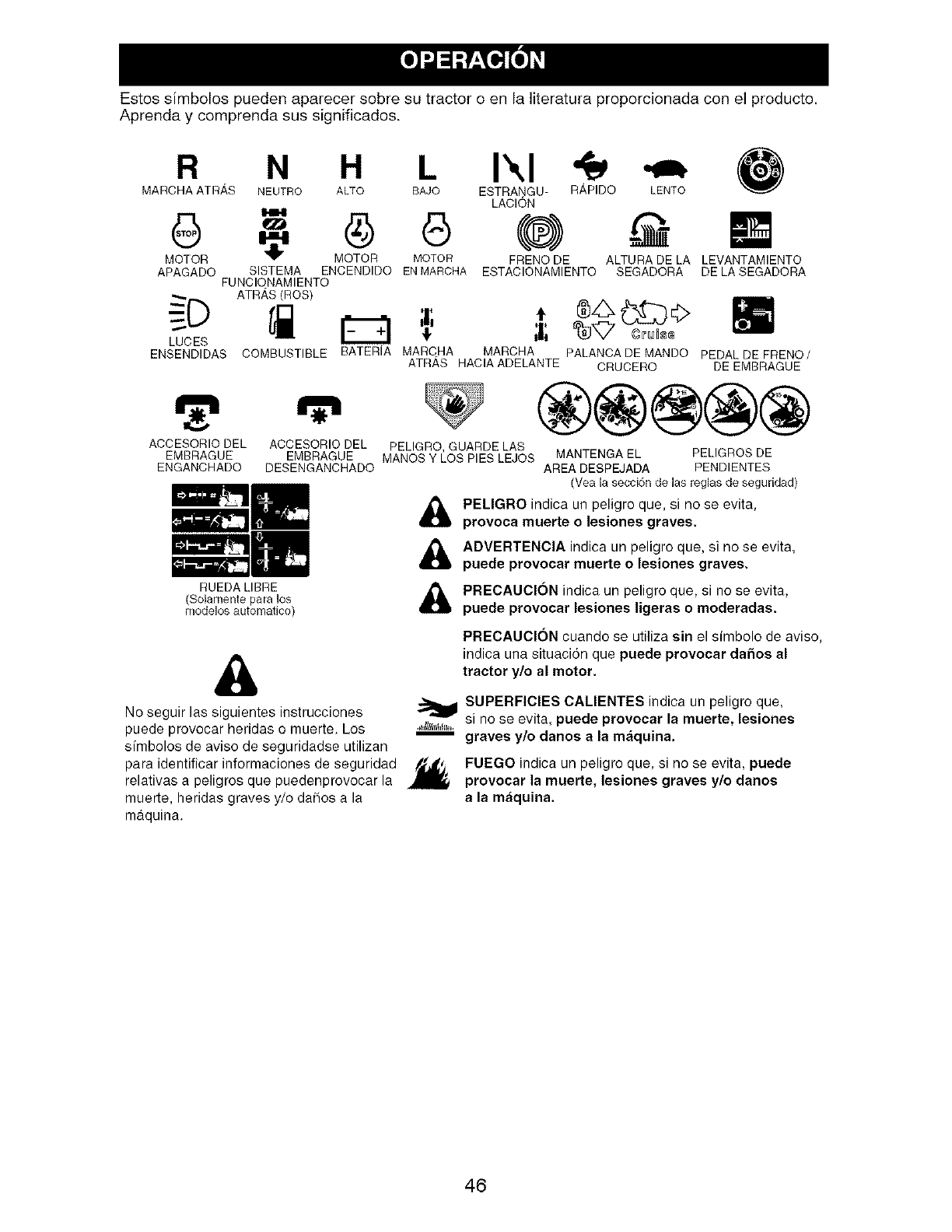
Estos simbolos pueden aparecer sobre su tractor o en la literatura proporcionada con el producto.
Aprenda y comprenda sus significados.
R N H I",1
MARCHAATR_,S NEUTRO ALTO BAJO ESTRANGU-
LACION
MOTOR MOTOR MOTOR FRBNODE
APAGADO SISTBMA BNDBNDIDO ENMAROHA ESTADIONAMIBNTO
FUNDIONAMIBNTO
ATR,_S(ROS)
R,_,PIDO LENTO
ALTURADE LA LEVANTAMIENTO
SEGADORA DE LASEGADORA
LUCES
ENSENDIDAS COMBUSTIBLE BATERIA MARCHA MARCHA PALANCADE MANDO PEDALDE FRENO/
ATRAS HACIAADELANTE CRUCERO DE EMBRAGUE
ACCESORIO DEL ACCESORIO DEL
EMBRAGUE EMBRAGUE
ENGANCHADO DESENGANCHADO
®@@@@
PELIGRO, GUARDE LAS
MANOS Y LOS PIES LEJOS MANTENGA EL PELIGROS DE
AREA DESPEJADA PENDIENTES
(Vea la secci6n de las reglas de seguridad)
PELIGRO indica un peligro que, si no se evita,
provoca muerte o lesiones graves.
ADVERTENCIA indica un peligro que, si no se evita,
puede provocar muerte o lesiones graves.
RUEDA LIBRE
(Solamente para los
modelos automalJco) PRECAUCION indica un peligro que, si no se evita.
puede prevocar lesiones ligeras o moderadas.
&
No seguir las siguientes instrucciones
puede provocar heridas o muerte. Los
simbolos de aviso de seguridadse utilizan
para identificar informaciones de seguridad
relativas a peligros que puedenprovocar la
muerte, heridas graves y/o da_os a la
PRECAUCION cuando se utiliza sin el sfmbolo de aviso,
indica una situacion que puede provocar da5os al
tractor y/o al motor.
SUPERFICIES CALIENTES indica un peligro que,
- ""_ si no se evita, puede provocar la muerte, lesiones
graves y/o danos a la m_quina,
FUEGO indica un peligro que, si no se evita, puede
provocar la muerte, lesiones graves y/e danos
a la m&quina.
maquina.
46
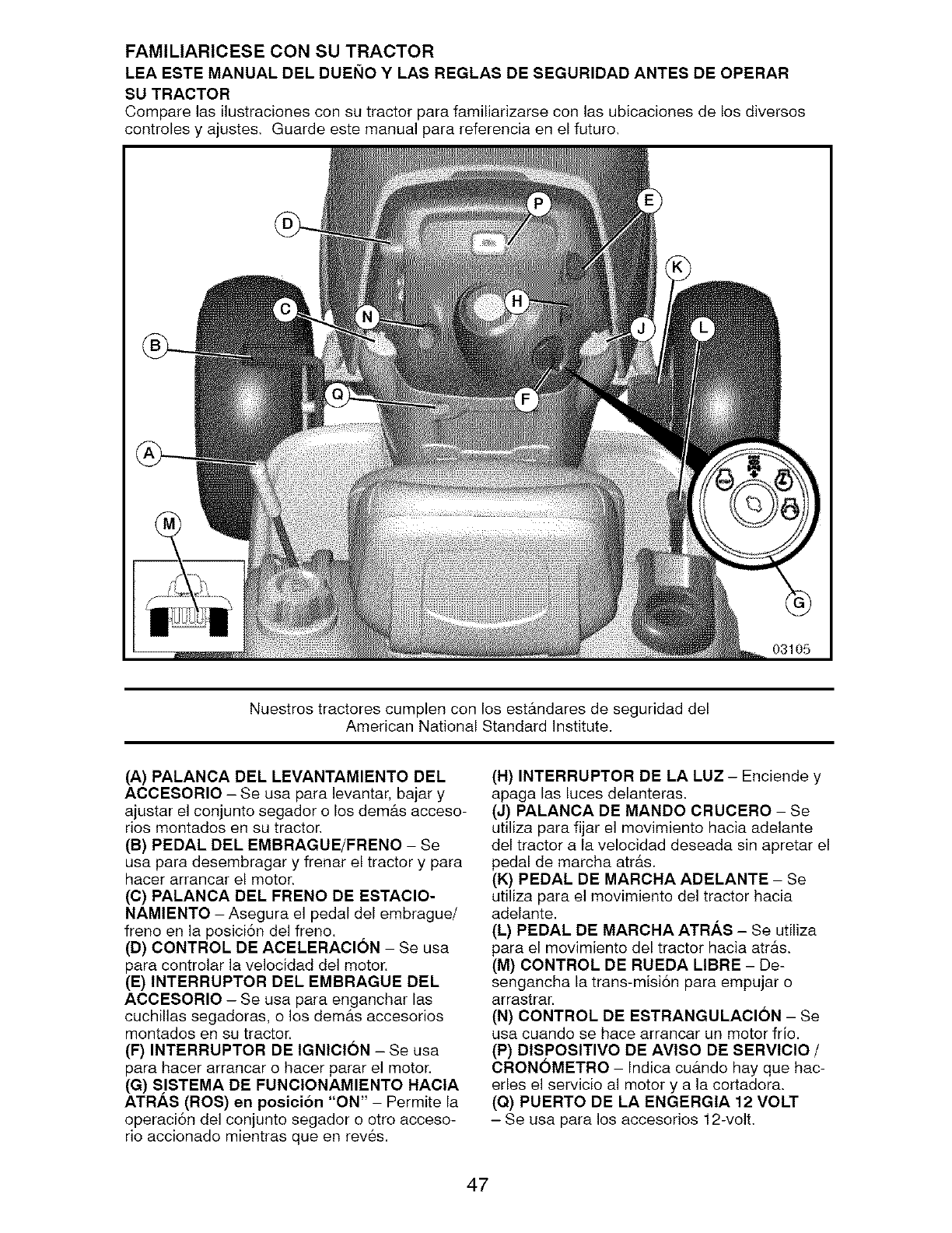
FAMILIARICESE CON SU TRACTOR
LEA ESTE MANUAL DEL DUEI_IO YLAS REGLAS DE SEGURIDAD ANTES DE OPERAR
SU TRACTOR
Compare las ilustraciones con su tractor parR familiarizarse con las ubicaciones de los diversos
controles y ajustes, Guarde este manual parR referencia en el futuro,
03105
Nuestros tractores cumplen con los est&ndares de seguridad del
American National Standard Institute.
(A) PALANCA DEL LEVANTAMIENTO DEL
ACCESORIO - Se usa parR levantar, bajar y
ajustar el conjunto segador o los dem&s acceso-
rios montados en su tractor,
(B) PEDAL DEL EMBRAGUE/FRENO - Se
usa para desembragar y frenar el tractor y para
Racer arrancar el motor.
(C) PALANCA DEL FRENO DE ESTACIO-
NAMIENTO - Asegura el pedal del embrague/
freno en la posici6n del freno.
(D) CONTROL DE ACELERAClON - Se usa
parR controlar la velocidad del motor.
(E) INTERRUPTOR DEL EMBRAGUE DEL
ACCESORIO - Se usa parR enganchar las
cuchillas segadoras, o los dem&s accesorios
montados en su tractor.
(F) INTERRUPTOR DE IGNICION - Se usa
parR Racer arrancar o Racer parar el motor.
(G) SISTEMA DE FUNCIONAMIENTO HACIA
ATRAS (ROS) en posicion "ON" - Permite la
operaci6n del conjunto segador o otro acceso-
rio accionado mientras que en rev6s.
(H) INTERRUPTOR DE LA LUZ - Enciende y
apaga las luces delanteras.
(J) PALANCA DE MANDO CRUCERO - Se
utiliza para fijar el movimiento hacia adelante
del tractor a la velocidad deseada sin apretar el
pedal de marcha atr#.s.
(K) PEDAL DE MARCHA ADELANTE - Se
utiliza para el movimiento del tractor hacia
adelante.
(L) PEDAL DE MARCHA ATRAS - Se utiliza
para el movimiento del tractor hacia atrAs.
(M) CONTROL DE RUEDA LIBRE - De-
sengancha la trans-misi6n para empujar o
arrastrar.
(N) CONTROL DE ESTRANGULACION - Se
usa cuando se Race arrancar un motor fr[o.
(P) DISPOSITIVO DE AVISO DE SERVICIO /
CRONOMETRO - Indica cu&ndo hay que hac-
erles el servicio al motor y a la cortadora.
(Q) PUERTO DE LA ENGERGIA 12 VOLT
- Se usa para los accesorios 12-volt,
47
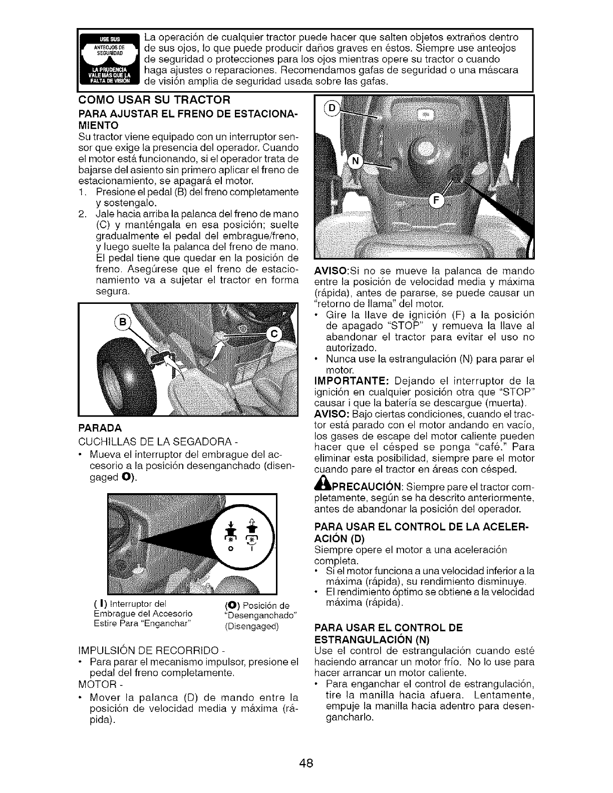
La operaci6n de cualquier tractor puede hacer que salten objetos extraSos dentro
de sus ojos, Io que puede producir daSos graves en _stos. Siempre use anteojos
de seguridad o protecciones para los ojos mientras opere su tractor o cuando
haga ajustes o reparaciones. Recomendamos gafas de seguridad o una mb,scara
de visi6n amplia de seguridad usada sobre las gafas.
COMO USAR SU TRACTOR
PARA AJUSTAR EL FRENO DE ESTAClONA-
MIENTO
Su tractor viene equipado con un interruptor sen-
sor que exige la presencia del operador. Cuando
el motor eet& funcionando, si el operador trata de
bajarse del aeiento sin primero aplicar el freno de
eetacionamiento, ee apagar& el motor.
1. Preeione el pedal (B) del freno completamente
y sostengalo.
2. Jale hacia arriba la palanca del freno de mane
(C) y mant6ngala en esa poeici6n; suelte
gradualmente el pedal del embrague/freno,
y luego suelte la palanca del freno de mano.
El pedal tiene que quedar en la posici6n de
freno. AsegSreee que el freno de estacio-
namiento va a sujetar el tractor en forma
segura.
PARADA
CUCHILLAS DE LA SEGADORA -
• Mueva el interruptor del embrague del ac-
cesorio a la posici6n desenganchado (disen-
gaged O).
(I) interrupter del
Embrague del Accesorio
Estire Para "Enganchar"
(O) Posici6n de
"Desenganchado"
(Disengaged)
IMPULSION DE RECORRIDO -
• Para parar el mecanismo impulsor, presione el
pedal del freno completamente.
MOTOR -
• Mover la palanca (D) de mando entre la
posici6n de velocidad media y m&xima (r&-
pida).
AVISO:Si no se mueve la palanca de mando
entre la posici6n de velocidad media y m&xima
(r&pida), antes de pararse, se puede causar un
"retorno de llama" del motor.
Gire la Ilave de ignici6n (F) a la posicion
de apagado "STOP" y remueva la Ilave al
abandonar el tractor para evitar el uso no
autorizado.
Nunca use la estrangulaci6n (N) para parar el
motor.
IMPORTANTE: Dejando el interruptor de la
ignici6n en cualquier posici6n otra que "STOP"
causar i que la bateria se descargue (muerta).
AVISO: Bajo ciertas condiciones, cuando el trac-
tor est& parado con el motor andando en vacio,
los gases de escape del motor caliente pueden
hacer que el cesped se ponga "cafe." Para
eliminar esta posibilidad, siempre pare el motor
cuando pare el tractor en &reas con cesped.
_I_PRECAUCION: Siempre pare el tractor com-
pletamente, segt_n se ha descrito anteriormente,
antes de abandonar la posici6n del operador.
PARA USAR EL CONTROL DE LA ACELER-
ACION (D)
Siempre opere el motor a una aceleraci6n
completa.
Si el motor funciona a una velocidad inferior a la
maxima (rb,pida), su rendimiento disminuye.
El rendimiento 6ptimo se obtiene a la velocidad
m&xima (r&pida).
PARA USAR EL CONTROL DE
ESTRANGULACION (N)
Use el control de estrangulaci6n cuando est6
haciendo arrancar un motor frio. No Io use para
hacer arrancar un motor caliente.
Para enganchar el control de estrangulaci6n,
tire la manilla hacia afuera. Lentamente,
empuje la manilla hacia adentro para desen-
ganchado.
48
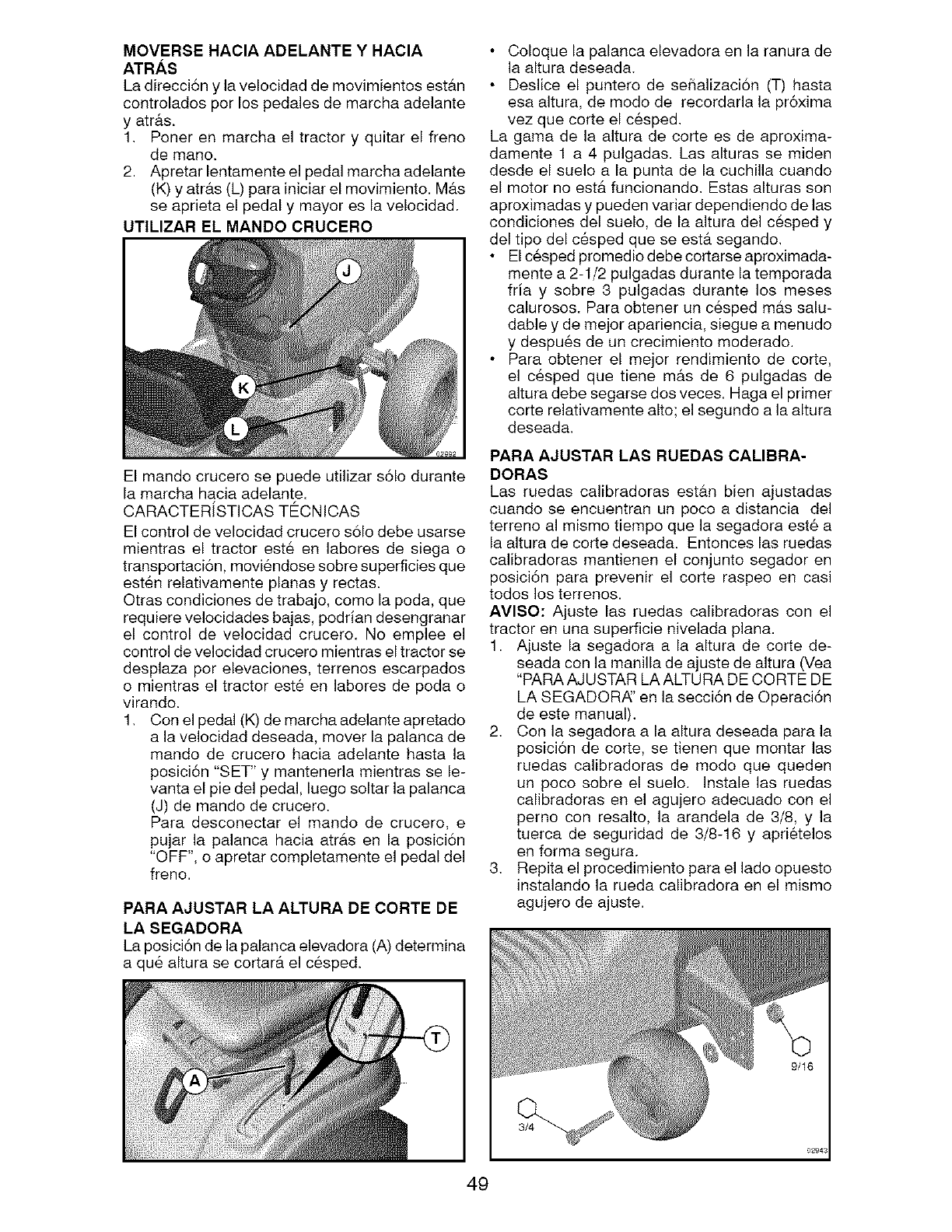
MOVERSE HACIA ADELANTE Y HACIA
ATRAS
La direcci6n y la velocidad de movimientos estb.n
controlados por los pedales de marcha adelante
y atr&s.
1. Poner en marcha el tractor y quitar el freno
de mane.
2. Apretar lentamente el pedal marcha adelante
(K) y atr&s (L) para iniciar el movimiento. M&s
se aprieta el pedal y mayor es la velocidad.
UTILIZAR EL MANDO CRUCERO
El mando crucero se puede utilizar s61o durante
la marcha hacia adelante.
CARACTERiSTICAS TECNICAS
El control de velocidad crucero solo debe usarse
mientras el tractor este en labores de siega o
transportaci6n, moviendose sobre superficies que
esten relativamente planas y rectas.
Otras condiciones de trabajo, como la poda, que
requiere velocidades bajas, podrian desengranar
el control de velocidad crucero. No emplee el
control de velocidad crucero mientras el tractor se
desplaza por elevaciones, terrenos escarpados
o mientras el tractor est6 en labores de poda o
virando.
1. Con el pedal (K) de marcha adelante apretado
a la velocidad deseada, mover la palanca de
mando de crucero hacia adelante hasta la
posici6n "SET" y mantenerla mientras se le-
vanta el pie del pedal, luego soltar la palanca
(J) de mando de crucero.
Para desconectar el mando de crucero, e
pujar la palanca hacia atr&s en la posici6n
"OFF", o apretar completamente el pedal del
freno.
PARA AJUSTAR LA ALTURA DE CORTE DE
LA SEGADORA
La posici6n de la palanca elevadora (A) determina
a qu6 altura se cortar& el c6sped.
• Coloque la palanca elevadora en la ranura de
la altura deseada.
• Deslice el puntero de sehalizaci6n (T) hasta
esa altura, de modo de recordarla la pr6xima
vez que corte el c6sped.
La gama de la altura de corte es de aproxima-
damente 1 a 4 pulgadas. Las alturas se miden
desde el suelo a la punta de la cuchilla cuando
el motor no estb, funcionando. Estas alturas son
aproximadas y pueden variar dependiendo de las
condiciones del suelo, de la altura del cesped y
del tipo del c6sped que se est& segando.
• El c6sped promedio debe cortarse aproximada-
mente a 2-1/2 pulgadas durante la temporada
fria y sobre 3 pulgadas durante los meses
calurosos. Para obtener un c6sped m&s salu-
dable y de mejor apariencia, siegue a menudo
y despu6s de un crecimiento moderado.
• Para obtener el mejor rendimiento de corte,
el c6sped que tiene m&s de 6 pulgadas de
altura debe segarse dos veces. Haga el primer
corte relativamente alto; el segundo a la altura
deseada.
PARA AJUSTAR LAS RUEDAS CALIBRA-
DORAS
Las ruedas calibradoras est&n bien ajustadas
cuando se encuentran un poco a distancia del
terreno al mismo tiempo que la segadora est_ a
la altura de corte deseada. Entonces las ruedas
calibradoras mantienen el conjunto segador en
posici6n para prevenir el corte raspeo en casi
todos los terrenos.
AVISO: Ajuste las ruedas calibradoras con el
tractor en una superficie nivelada plana.
1. Ajuste la segadora a la altura de corte de-
seada con la manilla de ajuste de altura (Vea
"PARA AJUSTAR LA ALTURA DE CORTE DE
LA SEGADORi_' en la secci6n de Operaci6n
de este manual).
2. Con la segadora a la altura deseada para la
posici6n de corte, se tienen que montar las
ruedas calibradoras de modo que queden
un poco sobre el suelo. Instale las ruedas
calibradoras en el agujero adecuado con el
perno con resalto, la arandela de 3/8, y la
tuerca de seguridad de 3/8-16 y apri6telos
en forma segura.
3. Repita el procedimiento para el lado opuesto
instalando la rueda calibradora en el mismo
agujero de ajuste.
4g
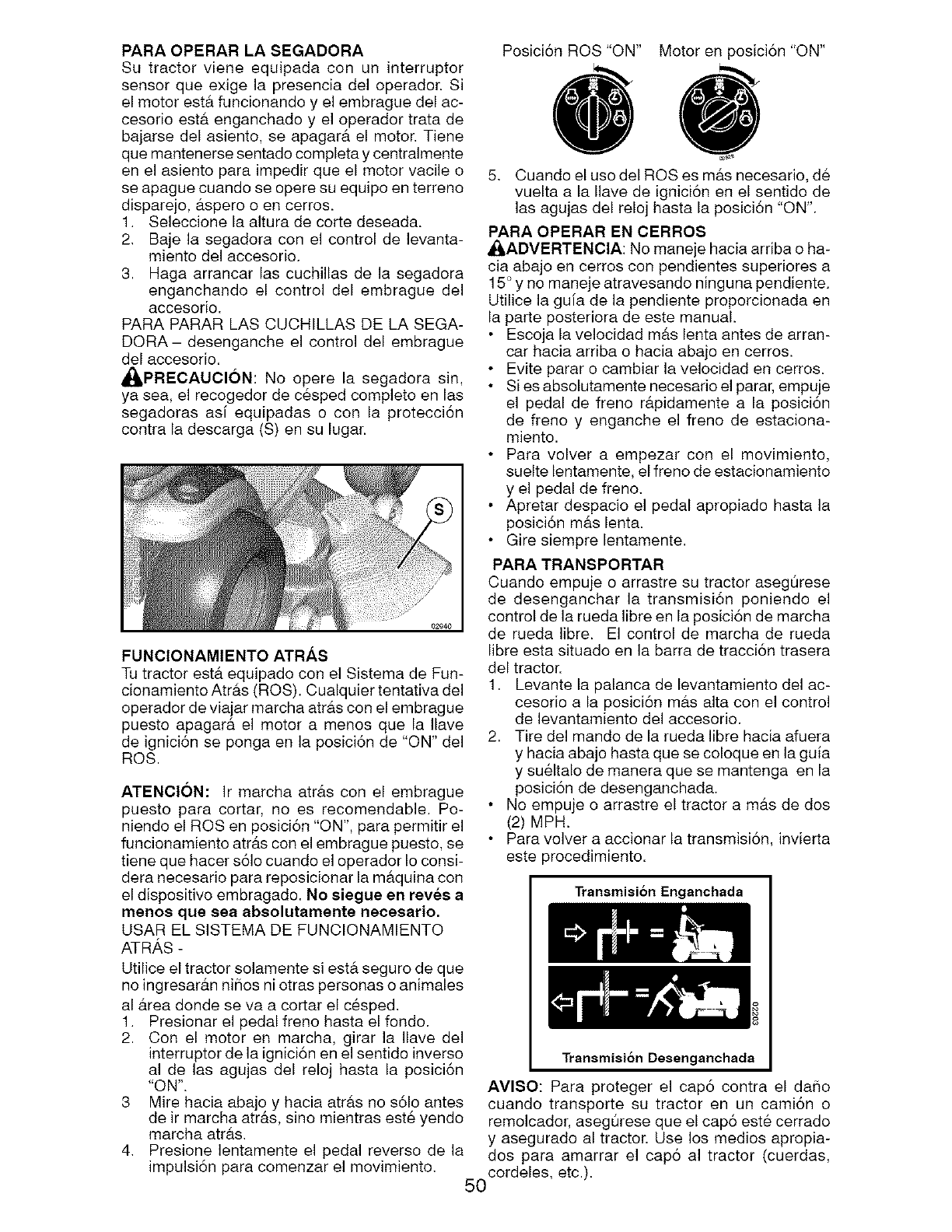
PARA OPERAR LA SEGADORA
Su tractor viene equipada con un interruptor
sensor que exige la presencia del operador. Si
el motor estb, funcionando y el embrague del ac-
cesorio estb, enganchado y el operador trata de
bajarse del asiento, se apagar& el motor. Tiene
que mantenerse sentado completa y centralmente
en el asiento para impedir que el motor vacile o
se apague cuando se opere su equipo en terreno
disparejo, &spore o en cerros.
1. Seleccione la altura de corte deseada.
2. Baje la segadora con el control de levanta-
miento del accesorio.
3. Haga arrancar las cuchillas de la segadora
enganchando el control del embrague del
accesorio.
PARA PARAR LAS CUCHILLAS DE LA SEGA-
DORA- desenganche el control del embrague
del accesorio.
_PRECAUCl0N: No opere la segadora sin,
ya sea, el recogedor de c6sped completo en las
segadoras asi equipadas o con la protecci6n
contra la descarga (S) en su lugar.
Posici6n ROS "ON" Motor en posici6n "ON"
5. Cuando el uso del ROSes m&s necesario, de
vuelta a la Ilave de ignici6n en el sentido de
las agujas del reloj hasta la posici6n "ON".
PARA OPERAR EN CERROS
_ADVERTENCIA: No maneje hacia arriba o ha-
cia abajo en cerros con pendientes superiores a
15° y no maneje atravesando ninguna pendiente.
Utilice la guia de la pendiente proporcionada en
la parte posteriora de este manual.
Escoja la velocidad m&s lenta antes de arran-
car hacia arriba o hacia abajo en cerros.
Evite parar o cambiar la velocidad en cerros.
Si es absolutamente necesario el parar, empuje
el pedal de freno r&pidamente a la posici6n
de freno y enganche el freno de estaciona-
miento.
Para volver a empezar con el movimiento,
suelte lentamente, el freno de estacionamiento
y el pedal de freno.
• Apretar despacio el pedal apropiado hasta la
posici6n m#.s lent&
Gire siempre lentamente.
FUNCIONAMIENTO ATRAS
Tu tractor est& equipado con el Sistema de Fun-
cionamiento Atr&s (ROS). Cualquier tentativa del
operador de viajar marcha atrb,s con el embrague
puesto apagar#, el motor a menos que la Ilave
de ignici6n se ponga en la posici6n de "ON" del
ROS.
ATENClON: Ir marcha atr&s con el embrague
puesto para cortar, no es recomendable. Po-
niendo el ROSen posici6n "ON", para permitir el
funcionamiento atr&s con el embrague puesto, se
tiene que hacer s61o cuando el operador Io consi-
dora necesario para reposicionar la m&quina con
el dispositivo embragado. No siegue en rev_s a
menos que sea absolutamente neoesario.
USAR EL SISTEMA DE FUNCIONAMIENTO
ATRAS -
Utilice el tractor solamente si est& seguro de que
no ingresarb, n ni_ios ni otras personas o animales
al b,rea donde se va a cortar el c6sped.
1. Presionar el pedal freno hasta el fondo.
2. Con el motor en marcha, girar la Ilave del
interrupter de la ignici6n en el sentido inverse
al de las agujas del reloj hasta la posici6n
"ON".
3 Mire hacia abajo y hacia atrb,s no s61o antes
de ir marcha atr&s, sino mientras est_ yendo
marcha atrb,s.
4. Presione lentamente el pedal reverso de la
impulsi6n para comenzar el movimiento.
PARA TRANSPORTAR
Cuando empuje o arrastre su tractor aseg0rese
de desenganchar la transmisi6n poniendo el
control de la rueda libre en la posici6n de marcha
de rueda libre. El control de marcha de rueda
libre esta situado en la barra de tracci6n trasera
del tractor.
1. Levante la palanca de levantamiento del ac-
cesorio a la posici6n m&s alta con el control
de levantamiento del accesorio.
2. Tire del mando de la rueda libre hacia afuera
y hacia abajo hasta que se coloque en la guia
y su61talo de manera que se mantenga en la
posicion de desenganchada.
No empuje o arrastre el tractor a m&s de dos
(2) MPH.
Para volver a accionar la transmisi6n, invierta
este procedimiento.
Transmisi6n Enganchada
Transmisi6n Desenganchada
AVISO: Para proteger el cap6 contra el da_io
cuando transporte su tractor en un cami6n o
remolcador, aseg0rese que el cap6 este cerrado
y asegurado al tractor. Use los medios apropia-
dos para amarrar el cap6 al tractor (cuerdas,
cordeles, etc.).
5O
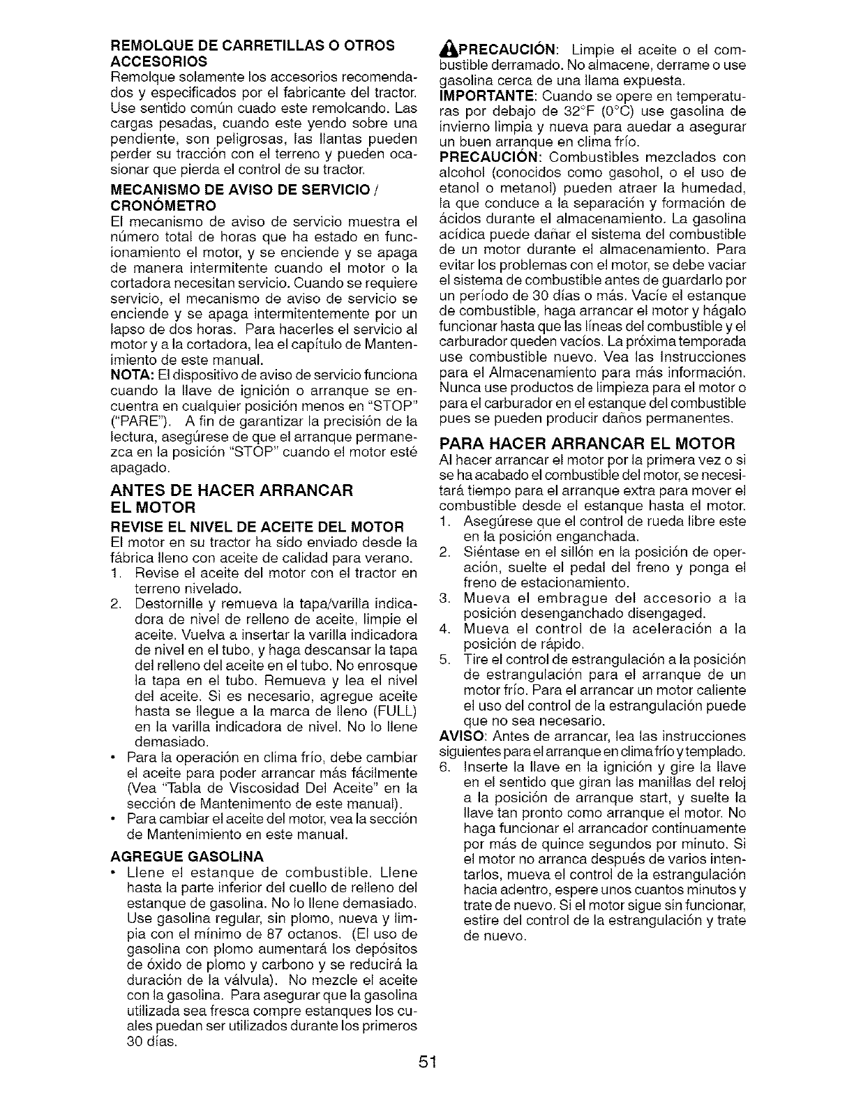
REMOLQUE DE CARRETILLAS O OTROS
ACCESORIOS
Remolque eolamente los accesorios recomenda-
dos y especificadoe por el fabricante del tractor.
Use sentido comQn cuado eete remolcando. Las
cargas pesadas, cuando este yendo sobre una
pendiente, son peligroeas, las Ilantas pueden
perder su traccion con el terreno y pueden oca-
sionar que pierda el control de eu tractor.
MECANISMO DE AVlSO DE SERVlClO /
CRONOMETRO
El mecanismo de aviso de servicie mueetra el
n_mero total de horas que ha eetado en func-
ionamiento el motor, y se enciende y se apaga
de manera intermitente cuando el motor o la
cortadora necesitan servicio. Cuando ee requiere
servicio, el mecanismo de avieo de servicio se
enciende y se apaga intermitentemente por un
lapso de dos horas. Para hacerles el servicio al
motor y a la cortadora, lea el capitulo de Manten-
imiento de eete manual.
NOT,&: El dispositivo de aviso de servicio funciona
cuando la Ilave de ignici6n o arranque se en-
cuentra en cualquier posici6n menos en "STOP"
("PARE"). A fin de garantizar la precisi6n de la
lectura, aeegQrese de que el arranque permane-
zca en la posici6n "STOP" cuando el motor est_
apagado.
ANTES DE HACER ARRANCAR
EL MOTOR
REVISE EL NIVEL DE ACEITE DEL MOTOR
El motor en su tractor ha sido enviado desde la
f&brica Ileno con aceite de calidad para verano.
1. Revise el aceite del motor con el tractor en
terreno nivelado.
2. Destornille y remueva la tapa/varilla indica-
dora de nivel de relleno de aceite, limpie el
aceite. Vuelva a insertar la varilla indicadora
de nivel en el tube, y haga descansar la tapa
del relleno del aceite en el tubo. No enrosque
la tapa en el tubo. Remueva y lea el nivel
del aceite. Si es necesario, agregue aceite
hasta se Ilegue a la marca de Ileno (FULL)
en la varilla indicadora de nivel. No Io Ilene
demasiado.
• Para la operaci6n en clima frio, debe cambiar
el aceite para poder arrancar m&s f&cilmente
(Vea "Tabla de Viscosidad Del Aceite" en la
secci6n de Mantenimento de este manual).
• Para cambiar el aceite del motor, vea la secci6n
de Mantenimiento en este manual.
AGREGUE GASOLINA
• Llene el estanque de combustible. Llene
hasta la parte inferior del cuello de relleno del
estanque de gasolina. No Io Ilene demasiado.
Use gasolina regular, sin plomo, nueva y lim-
pia con el minimo de 87 octanos. (El uso de
gasolina con plomo aumentar& los dep6sitos
de 6xido de plomo y carbono y se reducir& la
duraci6n de la v&lvula). No mezcle el aceite
con la gasolina. Para asegurar que la gasolina
utilizada sea fresca compre estanques los cu-
ales puedan ser utilizados durante los primeros
30 dias.
51
_PRECAUCI6N: Limpie el aceite o el com-
bustible derramado. No almacene, derrame o use
gasolina cerca de una llama expuesta.
IMPORTANTE: Cuando se opere en temperatu-
ras por debajo de 32°F (0°C) use gaselina de
invierno limpia y nueva para auedar a asegurar
un buen arranque en clima frio.
PRECAUCION: Combustibles mezclados con
alcohol (conocidos como gasohol, o el use de
etanol o metanol) pueden atraer la humedad,
la que conduce a la separaci6n y formaci6n de
&cidos durante el almacenamiento. La gasolina
acidica puede daSar el sistema del combustible
de un motor durante el almacenamiento. Para
evitar los problemas con el motor, se debe vaciar
el sistema de combustible antes de guardarlo per
un periodo de 30 dias o m&s. Vacie el estanque
de combustible, haga arrancar el motor y h&galo
funcionar hasta que las lineas del combustible y el
carburador queden vacios. La pr6xima temporada
use combustible nuevo. Yea las Instrucciones
para el AImacenamiento para m&s informaci6n.
Nunca use productos de limpieza para el motor o
para el carburador en el estanque del combustible
pues se pueden producir daiios permanentes.
PARA HACER ARRANCAR EL MOTOR
AI hacer arrancar el motor per la primera vez o si
se ha acabado el combustible del motor, ee neceei-
tar& tiempo para el arranque extra para mover el
combustible deede el estanque hasta el motor.
1. AsegQrese que el control de rueda libre eete
en la posici6n enganchada.
2. Si6ntase en el sill6n en la posici6n de oper-
aci6n, suelte el pedal del freno y ponga el
freno de estacionamiento.
3. Mueva el embrague del accesorio a la
posici6n desenganchado disengaged.
4. Mueva el control de la aceleraci6n a la
posici6n de r&pido.
5. Tire el control de estrangulaci6n a la posici6n
de estrangulacion para el arranque de un
motor frio. Para el arrancar un motor caliente
el uso del control de la estrangulaci6n puede
que no sea necesario.
AVlSO: Antes de arrancar, lea las instrucciones
siguientes para el arranque en clima frio y templado.
6. Inserte la Ilave en la ignici6n y gire la Ilave
en el sentido que giran las manillas del reloj
a la posici6n de arranque start, y suelte la
Ilave tan pronto como arranque el motor. No
haga funcionar el arrancador continuamente
per m&s de quince segundos per minute. Si
el motor no arranca despu@s de varios inten-
tarlos, mueva el control de la estrangulaci6n
hacia adentro, espere unos cuantos minutos y
trate de nuevo. Si el motor sigue sin funcionar,
estire del control de la estrangulaci6n y trate
de nuevo.
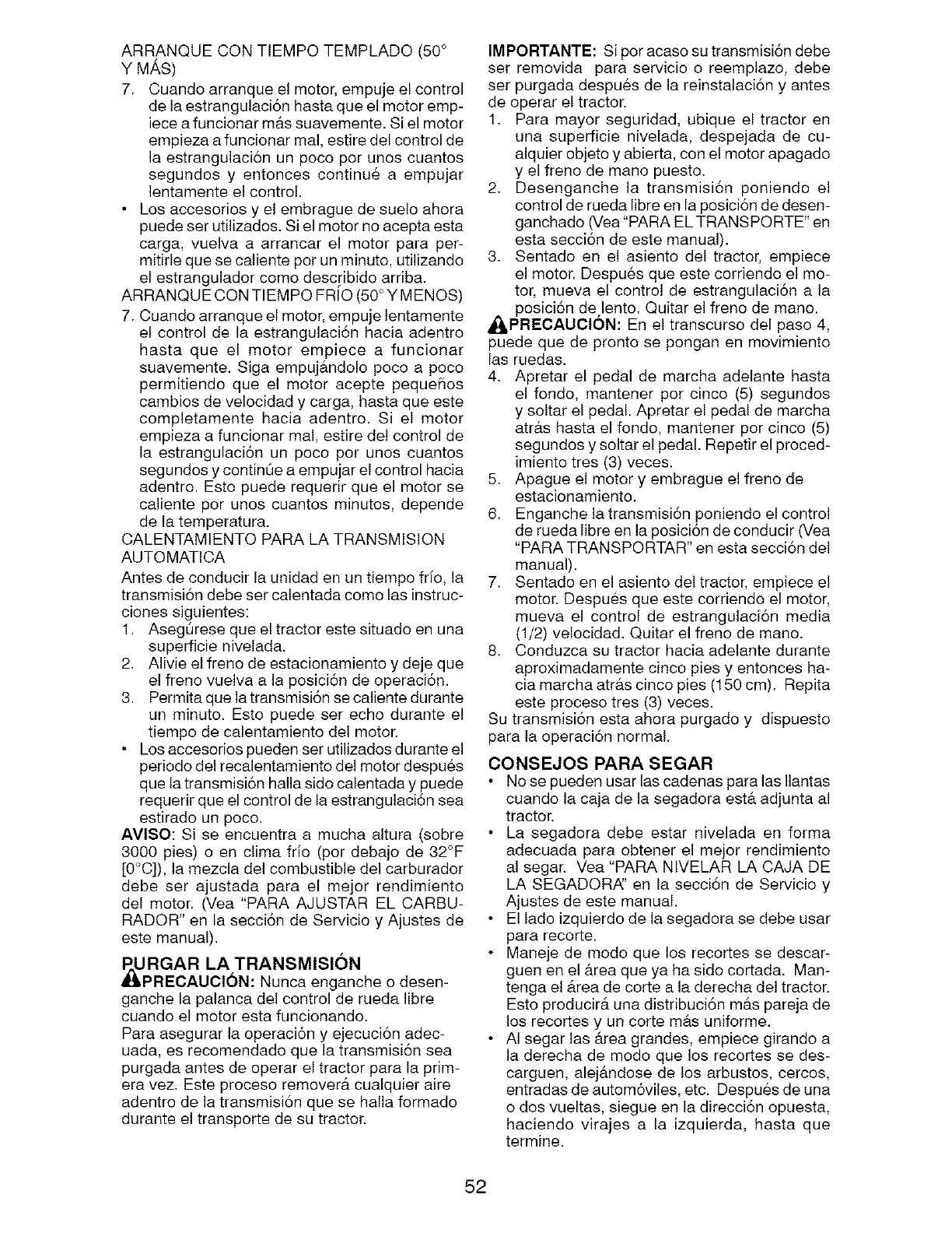
ARRANQUECONTEMPOTEMPLADO(50°
Y MAS)
7. Cuandoarranqueelmotor,empujeelcontrol
delaestrangulaci6nhastaqueelmotoremp-
ieceafuncionarmAssuavemente.Sielmotor
empiezaafuncionarmal,estiredelcontrolde
laestrangulaci6nunpocoporunoscuantos
segundosy entoncescontinu6a empujar
lentamenteelcontrol.
• Losaccesoriosy el embraguedesueloahora
puedesetutilizados.Sielmotornoaceptaesta
carga,vuelvaa arrancarel motorpara per-
mitirlequesecalientepotunminuto,utilizando
elestranguladorcomodescribidoarriba.
ARRANQUECONTIEMPOFRIO(50°YMENOS)
7.Cuandoarranqueelmotor,empujelentamente
el controldela estrangulaci6nhaciaadentro
hasta que el motor empiecea funcionar
suavemente.Sigaempujb,ndolopocoa poco
permitiendoque el motoraceptepeque_ios
cambiosdevelocidady carga,hastaqueeste
completamentehaciaadentro.Si el motor
empiezaa funcionarmal,estiredelcontrolde
la estrangulaci6nun pocoperunoscuantos
segundosycontin0eaempujarelcontrolhacia
adentro.Estopuederequerirqueelmotorse
calienteporunoscuantosminutes,depende
delatemperatura.
CALENTAMIENTOPARALATRANSMISION
AUTOMATICA
Antesde conducirlaunidadenuntiempofrio,la
transmisi6ndebesetcalentadacomolasinstruc-
clonessiguientes:
1. Aseg0resequeeltractorestesituadoenuna
superficienivelada.
2. Alivieelfrenodeestacionamientoy dejeque
elfrenovuelvaa lapesici6ndeoperaci6n.
3. Permitaquelatransmisi6nsecalientedurante
un minuto.Estopuedeserechoduranteel
tiempodecalentamientodel motor.
• Losaccesoriospuedensetutilizadosduranteel
periododelrecalentamientodelmotordespues
quelatransmisi6nhallasidecalentaday puede
requerirqueelcontroldelaestrangulaci6nsea
estiradounpoco.
AVlSO:Sise encuentraa muchaaltura(sobre
3000pies)o enclimafrio (perdebajode32°F
[0°C]),la mezcladelcombustibledelcarburador
debeser ajustadapara el mejorrendimiento
del motor.(Vea"PARAAJUSTAREL CARBU-
RADOR"en lasecci6ndeServicioy Ajustesde
estemanual).
RURGAR LA TRANSMISION
_PRECAUCI6N: Nuncaengancheodesen-
ganchelapalancadelcontrolderuedalibre
cuandoel motorestafuncionando.
Paraasegurarlaoperaci6ny ejecuci6nadec-
uada,esrecomendadoquelatransmisi6nsea
purgadaantesdeoperareltractorparalaprim-
eravez.Esteprocesoremover&cualquieraire
adentrodelatransmisi6nquesehallaformado
duranteeltransportedesutractor.
IMPORTANTE:Siporacasosutransmisi6ndebe
ser removidaparaservicioo reemplazo,debe
serpurgadadespu6sdelareinstalaci6ny antes
deoperareltractor.
1. Paramayorseguridad,ubiqueel tractoren
unasuperficienivelada,despejadade cu-
alquierobjetoy abierta,conelmotorapagado
y elfrenodemanopuesto.
2. Desenganchela transmisi6nponiendoel
controlderuedalibreenlaposici6ndedesen-
ganchado(Vea"PARAELTRANSPORTE"en
estasecci6ndeestemanual).
3. Sentadoen el asientodel tractor,empiece
elmotor.Despuesqueestecorriendoelmo-
tor,muevael controlde estrangulaci6na la
posici6ndelento.Quitarelfrenodemano.
_PRECAUCl6N: Eneltranscursodelpaso4,
puedequedeprontose ponganenmovimiento
lasruedas.
4. Apretarel pedalde marchaadelantehasta
el fondo,mantenerpercinco(5)segundos
y soltarelpedal.Apretarel pedalde marcha
atr#,shastaelfondo,mantenerporcinco(5)
segundosysoltarelpedal.Repetirelproced-
imientotres(3)veces.
5. Apagueel motory embragueelfrenode
estacionamiento.
6. Enganchelatransmisi6nponiendoelcontrol
deruedalibreenlaposici6ndeconducir(Vea
"PARATRANSPORTAR"enestasecci6ndel
manual).
7. Sentadoenelasientodeltractor,empieceel
motor.Despuesqueestecorriendoel motor,
muevael controlde estrangulaci6nmedia
(1/2)velocidad.Quitarel frenodemano.
8. Conduzcasutractorhaciaadelantedurante
aproximadamentecincopiesy entoncesha-
ciamarchaatr#.scincopies(150cm).Repita
esteprocesotres (3)veces.
Sutransmisionestaahorapurgadoy dispuesto
paralaoperaci6nnormal.
CONSEJOS PARA SEGAR
No se pueden usar las cadenas para las Ilantas
cuando la caja de la segadora ester adjunta al
tractor.
La segadora debe estar nivelada en forma
adecuada para obtener el mejor rendimiento
al segar. Vea "PARA NIVELAR LA OAJA DE
LA SEGADOR,_' en la secci6n de Servicio y
Ajustes de este manual.
El lado izquierdo de la segadora se debe usar
para recorte.
Maneje de modo que los recortes se descar-
guen en el #.rea que ya ha sido cortada. Man-
tenga el #.rea de corte a la derecha del tractor.
Esto producir& una distribuci6n mb,s pareja de
los recortes y un corte m_ts uniforme.
• AI segar las _.rea grandes, empiece girando a
la derecha de modo que los recortes se des-
carguen, alejandose de los arbustos, cercos,
entradas de autom6viles, etc. Despues de una
o dos vueltas, siegue en la direcci6n opuesta,
haciendo virajes a la izquierda, hasta que
termine.
52
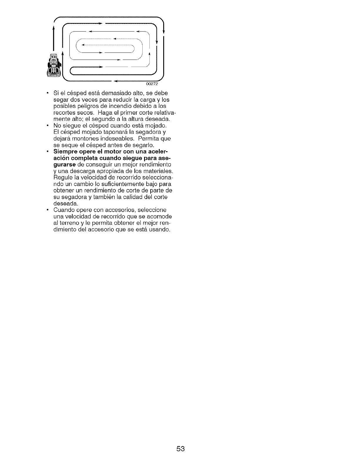
f
ir
J
, J
00272
• Si el c6sped est& demasiado alto, se debe
segar dos veces para reducir la carga y los
posiblos peligros do incendio dobido a los
recortos socos. Haga el primer corte relativa-
monte alto; el sogundo a la altura doseada.
• No siegue el cesped cuando est& mojado.
El c6spod mojado taponar& la segadora y
dojar& montones indesoablos. Pormita quo
so seque el c6sped antes do segarlo.
• Siempre opere el motor con una aeeler-
aoion completa cuando siegue para ase-
gurarse de consoguir un mojor rendimiento
y una doscarga apropiada de los matoriales.
Regulo la velocidad do recorrido selocciona-
ndo un cambio Io suficientomento bajo para
obtonor un rondimiento de corte de parto do
su segadora y tambi6n la calidad dol corte
dosoada.
• Cuando opero con accosorios, seleccione
una volocidad de rocorrido que so acomode
al torreno y Io pormita obtonor el mojor ren-
dimiento del accesorio quo se est& usando.
53
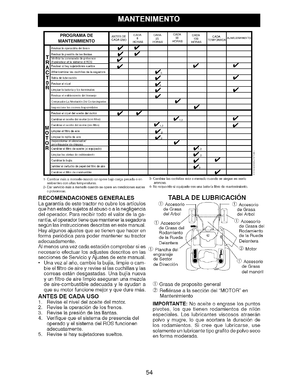
PROGRAMA DE ANTES DE CADA CADA CADA CADA CADA ALMACENAMIENT{
8 25 50 100 TEMPORAD/_
MANTENIMIENTO CADA USO HORAS HORAS HORAS HORAS
Revisar la operaciSn del freno
Revisar la presi6n de las llantas
m Verifi_z la commande de pr_nce
R d'operateur et le sistema d ROS
ARevisar si hay sujetadores sueltos
C Afilal/cambial las cuchillas de la segadora
m Tabla de lublicaci6n
0Revisar el nivel
R Limpiar la bateda y los terminales
Revisar el enfriamiento del transeje
Com_ruobe La Nive_aci_ Dol Cort_c_pedes
I_spe¢cione las ¢o_ress _apezoidale$
Revisar el rkivel del aceite del motor
Cambiar el aceite del motor (con filtlo)
Cambiar el aceite del motor (sin filt to)
M
O Limpiar el lilt ro de aire
TUmpiar la rejilla de aire
Inspeccionar el silenciador/
amor ti_uador de ¢hisDas
a Cambiar el fi_ro de aceite (si equipado)
Umpiar las aletas de enf riamiento
Cambiar la bujla
_ambial e_ ¢artucho de papel del fi_trode aile
Cambiar el fitiro de combustilNe
_2
1- Cambiar mas a menudo cuando se opere bajo carga pesada o en
ambientes con altas temperaturas.
2- Bar servicio mas a menudo cuando se opere en ¢oRdicioRes SUCiAS
O polvorosas.
RECOMENDACIONES GENERALES
La garantia de este tractor no cubre los articulos
que han estado sujetos al abuso o a la negligencia
del operador. Para recibir todo el valor de la ga-
rantia, el operador tiene que mantener la segadora
segOn las instrucciones descritas en este manual.
Hay algunos ajustes que se tienen que hacer en
forma peri6dica para poder mantener su tractor
adecuadamente.
AI menos una vez cada estaci6n comprobar si es
necesario efectuar los adjustes descritos en las
secciones de Servicio y Ajustes de este manual.
• Una vez al aflo, cambie la bujia, limpie o cam-
bie el filtro de aire y revise si las cuchillas y las
correas est&n desgastadas. Una bujia nueva
y un filtro de aire limpio aseguran una mezcla
de aire-combustible adecuada y le ayudan a
que su motor funcione mejor y que dure mb,s.
ANTES DE CADA USO
1. Revise el nivel del aceite del motor.
2. Revise la operaci6n de los frenos.
3. Revise la presi6n de las Ilantas.
4. Verifique que el sistema de presencia del
operado y el sistema del ROS funcionen
adecuatamente.
5. Revise si hay sujetadores sueltos.
3- Carnbiar las cuchillas mas a menudo cuando se siegue en suelo
arenoso.
4- No requeddo si equipado con una bateria libre de mantenimiento.
TABLA DE LUBRICAClON
(f_ _ Accesorio
de Grasa de Grasa
del Arbol del Arbol
(i_ Accesorio
de Grasa del de Grasa del
Rodamiento Rodamiento
de la Rueda de la Rueda
Delantera Delantera
_ Motor
engranaje
de Sector Accesorio
de Direcci6n de Grasa
del mandril
(1-)Grasa de proposito general
(_ Refi6rase a la secci6n del "MOTOR" en
Mantenimiento
IMPORTANTE: No aceite o engrase los puntos
pivotes, los que tienen rodamientos de nil6n
especiales. Los lubricantes viscosos atraer&n
polvo y mugre, Io que acortara la duraci6n de
los rodamientos. Si cree que lubricarse, use
solamente un lubricante tipo grafito de polvo seco
en forma moderada.
54
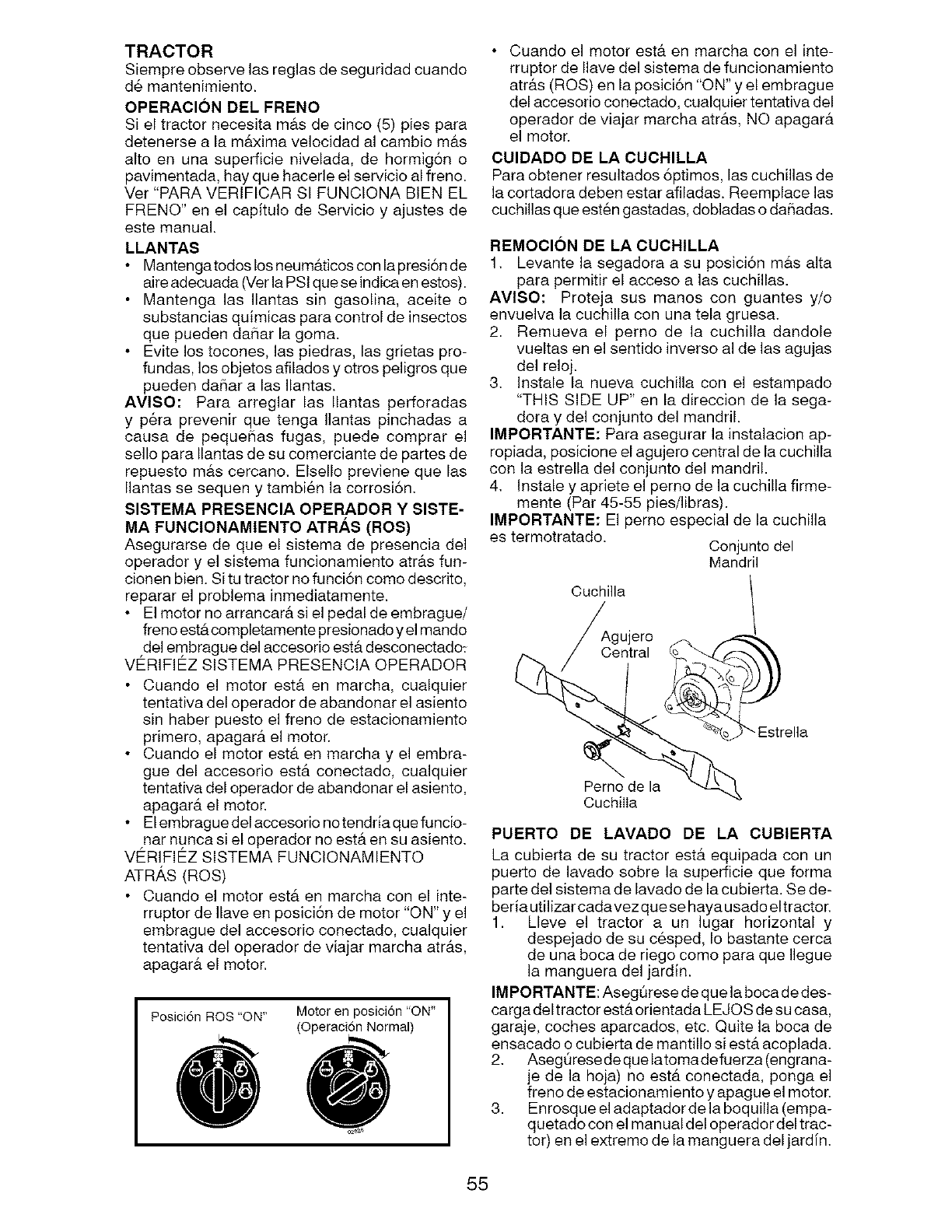
TRACTOR
Siempre observe las reglas de seguridad cuando
d_ mantenimiento.
OPERACl0N DEL FRENO
Si el tractor necesita m&s de cinco (5) pies para
detenerse a la m&xima velocidad al cambio m&s
alto en una superficie nivelada, de hormigSn o
pavimentada, hay que hacerle el servicio al freno.
Ver "PARA VERIFICAR SI FUNCIONA BEN EL
FRENO" en el capitulo de Servicio y ajustes de
este manual.
LLANTAS
Mantengatodos los neum&ticos con la presi6n de
aire adecuada 07erla PSi que se indica en estos).
Mantenga las Ilantas sin gasolina, aceite o
substancias quimicas para control de insectos
que pueden dafiar la goma.
Evite los tocones, las piedras, las grietas pro-
fundas, los objetos afilados y otros peligros que
pueden da_ar a las Ilantas.
AVISO: Para arreglar las Ilantas perforadas
y p6ra prevenir que tenga Ilantas pinchadas a
causa de pequehas fugas, puede comprar el
sello para Ilantas de su comerciante de partes de
repuesto m&s cercano, Elsello previene que las
Ilantas se sequen y tambien la corrosi6n.
SISTEMA PRESENCIA OPERADOR YSISTE-
MA FUNCIONAMIENTO ATRAS (ROS)
Asegurarse de que el sistema de presencia del
operador y el sistema funcionamiento atr&s fun-
cionen bien. Si tu tractor no funci6n come descrito,
reparar el problema inmediatamente.
El motor no arrancar& si el pedal de embrague/
freno est& completamente presionado y el mando
del embrague del accesorio est& desconectado_
VERIFIEZ SISTEMA PRESENCIA OPERADOR
Cuando el motor est& en marcha, cualquier
tentativa del operador de abandonar el asiento
sin haber puesto el freno de estacionamiento
primero, apagar& el motor.
Cuando el motor est& en marcha y el embra-
gue del accesorio est& conectado, cualquier
tentativa del operador de abandonar el asiento,
apagar& el motor.
El embrague del accesorio no tendria que funcio-
nar nunca si el operador no est& en su asiento.
VERIFIEZ SlSTEMA FUNCIONAMIENTO
AT R,_,S (ROS)
Cuando el motor est& en marcha con el inte-
rrupter de Ilave en posici6n de motor "ON" y el
embrague del accesorio conectado, cualquier
tentativa del operador de viajar marcha atr&s,
apagar& el motor.
Posicion ROS "ON" Motor en posici6n "ON"
(Operacion Normal)
• Cuando el motor est& en marcha con el inte-
rruptor de Ilave del sistema de funcionamiento
atr&s (ROS) en la posici6n "ON" y el embrague
del accesorio conectado, cualquier tentativa del
operador de viajar marcha atr&s, NO apagar#.
el motor.
CUIDADO DE LA CUCHILLA
Para obtener resultados 6ptimos, las cuchillas de
la cortadora deben estar afiladas. Reemplace las
cuchillas que est6n gastadas, dobladas o daSadas.
REMOCION DE LA CUCHILLA
1. Levante la segadora a su posici6n m&s alta
para permitir el acceso alas cuchillas.
AVISO: Proteja sus manes con guantes y/o
envuelva la cuchilla con una tela gruesa.
2. Remueva el perno de la cuchilla dandole
vueltas en el sentido inverso al de las agujas
del reloj.
3. Instale la nueva cuchilla con el estampado
"THIS SIDE UP" en la direccion de la sega-
dora y del conjunto del mandril.
IMPORTANTE: Para asegurar la instalacion ap-
ropiada, posicione el agujero central de la cuchilla
con la estrella del conjunto del mandril.
4. Instale y apriete el perno de la cuchilla firme-
mente (Par 45-55 pies/libras).
IMPORTANTE: El perno especial de la cuchilla
es termotratado. Conjunto del
Mandril
Cuchilla
Perno de la
CuchilIa
PUERTO DE LAVADO DE LA CUBIERTA
La cubierta de su tractor estb, equipada con un
puerto de lavado sobre la superficie que forma
parte del sistema de lavado de la cubierta. Se de-
beria utilizar cadavezquese haya usado eltractor.
1. Lleve el tractor a un lugar horizontal y
despejado de su cesped, Io bastante cerca
de una boca de riego como para que Ilegue
la manguera del jardin.
IMPORTANTE: AsegQrese de que la boca de des-
carga del tractor est& orientada LEJO S de su casa,
garaje, coches aparcados, etc. Quite la boca de
ensacado o cubierta de mantillo si est& acoplada.
2. AsegQrese de quelatomadefuerza (engrana-
je de la hoja) no est& conectada, ponga el
freno de estacionamiento y apague el motor.
3. Enrosque el adaptador de la boquilla (empa-
quetadocon el manualdel operador deltrac-
tor) en el extremo de la manguera del jardin.
55
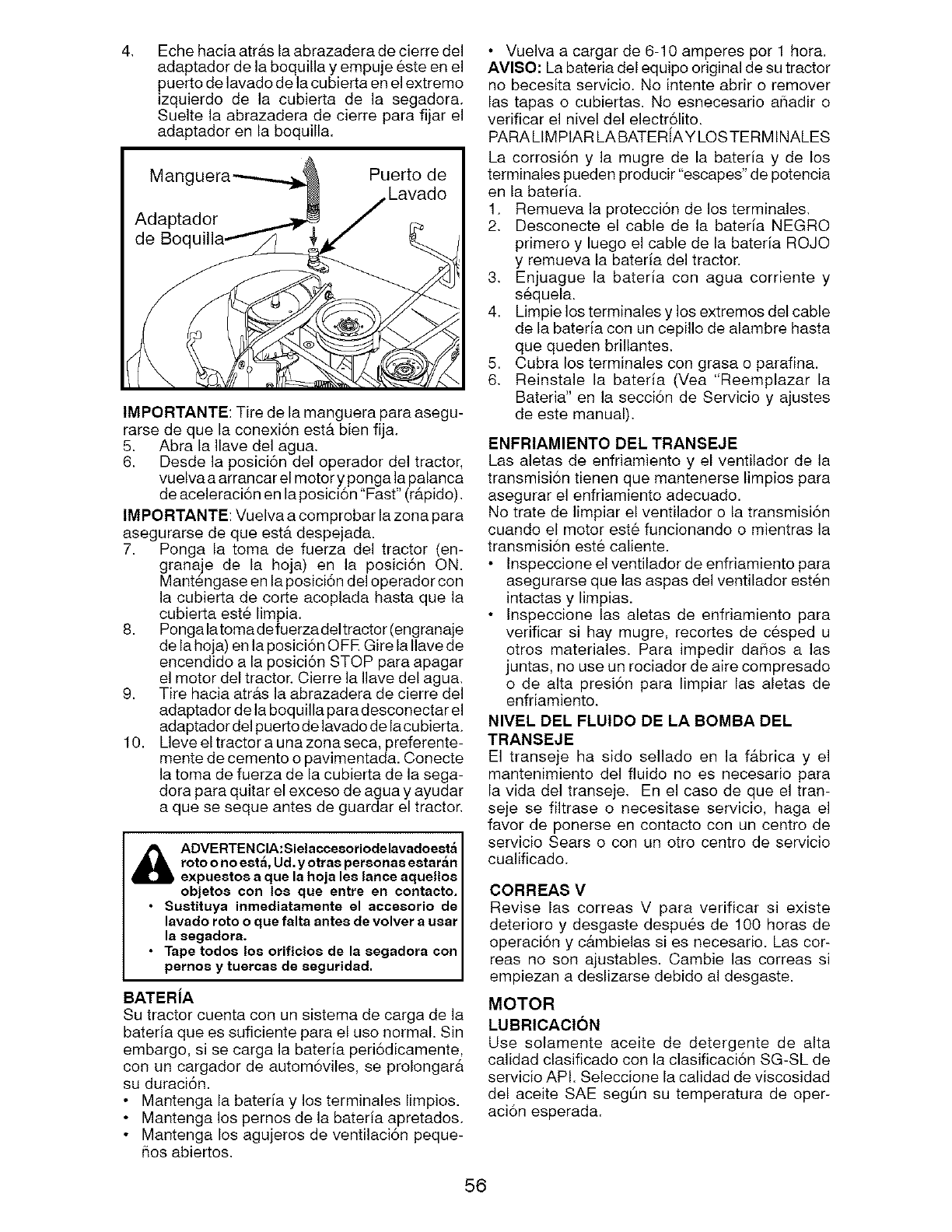
41 Eche hacia atr&s la abrazadera de cierre del
adaptador de la boquilla y empuje este en el
puerto de lavado de la cubierta en el extremo
izquierdo de la cubierta de la segadora.
Suelte la abrazadera de cierre para fijar el
adaptador en la boquilla.
IMPORTANTE: Tire de la manguera para asegu-
rarse de que la conexi6n est& bien fija.
5. Abra la Ilave del agua.
6. Desde la posici6n del operador del tractor,
vuelva a arrancar el motor y ponga la palanca
de aceleraci6n en la posici6n "Fast" (r&pido).
IMPORTANTE: Vuelva a comprobar la zona para
asegurarse de que est& despejada.
7. Ponga la toma de fuerza del tractor (en-
granaje de la hoja) en la posici6n ON.
Mant6ngase en la posici6n del operador con
la cubierta de corte acoplada hasta que la
cubierta est6 limpia.
8. Ponga latoma defuerzadeltractor (engranaje
de la hoja) en la posici6n OFR Gire la Ilave de
encendido a la posici6n STOP para apagar
el motor del tractor. Cierre la Ilave del agua.
9. Tire hacia atr&s la abrazadera de cierre del
adaptador de la boquilla para desconectar el
adaptador del puerto de lavado de la cu bierta.
10. Lleve el tractor a una zona seca, preferente-
mente de cemento o pavimentada. Conecte
la toma de fuerza de la cubierta de la sega-
dora para quitar el exceso de agua y ayudar
a que se seque antes de guardar el tractor.
_IL ADVERTEN ClA: Sielacceeoriodelavadoeeta
roto onoeet_, Ud.y otrae personae eetar_n
expueetoe a que la hoja lee lance aquelloe
objetoe con los que entre en contacto.
• Suetituya inrnediatarnente el acceeorio de
lavado roto o que falta antee de volver a uear
la eegadora.
•Tape todoe los orificioe de la eegadora con
pernoe y tuercae de eeguridad.
BATERJA
Su tractor cuenta con un sistema de carga de la
bateria que es suficiente para el uso normal. Sin
embargo, si se carga la bateria peri6dicamente,
con un cargador de autom6viles, se prolongar&
su duraci6n.
• Mantenga la bateria y los terminales limpios.
• Mantenga los pernos de la bateria apretados.
• Mantenga los agujeros de ventilaci6n peque-
5os abiertos.
• Vuelva a cargar de 6-10 amperes per 1 hora.
AVlSO: La bateria del equipo original de su tractor
no becesita servicio. No intente abrir o remover
las tapas o cubiertas. No esnecesario aSadir o
verificar el nivel del electr61ito.
PARA LIMPIAR LA BATERiAY LOS TERMINALES
La corrosi6n y la mugre de la bateria y de los
terminales pueden producir "escapes" de potencia
en la bateria.
1. Remueva la protecci6n de los terminales.
21 Desconecte el cable de la bateria NEGRO
primero y luego el cable de la bateria ROJO
y remueva la bateria del tractor.
31 Enjuague la bateria con agua corriente y
sequela.
4. Limpie los terminales y los extremos del cable
de la bateria con un cepillo de alambre hasta
que queden brillantes.
5. Cubra los terminales con grasa o parafina.
61 Reinstale la bateria (Vea "Reemplazar la
Bateria" en la secci6n de Servicio y ajustes
de este manual).
ENFRIAMIENTO DEL TRANSEJE
Las aletas de enfriamiento y el ventilador de la
transmisi6n tienen que mantenerse limpios para
asegurar el enfriamiento adecuado.
No trate de limpiar el ventilador o la transmisi6n
cuando el motor este funcienando o mientras la
transmisi6n este caliente.
Inspeccione el ventilador de enfriamiento para
asegurarse que las aspas del ventilador est6n
intactas y limpias.
Inspeccione las aletas de enfriamiento para
verificar si hay mugre, recortes de cesped u
otros materiales. Para impedir daSos alas
juntas, no use un reciador de aire compresado
o de alta presi6n para limpiar las aletas de
enfriamiento.
NIVEL DEL FLUIDO DE LA BOMBA DEL
TRANSEJE
El transeje ha sido sellado en la f&brica y el
mantenimiento del fluido no es necesario para
la vida del transeje. En el case de que el tran-
seje se filtrase o necesitase servicio, haga el
favor de ponerse en contacto con un centro de
servicio Sears o con un otro centro de servicio
cualificado.
CORREAS V
Revise las correas V para verificar si existe
deterioro y desgaste despu6s de 100 horas de
operaci6n y c&mbielas si es necesario. Las cor-
reas no son ajustables. Cambie las correas si
empiezan a deslizarse debido al desgaste.
MOTOR
LUBRICAClON
Use solamente aceite de detergente de alta
calidad clasificado con la clasificaci6n SG-SL de
servicio API. Seleccione la calidad de viscosidad
del aceite SAE segOn su temperatura de oper-
aci6n esperada.
56
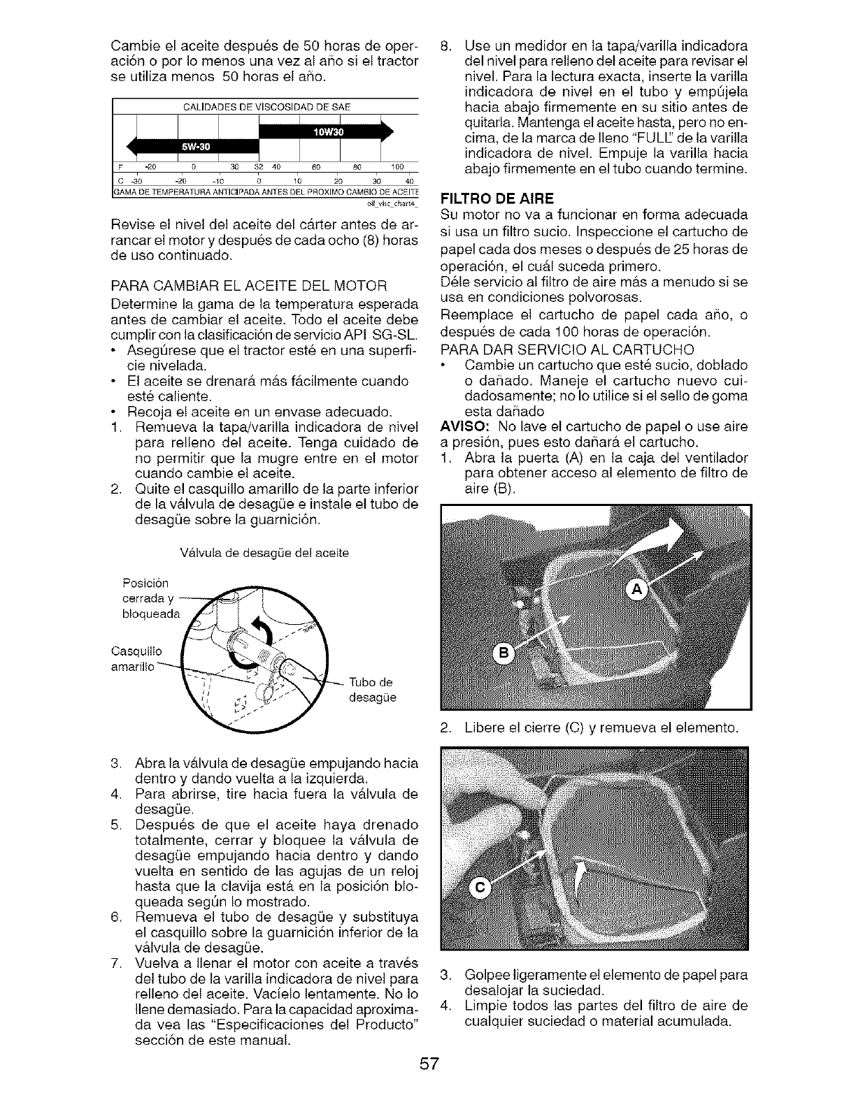
Cambie el aceite despu6s de 50 horas de oper-
aci6n o por Io menos una vez al aflo si el tractor
se utiliza menos 50 horas el aSo.
CALIDADES DE VISCOSIDAD DE SAE
oil vi/ccha[t4
Revise el nivel del aceite del c&rter antes de ar-
rancar el motor y despues de cada ocho (8) horas
de uso continuado.
PARA CAMBIAR EL ACEITE DEL MOTOR
Determine la gama de la temperatura esperada
antes de cambiar el aceite. Todo el aceite debe
cumplir con la clasificaci6n deservicioAPI SG-SL
• Aseg0rese que el tractor est6 en una superfi-
cie nivelada.
• El aceite se drenar& m&s f&cilmente cuando
este caliente.
• Recoja el aceite en un envase adecuado.
1. Remueva la tapa/varilla indicadora de nivel
para relleno del aceite. Tenga cuidado de
no permitir que la mugre entre en el motor
cuando cambie el aceite.
2. Quite el casquillo amarillo de la parte inferior
de la v&lvula de desagQe e instale el tubo de
desag0e sobre la guarnici6n.
8, Use un medidor en la tapa/varilla indicadora
del nivel para relleno del aceite para revisar el
nivel. Para la lectura exacta, inserte la varilla
indicadora de nivel en el tubo y emp0jela
hacia abajo firmemente en su sitio antes de
quitarla. Mantenga el aceite hasta, pero no en-
cima, de la marca de Ileno "FULE' de la varilla
indicadora de nivel. Empuje la varilla hacia
abajo firmemente en el tubo cuando termine.
FILTRO DE AIRE
Su motor no va a funcionar en forma adecuada
si usa un filtro sucio, Inspeccione el cartucho de
papel cada dos meses o despues de 25 horas de
operaci6n, el cu&l suceda primero.
D61e servicio al filtro de aire m&s a menudo si se
usa en condiciones polvorosas.
Reemplace el cartucho de papel cada aSo, o
despues de cada 100 horas de operaci6n.
PARA DAR SERVlCIO AL CARTUCHO
Cambie un cartucho que est6 sucio, doblado
o daSado. Maneje el cartucho nuevo cui-
dadosamente; no Io utilice si el sello de goma
esta daflado
AVI$O: No lave el cartucho de papel o use aire
a presi6n, pues esto daflar& el cartucho.
1. Abra la puerta (A) en la caja del ventilador
para obtener acceso al elemento de filtro de
aire (B).
V&lvula de desagQe det aceite
Posicion
cerrada y
bloqueada/_._ L _I_._
amaril'° __,
2. Libere el cierre (C) y remueva el elemento.
3. Abra la v&lvula de desag0e empujando hacia
dentro y dando vuelta a la izquierda.
4. Para abrirse, tire hacia fuera la valvula de
desagOe.
5. Despu6s de que el aceite haya drenado
totalmente, cerrar y bloquee la v&lvula de
desagQe empujando hacia dentro y dando
vuelta en sentido de las agujas de un reloj
hasta que la clavija est& en la posici6n blo-
queada segOn Io mostrado.
6. Remueva el tubo de desagQe y substituya
el casquillo sobre la guarnici6n inferior de la
v&lvula de desagQe.
7. Vuelva a Ilenar el motor con aceite a traves
del tubo de la varilla indicadora de nivel para
relleno del aceite. Vacielo lentamente. No Io
Ilene demasiado. Para la capacidad aproxima-
da vea las "Especificaciones del Producto"
secci6n de este manual.
3. Golpee ligeramente el elemento de papel para
desalojar la suciedad.
4. Limpie todos las partes del filtro de aire de
cualquier suciedad o material acumulada.
57
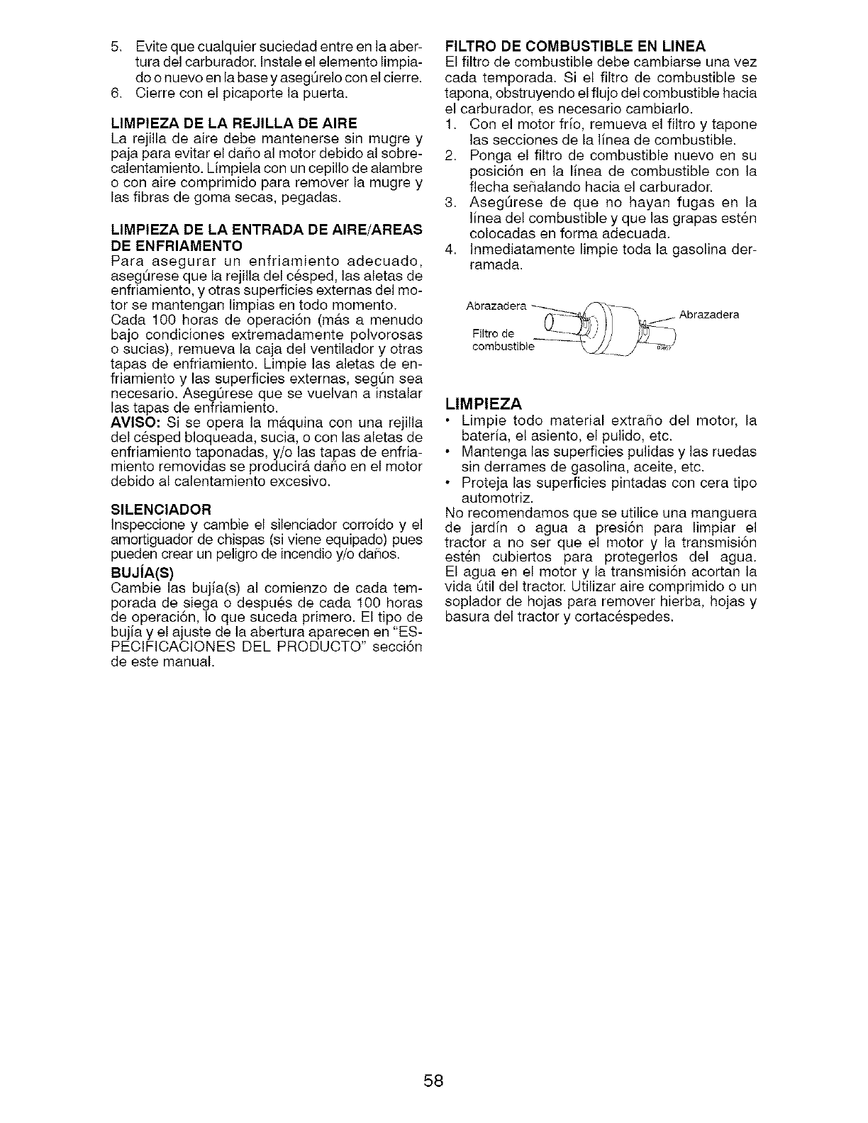
5. Evite que cualquier suciedad entre en la aber-
tufa del carburador. Instale el elemento limpia-
do o nuevo en la base y asegQrelo con el cierre.
6. Cierre con el picaporte la puerta.
LIMPIEZA DE LA REJILLA DE AIRE
La rejilla de aire debe mantenerse sin mugre y
paja para evitar el daSo al motor debido al sobre-
calentamiento. Limpiela con un cepillo de alambre
e con aire comprimido para remover la mugre y
las fibras de goma secas, pegadas.
LIMPIEZA DE LA ENTRADA DE AIRE/AREAS
DE ENFRIAMENTO
Para asegurar un enfriamiento adecuado,
aseg0rese que la rejilla del cesped, las aletas de
enfriamiento, y otras superficies externas del mo-
tor se mantengan limpias en todo momento.
Cada 100 horas de operaci6n (mb,s a menudo
bajo condiciones extremadamente polvorosas
o sucias), remueva la caja del ventilador y otras
tapas de enfriamiento. Limpie las aletas de en-
friamiento y las superficies externas, segt3n sea
necesario. AsegQrese que se vuelvan a instalar
las tapas de enfriamiento.
AVISO: Si se opera la m&quina con una rejilla
del c6sped bloqueada, sucia, o con las aletas de
enfriamiento taponadas, y/o las tapas de enfria-
miento removidas se producir& daSo en el motor
debido al calentamiento excesivo.
SILENCIADOR
Inspeccione y cambie el silenciador corroido y el
amortiguador de chispas (si viene equipado) pues
pueden crear un peligro de incendio _/o da_ios.
BUJiA(S)
Cambie las bujia(s) al comienzo de cada tem-
porada de siega o despu6s de cada 100 horas
de operaci6n, Io que suceda primero. El tipo de
bujia y el ajuste de la abertura aparecen en "ES-
PECIFICACIONES DEL PRODUCTO" secci6n
de este manual.
FILTRO DE COMBUSTIBLE EN MNEA
El filtro de combustible debe cambiarse una vez
cada temporada. Si el filtro de combustible se
tapona, obstruyendo el flujo del combustible hacia
el carburader, es necesario cambiarlo.
1. Con el motor if[o, remueva el filtro y tapone
las secciones de la I[nea de combustible.
2. Ponga el filtro de combustible nuevo en su
posici6n en la linea de combustible con la
flecha seSalando hacia el carburador.
3. AsegOrese de que no hayan fugas en la
linea del combustible y que las grapas esten
colocadas en forma adecuada.
4. Inmediatamente limpie toda la gasolina der-
ramada.
Filtro de
combustible
LIMPIEZA
Limpie todo material extraSo del motor, la
bateria, el asiento, el pulido, etc.
Mantenga las superficies pulidas y las ruedas
sin derrames de gasolina, aceite, etc.
Proteja las superficies pintadas con cera tipo
automotriz.
No recomendamos que se utilice una manguera
de jardin o agua a presi6n para limpiar el
tractor a no ser que el motor y la transmisi6n
esten cubiertos para protegerlos del agua.
El agua en el motor y la transmisi6n acortan la
vida Qtil del tractor. Utilizar aire comprimido o un
soplador de hojas para remover hierba, hojas y
basura del tractor y cortacespedes.
58
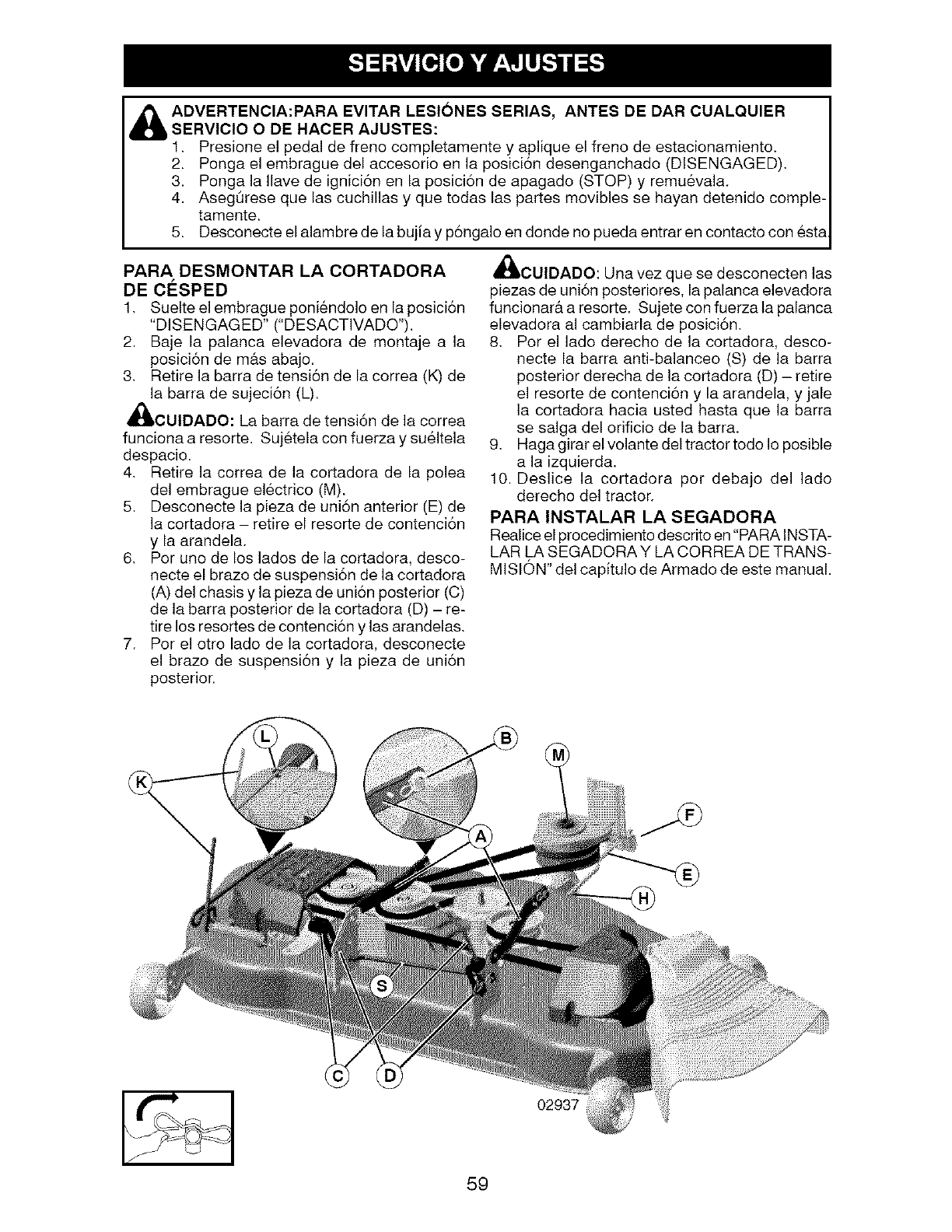
ADVERTENCIA:PARA EVITAR LESIONES SERIAS, ANTES DE DAR CUALQUIER
SERVICIO O DE HACER AJUSTES:
1. Presione el pedal de freno completamente y aplique el freno de estacionamiento.
2. Ponga el embrague del accesorio en la posici6n desenganchado (DISENGAGED).
3. Ponga la Ilave de ignici6n en la posici6n de apagado (STOP) y remu&vala.
4. AsegOrese que las cuchillas y que todas las partes movibles se hayan detenido comple-
tamente.
5. Desconecte el alambre de la buj[a y p6ngalo en donde no pueda entrar en contacto con esta
PARA DESMONTAR LA CORTADORA
DE ClaSPED
1. Suelte el embrague poniendolo en la posici6n
"DISENGAGED" ("DESACTIVADO").
2. Baje la palanca elevadora de montaje a la
posici6n de m#.s abajo.
3. Retire la barra de tensi6n de la correa (K) de
la barra de sujeci6n (L).
CUIDADO: La barra de tensi6n de la correa
funciona a resorte. Sujetela con fuerza y sueltela
despacio.
4. Retire la correa de la cortadora de la polea
del embrague electrico (M).
5. Desconecte la pieza de uni6n anterior (E) de
la cortadora - retire el resorte de contenci6n
y la arandela.
6. Por uno de los lados de la cortadora, desco-
necte el brazo de suspensi6n de la cortadora
(A) del chasis y la pieza de union posterior (C)
de la barra posterior de la cortadora (D) - re-
tire los resortes de contenci6n y las arandelas.
7. Por el otto lado de la cortadora, desconecte
el brazo de suspensi6n y la pieza de uni6n
posterior.
_ICUIDADO: Una vez que se desconecten las
piezas de uni6n posteriores, la palanca elevadora
funcionar& a resorte. Sujete con fuerza la palanca
elevadora al cambiarla de posici6n.
8. Per el lado derecho de la cortadora, desco-
necte la barra anti-balanceo (S) de la barra
posterior derecha de la cortadora (D) - retire
el resorte de contenci6n y la arandela, y jale
la cortadora hacia usted hasta que la barra
se salga del orificio de la barra.
9. Haga girar el volante del tractor todo Io posible
a la izquierda.
10. Deslice la cortadora per debajo del lado
derecho del tractor.
PARA INSTALAR LA SEGADORA
Realice el procedimiento descrito en "PARA INSTA-
LAR LA SEGADORA Y LA CORREA DE TRANS-
MlSl0N" del capitulo de Armado de este manual.
59
02937
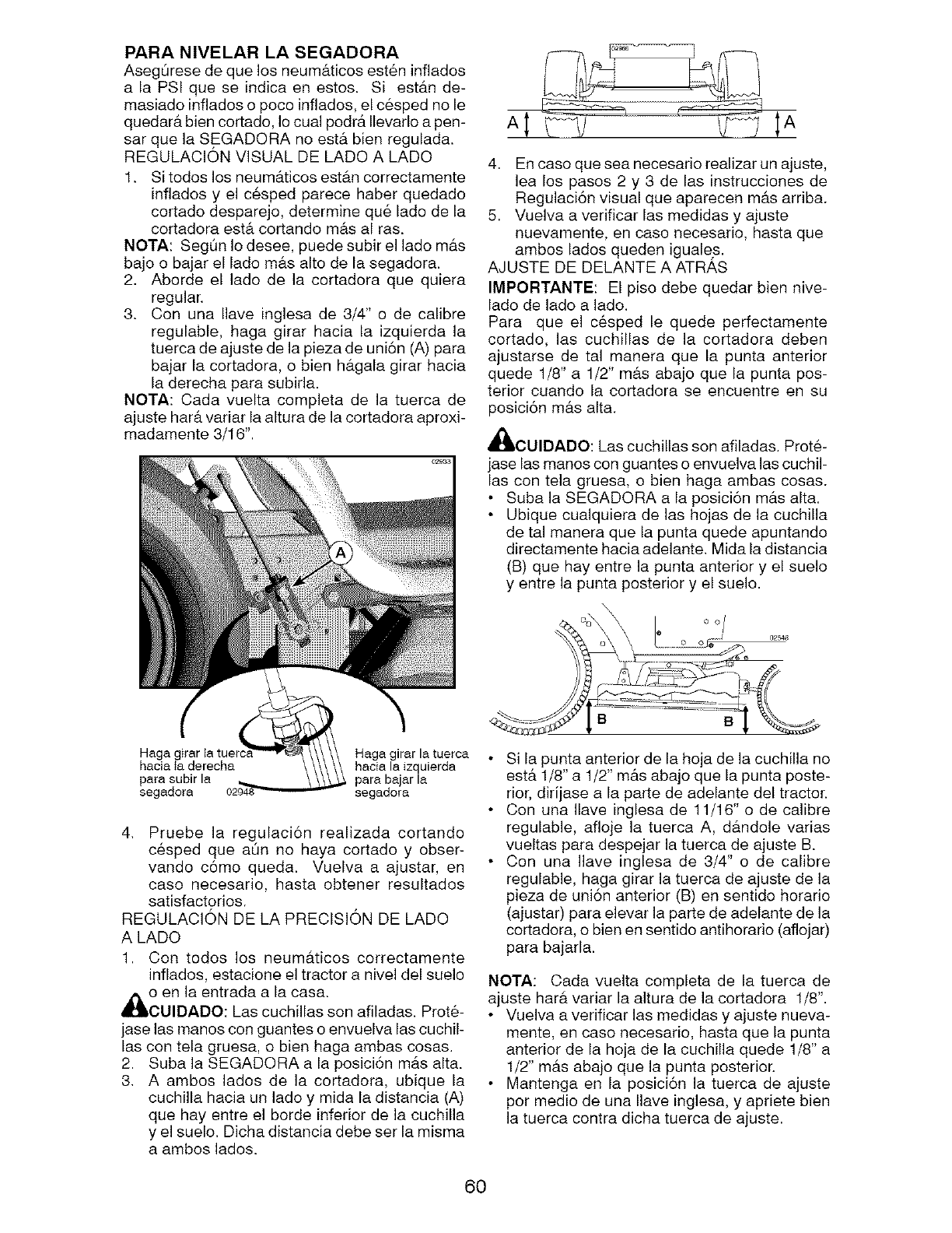
PARA NIVELAR LA SEGADORA
Aseg0resedequelosneum&ticosest6ninfiados
a la PSIquese indicaenestos. Si est&nde-
masiadoinfiadoso pocoinfiados,elcespednole
quedar&biencortado,Iocualpodr&Ilevarloapen-
sarquelaSEGADORAnoest&bienregulada.
REGULACIONVISUALDELADOA LADO
1. Sitodoslosneum&ticosest&ncorrectamente
infiadosy elc6spedparecehaberquedado
cortadodesparejo,determinequ6ladodela
cortadoraest&cortandom&sal ras.
NOTA:SegOnIodesee,puedesubirel ladom&s
bajoo bajarel ladem&saltodelasegadora.
2. Abordeel ladede la cortadoraque quiera
regular.
3. Conuna Ilaveinglesade 3/4" o de calibre
regulable,hagagirar haciala izquierdala
tuercadeajustedelapiezadeuni6n(A)para
bajarlacortadora,o bienh&galagirarhacia
laderechaparasubida.
NOTA:Cadavueltacompletade la tuercade
ajustehar&variarlaalturadelacortadoraaproxi-
madamente3/16".
4. Encasoqueseanecesariorealizarunajuste,
lealospasos2 y 3 de lasinstruccionesde
Regulaci6nvisualqueaparecenm#.sarriba.
5. Vuelvaaverificarlasmedidasy ajuste
nuevamente,encasenecesario,hastaque
ambosladosquedeniguales.
AJUSTEDEDELANTEAATRAS
IMPORTANTE:El pisodebequedarbiennive-
ladodeladoa lado.
Para que el c6spedle quedeperfectamente
cortado,las cuchillasde la cortadoradeben
ajustarsede tal maneraque la puntaanterior
quede1/8"a 1/2"m&sabajoquela puntapos-
teriorcuandola cortadorase encuentreensu
posici6nm&salta.
CUIDADO:Lascuchillassonafiladas.Prot6-
jaselasmanosconguantesoenvuelvalascuchil-
lascontelagruesa,o bienhagaambascosas.
SubalaSEGADORAa laposici6nm&salta.
Ubiquecualquieradelashojasdela cuchilla
detalmaneraquela puntaquedeapuntando
directamentehaciaadelante.Midaladistancia
(B)quehayentrelapuntaanteriory el suelo
y entrelapuntaposteriory el suelo.
\\
oo/
Haga girar la tuerca
hacia Ia derecha hacia la izquierda
papa subir la para bajar la
segadora segadora
4. Pruebe la regulaci6n realizada cortando
c6sped que a0n no haya cortado y obser-
vando c6mo queda. Vuelva a ajustar, en
caso necesario, hasta obtener resultados
satisfactorios.
REGULACION DE LA PRECISION DE LADO
A LADO
1. Con todos los neum&ticos correctamente
infiados, estacione el tractor a nivel del suelo
,_o en la entrada a la casa.
CUIDADO: Las cuchillas son afiladas. Prot6-
jase las manes con guantes o envuelva las cuchil-
las con tela gruesa, o bien haga ambas cosas.
2. Suba la SEGADORA a la posici6n m&s alta.
3. A ambos lados de la cortadora, ubique la
cuchilla hacia un lade y mida la distancia (A)
que hay entre el borde inferior de la cuchilla
y el suelo. Dicha distancia debe ser la misma
a ambos lados.
B B
Si la punta anterior de la hoja de la cuchilla no
est,. 1/8" a 1/2" m&s abajo que la punta poste-
rior, dirijase a la parte de adelante del tractor.
Con una Ilave inglesa de 11/16" o de calibre
regulable, afioje la tuerca A, d&ndole varias
vueltas para despejar la tuerca de ajuste B.
Con una Ilave inglesa de 3/4" o de calibre
regulable, haga girar la tuerca de ajuste de la
pieza de uni6n anterior (B) en sentido horario
(ajustar) para elevar la parte de adelante de la
cortadora, o bien en sentido antihorario (afiojar)
para bajarla.
NOTA: Cada vuelta completa de la tuerca de
ajuste har& variar la altura de la cortadora 1/8".
• Vuelva a verificar las medidas y ajuste nueva-
mente, en caso necesario, hasta que la punta
anterior de la hoja de la cuchilla quede 1/8" a
1/2" m&s abajo que la punta posterior.
Mantenga en la posici6n la tuerca de ajuste
per medio de una Ilave inglesa, y apriete bien
la tuerca contra dicha tuerca de ajuste.
60
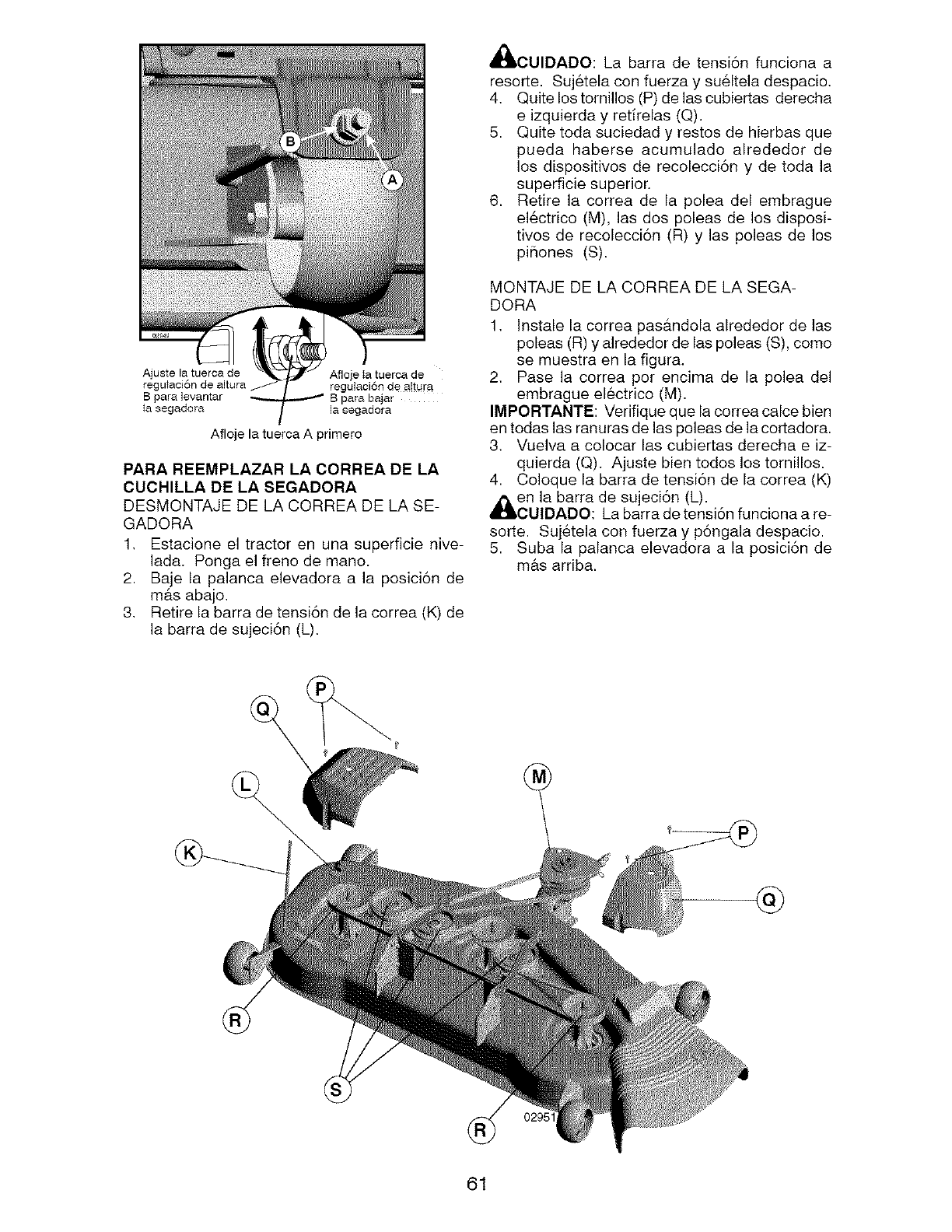
Aiuste la tuerca de
regu_aci6n de altura
B paralevantar
_a segadora
Afloje Ia tuerca de
regulaci6n de altura
la segadora
Afloje la tuerca A primero
PARA REEMPLAZAR LA CORREA DE LA
CUCHILLA DE LA SEGADORA
DESMONTAJE DELACORREA DELASE-
GADORA
1, Estacione el tractor en una superficie hive-
lad& Ponga el freno de mano.
2. Baje la palanca elevadora a la posici6n de
m&s abajo,
3, Retire la barra de tensi6n de la correa (K) de
la barra de sujeci6n (L).
_I_CUIDADO: La barra de tensi6n funciona a
resorte. Sujetela con fuerza y su61tela despacio,
4, Quite los tornillos (P) de las cubiertas derecha
e izquierda y retirelas (Q).
5. Quite toda suciedad y restos de hierbas que
pueda haberse acumulado alrededor de
los dispositivos de recolecci6n y de toda la
superficie superior.
6. Retire la correa de la polea del embrague
electrico (M), las dos poleas de los disposi-
tivos de recolecci6n (R) y las poleas de los
piSones (S).
MONTAJE DE LA CORREA DE LA SEGA-
DORA
1, Instale la correa pas&ndola alrededor de las
poleas (R) y alrededor de las poleas (S), como
se muestra en la figura.
2, Pase la correa pot encima de la polea del
embrague electrico (M).
IMPORTANTE: Verifique que la correa calce bien
en todas las ranuras de las poleas de la cortadora.
3, Vuelva a colocar las cubiertas derecha e iz-
quierda (Q). Ajuste bien todos los tornillos.
4. Coloque la barra de tensi6n de la correa (K)
,_en la barra de sujeci6n (L).
CUlDADO: La barra de tensi6n funciona a re-
sorte. Sujetela con fuerza y p6ngala despacio.
5. Suba la palanca elevadora a la posici6n de
m&s arriba.
@
61
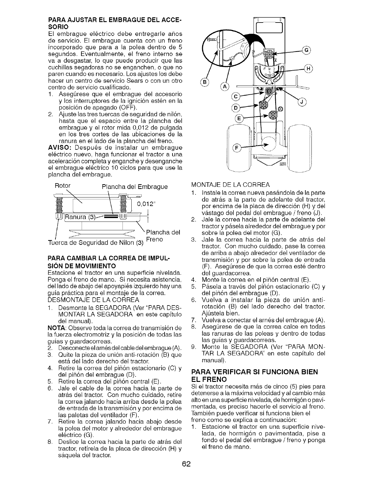
PARA AJUSTAR EL EMBRAGUE DEL ACCE-
SORIO
El embrague el6ctrico debe entregarle a_ios
de servicio. El embrague cuenta con un freno
incorporado que para ala polea dentro de 5
segundos. Eventualmente, el freno interne se
va a desgastar, Io que puede producir que las
cuchillas segadoras no se enganchen, o que no
paren cuando es necesario. Los ajustes los debe
hacer un centro de servicio Sears o con un otro
centro de servicio cualificado.
1. Asegt_rese que el embrague del accesorio
y los interruptores de la ignici6n est_n en la
posici6n de apagado (OFF).
2. Ajuste las tres tuercas de seguridad de nil6n,
hasta que el espacio entre la plancha del
embrague y el rotor mida 0,012 de pulgada
en los tres cortes de las ubicaciones de la
ranura en el lado de la plancha del freno.
AVISO: Despu6s de instalar un embrague
electrico nuevo, haga funcionar el tractor a una
aceleraci6n completa y enganche y desenganche
el embrague electrico 10 ciclos para que use la
plancha del embrague.
Rotor Plancha del Embrague
_--_ \"i'\ / _,0112"
LRanura13)/ i
/i i \
/__ Plancha del
Tuernca de S° eguridad de Nilo_ (3) Freno
PARA CAMBIAR LA CORREA DE IMPUL-
SION DE MOVIMIENTO
Estacione el tractor en una superficie nivelada.
Ponga el freno de mano. Si necesita asistencia,
del lado de abajo del apoyapies izquierdo hay una
guia pr&ctica para el montaje de la correa.
DESMONTAJE DE LA CORREA
1. Desmonte la SEGADORA (Ver "PARA DES-
MONTAR LA SEGADORA en este capitulo
del manual).
NOTA: Observe toda la correa de transmisi6n de
la fuerza electromotriz y la posici6n de todas las
guias y guardacorreas.
2. Desconecte el arnes del cable del embrague (A).
3. Quite la pieza de uni6n anti-rotaci6n (B) que
estfl del lado derecho del tractor.
4. Retire la correa del pi56n estacionario (C) y
del pi56n del embrague (D).
5. Retire la correa del pifl6n central (E).
6. Jale el cable de la correa hacia la parte de
atr&s del tractor. Con mucho cuidado, retire
la correa jalando hacia arriba desde la polea
de entrada de la transmisi6n y por encima de
las paletas del ventilador (F).
7. Retire la correa jalando hacia abajo desde
la polea del motor y alrededor del embrague
el_ctrico (G).
8. Deslice la correa hacia la parte de atr&s del
tractor, retirela de la placa de direcci6n (H) y
s&quela del tractor.
62
MONTAJE DE LA CORREA
1. Instale la correa nueva pas&ndola de la parte
de atr&s a la parte de adelante del tractor,
per encima de la placa de direcci6n (H) y del
v&stago del pedal del embrague /freno (J).
2. Jale la correa hacia la parte de adelante del
tractor y p&sela alrededor del embrague y per
sobre la polea del motor (G).
3. Jale la correa hacia la parte de atr&s del
tractor. Con mucho cuidado, pase la correa
de arriba a abajo alrededor del ventilador de
transmisi6n y per sobre la polea de entrada
(F). AseglJrese de que la correa este dentro
del guardacorrea.
4. Monte la correa en el pi_i6n central (E).
5. P&sela a trav_s del pi_i6n estacionario (C) y
del pifl6n del embrague (D).
6. Vuelva a instalar la pieza de uni6n anti-
rotaci6n (B) del lade derecho del tractor.
Aj0stela bien.
7. Vuelva a conectar el arnes del embrague (A).
8. Aseg_rese de que la correa calce en todas
las ranuras de las poleas y dentro de todas
las guias y guardacorreas.
9. Monte la SEGADORA (Vet "PARA MON-
TAR LA SEGADORi_' en este capitulo del
manual).
PARA VERIFICAR Sl FUNClONA BIEN
EL FRENO
Si el tractor necesita m&s de cinco (5) pies para
detenerse a la mflxima velocidad y al cambio m#.s
alto en una superficie nivelada, de hormig6n o pavi-
mentada, es preciso hacerle el servicio al freno.
Tambien puede verificar si funciona bien el
freno como se explica a continuaci6n:
1. Estacione el tractor en una superficie nive-
lada, de hormig6n o pavimentada, pise a
fondo el pedal del embrague /freno y penga
el freno de mane.
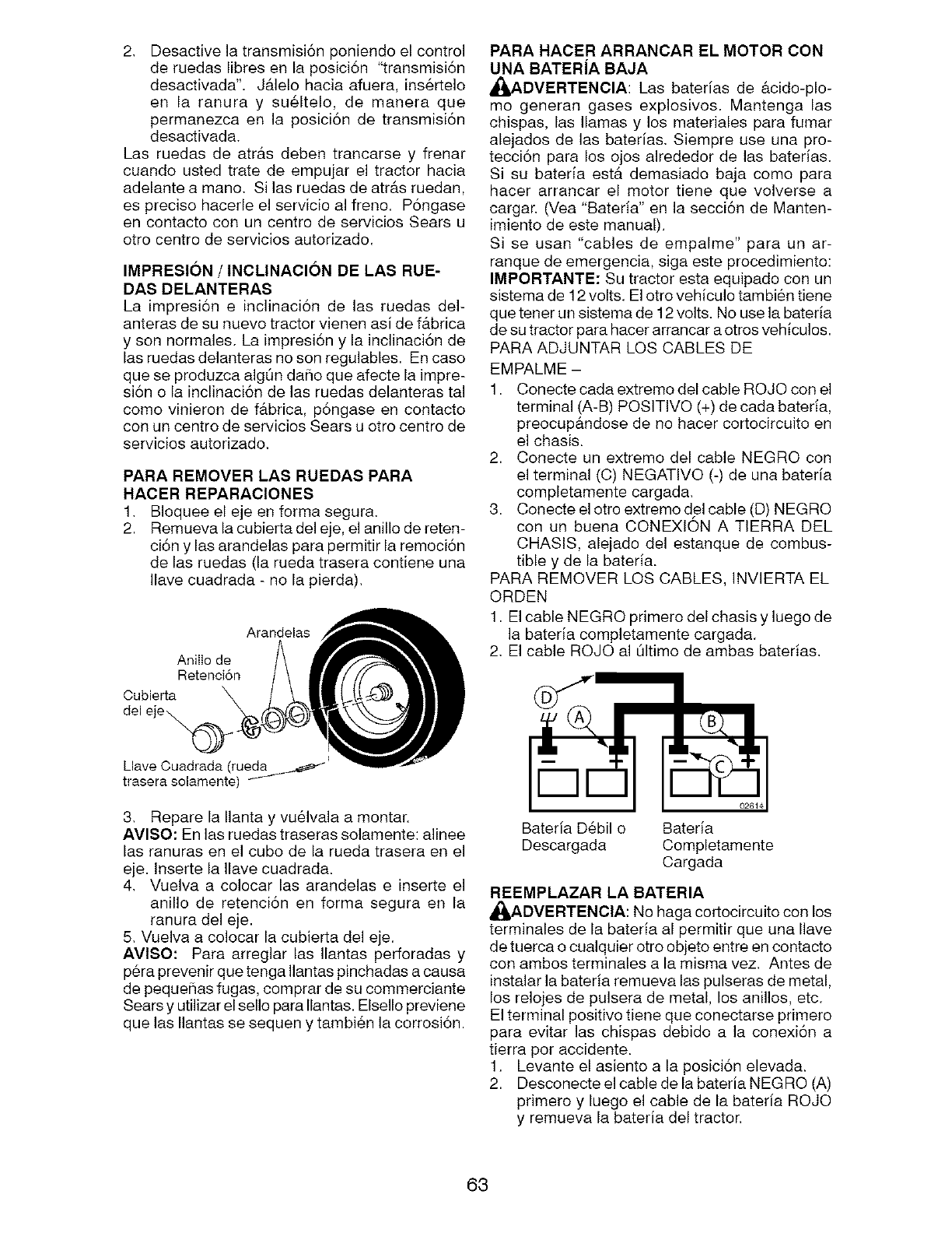
2. Desactivelatransmisi6nponiendoelcontrol
deruedaslibresenlaposici6n"transmisi6n
desactivada".J&lelohaciaafuera,ins_rtelo
en la ranura y su61telo,de maneraque
permanezcaen la posici6nde transmisi6n
desactivada.
Lasruedasde atrb,s debentrancarsey frenar
cuandoustedtratede empujarel tractorhacia
adelanteamano.Silasruedasdeatr&sruedan,
esprecisohacerleel servicioalfreno. Pongase
encontactoconuncentrodeserviciosSearsu
otrocentrodeserviciosautorizado.
IMPRESION /INCLINACION DE LAS RUE-
DAS DELANTERAS
La impresi6n e inclinaci6n de las ruedas del-
anteras de su nuevo tractor vienen asi de f&brica
y son normales. La impresi6n y la inclinaci6n de
las ruedas delanteras no son regulables. En caso
que se produzca algQn daho que afecte la impre-
si6n o la inclinaci6n de las ruedas delanteras tal
como vinieron de f&brica, p6ngase en contacto
con un centro de servicios Sears u otro centro de
servicios autorizado.
PARA REMOVER LAS RUEDAS PARA
HACER REPARACIONES
1. BIoquee el eje en forma segura.
2. Remueva la cubierta del eje, el anillo de reten-
ci6n y las arandelas para permitir la remoci6n
de las ruedas (la rueda trasera contiene una
Ilave cuadrada - no la pierda).
Arandelas
Anillo de
Retenci6n
Cubierta
del e"
Llave Ouadrada (rueda
trasera solamente)
3. Repare la Ilanta y vu&lvala a montar.
AVISO: En las ruedas traseras solamente: alinee
las ranuras en el cubo de la rueda trasera en el
eje. Inserte la Ilave cuadrada.
4. Vuelva a colocar las arandelas e inserte el
anillo de retenci6n en forma segura en la
ranura del eje.
5. Vuelva a colocar la cubierta del eje.
AVISO: Para arreglar las Ilantas perforadas y
pera prevenir que tenga Ilantas pinchadas a causa
de peque#ias fugas, comprar de su commerciante
Sears y utilizar el sello para Ilantas. Elsello previene
que las Ilantas se sequen y tambi6n la corrosi6n.
PARA HACER ARRANCAR EL MOTOR CON
UNA BATERiA BAJA
_IADVERTENCIA: Las baterias de &cido-plo-
mo generan gases explosivos. Mantenga las
chispas, las llamas y los materiales para fumar
alejados de las baterias. Siempre use una pro-
tecci6n para los ojos alrededor de las baterias.
Si su bateria est& demasiado baja como para
hacer arrancar el motor tiene que volverse a
cargar. (Vea "Bateria" en la secci6n de Manten-
imiento de este manual).
Si se usan "cables de empalme" para un ar-
ranque de emergencia, siga este procedimiento:
IMPORTANTE: Su tractor esta equipado con un
sistema de 12 volts. El otro vehiculo tambi6n tiene
que tener un sistema de 12 volts. No use la bateria
de su tractor para hacer arrancar a otros vehiculos.
PARA ADJUNTAR LOS CABLES DE
EMPALME -
1. Conecte cada extremo del cable ROJO con el
terminal (A-B) POSITIVO (+) de cada bateria,
preocup&ndose de no hacer cortocircuito en
el chasis.
2. Conecte un extremo del cable NEGRO con
el terminal (C) NEGATIVO (-) de una bateria
completamente cargada.
3. Conecte el otro extremo del cable (D) NEGRO
con un buena CONEXlON A TIERRA DEL
CHASlS, alejado del estanque de combus-
tible y de la bated&
PARA REMOVER LOS CABLES, INVlERTA EL
ORDEN
1. El cable NEGRO primero del chasis y luego de
la bateria completamente cargada.
2. El cable ROJO al Qltimo de ambas baterias.
Bateria Debil o Bateria
Descargada Completamente
Cargada
REEMPLAZAR LA BATERIA
_,DVERTENCIA: No haga cortocircuito con los
terminales de la bateria al permitir que una Ilave
de tuerca o cualquier otro objeto entre en contacto
con ambos terminales a la misma vez. Antes de
instalar la bateria remueva las pulseras de metal,
los relojes de pulsera de metal, los anillos, etc.
El terminal positivo tiene que conectarse primero
para evitar las chispas debido a la conexi6n a
tierra por accidente.
1. Levante el asiento a la posici6n elevada.
2. Desconecte el cable de la bateria NEGRO (A)
primero y luego el cable de la bateria ROJO
y remueva la bateria del tractor.
63
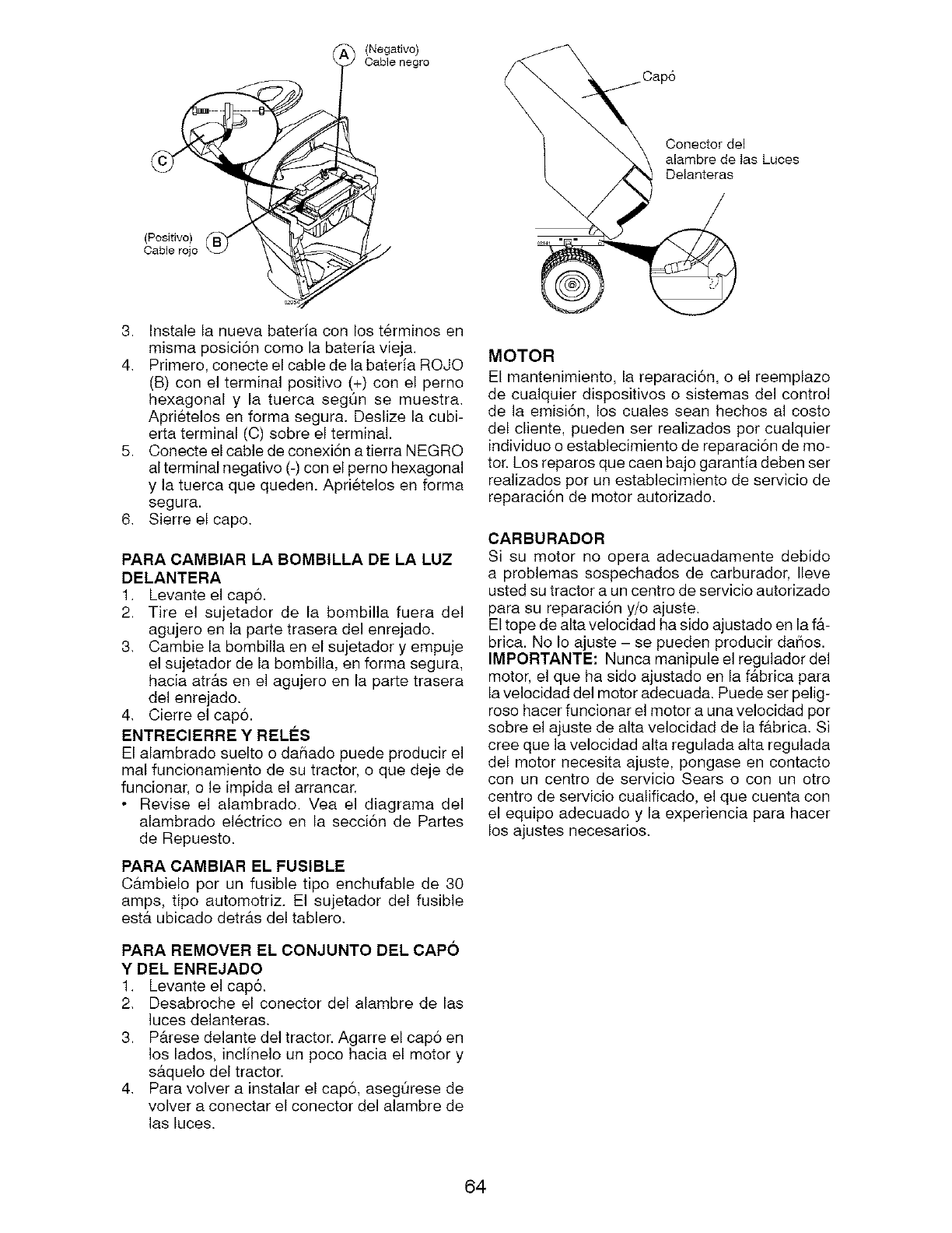
(Negativo)
Cable negro
(Positivo)
Cable rojo
Conector del
_, alambre de las Luces
Delanteras
\
3. Instale la nueva bateria con los terminos en
misma posici6n como la bateria vieja.
4. Primero, conecte el cable de la bateria ROJO
(B) con el terminal positivo (+) con el perno
hexagonal y la tuerca segt_n se muestra.
Aprietelos en forma segura. Deslize la cubi-
erta terminal (C) sobre el terminal.
5. Conecte el cable de conexi6n a tierra NEGRO
al terminal negativo (-) con el perno hexagonal
y la tuerca que queden. Aprietelos en forma
segura.
6. Sierre el capo.
PARA CAMBIAR LA BOMBILLA DE LA LUZ
DELANTERA
1. Levante el cap6.
2. Tire el sujetador de la bombilla fuera del
agujero en la parte trasera del enrejado.
3. Cambie la bombilla en el sujetador y empuje
el sujetador de la bombilla, en forma segura,
hacia atrAs en el agujero en la parte trasera
del enrejado.
4. Cierre el cap&
ENTREClERRE Y REL#:S
El alambrado suelto o daSado puede producir el
real funcionamiento de su tractor, o que deje de
funcionar, o le impida el arrancar.
• Revise el alambrado. Yea el diagrama del
alambrado electrico en la secci6n de Partes
de Repuesto.
PARA CAMBIAR EL FUSIBLE
C&mbielo por un fusible tipo enchufable de 30
amps, tipo automotriz. El sujetador del fusible
est& ubicado detr&s del tablero.
PARA REMOVER EL CONJUNTO DEL CAPO
YDEL ENREJADO
1. Levante el cap&
2. Desabroche el conector del alambre de las
luces delanteras.
3. P&rese delante del tractor. Agarre el cap6 en
los lados, inclinelo un poco hacia el motor y
s&quelo del tractor.
4. Para volver a instalar el cap6, asegQrese de
volver a conectar el conector del alambre de
las luces.
MOTOR
El mantenimiento, la reparaci6n, o el reemplazo
de cualquier dispositivos o sistemas del control
de la emisi6n, los cuales sean hechos al costo
del cliente, pueden ser realizados por cualquier
individuo o establecimiento de reparaci6n de mo-
tor. Los reparos que caen bajo garantia deben set
realizados pot un establecimiento de servicio de
reparaci6n de motor autorizado.
CARBURADOR
Si su motor no opera adecuadamente debido
a problemas sospechados de carburador, Ileve
usted su tractor a un centro de servicio autorizado
para su reparaci6n y/o ajuste.
El tope de alta velocidad ha sido ajustado en la f&-
brica. No Io ajuste - se pueden producir daSos.
IMPORTANTE: Nunca manipule el regulador del
motor, el que ha sido ajustado en la f&brica para
la velocidad del motor adecuada. Puede ser pelig-
roso hacer funcionar el motor a una velocidad por
sobre el ajuste de alta velocidad de la f&brica. Si
cree que la velocidad alta regulada alta regulada
del motor necesita ajuste, pongase en contacto
con un centro de servicio Sears o con un otro
centro de servicio cualificado, el que cuenta con
el equipo adecuado y la experiencia para hacer
los ajustes necesarios.
64
Inmediatamente prepare su tractor para el alma-
cenamiento al final de la temporada o si el tractor
no se va a usar por 30 dias o m&s.
_r',DVERTENClA: Nunca almacene el tractor con
gasolina en el estanque dentro de un edificio en
donde los gases pueden alcanzar una llama expu-
esta o una chispa. Permita que el motor se enfrie
antes de almacenado en cualquier recinto privado.
TRACTOR
Cuando el tractor ee va a almacenar por cierto
periodo de tiempo, limpiela cuidadosamente,
quite toda la mugre, la grasa, las hojas, etc.
Gu&rdela en una &rea limpia y seca.
1. Limpie todo el tractor (yea "LIMPIEZ,_' en la
secci6n de Mantenimiento en eete manual).
2. Inspeccione y cambie las correas, si es nec-
eeario (yea las instruccionee para el cambio
de las correas en la secci6n de Servicio y
Ajustes de este manual).
3. Lubriquelo, eegQn se muestra en la secci6n
de Mantenimiento de este manual.
4. AsegSreee que todae las tuercas, los pemoe y
los tornillos est6n sujetados en forma segura.
Inspeccione las partes movibles para verificar
ei hay da#io, rotura o desgaste. C&mbielae si
es necesafio.
5. Retoque todas superficies pintadae oxidadas
o picadas; aplique lija antes de pintar.
BATERJA
• Cargue la bateria completamente antes de
guardarla.
• Despues de cierto periodo de tiempo en alma-
cenamiento, la bateria puede neceeitar volver
a cargarse.
• Para ayudar a evitar la corrosi6n y las fugas
de potencia durante largos periodos de alma-
cenamiento, se deben desconectar los cables
de la bateria y se debe limpiar cuidadosamente
(vea"PARA LIMPIAR LA BATERIA Y LOS TER-
MINALES" en la secci6n de Mantenimientode
este manual).
• Despu6s de limpiarla, deje los cables desco-
nectados y p6ngalos en donde no puedan
entrar en contacto con los terminales de la
bateria.
• Si se remueve la bateria del tractor para el
almacenamiento, no la guarde directamente
sobre concreto o sobre superficies hOmedas.
MOTOR
SlSTEMA DE COMBUSTIBLE
IMPOFITANTE: Es important evitar que ee for-
man depositos de goma en partes fundamen-
tales del sistema de combus-tible tales como el
carburador, el filtro del combustible, la manguera
del combustibles mezclados con alcohol (cono-
cido como gaeohol o que tienen etanol o meta-
nol) pueden atraer humedad, Io que conduce
a la eeparaci6n y a la formaci6n de acudoe
durante elalmacenamiento. La gasolina acidica
puede daSar el sistema de combustible de un
motor durante el periodo de almacenamiento.
• Vaciar el dep6sito del carburante poniendo en
marcha el motor y dej&ndolo funcionar hasta que
el carburante termine el carburador est6 vacio.
• Nunca use los productos para limpieza del carbu-
rador odel motor en el estanque de combustible
pues se pueden producir daSos permanentes.
• Use combustible nuevo la pr6xima temporada.
AVISO: El estabilizador de combustible es una
alternativa aceptable para reducir a un minimo
la formaci6n de dep6sitos de goma en el com-
bustible durante el periodo de almacenamiento.
Agregue estabilizador a la gasolina en el es-
tanque de combustible o en el envase para el
almacenamiento. Siempre siga la proporci6n de
mezcla que se encuentra en el envase del estabi-
lizador. Haga funcionar el motor pot Io menos 10
minutos despu6s de agregar el estabilizador, para
permitir que 6ste Ilegue al carburador. No vaciar la
gasolina del estanque de gasolina y el carburador
si se esta usando estabilizador de combustible.
ACEITE DEL MOTOR
Drene el aceite (con el motor caliente) y c&mbielo
con aceite de motor limpio. (Vea "MOTOR" en
la secci6n de Mantenimiento" de este manual.)
ClLINDRO(S)
1. Remueva la(s) bujia(s).
2. Vacie una onza de aceite a trav6s del
agujero(s) de la bujia en el cilindro(s).
3. Gire la Ilave de ignici6n a la posici6n de 'Ar-
ranque" (Start), por unos cuantos segundos
para distribuir el aceite.
4. Cambie por bujia(s) nueva(s).
OTROS
• No guarde la gasolina de una temporada a la
otra.
• Cambie el envase de la gasolina si se emp-
ieza a oxidar. La oxidaci6n y/o la mugre en su
gasolina producir&n problemas.
• Si es posible, guarde su unidad en un recinto
cerrado y cQbrala para protegeda contra el
polvo y la mugre.
• Cubra su unidad con un forro protector ad-
ecuado que no retenga la humedad. No use
pl&stico. El pl&stico no puede respirar, Io que
permite la formaci6n de condensaci6n, Io que
producir& la oxidaci6n de su unidad.
IMPORTANTE: Nunca cubra el tractor mientras el
motor y laeareas de escape todavia eetan calientes.
65
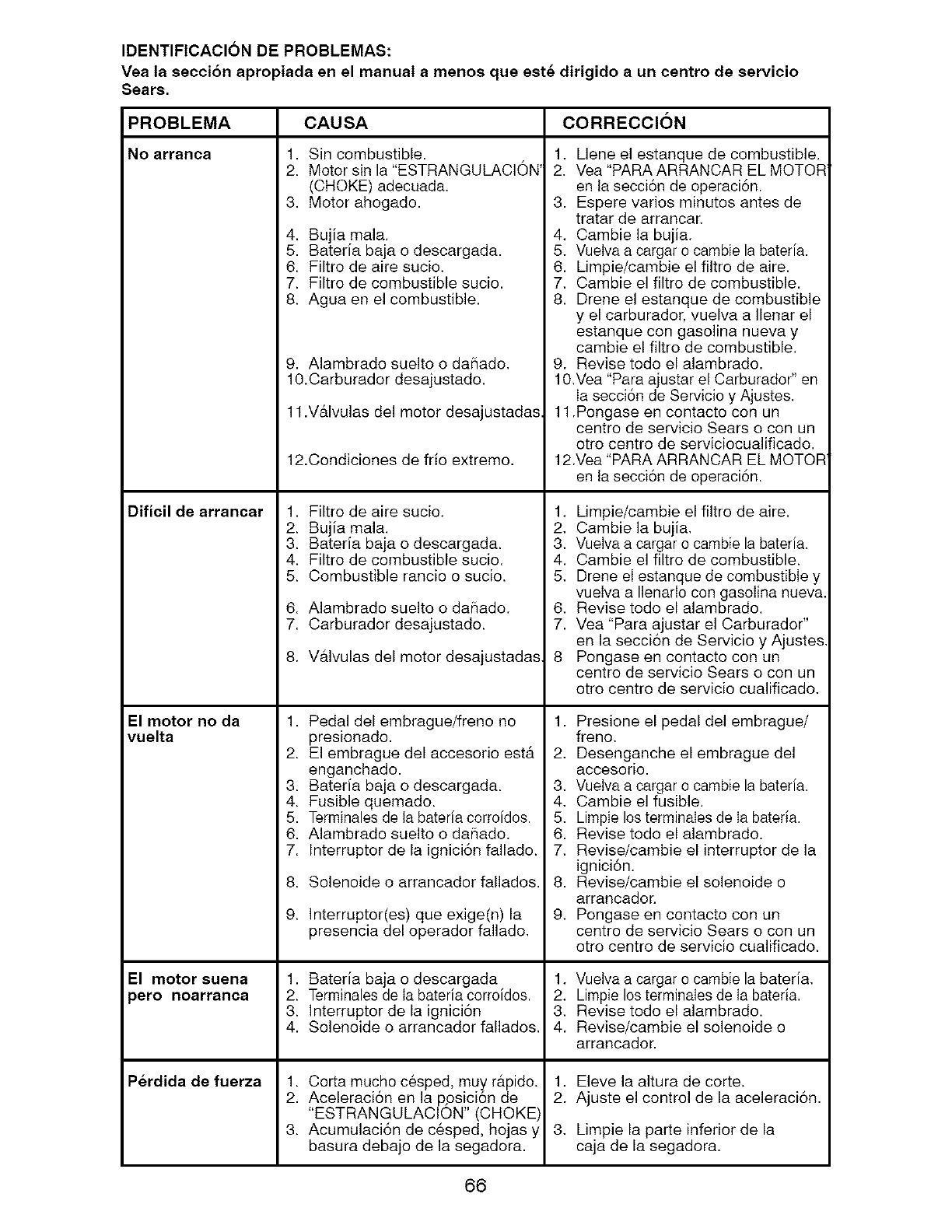
IDENTIFICACION DE PROBLEMAS:
Vea la seccion apropiada en el manual a menos que est_ dirigido a un centro de servicio
Sears.
CAUSA CORRECCIONPROBLEMA
No arranca 1. Sin combustible.
2. Motor sin la "ESTRANGULACION'
(CHOKE) adecuada.
3. Motor ahogado.
Dificil de arrancar 1.
2.
3.
4. Bujia mala.
5. Bateria baja o descargada.
6. Filtro de aire sucio.
7. Filtro de combustible sucio.
8. Agua en el combustible.
El motor no da
vuelta
El motor suena
pero noarranca
P_rdida de fuerza
9. Alambrado suelto o dahado,
10.Carburador desajustado.
11.V&lvulas del motor desajustadas.
12.Condiciones de frio extremo.
Filtro de aire sucio,
Bujia mala.
Bateria baja o descargada.
4. Filtro de combustible sucio.
5. Combustible rancio o sucio.
6. Alambrado suelto o dahado.
7. Carburador desajustado.
8. V&lvulas del motor desajustadas,
1. Pedal del embrague/freno no
presionado.
2. El embrague del accesorio est&
enganchado.
3. Bateria baja o descargada.
4. Fusible quemado.
5. Terminales de la bateria corroidos.
6. Alambrado suelto o dahado,
7. Interruptor de la ignici6n fallado.
8.
9.
Solenoide o arrancador fallados,
Interruptor(es) que exige(n) la
presencia del operador fallado,
1. Bateria baja o descargada
2. Terminales de ta bateria corroidos.
3. Interruptor de la ignici6n
4. Solenoide o arrancador fallados,
1. Corta mucho c6sped, muy r&pido.
2. Aceleraci6n en la p,osici6n de
"ESTRANGULACION" (CHOKE)
3. Acumulaci6n de c6sped, hojas y
basura debajo de la segadora.
1, Llene el estanque de combustible.
2. Vea "PARA ARRANCAR EL MOTOR
en la secci6n de operaci6n.
3. Espere varios minutos antes de
tratar de arrancaK
4, Cambie la bujia,
5, Vuetva a cargar o cambie la bateria.
6. Limpie/cambie el filtro de aire.
7, Cambie el filtro de combustible.
8. Drene el estanque de combustible
y el carburador, vuelva a Ilenar el
estanque con gasolina nueva y
cambie el filtro de combustible.
9. Revise todo el alambrado.
10,Vea "Para ajustar el Carburador" en
Ia secci6n de Servicio y Ajustes.
11.Pongase en contacto con un
centro de servicio Sears o con un
otto centro de serviciocualificado.
12.Vea "PARA ARRANCAR EL MOTOR
en la secci6n de operaci6n.
1, Limpie/cambie el filtro de aire.
2, Cambie la bujia,
3, VueIva a cargar o cambie la bateria.
4. Oambie el filtro de combustible.
5, Drene el estanque de combustible y
vuelva a Ilenarlo con gasolina nueva.
6, Revise todo el alambrado.
7. Vea "Para ajustar el Carburador"
en la secci6n de Servicio y Ajustes
8 Pongase en contacto con un
centro de servicio Sears o con un
otto centro de servicio cualificado,
1. Presione el pedal del embrague/
freno,
2, Desenganche el embrague del
accesorio.
3, VueIva a cargar o cambie la bateria.
4, Cambie el fusible.
5, Limpie los terminales de Ia bateria.
6. Revise todo el alambrado.
7, Revise/cambie el interruptor de la
ignici6n.
8. Revise/cambie el solenoide o
arrancador.
9, Pongase en contacto con un
centro de servicio Sears o con un
otto centro de servicio cualificado,
1, Vuetva a cargar o cambie la bateria,
2. Limpie los terminaIes de Ia bateria.
3, Revise todo el alambrado.
4. Revise/cambie el solenoide o
arrancador.
1. Eleve la altura de corte.
2. Ajuste el control de la aceleraci6n.
3, Limpie la parte inferior de la
caja de la segadora.
66
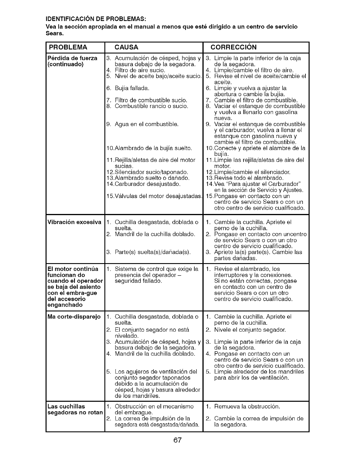
IDENTIFICACION DE PROBLEMAS:
Vea la seccion apropiada en el manual a menos que est_ dirigido a un centro de servicio
Sears.
PROBLEMA
Perdida de fuerza
(continuado)
Vibracion excesiva
El motor contint_a
funcionan do
cuando el operador
se baja del asiento
con el embra-gue
del accesorio
enganchado
Ma corte-disparejo
CAUSA CORRECCION
3. Acumulaci6n de cesped, hojas y
basura debajo de la segadora•
4. Filtro de aire sucio.
5• Nivel de aceite bajo/aceite sucio.
6. Bujia fallada.
7. Filtro de combustible sucio.
8. Combustible rancio o sucio.
9. Agua en el combustible•
10.Alambrado de la bujia suelto.
1.Rejilla/aletas de aire del motor
sucias.
12.Silenciador sucio/taponado.
13.Alambrado suelto o da_ado.
14•Carburador desajustado.
15.V&lvulas del motor desajustadas,
. Cuchilla desgastada, doblada o
suelta.
2. Mandril de la cuchilla doblado.
3. Parte(s) suelta(s)/da_iada(s).
• Sistema de control que exige la
presencia del operador -
seguridad fallado.
. Cuchilla desgastada, doblada o
suelta.
2. El conjunto segador no est&
nivelado.
3• Acumulaci6n de cesped, hojas y
basura debajo de la segadora.
4. Mandril de la cuchilla doblado.
5, Los agujeros de ventilaci6n del
conjunto segador taponados
debido a la acumulaci6n de
c_sped, hojas y basura alrededor
de los mandriles.
3. Limpie la parte inferior de la caja
de la segadora.
4. Limpie/cambie el filtro de aire.
5. Revise el nivel de aceite/cambie el
aceite.
6• Limpie y vuelva a ajustar la
abertura o cambie la bujia.
7. Cambie el filtro de combustible.
8• Vaciar el estanque de combustible
y vuelva a Ilenarlo con gasolina
Nuevs.
9• Vaciar el estanque de combustible
y el carburador, vuelva a Ilenar el
estanque con gasolina nueva y
cambie el filtro de combustible.
10.Conecte y apriete el alambre de la
bujia.
11.Limpie las rejilla/aletas de aire del
motor.
12,Limpie/cambie el silenciador.
13, Revise todo el alambrado.
14.Vea "Para ajustar el Carburador"
en la secci6n de Servicio y Ajustes.
15.Pongase en contacto con un
centro de servicio Sears o con un
otro centro de servicio cualificado.
1. Cambie la cuchilla. Apriete el
perno de la cuchilla.
2• Pongase en contacto con uncentro
de servicio Sears o con un otto
centro de servicio cualificado.
3. Apriete la(s) patters). Cambie las
partes da_adas.
1. Revise el alambrado, los
interruptores y la conexiones•
Si no est&n correctas, pongase
en contacto con un centre de
servicio Sears o con un otto
centro de servicio cualificado.
1•
2.
3.
4.
5•
Cambie la cuchilla. Apriete el
perno de la cuchilla.
Nivele el conjunto segador.
Limpie la parte inferior de la caja
de la segadora.
Pongase en contacto con un
centro de servicio Sears o con un
otto centro de servicio cualificado.
Limpie alrededor de los mandriles
para abrir los de ventilaci6n.
Las cuchillas .Obstrucci6n en el mecanismo 1. Remueva la obstrucci6n.
segadoras no rotan del embrague,
2, La correa de impulsi6n de la 2. Cambie la correa de impulsi6n de
segadora esta desgastada/da_iada, la segadora,
67
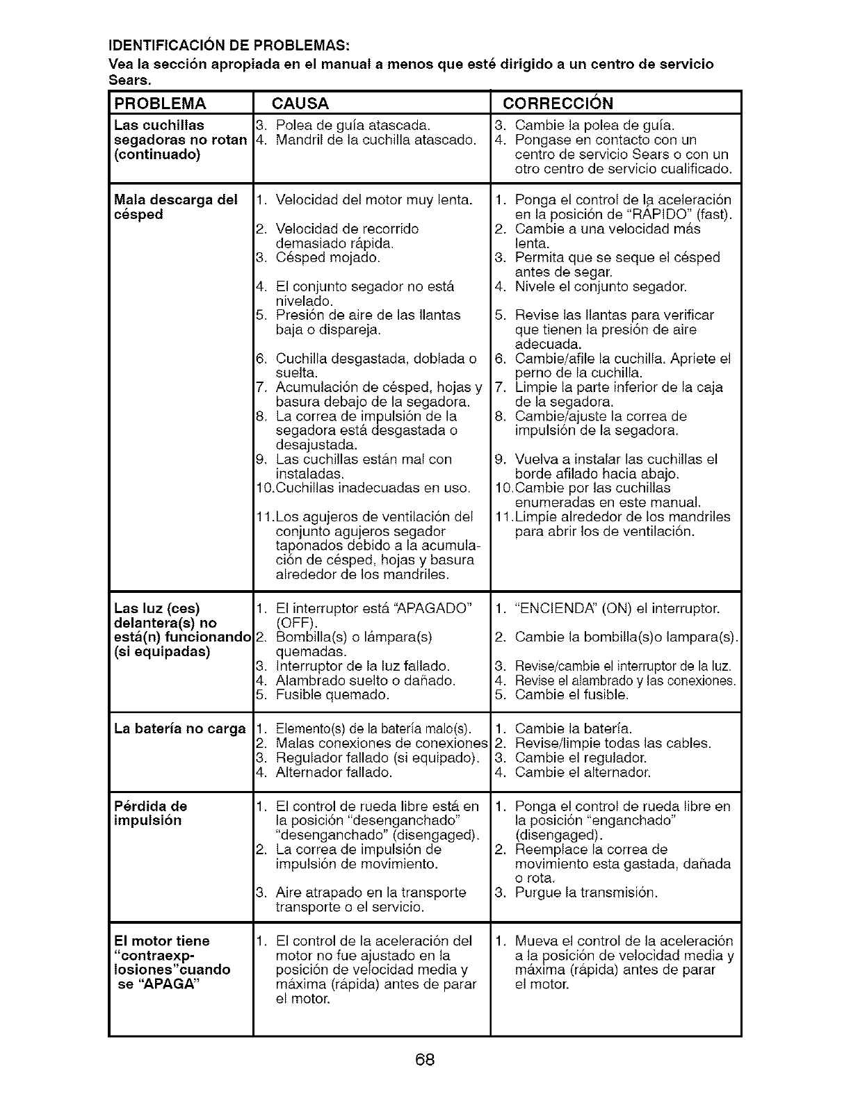
IDENTIFICACION DE PROBLEMAS:
Vea la seccion apropiada en el manual a menos que est_ dirigido a un centro de servicio
Sears.
PROBLEMA
Las cuchillas
segadoras no rotan
(continuado)
Mata descarga det
cesped
Las luz (ces)
delantera(s) no
esta(n) funcionandc
(si equipadas)
CAUSA CORRECCION
3. Polea de guia atascada. 3, Cambie la polea de guia,
4. Mandril de la cuchilla atascado. 4. Pongase en contacto con un
centro de servicio Sears o con un
otto centro de servicio cualificado•
• Velocidad del motor muy lenta.
2•
3.
4.
5,
Velocidad de recorrido
demasiado r&pida.
C6sped mojado.
El conjunto segador no est&
nivelado.
Presi6n de aire de las Ilantas
baja o dispareja.
6, Cuchilla desgastada, doblada o
suelta,
7. Acumulaci6n de c6sped, hojas y
basura debajo de la segadora.
8. La correa de impulsi6n de la
segadora est& desgastada o
desajustada.
9, Las cuchillas est#,n mal con
instaladas.
10.Cuchillas inadecuadas en uso.
1.Los agujeros de ventilaci6n del
conjunto agujeros segador
taponados debido a la acumula-
ci6n de c6sped, hojas y basura
alrededor de los mandriles.
• El interruptor estb, "APAGADO"
(OFF)•
2. Bombilla(s) o I&mpara(s)
quemadas.
3. Interruptor de la luz fallado.
4. Alambrado suelto o daPiado•
5. Fusible quemado.
1. Ponga el control de I,aaceleraci6n
en la posici6n de "RAPIDO" (fast).
2. Cambie a una velocidad m_.s
lenta.
3• Permita que se seque el c6sped
antes de segar.
4, Nivele el conjunto segador.
5. Revise las Ilantas para verificar
que tienen la presi6n de aire
adecuada.
6. Cambie/afile la cuchilla. Apriete el
pemo de la cuchilla,
7, Limpie la parte inferior de la caja
de la segadora.
8• Cambie/ajuste la correa de
impulsi6n de la segadora.
9. Vuelva a instalar las cuchillas el
borde afilado hacia abajo.
10,Cambie por las cuchillas
enumeradas en este manual•
11•Limpie alrededor de los mandriles
para abrir los de ventilaci6n,
1. "ENCIEND,_' (ON) el interrupter.
2, Cambie la bombilla(s)o lampara(s),
3, Revise/cambie et interruptor de la luz•
4. Revise el alambrado y las conexiones.
5. Cambie el fusible,
La bateria no carga . Elemento(s) de la bateria malo(s). 1. Cambie la bateria.
2. Malas conexiones de conexiones 2• Revise/limpie todas las cables•
3. Regulador fallado (si equipado)• 3. Cambie el regulador.
4. AIternador fallado. 4, Cambie el alternador.
• El control de rueda libre est,, en
la posici6n "desenganchado"
"desenganchado" (disengaged),
La correa de impulsi6n de
impulsi6n de movimiento.
Aire atrapado en la transporte
transporte o el servicio.
P_rdida de
impulsion
El motor tiene
"contraexp-
losiones"cuando
se "APAGA"
2•
3.
• El control de la aceleraci6n del
motor no fue ajustado en la
posici6n de velocidad media y
maxima (r#,pida) antes de parar
el motor•
1• Ponga el control de rueda libre en
la posici6n "enganchado"
(disengaged)•
2• Reemplace la correa de
movimiento esta gastada, daPiada
o rota.
3, Purgue la transmisi6n.
1• Mueva el control de la aceleraci6n
a la posici6n de velocidad media y
maxima (rb,pida) antes de parar
el motor•
68
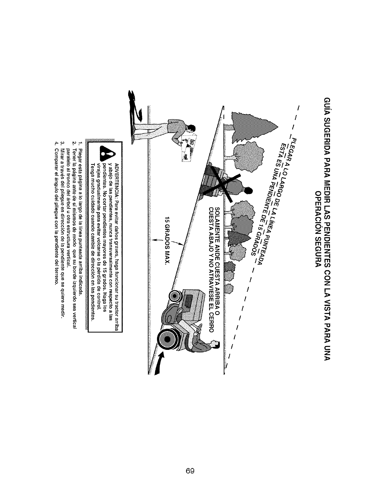
/
/
/
/
/
/
/
/
/
/
rn
0
"1@
_0
m
OO
m
:Dr-
(..) o0
(,o0
m_
_z
C:-. I
_Om
_o0
(,.)
0
Z
I'-
,-I
-1@
Z
69

7O

71

NEED MORE HELP?
You].[ find the ar_swer and rr_ore on _anagemyhemeocom = for free!
, Find this and aLLyour other product manuals online.
, Get answersfrom our team of home experts.
• Get a personalized maintenance plan for your home.
° Find information and tools to help with home projects.
home
b[eeght te Fee by 5ea_s
Your Home
For repair - in your home - of all major brand appliances,
lawn and garden equipment, or heating and cooling systems,
no matter who made it, no matter who sold it!
For the replacement parts, accessories and
owner's manuals that you need to do-it-yourself. i:!i:ii:il
For Sears professional installation of home appliances ....
and items like garage door openers and water heaters. ....
1-800-4-MY-HOM I=(_ Anytime, day or night
(1-800-469-4663) (U.SA. and Canada)
www.sears.com www.sears.ca
Our Home
For repair of carry-in products like vacuums, lawn equipment,
and electronics, call or go on-line for the nearest ii!iiiiiil
Sears Parts and Repair Center.
1-800488-1222 Anytime, day or night (U.S.A. only)
www.sears.com
To porchase a protection agreement (US.A.)
or maintenance agreement (Canada) on a product serviced by Sears: ....
i:!i:ii:il
1-800-827-6655 (U.S.A.) 1-800-361-6665 (Canada) ....
Para pedir servicio de reparacidn Au Canada pour service en frangais:
a domicilio, y paraordenar piezas: 1-800-LE-FOYERMc
1.888.SU.HOGAR ® (14300-533_937)
(1488-784_$427) v_ww.sears.ca
Sea/ItS
© Sears Brands, LLC
TM SM
® Registered Trademark /Trademark /' Service Mark of Bears Brands, LLC
M SM
®MarcaRegistrada/T MarcadeFabdca/ 'MarcadeServiciodeSearsBrands, LLC
MC MD
Marque de commerce /Marque deposCe de Sears Brands, LLC
417454 Rev 2 06.06,08 SBW Printed in U.S.A.
