Craftsman 917289550 User Manual TRACTOR Manuals And Guides 1007809L
User Manual: Craftsman 917289550 917289550 CRAFTSMAN TRACTOR - Manuals and Guides View the owners manual for your CRAFTSMAN TRACTOR #917289550. Home:Lawn & Garden Parts:Craftsman Parts:Craftsman TRACTOR Manual
Open the PDF directly: View PDF ![]() .
.
Page Count: 72

Operator's Manual
GAR E
26.0 HP,* 54"
Enectric Start
TRACTO
Mower
6 Speed Transaxle
Model No.
917.28955
• Espafiol, p. 35
This product has a low emission engine which operates
differently from previously built engines. Before you start the
engine, read and understand this Owner's Manual.
IMPORTANT:
Read and follow all Safety
Rules and Instructions before
operating this equipment.
For answers to your questions
about this product, Call:
t-800-659-5917
Sears Craftsman Help Line
5 am _5 pm, Mon- Sat
SEARS, ROEBUCK AND CO., HOFFMAN ESTATES, IL 60179 U.S.A.
Visit our Craftsman website:www.sears.com/craftsman *As r_led by the engine menufacturer
433808 Rev. 2
Warranty .................................................... 2
Safety Rules .......................................... 3
Product Specifications ........................... 6
Assembly/Pre-Operation ........................ 8
Operation ............................................. 12
Maintenance Schedule ........................ 19
Maintenance ........................................ 19
Service and Adjustments ...................... 24
Storage ................................................ 29
Troubleshooting ................................... 30
Sears Service ........................ Back Cover
Craftsman Riding Equipment Warranty:
Lawn Tractors, Garden Tractors, Zero Turn Riders
CRAFTSMAN TWO YEAR FULL WARRANTY
FOR TWO YEARS from the date of purchase, if any non-expendable part of this riding
equipment fails due to a defect in material or workmanship, visit www.craftsman.com or
call 1-800-659-5917 to arrange for free in-home repair.
The frame and front axle will be repaired free of charge for five years from the date of
purchase if defective in material or workmanship°
In all cases, if repair proves impossible, the riding equipment will be replaced free of
charge with the same or an equivalent model.
The battery will be replaced free of charge for 90 days from the date of purchase if
defective in material or workmanship (our testing proves that it will not hold a charge)°
This warranty is void if this product is ever used while providing commercial services or if
rented to another person°
This warranty covers ONLY defects in material and workmanship. Warranty
coverage does NOT include:
° Expendable items that can wear out from normal use within the warranty period,
including but not limited to blades, spark plugs, air cleaners, belts, and oil filters.
° Standard maintenance servicing, oil changes, or tune_upso
o Tire replacement or repair caused by punctures from outside objects, such as nails,
thorns, stumps, or glass.
° Tire or wheel replacement or repair resulting from normal wear, accident, or improper
operation or maintenance.
° Repairs necessary because of operator abuse, including but not limited to damage
caused by towing objects beyond the capability of the riding equipment, impacting
objects that bend the frame or crankshaft, or over-speeding the engine.
o Repairs necessary because of operator negligence, including but not limited to,
electrical and mechanical damage caused by improper storage, failure to use the
proper grade and amount of engine oil, failure to keep the deck clear of flammable
debris, or failure to maintain the riding equipment according to the instructions
contained in the operator's manual
• Engine (fuel system) cleaning or repairs caused by fuel determined to be
contaminated or oxidized (stale). In general, fuel should be used within 30 days of its
purchase date.
•Normal deterioration and wear of the exterior finishes, or product label replacement.
This warranty gives you specific legal rights, and you may also have other rights which
vary from state to state.
Sears Brands Management Corporation, Hoffman Estates, IL 60179
2
_DANGER: This cutting machine is capable of amputating hands and feet and
throwing objects. Failure to observe the following safety instructions could result
in serious injury or death.
_WARNING: in order to prevent acciden-
tal starting when setting up, transporting,
adjusting or making repairs, always discon-
nect spark plug wire and place wire where
it cannot contact spark plug.
_WARNING: Do not coast down a hill in
neutral, you may lose control of the tractor.
_WARNING: Tow only the attachments
that are recommended by and comply with
specifications of the manufacturer of your
tractor° Use common sense when towing.
Operate only at the lowest possible speed
when on a slope. Too heavy of a load, while
on a slope, is dangerous. Tires can lose
traction with the ground and cause you to
lose control of your tractor.
_,WARNING: Engine exhaust, some of its
constituents, and certain vehicle components
contain or emit chemicals known to the State
of California to cause cancer and birth defects
or other reproductive harm_
_,WARNING: Battery posts, terminals and
related accessories contain lead and lead
compounds, chemicals known to the State of
California to cause cancer and birth defects
or other reproductive harm° Wash hands
after handling.
I. GENERAL OPERATION
• Read, understand, and follow all instruc-
tions on the machine and in the manual
before starting.
• Do not put hands or feet near rotating
parts or under the machine. Keep clear
of the discharge opening at all times°
.Only allow responsible adults, who are
familiar with the instructions, to operate
the machine°
• Clear the area of objects such as rocks,
toys, wire, etc., which could be picked up
and thrown by the blades.
•Be sure the area is clear of bystanders
before operating. Stop machine if anyone
enters the area.
•Never carry passengers.
o Do not mow in reverse unless absolutely
necessary. Always look down and behind
before and while backing.
• Never direct discharged material toward
anyone. Avoid discharging material
against a wall or obstruction. Material may
ricochet back toward the operator. Stop the
blades when crossing gravel surfaces.
° Do not operate machine without the entire
grass catcher, discharge guard, or other
safety devices in place and working.
°Slow down before turning.
,Never leave a running machine unat-
tended. Always turn off blades, set park-
ing brake, stop engine, and remove keys
before dismounting.
• Disengage blades when not mowing. Shut
off engine and wait for all parts to come
to a complete stop before cleaning the
machine, removing the grass catcher, or
unclogging the discharge guard.
° Operate machine only in daylight or good
artificial light.
° Do not operate the machine while under
the influence of alcohol or drugs.
°Watch for traffic when operating near or
crossing roadways.
° Use extra care when loading or unloading
the machine into a trailer or truck.
°Always wear eye protection when operat-
ing machine.
,Data indicates that operators, age 60
years and above, are involved in a large
percentage of riding mower*related inju-
des° These operators should evaluate
their ability to operate the riding mower
safely enough to protect themselves and
others from serious injury.
•Follow the manufacturer's recommen-
dation for wheel weights or counter-
weights.
•Keep machine free of grass , leaves
or other debris build-up which can
touch hot exhaust /engine parts and
burn. Do not allow the mower to plow
leaves or other debris which can cause
build-up to occur. Clean any oil or fuel
spillage before operating or storing the
machine. Allow machine to cool before
storage.
3
H. SLOPE OPERATION
Slopes are a major factor related to loss of
control and tip-over accidents, which can
result in severe injury or death. Operation
on all slopes requires extra caution. If you
cannot back upthe slope or if you feel uneasy
on it, do not mow it.
° Mow up and down slopes, not across.
• Watch for holes, ruts, bumps, rocks, or
other hidden objects. Uneven terrain could
overturn the machine. Tall grass can hide
obstacles.
° Choose a low ground speed so that you
will not have to stop or shift while on the
slope.
• Do not mow on wet grass. Tires may lose
traction.
Always keep the machine in gear when
going down slopes. Do not shift to neutral
and coast downhill
• Avoid starting, stopping, or turning on a
slope. Ifthetires lose traction, disengage
the blades and proceed slowly straight
down the slope.
• Keep all movement on the slopes slow and
gradual. Do not make sudden changes
in speed or direction, which could cause
the machine to roll over°
° Use extra care while operating machine
with grass catchers or other attachments;
they can affect the stability of the machine.
Do no use on steep slopes.
° Do not try to stabilize the machine by
putting your foot on the ground.
• Do not mow near drop-offs, ditches, or
embankments. The machine could sud-
denly roll over if a wheel is over the edge
or if the edge caves in.
!il. CHILDREN
Tragic accidents can occur if the operator
is not alert to the presence of children.
Children are often attracted to the machine
and the mowing activity. Never assume
that children will remain where you last
saw them°
° Keep children outofthe mowing area and
inthe watchful care of a responsible adult
other than the operator,
.Be alert and turn machine off if achild
enters the area.
• Before andwhile backing, look behind and
down for small children.
° Never carry children, even with the blades
shut off. They may fall off and be seriously
injured or interfere with safe machine
operation. Children who have been given
rides in the past may suddenly appear in
the mowing area for another ride and be run
over or backed over by the machine.
° Never allow children to operate the ma-
chine.
° Use extra care when approaching blind
corners, shrubs, trees, or other objects
that may block your view of a child.
IV. TOWING
°Tow only with a machine that has a hitch
designed for towing. Do not attach towed
equipment except at the hitch poinL
• Follow the manufacturer's recommenda-
tion for weight limits for towed equipment
and towing on slopes.
• Never allow children or others in or on
towed equipment.
° On slopes, the weight of the towed equip-
ment may cause loss of traction and loss
of control.
°Travel slowly and allow extra distance to
stop.
V. SERVICE
SAFE HANDLING OF GASOLINE
To avoid personal injury or property dam-
age, use extreme care in handling gasoline.
Gasoline is extremely flammable and the
vapors are explosive.
•Extinguish all cigarettes, cigars, pipes,
and other sources of ignition°
• Use only approved gasoline container.
• Never remove gas cap or add fuel with
the engine running. Allow engine to cool
before refueling.
°Never fuel the machine indoors.
° Never store the machine or fuel container
where there is an open flame, spark, or
pilot light such as on a water heater or
other appliances.
•Never fill containers inside a vehicle or
on a truck or trailer bed with plastic liner.
Always place containers on the ground
away from your vehicle when filling.
°Remove gas-powered equipment from the
truck or trailer and refuel it on the ground.
If this is not possible, then refuel such
equipment with a portable container, rather
than from a gasoline dispenser nozzle.
- Keepthe nozzleincontactwiththerimof
the fuel tank or containeropeningat all
timesuntilfuelingiscomplete.Donotuse
a nozzlelock-opendevice.
° Iffuetisspilledonclothing,changeclothing
immediately_
, Neveroverfillfuel tank. Replacegascap
andtightensecurely.
GENERAL SERVICE
" Never operate machine in a closed
area.
, Keep all nuts and bolts tight to be sure the
equipment is in safe working condition.
, Never tamper with safety devices. Check
their proper operation regularly.
° Keep machine free of grass, leaves, or
other debris build-up. Clean oil or fuel spill-
age and remove any fuel-soaked debris.
Allow machine to cool before storing.
• If you strike a foreign object, stop and
inspect the machine. Repair, if necessary,
before restarting.
oNever make any adjustments or repairs
with the engine running.
oCheck grass catcher components and the
discharge guard frequently and replace
with manufacturer's recommended parts,
when necessary.
•Mower blades are sharp. Wrap the blade
orwear gloves, and use extra caution when
servicing them.
°Check brake operation frequently_ Adjust
and service as required.
• Maintain or replace safety and instruction
labels, as necessary.
• Be sure the area is clear of bystanders
before operating. Stop machine if anyone
enters the area.
• Never carry passengers_
• Do not mow in reverse unless absolutely
necessary. Always look down and behind
before and while backing.
° Never carry children, even with the
blades shut off. They may fall off and
be seriously injured or interfere with safe
machine operation. Children who have
been given rides in the past may suddenly
appear in the mowing area for another
ride and be run over or backed over by
the machine.
•Keep children outofthe mowing areaand
in the watchful care of a responsible adult
other than the operator°
° Be alert and turn machine off if a child
enters the area.
•Before and while backing, look behind
and down for small children_
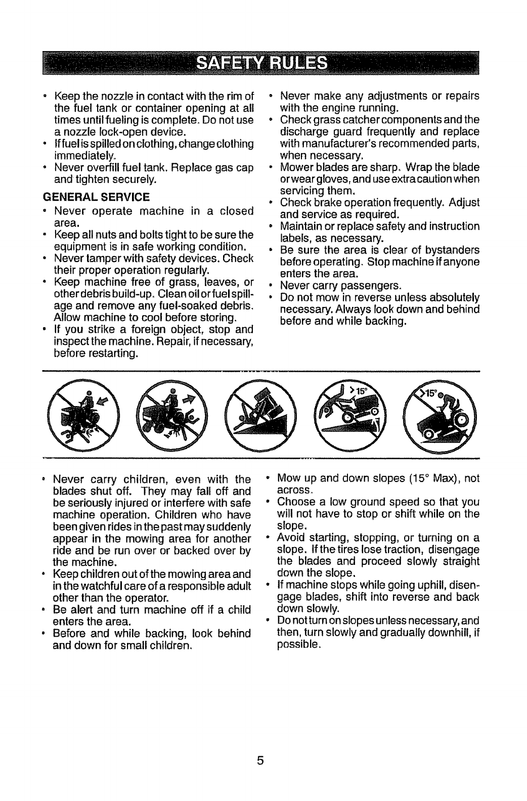
°Mow up and down slopes (15 ° Max), not
across.
°Choose a low ground speed so that you
will not have to stop or shift while on the
slope.
°Avoid starting, stopping, or turning on a
slope. If the tires lose traction, disengage
the blades and proceed slowly straight
down the slope.
° if machine stops while going uphill, disen-
gage blades, shift into reverse and back
down slowly.
•Do notturn on slopes unless necessary, and
then, turn slowly and gradually downhill, if
possible.
5

PRODUCT SPECIFiCATiONS
Gasoline Capacity 4 Gallons
and Type: Unleaded Regular
Oil Type SAE 10W30(above 32°F)
(API-SG-SL): SAE 5W30(below 32°F
Oil Capacity: 64 oz
Spark Plug: Champion RC12YC
(Gap: .030")
Ground Speed Forward:
(MPH): 1st 1.58
2rid 1.14
3rd 't .77
4th 2.65
5th 3.38
6th 4.33
Reverse: 1.33
Charging System: 15 Amps
Battery: Amp/Hr: 28
Min. CCA: 230
Case size: U1R
Blade Bolt Torque: 45-55 Ft. Lbs.
CONGRATULATIONS on your purchase of
a new tractor. It has been designed, engi-
neered and manufactured to give you the best
possible dependability and performance.
Should you experience any problem you
cannot easily remedy, please contact a
Sears or other qualified service center. We
have competent, well-trained technicians
and the proper tools to service or repair
this tractor.
Please read and retain this manual. The
instructions will enable you to assemble
and maintain your tractor properly. Always
observe the "SAFETY RUI.ES".
CUSTOMER RESPONSIBILITIES
•Read and observe the safety rules.
• Follow a regular schedule in maintaining,
caring for and using your tractor.
, Follow the instructions under "Mainte-
nance" and "Storage" sections of this
owner's manual,
d_IbWARNING: This tractor is equipped with
an internal combustion engine and should not
be used on or near any unimproved forest-
covered, brush-covered or grass-covered
land unless the engine's exhaust system is
equipped with a spark arrestor meeting ap-
plicable local or state laws (if any). If a spark
arrestor is used, it should be maintained in
effective working order by the operator.
in the state of California the above is required
by law (Section 4442 of the California Public
Resources Code). Other states may have
similar laws. Federal laws apply on federal
lands. A spark arrestor for the muffler is
available through your nearest Sears service
center (See REPAIR PARTS manual)_
REPAIR PROTECTION
AGREEMENTS
Congratulations on making a smart purchase.
Your new Craftsman® product is designed
and manufactured for years of dependable
operation. But like all products, it may require
repair from time to time. That's "when having
a Repair Protection Agreement can save you
money and aggravation.
Purchase a Repair Protection Agreement
now and protect yourseff from unexpected
hassle and expense.
Here's what's included in the Agreement:
•Expert service by our 12,000 profesional
repair specialists.
• Unlimited service and no charge for parts
and labor on all covered repairs.
, Product replacement if your covered
product can't be fixed.
• Discount of 10% from regular price of ser-
vice and service-related parts not covered
by the agreement; also, 10% off regular
price of preventive maintenance check.
° Fast help by phone - phone support from
a Sears representative on products requir-
ing in-home repair, plus convenient repair
scheduling.
Once you purchase the Agreement, a
simple phone call is all that it takes for you
to schedule service. You can call anytime
day or night, or schedule a service appoint-
ment online.
Sears has over 12,000 professional repair
specialists, who have access to over 4.5
million quality parts and accessories. That's
the kind of professionalism you can count on
to help prolong the life of your new purchase
for years to come. Purchase your Repair
Protection Agreement todayt
Some limitations and exclusions apply.
For prices and additional information call
1-800-827-6655.
SEARS INSTALLATION SERVICE
For Sears professional installation of home
appliances, garage door openers, water
heaters, and other major home items, in the
U.S.A. call 1-800-4-MY-HOME®
6
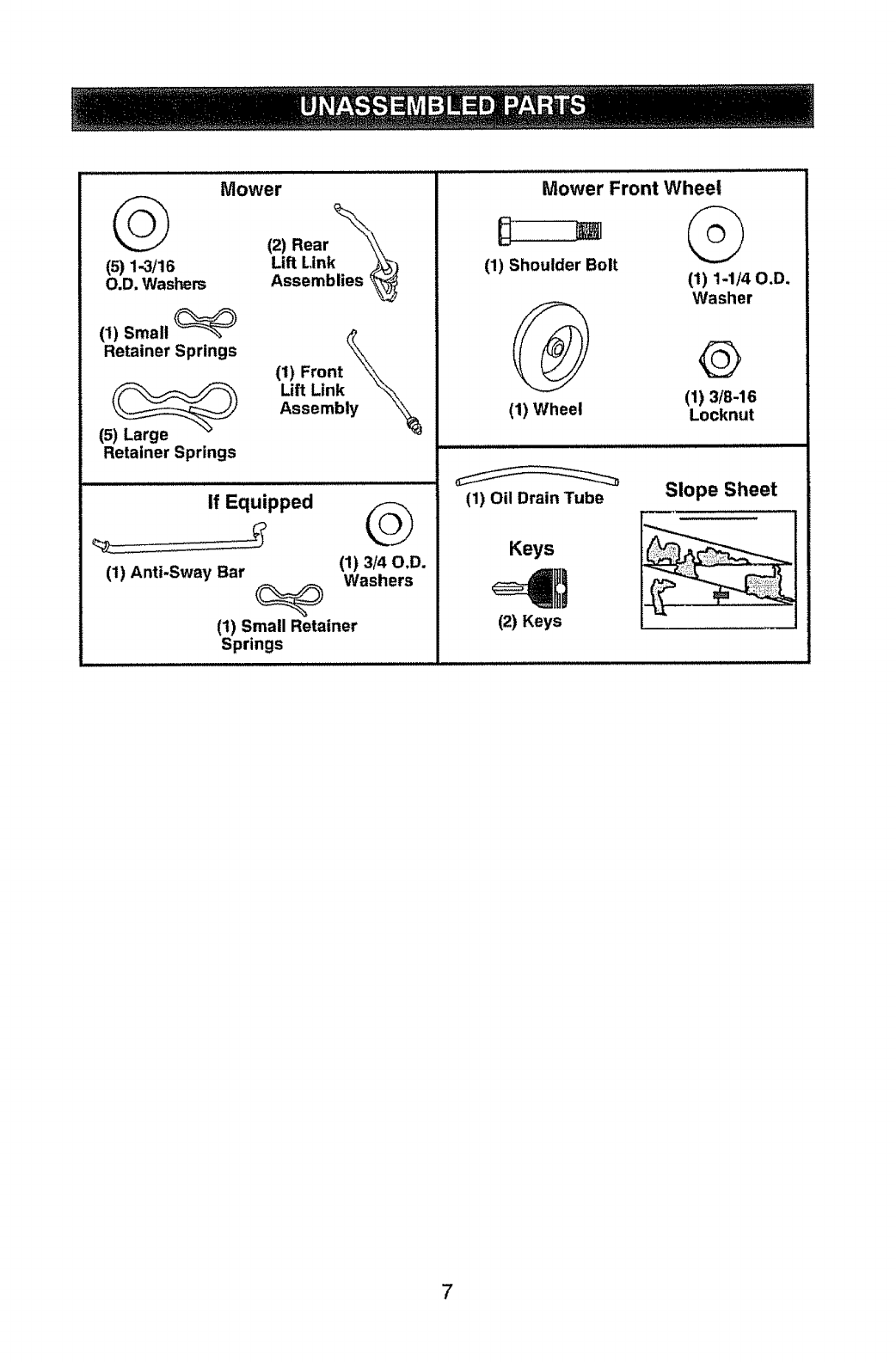
_(2) Rear
(5) 1--3/16 Lift Link
O.D. Washers Assemblies
Mower Mower Front Wheel
(I) Small
Retainer Springs
(5) Large
Retainer Springs
(1) Front
Lift Link
Assembly
If Equipped
(1) Anti-Sway Bar
G
(1)3/40.D.
Washers
(1) Small Retainer
Springs
(1) Shoulder Bolt
(1) Wheel
(1) 1-1/40.D.
Washer
@
(1) 3/8-16
Locknut
(1) Oil Drain Tube Slope Sheet
Keys
12! Keys
7
"Your new tractor has been assembled at the factory with exception of those parts left
unassembled for shipping purposes. To ensure safe and proper operation of your tractor
all parts and hardware you assemble must be tightened securely. Use the correct tools
as necessary to insure proper tightness.
TOOLS REQUIRED FOR ASSEMBLY
A socket wrench set will make assembly
easier° Standard wrench sizes are listed.
(2) 7/16" wrenches Utility knife
(1) 1/2" wrench Tire pressure gauge
(1) 3/4" wrench Pliers
(1) 3/4" socket w/drive ratchet
(1) 9/16" wrench Flashlight
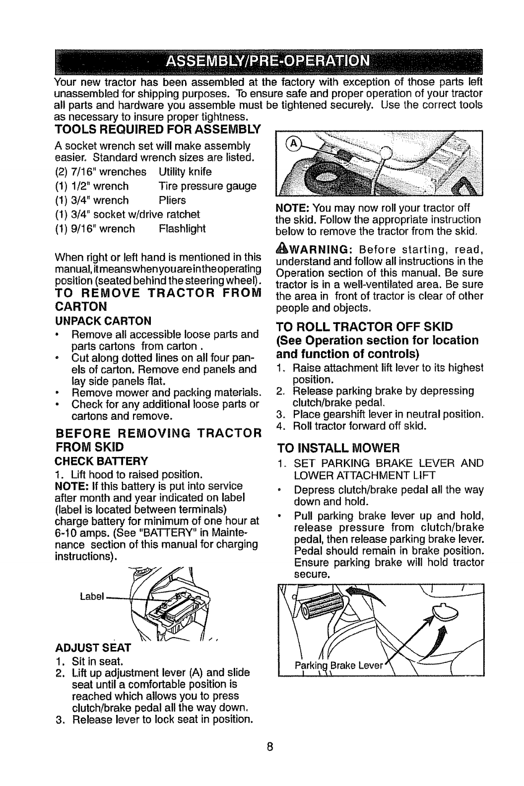
NOTE: You may now roll your tractor off
the skid. Follow the appropriate instruction
below to remove the tractor from the skid°
When right or left hand is mentioned in this
manual, itmeanswhenyou areintheoperating
position (seated behind the steering wheel).
TO REMOVE TRACTOR FROM
CARTON
UNPACK CARTON
• Remove all accessible loose parts and
parts cartons from carton.
oCut along dotted lines on all four pan-
els of carton. Remove end panels and
lay side panels flat.
• Remove mower and packing materials.
• Check for any additional loose parts or
cartons and remove.
BEFORE REMOVING TRACTOR
FROM SKiD
CHECK BATTERY
1. Lift hood to raised position.
NOTE: If this battery is put into service
after month and year indicated on label
(label is located between terminals)
charge battery for minimum of one hour at
6-10 amps. (See "BATTERY" in Mainte-
nance section of this manual for charging
instructions).
Label _ !
ADJUST SEAT
1. Sit in seat.
2.
3_
Lift up adjustment lever (A) and slide
seat until a comfortable position is
reached which allows you to press
clutch/brake pedal all the way down°
Release lever to lock seat in position.
_AWARNING: Before starting, read,
understand and follow all instructions in the
Operation section of this manual. Be sure
tractor is in a well-ventilated area. Be sure
the area in front of tractor is clear of other
people and objects.
TO ROLL TRACTOR OFF SKiD
(See Operation section for location
and function of controls)
!, Raise attachment lift lever to its highest
position.
2, Release parking brake by depressing
clutch/brake pedal,
3. Place gearshift lever in neutral position.
4. Roll tractor forward off skid.
TO INSTALL MOWER
In
t
SET PARKING BRAKE LEVER AND
LOWER ATTACHMENT LIFT
Depress clutch/brake pedal all the way
down and hold.
Pull parking brake lever up and hold,
release pressure from clutch/brake
pedal, then release parking brake lever.
Pedal should remain in brake position.
Ensure parking brake will hold tractor
secure,
Brake Lever
8
° The attachment lift switch is used to 3.
raise and lower the mower deck or other
attachments mounted to your tractor, ign- o
it,on must be on to operate this switch°
. Lower attachment lift to lowest position.
CAUTION: Continuing to press the electric
lift switch after the mower deck has reached
the minimum or maximum position may result
in damage to the electric lift mechanism_
The electric lift mechanism is equipped with
a thermal protection system, if the system
overheats or fails to operate, allowthe system
to cool before attempting to operate again.
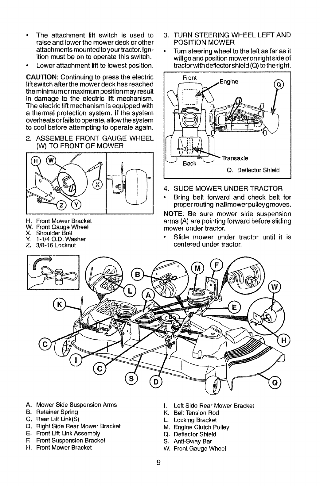
.ASSEMBLE FRONT GAUGE WHEEL
(W) TO FRONT OF MOWER
H. Front Mower Bracket
W, Front Gauge Wheel
X, Shoulder Bolt
Yo 1-1/40oD_ Washer
Z. 3/8-16 Locknut
TURN STEERING WHEEL LEFT AND
POSITION MOWER
Turn steering wheel to the left as far as it
will go and position mower on right side of
tractorwith deflector shield (Q) to the right.
Front
Back Transaxle
Q_ Deflector Shield
4. SLIDE MOWER UNDER TRACTOR
" Bring belt forward and check belt for
proper routing in all mower pulley grooves.
NOTE: Be sure mower side suspension
arms (A) are pointing forward before sliding
mower under tractor.
° Slide mower under tractor until it is
centered under tractor.
A. Mower Side Suspension Arms
B. Retainer Spring
C, Rear Lift Link(S)
D, Right Side Rear Mower Bracket
E. Front Lift Link Assembly
E Front Suspension Bracket
H_ Front Mower Bracket
L Left Side Rear Mower Bracket
K, Belt Tension Rod
Lo Locking Bracket
M_ Engine Clutch Pulley
Q, Deflector Shield
So Anti-Sway Bar
W, Front Gauge Wheel
9
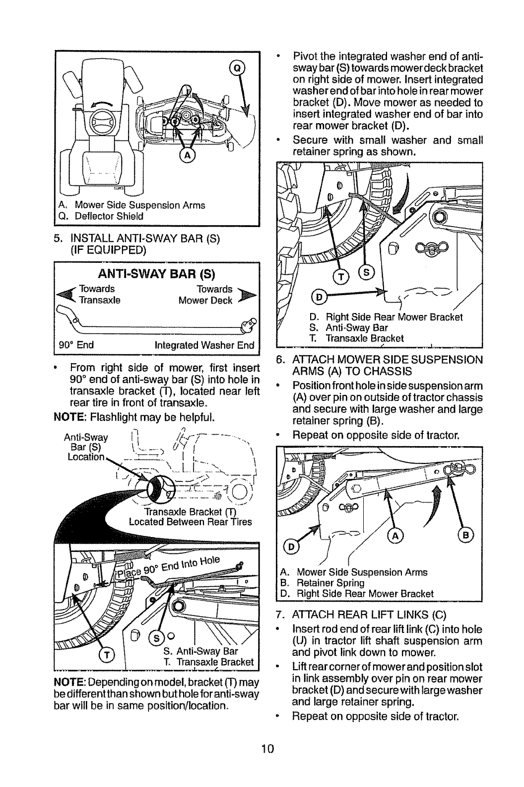
A, Mower Side Suspension Arms
Q. Deflector Shield
5. INSTALL ANTI-SWAY BAR (S)
(IF EQUIPPED)
ANTI-SWAY BAR (S)
Towards Towards
Transaxle Mower Deck
90° End Integrated Washer End
From right side of mower, first insert
90 ° end of anti-sway bar (S) into hole in
transaxle bracket (T), located near left
rear tire in front of transaxle.
NOTE: Flashlight may be helpful,
Anti-Sway i i
Bar , _......... t
•L.
Transaxle Bracket (_
Located Between Rear Tires
NOTE: Depending on model, bracket (T) may
be different than shown but hole for anti-sway
bar wil! be in same position/location.
. Pivot the integrated washer end of anti-
sway bar (S) towards mower deck bracket
on right side of mower. Insert integrated
washer end of bar into hole in rear mower
bracket (D). Move mower as needed to
insert integrated washer end of bar into
rear mower bracket (D).
.Secure with small washer and small
retainer spring as shown.
6o ATTACH MOWER SIDE SUSPENSION
ARMS (A) TO CHASSIS
° Position front hole in sidesuspension arm
(A) over pin on outside of tractor chassis
and secure with large washer and large
retainer spring (B).
-Repeat on opposite side of tractor.
A. Mower Side Suspension Arms
B, Retainer Spring
D. Right Side Rear Mower Bracket
7. ATTACH REAR LIFT LINKS (C)
• Insert rod end of rear lift link (C) into hole
(U) in tractor lift shaft suspension arm
and pivot link down to mower.
•Lift rear corner of mower and position slot
in link assembly over pin on rear mower
bracket (D) and secure with large washer
and large retainer spring.
•Repeat on opposite side of tractor,
10
J
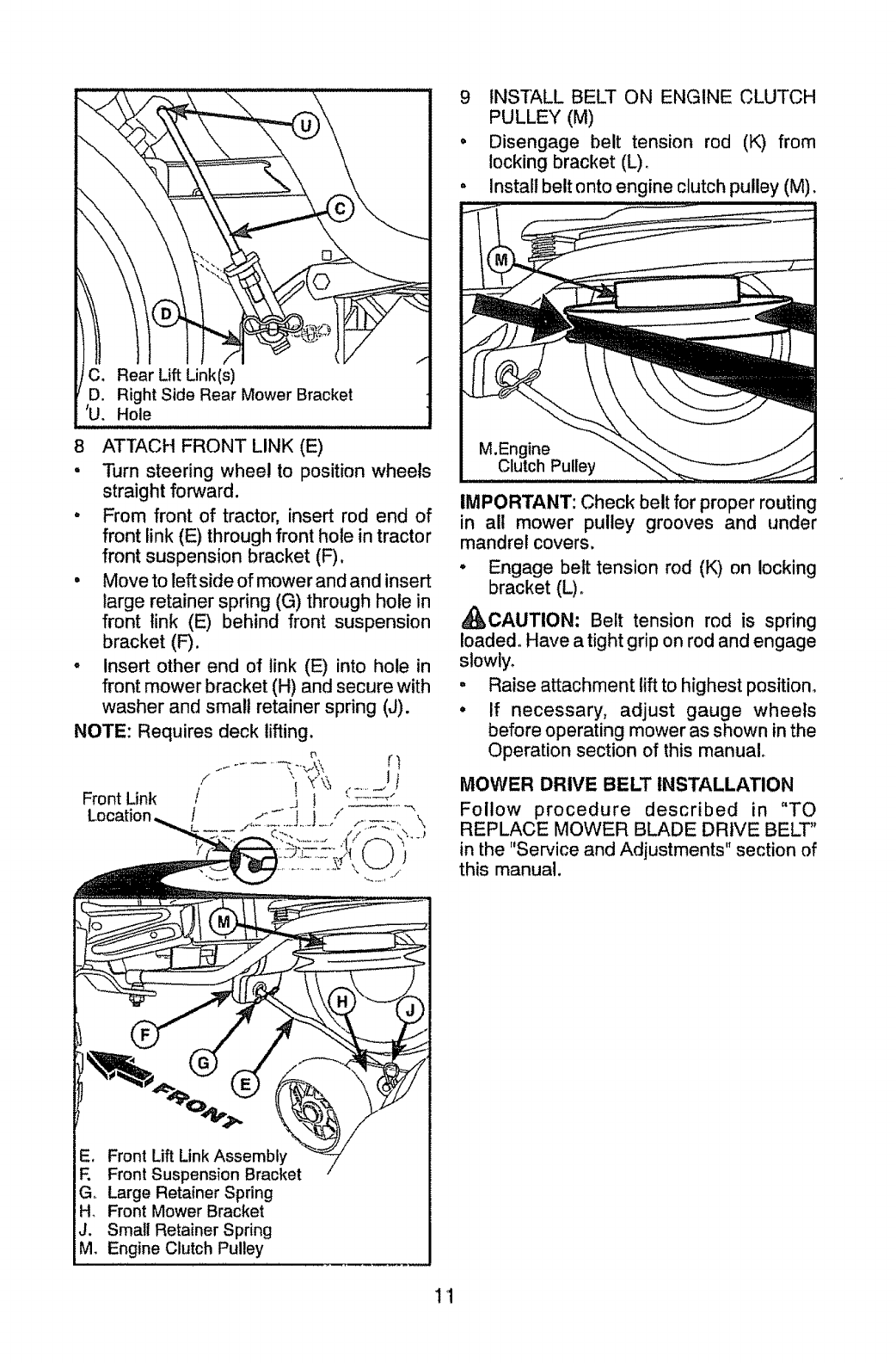
8 ATTACH FRONT LINK (E)
• Turn steering wheel to position wheels
straight forward.
• From front of tractor, insert rod end of
front link (E) through front hole in tractor
front suspension bracket (F).
• Move to left side of mower and and insert
large retainer spring (G) through hole in
front link (E) behind front suspension
bracket (F).
, Insert other end of link (E) into hole in
front mower bracket (H) and secure with
washer and small retainer spring (J).
NOTE: Requires deck lifting.
Front Link /!
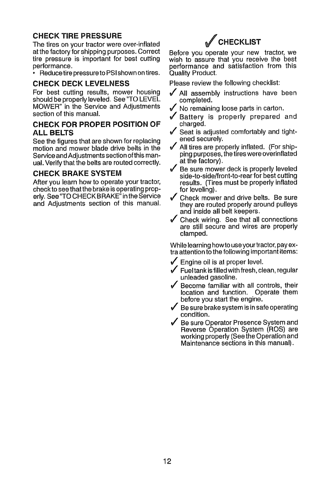
9 INSTALL BELT ON ENGINE CLUTCH
PULLEY (M)
• Disengage belt tension rod (K) from
locking bracket (L).
, install belt onto engine clutch pulley (M).
IMPORTANT: Check belt for proper routing
in all mower pulley grooves and under
mandrel covers.
° Engage belt tension rod (K) on locking
bracket (L) o
_CAUTION: Belt tension rod is spring
loaded. Have a tight grip on rod and engage
slowly.
- Raise attachment lift to highest position.
° If necessary, adjust gauge wheels
before operating mower as shown in the
Operation section of this manual.
MOWER DRIVE BELT INSTALLATION
Follow procedure described in "TO
REPLACE MOWER BLADE DRIVE BELT"
in the "Service and Adjustments" section of
this manual.
Front Lift Link Assembly
F. Front Suspension Bracket
G, Large Retainer Spring
H, Front Mower Bracket
J. Small Retainer Spring
M, Engine Clutch Pulley
11
CHECK TiRE PRESSURE
The tires on your tractor were over-inflated
at the factory for shipping purposes. Correct
tire pressure is important for best cutting
performance.
° Reducetire pressure to PSIshown ontires.
CHECK DECK LEVELNESS
For best cutting results, mower housing
should be properly leveled. See "TO LEVEL
MOWER" in the Service and Adjustments
section of this manual.
CHECK FOR PROPER POSITION OF
ALL BELTS
See the figures that are shown for replacing
motion and mower blade drive belts in the
Service and Adjustments section of this man-
ual. Verify that the belts are routed correctly.
CHECK BRAKE SYSTEM
After you learn how to operate your tractor,
check to see that the brake is operating prop-
erlyoSee"TO CHECK BRAKE" inthe Service
and Adjustments section of this manual°
CHECKLmST
Before you operate your new tractor, we
wish to assure that you receive the best
performance and satisfaction from this
Quality Product.
Please review the following checklist:
VfAll assembly instructions have been
completed.
J" No remaining loose parts in carton,
v/Battery is properly prepared and
charged.
VfSeat is adjusted comfortably and tight-
ened securely.
u/" All tires are properly inflated. (For ship-
ping purposes, the tires were overinflated
at the factory).
VI' Be sure mower deck is properly leveled
side-to-side/front-to-rear for best cutting
results, (Tires must be properly inflated
for leveling)_
J' Check mower and drive belts. Be sure
they are routed properly around pulleys
and inside all belt keepers.
J" Check wiring. See that all connections
are still secure and wires are properly
clamped.
While learning howto use your tractor, pay ex-
tra attention to the following important items:
v/ Engine oil is at proper level.
v( Fueltank is filled with fresh, clean, regular
unleaded gasoline.
v/" Become familiar with all controls, their
location and function. Operate them
before you start the engine.
V( Be sure brake system is in safe operating
condition.
v/ Be sure Operator Presence System and
Reverse Operation System (ROS) are
working properly (See the Operation and
Maintenance sections in this manual)°
12
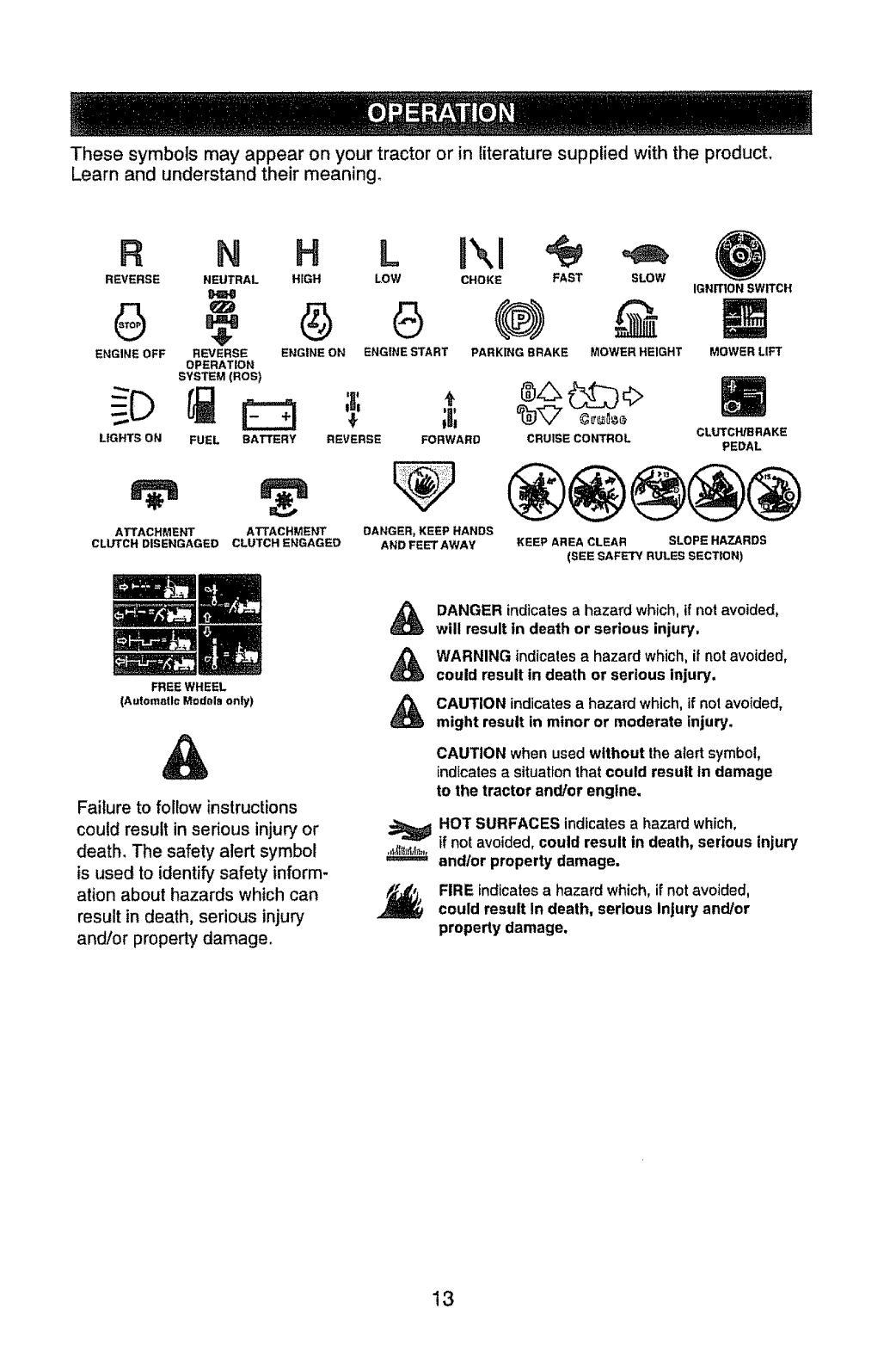
These symbols may appear on your tractor or in literature supplied with the product.
Learn and understand their meaning,
R N H L
REVERSE NEUTRAL HiGH LOW
ENGINE OFF REVERSE ENGINE ON ENGINE START
OPERATION
SYSTEM (ROS)
LIGHTS ON FUEL BATTERY
ATTACHMENT
CLUTCH DISENGAGED
ATTACHMENT
CLUTCH ENGAGED
FREE WHEEL
(Automatic Modals only)
Failure to follow instructions
could result in serious injury or
death, The safety alert symbol
is used to identify safety inform-
ation about hazards which can
result in death, serious injury
and/or property damage.
CHOKE FAST SLOW
PARKING BRAKE MOWER HEIGHT
IGNITION SWITCH
MOWER LIFT
REVERSE
;a;
FORWARD
DANGER, KEEP HANDS
AND FEET AWAY
CRUISE CONTROL CLUTCH/BRAKE
PEDAL
KEEP AREA CLEAR SLOPE HAZARDS
(SEE SAFETY RULES SECTION)
&
&
&
DANGER indicates a hazard which, if not avoided,
will result in death or serious injury,
WARNING indicates a hazard which, if not avoided,
could result in death or serious injury,
CAUTION indicates a hazard which, if not avoided,
might result in minor or moderate injury,
CAUTION when usedwithout thealert symbol,
indicates a situationthat could result in damage
to the tractor and/or engine.
HOT SURFACES indicatesa hazard which,
if not avoided,could result in death, serious injury
and/or property damage.
FIRE indicatesa hazard which,if not avoided,
could result In death, serious Injury and/or
property damage.
13
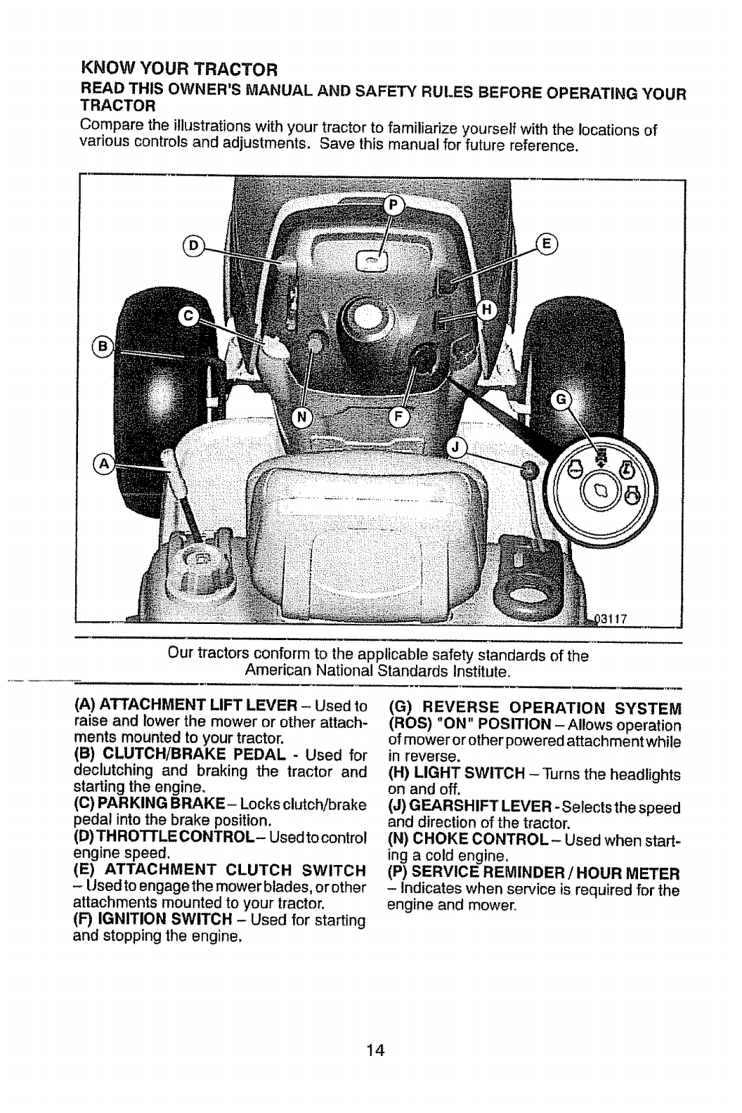
KNOW YOUR TRACTOR
READ THIS OWNER'S MANUAL AND SAFETY RULES BEFORE OPERATING YOUR
TRACTOR
Compare the illustrations with your tractor to familiarize yourself with the locations of
various controls and adjustments. Save this manual for future reference.
_117
Our tractors conform to the applicable safety standards of the
American National Standards Institute
(A) ATTACHMENT LIFT LEVER - Used to
raise and lower the mower or other attach-
ments mounted to your tractor.
(B) CLUTCH/BRAKE PEDAL - Used for
declutching and braking the tractor and
starting the engine°
(C) PARKING BRAKE- Locksclutch/brake
pedal into the brake position.
(13)THROTTLE CONTROL- Used to control
engine speed.
(E) ATTACHMENT CLUTCH SWITCH
-Usedtoengage the mower blades, or other
attachments mounted to your tractor.
(F) IGNITION SWITCH - Used for starting
and stopping the engine.
(G) REVERSE OPERATION SYSTEM
(ROS) "ON" POSITION - Allows operation
of mower or other powered attachment while
in reverse.
(H) LIGHT SWITCH - Turns the headlights
on and off.
(J) GEARSHIFT LEVER -Selects the speed
and direction of the tractor.
(N) CHOKE CONTROL- Used when start-
ing a cold engine.
(P) SERVICE REMINDER /HOUR METER
-Indicates when service is required for the
engine and mower.
14
The operation of any tractor can result in foreign objects thrown into the
eyes, which can result in severe eye damage° Always wear safety glasses
or eye shields while operating your tractor or performing any adjustments
or repairs. We recommend standard safety glasses or a wide vision safety
mask worn over spectacles.
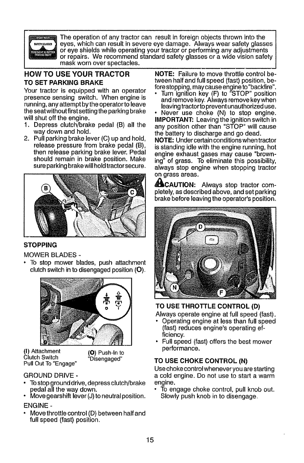
HOW TO USE YOUR TRACTOR
TO SET PARKING BRAKE
"Yourtractor is equipped with an operator
presence sensing switch. When engine is
running, any attempt bythe operatortoleave
theseat withoutfirst setting the parking brake
will shut off the engine.
1. Depress clutch/brake pedal (B) all the
way down and hold.
2. Pull parking brake lever (C) up and hold,
release pressure from brake pedal (B),
then release parking brake lever. Pedal
should remain in brake position. Make
sure parkingbrakewillholdtractorsecure.
NOTE: Failure to move throttle control be-
tween half and full speed (fast) position, be-
fore stopping, may cause engine to "backfire".
-Turn ignition key (F) to "STOP" position
and remove key. Always remove keywhen
leaving tractorto prevent unauthorized use.
•Never use choke (N) to stop engine.
IMPORTANT; Leaving the ignition switch in
any position other than "STOP" will cause
the batter,/to discharge and go dead.
NOTE; Under certain conditions when tractor
is standing idle with the engine running, hot
engine exhaust gases may cause "brown-
ing" of grass. To eliminate this possibility,
always stop engine when stopping tractor
on grass areas,
_CAUTION: Always stop tractor com-
pletely, as described above, and set parking
brake before leaving the operator's position.
STOPPING
MOWER BLADES
o To stop mower blades, push attachment
clutch switch in to disengaged position (O)_
(I) Attachment
Clutch Switch
Pull Out To "Engage"
(O) Push-ln to
"Disengaged"
GROUND DRIVE -
• To stop ground drive, depress clutch/brake
pedal all the way down.
• Move gearshift lever (J) to neutral position.
ENGINE -
°Move throttle control (D) between half and
fu!l speed (fast) position.
TO USE THROTTLE CONTROL (D)
Always operate engine at full speed (fast).
, Operating engine at less than full speed
(fast) reduces engine's operating ef o
ficiency.
•Full speed (fast) offers the best mower
performance.
TO USE CHOKE CONTROL (N)
Use choke control whenever you are starting
a cold engine. Do not use to start a warm
engine.
oTo engage choke control, pull knob out.
Slowly push knob in to disengage_
15
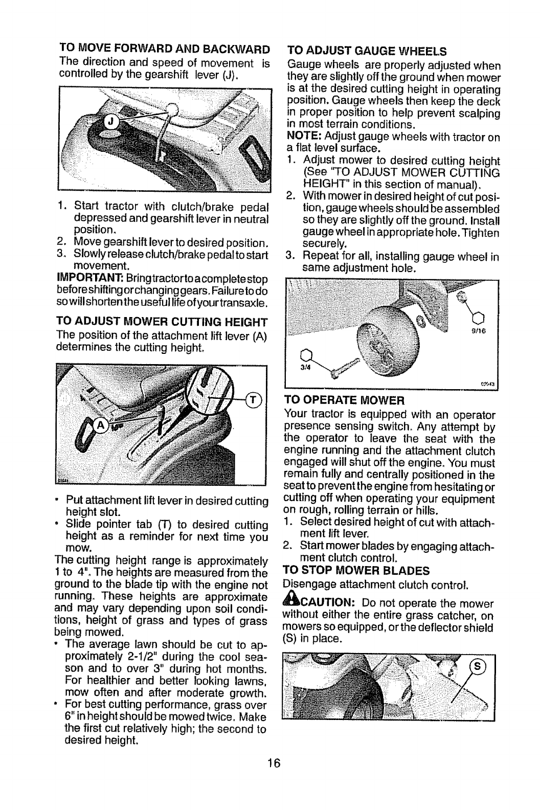
TO MOVE FORWARD AND BACKWARD
The direction and speed of movement is
controlled by the gearshift lever (J),
1. Start tractor with clutch/brake pedal
depressed and gearshift lever in neutral
position.
2. Move gearshift leverto desired position.
3. Slowly release clutch/brake pedalto start
movement.
IMPORTANT; Bringtractorto acomplete stop
before shifting or changing gears. Failure to do
so will shorten the useful life of your transaxle,
TO ADJUST MOWER CUTTING HEIGHT
The position of the attachment lift lever (A)
determines the cutting height.
•Put attachment lift lever in desired cutting
height slot.
•Slide pointer tab (3") to desired cutting
height as a reminder for next time you
mow.
The cutting height range is approximately
1 to 4". The heights are measured from the
ground to the blade tip with the engine not
running. These heights are approximate
and may vary depending upon soil condi-
tions, height of grass and types of grass
being mowed.
oThe average lawn should be cut to ap-
proximately 2-1/2" during the cool sea-
son and to over 3" during hot months.
For healthier and better looking lawns,
mow often and after moderate growth.
•For best cutting performance, grass over
6" in height should be mowed twice. Make
the first cut relatively high; the second to
desired height.
16
TO ADJUST GAUGE WHEELS
Gauge wheels are properly adjusted when
they are slightly offthe ground when mower
is at the desired cutting height in operating
position. Gauge wheels then keep the deck
in proper position to help prevent scalping
in most terrain conditions.
NOTE; Adjust gauge wheels with tractor on
a flat level surface.
1. Adjust mower to desired cutting height
(See '_FO ADJUST MOWER CUTTING
HEIGHT" in this section of manual).
2, With mower in desired height of cut posi-
tion, gauge wheels should be assembled
so they are slightly off the ground. Install
gauge wheel in appropriate hole. Tighten
securely.
3. Repeat for all, installing gauge wheel in
same adjustment hole.
J i ,, ,i,,,, :
TO OPERATE MOWER
Your tractor is equipped with an operator
presence sensing switch_ Any attempt by
the operator to leave the seat with the
engine running and the attachment clutch
engaged will shut off the engine. You must
remain fully and centrally positioned in the
seat to prevent the engine from hesitating or
cutting off when operating your equipment
on rough, rolling terrain or hills.
1. Select desired height of cut with attach-
ment lift lever.
2. Start mower blades by engaging attach-
ment clutch control.
TO STOP MOWER BLADES
engage attachment clutch controt.
CAUTION: Do not operate the mower
without either the entire grass catcher, on
mowers so equipped, or the deflector shield
(S) in place.
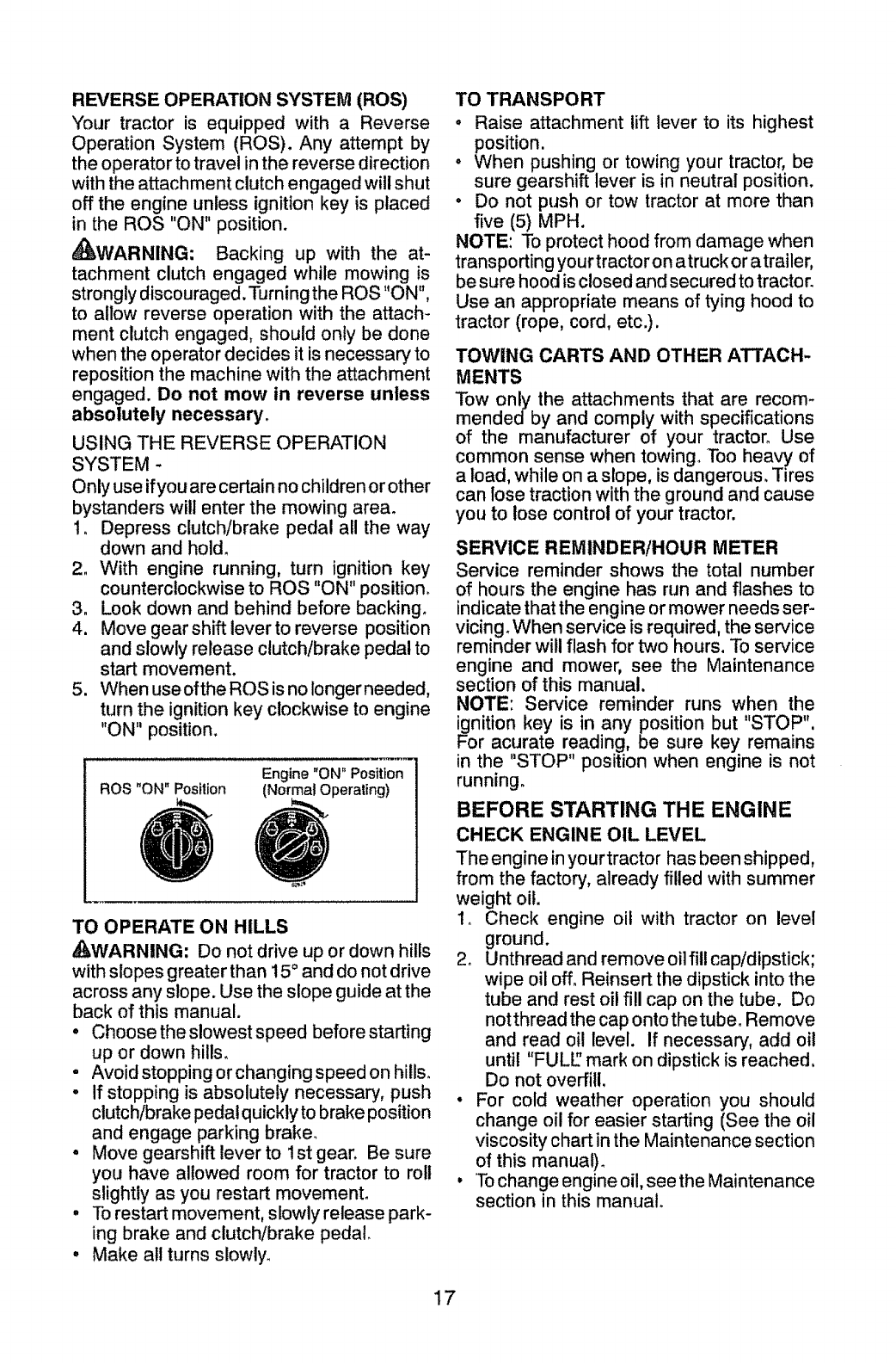
REVERSE OPERATION SYSTEM (ROS)
"Your tractor is equipped with a Reverse
Operation System (ROS). Any attempt by
the operator to travel in the reverse direction
with the attachment clutch engaged will shut
off the engine unless ignition key is placed
in the ROS "ON" position.
_WARNING: Backing up with the at-
tachment clutch engaged while mowing is
strongly discouraged. Turning the ROS "ON",
to allow reverse operation with the attach-
ment clutch engaged, should only be done
when the operator decides it is necessary to
reposition the machine with the attachment
engaged. Do not mow in reverse unless
absolutely necessary.
USING THE REVERSE OPERATION
SYSTEM -
Only use if you are certain no children or other
bystanders will enter the mowing area_
I. Depress clutch/brake pedal all the way
down and hold.
2. With engine running, turn ignition key
counterclockwise to ROS "ON" position.
3. Look down and behind before backing.
4. Move gear shift lever to reverse position
and slowly release clutch/brake pedal to
start movement.
5. When use ofthe ROS is no longer needed,
turn the ignition key clockwise to engine
"ON" position,
ROS "ON" Position Engine "ON" Position
TO OPERATE ON HILLS
,_WARNING: Do not drive up or down hills
with slopes greater than 15 ° and do not drive
across any slope. Use the slope guide at the
back of this manual.
• Choose the slowest speed before starting
up or down hills.
, Avoid stopping orchanging speed on hills°
° If stopping is absolutely necessary, push
clutch/brake pedal quickly to brake position
and engage parking braker
• Move gearshift lever to 1st gear. Be sure
you have allowed room for tractor to roll
slightly as you restart movement.
• To restart movement, slowly release park-
ing brake and clutch/brake pedal.
° Make all turns slowly.
TO TRANSPORT
, Raise attachment lift lever to its highest
position.
o When pushing or towing your tractor, be
sure gearshift lever is in neutral position.
° Do not push or tow tractor at more than
five (5) MPH.
NOTE: To protect hood from damage when
transporting your tractor on a truck or a trailer,
be sure hood is closed and secured to tractor.
Use an appropriate means of tying hood to
tractor (rope, cord, etc.).
TOWING CARTS AND OTHER ATTACH-
MENTS
Tow only the attachments that are recom-
mendedby and comply with specifications
of the manufacturer of your tractor. Use
common sense when towing. Too heavy of
a load, while on a slope, is dangerous. Tires
can lose traction with the ground and cause
you to lose control of your tractor.
SERVICE REMINDER!HOUR METER
Service reminder shows the total number
of hours the engine has run and flashes to
indicatethat the engine or mower needs ser-
vicing.When service is required, the service
reminder will flash for two hours. To service
engine and mower, see the Maintenance
section of this manual.
NOTE: Service reminder runs when the
ignition key is in any position but "STOP",
For acurate reading, be sure key remains
in the "STOP" position when engine is not
running.
BEFORE STARTING THE ENGINE
CHECK ENGINE OIL LEVEL
The engine in yourtractor has been shipped,
from the factory, already filled with summer
weight oit.
1o Check engine oit with tractor on level
ground.
2o Unthread and remove oil fill cap/dipstick;
wipe oil off. Reinsert the dipstick into the
tube and rest oil fill cap on the tube. Do
not thread the cap onto the tube. Remove
and read oil level. If necessary, add oil
until "FULl" mark on dipstick is reached,
Do not ove_itl.
• For cold weather operation you should
change oil for easier starting (See the oil
viscosity chart in the Maintenance section
of this manua!)_
. To change engine oil, see the Maintenance
section in this manual.
17
ADD GASOLINE
"Fill fuel tank to bottom of filler neck. Do
not overfill. Use fresh, clean, regular
unleaded gasoline with a minimum of
87 octane. (Use of leaded gasoline will
increase carbon and lead oxide deposits
and reduce valve life). Do not mix oilwith
gasoline. Purchase fuel in quantities that
can be used within 30 days to assure fuel
freshness°
_CAUTION: Wipe off any spilled oilor fuel.
Do not store, spill or use gasoline near an
open flame.
IMPORTANT: When operating in tempera-
turesbelow32 °F(0°C), use fresh, clean winter
grade gasoline to help ensure good cold
weather starting.
CAUTION: Alcohol blended fuels (called
gasohol or using ethanol or methanol) can
attract moisture which leads to separation
and formation of acids during storage. Acidic
gas can damage the fuel system of an engine
while in storage. To avoid engine problems,
the fuel system should be emptied before
storage of 30 days or longer. Drain the gas
tank, start the engine and let it run until the
fue! lines and carburetor are empty. Use fresh
fuel next season. See Storage instructions
for additional information. Never use engine
or carburetor cteaner products in the fue! tank
or permanent damage may occur.
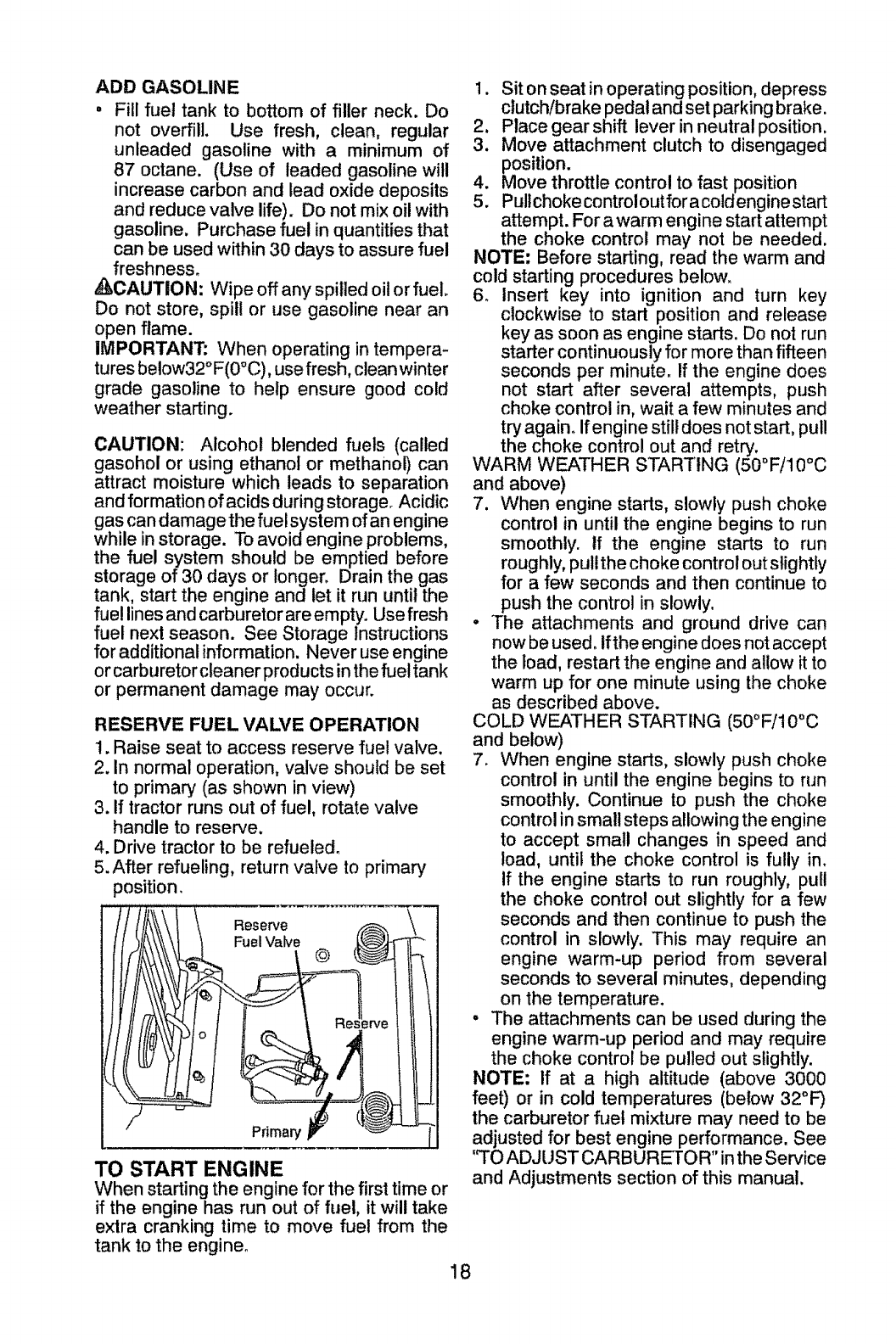
RESERVE FUEL VALVE OPERATION
!. Raise seat to access reserve fuel valve.
2. In normal operation, valve should be set
to primary (as shown in view)
3. If tractor runs out of fuel, rotate valve
handle to reserve.
4. Drive tractor to be refueled.
5. After refueling, return valve to primary
position.
Reserve
Fuel Valve @
Primary
TO START ENGINE
When starting the engine for the first time or
if the engine has run out of fuel, it will take
extra cranking time to move fuel from the
tank to the engine_
1. Sit on seat in operating position, depress
clutch/brake pedal and set parking brake.
2, Place gear shift lever in neutral position.
3. Move attachment clutch to disengaged
position.
4. Move throttle control to fast position
5. Pullchoke controiout for a coldengine start
attempt. For a warm engine start attempt
the choke control may not be needed.
NOTE: Before starting, read the warm and
cold starting procedures below.
6_ Insert key into ignition and turn key
clockwise to start position and release
key as soon as engine starts. Do not run
starter continuously for more than fifteen
seconds per minute, if the engine does
not start after several attempts, push
choke control in, wait a few minutes and
try again. If engine still does not start, pull
the choke control out and retry, o o
WARM WEATHER STARTING (50 F!10 C
and above)
7, When engine starts, slowly push choke
control in until the engine begins to run
smoothly. If the engine starts to run
roughly, pull the choke control out slightly
for a few seconds and then continue to
push the control in slowly.
• The attachments and ground drive can
now be used. lfthe engine does not accept
the load, restart the engine and allow it to
warm up for one minute using the choke
as described above.
COLD WEATHER STARTING (50°F/10°C
and below)
7. When engine starts, slowly push choke
control in until the engine begins to run
smoothly. Continue to push the choke
control in small steps allowing the engine
to accept small changes in speed and
load, until the choke control is fully in.
If the engine starts to run roughly, pull
the choke control out slightly for a few
seconds and then continue to push the
control in slowly. This may require an
engine warm-up period from several
seconds to several minutes, depending
on the temperature.
• The attachments can be used during the
engine warm-up period and may require
the choke control be pulled out slightly.
NOTE; If at a high altitude (above 3000
feet) or in cold temperatures (below 32°1=)
the carburetor fuel mixture may need to be
adjusted for best engine performance. See
'q'O ADJUST CARBURETOR" inthe Service
and Adjustments section of this manual.
18
MOWING TIPS
.Tire chains cannot be used when the
mower housing is attached to tractor.
. Mowershould be properly leve led for best
mowing performance, See "TO LEVEL
MOWER HOUSING" in the Service and
Adjustments section of this manual°
.The left hand side of mower should be
used for trimming.
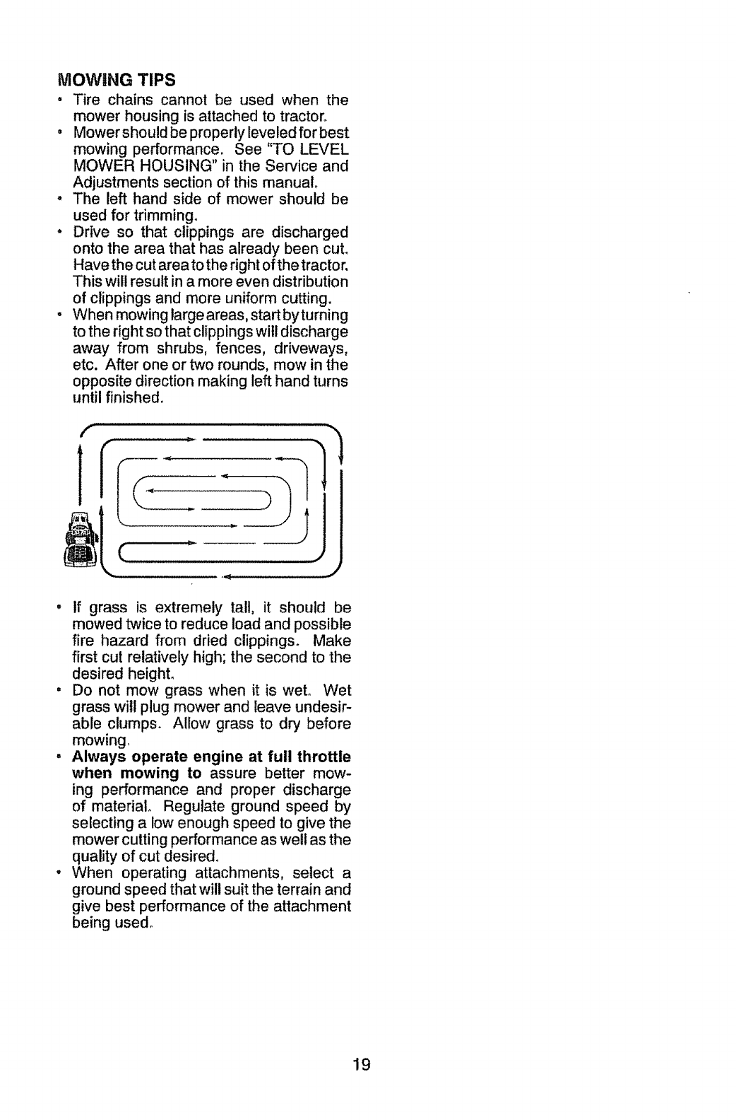
•Drive so that clippings are discharged
onto the area that has already been cut.
Have the cut area to the right of the tractor.
This wilt result in a more even distribution
of clippings and more uniform cutting.
- When mowing large areas, start byturning
to the fight so that clippings will discharge
away from shrubs, fences, driveways,
etc. After one or two rounds, mow in the
opposite direction making left hand turns
until finished.
f
•If grass is extremely tall, it should be
mowed twice to reduce load and possible
fire hazard from dried clippings. Make
first cut relatively high; the second to the
desired height.
.Do not mow grass when it is wet. Wet
grass will plug mower and leave undesir-
able clumps. Allow grass to dry before
mowing,
°Always operate engine at full throttle
when mowing to assure better mow-
ing performance and proper discharge
of material. Regulate ground speed by
selecting a low enough speed to give the
mower cutting performance as well as the
quality of cut desired°
°When operating attachments, select a
ground speed that will suit the terrain and
give best performance of the attachment
being used°
19
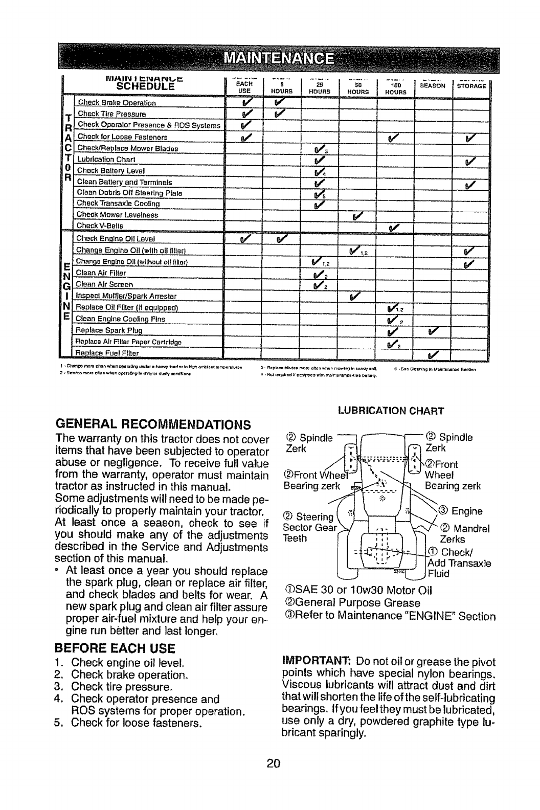
IVl/_IN ! I::N/_NL,_"
SCHEDULE
Check Brake Operation V #" _" .... f
ChockTt_'ePressure _#' _ .....
_ Check Operator Presence &ROS Systems i °_/' i ...........
AC"ec.Wo,L00_eF.si_no,. l _ [ ..............
ChecWReplace Mower Blades ...... _'_
Lubrication Chart
0 Check Battery Level
.RjC,eonB.,e_..._.ndTerra_..l. ........................................... ) .....................
K
Clean Debris Off Steering Plate
Check Transaxle Cooling ...... ............:=
Check Mower Leve{ness
Check V-Belts
Check Engine O Lave a/
Change En,qine Oi (,wll h pll !ifter) .........
E Change Engine ell (wtiheul Oil filial)
,,,c,o..AirF,tor
i"_G €iean Air S_reon
!,Inspect MulflodSpar k A_ester ......
NReplace Oil Filler (tf equipped)
EcleanEng=.ocoo!!ngFine
Rep!aFe Spark Plug
Replace Air Filler Paper Codrldge
ReDlace Fuel FliP,or
J
, ,1 ,,
.......... V'
.... j ,,
v"
_2 ....
GENERAL RECOMMENDATIONS
The warranty on this tractordoes not cover
items that have been subjected to operator
abuse or negligence, To receive full value
from the warranty, operator must maintain
tractor as instructed in this manual.
Some adjustments will need to be made pe-
riodically to properly maintain your tractor.
At least once a season, check to see if
you should make any of the adjustments
described in the Sen/ice and Adjustments
section of this manual
, At least once a year you should replace
the spark plug, clean or replace air filter,
and check blades and belts for wear. A
new spark plug and clean air filter assure
proper air-fuel mixture and help your en-
gine run better and last longer.
BEFORE EACH USE
1. Check engine oil level.
2. Check brake operatiom
3. Check tire pressure,
4. Check operator presence and
ROS systems for proper operation.
5. Check for loose fasteners,
LUBRICATION CHART
L._Spindle
Zerk
L_3Front
Bearing zerk
Spindle
Zerk
,@Front
Wheel
Bearing zerk
.__ Steering
Sector Gea_
Teeth
Engine
Mandrel
Zerks
Check/
Add Transaxte
Fluid
_SAE 30 or !0w30 Motor Oil
_3General Purpose Grease
(_Refer to Maintenance "ENGINE" Section
IMPORTANT: Do not oil or grease the pivot
points which have special nylon bearings°
Viscous lubricants will attract dust and dirt
that will shorten the life of the self-lubricating
bearings, ffyou feelthey must be lubricated,
use only a dry, powdered graphite type lu-
bricant sparingly°
2O
TRACTOR
Always observe safety rules when per-
forming any maintenance.
BRAKE OPERATION
If tractor requires more than five (5) feet to
stop at highest speed in highest gear on a
level, dry concrete or paved surface, then
brake must be serviced. (See "TO CHECK
BRAKE" in the Service and Adjustments
section of this manual).
TIRES
•Maintain proper air pressure in all tires
(See PSi on tires).
° Keep tires free of gasoline, oil, or insect
control chemicals which can harm rub-
ber.
o Avoid stumps, stones, deep ruts, sharp
objects and other hazards that may
cause tire damage.
NOTE; To seal tire punctures and prevent
flat tires due to slow leaks, tire sealant
may be purchased from your local parts
dealer. Tire sealant also prevents tire dry
rot and corrosion.
OPERATOR PRESENCE SYSTEM AND
REVERSE OPERATION SYSTEM (ROS)
Be sure operator presence and reverse
operation systems are working properly, tf
your tractor does not function as de-
scribed, repair the problem immediately.
• The engine should not start unless the
brake pedal is fully depressed, and the
attachment clutch control is in the disen-
gaged position.
CHECK OPERATOR PRESENCE
SYSTEM
°When the engine is running, any at-
tempt by the operator to leave the seat
without first setting the parking brake
should shut off the engine.
•When the engine is running and the
attachment clutch is engaged, any at-
tempt by the operator to leave the seat
should shut off the engine°
°The attachment clutch should never op-
erate unless the operator is in the seat.
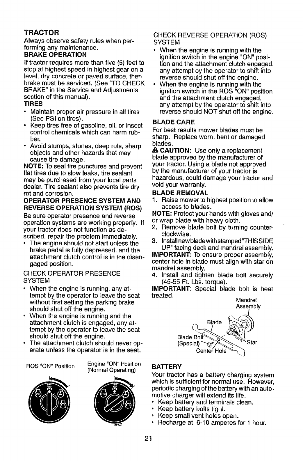
ROS "ON" Position Engine "ON" Position
(Normal Operating)
CHECK REVERSE OPERATION (ROS)
SYSTEM
oWhen the engine is running with the
ignition switch in the engine "ON" posi-
tion and the attachment clutch engaged,
any attempt by the operator to shift into
reverse should shut off the engine.
• When the engine is running with the
ignition switch in the ROS "ON" position
and the attachment clutch engaged,
any attempt by the operator to shift into
reverse should NOT shut off the engine.
BLADE CARE
For best results mower blades must be
sharp. Replace worn, bent or damaged
blades.
_k CAUTION: Use only a replacement
blade approved by the manufacturer of
your tractor. Using a blade not approved
by the manufacturer of your tractor is
hazardous, could damage your tractor and
void your warranty.
BLADE REMOVAL
1. Raise mower to highest position to allow
access to blades.
NOTE: Protect your hands with gloves and/
or wrap blade with heavy cloth.
2. Remove blade bolt by turning counter-
clockwise.
3. Installnewbladewithstamped"THIS SIDE
UP" facing deck and mandrel assembly.
IMPORTANT: To ensure proper assembly,
center hole in blade must align with star on
mandrel assembly.
4. Install and tighten blade bolt securely
(45-55 Ft. Lbs. torque).
IMPORTANT: Special blade bolt is heat
treated. Mandrel
Assembly
(_.. Btade d""'*/_'_
Blade Bolt':_-'--__%_. e,.
(special) Z Star
Cente('Hole'_-'_-'--_.)
BATTERY
Your tractor has a battery charging system
which is sufficient for normal use. However,
periodic charging ofthe battery with an auto-
motive charger will extend its life.
• Keep battery and terminals clean.
• Keep battery, bolts tighL
• Keep small vent holes open.
• Recharge at 6-10 amperes for 1 hour.
21
NOTE: The original equipment battery on
your tractor is maintenance free. Do not
attempt to open or remove caps or covers.
Adding or checking level of electrolyte is
not necessary.
TO CLEAN BATTERY AND TERMINALS
Corrosion and dirt on the battery and termi-
nals can cause the battery to "!eak" power.
1. Remove terminal guard°
2. Disconnect BLACK battery cable first
then RED battery cable and remove
battery from tractor.
3. Rinse the battery with plain water and dry.
4. Clean terminals and battery cable ends
with wire brush until bright.
5. Coat terminals with grease or petroleum
jelly.
6o Reinstall battery (See "REPLACING
BATTERY" in the SERVICE AND AD-
JUSTMENTS section of this manual).
TRANSAXLE COOLING
Keep transaxle free from build-up of dirt and
chaff which can restrict cooling.
V-BELTS
Check V-belts for deterioration and wear after
I00 hours of operation and replace if neces-
sary. The belts are not adjustable. Replace
belts if they begin to slip from wear.
ENGINE
LUBRICATION
Only use highquality detergent oi! rated with
API service classificationSG-SLo Selectthe
oil's SAE viscosity grade according to your
expected operating temperature,
SAE VISCOS I'£'_"GRADES
=am_i_
C"30 "_*10 0 10 20 _1) 40
3*EMPERATURE RANGE A_ICIP_T,ED,,BEFORE NEXT OIL C_HGE
Change the oil after every 50 hours of opera-
tion or at least once a year if the tractor is
not used for 50 hours in one year.
Check the crankcase oil level before starting
the engine and after each eight (8) hours of
operation.
TO CHANGE ENGINE OIL
Determine temperature range expected
before oil change. All oil must meet API
service classification SG-SC
, Be sure tractor is on level surface.
• Oil will drain more freely when warm.
• Catch oil in a suitable container.
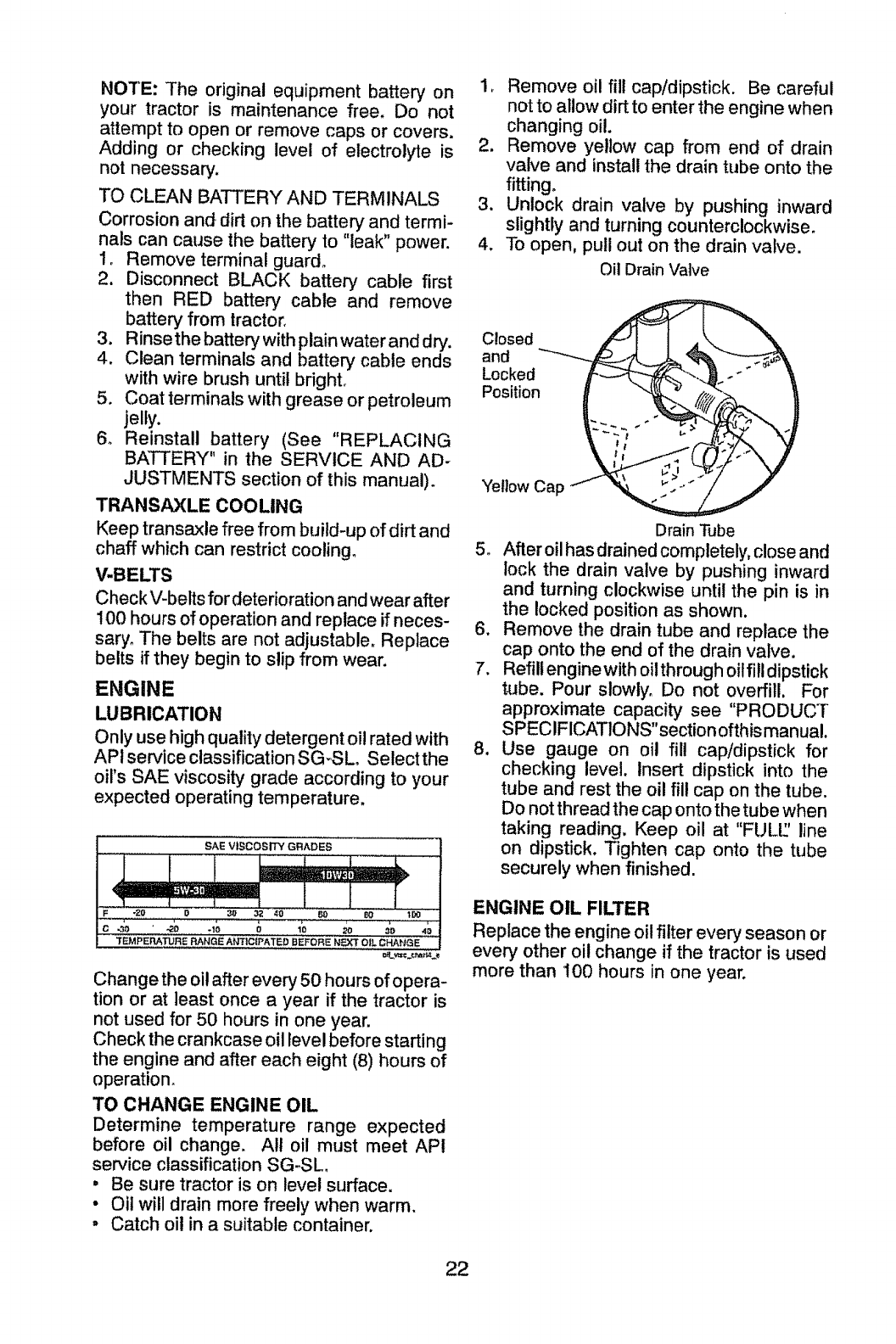
1. Remove oil fill cap/dipstick. Be careful
not to allow dirt to enter the engine when
changing oil.
2. Remove yellow cap from end of drain
valve and install the drain tube onto the
fitting.
3. Unlock drain valve by pushing inward
slightly and turning counterclockwise.
4. To open. pull out on the drain valve.
Oil Drain Valve
Drain Tube
5. After oil has drained completely, close and
lock the drain valve by pushing inward
and turning clockwise until the pin is in
the locked position as shown.
6. Remove the drain tube and replace the
cap onto the end of the drain valve.
7. Refill enginewith oilthrough oiffill dipstick
tube. Pour slowly_ Do not overfill. For
approximate capacity see "PRODUCT
SPECIFICATIONS"section of this manual.
8. Use gauge on oil fill cap/dipstick for
checking level. Insert dipstick into the
tube and rest the oil fill cap on the tube.
Do not thread the cap onto the tube when
taking reading. Keep oil at "FULL:' line
on dipstick. Tighten cap onto the tube
securely when finished.
ENGINE OIL FILTER
Replace the engine oil filter every season or
every other oil change if the tractor is used
more than I00 hours in one year.
22
AIR FILTER
Your engine will not run properly using a
dirty air filter, Service paper cartridge every
two months or every 25 hours of operation,
whichever occurs first.
Service paper cartridge more often under
dusty conditions.
Replace the paper cartridge annually, or
after every 100 hours of operation.
TO SERVICE CARTRIDGE
• Replace a dirty, bent, or damaged car-
tridge. Handle new cartridge carefully; do
not use if the rubber seal is damaged.
NOTE: Do not wash the paper cartridge
or use pressurized air, as this will damage
the cartridge_
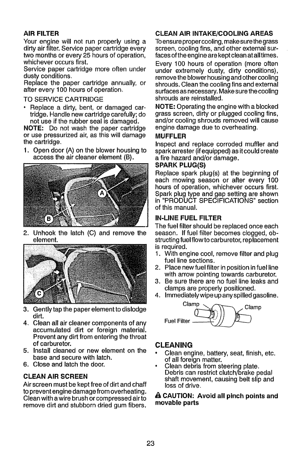
1. Open door (A) on the blower housing to
access the air cleaner element (B).
2. Unhook the latch (C) and remove the
element,
3. Gently tap the paper element to dislodge
dirt.
4. Clean all air cleaner components of any
accumulated dirt or foreign material.
Prevent any dirt from entering the throat
of carburetor.
5. Install cleaned or new element on the
base and secure with latch.
6. Close and latch the door.
CLEAN AIR SCREEN
Air screen must be kept free of dirt and chaff
to prevent engine damage from overheating.
Clean with awire brush or compressed airto
remove dirt and stubborn dried gum fibers.
CLEAN AIR INTAKE/COOLING AREAS
Toensureproper cooling,makesure thegrass
screen, coolingfins, and other external sur-
faces ofthe engine are kept clean atalltimes.
Every 100 hours of operation (more often
under extremely dusty, dirty conditions),
removethe blowerhousing and othercooling
shrouds. Clean the cooling fins and external
surfaces as necessary.Make sure the cooling
shrouds are reinstalled.
NOTE: Operating the engine with a blocked
grass screen, dirty or plugged cooling fins,
and/or cooling shrouds removed will cause
engine damage due to overheating.
MUFFLER
Inspect and replace corroded muffler and
sparkarrester (if equipped) as itcouldcreate
afire hazard and/or damage.
SPARK PLUG(S)
Replace spark plug(s) at the beginning of
each mowing season or after every 100
hours of operation, whichever occurs first.
Spark plug type and gap setting are shown
in "PRODUCT SPECIFICATIONS" section
of this manual.
IN-LINE FUEL FILTER
The fuel filtershould be replaced once each
season. If fuel filter becomes clogged, ob-
structing fuel flow to carburetor, replacement
is required.
1. With engine cool, remove filter and plug
fuel line sections.
2. Place newfuel filter inposition in fuel line
with arrow pointing towards carburetor.
3. Be sure there are no fuel line leaks and
clamps are properly positioned.
4. Immediatelywipe up any spilled gasoline°
Clam_mp
Fuel Filter _k__ F_)
CLEANING
•Clean engine, battery, seat, finish, etc.
of all foreign matter.
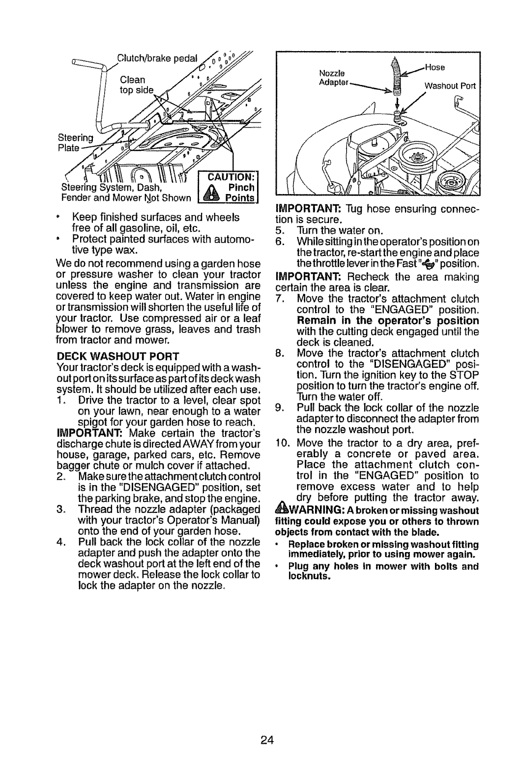
, Clean debris from steering plate.
Debris can restrict clutch/brake pedal
shaft movement, causing belt slip and
loss of drive.
CAUTION: Avoid all pinch points and
movable parts
23
Clutch/brake pedal
tCAUTION:
Steering System, Dash, Pinch
Fender and Mower l_ot Shown _ Points
,Keep finished surfaces and wheels
free of all gasoline, oil, etc.
° Protect painted surfaces with automo-
tive type wax.
We do not recommend using a garden hose
or pressure washer to clean your tractor
unless the engine and transmission are
covered to keep water out. Water in engine
or transmission will shorten the useful life of
your tractor. Use compressed air or a leaf
blower to remove grass, leaves and trash
from tractor and mower.
DECK WASHOUT PORT
"Your tractor's deck is equipped with a wash-
out port on its surface as part of its deck wash
system. It should be utilized after each use.
1o Drive the tractor to a level, clear spot
on your lawn, near enough to a water
spigot for your garden hose to reach.
IMPORTANT: Make certain the tractors
discharge chute is directed AWAY from your
house, garage, parked cars, etc. Remove
bagger chute or mulch cover if attached°
2. Make sure the attachment clutch control
is in the "DISENGAGED" position, set
the parking brake, and stop the engine.
3o Thread the nozzle adapter (packaged
with your tractor's Operator's Manual)
onto the end of your garden hose.
4. Pull back the lock collar of the nozzle
adapter and push the adapter onto the
deck washout port at the left end of the
mower deck. Release the lock collar to
lock the adapter on the nozzle.
Nozzlo
Washout Port
IMPORTANT: Tug hose ensuring connec-
tion is secure.
5. "Pdrn the water on.
6. While sitting in the operator's position on
the tractor, re-start the engine and place
the throttle lever in the Fast",_" position.
IMPORTANT: Recheck the area making
certain the area is clear.
7. Move the tractor's attachment clutch
control to the "ENGAGED" position.
Remain in the operator's position
with the cutting deck engaged until the
deck is cleaned.
B. Move the tractor's attachment clutch
control to the "DISENGAGED" posi-
tion. Turn the ignition key to the STOP
position to turn the tractor's engine off.
Turn the water off.
9. Pull back the lock collar of the nozzle
adapter to disconnect the adapter from
the nozzle washout port.
10. Move the tractor to a dry area, pref-
erably a concrete or paved area.
Place the attachment clutch con-
trol in the "ENGAGED" position to
remove excess water and to help
,_dry before putting the tractor away.
WARNING: A broken or missing washout
fitting could expose you or others to thrown
objects from contact with the blade.
•Replace broken or missing washoutflttlng
immediately, prior to using mower again.
•Plug any holes in mower with bolts and
Iocknuts.
24
WARNING: TO AVOID SERIOUS INJURY, BEFORE PERFORMING ANY
SERVICE OR ADJUSTMENTS:
1. Depress clutch/brake pedal fully and set parking brake,
2. Place gearshift lever in neutral position.
3. Place attachment clutch in "DISENGAGED" position,
4. Turn ignition key to "STOP" and remove key.
5. Make sure the blades and all moving parts have completely stopped.
6. Disconnect spark plug wire from spark plug and place wire where it cannot
come in contact with plug,
TO REMOVE MOWER
1, Place attachment clutch in "DISEN_
GAGED" position_
2. Lower attachment lift lever to its lowest
position.
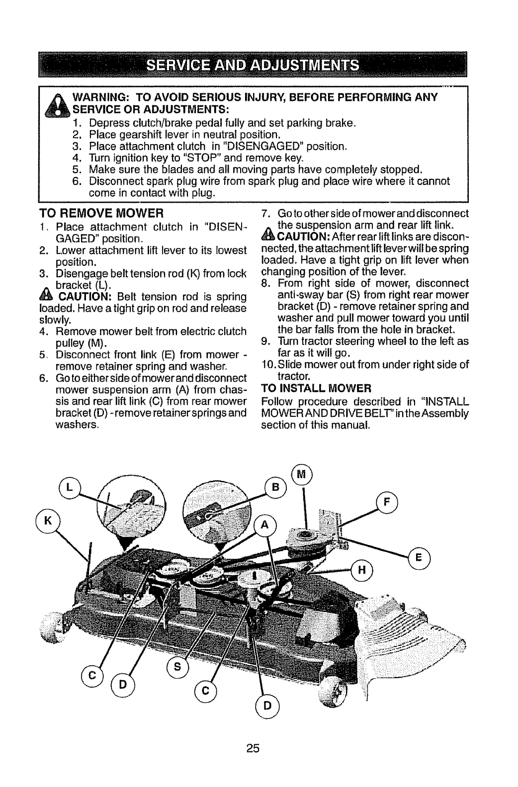
3, Disengage belttension rod (K) from lock
bracket (L)o
_, CAUTION: Belt tension rod is spring
loaded, Have a tight grip on rod and release
slowly.
4. Remove mower belt from electric clutch
pulley (M).
5, Disconnect front link (E) from mower -
remove retainer spring and washer,
6, Go to either side of mower and disconnect
mower suspension arm (A) from chas-
sis and rear lift link (C) from rear mower
bracket (D) _remove retainer springs and
washers,
7, Go to other side of mower and disconnect
the suspension arm and rear lift linko
CAUTION: After rear lift links are discon-
nected, the attachment lift lever will be spring
loaded. Have a tight grip on lift lever when
changing position of the lever.
8, From right side of mower, disconnect
anti-sway bar (S) from right rear mower
bracket (D) - remove retainer spring and
washer and pull mower toward you until
the bar fails from the hole in bracket,
9, Turn tractor steering wheel to the left as
far as it will go,
10. Slide mower out from under right side of
tractor.
TO INSTALL MOWER
Follow procedure described in "INSTALL
MOWER AND DRIVE BELT" in the Assembly
section of this manual,
®
25
TO LEVEL MOWER
Make sure tires are properly inflated to the
PSI shown on tires. Iftires are over or under
inflated, it may affect the appearance of your
lawn and lead you to think the mower is not
adjusted properly.
VISUAL SIDE-TO-SIDE ADJUSTMENT
1. With all tires properly inflated and if your
lawn appears unevenly cut, determine
which side of mower is cutting lower.
NOTE; As desired, you can raise the low
side of mower or lower the high side°
2. Go to side of mower you wish to adjust.
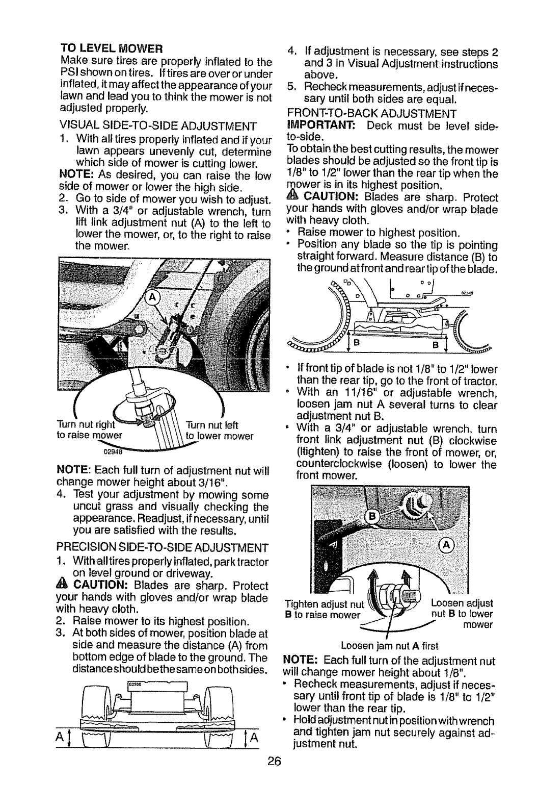
3. With a 3/4" or adjustable wrench, turn
lift link adjustment nut (A) to the left to
lower the mower, or, to the right to raise
the mower_
Turn nut rigi
to raise mower Turn nut left
to lower mower
NOTE: Each MI turn of adjustment nut will
change mower height about 3/t 6"°
4. Test your adjustment by mowing some
uncut grass and visually checking the
appearance, Readjust, if necessary, until
you are satisfied with the results.
PRECISION SIDE-TO-SIDE ADJUSTMENT
1. With alltires properly inflated, park tractor
on level ground or driveway.
CAUTION: Blades are sharp. Protect
your hands with gloves and!or wrap blade
with heavy cloth.
2. Raise mower to its highest position.
3. At both sides of mower, position blade at
side and measure the distance (A) from
bottom edge of blade to the ground. The
distance should bethe same on both sides.
4. if adjustment is necessary, see steps 2
and 3 in Visual Adjustment instructions
above.
5. Recheck measurements, adjust if neces-
sary until both sides are equal.
FRONT-TO-BACK ADJUSTMENT
IMPORTANT: Deck must be level side-
to-side.
To obtain the best cutting results, the mower
blades should be adjusted so the front tip is
1/8" to 1/2" lower than the rear tip when the
ower is in its highest position.
CAUTION: Blades are sharp. Protect
your hands with gloves and/or wrap blade
with heavy cloth.
•Raise mower to highest position.
•Position any blade so the tip is pointing
straight forward. Measure distance (B) to
the ground at front and rear tip of the blade.
•tf front tip of blade is not 1/8" to 1/2" lower
than the rear tip, go to the front of tractor.
,With an 1!/16" or adjustable wrench,
loosen jam nut A several turns to clear
adjustment nut B.
, With a 3/4" or adjustable wrench, turn
front link adjustment nut (B) clockwise
(Itighten) to raise the front of mower, or,
counterclockwise (loosen) to lower the
front mower.
Tighten adjust nut
Bto raise mower
26
Loosen adjust
nut B to lower
mower
Loosen jam nut A first
NOTE; Each full turn of the adjustment nut
will change mower height about 1/8".
• Recheck measurements, adjust if neces-
sary until front tip of blade is 1/8" to 1/2"
lower than the rear tip.
• Hold adjustment nut in position withwrench
and tighten jam nut securely against ad-
justment nut.
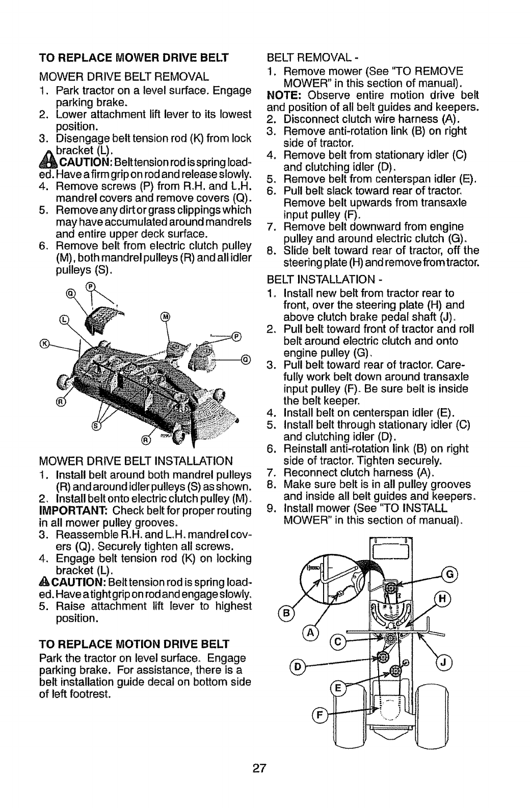
TO REPLACE MOWER DRIVE BELT
MOWER DRIVE BELT REMOVAL
i. Park tractor on a level surface. Engage
parking brake.
2. Lower attachment lift lever to its lowest
position.
3. Disengage belt tension rod (K) from lock
bracket (L).
AUTION: Beittension rod is spring load-
ed. Have a firm grip on rod and release slowly.
4. Remove screws (P) from R.H. and L.H.
mandrel covers and remove covers (Q).
5. Remove any dirt or grass clippings which
may have accumulated around mandrels
and entire upper deck surface.
6. Remove belt from electric clutch pulley
(M). both mandrel pulleys (R) and all idler
pulleys (S).
\
®
MOWER DRIVE BELT INSTALLATION
t. Install belt around both mandrel pulleys
(R) and around idler pulleys (S) as shown.
2_ Install belt onto electric clutch pulley (M) o
IMPORTANT: Check belt for proper routing
in all mower pulley grooves.
3. Reassemble R.H. and L_H. mandrel cov-
ers (Q). Securely tighten all screws.
4. Engage belt tension rod (K) on locking
bracket (L).
,_ CAUTION: Belt tension rod is spring load-
ed. Have atight grip on rod and engage slowly°
5. Raise attachment lift lever to highest
position.
TO REPLACE MOTION DRIVE BELT
Park the tractor on level surface. Engage
parking brake. For assistance, there is a
belt installation guide decal on bottom side
of left footrest.
BELT REMOVAL -
1. Remove mower (See 'q-O REMOVE
MOWER" in this section of manual).
NOTE: Observe entire motion drive belt
and position of all belt guides and keepers.
2. Disconnect clutch wire harness (A).
3. Remove anti-rotation link (B) on right
side of tractor.
4. Remove belt from stationary idler (C)
and clutching idler (D).
5. Remove belt from centerspan idler (E).
6. Pull belt slack toward rear of tractor.
Remove belt upwards from transaxle
input pulley (F).
7. Remove belt downward from engine
pulley and around electric clutch (G)o
8. Slide belt toward rear of tractor, off the
steering plate (H) and remove fromtractor.
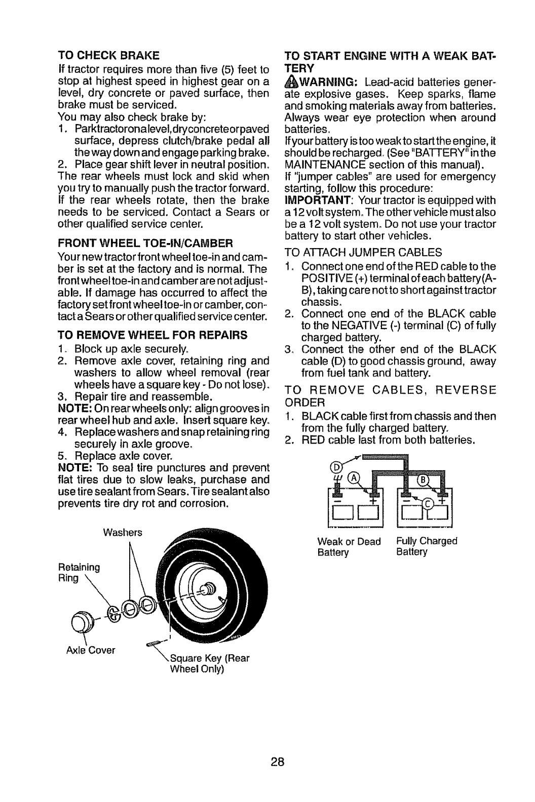
BELT INSTALLATION -
1o Install new belt from tractor rear to
front, over the steering plate (H) and
above clutch brake pedal shaft (J)_
2. Pull belt toward front of tractor and roll
belt around electric clutch and onto
engine pulley (G).
3. Pull belt toward rear of tractor. Care-
fully work belt down around transaxle
input pulley (F). Be sure belt is inside
the belt keeper.
4. Install belt on centerspan idler (E).
5. Install belt through stationary idler (C)
and clutching idler (D).
6. Reinstall anti-rotation link (B) on right
side of tractor. Tighten securely.
7. Reconnect clutch harness (A).
8. Make sure belt is in all pulley grooves
and inside all belt guides and keepers.
9. install mower (See 'q'O INSTALL
MOVVER" in this section of manual).
27
TO CHECK BRAKE
If tractor requires more than five (5) feet to
stop at highest speed in highest gear on a
level, dry concrete or paved surface, then
brake must be serviced.
You may also check brake by:
1. Parktractoronalevel,dryconcreteorpaved
surface, depress clutch/brake pedal all
the way down and engage parking brake.
2, Place gear shift lever in neutral position°
The rear wheels must lock and skid when
you try to manually push the tractor forward.
If the rear wheels rotate, then the brake
needs to be serviced. Contact a Sears or
other qualified service center.
FRONT WHEEL TOE-IN/CAMBER
Your new tractor front wheel toe-in and cam-
ber is set at the factory and is normal. The
front wheel toe-in and camber are not adjust_
able. if damage has occurred to affect the
factory set front wheel toe-inor camber, con-
tact aSears orother qualified service center.
TO REMOVE WHEEL FOR REPAIRS
1. Block up axle securely.
2. Remove axle cover, retaining ring and
washers to allow wheel removal (rear
wheels have a square key - Do not lose)o
3. Repair tire and reassemble.
NOTE: On rearwheels only: aligngrooves in
rear wheel hub and axle. Insert square key°
4. Replacewashers andsnap retaining ring
securely in axle groove°
5. Replace axle cover.
NOTE: To seal tire punctures and prevent
flat tires due to slow leaks, purchase and
use tiresealant from Sears. Tire sealant also
prevents tire dry rot and corrosion.
TO START ENGINE WITH A WEAK BAT-
TERY
_WARNING; Lead-acid batteries gener-
ate explosive gases. Keep sparks, flame
and smoking materials away from batteries.
Always wear eye protection when around
batteries
If your battery is too weak to start the engine, it
should be recharged. (See "BATTERY" in the
MAINTENANCE section of this manual).
tf "jumper cables" are used for emergency
starting, follow this procedure:
IMPORTANT: Your tractor is equipped with
a 12 volt system. The other vehicle must also
be a 12 volt system. Do not use your tractor
battery to start other vehicles.
TO ATTACH JUMPER CABLES
1. Connect one end of the RED cable to the
POSITIVE (+) terminal of each battery(A-
B), taking care not to short against tractor
chassis.
2. Connect one end of the BLACK cable
to the NEGATIVE (-) terminal (C) of fully
charged battery.
3o Connect the other end of the BLACK
cable (D) to good chassis ground, away
from fuel tank and battery.
TO REMOVE CABLES, REVERSE
ORDER
I. BLACK cable first from chassis and then
from the fully charged battery.
2. RED cable last from both batteries.
Retaining
Ring
Washers Weak or Dead Fully Charged
Batter,] Battery
Axle Cover
!
_.Square Key (Rear
Wheel Only)
28
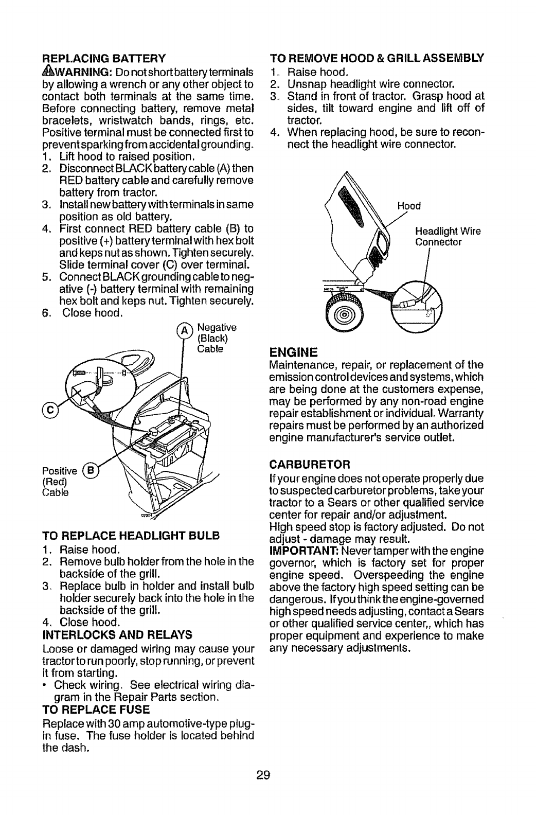
REPLACING BATTERY
_WARNING: Do not short battery terminals
by allowing a wrench or any other object to
contact both terminals at the same time.
Before connecting battery, remove metal
bracelets, wristwatch bands, rings, etc.
Positive terminal must be connected first to
prevent sparking from accidental grounding.
1.
2.
.
4_
1
.
Lift hood to raised position,
Disconnect BLACK battery cable (A) then
RED batter,] cable and carefully remove
battery from tractor.
Install new battery with terminals in same
position as old battery.
First connect RED battery cable (B) to
positive (+) batterytermina! with hex bolt
and keps nut as shown. Tighten securely.
Slide terminal cover (C) over terminal.
Connect BLACK grounding cable to neg-
ative (-) battery terminal with remaining
hex bolt and keps nut. Tighten securely.
Close hood.
_, _ Negative
(Black)
Cable
Positive
(Red)
Cable
TO REPLACE HEADLIGHT BULB
1. Raise hood.
2. Remove bulb holderfrom the hole in the
backside of the grill,
3_ Replace bulb in holder and install bulb
holder securely back into the hole in the
backside of the grill.
4. Close hood.
INTERLOCKS AND RELAYS
Loose or damaged wiring may cause your
tractor to run poorly, stop running, or prevent
it from starting.
•Check wiring. See electrical wiring dia-
gram in the Repair Parts section.
TO REPLACE FUSE
Replace with 30 amp automotive-type plug-
in fuse. The fuse holder is located behind
the dash.
TO REMOVE HOOD &GRILLASSEMBLY
1. Raise hood.
2. Unsnap headlight wire connector,
3. Stand in front of tractor. Grasp hood at
sides, tilt toward engine and lift off of
tractor.
4. When replacing hood, be sure to recon-
nect the headlight wire connector.
Hood
Headlight Wire
Connector
ENGINE
Maintenance, repair, or replacement of the
emission control devices and systems, which
are being done at the customers expense,
may be performed by any non-road engine
repair establishment or individual Warranty
repairs must be performed by an authorized
engine manufacturer's service outlet.
CARBURETOR
If your engine does not operate properly due
to suspected carburetor problems, take your
tractor to a Sears or other qualified service
center for repair and/or adjustment.
High speed stop is factory adjusted. Do not
adjust - damage may result.
IMPORTANT: Never tamper with the engine
governor, which is factory set for proper
engine speed. Overspeeding the engine
above the factory high speed setting can be
dangerous. Ifyouthinkthe engine-governed
high speed needs adjusting, contact a Sears
or other qualified service center,, which has
proper equipment and experience to make
any necessary adjustments.
29
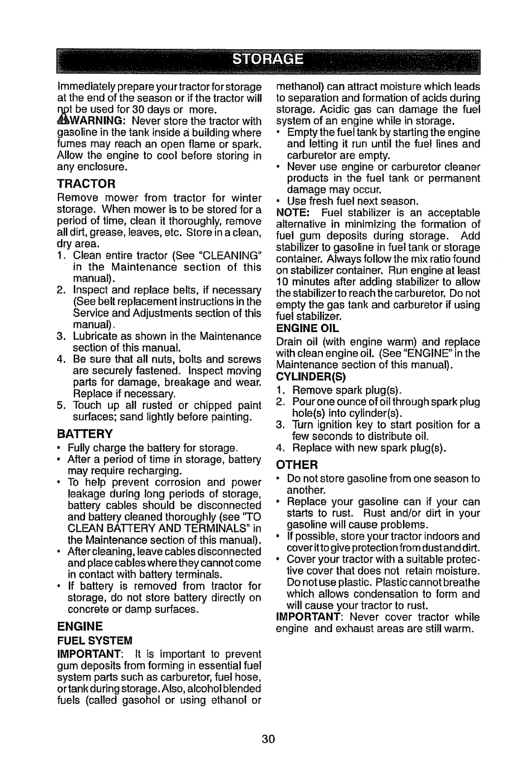
Immediately prepare your tractor for storage
at the end of the season or if the tractor will
be used for 30 days or more.
RNING: Never store the tractor with
gasoline in the tank inside abuilding where
fumes may reach an open flame or spark.
Allow the engine to cool before storing in
any enclosure.
TRACTOR
Remove mower from tractor for winter
storage. When mower is to be stored for a
period of time, clean it thoroughly, remove
all dirt,grease, leaves, etc. Store ina clean,
dry area.
1. Clean entire tractor (See "CLEANING"
in the Maintenance section of this
manual).
2. inspect and replace belts, if necessary
(See beltreplacement instructionsinthe
Service and Adjustments section of this
manual),
3. Lubricate as shown in the Maintenance
section of this manual.
4. Be sure that all nuts, bolts and screws
are securely fastened_ Inspect moving
parts for damage, breakage and wear.
Replace if necessary.
5. Touch up all rusted or chipped paint
surfaces; sand lightly before painting,
BATTERY
•Fully charge the battery for storage,
•After aperiod of time in storage, battery
may require recharging.
•To help prevent corrosion and power
leakage during long periods of storage,
battery cables should be disconnected
and battery cleaned thoroughly (see '3"O
CLEAN BATTERY AND TERMINALS" in
the Maintenance section of this manual).
• After cleaning, leave cables disconnected
and placecables where they cannot come
in contact with battery terminals,
•If battery is removed from tractor for
storage, do not store battery directly on
concrete or damp surfaces.
ENGINE
FUEL SYSTEM
IMPORTANT: It is important to prevent
gum deposits from forming in essential fuel
system parts such as carburetor, fuel hose,
or tank during storage. Also, alcohol blended
fuels (called gasohol or using ethanol or
methanol) can attract moisture which leads
to separation and formation of acids during
storage. Acidic gas can damage the fuel
system of an engine while in storage.
°Empty the fuel tank by starting the engine
and letting it run until the fuel lines and
carburetor are empty.
o Never use engine or carburetor cleaner
products in the fuel tank or permanent
damage may occur.
, Use fresh fuel next season.
NOTE: Fuel stabilizer is an acceptable
alternative in minimizing the formation of
fuel gum deposits during storage. Add
stabilizer to gasoline in fuel tank or storage
container. Always follow the mix ratio found
on stabilizer container. Run engine at least
10 minutes after adding stabilizer to allow
the stabilizer to reach the carburetor. Do not
empty the gas tank and carburetor if using
fuel stabilizer.
ENGINE OIL
Drain oil (with engine warm) and replace
with clean engine oil. (See "ENGINE" in the
Maintenance section of this manual).
CYLiNDER(S)
1. Remove spark plug(s)_
2o Pour one ounce of oi! through spark plug
hole(s) into cylinder(s).
3. Turn ignition key to start position for a
few seconds to distribute oilo
4. Replace with new spark plug(s).
OTHER
• Do not store gasoline from one season to
another.
•Replace your gasoline can if your can
starts to rust. Rust and/or dirt in your
gasoline will cause problems.
° if possible, store your tractor indoors and
cover itto give protection from dust and dirt.
° Cover your tractor with a suitable protec-
tive cover that does not retain moisture.
Do not use plastic. Plastic cannot breathe
which allows condensation to form and
will cause your tractor to rust.
IMPORTANT: Never cover tractor while
engine and exhaust areas are still warm.
3O
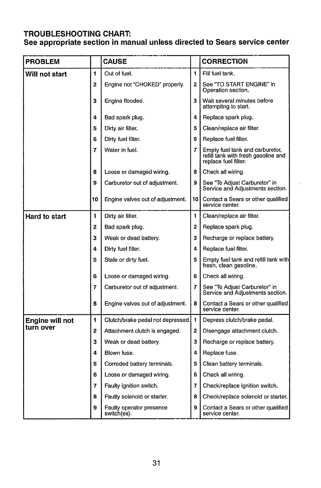
TROUBLESHOOTING CHART:
See appropriate section in manual unless directed to Sears service center
PROBLEM
Will not start
Hard to start
Engine will not
turn over
1
2
3
4
5
6
7
8
9
10
1
2
_3
4
5
6
7
8
1
2
3
4
5
6
7
8
9
CAUSE
Out of fuel.
Engine not "CHOKED" properly..
Engine flooded°
Bad spark plug,
Dirty air filter,
Dirty fuelfilter.
Water in fuel
Loose or damaged wiring,
Carburetor out of adjustment.
Engine valves out of adjustment,
Dirty air filter`
Bad spark plug.,
Weak or dead battery,
Dirty fuel filter,
Stale or dirty fuel,
Loose or damaged wiring.
Carburetor out of adjustment°
Engine valves out of adjustment°
Clutch/brake pedal not depressed
Attachment clutch is engaged_
Weak or dead battery_
Blown fuse.
Corroded battery terminals,
Loose or damaged wiring,
Faulty ignition switch,
Faulty solenoid or starter,
Faulty operator presence
switch(es),
1
2
3
4
5
6
T
B
9
10
1
2
3
4
5
6
7
B
1
2
3
4
5
6
7
8
9
CORRECTION
Fill fuel tank.
See "TO START ENGINE" in
Operation section.
Wait several minutes before
attempting to start°
Replace spark plug.
Clean/replace air filter,
Replace fuel filter,
Empty fuel tank and carburetor,
refill tank with fresh gasoline and
replace fuel filter,
Check all wiring°
See "To Adjust Carburetor" in
Service and Adjustments section,
Contact a Sears or other qualified
service center_
Clean/replace air filter,,
Replace spark plug,
Recharge or replace battery,,
Replace fuel filter,
Empty fuel tank and refill tank with
flesh, clean gasoline.
Check all wiring,
See "To Adjust Carburetor" in
Service and Adjustments section,
Contact a Sears or other qualified
service center_
Depress clutch/brake pedal,
Disengage attachment clutch_
Recharge or replace battery°
Replace fuse,
Clean battery terminals,
Check all widng,
Check/replace ignition switch.
Check/replace solenoid or starter.
Contact aSears or other qualified
service center.
31
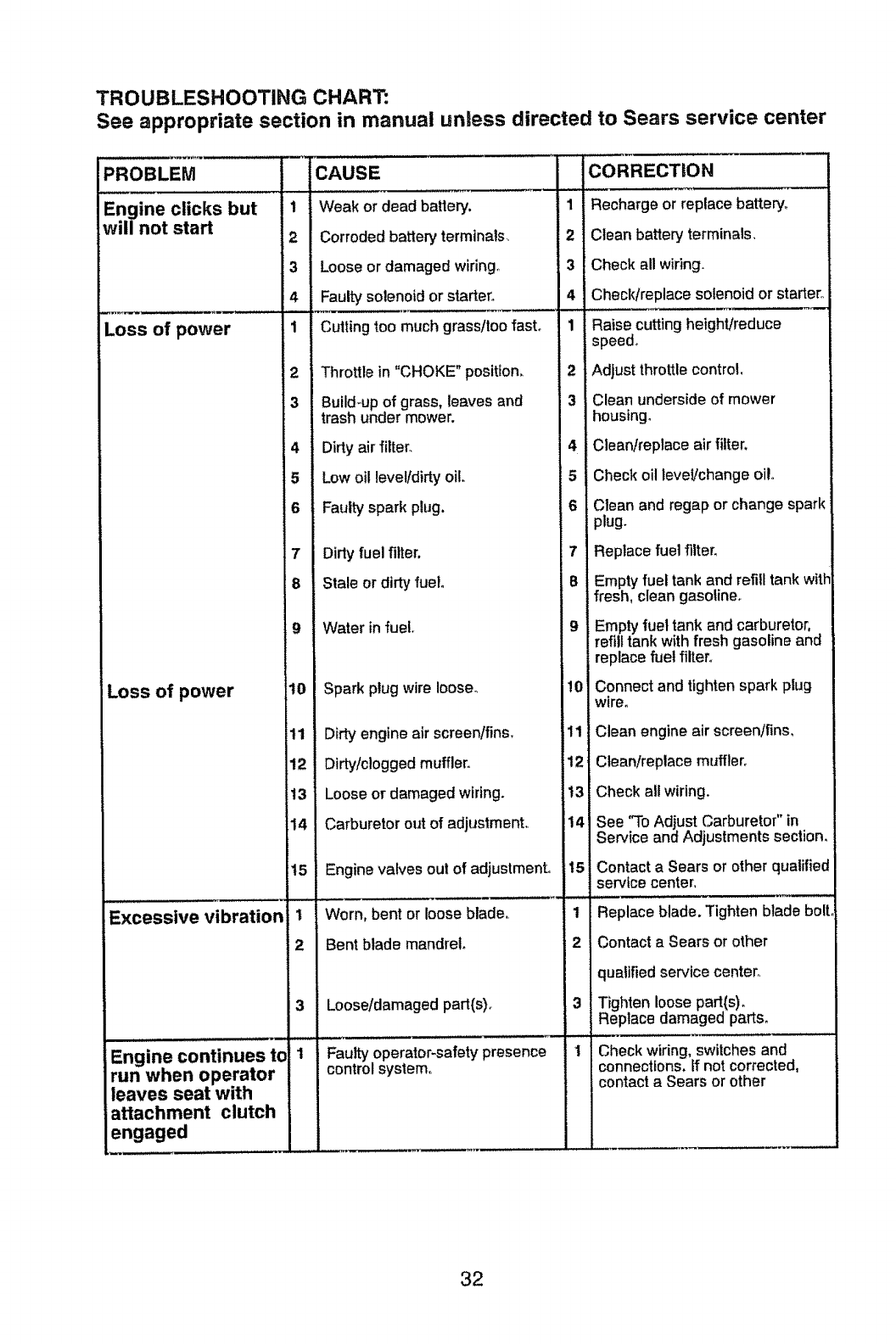
TROUBLESHOOTING CHART:
See appropriate section in manual unless directed to Sears service center
PROBLEM
Engine clicks but
will not start
Loss of power
Loss of power
Excessive vibration
Engine continues to
run when operator
leaves seat with
attachment clutch
engaged
t
2
3
4
1
2
3
4
5
6
7
8
9
t0
11
12
13
14
15
1
2
3
i
CAUSE
Weak or dead battery.
Corroded battery' terminals,
Loose or damaged wiring.,
Faulty solenoid or starter.
Cutting _.oomuch grass/too fast°
Throttle in "CHOKE" position,
Build_up of grass, leaves and
trash under mower.
Dirty air filter.
Low oil level/dirty oil.
Faulty spark p_ug.
Dirty fuel filter.
Stale or dirtyfuel.
Water infuel.
Spark plugwire loose°
Dirty engine air screen/fins.
Dirty/clogged muffler.
Loose or damaged wiring.
Carburetor out of adjustment,,
Engine valves out of adjustment.
Worn, bent or loose blade,
Bent blade mandrel.
Loose/damaged part(s).
Faulty operator-safety presence
control system.
1
2
3
4
1
2
3
5
6
7
8
9
10
I1
12
t3
14
15
1
2
3
CORRECTION
Recharge or replace battery_
Clean battery terminals,
Check all wiring.
Checldreplace solenoid or stader,
Raise cutting height/reduce
speed.
Adjust throttle control,
Clean underside of mower
housing°
Clean/replace air filter,
Check oil level/change oi!.
C_ean and regap or change spark
:dug°
Replace fuel filter,
Empty fuel tank and refill tank wirer
fresh, clean gasoline,
Empty fuel tank and carburetor,
refill tank with fresh gasoline and
replace fuel filter,
Connect and tighten spark phJg
wire.
Clean engine air screenJfins,
Clean!replace muffler.
Check all wiring.
See "To Adjust Carburetor" in
Service and Adjustments section.
Contact a Sears or other qualified
service center,
Replace blade. Tighten blade bolt.
Contact a Sears or other
qualified service center_
Tighten loose part(s).
Replace damaged parts.
Check wiring, switches and
connections. If not corrected,
contact a Sears or other
32
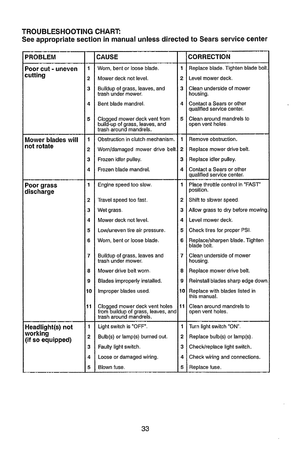
TROUBLESHOOTING CHART:
See appropriate section in manual unless directed to Sears service center
PROBLEM
Poor cut - uneven
cutting
Mower blades will
not rotate
Poor grass
discharge
1
2
3
4
5
1
2
3
4
1
2
3
4
5
6
7
8
9
10
11
1
2
3
4
5
Headlight(s) not
working
(if so equipped)
CAUSE
Worn, bent or loose blade_
Mower deck not level°
Buildup of grass, leaves, and
trash under mower_
Bent blade mandrel°
Clogged mower deck vent from
build-up of grass, leaves, and
trash around mandrels_
Obstruction in clutch mechanism.
Worn/damaged mower drive belt
Frozen }dler pulley°
Frozen blade mandrel.
Engine speed too slow,
Travel speed too fast,,
Wet grass_
Mower deck not level°
Low/uneven tire air pressure,,
Worn, bent or loose blade.
Buildup of grass, leaves and
trash under mower°
Mower drive belt worn.
Blades improperly installed.
Improper blades used,
Clogged mower deck vent holes
from buildup of grass, leaves, and
trash around mandrels.
Light switch is "OFF"_
Bulb(s) or lamp(s) burned out°
Fautb/light switch°
Loose or damaged wiring.
Blown fuse.
1
2
3
4
5
1
2
3
4
u_
1
2
3
4
5
6
7
8
g
10
11
1
2
3
4
5
CORRECTION
Replace blade°Tighten blade bolt.
Levelmower deck_
Clean undersideof mower
housing°
Contact a Sears or other
qualifiedservicecenter,
Clean aroundmandrels to
open vent holes
Remove obstruction.
Replace mower drive belto
Replace idler pulley,,
Contact a Sears or other
qualified service center°
Place throttle control In "FAST'
position.
Shift to slower speed_
Allow grass to dry before mowing,
Level mower deck,
Check tires for proper PSI,
Replace/sharpen blade, Tighten
btade bolt,,
Clean underside of mower
housing._
Replace mower drive belt.
Reinstall blades sharp edge down.
Replace with blades listed in
this manual.
Clean around mandrels to
open vent holes_
Turn light switch "ON",
Replace bulb(s) or lamp(s)o
Check/replace light switch.
Check wiring and connections.
Replace fuse°
33
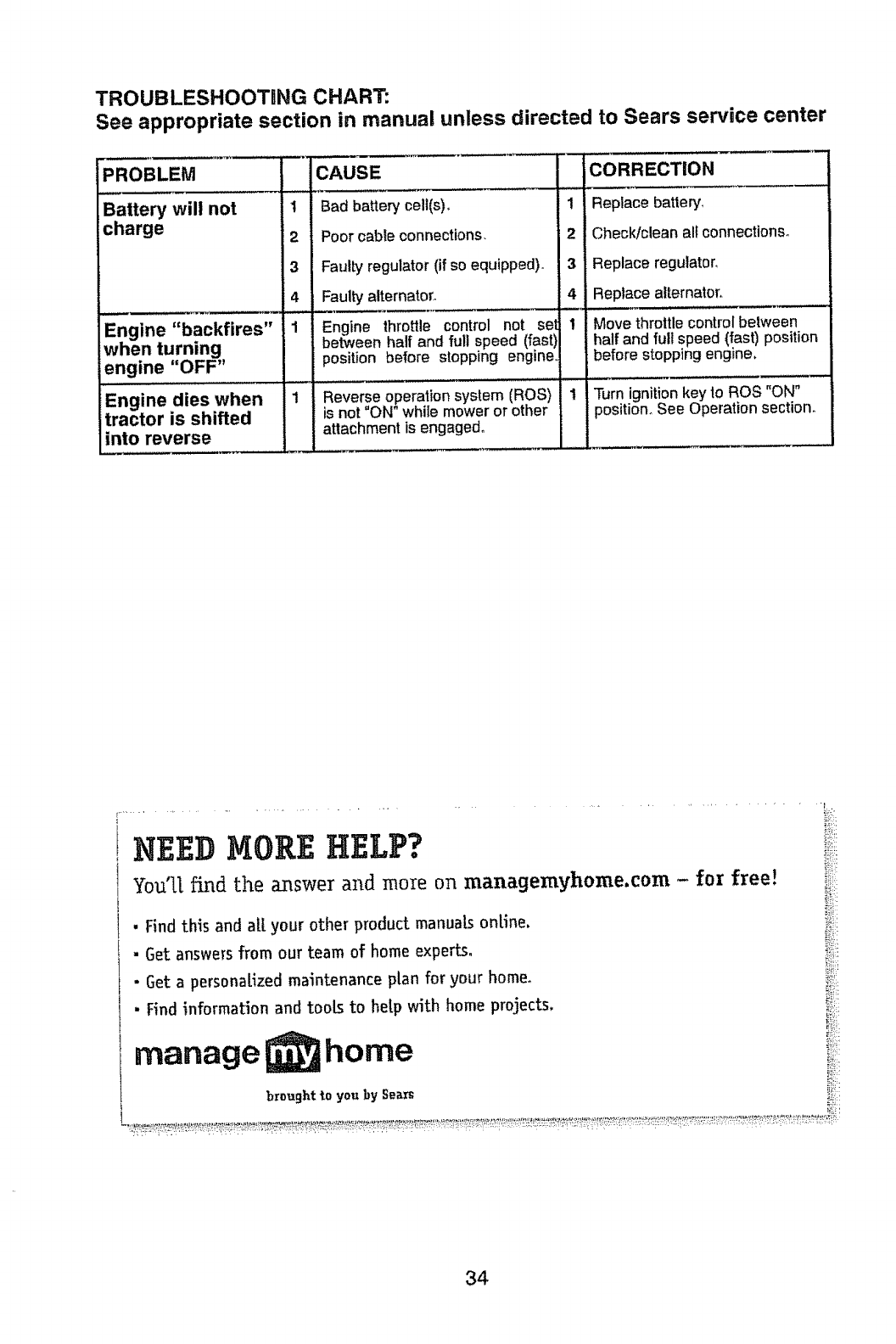
TROUBLESHOOTING CHART:
See appropriate section in manual unless directed to Sears service center
PROBLEM
Battew will not
charge
Engine "backfires"
when turning
engine "OFF"
Engine dies when
tractor is shifted
into reverse
I
2
3
4
1
1
CAUSE
Bad battery cell(s),
Poor cable connections.
Faul[y regulator (if so equipped)°
Faulty" alternator,
Engine throttle control not sel
between half and full speed (fast)
position before stopping engine,
Reverse operation system (ROS)
is not "ON" while mower or other
attachment is engaged°
1
2
3
4
!
1
CORRECTION
Replace battery,
Check/clean alt connections.
Replace regulator,
Replace alternator.
Move throttle control between
half and full speed (fast) position
before stopping engine,
Turn ignitionkey to ROS "ON"
position° See Operation section.
34
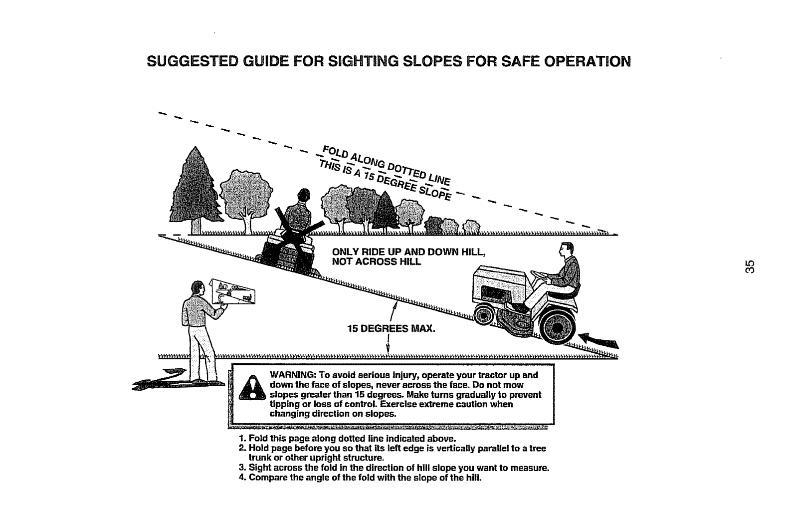
SUGGESTED GUIDE FOR SiGHTiNG SLOPES FOR SAFE OPERATION
ONLY RIDE UP AND DOWN HILL,
NOT ACROSS HILL
15 DEGREES MAX.
I
WARNING: To avoid serious injury, operate your tractor up and
down the face of slopes, never across the face. Do not mow
slopes greater than 15 degrees. Make turns gradually to prevent
tipping or loss of control. Exercise extreme caution when
changing direction on siopes_
1. Fold this page along dotted line indicated above.
2. Hold page before you so that its left edge is vertically parallel to atree
trunk or other upright structure.
3. Sight across the fold in the direction of hill slope you want to measure.
4. Compare the angle of the fold with the slope of the hill.
u3
03
Garantia .......................................................... 34
Reglas de Seguridad ................................... 35
Especificaciones del Producto .......................39
Montaje/Pre OperaciSn ....................................40
Operaci6n ....................................................... 45
Mantenimiento ................................................ 52
Pmgrama de Mantenimiento ....................... 52
Servicio y Ajustes ........................................ 57
Aimacenamiento ........................................... 63
IdentificaciSn de Problemas ..............................64
Servicio Sears ................................ Contratapa
Garantia Para Equipos Tractores Craftsman:
Tractores Cortacesped, Tractores De Jardin, Carritos Con Radio De Giro Cero
GARANTiA COMPLETA POR DOS AltOS DE CRAFTSMAN
Si alguna de las panes de desgaste de este equipo tractor falla debido a un defecto de material o mano
de obra DENTRO DE LOS DOS AthOS posteriores a la fecha de compra, visite www.craftsman.
corn o flame at 1-800-659-5917 para solicitar la reparaciSn gratuita en nuestras instalacioneso
El bastidor y el eje delantero se reparar_n sin cargo por cinco aSos a partir de la fecha de compra si
tienen defectos de material o mano de obrao
En todos los casos, si la reparaci6n es imposible, et equipo tractor ser_ sustituido sin cargo con el
mismo modelo o uno equivalente.
La baterla se sustituir& sin cargo durante 90 dias a partir de la fecha de compra st tiene defectos de
material o mano de obra (nuestras pruebas demuestran que no retiene la carga).
Esta garantia ser& nula si este producto se utiliza alguna vez para brindar ser¢icios comerciales o si
se alquila a otra persona,
Esta garantia cubre UNICAMENTE defectos de material y mano de obra. La
cobertura de garantia NO incluye:
= Componentes de desgaste que se puedan desgastar por el uso normal dentro del periodo de
garantla, incluso (pero sin limitarse a etfo) hojas, bujias, filtros de aire, correas y filtros de aceite,
• SenJicios de mantenimiento est&ndar, cambtos de aceite o afinaciones,
o Reemplazo o reparaci6n de neum&ticos por pinchazos causados por objetos extemos como
clavos, espinas, tocones o vidrios.
o Reemplazo o reparaciSn de neum_ticos o ruedas por desgaste normal, accidentes o por
operaci6n o mantenimiento incorrectos.
• Reparaciones necesarias por abuso del operador, incluso (pero sin limitarse a ello) daSos
causados pot remolcar objetos que superen la capacidad del equipo tractor, chocar contra
objetos que doblen et bastidor o el cigOe5al o sobrepasar la vetoctdad del motor.
• Reparaciones necesarias por negligencia del operador, inctuso (pero sin limttarse a ello)
daSos el_ctricos y mec&nicos causados por el almacenamiento incorrecto, pot no usar et
grado y la cantidad correctos de aceite de motor, por no mantener del muelle fibre de residuos
inflamabfes o por no mantener el equipo tractor de acuerdo con tas instrucciones que contiene
el manual del operador.
• Limpieza o reparaciones del motor (sistema de combustible) cuando se determina que se us6
combustible contamtnado y oxidado (sarro). En general, el combustible debe usarse dentro de
los 30 dias posteriores a su compra.
" Deterioro y desgaste normal de los acabados exteriores o sustituci6n de r6tulos de productos,
Esta garantia le otorga derechos legales especificos, y usted tambi_n puede tenet otros derechos
que varlan de un estado a otrm
Sears Brands Management Corporation, Hoffman Estates, IL 60179
36
IMPORTANTE: Esta Maquina cortadora es capaz de amputar las manosy los pies yde lanzar objetos, si
nose observan las instrucciones de seguridad siguientes se pueden producir tesiones graves o la muerte.
I. FUNClONAMIENTO GENERAL • No hacer funcionar ta m_.quina sin el captador
_ADVERTENClA: Siempre desconecte el
alambre de la bujia yp6ngalo donde no pueda
entrar en contacto con la bujia, para evitar et
arranque por accidente, durante la preparaci6n,
el transporte, el ajuste o cuando se hacen
reparacioneso
_DVERTENCIA: No avance cuesta abajo a
punto muerto ya que podria perder el control
del tractor.
_t_ADVERTENCIA: Remolque solamente los
accesorios recomendados y conformes a las
caracteristicas indicadas pot el fabricante de
su tractor_ Tenga cuidado y prudencia al utilizar
el tractor. Cuando se encuentre en un declive,
oper utilizando exclusivamente la veloctdad m_s
baja. En caso de un declive una carga excesiva
podria resultar peligrosa_ Los neum&ticos pueden
perder la tracci6n con el suelo y hacerle perder
el control de su tractor.
_.DVERTENCIA: El tubo de escape del motor,
algunos de sus constituyentes y algunos com-
ponentes del veh{culo contienen o desprenden
productos quimicos conocidos en et Estado de
California como causa de c&ncer y defectos al
nacimiento u otros dafios reproductivos.
_J_ADVERTENCIA: Los bornes, terminales y
accesorios relativos de la bateria contienen plomo
o compuestos de plomo, productos quimicos
conocidos en el Estado de California como causa
de c&ncer y defectos al nacimiento u otros daSos
reproductivos. Lavar las manos despu_s de
manipularlos.
• Leer, entender yseguir todas las instrucciones
sobre la m&quina y en el manual antes de
empezar.
•No poner las manos olos pies cerca de partes
giratorias o debajo de ta m&quina, mantener
siempre limpia la abertura de descarga.
• Permitirel funcionamiento de la m&quina s6to a
aduttosque tengan familiaddad con las instruc-
ciones.
•Limpiar el &rea de objetos como piedras,
juguetes, cables, etc. que pueden ser recogi-
dos y disparados con las cuchillas°
• Asegurarse de que el _,rea est_ fibre de otras
personas antes de ponerla en marcha_ Parar
la m&quina s_alguien entra en et _reao
•Hunca Ilevar pasajeros.
• No cortar marcha atr&s al no ser absolutamente
necesarioo Mirar siempre abajo y delante mien-
tras se procede atr&s_
•Nunca dirigir e! material descargado hacia
nadie. Evitar descargar material contra paredes
u obstruccioneso El material podrfa rebotar
hacia el operador. Parar las cuchitlas cuando
se pasan superficies de gravao
de hierba entera, ta protecci6n de descarga u
otros dispositivos de seguridad en su tugar y
en buenas condiciones_
. Ralentizar antes de girar_
.Nunca dejar una m&quina encendida sin vigi-
tancia. Apagar siempre tas cuchillas, poner el
freno de estacionamiento, parar el motor, y
quitar las Uaves antes de bajar,
•Desconectar las cuchillas cuando no se cortao
Apagar el motor y esperar que todas las partes
est_n completamente paradas antes de limpiar
la m&quina, quitar el captador de hierba, o
desatascar la protecci6n de descarga.
• Hacer funcionar la m,_quina s61o con la luz del
dia o luz artificial buena.
• No hacer funcionar la m&quina estando bajo
los efectos de alcohol o droga.
.Poner atenci6n al tr&fico cuando se opera cerca
de calles o se cruzan.
• Porter la m&xima atenci6n al cargar o descar-
gar la m_quina en una caravana o cami6m
•Llevar siempre gafas de protecci6n cuando se
hace funcionar la m&quina_
.Los datos indican que los operadores a partir
de los 60 arios est&n afectados por un gran
porcentaje de heridas relativas a la conducci6n
del cortac6sped. Estos operadores tendfian
que evaluar su habilidad de hacer funcionar
et cortac_sped de modo Io bastante seguro
para proteger a st mismos y aotras personas
de heridas graves.
•Seguir las recomendaciones del fabricante
para los pesos y contrapesos de las ruedas.
= Mantener la m,_quina libre de hierba, hojas
u otros escombros que pueden tocar el
tubo de escape /partes del motor calientes
y quemarse. No permitir que el puente del
cortac_sped cargue hojas u otros residuos
que pueden causar acumulacioneso Limpiar
toda salpicadura de aceite o carburante antes
de hacer operaciones sobre la m_quina o
guardarta. Dejarla enfriar antes de guardarla_
I1. FUNCIONAMENTO EN PENDIENTES
Las pendientes son el mayor factor de acci-
dentes relativos a la p_rdida de controly vuelco,
que pueden causar severas heridas o muerte.
El funcionamiento en pendientes requiere una
atenci6n extra_ Si no es posible hacer marcha
atr&s en una pendiente o si te sientes incomodo,
no la cortes.
• Cortar hacia arriba y abajo de una pendiente,
no de modo horizontal
• Poner atenciones a los hoyos, las raices, los
bultos, las piedras u otros objetos escondidos.
Et terreno irregular puede volcar la m&quina.
La hierba alta puede esconder obst&culos.
37
, Escoger una velocidad de marcha baja de
modo que no sea necesario pararse o cambiar
estando en una pendiente.
•No cortar la hierba mojadao Las ruedas pueden
perder tracci6n.
Porter siempre una marcha cuando se est&
en pendientes. No porter en punto muerto e ir
cuesta abajo.
• Evitar arrancar, pararse o girar en una pendi-
ente. Si las ruedas pierden tracci6n, desconec-
tar ias cuchitlas y proceder despacio cuesta
abajo en ta pendiente.
° Mantener todo los movimientos en tas pen-
dientes lentos y gradual. No hacer cambios
repentinos de vetocidad o direcci6n, ya que
pueden causar el escape de la m_quina.
,Poner ta m&xima atenci6n cuando la m&quina
funciona con captadores de hierba u otros
dispositivos enganchados; pueden afectar la
estabilidad de la m&quinar No usar en pendi-
entes empinados.
• No intentar estabitizar la m&quina poniendo el
pie en el terreno.
• No cortar cerca de bajadas, cunetas y orUlas.
Las m&quina puede volcarse improvisamente
sf una rueda est& en et borde o se hunde.
iii. NII_OS
Si el operador no pone atenci6n a ta presencia
de los nifios pueden ocurrir accidentes tr_gicoso
Los niSos a menudo est_n atraidos por la m&qui-
nay las actividad de cortar. No dar por hecho
de que los niSos se queden adonde estaban la
_itima vez que los vistes_
•Mantener los nifios fuera del &rea de corte y
vigilados pot un adulto responsable que no sea
el operador.
°Estar alerta y apagar ta m&quina si un nifios
entra en el _rea.
• Antes y durante la marcha atr&s, mirar adelante
y abajo para ver si hay niSos peque_,oso
• Nunca Ilevar niSos, incluso si hay tas cuchillas
apagadas. Podrlan caer y herirse sedamente
o interferir con et funcionamiento seguro de la
m&quina, los nifos que se ban llevado prec-
edentemente pueden aparecer de pronto en el
&rea de corte por otro paseo y set atropellados
o tumbados por la m&quinao
, Nunca dejar que los niSos manipulen la
m&quinao
, Tenet el m_ximo cuidado cuando se acerca
a cantos ciegos, arbustos, &rboles u otros
objetos que pueden impedir la vista de nifios.
IV. REMOLQUE
• Remolcar s61o con una m_quina que tenga un
gancho diseSado para remolcar. Enganchar el
equipo o remolcar s61o en el punto dispuesto
a! efectoo
° Seguir las recomendaciones del productor con
respecto a los limites de! equipo per remolcar
y el remolque en pendientes.
• Nunca permitir que niSos u otras personas
est6n dentro del equipo por remolcaro
° En pendientes, el peso del equipo remolcado
puede causar la p6rdida de tracci6n y la p_ro
dida de control.
, Viajar despacio y dejar m&s distancia para
frenar.
V. SERV|ClO
MANIPULACI6N SEGURA DE LA
GASOLINA
Para evitar heridas personales o dar_os alas
cosas, ponerel m&ximo cuidado ala hora de ma-
nipular la gasolina. La gasolina es extremamente
inflamabte y los vapores son explosivos.
, Apagar todos los cigarrillos, cigarros, pipas y
otras fuentes de ignici6no
• Usar s61ocontenedores para gasolina aproba-
dos°
• Nunca quitar el tap6n de la gasolina o aSadir
carburante con el motor en marcha, dejar
enfriar el motor antes del abastecimiento de
la gasolina.
• Nunca abastecer la m_quina al interior de un
local.
• Nunca guardar la m&quina o el contenedor
del carburante donde haya una llama abierta,
chispas o una luz piloto como un calentador
de agua u otros dispositivos.
o Nunca ltenar los contenedores al interior de
un vehicuto o en una caravana o cami6n
recubiertos con un forro de pl&stico. Colocar
siempre los contenedores en el terreno lejos
del vehiculo cuando se est,. ilenandoo
°Quitar el equipo de gas del cami6n o caravana
y abastecerlo en el terreno. Si no es posible,
abastecer dicho equipo con un contenedor
port&til, m&s bien que de un surtidor de gaso-
lina.
, Mantener ta boquilla a contacto del borde
del dep6sito de carburante o la abertura del
contenedor durante toda la operaciSn de
abastecimiento. No utitizar un dispositivo con
boquilta cerrada-abiertao
° Si se vierte carburante sobre la ropa, cambi-
arse la ropa inmediatamente.
° Nunca !lenar el dep6sito m&s de Io debido.
Volver a colocar el tap6n del gas y cerrar de
modo firme.
OPERACIONES DE SERVICIO
GENERALES
, Nunca hacer funcionar la m&quina en un ,_rea
cerradao
,Mantener todas las tuercas y pernos apretados
para asegurarse de que trabaja en condiciones
seguras.
• Nunca modificar los dispositivos de seguridad.
Controlar su correcto funcionamiento regular-
mente.
38
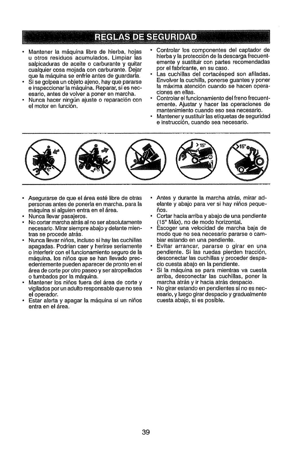
, Mantener la m&quina libre de hierba, hojas °
u otros residuos acumulados. Limpiar las
salpicaduras de aceite o carburante y quitar
cualquier cosa mojada con carburante. Dejar
que la m&quina se enfrie antes de guardarta_ °
Si se gotpea un objeto ajeno, hay que pararse
e inspeccionar la m_quina. Reparar, si es nec-
esafio, antes de volver a poner en marcha_
Nunca hacer ningt'm ajuste o reparaci6n con °
el motor en funci6n.
Controlar los componentes del captador de
hierba y ia protecci0n de la descarga frecuent-
emente y sustituir con partes recomendadas
por el fabricante, en su caso.
Las cuchtllas del cortac_sped son afiladas.
Envolver la cuchilla, ponerse guantes y poner
la m_ima atenci6n cuando se hacen opera-
ciones en elias.
Controlar et funcionamiento del freno frecuent-
emente. Ajustar y hacer las operaciones de
mantenimlento cuando eso sea necesario.
Mantener y sustituir las etiquetas de seguridad
e instrucci6n, cuando sea necesario.
• Asegurarse de que el _rea est_ libre de otras
personas antes de ponerla en marcha, para la
m&quina si atguien entra en el &reao
• Nunca Ilevar pasajeros°
° No cortar marcha atr&s al no ser absolutamente
necesario. Mirar siempre abajo y delante mien-
tras se procede atr&s.
, Nunca Ilevar ni6os, incluso si hay las cuchillas
apagadas. Podrian caer y herirse seriamente
o interferir con el funcionamtento seguro de la
m&quina, los niSos que se han !levado prec-
edentemente pueden aparecer de pronto en el
&rea de corte por otto paseo y ser atropellados
o tumbados por la m_.quinao
• Mantener los ni6os fuera del _rea de corte y
vigilados por un adulto responsable que no sea
e! operador,
• Estar alerta y apagar la m&quina si un ni6os
entra en el _reao
• Antes y durante la marcha atr&s, mirar ad-
elante y abajo para ver si hay ni6os peque-
5os,
• Cortar hacia arfiba y abajo de una pendiente
(15° M_), no de modo horizontal.
, Escoger una velocidad de marcha baja de
modo que no sea necesario pararse o cam-
biar estando en una pendiente.
• Evltar arrancar, pararse o girar en una
pendiente. Si las ruedas pierden tracci6n,
desconectar Ias cuchitlas y proceder despa-
cio cuesta abajo en la pendiente.
• Si la m&quina se para mientras va cuesta
arriba, desconectar las cuchitlas, poner la
marcha atr&s y ir hacia atr&s despacio_
• No girar estando en pendientes si no es nec-
esafio, y luego girar despacio y gradualmente
cuesta abajo, si es posible.
39
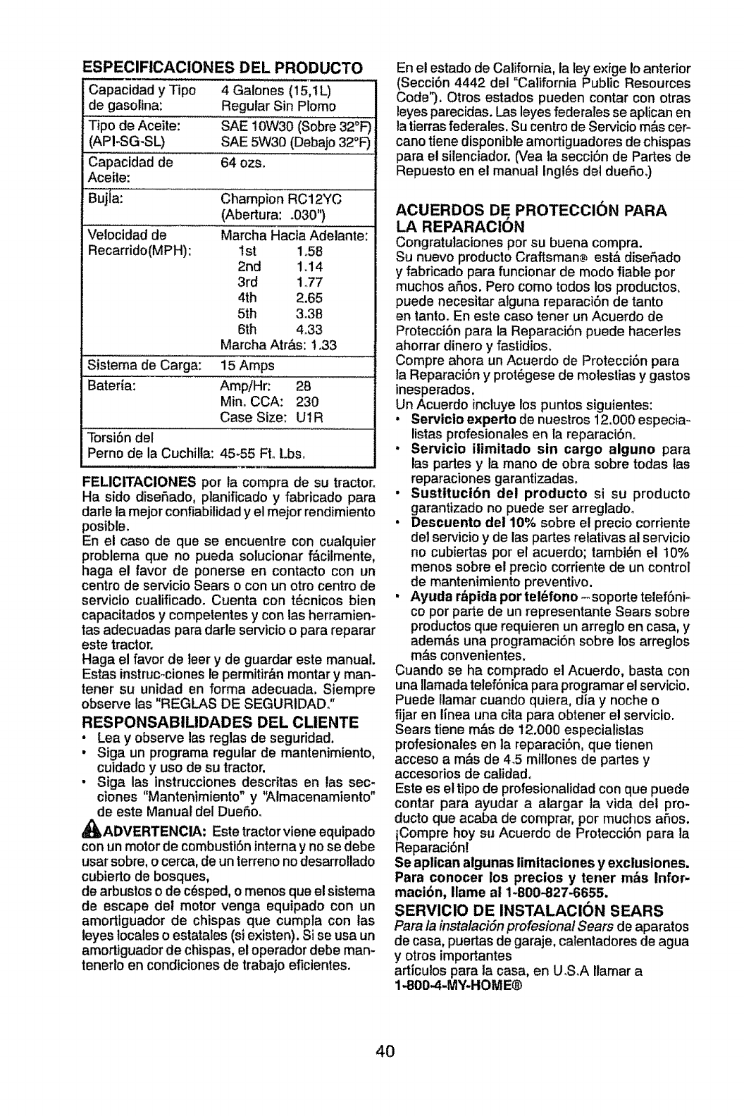
ESPECIFICACIONES DEL PRODUCTO
Capacidad y Tipo 4 Galones (15,11_)
de gasotina: Regular Sin Plomo
Tipo de Aceite: SAE 10W30 (Sobre 32°F)
(API-SG-SL) SAE 5W30 (Debajo 32°1=)
Capacidad de 64 ozso
Aceite:
Bujta: Champion RC12YC
(Abertura: .030")
Velocidad de Marcha Hacia Adelante:
Recarrido(MPH): I st 1.58
2rid 1.14
3rd 1°77
4th 2.65
5th 3o38
6th 4,33
Marcha Atr&s: ! °33
Sistema de Carga: 15 Amps
Bateria: AmpiHr: 28
Min. CCA: 230
Case Size: U1R
Torsi6n del
Perno de la Cuchilla: 45-55 FtoLbso
FELICITACIONES por la compra de su tractor.
Ha sido dise6ado, planificado y fabricado para
darle la mejor confiabilidad y el mejor rendimiento
posible.
En el caso de que se encuentre con cualquier
problema que no pueda solucionar f&cilmente,
haga el favor de ponerse en contacto con un
centro de servicio Sears o con un otro centro de
serviclo cualificado. Cuenta con t_cnicos bien
capacitados y competentes y con las herramien-
tas adecuadas para darle servicio o para reparar
este tractor.
Haga el favor de leer y de guardar este manual.
Estas instruc°cionesle permitir&n montar y man-
tenet su unidad en forma adecuada. Siempre
observe tas "REGLAS DE SEGURIDAD."
RESPONSABILIDADES DEL CLIENTE
• Lea yobserve las reglas de seguridad.
• Siga un programa regular de mantenimiento,
cuidado y uso de su tractor.
• Siga las instrucciones descritas en las sec-
clones "Mantenimiento ° y'Almacenamiento"
de este Manual del DueSoo
_ADVERTENClA: Este tractorviene equipado
con un motor de combusti6n interna y no se debe
usar sobre, o cerca, de un terrenono desarro!lado
cubierto de bosques,
de arbustos o de c(_sped, o menos que el sistema
de escape del motor venga equipado con un
amortiguador de chispas que cumpla con las
leyes locales o estatales (si existen). Si se usa un
amortiguador de chispas, el operador debe man-
tenerto en condiciones de trabajo eficientes°
En e! estado de California, la ley exige Io anterior
(Secci6n 4442 del "California Public Resources
Code"). Otros estados pueden contar con otras
leyes parecidas. Las leyes federales se aplican en
la tierras federales. Su centro de Servicio m&s cer-
cano tiene disponible amortiguadores de chispas
para el silenciador. (Vea la secci6n de Partes de
Repuesto en el manual Ingi6s det dueSo.)
ACUERDOS DE PROTECCION PARA
LA REPARACION
Congratulaciones por su buena compra.
Su nuevo producto Craftsman® est& disefiado
yfabricado para funcionar de modo liable por
muchos aSos. Pero como todos los productos,
puede necesitar alguna reparaci6n de tanto
en tanto. En este caso tener un Acuerdo de
Protecci6n para la Reparaci6n puede hacerles
ahorrar dinero y fastidios.
Compre ahora un Acuerdo de Protecci6n para
la Reparaci6n yprot6gese de molestias y gastos
inesperados.
Un Acuerdo incluye los puntos siguientes:
•Servicio experto de nuestros 12.000 especia-
listas profesionales en la reparaci6n°
• Servicio tlimitado sin cargo alguno para
las partes y ta mano de obra sobre todas tas
reparaciones garantizadas.
. Sustituci6n del producto si su producto
garantizado no puede ser arreglado.
•Descuento de110% sobre el precio corriente
del servicio y de las partes relativas al servicio
no cubiertas por el acuerdo; tambi6n el 10%
menos sobre el precio corriente de un control
de mantenimiento preventivo.
• Ayuda r_pida por tel_fono -soporte telef6ni-
co por parte de un representante Sears sobre
productosque requieren un arreglo en casa, y
adem&s una programaci6n sobre los arreglos
m&s convenientes.
Cuando se ha comprado el Acuerdo, basta con
una Ilamada telef6nica para programarel servicio.
Puede llamar cuando quiera, dia y noche o
fijar en linea una cita para obtener el servicio.
Sears tiene m&s de 12.000 especialistas
profesionates en la reparaci6n, que tienen
acceso a m_s de 4.5 mitlones de partes y
accesorios de calidado
Este es el tipo de profesionalidad con que puede
contar para ayudar a alargar la vida del pro-
ducto que acaba de comprar, por muchos ahos.
tCompre hoy su Acuerdo de Protecci6n para la
Reparaci6n!
Se aplican algunas limitaciones y exclusiones.
Para conocer los precios y tener m&s Infor-
macibn, Ilame al 1-800-827-6655.
SERVICIO DE INSTALACION SEARS
Para /a insta/aci6n profesiona/ Sears de aparatos
de casa, puertas de garaje, calentadores de agua
yotros importantes
articutos para la casa, en U.S.A Ilamar a
I_O0,,4-MY-HOME®
4O
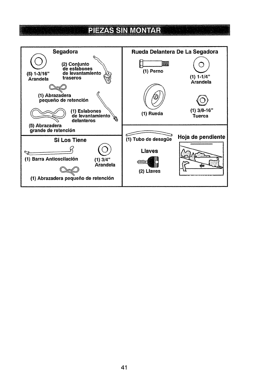
Segadora
(2) ConJunto _',,,
de eslabones ',,_'\
(5) 1-3/16" de levantamlento _)
Arandela traseros '_
(1) Abrazadera
peque_o de retenci6n "_
\\
(__ (1) Eslabone s "_
_,_ de levantamiento'_
_delanteros "_
(5) Abrazadera
grande de retencl6n
Si Los Tiene
(1) Barra Anttoscilacibn @
(1) 3/4"
Arandela
(I) Abrazadera pequeho de retenci6n
Rueda Delantera De La Segadora
©
(1) Perno
(1) 1-1/4"
Arandela
(1) 3/8.16"
Tuerca
(1) Rueda
(1) Tubo de desag_e
Llaves
4Et
12) Llaves
Hoja de pendiente
41
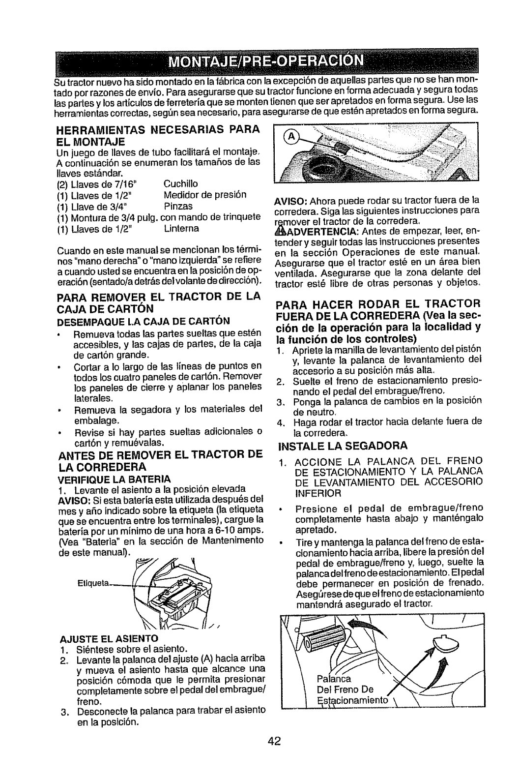
Su tractor nuevo ha sido montado en la f&brica con la excepciSn de aquellas panes que no se han mon-
tado por razones de envio, Para asegurarse que su tractor funcione en forma adecuada y segura todas
las panes y los articulos de ferreteda que se monten tienen que ser apretados en forma segura. Use las
herramientas correctas, seg_3nsea necesado, para asegurarse de que est6n apretados en forma segura.
HERRAMIENTAS NECESARIAS PARA
EL MONTAJE
Un juego de Ilaves de tubo facititar& el montaje_
Acontinuaci6n se enumeran los tamafios de las
llaves est_ndar.
(2) Llaves de 7/16" Cuchillo
(1) Ltaves de 1/2" Medidor de presi6n
(1) Ltave de 3/4" Pinzas
(1) Montura de 3/4 pulg. con mando de trinquete
(1) Llaves de 1/2" Linterna
Cuando en este manual se mencionan los t6rmi-
nos"mano derecha" o"mar_ izquierda"se refiere
acuando usted se encuentra en la posici6n de op-
eraci6n (sentado/adetr_s delvolante de direcci6n).
PARA REMOVER EL TRACTOR DE LA
CAJA DE CART6N
DESEMPAQUE LA CAJA DE CART(_N
• Remueva todas las partes sueltas que est_n
accesibles, y las cajas de partes, de la caja
de cart6n grandeo
•Cortar a Io largo de las lineas de puntos en
todos los cuatro paneles de cart6n, Remover
los paneles de cierre y aplanar los paneles
laterates.
. Remueva ta segadora y los materiales del
embalage,
•Revise si hay partes sueltas adicionales o
cart6n y remu_valas.
ANTES DE REMOVER EL TRACTOR DE
LA CORREDERA
VERIFIQUE LA BATERIA
I. Levante et asiento a la posici6n elevada
AVISO: Siesta bateria esta utitizada despu6s det
rnes y afio indicado sobre la etiqueta (la etiqueta
que se encuentra entre los terminales), cargue ia
baterfa por un m{nimo de una hora a 6-10 amps.
(Vea "Baterta" en la secciSn de Mantenimento
de este manual).
Etlqueta-..-...__
/'/
AJUSTE EL ASIENTO
1. Si_ntese sobre et astento.
2o Levante la palanca del ajuste (A) hacia arriba
y mueva el asiento hasta que atcance una
posici6n c6moda que le permita presionar
completamente sobre el pedal del embraguei
freno,
3, Desconecte la palanca para trabar e! astento
en la posici6n.
AVISO: Ahora puede rodar su tractor fuera de la
correderao Siga las siguientes instruccionespara
r_over el tractor de la correderao
DVERTENCIA: Antes de empezar, leer, en-
tender y seguir todas las instruccionespresentes
en la secci6n Operaciones de este manual,,
Asegurarse que el tractor est_ en un &rea bien
ventilada. Asegurarse que la zona delante del
tractor est_ fibre de otras personas y objetoso
PARA HACER RODAR EL TRACTOR
FUERA DE LA CORREDERA (Vea la sec-
cibn de la operacibn para la Iocalidad y
la funci6n de los controles)
1_ Apriete la manilla de levantamiento det pist6n
y, levante la palanca de levantamiento det
accesorio a su posici6n m&s atta.
2. Suelle el freno de estacionamiento presio-
nando e! pedal del embragueffreno,
3. Ponga la palanca de cambios en la posici6n
de neutro.
4. Haga rodar el tractor hacia delante fuera de
la corredera.
INSTALE LA SEGADORA
ACCtONE LA PALANCA DEL FRENO
DE ESTACtONAMIENTO Y LA PALANCA
DE LEVANTAMIENTO DEL ACCESORIO
INFERIOR
Presione el pedal de embraguelfreno
completamente hasta abajo y mant6ngalo
apretado.
Tire y mantenga la patanca del freno de esta-
cionamiento hacia arriba, Iibere ta presi6n del
pedal de embrague/freno y, luego, sueRe la
palancadelfreno de estacionamiento. El pedal
debe permanecer en posici6n de frenado,
Aseg6rese deque el freno de estacionamiento
mantendr#, asegurado el tractor,,
:a
42
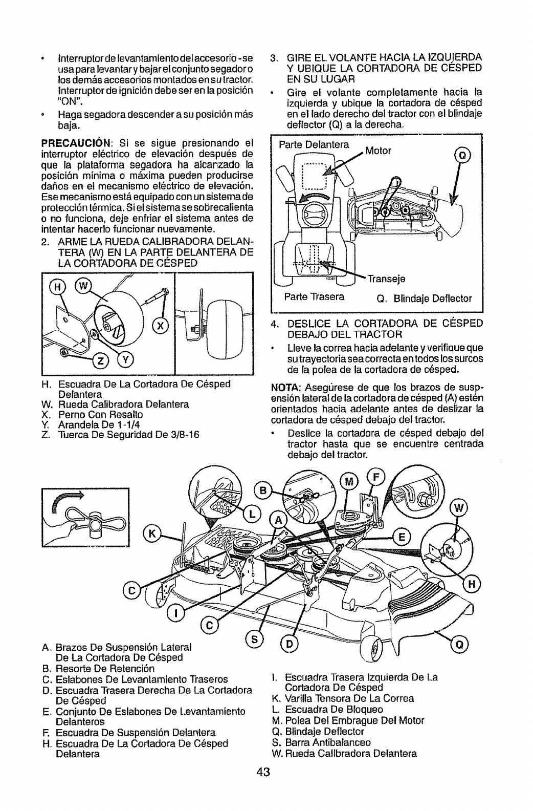
.tnterruptor de tevantamiento delaccesofio-se
usa para levantar y bajar el conjunto segador o
los demos accesorios montados en su tractor.
Interruptor de ignici6n debe ser en la posici6n
"ON".
, Haga segadoradescenderasu posict6n m&s
baja.
PRECAUCI6N: Si se sigue presionando el
interruptor el_ctrico de elevaciSn despu_s de
que la plataforma segadora ha alcanzado la
posiciSn minima o m&xima pueden producirse
daSo_ en el mecanismo el6ctrico de elevaci6n.
Ese mecanismo est,, equipado con [insistema de
protecci6n t_rmica. Si el sistema se sobrecalienta
o no funciona, deje enfriar el sistema antes de
intentar hacerlo funcionar nuevamente.
2. ARME LA RUEDA CALIBRADORA DELAN-
TERA (W) EN LA PAR'rE DELANTERA DE
LA CORTADORA DE CESPED
H. Escuadra De La Cortadora De C_sped
Delantera
W. Rueda Catibradora Delantera
Xo Perno Con Resatto
YArandela De 1_1/4
Z° "i]aerca De Seguridad De 3/8-16
3. GIRE EL VOLANTE HACIA LA IZQUIERDA
Y UBtQUE LA CORTADORA DE CESPED
EN SU LUGAR
• Gire et volante comptetamente hacia la
izquierda y ubique la cortadora de c_sped
en el lado derecho del tractor con el blindaje
deflector (Q) a la derecha.
4_
Parte Delantera Motor
Parte Trasera
le
Q, Blindaje Deflector
DESLICE LA COR]ADORA DE CESPED
DEBAJO DEL TRACTOR
Lleve la correa hacia adelante y vefifique que
su trayectoria sea correcta en todos los surcos
de la polea de la cortadora de c_sped.
NOTA: Asegurese de que los brazos de susp-
ensi6n lateral de la cortadora de c@sped(A) esten
orientados hacia adelante antes de deslizar la
cortadora de c_sped debajo del tractor.
•Deslice la cortadora de c_sped debajo del
tractor hasta que se encuentre centrada
debajo del tractor.
A_ Brazos De Suspensi6n Lateral
De La Cortadora De C_sped
Bo Resorte De Retenci6n
C. Eslabones De Levantamiento Traseros
D. Escuadra Trasera Derecha De La Cortadora
De C6sped
E, Conjunto De Eslabones De Levantamiento
Delanteros
F. Escuadra De Suspensi6n Delantera
H. Escuadra De La Cortadora De C_sped
Delantera
L Escuadra Trasera Izquierda De La
Cortadora De C_sped
K. Vafilla Tensora De La Correa
L. Escuadra De Bloqueo
MoPolea Det Embrague Del Motor
Q. Btindaje Deflector
S. Barra Antibatanceo
W°Rueda Callbradora Detantera
43
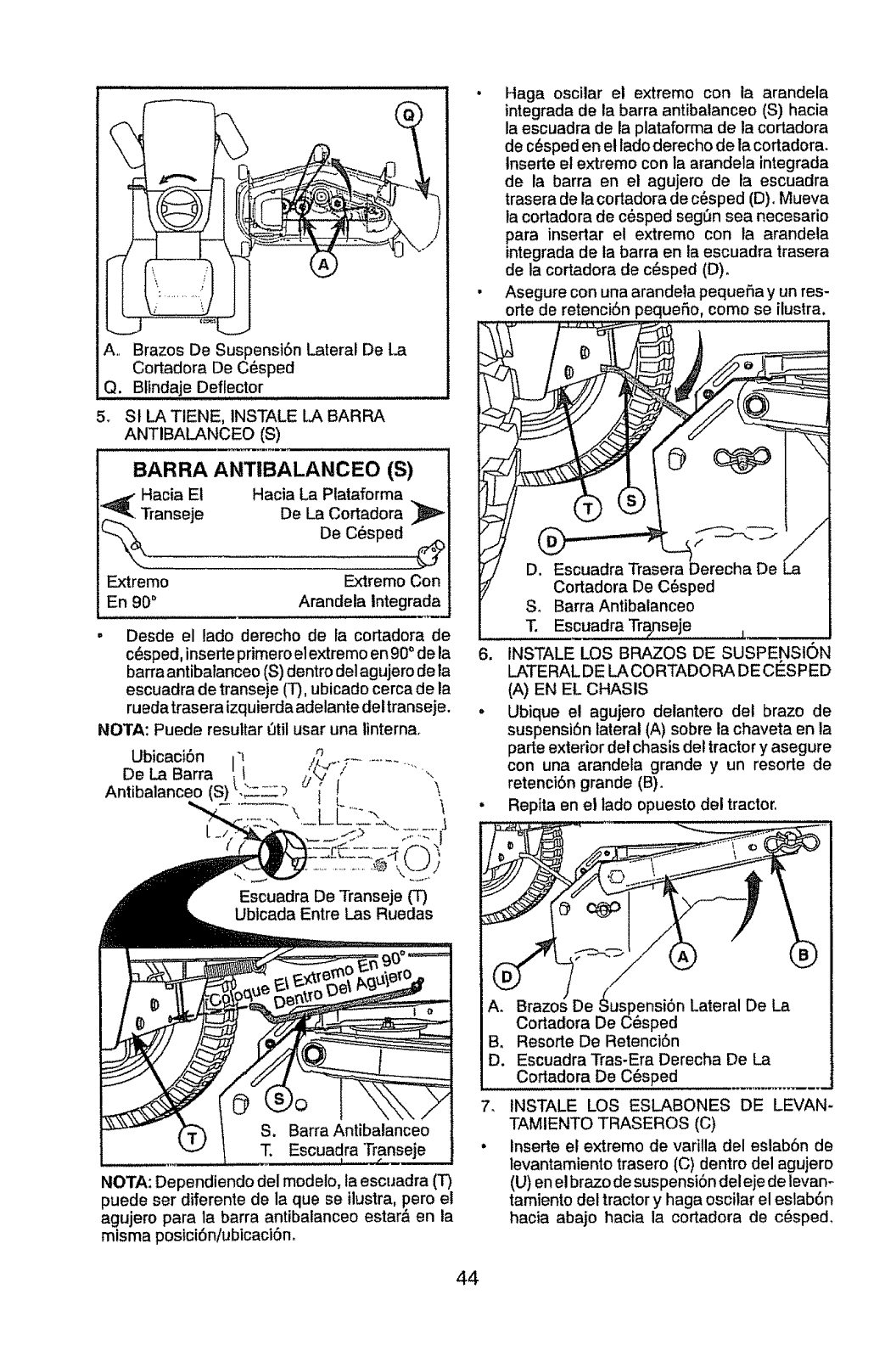
A.. Brazos De Suspensi6n Lateral De La
Cortadora De C_sped
Q. Blindaje Deflector
5. St LA TIENE, INSTALE LJ_BARRA
ANTIBALANCEO (S)
BARRA ANTIBALANCEO (S)
Hacia Et Hacia La Plataforma
ranseje De La Cortadora
De C_sped ¢/_
Extremo Extremo Con
En 90° Arandela Integrada
. Desde el lado derecho de la cortadora de
c_sped, inserte primero el extremo en 90°de la
barra antibalanceo (S) dentro delagujero de la
escuadra de transeje (T), ubicado cerca de ia
ruedatraseraizquierdaadelantedeltranseje.
NOTA: Puede resultar 0til usar una linterna.
Escuadra De Transeje (T)
Ubtcada Entre Las Ruedas
Escuadra Transeje
NOTA: Dependiendo del modelo, la escuadra (T)
puede ser diferente de la que se ilustra, pero el
agujero para la barra antibalanceo estar& en la
misma posici6niubicaciSn.
. Haga oscilar el extremo con la arandela
integrada de la barra antibalanceo (S) hacia
la escuadra de la plataforma de la cortadora
de c_sped en el lado derecho de la cortadora.
lnserte et extremo con la arandela integrada
de la barra en el agujero, de la escuadra
trasera de la cofladora de cesped (D)oMueva
la cortadora de c6sped seg_3nsea necesario
para insertar et extremo con ta arandela
integrada de la barra en la escuadra trasera
de la cortadora de c_sped (D).
• Asegure con una arandeta pequefia y un res-
cale de retenci6n pequefio, como se ilustra.
6. INSTALE LOS BRAZOS DE SUSPENSION
LATERAL DE LA CORTADO RA DE CESPED
(A) EN EL CHASIS
. Ubique el agujero delantero det braze de
suspensi6n lateral (A) sobre la chaveta en la
parte exterior del chasis del tractor y asegure
con una arandela grande y un resorte de
retenci6n grande (B).
• Repita en el lado opuesto del tractor,
B. Resorte De Retenci6n
D. Escuadra Tras-Era Derecha De La
Cortadora De C6sped
7. INSTALE LOS ESLABONES DE LEVAN-
TAMIENTO TRASEROS (C)
• Inserte el extremo de varilla del eslab6n de
levantamiento trasero (C) dentro del agujero
(U) en elbrazo de suspensi6n deleje de fevan-
tamiento del tractor y haga oscilar el eslab6n
hacia abajo hacia la cortadora de c6sped.
44
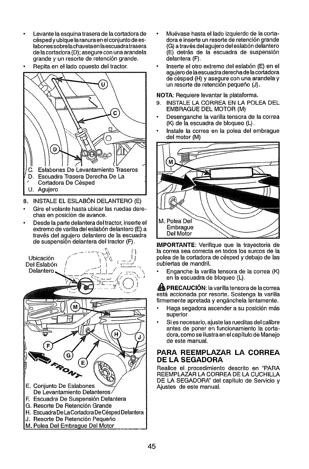
• Levante la esquina trasera de la cortadora de
c_sped y ubique la ranura en elconjunto de es_
labonessobre lachaveta en laescuadratrasera
de la cortadora (D); asegure con una arandela
grande y un resorte de retenci6n grande_
• Repita en et lado opuesto del tractor.
s De Levantamiento Traseros
!/D. Escuadra Trasera Derecha De La
!t Cortadora De C_sped
!U_ Agujero
B. tNSTALE EL ESLAB6N DELANTERO (E)
• Gire el volante hasta ubicar las ruedas dere-
chas en poslciOn de avance_
• Desde la parte delantera del tractor, inserte el
extremo de varilla del eslabOn delantero (E) a
trav6s det agujero delantero de la escuadra
de suspensi6n delantera del tractor (F)o
Ubicaci6n i"1 _<°\_ ....... 1f
Del Eslab6n I.i i __:_d_ .
/ t ..... t i /....... '_
t
-', Conjunto De Estabones
De Levantamiento Delanterosi
F. Escuadra De Suspensi6n Delantera
G. Resorte De Retenci6n Grande
H. EscuadraDe LaCortadoraDeC_sped Delantera
J. Resorte De Retenci6n Pequefio
M, Polea Del Embrague Det Motor __
• Mu_vase hasta el lado izquierdo de la corta-
dora e inserte un resorte de retenci6n grande
((3)a trav_s del agujero del estab6n delantero
(E) detr&s de la escuadra de suspensi6n
detantera (F),,
.Inserte el otro extremo del eslab6n (E) en el
agujero de laescuadra derecha de la cortadora
de c_sped (H) y asegure con una arandela y
un resorte de retenci6n pequeflo (J),
NOTA: Requiere levantar ta plataforma.
9_ INSTALE LA CORREA EN LA POLEA DEL
EMBRAGUE DEL MOTOR (M)
• Desenganche la varilla tensora de la correa
(K) de la escuadra de bloqueo (L),
•Inslale la correa en la polea del embrague
del motor (M)
IMPORTANTE: Verifique que la trayectoria de
la correa sea correcta en todos los surcos de fa
polea de la cortadora de c6sped y debajo de las
cubiertas de mandril.
•Enganche la varilla tensora de la correa (K)
en la escuadra de bloqueo (L),
PRECAUCl0N: la varilla tensora de la correa
est& accionada pot resorte, Sostenga la varilla
firmemente apretada y eng&nchela lentamente,
• Haga segadora ascender a su posiciOn m_s
superior.
•Si es necesario, ajuste las rueditas detcalibre
antes de poner en funcionamiento la corta-
dora, como se ilustra en el capitulo de Manejo
de este manual.
PARA REEMPLAZAR LA CORREA
DE LA SEGADORA
Realice el procedimiento descrito en "PARA
REEMPLAZAR LA CORREA DE LA CUCHILLA
DE LA SEGADORi_' del capitulo de Servicio y
Ajustes de este manual.
45
REV|SION DE LA PRESION DE LAS
LLANTAS
Las tlantas en su unidad fueron infladas de-
masiado en la f&brica por razones de envioo La
presi6n de tas Ilantas correctas es importante
para obtener el mejor rendimiento en et code.
•Reduzca la presi6n de los neum_ticos a la PSI
que se indica en estos.
REV|SION DE LA NIVELACION DEL
CONJUNTO
Para obtener los mejores resultados en el code, la
caja de la segadora tiene que estar nivelada en la
forma adecuada. Vea "PARA NIVELAR LA CAJA
DE LA SEGADOR,_' en la secci6n de Servicio y
Ajustes de este manual°
REVISI6N DE LA POSICION ADECUADA
DE TODAS LAS CORREAS
Yea las figuras que aparecen para cambiar las
correas de impulsi6n de la cuchilla de la sega-
dora y de movimiento en la secci6n de Servicio y
Ajustes de este manual° Verifique que las correas
slgan su paso correcto.
REVISI6N DEL SISTEMA DE FRENOS
Una vez que usted haya aprendido a manejar su
tractor, verifique que el freno funcione correcta-
mente. Ver "PARA VERIFICAR S! FUNCIONA
BIEN EL FRENO" en el capitulo de servicio y
ajustes de este manual°
v'LISTA DE REVISION
Antes de operar y de disfrutar de su tractornuevo,
le deseamos que reciba el mejor rendimiento y la
mayor satisfaccion de este producto de calidado
Haga el favor de revisar la lista a continuacion:
,/" Se han completado todas las instrucciones de
montaje_
_" No quedan partes sueltas en la caja de
cart6no
#" La bateda esta preparada y cargada en forma
adecuada.
_" El asiento ha sido ajustado en forma c6moda
y apretado en forma segura.
v" Todas las llantas han sido infladas en forma
adecuada. (Para fines de envio, las llantas se
inflaron demasiado en la f&bricao)
J" AsegQrese que et conjunto segador est_
nivelado en forma adecuada, de lado a lado y
desde adelante hacia atr&s, para obtener los
mejores resuttados en el corte o (Las Ilantas
tienen que estar infladas en forma adecuada
para la nivelaci6n_)
J" Revise las correas de impulsi6n y de ta
segadora. Asegurese que recorran el paso
adecuado alrededor de las poleas y dentro de
todos los fijadores de las correas.
,/Revise el alambrado_ Fijese que todas las
conexiones todavia est_n seguras y que los
alambres est_n sujetos en forma adecuada_
v' Antes de conductr el tractor, asegQrese, q.ue
el control de rueda libre este en la posmclon
de "transmist6n enganchada" (Vea "PARA
TRANSPORTAR" en ta secci6n de la Oper-
aci6n de este manual).
AI mismo tiempo que aprende a como usar su
tractor, preste atencion extra a los puntos de
importancia que se presentan a continuacion:
#" El aceite del motor tiene que itegar al nivel
adecuado_
,! Et estanque de combustible tiene que estar
iteno con gasolina sin ptomo regular, nueva y
limpiao
€" Familiarfcese con todos los controles - su ubi-
caci6n y su funci6n, Op6relos antes de hacer
arrancar el motor.
,f Aseg_3rese que el sistema de frenos est_ en
una condici6n de operaci6n segura_
v' Asegurarse de que el Sistema de Presencia
del Operador y el Sistema de Funcionamiento
Atr_s (ROS) funcionan de modo adecuado (Ver
las Secciones de Funcionamiento y Manteni-
miento en este manuaf)_
#" Es importante purgar la transmtsi6n antes de
operar su tractor por la primera vez, Siga las tn-
strucciones adecuadas para el empiezo y para
purgar (Vea "PARA EMPESAR EL MOTOR"
y PARA PURGAR LA TRANSMIStON" en la
secci6n de la Operaci6n de este manual.
46
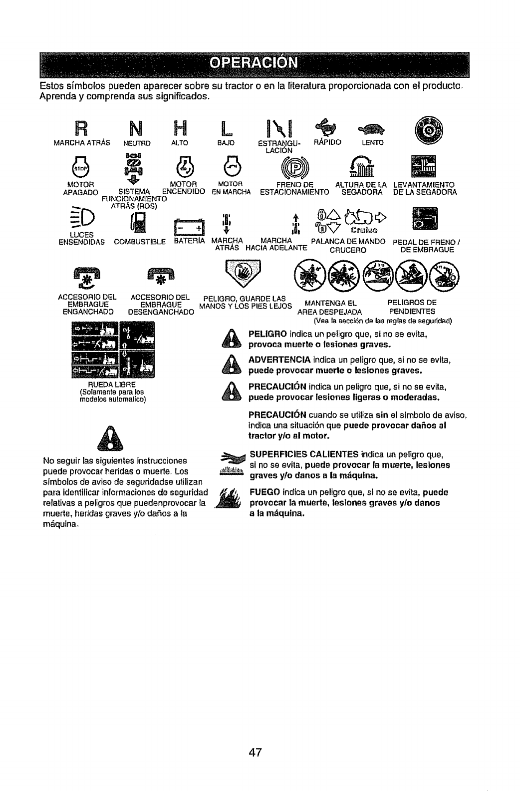
Estos simbolos pueden aparecer sobre su tractor oen la literatura proporcionada con el producto,
Aprenda y comprenda sus significados,
R
MARCHA ATRAS
MOTOR
APAGADO
LUCES
ENBENDIDAS
ACCESORIO DEL
EMBRAGUE
ENGANCHADO
N H L I' ,1
NEUTRO ALTO BAJO ESTRANGU- R/_PIDO LENTO
LAClON
" G (®)
MOTOR MOTOR FRENO DE ALTURA DE LA
SISTEMA ENCENDtDO EN MARCHA ESTACIONAMIENTO SEGADORA
FUNClONAMfENTO
ATR_,S (ROB)
COMBUSTIBLE BATERIA
ACCESORIO DEL
EMBRAGUE
DESENGANCHADO
RUEDA LtBRE
(Solamente para los
modelos aul.omalico)
LEVANTAMIENTO
DE LA SEGADORA
,,
_._ARO.AMA'_O.APA_.CADEMA.OO
ATRAS.AO,AAOELA.TEC"UCERO
PEDAL DE FRENO t
DE EMBRAGUE
PELfGRO, GUARDE LAB
MAt,lOS Y LOS PIES LEJOS MANTENGA EL PELIGROS DE
AREA DESPEJADA PENDIENTES
(Yea la secci6n de las regbs de seguridad)
PELIGRO indica un peligro que, si no se evita,
provoca muerte o lesiones graves.
ADVERTENCIA indica un peligro que, si no se evita,
puede provocar muerte o leslones graves,
PRECAUCI(_N indica un peligro que, si no se evil,a,
puede provocar lesiones ligeras o moderadas.
&
No seguir las siguientes instrucciones
puede provocar heridas omuerteo Los .=_,_I_=.=,===,,_
s[mbolos de avtso de seguridadse utilizan
para identificarinformaciones de seguridad _._,j,
relativas a petigros que puedenprovocar la .
muerte, hertdas graves y/o dafios a la
m&quinao
PRECAUCI6N cuando se uttliza sin el sfmbolo de aviso,
indica una sltuactSn que puede provocar da_os al
tractor y/o al motor.
SUPERFICIES CALIENTES indica un peligro que,
si no se evita, puede provocar la muerte, lesiones
graves yto danos a la m&qulna,
FUEGO tndtcaun peligro que, si no se evita, puede
provocar la muerte, leslones graves ylo danos
a la m_quina,
47
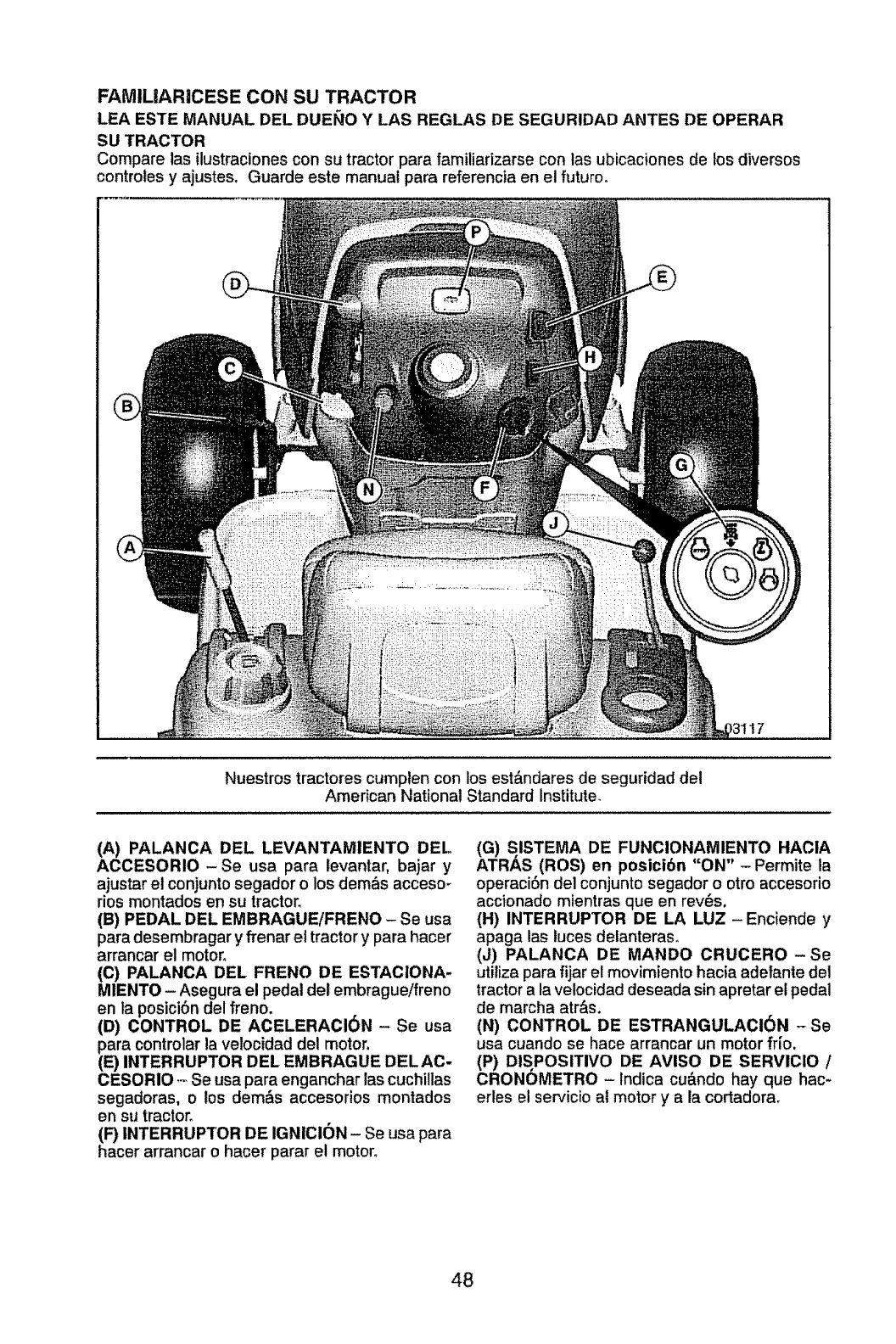
FAMlUARICESE CON SU TRACTOR
LEA ESTE MANUAL DEL DUEl;tO Y LAS REGLAS DE SEGURIDAD ANTES DE OPERAR
SU TRACTOR
Compare tas ilustraciones con su tractor para familiarizarse con las ubicaciones de los diversos
controtes y ajustes, Guarde este manual para referencia en el futuro.
17
Nuestros tractores cumplen con los est&ndares de seguridad del
American National Standard Institute.
(A) PALANCA DEL LEVANTAMIENTO DEL
ACCESORIO -Se usa para levantar, bajar y
ajustar el conjunto segador o los demos accesm
dos montados en su tractor.
(B) PEDAL DEL EMBRAGUE!FRENO - Se usa
para desembragar yfrenar el tractor y para hacer
arrancar el motor.
(C) PALANCA DEL FRENO DE ESTACIONA-
MIENTO - Asegura el pedal del embragueifreno
en ta posici6n del freno.
(D) CONTROL DE ACELERACI6N - Se usa
para controlar la vetocidad del motor.
(E) INTERRUPTOR DEL EMBRAGUE DELAC-
CESORIO .- Se usa para enganchar las cuchillas
segadoras, o los demos accesorios montados
en su tractor.
(F) INTERRUPTOR DE IGNICION - Se usa para
hacer arrancar o hacer parar el motor.
(G) SISTEMA DE FUNCIONAMIENTO HACIA
ATRAS (ROS) en posicibn "ON" -Permite la
operaci6n del conjuntosegador o otro accesorio
accionado mientras queen rev_s.
(H) INTERRUPTOR DE LA LUZ- Enciende y
apaga las luces delanteraso
(J) PALANCA DE MANDO CRUCERO- Se
utiliza para fijar el movimtento hacia adefante del
tractor a la velocidad deseada sin apretar el pedal
de marcha atr&s.
(N) CONTROL DE ESTRANGULACI6N -Se
usa cuando se hace arrancar un motor frio.
(P) DISPOSITIVO DE AVISO DE SERVICIO /
CRONOMETRO -Indica cu&ndo hay que hac-
erles el servicio al motor y a la cortadora.
48
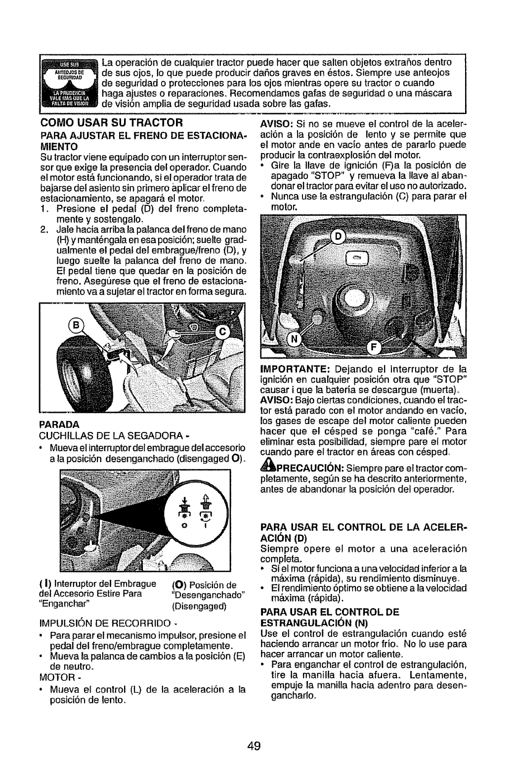
La operaci6n de cualquier tractor puede hacer que salten objetos extrafios dentro
de sus ojos, Io que puede producir daSos graves en _stos. Siempre use anteojos
de seguridad o protecciones para los ojos mientras opere su tractor o cuando
haga ajustes o reparaciones_ Recomendamos galas de seguridad o una m_scara
de visi6n amplia de seguddad usada sobre las gafas,
COMO USAR SU TRACTOR
PARA AJUSTAR EL FRENO DE ESTACIONA-
MtENTO
Su tractor viene equipado con un interruptorsen-
sor que exige la presencia det operador. Cuando
el motor est_ funcionando, si el operador trata de
bajarse del asiento sin primero &plicar el freno de
estacionamiento, se apagar& el motor.
t. Presione el peda! (D) del freno compteta-
mente ysostengalo.
2, Jale haciaarriba la palanca del freno de mano
(H) ymant_ngata en esa posici6n; suelte grad-
ualmente el pedal del embrague/freno (D), y
luego suette la palanca del freno de mano_
El pedal tiene que quedar en la posici6n de
freno. Asegurese que el freno de estaciona-
miento va a sujetar el tractoren forma segura_
AVISO: Si no se mueve el control de la aceler_
aci6n a la posici6n de lento yse permite que
el motor ande en vacio antes de pararlo puede
producir ta contraexplosi6n del motor.
• Gire la Ilave de ignici6n (F)a !a posici6n de
apagado "STOP" y remueva la I!ave al abam
donar el tractor para evitar el uso no autorizado.
• Nunca use la estrangulaci6n (C) para parar el
motor.
PARADA
CUCHtLLAS DE LA SEGADORA -
•Mueva el interruptor del embrague del accesorio
a la posici6n desenganchado (disengaged O) o
IMPORTANTE: Dejando el interruptor de la
ignici6n en cualquier posici6n otra que "STOP"
causar ique la bateria se descargue (muerta)_
AVISO: Bajo ciertas condiciones, cuando el trac-
tor est& parado con el motor andando en vacio,
los gases de escape det motor caliente pueden
hacer que el c_sped se ponga "cafe." Para
eliminar esta posibilidad, siempre pare el motor
cuando pare el tractor en &reas con c6sped.
_IbPRECAUCI6N: Siempre pare el tractor com-
pletamente, segOn se ha descrito anteriormente,
antes de abandonar la posici6n det operador.
(I) Interruptor del Embrague (O) Posici6n de
del Accesorio Estire Para "Desenganchado"
"Enganchar" (Disengaged)
IMPULSION DE RECORRIDO -
• Para parar el mecanismo impulsor, presione el
pedal del freno/embrague completamente.
• Mueva la palanca de cambios a ta posici6n (E)
de neutroo
MOTOR -
• Mueva e! control (L) de la aceleraci6n a la
posici6n de lento,
PARA USAR EL CONTROL DE LA ACELER-
ACI(_N (D)
Siempre opere el motor auna aceleraci6n
completa.
°Si el motor funciona a unavelocidad inferiora la
m&xima (r,_pida),su rendimiento disminuyeo
.El rendimiento 6ptimo se obtiene ala velocidad
m&xima (r&pida).
PARA USAR EL CONTROL DE
ESTRANGULACI_)N (N)
Use el control de estrangulaci6n cuando est_
haciendo arrancar un motor frio. No Io use para
hacer arrancar un motor caliente,
•Para enganchar el control de estrangulaci6n,
tire la manilla hacia afuera. Lentamente,
empuje la manilla hacia adentro para desen-
gancharloo
49
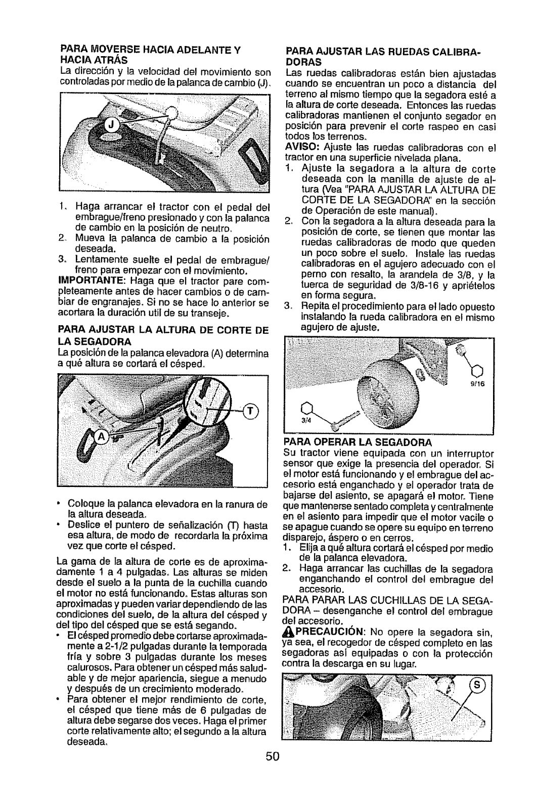
PARA MOVERSE HACIA ADELANTE Y
HACIA ATRAS
La direcci6n y ta velocidad del movimiento son
controladaspormedio de la palanca de cambio(J),
1o Haga arrancar el tractor con el pedal del
embrague/freno presionado y con la palanca
de cambio en la posici6n de neutro.
2. Mueva la palanca de cambio a la posici6n
deseada.
3_ Lentamente suelte el pedal de embrague/
freno para empezar con el movimiento.
IMPORTANTE: Haga que el tractor pare com-
pleteamente antes de hacer cambios o de cam-
biar de engranajes. Si no se hace 1oanterior se
acortara la duraciSn util de su transeje.
PARA AJUSTAR LA ALTURA DE CORTE DE
LA SEGADORA
La posici6nde la palanca elevadora (A) determina
a qu_ altura se cortar_ el c_sped_
PARA AJUSTAR LAS RUEDAS CALIBRA-
DORAS
Las ruedas calibradoras est&n bien ajustadas
cuando se encuentran un poco a distancia del
terreno al mismo tiempo que la segadora esl_ a
la altura de corte deseada. Entonces las ruedas
calibradoras mantienen el conjunto segador en
posici6n para prevenir el corte raspeo en casi
todos los terrenos_
AMISO: Ajuste tas ruedas calibradoras con el
tractor en una superficie nivelada plana.
to Ajuste la segadora a la altura de corte
deseada con la maniila de ajuste de al-
tura (Vea "PARA AJUSTAR LA ALTURA DE
CORTE DE LA SEGADOR/_' en la secci6n
de Operaci6n de este manual).
2. Con la segadora a la altura deseada para la
posici6n de corte, se tienen que montar las
ruedas calibradoras de modo que queden
un poco sobre el suelo. Instale ]as ruedas
calibradoras en el agujero adecuado con el
perno con resalto, la arandela de 3/8, y la
tuerca de seguridad de 3/8-16 y apri_telos
en forma segura.
3o Repita el procedimiento para et lado opuesto
instalando la rueda calibradora en et mismo
agujero de ajuste.
• Coloque la patanca elevadora en la ranura de
la altura deseadao
• Deslice el puntero de sefializaci6n (T) hasta
esa altura, de modo de recordarla la pr6xima
vez que corte el c_sped.
La gama de la altura de corte es de aproxima-
damente I a 4 pulgadas_ Las alturas se miden
desde el sueto a ta punta de la cuchilla cuando
el motor no est& funcionandoo Estas alturas son
aproximadas y pueden variar dependiendo de las
condiciones del suelo, de la altura del c6sped y
de! tipo del c6sped que se est& segando.
• El c_sped promedio debe cortarse aproximada-
mente a 2-I/2 pulgadas durante la temporada
ffia y sobre 3 pulgadas durante los meses
calurosos. Para obtener un c_sped m_s salud-
able y de mejor apariencia, siegue a menudo
y despu_s de un crecimiento moderado.
°Para obtener el mejor rendimiento de corte,
el c_sped que tiene m_s de 6 pulgadas de
altura debe segarse dos veceso Haga el primer
corte relativamente alto; el segundo a la altura
deseadao
5O
PARA OPERAR LA SEGADORA
Su tractor viene equipada con un interruptor
sensor que exige la presencia del operadoro Si
el motor est,. funcionando y el embrague del ac-
cesorio est,, enganchado y el operador trata de
bajarse del asiento, se apagar& el motor. Tiene
que mantenerse sentado completa ycentralmente
en el asiento para impedir que el motor vacile o
se apague cuando se opere su equipo en terreno
disparejo, dspero o en cerros.
1. Elija a qu_ altura cortara et c_sped pot medio
de la palanca elevadora.
2. Haga arrancar las cuchillas de la segadora
enganchando el control de! embrague del
accesorio.
PARA PARAR LAS CUCHILLAS DE LA SEGA-
DORA- desenganche el control del embrague
del accesorio.
_PRECAUCI6N: No opere la segadora sin,
ya sea, el recogedor de c6sped compteto en las
segadoras asl equipadas o con la protecci6n
contra la descarga en su lugar.
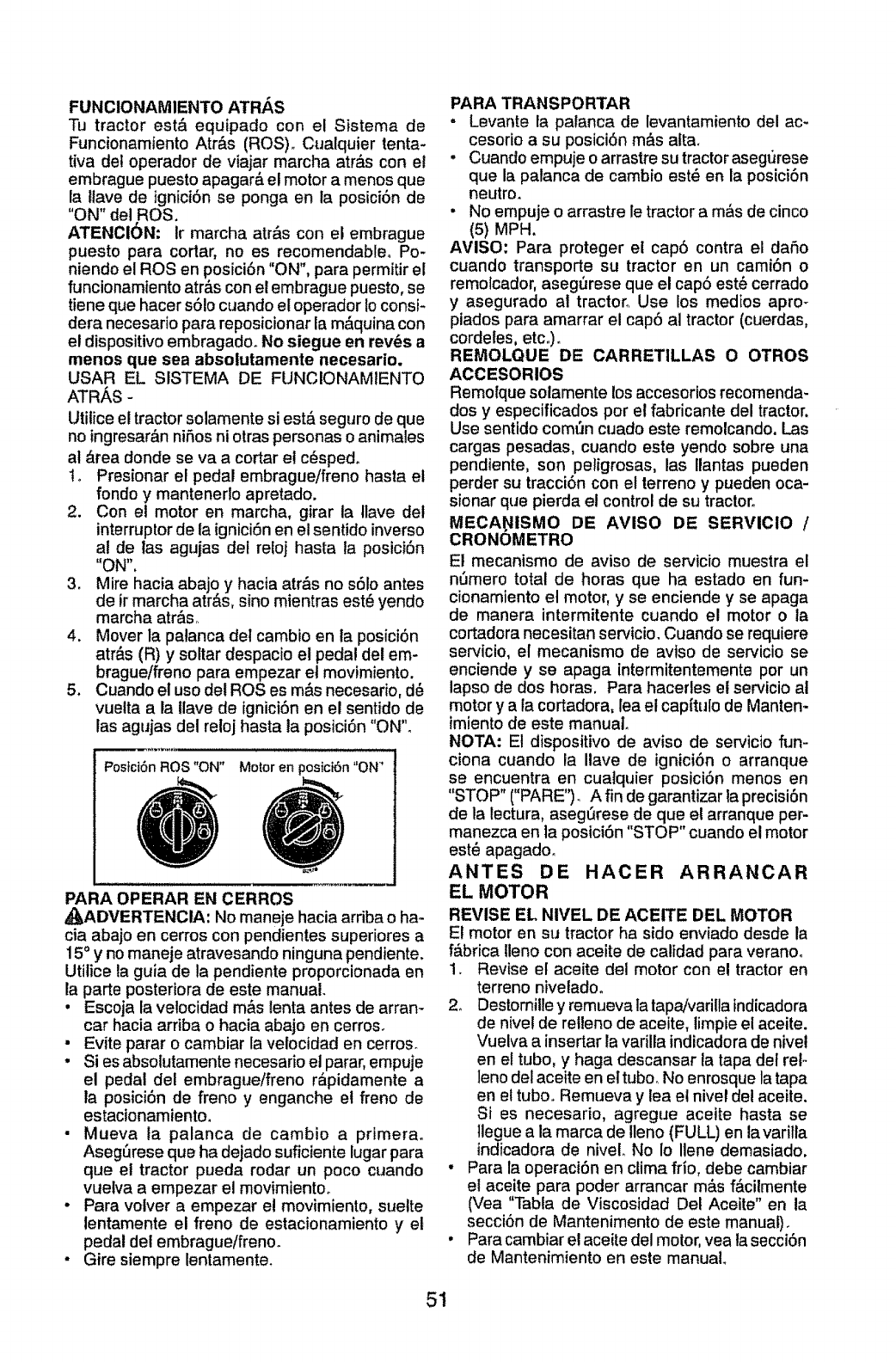
FUNCIONAMIENTO ATRAS
Tu tractor est_ equipado con el Sistema de
Funcionamiento Atr&s (ROS). Cualquier tenta-
tiva del operador de viajar marcha atr&s con el
embrague puesto apagar& el motor a menos que
la ltave de ignici6n se ponga en ia posici6n de
"ON" del ROS.
ATENCI6N: lr marcha atr&s con el embrague
puesto para cortar, no es recomendableo Po-
niendo el ROSen posici6n "ON", para permitir el
funcionamiento atr&s con el embrague puesto, se
tiene que hacer s61ocuando el operador Io consi-
dora necesario para reposicionar la m&quina con
el dispositivo embragado. No siegue en rev_s a
menos que sea absolutamente necesario.
USAR EL SISTEMA DE FUNCIONAMIENTO
ATRAS -
Utilice el tractor solamente si est& seguro de que
no ingresar&n niSos ni otras personas o animales
al _trea donde se va a cortar el c6sped,
t, Presionar el pedal embrague/freno hasta et
rondo y mantenerlo apretado.
2. Con el motor en marcha, girar ta tlave det
interruptor de la igniciSn en el sentido inverso
al de las agujas del reloj hasta la posici6n
"ON".
3. Mire hacia abajo y hacia atr_,s no s6Io antes
de ir marcha atr_,s, sino mientras est6 yendo
marcha atr&s.
4. Mover la palanca del cambio en la posiciSn
atr&s (R) y soltar despacio el pedal del em-
brague/freno para empezar el movimiento.
5. Cuando el uso del ROSes m&s necesario, d6
vueita a la llave de ignici6n en el sentido de
las agujas dei reloj hasta la posici6n "ON"_
Postci6n ROS "ON" Motor en pos{ct6n "ON'
PARA OPERAR EN CERROS
,_J,ADVERTENCIA: No maneje hacia arriba o ha-
cia abajo en cerros con pendientes superiores a
15° y no maneje atravesando ninguna pendiente.
Utilice la guia de la pendiente proporcionada en
la parte posteriora de este manual.
, Escoja la velocidad mbs lenta antes de arran-
car hacia arriba o hacia abajo en cerros_
• Evite parar o cambiar la velocidad en cerroso
•Si es absolutamente necesario el parar, empuje
el pedal del embrague/freno r_pidamente a
la posici6n de freno y enganche el freno de
estacionamiento.
• Mueva la palanca de cambio a primerao
Aseg6rese que ha dejado suficiente lugar para
que el tractor pueda rodar un poco cuando
vuetva a empezar el movimientoo
• Para voiver a empezar e! movimiento, suelte
lentamente el freno de estacionamiento y el
pedal del embrague/freno_
• Gire siempre lentamente.
PARA TRANSPORTAR
, Levante la palanca de levantamiento del ac-
cesorio a su posiciSn m&s att&
, Cuando empuje o arrastre su tractor asegt)rese
que la palanca de cambio est_ en la posici6n
neutron
•No empuje o arrastre le tractor a m&s de cinco
(5) MPH.
AVISO: Para proteger el cap6 contra el daSo
cuando transporte su tractor en un cami6n o
remolcador, asegSrese que el cap6 est_ cerrado
y asegurado al tractor. Use los medios aprm
piados para amarrar el cap6 al tractor (cuerdas,
cordetes, etc°).
REMOLQUE DE CARRETILLAS O OTROS
ACCESORIOS
Remolque solamente los accesorios recomenda-
dos y especificados por el fabricante del tractor.
Use sentido comt)n cuado este remolcando. Las
cargas pesadas, cuando este yendo sobre una
pendiente, son petigrosas, las Ilantas pueden
perder su tracci6n con el terreno y pueden oca-
sionar que pierda el control de su tractor.
MECA_IISMO DE AVISO DE SERVICIO /
CRONOMETRO
Et mecanismo de aviso de ser¢icio muestra el
n6mero total de horas que ha estado en fun-
cionamiento et motor, y se enciende yse apaga
de manera intermitente cuando el motor o la
cortadora necesitan servicio. Cuando se requiere
servicio, el mecanismo de avtso de servicio se
enciende y se apaga intermitentemente por un
lapso de dos horas. Para hacerles et servicio ai
motor y a la cortadora, lea el capftulo de Manten*
{miento de este manual.
NOTA: El dispositivo de aviso de servicio fun-
ciona cuando la Ilave de igniciSn o arranque
se encuentra en cualquier posici6n menos en
"STOP" ("PARE")_ A fin de garantizar taprecisi6n
de la lectura, asegt_rese de que el arranque per-
manezca en la posici6n "STOP" cuando e! motor
est_ apagado.
ANTES DE HAOER ARRANCAR
EL MOTOR
REVISE EL NIVEL DE ACEITE DEL MOTOR
El motor en su tractor ha side enviado desde la
f&brica tleno con aceite de calidad para veranoo
1. Revise el aceite del motor con e! tractor en
terreno nivetado°
2. Destomille y remueva la tapajvarilla fndicadora
de nivel de relleno de aceite, limpie el aceite.
Vuelva a insertar la varilla indicadora de nivel
en el tubo, y haga descansar la tapa det tel o
leno del aceite en eltubo. No enrosque la tapa
en el tubo.. Rernueva y lea el nivef del aceite.
Si es necesario, agregue aceite hasta se
llegue a la marca de Ileno (FULL) en la varilla
indicadora de nivet. No Io Ilene demasiado.
• Para la operaci6n en ctima frio, debe cambiar
el aceite para poder arrancar m&s f&cilmente
(Vea "Tabla de Viscosidad Del Aceite" en la
secci6n de Mantenimento de este manual).
, Para cambiar el aceite del motor, vea la secci6n
de Mantenimiento en este manual
51
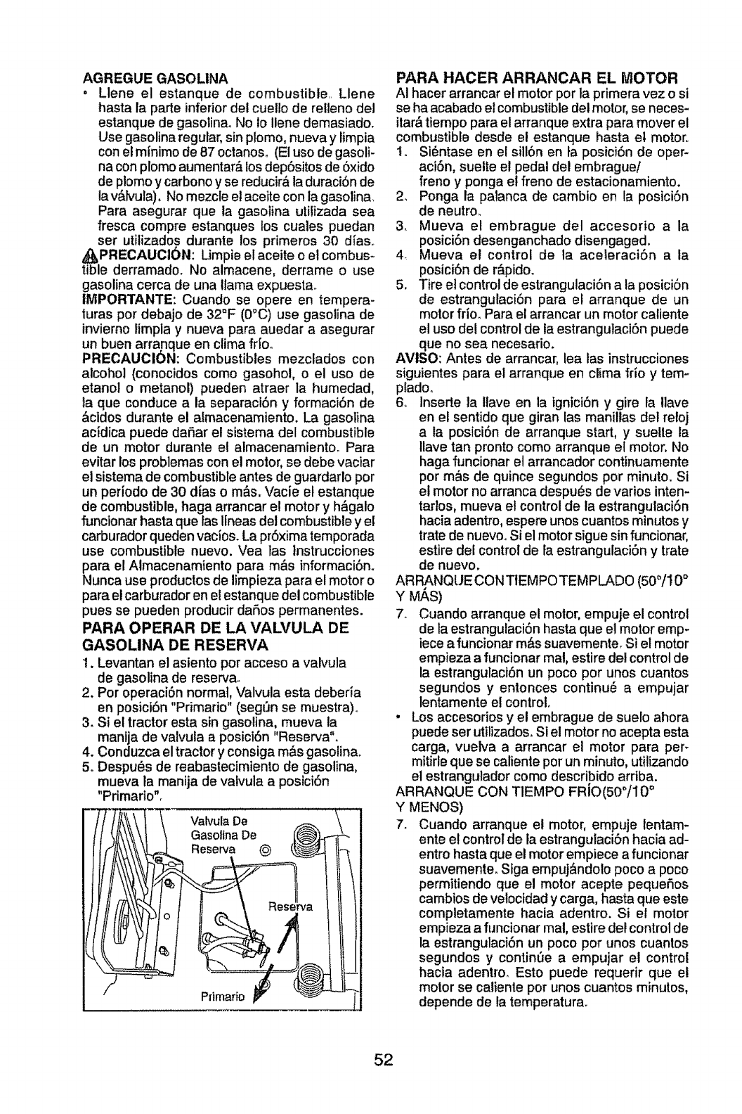
AGREGUE GASOLINA
• Llene el estanque de combustible,. Llene
haste ta parte inferior det cuello de relleno del
estanque de gasoline. No 1oIlene demasiadoo
Use gasoline regular,sin plomo, nueva y limpia
con el m{nimo de 87 octanoso (El uso de gasoli-
na con plomo aumentar_, los dep6sitos de 6xido
de plomo y carbonoy se reducir_,la duraci6n de
lav&lvula). No mezcle el aceite con ta gasolina.
Para asegurar que ta gasotina utilizada sea
fresca compre estanques los cuales puedan
set utitizados durante los primeros 30 d{as..
,_PRECAUCI_N: Limpie et aceite o el combus-
tible derramado. No almacene, derrame o use
gasoline cerca de una llama expuesta.
IMPORTANTE: Cuando se opere en tempera-
turas por debajo de 32°F (0°C) use gasolina de
invierno timpia y nueva para auedar a asegurar
un buen arranque en clima fifo°
PRECAUCION: Combustibles mezclados con
alcohol (conocidos como gasoho!, o el uso de
etanol o metanol) pueden atraer la humedad,
ta que conduce ala separact6n y formaci6n de
&cidos durante el almacenamiento. La gasoline
acidica puede da_,ar el sistema del combustible
de un motor durante et almacenamientoo Para
evitar los problemas con el motor, se debe vaciar
el sistema de combustible antes de guardarlo por
un periodo de 30 d{as o m_,s.Vacie el estanque
de combustible, haga arrancar el motor y h&galo
funcionar haste que las lineas del combustible y el
carburador queden vacios_ La pr6xima temporada
use combustible nuevo. Vea las lnstrucciones
para el Atmacenamiento para m&s informaci6n.
Nunca use productos de limpieza para el motor o
pare el carburador en el estanque del combustible
pues se pueden producir daSos permanentes.
PARA OPERAR DE LA VALVULA DE
GASOLINA DE RESERVA
1. Levantan el asiento por acceso a valvula
de gasoline de reserva_
2. Por operaci6n normal, Valvula esta deberia
en posici6n "Primario" (seg_n se muestra)..
3. Si el tractor esta sin gasolina, mueva ia
manija de valvuta a posici6n "Reserve".
4. Conduzca el tractor y consiga m&s gasolina_
5. Despu_s de reabastecimiento de gasolina,
mueva la manija de valvula a posici6n
"Primario".
Vatvula De
Gasoltna De
Reserva (_
Prtmario
PARA HACER ARRANCAR EL I_OTOR
AI hacer arrancar el motor porta primera vez o si
se ha acabado el combustible del motor, se neces-
itar_,tiempo pare el arranque extra pare mover el
combustible desde el estanque hasta et motor,.
t. Si6ntase en el sill6n en fa posiciSn de oper-
aciSn, suelte el pedal del embrague/
freno y ponga el freno de estacionamiento.
2o Ponga la patanca de cambio en la posici6n
de neutro.
3. Mueva el embrague del accesorio ala
posici6n desenganchado disengaged.
4. Mueva et control de la aceteraci6n ala
posici6n de r&pido.
5. Tire el control de estrangulaciSn ata posici6n
de estrangulaci6n para el arranque de un
motor frio. Pare el arrancar un motor caliente
el uso del control de la estrangulaci6n puede
qua no sea necesarioo
AVISO: Antes de arrancar, lea tas instrucciones
siguientes para el arranque en clima frlo y tem-
pladoo
6,, Inserte ta llave en la ignici6n y gire la !lave
en el sentido que giran las manillas del retoj
ala posici6n de arranque start, y suelle la
llave tan pronto como arranque el motor. No
haga funcionar el arrancador continuamente
por m&s de quince segundos por minuto. Si
el motor no arranca despu_s de varios inten-
tartos, mueva el control de la estrangutaci6n
hacia adentro, espere unos cuantos minutos y
trate de nuevooSi el motor sigue sin funcionar,
estire del control de la estrangulaci6n y trate
de nuevo.
ARRANQUE CON TIEMPO TEMPLADO (50°/10 °
Y M,_S)
7o Cuando arranque el motor, empuje el control
de la estrangulaci6n haste que el motor emp-
iece a funcionar m_,ssuavemente_ Si el motor
empieza a funcionar mal, estire del control de
la estrangulaci6n un poco por unos cuantos
segundos y entonces continu_ a empujar
lentamente el control.
.Los accesorios y et embrague de suelo ahora
puede ser utilizados. Si el motor no acepta esta
carga, vueiva a arrancar el motor para pert
mitirle que se caliente por un minuto, utilizando
el estrangutador como describido arriba.
•O
ARRANQUE CON TIEMPO FR!O(50°/IO
Y MENOS)
7_ Cuando arranque et motor, empuje lentam-
ente e! control de la estrangulaci6n hacia ad-
entro hasta que el motor empiece a funcionar
suavemente. Siga empuj&ndolo poco a poco
permitiendo que el motor acepte pequeSos
cambios de velocidad y carga, haste que este
completamente hacia adentro. Si el motor
empieza a fi_ncionar mal, estire det control de
la estrangulaci6n un poco por unos cuantos
segundos y continSe a empujar el control
hacia adentro. Esto puede requerir que e!
motor se caliente por unos cuantos minutos,
depende de la temperatura.
52
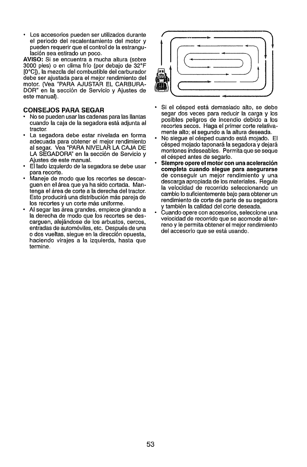
*Los accesorios pueden ser utilizados durante
el periodo del recalentamiento de! motor y
pueden requerir que et control de la estrangu-
laci6n sea estirado un poco_
AVISO: Si se encuentra a mucha altura (sobre
3000 pies) o en clima frlo (por debajo de 32°F
[0"C]), la mezcla del combustible del carburador
debe ser ajustada para el mejor rendimiento del
motor. Cv'ea"PARA AJUSTAR EL CARBURA-
DOR" en la secci6n de Servicio y Ajustes de
este manual),
CONSEJOS PARA SEGAR
•No se pueden usar ias cadenas paratas Ilantas
cuando la caja de la segadora est& adjunta al
tractor_
•La segadora debe estar nivelada en forma
adecuada para obtener el mejor rendimiento
al segar. Vea "PARA NtVELAR LA CAJA DE
LA SEGADOF_' en la secci6n de Sewicio y
Ajustes de este manual.
•El lade izquierdo de la segadora se debe usar
para recorte.
•Maneje de modo que los recortes se descar-
guen en el ,_rea que ya ha sido cortada. Man-
tenga el &rea de corte a ta derecha det tractor_
Esto producir& una distribuci6nm&s pareja de
los recortes y un corte m&suniforme.
.AI segar las &rea grandes, empiece girando a
la derecha de modo que los recortes se des-
carguen, alej&ndose de los arbustos, cercos,
entradas de autom6viles, etc. Despu6s de una
o dos vueltas, siegue en la direcci6n opuesta,
haciendo virajes ala izquierda, hasta que
termine,
f-------
i,,)
•Si el c_sped est& demasiado alto, se debe
segar dos veces para reducir la carga y los
posibles petigros de incendio debido a los
recortes secos, Haga el primer corte relativa-
mente alto; el segundo a la altura deseadao
.No siegue el c_sped cuando est& mojado. El
c_sped mojado taponar& la segadora y dejar&
montones indeseables. Permita que se seque
et c_sped antes de segarloo
. Stempre opere el motor con una aceleraci6n
completa cuando slegue para asegurarse
de conseguir un mejor rendimiento y una
descarga apropiada de los materiales. Regule
la velocidad de recorrido seleccionando un
camblo io suficientemente bajo para obtener un
rendimiento de corte de parte de su segadora
y tambi_n la calidad det corte deseadao
•Cuando opere con accesorios, seleccione una
velocidad de recorrido que se acomode at ter-
reno y le permita obtener el mejor rendimiento
del accesorio que se est_ usando_
53
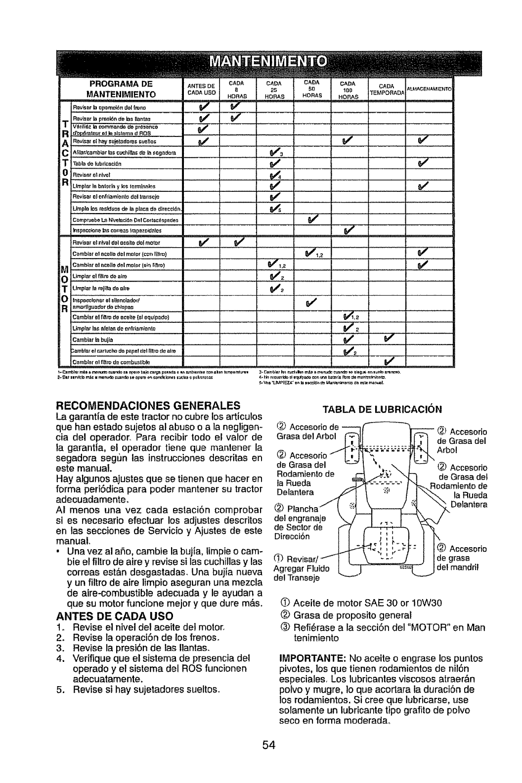
PROGRAMA DE ANTESDE CAOA CAOA CADA CADA CADA AU,_ACB'_A_TO
MANTENtMIENTO CADA USe B 25 50 10D TE3/iPORADA
HORAS HORAS HORAS HORAB
Ravis_r b opDmd(_n dollmno
RaviSllr ta prssk_nde,tos ikmlas
Rd'op6ra_tJurtt! lo t+_teme d ROS V'
A Ro._=.t,..._o-._mdom._oo,oo 0/ :
C Ah_r, fcl_mbl_r _lS cuchiP,_l; rio la t:ogBrio_ I _tl'3
T T.mdole_r+ceo_+. _'
Ru_p_e,,,b.l,rf,y_ _m._ ' ........ _........ :_e/
Revisel o_on(riem}e_to dol lt_nsejo
Umpie los _re_Juos de tnplnoa dB d_rec_16n . . _5
Comp_ei:+_ LP, hllw:_ci_n Dn_ C_ tt==t+_p_ d_'s
ln,+pnmc;one +msco,teaS tmpl+_o_Je_os _ I
Reviser o=n_ d_lecelte dof molor V' V'
Cemb_ar o! acoUe d_l motor (c-_n fltlm) _1.2 _#_
Camb_nr o! ni:eile del motor |slntiffin)
OUmpire" el fl!lro _e atre . _2 _ .
............................ ....... ,,, , , , , , ,, , .... ,,, ........ ,_ , , .....
RnmortlgtJeffor dr+chlr+pa_ .....
u=.,.,,._,.,m.do..!,,,_,_.,o ..................... i Iiii .... _[_ _
Cr_mb_arla bujla _ _+"
.-.==mb{et e! r_'_rt #c|m do p_pe! dot li_m de _im _2
Cemb_r el _+_mde oombusUb_e
RECOMENDACIONES GENERALES
La garantia de este tractor no cubre los articu!os
que han estado sujetos at abuse o ala negligen-
cia del operador_ Para recibir todo el valor de
ta garantta, el operador tiene que mantener la
segadora seg_'m tas instrucciones descritas en
este manual.
Hay algunos ajustes que se tienen que hacer en
forma peri6dica para poder mantener su tractor
adecuadamente,
At menos una vez cada estaci6n comprobar
si es necesario efectuar los adjustes descritos
en tas secciones de Servicio y Ajustes de este
manual.
. Una vez al are, cambie la buj(a, limpie o cam-
bie el filtrode aire y revise silas cuchillas y las
correas est&n desgastadas_ Una bujia nueva
y un fittro de aire limpio aseguran una mezcla
de aire-combustible adecuada y le ayudan a
que su motor funcione mejor yque dure m&s.
ANTES DE CADA use
!. Revise el nivel det aceite det motor.
2. Revise la operaciSn de los #enos.
3. Revise la presi6n de tas flantas.
4. Vefifique que el sistema de presencia del
operado y el sistema del ROS funcionen
adecuatamente.
5. Revise si hay sujetadores sueltoso
TABLA DE LUBRICACION
(_ Accesofio de
Grasa del Arbol
®
dBGrasadel
Rodamientode
la Rueda
Delantera
®
de! engranaje
de Sector de
Direcci6n
_) Revisar
Agregar F1uido
dot Transeje
t1 1
Il
_) Accesorio
de Grasa del
Arbol
L_ Accesodo
de Grasa del
Rodamiento de
_y, la Rueda
Delantera
\(_ Acceserio
de grasa
de! mandril
Aceite de motor SAE 30 or 10W30
@>Grasa de proposito general
Refi6rase ala secci6n del "MOTOR" en Man
tenimiento
IMPORTANTE: No aceite oengrase los puntos
pivotes, los que tienen rodamientos de nil_n
especiales. Los lubricantes viscosos atraer&n
polvo y mugre, Io que acortara la duraciSn de
los rodamientos. Si cree que lubricarse, use
solamente un lubficante tipo grafito de polvo
seco en forma moderadao
54
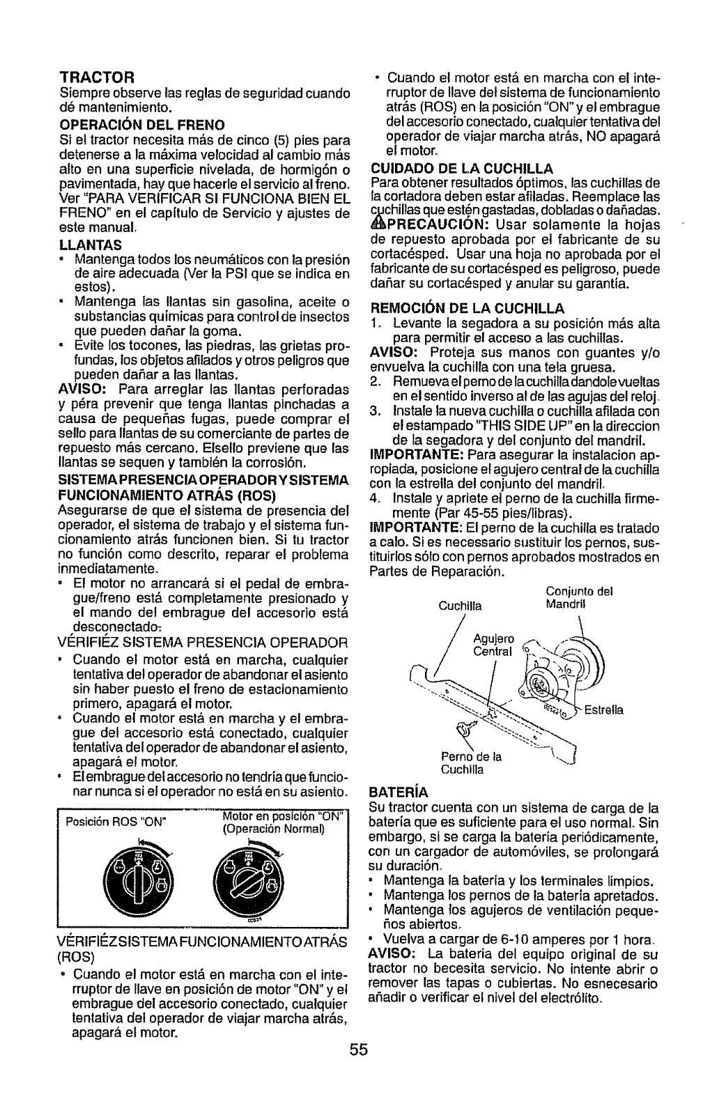
TRACTOR
Siempre observe las reglas de seguridad cuando
d_ mantenimiento.
OPERACi6N DEL FRENO
Si et tractor necesita m&s de cinco (5) pies para
detenerse a la m_lxima velocidad al cambio m&s
alto en una superficie nivelada, de hormig6n o
pavimentada, hay que hacerle el servicio al freno.
Ver "PARA VERIFICAR SI FUNCtONA BIEN EL
FRENO" en el cap(tulo de Servicio y ajustes de
este manual.
LLANTAS
• Mantenga todos los neum&ticos con ta presiSn
de aire adecuada (Ver la PSI que se indica en
estos).
• Mantenga las !lantas sin gasolina, aceite o
substancias quimicas para control de insectos
que pueden daSar la goma.
• Evite los tocones, las piedras, las grietas pro-
fundas, los objetos afilados y otros peligros que
pueden daSar alas tlantas.
AVISO, Para arreglar las Ilantas perforadas
y p_ra prevenir que tenga Ilantas ptnchadas a
causa de pequeSas fugas, puede comprar el
sello para llantas de su comerciante de partes de
repuesto m&s cercano. Elsel!o previene que las
llantas se sequen y tambi_n la corrosi6n.
SISTEMA PRESENCIA OPERADORYSISTEMA
FUNCIONAMIENTO ATRAS (ROS)
Asegurarse de que el sistema de presencia del
operador, el sistema de trabajo y el sistema fun-
cionamiento atr_s funcionen bien. Si tu tractor
no funci6n corno descrito, reparar et problema
inmediatamente_
, E! motor no arrancar& si el pedal de embra-
gueifreno est,, completamente presionado y
el mando de! embrague del accesorio est&
desconectado_
VI_RIFIt_Z SISTEMA PRESENCIA OPERADOR
• Cuando et motor est& en marcha, cualquier
tentativa del operador de abandonar el asiento
sin haber puesto el freno de estacionamiento
primero, apagar& el motor.
• Cuando el motor est_ en marcha y el embra-
gue del accesodo est,. conectado, cualquier
tentativa del operador de abandonar el asiento,
apagar& e! motor.
• Elembrague del accesodo notendria que funcio-
nat nunca si el operador no est& en su asiento.
Posici6n ROS "ON" Motor en posfci6n "ON"
(Operact6n Normal)
VERIFIt_Z SISTEMA FUNCIONAMtENTO ATR,_S
(ROS)
• Cuando el motor est& en marcha con el inte-
rruptor de Ilave en posiciSn de motor "ON" y et
embrague del accesorio conectado, cualquier
tentativa del operador de viajar marcha atr&s,
apagar_ el motor.
oCuando et motor est_ en marcha con el inte-
rruptor de tlave det sistema de funcionamiento
atr&s (ROS) en ta posiciSn "ON" y el embrague
del accesodo conectado, cuatquier tentativa del
operador de viajar marcha atr&s, NO apagar_
el motor_
CUIDADO DE LA CUCHILLA
Para obtener resultados 6ptimos, las cuchfllas de
la cortadora deben estar afiladas. Reemplace las
,_hiltas que est_n gastadas, dobladas o daSadas.
REOAUCION: Usar solamente ta hojas
de repuesto aprobada pot et fabricante de su
cortac_sped. Usar una hoja no aprobada por et
fabricante de su cortac_sped es peligroso, puede
daSar su cortac_sped y anutar su garantia.
REMOCI6N DE LA CUCHILLA
1. Levante la segadora a su posiciSn m&s alta
para permitir el acceso a las cuchilfas.
AVISO: Proteja sus manos con guantes y/o
envuelva la cuchilla con una tela gruesa.
2. Remueva el perno de lacuchilladandolevueltas
en el sentido inverso al de las agujas del reloj_
3. Instale la nueva cuchilla o cuchilla afilada con
el estampado "THIS SIDE UP" en la direccion
de la segadora y del conjunto del mandril.
IMPORTANTE: Para asegurar la instalacion ap-
ropiada, posicione el agujero central de lacuchilla
con la estrella det conjunto del mandril,
4. Instale y apriete e] perno de la cuchilta firme-
mente (Par 45-55 pies/libras).
IMPORTANTE: El perno de la cuchitla es tratado
a calo. Si es necessario sustituir los pernos, sus-
tituirlos s61ocon pernos aprobados mostrados en
Partes de Reparaci6n.
Conjuntodel
Cuchilla Mandril
Agujero
Central
Pem_odeIa
Cuchilla
BATERiA
Su tractor cuenta con un sistema de carga de la
bateria que es suficiente para et uso normal, Sin
embargo, si se carga ta bateria peri6dicamente,
con un cargador de autom6viles, se prolongar&
su duraci6no
• Mantenga la bateria y los terminales limpios,
• Mantenga los pernos de la bateria apretados,
• Mantenga los agujeros de ventilaci6n peque-
hos abiertoso
• Vuelva a cargar de 6-10 amperes por 1 hora.
AVISO: La bateria del equipo original de su
tractor no becesita servicioo No intente abrir o
remover las tapas o cubiertas. No esnecesario
aSadir o verificar el nivel del etectr6tito.
55
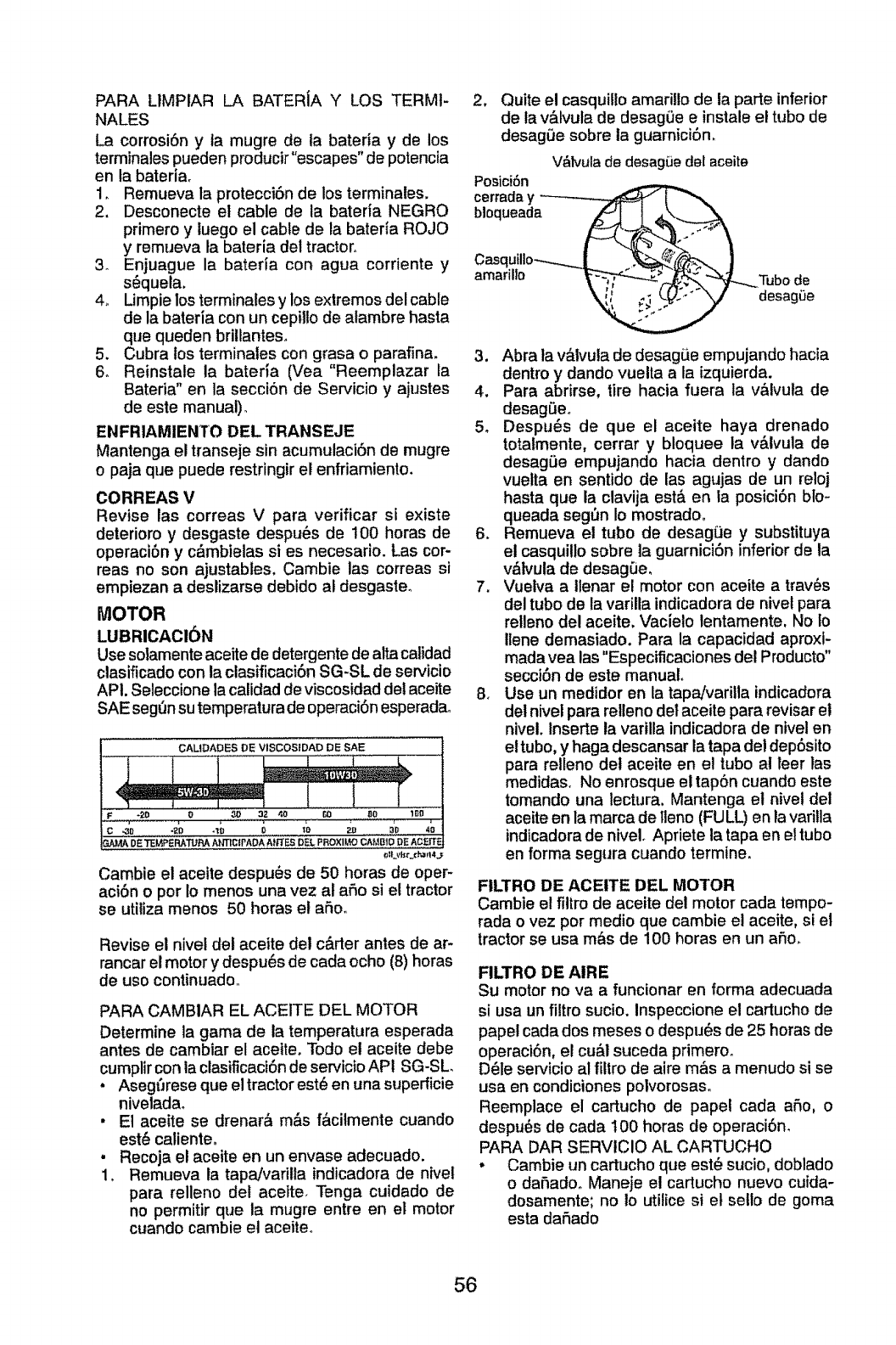
PARA LIMPIAR LA BATERJA Y LOS TERM1-
NALES
La corrosi6n y la mugre de la bateda y de los
terminales pueden producir"escapes" de potencia
en ta bateria,
1, Remueva ta protecciSn de los terminales.
2, Desconecte el cable de la batefia NEGRO
primero y luego el cable de la bateria ROJO
y remueva la bateria del tractor,,
3_ Enjuague la batefla con agua corriente y
s_queta,
4_ Limpie los terminales y los extremos del cable
de la bateria con un cepillo de alambre hasta
que queden briilanteso
5, Cubra los terminales con grasa o parafina.
6o Reinstale la bateria (Vea "Reemplazar la
Bateria" en la secci6n de Servicio y ajustes
de este manual)°
ENFRIAMIENTO DEL TRANSEJE
Mantenga el transeje sin acumulaciSn de mugre
o paja que puede restringir el enfriamiento,
CORREAS V
Revise las correas Vpara verificar si existe
deterioro y desgaste despu_s de 100 horas de
operacibn y c&mbielas si es necesario, Las cor-
reas no son ajustables. Cambie las correas si
empiezan a destizarse debido al desgasteo
MOTOR
LUBRICACI6N
Use sotamente aceite de detergentede alta catidad
clasificado con la clasificaci6n SG-SL de servicio
APt. Seleccione lacalidad de viscosidaddet aceite
SAE seg_n sutemperaturade operaci6nesperadao
CALIDADES DE VISCOSrDAD DE SAE
........... t
4 _ _ mWJt_ .....................1
.w_ DE_PERATU_t_rnctP,_bkt,_ _L PROXlUOC^_.IB10D__c_rrE
Cambie el aceite despu_s de 50 horas de oper-
aciSn o por Io menos una vez at afio si el tractor
se utiliza menos 50 horas et aSoo
Revise el nivel det aceite del c&rter antes de ar-
rancar el motor y despu6s de cada ocho (8) horas
de uso continuado,
PARA CAMBIAR EL ACEITE DEL MOTOR
Determine la gama de la temperatura esperada
antes de cambiar el aceiteo Todo el aceite debe
cumplir con la ctasificaci6nde servicio APt SG-SL
•AsegfJrese que el tractor est6 en una superficie
nivelada°
•El aceite se drenar& m&s f&cilmente cuando
est6 calienteo
.Recoja el aceite en un envase adecuado.
1, Remueva la tapa/varilla indicadora de nivel
para relleno del acelte, Tenga cuidado de
no permitir que la mugre entre en el motor
cuando cambie el aceite,
2, Quite el casquillo amarillo de la parte inferior
de la v&lvuta de desagOe e instale el tubo de
desagL_esobre la guarnici6n.
V&tvula de desagSe dal aceite
Posici6n
cerrada y----------
bloqueada
Casquillo_j
amarillo _
3. Abra la v&lvula de desagLie empujando hacia
dentro y dando vuelta a la izquierda.
4, Para abrirse, tire hacia fuera la v_lvuta de
desagSeo
5_ Despu_s de que el aceite haya drenado
totatmente, cerrar y bloquee la v&lvula de
desag_e empujando hacia dentro y dando
vuetta en sentido de las agujas de un reloj
hasta que la clavija est& en la posici6n blo-
queada segt_n Io mostrado,
6. Remueva el tubo de desagiJe y substituya
el casquillo sobre la guarnici6n inferior de la
v&lvula de desagSe,
7. Vuelva a llenar el motor con aceite a tray,s
del tubo de la varilla indicadora de nivel para
relleno del aceite. Vacielo lentamente, No Io
ilene demasiado. Para la capacidad aproxl-
mada yea las "Especificaciones del Producto"
secci6n de este manual.
&Use un medidor en la tapa/varilla indicadora
del nivel para reUenodel aceite para revisar el
nivel. Inserte la varilla indicadora de nivel en
ettubo, y haga descansar la tapa del dep6sito
para relleno det aceite en el tubo at leer las
medidas, No enrosque el tapSn cuando este
tomando una lectura. Mantenga el nivel del
aceite en la marca de lleno(FULL) en la varilla
indicadorade nivelo Apriete la tapa en el tubo
en forma segura cuando termine.
FILTRO DE ACEITE DEL MOTOR
Cambie el filtro de aceite del motor cada tempo-
rada ovez por medio que cambie el aceite, si el
tractor se usa m&s de 100 horas en un afio,
FILTRO DE AIRE
Su motor no va a funcionar en forma adecuada
si usa un filtro sucio, Inspeccione el cartucho de
papel cada dos meses o despu6s de 25 horas de
operaci6n, el cu&! suceda primero,
D_le servicio al filtro de aire m&s a menudo si se
usa en condiciones potvorosaso
Reemplace el cartucho de papel cada aSo, o
despu_s de cada 100 horas de operaci6n,
PARA DAR SERVICIO AL CARTUCHO
• Cambie un cartucho que est_ sucio, doblado
o daSado° Maneje el cartucho nuevo cuida-
dosamente; no Io utilice si et setlo de goma
esta daSado
56
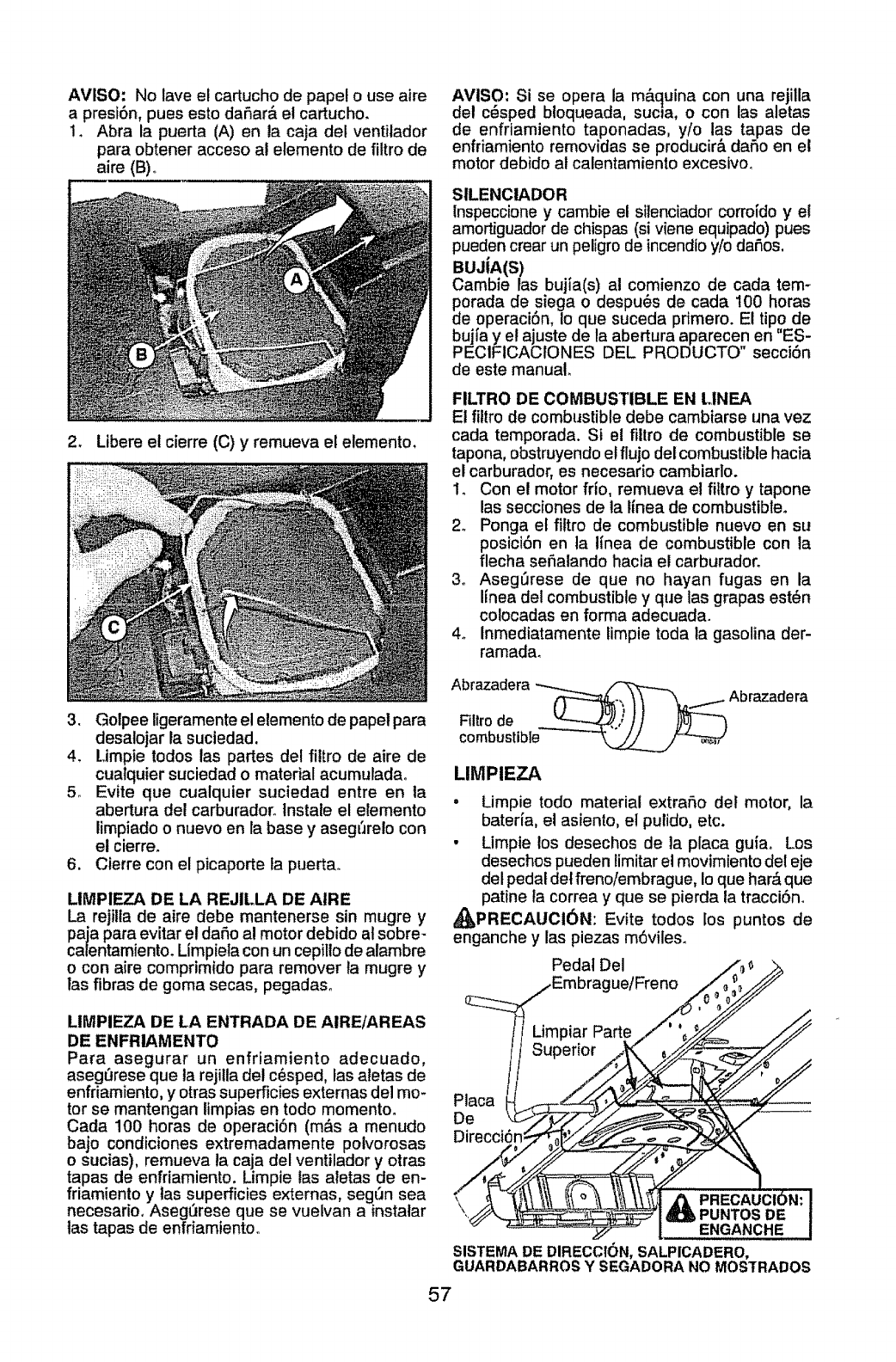
AVISO: No lave el cartucho de pape! o use aire
a prest6n, pues esto daAar& et cartucho.
1. Abra la puerta (A) en la caja del ventilador
para obtener acceso al elemento de filtro de
aire (B)._
AVISO: Si se opera la m&quina con una rejilla
del c_sped bloqueada, sucla, o con las aletas
de enfriamiento taponadas, y/o las tapas de
enfriamiento removidas se producira daAo en et
motor debido al calentamiento excesivoo
SILENClADOR
Inspeccione y cambie el silenciador corroido y el
amortiguador de chispas (si viene equipado) pues
pueden crear un peligro de incendio y/o daAos.
BUJtA(S)
Cambie las bujia(s) at comienzo de cada tem-
dPoradade siega o despu_s de cada 100 horas
e operaci6n, Io que suceda primero. E! tipo de
bujfa y et ajuste de la abertura aparecen en "ES-
PECIFICACIONES DEL PRODUCTO" secciSn
de este manual.
2. Libere el cierre (C) y remueva el elemento.
FILTRO DE COMBUSTIBLE EN LINEA
Et fillro de combustible debe cambiarse una vez
cada temporada. Si el fiitro de combustible se
tapona, obstruyendo etflujo delcombustiblehacia
el carburador, es necesario cambiarlo.
1, Con el motor frio, remueva el filtroy tapone
las secciones de ta finea de combustible.
2. Ponga el filtro de combustible nuevo en su
posici6n en ta Iinea de combustible con la
flecha seAalando hacia el carburador,
3o Aseg_rese de que no hayan fugas en la
lfnea del combustibley que las grapas est_n
colocadas en forma adecuada.
4o Inmediatamente limpie toda la gasolina der-
ramada.
3. Golpee ligeramente el elemento de papel para
desalojar la suciedad.
4. Limpie redes las partes del fittro de aire de
cualquier suciedad o material acumuladao
5o Evite que cualquier suciedad entre en la
abertura del carburadoro lnstale el elemento
limpiado o nuevo en la base y aseg(Jrelo con
el cierre.
6. Cierre con el picaporte la puertao
LIMPIEZA DE LA REJILLA DE AIRE
La rejiltade aire debe mantenerse sin mugre y
paja para evitar el dafio al motor debido at sobre-
calentamiento_ Limpieta con un cepillo de alambre
o con aire comprimido para remover {a mugre y
las fibras de goma secas, pegadaso
LIMPIEZA DE LA ENTRADA DE AIRE/AREAS
DE ENFRIAMENTO
Para asegurar un enfriamiento adecuado,
asegurese que ta rejilla det cesped, las aletas de
enfriamiento, y otras superficies externas del mo-
tor se mantengan ltmpias en todo momentoo
Cada 100 horas de operacion (mas a menudo
bajo condiciones extremadamente polvorosas
o sucias), remueva la caja del ventilador y otras
tapas de enfriamiento. Limpie las aletas de en-
friamiento y tas superficies externas, segQn sea
necesario, Aseg_rese que se vuelvan a instalar
tas tapas de enfdamientoo
Abrazadera _ _ A
Filtrode _.J ,// ])O)-'_
combustible _-_
LIMPIEZA
.Limpie todo material extrafio def motor, la
bateria, el asiento, e! putido, etc.
• Limpie los desechos de la placa guia. Los
desechos pueden limitar el movimiento del eje
del pedal det freno/embrague, Io que har_,que
patine ia correa y que se pierda la tracci6n.
_PRECAUOI6N: Evite todos los puntos de
enganche y las piezas m6viles.
Pedal Del
ue/Freno
Placa
De
PUNTOS DE
ENGANCHE
SISTEMA DE DIRECCION, SALPICADERO,
GUARDABARROS Y SEGADORA NO MOSTRADOS
57
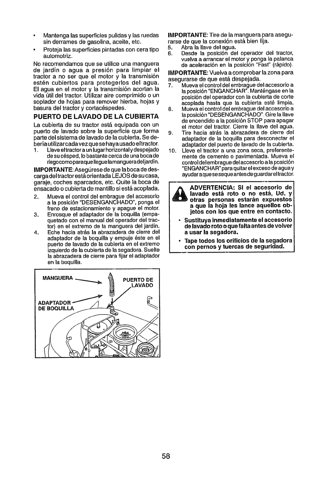
o Mantenga las superficies pulidas y las ruedas
sin derrames de gasolina, aceite, etc.
° Proteja las superficies pintadas con cera tipo
automotriz,
No recomendamos que se utilice una manguera
de jardin o agua a presi6n para limpiar el
tractor a no ser que el motor y la transmisi6n
est6n cubiertos para protegertos del aguao
El agua en el motor y la transmisiSn acortan la
vida t_tildel tractor,, Utilizar aire comprimido o un
soptador de hojas para remover hierba, hojas y
basura del tractor y cortac_spedes,
PUERTO I)15 LAVABO DE LA CUBIERTA
La cubierta de su tractor est& equipada con un
puerto de lavado sobre la superficie que forma
parte det sistema de lavado de la cubierta. Se de-
beria utitizar cadavez que se haya usado eltractor,
!o Ueveeltractor aun lugarhorizontatydespejado
desu c@.sped,Io bastante cerca de una bocade
riegocomoparaquelleguelamangueradeljardin,
IMPORTANTE: Asegt]rese de que la boca de des-
carga dettractor est&orientada LEJOS de su casa,
garaje, coches aparcados, etc. Quite ia boca de
ensacado 0 cubierta de mantillo si est& acoplada.
2. Mueva el control del embrague del accesofio
a la postciSn "DESENGANCHADO",ponga el
freno de estacionamiento y apague el motor.
3. Enrosque el adaptador de la boquilla (empa_
quetado con el manual del operador del trac-
tor) en el extremo de ta manguera del jardin.
4. Eche hacta atr&s la abrazadera de cierre del
adaptador de la boquilla y empuje 6ste en et
puerto de tavado de la cubierta en el extremo
izquierdo de la cubierta de la segadora_Suelte
la abrazadera de cierre para fijar el adaptador
en la boqullla.
IMPORTANTE: Tire de la manguera para asegu-
rarse de que la conexi6n est& bien fija,
5, Abra la Ilave del agua.
6, Desde la posici6n det operador del tractor,
vuelva a arrancar et motor y ponga la palanca
de aceleractSn en la postci6n "Fast" (r&pldo),
IMPORTANTE: Vuelva a comprobar la zona para
asegurarse de que est,_ despejada,
7_ Mueva et control del embrague del accesorio a
la posici6n "ENGANCHAR', Mant6ngase en la
posici6n del operador con la cubierta de corte
acoplada hasta que la cubierta est_ limpia.
8, Mueva el control del embrague del accesodo a
la posici6n"DESENGANCHADO" Gire ia Ilave
de encendido a la posici6n STOP para apagar
el motor del tractor° Cierre la Ilave del agua.
9, Tire hacia atr&s la abrazadera de cierre del
adaptador de la boquilta para desconectar el
adaptador de! puerto de lavado de ta cubierta,
10, Lleve el tractor a una zona seca, preferente-
mente de cemento o pavimentadao Mueva el
controldel embrague del accesoflo a la posiciSn
"ENGANCHAR" para quitar el exceso de aguay
ayudar aque sesequeantes deguardareltractor.
ADVERTENCIA: Si el accesorio de
lavado est& roto o no est,, Ud. y
otras personas estarbn expuestos
a que la hoja les lance aqueUos ob-
jetos con los que entre en contacto.
Sustituya inmediatamente el accesorio
de lavado roto o que falta antes devolver
a usar la segadora.
Tape todos los orificios de la segadora
con pernos y tuercas de seguridad.
PUERTO DE
LAVADO
58
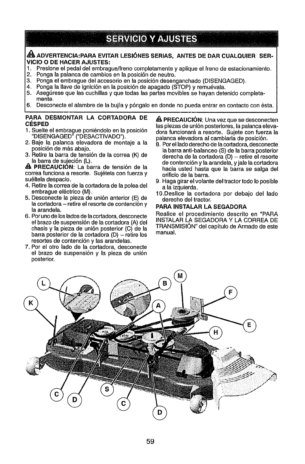
ADVERTENCIA:PARA EVITAR LESI6NES SERIAS, ANTES DE DAR CUALQUIER SER-
VICIO O DE HACER AJUSTES:
Io Preslone e! pedal del embrague/freno completamente y aplique el freno de estacionamiento_
2o Ponga la palanca de cambios en la posici6n de neutro.
3o Ponga el embrague del accesorio en la posici6n desenganchado (DISENGAGED),
4o Ponga la llave de ignici6n en la posici6n de apagado (STOP) y remu_valao
5. Aseg6rese que las cuchillas y que todas las partes movibles se hayan detenido completa-
mente_
6 Desconecte el alambre de la bujfa y p6ngalo en donde no pueda entrar en contacto con 6sta.
PARA DESMONTAR LA CORTADORA DE
1. Suelte el embrague poni_ndoto en la posici6n
"DISENGAGED" ("DESACTIVADO").
2oBaje ta palanca elevadora de montaje a ta
posici6n de m&s abajo.
3. Retire la barra de tensi6n de la correa (K) de
la barra de sujeci6n (L)o
PRECAUCION: La barra de tensi6n de la
correa funciona a resorter Suj_tela con fuerza y
su_ltela despacfm
4. Retire la correa de la cortadora de la polea del
embrague el6etrico (M).
5. Desconecte la pieza de uni6n anterior (E) de
la cortadora - retire el resorte de contenci6n y
ta arandela.
6o Poruno de los lados de lacortadora, desconecte
el brazo de suspensi6n de la cortadora (A) det
chasis y la pieza de uni6n posterior (C) de la
barra posterior de ta cortadora (D) - retire los
resortes de contenci6n y las arandelas.
7. Por el otro lado de la cortadora, desconecte
el brazo de suspensi6n y la pieza de uni6n
posterior.
_, PRECAUCI_)N: Una vez que se desconecten
las ptezas de uni6n posteriores, la patanca eleva-
dora funcionar,_ a resorte. Sujete con fuerza la
palanca elevadora al cambiarla de posici6n.
8. Por el ladoderecho de la cortadora, desconecte
ta barra anti-balanceo (S) de la barra posterior
derecha de la cortadora (D) - retire el resorte
de contenci6n yla arandela, y jale la cortadora
hacia usted hasta que la barra se salga clel
orificio de la barra.
9. Haga girar el volante del tractor todo Io posible
a la izquierdao
10.Deslice la cortadora por debajo del lado
derecho del tractor.
PARA INSTALAR LA SEGADORA
Realice el procedimiento descrito en "PARA
INSTALAR LA SEGADORA Y LA CORREA DE
TRANSMISION" del capitulo de Armado de este
manual.
®
59
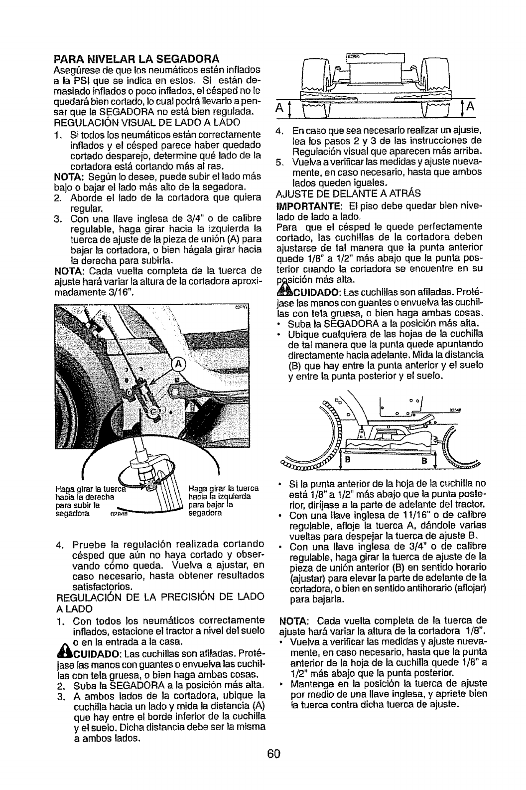
PARA NIVELAR LA SEGADORA
Asegt_rese de que los neum&ticos est_n inflados
a la PSt que se indica en estos, Si est&n de-
masiado inflados o poco inflados, el c_sped no le
quedar_ bien cortado, Io cual podr& Ilevarlo a pen-
sar que la SEGADORA no est& bien reguladao
REGULACtON VISUAL DE LADe A LADe
1o Si redes los neum&ticos est&n correctamente
inflados y el c_sped parece haber quedado
cortado desparejo, determine qu6 lade de la
cortadora est& cortando m&s al ras.
NOTA: Seg_n Io desee, puede subir el lade m&s
bajo o bajar et lade m&s alto de la segadora.
2. Aborde el lade de la codadora que quiera
regular.
3. Con una ltave inglesa de 3/4" o de calibre
regulabte, haga girar hacia la izquierda ta
tuerca de ajuste de la pieza de uniSn (A) para
bajar la cortadora, o bien h_,gala girar hacia
la derecha para subirla.
NOTA: Cada vuelta completa de la tuerca de
ajuste har#,variar ta altura de la cortadora aproxi-
madamente 3/16".
4, En case que sea necesario realizar un ajuste,
lea los pasos 2 y 3 de las instrucciones de
Regulaci6n visual que aparecen m&s arriba°
5, Vuelva a verificar las medidas y ajuste nueva-
mente, en case necesario, basra que ambos
lades queden iguates.
AJUSTE DE DELANTE A ATRi_S
IMPORTANTE: El piso debe quedar bien nive-
lade de lade a lade.
Para que el c6sped le quede perfectamente
cortado, las cuchiltas de la cortadora deben
ajustarse de tal manera que la punta anterior
quede 1/8"a 1/2" m&s abajo que la punta pos-
terior cuando la cortadora se encuentre en su
Ci6n m&s alta.
UIDADO: Las cuchillas son afiladas. Prot#-
jase las manes con guantes o envuelva las cuchil-
las con tela gruesa, o bien haga ambas cosas.
• Suba la SEGADORA a la posici6n m#,s altao
. Ubique cualquiera de las hojas de la cuchilla
de tal manera que ]a punta quede apuntando
directamente hacia adelante, Mida la distancia
(B) que hay entre la punta anterior yet suelo
y entre ta punta posterior y et suelo.
Haga g|rar la Haga gimr la tuerca
hacia la derecha hacla la tzquterda
parasubirla parabajarla
segadora segadora
4. Pruebe ta regtdaci6n realizada cortando
c6sped que at3n no haya cortado y obser-
vando c6mo queda. Vuelva a ajustar, en
case necesario, hasta obtener resultados
satisfactorios.
REGULACI6N DE LA PRECIS16N DE LADe
A LADe
1. Con redes los neum&ticos correctamente
inflados, estacione el tractor a nivel del suelo
o en la entrada a la casa,
CUIDADO: Las cuchillas son afiladaso Prot_-
jase las manes con guantes o envuelva ias cuchil-
las con tela gruesa, o bien haga ambas cosas.
2. Suba la SEGADORA a la posici6n m#,s attao
3. A ambos lades de la cortadora, ubique la
cuchitla hacia un tado y mida la distancia (A)
que hay entre el borde inferior de la cuchilla
y el suelo. Dicha distancia debe ser la misma
a ambos lades,
6O
B
• Si la punta anterior de la hoja de la cuchilta no
est& 1/8" a 1/2" m_s abajo que ta punta poste-
rior, dirijase a la parte de adelante del tractor,
. Con una ltave inglesa de 11/16" o de calibre
regulable, afloje la tuerca A, d&ndole varias
vueltas para despejar la tuerca de ajuste B°
• Con una Ilave inglesa de 3/4" o de calibre
regulable, haga girar la tuerca de ajuste de la
pieza de uniSn anterior (B) en sentido horario
(ajustar) para elevar la parte de adelante de la
cortadora, o bien en sentido antihorado (aflojar)
para bajartao
NOTA: Cada vueita completa de la tuerca de
ajuste har& variar la altura de ta cortadora 1/8",
• Vuelva a verificar tas medidas y ajuste nueva-
mente, en case necesario, hasta que la punta
anterior de la hoja de la cuchilla quede t/8" a
!/2" m&s abajo que la punta posterior.
• Mantenga en la posici6n la tuerca de ajuste
per medio de una Ilave inglesa, y apriete bien
la tuerca contra dicha tuerca de ajuste.
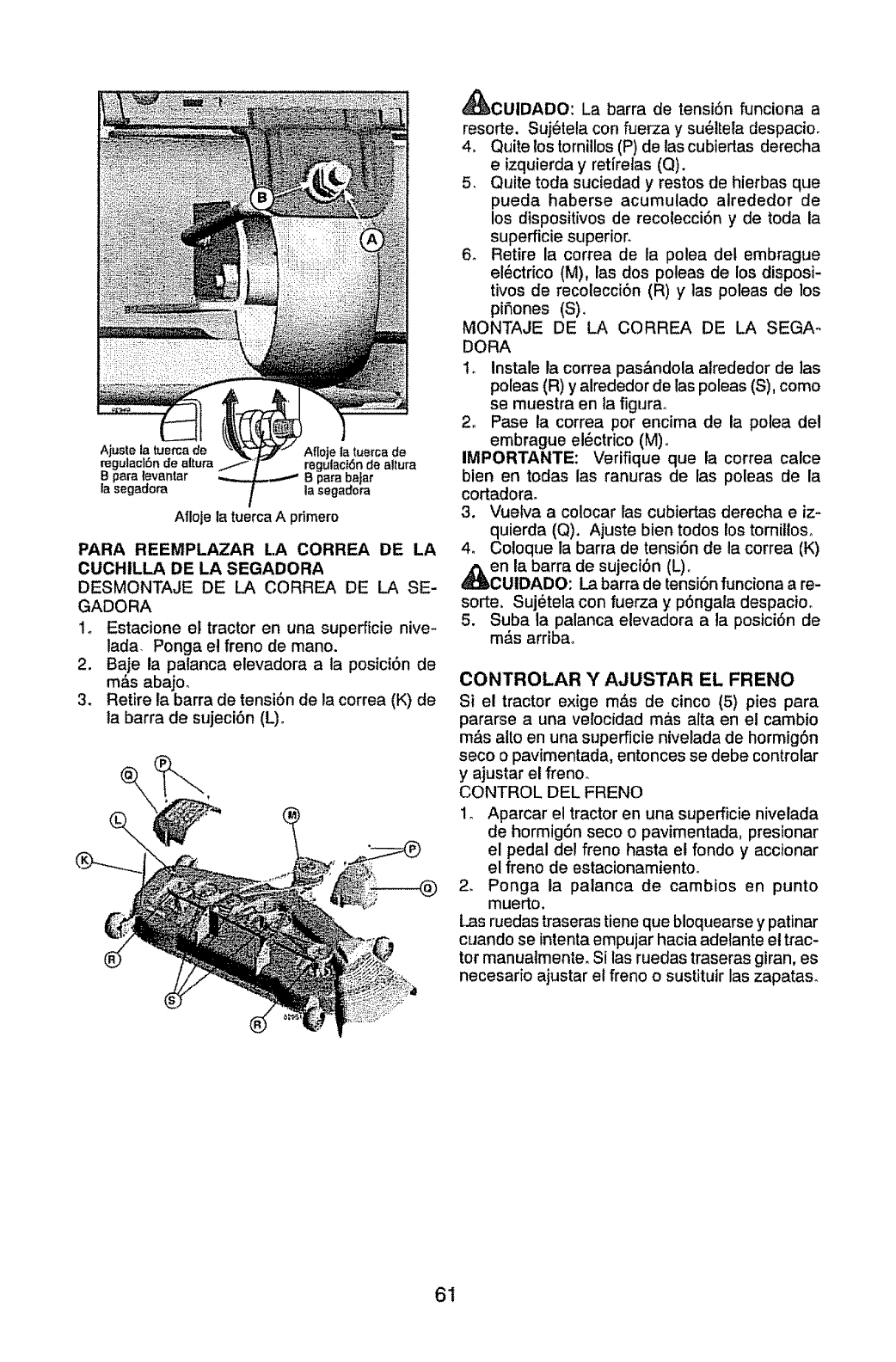
Ajuste la tuercade
regulact6n de altura
Bpara tevantar
la segadora
Afloje ta tuerca de
ragulaci6nde altura
B para ba[ar
la segadora
Afloje la tuerca A primero
PARA REEMPLAZAR LA CORREA DE LA
CUCHILLA DE LA SEGADORA
DESMONTAJE DE LA CORREA DE LA SE-
GADORA
1o Estacione el tractor en una superficie nive-
lada- Ponga el freno de mane.
2. Baje la palanca elevadora a la posici6n de
m&s abajo_
3. Retire la barra de tensi6n de la correa (K) de
la barra de sujeci6n (L)o
\
®
_CUIDADO: La barra de tensi6n funciona a
resorte. Suj6tela con fuerza y su_ltela despacioo
4, Quite lostornillos(P) de las cubiertas derecha
eizquierda y retfrelas (Q).
5. Quite toda suciedad y restos de hierbas que
pueda haberse acumulado alrededor de
los dispositivos de recolecci6n y de toda la
superficie superion
6o Retire la correa de la polea del embrague
el_ctrico (M), las dos poleas de los disposi-
rives de recolecci6n (R) y ]as poleas de los
pifiones (S),
MONTAJE DE LA CORREA DE LA SEGA°
DORA
to Instale la correa pas&ndola alrededor de las
poleas (R) y alrededor de las poleas (S), come
se muestra en la figura.
2. Pase la correa per encima de la polea del
embrague el_ctrico (M).
IMPORTANTE: Verifique que la correa calce
bien en tedas las ranuras de fas poleas de la
cortadora.
3. Vuelva a colocar las cubiertas derecha eiz-
quierda (Q). Ajuste bien to(los lostornilloso
4_ Coloque la barra de tensi6n de la correa (K)
en la barra de sujeci6n (L)o
CUIDADO: La barra de tensi6n funciona a re-
sorte, Suj_tela con fuerza y p6ngala despacioo
5. Suba la palanca elevadora a la posici6n de
m_,s arriba.
CONTROLAR YAJUSTAR EL FRENO
Si el tractor exige m,_s de cinco (5) pies para
pararse a una velocfdad ma,s alta en el cambio
m,_salto en una superficie nivelada de hormig6n
seco o pavimentada, entonces se debe controtar
yajustar el freno_
CONTROL DEL FRENO
1o Aparcar el tractor en una supefficie nivelada
de hormig6n seco o pavimentada, presionar
el pedal del freno hasta et rondo y accionar
el freno de estacionamiento.
2. Ponga ta palanca de cambios en punto
muerto.
i.as ruedas traserastiene que bloquearse y patinar
cuando se intenta empujar hacia adelante et trac-
tor manuatmente. Si las rueclas traseras giran, es
necesario ajustar et freno o sustituir las zapataso
61
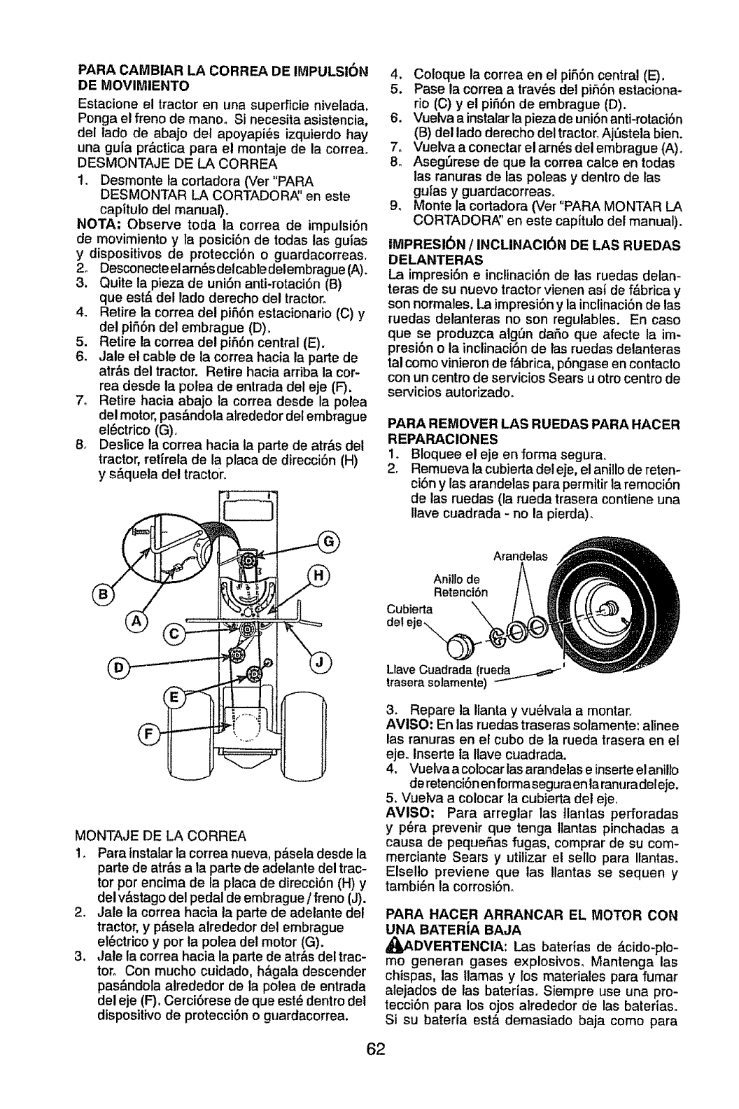
PARA CAMBIAR LA CORREA DE IMPULSION
DE MOVIMIENTO
Estacione el tractor en una superficie nivelada,
Ponga el freno de manoo Si necesita asistencia,
del lado de abajo del apoyapi_s izquierdo hay
una gula pr&ctica para el montaje de la correao
DESMONTAJE DE LA CORREA
!. Desmonte la cortadora (Ver "PARA
DESMONTAR LA CORTADOR/_' en este
capitulo del manual).
NOTA; Observe toda la correa de impulsi6n
de movimiento y la posiciSn de todas las guias
y dispositivos de protecci6n o guardacorreas.
2o Desconecteelarn_sdelcabledelembrague (A).
3. Quite la pieza de uni6n anti-rotaci6n (B)
que est& del lado derecho del tractor.
4. Retire |a correa dei pi56n estacionario (C) y
del pi56n del embrague (D).
5. Retire la correa del pi56n central (E).
6, Jale el cable de la correa hacia la parle de
atr&s del tractor. Retire hacia arriba la cor-
tea desde la polea de entrada del eje (F).
7. Retire hacia abajo la correa desde la polea
del motor, pas&ndola alrededor del embrague
el_ctrlco (G)o
8. Deslice ta correa hacia la parte de atr&s del
tractor, retirela de la placa de direcciOn (H)
y s_quela del tractor.
4, Coloque la correa en el piSOn central (E),
5. Pase la correa atravOs del pi56n eslaciona-
rio (C) y el pifi6n de embrague (D).
6, Vuelva a instalar ta pieza de uni6n anti-rotaciSn
(B) del lado derecho del tractor. Aj_stela bien.
7, Vuelva a conectar el arn_s del embrague (A).
8. Aseg_rese de que la correa calce en todas
las ranuras de las poleas y dentro de las
gulas y guardacorreas_
9. Monte la cortadora (Ver "PARA MONTAR LA
CORTADORA" en este capitulo del manual).
IMPRESI6N /INCLINACI6N DE LAS RUEDAS
DELANTERAS
La impresi6n e inclinaci6n de las ruedas delan-
teras de su nuevo tractor vienen asi de f&brica y
son normales, La impresi6n y la inclinaciOn de las
ruedas delanteras no son regulables. En caso
qua se produzca algQn dafio qua afecte la im-
presi6n o la inclinaci6n de tas ruedas detanteras
tal como vinieron de f_brica, p6ngase en contacto
con un centro de servicios Sears u otro centro de
servicios autorizado°
PARA REMOVER LAS RUEDAS PARA HACER
REPARACIONES
1. Bloquee el eje en forma segura,.
2. Remueva la cubiertadel eje, el anillo de reten-
ci6n y las arandelas para permitir la remoci6n
de las ruedas (la rueda trasera contiene una
llave cuadrada - no la pierda).
MONTAJE DE LA CORREA
1. Para instalarla correa nueva, p&sela desde la
parle de atr&s a la parle de adelante del trac-
tor per encima de la plata de direcci6n (H) y
del v&stago del pedal de embrague/freno (J).
2. Jale la correa hacta la parte de adelante del
tractor, y p&sela alrededor de! embrague
el6ctrico y por ia polea del motor (G)o
3. Jale ta correa hacia la parle de atr&s de! trac-
tor. Con mucho cuidado, h&gala descender
pas&ndola atrededor de la polea de entrada
del eje (F)oCerci6rese de qua est_ dentro det
dispositivo de protecci6n o guardacorrea,
Arandelas
Anitlode
Retencibn
Cubierta
del eje\._
LlaveCuadrada (rueda_...._'_
trasara solarnente)
3. Repare la Ilanta y vu61vafa a montaro
AVISO: En las ruedas traseras solamente: alinee
las ranuras en el cubo de la rueda trasera en et
eje. Inserte la Ilave cuadrada.
4. Vuelva a colocar las arandelas e inserte el anillo
de retenci6n enformaseguraen la ranuradeleje.
5. Vuelva a colocar la cubierta del eje,
AVlSO; Para arreglar las ]lantas perforadas
y p6ra preventr qua tenga llantas pinchadas a
causa de pequeSas fugas, comprar de su com-
merciante Sears y utitizar el sello para Itantaso
Elsello previene qua tas Ilantas se sequen y
tambi_n la corrosi6n.
PARA HACER ARRANCAR EL MOTOR CON
UNA BATERiA BAJA
_DVERTENCIA: Las baterias de _cido-plo-
mo generan gases explosivos, Mantenga las
chispas, las llamas y los materiales para fumar
alejados de las bateruas. Siempre use una pro-
tecci6n para los ojos alrededor de las baterias.
Si su bateria est& demasiado baja como para
62
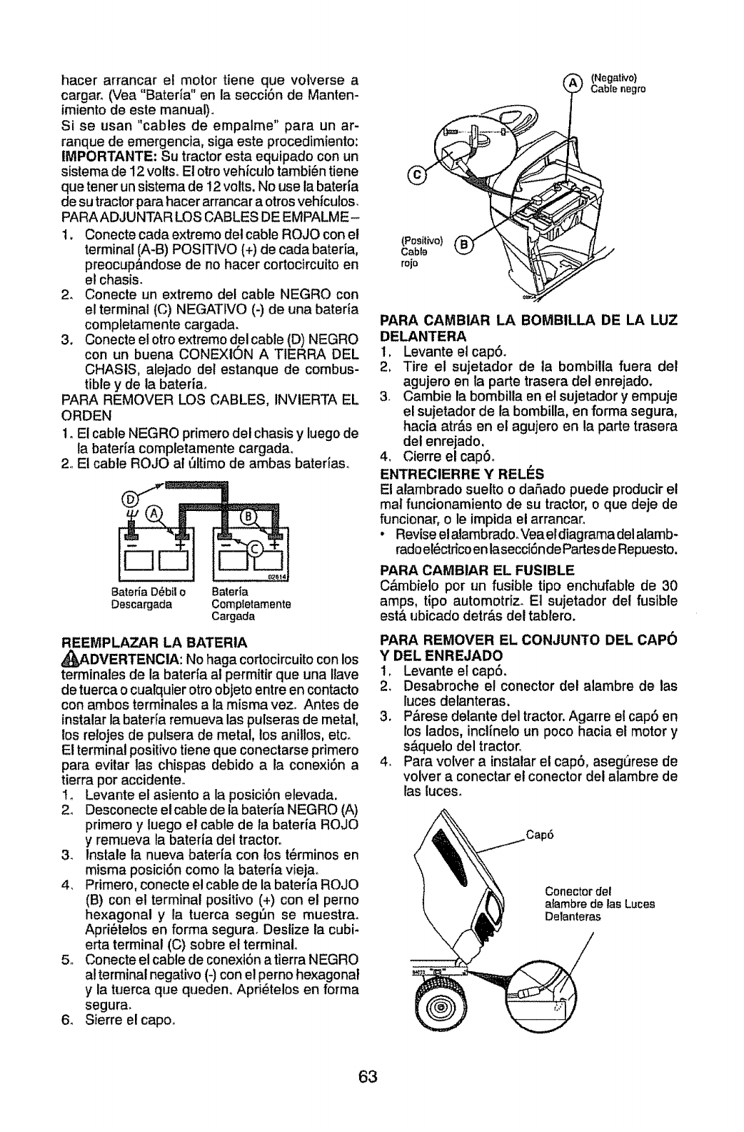
hacer arrancar el motor tiene que votverse a
cargar_ (Vea "Bateria" en la seccion de Manten-
imiento de este manual).
Si se usan "cables de empalme" para un ar-
ranque de emergencia, siga este procedimiento:
IMPORTANTE: Su tractor esta equipado con un
sistema de 12 volts° El otto vehtculo tambi_n tiene
que tener un sistema de !2 volts. No use la bateria
de su tractor para hacer arrancar a otros vehfculos.
PARA ADJUNTAR LOS CABLES DE EMPALME-
1. Conecte cada extremo del cable ROJO con el
terminal (A-B) POSITIVO (+) de cada bateria,
preocup_ndose de no hacer cortocircuito en
el chasis.
2. Conecte un extremo del cable NEGRO con
el terminal (C) NEGATIVO (-) de una bateda
completamente cargada.
3. Conecte el otro extremo del cable (D) NEGRO
con un buena CONEXION A TIERRA DEL
CHAStS, alejado det estanque de combus-
tible y de la bateria_
PARA REMOVER LOS CABLES, INVIERTA EL
ORDEN
I. El cable NEGRO primero del chasis y luego de
la baterfa completamente cargada.
2_Et cable ROJO at ,31timode ambas baterias..
Bateria D_bil o Bateria
Descargada Compietamente
Cargada
REEMPLAZAR LA BATERIA
_,DVERTENCIA: No haga cortocircuitocon los
terminates de la baterfa al permitir que una Ilave
de tuerca o cualquIerotroobJetoentre en contacto
con ambos terminales a la misma vez. Antes de
instalar la baterfa remueva las pulseras de metal,
los relojes de pulsera de metal, los anillos, etco
E! terminal positivo tiene que conectarse primero
para evitar tas chispas debido a la conexi6n a
tierra por accidente.
I_ Levante el asiento a la posici6n elevada,
2_ Desconecte el cable de la baterfa NEGRO (A)
primero y luego el cable de la bateria ROJO
y remueva la bateria del tractor.
3_ lnstale la nueva baterfa con los t@rminos en
misma posici6n como la bateda vieja.
4, Primero, conecte el cable de la bateria ROJO
(B) con el terminal positivo (+) con el perno
hexagonal y la tuerca seg6n se muestra.
Apri6telos en forma segurao Destize la cubi-
erta terminal (C) sobre el terminal°
5o Conecte el cable de conexi6n atierra NEGRO
al terminal negativo (-) con el perno hexagonal
y la tuerca que queden. Apri_telos en forma
segura.
6_ Sierre elcapo°
(Posit_vo)
Cabte
rojo
(Negattvo}
Cable nBgro
PARA CAMBIAR LA BOMBILLA DE LA LUZ
DELANTERA
1, Levante e! cap6_
2, Tire el sujetador de la bombilla fuera del
agujero en la parte trasera del enrejado.
3. Cambie la bombitla en et sujetador y empuje
el sujetador de la bombilla, en forma segura,
hacia atr_.sen el agujero en la parte trasera
det enrejado,
4. Cierre elcap6.
ENTRECIERRE Y RELI_S
El alambrado suetto o dafiado puede producirel
mal funcionamiento de su tractor, o que deje de
funcionar, o le impida el arrancar.
•Revise el alambrado_Vea eldiagrama del alamb-
radoel_ctdco enlasecci6nde Partesde Repuesto.
PARA CAMBIAR EL FUSIBLE
C&mbielo pot un fusible tipo enchufable de 30
amps, tipo automotriz. El sujetador del fusible
est& ubicado detr&s del tablero.
PARA REMOVER EL CONJUNTO DEL CAP6
Y DEL ENREJADO
1, Levante el cap6.
2. Desabroche el conector det alambre de las
luces delanteras,
3. P,_rese delante del tractor.Agarre el cap6 en
los lados, inclinelo un poco hacia et motor y
s&queto del tractor,
4, Para volver a instalar et cap6, aseg(_resede
volver a conectar e! conector del alambre de
las luces°
Conector del
atambre de las Luces
Delanteras
63
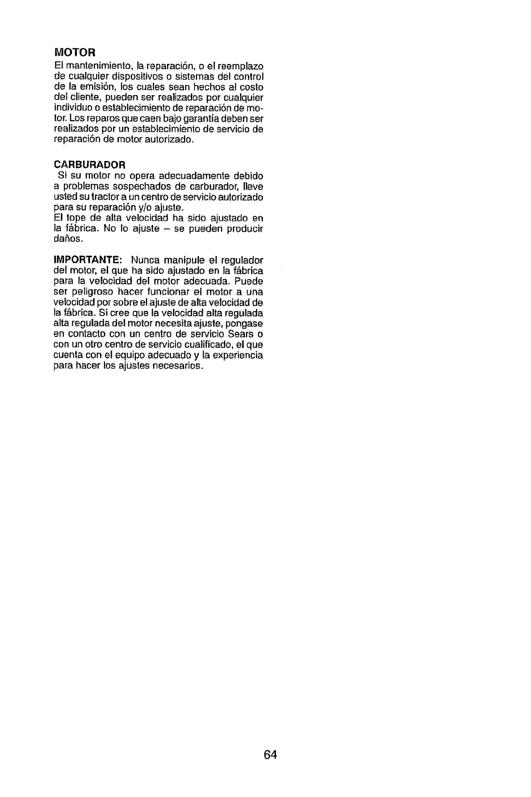
MOTOR
El mantenimiento, la reparaci6n, o el reemplazo
de cualquier dispositivos o sistemas del control
de la emisi6n, los cuales sean hechos al costo
del cliente, pueden set realizados por cualquier
individuo o establecimiento de reparaci6n de mo-
toroLos reparos que caen bajo garantia deben ser
realizados por un establecimiento de servicio de
reparaciSn de motor autorizadoo
CARBURADOR
Si su motor no opera adecuadamente debido
a problemas sospechados de carburador, lleve
usted su tractor a un centro de servicio autorizado
para su reparaciSn yio ajusteo
El tope de alta velocidad ha sido ajustado en
ta ffbrica. No Io ajuste - se pueden producir
daSos.
IMPORTANTE: Nunca manipute el regulador
del motor, el que ha sido ajustado en la f&brica
para la velocidad del motor adecuadao Puede
set peligroso hacer funcionar el motor a una
velocidad pot sobre el ajuste de alta velocidad de
ta ffibrica. Si cree que la veiocidad alta regulada
alta regulada del motor necesita ajuste, pongase
en contacto con un centro de servicio Sears o
con un otro centro de servicio cualificado, el que
cuenta con el equipo adecuado y la experiencia
para hacer los ajustes necesarios.
64
Inmediatamente prepare su tractor para el al-
macenamiento at final de la temporada o si el
tractor no se va a usar por 30 alias o m&s.
_ADVERTENC1A: Nunca atmacene el tractor
con gasolina en el estanque dentro de un edificio
en donde los gases pueden alcanzar una llama
expuesta o una chispa. Permita que el motor se
enffle antes de almacenarlo en cualquier recinto
privado.
TRACTOR
Remueva la segadora del tractor para el almace-
namiento por el invierno° Cuando la segadora
se va a almacenar pot cierto per[odo de tiempo,
limpiela cuidadosamente, quite toda ta mugre,
la grasa, las hojas, etc_ Gu_rdela en una &rea
limpia y seca,
I, Limpie todo el tractor (vea "LIMPIEZ_' en la
secci6n de Mantenimiento en este manual).
2. tnspeccione y cambie las correas, si es nec-
esario (vea las instrucciones para et cambio
de las correas en la secci6n de Servicio y
Ajustes de este manual)°
3. Lubdquelo, seg_n se muestra en la secci6n
de Mantenimiento de este manual.
4. Aseg6rese que todas tas tuercas, los pernos y
los tornillos est_n sujetados en forma segura.
Inspeccione las partes movibles para vedficar
si hay dafio, rotura o desgaste. C&mbielas si
es necesario.
5_ Retoque todas superficies pintadas oxidadas
o picadas; aptique lija antes de pintar.
BATERiA
. Cargue la bateda completamente antes de
guardarla.
• Despu_s de cierto periodo de tiempo en
aimacenamiento, la bateria puede necesitar
volver a cargarseo
• Para ayudar a evitar ta corrosi6n y las fugas de
potencia durante largos periodos de atmace-
namiento, se deben desconectar los cables de
ta bateria y se debe Umpiar cuidadosamente
(vea "PARA LIMPIAR LA BATERIA Y LOS
TERMINALES" en la secci6n de Manten-
imiento de este manual).
• Despu_s de limpiarla, deje los cables
desconectados y p6nga!os en donde no
puedan entrar en contacto con los terminales
de la bateria,
• Si se remueve la baterfa del tractor para e!
almacenamiento, no la guarde directamente
sobre concreto o sobre superficies h_medas_
MOTOR
SISTEMA DE COMBUSTIBLE
IMPORTANTE: Es important evitar que se for-
man depositos de goma en partes fundamen-
tales dei sistema de combus-tible tales como el
carburador, e!filtro det combustible, la manguera
del combustibles mezclados con alcohol
(conocido como gasohol o que tienen etanol o
metanot) pueden atraer humedad, Io que con-
duce a la separaci6n y a la formaci6n de acudos
durante elatmacenamiento, La gasolina acidica
puede daiSar el sistema de combustible de un
motor durante el periodo de atmacenamiento.
° Vaciar el dep6sito del carburante poniendo en
marcha el motor y dej&ndolo funcionar hasta que
el carburante termine el carburador est_ vacio.
•Nunca use los productos para limpieza del
carburador o del motor en el estanque de
combustible pues se pueden producir dafios
permanentes+
• Use combustible nuevo la pr6×ima
temporadao
AVISO: El estabitizador de combustible es una
alternativa aceptable para reducir a un mlnimo
la formaci6n de dep6sitos de goma en el com-
bustible durante el perfodo de almacenamiento.
Agregue estabitizador a la gasotina en el estanque
de combustible o en el envase para el almace-
namiento. Siempre siga ta proporci6n de mezcla
que se encuentra en el envase det estabiUzador,
Haga funcionar el motor por Io menos 10 minutos
despu_s de agregar el estabilizador, para permitir
que _ste Ilegue al carburador. No vaciar la gaso-
lina det estanque de gasolina y el carburador si se
est& usando estabitizador de combustible.
ACEITE DEL MOTOR
Drene el aceite (con el motor caliente) y c,_mbielo
con aceite de motor limpio. (Vea "MOTOR" en la
secci6n de Mantenimiento" de este manual.)
CIL1NDRO(S)
1. Remueva la(s) bujia(s).
2. Vacie una onza de aceite a trav_s def
agujero(s) de la bujfa en el cilindro(s).
3_ Gire ta Ilave de ignici6n a la posici6n de 'Ar-
ranque" (Start), por unos cuantos segundos
para distribuir et aceite.
4. Cambie por bujia(s) nueva(s).
OTROS
• No guarde la gasolina de una temporada a la
otrao
• Cambie el envase de la gasolina si se empieza
a oxidar. La oxidaci6n y/o la mugre en su gaso-
lina producir&n problemas.
. Si es posible, guarde su unidad en un recinto
cerrado y c6brala para protegerla contra el
polvo y la mugre,
• Cubra su unidad con un forro protector ad-
ecuado que no retenga la humedado No use
pl__stico_El pl&stico no puede respirar, Io que
permite la formaci6n de condensaci6n, to que
producir& la oxidaci6n de su unidad.
IMPORTANTE: Nunca cubra el tractor mientras
el motor y las areas de escape todavia estan
calientes.
65
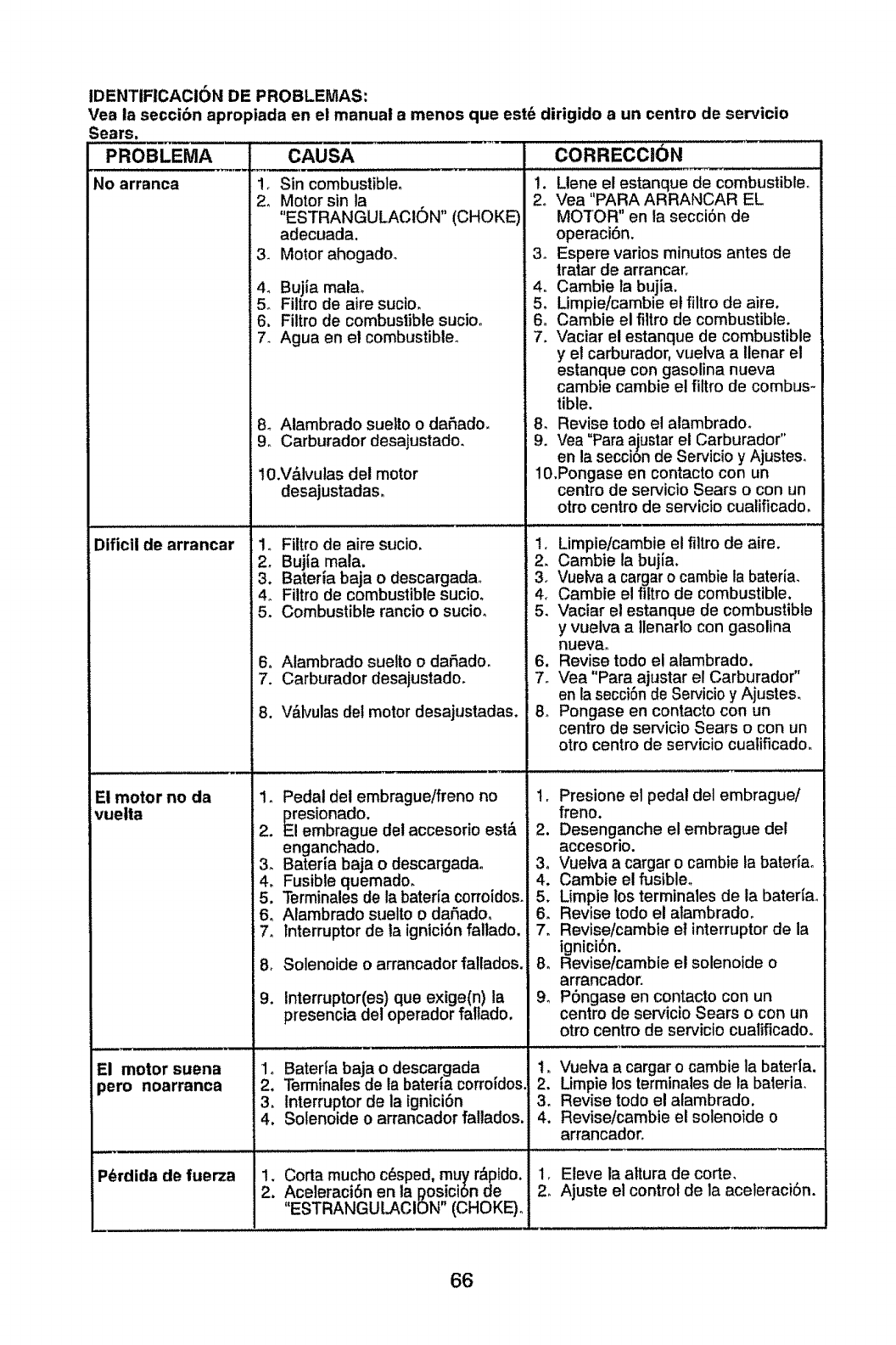
IDENTIFICACI6N DE PROBLEMAS:
Vea la seccibn apropiada en el manual a menos que est_ dirigido a un centre de ser¢icio
Sears.
PROBLEMA CAUSA CORRECCI0N
,Sin combustible.
° Motor sin la
"ESTRANGULACION" (CHOKE)
adecuada.
3. Motor ahogado.
4. Bujia malao
. Filtro de aire sucio.
6. Filtro de combustible sucioo
7. Agua en el combustible.
8_ Alambrado suelto o da5ado,
9, Carburador desajustado.
10.V&lvutas del motor
desajustadas.
1o Fiitro de aire sucio.
2, Bujia mala,
3. Bateria baja o descargadao
4o Filtro de combustible sucio.
5. Combustible rancio o sucio,
No arranca
)ificii de arrancar
El motor no da
vuetta
El motor suena
:_ero noarranca
6o Alambrado suetto o daSado.
7. Carburador desajustadoo
8. V_,lvulasdel motor desajustadas.
.
2.
3_
4,
5.
6,
7o
8,
9.
Pedal del embrague/freno no
esionado,
embrague del accesorio est&
enganchado.
Bateria baja o descargada.
Fusible quemado°
Terminalesde la baterfa corroidos,
Alambrado suelto o daSado.
Interrupter de ia igntci6n fallado,
Solenoide o arrancador fallados.
Interruptor(es) que exige(n) la
presencia del operador faltado.
1o Bater|a baja odescargada ,
2, Terminales de la bateria corrmdos,
3, interrupter de la ignici6n
4. Solenoide o arrancador fallados.
.Corta mucho c6sped, muy r&pido,
.Aceleraci6n en la posici6n de
"ESTRANGULACION" (CHOKE),
P_rdida de fuerza
1. Llene el estanque de combustible,
2. Vea "PARA ARRANCAR EL
MOTOR" en la secci6n de
operaci6n.
3o Espere varies minutes antes de
tratar de arrancar.
4. Cambie ta bujia.
5, Limpie/cambie el filtro de aire.
6. Cambie el filtro de combustible.
7, Vaciar el estanque de combustible
y et carburador, vuelva a llenar el
estanque con gasolina nueva
cambie cambie el filtro de combus-
tible.
8, Revise rode el atambradoo
9. Vea "Para ajustar et Carburador"
en la seccion de SeP¢icioy Ajusteso
10.Pongase en contacto con un
centre de servicio Sears o con un
otto centre de servicio cuatificado,
,Limpie/cambie el filtro de aire.
. Cambie ia bujia.
3. Vuelva a cargar o cambie la bateria,
4. Cambie el fittro de combustible.
5, Vaciar el estanque de combustible
y vuelva a llenarlo con gasolina
nueva_
6. Revise todo e! alambrado.
7. Vea "Para ajustar el Carburador"
en lasecci6n de Serviciey Ajusteso
8_ Pongase en contacto con un
centre de servicio Sears o con un
otro centre de servicio cuatificado.
1, Presione el pedal del embrague/
freno.
2. Desenganche el embrague det
accesorlo.
3o Vuetva a cargar o cambie ta batefiao
4, Cambie el fusible.
5, Limpie los terminales de la bateriao
6. Revise todo el atambradoo
7. Revise/cambie el interrupter de la
ignici6n.
8. Revise/cambie el solenoide o
arrancador.
9_ P6ngase en contacto con un
centre de ser¢icio Sears o con un
otro centre de ser¢icio cualificadoo
1. Vuelva a cargar o cambie la baterla.
, Limpie los terminales de la bateria,
°Revise todo el alambradoo
4. Revise/cambie el solenoide o
arrancador_
1, Eleve la altura de corte,
2_ Ajuste el control de la aceleraci6n.
66
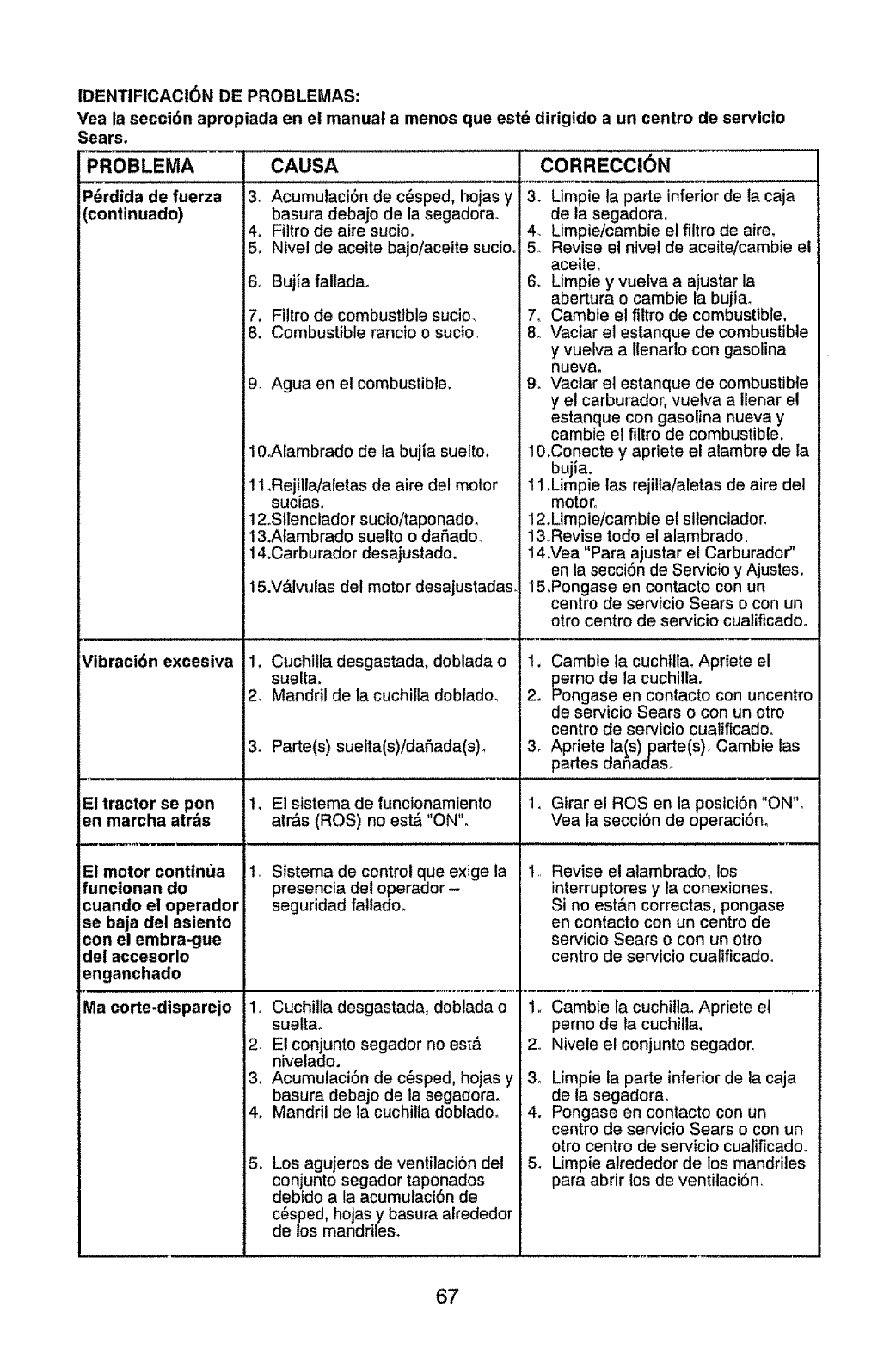
IDENTIFICACION DE PROBLEMAS:
Vea la secci6n apropiada en el manual a menos que est6 dirigido a un centro de servicio
Sears.
PROBLEMA
P_rdida de fuerza
(continuado)
Vibraci6n excesiva
El tractor se pon
en marcha atrbs
El motor continua
funcionan do
cuando el operador
se baja del asiento
con el embra-gue
del accesorlo
enganchado
Ma corte-disparejo
CAUSA
3_ Acumutaci6n de c_sped, hojas y
basura debajo de la segadora.
4. Filtro de aire sucio.
5. Nivel de aceite bajo!aceite sucio.
6. Bujia fallada.
7. Filtro de combustible sucio_
8. Combustible rancio o sucio_
9. Agua en el combustible.
10.Alambrado de la bujia suelto.
11.Rej!lla/aletas de aire del motor
SUClaS,
12oSilenciador sucio/taponado,
13.Alambrado suelto o dafiado_
14.Carburador desajustado,
15.V_lvulas del motor desajustadas
1. Cuchilla desgastada, doblada o
suelta.
2. Mandril de la cuchilla doblado.
3_
1.
Parte(s) sueita(s)/daflada(s)_
El sistema de funcionamiento
atr&s (ROS) no est& "ON".
I_ Sistema de control que exige la
presencia de! operador -
seguridad fatlado.
1o Cuchilla desgastada, doblada o
suetta_
2. El conjunto segador no est_
nivelado.
3. Acumulaci6n de c_sped, hojas y
basura debajo de la segadora.
4= Mandril de la cuchilla dobladoo
5_
CORRECCI6N
3. Llmpie la parte inferior de la caja
de la segadora.
. Limpie/cambie el filtro de airm
. Revise el nivel de aceite/cambie el
aceite.
6. Limpie y vuelva a ajustar la
abertura o cambie la bujiao
7< Cambie el filtro de combustible.
8. Vaciar el estanque de combustible
y vuelva a llenarlo con gasolina
nueva.
9o Vaciar et estanque de combustible
y et carburador, vuetva a llenar el
estanque con gasolina nueva y
cambie el filtro de combustible.
10.Conecte y apriete el alambre de la
bujia.
11 .Limpie las rejitla/aletas de aire del
motor°
12.Limpie/cambie el silenciadoro
13oRevise todo el alambrado_
14.Vea "Para ajustar el Carburador"
en la secci6n de Servicio y Ajustes.
15.Pongase en contacto con un
centro de servicio Sears o con un
otro centro de servicio cualificadoo
!. Cambie la cuchilla. Apriete el
perno de la cuchilla.
2. Pongase en contacto con uncentro
de ser¢icio Sears o con un otro
centro de servicio cuatificado.
3. Apdete la(s)parte(s)< Cambie las
partes dafiadas_
1. Girar el ROSen la posici6n "ON".
Vea la secci6n de operaci6n_
Revise el alambrado, los
interruptores y la conexiones.
Si no est&n correctas, pongase
en contacto con un centro de
servicio Sears o con un otro
centro de servicio cualificado.
2
3.
4.
Cambie la cuchitla. Apriete et
perno de ta cuchilla.
Nivete el conjunto segador.
Limpie fa parte inferior de la caja
de la segadora.
Pongase en contacto con un
centro de servicio Sears o con un
Los agujeros de ventilaci6n det
conjunto segador taponados
debido a la acumutaci6n de
c_sped, hojas y basura alrededor
de los mandriles.
otro centro de servicio cualificado.
5. Limpie alrededor de los mandriles
para abrir los de ventilaciSn.
67
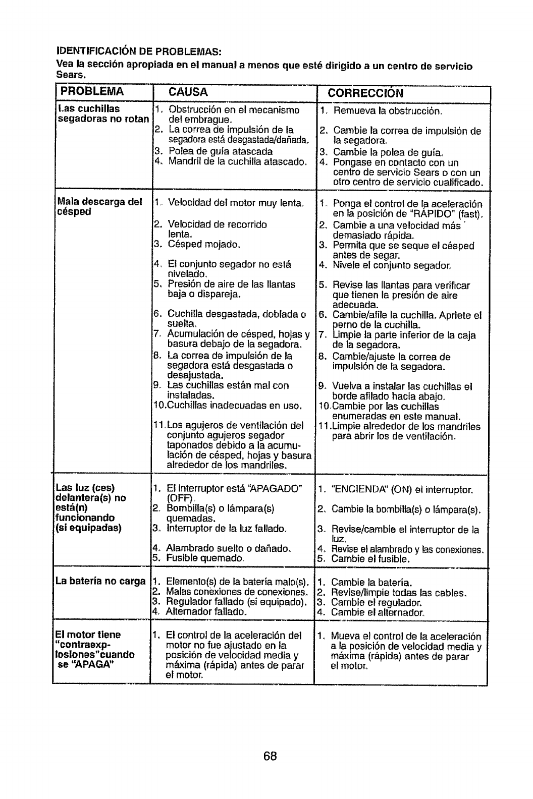
IDENTIFICACtON DE PROBLEMAS:
Vea la seccibn apropiada en el manual a menos que estd dirigido a un centro de ser-vicio
Sears.
PROBLEMA
Las cuchillas
segadoras no rotan
Mala descarga del
cdsped
Las luz (ces)
delantera(s) no
estd(n)
funcionando
(si equipadas)
La baterla no carga
CAUSA
El motor tlene
"contraexp-
Iosiones"cuando
se "APAGA"
!. Obstrucci6n en et mecanismo
del embragueo
2. La correa de impulsiSnde la
segadora est&desgastada/dafiada.
3. Polea de gufa atascada
4. Mandril de la cuchilla atascadoo
2.
.
Velocidad del motor muy lentao
Velocidad de recorrido
lenta_
C_sped mojado.
4, E! conjunto segador no est&
niveladoo
5. Presi6n de aire de las Ilantas
baja o dispareja.
6. Cuchilla desgastada, doblada o
suelta.
7. Acumutaci6n de c_sped, hojas y
basura debajo de la segadora.
B. La correa de impulsi6n de ia
segadora est._ desgastada o
desajustada.
9. Las cuchitlas est&n mal con
instaladas.
10.Cuchillas inadecuadas en uso.
1°Los agujeros de ventitaci6n del
conjunto agujeros segador
taponados debido a la acumu-
laci6n de cesped, hojas y basura
alrededor de los mandriles.
2,
3o
4_
5.
1.
:2.
!.
El interruptor est_ 'APAGADO"
(OFF).
Bombitla(s) o I&mpara(s)
quemadas.
Interruptor de la luz fallado+
Atambrado sueito odafiado..
Fusible quemado.
Elemento(s)de la bateria malo(s).
Malas coni_xiones de conexiones_
Regulador faltado (st equipado).
Alternador fallado.
El control de la aceleraci6n del
motor no rue ajustado en la
posici6n de velocidad media y
m_xima (r&pida) antes de parar
el motor°
CORRECC|ON
11 Remueva la 0bstrucci6n,
2. Cambie la correa de impulsi6n de
la segadora.
3o Cambie la polea de guiao
4. Pongase en contacto con un
centro de servicio Sears o con un
otro centro de servicio cualificado.
1. Ponga et control de Ip aceleraciSn
en la posiciSn de "RAPIDO" (fast).
2. Cambie a una velocidad m_s"
demasiado r&pidao
3. Permita que se seque el c6sped
antes de segar.
4. Nivete el conjunto segadoro
5_ Revise las Ilantas para verificar
que tienen la presi6n de aire
adecuada.
6. Cambie/afile la cuchilla. Apriete el
perno de la cuchillao
7. Limpie ta parle inferior de la caja
de la segadora.
8. Cambie!ajuste la correa de
impulsion de ta segadora.
9. Vuetva a instalar las cuchittas el
borde afitado hacia abajoo
IBCambie por las cuchillas
enumeradas en este manual.
11.Limpie atrededor de los mandrites
para abrir los de ventilaci6no
,
2_
3o
4.
5.
t.
2.
3.
4.
"ENCIENDA" (ON) el interruptor.
Cambie la bombil]a(s) o I&mpara(s).
Revise/cambie el interruptorde la
luz.
Revise et alambrado y las conexioneso
Cambie el fusible.
Cambie la bateria.
Revise/limpie todas las cables_
Cambie el regulador.
Cambie el alternador.
Mueva et control de la aceleraci6n
a la posici6n de velocidad media y
maxima (r&pida) antes de parar
el motor.
68

69

70
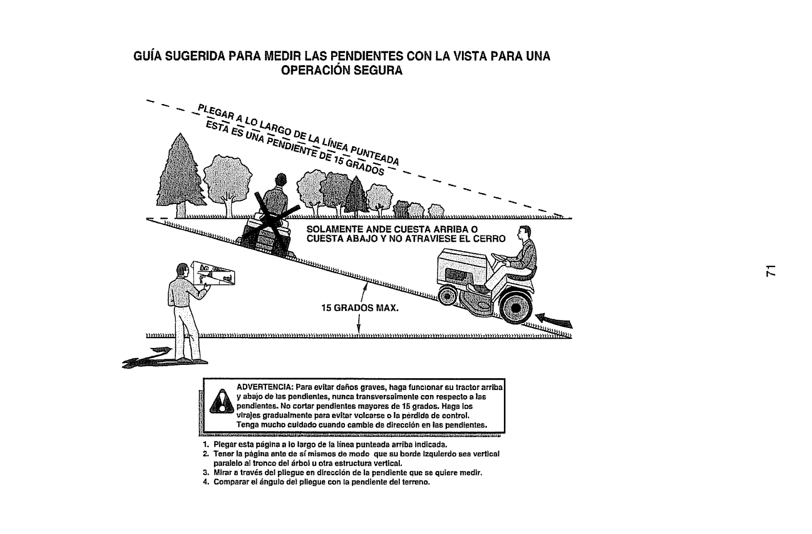
GUfA SUGERIDA PARA MEDIR LAS PENDIENTES CON LA VISTA PARA UNA
OPERACION SEGURA
SOLAMENTE ANDE CUESTA ARRIBA O
CUESTA ABAJO Y NO ATRAVIESE EL CERRO
15 GRADOS MAX,
i,l,,i,,lll,lJ,,mi , ii
jADVERTENCtA: Pare evttar dafios graves, hega funcmnar su tractor arriba
._ y abajo de tas pendientes, nunca transversaimente con respecto ales
pendlentes. No cotter pend_entes m_yores de 15 grados. Hage los
_] vlraJesgraduelmente pare evitar volcarse o ia perdtda de control=
_Tenga mucho cutdado cuendo camble de dlreeet6n en lea pendientes,
I_I IIIIIIIIIIIIIII IIIIll Illlllllllll[lll r
1. Plegar esta pdgina a Io largo de la linea punteada arriba fndtcada.
2. Tener la pagina ante de sf mfsmos de modo que au borde Izqulerdo sea vertical
paraleto al tronco del _rboi u o_Jaestructura vertical.
3. Mtrar a travds del pltegue en dlrecci6n de la pendtente que se quiere medtr.
4. Comparar el dngulo del pliegue con la pendiente de! termno.

• Findthisand at[yourotherproductmanualsonline.
.Getanswersfrom our team of homeexperts,
• Get a personalized maintenance plan for your home.
,Findinformation and too|s to help with home projects,
Your Home
For repair - in your home - of all major brand appliances,
lawn and garden equipment, or heating and cooling systems,
no matter who made it, no matter who sold it!
For the replacement parts, accessories and :_:_i_
owner's manuals that you need to do-it-yourself. :::_::;_
For Sears professional installation of home appliances
and items like garage door openers and water heaters. :!:i:iJ
1-800-4-MY-HOME ® Anylime, dayor night
(%80D-469-4663) (US A., and Canada)
www.sears.com wwwosears,ca
Our Home
For repair of carry-in products like vacuums, lawn equipment,
and electronics, call or go on-line for the nearest
Sears Parts and Repair Center.
1-800-488-t 222 Anyltme, day or nigh! (U.S.A. only)
www,sears,com
To purchase a protection agreement (U.SAo)
or maintenance agreement (Canada) on a product serviced by Sears:
1-800-361-6665 (Careda)1-800-827-6655 (U.SA)
Au Canada pour service en franr,_Ls:
1.800.LE.FOYER uc
(1-800.633-6937)
www,,eears,oa
Para pedir servido de reparaci6n
!_ a domicilio, y paraordenar piezas:
1.eBB,,SU.HOG/_ _
................_': (1-888-784-6_27)
i:ii!:!iiii:!i
i:!':ii:ii;
!1111;!!i!:!:i;11
=i::?_?:ii
=:i!::;!!._
06.21.10 JA
© se_ Br-_nds.LLC
® Registered Trademark tT_ Trademark/s_ Service Mark of Seats Brands, LLC
®Merca Regislrade 1T_ Marce de F_bric8 ts= Marce de Servlclo de Seers Brands. LLC
_c Ma_que de commerce t_v_Marque d_pos_e de SBars Brands, LLC
Printed in the U.S.A.
