Craftsman 917293340 User Manual 9.0HP REAR TINE TILLER Manuals And Guides L9120288
CRAFTSMAN Rear Tine, Gas Tiller Manual L9120288 CRAFTSMAN Rear Tine, Gas Tiller Owner's Manual, CRAFTSMAN Rear Tine, Gas Tiller installation guides
User Manual: Craftsman 917293340 917293340 CRAFTSMAN CRAFTSMAN 9.0HP REAR TINE TILLER - Manuals and Guides View the owners manual for your CRAFTSMAN CRAFTSMAN 9.0HP REAR TINE TILLER #917293340. Home:Lawn & Garden Parts:Craftsman Parts:Craftsman CRAFTSMAN 9.0HP REAR TINE TILLER Manual
Open the PDF directly: View PDF ![]() .
.
Page Count: 36
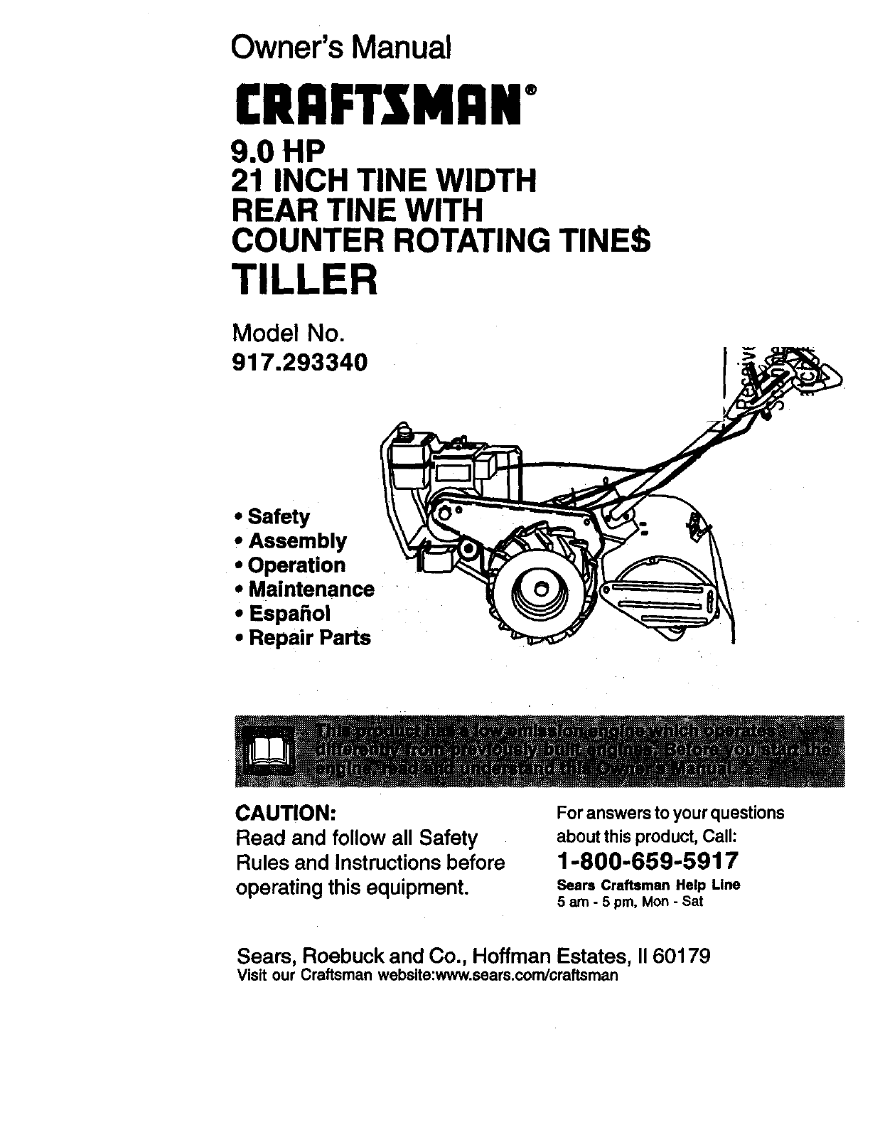
Owner's Manual
[RRFTSMRN*
9.0 HP
21 INCH TINE WIDTH
REAR TINE WITH
COUNTER ROTATING TINES
TILLER
Model No.
917.293340
*Safety
* Assembly
*Operation
e Maintenance
e Espa_ol
. Repair Parts
I
CAUTION:
Read and follow all Safety
Rules and Instructions before
operating this equipment.
For answers to your questions
about this product, Call:
1-800-659-5917
Seers Craftsman Help Line
5 am -5 pm, Mon -Sat
Seam, Roebuck and Co., Hoffman Estates, II 60179
Visit our Craftsman website:www.sears.com/craftsman
Warranty................................................ 2
Safety Rules ................. ,........................ 2
Product Specifications ............................ 4
Assembly ...................... i ......:.................. 5
Operation ........ ._............i ......_................. 8
Maintenance ....L....._......_......_............... 13
Maintenance Schedule ............ ........... 13
Service and Adjustments ..................... 15
Storage ................................................ 19
Troubleshooting .................................. 20
Illustrated Parts List ............................. 42
Parts Ordering ...................... Back Cover
LIMITED TWO , ,RR_NTY ON CRAFTSMAN TILLER
Forltwo!(2)yearsfrom d_te(ifpurchase,when thisCraftsmanTillerismaintained,
lubricated,and tune_ up!ac_rding to theoperatingand maintenanceinstructionsin
theowner'smanual,ISeslrs_illrepairfreeofchargeany defectinmaterialorworkman-
ship. _ " -
This Warranty does not cover:
• Expendable items wh Ch becorne'!wom,,during normal use, such as tines, spark
plugs, air cleaners and belts.
• Repairs necessary because ofoperator abuse or negligence, including bent
crankshafts and the failure to maintain the equipment according to the instructions
contained in theowner's manual:
• If this Craftsman Tiller is used for commercial or rental purposes, this Warranty
applies for only thirty (30) days from the date of purchase.
Warranty service is available by returning the Craftsman power mower to the nearest
Sears service center/department in the United States. This warranty applies only while
this product is in use in the United States.
This Warranty gives you specific legal rights, and you may also have other rights which
vary from state to state:
SEARS, ROEBUCKAND CO., D/817WA, HOFFMAN ESTATES, IL 60179
IMPORTANT: This cutting machine is
capable of amputating hands and feet
and throwing objects. Failure to observe
the following safety instructions could
result in serious injury or death.
TRAINING
•Read the Owner's Manual carefully. Be
thoroughly familiar with the controls
and the proper use of the equipment.
Know how to stop the unit and disen-
gage the controls quickly.
•Never allow children to operate the
equipment. Never allow adults to
operate the equipment without proper
instruction.
•Keep the area of operation clear of all
persons, particularly small children,
and pets.
PREPARATION
•Thoroughly inspect the area where the
equipment is to be used and remove all
foreign objects.
• Disengage all clutches and shift into
neutral before starting the engine
(motor)
•Do not operate the equipment without
wearing adequate outer garments,
Wear footwear that will improve footing
on slippery surfaces,
•Handle fuel with care; it is highly
flammable.
•Use an approved fuel container,
•Never add fuel to a running engine or
hot engine.
•Fill fuel tank outdoors with extreme
care. Never fill fuel tank indoors.
•Replace gasoline cap securely and
clean up spilled fuel before restarting.
•Use extension cords and receptacles
as specified by the manufacturer for all
units with electric drive motors or
electric starting motors.
2
• Never attempt to make any adjustments
while the engine (motor) is running
(except where specifically recommend-
ed by manufacturer).
OPERATION
• Do not put hands or feet near or under
rotating parts.
•Exercise extreme caution when
operating on or crossing gravel drives,
walks, or roads. Stay alert for hidden
hazards or traffic. Do not carry passen-
gers.
,After striking a foreign object, stop the
engine (motor), remove the wire from
the spark plug, thoroughly inspect the
tiller for any damage, and repair the
damage before restarting and operat-
ing the tiller.
•Exercise caution to avoid slipping or
falling.
•If the unit should start to vibrate
abnormally, stop the engine (motor)
and check immediately for the cause.
Vibration is generally a warning of
trouble.
•Stop the engine (motor) when leaving
the operating position.
•Take all possible precautions when
leaving the machine unattended.
Disengage the tines, shift into neutral,
and stop the engine.
•Before cleaning, repairing, or inspect-
ing, shut off the engine and make
certain all moving parts have stopped.
Disconnect the spark plug wire, and
keep the wire away from the plug to
prevent accidental starting. Disconnect
the cord on electdc motors.
•Do not run the engine indoors; exhaust
fumes are dangerous.
•Never operate the tiller without proper
guards, plates, or other safety protec-
tive devices in place.
•Keep children and pets away.
•Do not overload the machine capacity
by attempting to tilltoo deep at too fast
a rate.
•Never operate the machine at high
speeds on slippery surfaces. Look
behind and use care when backing.
•Never allow bystanders near the unit.
• Use only attachments and accessodes
approved by the manufacturer of the
tiller.
•Never operate the tiller without good
visibility or light.
•Be careful when tilling in hard ground.
The tines may catch in the ground and
propel the tiller forward. If this occurs,
• let go of the handlebars and do not
restrain the machine.
MAINTENANCE AND STORAGE
• Keep machine, attachments, and
accessories in safe working condition.
•Check shear pins, engine mounting
bolts, and other bolts at frequent
intervals for proper tightness to be sure
the equipment is in safe working
condition.
•Never store the machine with fuel in the
fuel tank inside a building where
ignition sources are present, such as
hot water and space heaters, clothes
dryers, and the like. Allow the engine to
cool before stodng in any enclosure.
•Always refer to the operator's guide
instructions for important details if the
tiller is to be stored for an extended
period.
ALook for this symbol to point out
important safety precautions. It means
CAUTION!t! BECOMEAWAREt!!YOUR
SAFETY IS INVOLVED.
ACAUTION: Always disconnect spark
plug wire and place wire where it cannot
contact spark plug in order to prevent
accidental starting when setting up,
transporting, adjusting or making repairs.
_WARNING: The engine exhuast from
this product contains chemicals known to
the State of Califomia to cause cancer,
birth defects or other reproductive harm.
3
PRODUCT SPECIFICATIONS
GASOLINE 4 QUARTS
CAPACITY: UNLEADED
REGULAR
OIL(API-SF/SG/SH): SAE 30
(CAPACITY: 44 OZ.) (ABOVE 32°F)
SAE3W-30
(BELOW 32°F)
SPARK PLUG : CHAMPION
GAP: .030") RJ19LM OR
J19LM
Congratulations on your purchase of a
Craftsman l]ller. It has been designed,
engineered and manufactured to give
you the best possible dependability and
performance.
Should you experience any problems you
cannot easily remedy, please contact
your nearest authorized Sears Service
Center/Department. We have competent,
well-trained technicians and the proper
tools to service or repair this unit.
Please read and retain this manual. The
instructions will enable you to assemble
and maintain your tiller properly. Always
observe the =SAFETY RULES".
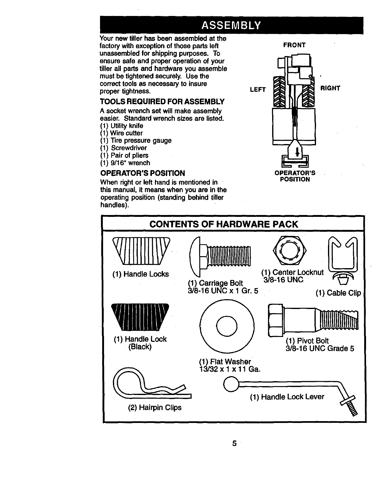
Your new tiller has been assembled at the
factory with exception of those parts left
unassembled for shipping purposes. To
ensure safe and proper operation of your
tiller all parts and hardware you as-
semble .mustbe tightened securely. Use
the correct tools as necessary to insure
proper tightness.
MAINTENANCE AGREEMENT
A Sears Maintenance Agreement is
available on this product. Contact your
nearest Sears store for details.
CUSTOMER RESPONSIBILITIES
• Read and observe the safety rules.
•Follow a regular schedule in maintain-
ing, caring for and using your tiller.
•Follow the instructions under the
=Maintenance" and =Storage" sections
of this Owner's Manual.
AWARNING: This unit is equipped with
an internal combustion engine and
should not be used on or near any
unimproved forest-coversd, brush-
covered or grass covered land unless the
engine's exhaust system is equipped with
a spark arrester meeting applicable local
or state laws (if any). If a spark arrester is
used, it should be maintained in effective
working order by the operator.
In the state of California the above is
required by law (Section 4442 of the
California Public Rasources Code).
Other states may have similar laws.
Federal laws apply on federal lands. See
your Sears Authorized Service Center for
spark arrester. Refer tothe Repair Parts
section of this manual for part number.
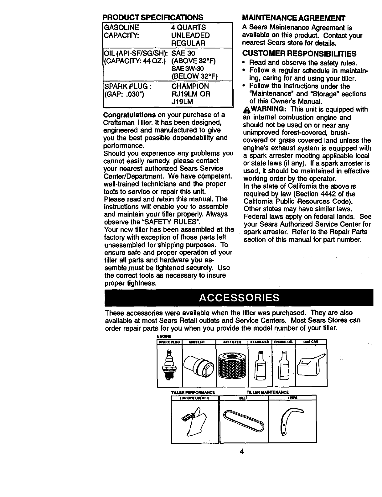
These accessories were available when the tiller was purchased. They are also
available at most Sears Retail outlets and Service Centers. Most Sears Stores can
order repair parts for you when you provide the model number of your tiller.
EIKIINE
IPARK PLUG MUFR.,F_ AIR FIL'III_
Your new tiller has been assembled at the
factory with exception of those parts left
unassembled for shipping purposes. To
ensure safe and proper operation of your
tiller all parts and hardware you assemble
must be tightened securely. Use the
correct tools as necessary to insure
proper tightness,
TOOLS REQUIRED FOR ASSEMBLY
A socket wrench set will make assembly
easier. Standard wrench sizes are listed.
(1) Utility knife
(1) Wire cutter
(1) Tire pressure gauge
(1) Screwdriver
(1) Pair of pliers
(1) 9/16" wrench
OPERATOR'S POSITION
When right or left hand is mentioned in
this manual, it means when you are in the
operating position (standing behind tiller
handles).
LEFT
FRONT
OPERATOR'S
POSITION
I
RIGHT
CONTENTS OF HARDWARE PACK
(1) Handle Lock
(Black)
(2) Hairpin Clips
(1) Carriage Bolt
3/8-16 UNC x 1 Gr. 5
(1) Flat Washer
13/32 x I xll Ga.
©
(1_8.Cle_t_l_lLc°cknut
(1) Cable Clip
(1) Pivot Bolt
3/8-16 UNC Grade 5
(1) Handle Lock Lever
5
UNPACKINGCARTON
_CAUTION: Be careful of exposed
staples when handling or disposing of
cartoning material.
IMPORTANT:When unpacking and
assembling tiller, be careful not to stretch
or kink cables.
• While holding handle assembly, cut
cable ties securing handle assembly to
top frame. Let handle assembly rest on
tiller.
•Remove top frame of carton.
•Slowly ease handle assembly up and
place on top of carton.
•Cut down right hand front and right
hand rear corners of carton. Lay side
carton wall down.
•Cut down left hand rear corner of
carton. Lay rear carton wall down,
which will remove the protective
cardboard flap from leveling shield.
•Remove packing material from handle
assembly.
Shift Rod
Assembly
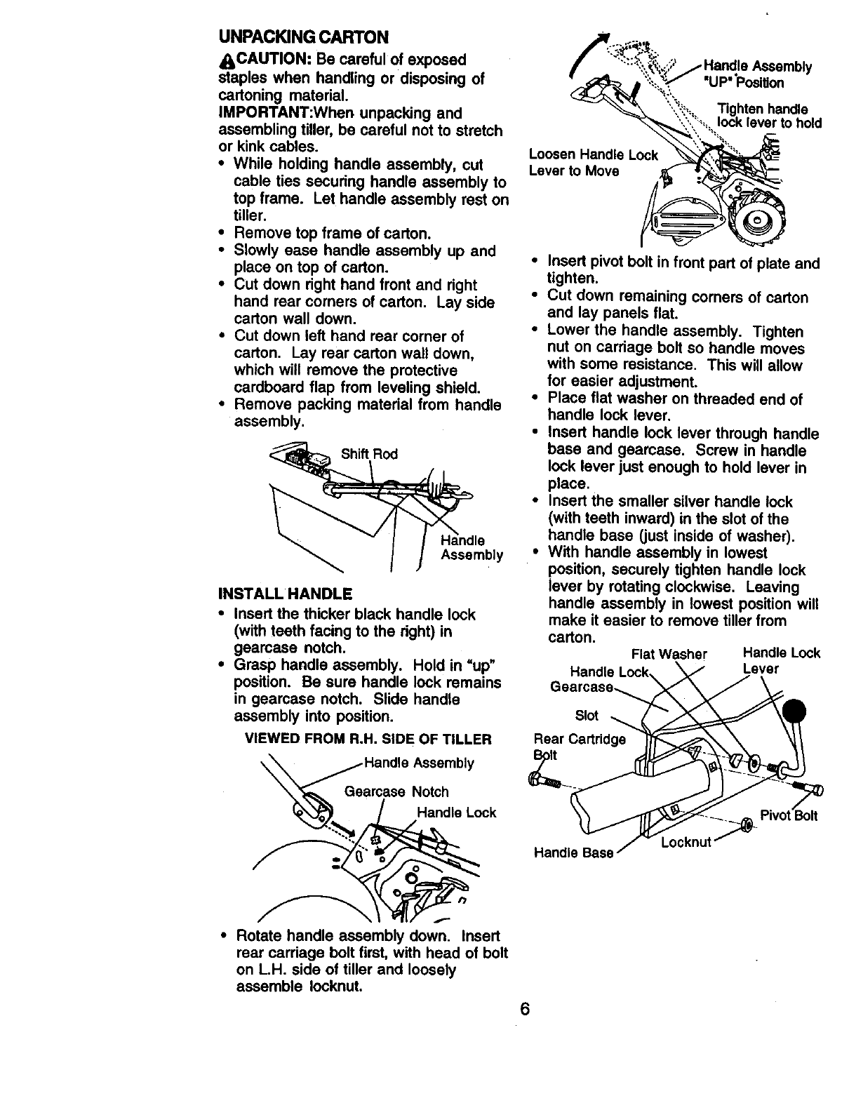
INSTALL HANDLE
• Insert the thicker black handle lock
(with teeth facing to the right) in
gearcase notch.
•Grasp handle assembly. Hold in =up"
position. Be sure handle lock remains
in gearcase notch. Slide handle
assembly into position.
VIEWED FROM R.H, SIDE OF TILLER
_. Ge _/HandHl_na_l:_So_:: bly
le Lock
•Rotate handle assembly down. Insert
rear cardage bolt first, with head of bolt
on L.H. side of tiller and loosely
assemble Iocknut.
Loosen Handle Lock
Lever to Move
,. Handle Assembly
"UP"Posltion
Tighten har_e
lock lever to hold
Q
Insert pivot bolt in front part of plate and
tighten.
Cut down remaining corners of carton
and lay panels flat.
Lower the handle assembly. Tighten
nut on cardage bolt so handle moves
with some resistance, This will allow
for easier adjustment.
Place flat washer on threaded end of
handle lock lever,
Insert handle lock lever through handle
base and geamase. Screw in handle
lock lever just enough to hold lever in
place.
Insert the smaller silver handle lock
(with teeth inward) in the slot of the
handle base (just inside of washer).
With handle assembly in lowest
position, seourely tighten handle lock
lever by rotating clockwise. Leaving
handle assembly in lowest position will
make it easier to remove tiller from
carton. FlatWasher HandleLock
Handle Lock Lever
Gearcase_
Slot
Rear Cartridge
Locknut
Handle Base
6
INSERT CABLE CLIP
•Insert plastic cable clip into hole on the
back of handle column. Push cables
into clip.
Handle Column
Cables
Cable Clip
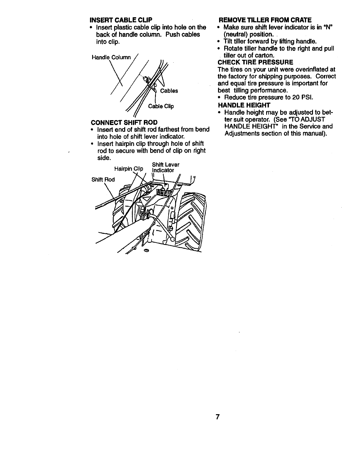
CONNECT SHIFT ROD
• Insert end of shift rod farthest from bend
into hole of shift lever indicator.
• Insert hairpin clip through hole of shift
rod to secure with bend of clip on right
side.
Shift Lever
Hairpin Indicator
Shift Rod
REMOVE TILLER FROM CRATE
•Make sure shift lever indicator is in =N"
(neutral) position.
•Tilt tiller forward by lifting handle.
•Rotate tiller handle to the right and pull
tiller out of carton.
CHECK TIRE PRESSURE
The tires on your unit were overinflated at
the factory for shipping purposes. Correct
and equal tire pressure is important for
best tilling performance.
•Reduce tire pressure to 20 PSI.
HANDLE HEIGHT
•Handle height may be adjusted to bet-
ter suit operator. (See "1"0 ADJUST
HANDLE HEIGHT" in the Service and
Adjustments section of this manual).
7

These symbols may appear on your Tiller or in literature supplied with the product.
Learn and understand their meaning.
KNOW YOUR TILLER
READ THIS OWNER'S MANUALAND SAFETY RULES BEFORE OPERATING YOUR
TILLER.
Compare the illustrations with your tiller to familiarize yourself with the location of
various controls and adjustments. Save this manual for future reference.
F N R& @
T_LUNG FORWARO NEUTRAL REVERSE _ENGINE ENGINE CHOKE FUEL OIL
OR wARNING ON OFF
Control
Lever
Drive Control Bar
Choke Control
Shift Lever Indicator
Depth
• @ Recoil
Leveling Starter
Handle
Outer
MEETS ANSI SAFETY REQUIREMENTS
Our tillers conform to the safety standards of the Amedcan National Standards Institute.
DRIVE CONTROL BAR -Used to engage
tines.
DEPTH STAKE -Controls depth at which
tiller will dig.
OUTER SIDE SHIELD -Adjustable to
protect small plants from being buried.
THROTTLE CONTROL -Used to control
engine speed.
LEVELING SHIELD -Levels tilled soil.
SHIFT LEVER -Used to shift transmission
gears.
SHIFT LEVER INDICATOR -Shows
which gear the transmission is in.
RECOIL STARTER HANDLE -Used to
start the engine.
CHOKE CONTROL -Used when starting
a cold engine.
8
The operation of any tiller can result in foreign objects thrown into the eyes,
which can result in severe eye damage. Always wear safety glasses or aye
shields before starting your tiller and while tilling. We recommend a wide
vision safety mask over spectacles or standard safety glasses.
HOW TO USE YOUR TILLER
Know how to operate all controls before
adding fuel and oil or attempting to start
engine.
STOPPING
TINES AND DRIVE
•Release drive control bar to stop
movement.
•Move shift lever to "N" (neutral)
position.
ENGINE
•Move throttle control to "STOP" posi-
tion. If equipped with stop switch, move
switch to =STOP" position.
•Never use choke to stop engine.
Drive Control Bar
"ENGAGED" Position Shift Lever
•Hold ddve control bar against the
handle to start tiller movement.
HARD TO SHIFT GEARS
•Briefly engage ddve control bar and
release or rock tiller forward and
backward until are able to shift gears.
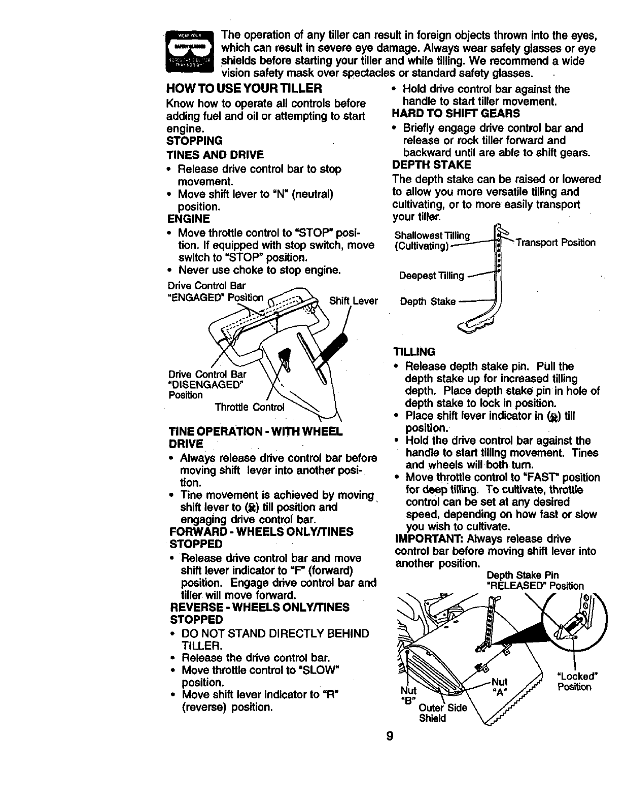
DEPTH STAKE
The depth stake can be raised or lowered
to allow you more versatile tilling and
cultivating, or to more easily transport
your tiller.
Shallowest Tilling
(Cultivating Position
Deepest Tiffin
Depth
Drive Control Bar
=DISENGAGED"
Position
Throttle Control
TINE OPERATION - WITH WHEEL
DRIVE
•Always release ddve control bar before
moving shift lever into another posi-
tion.
•Tine movement is achieved by moving
shift lever to (_) till position and
engaging ddve control bar.
FORWARD -WHEELS ONLY/TINES
STOPPED
•Release drive control bar and move
shift lever indicator to =F" (forward)
position. Engage drive control bar and
tiller will move forward.
REVERSE -WHEELS ONLY/TINES
STOPPED
•DO NOT STAND DIRECTLY BEHIND
TILLER.
•Release the ddve control bar.
•Move throttle control to =SLOW"
position.
•Move shift lever indicator to =R"
(reverse) position.
TILLING
•Release depth stake pin. Pull the
depth stake up for increased tilling
depth. Place depth stake pin in hole of
depth stake to lock in position.
•Place shift lever indicator in (_) till
position.
•Hold the ddve control bar against the
handle to start tillingmovement. Tines
and wheels will both tum.
•Move throttle control to =FAST" position
for deep tilling. To cultivate, throttle
control can be set at any desired
speed, depending on how fast or slow
you wish to cultivate.
IMPORTANT: Always release drive
control bar before moving shift lever into
another position.
Depth Stake Pin
=RELEASED" Position
\ \
"B"
Shield
9
TURNING
•Release the drive control bar.
•Move throttle control to =SLOW"
position.
•Place shift lever indicator in up,
(forward) position. Tines will not tum.
•Lift handle to raise tines out of ground.
•Swing the handle in the opposite
direction you wish to turn, being careful
to keep feet and legs away from tines.
•When you have completed your turn-
around, release the drive control bar
and lower handle. Place shift lever in
till position and move throttle control to
desired speed. To begin tilling, hold
drive control bar against the handle.
OUTER SIDE SHIELDS
The back edges of the outer side shields
are slotted so that the shields can be
raised for deep tilling and lowered for
shallow tilling to protect small plants from
being buried. Loosen nut =A" in slot and
nut =B'. Move shield to desired position
(both sides). Retighten nuts.
TO TRANSPORT
_CAUTION: Before lifting or transport-
ing, allow tiller engine and muffler to cool.
Disconnect spark plug wire. Drain
gasoline from fuel tank.
AROUND THE YARD
•Release the depth stake pin. Move the
depth stake down to the top hole for
transporting the tiller. Place depth
stake pin in hole of depth stake to lock
in position. This prevents tines from
scuffing the ground.
•Place shift lever indicator in =F"
(forward) position for transporting.
•Hold the drive control bar against the
handle to start tiller movement. Tines
will not turn.
•Move throttle control to desired speed.
AROUND TOWN
•Disconnect spark plug wire.
•Drain fuel tank.
•Transport in upright position to prevent
oil leakage.
BEFORE STARTING ENGINE
IMPORTANT: Be very careful not to allow
dirt to enter the engine when checking or
adding oil or fuel. Use clean oil and fuel
and store in approved, clean, covered
containers, use clean fill funnels.
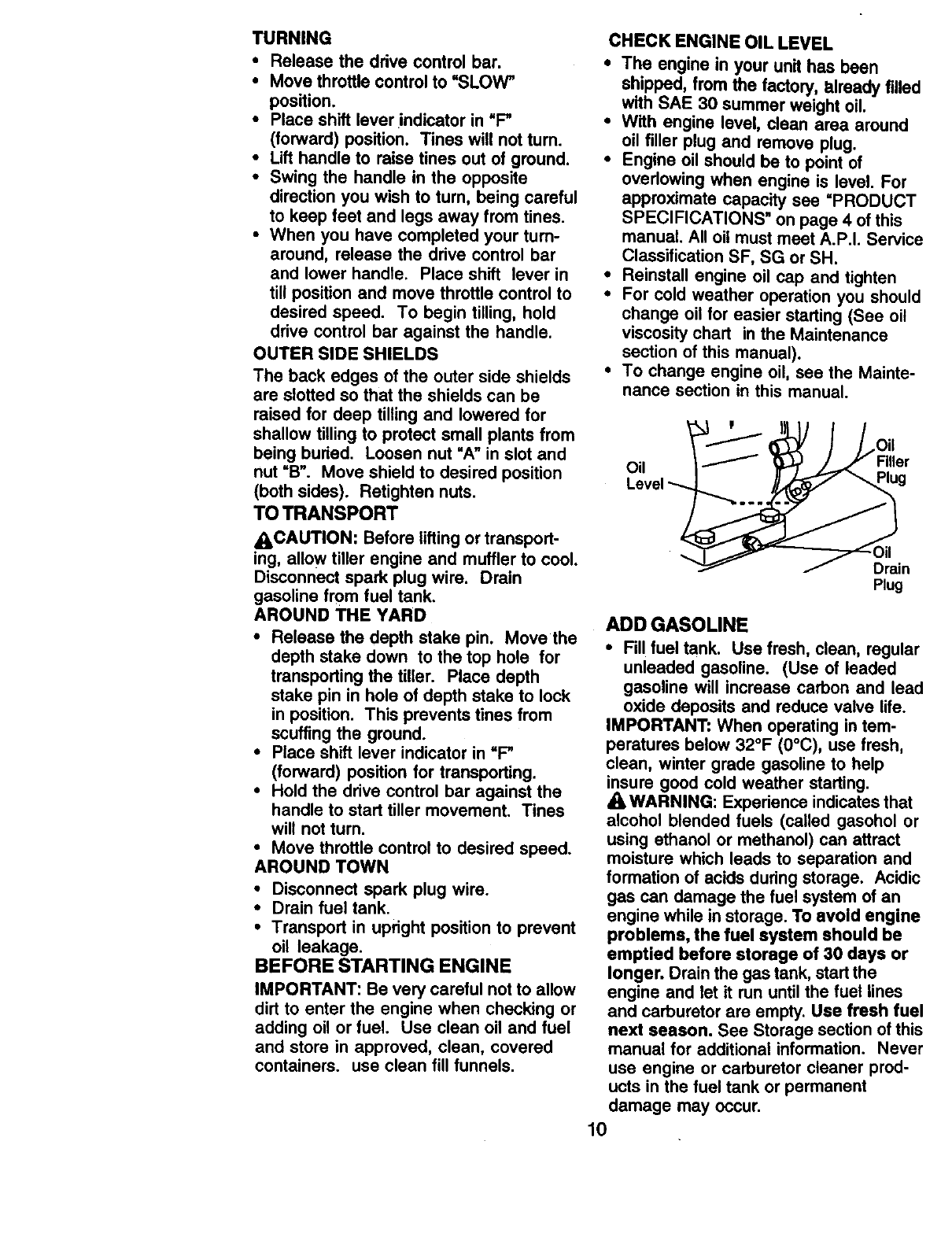
CHECK ENGINE OIL LEVEL
•The engine in your unit has been
shipped, from the factory, already filled
with SAE 30 summer weight oil.
•With engine level, clean area around
oil filler plug and remove plug.
•Engine oil should be to point of
ovedowing when engine is level. For
approximate capacity see =PRODUCT
SPECIFICATIONS" on page 4 of this
manual. All oil must meet A.P.I. Service
Classification SF, SG or SH.
•Reinstall engine oil cap and tighten
•For cold weather operation you should
change oil for easier starting (See oil
viscosity chart in the Maintenance
section of this manual).
•To change engine oil, see the Mainte-
nance section in this manual.
Oil
,Oil
Filler
Drain
Plug
ADD GASOLINE
•Fill fuel tank. Use fresh, clean, regular
unleaded gasoline. (Use of leaded
gasoline will increase carbon and lead
oxide deposits and reduce valve life.
IMPORTANT: When operating in tem-
peratures below 32°F (0°C), use fresh,
clean, winter grade gasoline to help
insure good cold weather starting.
AWARNING: Experience indicates that
alcohol blended fuels (called gasohol or
using ethanol or methanol) can attract
moisture which leads to separation and
formation of acids during storage. Acidic
gas can damage the fuel system of an
engine while in storage. To avoid engine
problems, the fuel system should be
emptied before storage of 30 days or
longer. Drain the gas tank, startthe
engine and let it run until the fuel lines
and carburetor are empty. Use fresh fuel
next season. See Storage section of this
manual for additional information. Never
use engine or carburetor cleaner prod-
ucts in the fuel tank or permanent
damage may occur.
10
_CAUTION: Fillto within 1/2 inch of top
of fuel tank to prevent spills and to allow
for fuel expansion. If gasoline is acciden-
tally spilled, move machine away from
area of spill. Avoid creating any source of
ignition until gasoline vapors have
disappeared.
Do not overfill. Wipe off any spilled oil or
fuel. Do not store, spill or use gasoline
near an open flame.
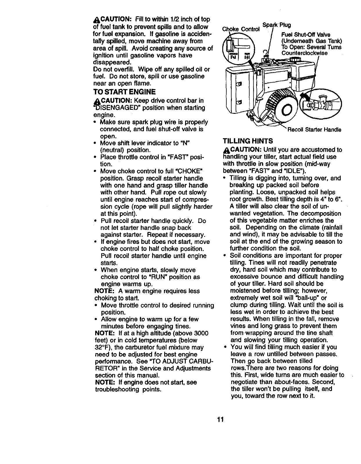
TO START ENGINE
_CAUTION: Keep drive control bar in
ISENGAGED" position when starting
engine.
•Make sure spark plug wire is propedy
connected, and fuel shut-off valve is
open.
•Move shift lever indicator to UN"
(neutral) position.
•Place throttle control in =FAST" posi-
tion.
•Move choke control to full =CHOKE"
position. Grasp recoil starter handle
with one hand and grasp tiller handle
with other hand. Pull rope out slowly
until engine reaches start of compres-
sion cycle (rope will pull slightly harder
at this point).
•Pull recoil starter handle quickly. Do
not let starter handle snap back
against starter. Repeat if necessary.
•If engine fires but does not start, move
choke control to half choke position.
Pull recoil starter handle until engine
starts.
•When engine starts, slowly move
choke control to =RUN" position as
engine warms up.
NOTE: A warm engine requires less
choking to start.
•Move throttle control to desired running
position.
•Allow engine to warm up for a few
minutes before engaging tines,
NOTE: If at a high altitude (above 3000
feet) or in cold temperatures (below
32°F), the carburetor fuel mixture may
need to be adjusted for best engine
performance. See 9"O ADJUST CARBU-
RETOR" in the Service and Adjustments
section of this manual.
NOTE: If engine does not start, see
troubleshooting points.
Choke Control Fuel Shut-Off Valve
(Underneath Gas Tank)
To Open: Several Turns
Counterclockwise
Recoil Starter Handle
TILLING HINTS
_aaCAUTION: Until you are accustomed to
ndling your tiller, start actual field use
with throttle in slow position (mid-way
between =FAST" and =IDLE").
•Tilling is digging into, turning over, and
breaking up packed soil before
planting. Loose, unpacked soil helps
root growth. Best tilling depth is 4" to 6".
A tiller will also clear the soil of un-
wanted vegetation. The decomposition
of this vegetable matter enriches the
soil. Depending on the climate (rainfall
and wind), it may be advisable to till the
soil at the end of the growing season to
further condition the soil.
•Soil conditions are important for proper
tilling. Tines will not readily penetrate
dry, hard soil which may contribute to
excessive bounce and difficult handling
of your tiller. Hard soil should be
moistened before tilling; however,
extremely wet soil will =ball-up" or
clump during tilling. Wait until the soil is
less wet in order to achieve the best
results. When tilling in the fall, remove
vines and long grass to prevent them
from ,wrapping around the tine shaft
and slowing your tilling operation.
•You will find tilling much easier if you
leave a row untilled between passes.
Then go back between tilled
rows.There are two reasons for doing
this. First, wide turns are much easier to
negotiate than about-faces. Second,
the tiller won't be pulling itself, and
you, toward the row next to it.
11

•Do not lean on handle. This takes
weight off the wheels and reduces
traction. To get through a really tough
section of sod or hard ground, apply
upward pressure on handle or lower
the depth stake.
CULTIVATING
Cultivating is destroying the weeds
between rows to prevent them from
robbing nourishment and moisture from
the plants. At the same time, breaking up
the upper layer of soil crust will help
retain moisture in the soil. Best digging
depth is 1" to 3" (2.5-7.5 cm). Lower the
outer side shields to protect small plants
from being buried.
•Cultivate up and down the rows at a
speed which will allow tines to uproot
weeds and leave the ground in rough
condition, promoting no further growth
of weeds and grass.
IOOOIOO
OOOIOO
OOOIOO
©O O',OO
TINE SHEAR PINS
The tine assemblies on your tiller are
secured to the tine shaft with shear pins
(See %INE REPLACEMENT in the
Service and Adjustments section of this
manual).
If the tiller is unusually overloaded or
jammed, the shear pins are designed to
break before internal damage occurs to
the transmission.
•If shear pin(s) break, replace only with
those shown in the Repair Parts
section of this manual.
ADJUST WHEELS FOR
CULTIVATING
•Place blocks under right hand side of
tiller and remove hairpin clip and clevis
pin from right hand wheel.
•Move wheel outward approximately 1
inch until hole in inner wheel hub lines
up with inner hole in axle.
•Replace clevis pin and hairpin clip on
inside of wheel and remove blocks.
•Repeat preceding steps on left hand
side.
NOTE: In extremely rough conditions
and while cultivating, the wheels should
be moved outward on the axle for
increased stability.
OUTER VIEW OF TIRE
Clevis
Pin
INNER VIEW OF TIRE
Clevis
Pin
Hairpin
12

SCHEDULE
AS YOU COMPLETE ERVICE DATES
REGULAR SERVICE
Check Engine Oil Level I_
Change Engine Oil I_L2
Oil Pivot Points
Inspect Spark Armster /Muffler ide
Inspect Air Screen ll_
Clean or Replace Air Cleaner Cartridge I_2
Clean Engine Cylinder Fins ll_
Replace Spark Plug I_
RH Gear Case Grease Fitting (1oz.) II_
1 - Change more oltefl when opera,rig unde_iheavy load of In hlg_ ambient tempera_e$,
2 - SenSe mole often v/hen operJng In dirty or dusty _.
GENERAL RECOMMENDATIONS
The warranty on this tiller does not cover
items that have been subjected to
operator abuse or negligence. To receive
full value from the warranty, the operator
must maintain tiller as instructed in this
manual.
Some adjustments will need to be made
perindically to properly maintain your
tiller.
All adjustments in the Service and
Adjustments section of this manual
should be checked at least once each
season.
•Once a year you should replace the
spark plug, clean or replace air filter,
and check tines and belts for wear. A
new spark plug and clean air filter
assure proper air-fuel mixture and help
your engine run better and last longer.
BEFORE EACH USE
•Check engine oil level,
•Check tine operation.
•Check for loose fasteners.
LUBRICATION
Keep unit well lubricated (See "LUBRI-
CATION CHAR'F*).
LUBRICATION CHART
* Throttle Control
** Engine "**RH Gear Case
Rffing
Shield
Hinges
*Idler Bracket Wheel Hub
* SAE 30 OR 5W-30 Motor Oil
** Refer to Maintenance "ENGINE" Section
*** EP #1 Grease
13
_eCAUTION: Disconnect spark plug wire
fore performing any maintenance
(except carburetor adjustment) to prevent
accidental starting of engine.
Prevent fires! Keep the engine free of
grass, leaves, spilled oil, or fuel. Remove
fuel from tank before tipping unit for
maintenance. Clean muffler area of all
grass, dirt, and debris.
Do not touch hot muffler or cylinder fins
as contact may cause bums.
ENGINE
LUBRICATION
Use only high quality detergent oil rated
with API service classification SF, SG or
SH. Select the oil's SAE viscosity grade
according to your expected temperature.
SAE VISCOSITY GRADES
TEMPERATURE RANGE ANTICIPATED BEFORE NEXT OIL CHANGE
NOTE: Although multi-viscosity oils (5W-
30, 10W-30, etc.) improve starting in cold
weather, these multi-viscosity oils will
result in increased oil consumption when
used above 32°F (0°C). Check your
engine oil level more frequently to avoid
possible engine damage from running
low on oil
Change the oil after every 50 hours of
operation or at least once a year if the
tiller is not used for 50 hours in one year.
Check the crankcase oil level before
starting the engine and after each five (5)
hours of continuous use. Add SAE 30
motor oil or equivalent. Tighten oil filler
plug securely each time you check the oil
level.
TO CHANGE ENGINE OIL
Determine temperature range expected
before oil change. All oil must meet API
service classification SF, SG or SH.
•Be sure tiller is on level surface.
•Oil will drain more freely when warm.
•Use a funnel to prevent oil spill on tiller,
and catch oil in a suitable container.
•Remove oil drain plug. Be careful not
to allow dirt to enter the engine. For
easier removal of plug use 7/16 12 Pt.
socket with extension.
•Tip tiller forward to drain oil.
•After oil has drained completely,
replace oil drain plug and tighten
securely.
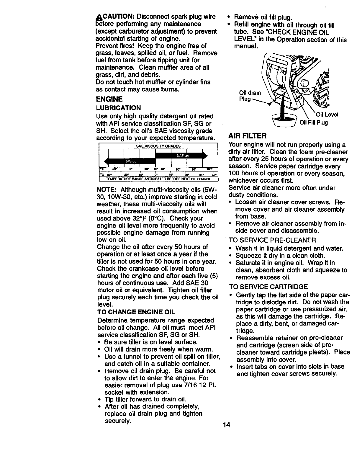
•Remove oil fill plug.
•Refill engine with oil through oil fill
tube. See •CHECK ENGINE OIL
LEVEL" in the Operation section of this
manual.
Oil drain
Level
Oil FillPlug
AIR FILTER
Your engine will not run properly using a
dirty air filter. Clean the foam pre-cleaner
after every 25 hours of operation or every
season. Service paper cartridge every
100 hours of operation or every season,
whichever occurs first.
Service air cleaner more often under
dusty conditions.
•Loosen air cleaner cover screws. Re-
move cover and air cleaner assembly
from base.
•Remove air cleaner assembly from in-
side cover and disassemble.
TO SERVICE PRE-CLEANER
•Wash it in liquid detergent and water.
•Squeeze it dry in a clean cloth.
•Saturate it in engine oil. Wrap it in
clean, absorbent cloth and squeeze to
remove excess oil
TO SERVICE CARTRIDGE
•Gently tap the flat side of the paper car-
tridge to dislodge dirt. Do not wash the
paper cartridge or use pressurized air,
as this will damage the cartridge. Re-
place a dirty, bent, or damaged car-
tridge.
•Reassemble retainer on pre-cleaner
and cartridge (screen side of pre-
cleaner toward cartridge pleats). Place
assembly into cover.
• Insert tabs on cover into slots in base
and tighten cover screws securely.
14

Cover Tab
Pre-Cleaner Blot
Retainer
Base
Cover Screws
Dual ElementJCartddge Air Cleaner
COOLING SYSTEM
Your engine is air cooled. For proper en-
gine performance and long life keep your
engine clean.
•Clean air screen frequently using a
stiff-bdsUed brush.
•Remove blower housing and clean as
necessary.
•Keep cylinder fins free of dirt and chaff,
.Cylinder
Fins
Air
/Screen
MUFFLER
Do not operate tiller without muffler. Do not
tamper with exhaust system. Damaged
mufflers or spark arresters could create a
fire hazard. Inspect periodically and
replace if necessary. If your engine is
equipped with a spark arrester screen
assembly, remove every 50 hours for
cleaning and inspection. Replace if
damaged.
SPARK PLUG
Replace spark plugs at the beginning of
each tilling season or after every 50 hours
of use, whichever comes first. Spark plug
type and gap setting is shown in "PROD-
UCT SPECIFICATIONS" on page 4 of this
manual.
TRANSMISSION
Once a season, lubricate the right hand
gear case grease fittingwith 1 oz. of EP #1
grease.
CLEANING
•Clean engine, wheels, finish, etc. of all
foreign matter.
•Keep finished surfaces and wheels free
of all gasoline, oil, etc.
•Protect painted surfaces with automo-
tive type wax.
We do not recommend using a garden
hose to clean your unit unless the muffler,
air filter and carburetor are covered to
keep water out. Water in engine can
result in a shortened engine life.
r_roCAUTION: Disconnect spark plug wire
mspark plug and place wire where it
cannot come into contact with plug.
TILLER
TO ADJUST HANDLE HEIGHT
Select handle height best suited for your
tilling conditions. Handle height will be
different when tiller digs into soil.
• First loosen handle lock lever.(Do not
loosen too much or handle locks may
fall out.)
•Handle can be positioned at different
settings between =HIGH" and uLOW"
positions.
•Retighten handle lock lever securely
after adjusting.
Handle (High) Position
Handle Lock Lever
Handle (Low) Position
TIRE CARE
_I_CAUTION: When mounting tires,
unless beads are seated, overinflation
can cause an explosion.
15
•Maintain 20 pounds of tire pressure. If
tire pressures are not equal, tiller will
pull to one side.
•Keep tires free of gasoline or oil which
can damage rubber.
TO REMOVE WHEEL
•Place blocks under transmission to
keep tiller from tipping.
•Remove outer side shield by removing
nuts "A"and =B".
•Remove inner side shield by removing
nuts =C"and =D".
•Remove hairpin clip and clevis pin from
wheel.
•Remove wheel and tire.
•Repair tire and reassemble.
Clevis
Hairpin Clip
Nut
Nut Shield
Outer Side Shield
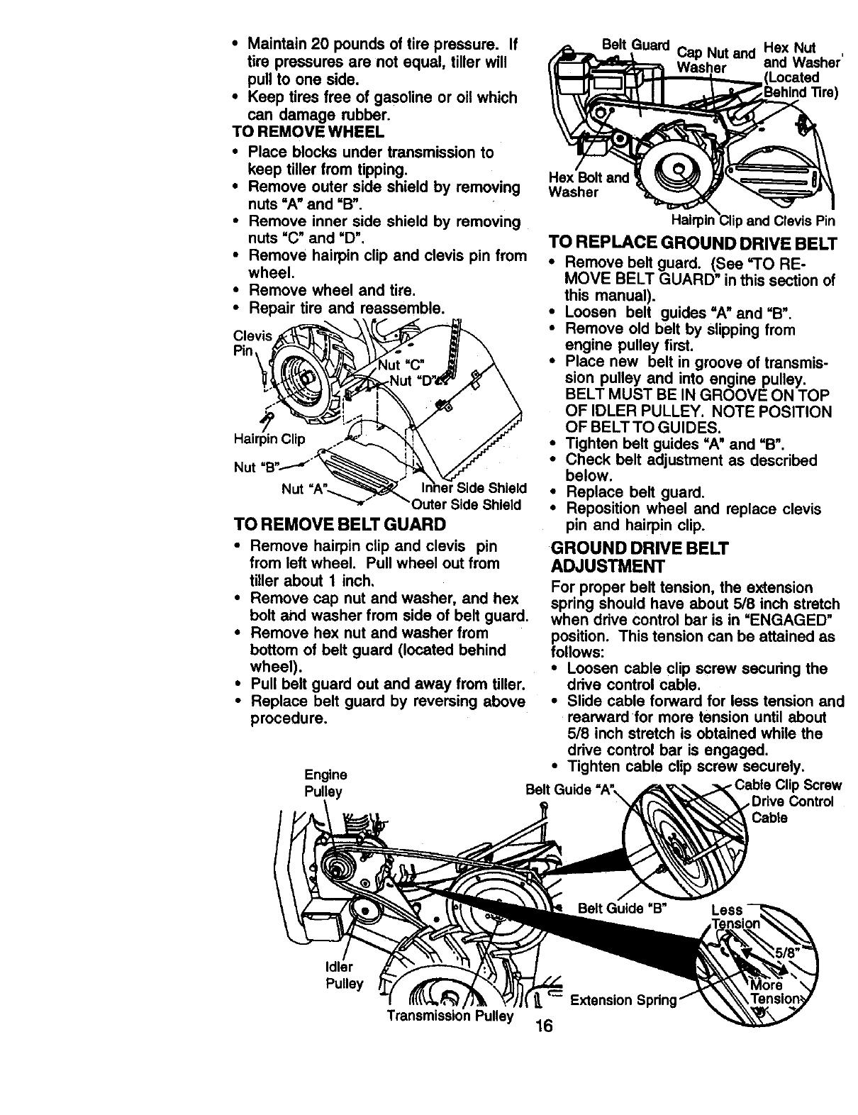
TO REMOVE BELT GUARD
•Remove hairpin clip and clevis pin
from left wheel. Pull wheel out from
tiller about Jinch.
•Remove cap nut and washer, and hex
bolt and washer from side of belt guard.
•Remove hex nut and washer from
bottom of belt guard (located behind
wheel).
•Pull belt guard out and away from tiller.
•Replace belt guard by reversing above
procedure.
Engine
Pulley
Belt Guard Cap Nut and Hex Nut
end We,she
Located
Hex Bolt end
Washer
Halrpin_Clipand Clevis Pin
TO REPLACE GROUND DRIVE BELl
•Remove belt guard. (See =TO RE-
MOVE BELT GUARD" inthis section of
this manual).
•Loosen belt guides "A"and =B".
•Remove old belt by slipping from
engine pulley first.
•Place new belt in groove of transmis-
sion pulley and into engine pulley.
BELT MUST BE IN GROOVE ON TOP
OF IDLER PULLEY. NOTE POSITION
OF BELT TO GUIDES.
•Tighten belt guides =A" and =B".
•Check belt adjustment as described
below.
•Replace belt guard.
•Reposition wheel and replace clevis
pin and hairpin clip.
GROUND DRIVE BELT
ADJUSTMENT
For proper belt tension, the extension
spring should have about 5/8 inch stretcl
when ddve control bar is in =ENGAGED"
position. This tension can be attained as
follows:
•Loosen cable clip screw securing the
ddve control cable.
•Slide cable forward for less tension an
rearward for more tension until about
5/8 inch stretch is obtained while the
drive control bar is engaged.
•Tighten cable clip screw securely.
.Cable Clip Screv
Control
Cable
Idler
Pulley _Extension Sprin!
Transmission Pulley 16
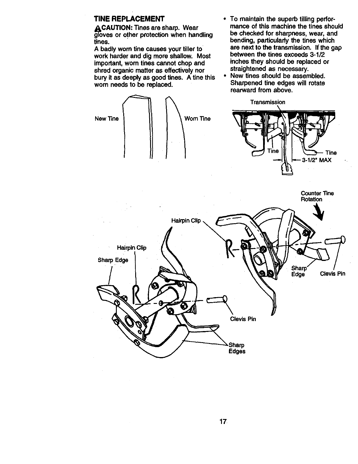
TINE REPLACEMENT
g_oCAUTION: Tines are sharp. Wear
vas or other protection when handling
tines.
A badly worn fine causes your tiller to
work harder and dig more shallow. Most
important, wom tines cannot chop and
shred organic matter as effectively nor
bury it as deeply as good tines. A tine this
worn needs to be replaced.
New "line
\
Wom "rine
•To maintain the superb tilling perfor-
mance of this machine the tines should
be checked for sharpness, wear, and
bending, particularly the tines which
are next to the transmission. If the gap
between the tines exceeds 3-1/2
inches they should be replaced or
straightened as necessary.
•New tines should be assembled.
Sharpened tine edges will rotate
rearward from above.
MAX
Counter "Rne
Rotation
Hairpin Clip
Sharp Edge
/Edge Clevis Pin
Clevis Pin
,Sharp
Edges
17
ENGINE
Maintenance, repair, or replacement of
the emission control devices and sys-
tems, which are being done at the
customers expense, may be performed
by any non-read engine repair establish-
ment or individual. Warranty repairs must
be performed by an authorized engine
manufacturer's service outlet.
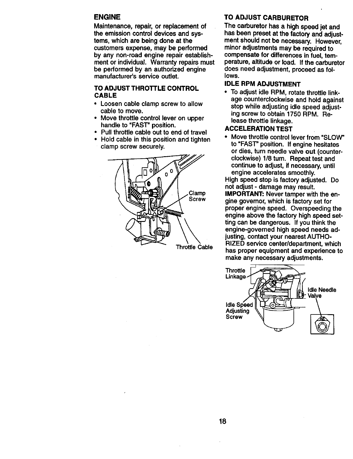
TO ADJUST THROTTLE CONTROL
CABLE
•Loosen cable clamp screw to allow
cable to move.
•Move throttle control lever on upper
handle to =FAST" position.
• Pull throttle cable out to end of travel
•Hold cable in this position and tighten
clamp screw securely.
Screw
Throttle Cable
TO ADJUST CARBURETOR
The carburetor has ahigh speed jet and
has been preset at the factory and adjust-
ment should not be necessary. However,
minor adjustments may be required to
compensate for differences in fuel, tem-
perature, altitude or load. If the carburetor
does need adjustment, proceed as fol-
lows.
IDLE RPM ADJUSTMENT
•To adjust idle RPM, rotate throttle link-
age counterclockwise and hold against
stop while adjusting idle speed adjust-
ing screw to obtain 1750 RPM. Re-
lease throttle linkage.
ACCELERATION TEST
•Move throttle control lever from =SLOW"
to =FAST" position. If engine hesitates
or dies, turn needle valve out (counter-
clockwise) 1/8 tum. Repeat test and
continue to adjust, if necessary, until
engine accelerates smoothly.
High speed stop is factory adjusted. Do
not adjust - damage may result.
IMPORTANT: Never tamper with the en-
gine govemor, which is factory set for
proper engine speed. Overspeeding the
engine above the factory high speed set-
ting can be dangerous. If you think the
engine-governed high speed needs ad-
justing, contact your nearest AUTHO-
RIZED service center/department, which
has proper equipment and experience to
make any necessary adjustments.
Throttle _-_
Linkag_ Val_/eldleNeedle
Idle Speed II _
Adjusting \\
Screw "_
18

Immediately prepare your tiller for storage
at the end of the season or if the unitwill
not be used for 30 days or more.
_CAUTION: Never store the tiller with
gasoline in the tank inside a building
where fumes may reach an open flame or
spark. Allow the engine to cool before
storing in any enclosure.
TILLER
• Clean entire tiller (See =CLEANING" in
the Maintenance se_ion of this
manual).
•Inspect and replace belts, if necessary
(See belt replacement instructions in
the Service and Adjustments section of
this manual).
• Lubricate as shown in the Maintenance
section of this manual.
•Be sure that all nuts, bolts and screws
are securely fastened. Inspect moving
parts for damage, breakage and wear.
Replace if necessary.
•Touch up all rusted or chipped paint
surfaces; sand lightly before painting.
ENGINE
FUEL SYSTEM
IMPORTANT: It is important to prevent
gum deposits from forming in essential
fuel system parts such as the carburetor,
fuel filter, fuel hose, or tank during
storage, also, experience indicates that
alcohol blended fuels (called gasohol or
using ethanol or methanol) can attract
moisture which leads to separation and
formation of acids during storage. Acidic
gas can damage the fuel system of an
engine while in storage.
•Drain the fuel tank.
•Start the engine and let it run until the
fuel lines and carburetor are empty.
•Never use engine or carburetor cleaner
products in the fuel tank or permanent
damage may occur.
•Use fresh fuel next season.
NOTE: Fuel stabilizer is an acceptable
alternative in minimizing the formation of
fuel gum deposits during storage. Add
stabilizer to gasoline in fuel tank or
storage container. Always follow the mix
ratio found on stabilizer container. Run
engine at least 10 minutes after adding
stabilizer to allow the stabilizer to reach
the carburetor. Do not drain the gas tank
and carburetor if using fuel stabilizer.
ENGINEOIL
Drain oil (with engine warm) and replace
with clean oil. (See =ENGINE" in the
Maintenance section of this manual).
CYLINDER(S)
•Remove spark plug.
•Pour 1ounce (29 ml) of oil through
spark plug hole into cylinder.
•Pull starter handle slowly several times
to distribute oil.
•Replace with new spark plug.
OTHER
•Do not store gasoline from one season
to another.
•Replace your gasoline can if your can
starts to rust. Rust and/or dirt in your
gasoline will cause problems.
•If possible, store your unit indoors and
cover it to give protection from dust and
dirt.
• Cover your unit with a suitable protec-
tive cover that does not retain moisture.
Do not use plastic. Plastic cannot
breathe which allows condensation to
form and will cause your unit to rust.
IMPORTANT: Never cover tiller while
engine and exhaust areas are still warm.
19
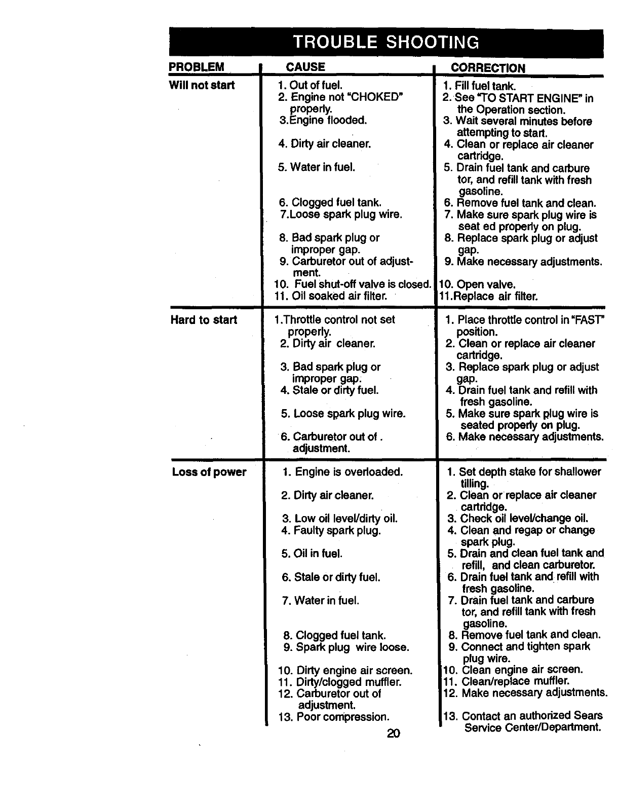
PROBLEM
Will not start
Hard to start
Loss of power
CAUSE
1. Out of fuel.
2. Engine not "CHOKED"
properly.
3.Engine flooded.
4. Dirty air cleaner.
5. Water in fuel.
6. Clogged fuel tank.
7.Loose spark plug wire.
8. Bad spark plug or
improper gap.
9. Carburetor out of adjust-
ment.
t0. Fuel shut-off valve is closed.
11. Oil soaked air filter.
1.Throttle control not set
properly.
2. Dirty air cleaner.
3. Bad spark plug or
improper gap:
4. Stale or dirty fuel.
5. Loose spark plug wire.
6. Carburetor outof.
adjustment.
1. Engine is overloaded.
2. Dirty air cleaner.
3. Low oil level/dirty oil.
4. Faulty spark plug.
5. Oil in fuel.
6. Stale or dirtyfuel.
7. Water in fuel.
8. Clogged fuel tank.
9. Spark plug wire loose.
10. Dirty engine air screen.
11. Dirty/clogged muffler.
12. Carburetor out of
adjustment.
13. Poor compression.
2O
CORRECTION
1. Fill fuel tank.
2. See TO START ENGINE" in
the Operation section.
3. Wait several minutes before
attempting to start.
4. Clean or replace air cleaner
cartridge.
5. Drain fuel tank and carbure
tor, and refill tank with fresh
gasoline.
6. Remove fuel tank and clean.
7. Make sure spark plug wire is
seat ed properly on plug.
8. Replace spark plug or adjust
gap.
9. Make necessary adjustments.
10. Open valve,
11.Raplace air filter.
1. Place throttle control in"FAST"
position.
2. Clean or replace air cleaner
cartridge.
3. Replace spark plug or adjust
gap.
4. Drain fuel tank and refillwith
fresh gasoline.
5. Make sure spark plug wire is
seated properly on plug.
6. Make necessary adjustments.
1. Set depth stake for shallower
tilling.
2. Clean or replace air cleaner
cartridge.
3. Check oil level/change oil.
4. Clean and regap or change
spark plug.
5. Drain and clean fuel tank and
refill, and clean carburetor.
6. Drain fuel tank and refillwith
fresh gasoline.
7. Drain fuel tank and carbure
tor, and refilltank with fresh
gasoline.
8. Remove fuel tank and clean.
9. Connect and tighten spark
plug wire.
10. Clean engine air screen.
11. Clean/replace muffler.
12. Make necessary adjustments.
13. Contact an authorized Sears
Service Center/Department.
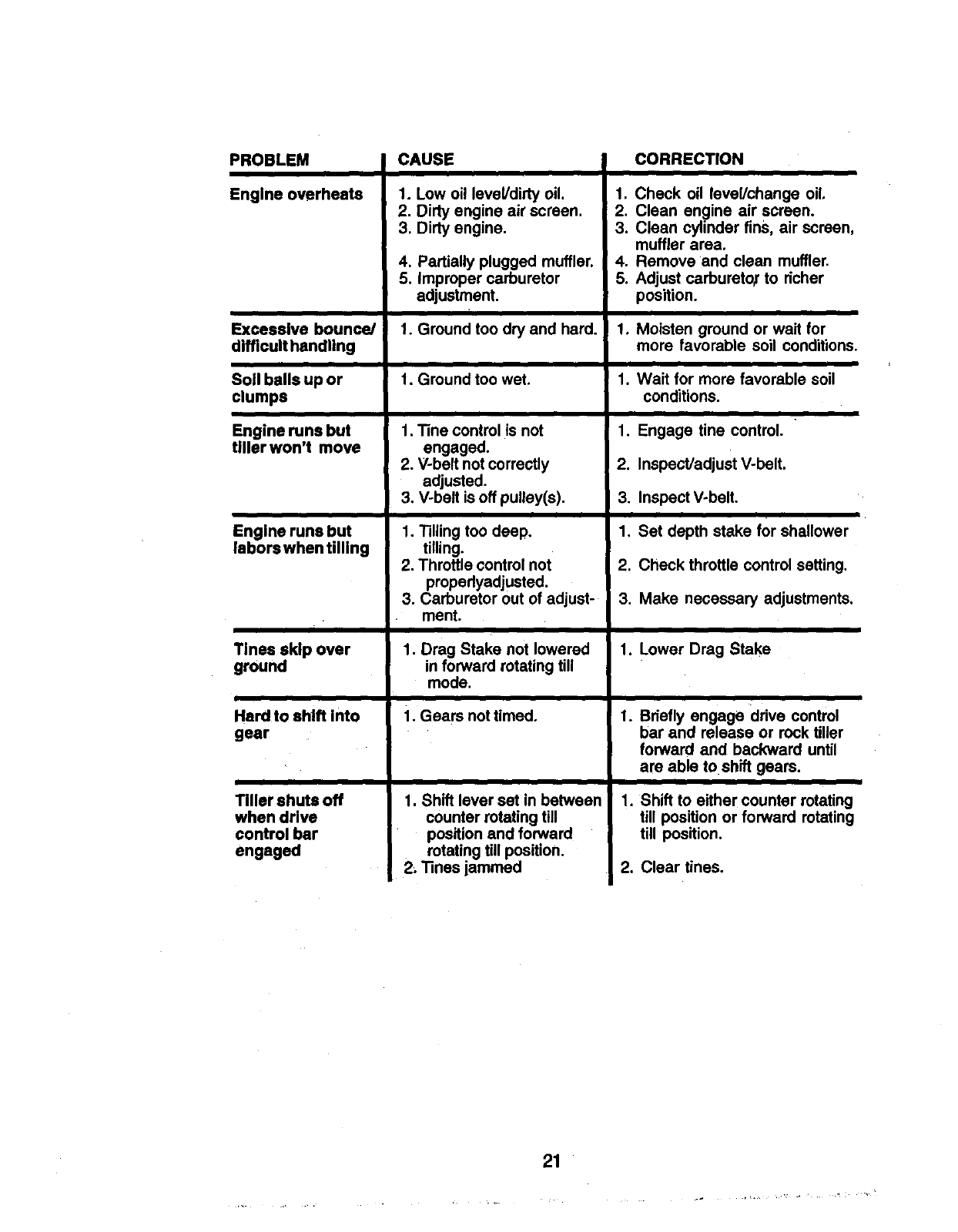
PROBLEM
Engine overheats
Excessive bounce/
difficult handting
Soil balls up or
clumps
Engine runs but
tiller won't move
Engine runs but
labors when tilling
Tines skip over
ground
Herd to shift Into
gear
Tiller shuts off
when drive
control bar
engaged
CAUSE
1. Low oil level/dirty oil.
2. Dirty engine air screen.
3. Dirty engine.
4. Partially plugged muffler.
5. Improper carburetor
adjustment.
1. Ground too dry and hard.
1. Ground too wet.
1. Tine control is not
engaged,
2. V-belt not correctly
adjusted.
3. V-belt is off pulley(s).
1. Tilling too deep.
tilling.
2. Throttle control not
propedyadjusted.
3. Carburetor out of adjust-
ment.
1. Drag Stake not lowered
in forward rotating till
mode.
1. Gears not timed.
1. Shift lever set in between
counter rotating till
position and forward
rotating till position.
2. Tines jammed
CORRECTION
1. Check oil level/change oil.
2. Clean engine air screen.
3. Clean cylinder fins, air screen,
muffler area.
4. Remove and clean muffler.
5. Adjust carburetor" to richer
position.
1. Moisten ground or wait for
more favorable soil conditions.
1. Wait for more favorable soil
conditions.
1. Engage tine control.
2. Inspect/adjust V-belt.
3. Inspect V-belt.
1. Set depth stake for shallower
2. Check throttle control setting.
3. Make necessary adjustments.
1. Lower Drag Stake
,
,
Briefly engage drive control
bar and release or rock tiller
forward and backward until
are able to shift gears.
i
Shift to either counter rotating
till position or forward rotating
till position.
2. Clear tines.
21
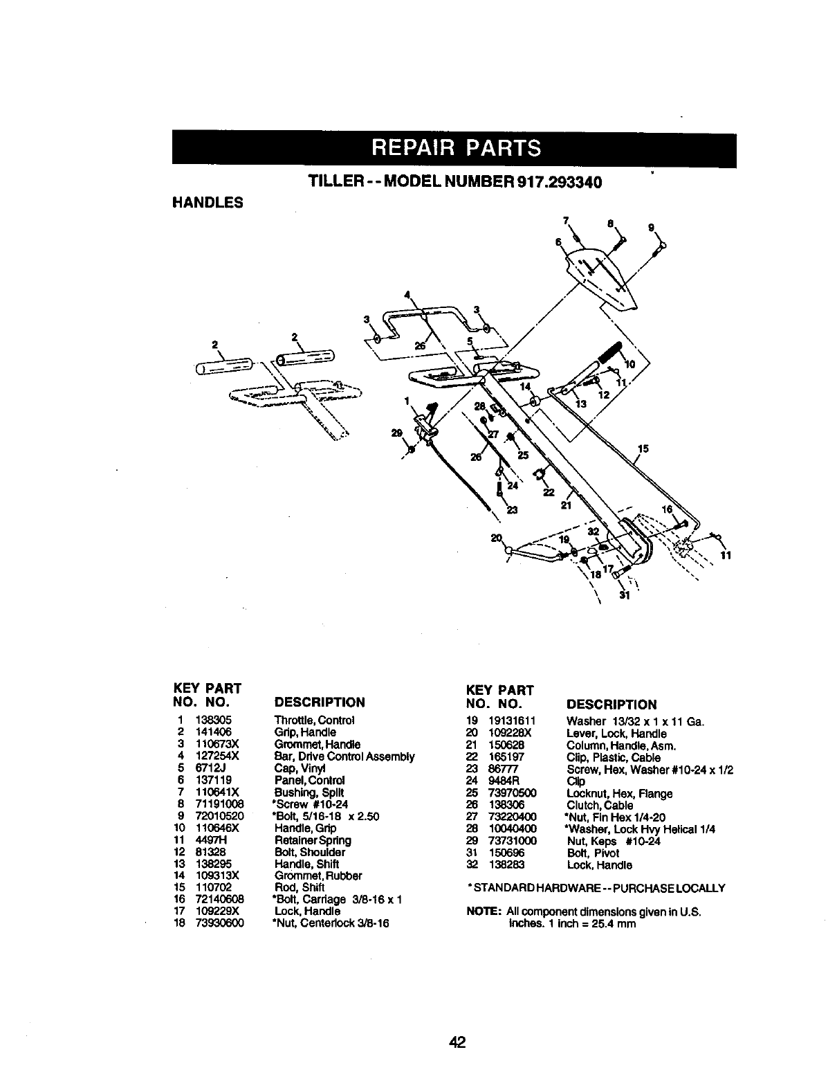
TILLER - - MODEL NUMBER 917.293340
HANDLES
\
19
11
\\ _,\
\31
\
KEY PART
NO. NO. DESCRIPTION
1 138305 Throttle,Control
2 141406 Gdp,Handle
3 110673X Grommet,Handle
4 127254X Bar, Ddve ControlAssembly
5 6712J Cap, Vinyl
6 137119 Panel,Control
7 110641X Bushing,Split
8 71191008 *Screw #10-24
9 72010520 *Bolt,5/16.18 x2.50
10 110646X Handle,Grip
11 44971-1 RetainerSpring
12 81328 Bolt,Shoulder
13 138295 Handle,Shift
14 109313X Grommet,Rubber
15 110702 Rod, Shift
16 72140608 *Bolt,Cardage 3_-16xl
17 1C9229X Lock,Handle
18 73930600 "Nut,Centedock 3/8-16
KEY PART
NO. NO. DESCRIPTION
19 19131611 Washer 13/32xl xll Ga.
20 109228X Lever, Lock,Handle
21 150628 Column,Handle,Asm.
22 165197 Clip, Plastic,Cable
23 86777 Screw,Hex, Washer#10-24 x 1/2
24 9484R Clip
25 73970500 Locknut,Hex, Range
26 138306 Clutch,Cable
27 73220400 *Nut, FinHex 1/4-20
28 10040400 *Washer, LockHvy Helical 1/4
29 73731000 Nut,Kaps #10-24
31 150696 Bolt, Pivot
32 138283 Lock,Handle
* STANDARD HARDWARE -- PURCHASE LOCALLY
NOTE: Allcomponentdimensionsgiven inU.S.
inches. 1 inch= 25.4 mm
42
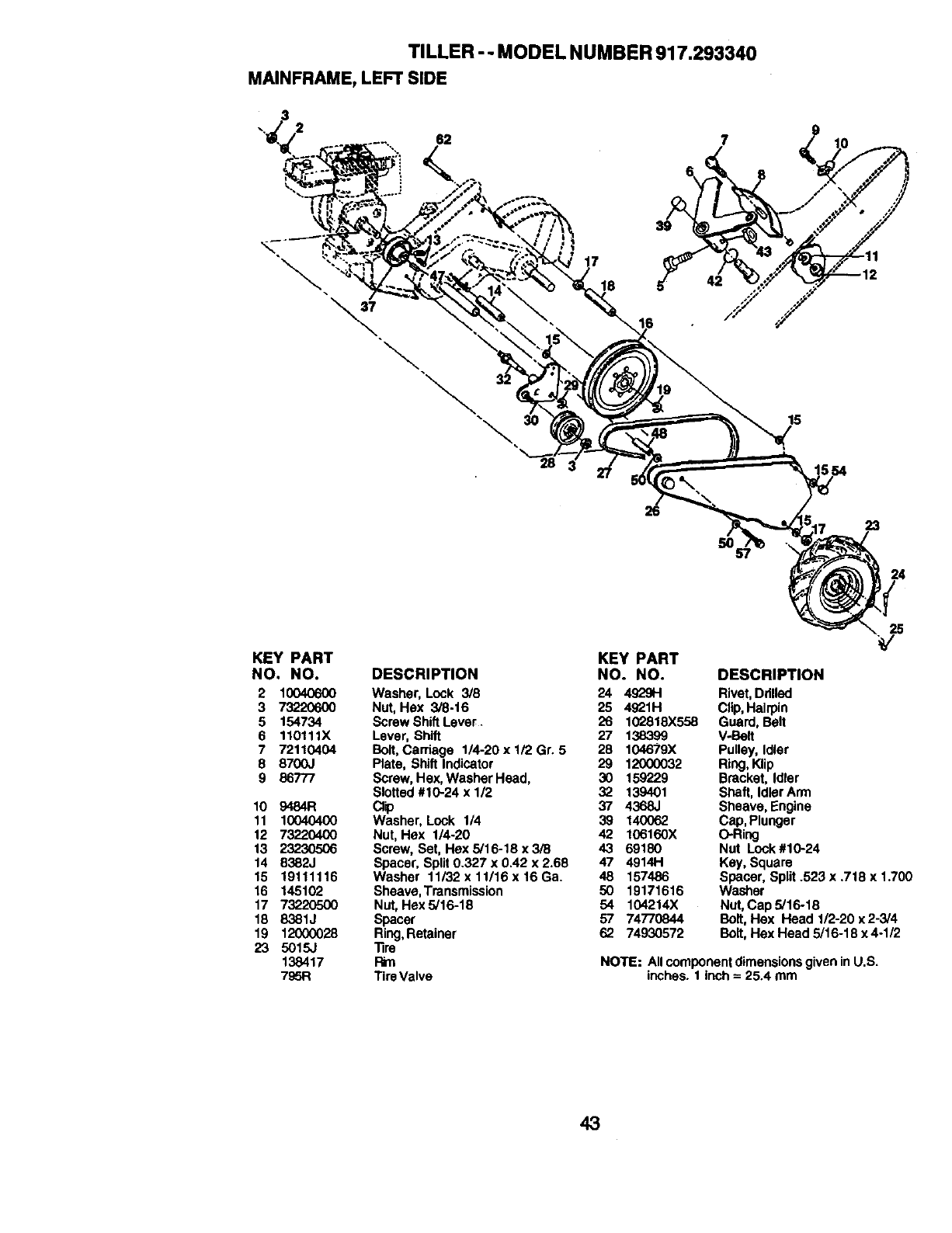
TILLER -- MODEL NUMBER 917.293340
MAINFRAME,LEFT SIDE
62
18
7
8
15
26
5O
23
24
KEY PART KEY PART
NO. NO. DESCRIPTION NO. NO.
2 10040600 Washer, Lock 3/8 24 4929H
3 73220600 Nut, Hex 3/8-16 25 4921H
5 154734 Screw ShiftLever . 26 102818X558
6 110111X Lever, Shift 27 138399
7 72110404 Bolt,Carriage 1/4-20 x 1/2 Gr. 5 28 104679X
8 8700J Plate, Shift Indicator 29 12000032
9 86777 Screw, Hex, Washer Head, 30 159229
Slotted #10-24 x 112 32 139401
10 9484R Clip 37 4368J
11 10040400 Washer, Lock 1/4 39 140062
12 73220400 Nut, Hex 1/4-20 42 106160X
13 23230506 Screw, Set, Hex 5/16-18 x 3/8 43 69180
14 8382J Spacer, Split 0.327 x 0.42 x 2.68 47 4914H
15 19111116 Washer 11i32x11/16x16Ga. 48 157486
16 145102 Sheave, Transmission 50 19171616
17 73220500 Nut, Hex5/16-18 54 104214X
18 8381J Spacer 57 74770844
19 12000028 Ring,Retainer 62 74930572
23 5015J Tire
138417 P_n
795R Tire Valve
25
DESCRIPTION
Rivet, Drilled
Clip,Hairpin
Guard, Belt
V-Belt
Pulley, Idler
Ring, Klip
Bracket, Idler
Shaft, IdlerArm
Sheave, Engine
Cap, Plunger
O-Ring
Nut Lock #10-24
Kay, Square
Spacer, Split .523 x .718 x 1.700
Washer
Nut, Cap 5/16-18
Bolt,Hax Head 1/2-20 x2-3/4
Bolt, Hex Head 5/16-18 x 4-1/2
NOTE: All componentdimensionsgiven in U.S.
inches. 1 inch = 25.4 mm
43
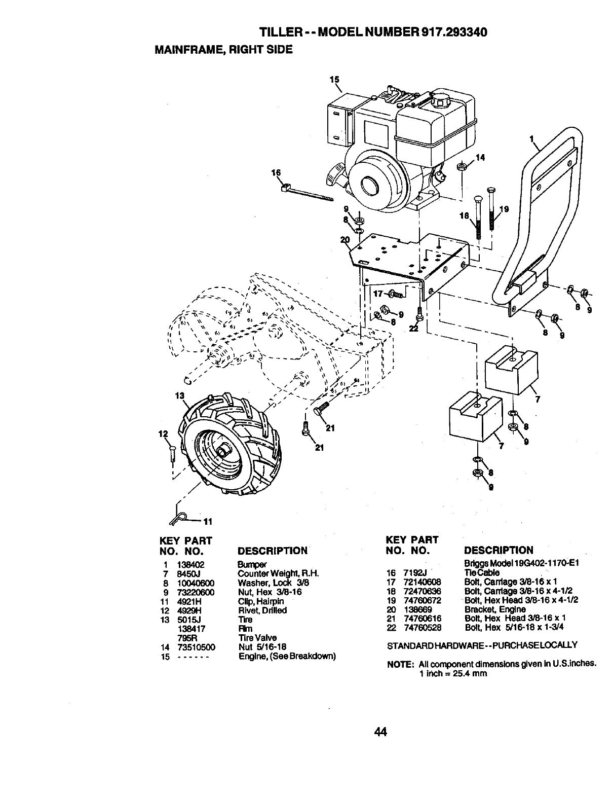
TILLER - - MODEL NUMBER 917.293340
MAINFRAME,RIGHTSIDE
15
\
1\
16
KEY PART
NO. NO. DESCRIPTION
1 138402 Bumper
7 8450J Counter Weight, R.H.
8 10040600 Washer, Lock 3/8
9 73220600 Nut, Hex 3/8-16
11 4921H Clip, Hairpin
12 4929H Rivet,Ddlled
13 5015J Tire
138417 Rm
795R Tin) Valve
14 73510500 Nut 5/16-18
15 ...... Engine, (See Breakdown
KEY PART
NO. NO.
16 7192J
17 72140608
18 72470636
19 74760672
2O 138669
21 74760616
22 74760528
DESCRIPTION
BriggsModel19G402-1170-E1
Tie_e
Bolt,Carriage 3/6-16 x 1
Bolt,Carriage 3/8-16 x 4-1/2
Bolt, Hex Head 3/8-16 x 4-1/2
Bracket, Engine
Bolt, Hex Head 3/8-16 x 1
Bolt,Hex 5/16-18 x 1-3/4
STANDARD HARDWARE --PURCHASELOCALLY
NOTE: All componentdimensions givenin U.S.inches.
1 inch = 25.4 mm
44

TRANSMISSION
TILLER - - MODEL NUMBER 917.293340
41
lS
10 A B C
41
44
41
KEY PART KEY PART
NO. NO. DESCRIPTION NO. NO.
o- 170324 TransmissjonAssembly 28 8357J
1 170325 Gearcass Assembly, R.H. w/ 29 674A289
Baarlng (Includes Key No. 18)
2 8370J Bo!t, Upset 30 6803J
3 8547J Gear, Reverse 31 12000040
4 8546J Gear, Cluster, Red,. 1st and 2nd 32 8356J
5 100413K Bearing,Needle 33 100016)(
6 674A291 SprocketAssembly, Tine 34 106392X
7 674A290 SprockstAssemblyw/Beadngs 35 106394X
(Includes Key #6 and (2)of key #5) 36 100436L
8 435&J Washer 37 142145
9 835&J Shaft, Reduction (1st) 38 106393X
10 8371J Chain, Roller 60 P 41 155236
11 100371K Spdng, Shlft, Fork 42 10040700
12 7"-7"-7"-7"-7"-7"-7_MBali, Steal 43 73610700
13 8353J Fork, Shift 44 162165
14 8354J Shaft, Shift
t5 12000039 Klip, Ring 45 17720510
16 154467 Washer, Seal 47 73220500
17 1370H Washer, Thrust 5/8x1.10xli32 48 100107K
18 4895H Beadng, Neadle 49 106391X
19 150695 Shaft, Input 60 6855M
21 105378X ShaftAscembly, Tlne -- 6066J
22 106181X Spacer 1.008 x 1-3/4 x .645
23 8359J Pinion, Input
24 5020J Beadng, Needle
25 164396 Gasket, Gearcesa
26 106389X Spacer .765 I,D. x 1.12 x 5/8
27 100433M Gear, Cluster, Red 1st & 2nd
DESCRIPTION
Gear, ReverseIdler
Gear, Assembly, Reverse Idler
(Includes Key Nos, 28 and 30)
Beating, Needle
Klip, Ring
Shaft, Reverse Idler
Shaft, Reduction (2nd)
Spacer .765 x I.D. x 1-1/8 x 1-3/8
Spacer Ground Drive L.H.
Shaft Assembly, Ground
Arm Assembly, Shift
Spacer GroundDdve R.H.
Seal, OII
Washer, Lock 7/16
Nut, Hex 7/16-20
Gearcase Assembly, LH., w/
Bearing (Includes Key #24)
Screw 5/16-18 x 5/8
Nut, Hax Head 5/16-18
Screw, Whiz, Lock 5/16-18 x4
Spacer .765 I.D. x 1.12 x 3/4
FittingGrease
Grease, Plastilube#1
* STANDARD HARDWARE - - PURCHASE LOCALLY
NOTE: All component dimensionsgiven In U.S,inches.
1 inch = 25.4 mm
45
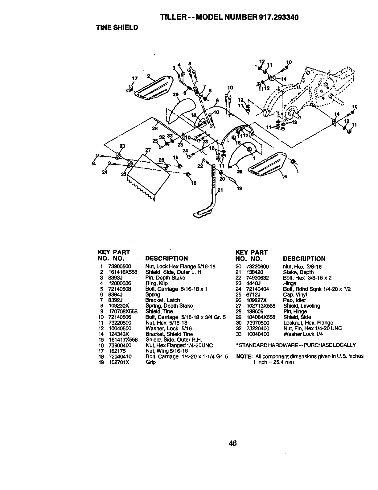
TINE SHIELD
TILLER - - MODEL NUMBER 917.293340
lO
8
28
!4
24 29
19
KEY PART
NO. NO.
1 739O05OO
2 161416X558
3 8393J
4 12000036
5 72140508
6 8394J
7 8392J
8 109230X
9 170708X558
10 72140506
11 73220500
12 10040500
14 124343X
15 161417X558
16 73900400
17 162175
18 72040410
19 102701X
KEY PART
DESCRIPTION NO. NO.
Nut, Lock Hex Flange 5/16-18 20 73220600
Shield, Side, Outer L.H. 21 138420
Pin, Depth Stake 22 74930632
Ring,Klip 23 4440J
Bolt,Carriage 5/16-18 x I 24 72140404
Spring 25 6712J
Bracket, Latch 26 109227X
Spring, Depth Stake 27 102713)(558
Shield,Tine 28 138609
Bolt,Carriage 5i16-18x3/4Gr. 5 29 104084X558
Nut, Hex 5/16-18 30 73970500
Washer, Lock 5/16 32 73220400
Bracket, Shield Tine 33 10040400
Shield, Side, Outer R.H.
Nut, Hex Flanged 1/4-20UNC
Nut, Wing 5/16-18
Bolt, Cardage 1/4-20 x 1-1/4 Gr. 5
Grip
DESCRIPTION
Nut, Hex 3/8-16
Stake, Depth
Bolt, Hex 3/8-16 x 2
Hinge
Bolt, Rdhd Sqnk 1/4-20 x 1/2
Cap, Vinyl
Pad, Idler
Shield,Leveling
Pin,Hinge
Shield,Side
Locknut,Hex, Flange
Nut, Fin,Hex 1/4-20 UNC
Washer Lock 1/4
*STANDARD HARDWARE -- PURCHASE LOCALLY
NOTE: Allcomponent dimensionsgiven in U.S. inches
1 inch =-25.4 mm
46
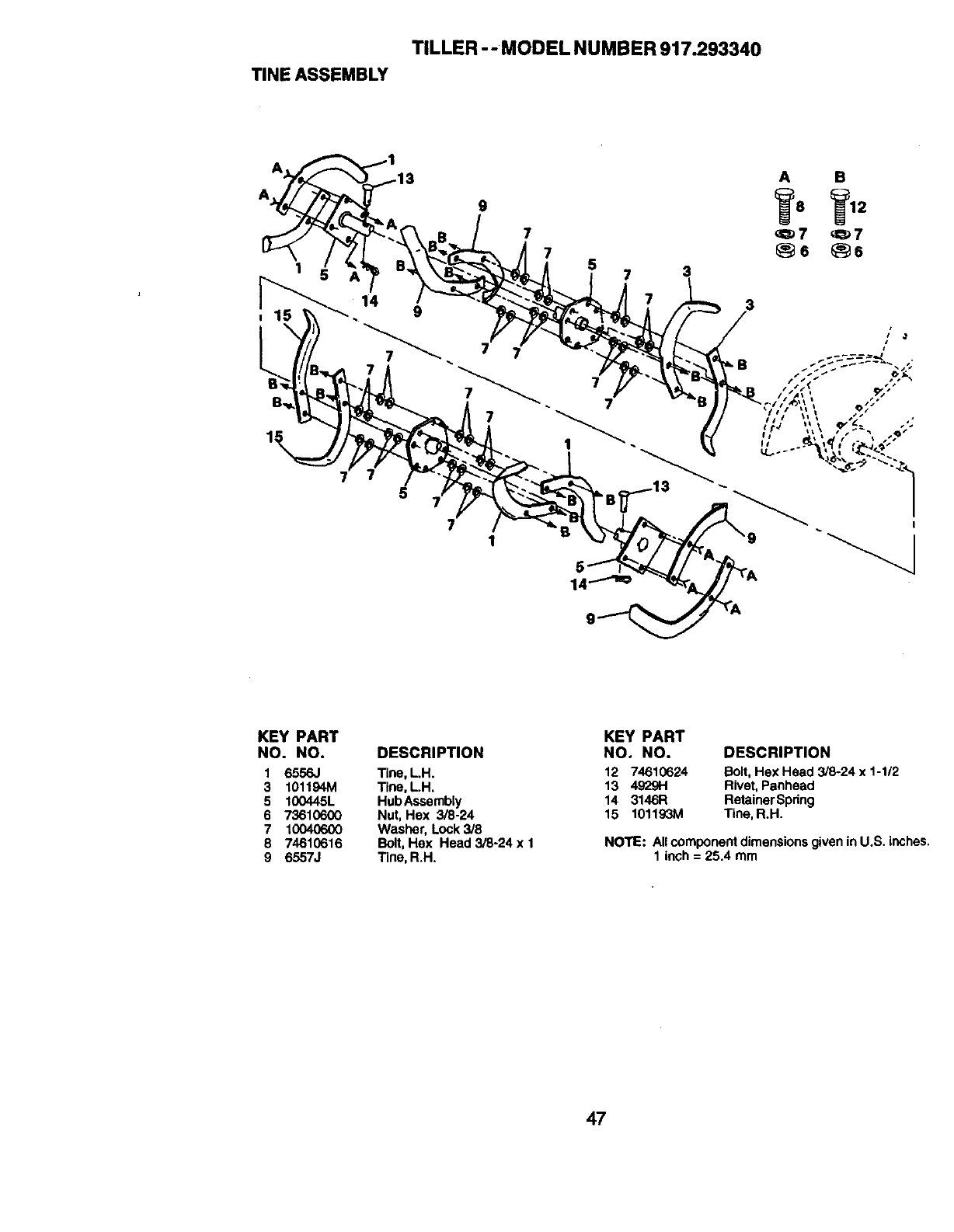
TILLER -- MODEL NUMBER 917.293340
TINEASSEMBLY
A
A
1!
9
7
14 9
7
75
71
57 3
7
3
I
KEY PART
NO. NO.
1 6556,1
3 101194M
5 100445L
6 73610600
7 10040600
8 74610616
9 6557J
DESCRIPTION
Tine, L.H.
Tine, LH.
HubAssembly
Nut, Hex 3/8-24
Washer, Lock 3/8
Boit,Hex Head 3/8-24 x 1
Tine, R.H.
KEY PART
NO. NO. DESCRIPTION
12 74610624 Bolt, Hex Head 3/8-24 x 1-1/2
13 4929H Rivet,Panhead
14 3146R RetainerSpring
15 101193M Tine, R.H.
NOTE: All component dimensions given in U.S. inches.
1 inch = 25.4 mm
47
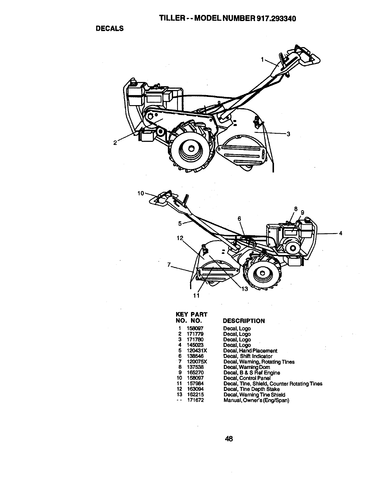
DECALS
TILLER - - MODEL NUMBER 917.293340
2
89
6
12\
11
KEY PART
NO. NO.
1 158097
2 171779
3 171780
4 145023
5 120431X
6 138546
7 120075X
8 137538
9 165270
10 158097
11 157984
12 163094
13 162215
- - 171672
DESCRIPTION
Decal, Logo
Decal, Logo
Decal, Logo
Decal,Logo
Decal, Hand Placement
Decal, Shift Indicator
Decal, Waming, RotatingTines
Decal, Waming Dora
Decal, B & S Ref Engine
Decal, Control Panel
Decal, "line, Shield, Counter RotatingTines
Decal, Tine Depth Stake
Decal, Waming Tine Shield
Manual, Owner's (Eng/Span)
48
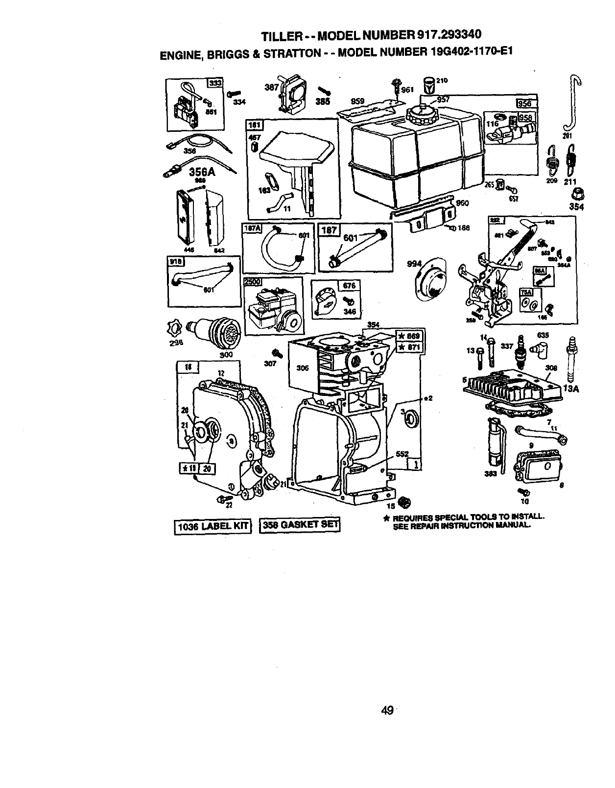
TILLER - - MODEL NUMBER 917.293340
ENGINE, BRIGGS & STRATTON - - MODEL NUMBER 19G402-1170-E1
,210
11036 LABEL KIT I1358 GASKET SE'_.
lk REQUIRES SPECIAL TOOLS TO INSTALL,
SEE REPAIR INSTRUCTION MANUAL.

TILLER-- MODEL NUMBER 917.293340
ENGINE, BRIGGS & STRATTON - - MODEL NUMBER 19G402-1170-E1
230
u,_e
it 8EQUIRES 8PECLALTOOLS
TO IN_rALL; SEE REPAIR
INSTRUCTIONMANUAL.
5O
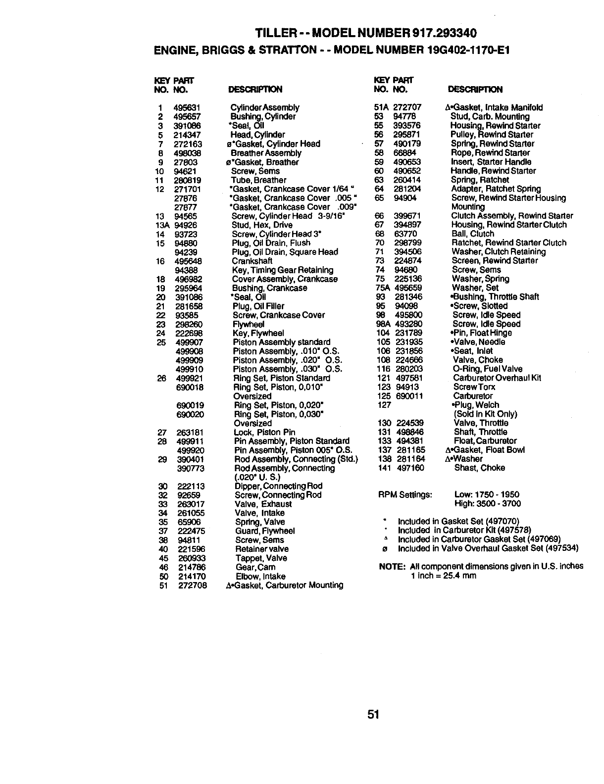
TILLER -- MODEL NUMBER 917.293340
ENGINE,BRIGGS& STRATTON- - MODELNUMBER19G402-1170-E1
KL=YPART K]EYPART
NO. NO. DESCRg:qlON NO. NO. DESCRIFnON
1 495631 CylinderAssembly 51A 272707
2 495657 Bushing,Cylinder 53 94778
3 391086 *Seal, Oil 55 393576
5 214347 Head,Cylinder 56 295871
7 272163 a'Gasket, Cylinder Head 57 490179
8 49_)38 BreatherAssembly 58 66884
9 27803 a'Gasket, Breather 59 490653
10 94621 Screw, Sems 60 490652
11 280819 Tube, Breather 63 260414
12 271701 *Gasket, Crankcase Cover 1/64 =64 281204
27876 *Gasket, Crankcase Cover .005 =65 94904
27677 *Gasket, Crankcase Cover .009"
13 94565 Screw, Cylinder Head 3-9/16" 66 399671
13A 94926 Stud, Hex, Drive 67 394897
14 93723 Screw, CylinderHead 3" 68 63770
15 94880 Plug, Oil Drain, Flush 70 298799
94239 Plug, Oil Drain, Square Head 71 394506
16 495648 Crankshaft 73 224874
94388 Key, TimingGear Retaining 74 94680
18 496982 CoverAssembly, Crankcase 75 225136
19 295964 Bushing,Crankcase 75A 495659
20 391086 *Seal, Oil 93 281346
21 281658 Plug,Oil RIler 95 94098
22 93585 Screw, Crankcase Cover g8 495800
23 298260 Flywheel 98A 493280
24 222698 Key,Fiywhael 104 231789
25 499907 Piston Assemblystandard 105 231935
499<308 Piston Assembly, .010" O.S. 106 231856
499909 Piston Assembly, .020" O.S. 108 224666
499910 Piston Assembly, .030" O.S. 116 280203
26 499921 RingSet, Piston Standard 121 497581
690018 Ring Set, Piston, 0,010" 123 94913
Oversized 125 690011
690019 Ring Set, Piston, 0,020 =127
690020 Ring Set, Piston, 0,030"
Oversized 130 224539
27 263181 Lock, PiSton Pin 131 498846
28 499911 Pin Assembly, PistonStandard 133 494381
499920 Pin Assembly, Piston 005" O.S. 137 281165
29 390401 Rod Assembly,Connecting(Std.) 138 281164
390773 Rod Assembly,Connecting 141 497160
(.020" U. S.)
30 222113 Dipper, Connecting Rod
32 92659 Screw,Connecting Rod
33 263017 Valve, Exhaust
34 261055 Valve, Intake
35 65.906 Spdng, Valve
37 222475 Guard,Flywheel
38 94811 Screw, Sems
40 221596 Retainer valve
45 260933 Tappet, Valve
46 214786 Gear, Cam
50 214170 Elbow, Intake
51 272708 A.Gasket, Carburetor Mounting
A-Gasket, Intake Manifold
Stud, Cad). Mounting
Housing, RewindStarter
Pulley, Rewind Stader
Spring, Rewind Starter
Rope, Rewind Starter
Insert, Starter Handle
Handle, Rewind Starter
Spdng, Ratchet
Adapter, Ratchet Spring
Screw, Rewind Starlet Housing
Mounting
ClutchAssembly,Rewind Starter
Housing, Rewind Starter Clutch
Ball, Clutch
Ratchet, Rewind Starter Clutch
Washer, Clutch Retaining
Screen, Rewind Starter
Screw,Sems
Washer, Spring
Washer, Set
•Bushing,Throttle Shaft
•Screw, Slotted
Screw, IdleSpeed
Screw, IdleSpeed
•Pin, Roat Hinge
•Valve, Needle
•Seat, Inlet
Valve, Choke
O-Ring, FuelValve
CarburetorOverhaul Kit
ScrewTorx
Carburetor
•Plug, Welch
(Sold in Kit Only)
Valve, Throttle
Shaft, Throttle
Float,Carburetor
A.Gasket, Roar Bowl
A-Washer
Shast, Choke
RPM Settings: Low: 1750 - 1950
High: 3500. 3700
Included in Gasket Set (497070)
Included In Carburetor Kit(497578)
AIncluded inCarburetor Gasket Set (497069)
•Included in Valve Overhaul Gasket Set (497534)
NOTE: Allcomponent dimensionsgiven in U.S. inches
1 inch = 25.4 mm
51
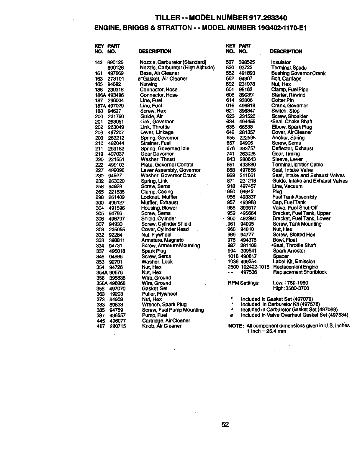
TILLER-- MODEL NUMBER 917.293340
ENGINE,BRIGGS& STRATrON- - MODELNUMBER19G402-1170-E1
PART _PART
NO. NO. DESCRIPTION NO. NO. DESCRIPTION
142 690125 Nozzle, Carburetor(Standard) 507 398525
690126 Nozzle, Carburetor (High Altitude) 520 93722
161 497669 Base, AirCleaner 552 491893
163 273101 e*Gaskat, Air Cleaner 562 94907
165 94692 Nutwing 592 231978
186 230318 Connector, Hose 601 95162
186A 493496 Connector, Hose 608 390391
187 296004 LIne, Fusi 614 93306
187A 497029 Line, Fuel 616 496818
188 94627 Screw, Hex 621 396847
200 221760 Guide, Air 623 231520
201 263051 Link, Governor 634 494455
202 263049 Link, Thmttla 635 66538
203 497207 Lever, Linkage 642 281357
209 263212 Spring, Governor 655 222598
210 492044 Strainer, Fuel 657 94906
211 263182 Spdng, Governed Idle 676 393757
219 497037 GearGovemor 741 263025
220 221551 Washer, Thruet 843 280643
222 499103 Plate, GovemorContml 851 493880
227 499096 Lever Assembly, Governor 868 497656
230 94927 Washer, GovemorCrenk 869 211661
232 263020 Spring, Link 871 231218
258 94929 Screw, Sems 918 497457
265 221535 Clamp,Casing 950 94642
298 261409 Locknut, Muffler 956 493337
300 496127 Muffler, Exhaust 957 493988
304 491596 Housing,Blower 958 399517
305 94786 Screw, Sems 959 495664
306 496797 Shield,Cylinder 960 492990
307 94930 Screw,CylinderShield 961 94095
308 225055 Cover, CylinderHead 965 94010
332 92284 Nut, Rywheel 969 94777
333 398811 Armature,Magneto 975 494378
334 94731 Screw, ArmatureMounting 987 281166
337 496018 Spark Plug 994 399541
346 94896 Screw, Sems 1016 490817
353 92791 Washer, Lock 1036 499354
354 94726 Nut, Hex
354A 90576 Nut, Hex
356 3.98838 Wire, Ground
356A 496868 Wire, Ground
358 497070 Gasket Set
363 19203 Puller,Rywheel
373 94908 Nut, Hex
383 89838 Wrench, Spark Plug
385 94789 Screw, Fuel Pump Mountlog
387 496257 Pump, Fuel
445 496077 Cartridge,AirCleaner
467 280715 Knob, Air Cleaner
Insulator
Terminal, Spade
BushingGovernorCrank
Bolt,Cantage
Nut, Hex
Clamp, Fuel Pipe
Starter,Rewind
Cotter Pin
Crank,Govemor
Switch, Stop
Screw, Shoulder
•Seal, Choke Shaft
Elbow, Spark Plug
Cover, AirCleaner
Anchor, Spring
Screw, Seres
Deflector, Exhaust
Gear Timing
Sleeve, Lever
Terminal, IgnitionCable
Seal, Intake Valve
Seat, Intake and Exhaust Valves
Guide, Intake and Exhaust Valves
Line Vacuum
Rug
FuelTank Assembly
Cap, FuelTank
Valve, Fuel Shut-Off
Bracket, Fuel Tank, Upper
Bracket, Fuel Tank, Lower
Screw,Tank Mounting
Nut, Hex
Screw, SlottedHex
Bowl,Float
•Seal, Throttla Shaft
Spark Anester
Spacer
Label Kit,Emission
2500 192402-1015 ReplacementEngina
--497536 ReplacementShortblock
RPM Seffings: Low:.1750-1950
High:35(X)-3700
Included in Gasket Set (497070)
Included inCarburetor Kit (497576)
" Included inCarburetor Gasket Set (497069)
•Included in Valve Overhaul Gasket Set (497534)
NOTE: All componentdimensionsgiven In U.S; Inclles
1 inch = 25.4 mm
52

53

54

55

For in-home major brand repair service:
Call 24 hoursa day,7 days a week
1-800-4-MY-HOME sM (1-800-469-4663)
Para pedir servicio de reparaci6n a domicilio
1-800-676-5811
In Canada for all your service and parts needs call
Au Canada pour tout le service ou les pi_ces
1-800-665-4455
For the repair or replacement parts you need:
Call 6 am - 11 pm CST, 7 days aweek
PartsDirect sM
1-800-366-PART (1-800-366-7278)
Para ordenar piezas con entrega a domicilio
1-800-659-7084
For the location of a Sears Parts and Repair Center
in your area:
Call 24 hours a day, 7 days a week
1-800-488-1222
For information on purchasing a Sears Maintenance
Agreement or to inquire about an existing Agreement:
Call 9 am -5 pm, Monday -Saturday
1-800-827-6655
171672 11.12.99 TR Printed in U.S.A.
