Craftsman 917293401 User Manual REAR TINE TILLER Manuals And Guides 1008365L
User Manual: Craftsman 917293401 917293401 CRAFTSMAN REAR TINE TILLER - Manuals and Guides View the owners manual for your CRAFTSMAN REAR TINE TILLER #917293401. Home:Lawn & Garden Parts:Craftsman Parts:Craftsman REAR TINE TILLER Manual
Open the PDF directly: View PDF ![]() .
.
Page Count: 36

Owner's Manual
®
6,0 HP
17 UNCHTJNE WHDTH
REAR NE WiTH
COUNTER ROTA NG TINES
TILLE
Model No.
917.293401
oSafety
AssembBy
Operation
Maintenance
, Repair Parts
CAUTION:
Read and follow all
Safety Rules and Instructions
before operating this equipment
Sears, Roebuck and Co., Hoffman Estates, IL 60179
Safety Rules ........................................... 2
Warranty ................................................. 2
Product Specifications .......................... 4
Assembly ................................................ 5
Operation ................................................ 8
Maintenance ......................................... 13
Service and Adjustments ...................... 15
Storage ................................................. 19
Troubleshooting .................................... 20
Illustrated Parts List .............................. 22
Parts Ordering ....................... Back Cover
LIMITED TWO YEAR WARRANTY ON CRAFTSMAN TILLER
For two (2) years from date of purchase, when this Craftsman Tiller is maintained, lubri-
cated, and tuned up according to the operating and maintenance instructions in the
owner's manual, Sears wilt repair free of charge any defect in material or workmanship.
This Warranty does not cover:
o Expendable items which become worn during normal use, such as tines, spark plugs,
air cleaners and belts.
, Repairs necessary because of operator abuse or negligence, including bent crank-
shafts and the failure to maintain the equipment according to the instructions con-
tained in the owner's manual.
oIf this Craftsman Tiller is used for commercial or rental purposes, this Warranty
applies for only thirty (30) days from the date of purchase.
Warranty service is avai{able by returning the craftsman power mower to the nearest
sears service center/department in the united states. This warranty applies only while
this product is in use in the united states° .-_
This Warranty gives you specific legal rights, and you may also have other rights which
vary from state to state.
SEARS, ROEBUCK AND CO., D/817WA, HOFFMAN ESTATES, IL 60179
TRAINING
° Read the Owner's Manual carefully° Be
thoroughly familiar with the controls and
the proper use of the equipment. Know
how to stop the unit and disengage the
controls quickly.
-Never allow children to operate the
equipmenL Never allow adults to oper-.
ate the equipment without proper
instruction.
- Keep the area of operation clear of all
persons, particularly small children, and
pets.
PREPARATION
•Thoroughly inspect the area where the
equipment is to be used and remove all
foreign objects°
° Disengage all clutches and shift into
neutral before starting the engine (mo-
tor),
• Do not operate the equipment without
wearing adequate outer garments. Wear
footwear that will improve footing on
slippery surfaces.
, Handle fuel with care; it is highly flam-
mable.
oUse an approved fuel container.
° Never add fuel to a running engine or
hot engine.
° Fil] fuel tank outdoors with extreme care.
Never fill fuel tank indoors.
°Replace gasoline cap securely and
clean up spilled fuel before restarting.
° Use extension cords and receptacles as
specified by the manufacturer for ail
units with electric drive motors or electric
starting motors.
• Never attempt to make any adjustments
while the engine (motor) is running
(except where specifically recommend.,
ed by manufacturer).
2
OPERATION
oDo not put hands or feet near or under
rotating parts.
o Exercise extreme caution when operat-
ing on or crossing gravel drives, walks,
or roads. Stay alert for hidden hazards
or traffic. Do not carry passengers.
o After striking a foreign object, stop the
engine (motor), remove the wire from
the spark plug, thoroughly inspect the
tiller for any damage, and repair the
damage before restarting and operating
the tiller_
o Exercise caution to avoid slipping or
falling.
° If the unit should start to vibrate abnor-
mally, stop the engine (motor) and check
immediately for the cause. Vibration is
generally a warning of trouble.
o Stop the engine (motor) when leaving
the operating position.
o Take all possible precautions when leav-
ing the machine unattended. Disengage
the tines, shift into neutral, and stop the
engine.
° Before cleaning, repairing, or inspecting,
shut off the engine and make certain all
moving parts have stopped. Disconnect
the spark plug wire, and keep the wire
away from the plug to prevent accidental
starting. Disconnect the cord on electric
motors.
oDo not run the engine indoors; exhaust
fumes are dangerous.
= Never operate the tiller without proper
guards, plates, or other safety protective
devices in place.
• Keep children and pets away.
o Do not overload the machine capacity
by attempting to till too deep at too fast a
rate.
o Never operate the machine at high
speeds on slippery surfacesr Look
behind and use care when backing.
o Never allow bystanders near the unit.
° Use only attachments and accessories
approved by the manufacturer of the
tiller (such as wheel weights, counter-
weights, cabs, and the like). '
°Never operate the tiller without good vis-
ibility or light.
°Be careful when tilling in hard ground.
The tines may catch in the ground and
propel the tiller forward_ If this occurs,
let go of the handlebars and do not
restrain the machine.
.r'
MAINTENANCE AND STORAGE
oKeep machine, attachments, and
accessories in Safe working condition.
= Check shear pins, engine mounting
bolts, and other bolts at frequent inter-
vals for proper tightness to be sure the
equipment is in safe working condition.
o Never store the machine with fuel in the
fuel tank inside a building where ignition
sources are present, such as hot water
and space heaters, clothes dryers, and
the like. Allow the engine to cool before
storing in ar_y enclosure.
°Always refer to the operator's guide
instructions for important details if the
tiller is to be stored for an extended peri-
CAUTION: Always disconnect spark
plug wire and place wire where it cannot
contact spark plug in order to prevent acci-
dental starhng when sethng up, transport-
ing, adjusting or making repairs.
WARNING
The engine exhuast from this product con-
tains chemicals known to the State of
California to cause cancer, birth defeotd, or
other reproductive harm°
3 _
PRODUCT SPECIRCATIONS
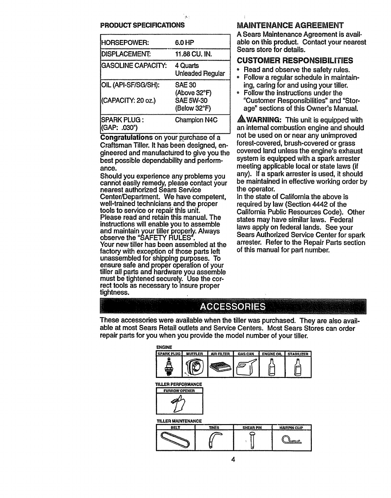
HORSEPOWER: 6.0 HP
DISPLACEMENT: 11.88CU. IN.
GASOLINECAPACITY: 4 Quarts
Unleaded Regular
SAE30
(Above32°F)
SAE 5W-30
(Below32°F)
OIL (API-SF/SG/SH):
CAPACITY: 20 oz,)
SPARKPLUG :Champion N4C
(GAP: .030")
Congratulations on your purchase of a
Craftsman Tiller. it has been designed, en-
gineered and manufactured to give you the
best possible dependability and perform-
ance.
Should you experience any problems you
cannot easily remedy, please contact your
nearest authorized Sears Service
Center/Department. We have competent,
well-trained technicians and the proper
tools to service or repaii"this unit.
Please read and retain this manual. The
instructionswill enable you to assemble
and maintain your tiller properly.Always
observe the =SAFETY" RULES",
Your new tiller has been assembled at the
factory with exception of those parts left
unassembled for shipping purposes. To
ensure safe and proper operation of your
tiller all parts and hardware you assemble
must be tightened securely. Use the cor-
rect tools as necessary to insure proper
tightness.
MAINTENANCE AGREEMENT
A Sears Maintenance Agreement is avail-
able on this product. Contact your nearest
Sears store for details.
CUSTOMER RESPONSIBILITIES
•Read and observe the safety rules.
oFollowa regular schedule in maintain-
ing, caring for and usingyour tiller.
oFollowthe instructionsunder the
"Customer Responsibilities"and =Stor-
age" sections of this Owner's Manual.
_kWARNING: This unit is equipped with
an internal combustion engine and should
not be used on or near any unimproved
forsst-covered, brush-covered or grass
covered land unless the engine's exhaust
system is equipped with a spark arrester
meeting applicable local or state laws (if
any). if a spark arrester is used, it should
be maintained in effective working order by
the operator.
In the state of California the above is
required by law (Section 4442 ofthe
California Public Resources Code). Other
states may have similar laws. Federal
laws apply on federal lands. See your
Sears Authorized Service Center for spark
arrester. Refer to the Repair Parts section
of this manual for part number.
These accessories were available when the tiller was purchased. They are also avail-
able at most Sears Retail outlets and Service Centers. Most Sears Stores can order
repair partsfor you when you provide the model number of your tiller.
ENGINE
TILLERMAINTENANCE
•BE_LT ,'I_N_:S GHEAR PIN HAIRPIN CLIp
4
"Yournew tiller has been assembled at the
factory with exception of those parts left
unassembled for shipping purposes. To
ensure safe and proper operation of your
tiller all parts and hardware you assemble
must be tightened securely. Use the cor-
rect tools as necessary to insure proper
tightness.
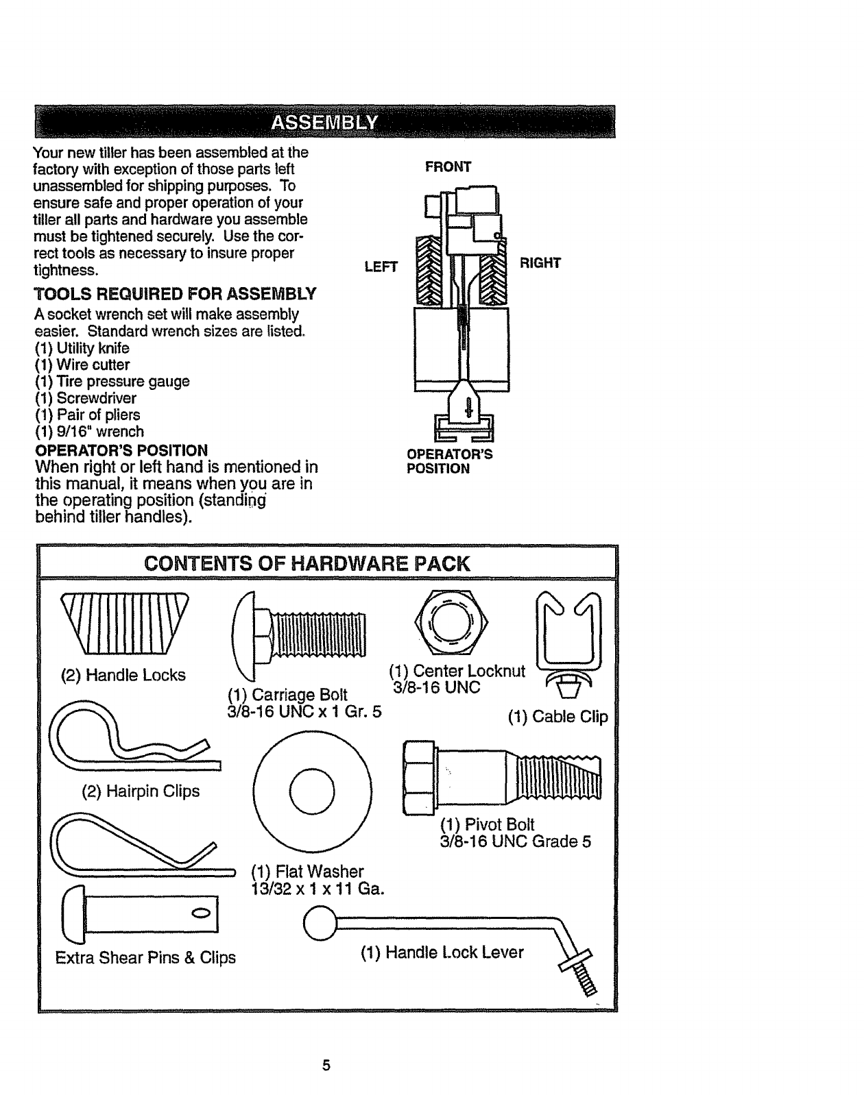
TOOLS REQUIRED FOR ASSEMBLY
A socket wrench set will make assembly
easier. Standard wrench sizes are listed.
(t) Utilityknife
(1) Wire cutter
(1) Tire pressure gauge
(1) Screwdriver
(1) Pair of pliers
(1) 9/16" wrench
OPERATOR'S POSITION
When right or left hand is mentioned in
this manual, it means when you are in
the operating position (standing
behind tiller handles).
LEFT
FRONT
OPERATOR'S
POSITION
RIGHT
CONTENTS OF HARDWARE PACK
(2) Handle Locks
(2) Hairpin Clips
(1) Carriage Bolt
3/8-16 UNC x1Gr. 5 (1) Cable Clip
(1) Pivot Bolt
3/8-16 UNC Grade 5
(1) Flat Washer
13/32 x 1 x 11 Ga.
(1) Handle Lock Lever "_
5
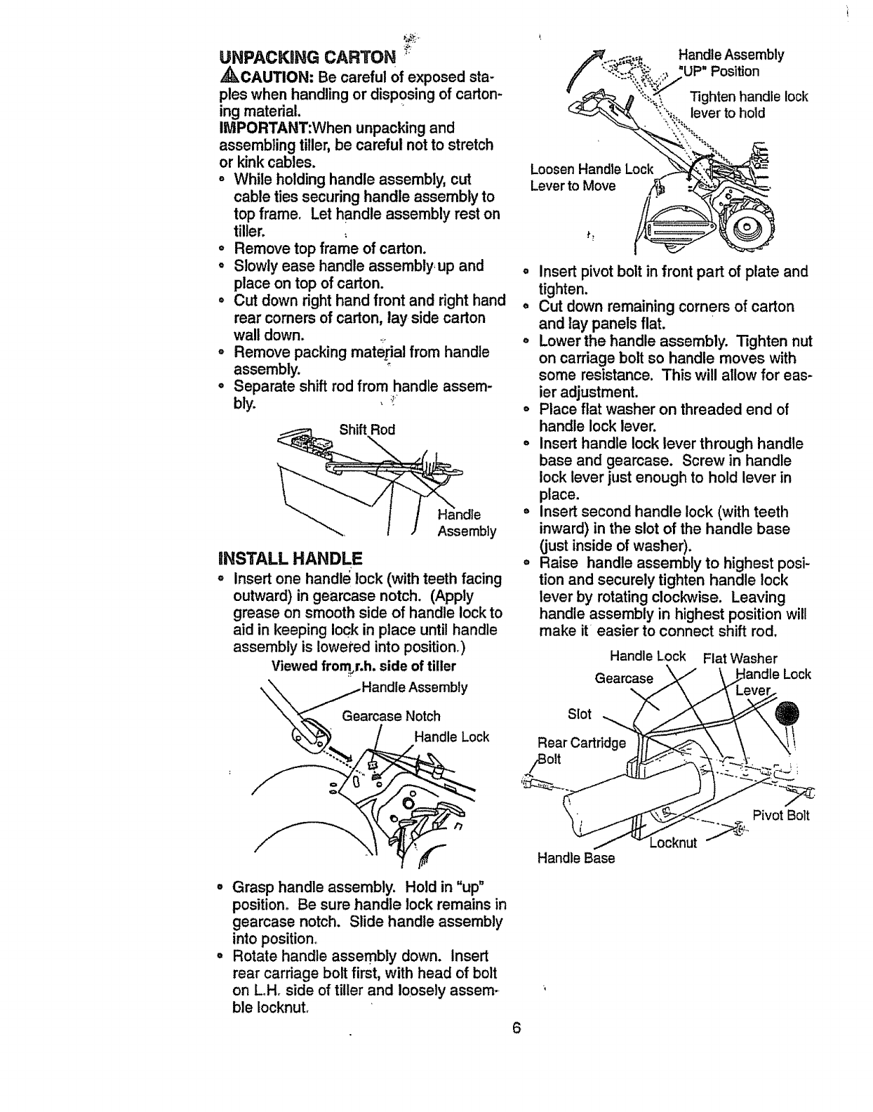
UNPACKING CARTON '
A_kCAUTION: Be careful of exposed sta-
ples when handling or disposing of carton-
ing material.
IMPORTANT:When unpacking and
assembling tiller,be careful not to stretch
or kinkcables.
=While holding handle assembly, cut
cable ties securing handle assembly to
top frame. Let handle assembly rest on
tiller.
= Remove top frame of carton.
• Slowly ease handle assembly, up and
place on top of carton.
° Cut down right hand front and right hand
rear comers of carton, lay side carton
wall down.
° Remove packing material from handle
assembly.
o Separate shift rod from handle assem-
bly. , :!_
INSTALL HANDLE
o Insert one handle lock (with teeth facing
outward) in geamase notch. (Apply
grease on smooth side of handle lockto
aid in keeping lock in place until handle
assembly is Iowe_redinto position_)
Viewedfromj.h, side of tiller
_._ /Handle Lock
° Grasp handle assembly. Hold in "up"
position. Be sure handle lock remains in
gearcase notch. Slide handle assembly
into position.
°Rotate handle assembly down. Insert
rear carriage bolt first, with head of bolt
on LHr side of tiller and loosely assem-
ble Iocknutr
Handle Assembly
'UP" Position
Tighten handle lock
lever to hold
Loosen Handle Lock
Lever to Move
•Insert pivot bolt in front part of plate and
tighten.
o Cut down remaining corners of carton
and lay panels flat.
oLowerthe handle assembly. Tighten nut
on carriage bolt so handle moves with
some resistance. This will allow for eas-
ier adjustment.
oPlace flat washer on threaded end of
handle lock lever.
°insert handle lock lever through handle
base and gearcase. Screw in handle
lock lever just enough to hold lever in
place.
=Insert second handle lock (with teeth
inward) in the slot of the handle base
(just inside of washer).
°Raise handle assembly to highest posi-
tion and securely tighten handle lock
lever by rotating clockwise. Leaving
handle assembly in highest position will
make it easier to connect shift rod.
Handle Lock Flat Washer
Gearcase Lock
Slot
Rear Cartridge
Pivot Bolt
Handle Base
6
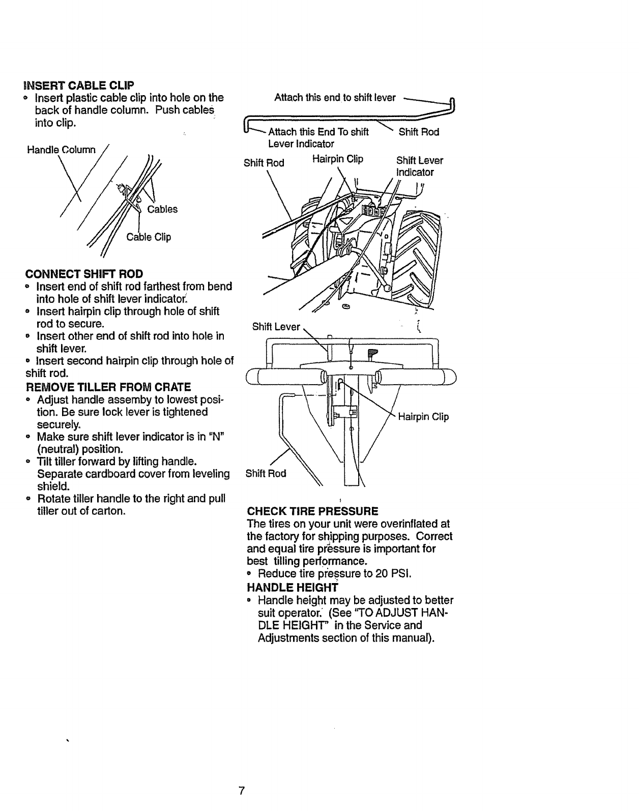
INSERTCABLE CLIP
oInsert plasticcable clip into hole on the
back of handle column. Push cables
into clip.
Handle Column
Cables
Clip
Attach this endto shift lever "'III '
_----_-Attach this End To shift _ Shift Rod
Lever Indicator
Shift Rod Hairpin Clip Shift Lever
\_ indicator
CONNECT SHIFT ROD
oInsert end of shift rod farthestfrom bend
into hole of shift lever indicator,
°Insert hairpin clip through hole of shift
rod to secure.
°Insert other end of shiftrod into hole in
shift lever.
•insert second hairpin clip throughhole of
shift rod.
REMOVE TILLER FROM CRATE
°Adjust handle assemby to lowest posi-
tion. Be sure lock lever is tightened
securely.
o Make sure shift lever indicator is in "N"
(neutral) position.
o Tilt tiller forward by lifting handle.
Separate cardboard cover from leveling
shield.
° Rotate tiller handle to the right and pull
tiller out of carton.
Shift Lever
Sh,ft Rod _ L
Hairpin Clip
CHECK TIRE PRESSURE
The tires on your unit were overinftated at
the factory for shipping purposes. Correct
and equal tire pressure is important for
best tilling performance.
•Reduce tire pl;essureto 20 PSI.
HANDLE HEIGHT
° Handle height may be adjusted to better
suit operator. (See '3"0 ADJUST HAN-
DLE HEIGHT" in the Service and
Adjustments section ofthis manual).
7
These symbols may appea_" on your Tiller or in literature supplied with the product.
Learn and understand their meaning.
11LUNG FORWARD NFJ/TBAL P,EVERS_ FU_
A 6 "@ m\l
CAUTION F.J_BINE F_NG1N_' FAST _LOW CHOI_
OR WARNING ON OFF
RUN
OIL STOP O
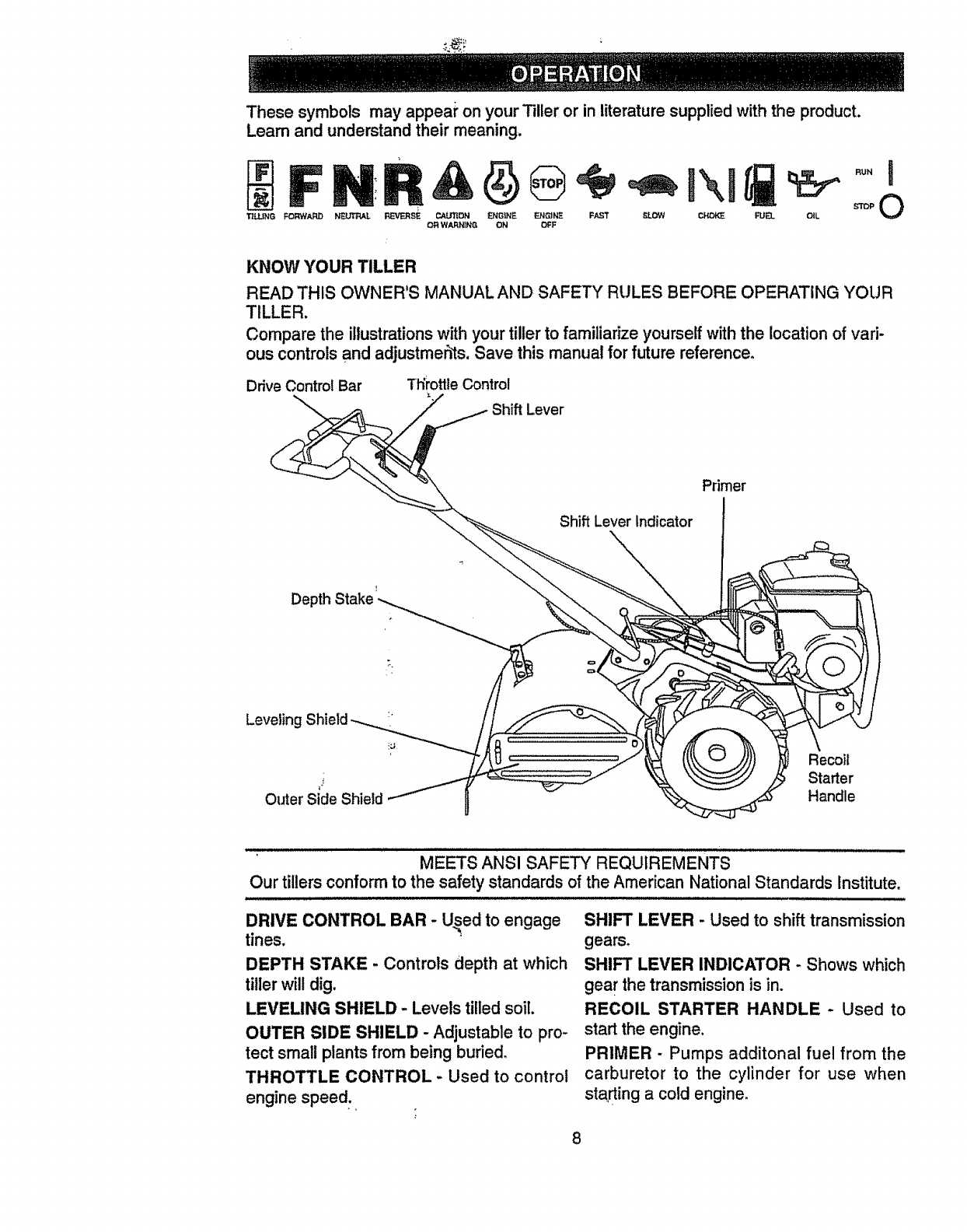
KNOW YOUR TILLER
READ THIS OWNER'S MANUAL AND SAFETY RULES BEFORE OPERATING YOUR
TILLER.
Compare the illustrationswith your tiller to familiarize yourself withthe location of vari-
ous controls and adjustmehts. Save this manual for future reference.
Drive Control Bar Tt_rottleControl
Lever
Primer
Shift Lever Indicator
DepthStake
Leveling :
Recoil
i Starter
OuterSideShield Handle
MEETS ANSI SAFETY REQUIREMENTS
Our tillers conform to the safety standards of the American National Standards Institute.
DRIVE CONTROL BAR - U_ed to engage
tines.
DEPTH STAKE - Controls depth at which
tiller will dig.
LEVELING SHIELD -Levels tilled soil.
OUTER SIDE SHIELD - Adjustable to pro-
tect small plants from being buried.
THROTTLE CONTROL -Used to control
engine speed+.
SHIFT LEVER - Used to shift transmission
gears,
SHIFT LEVER INDICATOR - Shows which
gea rthe transmission is in.
RECOIL STARTER HANDLE -Used to
start the engine.
PRIMER -Pumps additonal fuel from the
carburetor to the cylinder for use when
starting a cold engine,
8
The operation of any tiller can result in foreign objects thrown into the eyes,
which canresult in severe eye damage. Always wear safety glasses or eye
shields before starting your tiller and while tilling. We recommend a wide
vision safety mask over the spectacles or standard safety glasses.
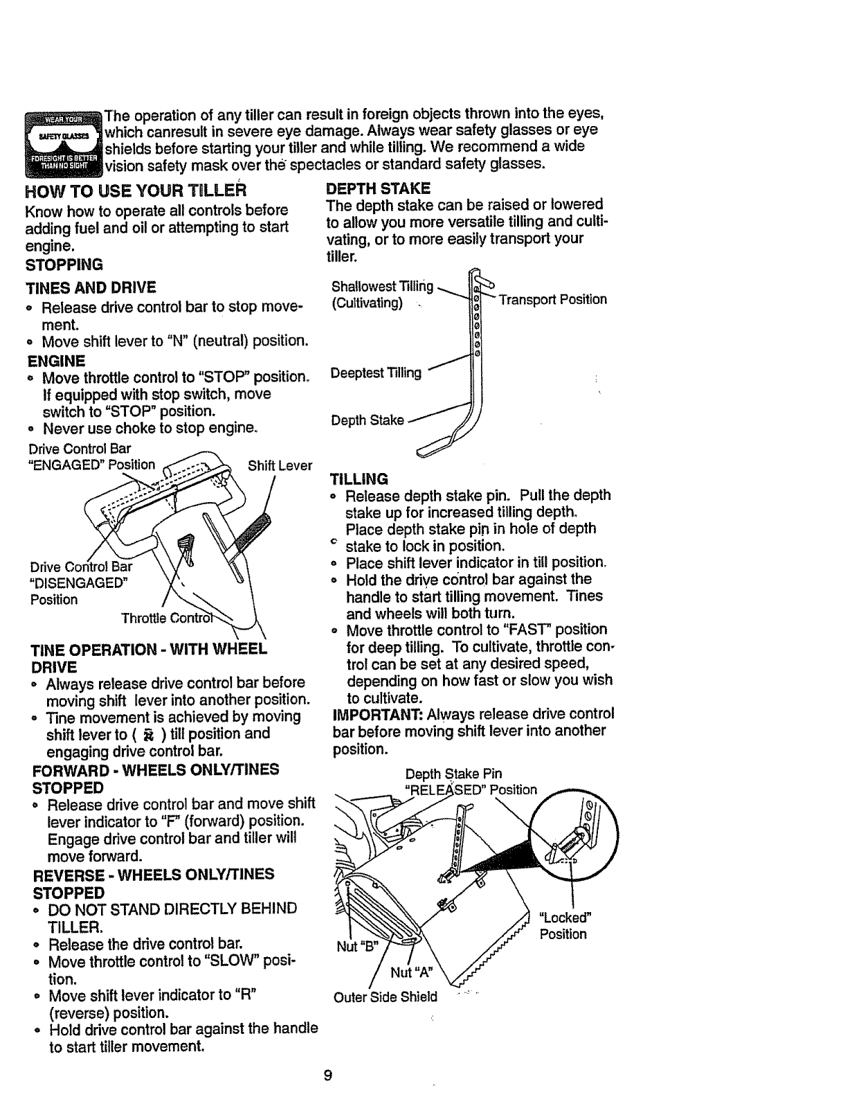
HOW TO USE YOUR TULLER
Know how to operate all controls before
adding fuel and oilor attempting to start
engine.
STOPPING
TINES AND DRIVE
o Release drive control bar to stop move-
ment.
= Move shift lever to "N" (neutral) position.
ENGINE
, Move throttlecontrolto "STOP" position°
If equipped with stop switch, move
switch to "STOP" position.
°Never use choke tostop engine.
DriveControlBar
"ENGAGED" Position ShiftLever
Drive Control Bar
"DISENGAGED"
Position
"Throttle
TINE OPERATION -WITH WHEEL
DRIVE
=Always release drive controlbar before
moving shift lever into another position.
°"line movement is achieved by moving
shift lever to ( _) tiltpositionand
engaging drive control bar.
FORWARD - WHEELS ONLY/TINES
STOPPED
• Release drive controlbar and move shift
lever indicatorto "F" (forward) position.
Engage drive controlbar and tiller will
move forward.
REVERSE -WHEELS ONLY/TINES
STOPPED
,DO NOT STAND DIRECTLY BEHIND
TILLER.
° Release the drivecontrol bar.
oMove throttlecontrolto "SLOW" posi-
tion.
• Move shiftlever indicator to "R"
(reverse) position.
°Hold drive control bar against the handle
to start tiller movement.
DEPTH STAKE
The depth stake can be raised or lowered
to allow you more versatile tillingand culti-
vating, or to more easily transport your
tiller.
Shallowest Tilling
(Cultivating)
Deeptest Tilling
Depth Stake _'_
"_ Transport Position
TILLING
°Release depth stake pin. Pull the depth
stake up for increased tilling depth.
Place depth stake pi.nin hole of depth
cstake to lock in position.
oPlace shift lever indicator in till position.
=Hold the drive control bar against the
handle to start tilling movement. Tines
and wheels will both turn.
o Move throttle control to "FAST" position
for deep tilling. To cultivate, throttle con-
trol can be set at any desired speed,
depending on how fast or stow you wish
to cultivate.
IMPORTANT: Always release drive control
bar before moving shift lever into another
position.
Depth Stake Pin
Position
Nut "B"
Nut "A"
Outer Side Shield
"Locked"
Position
9
TURNING
o
o
o
o
o
Release the drive control bar.
Move throttlecontrol to "SLOW" posi-
tion.
Place shift lever indicator in "F" (forward)
position. Tines will notturn.
Lift handle to raise tines outof ground.
Swing the handle in the opposite direc-
tion you wish to turn, being careful to
keep feet and legs away from tines.
oWhen you have completed your turn-
around, release the drive controlbar and
lower handle. Place shift lever in till
positionand move throttle controlto de-
sired _peed. To begin tilling,hold drive
control bar against the h_ndle.
OUTER SIDE SHIELDS
The back edges of the _uter side shields
are slotted so that the sl_ieldscan be
raised for deep tillingand lowered for shal-
low tillingto protect small plants from
being buried. Loosen nut "A" in slot and
nut "B". Move shield to desired position
(both sides). Retighte_ nuts.
TO TRANSPORT '
,_CAUTION: Before liftingor transport-
ing, allow tiller engine and mufflerto cool.
Disconnect spark plug wire. Drain gaso-
line from fuel tank.
AROUND THE YARD
oRelease the depth stake pin. Move the
depth stake down to the top hole for
transportingthe tiller. Place depth stake
pin in hole of depth stake to lock in posi-
tion. This preverits tines from scuffing
the ground. ,
oPlace shift lever indicator in "F"(forward)
positionfor transporting.
°Hold the drive control bar against the
handle to start tiller movement. Tines
will not turn.
•Move throttlecontrol to desired speed.
ARO_IND TOWN
•Disconnect spark plug wire.
oDrain fuel tank.
oTransport in upright posit=_nto prevent
oil leakage.
BEFORE STARTING ENGINE
IMPORTANT: Be very careful notto allow
dirt to enter the engine when checking or
adding oil or fuel. Use clean oil and fuel
and store in approved, clean, covered con-
tainers, use clean fill funnels.
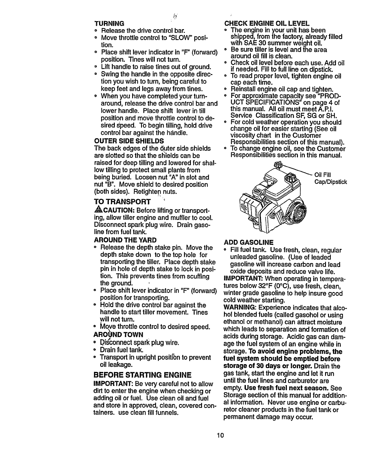
CHECK ENGINE OIL LEVEL
oThe engine in your unit has been
shipped, from the factory, already filled
with SAE 30 summer weight oil.
o Be sure tiller is level and the area
around oilfill is clean.
eCheck oil level before each use. Add oil
if needed. Fill to full line on dipstick.
oTo read proper level, tighten engine oil
cap each time. k
o Reinstall engine oil cap and tighten.
°For approximate capacity see "PROD-
UCT SPECIFICATIONS" on page 4 of
thls manual. All oil must meet A.P.I.
Service Classification SF, SG or SH.
o For cold weather operation you should
change oil for easier starting (See oil
viscosity chart in the Customer
Responsibilities section of this manual).
•To change engine oil, see the Customer
Responsibilitiessection in this manual.
Oil Fill
Cap/Dipstick
ADD GASOLINE
oFill fuel tank. Use fresh, clean, regular
unleaded gasoline. (Use of leaded
gasoline will increase carbon and lead
oxide deposits and reduce valve life.
IMPORTANT: When operating in tempera-
tures below 32°F (0°C), use fresh, clean,
winter grade gasoline to help insure good
cold weather starting.
WARNING: Experience indicates that alco-
hol blended fuels (called gasohol or using
ethanol or methanol) can attract moisture
which leads to separation and formation of
acids during storage° Acidic gas can dam-
age the fuel system of an engine while in
storage. To avoid engine problems, the
fuel system should be emptied before
storage of 30 days or longer. Drain the
gas tank, start the engine and let it run
until the fuel lines and carburetor are
empty. Use fresh fuel next season, See
Storage section of this manual for addition-
al information. Never use engine or carbu-
retor cleaner products in the fuel tank or
permanent damage may occur.
10
,_CAUTION: Fill to within 1/2 inch of top
offuel tank to prevent spills and to allow
for fuel expansion. If gasoline is acciden-
tally spilled, move machine away from
area of spill. Avoid creating any source of
ignition until gasoline vapors have disap-
peared.
Do not overfill. Wipe off any spilled oil or
fuel. Do not store, spill or use gasoline
near an open flame.
TO START ENGRNE
_kCAUTION: Keep drive control bar in
"DISENGAGED" position when starting en-
gine.
When starting engine for the first time or if
engine has run out of fuel, it wilttake extra
pulls of the recoil starter to move fuel from
the tank to the engine.
oMake sure spark plug wire is properly
connected.
•Move shift lever indicator to "N" (neutral)
position.
oPlace throttle control in "FAST" position.
oTo start a cold engine, push primer five
(5) times before tryin_tto start. Use a
firm push. This step =snot usuallynec-
essary when starting an engine which
has already run for afew minutes.
oGrasp recoil starter handle with one
hand and grasp tiller handle with other
hand. Pull rope out slowly untilengine
reaches start of compression cycle (rope
will pullslightly harder at this point).
°Pull recoilstarter handle quickly. Do not
let starter handle snap back against
starter.
°Allow engine to warm up for afew min-
utes before engaging tines.
NOTE: In cooler weather it may be neces-
sary to repeat priming steps, In warmer
weather over priming may cause flooding
and engine will not start. If you do flood
engine, wait a few minutes before attempt-
Jngto start and do not repeat priming
steps.
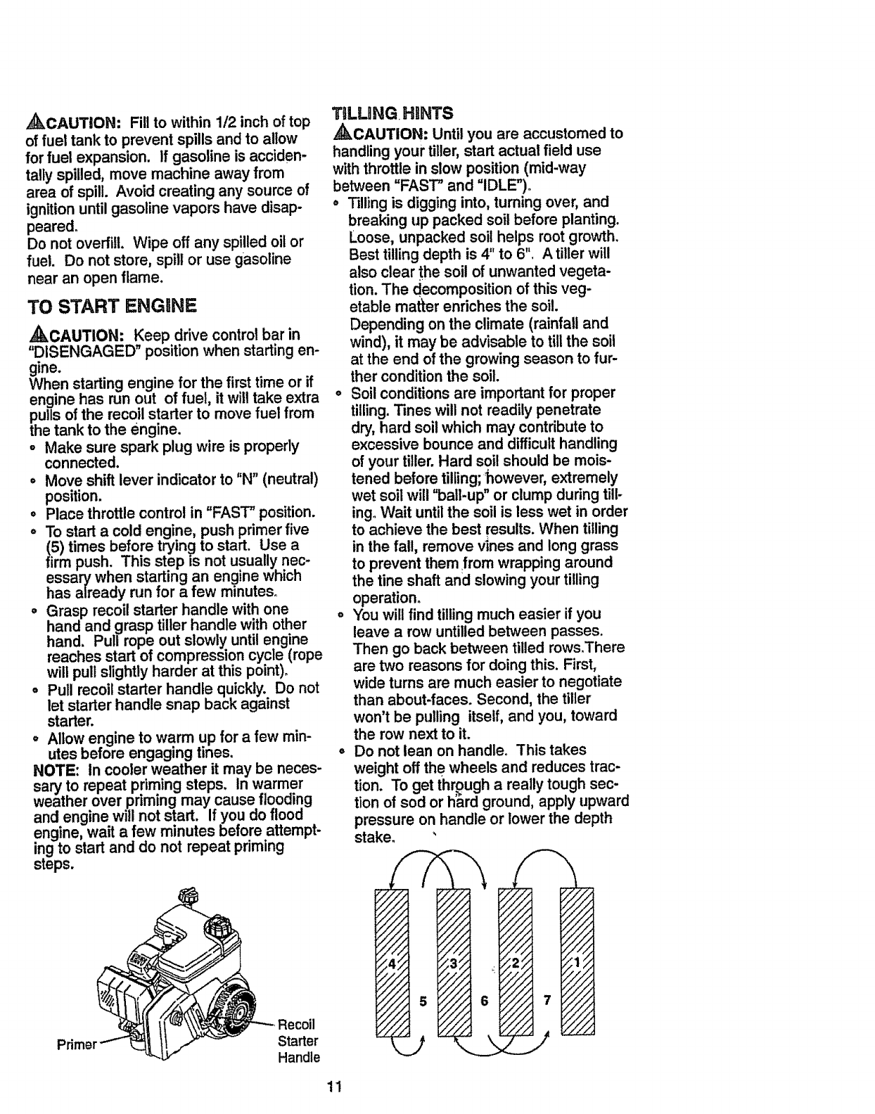
Starter
Handle
TiLLING.HINTS
,_CAUTION: Until you are accustomed to
handling your tiller, start actual field use
with throttle in slow position (mid-way
between "FAST" and "IDLE").
°Tilling is digging into, turning over, and
breaking up packed soil before planting.
Loose, unpacked soil helps root growth.
Best tillingdepth is 4" to 6". A tiller will
also clear the soil of unwanted vegeta-
tion. The decomposition of this veg-
etable matter enriches the soil.
Depending on the climate (rainfall and
wind), it may be advisable to till the soil
at the end of the growing season to fur-
ther condition the soil.
oSoil conditions are important for proper
tilling.Tines will not readily penetrate
dry, hard soil which may contributeto
excessive bounce and difficulthandling
of your tiller. Hard soil should be mois-
tened before tilling;'however, extremely
wet soil will "ball-up" or clump during tili-
ing. Wait untilthe soil is less wet in order
to achieve the best results. When tilling
in the fall, remove vines and long grass
to prevent them from wrapping around
the fine shaft and slowing your tilling
operation.
oYou will find tilling much easier if you
leave a row untilledbetween passes.
Then go back between tilled rows_There
are two reasons for doing this. First,
wide turns are much easier to negotiate
than about-faces. Second, the tiller
won't be pulling itself, and you, toward
the row next to it.
°Do not lean on handle. This takes
weight off the wheels and reduces trac-
tion. To get through a really tough sec-
t=onof sod or hard ground, apply upward
pressure on handle or lower the depth
stake_ '
11
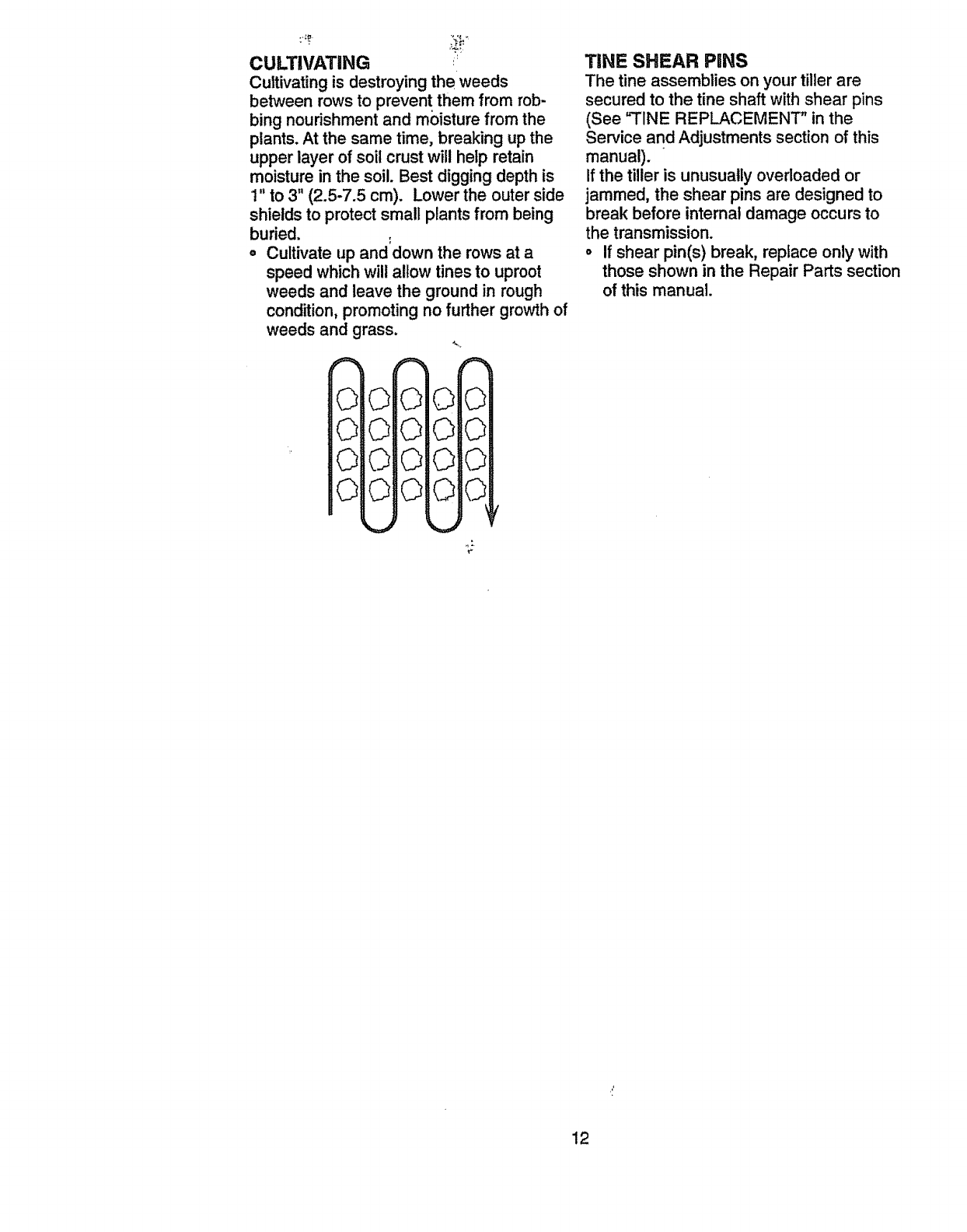
CULTIVATING
Cultivatingis destroying the weeds
between rows to prevent them from rob-
bing nourishmentand moisture from the
plants. At the same time, breaking up the
upper layer of soil crust will help retain
moisture in the soil. Best digging depth is
1" to 3" (2.5-7.5 cm). Lower the outerside
shieldsto protect small plants from being
buried.
oCultivate up and down the rows at a
speed which will allow tines to uproot
weeds and leave the ground in rough
condition,promoting no further growthof
weeds and grass.
O0
O0
O0
O0
000
0©0
000
©©©
€"
TINE SHEAR PiNS
The tine assemblies on your tiller are
secured to the fine shaft with shear pins
(See "TINE REPLACEMENT" inthe
Service and Adjustments section of this
manual).
If the tiller is unusually overloaded or
jammed, the shear pins are designed to
break before internal damage occurs to
the transmission.
°If shear pin(s) break, replace only with
those shown in the Repair Parts section
of this manual.
12
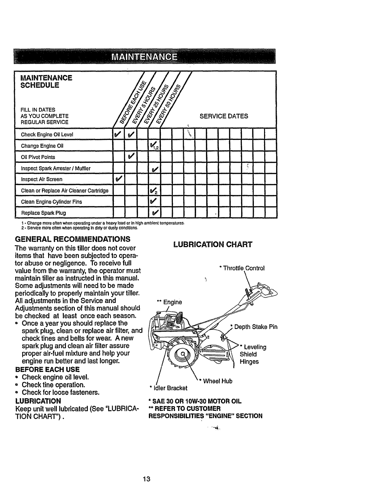
SCHEDULE
FILL tN DATES _"_ _ _
AS YOU COMPLETE /_"/f _</__/__/ SERVICE DATES
REGULAR SERVICE / q]'/ _}'/t._/_'/
......::: ................. , ill
Check EngineOil Level 1_ _/' i _'
.............................................. ,,,m,n , / /Lu,
Change EngineOtl 1_1,2
......... ,u,L
Oil PivotPoints
InspectSpark ArresterIMuffler
IH, ....................................
Inspect AirScreen
Clearl orReplace AirCleanerCartridge ill, ...........
Clean EngineCylinderFins
Replace Spark Plug _' ]
1 - Ch_mge more often when operating under a heaw toad or in high ambient temperatureS
2-Se_ce more often when operating In d_ or dusty condlUons,
GENERAL RECOMMENDATIONS
The warranty on this tiller does not cover
items that have been subjected to opera-
tor abuse or negligence. To receive full
value from the warranty,the operator must
maintain tiller as instructed in this manual.
Some adjustmentswill need to be made
periodicallyto properly maintain your tiller.
All adjustments in the Service and
Adjustments section of this manual should
be checked at least once each season.
oOnce a year you should replace the
spark plug, clean or replace air filter, and
check tines and belts for wear. A new
spark plug and clean air filterassure
proper air-fuel mixture and help your
engine run better and last longer.
BEFORE EACH USE
oCheck engine oillevel.
, Checktine operation.
°Check for loose fasteners.
LUBRICATION
Keep unitwell lubricated (See "LUBRICA-
TION CHART").
LUBRiCATiON CHART
* Throttle Control
** Engine
Depth Stake Pin
Leveling
Shield
Hinges
Wheel Hub
* Idler Bracket
*SAE 30 OR 10W-30 MOTOR OIL
** REFER TO CUSTOMER
RESPONSIBILITIES "ENGINE" SECTION
13
Disconnectspark plug wire before per-
forming any maintenance (except carbure-.
tor adjustment) to prevent accidental start-
ing of engine.
Prevent fires! Keep the engine free of
grass, leaves, spilled oil, or fuel. Remove
fuel from tank before tipping unit for main-
tenance. Clean muffler area of all grass,
dirt, and debris.
Do not touch hot muffler or cylinder fins as
contact may cause bums.
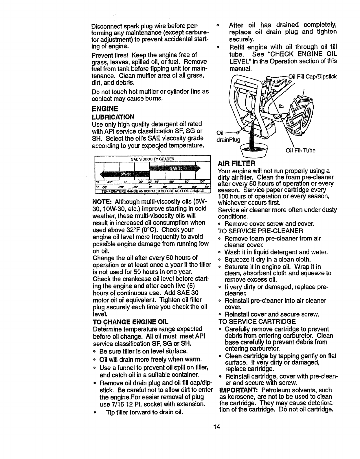
ENGINE
LUBRICATION
Use only high quality detergent oil rated
with API service classification SF, SG or
SH. Select the oil's SAE viscosity grade
accordingto your expec_!edtemperature.
SAE VISCOSITY GRADES
TEMPERATURE RANGE'/_NTICIPATED BEFORE NEXT OIL C_GE
NOTE: Although multi-viscosity oils (5W-
30, 10W-30, etc.) improve starting in cold
weather, these multi-viscosityoils will
result in increased oil consumption when
used above 32°F (0°C). Check your
engine oil level more frequently to avoid
possible engine damage from running low
on oil.
Change the oilaftei"every 50 hours of
operation or at least once a year if the tiller
is not used for 50 hours in one year.
Check the crankcase oil level before start-
ing the engine and after each five (5)
hours of continuous use. Add SAE 30
motor oilo_equivalent. Tighten oilfiller
plug securely each time you check the oil
level.
TO CHANGE ENGINE OIL
Determine temperature range expected
before oil change. All oil must meet API
service classificationSF, SG or SH.
oBe sure tiller is on level surface.
° Oil will drain more freely Whenwarm.
=Use a funnel to prevent oil spill on tiller,
and catch oil in a suitable container.
°Remove oiidrain plug and oilfill cap!dip-
stick. Be careful not to allow dirt to enter
the engine.For easier removal of plug
use 7/16 12 Pt. socket with extension.
°Tip tiller forward to drain oil.
After oil has drained completely,
replace oil drain plug and tighten
securely.
Refill engine with oil through oil fill
tube. See "CHECK ENGINE OIL
LEVEL" in the Operation section of this
manual.
'Oit FillCap/Dipstick
Oil
drainPtug
OilFillTube
AIR FILTER
Your engine will not run properly using a
dirtyair filter. Clean the foam pre-cleaner
after every 50 hours of operation or every
season. Service paper cartridge every
100 hours of operation or every season,
whichever occurs first.
Service air cleaner more often under dusty
conditions.
•Remove cover screw and cover.
TO SERVICE PRE-CLEANER
oRemove foam pre-cleaner from air
cleaner cover.
•Wash it in liquiddetergent and water.
o Squeeze it dry in aclean cloth.
° Saturate it in engine oil. Wrap it in
clean, absorbent cloth and squeeze to
remove excess oil.
°if very dirty or damaged, replace pre-
cleaner.
• Reinstall pre-cleaner into air cleaner
cover.
°Reinstall cover and secure screw.
TO SERVICE CARTRIDGE
° Carefully remove cartridge to prevent
debris from entering carburetor. Clean
base carefully to prevent debris from
entering carburetor.
° Clean cartridge by tapping gently on flat
surface. If very dirty or damaged,
replace cartridge.
oReinstall cartridge, cover with pre-clean-
er and secure with screw.
IMPORTANT" Petroleum solvents, such
as kerosene, are not to be used to clean
the cartridge. They may cause deteriora-
tion of the cartridge. Do not oilcartridge.
14
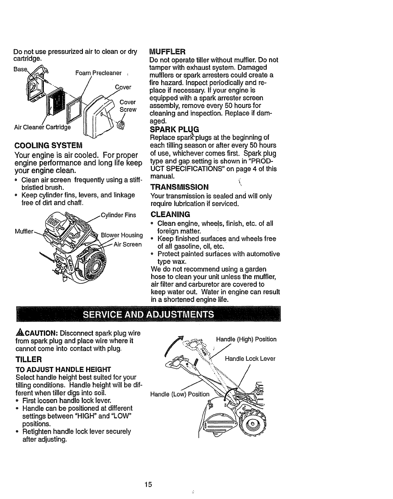
Do not use pressurized air to clean or dry
cartridge+
Foam Precleaner
Air Cleane/r Cartridge
Cover
Screw
COOLING SYSTEM
Your engine is air cooled. For proper
engine performance and long life keep
your engine clean.
• Clean air screen frequently using a stiff-
bristled brush.
o Keep cylinder fins, levers, and linkage
free of dirt and chaff.
__ Cylinder Fins
MUFFLER
Do not operate tiller without muffler. Do not
tamper with exhaust system° Damaged
mufflers or spark arresters could create a
fire hazard. Inspect periodically and re-
place if necessary, if your engine is
equipped with a spark arrester screen
assembly, remove every 50 hours for
cleaning and inspection. Replace if dam-
aged.
SPARK PLUG
Replace sparE'plugs at the beginning of
each tilling season or after every 50 hours
of use, whichever comes first. Spark plug
type and gap setting is shown in "PROD-
UCT SPECIFICATIONS" on page 4 of this
manual
TRANSMISSION '_
Your transmission is sealed and will only
require lubrication if serviced.
CLEANING
oClean engine, wheels, finish, etc. of all
foreign matter. +
o Keep finished surfaces and wheels free
of all gasoline, oil, etc.
• Protect painted surfaces with automotive
type wax.
We do not recommend using a garden
hose to clean your unit unless the muffler,
air filter and carburetor are covered to
keep water out. Water in engine can result
in a shortened engine life.
,_CAUTION: Disconnect spark plug wire
from spark plug and place wire where it
cannot come into contactwith plug+
TILLER
TO ADJUST HANDLE HEIGHT
Select handle height best suited for your
tillingconditions. Handle height will be dif-
ferent when tiller digs into soil+
oFirst loosen handle lock lever.
•Handle can be positioned at different
settings between "HIGH" and "LOW"
positions.
oRetighten handle lock lever securely
after adjusting,
Handle (Low) Position
Handle (High) Position
Handle Lock Lever
15
TIRE CARE
CAUTION: When mounting tires, unless
beads are seated, overinflation can cause
an explosion.
oMaintain 20 pounds of tire pressure. If
tire pressures are not equal, tiller will
pull to one side.
oKeep tires free of gasoline or oil which
can damage rubber.
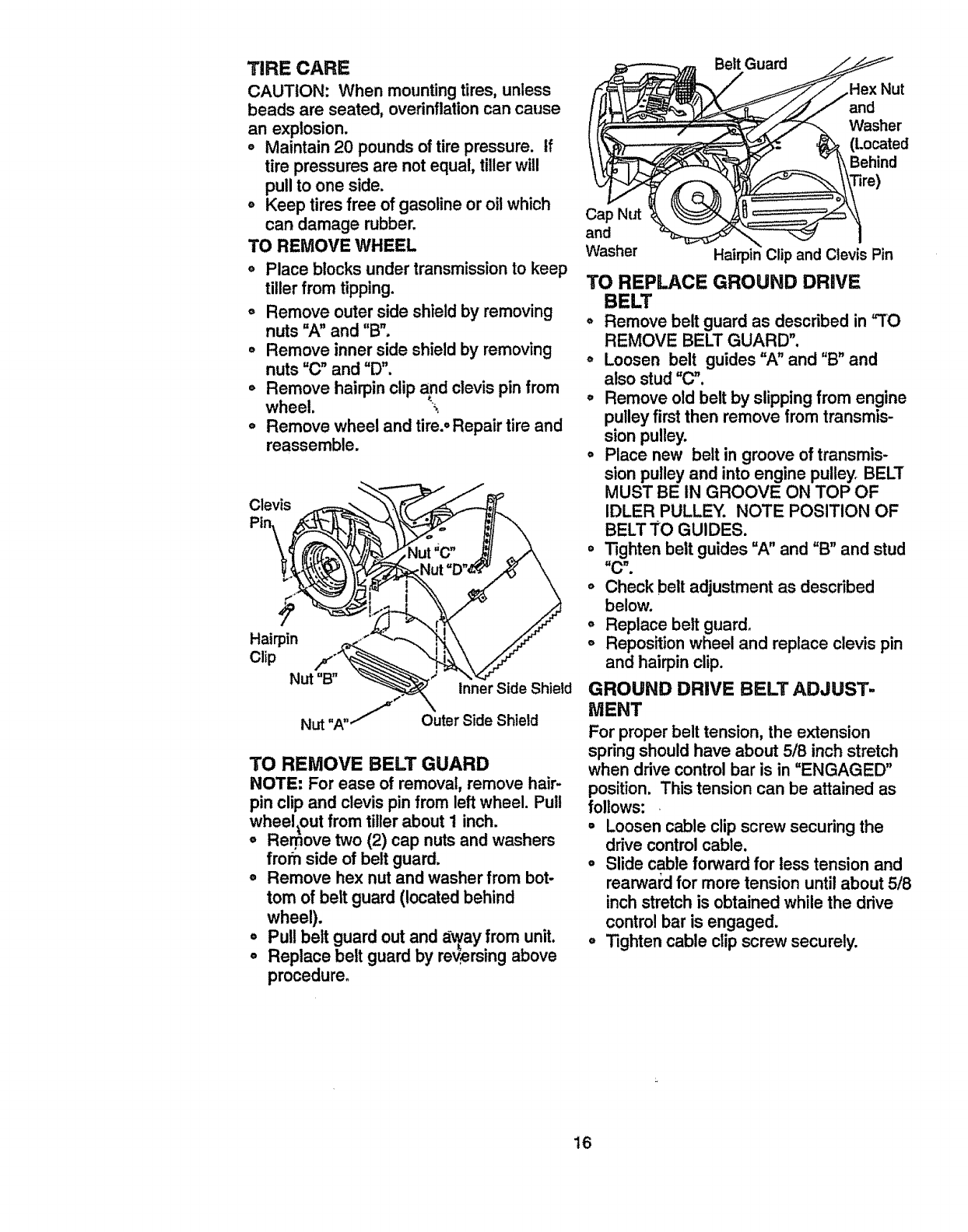
TO REMOVE WHEEL
o Place blocks under transmission to keep
tiller from tipping.
o Remove outer side shield by removing
nuts "A" and "B"°
• Remove inner side shield by removing
nuts "(3" and "D".
o Remove hairpin clip and clevis pin from
wheel. _
o Remove wheel and tire., Repair tire and
reassemble.
Clevis
¢
Hairpin
Clip Nut"B"
Nut "A
Inner Side Shield
Outer Side Shield
TO REMOVE BELT GUARD
NOTE: For ease of removal, remove hair-
pin clip and clevis pin from left wheel, Pull
wheeltout from tiller about 1inch.
oRemove two (2) cap nuts and washers
from side of belt guard.
o Remove hex nut and washer from bot-
tom of belt guard (located behind
wheel).
oPull belt guard out and array from unit.
oReplace belt guard by reversing above
procedure°
Cap NUt
and
Washer
Belt Guard
and
Washer
(Located
Behind
Hairpin Clip and Clevis Pin
TO REPLACE GROUND DRIVE
BELT
o Remove belt guard as described in "TO
REMOVE BELT GUARD",
°Loosen belt guides "A" and "B" and
also stud "C".
oRemove old belt by slipping from engine
pulley first then remove from transmis-
sion pulley.
oPlace new belt in groove of transmis-
sion pulley and into engine pulley, BELT
MUST BE IN GROOVE ON TOP OF
IDLER PULLEY. NOTE POSITION OF
BELT TO GUIDES,
o Tighten belt guides "A" and "B" and stud
"C".
o Check belt adjustment as described
below.
o Replace belt guard°
o Reposition wheel and replace clevis pin
and hairpin clip.
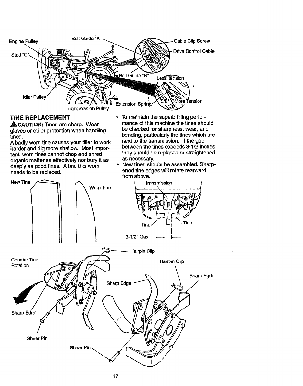
GROUND DRIVE BELT ADJUST-
MENT
For proper belt tension, the extension
springshould have about 5/8 inchstretch
when drive control bar is in "ENGAGED"
position. This tension can be attained as
follows:
•Loosen cable clip screw securing the
drive controlcable,
oSlide cable forward for less tension and
rearwa_'dfor more tension until about 5/8
inch stretch is obtained while the drive
controlbar is engaged.
°Tighten cable clip screw securely.
16
Belt Guide "A"_ ClipScrew
DriveControlCable
idler Pulley,
Transmission Pulley Extension S
TINE REPLACEMENT "
_kCAUTION: Tines are sharp. Wear
gloves or other protectionwhen handling
tines.
A badly worn tine causes your tiller to work
harder and dig more shallow. Most impor-
tant, worn tinescannot chop and shred
organic matter as effectively nor bury it as
deeply as goodtines, A tine this worn °
needs to be replaced_
Les_on
New Tine
Tine i
i
3-i12=Max ---H
_\Tine_
t
!
Counter "line
Rotation
Sharp Edge
Sharp Egde
Sha_ Edge
Shear Pin
Shear Pin
17
ENGUNE
Maintenance, repair,or replacement of the
emission control devices and systems,
which are being done at the customers
expense, may be performed by any non-
road engine repair establishment or indi-
vidual. Warranty repairs must be per-
formed by an authorized engine manufac_=
turer'sservice outlet.
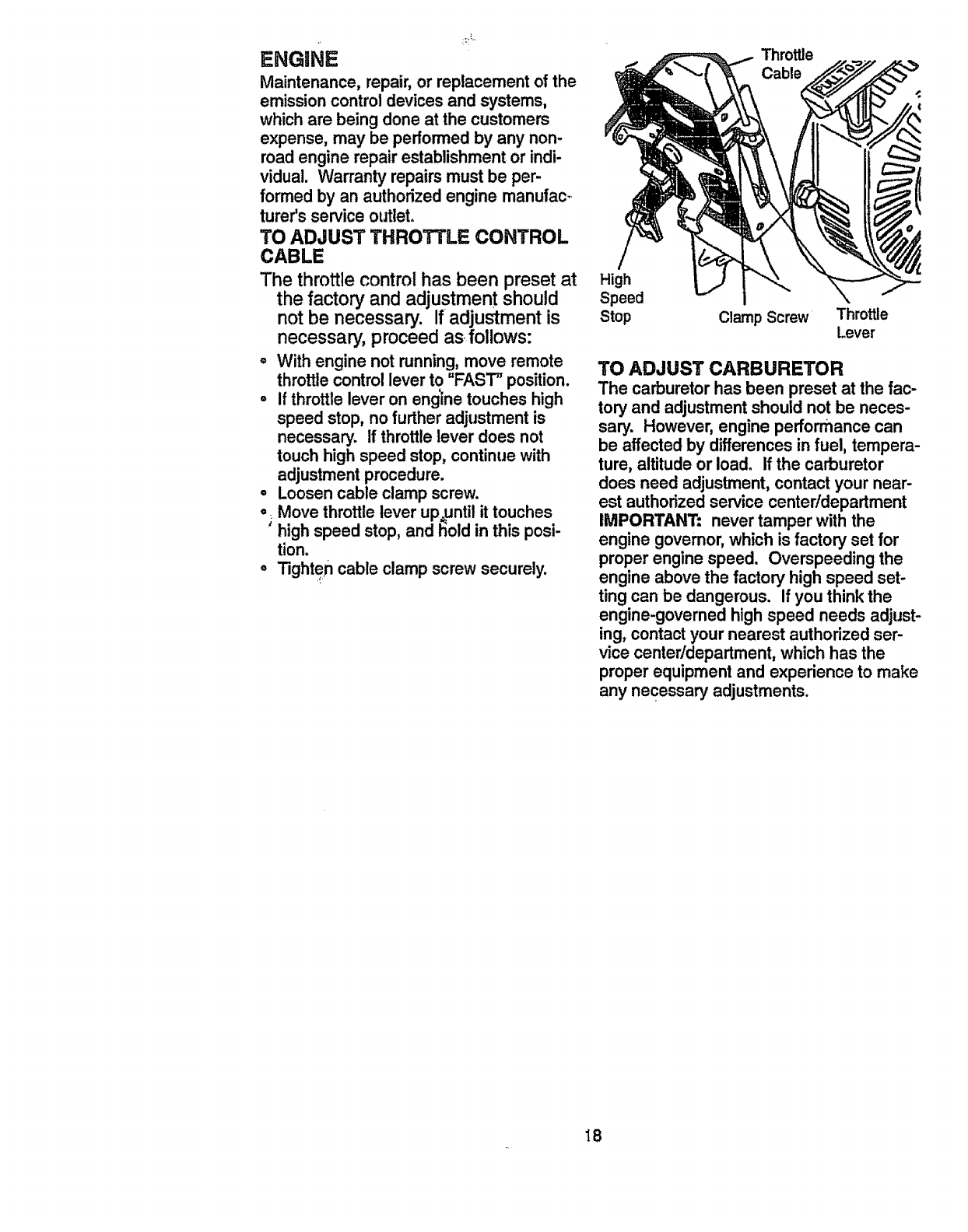
TO ADJUST THROTTLE CONTROL
CABLE
The throttle control has been preset at
the factory and adjustment should
not be necessary. If=adjustment is
necessary, proceed as follows:
°With engine not running, move remote
throttle controllever to "FAST"position.
oif throttle lever on engine touches high
speed stop, no further adjustment is
necessary. If throttlelever does not
touch high speed stop, continue with
adjustment procedure.
°Loosen cable clamp screw.
o=Move throttle lever up,until it touches
high speed stop, and t'ioldin this posi-
tion.
oTighten cable clamp screw securely.
Throttle
Cable
High
Speed
Stop Clamp Screw Throttle
[.ever
TO ADJUST CARBURETOR
The carburetor has been preset at the fac-
tory and adjustment should not be neces-
sary. However, engine performance can
be affected by differences in fuel, tempera-
ture, altitude or load. If the carburetor
does need adjustment, contact your near-
est authorized service center/department
IMPORTANT: never tamper with the
engine governor, which is factory set for
proper engine speed. Overspeeding the
engine above the factory high speed set-
ting can be dangerous. If you think the
engine-governed high speed needs adjust-
ing, contact your nearest authorized ser-
vice center/department, which has the
proper equipment and experience to make
any necessary adjustments.
18
Immediately prepare your tillerfor storage
at the end ofthe season or if the unit will
not be used for 30 days or more.
_CAUTION: Never store the tillerwith
gasoline in the tank inside a building
where fumes may reach an open flame or
spark. Allow the engine to cool before
storing in any enclosure.
TILLER
o Clean entire tiller (See "CLEANING" in
the Customer Responsibilitiessection of
this manual).
o Inspect and replace belts, if necessary
(See belt replacement instructionsin the
Service and Adjustments section of this
manual).
oLubricate as shown in the Customer
Responsibilitiessection of this manual.
oBe sure that all nuts, bolts and screws
are securely fastened. Inspect moving
parts for damage, breakage and wear.
Replace if necessary.
•Touch up all rusted or chipped paint sur-
faces; sand lightly before painting.
ENGINE
FUEL SYSTEM
IMPORTANT: it is importantto prevent
gum deposits from forming in essential fuel
system parts such as the carburetor,fuel
filter, fuel hose, or tank during storage.
also, experience indicates that alcohol
blended fuels (called gasohol or using
ethanol or methanol) can attract moisture
which leads to separation and formation of
acids during storage. Acidic gas can dam-
age the fuel system of an engine while in
storage.
oDrain the fuel tank.
°Start the engine and let it run until the
fuel lines and carburetor are empty.
°Never use engine or carburetor cleaner
productsin the fuel tank or permanent
damage may occur.
°Use fresh fuel next season.
NOTE: Fuel stabilizer is an acceptable
alternative in minimizing the formation of
fuel gum deposits during storage. Add sta-
bilizer to gaso!ine in fuel tank or storage
container. AlWays follow the mix ratio
found on stabiliZe;rcontainer. Run engine
at least 10 minutes after adding stabilizer
to allow the stabilizer to reach the carbure-
tor. Do not drain the gas tank and carbu-
retor if usingfuel stabilizer.
ENGINE OIL
Drain oil (with engine warm) and replace
with clean oil. (See "ENGINE" in the
Customer Responsibilitiessection of this
manual).
CYLINDER
° Remove spark plug.
oPour 1 ounce (29 ml) of oilthrough
spark plug hole into cylinder.
oPull starter handle slowly several times
to distributeoil.
•Replace with new spark plug.
OTHER
oDo not store gasoline from one season
to another.
oReplace your gasoline can if your can
starts to rust. Rust and/or dirt in your
gasoline will cause problems.
•if possible, store your unit indoorsand
cover it to give protectionfrom dust and
dirt,
• Coveryourunitwitha suitableprotective
coverthatdoes notretainmoisture.Do
not use plastic. Plastic cannot breathe
which allows condensation to form and
will cause your unit to Past.
IMPORTANT: Never cover tiller while
engine and exhaust areas are still warm.
19
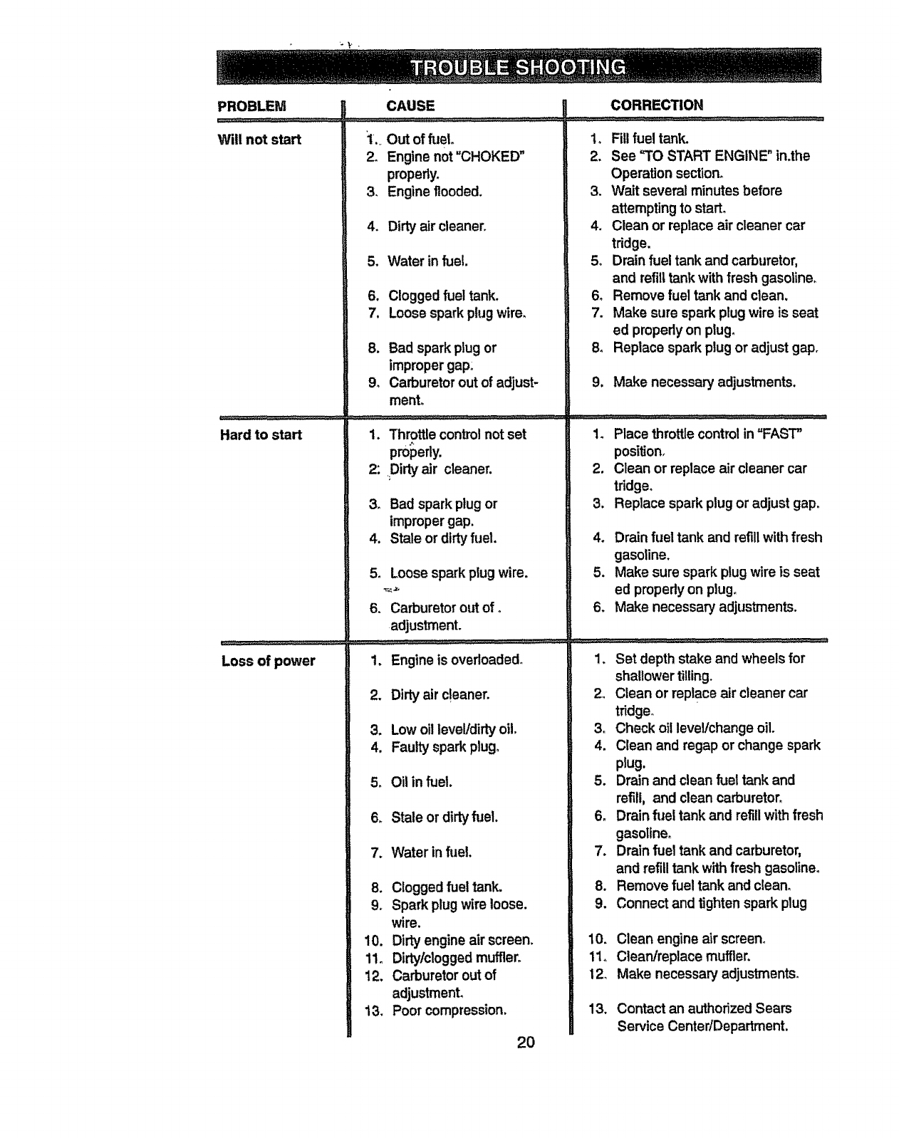
PROBLEM
Will not start
Hard to start
Loss of power
CAUSE
'1.. Out of fuel
2, Engine not =CHOKED"
properly.
3, Engine flooded.
4. Dirty air cleaner.
5. Water in fuel.
6. Clogged fuel tank.
7. Loose spark plugwire.
8. Bad spark plug or
impropergap:
9o Carburetor out of adjust-
ment.
1. Throttle control notset
properly.
2: Dirtyair cleaner.
3_ Bad spark plug or
improper gap.
4. Stale or dirty fuel.
5. Loose spark plug wire.
6. Carburetor out of o
adjustment.
1. Engine is overloaded.
2. Dirty air cleaner.
3. Low oil level/dirty oil.
4. Faulty spark plug.
5. Oil in fuel.
6_ Stale or dirtyfuel.
7. Water in ft_el.
8. Clogged fuel tank.
9. Spark plug wire loose.
wire.
10, Dirty engine air screen.
1!o Dirty/clogged muffler.
12. Carburetor out of
adjustmenL
13. Poor compression.
2O
CORRECTION
1. Fill fuel tank.
2. See "TO START ENGINE" in.the
Operation section.
3. Wait several minutes before
attempting to start°
4. Clean or replace air cleaner car
tridge.
5. Drain fuel tank and carburetor,
and refilltank with fresh gasoline.
6. Remove fuel tank and clean.
7. Make sure spark plug wire is seat
ed properlyon plugo
8. Replace spark plug or adjust gapr
9. Make necessary adjustments.
1. Place throttle control in"FAST"
positJon.
2. Clean or replace air cleaner car
tridge.
3. Replace spark plug or adjust gap.
4. Drain fuel tank and refill with fresh
gasoline.
5. Make sure spark plug wire is seat
ed properly on plug,,
6. Make necessary adjustments.
1. Set depth stake and wheels for
shallower tilling.
2. Clean or replace air cleaner car
tridge_
3. Check oil level/change oil.
4. Clean and regap or change spark
plug.
5. Drain and clean fuel tank and
refill, and clean carburetor.
6. Drain fuel tank and refill with fresh
gasoline.
7. Drain fuel tank and carburetor,
and refilltank with fresh gasoline.
8. Remove fuel tank and clean.
9. Connect and tighten spark plug
10. Clean engine air screen°
11o Clean/replace muffler.
12. Make necessary adjustments.
13. Contact an authorized Sears
Service Center/Department.
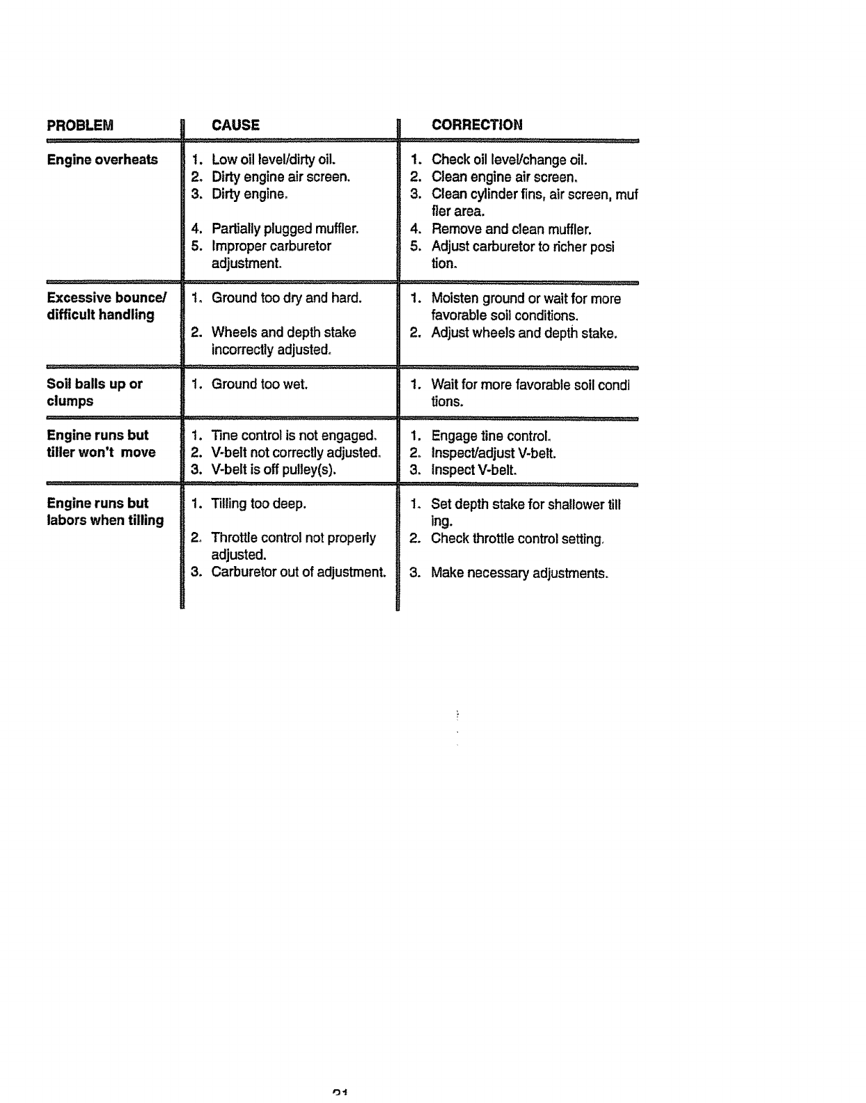
PROBLEM
Engineoverheats
Excessivebounce/
difficulthandling
Soilballsupor
clumps
Enginerunsbut
tillerwon't move
Enginerunsbut
laborswhentilling
CAUSE
1. Low oil level/dirtyoil.
2. Dirty engine air screen.
3. Dirt',,engine.
4. Partially plugged muffler.
5. Improper carburetor
adjustment.
1o Ground too dry and hard.
2. Wheels and depth stake
incorrectlyadjusted°
1, Ground too wet.
1. Tine control is not engagsdo
2. V-belt not correctly adjusted,
3. V-belt is off pulley(s).
1. _lling toodeep,
2o ThrotfJe control not properly
adjusted.
3. Carburetor out of adjustment,
CORRECTION
1. Check oil level/change oil.
2. Clean engine air screen.
3. Clean cylinder fins, air screen, muf
tier area.
4. Remove and clean muffler.
5. Adjust carburetor to richerposi
tiono
............................................._u,, ,..................
1, Moisten ground or wait for more
favorable soil conditions,
2. Adjust wheels and depth stake,
1. Wait for more favorable soil condi
tions,
1. Engage tine control
2. Inspect/adjust V-belt,
3. Inspect V-belt.
...................................... ....................................,'L_L'W,, ...................................
1, Set depth stake for shallower till
ing.
2. Check throttlecontrol setting,
3. Make necessary adjustments.
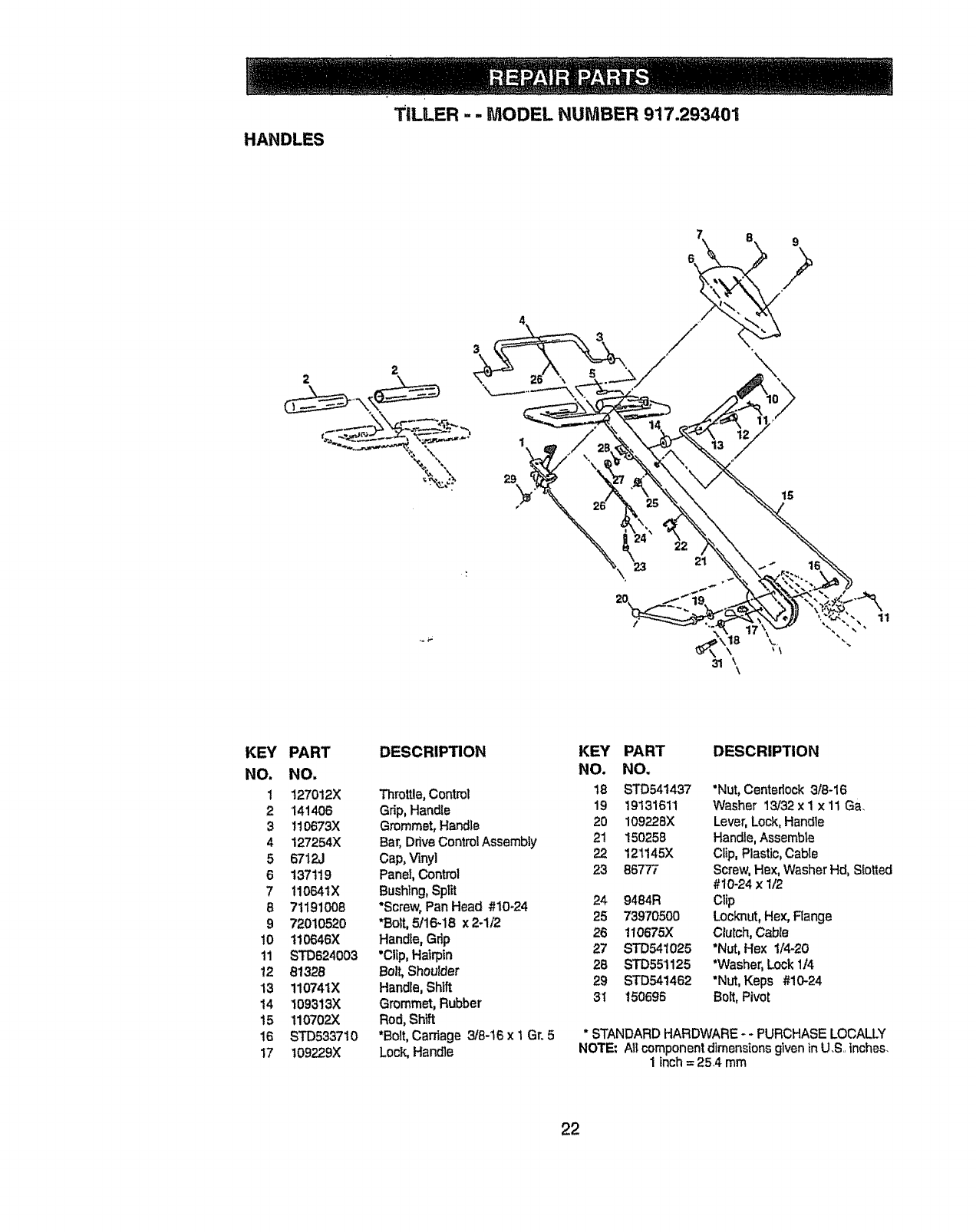
HANDLES
TELLER -- MODEL NUMBER 917.293401
20
11
\
31 \
KEY
NO.
1
2
3
4
5
6
7
6
9
lO
11
12
13
14
15
16
17
PART
NO.
127012X
141406
110673X
127254X
6712J
137119
11O641X
71191008
7201o520
110646X
STD624003
81328
110741X
109313X
110702)(
STD5337 ! 0
109229)(
DESCRIPTION
Throttle,Control
Grip, Handle
Grommet, Handle
Bar, Ddve Control Assembly
Cap, Vinyl
Panel, Control
Bushtng, Split
*Screw, Pan Head #10-24
*Bolt,5/16-18 x 2-I/2
Hand_e,Grip
*CIlp, Hatrpin
Bolt,Shoulder
Handle, Shift
Grommet, Rubber
Red, Shift
*Bolt, Carriage 3/8-16 x 1 Gr. 5
Lock,Handle
KEY PART DESCRIPTION
NO. NO,
t8 STD541437 "Nut,Centedock 3/8-t6
19 19131611 Washer t3/32 x 1 x 11 Ga.
20 109228X Lever, Lock, Handle
21 150258 Handle, Assemble
22 121145X Clip, Plastic, Cable
23 86777 Screw, Hex, Washer Hal, Slotted
#10-24 x 1/2
24 9484R Clip
25 73970500 Locknut,Hex,Range
26 110675)( Clutch,Cable
27 STD541025 "Nut,Hex 1/4-20
2B STD551125 *Washer,Lock 1/4
29 STD541462 "Nut,Keps #10-24
3t 150696 Bo_t,Pivot
* STANDARD HARDWARE- -PURCHASE LOCALLY
NOTE: AI; component dimensions given inU.S.. inches.
1inch= 254 mm
22
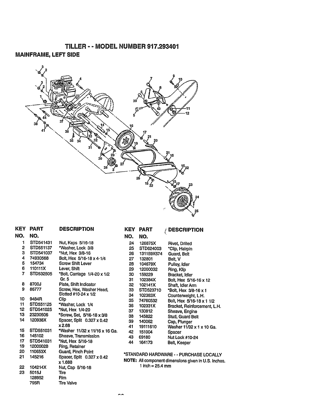
TELLER .. -MODEL NUMBER 917.293401
MAINFRAME, LEFT SIDE
9
//
26
15 17 23
24
KEY
NO.
1
2
3
4
5
6
7
8
9
lO
11
12
13
14
15
16
t7
19
20
21
23
PART
NO.
STD541431
STD551137
STD541037
74930566
154734
110111X
STD532505
8700J
86777
9484R
STD551125
STD541025
23230506
120938X
STD551031
145102
STD541031
12000028
110653X
145216
104214}(
5015,!
126952
795R
DESCRIPTION KEY
NO.
Nut, Keps 5/t6-18 24
*Washer, Lock :3/8 25
*Nut, Hex 3/8-16 26
Bolt,He}{ 5/16-18 x4-1/4 27
Screw ShiftLever 28
Lever, Shift 29
*Bolt, Carriage 1/4-20 x 1/2 30
Gr_5 31
Rate, ShiftIndicator 32
Screw,Hex, Washer Head, 33
Slotted#10-24 x 1/2 34
Clip 35
*Washer, Lock 1/4 36
*Nut, Hex 1/4-20 37
*Screw,Set, 5/16-18 x 3/8 38
Spacer,Split 0.327 x 0.42 39
x 2°68 41
*Washer 11132x 11116x t6 Ga. 42
Sheave,Transmission 43
*Nut, Hex 5116-18 44
Ring,Retainer
Guard,Pinch Point
Spacer,Split 0_327x 0A2
x 1.686
Nut, Cap 5/16-16
Tire
Rim
Tire Valve
PART /DESCRIPTION
NO.
126875X Rivet, Ddfled
STD624003 "Clip,Hatrpin
131159X574 Guard, Belt
132801 Belt,V
104679}{ Pulley,idler
12000032 Ring,Kllp
159229 Bracket,Idler
102384X Bolt, Hex 5/16-16 x 12
102141X Shaft, Idler Arm
STD523710 *Bolt, He}{ 3/8-16 x I
102383X Counterweight,L.H.
74760532 Bolt, Hex 5/16-18 x 1 1/2
102331X Bracket, Reinforcement,LH.
130812 Sheave, Engine
145822 Stud,Guard Belt
140062 Cap, Plunger
19111610 Washer 11132x 1 x 10 Ga.
151004 Spacer
69180 Nut Lock #10-24
164173 Belt, Keeper
=STANDARD HARDWARE - - PURCHASE LOCALLY
NOTE: A!lcomponentdimensionsgiven tn UoSoinches.
Iinch= 25.4 mm
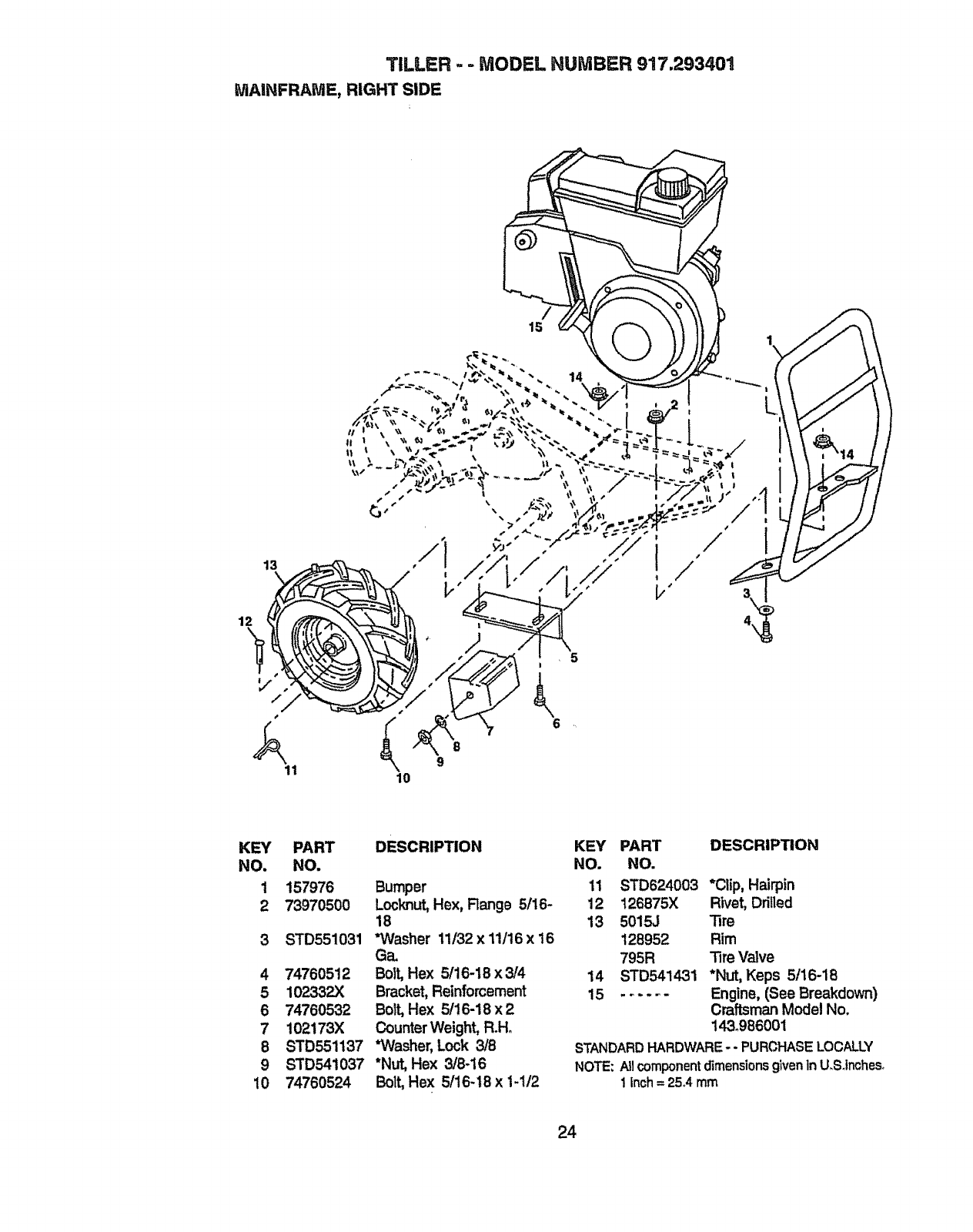
TILLER - - MODEL HUMBER 917.293401
MAINFRAME, RIGHT SIDE
/
15
13
12
s
11
!
!
i/"
KEY PART
NO. NO.
1 157976
2 73970500
3 STD551031
4 74760512
5 102332X
6 74760532
7 102173)(
8 STD551137
9 STD541037
10 74760524
DESCRIPTION
Bumper
Locknut,Hex, Range 5/16-
18
*Washer 11/32 x 11116x 16
Ga.
Bolt,Hex 5/16-18 x 3/4
Bracket, Reinforcement
Bolt,Hex 5/16-18 x 2
Counter Weight, R.Ho
*Washer, Lock 3/8
*Nut, Hex 3/8-16
Bolt,Hex 5/16-18 x 1-1/2
KEY PART DESCRIPTION
NO. NO.
11 STD624003 *Clip, Hairpin
12 126875X Rivet, Drilled
13 5015J Tire
128952 Rim
795R Tire Valve
14 STD541431 *Nut, Keps 5/16-18
15 ...... Engine, (See Breakdown)
Craftsman Model No.
143.986001
STANDARD HARDWARE - - PURCHASE LOCALLY
NOTE:AllcomponentdimensionsgivenInU.Solrtches.
1 inch= 25A mm
24
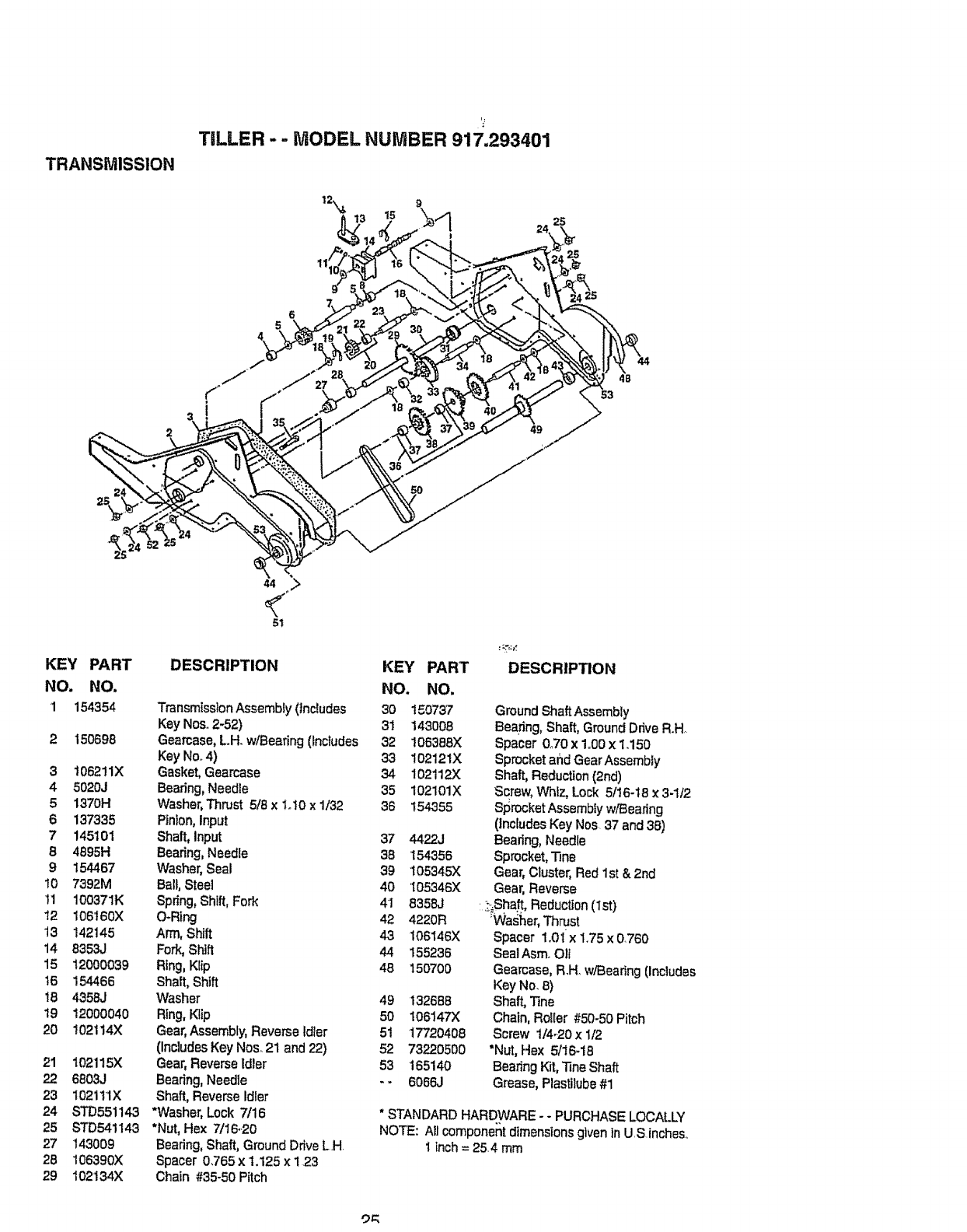
TRANSMISSION
TILLER --MODEL NUMBER 917.293401
I
49
S0
KEY PART
NO. NO,
1 154354
2150698
31062!1X
4 5020J
5 1370H
6 137335
7 145101
84895H
9 154467
10 7392M
11 10037IK
12 106t60X
13 142145
14 8353J
15 12000039
t6 154466
18 435_J
19 12000040
20 102114X
21 1021t5X
22 6803J
23 I021tlX
24 STD55!143
25 STD541143
27 143009
28 106390)(
29 102'134X
DESCRIPTION
Transmission Assembly (Includes
Key Noso2-52)
Gearcase, LH. w/Bearing (Includes
Key Noo4)
Gasket, Gearcase
Bearing, Needle
Washer,Thrust 5/8 x 1o10x 1/32
Pinion, Input
Shaft, Input
Bearing,Needle
Washer, Seal
Ball, Steel
Spring,Shift,Fork
O-Ring
Arm, Shift
Fork,Sh_fl
Ring, Klip
Shaft, Shift
Washer
Ring,Kiip
Gear,Assembly,Reverse tdler
(Includes Key Noso21 and 22)
Gear, Reverse Idler
Bearing, Needle
Shaft, ReverseIdler
*Washer, Lock 7/16
*Nut, Hex 7/16.20
Bearing, Shaft, Ground Drive LH
Spacer 0,765 x t.125 x 1 23
Chain #35-50 Pitch
KEY PART
NO. NO.
30 150737
31 !43008
32 !06388X
33 102121X
34 102112X
35 102101X
36 154355
37 4422J
38 154356
39 105345X
40 105346X
41 8358J
42 4220R
43 106146X
44 155236
48 150700
49 132688
50 106147X
51 17720408
52 73220500
53 165140
-- 6066J
DESCRIPTION
GroundShaftAssembly
Bearing, Shaft,GroundDriveR.H
Spacer 0_70 x 1o00x 1.150
Sprocket and Gear Assembly
Shaft, Reduction (2nd)
Screw, Whiz, Lock 5/16-18 x 3-1/2
Sprocket Assembiy w/Bearing
(Includes Key Nos 37 and 38)
Bearing, Needle
Sprocket,"13ne
Gear, CLuster,Red 1st & 2nd
Gear, Reverse
;;_Shaft,Reduction (1st)
rWasher, Thrust
Spacer 1.01 x 175 x 0760
Seal AsmoOli
Gearcase, R.H. w/Bearing (Includes
Key No. 8)
Shaft,,"Fine
Chain, RoUer #50-50 Pitch
Screw 1/4.20 x 1/2
"Nut, Hex 5/16-18
BearingKit, Tine Shaft
Grease, Plastilube#1
*STANDARD HARDWARE - - PURCHASE LOCALLY
NOTE: All component dimensions given in U S inches
1inch= 254 mm
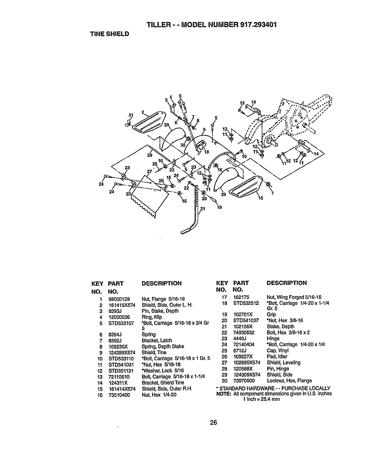
TINE SHIELD
TILLER - - MODEL NUMBER 917.293401
24
KEY PART
NO. NO.
t 980OO129
2 t61415X574
3 8393J
4 1200O036
5 STD533107
6 83943
7 B392J
8109230X
9124289X574
10 STD533110
11 STD541031
12 STD551131
13 72110510
14 !24311X
15 161414)(574
16 73510400
DESCRIPTION
Nut,Range 5/16.18
Shield,Side,OuterL H,,
Pin,Stake,Depth
Ring,I'¢lip
"Bolt,Carriage5/16-18x3/4 Gr
5
Spring
Bracket,Latch
Spdng,DepthStake
Shietd,Tine
*Bolt,Cardage5/16-18x 1Gro5
*Nut,Hex 5/16-18
*Washer,Lock5/16
Bott,Carriage5/16-18x1-i/4
BracketShield'iine
Shield,Side,OuterR,H_
Nut,Hex 11420
KEY PART DESCRIPTION
NO. NO,
17 162175 Nut, Wing Forged5/16-18
18 STD532512 *Bolt,Carriage 1/4.20 x 1-114
Gr. 5
19 t02701X Grip
20 STD541037 *Nut, Hex 3/8.16
21 102155X Stake, Depth
22 74930632 Bolt,Hex 3/6-16 x 2
23 4440J Hinge
24 72140404 "Bolt'Carriage 1/4-20 x 1/4
25 6712J Cap, Vinyl
26 109227X Pad, Idler
27 102595X574 Sh;eld, Leveling
28 120588X Pin, Hinge
29 I24309X574 Shield,Side
30 73970500 Locknut,Hex, Range
*STANDARDHARDWARE- - PURCHASELOCALLY
NOTE: AflcomponentdimensIonsgivenIn U.SoInches
i inch=25.4 mm
,26

TBLLER- =MODEL NUMBER 917.293401
TINE ASSEMBLY
3#
3
11
KEY
NO.
1
2
3
4
5
6
7
8
PART
NO.
4459J
132673
6554J
STD624006
132727
736106O0
STD551137
74610616
DESCRIPTION
Tine, Outer, L.H.
Pin, Shear
Tine, Inner, LH.
*Cttp, Hairpin
Assembly, Hub and Plate, LH,
Nut, Hex 318-24
*Washer, Lock 3/8
Bolt,Hex 3/8-24 x I
KEY PART DESCRIPTION
NO, NO,
9 4460J _ne, Outer,R.Ho
10 132728 Assembly,Huband Plate,Roll.
11 6555J "Fine,Inner,R.H_
*STANDARD HARDWARE - - PURCHASE LOCALLY
NOTE: AllcomponentdimensionsgiveninUoSoinches.
1 inch=25.4 mm
27
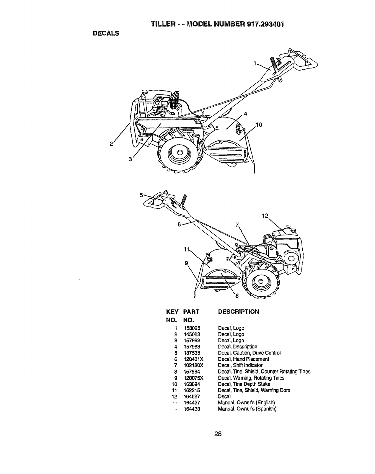
DECALS
TILLER =-MODEL HUMBER 917.293401
12
KEY PART DESCRIPTION
NO. NO.
1 158095 Decal,Logo
2 145023 Decal,Logo
3 157982 Decal,Logo
4 157983 Decal,Description
5 137538 Decal,Caution,DriveControl
6 120431X Decal,HandPlacement
7 102180)( Decal,ShlftIndicator
8 157984 Decal,'11qe,Shield,CounterRotatingTines
9 120075X Decal,Warning,Rotating_nes
10 163094 Decal,TinsDepthStake
11 162215 Decal,'rine,Shield,WarningDoro
12 164527 Decal
--164437 Manual,Owner's(English)
-- t64438 Manua!,Owner's(Spanish)
28
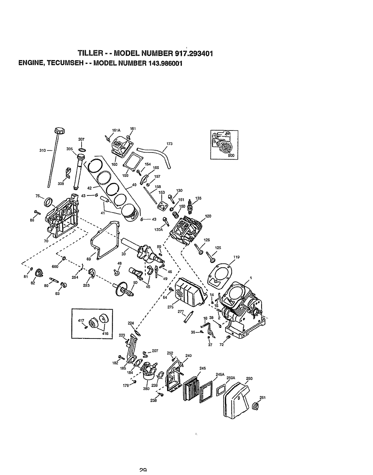
TILLER - - MODEL HUMBER 917.293401
ENGINE, TECUMSEH - - MODEL NUMBER 143.986001
161A 161
185 184/ 245A
'/
I
5_€_
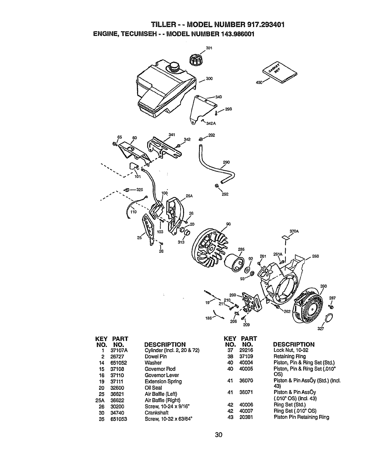
TDLLER -.. MODEL NUMBER 917.293401
ENGINE, TECUMSEH --MODEL NUMBER 143.986001
301
/
65 60 341 342
KEY PART
NO. NO.
1 37107A
2 26727
14 6-51052
15 37108
16 37110
19 371'11
20 32600
25 36621
25A 36622
26 3020O
30 34740
35 651053
DESCRIPTION
Cylinder(IncL2, 20 &72)
Dowel Pin
Washer
GovernorRod
GovernorLever
ExtensionSpdng
Oi! Seal
AirBaRe (Left)
Air Baffle(Right)
Screw, 10-24 x 9116"
Crankshaft
Screw,10-32 x 63/64"
KEY
NO.
37
38
40
40
41
41
42
42
43
PART
NO.
29216
37109
40004
40005
36070
36071
40006
40007
20381
261
370A
I26O
390
/287
/
/©
DESCRIPTION
Lock Nut, 10-32
Retaining Ring
Piston, Pln & Ring Set (Std,)
Piston, Pin & Ring Set (,010"
os)
Piston& Pin Assay (Std,) (IncL
43)
Piston & PinAssOy
(,,010"OS) (IncL 43)
Ring Set (Std,.)
Ring Set (.010" OS)
Piston Pin Retaining Ring
3O
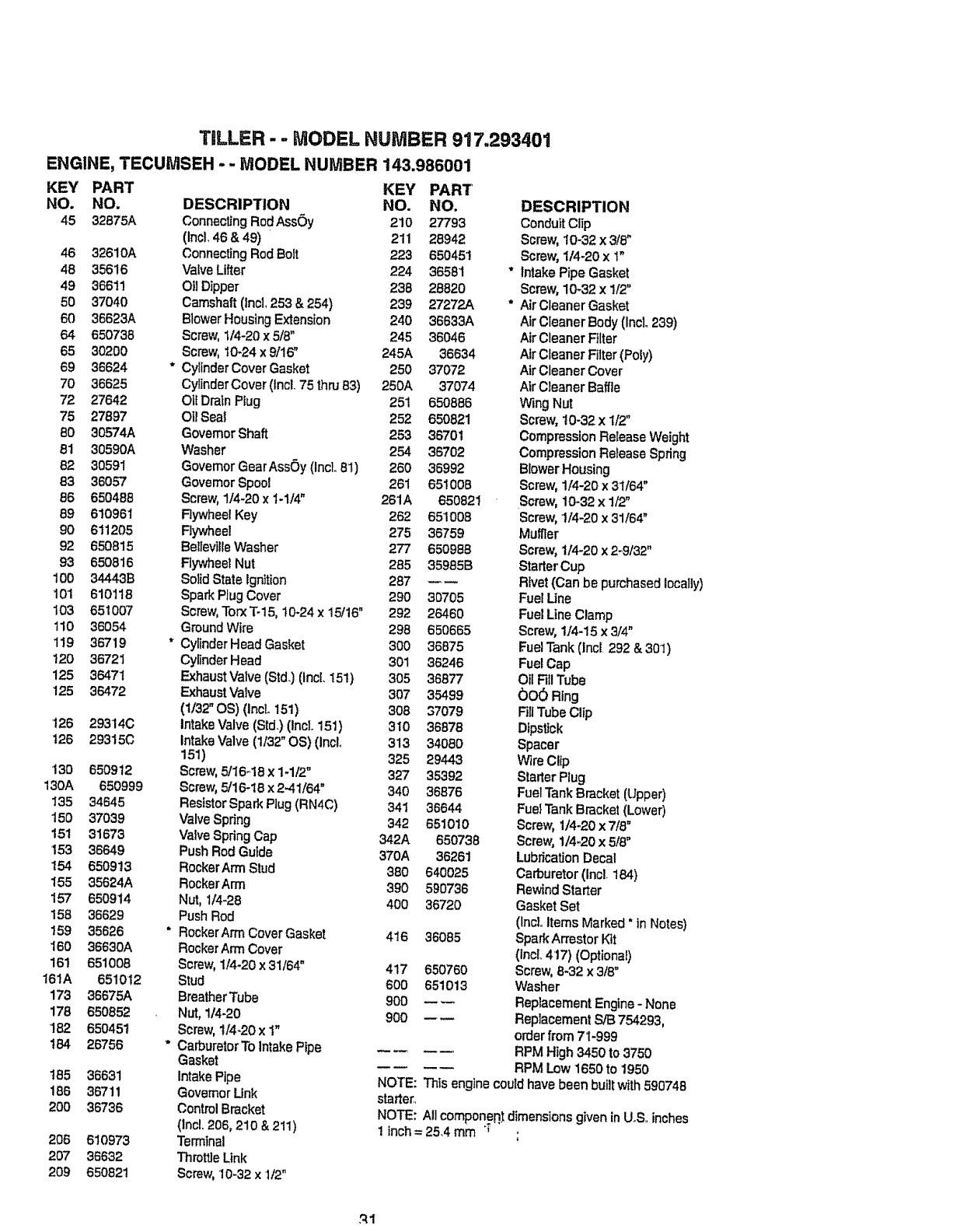
TILLER - - MODEL HUMBER 917,293401
ENGINE, TECUMSEH --MODEL NUMBER
KEY PART
NO. NO.
45 32875A
46 32610A
48 35616
49 36611
50 37040
60 36623A
64 650738
65 30200
69 36624
70 36625
72 27642
75 27897
B0 30574A
,91 30590A
82 30591
83 36057
86 650488
89 610961
90 6!1205
92 650815
93 650816
100 34443B
101 610118
103 651007
110 36054
119 36719
120 36721
125 36471
125 36472
t26
126
130
130A
135
150
151
153
154
155
157
158
159
160
161
161A
173
178
182
t54
165
186
2OO
206
2O7
209
29314C
29315C
650912
650999
34645
37039
31673
36649
650913
35624A
650914
36629
35626
36630A
651008
651012
36675A
650852
65O451
26756
36631
36711
36736
610973
36632
650821
143.986001
KEY PART
DESCRIPTION NO. NO.
ConnectingRodAssOy 210 27793
(Incl. 46 & 49) 211 28942
ConnectingRod Bott 223 650451
Valve Lifter 224 36581
OilDipper 238 28820
Camshaft(lnc], 253 & 254) 239 27272A
Blower Housing Extension 240 36633A
Screw,1/4-20 x 5/8" 245 36046
Screw,10_24x 9/16" 245A 36634
Cylinder Cover Gasket 250 37072
Cylinder Cover (lncL 75 thru B3) 250A 37074
Otf Drain Ptug 251 650886
Oil Sea_ 252 650821
GovernorShaft 253 36701
Washer 254 36702
GovernorGearAssOy (incL81) 260 36992
GovernorSpool 261 651008
Screw,1/4_20 x t-1/4" 261A 650821
Rywheel Key 262 651008
Rywheel 275 36759
Beltev]l[eWasher 277 650988
Flywheel Nut 285 35985B
SolidState Ignltion 287 --
SparkPtug Cover 290 30705
Screw,TorxTo15,10-24 x 15/16" 292 26460
Ground Wire 298 650665
CylinderHead Gasket 300 36875
CylinderHead 301 36246
ExhaustValve (Std.) (lncL 151) 305 36877
Exhaust Valve 307 35499
(t/32" OS) (incL 151) 308 37079
IntakeValve (Std,) (IncL 151) 310 36878
IntakeValve (1/32"OS) (InoL 313 34080
151) 325 29443
Screw,5/16-18 x 14/2" 327 35392
Screw,5/16-18 x 2.41/64" 340 36876
Resfstor Spark Plug (RN4C) 341 36644
Valve Spdng 342 651010
Valve SpringCap 342A 650738
Push Rod Guide 370A 36261
Rocker Arm Stud 380 640025
RockerArm 390 590736
Nut, 1/4-28 400 36720
Push Rod
RockerArm Cover Gasket 416 36085
RockerArm Cover
Screw, 114-20x 31/64" 417 650760
Stud 600 651013
Breather Tube 900 --
Nut, 1/4-20 900 _w
Screw,!/4-20 x t"
Carburetor To intakePipe
Gasket
Intake Pipe
Governor Unk
ControlBracket
(lncl. 206, 21o & 211)
Terminal
ThrottleLink
Screw, 10-32 x 1/2"
v
t,
DESCRIPTION
ConduitClip
Screw,10-32 x3/8"
Screw,1/4-20 x 1"
Intake Pipe Gasket
Screw, 10-32 x 1t2"
Air Cleaner Gasket
Air Cleaner Body (Inclo239)
Air Cleaner Filter
Air Cleaner Filtar (Poly)
Air Cleaner Cover
Air Cleaner Baffle
Wing Nut
Screw, 10-32 x 1/2"
Compression Release Weight
Compression Release Spring
Blower Housing
Screw,1/4-20 x 31/64"
Screw, 10-32 x 1/2"
Screw, 1/4-20 x 31/64"
Mumer
Screw, 114-20x 2-9132"
StarterCup
Rivet (Can be purchased locally)
Fuel Une
Fuel Line Clamp
Screw,1/4-15 x 3/4"
,FuelTank (Incl 292 & 301)
FuelCap
OilFillTube
00_) Ring
FiliTube Clip
Dipstick
Spacer
Wire Clip
StarterPlug
Fuel Tank Bracket (Upper)
Fuel Tank Bracket (Lower)
Screw, 1/4-20 x 7/8"
Screw, 1/4-20 x5/8"
LubricationDecal
Carburetor(Incl. 184)
Rewind Starter
Gasket Set
(IncLitems Marked * in Notes)
SparkArrestor Kit
(IncL 4'17) (Optional)
Screw,8-32 x 3/8"
Washer
Replacement Engine - None
Replacement S/B 754293,
order from 71-999
RPM High 3450 to 3750
RPM Low 1650 to 1950
NOTE: Th_sengine couldhave been buBtwith59074B
starter,,
NOTE: All componen.t dimensions given inUoS,,inches
1inch= 25,4 mm' ;
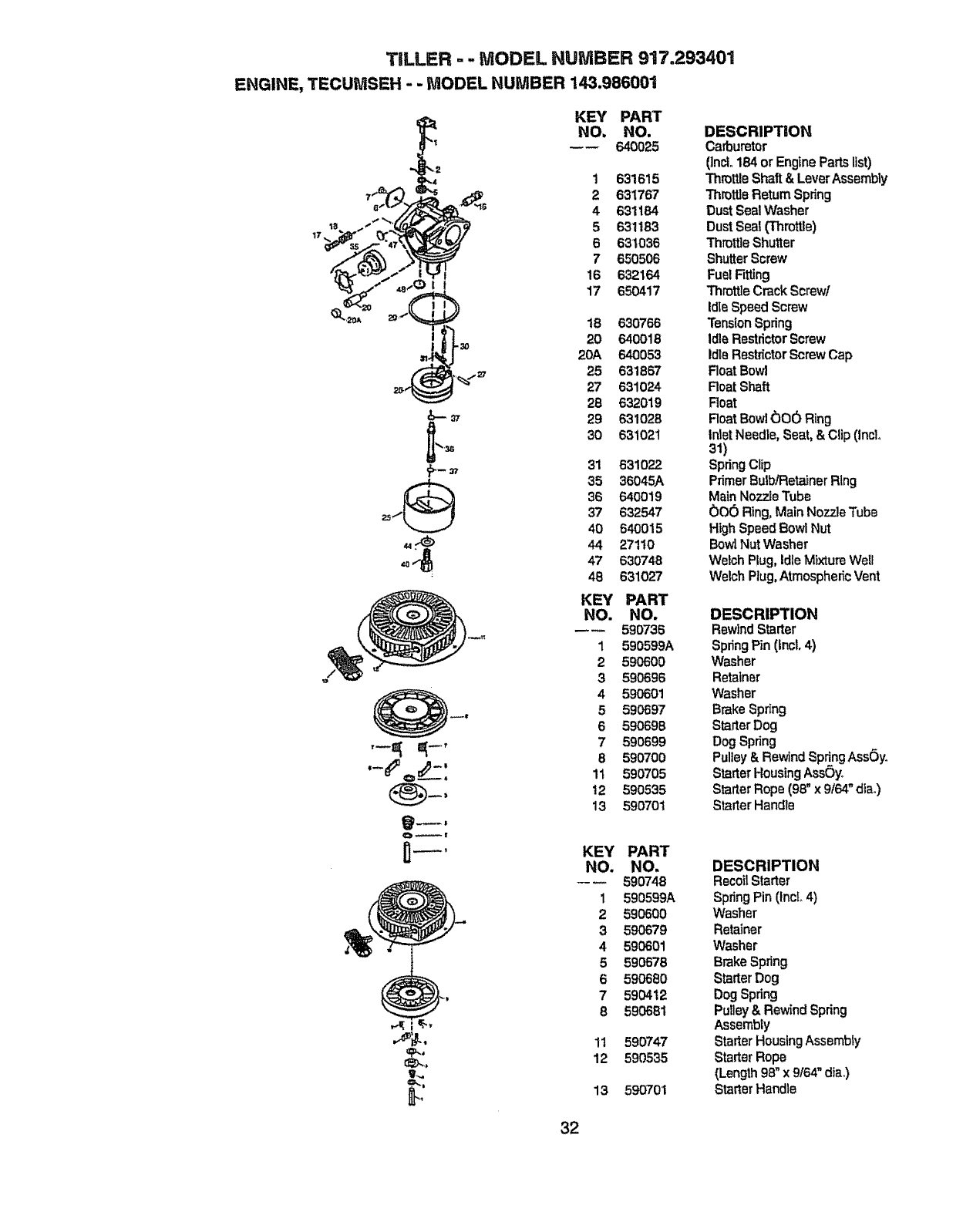
TILLER - -MODEL NU 'IBER 917.293401
ENGINE, TECUMSEH --MODEL HUMBER 143.986001
KEY PART
_'2 NO. NO.
---- 640025
1 631615
_2 631767
4 631184
5 631163
6 631036
7 650506
16 632'164
17 650417
18 630766
20 640018
20A 640053
25 631867
27 631024
28 632019
29 631028
30 631021
31 631022
35 36045A
36 640019
37 632547
40 640015
44 27110
47 630748
413 631027
KEY PART
NO. NO.
_590735
1 590599A
2 590600
3 590696
4 590601
5 590697
6 59069B
7 590699
6590700
11 590705
t2 590535
13 590701
KEY PART
NO. NO.
-- 590748
1 590599A
2 590600
3 590679
4 590601
5 590676
6 590680
7 590412
85906B1
11 590747
12 590535
13 59070I
DESCRIPTION
Cadmretor
(]nrJ_184or EnginePartslist)
ThrotUeShaft& LeverAssembly
Th_tt]eReturnSpdng
DustSealWasher
DustSeal(Throttle)
ThrottleShutter
ShutterScrew
FuelRtting
ThrottleCrackScrew/
IdleSpeedScrew
TensionSpdng
IdleRestrictorScrew
IdleRestdctorScrewCap
RoatBowl
RoarShaft
Roat
RoarBowl(_00 Ring
InletNeedle,Seat,& Clip(Incl.,
31)
SpringClip
PrimerBulb/RetainerRing
MainNozzJeTube
006 Ring,MainNozzleTube
HighSpeedBowlNut
BowlNutWasher
WelchRug,IdleMixtureWeU
WelchPlug,A'lmospheficVent
DESCRIPTION
RewtndStarter
SpringPin (Incl. 4)
Washer
Retainer
Washer
BrakeSpring
StarterDog
Dog Spring
Pulley& Rewind SpringAssC)yo
Sta,_erHousingAss_)yo
StarterRope (98' x 9t64" die.)
StarterHandle
DESCRIPTION
Recoi_Starter
SpringPin (IncL4)
Washer
Retainer
Washer
BrakeSpring
StarterDog
DogSpring
Pulley& RewindSpring
Assembly
StarterHousingAssembly
StarterRope
(Length98_'x 9t64"dial)
StarterHandle
32

33

34

35
Forthe repair or replacement parts you need
delivered directly to your home
Call 7 am - 7 pm, 7days a week
1=800=366 PART
(1-800-366-7278)
Para ordenar piezas con entrega a
domicilio - 1-800-659-7084
For in-house major brand repair service
Call 24 hours a day, 7 days a week
1-800o4-REPAnR
(1-800-473-7274)
Para pedir servicio de reparaci6n a
domicilio - 1-800-676-5811
For the location of aSears Parts and
Repair Center in your area
Call 24 hours a day, 7 days a week
1-800=488-1222
For information on purchasing a Sears
Maintenance Agreement or to inquire
about an existing Agreement
Call 9 am - 5 pro, Monday-Saturday
1=800-827=6655
When requesting service or ordering
parts, always provide the following
information:
oProduct Type • Part Number
o Model Number o Part Description
America sRepasr Speciattsts
164437 Rew 5 4_13o98 TR Printed in U_S.A.
