Craftsman 917293483 User Manual REAR TINE TILLER Manuals And Guides L0202287
CRAFTSMAN Rear Tine, Gas Tiller Manual L0202287 CRAFTSMAN Rear Tine, Gas Tiller Owner's Manual, CRAFTSMAN Rear Tine, Gas Tiller installation guides
User Manual: Craftsman 917293483 917293483 CRAFTSMAN REAR TINE TILLER - Manuals and Guides View the owners manual for your CRAFTSMAN REAR TINE TILLER #917293483. Home:Lawn & Garden Parts:Craftsman Parts:Craftsman REAR TINE TILLER Manual
Open the PDF directly: View PDF ![]() .
.
Page Count: 56

Owner's Manual
JCRRFTSMIIWJ
REAR TINE TILLER WITH
COUNTER ROTATING TINES
6.5 HP
17 Inch Tine Width
Model No.
This product has a low emission engine which operates
differently from previously built engines. Before you start the
engine, read and understand this Owner's Manual.
CAUTION:
Read and follow all Safety
Rules and Instructions before
operating this equipment.
Sears, Roebuck and Co., Hoffman Estates, II 60179 U.S.A.
Visit our Craftsman website:www.sears.com/craftsman
SafetyRules .........................................2
Warranty...............................................2
ProductSpecifications..........................4
Assembly..............................................5
Operation..............................................8
Maintenance.......................................13
Serviceand Adjustments....................15
Storage ...............................................19
Troubleshooting.................................20
IllustratedPartsList............................42
SearsService......................BackCover
LIMITEDTWOYEARWARRANTYONCRAFTSMANTILLER
For two(2) yearsfrom dateof purchase,whenthisCraftsmanTilleris maintained,
lubricated, and tuned up according to the operating and maintenance instructions in
the owner's manual, Sears will repair free of charge any defect in material or workman-
ship.
This Warranty does not cover:
•Expendable items which become worn during normal use, such as tines, spark
plugs, air cleaners and belts.
•Repairs necessary because of operator abuse or negligence, including bent
crankshafts and the failure to maintain the equipment according to the instructions
contained in the owner's manual.
• If this Craftsman Tiller is used for commercial or rental purposes, this Warranty
applies for only thirty (30) days from the date of purchase.
Warranty service is available by returning the craftsman power mower to the nearest
sears service center/department in the united states. This warranty applies only while
this product is in use in the united states.
This Warranty gives you specific legal rights, and you may also have other rights which
vary from state to state.
SEARS, ROEBUCKAND CO., D/817WA, HOFFMAN ESTATES, IL 60179 U.S.A.
IMPORTANT: This cutting machine is capable of amputating hands and feet and
throwing objects. Failure to observe the following safety instructions could result in
serious injury or death.
TRAINING
• Read the Owner's Manual carefully. Be
thoroughly familiar with the controls
and the proper use of the equipment.
Know how to stop the unit and disen-
gage the controls quickly.
• Never allow children to operate the
equipment. Never allow adults to
operate the equipment without proper
instruction.
• Keep the area of operation clear of all
persons, particularly small children,
and pets.
PREPARATION
•Thoroughly inspect the area where the
equipment is to be used and remove all
foreign objects.
• Disengage all clutches and shift into
neutral before starting the engine
(motor).
• Do not operate the equipment without
wearing adequate outer garments.
Wear footwear that will improve footing
on slippery surfaces.
• Handle fuel with care; it is highly
flammable.
• Use an approved fuel container.
• Never add fuel to a running engine or
hot engine.
•Fill fuel tank outdoors with extreme
care. Never fill fuel tank indoors.
• Replace gasoline cap securely and
clean up spilled fuel before restarting.
• Use extension cords and receptacles
as specified by the manufacturer for all
units with electric drive motors or
electric starting motors.
•Never attempt to make any adjustments
while the engine (motor) is running
(except where specifically recommend-
ed by manufacturer).
OPERATION
• Do not put hands or feet near or under
rotating parts.
•Exercise extreme caution when
operating on or crossing gravel drives,
walks, or roads. Stay alert for hidden
hazards or traffic. Do not carry passen-
gers.
•After striking a foreign object, stop the
engine (motor), remove the wire from
the spark plug, thoroughly inspect the
tiller for any damage, and repair the
damage before restarting and operat-
ing the tiller.
• Exercise caution to avoid slipping or
falling.
• If the unit should stad: to vibrate
abnormally, stop the engine (motor)
and check immediately for the cause.
Vibration is generally a warning of
trouble.
• Stop the engine (motor) when leaving
the operating position.
• Take all possible precautions when
leaving the machine unattended.
Disengage the tines, shift into neutral,
and stop the engine.
• Before cleaning, repairing, or inspect-
ing, shut off the engine and make
certain all moving parts have stopped.
Disconnect the spark plug wire, and
keep the wire away from the plug to
prevent accidental starting. Disconnect
the cord on electric motors.
• Do not run the engine indoors; exhaust
fumes are dangerous.
• Never operate the tiller without proper
guards, plates, or other safety protec-
tive devices in place.
• Keep children and pets away.
• Do not overload the machine capacity
by attempting to till too deep at too fast
a rate.
• Never operate the machine at high
speeds on slippery surfaces. Look
behind and use care when backing.
• Never allow bystanders near the unit.
• Use only attachments and accessories
approved by the manufacturer of the
tiller.
• Never operate the tiller without good
visibility or light.
• Be careful when tilling in hard ground.
The tines may catch in the ground and
propel the tiller forward. If this occurs,
let go of the handlebars and do not
restrain the machine.
MAINTENANCE AND STORAGE
• Keep machine, attachments, and
accessories in safe working condition.
• Check shear pins, engine mounting
bolts, and other bolts at frequent
intervals for proper tightness to be sure
the equipment is in safe working
condition.
• Never store the machine with fuel in the
fuel tank inside a building where
ignition sources are present, such as
hot water and space heaters, clothes
dryers, and the like. Allow the engine to
cool before storing in any enclosure.
• Always refer to the operator's guide
instructions for important details if the
tiller is to be stored for an extended
period.
ALook for this symbol to point out
important safety precautions. It means
CAUTION!!! BECOMEALERT!!T YOUR
SAFETY IS INVOLVED.
_,CAUTION: Always disconnect spark
plug wire and place wire where it cannot
contact spark plug in order to prevent
accidental starting when setting up,
transporting, adjusting or making repairs.
_,WARNING: Engine exhaust, some of its
constituents, and certain vehicle compo-
nents contain or emit chemicals known to
the State of California to cause cancer
and birth defects or other reproductive
harm.
3
PRODUCT SPECIFICATIONS
Gasoline 3Quarts
Capacity: Unleaded
Regular
Oil (API-SF-SJ): SAE 30
(Capacity: 19 oz.) (Above 40°F)
SAE5w-30/10W-30
(Below 40°F)
Spark Plug : Champion
Gap: .030") RC12YC
CONGRATULATIONS on your purchase
of a Sears Tiller. It has been designed,
engineered and manufactured to give
you the best possible dependability and
performance.
Should you experience any problems you
cannot easily remedy, please contact a
Sears or other qualified Service Center.
We have competent, well-trained techni-
cians and the proper tools to service or
repair this unit.
Please read and retain this manual. The
instructions will enable you to assemble
and maintain your tiller properly. Always
observe the "SAFETY RULES".
Your new tiller has been assembled at the
factory with exception of those parts left
unassembled for shipping purposes. To
ensure safe and proper operation of your
tiller all parts and hardware you as-
semble must be tightened securely. Use
the correct tools as necessary to insure
proper tightness.
CUSTOMER RESPONSIBILITIES
•Read and observe the safety rules.
• Follow a regular schedule in maintain-
ing, caring for and using your tiller.
•Follow the instructions under the
"Customer Responsibilities" and
"Storage" sections of this Owner's
Manual.
,_IkWARNING: This unit is equipped with
an internal combustion engine and
should not be used on or near any
unimproved forest-covered, brush-
covered or grass covered land unless the
engine's exhaust system is equipped with
aspark arrester meeting applicable local
or state laws (if any). If a spark arrester is
used, it should be maintained in effective
working order by the operator.
In the state of California the above is
required by law (Section 4442 of the
California Public Resources Code).
Other states may have similar laws.
Federal laws apply on federal lands. A
spark arrester for the muffler is available
through your nearest Sears service
center (See REPAIR PARTS section of
this manual).
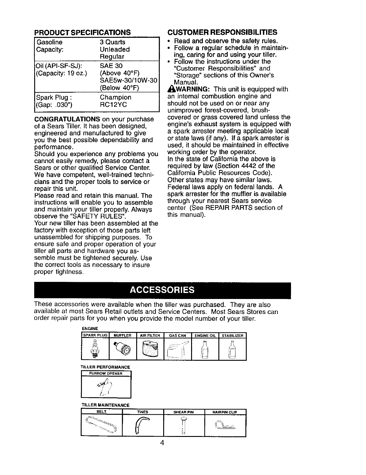
These accessories were available when the tiller was purchased. They are also
available at most Sears Retail outlets and Service Centers. Most Sears Stores can
order repair parts for you when you provide the model number of your tiller.
ENGINE
SPARK PLUG MUFFLER AIR FILTER GAS CAN !ENGINE OIL STABILIZER
TILLER PERFORMANCE
I FURROW OPENER I
TILLER MAINTENANCE
BELT
_-_
TINES SHEAR PIN HAIRPIN CLIP
4
Your new tiller has been assembled at the
factory with the exception of those parts
left unassembled for shipping purposes.
To ensure safe and proper operation of
your tiller all parts and hardware you
assemble must be tightened securely.
Use the correct tools as necessary to
insure proper tightness.
TOOLS REQUIRED FOR ASSEMBLY
A socket wrench set will make assembly
easier. Standard wrench sizes are listed.
(1) Utility knife
(1) Wire cutter
(1) Tire pressure gauge
(1) Screwdriver
(1) Pair of pliers
(1) 9/16" wrench
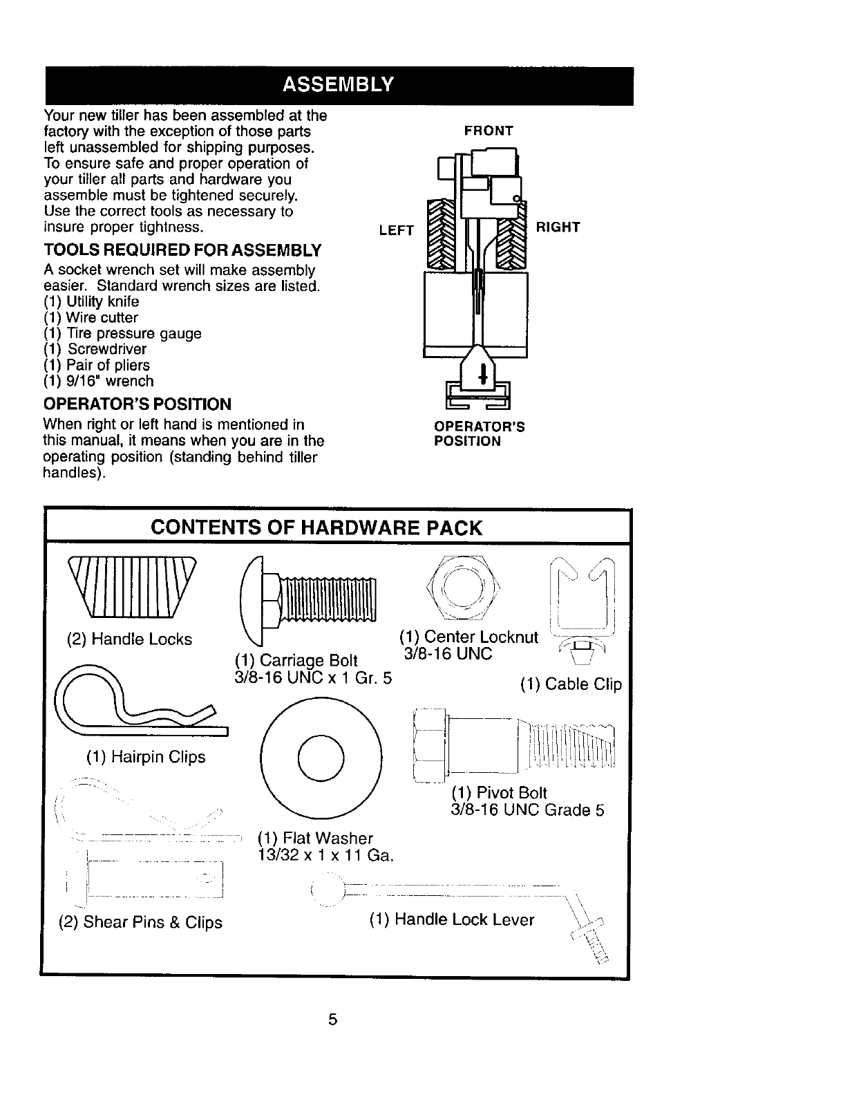
OPERATOR'S POSITION
When right or left hand is mentioned in
this manual, it means when you are in the
operating position (standing behind tiller
handles).
LEFT
FRONT
OPERATOR'S
POSITION
RIGHT
CONTENTS OF HARDWARE PACK
(2) Handle Locks (1) Center Locknut
(1) Carriage Bolt 3/8-16 UNC
3/8-16 UNC x 1 Gr. 5
(1) Hairpin Clips k _,,,j) J
:_ - _ (1) Flat Washer
13/32 x 1 x 11 Ga.
I
I
I_ _
(2) Shear Pins & Clips
(1) Cable Clip
(1) Pivot Bolt
3/8-16 UNC Grade 5
(1) Handle Lock Lever '.,,
5
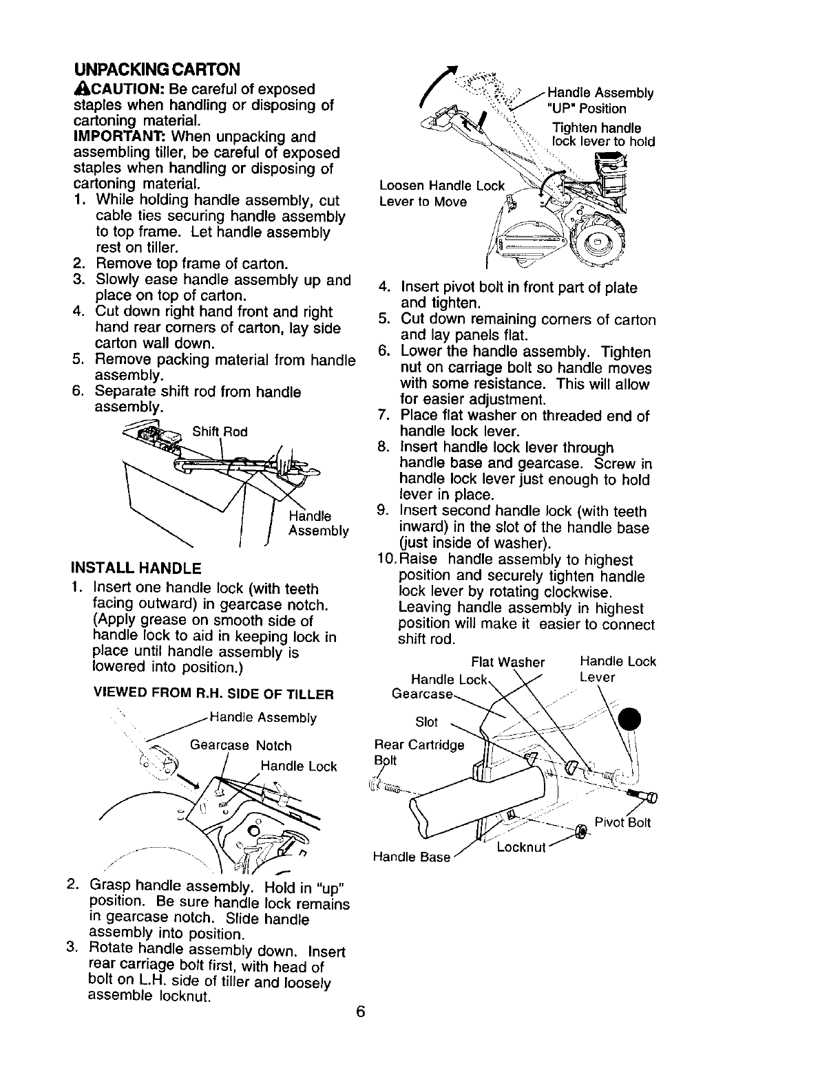
UNPACKING CARTON
_CAUTION: Be careful of exposed
staples when handling or disposing of
cartoning material.
IMPORTANT: When unpacking and
assembling tiller, be careful of exposed
staples when handling or disposing of
cartoning material.
1. While holding handle assembly, cut
cable ties securing handle assembly
to top frame. Let handle assembly
rest on tiller.
2. Remove top frame of carton.
3. Slowly ease handle assembly up and
place on top of carton.
4. Cut down right hand front and right
hand rear comers of carton, lay side
carton wall down.
5. Remove packing material from handle
assembly.
6. Separate shift rod from handle
assembly.
Shift Rod
Assembly
INSTALL HANDLE
1. Insert one handle lock (with teeth
facing outward) in gearcase notch.
(Apply grease on smooth side of
handle lock to aid in keeping lock in
place until handle assembly is
lowered into position.)
VIEWED FROM R.H. SIDE OF TILLER
_Handle Assembly
Gearcase Notch
('_.._. ,_ /Handle Lock
2. Grasp handle assembly. Hold in "up"
position. Be sure handle lock remains
in gearcase notch. Slide handle
assembly into position.
3. Rotate handle assembly down. Insert
rear carriage bolt first, with head of
bolt on L.H. side of tiller and loosely
assemble Iocknut.
mdle Assembly
"UP" Position
,,_ Tighten handle
,,: lock lever to hold
Loosen Handle Lock
Lever to Move
4. Insert pivot bolt in front part of plate
and tighten.
5. Cut down remaining corners of carton
and lay panels flat.
6. Lower the handle assembly. Tighten
nut on carriage bolt so handle moves
with some resistance. This will allow
for easier adjustment.
7. Place flat washer on threaded end of
handle lock lever.
8. Insert handle lock lever through
handle base and gearcase. Screw in
handle lock lever just enough to hold
lever in place.
9. insert second handle lock (with teeth
inward) in the slot of the handle base
(just inside of washer).
10.Raise handle assembly to highest
position and securely tighten handle
lock lever by rotating clockwise.
Leaving handle assembly in highest
position will make it easier to connect
shift rod.
Flat Washer Handle Lock
Handle Lock, Lever
Gearcase_.
Slot
Rear Cartridge
B/olt 7=
Pivot Bolt
Handle Base
6
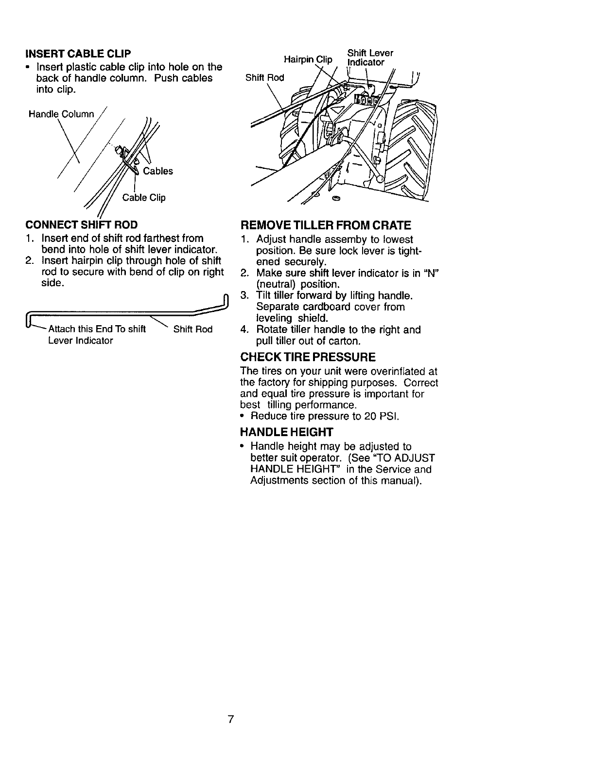
INSERT CABLE CLIP
•Insert plastic cable clip into hole on the
back of handle column. Push cables
into clip.
Handle Column
Hairpin
Shift Rod
Shift Lever
Indicator
Cables
Cable Clip
CONNECT SHIFT ROD
1. Insert end of shift rod farthest from
bend into hole of shift lever indicator.
2. Insert hairpin clip through hole of shift
rod to secure with bend of clip on right
side.
LAttach this End To shift _ Shift Rod
Lever Indicator
REMOVE TILLER FROM CRATE
1. Adjust handle assemby to lowest
position. Be sure lock lever is tight-
ened securely.
2. Make sure shift lever indicator is in "N"
(neutral) position.
3. Tilt tiller forward by lifting handle.
Separate cardboard cover from
leveling shield.
4. Rotate tiller handle to the right and
pull tiller out of carton.
CHECK TIRE PRESSURE
The tires on your unit were overinflated at
the factory for shipping purposes. Correct
and equal tire pressure is important for
best tilling performance.
• Reduce tire pressure to 20 PSI.
HANDLE HEIGHT
•Handle height may be adjusted to
better suit operator. (See "TO ADJUST
HANDLE HEIGHT" in the Service and
Adjustments section of this manual).
7
Thesesymbols may appear on your Tiller or in literature supplied with the product.
Learn and understand their meaning.
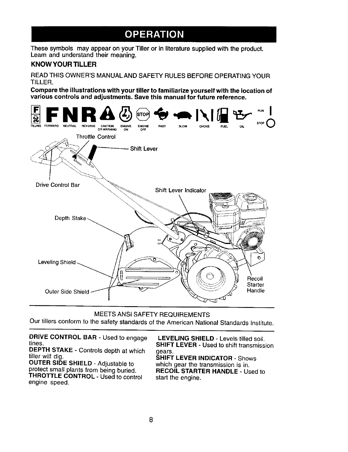
KNOW YOUR TILLER
READ THIS OWNER'S MANUALAND SAFETY RULES BEFORE OPERATING YOUR
TILLER.
Compare the illustrations with your tiller to familiarize yourself with the location of
various controls and adjustments. Save this manual for future reference.
_F N R_I _ o _, _.,t'.,I_ _ _t,_o.
13LUN_ FORWARD NEUTRAL REVERSE CAUTION ENTWINE ENGINE FAST SLOW CHOKE FUEL OIL V
OR WARNING Oke OFF
Throttle Control
Shift Lever
Drive Control Bar Shift Lever Indicator
Depth
Leveling
Recoil
Starter
Handle
MEETS ANSI SAFETY REQUIREMENTS
Our tillers conform to the safety standards of the American National Standards Institute.
DRIVE CONTROL BAR -Used to engage
tines.
DEPTH STAKE -Controls depth at which
tiller will dig.
OUTER SIDE SHIELD - Adjustable to
protect small plants from being buried.
THROTTLE CONTROL - Used to control
engine speed.
LEVELING SHIELD -Levels tilled soil.
SHIFT LEVER - Used to shift transmission
gears.
SHIFT LEVER INDICATOR - Shows
which gear the transmission is in.
RECOIL STARTER HANDLE - Used to
start the engine.
8
The operation of any tiller can result in foreign objects thrown into the eyes,
which can result in severe eye damage. Always wear safety glasses or eye
shields before starting your tiller and while tilling. We recommend a wide
vision safety mask over spectacles or standard safety glasses.
HOW TO USE YOUR TILLER
Know how to operate all controls before
adding fuel and oil or attempting to start
engine.
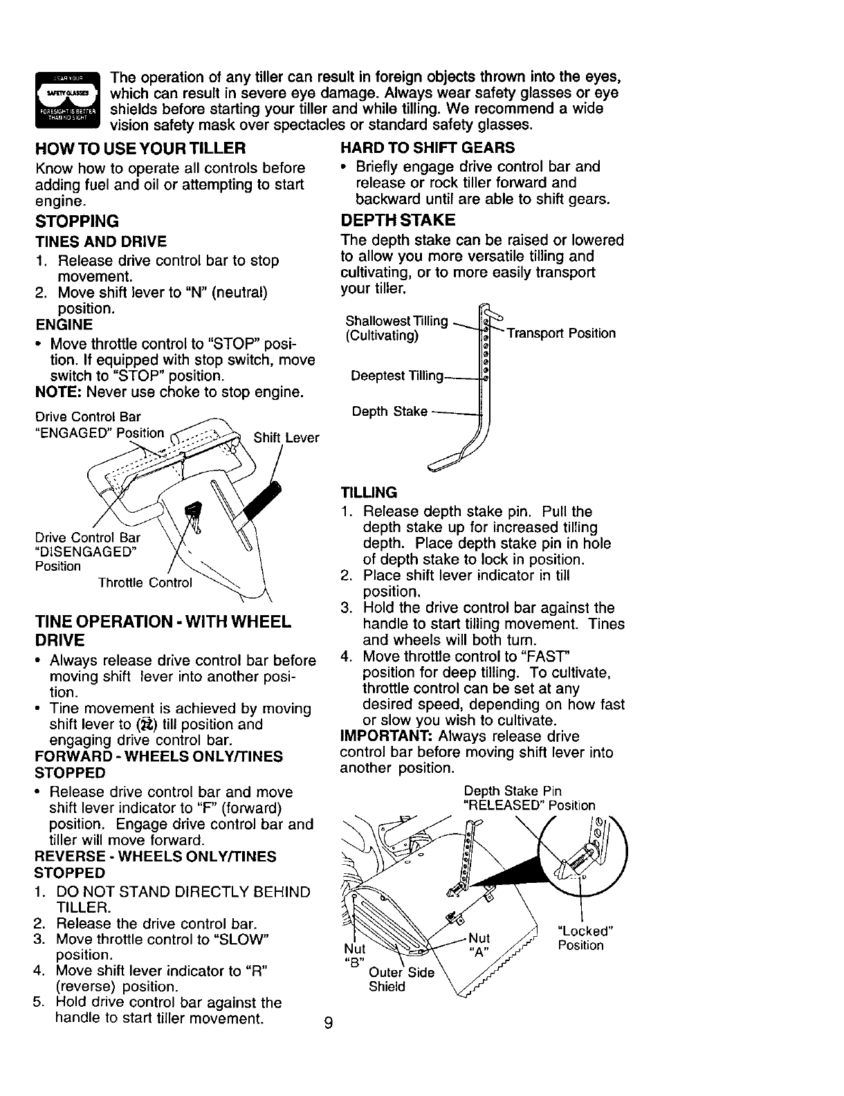
STOPPING
TINES AND DRIVE
1. Release drive control bar to stop
movement.
2. Move shift lever to "N" (neutral)
position.
ENGINE
•Move throttle control to "STOP" posi-
tion. If equipped with stop switch, move
switch to "STOP" position.
NOTE: Never use choke to stop engine.
Drive Control Bar
"ENGAGED" Position Shift Lever
HARD TO SHIFT GEARS
•Briefly engage drive control bar and
release or rock tiller forward and
backward until are able to shift gears.
DEPTH STAKE
The depth stake can be raised or lowered
to allow you more versatile tilling and
cultivating, or to more easily transport
your tiller.
Shallowest Tilling
(Cultivating)
Deeptest "l'illing_
Depth Stake
"'Transport Position
Drive Control Bar
"DISENGAGED"
Position
Throttle Control
TINE OPERATION -WITH WHEEL
DRIVE
• Always release drive control bar before
moving shift lever into another posi-
tion.
• Tine movement is achieved by moving
shift lever to (_;) till position and
engaging drive control bar.
FORWARD - WHEELS ONLY/TINES
STOPPED
•Release drive control bar and move
shift lever indicator to "F" (forward)
position. Engage drive control bar and
tiller will move forward.
REVERSE - WHEELS ONLY/TINES
STOPPED
1. DO NOT STAND DIRECTLY BEHIND
TILLER.
2. Release the drive control bar.
3. Move throttle control to "SLOW"
position.
4. Move shift lever indicator to "R"
(reverse) position.
5. Hold drive control bar against the
handle to start tiller movement.
TILLING
1. Release depth stake pin. Pull the
depth stake up for increased tilting
depth. Place depth stake pin in hole
of depth stake to lock in position.
2. Place shift lever indicator in till
position.
3. Hold the drive control bar against the
handle to start tilling movement. Tines
and wheels will both turn.
4. Move throttle control to "FAST'
position for deep tilling. To cultivate,
throttle control can be set at any
desired speed, depending on how fast
or slow you wish to cultivate.
IMPORTANT: Always release drive
control bar before moving shift lever into
another position.
Depth Stake Pin
"RELEASED" Position
\
Nut
81g,i Oute
Shield
"Locked"
Position
9
TURNING
1. Release the drive control bar.
2. Move throttle control to "SLOW"
position.
3. Place shift lever indicator in "F"
(forward) position. Tines will not turn.
4. Lift handle to raise tines out of ground.
5. Swing the handle in the opposite
direction you wish to turn, being
careful to keep feet and legs away
from tines.
6. When you have completed your turn-
around, release the drive control bar
and lower handle. Place shift lever in
(till) position and move throttle control
to desired speed. To begin tilling,
hold drive control bar against the
handle.
OUTER SIDE SHIELDS
The back edges of the outer side shields
are slotted so that the shields can be
raised for deep tilling and lowered for
shallow tilling to protect small plants from
being buried.
1. Loosen nut "A" in slot and nut "B".
2. Move shield to desired position (both
sides).
3. Retighten nuts.
TO TRANSPORT
_I_CAUTION: Before lifting or transporting,
allow tiller engine and muffler to cool.
Disconnect spark plug wire. Drain
gasoline from fuel tank.
AROUND THE YARD
1. Release the depth stake pin. Move
the depth stake down to the top hole
for transporting the tiller. Place depth
stake pin in hole of depth stake to lock
in position. This prevents tines from
scuffing the ground.
2. Place shift lever indicator in "F"
(forward) position for transporting.
3. Hold the drive control bar against the
handle to start tiller movement. Tines
will not turn.
4. Move throttle control to desired speed.
AROUND TOWN
1. Disconnect spark plug wire.
2. Drain fuel tank.
3. Transport in upright position to
prevent oil leakage.
BEFORE STARTING ENGINE
IMPORTANT: Be very careful not to allow
dirt to enter the engine when checking or
adding oil or fuel. Use clean oil and fuel
and store in approved, clean, covered
containers, use clean fill funnels. 10
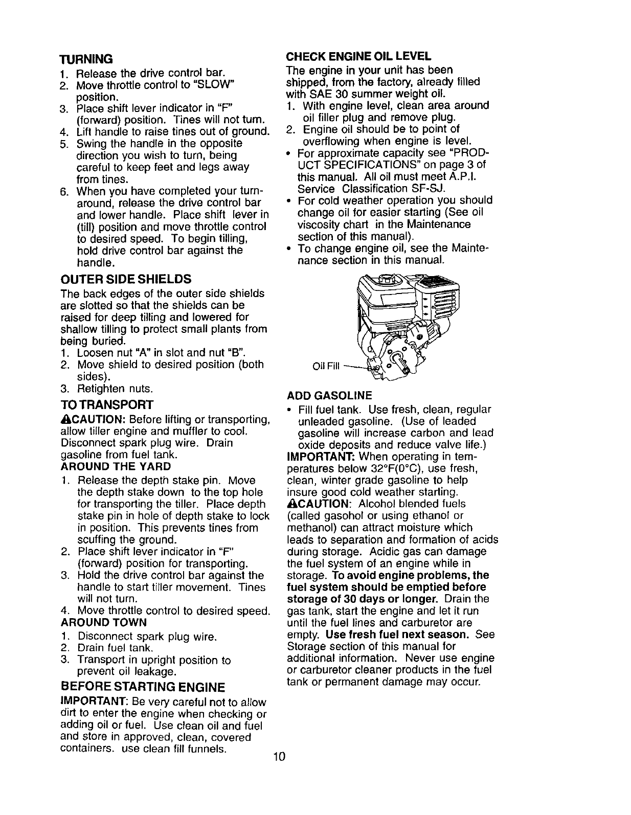
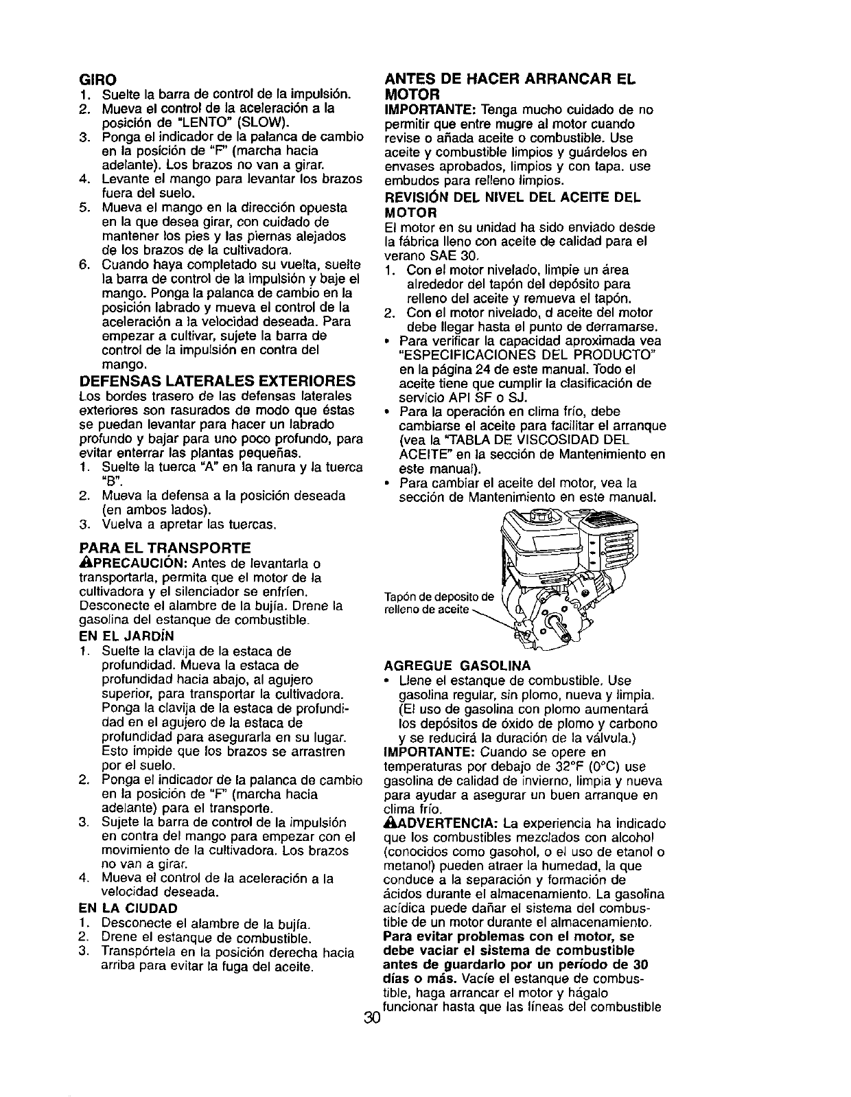
CHECK ENGINE OIL LEVEL
The engine in your unit has been
shipped, from the factory, already filled
with SAE 30 summer weight oil.
1. With engine level, clean area around
oil filler plug and remove plug.
2. Engine oil should be to point of
overflowing when engine is level.
•For approximate capacity see "PROD-
UCT SPECIFICATIONS" on page 3 of
this manual, All oil must meet A.P.I.
Service Classification SF-SJ.
•For cold weather operation you should
change oil for easier starting (See oil
viscosity chart in the Maintenance
section of this manual).
•To change engine oil, see the Mainte-
nance section in this manual.
Oil Fill
ADD GASOLINE
• Fill fuel tank. Use fresh, clean, regular
unleaded gasoline. (Use of leaded
gasoline will increase carbon and lead
oxide deposits and reduce valve life.)
IMPORTANT: When operating in tem-
peratures below 32°F(0°C), use fresh,
clean, winter grade gasoline to help
insure good cold weather starting.
_I,CAUTION: Alcohol blended fuels
(called gasohol or using ethanol or
methanol) can attract moisture which
leads to separation and formation of acids
during storage. Acidic gas can damage
the fuel system of an engine while in
storage. To avoid engine problems, the
fuel system should be emptied before
storage of 30 days or longer. Drain the
gas tank, start the engine and let it run
until the fuel lines and carburetor are
empty. Use fresh fuel next season. See
Storage section of this manual for
additional information. Never use engine
or carburetor cleaner products in the fuel
tank or permanent damage may occur.
_I,CAUTION: Fill to within 1/2 inch of top
ol fuel tank to prevent spills and to allow
for fuel expansion. If gasoline is acciden-
tally spilled, move machine away from
area ot spill. Avoid creating any source of
ignition until gasoline vapors have
disappeared.
Do not overfill. Wipe off any spilled oil or
fuel. Do not store, spill or use gasoline
near an open flame.
TO START ENGINE
_kCAUTION: Keep drive control bar in
"DISENGAGED" position when starting
engine.
When starting engine for the first time or if
engine has run out of fuel, it will take
extra pulls of the recoil starter to move
fuel from the tank to the engine.
I. Make sure spark plug wire is properly
connected.
2. Move shift lever indicator to "N"
(neutral) position.
3. Place throttle control in "FAST"
position.
4. Turn fuel shut-off valve 1/4 turn to
open position.
5. Move choke control to choke position.
6. Grasp recoil starter handle with one
hand and grasp tiller handle with
other hand. Pull rope out slowly until
engine reaches start of compression
cycle (rope will pull slightly harder at
this point).
7. Pull recoil starter handle quickly. Do
not let starter handle snap back
against starter.
NOTE: If engine fires but does not start,
move choke control to half choke position.
Pull recoil starter handle until engine
starts.
8. When engine starts, slowly move
choke control to "RUN" position as
engine warms up.
NOTE: A warm engine requires less
choking to start.
9. Move throttle control to desired
running position.
10.Allow engine to warm up for a few
minutes before engaging tines.
NOTE: If at a high altitude (3000 feet) or
in cold temperatures (below 32°F), the
carburetor fuel mixture may need to be
adjusted for best engine performance.
See "TO ADJUST CARBURETOR" in the
Service and Adjustments section of this
manual.
NOTE: If engine does not start, see
troubleshooting points.
11
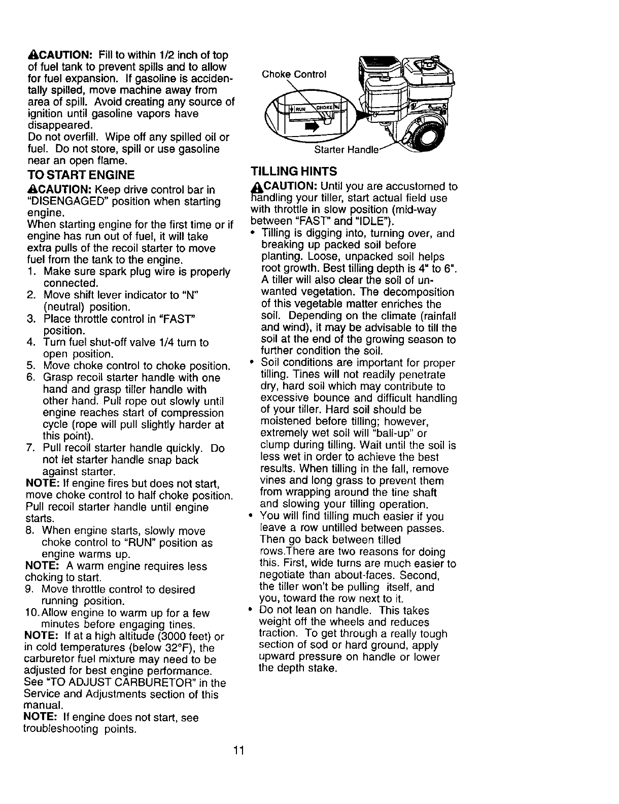
Choke Control
TILLING HINTS
_aaCAUTION: Until you are accustomed to
ndling your tiller, start actual field use
with throttle in slow position (mid-way
between "FAST" and "IDLE").
• Tilling is digging into, turning over, and
breaking up packed soil before
planting. Loose, unpacked soil helps
root growth. Best tilling depth is 4" to 6".
A tiller will also clear the soil of un-
wanted vegetation. The decomposition
of this vegetable matter enriches the
soil. Depending on the climate (rainfall
and wind), it may be advisable to till the
soil at the end of the growing season to
further condition the soil.
•Soil conditions are important for proper
tilling. Tines will not readily penetrate
dry, hard soil which may contribute to
excessive bounce and difficult handling
of your tiller. Hard soil should be
moistened before tilling; however,
extremely wet soil will "ball-up" or
clump during tilling. Wait until the soil is
less wet in order to achieve the best
results. When tilling in the fall, remove
vines and long grass to prevent them
from wrapping around the tine shaft
and slowing your tilling operation.
• You will find tilling much easier if you
leave a row untilled between passes.
Then go back between tilled
rows.There are two reasons for doing
this. First, wide turns are much easier to
negotiate than about-faces. Second,
the tiller won't be pulling itself, and
you, toward the row next to it.
• Do not lean on handle. This takes
weight off the wheels and reduces
traction. To get through a really tough
section of sod or hard ground, apply
upward pressure on handle or lower
the depth stake.
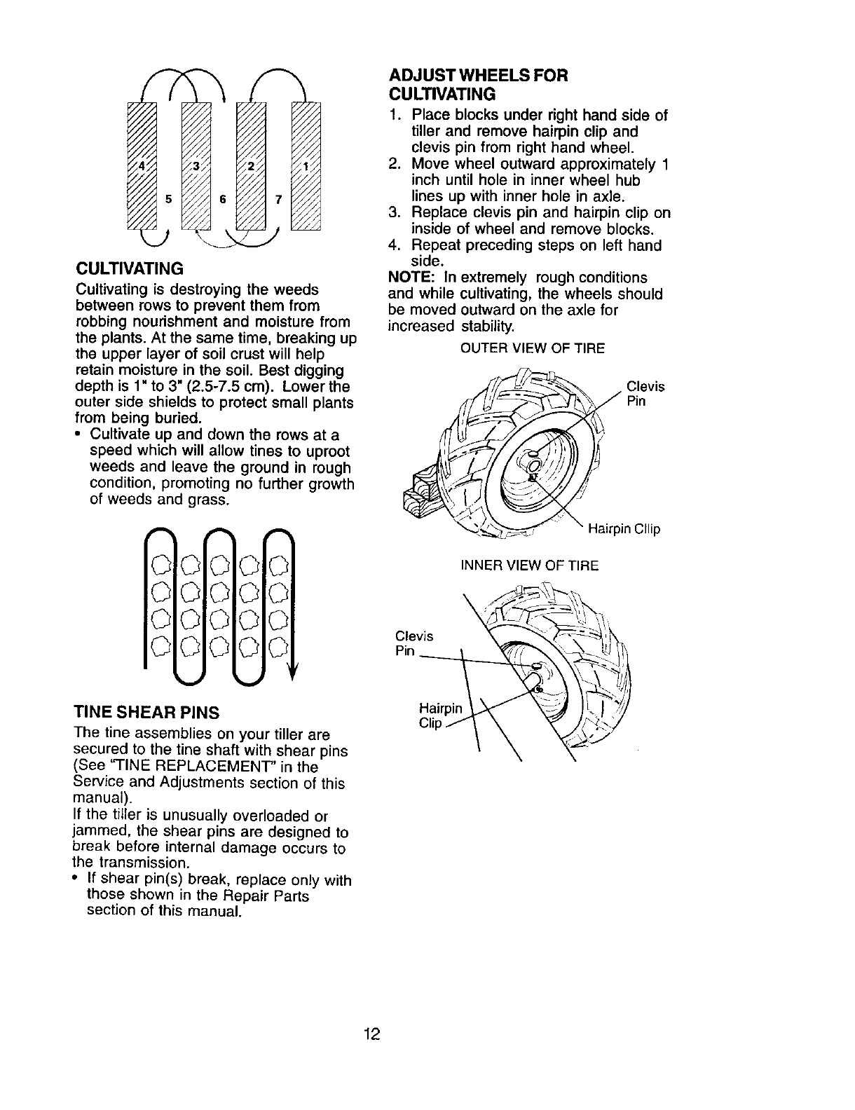
CULTIVATING
Cultivating is destroying the weeds
between rows to prevent them from
robbing nourishment and moisture from
the plants. At the same time, breaking up
the upper layer of soil crust will help
retain moisture in the soil. Best digging
depth is 1" to 3" (2.5-7.5 cm). Lower the
outer side shields to protect small plants
from being buried.
•Cultivate up and down the rows at a
speed which will allow tines to uproot
weeds and leave the ground in rough
condition, promoting no further growth
of weeds and grass.
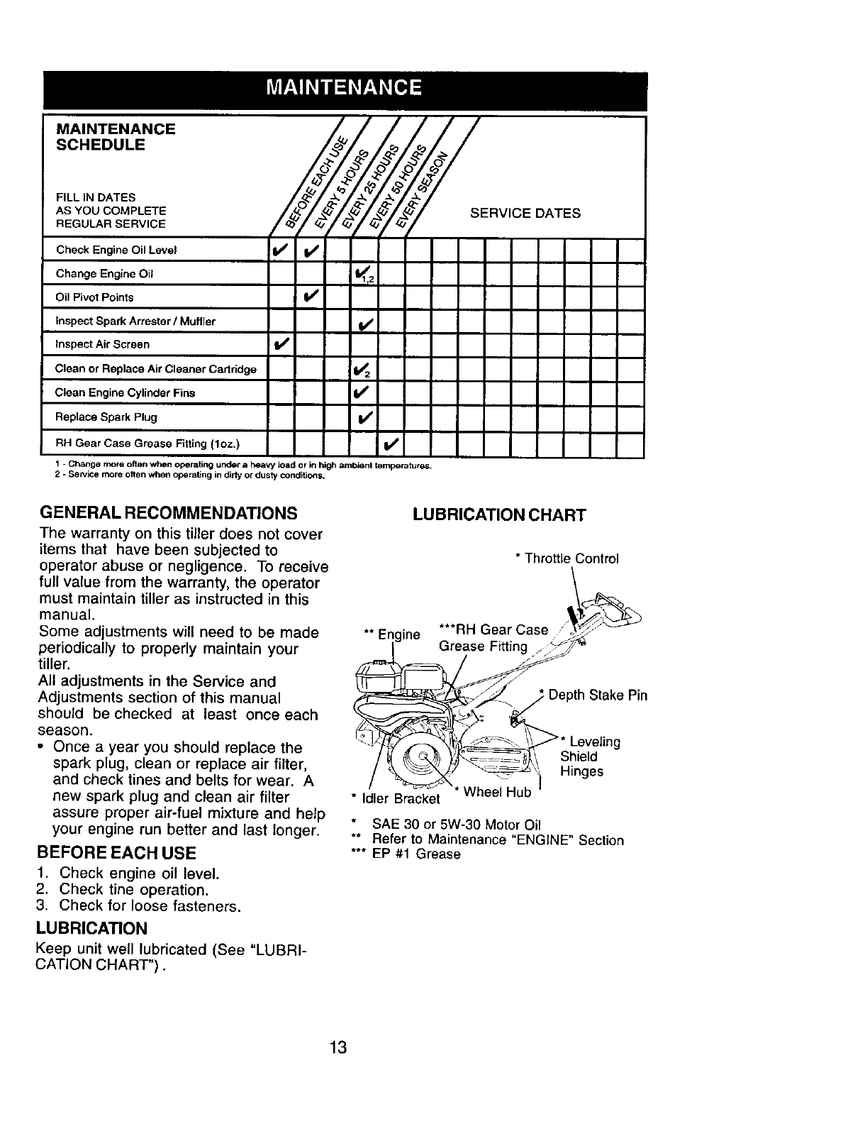
ADJUST WHEELS FOR
CULTIVATING
1. Place blocks under right hand side of
tiller and remove hairpin clip and
clevis pin from right hand wheel.
2. Move wheel outward approximately 1
inch until hole in inner wheel hub
lines up with inner hole in axle.
3. Replace clevis pin and hairpin clip on
inside of wheel and remove blocks.
4. Repeat preceding steps on left hand
side.
NOTE: In extremely rough conditions
and while cultivating, the wheels should
be moved outward on the axle for
increased stability.
OUTER VIEW OF TIRE
_/ia.rp% Clevis
Pin
in Cllip
0010 0 0
0 010 OI0
©010 OI0
©010 OI0
TINE SHEAR PINS
The tine assemblies on your tiller are
secured to the tine shaft with shear pins
(See "-FINE REPLACEMENT" in the
Service and Adjustments section of this
manual).
If the tiller is unusually overloaded or
jammed, the shear pins are designed to
break before internal damage occurs to
the transmission.
•If shear pin(s) break, replace only with
those shown in the Repair Parts
section of this manual.
INNER VIEW OF TIRE
CIe_is "_ 8_'--<Hairpin }_
Clip _ _
12
MAINTENANCE
SCHEDULE
FILL IN DATES
AS YOU COMPLETE
REGULAR SERVICE !o<V
Check Engine Oil Level !1_ If
Change Engine Oil
Oil Pivot Points I_
Inspect Spark Arrester/Muffler
Inspect Air Screen I/
Clean or Replace Air Cleaner Cadridge 1_2
Clean Engine Cylinder Fins If
Replace Spark Plug
RH Gear Case Grease Fitting (1oz.) if
1-Change more often when operating under aheavy load or in high ambient temperatures.
2 - Sen/ice more often when operating in dirty or dusty Conditions,
DATES
GENERAL RECOMMENDATIONS
The warranty on this tiller does not cover
items that have been subjected to
operator abuse or negligence. To receive
full value from the warranty, the operator
must maintain tiller as instructed in this
manual.
Some adjustments will need to be made
periodically to properly maintain your
tiller.
All adjustments in the Service and
Adjustments section of this manual
should be checked at least once each
season.
• Once a year you should replace the
spark plug, clean or replace air filter,
and check tines and belts for wear. A
new spark plug and clean air filter
assure proper air-fuel mixture and help
your engine run better and last longer.
BEFORE EACH USE
1. Check engine oil level.
2. Check tine operation.
3. Check for loose fasteners.
LUBRICATION
Keep unit well lubricated (See "LUBRI-
CATION CHART").
LUBRICATION CHART
*Throttle Control
**Engine ***RH Gear Case
Grease Fitting
Stake Pin
Shield
Hinges
* Idler Bracket * Wheel Hub
SAE 30 or 5W-30 Motor Oil
** Refer to Maintenance "ENGINE" Section
*** EP #1 Grease
13
_I, CAUTION: Disconnect spark plug wire
before performing any maintenance
(except carburetor adjustment) to prevent
accidental starting of engine.
Prevent fires! Keep the engine free of
grass, leaves, spilled oil, or fuel. Remove
fuel from tank before tipping unit for
maintenance. Clean muffler area of all
grass, dirt, and debris.
Do not touch hot muffler or cylinder fins
as contact may cause burns.
ENGINE
LUBRICATION
Use only high quality detergent oil rated
with API service classification SF-SJ.
Select the oil's SAE viscosity grade
according to your expected temperature.
$AEVISCOSITYGRADES
-20 0 30 32. 40 60 80 100
TEMPERATURERANGEANTICIPATEDBEFORENEXT OIL CHANGE
NOTE: Although multi-viscosity oils (5W-
30, 10W-30, etc.) improve starting in cold
weather, these multi-viscosity oils will
result in increased oil consumption when
used above 32°F (0°C). Check your
engine oil level more frequently to avoid
possible engine damage from running
low on oil.
Change the oil after every 25 hours of
operation or at least once a year if the
tiller is not used for 25 hours in one year.
Check the crankcase oil level before
starting the engine and after each five (5)
hours of continuous use. Add SAE 30
motor oil or equivalent. Tighten oil filler
plug securely each time you check the oil
level.
TO CHANGE ENGINE OIL
Determine temperature range expected
before oil change. All oil must meet API
service classification SF-SJ.
• Be sure tiller is on level surface.
• Oil will drain more freely when warm.
• Use a funnel to prevent oil spill on tiller,
and catch oil in a suitable container.
1. Remove drain plug.
2. Tip tiller forward to drain oil.
3. After oil has drained completely,
replace oil drain plug and tighten
securely.
4. Remove oil filler plug. Be careful not
to allow dirt to enter the engine.
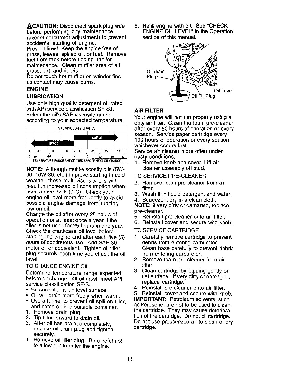
5. Refill engine with oil. See "CHECK
ENGINE OIL LEVEL" in the Operation
section of this manual.
__il Level
Oil Fill Plug
AIR FILTER
Your engine will not run properly using a
dirty air filter. Clean the foam pre-cleaner
after every 50 hours of operation or every
season. Service paper cartridge every
100 hours of operation or every season,
whichever occurs first.
Service air cleaner more often under
dusty conditions.
1. Remove knob and cover. Lift air
cleaner assembly off stud.
TO SERVICE PRE-CLEANER
2. Remove foam pre-cleaner from air
filter.
3. Wash it in liquid detergent and water.
4. Squeeze it dry in a clean cloth.
NOTE: If very dirty or damaged, replace
pre-cleaner.
5. Reinstall pre-cleaner onto air filter.
6. Reinstall cover and secure with knob.
TO SERVICE CARTRIDGE
1. Carefully remove cartridge to prevent
debris from entering carburetor.
Clean base carefully to prevent debris
from entering carburetor.
2. Remove foam pre-cleaner from air
filter.
3. Clean cartridge by tapping gently on
flat surface. If very dirty or damaged,
replace cartridge.
4. Reinstall pre-cleaner onto air filter.
5. Reinstall cover and secure with knob.
IMPORTANT: Petroleum solvents, such
as kerosene, are not to be used to clean
the cartridge. They may cause deteriora-
tion of the cartridge. Do not oil cartridge.
Do not use pressurized air to clean or dry
cartridge.
14
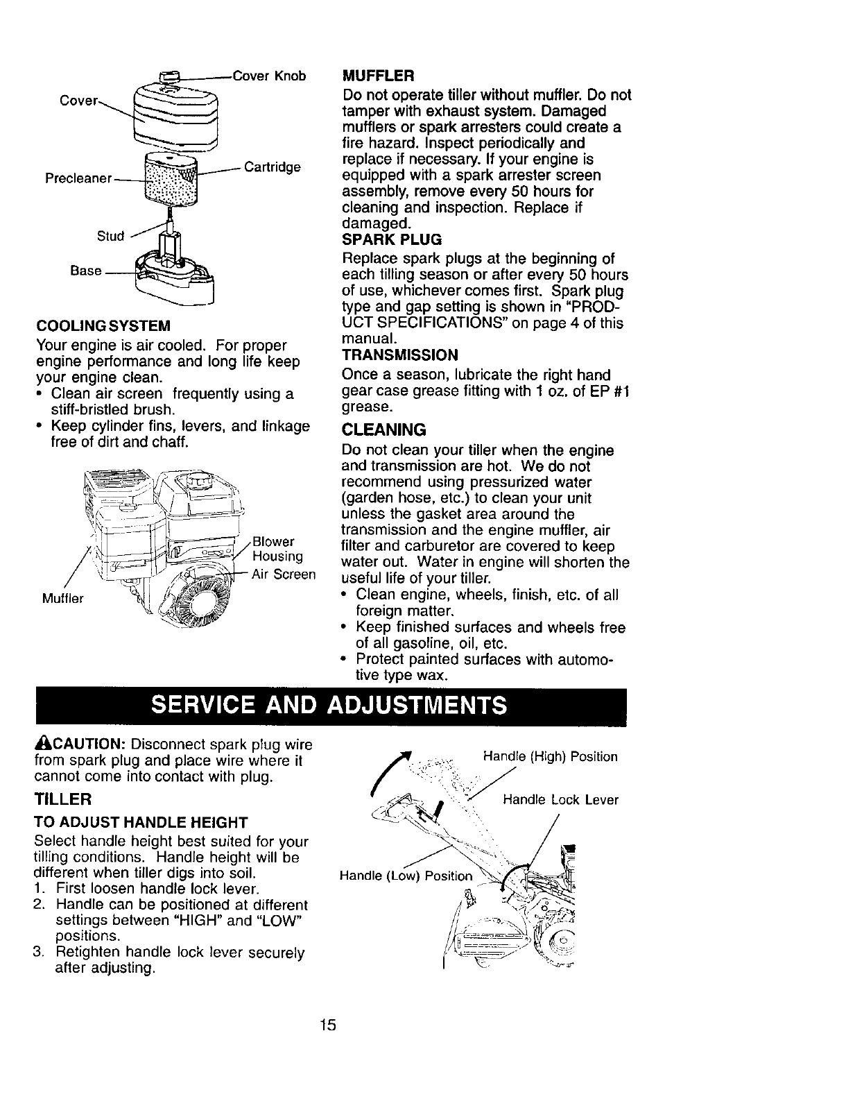
stu.jL
Base
COOLING SYSTEM
Your engine is air cooled. For proper
engine performance and long life keep
your engine clean.
• Clean air screen frequently using a
stiff-bristled brush.
• Keep cylinder fins, levers, and linkage
free of dirt and chaff.
,Blower
Housing
Muffler
MUFFLER
Do not operate tiller without muffler. Do not
tamper with exhaust system. Damaged
mufflers or spark arresters could create a
fire hazard. Inspect periodically and
replace if necessary. If your engine is
equipped with a spark arrester screen
assembly, remove every 50 hours for
cleaning and inspection. Replace if
damaged.
SPARK PLUG
Replace spark plugs at the beginning of
each tilling season or after every 50 hours
of use, whichever comes first. Spark plug
type and gap setting is shown in "PROD-
UCT SPECIFICATIONS" on page 4 of this
manual.
TRANSMISSION
Once a season, lubricate the right hand
gear case grease fitting with 1 oz. of EP #1
grease.
CLEANING
Do not clean your tiller when the engine
and transmission are hot. We do not
recommend using pressurized water
(garden hose, etc.) to clean your unit
unless the gasket area around the
transmission and the engine muffler, air
filter and carburetor are covered to keep
water out. Water in engine will shorten the
useful life of your tiller.
•Clean engine, wheels, finish, etc. of all
foreign matter.
• Keep finished surfaces and wheels free
of all gasoline, oil, etc.
•Protect painted surfaces with automo-
tive type wax.
_CAUTION: Disconnect spark plug wire
from spark plug and place wire where it
cannot come into contact with plug.
TILLER
TO ADJUST HANDLE HEIGHT
Select handle height best suited for your
tilling conditions. Handle height will be
different when tiller digs into soil.
1. First loosen handle lock lever.
2. Handle can be positioned at different
settings between "HIGH" and "LOW"
positions.
3 Retighten handle lock lever securely
after adjusting.
;,_ Handle (High) Position
-- :"':i'i_:;:-_Handle Lock Lever
Handle (Low) Position
j
15
TIRE CARE
• I,CAUTION: When mounting tires, unless
beads are seated, overinflation can
cause an explosion.
• Maintain 20 pounds of tire pressure. If
tire pressures are not equal, tiller will
pull to one side.
•Keep tires free of gasoline or oil which
can damage rubber.
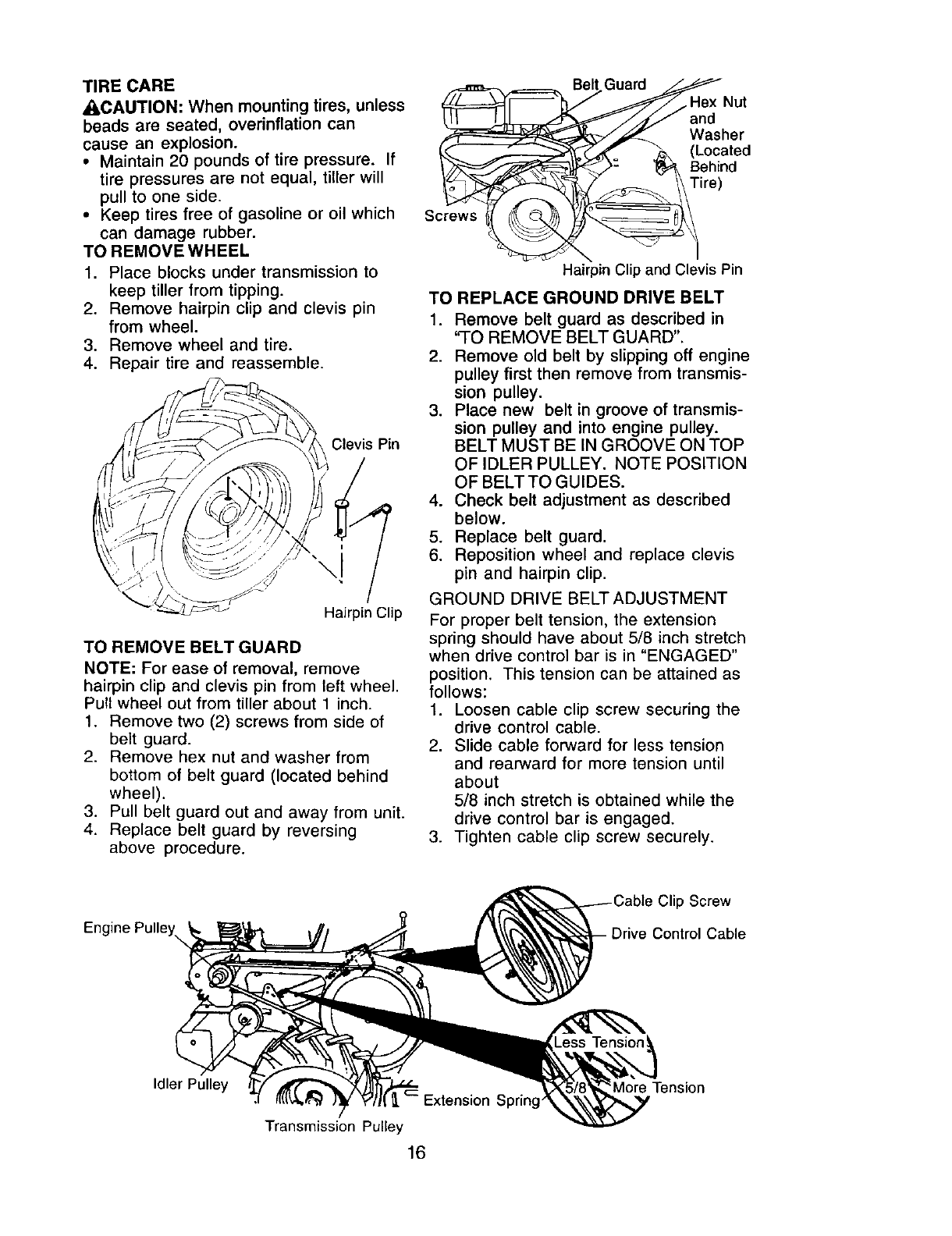
TO REMOVE WHEEL
1. Place blocks under transmission to
keep tiller from tipping.
2. Remove hairpin clip and clevis pin
from wheel.
3. Remove wheel and tire.
4. Repair tire and reassemble.
i-" j
Clevis Pin
Hairpin Clip
TO REMOVE BELT GUARD
NOTE: For ease of removal, remove
hairpin clip and clevis pin from left wheel.
Pull wheel out from tiller about 1 inch.
1. Remove two (2) screws from side of
belt guard.
2. Remove hex nut and washer from
bottom of belt guard (located behind
wheel).
3. Pull belt guard out and away from unit.
4. Replace belt guard by reversing
above procedure.
.,_m_._-_,,=====_ Bel Guard _j__Hex Nut
/_ Washer
L__ ,_= _ (Located
I__ )= ]_ Behind
Screws °_
Hairpin Clip and Clevis Pin
TO REPLACE GROUND DRIVE BELT
1. Remove belt guard as described in
'qO REMOVE BELT GUARD".
2. Remove old belt by slipping off engine
pulley first then remove from transmis-
sion pulley.
3. Place new belt in groove of transmis-
sion pulley and into engine pulley.
BELT MUST BE IN GROOVE ON TOP
OF IDLER PULLEY. NOTE POSITION
OF BELT TO GUIDES.
4. Check belt adjustment as described
below.
5. Replace belt guard.
6. Reposition wheel and replace clevis
pin and hairpin clip.
GROUND DRIVE BELTADJUSTMENT
For proper belt tension, the extension
spring should have about 5/8 inch stretch
when drive control bar is in "ENGAGED"
position. This tension can be attained as
follows:
1. Loosen cable clip screw securing the
drive control cable.
2. Slide cable forward for less tension
and rearward for more tension until
about
5/8 inch stretch is obtained while the
drive control bar is engaged.
3. Tighten cable clip screw securely.
Engine Pulley
ipScrew
Drive Control Cable
Less Tension!
Idler Pulley Extension Spring
Transmission Pulley
16
More Tension
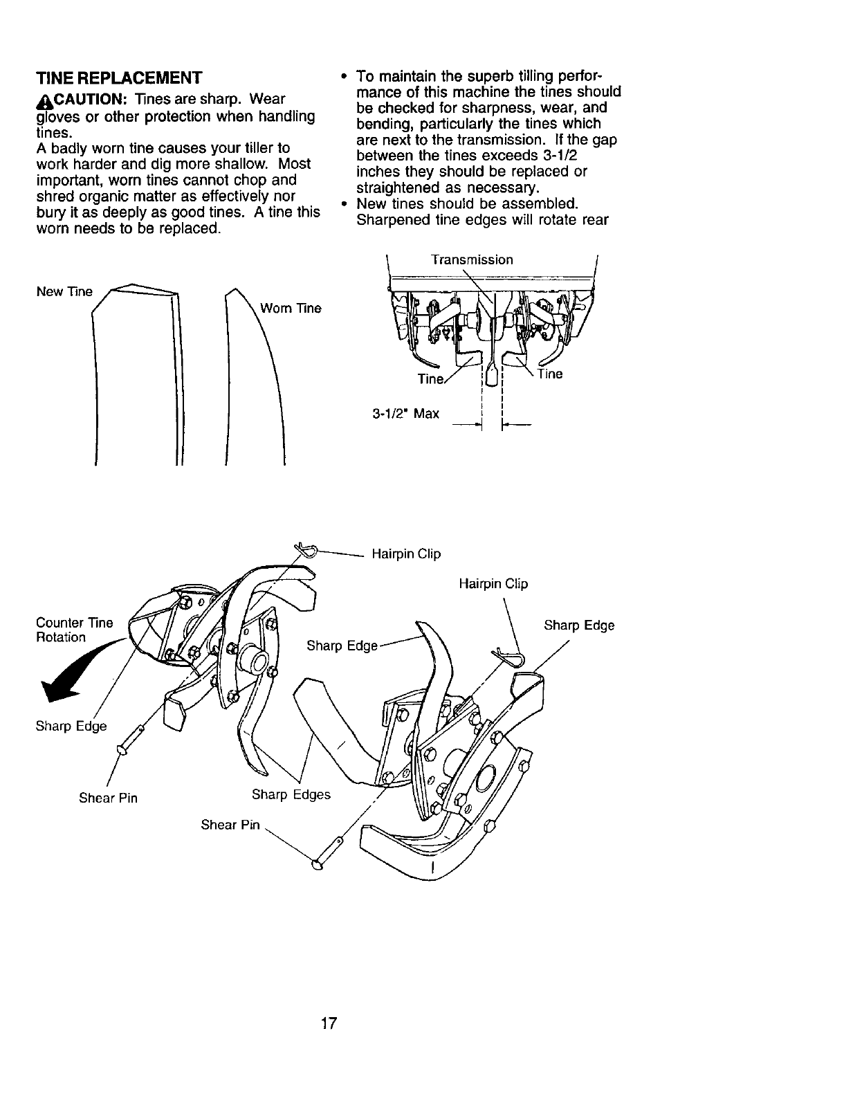
TINE REPLACEMENT
_I_CAUTION: Tines are sharp. Wear
gloves or other protection when handling
tines.
A badly worn tine causes your tiller to
work harder and dig more shallow. Most
important, worn tines cannot chop and
shred organic matter as effectively nor
bury it as deeply as good tines. A tine this
worn needs to be replaced.
New "13ne
m"Fine
•To maintain the superb tilling perfor-
mance of this machine the tines should
be checked for sharpness, wear, and
bending, particularly the tines which
are next to the transmission. If the gap
between the tines exceeds 3-1/2
inches they should be replaced or
straightened as necessary.
• New tines should be assembled.
Sharpened tine edges will rotate rear
issi_
Ti_ ._- '_ _Tine
Iine/ r I
I
i i
3-1/2" Max
Hairpin Clip
Hairpin Clip
Counter Tine
Rotation Sharp Edge
Sharp Edge
Shear Pin Sharp Edges
Shear Pin
17
ENGINE
Maintenance, repair, or replacement of
the emission control devices and sys-
tems, which are being done at the
customers expense, may be performed
by any non-road engine repair establish-
ment or individual. Warranty repairs must
be performed by an authorized engine
manufacturer's service outlet.
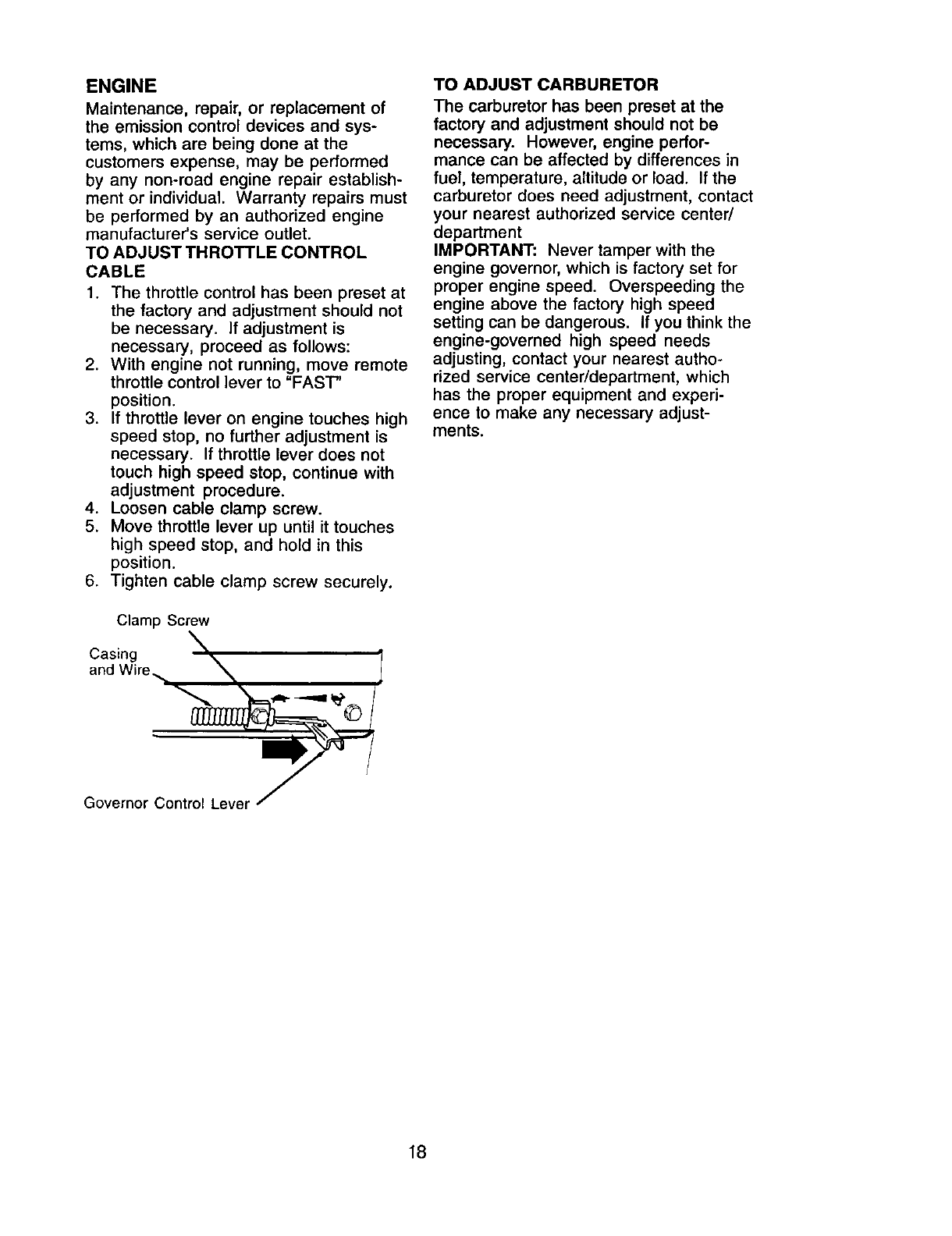
TO ADJUST THROTTLE CONTROL
CABLE
1. The throttle control has been preset at
the factory and adjustment should not
be necessary, if adjustment is
necessary, proceed as follows:
2. With engine not running, move remote
throttle control lever to "FAST"
position.
3. If throttle lever on engine touches high
speed stop, no further adjustment is
necessary. If throttle lever does not
touch high speed stop, continue with
adjustment procedure.
4. Loosen cable clamp screw.
5. Move throttle lever up until it touches
high speed stop, and hold in this
position.
6. Tighten cable clamp screw securely.
Clamp Screw
Casing
and Win
TO ADJUST CARBURETOR
The carburetor has been preset at the
factory and adjustment should not be
necessary. However, engine perfor-
mance can be affected by differences in
fuel, temperature, altitude or load. If the
carburetor does need adjustment, contact
your nearest authorized service center/
department
IMPORTANT: Never tamper with the
engine governor, which is factory set for
proper engine speed. Overspeeding the
engine above the factory high speed
setting can be dangerous. If you think the
engine-governed high speed needs
adjusting, contact your nearest autho-
rized service center/department, which
has the proper equipment and experi-
ence to make any necessary adjust-
ments.
Governor Control Leve_
18
Immediately prepare your tiller for storage
at the end of the season or if the unit will
not be used for 30 days or more.
A, CAUTION: Never store the tiller with
gasoline in the tank inside a building
where fumes may reach an open flame or
spark. Allow the engine to cool before
storing in any enclosure.
TILLER
1. Clean entire tiller (See "CLEANING" in
the Maintenance section of this
manual).
2. Inspect and replace belts, if necessary
(See belt replacement instructions in
the Service and Adjustments section
of this manual).
3. Lubricate as shown in the Mainte-
nance section of this manual.
4. Be sure that all nuts, bolts and screws
are securely fastened. Inspect moving
parts for damage, breakage and wear.
Replace if necessary.
5. Touch up all rusted or chipped paint
surfaces; sand lightly before painting.
ENGINE
FUEL SYSTEM
IMPORTANT: It is important to prevent
gum deposits from forming in essential
fuel system parts such as the carburetor,
fuel filter, fuel hose, or tank during
storage. Also, alcohol blended fuels
(called gasobol or using ethanol or
methanol) can attract moisture which
leads to separation and formation of
acids during storage. Acidic gas can
damage the fuel system of an engine
while in storage.
1. Drain the fuel tank.
2. Start the engine and let it run until the
fuel lines and carburetor are empty.
•Never use engine or carburetor cleaner
products in the fuel tank or permanent
damage may occur.
•Use fresh fuel next season.
NOTE: Fuel stabilizer is an acceptable
alternative in minimizing the formation of
fuel gum deposits during storage. Add
stabilizer to gasoline in fuel tank or
storage container. Always follow the mix
ratio found on stabilizer container. Run
engine at least 10 minutes after adding
stabilizer to allow the stabilizer to reach
the carburetor. Do not drain the gas tank
and carburetor if using fuel stabilizer.
ENGINE OIL
Drain oil (with engine warm) and replace
with clean oil. (See "ENGINE" in the
Maintenance section of this manual).
CYLINDER
1. Remove spark plug.
2. Pour 1 ounce (29 ml) of oil through
spark plug hole into cylinder.
3. Pull starter handle slowly several
times to distribute oil.
4. Replace with new spark plug.
OTHER
•Do not store gasoline from one season
to another.
•Replace your gasoline can if your can
starts to rust. Rust and/or dirt in your
gasoline will cause problems.
• If possible, store your unit indoors and
cover it to give protection from dust and
dirt.
• Cover your unit with a suitable protec-
tive cover that does not retain moisture.
Do not use plastic. Plastic cannot
breathe which allows condensation to
form and will cause your unit to rust.
IMPORTANT: Never cover tiller while
engine and exhaust areas are still warm.
19
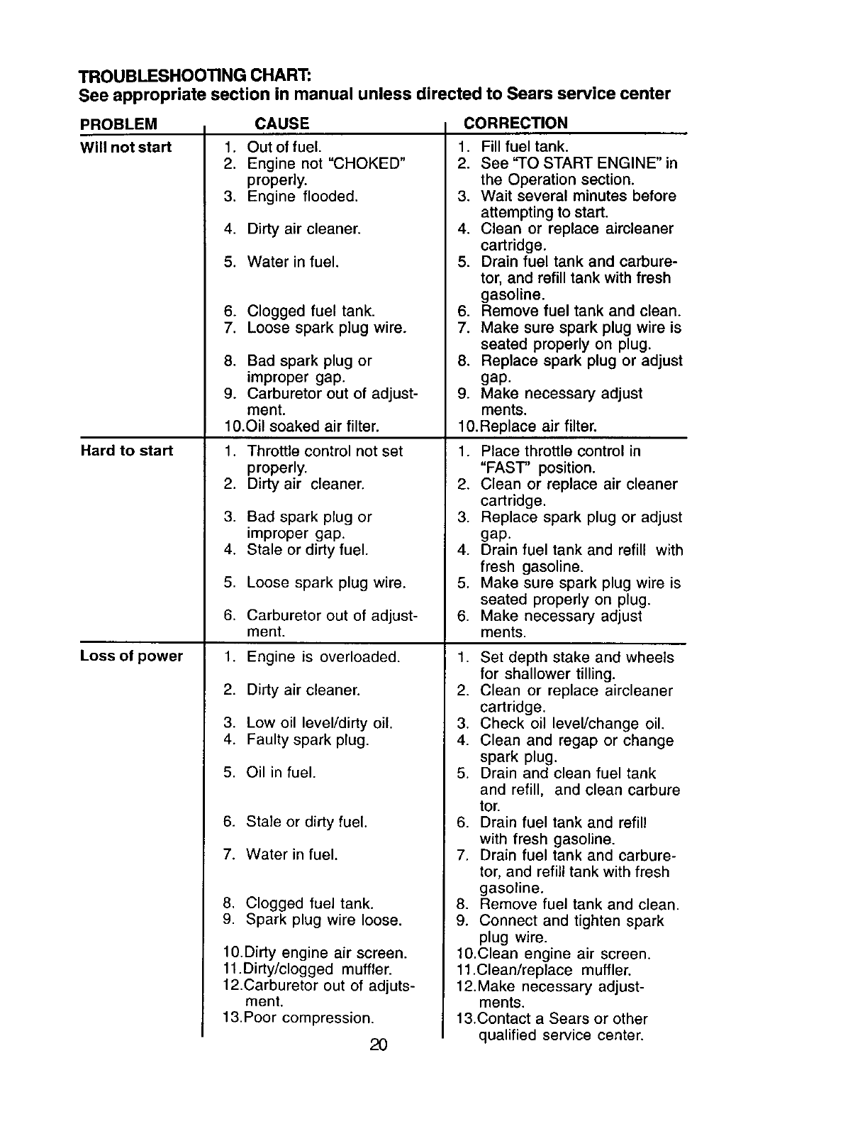
TROUBLESHOOTING CHART:
See appropriate section in manual unless directed to Sears service center
PROBLEM CAUSE
Will not start
Hard to start
Loss of power
1. Out of fuel.
2. Engine not "CHOKED"
properly.
3. Engine flooded.
4. Dirty air cleaner.
5. Water in fuel.
6. Clogged fuel tank.
7. Loose spark plug wire,
8. Bad spark plug or
improper gap.
9. Carburetor out of adjust-
ment.
CORRECTION
1. Fill fuel tank.
2. See "TO START ENGINE" in
the Operation section.
3. Wait several minutes before
attempting to start.
4. Clean or replace aircleaner
cartridge.
5. Drain fuel tank and carbure-
tor, and refill tank with fresh
gasoline.
6. Remove fuel tank and clean.
7. Make sure spark plug wire is
seated properly on plug.
8. Replace spark plug or adjust
gap.
9. Make necessary adjust
ments.
10.Oil soaked air filter.
1. Throttle control not set
properly.
2. Dirty air cleaner,
3. Bad spark plug or
improper gap.
4. Stale or dirty fuel.
5. Loose spark plug wire.
6. Carburetor out of adjust-
ment.
1. Engine is overloaded.
2. Dirty air cleaner.
3. Low oil level/dirty oil.
4. Faulty spark plug.
5. Oil in fuel.
6. Stale or dirty fuel.
7. Water in fuel.
8. Clogged fuel tank.
9. Spark plug wire loose.
10.Dirty engine air screen.
11.Dirty/clogged muffler.
12.Carburetor out of adjuts-
ment.
13. Poor compression.
20
10.Replace air filter.
1. Place throttle control in
"FAST' position.
2. Clean or replace air cleaner
cartridge.
3. Replace spark plug or adjust
gap.
4. Drain fuel tank and refill with
fresh gasoline,
5. Make sure spark plug wire is
seated properly on plug.
6. Make necessary adjust
ments.
1. Set depth stake and wheels
for shallower tilling.
2. Clean or replace aircleaner
cartridge,
3. Check oil level/change oil.
4. Clean and regap or change
spark plug.
5. Drain and clean fuel tank
and refill, and clean carbure
tot.
6. Drain fuel tank and refill
with fresh gasoline.
7. Drain fuel tank and carbure-
tor, and refill tank with fresh
gasoline.
8. Remove fuel tank and clean.
9. Connect and tighten spark
plug wire.
10.Clean engine air screen.
11.Clean/replace muffler.
12.Make necessary adjust-
ments.
13.Contact a Sears or other
qualified service center.
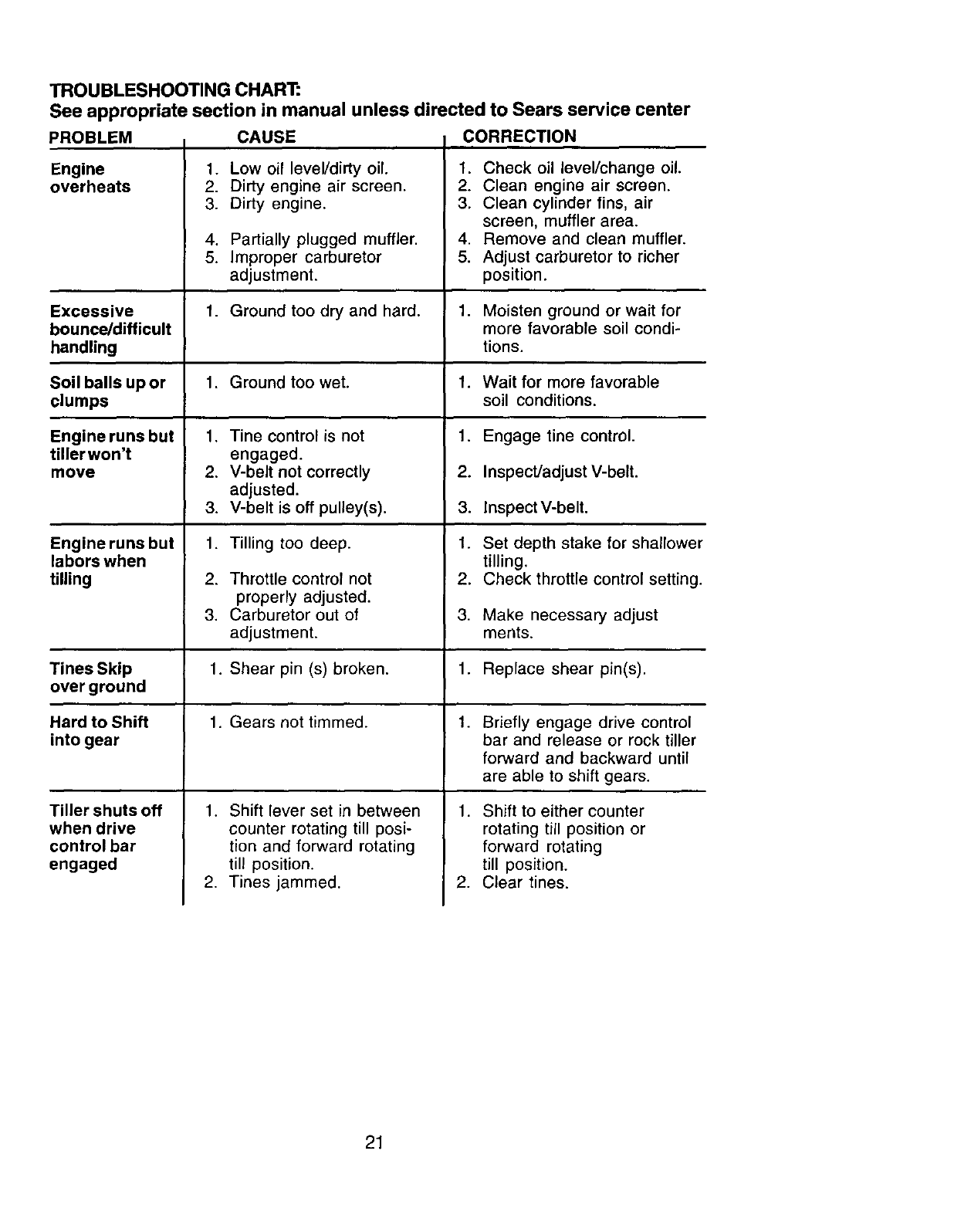
TROUBLESHOOTING CHART:
See appropriate section in manual unless directed to Sears service center
PROBLEM CAUSE CORRECTION
Engine
overheats 1. Low oil leveVdirty oil.
2. Dirty engine air screen.
3. Dirty engine.
4. Partially plugged muffler.
5. Improper carburetor
adjustment.
1. Check oil level/change oil.
2. Clean engine air screen.
3. Clean cylinder fins, air
screen, muffler area.
4. Remove and clean muffler.
5. Adjust carburetor to richer
position.
Excessive 1. Ground too dry and hard. 1. Moisten ground or wait for
bounce/difficult more favorable soil condi-
handling tions.
Soil balls up or 1. Ground too wet. 1. Wait for more favorable
clumps soil conditions.
Engine runs but 1. Tine control is not Engage tine control.
tiller won't engaged.
move 2. V-belt not correctly InspecVadjust V-belt.
adjusted.
3. V-belt is off pulley(s), lnspectV-belt.
1. Tilling too deep.
2. Throttle control not
properly adjusted.
3. Carburetor out of
adjustment.
.
2.
3.
1.
2.
3.
Engine runs but
labors when
tilling
Set depth stake for shallower
tilling.
Check throttle control setting.
Make necessary adjust
merits.
Tines Skip 1. Shear pin (s) broken. 1. Replace shear pin(s).
over ground
Hard to Shift 1. Gears not timmed. 1. Briefly engage drive control
into gear bar and release or rock tiller
forward and backward until
are able to shift gears.
1.
.
1. Shift lever set in between
counter rotating till posi-
tion and forward rotating
till position.
2. Tines jammed.
Tiller shuts off
when drive
control bar
engaged
Shift to either counter
rotating till position or
forward rotating
till position.
Clear tines.
21
Reglas de Seguddad ................................... 22
Garantfa ...................................................... 22
Especificaciones del producto .................... 24
Montaje ........................................................ 25
Operacibn .................................................... 28
Mantenimiento ............................................. 33
Programa de Mantenimiento ....................... 33
Servicio y Ajustes ...................................... 35
Almacenamiento .......................................... 39
IdentificaciSnde Problemas ........................ 40
Yea el Manual Ingl4s ........... Ingles del Duefio
GARANTIA LIMITADA DE DOS AI_IOS PARA LA CULTIVADORA CRAFTSMAN
Per dos (2) aries, a partir de la fecha de compra, cuando esta Cultivadora Craftsman se
mantenga, lubrique y afine segL_nlas instrucciones para la operacibn y el mantenimiento en el
manual del duefio, Sears reparar_, gratis, todo defecto en el material y la mane de obra.
Esta Garantia no cubre:
•Art(culos que se desgastan durante el use normal tales come los brazes, las bujias, los filtros
de aire y las correas,
•Reparaciones necesadas debido al abuse o a la negligencia del operador, incluy_ndose a los
cig_3ehales doblados y a la falta de mantenimiento del equipo segL_n las instrucciones que se
incluyen en el manual del duefio.
• Si la Cultivadora Craftsman se usa para fines de arriendo, esta garantfa se aplica solamente
per treinta (30) treintadfas a partir de la fecha de compra.
El Sewicio de Garantia esta disponible al devolver la cultivadora Craftsman al centre/
departamento de servicio Sears m&s cercano en los estados unidos.
Esta Garantfa se aplica solamente mientras el producto este en use en los estados unidos. Esta
Garantia le otorga derechos legales especfficos, y puede que tambi_n tenga otres derechos que
varian de estado a estado.
SEARS, ROEBUCK AND CO., D/817WA, HOFFMAN ESTATES, IL 60179 U.S.A.
IMPORTANTE: Esta Maquina cortadora es capaz de amputar las manosy los pies y de lanzar
objetos, si no se observan las instrucciones de seguridad siguientes se pueden producir
lesiones graves ola muerte.
ENTRENAMIENTO
• Lea el Manual del Duefio cuidadosamente.
Familiaficese completamente con los
controles y con el use adecuado del equipo.
Sepa cSmo parar la unidad y desenganchar
los controles r_pidamente.
• Nunca permita que los nifios operen el
equipo. Nunca permita que los adultos
operen el equipo sin los conocimientos
adecuados.
• Mantenga et &rea de operaci6n despejada
de personas, especialmente nJ_os
pequeSos y animates domesticos.
PREPARACII_N
• Inspeccione cuidadosamente el area en
donde se va usar el equipo y remueva los
objetos extrai_os.
• Desenganche todos los embragues y
cambie a neutro antes de hacer arrancar el
motor.
• No opere el equipo sin usar ropa exterior
adecuada. Use zapatos que mejoren el
equilibrio en superficies resbalosas.
• Maneje el combustible con cuidado pues es
• Use un envase de combustible aprobado.
• Nunca afiada combustible a un motor en
funcionamiento o caliente.
• Llene el estanque de combustible afuera
con mucho cuidado. Nunca Ilene el
estanque de combustible en un recinto
cerrado.
• Vuelva a colocar la tapa del deposito de
gasolina en forma segura y limpie el
combustible derramado antes de volver a
arrancar.
• Use cordones de extensi6n y recept&culos,
segt_n las especificaciones del fabricante,
para todas las unidades con motores de
impulsi6n o con motores de arranque
el6ctrico.
• Nunca trate de hacer ningDn ajuste
mientras que el motor est_ funcionando
(excepto en los cases especificamente
recomendados per el fabricante).
OPERACI(_N
•No ponga ni las manes ni los pies cerca o
debajo de las piezas rotatorias.
muy inflamable. 22
•Tenga mucho euidado cuando opere o
cruce entradas para autombviles de ripio,
senderos o caminos. Est_ alerta en Io que
se refiere a los peligros escondidos o al
tra.fico. No Ileve pasajeros.
• Despues de pegarle a un objeto extraSo,
pare el motor, remueva el alambre de la
bujfa, inspeccione la cultivadora
cuidadosamente, para verificar si hay
daSos, y repare el daSo antes de volver a
arrancar y operar la cultivadora.
• Tenga cuidado para evitar resbalarse o
caerse.
• Si la unidad empieza a vibrar anormalmente,
pare el motor y revfsela inmediatamente
para verificar la causa. La vibraci6n
normalmente es un aviso de probiemas.
• Pare el motor cuando abandone la posici6n
de operaci6n.
• Tome todas las precauciones posibles
cuando deje la m_quina desatendida.
Desenganche Ios brazos, cambie a neutro
y pare el motor.
•Antes de limpiar, reparar einspeccionar,
apague el motor y asegSrese que todas las
partes en movimiento se han detenido.
Desconecte el alambre de la bujia, y
mant6ngalo alejado de _sta para evitar el
arranque por accidente. Desconecte el
cord6n en los motores el_ctricos.
•No haga funcionar el motor en recintos
cerrados; los gases de escape son
peligrosos.
• Nunca opere la cu]tivadora sin las
protecciones, y las planchas adecuadas y
sin los demas dispositivos de seguridad en
su lugar.
• Mantenga a los ni_os y a los animales
domesticos alejados.
• No sobrecargue la capacidad de la
maquina, tratando de cultivar a mucha
profundidad, muy rapido.
• Nunca opere la m&quina a altas velocidades
en superficies resbalosas. Mire hacia arras
y tenga cuidado cuando retroceda.
• Nunca permita la presencia de
espectadores cerca de la unidad.
• Use solamente accesorios y aditamentos
para la cultivadora aprobados por el
fabricante.
• Nunca opere la cultivadora sin buena
visibilidad o luz.
• Tenga cuidado al cultivar en terreno duro.
Los brazos pueden quedarse agarrados en
el suelo e impulsar a la cultivadora hacia
adelante. Si esto sucede, suelte los mangos
y no restrinja la m_quina.
MANTENIMIENTO Y
ALMACENAMIENTO
•Mantenga los accesorios y aditamentos de
la m_,quina en buenas condiciones para el
funcionamiento.
•Revise las clavijas de seguro, los pernos de
montaje del motor y otros pernos, a
intervalos frecuentes, para verificar si estan
apretados en forma segura y asegurarse
que el equipo est_ en buenas condiciones
de funcionamiento.
•Nunca guarde la m&quina con combustible
en el estanque de combustible dentro de un
edificio en donde hay fuentes de ignici6n
presentes, tales como calentadores de
agua odel ambiente, secadoras de ropa u
otros artefactos parecidos. Permita que se
enfrfe el motor antes de guardado en alg_n
lugar cerrado.
•Siempre refi_rase alas instruccionesen Ta
guia del operador para ver los detalles de
importancia si la cultivadorava a ser
guardada por un periodo de tiempo largo.
ABusque este simbolo que seSala las
precauciones de seguridad de importancia.
Quiere decir - iiiATENCION!!! iiiESTE
ALERTO!!! SU SEGURIDAD ESTA COMPRO-
METIDA.
APRECAUCI(_N: Siempre desconecte el
aiambre de la bujia y pbngalo donde no pueda
entrar en contacto con la bujia, para evitar el
arranque por accidente, durante la
preparaci6n, el transporte, el ajuste o cuando
se hacen reparaciones.
4_bADMERTENClA: El tubo de escape del
motor, algunos de sus constituyentes y
algunos componentes del vehiculo contienen
o desprenden productos quimicos conocidos
en el Estado de California como causa de
c&ncer y defectos al nacimiento u otros da5os
reproductivos.
23
ESPECIFICACIONES DEL PRODUCTO
Capacidadde 3 Cuartos
gasolina: Sinplomo,regular
Aceite(API-SF-SJ): SAE30 (Sobre40°F)
(Capacidad:19 oz.) SAE5w-30SAE10w-30
(Debajo40°F)
Bujia : Champion RC12YC
(Abertura:0,030")
FELICITACIONES por la compre de su
Cultivadora Sears. Ha sido diseSada,
planificada y fabricada para darle la mejor
confiabitidad y el mejor rendimiento posibte.
En el caso de que se encuentre con cualquier
problema que no pueda solucionar facilmente,
haga el favor de ponerse en contacto con su
centro de servicio cualificado. Soars cuenta
con t_cnicos bien capacitados y competentes
con herramientas adecuadas para darle
servicio o para reparar su unidad.
Haga el favor de leer y de guardar este
manual, Estas instrucciones le permitir_n
montar y mantener su cultivadora en forma
adecuada. Siempre observe las "REGLAS DE
SEGURIDAD."
RESPONSABILIDADES DEL CLIENTE
•Lea y observe las reglas de seguridad.
•Siga un programa regular de mantenimiento,
cuidado y uso de su eultivadora.
•Siga las instrucciones descritas en las
secciones "Mantenimiento" y
"AImacenamiento" de este Manua_ del
DueSo.
_I_DMERTENCIA: Esta unidad viene
equipada con un motor de combustibn interno
y no se debe usar sobre, o cerca, de un
terreno no desarrollado cubierto de bosques,
de arbustos o de c_sped, a menos que el
sistema de escape del motor venga equipado
con un amortiguador de chispas que cumpla
con las leyes locales o estatales (si existen).
Si se usa un amortiguador de ehispas, el
operedor debe mantenerlo en condiciones de
trabajo eficientes.
En el estado de California, la ley exige Io
anterior (Seccibn 4442 del "California Public
Resources Code" [Decreto de Recursos
P_blicos de California]). Otros estados
pueden contar con otras leyes parecidas. Las
leyes federeles se aplican en las tierras
federales. Su centro de Servicio m_.s cercano
tiene disponible amortiguadores de chispas
para el silenciador. (Vea la seccibn de Partes
de Repuesto en el manual Ingl6s del dueSo.)
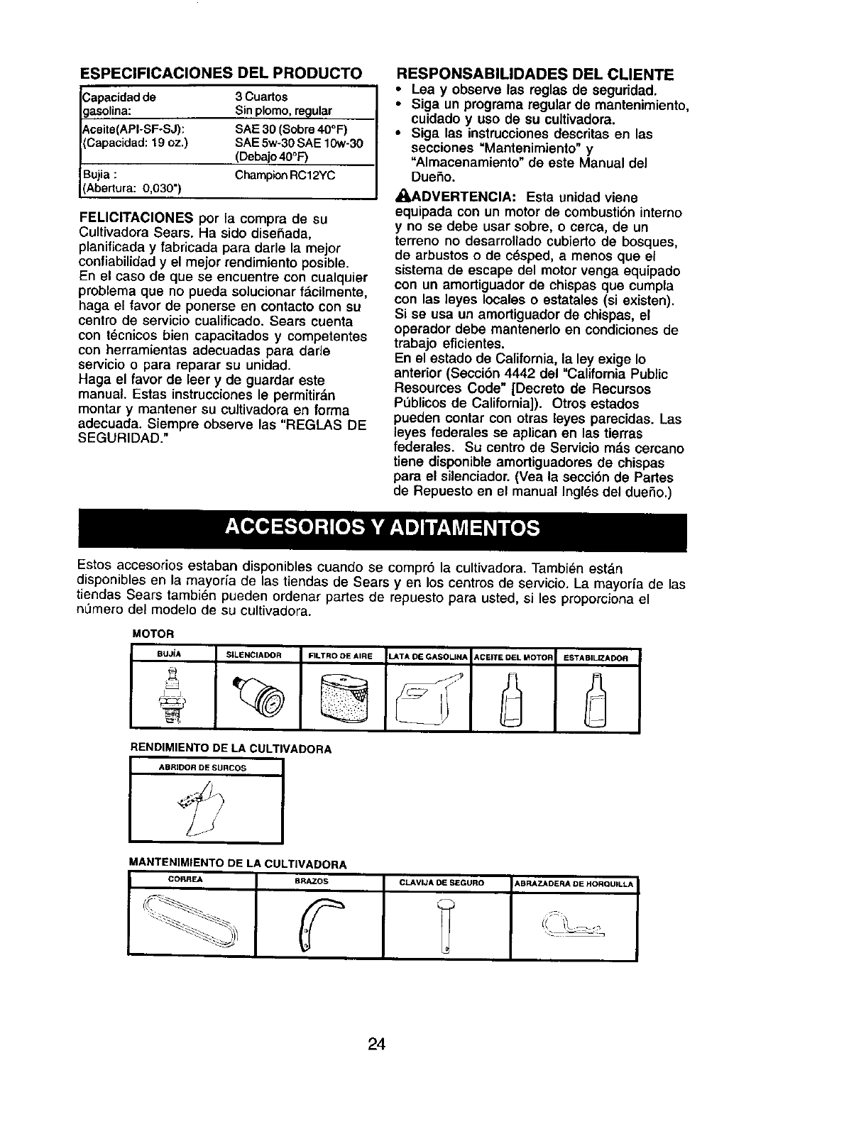
Estos accesorios estaban disponibles cuando se compr6 la cultivadora. Tambien estdn
disponibtes en ta mayoria de las tiendas de Sears yen los centros de servicio. La mayoria de tas
tiendas Sears tambi_n pueden ordenar panes de repuesto para usted, si les proporciona el
n_mero del modelo de su cultivadora.
MOTOR
BUJiA $_LENCIADOR FILTRD DE AIRE
RENDIMIENTO DE LA CULTIVADORA
ABRJDOR DE SURCOS
LATA DE GASOLINA ACEITE DEL MOTOF ESTABILIZADOR
MANTENIMIENTO DE LA CULTIVADORA
CORREA BRAZOS CLAVIJA DE SEGURO _,BRAZADERA DE HORQUDLLA
24
Su cultivadora nueva ha sido montada en la
f_.brica, con la excepci6n de aquellas partes
que se dejaron sin montar por razones de
envfo. Para asegurarse que la cultivadora
operara en forma segura y adecuada, todas
las partes y los artfculos de ferreterfa que
monte tienen que estar apretados en forma
segura. Use las herramientas correctas,
segt_n sea necesario, para asegurarse de que
queden apretadas en forma segura.
HERRAMIENTAS NECESARIAS PARA
EL MONTAJE
Se le facilitar_, el montaje si cuenta con un
juego de Ilaves de tubo. Se han enumerado los
tama_os est_.ndar de las Ilaves.
(1) Cuchillo para todo uso
(1) Cortador de alambres
(1) Destomillador
(1) Medidor de presi6n de las Ilantas
(1) Par de alicates
(1) Llave de 9/16"
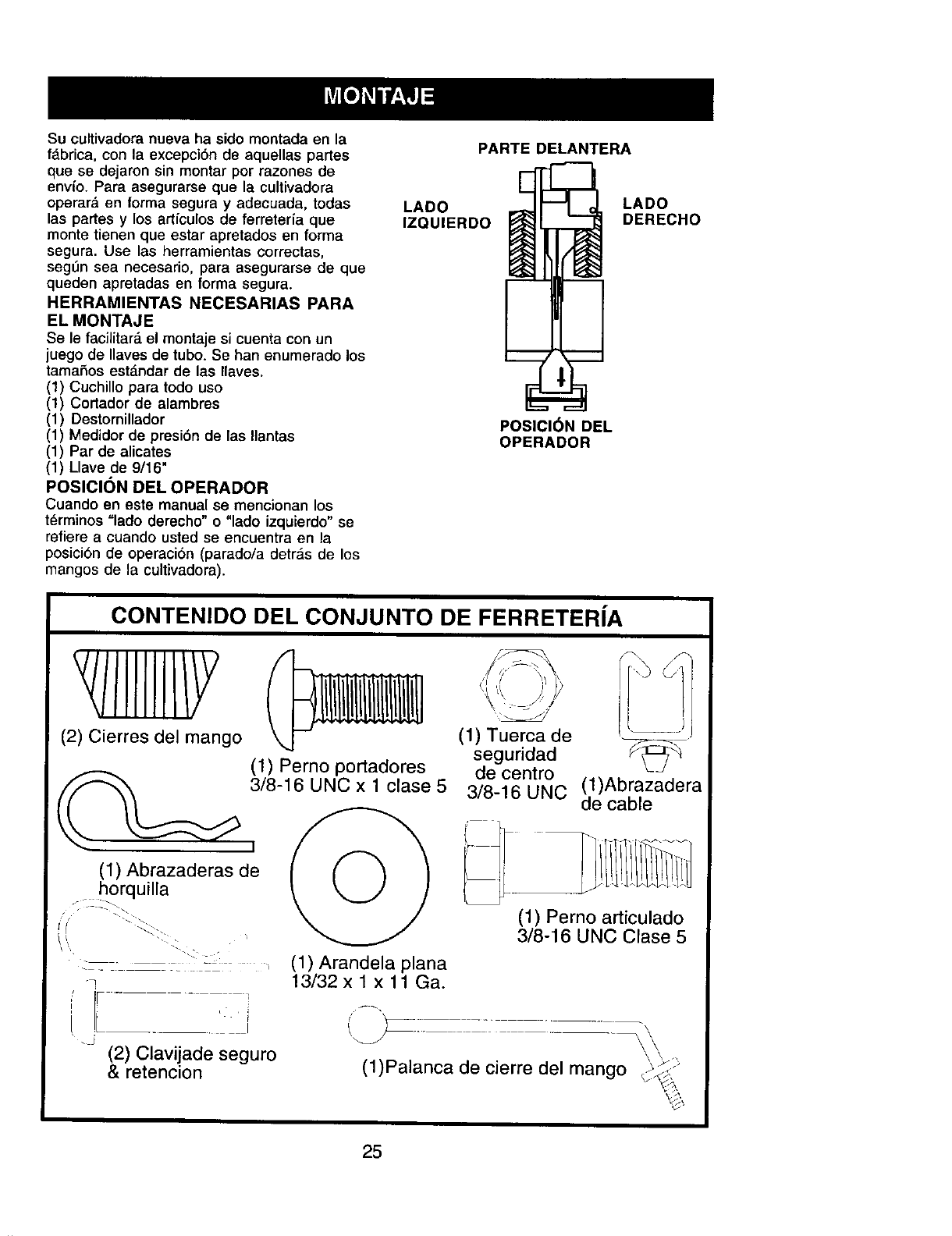
POSICION DEL OPERADOR
Cuando en este manual se mencionan los
tdrminos "lado derecho" o "lado izquierdo" se
refiere a cuando usted se encuentra en la
posici6n de operaci6n (parado/a detras de los
mangos de la cultivadora).
PARTE DELANTERA
LADO LADO
IZQUIERDO DERECHO
POSICI6N DEL
OPERADOR
CONTENIDO DEL CONJUNTO DE FERRETERIA
(2) Cierres del mango
(1) Abrazaderas de
horquilla
(1) Perno portadores
3/8-16 UNC x 1 clase 5
: - _ -:: , (1)Arandelaplana
-7 13/32 x 1 x 11 Ga.
Lt_
t.
.J (2) Clavijade seguro
& retencion
(1) Tuerca de
seguridad
de centro
3/8-16 UNC (1)Abrazadera
de cable
(1) Perno articulado
3/8-16 UNC Clase 5
(1)Palanca de cierre del mango
25
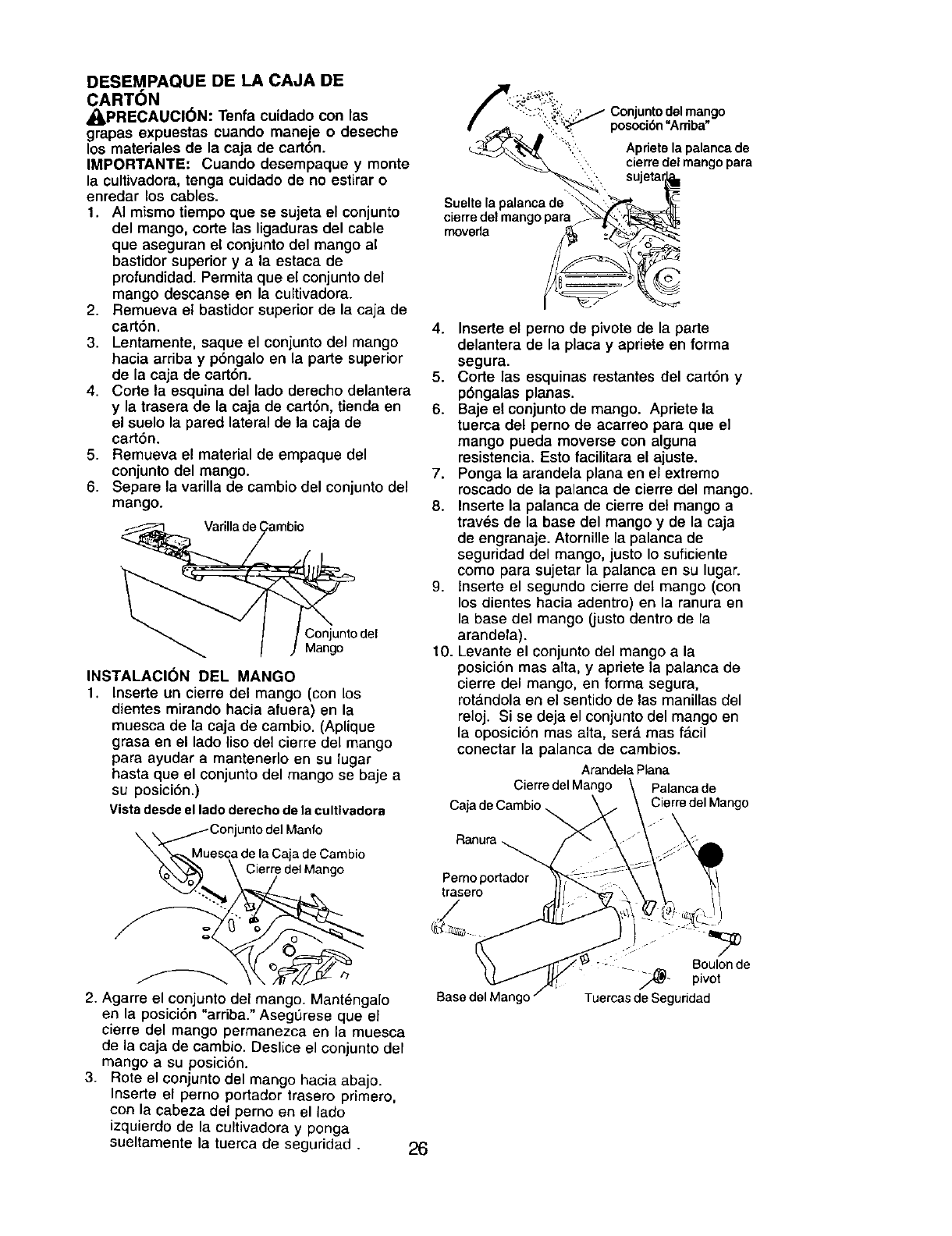
DESEMPAQUE DE LA CAJA DE
CARTON
,_PRECAUClON: Tenfa cuidado con las
grapas expuestas cuando maneje o deseche
los materiales de la caja de cart6n.
IMPORTANTE: Cuando desempaque y monte
la cultivadora, tenga cuidado de no estirar o
enredar los cables.
1. AI mismo tiempo que se sujeta el conjunto
del mango, corte las ligaduras del cable
que aseguran el conjunto del mango al
bastidor superior y a la estaca de
profundidad. Permita que el conjunto del
mango descanse en la cultivadora.
2. Remueva el bastidor superior de la caja de
cart6n.
3. Lentamente, saque el conjunto del mango
hacia arriba y p6ngalo en la parte superior
de la caja de cart6n.
4. Corte la esquina del lado derecho delantera
y la trasera de la caja de cart6n, tienda en
el suelo la pared lateral de la caja de
cart6n.
5. Remueva el material de empaque del
conjunto del mango.
6. Separe la varilla de cambio del conjunto del
mango.
Varilla de i
Conjunto del
Mango
INSTALACI(_N DEL MANGO
1. Inserte un cierre del mango (con los
dientes mirando hacia afuera) en la
muesca de la caja de cambio. (Aplique
grasa en el lado liso del cierre del mango
para ayudar a mantenerlo en su lugar
hasta que el conjunto del mango se baje a
su posici6n.)
Vistadesdeel ladoderechodela cultlvadora
Conjunto del Manfo
esca de la Caja de Cambio
_ Cierr/edelMango
2. Agarre el conjunto del mango. Mantengalo
en la posici6n "arriba." Asegt_rese que el
cierre del mango permanezca en la muesca
de la eaia de cambio. Deslice el eonjunto del
mango a su posicidn.
3. Rote el conjunto del mango hacia abajo.
Inserte el perno portador trasem primero,
con la cabeza del perno en el lado
izquierdo de la cultivadora y ponga
sueltamente la tuerca de seguridad . 26
posoci6n "Ardba"
Aprietola palancade
"_::ii_', cierredel mango para
Suelte Is palanca de
cierre del mangopars
rnoverla
4. Inserte el perno de pivote de la parte
delantera de la placa y apriete en forma
segura.
5. Corte las esquinas restantes del cart6n y
p6ngalas planas.
6. Baje el conjunto de mango. Apriete la
tuerca del perno de acarreo para que el
mango pueda moverse con alguna
resistencia. Esto facilitara el ajuste.
7. Ponga la arandela plana en el extremo
roscado de la palanca de cierre del mango.
8. Inserte la palanca de cierre det mango a
traves de la base del mango y de la caja
de engranaje. Atornille la palanca de
seguridad del mango, justo Io suficiente
como para sujetar la palanca en su lugar.
9. lnserte el segundo cierre del mango (con
los dientes hacia adentro) en la ranura en
la base del mango (justo dentro de la
arandela).
10. Levante el conjunto del mango a la
posici6n mas alta, y apriete la palanca de
cierre del mango, en forma segura,
rota.ndola en el sentido de las manillas del
reloj. Si se deja el conjunto del mango en
la oposici6n mas alta, ser_. mas f_.cil
conectar la palanca de cambios.
ArandelaPlana
CierredelMango Palancade
Caj_ CierredelMango
F_anufa
Pernoportador
trasero
Base del Mange
Boulonde
-- _- pivot
TuemasdeSeguddad
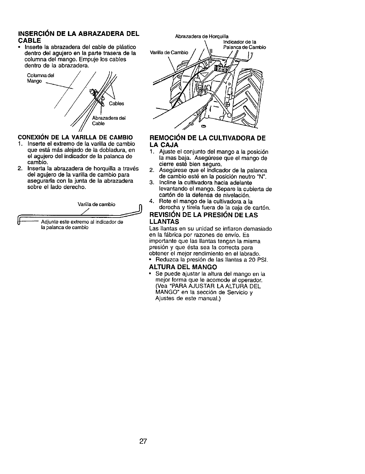
INSERCI6N DE LA ABRAZADERA DEL
CABLE
•Inserte la abrazadera del cable de pldstico
dentro del agujero en la parte trasera de la
columna del mango. Empuje los cables
dentro de ]a abrazadera,
Columnadel
Mango
Abrazadera de Horquiila
Indicadorde la
Palancade Carnbio
Varifla de Cambio
Cables
Abrazadera del
Cable
CONEXlON DE LA VARILLA DE CAMBIO
1. Inserte el extremo de la varilla de cambio
que estd mds alejado de la dobladura, en
el agujero del indicador de la palanca de
cambio.
2. Inserta la abrazadera de horquilla a travds
del agujero de la varilla de cambio para
asegurada con la junta de la abrazadera
sobre el lado derecho.
Varilladecambio
_L-'_ Adjunteesteextremoal indicadorde
lapalancadecambio
REMOCION DE LA CULTIVADORA DE
LA CAJA
1. Ajuste el conjunto del mango a la posici6n
la mas baja. Asegdrese que el mango de
cierre est6 bien seguro.
2. AsegL_reseque el indicador de la palanca
de cambio est_ en la posici6n neutro "N".
3. Incline la cultivadora hacia adelante
levantando el mango. Separe la cubierta de
cart6n de la defensa de nivelaci6n,
4. Rote el mango de la cultivadora a la
derecha y tlrela fuera de la caja de cart6n.
REVISION DE LA PRESION DE LAS
LLANTAS
Las Ilantas en su unidad se inflaron demasiado
en la f_brica por razones de envio, Es
impo_ante que las Ilantas tengan la misma
presi6n y que _sta sea la correcta para
obtener el mejor rendimiento en el labrado,
•Reduzca la presi6n de las Ilantas a 20 PSI.
ALTURA DEL MANGO
•Se puede ajustar la altura del mango en la
mejor forma que le acomode al operador.
(Vea "PARA AJUSTAR LA ALTURA DEL
MANGO" en la secci6n de Servicio y
Ajustes de este manual.)
27
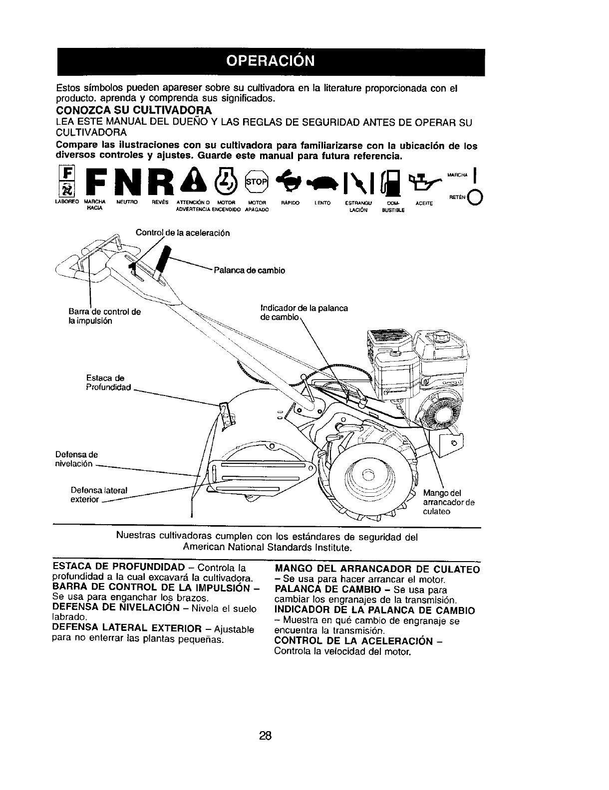
Estos simbolos pueden apareser sobre su cultivadora en la literature proporcionada con el
producto, aprenda y comprenda sus significados.
CONOZCA SU CULTIVADORA
LEA ESTE MANUAL DEL DUEI_IO Y LAS REGLAS DE SEGURIDAD ANTES DE OPERAR SU
CULTIVADORA
Compare las ilustraciones con su cultivadora para familiarizarse con la ubicaci6n de los
diversos controles y ajustes. Guarde este manual para fututa referencia.
F N R -,=I\li
LABOREO MAR_I4A I_EL/TRO REV_S A3'TE_ICI_N O M<_TOR MOTOR RApIOO LENTO ESTRANGU COM= ACEITE
HAC_A ADVERTENCIA Ek_ENDIDO APAGAOO LACI()N BUSTIBLE
Control de la aceleraci6n
Palanca de cambio
Indicador de la palanca
Barrr= de cambio
la impulsibn
Estaca de
Profundidad.
\
Defensa de
Defensa lateral Mangodel
exteri¢ arrancador de
culateo
Nuestras cultivadoras cumplen con los est_ndares de seguridad del
American National Standards Institute.
ESTACA DE PROFUNDIDAD - Controla la
protundidad a la cual excavar& la cultivadora.
BARRA DE CONTROL DE LA IMPULSION -
Se usa para enganchar los brazos.
DEFENSA DE NIVELACION - Nivela el suelo
labrado.
DEFENSA LATERAL EXTERIOR -Ajustable
para no enterrar las plantas pequefias.
MANGO DEL ARRANCADOR DE CULATEO
- Se usa para hacer arrancar el motor.
PALANCA DE CAMBIO - Se usa para
cambiar los engranejes de la transmisi6n.
INDICADOR DE LA PALANCA DE CAMBIO
- Muestra en que cambio de engranaje se
encuentra la transmisi6n.
CONTROL DE LA ACELERACI(_N -
Controla la velocidad del motor.
28
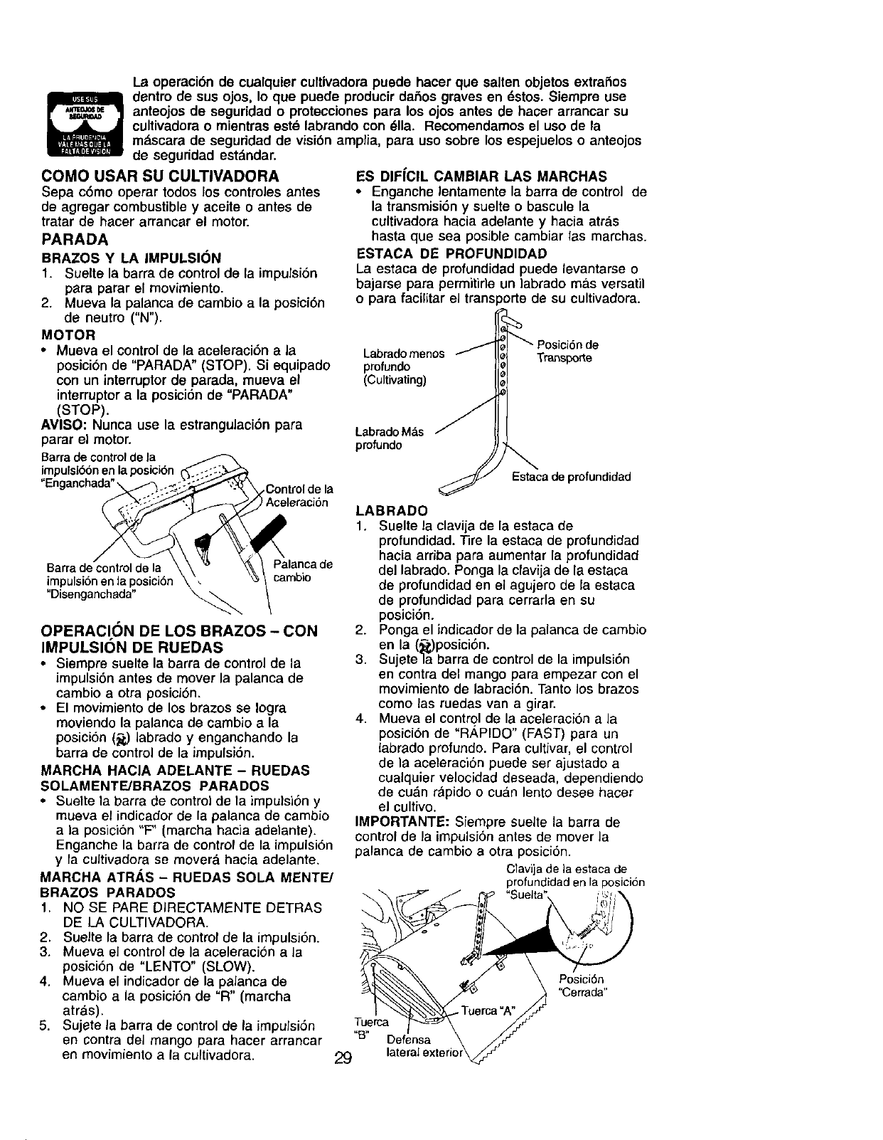
La operaci6n de cualquier cultivadora puede hacer que salten objetos extrafios
dentro de sus ojos, Io que puede producir dafios graves en _stos. Siempre use
anteojos de seguridad oprotecciones para los ojos antes de hater arrancar su
cultivadora o mientras este labrando con #lla. Recomendamos el uso de la
mz_scarade seguridad de visi6n amplia, para uso sobre los espejuelos o anteojos
de seguridad est&ndar.
COMO USAR SU CULTIVADORA
Sepa c6mo operar todos los controles antes
de agregar combustible y aceite o antes de
tratar de hacer arrancar el motor.
PARADA
BRAZOS Y LA IMPULSION
1. Suelte la barra de control de la impulsi6n
para parar el movimiento.
2. Mueva la palanca de cambio a la posici6n
de neutro ("N").
MOTOR
• Mueva el control de la aceleraci6n a la
posici6n de "PARADA" (STOP). Si equipado
con un interruptorde parada, mueva el
interruptora la posici6n de "PARADA"
(STOP).
AVISO: Nunca use la estrangulaci6n para
parar el motor.
Barrade controlde la
impulsi66nen la posici6n
"Engancha_
Barrade controlde la
impulsi6nen Japosici6tl
"Disenganchada"
COntrolde la
2
cambJo
OPERACI()N DE LOS BRAZOS - CON
IMPULSION DE RUEDAS
•Siempre suelte la barra de control de la
impulsi6n antes de mover la palanca de
cambio a otra posici6n.
• El movimiento de los brazos se Iogra
moviendo la palanca de cambio a la
posici6n (5) labrado y enganchando la
barra de control de la impulsi6n.
MARCHA HACIA ADELANTE - RUEDAS
SOLAMENTE/BRAZOS PARADOS
•Suelte la barra de control de la impulsi6n y
mueva el indicador de la palanca de cambio
ala posici6n "F" (marcha hacia adelante).
Enganche la barra de control de la impulsi6n
y la cuJtivadora se moverd hacia adelante.
MARCHA ATR._,S - RUEDAS SOLA MENTE/
BRAZOS PARADOS
1. NO SE PARE DIRECTAMENTE DETRAS
DE LA CULTIVADORA.
2, Suelte la barra de control de la impulsi6n.
3. Mueva el control de la aceleraci6n a la
posici6n de "LENTO" (SLOW).
4. Mueva el indicador de la paJanca de
cambio a la posici6n de "R" (marcha
atr&s).
5. Sujete la barra de control de la impulsi6n
en contra del mango para hacer arrancar
en movimiento a la cultivadora.
ES DIFfCIL CAMBIAR LAS MARCHAS
• Enganche lentamente la barra de control de
la transmisi6n y suelte o bascule la
cultivadora hacia adelante yhacia atr_.s
hasta que sea posible cambiar las marchas.
ESTACA DE PROFUNDIDAD
La estaca de profundidad puede levantarse o
bajarse para permitide un labrado mas versatil
o para facilitar el transporte de su cultivadora.
Labrado menos
profundo
(Cultivating)
LabradoMas
profundo
Estaca de profundidad
LABRADO
1. Suelte la claviia de la estaca de
profundidad. Tire la estaca de profunclidad
hacia arriba para aumentar la profundidad
del labrado. Ponga la clavija de la estaca
de profundidad en el agujero de la estaca
de profundidacl para cerrarla en su
posici6n.
2. Ponga el indicador de la palanca de cambio
en la (_,)posici6n.
3. Sujete]a barra de control de la impulsi6n
en contra clel mango para empezar con el
movimiento de labraci6n. Tanto los brazos
como las ruedas van a girar.
4. Mueva el control de la aceleraci6n a la
posici6n de "R,¢PIDO" (FAST) para un
labrado profundo. Para cultivar, el control
de la aceleraci6n puede set ajustado a
cualquier velocidad deseada, dependiendo
de cu_.nr_pido o cuan lento desee hacer
el cultivo.
IMPORTANTE: Siempre suelte la barra de
control de la impulsi6nantes de mover la
palanca de cambio a otra posici6n.
Clavijade laestacade
profundidadenla posici6n
Tuerca
"B" Defensa
29
Posici6n
"Cerrada"
GIRO
1. Suelte la barra de control de la impulsi6n.
2. Mueva el control de la aceleraci6n a la
posici6n de "LENTO" (SLOW).
3. Ponga el indicador de la palanca de cambio
en la posici6n de "F" (marcha hacia
adelante). Los brazos no van a girar.
4. Levante el mango para levantar los brazos
fuera del suelo.
5. Mueva el mango en la direcci6n opuesta
en la que desea girar, con cuidado de
mantener los pies y las piernas alejados
de los brazos de la cultivadora.
6. Cuando haya completado su vuelta, suelte
la barra de control de la impulsi6n y baje el
mango. Ponga la palanca de cambio en la
posici6n labrado y mueva el control de la
aceleraci6n a ta velocidad deseada. Para
empezar a cultivar, sujete la barra de
control de la impulsi6n en contra del
mango.
DEFENSAS LATERALES EXTERIORES
Los hordes trasero de las defensas laterales
exteriores son rasurados de modo que estas
se puedan levantar para hacer un labrado
profundo y bajar para uno poco profundo, para
evitar enterrar las plantas peque,Sas.
1. Suelte la tuerca "A" en la ranura y la tuerca
"B".
2. Mueva la defensa ala posicibn deseada
(en ambos lados).
3. Vuelva a aprotar las tuercas.
PARA EL TRANSPORTE
•I,PRECAUCION: Antes de levantarla o
transportarla, permita que el motor de la
cultivadora y el silenciador se enfrfen.
Desconecte el alambre de la bujia. Drene la
gasolina del estanque de combustible.
EN EL JARDiN
1. Suelte la clavija de la estaca de
profundidad. Mueva la estaca de
profundidad hacia abajo, al agujero
superior, para transportar la cultivadora.
Ponga la clavija de la estaca de profundi-
dad en el agujero de la estaca de
profundidad para asegurarla en su lugar.
Esto impide que los brazos se arrastren
por el suelo.
2. Ponga el indicador de la palanca de cambio
en la posici6n de "F" (marcha hacia
adelante) para el transporte.
3. Sujete la barra de control de la impulsi6n
en contra del mango para empezar con el
movirniento de la cultivadora. Los brazos
no van a girar.
4. Mueva el control de la aceleraci6n a la
velocidad deseada.
EN LA CIUDAD
1. Desconecte el alambre de la bujia.
2. Drene el estanque de combustible.
3. Transp6rtela en la posici6n derecha hacia
arriba para evitar la fuga del aceite.
ANTES DE HACER ARRANCAR EL
MOTOR
IMPORTANTE: Tenga mucho cuidado de no
permitir que entre mugre al motor cuando
revise o a_ada aceite o combustible. Use
aceite y combustible limpios y gudrdelos en
envases aprobados, limpios y con tapa. use
embudos para relleno limpios.
REVISI6N DEL NIVEL DEL ACEITE DEL
MOTOR
El motor en su unidad ha sido enviado desde
la fabrica Ileno con aceite de calidad para el
verano SAE 30.
1. Con el motor nivelado, limpie un drea
alrededor del tap6n del dep6sito para
relleno del aceite y remueva el tap6n.
2. Con el motor nivelado, d aceite del motor
debe Ilegar hasta el punto de derramarse.
• Para verificar la capacidad aproximada vea
"ESPECIFICACIONES DEL PRODUCTO"
en la pdgina 24 de este manual. Todo el
aceite tiene que cumplir la clasificaci6n de
servicio API SF oSJ.
• Para la operaci6n en clima frio, debe
cambiarse el aceite para facilitar el arranque
(vea la "TABLA DE VISCOSIDAD DEL
ACEITE" en la secci6n de Mantenimiento en
este manual).
• Para cambiar el aceite del motor, vea ra
secci6n de Manteni "niento en este manual.
Tap6ndedepositode
rellenode aceite_._
AGREGUE GASOLINA
• Llene el estanque de combustible, Use
gasolina regular,sin plomo, nueva y limpia.
(El uso de gasolina con plomo aumentar_.
los dep6sitos de 6xido de plomo y carbono
yse reducir_,la duraci6n de la v&lvula.)
IMPORTANTE: Cuando se opere en
temperaturas pot debajo de 32°F (0°C) use
gasolina de calidad de invierno, limpia y nueva
para ayudar a asegurar un buen arranque en
clima frfo.
AADVERTENCIA: La expenencia ha indicado
que los combustibles mezclados con alcohol
(conocidos como gasohol, o el uso de etanol o
metanol) pueden atraer la humedad, la que
conduce a la separaci6n y formaci6n de
acidos durante el almacenamiento. La gasolina
acfdica puede daSar el sistema del combus-
tible de un motor durante el almacenamiento.
Para evitar problemas con el motor, se
debe vaciar el sistema de combustible
antes de guardarlo por un periodo de 30
dias o mds. Vacie el estanque de combus-
tible, haga arrancar el motor y hagalo
30funcionar hasta que las lineas del combustible
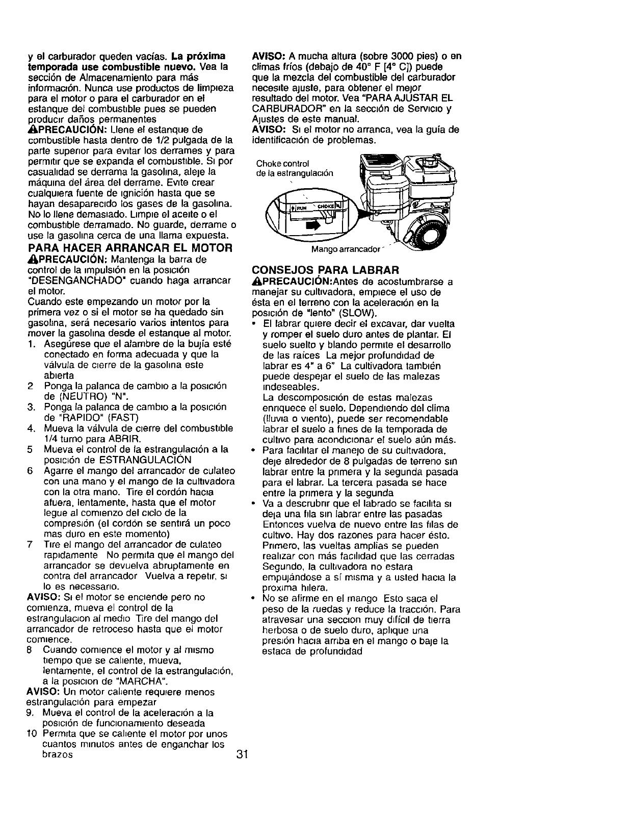
y el carburador queden vacias. La pr6xima
temporada use combustible nuevo. Vea la
secci6n de Almacenamiento para m._s
informacl6n. Nunca use productos de limpteza
para el motor o para el carburador en el
estanque del combust=blepues se pueden
_roduc=r daSos permanentes
PRECAUCI(_N: Llene el estanque de
combustible hasta dentro de 1/2 pulgada de la
parte superior para ewtar los derrames y para
permlt=r que se expanda el combustrble. St por
casuahdad se derrama la gasolma, aleje la
ma.quma del ,_rea del derrame. Evtte crear
cualqu_era fuente de _gniciSn hasta que se
bayan desaparectdo los gases de la gasohna.
No Io Ilene demastado. LJmp=eel aceJte o el
combustible derramado. No guarde, derrame o
use la gasolma cerca de una llama expuesta.
PARA HACER ARRANCAR EL MOTOR
_,PRECAUCI(_N: Mantenga la barra de
control de la impulst6nen la poslct6n
"DESENGANCHADO" cuando haga arrancar
el motor.
Cuando este smpezando un motor por la
pdmera vez o si el motor se ha quedado sin
gasohna, sera necesario varios intentos para
mover la gasohna desde el estanque al motor.
1. Aseg_rese que el alambre de la bulia est6
conectado en forma adecuada y que la
valvula de clerre de la gasohna este
abterta
2 Ponga la palanca de camblo a la poslcl6n
de (NEUTRO)"N".
3. Ponga la palanca de cambto a la postcton
de "RAPIDO" (FAST)
4. Mueva la va.lvula de crerre del combustible
1/4 turno para ABRIR.
5 Mueva el control de la estrangulaclSn a la
poslcl6n de ESTRANGULACION
6 Agarre el mango del arrancador de culateo
con una mano y el mango de la culttvadora
con la otra mano. ]3re el cordbn hac_a
afuera, lentamente, hasta que el motor
legue al com_enzo del clclo de la
compreslSn (el cordon se senttr_ un poco
mas duro en este momento)
7 Tire el mango de[ arrancador de culateo
raptdamente No permlta que el mango del
arrancador se devuelva abruptamente en
contra del arrancador Vuelva a repetlr, sl
Io es necessar_o.
AMISO: SI el motor se enctende pero no
comJenza, mueva el control de la
estrangulac_on al medto ]3re del mango del
arrancador de retroceso hasta que el motor
oomlence.
8 Cuando comtence el motor y al m_smo
t_empo que se cahente, mueva,
lentamente, el control de la estrangulacrbn,
a Ja poslclon de "MARCHA".
AVISO: Un motor cahente requrere menos
estrangulacton para empezar
9. Mueva el control de la aceleracl6n a la
postctSn de functonam=ento deseada
t0 Permrta que se cahente el motor por unos
cuantos mmutos antes de enganchar los
brazos
AVISO: A mucha altura (sobre 3000 pies) o en
climas trios (debajo de 40° F [4° C]) puede
que la mezcla del combustible del carburador
neces=teajuste, para obtener el mejor
resultado del motor.Vea "PARA AJUSTAR EL
CARBURADOR" en la seccJ_)nde Servtclo y
Aiustes de este manual.
AMISO: St el motor no arranca, vea la guia de
identiticaclbn de problemas.
31
Choke control
de la estrangulacl6n
Mango arrancador _"
CONSEJOS PARA LABRAR
A, PRECAUCI(_N:Antes de acostumbrarse a
manejar su cultlvadora, emptece el uso de
_sta en el terreno con la acelerac=bnen la
posJct6nde "lento" (SLOW).
• El labrar quJeredecir el excavar, dar vuelta
y romper el suelo duro antes de plantar. El
suelo suelto y blando permlte el desarrollo
de las raices La mejor profundldad de
labrar es 4" a 6" La cultivadora tambt_n
puede despeiar el suelo de las malezas
Indeseables.
La descompos=ctSnde estas malezas
ennquece el suelo. Dependtendo del clima
(lluwa o wento), puede set recomendable
labrar el suelo a fines de la temporada de
cUItlVOpara acondlc_onar el suelo a_n m_.s.
•Para facthtar el manejo de su cult=vadora,
deje alrededor de 8 pulgadas de terreno s=n
labrar entre la pnmera y la segunda pasada
para el labrar. La tercera pasada se hace
entre la pnmera y la segunda
•Va a descrubnr que el labrado se factltta sl
dela una ilia stn Jabrarentre las pasadas
Entonces vuelva de nuevo entre las filas de
cultlvo. Hay dos razones para hacer esto.
Pnmero, las vueitas amplias se pueden
reahzar con m&s facd=dad que las cerradas
Segundo, la cultwadora no estara
empuj;§ndose a si m=sma y a usted hacta la
prox_ma hdera.
• No se afirme en el mango Esto saga el
peso de la ruedas y reduce la traccl6n. Para
atravesar una secc_on muy dlfiCll de tlerra
herbosa o de suelo duro, aphque una
presJ6n hacla arnba en el mango o bale la
estaca de profund=dad
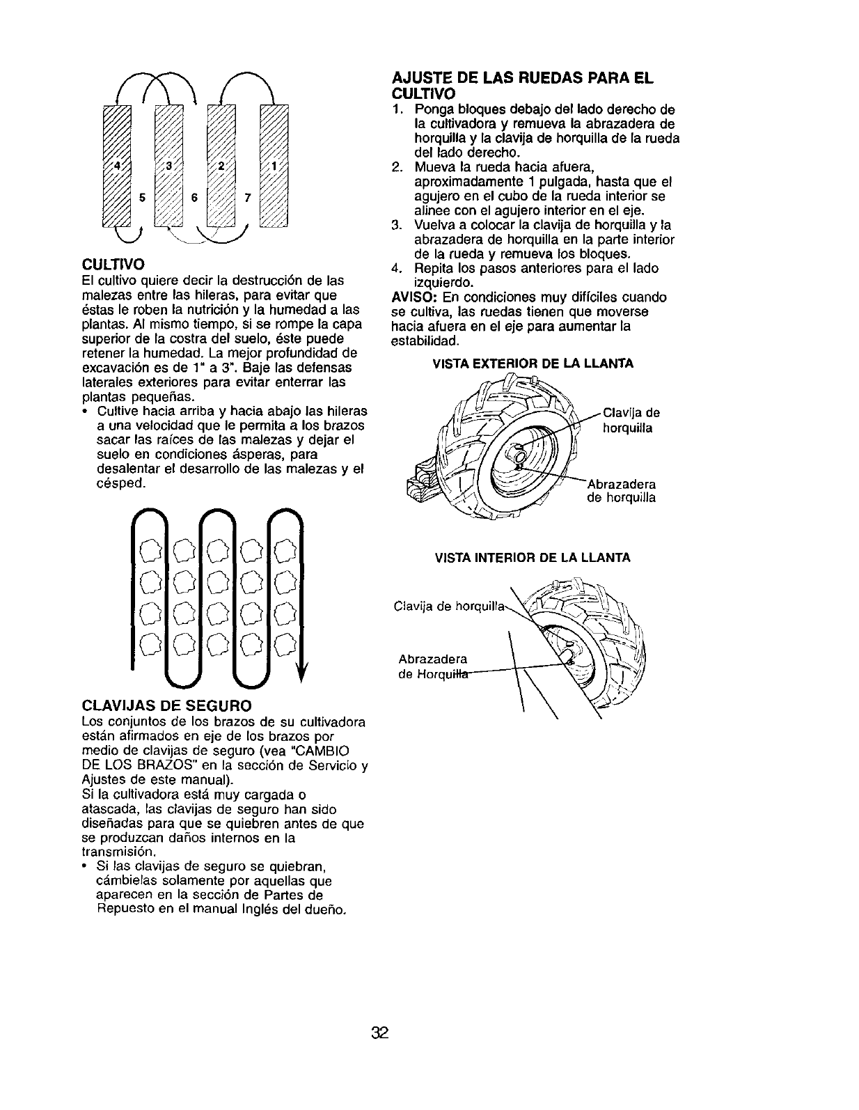
CULTIVO
El cultivo quiere decir la destrucci6n de las
malezas entre las hileras, para evitar que
_stas le roben la nutrici6n y la humedad a las
plantas. AI mismo tiempo, si se rompe la capa
superior de la costra del suelo, _ste puede
retener la humedad. La mejor profundidad de
excavaci6n es de 1" a 3". Baje las defensas
laterales exteriores para evitar enterrar las
plantas pequefias.
•Cultive hacia arriba y hacia abajo las hileras
a una velocidad que le permita alos brazos
sacar las farces de las malezas y dejar el
suelo en condiciones dsperas, para
desalentar el desarrollo de las malezas y el
c_sped.
CLAVIJAS DE SEGURO
Los conjuntos de los brazos de su cultivadora
est&n afirmados en eje de los brazos pot
medio de clavijas de seguro (vea "CAMBIO
DE LOS BRAZOS" en la secci6n de Servicio y
Ajustes de este manual).
Si la cultivadora est& muy cargada o
atascada, las davids de seguro hart sido
diseSadas para que se quiebren antes de que
se produzcan daSos intemos en la
transmisi6n.
•Si las clavijas de seguro se quiebran,
c_mbielas solamente por aquellas que
aparecen en la secci6n de Partes de
Repuesto en el manual Ingles del due5o.
AJUSTE DE LAS RUEDAS PARA EL
CULTIVO
1. Ponga bloques debajo del lado derecho de
la cultivadora y remueva la abrazadera de
horquillay la clavija de horquilla de la rueda
del lado derecho.
2. Mueva la rueda hacia afuera,
aproximadamente 1 pulgada, hasta que el
agujero en el cubo de la rueda interiorse
alinee con el agujero interior en el eje.
3. Vuelva a colocar la clavija de horquillay la
abrazadera de horquilla en la parte interior
de la rueda y remueva los bloques.
4. Repita los pasos anteriores para el lado
izquierdo.
AVISO: En condiciones muy diffciles cuando
se cultiva, las ruedas tienen que moverse
hacia afuera en el eje para aumentar la
estabilidad.
VISTA EXTERIOR DE LA LLANTA
Clavija de
horquilla
razadera
horquilla
VISTA INTERIOR DE LA LLANTA
Clavija
Abrazadera
de Horqt
32
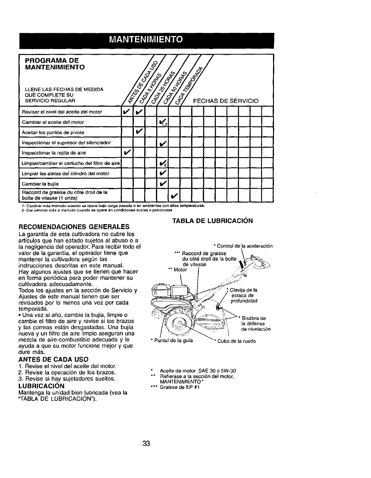
MANTENIMIENTO _
•.E.EEEC.ASMEO,OA
QUE COMPLETE SU /_ _,_/_II*"I"'-- L--L--I I__'_ _'_ _" _'_
SERVICIO REGULAR /_,//O_"Q//O_//_7 FECHAS DE SERVIC'O
Revisar el nivel del aceite del motor I_ I_
Cambiar el aceite del motor <2
Aceitar los puntos de pivote I_
Inspeccionar el supresor del silenciador If
Inspeccionar la rejilla de aire I,/
Limpiadcambiar el cartucho del filtro de aim 1_2
Limpiar las aletas del cilindro del motor I_
Cambiar la bujfa If
Raccord de graisse du c6te droit de la
boite de vitesse (1 onza) I_
1- Cambiar m_s menudo cuando se opere bajo carga pesada oen ambientes con altas ternperalutas.
2- Oar seivicio rods _ merludo cu_r_do se opere en _ndici0nes sucias 0polvorosas
TABLA DE LUBRICACI()N
RECOMENDACIONES GENERALES
La garantfa de esta cultivadora no cubre los
artfculos que han estado sujetos al abuso o a
la negligencia del operador. Para recibir todo el
valor de la garantia, el operador tiene que
mantener la cultivadora segL_n las
instrucciones descritas en este manual.
Hay algunos ajustes que se tienen que hacer
en forma periodica para poder mantener su
cultivadora adecuadamente.
Todos los ajustes en la secci6n de Servicio y
Ajustes de este manual tienen que set
revisados per Io menos una vez por cada
temporada.
•Una vez al aho, cambie la bujia, limpie o
cambie el filtro de aire y revise si los brazos
y las correas est_n desgastaclas. Una bujia
nueva y un filtro de aire limpio aseguran una
mezcla de aire-combustib]e adecuada y le
ayuda a que su motor funcione mejor y que
(:lure mas.
ANTES DE CADA USO
1. Revise el nivel del aceite del motor.
2. Revise la operaci6n de los brazos.
3. Revise si hay sujetadores sueitos.
LUBRICACION
Mantenga la unidad bien !ubricada (yea la
"TABLA DE LUBRICACION").
* Controlde laaceleracion
Raccord de graisse \ __
t
du c6t_droit de la boite \,_d_,
de vitesse '_P i:_"_-'_
"" MOor /_'_"f
_I /)j_ / estaca de
"_ /profundidad
/_( _ _ _._ ]a defensa
,e ,ve,aoidn
*Puntaldo la guia _" Cubo de]a rueda
Aceite de motor SAE 30 o5W-30
"* Refierase ala secci6n del motor,
MANTENIMIENTO"
"** Graisse de EP #1
33
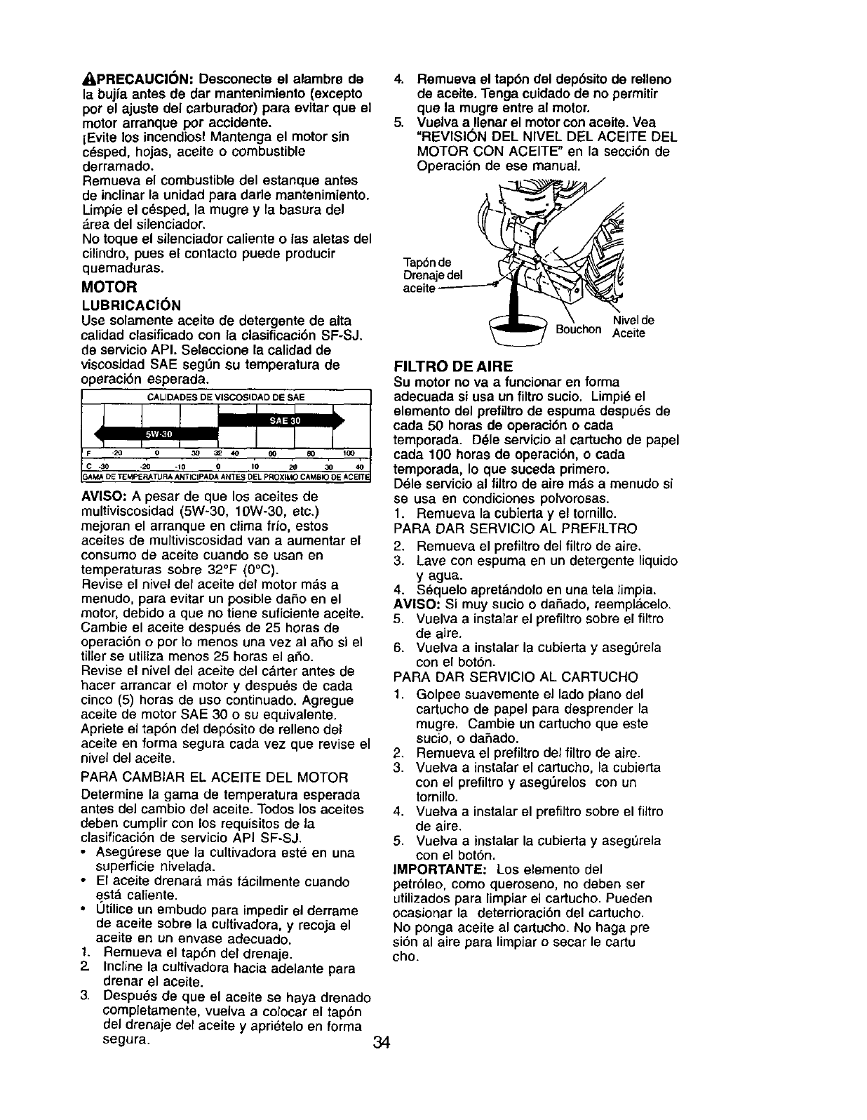
_,PRECAUCI6N: Desconecte el alambre de
la bujfa antes de dar mantenimiento (excepto
por el ajuste del carburador) pare evitar que el
motor arranque por accidente.
lEvite los incendios! Mantenga el motor sin
crisped, hojas, aceite o combustible
derramado.
Remueva el combustible del estanque antes
de inclinar la unidad para darle mantenimiento.
Limpie el cesped, la mugre y la basura del
_rea del silenciador.
No toque el silenciador caliente o las aletas del
cilindro, pues el contacto puede producir
quemaduras.
MOTOR
LUBRICACION
Use solamente aceite de detergente de alta
calidad clasificado con la clasificaci6n SF-SJ.
de servicioAPI. Seleccione la calidad de
viscosidad SAE seg_n su temperature de
operaci6n esperada.
CALIDADES DE VISCOSIDAD DE SAE
AVISO: A pesar de que los aceites de
multiviscosidad (5W-30, 10W-30, etc.)
mejoran el arranque en clima frio, estos
aceites de multiviscosidad van a aumentar el
consumo de aceite cuando se usan en
temperaturas sobre 32°F (0°C).
Revise el nivel del aceite del motor mds a
menudo, para evitar un posible da£_oen el
motor, debido a que no tiene suficiente aceite.
Cambie el aceite despues de 25 horas de
operacibn o por Io menos una vez al a_o si el
tiller se utiliza menos 25 horas el a_o.
Revise el nivel del aceite del carter antes de
hacer arrancar el motor y despu_s de cada
cinco (5) horas de uso continuado. Agregue
aceite de motor SAE 30 o su equivalente.
Apriete el tap6n del dep6sito de relleno del
aceite en forma segura cada vez que revise el
nivel del aceite.
PARA CAMBIAR EL ACEITE DEL MOTOR
Determine la gama de temperature esperada
antes del cambio del aceite. Todos los aceites
cleben cumplir con los requisitos de la
clasificaci6n de servicio API SF-SJ.
•Aseg_rese que la cultivadora este en una
superficie nivelada.
• El aceite drenara mas t&cilmente cuando
esta caliente.
•Utilice un embudo para impedir el derrame
de aceite sobre la cultivadora, y recoja el
aceite en un envase adecuado.
t. Remueva el tap6n del drenaje.
2. Incline la curtivadora hacia adelante pare
drenar el aceite.
3. Despu_s de que el aceite se haya drenado
completamente, vuelva a colocar el tap6n
del drenaje del aceite y aprietelo en forma
segura. 34
4. Remueva el tap6n del dep6sito do relleno
de aceite. Tenga cuidado de no permitir
que la mugre entre al motor.
5. Vuelva a Ilenar el motor con aceite. Vea
=REVISI(_N DEL NIVEL DEL ACEITE DEL
MOTOR CON ACEITE" en la secci6n de
Operacion de ese manual.
Tap6n de
Drenaje del
aceite
Nivelde
Bouchon Aceite
FILTRO DE AIRE
Su motor no va afuncionar en forma
adecuada si usa un filtrosucio. Limpi6 el
elemento del prefiltro de espuma despu_s de
carla 50 horas de operaci6n o cada
temporada. D_le servicio al cartucho de papel
cada 100 horas de operacion, ocada
temporada, Io que suceda primero.
Ddle servicio al filtro de aim mds a menudo si
so usa en condicJonespofvorosas.
1. Remueva la cubierta y el tomillo.
PARA DAR SERVIClO AL PREFILTRO
2. Remueva el prefiltro del filtro de aire.
3. Lave con espuma en un detergente liquido
y agua.
4. S_quelo apret&ndolo en una tela limpia.
AMISO: Si muy sucio o dafiado, reemplacelo.
5. Vuelva a instalar el prefiltrosobre el filtro
de aire.
6. Vuelva a instalar la cubierta y aseg0rela
con el bot6n.
PARA DAR SERVIClO AL CARTUCHO
1. Golpee suavemente el lado piano del
cartucho de papel para desprender la
mugre. Cambie un cartucho que este
sucio, o daSado.
2. Remueva el prefiltro del filtro de aire.
3. Vuelva a instalar el cartucho, la cubierta
con el prefiltro y aseg_relos con un
tomillo.
4. Vuelva a instalar el prefiltro sobre el filtro
de aire.
5. Vuelva a instalar la cubieda y asegL_rela
con el bot6n.
IMPORTANTE: Los elemento del
petr61eo, como queroseno, no deben ser
utilizados para limpiar el cartucho. Pueden
ocasionar la deterrioracibn del cartucho.
No ponga aceite al cartucho. No haga pre
si6n al aire para limpiar o secar le cartu
cho.
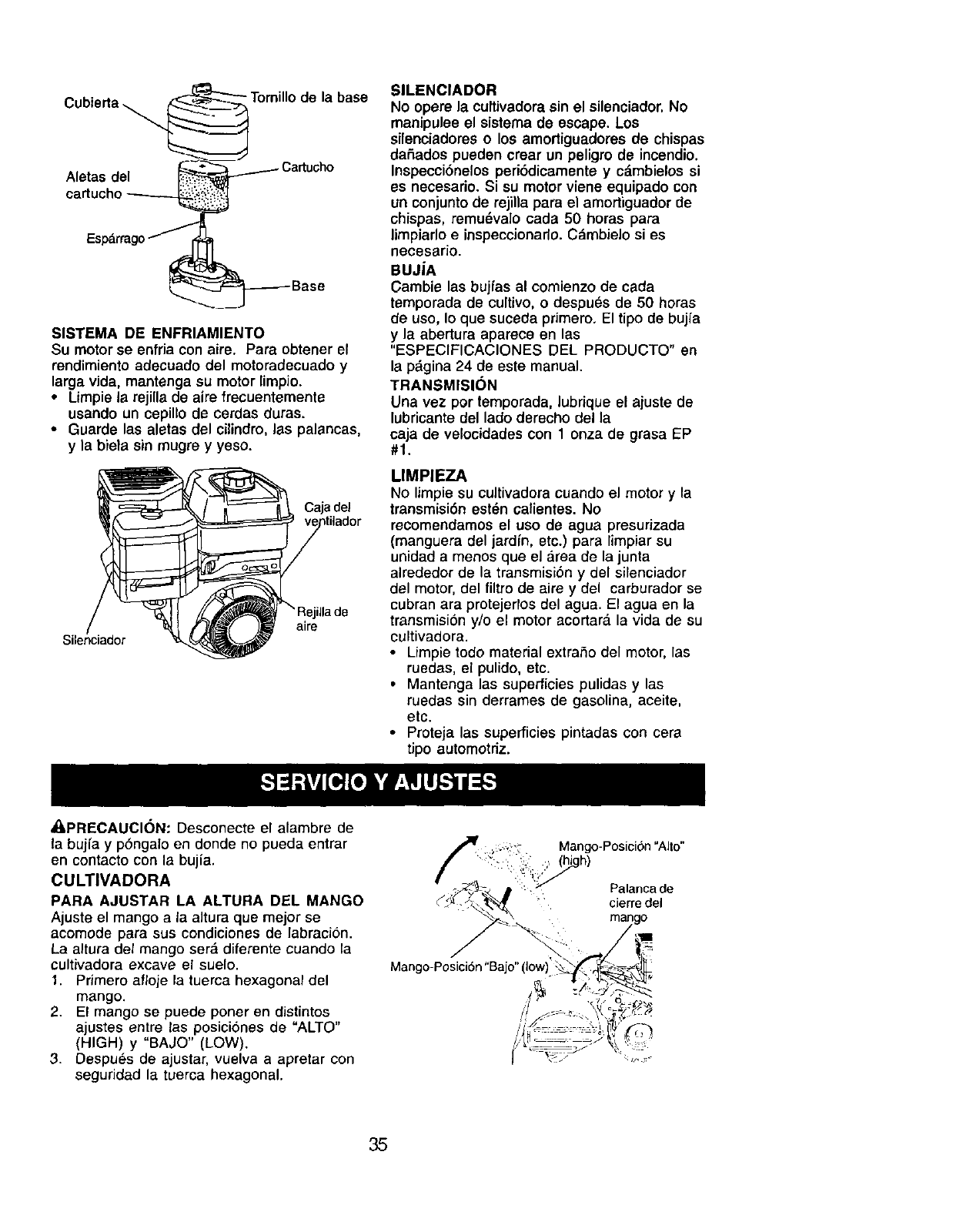
base
Aletas del
SISTEMA DE ENFRIAMIENTO
Su motor se enfria con aire. Para obtener el
rendimiento adecuado del motoredecuado y
larga vida, mantenga su motor limpio.
• Limpiela rejilla de aire frecuentemente
usando un cepillo de cerdas duras.
=Guarde las aletas del cilindro, las palancas,
y la biela sin mugre y yeso.
Caja del
Silenciador
Ila de
aire
_,PRECAUCl6N: Desconecte el alambre de
SILENClADOR
No opere la cultivadora sin el silenciador.No
manipulee el sistema de escape. Los
silenciadores o los amortiguadores de chispas
dafiados pueden crear un peligro de incendio.
Inspecci6nelos peri6dicamente y c&mbielos si
es necesario. Si su motor viene equipado con
un conjunto de rejilla para el amortiguador de
chispas, remu6valo cada 50 horas para
limpiarlo einspeccionado. C_mbielo si es
necesario.
BUJiA
Cambie las bujfas al comienzo de cada
temporada de cultivo, o despues de 50 heras
de use, Io que suceda primero. El tipo de bujfa
yla abertura aparece en las
"ESPECIFICACIONES DEL PRODUCTO" en
la p_gina 24 de este manual.
TRANSMISI()N
Una vez per temporada, lubfique el ajuste de
lubricante del lade derecho della
caja de velocidades con 1 onza de grasa EP
#1.
LIMPIEZA
No limpie su cultivadoracuando el motor y la
transmisi6n est_n calientes. No
recomendamos el use de agua presurizada
(manguera del jardfn, etc.) para limpiar su
unidad a menos que el area de la junta
alrededor de la transmision y del silenciador
del motor, del filtro de aire y del carburador se
cubran are protejerlos del agua. El agua en la
transmisi6n y/o el motor acortar_, la vida de su
cultivadora.
• Limpie todo material extrafio del motor, las
ruedas, el pulido, etc.
• Mantenga las superficies pulidas y las
ruedas sin derrames de gasolina, aceite,
etc.
• Proteja las superficies pintadas con cera
tipo automotriz.
la bujfa y p6ngalo en donde no pueda entrar
en contacto con la bujia.
CULTIVADORA
PARA AJUSTAR LA ALTURA DEL MANGO
Ajuste el mango a la alture que mejor se
acomode para sus condiciones de fabraci6n.
La altura del mango ser,_ diferente cuando la
cultivadora excave el suelo.
1. Pfimero afloje la tuema hexagonal del
mango.
2. El mango se puede porter en distintos
ajustes entre las posici6nes de "ALTO"
(HIGH) y "BAJO" (LOW).
3. Despues de ajustar, vuelva a apretar con
seguridad la tuerca hexagonal.
Mango-Posici6n "Alto"
Palanca de
cierre del
Mango-Posici6n "Bajo" (low)'
35
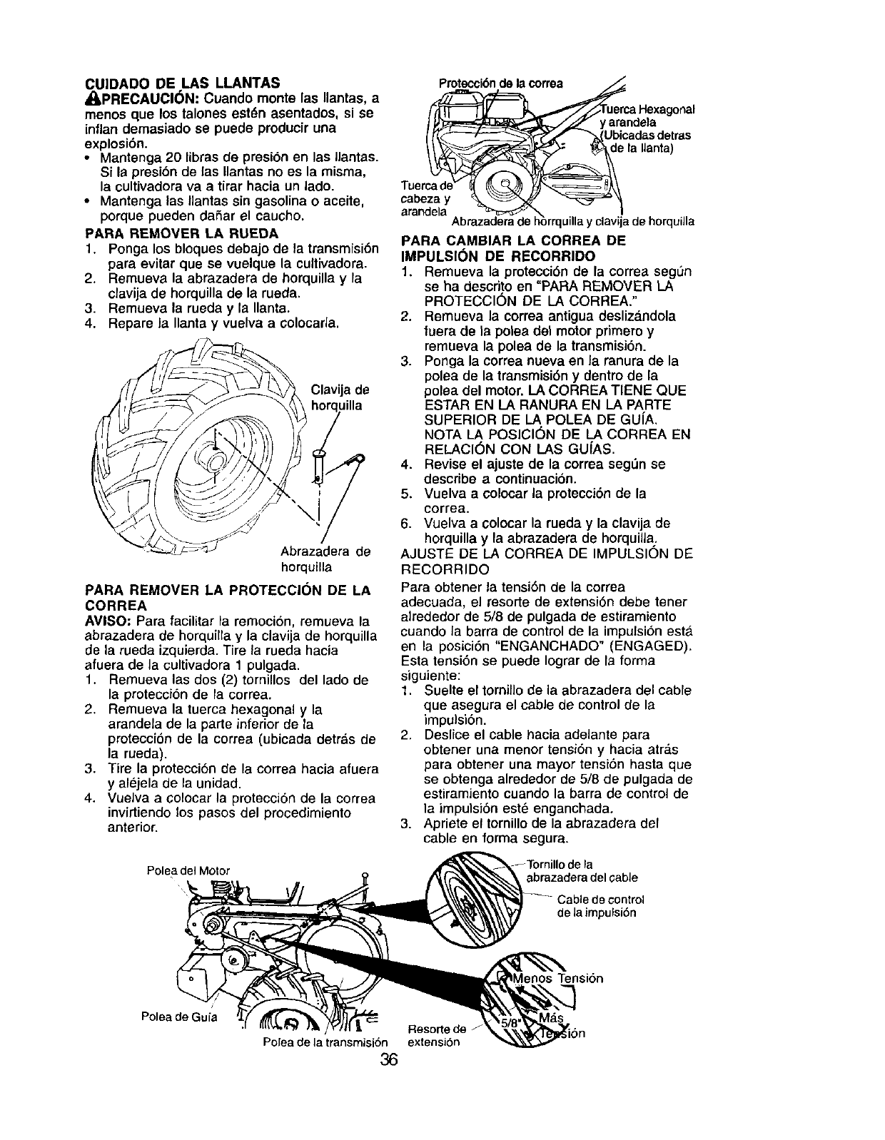
CUIDADO DE LAS LLANTAS
/I, PRECAUCI(_N: Cuando monte las Ilantas, a
menos que los talones estdn asentados, si se
inflan demasiado se puede producir una
explosi6n.
• Mantenga 20 libras de presi6n en las Ilantas.
Si la presibn de las Ilantas no es la misma,
la cultivadorava a tirar hacia un lado.
•Mantenga las Ilantas sin gasolina o aceite,
porque pueden dafiar el caucho.
PARA REMOVER LA RUEDA
1. Ponga los bleques debajo de la transmisi6n
para evitar que se vuelque la cultivadora.
2. Remueva la abrazadera de horquillay la
clavija de horquilla de la rueda.
3. Remueva la rueda y la Ilanta.
4. Repare la Ilanta y vuelva a colocarla.
Clavija de
Abrazadera de
horquilla
PARA REMOVER LA PROTECCION DE LA
CORREA
AVISO: Para facilitar la remoci6n, remueva la
abrazadera de horquillay la clavija de horquilla
de la rueda izquierda. Tire la rueda haeia
afuera de la eultivadora 1 pulgada.
1. Remueva las dos (2) tornillos del lado de
la protecci6n de la correa.
2. Remueva la tuerca hexagonal yla
arandela de la parte inferior de la
protecci6n de la correa (ubicada detr&s de
la rueda).
3. Tire la protecci6n de la correa hacia afuera
y alejela de la unidad.
4. Vuelva a colocar la protecci6n de la correa
invirtiendo los pasos del precedimiento
anterior.
Polea del Motor
Pmtecci6nde la correa
_ma Hexagonal
]. _ y arande}a
I ___'_':'_X' _-_Ubicadas detras
e la Ilanta)
Tuercade" _ /_L,_)]_,,,,,,,_=:_,\
cabeza y %,=_ _
arandela. _ _'_ _ .!
Abrazaderade horrquillay clavijade horquilla
PARA CAMBIAR LA CORREA DE
IMPULSK}N DE RECORRIDO
1. Remueva la protecci6n de la correa seg_n
se ha descrito en "PARA REMOVER LA
PROTECCION DE LA CORREA."
2. Remueva la correa antigua desliza.ndola
fuera de la polea del motor primero y
remueva la polea de la transmisi6n.
3. Ponga la correa nueva en Jaranura de la
polea de la transmisi6n y dentin de la
polea del motor. LA CORREA TIENE QUE
ESTAR EN LA RANURA EN LA PARTE
SUPERIOR DE LA POLEA DE GU[A.
NOTA LA POSICION DE LA CORREA EN
RELACI6N CON LAS GU[AS.
4. Revise el ajuste de la correa seg_n se
describe a continuaci6n.
5. Vuelva a colocar la protecci6n de la
correa.
6. Vuelva a ¢olocar la rueda y la clavija de
horquilla y la abrazadera de horquilla.
AJUSTE DE LA CORREA DE IMPULSION DE
RECORRIDO
Para obtener la tensi6n de la correa
adecuada, el resorte de extensi6n debe tener
alrededor de 5/8 de pulgada de estiramiento
cuando la barra de control de la impulsi6n esta.
en la posiciSn "ENGANCHADO" (ENGAGED),
Esta tensi6n se puede Iograr de la forma
siguiente:
1. Suelte el tomillo de la abrazadera del cable
que asegura el cable de control de la
impulsi6n.
2. Deslice el cable bacia adelante para
obtener una menor tensi6n y hacia atr_.s
para obtener una mayor tensi6n hasta que
se obtenga alrededor de 5/8 de pulgada de
estiramiento cuando la barra de control de
la impulsi6n est6 enganchada,
3. Apriete el tornillo de la abrazadera del
cable en forma segura.
abrazadera del cable
-_ Cable decontrol
de la impulsi6n
Polea de Gufa
Polea de la transmisi6n 36
Resorte de _
extensi6n
nos Tension
Mds
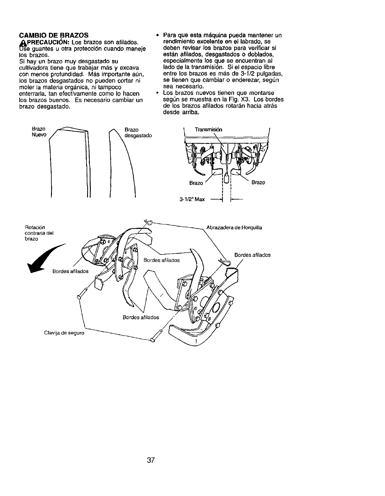
CAMBIO DE BRAZOS
_soPRECAUCI_N: Los brazos son afilados.
guantes u otra protecci6n cuando maneje
los brazos.
Si hay un brazo muy desgastado su
cultivadora tiene que trabajar m_.sy excava
con menos profundidad. Mds importante a_n,
los brazos desgastados no pueden cortar ni
moler la materia organica, ni tampoco
enterrarla, tan efectivamente como Io hacen
los brazos buenos. Es necesario cambiar un
brazo desgastado.
•Para que esta mdquina pueda mantener un
rendimiento excelento en el labrado, se
deben rovisar los brazos para verificar si
estdn afilados, desgastados o doblados,
especialmente los que se encuentran al
lado do la transmisi6n. Si el espacio libre
entre los brazos es rods de 3-1/2 pulgadas,
so tienen que cambiar o enderezar, segLin
sea necesario.
•Los brazos nuevos tienen que montarse
seg_n se muestra on la Fig. X3. Los bordes
de los brazos afilados rotardn hacia atr_s
desde arriba.
BrazoNuevo
°stado
II
I
3-1/2" Max
Rotation
contraria del
brazo
_Bordes afilados
Abrazadera de Horquilla
Bordes afilados
Clavija de seguro
37
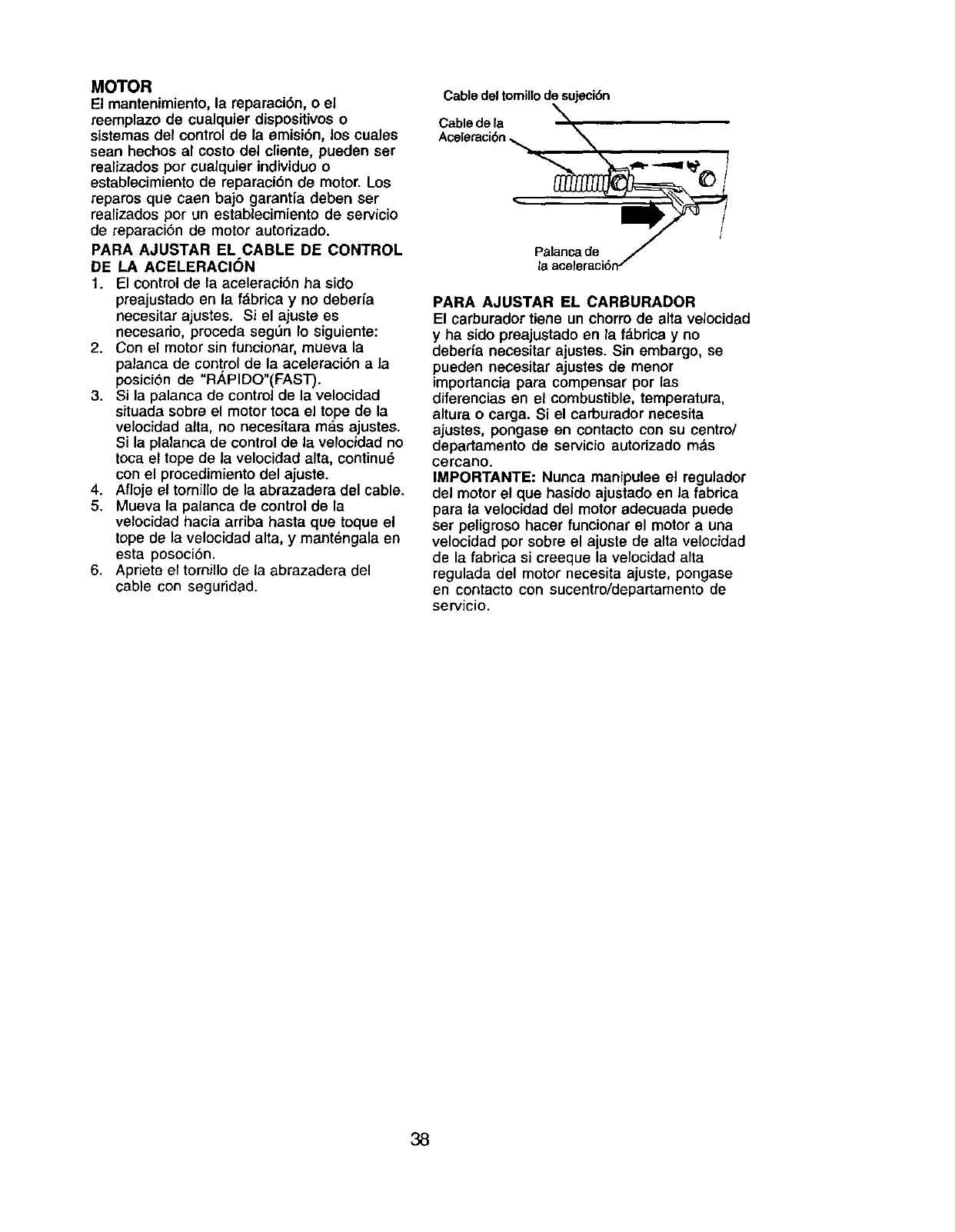
MOTOR
El mantenimiento, la reparaci6n, o el
reemplazo de cualquier dispositivos o
sistemas del control de la emisibn, los cuales
sean hechos al costo del cliente, pueden ser
realizados pot cualquier individuo o
establecimiento de reparaci6n de motor. Los
reparos que caen bajo garantia deben ser
realizados por un establecimiento de servicio
de reparaci6n de motor autorizado.
PARA AJUSTAR EL CABLE DE CONTROL
DE LA ACELERACION
1. El control de la aceleraci6n ha sido
preajustado en la f&brica y no deberfa
necesitar ajustes. Si el ajuste es
necesario, proceda seg_n Io siguiente:
2. Con el motor sin funcionar, mueva la
palanca de control de la aceleraci6n a la
posici6n de "RAPIDO"(FAST).
3. Si la palanca de control de la velocidad
situada sobre el motor toca el tope de la
velocidad alta, no necesitara mas ajustes.
Si la plalanca de control de la velocidad no
toca el tope de la velocidad alta, continu_
con el procedimiento del ajuste.
4. Afloje el tornillo de la abrazadera del cable.
5. Mueva la palanca de control de la
velocidad hacia arriba hasta que toque el
tope de la velocidad alta, y mant_ngala en
esta posoci6n.
6. Apriete el tornillo de la abrazadera del
cable con seguridad.
Cabledeltomillode sujeci6n
Cablede la
Aceleraci6n,_ N
PARA AJUSTAR EL CARBURADOR
El carburador tiene un chorro de alta velocidad
y ha sido preajustado en la f&brica y no
debeHa necesitar ajustes. Sin embargo, se
pueden necesitar ajustes de menor
importancia para compensar por las
diferencias en el combustible, temperatura,
altura o carga. Si el carburador necesita
ajustes, pongase en contacto con su centro/
departamento de servicio autorizado m&s
cercano.
IMPORTANTE: Nunca manipulee el regulador
del motor el que hasido ajustado en la fabrica
para la velocidad del motor adecuada puede
ser peligroso hacer funcionar el motor a una
velocidad por sobre el ajuste de alta velocidad
de la fabrica si creeque la velocidad alta
regulada del motor necesita ajuste, pongase
en contacto con sucentro/departamento de
servicio.
38
Inmediatamente prepare su cultivadora para el
almacenamiento al final de la temporada o si la
unidad no se va a usar por 30 d{as o m_s.
,_k.PRECAUCl6N: Nunca almacene la
cultivadora con gasolina en el estanque dentro
de un edificio en donde los gases pueden
alcanzar una llama expuesta o una chispa.
Permita que el motor se enfrfe antes de
almacenarlo en cualquier recinto pfivado.
CULTIVADORA
1. Limpie toda la cultivadora (vea "LIMPIEZA"
en la secci6n de Mantenimiento en este
manual).
2, Inspeccione y cambie las correas, si es
necesario (vea las instrucciones para el
cambio de la correa en la secci6n de
Servicio y Ajustes de este manual).
3. Lubriquela segt_nse muestra en la
secci6n de Mantenimiento en este manual.
4. AsegOrese que todas las tuercas, pemos
y tomillos est_n apretados en forma
segura. Inspeccione las partes movibles
para vedficar si estan dafiadas, rotas o
desgastadas. C&mbielas si es necesario.
5. Retoque todas las superficies pintadas
que est_n oxidadas o picadas; use una lija
suavemente antes de pintar.
MOTOR
SISTEMA DE COMBUSTIBLE
IMPORTANTE: Es importante evitar que se
formen dep6sitos de goma en partes
fundamentales del sistema de combustible
tales como el carburador, el filtro del combus-
tible, la manguera del combustible o en el
estanque durante el almacenamiento. La
experiencia tambi6n indica que los combus-
tibles mezclados con alcohol (conocido como
gasohol o que tienen etanol o metanol) pueden
atraer humedad, Io que conduce a la
separaci6n de acidos durante el
almacenamiento. La gasolina &cidica puede
dafiar el sistema de combustible de un motor
durante el periodo de almacenamiento.
1. Drene el estanque de combustible.
2. Haga arrancar el motor y d_jelo funcionar
hasta que las Iineas del combustible y el
carburador esten vacfos.
•Nunca use los pmductos para limpieza del
carburador o del motor en el estanque de
combustible pugs se pueden producir
dafios permanentes.
• Use combustible nuevo la pr6xima
temporada.
AVISO: El estabilizador de combustible es una
altemativa aceptable para reducir a un minimo
la forrnaci6n de dep6sitos de goma en el
combustible durante el pedodo de
almacenamiento. Agregue estabilizador a la
gasolina en el estanque de combustible o en el
envase para el almacenamiento. Siempre siga
la proporci6n de mezcla que se encuentra en
el envase del estabilizador. Haga funcionar el
motor pot Io menos 10 minutos despu_s de
agregar el estabilizador, para permitir que _ste
Ilegue al carburador. No drone la gasolina del
estanque de gasolina y el carburador si se
est& usando estabilizador de combustible.
ACEITE DEL MOTOR
Drene el aceite (con el motor caliente) y
c_.mbielocon aceite de motor limpio. (Vea
"MOTOR" en la seccibn de Mantenimiento de
este manual.)
CILINORO(S)
1. Remueva la bujfa.
2. Vacfe una onza de aceite a tray,s del
agujero de la bujia an el cilindro.
3. 13m el mango del arrancador, lentarnente,
varias veces para distribuirel aceite.
4. Cambie por una bujfa nueva.
OTROS
• No guarde la gasolina de una temporada a
la otra.
• Cambie el envase de la gasolina si se
empieza a oxidar. La oxidaci6n y/o la mugre
en su gasolina producir&n problemas.
• Si es posible, guarde su unidad en un
recinto cerrado y ct_brala para protegerla
contra el polvo y la mugre.
• Cubra su unidad con un forro protector
adecuado que no retenga la humedad. No
use pl&stico. El pl&stico no puede respirar,
Io que permite la formaci6n de
condensacion, Io que producira la oxidaci6n
de su unidad.
IMPORTANTE: Nunca cubra la cultivadora
mientras el motor y las areas de escape
todavia estan calientes.
39
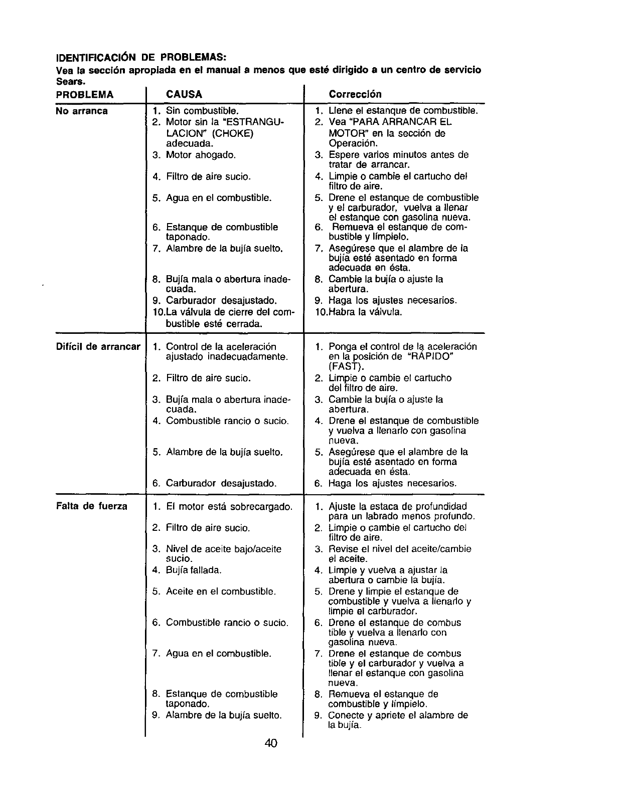
IDENTIFICACI6N DE PROBLEMAS:
Vea la secci6n apropiada en el manual a menos que eetd dirigido a un centro de servicio
Sears.
PROBLEMA
No arranca
Dificil de arrancar
Falta de fuerza
CAUSA
1. Sin combustible.
2. Motor sin la "ESTRANGU-
LACION" (CHOKE)
adecuada.
3. Motor ahogado.
4. Filtro de aire sucio.
5. Agua en el combustible.
6. Estanque de combustible
taponado.
7. Alambre de la bujia suelto.
8. Bujfa mala oabertura inade-
cuada.
9. Carburador desajustado.
10.La vdlvula de cierre del com-
bustible est_ cerrada.
1. Control de la aceleraci6n
ajustado inadecuadamente.
2. Filtro de aire sucio.
3. Bujfa mala o abertura inade-
cuada.
4. Combustible rancio o sucio.
5. Alambre de la bujia suelto.
6. Carburador desajustado.
1. El motor esta. sobrecargado.
2. Filtro de aire sucio.
3. Nivel de aceite bajo/aceite
sucio.
4. Bujia fallada.
5. Aceite en el combustible.
6. Combustible rancio o sucio.
7. Agua en el combustible.
8. Estanque de combustible
taponado.
9. Alambre de la bujia suelto.
Correccl6n
1. Llene el estanque de combustible.
2. Yea "PARA ARRANCAR EL
MOTOR" en la secci6n de
Operaci6n.
3. Espere varios minutos antes de
tratar de arrancar.
4. Limpie o cambie el cartucho del
filtro de aire.
5. Drene el estanque de combustible
y el carburador, vuelva a Ilenar
el estanque con gasolina nueva.
6. Remueva el estanque de com-
bustible y Ifmpielo.
7. Aseg_rese que el alambre de la
bujfa est_ asentado en forma
adecuada an _sta.
8. Cambie la bujfa o ajuste la
abertura.
9. Haga los ajustes necesarios.
10.Habra la vdlvula.
1. Ponga el control de la aceleraci6n
en la posici6n de "RAPIDO"
(FAST).
2. Limpie o cambie el cartucho
del filtro de aire.
3. Cambie la bujia o ajuste la
abertura.
4. Drene el estanque de combustible
y vuelva aIlenarlo con gasolina
nueva.
5. AsegSrese que el alambre de la
bujia est_ asentado en forma
adecuada en _sta.
6. Haga los ajustes necesarios.
1. Ajuste la estaca de profundidad
para un labrado menos profundo.
2. Limpie o cambie el cartucho del
filtro de aire.
3. Revise el nivel del aceite/cambie
el aceite.
4. Limpie y vuelva a ajustar la
abertura o cambie la bujia.
5. Drene y limpie el estanque de
combustible y vuelva a Ilenarlo y
limpie el carburador.
6. Drene el estanque de combus
tible y vuelva a Ilenarlo con
gasolina nueva.
7. Drene el estanque de combus
tible y el carburador y vuelva a
Ilenar el estanque con gasolina
nueva.
8. Remueva el estanque de
combustible y limpielo.
9. Conecte y apriete el alambre de
la bujia.
40
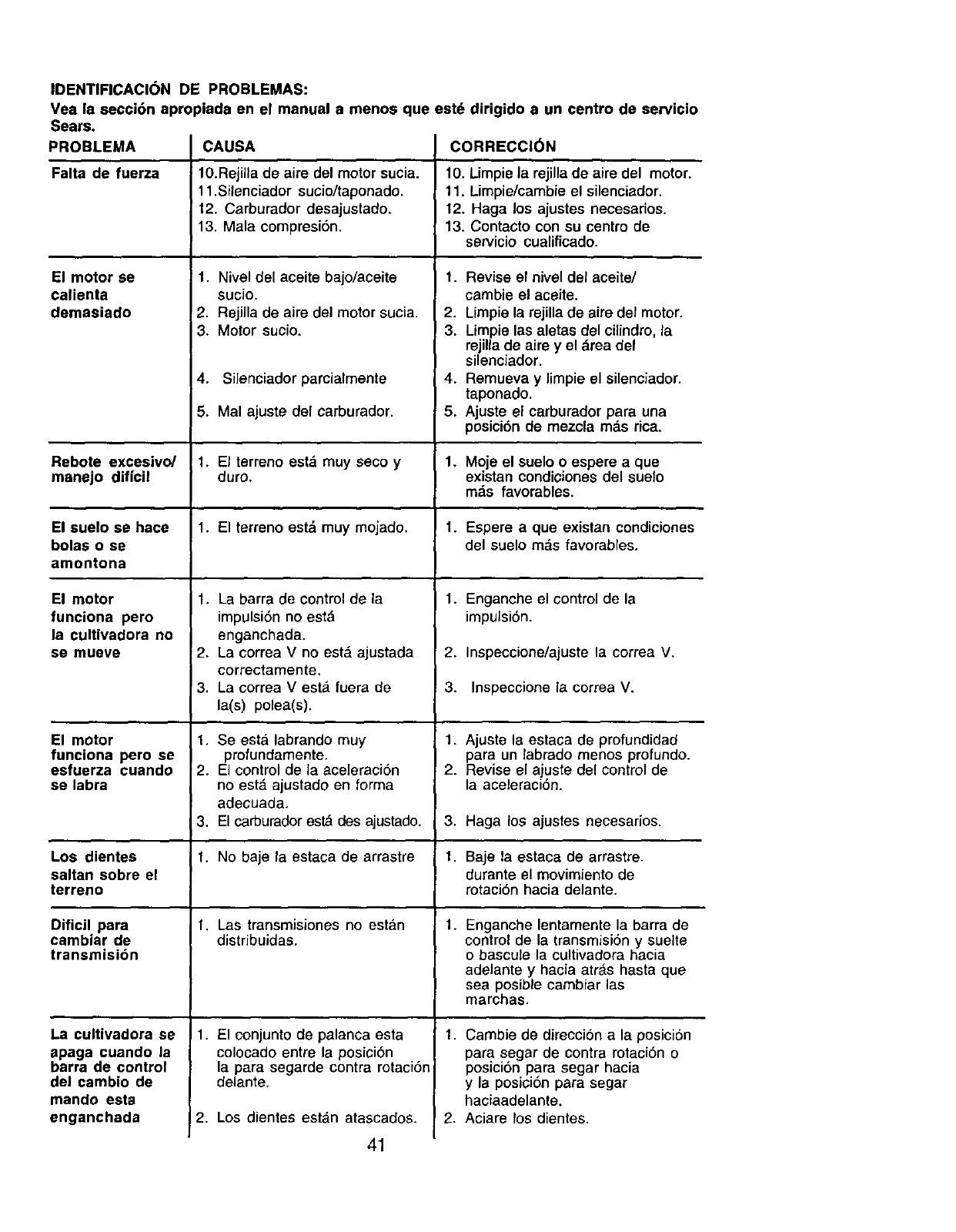
IDENTIFICACION DE PROBLEMAS:
Vea la secci6n apropiada en el manual a menos que estd dirigido a un centro de servicio
Sears.
PROBLEMA
Falta de fuerza
El motor se
calienta
demasiado
CAUSA
10.Rejilla de aire del motor sucia.
11.Silenciador sucio/taponado.
12. Carburador desajustado.
13. Mala compresi6n.
1. Nivel del aceite bajo/aceite
sucio.
2. Rejilla de aire del motor sucia.
3. Motor sucio.
4. Silenciador parcialmente
5. Mal ajuste del carburador.
CORRECCI6N
10. Limpie la rejilla de aire del motor.
11. Limpie/cambie el silenciador.
12. Haga los ajustes necesarios.
13. Contacto con su centro de
servicio cualificado.
1. Revise el nivel del aceite/
cambie el acaite.
2. Llmpie la rejilla de aire def motor.
3. Limpie las aletas del cilindro, la
rejilla de aire y el _.readel
silenciador.
4. Remueva y limpie el silenciador.
taponado.
5. Ajuste el carburador para una
posici6n de mezcla mds rica.
Rebote excesivo/ 1. El terreno estd muy seco y1. Moje el suelo o espere a que
manejo diffcil duro. existan condiciones del suelo
mds favorables.
El suelo se hace 1. El terreno estd muy mojado. 1. Espera a que existan condiciones
bolas o se del suelo mds favorables.
amontona
Enganche el control de la
impulsi6n.
El motor
funciona pero
la cultivadora no
se mueve
El motor
funciona pero se
esfuerza cuando
se labra
1. La barra de control de la
impulsiSnno est&
enganchada.
2. La correa V no est& ajustada
correctamente.
3. La correa Vesta fuera de
la(s) polea(s).
1, Se est;_ labrando muy
profundamente,
2, El control de la aceleraci6n
no estd ajustado en forma
adecuada,
3. El carburador estd des ajustado.
1. No baje la estaca de arrastre
1. Las transmisiones no est&n
distribuidas.
1. El conjunto de palanca esta
colocado entre la posici6n
la para segarde contra rotaci6n
delante.
2. Los dientes est&n atascados.
Los dientes
saltan sobre el
terreno
Dificil para
cambiar de
transmisibn
La cultivadora se
apaga cuando la
barra de control
del cambio de
mando esta
enganchada
1+
2.
3.
Inspeccione/ajuste la correa V.
Inspeccione la correa V.
1. Ajuste la estaca de profundidad
para un labrado menos profundo.
2. Revise el ajuste del control de
la aceleraci6n.
3. Haga los ajustes necesarios.
1. Baje la estaca de arrastre.
durante el movimiento de
rotaci6n hacia delante.
1. Enganche lentamente la barra de
control de la transmision y suelte
o bascule la cultivadora hacia
adelante y hacia atrAs hasta que
sea posible cambiar las
marchas.
1. Cambie de direccion a la posicion
para segar de contra rotaci6n o
posicion para segar hacia
y la posici6n para segar
haciaadelante.
2. Aciare los dientes.
41
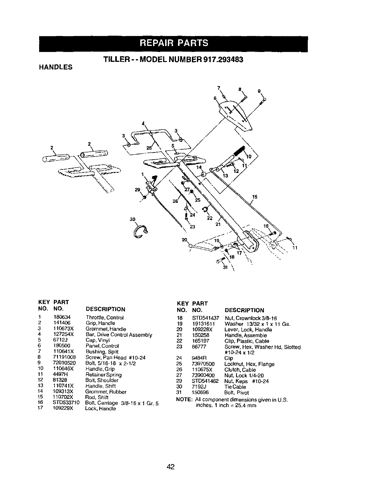
TILLER --MODEL NUMBER 917.293483
HANDLES
3
2
7 8 g
15
22 21
\,\
31 \\
11
KEY PART
NO. NO. DESCRIPTION
1 180634 Throttle, Control
2 141406 Grip, Handle
3 110673X Grommet, Handle
4 127254X Bar, Drive Control Assembly
5 6712J Cap, Vinyl
6 180500 Panel, Control
7 110641X Bushing, Split
8 71191008 Screw, Pan Head #10-24
9 72010520 Bolt, 5/16-18 x 2-1/2
10 110646X Handle, G rip
11 4497H Retainer Spring
12 81328 Bolt, Shoulder
13 110741X Handle, Shift
14 109313X Grommet, Rubber
15 110702X Rod, Shift
16 STb533710 Bolt, Carriage 3/8-16 x 1 Gr. 5
t7 109229X Lock, Handle
KEY PART
NO. NO. DESCRIPTION
18 STD541437 Nut, Crownlock 3/8-16
19 19131611 Washer 13/32 x 1 x 11 Ga.
20 109228X Lever, Lock, Handle
21 150258 Handle, Assemble
22 165197 Clip, Plastic, Cable
23 86777 Screw, Hex, Washer Hd, Slotted
#10-24 x 1/2
24 9484R Clip
25 73970500 Locknut, Hex, Flange
26 110675X Clutch, Cable
27 73900400 Nut, Lock 1/4-20
29 STD541462 Nut, Keps #10-24
30 7192J Tie CabJe
31 150696 Bolt, Pivot
NOTE: All component dimensions given in U.S.
inches. 1inch =25.4 mm
42
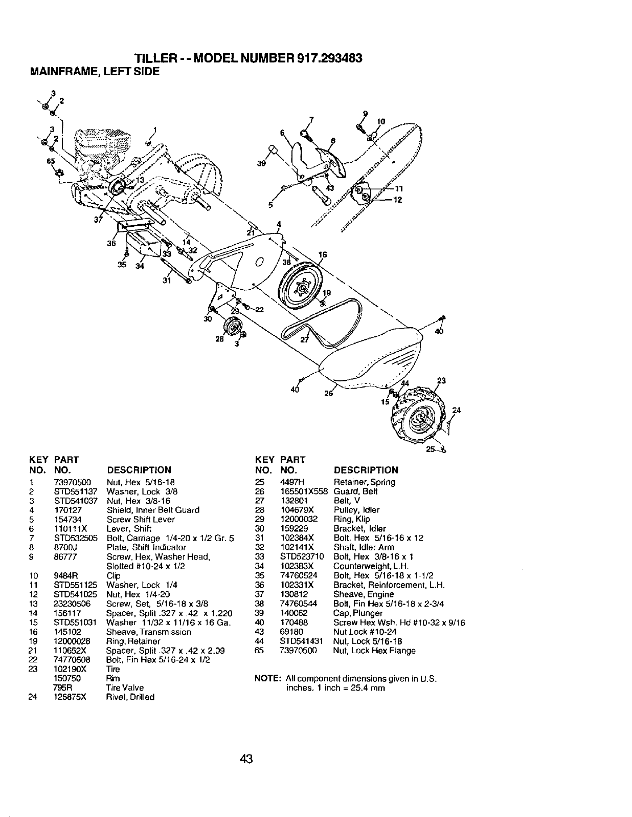
TILLER - - MODEL NUMBER 917.293483
MAINFRAME,LEFTSIDE
3
3
65
9
8
\
36
35
16
31
19
\
3O
28 3
40
23
24
KEY PART KEY
NO. NO. DESCRIPTION NO.
1 73970500 Nut, Hex 5/16-18 25
2 STD55t137 Washer, Lock 3/6 26
3 STD541037 Nut, Hex 3/8-16 27 132801
4 170127 Shield, Inner Belt Guard 28 104679X
5 154734 Screw Shift Lever 29 12000032
6 110111X Lever, Shift 30 159229
7 STD532505 Bolt, Carriage 1/4-20 x 1/2 Gr. 5 31 102384X
8 8700J Plate, Shift Indicator 32 102141X
9 86777 Screw, Hex, Washer Head, 33 STD523710
Slolted #10-24 x 1/2 34 102383X
10 9484R Clip 35 74760524
11 STD551125 Washer, Lock 1/4 36 102331X
12 STD541025 Nut, Hex 1/4-20 37 130812
13 23230506 Screw, Set, 5/16-18 x 3/8 38 74760544
14 156117 Spacer, Split .327 x .42 x 1.220 39 140062
15 STD551031 Washer 11/32x11/16x16Ga. 40 170488
16 145102 Sheave, Transmission 43 69180
19 12000028 Ring, Retainer 44 STD541431
21 110652X Spacer, Split .327 x .42 x 2.09 65 73970500
22 74770508 Bolt, Fin Hex 6/16-24 x 1/2
23 102190X 13re
150750 Rim
795R Tire Valve
24 126875X Rivet, Drilled
PART
NO. DESCRIPTION
4497H Retainer,Spdng
165501X558 Guard, Belt
Belt, V
Pulley, Idler
Ring,Klip
Bracket, Idler
Bolt, Hex 5/16-16 x 12
Shaft, IdlerArm
Bolt,Hex 3/8-16 x 1
Counterweight,L.H.
Bolt,Hex 6/16-18 x 1-1/2
Bracket, Reinfomement, L.H.
Sheave, Engine
Bolt,Fin Hex 5/16-18 x 2-3/4
Cap, Plunger
Screw Hex Wsh. Hd #19-32 x 9/16
Nut Lock #10-24
Nut, Lock 5/16-18
Nut, Lock Hex Flange
NOTE: All component dimensionsgiven in U.S.
inches, 1 inch = 25.4 mm
43
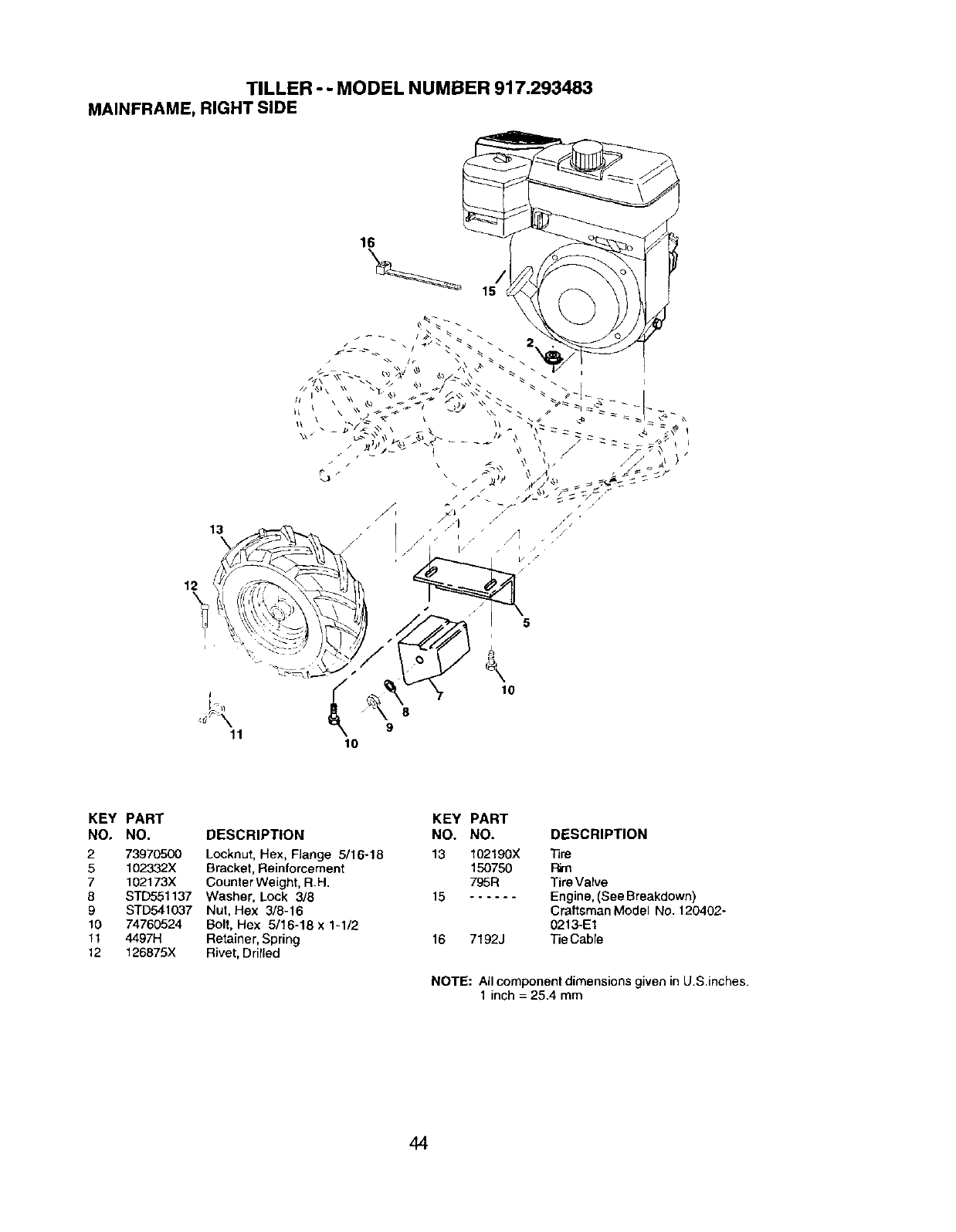
TILLER --MODEL NUMBER 917.293483
MAINFRAME, RIGHT SIDE
16
12
13
I
11 9
10
5
10
KEY PART
NO, NO. DESCRIPTION
273970500 Locknut, Hex, Flange 5/16-18
5 102332X Bracket, Reinforcement
7 102173X CounterWeight, R.H.
8 STD551137 Washer, Lock 3/8
9 STD541037 Nut, Hex 3/8-16
10 74760524 Bolt, Hex 5/16-18 x 1-1/2
1t 4497H Retainer, Spring
12 128875X Rivet, Drilled
KEY PART
NO. NO. DESCRIPTION
13 I02190X Tire
150750 Pirn
795R Tire Valve
15 Engine,(See Breakdown)
Craftsman Model NO.120402-
0213-E1
16 7192J Tie Cable
NOTE: All component dimensions given in U.S.inches.
1 inch = 25.4 mm
44
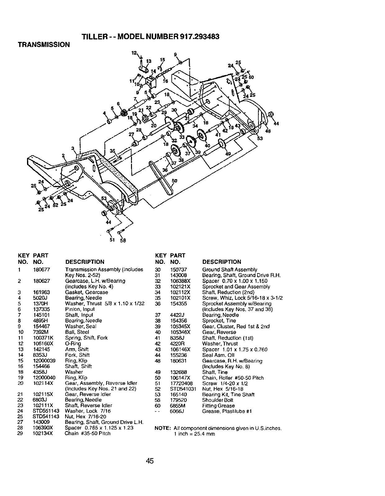
TRANSMISSION TILLER - - MODEL NUMBER 917.293483
18
I
11
6
5
25
44
81
KEY PART KEY PART
NO. NO. DESCRIPTION NO. NO.
1 180677 TransmissionAssembly(includes 30 150737
Key Nos. 2-52) 31 143008
2 180627 Geamase, L.H. w/Bearing 32 106388X
(includes Key No. 4) 33 102121X
3 161963 Gasket, Gearcase 34 102112X
4 5020J Bearing,Needle 35 102101X
5 1370H Washer, Thrust 5/8 x 1.10 x 1/32 36 154355
6137335 Pinion, Input
7 145101 Shaft, Input 37 4422J
8 4895H Bearing,Needle 38 154356
9154467 Washer, Seal 39 105345X
10 7392M Ball, Steel 40 105346X
11 100371K Spring, Shift, Fork 41 8358J
12 106160X O-Ring 42 4220R
13 142145 Arm, Shift 43 106146X
14 8353J Fork, Shift 44 155236
15 12000039 Ring,Klip 48 180631
16 154466 Shaft, Shift
18 4358J Washer 49 132688
19 12000040 Ring, Klip 50 106147X
20 102114X Gear, Assembly, Reverse Idler 51 17720408
(Includes Key Nos+21 and 22) 52 STD541031
21 102115X Gear, Reverse Idler 53 165140
22 6803J Bearing,Needle 58 t 79520
23 102111X Shaft, Reverse Idler 60 6855M
24 STD551143 Washer, Lock 7/16 -- 6066J
25 STD641143 Nut, Hex 7/16-20
27 143009 Bearing, Shaft, Ground Drive LH.
28 106390X Spacer 0.765 x 1.t25 x 1.23
29 102134X Chain #35-50 Pitch
DESCRIPTION
GroundShaft Assembly
Bearing,Shaft, Ground DriveR.H.
Spacer 0.70 x 1.00 x 1.150
Sprocketand Gear Assembly
Shaft, Reduction(2nd)
Screw, Whiz, Lock 5/16-18 x 3-1/2
SprocketAssemblyw/Bearing
(includesKey Nos. 37 and 38)
Bearing,Needle
Sprocket,Tine
Gear, Cluster, Red 1st & 2nd
Gear, Reverse
Shaft, Reduction(1st)
Washer, Thrust
Spacer 1.01 x 1.75 x 0.760
Seal Asm. OII
Gearcase, R.H. w/Bearing
(Includes Key No. 8)
Shaft, Tine
Chain, Roller #50-50 Pitch
Screw 1/4-20 x 1/2
Nut, I-lex 5/16-18
Bearing Kit, Tine Shaft
Shoulder Bolt
Fitting Grease
Grease, Plastilube #1
NOTE: Air componentdimensions given in US.inches.
1 inch = 25.4 mm
45
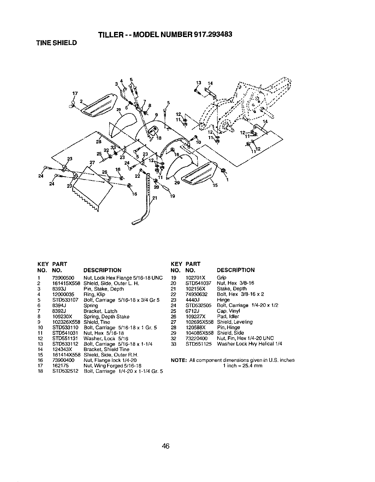
TILLER -- MODEL NUMBER 917.293483
TINE SHIELD
24
17
5
3 13 14
1
24 29 15
19
KEY PART KEY PART
NO. NO. DESCRIPTION NO. NO, DESCRIPTION
1 73900500 Nut, Lock Hex Flange 5/16-18 UNC 19 102701X Grip
21614t5X558 Shield, Side, Outer L.H. 20 STD541037 Nut, Hex 3/8-16
3 8393J Pin, Stake, Depth 21 102156X Stake, Depth
4 12000035 Ring, Klip 22 74930632 Bolt, Hex 3/8-16 x 2
5 STD533107 Bolt, Carriage 5/16-18 x 3/4 Gr 5 23 4440J Hinge
6 8394J Spring 24 STD532505 Bort, Carriage 1/4-20 x 1/2
7 8392J Bracket, Latch 25 6712J Cap, Vinyl
8 109230X Spring, Depth Stake 26 109227X Pad, Idler
9 102326X558 Shield,Tiee 27 102695X558 Shield, Leveling
10 STD533110 Bolt, Carriage 5/16-18 x 1 Gr. 528 120588X Pin, Hinge
11 STD541031 Nut, Hex 5/16-18 29 104085X558 Shield, Side
12 STD551131 Washer, Lock 5/16 32 73220400 Nut, Fin, Hex 1/4-20 UNC
13 STD538112 Bolt, Carriage 5/16-18 x 1-1/4 33 STD551125 Washer Lock Hvy Helical 1/4
14 124343X Bracket, Shield Tine
15 161414X558 Shield, Side, Outer R.H.
16 73900400 Nut, Flange lock 1/4-20 NOTE: All component dimensions given in U.S. inches
17 162175 Nut, Wing Forged 5/16-18 t inch = 25.4 mm
18 STD532512 Bolt, Carriage 1/4-20 x 1-1/4 Gr. 5
46
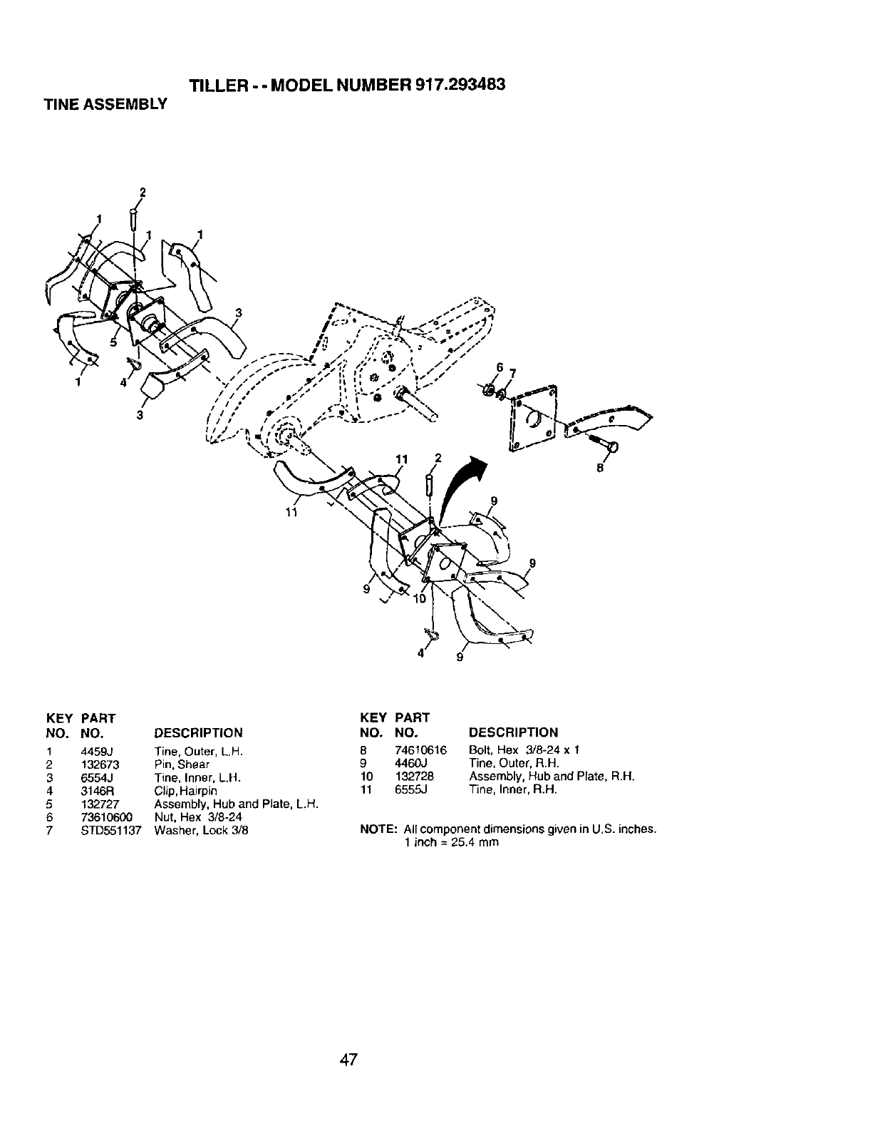
TILLER --MODEL NUMBER 917.293483
TINE ASSEMBLY
9
9
9
KEY PART
NO. NO. DESCRIPTION
1 4459J Tine, Outer, L.H.
2 132673 Pin, Shear
3 6554J Tine, Inner, L.H.
4 3146R Clip, Hairpin
5 132727 Assembly, Hub and Plate, L.H.
6 73610600 Nut, Hex 3/8-24
7STD551137 Washer, Lock 3/8
KEY PART
NO. NO, DESCRIPTION
8 74610616 Bolt, Hex 3/8-24 x 1
9 4460J Tine, Outer, R.H.
10 132728 Assembly, Hub and Plate, R.H.
11 6555J Tine, Inner, R.H.
NOTE: All component dimensions given in U,S. inches.
1 inch = 25.4 mm
47
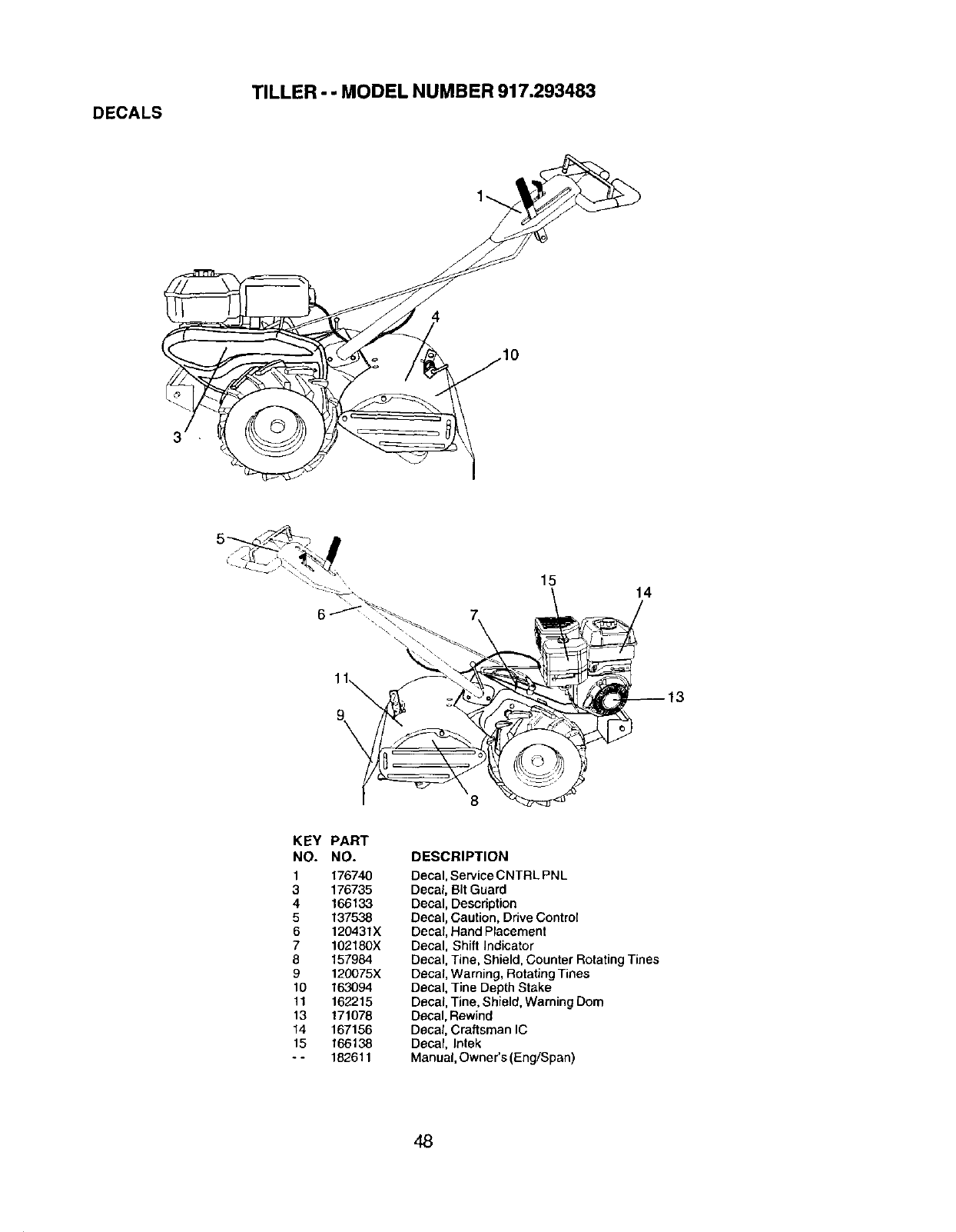
DECALS
TILLER --MODEL NUMBER 917.293483
1
6
15 14
/
_13
KEY
NO.
1
3
4
5
6
7
8
9
10
11
13
14
15
..
PART
NO.
176740
176735
166133
137538
120431X
102180)(
157984
120075X
163094
162215
171078
167156
166138
182611
DESCRIPTION
Decal, Service CNTRL PNL
Decal, Bit Guard
Decal, Description
Decal, Caution, Ddve Control
Decal, Hand Placement
Decal, Shift Indicator
Decal, Tine, Shield, Counter Rotating Tines
Decal, Warning, Rotating Tines
Decal, Tine Depth Stake
Decal, Tine, Shield, Warning Dom
Decal, Rewind
Decal, Craftsman IC
Decal, Intek
Manual, Owner's (Eng/Span)
48
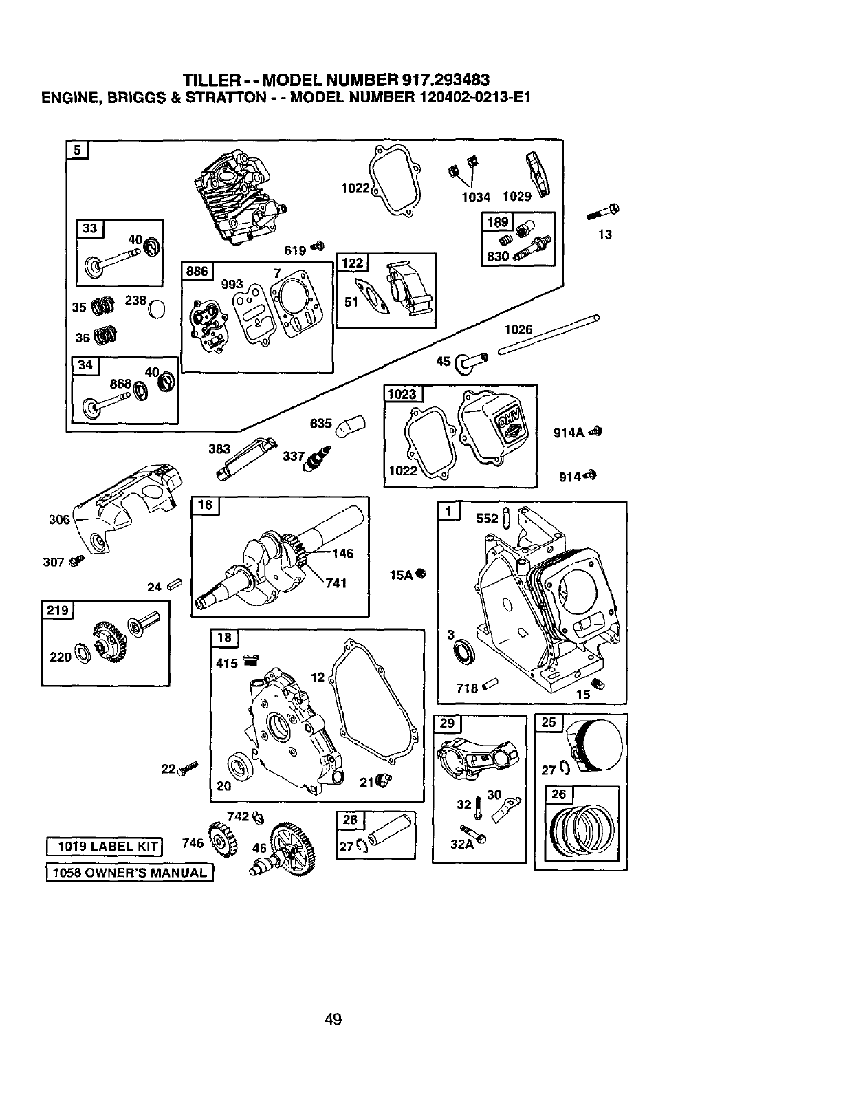
TILLER --MODEL NUMBER 917.293483
ENGINE, BRIGGS & STRATTON - - MODEL NUMBER 120402--0213-E1
307 _P
24
22_
415
7421_
, 1019 LABEL KITJ 746_ 46_
15A_
49
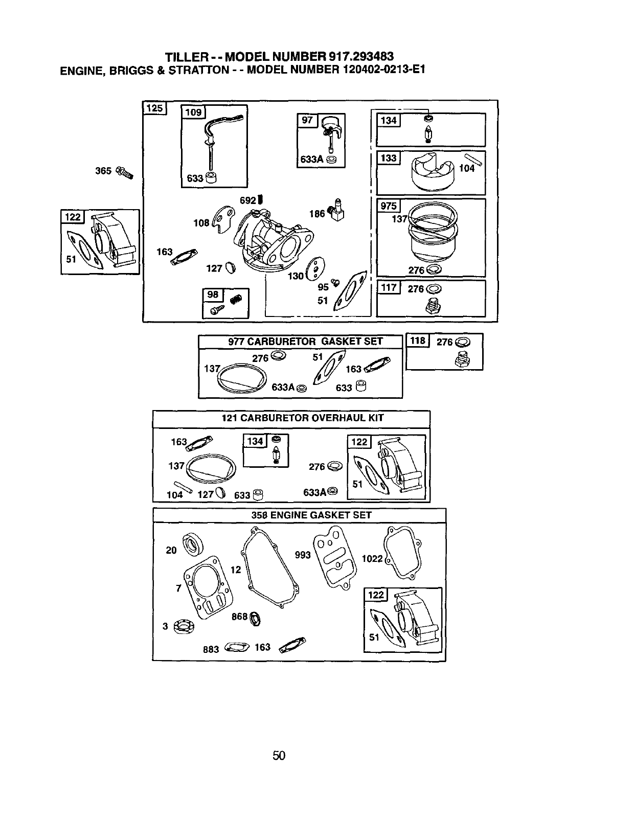
TILLER -- MODEL NUMBER 917.293483
ENGINE, BRIGGS & STRATTON - -MODEL NUMBER 120402-0213-E1
633
69211
163 _ ("_,_ _// --
127(_ _0_ /' 276_
977 CARBURETOR276_55_/_GASKETSET 1_'J
137Q 163_
633A_ L_ 633
276
121 CARBURETOR OVERHAUL KIT
104 127(_ 633_ 833A
358 ENGINE GASKET SET
2O
868_
883 _163
5O
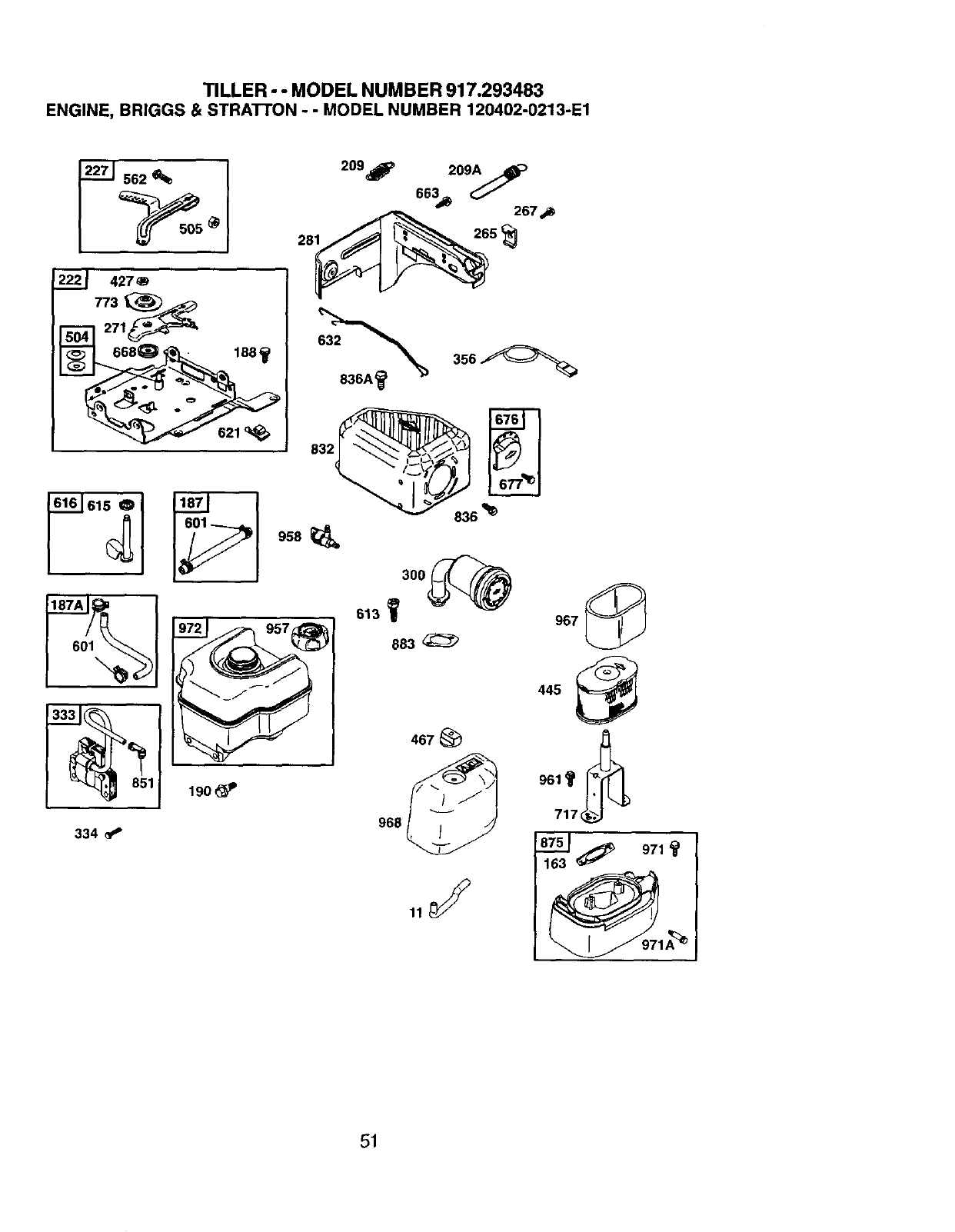
TILLER - - MODEL NUMBER 917.293483
ENGINE, BRIGGS & STRATrON - -MODEL NUMBER 120402-0213-E1
427
271_
663_ 267 .,_
851 I
334
621'_;. 832
190_
836 _
3oo
613 _"_"
883
467_
968
445
9_1t
717 _._1.
87_ _;_ 971
163
51
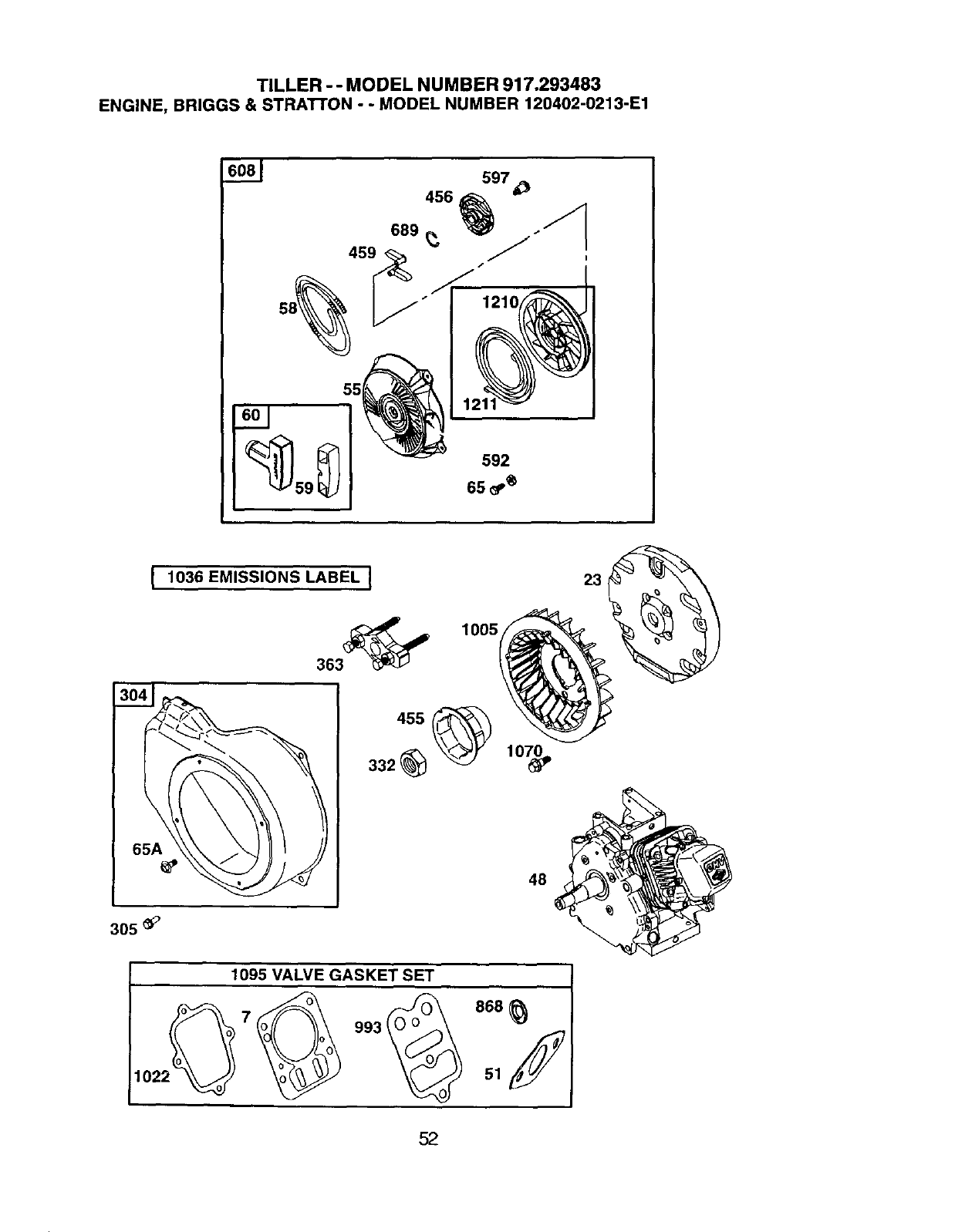
TILLER - - MODEL NUMBER 917.293483
ENGINE, BRIGGS & STRATI'ON --MODEL NUMBER 120402-0213-E1
456 597
689 _, j'_
I1036 EMISSIONS LABEL I
363_
1005
48
23
305 _'
1095 VALVE GASKET SET
2_7_ "3_ 666_102 51 f
52
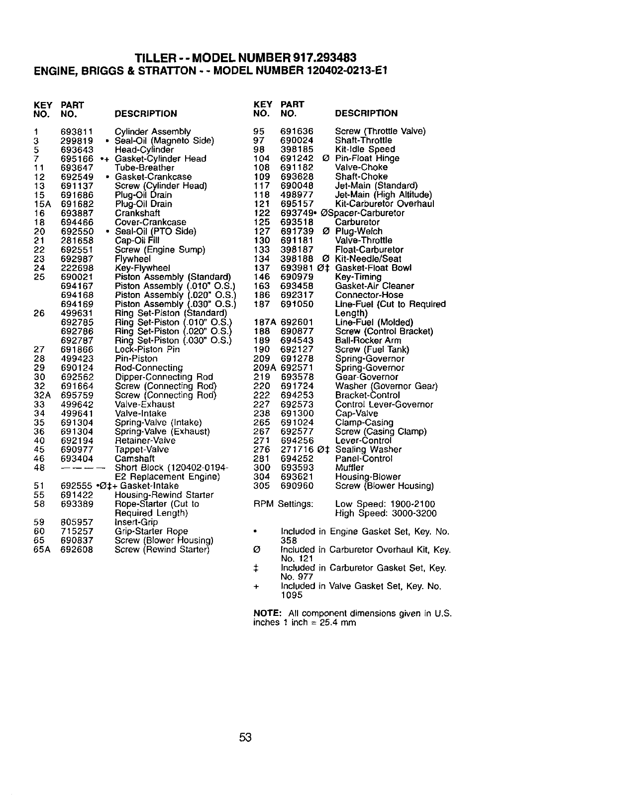
TILLER - - MODEL NUMBER 917.293483
ENGINE, BR]GGS & STRATTON -- MODEL NUMBER 120402-0213-E1
KEY PART KEY PART
NO. NO. DESCRIPTION NO. NO. DESCRIPTION
1693811 Cylinder Assembly 95 691636
3299819 • Seal-Oil (Magneto Side) 97 690024
5 693643 Head-Cylinder 98 398185
7 695166 .+ Gasket-Cylinder Head 104 691242
11 693647 Tube-Breather 108 691182
12 692549 •Gasket-Crankcase f09 693628
13 691137 Screw (Cylinder Head) 117 690048
15 691686 Plug-Oil Drain 118 498977
15A 691682 Plug-Oil Drain 121 695157
16 693887 Crankshaft f 22
18 694466 Cover-Crankcase 125
20 692550 •Seal-Oil (PTO Side) 127
21 281658 Cap-Oil Fill 130
22 692551 Screw (Engine Sump) 133
23 692987 Flywheel 134
24 222698 Key-Flywheel 137
25 690021 Piston Assembly (Standard) 146 690979
694167 Piston Assembly (.010" O.S.) 163 693458
694168 Piston Assembly _.020" O.S.) 186 692317
694169 Piston Assembly (.030" O.S.) 187 691056
26 499631 Ring Set-Piston (Standard)
692785 Ring Set-Piston (.010" O.S.) 187A 692601
692786 Ring Set-Piston (.020" O.S.) 188 690877
692787 Ring Set-Piston (.030" O.S,) 189 694543
27 691866 Lock-Piston Pin 190 692127
28 499423 Pin-Piston 209 691278
29 690124 Rod-Connecting 209A 692571
30 692562 Dipper-Connecting Rod 219 693578
32 691664 Screw (Connecting Rod) 220 691724
32A 695759 Screw (Connecting Rod) 222 694253
33 499642 Valve-Exhaust 227 692573
34 499641 Valve-Intake 238 691300
35 691304 Spring-Valve (Intake) 265 691024
36 691304 Spring-Valve (Exhaust) 267 692577
40 692194 Retainer-Valve 271 694256
45 690977 Tappet-Valve 276 271716
46 693404 Camshaft 261 694252
46 Short B{ock (120402-0194- 300 693593
E2 Replacement Engine) 304 693621
51 692555 -_:_+ Gasket-Intake 305 690960
55 691422 Housing-Rewind Starter
58 693389 Rope-Starter (Cut to
Required Length)
59 605957 Insert-Grip
60 715257 Grip-Starter Rope
65 690837 Screw (Blower Housing)
65A 692608 Screw (Rewind Starler)
Screw (Throttle Valve)
Shaft-Throttle
Kit-Idle Speed
O Pin-Float Hinge
Valve-Choke
Shaft-Choke
Jet-Main (Standard)
Jet-Main (High Altitude)
Kit-Carburetor Overhaul
693749° _Spacer-Carburetor
693518 Carburetor
691739 _ Plug-Welch
691181 Valve-Throttle
398187 Float-Carburetor
398188 121Kit-Needle/Seat
693981 _:1: Gasket-Float Bowl
Key-Timing
Gasket-Air Cleaner
Connector-Hose
Line-Fuel (Cut to Required
Length)
Line-Fuel (Molded)
Screw (Control Bracket)
Bali-Rocker Arm
Screw (Fuel Tank)
Spring-Governor
Spring-Governor
Gear-Governor
Washer (Governor Gear)
Bracket-Control
Contro{ Lever-Governor
Cap-Valve
Clamp-Casing
Screw (Casing Clamp)
Lever-Control
O:_ Sealing Washer
Panel-Control
Muffler
Housing-Blower
Screw (Blower Housing)
RPM Settings: Low Speed: 1900-2100
High Speed: 3000-3200
÷
Included
358
Included
No. 121
Included
No. 977
Included
1095
in Engine Gasket Set, Key. No.
in Carburetor Overhaul Kit, Key.
in Carburetor Gasket Set, Key.
in Valve Gasket Set, Key. No.
NOTE: All component dimensions given in U.S.
inches 1 inch = 25.4 mm
53
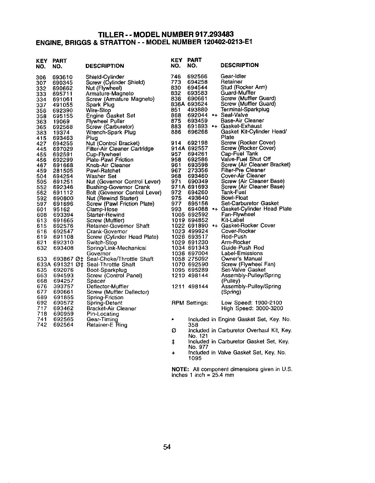
TILLER --MODEL NUMBER 917.293483
ENGINE, BRIGGS & STRATTON -- MODEL NUMBER 120402-0213-E1
KEY PART KEY PART
NO. NO. DESCRIPTION NO. NO, DESCRIPTION
306 693610 Shield-Cylinder 746 692566 Gear-Idler
307 690345 Screw (Cylinder Shield) 773 694258 Retainer
332 690662 Nut (Flywheel) 830 694544 Stud (Rocker Arm)
333 69571t Armature-Magneto 832 693583 Guard-Muffler
334 691061 Screw (Armature Magneto) 836 690661 Screw (Muffler Guard)
337 491055 Spark Plug 836A 693624 Screw (Muffler Guard)
356 692390 Wire-Stop 851 493880 TerminaI-Sparkplug
358 695155 Engine Gasket Set 868 692044 ,+ Seal-Valve
363 t9069 Flywheel Puller 875 693459 Base-Air Cleaner
365 692568 Screw (Carburetor) 883 691893 ,+ Gasket-Exhaust
383 19374 Wrench-Spark Plug 886 696268 Gasket Kit-Cylinder Head/
415 693463 Plug Plate
427 694255 Nut (Control Bracket) 914 692198 Screw (Rocker Cover)
445 697029 Filter-Air Cleaner Cartridge 914A 692557 Screw (Rocker Cover)
455 692591 Cup-Flywheel 957 694261 Cap-Fuel Tank
456 692299 Plate-Pawl Fdction 958 692586 Valve-Fuel Shut Off
467 691668 Knob-Air Cleaner 961 693598 Screw (Air Cleaner Bracket)
459 281505 PawI-Ratchet 967 273356 Filter-Pre Cleaner
504 694254 Washer Set 968 693460 Cover-Air Cleaner
505 691251 Nut (Governor Control Lever) 971 690349 Screw (Air Cleaner Base)
552 692346 Bushing-Governor Crank 971A 691693 Screw (Air Cleaner Base)
562 691112 Bolt (Govemor Control Lever) 972 694260 Tank-Fuel
592 690800 Nut (Rewind Starter) 975 493640 Bowl-Float
597 691696 Screw (Pawl Friction Plate) 977 695156 Set-Carburator Gasket
601 95162 Clamp-Hose 993 694089 °+ Gasket-Cylinder Head Plate
608 693394 Starter-Rewind 1005 692592 Fan-Flywheel
613 691665 Screw(Muffler) 1019 694852 Kit-Label
615 692576 Retainer-Governor Shaft 1022 691890 ,+ Gasket-Rocker Cover
616 692547 Crank-Governor 1023 499924 Cover-Rocker
619 691108 Screw (Cylinder Head Plate) 1025 693517 Rod-Push
621 692310 Switch-Stop 1029 691230 Arm-Rocker
632 693408 Spring/Link-Mechanical 1034 691343 Guide-Push Rod
Governor 1036 697004 Label-Emissions
633 693867 O_; Seal-Choke/Throttle Shaft 1056 275092 Owner's Manual
633A 691321 _: Seal-Throttle Shaft 1070 692590 Screw (Flywheel Fan)
635 692076 Boot-Sparkplug 1095 695289 Set-Valve Gasket
663 694593 Screw (Control Panel) 1219 498144 Assembly-Pulley/Spring
668 694257 Spacer (Pulley)
676 393757 Deflector-Muffler 1211 498144 Assembly-Pulley/Spring
677 690661 Screw (Muffler Deflector) (Spring)
689 691855 Spring-Friction
692 690572 Spring-Detent RPM Settings: Low Speed: 1900-2100
717 693462 Bracket-Air Cleaner High Speed: 3000-3200
718 690959 Pin-Locating
741 692565 Gear-Timing Included in Engine Gasket Set, Key. No.
742 692564 Retainer-E Ring 358
Included in Carburetor Overhaul Kit, Key.
No. 121
:1: Included in Carburetor Gasket Set, Key.
No. 977
+Included in Valve Gasket Set, Key. No.
1095
NOTE: All component dimensions given in U.S.
inches 1 inch = 25.4 mm
54

55
Forrepairof carry-in products like vacuums, lawn equipment, and
electronics, call for the nearest Sears Parts and Repair Center.
1-800-488-1222 _, dayornight(U.SA.orgy)
L<_[t
!i 111
iili!ili!:11!i
i!iliii_1
i:i:i_!i}i) i
>>
i i!iii!i1
!iiiiiiiiii i
:!_!i!lii!
For the replacement parts, accessories and owner's manuals
that you need to do-it-yourself, call Sears PartsDirectSM!
1-800-366-PART 6a.m.-11 p.m., 7 daysaweek
(1-800-366-7278) (U.S.A.only)
www.sears.c_partsdirect
To purchase or inquire about a Sears Service Agreement
or Sears Maintenance Agreement:
1-800-827-6655 (u.s._.) 1-800-361-6665 (Canada)
7 a.m.- 5 p.m.,CST, Mort.- Sat. 9 a.m.- 8 p.m. EST,M- F,4 p.m. Sat.
Parapedirsewicio de reparaci6na
dom_cilio,y para ordenarpiezas:
1-888-SU-HOGAR_
(1-8a8-784-642-/)
AuCanada pourset,Aceenf_:
1-800-LE-FOYERMC
(1-800-533_o9_
_NW._ars._
}i ;" iii, _;<
....:=:=!:]IE]=IIIEI=II]=I=EII]=Ei]]I
H°meCentral®J
® Registered Trademark /TMTrademark /SMService Mark of Sears, Roebuck and Co.
® Marca Registrada /TMMarca de F_,brica /su Marca de Servicio de Sears, Roebuck and Co.
Mc Marque de commerce /UDMarque d6pos_e de Sears, Roebuck and Co.
182611 2.12.02 TR Printed in U.S.A.
