Craftsman 917293490 User Manual REAR TINE TILLER Manuals And Guides L0101118
CRAFTSMAN Rear Tine, Gas Tiller Manual L0101118 CRAFTSMAN Rear Tine, Gas Tiller Owner's Manual, CRAFTSMAN Rear Tine, Gas Tiller installation guides
User Manual: Craftsman 917293490 917293490 CRAFTSMAN REAR TINE TILLER - Manuals and Guides View the owners manual for your CRAFTSMAN REAR TINE TILLER #917293490. Home:Lawn & Garden Parts:Craftsman Parts:Craftsman REAR TINE TILLER Manual
Open the PDF directly: View PDF ![]() .
.
Page Count: 39
Owner's Manual
JCRAFTSMAWJ
7.0 HP
19 INCH TINE WIDTH
REAR TINE WITH
DUAL ROTATING TINES
TILLER
Model No.
917.293490
Safety
Assembly /_
•Operation /
•Maintenance _/_ °
•Espanol / __
•Repair Parts __'_ i,_
This product has a low emission engine which operates
differently from previously built engines. Before you start the
engine, read and understand this Owner's Manual.
CAUTION:
Read and follow all Safety
Rules and Instructions before
operating this equipment,
Seam, Roebuck and Co., Hoffman Estates, II 60179
Visit our Craftsman website:www.sears.com/craftsman
Warranty ............................................... 2
Safety Rules ......................................... 2
Product Specifications .......................... 4
Assembly .............................................. 5
Operation .............................................. 8
Maintenance ....................................... 14
Maintenance Schedule...................... 14
Serviceand Adjustments.................... 16
Storage ............................................... 20
Troubleshooting................................. 21
IllustratedParts List............................44
Parts Ordering..................... Back Cover
LIMITED TWO YEAR WARRANTY ON CRAFTSMAN TILLER
For two (2) years from date of purchase, when this Craftsman Tiller is maintained,
lubricated, and tuned up according to the operating and maintenance instructions in
the owner's manual, Sears will repair free of charge any defect in material or workman-
ship.
This Warranty does not cover:
•Expendable items which become worn during normal use, such as tines, spark
plugs, air cleaners and belts.
•Repairs necessary because of operator abuse or negligence, including bent
crankshafts and the failure to maintain the equipment according to the instructions
contained in the owner's manual.
•If this Craftsman Tiller is used for commercial or rental purposes, this Warranty
applies for only thirty (30) days from the date of purchase.
Warranty service is available by returning the craftsman power mower to the nearest
sears service center/department in the united states. This warranty applies only while
this product is in use in the united states.
This Warrantygivesyouspecificlegal rights,and you may also have other dghts which
varyfrom stateto state.
SEARS, ROEBUCK AND CO., D/817WA, HOFFMAN ESTATES, IL 60179
IMPORTANT: This cutting machine is capable of amputating hands and feet and
throwing objects. Failure to observe the following safety instructions could result in
serious injury or death.
TRAINING •
• Read the Owner's Manual carefully. Be
thoroughly familiar with the controls
and the proper use of the equipment. "
Know how to stop the unit and disen-
gage the controls quickly.
•Never allow children to operate the
equipment. Never allow adults to °
operate the equipment without proper
instruction.
•Keep the area of operation clear of all "
persons, padicularly small children,
and pets. °
PREPARATION
•Thoroughly inspect the area where the
equipment is to be used and remove all
foreign objects. 2
Disengage all clutches and shift into
neutral before starting the engine
(motor).
Do not operate the equipment without
wearing adequate outer garments.
Wear footwear that will improve footing
on slippery surfaces.
Handle fuel with care; it is highly
flammable.
Use an approved fuel container.
Never add fuel to a running engine or
hot engine.
Fill fuel tank outdoors with extreme
care. Never fill fuel tank indoors.
Replace gasoline cap securely and
clean up spilled fuel before restarting.

• Useextension cords and receptacles
as specified by the manufacturer for all
units with electric drive motors or
electric starting motors.
• Never attempt to make any adjustments
while the engine (motor) is running
(except where specifically recommend-
ed by manufacturer).
OPERATION
•Do not put hands or feet near or under
rotating parts.
•Exercise extreme caution when
operating on or crossing gravel drives,
walks, or roads. Stay alert for hidden
hazards or traffic. Do not carry passen-
gers.
•After striking a foreign object, stop the
engine (motor), remove the wire from
the spark plug, thoroughly inspect the
tiller for any damage, and repair the
damage before restarting and operat-
ing the tiller.
•Exercise caution to avoid slipping or
falling.
• If the unit should start to vibrate
abnormally, stop the engine (motor)
and check immediately for the cause.
Vibration is generally a warning of
trouble.
•Stop the engine (motor) when leaving
the operating position.
•Take all possible precautions when
leaving the machine unattended.
Disengage the tines, shift into neutral,
and stop the engine.
•Before cleaning, repairing, or inspect-
ing, shut off the engine and make
certain all moving parts have stopped.
Disconnect the spark plug wire, and
keep the wire away from the plug to
prevent accidental starting. Disconnect
the cord on electric motors.
•Do not run the engine indoors; exhaust
fumes are dangerous.
•Never operate the tiller without proper
guards, plates, or other safety protec-
tive devices in place.
•Keep children and pets away.
•Do not ovedoad the machine capacity
by attempting to till too deep at too fast
a rate.
•Never operate the machine at high
speeds on slippery surfaces. Look
behind and use care when backing.
•Never allow bystanders near the unit.
•Usa only attachments and accessories
approved by the manufacturer of the
tiller.
•Never operate the tiller without good
visibility or light.
•Be careful when tilling in hard ground.
The tines may catch in the ground and
propel the tiller forward. If this occurs,
let go of the handlebars and do not
restrain the machine.
MAINTENANCE AND STORAGE
•Keep machine, attachments, and
accessories in safe working condition.
•Check shear pins, engine mounting
bolts, and other bolts at frequent
intervals for proper tightness to be sure
the equipment is in safe working
condition.
•Never store the machine with fuel in the
fuel tank inside a building where
ignition sources are present, such as
hot water and space heaters, clothes
dryers, and the like. Allow the engine to
cool before storing in any enclosure.
•Always refer to the operator's guide
instructions for important details if the
tiller is to be stored for an extended
period.
_Look for this symbol to point out
important safety precautions. It means
CAUTION!!! BECOMEALERT!H YOUR
_LAFETY IS INVOLVED.
CAUTION: Always disconnect spark
plug wire and place wire where it cannot
contact spark plug in order to prevent
accidental starting when setting up,
transporting, adjusting or making repairs.
_WARNING: Engine exhaust, some of
its constituents, and certain vehicle
components contain or emit chemicals
known to the State of California to cause
cancer and birth defects or other repro-
ductive harm.
3
PRODUCT SPECIFICATIONS
GASOLINE 4 QUARTS
CAPACITY: UNLEADED
REGULAR
OIL (API-SF-SJ): SAE 30
3APACITY: 19 OZ.) (ABOVE 40°F)
SAE5W-30/10W-30
(BELOW 40°F)
,SPARK PLUG : CHAMPION
(GAP: .030") RJ19LM OR
J19LM
CONGRATULATIONS on your purchase
of a Sears Tiller. It has been designed,
engineered and manufactured to give
you the best possible dependability and
performance.
Should you experience any problems you
cannot easily remedy, please contact a
Sears or other qualified Service Center.
We have competent, well-trained techni-
cians and the proper tools to service or
repair this unit.
Please read and retain this manual. The
instructions will enable you to assemble
and maintain your tiller properly. Always
observe the "SAFETY RULES".
Your new tiller has been assembled at the
factory with exception of those parts left
unassembled for shipping purposes. To
ensure safe and proper operation of your
tiller all parts and hardware you as-
semble must be tightened securely. Use
the correct tools as necessary to insure
proper tightness.
CUSTOMER RESPONSIBILITIES
•Read and observe the safety rules.
•Follow a regular schedule in maintain-
ing, caring for and using your tiller.
•Follow the instructions under the
"Customer Responsibilities" and
"Storage" sections of this Owner's
_Manual.
WARNING: This unit is equipped with
an internal combustion engine and
should not be used on or near any
unimproved forest-covered, brush-
covered or grass covered land unless the
engine's exhaust system is equipped with
a spark arrester meeting applicable local
or state laws (if any). If a spark arraster is
used, it should be maintained in effective
working order by the operator.
In the state of California the above is
required by law (Section 4442 of the
California Public Rssourcas Code).
Other states may have similar laws.
Federal laws apply on federal lands. A
spark arrester for the muffler is available
through your nearest Sears service
center (See REPAIR PARTS section of
this manual).
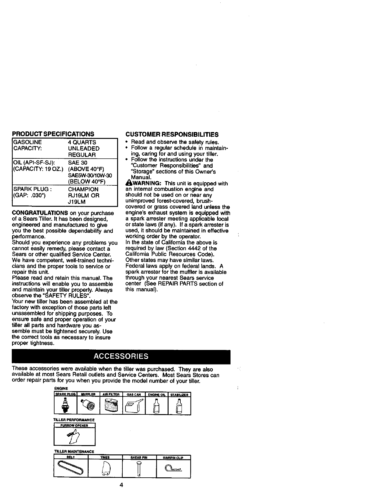
These accessories were available when the tiller was purchased. They are also
available at most Seam Retail outlets and Service Centem. Most Seam Stores can
order repair parts for you when you provide the model number of your tiller.
ENGINE
JSPARKPLUGI MUFFLER I AIRFILTER IGASC_ IENGIm!OIL _AUn_R
TILLER PERFORMANCE
FURROW OPENER
¢
TILLER MAINTENANCE
BELT _NES SHEAR MN HAIRPIN CLIp

Your new tiller has been assembled at the
factory with exception of those parts left
unassembled for shipping purposes. To
ensure safe and proper operation of your
tiller all parts and hardware you assemble
must be tightened securely. Use the
correct tools as necessary to insure
proper tightness.
TOOLS REQUIRED FOR ASSEMBLY
A socket wrench set will make assembly
easier. Standard wrench sizes are listed.
(1) Utility knife
(1) Wire cutter
(1) Tire pressure gauge
(t) Screwdriver
(1) Pair of pliers
(1) 9/16" wrench
OPERATOR'S POSITION
When right or left hand is mentioned in
this manual, it means when you are in the
operating position (standing behind tiller
handles).
FRONT
OPERATOR'S
POSITION
RIGHT
CONTENTS OF HARDWARE PACK
(2) Handle Locks
(1) Center Locknut
(1) Carriage Bolt 3/8-16 UNC
3/8-16 UNC x 1Gr. 5
(1) Hairpin Clips
,(1) Flat Washer
13/32 x 1 x 11 Ga.
°l
(2) Shear Pins & Clips
(1) Cable Clip
(1) Pivot Bolt
3/8-16 UNC Grade 5
O(1) Handle Lock Lever %

UNPACKING CARTON
ACAUTION: Be careful of exposed
staples when handling or disposing of
cartoning material.
IMPORTANT: When unpacking and
assembling tiller, be careful not to stretch
or kink cables.
I. While holding handle assembly, cut
cable ties securing handle assembly
to top frame. Let handle assembly
rest on tiller.
2. Remove top frame of carton.
3. Slowly ease handle assembly up and
place on top of carton.
4. Cut down right hand front and right
hand rear comers of carton. Lay side
carton wall down.
5. Remove packing material from handle
assembly.
Shift Rod
Assembly
INSTALL HANDLE
1. Insert the thicker black handle lock
(with teeth facing to the right) in
gearcase notch.
VIEWED FROM R.H. SIDE OF TILLER
Assembly
Gearcase Notch
Handle Lock
•_t Handle Assembly
'_UP Positon
Tightenhandle
lockleverI hold
3. Rotate handle assembl,
JlF _
down. Insert
rear carriage bolt first, with head of
bolt on L.H. side of tiller and loosely
assemble Iocknut.
4. Insert pivot bolt in front part of plate
and tighten.
5. Cut down left hand rear corner of
carton. Lay rear carton wall down,
which will remove the protective
cardboard flap from leveling shield.
6. Cut down remaining comers of carton
and lay panels flat.
7. Lower the handle assembly. Tighten
nut on carriage bolt so handle moves
with some resistance. This will allow
for easier adjustment.
8. Place flat washer on threaded end of
handle lock lever.
9. Insert handle lock lever through
handle base and gearcase. Screw in
handle lock lever just enough to hold
lever in place.
10. Insert the smaller silver handle lock
(with teeth inward) in the slot of the
handle base (just inside of washer).
11 .With handle assembly in lowest
position, securely tighten handle lock
lever by rotating clockwise. Leaving
handle assembly in lowest position
will make it easier to remove tiller from
carton.
Flat Washer Handle Lock
Handle Lock, Lever
Slot
2. Grasp handle assembly. Hold in "up" Rear Cartridge
position. Be sure handle lock remains BpIt
in gearcase notch. Slide handle
assembly into position.
Handle Bass
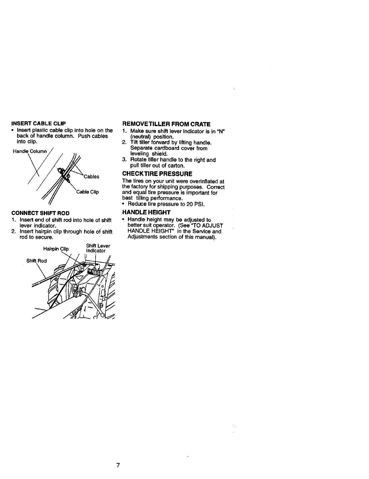
INSERT CABLE CLIP
• Insert plastic cable clip into hole on the
back of handle column. Push cables
into clip,
Handle Column
Clip
CONNECT SHIFT ROD
1. Insert end of shift rod into hole of shift
lever indicator.
2. Insert hairpin clip through hole of shift
rod to secure.
ShiftLever
HairpinC_lip Indicator
Sh_ Rod
REMOVETILLER FROM CRATE
1. Make sure shift lever indicator is in "N"
(neutral) position.
2. Tilt tiller forward by lifting handle.
Separate cardboard cover from
leveling shield.
3. Rotate tiller handle to the right and
pull tiller out of carton.
CHECKTIRE PRESSURE
The tires on your unit were overinflatad at
the factory for shipping purposes. Correct
and equal tire pressure is important for
best tilling performance.
•Reduce tire pressure to 20 PSI.
HANDLE HEIGHT
•Handle height may be adjusted to
better suit operator. (See _O ADJUST
HANDLE HEIGHT" in the Service and
Adjustments section of this manual).
7
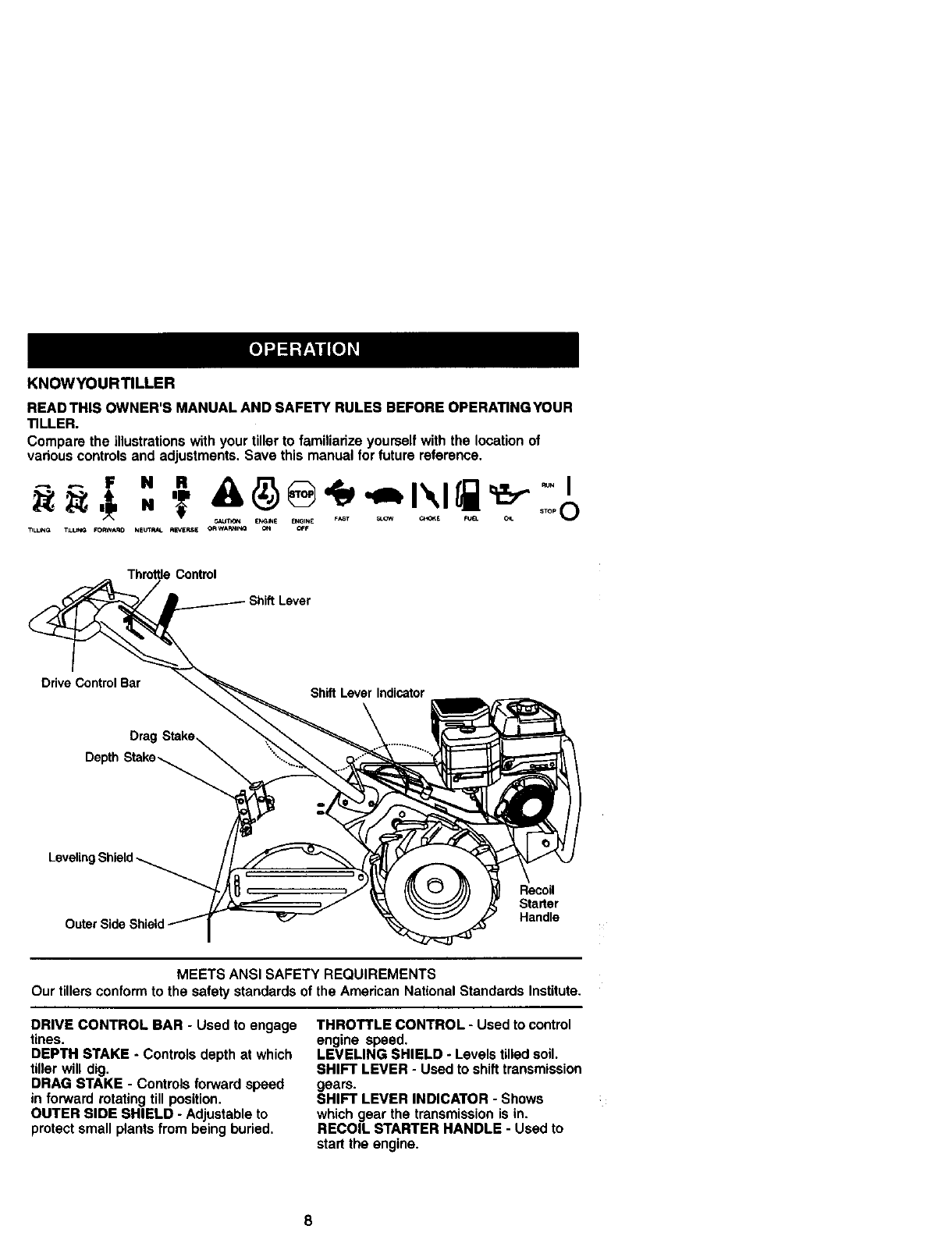
KNOWYOURTILLER
READTHIS OWNER'S MANUAL AND SAFETY RULES BEFORE OPERATING YOUR
TILLER.
Compare the illustrations with your tiller to familiarize yourself with the location of
various controls and adjustments. Save this manual for future reference.
_T_ E_S _GINE _ lr _ _ FUEL O_
_LL_G T_L_ FO_A_O NE_ R_ERSE CRWA_I_ ON _F
ThrottleControl
Lever
Ddve Control Bar Shift Lever Indicator
Drag
Depth Stake_
Recoil
Starter
Handle
MEETS ANSI SAFETY REQUIREMENTS
Ourtillersconformto the safetystandardsof the American National StandardsInstitute.
DRIVE CONTROL BAR -Used to engage
tines.
DEPTH STAKE - Controls depth at which
tiller will dig.
DRAG STAKE -Controls forward speed
in forward rotating till position.
OUTER SIDE SHIELD -Adjustable to
protect small plants from being buried,
THROTTLE CONTROL -Used to control
engine speed.
LEVELING SHIELD - Levels tilled soil.
SHIFT LEVER - Used to shift transmission
gears.
SHIFT LEVER INDICATOR - Shows
which gear the transmission is in.
RECOIL STARTER HANDLE - Used to
start the engine.
8

The operation of any tiller can result in foreign objects thrown into the eyes,
which can result in severe eye damage. Always wear safety glasses or eye
shields before starting your tiller and while tilling. We recommend a wide
vision safety mask over spectacles or standard safety glasses.
HOWTO USEYOURTILLER
Know how to operate all controls before
adding fuel and oil or attempting to start
engine.
STOPPING
TINES AND DRIVE
1. Release drive control bar to stop
movement.
2. Move shift lever to "N" (neutral)
position.
ENGINE
• Move throttle control to "STOP" posi-
tion. if equipped with stop switch, move
switch to =STOP*' position.
NOTE: Never use choke to stop engine.
Drive ControlBar
"ENGA_ _._ Lever
"DISENGAGED" /
Position Throttle/_C(i
TINE OPERATION -WITH WHEEL
DRIVE
• Always release ddve control bar before
moving shift lever into another posi-
tion,
•Tins movement is achieved by moving
shift lever to either the counter rotating
(_,) till position or the forward rotating
(_) till position and engaging drive
control bar.
FORWARD -WHEELS ONLY/TINES
STOPPED
•Release drive control bar and move
shift lever indicator to UF"(forward)
position. Engage ddve control bar and
tiller will move forward.
REVERSE -WHEELS ONLY/TINES
STOPPED
1. DO NOT STAND DIRECTLY BEHIND
TILLER.
2. Release the drive control bar.
3. Move throttle control to "SLOW"
position,
4, Move shift lever indicator to "R"
(reverse) position.
5. Hold ddve control bar against the
handle to start tiller movement.
HARD TO SHIFT GEARS
•Bdefly engage drive control bar and
release or rock tiller forward and
backward until are able to shift gears,
DEPTH STAKE
The depth stake can be raised or
lowered to allow you more versatile
tilling and cultivating, or to more easily
transport your tiller,
ShallowestTilling _.. ""Transport Position
DeepestTilling
Depth Stake
U
DRAG STAKE
The drag stake should be raised when
tilling the counter rotating (_) till position.
The drag stake should be lowered when
tilling in the forward rotating (_) till
position.
Lowered_
(ForwardRotatingtill)
Raised
(Counterrotatingtill)
"RLUNG
NOTE: Use the counter rotating tine drive
when tilling hard or rockey soil, virgin
ground or sod.
1. Release depth stake and drag stake
pins. Pull the depth stake up for
increased tilling depth. Raise the
drag stake. Place proper pin in hole of
depth stake or drag stake to lock in
position.
2. Place shift lever indicator in counter
rotating (_) till position.
3. Hold the drive control bar against the
handle to start tilling movement. Tines
and wheels will both turn.
9
4. Move throttle control to =FAST"
position for deep tilling.
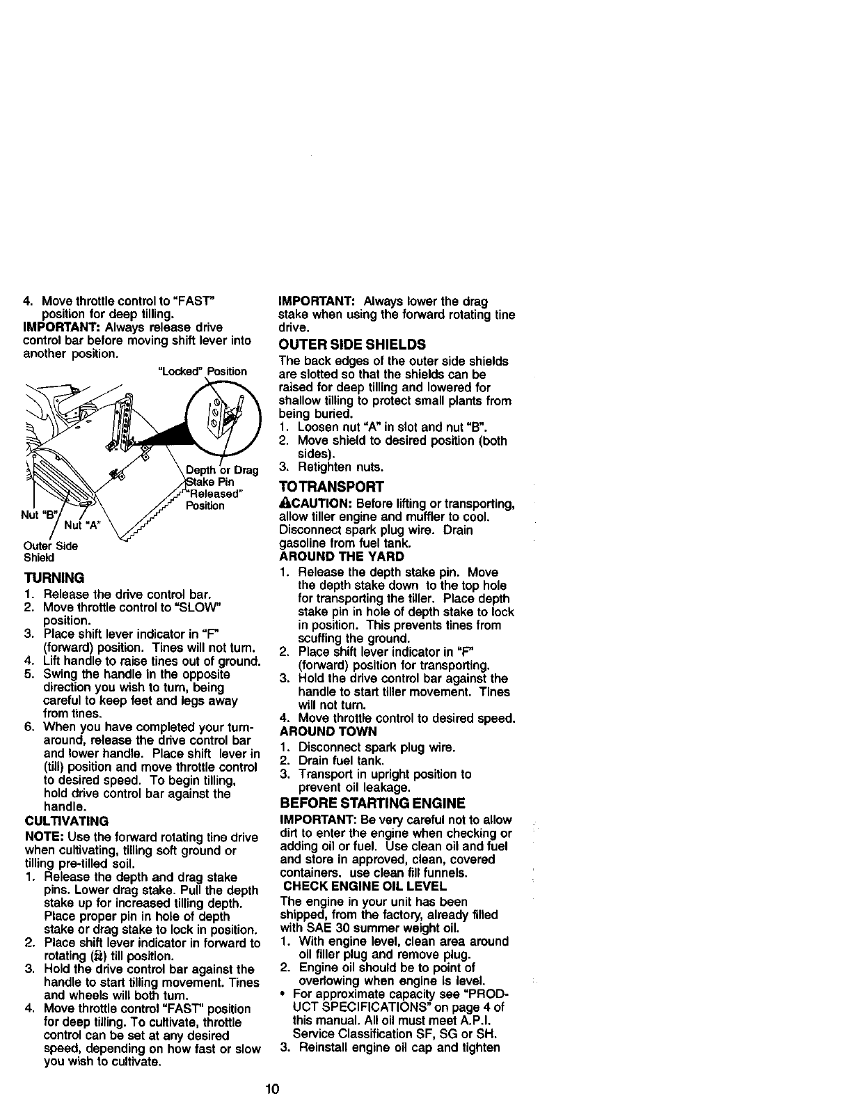
IMPORTANT: Always release drive
control bar before moving shift lever into
another position.
"Locked"Position
I/J'r '-FleI..eased"
Nit ,B,N_U_.A_ _Position
Outer Side
Shield
TURNING
1. Release the ddve control bar.
2. Move throttle control to =SLOW"
position.
3. Place shift lever indicator in =F"
(forward) position. Tines will not turn.
4. Lift handle to raise tines out of ground.
5. Swing the handle in the opposite
direction you wish to turn, being
careful to keep feet and legs away
from tines.
6. When you have completed your turn-
around, release the ddve control bar
and lower handle. Place shift lever in
(till) position and move throttle control
to desired speed. To begin tilling,
hold drive control bar against the
handle.
CULTIVATING
NOTE: Use the forward rotating fine drive
when cultivating, tilling soft ground or
tilling pre-tilled soil.
1. Release the depth and drag stake
pins. Lower drag stake. Pull the depth
stake up for increased tilling depth.
Place proper pin in hole of depth
stake or drag stake to lock in position.
2. Place shift lever indicator in forward to
rotating (_) till position.
3. Hold the ddve control bar against the
handle to start tilling movement. Tines
and wheels will both turn.
4. Move throttle control "FAST" position
for deep tilling. To cultivate, throttle
control can be set at any desired
speed, depending on how fast or slow
you wish to cultivate.
IMPORTANT: Always lower the drag
stake when using the forward rotating tine
drive.
OUTER SIDE SHIELDS
The back edges of the outer side shields
are slotted so that the shields can be
raised for deep tilling and lowered for
shallow tilling to protect small plants from
being buried.
1. Loosen nut _A" in slot and nut "B".
2. Move shield to desired position (both
sides).
3. Retighten nuts.
TOTRANSPORT
ACAUTION: Before lifting or transporting,
allow tiller engine and muffler to cool,
Disconnect spark plug wire. Drain
gasoline from fuel tank.
AROUND THE YARD
1. Release the depth stake pin. Move
the depth stake down to the top hole
for transporting the tiller. Place depth
stake pin in hole of depth stake to lock
in position. This prevents tines from
scuffing the ground.
2. Place shift lever indicator in "F_
(forward) position for transporting.
3. Hold the drive control bar against the
handle to start tiller movement. Tines
will not turn.
4. Move throttle control to desired speed.
AROUND TOWN
1. Disconnect spark plug wire.
2. Drain fuel tank.
3. Transport in updght position to
prevent oil leakage.
BEFORE STARTING ENGINE
IMPORTANT: Be very careful not to allow
dirt to enter the engine when checking or
adding oil or fuel. Use clean oil and fuel
and store in approved, clean, covered
containers, use clean fill funnels.
CHECK ENGINE OIL LEVEL
The engine in your unit has been
shipped, from the factory, already filled
with SAE 30 summer weight oil.
1. With engine level, clean area around
oil filler plug and remove plug.
2. Engine oil should be to point of
ovedowing when engine is level.
•For approximate capacity see "PROD-
UCT SPECIFICATIONS" on page 4 of
this manual. All oil must meet A.P.I,
Service Classification SF, SG or SH.
3. Reinstall engine oil cap and tighten
10

•For cold weather operation you should
change oil for easier starting (See oil
viscosity chart in the Maintenance
section of this manual).
•To change engine oil, see the Mainte-
nance section in this manual.
Oil Fill
ADD GASOLINE
•Fill fuel tank. Use fresh, clean, regular
unleaded gasoline. (Use of leaded
gasoline will increase carbon and lead
oxide deposits and reduce valve life.)
IMPORTANT: When operating in tem-
peratures below 32°F(0°C), use fresh,
clean, winter grade gasoline to help
insure good cold weather starting.
_WARNING: Experience indicates that
alcohol blended fuels (called gasohol or
using ethanol or methanol) can attract
moisture which leads to separation and
formation of acids during storage. Acidic
gas can damage the fuel system of an
engine while in storage. To avoid engine
problems, the fuel system should be
emptied before storage of 30 days or
longer. Drain the gas tank, start the
engine and let it run until the fuel lines
and carburetor are empty. Use fresh fuel
next season. See Storage section of this
manual for additional information. Never
use engine or carburetor cleaner prod-
ucts in the fuel tank or permanent
damage may occur.
ACAUTION: Fill to within 1/2 inch of top
of fuel tank to prevent spills and to allow
for fuel expansion. If gasoline is acciden-
tally spilled, move machine away from
area of spill. Avoid creating any source of
ignition until gasoline vapors have
disappeared.
Do not overfill. Wipe off any spilled oil or
fuel. Do not store, spill or use gasoline
near an open flame.
TO START ENGINE
ACAUTION: Keep fine control in "OFF"
position when starting engine.
When starting engine for the first time or if
engine has run out of fuel, it will take
extra pulls of the recoil starter to move
fuel from the tank to the engine.
1. Make sure spark plug wire Is propedy
connected.
2. Move shift lever indicator to "N"
(neutral) position.
3. Place throttle control in "FAST"
position.
4. Turn fuel shut-off valve 1/4 turn to
open position.
5. Push stop switch to "ON" position.
6. Move choke control to "CHOKE"
position.
7. Grasp recoil starter handle with one
hand and grasp tiller handle with
other hand. Pull rope out slowly until
engine reaches start of compression
cycle (rape will pull slightly harder at
this point).
8. Pull recoil starter handle quickly. Do
not let starter handle snap back
against starter.
NOTE: If engine fires but does not start,
move choke control to half choke position.
Pull recoil starter handle until engine
starts.
9. When engine starts, slowly move
choke control to "RUN" position as
engine warms up.
NOTE: A warm engine requires less
choking to start.
1O.Move throttle control to desired
running position.
11.Allow engine to warm up for afew
minutes before engaging tines.
NOTE: If at a high altitude (3000 feet) or
in cold temperatures (below 32°F), the
carburetor fuel mixture may need to be
adjusted for best engine performance.
See =TO ADJUST CARBURETOR" in the
Service and Adjustments section of this
manual.
NOTE: If engine does not start, see
troubleshooting points.
Fuel shut-off Choke controls
Rewinds
11
TILLING HINTS
_anCAUTION; Until you are accustomed to
dling your tiller, start actual field use
with throttle in slow position (mid-way
between _FAST" and =iDLE").
• Tilling is digging into, turning over, and
breaking up packed soil before
planting. Loose, unpacked soil helps
root growth. Best tilling depth is 4" to 6".
A tiller will also clear the soil of un-
wanted vegetation. The decomposition
of this vegetable matter enriches the
soil. Depending on the climate (rainfall
and wind), it may be advisable to till the
soil at the end of the growing season to
further condition the soil.
•Soil conditions are important for proper
tilling. Tines will not readily penetrate
dry, hard soil which may contribute to
excessive bounce and difficult handling
of your tiller. Hard soil should be
moistened before tilling; however,
extremely wet soil will "ball-up" or
clump during tilling. Wait until the soil is
less wet in order to achieve the best
results. When tilling in the fall, remove
vines and long grass to prevent them
from wrapping around the tine shaft
and slowing your tilling operation.
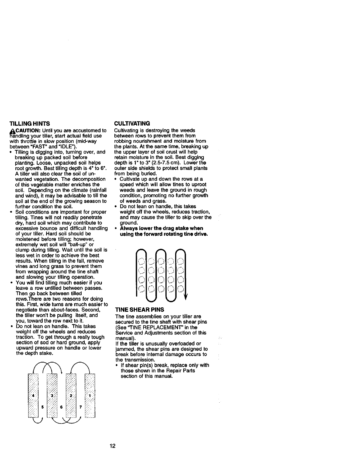
•You will find tilling much easier if you
leave a row untilled between passes.
Then go back between tilled
rows.There are two reasons for doing
this. First, wide turns are much easier to
negotiate than about-faces. Second,
the tiller won't be pulling itself, and
you, toward the row next to it.
•Do not lean on handle. This takes
weight off the wheels and reduces
traction. To get through a really tough
section of sod or hard ground, apply
upward pressure on handle or lower
the depth stake.
-_>
CULTIVATING
Cultivating is destroying the weeds
between rows to prevent them from
robbing nourishment and moisture from
the plants. At the same time, breaking up
the upper layer of soil crust will help
retain moisture in the soil. Best digging
depth is 1" to 3" (2.5-7.5 cm). Lower the
outer side shields to protect small plants
from being buried.
•Cultivate up and down the rows at a
speed which will allow tines to uproot
weeds and leave the ground in rough
condition, promoting no further growth
of weeds and grass.
• Do not lean on handle, this takes
weight off the wheels, reduces traction,
and may cause the tiUerto skip over the
ground.
•Always lower the drag stake when
using the forward rotating tine drive.
© ©O©
_ /_
j©©
TINE SHEAR PINS
The tine assemblies on your tiller are
secured to the tine shaft with shear pins
(See "TINE REPLACEMENT" in the
Sewice and Adjustments section of this
manual).
If the tiller is unusually overloaded or
jammed, the shear pins are designed to
break before internal damage occurs to
the transmission.
•If shear pin(s) break, replace only with
those shown in the Repair Parts
section of this manual.
12
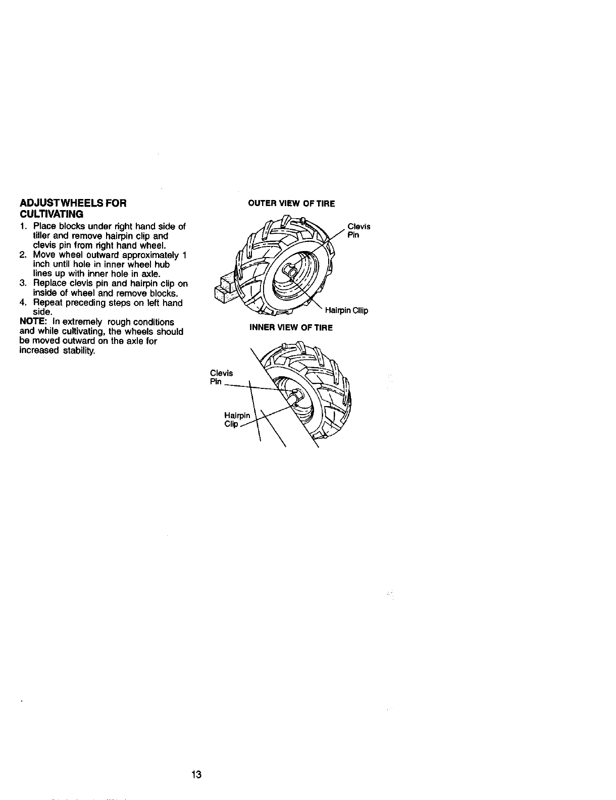
ADJUSTWHEELS FOR
CULTIVATING
1. Place blocks under right hand side of
tiller and remove hairpin clip and
clevis pin from right hand wheel.
2. Move wheel outward approximately 1
inch until hole in inner wheel hub
lines up with inner hole in axle.
3. Replace clevis pin and hairpin clip on
inside of wheel and remove blocks.
4. Repeat preceding steps on left hand
side.
NOTE: In extremely rough conditions
and while cultivating, the wheels should
be moved outward on the axle for
increased stability.
Clevis "_
Pin
OUTER VIEW OF TIRE
_1_ HairpinCllip
INNER VIEW OF TIRE
13
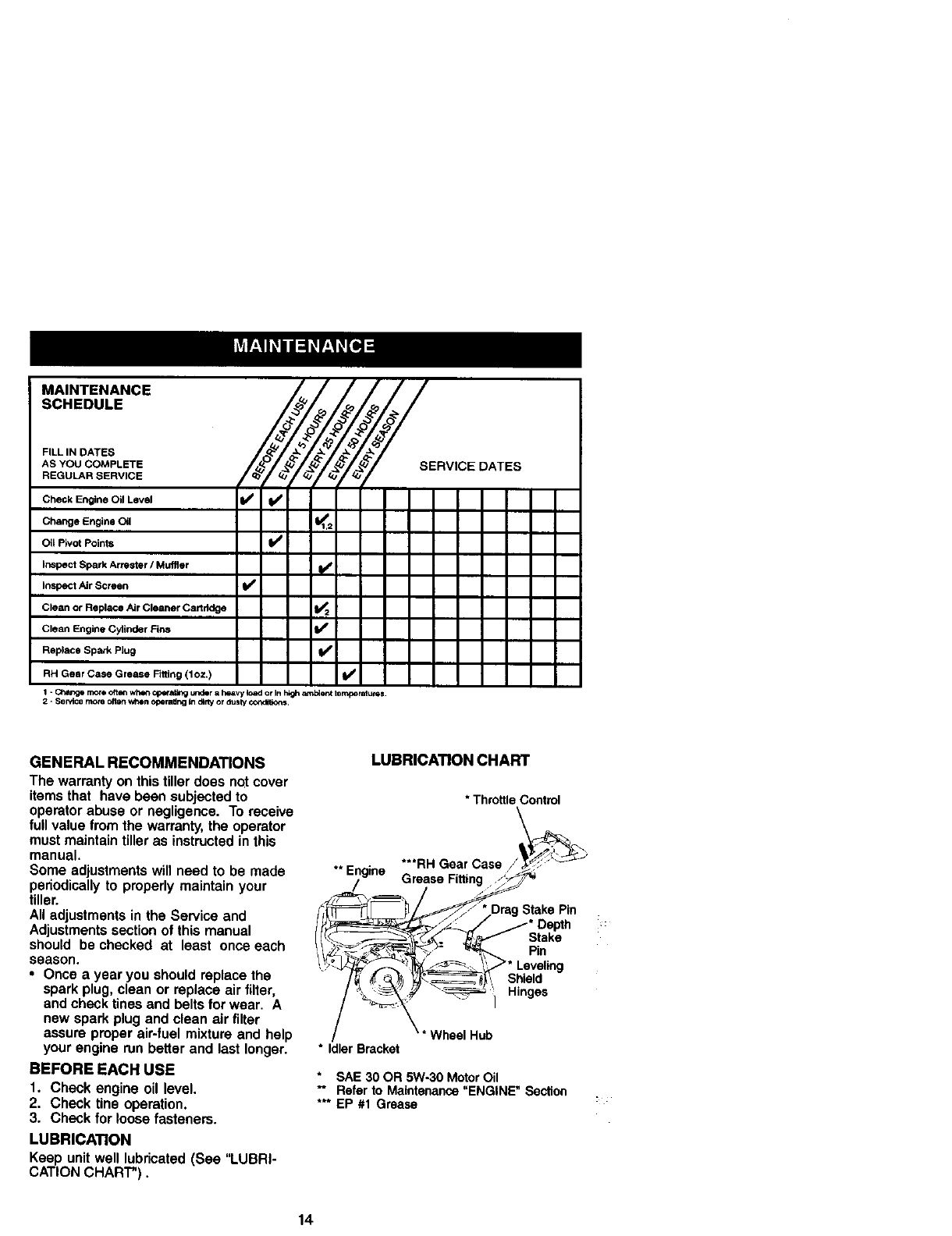
MAINTENANCE _/_
SCHEDULE
FILL IN DATES _ _- *_
REGULAR SERVICE
Check Engine Oil Level 11_ Vw
Change Engine Oil 1_,2
OI Pivot Points ll_
I_pect Spark Armster /Muffler
In_speotAir Screen t/
Clean or Replace Air Cleaner Cartridge
Clean Engine Cylinder Fins I1_
Replace Spark Plug I_
RH Gear Case Grease Fiffing (1oz.) III/I
1 - _flnOre oftoN whert O_a_ u_r a h_ivy _*ad or In I1_ _111_efl_ ter_rat UCl_S.
2 " Service more ollen when Oflerattrig In d_lty or ciusly ¢WtGtdior_;
__SERVICE DATES
GENERAL RECOMMENDATIONS
The warranty on this tiller does not cover
items that have been subjected to
operator abuse or negligence. To receive
full value from the warranty, the operator
must maintain tiller as instructed in this
manual.
Some adjustments will need to be made
periodically to properly maintain your
tiller.
All adjustments in the Service and
Adjustments section of this manual
should be checked at least once each
season.
•Once a year you should replace the
spark plug, clean or replace air filter,
and check tines and belts for wear. A
new spark plug and clean air filter
assure proper air-fuel mixture and help
your engine run better and last longer.
BEFORE EACH USE
1. Check engine oil level.
2. Check tine operation.
3. Check for loose fasteners.
LUBRICATION
Keep unitwell lubricated(See "LUBRI-
CATION CHART").
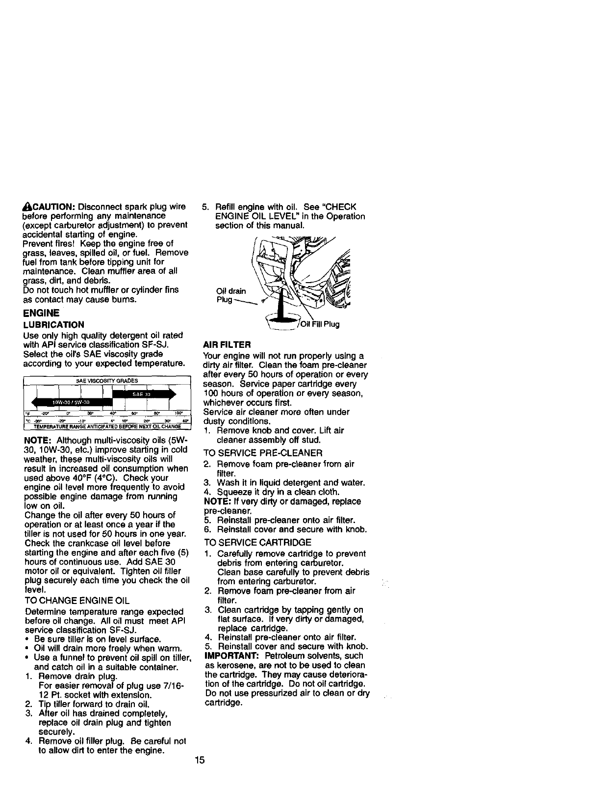
LUBRICATION CHART
** Engine
* ThrottleControl
R.GearOsse
Gr)ase F_:tak s Pin
_* Leveling
_'1 Hinges
\* Wheel Hub
* Idler Bracket
* SAE 30 OR 5W-30 Motor Oil
-- Refer to Maintenance "ENGINE" Section
*** EP #1 Grease
14
_LCAUTION: Disconnect spark plug wire
before performing any maintenance
(except carburetor adjustment) to prevent
accidental starting of engine.
Prevent fires! Keep the engine free of
grass, leaves, spilled oil, or fuel. Remove
fuel from tank before tipping unit for
maintenance. Clean muffler area of all
grass, dirt, and debris.
Do not touch hot muffler or cylinder fins
as contact may cause bums.
ENGINE
LUBRICATION
Use only high quality detergent oil rated
with API service classification SF-SJ.
Select the oil's SAE viscosity grade
according to your expected temperature.
NOTE: Although multi-viscosity oils (5W-
30, 10W-30, etc.) improve starting in cold
weather, these multi-viscosity oils will
result in increased oil consumption when
used above 40°F (4°C). Check your
engine oil level more frequently to avoid
possible engine damage from running
low on oil.
Change the oil after every 50 hours of
operation or at least once a year if the
tiller is not used for 60 hours in one year.
Check the crankcase oil level before
starting the engine and after each five (5)
hours of continuous use. Add SAE 30
motor oil or equivalent. Tighten oil filler
plug securely each time you check the oil
level.
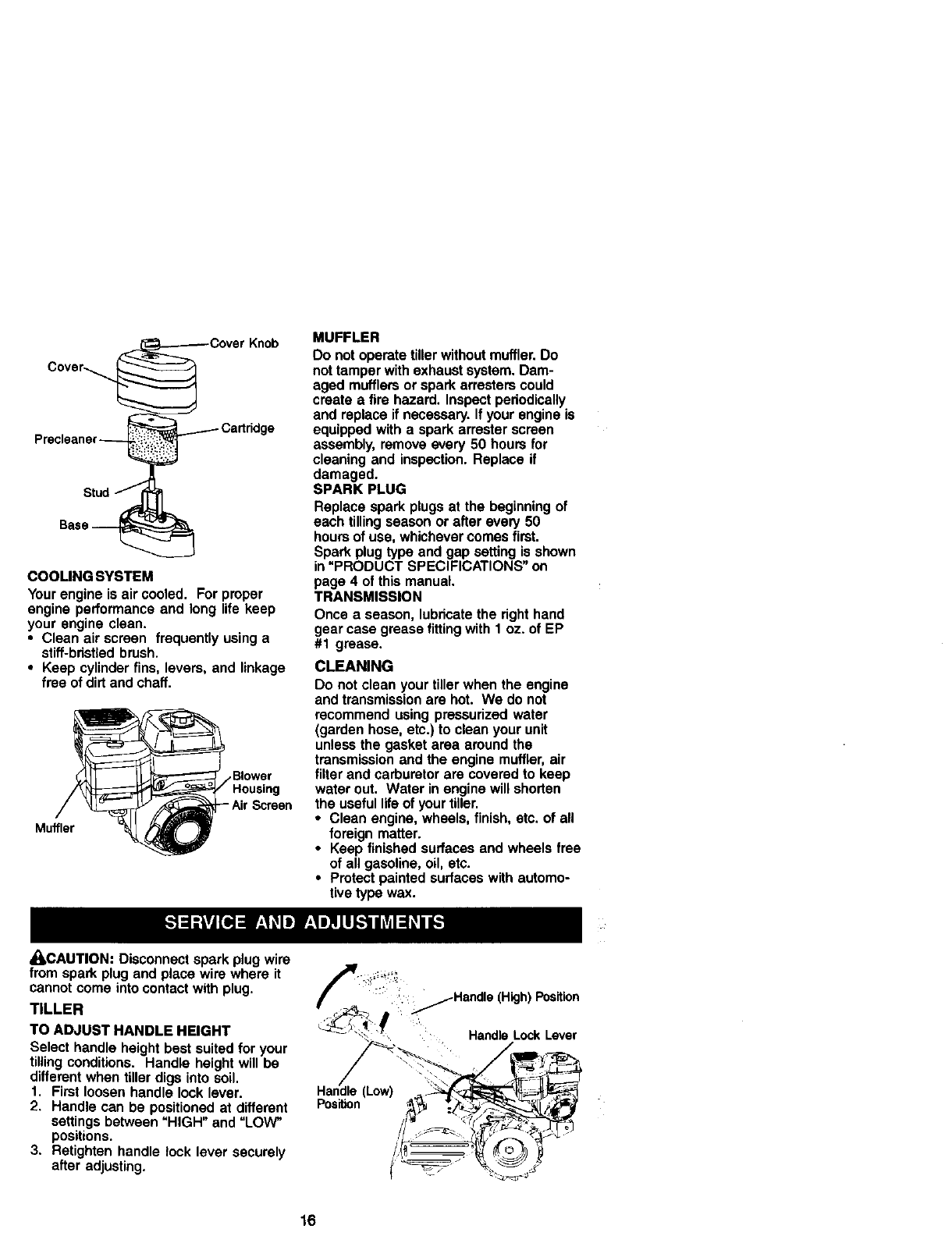
TO CHANGE ENGINE OIL
Determine temperature range expected
before oil change. All oil must meet API
service classification SF-SJ.
•Be sure tiller is on level surface.
•Oil will drain more freely when warm.
•Use a funnel to prevent oil spill on tiller,
and catch oil in a suitable container.
1. Remove drain plug.
For easier removal of plug use 7/16-
12 Pt. socket with extension.
2. Tip tiller forward to drain oil.
3. After oil has drained completely,
replace oil drain plug and tighten
securely.
4. Remove oil filler plug. Be careful not
to allow dirt to enter the engine.
5. Refill engine with oil. See "CHECK
ENGINE OIL LEVEL" in the Operation
section of this manual.
Oil drain
Plug
AIR FILTER
Your engine will not run properly using a
dirty air filter. Clean the foam pre-cleaner
after every 50 hours of operation or every
season. Service paper cartridge every
100 hours of operation or every season,
whichever occurs first.
Service air cleaner more often under
dusty conditions.
1. Remove knob and cover. Lift air
cleaner assembly off stud.
TO SERVICE PRE-CLEANER
2. Remove foam pre-cteaner from air
filter.
3. Wash it in liquid detergent and water.
4. Squeeze it dry in a clean cloth.
NOTE: If very dirty or damaged, replace
pre-cteaner.
5. Reinstall pre-cleaner onto air filter.
6. Reinstall cover end secure with knob.
TO SERVICE CARTRIDGE
1. Carefully remove cartridge to prevent
debris from entering carburetor.
Clean base carefully to prevent debris
from entering carburetor.
2. Remove foam pra-cleaner from air
filter.
3. Clean carfridge by tapping gently on
flat surface. If very dirty or damaged,
replace cartridge.
4. Reinstall pre-cleaner onto air filter.
5. Reinstall cover and secure with knob.
IMPORTANT: Petroleum solvents, such
as kerosene, are not to be used to clean
the cartridge. They may cause deteriora-
tion of the cartridge. Do not oil cartridge.
Do not use pressurized air to clean or dry
cartridge.
15
,___:_ Cover Knob
Cover-__
_Cartridge
Precleaner_
Bass _
COOLING SYSTEM
Your engine is air cooled. For proper
engine performance and long life keep
your engine clean.
• Clean air screen frequently using a
stiff-bdstled brush.
•Keep cylinder fins, levers, and linkage
free of dirt and chaff.
Muffler
Screen
•(_CAUTION: Disconnect spark plug wire
MUFFLER
Do not operate finer without muffler. Do
not tamper with exhaust system. Dam-
aged mufflers or spark arresters could
create a fire hazard. Inspect periodically
and replace if necessary. If your engine is
equipped with a spark arraster screen
assembly, remove every 50 hours for
cleaning and inspection. Replace if
damaged.
SPARK PLUG
Replace spark plugs at the beginning of
each tilling season or after eve/'/50
hours of use, whichever comes first.
Spark plug type and gap setting is shown
in "PRODUCT SPECIFICATIONS" on
page 4 of this manual.
TRANSMISSION
Once a season, lubdcate the right hand
gear case grease fitting with 1 oz. of EP
#1 grease.
CLEANING
Do not clean your tiller when the engine
and transmission are hot. We do not
recommend using pressurized water
(garden hose, etc.) to clean your unit
unless the gasket area around the
transmission and the engine muffler, air
filter and carburetor are covered to keep
water out. Water in engine will shorten
the useful life of your tiller.
•Clean engine, wheels, finish, etc. of all
foreign matter.
• Keep finished surfaces and wheels free
of all gasoline, oil, etc.
•Protect painted surfaces with automo-
tive type wax.
from spark plug and place wire where it
cannot come into contact with plug.
TILLER
TO ADJUST HANDLE HEIGHT
Select handle height best suited for your
tilling conditions. Handle height will be
different when tiller digs into soil.
1. First loosen handle lock lever.
2. Handle can be positioned at different
settings between =HIGH" and =LOW"
positions.
3. Retighten handle lock lever securely
after adjusting.
:::;j_/-Handle (High) Position
Handle Lock Lever
(Low) :\\
Position
16
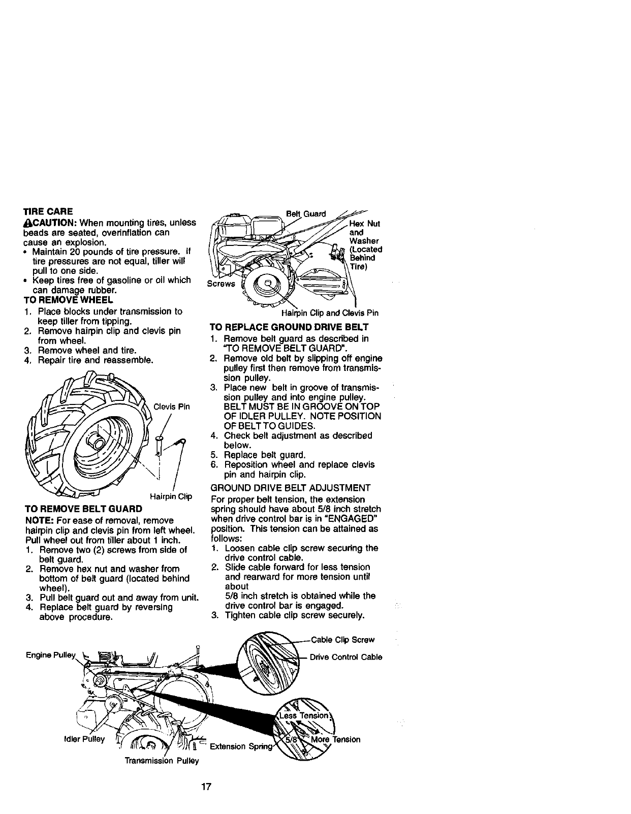
TIRE CARE
_kCAUTION: When mounting tires, unless
beads are seated, ovednflation can
cause an explosion.
• Maintain 20 pounds of tire pressure. If
tire pressures are not equal, tiller will
pull to one side.
• Keep tires free of gasoline or oil which
can damage rubber.
TO REMOVE WHEEL
1, Place blocks under transmission to
keep tiller from tipping.
2, Remove hairpin clip and clevis pin
from wheel.
3, Remove wheel and tire.
4, Repair tire end reassemble.
Clevis Pin
HairpinClip
TO REMOVE BELT GUARD
NOTE: For ease of removal, remove
hairpin clip and clevis pin from left wheel.
Pull wheel out from tiller about 1 inch.
1. Remove two (2) screws from side of
belt guard.
2. Remove hsx nut and washer from
bottom of belt guard (located behind
wheel).
3. Pull belt guard out and away from unit.
4. Replace belt guard by reversing
above procedure.
Hex Nut
f/j/;n
y_,_ Washer
.J_ (Located
"_,_ Behind
HairpinClip andClevis Pin
TO REPLACE GROUND DRIVE BELT
I. Remove belt guard as described in
"TO REMOVE BELT GUARD".
2, Remove old belt by slipping off engine
pulley first then remove from transmis-
sion pulley.
3. Place new belt in groove of transmis-
sion pulley and into engine pulley.
BELT MUST BE IN GROOVE ON TOP
OF IDLER PULLEY. NOTE POSITION
OF BELT TO GUIDES.
4. Check belt adjustment as described
below.
5. Replace belt guard.
6. Reposition wheel and replace clevis
pin and hairpin clip.
GROUND DRIVE BELT ADJUSTMENT
For proper belt tension, the extension
spring should have about 5/8 inch stretch
when drive control bar is in "ENGAGED"
fosition. This tension can be attained as
ollows:
1. Loosen cable clip screw securing the
drive control cable.
2. Slide cable forward for less tension
and rearward for more tension until
about
5/8 inch stretch is obtained while the
drive control bar is engaged.
3. Tighten cable clip screw securely.
,Screw
Drive Control Cable
Idler Pulley
Transmission Pulley
More Tension
17

TINE REPLACEMENT
g_oCAUTION: Tines are sharp. Wear
ves or other protection when handling
tines.
A badly worn tine causes your tiller to
work harder and dig more shallow. Most
important, worn tines cannot chop and
shred organic matter as effectively nor
bury itas deeply as good tines. A tine this "
worn needs to be replaced.
New Tine Worn Tine
To maintain the superb tilling perfor-
mance of this machine the tines should
be checked for sharpness, wear, and
bending, particularly the tines which
are next to the transmission. If the gap
between the tines exceeds 3-1/2
inches they should be replaced or
straightened as necessary.
For tines that are slightly worn, the
bolted tins and hub assemblies can be
switched between sides to continue till-
ing in the same tilling mode if tilling in a
different mode is desired then the
bolted tine and hub assemblies should
be switched back to their original side
so that the tine edge with the least wear
will be used.
ion _
II
I
I I _3-1/2" MAX
Sharp r Sharp
Hairpin Clip
Sharp
/
18

ENGINE
Maintenance, repair, or replacement of
the emission control devices and sys-
tems, which are being done at the
customers expense, may be performed
by any non-roed engine repair establish-
ment or individual. Warranty repairs must
be performed by an aulhorized engine
manufacturer's service outlet.
TO ADJUST THROTTLE CONTROL
CABLE
1. The throttle control has been preset at
the factory and adjustment should not
be necessary. If adjustment is
necessary, proceed as follows:
2. With engine not running, move remote
throttle control lever to =FAST"
position.
3. If throttle lever on engine touches high
speed stop, no further adjustment is
necessary. If throttle lever does not
touch high speed stop, continue with
adjustment procedure.
4. Loosen cable clamp screw.
5. Move throttle lever up until it touches
high speed stop, and hold in this
position.
6. Tighten cable clamp screw securely.
Fuel Tank 1/Clamp
_Screw JJCasing
[// _)ndWire
_ovemor
Control
Lever
TO ADJUST CARBURETOR
The carburetor has been preset at the
factory and adjustment should not be
necessary. However, engine perfor-
mance can be affected by differences In
fuel, temperature, altitude or load. It the
carburetor does need adjustment, contact
your nearest authorized service center/
department
IMPORTANT: Never tamper with the
engine governor, which is factory set for
proper engine speed. Overspeeding the
engine above the factory high speed
setting can be dangerous. If you think the
engine-governed high speed needs
adjusting, contact your nearest sears or
other qualified service center which has
the proper equipment and experience to
make any necessary adjustments.
19

Immediately prepare your tiller for storage
at the end of the season or ifthe unit will
not be used for 30 days or more.
_kCAUTION: Never store the tiller with
gasoline in the tank inside a building
where fumes may reach an open flame or
spark. Allow the engine to cool before
storing in any enclosure.
TILLER
t. Clean entire tiller (See "CLEANING" in
the Maintenance section of this
manual).
2. Inspect and replace belts, if necessary
(See belt replacement instructions in
the Service and Adjustments section
of this manual).
3. Lubricate as shown in the Mainte-
nance section of this manual.
4. Be sure that all nuts, bolts and screws
are securely fastened. Inspect moving
parts for damage, breakage and wear.
Replace if necessary.
5. Touch up all rusted or chipped paint
surfaces; sand lightly before painting.
ENGINE
FUEL SYSTEM
IMPORTANT: It is important to prevent
gum deposits from forming in essential
fuel system parts such as the carburetor,
fuel filter, fuel hose, or tank during
storage, also, experience indicates that
alcohol blended fuels (called gesohol or
using ethanol or methanol) can attract
moisture which leads to separation and
formation of acids during storage. Acidic
gas can damage the fuel system of an
engine while in storage.
1. Drain the fuel tank.
2. Start the engine and let it run until the
fuel lines and carburetor are empty.
•Never use engine or carburetor cleaner
products in the fuel tank or permanent
damage may occur.
• Use fresh fuel next season.
NOTE: Fuel stabilizer is an acceptable
alternative in minimizing the formation of
fuel gum deposits during storage. Add
stabilizer to gasoline in fuel tank or
storage container. Always follow the mix
ratio found on stabilizer container. Run
engine at least 10 minutes after adding
stabilizer to allow the stabilizer to reach
the carburetor. Do not drain the gas tank
and carburetor if using fuel stabilizer.
ENGINE OIL
Drain oil (with engine warm) and replace
with clean oil. (See "ENGINE" in the
Maintenance section of this manual).
CYLINDER
1. Remove spark plug.
2. Pour 1 ounce (29 ml) of oil through
spark plug hole into cylinder.
3. Pull starter handle slowly several
times to distribute oil.
4. Replace with new spark plug.
OTHER
•Do not store gasoline from one season
to another.
•Replace your gasoline can if your can
starts to rust. Rust and/or dirt in your
gasoline will cause problems.
•If possible, store your unit indoors and
cover itto give protection from dust and
dirt.
•Cover your unit with a suitable protec-
tive cover that does not retain moisture.
Do not use plastic. Plastic cannot
breathe which allows condensation to
form and will cause your unit to rust.
IMPORTANT: Never cover tiller while
engine and exhaust areas are still warm.
2O
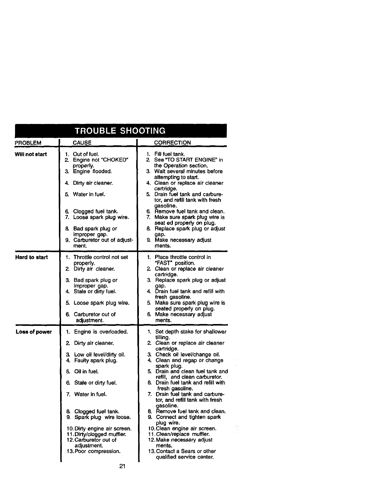
PROBLEM
Will not start
Hard to start
Loss of power
1,
Z
&
4.
6.
CAUSE
Out of fuel.
Engine not "CHOKED"
properly.
Engine flooded.
Dirty air cleaner.
Water in fuel.
6. Clogged fuel tank.
7. Loose spark plug wire.
8. Bad spark plug or
improper gap.
9. Carburetor out of adjust-
ment.
1. Throttle control not set
properly,
2. Dirty air cleaner.
3. Bad spark plug or
improper gap.
4. Stale or dirty fuel.
5. Loose spark plug wire.
6. Carburetor out of
adjustment.
1. Engine is overloaded.
2. Dirty air cleaner.
3. Low oil level/dirty oil.
4. Faulty spark plug.
5. Oil in fuel.
6. Stale or dirtyfuel.
7. Water infuel.
6. Clogged fuel tank.
9. Spark plug wire loose.
10. Dirty engine air screen.
11. Dirty/clogged muffler.
12.Carburetor out of
adjustment.
t 3. Poor compression.
21
CORRECTION
1. Fill fuel tank.
2. See "1"O START ENGINE" in
the Operation section.
3. Wait several minutes before
attempting to stad.
4. Clean or replace air cleaner
cartridge.
5. Drain fuel tank and carbure-
tor, and refill tank with fresh
gasoline.
6. Remove fuel tank and clean.
7. Make sure spark plug wire is
seat ed properly on plug.
8. Replace spark plug or adjust
gap.
9. Make necessary adjust
ments.
1. Place throttle control in
"FAST" position.
2. Clean or replace air cleaner
cartridge.
3. Replace spark plug or adjust
g_ap.
4. Drain fuel tank and refill with
fresh gasoline.
5. Make sure spark plug wire is
seated properly on plug.
6. Make necessary adjust
ments.
1. Set depth stake for shallower
tilling.
2. Clean or replace air cleaner
cartridge.
3. Check oil level/change oil.
4. Clean and regap or change
spark plug.
5. Drain and clean fuel tank and
refill, and clean carburetor.
6. Drain fuel tank and refill with
fresh gasoline.
7. Drain fuel tank and carbure-
tor, and refill tank with fresh
gasoline.
8. Remove fuel tank and clean.
9. Connect and tighten spark
plug wire.
lO.Clean engine air screen.
11 .Clean/replace muffler.
12.Make necessary adjust
ments.
13.Contact a Sears or other
qualified service center.
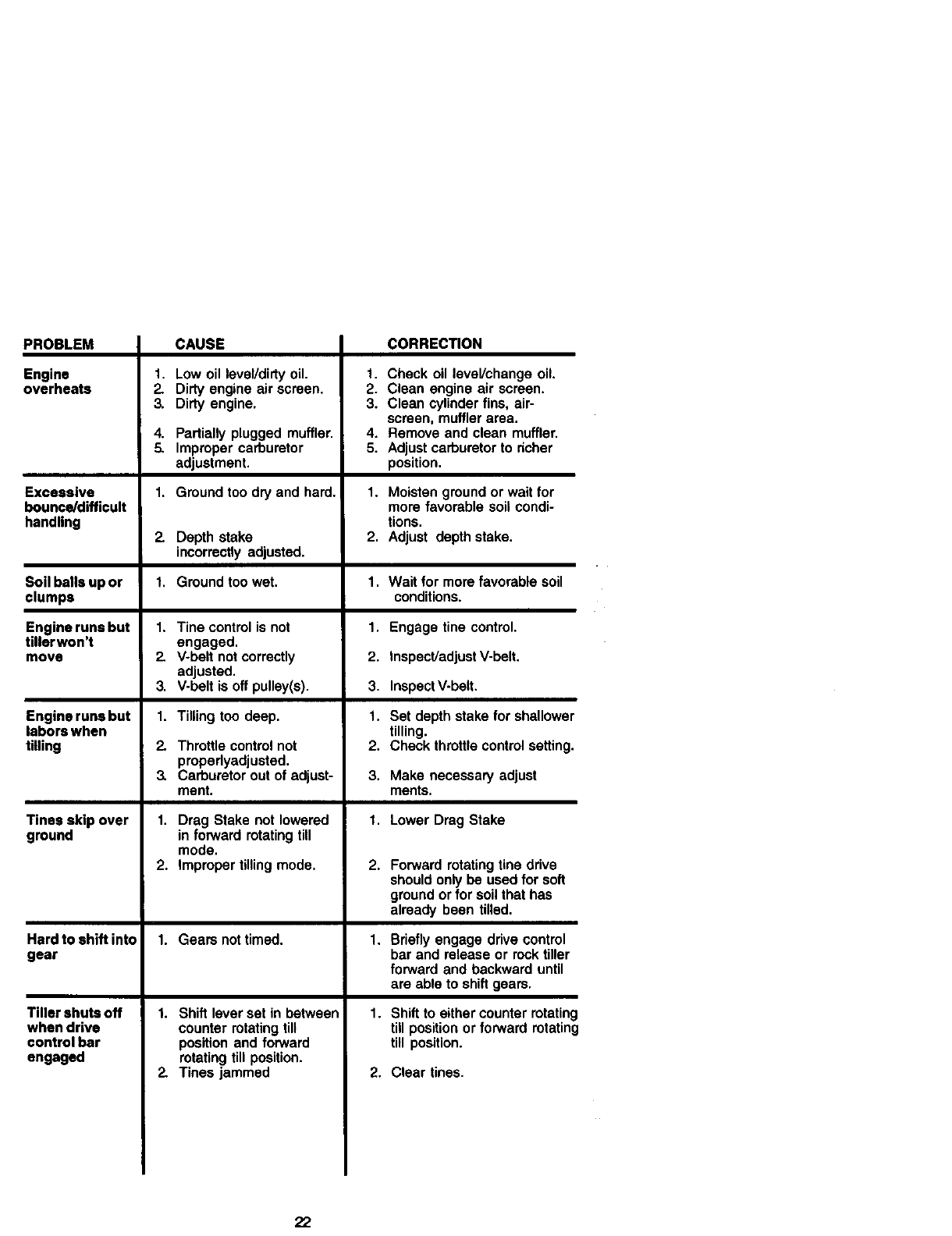
PROBLEM
Engine
overheats
Excessive
bounce/difficult
handling
Soil balls up or
clumps
Engine runs but
tiller won't
move
Engine runs but
labors when
tilling
Tines skip over
ground
Hard to shift into
gear
Tiller shuts off
when drive
control bar
engaged
CAUSE
1. Low oil level/dirty oil.
2. Dirty engine air screen.
3. Dirty engine.
4. Partially plugged mufflen
5. Improper carburetor
adjustment.
1. Ground too dry and hard,
ZDepth stake
incorrectlyadjusted.
1. Groundtoowet.
1.
Z
3.
1.
2.
3.
Tine control is not
engaged.
V-belt not correctly
adjusted.
V-belt is off pulley(s).
Tilling too deep.
Throttlecontrolnot
properlyadjusted.
Carburetorout of adjust-
ment.
1. Drag Stake not lowered
in forward rotating till
mode.
2. Improper tilling mode.
1. Gears nottimed.
1. Shift lever set in between
counter rotating till
position and forward
rotating till position.
2. Tines jammed
CORRECTION
1. Check oil leveVchange oil.
2. Clean engine air screen.
3. Clean cylinder fins, air-
screen, muffler area.
4. Remove and clean muffler.
5. Adjust carburetor to richer
position.
1. Moisten ground or wait for
more favorable soil condi-
tions.
2. Adjust depth stake.
1. Wait for more favorable soil
conditions.
1. Engage tine control,
2. Inspect/adjust V-belt.
3. Inspect V-belt,
1. Set depth stake for shallower
tilling.
2. Check throttle control setting.
3. Make necessary adjust
merits.
1. Lower Drag Stake
2.
1,
1.
2.
Forward rotating tine drive
should only be used for soft
ground or for soil that has
already been tilled.
Brieflyengage drive control
bar and release or rocktiller
forwardand backward until
are able to shiftgears.
Shift to either counter rotating
till position or forward rotating
till position.
Clear tines.
22
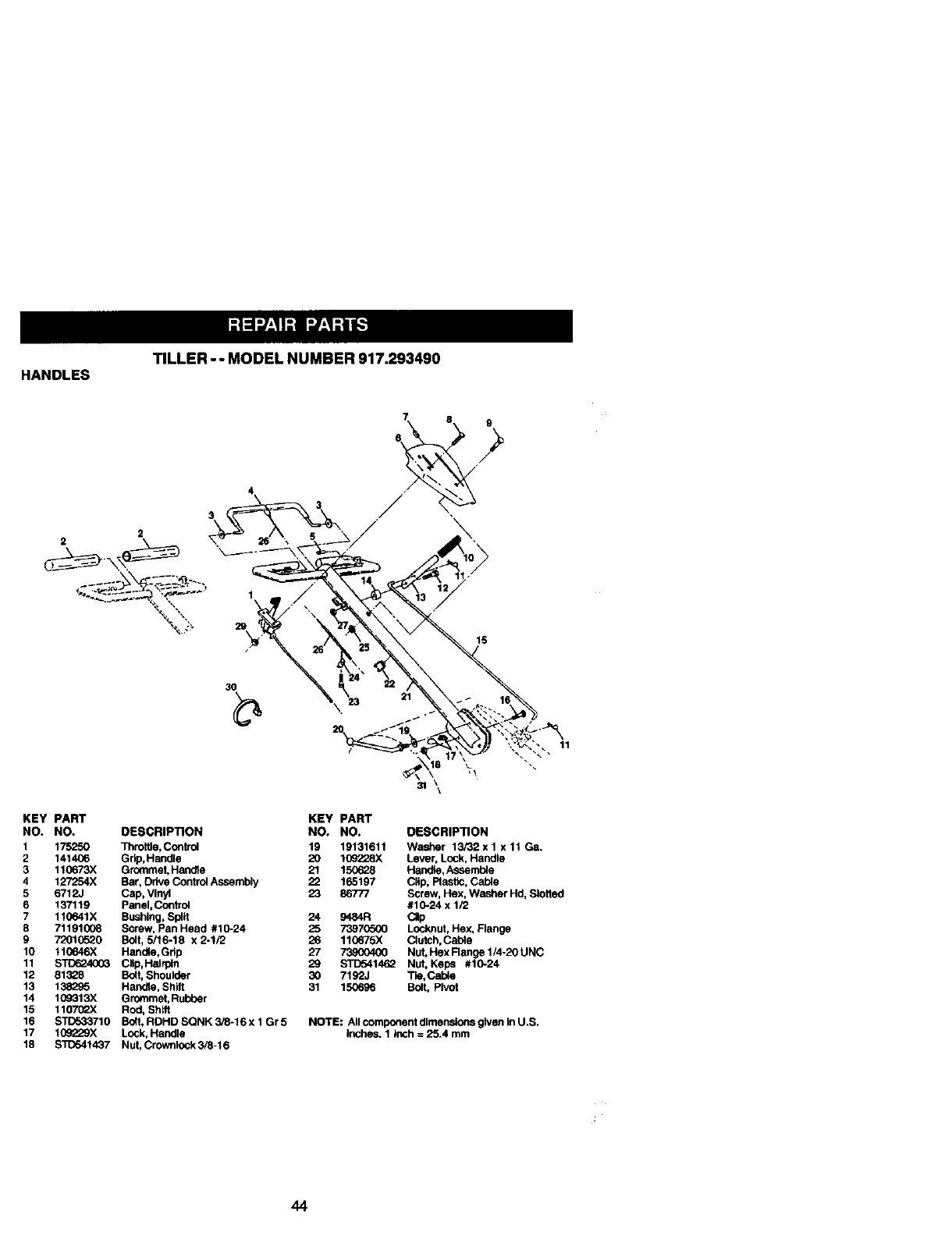
TILLER-- MODELNUMBER917.293490
HANDLES
2
30
KEY PART KEY
NO. NO. DESCRIPTION NO.
I 175250 Throttle, Control 19
2 141406 Grlp,Handle 20
3 110673X Grommet, Handte 21
4 127254X Bar, Drive Control Assembly 22
5 6712J Cap, Vinyl 23
6 137119 panel,Control
7 110641X Bushing, Split 24
8 71191008 Screw, Pan Head #10-24 25
9 7201(To20 Bolt, 5/16-18 x 2-112 26
10 110646X Handle, Grip 27
11 STO1_4003 Clip, Hairpin 29
12 81328 Bolt, Shoulder 30
13 138295 Handle, Shitt 31
14 109313X Grommet, Rubber
15 110702X Rod, Sh_
16 STITo33710 Bolt, RDHD SQNK Sl8-16 x 1Gr 5
17 109229X Lock, Handle
18 $30541437 Nut, Crownlock 3/8-16
11
31
PART
NO. DESCRIPTION
19131611 Washer 13/22 x 1 x 11Ga,
109228X Lever, Lock, Handle
150628 HanDle, Assemole
165197 Cllp, Plastic, Cable
86777 Screw, Hex, Washer Hd, Slotted
#10-24 x 1/2
9484R CJp
73970500 Locknut, Hex, Flange
110675X Clutch, Cable
73_00400 Nut, Hex Range 1/4-20 UNC
STD541462 Nut, Keps #10-24
7192J Tie, Cable
150696 Bolt, Pivot
NOTE: All component dimensions given In U.S.
inches. 1 Inch = 25.4 mm
44
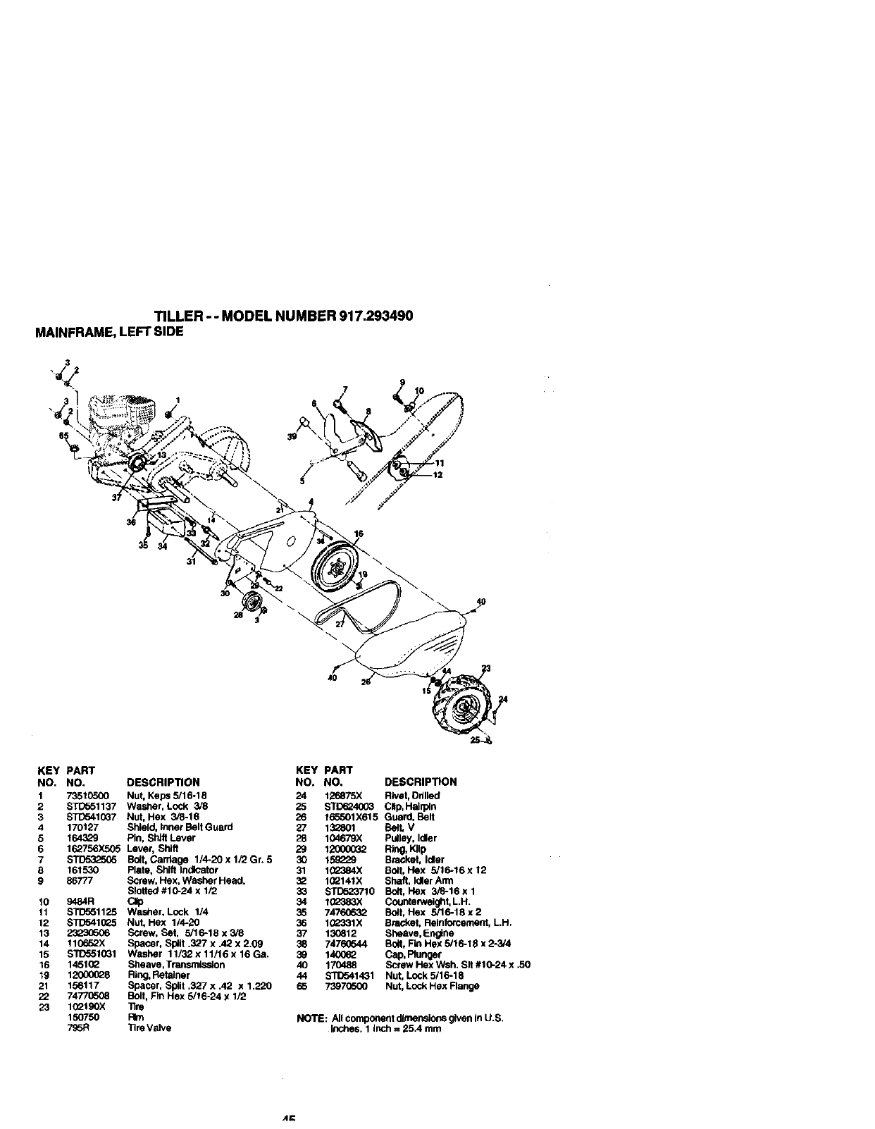
TILLER - - MODEL NUMBER 917.293490
MAINFRAME, LEFT SIDE
3
30
28
KEY PART
NO. NO.
1 7351(To00
2 STD551137
3 STD541(JQ7
4 170127
5164329
6 162756X505
7 S_
8 161530
9 86777
10 9484R
11 STD581125
12 STD541(_R5
13
14 110652X
15 STD551031
16 1451(_
19 12000028
21 156117
22 74770508
23 10_t90X
150750
795R
DESCRIPTION
Nut, Kepa 5/16-18
Washer, Lock 3/8
Nut, Hex 3/8-16
Shield, Inner Belt Guard
Pin, Shift Lever
Lever, Shift
Bolt, Cardege 1/4-20 x 1/2 Gr. 5
Plate, Shift Indicator
Screw, Hex, Washer Head,
Slotted #10-24 x 1/2
C,p
Washer, Lock 1/4
Nut, Hex 1/4-20
Screw, Bet, 5/16-18 x 3/8
Spacer, Split .327 x .42 x 2.09
Washer 11/32 x11/16 x16 Ga.
Sheave, Transmission
Ring, Retainer
Spacer, Split .327 x .42 x 1.220
Bolt, Fln Hex 5/16-24 x 112
tire
Fire
Tire Valve
KEY PART
NO. NO. DESCRIPTION
24 126875X F,vet, Drilled
25 STD624003 Clip. Hailpln
26 165501X615 Guard. Belt
27 1_801 Belt. V
28 104679X Pulley, Idler
29 12000032 RI,g. KIIp
30 15g_o9 Bracket, Idler
31 1G2384X 8o_t, Hex 5/16-!6 x 12
3_ 1(_Q141X Shaft, Idler Arm
33 STD523710 Bo_,Hex 3/6-16xl
34 10_383X _l_-
Countel_tel t.L.H.
35 74760532 Bolt, Hex 18 x 2
36 1_o331X Bracket, Reinforcement, LH.
37 130812 Sheave. Engine
38 74760544 Boft, Fm Hex 5/16-18 x 2-3/4
39 1400_ Cap, Plunger
40 170488 Screw Hex Wsh. Sit #10-24 x 30
44 STD541431 Nut, Lock 5/16-18
65 73970500 Nut, Lock He)( Range
NOTE: All component dimensions given in U.S.
inches. 1 inch = 25.4 mm
A=:
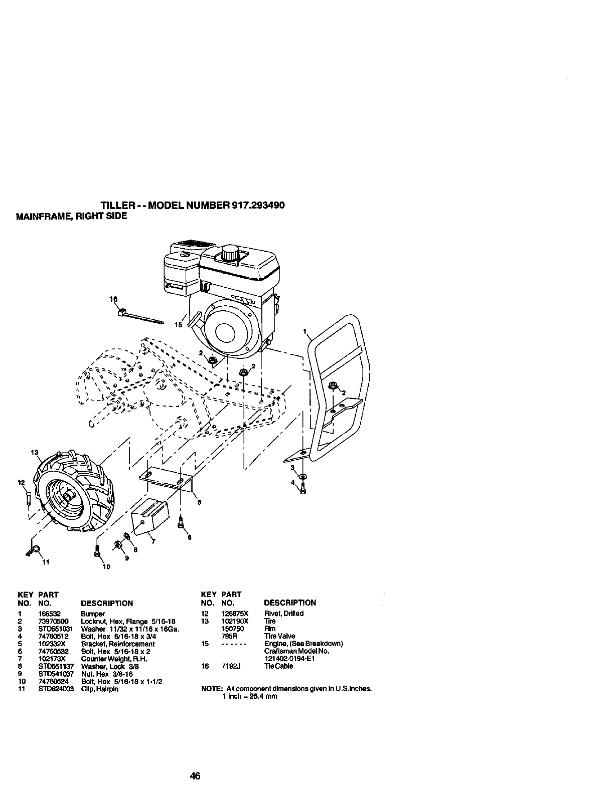
TILLER - - MODEL NUMBER 917.293490
MAINFRAME, RIGHT SIDE
13
5
" t
X ,( '
8
11 9
10
KEY PART KEY PART
NO. NO. DESCRIPTION NO, NO. DESCRIPTION
1 16653Q Bumper 12 126875X Rivet, Drilled
2 7397(_600 Locknut, He)(, Flange 5/16-18 13 102190X "Rre
3 S_10G1 Washer 11/32x11/16x16Ga. 150750 Rm
4 74760512 Bolt, Hex 5/16-18 x 3/4 7SSR ]Ire Valve
5 10_33_X Bracket, Reinforcement 15 Engine, (See Breakdown )
6 74760532 Bolt, Hex 5/16-18 x 2 Craftsman Model No.
7 102173X Couflter Weight, R.H. 121402-0194-E1
8 STD551137 Washer, Lock 3/8 16 7192J _eCable
9 S'RTo410_7 Nut, Hex 3/8-16
10 74760624 Bolt, Hex 5/16-18 x 1-1/2
11 S1I_24003 CIIp, Halq)ln NOTE: AIIcomponentdlmensionsglvenlnU.S.inches.
1 inch = 25.4 mm
46

TILLER - - MODEL NUMBER 917.293490
TRANSMISSION
KEY PART
NO. NO. DESCRIPTION
1 170306 Tmnsmlasten Assembly (includes
Key NOS. 2-52)
2 161510 Gearcase, L.H. w/Beadng
(Includes Key No. 4)
3 161963 Gasket, Gearcase
4 5020J Beadng, Needle
5 1370H Washer, Thrust 5/8 x 1,10 x 1/32
6 161520 Pldlon, Input
7 161518 Shaft, Input
8 4895H Beadng, Needle
9 154467 Washer, Seal
10 7392M Bdlh Steel
11 1(X_71K Spdng, Shift, Fork
12 106160X O-Ring
13 142145 Ann, Shift
14 8353J Fork, Shift
15 120(_039 Ring, Klip
16 161516 Shaft, Shift
18 4358J WaSher
19 12000040 Ring, Klip
20 1(_114X Gear, Assembly, Reverse Idler
(includes Key NOS. 21 and 22)
21 102115X Gear, Reverse Idler
22 6803J Beadng, Needle
23 161527 Shaft, Reverse Idler
24 STD551143 Washer, Lock 7/16
25 STC541143 Nut, Hex 7/16-20
27 143009 Beadng, Shaft, Ground Ddve LH.
28 1(_390X Spacer 0.76,5 x 1.125 x 1.23
29 10_134X Chain #55-50 Pitch
30 150737 GrOund Shaft Assembly
31 143008 Beadng, Shaft, Ground Drive R.H.
3_ 106388X Spacer 0.70 x 1.00 x 1.150
KEY PART
NO. NO. DESCRIPTION
33 1(_121X Sprocket and Gear Assembly
34 1(_112X St=aft, ReduC_on (2nd)
35 1(_101X Screw, Whiz, Lock 5/16-18 x 3-1/2
36 161524 Sprocket Asseml_y w/Bea dng
(includes Key Noe. 37 and 38)
37 100413K Beadng, Nasdle
38 161525 Sprocket, Tice
39 161526 Gear, Cluster, Red 1st & 2nd
40 1_5346X Gear, Reverse
41 161523 Shaft, Reduction (tst)
42 4220R Washer, Thrast
43 106146X Spacer 1.01 x 1.75 x 0.760
44 155236 Seal Asm. OII
48 170307 Gearcase, R.H. w/Bearing
(_ocludas Key No. 8)
49 132688 Shaft, "Fine
50 106147X Chain, Rotter #50-50 Pitch
51 1772040_ Screw 1/4-20 x 1/2
52 73,,_(To(X) Nut, Hex 5/16-16
53 165140 Beadng Kit, "FineShaft
54 161528 Gear, DRT Idler w/Bearing
(includes Key No. 56)
55 3400R Beadng, Needle
56 161529 Gear, DRTIdler
57 165889 Spacer, Sptit .52 x .64 x 1.04
58 17720412 Screw 1/4-20 x 3/4
60 6855M FI16ng Grease
-- 60663 Grease, Plastilube #1
NOTE: All component dimensions given in U.S.Inchas.
1 Inch = 25.4 mm

TINE SHIELD
TILLER - - MODEL NUMBER 917.293490
17
5
713 14
15
KEY PART
NO. NO.
2 161415)(616
3 8393J
4 12000036
5 STD533107
6 8394J
7 8392J
8 109230X
9163496X615
10 S_110
11 STD551131
12 s'rD5410G1
13 7211(_510
14 124343X
15 161414X615
16 73900400
17 162176
18 $10532512
KEY PART
DESCRIPTION NO. NO. DESCRIPTION
Nut, Lock Hex Flange 5/16-18 UNC 19 1(_701X Gdp
Shleld, Stde, OuterL. H. 20 STD541037 NuLHex 3/8-16
Pin, Stake, Depth 21 1(_156X Stake, Depth
Ring, Klip 22 74930632 Bdlt, Hex 3/8-16 x 2
Bdlt, Carriage 5/16-18 x 3/4 Gr 5 23 4440J Hinge
Spring 24 72140404 Bolt, Cardage 114-20 x 112
Bracket, Latch 25 6712J Cap, Vinyl
Spdng, Depth Stake 26 109227X Pad, Idler
Shield, Tlne 27 163497)(615 Shield, Leveling
Bolt, Cardage 5/16-18 x 1 Gr. 5 28 120588X Pin, Hinge
Washer, Lock 5/16 29 104065X615 Shield, Side
Nut, Hex 5/16-18 31 163498)(417 Stake, Drag
Dolt, Cardage 5/16-18 x 1-1/4 32 73220400 Nut, Rn, Hex 1/4.20 UNC
Bracket, Shield TIne 33 S_1125 Washer Lock Hvy Helical 1/4
Shield, Side, Outer R.H.
Nut, Hex Flange 1/4-20
Nut, Wing Forged 5/16-18 NOTE: AJlcomponent dlmens}ons given In U.S. inches
Bolt, Carriage 1/4-20 x 1-1/4 Gr. 5 1 Inch = 25.4 mm
48
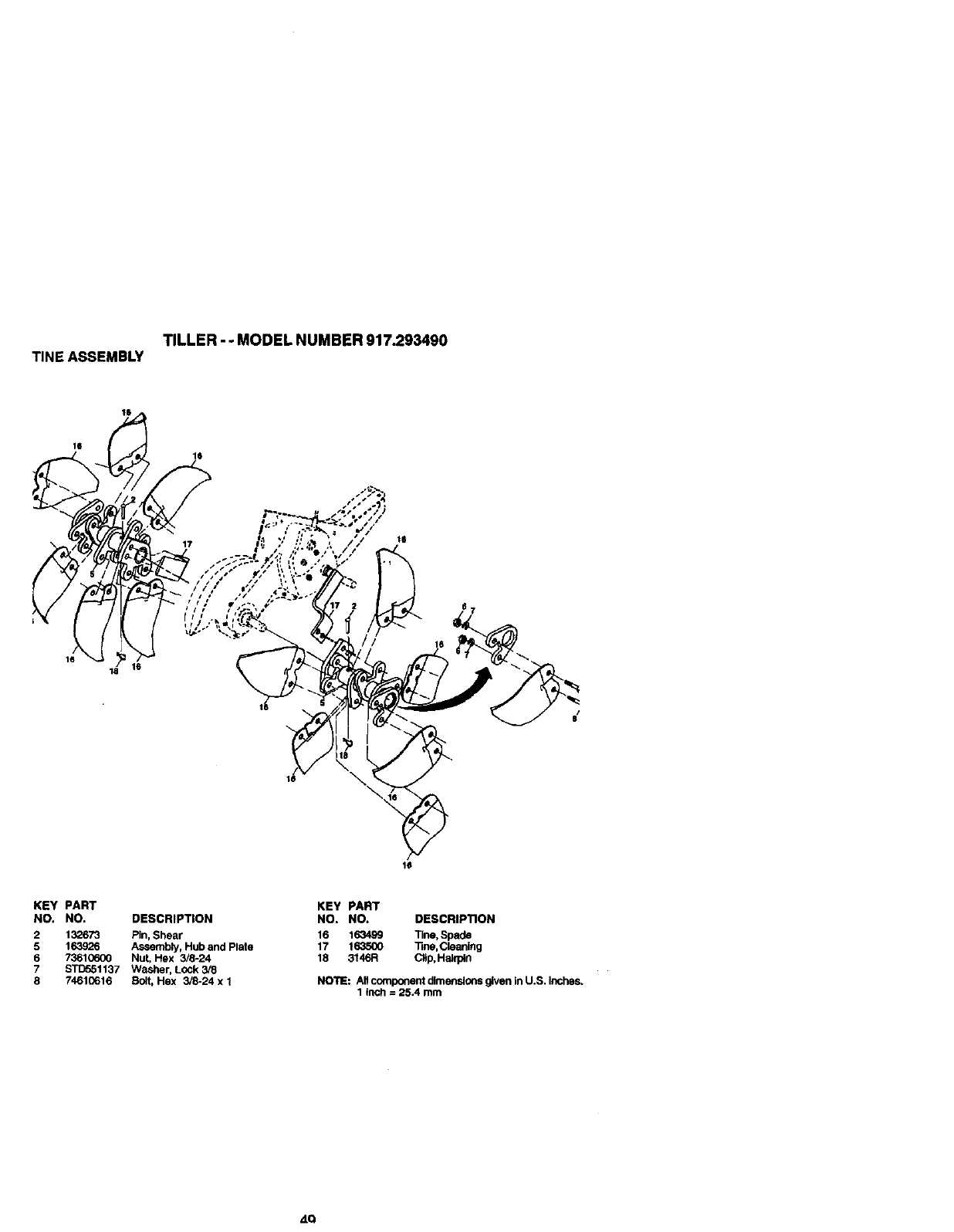
TILLER -- MODEL NUMBER 917.293490
TINE ASSEMBLY
/_ _o
KEY PART KEY PART
NO. NO. DESCRIPTION NO. NO. DESCRIP'nON
2 132673 Pin, Shear 16 163499 Tlne, Spade
5 163926 Assembly, Hub and Plate 17 1635(_ Tme,Cleaolng
673610600 Nut, Hex 3/8-24 18 3146R Clip, Hairpin
7STD551137 Washer, LOCk 3/8
874610616 Bolt, Hex 3/8-24 x 1 NOTE: All component dimensions _ven In U.S. Inches.
1 inch =25.4 mm
ZLQ
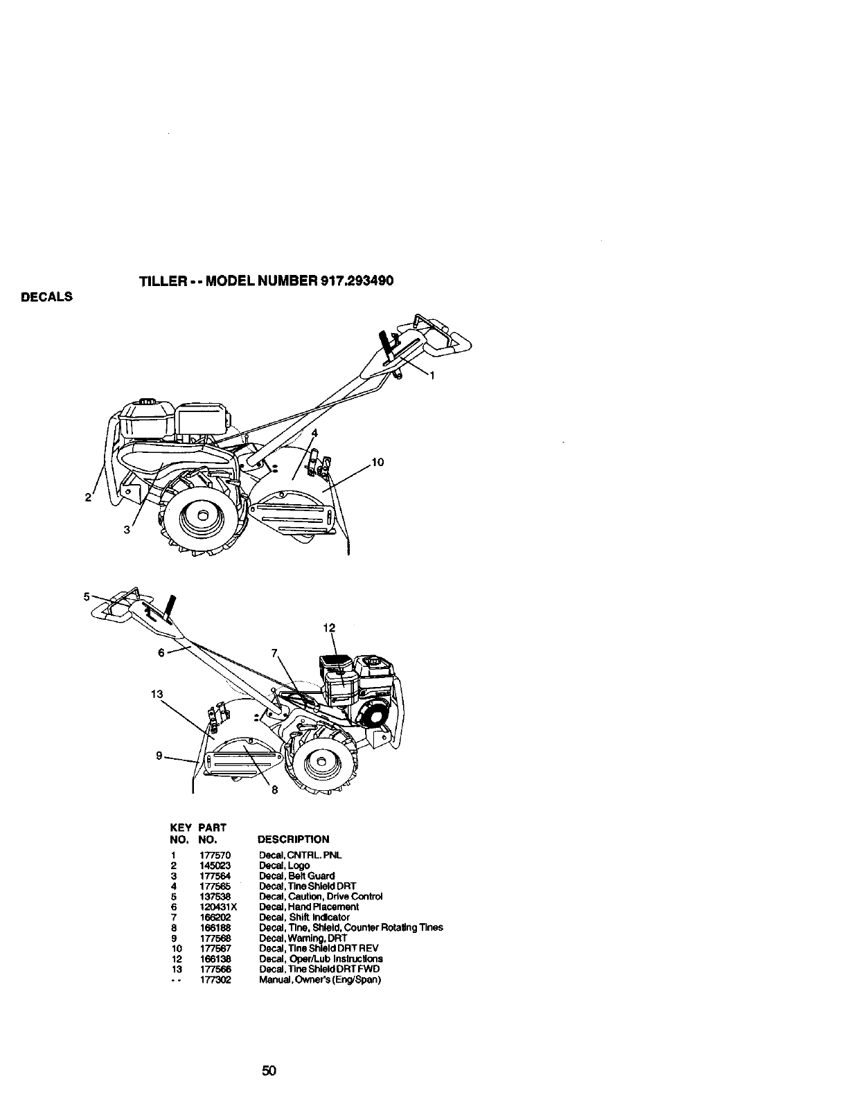
DECALS
TILLER - - MODEL NUMBER 917.293490
2
12
13
KEY PART
NO. NO. DESCRIPTION
1 177570 DeCal,CNTRL PNL
2 145023 Decal, Logo
3 177564 Decal, Belt Guard
4 177565 Decal, Tine Shiald DRT
5 137538 Decal, Caution, Drive Control
6 120431X BeCal, Hand Placement
7 166_02 Decal, Shift Indicator
8 166188 Decal, Tlne, Shield, Counter Rotating Tines
9 177568 Decal, Warning, DRT
10 177567 Decal, Tlne Shlold DRT REV
12 166138 Decal, Oper/Lub Instructions
13 177566 Decal, 13he Shiald DRT FWD
-- 1773(_ Manual, Owner's ( Eng/Span )
5O
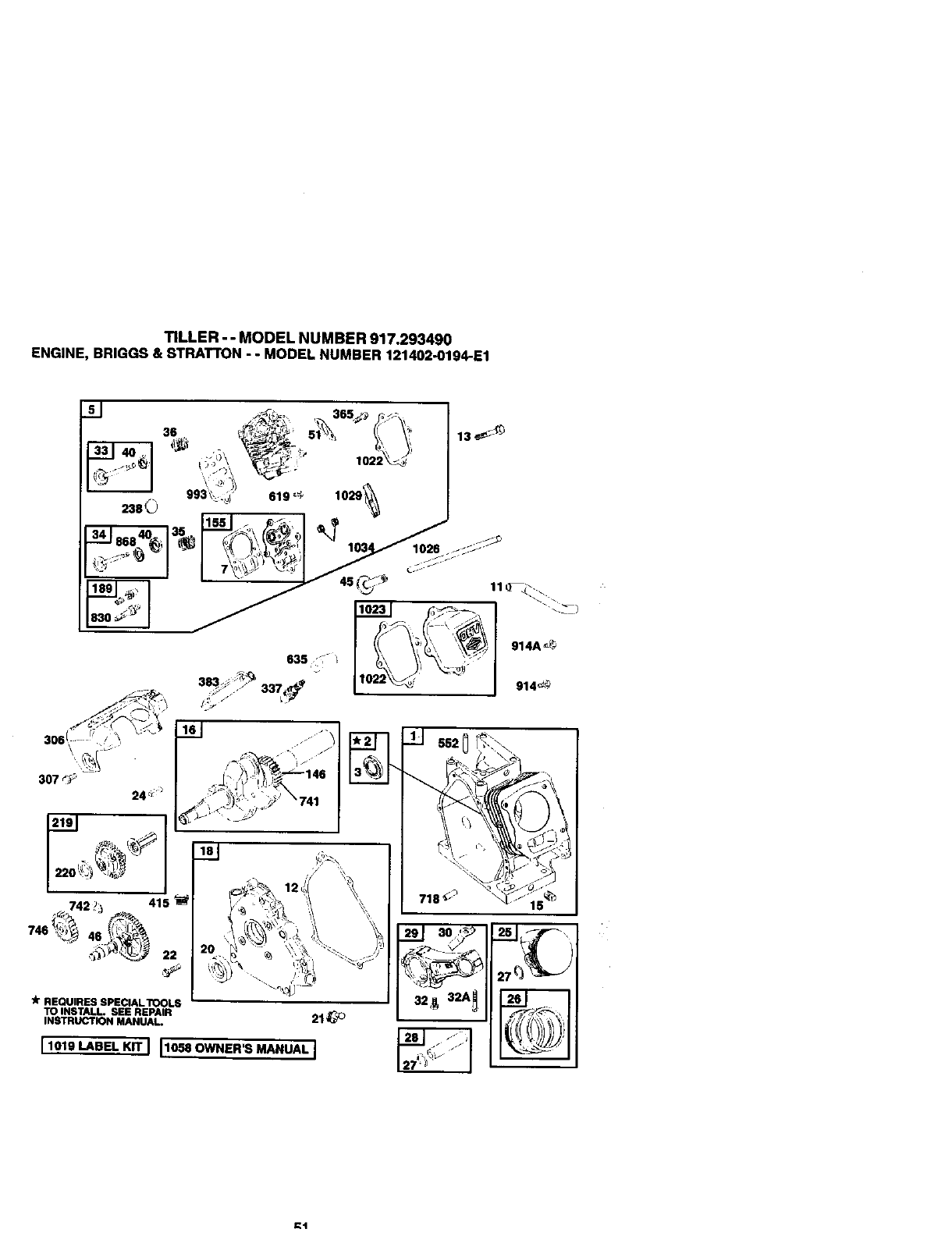
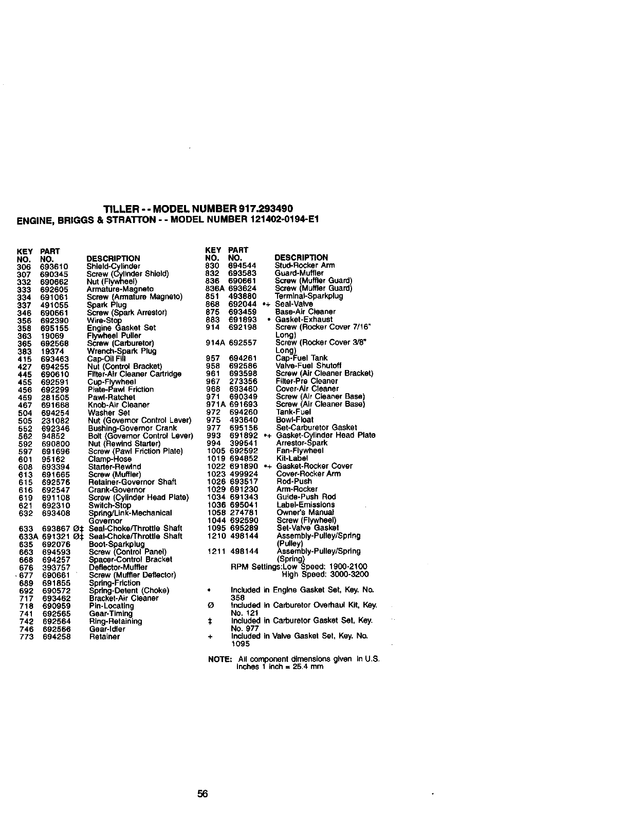
TILLER-- MODELNUMBER917.293490
ENGINE,BRIGGS&STRATTON- - MODELNUMBER121402-O194-E1
(\ !_ 13 _-_
238QJ 993_, 619 :_ 1029_
_r REQUIRES SPECIALTOOLS
TO INSTALL. SEE REPAIR
INSTRUCTION MANUAL.
I 1019 LABEL KIT 111o"OWNER'S MANUAL J
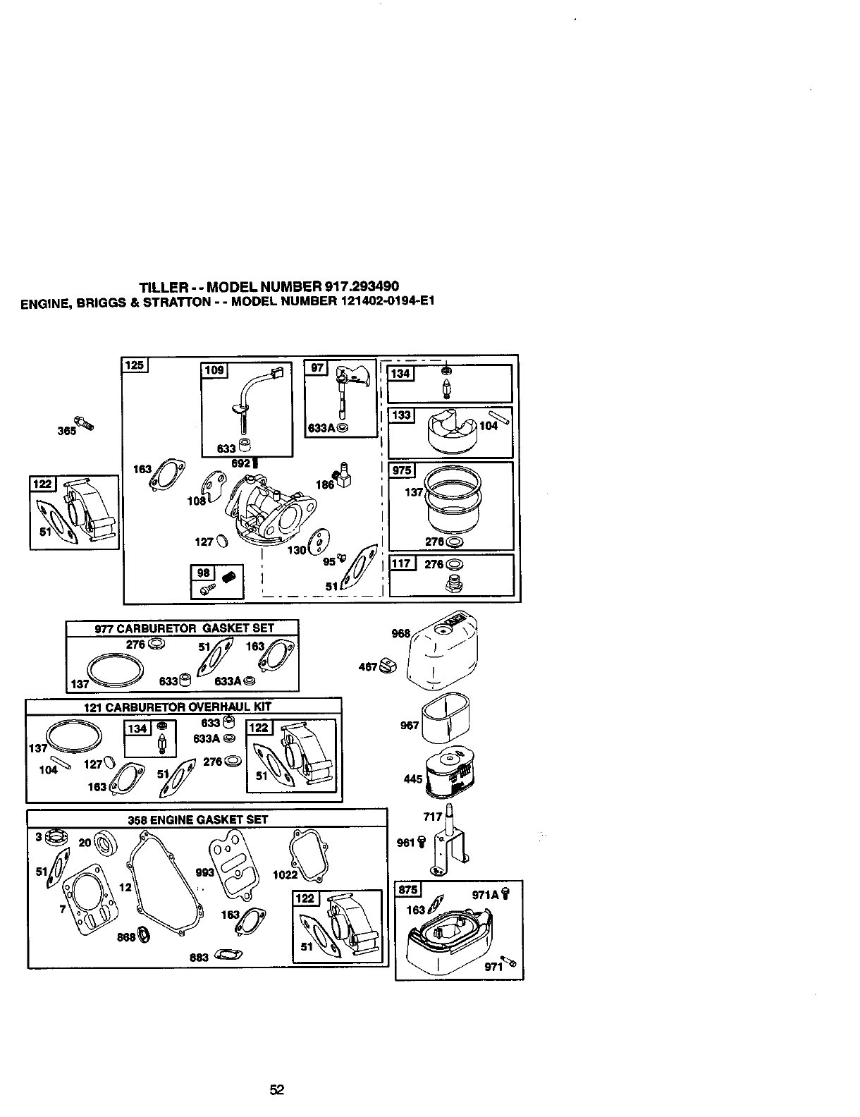
TILLER - - MODEL NUMBER 917.293490
ENGINE, BRIGGS & STRATTON - - MODEL NUMBER 121402-0194-E1
3@
6921
127_ 276_
95_ _.J 2760
977 CARBURETOR GASKET SET
I276 _51 163
L1370 633_ _3A_ _
121 CARBURETOR OVERHAUL KIT
_633_ 11221
358 ENGINE GASKET SET
467 _968_
-@
883_
52
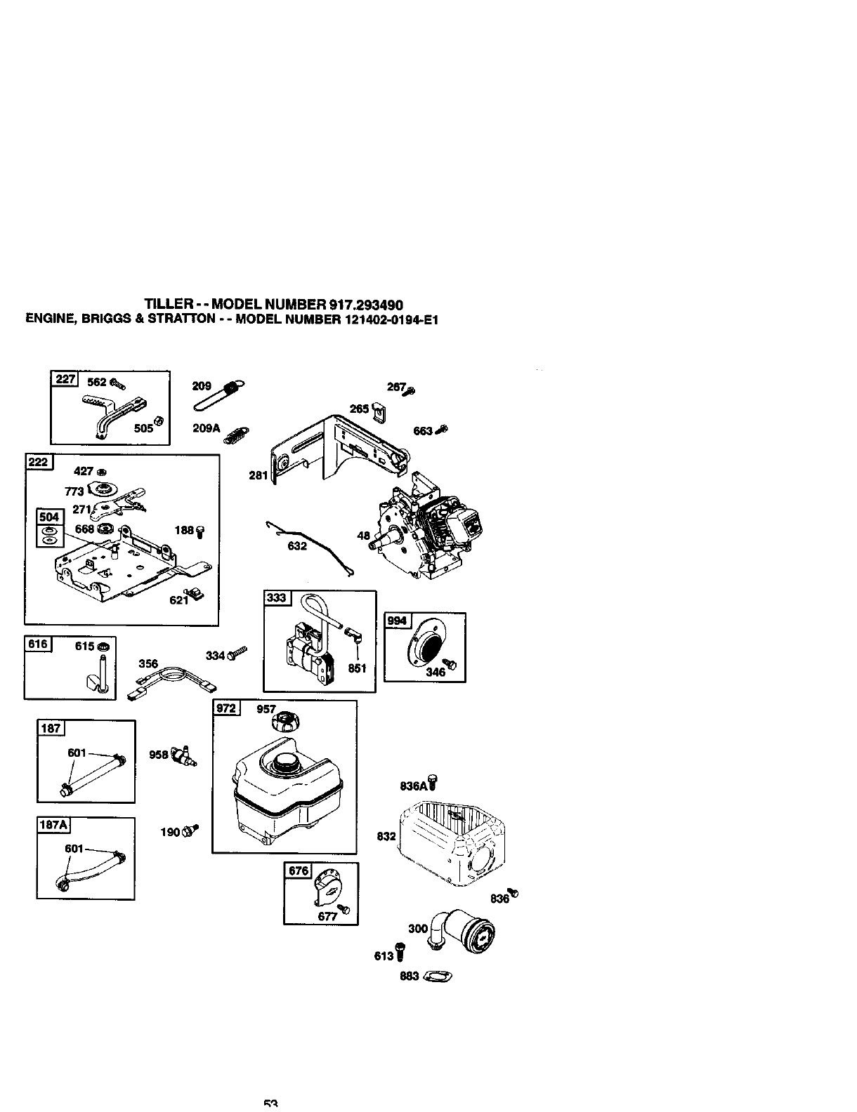
TILLER - - MODEL NUMBER 917.293490
ENGINE, BRIGGS & ETRATrON - - MODEL NUMBER 121402-0194-E1
2221 427 ®
958
;_ 190_P
e36A'_
883,_
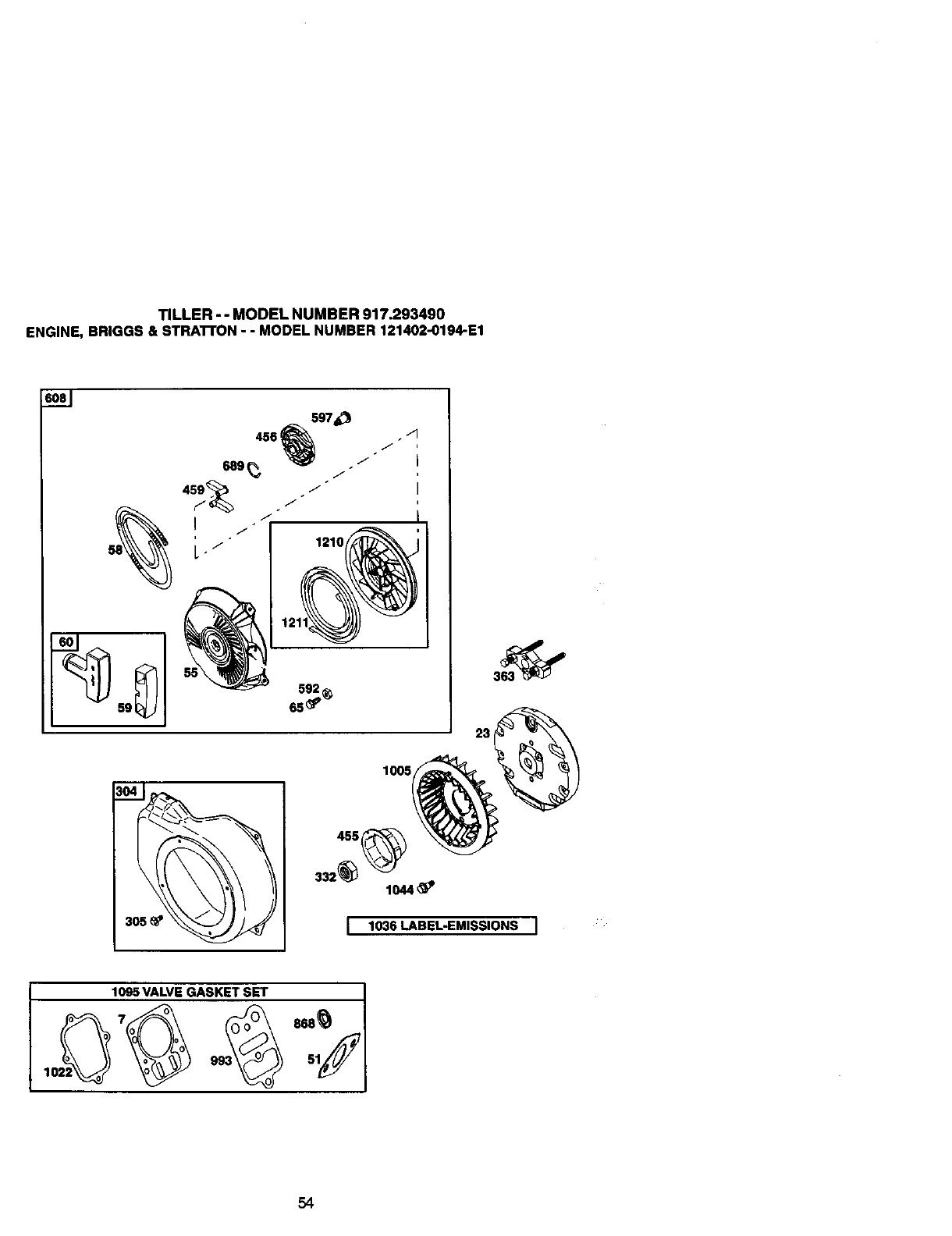
TILLER - - MODEL NUMBER 917.293490
ENGINE, BRIGGS & STRATFON- - MODEL NUMBER 121402-0194-E1
+4
J
23
1005
455
lO44_'
1036 LABEL-EMISSIONS I
54
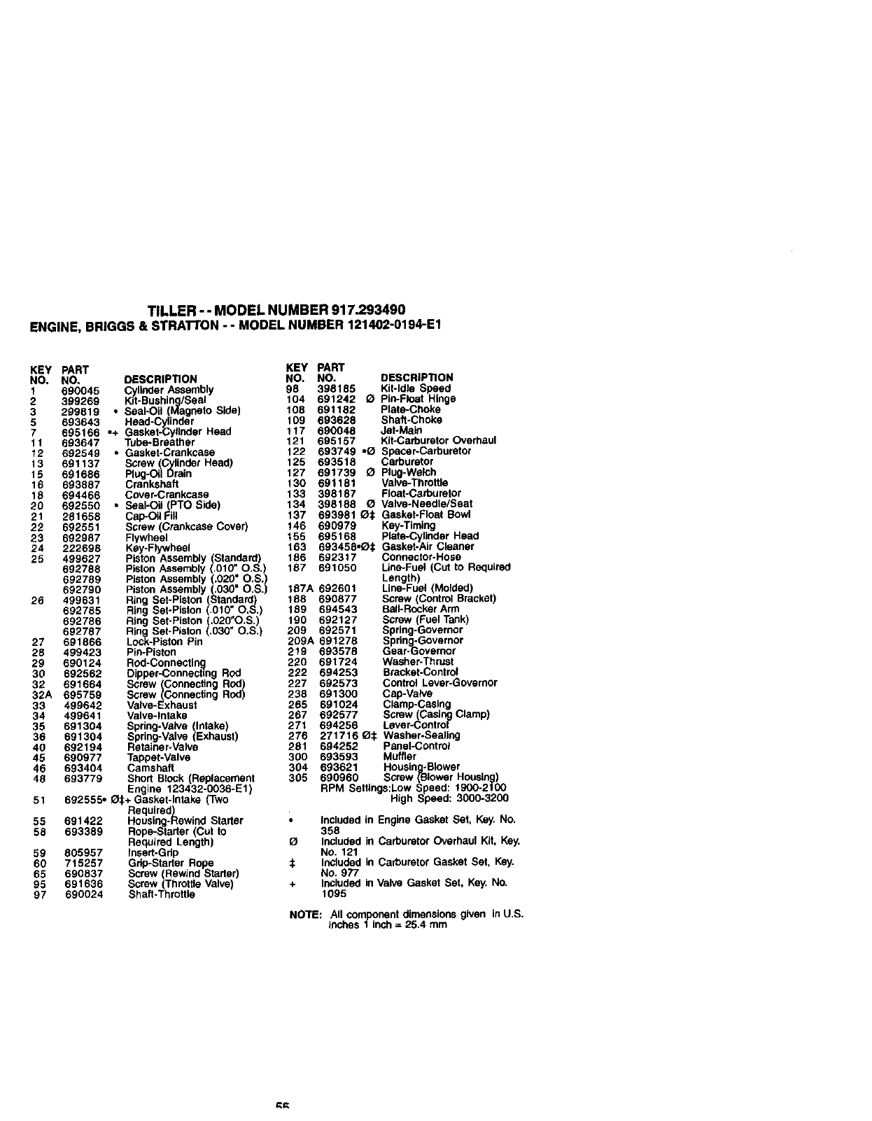
TILLER-- MODELNUMBER917.293490
ENGINE,BRIGGS&STRATrON-- MODELNUMBER121402-0194-E1
KEY PART KEY PART
NO, NO. DESCRIPTION NO. NO. DESCRIPTION
1690045 Cylinder Assembly 98 398185 Kit-Idle Speed
2 399269 Kit-Bushing/Seal 104 691242 OPin-Float Hinge
3299819 • Seal-Oil (Magneto Side) 108 691182 Plate-Choke
5 693643 Heed-Cylinder 109 693628 Shaft-Choke
7 695166 ,+ Gasket-Cylinder Head 117 690048 Jet-Main
11 693647 Tube-Breather 121 695157 Kit-Carburator Overhaul
12 692549 • Gasket-Crankcase 122 693749 ,_ Spacer-Carburetor
13 691137 Screw (Cylinder Head) 125 693518 Carburetor
15 691686 Plug-Oil Drain 127 691739 QPlug-Welch
16 693887 Crankshaft 130 691181 Valve-Throttle
18 694466 Cover-Crankcese 133 398187 FIoat-Carbu retor
20 692550 • SaaI-Oil(PTO Side) 134 398188 OValve-Needle/Seat
21 281658 Cap-OiIFill 137 693981 0¢ Gasket-Float Bowl
22 692551 Screw (Crankcase Cover) 146 690979 Key-Timing
23 692987 Flywheel 155 695168 plate-Cylinder Head
24 222698 Key-Flywheel 163 693458,O_: Gasket-Air Cleaner
26 499627 Piston Assembly (Standard) 186 692317 Connector-Hoce
692788 Piston Assembly (.010 _O.S.) 187 691050 Line-Fuel (Cut to Required
692789 Piston Assembly (.020_ O.S.) Length
692790 Piston Assembly (.030 O.S.) 187A 692601 Line-Fue (Molded)
26 499631 Ring Set-Piston (Standard) 188 690877 Screw (Control Bracket)
692785 Ring Set-Piston (.OlO_O.S.) 189 694543 BalI-RockerArm
692786 Ring Set-Piston (.020"O.S.) 190 692127 Screw (Fuel Tank)
692787 Ring Set-Piston (.030" O.S.) 209 692571 Spring-Governor
27 691866 Lock-Piston Pin 209A 691278 Spring-Governor
28 499423 Pin-Piston 219 693578 Gear-Governor
29 690124 Rod-Connectln_l 220 691724 Washer-Thrust
30 692562 Dipper-Connecting Rod 222 694253 Bracket-Control
32 691664 Screw (Connecting Rod) 227 692573 Control Lever-Governor
32A 695759 Screw (Connecting Rod) 238 691300 Cap-Valve
33 499642 Valve-Exhaust 285 691024 Clamp-Casing
34 499641 Valve-Intake 267 692577 Screw (Casing Clamp)
35 691304 271 694256 Lever-Control
Spdng-Valve (Intake
36 691304 Spring-Valve (Exhaust) 276 271716 0¢ Washer.Sealing
40 692194 Retainer-Valve 261 694252 Panel-Control
45 690977 Tappet-Valve 360 693593 Muffler
48 693404 Camshaft 304 693621 Housing-Blower
49 693779 Short Block (Replacement 305 690960 Screw (Blower Housing)
Engine 123432-0036-Et RPM Seffings:Low Speed: 1900-2100
51 692555, Q.t+ Gasket-Intake Two High Speed: 3000-3200
Required)
55 691422 Housing-Rewind Starter Included in Engine Gasket Set, Key. No.
58 693389 Rope-Starter (Cut to 358
Required Length) O Included in Carburetor Overhaul Kit, Key.
59 805957 Insert-Grip No. 121
60 715257 Grip-Starter Rope :_ InCluded in Carburetor Gasket Set, Key.
65 690837 Screw (Rewind Starter) NO. 977
95 691636 Screw (Throttle Valve) + Included in Valve Gasket Set, Key. No.
97 690024 Shag-Throgle 1095
NOTE: All component dimensions given in U.S.
inches 1 inch = 25.4 mm
TILLER - - MODEL NUMBER 917.293490
ENGINE, BRIGGS & STRAI"rON - - MODEL NUMBER 121402-0194-E1
KEY PART KEY PART
NO. NO. DESCRIPTION NO. NO. DESCRIPTION
306 693610 Shield-Cylinder 830 694544 Stud-Rocker Arm
307 690345 Screw (Cylinder Shield) 832 693583 Guard-Muffler
332 690662 Nut (Flywheel) 836 690661 Screw Muffler Guard)
333 692605 Armature-Magneto 836A 693624 Screw Muffet Guard
334 691061 Screw (Armature Magneto) 851 493880 TermleaI-Sparkplug
337 491055 Spark Plug 868 692044 .+ Seal-Valve
346 690661 Screw (Spark Arrestor) 875 693459 Base-Air Cleaner
356 692390 Wire-St)to 883 691893 • Gasket-Exhaust
358 695155 Engine Gasket Set 914 692198 Screw (Rocker Cover 7/16"
363 19069 Flywheel Puller Long)
365 692568 Screw (Carburetor) 914A 692557 Screw (Rocker Cover 3/8"
383 19374 Wrench-Spark Plug Long)
415 693463 Cap-Oil Fill 957 694261 Cap-Fuel Tank
427 694255 Nut (Control Bracket) 958 692586 Valve-Fuel Shutoff
445 690610 Fitter-Air Cleaner Cartridge 961 693598 Screw (Air Cleaner Bracket)
455 692591 Cup-Flywheel 967 273356 FUter-Pre Cleaner
456 692299 Plate-Pawi Friction 968 693460 Cover-Air Cleaner
459 281505 Pawi-Ratchet 971 690349 Screw Air Cleaner Base)
467 691668 Knob-AIrCleaner 971A691693 Screw ArCeanerBase)
504 694254 Washer Set 972 694260 Tank-Fuel
505 231082 Nut (Governor Control Lever) 975 493640 Bowl-Float
552 692346 Bushing-Governor Crank 977 695156 Set-Carburetor Gasket
562 94852 Bolt (Governor Control Lever) 993 691892 .+ Gasket-Cylinder Head Plate
592 690800 Nut (Rewind Starter) 994 399541 Arrestor-Spark
597 691696 Screw (Pawl Fdction Plate) 1005 692592 Fan-Flywheel
601 95162 Clamp-Hose 1019 694852 Kit-Label
608 693394 Starter-Rewind 1022 691890 .+ Gasket-Rocker Cover
613 691665 Screw (Muffler) 1023 499924 Cover-Rocker Arm
615 692576 Retainer-Governor Shaft 1026 693517 Rod-Push
616 692547 Crank-Governor 1029 691230 Arm-Rocker
619 691108 Screw (Cylinder Head Plate) 1034 691343 Guide-Push Rod
621 692310 Switch-Stop 1036 695041 LabeI-Emissiose
632 693408 Spring/Link-Mechanical 1058 274781 Owner's Manual
Governor 1044 692590 Screw(Flywheel)
633 693867 O:[: Seal-Choke/Throttle Shaft 1095 695289 Set-Valve Gasket
633A 691321 _:1: Seal-Choke/Throttle Shaft 1210 498144 Assembly-Pulley/Spring
635 692076 Boot-Sparkplug (Pulley)
663 694593 Screw (Control Panel) 1211 498144 Assembly-Pulley/Sprleg
668 694257 Spaser-Control Bracket (Spring)
676 393757 Deflector-Muffler RPM Settings:Low Speed: 1900-2100
,677 690661 Screw (Muffler Deflector) High Speed: 3000-3200
689 691855 Spring-Friction
692 690572 Spring-Detent (Choke) Included in Engine Gasket Set, Key. NO.
717 693462 Bracket-Air Cleaner 358
718 690959 Pin-Locating _tncluded in Carburetor Overhaul Kit, Key.
741 692565 Gear-Timing NO. 121
742 692564 Ring-Retaining $Included in Carburetor Gasket Set, Key.
746 692566 Gear-Idler No. 977
773 694258 Retainer + Included in Valve Gasket Set, Key. No.
1095
NOTE: All component dimensions given in U.S.
inches 1 inch =25.4 mm
56


58

€lt_

Get it fixed, at your home or ours!
For repair of major brand appliances in your own home...
no matter who made it, no matter who sold it!
1-800-4-MY-HOM EsMAngina,dayo,.Ig.t
(1-800-489-4663)
www.sears,com
To bring in products such as vacuums,
lawn equipment and electronics for repair, call for
the location of your nearest Sears Parts & Repair Center.
1-800-488-1222 A._r_,d,yor night
www.sears.com
For the replacement parts, accessories and owner's manuals
that you need to do-it-yourself, call Sears ParteDirectSM!
1-800-366-PART 6..=- 11p,m.CST,
(1-800-366-7278) 7daysa week
www.sears,com/partsdlrect
To purchase or inquire about aSears Service Agreement:
1-800-827-6655
7 a.m.- 5 p.m.CST,Mort.- Sat.
Para pedirserviciode reparacibna dornlcillo,
y pare ordenar piezas conentrega a domicilio:
1-888-SU-HOGAR TM
(%888-784-6427)
AUCanada pourserv_,een frangals:
1-877-LE-FOYER _
(t-877-533-6937)
© Seanl, S_ll_i_Ind CO. ®RegisteredTrademarkIT. Trademad_of Seam, Roebuckand Ca
®Mama Registrada/ _Mama de F6bdca de Sears, RoebuCkend CO.
177302 Rev. 1 12.8:00 TR Printed in U.S.A.
