Craftsman 917299230 User Manual SEARS REAR TINE TILLER Manuals And Guides L0808215
CRAFTSMAN Rear Tine, Gas Tiller Manual L0808215 CRAFTSMAN Rear Tine, Gas Tiller Owner's Manual, CRAFTSMAN Rear Tine, Gas Tiller installation guides
User Manual: Craftsman 917299230 917299230 CRAFTSMAN SEARS REAR TINE TILLER - Manuals and Guides View the owners manual for your CRAFTSMAN SEARS REAR TINE TILLER #917299230. Home:Lawn & Garden Parts:Craftsman Parts:Craftsman SEARS REAR TINE TILLER Manual
Open the PDF directly: View PDF ![]() .
.
Page Count: 32
i lll
!sear
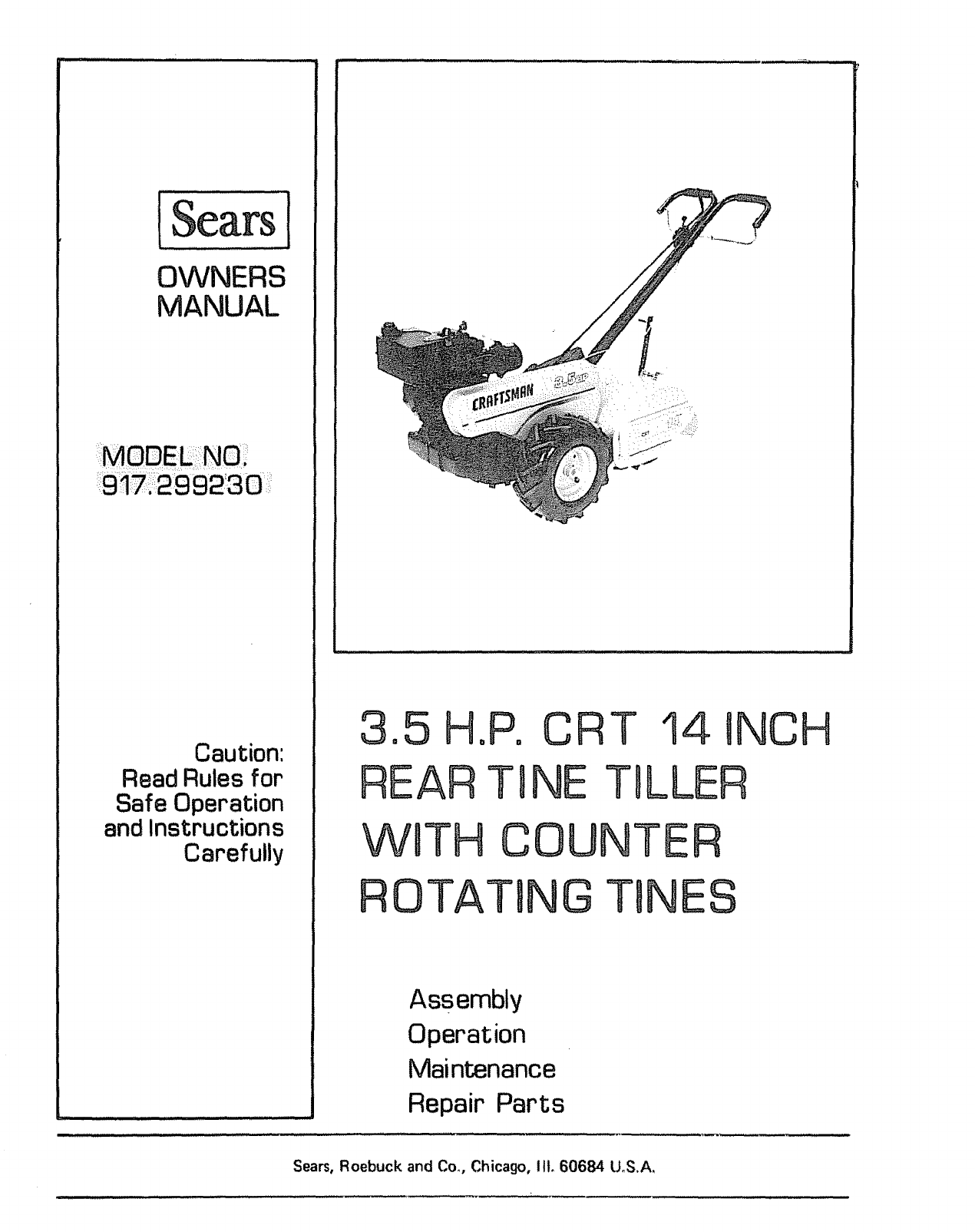
OWNERS
MANUAL
Caution:
Read Rules for
Safe Operation
and Instructions
Carefully
3o5H
REAR
WBTH
ROTA
oPoCRT 14 INCH
T INE TILLER
COUNTER
TIN G TONES
Assembly
Operation
Maintenance
Repair Parts
Sears, Roebuck and Con, Chicago, 11t.60684 U.S.A.
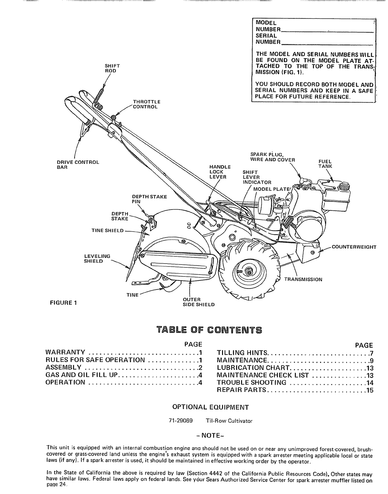
SHIFT
ROD
THROTTLE
MODEL
NUMBER
SERIAL
NUMBER
THE MODEL AND SERIAL NUMBERS WILL
BE FOUND ON THE MODEL PLATE AT-
TACHED TO THE TOP OF THE TRANS,
MISSION (FIG. 1L
YOU SHOULD RECORD BOTH MODEL AND
SERIAL NUMBERS AND KEEP IN A SAFE
PLACE FOR FUTURE REFERENCE.
DRIVECONTROL
BAR
DEPTH STAKE
PIN
OEPTH_
STAKE \
TINE SHIELD
HANDLE
LOCK
LEVER
SPARK PLUG,
WIRE AND COVER
SHIFT
LEVER
INDICATOR
MODEL PLATE _
FUEL
TANK
LEVELING
SHIELD
IGHT
TRANSMISSION
TtNE OUTER
FIGURE 1 SIDE SHIELD
TABLE OF
PAGE
WARRANTY .............................. 1
RULES FOR SAFE OPERATION .............. 1
ASSEMBLY ............................... 2
GAS AND OIL FILL UP ....................... 4
OPERATION .............................. 4
CONTENTS
PAGE
TILLING HINTS ............................ 7
MAINTENANCE ............................ 9
LUBRICATION CHART ..................... 13
MAINTENANCE CHECK LIST ............... 13
TROUBLE SHOOTING ..................... 14
REPAIR PARTS ........................... 15
OPTIONAL EQU IPMENT
71-29f369 Til-Row Cultivator
- NOTE-
This unit is equipped with an internal combustion engine ana should not be used on or near any unimproved forest_covered, brush-
.I
covered or grass-covered land unless the engine s exhaust system is equipped with aspark arrester meeting applicable local or state
laws (if any). If a spark attester is used, it should be maintained in effective working order by the operator_
In the State of California the above is required by taw (Section 4442 of the California Public Resources Code), Other states may
have similar lawso Federal laws apply on federal lands See y6ur Sears Authorized Service Center for spark arrester muffler listed on
pa.qe 24
LIMITED ONE YEAR _tVARRANTY ON TILLER
For one year from date of purchase, _Jhen this tiller is maintained, lubricated, and tuned up according to the operating and
maintenance instructions in the owner s manual, Sears will repair free of charge any defect in material or workmanship
This warranty excludes tine(s), spark plug, air cleaner and belt(s) which are expendable parts and become worn during norma_
use.
If this tiller is used for commercial or rental purposes, this warranty applies for only 30 days from the date of purchase.
WARRANTY SERVICE IS AVAILABLE BY CONTACTING THE NEAREST SEARS SERVICE CENTER/DEPARTMENT
IN THE UNITED STATES. This warranty applies only while this product is in use in the United States.
This warranty gives you specific legal rights, and you may also have other rights which vary from state to state.
SEARS, ROEBUCK AND CQ, D/698o731A, SearsTower, Chicago, IL 60684
RULES FOR SAFE
1, KNOW YOUR TILLER. Become familiar with all the
different sections of this Owners Manual before attempt°
ing to operate your Tiller. Know the controls and how
to stop quickly.
2, ALWAYS KEEP HANDS AND FEET AWAY FROM
ROTATING TINES AND OTHER DRIVEN PARTS,
Always wear substantial footwear Do not wear loose fit ._
t|ng clothing that could get caught in moving parts
3, LIMIT YOUR TILLER'S USE TO TRAINED ADULTS,
Do not atfow children to operate your Tilter Keep by-
standers and pets away from the area when you are
o!Seratingyour Tiller
4, MAKE SURE THE AREA IS CLEAR of bottles, stones,
wire and other hazardous items before tilling
5, HANDLE FUEL WITH CARE; it is highly flammable,
Never add fuel to a running or hot engine or fill tank
indoors. Turn engine off and let your Engine coot before
refueling
.
Fuel Tank Cap must be secure at all times except during
refueling
Do not smoke while refueling
Fuel your Tiller in a clean area
.
Avoid spilling gasoline or oil. Wipe the Tiller clean of
any spilled fuel or o_t,
Do not operate engine if air cleaner or cover directly
over carburetor air intake is removed, except for adjust-
ment Removal of such part could create a fire hazard.
Do not use flammable solutions to clean the air filter
Store your Titler fuel and oil in approved containers
away from heat or open flame and out of reach of chil-
dren
6,, USE YOUR TILLER PROPERLY, Before starting en-
gine make sure Drive Control Bar is in _'STOP" position
and Shift Lever indicator is in "N" NEUTRAL position.
9_
Operate your Tiller up and down the face of slopes (not
greater than 15°); never across the face. Make turns
gradually to prevent tipping or loss of control, EYercise
extreme caution when changing direction on slopes,
OPERATeON
Do not run engine indoors, exhaust fumes are poison-
ous
Never operate product when tired or fatigued. Always
operate product with extreme care with your own safety
in rain& Carelessness or misuse could lead to severe in-
jury,
Before removing obstacles, transporting your Tiller, or
when making any adjustments except carburetor, make
sure Drive Control Bar is in "STOP" position and Shift
Lever Indicator is in "N" NEUTRAL position° Stop
engine before leaving the operating position. D_sconnect
spark plug wire and cover from spark plug,
Release Drive Control Bar to disengaqe tines before
shifting into reverse,, Be sure of your footing,, DonTt back
yourself into a soiid obstruction, such as a tree, fence,
etco To stop quickly, release the drive control bar_
ALLOW THE ENGINE ON YOUR TILLER TO COOL
before performing any maintenance or adjustments,
transporting your Tiller or storing your Tiller in any en-
closure Never store your Tiller with fuel in the tank in-
side a building where fumes may reach an open flame or
spark.
BE SURE THE TILLER IS IN GOOD WORKING OR-
DER, Keep all nuts, bolts and screws tight to be sure
your Tiller is in safe working condition°
Do not change governor settings or over speedengine°
Do not tamper with the exhaust system° Damaged muf-
tiers or spark arrestorscould create a fire hazard, Inspect
periodically and replace if necessary°
Your Tiller must be stopped and inspected for damage
after striking a foreign object_ The damage must be re_
paired before restarting or operating your Tiller
YOUR TILLER HAS BEEN DESIGNED WITH YOUR
SAFETY AND CONVENIENCE IN MIND, Keep'all
safety devices in place and do not alter your Tiller.
LOOK FOR THIS SYMBOL TO
POINT OUT IMPORTANT SAFE-
TY PRECAUTIONS, IT MEANS -
ATTENTION! BECOME ALERT!
YOUR SAFETY IS INVOLVED.
-1-
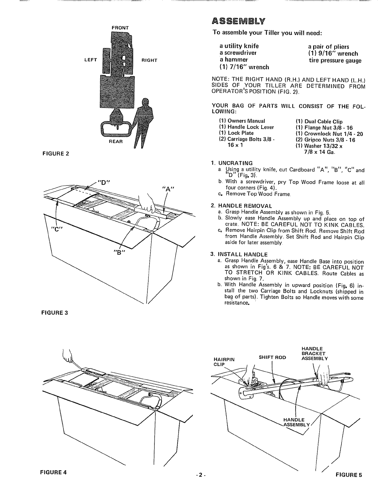
FIGURE 2
FIGURE 3
LEFT
FRONT
REAR
RIGHT
ASSEMBLY
To assemble your' Tiller you will need:
a utility knife
a screwdriver
a hammer'
(1) 7/16" wrench
a pair of pliers
(1) 9/16" wrench
tire pressure gauge
NOTE: THE RIGHT HAND (R,.H.) AND LEFT HAND (LH,)
SIDES OF YOUR TILLER ARE DETERMINED FROM
OPERATOR'S POSITION (FIG,, 2)°
YOUR BAG OF PARTS WILL CONSIST OF THE FOL-
LOWING:
(1) Owners Manual
(1) Handle Lock Lever
(1) Lock Plate
(2) Carriage Bolts 3/8 -
16xl
(1) Dual Cable Clip
(1) Flange Nut 3/8 - 16
(i) Crowntock Nut 1/4 -20
(2) Gripco Nuts 3/8 - 16
(1) Washer 13/32 x
7/8 x 14 Ga.
UNCRATING ""_'B_ "C"
a Using a utility knife, cut Cardboard A , and
tt tr , " w
D (Fig, 3),.
b, With a screwdriver, pry Top Wood Frame loose at atl
four corners (Fig,, 4).
c, Remove Top Wood Frame,
2_ HANDLE REMOVAL
a, Grasp Handle Assembly as shown in Fig,, 5,
b,. Slowly ease Handle Assembly up and place on top of
crate, NOTE: BE CAREFUL NOT TO KINK CABLES,
co Remove Hairpin Clip from Shift Rod, Remove Shift Rod
from Handle Assembly, Set Shift Rod and Hairpin Clip
aside for later assembly,
3. INSTALL HANDLE
ao Grasp Handle Assembly, ease Handle Base into position
as shown in Fig_s_6 & 7, NOTE; BE CAREFUL NOT
TO STRETCH OR KiNK CABLES,. Route Cables as
shown in Fig, 7,
b_ With Handle Assembly in upward position (Fig, 61 in-
stall the two Carriage Bolts and Locknuts (shipped in
bag of parts),, Tighten Bolts so Handle moves with some
resistance.
HAIRPIN SHIFT ROD
HANDLE
BRACKET
ASSEMBLY
J
FIGURE 4 _2 - FIGURE 5
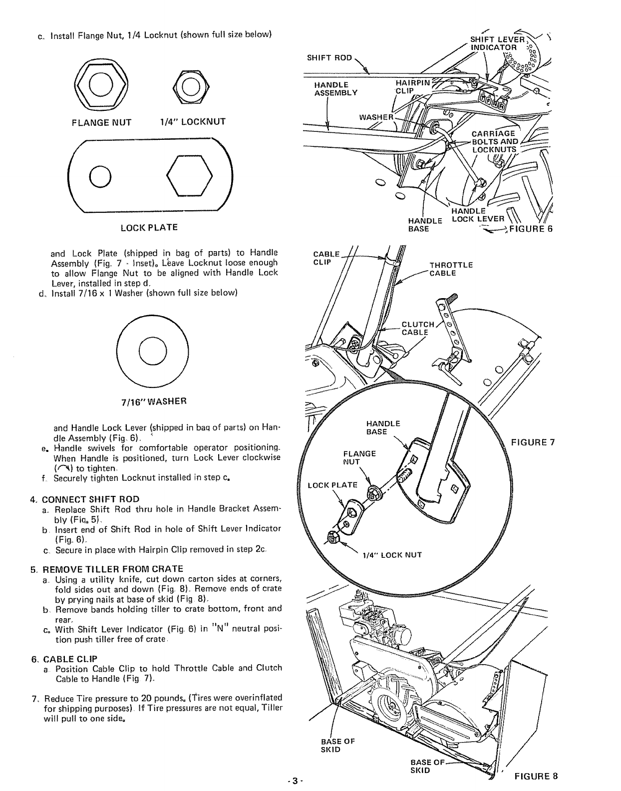
c., Install Flange Nut, 1/4 Locknut (shown full size below)
Q
FLANGE NUT 1/4" LOCKNUT
LOCK PLATE
d_
and Lock Plate (shipped in bag of parts) to Handle
Assembly (Fig,. 7 - Inset)° L_ave Locknut loose enough
to allow Flange Nut to be aligned with Handle Loc!<
Lever, installed in step d.
Install 7/16 x t Washer (shown full size below)
SHIFT ROD
HANDLE
ASSEMBLY
CABLE
CLIP
HAIRPIN
'CLIP
HANDLE
BASE
THROTTLE
:ABLE
7/16" WASHER
and Handle Lock Lever (shipped in baq of parts) on Han-
dle Assembly (Fig 6)_, _
e. F1andle swivels for comfortable operator positioning..
When Handle is positioned, turn Lock Lever clockwise
(f"_) to tighten,
f, Securely tighten Locknut installed in step c.
4o CONNECT SHIFT ROD
a. Replace Shift Rod thru hole in Handle Bracket Assem-
bly (Fiq= 5},
b. Insert end of Shift Rod in hole of Shift Lever Indicator
(Fig. 6)..
c. Secure in place with Hairpin Clip removed in step 2c,
5. REMOVE TILLER FROM CRATE
a,, Using a utility knife, cut down carton sides at corners,
fold sides out and down (Fig, 8)., Remove ends of crate
by prying nails at base of skid (Fig 8)_
b. Remove bands holding tiller to crate bottom, front and
rear,,
c. With Shift Lever Indicator (Fig 6) in "N" neutral posi-
tion push tiller free of crate.
6, CABLE CLIP
a Position Cable Clip to hold Throttle Cable and Clutch
Cable to Handle (Fig 7).,
7., Reduce Tire pressure to 20 pounds° (3_ires were overinflated
for shipping purposes) If Tire pressures are not equal, TilLer
will pull to one side.
HANDLE
BASE
FLANGE
NUT
LOCI< PLATE
BASE OF
SKID
CLUTCH
I14" LOCI( NUT
BASE
SKID
FIGURE 7
- 3 - FIGURE 8
,FUEL TANK
CAP
FIGURE 9
_NDLE
"HIGH" POSITION
FIGURE 10
,LOOSEN
"%_%'-
HANDLE __
LOCI( LEVE
SPARK PLUG
WIRE AND
COVER \
SPARK
PLUG _._ Li
TIGHTEN __
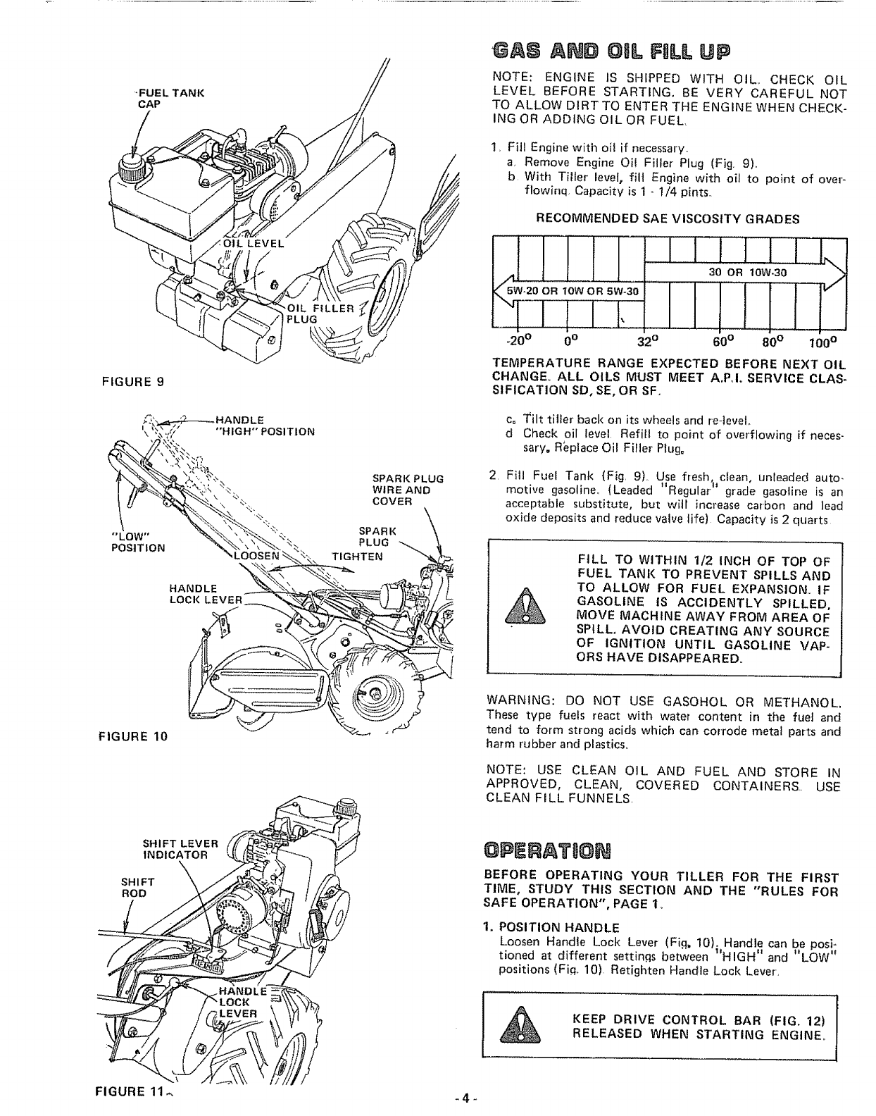
AND OiL FILl UP
NOTE: ENGINE IS SHIPPED WITH OIL_ CHECK OIL
LEVEL BEFORE STARTING, BE VERY CAREFUL NOT
TO ALLOW DIRT TO ENTER THE ENGINE WHEN CHECK-
ING OR ADDING OIL OR FUEL,
1_ Fill Engine with oil if necessary_
a, Remove Engine Oil Filler Plug (Fig 9)
b With Tiller level, fill Engine with oil to point of over-
flowinq Capacity is 1 - 1/4 pints.
RECOMMENDED SAE VISCOSITY GRADES
ORlowOR5W30
_20o0o
II
_2°
II1 I1 .
I
60° 80 °100 °
TEMPERATURE RANGE EXPECTED BEFORE NEXT OIL
CHANGE. ALL OILS MUST MEET A,PJ° SERVICE CLAS-
SIFICATION SO, SE, OR SF.
c= l'ilt tiller back on its wheels and re-level
d Check oil level Refill to point of overflowing if neces-
sary, Replace Oil Filler Plug=
2 Fill Fuel Tank {Fig 9) Use fresh, ciean, unleaded auto-
motive gasoline. (Leaded "Regular" grade gasoline is an
acceptable substitute, but witl increase carbon and lead
oxide deposits and reduce valve life) Capacity is 2 quarts
FILL TO WITHIN 1/2 INCH OF TOP OF
FUEL TANK TO PREVENT SPILLS AND
TO ALLOW FOR FUEL EXPANSION, IF
GASOLINE IS ACCIDENTLY SPILLED.
MOVE MACHINE AWAY FROM AREA OF
SP_LL. AVOID CREATING ANY SOURCE
OF IGNITION UNTIL GASOLINE VAP-
ORS HAVE DISAPPEARED,
WARNING: DO NOT USE GASOHOL OR METHANOL.
These type fuels react with water content in the fueJ and
tend to form strong acids which can corrode metal parts and
harm rubber and plastics,
NOTE: USE CLEAN OIL AND FUEL AND STORE IN
APPROVED, CLEAN, COVERED CONTAINERS. USE
CLEAN FiLL FUNNELS
SHIFT LEVER
INDICATOR
SHIFT X
ROD
BEFORE OPERATING YOUR TILLER FOR THE FIRST
TIME, STUDY THIS SECTION AND THE "RULES FOR
SAFE OPERATION", PAGE 1_
1. POSITION HANDLE
Loosen Handte Lock Lever (Fig= 10). Handle can be posi-
tioned at different settings between _'HIGH" and "LOW"
positions (Fi.q_ 10) Retighten Handle Lock Lever,
KEEP DRIVE CONTROL BAR (FIG. 12)
RELEASED WHEN STARTING ENGINE_
FIGURE 11_. -4-

2o STARTING THE ENGINE
NOTE: BE SURE SPARK PLUG, WIRE AND COVER
ARE ATTACHED TO SPARK PLUG,(FIG t0),
a., Move Shift Lever Indicator to N (neutral) position
(Fig.II). II II • •
bo Place Throttle Control (Figo 121 in START position.
c.. Move Choke Control on engine to _'FULL CHOKE"
position (Fig. 13).
d, Grasp Starter HandJe (Fig. 14) and pull rope out slowty
untit engine reaches start of compression cycle (rope will
pull stightty harder at this point). Let rope rewind slow-
ty.
e, Pull rope with a rapid continuous full arm stroke Keep a
firm grip on Starter Handle and let rope rewind slowly.,
Do not let Starter Handle snap back against starter.
f, Repeat preceding instructions d and e until engine fires
and when engine starts, move Choke Control on engine
to t_NO CHOKE" position (Fiq, 13)
II ,_II ,,
g. Move Throttte Control to S slow posttJon for a few
minutes warm up.,
3. TRANSPORTING
a Release the Depth Stake Pin (Fig., 15),. Move the Depth
Stake down to the top hole for transporting the Tiller',,
This prevents Tines from scuffing the ground. Place
Depth Stake Pin in hole of Depth Stake to loci{ in posi-
tion (Fig. 15),
bo Place Shift Lever Indicator (Fig. 11) in "F" (forward)
position for transporting,
c. Hold the Drive Control Bar against the Handle (Fig., t2)
to start Tiller movement, Tines 'will not turn
d° Move Throttle Control (Fig. 12) to desired speed
NEVER OPERATE TILLER WITH RIVETS
REMOVED FROM WHEELS (FIG., 14)o
UNTIL YOU ARE ACCUSTOMED TO
HANDLING YOUR TILLER, START
ACTUAL FIELD USE WITH THROTTLE
tN SLOW POSITION (MIDWAY BETWEEN
"FAST" AND "IDLE").
CHOKE CONTROL
/
JI
CHOK_ CO_JTROLZ,_/i,,FULLCHOKE,, _. _ y
\
RIVET
STARTER
HANDLE
HAIRPIN CLIP
FIGURE 13
FIGURE 14
HANDLE,
FIGURE 12 -5- FIGURE 15
SHIFT
LEVER
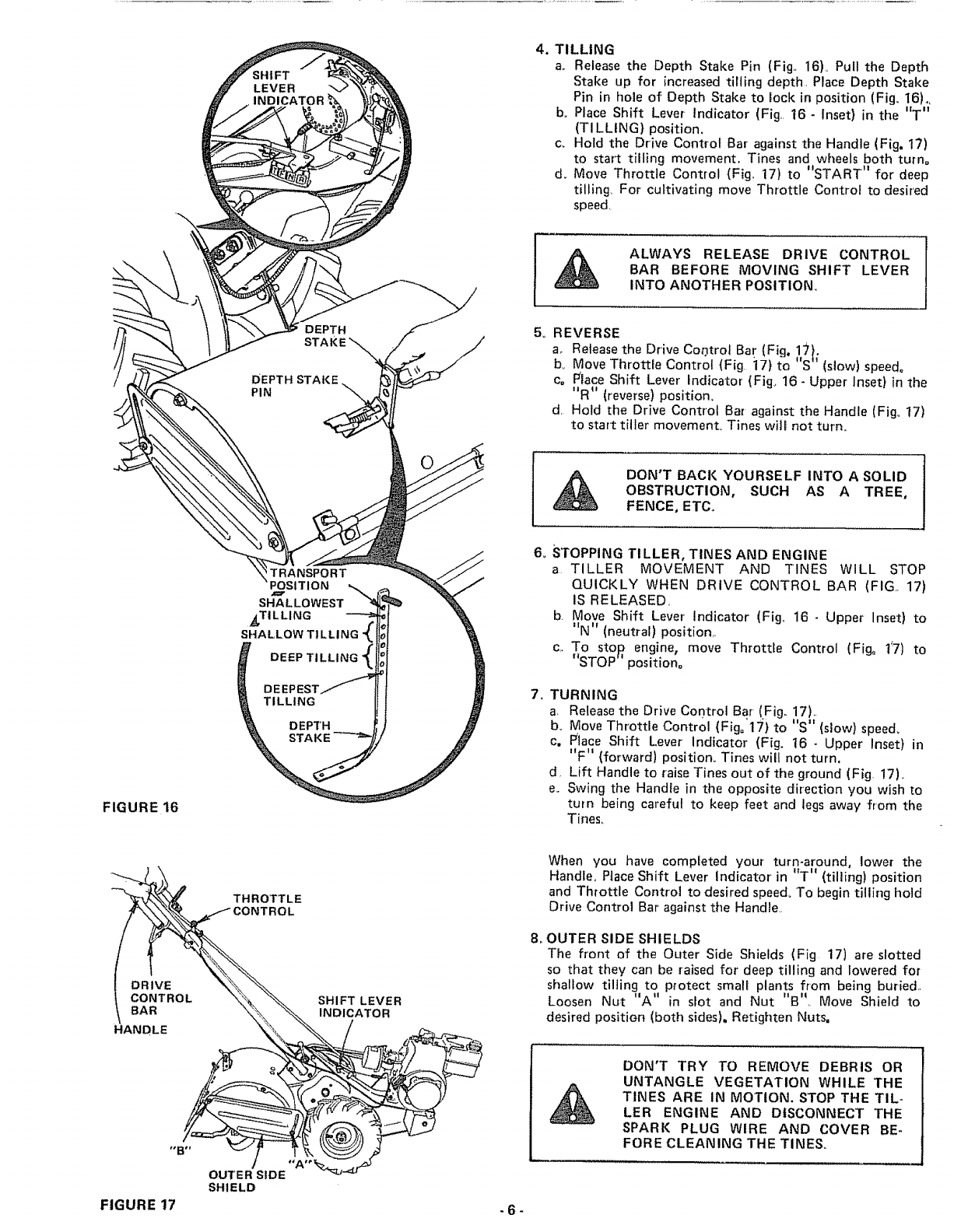
4, TILLING
a_ Release the Depth Stake Pin (Fig. 16L Pull the Depth
Stake up for increased tilling depth, Place Depth Stake
Pin in hole of Depth Stake to lock in position (Fig, t6),,
bo Place Shift Lever Indicator (Fig, 16 -Inset) in the "T"
(TILLING) position.
c,. Hold the Drive Control Bar against the Handle (Fig. 17)
to start tilling movement. Tines and wheels both turn°
d, Move Throttle Control (Fig,, 17} to "START" for deep
tilling, For cultivating move Throttle Control to desired
speed,
\
DEPTH
STAKE _
DEPTH STAKE
PIN
ALWAYS RELEASE DRIVE CONTROL
BAR BEFORE MOVING SHIFT LEVER
INTO ANOTHER POSITION,
5o REVERSE
a,_ Release the Drive Cor.ltrot Ba? (Fig. _7!.
bv Move Throttle Control (Fig 17} to S' (slow) speedo
c° Race Shift Lever indicator (Fig_ 16- Upper Inset) in the
"R" (reverse) position.
d, Hold the Drive Control Bar against the Handle (Fig_ t7)
to start tiller movement. Tines wiil not turn,
DON'T BACK YOURSELF INTO ASOLID
OBSTRUCTION, SUCH AS A TREE,
FENCE, ETC.
FIGURE 16
TRANSPORT
POSITION
SHALLOWEST
_TILLING
SHALLOW TILLING _
DEEP TILLING
TILLING
DEPTH
STAKE
6,, STOPPING TILLER, TINES AND ENGINE
a TILLER MOVEMENT AND TINES WILL STOP
QUICKLY WHEN DRIVE CONTROL BAR (FIG 17)
IS RELEASED,
b. Move Shift Lever indicator (Fig,, 16- Upper Inset) to
"N" (neutral) position,,
c,. To stop engine, move Throttle Control (Fig° 17) to
"STOP" position=
7,, TURNING
a Release the Drive Control Bar (Fig,, 17)1,
b. Move Throtde Control {Fig°'17) to "S" (slow) speed,
c, Place Shift Lever' Indicator (Fig, 16- Upper Inset) in
"F" (forward) position,. Tines will not turn.
d, Lift Handle to raise Tines out of the ground (Fig, 17),.
e,. Swing the Handie in the opposite direction you wish to
turn being careful to keep feet and legs away from the
Tines_
OUTER SIDE
SHIELD
SHIFT LEVER
INDICATOR
When you have compEeted your turn-around, lower the
Handle. Piace Shift Lever indicator in "T" (tilling) position
and Throttle Control to desired speed, To begin tilling hold
Drive Control Bar against the Handle.
8oOUTER SIDE SHIELDS
The front of the Outer Side Shields (Fig 17) are slotted
so that they can be raised for deep tilling and lowered for
shallow tilling to protect small plants from being buried.
Loosen Nut "A" in slot and Nut "B",, Move Shield to
desired position (both sides), Retighten Nuts.
DON'T TRY TO REMOVE DEBRIS OR
UNTANGLE VEGETATION WHILE THE
TINES ARE IN MOTION. STOP THE TIL-
LER ENGINE AND DISCONNECT THE
SPARK PLUG WIRE AND COVER BE-
FORE CLEANING THE TINES,
FIGURE 17 - 6 -
WUNTER OPERATION
(UNDER 32o[:.)
1. ENGINE LUBRICATION:
a, Drain the engine oil while engine is warm_
b_ Refill with new oito Use oil labeled 5W20 or 10W or
5W30 (See chart, page 4) Capacity is 1 - t/4 pints
2 FUEL:
ao Use fresh, clean, unleaded automotive gasoline Capacity
is 2 quarts,
3 COLD WEATHER STARTING HINTS:
a, Be sure to use the proper oil and gasoline
bKeep Drive Control Bar released when starting the
engine
c, Use full Choke for starting. Set Throttle Control at med-
ium to fast position. Slowly move Choke Control to
NO CHOKE pos tlon as engine warms up.
NOTE: BE SURE TO CHANGE ENGINE OIL BACK
TO S AoE 30 OR 10W30 (SD, SE OR SF} FOR SPRING
TILLING. (See chart, page 4)
TBLL0 G HB TS
Tilling is digging into, turning over, and breaking up packed
soil before planting Loose unpacked soil helps root growth
ii |I *
Best tilling depth is 4 to 6 A Tdter will also clear the
soil of unwanted vegetation. The decomposition of tf_is vegeta-
ble matter enriches rite soil, Cross-titling is the further breakup
of the soi!. Depending on the climate (rainfall and wind), it
may be advisable to till the soil at the end of the growing
season to further condition the soil
Soil conditions are important for proper tilling, Tines will not
readily penetrate dry, hard soil which may contribute to ex-
cessive bounce and difficult handling of your Tiller,, Hard soil
should be moistened before tilling_ In extremely wet condi-
tions, the soil will "ball up" or clump during tilling, Wait um
til the soil is less wet in order to achieve the best results,
When tilling in the fall, remove vines and long grass to prevent
them from wrapping around the tine shaft and slowing your
tilling operation.,
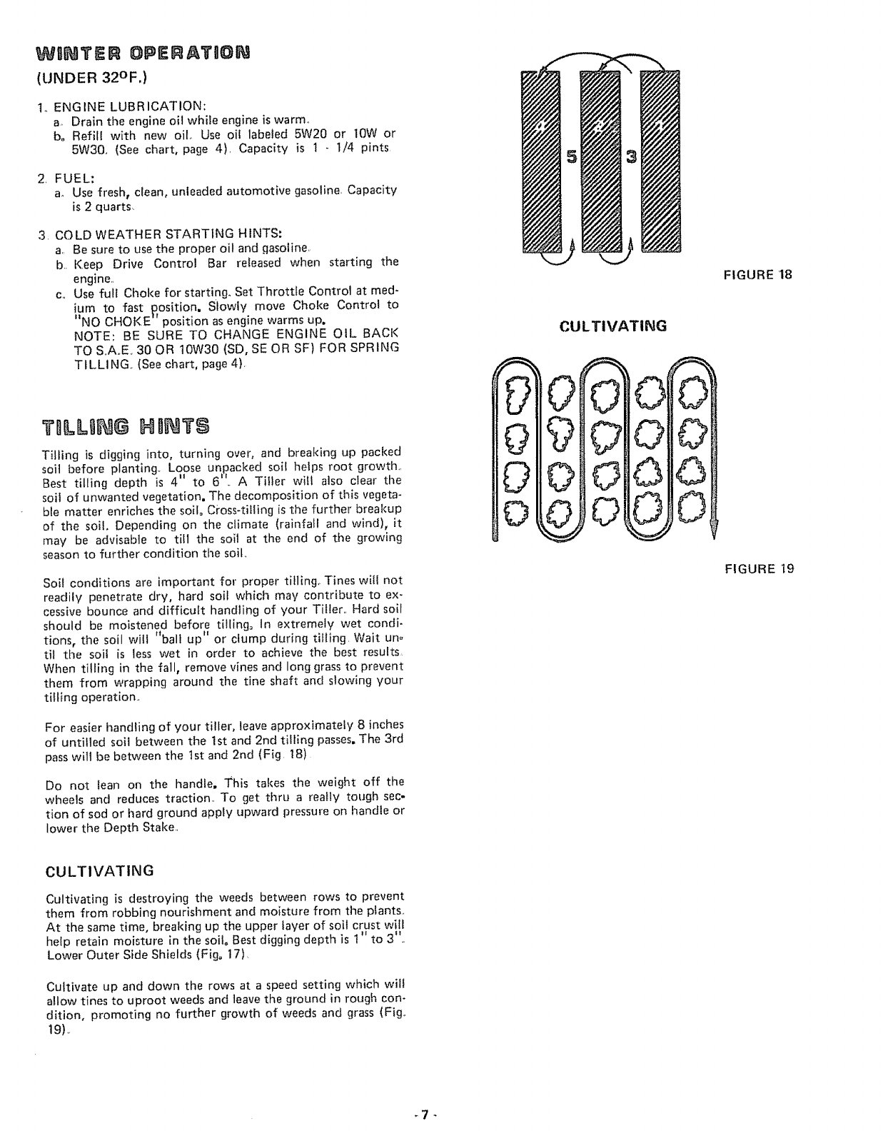
For easier handling of your tiller, leave approximately 8 inches
of untilled soil between the 1st and 2nd tilling passes, The 3rd
pass will be between the 1st and 2nd (Fig 18)
Do not lean on the handle, This takes the weight off the
wheels and reduces traction To get thru a really tough sec-
tion of sod or hard ground apply upward pressure on handle or
lower the Depth Stake
v
CULTIVATING
_
FIGURE 18
FIGURE t9
CULTIVATING
Cultivating is destroying the ,weeds between rows to prevent
them from robbing nourishment and moisture from the plants
At the same time, breaking up the upper layer of soil crust will
help retain moisture in the soilo Best digging depth is I" to 3"
Lower Outer Side Shields (Fig. 17)
Cultivate up and down the rows at a speed setting which will
allow tines to uproot weeds and leave the ground in rough con-
dition, promoting no further growth of weeds and grass (Fig,,
19).
NEW
TINE WORN
TINE
FIGURE 20
TINE
TINE I
T|NE
3.1/2" MAX,.
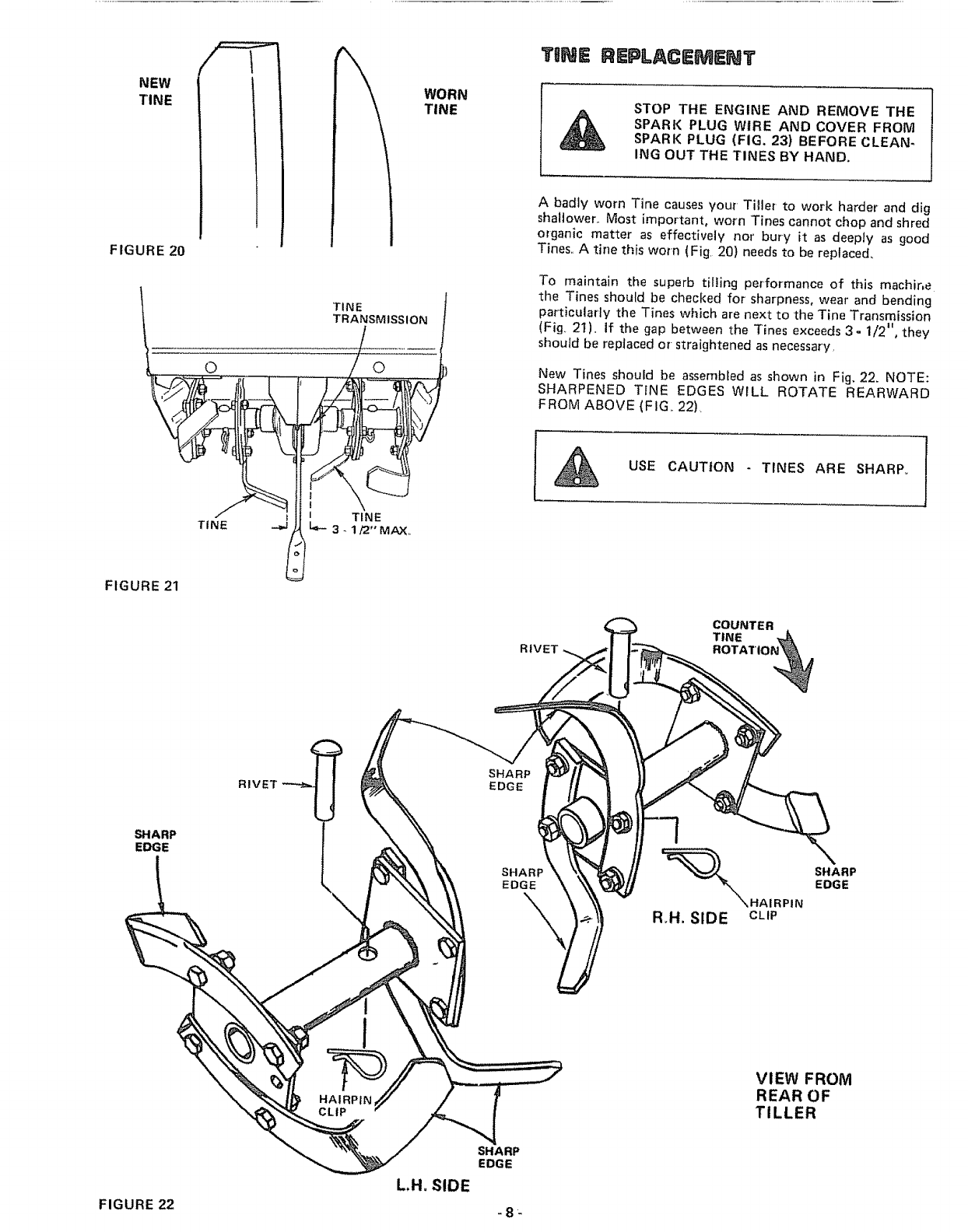
TINE REPLACEMENT
STOP THE ENGINE AND REMOVE THE
SPARK PLUG WIRE AND COVER FROM
SPARK PLUG (FIG. 23) BEFORE CLEAN-
ING OUT THE TINES BY HAND.
A badly worn Tine causesyour Tiller to work harder and dig
shallower.. Most important, worn Tines cannot chop and shred
organic matter as effectively nor' bury it as deeply as good
Tines.. A tine this worn (Fig. 20) needs to be replaced,
To maintain the superb tilling performance of this machir, e
the Tines should be checked for sharpness, wear and bending
particularly the Tines which are next to the Tine Transmission
(Fig, 21), If the gap between the Tines exceeds 3- 1/2", they
should be repiaced or-straightened as necessary,
New Tines should be assembled as shown in Fig. 22. NOTE:
SHARPENED TINE EDGES WILL ROTATE REARWARD
FROM ABOVE (FIG.. 22).
USE CAUTION - TINES ARE SHARP°
FIGURE 21
COUNTER
SHARP
EDGE
RIVET
SHARP
EDGE
SHARP
EDGE
\R,H. SIDE CLIP
SHARP
EDGE
HAIRPIN
CLIP
VIEW FROM
REAR OF
TILLER
L,H, SIDE
SHARP
EDGE
FIGURE 22 -8-
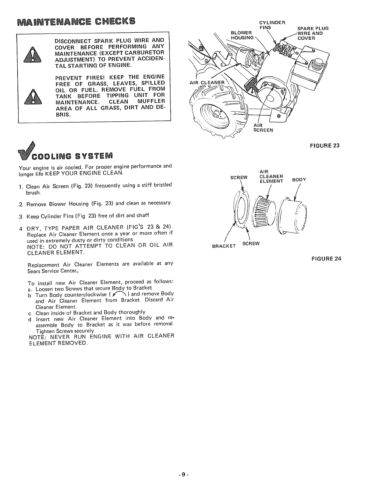
MAINTENANCE CHECKS
DISCONNECT SPARK PLUG WIRE AND
COVER BEFORE PERFORMING ANY
MAINTENANCE (EXCEPT CARBURETOR
ADJUSTMENT) TO PREVENT ACCIDEN-
TAL STARTING OF ENGINE,
PREVENT FIRES! KEEP THE ENGINE
FREE OF GRASS, LEAVES, SPILLED
OIL OR FUEL. REMOVE FUEL FROM
TANK BEFORE TIPPING UNIT FOR
MAINTENANCE, CLEAN MUFFLER
AREA OF ALL GRASS, DIRT AND DE-
BRIS,
AIR CLEANER
BLOWER
CYLINDER
FINS SPARK PLUG
WIRE AND
COVER
COOLDNG SYSTEM
Your engine is air cooled. For proper engine performance and
longer life KEEP YOUR ENGINE CLEAN.
Io Clean Air Screen (Fig_ 23) frequently using a stiff bristled
brush,
2o Remove Blower Housing (Fig, 23) and clean as necessary,
3. Keep Cylinder Fins (Fig. 23) free of dirt and chaff
4 DRY, TYPE PAPER AIR CLEANER (FIG'S 23 &24).
Replace Air Cleaner Element once a year or more often if
used in extremely dusty or dirty conditions.
NOTE: DO NOT ATTEMPT TO CLEAN OR OIL AIR
CLEANER ELEMENT..
Replacement Air Cleaner Elements are available at any
Sears Service Center°
To insta_I new Air Cleaner" E{ement, proceed as fo{lows:
a_ Loosen two Screws that secure Body to Bracket
b Turn Body counterclockwise ( _ ) and remove Body
and Ah" C[eaner Element from Bracket, Discard Air
Cleaner Element,,
c, Clean inside of Bracket and Body thoroughly
d, _nsert new Air Cleaner Element into Body and re=
assemble Body to BracI_et as it was before removal
Tighten Screws securely,
NOTE: NEVER RUN ENGINE WITH AIR CLEANER
ELEMENT REMOVED.
AIR
SCREW CLEANER
ELEMENT
BRACKET SCREW
BODY
FIGURE 23
FIGURE 24
-9-
FtGURE 25
_IDLE ADJUST SCREW
//'.,
ADJUST SCREW
_CONTROL'LEVER
CLAMP S(
FIGURE 26
HIGH SPEED STOP _4
CONTROL BRACKET
CONTROL CABLE
f II tt
v
FIGURE 27
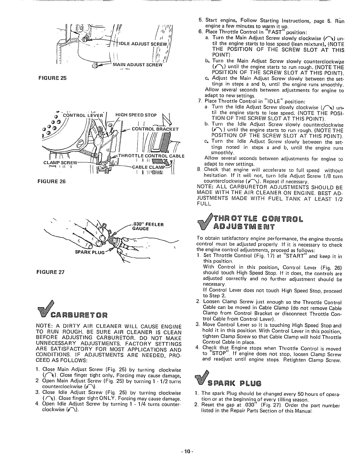
CARBURETOR
NOTE: A DIRTY AIR CLEANER WILL CAUSE ENGINE
TO RUN ROUGH° BE SURE AIR CLEANER lS CLEAN
BEFORE ADJUSTING CARBURETOR. DO NOT MAKE
UNNECESSARY ADJUSTMENTS. FACTORY SETTINGS
ARE SATISFACTORY FOR MOST APPLICATIONS AND
CONDITIONS, IF ADJUSTMENTS ARE NEEDED, PRO-
CEED AS FOLLOWS:
1, Close Main Adjust Screw (Fig,, 25) by turning clockwise
(t'_). Close finger' tight only, Forcing may cause damage,
2, Open Main Adjust Screw (Fig,, 25) by turning 1 - 1/2 turns
counterclockwise (_'_),
3,, Close Idte Adjust Screw (Fig. 25} by turning clockwise
(f"_), Close finger tight ON LY,. Forcing may cause damage.,
4, Open Idle Adjust Screw by turning 1 -1/4 turns counter-
c_ockwise(f'_),,
5, Start engine. Follow Starting Instructions, page 5o RIJn
engine a few minutes to warm it up_
6_ Place Throttle Control m FAST posrtlon:
a, Turn the Main Adjust Screw slowty clocJ_wise (/_) un-
til the engine starts to tose speed (lean mixture). (NOTE
THE POSITION OF THE SCREW SLOT AT THIS
POINT),
b. Turn the Main Adiust Screw slowly counterclockwise
(f'3,) until the engine starts to run rough. (NOTE THE
POSITtON OF THE SCREW SLOT AT THIS POINT),,
c= Adjust the Main Adjust Screw slowty between the set-
tings in steps a and b, until the engine runs smoothly,,
Allow several seconds between adjustments for engine to
adapt to new settings.
7,. Place Throttle Control in "IDLE" position:
a, Turn the Idle Adjust Screw slowly clockwise {t"_) un-
til the engine starts to lose speed. (NOTE THE POSI-
TION OF THE SCREW SLOT AT THIS POINT),.
b,. Turn the Idle Adjust Screw slowly counterclockwise
(F-_ } until the engine starts to run rough. (NOTE THE
POSITION OF THE SCREW SLOT AT THIS POINT),.
c. Turn the Idle Adjust Screw slowly between the set-
tings noted in steps a and b, until the engine runs
smoothly..
Allow several seconds between adjustments for engine to
adapt to new settings,,
8. Cheek that engine will accelerate to fuli speed without
hesitation If it will not, turn idle Adjust Screw 1/8 turn
counterclockwise (f-'x). Repeat if necessary,
NOTE: ALL CARBURETOR ADJUSTMENTS SHOULD BE
MADE WITH THE AIR CLEANER ON ENGINE,. BEST AD-
JUSTMENTS MADE WITH FUEL TANK AT LEAST 1/2
FULL
THR O't3=ILE C@ 't @tL
ADJUS? QE ?
To obtain satisfactory engine performance, the engine throttle
control must be adjusted properly. If it is necessary to check
the engine control adjustments, proceed as follows:
1. Set Throttle Control (Fig. 17) at "START" and keep it in
this position.
With Control in this position, Control Lever (Fig. 26}
should touch High Speed Stop. If it does, the controls are
adjusted correctly and no further adjustment should be
necessary..
If Control Lever does not touch High Speed Stop, proceed
to Step 2.
2. Loosen Clamp Screw just enough so the Throttle Control
Cable can be moved in Cable Clamp (do not remove Cable
Clamp from Control Bracket or disconnect Throttle Con-
trol Cable from Control Lever).
3.. Move Control Lever so it is touching High Speed Stop and
hold it in this position. With Control Lever in this position,
tighten Clamp Screw so that Cable Clamp will hold Throttle
Control Cable in place.,
4. Check that Engine stops when Throttle Control is moved
to "STOP _. If engine does not stop, loosen Clamp Screw
and readjust until engine stops_ Retighten Clamp Screw.
S PARK PLUG
1.. The spark Plug should be cilanged every 50 hours of opera.
tion or at the beginninq of every tilling season.
2.. Reset the gap at ,030" (Fig.. 27). Order the part number
listed in the Repair Parts Section of this Manual.
-10°
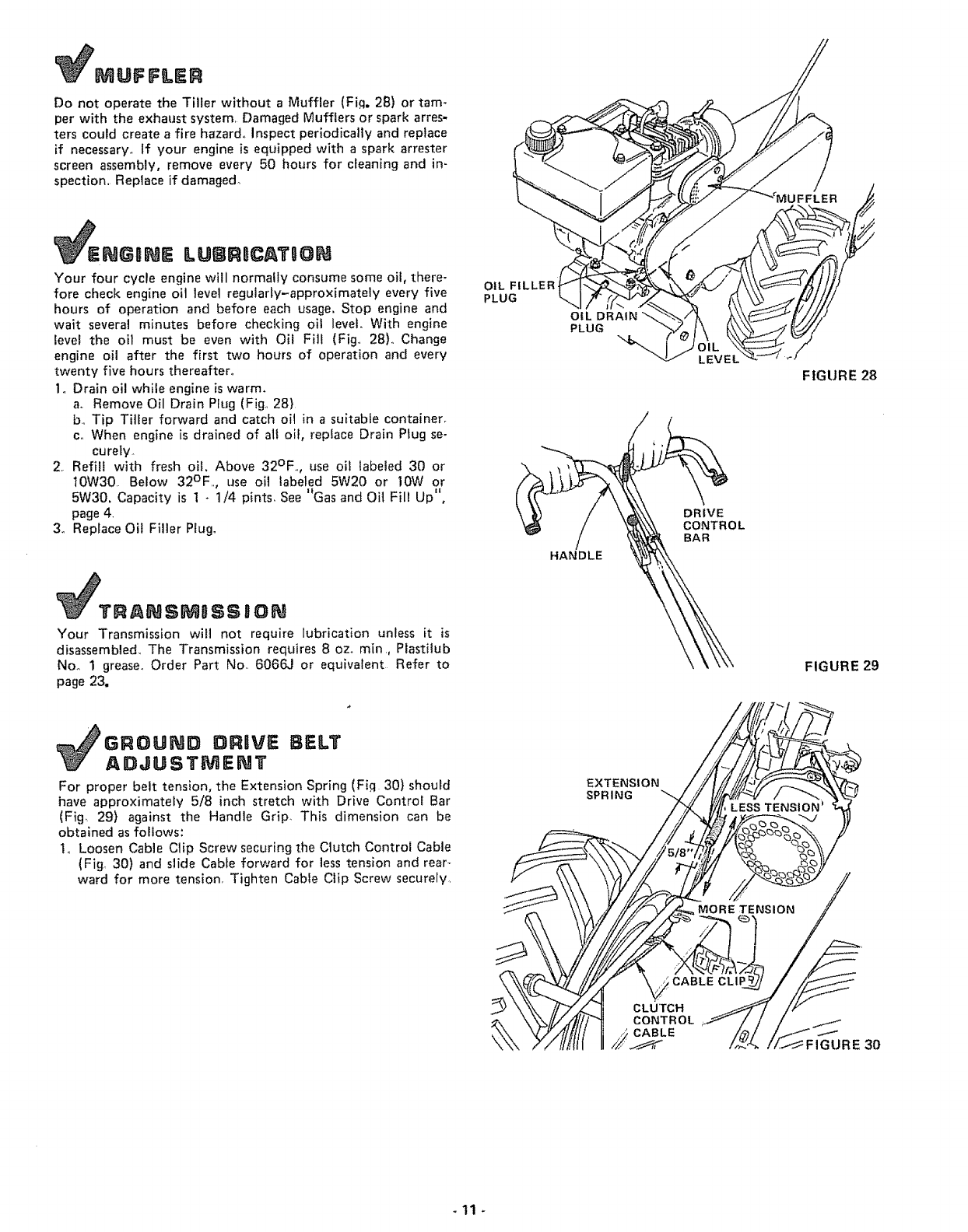
Do not operate the Tiller without a Muffler (Fig. 28) or tam-
per with the exhaust system Damaged Mufflers or spark arres-
ters could create a fire hazard° Inspect periodically and replace
if necessary° if your engine is equipped with a spark arrester
screen assembly, remove every 50 hours for cleaning and in-
spection, Replace if damaged°
ENGaNE LU[]RmCATUON
Your four cycle engine will normally consume some oil, there-
fore check engine oil level regularly-approximately every five
hours of operation and before each usage. Stop engine and
wait several minutes before checking oil level. With engine
level the oil must be even with Oil Fill (Fig, 28L Change
engine oil after the first two hours of operation and every
twenty five hours thereafter.
1. Drain oil while engine is warm.
a. Remove Oil Drain Plug (Fig., 28)
b, Tip Tiller forward and catch oil in a suitable container.
co When engine is drained of all oil, replace Drain Plug sen
cu re|y
2. Refill with fresh oil, Above 32°F., use oil labeled 30 or
10W30 Below 32°F, use oil labeled 5W20 or !0W or
5W30, Capacity is 1 - 1/4 pints_ See '_Gas and Oil Fill Up",
page 4.
3. Replace Oil Filler Plug.
TRANSMgSSBON
Your Transmission will not require lubrication unless it is
disassembled_ The Transmission requires 8 ozo min, Plastilub
Noo 1 grease., Order Part No 6066J or equivalent Refer to
page 23.
OIL FILLER
PLUG
OIL DRAIN
PLUG
HANDLE
DRIVE
CONTROL
BAR
FIGURE 28
FIGURE 29
GROUND DRBVE BELT
ADaUSTMENT
For proper belt tension, the Extension Spring (Fig 30} should
have approximately 5/8 inch stretch with Drive Control Bar
(Fig_ 29) against the Handle Grip This dimension can be
obtained as follows:
10 Loosen Cable Clip Screw securing the Clutch Control Cable
(Fig_ 30) and slide Cable forward for less tension and rear-
ward for more tension, Tighten Cable Clip Screw securely,
EXTENSION
SPRING _-_
CLUTCH
CONT ROL
_ CABLE Jf
FIGURE 30
-11
NUT
HAIRPIN CLIP
AND RIVET
FIGURE 31
ENGINE
PULLEY
IDLER
PULLEY
FIGURE 32
FIGURE 33
GUARD
CAP
NUT
,CAP NUT
(LOCATED
BEHIND TIRE)_
TRANSMISSION
PULLEY
WHEEL AND
RIVET
HAIRPIN
CLIP
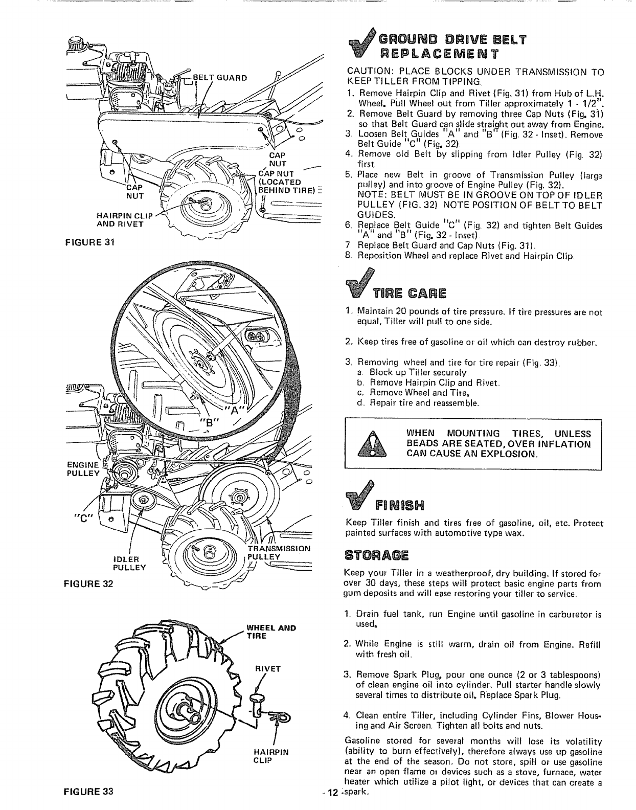
GROUND DRUVE BELT
REPLACEMErJ T
CAUTION: PLACE BLOCKS UNDER TRANSMISSION TO
KEEP TILLER FROM TIPPING.
1. Remove Hairpin Clip and Rivet (Fig, 31) from Hub of L.H,,
Wheel. P_II Wheel out from Tiller approximately 1 -1/2".
2, Remove Belt Guard by removing three Cap Nuts (Fig, 31)
so that Belt Guard can slide straiqht out away from Engine
* |1 I! I! IT .
3. Loosen Belt Guides A and B (Fig,. 32- Inset),, Remove
Belt Guide "C" (Fig, 32}
4,. Remove old Belt by slipping from idler Pulley (Fig. 32)
first_
5. Piace new Beit in groove of Transmission Pulley (large
pulley) and into groove of Engine Pulley (Fig. 32}.
NOTE: BELT MUST BE IN GROOVE ON TOP OF IDLER
PULLEY(FIG,.32) NOTE POSiTiON OF BELT TO BELT
GUIDES,
6, Rel_tace Belt Guide C (Fig. 32) and tighten Belt Guides
"A" and "B" (Fig. 32 -Inset)
7 Replace Belt Guard and Cap Nuts (Fig, 31),,
8. Reposition Whee] and replace Rivet and Hairp{n Clip.
CTIIRE CARI
1. Maintain 20 pounds of tire pressure. If tire pressures are not
equal, Tiller will pull to one side..
2, Keep tires free of gasoline or oH which can destroy rubber°
3_. Removing wheel and tire for tire repair (Fig. 33).
a. Block up Tiller securely
b Remove Hairpin Clip and Rivet.
co Remove Wheel and Tire°
d. Repair tire and reassemble..
WHEN MOUNTING TIRES, UNLESS
BEADS ARE SEATED, OVER INFLATION
CAN CAUSE AN EXPLOSION.
NgSN
Keep Tiller finish and tires free of gasotine, oil, etc_ Protect
painted surfaces with automotive type wax_
STORAGE
Keep your Tiller in a weatherproof, dry building_ If stored for
over' 30 days, these steps will protect basic engine parts from
gum deposits and will ease restoring your tiller to service..
1. Drain fuel tank, run Engine until gasoline in carburetor it
used,
2. While Engine is still warm, drain oil from Engine, Refill
with fresh oil
3o Remove Spark Plug, pour one ounce (2 or 3 tablespoons)
of clean engine oil into cylinder° Puff starter handle slowly
several times to distribute oil Replace Spark Plug.
4, Clean entire TilJer, including Cylinder Fins, Blower Hous-
ing and Air Screen, Tighten all bolts and nuts.
Gasoline stored for several months will lose its volatility
(ability to burn effectively), therefore always use up gasoline
at the end of the season. Do not store, spill or use gasoline
near an open flame or devices such as a stove, furnace, water
heater which utilize a pilot light, or devices that can create a
-12 "spark.
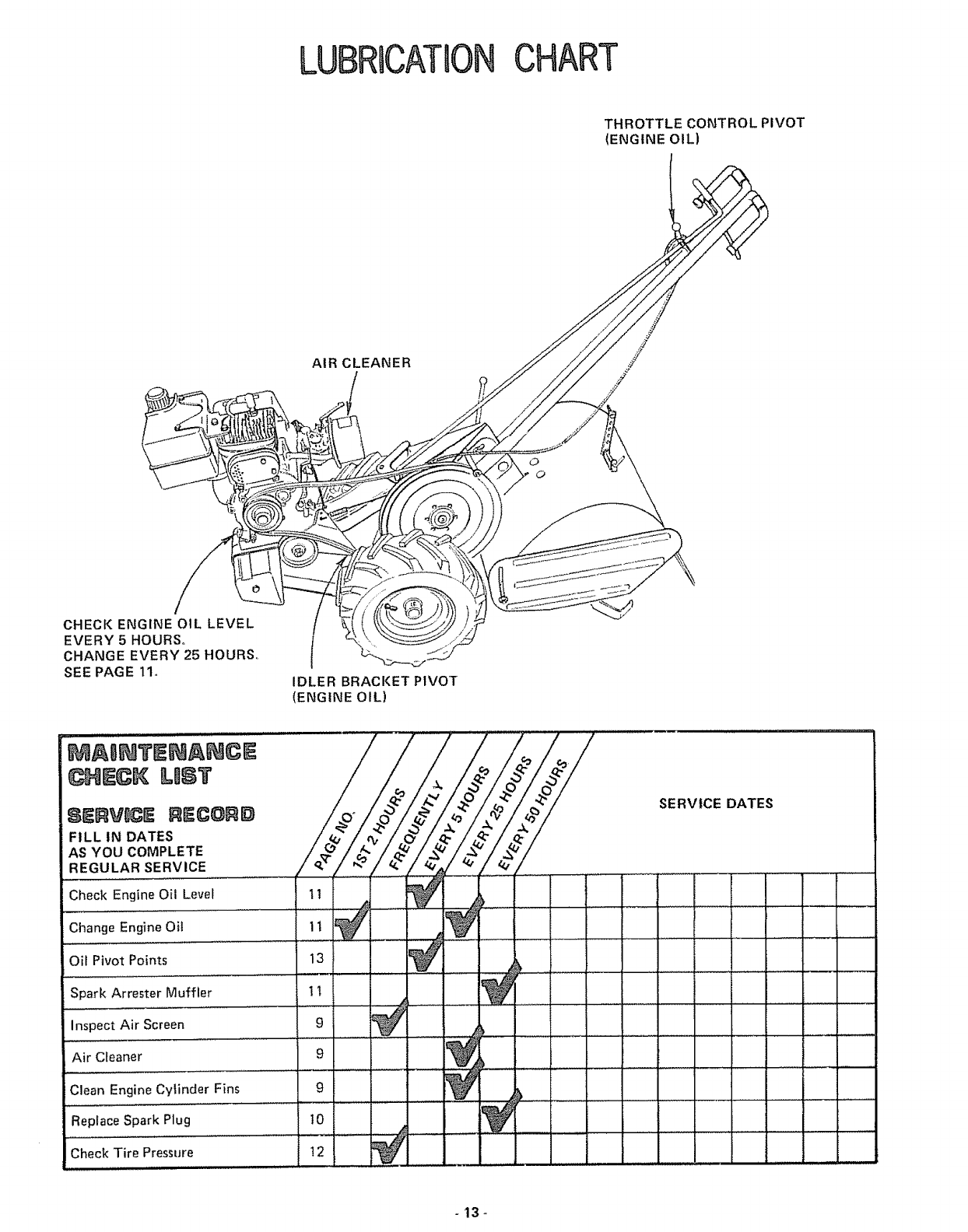
LUBRUCATOONCHART
THROTTLE CONTROL PIVOT
(ENGINE OIL)
AIR CLEANER
CHECK ENGINE OIL LEVEL
EVERY 5 HOURS,,
CHANGE EVERY 25 HOURS.
SEE PAGE 11o IDLER BRACKET PIVOT
(ENGINE OIL)
MASNTENANCE
_}_ECK US?
REC@_D
FILL IN DATES
AS YOU COMPLETE
REGULAR SERVICE
Check Engine Oil Level
Change Engine Oil
Oil Pivot Points
Spark Arrester Muffler
Inspect Air Screen
Air Cleaner
Clean Engine Cytinder Fins
Replace Spark Plug
Check Tire Pressure
SERVICE DATES
-13 -
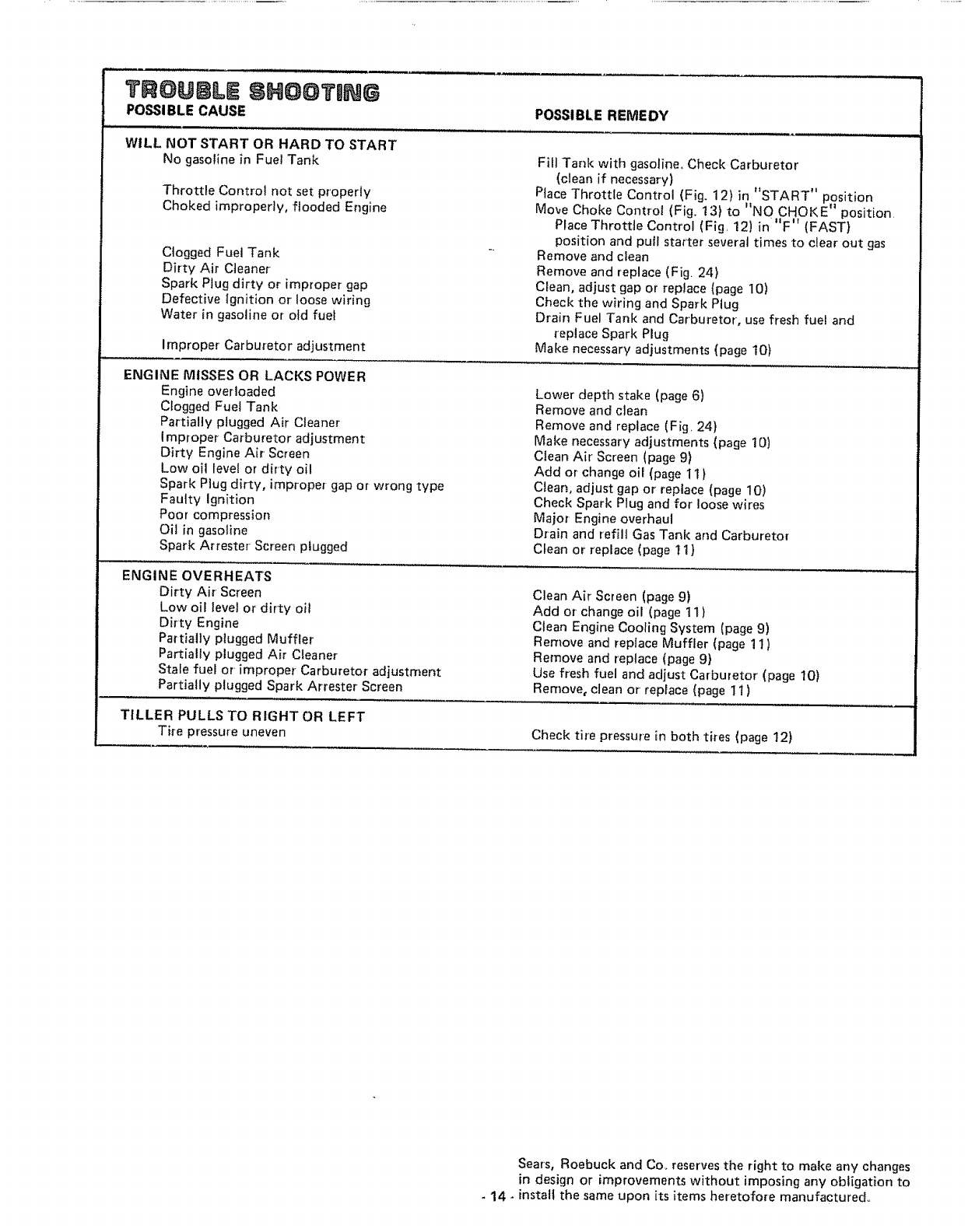
TROUBLE SHOOTING
POSSIBLE CAUSE POSSIBLE REMEDY
WILL NOT START OR HARD TO START
No gasoline in Fuel Tank
Throttle Control not set properly
Choked improperly, flooded Engine
Clogged Fuel Tank
Dirty Air Cleaner
Spark Plug dirty or improper gap
Defective Ignit{on or loose wiring
Water in gasoline or old fuel
Improper Carburetor adjustment
ENGINE MISSES OR LACKS POWER
Engine overloaded
Clogged Fuel Tank
Partially plugged Air Cleaner
improper Carburetor adjustment
Dirty Engine Air Screen
Low oil level or dirty oil
Spark Plug dirty, improper gap or wrong type
Faulty Ignition
Poor compression
Oil in gaso]ine
Spark Attester Screen plugged
Fill Tank with gasoline,, Check Carburetor
(clean if necessary)
Place Throttle Control (Fig. 12)in "START" position
"NO
Move Choke Control (Fig_ 13) to CHOKE r' position
Place Throttle Control (Fig. 12)in"F 't (FAST)
position and pull starter several times to clear out gas
Remove and clean
Remove and replace (Fig. 24)
Clean, adjust gap or replace (page 10)
Check the wiring and Spark Plug
Drain Fuel Tank and Carburetor, use fresh fuel and
replace Spark Plug
Make necessary adjustments (page 10)
Lower depth stake (page 6)
Remove and clean
Remove and replace (Fig, 24}
Make necessary adjustments (page 10)
Clean Air Screen (page 9)
Add or change oil (page 11 )
Clean, adjust gap or replace (page 10)
Check Spark Plug and for loose wires
Major Engine overhaul
Drain and refill Gas Tank and Carburetor
Clean or replace (page 11)
ENGINE OVERHEATS
Dirty Air Screen
Low oil level or dirty oil
Dirty Engine
Partially plugged Muffler
Partially plugged Air Cleaner
Stale fuel or' improper Carburetor adjustment
Partially plugged Spark Attester Screen
Clean Air Screen (page 9)
Add or change oil (page 11 )
Clean Engine Cooling System (page 9)
Remove and replace Muffler (page 11 )
Remove and replace (page 9}
Use fresh fuel and adjust Carburetor (page 10)
Remove, clean or replace (page 11 )
TILLER PULLS TO RIGHT OR LEFT
Tire pressure uneven Check tire pressure in both tires (page 12)
Sears, Roebuck and Co, reserves the right to make any changes
in design or improvements without imposing any obligation to
- 14 -install the same upon its items heretofore manufactured°
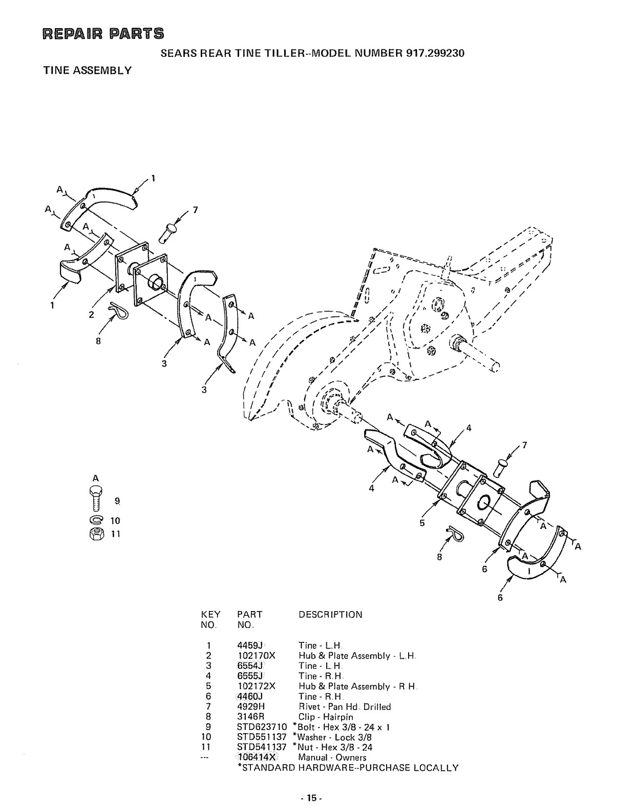
REPAmR PARTS
SEARS REAR TINE TILLER-MODEL NUMBER 917.299230
TINE ASSEMBLY
/
1
8
A
011
ti
t,
4
A
5
8
6
KEY
NO,
1
2
3
4
5
6
7
8
9
t0
11
PART DESCR IPTION
NO,
44592 : Tine - L.H
102170X Hub & Plate Assembly - L H
6554J: Tine- L,H,
6555J :: Tine- R,H.
I02172X Hub & Plate Assembly - R H,
44603 Tine- R,H.
4929H Rivet- Pan Hd, Drilled
3146R Clip - Hairpin
STD623710 *Bolt - Hex 3/8- 24 x I
STD551137 *Washer- Lock 3/8
STD541137 *Nut- Hex 3/8- 24
':106#11#X Manual- Owners
*STANDARD HARDWAR E--PURCHASE LOCALLY
-15-
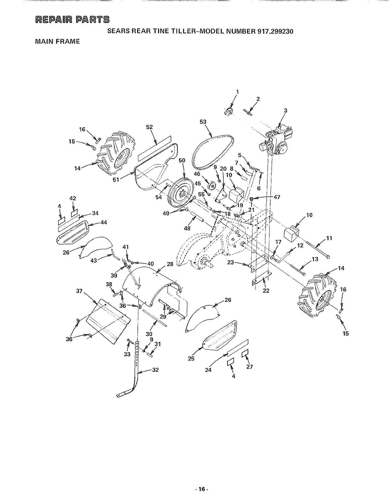
REPAmR PA_TS
SEARS REAR TINE TILLER--MODEL NUMBER 917,299230
MAIN FRAME
52
1
J
53
2
42
39
38
41
30
9
33
54
28
31
25
24 27
22
.\
15
-16-
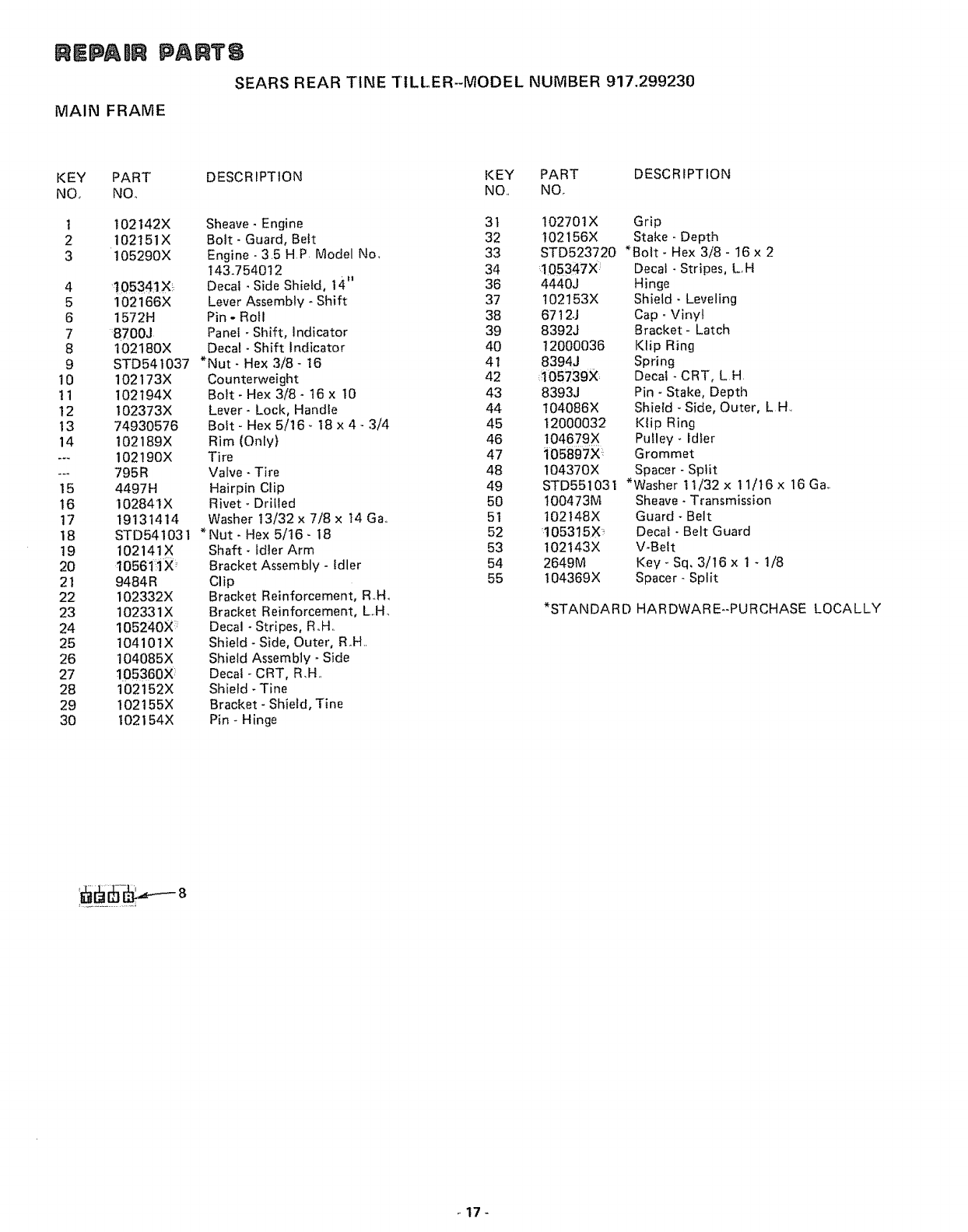
REPADR PARTS
SEARS REAR TINE TILLER--MODEL NUMBER 917.299230
MAIN FRAME
KEY PART DESCRIPTION KEY PART DESCRIPTION
NO. NO. NO.. NOr
t 102142X Sheave- Engine 3t 102701X Grip
2 102151X Bolt- Guard, Belt 32 102156X Stake - Depth
3 105290X Engine - 3.5 HP Model No. 33 STD523720 *Bolt- Hex 3/8 - 16 x 2
I43.7540t2 34 105347X Decal _Stripes, L,H
4 t05341X: Decal - Side Shield, 14" 36 4440J Hinge
5 102166X Lever Assembly - Shift 37 t02153X Shield - Leveling
6 1572H Pin - Roll 38 67t2J Cap - Vinyl
7 :8700J Panel - Shift, Indicator 39 8392J Bracket - Latch
8 102180X Decal - Shift Indicator 40 12000036 Klip Ring
9 STD541037 *Nut- Hex 3/8- 16 4t 8394J Spring
10 102173X Counterweight 42 :_05739X Decal - CRT, L H.
! 1 102194X Bolt- Hex 3/8- 16 x 10 43 8393J Pin -Stake, Depth
12 I02373X Lever- Lock, Handle 44 104086X Shield - Side, Outer, LH.
t3 74930576 Bolt- Hex 5/16- t8 x 4- 3/4 45 12000032 Klip Ring
14 102189X Rim (Only) 46 104679X Pulley - Idler
--_ 102!90X Tire 47 105897X::: Grommet
--- 795R Valve -Tire 48 104370X Spacer - Split
15 4497H Hairpin Clip 49 STD551031 *Washer 11/32x 11/t6x 16 Ga,.
16 I02841X Rivet- Driiled 50 !00473M Sheave- Transmission
17 19131414 Washer 13/32 x 7/8 x t4 Ga. 51 t02148X Guard - Belt
18 STD541031 *Nut _Hex 5/16- 18 52 1053t5X Decal - Belt Guard
19 102141X Shaft- fdler Arm 53 102143X V-Belt
20 10561:iX: Bracket Assembly - Idler 54 2649M Key- Sq. 3/t6 x 1 - 1/8
21 9484R Clip 55 104369X Spacer- Split
22 I02332X Bracket Reinforcement, R..Ho
23 !02331X Bracket Reinforcement, L..H_ *STANDARD HARDWARE--PURCHASE LOCALLY
24 105240X :::_ Decal -Stripes, RoHo
25 104101X Shield- Side, Outer, R.H.
26 104085X Shield Assembly - Side
27 105360X Decal -CRT, R.H..
28 102152X Shield -Tine
29 102155X Bracket -Shield, Tine
30 I02154X Pin - Hinge
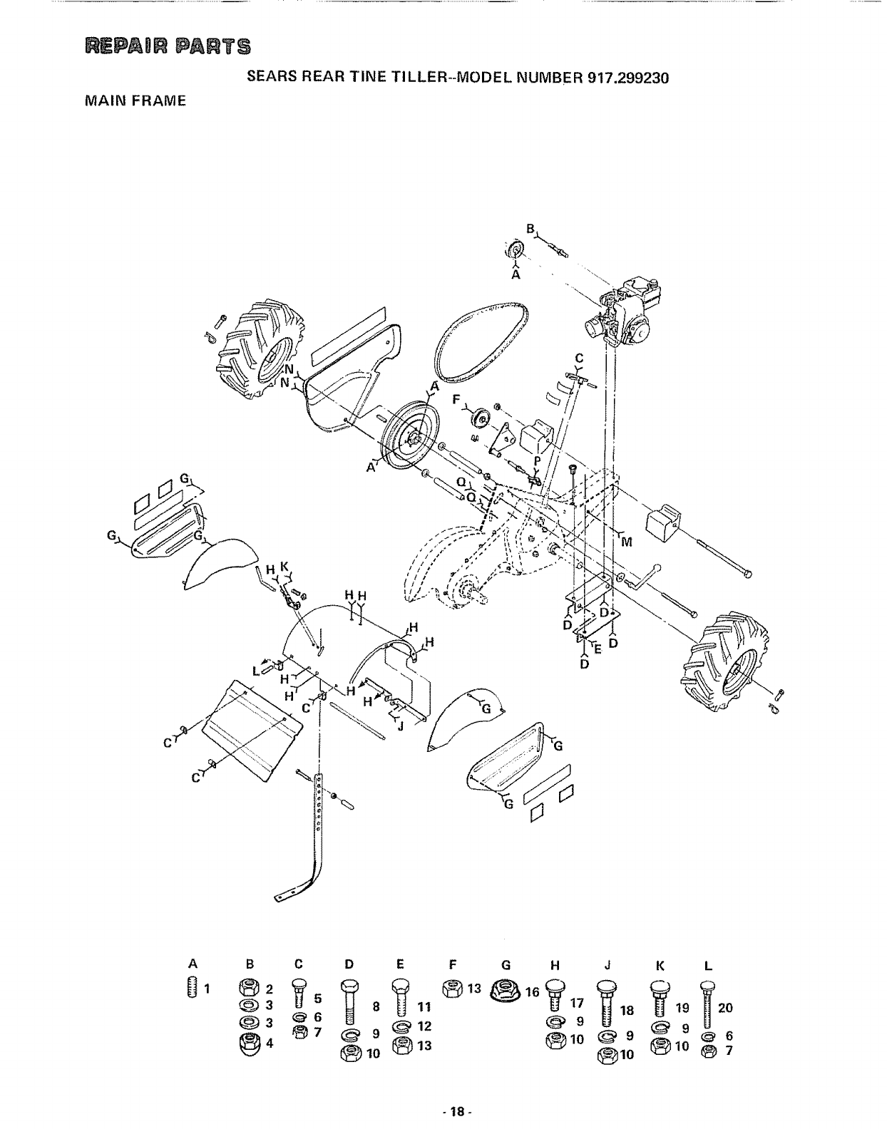
_PAI_R PAAT,_
SEARS REAR TINE TILLER--MODEL NUMBER 917.299230
MAIN FRAME
B
A
HHD
D
C
B
®2
_3
Q3
@,
C
_6
@7
D
10
EFG H
_9
J
_9
_]10
K L
)19 _20
_ 9 _ 6
®1o _7
-18-
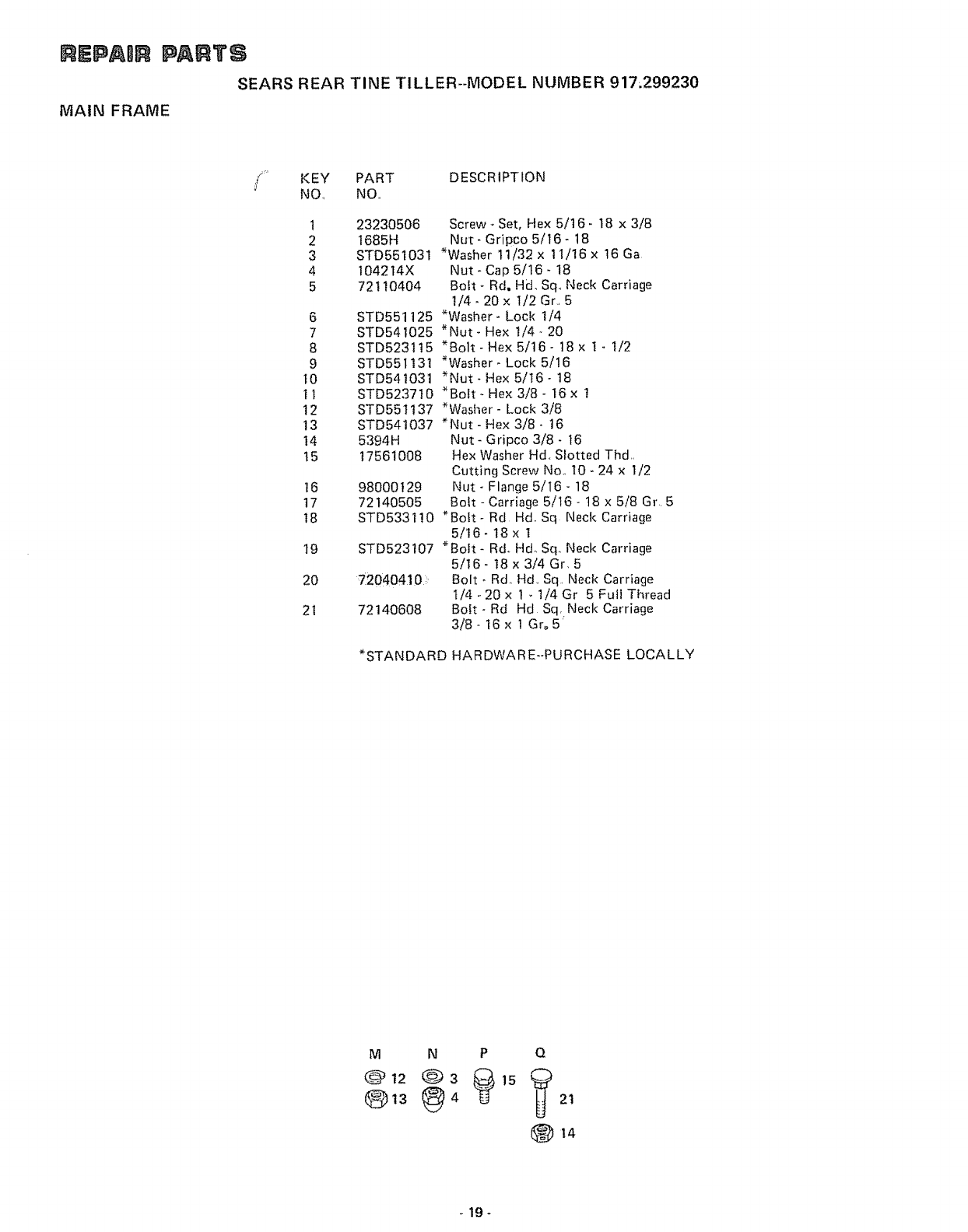
REPABR PARTS
SEARS REAR TINE TILLER--MODEL NUMBER 917.299230
MAIN FRAME
KEY PART DESCRIPTION
NO, NQ,
t
2
3
4
5
6
7
8
9
t0
tt
12
13
14
t5
t6
17
18
19
20
2t
23230506
1685H
STD551031
104214X
72110404
STD551125
STD541025
STD523 t 15
STD551131
STD541031
STD5237 t0
STD551137
STD541037
5394H
17561008
98000129
72 ] 40505
STD 5331 ! 0
STD523107
72040410
72140608
*STANDARD
Screw- Set, Hex 5/16 - 18 x 3/8
Nut- Gripco 5/t6- 18
*Washer 11/32 x tl/16 x t6 Ga
Nut- Cap 5/16- 18
Bolt- Rd, Hd, Sq, Neck Carriage
1/4- 20 x 1/2 Gr., 5
*Washer- Loc!( 1/4
*Nut- Hex !/4- 20
*Bolt- Hex 5/t6 - t8 x l _ t/2
*Washer* Lock 5/16
*Nut- Hex 5/t6- 18
*Bolt - Hex 3/8 - 16 x !
*Washer- Lock 3/8
*Nut- Hex 3/8- 16
Nut- Gripco 3/8- t6
Hex Washer Hd,, Slotted Thd,,
Cutting Screw No,, 10 _ 24 x I/2
Nut _Flange 5/16- 18
Bott - Carriage 5/16- 18 x 5/8 Gr, 5
*Bolt- Rd Hd.. Sq Neck Carriage
5/16- 18 x ]
*Bolt- Rdo Hd. Sq,.Neck Carriage
5/16 _ 18 x 3/4 Gr, 5
Bolt _ Rd_ Hd_ Sq,, Neck Carriage
t/4 - 20 x 1 - 1/4 Gr 5 Futi Thread
BoEt- Rd Hd Sq, Neck Carriage
3/8- t6 x ]Gr_5 _
HARDWAR E--PURCHASE LOCALLY
M
@ 12
Ot3
N P Q
4 21
-19-
REPAmR PARTS
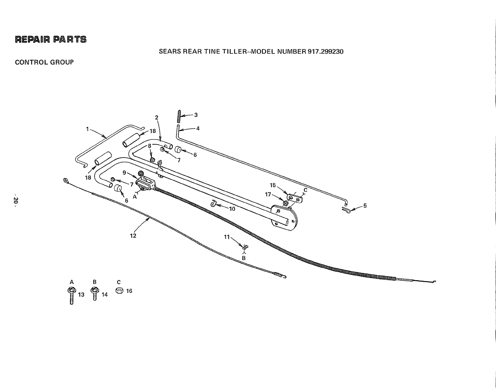
CONTROL GROUP
SEARS REAR TINE TILLER--MODEL NUMBER 917.299230
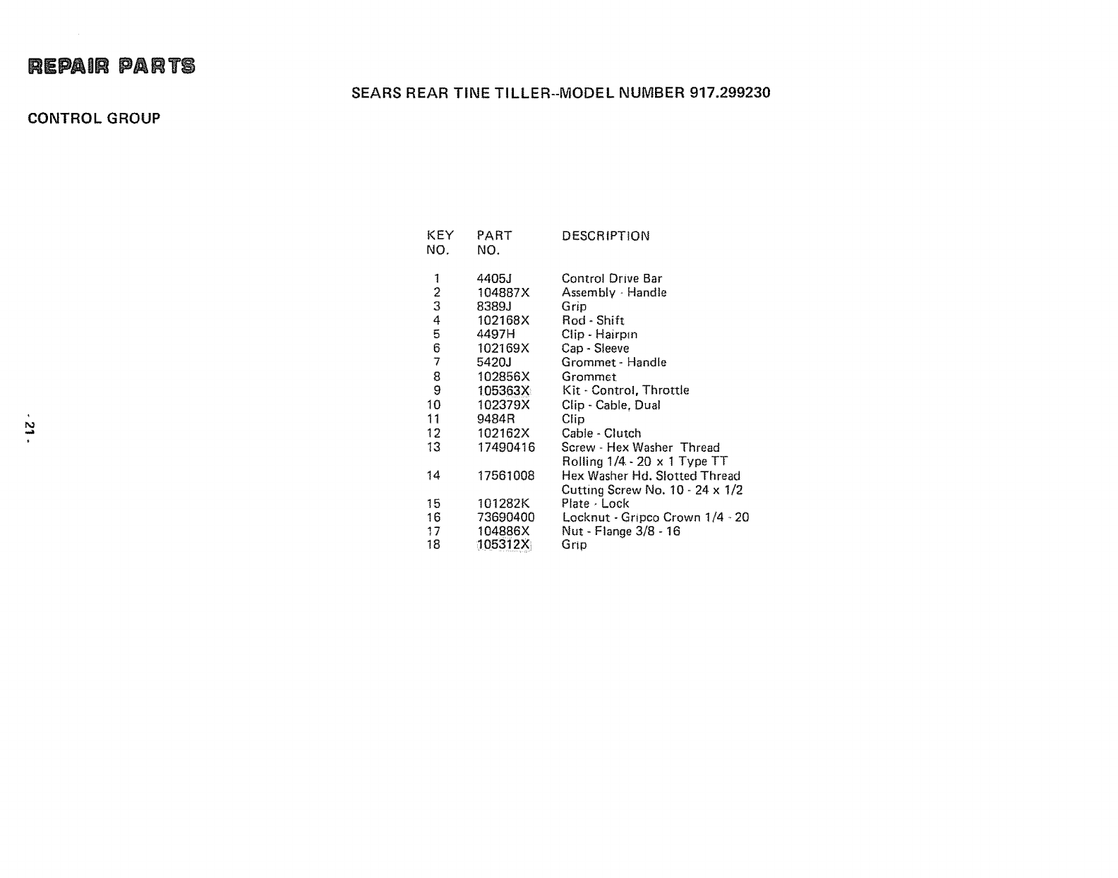
REPAIR PARTS
CONTROL GROUP
SEARS REAR TINE TILLER--MODEL NUMBER 917.299230
KEY PART DESCRIPTION
NO. NO.
1 4405J
2 104887X
3 8389J
4 102168X
5 4497H
6 102169X
7 5420J
8 102856X
9 t05363X
10 102379X
11 9484R
12 102162X
13 17490416
14 17561008
15 1012821<
16 73690400
17 104886X
18 ,!053_2X!,
Control Drive Bar
Assembly -Handte
Grip
Rod - Shift
Clip - Hairpin
Cap - Sleeve
Grommet- Handle
Grommet
Kit - Control, Throttle
Clip - Cable, Dua!
Clip
Cable - Clutch
Screw - Hex Washer Thread
Rolling 1/4 - 20 x 1 Type TT
Hex Washer Hd. Slotted Thread
Cutting Screw No. 10 - 24 x 1/2
Plate -Lock
Locknut - Gripco Crown t/4 _ 20
Nut - Flange 3/8 - 16
Grip
SmtEPAQti_PAI_7'_
TRANSMISSION - GROUND DRIVE
SEARS REAR TINE TILLER--MODEL NUMBER 917.299230.
4142
42
28
26
\
22
14
21
53
B
51
39
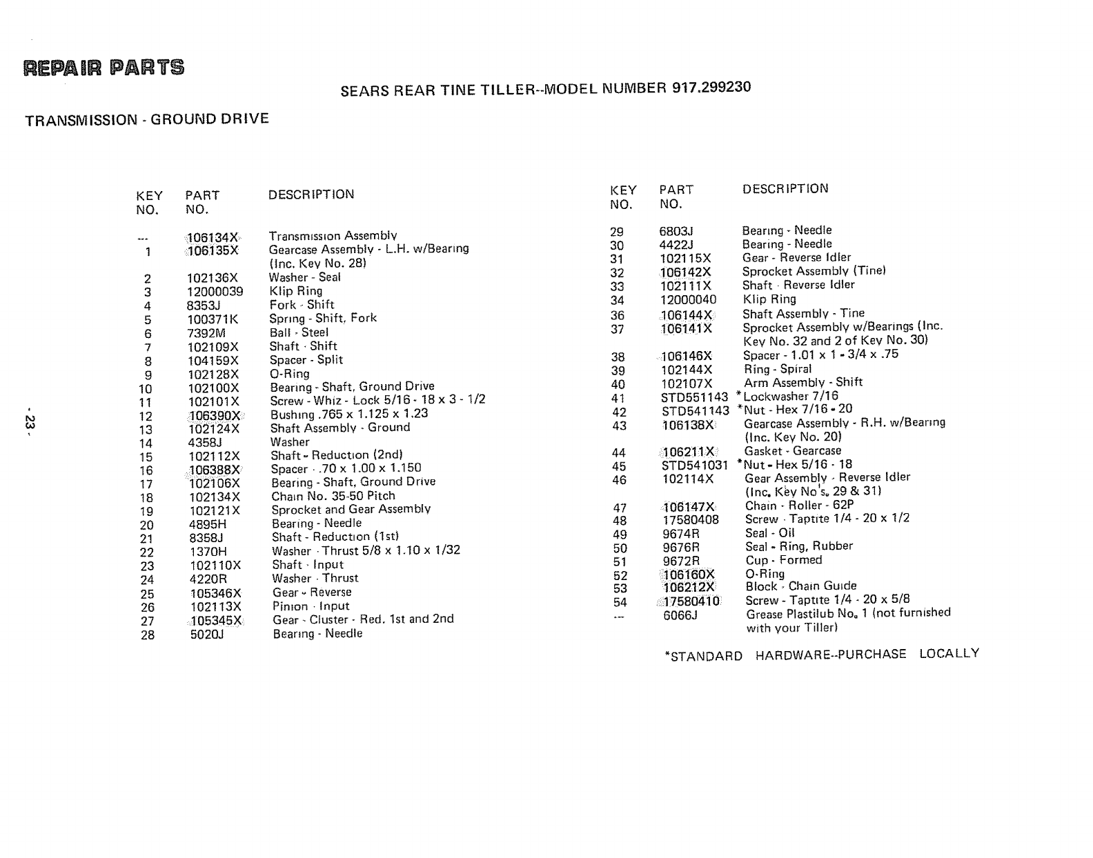
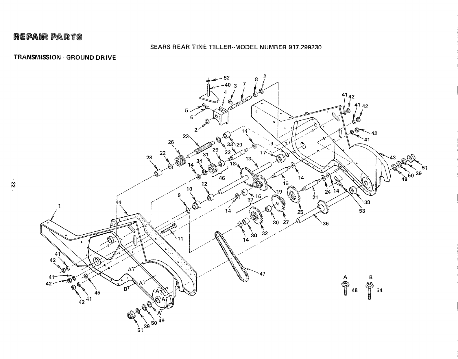
REPAIR PARTS
TRANSMISSION - GROUND DRIVE
SEARS REAR TINE TILLER--MODEL NUMBER 917.299230
FO
KEY PART
NO, NO,
.... t06134X
1a0e_35x
2 t02136X
3 12O00039
4 8353J
5 100371K
6 7392M
7t02109X
8 t04t59X
9 102128X
10 t02100X
!I 102101X
12 _306390XI_
13 1021'24X
14 4358J
15 t02t12X
16 _06:388x
!7 102106X
18 102t34X
19 t02t21X
20 4895H
2! 8358J
22 1370H
23 102110X
24 4220R
25 105346×
26 1021t3X
27 _O5345X_
28 5020J
DESCR IPTION
Transmission Assembly
Gearcase Assembly - L.H. w/Bearing
(Inc. Key No, 28)
Washer - Seal
Klip Ring
Fork - Shift
Spnng - Shift, Fork
Ball - Steel
Shaft, Shift
Spacer - Split
O-Ring
Bearing - Shaft, Ground Drive
Screw-Whiz- Lock 5116- 18 x 3 - 112
Bushing .765 x 1.125 x 1.23
Shaft Assembly - Ground
Washer
Shaft _ Reduction (2nd)
Spacer • .70 x t.00 x 1.150
Bearing - Shaft, Ground Drive
Chain No. 35-50 Pitch
Sprocket and Gear Assembly
Bearing- Needle
Shaft- Reduction (1st)
Washer .Thrust 5/8 x 1.10 x 1/32
Shaft-Input
Washer -Thrust
Gear- Reverse
Pimon -Input
Gear - Cluster - Red, 1st and 2nd
Bearing - Needle
KEY PART
NO. NO.
29
30
31
32
33
34
36
37
38
39
4O
41
42
43
44
45
46
47
48
49
5O
51
52
53
54
DESCRIPTION
6803J
4422J
102115X
,!06142×
102111X
12000040
_I06!44X:_
_!06_41X
106146X
102144X
t02107X
Bearing- Needle
Bearing - Needle
Gear- Reverse Idler
Sprocket Assembly (Tine)
Shaft • Reverse Idler
KIip Ring
Shaft Assembtv - Tine
Sprocket Assembly w/Bearings (Inc.
Key No. 32 and 2 of Key No. 30)
Spacer - 1.01 x 1 - 3/4 x .75
Ring - Spiral
Arm Assembly - Shift
STD551143 * Lockwasher 7/16
STD541143 *Nut - Hex 7/16- 20
106138X Gearcase Assembly - R.H. w/Bearing
:!062!_X
STD541031
102114X
,,_06!47X
17580408
9674R
9676R
9672R
:106160×
1062_ 2X
J:75804i0
6066J
(lnc, Key No. 20)
Gasket - Gearcase
*Nut- Hex 5/16- 18
Gear Assembly -. Reverse Idler
(Inc. Key Notso 29 & 31)
Chain - Roller - 62P
Screw. Taptite 1/4 - 20 x 1/2
Seal - Oil
Sea] - Ring, Rubber
Cup- Formed
O_Ring
Block o Chain Guide
Screw - Taptite 1/4 - 20 x 5/8
Grease Plastilub No. 1 (not furnished
with your Tiller)
*STANDARD HARDWARE--PURCHASE LOCALLY
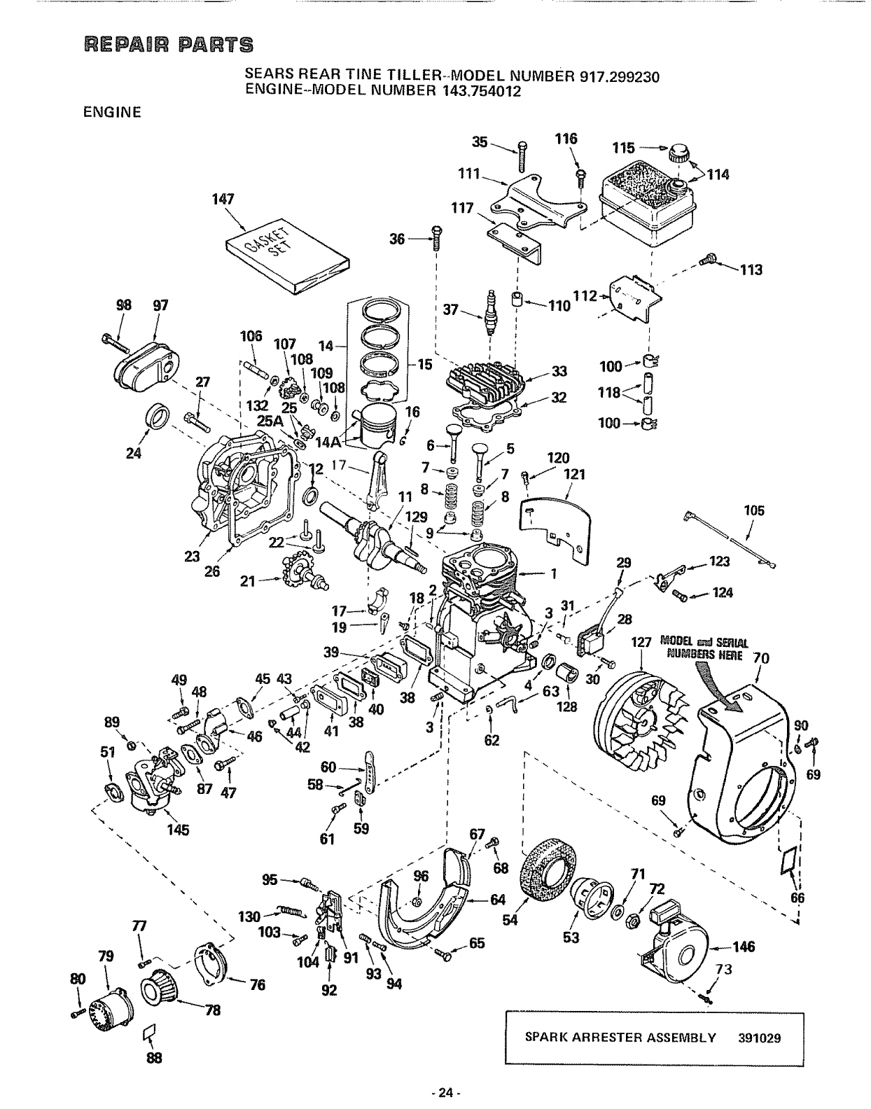
REPAmR PARTS
SEARS REAR TINE TILLER--MODEL NUMBER 917.299230
ENGINE--MODEL NUMBER 143,754012
ENGINE
147
S8 97
89
\
62
120
SPARK ARRESTER ASSEMBLY 391029
-24 -
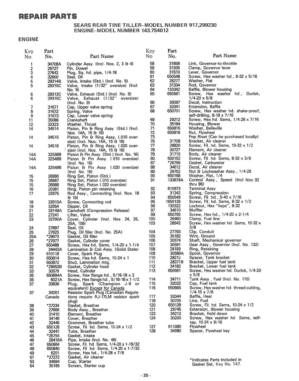
REPAmR PARTS
SEARS REAR TINE TILLER--MODEL NUMBER 917.299230
ENGINE--MODEL NUMBER 143.754012
ENGINE
Key Part
No, No. Part Name
1
2
3
4
5
5
6
6
7
8
9
11
12
14
t4
14
14A
14A
14A
15
15
15
16
17
18
19
21
22
23
24
25
25A
26
27
28
29
30
31
32
33
35
36
37
37
38
39
4O
4t
42
43
44
45
46
47
48
49
5t
53
54
34708A
26727
27642
32600
29314B
29315C
29313C
29315C
31671
31672
31673
35086
32323
34514
34515
34516
325388
32548B
32549B
28986
28987
28988
20381
32875
32610A
32654
33149A
27241
32700A
27897
27625
*29673
"27677
650488
34443A
610118
650814
650872
*299538
30579
650694A
6021A
33636
34251
Canada
"27234
27666
31410
34146
32446
650128
32447
"26754
28416A
650664
650840
6201
*27272
34694
35185
Key Part
No No.
Cylinder Assy. (IncL Noso 2, 3 8- 4) 58 31858
Pin, Dowel 59 31335
Plug, Sq. hd. pipe, I/4-18 60 31510
Seal, Oil 61 650548
Valve, Intake (Std.) (IncL Noo 9) 62 28277
Valve, intake (1132" oversize) (Incl, 63 31334
No. 9) 64 t33342
Valve, Exhaust (Std.) (lncL Non 9) 65 650561
Valve, Exhaust (1/32" oversize)
(Incl. No. 9) 66 35087
Cap, Upper valve spring 67 33341
Spring, Valve 68 650701
Cap, Lower valve spring
Crankshaft 69 29212
Washer, Thrust 70 35184
Piston, Pin 8" Ring Assy (Std.) (Incl., 71 650815
Nos. 14A, 15 8" 16) 72 650816
Piston, Pin 8 Ring Assy, (.010 over- 73
size) {IncL Nos. 14A, 15 8 16) 76 31708
Piston, Pin Ef Ring Assy. (,020 over- 77 28820
size) (Incl. Nos. 14A, 15 8 16) 78 30727
Piston E_Pin Assy (Std) (incl No. 16) 79 31715
Piston 8- Pin Ass% (.010 oversize) 80 650152
(Incl,. No.. 16) 87 *26756
Piston 8- Pin Assy (_020 oversize) 88 34612
(Incl No 16) 89 29752
Ring Set, Piston (Std.) 90 650168
Ring Set, Piston (.010 oversize) 91 t33879A
Ring Set, Piston (.020 oversize)
Ring, Piston pin retaining 92 610973
Rod Assy, Connecting (IncL Noso t8 93 31342
8- 19) 94 650549
Screw, Connecting rod 95 1650139
Dipper, Oil 96 t30322
Camshaft (Compression Release) 97 34610
Lifter, Valve 98 650795
Cover, Cylinder (IncL Nos 24, 25, 100 26460
25A, 106) 103 28942
Seal, Oil
Plug, Oil filler (incl No. 25A) 104 27793
Gasket, Oi! filler 105 35182
Gasket, Cylinder cover 106 30574
Screw, Hex hd. Sems, 1/4"20 x I-1/4 t07 30591
Lamination Ef Coil Assy, (Solid State) t08 29193
Cover, Spark Plug 109 30588A
Screw, Hex hd_ Sems, 10-24 x 1 t10 28212
Stud, Lamination mtg. 111 28371B
Gasket, Cylinder head t 12 34182
Head, Cylinder 113 650561
Screw, Hex flange hd, 5/16-18 x 2
Screw, Hex flange hal, 5/16-t8x 1-1/2 114 34711
Plug, Spark (Champion J-8 or 115 33032
equivalent) _ f_zorCanada 116 650665
Resistor Spark Plug (Canadian Regula-
tions require RJ-17LM resistor spark t17 33344
plug) 118 30705
Gasket, Breather !20 650128
Body Assyo, Breather 121 29745
Element, Breather 123 34212
Cover, Breather 124 30200
Grommet, Breather tube
Screw, FiL hd Sems, 10-24 x I/2 t27 611080
Tube, Breather t28 34080
Gasket, Intake
Pipe, Intake (incL Nov 48)
Screw, Fit hd Sems, 1/4-20 x 1-19/32
Screw, Fil hd Sems, 1/4-20 x 1-7/32
Screw, Hex hd., 1/4-28 x 7/8
Gasket, Air cleaner
Cup, Starter
Screen, Starter cup
Part Name
Link, Governor-to-throttle
Clamp, Governor lever
Lever, Governor
Screw, Hex washer hd,, 8-32 x 5/t6
Washer, Flat
Rod, Governor
Baffle, Blower housing
Screw, Hex washer hd, Durlok,
1/4-20 x 5/8
Decal, Instruction
E,,_ension, Baffle
Screw, Hex washer hdo shake-proof,
self-drilling, 8-18 x 7/16
Screw, Hex hd, Sems, 1/4-28 x 7/16
Housing, Blower
Washer, BeHevilte
Nut, Flywheel
Pop Rivet (Can be purchased locally)
Bracket, Air cleaner
Screw, Fil. hal. Sems, 10-32 x 1/2
Element, Air cleaner
Body, Air cleaner
Screw, Fii hd Sems, 8-32 x 3/8
Gasket, Carburetor
Decal, Air cleaner
Nut 8 Lockwasher Assy., 1/4-28
Washer, Fiat, 1/4
Control Assy, Speed (Incl Nos.92
thru 98)
Terminal Assy
Spring, Compression
Screw, Fil hd, 5.40 x 7/16
Screw, Fit, hd. Sems, 8-32 x t/2
Locknut, Hex "keps", 8-32
Muffler
Screw, Hex hd, 1/4-20 x 2-1/4
Clamp, Fuel line
Screw, Hex washer hd. Seres, 10_32 x
3/8
Clip, Conduit
Wire, Ground
Shaft, Mechanical governor
Gear Assy., Governor (incL No.. t32)
Ring, Retaining
Spool, Governor
Spacer, Tank bracket
Bracket, Upper fuei tank
Bracket, Lower fuel tank
Screw, Hex washer hd Durlok, t/4-20
x 5/8
Tank Assy, Fuel (Incl.. No. 115}
Cap, Fuel tank
Screw, Hex washer hd thread cutting,
1/4-15 x 7/8
Baffle, Heat
Line, Fuel
Screw, Fil, hd, Sems, 10-24 x 1/2
Extension, Blower housing
Bracket, Hold down
Screw, Hex washer hd Seres, setf-
tap, 10-24 x 9/16
Flywheel
Spacer, Flywheel key
*indicates Parts included in
Gasket Set, Key No. 147.
- 25 -
@lP&l@ pA@3"_
SEARS REAR TINE TILLER-MODEL NUMBER 917,299230
ENGINE-MODEL NUMBER 143.754012
ENGINE
116
,\ J14
79
77
80
%, . 130...-,-"_ 54 /
"> 103 _,,-_ 53 ..,--146
"9' 73
"" 76 92 94 "',_
"'_78
88
-26 -
REPADR PARTS
SEARS REAR TINE TILLER--MODEL NUMBER 917,299230
ENGINE--MODEL NUMBER 143.754012
ENGINE
Key Part Key Part
No, No. Part Name No. No.
129 610961 Key, Flywheel
130 31426 Spring, Extension
132 30590A Washer, Flat
145 6.32284 Carburetor (Incl, Nor 87)
146 590420A Starter, Rewind
!47 33233 Gasket Set (Incl., items marked *)
"Indicates Parts Included in
Gasket Set, Refo No, 147,,
P_tName
tin original production the speed con-
tro! assembly is riveted to the blower
housing baffle, Replacement speed
control assembly includes screws and
nuts for mounting. Replacement baffle
has threaded holes.
-27-
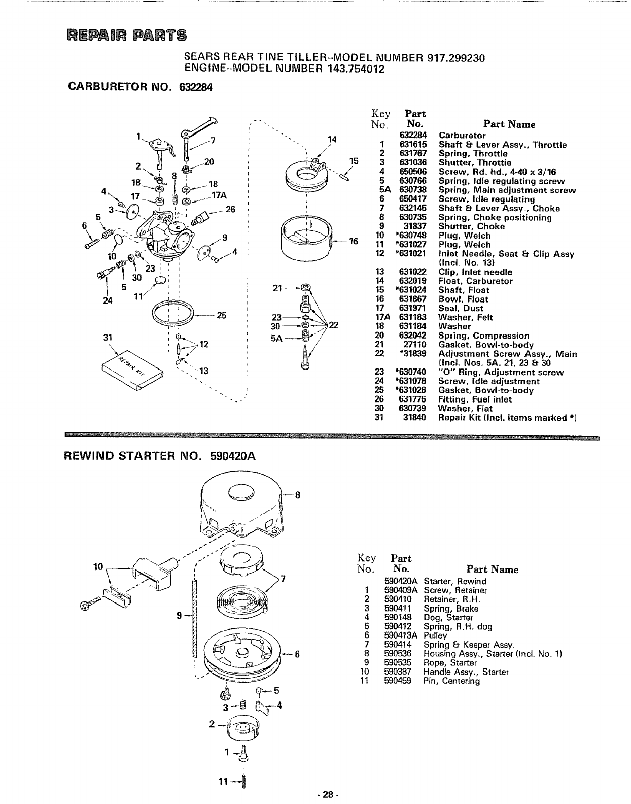
$1EPAJ$ PA TS
SEARS REAR TINE TILLER-MODEL NUMBER 917.299230
ENGINE-MODEL NUMBER 143.754012
CARBURETOR NO. 632284
Key Part
"-'-. No. No. Part Name
"- _632284 Carburetor
j4 1 631615 Shaft _t Lever Assy,,, Throttle
""', 2631767 Spring, Throttle
15 3631036 Shutter, Throttle
'--,..j 4 650506 Screw, Rd.. hd. 4-40 x3/16
5 630766 Spring, Idle regulating screw
5A 630738 Spring. Main adjustment screw
'_ 6 650417 Screw. Idle regulating
, 7 632145 Shaft _Lever Assy. Choke
8 630735 Spring. Choke positioning
9 31637 Shutter, Choke
10 "630748 Plug, Welch
16 11 *631027 Plug, Welch
12 _631021 Inlet Needle. Seat [ff Clip Assy
(IncL No,, 13}
: 13 631022 Clip, inlet needle
'14 632019 Float. Carburetor
21 _, 15 "631024 Shaft, Float
_3__ 16 631867 Bowl, Float
17 631971 Seal, Dust
17A 631163 Washer, Felt
22 18 631184 Washer
5A ........-_f'_i 20 632042 Spring, Compression
21 27110 Gasket, Bowl-to-body
22 "31839 Adjustment Screw Assy., Main
(Incl. Nos,, 5Ao 21, 23 _30
23 *630740 "O" Ring, Adjustment screw
24 *631078 Screw, Idle adjustment
25 *6-31028 Gasket, Bowl-to-body
26 631775 Fitting, Fuel inlet
30 630739 Washer, Flat
31 31840 Repair Kit (Incl. items marked _]
REWIND STARTER NO. 590420A
_, "..-'_>" I _ .2 _
- 28-
Key Part
No,. No. Part Name
590420A Starter, Rewind
1590409A Screw, Retainer
2 590410 Retainer', R,H.
3 590411 Spring, Brake
4 590148 Dog, Starter
5590412 Spring, R,H. dog
6 590413A Pulley
7 590414 Spring 8Keeper Assy,
8 590536 Housing Assy. Starter (Incl. No. 1)
9 590.&35 Rope, Starter
10 590387 Handle Assy,, Starter
11 590459 Pin, Centering

9E_VUCE N@TE8
106414X-12,,984
- 29- Printed in US,A_
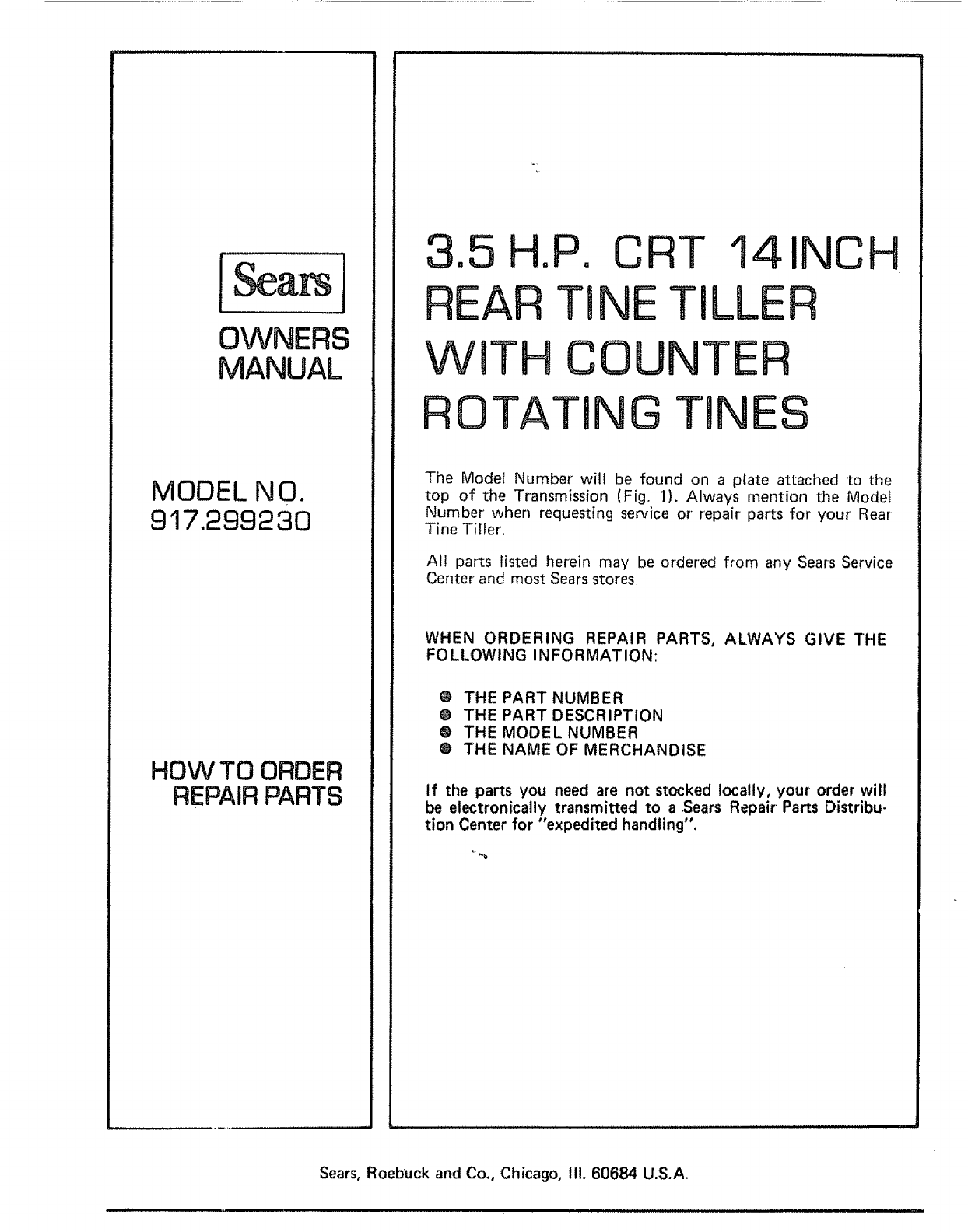
[Sears 1
OWNERS
MANUAL
MODEL N O.
917.299230
HOW TO ORDER
REPAIR PARTS
3
REAR
Wg
RO
.5 H.P. CRT 14INCH
TINE TILLER
TH COUNTER
TATING TINES
The Mode[ Number will be found on a plate attached to the
top of the Transmission (Fig_ 1). Always mention the Model
Number when requesting service or repair parts for your Rear-
Tine Tiller',
AI! parts listed herein may be ordered from any Sears Service
Center and most Sears stores,
WHEN ORDERING REPAIR PARTS, ALWAYS GIVE THE
FOLLOWING INFORMATION:
@THE PART NUMBER
@THE PART DESCRIPTION
O THE MODEL NUMBER
O THE NAME OF MERCHANDISE
if the parts you need are not stocked locally, your order will
be electronically transmitted to a .Sears Repair Parts Distribu-
tion Center for "expedited handling".
Sears, Roebuck and Co., Chicago, II1,,60684 U.S.Ao
