Craftsman 917377330 User Manual ROTARY LAWN MOWER Manuals And Guides L0804444
CRAFTSMAN Walk Behind Lawnmower, Gas Manual L0804444 CRAFTSMAN Walk Behind Lawnmower, Gas Owner's Manual, CRAFTSMAN Walk Behind Lawnmower, Gas installation guides
User Manual: Craftsman 917377330 917377330 CRAFTSMAN ROTARY LAWN MOWER - Manuals and Guides View the owners manual for your CRAFTSMAN ROTARY LAWN MOWER #917377330. Home:Lawn & Garden Parts:Craftsman Parts:Craftsman ROTARY LAWN MOWER Manual
Open the PDF directly: View PDF ![]() .
.
Page Count: 28
S_EARS
®
MODEL NUMBER 917.377330 OWNER'S MANUAL
oAssembly
oOperation
oCustomer
Responsibilities
oService
Adjustments
oRepair Parts
Caution:
Read and Follow
all Safety Rules
and Instructions
Before Operating
This Equipment
156675 12o6o96 VBL Printed in USoA.
...... ,...................................................... , ........... ,,,,
SAFETY RULES
_Safe Operation Practices for Walk-Behind Mowers
IMPORTANT: THIS CUTTING MACHINE iS CAPABLE OF AMPUTATING HANDS AND FEET AND THROWING OBJECTS=
FAILURE TO OBSERVE THE FOLLOWING SAFETY INSTRUCTIONS COULD RESULT IN SERIOUS INJURY OR DEATH
SAFETY STANDARDS REQUIRE OPERATOR PRESENCE CONTROLS TO MINIMIZE THE RISK OF INJURY. YOUR UNIT IS
EQUIPPED WiTH SUCH CONTROLS, DO NOT ATTEMPT TO DEFEAT THE FUNCTION OF THE OPERATOR PRESENCE
CONTROLS UNDER ANY CtRCUMSTANCES_
TRAINING:
* Read this operator's manual carefully. Become familiar with
the controls and know how to operate your mower propedy..
Learn how to quickly stop mower.
- Do not allow children to use your mower. Never allow adults
to use mower without proper instructions.
oKeep the area of operation clear of all persons, especially
small children and pets,.
.Use mower only as the manufacturer intended and as de-
scribed in this manual,
*Do not operate mower if it has been dropped or damaged in
any manner_ Always have damage repaired before using
your mower,
•Do not use accessory attachments that are notrecommended
by the manufacturer. Use of such attachments may be
hazardous°
•The blade turns when the engine isrunning°
PREPARATION:
•Always thoroughly check the area to be mowed and clearit of
all stones, sticks, wires, bones, and other foreign objects.
These objects will be thrown by the blade and can cause
severe injury..
•Always wear safety glasses or eye shields when starting and
while using your mower,
•Dress properly, Do not operate mower when barefoot or
wearing open sandals. Wear only sotid shoes with good
traction when mowing_
•Check fuel tank before starting engine. Do not fill gas tank
indoors, when the engine is running or when the engine is hot..
Allow the engine to cool for several minutes before filling the
gas tank_ Clean off any spilled gasoline before starting the
engine.
.Always make wheel height adjustments before starting your
mower. Never attempt to do this while the engine is running.
•Mow only in daylight or good artificial light.
OPERATION:
•Keep your eyes and mind on your mower and the area being
cut° Do not let other interests distract you.
• Do not mow wet or slippery grass, Never run while operating
your mower. Always be sure of your footing -keep a firm hold
on the handles and walk.
,, Do not put hands or feet near or under rotating parts. Keep
clear of the discharge opening at all times,
•Always stop the engine whenever you leave or are not using
your mower, or before crossing driveways, waiks, roads, and
any gravel-covered areas.
• Never direct discharge of material toward bystanders nor
allow anyone near the mower while you are operating it.
• Before cleaning, inspecting, or repairing your mower, stop the
engine and make absolutely sure the blade and all moving
parts have stopped_ Then disconnect the sparkplug wire and
keep it away from the spark plug to prevent accidental
starting.
°Do not continue to run your mower if you hit aforeign object°
Follow the procedure outlined above, then repair any dam*
age before restarting and operating you mower.
•Do not change the governor settings or overspeed the
engine. Engine damage or personal injury may resulL
• Do not operate your mower if it vibrates abnormally., Excess
sive vibration is an indication of damage; stop the engine,
safely check for the cause of vibration and repair as required.
•Do not run the engine indoors, Exhaust fumes are danger-
ous.
•Never cut grass by pulling the mower towards you.. Mow
across the face of slopes, never up and down or you might
loseyourfooting° Donotmowexcesstvelysteepslopes. Use
caution when operating the mower on uneven terrain orwhen
changing directions _ maintain good footing.
•Never operate your mower without proper guards, plates,
grass catcher or other safety devices in place.
MAINTENANCE AND STORAGE:
•Check the blade and the engine mounting bolts often to be
sure they are tightened property.
•Check all boils, nuts and screws at frequent intervals for
proper tightness to be sure mower is in safe working condi-
tion.
• Keep all safety devices in place and working_
• To reduce fire hazard, keep the engine free of grass, leaves
or excessive grease and oil
Check grass catcher often for deterioration and wear and
replace worn bags. Use only replacement bags that are
recommended by and comply with specifications of the
manufacturer of your mower.
o Always keep a sharp blade on your mower,
•Allow engine to cool before stodng in any enclosure.
• Never store mower with fuel in the tank inside abuilding
where fumes may reach an open flame or an ignition source
such as a hot water heater, space heater, clothes dryer, etc..
iLook fore:this symbol to point out im-
portant safety precautions. It means
CAUTIONH! BECOMEALERTIIt YOUR
SAFETY IS INVOLVED.
CAUTION: Always disconnect spark
plug wire and place wire where it can-
not contact spark plug in order to pre-
vent accidental starting when setting
up, transporting, adjusting or making
repairs.
i, ,1111................................. i iiiiiii
WARNING &
The engine exhaust from this product con-
tains chemicals known to the State of Califor-
nia to cause cancer, birth defects, or other
reproductive harm.
L.ONGRATULATIONS on your purchase of a Sears Lawn
Mower. It has been designed, engineered and manufac-
tured to give you the best possible dependability and
performance.
Should you experience any problem you cannot easily
remedy, please contact your nearest Sears Authorized
Service CentedDepartment We have competent, well-
trained technicians and the proper tools to service or repair
this lawn mower.
Please read and retain this manual The instructions will
enable you _o assemble and maintain your lawn mower
properlyo Always observe the "SAFETY RULES"
MODEL
NUMBER 9174377330
SERIAL
NUMBER
DATEOF PURCHASE
THE MODELANDSERIAL NUMBEPSWILL BE FOUND
ON A DECAL ATTACHED TO THE REAR OF THE
LAWN MOWER HOUSING
YOU SHOULD RECORD BOTH SERIAL NUMBER AND
DATE OF PURCHASE AND KEEP IN A SAFE PLACE
FOR FUTURE REFERENCE
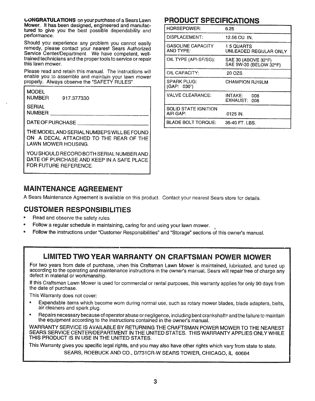
PRODUCT SPECIFnCATIONS
HORSEPOWER: 6.25
DISPLACEMENT: 12o56CU INo
GASOLINE CAPACITY 1 5 QUARTS
AND TYPE: UNLEADED REGULAR ONLY
OIL TYPE (APt-SF/SG): SAE 30 (ABOVE 32°F)
SAE 5W-30 (BELOW 32°F)
OIL CAPACITY: 20 OZS.
SPARK PLUG: CHAMPION RJ19LM
GAP: 030")
VALVE CLEARANCE: INTAKE: 008
EXHAUST: .008
SOLID STATE IGNITION
AIR GAP: .0125 IN,.
BLADE BOLT TORQUE: 35-40 FT. LBS..
MAgNTENANCF_ AGREEMENT
A Sears Maintenance Agreement is available on this product. Contact your nearest Sears store for details.
CUSTOMER RESPONSBBILITIES
.Read and observe the safety rules,
', Follow a regular schedule in maintaining, caring for and using your lawn mower.
o Follow the instructions under "Customer Responsibilities" and "Storage" sections of this owner's manual,
LnMITF_DTWO YEAR WARRANTY ON CRAFTSMAN POWER MOWER
For two years from date of purchase, when this Craftsman Lawn Mower is maintained, lubricated, and tuned up
according to the operating and maintenance instructionsin the owner's manual, Sears will repair free of charge any
defect in material or workmanship..
If this Craftsman Lawn Mower is used for commercial or rental purposes, this warranty applies for only 90 days from
the date of purchase.
This Warranty does not cover:
• Expendable items which become worn dudng normal use, such as rotary mower blades, blade adapters, belts,
air cleaners and spark plug.
• Repairs necessary because of operator abuse or negligence, includingbent crankshaft._ and the failure to maintain
the equipment according to the instructions contained in the owner's manual
WARRANTY SERVICE IS AVAILABLE BY RETURNING THE CRAFTSMAN POWER MOWER TO THE NEAREST
SEARS SERVICE CENTER/DEPARTMENT IN THE UNITED STAi"ESo THIS WARRANTY APPLIES ONLY WHILE
THIS PRODUCT IS IN USE IN THE UNITED STATES.
This Warranty gives you specific legal rights, and you may also have other rights which vary from state to state.
SEARS, ROEBUCK AND CO., D/731CR-W SEARS TOWER, CHICAGO, 1L 60684
3
TABLE OF CONTENTS
SAFETY RULES ............................................................ 2
PRODUCT SPECIFICATIONS ...................................... 3
CUSTOMER RESPONSIBILITIES ...................... 3,12-15
WARRANTY .................................................................. 3
ASSEMBLY ................................................................. 6
OPERATION ...................................................... :............ 8
CUSTOMER RESPONSIBILITIES .............................. 12
SERVICE AND ADJUSTMENTS ................................. 16
STORAGE ................................................................... 18
REPAIR PARTS- LAWN MOWER ........................ 19-23
REPAIR PARTS - ENGINE .................................... 24-26
TROUBLESHOOTING .................................................. 27
PARTS ORDERING/SERVICE .................................... 28
aNDEX
A
Adjustments:
Carburetor ........................................17
Drive Control ...............................16
Engine Speed ............................ 17
Handle Height .......................... 17
Height of Cut .....................................9
Air Filter:
Replacement .......................... 15
Service ........................................15
Assembly ..............................................6
B
Blade:
Sharpening ...................................... 13
Replacement ....................................13
C
Controls:
Drive Control ....................................8
Engine Zone Control ........................8
Engine Speed Control ............. 8
Operator Presence Control Bar 8
Customer' Responsibilities ......3,12d 5
Air Filter ..............:::o:...........Lo_ 15
Blade Care/Replacement ...... 13
Drive Wheels ......................... 14
Engine ....................................... 15
Lubrication .............................. 15
Spark Plug ...................................15
Cutting Levels .................................... 9
E
Engine:
Air Filter° .................................... 15
Oil Change ................................. 15
Oil Level .........................................15
Oil Type .........................................15
Starting .................................... 10
Stopping .........................................l0
Storage ................................. 18
F
Fuel:
CapaciLy .............................................3
Storage ...........................................18
Type ............................................10
H
Handle Adjustment:
Assembly .......................................6
Cutting Height ....................... 17
L
Lubrication:
Engine ....................................... 15
Lawn Mower ..,,,, ............12
Maintenance Agreement ...................3
Maintenance Schedule ....................12
Mowing Tips .................................... 11
0ii:
0
Engine ...................................... 15
Storage ................................... 18
Operation:
Drive Control ...............................10
Engine Control ...................................9
Grass Catcher. ........................... 9
Mower ...........................................9
Operator Presence Control Bar 9
R
Repair Parts:
Engine ...................................24-26
Lawn Mower ...................;...... 19-23
Responsibilities, Customer... 3,12-15
S
Safety Rules ...........................................2
Service and Adjustments ..................16
Carburetor ........................................17
Drive Belt ....................................16
Drive Control ................................17
Engine Speed ............................17
Handle ........................................17
Spark Plug ...................................... 15
Specifications .................................... 3
Speed Control:
Engine ..................................... 17
Starting the Engine ........................ 10
Stopping the Engine ........................ 10
Storage .............................................. 18
T
Trouble Shooting Chart .....................27
W
Warranty .......................................................3
4
i.....i, u,u,uu i,,i,u n I lu,n
LAWN !R ACCESSORIES
.......................... Ull.U,l,,U, i i ,,, i
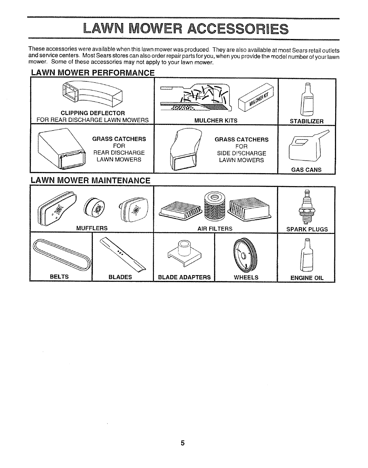
These accessories were available when this lawn mower was produced, They are also available at most Sears retail outlets
and service centers, Most Sears stores can also order repair parts for you, when you provide the model number of your lawn
mower_ Some of these accessories may not apply to your lawn mower°
LAWN MOWER PERFORMANCE
i.n ..m ............................
CLIPPING DEFLECTOR
FOR REAR DISCHARGE LAWN MOWERS MULCHER KITS
GRASS CATCHERS
FOR
REAR DISCHARGE
LAWN MOWERS
GRASS CATCHERS
FOR
SIDE D!SCHARGE
LAWN MOWERS
LAWN MOWER MAINTENANCE
MUFFLERS
BELTS
AIR FILTERS
BLADES
,,,, ,, i ii i .................................
BLADE ADAPTERS WHEELS
,,u,i .n,.n, ,I I
STABILIZER
ilnl,,i,l,ll,i i i
GAS CANS
SPARK PLUGS
ENGINE OIL
..................... i.........................
5
II-,"H iii, ,,, ,i .... i i i' ,,i .....
BL¥
............................................................. IIH ii iii, i i, ,i ii ....iii,,i' llln,,,l I
Read these instructions and this manual in its entirety
before you attempt to assemble or operate your new lawn
mower. Your new lawn mower has been assembled at the
factory with the exception of those parts left unassembled
for shipping purposes To ensure safe and proper opera-
tion of your lawn mower, all parts and hardware you
assemble must be tightened securely Use the correct
tools as necessary to ensure proper tightness_ All parts
such as nuts, washers, bolts, etc, necessary to complete
the assembly have been placed in the parts bag
TO REMOVE LAWN MOWER FROM
CARTON
o Remove ioose parts included with mower.
= Cut down two end corners of carton and lay end
panel down flat.
o Remove all packing materials except padding be-
tween upper and lower handle and padding holding
operator presence control bar to upper handle.
oRoll lawn mower out of carton and check carton
thoroughly for additional loose parts
HOW TO SET UP YOUR LAWN
MOWER
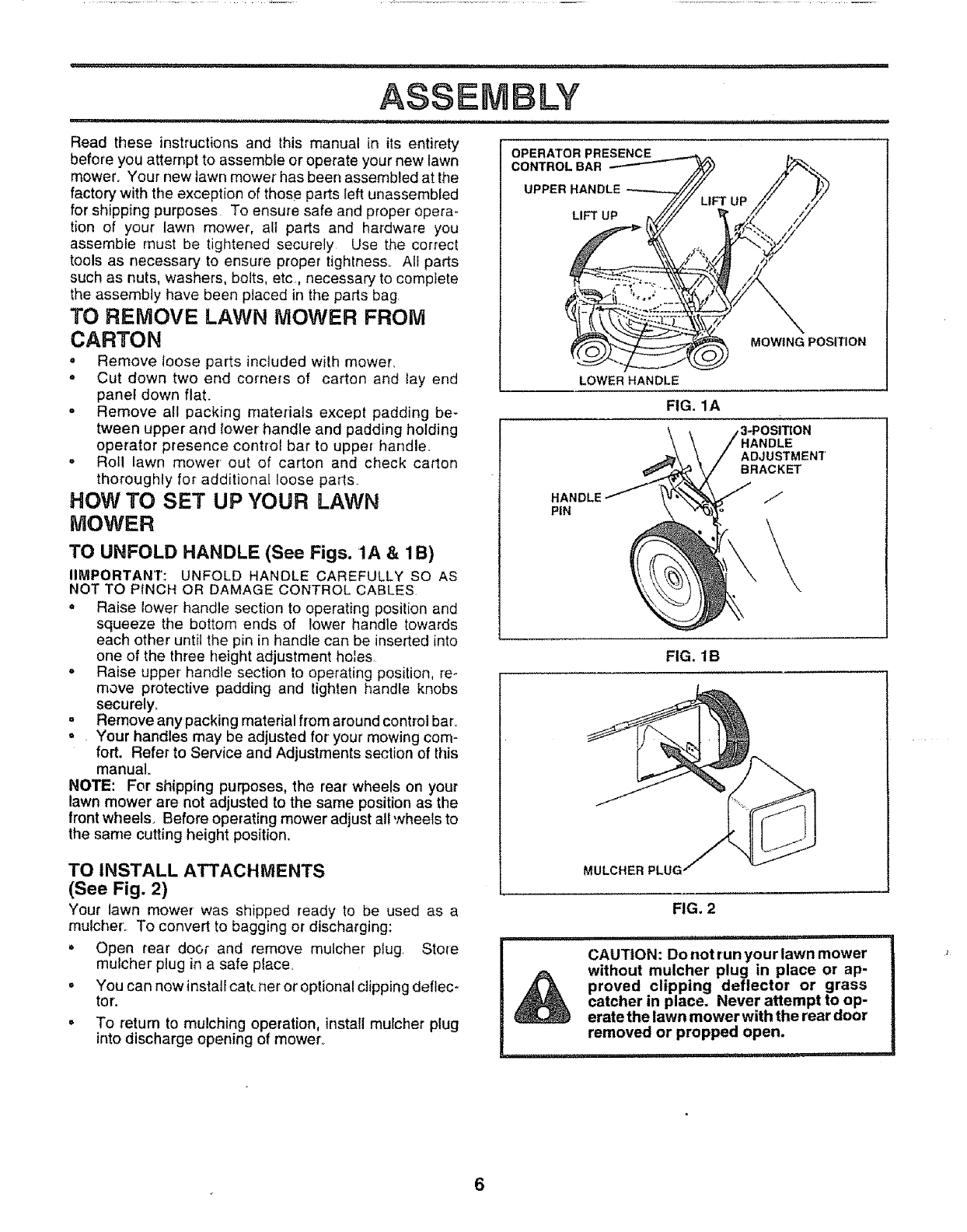
TO UNFOLD HANDLE (See Figs. 1A & 1B)
IIMPORTANT: UNFOLD HANDLE CAREFULLY SO AS
NOT TO PINCH OR DAMAGE CONTROL CABLES
o Raise lower handle section to operating position and
squeeze the bottom ends of lower handle towards
each other until the pin in handle can be inserted into
one of the three height adjustment holes.
, Raise upper handle section to operating position, re-
move protective padding and tighten handle knobs
securely,
= Remove any packing material from around control bar=
° Your handles may be adjusted for your mowing com-
fort. Refer to Service and Adjustments section of this
manual,
NOTE: For shipping purposes, the rear wheels on your
lawn mower are not adjusted to the same position as the
front wheels. Before operating mower adjust all wheels to
the same cutting height position.
TO INSTALL ATTACHMENTS
(See Fig. 2)
Your lawn mower was shipped ready to be used as a
mulcher._ To convert to bagging or discharging:
•Open rear door and remove mulcher plug. Store
mulcher plug in asafe place
= You can now installcat(. net or optional clipping deflec-
tor.
o To return to mulching operation, install mulcher plug
into discharge opening of mower°
OPERATOR PRESENCE
CONTROL BAR
UPPER HANDLE
LIFT UP
MOWING POSITION
HANDLE
P{N
LOWER HANDLE
FIG. 1A
3_OS|_ON
ADJUSTMENT
BRACKET
/I
FIG. 1B
MULCHER PLUG
FIG. 2
CAUTION: Do not run your lawn mower
without mulcher plug in place or ap-
proved clipping deflector or grass
catcher in place. Never attempt to op-
erate the lawn mower with the rear door
removed or propped open.
LY
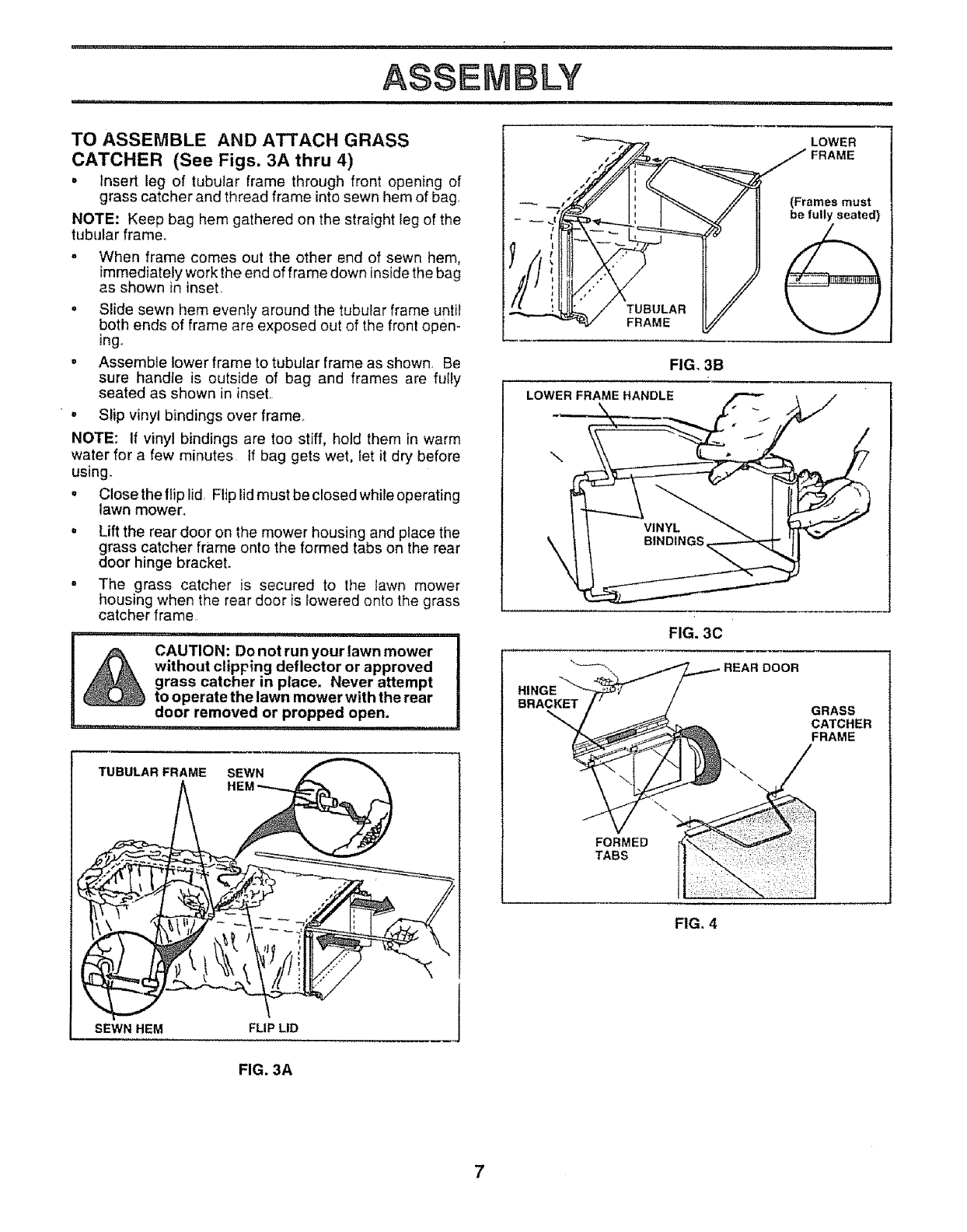
TO ASSEMBLE AND ATTACH GRASS
CATCHER (See Figs. 3A thru 4)
oinsert leg of tubular frame through front opening of
grass catcher and thread frame intosewn hem of bag,
NOTE: Keep bag hem gathered on the straight leg of the
tubular frame.
o When frame comes out the other end of sewn hem,
immediately work the end of frame down inside the bag
as shown in inset,
•Slide sewn hem evenly around the tubular frame until
both ends of frame are exposed out of the front open-
ingo
= Assemble lower frame to tubular frame as shown, Be
sure handte is outside of bag and frames are fuIly
seated as shown in inset,
°Slip vinyl bindings over frame,
NOTE: If vinyl bindings are too stiff, hold them in warm
water for a few minutes If bag gets wet, let it dry before
using.
o Close the flip lid, Flip lid must be closed while operating
lawn mower,,
o Lift the rear door on the mower housing and place the
grass catcher frame onto the formed tabs on the rear
door hinge bracket.
= The grass catcher is secured to the {awn mower
housing when the rear door is lowered onto the grass
catcher frame
,i,ii ,,,i,i,ii1,1i1,,iii,
CAUTION: Do not run your lawn mower
withot,t cliprlng deflector or approved
grass catcher in place. Never attempt
to operate the lawn mower with the rear
door removed or propped open.
TUBULAR FRAME SEWN
SEWN HEM FUP LID
i
FIG. 3B
LOWER FRAME HANDLE
\
BRACKET
\
FORMED
TABS
GRASS
CATCHER
FRAME
FIG. 4
FIG. 3A
OPERATmO
,,,111,,11= =, ,1111, ,1,,11,11,1,1, 11 111 11,, , i
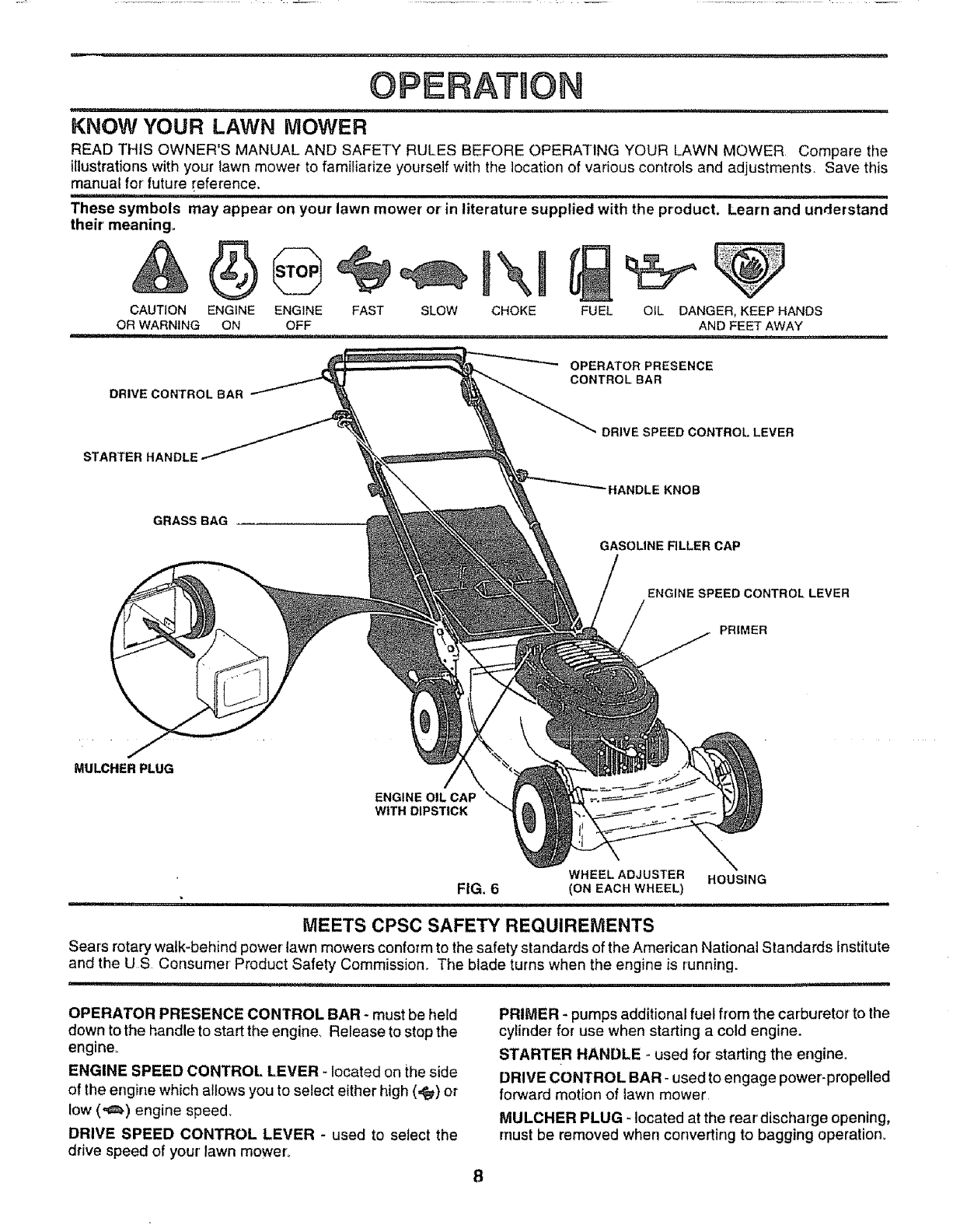
KNOW YOUR LAWN MOWER
READ THtS OWNER'S MANUAL AND SAFETY RULES BEFORE OPERATING YOUR LAWN MOWER, Compare the
illustrations with your lawn mower to familiarize yourself with the location of various controls and adjustments, Save this
manual for future _eference.
H "==="=====Hi"H'= = 11
These symbols may appear on your lawn mower' or' in literature supplied with the product. Learn and understand
their' meaning,
CAUTION FU EL
OR WARNING
ENGINE ENGINE FAST SLOW CHOKE
ON OFF OIL DANGER, KEEP HANDS
AND FEET AWAY
DRIVECONTROLBAR
OPERATOR PRESENCE
CONTROLBAR
STARTER HANDLE
GRASSBAG
MULCHER PLUG
ENGINE OIL CAP
WITH DIPSTICK
DRIVE SPEED CONTROL LEVER
HANDLE KNOB
GASOLINE RLLER CAP
ENGINE SPEED CONTROL LEVER
PRIMER
WHEEL ADJUSTER HOUSING
FIG. 6 (ON EACHWHEEL}
MEETS CPSC SAFETY REQUIREMENTS
Sears rotary walk-behind power lawn mowers conform to the safety standards of the American National Standards Institute
and the US Consumer Product Safety Commission_ The blade turns when the engine is running.
,,=m,iNP,,i...... Hi'I'""HH""I" '1 ='1"1
OPERATOR PRESENCE CONTROL BAR - must be held
down to the handle to start the engine Release to stop the
engine_
ENGINE SPEED CONTROL LEVER - located on the side
of the engine which allows you to select either high (,_) or
low (,_) engine speed_
DRIVE SPEED CONTROL LEVER - used to select the
drive speed of your lawn mower°
PRIMER - pumps additional fuel from the carburetor to the
cylinder for use when starting a cold engine.
STARTER HANDLE - used for starting the engine.
DRIVE CONTROL BAR -used to engage power-propelled
forward motion of lawn mower,
MULCHER PLUG -located at the rear' discharge opening,
must be removed when converting to bagging operation°
r'"J'l'l"_""U"" i i
! o! i
HOW TO USE YOUR LAWN MOWER
OPERATION
..... i i,i1,11,,,i ...... i,i ,i i, i, ,i, i1,,i,1,,,i i, i
i1,1........... i,ii 1,1,.,, H'I " I.......... '1'"
The operation of any lawn mower can result in foreign objects thrown into the eyes, which can
result in severe eye damager Always wear safety glasses or eye shields while operating your
lawn mower or performing any adjustments or repairs. We recommend a wide vision safety
mask over the spectacles or standard safety glasses,
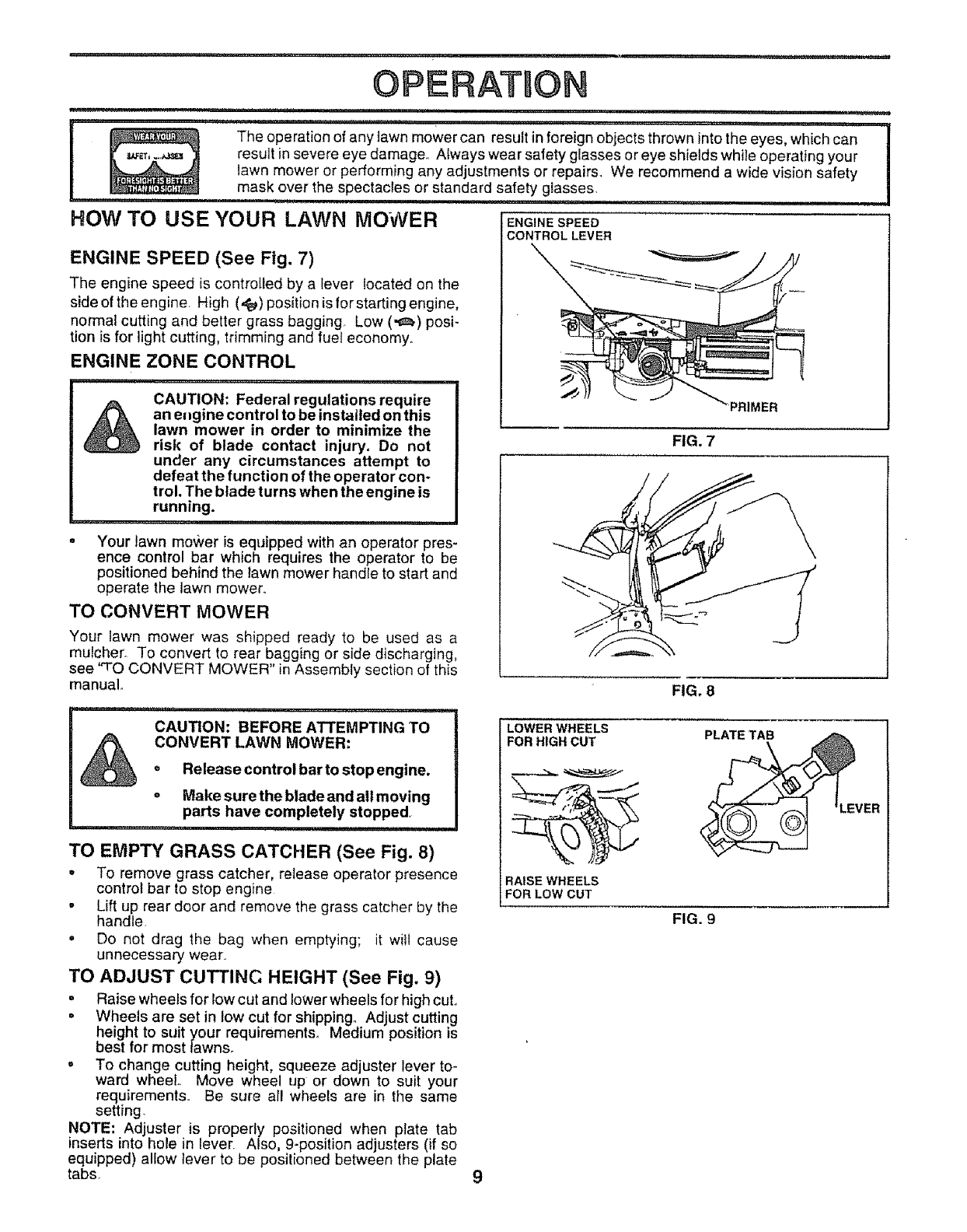
ENGINE SPEED (See Fig. 7)
The engine speed is controlled by a lever located on the
side of the engine. High (._) position is for starting engine,
normal cutting and better grass bagging° Low (,,_.) posi-
tion is for light cutting, trimming and fuel economy,,
ENGINE ZONE CONTROL
,,i,, ,11,,i,,,,iii1,,,,,i,
CAUTION: Federal regulations require
an engine control to be installed on this
lawn mower in order to minimize the
risk of blade contact injury. Do not
under any circumstances attempt to
defeat the function of the operator con-
trol. The blade turns when the engine is
running.
....... i,iii1,111,11,, i ,11 ,i
oYour lawn mower is equipped with an operator pres-
ence control bar which requires the operator to be
positioned behind the lawn mower handle to start and
operate the lawn mower.
TO CONVERT MOWER
ENGINE SPEED
CONTROL LEVER
Your lawn mower was shipped ready to be used as a
mulcher. To convert to rear bagging or side discharging,
see "TO CONVERT MOWER" in Assembly section of this
manual.
,,,i,1,1,,111,, _ m
CAUTION: BEFORE ATTEMPTING TO
CONVERT LAWN MOWER:
•Release control bar to stop engine,
oMake sure the blade and all moving
parts have completely stopped,
i, ,11
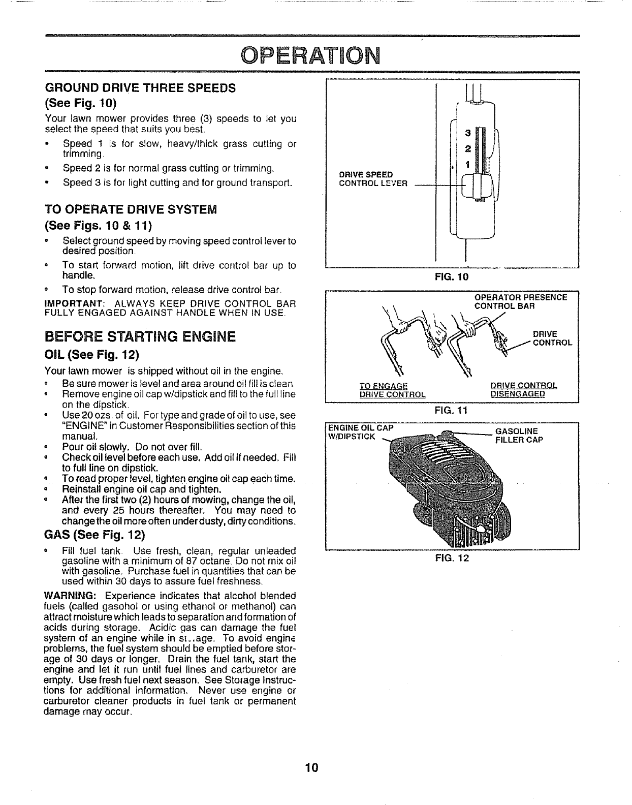
TO EMPTY GRASS CATCHER (See Fig. 8)
•To remove grass catcher, retease operator presence
control bar to stop engine
•Lift up rear door and remove the grass catcher by the
handle,
=Do not drag the bag when emptying; it witl cause
unnecessary wear.
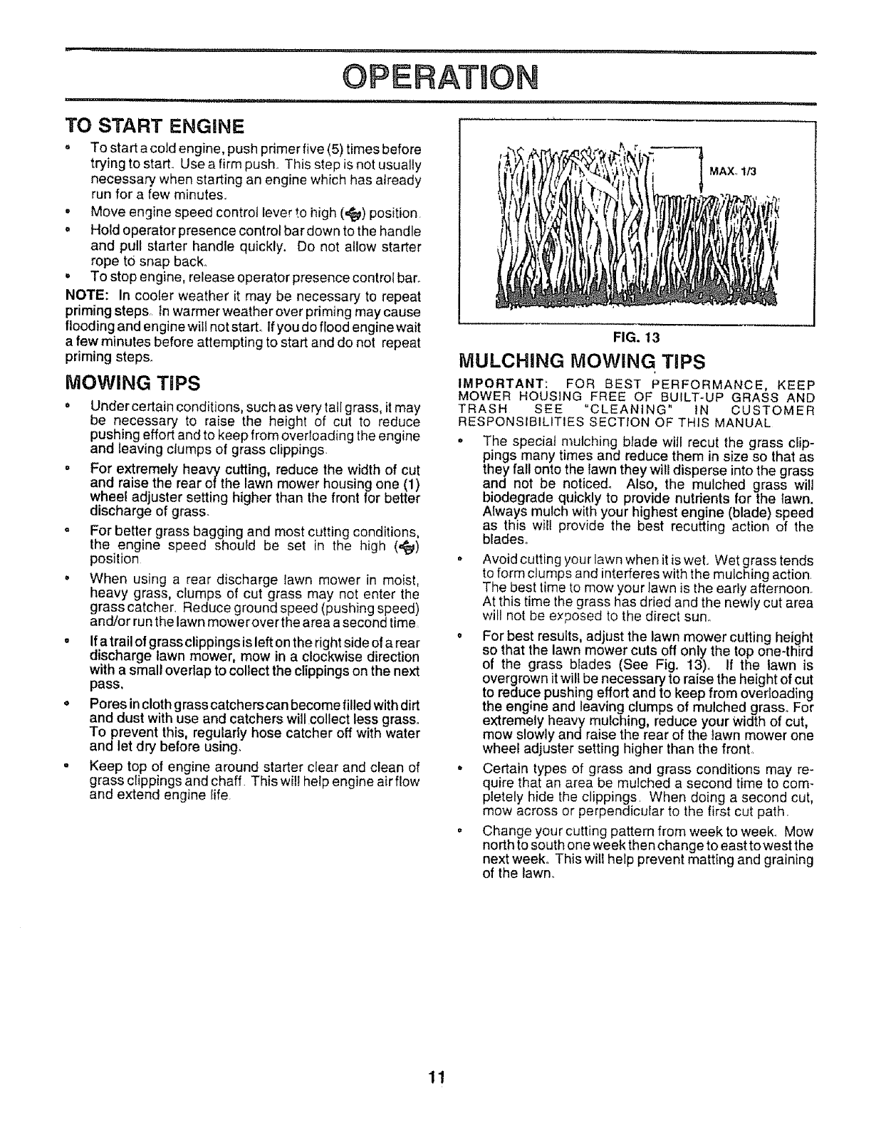
TO ADJUST CUTTINC HEIGHT (See Fig. 9)
= Raise wheels for lowcut and lower wheels for high cuL
= Wheels are set in tow cut for shipping. Adjust cutting
height to suit your requirements,, Medium position is
best for most lawns°
o To change cutting height, squeeze adjuster lever to-
ward wheel. Move wheel up or down to suit your
requirements,, Be sure all wheels are in the same
setting.
NOTE: Adjuster is properly positioned when plate tab
inserts into hole in lever. Also, 9-position adjusters (if so
equipped) allow lever to be positioned between the plate
tabs.
PRIMER
FIG. 7
9
FIG. 8
LOWER WHEELS PLATE TAB
FOR HIGH CUT
RAISE WHEELS
FOR LOW CUT
FIG. 9
VER
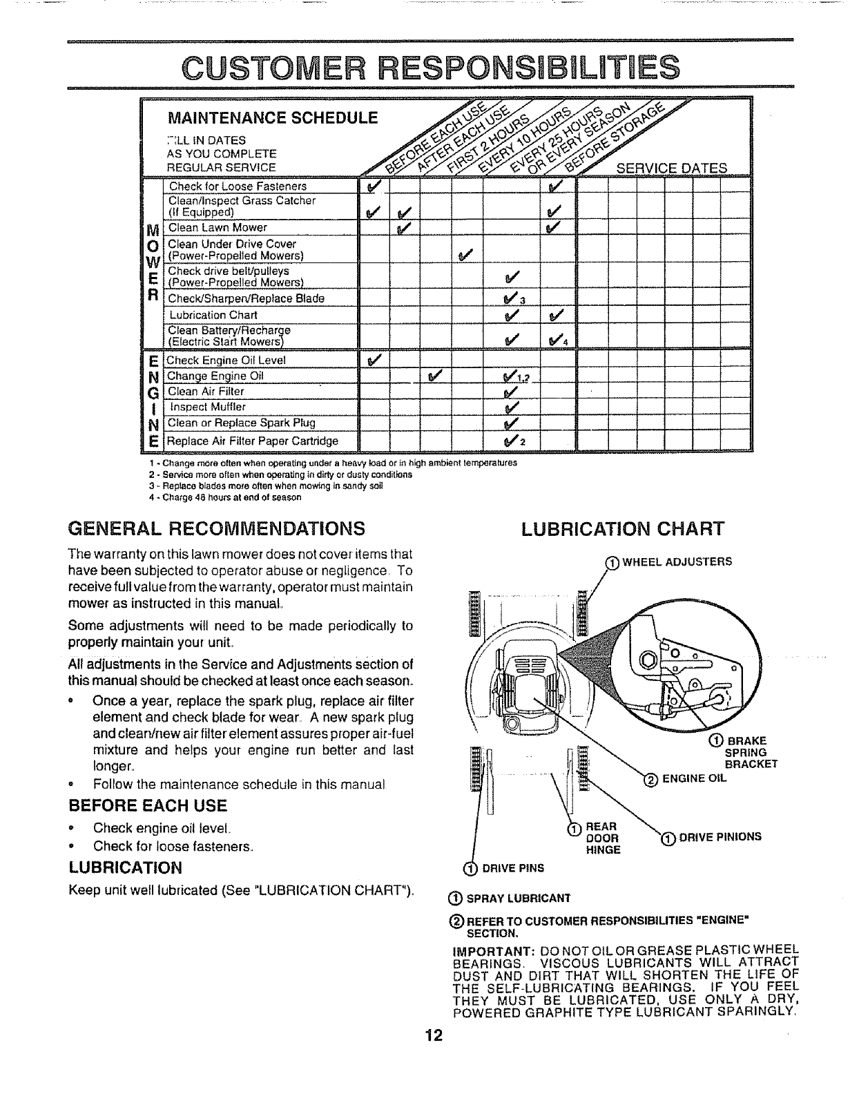
GROUND DRIVE THREE SPEEDS
(See Fig. 10)
Your lawn mower provides three (3) speeds to let you
select the speed that suits you best.
° Speed 1 is for slow, heavy/thick grass cutting or
trimming
• Speed 2 is for normal grass cutting or trimming..
,, Speed 3 is for light cutting and for ground transport.
TO OPERATE DRIVE SYSTEM
(See Figs. 10 & 11)
-Select ground speed by moving speed controi lever to
desired position
•To start forward motion, lift drive controi bar up to
handle.
oTo stop forward motion, release drive control bar.
IMPORTANT: ALWAYS KEEP DRIVE CONTROL BAR
FULLY ENGAGED AGAINST HANDLE WHEN IN USE.
BEFORE STARTING ENGINE
OIL (See Fig. 12)
Your lawn mower is shipped without oil in the engine.
, Be sure mower is level and area around oil fill is clean
, Remove engine oil cap w/dipstick and fiti to the full line
on the dipstick.
oUse 20 ozs, of oil. For type and grade of oil to use, see
"ENGINE" in Customer Responsibilities section of this
manual.
.Pour oil slowly. Do not over fill.
.Check oil level before each use, Addoitifneededo Fill
to full line on dipstick.
°To read proper level, tighten engine oil cap each time.
,, Reinstall engine oil cap and tighten.
,, After the first two (2) hours of mowing, change the oil,
and every 25 hours thereafter. You may need to
changethe oil more often under dusty, dirty conditions.
GAS (See Fig. 12)
.Fill fuel tank Use fresh, clean, regular unleaded
gasoline with a minimum of 87 octane Do not mix oil
with gasoline Purchase fuel in quantities that can be
used within 30 days to assure fuel freshnes&
WARNING: Experience indicates that alcohol blended
fuels (called gasohot or using ethanol or methanol) can
attract moisture which leads to separation and formation of
acids during storage,, Acidic gas can damage the fuel
system of an engine while in st.,ageo To avoid engine
problems, the fuel system should be emptied before stor*
age of 30 days or longer° Drain the fuel tank, start the
engine and let it run until fuet lines and carburetor are
empty. Use fresh fuel next season. See Storage Instruc-
tions for additional information. Never use engine or'
carburetor cleaner products in fuel tank or permanent
damage may occur.
DRIVE SPEED
CONTROL LEVER
FIG. 10
OPERATOR PRESENCE
CONTROLBAR
DRIVE
TO ENGAGE
DRIVE CONTROL
FIG,, tl
DRIVE CN_
DISENGAGED
ENGINE OIL CAP
W/DIPSTICK GASOLINE
FILLER CAP
FIG. 12
10
TO START ENGINE
o To start a cold engine, push primer five (5) times before
trying to start., Use a firm push., This step isnot usually
necessary when starting an engine which has already
run for a few minutes.
oMove engine speed control lever to high (,_) position
•Hold operator presence control bar down to the handle
and pull starter handle quickly. Do not allow starter
rope to snap back°
oTo stop engine, release operator presence control bar.
NOTE: In cooler weather it may be necessary to repeat
priming steps, tn warmer weather over priming may cause
flooding and engine wilt net start,. If you do flood engine wait
a few minutes before attempting to start and do not repeat
priming steps.
MOWING TiPS
•Under certain conditions, such as very tall grass, it may
be necessary to raise the height of cut to reduce
pushing effort and to keep from overloading the engine
and leaving clumps of grass clippings
= For extremely heavy cutting, reduce the width of cut
and raise the rear of the lawn mower housing one (1)
wheel adjuster setting higher than the front for better
discharge of grass_
o For better grass bagging and most cutting conditions,
the engine speed should be set in the high (,,_)
position
•When using a rear discharge lawn mower in moist,
heavy grass, clumps of cut grass may not enter the
grasscatcher, Reduce ground speed (pushing speed)
and/or run the lawnmowerover the area a second time
•If atrail of grass clippings is left on the right side of a rear
discharge lawn mower, mow in a clockwise direction
with a small overlap to collect the clippings on the next
pass,
oPores incloth grass catcherscan become filled with dirt
and dust with use and catchers will collect less grass.
To prevent this, regularly hose catcher off with water
and let dry before using.
•Keep top of engine around starter clear and clean of
grass clippings and chaff This will help engine air flow
and extend engine fife,
MAX,, 1/3
FIG. 13
MULCHING MOWING TiPS
IMPORTANT: FOR BEST PERFORMANCE, KEEP
MOWER HOUSING FREE OF BUILT-UP GRASS AND
TRASH SEE "CLEANING" iN CUSTOMER
RESPONSIBILITIES SECTION OF THIS MANUAL
"The special mulching blade will recut the grass dip-
pings many times and reduce them in size so that as
they fal! onto the lawn they will disperse into the grass
and not be noticed_ Also, the mulched grass will
biodegrade quickly to provide nutrients for the lawn.
Always mulch with your highest engine (blade) speed
as this will provide the best recutting action of the
blades,,
•Avoid cutting your lawn when it is weL Wet grasstends
to form clumps and interferes with the mulching action,
The best time to mow your Pawnis the early afternoon.
At this time the grass has dried and the newly cut area
will not be exposed to the direct sun,,
o For best results, adjust the lawn mower cutting height
so that the lawn mower cuts off only the top one-third
of the grass blades (See Fig. 13)o If the lawn is
overgrown it will be necessary to raise the height of cut
to reduce pushing effort and to keep from overloading
the engine and leaving clumps of mulched grass° For
extremely heavy mulching, reduce your Width of cut,
mow slowly andraise the rear of the Pawnmower one
wheel adjuster setting higher than the front,
° Certain types of grass and grass conditions may re-
quire that an area be mulched a second time to com-
pletely hide the clippings, When doing a second cut,
mow across or perpendicular to the first cut path,
• Change your cutting pattern from week to week., Mow
north to south one week then change to east to west the
next week° This will help prevent matting and graining
of the lawn,.
11
CUSTO
u,n
MAINTENANCESCHEDULE
:-_LL IN DATES
AS YOU COMPLETE
REGULAR SERVICE
Check for Loose Fasteners'
Clean/Inspect Grass Catcher
(if Equipped)
M Clean Lawn Mower
O Clean Under Drive Cover
(Power-Propelled Mowers)
Check drive belt/pulleys
E(Power-Propelled Mowers)
aChecP.JSharperu'ReP!ac,e Biade .........................
Lubrication Chart
Clean Battery/Recharge
(Electric Start Mowers)
ECheck Engine Oif Levet
N Chang e Engine Oil
G,c,[ean Air Fiiter
i Inspect Muffler ...............
N C_ean or Replace Spark Plug
EReplace Air Filter Paper Cartridge
,v'
v'
e,'
SERVICE DATES
e"3
_" v'
..........v' .................v'4.....
J2
I-Change more often when operating under aheavy _ad or ie high ambient temperalures
2-Services more often when eperaUng indittyot dus_ conditions
3*Replace blades more often when mowing insandy sai_
4 - Charge 48 hours at and e! season
J
l ....
GENERAL RECOMMENDATIONS
The warranty on this lawn mower does not cover items that
have been subjected to operator abuse or negligence, To
receive full value from the warranty, operator must maintain
mower as instructed in this manual,
Some adjustments will need to be made periodically to
properly maintain your unit,,
All adjustments in the Service and Adjustments section of
this manual should be checked at least once each season,
o Once a year, replace the spark plug, replace air filter
element and check blade for wear.. A new spark plug
and clean/new air filter' element assures proper air-fuel
mixture and helps your engine run better and last
longer°
o Follow the maintenance schedule in this manual
BEFORE EACH USE
o Check engine oil level.
- Check for loose fasteners..
LUBRICATION
Keep unit well lubricated (See "LUBRICATION CHART").
LUBRICATION CHART
WHEEL ADJUSTERS
(_) BRAKE
il SPRING
BRACKET
ENGINE OIL
DRIVE PINS
REAR
ODOR
HINGE DRIVE PINIONS
(_ SPRAY LUBRICANT
(_ REFER TO CUSTOMERRESPONSIB|UTIES "ENGINE"
SECTION,
IMPORTANT: DO NOT OIL OR GREASE PLASTIC WHEEL
BEARINGS, VISCOUS LUBRICANTS WILL ATTRACT
DUST AND DIRT THAT WILL SHORTEN THE LIFE OF
THE SELF-LUBRICATING BEARINGS. IF YOU FEEL
THEY MUST BE LUBRICATED, USE ONLY A DRY,
POWERED GRAPHITE TYPE LUBRICANT SPARINGLY_
12
==............ iiii i,ii,
CUSTOMER ESPON$1BULITIES
LAWN &/IOWER
Always observe safety rules when performing any mainte-
nance
TIRES
,, Keep tires free of gasoline, oil, or insect control chemi-
cals which can harm rubber
. Avoid stumps, stones, deep ruts, sharp objects and
other hazards that may cause tire damage,
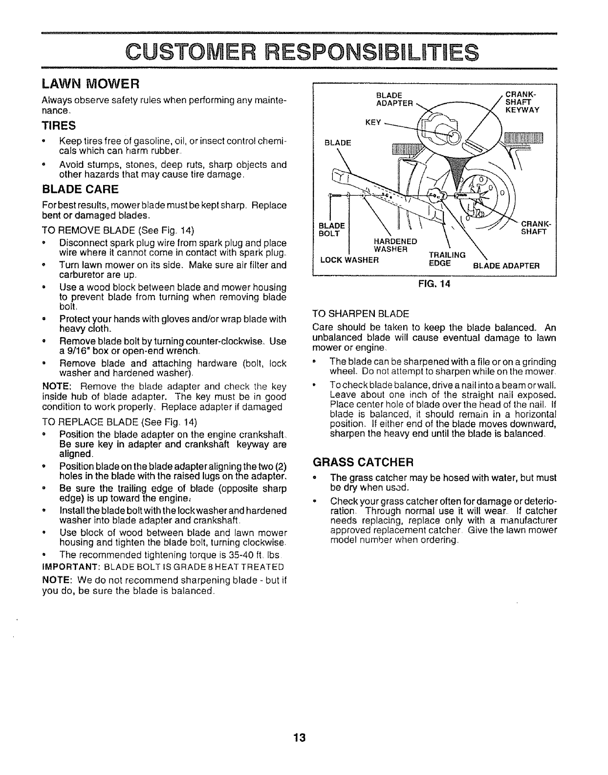
BLADE CARE
For best results, mower blade must be kept sharp, Replace
bent or damaged blades,,
TO REMOVE BLADE (See Fig., 14)
.Disconnect spark plug wire from spark plug and place
wire where it cannot come in contact with spark plug.
. Turn lawn mower on its side. Make sure air filter and
carburetor are up,
.Use a wood block between blade and mower housing
to prevent blade from turning when removing blade
bolt,
oProtect you r hands with gloves and/or wrap blade with
heavy cloth.
° Remove blade bolt by turning counter-clockwise._ Use
a 9/16 box or open-end wrench.
- Remove blade and attaching hardware (bolt, lock
washer and hardened washer).
NOTE: Remove the blade adapter and check the key
inside hub of blade adapter. The key must be in good
condition to work properly., Replace adapter if damaged
TO REPLACE BLADE (See Fig. 14)
• Position the blade adapter on the engine crankshaft,,
Be sure key in adapter and crankshaft keyway are
aligned.
.Position blade on the blade adapter aligning the two (2)
holes in the blade with the raised lugs on the adapter,
,, Be sure the trailing edge of blade (opposite sharp
edge) is up toward the engine:
° Install the blade bolt with the lock washer and hardened
washer into blade adapter and crankshaft
.Use block of wood between blade and lawn mower
housing and tighten the blade bolt, turning clockwise.
• The recommended tightening torque is 35-40 ft. [bs
IMPORTANT: BLADE BOLT IS GRADE 8 HEAT TREATED
NOTE: We do not recommend sharpening blade - but if
you do, be sure the blade is balanced.
BLADE ._ CRANK-
ADAPTER __ _ /SHAFT
_. --/_ KEYWAY
BOLT I \ "° _ ' _ "_SHAFT
I HARDENED \ \
IWAS"ERTBA,L,.G\
LOCK WASHER EDGE BLADE ADAPTER
FIG. 14
TO SHARPEN BLADE
Care should be taken to keep the blade balanced,, An
unbalanced blade will cause eventual damage to lawn
mower or engine.
°The blade can be sharpened with a file or on a grinding
wheel Do not attempt to sharpen while on the mower.
.To check blade balance, drive a nail into a beam orwalL
Leave about one inch of the straight nail exposed.
Place center hole of blade over the head of the nail. If
blade is balanced, it should remain in a horizontal
position. If either end of the blade moves downward,
sharpen the heavy end until the blade is balanced,,
GRASS CATCHER
o
a
The grass catcher may be hosed with water, but must
be dry when used.
Check your grass catcher often for damage or deterio-
ration Through normal use it will wear If catcher
needs replacing, replace only with a manufacturer
approved replacement catcher, Give the lawn mower
model number when ordering
13
CUSTOMER BIL JEG
....... iiiii, ,i,i ii ...... i,,i ,,
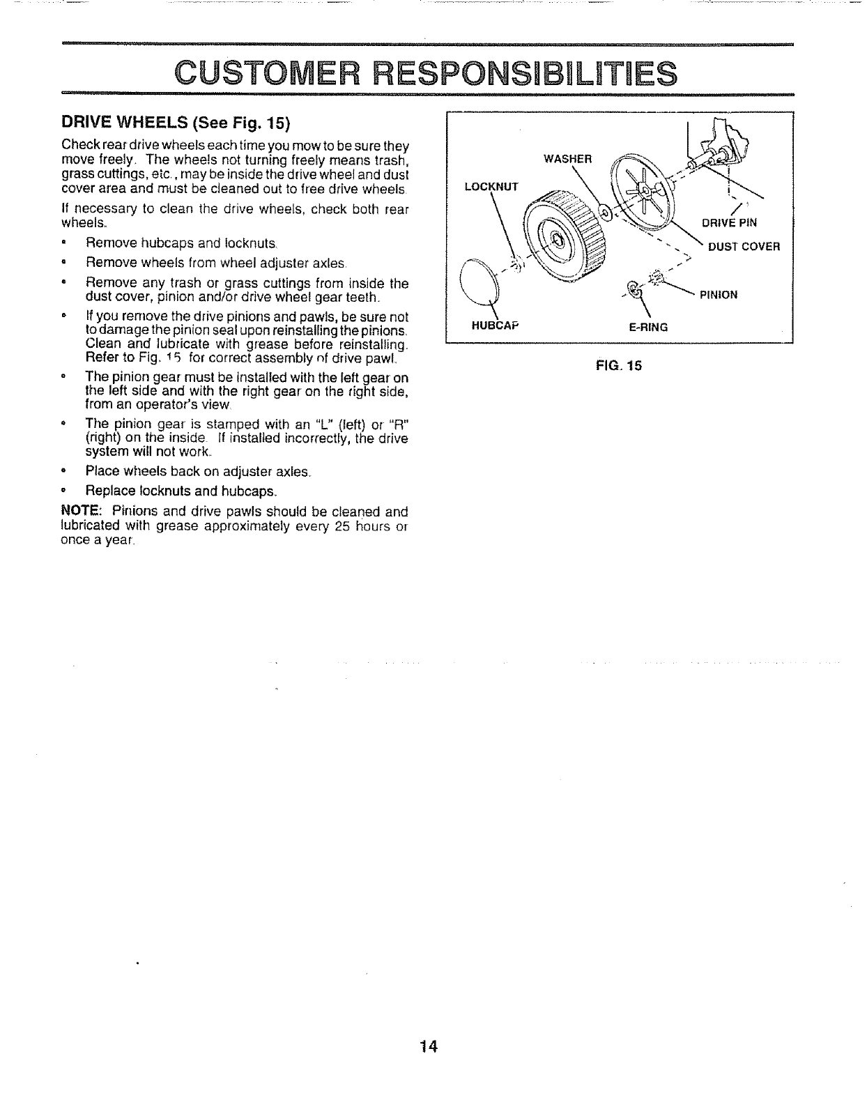
DRIVE WHEELS (See Fig. 15)
Check rear drive wheels each time you mow to be sure they
move freely. The wheels not turning freely means trash,
grass cuttings, etc, may be inside the drive wheet and dust
cover area and must be cleaned out to free drive wheels
If necessary to clean the drive wheels, check both rear
wheels.,
= Remove hubcaps and tocknuts
° Remove wheels from wheel adjuster axles.
° Remove any trash or grass cuttings from inside the
dust cover, pinion and/or drive wheel gear teeth.
, If you remove the drive pinions and pawls, be sure not
to damage the pinion seal upon reinstalling the pinions,
Clean and lubricate with grease before reinstalling.
Refer to Fig., 15 for correct assembly nf drive pawL
- The pinion gear must be installed with the left gear on
the left side and with the right gear on the right side,
from an operator's view
,, The pinion gear is stamped with an "L" (left) or "R"
(right) on the inside If installed incorrectly, the drive
system wil! not work.
oPlace wheels back on adjustei" axles.
,, Replace locknuts and hubcaps.
NOTE: Pinions and drive pawls should be cleaned and
lubricated with grease approximately every 25 t_ours or
once a year.
FIG. t5
14
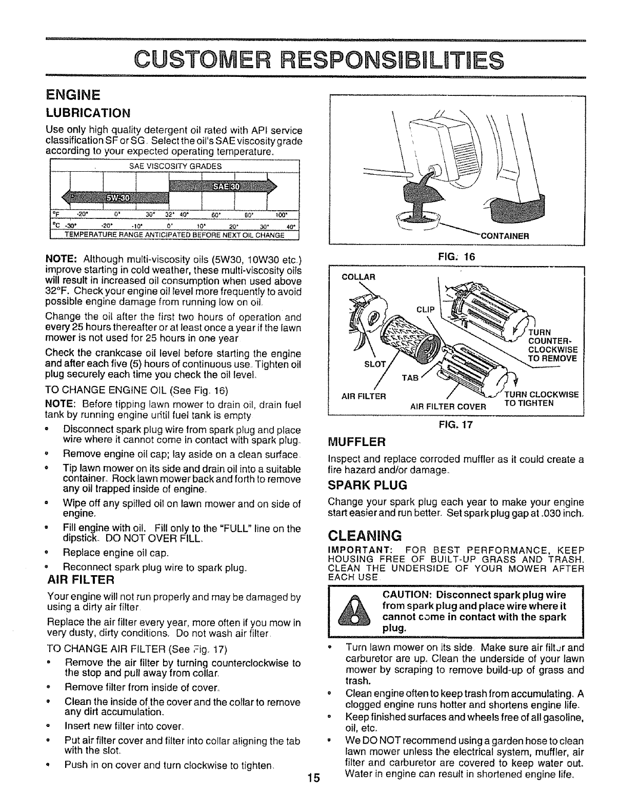
LUBRICATION
Use only high quality detergent oil rated with API service
classification SF or SG Select the oit's SAE viscosity grade
according to your expected operating temperature..
SAE VISCOSITY GRADES
"_ :_0" 0_3o" a2" 40" 60" eo" _oo'
%.3o" -20" -le' o' .... 20°30" 40"
TEMPERATURE RANG EANTfCIPATED BEFORE NEXT OiL CHANGE
NOTE: Although multi-viscosity oils (5W30, 10W30 etc)
improve starting in cold weather, these multi-viscosity oils
will result in increased oil consumption when used above
32°F. Check your engine oil level more frequently to avoid
possible engine damage from running low on oil.
Change the oil after the first two hours of operation and
every 25 hours thereafter or at least once a year if the lawn
mower is not used for 25 hours in one year
Check the crankcase oil level before starting the engine
and after each five (5) hours of continuous use..Tighten oil
plug securely each time you check the oil level
TO CHANGE ENGINE OIL (See Fig_ 16)
NOTE: Before tipping lawn mower to drain oil, drain fuel
tank by running engine ufit[] fuet tank is empty
" Disconnect spark plug wire from spark plug and place
wire where it cannot come in contact with spark plug..
• Remove engine oil cap; lay aside on a clean surface.
o Tip lawn mower on its side and drain oil into a suitable
container. Rock lawn mower back and forth to remove
any oil trapped inside of engine.
•Wipe off any spilled oil on lawn mower and on side of
engme_
,, Fill engine with oil. Fill only to the "FULL" line on the
dipstick. DO NOT OVER FILL.
oReplace engine oil cap.
• Reconnect spark plug wire to spark plug..
AIR FILTER
Your engine will not run properly and may be damaged by
using a dirty air filter
Replace the air filter every year, more often if you mow in
very dusty, dirty conditions_ Do not wash air filter
TO CHANGE AIR FILTER (See Fig_ 17)
,, Remove the air filter by turning counterclockwise to
the stop and pull away from coltar.
o Remove filter from inside of cover°
oClean the inside of the cover and the coIlar to remove
any dirt accumulation.
,, Insert new filter into cover°
oPut air filter cover and filter into collar aligning the tab
with the slot.
•Push in on cover and turn clockwise to tighten.
i
"CONTAINER i
FIG. 16
COLLAR
CLIP
15
COUNTER-
CLOCKWISE
TO REMOVE
AIR FILTER FURN CLOCKWISE
AIR FILTER COVER TO TIGHTEN
FIG, 17
MUFFLER
Inspect and replace corroded muffler as it could create a
fire hazard and/or damage.
SPARK PLUG
Change your spark plug each year to make your engine
start easier and run better. Set spark plug gap at .030 inch.
CLEANING
IMPORTANT: FOR BEST PERFORMANCE, KEEP
HOUSING FREE OF BUiLT-UP GRASS AND TRASH.
CLEAN THE UNDERSIDE OF YOUR MOWER AFTER
EACH USE
CAUTION: Disconnect spark plug wire
from spark plug and place wire where it
cannot come in contact with the spark
plug.
oTurn lawn mower on its side. Make sure air filt-r and
carburetor are upo Clean the underside of your lawn
mower by scraping to remove build-up of grass and
trash.
oClean engine often to keep trash from accumulating. A
clogged engine runs hotter and shortens engine life.
°Keep finished surfaces and wheels free of all gasoline,
oil, etco
-We DO NOT recommend using a garden hose to clean
Iawn mower unless the electrical system, muffler, air
filter and carburetor are covered to keep water out.
Water in engine can result in shortened engine lifeo
........... , , ,,,,, ,,,,,,,,,,,,, .....
$ERVmCIEAN ADJU ;TMENTS
,II,I,HI,,,III i, ii i , , ,l!ll HIIII ,ll,!l,ii i i i
i,i, ii
CAUTION: BEFORE PERFORMING ANY SERVICE OR ADJUSTMENTS: I
Release control bar and stop engine, I
=Make sure the blade and all moving parts have completely stopped.
°Disconnect spark plug wire from spark plug and place where it cannot come in contact with plug,
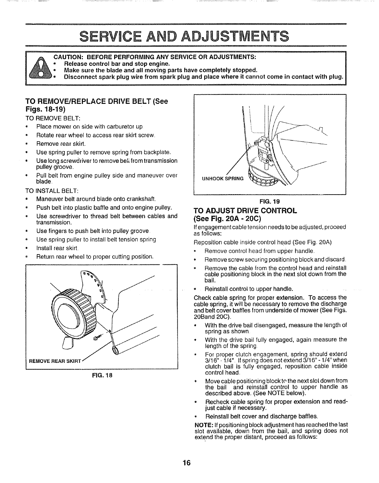
TO REMOVE/REPLACE DRIVE BELT (See
Figs. 18-19)
TO REMOVE BELT:
oPlace mower on side with carburetor up
,Rotate rear wheel to access rear skirt screw_
*Remove rear skirt.
oUse spring puller to remove spring from backplate.
oUse long screwdriver to remove be_;.from transmission
pulley groove_
oPull belt from engine pulley side and maneuver over
blade
TO INSTALL BELT:
oManeuver belt around blade onto crankshafL
oPush belt into plastic baffle and onto engine pulley.
oUse screwdriver to thread belt between cables and
transmission.
,Use fingers to push belt into putley groove
- Use spring puller to install belt tension spring
*Install rear skirt
° Return rear wheel to proper cutting position
REMOVE REAR SKtR'!
FIG. 18
UNHOOK SPRING
FIG, 19
TO ADJUST DRIVE CONTROL
(See Fig. 20A - 20C)
Ifengagement cable tension needs to be adjusted, p_oceed
as follows:
Reposition cable inside control head (See Fig. 20A)
• Remove contro! head from upper handle
= Remove screw securing positioning block and discard
. Remove the cable from the control head and reinstall
cable positioning block in the next slot down from the
bail.
= Reinstall control to upper handle.
Check cable spring for proper extension° To access the
cable spdng, it will be necessary to remove the discharge
and belt cover bafftes from underside of mower (See Figs.
20Band 20C).
° With the drive bail disengaged, measure the length of
spring as shown
oWith the drive bail folly engaged, again measure the
length of the spring
= For proper clutch engagement, spring should extend
3/16"- 1/4" If spring does not extend 3/I6"- t/4" when
clutch bail is fulty engaged, reposition cable inside
control head
° Move cable positioning block tr, the next slot down from
the bail and reinstall control to upper handle as
described above. (See NOTE below)°
= Recheck cable spring for proper extension and read-
just cable if necessary.
-Reinstall belt cover and discharge baffles,
NOTE: If positioning block adjustment has reached the last
slot available, down from the bail, and spring does not
extend the proper distant, proceed as follows:
16
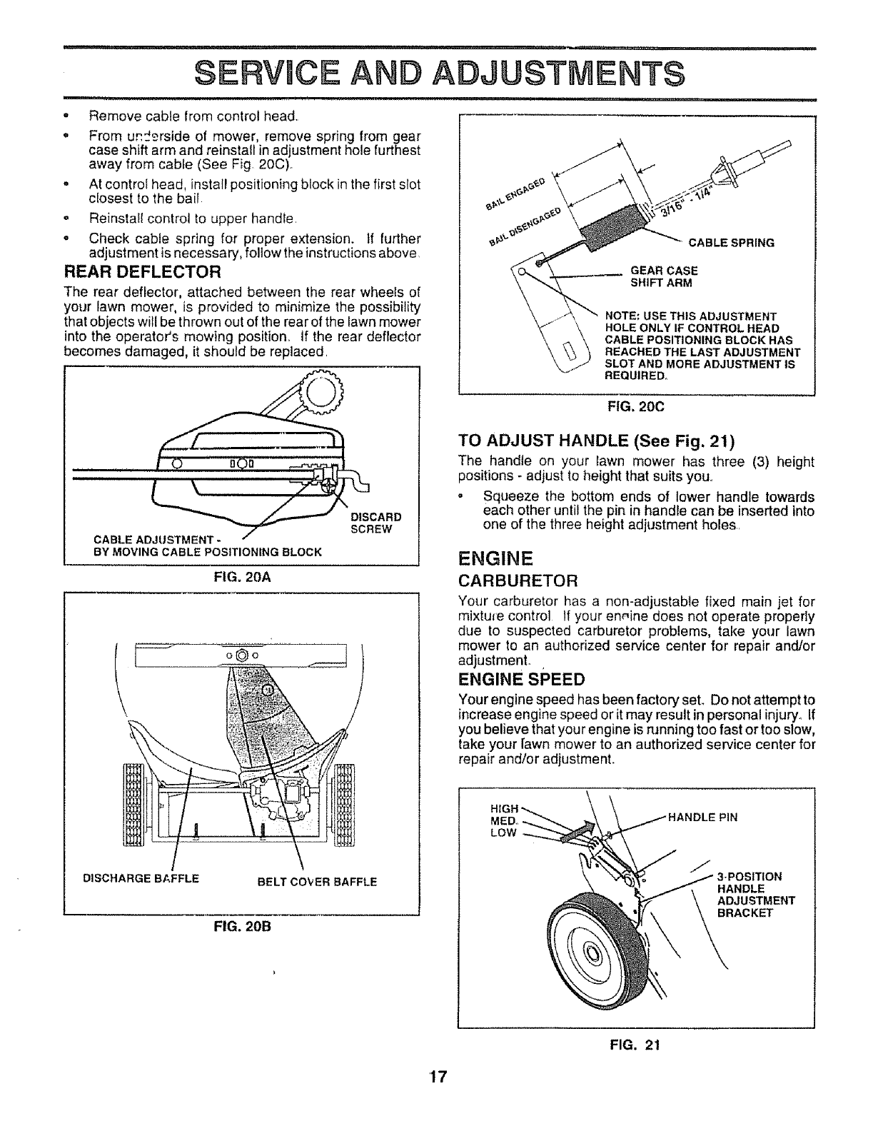
,Remove cable from control head.
,' From u_£rside of mower, remove spring from gear
case shift arm and reinstall inadjustment hole furthest
away from cabfe (See Fig 20C).
° At controt head, install positioning block inthe first slot
c{osest to the bait
= Reinstall control to upper handle.
o Check cable spring for proper extension, tf further
adjustment is necessary, follow the instructions above
REAR DEFLECTOR
The rear deflector, attached between the rear wheels of
your lawn mower, is provided to minimize the possibility
that objects will be thrown out of the rear of the lawn mower
into the operator's mowing position. If the rear deflector
becomes damaged, it should be replaced.
BY MOVING CABLE POSITIONING BLOCK
FIG. 20A
CABLE SPRING
GEAR CASE
SHIFT ARM
NOTE: USE THIS ADJUSTMENT
HOLE ONLY IF CONTROL HEAD
CABLE POSITIONING BLOCK HAS
REACHED THE LAST ADJUSTMENT
SLOT AND MORE ADJUSTMENT IS
REQUIRED°
FIG. 20C
DISCHARGE BAFFLE BELT COVER BAFFLE
FIG. 20B
TO ADJUST HANDLE (See Fig, 21)
The handle on your lawn mower has three (3) height
positions - adjust to height that suits your
o Squeeze the bottom ends of lower handle towards
each other until the pin in handle can be inserted into
one of the three height adjustment holes.
ENGINE
CARBURETOR
Your carburetor has a non-adjustable fixed main jet for
mixture control If your ermine does not operate properly
due to suspected carburetor problems, take your lawn
mower to an authorized service center for repair and/or
adjustmenL .
ENGINE SPEED
Your engine speed has been factory seL Do not attempt to
increase engine speed or it may result in personal injury_ If
you believe that your engine is running too fast or too s!ow,
take your lawn mower to an authorized service center for
repair and/or adjustment.
MED,.
LOW
PIN
HANDLE
ADJUSTMENT
BRACKET
FIG. 21
'17
,u,, i, .l=U................ u ...._........
STORAGE
i_ =,u= n ..........................
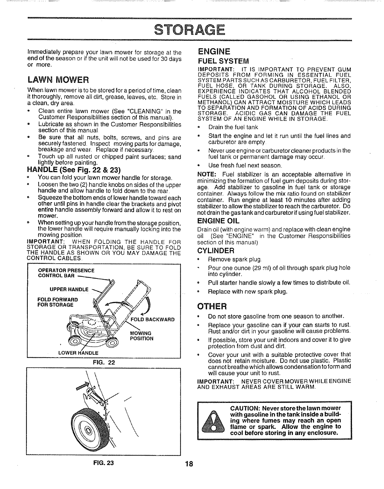
Immediately prepare your lawn mower for storage at the
end of the season or if the unit will not be used for 30 days
or more.
LAWN MOWER
When lawn mower is to be stored for a period of time, clean
it thoroughly, remove all dirt, grease, leaves, etc_ Store in
a clean, dry area.
• Clean entire lawn mower (See "CLEANING" in the
Customer Responsibilities section of this manual)_
, Lubricate as shown in the Customer Responsibilities
section of this manual
oBe sure that all nuts, bolts, screws, and pins are
securely fastened Inspect moving parts for damage,
breakage and wear. Replace if necessary.
o Touch up all rusted or chipped paint surfaces; sand
lightly before painting.
HANDLE (See Fig. 22 & 23)
" You can fold your Iawn mower handle for storage.
oLoosen the two (2) handle knobs on sides of the upper
handle and allow handle to fold down to the rear.
" Squeeze the bottom ends of tower handle toward each
other until pins in handle clear the brackets and pivot
entire handle assembly forward and allow it to rest on
mower'.
o When setting up your handle from the storage position,
the lower handle will require manually locking into the
mowing position
IMPORTANT: WHEN FOLDING THE HANDLE FOR
STORAGE OR TRANSPORTATION, BE SURE TO FOLD
THE HANDLE AS SHOWN OR YOU MAY DAMAGE THE
CONTROL CABLES,
OPERATOR PRESENCE
CONTROLBAR
UPPER HANDLE
FOLD FORWARD
FOR STORAGE
FOLD BACKWARD
MOWING
POSITION
LOWER HANDLE
FIG. 22
J
ENGINE
FUEL SYSTEM
IMPORTANT: IT IS IMPORTANT TO PREVENT GUM
DEPOSITS FROM FORMING iN ESSENTIAL FUEL
SYSTEM PARTS SUCH AS CARBURETOR, FUEL FILTER,
FUEL HOSE, OR TANK DURING STORAGE. ALSO,
EXPERIENCE INDICATES THAT ALCOHOL BLENDED
FUELS (CALLED GASOHOL OR USING ETHANOL OR
METHANOL) CAN ATTRACT MOISTURE WHICH LEADS
TO SEPARATION AND FORMATION OF ACIDS DURING
STORAGE. ACIDIC GAS CAN DAMAGE THE FUEL
SYSTEM OF AN ENGINE WHILE IN STORAGE
o Drain the fuel tank
° Start the engine and let it run until the fuel lines and
carburetor are empty
• Never use engine or isarburetor cleaner products in the
fuel tank or permanent damage may occur.
,, Use fresh fuel next season.
NOTE: Fuel stabilizer is an acceptable alternative in
minimizing the formation of fuel gum deposits during stor-
age. Add stabilizer to gasoline in fuel tank or storage
containerr. Always foltow the mix ratio found on stabilizer
container. Run engine at least 10 minutes after adding
stabilizer to allow the stabilizer to reach the carburetor. Do
not drain the gas tank and carburetor if using fuel stabilizero
ENGINE OIL
Drain oil (with engine warm) and replace with clean engine
oil (See "ENGINE" in the Customer Responsibilities
section of this manual)
CYLINDER
,Remove spark plug
Pour one ounce (29 ml) of oil through spark plug hole
into cylinder.
,, Pull starter handle slowly a few times to distribute oil
,, Replace with new spark plug.
OTHER
• Do not store gasoline from one season to another.
-Replace your gasoline can if your can starts to rusL
Rust and/or dirt in your gasoline will cause problems.
=If possible, store your unit indoors and cover it to give
protection from dust and dirt.
,, Cover your unit with a suitable protective cover that
does not retain moisture. Do not use plastic. Plastic
cannot breathe which allows condensation to form and
witl cause your unit to rust.
IMPORTANT: NEVER COVER MOWER WHILE ENGINE
AND EXHAUST AREAS ARE STILL WARM.
CAUTION: Never storethe lawn mower
with gasoline in the tank inside a build-
ing where fumes may reach an open
flame or spark. Allow the engine to
cool before storing in any enclosure.
FIG. 23 18
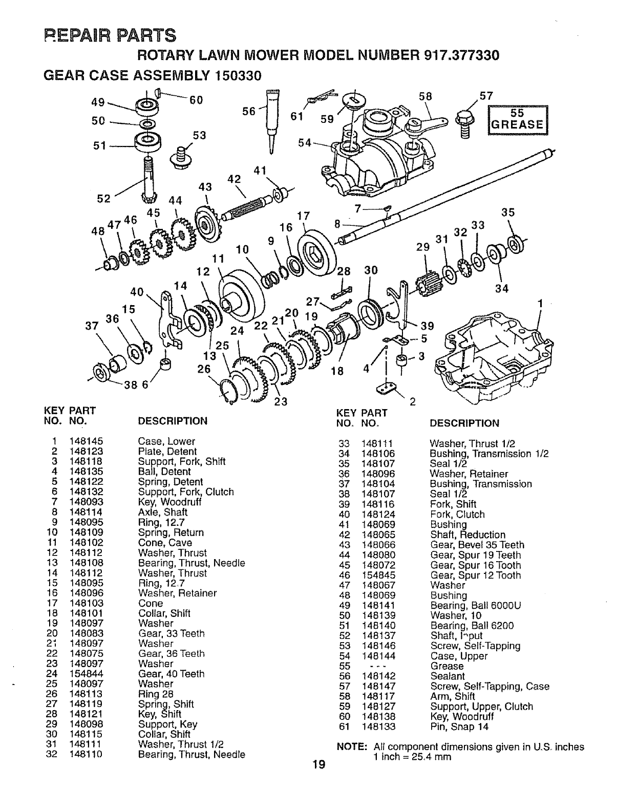
R =PAaR PARTS
ROTARY LAWN MOWER MODEL NUMBER 917.377330
GEAR CASE ASSEMBLY 150330
S
52
45
48 4'
40
"_ 60 56_
53
_(_ 41
42
43 \
44 \
11
12
14
9
10
16
15
37\25
13
26
-38 6
23
KEY PART
NO. NO. DESCRIPTION
17 35
8 33
29 3'
18
KEY
NOo
30
34
1
PART
NO. DESCRIPTION
1 148145 Case, Lower
2148123 Plate, Detent
3 148118 Support, Fork, Shift
4 148135 Ball, Detent
5 148122 Spdng, Detent
6 148132 Support, Fork, Clutch
7 148093 Key, Woodruff
8 148114 Axle, Shaft
9 148095 Ring, 12.7
10 148109 Spring, Return
11 148102 Cone, Cave
12 148! 12 Washer, Thrust
13 148108 Bearing, Thrust, Needle
14 148112 Washer, Thrust
15 148095 Ring, 12.7
16 148096 Washer, Retainer
17 148103 Cone
18 148101 Collar, Shift
19 148097 Washer
20 148083 Gear, 33Teeth
2_; 148097 Washer
22 !48075 Gear, 36 Teeth
23 148097 Washer
24 154844 Gear, 40 Teeth
25 148097 Washer
26 148113 Ring 28
27 148119 Spring, Shift
28 148121 Key, Shift
29 148098 Support, Key
30 148115 Collar, Shift
31 148111 Washer, Thrust I/2
32 148110 Bearing, Thrust, Needle 19
33 148111 Washer, Thrust 1/2
34 148106 Bushing, Transmission 1/2
35 148107 Seal 1/2
36 148096 Washer, Retainer
37 148104 Bushing, Transmission
38 148107 Seal 112
39 148116 Fork, Shift
40 148124 Fork, Clutch
4t 148069 Bushing
42 148065 Shaft, Reduction
43 148066 Gear, Bevel 35 Teeth
44 148080 Gear, Spur 19 Teeth
45 148072 Gear, Spur 16Tooth
46 154845 Gear, Spur 12 Tooth
47 148067 Washer
48 148069 Bushing
49 148141 Bearing, Balt6000U
50 148139 Washer, 10
51 148140 Bearing, Ball 6200
52 148137 Shaft, I'_put
53 148146 Screw, Self-Tapping
54 148144 Case, Upper
55 - _- Grease
56 148142 Sealant
57 148147 Screw, Self-Tapping, Case
58 148117 Arm, Shift
59 148127 Support, Upper, Clutch
60 148138 Key, Woodruff
61 148133 Pin, Snap 14
NOTE: All component dimensions given in U.S. inches
1inch = 25.A mm
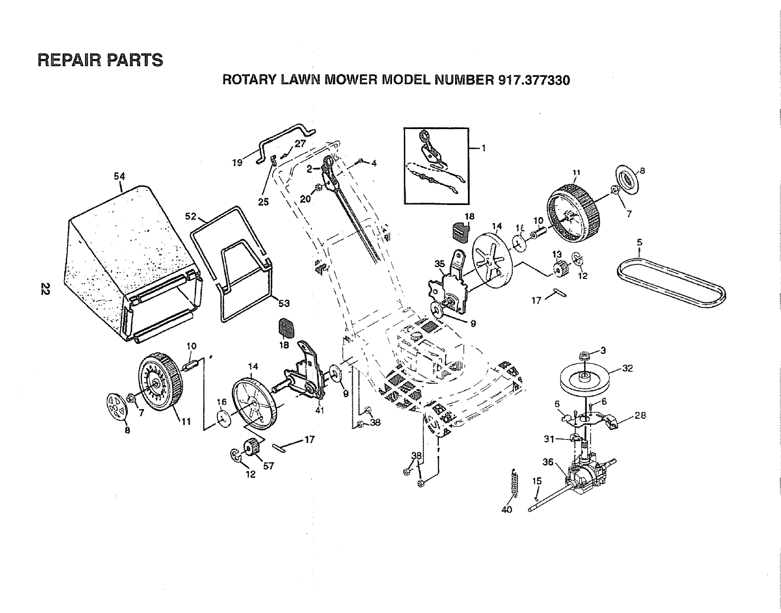
REPARR PARTS
ROTARY LAWN MOWER MODEL NUMBER 917.377330
ro
o
2
56
i 56 4
23
27
24
26
58
65
24
65
57
26
30
36
34
47
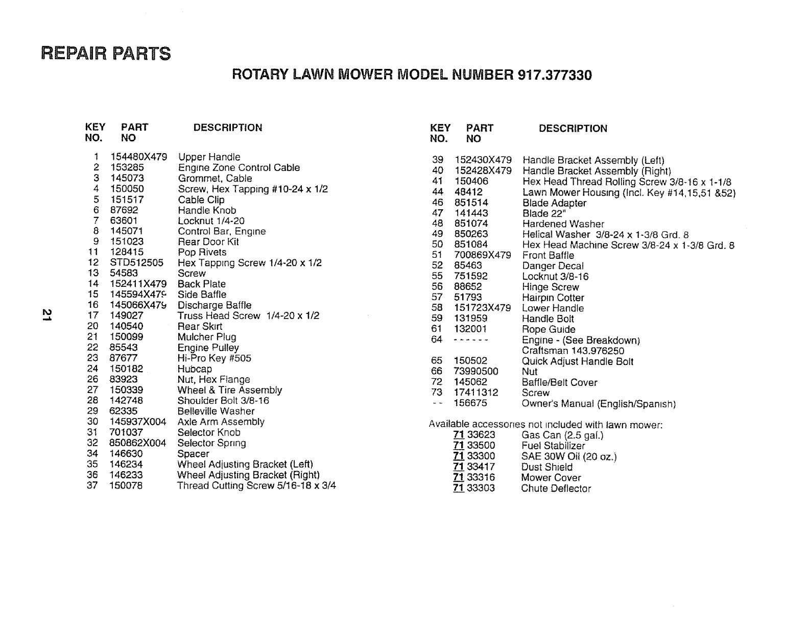
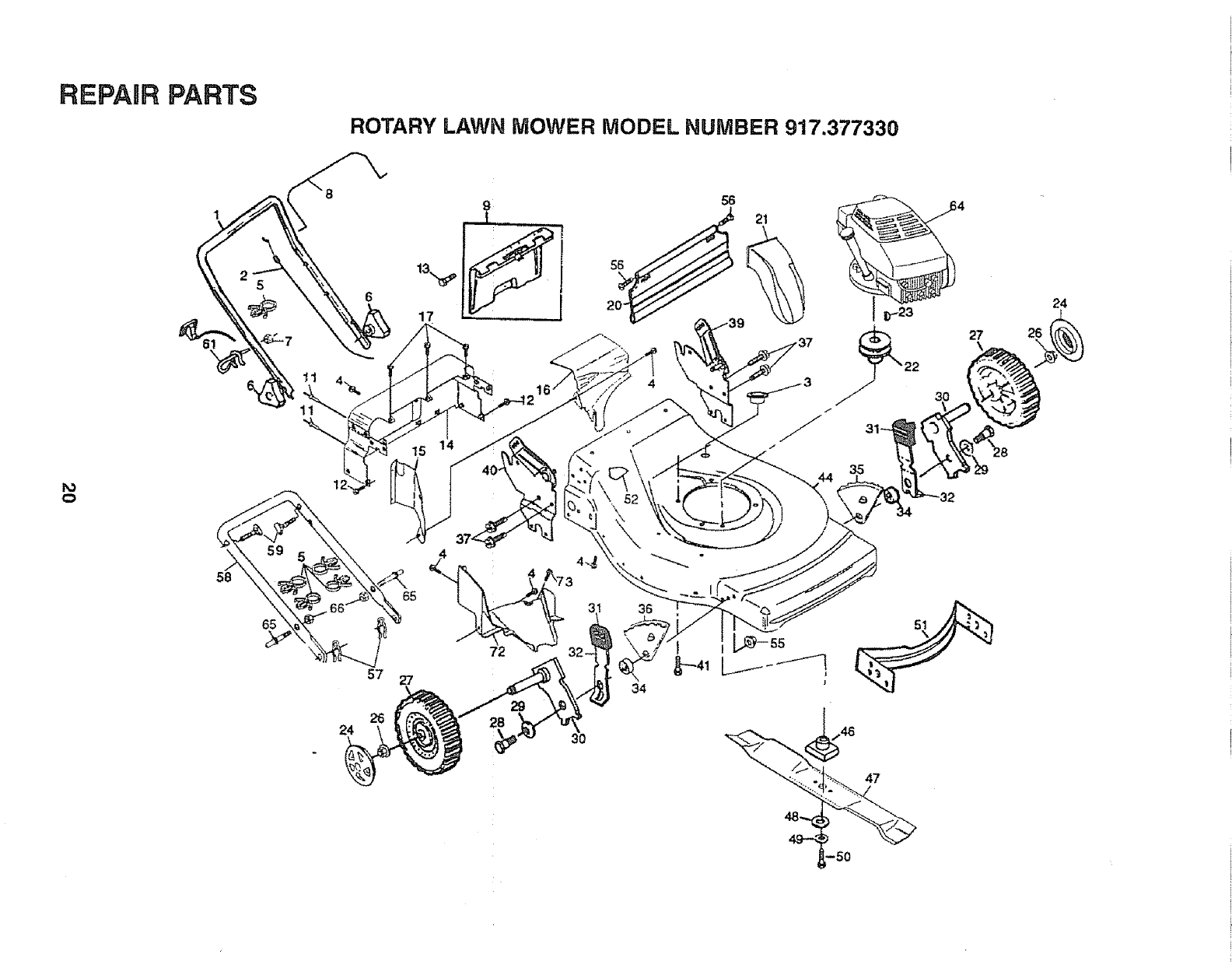
REPAIR PARTS
ROTARY LAWN MOWER MODEL NUMBER 917.377330
ro
KEY PART
NO. NO
1 154480X479
2 153285
3 145073
4 150050
5 151517
6 87692
7 63601
8 145071
9 151023
11 128415
12 STD512505
13 54583
14 152411X479
15 145594X47_
16 145066X47_
17 149027
20 140540
21 150099
22 85543
23 87677
24 150182
26 83923
27 150339
28 142748
29 62335
30 !45937X004
31 701037
32 850862X004
34 146630
35 146234
36 146233
37 150078
DESCRIPTION
Upper Handle
Engine Zone Control Cable
Grommet, Cable
Screw, Hex Tapping #10-24 x 1/2
Cable Clip
Handfe Knob
Locknut 1/4-20
Control Bar, Engine
Rear Door Kit
Pop Rivets
Hex Tapp=ng Screw 1/4-20 x 1/2
Screw
Back Plate
Side Baffle
Discharge Baffle
Truss Head Screw 1/4-20 x 1/2
Rear Skirt
Mulcher Plug
Engine Pulley
Hi-Pro Key #505
Hubcap
Nut, Hex F_ange
Wheel & Tire Assembiy
Shoulder Bolt 3/8-16
Belleviile Washer
Axle Arm Assembly
Selector Knob
Selector Spring
Spacer
Wheel Adiusting Bracket (Left)
Wheel Adjusting Bracket (Right)
Thread Cutting Screw 5/t6-18 x 3/4
KEY PART DESCRIPTION
NO. NO
39 t52430X479
40 152428X479
41 150406
44 48412
46 851514
47 141443
48 851074
49 850263
50 851084
51 700869X479
52 85463
55 751592
56 88652
57 51793
58 151723X479
59 131959
61 132001
64 ......
65 150502
66 73990500
72 145062
73 17411312
-- 156675
Handle Bracket Assembly (Left)
Handle Bracket Assembly (Right)
Hex Head Thread Rolling Screw 3/8-16 x 1-1/8
Lawn Mower Housing (ind. Key #14,15,5t &52)
Blade Adapter
Blade 22"
Hardened Washer
Helical Washer 3/8-24 x 1-3/8 Grd. 8
Hex Head Machine Screw 3/8-24 x 1_3/8 Grd. 8
Front Baffle
Danger Decal
Locknut 3/8_16
Hinge Screw
Hairpin Cotter
Lower Handle
Handle Bolt
Rope Guide
Engine - (See Breakdown)
Craftsman t43.976250
Quick Adjust Handle Bolt
Nut
Baffle/Belt Cover
Screw
Owner's Manual (English/Spanish)
Available accessones not included with lawn mower:
7_!133623 Gas Can (2.5 gal.)
7"133500 Fuel Stabilizer
7_1133300 SAE 30W Oil (20 oz.}
7"133417 Dust Shield
71 33316 Mower Cover
7"133303 Chute Deflector
REPAIR PARTS
ROTARY LAWN MOWER MODEL NUMBER 917.377330
I'o
54
!4
12
\
\\ \\ 18
35
!
I0 7
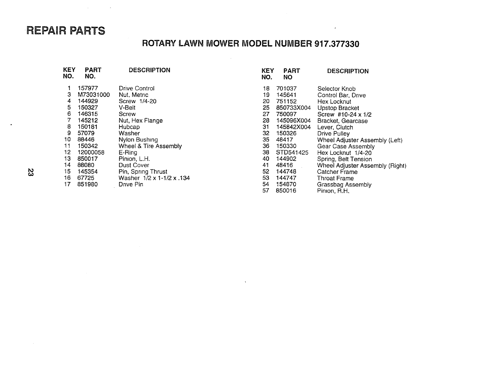
-REPAgR PARTS
ROTARY LAWN MOWER MODEL NUMBER 917.377330
KEY PART
NO. NO.
1 157977
3 M73031000
4 144929
5 150327
6 146315
7 145212
8 150181
9 57079
10 88446
11 150342
12 12000058
13 850017
14 88080
15 145354
16 67725
17 851980
DESCRIPTION KEY PART DESCRIPTION
NO. NO
Drive Control 18 701037
Nut, Metric 19 145641
Screw 1/4-20 20 751152
V-Belt 25 850733X004
Screw 27 750097
Nut, Hex Flange 28 145096X004
Hubcap 31 145842X004
Washer 32 150326
Nylon Bushing 35 48417
Wheel & Tire Assembly 36 150330
E-Ring 38 STD541425
Pinion, L.H. 40 144902
Dust Cover 41 48416
Pin, Spring Thrust 52 144748
Washer 1/2 x 1-1/2 x .134 53 144747
Drive Pin 54 154870
57 8500t6
Selector Knob
Control Bar, Drwe
Hex Locknut
Upstep Bracket
Screw #10-24 x 1/2
Bracket, Gearcase
Lever. Ciutch
Drive Pulley
Wheel Adiuster Assembly (Left)
Gear Case Assembly
Hex Locknut 1t4-20
Spring, Belt Tension
Wheel Adjuster Assembiy (Right)
Catcher Frame
Throat Frame
Grassbag Assembly
Pinion, R.H,
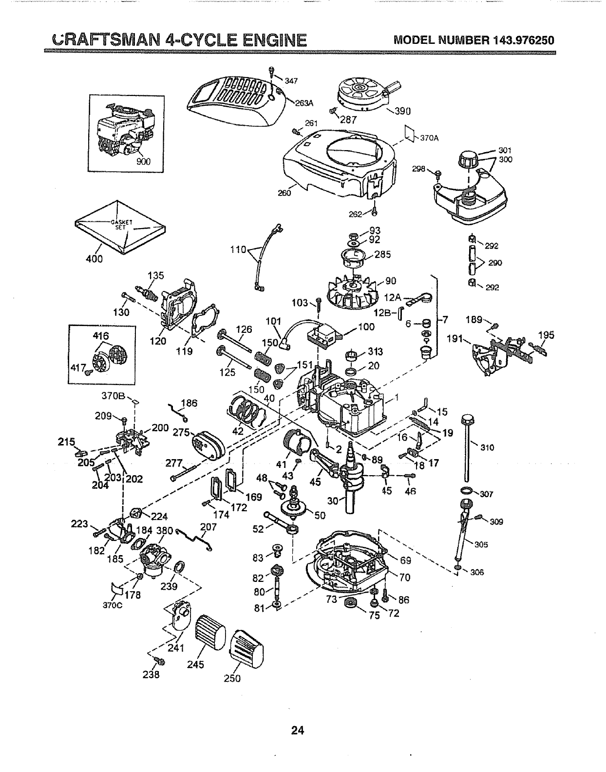
_RAFTSMAN 4=CYCLE ENGWNE MODELNUMBER143.976250
90O
400
I
I
I
I
_3
182 185
3700
120 119
261
11o
!
125
.-93
2
285
¢5 46
69 "%
301
3O0
_"305
_" 306
24
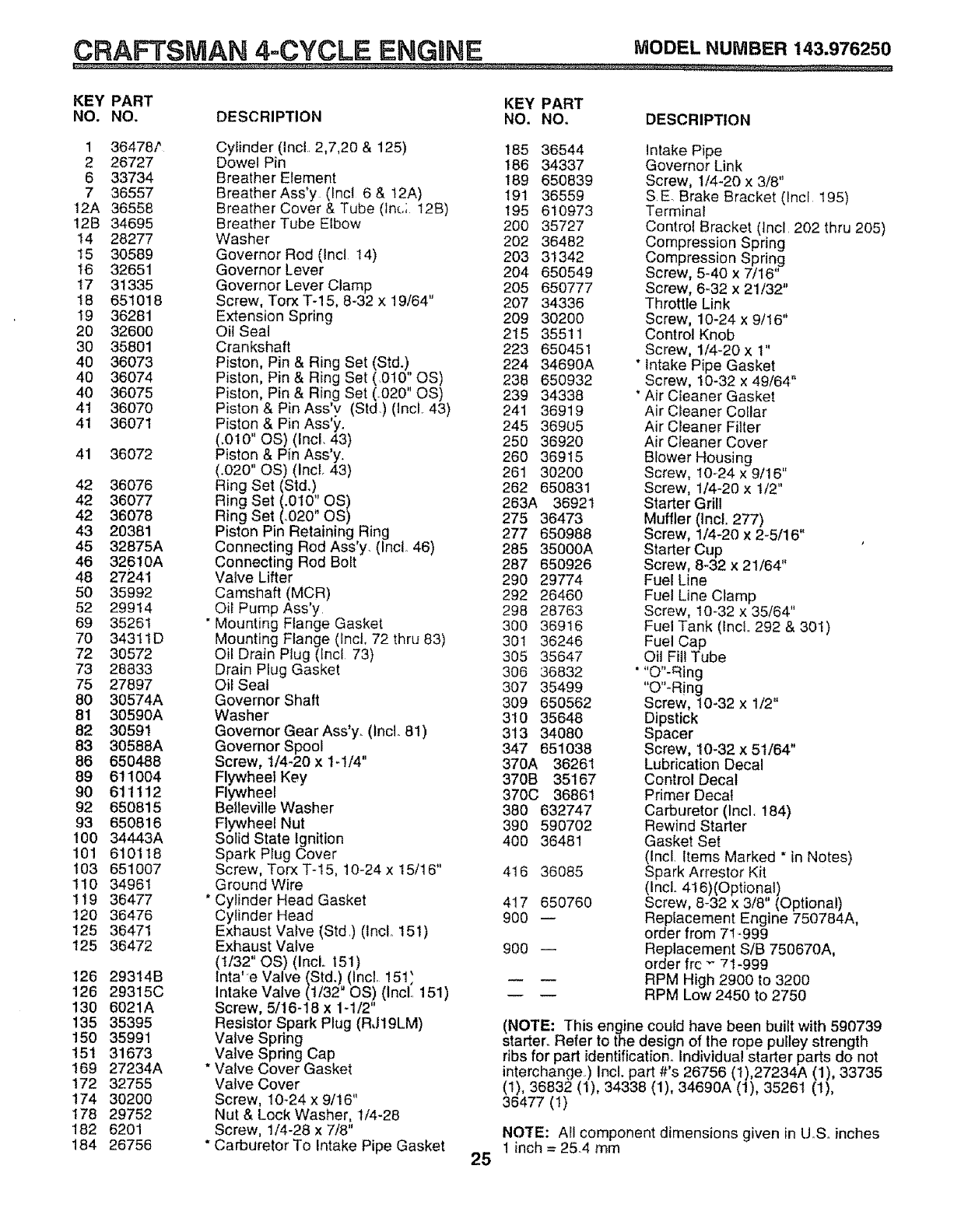
CRAFTSMAN 4=CYCLE ENGaNE MODELNUMBER143.976250
KEY PART KEY PART
NO. NO. DESCRIPTION NO. NO, DESCRIPTION
1 36478?
2 26727
6 33734
7 36557
12A 36558
12B 34695
14 28277
t5 30589
16 32651
17 31335
!8 651018
19 36281
20 32600
30 35801
40 36073
40 36074
40 36075
41 36070
41 36071
41 36072
42 36076
42 36077
42 36078
43 20381
45 32875A
46 32610A
48 27241
50 35992
52 29914
69 35261
70 34311D
72 30572
73 28833
75 27897
80 30574A
81 30590A
82 30591
83 30588A
86 650488
89 611004
90 611112
92 650815
93 650816
100 34443A
101 610118
103 651007
110 34961
119 36477
120 36476
125 36471
125 36472
126 29314B
126 29315C
130 6021A
135 35395
150 35991
15! 31673
169 27234A
172 32755
174 30200
178 29752
182 6201
184 26756
Cylinder (IncL 2,7,20 & 125)
Dowel Pin
Breather Element
Breather Ass'y (Incl 6 & 12A)
Breather Cover & Tube (lnc; 12B)
Breather Tube Elbow
Washer
Governor Rod (Incl 14)
Governor Lever
Governor Lever Clamp
Screw, Torx T-15, 8-32 x 19/64"
Extension Spring
Oil Seal
Crankshaft
Piston, Pin & Ring Set (Std.)
Piston, Pin & Ring Set (.010" OS)
Piston, Pin & Ring Set (-020" OS)
Piston & Pin Ass'v (Std) (lncl. 43)
Piston & Pin Ass'y.
(.0t0" OS) (Incl. 43)
Piston & Pin Ass'y.
(.020" OS) (Incl. 43)
Ring Set (Std.)
Ring Set (.010" OS)
Ring Set (.020" OS)
Piston Pin Retaining Ring
Connecting Rod Ass'y. (Incl. 46)
Connecting Rod Bolt
Valve Lifter
Camshaft (MCR)
Oil Pump Ass'y
" Mounting Flange Gasket
Mounting Flange (lncl, 72 thru 83)
Oil Drain Plug (lncl 73)
Drain Plug Gasket
Oil Seal
Governor Shaft
Washer
Governor Gear Ass'y. (Incl. 81)
Governor Spool
Screw, 1/4-20 x 1-!/4"
Flywheel Key
Flywheel
Belleville Washer
Flywheel Nut
Solid State Ignition
Spark Plug Cover
Screw, Torx T-15, 10-24 x 15/16"
Ground Wire
* Cylinder Head Gasket
Cylinder Head
Exhaust Valve (Std) (incl.. 151)
Exhaust Valve
(t/32" OS) (Incl.. 151)
lnta' e Valve (Std.) (Incl. !51}
Intake Valve (1/32" OS) (Inct, 151)
Screw, 5/16-18 x 1-1/2"
Resistor Spark Plug (RJ19LM)
Valve Spring
Valve Spring Cap
*Valve Cover Gasket
Valve Cover
Screw, 10-24 x 9/16"
Nut & Lock Washer, 1/4-28
Screw, 1/4-28 x 7/8"
* Carburetor To Intake Pipe Gasket 25
185 36544 Intake Pipe
186 34337 Governor Link
189 650839 Screw, 1/4-20 x 3/8"
19t 36559 S.E Brake Bracket (lncl 195)
195 610973 Terminal
200 35727 Control Bracket (Incl 202 thru 205)
202 36482 Compression Spring
203 31342 Compression Spring
204 650549 Screw, 5-40 x 7/16"
205 650777 Screw, 6_32 x 21/32"
207 34336 Throttle Link
209 30200 Screw, 10-24 x 9/16"
215 3551! Control Knob
223 650451 Screw, 1/4-20 x 1"
224 34690A *Intake Pipe Gasket
238 650932 Screw, 10-32 x 49/64"
239 34338 "Air Cleaner Gasket
241 36919 Air Cleaner Collar
245 36905 Air Cleaner Filter
250 36920 Air Cleaner Cover
260 36915 Blower Housing
261 30200 Screw, 10-24 x 9/16"
262 650831 Screw, t/4-20 x 1/2"
263A 36921 Starter Grill
275 36473 Muffler (Incl. 277)
277 650988 Screw, 1/4-20 x 2-5/16"
285 35000A Starter Cup
287 650926 Screw, 8-32 x 21/64"
290 29774 Fuel Line
292 26460 Fuel Line Clamp
298 28763 Screw, 10-32 x 35/64"
300 36916 Fuel Tank (IncL 292 & 301)
301 36246 Fuel Cap
305 35647 Oil Fill Tube
306 36832 * "O"-Ring
307 35499 "O"-R!ng
309 650562 Screw, 10-32 x t/2"
310 35648 Dipstick
313 34080 Spacer
347 651038 Screw, 10-32 x 51/64"
370A 36261 Lubrication Decal
370B 35167 Control Decal
370C 36861 Primer Decal
380 632747 Carburetor (Incl. t84)
390 590702 Rewind Starter
400 36481 Gasket Set
(Incl Items Marked *in Notes)
416 36085 Spark Arrestor Kit
(Incl.. 4I 6)(Optional)
417 650760 Screw, 8-32 x 3/8" (Optional)
900 -- Replacement Engine 750784A,
order from 7! -999
900 -- Replacement S/B 750670A,
order frc "- 71-999
RPM High 2900 to 3200
RPM Low 2450 to 2750
(NOTE: This engine could have been built with 590739
starter.. Refer to the design of the rope pulley strength
ribs for part identification,1 Individual starter parts do not
interchange.) Incl. part #'s 26756 (1),27234A (1), 33735
(1), 36832 (1), 34338 (1), 34690A (1), 35261 (1),
36477 (1)
NOTE: All component dimensions given in UoSoinches
t inch = 25_4 mm
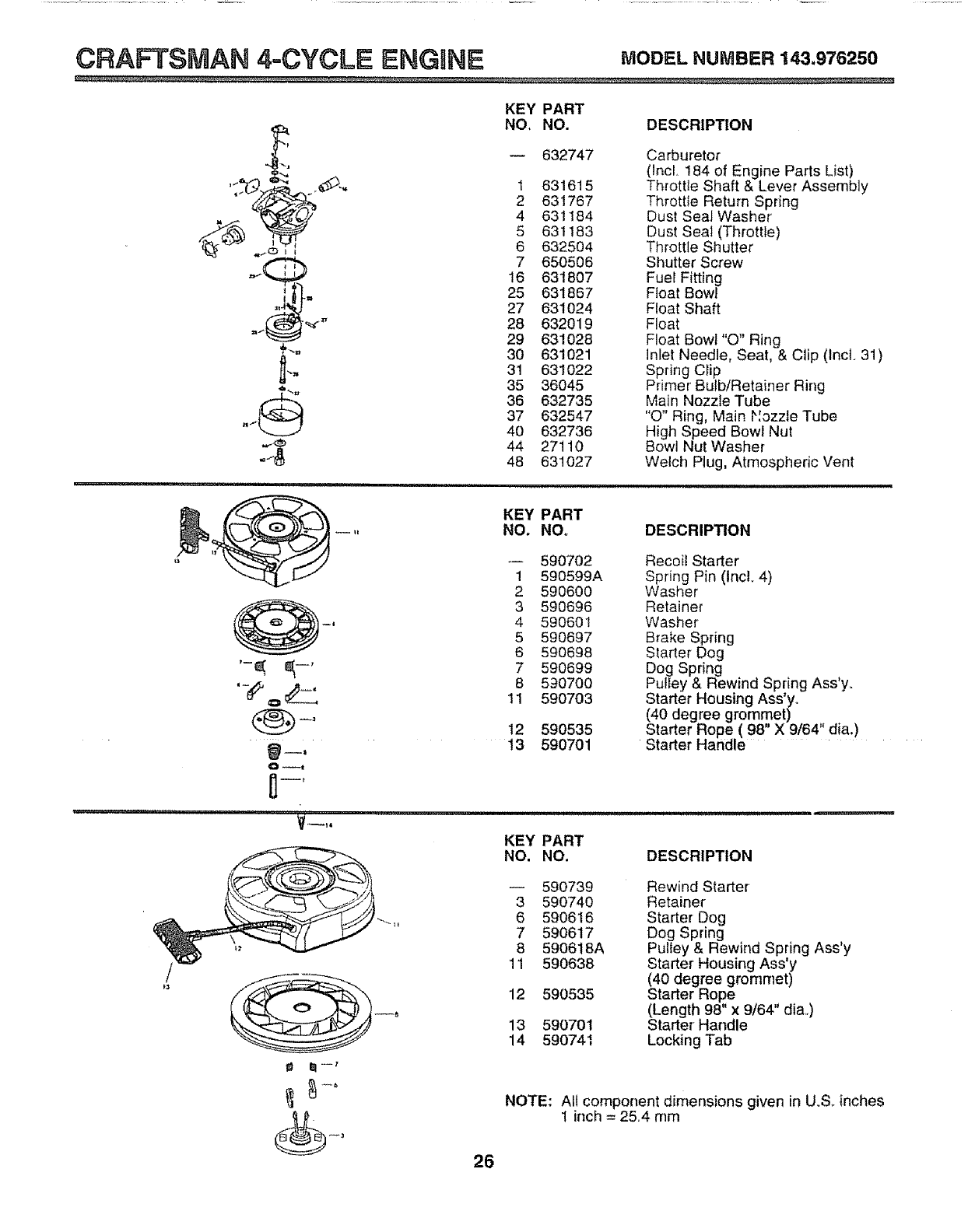
CRAFTSMAN 4.=CYCLE ENGaNF= MODELNUMBER143.976250
KEY PART
NO, NO. DESCRIPTION
632747
_j
1 631615
_ 2 631767
_._o-_ 4 631184
5 631183
6 632504
_ =j__ 7 650506
16 631807
25 631867
27 631024
" 28 632019
29 631028
'" 30 631021
.,, 3! 631022
35 36045
_'"" 36 632735
..._ 37 632547
40 632736
"-_ 44 27110
""_ 48 631027
Carburetor
(lncl, 184 of Engine Parts List)
Thfottle Shaft & Lever Assembly
Throttle Return Spring
Dust Seal Washer
Dust Seal (Throttle)
Throttle Shutter
Shutter Screw
Fuel Fitting
Float Bowl
Float Shaft
Float
Float Bowl "O" Ring
Inlet Needle, Seat, & Clip (tncl. 31)
Spring C_ip
Primer Bulb/Retainer Ring
Main Nozzle Tube
"O" Ring, Main Hozzle Tube
High Speed Bowl Nut
Bowl Nut Washer
Welch Plug, Atmospheric Vent
'-e; e,-,
=N'H' '= 'U"= U'= '' I
KEY PART
NO. NOo DESCRIPTION
590702 Recoil Starter
1 590599A Spring Pin (IncL 4)
2 590600 Washer'
3 590696 Retainer
4 590601 Washer
5 590697 Brake Spring
6 590698 Starter Dog
7 590699 Dog Spring
8 590700 Pulfey& Rewind Spring Ass'y.
11 590703 Starter Housing Ass'y.
(40 degree grommet)
12 590535 Starter Rope ( 98" X 9/64" dia.)
13 590701 Starter Handle
KEY PART
NO. NO. DESCRIPTION
I_ -_
-- 590739 Rewind Starter
3 590740 Retainer
6 590616 Starter Dog
7 590617 Dog Spring
8 590618A Pulley & Rewind Spring Ass'y
11 590638 Starter Housing Ass'y
(40 degree grommet)
12 590535 Starter Rope
(Length 98" x 9/64" dia,,)
13 590701 Starter' Handle
14 590741 Locking Tab
NOTE: All component dimensions given in Uo& inches
1 inch =25,4 mm
26
_" '"" ,, ,,,,,Hnl,,n = ,,,i,,=,,r,i......... i i i
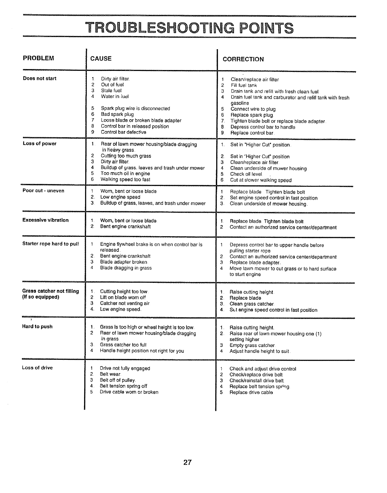
TROUBLESHOOTBNG POUNTS
mu, n, i ,,1,1111....................... 11 , , , = m, nn
PROBLEM
Does not start
,,,p,,=
Loss of power
,q,
Poor out - uneven
,"' i,,,,i,,,, =
Excessive vibration
..... H="HH"="='
Starter rope hard to pull
Grass catcher not filling
(If so equipped)
}
Hard to push
Loss of drive
CAUSE
1 Dirty air filter
2 Out of fuel
3 State fueI
4Water in iuel
5 Spark plug wire is disconnected
6 Bad spark plug
7Loose blade or broken blade adapter
8 Control bar in released position
9 Controf bardefect!ve
=,,,,,H,, u,, 1,1 u
1 Rear of lawn mower housing/blade dragging
in he#,vy grass
2 Cutting too much grass
3 Dirty air filter.
4 Bu{Idup of grass, teaves and trash under mower
5 Too much oil in engine
6 Walking speed 1oo fast
1 Worn, bent or loose blade
2. Low engine speed
3Buildup of grass, leaves, and trash under mower
1Worn, bent or Ioose blade
2 Bent engine crankshaft
1 Engine fEywheel brake is on when control bar is
re_eased
2 Bent engine crankshaft
3 Blade adapter broken
4 Blade dragging in grass
1 Cutting height too low
2 Lift on blade wom off
3Catcher not venting air
4. Low engine speed.
1. Grass is too high or wheel height is too low.
2 Rear of lawn mower housingfalade dragging
in grass
3 Grass catcher too full
4 Handle height position not right for you
1 Drive not fully engaged
2 Bert wear
3 Belt off of pulley.
4 Belt tension spring off
5 Drive cable worn or broken
2
3
4
5
6
1
2
3
1
2
CORRECTION
1 Clean/replace air filter
2 FiII fuel tank
3 Drain lank and refill with fresh clean fuel
4 Drain fuel tank and carburetor and refill tank with fresh
gasoline
5 Connect wire to plug
6 Reptace spark plug
7 Tighten blade boil or replace blade adapter
8 Depress control bar to handle
9 Replace control bar
Set in "Higher Cut' position
Set in "Higher Cur position
C_eanirep{ace air filter
Clean underside of mower housing
Check oil level
Cut at sfower walking speed
H,,,,,'U'H"H 1'11
Replace binds Tighten blade bolt
Set engine speed control in fast position
Clean underside of mower housing.
Replace blade Tighten blade bolt
Contact an authorized service centerldepartment
1 Depress control bar to upper handle before
pulling starter rope
2 Contact an authorized service center/department
3 Replace blade adapter.
4 Move lawn mower to cut grass or to hard surface
to start engine
tRaise cutting height
2. Replace brads
3. Clean grass catcher
4. S_.t engine speed control in fast position
tRaise cutting height.
2 Raise rear of lawn mower housing one (I)
setting higher
3 Empty grass catcher
4 Adjust handte height to suit
1 Check and adjust ddve controt
2 Check/replace drive belt
3 Check/reinstal_ drive belt.
4 Replace bert tension sp#ng
5 Replace drive cable
27
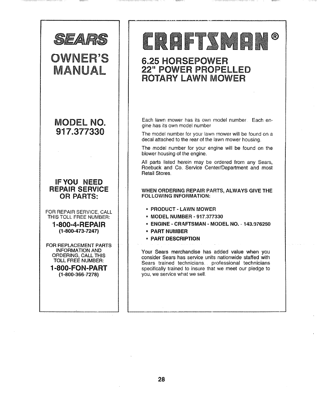
OWNER'S
UAL
MODEL NO.
917.377330
IF YOU NEED
REPAIR SERVICE
OR PARTS:
FOR REPAIR SERVICE, CALL
THIS TOLL FREE NUMBER:
1-800-4-REPAIR
(1-800-473-7247)
FOR REPLACEMENT PARTS
INFORMATION AND
ORDERING, CALL THIS
TOLL FREE NUMBER:
1-800-FON-PART
(1-800-366.7278)
®
6=25 HORSEPOWER
22" POWER PROPELLED
ROTARY LAWN MOWER
Each lawn mower has its own model number Each en-
gine has its own model number
The model number for your lawn mower will be found on a
decal attached to the rear of the lawn mower housing,,
The model number for your engine will be found on the
blower housing of the engine_
All parts listed herein may be ordered from any Sears,
Roebuck and Co. Service CentedDepartment and most
Retail Stores
WHEN ORDERING REPAIR PARTS, ALWAYS GIVE THE
FOLLOWING INFORMATION:
=PRODUCT -LAWN MOWER
•MODEL NUMBER -917.377330
"ENGINE -CRAFTSMAN -MODEL NO. _143.976250
oPART NUMBER
oPART DESCRIPTION
Your Sears merchandise has added value when you
consider Sears has service units nationwide staffed with
Sears trained technicians, professional technicians
specifically trained to insure that we meet our pledge to
you, we service what we sell.
28
