Craftsman 917377791 User Manual Gas, Walk Behind Lawnmower Manuals And Guides L0309459
CRAFTSMAN Walk Behind Lawnmower, Gas Manual L0309459 CRAFTSMAN Walk Behind Lawnmower, Gas Owner's Manual, CRAFTSMAN Walk Behind Lawnmower, Gas installation guides
User Manual: Craftsman 917377791 917377791 CRAFTSMAN Gas, Walk Behind Lawnmower - Manuals and Guides View the owners manual for your CRAFTSMAN Gas, Walk Behind Lawnmower #917377791. Home:Lawn & Garden Parts:Craftsman Parts:Craftsman Gas, Walk Behind Lawnmower Manual
Open the PDF directly: View PDF ![]() .
.
Page Count: 44
Owner's Manual
IC.nFTSMnWl
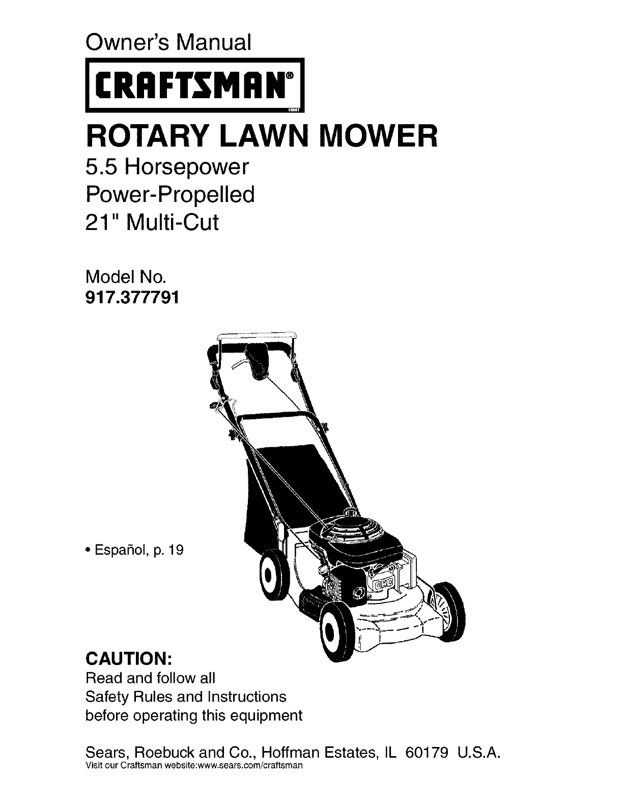
ROTARY LAWN MOWER
5.5 Horsepower
Power-Propelled
21" Multi-Cut
Model No.
917.377791
•EspaSol, p. 19
CAUTION:
Read and follow all
Safety Rules and Instructions
before operating this equipment
Sears, Roebuck and Co., Hoffman Estates, IL 60179 U.S.A.
Visit our Craftsman website:www.sears.com/craftsman

Warranty ................................................ 2
Safety Rules ....................................... 2-4
Product Specifications ......................... 4
Assembly /Pre-Operation ..................... 6
Operation .......................................... 7-11
Maintenance Schedule ........................ 12
Maintenance ................................... 12-14
Service and Adjustments ..................... 15
Storage ........................................... 16-17
Troubleshootin( .............................. 17-18
Repair Parts .................................... 38-46
Sears Service ........................ Back Cover
LIMITED TWO YEAR WARRANTY ON CRAFTSMAN POWER MOWER
For two years from date of purchase, when this Craftsman Lawn Mower is maintained,
lubricated, and tuned up according to the operating and maintenance instructions in the
owner's manual, Sears will repair free of charge any defect in material or workmanship.
If this Craftsman Lawn Mower is used for commercial or rental purposes, this warranty
applies for only 90 days from the date of purchase.
This Warranty does not cover:
• Expendable items which become worn during normal use, such as rotary mower
blades, blade adapters, belts, air cleaners and spark plug.
• Repairs necessary because of operator abuse or negligence, including bent crank-
shafts and the failure to maintain the equipment according to the instructions con-
tained in the owner's manual.
Warranty service is available by returning the Craftsman power mower to the nearest Sears
Parts & Repair Center in the United States. This warranty applies only while this product
is used in the United States.
This Warranty gives you specific legal rights, and you may also have other rights which
vary from state to state.
Sears, Roebuck And Co., D/817 WA, Hoffman Estates, IL 60179
IMPORTANT: This cutting machine is capable of amputating hands and feet and throw-
ing objects. Failure to observe the following safety instructions could result in serious
injury or death.
_¢LLookfor this symbol to point out
important safety precautions. It means
CAUTION!H BECOME ALERT!H
YOUR SAFETY IS INVOLVED.
_,WARNING: In order to prevent ac-
cidental starting when setting up, trans-
porting, adjusting or making repairs,
always disconnect spark plug wire and
place wire where it cannot come into
contact with the spark plug.
Ai:LWARNING: Engine exhaust, some of its
constituents, and certain vehicle compo-
nents contain or emit chemicals known
to the State of California to cause cancer
and birth defects or other reproductive
harm.
2
Ai_WARNING: Battery posts, terminals and
related accessories contain lead and lead
compounds, chemicals known to the State
of California to cause cancer and birth
defects or other reproductive harm. Wash
hands after handling.
_, CAUTION: Muffler and other engine
parts become extremely hot during
operation and remain hot after engine has
stopped. To avoid severe burns on contact,
stay away from these areas.
I. GENERAL OPERATION
• Read, understand, and follow all
instructions on the machine and in the
manual(s) before starting. Be thoroughly
familiar with the controls and the proper
use of the machine before starting.
• Do not put hands or feet near or under
rotating parts. Keep clear of the dis-
charge opening at all times.
• Only allow responsible individuals, who
are familiar with the instructions, to
operate the machine.
• Clear the area of objects such as rocks,
toys, wire, bones, sticks, etc., which
could be picked up and thrown by the
blade.
• Be sure the area is clear of other people
before mowing. Stop machine if anyone
enters the area.
• Do not operate the mower when bare-
foot or wearing open sandals. Always
wear substantial foot wear.
• Do not pull mower backwards unless
absolutely necessary. Always look down
and behind before and while moving
backwards.
• Do not operate the mower without
proper guards, plates, grass catcher or
other safety protective devices in place.
• See manufacturer's instructions for
proper operation and installation of
accessories. Only use accessories ap-
proved by the manufacturer.
• Stop the blade(s) when crossing gravel
drives, walks, or roads.
• Stop the engine (motor) whenever you
leave the equipment, before cleaning
the mower or unclogging the chute.
• Shut the engine (motor) off and wait
until the blade comes to complete stop
before removing grass catcher.
• Mow only in daylight or good artificial
light.
• Do not operate the machine while under
the influence of alcohol or drugs.
• Never operate machine in wet grass.
Always be sure of your footing: keep a
firm hold on the handle and walk; never
run.
• Disengage the self-propelled mech-
anism or drive clutch on mowers so
equipped before starting the engine
(motor).
• If the equipment should start to vibrate
abnormally, stop the engine (motor) and
check immediately for the cause. Vibra-
tion is generally a warning of trouble.
• Always wear safety goggles or safety
glasses with side shields when oper-
ating mower. 3
II. SLOPE OPERATION
Slopes are a major factor related to slip
and fall accidents which can result in
severe injury. All slopes require extra cau-
tion. If you feel uneasy on a slope, do not
mow it.
DO:
• Mow across the face of slopes: never
up and down. Exercise extreme caution
when changing direction on slopes.
• Remove obstacles such as rocks, tree
limbs, etc.
• Watch for holes, ruts, or bumps. Tall
grass can hide obstacles.
DO NOT:
• Do not trim near drop-offs, ditches or
embankments. The operator could lose
footing or balance.
• Do not trim excessively steep slopes.
• Do not mow on wet grass. Reduced
footing could cause slipping.
III. CHILDREN
Tragic accidents can occur if the operator
is not alert to the presence of children.
Children are often attracted to the ma-
chine and the mowing activity. Neveras-
sume that children will remain where you
last saw them.
• Keep children out of the trimming area
and under the watchful care of another
responsible adult.
• Be alert and turn machine off if children
enter the area.
• Before and while walking backwards,
look behind and down for small children.
• Never allow children to operate the
machine.
• Use extra care when approaching blind
corners, shrubs, trees, or other objects
that may obscure vision.
IV. SERVICE
•Use extra care in handling gasoline and
other fuels. They are flammable and
vapors are explosive.
-Use only an approved container.
-Never remove gas cap or add fuel
with the engine running.
Allow engine to cool before refueling.
Do not smoke.
-Never refuel the machine indoors.
-Never store the machine or fuel
container inside where there is an
open flame, such as a water heater.
•Never run a machine inside a closed area.
•Never make adjustments or repairs with
the engine (motor) running. Disconnectthe
spark plug wire, and keep the wire away
from the plug toprevent accidental starting.
• Keepnuts and bolts,especiallyblade
attachmentbolts,tightand keepequip-
ment ingood condition.
• Nevertamperwith safetydevices.Check
theirproperoperationregularly.
• Keep machine free of grass, leaves, or
otherdebrisbuild-up.Cleanoilorfuelspill-
age.Allowmachineto coolbeforestoring.
• Stop and inspectthe equipmentif you
strikean object. Repair,if necessary,
before restarting.
• Neverattempttomakewheelheightadjust-
mentswhiletheengine(motor)is running.
• Grasscatchercomponentsare subject
to wear,damage,and deterioration,
which couldexposemovingpartsor
allowobjectsto be thrown.Frequently
checkcomponentsand replacewith
manufacturer'srecommendedparts,
when necessary.
• Mowerbladesare sharp and can cut.
Wrap the blade(s)or wear gloves,and
useextracautionwhenservicingthem.
• Donot changethe enginegovernorset-
ting or overspeedthe engine.
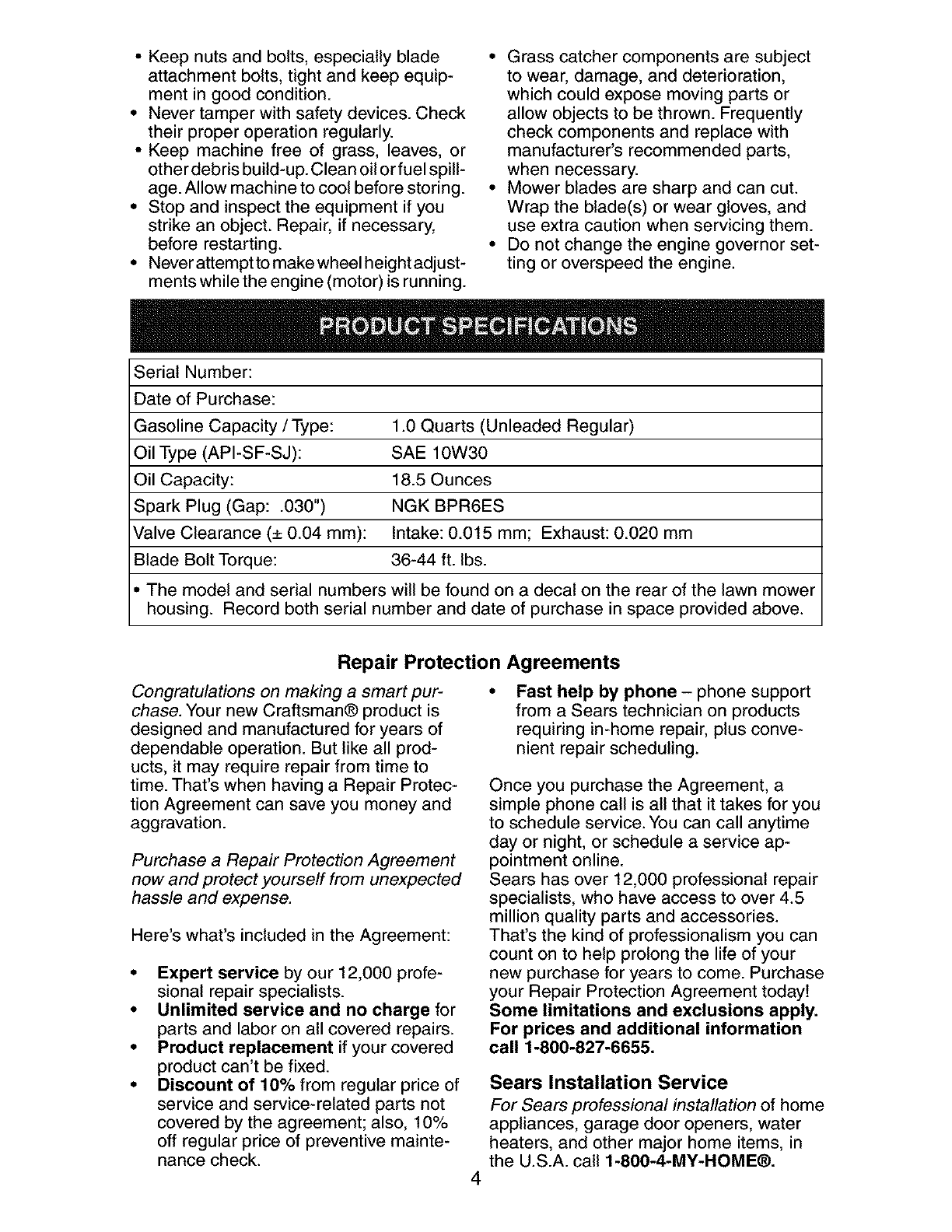
Serial Number:
Dateof Purchase:
GasolineCapacity/Type: 1.0 Quarts (Unleaded Regular)
Oil Type (API-SF-SJ): SAE 10W30
Oil Capacity: 18.5 Ounces
Spark Plug (Gap: .030") NGK BPR6ES
Valve Clearance (± 0.04 mm): Intake: 0.015 mm; Exhaust: 0.020 mm
Blade Bolt Torque: 36-44 ft. Ibs.
• The model and serial numbers will be found on a decal on the rear of the lawn mower
housing. Record both serial number and date of purchase in space provided above.
Repair Protection Agreements
Congratulations on making a smart pur-
chase. Your new Craftsman® product is
designed and manufactured for years of
dependable operation. But like all prod-
ucts, it may require repair from time to
time. That's when having a Repair Protec-
tion Agreement can save you money and
aggravation.
Purchase a Repair Protection Agreement
now and protect yourself from unexpected
hassle and expense.
Here's what's included in the Agreement:
•Expert service by our 12,000 profe-
sional repair specialists.
• Unlimited service and no charge for
parts and labor on all covered repairs.
• Product replacement if your covered
product can't be fixed.
• Discount of 10% from regular price of
service and service-related parts not
covered by the agreement; also, 10%
off regular price of preventive mainte-
nance check.
Fast help by phone - phone support
from a Sears technician on products
requiring in-home repair, plus conve-
nient repair scheduling.
Once you purchase the Agreement, a
simple phone call is all that it takes for you
to schedule service. You can call anytime
day or night, or schedule a service ap-
pointment online.
Sears has over 12,000 professional repair
specialists, who have access to over 4.5
million quality parts and accessories.
That's the kind of professionalism you can
count on to help prolong the life of your
new purchase for years to come. Purchase
your Repair Protection Agreement today!
Some limitations and exclusions apply.
For prices and additional information
call 1-800-827-6655.
4
Sears Installation Service
For Sears professional installation of home
appliances, garage door openers, water
heaters, and other major home items, in
the U.S.A. call 1-800-4-MY-HOME®.
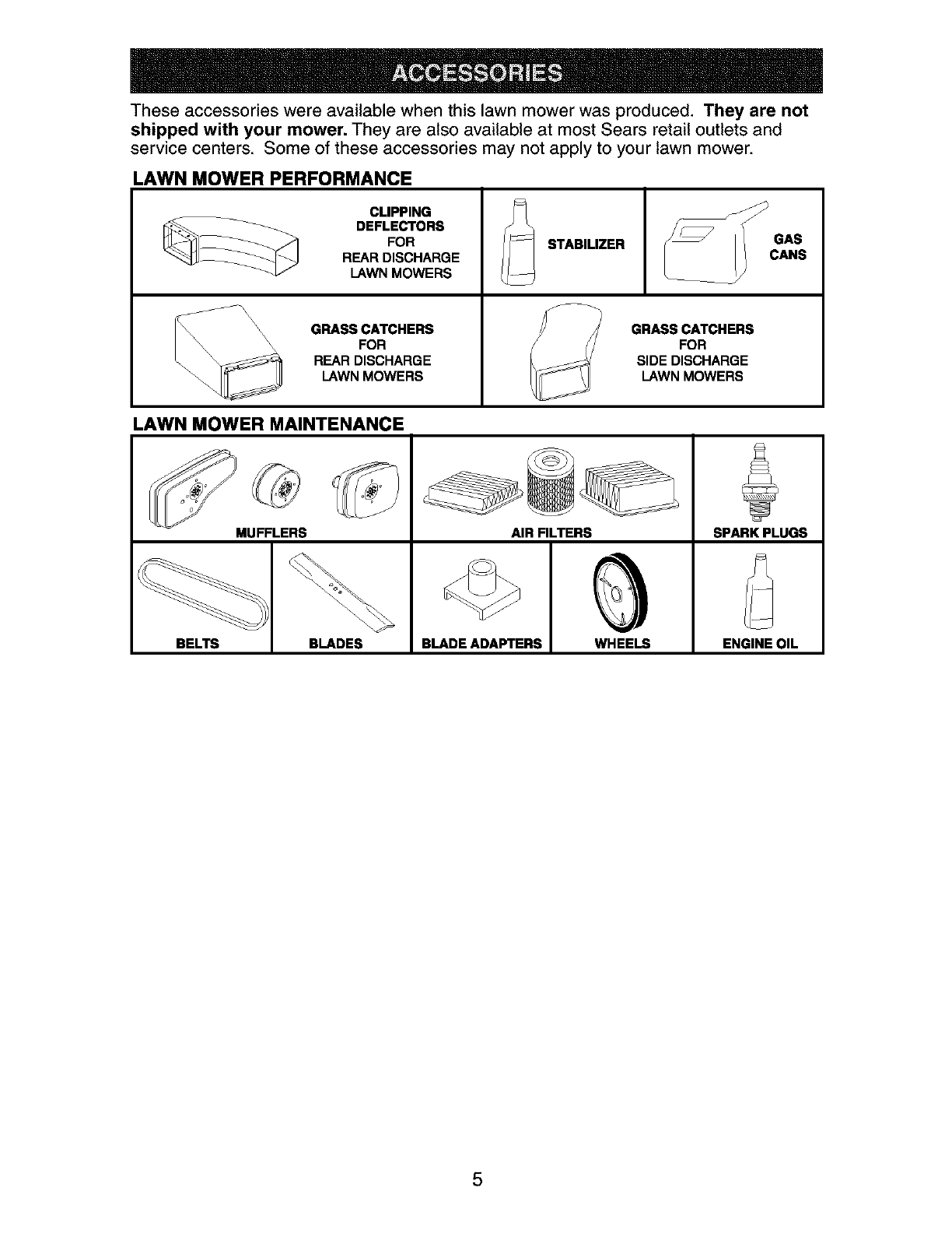
These accessories were available when this lawn mower was produced. They are not
shipped with your mower. They are also available at most Sears retail outlets and
service centers. Some of these accessories may not apply to your lawn mower.
LAWN MOWER PERFORMANCE
CLIPPING
DEFLECTORS
FOR
REAR DISCHARGE
LAWN MOWERS
\\ GRASS CATCHERS
_\\ \\\ FOR
REAR DISCHARGE
LAWN MOWERS
STABILIZER
GRASS CATCHERS
FOR
SIDE DISCHARGE
LAWN MOWERS
GAS
CANS
LAWN MOWER MAINTENANCE
MUFFLERS AIR FILTERS SPARK PLUGS
BELTS BLADES BLADE ADAPTERS WHEELS ENGINE OIL
5

Read these instructions and this manual in its entirety before you attempt to assemble or
operate your new lawn mower.
IMPORTANT: This lawn mower is shipped WITHOUT OIL OR GASOLINE in engine.
Your new lawn mower has been assembled at the factory with the exception of those
parts left unassembled for shipping purposes. All parts such as nuts, washers, bolts, etc.,
necessary to complete the assembly have been placed in the parts bag. To ensure safe
and proper operation of your lawn mower, all parts and hardware you assemble must
be tightened securely. Use the correct tools as necessary to ensure proper tightness.
TO REMOVE LAWN MOWER FROM
CARTON
1. Remove loose parts included with
mower.
2. Cut down two end corners of carton
and lay end panel down flat.
3. Remove all packing materials except
padding between upper and lower
handle and padding holding operator
presence control bar to upper handle.
4. Roll lawn mower out of carton and
check carton thorougly for additional
loose parts.
HOW TO SET UP YOUR LAWN MOWER
TO UNFOLD HANDLE
IMPORTANT: Unfold handle carefully so
as not to pinch or damage control cables.
1. Raise lower handle section to oper-
ating position and squeeze the bottom
ends of lower handle towards each
other until the pin in handle can be
inserted into one of the three height
adjustment holes.
2. Remove protective padding, raise up-
per handle section into place on lower
handle and tighten both handle knobs.
3. Remove any packing material from
around control bar.
Your lawn mower handle can be adjusted
for your mowing comfort. Refer to "AD-
JUST HANDLE" in the Service and Adjust-
ments section of this manual.
Handle pin
SQU
Handle J
bracket
TO ASSEMBLE GRASS CATCHER
1. Put grass catcher frame into grass bag
with rigid part of bag on the bottom.
Make sure the frame handle is outside
of the bag top.
2. Slip vinyl bindings over frame.
NOTE: If vinyl bindings are too stiff, hold
them in warm water for a few minutes. If
bag gets wet, let it dry before using.
Catcher
frame
handle
Operator presence
control bar
LIFT
Mowing
position
Lower handle
._._ Frame
opening
TO INSTALL ATTACHMENTS
Your lawn mower was shipped ready to
be used as a mulcher. To convert to bag-
ging or discharging, see "TO CONVERT
MOWER" in the Operation section of this
manual.
6
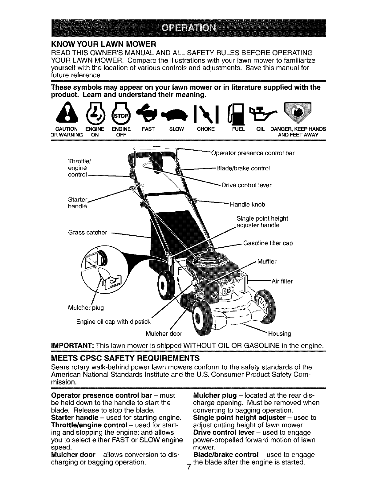
KNOW YOUR LAWN MOWER
READ THIS OWNER'S MANUAL AND ALL SAFETY RULES BEFORE OPERATING
YOUR LAWN MOWER. Compare the illustrations with your lawn mower to familiarize
yourself with the location of various controls and adjustments. Save this manual for
future reference.
These symbols may appear on your lawn mower or in literature supplied with the
product. Learn and understand their meaning.
CAUTION ENGINE ENGINE FAST SLOW CHOKE FUEL OIL DANGER, KEEP HANDS
DR WARNING ON OFF AND FEET AWAY
Throttle/
engine
control
Starter
handle
Grass catcher
)perator presence control bar
Blade/brake control
Drive control lever
Handle knob
Single point height
uster handle
Muffler
Mulcher plug
Engine oil cap with dipstick
Mulcher door :)using
IMPORTANT: This lawn mower is shipped WITHOUT OIL OR GASOLINE in the engine.
MEETS CPSC SAFETY REQUIREMENTS
Sears rotary walk-behind power lawn mowers conform to the safety standards of the
American National Standards Institute and the U.S. Consumer Product Safety Com-
mission.
Operator presence control bar - must
be held down to the handle to start the
blade. Release to stop the blade.
Starter handle - used for starting engine.
Throttle/engine control - used for start-
ing and stopping the engine; and allows
you to select either FAST or SLOW engine
speed.
Mulcher door - allows conversion to dis-
charging or bagging operation.
Mulcher plug - located at the rear dis-
charge opening. Must be removed when
converting to bagging operation.
Single point height adjuster - used to
adjust cutting height of lawn mower.
Drive control lever - used to engage
power-propelled forward motion of lawn
mower.
Blade/brake control - used to engage
7 the blade after the engine is started.
The operationof any lawn
mowercan resultin foreign
objectsthrown intothe
eyes,whichcan resultin
severeeye damage.Always
wear safety glassesor eye shieldswhile
operatingyourlawn moweror performing
any adjustmentsor repairs.We recom-
menda standardsafetyglassesor wide
vision safetymask worn overspectacles.
HOW TO USE YOUR LAWN MOWER
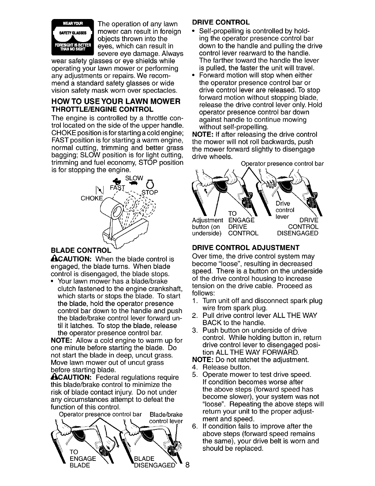
THROTTLE/ENGINE CONTROL
The engine is controlled by a throttle con-
trol located on the side of the upper handle.
CHOKE position is for starting a cold engine;
FAST position is for starting a warm engine,
normal cutting, trimming and better grass
bagging; SLOW position is for light cutting,
trimming and fuel economy, STOP position
is for stopping the engine. _
FAST 0
I",1 ,.
CHOK .4.... ,,, ),'; ',.:-,
,,_-, _ tSr" Jt
I1
II
It,
BLADE CONTROL
_i,CAUTION: When the blade control is
engaged, the blade turns. When blade
control is disengaged, the blade stops.
• Your lawn mower has a blade/brake
clutch fastened to the engine crankshaft,
which starts or stops the blade. To start
the blade, hold the operator presence
control bar down to the handle and push
the blade/brake control lever forward un-
til it latches. To stop the blade, release
the operator presence control bar.
NOTE: Allow a cold engine to warm up for
one minute before starting the blade. Do
not start the blade in deep, uncut grass.
Move lawn mower out of uncut grass
_ecfore starting blade.
AUTION: Federal regulations require
this blade/brake control to minimize the
risk of blade contact injury. Do not under
any circumstances attempt to defeat the
function of this control.
Operator presence control bar Blade/brake
control lever
TO
ENGAGE
BLADE
DRIVE CONTROL
• Self-propelling is controlled by hold-
ing the operator presence control bar
down to the handle and pulling the drive
control lever rearward to the handle.
The farther toward the handle the lever
is pulled, the faster the unit will travel.
• Forward motion will stop when either
the operator presence control bar or
drive control lever are released. To stop
forward motion without stopping blade,
release the drive control lever only. Hold
operator presence control bar down
against handle to continue mowing
without self-propelling.
NOTE: If after releasing the drive control
the mower will not roll backwards, push
the mower forward slightly to disengage
drive wheels.
._ratorpresence control bar
Drive
control
TO lever
Adjustment ENGAGE DRIVE
button (on DRIVE CONTROL
underside) CONTROL DISENGAGED
DRIVE CONTROL ADJUSTMENT
Over time, the drive control system may
become "loose", resulting in decreased
speed. There is a button on the underside
of the drive control housing to increase
tension on the drive cable. Proceed as
follows:
1. Turn unit off and disconnect spark plug
wire from spark plug.
2. Pull drive control lever ALL THE WAY
BACK to the handle.
3. Push button on underside of drive
control. While holding button in, return
drive control lever to disengaged posi-
tion ALL THE WAY FORWARD.
NOTE: Do not ratchet the adjustment.
4. Release button.
5. Operate mower to test drive speed.
If condition becomes worse after
the above steps (forward speed has
become slower), your system was not
"loose". Repeating the above steps will
return your unit to the proper adjust-
ment and speed.
6. If condition fails to improve after the
above steps (forward speed remains
the same), your drive belt is worn and
should be replaced.
8

TO ADJUST CUTTING HEIGHT
All four wheels are adjusted by a single lever.
• Pull adjuster lever toward wheel. To
raise mower, move lever forward to
desired position. To lower mower, move
the lever toward the rear.
\
LEVER
BACKWARD
TO LOWER _ Height
MOWER adjuster
lever
LEVER
FORWARD
TO RAISE
MOWER
TO CONVERT MOWER
Your lawn mower was shipped ready to be
used as amulcher. To convert to bagging
or discharging:
REAR BAGGING
• Open rear door and remove mulcher plug.
Store mulcher plug in a safe place.
• You can now install the grass catcher.
• To convert to mulching or discharging
operation, install mulcher plug into rear
discharge opening of mower.
TO ATTACH GRASS CATCHER
1. Lift the rear door of the lawn mower
and place the grass catcher frame side
hooks into the slots of the rear door.
2. The grass catcher is secured to the lawn
mower housing when the rear door is
lowered onto the grass catcher frame.
A¢_CAUTION: Do not run your lawn mower
without mulcher plug or approved grass
catcher in place. Never attempt to op-
erate the lawn mower with the rear door
removed or propped open.
Rear door slots
Grass
catcher
handle
Catcher frame hook
TO EMPTY GRASS CATCHER
1. Lift up on grass catcher using the
frame handle.
2. Remove grass catcher with clippings
from under lawn mower handle.
3. Empty clippings from bag using both
frame handle and bag handle.
NOTE: Do not drag the bag when empty-
ing; it will cause unnecessary wear.
Grass
catcher
Bag frame
handle handle
Mulcher plug
9
SIDE DISCHARGING
• Mulcher plug must be installed into rear
discharge opening of mower.
• Open mulcher door and install dis-
charge deflector under door as shown.
• Mower is now ready for discharging
operation.
• To convert to mulching or bagging
operation, discharge deflector must be
removed and mulcher door closed.
Open
mulcher
door
Discharge
SIMPLE STEPS TO REMEMBER WHEN
CONVERTING YOUR LAWN MOWER
FOR MULCHING -
1. Rear mulcher plug installed.
2. Mulcher door closed.
FOR REAR BAGGING -
1. Rear mulcher plug removed.
2. Grass catcher installed.
3. Mulcher door closed.
FOR SIDE DISCHARGING -
1. Rear mulcher plug installed.
2. Discharge deflector installed.
_CAUTION: Do not run your lawn
mower without mulcher plug or approved
grass catcher in place. Never attempt to
operate the lawn mower with the rear door
removed or propped open.
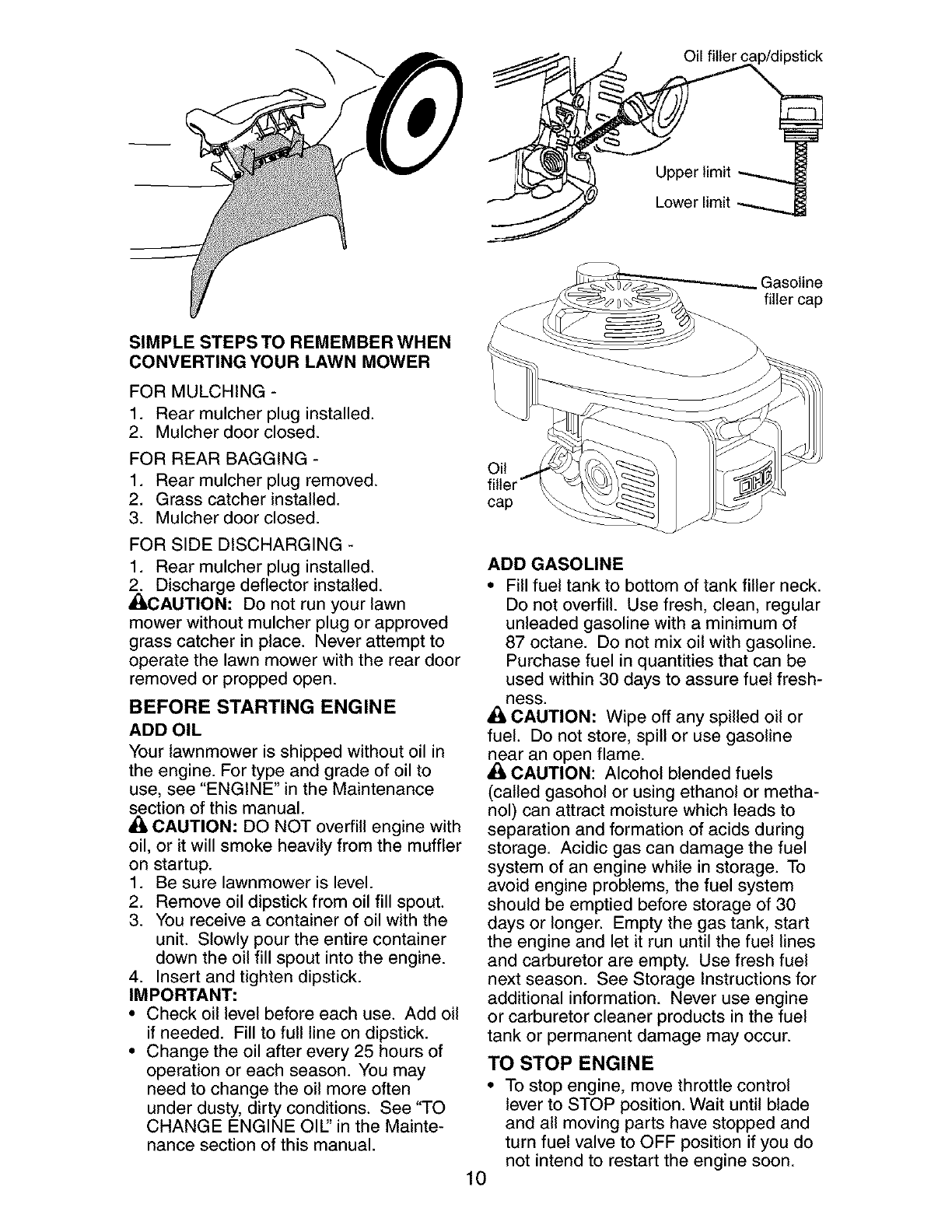
BEFORE STARTING ENGINE
ADD OIL
Your lawnmower is shipped without oil in
the engine. For type and grade of oil to
use, see "ENGINE" in the Maintenance
section of this manual.
• I,CAUTION: DO NOT overfill engine with
oil, or it will smoke heavily from the muffler
on startup.
1. Be sure lawnmower is level.
2. Remove oil dipstick from oil fill spout.
3. You receive a container of oil with the
unit. Slowly pour the entire container
down the oil fill spout into the engine.
4. Insert and tighten dipstick.
IMPORTANT:
• Check oil level before each use. Add oil
if needed. Fill to full line on dipstick.
• Change the oil after every 25 hours of
operation or each season. You may
need to change the oil more often
under dusty, dirty conditions. See "TO
CHANGE ENGINE OIL' in the Mainte-
nance section of this manual.
,_ Oil filler cap/dipstick
Upper limit
Lower limit
Gasoline
filler cap
Oil
cap
ADD GASOLINE
• Fill fuel tank to bottom of tank filler neck.
Do not overfill. Use fresh, clean, regular
unleaded gasoline with a minimum of
87 octane. Do not mix oil with gasoline.
Purchase fuel in quantities that can be
used within 30 days to assure fuel fresh-
Bess.
CAUTION: Wipe off any spilled oil or
fuel. Do not store, spill or use gasoline
near an open flame.
CAUTION: Alcohol blended fuels
(called gasohol or using ethanol or metha-
nol) can attract moisture which leads to
separation and formation of acids during
storage. Acidic gas can damage the fuel
system of an engine while in storage. To
avoid engine problems, the fuel system
should be emptied before storage of 30
days or longer. Empty the gas tank, start
the engine and let it run until the fuel lines
and carburetor are empty. Use fresh fuel
next season. See Storage Instructions for
additional information. Never use engine
or carburetor cleaner products in the fuel
tank or permanent damage may occur.
TO STOP ENGINE
•To stop engine, move throttle control
lever to STOP position. Wait until blade
and all moving parts have stopped and
turn fuel valve to OFF position if you do
not intend to restart the engine soon.
10
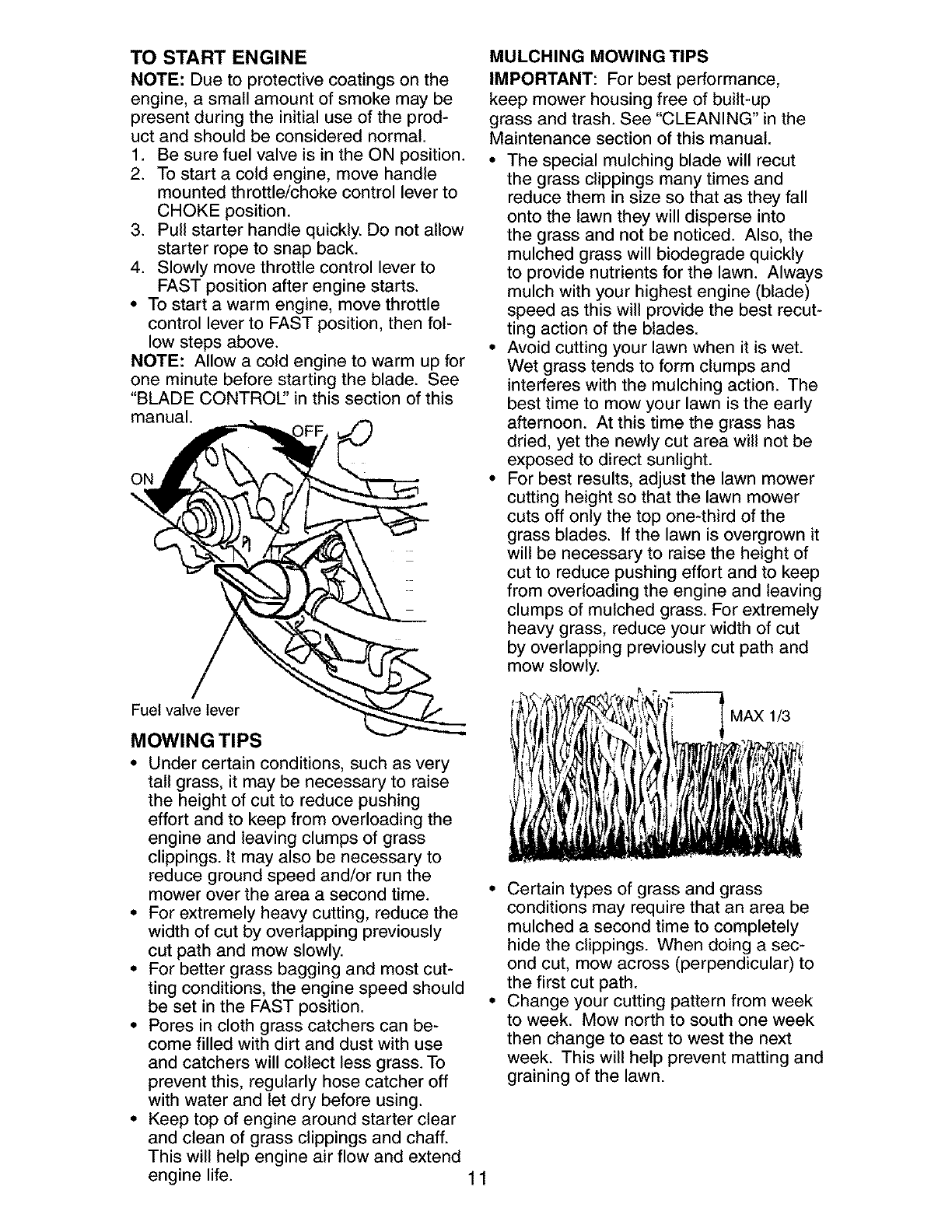
TO START ENGINE
NOTE: Due to protective coatings on the
engine, a small amount of smoke may be
present during the initial use of the prod-
uct and should be considered normal.
1. Be sure fuel valve is in the ON position.
2. To start a cold engine, move handle
mounted throttle/choke control lever to
CHOKE position.
3. Pull starter handle quickly. Do not allow
starter rope to snap back.
4. Slowly move throttle control lever to
FAST position after engine starts.
• To start a warm engine, move throttle
control lever to FAST position, then fol-
low steps above.
NOTE: Allow a cold engine to warm up for
one minute before starting the blade. See
"BLADE CONTROl" in this section of this
manual.
ON
Fuel valve lever
MOWING TIPS
• Under certain conditions, such as very
tall grass, it may be necessary to raise
the height of cut to reduce pushing
effort and to keep from overloading the
engine and leaving clumps of grass
clippings. It may also be necessary to
reduce ground speed and/or run the
mower over the area a second time.
• For extremely heavy cutting, reduce the
width of cut by overlapping previously
cut path and mow slowly.
• For better grass bagging and most cut-
ting conditions, the engine speed should
be set in the FAST position.
• Pores in cloth grass catchers can be-
come filled with dirt and dust with use
and catchers will collect less grass. To
prevent this, regularly hose catcher off
with water and let dry before using.
• Keep top of engine around starter clear
and clean of grass clippings and chaff.
This will help engine air flow and extend
engine life. 11
MULCHING MOWING TIPS
IMPORTANT: For best performance,
keep mower housing free of built-up
grass and trash. See "CLEANING" in the
Maintenance section of this manual.
• The special mulching blade will recut
the grass clippings many times and
reduce them in size so that as they fall
onto the lawn they will disperse into
the grass and not be noticed. Also, the
mulched grass will biodegrade quickly
to provide nutrients for the lawn. Always
mulch with your highest engine (blade)
speed as this will provide the best recut-
ting action of the blades.
• Avoid cutting your lawn when it is wet.
Wet grass tends to form clumps and
interferes with the mulching action. The
best time to mow your lawn is the early
afternoon. At this time the grass has
dried, yet the newly cut area will not be
exposed to direct sunlight.
• For best results, adjust the lawn mower
cutting height so that the lawn mower
cuts off only the top one-third of the
grass blades. If the lawn is overgrown it
will be necessary to raise the height of
cut to reduce pushing effort and to keep
from overloading the engine and leaving
clumps of mulched grass. For extremely
heavy grass, reduce your width of cut
by overlapping previously cut path and
mow slowly.
MAXI_
• Certain types of grass and grass
conditions may require that an area be
mulched a second time to completely
hide the clippings. When doing a sec-
ond cut, mow across (perpendicular) to
the first cut path.
• Change your cutting pattern from week
to week. Mow north to south one week
then change to east to west the next
week. This will help prevent matting and
graining of the lawn.
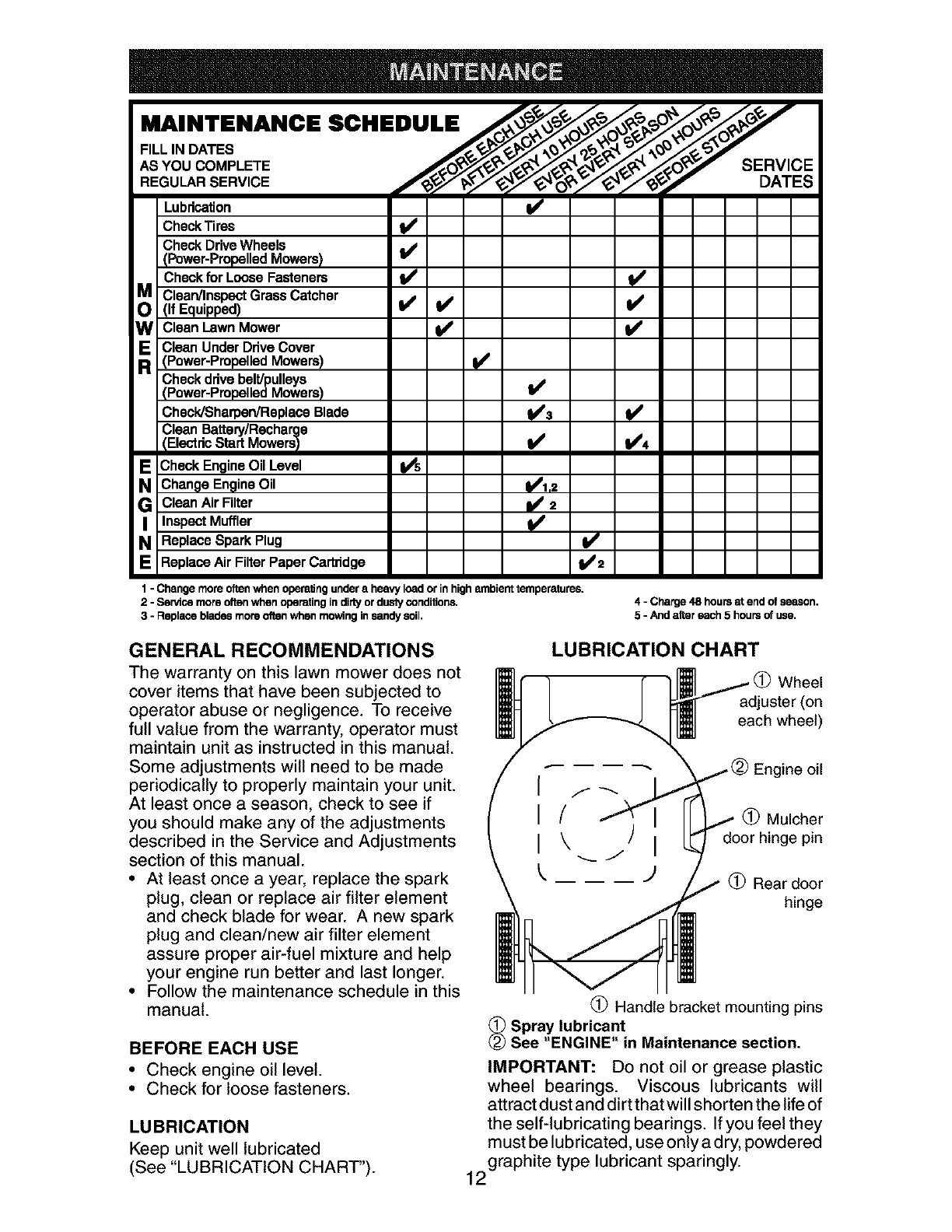
MAINTENANCE SCHEDULE /_:_°'_o_y
""DATES --
AS YOU COMPLETE S
REGO RSERV.OE =E#V'CI
Lubrication It#'
CheckTires I_
Check Drive Wheels
(Power-Propelled Mowers) I/'
Check for Loose Fasteners I_ I/
IClean/Inspect Grass Catcher
(If Equipped) I/ I/
WClean Lawn Mower V' l/
ICleanUnderDriveCover
(Power-Propelled Mowers) I_
Check drive belt/pulleys
Power-Propelled Mowers) I_
Check/Sharpen/Replace Blade _//$ I_
Clean Battery/Recharge
IElectdc StartMowersII_ I/'4
ICheck Engine Oil Level I_s
Change Engine Oil 1_1.2
GI Clean Air Filter I_ 2
Inspect Muffler II/
IReplace Spark Plug I_'
Replace Air Filter Paper Cartridge I/2
1 - Change more oftenwhenopemlng underaheavy loador inhighambient temperatures.
2-Servicemoreoftenwhen operatingindirtyordustyconditions,
3-Replacebladesmoreoftenwhen mowinginsandysoil,
4- Charge48 hoursat end of season.
5-And alter each5 hoursof use.
GENERAL RECOMMENDATIONS
The warranty on this lawn mower does not
cover items that have been subjected to
operator abuse or negligence. To receive
full value from the warranty, operator must
maintain unit as instructed in this manual.
Some adjustments will need to be made
periodically to properly maintain your unit.
At least once a season, check to see if
you should make any of the adjustments
described in the Service and Adjustments
section of this manual.
• At least once a year, replace the spark
plug, clean or replace air filter element
and check blade for wear. A new spark
plug and clean/new air filter element
assure proper air-fuel mixture and help
your engine run better and last longer.
• Follow the maintenance schedule in this
manual.
BEFORE EACH USE
• Check engine oil level.
• Check for loose fasteners.
LUBRICATION
Keep unit well lubricated
(See "LUBRICATION CHART").
LUBRICATION CHART
_ / I I_ /(_)Wheel
LJ _ adjuster(on
I_l [/__ I_l each wheel)
Engine oil
(_) Mulcher
door hinge pin
Rear door
hinge
Handle bracket mounting pins
_Spray lubricant
See "ENGINE" in Maintenance section.
IMPORTANT: Do not oil or grease plastic
wheel bearings. Viscous lubricants will
attract dust and dirtthatwill shorten the life of
the self-lubricating bearings. If you feel they
must be lubricated, use only a dry, powdered
graphite type lubricant sparingly.
12

LAWN MOWER
Always observe safety rules when per-
forming any maintenance.
TIRES
• Keep tires free of gasoline, oil, or insect
control chemicals which can harm rubber.
• Avoid stumps, stones, deep ruts, sharp
objects and other hazards that may
cause tire damage.
DRIVE WHEELS
Check rear drive wheels each time you
mow to be sure they move freely. The
wheels not turning freely means trash,
grass cuttings, etc., may be inside the
drive wheel and dust cover area and must
be cleaned out to free drive wheels.
BLADE CARE
For best results, mower blade must be kept
sharp. Replace bent or damaged blades.
TO REMOVE BLADE
1. Disconnect spark plug wire from spark
plug and place wire where it cannot
come in contact with spark plug.
2. Turn lawn mower on its side. Make
sure air filter and carburetor are up.
3. Use a wood block between blade and
mower housing to prevent blade from
turning when removing blade bolts.
NOTE: Protect your hands with gloves
and/or wrap blade with heavy cloth.
4. Remove blade bolts by turning counter-
clockwise.
TO REPLACE BLADE
1. Position the blade. Be sure the trailing
edge of blade (opposite sharp edge)
is up toward the engine and install the
blade bolts.
2. Use block of wood between blade and
lawn mower housing and tighten the
blade bolts, turning clockwise.
• The recommended tightening torque is
36-44 ft. Ibs.
\\
\ \ Blade
IMPORTANT: Blade bolts are heat treat-
ed. If bolts need replacing, replace only
with approved bolts shown in the Repair
Parts section of this manual.
TO SHARPEN BLADE
NOTE: We do not recommend sharpening
blade - but if you do, be sure the blade is
balanced.
Care should be taken to keep the blade bal-
anced. An unbalanced blade will cause even-
tual damage to lawn mower or engine.
• The blade can be sharpened with a file
or on a grinding wheel. Do not attempt
to sharpen while on the mower.
• To check blade balance, drive a nail into
a beam or wall. Leave about one inch of
the straight nail exposed. Place center
hole of blade over the head of the nail.
If blade is balanced, it should remain in
a horizontal position. If either end of the
blade moves downward, sharpen the
heavy end until the blade is balanced.
GRASS CATCHER
• The grass catcher may be hosed with
water, but must be dry when used.
• Check your grass catcher often for dam-
age or deterioration. Through normal
use it will wear. If catcher needs replac-
ing, replace only with approved replace-
ment catcher shown in the Repair Parts
section of this manual. Give the lawn
mower model number when ordering.
ENGINE
LUBRICATION
Use only high quality detergent oil rated with
API service classification SF-SJ. Select the
oil's SAE viscosity grade according to your
expected operating temperature.
SAE VISCOSITY GRADES
"F -20 0 30 3_ 40 60 80 100
-30 -20 -10 D 10 20 30
"I_MPERATURE RANGE ANTICIPATED BEFORE NEXT OIL CHANGE
NOTE: Multi-viscosity oils (5W30, 10W30
etc.) improve starting in cold weather, and
you should check your engine oil level fre-
quently to avoid possible engine damage
from running low on oil.
Change the oil after every 25 hours of
operation or at least once a year if the
lawn mower is not used for 25 hours in
one year.
Check the crankcase oil level before
starting the engine and after each five (5)
hours of continuous use. Tighten oil plug
securely each time you check the oil level.
13
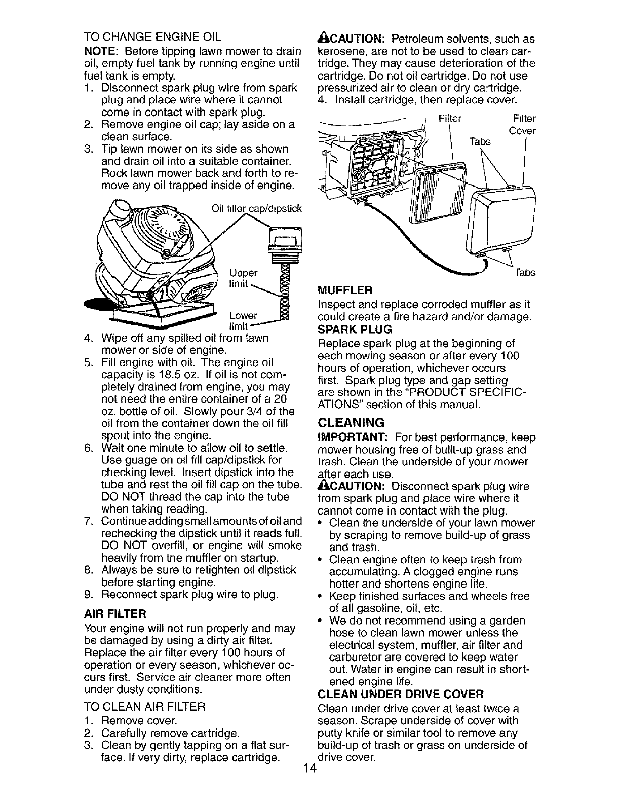
TO CHANGEENGINEOIL
NOTE: Beforetippinglawnmowerto drain
oil, emptyfuel tank by runningengine until
fuel tank is empty.
1. Disconnectsparkplug wire from spark
plugand place wire whereit cannot
comeincontactwith sparkplug.
2. Removeengineoil cap; layasideon a
cleansurface.
3. Tip lawnmoweron its side as shown
and drainoil into a suitablecontainer.
Rocklawnmowerback and forth to re-
moveanyoil trappedinsideof engine.
Oil filler cap/dipstick
_i, CAUTION: Petroleum solvents, such as
kerosene, are not to be used to clean car-
tridge. They may cause deterioration of the
cartridge. Do not oil cartridge. Do not use
pressurized air to clean or dry cartridge.
4. Install cartridge, then replace cover.
Tabs
4. Wipe off any spilled oil from lawn
mower or side of engine.
5. Fill engine with oil. The engine oil
capacity is 18.5 oz. If oil is not com-
pletely drained from engine, you may
not need the entire container of a 20
oz. bottle of oil. Slowly pour 3/4 of the
oil from the container down the oil fill
spout into the engine.
6. Wait one minute to allow oil to settle.
Use guage on oil fill cap/dipstick for
checking level. Insert dipstick into the
tube and rest the oil fill cap on the tube.
DO NOT thread the cap into the tube
when taking reading.
7. Continue adding small amounts of oil and
rechecking the dipstick until it reads full.
DO NOT overfill, or engine will smoke
heavily from the muffler on startup.
8. Always be sure to retighten oil dipstick
before starting engine.
9. Reconnect spark plug wire to plug.
AIR FILTER
Your engine will not run properly and may
be damaged by using a dirty air filter.
Replace the air filter every 100 hours of
operation or every season, whichever oc-
curs first. Service air cleaner more often
under dusty conditions.
TO CLEAN AIR FILTER
1. Remove cover.
2. Carefully remove cartridge.
3. Clean by gently tapping on a flat sur-
face. If very dirty, replace cartridge.
Tabs
MUFFLER
Inspect and replace corroded muffler as it
could create a fire hazard and/or damage.
SPARK PLUG
Replace spark plug at the beginning of
each mowing season or after every 100
hours of operation, whichever occurs
first. Spark plug type and gap setting
are shown in the "PRODUCT SPECIFIC-
ATIONS" section of this manual.
CLEANING
IMPORTANT: For best performance, keep
mower housing free of built-up grass and
trash. Clean the underside of your mower
after each use.
• I,CAUTION: Disconnect spark plug wire
from spark plug and place wire where it
cannot come in contact with the plug.
• Clean the underside of your lawn mower
by scraping to remove build-up of grass
and trash.
• Clean engine often to keep trash from
accumulating. A clogged engine runs
hotter and shortens engine life.
• Keep finished surfaces and wheels free
of all gasoline, oil, etc.
• We do not recommend using a garden
hose to clean lawn mower unless the
electrical system, muffler, air filter and
carburetor are covered to keep water
out. Water in engine can result in short-
ened engine life.
CLEAN UNDER DRIVE COVER
Clean under drive cover at least twice a
season. Scrape underside of cover with
putty knife or similar tool to remove any
build-up of trash or grass on underside of
drive cover.
14

/i, WARNING: To avoid serious injury, before
performing any service or adjustments:
1. Release control bar and stop engine.
2. Make sure the blade and all moving
parts have completely stopped.
3. Disconnect spark plug wire from spark
plug and place wire where it cannot
come in contact with the spark plug.
LAWN MOWER
TO ADJUST CUTTING HEIGHT
See "TO ADJUST CUTTING HEIGHT' in
the Operation section of this manual.
REAR DEFLECTOR
The rear deflector, attached between the rear
wheels of your mower, is provided to minimize
the possibility that objects will be thrown out
of the rear of the mower into the operator's
mowing position. If the deflector becomes
damaged, it should be replaced.
DRIVE BELT
If your mower does not operate properly
due to suspected drive belt problems,
take your mower to a Sears or other
qualified service center for repair and/or
adjustment.
TO ADJUST HANDLE
The handle on your lawn mower has three
(3) height positions - adjust to height that
suits you.
• Squeeze the bottom ends of lower
handle towards each other until the pin
in handle can be inserted into one of the
three height adjustment holes.
ENGINE
Maintenance, repair, or replacement of
the emission control devices and systems,
which are being done at the customers ex-
pense, may be performed by any non-road
engine repair establishment or individual.
Warranty repairs must be performed by an
authorized engine manufacturer's service
outlet.
ENGINE SPEED
Your engine speed has been factory set.
Do not attempt to increase engine speed
or it may result in personal injury. If you
believe that the engine is running too fast
or too slow, take your lawn mower to a
Sears or other qualified service center for
repair and adjustment.
CARBURETOR
Your carburetor is not adjustable. If your
engine does not operate properly due to
suspected carburetor problems, take your
lawn mower to a Sears or other qualified
service center for repair and/or adjust-
ment.
IMPORTANT: Never tamper with the
engine governor, which is factory set
for proper engine speed. Overspeeding
the engine above the factory high speed
setting can be dangerous. If you think
the engine-governed high speed needs
adjusting, contact a Sears or other
qualified service center, which has proper
equipment and experience to make any
necessary adjustments.
SQL _ndle pin
Handle
bracke
15

Immediately prepare your lawn mower for
storage at the end of the season or if the
unit will not be used for 30 days or more.
LAWN MOWER
When lawn mower isto be stored for a period
of time, clean it thoroughly, remove all dirt,
grease, leaves, etc. Store in aclean, dryarea.
1. Clean entire lawn mower (See
"CLEANING" in the Maintenance sec-
tion of this manual).
2. Lubricate as shown in the Maintenance
section of this manual.
3. Be sure that all nuts, bolts, screws,
and pins are securely fastened. Inspect
moving parts for damage, breakage
and wear. Replace if necessary.
4. Touch up all rusted or chipped paint
surfaces; sand lightly before painting.
HANDLE
You can fold your mower handle for storage.
NOTE: The upper handle has an "anti-fold"
bracket located on the right side of the
handle. This bracket prevents the upper
handle from folding forward, which helps
protect control cable(s) from damage.
1. Loosen the two (2) handle knobs on
sides of the upper handle and allow
handle to fold down to the rear.
2. Squeeze the bottom ends of lower
handle toward each other until pins
in handle clear the brackets and pivot
entire handle assembly forward and
allow it to rest on mower.
• When setting up your handle from the
storage position, you must manually
lock lower handle into mowing position.
IMPORTANT: When folding the handle for
storage or transportation, be sure to fold
the handle as shown or you may damage
the control cables.
Operator presence
control bar
Lower
SQL
Handle
bracket
J
pin
ENGINE
FUEL SYSTEM
IMPORTANT: It is important to prevent
gum deposits from forming in essential
fuel system parts such as carburetor, fuel
filter, fuel hose, or tank during storage.
Also, alcohol blended fuels (called gasohol
or using ethanol or methanol) can attract
moisture which leads to separation and
formation of acids during storage. Acidic
gas can damage the fuel system of an
engine while in storage.
• Empty the fuel tank by starting the en-
gine and letting it run until the fuel lines
and carburetor are empty.
• Never use engine or carburetor cleaner
products in the fuel tank or permanent
damage may occur.
• Use fresh fuel next season.
NOTE: Fuel stabilizer is an acceptable
alternative in minimizing the formation
of fuel gum deposits during storage. Add
stabilizer to gasoline in fuel tank or stor-
age container. Always follow the mix ratio
found on stabilizer container. Run engine
at least 10 minutes after adding stabilizer
to allow the stabilizer to reach the car-
buretor. Do not empty the gas tank and
carburetor if using fuel stabilizer.
ENGINE OIL
Drain oil (with engine warm) and replace
with clean engine oil. (See "ENGINE" in
the Maintenance section of this manual).
CYLINDER
1. Remove spark plug.
2. Pour one ounce (29 ml) of oil through
spark plug hole into cylinder.
3. Pull starter handle slowly a few times
Mowing to distribute oil.
position 4. Replace with new spark plug.
16
OTHER
• Do not store gasoline from one season
to another.
• Replace your gasoline can if your can
starts to rust. Rust and/or dirt in your
gasoline will cause problems.
• If possible, store your unit indoors and
cover it to protect it from dust and dirt.
• Cover your unit with a suitable protective
cover that does not retain moisture. Do
not use plastic. Plastic cannot breathe,
which allows condensation to form and
will cause your unit to rust.
IMPORTANT: Never cover mower while
engine and exhaust areas are still warm.
ACAUTION: Never store the lawn mower
with gasoline in the tank inside a building
where fumes may reach an open flame or
spark. Allow the engine to cool before stor-
ing in any enclosure.
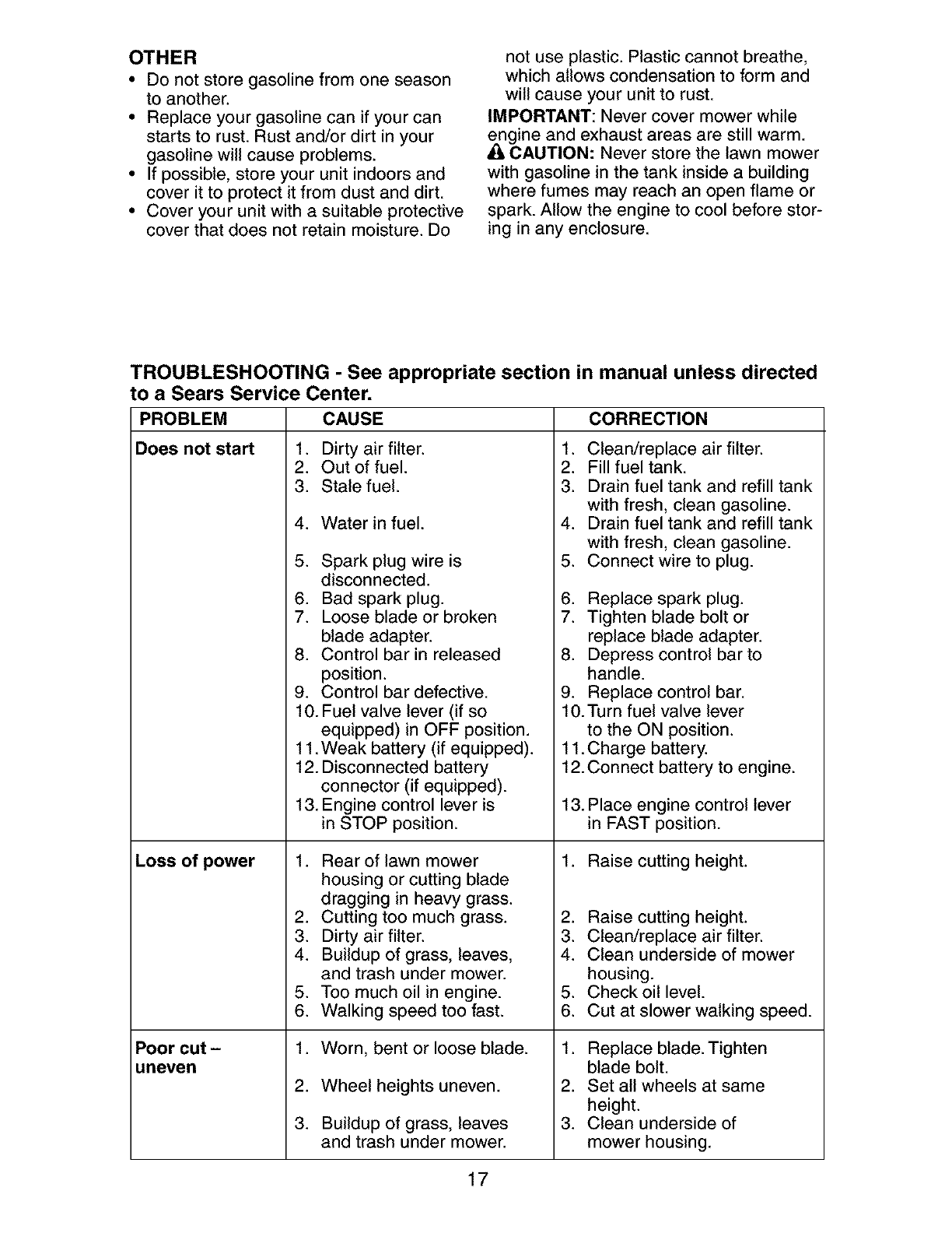
TROUBLESHOOTING -See appropriate section in manual unless directed
to a Sears Service Center.
PROBLEM CAUSE
Does not start 1. Dirty air filter.
Loss of power
Poor cut -
uneven
2. Out of fuel.
3. Stale fuel.
4. Water in fuel.
5. Spark plug wire is
disconnected.
6. Bad spark plug.
7. Loose blade or broken
blade adapter.
8. Control bar in released
position.
9. Control bar defective.
10. Fuel valve lever (if so
equipped) in OFF position.
11. Weak battery (if equipped).
12. Disconnected battery
connector (if equipped).
13. Engine control lever is
in STOP position.
1. Rear of lawn mower
housing or cutting blade
dragging in heavy grass.
2. Cutting too much grass.
3. Dirty air filter.
4. Buildup of grass, leaves,
and trash under mower.
5. Too much oil in engine.
6. Walking speed too fast.
1. Worn, bent or loose blade.
2. Wheel heights uneven.
3. Buildup of grass, leaves
and trash under mower.
CORRECTION
1. Clean/replace air filter.
2. Fill fuel tank.
3. Drain fuel tank and refill tank
with fresh, clean gasoline.
4. Drain fuel tank and refill tank
with fresh, clean gasoline.
5. Connect wire to plug.
6. Replace spark plug.
7. Tighten blade bolt or
replace blade adapter.
8. Depress control bar to
handle.
9. Replace control bar.
10. Turn fuel valve lever
to the ON position.
11. Charge battery.
12. Connect battery to engine.
13. Place engine control lever
in FAST position.
1. Raise cutting height.
2. Raise cutting height.
3. Clean/replace air filter.
4. Clean underside of mower
housing.
5. Check oil level.
6. Cut at slower walking speed.
1. Replace blade. Tighten
blade bolt.
2. Set all wheels at same
height.
3. Clean underside of
mower housing.
17

TROUBLESHOOTING - See appropriate section in manual unless directed
to a Sears Service Center.
PROBLEM CAUSE CORRECTION
Excessive 1. Worn, bent or loose blade. 1. Replace blade. Tighten
vibration blade bolt.
2. Bent engine crankshaft. 2. Contact a Sears or other
qualified service center.
1.
Starter rope
hard to pull 1. Engine flywheel brake is on
when control bar is released.
2. Bent engine crankshaft.
3. Blade adapter broken.
4. Blade dragging in grass.
5. Defective blade/brake clutch.
Grass catcher 1. Cutting height too low. 1. Raise cutting height.
not filling 2. Lift on blade worn off. 2. Replace blade.
(If so equipped) 3. Catcher not venting air. 3. Clean grass catcher.
Hard to push 1. Raise cutting height.1. Grass is too high or wheel
height is too low.
2. Rear of lawn mower
housing or cutting blade
dragging in grass.
3. Grass catcher too full.
4. Handle height position not
right for you.
Depress control bar to
upper handle before
pulling starter rope.
2. Contact a Sears or other
qualified service center.
3. Replace blade adapter.
4. Move lawn mower to cut
grass or to hard surface.
5. Replace blade/brake clutch.
2. Raise rear of lawn mower
housing one (1) setting
higher.
3. Empty grass catcher.
4. Adjust handle height to suit.
Blade/brake 1. Defective blade control. 1. Replace blade/brake control.
clutch does
not engage
Engine dies 1. Cold engine. 1. Allow engine to warm up
when starting for one minute.
blade 2. Mower is in uncut grass. 2. Move mower to cleared area.
Loss of drive 1. Belt wear. 1. Check/replace drive belt.
or slowing of 2. Belt off of pulley. 2. Check/reinstall drive belt.
drive speed 3. Drive cable worn or broken. 3. Replace drive cable.
4. "Loose" drive control system. 4. Adjust drive control.
18
Garantia ......................................................... 19
Reglas de Seguridad ................................ 19-21
Especificaciones del Producto ....................... 21
Montaje /Pre-Operaci6n ............................... 22
Operaci6n ................................................. 24-28
Mantenimiento .......................................... 29-31
Programa de Mantenimiento ......................... 29
Servicio y Adjustes ........................................ 32
Almacenamiento ....................................... 33-34
Identificaci6n de problemas ...................... 34-35
Servicio Sears .......................................... 36-46
Orden de Partes ............................... Contratapa
GARANTiA LIMITADA DE DOS AI_IOS PARA LA SEGADORA A MOTOR CRAFTSMAN
Per dos (2) aSos, a partir de la fecha de compra, cuando esta Segadora Craftsman se mantenga,
lubrique y afine segSn las instrucciones para la operaci6n y el mantenimiento en el manual del
dueSo, Sears repararA gratis todo defecto en el material y la mane de obra.
Si la Segadora Craftsman se usa para fines comerciates o de arriendo, esta garantia s61o se aplica
per noventa (90) dias a partir de la fecha de compra.
Esta Garantia no cubre:
• Articulos que se desgastan durante el use normal tales come las cuchillas segadoras rotatorias,
los adaptadores de la cuchilla, las correas, los filtros de aire y las bujias.
• Reparaciones necesarias debido al abuse o a la negligencia del operador, incluy_ndose a los
cigee5ales doblados y a la falta de mantenimiento del equipo segSn las instrucciones que se
inctuyen en el manual del due5o.
El servicio de garantia esta disponible al devolver la segadora a motor Craftsman al Centre de
Servicio Sears mas cercano en los Estados Unidos. Esta garantfa se apiica solamente mientras el
producto este en use en los Estados Unidos.
Esta Garanfia le otorga derechos legales especfficos, y puede que tambi6n tenga otros derechos
que varfan de estado a estado.
Sears, Roebuck and Co., D/817WA, Hoffman Estates, IL 60179 USA
IMPORTANTE: Esta maquina cortadaora es capaz de amputar las manes y los manes y los pies y
de lanzar objetos. Si no se observan las instrucciones de seguridad siguientes se pueden producir
lesiones graves o la muerte.
LC;LBusqueeste simbolo que se_ala las precau-
clones de seguridad de importancia. Quiere
decir- iiiATENCION!!! iiiESTE ALERTO!!!
SU SEGURIDAD ESTA COMPROMETIDA.
,_.ADVERTENClA: Siempre desconecte el
alambre de la bujfa y p6ngato donde no pueda
entrar en contacto con la bujfa, para evitar et
arranque per accidente, durante la preparaci6n,
el transporte, el ajuste o cuando se hacen
reparaciones.
L_kaLDVERTENClA: Los bornes, terminales y
accesorios relatives de la bateria contienen
plomo o compuestos de plomo, productos
qu[micos conocidos en el Estado de California
come causa de cancer y defectos al nacimiento
u otros daSos reproductivos. Lavar lae manes
despu_e de manipularloe.
_ILPRECAUCI(_N: El tube de escape del motor,
algunos de sus constituyentes y algunos com-
ponentes del vehfculo contienen o desprenden
productos qufmicos conocidos en el Estado de
California come causa de cancer y defectos at
nacimiento u otros daSos reproductivos.
AqlLPRECAUCl0N: El silenciador y otras
piezas del motor llegan a sre extremadamente
calientes durante la operaci6n y siguen siendo
calientes despu_s de que el motor haya parade.
Para evitar quemaduras severas, permanezca
lejos de estas Areas.
19

I. OPERAClON
• Antes de empezar, debe familiarizarse comple-
tamente con los controles y el uso correcto de
la maquina. Para esto, debe leer y comprender
todas las instrucciones que aparecen en la ma-
quina yen los manuales de operaci6n.
• No ponga las manos o los pies cerca o
debajo de las partes rotatorias. Mant6ngase
siempre lejos de la abertura de la descarga.
• Permita que solamente las personas re-
sponsables que est6n familiarizadas con las
instrucciones operen la mAquina.
• Despeje el Area de objetos tales como pie-
dras, juguetes, alambres, huesos, palos, etc.
que pueden ser recogidos y lanzados por las
cuchillas.
• AsegSrese que el Area no se hallen per-
sonas, antes de segar. Pare la mAquina si
alguien entra en el Area.
• No opere la maquina sin zapatos o con sanda-
lias abiertas. P6ngase siempre zapatos s61idos.
• No tire de la segadora hacia atrAs a menos
que sea absolutamente necesado. Mire
siempre hacia abajo y hacia detrAs antes y
mientras que se mueve hacia atrAs.
• No opere la segadora sin los respectivos
resguardos, las placas, el recogedor de
c6sped u otros aditamentos dise ados para
su protecci6n y seguridad.
• Refi_rase alas instrucciones det fabricante
para el funcionamiento e instataci6n de
accesorios. Use t_nicamente accesorios
aprobados por el fabricante.
• Detenga la cuchilla o las cuchillas cuando cruce
por catzadas, calles o caminos de grava.
• Parar el motor cada vez que se abandona el
aparato, antes de limpiar la segadora o de
remover residuos del tubo.
• Apagar el motor y esperar hasta que las
cuchillas est_n completamente paradas
antes de remover el receptor de hierba.
• Segar solamente con luz del dfa o con una
buena luz artificial.
• No opere la mAquina bajo la influencia del
alcohol o de las drogas.
• Nunca opere la maquina cuando la hierba
est_ mojada. Asegt]rese siempre de tener
buena tracci6n en sus pies; mantenga el
mango firmemente y camine; nunca corra.
• Desconectar el mecanismo de propulsi6n
aut6noma o el embrague de transmisi6n en
las segadoras que Io tienen antes de poner
en marcha el motor.
• Si el equipo empezara a vibrar de una
manera anormal, pare el motor y revise de
inmediato para averiguar la causa. General-
mente la vibraci6n suele indicar que existe •
alguna averia.
• Siempre use gafas de seguridad o anteojos con •
protecci6n lateral cuando opere la segadora.
II. OPERACION SOBRE LAS CUESTAS
Los accidentes ocurren con mAs frecuencia en
las cuestas. Estos accidentes ocurren debido a
resbaladas o caidas, las cuales pueden resultar •
en graves lesiones. Operar la recortadora en
cuestas requiere mayor concentraci6n. Si se
siente inseguro en una cuesta, no la recorte. 20
HACER:
• Puede recortar a trav6s de la superficie de
la cuesta, nunca hacia ardba y hacia abajo.
Proceda con extrema precauci6n cuando
cambie de direcci6n en las cuestas.
• Renueva todos los objetos extraSos, tales
como guijarros, ramas, etc.
• Debe prestar atenci6n a hoyos, baches o
protuberancias. Recuerde que la hierba alta
puede esconder obstAculos.
NO HACER:
• No recorte cerca de pendientes, zanjas o
terraplenes. El operador puede perder la
tracci6n en los pies o el equilibrio.
• No recorte cuestas demasiado inclinadas.
• No recorte en hierba mojada. La reducci6n
en la tracci6n de la pisada puede causar
resbalones.
III. NINOS
Se pueden producir accidentes trAgicos si el
operador no presta atenci6n a la presencia
de los niSos. A menudo, los niSos se sienten
atraidos por la maquina y por la actividad de
la siega. Nunca suponga que los niSos van a
permanecer en el mismo lugar donde los vio
por _ltima vez.
• Mantenga a los niSos alejados del Area de
la siega y bajo el cuidado estricto de otra
persona adulta responsable.
• Est6 alerta y apague la maquina si hay niSos
que entran at Area.
• Antes y cuando este retrocediendo, mire
hacia atrAs y hacia abajo para verificar si hay
niSos pequeSos.
• Nunca permita que los ni_os operen la mAquina.
• Tenga un cuidado extra cuando se acerque
a esquinas donde no hay visibilidad, a los
arbustos, Arboles u otros objetos que pueden
interferir con su linea de visi6n.
IV. SERMIClO
• Tenga cuidado extra al manejar la gasolina y
los demAs combustibles. Son inflamables y
los gases son explosivos.
- Use solamente un envase aprobado.
- Nunca remueva la tapa del dep6sito de
gasolina o agregue combustible con el mo-
tor funcionando. Permita que el motor se
enfrfe antes de volver a pone combustible.
No fume.
- Nunca vuelva a poner combustible en la
mAquina en recintos cerrados.
- Nunca almacene la mAquina o el envase
del combustible dentro de algt]n lugar en
donde haya una llama expuesta, tat como
la del calentador de agua.
Nunca haga funcionar una mAquina dentro
de un Area cerrada.
Nunca haga ajustes o reparaciones mientras
el motor est_ en marcha. Desconecte et
cable de la bujfa, y mant_ngalo a cierta
distancia de 6sta para prevenir un arranque
accidental.
Mantenga las tuercas y los pernos, espe-
cialmente los pernos del accesorio de la
cuchilla, apretados y mantenga el equipo en
buenas condiciones.

• Nuncamanipuledeformaindebidalos
dispositivosdeseguddad.Controleregular-
mentesufuncionamientocorrecto.
• MantengalamAquinalibradehierba,hojas
uotrasacumulacionesdedesperdicio.
Limpielosderramesdeaceiteo combustible.
Permitaquelamaquinaseenfrfeantesde
almacenarla.
• Paree inspeccioneelequiposilepegaa un
objeto.Rep_,relo,siesnecesado,antesde
hacerloarrancar.
• Enningt]ncasohayqueregularlaalturade
lasruedasmientrasel motorestAen marcha.
• Loscomponentesdelreceptordelahierba
vansujetosadesgaste,daSosy deterioro,
quepuedenexponerlaspartesenmov-
imientoopermitirqueobjetosseandispara-
dos.Controlarfrecuentementey cuandosea
necesariosustituirconpartesaconsejadas
porelfabdcante.
• Lascuchillasdelasegadoraest#,nafiladasy
puedencortar.CubrirlashojasoIlevarguantes,
y utilizarprecaucionesespecialescuandose
efectQa mantenimiento sobre las mismas.
• No cambie el ajuste del regulador del motor
ni exceda su velocidad.
NQmero de Serie:
Fecha de Compra:
Capacidad y Tipo de Gasolina: 1.0 Cuartos (Regular sin PIomo)
Tipo de Aceite (API-SF-SJ): SAE 10W30
Capacidad de Aceite: 18.50nzas
Bujia (Abertura: .030") NGK BPR6ES
Tolerancia de VAIvula (+ 0.004 mm) Admisi6n: 0.015 mm; Descarga: 0.020 mm
Torsi6n del Perno de la Cuchilla: 36-44 ft. Ibs.
El nSmero del nodelo y et de sede se encuentran en la calcomania adjunta a la parte trasera
de la caja de la segadora. Debe registrar tanto el nt]mero de serie come la fecha de compra y
mantengalos en un lugar seguro para refencia en el futuro.
Acuerdos de Protecci6n para la Reparaci6n
Congratulaciones por su buena compra. Su
nuevo producto Craftsman® estA diseSado
y fabricado para funcionar de modo fiable por
muchos aSos. Pero como todos los productos,
puede necesitar alguna reparaci6n de tanto
en tanto. En este caso tener un Acuerdo de
Protecci6n para la Reparaci6n puede hacerles
ahorrar dinero y fastidios.
Compre ahora un Acuerdo de ProtecciSn para
la ReparaciSn y protegese de molestias y gas-
tos inesperados.
Un Acuerdo incluye los punto$ $iguientes:
•Servicio experto de nuestros 12.000 espe-
cialistas profesionales en la reparaci6n.
• Servicio ilimitado sin cargo alguno para
las partes y ta mano de obra sobre todas las
reparaciones garantizadas.
• Sustitucion del producto si su producto
garantizado no puede ser arreglado.
•Descuento de110% sobre el precio cor-
riente del servicio y de las partes relativas al
servicio no cubiertas por el acuerdo; tambi_n
el 10% menos sobre el precio corriente de
un control de mantenimiento preventive.
•Ayuda rapida por telefono - soporte tele-
f6nico per parte de un t6cnico Sears sobre
productos que requieren un arreglo en casa,
y adem#,s una programaci6n sobre los a
reglos mAs convenientes.
Cuando se ha comprado el Acuerdo, basta con
una Ilamada telef6nica para programar el servi-
cio. Puede Ilamar cuando quiera, dia y noche o
fijar en linea una cita para obtener el servicio.
Sears tiene m#,s de 12.000 especialistas
profesionales en la reparaci6n, que tienen
acceso a mAs de 4.5 millones de partes y
accesorios de calidad. Este es el tipo de
profesionalidad con que puede contar para
ayudar a alargar la vida det producto que acaba
de comprar, por muchos aSos. iCompre hoy su
Acuerdo de Protecci6n para la Reparaci6n!
Se aplican algunas limitaciones y exclu-
siones. Para conocer los precios y tener
mas informacion, Ilame al 1-800-827-6655.
Servicio de Instalacibn Sears
Para la instalaci6n profesional Sears de
aparatos de casa, puertas de garaje,
calentadores de agua y otros importantes
artfculos para ta casa, en U.S.A. Ilamar a
1-8OO-4-MY-HOME®.
21
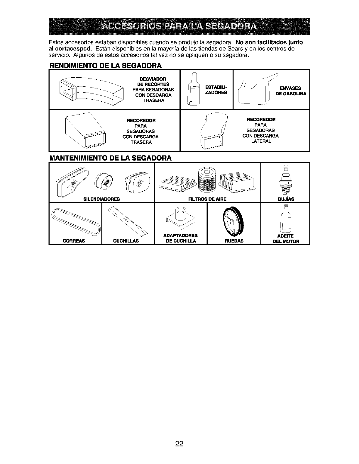
Estos accesorios estaban disponibles cuando se produjo la segadora. No son facilitados junto
al cortacesped. Est&n disponibles en la mayorfa de las tiendas de Sears y en los centros de
servicio. Algunos de estos accesorios tat vez no se apliquen a su segadora.
RENDIMIENTO DE LA SEGADORA
__ DESVIADOR
DE RECORTES
PARA SEGADORAS ESTABILI-
CON DESCARGA ZADORES
TRASERA
RECOREDOR RECOREDOR
PARA PAPA
SEGADORAS SEGADORAS
CON DESCARGA CON DESCARGA
TRASERA LATERAL
MANTENIMIENTO DE LA SEGADORA
SILENCIADORES FILTROS DE AIRE BUJIAS
ADAPTADORE8 ACEITE
CORREAS CUCHILLAS DE CUCHILLA RUEDAS DEL MOTOR
22
Lea estas instrucciones y el manual completamente antes de tratar de montar u operar su segadora nueva.
IMPORTANTE: Este cortacesped viene SIN ACEITE O GASOLINA en el motor.
Su segadora nueva ha sido montada en la f&brica con la excepci6n de aquellas partes que se
dejaron sin montar por razones de envio. Todas las partes como las tuercas, las arandelas, los
pernos, etc., que son necesarias para completar el montaje han sido colocadas en ta bolsa de
partes. Para asegurarse que su segadora funcione en forma segura y adecuada, todas las par-
tes y los artfculos de ferreteria que se monten tienen que ser apretados seguramente. Use las
herramientas correctas, como sea necesario, para asegurar que se aprieten adecuadamente.
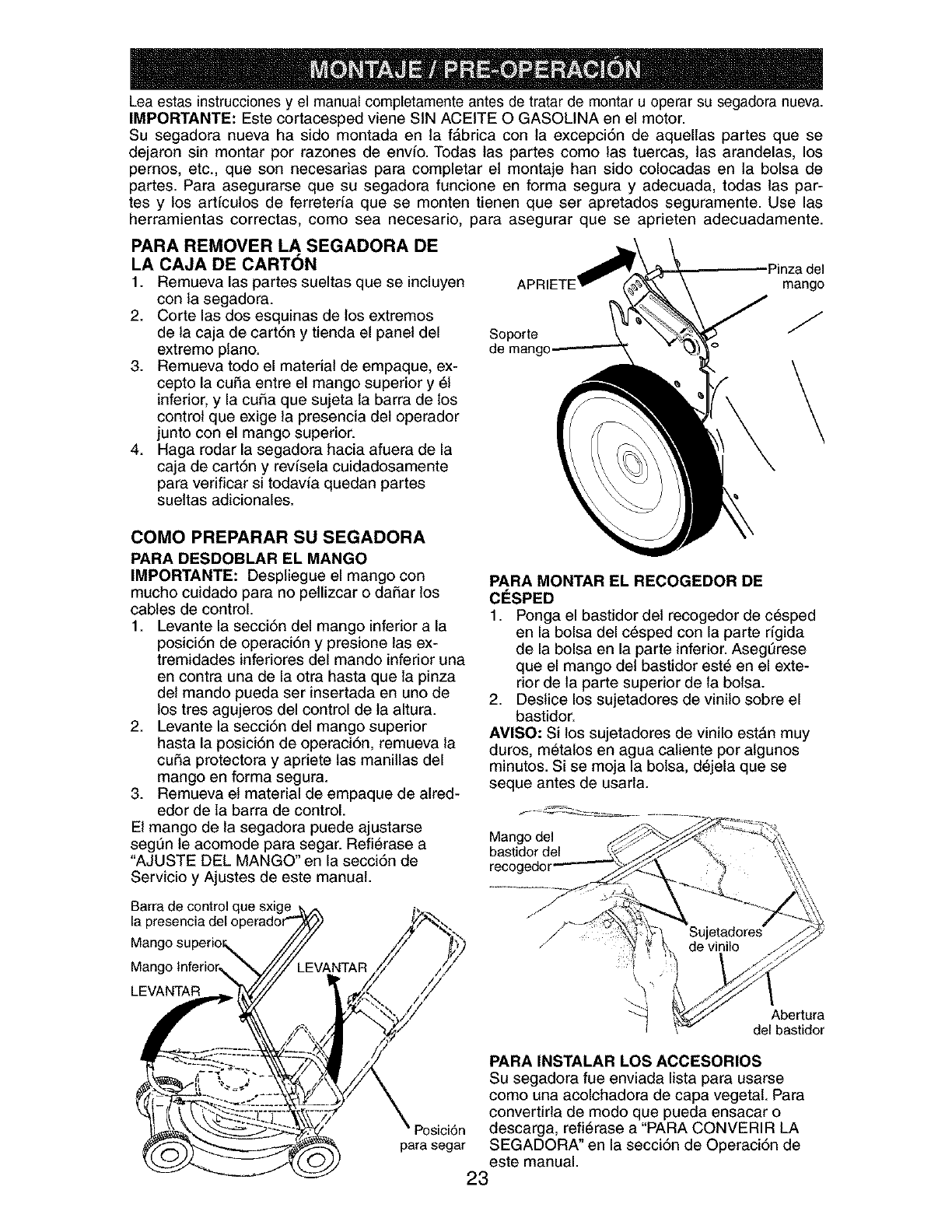
PARA REMOVER LA SEGADORA DE
LA CAJA DE CARTON
1. Remueva las partes sueltas que se incluyen
con la segadora.
2. Corte las dos esquinas de los extremos
de la caja de cart6n y tienda el panel del
extremo piano.
3. Remueva todo el material de empaque, ex-
cepto la cuSa entre el mango superior y 51
inferior, y la cui_a que sujeta la barra de los
control que exige la presencia del operador
junto con el mango superior.
4. Haga rodar la segadora hacia afuera de la
caja de cart6n y revfsela cuidadosamente
para verificar si todavia quedan partes
sueltas adicionales.
Soporte
de mang(
Pinza del
mango
J
\
COMO PREPARAR SU SEGADORA
PARA DESDOBLAR EL MANGO
IMPORTANTE: Despliegue el mango con
mucho cuidado para no pellizcar o daSar los
cables de control.
1. Levante la secci6n del mango inferior a la
posici6n de operaci6n y presione las ex-
tremidades inferiores del mando inferior una
en contra una de la otra hasta que la pinza
det mando pueda ser insertada en uno de
los tres agujeros del control de ta altura.
2. Levante la secci6n del mango superior
hasta la posici6n de operaci6n, remueva la
cuSa protectora y apriete las manillas del
mango en forma segura.
3. Remueva et material de empaque de alred-
edor de la barra de control.
El mango de la segadora puede ajustarse
segL]n le acomode para segar. Refi_rase a
"AJUSTE DEL MANGO" en la secci6n de
Servicio y Ajustes de este manual.
Barra de control que sxige
la presencia del o
PARA MONTAR EL RECOGEDOR DE
CESPED
1. Ponga el bastidor del recogedor de c6sped
en la bolsa del c_sped con la parte rfgida
de la bolsa en la parte inferior. Asegt]rese
que el mango del bastidor est_ en el exte-
rior de la parte superior de la bolsa.
2. Destice los sujetadores de vinilo sobre el
bastidor.
AMISO: Si los sujetadores de vinilo est&n muy
duros, m_talos en agua caliente por algunos
minutos. Si se moja la bolsa, d6jela que se
seque antes de usarla.
Mango del
bastidor del
Mango lnferior,_
LEVANTAR
"_ Abertura
del bastidor
Posici6n
para segar
PARA INSTALAR LOS ACCESORIOS
Su segadora fue enviada lista para usarse
como una acolchadora de capa vegetal. Para
convertirla de modo que pueda ensacar o
descarga, refi6rase a "PARA CONVERIR LA
SEGADORA" en la secci6n de Operaci6n de
este manual.
23
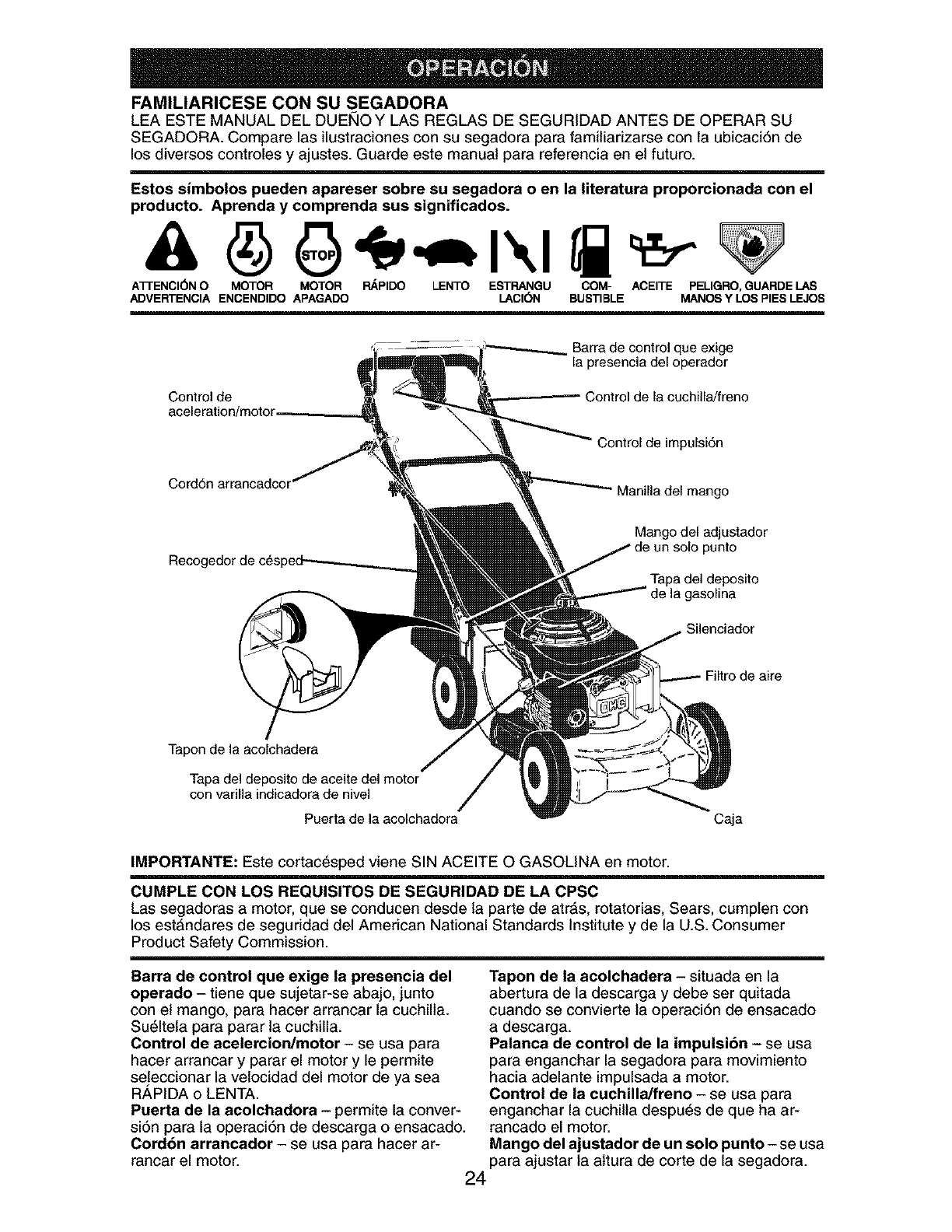
FAMILIARICESE CON SU SEGADORA
LEA ESTE MANUAL DEL DUEI_IO Y LAS REGLAS DE SEGURIDAD ANTES DE OPERAR SU
SEGADORA. Compare las ilustraciones con su segadora para familiarizarse con la ubicaci6n de
los diversos controles y ajustes. Guarde este manual para referencia en el futuro.
Estos simbolos pueden apareser sobre su segadora o en la literatura proporcionada con el
producto. Aprenda y comprenda sus significados.
ATI'ENCI(_N O MOTOR MOTOR RAPIDO LENTO ESTRANGU COM- ACEITE PELIGRO, GUARDE LAS
ADVERTENCIA ENCENDIDO APAGADO LACI(_N BUSTIBLE MANOS Y LOS PIES LEJOS
Control de
Barra de control que exige
la presencia del operador
Control de la cuchilla/freno
Control de impulsi6n
Cord6n arrancadc(
Mango del adjustador
punto
Tapa del deposito
de la gasolina
Silenciador
de aire
Tapon de la acolchadera
Tapa del deposito de aceite del motor
con varilla indicadora de nivel
Puerta de la acolchadora Caja
IMPORTANTE: Este cortac_sped viene SIN ACEITE O GASOLINA en motor.
CUMPLE CON LOS REQUISITOS DE SEGURIDAD DE LA CPSC
Las segadoras a motor, que se conducen desde la parte de atr&s, rotatorias, Sears, cumplen con
los estAndares de seguridad del American National Standards Institute y de la U.S. Consumer
Product Safety Commission.
Barra de control que exige la presencia del
operado- tiene que sujetar-se abajo, junto
con el mango, para hacer arrancar la cuchilla.
Su61tela para parar la cuchilla.
Control de acelercion/motor - se usa para
hacer arrancar y parar el motor y le permite
seleccionar la vetocidad del motor de ya sea
R,_,PIDA o LENTA.
Puerta de la acolchadora - permite la conver-
si6n para la operaci6n de descarga o ensacado.
Cordbn arrancador - se usa para hacer ar-
rancar el motor.
Tapon de la acolchadera - situada en la
abertura de la descarga y debe ser quitada
cuando se convierte la operaci6n de ensacado
a descarga.
Palanca de control de la impulsion - se usa
para enganchar la segadora para movimiento
hacia adelante impulsada a motor.
Control de la cuchilla/freno - se usa para
enganchar la cuchilla despu6s de que ha ar-
rancado el motor.
Mango del ajustador de un solo punto- se usa
para ajustar la attura de corte de la segadora.
24

La operaci6n de cualquier
segadora puede hacer que
satten objetos extrafios dentro de
sus ojos, Io que puede producir
dafios graves en 6stos. Siempre
use anteojos de seguridad o protecci6n para
los ojos mientras opere su segadora o cuando
haga ajustes o reparaciones. Recomendamos
gafas o una mascara de seguridad de visi6n
amplia de seguridad usada sobre las gafas.
COMO USAR SU SEGADORA
MANDO DE ACELERICION/MOTOR
El motor se acciona a trav6s de un mando de
mariposa situado en el lado de/mango superior.
La posici6n ESTRANGULACION se utiliza para
poner en marcha el motor; la posici6n RAPIDO
se utiliza para porter en marcha un motor tibio,
para un corte y acabado mejores y para ensacar
mejor la hierba; la posici6n LENTA se utiliza para
un corte ligero, para reatizar los acabados y para
ahorrar carburante; la posici6n STOP se utiliza
para parar el motor.
RAPIDO_ LE_NTAO
I\1
ESTRAN-
GULACIONL
,''v--. STO P
<. 11 /
Ii
J/i
J_l _ _
g" /,,// Ii
_ _,1( ///
dI_pNTROL DE LA CUCHILLA
RECAUCION: Cuando el mando de la
cuchilla est#, accionado, la cuchilla gira. Cuando
el mando de la cuchilla no est& accionado, la
cuchilla esta parada.
• Su segadora tiene un embrague de cuchilla/
freno sujetado al &rbol acodado del motor,
que acciona o para la cuchilla. Para accionar
la cuchilla, mantener la palanca de control
que exige la presencia del operador abajo
hacia el mango y presionar la palanca de
mando cuchillaJfreno hacia adelante hasta
que se enganche. Para detener la cuchilla,
soltar la palanca de control que exige la
presencia del operador.
AMISO: Permita que un motor frio se caliente
por un minuto antes de encender la cuchilla.
No accionar la cuchilla en presencia de hierba
muy alta por cortar. Llevar la segadora fuera de
_hierba alta antes de accionar la cuchilla.
RECAUCION: Las normativas federates
requieren que este mando de cuchillaJfreno
minimice el riesgo de heddas provocadas por
el contacto con la cuchilla. En ningt]n caso
intentar anular las funciones de mando.
Barra de control que exige Palanca
la presencia del operador de mando
cuchilla/freno
CONTROL DE LA IMPULSION
•La autopropulsi6n se controla manteniendo
la palanca de mando operador presente
abajo hacia el mango y tirando la palanca de
accionamiento atrAs hacia el mango. Cuanto
m&s lejos se tira la palanca hacia el mango,
m&s r_,pida ir& la unidad.
• El movimiento hacia adelante se detiene
cuando sea la palanca de mando operador
presente o la palanca de accionamiento se
sueltan. Para detener el movimiento hacia
adelante sin apagar el cuchilla, soltar s61o
la palanca de accionamiento. Mantener la
palanca de mando operador presente abajo
contra el mango para continuar a cortar sin
autopropulsi6n.
AMISO: Si despu6s haber desenganchado
de la palanca de control, la segadora no roda
hacia atrAs, empuje la segadora un poco hacia
adelante para desenganchar las ruedas de la
impulsi6n.
Barra de control que ,perador
PARA
Bot6n ajuste ENGANCHAR EL
(en la parte CONTROL DE LA
trasera) IMPULSION
Control
la impulsi6r
CONTROL DE LA
IMPULSION
DESENGANCHADO
AJUSTE DEL MANDO
Ocasionalmente, el sistema de mando puede
"aflojarse', provocando una disminuci6n de la
velocidad. Hay un bot6n en la parte trasera de
la sede del mando para apretar la tensi6n del
cable. Proceder de la siguiente manera:
1. Apagar la unidad y desconectar el cable de
bujia de la bujfa.
2. Tirar la palanca de accionamiento TODO
ATR/_S HACIA el mango.
3. Empujar el bot6n en la parte trasera del
mando. Con et bot6n apretado, revuelva la
palanca de controles det mecanismo impul-
sor a la posici6n desenganchada TODO
DELANTERO HACIA et mango.
AMISO: No el trinquete el ajuste.
4. Soltar el bot6n.
5. Opere la segadora para probar la velocidad
del mecanismo. Si tras los pasos descritos
arriba la situaci6n se empeora (la velocidad
de avance ha disminuido), el sistema no
estaba "aflojado'. Repitiendo los pasos de
arriba se vuelve la unidad at ajuste y veloci-
dad correctos.
6. Si las condiciones no mejoran despu6s
de los pasos descritos (la velocidad hacia
adelante queda la misma), la correa de
transmisi6n estA desgastada y tiene que ser
sustituida.
PARA DESCOr
ACCIONAR EXION DE
LA CUCHILL_ CUCHILLA 25
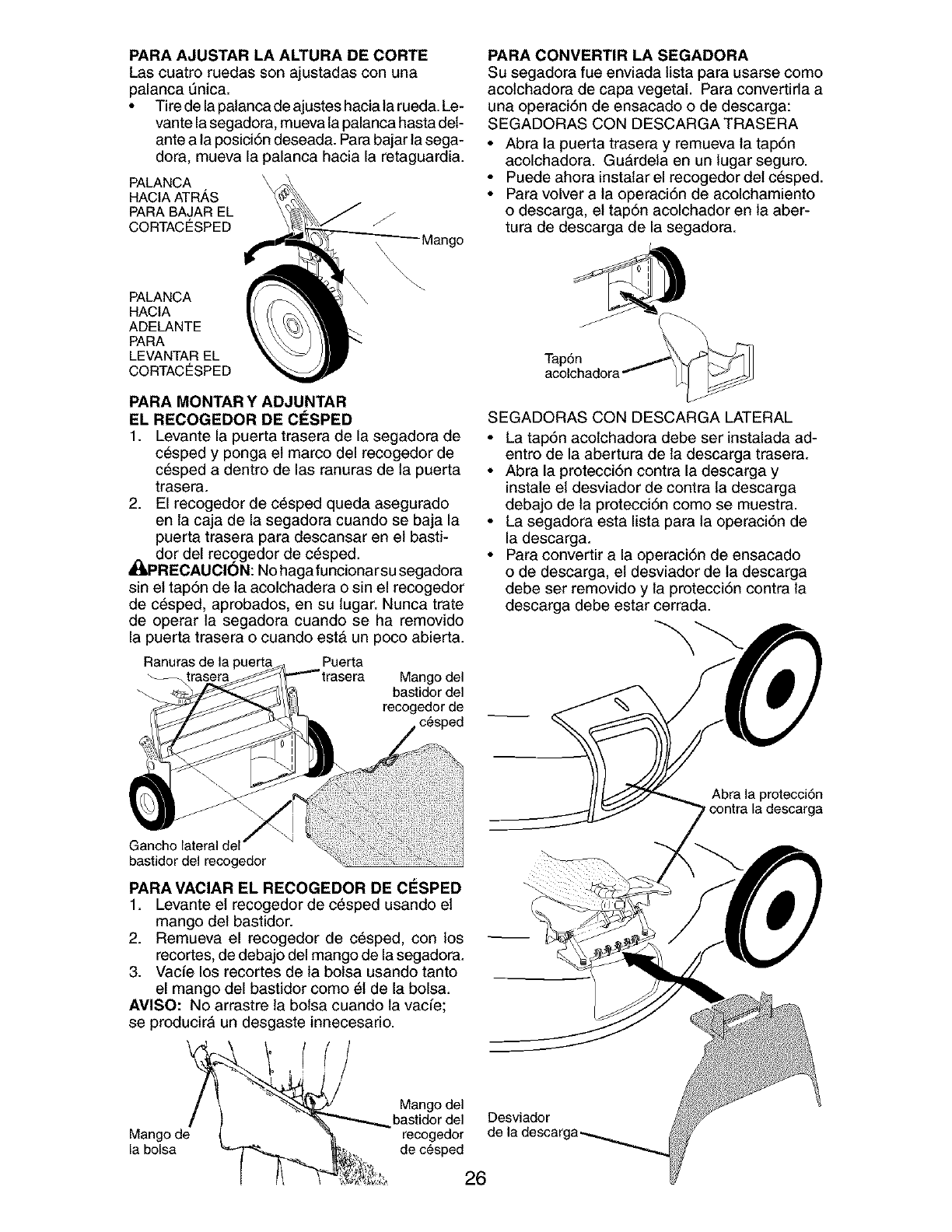
PARA AJUSTAR LA ALTURA DE CORTE
Las cuatro ruedas son ajustadas con una
palanca 0nica.
• Tire de la palanca de ajustes hacia la rueda. Le-
vante la segadora, mueva la palanca hasta det-
ante a la posici6n deseada. Para bajar la sega-
dora, mueva la palanca hacia la retaguardia.
PALANCA
HACIA ATRAS
PARA BAJAR EL
CORTACESPED
PALANCA
HACIA
ADELANTE
PARA
LEVANTAR EL
CORTACESPED
PARA CONVERTIR LA SEGADORA
Su segadora fue enviada lista para usarse come
acolchadora de capa vegetal. Para convertida a
una operaci6n de ensacado o de descarga:
SEGADORAS CON DESCARGA TRASERA
• Abra la puerta trasera y remueva la tap6n
acolchadora. Gu&rdela en un lugar seguro.
• Puede ahora instalar el recogedor del c6sped.
• Para volver a la operaci6n de acolchamiento
o descarga, el tap6n acolchador en la aber-
tura de descarga de la segadora.
Tap6n
PARA MONTAR Y ADJUNTAR
EL RECOGEDOR DE CESPED
1. Levante la puerta trasera de la segadora de
c6sped y ponga et marco del recogedor de
c6sped a dentro de las ranuras de la puerta
trasera.
2. El recogedor de c_sped queda asegurado
en la caja de la segadora cuando se baja la
puerta trasera para descansar en el basti-
_dor del recggedor de c_sped.
PRECAUClON: No haga funcionarsu segadora
sin el tap6n de la acolchadera o sin el recogedor
de c_sped, aprobados, en su lugar. Nunca trate
de operar la segadora cuando se ha removido
la puerta trasera o cuando est& un poco abierta.
Ranuras de la Puerta
Mango del
bastidor del
recogedor de
c_sped
bastidor del recogedor
PARA VACIAR EL RECOGEDOR DE ClaSPED
1. Levante el recogedor de c_sped usando el
mango del bastidor.
2. Remueva el recogedor de c_sped, con los
recortes, de debajo del mango de la segadora.
3. Vacfe los recortes de la bolsa usando tanto
el mango del bastidor como 61de la bolsa.
AMISO: No arrastre ta bolsa cuando la vacfe;
se producirA un desgaste innecesario.
Mango de
la bolsa
SEGADORAS CON DESCARGA LATERAL
• La tap6n acolchadora debe ser instalada ad-
entre de la abertura de la descarga trasera.
• Abra la protecci6n contra la descarga y
instale et desviador de contra la descarga
debajo de la protecci6n como se muestra.
• La segadora esta lista para la operaci6n de
la descarga.
• Para convertir a la operaci6n de ensacado
o de descarga, et desviador de ta descarga
debe ser removido y la protecci6n contra la
descarga debe estar cerrada.
Abra la protecci6n
,contra la descarga
Mango del
bastidor del Desviador
recogedor de
de c_sped
26
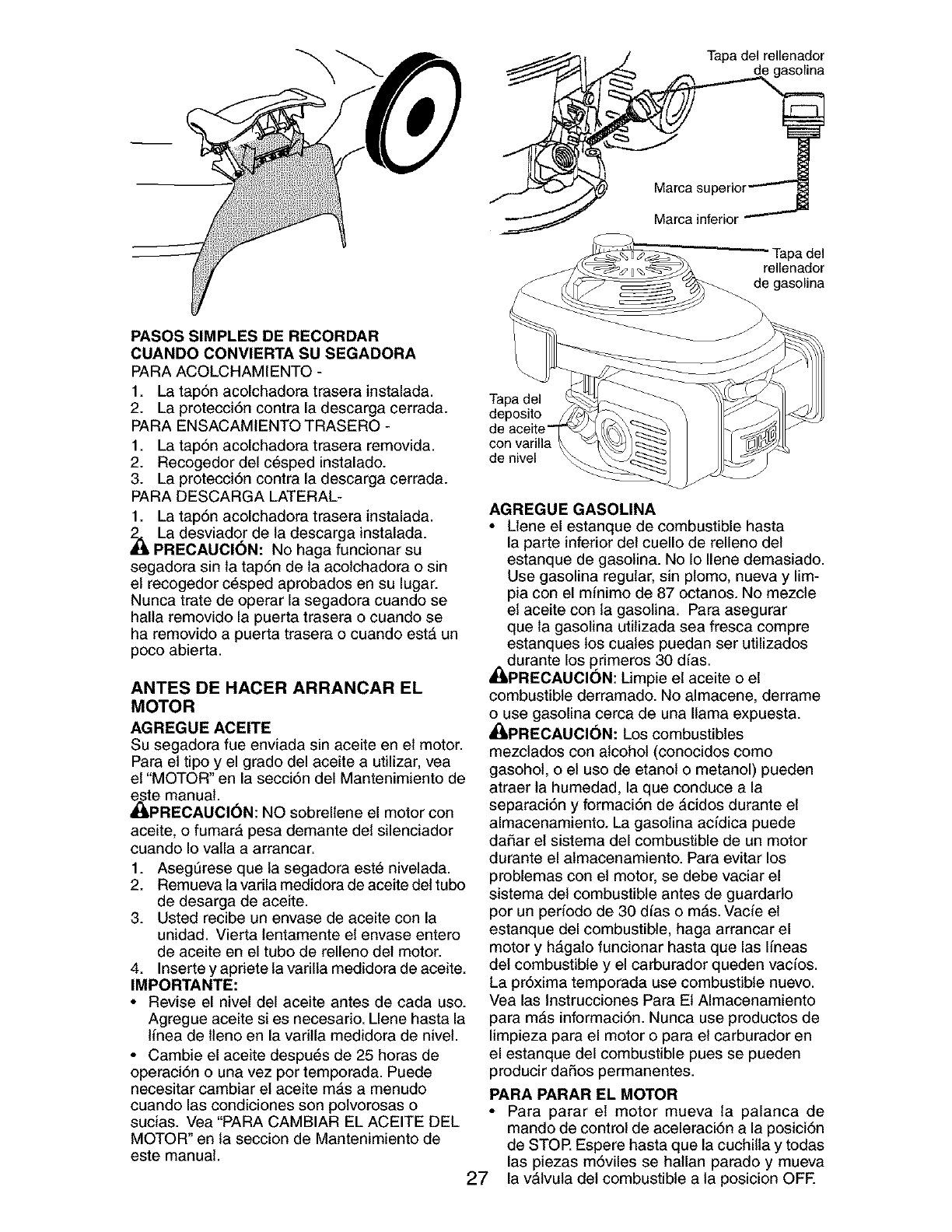
Tapa del rellenador
de gasolina
Mama superior"""
Mama inferior
rapadel
rellenador
de gasolina
PASOS SIMPLES DE RECORDAR
CUANDO CONVIERTA SU SEGADORA
PARA ACOLCHAMIENTO -
1. La tap6n acolchadora trasera instalada.
2. La protecci6n contra la descarga cerrada.
PARA ENSACAMIENTO TRASERO -
1. La tap6n acolchadora trasera removida.
2. Recogedor del c6sped instalado.
3. La protecci6n contra la descarga cerrada.
PARA DESCARGA LATERAL-
1. La tap6n acolchadora trasera instalada.
_La desviador de la descarga instalada.
PRECAUCION: No haga funcionar su
segadora sin la tap6n de la acolchadora o sin
el recogedor c_sped aprobados en su lugar.
Nunca trate de operar la segadora cuando se
halla removido la puerta trasera o cuando se
ha removido a puerta trasera o cuando est& un
poco abierta.
ANTES DE HACER ARRANCAR EL
MOTOR
AGREGUE ACEITE
Su segadora fue enviada sin aceite en el motor.
Para el tipo y el grado del aceite a utilizar, vea
el "MOTOR" en la secci6n del Mantenimiento de
_te manual.
PRECAUCI(_N: NO sobrellene el motor con
aceite, o fumar& pesa demante del silenciador
cuando Io valla a arrancar.
1. AsegSrese que la segadora est6 nivelada.
2. Remueva la varila medidora de aceite del tubo
de desarga de aceite.
3. Usted recibe un envase de aceite con la
unidad. Vierta lentamente el envase entero
de aceite en el tubo de relleno del motor.
4. Inserte y apriete la varilla medidora de aceite.
IMPORTANTE:
• Revise el nivel del aceite antes de cada uso.
Agregue aceite si es necesario. Llene hasta la
linea de lleno en la varilla medidora de nivel.
• Cambie el aceite despu6s de 25 horas de
operaci6n o una vez pot temporada. Puede
necesitar cambiar el aceite mAs a menudo
cuando las condiciones son polvorosas o
sucias. Vea "PARA CAMBIAR EL ACEITE DEL
MOTOR" en la seccion de Mantenimiento de
este manual.
Tapa del
deposito
con varilla
de nivel
AGREGUE GASOLINA
• Llene el estanque de combustible hasta
la parte inferior del cuello de relleno del
estanque de gasolina. No Io Ilene demasiado.
Use gasolina regular, sin plomo, nueva y lim-
pia con el minimo de 87 octanos. No mezcle
el aceite con la gasolina. Para asegurar
que la gasolina utilizada sea fresca compre
estanques los cuates puedan ser utilizados
durante los primeros 30 dfas.
_[I,PRECAUCION: Limpie et aceite o el
combustible derramado. No almacene, derrame
o use gasolina cerca de una llama expuesta.
_PREOAUCION: Los combustibles
mezctados con alcohol (conocidos como
gasohol, o el uso de etanol o metanol) pueden
atraer la humedad, la que conduce a la
separaci6n y formaci6n de &cidos durante el
almacenamiento. La gasolina acfdica puede
daSar el sistema del combustible de un motor
durante el almacenamiento. Para evitar los
problemas con el motor, se debe vaciar el
sistema del combustible antes de guardarlo
por un periodo de 30 dfas o m&s. Vacie el
estanque del combustible, haga arrancar el
motor y h&galo funcionar hasta que las lineas
del combustible y el carburador queden vacfos.
La pr6xima temporada use combustible nuevo.
Vea las Instrucciones Para Et Almacenamiento
para m&s informaci6n. Nunca use productos de
limpieza para el motor o para el carburador en
el estanque del combustible pues se pueden
producir daSos permanentes.
PARA PARAR EL MOTOR
• Para parar el motor mueva la palanca de
mando de control de aceleraci6n a la posici6n
de STOP. Espere hasta que la cuchilla y todas
las piezas m6viles se hallan parado y mueva
27 la vAlvula del combustible a la posicion OFF.
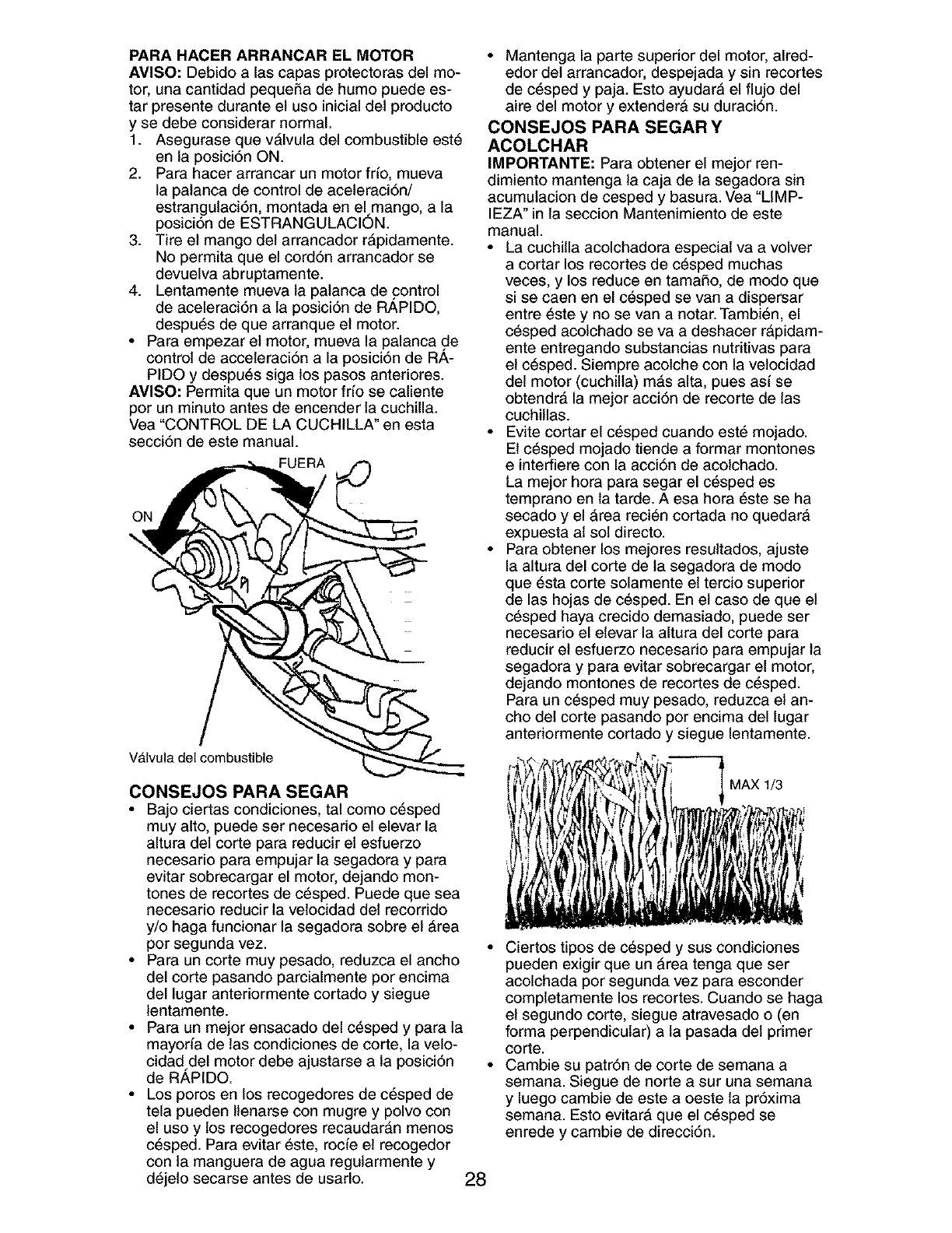
PARA HACER ARRANCAR EL MOTOR
AVISO: Debido alas capas protectoras del mo-
tor, una cantidad pequeSa de humo puede es-
tar presente durante el uso inicial del producto
y se debe considerar normal.
1. Asegurase que vAIvula del combustible est6
en la posici6n ON.
2. Para hacer arrancar un motor frfo, mueva
la palanca de control de aceleraci6n/
estrangulaci6n, montada en elmango, a la
posici6n de ESTRANGULACION.
3. Tire el mango del arrancador rApidamente.
No permita que el cord6n arrancador se
devuelva abruptamente.
4. Lentamente mueva la palanca de control
de aceleraci6n a la posici6n de RAPIDO,
despu6s de que arranque el motor.
• Para empezar el motor, mueva la palanca de
control de acceleraci6n a la posici6n de RA-
PIDO y despu6s siga los pasos anteriores.
AMISO: Permita que un motor fr[o se caliente
por un minuto antes de encender la cuchilla.
Vea "CONTROL DE LA CUCHILLA" en esta
secci6n de este manual.
FUERA
ON
VAIvula del combustible
CONSEJOS PARA SEGAR
• Bajo ciertas condiciones, tal como c_sped
muy alto, puede ser necesado el elevar la
altura del corte para reducir el esfuerzo
necesario para empujar la segadora y para
evitar sobrecargar el motor, dejando mon-
tones de recortes de c_sped. Puede que sea
necesario reducir la velocidad del recorrido
y/o haga funcionar la segadora sobre el Area
por segunda vez.
• Para un corte muy pesado, reduzca el ancho
del corte pasando parcialmente por encima
del lugar anteriormente cortado y siegue
lentamente.
• Para un mejor ensacado del c_sped y para la
mayoria de tas condiciones de corte, la velo-
cidad del motor debe ajustarse a la posici6n
de RAPIDO.
• Los poros en los recogedores de c6sped de
tela pueden llenarse con mugre y polvo con
el uso y los recogedores recaudarAn menos
c6sped. Para evitar 6ste, rocie el recogedor
con la manguera de agua regularmente y
d6jelo secarse antes de usarlo. 28
• Mantenga la parte superior del motor, alred-
edor del arrancador, despejada y sin recortes
de c_sped y paja. Esto ayudarA el flujo del
aire del motor y extenderA su duraci6n.
CONSEJOS PARA SEGAR Y
ACOLCHAR
IMPORTANTE: Para obtener el mejor ren-
dimiento mantenga la caja de la segadora sin
acumulacion de cesped y basura. Vea "LIMP-
IEZA" in la seccion Mantenimiento de este
manual.
• La cuchilla acolchadora especial va a volver
a cortar los recortes de c_sped muchas
veces, y los reduce en tamaSo, de modo que
si se caen en el c6sped se van a dispersar
entre 6ste y no se van a notar. Tambi6n, el
c_sped acolchado se va a deshacer rApidam-
ente entregando substancias nutritivas para
el c6sped. Siempre acolche con la vetocidad
del motor (cuchilla) mAs alta, pues asf se
obtendrA la mejor acci6n de recorte de las
cuchillas.
• Evite cortar el c_sped cuando est6 mojado.
El c6sped mojado tiende a formar montones
e interfiere con la acci6n de acolchado.
La mejor hora para segar el c_sped es
temprano en la tarde. A esa hora 6ste se ha
secado y el Area reci6n cortada no quedarA
expuesta al sol directo.
• Para obtener los mejores resultados, ajuste
la altura del corte de ta segadora de modo
que _sta corte solamente el tercio superior
de las hojas de c_sped. En el caso de que el
c_sped haya crecido demasiado, puede ser
necesado el elevar la altura del corte para
reducir el esfuerzo necesado para empujar la
segadora y para evitar sobrecargar el motor,
dejando montones de recortes de c_sped.
Para un c_sped muy pesado, reduzca el an-
cho del corte pasando por encima del lugar
anteriormente cortado y siegue lentamente.
MAXI_
• Ciertos tipos de c6sped y sus condiciones
pueden exigir que un Area tenga que set
acolchada por segunda vez para esconder
completamente los recortes. Cuando se haga
el segundo corte, siegue atravesado o (en
forma perpendicular) a la pasada del primer
corte.
• Cambie su patr6n de corte de semana a
semana. Siegue de norte a sur una semana
y luego cambie de este a oeste ta pr6xima
semana. Esto evitarA que el c_sped se
enrede y cambie de direcci6n.
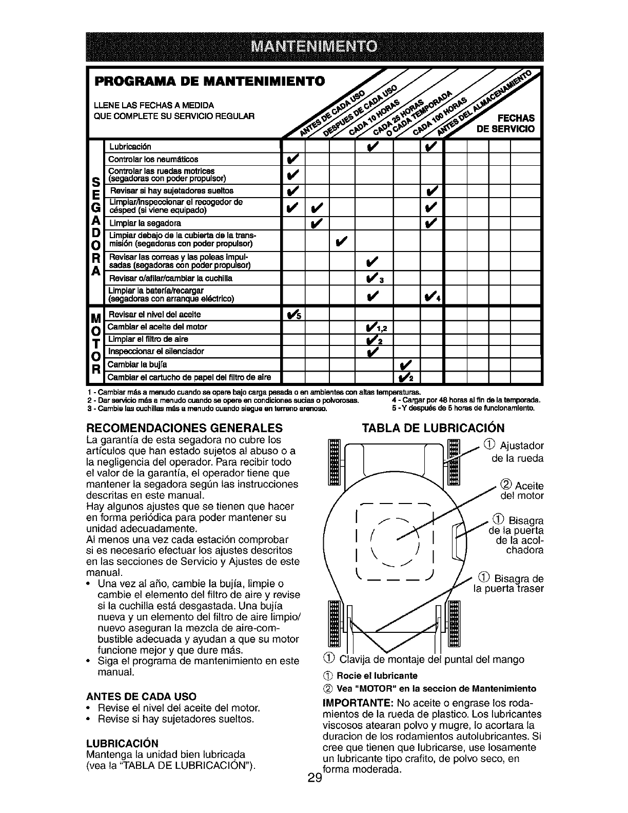
PROQRAMA DE MANTENIMIENTO /__ _-_'_
0u
Lubricaci6n ql_
Controlarlosneum_.ticos I_
v
Controlarlasruedasmotrices
S(segadoras con poder propulsor)Revisarsihaysujetadoressueltos V' V'
Limpiar/inspecoionar el recogedor de II_
G c_sped(sivieneequipado) I_ _
Limpiarlasegadora
Limpiar debajo delacubiertade latrans-
misidn(segadorasconpoderpropulsor)
R Revisarlascorreasylaspoleasimpul-
sadas (segadorascon poder propulsor) ll_
Revisaro/afilar/cambiarlacuchilla V' 3
Limpiarla baterfa/recargar
(segadorasconarranqueeldctrico) I_ VP4
MRevisarelniveldelacelte Vt'5
Cambiar el aceite del motor _1,2
Limpiar elfiltrodeairo _2
O Inspecci°narelsilenciad°r _ _2
Cambiarlabuj[a
Cambiarel cortuchode papel delfiltrodeaire
1 - Cambiarmdsa menudocuandose opensbajocarga pesadao en ambientesconalmstemperaturas.
2 - Dar servidomdsa menudo cuandose opensen condicionessudas o polvorosas. 4 - Cargarpor48 horasal finde la temporada.
3 - Cambielas cuchillasmdsa menudocuandosiegue en terrenoarenoso. 5 - Y despuef_sde 5 horasde funclonamlento.
RECOMENDACIONES GENERALES
La garantia de esta segadora no cubre los
art[culos que han estado sujetos at abuso o a
la negligencia del operador. Para recibir todo
el valor de la garant[a, el operador tiene que
mantener la segadora segdn las instrucciones
descritas en este manual.
Hay algunos ajustes que se tienen que hacer
en forma periddica para poder mantener su
unidad adecuadamente.
AI menos una vez cada estacidn comprobar
si es necesario efectuar los ajustes descdtos
en las secciones de Servicio y Ajustes de este
manual.
•Una vez al aSo, cambie la bujfa, limpie o
cambie el elemento del filtro de aire y revise
si la cuchilla est& desgastada. Una bujia
nueva y un elemento del filtro de aire limpio/
nuevo aseguran la mezcla de aire-com-
bustible adecuada y ayudan a que su motor
funcione mejor y que dure mAs.
• Siga el programa de mantenimiento en este
manual.
ANTES DE CADA USO
• Revise el nivel del aceite del motor.
• Revise si hay sujetadores sueltos.
LUBRICACION
Mantenga la unidad bien lubricada
(vea la "TABLA DE LUBRICACION').
TABLA DE LUBRICACION
Ajustador
de la rueda
(_) Aceite
del motor
Bisagra
de la puerta
de la acol-
chadora
(_ Bisagra de
la puerta traser
(_ Ciavija de montaje del puntal del mango
(_) Rocie el lubricante
(_) Vea "MOTOR" en la seccion de Mantenimiento
IMPORTANTE: No aceite o engrase los roda-
mientos de la rueda de plastico. Los lubricantes
viscosos atearan polvo y mugre, 1oacortara la
duracion de los rodamientos autolubficantes. Si
cree que tienen que lubricarse, use losamente
un lubricante tipo crafito, de polvo seco, en
29forma mederada.
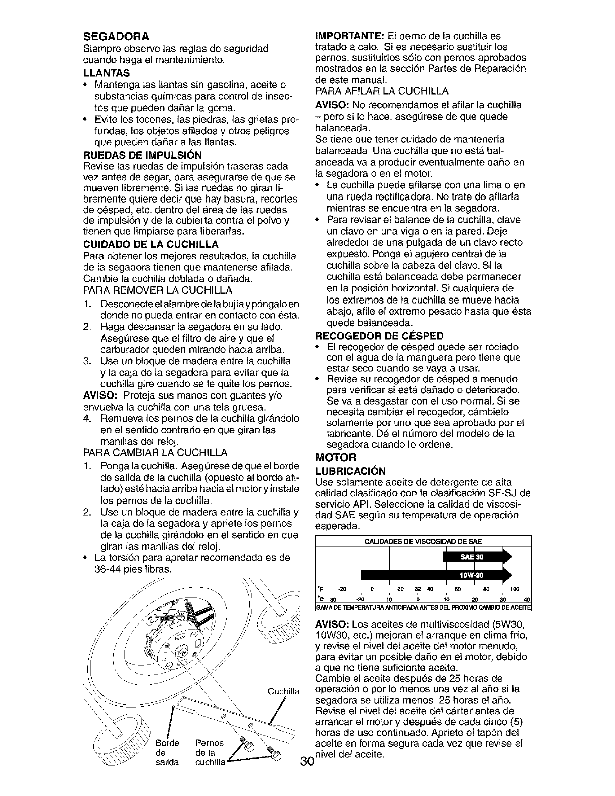
SEGADORA
Siempre observe las reglas de seguridad
cuando haga el mantenimiento.
LLANTAS
•Mantenga las llantas sin gasolina, aceite o
substancias qu[micas para control de insec-
tos que pueden dafiar la goma.
• Evite los tocones, las piedras, las gdetas pro-
fundas, los objetos afilados y otros peligros
que pueden dafiar alas Ilantas.
RUEDAS DE IMPULSION
Revise las ruedas de impulsi6n traseras cada
vez antes de segar, para asegurarse de que se
mueven libremente. Si las ruedas no giran li-
bremente quiere decir que hay basura, recortes
de c_sped, etc. dentro del Area de las ruedas
de impulsi6n y de la cubierta contra el polvo y
tienen que limpiarse para liberarlas.
CUIDADO DE LA CUCHILLA
Para obtener los mejores resultados, la cuchilla
de la segadora tienen que mantenerse afilada.
Cambie la cuchilla doblada o dafiada.
PARA REMOVER LA CUCHILLA
1. Desconecte el alambre de la bujfa y p6ngalo en
donde no pueda entrar en contacto con 6sta.
2. Haga descansar la segadora en su lado.
AsegSrese que el filtro de aire y que et
carburador queden mirando hacia ardba.
3. Use un bloque de madera entre la cuchilla
y la caja de la segadora para evitar que la
cuchilla gire cuando sete quite los pernos.
AMISO: Proteja sus manes con guantes y/o
envuelva la cuchilla con una tela gruesa.
4. Remueva los pernos de la cuchilla girAndolo
en el sentido contrado en que giran las
manillas del reloj.
PARA CAMBIAR LA CUCHILLA
1. Ponga la cuchilla. AsegSrese de que el borde
de salida de la cuchilla (opuesto al borde aft-
lado) est6 hacia ardba hacia el motory instale
los pernos de la cuchilla.
2. Use un bloque de madera entre la cuchilla y
la caja de la segadora y apdete los pernos
de la cuchilla gir_,ndolo en el sentido en que
giran las manillas det reloj.
• La torsi6n para apretar recomendada es de
36-44 pies libras.
Cuchilla
Borde
de
salida de la
cuchilla
IMPORTANTE: El perno de la cuchilla es
tratado a calo. Si es necesario sustituir los
pemos, sustituirlos s61o con pernos aprobados
mostrados en la secci6n Partes de Reparaci6n
de este manual.
PARA AFILAR LA CUCHILLA
AVISO: No recomendamos el afilar la cuchilla
- pero si Io hace, asegt]rese de que quede
balanceada.
Se tiene que tener cuidado de mantenerla
balanceada. Una cuchilla que no est& bal-
anceada va a producir eventuatmente dafio en
la segadora o en el motor.
• La cuchilla puede afilarse con una lima o en
una rueda rectificadora. No trate de afilarla
mientras se encuentra en la segadora.
• Para revisar el balance de la cuchilla, clave
un clavo en una viga o en la pared. Deje
alrededor de una pulgada de un clave recto
expuesto. Ponga el agujero central de la
cuchilla sobre la cabeza del clavo. Si ta
cuchilla est#, balanceada debe permanecer
en la posici6n horizontal. Si cualquiera de
los extremos de la cuchilla se mueve hacia
abajo, afile et extreme pesado hasta que 6sta
quede balanceada.
RECOGEDOR DE CESPED
• El recogedor de c_sped puede ser rociado
con el agua de la manguera pero tiene que
estar seco cuando se vaya a usar.
• Revise su recogedor de c_sped a menudo
para verificar siestA dafiado o deteriorado.
Se va a desgastar con el use normal. Si se
necesita cambiar el recogedor, cambielo
sotamente por uno que sea aprobado por el
fabricante. D_ el nt]mero del modelo de la
segadora cuando Io ordene.
MOTOR
LUBRICACI(_N
Use solamente aceite de detergente de alta
calidad clasificado con la clasificaci6n SF-SJ de
servicio API. Seleccione la catidad de viscosi-
dad SAE segSn su temperatura de operaci6n
esperada.
CALIDADES DE VISCOSIDAD DE SAE
"F ,.20 0 30 32 40 60 80 100
"c _o -_ -io o_o 2o 30
GAMA DE "_MPERAI1JRA AN'_CIPADA ANTES DEL PROXIMO CAMBIO DE ACEiTE
AVISO: Los aceites de multiviscosidad (5W30,
10W30, etc.) mejoran el arranque en clima frio,
y revise el nivel del aceite del motor menudo,
para evitar un posible dafio en el motor, debido
a que no tiene suficiente aceite.
Cambie el aceite despu6s de 25 horas de
operaci6n o per Io menos una vez al afio si la
segadora se utiliza menos 25 horas el afio.
Revise el nivel del aceite del c&rter antes de
arrancar el motor y despu6s de cada cinco (5)
horas de uso continuado. Apriete el tap6n del
aceite en forma segura cada vez que revise el
30nivel del aceite.
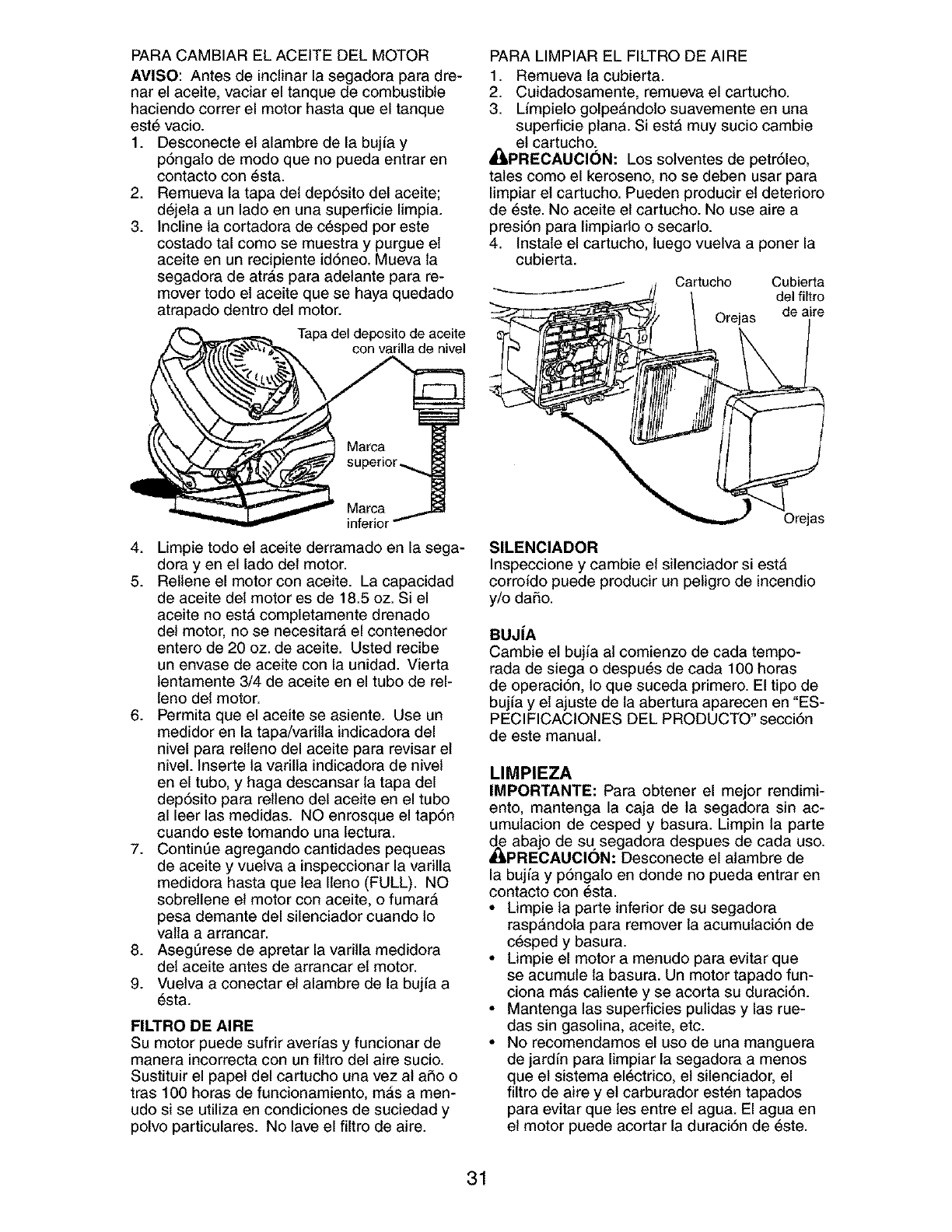
PARA CAMBIAR EL ACEITE DEL MOTOR
AVISO: Antes de inclinar la segadora para dre-
nar el aceite, vaciar el tanque de combustible
haciendo correr el motor hasta que el tanque
est6 vacio.
1. Desconecte el alambre de la bujfa y
p6ngato de modo que no pueda entrar en
contacto con 6sta.
2. Remueva la tapa del dep6sito del aceite;
d6jela a un lade en una superficie limpia.
3. Incline la cortadora de c_sped por este
costado tal como se muestra y purgue el
aceite en un recipiente id6neo. Mueva la
segadora de atrAs para adelante para re-
mover todo el aceite que se haya quedado
atrapado dentro del motor.
Tapa del deposito de aceite
con varilla de nivel
Marca
inferior
4. Limpie todo el aceite derramado en la sega-
dora yen el lado del motor.
5. Rellene el motor con aceite. La capacidad
de aceite det motor es de 18.5 oz. Si el
aceite no estA completamente drenado
del motor, no se necesitarA el contenedor
entero de 20 oz. de aceite. Usted recibe
un envase de aceite con la unidad. Vierta
lentamente 3/4 de aceite en el tubo de rel-
leno det motor.
6. Permita que el aceite se asiente. Use un
medidor en la tapa/varilla indicadora del
nivel para relleno del aceite para revisar el
nivel. Inserte la varilla indicadora de nivel
en el tubo, y haga descansar ta tapa del
dep6sito para relleno del aceite en el tubo
al leer las medidas. NO enrosque el tap6n
cuando este tomando una lectura.
7. ContinUe agregando cantidades pequeas
de aceite y vuelva a inspeccionar la varilla
medidora hasta que lea Ileno (FULL). NO
sobretlene el motor con aceite, o fumar_
pesa demante del silenciador cuando 1o
valla a arrancar.
8. Aseg_rese de apretar la varilla medidora
del aceite antes de arrancar el motor.
9. Vuetva a conectar el alambre de la bujfa a
6sta.
FILTRO DE AIRE
Su motor puede sufdr averfas yfuncionar de
manera incorrecta con un filtro del aire sucio.
Sustituir el papet del cartucho una vez al aSo o
tras 100 horas de funcionamiento, m_s a men-
udo si se utiliza en condiciones de suciedad y
polvo particulares. No lave el filtro de aire.
PARA LIMPIAR EL FILTRO DE AIRE
1. Remueva la cubierta.
2. Cuidadosamente, remueva el cartucho.
3. Limpielo golpe_ndolo suavemente en una
superficie plana. SiestA muy sucio cambie
el cartucho.
_I_PREOAUCI()N: Los solventes de petr61eo,
tales como el kerosene, no se deben usar para
limpiar el cartucho. Pueden producir el deterioro
de 6ste. No aceite el cartucho. No use aire a
presi6n para limpiarlo o secarlo.
4. Instale el cartucho, luego vuelva a poner la
cubierta.
Cartucho Cubierta
del filtro
Orejas de aire
Orejas
SlLENClADOR
Inspeccione y cambie et silenciador si est&
corroido puede producir un peligro de incendio
y/o daSo.
BUJ|A
Cambie et bujia at comienzo de cada tempo-
rada de siega o despu6s de carla 100 horas
de operaci6n, 1oque suceda primero. El tipo de
buj[a y el ajuste de la abertura aparecen en "ES-
PECIFICACIONES DEL PRODUCTO °secci6n
de este manual.
LIMPIEZA
IMPORTANTE: Para obtener el meier rendimi-
ento, mantenga la caja de la segadora sin ac-
umulacion de cesped y basura. Limpin ta parte
_._ abajo de su segadora despues de cada use.
PRECAUCION: Desconecte el atambre de
la bujfa y p6ngalo en donde no pueda entrar en
contacto con 6sta.
•Limpie la parte inferior de su segadora
rasp&ndola para remover la acumulaci6n de
c_sped y basura.
• Limpie el motor a menudo para evitar que
se acumule la basura. Un motor tapado fun-
ciona m&s catiente y se acorta su duraci6n.
• Mantenga las superficies pulidas y las rue-
das sin gasolina, aceite, etc.
• No recomendamos el uso de una manguera
de jardfn para limpiar la segadora a menos
que el sistema el_ctrico, el silenciador, el
filtro de aire y el carburador est6n tapados
para evitar que les entre el agua. El agua en
el motor puede acortar la duraci6n de 6ste.
31
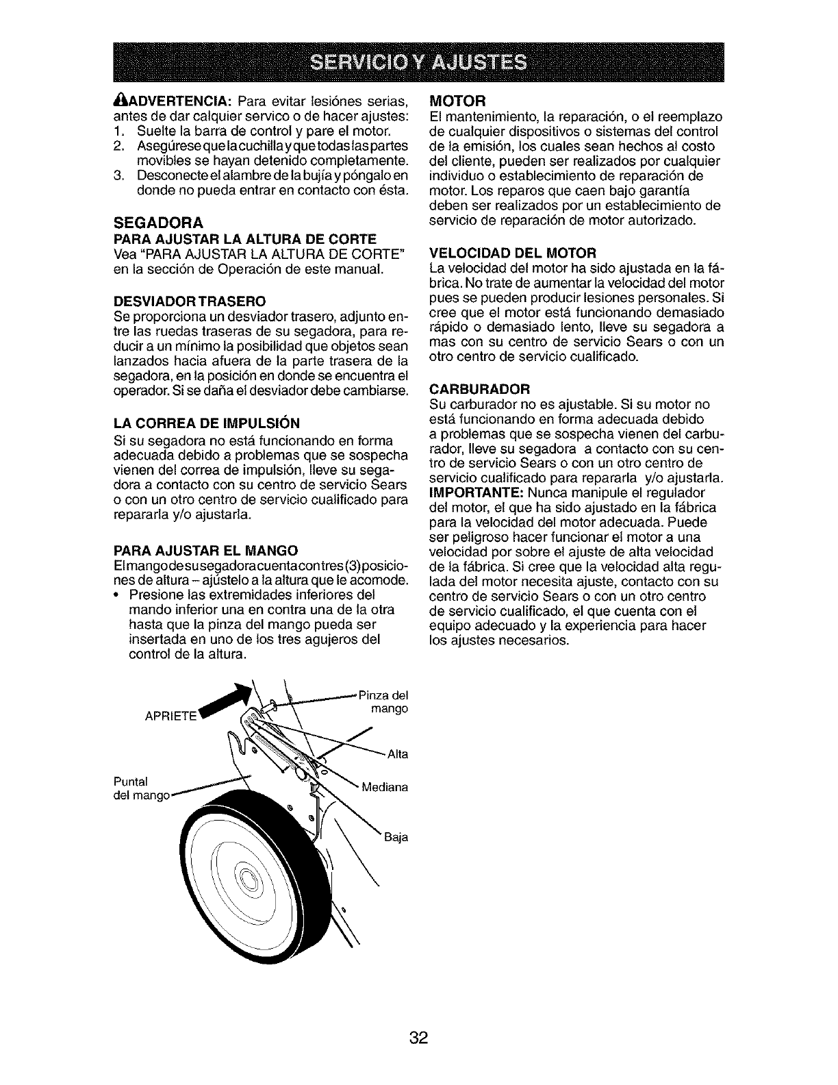
_';LADVERTENCIA: Para evitar lesi6nes serias,
antes de dar calquier service o de hacer ajustes:
1. Suelte la barra de control y pare el motor.
2. Asegt]rese que lacuchillayque todaslas partes
movibles se hayan detenido completamente.
3. Desconecte el alambre de la bujia y p6ngalo en
donde no pueda entrar en contacto con 6sta.
SEGADORA
PARA AJUSTAR LA ALTURA DE CORTE
Vea "PARA AJUSTAR LA ALTURA DE CORTE"
en la secci6n de Operaci6n de este manual.
DESVIADOR TRASERO
Se proporciona un desviador trasero, adjunto en-
tre las ruedas traseras de su segadora, para re-
ducir a un m[nimo la posibilidad que objetos sean
lanzados hacia afuera de la parte trasera de la
segadora, en la posici6n en donde se encuentra el
operador. Si se dafia el desviador debe cambiarse.
LA CORREA DE IMPULSION
Si su segadora no esta funcionando en forma
adecuada debido a problemas que se sospecha
vienen del correa de impulsi6n, Ileve su sega-
dora a contacto con su centre de servicio Sears
o con un otro centre de servicio cualificado para
repararla y/o ajustarla.
PARA AJUSTAR EL MANGO
Elmangode susegadoracuentacontres(3) posicio-
nes de altura- ajt_stelo a la altura que le acomode.
• Presione las extremidades infedores del
mando inferior una en contra una de ta otra
hasta que la pinza del mango pueda ser
insertada en uno de los tres agujeros del
control de la altura.
MOTOR
El mantenimiento, la reparaci6n, o el reemplazo
de cualquier dispositivos o sistemas del control
de ta emisi6n, los cuales sean hechos al costo
del cliente, pueden ser realizados per cualquier
individuo o establecimiento de reparaci6n de
motor. Los reparos que caen bajo garantfa
deben ser realizados por un establecimiento de
servicio de reparaci6n de motor autorizado.
VELOCIDAD DEL MOTOR
La vetocidad del motor ha sido ajustada en la f#,-
brica. No trate de aumentar la velocidad del motor
pues se pueden producir lesiones personales. Si
cree que el motor est#, funcionando demasiado
rApido o demasiado lento, Ileve su segadora a
mas con su centre de servicio Sears o con un
otro centro de servicio cualificado.
CARBURADOR
Su carburador no es ajustable. Si su motor no
est#, funcionando en forma adecuada debido
a problemas que se sospecha vienen del carbu-
rador, Ileve su segadora a contacto con su cen-
tre de servicio Sears o con un otto centro de
servicio cuatificado para repararla y/o ajustarla.
IMPORTANTE: Nunca manipule el regulador
det motor, el que ha sido ajustado en la fAbrica
para la velocidad del motor adecuada. Puede
ser peligroso hacer funcionar el motor a una
velocidad por sobre el ajuste de alta velocidad
de la f_,brica. Si cree que la velocidad alta regu-
lada del motor necesita ajuste, contacto con su
centro de servicio Sears o con un otro centre
de servicio cualificado, el que cuenta con el
equipo adecuado y la experiencia para hacer
los ajustes necesarios.
mango
Puntal
-AIta
32
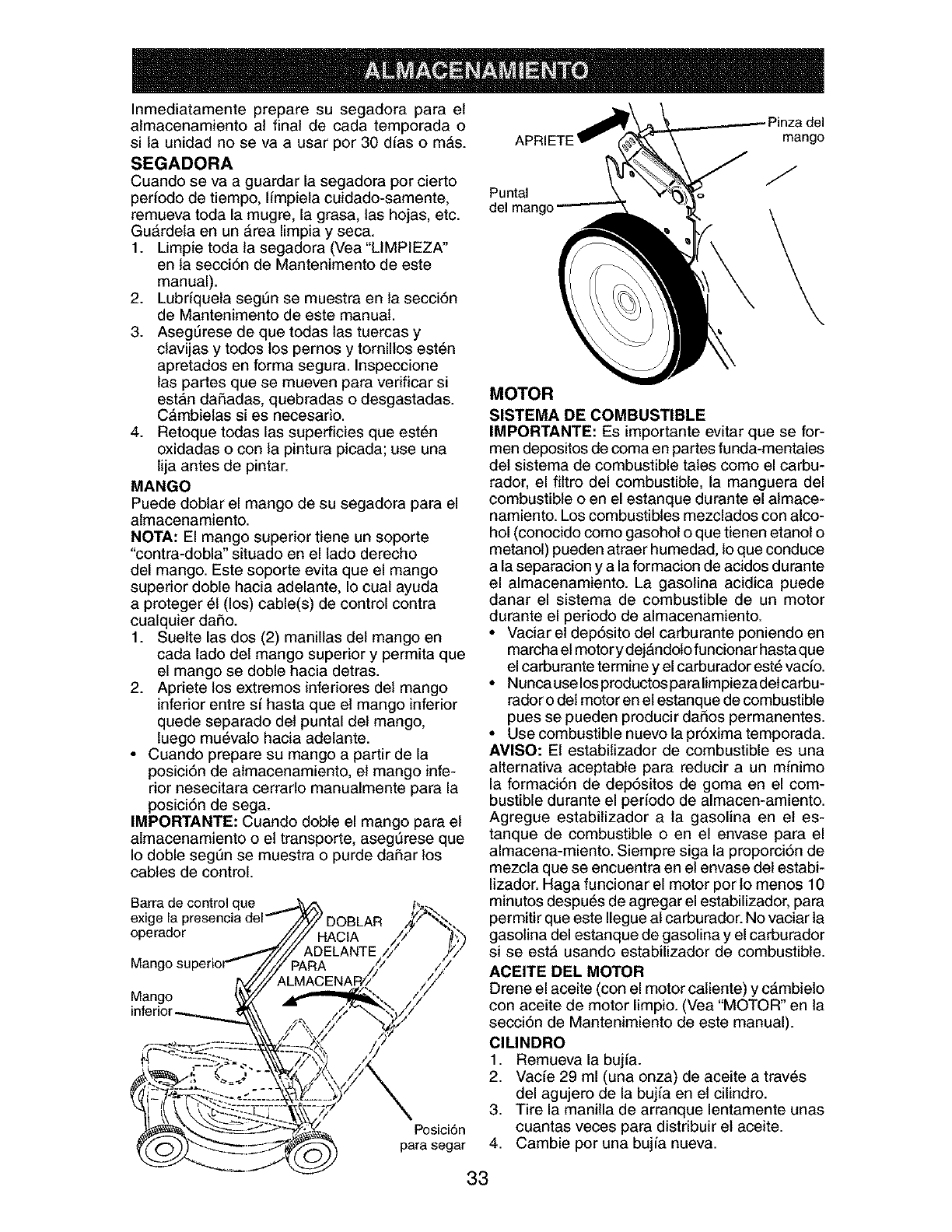
Inmediatamente prepare su segadora para el
atmacenamiento at final de cada temporada o
si la unidad no se va a usar por 30 dfas o m&s.
SEGADORA
Cuando se va a guardar la segadora por cierto
periodo de tiempo, limpiela cuidado-samente,
remueva toda la mugre, la grasa, las hojas, etc.
GuArdeta en un &rea limpia y seca.
1. Limpie toda ta segadora (Vea "LIMPIEZA"
en ta secci6n de Mantenimento de este
manual).
2. Lubriquela segSn se muestra en la secci6n
de Mantenimento de este manual.
3. Aseg_rese de que todas las tuercas y
ctavijas y todos los pernos y tornillos est6n
apretados en forma segura. Inspeccione
las partes que se mueven para verificar si
estan dai_adas, quebradas o desgastadas.
C&mbielas si es necesario.
4. Retoque todas las superficies que est6n
oxidadas o con la pintura picada; use una
lija antes de pintar.
MANGO
Puede doblar el mango de su segadora para el
almacenamiento.
NOTA: El mango superior tiene un soporte
"contra-dobla" situado en el lado derecho
del mango. Este soporte evita que el mango
superior doble hacia adelante, Io cual ayuda
a proteger 51(los) cable(s) de control contra
cualquier daSo.
1. Suelte las dos (2) manillas del mango en
cada lado del mango superior y permita que
el mango se doble hacia detras.
2. Apriete los extremes inferiores del mango
inferior entre s[ hasta que el mango inferior
quede separado det puntal del mango,
luego mu_vato hacia adelante.
• Cuando prepare su mango a partir de la
posici6n de almacenamiento, el mango infe-
rior nesecitara cerrarlo manualmente para la
posici6n de sega.
IMPORTANTE: Cuando doble el mango para el
almacenamiento o el transporte, asegt_rese que
Io doble segt]n se muestra o purde daSar los
cables de control.
Barra de control que
operador
Mango
Posici6n
para segar
Puntal
del mango
mango
MOTOR
SISTEMA DE COMBUSTIBLE
IMPORTANTE: Es importante evitar que se for-
men depositos de coma en partes funda-mentales
det sistema de combustible tales como el carbu-
rador, el filtro del combustible, la manguera del
combustible o en el estanque durante el almace-
namiento. Los combustibles mezclados con alco-
hol (conocido como gasohol o que tienen etanol o
metanol) pueden atraer humedad, lo que conduce
a la separacion y a la formacion de acidos durante
el almacenamiento. La gasolina acidica puede
danar el sistema de combustible de un motor
durante el periodo de almacenamiento.
• Vaciar el dep6sito del carburante poniendo en
marcha el motor y dej&ndolo funcionar hasta que
el carburante termine y el carburador est_ vacio.
• Nunca use los productos paralimpieza detcarbu-
rador o del motor en et estanque de combustible
pues se pueden producir daSos permanentes.
• Use combustible nuevo la pr6xima temporada.
AVlSO: El estabilizador de combustible es una
altemativa aceptable para reducir a un mfnimo
la formaci6n de dep6sitos de goma en el com-
bustible durante el perfodo de almacen-amiento.
Agregue estabilizador a la gasolina en et es-
tanque de combustible o en el envase para el
almacena-miento. Siempre siga la proporci6n de
mezcla que se encuentra en el envase del estabi-
lizador. Haga funcionar el motor por to menos 10
minutos despu6s de agregar el estabilizador, para
permitir que este Ilegue al carburador. No vaciar la
gasolina del estanque de gasolina y el carburador
si se est#, usando estabilizador de combustible.
ACEITE DEL MOTOR
Drene el aceite (con el motor caliente) y c_mbielo
con aceite de motor limpio. (Vea "MOTOR" en la
secci6n de Mantenimiento de este manual).
CILINDRO
1. Remueva la bujfa.
2. Vac[e 29 ml (una onza) de aceite a trav_s
del agujero de la bujia en el cilindro.
3. Tire la manilla de arranque lentamente unas
cuantas veces para distribuir el aceite.
4. Cambie por una bujfa nueva.
33
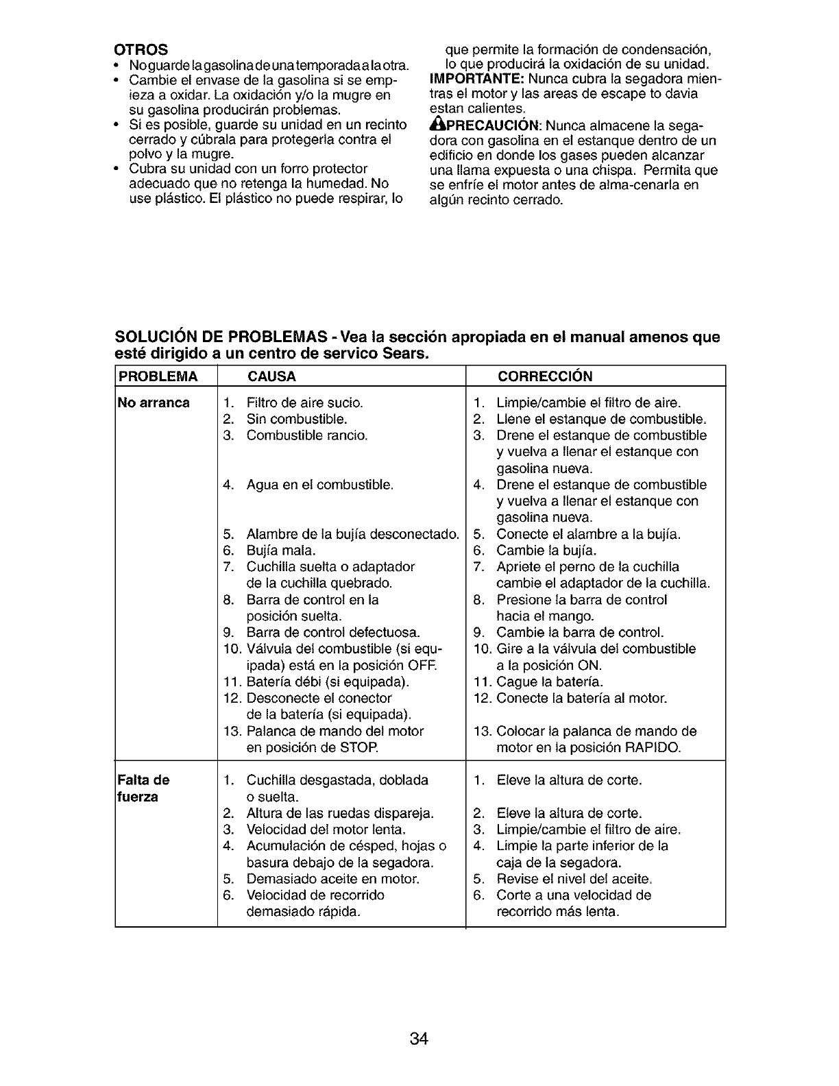
OTROS
• No guarde lagasolina de una temporada a la otra.
• Cambie el envase de la gasolina si se emp-
ieza a oxidar. La oxidaci6n y/o la mugre en
su gasolina producir&n problemas.
• Si es posible, guarde su unidad en un recinto
cerrado y c_brala para protegerla contra el
polvo y la mugre.
• Cubra su unidad con un forro protector
adecuado que no retenga la humedad. No
use pl&stico. El pl&stico no puede respirar, 1o
que permite la formaci6n de condensaci6n,
Io que producirA la oxidaci6n de su unidad.
IMPORTANTE: Nunca cubra la segadora mien-
tras el motor y las areas de escape to davia
estan catientes.
_ilLPRECAUCI(_N: Nunca almacene la sega-
dora con gasolina en el estanque dentro de un
edificio en donde los gases pueden alcanzar
una llama expuesta o una chispa. Permita que
se enfrfe el motor antes de atma-cenarla en
algt]n recinto cerrado.
SOLUCION DE PROBLEMAS -Vea la secci6n apropiada en el manual amenos que
est_ dirigido a un centro de servico Sears.
PROBLEMA CAUSA
No arranca 1. Filtro de aire sucio.
2. Sin combustible.
3. Combustible rancio.
4. Agua en el combustible.
5. Alambre de la bujia desconectado.
6. Bujia mala.
7. Cuchilla suelta o adaptador
de la cuchilla quebrado.
8. Barra de control en la
posici6n suelta.
9. Barra de control defectuosa.
10. V_,lvula del combustible (si equ-
ipada) est& en la posici6n OFE
11. Bateria d6bi (si equipada).
12. Desconecte el conector
de la bater[a (si equipada).
13. Palanca de mando del motor
en posici6n de STOP.
Falta de 1. Cuchilla desgastada, doblada
fuerza o suelta.
2. Altura de las ruedas dispareja.
3. Velocidad del motor lenta.
4. Acumulaci6n de c_sped, hojas o
basura debajo de la segadora.
5. Demasiado aceite en motor.
6. Velocidad de recorrido
demasiado r&pida.
CORRECCION
1. Limpie/cambie el filtro de aire.
2. Ltene el estanque de combustible.
3. Drene el estanque de combustible
y vuelva a llenar el estanque con
gasolina nueva.
4. Drene el estanque de combustible
y vuelva a llenar el estanque con
gasolina nueva.
5. Conecte el atambre a la bujia.
6. Cambie la buj[a.
7. Apriete el perno de la cuchilla
cambie el adaptador de la cuchilla.
8. Presione la barra de control
hacia el mango.
9. Cambie la barra de control.
10. Gire a la vAlvula del combustible
a la posici6n ON.
11. Cague la bateria.
12. Conecte la bater[a al motor.
13. Colocar la patanca de mando de
motor en la posici6n RAPIDO.
1. Eleve la attura de corte.
2. Eleve la altura de corte.
3. Limpie/cambie el filtro de aire.
4. Limpie la parte inferior de la
caja de la segadora.
5. Revise el nivel del aceite.
6. Corte a una velocidad de
recorrido mAs lenta.
34
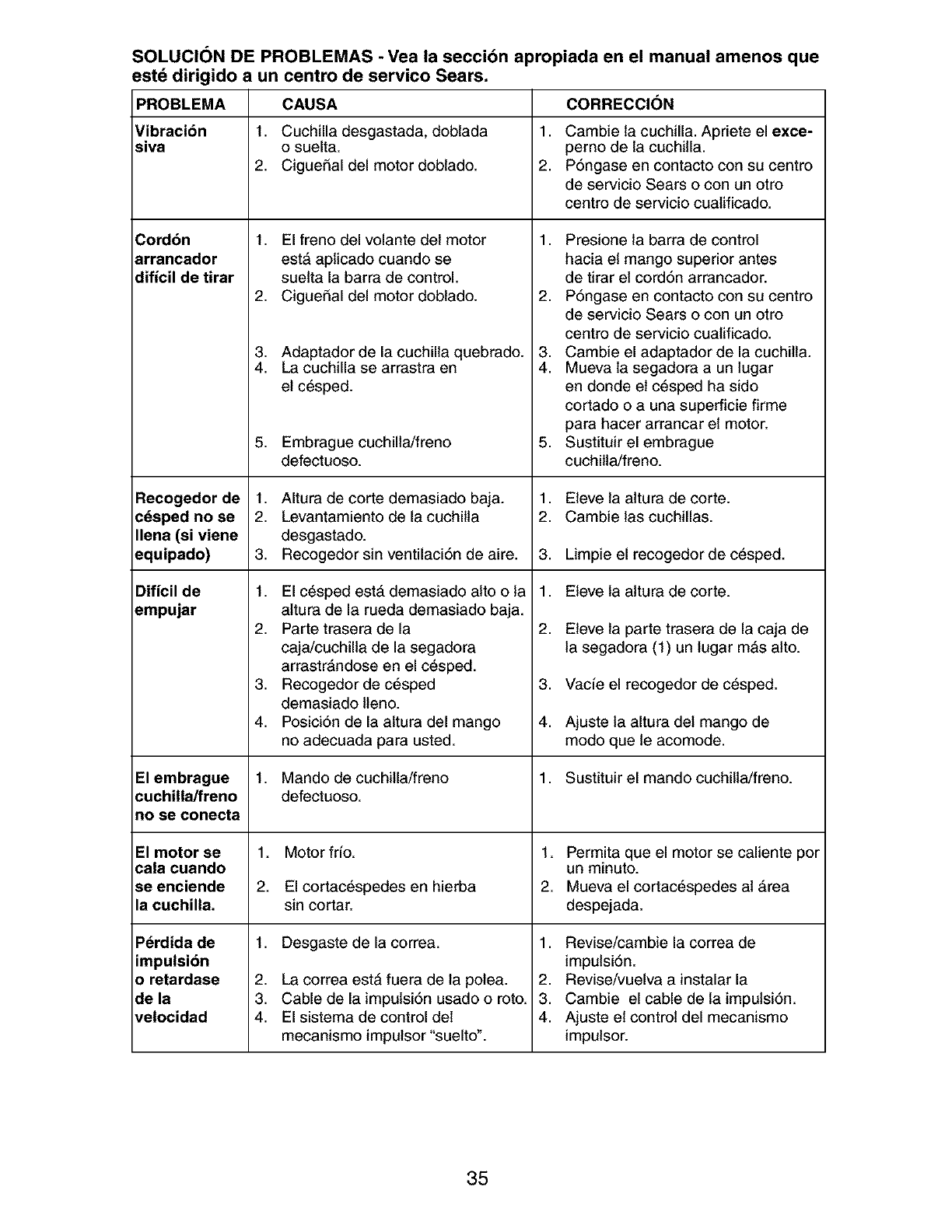
SOLUCION DE PROBLEMAS - Vea la secci6n apropiada en el manual amenos que
estd dirigido a un centro de servico Sears.
PROBLEMA CAUSA CORRECCI()N
Vibracion 1. Cuchilla desgastada, doblada 1. Cambie la cuchilla. Apriete el exce-
siva o suelta, perno de la cuchilla.
2. CigueSal del motor doblado. 2. P6ngase en contacto con su centro
de servicio Sears o con un otro
centro de servicio cualificado.
Cordbn
arrancador
dificil de tirar
Recogedor de
c_sped no se
Ilena (si viene
equipado)
Dificil de
empujar
1. El freno del volante del motor
estA aplicado cuando se
suelta la barra de control.
2. CigueiSal del motor doblado.
3. Adaptador de la cuchilla quebrado.
4. La cuchilla se arrastra en
el c_sped.
5. Embrague cuchilla/freno
defectuoso.
1. Altura de corte demasiado baja.
2. Levantamiento de la cuchilla
desgastado.
3. Recogedor sin ventilaci6n de aire.
1. El c_sped est#, demasiado alto o la
altura de la rueda demasiado baja.
2. Parte trasera de la
caja/cuchilla de la segadora
arrastrAndose en el c_sped.
3. Recogedor de c6sped
demasiado lleno.
4. Posici6n de la altura del mango
no adecuada para usted.
1. Presione la barra de control
hacia el mango superior antes
de tirar el cord6n arrancador.
2. P6ngase en contacto con su centro
de servicio Sears o con un otro
centro de servicio cualificado.
3. Cambie el adaptador de la cuchilla.
4. Mueva la segadora a un lugar
en donde et c6sped ha sido
cortado o a una superficie firme
para hacer arrancar el motor.
5. Sustituir el embrague
cuchilla/freno.
1. Eleve ta altura de corte.
2. Cambie las cuchillas.
3. Limpie el recogedor de c_sped.
Motor frfo.
El cortac_spedes en hierba
sin cortar.
Desgaste de la correa.
La correa est_ fuera de la polea.
Cable de la impulsi6n usado o roto.
El sistema de control del
mecanismo impulsor "suelto".
1. Eleve la attura de corte.
2. Eteve la parte trasera de la caja de
la segadora (1) un lugar m&s alto.
3. Vacfe el recogedor de c_sped.
4. Ajuste la altura del mango de
modo que le acomode.
El embrague 1. Mando de cuchilla/freno 1. Sustituir el mando cuchilla/freno.
cuchilla/freno defectuoso.
no se conecta
El motor se 1. t. Permita que el motor se caliente por
cala cuando un minuto.
se enciende 2. 2. Mueva el cortac_spedes at _rea
la cuchilla, despejada.
1. 1.
Pdrdida de
impulsion
o retardase
de la
velocidad
2,
3.
4.
2,
3.
4.
Revise/cambie la correa de
impulsi6n.
Revise/vuelva a instalar la
Cambie el cable de la impulsi6n.
Ajuste el control del mecanismo
impulsor.
35
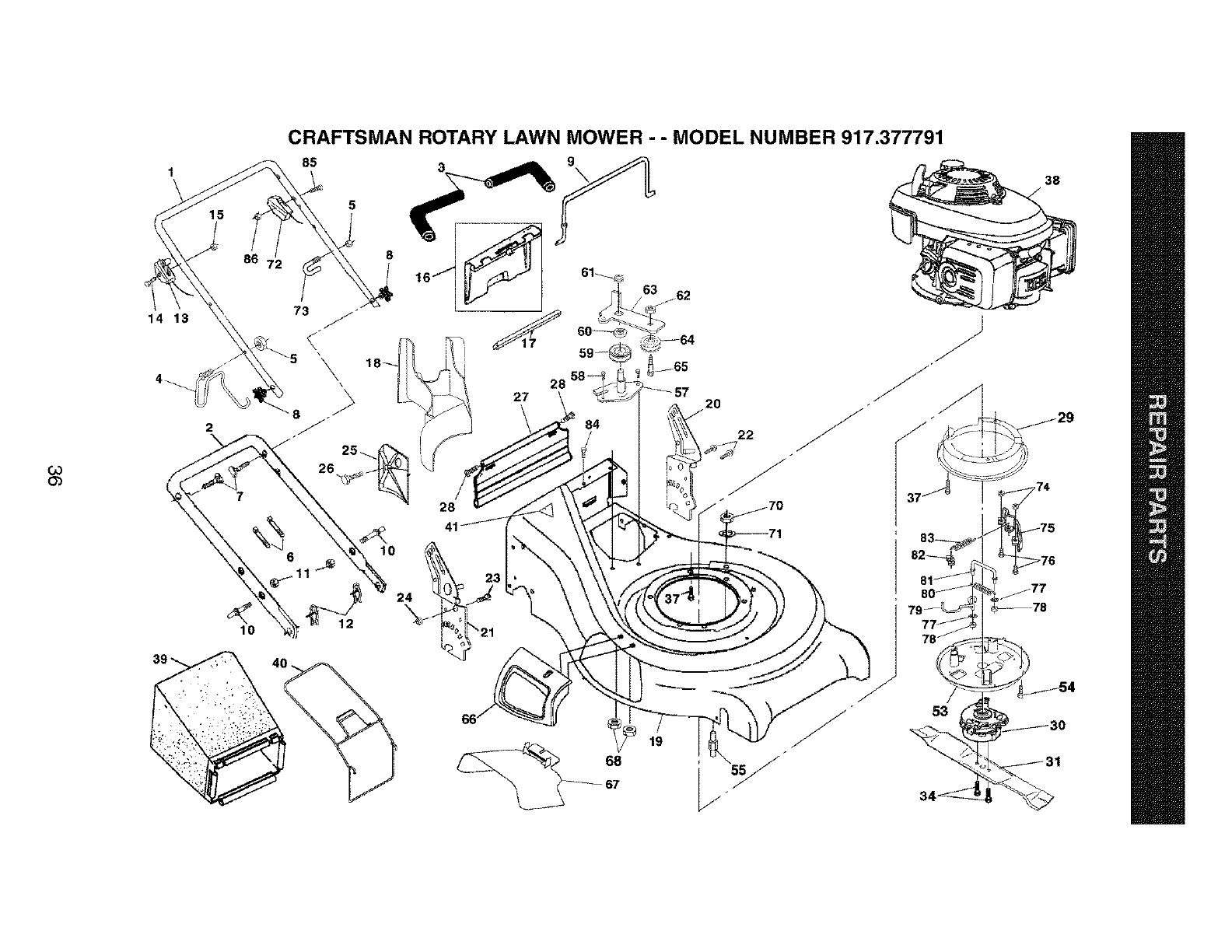
b3
O_
14 13
2
\
CRAFTSMAN ROTARY LAWN MOWER - - MODEL NUMBER 917.377791
85 5 _9
2O
22
24
68
67
53

CRAFTSMAN ROTARY LAWN MOWER - - MODEL NUMBER 917.377791
Co
"-4
KEY PART
NO. NO.
1 182724
2 161105X479
3 182748
4 186079
5 132004
6 66426
7 131959
8 180833
9 183560
10 161551
11 73990500
12 51793
13 180900
14 183365
15 132004
16 162085
17 179885
18 182778
19 186139
20 181021X479
21 181020X479
22 150078
23 163183
24 63124
25 161333
26 163409
27 161550
28 88652
29 183758X479
30 ---
31 180459
34 180460
37 150406
38 ---
39 186023
40 180026
41 85463
53 180191
54 750097
KEY PART
DESCRIPTION NO. NO
Handle, Upper, with Grip 55 182131
Handle, Lower 57 179783X004
Grip, Foam 58 57808
Rope Guide /Anti-Fold Bracket 59 166042
Nut, Hex Lockwasher 1/4-20 60 166050
Wire, Tie 61 145212
Bolt, Handle 5/16-18 x 1.75 62 155552
Knob, Handle 63 179719X004
Ball, Wire 64 166043
Bolt, Carriage 65 160829
Nut, Hex, with Lockwasher Insert 5/16-18 UNC 66 183058
Cotter, Hairpin 67 169699
Control, Engine Zone 68 88349
Screw 70 73900600
Nut, Hex 71 850263
Kit, Rear Door 72 183666
Seal, Rear Door 73 182003
Plug, Mulcher 74 73900400
Kit, Housing 75 180189X004
Handle Bracket Assembly, Left 76 74780410
Handle Bracket Assembly, Right 77 53998
Screw, Hex Washer Head 78 73510600
Bolt, Hex Head 5/16-18 x 5/8 79 182132
Nut, Hex, with Lockwasher Insert 5/16-18 80 180394
Baffle, Side 81 180188
Screw #12 x 5/8 82 183758X479
Skirt 83 180393
Screw, Hinge 1/4-20 x 1.25 84 54583
Belt Cover, Top 85 158755
Blade Brake Clutch (See Engine Breakdown) 86 751152
Blade, 21" - - 161058
Bolt, Hex Head - - 186135
Bolt, Engine
Engine, Honda, Model Number
GCV-160-ABHH (See Breakdown)
Grass Catcher Bag 71 33623
Grass Catcher Frame 71 33500
Danger Decal
Belt Cover, Bottom
Screw
DESCRIPTION
Stud, Belt Guide
Bracket Assembly
Screw
Pulley, V-Groove
Idler Arm Spacer
Flange Nut
Locknut
Idler Arm
Idler Pulley
Shoulder Bolt
Door Assembly
Mulcher Door, Multi-Cut
Nut, Hex
Nut, Hex
Washer, Lock
Control, Blade Brake/Clutch
Clip
Nut, Hex
Bracket
Bolt, Hex Head
Washer, Lock
Nut, Hex
Belt Keeper
Spring
Link, Torque
Tab, Belt Guide
Spring
Screw
Screw
Nut, Hex
Warning Decal (Not Shown)
Owner's Manual
Available accessories not included with lawn mower:
Gas Can (2.5 gallon)
Fuel Stabilizer
NOTE: All component dimensions given in U.S. inches.
1 inch = 25.4 mm
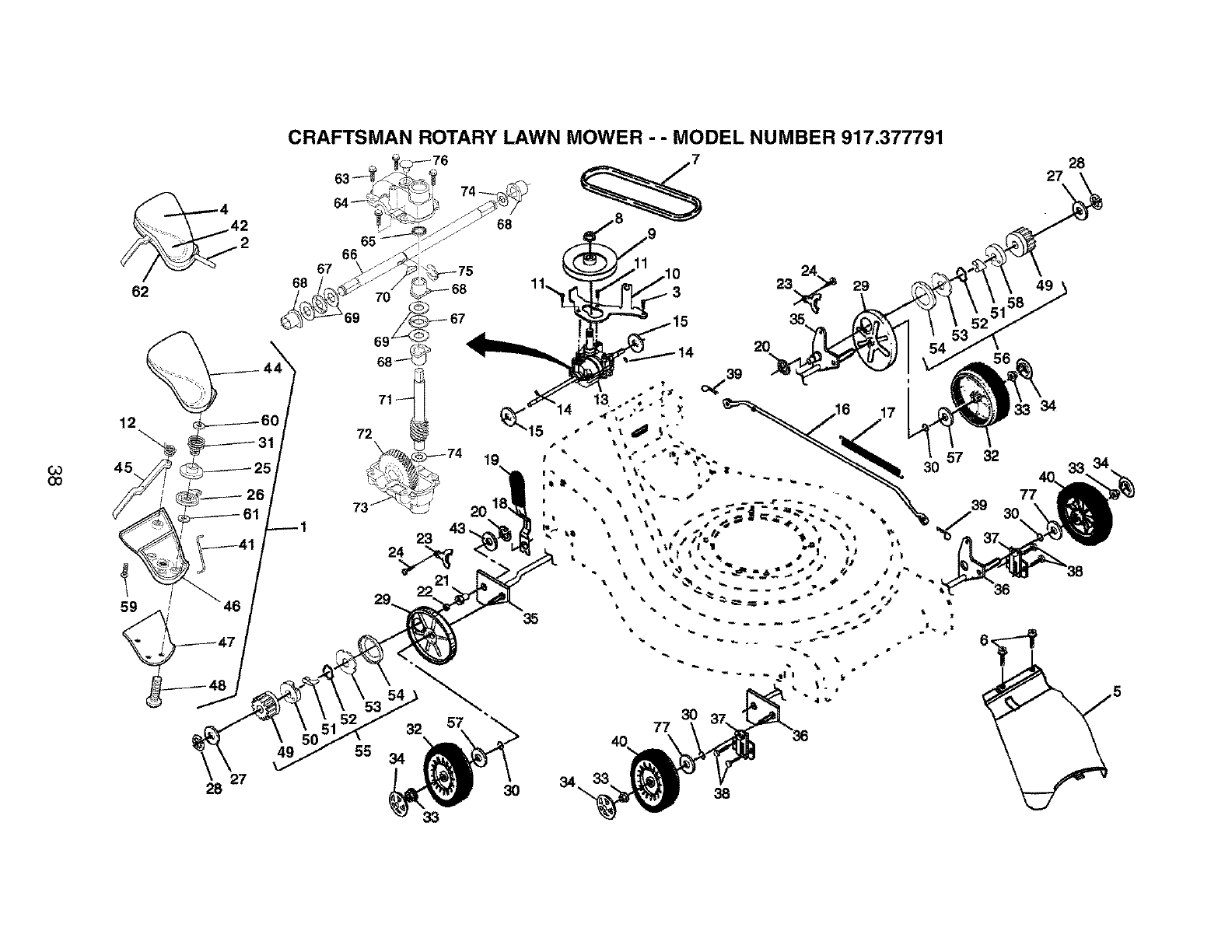
03
GO
42
2
62
12
27
28
CRAFTSMAN ROTARY LAWN MOWER - - MODEL NUMBER 917.377791
23
22
55
&3
28
27X
20
29 49

CRAFTSMAN ROTARY LAWN MOWER - - MODEL NUMBER 917.377791
CO
_0
KEY
NO.
1
2
3
4
5
6
7
8
9
10
11
12
13
14
15
16
17
18
19
20
21
22
23
24
25
26
27
28
29
30
31
32
33
34
35
36
37
38
39
40
PART
NO.
181071
180612
54583
181232
161537
750634
182212
132010
184749
166021X004
17541011
181045
180868
145354
57079
161584
161602
160477X004
167650
12000022
163365
169911
161118X004
57808
180604
180603
52160
12000058
180504
188152
180607
180545
83923
180626
160785X004
160786X004
161463
163409
700279
180542
KEY PART
DESCRIPTION NO. NO. DESCRIPTION
EZ Walk Drive Control Assembly 41 181609
Cable, Drive 42 181233
Screw 43 19572216
Decal, Drive Control 44 180601
Cover, Drive 45 180982
Screw, Threaded, Rolled #10-25x .50 46 180602
V-Belt 47 181363X479
Nut, Hex, Flangelock, Zinc Plated 3/8-16 48 181698
Pulley, Drive 49 175103
Belt Keeper Bracket 50 175102
Screw, Hex Washer Head #10-24 x .668 51 175098
Spring, Return, Lever 52 188291
Gear Case Assembly, Complete 53 175104
Pin, Spring, Thrust 54 175101
Washer ,Hardened 55 188293
Rod, Connecting 56 188292
Spring, Extension 57 67725
Spring, Selector 58 175105
Knob, Selector Spring 59 180606
E-Ring 7/8 60 52160
Support, Bearing 61 57079
Bearing, Ball 62 182494
Retainer, Drive Assembly, Stamped 63 17541011
Screw, Tapping, Hex Head 1/4-20 x .75 64 160672
Pulley, Split, Upper 65 57072
Pulley, Split, Lower 66 179754
Washer 67 160818
E-Ring 7/16 68 77881
Cover, Dust Wheel 69 160817
O-Ring 70 850848
Spring, Pulley Adjuster 71 160678
Wheel 9 x 2 72 160679
Nut, Hex, Fiangelock 3/8-16 73 160673
Hubcap, Mag, Platinum 74 57079
Shaft Assembly, Rear 75 12000039
Shaft Assembly, Front 76 86447
Retainer, Front Shaft 77 88348
Screw #12 x 5/8
Clip, Retainer
Wheel 8 x 2
Connector, Lever/Pulley
Decal, Drive Control Operation
Washer
Cover, Top, EZ Walk Drive Control
Lever, EZ Walk Drive Control
Cover, Bottom, EZ Walk Drive Control
Plate, Trigger, EZ Walk Drive Control
Screw, Phillips Head #10-5/8
Pinion, Gear
Retainer, Drive, RH
Pawl
Spring, Torsion
Disc, Drive
Seal, Friction
Pinion/Pawl Assembly, RH
Pinion/Pawl Assembly, LH
Washer 1/2 x 1-1/2
Retainer, Drive, LH
Screw
Washer
Washer
Decal, Drive Control Adjustment (bottom)
Screw, Tapping #10-24 x .668
Gear Case, Upper
Seal
Drive Shaft
Bearing, Needle, Thrust
Bearing
Washer, Thrust
Key, Hi-Pro
Shaft, Worm
Gear, Helical
Gear Case, Lower
Washer, Hardened
E-Ring
Plug
Washer, Flat 3/8
NOTE: All component dimensions given in U.S. inches.
1 inch = 25.4 mm

HONDA 4-CYCLE ENGINE MODEL NUMBER GCV-160-ABHH
FAN COVER I
12 -'%
FLYWHEEL ]
3
2
4
CONTROL]
15
ok
12 13
3
11
RECOIL STARTER I
A{R CLEANER
12
7
13
CARBURETOR I -
40
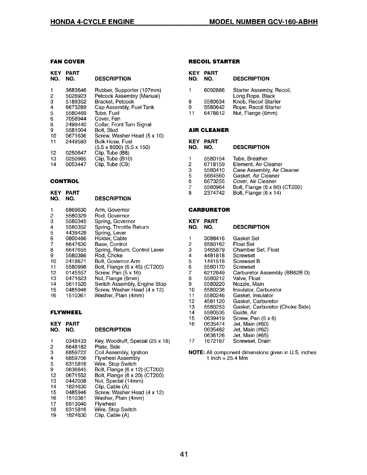
HONDA 4-CYCLE ENGINE MODEL NUMBER GCV-160-ABHH
FAN COVER
KEY PART
NO. NO. DESCRIPTION
1 3683646 Rubber, Supporter (107mm)
2 5028923 Petcock Assembly (Manual)
3 5189352 Bracket, Petcock
4 6673289 Cap Assembly, Fuel Tank
5 5580469 Tube, Fuel
6 7058944 Cover, Fan
8 2499440 Collar, Front Turn Signal
9 5581004 Bolt, Stud
10 0671636 Screw, Washer Head (5 x 10)
11 2449593 Bulk Hose, Fuel
(5.5 x 8000) (5.5 x 150)
12 0250647 Clip, Tube (B8)
13 0250985 Clip, Tube (B10)
14 0053447 Clip, Tube (C9)
CONTROL
KEY PART
NO. NO. DESCRIPTION
1 6869630 Arm, Governor
2 5580329 Rod, Governor
3 5580345 Spring, Governor
4 5580352 Spring, Throttle Return
5 4439428 Spring, Lever
6 0800466 Holder, Cable
7 6647630 Base, Control
8 6647655 Spring, Return, Control Lever
9 5580386 Red, Choke
10 2418671 Bolt, Governor Arm
11 5580998 Bolt, Flange (6 x 45) (CT200)
12 0145557 Screw, Pan (5 x 16)
13 0471623 Nut, Flange (6mm)
14 5611520 Switch Assembly, Engine Stop
15 0485946 Screw, Washer Head (4 x 12)
16 1510361 Washer, Plain (4mm)
FLYWHEEL
KEY PART
NO. NO. DESCRIPTION
1 0348433
2 6648182
3 6859722
4 6859706
5 6315816
9 0636845
12 0671552
13 0442038
14 1824630
15 0485946
16 1510361
17 6913040
18 6315816
19 1824630
Key, Woodruff, Special (25 x 18)
Plate, Side
Coil Assembly, Ignition
Flywheel Assembly
Wire, Stop Switch
Bolt, Flange (6 x 12) (CT200)
Bolt, Flange (6 x 20) (CT200)
Nut, Special (14mm)
Clip, Cable (A)
Screw, Washer Head (4 x 12)
Washer, Plain (4mm)
Flywheel
Wire, Stop Switch
Clip, Cable (A)
RECOIL STARTER
KEY PART
NO. NO. DESCRIPTION
8
9
11
6092886 Starter Assemby, Recoil,
Long Rope, Black
5580634 Knob, Recoil Starter
5580642 Rope, Recoil Starter
6478812 Nut, Flange (6mm)
AIR CLEANER
KEY PART
NO. NO.
1 5580154
2 6718159
3 5580410
5 5664560
6 6673255
7 5580964
8 2374742
DESCRIPTION
Tube, Breather
Element, Air Cleaner
Case Assembly, Air Cleaner
Gasket, Air Cleaner
Cover, Air Cleaner
Bolt, Flange (6 x 86) (CT200)
Bolt, Flange (6 x 14)
CARBURETOR
KEY PART
NO. NO. DESCRIPTION
1 3088416 Gasket Set
25580162 Float Set
3 3465879 Chamber Set, Float
4 4481818 Screwset
5 1441518 Screwset B
6 5580170 Screwset
7 6212849 Carburetor Assembly (BB62B D)
8 5580212 Valve, Float
9 5580220 Nozzle, Main
10 5580238 Insulator, Carburetor
11 5580246 Gasket, Insulator
12 4581120 Gasket, Carburetor
13 5580253 Gasket, Carburetor (Choke Side)
14 5580535 Guide, Air
15 0639419 Screw, Pan (5 x 6)
16 0635474 Jet, Main (#60)
0635482 Jet, Main (#62)
0636126 Jet, Main (#65)
17 1672187 Screwset, Drain
NOTE: All component dimensions given in U.S. inches
1 Inch = 25.4 Mm
41
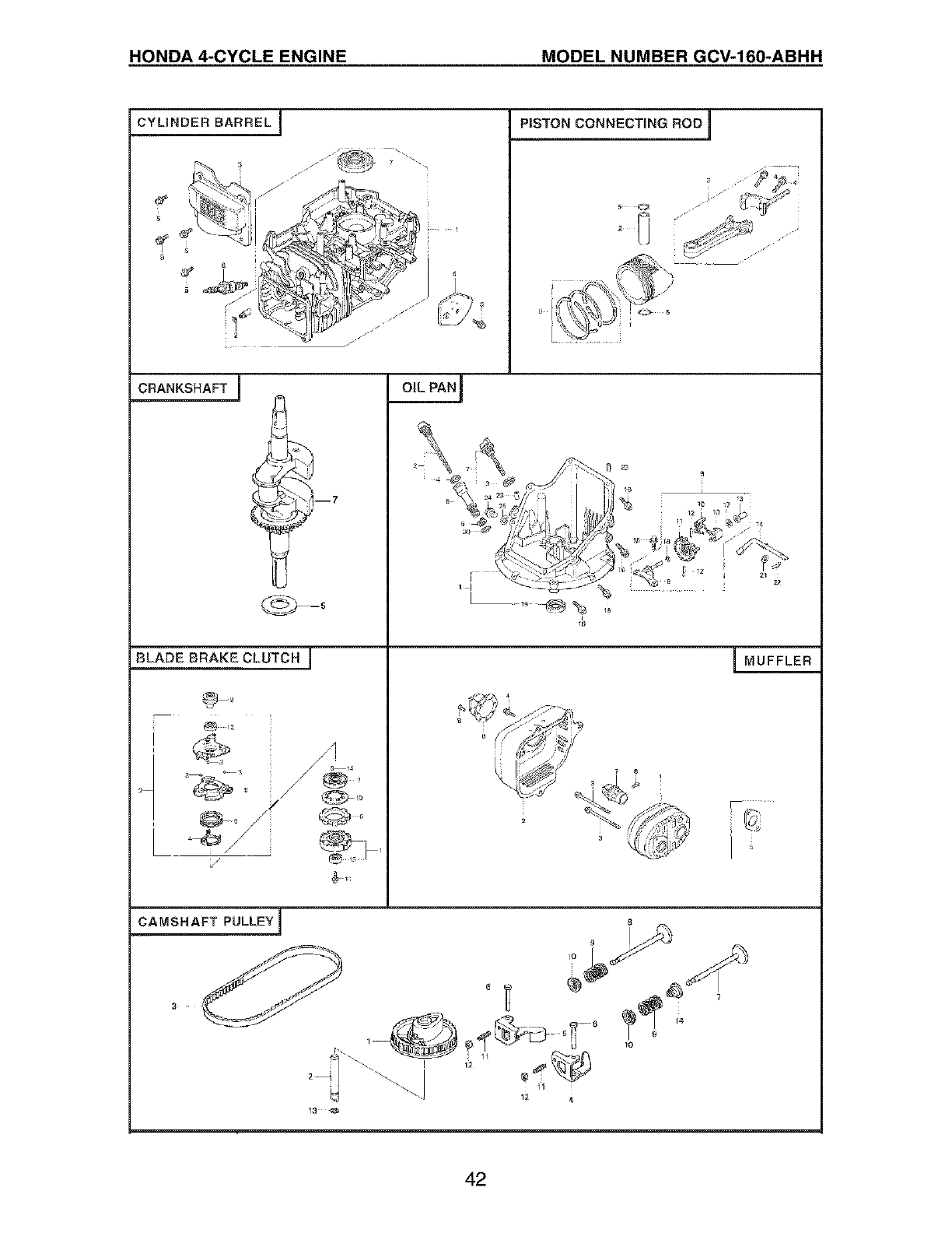
HONDA 4-CYCLE ENGINE MODEL NUMBER GCV-160-ABHH
CYLINDER BARREL J
:
CRANKSHAFT I
BLADE BRAKECLUTCH F
V
OIL PAN]-
CAMSHAFT PULLEY I
PISTON CONNECTING ROD 1
.8
I
8
Ill
o,,@m,T°
11
12 4
;/
j
j"
f,
MUFFLER
r_
42
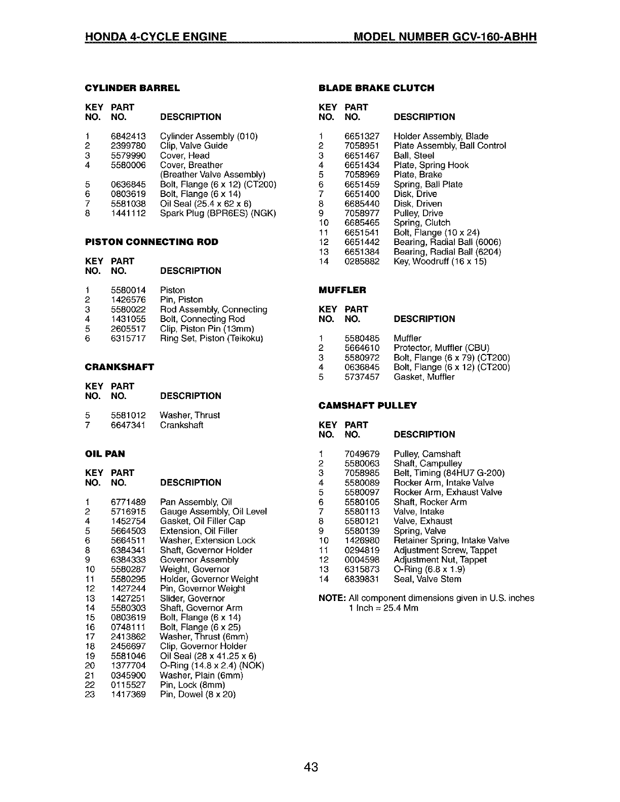
HONDA 4-CYCLE ENGINE MODEL NUMBER GCV-160-ABHH
CYLINDER BARREL
KEY PART
NO. NO. DESCRIPTION
1
2
3
4
5
6
7
8
6842413
2399780
5579990
5580006
0636845
O803619
5581O38
1441112
Cylinder Assembly (010)
Clip, Valve Guide
Cover, Head
Cover, Breather
(Breather Valve Assembly)
Bolt, Flange (6 x 12) (CT200)
Bolt, Flange (6 x 14)
Oil Seal (25.4 x 62 x 6)
Spark Plug (BPR6ES) (NGK)
PISTON CONNECTING ROD
KEY PART
NO. NO. DESCRIPTION
1
2
3
4
5
6
5580014 Piston
1426576 Pin, Piston
5580022 Rod Assembly, Connecting
1431055 Bolt, Connecting Rod
2605517 Clip, Piston Pin (13mm)
6315717 Ring Set, Piston (Teikoku)
CRANKSHAFT
KEY PART
NO. NO. DESCRIPTION
5 5581012 Washer, Thrust
7 6647341 Crankshaft
OIL PAN
KEY PART
NO. NO. DESCRIPTION
1 6771489 Pan Assembly, Oil
2 5716915 Gauge Assembly, Oil Level
4 1452754 Gasket, Oil Filler Cap
5 5664503 Extension, Oil Filler
6 5664511 Washer, Extension Lock
8 6384341 Shaft, Governor Holder
9 6384333 Governor Assembly
10 5580287 Weight, Governor
11 5580295 Holder, Governor Weight
12 1427244 Pin, Governer Weight
13 1427251 Slider, Governor
14 5580303 Shaft, Governor Arm
15 0803619 Bolt, Flange (6 x 14)
16 0748111 Bolt, Flange (6 x 25)
17 2413862 Washer, Thrust (6mm)
18 2456697 Clip, Governor Holder
19 5581046 Oil Seal (28 x 41.25 x 6)
20 1377704 O-Ring (14.8 x 2.4) (NOK)
21 0345900 Washer, Plain (6mm)
22 0115527 Pin, Lock (8mm)
23 1417369 Pin, Dowel (8 x 20)
BLADE BRAKE CLUTCH
KEY PART
NO. NO. DESCRIPTION
1 6651327 Holder Assembly, Blade
2 7058951 Plate Assembly, Ball Control
3 6651467 Ball, Steel
4 6651434 Plate, Spring Hook
5 7058969 Plate, Brake
6 6651459 Spring, Ball Plate
7 6651400 Disk, Drive
8 6685440 Disk, Driven
9 7058977 Pulley, Drive
10 6685465 Spring, Clutch
11 6651541 Bolt, Flange (10 x 24)
12 6651442 Bearing, Radial Ball (6006)
13 6651384 Bearing, Radial Ball (6204)
14 0285882 Key, Woodruff (16 x 15)
MUFFLER
KEY PART
NO. NO. DESCRIPTION
1 5580485 Muffler
2 5664610 Protector, Muffler (CBU)
3 5580972 Bolt, Flange (6 x 79) (CT200)
4 0636845 Bolt, Flange (6 x 12) (CT200)
5 5737457 Gasket, Muffler
CAMSHAFT PULLEY
KEY PART
NO. NO. DESCRIPTION
1 7049679 Pulley, Camshaft
2 5580063 Shaft, Campulley
3 7058985 Belt, Timing (84HU7 G-200)
4 5580089 Rocker Arm, Intake Valve
5 5580097 Rocker Arm, Exhaust Valve
6 5580105 Shaft, Rocker Arm
7 5580113 Valve, Intake
8 5580121 Valve, Exhaust
9 5580139 Spring, Valve
10 1426980 Retainer Spring, Intake Valve
11 0294819 Adjustment Screw, Tappet
12 0004598 Adjustment Nut, Tappet
13 6315873 O-Ring (6.8 x 1.9)
14 6839831 Seal, Valve Stem
NOTE: All component dimensions given in U.S. inches
1 Inch = 25.4 Mm
43

Your Home
For repair - in your home - of all major brand appliances,
lawn and garden equipment, or heating and cooling systems,
no matter who made it, no matter who sold it!
For the replacement parts, accessories and
owner's manuals that you need to do-it-yourself.
For Sears professional installation of home appliances
and items like garage door openers and water heaters.
1-800-4-MY-HOME _Anytime, day or night
(1-800-469-4663) (U.S.A. and Canada)
www.sears.com www.sears.ca
Our Home
For repair of carry-in products like vacuums, lawn equipment,
and electronics, call or go on-line for the nearest
Sears Parts and Repair Center.
1-800-488-1222 Anytime, day or night (U.S.A. only)
www,seats.com
To purchase a protection agreement (U.S.A.)
or maintenance agreement (Canada) on a product serviced by Sears:
1-800-827-6655 (U.S.A.) 1-800-361-6665 (Canada)
Para pedir servicio de reparaciSn
a domicilio, y para ordenar piezas:
1-888-SU-HOGAR sM
(1-888-784-6427)
Au Canada pour service en fran_;;ais:
1-800-LE-FOYER Mc
(1-800-533-6937)
www.sears.ca
SEAR6
© Sea_, Roebuck and Co.
® Registered Trademark /TMTrademark /SMService Mark of Sears, Roebuck and Co.
® Marca Registrada /TMMarca de FAbrica /SMMarca de Servicio de Sears, Roebuck and Co.
MCMarque de commerce /MDMarque d_pos_e de Sears, Roebuck and Co.
186135 Rev. 4 09.04.03 BY Printed in U.S.A.
