Craftsman 917378300 378300 Es 589804001_r0 User Manual LAWN MOWER Manuals And Guides 1611115L
User Manual: Craftsman 917378300 917378300 CRAFTSMAN LAWN MOWER - Manuals and Guides View the owners manual for your CRAFTSMAN LAWN MOWER #917378300. Home:Lawn & Garden Parts:Craftsman Parts:Craftsman LAWN MOWER Manual
Open the PDF directly: View PDF ![]() .
.
Page Count: 52
CAUTION:
Read and follow all
Safety Rules and In struc tions
before operating this equipment
Owner’s Manual
Model No.
917.378300
ROTARY LAWN MOWER
160cc Honda Engine
Power-Propelled
22" Multi-Cut
• Español, p. 21
Sears Brands Management Corp., Hoffman Estates, IL 60179 U.S.A.
Visit our Craftsman website: www.craftsman.com

2
Warranty .................................................... 2
Safe ty Rules ...........................................2-4
Prod uct Spec i fi ca tions .............................. 2
Assembly / Pre-Operation ......................6-7
Op er a tion .............................................8-12
Maintenance Sched ule ...........................13
Maintenance .......................................13-16
Ser vice and Ad just ments ...................17-18
Stor age ............................................... 18-19
Trou ble shoot ing .................................19-20
Re pair Parts ........................................40-49
Sears Service ...........................Back Cov er
TABLE OF CONTENTS
WARRANTY
CRAFTSMAN 2-YEAR FULL WARRANTY
For TWO YEARS from the date of purchase, this product is warranted against any
defects in material or workmanship. Defective product will receive free repair or
replacement if repair is unavailable.
For warranty coverage details to obtain free repair or replacement, visit the web page:
www.craftsman.com/warranty
This warranty covers ONLY defects in material and workmanship.
Warranty coverage does NOT include:
• Expendable parts that can wear out from normal use within the warranty
period, such as blades, blade adapters, belts, filters or spark plugs.
• Product damage resulting from user attempts at product modification or repair
or caused by product accessories.
• Repairs necessary because of accident or failure to operate or maintain this
product according to all supplied instructions.
• Preventative maintenance, or repairs necessary due to improper fuel mixture,
contaminated or stale fuel.
This warranty is void if this product is ever used while providing commercial services or
if rented to another person.
This warranty gives you specific legal rights, and you may also have other rights which
vary from state to state.
Sears Brands Management Corporation, Hoffman Estates, IL 60179
SAFETY RULES
IMPORTANT: This cutting machine is
capable of amputating hands and feet and
throwing objects. Failure to observe the
following safety instructions could result in
serious injury or death.
Look for this symbol to point out im por-
tant safety precautions. It means
CAU TION!!! BECOME ALERT!!!
YOUR SAFE TY IS INVOLVED.
WARNING: In order to prevent ac ci-
den tal starting when setting up, trans port-
ing, ad just ing or making repairs, always
dis con nect spark plug wire and place wire
where it can not come in contact with plug.
Serial Number:
Date of Purchase:
Gasoline Capacity / Type: 1.0 Quarts (Unleaded Regular)
Oil Capacity: 0.58 Quarts
Oil Type (API SJ–SN): SAE 30 (above 32°F) or SAE 10W-30
Spark Plug (Gap: .030") NGK BPR5ES
Valve Clearance (± 0.04 mm): Intake: 0.006 mm; Exhaust: 0.008 mm
Blade Bolt Torque: 35–40 ft. lbs. (47–54 Nm)
• The model and serial numbers will be found on a decal on the rear of the lawn mower
housing. Record both serial number and date of purchase in space provided above.
PRODUCT SPECIFICATIONS
3
CAUTION: Muffler and other engine
parts become extremely
hot during operation and
remain hot after engine
has stopped. To avoid
severe burns on contact,
stay away from these areas.
WARNING: Engine exhaust, some of its
constituents, and certain vehicle com po-
nents contain or emit chem i cals known to
the State of Cal i for nia to cause can cer and
birth defects or oth er re pro duc tive harm.
WARNING: Battery posts, terminals and
related accessories contain lead and lead
compounds, chemicals known to the State
of Cal i for nia to cause can cer and birth
defects or oth er re pro duc tive harm. Wash
hands after handling.
WARNING: This lawn mower is
equipped with an internal com bus tion
engine and should not be used on or near
any un im proved forest-covered, brush-
covered or grass-cov ered land unless the
engine’s exhaust system is equipped with
a spark arrester meeting applicable local
or state laws (if any). If a spark arrester is
used, it should be maintained in effective
working order by the operator.
In the state of California the above is re-
quired by law (Section 4442 of the Califor-
nia Public Resources Code). Other states
may have similar laws. Federal laws apply
on federal lands. A spark arrester for the
muffler is available through your nearest
Sears Parts & Repair Center (See the RE-
PAIR PARTS section of this manual).
I. CHILDREN
WARNING: CHILDREN CAN
BE SERIOUSLY INJURED OR
KILLED BY THIS EQUIPMENT.
Carefully read and follow all of
the safety instructions below.
The American Academy of Pediatrics recom-
mends that children be a minimum of 12 year
of age before operating a pedestrian con-
trolled lawn mower and a minimum of 16 years
of age before operating a riding lawn mower.
Tragic accidents can occur if the op er a tor is
not alert to the presence of children. Children
are often attracted to the ma chine and the
mowing activity. Never assume that children
will remain where you last saw them.
• Keep children out of the mowing area
and under the watchful care of a re-
spon si ble adult other than the operator.
• Be alert and turn machine off if chil dren
enter the area.
• Before and while walking back wards, look
behind and down for small chil dren.
• Never allow children to operate the
machine.
II. GENERAL OPERATION
• Read, understand, and follow all
in struc tions on the machine and in the
manual(s) before starting. Be thor ough ly
familiar with the controls and the proper
use of the machine before starting.
• Do not put hands or feet near or under
rotating parts. Keep clear of the dis-
charge opening at all times.
• Only allow responsible individuals, who
are familiar with the in struc tions, to
operate the machine.
• Clear the area of objects such as rocks,
toys, wire, bones, sticks, etc., which
could be picked up and thrown by
blade. Stay behind the handle when the
engine (motor) is running.
• Be sure the area is clear of other people
before mowing. Stop ma chine if anyone
enters the area.
• Do not operate machine bare footed or
while wearing sandals. Al ways wear
substantial footwear with good ankle
support while mowing.
• Do not pull mower backwards unless
absolutely nec es sary. Always look down
and behind before and while moving
backwards.
• Never direct discharged material toward
anyone. Avoid discharging material
against a wall or obstruction. Material
may richochet back toward the opera-
tor. Stop blade when crossing gravel
surfaces.
• Do not operate the mower without
proper guards, plates, grass catcher or
oth er safety protective devices in place.
• See manufacturer’s instructions for
proper operation and installation of
accessories. Only use accessories ap-
proved by the manufacturer.
• Stop the blade(s) when crossing grav el
drives, walks, or roads.
• Never leave a running machine unat-
tended.
• Stop the engine (motor) and wait until
the blade comes to a complete stop
before clean ing the machine, removing
the grass catcher, or unclogging the
discharge chute.
• Mow only in daylight or good artificial
light.
• Do not operate the machine while under
the influence of alcohol or drugs.
• Never operate machine in wet grass.
Always be sure of your footing: keep a
firm hold on the handle; walk, never run.
4
• Disengage the drive system, if so
equipped, before starting the engine
(motor).
• If the equipment should start to vi brate
abnormally, stop the engine (motor)
and check immediately for the cause.
Vibration is generally a warning of
trouble.
• Always wear eye protection when op er-
at ing machine.
• Use extra care when approaching blind
corners, shrubs, trees, or other objects
that may obscure vision.
• When loading or unloading this ma-
chine, do not exceed the maximum
recommended operation angle of 15°.
• Wear proper Personal Protective Equip-
ment (PPE) while operating this ma-
chine, including (at a minimum) sturdy
footwear, eye protection, and hearing
protection. Do not mow in shorts or
open toed footwear.
Always let someone know you are outside
mowing.
III. SLOPE OPERATION
Slopes are a major factor related to slip &
fall accidents, which can result in severe
injury. All slopes require extra caution. If
you feel uneasy on a slope, do not mow it.
DO:
• Mow across the face of slopes: nev er
up and down. Exercise extreme caution
when changing direction on slopes.
• Remove obstacles such as rocks, tree
limbs, etc.
• Watch for holes, ruts, bumps or hidden
objects. Uneven terrain could cause
a slip and fall accident. Tall grass can
hide obstacles.
DO NOT:
• Do not mow near drop-offs, ditches
or embankments. You could lose your
footing or balance.
• Do not mow on wet grass or exces-
sively steep slopes. Poor footing could
cause a slip and fall accident.
IV. SAFE HANDLING OF GASOLINE
To avoid personal injury or property dam-
age, use extreme care in handling gaso-
line. Gasoline is extremely flammable and
the vapors are explosive.
• Extinguish all cigarettes, cigars, pipes
and other sources of ignition.
• Use only an approved container.
• Never remove gas cap or add fuel with
the engine running.
• Allow engine to cool before refueling.
• Never refuel the machine indoors.
• Never store the machine or fuel contain-
er where there is an open flame, spark
or pilot light such as a water heater or
on other appliances.
• Never fill containers inside a vehicle, on
a truck or trailer bed with a plastic liner.
Always place containers on the ground
away from your vehicle before filling.
• Remove gas-powered equipment from
the truck or trailer and refuel it on the
ground. If this is not possible, then
refuel such equipment with a portable
container, rather than from a gasoline
dispenser nozzle.
• Keep the nozzle in contact with the rim
of the fuel tank or container opening at
all times until fueling is complete. Do
not use a nozzle lock-open device.
• If fuel is spilled on clothing, change
clothing immediately.
• Never overfill fuel tank. Replace gas
cap and tighten securely.
V. GENERAL SERVICE
• Never run machine inside a closed area.
• Never make adjustments or repairs with
the engine (motor) running. Dis con nect
the spark plug wire, and keep the wire
away from the plug to prevent ac ci den-
tal starting.
• Keep all nuts and bolts tight to be sure the
equipment is in safe working condition.
• Never tamper with safety devices.
Check their proper operation reg u lar ly.
Never do anything to interfere with the
intended function of a safety device or
reduce the protection provided by a
safety device.
• Keep machine free of grass, leaves, or
other debris build-up. Clean oil or fuel spill-
age. Allow machine to cool before storing.
• Stop and inspect the equipment if you
strike an object. Repair, if nec es sary,
before restarting.
• Never attempt to make wheel height ad-
justments while the engine is running.
• Grass catcher components are sub ject
to wear, dam age, and de te ri o ra tion,
which could expose moving parts or
allow objects to be thrown. Frequently
check com po nents and replace with
man u fac tur er’s recommended parts,
when necessary.
• Mower blades are sharp and can cut.
Wrap the blade(s) or wear gloves, and
use extra caution when ser vic ing them.
• Do not change the engine governor set-
ting or overspeed the engine.
• Maintain or replace safety and instruc-
tion labels, as necessary.
5
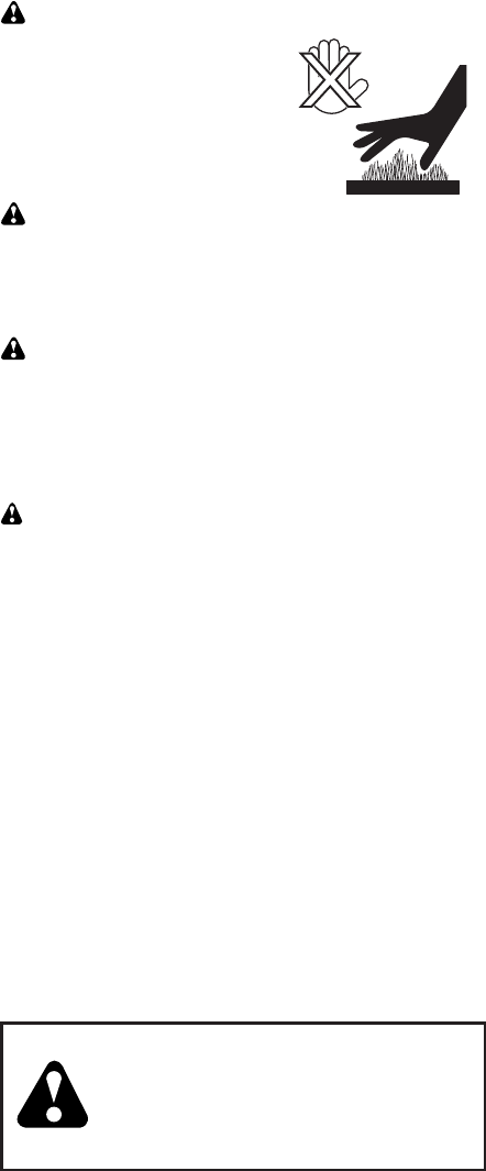
ACCESSORIES
These accessories were available when this lawn mower was produced. They are not
shipped with your mower. They are also available at most Sears retail outlets and service
centers. SOME OF THESE ACCESSORIES MAY NOT APPLY TO YOUR LAWN MOWER.
Congratulations on making a smart pur-
chase. Your new Craftsman® product is
designed and manufactured for years of
dependable operation. But like all prod-
ucts, it may require repair from time to
time. That’s when having a Repair Protec-
tion Agreement can save you money and
aggravation.
Purchase a Repair Protection Agreement
now and protect yourself from unexpected
hassle and expense.
Here’s what’s included in the Agreement:
• Expert service by our 12,000 profe-
sional repair specialists.
• Unlimited service and no charge for
parts and labor on all covered repairs.
• Product replacement if your covered
product can’t be fixed.
• Discount of 25% from regular price of
service and service-related parts not
covered by the agreement; also, 25%
off regular price of preventive mainte-
nance check.
• Fast help by phone – phone sup-
port from a Sears representative on
products requiring in-home repair, plus
convenient repair scheduling.
Once you purchase the Agreement, a
simple phone call is all that it takes for you
to schedule service. You can call anytime
day or night, or schedule a service ap-
pointment online.
Sears has over 12,000 professional repair
specialists, who have access to over 4.5 mil-
lion quality parts and accessories. That’s the
kind of professionalism you can count on to
help prolong the life of your new purchase
for years to come. Purchase your Repair
Protection Agreement today!
Some limitations and exclusions apply.
For prices and additional information
call 1-800-827-6655.
Sears Installation Service
For Sears professional installation of home
appliances, garage door openers, water
heaters, and other major home items, in
the U.S.A. call 1-800-4-MY-HOME®.
Repair Protection Agreements
6
ASSEMBLY / PRE-OPERATION
Read these instructions and this manual
in its entirety before you attempt to as-
semble or operate your new lawn mower.
IMPORTANT: This lawn mower is shipped
WITHOUT OIL OR GASOLINE in the
engine.
Your new lawn mower has been as sem-
bled at the factory with the exception of
those parts left unassembled for shipping
pur pos es. To ensure safe and proper op-
er a tion of your lawn mower, all parts and
hard ware you assemble must be tight-
ened securely. Use the correct tools as
nec es sary to ensure proper tightness. All
parts such as nuts, wash ers, bolts, etc.,
nec es sary to complete the as sem bly have
been placed in the parts bag.
TO REMOVE LAWN MOWER FROM
CARTON
1. Remove loose parts included with
mower.
2. Cut down two end corners of carton
and lay end panel down flat.
3. Remove all packing materials except
padding be tween upper and lower
handle and padding holding operator
presence control bar to upper handle.
4. Roll lawn mower out of carton and
check carton thor ough ly for additional
loose parts.
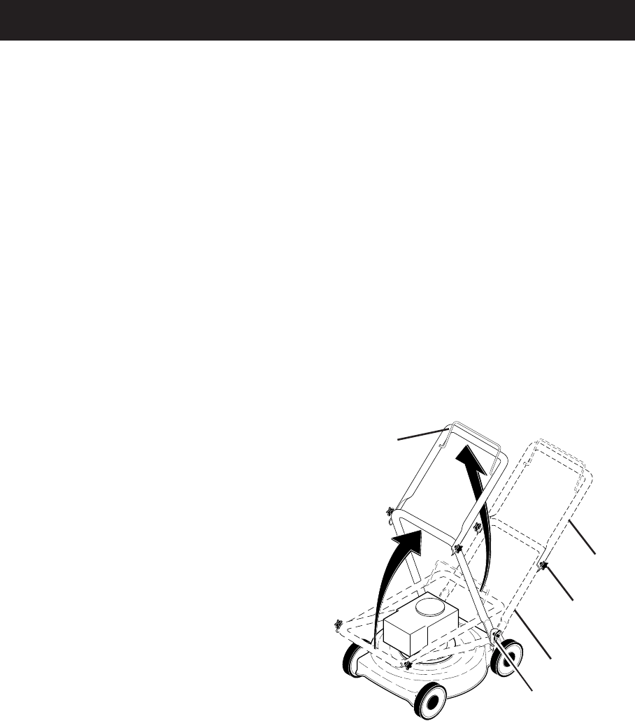
MOWING
POSITION
Lower handle
LIFT
UP
Operator
presence
control bar
Upper
handle
LIFT
UP
Upper handle
knob (“star”)
Lower handle knob
(“standard”)
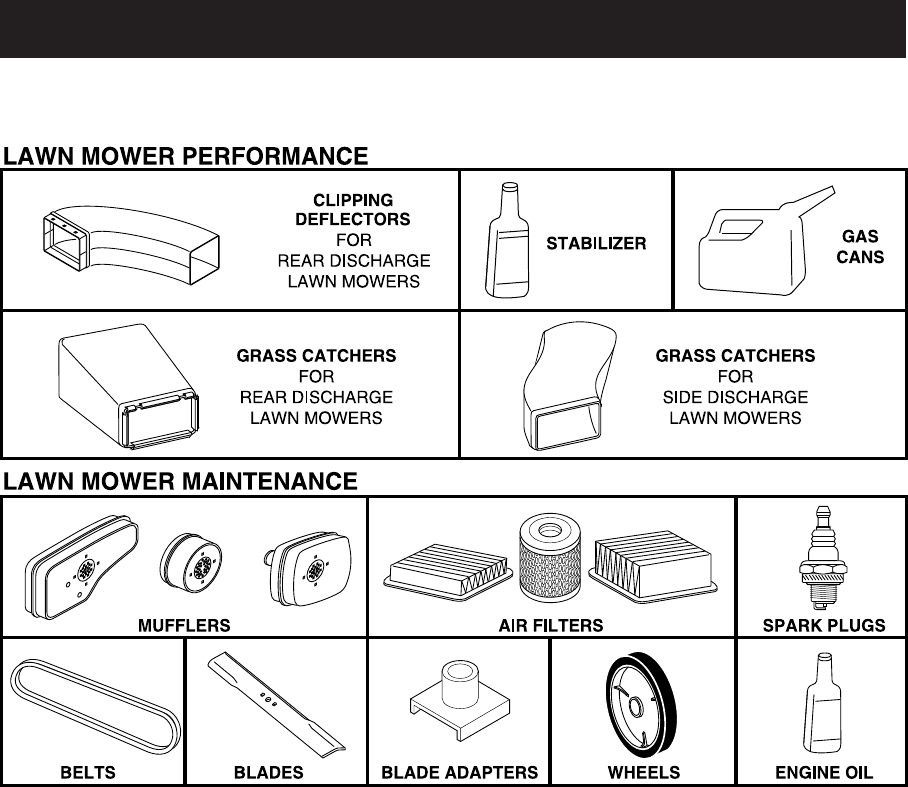
HOW TO SET UP YOUR LAWN
MOW ER
TO UNFOLD HANDLE
IMPORTANT: Unfold handle carefully so
as not to pinch or damage control cables.
1. Raise lower handle section to operat-
ing position and align holes in lower
handle with holes in handle brackets.
2. Insert handle bolts through lower
handles and handle brackets; secure
with lower (“standard”) knobs.
3. Remove protective padding, raise up-
per handle section into place on lower
handle and tighten both upper (“star”)
knobs.
4. Remove any packing material from
around control bar.
Your lawn mower handle can be adjusted
for your mowing comfort. Refer to “AD-
JUST HANDLE” in the Service and Adjust-
ments section of this manual.

7
TO ASSEMBLE GRASS CATCH ER
1. Put grass catcher frame into grass bag
with rigid part of bag on the bottom.
Make sure the frame handle is outside
of the bag top.
2. Slip vinyl bindings over frame.
NOTE: If vinyl bindings are too stiff, hold
them in warm water for a few minutes. If
bag gets wet, let it dry before using.
TO INSTALL ATTACHMENTS
Your lawn mower was shipped ready to
be used as a mulcher. To convert mower
to bagging or discharging, see “TO CON-
VERT MOWER” in the Operation section
of this manual.
Frame
handle
Frame
opening
Vinyl
bindings
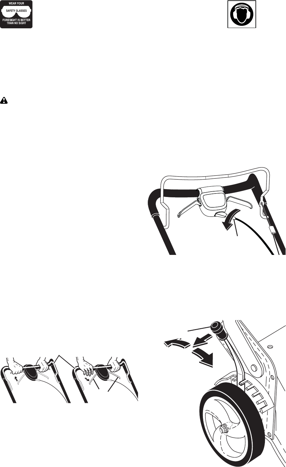
INSTALL STARTER ROPE
(MODELS EQUIPPED WITH T-KNOB)
1. Loosen T-knob.
2. Hold control bar against upper handle.
3. Slowly pull engine starter rope out until
rope will slip into loop of rope guide.
4. Tighten T-knob.
Upper handle
Control bar
Engine
starter rope
Rope guide T-Knob
8
IMPORTANT: This lawn mower is
shipped WITHOUT OIL OR GASOLINE in
the engine. NOTE: Gasoline containing up to
10% ethanol (E10) is acceptable for use in this
machine. The use of gasoline exceeding 10% ethanol (E10) will void the product warranty.
MEETS CPSC SAFETY REQUIREMENTS
Sears rotary walk-behind power lawn mowers conform to the safety standards of the
American National Standards Institute and the U.S. Consumer Product Safety Com mis sion.
WARNING: The blade turns when the engine is running.
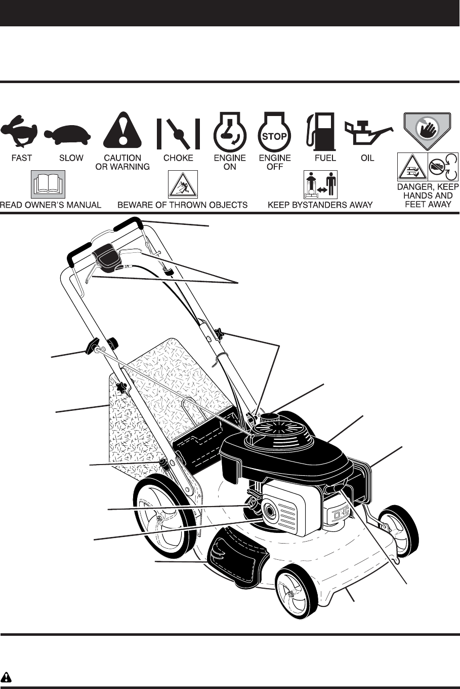
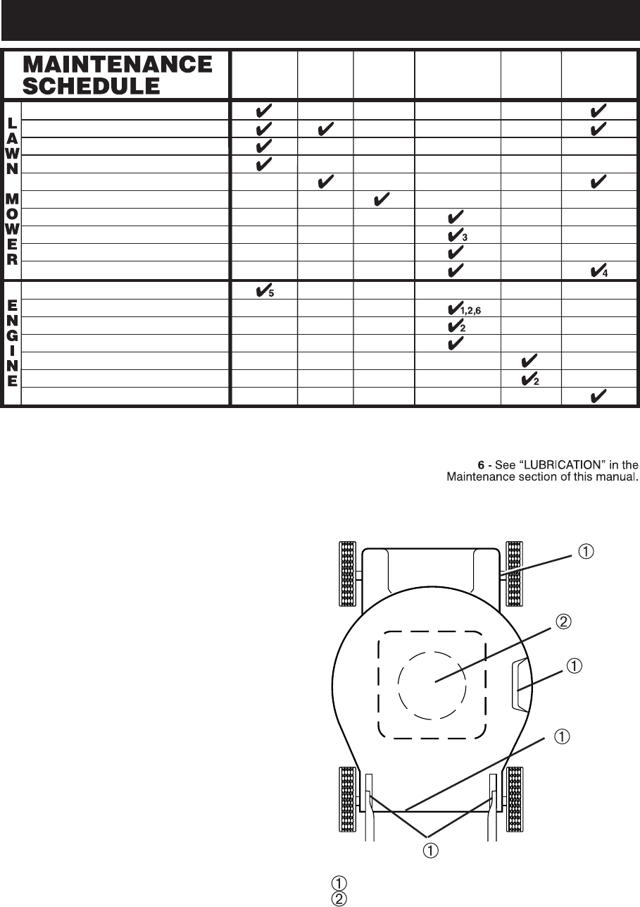
Single point
height adjuster
handle
Operator presence control bar
Starter
handle
Handle knobs
Operator presence control bar – must
be held down to the handle to start the
engine. Release to stop the engine.
Single point height adjuster – used to
adjust cutting height of lawn mower.
Starter handle – used for starting engine.
Mulcher door – allows con ver sion to
discharging or bagging operation.
Drive control levers – used to engage
power-pro pelled forward mo tion of mower.
Muffler
Grass
catcher
Drive control levers
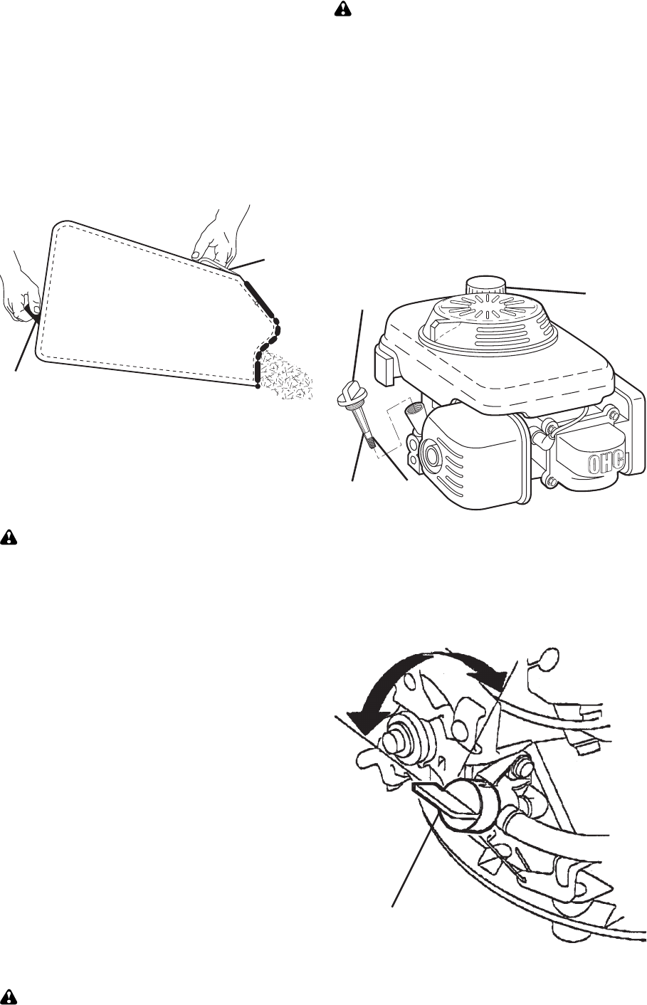
Spark
plug
Engine oil plug
Air filter
Gasoline filler cap
Fuel valve lever
Housing
Mulcher door
OPERATION
KNOW YOUR LAWN MOWER
READ THIS OWNER'S MANUAL AND ALL SAFETY RULES BEFORE OPERATING YOUR
LAWN MOWER. Compare the illustrations with your lawn mower to familiarize yourself with
the location of various controls and adjustments. Save this manual for future reference.
These symbols may appear on your lawn mower or in literature supplied with the product.
Learn and understand their meaning.
9
DRIVE CONTROL ADJUSTMENT
Over time, the drive control system may
become “loose”, resulting in decreased
speed. There is a turnbuckle on the drive
control housing to increase tension on the
drive cable. Pro ceed as follows:
1. Turn unit off and disconnect spark
plug wire from spark plug.
2. Rotate turnbuckle on drive control to
increase drive speed.
3. Operate mower to test drive speed.
Readjust as required.
4. If condition fails to improve after the
above steps (forward speed remains
the same), your drive belt is worn and
should be re placed.
HOW TO USE YOUR LAWN MOWER
ENGINE SPEED
Engine speed was set at the factory for
optimum performance. It is not adjustable.
ENGINE ZONE CONTROL
CAUTION: Federal regulations re quire
an engine control to be installed on this
lawn mower in order to minimize the risk
of blade contact injury. Do not un der
any circumstances attempt to de feat the
func tion of the operator con trol. The blade
turns when the engine is running.
• Your lawn mower is equipped with an
operator pres ence control bar which
requires the operator to be positioned
behind the lawn mower handle to start
and operate the lawn mower.
DRIVE CONTROL
• Self-propelling is controlled by hold ing
the operator presence control bar down
to the handle and pulling either drive
control lever rearward to the handle.
The further toward the handle a lever is
pulled, the faster the unit will travel.
• Forward motion will stop when either
the operator presence control bar or
a drive control lever are released. To
stop forward motion without stop ping
engine, re lease a drive control lever
only. Hold op er a tor presence control
bar down against handle to con tin ue
mowing without self-propelling.
NOTE: If after releasing the drive control
the mower will not roll backwards, push
the mower forward slightly to disengage
drive wheels.
TO ADJUST CUTTING HEIGHT
All four wheels are adjusted by a single
lever.
• Pull adjuster lever toward wheel. To
raise mower, move lever forward to
desired position. To lower mow er, move
the lever toward the rear.
LEVER
BACKWARD
TO LOWER
MOWER
LEVER
FORWARD
TO RAISE
MOWER
Height
adjuster lever
TO ENGAGE
DRIVE CONTROL
Drive
control levers
DRIVE CONTROL
DISENGAGED
Operator presence control bar
The operation of any lawn mower can result in foreign objects
thrown into the eyes, which can result in severe eye damage.
Always wear safety glasses or eye shields while operating your
lawn mower or performing any adjustments or repairs. We recom-
mend standard safety glasses or a wide vision safety mask over spectacles.
Use ear
protec-
tors to
avoid
damage to hearing.
Adjustment
turnbuckle
10
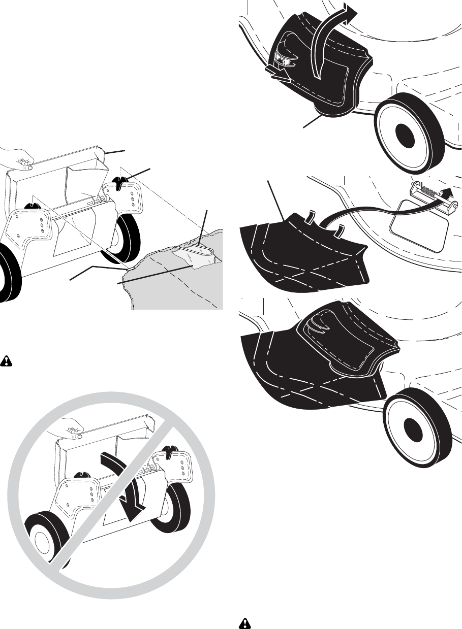
TO CONVERT MOWER
Your lawn mower was shipped ready to
be used as a mulcher. To convert to bag-
ging or discharging:
REAR BAGGING
• Lift rear door of the lawn mower and
place the grass catcher frame hooks
onto the grass bag brackets.
• To convert to mulching or dis charg ing
operation, remove grass catch er and
close rear door.
SIMPLE STEPS TO REMEMBER WHEN
CONVERTING YOUR LAWN MOWER
FOR MULCHING -
1. Rear door closed.
2. Mulcher door closed and locked.
FOR REAR BAGGING -
1. Grass catcher installed.
2. Mulcher door closed and locked.
FOR SIDE DISCHARGING -
1. Rear door closed.
2. Discharge deflector installed.
CAUTION: Do not run your lawn mow-
er with out rear door closed or ap proved
grass catcher in place. Never at tempt to
op er ate the lawn mow er with the rear door
re moved or propped open.
NOTE: Rear door will remain open until
operator presence control bar is held
down to the handle.
CAUTION: Do NOT force rear door to
close. Serious damage to your mower
could result.
SIDE DISCHARGING
• Rear door must be closed.
• Open mulcher door and install dis-
charge deflector under door as shown.
• Mower is now ready for discharging
operation.
• To convert to mulching or bagging
operation, dis charge deflector must be
removed and mulcher door must be
closed and locked.
Unlock
latch
Discharge
deflector
Open
mulcher door
Grass bag
bracket Grass
catcher
handle
Grass
catcher
frame hook
Rear door
Full bag
indicator
window
MOWER IS NOW READY
FOR DISCHARGING
OPERATION
11
BEFORE STARTING ENGINE
ADD OIL
Your lawnmower is shipped without oil in
the engine. For type and grade of oil to
use, see “EN GINE” in the Maintenance
section of this manual.
CAUTION: DO NOT overfill engine with
oil, or it will smoke on startup.
1. Be sure lawnmower is level.
2. Remove oil fill cap/dipstick from oil fill
spout.
3. You recieve a container of oil with the
unit. Slowly pour the entire container
down the oil fill spout into the engine.
4. Insert and tighten oil fill cap/dipstick.
IMPORTANT:
• Check oil level before each use. Add
oil if needed. Fill to full line on dipstick.
• Change the oil after every 25 hours of
operation or each season. You may
need to change the oil more often
under dusty, dirty conditions. See “TO
CHANGE ENGINE OIL” in the Mainte-
nance section of this manual.
ADD GASOLINE
• Fill fuel tank to bottom of tank filler
neck. Do not overfill. Use fresh, clean,
regular unleaded gasoline with a mini-
mum of 87 octane. Do not mix oil with
gasoline. Purchase fuel in quan ti ties
that can be used within 30 days to as-
sure fuel freshness.
CAUTION: Wipe off any spilled oil or
fuel. Do not store, spill or use gasoline
near an open flame.
CAUTION: Alcohol blended fuels
(called gasohol or using ethanol or meth-
anol) can attract moisture which leads to
separation and for ma tion of acids during
storage. Acidic gas can damage the fuel
system of an engine while in storage. To
avoid engine problems, the fuel system
should be emptied before stor age of 30
days or longer. Empty the gas tank, start
the engine and let it run until the fuel lines
and carburetor are empty. Use fresh fuel
next season. See Storage In struc tions for
additional information. Never use engine
or carburetor cleaner products in the fuel
tank or permanent damage may occur.
Grass
catcher
frame
handle
Bag
handle
TO EMPTY GRASS CATCHER
Empty the grass catcher when clippings
are visible in the full bag indicator window.
1. Lift up on grass catcher using the
frame han dle.
2. Remove grass catcher with clippings
from under lawn mower han dle.
3. Empty clippings from bag using both
frame handle and bag handle.
NOTE: Do not drag the bag when empty-
ing; it will cause unnecessary wear.
TO STOP ENGINE
• To stop engine, release operator pres-
ence control bar. Wait until blade and
all moving parts have stopped and turn
fuel valve to OFF position if you do not
intend to re start the engine soon.
Oil fill cap /
dipstick Gasoline
filler cap
Lower
mark
Upper
mark
Fuel valve lever
ON
OFF
TO START ENGINE
NOTE: Due to protective coatings on the
engine, a small amount of smoke may be
present during the initial use of the prod-
uct and should be considered normal.
12
MULCHING MOWING TIPS
IMPORTANT: For best performance,
keep mower housing free of built-up
grass and trash. See “CLEANING” in the
Maintenance section of this manual.
• The special mulching blade will recut
the grass clip pings many times and
reduce them in size so that as they fall
onto the lawn they will disperse into
the grass and not be noticed. Also,
the mulched grass will bio de grade
quick ly to provide nu tri ents for the lawn.
Always mulch with your highest engine
(blade) speed as this will provide the
best recutting action of the blades.
• Avoid cutting your lawn when it is wet.
Wet grass tends to form clumps and
in ter feres with the mulch ing action. The
best time to mow your lawn is the early
afternoon. At this time the grass has
dried, yet the newly cut area will not be
exposed to direct sunlight.
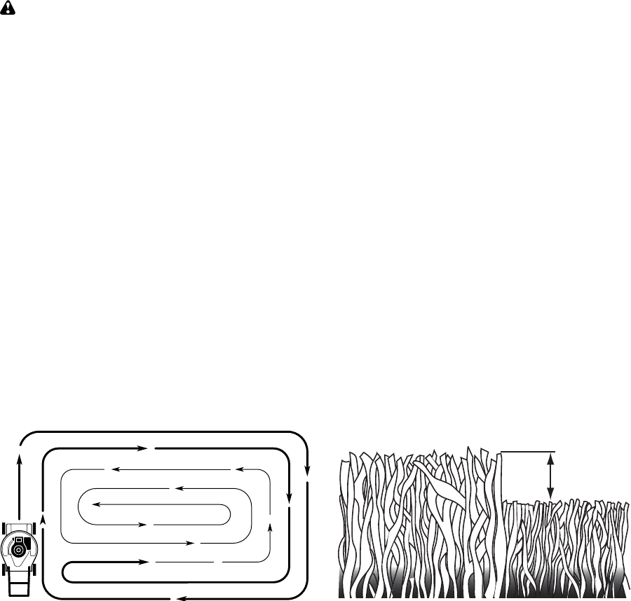
• For best results, adjust the lawn mower
cutting height so that the lawn mower
cuts off only the top one-third of the
grass blades. If the lawn is over grown
it will be nec es sary to raise the height
of cut to reduce pushing effort and to
keep from over load ing the engine and
leaving clumps of mulched grass. For
ex tremely heavy grass, reduce your
width of cut by overlapping previously
cut path and mow slowly.
• Certain types of grass and grass
con di tions may re quire that an area be
mulched a second time to com pletely
hide the clip pings. When doing a sec-
ond cut, mow across (perpendicular) to
the first cut path.
• Change your cutting pattern from week
to week. Mow north to south one week
then change to east to west the next
week. This will help prevent matting
and graining of the lawn.
MAX 1/3
1. Be sure fuel valve is in the ON po si-
tion.
2. Hold operator presence control bar
down to the han dle and pull starter
handle quickly. Do not allow starter
rope to snap back.
MOWING TIPS
CAUTION: Do not use de-thatcher
blade attachments on your mower. Such
attachments are hazardous, will damage
your mower and could void your warranty.
• Under certain conditions, such as very
tall grass, it may be necessary to raise
the height of cut to reduce pushing
effort and to keep from over load ing the
en gine and leaving clumps of grass
clippings. It may also be necessary to
reduce ground speed and/or run the
lawn mower over the area a second
time.
• For extremely heavy cutting, reduce the
width of cut by overlapping pre vi ous ly
cut path and mow slowly.
• For side discharge operation, cut in
a coun ter clock wise di rec tion, start ing
at the outside of the area to be cut, in
order to spread grass clip pings more
evenly and to put less load on the
engine. To keep clip pings off of walk-
ways, flower beds, etc., make the first
cuts in a clock wise direction.
• If a trail of grass clipping is left on the
right side of the lawn mower during rear
discharge operation, mow in a clock-
wise direction with a small overlap to
collect the clippings on the next pass.
• Pores in cloth grass catchers can be-
come filled with dirt and dust with use
and catchers will collect less grass. To
prevent this, regularly hose catcher off
with water and let dry before using.
• Keep top of engine around starter clear
and clean of grass clippings and chaff.
This will help engine air flow and extend
engine life.
13
Check for Loose Fasteners
Clean / Inspect Grass Catcher *
Check Tires
Check Drive Wheels ***
Clean Lawn Mower ****
Clean under Drive Cover ***
Check Drive Belt / Pulleys ***
Check / Sharpen / Replace Blade
Lubrication
Clean and Recharge Battery **
Check Engine Oil level
Change Engine Oil
Clean Air Filter
Inspect Muffler
Replace Spark Plug
Replace Air Filter Paper Cartridge
Empty fuel system or add Stabilizer
BEFORE
EACH
USE
AFTER
EACH
USE
EVERY
10
HOURS
EVERY
25 HOURS
OR SEASON
EVERY
100
HOURS
BEFORE
STORAGE
1 - Change more often if operating under a heavy load or in high outdoor temperatures.
2 - Service more often if operating in dirty or dusty conditions.
3 - Replace blades more often when mowing in sandy soil.
4 - Charge 48 hours at end of season.
5 - And after each 5 hours of use.
(if so equipped)
Electric-Start mowers
Power-Propelled mowers
Use a scraper
to clean under deck
*
**
***
****
MAINTENANCE
GENERAL REC OM MEN DA TIONS
The warranty on this lawn mower does not
cover items that have been sub ject ed to
operator abuse or negligence. To receive
full value from the warranty, operator must
maintain unit as in struct ed in this manual.
Some adjustments will need to be made
periodically to properly maintain your unit.
At least once a season, check to see if
you should make any of the adjustments
described in the Service and Ad just ments
section of this manual.
• At least once a year, replace the spark
plug, clean or replace air filter element
and check blade for wear. A new spark
plug and clean/new air filter element
assure proper air-fuel mix ture and help
your engine run bet ter and last longer.
• Follow the maintenance schedule in this
manual.
BEFORE EACH USE
• Check engine oil level.
• Check for loose fasteners.
LUBRICATION
Keep unit well lubricated
(See “LU BRI CA TION CHART”).
LUBRICATION CHART
Spray lubricant
See "ENGINE" in Maintenance section.
IMPORTANT: Do not oil or grease plastic
wheel bearings. Viscous lu bri cants will
attract dust and dirt that will short en the life
of the self-lu bri cat ing bearings. If you feel
they must be lu bri cated, use only a dry,
pow dered graphite type lubricant spar ingly.
Wheel
adjuster (on
each wheel)
Engine oil
Rear door
hinge
Handle bracket mounting pins
Mulcher
door hinge
pin
14
LAWN MOWER
Always observe safety rules when per-
form ing any main te nance.
TIRES
• Keep tires free of gasoline, oil, or insect
control chemi cals which can harm rubber.
• Avoid stumps, stones, deep ruts, sharp
objects and other hazards that may
cause tire damage.
DRIVE WHEELS
Check rear drive wheels each time be fore
you mow to be sure they move freely.
The wheels not turning freely means trash,
grass cuttings, etc. are in the drive wheel area
and must be cleaned to free drive wheels.
If necessary to clean the drive wheels, be
sure to clean both rear wheels.
BLADE CARE
For best results, mower blade must be
kept sharp. Re place a bent or dam aged
blade.
CAUTION: Use only a replacement
blade approved by the manufacturer of
your mower. Using a blade not approved
by the manufacturer of your mower is
hazardous, could damage your mower
and void your warranty.
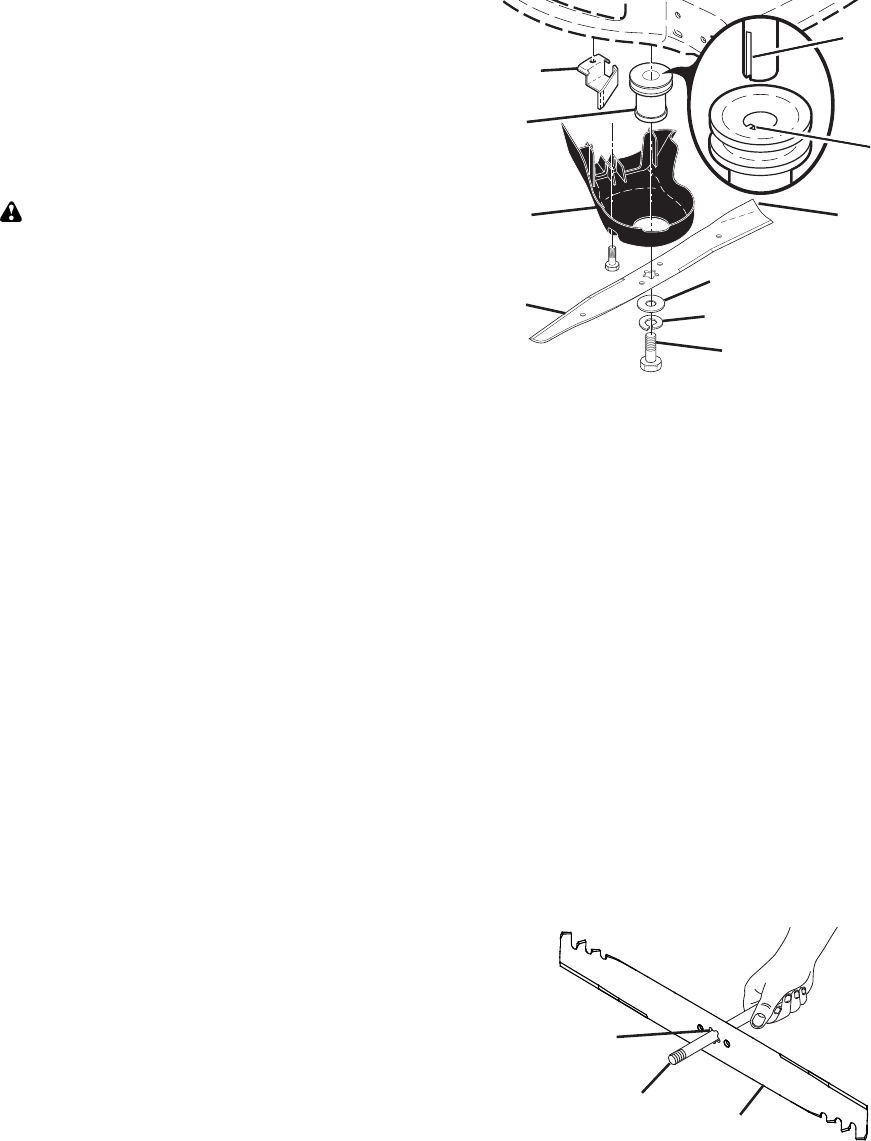
TO REMOVE BLADE
1. Disconnect spark plug wire from spark
plug and place wire where it cannot
come in contact with plug.
2. Turn lawn mower on its side. Make
sure air filter and carburetor are up.
3. Use a wood block between blade and
mower hous ing to prevent blade from
turning when re mov ing blade bolt.
NOTE: Protect your hands with gloves
and/or wrap blade with heavy cloth.
4. Remove blade bolt by turning counter-
clockwise.
5. Remove blade and attaching hardware
(bolt, lock wash er, hardened wash er).
6. Remove debris shield.
NOTE: Remove the blade adapter and check
the key inside hub of blade adapter. The key
must be in good condition to work properly.
Replace adapter if damaged.
TO REPLACE BLADE
1. Position the blade adapter on the
engine crank shaft. Be sure key in
adapter and crankshaft keyway are
aligned; and that the drive belt is
inside the tab of the belt retainer.
2. Install debris shield.
3. Position blade on the blade adapter.
IMPORTANT: To ensure proper as sem bly,
center hole in blade must align with star
on blade adapter.
4. Be sure the trailing edge of blade (oppo-
site sharp edge) is up toward the engine.
5. Install the blade bolt with the lock
washer and hardened washer into
blade adapter and crankshaft.
6. Use block of wood between blade and
lawn mower housing and tighten the
blade bolt, turning clockwise.
• The recommended tightening torque is
35–40 ft. lbs.
IMPORTANT: Blade bolt is heat treated.
If bolt needs replacing, replace only with
approved bolt shown in the Repair Parts
section of this manual.
TO SHARPEN BLADE
NOTE: We do not recommend sharp en ing
blade - but if you do, be sure the blade is
balanced. An un bal anced blade will cause
eventual damage to lawn mower or engine.
• The blade can be sharp ened with a file
or on a grinding wheel. Do not attempt
to sharpen while on the mower.
• To check blade balance, you will need a
5/8" diameter steel bolt, pin, or a cone bal-
ancer. (When using a cone bal anc er, follow
the in struc tions supplied with bal anc er.)
NOTE: Do not use a nail for balancing
blade. The lobes of the center hole may
appear to be centered, but are not.
• Slide blade on to an unthreaded portion
of the steel bolt or pin and hold the
bolt or pin parallel with the ground. If
blade is bal anced, it should remain in a
horizontal po si tion. If either end of the
blade moves downward, sharpen the
heavy end until the blade is balanced.
Blade bolt
Crank-
shaft
keyway
Hardened washer
Lockwasher
Blade
adapter Key
Blade
Trailing
edge
Belt
retainer
Debris
shield
5/8" bolt or pin
Center hole
Blade
15
4. Wipe off any spilled oil from lawn
mower or side of engine.
5. Fill engine with oil. Slowly pour oil
down the oil fill spout into the engine.
6. Wait one minute to allow oil to settle.
Use guage on oil fill cap/dipstick for
checking level. Insert dipstick into
the tube and rest the oil fill cap on the
tube. DO NOT thread the cap into the
tube when taking reading.
GRASS CATCHER
• The grass catcher may be hosed with
water, but must be dry when used.
• Check your grass catcher often for dam-
age or de te ri o ra tion. Through normal use
it will wear. If catcher needs replacing,
replace only with ap proved replacement
catcher shown in the Repair Parts section
of this manual. Give the lawn mower model
number when ordering.
GEAR CASE
• To keep your drive system work-
ing properly, the gear case and area
around the drive should be kept clean
and free of trash build-up. Clean under
the drive cover twice a season.
• The gear case is filled with lubricant to the
proper level at the factory. The only time
the lubricant needs attention is if service
has been performed on the gear case.
ENGINE
Maintenance, repair, or replacement of the
emission control devices and systems, which
are being done at the customers expense,
may be performed by any non-road engine
repair establishment or individual. Warranty
repairs must be performed by an authorized
engine manufacturer’s service outlet.
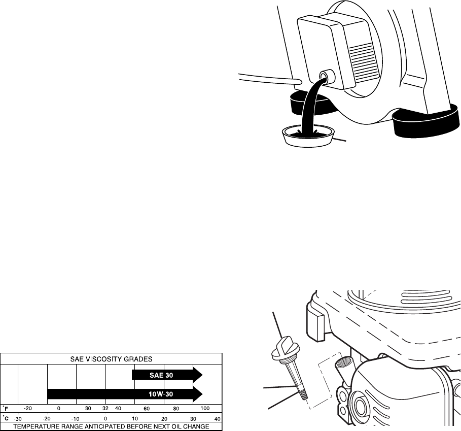
LUBRICATION
Use only high quality detergent oil rated
with API service classification SJ–SN.
Select the oil's SAE viscosity grade accord-
ing to your expected operating temperature.
2. Remove oil fill cap/dipstick; lay aside
on a clean surface.
3. Tip lawn mower on its side as shown
and drain oil into a suitable container.
Rock lawn mower back and forth to re-
move any oil trapped inside of engine.
NOTE: Multi-viscosity oils (5W30, 10W30
etc.) improve starting in cold weather, and
you should check your engine oil level fre-
quently to avoid possible engine damage
from running low on oil.
Change the oil after every 25 hours of opera-
tion or at least once a year if the lawn mower
is not used for 25 hours in one year.
Check the crankcase oil level before
starting the engine and after each five (5)
hours of continuous use. Tighten oil plug
securely each time you check the oil level.
TO CHANGE ENGINE OIL
NOTE: Before tipping lawn mower to
drain oil, empty fuel tank by running en-
gine until fuel tank is empty.
1. Disconnect spark plug wire from spark
plug and place wire where it cannot
come in contact with plug.
7. Continue adding small amounts of
oil and rechecking the dipstick until it
reads full. DO NOT overfill, or engine
will smoke on startup.
8. Always be sure to retighten oil fill cap/
dipstick before starting engine.
9. Reconnect spark plug wire to plug.
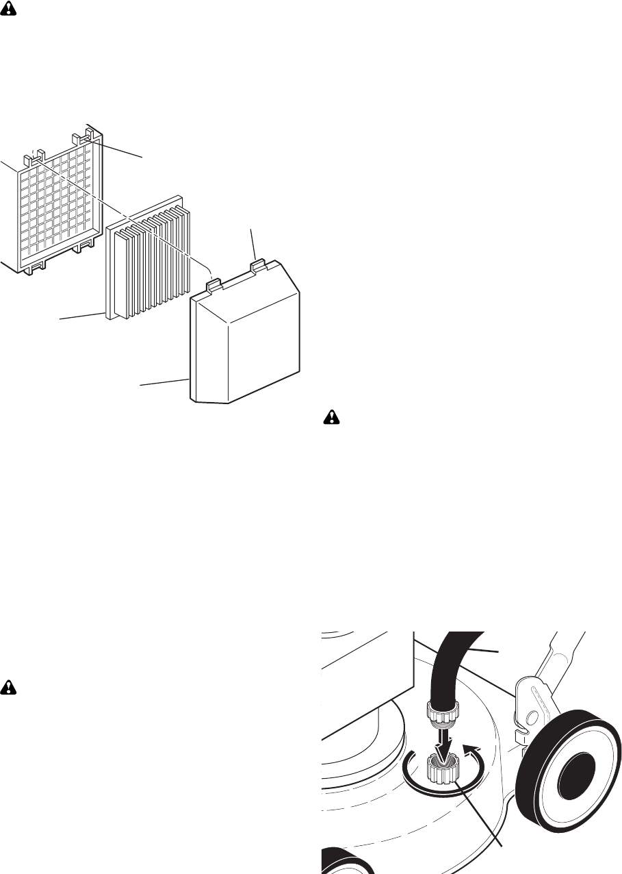
AIR FILTER
Your engine will not run properly and may
be damaged by using a dirty air filter.
Replace the air filter every 100 hours of
operation or every season, whichever oc-
curs first. Service air cleaner more often
under dusty conditions.
TO CLEAN AIR FILTER
1. Remove cover.
2. Carefully remove cartridge.
3. Clean by gently tapping on a flat sur-
face. If very dirty, replace cartridge.
Container
Oil fill cap /
dipstick
Lower
mark
Upper
mark
16
MUFFLER
Inspect and replace corroded muffler as it
could create a fire hazard and/or dam age.
SPARK PLUG
Replace spark plug at the beginning of
each mowing season or after every 100
hours of operation, whichever occurs
first. Spark plug type and gap setting
are shown in the “PROD UCT SPEC I FI CA-
TIONS” section of this manual.
CLEANING
IMPORTANT: For best performance,
keep mower housing free of built-grass
and trash. Clean the underside of your
mower after each use.
CAUTION: Disconnect spark plug wire
from spark plug and place wire where it
cannot come in contact with plug.
• Clean the underside of your lawn
mower by scraping to remove build-up
of grass and trash.
• Clean engine often to keep trash from
accumulating. A clogged engine runs
hotter and shortens engine life.
• Keep finished surfaces and wheels free
of all gasoline, oil, etc.
• With the exception of the water washout
port (if equipped), we do not recom-
mend using a garden hose to clean the
outside of your lawn mower unless the
elec tri cal system, muffler, air filter and
carburetor are covered to keep water
out. Water in engine can result in short-
ened engine life.
WATER WASHOUT FEATURE
Your lawn mower is equipped with a fitting
that allows quick and easy cleaning of
the underside of the housing. To use this
feature, proceed as follows:
1. Move lawn mower to an area of cut
grass or another hard surface.
NOTE: Water, grass and other debris will
drain from beneath the mower housing
during the washout process.
2. Remove grass catcher and discharge
chute assembly from lawn mower.
3. Close mulcher door (if equipped).
4. Connect a garden hose to the fitting
where shown.
IMPORTANT: Be sure the garden hose is
not routed under the lawn mower housing
or entangled in the wheels.
5. Turn on water supply and check for
leaks at the fitting.
If no leaks are present, start engine (as
described in the Operation section of
this manual) and let engine run until the
underside of the lawn mower is clean.
WARNING: Do not engage the drive
system during the washout process.
6. Shut off the engine.
7. Shut off water supply and remove
hose from fitting.
CAUTION: Do not remove hose from
fitting while engine is running. Water in
engine can result in shortened engine life.
8. Start engine (as described in the Op-
eration section of this manual) and let
engine run for a full minute to remove
excess water from mower.
CLEAN UNDER DRIVE COVER
Clean under drive cover at least twice a
season. Scrape underside of cover with
putty knife or similar tool to remove any
build-up of trash or grass on underside of
drive cover.
Hose
Fitting
Tab
Cartridge
Filter cover
Slot
CAUTION: Petroleum solvents, such
as ker o sene, are not to be used to clean
car tridge. They may cause de te ri o ra tion
of the cartridge. Do not oil car tridge. Do
not use pres sur ized air to clean or dry
car tridge.
4. Install cartridge, then replace cover.
17
SERVICE AND ADJUSTMENTS
WARNING: To avoid serious injury, before performing any service and adjustments:
1. Release control bar and stop engine.
2. Make sure the blade and all moving parts have completely stopped.
3. Disconnect spark plug wire from spark plug and place wire where it cannot come in
contact with spark plug.
LAWN MOWER
TO ADJUST CUTTING HEIGHT
See “TO ADJUST CUTTING HEIGHT” in
the Operation sec tion of this manual.
REAR DEFLECTOR
The rear deflector, attached between the
rear wheels of your mower, is provided to
minimize the possibility that objects will
be thrown out of the rear of the mower
into the operator mowing position. Re-
place the deflector if dam aged.
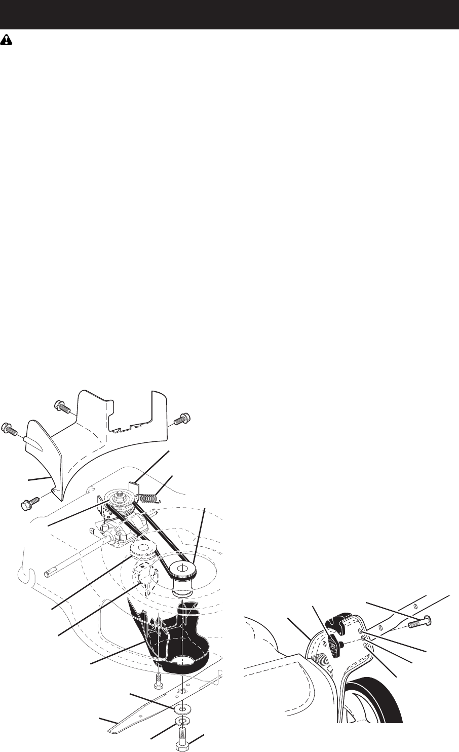
TO REMOVE DRIVE BELT
1. Remove screws securing rear baffle.
NOTE: Before tipping lawn mower to
remove drive belt, empty fuel tank by run-
ning engine until fuel tank is empty.
2. Turn lawn mower on its side with air
filter and car bu re tor up.
3. Remove rear baffle from mower.
4. Remove blade bolt, lockwasher, hard-
ened washer and blade.
5. Remove debris shield.
6. Remove gearcase belt keeper.
7. Remove drive belt.
TO REPLACE DRIVE BELT
1. Place new drive belt on gearcase pul-
ley.
NOTE: Always use factory approved belt
to assure proper fit and long life.
2. Reinstall gearcase belt keeper. Be
sure the new drive belt is inside the
tabs of the gearcase belt keeper.
3. Position the blade adapter on the
engine crank shaft. Be sure key in
adapter and crankshaft keyway are
aligned; and that the new drive belt is
inside the tabs of the belt retainer.
4. Place rear baffle in mower housing.
5. Reinstall debris shield.
6. Reinstall blade. The recommended
tightening torque is 35–40 ft. lbs.
7. Return mower to upright po si tion.
8. Reinstall rear baffle screws.
TO ADJUST HANDLE
The handle on your lawn mower has
multiple height positions - adjust to height
that suits you.
1. Remove knob and carriage bolt on
one side of the lower handle.
2. While holding handle assembly,
remove knob and car riage bolt from
opposite side, align hole in handle with
desired hole in handle bracket and
reassemble bolt and knob and tighten
securely.
3. Align opposite side of handle with
same positioning hole and secure with
bolt and knob.
Handle
bracket
Low
Knob
High
Medium
Bolt
Blade
bolt
Hardened washer
Lockwasher
Blade
adapter
Blade
Belt retainer
Gearcase
belt keeper
Return spring
Debris shield
Idler pulley
Rear
baffle
Gearcase
pulley

18
CARBURETOR
Your carburetor is not adjustable.
IMPORTANT: Never tamper with the
engine governor, which is factory set
for proper engine speed. Over speed-
ing the engine above the factory high
speed setting can be dangerous. If you
think the engine-governed high speed
needs adjusting, contact a Sears or other
qualified service center, which has proper
equip ment and ex pe ri ence to make any
nec es sary adjustments.
ENGINE
Maintenance, re pair, or re place ment of the
emission con trol de vic es and sys tems,
which are be ing done at the cus tom-
ers expense, may be performed by any
non-road engine repair es tab lish ment or
individual. Warranty repairs must be per-
formed by an authorized engine man u fac-
tur er's service outlet.
ENGINE SPEED
Your engine speed has been factory set.
STORAGE
Immediately prepare your lawn mower for
storage at the end of the season or if the
unit will not be used for 30 days or more.
LAWN MOWER
When lawn mower is to be stored for a
period of time, clean it thor oughly, remove
all dirt, grease, leaves, etc. Store in a
clean, dry area.
1. Clean entire lawn mower (See
“CLEANING” in the Maintenance sec-
tion of this manual).
2. Lubricate as shown in the Main te-
nance section of this manual.
3. Be sure that all nuts, bolts, screws,
and pins are securely fas tened. In-
spect moving parts for damage, break-
age and wear. Replace if necessary.
4. Touch up all rusted or chipped paint
surfaces; sand lightly before painting.
HANDLE
You can fold your lawn mower han dle for
storage.
1. Loosen the two “star” handle knobs
on sides of the upper handle and allow
handle to fold down to the rear.
2. Loosen the two “standard” handle
knobs on sides of the lower handle
and pivot entire handle as sem bly
forward and allow it to rest on mower.
3. Reinstall “standard” knobs and car-
riage bolts to lower handle or handle
brackets for safe keeping.
• When setting up your handle from the
storage position, you must manually
lock lower handle into mowing position.
IMPORTANT: When folding the handle
for storage or transportation, be sure to
fold the handle as shown or you may
damage the control cables.
ENGINE
FUEL SYS TEM
IMPORTANT: It is important to prevent
gum deposits from forming in essential
fuel system parts such as carburetor, fuel
filter, fuel hose, or tank during storage.
Alcohol blended fuels (called gasohol or
using ethanol or methanol) can attract
moisture which leads to separation and
formation of acids during storage. Acidic
gas can damage the fuel system of an
engine while in storage.
• Empty the fuel tank by starting the en-
gine and letting it run until the fuel lines
and car bu re tor are empty.
• Never use engine or carburetor cleaner
prod ucts in the fuel tank or permanent
damage may occur.
• Use fresh fuel next season.
FOLD
FORWARD
FOR
STORAGE
MOWING
POSITION
Lower handle
Operator
presence
control bar
Upper
handle
Upper handle
“star” knob
Lower handle
“standard” knob

19
Does not start 1. Dirty air filter. 1. Clean/replace air filter.
2. Out of fuel. 2. Fill fuel tank.
3. Stale fuel. 3. Empty fuel tank and refill tank
with fresh, clean gasoline.
4. Water in fuel. 4. Empty fuel tank and refill tank
with fresh, clean gasoline.
5. Spark plug wire disconnected. 5. Connect wire to plug.
6. Bad spark plug. 6. Replace spark plug.
7. Loose blade or broken 7. Tighten blade bolt or
blade adapter. replace blade adapter.
8. Control bar in released 8. Depress control bar to
position. handle.
9. Control bar defective. 9. Replace control bar.
10. Fuel valve lever (if so 10. Turn fuel valve lever
equipped) in OFF position. to the ON position.
11. Weak battery (if equipped). 11. Charge battery.
12. Disconnected battery 12. Connect battery to engine.
connector (if equipped).
PROBLEM CAUSE CORRECTION
TROUBLESHOOTING - See appropriate section in manual unless directed
to a Sears Parts & Repair Center.
OTHER
• Do not store gasoline from one season
to another.
• Replace your gasoline can if your can
starts to rust. Rust and/or dirt in your
gasoline will cause problems.
• If possible, store your unit indoors and
cover it to protect it from dust and dirt.
• Cover your unit with a suitable pro tec-
tive cover that does not retain mois ture.
Do not use plastic. Plastic cannot
breathe, which allows condensation to
form and will cause your unit to rust.
IMPORTANT: Never cover mower while
engine and exhaust areas are still warm.
CAUTION: Never store the lawn
mower with gaso line in the tank in side a
build ing where fumes may reach an open
flame or spark. Allow the engine to cool
before storing in any enclosure.
NOTE: Fuel stabilizer is an acceptable
alternative in min i miz ing the formation of
fuel gum deposits during stor age. Add
stabilizer to gasoline in fuel tank or stor-
age container. Always follow the mix ratio
found on stabilizer container. Run engine
at least 10 min utes after adding stabilizer
to allow the stabilizer to reach the car-
buretor. Do not empty the gas tank and
carburetor if using fuel stabilizer.
ENGINE OIL
Drain oil (with engine warm) and replace
with clean engine oil. (See “ENGINE” in
the Maintenance section of this man ual).
CYLINDER
1. Remove spark plug.
2. Pour one ounce (29 ml) of oil through
spark plug hole into cylinder.
3. Pull starter handle slowly a few times
to dis trib ute oil.
4. Replace with new spark plug.

20
Loss of power 1. Rear of mower housing or 1. Raise cutting height.
blade dragging in grass.
2. Cutting too much grass. 2. Raise cutting height.
3. Dirty air filter. 3. Clean/replace air filter.
4. Buildup of grass, leaves, 4. Clean underside of mower
and trash under mower. housing.
5. Too much oil in engine. 5. Check oil level.
6. Walking speed too fast. 6. Cut at slower walking speed.
Poor cut – 1. Worn, bent or loose blade. 1. Replace blade. Tighten
uneven blade bolt.
2. Wheel heights uneven. 2. Set all wheels at same
height.
3. Buildup of grass, leaves 3. Clean underside of
and trash under mower. mower housing.
Excessive 1. Worn, bent or loose blade. 1. Replace blade. Tighten
vibration blade bolt.
2. Bent engine crankshaft. 2. Contact a Sears or other
qualified service center.
Starter rope 1. Engine flywheel brake is on 1. Depress control bar to
hard to pull when control bar is released. upper handle before
pulling the starter rope.
2. Bent engine crankshaft. 2. Contact a Sears or other
qualified service center.
3. Blade adapter broken. 3. Replace blade adapter.
4. Blade dragging in grass. 4. Move lawn mower to cut
grass or to hard surface.
Grass catcher 1. Cutting height too low. 1. Raise cutting height.
not filling 2. Lift on blade worn off. 2. Replace blade.
(If so equipped) 3. Catcher not venting air. 3. Clean grass catcher.
Hard to push 1. Grass is too high or wheel 1. Raise cutting height.
height is too low.
2. Rear of mower housing or 2. Raise rear of mower housing
blade dragging in grass. one (1) setting higher.
3. Grass catcher too full. 3. Empty grass catcher.
4. Handle height position not 4. Adjust handle height to suit.
right for you.
Loss of drive 1. Belt wear. 1. Check/replace drive belt.
or slowing of 2. Belt off of pulley. 2. Check/reinstall drive belt.
drive speed 3. Drive cable worn or broken. 3. Replace drive cable.
4. “Loose” drive control system. 4. Adjust drive control.
NEED MORE HELP?
You'll find the answer and more on managemyhome.com – for free!
• Find this and all your other product manuals online.
• Get answers from our team of home experts.
• Get a personalized maintenance plan for your home.
• Find information and tools to help with home projects.
brought to you by Sears
PROBLEM CAUSE CORRECTION
TROUBLESHOOTING - See appropriate section in manual unless directed
to a Sears Parts & Repair Center.

21
TABLA DE MATERIAS
Garantía ...........................................................21
Reglas de Seguridad ................................ 21-23
Especificaciones del Producto .......................23
Montaje / Pre-Operación ........................... 25-26
Operación ................................................. 27-31
Programa de Mantenimiento ..........................32
Mantenimiento .......................................... 32-36
Servicio y Adjustes .................................... 36-37
Almacenamiento ....................................... 37-38
Identificación de problemas ..................... 38-39
Partes de repuesto ................................... 40-49
Servicio Sears .................................. Contratapa
GARANTÍA
GARANTÍA DE MANO DE OBRA COMPLETA CRAFTSMAN DE 2 AÑOS
Durante DOS AÑOS a partir de la fecha de compra, este producto está garantizado
contra cualquier defecto de material o mano de obra. El producto defectuoso recibirá
una reparación o un reemplazo en forma gratuita si la reparación no es posible.
Para conocer los detalles de la cobertura de la garantía con el fin de obtener una reparación
o un reemplazo en forma gratuita, visite el página web: www.craftsman.com/warranty
Esta garantía SÓLO cubre defectos de material y mano de obra.
La cobertura de la garantía NO incluye:
• Partes que se pueden gastar por el uso normal dentro del periodo de garantía,
como cuchillas, adaptadores de cuchillas, correas, filtros o bujías.
• Daño del producto que sea resultado de los intentos del usuario por modificar
o reparar el producto o a causa de los accesorios del producto.
• Reparaciones necesarias por accidente o falla al operar o dar mantenimiento
a este producto, de acuerdo con todas las instrucciones provistas.
• Mantenimiento preventivo o reparaciones necesarias debido a una mezcla de
combustible inapropiada, contaminada o inservible.
Esta garantía será nula si el producto se usa alguna vez mientras se proveen servicios
comerciales o si se renta a otra persona.
Esta garantía le otorga derechos legales específicos, además que de puede tener otros
derechos que varían de un estado a otro.
Sears Brands Management Corporation, Hoffman Estates, IL 60179
IMPORTANTE: Esta maquina cortadaora es
capaz de amputar las manos y los manos y
los pies y de lanzar objetos. Si no se observan
las instrucciones de seguridad siguientes se
pueden producir lesiones graves o la muerte.
Busque este símbolo que señala las precau-
ciones de seguridad de importancia. Quiere
decir – ¡¡¡ATENCIÓN!!! ¡¡¡ESTE ALERTO!!!
SU SEGURIDAD ESTA COMPROMETIDA.
REGLAS DE SEGURIDAD
ADVERTENCIA: Siempre desconecte el
alambre de la bujía y póngalo donde no pueda
entrar en contacto con la bujía, para evitar el
arranque por accidente, durante la prepara-
ción, el transporte, el ajuste o cuando se hacen
reparaciones.
Número de Serie:
Fecha de Compra:
Capacidad y Tipo de Gasolina: 1.0 Cuartos (Regular sin Plomo)
Capacidad de Aceite: 18.5 Onzas
Tipo de Aceite (API SJ–SN): SAE 30 (Debajo 0°C/32°F) o SAE 10W30
Bujía (Abertura: .030") NGK BPR5ES
Tolerancia de Válvula (± 0.04 mm) Admisión: 0.006 mm; Descarga: 0.008 mm
Torsión del Perno de la Cuchilla: 35-40 ft. lbs.
• El número del nodelo y el de serie se encuentran en la calcomania adjunta a la parte trasera
de la caja de la segadora. Debe registrar tanto el número de serie come la fecha de compra y
mantengalos en un lugar seguro para refencia en el futuro.
ESPECIFICACIONES DEL PRODUCTO
22
PRECAUCIÓN: El tubo de escape del mo-
tor, algunos de sus constituyentes
y algunos componentes del
vehículo contienen o des-
prenden productos químicos
conocidos en el Estado de
California como causa de
cáncer y defectos al nacimiento
u otros daños reproductivos.
ADVERTENCIA: Los bornes, terminales y
accesorios relativos de la batería contienen
plomo o compuestos de plomo, productos
químicos conocidos en el Estado de California
como causa de cáncer y defectos al nacimien-
to u otros daños reproductivos. Lavar las
manos después de manipularlos.
PRECAUCIÓN: El silenciador y otras piezas
del motor llegan a sre extremadamente calien-
tes durante la operación y siguen siendo cali-
entes después de que el motor haya parado.
Para evitar quemaduras severas, permanezca
lejos de estas áreas.
ADVERTENCIA: Este segadora viene
equipado con un motor de combustión interna
y no se debe usar sobre, o cerca, de un ter-
reno no desarrollado cubierto de bosques, de
arbustos o de césped, o menos que el sistema
de es cape del motor venga equipado con un
amor ti gua dor de chispas que cumpla con las
leyes lo cales o estatales (si existen). Si se
usa un amortiguador de chispas, el operador
debe mantenerlo en condiciones de trabajo
eficientes.
En el estado de California, la ley exige lo an-
te ri or (Sección 4442 del “California Pub lic Re-
sourc es Code”). Otros estados pueden contar
con otras leyes parecidas. Las leyes federales
se aplican en la tierras federales. Su centro de
Servicio Sears más cer ca no tiene disponible
amor ti gua do res de chispas para el si len cia dor
(Vea la sección de PARTES DE REPUESTO de
este man u al Inglés del dueño).
I. NIÑOS
ADVERTENCIA: LOS NIÑOS PU-
EDEN SUFRIR HERIDAS GRAVES
O MUERTE A CAUSA DE ESTE
EQUIPO. Lea y siga atentamente
todas las instrucciones siguientes.
La Academia Americana de Pediatría recomien-
da que los cortacésped de conductor a pie
sean manejados por personas de al menos 12
años de edad, mientras que los cortacésped
de conductor montado sean operados por
personas de al menos 16 años de edad.
Se pueden producir accidentes trágicos si el
operador no presta atención a la presencia
de los niños. A menudo, los niños se sienten
atraídos por la máquina y por la actividad de
la siega. Nunca suponga que los niños van a
permanecer en el mismo lugar donde los vio
por última vez.
• Mantenga a los niños alejados de la zona
de trabajo y bajo la supervisión atenta de un
adulto responsable aparte del operador.
• Esté alerta y apague la máquina si hay niños
que entran al área.
• Antes y cuando este retrocediendo, mire
hacia atrás y hacia abajo para verificar si hay
niños pequeños.
• Nunca permita que los niños operen la
máquina.
• Tenga un cuidado extra cuando se acer-
que a esquinas donde no hay visibilidad, a
los arbustos, árboles u otros objetos que
pueden interferir con su línea de visión.
II. OPERACION
• Antes de empezar, debe familiarizarse
completamente con los controles y el uso
correcto de la maquina. Para esto, debe leer
y comprender todas las instrucciones que
aparecen en la maquina y en los manuales
de operación.
• No ponga las manos o los pies cerca o
debajo de las partes rotatorias. Manténgase
siempre lejos de la abertura de la descarga.
• Permita que solamente las personas re-
sponsables que estén familiarizadas con las
instrucciones operen la máquina.
• Despeje el área de objetos tales como pie-
dras, juguetes, alambres, huesos, palos, etc.
que pueden ser recogidos y lanzados por
la cuchilla. Manténgase detrás del mango
cuando el motor esté en marcha.
• Asegúrese que el área no se hallen per-
sonas, antes de segar. Pare la máquina si
alguien entra en el área.
• No utilice la máquina descalzo o con sanda-
lias. Para trabajar, utilice siempre un calzado
resistente con buena protección de los tobil-
los.
• No tire de la segadora hacia atrás a menos
que sea absolutamente necesario. Mire
siempre hacia abajo y hacia detrás antes y
mientras que se mueve hacia atrás.
• Nunca dirigir el material descargado hacia
las personas. Evitar descargar material
contra paredes o barreras. El material
puede retornar al operador. Para la cuchilla
cuando se pasa por superficies de grava.
• No opere la segadora sin los respectivos
resguardos, las placas, el recogedor de
césped u otros aditamentos dise ados para
su protección y seguridad.
• Refiérase a las instrucciones del fabricante
para el funcionamiento e instalación de
accesorios. Use únicamente accesorios
aprobados por el fabricante.
• Detenga la cuchilla o las cuchillas cuando
cruce por calzadas, calles o caminos de
grava.
• Nunca deje la máquina en marcha sin super-
visión.
• Apague el motor y espere a que la cuchilla
se detenga por completo antes de limpiar
la máquina, extraer el colector de hierba o
desatascar el conducto de descarga.
• Apagar el motor y esperar hasta que las
cuchillas estén completamente paradas
antes de remover el receptor de hierba.
• Segar solamente con luz del día o con una
buena luz artificial.
• No opere la máquina bajo la influencia del
alcohol o de las drogas.
23
• Nunca opere la maquina cuando la hierba
esté mojada. Asegúrese siempre de tener
buena tracción en sus pies; mantenga el
mango firmemente y camine; nunca corra.
• Desconecte el sistema de tracción, si la
máquina cuenta con él, antes de arrancar el
motor.
• Si el equipo empezara a vibrar de una
manera anormal, pare el motor y revise de
inmediato para averiguar la causa. General-
mente la vibración suele indicar que existe
alguna avería.
• Utilice protección para los ojos siempre que
trabaje con la máquina.
• Siempre use gafas de seguridad o anteojos
con protección lateral cuando opere la sega-
dora.
• Cuando cargue o descargue la máquina, no
sobrepase el ángulo máximo recomendado
de operación de 15°.
• Utilice equipo de protección personal (EPP)
cuando utilice esta máquina, incluyendo
(como mínimo) calzando resistente, protec-
ción ocular y protección auditiva. No corte
el césped con calzado corto ni abierto.
Ponga en conocimiento de los demás que está
cortando el césped.
III. OPERACION SOBRE LAS CUESTAS
Los accidentes ocurren con más frecuencia en
las cuestas. Estos accidentes ocurren debido a
resbaladas o caídas, las cuales pueden resultar
en graves lesiones. Operar la recortadora en
cuestas requiere mayor concentración. Si se
siente inseguro en una cuesta, no la recorte.
HACER:
• Puede recortar a través de la superficie de
la cuesta, nunca hacia arriba y hacia abajo.
Proceda con extrema precaución cuando
cambie de dirección en las cuestas.
• Renueva todos los objetos extraños, tales
como guijarros, ramas, etc.
• Tenga cuidado con los huecos, surcos, bultos
u objetos ocultos. El terreno irregular puede
provocar resbalones y caídas. Recuerde que
la hierba alta puede esconder obstáculos.
NO HACER:
• No corte el césped cerca de barrancos,
zanjas o terraplenes. Puede perder pie o el
equilibrio.
• No corte hierba mojada ni trabaje en
pendientes muy pronunciadas. Si pierde el
equilibrio puede resbalarse o caer.
IV. MANEJO SEGURO DE GASOLINA
Para evitar daños personales o materiales,
tenga mucho cuidado al manipular gasolina.
La gasolina es extremamente inflamable y los
vapores son explosivos.
• Apagar todos los cigarrillos, cigarros, pipas
y otras fuentes de ignición.
• Usar solo un contenedor apropiado.
• Nunca quitar el tapón de la gasolina o añadir
carburante con el motor en marcha.
• Esperar que el motor se enfríe antes de
repostar la gasolina.
• Nunca repostar la máquina al interior de un
local.
• Nunca guardar la máquina o el contenedor
de gasolina donde hay una llama abierta,
chispa o luz piloto como una caldera u otros
dispositivos.
• Nunca llenar contenedores en un vehículo, en
un camión o caravana con un forro de plástico.
Colocar siempre los contenedores en el suelo
lejos de su vehículo antes de llenar.
• Quitar equipos que funcionan con gasoli-
na del camión o caravana y repostar en el
suelo. Si esto no es posible, repostar dicho
equipo con un contenedor portátil, más bien
que con una tobera de gasolina.
• Mantener la tobera en contacto con el bordo
del depósito de carburante o de la apertura
del contenedor siempre hasta terminar el
abastecimiento. No usar un dispositivo de
cierre-apertura de la tobera.
• Si el carburante cae en la ropa que se lleva,
cambiársela inmediatamente.
• Nunca llenar en exceso el depósito de
carburante. Colocar el tapón de la gasolina y
apretar de modo seguro.
V. SERVICIO
• Nunca haga funcionar una máquina dentro
de un área cerrada.
• Nunca haga ajustes o reparaciones mientras
el motor esté en marcha. Desconecte el
cable de la bujía, y manténgalo a cierta
distancia de ésta para prevenir un arranque
accidental.
• Mantenga todas las tuercas y pernos apreta-
dos para asegurarse de que el equipo se en-
cuentra en condiciones de trabajo seguras.
• Nunca manipule de forma indebida los
dispositivos de seguridad. Controle regu-
larmente su funcionamiento correcto. No
realice acción alguna que pueda interferir
con la función prevista de un dispositivo de
seguridad o reducir la protección suminis-
trada por un dispositivo de seguridad.
• Mantenga la máquina libre de hierba, hojas
u otras acumulaciones de desperdicio.
Limpie los derrames de aceite o com bus-
ti ble. Permita que la máquina se enfríe antes
de almacenarla.
• Pare e inspeccione el equipo si le pega a un
objeto. Repárelo, si es necesario, antes de
hacerlo arrancar.
• En ningún caso hay que regular la altura de
las ruedas mientras el motor está en marcha.
• Los componentes del receptor de la hierba
van sujetos a desgaste, daños y deterioro,
que pueden exponer las partes en mov-
imiento o permitir que objetos sean dispara-
dos. Controlar frecuentemente y cuando sea
necesario sustituir con partes aconsejadas
por el fabricante.
• Las cuchillas de la segadora están afiladas
y pueden cortar. Cubrir las hojas o llevar
guantes, y utilizar precauciones especiales
cuando se efectúa mantenimiento sobre las
mismas.
• No cambie el ajuste del regulador del motor
ni exceda su velocidad.
• Mantener o sustituir las etiquetas de seguri-
dad e instrucciones, cuando sea necesario.
24
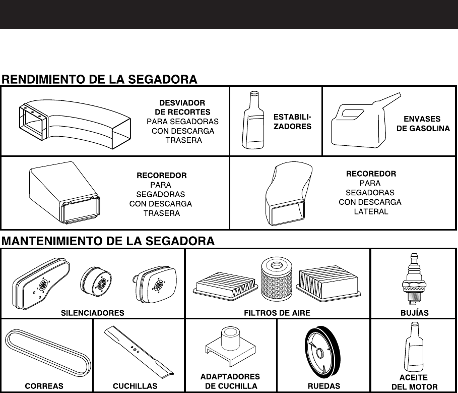
ACCESORIOS PARA LA SEGADORA
Estos accesorios estaban disponibles cuando se produjo la segadora. No son facilitados junto al
cortacesped. También están disponibles en la mayoría de las tiendas de Sears y en los centros de
servicio. ALGUNOS DE ESTOS ACCESORIOS TAL VEZ NO SE APLIQUEN A SU SEGADORA.
Congratulaciones por su buena compra. Su
nuevo producto Craftsman® está diseñado
y fabricado para funcionar de modo fiable por
muchos años. Pero como todos los productos,
puede necesitar alguna reparación de tanto
en tanto. En este caso tener un Acuerdo de
Protección para la Reparación puede hacerles
ahorrar dinero y fastidios.
Compre ahora un Acuerdo de Protección para
la Reparación y protégese de molestias y gas-
tos inesperados.
Un Acuerdo incluye los puntos siguientes:
• Servicio experto de nuestros 12.000 espe-
cialistas profesionales en la reparación.
• Servicio ilimitado sin cargo alguno para
las partes y la mano de obra sobre todas las
reparaciones garantizadas.
• Sustitución del producto si su producto
garantizado no puede ser arreglado.
• Descuento del 25% sobre el precio cor-
riente del servicio y de las partes relativas al
servicio no cubiertas por el acuerdo; tam-
bién el 25% menos sobre el precio corriente
de un control de mantenimiento preventivo.
• Ayuda rápida por teléfono – soporte tele-
fónico por parte de un representante Sears
sobre productos que requieren un arreglo en
casa, y además una programación sobre los
a reglos más convenientes.
Cuando se ha comprado el Acuerdo, basta con
una llamada telefónica para programar el servi-
cio. Puede llamar cuando quiera, día y noche
o fijar en línea una cita para obtener el servicio.
Sears tiene más de 12.000 especialistas pro-
fesionales en la reparación, que tienen acceso
a más de 4.5 millones de partes y accesorios
de calidad. Este es el tipo de profesionalidad
con que puede contar para ayudar a alargar la
vida del producto que acaba de comprar, por
muchos años. ¡Compre hoy su Acuerdo de
Protección para la Reparación!
Se aplican algunas limitaciones y exclu-sio-
nes. Para conocer los precios y tener más
información, llame al 1-800-827-6655.
Servicio de Instalación Sears
Para la instalación profesional Sears de apara-
tos de casa, puertas de garaje, calentadores
de agua y otros importantes artículos para la
casa, en U.S.A. llamar a
1-800-4-MY-HOME®.
Acuerdos de Protección para la Reparación
25
MONTAJE / PRE-OPERACIÓN
Lea estas instrucciones y este manual comple-
tamente antes de tratar de montar u operar su
segadora nueva.
IMPORTANTE: Este cortacésped viene SIN
ACEITE O GASOLINA en el motor.
Su segadora nueva ha sido montada en la
fábrica con la excepción de aquellas partes
que se dejaron sin montar por razones de
envío. Todas las partes como las tuercas, las
arandelas, los pernos, etc., que son necesarias
para completar el montaje han sido colocadas
en la bolsa de partes. Para asegurarse que su
segadora funcione en forma segura y adecua-
da, todas las partes y los artículos de ferretería
que se monten tienen que ser apretados segu-
ramente. Use las herramientas correctas, como
sea necesario, para asegurar que se aprieten
adecuadamente.
PARA REMOVER LA SEGADORA DE LA
CAJA DE CARTÓN
1. Remueva las partes sueltas que se incluyen
con la segadora.
2. Corte las dos esquinas de los extremos
de la caja de cartón y tienda el panel del
extremo plano.
3. Remueva todo el material de empaque, ex-
cepto la cuña entre el mango superior y él
inferior, y la cuña que sujeta la barra de los
control que exige la presencia del operador
junto con el mango superior.
4. Haga rodar la segadora hacia afuera de la
caja de cartón y revísela cuidadosamente
para verificar si todavía quedan partes
sueltas adicionales.
COMO PREPARAR SU SEGADORA
PARA DESDOBLAR EL MANGO
IMPORTANTE: Despliegue el mango con
mucho cuidado para no pellizcar o dañar los
cables de control.
1. Levante los mangos hasta que la sección
del mango inferior y alinee los pernos del
mango inferior con los agujeros en los
soportes del mango.
2. Inserte pernos de mango a través de
mango inferiores y los soportes del mango;
Asegure con manillas (“standard”) inferi-
ores.
3. Retire el protector acolchado, aumentar la
sección del mango superior en su lugar en
el mango inferior y apriete ambas manillas
superiores (“star”).
4. Remueva el material de empaque de alred-
edor de la barra de control.
El mango de la segadora puede ajustarse
según le acomode para segar. Refiérase a
“AJUSTE DEL MANGO” en la Sección de Servi-
cio y Ajustes de este manual.
Mango
superior
LEVAN-
TAR
LEVAN-
TAR
Mango Inferior
POSICIÓN
PARA
SEGAR
Barra de control
que sxige la
presencia del
operador
Manilla del
mango superior
“star”
Manilla del mango
inferior “standard”
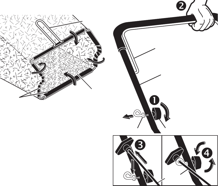
26
PARA MONTAR EL RECOGEDOR DE
CÉSPED
1. Ponga el bastidor del recogedor de césped
en la bolsa del césped con la parte rígida
de la bolsa en la parte inferior. Asegúrese
que el mango del bastidor esté en el exte-
rior de la parte superior de la bolsa.
2. Deslice los sujetadores de vinilo sobre el
bastidor.
AVISO: Si los sujetadores de vinilo están muy
duros, métalos en agua caliente por algunos
minutos. Si se moja la bolsa, déjela que se
seque antes de usarla.
PARA INSTALAR LOS ACCESORIOS
Su segadora fue enviada lista para usarse
como una acolchadora de capa vegetal. Para
convertirla de modo que pueda ensacar o
descargar, refiérase a “PARA CONVERTIR LA
SEGADORA” en la sección de Operación de
este manual.
Mango del
bastidor del
reco-
gedor
Abertura
del bastidor
Sujetadores
de vinilo
INSTALACIÓN DEL CORDÓN ARRANCA-
DOR
1. Afloje una manilla-T.
2. Sujete la barra de control en contra del
mango superior.
3. Lentamente tire el cordón arrancador del
motor hacia afuera hasta que se deslice
dentro la parte redondeada de la guía del
cordón.
4. Apriete una manilla-T.
Mango superior
Barra de control
Cordón
arrancador
del motor
Guía del cordon Manilla-T
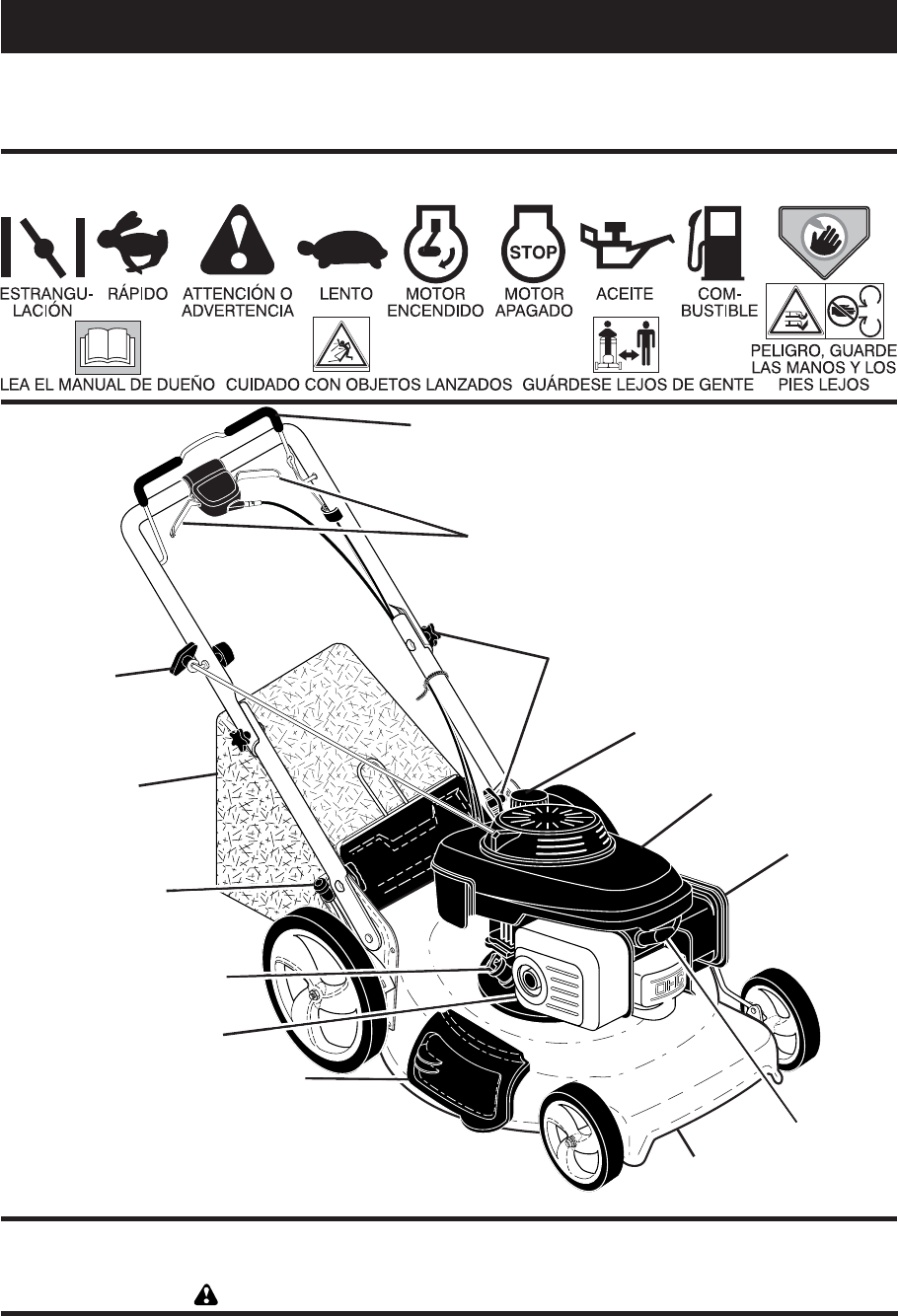
27
IMPORTANTE: Este cortacésped viene SIN
ACEITE O GASOLINA en motor. NOTA: Esta máquina
puede utilizar gasolina con un contenido de hasta el 10% de
etanol (E10). El uso de una gasolina que supere el 10% de etanol (E10) anulará la garantía del producto.
Barra de control que exige la
presencia del operador
Manillas del mango
Tapa del deposito
de la gasolina
Barra de control que exige la presencia del
operador – tiene que sujetarse abajo, junto
con el mango, para hacer arrancar el motor.
Suéltela para parar el motor.
Mango del ajustador de un solo punto – se
usa para ajustar la altura de corte de la sega-
dora.
Filtro
de aire
Puerta de la acolchadora – permite la conver-
sión para la operación de descarga o ensacado.
Cordón arrancador – se usa para hacer ar-
rancar el motor.
Barras de control de la impulsion – se usa
para enganchar la segadora para movimiento
hacia adelante impulsada a motor.
Mango del
ajustador de
un solo punto
Cordón
arrancador
Silenciador
Recogedor
de césped
Barras de control de la impulsión
Caja
Puerta de la
acolchadora
Bujía
OPERACIÓN
FAMILIARICESE CON SU SEGADORA
LEA ESTE MANUAL DEL DUENO Y LAS REGLAS DE SEGURIDAD ANTES DE OPARAR SU SEGA-
DORA. Compare las ilustraciones con su segadora para familiarizarse con la ubicación de los
diversos controles y ajustes. Guarde este manual para referencia en el futuro.
Estos símbolos pueden apareser sobre su segadora o en la literatura proporcionada con el
producto. Aprenda y comprenda sus significados.
CUMPLE CON LOS REQUISITOS DE SEGURIDAD DE LA CPSC
Las segadoras a motor, que se conducen desde la parte de atrás, rotatorias, Sears, cumplen con los
estándares de seguridad del American National Standards Institute y de la U.S. Con sum er Product
Safety Commission. PRECAUCIÓN: La cuchilla gira cuando el motor está funcionando.
Tapa del deposito de
aciete del motor con
varilla de nivel
Válvula del
combustible
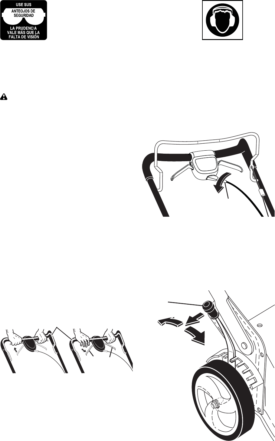
28
COMO USAR SU SEGADORA
VELOCIDAD DEL MOTOR
La velocidad del motor se estableció en la fá-
brica para un rendimiento óptimo. La velocidad
no se puede ajustar.
CONTROL DE ZONA DEL MOTOR
PRECAUCIÓN: Las regulaciones federales
exigen que se instale un control para el motor
en esta segadora para reducir a un mínimo el
riesgo de lesionarse debido al contacto con la
cuchilla. Por ningún motivo trate de eliminar
la función del control del operador. La cuchilla
gira cuando el motor está funcionando.
• Su segadora viene equipada con una barra
de controles que exigen la presencia del
operador, lo que requiere que el operador
esté detrás del mango de la segadora para
hacerla arrancar y operarla.
CONTROL DE LA IMPULSIÓN
• La autopropulsión se controla manteniendo
la palanca de mando operador presente
abajo hacia el mango y tirando cualquiera
palanca de accionamiento atrás hacia el
mango. Cuanto más lejos se tira a palanca
hacia el mango, más rápida irá la unidad.
• El movimiento hacia adelante se detiene
cuando sea la palanca de mando operador
presente o a palanca de accionamiento se
sueltan. Para detener el movimiento hacia
adelante sin apagar el motor, soltar sólo
a palanca de accionamiento. Mantener la
palanca de mando operador presente abajo
contra el mango para continuar a cortar sin
autopropulsión.
AVISO: Si después haber desenganchado
de la palanca de control, la segadora no roda
hacia atrás, empuje la segadora un poco hacia
adelante para desenganchar las ruedas de la
impulsión.
1. Apagar la unidad y desconectar el cable de
bujía de la bujía.
2. Vuelta el torniquete para aumentar la velo-
cidad del mecanismo.
3. Opere la segadora para probar la veloci-
dad del mecanismo. Reajuste según lo
requerido.
4. Si las condiciones no mejoran después
de los pasos descritos (la velocidad hacia
adelante queda la misma), la correa de
transmisión está desgastada y tiene que
ser sustituida.
PARA AJUSTAR LA ALTURA DE CORTE
Las cuatro ruedas son ajustadas con una
palanca única.
• Tire de la palanca de ajustes hacia la rueda.
Levante la segadora, mueva la palanca
hasta delante a la posición deseada. Para
bajar la segadora, mueva la palanca hacia la
retaguardia.
PALANCA
HACIA ATRÁS
PARA BAJAR EL
CORTACÉSPED
PALANCA HACIA
ADELANTE
PARA LEVANTAR EL
CORTACÉSPED
Palanca
de ajustes
PARA ENGANCHAR
EL CONTROL DE LA
IMPULSIÓN
Palancas
de la
impulsión
CONTROL DE LA
IMPULSIÓN
DESENGANCHADO
Barra de control que exige la presencia del operador
La operación de cualquier segadora puede hacer que
salten objetos extraños dentro de sus ojos, lo que puede
producir daños graves en éstos. Siempre use anteojos
de seguridad o protección para los ojos mientras opere
su segadora o cuando haga ajustes o reparaciones.
Recomendamos gafas o una mascara de seguridad
de visión amplia de seguridad usada sobre las gafas.
Utilice las
protec-
ciones
auditivas
para evitar
daño a la
audiencia.
AJUSTE DEL MANDO
Ocasionalmente, el sistema de mando puede
“aflojarse”, provocando una disminución de
la velocidad. Hay un torniquete en la sede
del mando para apretar la tensión del cable.
Proceder de la siguiente manera:
Torniquete
ajuste
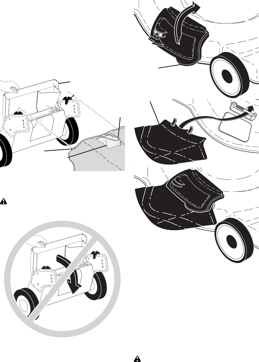
29
PARA CONVERTIR LA SEGADORA
Su segadora fue enviada lista para usarse como
acolchadora de capa vegetal. Para convertirla
a una operación de ensacado o de descarga:
SEGADORAS CON DESCARGA TRASERA
• Levantar la puerta trasera de cortacésped
y colocar los ganchos del armazón de la
recolectora de hierba en los soporte del
recogedor de césped.
• Para pasar a la operación de acolchamiento,
remover la recolectora de hierba y cerrar la
puerta trasera.
AVISO: Le puerta trasara seguirá siendo abi-
erto hasta la barra de control que exige la pres-
encia del operador se mantiene a la mango.
PRECAUCIÓN: No fuerce la puerta trasera
para cerrarse. El daño grave a su segadora
podía resultar.
PASOS SIMPLES DE RECORDAR
CUANDO CONVIERTA SU SEGADORA
PARA ACOLCHAMIENTO -
1. La puerta trasera cerrada.
2. La protección contra la descarga cerrada y
trabado.
PARA ENSACAMIENTO TRASERO -
1. Recogedor del césped instalado.
2. La protección contra la descarga cerrada y
trabado.
PARA DESCARGA LATERAL-
1. La puerta trasera cerrada.
2. La desviador de la descarga instalada.
PRECAUCIÓN: No haga funcionar su
segadora sin la placa de la acolchadora sin
el recogedor césped aprobados en su lugar.
Nunca trate de operar la segadora cuando se
halla removido la puerta trasera o cuando se
ha removido a puerta trasera o cuando está un
poco abierta.
SEGADORAS CON DESCARGA LATERAL
• La puerta trasera tiene que estar cerrada.
• Abra la protección contra la descarga y
instale el desviador de contra la descarga
debajo de la protección como se muestra.
• La segadora esta lista para la operación de
la descarga.
• Para convertir a la operación de ensacado
o de descarga, el desviador de la descarga
debe ser removido y la protección contra la
descarga debe estar cerrada y trabado.
Abierto la
protección
contra la
descarga
Desviador
de la descarga
Abra
Soporte del
recogedor de césped
Mango del
bastidor del
recogedor
de césped
Gancho
lateral del
bastidor del
recogedor
Puerta trasera
Indicador
de bolsa
llena
LA SEGADORA
ESTA LISTA PARA LA
OPERACIÓN DE LA
DESCARGA
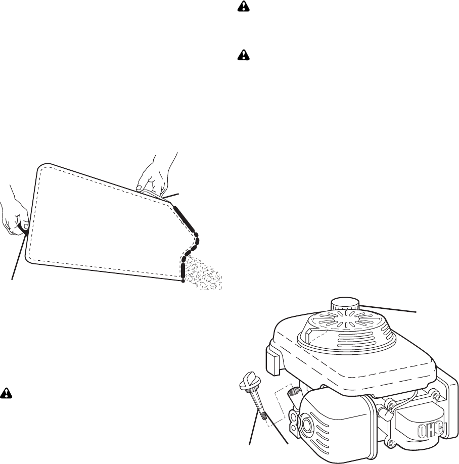
30
ANTES DE HACER ARRANCAR EL MO-
TOR
AGREGUE ACEITE
Su segadora fue enviada sin aceite en el motor.
Para el tipo y el grado del aceite a utilizar, vea
el “MOTOR” en la sección del Mantenimiento
de este manual.
PRECAUCIÓN: NO sobrellene el motor con
aceite, o fumará pesa demante del silenciador
cuando lo valla a arrancar.
1. Asegúrese que la segadora esté nivelada.
2. Remueva la varila medidora de aceite del
tubo de desarga de aceite.
3. Usted recibe un envase de aceite con la
unidad. Vierta lentamente el envase entero
de aceite en el tubo de relleno del motor.
4. Inserte y apriete la varilla medidora de aceite.
IMPORTANTE:
• Revise el nivel del aceite antes de cada uso.
Agregue aceite si es necesario. Llene hasta la
línea de lleno en la varilla medidora de nivel.
• Cambie el aceite después de 25 horas de
operación o una vez por temporada. Puede
necesitar cambiar el aceite más a menudo
cuando las condiciones son polvorosas o
sucias. Vea “PARA CAMBIAR EL ACEITE
DEL MOTOR” en la seccion de Mantenimien-
to de este manual.
AGREGUE GASOLINA
• Llene el estanque de combustible hasta la
parte inferior del cuello de relleno del es-
tanque de gasolina. No lo llene demasiado.
Use gasolina regular, sin plomo, nueva y lim-
pia con el mínimo de 87 octanos. No mezcle
el aceite con la gasolina. Para asegurar
que la gasolina utilizada sea fresca compre
estanques los cuales puedan ser utilizados
durante los primeros 30 días.
PRECAUCIÓN: Limpie el aceite o el
combustible derramado. No al ma ce ne,
derrame o use gasolina cerca de una llama
expuesta.
PRECAUCIÓN: Los com bus ti bles
mezclados con alcohol (conocidos como
gasohol, o el uso de etanol o metanol) pueden
atraer la humedad, la que conduce a la
separación y formación de ácidos durante el
almacenamiento. La gasolina acídica puede
dañar el sistema del combustible de un motor
durante el almacenamiento. Para evitar los
problemas con el motor, se debe vaciar el
sistema del combustible antes de guardarlo
por un período de 30 días o más. Vacíe el
estanque del combustible, haga ar rancar el
motor y hágalo funcionar hasta que las líneas
del combustible y el carburador queden vacíos.
La próxima temporada use combustible nuevo.
Vea las Instrucciones Para El Almacenamiento
para más información. Nunca use productos
de limpieza para el motor o para el carburador
en el estanque del combustible pues se
pueden producir daños permanentes.
PARA VACIAR EL RECOGEDOR DE
CÉSPED
Vacie el recogedor de césped cuando los
recortes son visibles en la ventana llena del
indicador de bolsa llana.
1. Levante el recogedor de césped usando el
mango del bastidor.
2. Remueva el recogedor de césped, con
los recortes, de debajo del mango de la
segadora.
3. Vacíe los recortes de la bolsa.
AVISO: No arrastre la bolsa cuando la vacíe;
se producirá un desgaste innecesario.
Mango del
bastidor
del
recogedor
de césped
Mango de césped
PARA PARAR EL MOTOR
• Para parar el motor y si no intenta ponerlo
en marcha de nuevo, alivie la barra de con-
trol que exige la presencia del operador. Es-
pere hasta que la cuchilla y todas las piezas
móviles se hallan parado y mueva la válvula
del combustible a la posicion APAGADO
(OFF).
PARA HACER ARRANCAR EL MOTOR
AVISO: Debido a las capas protectoras del mo-
tor, una cantidad pequeña de humo puede es-
tar presente durante el uso inicial del producto
y se debe considerar normal.
1. Asegurase que válvula del com bus ti ble
esté en la posición ON.
2. Sujete la barra de controles que exigen la
presencia del operador abajo en el mango
y tire el mango del arrancador rápidam-
ente. No permita que el cordón arrancador
se devuelva abruptamente.
Tapa del deposito
de aceite
con
varilla
de
nivel
Tapa del
rellenador
de gasolina
Marca
inferior
Marca
superior
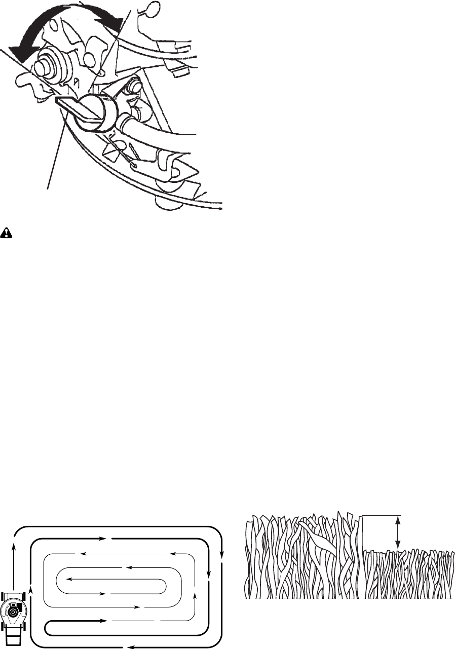
31
• Los poros en los recogedores de césped de
tela pueden llenarse con mugre y polvo con
el uso y los recogedores recaudarán menos
césped. Para evitar éste, rocíe el recogedor
con la manguera de agua, regularmente, y
déjelo secarse antes de usarlo.
• Mantenga la parte superior del motor, alrede-
dor del arrancador, despejada y sin recortes
de césped y paja. Esto ayudará el flujo del
aire del motor y extenderá su duración.
CONSEJOS PARA SEGAR Y ACOLCHAR
IMPORTANTE: Para obtener el mejor rendimiento
mantenga la caja de la segadora sin acumulacion
de cesped y basura. Vea “LIMPIEZA” en la
seccion de Mantenimento de este manual.
• La cuchilla acolchadora especial va a volver
a cortar los recortes de césped muchas
veces, y los reduce en tamaño, de modo
que si se caen en el césped se van a dispe-
sar entre éste y no se van a notar. También,
el césped acolchado se va a deshacer rápi-
damente entregando substancias nutritivas
para el césped. Siempre acolche con la
velocidad del motor (cuchilla) más alta, pues
así se obtendrá la mejor acción de recorte
de las cuchillas.
• Evite cortar el césped cuando esté mojado.
El césped mojado tiende a formar montones
e interfiere con la acción de acolchado.
La mejor hora para segar el césped es
temprano en la tarde. A esa hora éste se ha
secado y el área recién cortada no quedará
expuesta al sol directo.
• Para obtener los mejores resultados, ajuste
la altura del corte de la segadora de modo
que ésta corte solamente el tercio superior
de las hojas de césped. En el caso de que el
césped haya crecido demasiado, puede ser
necesario el elevar la altura del corte para re-
ducir el esfuerzo necesario para empujar la
segadora y para evitar sobrecargar el motor,
dejando montones de recortes de césped.
Para un césped muy pesado, reduzca el an-
cho del corte pasando por encima del lugar
anteriormente cortado y siegue lentamente.
• Ciertos tipos de césped y sus condiciones
pueden exigir que un área tenga que ser
acolchada por segunda vez para esconder
completamente los recortes. Cuando se
haga el segundo corte, siegue atravesado
(en forma perpendicular) a la pasada del
primer corte.
• Cambie su patrón de corte de semana a
semana. Siegue de norte a sur una semana
y luego cambie de este a oeste la próxima
semana. Esto evitará que el césped se
enrede y cambie de dirección.
CONSEJOS PARA SEGAR
PRECAUCIÓN: No utilizar dispositivos anti-
paja de la hoja en la segadora ya que estos
accesorios son peligrosos, pueden dañar su
segadora y anular su garantía.
• Bajo ciertas condiciones, tal como césped
muy alto, puede ser necesario el elevar
la altura del corte para reducir el esfuerzo
necesario para empujar la segadora y para
evitar sobrecargar el motor, dejando mon-
tones de recortes de césped. Puede que sea
necesario reducir la velocidad del recorrido
y/o haga funcionar la segadora sobre el área
por segunda vez.
• Para un corte muy pesado, reduzca el ancho
del corte pasando parcialmente por encima
del lugar anteriormente cortado y siegue
lentamente.
• Si las segadoras de descarga lateral cortan
en una dirección contraria a las manillas del
reloj, si se empieza en la parte de afuera
del área que se va a cortar, se repartirán los
recortes del césped en forma más pareja y
el motor se cargará menos. Para evitar que
los recortes caigan en los senderos, en las
flores, etc., haga los primeros cortes en la
dirección de las manillas del reloj.
MAX 1/3
• Si queda una huella de cortes en el lado
derecho de una segadora con descarga
trasera, siegue en la dirección en que giran
las manillas del reloj, solapando un poco
para recaudar los recortes en la próxima
pasada.
Válvula del combustible
ON
APAGADO
(OFF)
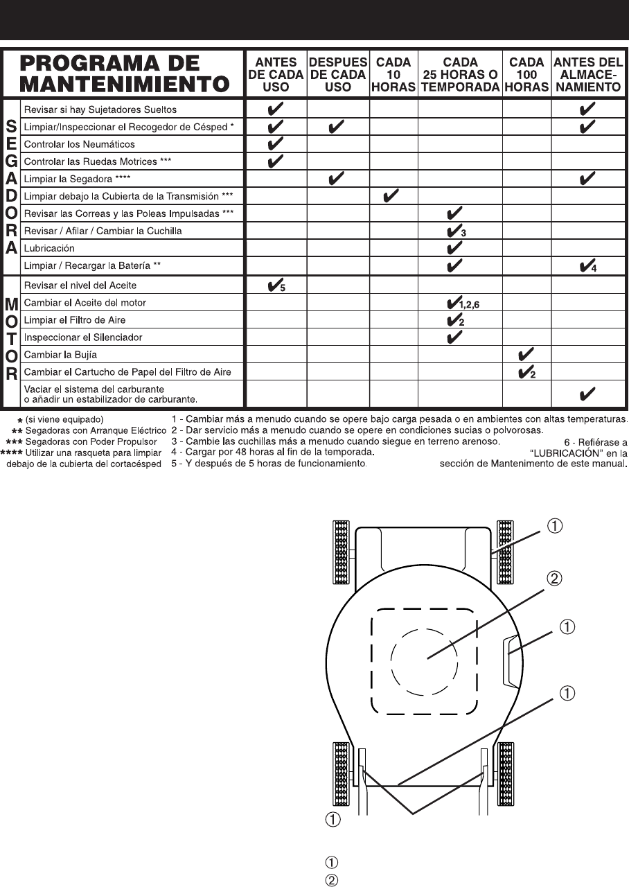
32
Ajustador
de la rueda
Clavija de montaje del puntal del mango
Bisagra
de la
puerta
traser
Aceite del
motor
MANTENIMENTO
RECOMENDACIONES GENERALES
La garantía de esta segadora no cubre los
artículos que han estado sujetos al abuso o a
la negligencia del operador. Para recibir todo
el valor de la garantía, el operador tiene que
mantener la segadora según las instrucciones
descritas en este manual.
Hay algunos ajustes que se tienen que hacer
en forma periódica para poder mantener su
unidad adecuadamente.
Al menos una vez cada estación comprobar
si es necesario efectuar los ajustes descritos
en las secciones de Servicio y Ajustes de este
manual.
• Una vez al año, cambie la bujía, limpie o
cambie el elemento del filtro de aire y revise
si la cuchilla está desgastada. Una bujía
nueva y un elemento del filtro de aire limpio/
nuevo aseguran la mezcla de aire-com bus-
ti ble adecuada y ayudan a que su motor
funcione mejor y que dure más.
• Siga el programa de mantenimiento en este
manual.
ANTES DE CADA USO
• Revise el nivel del aceite del motor.
• Revise si hay sujetadores sueltos.
LUBRICACIÓN
Mantenga la unidad bien lubricada
(vea la “TABLA DE LUBRICACIÓN”).
TABLA DE LUBRICACIÓN
Rocie el lubricante
Vea "MOTOR" en la seccion de Mantenimiento
IMPORTANTE: No aceite o engrase los roda-
mientos de la rueda de plastico. Los lubrican-
tes viscosos atearan polvo y mugre, lo acortara
la duracion de los rodamientos autolubrican-
tes. Si cree que tienen que lubricarse, use
losamente un lubricante tipo crafito, de polvo
seco, en forma moderada.
Bisagra
de la puerta
de la acol-
chadora
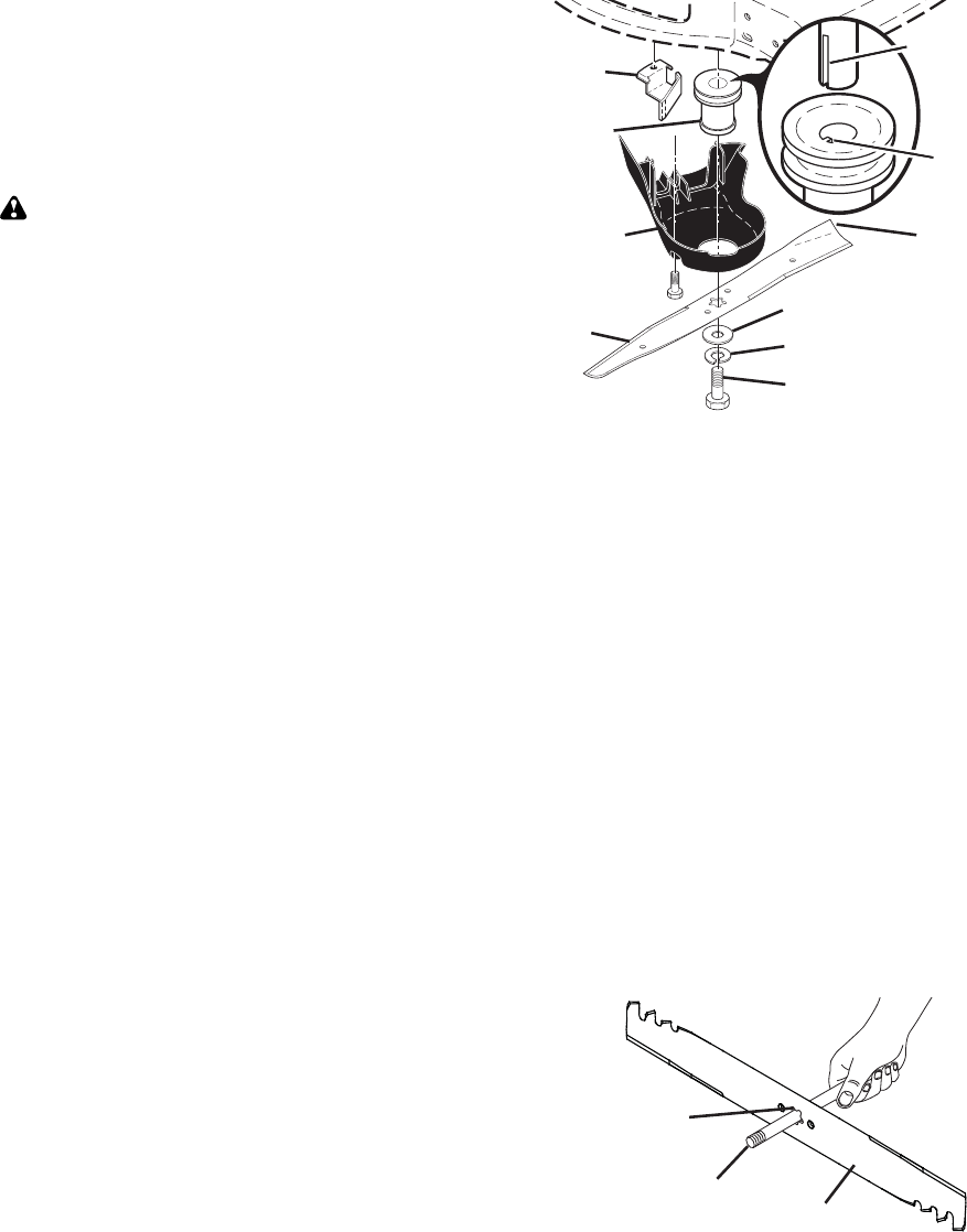
33
SEGADORA
Siempre observe las reglas de seguridad
cuando haga el mantenimiento.
LLANTAS
• Mantenga las llantas sin gasolina, aceite o
substancias químicas para control de insec-
tos que pueden dañar la goma.
• Evite los tocones, las piedras, las grietas
profundas, los objetos afilados y otros pelig-
ros que pueden dañar a las llantas.
RUEDAS DE IMPULSIÓN
Revise las ruedas de impulsión traseras cada
vez antes de segar, para asegurarse de que
se mueven libremente. Si las ruedas no
giran libremente quiere decir que hay basura,
recortes de césped, etc. en el área de las rue-
das de impulsión y tienen que limpiarse para
liberarlas.
Es necesario limpiar las ruedas de impulsión;
revise ambas ruedas traseras.
CUIDADO DE LA CUCHILLA
Para obtener los mejores resultados, la cuchilla
de la segadora tienen que mantenerse afilada.
Cambie la cuchilla doblada o dañada.
PRECAUCIÓN: Usar solamente la cuchilla
de repuesto aprobada por el fabricante de
su segadora. Usar una cuchilla no aprobada
por el fabricante de su segadora es peligroso,
puede dañar su segadora y anular su garantía.
PARA REMOVER LA CUCHILLA
1. Desconecte el alambre de la bujía y pón-
galo en donde no pueda entrar en contacto
con ésta.
2. Haga descansar la segadora en su lado.
Asegúrese que el filtro de aire y que el
carburador queden mirando hacia arriba.
3. Use un bloque de madera entre la cuchilla
y la caja de la segadora para evitar que la
cuchilla gire cuando se le quite el perno.
AVISO: Proteja sus manos con guantes y/o
envuelva la cuchilla con una tela gruesa.
4. Remueva el perno de la cuchilla girándolo
en el sentido contrario en que giran las
manillas del reloj.
5. Remueva la cuchilla y los artículos de fer-
retería adjuntadores (el perno, la arandela
de seguridad y la arandela endurecida).
6. Remueva el cubierta de la caja de en-
granajes.
AVISO: Remueva el adaptador de la cuchilla y
revise el cubo interior de la ranura del adapta-
dor de la cuchilla. La ranura tiene que estar en
buenas condiciones para que funcione en forma
adecuada. Cambie el adaptador si está dañado.
PARA CAMBIAR LA CUCHILLA
1. Ponga el adaptador de la cuchilla en el
cigueñal del motor. Asegúrese que la
ranura del adaptador y que el chavetero
del cigueñal estén alineados. Asegurarse
de que la correa se halle al interior de la
dispositivo de retención de correa.
2. Instale el cubierta de la caja de engranajes.
3. Ponga la cuchilla en el adaptador.
IMPORTANTE: Para asegurar la instalacion apro-
piada, posicione el agujero central de la cuchilla
con la estrella del conjunto del adaptador.
4. Asegúrese de que el borde de salida de
la cuchilla (opuesto al borde afilado) esté
hacia arriba hacia el motor.
5. Instale el perno de la cuchilla con la aran-
dela de seguridad y la arandela endurecida
en el adaptador de la cuchilla y el cigueñal.
6. Use un bloque de madera entre la cuchilla
y la caja de la segadora y apriete el perno
de la cuchilla girándolo en el sentido en
que giran las manillas del reloj.
• La torsión para apretar recomendada es de
35–40 pies libras.
IMPORTANTE: El perno de la cuchilla es
tratado a calo. Si es necesario sustituir los
pernos, sustituirlos sólo con pernos aprobados
mostrados en la sección Partes de Reparación
de este manual.
PARA AFILAR LA CUCHILLA
AVISO: No recomendamos el afilar la cuchilla
– pero si lo hace, asegúrese de que quede
balanceada. Una cuchilla que no está bal-
anceada va a producir eventualmente daño en
la segadora o en el motor.
• La cuchilla puede afilarse con una lima o en
una rueda rectificadora. No trate de afilarla
mientras se encuentra en la segadora.
• Para revisar el balance de la cuchilla, va a
necesitar un perno de acero de 5/8", una
clavija o un balanceador cónico. (Cuando se
use un balanceador cónico, siga las ins truc-
cio nes que vienen con el balanceador.)
AVISO: No use un elavo para balancear la
cuchilla. Los lóbulos del agujero central pueden
aparecer como centrados, pero no lo están.
• Deslice la cuchilla en una parte no roscada
del perno de acero o clavija y sujete el perno
o la clavija paralelo al suelo. Si la cuchilla está
balanceada, debe permanecer en la posición
horizontal. Si cualquiera de los extremos de la
cuchilla se mueva hacia abajo, afile el extremo
pesado hasta que ésta quede balanceada.
Perno de la cuchilla
Arandela endurecida
Arandela de seguridad
Adaptador
de la
cuchilla
Cuchilla
Borde de
salida
Retención
de correa
Cubierta de
la caja de
engranajes
Chavetero
del
ciguenal
Ranura
Agujero central
Perno de la
cuchilla de 5/8"
Cuchilla
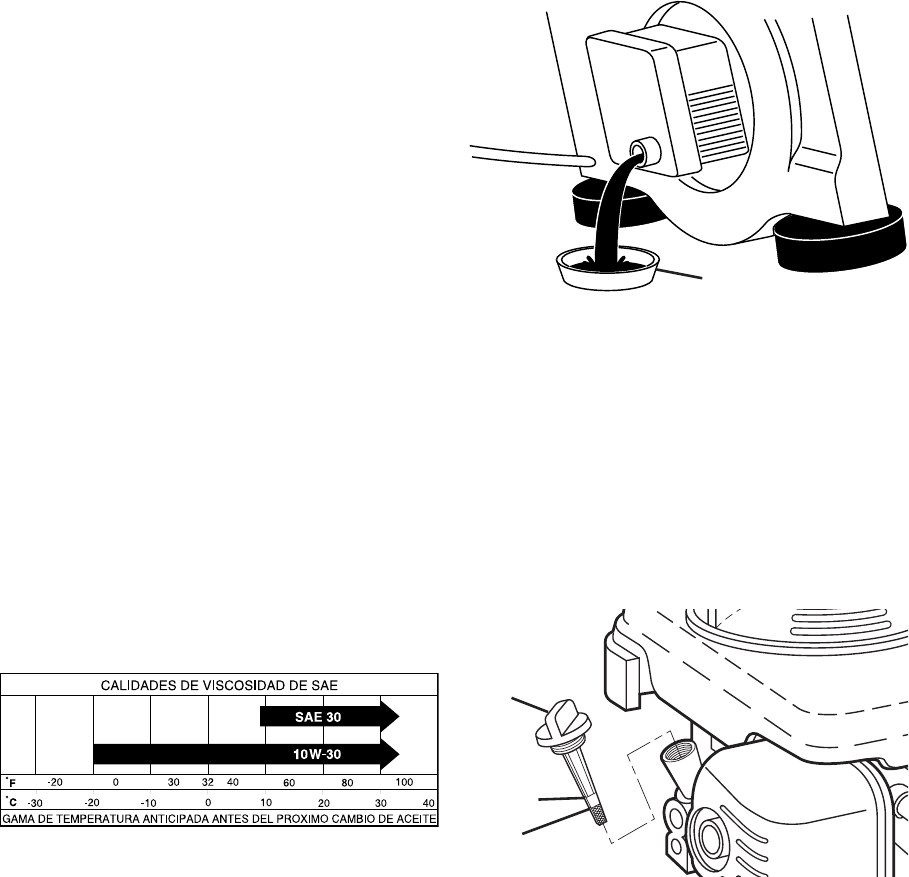
34
AVISO: Los aceites de multiviscosidad (5W30,
10W30, etc.) mejoran el arranque en clima frío,
y revise el nivel del aceite del motor menudo,
para evitar un posible daño en el motor, debido
a que no tiene suficiente aceite.
Cambie el aceite después de 25 horas de
operación o por lo menos una vez al año si la
segadora se utiliza menos 25 horas el año.
Revise el nivel del aceite del cárter antes de
arrancar el motor y después de cada cinco (5)
horas de uso continuado. Apriete el tapón del
aceite en forma segura cada vez que revise el
nivel del aceite.
PARA CAMBIAR EL ACEITE DEL MOTOR
AVISO: Antes de inclinar la segadora para drenar
el aceite, drene el tanque de com bus ti ble hacien-
do correr el motor hasta que el tanque esté vacio.
1. Desconecte el alambre de la bujía y
póngalo de modo que no pueda entrar en
contacto con ésta.
RECOGEDOR DE CÉSPED
• El recogedor de césped puede ser rociado
con el agua de la manguera pero tiene que
estar seco cuando se vaya a usar.
• Revise su recogedor de césped a menudo
para verificar si está dañado o deteriorado.
Se va a desgastar con el uso normal. Si se
necesita cambiar el recogedor, cámbielo
solamente por uno que sea aprobado por el
fabricante. Dé el número del modelo de la
segadora cuando lo ordene.
CAJA DE ENGRANAJES
• Para mantener el sistema de impulsión
funcionando en forma adecuada, la caja de
engranajes y el área alrededor de la impulsión
tienen que mantenerse limpias y sin acumu-
lación de basura. Limpie debajo de la cubierta
de la impulsión dos veces por temporada.
• La caja de engranajes se llena con lubrican-
te hasta el nivel adecuado en la fábrica. La
única vez que el lubricante necesita atención
es cuando se le ha prestado servicio a la
caja de engranajes.
MOTOR
El mantenimiento, la reparación, o el reemplazo
de cualquier dispositivos o sistemas del control
de la emisión, los cuales sean hechos al costo
del cliente, pueden ser realizados por cualquier
individuo o establecimiento de reparación de
motor. Los reparos que caen bajo garantía deben
ser realizados por un establecimiento de servicio
de reparación de motor autorizado.
LUBRICACIÓN
Use solamente aceite de detergente de alta
calidad clasificado con la clasificación SJ–SN
de servicio API. Seleccione la calidad de visco-
sidad SAE según su temperatura de operación
esperada.
2. Remueva la tapa del depósito del aceite;
déjela a un lado en una superficie limpia.
3. Incline la cortadora de césped por este
costado tal como se muestra y purgue el
aceite en un recipiente idóneo. Mueva la
segadora de atrás para adelante para re-
mover todo el aceite que se haya quedado
atrapado dentro del motor.
4. Limpie todo el aceite derramado en la
segadora y en el lado del motor.
5. Rellene el motor con aceite. Vierta lenta-
mente el aceite en el tubo de relleno del
motor.
6. Permita que el aceite se asiente. Use un
medidor en la tapa/varilla indicadora del
nivel para relleno del aceite para revisar el
nivel. Inserte la varilla indicadora de nivel
en el tubo, y haga descansar la tapa del
depósito para relleno del aceite en el tubo
al leer las medidas. NO enrosque el tapón
cuando este tomando una lectura.
Envase
Tapa del
deposito de
aceite con
varilla de
nivel
Marca
inferior
Marca
superior
7. Continúe agregando cantidades pequeas
de aceite y vuelva a inspeccionar la varilla
medidora hasta que lea lleno (FULL). NO
sobrellene el motor con aceite, o fumará
cuando lo valla a arrancar.
8. Asegúrese de apretar la varilla medidora
del aceite antes de arrancar el motor.
9. Vuelva a conectar el alambre de la bujía a
ésta.
FILTRO DE AIRE
Su motor puede sufrir averías y funcionar
de manera incorrecta con un filtro del aire
sucio. Sustituir el papel del cartucho una vez
al año o tras 100 horas de funcionamiento,
más a menudo si se utiliza en condiciones de
suciedad y polvo particulares. No lave el filtro
de aire.
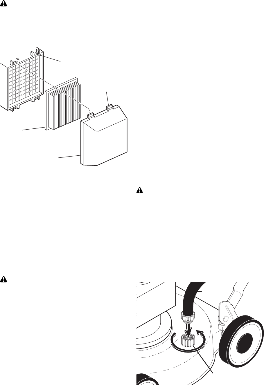
35
SILENCIADOR
Inspeccione y cambie el silenciador si está
corroído puede producir un peligro de incendio
y/o daño.
BUJÍA
Cambie el bujía al comienzo de cada tempo-
rada de siega o después de cada 100 horas
de operación, lo que suceda pri me ro. El tipo
de bujía y el ajuste de la abertura aparecen en
“ES PE CI FI CA CIO NES DEL PRODUCTO” sec-
ción de este manual.
LIMPIEZA
IMPORTANTE: Para obtener el mejor
rendimineto, mantenga la caja de la segadora sin
acumulacion de cesped y basura. Limpie la parte
de abajo de su segadora despues de cada uso.
PRECAUCIÓN: Desconecte el alambre de
la bujía y póngalo en donde no pueda entrar
en contacto con ésta.
• Haga descansar la segadora en su lado.
Asegúrese que el filtro de aire y que el
carburador queden mirando hacia arriba.
Limpie la parte inferior de su segadora
raspándola para remover la acumulación de
césped y basura.
• Limpie el motor a menudo para evitar que
se acumule la basura. Un motor tapado fun-
ciona más caliente y se acorta su duración.
• Mantenga las superficies pulidas y las rue-
das sin gasolina, aceite, etc.
• Con la excepción de la boca de derrubio del
agua (si está equipado), no recomendamos
el uso de una manguera de jardín para lim-
piar la parte exterior del segadora a menos
que el sistema eléctrico, el silenciador, el
filtro de aire y el carburador estén tapados
para evitar que les entre el agua. El agua en
el motor puede acortar la duración de éste.
DERRUBIO DEL AGUA
Su cortacéspedes de césped se equipa de una
guarnición que permita la limpieza rápida y
fácil del superficie inferior de la cubierta. Para
utilizar esta característica, siga de la forma
siguiente:
1. Mueva el cortacéspedes de césped a un
área de la hierba cortada o de otra superfi-
cie dura.
NOTA: El agua, la hierba y la otra ruina escur-
rirán debajo de la cubierta del cortacéspedes
durante el proceso del derrubio.
2. Quite el colector de la hierba y descargue
el montaje del canal inclinado del cortacés-
pedes de césped.
3. Cierre la puerta del mulcher (si está equi-
pado).
4. Conecte una manguera del jardín con la
guarnición donde demostrado.
IMPORTANTE: Sea seguro que la manguera
del jardín no está encaminada debajo de la
cubierta del cortacéspedes de césped ni que
está enredada en las ruedas.
5. Gire el abastecimiento y la comprobación
para de agua escapes en la guarnición.
Si no hay escapes presentes, encienda el
motor (según lo descrito en la sección de la
operación de este manual) y deje el motor
funcionar hasta que el superficie inferior del
cortacéspedes de césped está limpio.
ADVERTENCIA: No contrate el sistema de
impulsión durante el proceso del derrubio.
6. Apague el motor.
7. Apague el abastecimiento de agua y quite
la manguera de la guarnición.
PRECAUCIÓN: No quite la manguera de la
guarnición mientras que el motor está funcio-
nando. El agua en motor puede dar lugar a
vida acortada del motor.
8. Encienda el motor (según lo descrito en la
sección de la operación de este manual)
y deje el motor funcionar por un minuto
completo para quitar exceso de agua del
cortacéspedes.
Manguera
Guarnición
Oreja
Cartucho
Cubierta del filtro de aire
Ranura
PARA LIMPIAR EL FILTRO DE AIRE
1. Remueva la cubierta.
2. Cuidadosamente, remueva el cartucho.
3. Límpielo golpeándolo suavemente en una
superficie plana. Si está muy sucio cambie
el cartucho.
PRECAUCIÓN: Los solventes de petróleo,
tales como el keroseno, no se deben usar para
limpiar el cartucho. Pueden producir el deteri-
oro de éste. No aceite el cartucho. No use aire
a presión para limpiarlo o secarlo.
4. Instale el cartucho, luego vuelva a poner la
cubierta.
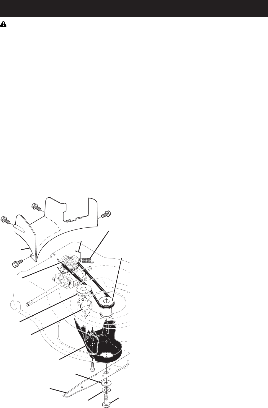
36
SERVICIO Y AJUSTES
ADVERTENCIA: Para evitar lesiónes serias, antes de dar calquier servico o de hacer ajustes:
1. Suelte la barra de control y pare el motor.
2. Asegúrese que la cuchilla y que todas las partes movibles se hayan detenido completamente.
3. Desconecte el alambre de la bujía y póngalo en donde no pueda entrar en contacto con ésta.
SEGADORA
PARA AJUSTAR LA ALTURA DE CORTE
Vea “PARA AJUSTAR LA ALTURA DE CORTE”
en la sección de Operación de este manual.
DESVIADOR TRASERO
Se proporciona un desviador trasero, adjunto
entre las ruedas traseras de su segadora, para
reducir a un mínimo la posibilidad que objetos
sean lanzados hacia afuera de la parte trasera
de la segadora, en la posición en donde se
encuentra el operador. Reemplaze el desviador
si esta danado.
PARA REMOVER CORREA DE IMPULSIÓN
1. Remueva los pernos asegúrela el bafle
posterior.
AVISO: Antes de inclinar la segadora para re-
mover la correa de implusión, drene el tanque
de com bus ti ble haciendo correr el motor hasta
que el tanque esté vacio.
2. Haga descansar la segadora en su lado
con el filtro de aire y el carburador mirando
hacia arriba.
3. Remueva la bafle posterior de la segadora.
4. Remueva perno de la cuchilla, arandela de
seguridad, arandela endurecida y cuchilla.
5. Remueva la cubierta de la caja de en-
granajes.
6. Remueva la fijador de la correa.
7. Remueva la correa.
PARA CAMBIAR CORREA DE IMPULSIÓN
1. Colocar la nueva correa de fijador de la
correa.
NOTA: Siempre use la correa aprobada por la
fábrica para asegurarse que calce y dure.
2. Reinstale la fijador de la correa. Asegu-
rarse de que la nueva correa se halle al
interior de los dispositivos de fijador de la
correa.
3. Ponga el adaptador de la cuchilla en el
cigueñal del motor. Asegúrese que la
ranura del adaptador y que el chavetero del
cigueñal estén alineados; y la nueva correa
se halle al interior de los dispositivos de
retención de la correa.
4. Inserto la bafle posterior en la segadora.
5. Reinstale la cubierta de la caja de en-
granajes.
6. Reinstale la cuchilla. La torsión para apre-
tar recomendada es de 35–40 pies libras.
7. Vuelva la segadora a la posición vertical.
8. Reinstale los pernos asegúrela el bafle
posterior.
PARA AJUSTAR EL MANGO
El mango de su segadora cuenta con múltiple
posiciones de altura – ajústelo a la altura que
le acomode.
1. Remueva la manilla y el perno portador en
un lado del mango inferior.
2. Al mismo tiempo que sujeta el conjunto
del mango, remueva la manilla y el perno
portador del lado opuesto, alinee el agujero
en el mango con el agujero deseado en
el puntal del mango y vuelva a montar el
perno y la manilla y apriételos en forma
segura.
3. Alinee el lado opuesto del mango con el
agujero de la misma posición y asegúrelos
con el perno y la manilla.
Perno
de la
cuchilla
Arandela endurecida
Arandela de seguridad
Cuchilla
Retención
de la correa
Polea
tensora
Fijador de
la correa
Cubierta de la
caja de engranajes
Bafle
posterior
Polea de
la caja de
engranajes
Adaptador
de la
cuchilla
Resorte de
vuelta
LIMPIE DEBAJO DE LA CUBIERTA DE LA
IMPULSIÓN
Limpie debajo de la cubierta de la impulsión por
lo menos dos veces cada temporada. Raspe
debajo de la cubierta con un cuchillo para masilla
o con una herramienta parecida, para remover
toda acumulación de césped o basura en la parte
inferior de la cubierta de la impulsión.
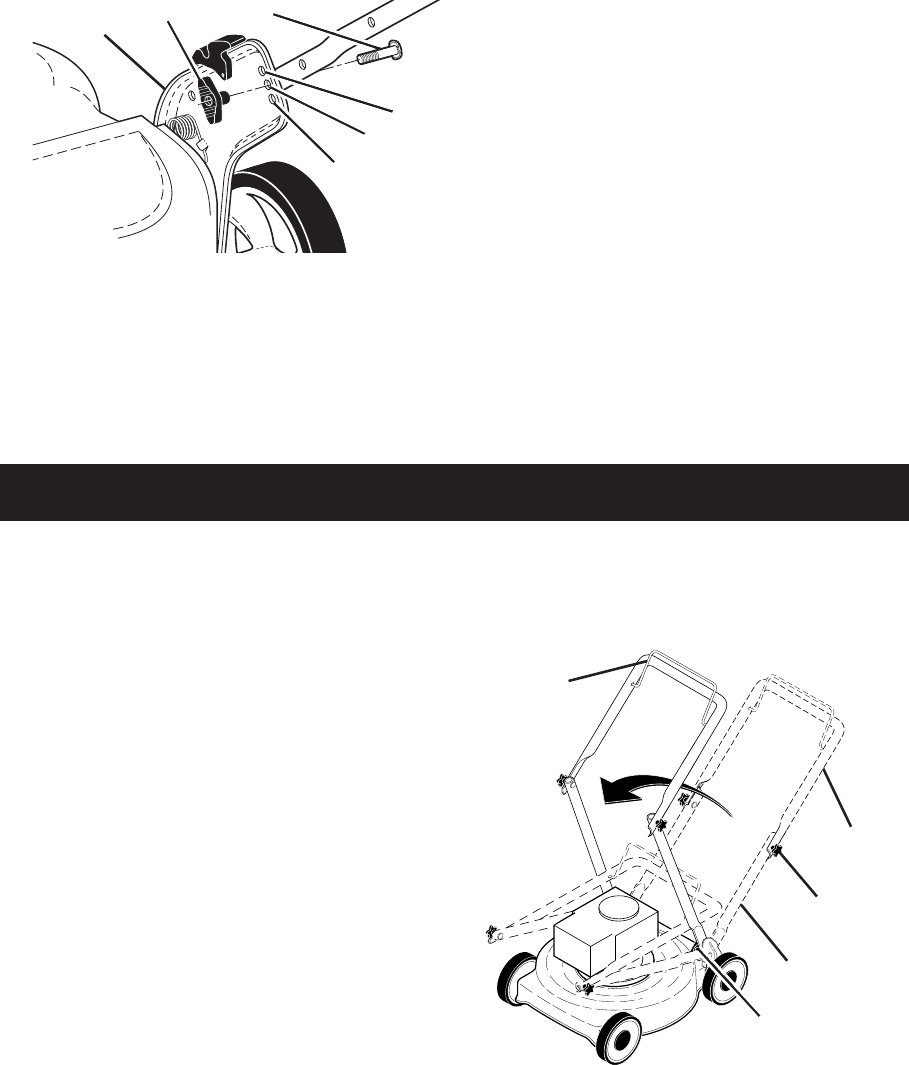
37
Puntal del
mango
Baja
Manilla
Alta
Mediana
Perno VELOCIDAD DEL MOTOR
La velocidad del motor ha sido ajustada en la
fábrica.
CARBURADOR
Su carburador tiene un chorro principal fijo no
ajustable para controlar la mezcla.
IMPORTANTE: Nunca manipule el regulador
del motor, el que ha sido ajustado en la fábrica
para la velocidad del motor adecuada. Puede
ser peligroso hacer funcionar el motor a una
velocidad por sobre el ajuste de alta velocidad
de la fábrica. Si cree que la velocidad alta regu-
lada del motor necesita ajuste,contacto con su
centro de servicio Sears o con un otro centro
de servicio cualificado, el que cuenta con el
equipo adecuado y la experiencia para hacer
los ajustes necesarios.
ALMACENAMIENTO
Inmediatamente prepare su segadora para el
almacenamiento al final de cada temporada o
si la unidad no se va a usar por 30 días o más.
SEGADORA
Cuando se va a guardar la segadora por cierto
período de tiempo, límpiela cuidadosamente,
remueva toda la mugre, la grasa, las hojas, etc.
Guárdela en un área limpia y seca.
1. Limpie toda la segadora (Vea “LIMPIEZA”
en la sección de Mantenimento de este
manual).
2. Lubríquela según se muestra en la sección
de Mantenimento de este manual.
3. Asegúrese de que todas las tuercas y
clavijas y todos los pernos y tornillos estén
apretados en foma segura. Inspeccione
las partes que se mueven para verificar si
están dañadas, quebradas o desgastadas.
Cámbielas si es necesario.
4. Retoque todas las superficies que estén
oxidadas o con la pintura picada; use una
lija antes de pintar.
MANGO
Puede doblar el mango de su segadora para el
almacenamiento.
1. Suelte las dos manillas del mango “star”
en cada lado del mango superior y permita
que el mango se doble hacia detras.
2. Suelte las dos manillas del mango “stan-
dard” en ambos lados del mango inferior y
pivote el conjunto entero del mango hacia
delante y permita le que se descanse sobre
la segadora.
3. Vuelva a poner las manillas “standard” y los
pernos al mango inferior o a los puntales
del mango para la seguridad.
• Cuando prepare su mango a partir de la
posición de almacenamiento, el mango infe-
rior nesecitara cerrarlo manualmente para la
posición de sega.
MOTOR
SISTEMA DE COM BUS TI BLE
IMPORTANTE: Es importante evitar que
se formen depositos de coma en partes
fundamentales del sistemade combustible tales
como el carburador, el filtro del combustible,
la mangura del combustible o en el estanque
durante el almacenamiento. Los combustibles
mezclados con alcohol (conocido come
gasohol o que tienen etanol o metanol)
Pueden atraer humedad, lo que conduce a la
separacion y a la formación de acidos durante
el almacenamiento. La gasolina acida puede
danar el sistema de combustible de un motor
durante el perido de almacenamiento.
POSICIÓN
PARA
SEGAR
Barra de control
que exige la
presencia del
operador
DOBLAR
HACIA
ADELANTE
PARA
ALMACENAR
Mango
superior
Mango inferior
Manilla del
mango superior
“star”
Manilla del mango
inferior “standard”
MOTOR
El mantenimiento, la reparación, o el reemplazo
de cualquier dispositivos o sistemas del control
de la emisión, los cuales sean hechos al costo
del cliente, pueden ser realizados por cualquier
individuo o establecimiento de reparación de
motor. Los reparos que caen bajo garantía deben
ser realizados por un establecimiento de servicio
de reparación de motor autorizado.
IMPORTANTE: Cuando doble el mango para
el almacenamiento o el transporte, asegúrese
que lo doble según se muestra o purde dañar
los cables de control.

38
• Vaciar el depósito del carburante poniendo
en marcha el motor y dejándolo funcionar
hasta que el carburante termine y el carbura-
dor esté vacío.
• Nunca use los productos para limpieza del
carburador o del motor en el estanque de
combustible pues se pueden producir daños
permanentes.
• Use combustible nuevo la próxima tempo-
rada.
AVISO: El estabilizador de combustible es
una alternativa aceptable para reducir a un
mínimo la formación de depósitos de goma
en el com bus ti ble durante el período de
almacenamiento. Agregue estabilizador a la
gasolina en el estanque de combustible o en
el envase para el almacenamiento. Siempre
siga la proporción de mezcla que se encuentra
en el envase del estabilizador. Haga funcionar
el motor por lo menos 10 minutos después de
agregar el estabilizador, para permitir que este
llegue al carburador. No drene la gasolina del
estanque de gasolina y el carburador si se está
usando estabilizador de combustible.
ACEITE DEL MOTOR
Drene el aceite (con el motor caliente) y
cámbielo con aceite de motor limpio. (Vea
“MOTOR” en la sección de Mantenimento de
este manual.)
CILINDRO
1. Remueva la bujía.
2. Vacíe una onza (29 ml) de aceite a través
del agujero de la bujía en el cilindro.
3. Tire la manilla de arranque lentamente unas
cuantas veces para distribuir el aceite.
4. Vuelva a montar la nueva bujía.
OTROS
• No guarde la gasolina de una temporada a
la otra.
• Cambie el envase de la gasolina si se emp-
ieza a oxidar. La oxidación y/o la mugre en
su gasolina producirán problemas.
• Si es posible, guarde su unidad en un
recinto cerrado y cúbrala para protegerla
contra el polvo y la mugre.
• Cubra su unidad con un forro protector
adecuado que no retenga la humedad. No
use plástico. El plástico no puede respirar, lo
que permite la formación de condensación,
lo que producirá la oxidación de su unidad.
IMPORTANTE: Nunca cubra la segadora
mientras el motor y las areas de escape
todavia estan calientes.
PRECAUCIÓN: Nunca almacene la
segadora con gasolina en el estanque dentro
de un edificio en donde los gases pueden
alcanzar una llama expuesta o una chispa.
Permita que se enfríe el motor antes de
almacenarla en algún recinto cerrado.
No arranca 1. Filtro de aire sucio. 1. Limpie/cambie el filtro de aire.
2. Sin combustible. 2. Llene el estanque de combustible.
3. Combustible rancio. 3. Vaciar el estanque y vuelva a llenar-
lo con combustible limpio y nuevo.
4. Agua en el combustible. 4. Vaciar el estanque y vuelva a llenar-
lo con combustible limpio y nuevo.
5. Alambre de la bujía desconectado. 5. Conecte el alambre a la bujía.
6. Bujía mala. 6. Cambie la bujía.
PROBLEMA CAUSA CORRECCIÓN
SOLUCIÓN DE PROBLEMAS - Vea la sección apropiada en el manual amenos que
esté dirigido a un centro de servico Sears.

39
No arranca 7. Cuchilla suelta o adaptador 7. Apriete el perno de la cuchilla
(continuado) de la cuchilla quebrado. cambie el adaptador de la cuchilla.
8. Barra de control en la 8. Presione la barra de control
posición suelta. hacia el mango.
9. Barra de control defectuosa. 9. Cambie la barra de control.
10. Válvula del combustible (si equ- 10. Gire a la válvula del combustible
ipada) está en la posición OFF. a la posición ON.
Falta de 1. Cuchilla desgastada, doblada 1. Eleve la altura de corte.
fuerza o suelta.
2. Altura de las ruedas dispareja. 2. Eleve la altura de corte.
3. Velocidad del motor lenta. 3. Limpie/cambie el filtro de aire.
4. Acumulación de césped, hojas o 4. Limpie la parte inferior de la
basura debajo de la segadora. caja de la segadora.
5. Demasiado aceite en motor. 5. Revise el nivel del aceite.
6. Velocidad de recorrido 6. Corte a una velocidad de
demasiado rápida. recorrido más lenta.
Mal corte- 1. Cuchilla desgastada, doblada 1. Cambie la cuchilla. Apriete el perno
disparejo o suelta. de la cuchilla.
2. Altura de las ruedas dispareja. 2. Ajuste todas las ruedas a la misma
altura.
3. Acumulación de césped, hojas o 3. Limpie la parte inferior de la
basura debajo de la segadora. caja de la segadora.
Vibración 1. Cuchilla desgastada, doblada 1. Cambie la cuchilla. Apriete el
excesiva o suelta. perno de la cuchilla.
2. Cigueñal del motor doblado. 2. Póngase en contacto con su centro
de servicio Sears o con un otro
centro de servicio cualificado.
Cordón 1. El freno del volante del motor 1. Presione la barra de control
arrancador está aplicado cuando se hacia el mango superior antes
difícil de tirar suelta la barra de control. de tirar el cordón arrancador.
2. Cigueñal del motor doblado. 2. Póngase en contacto con su centro
de servicio Sears o con un otro
centro de servicio cualificado.
3. Adaptador de la cuchilla quebrado. 3. Cambie el adaptador de la cuchilla.
4. La cuchilla se arrastra en 4. Mueva la segadora a un lugar
el césped. en donde el césped ha sido
cortado o a una superficie firme
para hacer arrancar el motor.
Recogedor de 1. Altura de corte demasiado baja. 1. Eleve la altura de corte.
césped no se 2. Levantamiento de la cuchilla 2. Cambie las cuchillas.
llena (si viene desgastado.
equipado) 3. Recogedor sin ventilación de aire. 3. Limpie el recogedor de césped.
Difícil de 1. El césped está demasiado alto o la 1. Eleve la altura de corte.
empujar altura de la rueda demasiado baja.
2. Parte trasera de la 2. Eleve la parte trasera de la caja de
caja/cuchilla de la segadora la segadora (1) un lugar más alto.
arrastrándose en el césped.
3. Recogedor de césped 3. Vacíe el recogedor de césped.
demasiado lleno.
4. Posición de la altura del mango 4. Ajuste la altura del mango de
no adecuada para usted. modo que le acomode.
Pérdida de 1. Desgaste de la correa. 1. Re vise/cambie correa de impulsión.
impulsión 2. La correa está fuera de la polea. 2. Revise/vuelva a instalar la
o retardase 3. Cable de la impulsión usado o roto. 3. Cambie el cable de la impulsión.
de la 4. El sistema de control del 4. Ajuste el control del mecanismo
velocidad mecanismo impulsor “suelto”. impulsor.
PROBLEMA CAUSA CORRECCIÓN
SOLUCIÓN DE PROBLEMAS - Vea la sección apropiada en el manual amenos que
esté dirigido a un centro de servico Sears.
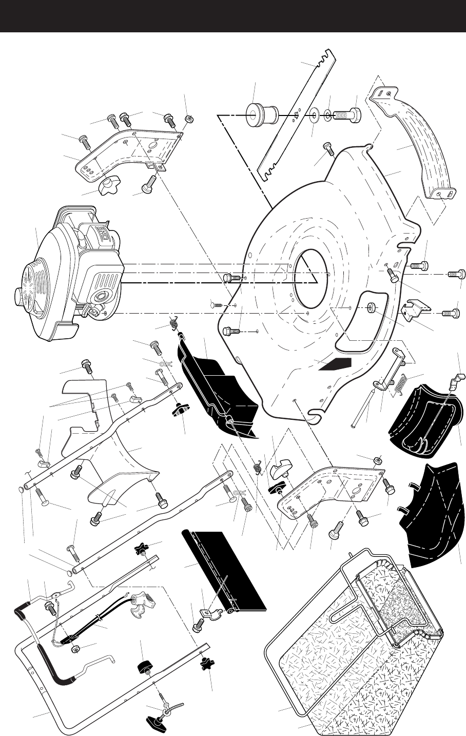
40
CRAFTSMAN ROTARY LAWN MOWER - - MODEL NUMBER 917.378300
REPAIR PARTS
18
9
21
30
31
32
33
36
53
38
39
42
44
45
46
48
49
50
51
52 53
57
22
34
53
63
57
28
28
22
34
40
12
41
41
41
43
53
97
59
13
11
17
26
56
56
58
84
96
12
59
6
6
11
26
59
24
20
83
85
18
19
56
84
98
99
2
47
64
41
CRAFTSMAN ROTARY LAWN MOWER - - MODEL NUMBER 917.378300
NOTE: All component dimensions given in U.S. inches. 1 inch = 25.4 mm.
IMPORTANT: Use only Original Equipment Manufacturer (O.E.M.) replacement parts. Failure to do so could be hazardous, damage your lawn mower and void your warranty.
KEY PART
NO. NO. DESCRIPTION KEY PART
NO. NO. DESCRIPTION
1 585864805 Upper Handle
2 585650803 Cable, Engine Zone Control /
Rear Door Prop
6 182398 Handle Knob, Star
8 587689301 Control Bar
9 585847601 Rear Door Assembly
11 425575 Hairpin, Door/Handle Pivot
12 189713X428 Handle Knob, Standard
13 437516 Plug, Handle Bar
17 581782101 Rear Baffle
18 581912601 T-Knob
19 581902101 Rope Guide
20 444501 Rear Skirt
21 419949 Spring, Rear Door, LH, Black
22 141841 Screw, Panhead, Torx #20
24 419948 Spring, Rear Door, RH, Grey
26 419945 Screw, Rear Door/Handle Pivot
28 586212501 Bolt, Carriage 5/16-18 x 5/8
30 580943406 Grassbag
31 585054703 Frame, Grass Catcher
32 419944X007 Latch, Mulcher Door
33 420019 Mulcher Door
34 419946X615 Bracket, Grassbag
36 175735 Hinge Bracket Assembly
38 419942X428 Discharge Deflector
39 585900702 Handle Bracket, LH
40 585900802 Handle Bracket, RH
41 150406 Screw, Dogpoint 3/8-16 x 1-1/8
42 193000 Spring, Torsion
43 191730 Nut, Hex, Nylock
44 431946 Kit, Lawn Mower Housing
45 175650 Rod, Hinge
46 581851501 Blade Adapter / Pulley
47 421825 Blade, 22"
48 851074 Washer, Hardened
49 850263 Washer, Helical
50 851084 Screw, Machine, Hex Head
3/8-24 x 1-3/8 Grade 8
51 430599 Front Baffle
52 404763 Decal, Danger
53 17000510 Screw, Hex Head 5-16-18
56 17411312 Screw, Hex Washer Head
#13 x 3/4
57 155377 Nut, Hex
58 585908202 Lower Handle
59 191574 Handle Bolt
63 178848 Screw #10-16 x 5/8
64 - - - Engine, Honda, Model
Number GCV160-LAOS3B
(See Breakdown)
83 750097 Screw, Hex Washer Head
84 428124 Fastener, Push
85 429801X004 Mounting Bracket,
Rear Skirt
96 197991 Clip, Cable
97 581115302 Bracket, Belt Guide
98 199687 Screw, Hex Head
99 132004 Nut, Hex
- - 423849 Bag of Parts (Includes
Key Numbers 6 and 59)
- - 589804001 Owner’s Manual,
English / Spanish
Available accessories not included with mower:
- - 71 33623 Gas Can
(2.5 Gallon Container)
- - 71 33500 Fuel Stabilizer
- - 71 33000 SAE 30W Oil
(20 Ounce Bottle)
KEY PART
NO. NO. DESCRIPTION
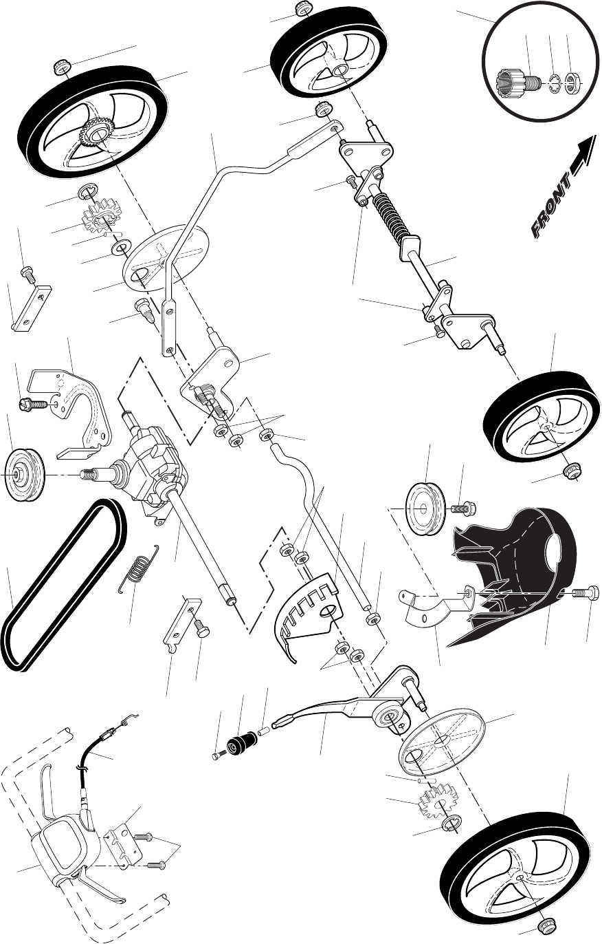
42
CRAFTSMAN ROTARY LAWN MOWER - - MODEL NUMBER 917.378300
12
12
16
23
24
29
57
35
38 38
38
39
44
28
29
31
41
32
32
57
14
26
13
37
55
22
22
59
59
19
21
58
17
11
11
85
36
33
33
40
48
49
50
51
28
31
41
27
20
25
22
86
87
18
40
1
9
10
61
43
CRAFTSMAN ROTARY LAWN MOWER - - MODEL NUMBER 917.378300
NOTE: All component dimensions given in U.S. inches. 1 inch = 25.4 mm.
IMPORTANT: Use only Original Equipment Manufacturer (O.E.M.) replacement parts. Failure to do so could be hazardous, damage your lawn mower and void your warranty.
KEY PART
NO. NO. DESCRIPTION KEY PART
NO. NO. DESCRIPTION
1 501408103 Drive Control Assembly
(Includes Cable)
9 581952101 Cable, Drive
10 587249302 Mounting Bracket, Drive Control
11 17411312 Screw
12 73940800 Nut, Hex
13 581680801 Gearcase Assembly, Complete
14 586963001 Pulley, Drive
16 428782X428 Rod, Connecting
17 751153 Nut, Hex
18 586691701 Kit, Selector Assembly
19 430697X615 Knob, Wheel Adjuster
20 580806901 Debris Shield
21 435242 Anchor
22 17000510 Screw, Hex Head 5/16-18
23 585281901 Wheel Axle Assembly, LH
24 433511 Bracket, Height Adjustment
25 581313802 Mounting Bracket, Debris Shield
26 589318302 Belt Keeper
27 19171216 Washer, Flat
28 12000058 E-Ring 7/16
29 585270701 Cover, Dust, Wheel
31 404845 Pawl, Drive
32 585437304 Wheel & Tire Assembly, Rear, 11"
33 409148 Nut, Flangelock 3/8-16
35 430598 Axle, Rear
36 441833X004 Axle, Front
37 163409 Screw, Hi-Lo Thread, 12 x 5/8
38 191730 Nut, Hex
39 407059 Bolt
40 400246X460 Wheel & Tire Assembly, Front, 8"
41 428783 Pinion
44 580364604 Belt, Drive
48 421114 Kit, Water Washout Assembly
49 419735 Fitting, Water Washout
50 415585 Washer, Lock, Internal Tooth
51 415586 Locknut, Hex, with O-Ring
55 581351301 Spring, Tension
57 409149 Locknut, Hex, Flanged
58 435241 Bolt, Shoulder
59 441786X004 Support Bracket
61 181698 Screw
85 439077 Support Bracket, Front Axle
86 587969201 Pulley, Idler
87 581127601 Screw
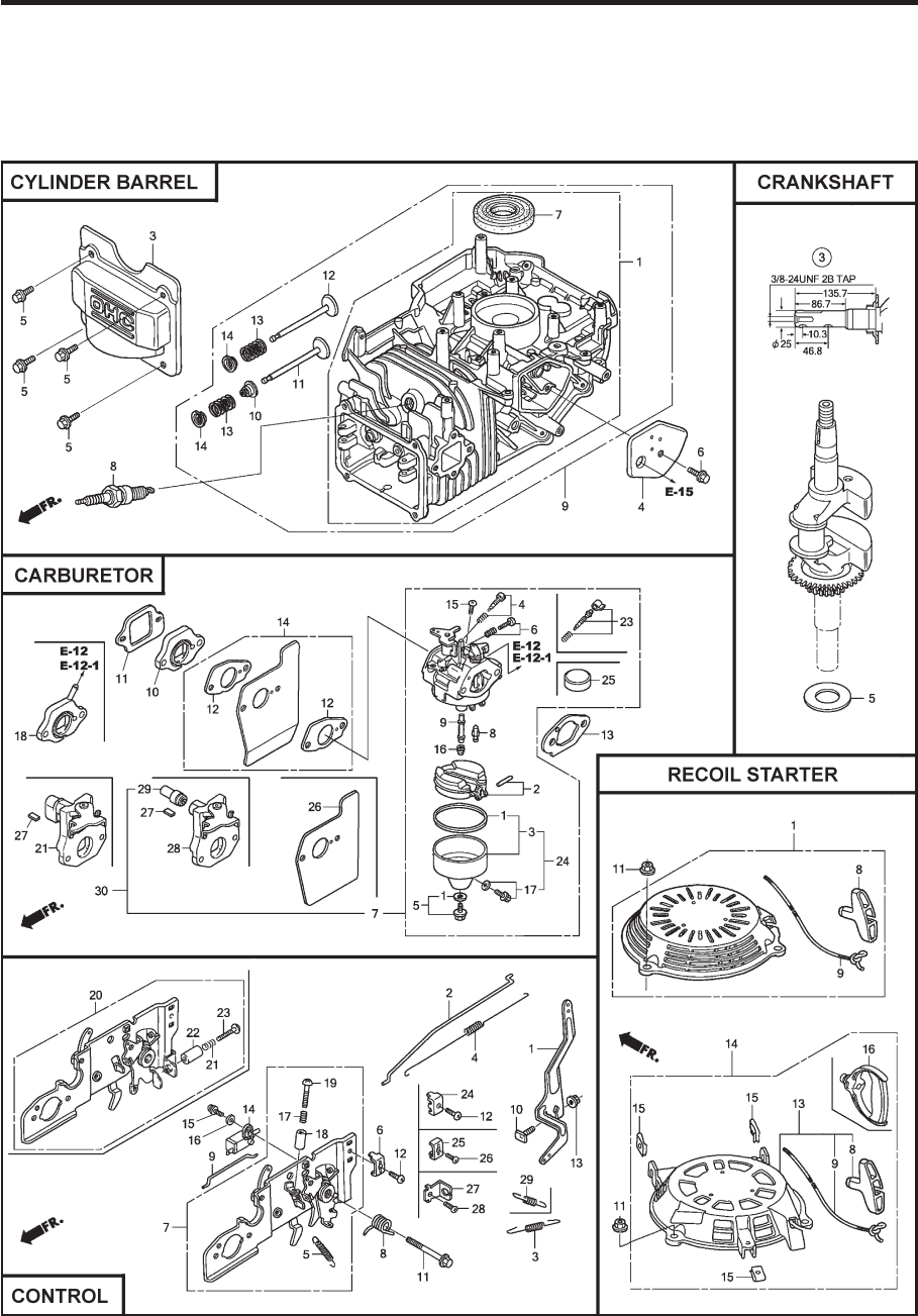
44
MODEL NUMBER GCV160-LAOS3B
HONDA 4-CYCLE ENGINE

45
CYLINDER BARREL
KEY PART
NO. NO. DESCRIPTION
1 12000-Z0L-406 Cylinder Assembly
12000-Z0L-840 Cylinder Assembly
3 12310-Z0J-000 Cover, Cylinder Head
12311-ZL8-D00 Cover, Head
12311-ZL8-000 Cover, Head
4 12355-ZL8-000 Cover, Breather
(Breather Valve Assembly)
5 90013-883-000 Bolt, Flange (#6 x 12)
(CT200)
6 90014-952-000 Bolt, Flange (#6 x 14)
(CT200)
7 91201-ZL8-003 Oil Seal (25.4 x 62 x 6)
8 98079-55846 Spark Plug (BPR5ES)
(NGK)
10 12209-ZM0-003 Seal, Valve Stem
11 14711-ZL8-000 Valve, Intake
(Technostar)
14711-Z0J-000 Valve, Intake (Rocknel)
14711-Z0J-800 Valve, Intake
12 14721-ZL8-000 Valve, Exhaust
13 14751-ZL8-000 Spring, Valve
14 14771-Z0J-000 Retainer, Valve Spring
CARBURETOR
KEY PART
NO. NO. DESCRIPTION
1 16010-883-015 Gasket Set
2 16013-ZL1-003 Float Set
3 16015-Z0L-881 Chamber Set, Float
5 16028-ZE0-005 Screw Set
16028-ZK7-S91 Screw Set
7 16100-Z0L-852 Carburetor Assembly
(BB62Z B)
8 16155-ZM0-013 Valve, Float
9 16166-ZM0-003 Nozzle, Main
10 16211-ZL8-000 Insulator, Carburetor
11 16212-ZL8-000 Gasket, Insulator
13 16228-ZL8-000 Gasket, Carburetor
15 93500-05006-0H Screw, Pan (#5 x 6)
16 99101-124-0600 Jet, Main (#60)
99101-124-0620 Jet, Main (#62)
99101-124-0650 Jet, Main (#65)
26 16951-Z0L-000 Guide, Air
CONTROL
KEY PART
NO. NO. DESCRIPTION
1 16551-ZM0-010 Arm, Governor
2 16555-Z0L-801 Rod, Governor
3 16561-Z0L-000 Spring, Governor
4 16562-ZM0-000 Spring, Throttle Return
10 90015-ZE5-010 Bolt, Governor Arm
13 94050-06000 Nut, Flange (6 mm)
15 93892-04012-00 Screw, Washer Head
(#4 x 12)
16 94103-04000 Washer, Plain (4 mm)
CRANKSHAFT
KEY PART
NO. NO. DESCRIPTION
3 13310-ZM0-610 Crankshaft
5 90402-ZL8-000 Washer, Thrust
RECOIL STARTER
KEY PART
NO. NO. DESCRIPTION
1 28400-Z0L-V20ZA Starter Assembly,
Recoil, “NH1”
(Long Rope) (Black)
8 28461-ZL8-003 Grip, Recoil Starter
9 28462-Z0L-V20 Rope, Recoil Starter,
“Long Type” (Black)
11 90201-ZM0-000 Nut, Flange (6 mm)
MODEL NUMBER GCV160-LAOS3B
HONDA 4-CYCLE ENGINE
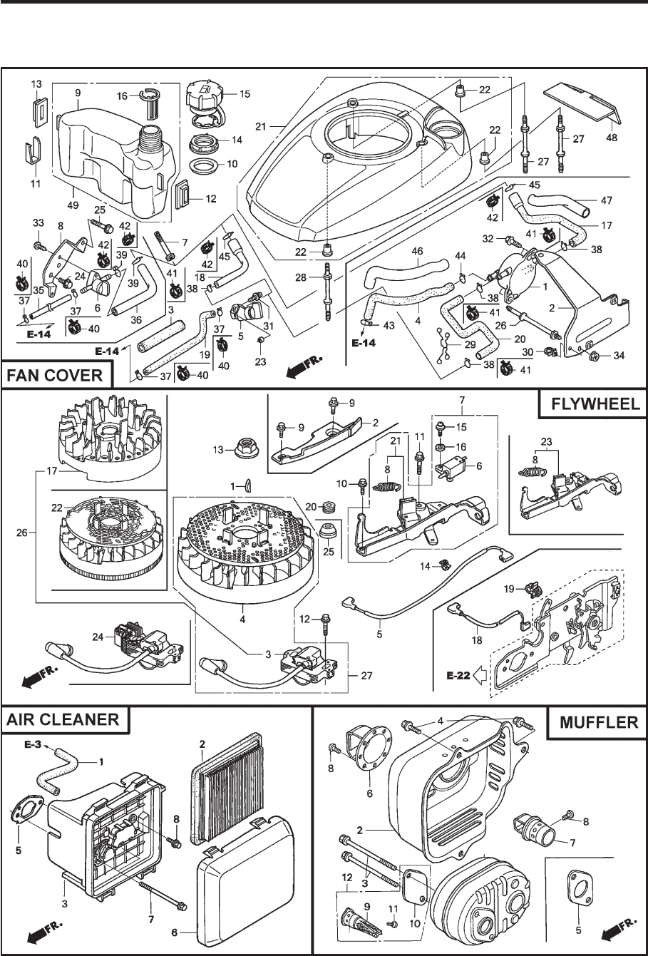
46
MODEL NUMBER GCV160-LAOS3B
HONDA 4-CYCLE ENGINE

47
FAN COVER
KEY PART
NO. NO. DESCRIPTION
6 16950-Z0Y-003 Petcock Assembly
7 16952-ZA8-800 Filter, Fuel
8 16961-Z0L-900 Stay, Fuel Petcock
9 17511-Z0L-030 Tank, Fuel
10 17514-Z0L-000 Seal, Fuel Filler Neck
11 17516-Z0L-000 Clip, Tank Mounting
12 17532-Z0L-000 Rubber A, Tank Mounting
13 17533-Z0L-000 Rubber B, Tank Mounting
14 17534-Z0L-000 Nut, Tank Mounting
15 17620-Z0J-800 Cap Assembly, Fuel Tank
16 17636-Z0L-000 Gauge, Fuel Level
21 19610-Z0L-861ZC Cover Assembly, Fan
“T89” (Craftsman Red)
19610-Z0L-861ZA Cover Assembly, Fan
“T89” (“NH1”) (Black)
19610-Z0L-861ZD Cover Assembly, Fan
“T93” (Husqvarna Grey)
19610-Z0L-861ZE Cover Assembly, Fan
“T98” (M.T.D. Red)
22 19619-ZL8-300 Collar, Fan Cover
24 90013-883-000 Bolt, Flanged (#6 x 12)
(CT200)
25 90015-883-000 Bolt, Flanged (#6 x 28)
(CT200)
27 90043-ZL8-000 Bolt, Stud (H=42.5mm)
28 90043-ZL8-000 Bolt, Stud (H=42.5mm)
33 93913-25220 Screw, Tapping (PO)
(#5 x 12)
35 91424-Z8B-821 Tube, Fuel Tank
36 91427-Z8B-821 Tube, Fuel (7.3 x 160)
40 95002-40800-08 Clip, Tube (D8)
42 95002-41200-08 Clip, Tube (D12)
MUFFLER
KEY PART
NO. NO. DESCRIPTION
1 18310-ZM0-000 Muffler
2 18321-Z0L-J00 Protector, Muffler
(S/N 1243452 and below)
18321-Z0L-J01 Protector, Muffler
(S/N 1243453 and above)
3 90004-ZL8-000 Bolt, Flange #6 x 79
(CT200)
4 90013-883-000 Bolt, Flange #6 x 12
(CT200)
5 18381-ZL8-305 Gasket, Muffler
9 18350-ZL8-000 Arrester, Spark
10 18356-ZL8-000 Plate, Arrester Number
11 90055-ZE1-000 Screw, Tapping #4 x 6
12 06180-Z0J-000 Kit, Spark Arrester
FLYWHEEL
KEY PART
NO. NO. DESCRIPTION
1 13331-357-000 Key, Special, Woodruff
(25 x 18)
3 30500-ZL8-014 Coil Assembly, Ignition
4 31105-ZM0-000 Flywheel Assembly
5 32195-ZM0-800 Wire, Stop Switch
6 35120-ZM0-003 Switch Assembly,
Engine Stop (NC)
8 75113-ZM0-000 Spring, Brake Lever
10 90014-952-000 Bolt, Flange (#6 x 14)
(CT200)
11 90018-ZE1-000 Bolt, Flange (#6 x 23)
(CT200)
12 90018-ZE1-000 Bolt, Flange (#6 x 23)
(CT200)
13 90201-Z0T-800 Nut, Special (14 mm)
14 51125-Z0L-003 Holder, Wire (Fastex)
90681-959-003 Clip A, Cable (3.8mm)
(Black) (NIFCO)
15 93892-04012-00 Screw, Washer Head
(#4 x 12)
16 94103-04000 Washer, Plain (4 mm)
21 75110-Z0Y-000 Brake Sub Assembly
25 91601-Z0L-300 Grommet, Brake Plate
AIR CLEANER
KEY PART
NO. NO. DESCRIPTION
1 15721-ZM0-000 Tube, Breather
2 17211-ZL8-023 Element, Air Cleaner
3 17220-ZM0-010 Case Assy., Air Cleaner
(S/N 1167575 and below)
17220-ZM0-020 Case Assy., Air Cleaner
(S/N 1167576–1239013)
17220-ZM0-030 Case Assy., Air Cleaner
(S/N 1239014 and above)
5 17228-ZM0-000 Gasket, Air Cleaner
6 17231-Z0L-030 Cover, Air Cleaner
(S/N 1167575 and below)
17231-Z0L-040 Cover, Air Cleaner
(S/N 1167575 and below)
17231-Z0L-050 Cover, Air Cleaner
7 90003-ZM0-010 Bolt, Flange (#6 x 85)
(CT200)
MODEL NUMBER GCV160-LAOS3B
HONDA 4-CYCLE ENGINE
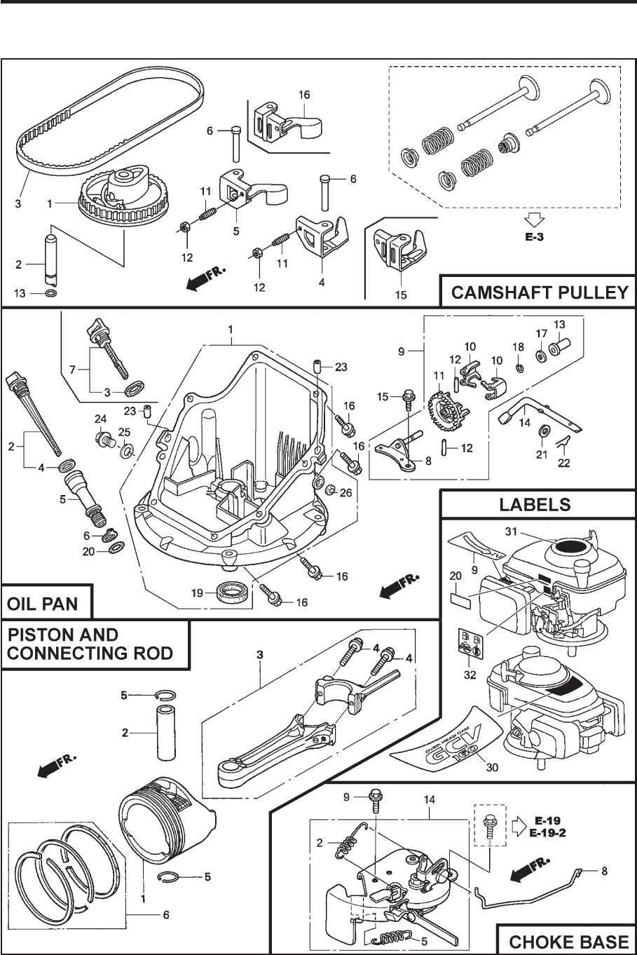
48
MODEL NUMBER GCV160-LAOS3B
HONDA 4-CYCLE ENGINE

49
MODEL NUMBER GCV160-LAOS3B
HONDA 4-CYCLE ENGINE
CAMSHAFT PULLEY
KEY PART
NO. NO. DESCRIPTION
1 14320-ZL8-010 Pulley, Camshaft
2 14324-ZL8-000 Shaft, Cam Pulley
3 14400-Z0J-014 Belt, Timing
(84HU7 G-200)
6 14461-ZL8-000 Shaft, Rocker Arm
11 90112-333-000 Screw, Tappet Adjusting
12 90206-001-000 Nut, Tappet Adjusting
13 91301-ZM0-V31 O-Ring (6.8 x 1.9) (ARAI)
15 14431-Z0J-000 Rocker Arm, Intake Valve
16 14441-Z0J-000 Rocker Arm,
Exhaust Valve
OIL PAN
KEY PART
NO. NO. DESCRIPTION
1 11300-ZM0-811 Pan Assembly, Oil
2 15650-ZM0-801 Gauge Assembly,
Oil Level
4 15625-ZE6-000 Gasket, Oil Filler Cap
5 15631-ZM0-000 Extension, Oil Filler
6 15639-ZM0-000 Lock Washer, Extension
8 16508-ZM0-010 Shaft, Governor Holder
9 16510-ZM0-010 Governor Assembly
10 16511-ZL8-000 Weight, Governor
11 16512-ZM0-000 Holder, Governor Weight
12 16513-ZE1-000 Pin, Governor Weight
13 16531-ZE1-000 Slider, Governor
14 16541-ZM0-000 Shaft, Governor Arm
15 90014-952-000 Bolt, Flange (#6 x 14)
(CT200)
16 90121-952-000 Bolt, Flange (#6 x 25)
(CT200)
17 90451-ZE1-000 Washer, Thrust (6 mm)
18 90602-ZE1-000 Clip, Governor Holder
19 91202-ZL8-003 Oil Seal (28 x 41.25 x 6)
20 91356-MA6-005 O-Ring (14.8 x 2.4) (NOK)
21 94101-068000 Washer, Plain (6 mm)
22 94251-08000 Pin, Lock (8 mm)
23 94301-08200 Pin, Dowel (#8 x 20)
PISTON / CONNECTING ROD
KEY PART
NO. NO. DESCRIPTION
1 13101-Z2A-010 Piston
2 13111-ZE0-000 Pin, Piston
3 13200-Z0J-000 Connecting Rod Assem-
bly
4 90001-ZE1-000 Bolt, Connecting Rod
5 90551-ZE0-000 Clip, Piston Pin (13 mm)
6 13010-Z0L-014 Ring Set, Piston, Standard
(Teikoku)
LABELS
KEY PART
NO. NO. DESCRIPTION
9 87528-Z0L-V20 Mark, Choke Indication
20 87114-ZH7-821 Label, Warning
30 87101-Z8B-000 Mark, Emblem (GCV160)
31 87169-Z8E-000 Mark, Recoil Cover
32 87524-Z8B-000 Mark, Caution,
Fuel Petcock
CHOKE BASE
KEY PART
NO. NO. DESCRIPTION
2 16592-Z2D-800 Spring, Return
5 16614-Z2D-800 Spring, Choke Lever
8 16632-Z0L-801 Rod, Stop
9 90022-888-010 Bolt, Flange (#6 x 20)
(CT200)
14 16610-Z2D-801 Lever Assembly, Choke
16610-Z2D-802 Lever Assembly, Choke
50
SERVICE NOTES
51
NOTAS SERVICIO

589804001 10.25.16 BY Printed in U.S.A.
