Craftsman 917383280 User Manual LAWN MOWER Manuals And Guides L0804448
CRAFTSMAN Walk Behind Lawnmower, Gas Manual L0804448 CRAFTSMAN Walk Behind Lawnmower, Gas Owner's Manual, CRAFTSMAN Walk Behind Lawnmower, Gas installation guides
User Manual: Craftsman 917383280 917383280 CRAFTSMAN LAWN MOWER - Manuals and Guides View the owners manual for your CRAFTSMAN LAWN MOWER #917383280. Home:Lawn & Garden Parts:Craftsman Parts:Craftsman LAWN MOWER Manual
Open the PDF directly: View PDF ![]() .
.
Page Count: 24
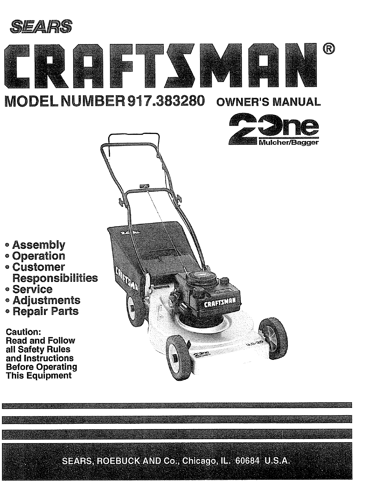
MODEL NUMBER 917.383280 OWNER'SMANUAL
®Assembly
Operation
, Customer
Responsibilities
Service
®Adjustments
®Repair Parts
Caution:
Read and Follow
all Safety Rules
and instructions
Before Operating
This Equipment
\\
,\
SAFETY RULES
CAUTION: ALWAYS DISCONNECTSPARK PLUGWIREAND PLACEWIREWHERE ITCANNOTCONTACT SPARK
PLUG TO PREVENT ACCIDENTAL STARTING WHEN SETTING UP, TRANSPORTING, ADJUSTING OR MAKING
REPAIRS. DNPORTANT
SAFETY STANDARDS REQUIRE OPERATOR PRESENCE CONTROLSTO MINIMIZE THERISK OFINJUR¥o YOUR UNIT IS EQUIPPED WITH SUCH
CONTROLS. DO NOT ATTEMPT TO DEFEAT THE FUNCTION OF TttE OPERATOR PRESENCE CONTROLS UNDER ANY CIRCUMSTANCES°
TRAINING:
= Read this operator's manual carefully. Become familiar with
the controls and know how to operate your mower properly
Learn how to quickly stop mower=
o Do not allow children to use your mower_ Never aUow adults
to use mower without proper instructions_
°Keep the area of operation clear of a!l persons, especially
small children and pets.
oUse mower only as the manufacturer intended and as de-
scribed in this manual
oDo not operate mower if it has been dropped or damaged in
any manner.. Always have damage repaired before using
your mower_
Do not use accessory attachments that are not recommended
by the manufacturer° Use of such attachments may be
hazardous,
The blade turns when the engine is running.
PREPARATION:
= Always thoroughly check the area to be mowed and clear it of
all stones, sticks, wires, bones, and other foreign objects°
These objects witl be thrown by the blade and can cause
severe injury°
oAlways wear safety glasses or eye shields when starting and
while using your mower.
= Dress properly° Do not operate mower when barefoot or
wearing open sandals. Wear onty solid shoes with good
traction when mowing.
°Check fuei tank before starting engine. Do not flU gas tank
indoors, when the engine is running or when the engine is hot°
Allow the engine to cool for several minutes before filling the
gas tank Clean off any spilled gasoline before starting the
engine,
. Always make wheel height adjustments before starting your
mower_ Never attempt to do this while the engine is running,
° Mow only in daylight or good artificial light.
OPERATION:
,Keep your eyes and mind onyour mower andthe area being
cut. Do not let other interests distract you.
•Do not mow wet or slippery grass. Never run while operating
your mower. Always be sure of your footing- keep afirm hold
on the handles and walk,
Do not puthands or feet near or under rotating parts_Keep
clear of the discharge opening at all times.
. Always stop the blade whenever you leave or are not using
your mower, or before crossing driveways, walks, roads, and
any gravel-covered areas..
° Never direct discharge of material toward bystanders nor
allow anyone near the mower while you are operating it.
° Before cleaning, inspecting, or repairing your mower, stop
the engine and make absolutely sure the blade and all
moving parts have stopped° Then disconnect the spark plug
wire and keep it away from the spark plug to prevent
accidental starting.
. Do not continue to run your mower ifyou hit a foreign object.
Follow the procedure outlined above, then repair any dam-
age before restarting and operating you mower.
° Do not change the cjovemor settings or overspeed the
engine° Engine damage or personal injury may result.
• Do not operate your mower if it vibrates abnormally,. Exces-
sive vibration is an indication of damage; stop the engine,
safely checkforthe cause of vibration and repair as required.
. Do not runthe engine indoors.. Exhaust fumes are danger-
ous,
.Never cut grass by pulling the mower towards you. Mow
across the face of slopes, never up and down or you might
lose your fcroting. Do not mow excessively steep slopes.
Use caution when operating the mower on uneven terrain or
when changing directions - maintain good footing.
oNever operate your mower without proper guards, plates,
grass catcher or other safety devices in place.
MAINTENANCE AND STORAGE:
° Cheek the blade andthe engine mounting botts often to be
sure they are tightened properly.
= Check all bolts, nuts and screws at frequent intervals for
proper tightness to be suremower is insafe working condi-
tiono
°Keep all safety devices in place and working°
= To reduce fire hazard, keep the engine free of grass, Ieaves
orrexcessive grease and oil.
• Check grass catcher often for deterioration and wear and
replace worn bags. Use only replacement bags that are
recommended by and comply with specifications of the
manufacturer of your mower.
o Always keep a sharp blade on your mower_
o Allow engine to cool before storing in any enclosure.
° Never store mower with fuel in the tank inside a building
where fumes may reach an open flame or an ignition source
such as a hot water heater, space heater, clothes dryer, etco
I,T.EANS-A.ENTJON!!!BECO.EA.ERT!!!YOUR ,.VO.VED. !
2

CONGRATULATIONS on your purchase of a Sears
Craftsman Lawn Mower. tt has been designed, engineered
and manufactured to give you the best possible de-
pendability and performance.
Should you experience any problems you cannot easily
remedy, please contact your nearest Sears Service Cen-
ter/Department. Sears has competent, well trained tech-
nicians and the proper tools to service or repair this unit..
Please read and retain this manual. The instructions will
enable you to assemble and maintain your lawn mower
properly.. Always observe the "SAFETY RULES"°
MODEL
NUMBER 917,383280
SERIAL
NUMBER
DATE OF
PURCHASE
THE MODEL AND SERIAL NUMBERS WILL BE
FOUND ON A DECAL ATTACHED TO THE REAR
OF THE LAWN MOWER HOUSING.
YOU SHOULD RECORD BOTH SERIAL NUMBER
AND DATE OF PURCHASE AND KEEP IN A SAFE
PLACE FOR FUTURE REFERENCE
PRODUCT SPECiFiCATIONS
HORSEPOWER: 3_5
DISPLACEMENT: 9.06 cu.. ino
GASOLINE CAPACITY: 1_5quarts
(Unleaded)
OIL (20 oz.. Capacity): SAE 30 (Above 32°F)
5W30 (Below 32=F)
SPARK PLUG (GAP °030 in..):
(0°76 ram)
Champion
RJ19LM or
Sears z_ 33312
or STD 361456
or STD 360950
VALVE CLEARANCE: Intake: o006 ino
Exhaust: °008 in..
SOLID STATE IGNITION
AIR GAP: .0125 in..
BLADE BOLT TORQUE: 35-40 ft.-Ibso
MAINTENANCE AGREEMENT
A Sears Maintenance Agreement is available on this product. Contact your nearest Sears store for details.
CUSTOMER RESPONSIBILITIES
• Read and observe the safety rules.
• Follow aregular schedule in maintaining, caring for and using your lawn mower,.
• Follow the instructions under "Customer Responsibilities" and "Storage" sections of this Owner's Manual
, ,P, , iii ,,,,i ............................. iii ,, ,i,,1111, i,i ,11,,
LAMEED ONE YEAR WARRANTY ON CRAFTSMAN POWER MOWER
For one year from date of purchase, when this Craftsman Lawn Mower is maintained, lubricated, and tuned up
according to the operating and maintenance instructions in the owner's manual, Sears will repair free of charge any
defect in material or workmanship_
If this Craftsman Lawn Mower is used for commercial or rental purposes, this warranty applies for only 90 days from
the date of purchase.
This Warranty does not cover:
o Expendable items which become worn during normal use, such as rotary mower blades, blade adapters, belts,
air cleaners and spark plugo
o Repairs necessary because of operator abuse or negligence, including bent crankshafts and the failure to
maintain the equipment according to the instructions contained in the owner's manual.
WARRANTY SERVICE IS AVAILABLE BY RETURNING THE CRAFTSMAN POWER MOWER TO THE NEAREST
SEARS SERVICE CENTER/DEPARTMENT IN THE UNITED STATES_ THIS WARRANTY APPLIES ONLY WH{LE
THIS PRODUCT IS IN USE IN THE UNITED STATES.
This Warranty gives you specific legal rights, and you may also have other rights which vary from state to state
SEARS, ROEBUCK AND CO., D/731CR-W SEARS TOWER, CHICAGO, IL 60684
3
TABLE OF CONTENTS
SAFETY RULES .................................................... 2
PRODUCT SPECIFICATIONS .............................. 3
CUSTOMER RESPONSIBILITIES ............. 3, 11-13
WARRANTY .......................................................... 3
LAWN MOWER ACCESSORIES .......................... 5
ASSEMBLY ........................................................... 6
OPERATION .......................................................... 7
MAINTENANCE SCHEDULE .............................. 11
SERVICE AND ADJUSTMENTS ......................... 14
STORAGE ........................................................... 15
TROUBLESHOOTING ......................................... 21
REPAIR PARTS -LAWN MOWER ................ 16-17
REPAIR PARTS -ENGINE ............................ 18-20
PARTS ORDERING/SERVICE ........ BACK COVER
nNDEX
A
Accessories............................................5
Adjustments:
Carburetor .................................. 14
Handle Height ............................ 14
Height of Cut ................................9
Air Filter:
Service ........................................ 13
Assembly:
Handle .......................................... 6
Grass Catcher ..............................6
B
Blade:
Sharpening ................................. 12
Replacement .............................. 12
C
Controls:
Operator Presence Control Bar..7
Speed Control .............................. 7
Customer Responsibilities .....3,11-13
Air Filter ...................................... 13
Blade Care/Replacement .......... 12
Engine .... ....._............................ 13
Lubrication ................................ 11
Spark Plug ................................. 13
E
Engine:
Oil Change ................................. 13
Oil Level ....................................... 9
Oil Type ........................................ 9
Starting....................................... 10
Storage ....................................... 15
F
Fuel:
Type ..............................................9
Storage .......................................15
H
Handle:
Adjustment.................................14
Assembly .....................................6
L
Lubrication:
Engine ........................................11
Brake Spring Bracket................11
Handle Bracket Mounting Pin _11
Wheel Adjuster ..........................11
M
Maintenance Agreement ....................:3
Mowing Tips ......................................10
Mowing Mulching Tips ..................... 10
O
Oil:
Engine ........................................13
Storage .... .......,,_..._._,,,.,.,.. ! 5
Operation:
Operating Lawn Mower............... 8
Control Bar...................................7
Engine Speed Control................. 8
Operator Presence Control Bar.........7
Options:
Attachments ................................. 5
P
Repair Parts
Lawn Mower .......................... 16-17
Engine ................................... 18-20
R
ResponsibUities, Customer .,..3, 11..13
S
Safety Rules ........................................ 2
Service and Adjustments:
Carburetor .................................. 14
Engine Speed ............................ 14
Handle ........................................ 14
Spark Plug ......................................... 13
Specifications ..................................... 3
Starting the Engine .......................... 10
Stopping the Engine ........................ 10
Storage .............................................. 15
T
Trouble Shooting Chart ................... 21
W
Warranty ............................................. 3
Wheels:
Wheel Adjusters .......................... 7
4
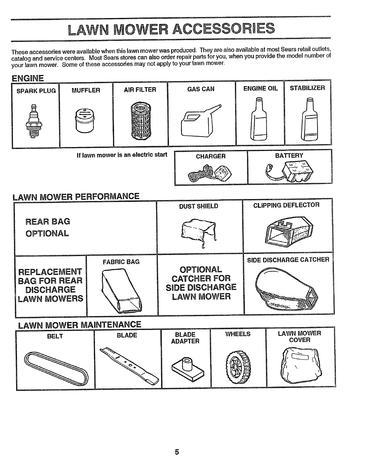
These accessories were available when this lawn mower was produced_ They are also available at most Sears retail outlets,
catalog and service centersr Most Sears stores can also order repair parts for you, when you provide the model number of
your lawn mower. Some of these accessories may not apply to your lawn mower_
ENGINE
,,H, , ,
SPARK PLUG MUFFLER
®
AIR FILTER
If lawn mower is an electric start
LAWN MOWER PERFORMANCE
GAS CAN ENGINE OIL
REAR BAG
OPTUONAL
REPLACEMENT
BAG FOR REAR
DISCHARGE
LAWN MOWERS
FABRIC BAG
CHARGER
STABILIZER
......................... i,
DUST SHIELD
]1 . .H=
OPTBONAL
CATCHER FOR
SRDEDUSCHARGE
LAWN MOWER
...i....i .... i,i
CLIPPING DEFLECTOR
BLADE BLADE
ADAPTER
.1.1.1111 i.. ii.llln .. i
WHEELS
.11.1.1_1 .,
SIDE DISCHARGE CATCHER
i i1.1.. .ii...it _, ..i,
LAWN MOWER
COVER
BATTERY
Your lawn mower has been assembled at the factory
except for the grass catcher bag and the grass catcher
frame°
TO REMOVE LAWN MOWER FROM
CARTON
•Remove loose parts included with mower.
oCut down two end corners of carton and lay end panel
down flat,
oRemoveall packing materials except padding between
upper and lower handle and padding holding operator
presence control bar to upper handle,
o Roll lawn mower out of carton and check carton thor-
oughly for additional loose parts.
HOW TO SET UP YOUR LAWN
MOWER
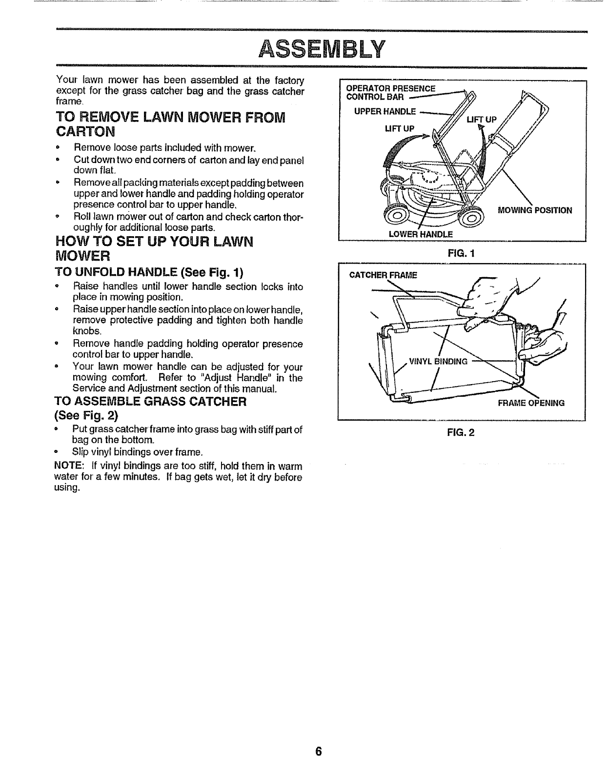
TO UNFOLD HANDLE (See Fig. 1)
= Raise handles until lower handle section locks into
place in mowing position,
o Raise upper handle section into place on lower handle,
remove protective padding and tighten both handle
knobs,
° Remove handle padding holding operator presence
control bar to upper handle.
° Your lawn mower handle can be adjusted for your
mowing comfort. Refer to "Adjust Handle" in the
Service and Adjustment section of this manual.
TO ASSEMBLE GRASS CATCHER
(See Fig. 2)
o Put grass catcher' frame into grass bag with stiff part of
bag on the bottom.
o Slip vinyl bindings over frame.
NOTE: If vinyl bindings are too stiff, hold them in warm
water for' a few minutes. If bag gets wet, let it dry before
using.
OPERATOR PRESENCE
CONTROL BAR
UPPER HANDLE
UFT UP
LOWER HANDLE
FIG. 1
CATCHERFRAME
MOWING POSITION
\
\
FRAME OPENING
FIG. 2
,i ii,,i,rl_.lll ................... ,_ ............ ,..... i1,11 i1,1 ii IIIII'H II IIIIIIMI II
OPERATBON
.i ii,,,i,,,i ............... I,,111.l_,lllr 'I1"1' '1,11111 I"'"_ I I
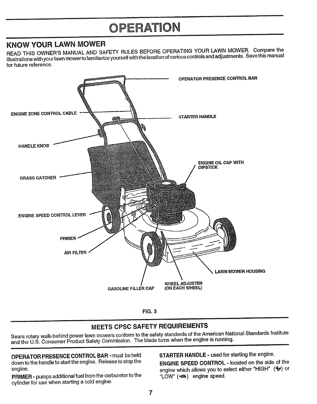
KNOW YOUR LAWN MOWER
READ THIS OWNER'S MANUAL AND SAFETY RULES BEFORE OPERATING YOUR LAWN MOWER° Compare the
illustrationswith your lawn mower to familiarize yourself with the location of variouscontrols and adjustments, Savethis manual
for future reference.
OPERATOR PRESENCE CONTROL BAR
ENGINE ZONE CONTROL CABLE
STARTER HANDLE
HANDLEKNOB
GRASS CATCHER
ENGINE SPEED CONTROL LEVER
ENGINE OIL CAP WITH
DIPSTICK
PRIMER
AIR RLTER
GASOLINE FILLER CAP
_\ LAWN MOWER HOUSING
WHEEL ADJUSTER
(ON EACH WHEEL)
FIG. 3
Ji i,l,,,lllll ,i i• ii ii ii ,i,ii i,ii .......................................... J ii
MEETS CPSC SAFETY REQUIREMENTS
Sears rotary walk-behind power lawn mowers conform to the safety standards of the American National Standards Institute
and the U,S, Consumer Product Safety Commission° The blade turns when the engine is running,
................. i iiii
OPERATOR PRESENCE CONTROL BAR -must be held
down to the handle to start the engine, Release to stop the
engine.
PRIMER -pumps additional fuel from the carburetor to the
cylinder for use when starting a cold engine°
STARTER HANDLE - used for starting the engine.
ENGINE SPEED CONTROL - located on the side of the
engine which allows you to select either "HIGH" ('_) or
"LOW" (,4_) engine speed_
n imllll i I_,HN,'' INN HHHN'l N N,N,,I,I'HI Imll I I I
OPERATION
Ul, ,Ni mm HI i I
HOW TO USE YOUR LAWN MOWER
N"l....... IIII I'll
CAUTION: Do not run your lawn mower
without mulcher plate in place and door
latch in locked position or approved
clipping deflector or grass catcher in
place. Never attempt to operate the
lawn mower with the rear door removed
or propped open.
ii ,u, ii i i IN'ml''
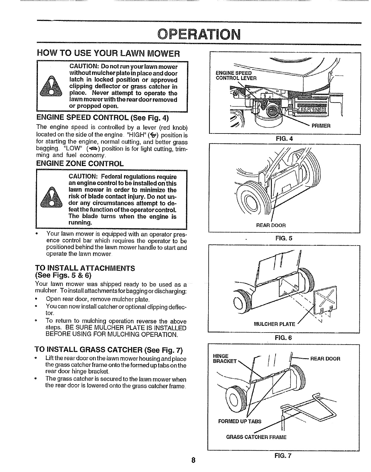
ENGINE SPEED CONTROL (See Fig. 4)
The engine speed is controlled by a lever (red knob)
located on the side of the engine "HIGH" (,r_) position is
for starting the engine, normal cutting, and better grass
bagging° "LOW" (_) position is for light cutting, trim-
ming and fuel economy_
ENGINE ZONE CONTROL
m u i, NIl'NHHm" HH'l'l ' I
CAUTION: Federal regulations require
an engine control to be installed on this
lawn mower in order to minimize the
risk of blade contact injury. Do not un-
der any circumstances attempt to de-
feat the function of the operator control.
The blade turns when the engine is
running.
•Your lawn mower is equipped with an operator pres-
ence control bar which requires the operator to be
positioned behind the lawn mower handte to start and
operate the tawn mower
ENGINE SPEED
CONTROL LEVER
TO INSTALL ATTACHMENTS
(See Figs. 5 & 6)
Your lawn mower was shipped ready to be used as a
mulcher To install attachments for bagging ordischarging:
o Open rear door, remove mulcher plate_
= You can now install catcher or optional clipping deflec-
tor/.
o To return to mulching operation reverse the above
steps, BE SURE MULCHER PLATE IS INSTALLED
BEFORE USING FOR MULCHING OPERATION,
PRIMER
FIG. 4
.x I z
REAR DOOR
FIG. 5
MULCHER PLATE
FIG. 6
TO INSTALL GRASS CATCHER (See Fig. 7)
• Lift the rear'door on the lawn mower housing and place
the grass catcher frame onto the formed up tabs on the
rear door hinge bracket_
oThe grass catcher is secured to the lawn mower when
the rear door is lowered onto the grass catcher frame
HINGE
BRACKET 11
FORMED UP TA_
GRASS CATCHER FRAME
FIG. 7
8
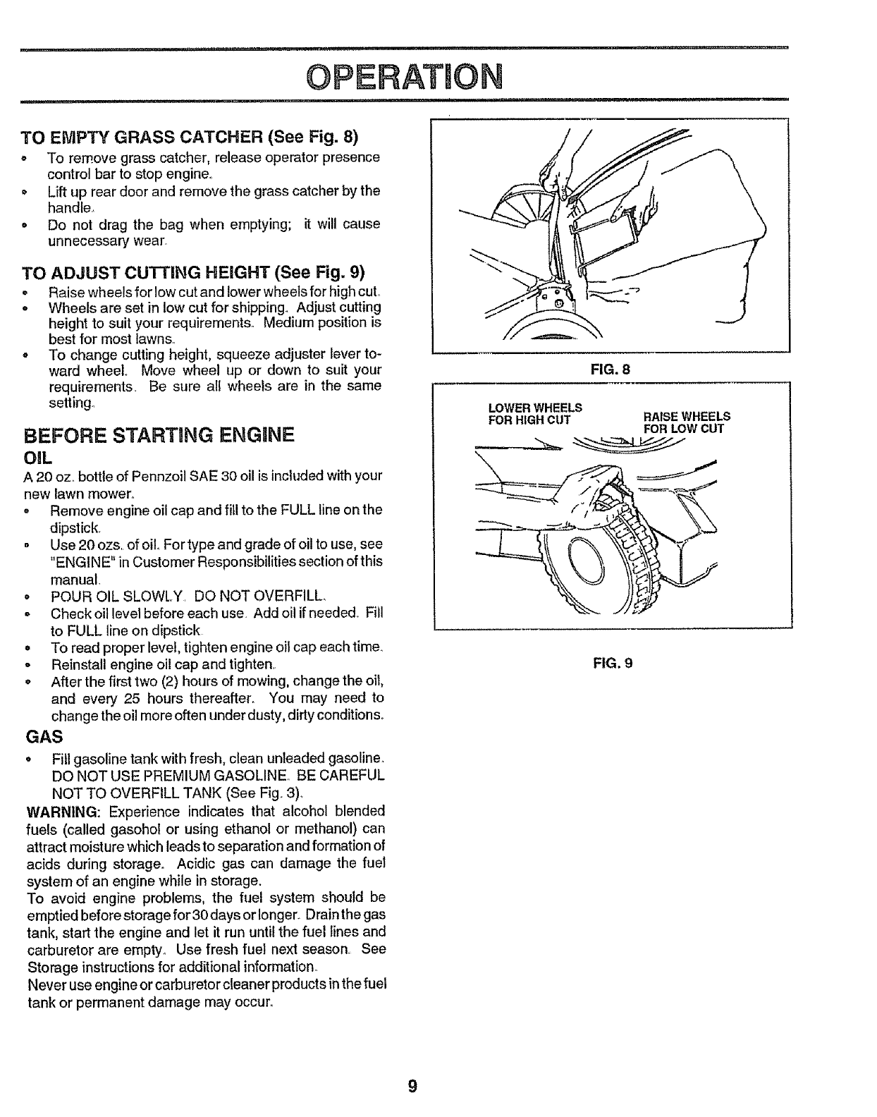
TO EMPTY GRASS CATCHER (See Fig. 8)
o To remove grass catcher, release operator presence
control bar to stop engine°
• Lift up rear door and remove the grass catcher by the
handle..
° Do not drag the bag when emptying; it will cause
unnecessary wear°
TO ADJUST cu'n'ING HEIGHT (See Fig. 9)
• Raise wheels for low cut and lower wheels for high cut°
• Wheels are set in low cut for shipping.. Adjust cutting
height to suit your requirements. Medium position is
best for most lawns.
o To change cutting height, squeeze adjuster lever to-
ward wheel.. Move wheel up or down to suit your
requirements Be sure all wheels are in the same
setting.
BEFORE STARTING ENGINE
OiL
A 20 oz. bottle of Pennzoil SAE 30 oil is included with your
new lawn mower.
•Remove engine oil cap and fill to the FULL line on the
dipstick,
•Use 20 ozs,. of oil, For type and grade of oil to use, see
"ENGINE" in Customer Responsibilities section of this
manual.
°POUR OIL SLOWLY. DO NOT OVERFILL°
- Check oil level before each use Add oil if needed, Fill
to FULL line on dipstick
°To read proper level, tighten engine oil cap each time_
oReinstall engine oil cap and tighten
o After the first two (2) hours of mowing, change the oit,
and every 25 hours thereafter. You may need to
change the oil more often under dusty, dirty conditions°
GAS
°Fill gasoline tank with fresh, clean unleaded gasoline.
DO NOT USE PREMIUM GASOLINE.. BE CAREFUL
NOT TO OVERFILL TANK (See Fig.. 3).
WARNING: Experience indicates that alcohol blended
fuels (called gasohol or using ethanol or methanol) can
attract moisture which leads to separation and formation of
acids during storage_ Acidic gas can damage the fuel
system of an engine while in storage.
To avoid engine problems, the fuel system should be
emptied before storage for 30 days or longer. Drainthe gas
tank, start the engine and let it run until the fuel lines and
carburetor are empty_ Use fresh fuel next season See
Storage instructions for additional information°
Never use engine or carburetor cleaner products in the fuel
tank or permanent damage may occur.
FIG. 8
LOWERWHEELS
FORHIGHCUT RAISEWHEELS
FORLOWCUT
FIG. 9
9
OPERATION
,11, i1,11 ,ill! I,H,, i, ,i,
TO START ENGINE
o To start a cold engine, push primer five (5) times
before trying to start. Use a firm push° This step is not
usually necessary when starting an engine which has
already run for a few minutes.,
o Push engine speed control lever to HIGH (+._) posi-
tion,
o Hold operator presence control bar down to the
handle and pull starter' handle quickly. DO NOT
allow starter rope to snap back.
oTo STOP engine, release operator presence control
bar+
NOTE: in cooler weather' it may be necessary to repeat
priming steps° In warmer weatherover priming maycause
flooding and engine will not starL If you do flood engine,
wait a few minutes before attempting to start and DO NOT
repeat priming steps.
MOWING TiPS
oUnder certain conditions, such as very tall grass, it
may be necessary to raise the height of cut to reduce
pushing effort and to keep from overloading the en-
gine and leaving clumps of grass clippings.
° For extremely heavy cutting, reduce the width of cut
and raise the rear of the lawn mower housing one (1)
wheel adjuster setting higher than the front for better
discharge of grass+
o For better grass bagging and most cutting conditions,
the engine speed should be set in the '"HIGH" (FAST)
(<r_) position,.
o When using a rear discharge lawn mower in moist,
heavy grass, clumps of cut grass may not enter the
grass catcher+ Reduce ground speed (pushing speed)
and/or run the lawn mower over the area a second
time.
• If a trail of grass clippings is left on the right side of a
rear discharge lawn mower, mow in a clockwise
direction with a small overlap to collect the clippings
on the next pass,
oKeep top of engine around starter clear and clean of
grass clippings and chaff. This will help engine air
flow and extend engine life+
. Pores in cloth grass catchers can become filled with
dirt and dust with use and catchers will collect less
grass° To prevent this, regularly hose catchers off
with water and let dry before using.
MAX 113
FIG. 10
MULCHING MOWING TiPS
IMPORTANT: FOR BEST PERFORMANCE, KEEP
MOWER HOUSING FREE OF BUILT-UP GRASS AND
TRASH, CLEAN UNDERSIDE OF MOWER HOUSING
AFTER EACH USE. SEE "CLEANING" IN CUSTOMER
RESPONSIBILITIES SECTION OF THIS MANUAL.
oThe special mulching blade will recut the grass clip-
pings many times and reduce them in size so that as
they fall onto the lawn they will disperse into the grass
and not be noticed. Also, the mulched grass will
biodegrade quickly to provide nutrients for the lawn
Always mulch with your highest engine (blade) speed
as this will provide the best recutting action of the
blades._
-Avoid cutting your lawn when it is wet,, Wet grass
tends to form clumps and interferes with the mulching
action The best time to mow your lawn is the early
afternoon+ At this time the grass has dried and the
newly cut area wiU not be exposed to the direct sun.
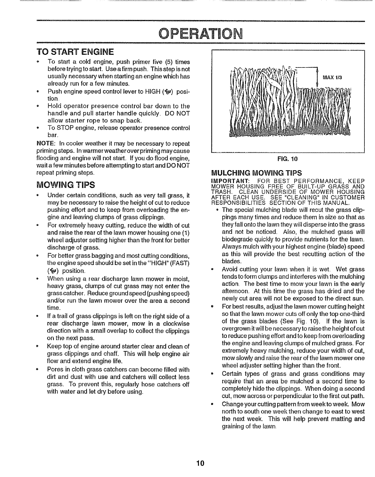
oFor best results, adjust the lawn mower cutting height
so that the tawn mower cuts off only the top one-third
of the grass blades (See Fig, 10)+ If the lawn is
overgrown it will be necessary to raise the height of cut
to reduce pushing effort and to keep from overloading
the engine and leaving clumps of mulched grass. For'
extremely heavy mulching, reduce your width of cut,
mow slowly and raise the rear of the lawn mower one
wheel adjuster setting higher than the fronL
°Certain types of grass and grass conditions may
require that an area be mulched a second time to
completely hide the clippings+ When doing a second
cut, mow across or perpendicular to the first cut path.
oChangeyourcutting pattern from weektoweek. Mow
north to south one week then change to east to west
the next week. This will help prevent matting and
graining of the lawn.
10
........ lU i ilU,,,,,u,,,,i,, ,, , i, ,,llUl,i ,,,
CUSTOM ESPONSRBBLRTmES
, ,,n,nn,uu ...... i,,,,r, ','n I,inl ....
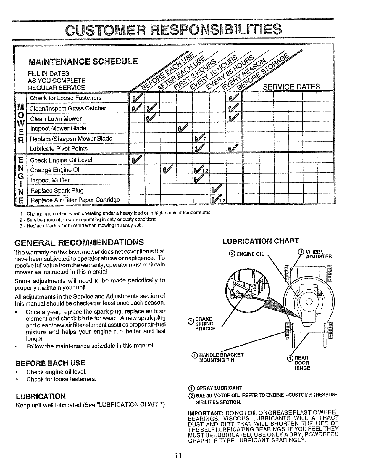
MA,.TE,,,A,,,OESO.EOOLE
AS YOU COMPLETE _'__%1_-_O._ _.........
REGU_R SERVlC E................ ,_'_/_.._,_"_ V 1C E p AT E S
Check for Loose Fasteners _ ..................... _##
M Cle'an/i'nspect Grass Catcher
£ Clean Lawn Mower
W
E inspectMowerBlaae ......
R Replace/Sharpen Mower BLade
Lubricate Pivot Points
E Check Engi,ne,,Oil Level
N Change Engine Oil
?inspect Muffler
N Repl.ac.e..Spark Plug
E Replace Air Filte r Paper Cartridge
..........
V' e/ .....
J J
,,J
........ ................
1-Change more often when operating under a heavy load or In high ambient temperatures
2- SerVice more often when operating in dirty or dusty conditions.
3 - Replace blades more often when mowfng in sandy soil
GENERAL RECOMMENDATIONS
The warranty on this lawn mower does not cover items that
have been subjected to operator abuse or negligence_ To
receivefu!! value from the warranty, operatormust maintain
mower as instructed in this manual.
Some adjustments will need to be made periodically to
properly maintain your unit..
All adjustments in the Service and Adjustments section of
this manual should be checked at least once each season°
o Once a year, replace the spark plug, replace air filter
element and check blade for wear. A new spark plug
and clean/new air _ter element assures proper air-fuel
mixture and helps your engine run better and last
longer.
oFollow the maintenance schedule in this manual,.
BEFORE EACH USE
o Check engine oil level.
o Check for loose fasteners.
LUBRiCATiON
Keep unit well lubricated (See "LUBRICATION CHART").
LUBRiCATiON CHART
_) ENGtNEOIL WHEEL
ADJUSTER
(_)BRAKE
SPRING
BRACKET
(_)HANDLEBRACKET
MOUNTINGPIN (_REAR
DOOR
HINGE
_) SPRAY LUBRICANT
(_) SAE30 MOTOROIL REFERTO ENGINE -CUSTOMERRESPON-
SIBILITIESSECTION.
IMPORTANT: DO NOT OiL OR GREASE PLASTIC WHEEL
BEARINGSo VISCOUS LUBRICANTS WILL ATTRACT
DUST AND DIRT THAT WILL SHORTEN THE LIFE OF
THE SELF LUBRICATING BEARINGS. IF YOU FEEL THEY
MUST BE LUBRICATED, USE ONLY A DRY, POWDERED
GRAPHITE TYPE LUBRICANT SPARINGLY.
11
CUSTOM RESPONSBBJLITUES
LAWN MOWER
Always observe safety rules when performing any mainte-
nanceo
TIRES
° Keep tires free of gasoline, oil, or'insect control chemi-
cals which can harm rubber:.
° Avoid stumps, stones, deep ruts, sharp objects and
other' hazards that may cause tire damage_
BLADE CARE
For best results, mower blade must be kept sharp, Replace
bent or damaged blades.
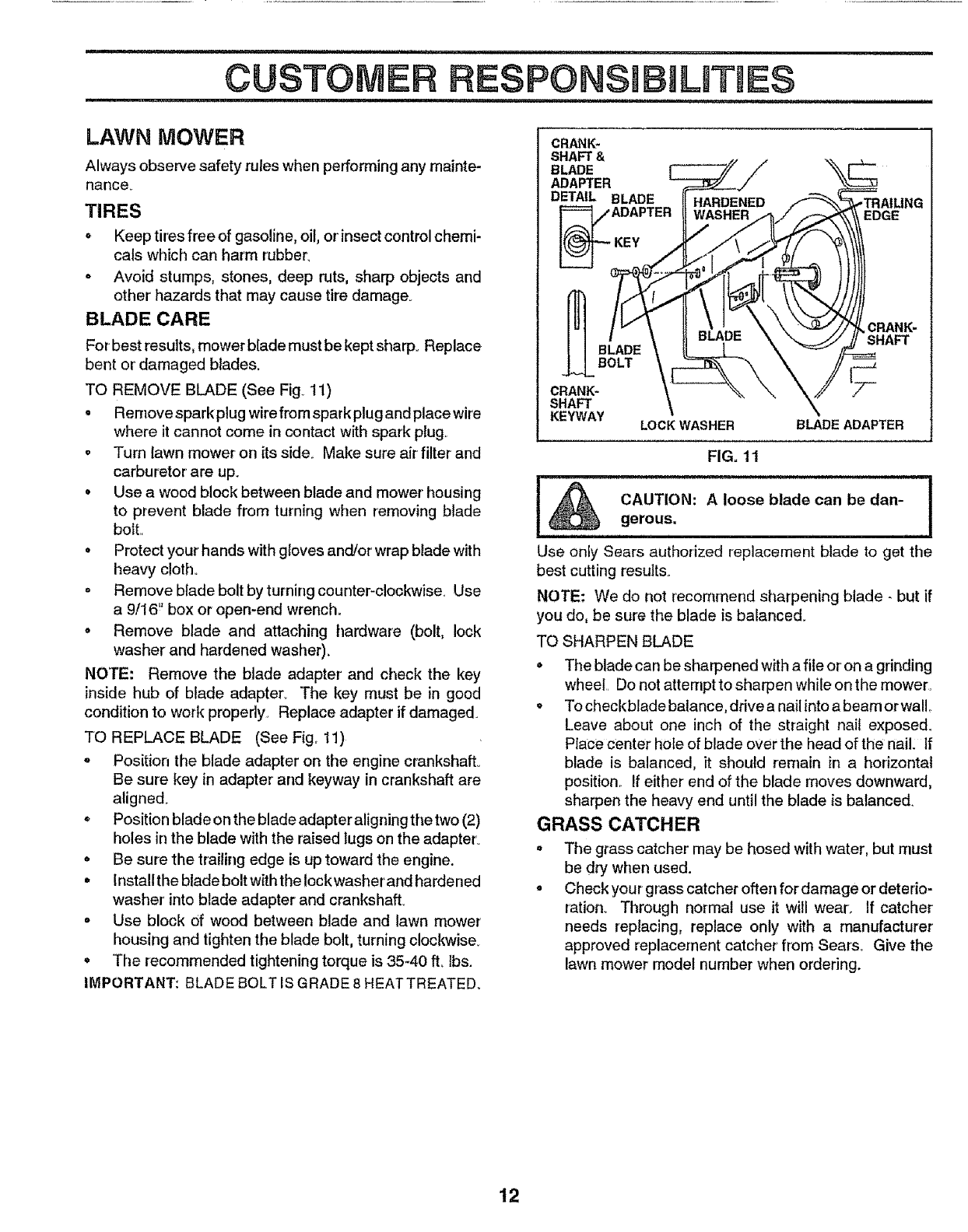
TO REMOVE BLADE (See Fig_ 11)
o Removesparkplug wire from spark plug and place wire
where it cannot come in contact with spark plug,
o Turn lawn mower on its side, Make sure air filter and
carburetor are up.
• Use a wood block between blade and mower' housing
to prevent blade from turning when removing blade
bolt.,
• Protect your hands with gloves andlor wrap blade with
heavy cloth,,
= Remove blade bolt by turning counter-clockwise. Use
a9116" box or open-end wrench.
o Remove blade and attaching hardware (bolt, lock
washer and hardened washer)_
NOTE: Remove the blade adapter and check the key
inside hub of blade adapter_ The key must be in good
condition to work properly, Replace adapter if damaged.
TO REPLACE BLADE (See Fig. 11)
= Position the blade adapter on the engine crankshaff_
Be sure key in adapter and keyway in crankshaft are
aligned.
°Position blade on the blade adapter aligning the two (2)
holes in the blade with the raised lugs on the adapter_
o Be sure the trailing edge is up toward the engine.
•Installthe blade bolt with the Iockwasher and hardened
washer into blade adapter and crankshaft.
o Use block of wood between blade and lawn mower
housing and tighten the blade bolt, turning cloclcwise
° The recommended tightening torque is 35-40 ft, lbs.
IMPORTANT: BLADE BOLT [SGRADE 8 HEAT TREATED.
CRANK.
SHAFT &
BLADE
ADAPTER
DETAIL BLADE
ADAPTER
KEY
EDGE
BLADE
BOLT
CRANK-
SHAFT
KEYWAY LOCK WASHER
CRANK-
SHAFT
BLADE ADAPTER
FIG= 1t
I_ CAUTION: A loose blade can be dan- I
I
I
gerous,
HH ==H'= H = ,=,=
Use only Sears authorized replacement blade to get the
best cutting results.
NOTE- We do not [ecornrnertd sharpening blade- but if
you do, be sure the blade is balanced.
TO SHARPEN BLADE
• The blade can be sharpened with a file or on a grinding
wheel Do not attempt to sharpen while on the mower,
• To checkblade balance, ddve a nailinto a beam or wall
Leave about one inch of the straight nail exposed.
Place center hole of blade over the head of the nail: If
blade is balanced, it should remain in a horizontal
position If either end of the blade moves downward,
sharpen the heavy end until the blade is balanced.
GRASS CATCHER
o
o
The grass catcher may be hosed with water, but must
be dry when used.
Check your grass catcher often for damage or deterio-
ration. Through normal use it will wear. If catcher
needs replacing, replace only with a manufacturer
approved replacement catcher from Seats, Give the
lawn mower model number when ordering.
12
'ii ....... i, i ,i,i ...... _,,,,, ,,,,l_,_J,i,,i ...... i1,,
CUSTOMER LmT E$
i ,,i,i1,,i .....
ENGINE
LUBRiCATiON
Use only high quality detergent oil rated with API service
classification SG.. Select the oil's SAE viscosity grade
according to your expected operating temperature°
RECOMMENDED SAE VISCOSITY GRADES
_F -20 _ 0° 32° 60 °800 100_
°C 429°-18" 0°160 270 38 °
NOTE: Although multi-viscosity oils (5W30, 10W30 etc,)
improve starting in cold weather, these multi-viscosity oils
will result in increased oil consumption when used above
32°F. Checkyour engine oil level more frequently toavoid
possible engine damage from running low on oil.
Change the oil after the first two hours of operation and
every 25 hours thereafter or at least once a year if the lawn
mower is not used for 25 hours in one year,
Check the crankcase oil level before starting the engine
and after each five (5) hours of continuous use. Tighten oil
plug securely each time you check the oil level.
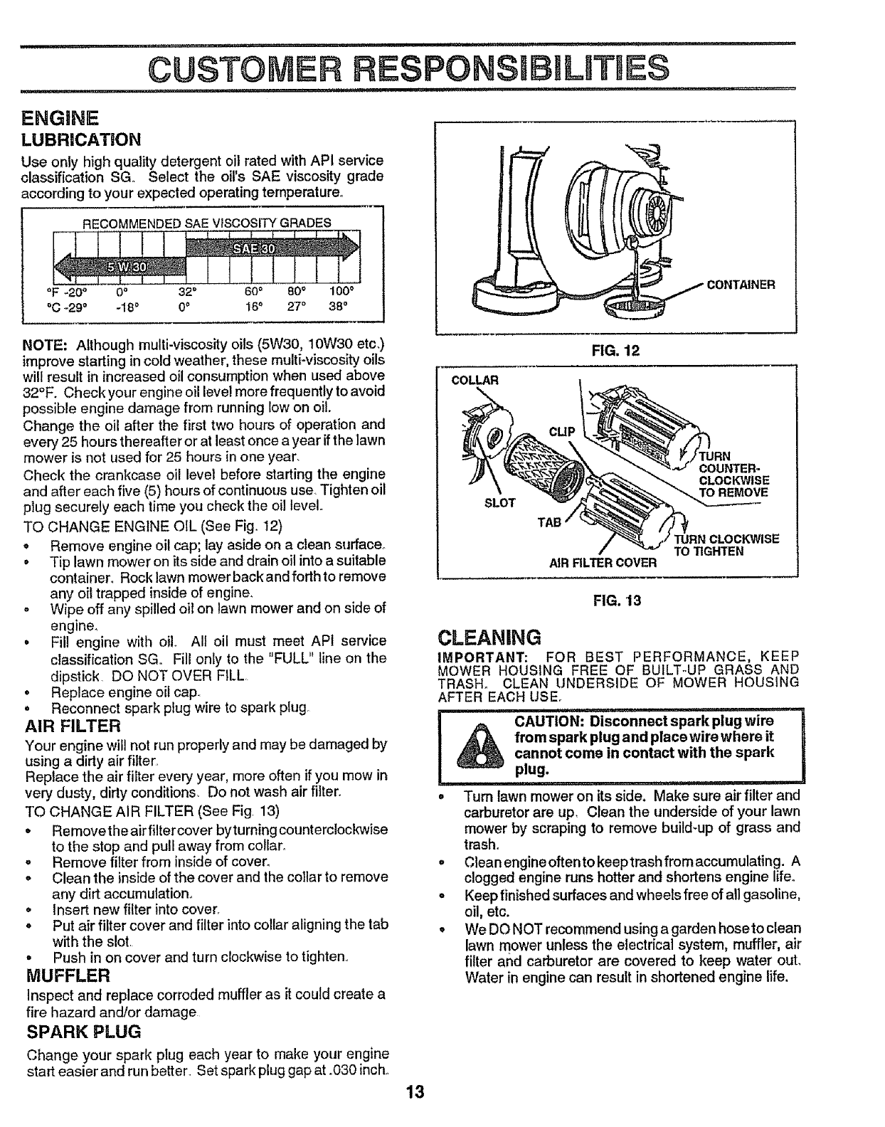
TO CHANGE ENGINE OIL (See Fig. t2)
.Remove engine oil cap; lay aside on a clean surface.
•Tip lawn mower on its side and drain oil into a suitable
container. Rock lawn mowerbackand forthto remove
any oil trapped inside of engine.
.Wipe off any spilled oil on lawn mower and on side of
engine,
° Fill engine with oil All oil must meet API service
classification SGo Fill only to the "FULL" line on the
dipstick. DO NOT OVER FILL
oReplace engine oil cap..
oReconnect spark plug wire to spark plug
AIR FILTER
Your engine will not run properly and may be damaged by
using a dirty air filter,
Reptace the air filter every year, more often if you mow in
very dusty, dirty conditions, Do not wash air fiitero
TO CHANGE AIR FILTER (See Fig, 13)
• Removetheairfiltercover bytuming counterclockwise
to the stop and pull away from collar°
. Remove filter from inside of cover_
o Clean the inside of the cover and the collar to remove
any dirt accumulation,,
• Insert new filter into cover.
• Put air filter cover and filter into collar aligning the tab
with the slot.
• Push in on cover and turn clockwise to tighten.
MUFFLER
Inspect and replace corroded muffler as it could create a
fire hazard and/or damage
SPARK PLUG
Change your spark plug each year to make your engine
start easier and run better. Set spark plug gap at °030 inch.,
13
FIG. 12
COLLAR
SLOT
TURN
COUNTER-
CLOCKWISE
TO REMOVE
TAB
TURN CLOCKWISE
TO TIGHTEN
AIR RLTER COVER
FIG. 13
CLEANING
IMPORTANT: FOR BEST PERFORMANCE, KEEP
MOWER HOUSING FREE OF BUILT-UP GRASS AND
TRASH_ CLEAN UNDERSIDE OF MOWER HOUSING
AFTER EACH USE.
i iii i,i ii, ii1,, i1,, i i,iii ii,,,,r i,i
_) CAUTION" Disconnect spark plug wire
from spark plug and place wire where it
cannot come in contact with the spark
plug.
........ 11111,I
o Turn lawn mower on its side. Make sure air filter and
carburetor are up, Clean the underside of your lawn
mower by scraping to remove build-up of grass and
trash.
• Cleanengineoftentokeeptrashfromaccumulating. A
clogged engine runs hotter and shortens engine life.
o Keep finished surfaces and wheels free of all gasoline,
oil, etc.
oWe DO NOT recommend using a garden hoseto clean
lawn mower unless the electrical system, muffler, air
filter and carburetor are covered to keep water out,
Water in engine can result in shortened engine life,
CAUTION: BEFORE PERFORMING ANY SERVICE OR ADJUSTMENTS:
°Release control bar.
• Make sure the blade and all moving parts have completely stopped.
•Disconnect spark plug wire from spark plug and place where it cannot come in contact with plug.
................................... ii,
LAWN MOWER
TO ADJUST CUTI'ING HEIGHT
See "TO ADJUST CUTTING HEIGHT" in the Operation
section of this manual,
REAR DEFLECTOR
The rear deflector, attached between the rear wheels of
your lawn mower, is provided to minimize the possibility
that objects will be thrown out the rear of the lawn mower
into the operator's mowing position_
If the rear deflector becomes damaged, it should be
replaced°
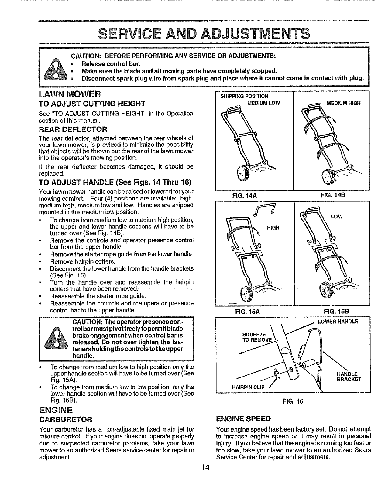
TO ADJUST HANDLE (See Figs. 14 Thru 16)
Your lawn mower handle can be raised or lowered for your
mowing comfort. Four (4) positions are available: high,
medium high, medium low and low. Handles are shipped
mounted in the medium low position.
°To change from medium low to medium high position,
the upper and lower handle sections will have to be
turned over (See Fig. 14B)_
• Remove the controls and operator presence control
bar from the upper' handle.
• Remove the starter rope guide from the lower handle,
• Remove hairpin cotters,
• Disconnect the lower handle from the handle brackets
(See Fig,, 16),
, Turn the handle over and reassemble the hairpin
cotters that have been removed.
•Reassemble the starter rope guide.
o Reassemble the controls and the operator presence
control bar' to the upper handle.
CAUTION: The operator presence con-
trol bar must pivot freely to permitblade
brake engagement when control bar is
released. Do not over tighten the fas-
teners hold ing the controls to the upper
handle.
oTo change from medium low to high position only the
upper handle section will have to be turned over (See
Fig, 15A)_
• To change from medium low to low position, only the
lower' handle section will have to be turned over (See
Fig. 15B),
ENGUNE
CARBURETOR
Your carburetor has a non-adjustable fixed main jet for
mixture control, If your engine does not operate properly
due to suspected carburetor problems, take your lawn
mower' to an authorized Sears service center for repair or
adjustment,
SHIPPINGPOSITION
MEDIUMLOW
FIG. 14A
HIGH
FIG. 15A FIG, 15B
LOWERHANDLE
SQUEEZE
TO REMOVE
HAIRPIN CLIP
FIG. 16
14
ENGKNE SPEED
Your engine speed has been factory set. Do not attempt
to increase engine speed or it may result in personal
injury, tf you believe that the engine is running too fast or
too slow, take your lawn mower to an authorized Sears
Service Center for repair and adjustment,
,i,iiii1,111, ,i ii ,i,,,,,,,i
.... =
Immediately prepare your lawn mower for storage at the
end of the season or if the unit will not be used for 30 days
or more.
LAWN MOWER
When lawn mower is to be stored for a period of time, clean
it thoroughly, remove aUdirt, grease, leaves, etc Store in
a clean, dry area.
-Clean entire lawn mower (See "CLEANING In the
Customer Responsibilities section of this manual).
°Lubricate as shown in the Customer Responsibilities
section of this manual.
oBe sure that all nuts, bolts, screws, and pins are
securely fastened. Inspect moving parts fordamage,
breakage and wear. Replace if necessary.
• Touch up all rusted or chipped paint surfaces; sand
lightly before painting.
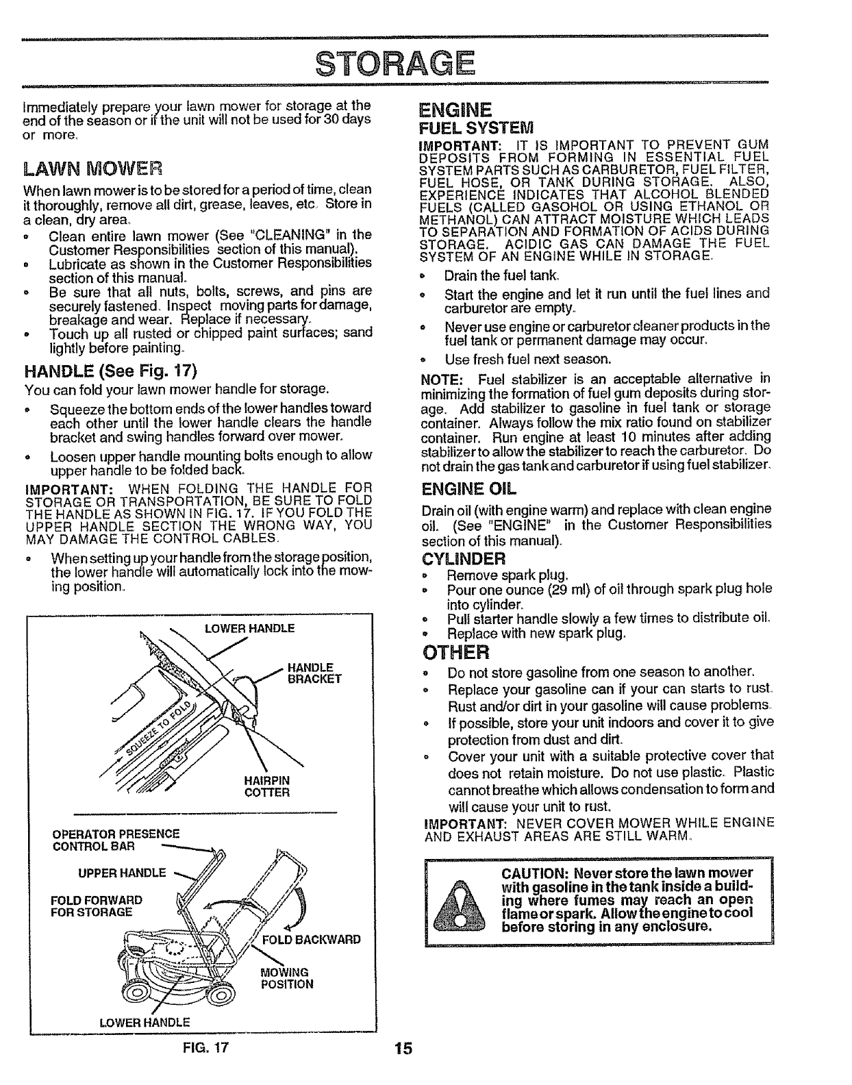
HANDLE (See Fig, 17)
You can fold your lawn mower handle for storage.
. Squeeze the bottom ends of the lower handles toward
each other until the lower handle clears the handle
bracket and swing handles forward over mower,.
° Loosen upper handle mounting bolts enough to allow
upper handle to be foIded back.
IMPORTANT: WHEN FOLDING THE HANDLE FOR
STORAGE OR TRANSPORTATION, BE SURE TO FOLD
THE HANDLE AS SHOWN IN FIG. 17. IF YOU FOLD THE
UPPER HANDLE SECTION THE WRONG WAY, YOU
MAY DAMAGE THE CONTROL CABLES.
oWhensetting upyourhandlefromthestorageposifion,
the lower handle wilt automatically lock into the mow-
ing position.
LOWER HANDLE
HANDLE
BRACKET
HAIRPIN
COTTER
OPERATOR PRESENCE
CONTROL BAR
UPPER HANDLE
FOLD FORWARD
FOR STORAGE
FOLD BACKWARD
MOWING
POSITION
LOWERHANDLE
FIG. 17
ENGINE
FUEL SYSTEM
IMPORTANT: IT IS iMPORTANT TO PREVENT GUM
DEPOSITS FROM FORMING IN ESSENTIAL FUEL
SYSTEM PARTS SUCH AS CARBURETOR, FUEL FILTER,
FUEL HOSE, OR TANK DURING STORAGE. ALSO,
EXPERIENCE INDICATES THAT ALCOHOL BLENDED
FUELS (CALLED GASOHOL OR USING ETHANOL OR
METHANOL) CAN ATTRACT MOISTURE WHICH LEADS
TO SEPARATION AND FORMATION OF ACIDS DURING
STORAGE. ACIDIC GAS CAN DAMAGE THE FUEL
SYSTEM OF AN ENGINE WHILE IN STORAGE.
• Drain the fuel tank..
• Start the engine and let it run until the fuel lines and
carburetor are empty°
• Never use engine or carburetor cleaner products in the
fuel tank or permanent damage may occur.
. Use fresh fuel next season.
NOTE: Fuel stabilizer is an acceptable alternative in
minimizing the formation of fuel gum deposits during stor-
age. Add stabilizer to gasotine in fuel tank or storage
container. Always follow the mix ratio found on stabilizer
container. Run engine at least 10 minutes after adding
stabilizer to allow the stabilizer to reach the carburetor. Do
not drain the gas tank and carburetor if using fuel stabilizer.
ENGINE OIL
Drain oil (with engine warm) and replace with clean engine
oil (See "ENGINE" in the Customer Responsibilities
section of this manual).
CYLINDER
° Remove spark plug_
° Pour one ounce (29 ml) of oil through spark plug hole
into cylinder°
o Pul! starter handle slowly a few times to distribute oilo
= Replace with new spark plug.
OTHER
o Do not store gasoline from one season to another.
• Replace your gasoline can if your can starts to rusL
Rust and/or dirt in your gasoline will cause problems.
• If possible, store your unit indoors and cover it to give
protection from dust and dirt.
o Cover your unit with a suitable protective cover that
does not retain moisture. Do not use plastic. Plastic
cannot breathe which allows condensation to form and
will cause your unit to rust.
IMPORTANT: NEVER COVER MOWER WHILE ENGINE
AND EXHAUST AREAS ARE STILL WARM_
i, i ......... i1,,'r'"lr
CAUTION: Never store the lawn mower
with gasoline in thetank inside a build-
ing where fumes may reach an open
flameorspark. Allowthe engineto cool
before storing in any enclosure.
15
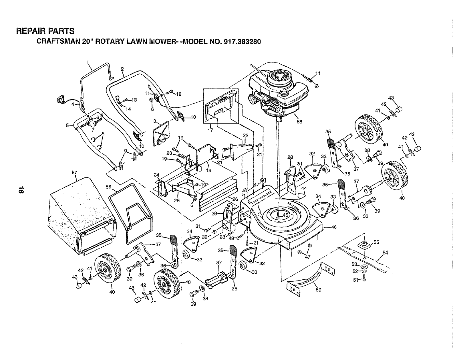
REPAIR PARTS
CRAFTSMAN 20" ROTARY LAWN MOWER- "MODEL NO. 917.383280
1
\ 2
57
42
43
\
4O
31
34
|
17
18
\38
39
\
36
\58
28 32
47
35
34 33
43
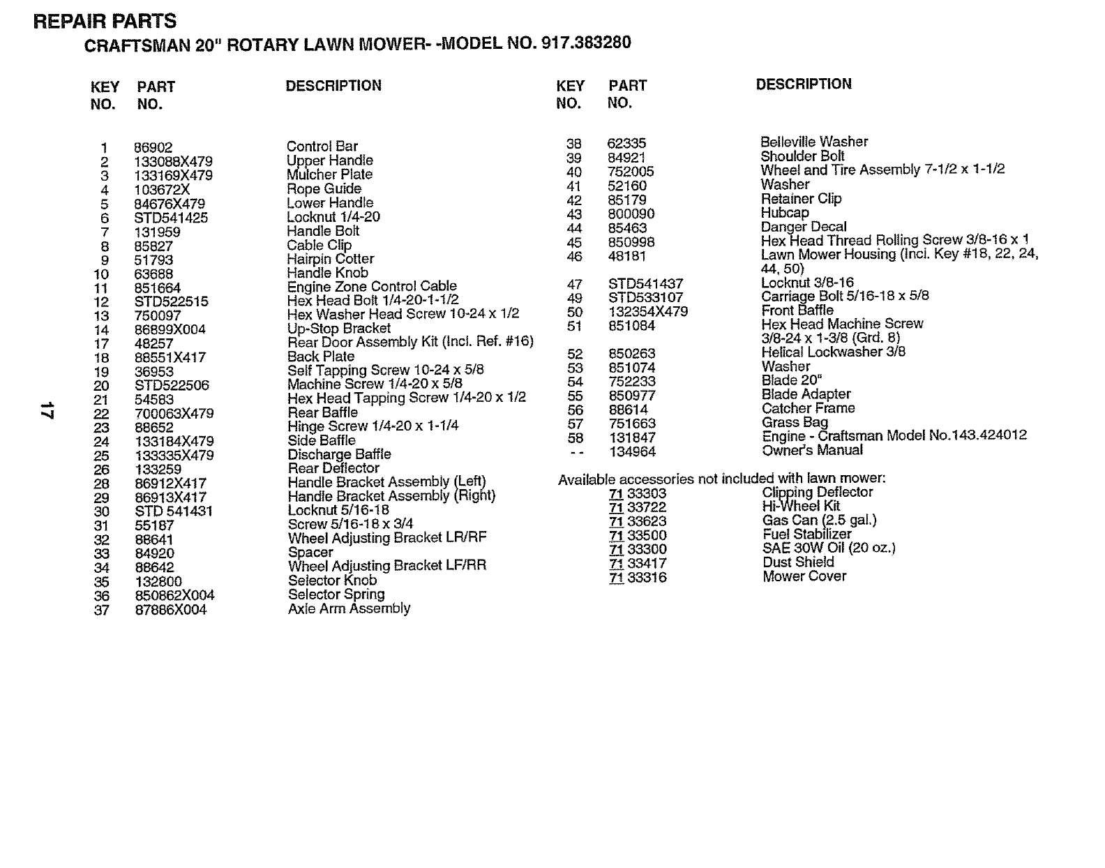
REPAIR PARTS
CRAFTSMAN 20" ROTARY LAWN MOWER- -MODEL NO. 917.383280
KEY PART DESCRIPTION KEY PART
NO, NO. NO. NO.
DESCRIPTION
_J=
1 86902
2 133088X479
3 133169X479
4 103672X
5 84676X479
6 STD541425
7 131959
8 85827
9 51793
10 63688
11 851664
12 STD522515
13 750097
14 86899X004
17 48257
18 88551X417
19 36953
20 STD522506
21 54583
22 700063X479
23 88652
24 133184X479
25 133335X479
26 133259
28 86912X417
29 86913X417
30 STD 541431
31 55187
32 88641
33 84920
34 88642
35 132800
36 850862X004
37 87886X004
Control Bar 38 62335
_Llper Handle 39 84921
cher Plate 40 752005
Rope Guide 41 52160
Lower Handle 42 85179
Locknut 1/4-20 43 800090
Handle Bolt 44 85463
Cable Clip 45 850998
Hairpin Cotter 46 48181
Handle Knob
Engine Zone Control Cable 47
Hex Head Bolt 1/4-20-1-1/2 49
Hex Washer Head Screw 10-24 x 1/2 50
Up-Stop Bracket 51
Rear Door Assembly Kit (Incl. Ref. #16)
Back Plate 52 850263
Self Tapping Screw 10-24 x 5/8 53 851074
Machine Screw 1/4-20 x 5/8 54 752233
Hex Head Tapping Screw 1/4-20 x 1/2 55 850977
Rear Baffle 56 88614
Hinge Screw 1/4-20 x 1-1/4 57 751663
Side Baffle 58 131847
Discharge Baffle - - 134964
Rear Deflector
Handle Bracket Assembly (Left)
Handle Bracket Assembly (Right)
Locknut 5/16-I8
Screw 5/16-18 x 3/4
Wheel Adjusting Bracket LR/RF
Spacer
Wheel Adjusting Bracket LFfRR
Selector Knob
Selector Spring
Axle Arm Assembly
STD541437
STD533107
132354X479
851084
Belteville Washer
Shoulder Bolt
Wheel and Tire Assembly 7-1/2 x 1-1/2
Washer
Retainer Clip
Hubcap
Danger Decal
Hex Head Thread Rolling Screw 3/8-16 x !
Lawn Mower Housing (tnci. Key #18, 22, 24,
44, 5o)
Locknut 3/8-16
Carriage Bolt 5/16-18 x 5/8
Front Baffle
Hex Head Machine Screw
3/8-24 x 1-3/8 (Grd. 8)
Helical Lockwasher 3/8
Washer
Blade 20"
Blade Adapter
Catcher Frame
Grass Bag
Engine - Craftsman Model No.143.424012
Owner's Manual
Available accessories not included with lawn mower:
7_!133303
71 33722
7_!133623
71 33500
7_!133300
71 33417
71 33316
Clipping Deflector
Hi-Wheel Kit
Gas Can (2.5 gal.)
Fuel Stabilizer
SAE 30W Oil (20 oz.)
Dust Shield
Mower Cover
CRAFTSMAN 4=CYCLE ENGnNE aODELNUMBER143.424012
119
215
204
223
182
185
370C
2O7
/
241
245
41
43
48
25O
3OO
189 194
185
_.....,..-,193
"310
"-388
18
CRAFTSMAN 4=CYCLE ENGINE MODELNUiVIBERlz13.424012
REF PART REF PART
NO. NO. DESCRIPTION NO, NO.
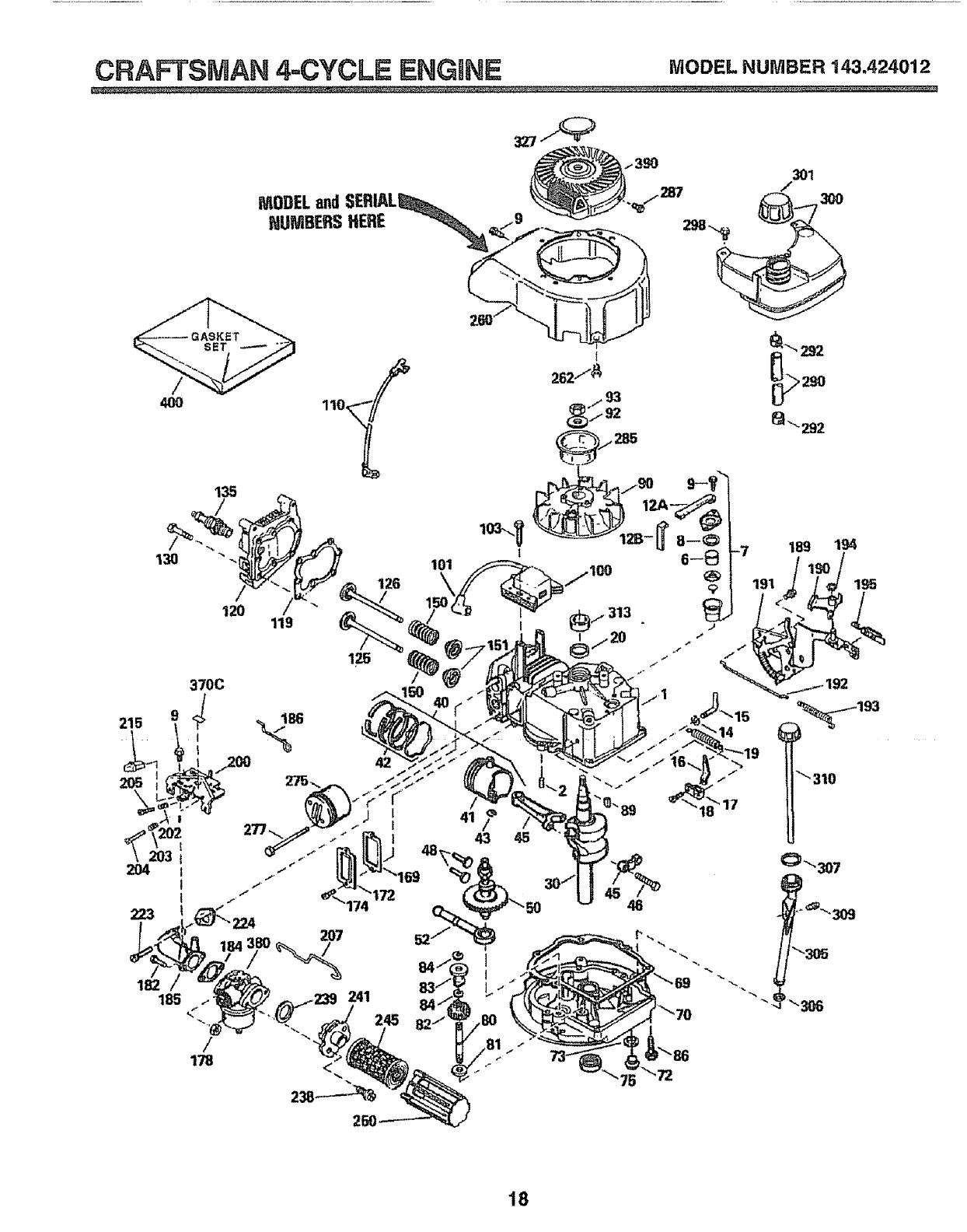
134975 Cylinder Assy. (Incl. #2, 8, 9 & 20) 135 35395
2 26727 Pin, Dowel
6 33734 Element, Breather 150 31672
7 34214A Breather Assembly (Includes 151 31673
Reference #6, 8, 9,12A and 12B) 169 27234A
* Gasket, Breather 172 32755
Screw Seres Hex Washer Head, 174 650128
Self-Tapping #10-24 x 9/16 178 29752
Tube, Breather 182 6201
Elbow, Breather Tube 184 26756
Washer, Flat 185 31384A
Rod, Governor (Includes ReL #14) 186 34358
Lever, Governor 189 650839
Clamp, Governor Lever
Screw, Hex Wash._ Hdo #8-32 x 5/16 190 35831
Spring, Extension t91 35040B
Seal, Oil 192 34966
Crankshaft Assembly 193 34965
Piston, Pin & Ring Assembly, Std. 194 32309
Piston, Pin & Ring Assy..010" over 195 610973
Piston, Pin & Ring Assy..020" over 200 35727
(_Assemblys Include #41, 42 and 43)
Piston & Pin Assembly, Standard 202 33802
Piston & Pin Assembly .O10" over 203 31342
Piston & Pin Assembly .020" over 204 650549
(Assemblys Include Reference #43) 205 650777
Ring Set, Piston, Standard 207 34336
Ring Set, Piston .010" oversize 215 32410
Ring Set, Piston .020" oversize 223 650451
Ring, Piston Pin Retaining 224 34690A
RodAssyo, Connecting (IncL #46) 238 650932
Bolt, Connecting Red
Valve, Lifter 239 34338
Camshaft, Compression Release 24t 35797
Pump Assembly, Oil 245 35066
* Gasket Mounting Flange 250 35065
Flange, Mount. (Inclo #72,73,75,80) 260 35393
Plug, Oil Drain (Includes Refo#73) 262 650831
* Gasket Oil Drain Plug (Not
Required With Plastic Oil Plug) 275 27181B
Seal, Oil 277 650795
Shaft, Governor 285 35000
Washer, Rat 287 650884
Gear Assyo, Governor (IncL #81) 290 30705
Spool, Governor 292 26460
Ring, Retaining 298 28763
Screw, Sems, Hex t/4-20 x 1-1/4
Key, Flywheel 300 34369A
Flywheel 301 35355
Washer, Belleville 305 35577
Nut Flywheel 306 34265
Solid State Assemb y 307 35499
Cover, Spark Plug 309 650562
Screw, Seres, T-15, Torx, Hex
Washer Head #10-24 x i 310 35578
Wire, Ground 313 34080
* Gasket, Cylinder Head 327 35392
Head, Cylinder 370C 35167
Valve, Exhaust, Standard Size 380 632046A
Valve, Exhaust, 1/32" oversize 390 590686
Valve, intake, Standard Size
Valve, Intake, 1/32" oversize (All
Valves Include Reference #151)
Screw, Hex Flange 5/16-18 x 1-1/2
8
933735
30200
12A 33886
12B 34695
14 28277
15 30589
16 31383A
17 31335
18 650548
19 31361
20 326OO
30 34460A
40 34514
34515
34516
41 32538B
32548B
32549B
42 28986
28987
28988
43 2O381
45 30963B
46 32610A
48 27241
50 33148A
52 29914
69 35261
70 35868
72 30572
73 28833
75 26208
8O 30574
81 30590A
82 30591
83 30588A
84 29193
86 650488
89 611004
9O 611t12
92 650815
93 650816
100 34443A
101 610118
103 650814
110 34961
119 29953C
t20 34335
125 29313C
29315C
126 29314B
29315C
130 6021A
DESCRIPTION
Spark Plug, Resistor (Champion
RJ-19LM or Equivalent)
Spring, Valve
Cap, Lower Valve Spdng
* Gasket, Valve Spring Box
Cover, Valve Spring Box
Screw, Sems, Hex #10-24 x 1/2
Nut & Lock Washer t/4-28
Screw, Hex Head t/4-28 ×7/8
* Gasket, Carburetor
Pipe, Intake (Inctudes Ref,. #224)
Link, Governor Spring
Screw, Hex Washer Head,
Powerlok 1/4_20 x3/8
Lever, Brake
Bracket, S,E,. Brake (Includes #195)
Link, Control
Spring, Extension
Ring, Retaining
Terminal Assembly
Control Assembly, Speed (Includes
Reference Numbers 202 thru 205)
Spring, Compression
Spring, Compression
Screw, Fillister Head #5-40 x 7/'16
Screw, Fillister Head #6-32 x 21/32
Link, Throttle
Knob, Control
Screw, Seres, Hex Head 1/4-20 x 1
* Gasket, Intake Pipe
Screw, Hex Washer Head,
Shoutder #10-32 x 49t64
*Gasket, Air Cleaner
Collar, Air Cleaner
Filter, Air Cleaner, Paper
Cover, Air Cleaner
Ho_.lsing, Blower
Screw, Hex Washer Head,
Powedok Thread 1/4-20 x 1/2
Muffler (Includes Reference #277)
Screw, Hex Head 1/4-20 x 2-1/4
Hub, Starter
Screw, Hex Wash. Hd. #8_32 x 1/2
Line, Fuel
Clamp, Fuel Line
Screw, Hex Washer Head,
Shakeproof #10-32 x 19/32
Tank Assembly (Inclo #292 & 301)
Cap, Fuel
Tube, Oil Fill
Gasket, Fill Tube
"O" Rin-
Screw, _ex Washer Head,
Shakeproof #10-32 x 1/2
Dipstick, Oil Fill
Spacer, Flywheel Key
Plug, Starter
Decal, Instruction
Carburetor (includes Ref, #'184)
Starter, Rewind
400 33238D Gasket Set (Incl. items marked *)
.R,PM Settings: High Speed: 2900-3200, Low: 2450-2750
Indicates Parts Included in Gasket Set, Reference #400
NOTE: All component dimensions given in U.S° inches
! inch = 25.4 mm
19
CRAFTSMAN 4,=CYCLEENGINE MODELNUMBER1 .424012
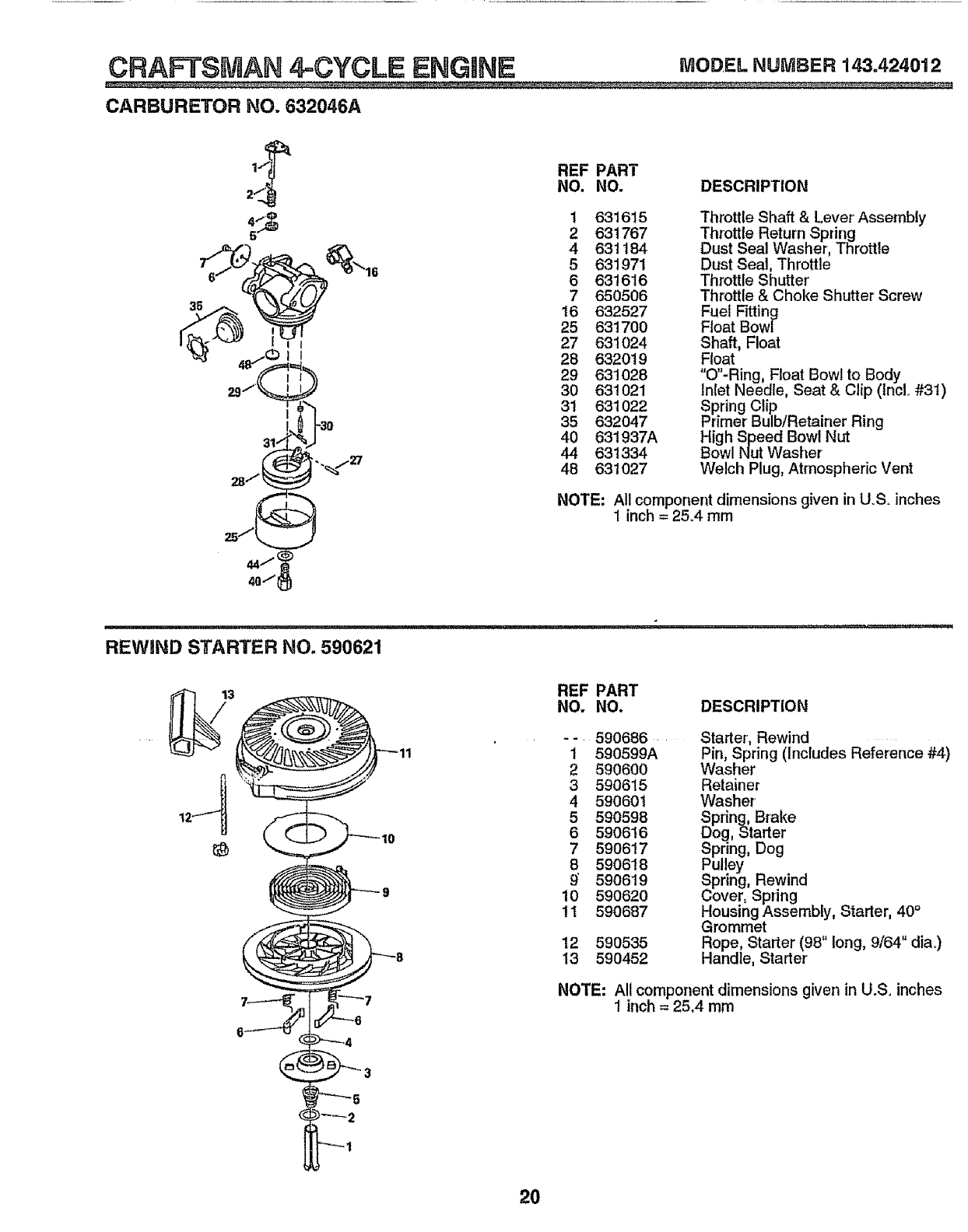
CARBURETOR NO. 632046A
fREF PART
2 NO. NO.
_ 1 631615
2 631767
_e/'tt___"L'3__" 4 631184
'16 5631971
6631616
7 650506
_._ ,'_ 16632527
25 6317O0
I_ ''_" [ ' i 27 631024
28 632019
29 631028
30 631021
31 631022
I85 632047
40 631937A
44 631334
"%'/_/ 48 63t027
DESCRIPTION
Throttle Shaft & Lever Assembly
Throttle Return Spdng
Dust Seal Washer, Throttle
Dust Seal, Throttle
Throttle Shutter
Throttle & Choke Shutter Screw
Fuel Fitting
Float Bowl
Shaft, Float
Float
"O"-Ring, Float Bowl to Body
Inlet Needle, Seat & C!ip (tncL #31)
Spring Clip
Primer Bulb!Retainer Ring
High Speed Bowl Nut
Bowl Nut Washer
Welch Plug, Atmospheric Vent
NOTE: All component dimensions given in U.So inches
1 inch = 25°4 mm
REWIND STARTER NO. 590621
3 REF PART
NO. NO. DESCRIPTION
- - 590686
1590599A
2 590600
4 3 590615
4 590601
15 590598
6 590616
7 590617
8 59O618
590619
10 590620
1t 59O687
12 590535
13 590452
Starter', Rewind ...........
Pin, Spring (Includes Reference #4)
Washer
Retainer
Washer
Spring, Brake
Dog, Starter
Spring, Dog
Pulley
Spring, Rewind
Cover, Spring
Housing Assembly, Starter, 40°
Grommet
Rope, Starter (98" long, 9/64" diao)
Handle, Starter'
NOTE: All component dimensions given in U.S, inches
1 inch =25,4 mm
20
i i1,,11,111, ii1,11,,,11,11 i iii ,11, i1,1
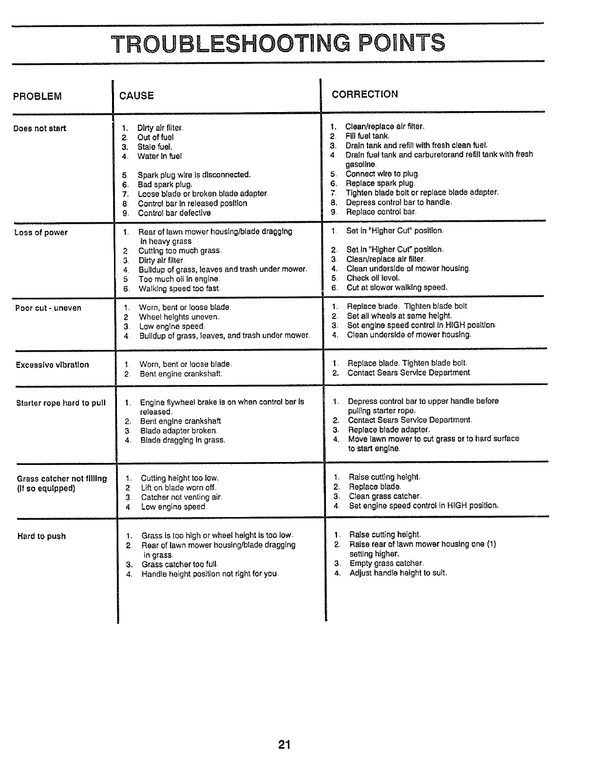
TROUBLESHOOTU
................................................ ir,i
PROBLEM
i i i ,i,
Does not start
Loss of power
i,i
Poor cut - uneven
L
Excessive vibration
Starter rope hard to pull
Grass catcher not filling
(if so equipped)
Hard to push
CAUSE
1o Dirty air ftlter r
2. Out of fuel
3. Stale fuel,
4. Water In fuel
5. Spark plug wire is disconnected.
6. Bad spark plug.
7. Loose blade or broken blade adapter.
8 Control bar tn released position
9. Control bar defective
1, Rear of lawn mower houslng/btade dragging
in heavy grass
2 Cutting too much grass,
3. Dirty air filter
4 Buildup of grass, leaves and trash under mower.
5 Too much eli tn engine.
6, Walktng speedtoo fast.
,i, ii1,,,,,,, ,,, ,,, ,i IIIM
1 Worn, bent or loose blade
2 Whee_helghtsuneven
3. Low englne speed,
4r Buildup of graSS, leaves, and trash under mower.
1 Worn, bent or loose blade.
2. Bent engine crankshaft.,
I., Engine fiywhee_ brake is on when control bar fs
released
2, Bent engtne crankshaft
3- Blade adapter broken_
4, B_ade dragglngtn grass,,
I4 Cutting height too low.
2Uft on blade worn off,
3, Catcher not venting air.
4_ Low engine speed
1. Grass Is too high or wheel height ts too low.
2 Rear of lawn mower housingtblede dragging
in grass,
3. Grass catcher too full-
4, Handle height position not dght for you
CORRECTION
t. Clean/replace air filter°
2, Ftli fuel tank,
3- Drain tank and refill with fresh clean fuel.
4Drain fuel tank and carburetorand refill tank with fresh
gasoline
5. Connect wire to plug
6, Replace spark plug,
7, Tighten blade bolt or replace blade adapter.
8. Depress control bar to handte_
9, Replace control bar
i111I.H..
1 Set In "Higher Cut" positlon.
2. Set In "Higher Cut" position.
3, Cleenfreplace air filter,
4. Clean underside of mower houstng
5 Check otl level
6. Cut at slower wa_klng speed.
iH HiHHI",.,.""""HH I11 HH'I'
1. Replace blade, Tighten blade best
2. Set all wheels at same height.
3. Set engine speed control in HIGH poslt_on,
4. Clean underside of mower housing
1 Repfece blade, Tighten btade boil
2. Contact Sears Service Department
1, Depresscontrol bar to upper handle before
pulling starter rope_
2. ContactSears Service Department
3, Replace blade adapter.
4, Move lawnmowerto cutgrass orto hard surface
to startengine.
1, Raise cutting height.
2 Replace blade,,
3. Ctean grass catcher.
4, Sat engine speed control tn HIGH position.
I, Raise cutting height.
2. Raise rear of lawn mower housing one (1)
setting higher.
3, Empty grass catcher.
4. Adjust handle height to suit.
21

SERVICE NOTES
22

SERVICE NOTES
23
MODEL NO.
917.38328G
HOW TO ORDER
REPAIR PARTS
®
3,5 HORSEPOWER
2G" REAR DISCHARGE
2in ONE MulchedBagger
ROTARY LAWN MOWER
Each Lawn Mower has its own model number, Each
engine has its own model number:,
The model number for your lawn mower will be found on
a decal attached to the rear of the lawn mower housing.
The model number for the engine will be found on the
Blower Housing of the engine adjacent to the spark plug=
All parts listed here in may be ordered through Sears,
Roebuck and Co,, Service Centers and most Retail
Stores°
WHEN ORDERING REPAIR PARTS, ALWAYS GIVE THE
FOLLOWING INFORMATION:
=PRODUCT -"ROTARY LAWN MOWER"
°MODEL NUMBER _917.383280
•ENGINE -CRAFTSMAN MODEL NO, 143.424012
o PART NUMBER
oPART DESCRIPTION
Your Sea_ merchandise has added value when you
consider that Sears has service units nationwide
staffed with Sears trained technicians._professional
t.echnici.ans specifically trained on Sears products
having the parts, tools and the equipment to insure that
we meet our pledge to you, we service what we sell.
134964 11t16/91 Printed in U.SA,
.......................... =.....
