Craftsman 917773422 User Manual HIGH WHEEL WEED TRIMMER Manuals And Guides L0102266
CRAFTSMAN Line Trimmers/Weedwackers, Gas Manual L0102266 CRAFTSMAN Line Trimmers/Weedwackers, Gas Owner's Manual, CRAFTSMAN Line Trimmers/Weedwackers, Gas installation guides
User Manual: Craftsman 917773422 917773422 CRAFTSMAN HIGH WHEEL WEED TRIMMER - Manuals and Guides View the owners manual for your CRAFTSMAN HIGH WHEEL WEED TRIMMER #917773422. Home:Lawn & Garden Parts:Craftsman Parts:917773422 Craftsman Grass trimmer (weed wacker) Manual
Open the PDF directly: View PDF ![]() .
.
Page Count: 26
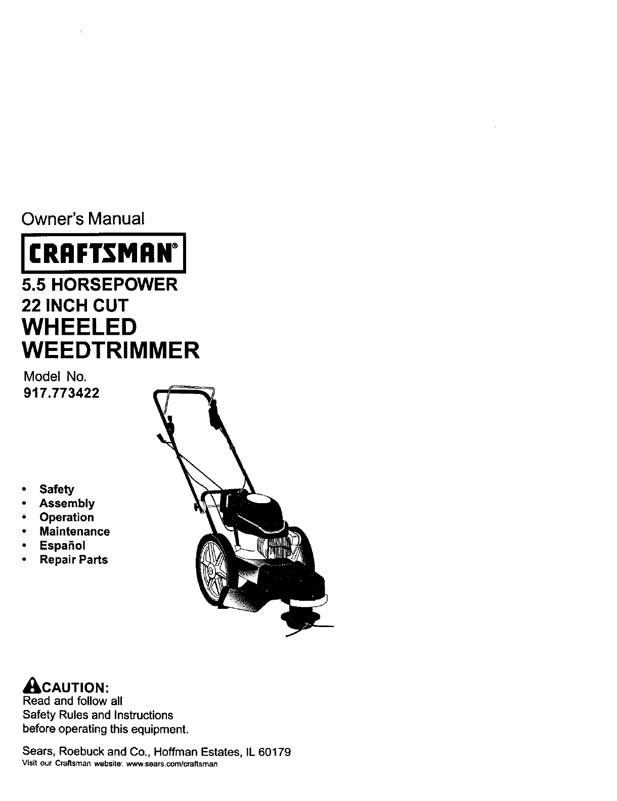
Owner's Manual
JCRRFTSMRWJ
5.5 HORSEPOWER
22 INCH CUT
WHEELED
WEEDTRIMMER
Model No.
917.773422
• Safety
•Assembly
•Operation
• Maintenance
•Espa_ol
•Repair Parts
_L, CAUTION:
Read and follow all
Safety Rules and Instructions
before operating this equipment.
Sears, Roebuck and Co., Hoffman Estates, IL 60179
Visit our Craftsman website: www.sears.com/craftsman
Warranty ................................................. 2
Safety Rules ........................................ 2-4
Assembly ................................................ 5
Operation ............................................. 6-8
Maintenance Schedule .......................... 9
Maintenance ...................................... 9-12
Product Specifications ............................ 9
Service and Adjustments ................. 13-14
Storage ................................................. 15
Troubleshooting ................................... 16
Repair Parts ..................................... 34-41
Parts Ordering ........................ Back Cover
LIMITED "I3NOYEAR WARRANTY ON CRAFTSMAN WEEDTRIMMER
For two years from date of purchase, when this Craftsman Weedtrimmer is maintained,
lubricated, and tuned up according to the operating and maintenance instructions in
the owner's manual, Sears will repair free of charge any defect in material or workman-
ship.
If this Craftsman Weedtrimmer is used for commercial or rental purposes, this warranty
applies for only 90 days from the date of purchase.
This Warranty does not cover:
• Expendable items which become worn during normal use, such as rotatinglines,
belts, air cleaners and spark plug.
• Repairs necessary because of operator abuse or negligence, including bent
crankshafts and the failure to maintain the equipment according to the instructions
contained in the owner's manual.
Warranty service is available by returning the Craftsman Weedtdmmer to the nearest
Sears Service Center in the United States. This warranty applies only while this product
is in use in the United States.
This Warranty gives you specific legal rights, and you may also have other rights which
vary from state to state.
Sears, Roebuck and Co., Dept. 817 WA, Hoffman Estates, IL 60179
WARNING: This trimmer is equipped with an internal combustion engine and should
not be used on or near any unimproved forest-covered, brush-covered or grass-
covered land unless the engine's exhaust system is equipped with aspark arrester
meeting applicable local or state laws (if any). If a spark arrester is used, it should be
maintained in effective working order by the operator.
In the state of California the above is required by law (Section 4442 of the California
Public Resources Code). Other states may have similar laws. Federal laws apply on
federal lands. A spark arrester for the muffler is available through your nearest Sears
service center (See REPAIR PARTS section of this manual).
The operation of any trimmer can result in foreign objects thrown into
the eyes, which can result in severe eye damage. Always wear safety
gasses or eye shields while operating your trimmer or performing any
adjustments or repairs. We recommend a wde vision safety mask
over spectacles or standard safety glasses.
L GENERAL OPERATION
•Read, understand, and follow all
instructionson the machine and in the
manual before starting. Be thoroughly
familiar with the controls and the proper
use of the machine before starting,
• Do not put hands or feet near or under
rotating parts.
•Keep aU parts of your body away from
muffler and spinning line. A hot muffler
can cause serious burns.
• Only allow responsible individuals, who
are familiar with the instructions,to
operate the machine.
•Stay away from breakable objects, such
as house windows, auto glass, green-
houses, etc.
• Clear the area of objects such as rocks,
toys, wire, bones, sticks, etc., which
could be picked up and thrown by the
spinning lines.
•Be sure the area is clear of other
people before trimming, particularly
small children and pets. Stop machine
if anyone enters the area.
•Wear appropriate clothing such as a
long-sleeved shirt or jacket. Also wear
longtrousers or slacks. Do not wear
shorts,
•Do not wear loose clothingwhich could
get caught in this equipment.
•Do not operate the machine when
barefoot or wearing open sandals.
Always wear work gloves and sturdy
footwear. Leather work shoes or short
bootswork well for most people. These
will protect the operator's ankles and
shins from small sticks, splinters, and
other debris, and improve traction.
• Do not pull machine backwards unless
absolutely necessary. Always look
down and behind before and while
moving backwards.
•Do not operate the machine without
proper guards, plates or other safety
protective devices in place.
,See manufacturer's instructions for
proper operation and installation of
accessories. Only use accessories
approved by the manufacturer.
•Never use blades, wire, or flailing
devices. This unit is designed for line
trimmer use only. Use of other accesso-
ries or attachments will increase the risk
of injury.
•Stop the rotatingtrimmer head when
crossing gravel drives, walks, or roads.
Wait for the cutting lines to stop rotating.
•Stop the engine (motor) whenever you
leave the equipment and allow it to
cool, before cleaning, repairing or
Inspecting the unit. Be sure the trimmer
head and all moving parts have
stopped.
• Operate only in daylight or good
artificial light.
•Do not operate the machine while
under the influence of alcohol or drugs.
• Never operate machine in wet grass.
Always be sure of your footing: keep a
firm hold on the handle and walk; never
run.
•If the equipment should start to vibrate
abnormally, stop the engine (motor)
and check immediately for the cause.
Vibration is generally a warning of
trouble.
• Always wear safety goggles or safety
glasses with side shields when operat-
ing machine.
3
II. SLOPEOPERATION
Slopesareamajorfactor related to slip
and fall accidents which can result in
severe injury. All slopes require extra
caution, If you feel uneasy on a slope, do
not trim it.
DO:
• Trim across the face of slopes: never up
and down. Exercise extreme caution
when changing direction on slopes.
•Remove obstacles such as rocks, tree
limbs, etc.
•Watch for holes, ruts, or bumps. Tall
grass can hide obstacles.
DO NOT:
•Do not trim near drop-offs, ditches or
embankments. The operator could lose
footing or balance.
• Do not trim excessively steep slopes.
•Do not trim on wet grass. Reduced
footing could cause slipping.
II1. CHILDREN
Tragic accidents can occur if the operator
is not alert to the presence of children.
Children are often attracted to the machine
and the trimming activity. Never assume
that children will remain where you last
saw them.
•Keep children out of the trimming area
and under the watchful care of another
responsible adult.
• Be alert and turn machine off if children
enter the area.
• Before and while moving backwards,
look behind and down for small
children.
•Never allow children to operate the
machine.
•Use extra care when approaching blind
corners, shrubs, trees, or other objects
that may obscure vision.
IV. SERVICE
•Use extra care in handling gasoline
and other fuels. They are flammable
and vapors are explosive.
- Use only an approved container.
- Never remove gas cap or add fuel
with the engine running. Allow
engine to cool before refueling. Do
not smoke.
- Never refuel the machine indoors.
- Never store the machine or fuel
container inside where there is an
open flame, such as a water heater.
- Move away from fueling site before
starting engine.
• Never run a machine inside a closed
area.
• Never make adjustments or repairs
with the engine (motor) running.
Disconnect the spark plug wire, and
keep the wire away from the plug to
prevent accidental starting.
• Keep nuts and bolts, especially tdmmer
head and engine bolts, tight and keep
equipment in good condition.
•Never tamper with safety devices.
Check their proper operation regularly.
• Keep machine free of grass, leaves, or
other debris buildup. Clean oil or fuel
spillage. Allow machine to cool before
cleaning or storing.
• Stop and inspect the equipment if you
strike an object. Repair, if necessary,
before restarting.
•Do not change the engine governor
setting or overspeed the engine.
•Clean and replace safety and instruc-
tion decals as necessary.
_Look for this symbol to point out
importantsafety precautions. It means
CAUTION!!! BECOMEALERT!T! YOUR
SAFETY IS INVOLVED.
AWARNING: In order to prevent
accidental starting when setting up,
transporting, adjusting or making repairs,
always disconnect spark plug wire and
place wire where it cannot contact spark
plug.
ACAUTION: Muffler and other engine
parts become extremely hot during
operation and remain hot after engine
has stopped. To avoid severe burns on
contact, stay away from these areas.
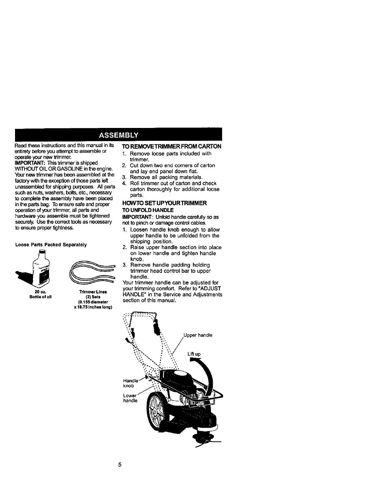
Readtheseinstructionsandthis manual in its
entirety beforeyouattemptto assembleor
operateyour new trimmer.
IMPORTANT: Thistrimmeris shipped
WITHOUT OILOR GASOLINE inthe engine.
Yournew trimmerhas been assembledatthe
factorywiththe excepSonof those partsleft
unassambledfor shippingpuq_oses.All parts
suchas nuts,washers,bolts,etc.,necessary
to completethe assembly have been placed
inthe parts bag. Toensuresafe andproper
oparationof yourtdmmer,all parts and
hardware you assemblemust be tightened
sacurely. Usa thecon'eottoolsas necessary
to ensurepropertightness.
Loose Pads Packed Separately
20 oz.
Bottleof oil Trimmer Lines
(2) Sets
(0.t55 diameter
x 18.75 Inches long)
TO REMOVETRIMMER FROM CARTON
1, Remove loose parts included with
trimmer.
2. Cut down two end corners of carton
and lay end panel down fiat.
3, Remove all packing materials,
4, Roll trimmer out of carton and check
carton thoroughly for additional loose
parts.
HOWTO SET UPYOURTRIMMER
TO UNFOLD HANDLE
IMPORTANT: Unfoldhandlecarefullyso as
not to pinch_damage controlcables.
I. Loosen handle knob enough to allow
upper handle to be unfolded from the
shipping position,
2. Raise upper handle section into place
on lower handle and tighten handle
knob,
3, Remove handle padding holding
trimmer head control bar to upper
handle.
Yourtrimmer handle can be adjusted for
your trimmingcomfort. Refer to "ADJUST
HANDLE" in the Service and Adjustments
section of this manual.
knob
handle
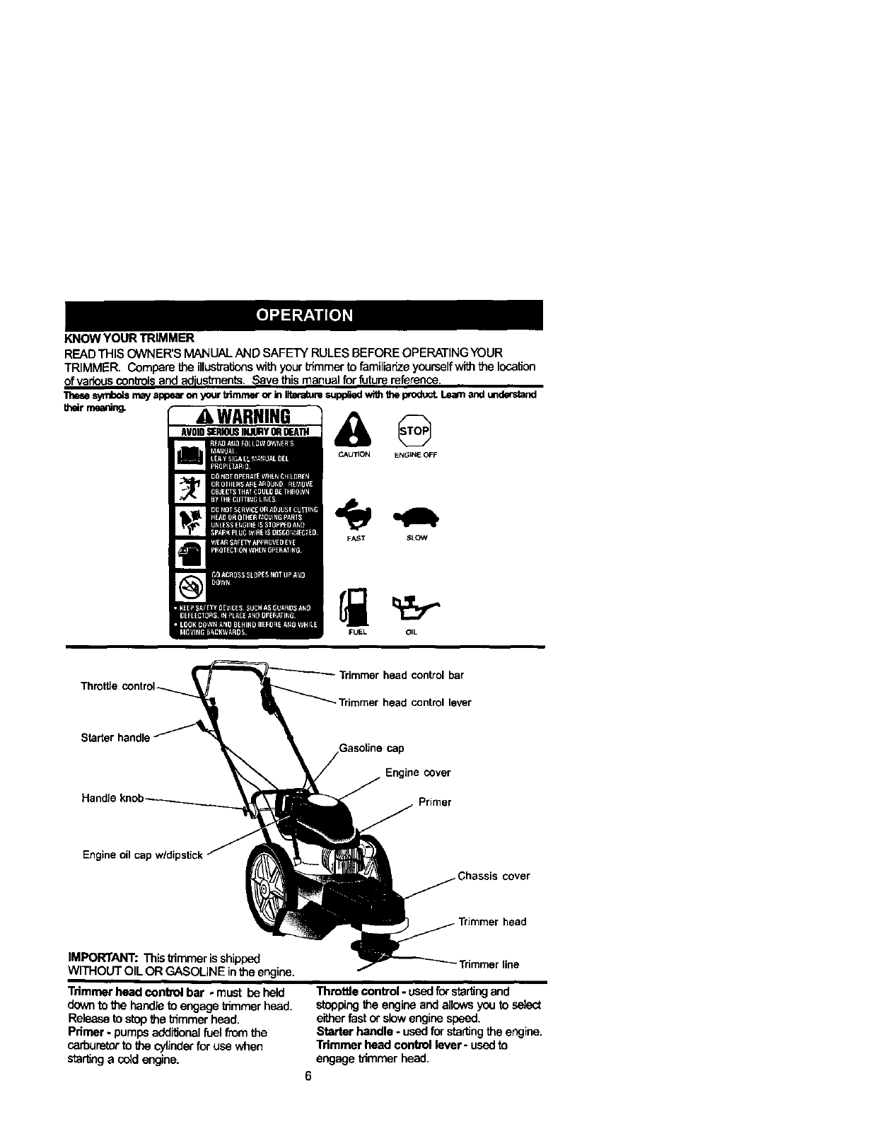
KNOW YOUR TRIMMER
READ THIS OWNER'S MANUALAND SAFETY RULES BEFORE OPERATINGYOUR
TRIMMER. Compare the illustrationswithyourI_'iromerto familianzeyourselfwiththelocation
of var;easconbolsand adjustments.Save this roanualforfuturereference.
These_mayappearonyourblmmerorinI_m suppliedwHhU)eproduct.Lea_andunderstand
41WARNING
Av0,o=..0=. Y=o.m @
CAUTION ENGIN_ OFF
FAST bLOW
FUEL OIL
ThrottJe - Trimmer head control bar
•Trimmer head control lever
Starter handle GasoSne cap
COver
Engine oil
cover
aad
IMPORTANT: Thisb'immeris shipped
WITHOUT OIL OR GASOLINE inthe engine. -Trimmer line
Trimmer head conbol bar - must be held
downto the handleto engagetrimmerhead.
Releaseto stopthe t_mmerhead.
Palmer- pumpsadditionalfuelfrom the
carburetorto the cylinderfor use when
startinga coldengine.
Throttle control- usedfor startingand
stoppingthe engineand allowsyouto select
eitherfast orslowenginespeed.
Starter handle -usedfor sta_ng the engine.
Trimmer head control lever- usedto
engage thmroer head.
6
The operation of any trimmer can result in
foreign objects being thrown into the
eyes, which can result in severe eye
damage. Always wear safety glasses or
eye shields while operating your tdmmer
or performing any adjustments or repairs.
We recommend a wide vision safety mask
over spectacles or standard safety
glasses.
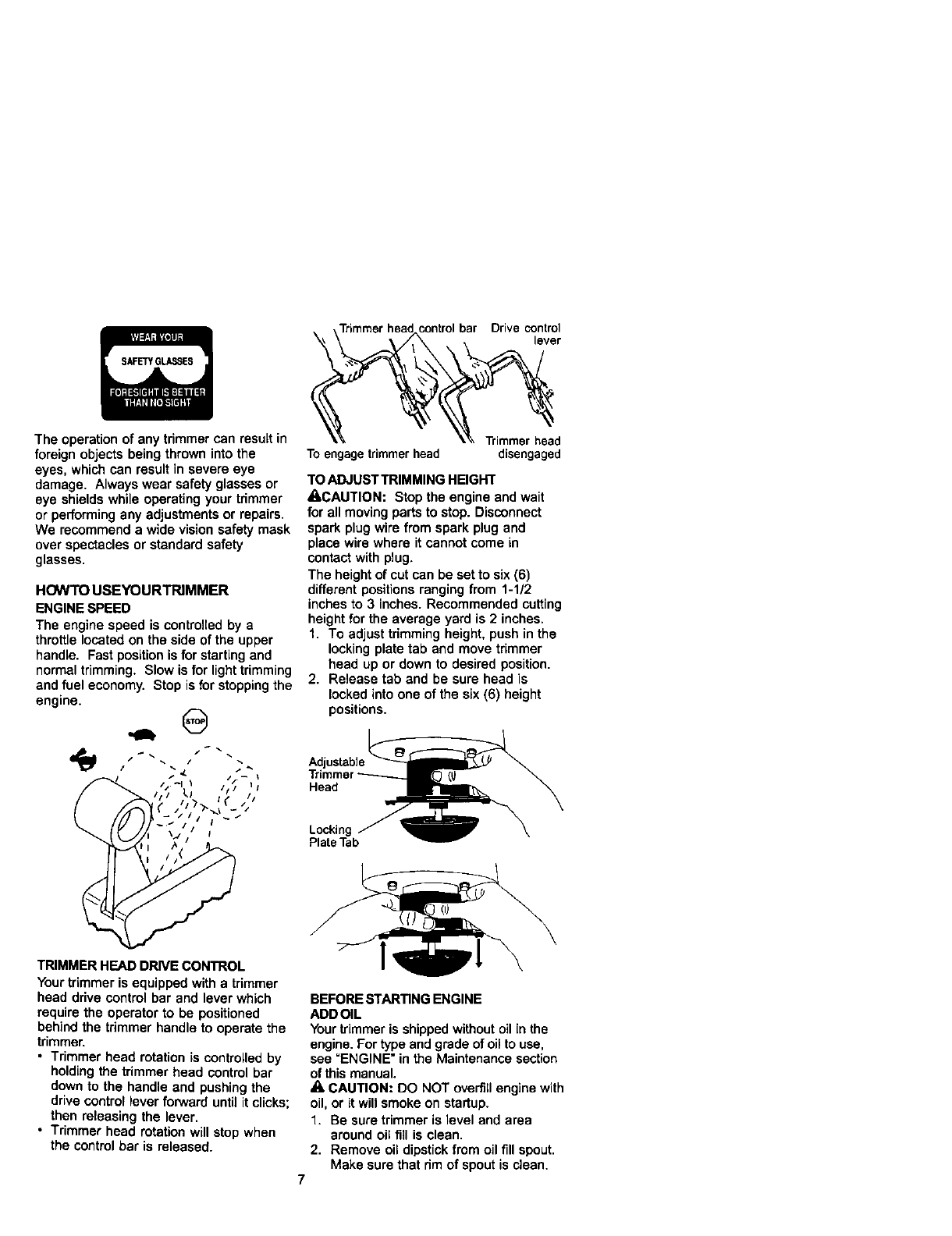
HOWTO USEYOURTRIMMER
ENGINE SPEED
The engine speed is controlled by a
throttle located on the side of the upper
handle. Fast positionis for starting and
normal trimming. Slow is for light trimming
and fuel economy. Stop is for stoppingthe
engine. .,., @
,Trimmerhead controlbar Drive control
lever
Toengagetrimmerhead disengaged
TO ADJUST TRIMMING HEIGHT
ACAUTION: Stop the engine and wait
for all moving parts to stop. Disconnect
spark plug wire from spark plug and
place wire where itcannot come in
contact with plug.
The height of cut can be set to six (6)
different positions ranging from 1-1/2
inches to 3 inches. Recommended cutting
height for the average yard is 2 inches,
1. To adjust trimming height, push in the
locking plate tab and move trimmer
head up or down to desired position.
2. Release tab and be sure head is
locked into one of the six (6) height
positions.
Adjustable
Head
Locking
Plate Tab
TRIMMER HEAD DRIVE CONTROL
Your trimmer is equipped with a trimmer
head drive control bar and lever which
require the operator to be positioned
behind the trimmer handle to operate the
trimmer.
•Trimmer head rotation is controlled by
holding the trimmer head control bar
down to the handle and pushingthe
drive control lever forward until itclicks;
then releasing the lever,
• Trimmer head rotation will stop when
the control bar is released.
BEFORE STARTING ENGINE
ADD OIL
Your trimmer is shipped withoutoil in the
engine. For type and grade of oil to use,
see "ENGINE" in the Maintenance section
of this manual.
A, CAUTION: DO NOT overfillengine with
oil, or it will smoke on startup.
1. Be sure trimmer is level and area
around oil fill is clean.
2. Remove oil dipstickfrom oil fill spout.
Make sure that rim of spout is clean.
3. Youreceive a 20 oz. container of oil
with the unit. Slowly pour 3/4 (15 oz.)
of the oil from the container down the
oil fill spout into the engine.
4. Wait one minute to allow oil to settle.
Insert and tighten dipstick, then
remove it to check oil level.
5. Continue adding small amounts of oil
and rechecking the dipstick until it
reads full. DO NOT overfill, or engine
will smoke on startup.
6. Always be sure to retighten oil dipstick
before starting engine.
•Check oil level before each use. Add oil if
needed. Fillto full line on dipstick.
•Change the oil alter every 25 hours of
operation or each season. You may need
to change the ell more often under dusty,
dirty conditions.
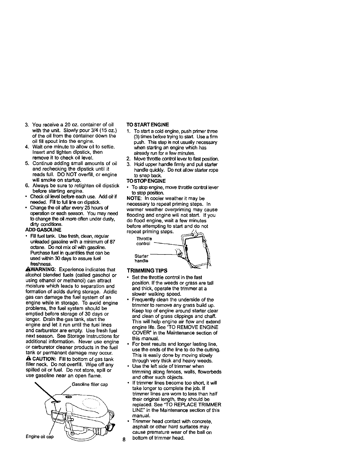
ADD GASOUNE
•Fill fuel tank. Use fresh, clean, regular
unleaded gasoline with a minimum of 87
octane. Do not mix ell with gasoline.
Purchasefuel inquantifJesthat can be
used within30 daysto assure fuel
freshness.
_,WARNING: Experience indicates that
alcohol blended fuels (called gasohol or
using ethanol or methanol) can attract
moisture which leads to separation and
formation of acids during storage. Acidic
gas can damage the fuel system of an
engine while in storage. To avoid engine
problems, the fuel system should be
emptied before storage of 30 days or
longer. Drain the gas tank, start the
engine and let it run until the fuel lines
and carburetor are empty. Use fresh fuel
next season. See Storage Instructions for
additional information. Never use engine
or carburetor cleaner products in the fuel
tank or permanent damage may occur.
_, CAUTION: Fill to bottom of gas tank
tiller neck. Do not overfill. Wipe off any
spilled oil or fuel. Do not store, spill or
use gasoline near an open flame.
Engne ol c_
Gasolinefillercap
TO START ENGINE
1. To starta cord engine,pushpnmerthree
(3)times before tryingto start. Use a firm
push. Thisstep is notusuallynecessary
when startingan engine which has
alreadyrunfor afew minutes.
2. Move throWecontrolleverto fast position.
3. Held upperhandlefirmly and pullstarter
handlequickly.Do notallowstarterrope
to snap back.
TO STOP ENGINE
• To stop engine, move throttle control lever
to stop position.
NOTE: In cooler weather it may be
necessary to repeat pdming steps. In
warmer weather overpriming may cause
flooding and engine will not start. If you
do flood engine, wait a few minutes
before attempting to start and do not
repeat priming steps. _
Throttle \\
control _
Starter _ _
handle
TRIMMING TIPS
• Set the throttlecontrolin the fast
position,Ifthe weeds or grass are tall
and thick,operate the trimmer at a
slower walking speed.
•Frequentlyclean the undersideof the
tnmmer to remove any grass buildup.
Keep top of engine around starterdear
and elean of grass clippingsand chaff.
This will help engine air flow and extend
engine life. See "TO REMOVE ENGINE
COVER" in the Maintenance sectionof
this manual.
•For best results and longer lasting line,
use the ends of the lineto do the cutting.
This is easily done by moving slowly
throughvery thick and heavy weeds.
• Use the leftside of trimmer when
trimming along fences, walls, flowerbeds
and other such objects.
•Iftrimmer linesbecome too short, it will
take longer to complete the job. If
trimmer lines are worn to less than half
their original length, they should be
replaced. See "TO REPLACE TRIMMER
LINE" in the Maintenance sectionof this
manual.
• Tdmmer head contact with concrete,
asphalt or other hard surfaces may
cause premature wear of the ball on
8 bottom of trimmer head.
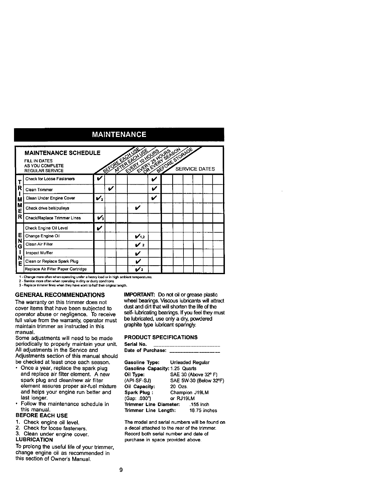
MAINTERA.CESC.E.ULE
AS YOU COMPLETE OY _:_/ _3 _ 8_
Check for Loose Fasteners I_ I_
T
iR Clean Trimmer I_ I_
I
M Clean Under Engine Cover I/2 l/
M Check drive belt/pulleys
R!CheckJReplace Trimmer Lines 1113
Check Engine Oil Level II_
EChange Engine Oil _1,2
GN Clean Air Filter I##2
I Inspect Muffler I1_
NClean or Replace Spark Plug II/
Replace Air Fi_terPaper Cartridge ti/2
1 - Change more c_tenwhen Operatingunder a heavy LOadc_in high ambient lempecatures
2-Sewtce more often when operatJngin dirtyor dusty condibons
3 - Replace _mmer li_e$ when they have worn Io half thek odgi_al length.
GENERAL RECOMMENDATIONS
The warranty on this trimmer does not
cover items that have been subjected to
operator abuse or negligence. To receive
full value from the warranty, operator must
maintain trimmer as instructed in this
manual.
Some adjustments will need to be made
periodically to propedy maintain your unit.
All adjustments in the Service and
Adjustments section of this manual should
be checked at least once each season.
• Once a year, replace the spark plug
and replace air filter element. Anew
spark plug and clean/new air filter
element assures proper air-fuel mixture
and helps your engine run better and
last longer,
• Follow the maintenance schedule in
this manual.
BEFORE EACH USE
1. Check engine oil level.
2. Check for loose fasteners.
3. Clean under engine cover.
LUBRICATION
To prolong the useful life of your trimmer,
change engine oil as recommended in
this section of Owner's Manual.
IMPORTANT: Do not oilorgrease plastic
wheel beatings. Viscous lubricants willattract
dust and dirt thatwill shorten the llfeof the
seif-lubdcaf_ngbeanngs. If you feel they must
be lubricated, use only a dry, powdered
graphite type lubricant sparingly.
PRODUCT SPECIFICATIONS
Serial No.
Date of Purchase: .............
Gasoline Type: Unleaded Regular
Gasoline Capacity: 1.25 Quarts
Oil Type: SAE 30 (Above 32° F)
(API-SF-SJ) SAE 5W-30 (Below 32°F)
Oil Capacity: 20 Ozs,
Spark Plug : Champion J19LM
(Gap: .030") or RJ19LM
Trimmer Line Diameter: ,155 inch
Trimmer Line Length: 18,75 inches
The model and serial numbers will be found on
a decal attached to the rear of the trimmer.
Record both serial number and date of
purchase in space provided above.
9
TRIMMER
Alwaysobsawe safetyruleswhen perform-
ingany maintenance.
TIRES
• Keeptiresfree of gasoline,oil, or insect
controlChemicalswhichcan harm rubber.
•Avoidstumps,stones, deep ruts,shaq)
objectsand otherhazardsthatmay cause
tiredamage.
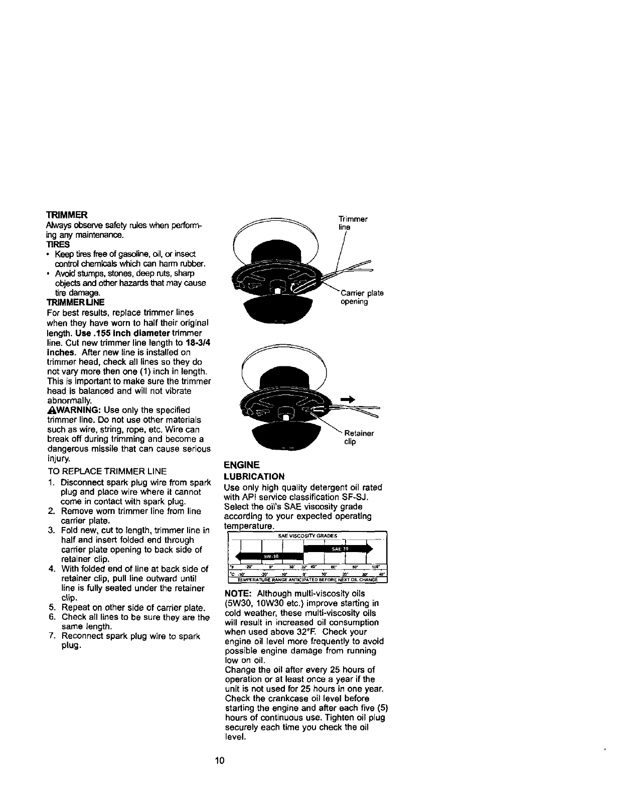
TRIMMER MNE
For best results, replace trimmer Lines
when they have worn to half their original
length. Use .155 inch diameter trimmer
line. Cut new tdmmer line length to 18-3/4
inches. After new line is installed on
tdmmer head, check all lines so they do
not vary more then one (1) inch in length.
This is important to make sure the trimmer
head is balanced and will not v{brate
abnormally.
A.WARNING: Use only the specified
trimmer line. Do not use other materials
such as wire, string, rope, etc. Wire can
break off duringtrimming and become a
dangerous missile that can cause serious
injury.
TO REPLACE TRIMMER LINE
1. Disconnect spark plug wire from spark
plug and place wire where it cannot
come in contact with spark plug.
2. Remove worn trimmer line from line
carrier plate.
3. Fold new, cut to length, trimmer line in
half and insert folded end through
carrier plate opening to back side of
retainer clip.
4. With folded end of line at back side of
retainer clip, pull line outward until
line is fully seated under the retainer
clip.
5. Repeat on other side of carrier plate.
6. Check all lines to be sure they are the
same length.
7. Reconnect spark plug wire to spark
plug.
Trimmer
line
Carrier plate
opening
cl_p
ENGINE
LUBRICATION
Use only high quality detergent oil rated
with API service classification SF-SJ.
Select the oil's ShE viscosity grade
according to your expected operating
temperature.
NOTE: Although multiwiscosity oils
(5W30, 10W30 etc.) improve starting in
cold weather, these multi-viscosity oils
will result in increased oil consumption
when used above 32°F. Check your
engine oil level more frequently to avoid
possible engine damage from running
low on oil.
Change the oil after every 25 hours of
operation or at least once a year if the
unit is not used for 25 hours in one year.
Check the crankcase oil level before
starting the engine and after each five (5)
hours of continuous use. Tighten oil plug
securely each time you check the oil
level.
10
TO CHANGE ENGINE OIL
NOTE: Before tipping trimmer to drain
oil. drain fuel tank by running engine
until fuel tank is empty.
1. Disconnect spark plug wire from spark
plug and place wire where it cannot
come in contact with spark plug.
2. Remove engine oil cap; lay aside on a
clean surface.
3. Tip trimmer on its side as shown and
drain oil into asuitable container.
Rock trimmer back and forth to
remove any oil trapped inside of
engine.
4. Wipe off any spilled oil from trimmer
and side of engine.
5. Fill engine with oil (See "ADD OIL" in
the Operation section of this manual).
6. Replace engine oil cap.
7. Reconnect spark plug wire to spark
plug.
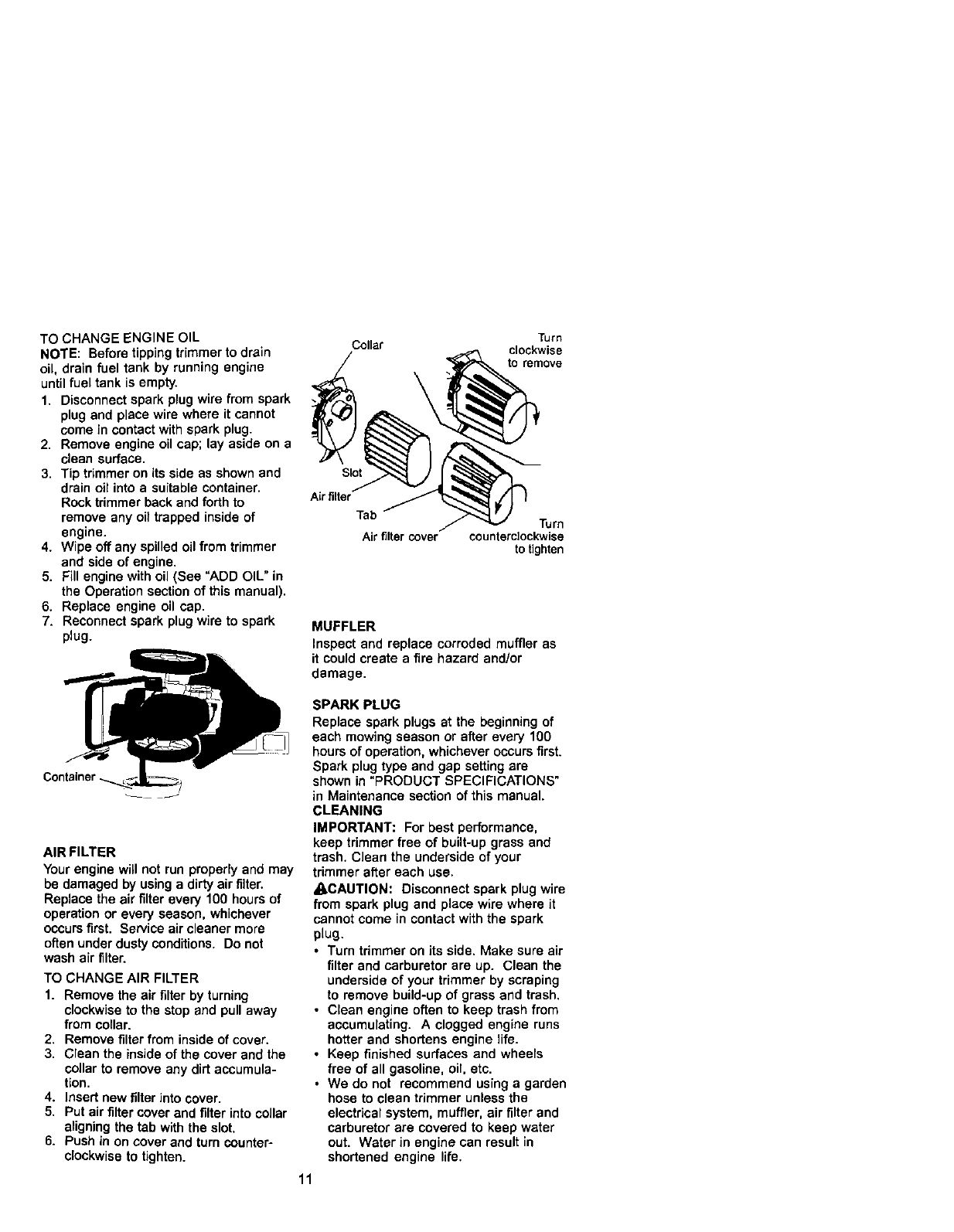
AIR FILTER
Yourengine will net run prepedy and may
be damaged by using a dirty air filter.
Replace the air filter every 100 hours of
operation or every season, whichever
occursfirst. Service air cleaner more
often under dusty conditions. Do not
wash air filter.
TO CHANGE AIR FILTER
1. Remove the air filter by turning
clockwise to the stop and pull away
from collar.
2. Remove filter from inside of cover.
3. Clean the inside of the cover and the
collar to remove any dirt accumula-
tion.
4. Insert new filter into cover.
5. Put air filter cover and filter into collar
aligning the tab with the slot.
6. Push in on cover and turn counter-
clockwise to tighten.
Turn
Collar clockwise
to remove
Slot
Air tilter
Tab
Air tilter cover Turn
counterclockwise
to tighten
MUFFLER
Inspect and replace corroded muffler as
it could create a fire hazard and/or
damage.
SPARK PLUG
Replace spark plugs at the beginning of
each mowing season or after every 100
hours of operation, whichever occurs first.
Spark plug type and gap setting are
shown in "PRODUCT SPECIFICATIONS"
in Maintenance section of this manual.
CLEANING
IMPORTANT: For best performance,
keep trimmer free of built-up grass and
trash. Clean the underside of your
trimmer after each use.
_CAUTION: Disconnect spark plug wire
from spark plug and place wire where it
cannot come in contact with the spark
plug.
• Turn trimmer on its side. Make sure air
filter and carburetor are up. Clean the
underside of your trimmer by scraping
to remove build-up of grass and trash.
• Clean engine often to keep trash from
accumulating. Aclogged engine runs
hotter and shortens engine fife.
•Keep finished surfaces and wheels
free of all gasoline, oil, etc.
• We do not recommend using agarden
hose to clean trimmer unless the
electrical system, muffler, air filter and
carburetor are covered to keep water
out. Water in engine can result in
shortened engine life.
11
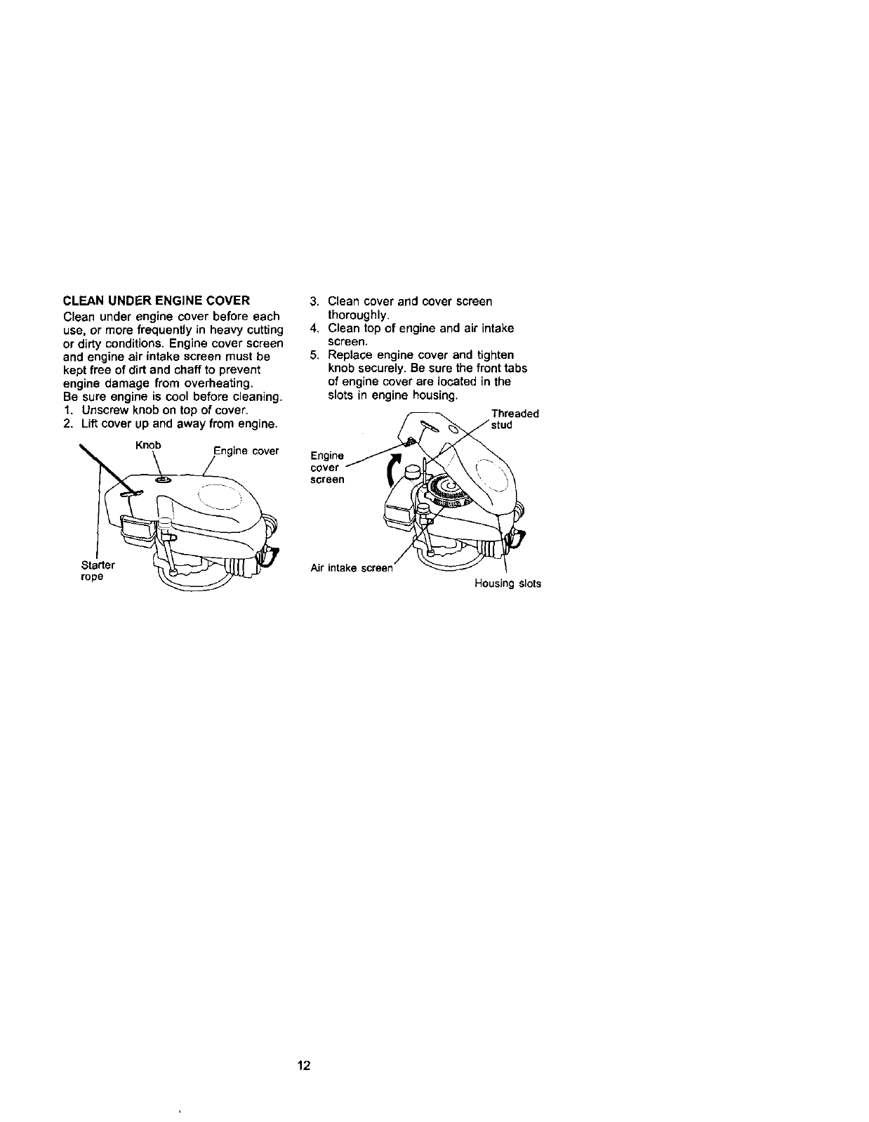
CLEAN UNDER ENGINE COVER
Clean under engine cover before each
use, or more frequently in heavy cutting
or dirty conditions. Engine cover screen
and engine air intake screen must be
kept free of dirt and chaff to prevent
engine damage from overheating.
Be sure engine is cool before cleaning.
1. Unscrew knob on top of cover.
2. Lift cover up and away from engine.
Knob
Starter
rope
3. Clean cover and cover screen
thoroughly.
4, Clean top of engine and air intake
screen.
5. Replace engine cover and tighten
knob securely. Be sure the front tabs
of engine cover are located in the
slots in engine housing.
Eo_vgienre _thul_aded
screenl scre_ 1
Air inta
Housir slots
12
ACAUTION: Before performing any
service and adjustments:
1. Stop engine.
2. Make sure the rotating lines and all
moving parts have completely
stopped.
3. Disconnect spark plug wire from spark
plug and place where it cannot come
in contact with plug.
TRIMMER
TO ADJUST TRIMMING HBGHT
See "TOADJUSTTRIMMING HEIGH'r" inthe
Opera,on secl_onof thismanual.
TO ADJUST HANDLE
The upper handle may be adjusted to
different height positions.
•Loosen handle knob only enough to
allow the upper handle to pivotto the
desired position.
•Tighten handle knob securely.
NOTE: The handle knob and bolt may be
reversed for left handed operation.
Upperhandle
\\
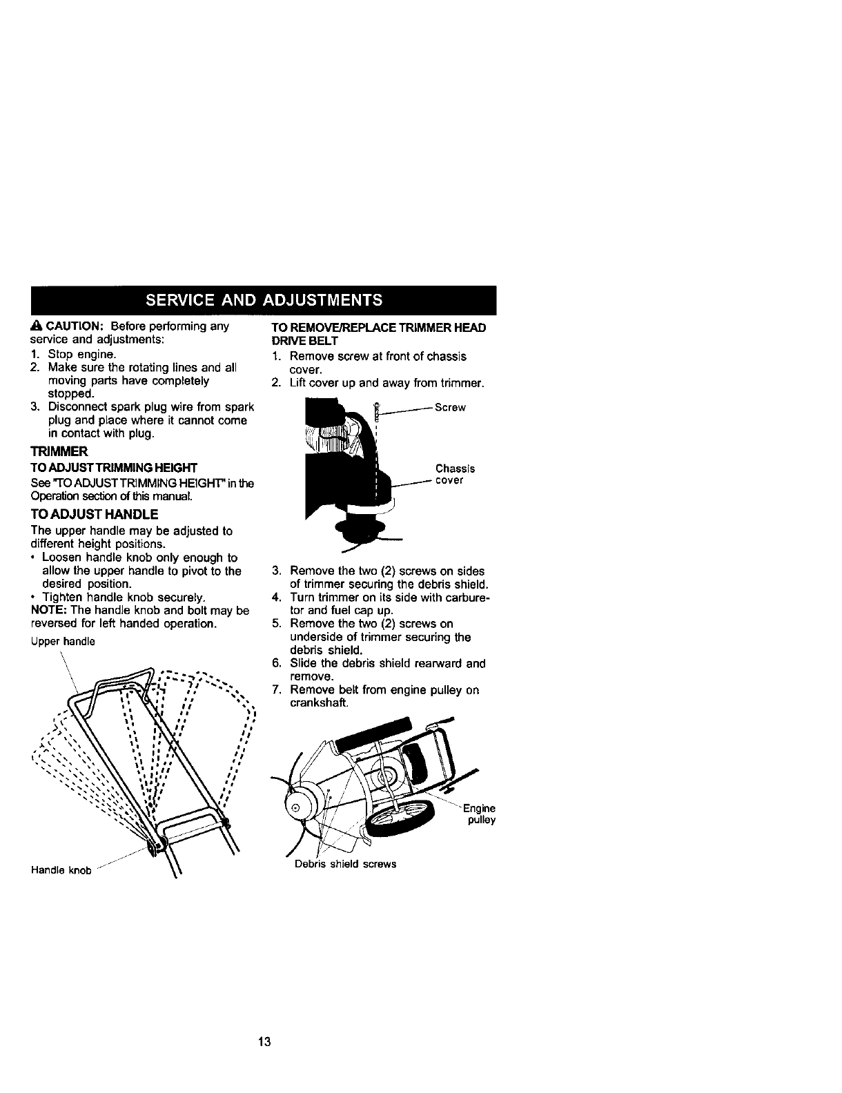
TO REMOVE/REPLACE TRIMMER HEAD
DRIVE BELT
1. Remove screw at front of chassis
cover.
2. Liftcover up and away from trimmer.
Chassis
3. Remove the two (2) screws on sides
of trimmer securing the debris shield.
4. Turn trimmer on its side with carbure-
tor and fuel cap up.
5. Remove the two (2) screws on
underside of trimmer securing the
debris shield.
6. Slide the debris shield rearward and
remove.
7. Remove belt from engine pulley on
crankshaft.
_" Engine
pulley
Handleknob "Debris shield screws
13
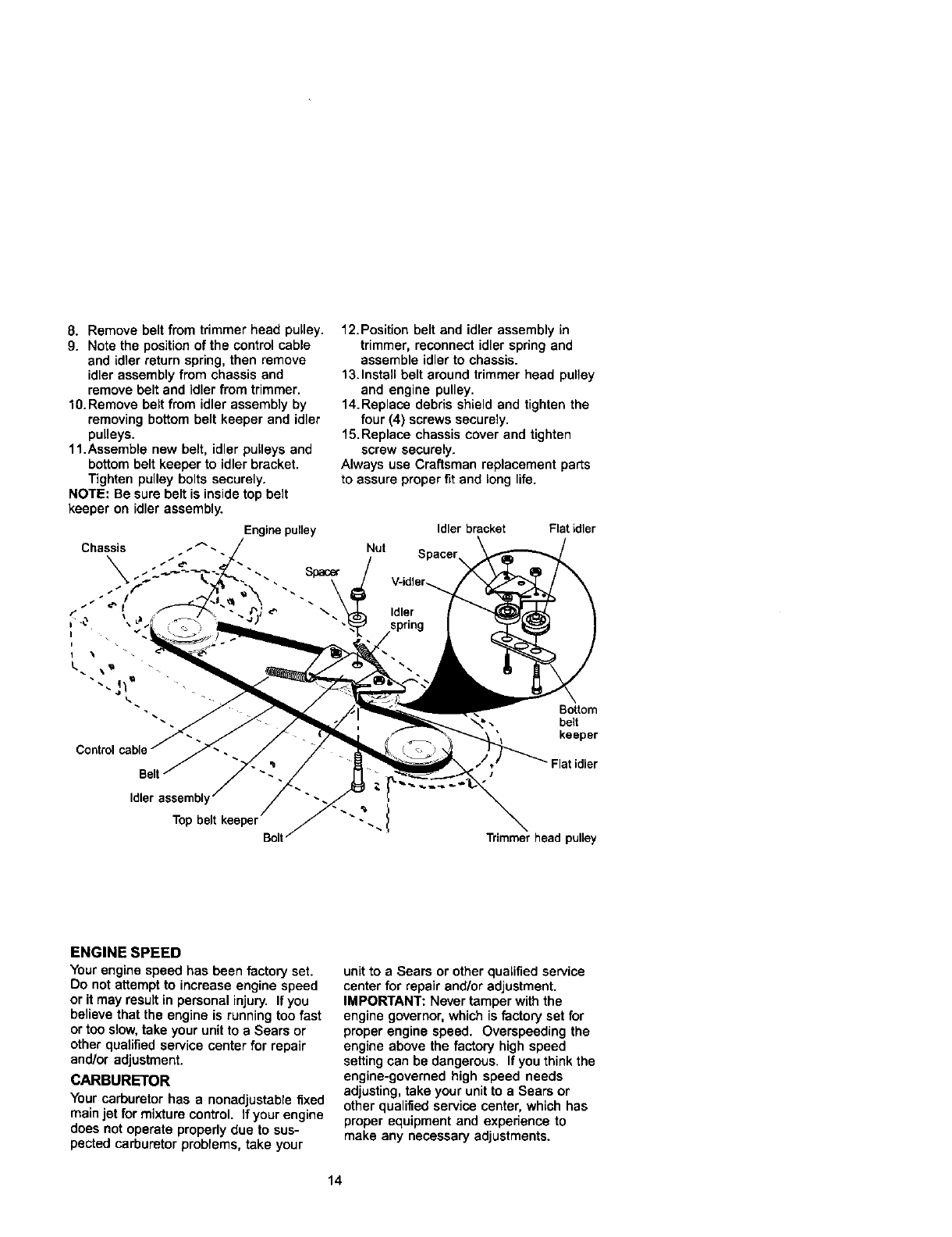
8. Remove belt from trimmer head pulley.
9. Note the position of the control cable
and idler return spring, then remove
idler assembly from chassis and
remove belt and idler from trimmer.
10.Remove belt from idler assembly by
removing bottom belt keeper and idler
pulleys.
11.Assemble new belt, idler pulleys and
bottom belt keeper to idler bracket.
Tighten pulley bolts securely.
NOTE: Be sure belt is inside top belt
keeper on idler assembly.
12.Position belt and idler assembly in
trimmer, reconnect idler spring and
assemble idler to chassis.
13.Install belt around trimmer head pulley
and engine pulley.
14.Replace debris shield and tighten the
four (4) screws securely.
15.Replace chassis cover and tighten
screw securely.
Always use Craftsman replacement parts
to assure proper fit and long life.
Enginepulley
Chassis .--_'_. Nut
I .
Idler bracket Flatidler
Spacer
V-idler_
Idler
Bottom
\,_ belt
keeper
Idler assembly
Top belt keeper _ '_" _ 1
Bolt Trimmer head pulley
ENGINE SPEED
Yourengine speed has been factoryset.
Do not attempt to increase engine speed
or it may result in personal injury. Ifyou
believe that the engine is running too fast
or too slow, take your unit to a Sears or
other qualified service center for repair
and/or adjustment.
CARBURETOR
Your carburetor has a nonadjustable fixed
main jet for mixture control. If your engine
does not operate properly due to sus-
pected carburetor problems, take your
unit to a Sears or other qualified service
center for repair and/or adjustment.
IMPORTANT: Never tamper with the
engine governor, which is factory set for
proper engine speed. Overspeeding the
engine above the factory high speed
setting can be dangerous. If you think the
engine-governed high speed needs
adjusting, take your unit to a Sears or
other qualified service center, which has
proper equipment and experience to
make any necessary adjustments.
14
Immediatelyprepare your trimmerfor storage
at theend ofthe seasonorif the unitwill not
be used for 30 days or more.
TRIMMER
When tnmmer isto be stored for a pedod of
time, dean it thoroughly, remove all dirt,
grease, leaves, etc. Store in a dean, dry area.
1. Clean entiretrimmer (See "CLEANING" in
the Maintenance section of this manual).
2. Lubricate as shown in the Maintenance
section of this manual.
3. Be sure that all nuta, bolts, screws, and
pinsare securelyfastened. Inspect
moving partsfordamage, breakage and
wear. Replaceif necessary.
4. Teach up allrustedor chipped paint
surfaces;sand lightlybefore painting.
HANDLE
You can fold your trimmer handle for storage.
•Loosen handle knob enough to allow
upper handle to be folded forward.
IMPORTANT: When folding the handle for
storage or transportation,be sure to fold the
handle as shown or you may damage the
controlcables.
handle
/
/
Handle knob
ENGINE
FUELSYSTEM
IMPORTANT: Itisimportantto preventgum
depositsfrom fon'ning in essentialfuel system
tank dudng storage. Also, expedense
indicatesthat alcoholblended fuels (called
gasohoi or using ethanol or methanol) can
attract moisturewhich leads to separation
and formation of acids dudng storage. Addic
gas can damage the fuel system of an
enginewhilein storage.
1. Drain the fuel tank.
2. Start the engine and let it run untilthe
fuel lines and carburetor are empty.
•Never use engine or carburetor cleaner
products in the fuel tank or permanent
damage may occur.
• Use fresh fuel next season.
NOTE: Fuel stabilizeris an acceptable
altemaWe in minimizing the formation of fuel
gum deposits during storage. Add stabilizer
to gasoline in fuel tank or storage container.
Always follow the mix ratiofound on stabilizer
oontainer. Run engine at least10 minutes
after adding stabilizer to allow the stabilizer to
reachthe carburetor. Do not drainthe gas
tank and carburetor if using fuel stabilizer.
ENGINEOIL
Drain oil (with engine warm) and replace with
clean engine oil. (See "ENGINE" in the
Maintenance section of this manual).
CYLINDER
1. Remove spark plug.
2. Pour one ounce (29 ml) of oil through
spark plug hole into cylinder,
3, Pull starter handle slowly a few times
to distribute oil.
4. Replace with new spark plug.
OTHER
• Do notstore gasolinefrom one season to
another.
•Rep_acayour gasolinecan if yourcan
startsto rust. Rustand/ordirtinyour
gasolinewillcause problems.
• If possible, store your unitindeareand
cover it to give protectionfrom dust and dirt.
• Dover your unit with asuitable protective
cover that deas not retain moisture. Do
notuse plastic. Plasticcannotbreathe,
whk_,hallows condensation to form and will
cause your unit to rest.
IMPORTANT: Never cover _mmer while
engine and exhaust areas are still warm.
_I_,CAUTION: Never store the trimmer
with gasoline in the tank inside a building
where fumes may reach an open flame or
spark. Allow the engine to cool before
parts suchas cerburat_, fuel tilter,fuel hoseor15storing in any enclosure.
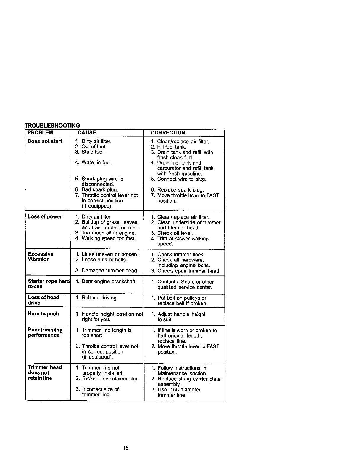
TROUBLESHOOTING
PROBLEM CAUSE
Does not start 1, Dirty air filter.
CORRECTION
2. Out of fuel.
3. Stale fuel.
4. Water in fuel.
5. Spark plug wire is
disconnected.
6. Bad spark plug.
7. Throttle control lever not
in correct position
(if equipped).
1. Dirty air filter.
2, Buildup of grass, leaves,
and trash under trimmer.
3. Too much oil in engine.
4. Walking speed too fast.
1. Lines uneven or broken.
2. Loose nuts or bolts.
3. Damaged trimmer head.
1. Bent engine crankshaft.
1. Belt not driving.
1. Handle height position not
right for you.
1. Trimmer line length is
too shorL
2. Throttle control lever not
in correct position
(if equipped).
1. Trimmer line not
properly installed.
2. Broken line retainer clip.
3. Incorrect size of
trimmer line.
1. Clean/replace air filter.
2. Fill fuel tank.
3. Drain tank and refill with
fresh clean fuel.
4. Drain fuel tank and
carburetor and refill tank
with fresh gasoline.
5. Connect wire to plug.
6. Replace spark plug.
7. Move throttle lever to FAST
position.
Loss of power 1, Clean/replace air filter.
2. Clean underside of trimmer
and trimmer head.
3. Check oil level.
4. Trim at slower walking
speed.
Excessive 1. Check trimmer lines.
Vibration 2. Check all hardware,
including engine bolts.
3. Check/repair trimmer head.
Starter rope hard 1. Contact a Sears or other
topull qualified service center.
Loss of head 1. Put belt on pulleys or
drive replace belt if broken.
iHard to push 1. Adjust handle height
to suit.
Poor trimming 1. If line is worn or broken to
performance half original length,
replace line.
2. Move throttle lever to FAST
position.
Trimmer head 1. Follow instructionsin
does not Maintenance section.
retain line 2. Replace stdng carrier plate
assembly,
3. Use .155 diameter
trimmer line.
16
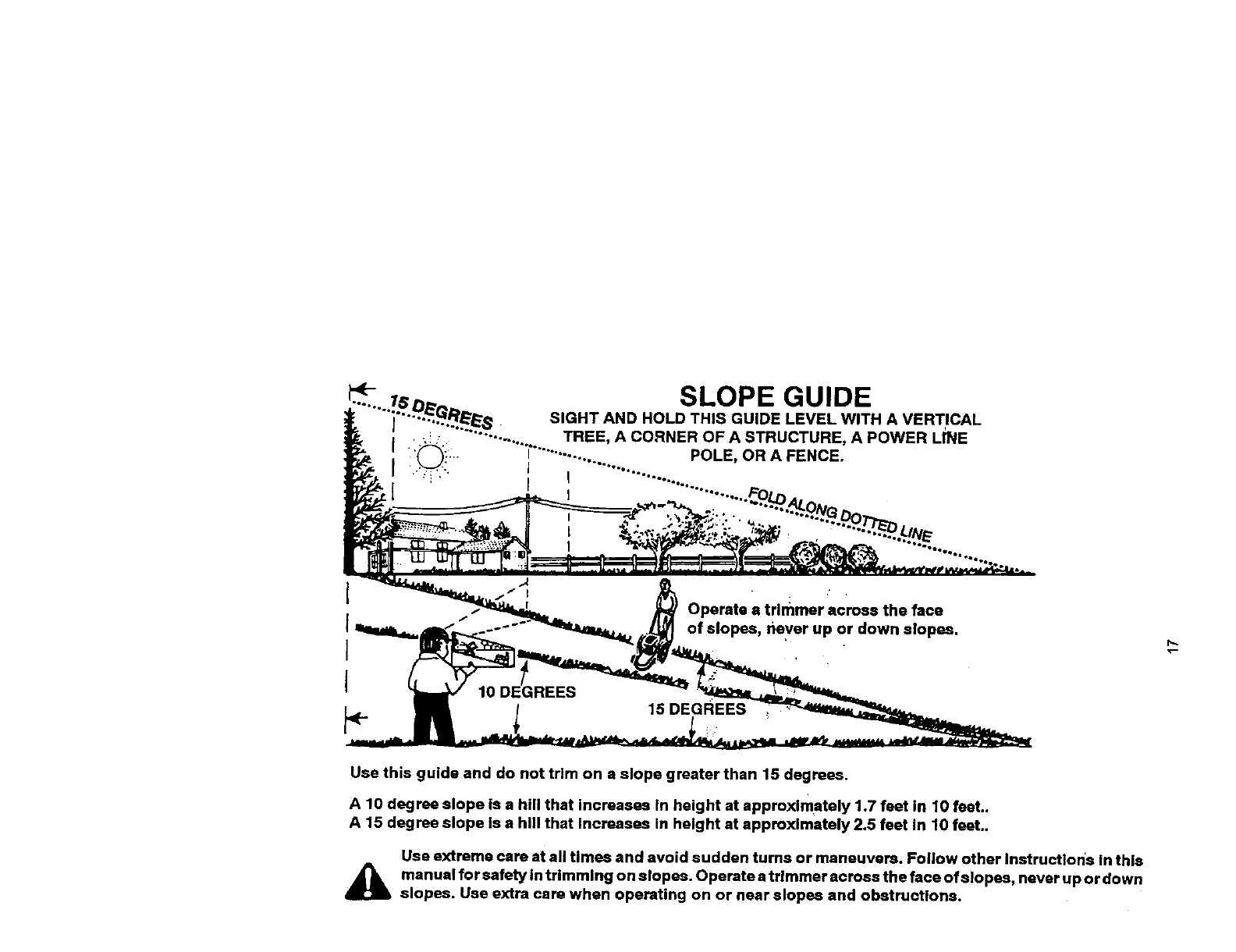
SLOPE GUIDE
SIGHT AND HOLD THIS GUIDE LEVEL WITH A VERTICAL
TREE, A CORNER OF A STRUCTURE, A POWER LINE
POLE, OR A FENCE.
Operate atrimmer across the face
of slopes, never up or down slopes.
15 DEGREEs
f_
Use this guide and do not trim on a slope greater than 15 degrees.
A 10 degree slope Is a hill that increases In height at approximately 1.7 feet in 10 feet..
A 15 degree slope Is ahill that increases in height at approximately 2.5 feet In t0 feet..
Use extreme care at all Umes and avoid sudden turns or maneuvers. Follow other Instruction's in this
j_li anuel for safety In trimming on slopes. Operate a trimmer across the face ofslopes, never up or down
slopes. Use extra care when operating on or near slopes and obstructions.
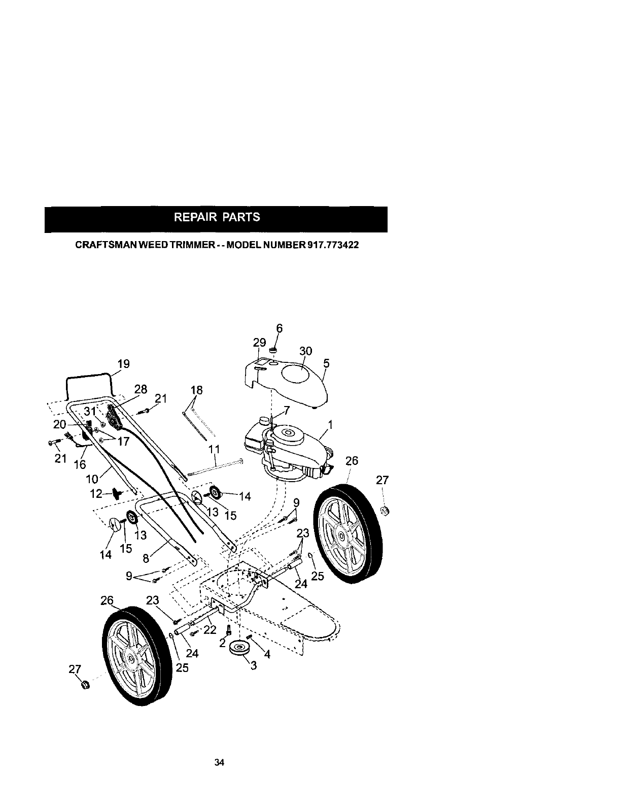
CRAFTSMANWEEDTRIMMER--MODEL NUMBER 917.773422
20-
21 li
27
19
28
14 15
26
21
24
25
26
/
J 27
34

CRAFTSMAN WEED TRIMMER- -MODEL NUM BER 917.773422
KEY PART
NO, NO. DESCRIPTION
1..... Engine. Craftsman.
Model Number 143.015502
(See Breakdown)
2 1504(6 Bolt. Engine Mounting 3/8-16
3 169791 Pulley, Engine (Includes Setscrew, Key #4)
4STD502502 Setscrew, Pulley
5 174317 Cover. Engine. with Screen
6 174274 Knob. Engine Cover
7 174030 Stud. Engine Cover
8 169821X479 Handle, Lower
9 150078 Screw. Hex Washer Head 5/16-18 x .75
10 169797)(479 Handle.Upper
11 170980 Bolt.Handle
12 136376 Knob, Handle
13 17(681 Adjuster, Handle. Inside
14 17(682 Adjuster. Handle. Outside
15 170554 Spring. Handle Adjust
16 153638 Guide, Rope
17 STD541025 Locknut 1/4 x 26
18 66426 WireTire
19 171449 ControIBar
20 174934 Throttk3Control
21 158755 Screw, Hex Washer Head
22 17475OX004 Axle Shaft Assembly
23 150076 Screw, Hex Washer Head 5/15-18 x .75
24 174751 Spacer, Axle
25 57143 Washer,Wave
26 752063 Wheel, 14 x 2
27 53923 Hex Flange LOCknut 3/8-16
28 174037 DriveControl
29 174034 Decal.Warning
30 174039 Decal, Engine Cover
31 751152 Locknut 1/4-20
-- 177731 Owner's Manual. English/Spanish
Available accessories not included with trimmer:
7133523 Gas Can (2.5 gal.)
]J.33000 SAE 3OW Oil (20 oz.)
7J.79991 Trimmer Line (Pack of 24 strings, .155 dia.)
NOTE: All component dimensions given inU.S. inches
t inch = 25,4 mm
35
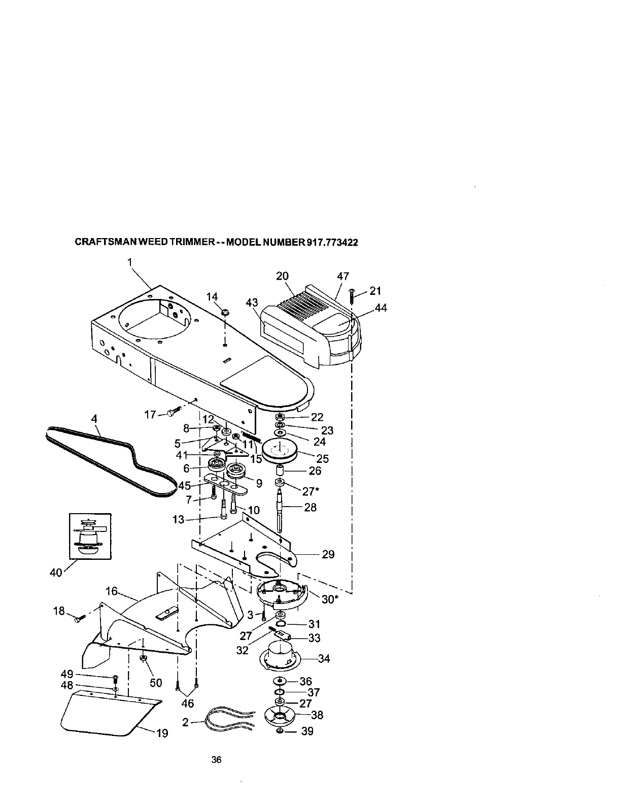
CRAFTSMAN WEED TRIMM ER --MODEL NUMBER 917.773422
1
20 47
14 43
423
24
32
36

CRAFTSMAN WEED TRIMMER-- MODEL NUMBER 917.773422
KEY PART
NO. NO. DESCRIPTION
1
2
3
4
5
6
7
8
9
10
11
12
13
14
15
16
17
18
19
20
21
22
23
24
25
25
27
28
29
3O
31
32
33
34
36
37
38
39
4O
41
43
44
45
46
47
48
49
5O
174031X558 Chassis Assembiy
169802 Line, Trimmer .155 diameter x 18.75 long
173715 Screw, Self-Tappleg 5/16-18 x 1
169790 V-Belt
172145X504 Bracket, Idler
166042 Pulley, Idler, VoGroove
173716 Bolt, Hex Head 3/6-16 x 1.25
751592 Locknut, Hex 3/8-16
166043 Pulley, Idler, Flat
160829 Bolt,Shoulder
155552 Locknut 5/16-18
173717 Spacer
174719 Bolt, Shoulder
145212 Locknut, Flange
173811 Spring, Return
177811 Shield, Oebds
57608 Screw 1/4°20x 1/2
85768 Screw #10-24 x 3/4
175301 Skirt
170553 Cover, Chassis, Top
149746 Screw #10-24 x 1-3/4
s'rD541137 Nut 3/6-24 UNF
S'rD551137 Washer, Lock 3/8
STD551037 Washer, Flat 3/8
169792 Pulley, Dnven
172551 Spacer, Pulley
174549 Bearing
172520 Jackshatt
169766X479 Cover, Chassis, Bottom
174543 Spindle Housing Assembly
(* Includes Upper Bearing, Key #27)
174581 Ring, Retaining, External, 17turn
176973 Spring, Locking Plate
172519 Locking Plate
174544 Carder Plate Assembly
172516 Cover, Bearing
174580 Ring, Retaining, Internal, 4gram
172523 Mow Ball
172636 Bolt, Mow Ball
172342 Head Assembly, Complete
(Includes Key Numbers 22-28, 30-39)
174029 Spacer
174042 Decal, Instruction
174035 Decal, Chassis Cover
174596 Belt Keepe=',Bottom
17060408 Screw, SelfoTapping
174036 Decal, Instruction
52784 Washer
76399 Screw
59931 Locknut
NOTE: All component dimensions given in U.S. Inches
I inch = 25.4 mm
37
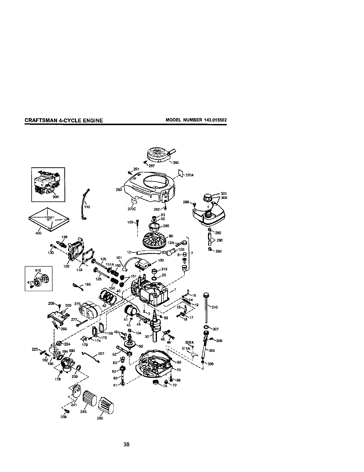
CRAFTSMAN 4-CYCLE ENGINE MODEL NUMBER 143.015502
4oo
130
416
182
185
120 119
125
43
/
179
1207
238 250
46 3_A
311A
38
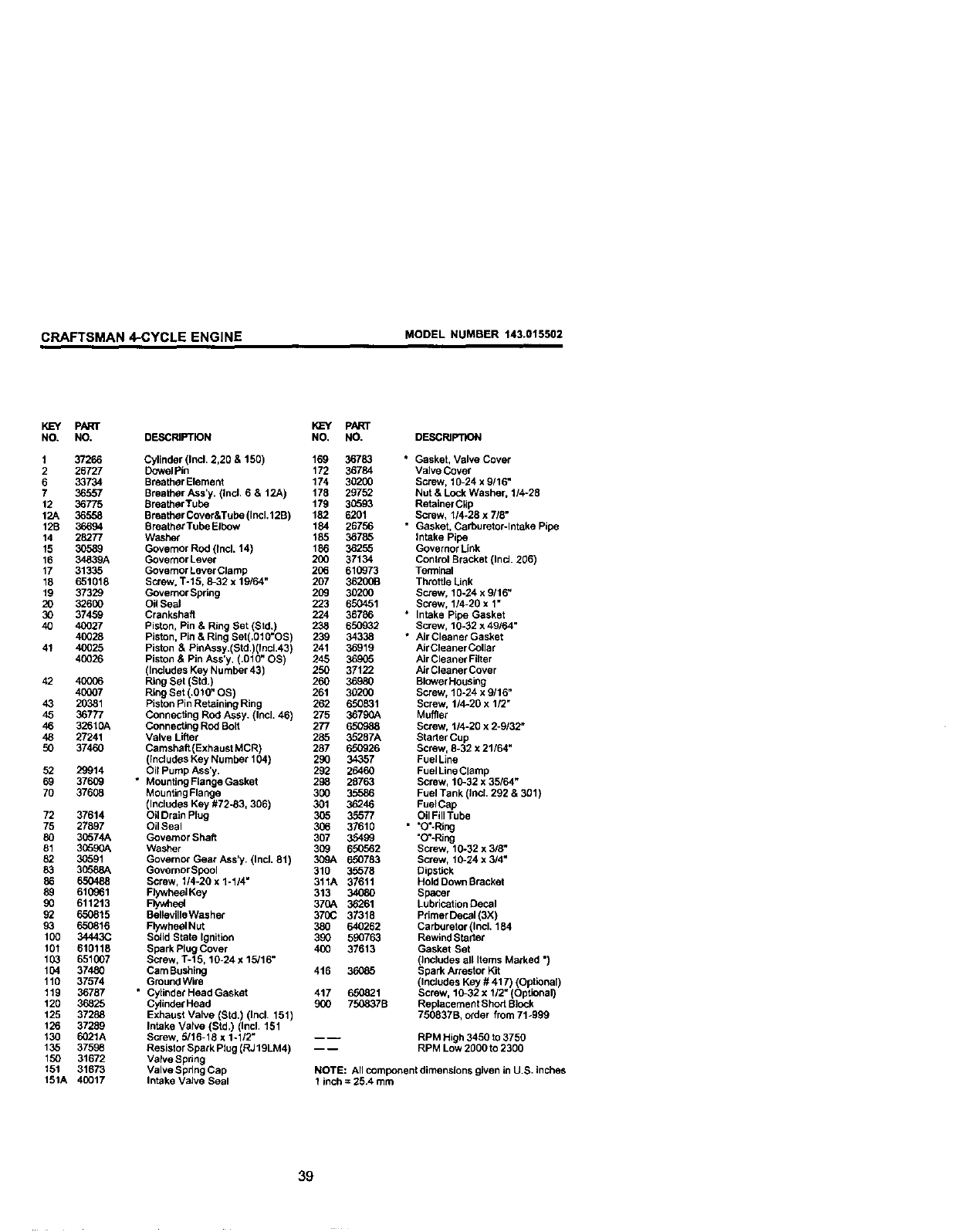
CRAFTSMAN 4-CYCLE ENGINE MODEL NUMBER 143.015502
KEY PART
NO. NO. DESCRIPTION
1 37266 Cylinder (Incl. 2,20 & 150)
2 26727 Dowel Pin
6 33734 Breather Element
7 36557 Breather Ass'y. (Incl. 6 & 12A)
12 36775 SreatherTube
12A 36558 Breather Cover&Tube (Incl.12B)
12B 36694 BreatherTube Elbow
14 28277 Wash_
15 30589 Governor Rod (Incl. 14)
16 34839A Governor Lever
17 31335 Governor Lever Clamp
18 651018 Screw. %15, 8-32 x 19164"
19 37329 Governor Spdng
20 32600 Oil Seal
30 37459 Crankshaft
40 40027 Piston, Pin & Ring Set (Std.)
40028 Piston, Pin & Ring Set(.010"OS)
41 40025 Piston & PJnAssy.(Std.)(Incl.43)
40026 Piston & Pin Ass'y. (.010" OS)
(Includes Key Number 43)
42 40006 Ring Set (Std.)
40007 Ring Set (.010" OS)
43 20381 Piston Pin Retaining Ring
45 36777 Connecting Rod Assy. (Incl. 46)
46 32610A Connecting Rod Bolt
48 27241 Valve Lifter
50 37460 Camshaft (Exhaust MCR)
(Includes Key Number 104)
52 29914 Oil Pump Ass'y.
69 37609 * Mounting Flange Gasket
70 37608 Mounting Flange
(Includes Key #72-83, 306)
72 37614 Oil Drain Plug
75 27697 Oil Seal
80 30574A Governor Shaft
81 30590A Washer
93 30591 Governo_ Gear Ass'y. (IncL 81)
83 30588A Governor Spool
86 650488 Screw, 114-20 x 1-114"
89 610961 Flywheel Key
90 611213 Flywheel
93 650815 Belleville Washer
93 650816 Flywheel Nut
100 34443C Solid State Ignition
101 610118 Spark Plug Cover
103 651007 Screw, %15, 10-24 x 15/16"
104 37480 Cam Bushing
110 37574 GrOundWire
119 36787 *CylindetHeadGasket
120 36825 Cylinder Head
125 37288 Exhaust Valve (Std.) (Incl. 151)
126 37289 Intake Valve (Std.) (Incl. 151
130 6021A Screw, 5/16-18 x 1-1/2'*
135 37598 Resistor Spark Plug (RJ19LM4)
150 31672 Varve Spdng
151 31673 Valve Spdng Cap
151A 40017 Intake Valve Seal
KL=Y pART
NO, NO. DESCRIPTION
169 36783 ° Gasket, Valve Cover
172 36784 Valve Cover
174 30200 Screw, 10-24 x 9116"
178 29752 Nut & Lock Washer, 114-28
179 30593 Retainer Clip
182 6201 Screw, 114-28 x 7/8"
184 26756 * Gasket, Carburetar-lntake Pipe
185 36785 Intake Pipe
186 36255 Governor Link
200 37134 Control Bracket (Ind. 206)
206 610973 Terminal
207 3620013 Throttle Link
209 30200 Screw, 10-24 x 9116"
223 650451 Screw, 1/4-20 x 1"
224 36786 * Intake Pipe Gasket
238 650932 Screw, 10-32 x 49/64"
239 34338 * Air Cleaner Gasket
241 36919 AirCleaner Collar
245 369_5 Air Cleaner Fitier
250 37122 Air Cleaner Cover
260 36980 Blower Housing
261 30200 Screw, 10-24 x 9/16"
252 650831 Screw, 1/4-20 x 1/2"
275 36790A Muffler
277 650988 Screw, 114-20 x 2-9/32"
285 35267A Starter Cup
287 650926 Screw, 8-32 x 21/64"
290 34357 FuelLine
292 26460 FueJLineClamp
298 26763 Screw, 10-32 x 35/64"
300 35586 Fuel Tank (Ind. 292 & 301 )
301 38246 FuelCap
306 35577 Oil Fill Tube
306 37610 " "O_-Ring
307 35499 "O'-Ring
309 650562 Screw, 10-32 x 3/8_
309A 650783 Screw, 10-24x3/4"
310 35578 Dipstick
311A 37611 Hold Down Bracket
313 34080 Spacer
370A 36261 Lubrication Decal
370(; 37318 Primer Decal (3X)
380 640262 Carburetor (IncL 184
390 590763 Rewind Starter
400 37613 Gasket Set
(includes all Items Marked ")
416 36085 Spark Arrestor Kit
(InCludes Key # 417) (Optional)
417 650821 Screw, 10-32 x 1/2" (Optional)
900 750837B Replacement Sho_ Block
750837B, order from 71-999
--- RPM High 3450 to 3750
-- -- RPM Low 2000 to 2300
NOTE: All component dimensions given in U.S. inches
1 inch = 25.4 turn
39
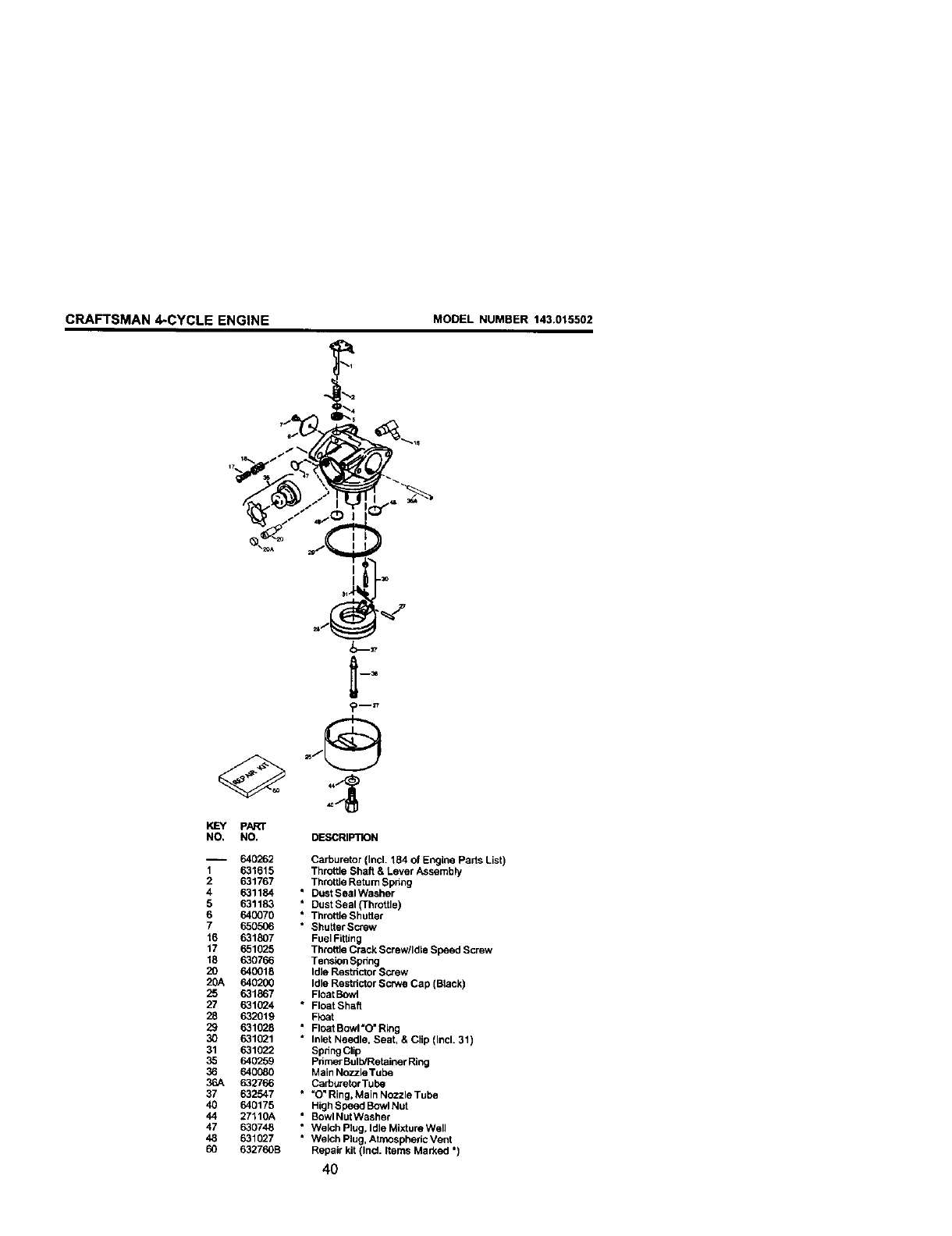
CRAFTSMAN 4-CYCLE ENGINE MODEL NUMBER 143.015502
PART
NO, NO. DESCRIPTION
-- 640262 Carburetor (Incl. 164 of Engine Parts List)
1 631615 Throttle Shaft & Lever Assembly
2 631767 ThrotSe Retum Spnng
4 631184 * Dust Seal Washer
5 631183 * Dust Seal (Throttle)
6 640070 * Throttle Shutter
7 650506 * Shutter Screw
16 631807 Fuel Fitting
17 651025 Throttle Crack Screwlldle Speed Screw
18 630766 Tension Spdng
20 640018 Idle Restnctor Screw
20A 640200 Idle Restdctor Sc_ve Cap (Black)
25 631867 Float Bowl
27 631024 *Float Shaft
28 632019 Fk_at
29 631028 "Float Bowl"0" Ring
30 631021 * Inlet Needle, Seat, & CHp (Incl. 31 )
31 631022 Spdng Clip
35 640259 Pnmer Bulb/Retainer Ring
36 640080 Main Nozzle Tube
36A 632766 Carburetor Tube
37 632547 " _O"Ring, Main Nozzle Tube
40 640175 High Sbeed BowlNut
44 27110A " BowlNut Washer
47 630748 * Welch Plug, Idle Mixture Well
48 631027 * Welch Plug, Atmospheric Vent
60 632760B Repair kit (Ind. Items Marked *)
40
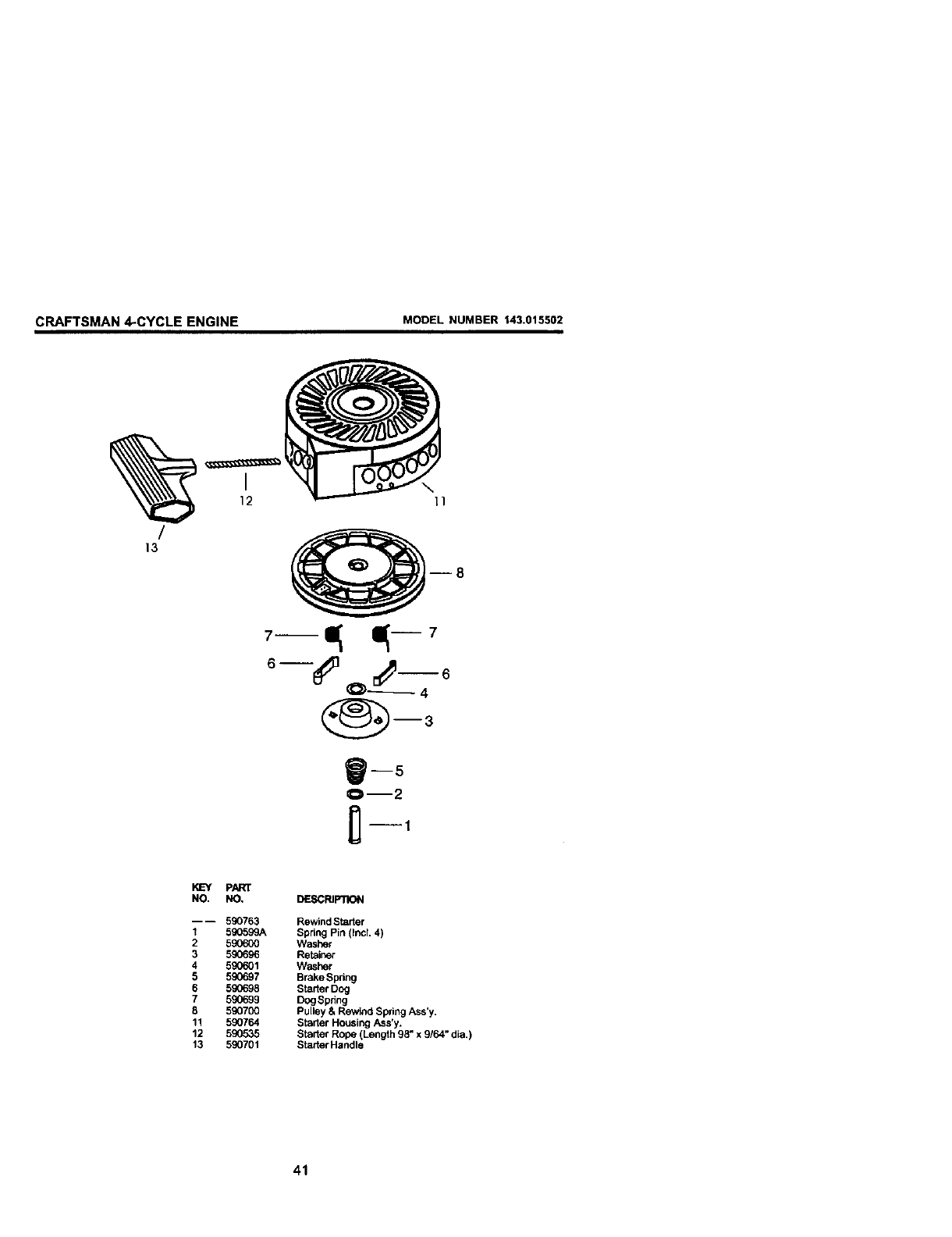
CRAFTSMAN 4-CYCLE ENGINE MODEL NUMBER 143.015502
%
/
13
I
12 \11
gl 15
Ore2
PART
NO. NO. DESCRIPTION
---- 590763 Rewind Starter
1 590599A Spring Pin (IncL 4)
2 590600 Washer
3 590696 Retainer
4 590601 Washer
5 590697 Brske Spring
6 590698 Starter Dog
7 590699 DogSpring
8 590700 Pulley & Rewind Spring Ass'y.
11 590764 Starter Housing Ass'y.
12 590535 Starter Rope (Length 98" x 9/64" dia.)
13 590701 Starter Handle
41
For repair of major brand appliances in your own home...
no matter who made it, no matter who sold it!
1-800-4-MY-HOME sMAoytime.dayo,nioht
(1-800-469-4663) _iilii
www.sears.com
To bring in products such as vacuums,
lawn equipment and electronics for repair, call for
the location of your nearest Sears Parts & Repair Center.
1-800-488-1222 An_imo.day or night
www.sears.com
For the replacement parts, accessories and owner's manuals
that you need to do-it-yourself, call Sears PartsDirectSM!
1-800-366-PART 6at.- 11pmCST,
(1-800-366-7278) 7 days a week
w_PN.sears.comlpartsdirect ...._,
To purchase or inquireabout aSears Service Agreement:
1-800-827-6655
7 a.m. - 5 p.m. CST, Mon. - Sat.
Papa pedir servicio de repapacidn a domicillo, Au Canada pour service en franerais:
y papa ordenar piezas con entrega adomicilio: 1-877-LE-FOYER s"
1-888-SU-HOGAR _" (1-877-533-6937)
(1-888-784-6427) [ )
SEARS
_'_ ;'_ " HomeCentral ®
®Sears, RoebuckandCo, ®Registered Trademark !r= Trademark of Sears, Roebuck and Co.
® Marca Registrada /TM Marca de Fabrica de Sears, RoebucJ_ and Co.
177731 01.22.01 BY Printed in U.S.A.
