Craftsman 919150020 User Manual SPRAY GUN Manuals And Guides L0807538
CRAFTSMAN Spray Gun Manual L0807538 CRAFTSMAN Spray Gun Owner's Manual, CRAFTSMAN Spray Gun installation guides
User Manual: Craftsman 919150020 919150020 CRAFTSMAN SPRAY GUN - Manuals and Guides View the owners manual for your CRAFTSMAN SPRAY GUN #919150020. Home:Tool Parts:Craftsman Parts:Craftsman SPRAY GUN Manual
Open the PDF directly: View PDF ![]() .
.
Page Count: 10
SEARS
GENERAL
OWNERS
MANUAL
MODEL NO.
919o150020
IMPORTANT:
Read the Safety Guidelines
and All Instructions
Carefully Before Operating
CRAFTSMAN DETAIL
TOUCH=UP GUN
DESCRIPTION
INSTALLATION
OPERATION
MAINTENANCE
PARTS LIST
lM-150020 10/10/94 J
Sears, Roebuckand Co., Hoffm_n Estates, IL60179 U.S.A.
TABLE OF CONTENTS
Page
WARRANTY ................................................................................................................................ 3
SAFETY GUIDELINES .......................................................................................................................................3
WARNING CHART .........................................................................................................................................4
AIR REQUIREMENTS ............................................................................................................................................4
GENERAL INFORMATION ...................................................................................................................................5
Spray Gun .......................................................................................................................................................5
PREPARATION FOR SPRAYING .......................................................................................................................5
OPERATION ....................................................................................................................................................................._
MAINTENANCE ..................................................................................................................................................:7
HINTS FOR GOOD SPRAYING RESULTS ................................................................................................7
TROUBLESHOOTING GUIDE ............................................................................................................................8
SPRAY GUN DIAGRAM ...............................................................................................................................................10
PARTS LIST ........................................................................................................................................................1t
HOW TO ORDER REPAIR PARTS ..................................................................................................................................12
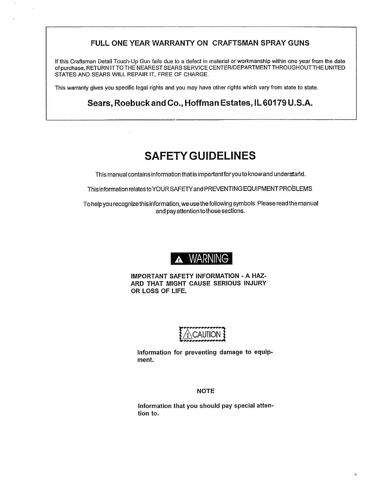
FULL ONE YEAR WARRANTY ON CRAFTSMAN SPRAY GUNS
If this Craftsman Detail Touch-Up Gun fails due to a defect in material or workmanship within one year from the date
of purchase, RETURN ITTO THE NEAREST SEARS SERVICE CENTER/DEPARTMENT THROUGHOUTTHE UNITED
STATES AND SEARS WILL REPAIR IT, FREE OF CHARGE
This warranty gives you specific legal rights and you may have other rights which vary from state to state.
Sears, Roebuck and Co., Hoffman Estates, IL 60179 U.S.A.
SAFETYGUIDELINES
This manual contains informationthat is importantforyou to know and under_ar_d_
This inforrnation relates to YOU R SAFETY and PREVENTING EQUIPMENT PROBLEMS
To help you recognize this information, we use the following symbols Please read the manual
and pay attention to those sections,
IMPORTANT SAFETY INFORMATION -A HAZ-
ARD THAT MIGHT CAUSE SERIOUS INJURY
OR LOSS OF LIFE.
Information for preventing damage to equip-
ment.
NOTE
Information that you should pay special atten-
tion to.
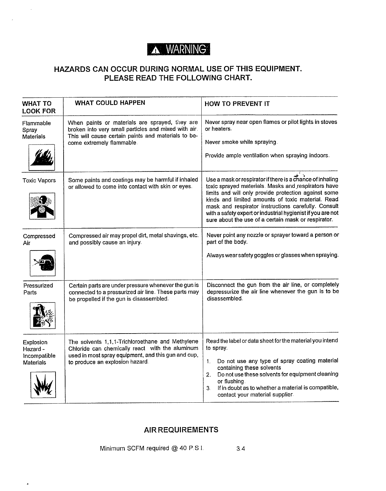
HAZARDS CAN OCCUR DURING NORMAL USE OF THIS EQUIPMENT.
PLEASE READ THE FOLLOWING CHART.
WHAT TO WHAT COULD HAPPEN HOW TO PREVENT IT
LOOK FOR
Neverspray near open flamesor pilot lightsinstoves
Flammable
Spray
Materials
Toxic Vapors
Compressed
Air
Pressurized
Parts
Explosion
Hazard -
Incompatible
Materials
When paints or materials are sprayed, they are
broken into very small particles and mixed with air.
This will cause certain paints and materials to be-
come extremely flammable
Some paints and coatings may be harmful if inhaled
or allowed to come into contact with skin or eyes
Compressed air may propel dirt, metal shavings, etc.
and possibly cause an injury
Certain parts are under pressure whenever the gun is
connected to a pressurized air line_ These parts may
be propelled if the gun is disassembled.
The solvents 1,1,1-Tdchloroethane and Methylene
Chlodde can chemically react with the aluminum
used in most spray equipment, and this gun and cup,
to produce an explosion hazard
or heaters.
Never smoke while spraying
Provide ample ventilation when spraying indoors.
Use a mask or resp=rator =fthere =sa chance of inhaling
toxic sprayed materials Masks and respirators have
limits and will only provide protection against some
kinds and limited amounts of toxic material Read
mask and respirator instructions carefully. Consult
with a safety expert or industdal hygienist if you are not
sure about the use of a certain mask or respirator.
Never point any nozzle or sprayer toward a person or
partof the body_
Always wear safety goggles or glasses when spraying.
Disconnect the gun from the air line, or completely
depressurize the air line whenever the gun is to be
disassembled.
Read the label or data sheet for the material you intend
to spray.
1 Do not use any type of spray coating material
containing these solvents
2. Do not use these solvents for equipment cleaning
or flushing
3 If in doubt as to whether a material is compatible,
contact your material supplier
AIR REQUIREMENTS
Minimum SCFM required @ 40 PSI 34
GENERAL INFORMATION
DESCRIPTION
The Craftsman Detail Touch-Up Gun is the only spray gun of its type that can be simply converted for use by a left
or right handed sprayer, by simply unscrewing the trigger pin, turning the trigger over and re-inserting the trigger pin.
The complete Craftsman Detail Touch-Up Gun consists of a detail touch-up gun and 8 oz. (240 cc) suction cup
assembled. The detail touch-up gun is a non-bleeder, suction feed, external mix type. The cup has a one half pint
capacity.
NOTE: This spray gun is designed to spray stains, acrylics, lacquers, primers, automotive metallics and
other light and medium viscosity finishes Most unreduced latex or other heavy bodied materials require
the use of a pressure feed paint tank. If used with corrosive, rust-inducing, or highly abrasive materials,
frequent and thorough cleaning will be reqt,ired and/or may increase the need for replacement parts.
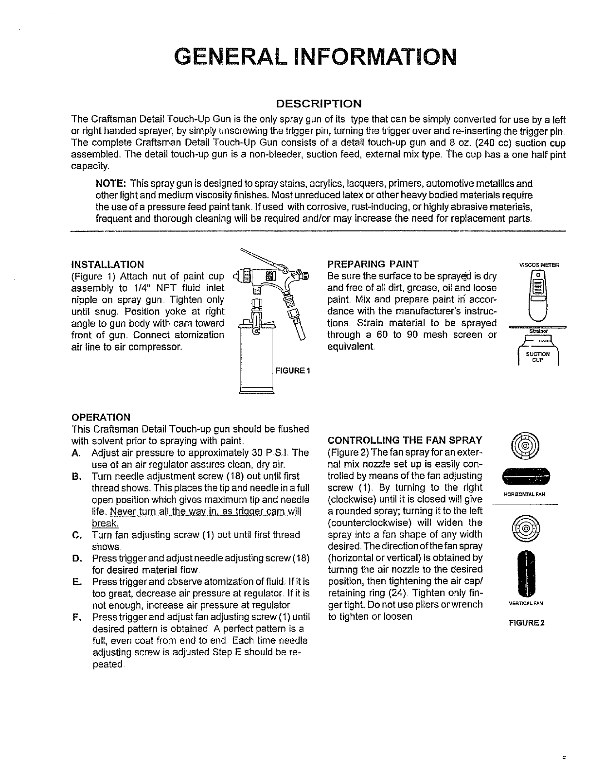
INSTALLATION
(Figure 1) Attach nut of paint cup
assembly to 1/4" NPT fluid inlet
nipple on spray gun, Tighten only
until snug, Position yoke at right
angle to gun body with cam toward
front of gun, Connect atomization
air line to air compressor.,
PREPARING PAINT VlSCOSIM_R
Be sure the surface to be sprayed is dry f'_
and free of all dirt, grease, oil and loose 0
paint Mix and prepare paint in" accor-
dance with the manufacturer's instruc-
tions. Strain material to be sprayed .
through a 60 to 90 mesh screen or ='_"_
equivalent
OPERATION
This Craftsman Detail Touch-up gun should be flushed
with solvent prior to spraying with paint
A. Adjust air pressure to approximately 30 P.SL The
use of an air regulator assures clean, dry air.
B. Turn needle adjustment screw (18) out until first
thread shows This places the tip and needle ina full
open position which gives maximt,m tip and needle
life. Never turn all the way in, as triqqer cam will
break.
C. Turn fan adjusting screw (1) out until first thread
shows
D. Press trigger and adjust needle adjt, sting screw (18)
for desired material flow.
E. Press trigger and observe atomization of fluid If it is
too great, decrease air pressure at regulator If it is
not enough, increase air pressure at regulator
F. Press trigger and adjust fan adjusting screw (I) until
desired pattern is obtained A perfect pattern is a
full, even coat from end to end Each time needle
adjusting screw is adjusted Step E should be re-
peated
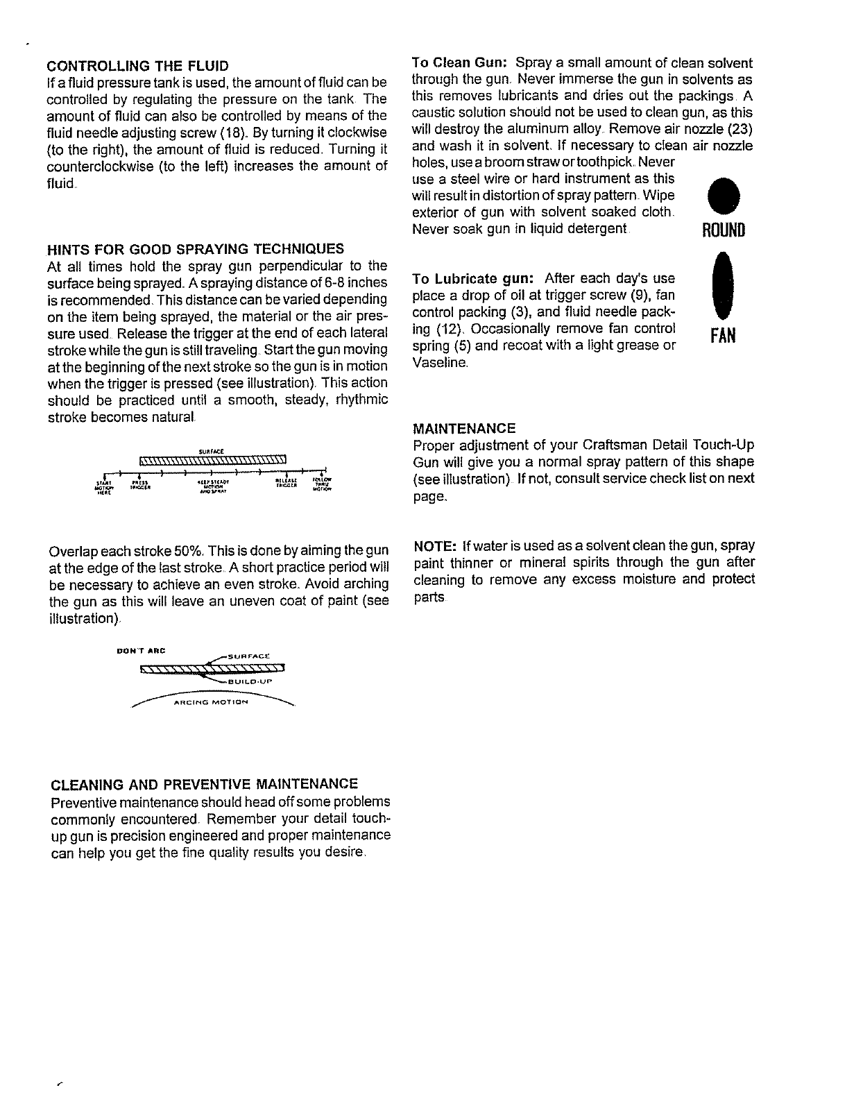
CONTROLLING THE FAN SPRAY
(Figure 2) The fan spray for an exter-
nal mix nozzle set up is easily con-
trolled by means of the fan adjusting
screw (1) By turning to the right
(clockwise) until it is closed will give
a rounded spray; turning it to the left
(counterclockwise) will widen the
spray into a fan shape of any width
desired The direction of the fan spray
(horizontal or vertical) is obtained by
turning the air nozzle to the desired
position, then tightening the air cap/
retaining ring (24) Tighten only fin-
ger tighL Do not use pliers or wrench
to tighten or loosen
®
HORLZONTAL FAN
®
0
VERTICAL FAN
FIGURE2
CONTROLLING THE FLUID
If a fluid pressure tank is used, the amount of fluid can be
controlled by regulating the pressure on the tank The
amount of fluid can also be controlled by means of the
fluid needle adjusting screw (18). By turning it clockwise
(to the right), the amount of fluid is reduced Turning it
counterclockwise (to the left) increases the amount of
fluid.
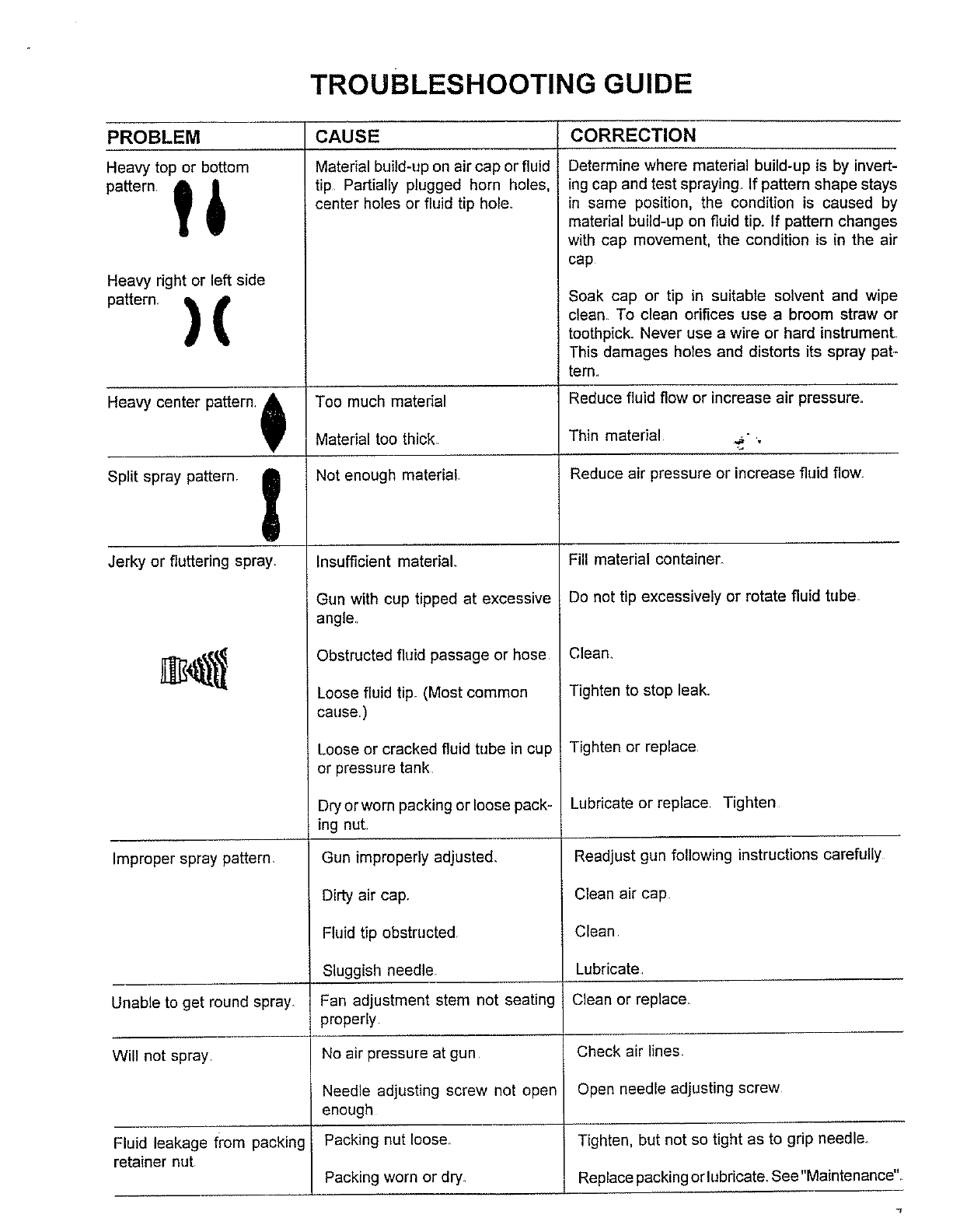
HINTS FOR GOOD SPRAYING TECHNIQUES
At all times hold the spray gun perpendicular to the
surface being sprayed. A spraying distance of 6-8 inches
is recommended. This distance can be varied depending
on the item being sprayed, the material or the air pres-
sure used Release the trigger at the end of each lateral
stroke while the gun isstill traveling Start the gun moving
at the beginning of the next stroke so the gun is in motion
when the trigger is pressed (see illustration) This action
should be practiced until a smooth, steady, rhythmic
stroke becomes natural
sunt_,_£
kk\\\\\\\\\ \\\\\\ \\\\\\ \\\\\\_\_
To Clean Gun: Spray a small amount of clean solvent
through the gun Never immerse the gun in solvents as
this removes lubricants and dries out the packings A
caustic solution should net be used to clean gun, as this
will destroy the aluminum alloy Remove air nozzle (23)
and wash it in solvent, If necessary to clean air nozzle
holes, use a broom straw or toothpick.. Never
use a steel wire or hard instrument as this A
will result in distortion of spray pattern. Wipe U
exterior of gun with solvent soaked cloth
Never soak gun in liquid detergent ROUND
To Lubricate gun: After each day's use
place a drop of oil at trigger screw (9), fan
control packing (3), and fluid needle pack-
ing (12), Occasionally remove fan control
spring (5) and recoat with a light grease or
Vaseline.
I
FAN
MAINTENANCE
Proper adjustment of your Craftsman Detail Touch-Up
Gun will give you a normal spray pattern of this shape
(see illustration) If not, consult service check list on next
page,
Overlap each stroke 50%. This is done by aiming the gun
at the edge of the last stroke. A short practice period will
be necessary to achieve an even stroke. Avoid arching
the gun as this will leave an uneven coat of paint (see
illustration).
DON'T ARC
fSU RFAC_
_-,,,-, o U *LD ta p
NOTE: If water is used as a solvent clean the gun, spray
paint thinner or mineral spirits through the gun after
cleaning to remove any excess moisture and protect
parts
CLEANING AND PREVENTIVE MAINTENANCE
Preventive maintenance should head off some problems
commonly encountered. Remember your detail touch-
up gun is precision engineered and proper maintenance
can help you get the fine quality results you desire
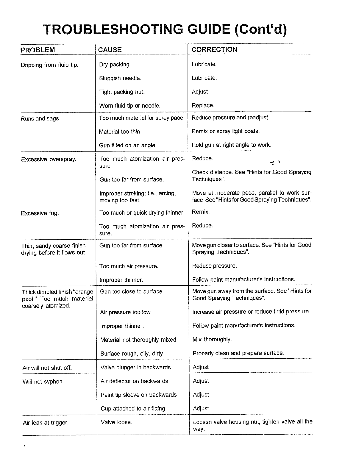
TROUBLESHOOTING GUIDE
PROBLEM
Heavy top or bottom
Pattern' _) i i
Heavy right or left side
)attern. ql i'
CAUSE
Material build-up on air cap or fluid
tip Partially plugged horn holes,
center holes or fluid tip hole_
CORRECTION
Determine where material build-up is by invert-
ing cap and test spraying If pattern shape stays
in same position, the condition is caused by
material build-up on fluid tip_ If pattern changes
with cap movement, the condition is in the air
cap
Soak cap or tip in suitable solvent and wipe
clean To clean orifices use a broom straw or
toothpick. Never use a wire or hard instrument
This damages holes and distorts its spray pat.-
tern.
Heavy center pattern, &Too much material Reduce fluid flow or increase air pressure.
Material too thick Thin material ._- ,
Split spray pattern. Not enough material. Reduce air pressure or increase fluid flow_
Jerky or fluttering spray. Insufficient material
Gun with cup tipped at excessive
angle,
Obstructed fluid passage or hose
Loose fluid tipr (Most common
cause)
Loose or cracked fluid tube in cup
or pressure tank
Dry or worn packing or loose pack-
ing nut
Gun improperly adjusted_
Dirty air cap.
Fluid tip obstructed
Sluggish needle_
Fan adjustment stem not seating
properly
No air pressure at gun
Needle adjusting screw not open
enough
Packing nut Ioose_
Packing worn or dry.
Improper spray pattern
Fill material container_
Do not tip excessively or rotate fluid tube
Clean_
Tighten to stop leak.
Tighten or replace
Lubricate or replace Tighten
Readjust gun following instructions carefully
Clean air cap
Clean
Lubricate
Clean or replace
Unable to get round spray_
Will not spray Check air lines,
Open needle adjusting screw
Fluid leakage from packing Tighten, but not so tight as to grip needle.
retainer nut Replace packing or lubricate. See"Maintenance"
TROUBLESHOOTING GUIDE (Cont'd)
PROBLEM
Dripping from fluid tip,
Runs and sag&
Excessive overspray.
Excessive fog
Thin, sandy coarse finish
drying before it flows out,
Thick dimpled finish "orange
CAUSE
Dry packing
Sluggish needle.
Tight packing nut
Worn fluid tip or needle.
Too much material for spray pace
Material too thin
Gun tilted on an angle.
Too much atomization air pres-
sure.
Gun too far from surface.
Improper stroking; ire., arcing,
moving too fast.
Too much or quick drying thinner
Too much atomization air pres-
sure
Gun too far from surface
Too much air pressure,
Improper thinner,
Gun too close to surface,
CORRECTION
Lubricate_
Lubricate_
Adjust.
Replace,
Reduce pressure and readjust.
Remix or spray light coats.
Hold gun at right angle to work.
Reduce.
Check distance. See "Hints forGood Spraying
Techniques'L
Move at moderate pace, parallel to work sur-
face See"Hints for Good Spraying Techniques'L
Remix
Reduce.
Move gun closer to surface_ See "Hints for Good
Spraying Techniques".
Reduce pressure.
Follow paint manufacturer's instructions_
Move gun away from the surface. See "Hints for
peel." Too much material
coarsely atomized
Air pressure too low
Improper thinner.
Good Spraying Techniques"
Increase air pressure or reduce fluid pressure
Follow paint manufacturer's instructions
Air will not shut off
Will not syphon
Air leak at trigger.
Material not thoroughly mixed
Surface rough, oily, dirty
Valve plunger in backwards
Air deflector on backwards
Paint tip sleeve on backwards
Cup attached to air fitting
Valve loose
i
Mix thoroughly.
Properly clean and prepare surface.
Adjust
Adjust
Adjust
Adjust
Loosen valve housing nut, tighten valve all the
way
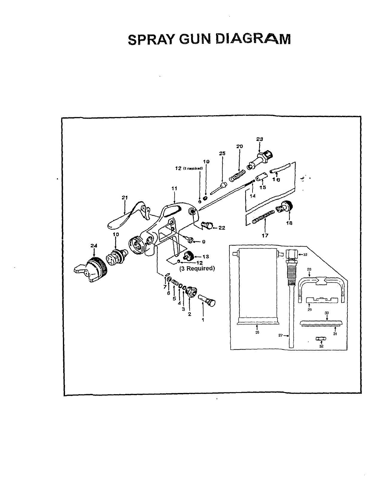
SPRAY GUN DIAGRAM
21
10
|
1t
6
2
(3 Required)
54
32
IG
15
14
t8
17
1
_6
.
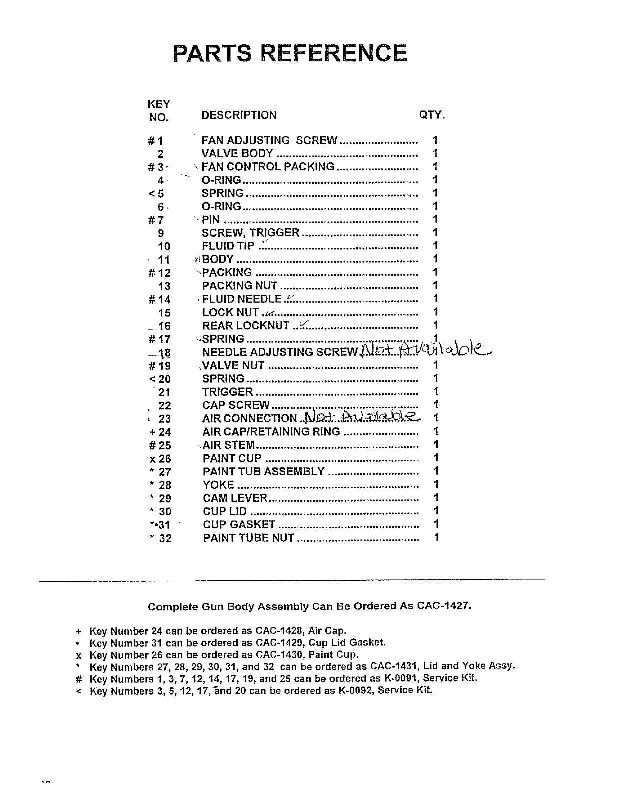
PARTS REFERENCE
KEY
NO.
#1
2
#3-
4
<5
6-
#7
9
10
11
#12
13
#14
15
=16
:# 17
#19
< 20
21
, 22
23
+ 24
# 25
x 26
* 27
* 28
* 29
* 30
*.31
* 32
DESCRIPTION QTY.
FAN ADJUSTING SCREW ......................... 1
VALVE BODY ............................................. 1
\FAN CONTROL PACKING .......................... 1
O-RING ........................................................ 1
SPRING ....................................................... 1
O-RING ........................................................ 1
•PIN .............................................................. 1
SCREW, TRIGGER ..................................... 1
FLUID TIP ._ ................................................ 1
_',BODY .......................................................... 1
",PACKING .................................................... 1
PACKING NUT ............................................ 1
, FLUID NEEDLE ..._........................................ I
LOCK NUT ._. .............................................. 1
REAR LOCKNUT .._. .................................. 1
,SPRING ....................................... _,.............. 1.,
NEEDLE ADJUSTING SCREW._._..._...JC'_I_ _L,_:_I__._
_VALVE NUT ................................................ 1
SPRING ....................................................... t
TRIGGER .................................................... 1
CAP SCREW ............................................... 1
AIR CO N NECTIO a ._t_J_.. _._)=_L[ ..._._ I
AIR CAP/RETAINING RING ........................ 1
AIR STEM .................................................... 1
PAINT CUP ................................................. 1
PAINT TUB ASSEMBLY ............................. 1
YOKE .......................................................... 1
CAM LEVER ................................................ 1
CUP LID ...................................................... 1
CUP GASKET ............................................. 1
PAINT TUBE NUT ....................................... 1
Complete Gun Body Assembly Can Be Ordered As CAC-1427.
+ Key Number 24 can be ordered as CAC-1428, Air Cap.
•Key Number 3! can be ordered as CAC-1429, Cup Lid Gasket.
x Key Number 26 can be ordered as CAC-1430, Paint Cup.
* Key Numbers 27, 28, 29, 30, 31, and 32 can be ordered as CAC-1431, Lid and Yoke Assy.
# Key Numbers 1, 3, 7, 12, 14, 17, 19, and 25 can be ordered as K-0091, Service Kit.
<Key Numbers 3, 5, 12, 17,_nd 20 can be ordered as K-0092, Service Kit.
